DATA COMMUNICATION 18CS46 4TH SEM - BMSIT
633
Department of ISE BMS Institute of Technology and Mgmt DATA COMMUNICATION 18CS46 4 TH SEM
-
Upload
khangminh22 -
Category
Documents
-
view
1 -
download
0
Transcript of DATA COMMUNICATION 18CS46 4TH SEM - BMSIT
BMS Institute of Technology and Mgmt Department of ISE Department of ISE BMS Institute of Technology and Mgmt
DATA COMMUNICATION 18CS46 4TH SEM

BMS Institute of Technology and Mgmt Department of ISE
Table of Contents
Module Number
Module Title Page Number
1 Introduction 1-105
2 Digital Transmission 106-193
3 Bandwidth Utilization 194-381
4 Data Link Control 382-531
5 Wired LANs Ethernet 531-631

BMS Institute of Technology and Mgmt Department of ISE
MODULE – 1
INTRODUCTION
1

BMS Institute of Technology and Mgmt Department of ISE
DATA COMMUNICATIONS
Telecommunication-communication at a distance.
Data -information presented in whatever form is agreed
upon by the parties creating and using the data.
Data communications are the exchange of data between
two devices via some form of transmission medium such as
a wire cable.
Fundamental characteristics[Effectiveness of DC]:
1. Delivery-correct destination
2. Accuracy-deliver data accurately
3. Timeliness- delivery data in timely manner
4. Jitter-variation in packet arrival time.
2
BMS Institute of Technology and Mgmt Department of ISE 1.3
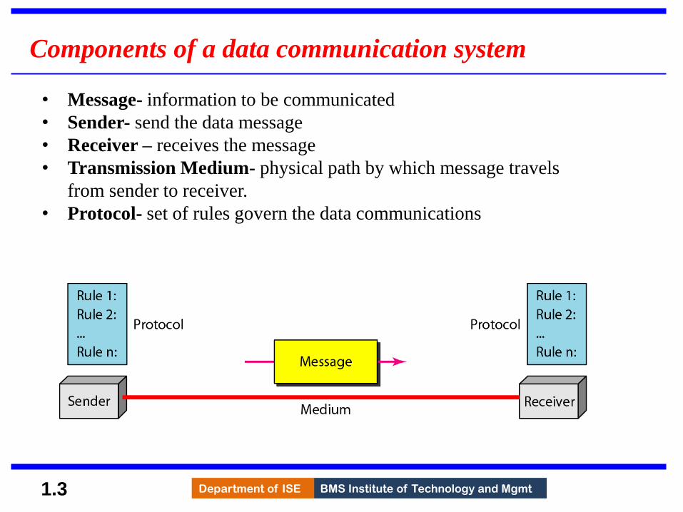
Components of a data communication system
• Message- information to be communicated
• Sender- send the data message
• Receiver – receives the message
• Transmission Medium- physical path by which message travels
from sender to receiver.
• Protocol- set of rules govern the data communications
3

BMS Institute of Technology and Mgmt Department of ISE 1.4
Data Representation
• Text
• Represented as bit pattern (sequence of bits 0s or 1s)
• Different set of bit pattern used to represent symbols or
characters.
• Each set is called code
• Process of representing symbols is called encoding
• Ex: ASCII,UNICODE
• Numbers
• Represented as bit pattern
• Directly converted to binary form
• Audio
• Recording or broadcasting of sound or music.
• Continuous not discrete
4

BMS Institute of Technology and Mgmt Department of ISE 1.5
Data Representation (Cont.…)
• Video
• Recording or broadcasting of picture or a movie
• Produced as :
• Continuous entity [TV camera]
• Combination of images-discrete entity
• Images
• Represented as bit pattern
• Image is divided into matrix of pixels(smallest element of an image)
• Each pixel is assigned a bit pattern (size and value of pattern depend
on image)
• Ex: black and white dots (chessboard) -1 bit pattern is enough to
represent a pixel, gray scale- 2 bit pattern.
• Several methods to represent colour images : RGB,YCM
5
BMS Institute of Technology and Mgmt Department of ISE
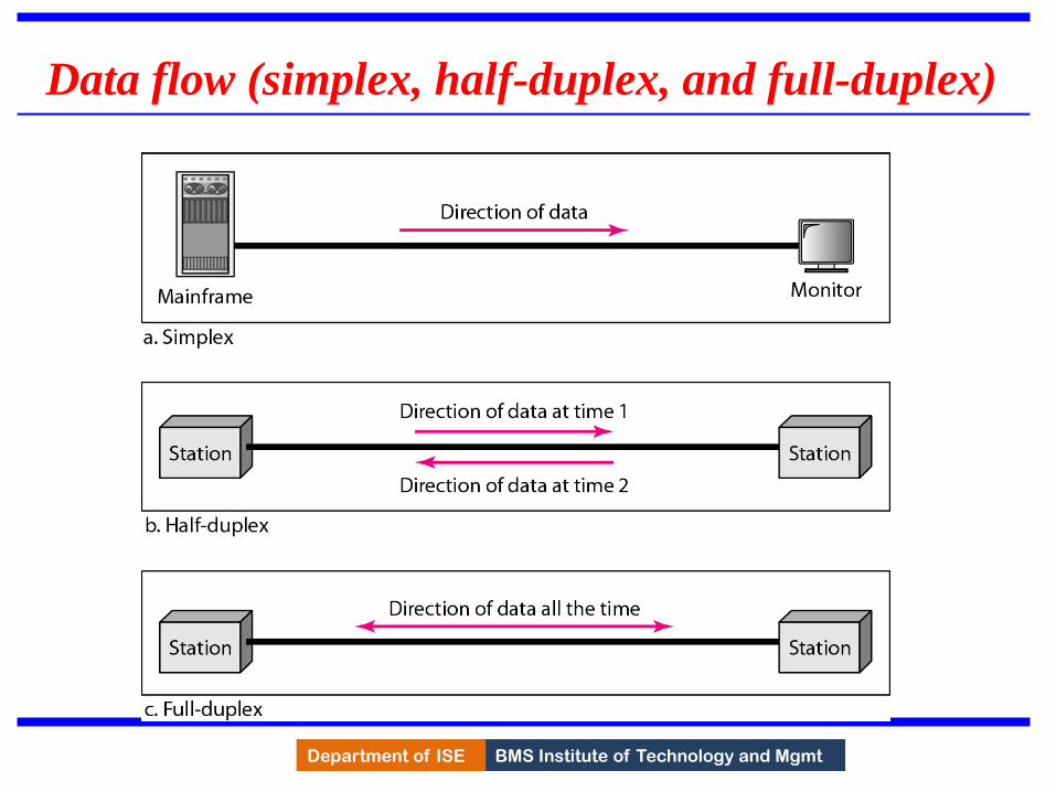
Data flow (simplex, half-duplex, and full-duplex)
6

BMS Institute of Technology and Mgmt Department of ISE 1.7
NETWORKS
A network is a set of devices (often referred to as nodes)
connected by communication links.
A node can be a computer, printer, or any other device
capable of sending and/or receiving data generated by
other nodes on the network.
A link can be a cable, air, optical fiber, or any medium
which can transport a signal carrying information.
Network Criteria
Physical Structures
Categories of Networks
Topics discussed in this section:
7

BMS Institute of Technology and Mgmt Department of ISE Department of ISE BMS Institute of Technology and Mgmt 1.8
Network Criteria
Performance
Measured using:
Transit time: time taken to travel a message from one device
to another.
Response time: time elapsed between enquiry and response.
Depends on following factors:
Number of users
Type of transmission medium
Efficiency of software
Evaluated by 2 networking metrics:
Throughput (high)
Delay (small)
8

BMS Institute of Technology and Mgmt Department of ISE Department of ISE BMS Institute of Technology and Mgmt
Network Criteria (cont..)
Reliability
Measured by
Frequency of failure.
Time taken to recover from a network failure.
Network robustness in a disaster.
Security
Protecting data from unauthorized access, damage and
development.
Implementing policies and procedures for recovery from breaches
and data losses.
9

BMS Institute of Technology and Mgmt Department of ISE Department of ISE BMS Institute of Technology and Mgmt
�Physical Structures
• Type of Connection
– Point to Point - single transmitter and receiver
– Multipoint - multiple recipients of single transmission
10

BMS Institute of Technology and Mgmt Department of ISE Department of ISE BMS Institute of Technology and Mgmt
�Physical Structures (Cont..)
• Physical Topology:
– Way in which network is laid out physically.
– Two or more links form a topology.
– “ Topology of network is the geometric representation of all links
and linking devices to one another”.
– Basic topologies:
• Mesh
• Star
• Bus and
• Ring
11

BMS Institute of Technology and Mgmt Department of ISE
Mesh Topology
• All devices are connected to each other
• Dedicated point-point link between all
devices
• “n(n-1)” physical channels to link “n” device.
• For „n‟ nodes
• n(n-1) physical links
• n(n-1)/2 duplex mode links
• Every device have (n-1) I/O ports to be
connected to other (n-1) devices.
Fully connected Mesh Topology
12

BMS Institute of Technology and Mgmt Department of ISE
Advantages:
Advantages:
1) Congestion reduced: Each connection can carry its own data load.
2) Robustness: If one link fails, it does not affect the entire system.
3) Security: When a data travels on a dedicated-line, only intended-receiver can see the
data.
4) Easy fault identification & fault isolation: Traffic can be re-routed to avoid problematic
links.
Disadvantages:
1) Difficult installation and reconfiguration.
2) Bulk of wiring occupies more space than available space.
3) Very expensive: hardware required to connect each link is expensive.
practical example: connection of telephone regional offices in which each regional office
needs to be connected to every other regional office.
Mesh Topology (cont.. )
13

BMS Institute of Technology and Mgmt Department of ISE
Star Topology
A star topology connecting four stations
• Point to Point connection
• All the devices are connected to a
central controller called a hub
• Dedicated point-to-point link
between a device & a hub.
• The devices are not directly linked to
one another. Thus, there is no direct
traffic between devices.
• The hub acts as a junction:
• If device-1 wants to send data
to device-2,
• the device-1 sends the data to
the hub,then the hub relays the
data to the device-2.
14

BMS Institute of Technology and Mgmt Department of ISE
Star Topology (cont..)
Advantages:
1) Less expensive: Each device needs only one link & one I/O port to connect
it to any devices.
2) Easy installation & reconfiguration: Nodes can be added/removed w/o
affecting the network.
3) Robustness: If one link fails, it does not affect the entire system.
4) Easy to detect and troubleshoot fault.
5) Centralized management: The hub manages and controls the whole
network.
Disadvantages:
1) Single point of failure: If the hub goes down, the whole network is dead.
2) Cable length required is the more compared to bus/ring topologies.
3) Number of nodes in network depends on capacity of hub.
Example: Local area network
15

BMS Institute of Technology and Mgmt Department of ISE 1.16
Bus Topology
A bus topology connecting three stations
• Multipoint connection
• All the devices are connected to the
single cable called bus (backbone)
• Devices are connected to the bus by
drop-lines and taps.
• A drop-line is a connection running
between the device and the bus (main
cable).
• A tap is a connector that links to the
bus
• Limit on number of taps a bus can
support and distance between those
taps-(as signal travels along
backbone some energy is transferred
to heat which makes it weaker as it
travels farther)
16
BMS Institute of Technology and Mgmt Department of ISE 1.17
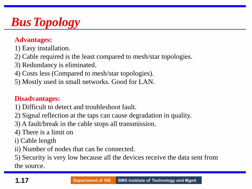
Bus Topology
Advantages:
1) Easy installation.
2) Cable required is the least compared to mesh/star topologies.
3) Redundancy is eliminated.
4) Costs less (Compared to mesh/star topologies).
5) Mostly used in small networks. Good for LAN.
Disadvantages:
1) Difficult to detect and troubleshoot fault.
2) Signal reflection at the taps can cause degradation in quality.
3) A fault/break in the cable stops all transmission.
4) There is a limit on
i) Cable length
ii) Number of nodes that can be connected.
5) Security is very low because all the devices receive the data sent from
the source.
17

BMS Institute of Technology and Mgmt Department of ISE 1.18
Ring Topology
A ring topology connecting six stations
• Each device is connected to the
next, forming a ring
• There are only two neighbours for
each device.
• Data travels around the network in
one direction till the destination is
reached.
• Sending and receiving of data takes
place by the help of token.
• Each device has a repeater.
• A repeater
→ receives a signal on transmission-
medium &
→ regenerates & passes the signal to
next device.
18
BMS Institute of Technology and Mgmt Department of ISE 1.19
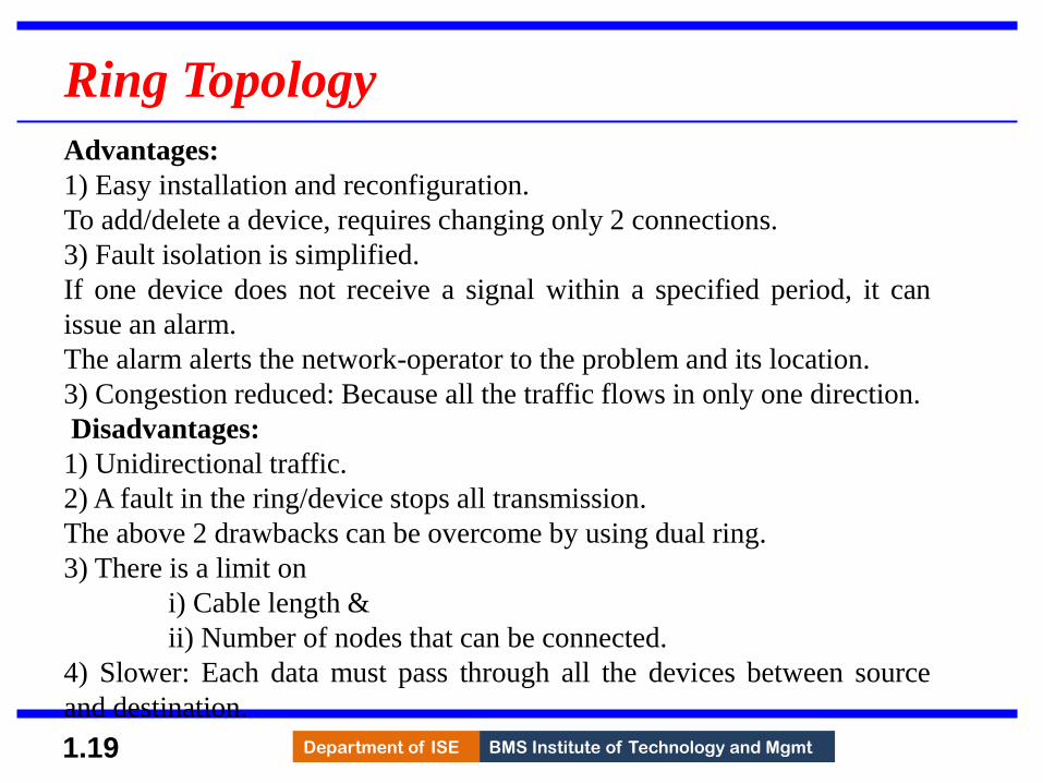
Ring Topology
Advantages:
1) Easy installation and reconfiguration.
To add/delete a device, requires changing only 2 connections.
3) Fault isolation is simplified.
If one device does not receive a signal within a specified period, it can
issue an alarm.
The alarm alerts the network-operator to the problem and its location.
3) Congestion reduced: Because all the traffic flows in only one direction.
Disadvantages:
1) Unidirectional traffic.
2) A fault in the ring/device stops all transmission.
The above 2 drawbacks can be overcome by using dual ring.
3) There is a limit on
i) Cable length &
ii) Number of nodes that can be connected.
4) Slower: Each data must pass through all the devices between source
and destination.
19
BMS Institute of Technology and Mgmt Department of ISE 1.20
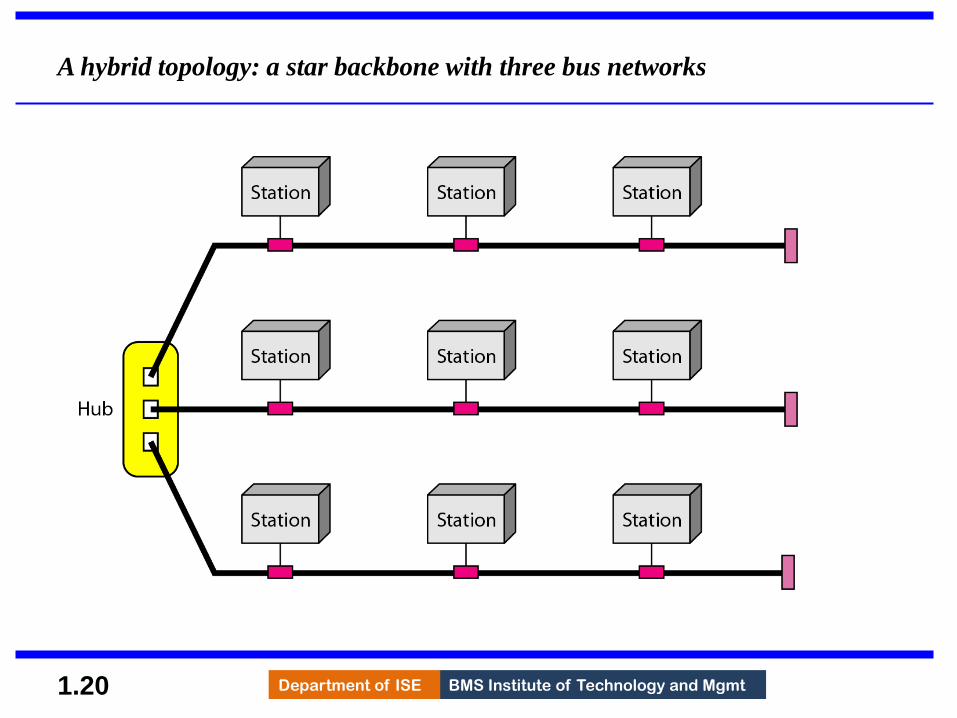
A hybrid topology: a star backbone with three bus networks
20

BMS Institute of Technology and Mgmt Department of ISE Department of ISE BMS Institute of Technology and Mgmt
�Categories of Networks Few criteria –size, geographical coverage and ownership to make this distinction.
• Local Area Networks (LANs)
– Short distances
– Designed to provide local interconnectivity
• Wide Area Networks (WANs)
– Long distances
– Provide connectivity over large areas
• Metropolitan Area Networks (MANs)
– Provide connectivity over areas such as a city, a campus
21

BMS Institute of Technology and Mgmt Department of ISE 1.22
Local Area Networks (LANs)
• It is used to connect computers in a single office, building or campus.
• Privately owned network.
• A LAN can be simple or complex.
1) Simple: LAN may contain 2 PCs and a printer.
2) Complex: LAN can extend throughout a company.(extend to audio
and video devices.)
• Each host in a LAN has an address that uniquely defines the host in the
LAN.
• A packet sent by a host to another host carries both source host‟s and
destination host‟s addresses.
22

BMS Institute of Technology and Mgmt Department of ISE 1.23
Local Area Networks (LANs) (cont…)
• LAN with common cable : packet sent by host
is received by all hosts. Intended host keep the
packet other drop the packet.
• LAN use a smart connecting switch.
• The switch is able to
→ recognize the destination address of the packet
& guide the packet to its destination.
→ reduces the traffic in the LAN
→ allows more than one pair to communicate with
each other at the same time.
Advantages:
1) Resource Sharing: Computer resources like printers and hard disks can be shared
by all devices on the network.
2) Expansion: Nowadays, LANs are connected to WANs to create communication at a
wider level.
23

BMS Institute of Technology and Mgmt Department of ISE 1.24
Wide Area Networks (WAN)
• WAN can cover wider geographical area. It can cover cities, states,
countries and even world.
• WAN interconnects connecting devices such as switches, routers, or
modems.
• Normally, WAN is
→ created & run by communication companies (Ex: BSNL, Airtel)
→ leased by an organization that uses it.
Two distinct examples of WANs:
• Point-to-point WAN
• Switched WAN
24

BMS Institute of Technology and Mgmt Department of ISE 1.25
Wide Area Networks (WAN) (cont…)
Two distinct examples of WANs:
• Point-to-point WAN:A point-to-point WAN is a network that connects 2
communicating devices through a transmission media
• Switched WAN: A switched WAN is a network with more than two ends.
• The switched WAN can be the backbones that connect the Internet.
• A switched WAN is a combination of several point-to-point WANs that
are connected by switches
25

BMS Institute of Technology and Mgmt Department of ISE 1.26
Wide Area Networks (WAN) (cont…)
Internetwork:
• A network of networks is called an internet. ( inter-network)
• EX: Assume that an organization has two offices, First office is on the east coast
& Second office is on the west coast.
• Each office has a LAN that allows all employees in the office to communicate
with each other.
• To allow communication between employees at different offices, the
management leases a point-to-point dedicated WAN from a ISP and connects
the two LANs.
• When a host in the west coast office sends a message to another host in the same
office, the router blocks the message, but the switch directs the message to the
destination.
• On the other hand, when a host on the west coast sends a message to a host on
the east coast, router R1 routes the packet to router R2, and the packet reaches
the destination.
26

BMS Institute of Technology and Mgmt Department of ISE 1.27
Wide Area Networks (WAN) (cont…)
Internetwork:
Internet with several LANs and WANs connected. One of the WANs is a switched
WAN with four switches.
27

BMS Institute of Technology and Mgmt Department of ISE 1.28
Wide Area Networks (WAN) (cont…)
Switching:
• An internet is a switched network in which a switch connects at least two links together.
• A switch needs to forward data from a network to another network when required.
• Two types of switched networks are
1) circuit-switched and
2) packet-switched networks.
28
BMS Institute of Technology and Mgmt Department of ISE 1.29
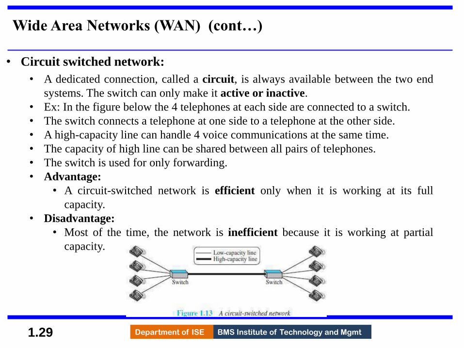
Wide Area Networks (WAN) (cont…)
• Circuit switched network:
• A dedicated connection, called a circuit, is always available between the two end
systems. The switch can only make it active or inactive.
• Ex: In the figure below the 4 telephones at each side are connected to a switch.
• The switch connects a telephone at one side to a telephone at the other side.
• A high-capacity line can handle 4 voice communications at the same time.
• The capacity of high line can be shared between all pairs of telephones.
• The switch is used for only forwarding.
• Advantage:
• A circuit-switched network is efficient only when it is working at its full
capacity.
• Disadvantage:
• Most of the time, the network is inefficient because it is working at partial
capacity.
29
BMS Institute of Technology and Mgmt Department of ISE 1.30
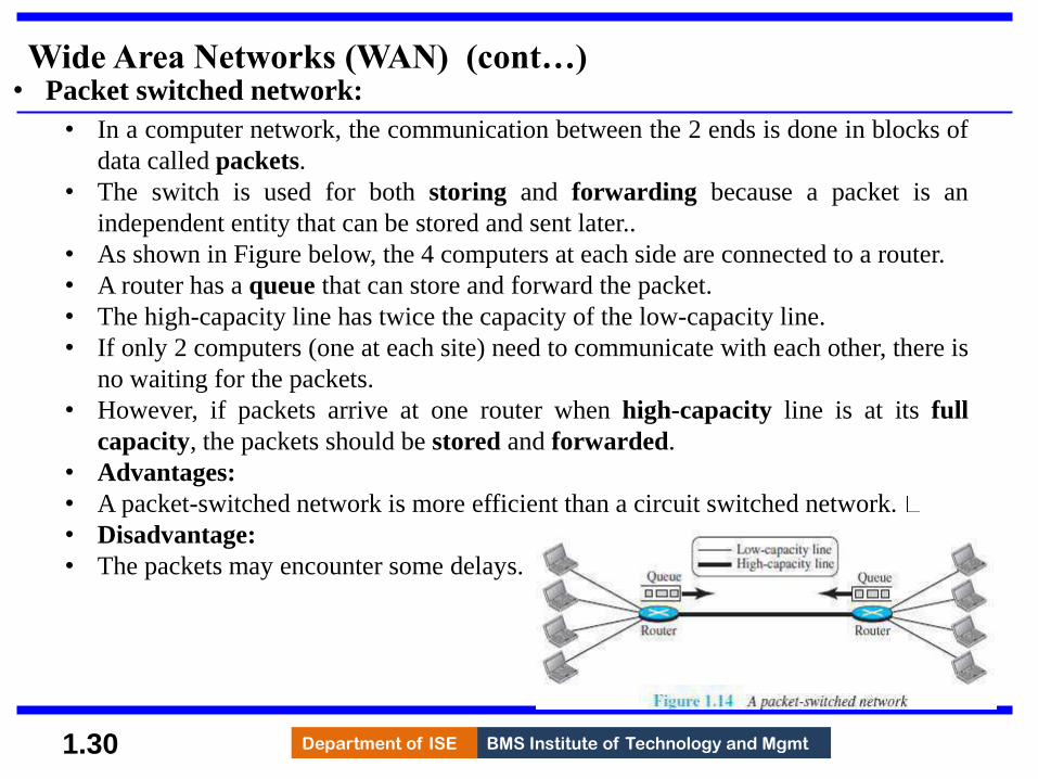
Wide Area Networks (WAN) (cont…) • Packet switched network:
• In a computer network, the communication between the 2 ends is done in blocks of
data called packets.
• The switch is used for both storing and forwarding because a packet is an
independent entity that can be stored and sent later..
• As shown in Figure below, the 4 computers at each side are connected to a router.
• A router has a queue that can store and forward the packet.
• The high-capacity line has twice the capacity of the low-capacity line.
• If only 2 computers (one at each site) need to communicate with each other, there is
no waiting for the packets.
• However, if packets arrive at one router when high-capacity line is at its full
capacity, the packets should be stored and forwarded.
• Advantages:
• A packet-switched network is more efficient than a circuit switched network.
• Disadvantage:
• The packets may encounter some delays.
30

BMS Institute of Technology and Mgmt Department of ISE
THE INTERNET
• The most notable internet(lowercase i) is called
the Internet (uppercase I) and is composed of
thousands of interconnected networks.
• Internet is made up of
1) Backbones
2) Provider networks &
3) Customer networks
1) Backbones
• Backbones are large networks owned by communication companies such as BSNL
and Airtel.
• The backbone networks are connected through switching systems, called peering
points.
2) Provider Networks (smaller network)
• Provider networks use the services of the backbones for a fee.
• Provider networks are connected to backbones and sometimes to other provider
networks.
3) Customer Networks
• Customer networks actually use the services provided by the Internet.
• Customer networks pay fees to provider networks for receiving services.
• Backbones and provider networks are also called Internet Service Providers (ISPs).
• The backbones are often referred to as international ISPs.
• The provider networks are often referred to as national or regional ISPs. 31

BMS Institute of Technology and Mgmt Department of ISE
Accessing the Internet
• The Internet today is an internetwork that allows any user to become part of it.
• However, the user needs to be physically connected to an ISP.
• The physical connection is normally done through a point-to-point WAN.
1) Using Telephone Networks
• Most residences have telephone service, which means they are connected to a telephone
network.
• Most telephone networks have already connected themselves to the Internet.
• Thus, residences can connect to the Internet using a point-to-point WAN.
• This can be done in two ways: Dial-up service and DSL Service
• A) Dial-up service
¤ A modem can be added to the telephone line.
¤ A modem converts data to voice.
¤ The software installed on the computer
→ dials the ISP &
→ imitates making a telephone connection.
Disadvantages:
i) The dial-up service is very slow.
ii) When line is used for Internet connection, it cannot be used for voice
connection.
iii) It is only useful for small residences. speed Internet services to residences 32
BMS Institute of Technology and Mgmt Department of ISE
Accessing the Internet (cont..)
B) DSL Service
¤ DSL service also allows the line to be used simultaneously for voice & data
communication.
¤ Some telephone companies have upgraded their telephone lines to provide
higher speed Internet services to residences.
2) Using Cable Networks
• A residence can be connected to the Internet by using cable service.
• Cable service provides a higher speed connection.
• The speed varies depending on the number of neighbours that use the same cable.
3) Using Wireless Networks
• A residence can use a combination of wireless and wired connections to access the
Internet.
• A residence can be connected to the Internet through a wireless WAN.
4) Direct Connection to the Internet
• A large organization can itself become a local ISP and be connected to the Internet.
• The organization
→ leases a high-speed WAN from a carrier provider and
→ connects itself to a regional ISP.
• For example, a large university with several campuses can create an internetwork
and then connect to the Internet. 33

BMS Institute of Technology and Mgmt Department of ISE
Internet History
• Internet has evolved from a private network to a global one in less than 40 years.
Early History
• Before 1960 there were some communication networks such as telegraph and telephone
networks.
• Suitable for constant-rate communication (after a connection was made between two
users, the encoded message(telegraphy) or voice (telephony) could be exchanged).
• Computer network should be able to handle bursty data (data received at variable rates
at different times)
Birth of packet switched networks:
• The theory of packet switching for bursty traffic was first presented by Leonard
Kleinrock in 1961 at MIT.
• At the same time, two other researchers, Paul Baran at Rand Institute and Donald
Davies at National Physical Laboratory in England, published some papers about
packet-switched networks.
34
BMS Institute of Technology and Mgmt Department of ISE
Internet History (cont…)
ARPANET: • In the mid-1960s, mainframe computers in research organizations were stand-alone
devices.
• Computers from different manufacturers were unable to communicate with one another.
• The Advanced Research Projects Agency (ARPA) in the Department of Defence (DOD)
was interested in finding a way to connect computers so that the researchers share their
findings, thereby reducing costs and eliminating duplication of effort.
• In 1967, at an Association for Computing Machinery (ACM) meeting, ARPA presented
its ideas for the Advanced Research Projects Agency Network (ARPANET), a small
network of connected computers.
• The idea was that each host computer (not necessarily from the same manufacturer)
would be attached to a specialized computer, called an interface message processor
(IMP).
• The IMPs, in turn, would be connected to each other. Each IMP had to be able to
communicate with other IMPs as well as with its own attached host.
• By 1969, ARPANET was a reality.
• Four nodes, at the University of California at Los Angeles (UCLA), the University of
California at Santa Barbara (UCSB), Stanford Research Institute (SRI), and the
University of Utah, were connected via the IMPs to form a network.
• Software called the Network Control Protocol (NCP) provided communication between
the hosts.
35

BMS Institute of Technology and Mgmt Department of ISE
Internet History (cont…)
Birth of the Internet • In 1972, Vint Cerf and Bob Kahn, both of whom were part of the core ARPANET
group, collaborated on what they called the Internetting Project.
• They wanted to link dissimilar networks so that a host on one network could
communicate with a host on another.
• There were many problems to overcome: diverse packet sizes, diverse interfaces,
and diverse transmission rates, as well as differing reliability requirements.
• Cerf and Kahn devised the idea of a device called a gateway to serve as the
intermediary hardware to transfer data from one network to another.
TCP/IP
• New version of NCP-transmission control protocol (TCP) included concepts such
as encapsulation, the datagram, and the functions of a gateway.
• In October 1977, an internet consisting of three different networks (ARPANET,
packet radio, and packet satellite) was successfully demonstrated. Communication
between networks was now possible.
• Authorities made a decision to split TCP into two protocols: Transmission Control
Protocol (TCP) and Internet Protocol (IP). IP would handle datagram routing while
TCP would be responsible for higher level functions such as segmentation,
reassembly, and error detection. The new combination became known as TCP/IP.
36

BMS Institute of Technology and Mgmt Department of ISE
Internet History (cont…)
MILNET:
In 1983, ARPANET split into two networks: Military Network (MILNET) for military
users and ARPANET for non-military users.
CSNET:
• Creation of CSNET in 1981.
• Computer Science Network (CSNET) was a network sponsored by the National Science
Foundation (NSF).
• The network was conceived by universities that were ineligible to join ARPANET due
to an absence of ties to the Department of Defense.
• CSNET was a
• Less expensive network;
• there were no redundant links and
• the transmission rate was slower.
• By the mid-1980s, most U.S. universities with computer science departments were
part of CSNET.
37
BMS Institute of Technology and Mgmt Department of ISE
Internet History (cont…)
NSFNET • With the success of CSNET, the NSF in 1986 sponsored the National Science
Foundation Network (NSFNET), a backbone that connected five supercomputer centres
located throughout the United States.
• Community networks were allowed access to this backbone, a T-1 line with a 1.544-
Mbps data rate, thus providing connectivity throughout the United States.
• In 1990, ARPANET was officially retired and replaced by NSFNET. In 1995, NSFNET
reverted back to its original concept of a research network.
ANSNET
• In 1991, the U.S. government decided that NSFNET was not capable of supporting the
rapidly increasing Internet traffic.
• Three companies, IBM, Merit, and Verizon, filled the void by forming a non-profit
organization called Advanced Network & Services (ANS) to build a new, high-speed
Internet backbone called Advanced Network Services Network (ANSNET).
38

BMS Institute of Technology and Mgmt Department of ISE
Internet Today
• Rapid growth both in the infrastructure and new applications.
• The Internet today is a set of pier networks that provide services to the whole world.
• What has made the Internet so popular is the invention of new applications.
World Wide Web
• The 1990s saw the explosion of Internet applications due to the emergence of the World
Wide Web (WWW).
• The Web was invented at CERN by Tim Berners-Lee. This invention has added the
commercial applications to the Internet.
Multimedia
Recent developments in the multimedia applications such as
• voice over IP (telephony),
• video over IP (Skype),
• view sharing (YouTube), and
• television over IP (PPLive)
increased the number of users and the amount of time each user spends on the network.
Peer-to-Peer Applications (P2P)
Peer-to-peer networking is also a new area of communication
Ex: BitTorrent
39

BMS Institute of Technology and Mgmt Department of ISE
Standards and Administration
Internet Standards
• An Internet standard is a thoroughly tested specification useful to those who work with
the Internet.
• The Internet standard is a formalized-regulation that must be followed.
• There is a strict procedure by which a specification attains Internet standard status.
• A specification begins as an Internet draft.
• An Internet draft is a working document with no official status and a 6-month lifetime.
• Upon recommendation from the Internet authorities, a draft may be published as a RFC.
• Each RFC is edited, assigned a number, and made available to all interested parties.
• RFCs go through maturity levels and are categorized according to their requirement
level. (working document -a work in progress RFC -Request for Comment).
40

BMS Institute of Technology and Mgmt Department of ISE
Standards and Administration (cont..)
Maturity Levels
• An RFC, during its lifetime, falls into one of 6 maturity levels (Figure 1.16):
•
1) Proposed Standard
Proposed standard is specification that is stable, well-understood & of interest to
Internet community.
Specification is usually tested and implemented by several different groups.
2) Draft Standard
A proposed standard is elevated to draft standard status after at least 2 successful
independent and interoperable implementations.
3) Internet Standard
A draft standard reaches Internet standard status after demonstrations of
successful implementation.
4) Historic
The historic RFCs are significant from a historical perspective.
They either
→ have been superseded by later specifications or
→ have never passed the necessary maturity levels to become an Internet standard.
5) Experimental
An RFC classified as experimental describes work related to an experimental
situation.
Such an RFC should not be implemented in any functional Internet service.
6) Informational
An RFC classified as informational contains general, historical, or tutorial
information related to the Internet.
Usually, it is written by a vendor.
41
BMS Institute of Technology and Mgmt Department of ISE
Standards and Administration (cont..)
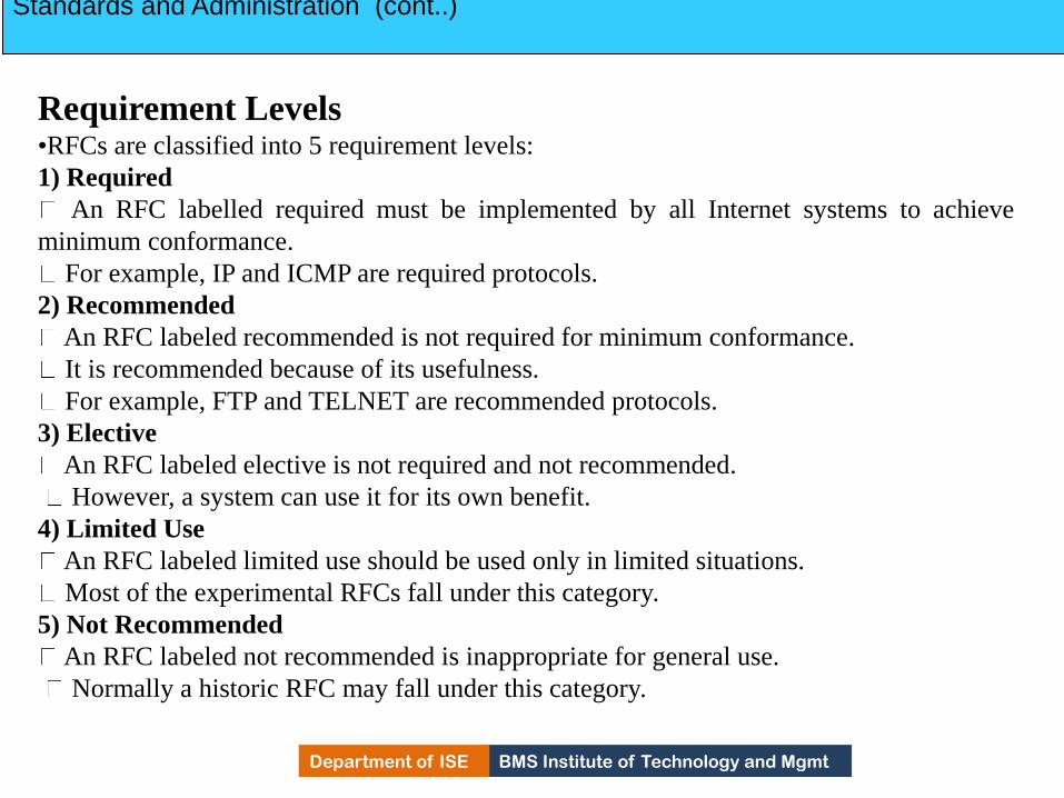
Requirement Levels •RFCs are classified into 5 requirement levels:
1) Required
An RFC labelled required must be implemented by all Internet systems to achieve
minimum conformance.
For example, IP and ICMP are required protocols.
2) Recommended
An RFC labeled recommended is not required for minimum conformance.
It is recommended because of its usefulness.
For example, FTP and TELNET are recommended protocols.
3) Elective
An RFC labeled elective is not required and not recommended.
However, a system can use it for its own benefit.
4) Limited Use
An RFC labeled limited use should be used only in limited situations.
Most of the experimental RFCs fall under this category.
5) Not Recommended
An RFC labeled not recommended is inappropriate for general use.
Normally a historic RFC may fall under this category.
42

BMS Institute of Technology and Mgmt Department of ISE
Standards and Administration (cont..)
Internet Administration 1) ISOC
• ISOC is a non-profit organization formed to provide support for Internet standards
process
• ISOC maintains and supports other Internet administrative bodies such as IAB, IETF,
IRTF, and IANA.
2) IAB
• IAB is the technical advisor to the ISOC.
• Two main purposes of IAB:
i) To oversee the continuing development of the TCP/IP Protocol Suite
ii) To serve in a technical advisory capacity to research members of the Internet
community.
• Another responsibility of the IAB is the editorial management of the RFCs.
• IAB is also the external liaison between the Internet and other standards organizations
and forums.
• IAB has 2 primary components: i) IETF and ii) IRTF.
43

BMS Institute of Technology and Mgmt Department of ISE
Standards and Administration (cont..)
i) IETF
IETF is a forum of working groups managed by the IESG.
IETF is responsible for identifying operational problems & proposing solutions to the
problems
IETF also develops and reviews specifications intended as Internet standards.
The working groups are collected into areas, and each area concentrates on a specific
topic.
Currently 9 areas have been defined. The areas include applications, protocols, routing,
network management next generation (IPng), and security.
ii) IRTF
IRTF is a forum of working groups managed by the IRSG.
IRTF focuses on long-term research topics related to Internet protocols, applications,
architecture, and technology.
44
BMS Institute of Technology and Mgmt Department of ISE 2.45
Chapter 2
Network Models
Copyright © The McGraw-Hill Companies, Inc. Permission required for reproduction or display.
45

BMS Institute of Technology and Mgmt Department of ISE 2.46
PROTOCOL LAYERING
• A protocol defines the rules that both the sender and receiver and all intermediate
devices need to follow to be able to communicate effectively.
• When communication is
• Simple -only one simple protocol.
• complex, we need to divide the task b/w different layers. We need a protocol at
each layer, or protocol layering.
Scenarios
First Scenario
• Communication is so simple that it can occur in only one layer.
• Assume Maria and Ann are neighbours with a lot of common ideas.
• Communication between Maria and Ann takes place in one layer, face to face, in the same
language
46

BMS Institute of Technology and Mgmt Department of ISE 2.47
PROTOCOL LAYERING (Cont..)
Second Scenario
• Maria and Ann communicate using regular mail through the post office .
• However, they do not want their ideas to be revealed by other people if the letters are
intercepted.
• They agree on an encryption/decryption technique.
• The sender of the letter encrypts it to make it unreadable by an intruder; the receiver of
the letter decrypts it to get the original letter.
47

BMS Institute of Technology and Mgmt Department of ISE
PROTOCOL LAYERING (Cont..)
• Protocol layering enables us to divide a complex task into several smaller and simpler tasks.
• Modularity means independent layers.
• A layer (module) can be defined as a black box with inputs and outputs, without concern about how
inputs are changed to outputs.
• If two machines provide the same outputs when given the same inputs, they can replace each other.
• Advantages:
1) It allows us to separate the services from the implementation.
2) There are intermediate systems that need only some layers, but not all layers.
• Disadvantage:
1) Having a single layer makes the job easier. There is no need for each layer to provide a
service to the upper layer and give service to the lower layer.
1.5.2 Principles of Protocol Layering
1) First Principle
• If we want bidirectional communication, we need to make each layer able to perform 2 opposite
tasks, one in each direction.
• For example, the third layer task is to listen (in one direction) and talk (in the other direction)
.
2) Second Principle
• The two objects under each layer at both sites should be identical.
• For example, the object under layer 3 at both sites should be a plaintext letter.
48

BMS Institute of Technology and Mgmt Department of ISE
PROTOCOL LAYERING (Cont..)
Logical Connections
• There is a logical (imaginary) connection at each layer through which two end systems can send the
object created from that layer..
49

BMS Institute of Technology and Mgmt Department of ISE
TCP/IP PROTOCOL SUITE
• TCP/IP is a protocol-suite used in the Internet today.
• Protocol-suite refers a set of protocols organized in different layers.
• It is a hierarchical protocol made up of interactive modules, each of which provides a
specific functionality.
• The term hierarchical means that each upper level protocol is supported by the services
provided by one or more lower level protocols.
• TCP/IP is thought of as a five-layer model.
50

BMS Institute of Technology and Mgmt Department of ISE
TCP/IP PROTOCOL SUITE (Cont..)
Layered Architecture
Let us assume that computer A communicates with computer B
• As shown in the Figure, we have five communicating devices:
1) Source host(computer A)
2) Link-layer switch in link 1
3) Router
4) Link-layer switch in link 2
5) Destination host (computer B).
• Each device is involved with a set of layers depending on the role of the device in the internet.
• The two hosts are involved in all five layers.
• The source host
→ creates a message in the application layer and
→ sends the message down the layers so that it is physically sent to the destination host.
• The destination host
→ receives the message at the physical layer and
→ then deliver the message through the other layers to the application layer.
• The router is involved in only three layers; there is no transport or application layer.
• A router is involved in n combinations of link and physical layers.
where n = number of links the router is connected to.
• The reason is that each link may use its own data-link or physical protocol.
• A link-layer switch is involved only in two layers: i) data-link and ii) physical.
51

BMS Institute of Technology and Mgmt Department of ISE
TCP/IP PROTOCOL SUITE (Cont..)
Layers in TCP/IP Protocol suite
• The duty of the
• Application, Transport, and Network layers is end-to-
end.
• Data-link and Physical layers is hop-to-hop (hop is a
host or router).
• The domain of duty of the
• top three layers is the internet.
• two lower layers is the link.
• In top 3 layers, the data unit should not be changed by any
router or link-layer switch.
• In bottom 2 layers, the data unit is changed only by the
routers, not by the link-layer switches.
• Identical objects exist between two hops. Because router
may fragment the packet at the network layer and send more
packets than received.
• The link between two hops does not change the object.
52
BMS Institute of Technology and Mgmt Department of ISE
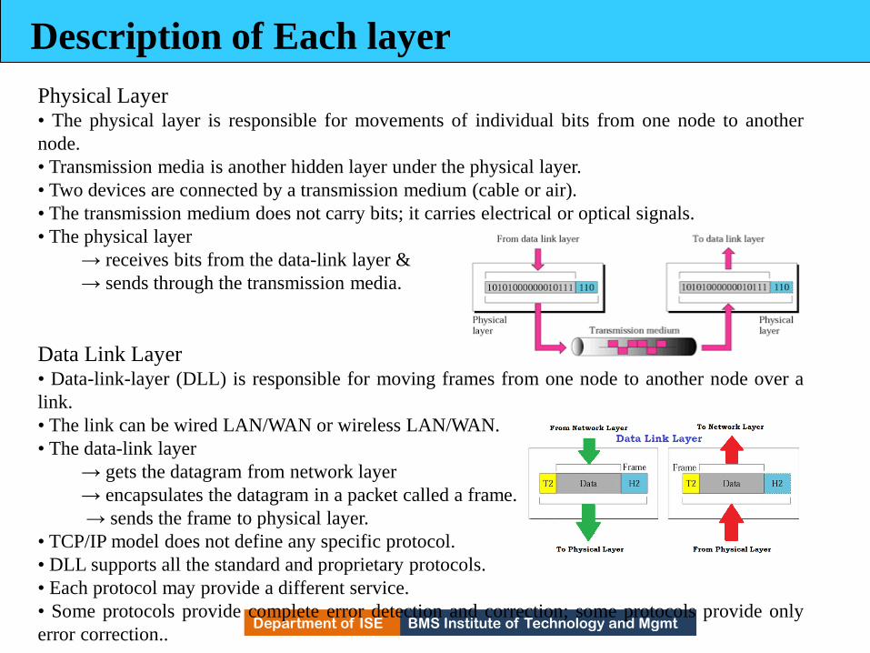
Description of Each layer
Physical Layer • The physical layer is responsible for movements of individual bits from one node to another
node.
• Transmission media is another hidden layer under the physical layer.
• Two devices are connected by a transmission medium (cable or air).
• The transmission medium does not carry bits; it carries electrical or optical signals.
• The physical layer
→ receives bits from the data-link layer &
→ sends through the transmission media.
Data Link Layer • Data-link-layer (DLL) is responsible for moving frames from one node to another node over a
link.
• The link can be wired LAN/WAN or wireless LAN/WAN.
• The data-link layer
→ gets the datagram from network layer
→ encapsulates the datagram in a packet called a frame.
→ sends the frame to physical layer.
• TCP/IP model does not define any specific protocol.
• DLL supports all the standard and proprietary protocols.
• Each protocol may provide a different service.
• Some protocols provide complete error detection and correction; some protocols provide only
error correction..
53

BMS Institute of Technology and Mgmt Department of ISE
Description of Each layer
Network Layer • The network layer is responsible for source-to-destination transmission of data.
• The network layer is also responsible for routing the packet.
• The routers choose the best route for each packet.
• Why we need the separate network layer?
1) The separation of different tasks between different layers.
2) The routers do not need the application and transport layers.
• TCP/IP model defines 4 protocols:
1) IP (Internetworking Protocol)
2) ARP (Address Resolution Protocol)
3) ICMP (Internet Control Message Protocol)
4) IGMP (Internet Group Message Protocol)
54

BMS Institute of Technology and Mgmt Department of ISE
1) IP
IP is the main protocol of the network layer.
IP defines the format and the structure of addresses.
IP is also responsible for routing a packet from its source to its destination.
It is a connection-less & unreliable protocol.
i) Connection-less means there is no connection setup b/w the sender and the receiver.
ii) Unreliable protocol means
→ IP does not make any guarantee about delivery of the data.
→ Packets may get dropped during transmission.
It provides a best-effort delivery service.
Best effort means IP does its best to get the packet to its destination, but with no guarantees. IP
does not provide following services
→ flow control
→ error control
→ congestion control services.
If an application requires above services, the application should rely only on the transportlayer protocol
2) ARP
ARP is used to find the physical-address of the node when its Internet-address is known.
Physical address is the 48-bit address that is imprinted on the NIC or LAN card.
Internet address (IP address) is used to uniquely & universally identify a device in the
internet.
3) ICMP
ICMP is used to inform the sender about datagram-problems that occur during transit.
4) IGMP
IGMP is used to send the same message to a group of recipients. 55

BMS Institute of Technology and Mgmt Department of ISE
Transport Layer
TL protocols are responsible for delivery of a message from a process to another process.
• The transport layer
→ gets the message from the application layer
→ encapsulates the message in a packet called a segment and
→ sends the segment to network layer.
• TCP/IP model defines 3 protocols: (as listed below)
1) TCP
TCP is a reliable connection-oriented protocol.
A connection is established b/w the sender and receiver before the data can be transmitted.
TCP provides
→ flow control
→ error control and
→ congestion control
2) UDP
UDP is the simplest of the 3 transport protocols.
It is an unreliable, connectionless protocol.
It does not provide flow, error, or congestion control.
Each datagram is transported separately & independently.
It is suitable for application program that
→ needs to send short messages &
→ cannot afford the retransmission.
3) SCTP
SCTP provides support for newer applications such as voice over the Internet.
It combines the best features of UDP and TCP. 56

BMS Institute of Technology and Mgmt Department of ISE
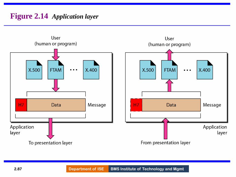
Application Layer
• The two application layers exchange messages between each other.
• Communication at the application layer is between two processes (two programs running at
this layer).
• To communicate, a process sends a request to the other process and receives a response.
• Process-to-process communication is the duty of the application layer.
• TCP/IP model defines following protocols:
1) SMTP is used to transport email between a source and destination.
2) TELNET is used for accessing a site remotely.
3) FTP is used for transferring files from one host to another.
4) DNS is used to find the IP address of a computer.
5) SNMP is used to manage the Internet at global and local levels.
6) HTTP is used for accessing the World Wide Web (WWW).
(FTP File Transfer Protocol
SMTP Simple Mail Transfer Protocol)
(DNS Domain Name System
HTTP Hyper Text Transfer Protocol)
(SNMP Simple Network Management Protocol
TELNET Terminal Network)
57

BMS Institute of Technology and Mgmt Department of ISE
Encapsulation and Decapsulation
• One of the important concepts in protocol layering in the Internet.
• Figure below shows this concept for the small internet.
58

BMS Institute of Technology and Mgmt Department of ISE
Encapsulation at the Source Host
At the source, we have only encapsulation
1) At the application layer, the data to be exchanged is referred to as a message.
A message normally does not contain any header or trailer.
The message is passed to the transport layer.
2) The transport layer takes the message as the payload.
TL adds its own header to the payload.
The header contains
→ identifiers of the source and destination application programs
→ information needed for flow, error control, or congestion control.
The transport-layer packet is called the segment (in TCP) and the user datagram (in UDP).
The segment is passed to the network layer.
3) The network layer takes the transport-layer packet as payload.
NL adds its own header to the payload.
The header contains
→ addresses of the source and destination hosts
→ some information used for error checking of the header &
→ fragmentation information.
The network-layer packet is called a datagram.
The datagram is passed to the data-link layer.
4) The data-link layer takes the network-layer packet as payload.
DLL adds its own header to the payload.
The header contains the physical addresses of the host or the next hop (the router).
The link-layer packet is called a frame.
The frame is passed to the physical layer for transmission
59

BMS Institute of Technology and Mgmt Department of ISE
1. After the set of bits are delivered to the data-link layer, this layer decapsulates the
datagram from the frame and passes it to the network layer.
2. The network layer only inspects the source and destination addresses in the
datagram
header and consults its forwarding table to find the next hop to which the datagram
is to
be delivered. The contents of the datagram should not be changed by the network
layer
in the router unless there is a need to fragment the datagram if it is too big to be
passed
through the next link. The datagram is then passed to the data-link layer of the next
link.
3. The data-link layer of the next link encapsulates the datagram in a frame and
passes it to the physical layer for transmission.
Decapsulation at the Destination Host
• At the destination host, each layer
→ decapsulates the packet received from lower layer
→ removes the payload and
60

BMS Institute of Technology and Mgmt Department of ISE
Addressing
• We have logical communication between pairs of layers.
• Any communication that involves 2 parties needs 2 addresses: source address and
destination
address.
• We need 4 pairs of addresses (Figure 2.9):
1) At the application layer, we normally use names to define
→ site that provides services, such as vtunotesbysri.com, or →
e-mail address, such as [email protected].
2) At the transport layer, addresses are called port numbers.
Port numbers define the application-layer programs at the source and destination.
Port numbers are local addresses that distinguish between several programs running at the
same time.
3) At the network-layer, addresses are called IP addresses.
IP address uniquely defines the connection of a device to the Internet.
The IP addresses are global, with the whole Internet as the scope.
4) At the data link-layer, addresses are called MAC addresses
The MAC addresses defines a specific host or router in a network (LAN or WAN). The
MAC addresses are locally defined addresses.
61

BMS Institute of Technology and Mgmt Department of ISE
Multiplexing and Demultiplexing
• Multiplexing means a protocol at a layer can encapsulate a packet from several next-higher
layer
protocols (one at a time) (Figure 2.10).
• Demultiplexing means a protocol can decapsulate and deliver a packet to several next-higher
layer
protocols (one at a time).
1) At transport layer, either UDP or TCP can accept a message from several application-layer
protocols.
2) At network layer, IP can accept
→ a segment from TCP or a user datagram from UDP. → a
packet from ICMP or IGMP.
3) At data-link layer, a frame may carry the payload coming from IP or ARP.
62

BMS Institute of Technology and Mgmt Department of ISE
OSI MODEL
• OSI model was developed by ISO.
• ISO is the organization, OSI is the model.
• Purpose: OSI was developed to allow systems with diff. platforms to communicate with each
other.
• Platform means hardware, software or operating system.
• OSI is a network-model that defines the protocols for network communications.
• OSI has 7 layers as follows (Figure 2.11):
1) Application Layer
2) Presentation Layer
3) Session Layer
4) Transport Layer
5) Network Layer
6) Data Link Layer
7) Physical Layer
• Each layer has specific duties to perform and has to co-operate with the layers above & below
it.
63

BMS Institute of Technology and Mgmt Department of ISE
OSI vs. TCP/IP
1) The four bottommost layers in the OSI model & the TCP/IP model are same (Figure 2.12).
However, the Application-layer of TCP/IP model corresponds to the Session, Presentation &
Application Layer of OSI model.
Two reasons for this are:
1) TCP/IP has more than one transport-layer protocol.
2) Many applications can be developed at Application layer
2) The OSI model specifies which functions belong to each of its layers.
In TCP/IP model, the layers contain relatively independent protocols that can be mixed and
matched depending on the needs of the system..
64

BMS Institute of Technology and Mgmt Department of ISE
Lack of OSI Model’s Success
• OSI was completed when TCP/IP was fully in place and a lot of time and money had been
spent on the
suite; changing it would cost a lot.
• Some layers in the OSI model were never fully defined.
• When OSI was implemented by an organization in a different application, it did not show a
high
enough level of performance
65

BMS Institute of Technology and Mgmt Department of ISE 2.66
THE OSI MODEL
Established in 1947, the International Standards
Organization (ISO) is a multinational body dedicated to
worldwide agreement on international standards. An ISO
standard that covers all aspects of network
communications is the Open Systems Interconnection
(OSI) model. It was first introduced in the late 1970s.
66

BMS Institute of Technology and Mgmt Department of ISE 2.67
ISO is the organization.
OSI is the model.
Note
67

BMS Institute of Technology and Mgmt Department of ISE 2.68
Figure 2.2 Seven layers of the OSI model
68
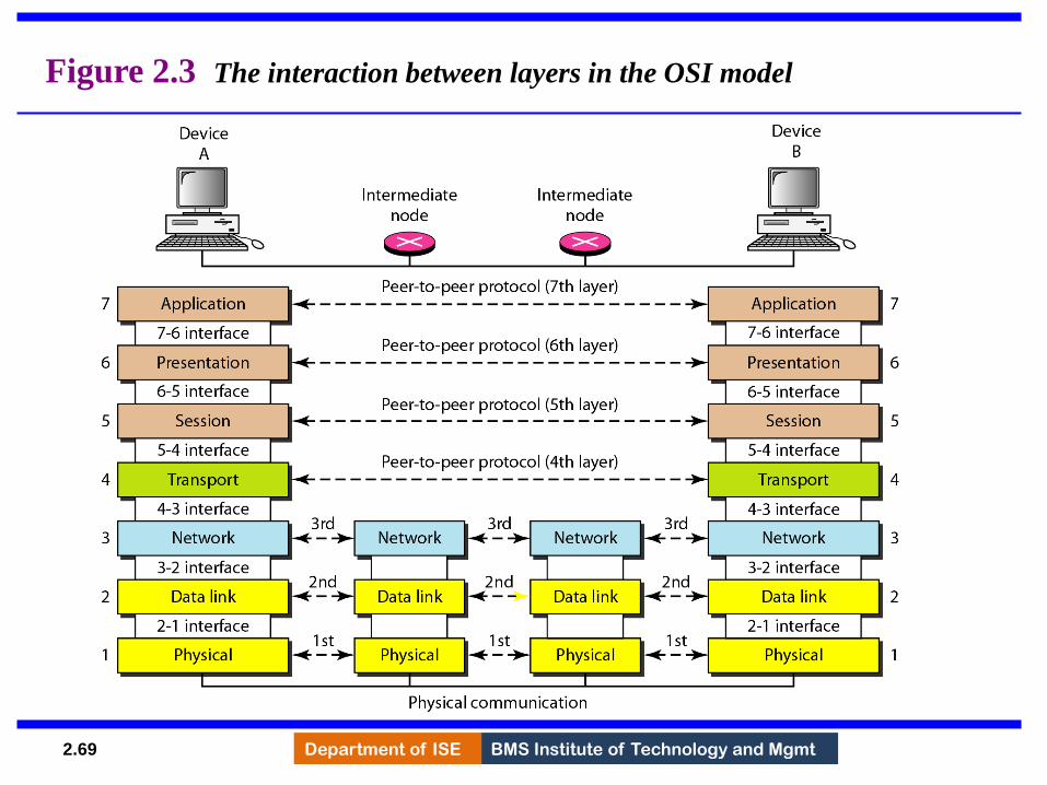
BMS Institute of Technology and Mgmt Department of ISE 2.69
Figure 2.3 The interaction between layers in the OSI model
69

BMS Institute of Technology and Mgmt Department of ISE 2.70
Figure 2.4 An exchange using the OSI model
70
BMS Institute of Technology and Mgmt Department of ISE 2.71
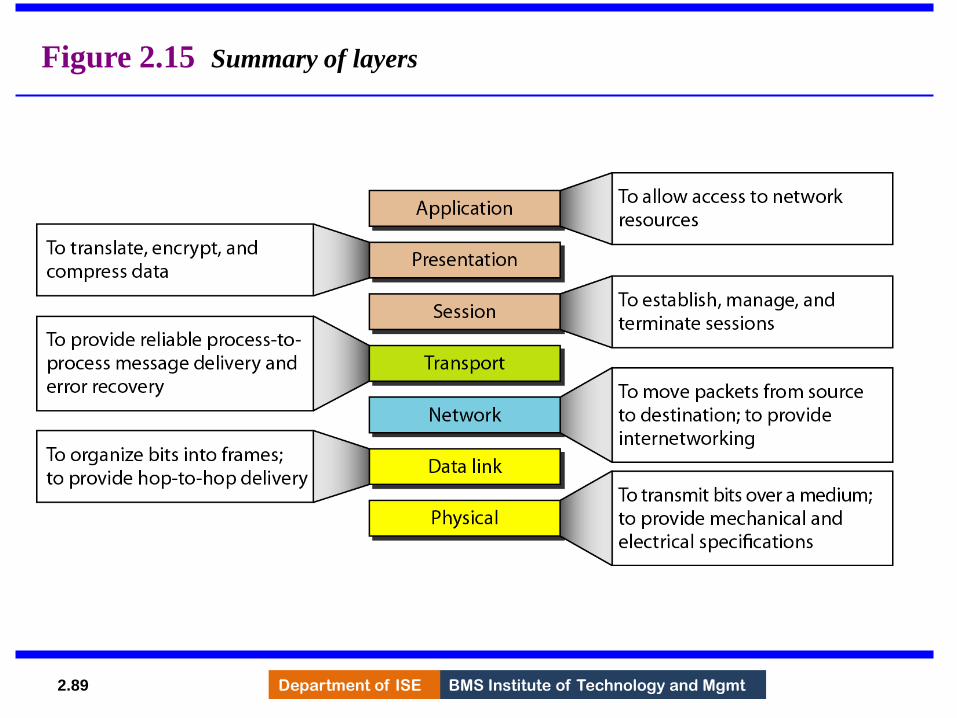
LAYERS IN THE OSI MODEL
In this section we briefly describe the functions of each
layer in the OSI model.
Physical Layer
Data Link Layer
Network Layer
Transport Layer
Session Layer
Presentation Layer
Application Layer
Topics discussed in this section:
71

BMS Institute of Technology and Mgmt Department of ISE 2.72
Figure 2.5 Physical layer
72
BMS Institute of Technology and Mgmt Department of ISE 2.73
The physical layer is responsible for movements of
individual bits from one hop (node) to the next.
Note
73

BMS Institute of Technology and Mgmt Department of ISE 2.74
Figure 2.6 Data link layer
74

BMS Institute of Technology and Mgmt Department of ISE 2.75
The data link layer is responsible for moving
frames from one hop (node) to the next.
Note
75

BMS Institute of Technology and Mgmt Department of ISE 2.76
Figure 2.7 Hop-to-hop delivery
76

BMS Institute of Technology and Mgmt Department of ISE 2.77
Figure 2.8 Network layer
77
BMS Institute of Technology and Mgmt Department of ISE 2.78
The network layer is responsible for the
delivery of individual packets from
the source host to the destination host.
Note
78
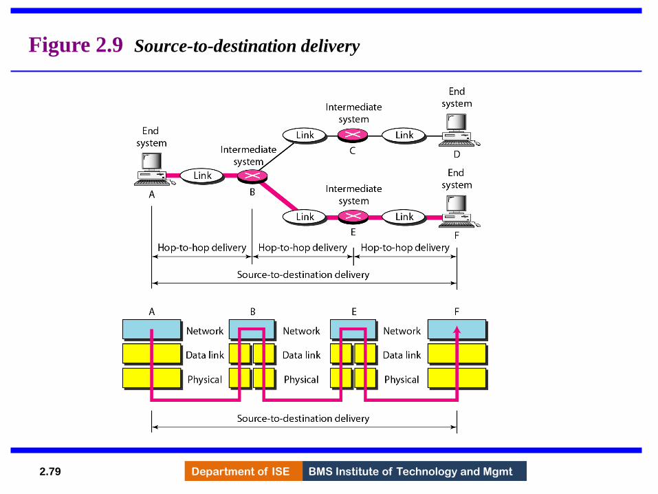
BMS Institute of Technology and Mgmt Department of ISE 2.79
Figure 2.9 Source-to-destination delivery
79

BMS Institute of Technology and Mgmt Department of ISE 2.80
Figure 2.10 Transport layer
80

BMS Institute of Technology and Mgmt Department of ISE 2.81
The transport layer is responsible for the delivery
of a message from one process to another.
Note
81

BMS Institute of Technology and Mgmt Department of ISE 2.82
Figure 2.11 Reliable process-to-process delivery of a message
82

BMS Institute of Technology and Mgmt Department of ISE 2.83
Figure 2.12 Session layer
83

BMS Institute of Technology and Mgmt Department of ISE 2.84
The session layer is responsible for dialog
control and synchronization.
Note
84

BMS Institute of Technology and Mgmt Department of ISE 2.85
Figure 2.13 Presentation layer
85

BMS Institute of Technology and Mgmt Department of ISE 2.86
The presentation layer is responsible for translation,
compression, and encryption.
Note
86
BMS Institute of Technology and Mgmt Department of ISE 2.87
Figure 2.14 Application layer
87

BMS Institute of Technology and Mgmt Department of ISE 2.88
The application layer is responsible for
providing services to the user.
Note
88
BMS Institute of Technology and Mgmt Department of ISE 2.89
Figure 2.15 Summary of layers
89
BMS Institute of Technology and Mgmt Department of ISE 2.90
TCP/IP PROTOCOL SUITE
The layers in the TCP/IP protocol suite do not exactly
match those in the OSI model. The original TCP/IP
protocol suite was defined as having four layers: host-to-
network, internet, transport, and application. However,
when TCP/IP is compared to OSI, we can say that the
TCP/IP protocol suite is made of five layers: physical, data
link, network, transport, and application.
Physical and Data Link Layers
Network Layer
Transport Layer
Application Layer
Topics discussed in this section:
90

BMS Institute of Technology and Mgmt Department of ISE 2.91
Figure 2.16 TCP/IP and OSI model
91
BMS Institute of Technology and Mgmt Department of ISE 2.92
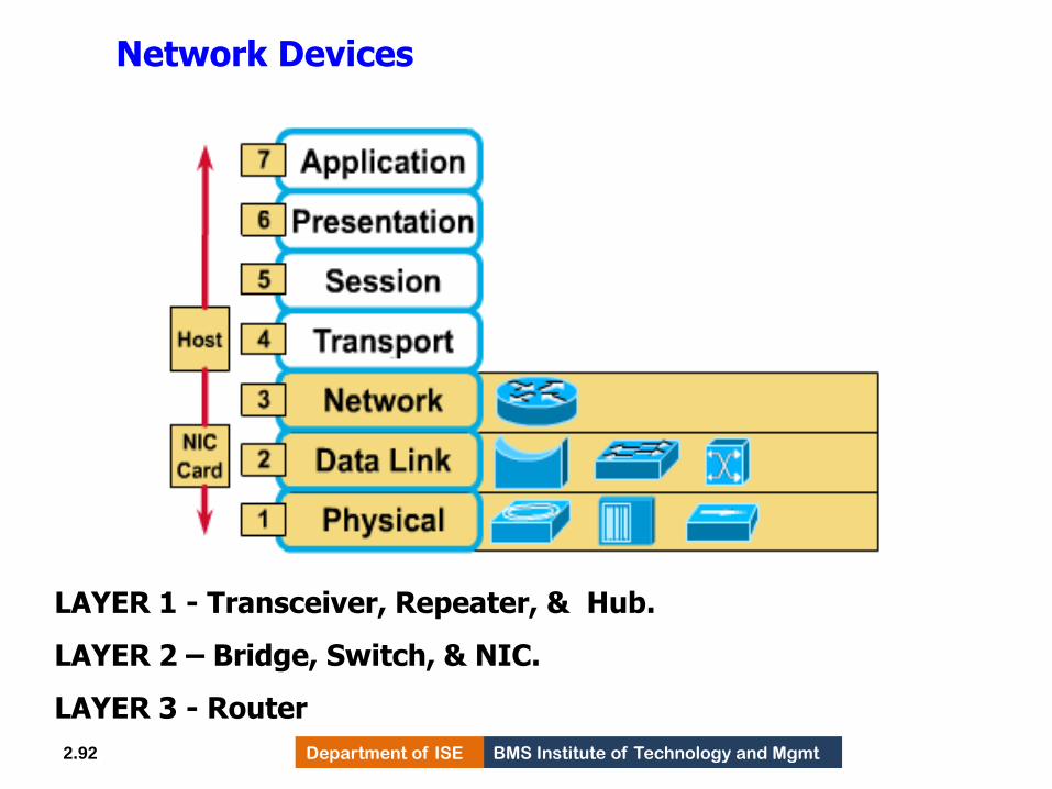
LAYER 1 - Transceiver, Repeater, & Hub.
LAYER 2 – Bridge, Switch, & NIC.
LAYER 3 - Router
Network Devices
92

BMS Institute of Technology and Mgmt Department of ISE 2.93
ADDRESSING
Four levels of addresses are used in an internet employing
the TCP/IP protocols: physical, logical, port, and specific.
Physical Addresses
Logical Addresses
Port Addresses
Specific Addresses
Topics discussed in this section:
93

BMS Institute of Technology and Mgmt Department of ISE 2.94
Figure 2.17 Addresses in TCP/IP
94

BMS Institute of Technology and Mgmt Department of ISE 2.95
Figure 2.18 Relationship of layers and addresses in TCP/IP
95

BMS Institute of Technology and Mgmt Department of ISE 2.96
In Figure 2.19 a node with physical address 10
sends a frame to a node with physical address 87.
The two nodes are connected by a link (bus topology
LAN). As the figure shows, the computer with
physical address 10 is the sender, and the computer
with physical address 87 is the receiver.
Example 2.1
96

BMS Institute of Technology and Mgmt Department of ISE 2.97
Figure 2.19 Physical addresses
97
BMS Institute of Technology and Mgmt Department of ISE 2.98
Most local-area networks use a 48-bit (6-byte)
physical address written as 12 hexadecimal digits;
every byte (2 hexadecimal digits) is separated by a
colon, as shown below:
Example 2.2
07:01:02:01:2C:4B
A 6-byte (12 hexadecimal digits) physical address.
98

BMS Institute of Technology and Mgmt Department of ISE 2.99
Figure 2.20 shows a part of an internet with two
routers connecting three LANs. Each device
(computer or router) has a pair of addresses (logical
and physical) for each connection. In this case, each
computer is connected to only one link and therefore
has only one pair of addresses. Each router,
however, is connected to three networks (only two
are shown in the figure). So each router has three
pairs of addresses, one for each connection.
Example 2.3
99

BMS Institute of Technology and Mgmt Department of ISE 2.100
Figure 2.20 IP addresses
100

BMS Institute of Technology and Mgmt Department of ISE 2.101
Figure 2.21 shows two computers communicating
via the Internet. The sending computer is running
three processes at this time with port addresses a, b,
and c. The receiving computer is running two
processes at this time with port addresses j and k.
Process a in the sending computer needs to
communicate with process j in the receiving
computer. Note that although physical addresses
change from hop to hop, logical and port addresses
remain the same from the source to destination.
Example 2.4
101

BMS Institute of Technology and Mgmt Department of ISE 2.102
Figure 2.21 Port addresses
102

BMS Institute of Technology and Mgmt Department of ISE 2.103
The physical addresses will change from hop to hop,
but the logical addresses usually remain the same.
Note
103

BMS Institute of Technology and Mgmt Department of ISE 2.104
Example 2.5
A port address is a 16-bit address represented by
one decimal number as shown.
753
A 16-bit port address represented
as one single number.
104

BMS Institute of Technology and Mgmt Department of ISE 2.105
Addressing
Four levels of addressing are used in an internet.
1) Physical address – It is used to identify the host on the network. It is a 48 bit size, represented in hexadecimal. It is a permanent address printed on the NIC.
Example – 07:01:02:01:2C:4B
2) Logical address – It is also called as IP address or Network address. It is a 32 bits size. It is represented in 4 decimal dots. Example- 10. 25. 26.45
3) Port address - It defines a process running on a host. It is a 16 bits decimal representation. Example: TELNET -23, FTP-21, SMTP- 25, DNS – 53.
4) specific address – User friendly address are known as specific addresses. It is also called as URL (Universal Resource locator) or Domain Name System (DSN) address.
Example – www.hotmail.com 105

BMS Institute of Technology and Mgmt Department of ISE
MODULE – 2
DIGITAL TRANSMISSION
106

BMS Institute of Technology and Mgmt Department of ISE Department of ISE BMS Institute of Technology and Mgmt
Line Coding
• Converting a string of 1’s and 0’s (digital data) into a sequence of signals that denote the 1’s and 0’s.
• For example a high voltage level (+V) could represent a “1” and a low voltage level (0 or -V) could represent a “0”.
107

BMS Institute of Technology and Mgmt Department of ISE
Figure 4.1 Line coding and decoding
108

BMS Institute of Technology and Mgmt Department of ISE Department of ISE BMS Institute of Technology and Mgmt
Mapping Data symbols onto Signal levels
• A data symbol (or element) can consist of a number of data bits: – 1 , 0 or
– 11, 10, 01, ……
• A data symbol can be coded into a single signal element or multiple signal elements – 1 -> +V, 0 -> -V
– 1 -> +V and -V, 0 -> -V and +V
• The ratio ‘r’ is the number of data elements carried by a signal element.
109
BMS Institute of Technology and Mgmt Department of ISE Department of ISE BMS Institute of Technology and Mgmt
Relationship between data rate and signal rate
• The data rate defines the number of bits sent per sec - bps. It is often referred to the bit rate.
• The signal rate is the number of signal elements sent in a second and is measured in bauds. It is also referred to as the modulation rate OR baud rate.
• Goal is to increase the data rate whilst reducing the baud rate.
110

BMS Institute of Technology and Mgmt Department of ISE
Figure 4.2 Signal element versus data element
111
BMS Institute of Technology and Mgmt Department of ISE Department of ISE BMS Institute of Technology and Mgmt
Data rate and Baud rate
• The baud or signal rate can be expressed as:
S = c x N x 1/r bauds
where N is data rate
c is the case factor (worst, best & avg.)
r is the ratio between data element & signal element
112

BMS Institute of Technology and Mgmt Department of ISE
A signal is carrying data in which one data
element is encoded as one signal element ( r = 1).
If the bit rate is 100 kbps, what is the average
value of the baud rate if c is between 0 and 1?
Solution
We assume that the average value of c is 1/2 . The baud
rate is then
Example 4.1
113
BMS Institute of Technology and Mgmt Department of ISE
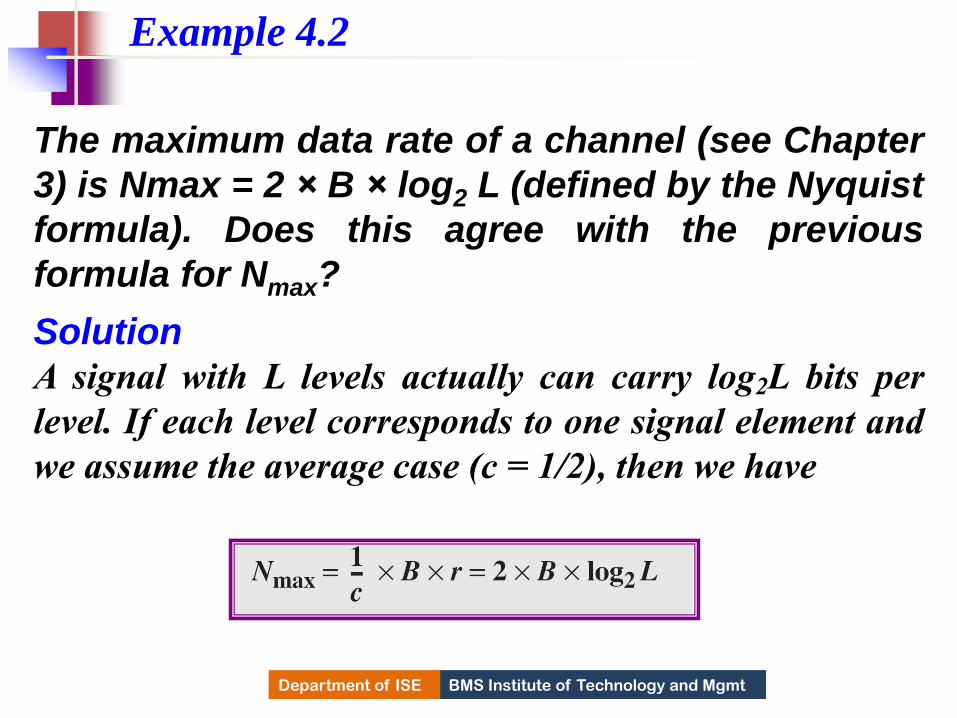
The maximum data rate of a channel (see Chapter
3) is Nmax = 2 × B × log2 L (defined by the Nyquist
formula). Does this agree with the previous
formula for Nmax?
Solution
A signal with L levels actually can carry log2L bits per
level. If each level corresponds to one signal element and
we assume the average case (c = 1/2), then we have
Example 4.2
114

BMS Institute of Technology and Mgmt Department of ISE Department of ISE BMS Institute of Technology and Mgmt
• Self synchronization - the clocks at the sender and the receiver must have the same bit interval.
• If the receiver clock is faster or slower it will misinterpret the incoming bit stream.
Considerations for choosing a good signal element referred to as line
encoding
115

BMS Institute of Technology and Mgmt Department of ISE
Figure 4.3 Effect of lack of synchronization
116

BMS Institute of Technology and Mgmt Department of ISE
In a digital transmission, the receiver clock is 0.1
percent faster than the sender clock. How many
extra bits per second does the receiver receive if
the data rate is
1 kbps? How many if the data rate is 1 Mbps? Solution
At 1 kbps, the receiver receives 1001 bps instead of 1000
bps.
Example 4.3
At 1 Mbps, the receiver receives 1,001,000 bps
instead of 1,000,000 bps.
117

BMS Institute of Technology and Mgmt Department of ISE Department of ISE BMS Institute of Technology and Mgmt
Line encoding C/Cs
• Error detection - errors occur during transmission due to line impairments.
• Some codes are constructed such that when an error occurs it can be detected.
118

BMS Institute of Technology and Mgmt Department of ISE Department of ISE BMS Institute of Technology and Mgmt
Line encoding C/Cs
• Noise and interference - there are line encoding techniques that make the transmitted signal “immune” to noise and interference.
• This means that the signal cannot be corrupted, it is stronger than error detection.
119

BMS Institute of Technology and Mgmt Department of ISE Department of ISE BMS Institute of Technology and Mgmt
Line encoding C/Cs
• Complexity - the more robust and resilient the code, the more complex it is to implement and the price is often paid in baud rate or required bandwidth.
120

BMS Institute of Technology and Mgmt Department of ISE
Figure 4.4 Line coding schemes
121

BMS Institute of Technology and Mgmt Department of ISE Department of ISE BMS Institute of Technology and Mgmt
Unipolar
• All signal levels are on one side of the time axis - either above or below
• NRZ - Non Return to Zero scheme is an example of this code. The signal level does not return to zero during a symbol transmission.
• Scheme is prone to baseline wandering and DC components. It has no synchronization or any error detection. It is simple but costly in power consumption.
122

BMS Institute of Technology and Mgmt Department of ISE
Figure 4.5 Unipolar NRZ scheme
123

BMS Institute of Technology and Mgmt Department of ISE Department of ISE BMS Institute of Technology and Mgmt
Polar - NRZ
• The voltages are on both sides of the time axis.
• Polar NRZ scheme can be implemented with two voltages. E.g. +V for 1 and -V for 0.
• There are two versions: – NZR - Level (NRZ-L) - positive voltage for one symbol
and negative for the other
– NRZ - Inversion (NRZ-I) - the change or lack of change in polarity determines the value of a symbol. E.g. a “1” symbol inverts the polarity a “0” does not.
124

BMS Institute of Technology and Mgmt Department of ISE
Figure 4.6 Polar NRZ-L and NRZ-I schemes
125

BMS Institute of Technology and Mgmt Department of ISE
In NRZ-L the level of the voltage
determines the value of the bit.
In NRZ-I the inversion
or the lack of inversion
determines the value of the bit.
Note
126
BMS Institute of Technology and Mgmt Department of ISE
NRZ-L and NRZ-I both have a DC
component problem and baseline
wandering, it is worse for NRZ-L. Both
have no self synchronization &no error
detection. Both are relatively simple to
implement.
Note
127

BMS Institute of Technology and Mgmt Department of ISE
A system is using NRZ-I to transfer 1-Mbps data.
What are the average signal rate and minimum
bandwidth?
Solution
The average signal rate is S= c x N x R = 1/2 x N x 1 =
500 kbaud. The minimum bandwidth for this average
baud rate is Bmin = S = 500 kHz.
Note c = 1/2 for the avg. case as worst case is 1 and best
case is 0
Example 4.4
128

BMS Institute of Technology and Mgmt Department of ISE Department of ISE BMS Institute of Technology and Mgmt
Polar - RZ • The Return to Zero (RZ) scheme uses three
voltage values. +, 0, -.
• Each symbol has a transition in the middle. Either from high to zero or from low to zero.
• This scheme has more signal transitions (two per symbol) and therefore requires a wider bandwidth.
• No DC components or baseline wandering.
• Self synchronization - transition indicates symbol value.
• More complex as it uses three voltage level. It has no error detection capability.
129

BMS Institute of Technology and Mgmt Department of ISE
Figure 4.7 Polar RZ scheme
130

BMS Institute of Technology and Mgmt Department of ISE Department of ISE BMS Institute of Technology and Mgmt
Polar - Biphase: Manchester and Differential Manchester
• Manchester coding consists of combining the NRZ-L and RZ schemes. – Every symbol has a level transition in the middle: from
high to low or low to high. Uses only two voltage levels.
• Differential Manchester coding consists of combining the NRZ-I and RZ schemes. – Every symbol has a level transition in the middle. But
the level at the beginning of the symbol is determined by the symbol value. One symbol causes a level change the other does not.
131

BMS Institute of Technology and Mgmt Department of ISE
Figure 4.8 Polar biphase: Manchester and differential Manchester schemes
132
BMS Institute of Technology and Mgmt Department of ISE
In Manchester and differential
Manchester encoding, the transition
at the middle of the bit is used for
synchronization.
Note
133
BMS Institute of Technology and Mgmt Department of ISE
The minimum bandwidth of Manchester
and differential Manchester is 2 times
that of NRZ. The is no DC component
and no baseline wandering. None of
these codes has error detection.
Note
134

BMS Institute of Technology and Mgmt Department of ISE Department of ISE BMS Institute of Technology and Mgmt
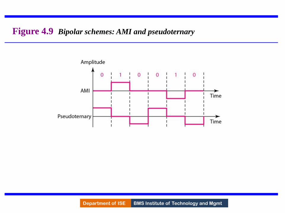
Bipolar - AMI and Pseudoternary
• Code uses 3 voltage levels: - +, 0, -, to represent the symbols (note not transitions to zero as in RZ).
• Voltage level for one symbol is at “0” and the other alternates between + & -.
• Bipolar Alternate Mark Inversion (AMI) - the “0” symbol is represented by zero voltage and the “1” symbol alternates between +V and -V.
• Pseudoternary is the reverse of AMI.
135
BMS Institute of Technology and Mgmt Department of ISE
Figure 4.9 Bipolar schemes: AMI and pseudoternary
136
BMS Institute of Technology and Mgmt Department of ISE Department of ISE BMS Institute of Technology and Mgmt
Bipolar C/Cs
• It is a better alternative to NRZ.
• Has no DC component or baseline wandering.
• Has no self synchronization because long runs of “0”s results in no signal transitions.
• No error detection.
137

BMS Institute of Technology and Mgmt Department of ISE 4.33
Digital Transmission
138

BMS Institute of Technology and Mgmt Department of ISE Department of ISE BMS Institute of Technology and Mgmt 4.34
PCM • PCM consists of three steps to digitize an analog
signal: 1. Sampling
2. Quantization
3. Binary encoding
139

BMS Institute of Technology and Mgmt Department of ISE 4.35
Figure 4.21 Components of PCM encoder
140
BMS Institute of Technology and Mgmt Department of ISE Department of ISE BMS Institute of Technology and Mgmt 4.36
Sampling • Analog signal is sampled every TS secs.
• Ts is referred to as the sampling interval.
• fs = 1/Ts is called the sampling rate or sampling frequency.
• There are 3 sampling methods: – Ideal - an impulse at each sampling instant
– Natural - a pulse of short width with varying amplitude
– Flattop - sample and hold, like natural but with single amplitude value
• The process is referred to as pulse amplitude modulation PAM and the outcome is a signal with analog (non integer) values
141
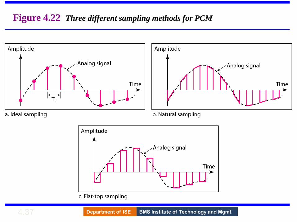
BMS Institute of Technology and Mgmt Department of ISE 4.37
Figure 4.22 Three different sampling methods for PCM
142
BMS Institute of Technology and Mgmt Department of ISE 4.38
According to the Nyquist theorem, the
sampling rate must be
at least 2 times the highest frequency
contained in the signal.
Note
143

BMS Institute of Technology and Mgmt Department of ISE 4.39
Figure 4.23 Nyquist sampling rate for low-pass and bandpass signals
144
BMS Institute of Technology and Mgmt Department of ISE Department of ISE BMS Institute of Technology and Mgmt 4.40
Quantization
• Sampling results in a series of pulses of varying amplitude values ranging between two limits: a min and a max.
• The amplitude values are infinite between the two limits.
• We need to map the infinite amplitude values onto a finite set of known values.
• This is achieved by dividing the distance between min and max into L zones, each of height
= (max - min)/L
145
BMS Institute of Technology and Mgmt Department of ISE Department of ISE BMS Institute of Technology and Mgmt 4.41
Quantization Levels
• The midpoint of each zone is assigned a value from 0 to L-1 (resulting in L values)
• Each sample falling in a zone is then approximated to the value of the midpoint.
146

BMS Institute of Technology and Mgmt Department of ISE Department of ISE BMS Institute of Technology and Mgmt 4.42
Quantization Zones
• Assume we have a voltage signal with amplitutes Vmin=-20V and Vmax=+20V.
• We want to use L=8 quantization levels.
• Zone width = (20 - -20)/8 = 5
• The 8 zones are: -20 to -15, -15 to -10, -10 to -5, -5 to 0, 0 to +5, +5 to +10, +10 to +15, +15 to +20
• The midpoints are: -17.5, -12.5, -7.5, -2.5, 2.5, 7.5, 12.5, 17.5
147
BMS Institute of Technology and Mgmt Department of ISE Department of ISE BMS Institute of Technology and Mgmt 4.43
Assigning Codes to Zones • Each zone is then assigned a binary code.
• The number of bits required to encode the zones, or the number of bits per sample as it is commonly referred to, is obtained as follows:
nb = log2 L
• Given our example, nb = 3
• The 8 zone (or level) codes are therefore: 000, 001, 010, 011, 100, 101, 110, and 111
• Assigning codes to zones: – 000 will refer to zone -20 to -15
– 001 to zone -15 to -10, etc.
148

BMS Institute of Technology and Mgmt Department of ISE 4.44
Figure 4.26 Quantization and encoding of a sampled signal
149

BMS Institute of Technology and Mgmt Department of ISE Department of ISE BMS Institute of Technology and Mgmt 4.45
Quantization Error • When a signal is quantized, we introduce an error
- the coded signal is an approximation of the actual amplitude value.
• The difference between actual and coded value (midpoint) is referred to as the quantization error.
• The more zones, the smaller which results in smaller errors.
• BUT, the more zones the more bits required to encode the samples -> higher bit rate
150
BMS Institute of Technology and Mgmt Department of ISE Department of ISE BMS Institute of Technology and Mgmt 4.46
PCM Decoder
• To recover an analog signal from a digitized signal we follow the following steps:
– We use a hold circuit that holds the amplitude value of a pulse till the next pulse arrives.
– We pass this signal through a low pass filter with a cutoff frequency that is equal to the highest frequency in the pre-sampled signal.
• The higher the value of L, the less distorted a signal is recovered.
151

BMS Institute of Technology and Mgmt Department of ISE 4.47
Figure 4.27 Components of a PCM decoder
152

BMS Institute of Technology and Mgmt Department of ISE 4.48
4-3 TRANSMISSION MODES
The transmission of binary data across a link can be
accomplished in either parallel or serial mode. In
parallel mode, multiple bits are sent with each clock
tick. In serial mode, 1 bit is sent with each clock tick.
While there is only one way to send parallel data, there
are three subclasses of serial transmission:
asynchronous, synchronous, and isochronous.
Parallel Transmission
Serial Transmission
Topics discussed in this section:
153

BMS Institute of Technology and Mgmt Department of ISE 4.49
Figure 4.31 Data transmission and modes
154

BMS Institute of Technology and Mgmt Department of ISE 4.50
Figure 4.32 Parallel transmission
155

BMS Institute of Technology and Mgmt Department of ISE 4.51
Figure 4.33 Serial transmission
156
BMS Institute of Technology and Mgmt Department of ISE 4.52
In asynchronous transmission, we send
1 start bit (0) at the beginning and 1 or
more stop bits (1s) at the end of each
byte. There may be a gap between
each byte.
Note
157
BMS Institute of Technology and Mgmt Department of ISE 4.53
Asynchronous here means
“asynchronous at the byte level,”
but the bits are still synchronized;
their durations are the same.
Note
158

BMS Institute of Technology and Mgmt Department of ISE 4.54
Figure 4.34 Asynchronous transmission
159

BMS Institute of Technology and Mgmt Department of ISE 4.55
In synchronous transmission, we send
bits one after another without start or
stop bits or gaps. It is the responsibility
of the receiver to group the bits. The bits
are usually sent as bytes and many
bytes are grouped in a frame. A frame is
identified with a start and an end byte.
Note
160
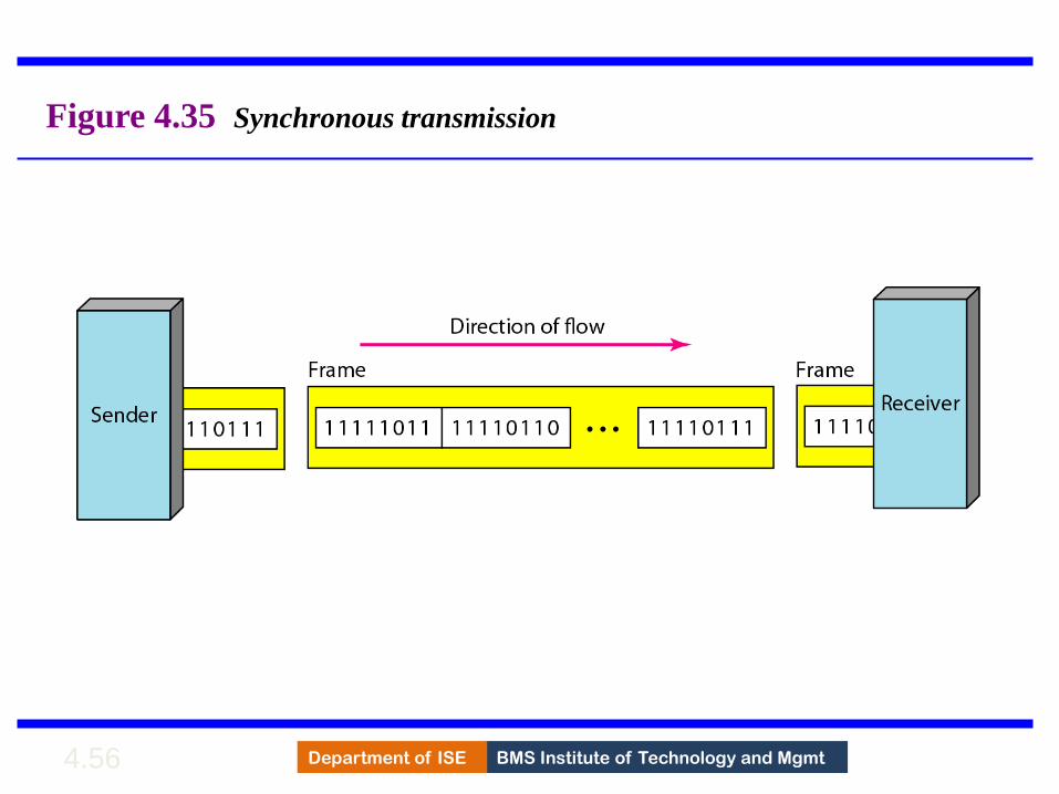
BMS Institute of Technology and Mgmt Department of ISE 4.56
Figure 4.35 Synchronous transmission
161

BMS Institute of Technology and Mgmt Department of ISE Department of ISE BMS Institute of Technology and Mgmt 4.57
Isochronous
• In isochronous transmission we cannot have uneven gaps between frames.
• Transmission of bits is fixed with equal gaps.
• Example: Multimedia transmission
162
BMS Institute of Technology and Mgmt Department of ISE Department of ISE BMS Institute of Technology and Mgmt
Line Coding
• Converting a string of 1’s and 0’s (digital data) into a sequence of signals that denote the 1’s and 0’s.
• For example a high voltage level (+V) could represent a “1” and a low voltage level (0 or -V) could represent a “0”.
163

BMS Institute of Technology and Mgmt Department of ISE
Figure 4.1 Line coding and decoding
164
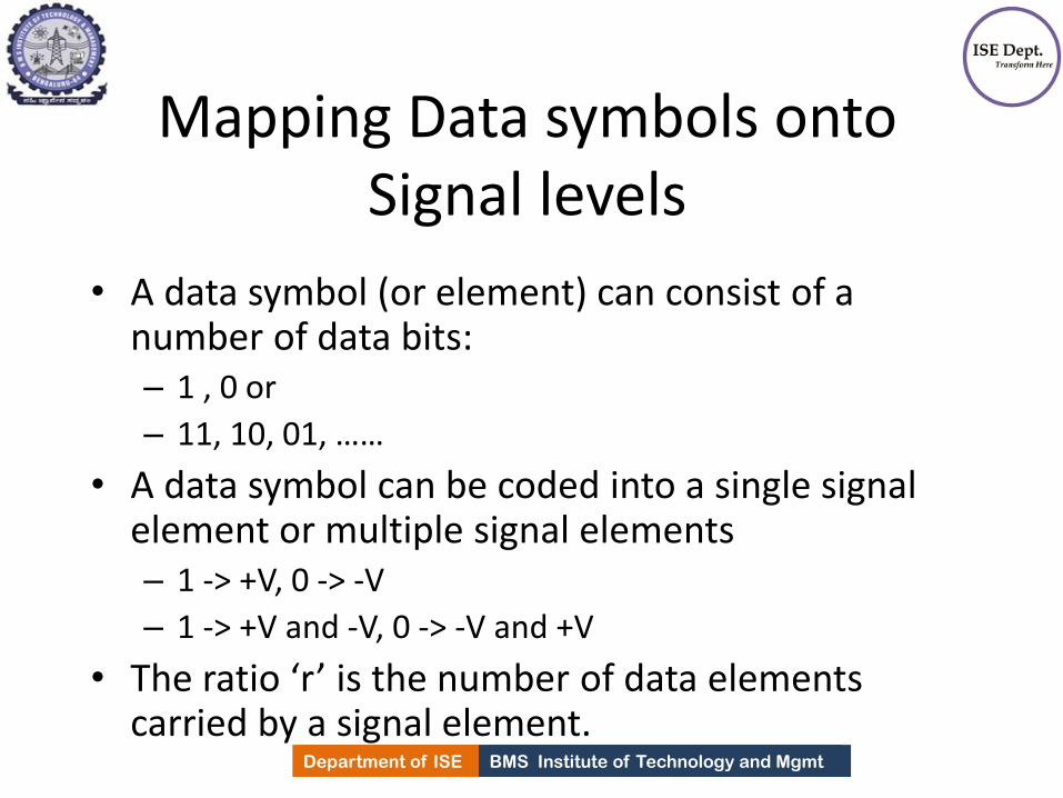
BMS Institute of Technology and Mgmt Department of ISE Department of ISE BMS Institute of Technology and Mgmt
Mapping Data symbols onto Signal levels
• A data symbol (or element) can consist of a number of data bits: – 1 , 0 or
– 11, 10, 01, ……
• A data symbol can be coded into a single signal element or multiple signal elements – 1 -> +V, 0 -> -V
– 1 -> +V and -V, 0 -> -V and +V
• The ratio ‘r’ is the number of data elements carried by a signal element.
165

BMS Institute of Technology and Mgmt Department of ISE Department of ISE BMS Institute of Technology and Mgmt
Relationship between data rate and signal rate
• The data rate defines the number of bits sent per sec - bps. It is often referred to the bit rate.
• The signal rate is the number of signal elements sent in a second and is measured in bauds. It is also referred to as the modulation rate OR baud rate.
• Goal is to increase the data rate whilst reducing the baud rate.
166

BMS Institute of Technology and Mgmt Department of ISE
Figure 4.2 Signal element versus data element
167

BMS Institute of Technology and Mgmt Department of ISE Department of ISE BMS Institute of Technology and Mgmt
Data rate and Baud rate
• The baud or signal rate can be expressed as:
S = c x N x 1/r bauds
where N is data rate
c is the case factor (worst, best & avg.)
r is the ratio between data element & signal element
168
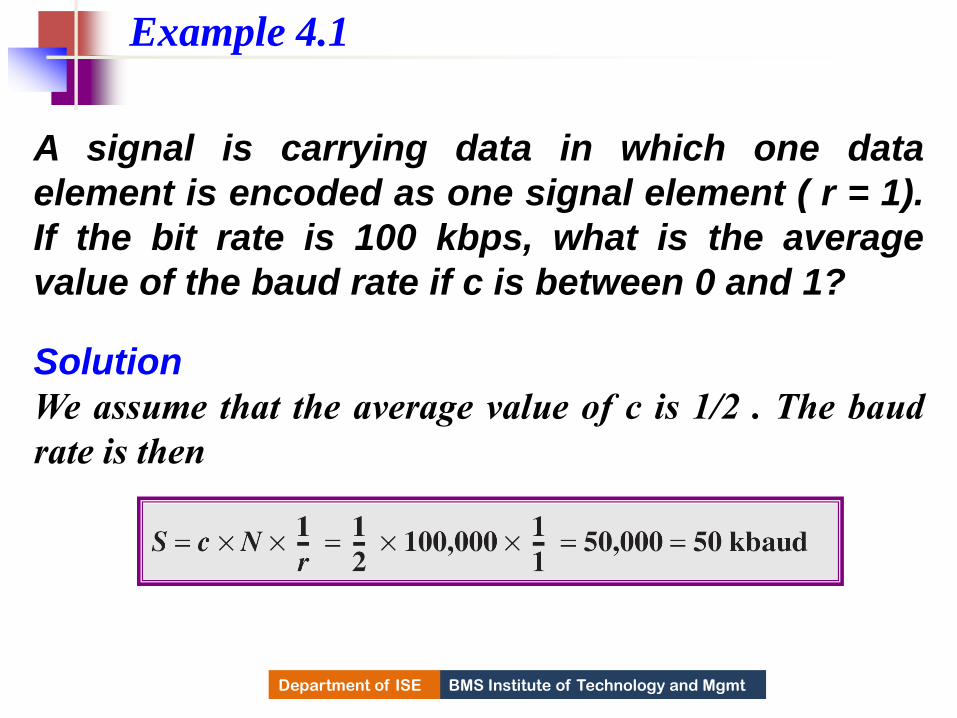
BMS Institute of Technology and Mgmt Department of ISE
A signal is carrying data in which one data
element is encoded as one signal element ( r = 1).
If the bit rate is 100 kbps, what is the average
value of the baud rate if c is between 0 and 1?
Solution
We assume that the average value of c is 1/2 . The baud
rate is then
Example 4.1
169

BMS Institute of Technology and Mgmt Department of ISE
The maximum data rate of a channel (see Chapter
3) is Nmax = 2 × B × log2 L (defined by the Nyquist
formula). Does this agree with the previous
formula for Nmax?
Solution
A signal with L levels actually can carry log2L bits per
level. If each level corresponds to one signal element and
we assume the average case (c = 1/2), then we have
Example 4.2
170

BMS Institute of Technology and Mgmt Department of ISE Department of ISE BMS Institute of Technology and Mgmt
• Self synchronization - the clocks at the sender and the receiver must have the same bit interval.
• If the receiver clock is faster or slower it will misinterpret the incoming bit stream.
Considerations for choosing a good signal element referred to as line
encoding
171

BMS Institute of Technology and Mgmt Department of ISE
Figure 4.3 Effect of lack of synchronization
172
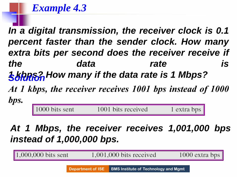
BMS Institute of Technology and Mgmt Department of ISE
In a digital transmission, the receiver clock is 0.1
percent faster than the sender clock. How many
extra bits per second does the receiver receive if
the data rate is
1 kbps? How many if the data rate is 1 Mbps? Solution
At 1 kbps, the receiver receives 1001 bps instead of 1000
bps.
Example 4.3
At 1 Mbps, the receiver receives 1,001,000 bps
instead of 1,000,000 bps.
173
BMS Institute of Technology and Mgmt Department of ISE Department of ISE BMS Institute of Technology and Mgmt
Line encoding C/Cs
• Error detection - errors occur during transmission due to line impairments.
• Some codes are constructed such that when an error occurs it can be detected.
174

BMS Institute of Technology and Mgmt Department of ISE Department of ISE BMS Institute of Technology and Mgmt
Line encoding C/Cs
• Noise and interference - there are line encoding techniques that make the transmitted signal “immune” to noise and interference.
• This means that the signal cannot be corrupted, it is stronger than error detection.
175

BMS Institute of Technology and Mgmt Department of ISE Department of ISE BMS Institute of Technology and Mgmt
Line encoding C/Cs
• Complexity - the more robust and resilient the code, the more complex it is to implement and the price is often paid in baud rate or required bandwidth.
176

BMS Institute of Technology and Mgmt Department of ISE
Figure 4.4 Line coding schemes
177

BMS Institute of Technology and Mgmt Department of ISE Department of ISE BMS Institute of Technology and Mgmt
Unipolar
• All signal levels are on one side of the time axis - either above or below
• NRZ - Non Return to Zero scheme is an example of this code. The signal level does not return to zero during a symbol transmission.
• Scheme is prone to baseline wandering and DC components. It has no synchronization or any error detection. It is simple but costly in power consumption.
178

BMS Institute of Technology and Mgmt Department of ISE
Figure 4.5 Unipolar NRZ scheme
179

BMS Institute of Technology and Mgmt Department of ISE Department of ISE BMS Institute of Technology and Mgmt
Polar - NRZ
• The voltages are on both sides of the time axis.
• Polar NRZ scheme can be implemented with two voltages. E.g. +V for 1 and -V for 0.
• There are two versions: – NZR - Level (NRZ-L) - positive voltage for one symbol
and negative for the other
– NRZ - Inversion (NRZ-I) - the change or lack of change in polarity determines the value of a symbol. E.g. a “1” symbol inverts the polarity a “0” does not.
180

BMS Institute of Technology and Mgmt Department of ISE
Figure 4.6 Polar NRZ-L and NRZ-I schemes
181

BMS Institute of Technology and Mgmt Department of ISE
In NRZ-L the level of the voltage
determines the value of the bit.
In NRZ-I the inversion
or the lack of inversion
determines the value of the bit.
Note
182

BMS Institute of Technology and Mgmt Department of ISE
NRZ-L and NRZ-I both have a DC
component problem and baseline
wandering, it is worse for NRZ-L. Both
have no self synchronization &no error
detection. Both are relatively simple to
implement.
Note
183
BMS Institute of Technology and Mgmt Department of ISE
A system is using NRZ-I to transfer 1-Mbps data.
What are the average signal rate and minimum
bandwidth?
Solution
The average signal rate is S= c x N x R = 1/2 x N x 1 =
500 kbaud. The minimum bandwidth for this average
baud rate is Bmin = S = 500 kHz.
Note c = 1/2 for the avg. case as worst case is 1 and best
case is 0
Example 4.4
184

BMS Institute of Technology and Mgmt Department of ISE Department of ISE BMS Institute of Technology and Mgmt
Polar - RZ • The Return to Zero (RZ) scheme uses three
voltage values. +, 0, -.
• Each symbol has a transition in the middle. Either from high to zero or from low to zero.
• This scheme has more signal transitions (two per symbol) and therefore requires a wider bandwidth.
• No DC components or baseline wandering.
• Self synchronization - transition indicates symbol value.
• More complex as it uses three voltage level. It has no error detection capability.
185

BMS Institute of Technology and Mgmt Department of ISE
Figure 4.7 Polar RZ scheme
186
BMS Institute of Technology and Mgmt Department of ISE Department of ISE BMS Institute of Technology and Mgmt
Polar - Biphase: Manchester and Differential Manchester
• Manchester coding consists of combining the NRZ-L and RZ schemes. – Every symbol has a level transition in the middle: from
high to low or low to high. Uses only two voltage levels.
• Differential Manchester coding consists of combining the NRZ-I and RZ schemes. – Every symbol has a level transition in the middle. But
the level at the beginning of the symbol is determined by the symbol value. One symbol causes a level change the other does not.
187

BMS Institute of Technology and Mgmt Department of ISE
Figure 4.8 Polar biphase: Manchester and differential Manchester schemes
188

BMS Institute of Technology and Mgmt Department of ISE
In Manchester and differential
Manchester encoding, the transition
at the middle of the bit is used for
synchronization.
Note
189

BMS Institute of Technology and Mgmt Department of ISE
The minimum bandwidth of Manchester
and differential Manchester is 2 times
that of NRZ. The is no DC component
and no baseline wandering. None of
these codes has error detection.
Note
190
BMS Institute of Technology and Mgmt Department of ISE Department of ISE BMS Institute of Technology and Mgmt
Bipolar - AMI and Pseudoternary
• Code uses 3 voltage levels: - +, 0, -, to represent the symbols (note not transitions to zero as in RZ).
• Voltage level for one symbol is at “0” and the other alternates between + & -.
• Bipolar Alternate Mark Inversion (AMI) - the “0” symbol is represented by zero voltage and the “1” symbol alternates between +V and -V.
• Pseudoternary is the reverse of AMI.
191

BMS Institute of Technology and Mgmt Department of ISE
Figure 4.9 Bipolar schemes: AMI and pseudoternary
192

BMS Institute of Technology and Mgmt Department of ISE Department of ISE BMS Institute of Technology and Mgmt
Bipolar C/Cs
• It is a better alternative to NRZ.
• Has no DC component or baseline wandering.
• Has no self synchronization because long runs of “0”s results in no signal transitions.
• No error detection.
193

BMS Institute of Technology and Mgmt Department of ISE
MODULE – 3
BANDWIDTH UTILIZATION
194

BMS Institute of Technology and Mgmt Department of ISE
MULTIPLEXING
•Multiplexing is the set of techniques that allows the
simultaneous transmission of multiple signals across a
single data link
•As data and telecommunications use increases, so does
traffic, this increase can be accommodated by
continuing to add individual links each time a new
channel is needed,
or
• Higher-bandwidth links are can be installed to carry
multiple signals in each link.
195

BMS Institute of Technology and Mgmt Department of ISE
Dividing a link into channels
196

BMS Institute of Technology and Mgmt Department of ISE Department of ISE BMS Institute of Technology and Mgmt
Multiplexing
• Each has a excess bandwidth needed for average
transmission of signal.
• If the bandwidth of a link is greater than the
bandwidth needs of the devices connected to it,
bandwidth is wasted.
• An efficient system maximizes the utilization of all
resources.
• Bandwidth is one of the most precious resource in
Data Communication.
197
BMS Institute of Technology and Mgmt Department of ISE Department of ISE BMS Institute of Technology and Mgmt
Multiplexing • In multiplexed system, n lines share the bandwidth of
one link.
• The lines on the left direct their transmission stream
into Multiplexer, which combines them into single
stream.
• The stream is fed to demultiplexer at the receiving
end, which separates the streams back into their
corresponding lines.
• Link refers to physical path.
198

BMS Institute of Technology and Mgmt Department of ISE Department of ISE BMS Institute of Technology and Mgmt
Multiplexing
• Channel refers to portion of a link that carries a
transmission between a given pair of lines.
• One link can have n channels.
• There are three multiplexing techniques.
1) Frequency division multiplexing(FDM)
2) Wave length division multiplexing(WDM)
3) Time division multiplexing(TDM)
199

BMS Institute of Technology and Mgmt Department of ISE
Categories of multiplexing
200

BMS Institute of Technology and Mgmt Department of ISE
Frequency-Division Multiplexing
•Frequency-division multiplexing (FDM) is an analog
technique that can be applied when the bandwidth of a
link (in hertz) is greater than the combined
bandwidths of the signals to be transmitted.
•In FDM, signals generated by each sending device
are modulated at different carrier frequencies.
•These modulated signals are then combined into a
single composite signal that can be transported by the
link.
201

BMS Institute of Technology and Mgmt Department of ISE
Frequency-division multiplexing
202

BMS Institute of Technology and Mgmt Department of ISE
FDM Process
203

BMS Institute of Technology and Mgmt Department of ISE Department of ISE BMS Institute of Technology and Mgmt
Multiplexing process
• Each source generates a signal of a similar frequency
range.
• Inside the multiplexer, these similar signals
modulates different carrier frequencies (f1,f2,f3).
• The resulting modulated signals are then combined
into a single composite signal that is sent over the
media which has enough bandwidth.
204

BMS Institute of Technology and Mgmt Department of ISE
FDM Demultiplexing Process
205

BMS Institute of Technology and Mgmt Department of ISE
Assume that a voice channel occupies a bandwidth of 4 kHz.
We need to combine three voice channels into a link with a
bandwidth of 12 kHz, from 20 to 32 kHz. Show the
configuration, using the frequency domain. Assume there
are no guard bands.
Example 6.1
Solution
Shift (modulate) each of the three voice channels to a
different bandwidth, as shown in the Figure below
206

BMS Institute of Technology and Mgmt Department of ISE
Example 6.1
207

BMS Institute of Technology and Mgmt Department of ISE
Five channels, each with a 100-kHz bandwidth, are to be
multiplexed together. What is the minimum bandwidth of
the link if there is a need for a guard band of 10 kHz
between the channels to prevent interference?
Example 6.2
Solution For five channels, at least four guard bands are required.
This means that the required bandwidth is
5 × 100 + 4 × 10 = 540 kHz, as shown below
208

BMS Institute of Technology and Mgmt Department of ISE Department of ISE BMS Institute of Technology and Mgmt
Analog carrier System
• Telephone companies, to maximize efficiency
of their infrastructure, multiplexed signals
from lower bandwidth lines into higher-
bandwidth lines.
• In analog hierarchy, 12 voice channels are
multiplexed onto higher bandwidth line to
create a group.
• The group has 48khz of BW and supports 12
voice channels and so on…..
209
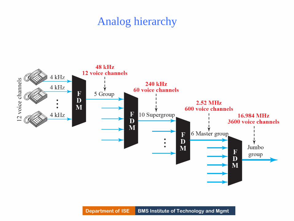
BMS Institute of Technology and Mgmt Department of ISE
Analog hierarchy
210

BMS Institute of Technology and Mgmt Department of ISE Department of ISE BMS Institute of Technology and Mgmt
Applications of FDM
1) FDM is used in FM and AM broadcasting.
Radio uses air as transmission medium.
A special band from 530 to 1700 kHz is
assigned to AM radio.
All radio channels need to share this band.
• AM stations needs 10kHz of BW. Each
station uses different carrier frequency ,
which means it is shifting its signal and
multiplexing.
211
BMS Institute of Technology and Mgmt Department of ISE Department of ISE BMS Institute of Technology and Mgmt
Continued..
• The signal that goes to air is the combination of
signals.
• The receiver receives all the signals but tunes only
the station desired.
• In FM broadcasting, FM has wider band of 88 to 108
MHz because each station needs a BW of 200 KHz.
Uses:
1) FDM is used in television broadcasting. Each TV
channel has its own BW of 6 MHz.
2) First generation of cellular telephones.
212
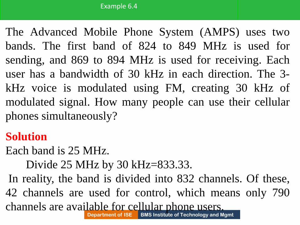
BMS Institute of Technology and Mgmt Department of ISE
The Advanced Mobile Phone System (AMPS) uses two
bands. The first band of 824 to 849 MHz is used for
sending, and 869 to 894 MHz is used for receiving. Each
user has a bandwidth of 30 kHz in each direction. The 3-
kHz voice is modulated using FM, creating 30 kHz of
modulated signal. How many people can use their cellular
phones simultaneously?
Example 6.4
Solution
Each band is 25 MHz.
Divide 25 MHz by 30 kHz=833.33.
In reality, the band is divided into 832 channels. Of these,
42 channels are used for control, which means only 790
channels are available for cellular phone users. 213
BMS Institute of Technology and Mgmt Department of ISE
Wavelength-Division Multiplexing
•Wavelength-division multiplexing (WDM) is
designed to use the high-data-rate capability of fiber-
optic cable.
•The optical fiber data rate is higher than the data rate
of metallic transmission cable, but using a fiber-optic
cable for a single line wastes the available bandwidth.
• Multiplexing allows users to combine several lines
into one.
214

BMS Institute of Technology and Mgmt Department of ISE
Wavelength-division multiplexing
215

BMS Institute of Technology and Mgmt Department of ISE Department of ISE BMS Institute of Technology and Mgmt
WDM
• Multiplexing and de multiplexing involves optical
signals through fiber optic channels.
• In WDM, different high frequency signals of different
frequencies are combined.
• A very narrow bands of light from different sources
are combined to make a wider band of light.
• Signals are separated from de multiplexer at the
receiver.
216

BMS Institute of Technology and Mgmt Department of ISE Department of ISE BMS Institute of Technology and Mgmt
WDM
• Idea in WDM technology is, combining multiple
light sources into one single light at multiplexer.
• Combining and splitting of light sources are handled
by prism.
• Prism bends a beam of light based on angle of
incidence and frequency.
• Using this technique, a multiplexer is made to
combine several input beams of light.
• Each containing a narrow band of frequencies, into
one output beam of wider band of frequencies.
217
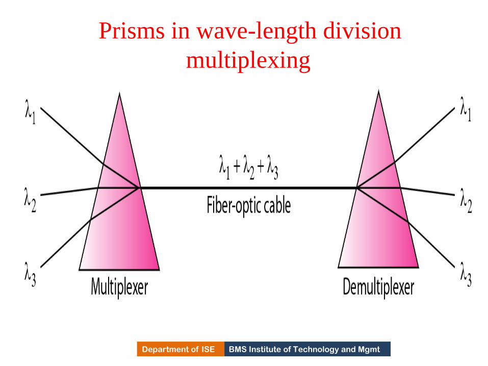
BMS Institute of Technology and Mgmt Department of ISE
Prisms in wave-length division
multiplexing
218

BMS Institute of Technology and Mgmt Department of ISE Department of ISE BMS Institute of Technology and Mgmt
Applications of WDM
• Used in SONET network in which multiple optical
fiber lines are multiplexed and de multiplexed
• A new method called dense WDM(DWDM)
is used to achieve greater efficiency
• DWDM can multiplex a very large number of
channels by spacing channels very close to one
another.
219

BMS Institute of Technology and Mgmt Department of ISE
Time-Division Multiplexing
•Time-division multiplexing (TDM) is a digital
process that allows several connections to share the
high bandwidth of a link.
•Instead of sharing a portion of the bandwidth as in
FDM, time is shared.
• Each connection occupies a portion of time in the
link.
•Figure shows conceptual view of TDM. The link is
sectioned by time rather than by frequency.
•In the figure below , portions of signals 1, 2, 3, and 4
occupy the link sequentially. 220

BMS Institute of Technology and Mgmt Department of ISE
TDM
221

BMS Institute of Technology and Mgmt Department of ISE Department of ISE BMS Institute of Technology and Mgmt
TDM • In the fig., all the data in a message from source 1
always go to one specific destination 1,2,3 or 4.
• Digital data from different sources are combined into one timeshared link.
• If data is analog, data is sampled changed to digital data and then multiplexed using TDM.
• TDM is divided into Synchronous TDM and statistical TDM.
• In synchronous TDM, the data flow of each input connection is divided into units.
• Each input occupies one input time slot.
• A Unit can be one char, 1 bit or one block of data.
222

BMS Institute of Technology and Mgmt Department of ISE Department of ISE BMS Institute of Technology and Mgmt
Time slots and frames
• Each i/p unit becomes one o/p unit and occupies one
o/p time slot.
• Duration of Output time slot is n times shorter than
the duration of an i/p time slot.
• TDM is a digital multiplexing technique for
combining several low-rate channels into one high-
rate one.
• In synchronous TDM, the data rate of the link is n times faster, and the unit duration is n times shorter
223

BMS Institute of Technology and Mgmt Department of ISE
Synchronous time-division multiplexing
224

BMS Institute of Technology and Mgmt Department of ISE Department of ISE BMS Institute of Technology and Mgmt
STDM
• In STDM, a round of data units from each i/p connection is collected into a frame.
• If n connections , a frame is divided into n time slots and one slot is allocated for each unit, one for each i/p line.
• If the duration each unit is T sec, then duration of each slot is T/n.
• Duration of each frame is T.
• The data rate of the o/p link must be n times the data rate of a connection to guarantee the flow of data.
225

BMS Institute of Technology and Mgmt Department of ISE Department of ISE BMS Institute of Technology and Mgmt
STDM
• In fig, the data rate of link is 3 times the data
rate of a connection.
• Duration of a unit on a connection is 3 times
that of the time slot.
• Time slots are grouped into frames.
• A frame consists of one complete cycle of time
slots, with one slot dedicated to each sending
device.
226
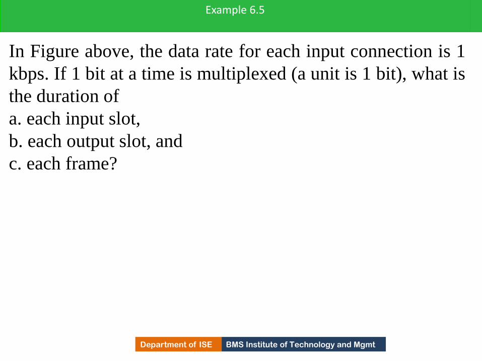
BMS Institute of Technology and Mgmt Department of ISE
In Figure above, the data rate for each input connection is 1
kbps. If 1 bit at a time is multiplexed (a unit is 1 bit), what is
the duration of
a. each input slot,
b. each output slot, and
c. each frame?
Example 6.5
227

BMS Institute of Technology and Mgmt Department of ISE
Example 6.5 (continued)
Solution
a. The data rate of each input connection is 1 kbps. This
means that the bit duration is 1/1000 s or 1 ms. The duration
of the input time slot is 1 ms (same as bit duration).
b The duration of each output time slot is one-third of the
input time slot. This means that the duration of the output
time slot is 1/3 ms.
c.Each frame carries three output time slots. So the duration
of a frame is 3 × (1/3) ms, or 1 ms. The duration of a frame
is the same as the duration of an input unit.
228

BMS Institute of Technology and Mgmt Department of ISE
Figure below shows synchronous TDM with a data stream
for each input and one data stream for the output. The unit
of data is 1 bit. Find (a) the input bit duration, (b) the output
bit duration, (c) the output bit rate, and (d) the output frame
rate.
Example 6.6
229
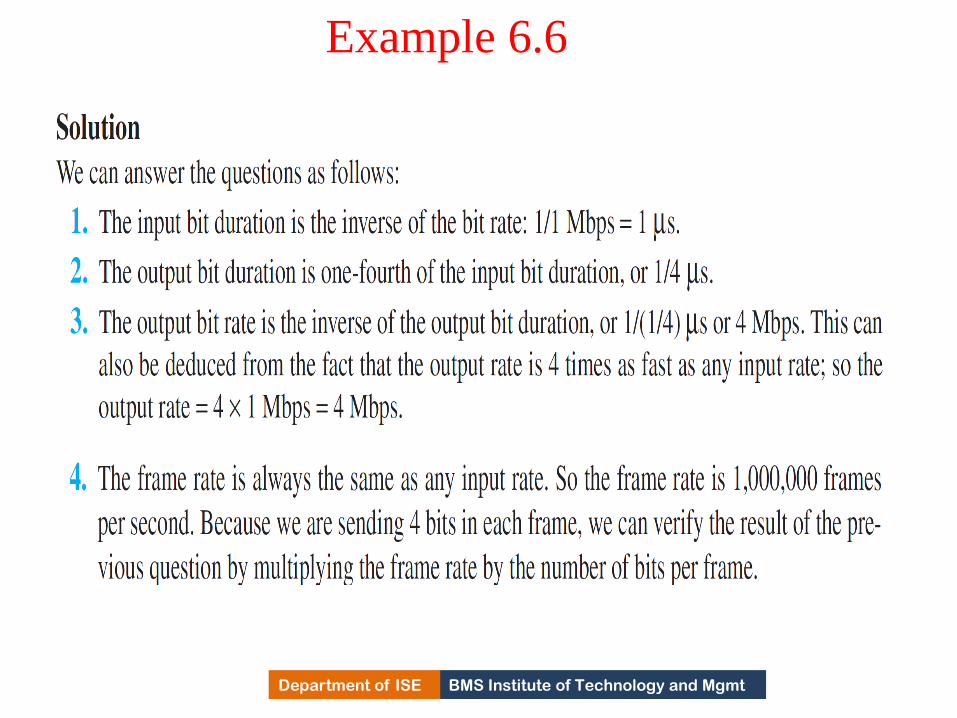
BMS Institute of Technology and Mgmt Department of ISE
Example 6.6
230

BMS Institute of Technology and Mgmt Department of ISE
Four 1-kbps connections are multiplexed together. A unit is
1 bit. Find (1) the duration of 1 bit before multiplexing, (2)
the transmission rate of the link, (3) the duration of a time
slot, and (4) the duration of a frame.
Example 6.7
231
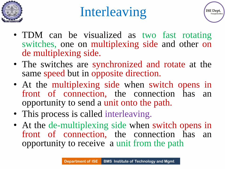
BMS Institute of Technology and Mgmt Department of ISE Department of ISE BMS Institute of Technology and Mgmt
Interleaving
• TDM can be visualized as two fast rotating switches, one on multiplexing side and other on de multiplexing side.
• The switches are synchronized and rotate at the same speed but in opposite direction.
• At the multiplexing side when switch opens in front of connection, the connection has an opportunity to send a unit onto the path.
• This process is called interleaving.
• At the de-multiplexing side when switch opens in front of connection, the connection has an opportunity to receive a unit from the path
232

BMS Institute of Technology and Mgmt Department of ISE
Interleaving
233
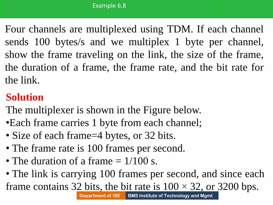
BMS Institute of Technology and Mgmt Department of ISE
Four channels are multiplexed using TDM. If each channel
sends 100 bytes/s and we multiplex 1 byte per channel,
show the frame traveling on the link, the size of the frame,
the duration of a frame, the frame rate, and the bit rate for
the link.
Example 6.8
Solution
The multiplexer is shown in the Figure below.
•Each frame carries 1 byte from each channel;
• Size of each frame=4 bytes, or 32 bits.
• The frame rate is 100 frames per second.
• The duration of a frame = 1/100 s.
• The link is carrying 100 frames per second, and since each
frame contains 32 bits, the bit rate is 100 × 32, or 3200 bps. 234
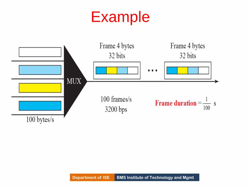
BMS Institute of Technology and Mgmt Department of ISE
Example
235
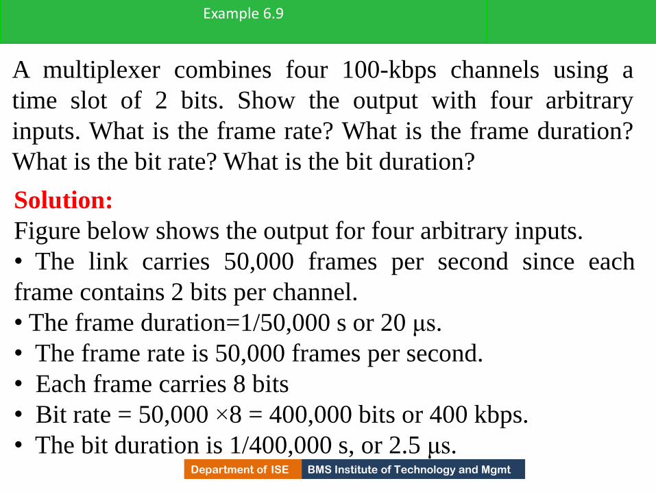
BMS Institute of Technology and Mgmt Department of ISE
A multiplexer combines four 100-kbps channels using a
time slot of 2 bits. Show the output with four arbitrary
inputs. What is the frame rate? What is the frame duration?
What is the bit rate? What is the bit duration?
Example 6.9
Solution:
Figure below shows the output for four arbitrary inputs.
• The link carries 50,000 frames per second since each
frame contains 2 bits per channel.
• The frame duration=1/50,000 s or 20 μs.
• The frame rate is 50,000 frames per second.
• Each frame carries 8 bits
• Bit rate = 50,000 ×8 = 400,000 bits or 400 kbps.
• The bit duration is 1/400,000 s, or 2.5 μs. 236

BMS Institute of Technology and Mgmt Department of ISE
Example
237
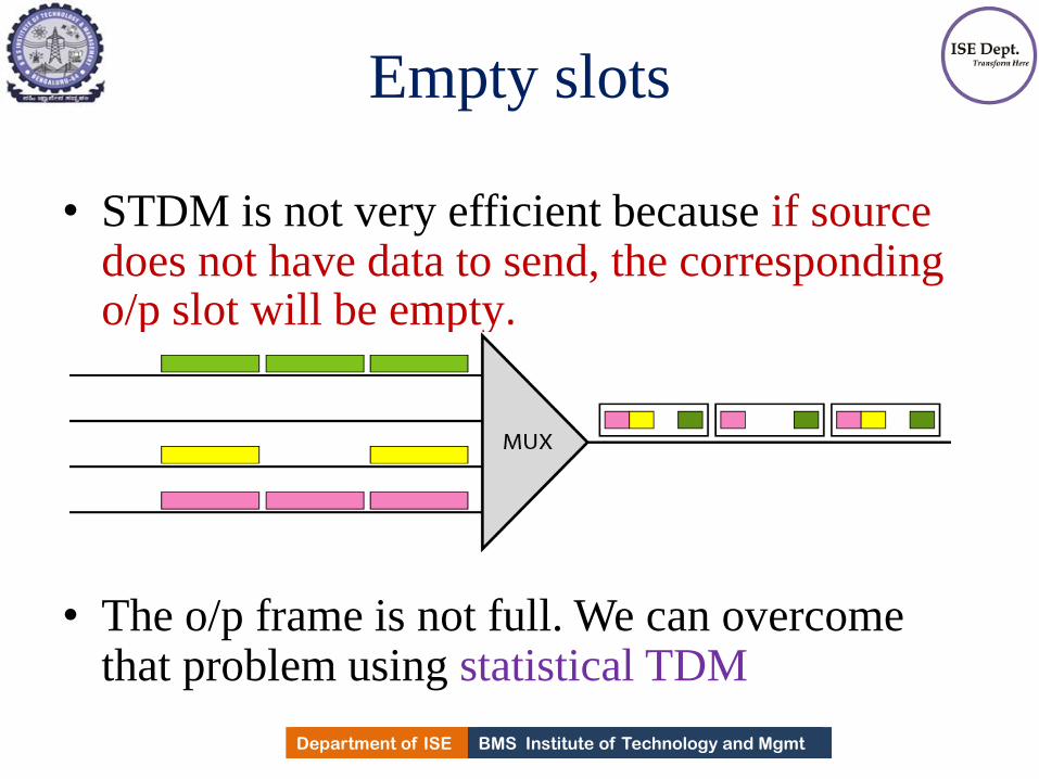
BMS Institute of Technology and Mgmt Department of ISE Department of ISE BMS Institute of Technology and Mgmt
Empty slots
• STDM is not very efficient because if source does not have data to send, the corresponding o/p slot will be empty.
• The o/p frame is not full. We can overcome that problem using statistical TDM
238

BMS Institute of Technology and Mgmt Department of ISE Department of ISE BMS Institute of Technology and Mgmt
Data rate management
• How to handle disparity in the i/p data rates in
TDM??
• If i/p data rates are not same, three strategies
are used
1) Multilevel Multiplexing
2) Multiple-slot allocation
3) Pulse stuffing.
239

BMS Institute of Technology and Mgmt Department of ISE Department of ISE BMS Institute of Technology and Mgmt
Multi level Multiplexing
• Is used when i/p data rate of an i/p line is
multiple of others.
240

BMS Institute of Technology and Mgmt Department of ISE Department of ISE BMS Institute of Technology and Mgmt
Multiple slot Multiplexing
• Allotting more than one slot in a frame to a
single i/p line.
241

BMS Institute of Technology and Mgmt Department of ISE Department of ISE BMS Institute of Technology and Mgmt
Pulse stuffing
• Some times bit rates of source are not multiple
integers of each other.
• Solution is to make highest i/p data rate the
dominant data rate and add dummy bits to the
i/p lines with lower rates.
242

BMS Institute of Technology and Mgmt Department of ISE Department of ISE BMS Institute of Technology and Mgmt
Frame synchronizing
• In TDM synchronization between multiplexer and de multiplexer is a major issue.
• If not synchronized, the bits belonging one channel will be received by wrong channel.
• Therefore, one or more synchronization bits are added to the beginning of each frame,
• That allows de multiplexer to synchronize with the incoming stream , so that it can separate the time slots accurately.
• The Synchronization information consists of 1 bit per frame , alternating between 0 and 1.
243

BMS Institute of Technology and Mgmt Department of ISE
Framing bits
244

BMS Institute of Technology and Mgmt Department of ISE
We have four sources, each creating 250 characters per
second. If the interleaved unit is a character and 1
synchronizing bit is added to each frame, find (1) the data
rate of each source, (2) the duration of each character in
each source, (3) the frame rate, (4) the duration of each
frame, (5) the number of bits in each frame, and (6) the data
rate of the link.
Example 6.10
Solution
1. The data rate of each source is 250 × 8 = 2000 bps = 2
kbps.
2. Each source sends 250 characters per second; therefore,
the duration of a character is 1/250 s, or 4 ms.
245

BMS Institute of Technology and Mgmt Department of ISE
3. Each frame has one character from each source, which
means the link needs to send 250 frames per second.
4. The duration of each frame is 1/250 s, or 4 ms.
5. Each frame carries 4 characters and 1 extra synchronizing
bit. This means that each frame is 4 × 8 + 1 = 33 bits.
6. The link sends 250 frames per second, and each frame
contains 33 bits. This means that the data rate of the link
is 250 × 33, or 8250 bps.
(Continued)
246

BMS Institute of Technology and Mgmt Department of ISE
Two channels, one with a bit rate of 100 kbps and another
with a bit rate of 200 kbps, are to be multiplexed. How this
can be achieved? What is the frame rate? What is the frame
duration? What is the bit rate of the link?.
Example 6.11
Solution
Allocate one slot to the first channel and two slots to the
second channel.
•Each frame carries 3 bits.
•The frame rate is 100,000 frames per second because it
carries 1 bit from the first channel.
• The frame duration is 1/100,000 s, or 10 ms.
• The bit rate is 100,000 frames/s × 3 bits per frame, or 300
kbps. 247

BMS Institute of Technology and Mgmt Department of ISE Department of ISE BMS Institute of Technology and Mgmt
Applications
1) Second generation cellular telephone
companies.
248
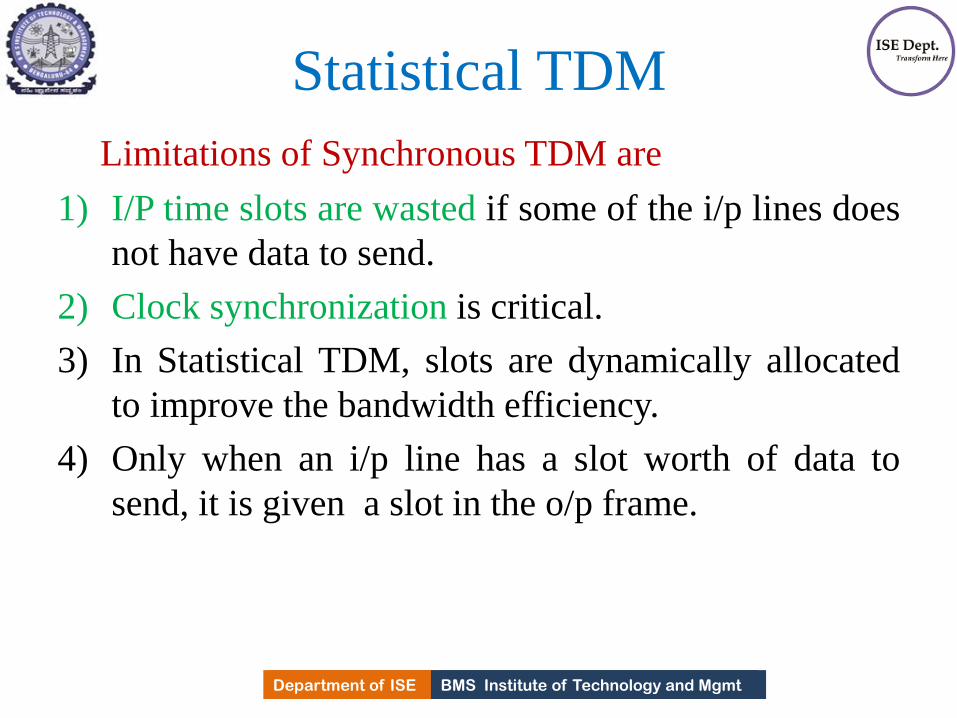
BMS Institute of Technology and Mgmt Department of ISE Department of ISE BMS Institute of Technology and Mgmt
Statistical TDM
Limitations of Synchronous TDM are
1) I/P time slots are wasted if some of the i/p lines does
not have data to send.
2) Clock synchronization is critical.
3) In Statistical TDM, slots are dynamically allocated
to improve the bandwidth efficiency.
4) Only when an i/p line has a slot worth of data to
send, it is given a slot in the o/p frame.
249

BMS Institute of Technology and Mgmt Department of ISE Department of ISE BMS Institute of Technology and Mgmt
Statistical TDM • In Statistical TDM, the no. of slots in each frame is
less than number of i/p lines.
• The multiplexer checks the i/p lines in round robin
fashion, and allocates slot for the i/p line only if it has
data to send.
if no data, it skips and checks the next line.
• In the fig 1. some slots are empty and therefore no
data to send.
• Fig.2 no slots are left empty as long as there
are data to be send by any i/p line.
250
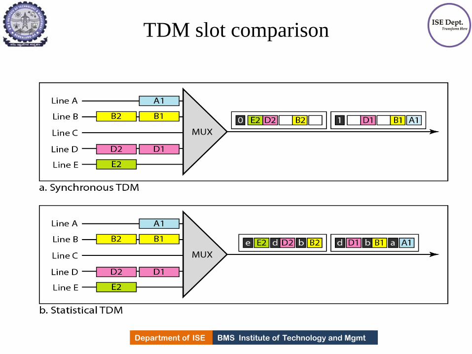
BMS Institute of Technology and Mgmt Department of ISE Department of ISE BMS Institute of Technology and Mgmt
TDM slot comparison
251

BMS Institute of Technology and Mgmt Department of ISE Department of ISE BMS Institute of Technology and Mgmt
Addressing: Differences
Synchronous TDM
1.O/P slot is occupied by data
2.No need of addressing : Synchronization and pre
assigned relationships between the i/p and o/p's serve
as address.
Statistical TDM
1.Slot needs to carry data as well as address of
destination
2.No fixed relationship b/w i/p's and o/p's because there
are no pre assigned or reserved slots. Need to include
address of receiver inside the slot.
252

BMS Institute of Technology and Mgmt Department of ISE Department of ISE BMS Institute of Technology and Mgmt
Statistical TDM
• Slot size: Slots carry both data and address. There
fore the ratio of data size to address size must be
reasonable to make transmission efficient.
• No need of Synchronization bit.
• The capacity of channel is normally less than sum
capacity of each channel.
• Capacity of link is based on statistics of load for each
channel
253
BMS Institute of Technology and Mgmt Department of ISE
SPREAD SPECTRUM
•In wireless applications, stations must be able to share this medium without
interception by an eavesdropper and without being subject to jamming from a
malicious intruder.
• To achieve these goals, spread spectrum techniques add redundancy
254
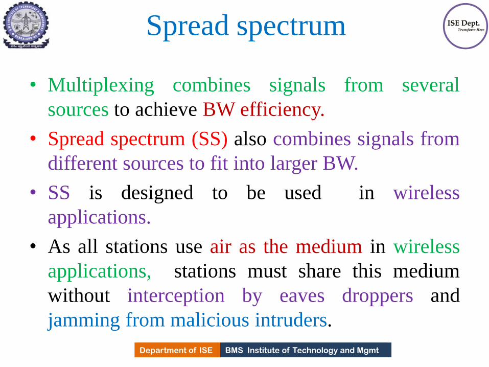
BMS Institute of Technology and Mgmt Department of ISE Department of ISE BMS Institute of Technology and Mgmt
Spread spectrum
• Multiplexing combines signals from several
sources to achieve BW efficiency.
• Spread spectrum (SS) also combines signals from
different sources to fit into larger BW.
• SS is designed to be used in wireless
applications.
• As all stations use air as the medium in wireless
applications, stations must share this medium
without interception by eaves droppers and
jamming from malicious intruders.
255
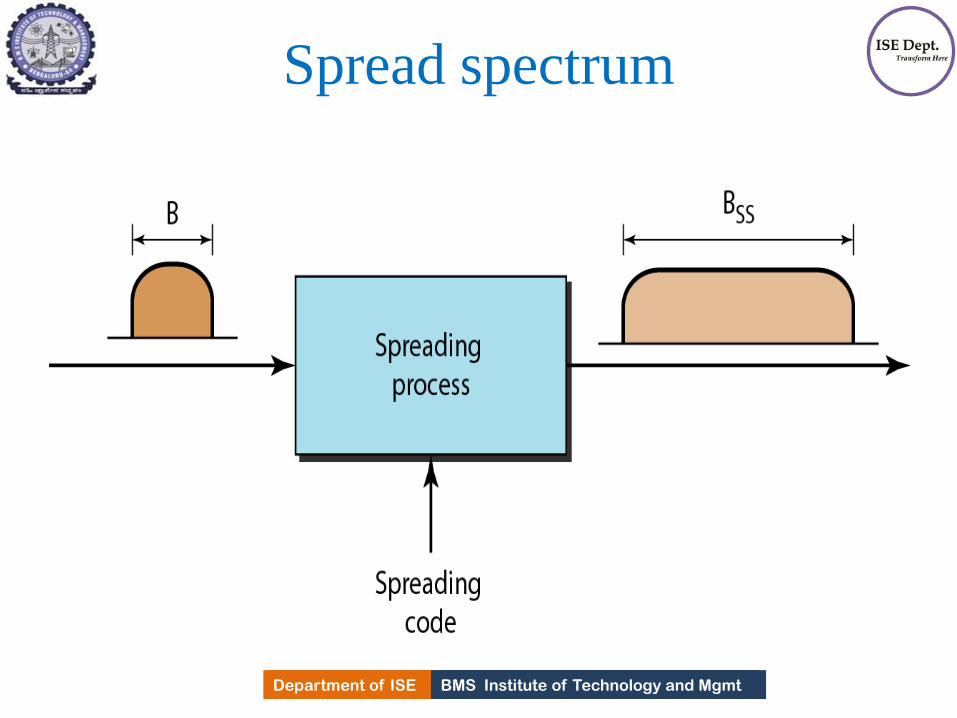
BMS Institute of Technology and Mgmt Department of ISE Department of ISE BMS Institute of Technology and Mgmt
Spread spectrum
256
BMS Institute of Technology and Mgmt Department of ISE Department of ISE BMS Institute of Technology and Mgmt
Spread spectrum
• The bandwidth allocated to each station needs to be
larger than what is needed. This allows redundancy.
• The expanding of original B to BW BSS must be
done by a process that is independent of original
signal.
• After the signal is created by the source, the
spreading process uses a spreads code and spreads the
BW.
• Two techniques to spread the badwidth
1. Frequency hopping Spread Spectrum(FHSS)
2. Direct sequence Spread Spectrum (DSSS) 257

BMS Institute of Technology and Mgmt Department of ISE
FHHS
Uses M different frequencies that are modulated by
source signal.
Signal modulates carrier frequencies one after
another.
Modulation is done using one carrier frequency at a
time and M frequencies are used.
Bandwidth occupied by a source after spreading
BFHSS > B
258

BMS Institute of Technology and Mgmt Department of ISE Department of ISE BMS Institute of Technology and Mgmt
Frequency Hopping Spread Spectrum(FHSS)
259

BMS Institute of Technology and Mgmt Department of ISE Department of ISE BMS Institute of Technology and Mgmt
Frequency Hopping Spread Spectrum(FHSS)
• Pseudo random code generator called pseudorandom
noise(PN), creates K bit pattern for every hopping
period Th
• The frequency table uses a pattern to find the
frequency to be used for this hopping period and
passes it to frequency synthesizer.
• The frequency synthesizer creates a carrier signal of
that frequency and
• source signal modulates the carrier frequency.
260

BMS Institute of Technology and Mgmt Department of ISE Department of ISE BMS Institute of Technology and Mgmt
Frequency selection in FHSS
261

BMS Institute of Technology and Mgmt Department of ISE Department of ISE BMS Institute of Technology and Mgmt
Frequency selection in FHSS
• Assume we have 8 hopping frequencies
M=8 and K=3.
• Pseudo random generator will create 8 different 3 bit
patterns.
• These are mapped to 8 different frequencies in
frequency table.
• The pattern Pseudo random and it is repeated after 8
hoppings .
262

BMS Institute of Technology and Mgmt Department of ISE Department of ISE BMS Institute of Technology and Mgmt
FHSS cycles
263
BMS Institute of Technology and Mgmt Department of ISE Department of ISE BMS Institute of Technology and Mgmt
FHSS
• If there are k-bit patterns and hopping period is short, a sender and receiver can have privacy.
• If an intruder tries to intercept the transmitted signal, she can access only small piece of data because she does not know the spreading sequence to adapt quickly to next hop.
• Scheme also has an anti jamming effect. Malicious intruder may send noise to jam the signal for one hopping period , but not for the whole period.
264

BMS Institute of Technology and Mgmt Department of ISE Department of ISE BMS Institute of Technology and Mgmt
Bandwidth sharing
• If no. of hopping frequencies is M, we can multiplex
M channels into one by using same BSS BW.
• This is possible because station uses just one
frequency in each hopping period.
• M-1 other frequencies can be used by M-1 stations.
• In FDM, each station uses 1/M of the BW, but
allocation is fixed.
• In FHSS, each station uses 1/M of BW, but the
allocation changes hop to hop.
265

BMS Institute of Technology and Mgmt Department of ISE
Bandwidth sharing
266

BMS Institute of Technology and Mgmt Department of ISE
Direct sequence spread spectrum(DSSS)
•The direct sequence spread spectrum (DSSS)
technique also expands the bandwidth of the original
signal, but the process is different.
•In DSSS, each data bit is replaced with n bits using a
spreading code.
•In other words, each bit is assigned a code of n bits,
called chips, where the chip rate is n times that of the
data bit.
267

BMS Institute of Technology and Mgmt Department of ISE Department of ISE BMS Institute of Technology and Mgmt
Direct sequence spread spectrum(DSSS)
• Also expands the BW of the original signal.
• Here we replace each data bit with n bits using
a spreading code.
268

BMS Institute of Technology and Mgmt Department of ISE Department of ISE BMS Institute of Technology and Mgmt
Direct sequence spread spectrum(DSSS)
• Each bit is assigned a code of n bits, called
chips, Where chip rate is n times that of data
rate.
269

BMS Institute of Technology and Mgmt Department of ISE Department of ISE BMS Institute of Technology and Mgmt
DSSS Eg: Consider a sequence used in wireless LAN, the
famous bankers sequence where n=11.
Assume that original signal and chips in the chip generator use NRZ polar encoding.
The spreading code is 11 chips having a pattern 10 110111000.
If original signal rate is N, the rate of spread signal is 11N means that the required BW for Spread signal is 11 times larger than the BW of the original signal.
The spread signal can provide privacy if the intruder does not know the code.
270
BMS Institute of Technology and Mgmt Department of ISE Department of ISE BMS Institute of Technology and Mgmt
DSSS
• The barker sequence provides good immunity
against interference and noise as well as some
protection against multipath propagation.
• Data bit 0 -1v and 1 by +1V.
• To transmit 1 bit , sequence is 10110111000
• To transmit 0 bit , sequence is 01001000111
271

BMS Institute of Technology and Mgmt Department of ISE
SWITCHING - INTRODUCTION
•A network is a set of connected devices. Whenever we have
multiple devices, the problem is how to connect them to make
one-to-one communication possible.
•The solution is switching.
A switched network consists of a series of interlinked nodes,
called switches.
Switches are devices capable of creating temporary
connections between the devices connected to it.
Some of these node are connected to the end
systems(Computer or Telephones) 272
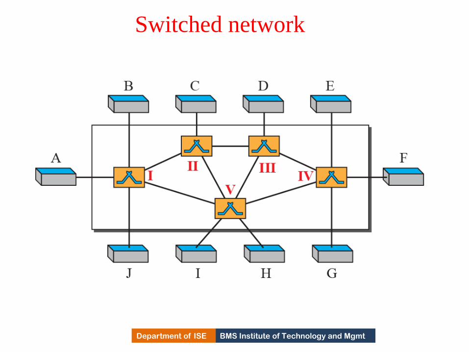
BMS Institute of Technology and Mgmt Department of ISE
Switched network
273

BMS Institute of Technology and Mgmt Department of ISE
Three Methods of Switching
•Traditionally, three methods of switching have been
discussed:
i)Circuit switching,
ii)Packet switching, and
iii)Message switching.
• The first two are commonly used today. The third
has been phased out in general communications but
still has applications.
Packet switching can further be divided into two
subcategories virtual-circuit approach and datagram
approach. 274

BMS Institute of Technology and Mgmt Department of ISE
Switching and TCP/IP Layers
•Switching can happen at several layers of the TCP/IP
protocol suite:
At the physical layer
At the data-link layer
At the network layer
275

BMS Institute of Technology and Mgmt Department of ISE
Taxonomy of switched networks
276

BMS Institute of Technology and Mgmt Department of ISE
CIRCUIT-SWITCHED NETWORKS
•A circuit-switched network consists of a set of switches connected by physical links.
•Connection between two stations has a dedicated path made of one or more links.
•However, each connection uses only one dedicated channel on each link.
•Each link is normally divided into n channels by using FDM or TDM
277

BMS Institute of Technology and Mgmt Department of ISE
A trivial circuit-switched network
278

BMS Institute of Technology and Mgmt Department of ISE
Circuit switched network
When end system A need to communicate with end
system M, Connection request must be accepted by all
switches and M itself.(Setup phase)
A circuit is reserved on each link.
A combination of circuits or channels defines
dedicated paths.
Next Phase is data transfer .
Finally tearing down the connection.
279

BMS Institute of Technology and Mgmt Department of ISE
Circuit switched network
Ckt. switching takes place at Physical Layer.
Before starting communication, the stations must
make a reservation for the resources to be used
during communication.
These resources :BW in FDM, time slots in TDM,
switch buffers, processing time, switch i/o ports,
must remain dedicate for the entire duration of data
transfer until tear down phase.
No addressing involved in data transfer.
280

BMS Institute of Technology and Mgmt Department of ISE
Three phases
1) Connection Setup phase
2)Data transfer phase
3)Tear down phase
281

BMS Institute of Technology and Mgmt Department of ISE Department of ISE BMS Institute of Technology and Mgmt
Three phases
• Before two parties can communicate, a dedicated
channel needs to be established.
• Connection set up means creating dedicated channel.
• Eg: System A would like to communicate to M.
• The setup request must pass through all the switches
between A and M.
• Switches have to find a dedicated channel.
• Destination should send back the Ack. to source in
opposite direction to system A.
282

BMS Institute of Technology and Mgmt Department of ISE Department of ISE BMS Institute of Technology and Mgmt
Three phases • Only after System A receives the ACK. ,
connection is established.
• End-to-end addressing is required to set up a
connection.
• Data transfer phase: After dedicated channel is
established, two parties can transfer the data.
• Tear down phase: When no data to transfer, a
signal is sent to all switches in between src.
and dest. To release the resources.
283

BMS Institute of Technology and Mgmt Department of ISE Department of ISE BMS Institute of Technology and Mgmt
Efficiency
As resources are allocated before data transfer
for the entire duration of connection,
• There is an argument that the CSN is not
efficient.
• Because the resources are unavailable for
other connections.
In telephone N/W, the moment conversation
is over, connection is released, Whereas in
Computer N/Ws, a computer can be connected
to other even if no activity for a long time. 284

BMS Institute of Technology and Mgmt Department of ISE Department of ISE BMS Institute of Technology and Mgmt
Delay
• Though CSN has low efficiency, delay is minimal.
• During data transfer, data are not delayed at switches.
• The total delay will be due to time needed to setup
connection, data transfer and tear down of
connection.
• Delay caused by set up is sum of four parts
Propagation time + Request signal transfer time+
Propagation time of Ack. From the destination +Signal
transfer time of ACK.
285

BMS Institute of Technology and Mgmt Department of ISE Department of ISE BMS Institute of Technology and Mgmt
Delay
• The delay due to data transfer is sum of two parts
Propagation time+ Data transfer time.
• Finally time required to tear down the connection.
286
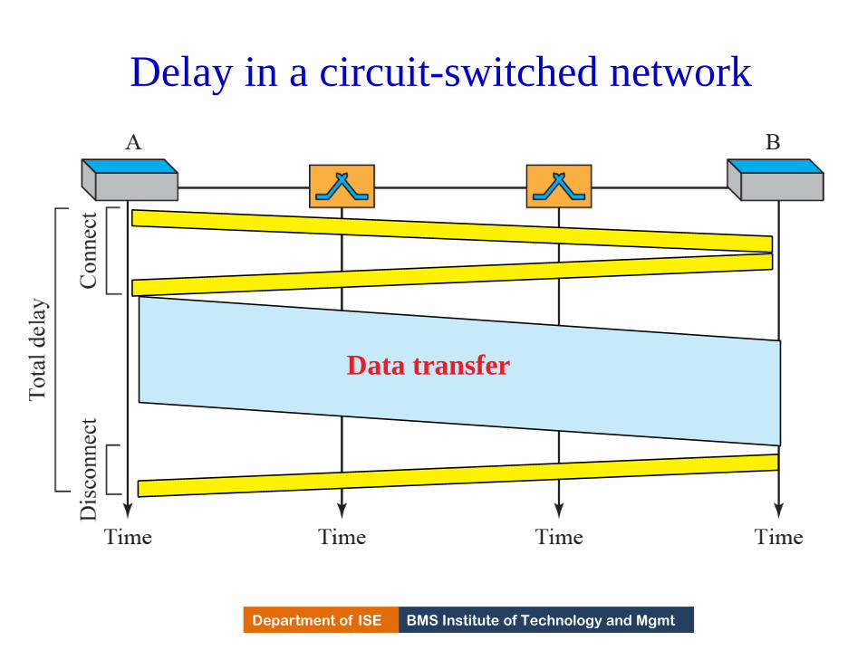
BMS Institute of Technology and Mgmt Department of ISE
Delay in a circuit-switched network
Data transfer
287
BMS Institute of Technology and Mgmt Department of ISE
PACKET SWITCHING
•In data communications, we need to send messages from one end system to another.
• If the message is going to pass through a packet-switched network, it needs to be
divided into packets of fixed or variable size.
•The size of the packet is determined by the network and the governing protocol.
288

BMS Institute of Technology and Mgmt Department of ISE
Datagram Networks
• In a datagram network, each packet is treated
independently of all others.
• Even if a packet is part of a multi packet
transmission, the network treats it as though it existed
alone.
Packets in this approach are referred to as data grams.
•Data gram switching is done at the N/W Layer.
•Data gram N/w’s are sometimes referred to as
connectionless N/W’s 289
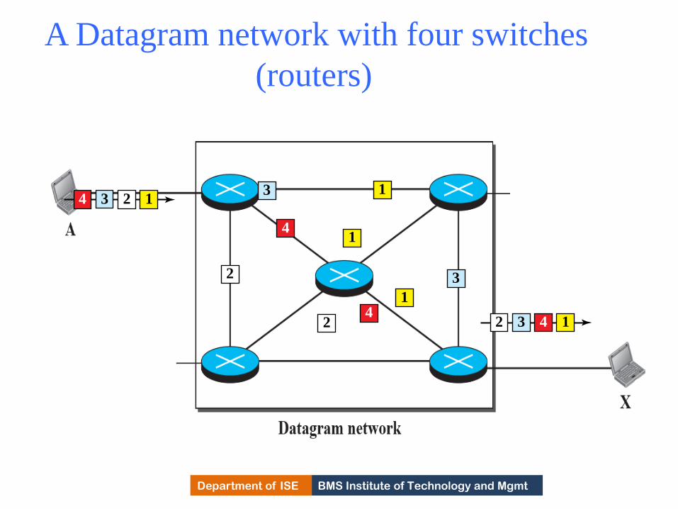
BMS Institute of Technology and Mgmt Department of ISE
A Datagram network with four switches
(routers)
4 3 2 11
4
3
2
1
1
2
3
4432 1
290

BMS Institute of Technology and Mgmt Department of ISE Department of ISE BMS Institute of Technology and Mgmt
Routing table
• Connection less means the switch does not keep information about the connection state.
• There is no setup or teardown phase Each switch has a routing table which is based on destination address.
• Routing tables are dynamic and updated periodically.
• The destination addresses and the corresponding forwarding o/p ports are recorded in the routing table.
• Every packet in the datagram N/W, carries the destination address along with the other header information.
291

BMS Institute of Technology and Mgmt Department of ISE Department of ISE BMS Institute of Technology and Mgmt
Routing table
• When switch receives a packet,
i)It examines the destination address and
ii) RT to find the corresponding port through
which packet should be forwarded.
• Efficiency of datagram N/W:
i) Resources are allocated when the packet is to
be transferred.
292

BMS Institute of Technology and Mgmt Department of ISE
Routing table in a datagram network
293
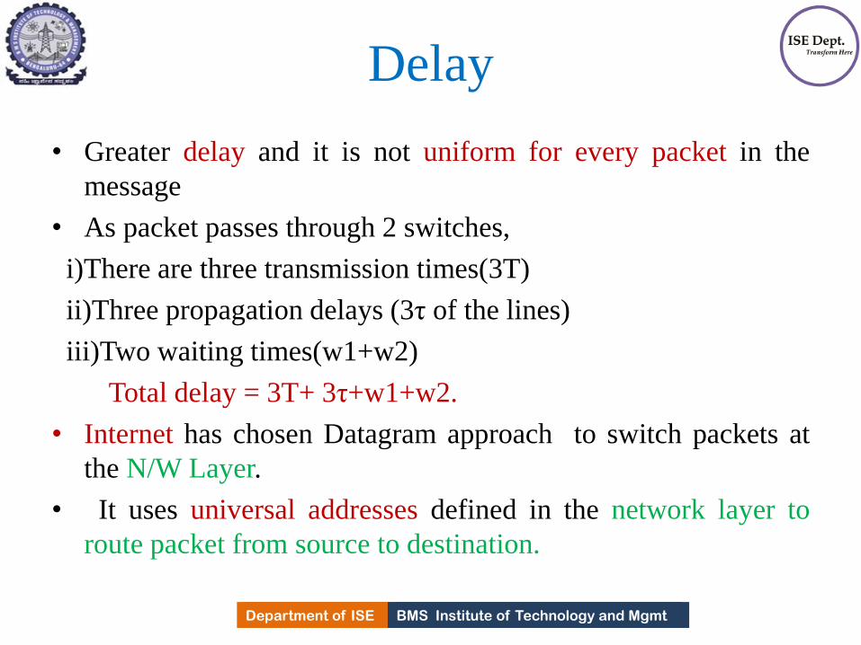
BMS Institute of Technology and Mgmt Department of ISE Department of ISE BMS Institute of Technology and Mgmt
Delay
• Greater delay and it is not uniform for every packet in the
message
• As packet passes through 2 switches,
i)There are three transmission times(3T)
ii)Three propagation delays (3τ of the lines)
iii)Two waiting times(w1+w2)
Total delay = 3T+ 3τ+w1+w2.
• Internet has chosen Datagram approach to switch packets at
the N/W Layer.
• It uses universal addresses defined in the network layer to
route packet from source to destination.
294

BMS Institute of Technology and Mgmt Department of ISE
Delays in a datagram network
295

BMS Institute of Technology and Mgmt Department of ISE
Virtual-Circuit Networks
•A virtual-circuit network is a cross between a circuit-
switched network and a datagram network.
•It has some characteristics of both.
296

BMS Institute of Technology and Mgmt Department of ISE Department of ISE BMS Institute of Technology and Mgmt
Virtual –Circuit Networks (VCN)
• A virtual-circuit network is a cross between a circuit-switched network and a datagram network. It has some characteristics of both.
1)There is setup and tear down phase in addition to the data transfer phase.
2)Resources are allocated during setup phase.
3)Data are packetized and each packet carries an address in the header.
Address in the packet has local jurisdiction which defines which is the next switch and the channel to forward the packet.
297

BMS Institute of Technology and Mgmt Department of ISE Department of ISE BMS Institute of Technology and Mgmt
Virtual –Circuit Networks
4)All packets follow the same path established
during the connection setup phase
5) Implemented in Data Link Layer
298
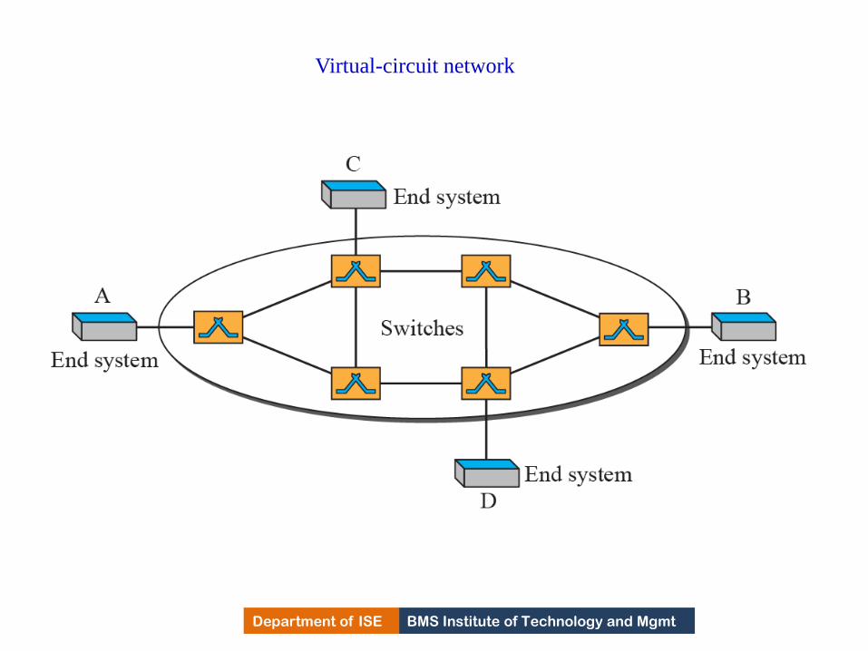
BMS Institute of Technology and Mgmt Department of ISE
Virtual-circuit network
299

BMS Institute of Technology and Mgmt Department of ISE Department of ISE BMS Institute of Technology and Mgmt
Addressing
• Two types of addresses are used:
Global and Local
• Source and destination need to have global addresses
i.e address which is unique through out the Internet.
• Global addresses in VCN are used only to create a
virtual circuit identifier(VCI).
• The identifier which is used for data transfer is called
VCI.
• VCI is a small number that has only switch scope.
• It is used by a frame b/w two switches and changes as
it moves from switch to switch.
300

BMS Institute of Technology and Mgmt Department of ISE
Virtual-circuit identifier
301
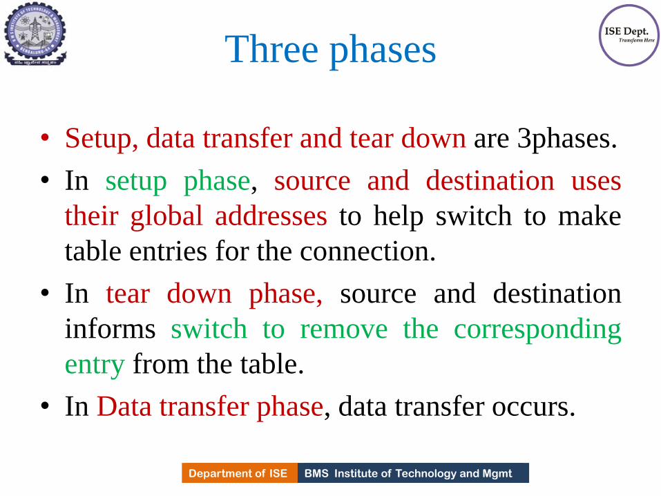
BMS Institute of Technology and Mgmt Department of ISE Department of ISE BMS Institute of Technology and Mgmt
Three phases
• Setup, data transfer and tear down are 3phases.
• In setup phase, source and destination uses
their global addresses to help switch to make
table entries for the connection.
• In tear down phase, source and destination
informs switch to remove the corresponding
entry from the table.
• In Data transfer phase, data transfer occurs.
302

BMS Institute of Technology and Mgmt Department of ISE
Switch and table for a virtual-circuit network
303
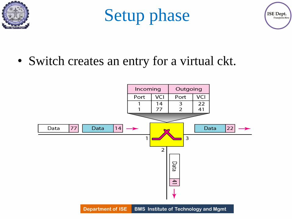
BMS Institute of Technology and Mgmt Department of ISE Department of ISE BMS Institute of Technology and Mgmt
Setup phase
• Switch creates an entry for a virtual ckt.
304

BMS Institute of Technology and Mgmt Department of ISE
Setup request in a virtual-circuit network
305

BMS Institute of Technology and Mgmt Department of ISE
Setup acknowledgment in a virtual-circuit network
306
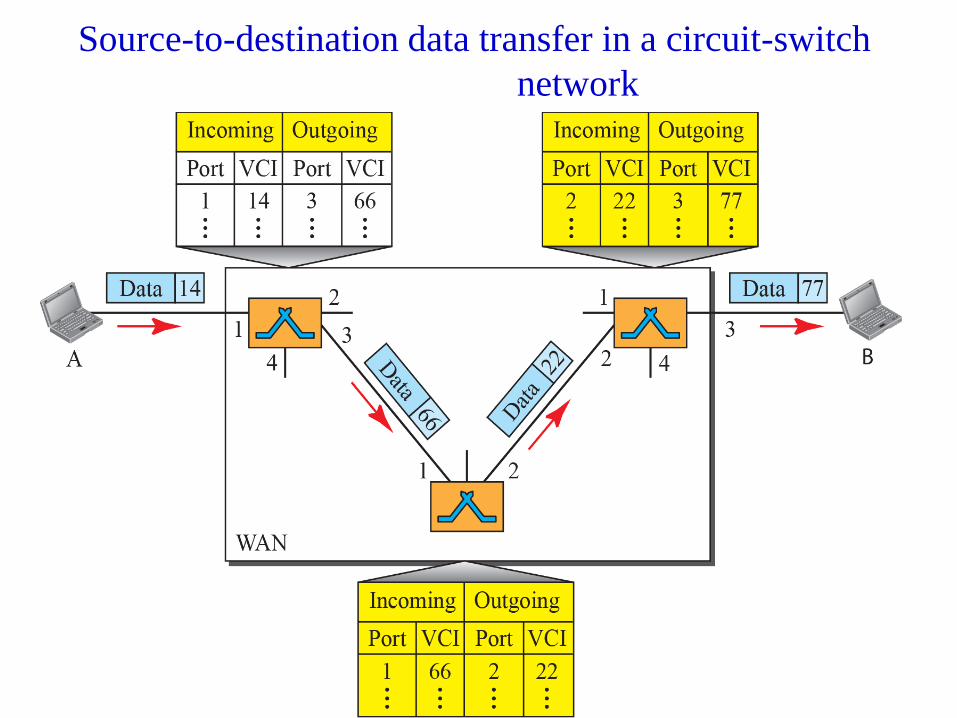
BMS Institute of Technology and Mgmt Department of ISE
Source-to-destination data transfer in a circuit-switch
network
307
BMS Institute of Technology and Mgmt Department of ISE Department of ISE BMS Institute of Technology and Mgmt
Efficiency
• As resources are reserved in VCN during
connection setup or can be on demand during
data transfer phase.
i) If connection set up, delay for each packet is
same.
ii) If during data transfer phase, each packet
may encounter different delays.
308

BMS Institute of Technology and Mgmt Department of ISE Department of ISE BMS Institute of Technology and Mgmt
Delay
• One time delay only for connection set up and one
time delay for tear down.
• If resources allocated during set up phase, no wait
time for individual packets.
Total delay = 3T+ 3τ+setup delay and tear
down delay.
• VCN’s are used in switched WAN’s such as
frame relay and ATM N/W.
309

BMS Institute of Technology and Mgmt Department of ISE
Delay in a virtual-circuit network
310
BMS Institute of Technology and Mgmt Department of ISE
ERROR DETECTION AND CORRECTION
•TCP/IP protocol does not define any protocol in DLL
or PL.
•These two layers are territories of networks that when
connected make up the Internet.
•These networks (wired/wireless), provide services to
upper three layers of TCP/IP suite.
•Networks must be able to transfer data from one
device to another with acceptable accuracy.
•For most of the applications, system must guarantee
that data received are identical to the one transmitted . 311

BMS Institute of Technology and Mgmt Department of ISE
INTRODUCTION
•In transmission, there are possibilities that any time
message gets corrupted.
•Many factors alter one or more bits of a message.
•Some applications require a mechanism for detecting
and correcting errors.
•Some applications can tolerate some errors.
Eg: A/V (random errors )
but transfer of text, expect high level of accuracy.
•Discuss some issues related, directly or indirectly, to
error detection and correction.
312
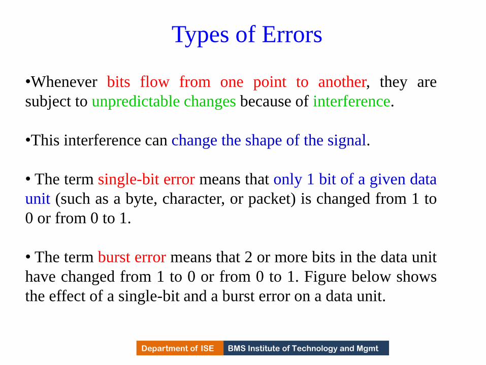
BMS Institute of Technology and Mgmt Department of ISE
Types of Errors
•Whenever bits flow from one point to another, they are
subject to unpredictable changes because of interference.
•This interference can change the shape of the signal.
• The term single-bit error means that only 1 bit of a given data
unit (such as a byte, character, or packet) is changed from 1 to
0 or from 0 to 1.
• The term burst error means that 2 or more bits in the data unit
have changed from 1 to 0 or from 0 to 1. Figure below shows
the effect of a single-bit and a burst error on a data unit.
313

BMS Institute of Technology and Mgmt Department of ISE
Single-bit and burst error
314

BMS Institute of Technology and Mgmt Department of ISE
Types of Errors
• Burst error is more likely to occur than single bit error.
• Reason is duration of noise signal is longer than the duration
of a bit.
• When noise affects data, it affects set of bits.
• Number of bits affected depends on the duration of the noise
and data rate.
Eg: If we send 1 kbps of data, a noise 1/100 s can affect 10 bits.
If 1 Mbps data rate, noise can affect 10,000 bits.
315

BMS Institute of Technology and Mgmt Department of ISE
Redundancy
•The central concept in detecting or correcting errors
is redundancy.
•To be able to detect or correct errors, need to send
some extra bits with our data.
•These redundant bits are added by the sender and
removed by the receiver.
•Presence of redundant bits allows the receiver to
detect or correct corrupted bits.
316

BMS Institute of Technology and Mgmt Department of ISE
Detection versus Correction
•The correction of errors is more difficult than the
detection.
• In error detection, check if any error has occurred.
The answer is a simple yes or no.Not interested in the
number of corrupted bits.
•A single-bit error is the same for us as a burst error.
•In error correction,
Need to know the exact number of bits that are
corrupted and, more importantly, their location in the
message. 317

BMS Institute of Technology and Mgmt Department of ISE
Coding
•Redundancy is achieved through various coding schemes.
•The sender adds redundant bits through a process that creates
a relationship between the redundant bits and the actual data
bits.
•The receiver checks the relationships between the two sets of
bits to detect errors.
•The ratio of redundant bits to data bits and the robustness of
the process are important factors in any coding scheme.
318

BMS Institute of Technology and Mgmt Department of ISE Department of ISE BMS Institute of Technology and Mgmt
Coding
• Two coding schemes are
i) Block coding ii) Convolution coding
• Concentrate on block codes.
• In modulo-N arithmetic, the integers in the range 0 to
N −1inclusive is used,
319

BMS Institute of Technology and Mgmt Department of ISE
BLOCK CODING
•In block coding, message is divided into blocks, each of k bits, called data words.
•Add r redundant bits to each block to make the length n = k + r.
•The resulting n-bit blocks are called code words.
320

BMS Institute of Technology and Mgmt Department of ISE
BLOCK CODING
•In block coding, we have set of data words, each of size k, code words, each of
size n.
•Since n>k, the possible number of code words are larger than the data words.
•Block coding process is one-to-one, same data word is encoded as code word.
•2n - 2K code words are not used.
•If receiver receives invalid codeword, it indicates data is corrupted during
transmission.
321

BMS Institute of Technology and Mgmt Department of ISE
Error Detection
•How can errors be detected by using block coding?
•If the following two conditions are met, the receiver
can detect a change in the original codeword.
a. The receiver has (or can find) a list of valid
code words.
b. The original codeword has changed to an invalid
one.
322

BMS Institute of Technology and Mgmt Department of ISE
Process of error detection in block coding
323

BMS Institute of Technology and Mgmt Department of ISE
Let us assume that k = 2 and n = 3. Table below shows the
list of data words and code words.
Example 10.1
A code for error detection
324

BMS Institute of Technology and Mgmt Department of ISE Department of ISE BMS Institute of Technology and Mgmt
Hamming distance
• The Hamming distance between two words(of same
size) is the number of differences between
corresponding bits. (total number of 1’s).
• Why HD in Error detection????
• HD between the sent code word & received codeword
is the number of bits that got corrupted during
transmission.
Eg: Let us find the Hamming distance between two
pairs of words.
325

BMS Institute of Technology and Mgmt Department of ISE Department of ISE BMS Institute of Technology and Mgmt
Hamming Distance
• The Hamming distance d(000, 011) is 2.
• The Hamming distance d(10101, 11110) is 3
because
• If the HD between sent & received code word is not
zero, then code word has been corrupted during
transmission.
• The minimum Hamming distance is the smallest
Hamming distance between all possible pairs in a set
of words.
326
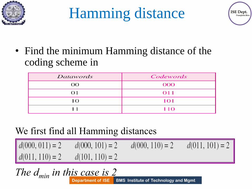
BMS Institute of Technology and Mgmt Department of ISE Department of ISE BMS Institute of Technology and Mgmt
Hamming distance
• Find the minimum Hamming distance of the coding scheme in
We first find all Hamming distances
The dmin in this case is 2
327
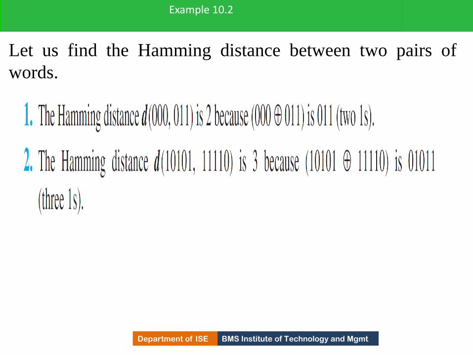
BMS Institute of Technology and Mgmt Department of ISE
Let us find the Hamming distance between two pairs of
words.
Example 10.2
328
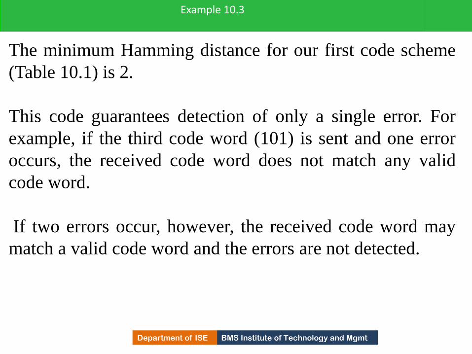
BMS Institute of Technology and Mgmt Department of ISE
The minimum Hamming distance for our first code scheme
(Table 10.1) is 2.
This code guarantees detection of only a single error. For
example, if the third code word (101) is sent and one error
occurs, the received code word does not match any valid
code word.
If two errors occur, however, the received code word may
match a valid code word and the errors are not detected.
Example 10.3
329
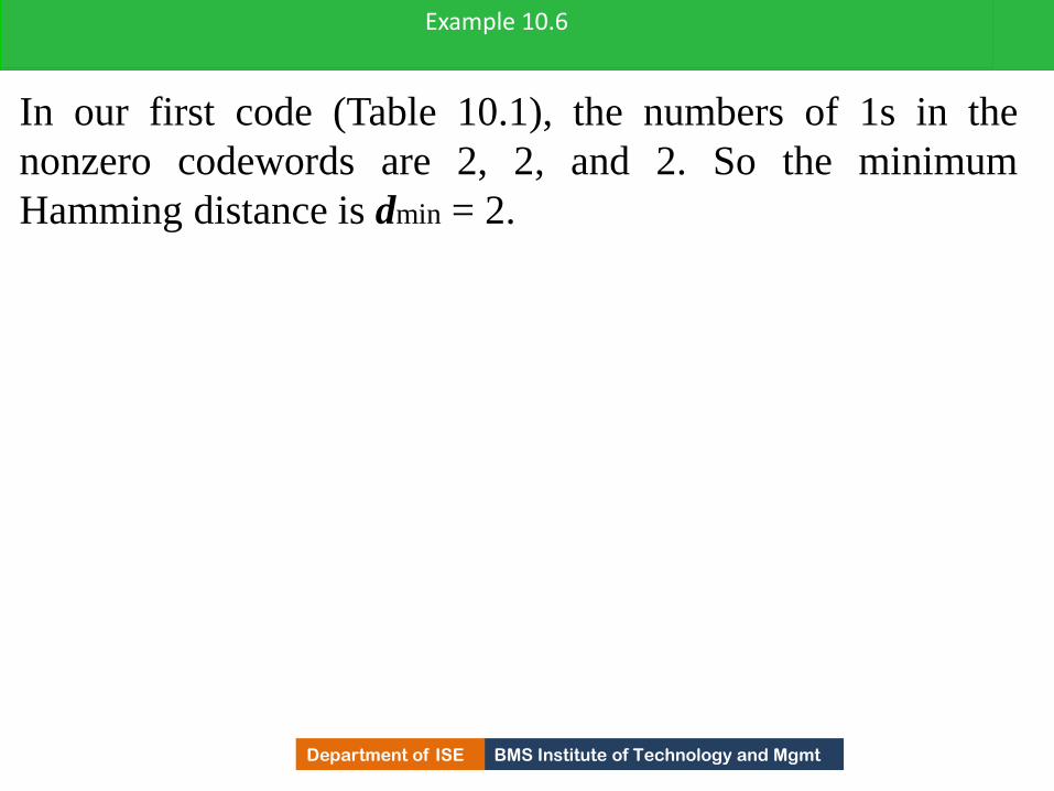
BMS Institute of Technology and Mgmt Department of ISE
In our first code (Table 10.1), the numbers of 1s in the
nonzero codewords are 2, 2, and 2. So the minimum
Hamming distance is dmin = 2.
Example 10.6
330

BMS Institute of Technology and Mgmt Department of ISE Department of ISE BMS Institute of Technology and Mgmt
LINEAR BLOCK CODES
• Almost all block codes used today belong to a
subset called linear block codes.
• A linear block code is a code in which the
exclusive OR (addition modulo-2) of two valid
code words creates another valid codeword.
331

BMS Institute of Technology and Mgmt Department of ISE
Table : Simple parity-check code C(5, 4)
332

BMS Institute of Technology and Mgmt Department of ISE Department of ISE BMS Institute of Technology and Mgmt
Example • Let us see if the two codes defined in Tables above,
belong to the class of linear block codes.
1. The scheme in the above Table is a linear block code because the result of XORing any codeword with
any other codeword is a valid codeword.
So the minimum Hamming distance is dmin = 2.
2. The scheme in Table second is also a linear block code. We can create all four codewords by XORing two other codewords.
• So the minimum hamming distance is dmin = 3.
333

BMS Institute of Technology and Mgmt Department of ISE Department of ISE BMS Institute of Technology and Mgmt
Simple Parity check code • A simple parity-check code is a single-bit error-
detecting code in which n = k + 1 with dmin = 2.
• The extra bit, called parity bit , is selected to make
number of 1’s in the code word even.
• The code is single-bit error detecting code.
• It can not correct any error.
• In the fig. encoder takes a copy of 4 bit data
word(a0,a1,a2,a3 ) and generates a parity bit r0.
• Parity bit creates the 5-bit code word.
334

BMS Institute of Technology and Mgmt Department of ISE
Encoder and decoder for simple parity-check code
335

BMS Institute of Technology and Mgmt Department of ISE Department of ISE BMS Institute of Technology and Mgmt
Simple Parity check code
• The parity bit that is added makes the number of 1’s
in the codeword even. i.e
r0 = a0 +a1 +a2 +a3 (modulo-2)
• If number of 1s is even, the result is 0.
• If number of 1s is odd, the result is 1.
The sender sends the code word which is corrupted
during transmission.
The receiver receives 5 bit code word.
The checker performs modulo-2 of all the bits
received. The result is called syndrome.
s0 = b0 +b1 +b2 +b3 + q0 (modulo-2)
336

BMS Institute of Technology and Mgmt Department of ISE Department of ISE BMS Institute of Technology and Mgmt
Continued..
• If number of 1s in the codeword is even, the syndrome is 0.
• If number of 1s in the codeword is odd, the syndrome is 1.
• The syndrome is passed to decision logic analyzer. If Syndrome is 0, no error in the code word received, data portion is extracted.
• If syndrome is 1, error in the received codeword and discarded.
337

BMS Institute of Technology and Mgmt Department of ISE
Let us look at some transmission scenarios. Assume the
sender sends the data word 1011. The codeword created
from this data word is 10111, which is sent to the receiver.
Five cases can be examined:
Example 10.7
338

BMS Institute of Technology and Mgmt Department of ISE
CYCLIC CODES
•Cyclic codes are special linear block codes with one extra property.
•In a cyclic code, if a codeword is cyclically shifted (rotated), the result is another
codeword.
Eg:1011000 is a codeword and if it is cyclically left-shifted, then 0110001 is also a
codeword.
We can shift the bits using
b1=a0,b2=a1, b3=a2, b4=a3, b5=a4, b6=a5, b0=a6
339

BMS Institute of Technology and Mgmt Department of ISE
Cyclic Redundancy Check
• Cyclic codes are created to correct errors.
•Discuss a subset of cyclic codes called the cyclic
redundancy check (CRC), which is used in networks
such as LANs and WANs.
340
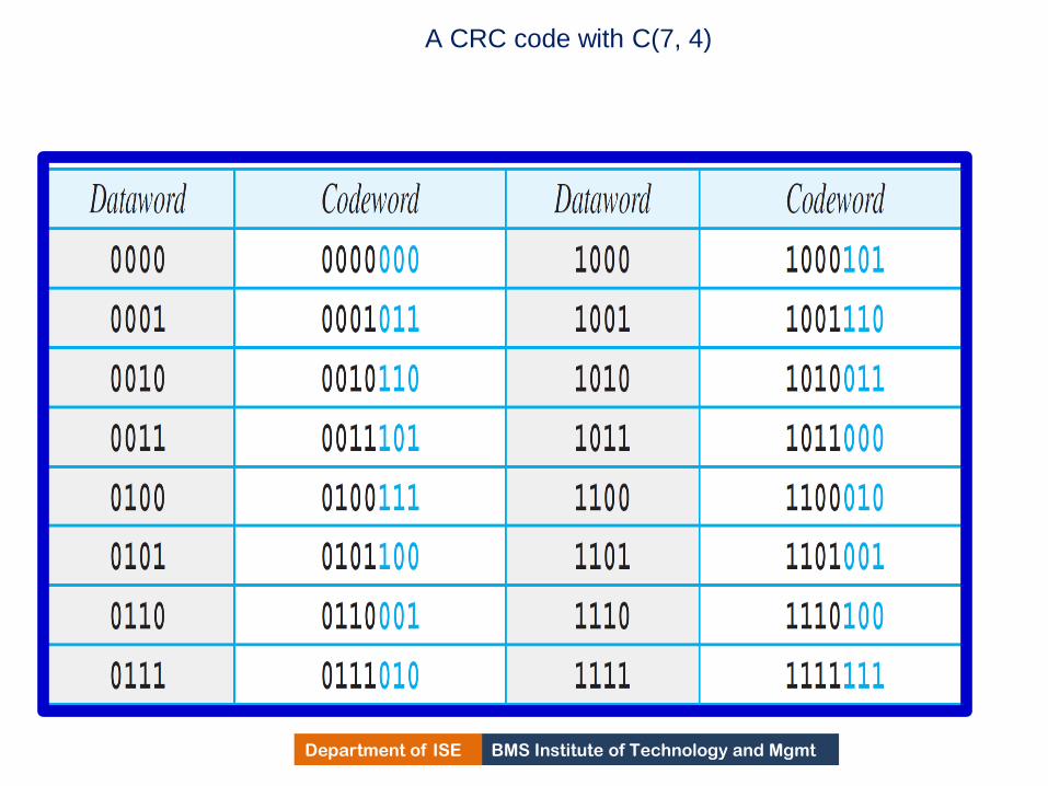
BMS Institute of Technology and Mgmt Department of ISE
A CRC code with C(7, 4)
341

BMS Institute of Technology and Mgmt Department of ISE
CRC encoder and decoder
342

BMS Institute of Technology and Mgmt Department of ISE Department of ISE BMS Institute of Technology and Mgmt
CRC
• In the encoder, the data word has k bits(4 bits),
code word has n bits(7 here).
• The data word is augmented by adding n-k 0s to
the right hand side of the word.
• The n-bit result is fed to the generator.
• The generator uses a divisor of size
n-k+1which is predefined and agreed upon.
• The generator divides the augmented dataword
343

BMS Institute of Technology and Mgmt Department of ISE Department of ISE BMS Institute of Technology and Mgmt
CRC
by divisor (modulo-2 division).
• The quotient of the division is discarded.
• The remainder r2r1 r0 is appended to the data word to create the codeword.
• The decoder receives the corrupted codeword.
• A copy of all n bits are fed to the checker.
• The remainder produced by checker is a syndrome of n-k bits, which is fed to the decision logic analyzer.
• If syndrome bits are 0, the 4 left most bits of the code word are accepted as a data word.
344

BMS Institute of Technology and Mgmt Department of ISE
Division in CRC encoder
345

BMS Institute of Technology and Mgmt Department of ISE Department of ISE BMS Institute of Technology and Mgmt
CRC-Encoder
• Encoder takes data word and augments it with
n-k number of 0s.
• It then divides the augmented data word by a
divisor.
• Modulo-2 binary division is used. For Addition and
subtraction, XOR operations is used.
• In each step, copy of the divisor is XOR ed
with 4 bits of dividend. The result of XOR
operation is 3 bits.
346

BMS Institute of Technology and Mgmt Department of ISE Department of ISE BMS Institute of Technology and Mgmt
CRC-Decoder
• Code word can change during transmission.
• The decoder same thing as encoder and
remainder of the division id the syndrome.
• If syndrome is all 0s, no error, data word is
separated from the code word and accepted.
• Otherwise , everything is discarded.
• Question is how divisor 1011 is chosen??
347

BMS Institute of Technology and Mgmt Department of ISE
Division in the CRC decoder for two cases
348
BMS Institute of Technology and Mgmt Department of ISE Department of ISE BMS Institute of Technology and Mgmt
Polynomials
• A better way to understand cyclic codes, and
how they can be analyzed is to represent them
as polynomials.
• A pattern of 0s and 1s can be represented as
polynomial with coefficient of 0 and 1.
• The power of each term shows the position of
the bit.
• The coefficient shows the value of the bit.
349

BMS Institute of Technology and Mgmt Department of ISE
A polynomial to represent a binary word
350

BMS Institute of Technology and Mgmt Department of ISE Department of ISE BMS Institute of Technology and Mgmt
Degree of Polynomials
• Is the highest power of the polynomial.
Eg: Degree of x6 + x+1 is 6.
• Degree of polynomial is one less than that the
number of bits in the pattern.
• Addition and subtraction of polynomials is
done by adding and subtracting the coefficient
terms with the same power.
• Coefficients are only 0 and 1, and adding is in
modulo-2
351

BMS Institute of Technology and Mgmt Department of ISE Department of ISE BMS Institute of Technology and Mgmt
Adding and subtracting of
polynomials
• Addition and subtraction is done by combining
terms and deleting pair of identical terms.
• Eg: x5 + x4+x2
x6 +x4+x2
-------------------------------
x6 + x5
352

BMS Institute of Technology and Mgmt Department of ISE Department of ISE BMS Institute of Technology and Mgmt
Multiplication and Division of
polynomials
• Multiplication is adding powers.
Eg: x4 * x2 = x6
• Division, subtract the power of second term
from the first term.
Eg: x5 / x2 = x3
• Multiplication of two polynomials (x5 + x3 + x2 ) (x2 + x + 1)= x7 + x6 + x5 + x5 + x4 + x3 + x4+ x3
+ x2
x7 + x6 + x2
353

BMS Institute of Technology and Mgmt Department of ISE Department of ISE BMS Institute of Technology and Mgmt
Shifting of polynomials
• A binary pattern is shifted left or right by
number of bits.
• Shifting to the left means adding extra 0s as
right most bits.
• Shifting to the right means deleting some right
most bits.
• Shifting to the left is accomplished by
multiplying each term of the polynomial by xm
where m is the number of shifted bits 354

BMS Institute of Technology and Mgmt Department of ISE Department of ISE BMS Institute of Technology and Mgmt
Continued..
• Shifting to the right is accomplished by
dividing each term of the polynomial by xm
where m is the number of shifted bits.
• Shift left by 3 bits :10011 becomes 10011000
x4+x +1 becomes x7 + x4+x3
• Shift right by 3 bits: 10011 becomes 10
x4+x +1 becomes x
355

BMS Institute of Technology and Mgmt Department of ISE
CRC division using polynomials
356

BMS Institute of Technology and Mgmt Department of ISE Department of ISE BMS Institute of Technology and Mgmt
Cyclic code analysis using
polynomials
• In a polynomial representation, divisor is
normally referred to as generator polynomial
t(x).
• f(x) is the polynomial with binary coefficients
data word d(x), code word c(x), Generator g(x)
syndrome s(x) and error e(x).
Is s(x) is not zero, one or more bits are
corrupted. If s(x) is zero, either no error or
decoder failed to detect any error. 357

BMS Institute of Technology and Mgmt Department of ISE
Cyclic Code Analysis
•Analyze a cyclic code to find its capabilities by using
polynomials.
• Define the following, where f(x) is a polynomial
with binary coefficients.
358
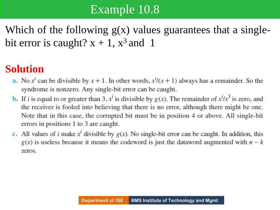
BMS Institute of Technology and Mgmt Department of ISE
Which of the following g(x) values guarantees that a single-
bit error is caught? x + 1, x3 and 1
Solution
Example 10.8
359
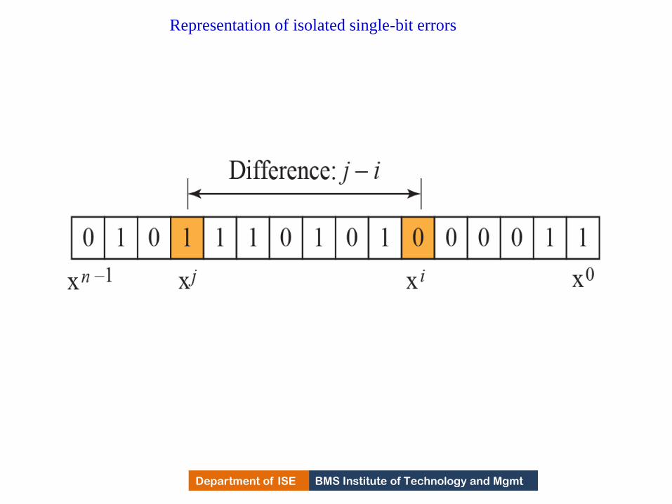
BMS Institute of Technology and Mgmt Department of ISE
Representation of isolated single-bit errors
360

BMS Institute of Technology and Mgmt Department of ISE
Find the suitability of the following generators in relation to
burst errors of different lengths: x6 + 1, x18 + x7 + x + 1, and
x32 + x23 + x7 + 10.
Solution
Example 10.9
361

BMS Institute of Technology and Mgmt Department of ISE
Find the status of the following generators related to two
isolated, single-bit errors: x + 1, x4 + 1, x7 + x6 + 1, and
x15 + x14 + 1
Solution
Example 10.10
362

BMS Institute of Technology and Mgmt Department of ISE Department of ISE BMS Institute of Technology and Mgmt
Summary
• A good polynomial generator needs to have the
following characteristics:
1. It should have at least two terms.
2. The coefficient of the term x0 should
be 1.
3. It should not divide xt + 1, for t
between 2 and n − 1.
4. It should have the factor x + 1.
363
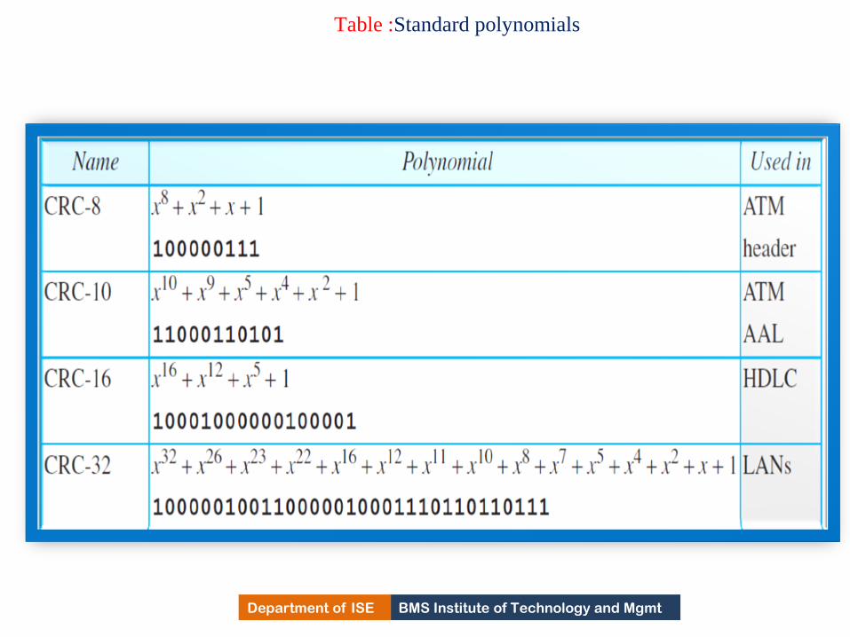
BMS Institute of Technology and Mgmt Department of ISE
Table :Standard polynomials
364
BMS Institute of Technology and Mgmt Department of ISE
Advantages of Cyclic Codes
• Cyclic codes have a very good performance in
detecting single-bit errors, double errors, an odd
number of errors, and burst errors.
•They can easily be implemented in hardware and
software.
•They are especially fast when implemented in
hardware which has made cyclic codes a good
candidate for many networks.
365

BMS Institute of Technology and Mgmt Department of ISE
Other Cyclic Codes
•The cyclic codes we have discussed are very simple.
• The check bits and syndromes can be calculated by
simple algebra.
•There are, however, more powerful polynomials that
are based on abstract algebra involving Galois fields.
•One of the most interesting of these codes is the
Reed-Solomon code used today for both detection and
correction.
366
BMS Institute of Technology and Mgmt Department of ISE
CHECKSUM
•Checksum is an error-detecting technique that can be applied to a message of any
length.
• In the Internet, the checksum technique is mostly used at the network and transport
layer rather than the data-link layer.
•At source,
Message is divided into m-bit units.
Generator then creates an extra m-bit unit called checksum, which is sent with
message.
367

BMS Institute of Technology and Mgmt Department of ISE
CHECKSUM
•At Destination,
Checker creates a new checksum from combination of the message and the sent
checksum.
If new checksum is all 0’s, the message is accepted else discarded.
368

BMS Institute of Technology and Mgmt Department of ISE
Checksum
369
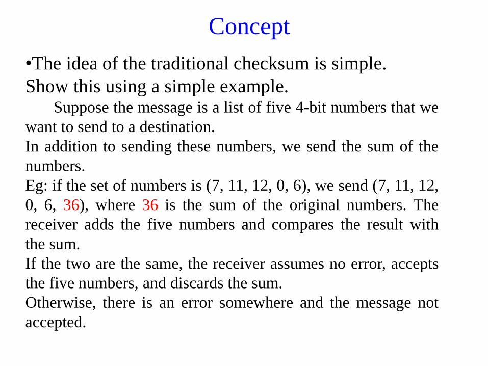
BMS Institute of Technology and Mgmt Department of ISE
Concept
•The idea of the traditional checksum is simple.
Show this using a simple example. Suppose the message is a list of five 4-bit numbers that we
want to send to a destination.
In addition to sending these numbers, we send the sum of the
numbers.
Eg: if the set of numbers is (7, 11, 12, 0, 6), we send (7, 11, 12,
0, 6, 36), where 36 is the sum of the original numbers. The
receiver adds the five numbers and compares the result with
the sum.
If the two are the same, the receiver assumes no error, accepts
the five numbers, and discards the sum.
Otherwise, there is an error somewhere and the message not
accepted.
370

BMS Institute of Technology and Mgmt Department of ISE
Ones compliment Addition
•Each number can be written as a 4 bit word except
sum.
•This drawback we can over come using ones
compliment arithmetic.
•Represent unsigned numbers between 0 and 2m -1
Using only m bits.
•If the number has more than m bits, the extra
leftmost bits need to be added to the m rightmost bits.
371
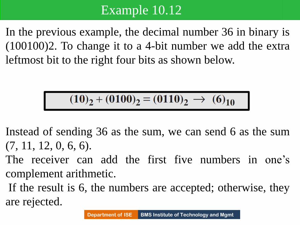
BMS Institute of Technology and Mgmt Department of ISE
In the previous example, the decimal number 36 in binary is
(100100)2. To change it to a 4-bit number we add the extra
leftmost bit to the right four bits as shown below.
Example 10.12
Instead of sending 36 as the sum, we can send 6 as the sum
(7, 11, 12, 0, 6, 6).
The receiver can add the first five numbers in one’s
complement arithmetic.
If the result is 6, the numbers are accepted; otherwise, they
are rejected. 372

BMS Institute of Technology and Mgmt Department of ISE
Let us use the idea of the checksum in Example 10.12. The
sender adds all five numbers in one’s complement to get the
sum = 6.
The sender then complements the result to get the checksum
= 9, which is 15 − 6.
Note that 6 = (0110)2 and 9 = (1001)2;they are
complements of each other.
The sender sends the five data numbers and the checksum
(7, 11, 12, 0, 6, 9).
If there is no corruption in transmission, the receiver
receives (7, 11, 12, 0, 6, 9) and adds them in one’s
complement to get 15.
Example 10.13
373

BMS Institute of Technology and Mgmt Department of ISE
Example 10.13
374

BMS Institute of Technology and Mgmt Department of ISE
Table : Procedure to calculate the traditional checksum
375

BMS Institute of Technology and Mgmt Department of ISE
Algorithm to calculate a traditional checksum
376
BMS Institute of Technology and Mgmt Department of ISE
Other Approaches
• One major problem with the traditional checksum
calculation.
• If two 16-bit items are transposed in transmission,
the checksum cannot catch this error.
•The reason is that the traditional checksum is not
weighted: it treats each data item equally.
•In other words, the order of data items is immaterial
to the calculation.
•Several approaches have been used to prevent this
problem.
•Two of them are: Fletcher and Adler.
377

BMS Institute of Technology and Mgmt Department of ISE Department of ISE BMS Institute of Technology and Mgmt
Fletcher Checksum • Was devised to weight each data item according to its position.
• Two algorithms i) 8-bit ii) 16-bit.
• In 8 bit Fletcher, calculation is done on 8-bit data and creates
16 bit checksum.
• Calculation is done using modulo256(28 )i.e intermediate
results are divided by 256 and remainder is kept.
• Algorithm uses two accumulators L & R
• First simply adds data items together,
• Second adds weights to the calculation.
• In 16 bit Fletecher, calculation is done on 16-bit data and
creates 32 bit checksum.
378

BMS Institute of Technology and Mgmt Department of ISE
Algorithm to calculate an 8-bit Fletcher checksum
379

BMS Institute of Technology and Mgmt Department of ISE Department of ISE BMS Institute of Technology and Mgmt
Adler Checksum • Is a 32 bit checksum.
• Similar to Fletcher.
• 3 Major differences
i) Calculation is done on single byte instead of 2 bytes at a time
ii) Modulus is a prime number(65,521)instead of 65,536.
iii) L is initialized to 1 instead of 0
380
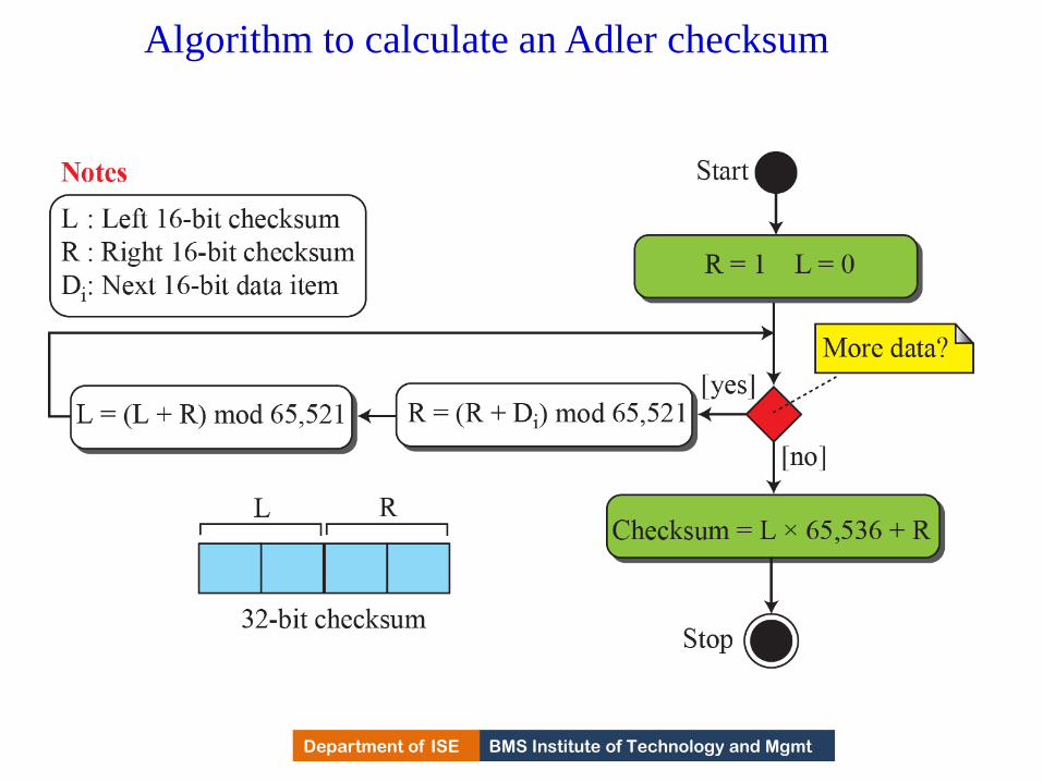
BMS Institute of Technology and Mgmt Department of ISE
Algorithm to calculate an Adler checksum
381

BMS Institute of Technology and Mgmt Department of ISE
MODULE – 4
Data Link Control
382

BMS Institute of Technology and Mgmt Department of ISE
DLC SERVICES
The data link control (DLC) deals with procedures for communication between two adjacent
nodes no matter whether the link is dedicated or broadcast.
Data link control functions include framing and flow and error control.
Discuss framing, or how to organize the bits that are carried by the physical layer.
Discuss flow and error control.
383

BMS Institute of Technology and Mgmt Department of ISE
Framing
The data-link layer needs to pack bits into frames,
so that each frame is distinguishable from another.
Our postal system practices a type of framing.
The simple act of inserting a letter into an envelope
separates one piece of information from another; the
envelope serves as the delimiter.
Framing in the data-link layer separates a message
from one source to a destination by adding a sender
address and a destination address.
The destination address defines where the packet is
to go; the sender address helps the recipient
acknowledge the receipt.
384

BMS Institute of Technology and Mgmt Department of ISE
Framing
Whole message can be placed in a single frame, but
that is not done because frame can be very large
making Flow Control and Error Control very
inefficient.
When message is carried in one large frame, even
single bit error would require the retransmission of
the whole frame.
When message is divided into small frames, single
bit error affect only that small frame.
385

BMS Institute of Technology and Mgmt Department of ISE
FrameSize
Frame can be i) fixed size
ii) Variable size.
In fixed size framing, no need to define the frame
boundaries. Size itself can be treated as a delimiter.
Eg: ATM frames of fixed size called cells.
In variable size framing, we need to define the frame
boundaries to identify beginning and end of the frame.
Two approaches are used for this purpose
i) Character-oriented Framing
ii) Bit-oriented Framing.
386

BMS Institute of Technology and Mgmt Department of ISE Department of ISE BMS Institute of Technology and Mgmt
Character-oriented Framing
• Data to be carried are 8-bit characters from coding
system such as ASCII.
• Header carries source, destination address along with
some control information.
• Trailer carries error detection or correction redundant
bits, are multiples of 8 bits.
• To separate one frame from other, a 1byte flag is
added to the beginning and end of frame.
• The flag, composed of protocol dependent special
characters which signals start or end of the frame.
387

BMS Institute of Technology and Mgmt Department of ISE
A frame in a character-oriented protocol
388

BMS Institute of Technology and Mgmt Department of ISE Department of ISE BMS Institute of Technology and Mgmt
Character-oriented Framing • Was popular only when text was exchanged by the DLL.
• Flag used, could be selected as any character which is not
used for text communication. As we send now other types of
information such graphs, audio and video, the pattern used for
flag could be the part of information.
• If receiver encounters this pattern in the middle of the data,
thinks it has reached the end of frame.
• Solution is byte-stuffing strategy was added in this approach.
389

BMS Institute of Technology and Mgmt Department of ISE
Byte stuffing and unstuffing
390

BMS Institute of Technology and Mgmt Department of ISE Department of ISE BMS Institute of Technology and Mgmt
Character-oriented Framing
• In byte stuffing, a special byte is added to the data
section of the frame when there is a character with the
same pattern as that of the flag.
• i.e Data section is stuffed with a special extra byte
called escape character. This approach presents
another problem in data communication.
• The universal coding systems, unicode, in use today,
have 16 or 32 bit characters that conflict with 8-bit
characters.
• Therefore, next approach is used
391

BMS Institute of Technology and Mgmt Department of ISE Department of ISE BMS Institute of Technology and Mgmt
Bit-oriented Framing • Data section of a frame is a sequence of bits to be interpreted
by the upper layer as text, graphs, video and so on.
• Delimiter used to separate one frame from another and used in
the beginning and end of frame is 8-bit pattern flag(01111110).
• Flag can create same problem. If flag pattern in present in the
frame, need to inform the receiver that , this is data portion of
the frame, not end of frame.
• This strategy is called bit stuffing.
• In bit stuffing, if a 0 and five consecutive 1 bits are
encountered, an extra 0 bit added .
• Which is removed from the data by the receiver.
392

BMS Institute of Technology and Mgmt Department of ISE
A frame in a bit-oriented protocol
393

BMS Institute of Technology and Mgmt Department of ISE
Bit stuffing and unstuffing
394
BMS Institute of Technology and Mgmt Department of ISE
Flow and Error Control
Data Communication requires at least two devices
working together, one to send and other to receive.
For communication and exchange of information, a
good coordination is must.
Most important responsibilities of DLL are Flow
Control and Error Control.
These functions together are called data link
control.
395
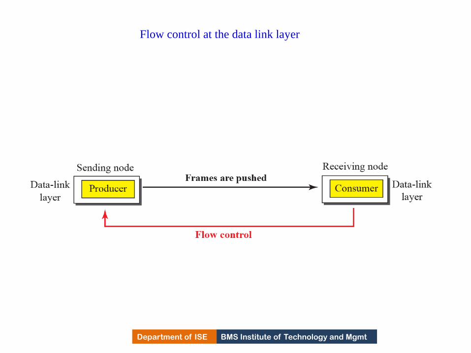
BMS Institute of Technology and Mgmt Department of ISE
Flow control at the data link layer
396
BMS Institute of Technology and Mgmt Department of ISE Department of ISE BMS Institute of Technology and Mgmt
Flow control • When an entity produces items and another entity
consumes them, there should be balance between
them.
• If items produced faster or slower compared the rate
at which it is consumed in faster/slower rate, the
systems becomes less efficient.
• Flow Control is to prevent the data items at the
consumer sites.
• In DC at DLL, we need 4 entities N/W & DLL at
sending and receiving nodes.
• DLL at sending pushes frames towards the DLL in
receiving nodes. 397

BMS Institute of Technology and Mgmt Department of ISE Department of ISE BMS Institute of Technology and Mgmt
Flow control • If the receiving node cannot deliver the frames in the same
rate to the N/W Layer, it becomes overwhelmed with the
frames.
• FC mechanism should send the feedback to the sending
device to stop or slow down the transmission of frames.
• At sending and receiving nodes, buffers are used at DLL.
• A buffer is a set of memory locations that can hold packets at
the sender and receiver.
• FC communication occur by sending signals from consumer to
producer.
• When buffer is full, it informs sender at DLL to stop pushing
frames.
398

BMS Institute of Technology and Mgmt Department of ISE
The above discussion requires that the consumers
communicate with the producers on two occasions: when
the buffer is full and when there are vacancies.
If the two parties use a buffer with only one slot, the
communication can be easier.
Assume that each data-link layer uses one single memory
slot to hold a frame.
When this single slot in the receiving data-link layer is
empty, it sends a note to the network layer to send the next
frame.
Example 111.1
399

BMS Institute of Technology and Mgmt Department of ISE Department of ISE BMS Institute of Technology and Mgmt
Error control (EC) • Since Underlying physical N/w is not fully reliable,
EC is required at the DLL to prevent receiving node
from delivering corrupted packets to its N/W Layer.
• EC at DLL is implemented using one of the following
methods
i) If frame is corrupted, it is silently discarded; if it is
not corrupted, packet is delivered N/W layer.
ii) If frame is corrupted, it is silently discarded; if it is
not corrupted, an acknowledgment is sent to the
sender.
400
BMS Institute of Technology and Mgmt Department of ISE Department of ISE BMS Institute of Technology and Mgmt
Combination of Error control & Flow control
i) Error Control & Flow Control can be combined.
ii) An Acknowledgment that is sent for flow control
can also be used for error control to send the sender
the packet has arrived uncorrupted.
iii) Lack of Acknowledgment means that there is a
problem in the sent frame.
401

BMS Institute of Technology and Mgmt Department of ISE
Connectionless and Connection-Oriented
A DLC protocol can be either connectionless or
connection-oriented.
Connectionless Protocol:
Frames are sent from one node to another without
any relationship between the frames, each frame is
independent.
Connectionless means there is no connection
between the frames.
Frames are not numbered and there is no sense of
ordering.
Eg: Most of DLL protocols for LANs are
connectionless protocols. 402

BMS Institute of Technology and Mgmt Department of ISE Department of ISE BMS Institute of Technology and Mgmt
Connection-oriented Protocol • A logical connection should be established between the two
nodes (Setup phase).
• All frames that are related to each other are transmitted
(Transfer phase)
• A Logical connection is terminated(teardown phase).
• Frames are numbered and sent in order.
• If they are not received in order, the receiver needs to wait
until all frames belonging to the same set are received and then
deliver them in order to Network Layer.
Rare in wired LANs, but we can see them in some PPP
protocols, wireless LANs & WANs.
403

BMS Institute of Technology and Mgmt Department of ISE
11-2 DATA-LINK LAYER PROTOCOLS
•Traditionally four protocols have been defined for the data-
link layer to deal with flow and error control:
Simple, Stop-and-Wait, Go-Back-N, and Selective-Repeat.
Although the first two protocols still are used at the data-
link layer, the last two have disappeared.
The behavior of DLL protocols can be better shown as a
finite state machine( FSM)
404
BMS Institute of Technology and Mgmt Department of ISE Department of ISE BMS Institute of Technology and Mgmt
Finite State Machines
• A FSM is thought of as a machine with a finite
number of states.
• A machine is always in one of the state until an event
occurs.
• Each event is associated with two reactions
i) Defining the list of actions to be performed
ii) Determining the next state(Which can be same as
current state).
One of the state must be defined as the initial state,
the state in which machine starts when turns on.
405

BMS Institute of Technology and Mgmt Department of ISE
FSMs
406

BMS Institute of Technology and Mgmt Department of ISE Department of ISE BMS Institute of Technology and Mgmt
FSMs
• Machine with three states.
• There are only 3 possible events and 3 actions.
• Machine starts with state1.
If event1 occurs, the machine performs action 1 & 2
& enters in to state2.
When machine is in state2, two events may occur.
If event 2 occurs, the machine perform action3 and
remains in the same state.
If event 3 occurs, machine performs no action, but
moves to state 1.
407

BMS Institute of Technology and Mgmt Department of ISE
Simple Protocol
First protocol is a simple protocol with neither flow
nor error control.
We assume that the receiver can immediately handle
any frame it receives.
In other words, the receiver can never be
overwhelmed with incoming frames.
Figure below shows the layout for this protocol.
DLL at sender gets a packet from N/W Layer, makes a
frames out of it and sends the frame.
DLL at the receiver side, extracts the packet from the
frame and delivers the packet to its N/W layer.
408

BMS Institute of Technology and Mgmt Department of ISE
Simple protocol
409

BMS Institute of Technology and Mgmt Department of ISE
FSM for the simple protocol
410

BMS Institute of Technology and Mgmt Department of ISE
Figure below shows an example of communication using
this protocol. It is very simple.
The sender sends frames one after another without even
thinking about the receiver.
Example 11.2
411
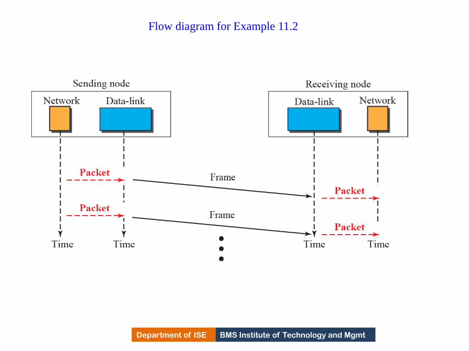
BMS Institute of Technology and Mgmt Department of ISE
Flow diagram for Example 11.2
412

BMS Institute of Technology and Mgmt Department of ISE
Stop-and-Wait Protocol
Second protocol is called the Stop-and-Wait protocol, which
uses both flow and error control.
In this protocol, the sender sends one frame at a time and
waits for an acknowledgment before sending the next one.
To detect corrupted frames, we need to add a CRC to each
data frame.
When a frames arrives at the receiver site, it is checked, if its
CRC is incorrect, the frame is incorrect & silently discarded.
Silence is an alert to the sender that frame is corrupted or
lost.
413

BMS Institute of Technology and Mgmt Department of ISE
Stop-and-Wait Protocol (Continued)
Every time sender sends a frame, it starts a timer and if ack.
arrives before timer expires, timer is stopped and next frame is
transmitted.
If timer expires before ack., frame is retransmitted because
sender assumes that frame is corrupted or lost.
This means that Sender needs to keep a copy of the sent
frame until he receives the ack.
When the corresponding acknowledgment arrives, the sender
discards the frame and send the next frame if it is ready
414

BMS Institute of Technology and Mgmt Department of ISE
Stop-and-wait Protocol
415

BMS Institute of Technology and Mgmt Department of ISE
FSM for the stop-and-wait protocol
416

BMS Institute of Technology and Mgmt Department of ISE Department of ISE BMS Institute of Technology and Mgmt
FSM for the stop-and-wait protocol
• At sender side:
The sender is initially in the ready state, but it can move between
the ready state and blocking state
i) Ready state: It is waiting for a packet from the N/W layer.
Sender creates a copy of the frame, starts the timer and sends
the frame. The sender moves to the blocking state.
ii)Blocking state: 3 events occur
a) if time out occurs, sender resends the saved copy of the frame and starts
timer.
b) If a corrupted ACK arrives, it is discarded.
c) If an error free ACK arrives, the sender stops the timer and discards the
saved copy of the frame & moves to ready state.
417
BMS Institute of Technology and Mgmt Department of ISE Department of ISE BMS Institute of Technology and Mgmt
FSM for the stop-and-wait protocol
At receiver side:
The receiver is always in ready state. The two
events may occur
a) If an error free frame arrives, message in the frame
is delivered to the network layer and ACK is sent.
b) If a corrupted frame arrives, the frame is discarded.
418

BMS Institute of Technology and Mgmt Department of ISE
In the figure below first frame is sent and acknowledged.
The second frame is sent, but lost. After time-out, it is
resent.
The third frame is sent and acknowledged, but the
acknowledgment is lost.
The frame is resent. However, there is a problem with this
scheme.
The network layer at the receiver site receives two copies of
the third packet, which is not right.
Discuss how to correct this problem using sequence
numbers and acknowledgment numbers.
Example 11.3
419

BMS Institute of Technology and Mgmt Department of ISE
Flow diagram
420
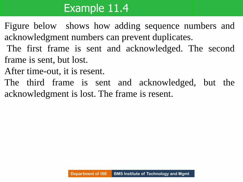
BMS Institute of Technology and Mgmt Department of ISE
Figure below shows how adding sequence numbers and
acknowledgment numbers can prevent duplicates.
The first frame is sent and acknowledged. The second
frame is sent, but lost.
After time-out, it is resent.
The third frame is sent and acknowledged, but the
acknowledgment is lost. The frame is resent.
Example 11.4
421

BMS Institute of Technology and Mgmt Department of ISE
Flow diagram
422

BMS Institute of Technology and Mgmt Department of ISE
Piggybacking
The two protocols we discussed in this section are
designed for unidirectional communication, in which
data is flowing only in one direction although the
acknowledgment may travel in the other direction.
Protocols have been designed in the past to allow
data to flow in both directions.
However, to make the communication more
efficient, the data in one direction is piggybacked with
the acknowledgment in the other direction.
423

BMS Institute of Technology and Mgmt Department of ISE
Point to Point Protocol (PPP)
One of the most common protocols for point-to-point
access is the Point-to-Point Protocol (PPP).
Today, millions of Internet users who need to connect
their home computers to the server of an Internet
service provider use PPP.
To control and manage the transfer of data, there is
a need for a point-to-point protocol at the data-link
layer. PPP is by far the most common.
424

BMS Institute of Technology and Mgmt Department of ISE
Services
•The designers of PPP have included several services
to make it suitable for a point-to-point protocol, but
have ignored some traditional services to make it
simple.
425

BMS Institute of Technology and Mgmt Department of ISE Department of ISE BMS Institute of Technology and Mgmt
Services provided by Point-point protocol
Defines 1. format of the frame to be exchanged between the devices.
2. How two devices can negotiate the establishment of the link
and the exchange of data.
3. How N/W layer data are encapsulated in the data link frame.
4. How two devices can authenticate each other.
5. Provides Multiple N/W services supporting a variety of N/W
Layer protocols.
6. Connection over multiple links is provided by new version of
PPP.
7. N/W address configuration. Useful when a home user needs
temporary N/W address to connect to Internet
426

BMS Institute of Technology and Mgmt Department of ISE Department of ISE BMS Institute of Technology and Mgmt
Services not provided by ppp
• PPP does not provide flow control. Sender can
send frames one after another w/o concerning
about overwhelming receivers buffer.
• Simple mechanism for error control. A CRC
field is used to detect errors. If frame is
corrupted , frame is silently discarded. Upper
Layer protocol need to take care of this.
• Does not provide addressing mechanism to
handle frames in a multipoint configuration.
427
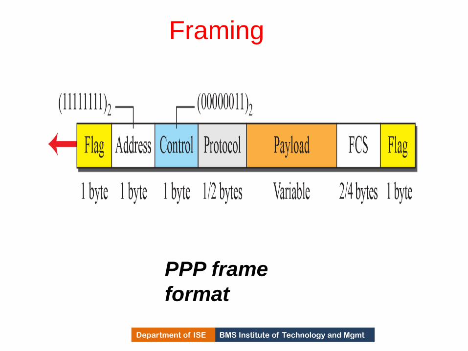
BMS Institute of Technology and Mgmt Department of ISE
Framing
PPP frame
format
428
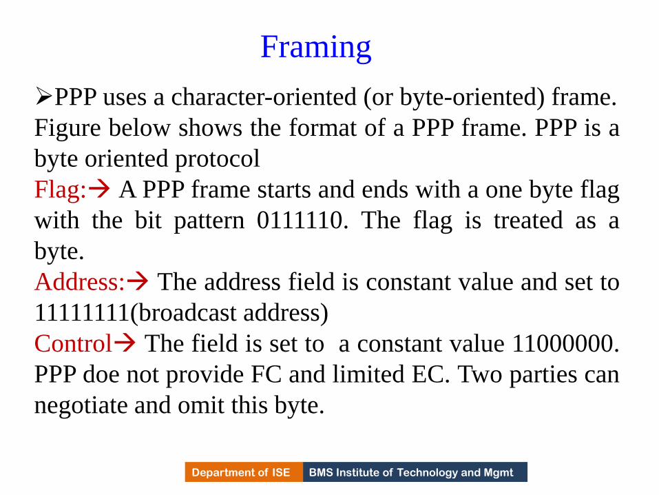
BMS Institute of Technology and Mgmt Department of ISE
Framing
PPP uses a character-oriented (or byte-oriented) frame.
Figure below shows the format of a PPP frame. PPP is a
byte oriented protocol
Flag: A PPP frame starts and ends with a one byte flag
with the bit pattern 0111110. The flag is treated as a
byte.
Address: The address field is constant value and set to
11111111(broadcast address)
Control The field is set to a constant value 11000000.
PPP doe not provide FC and limited EC. Two parties can
negotiate and omit this byte.
429

BMS Institute of Technology and Mgmt Department of ISE
Framing
Protocol defines what is being carried in the data field either user
data or other information.
Default size is 2 bytes, two parties can negotiate to use only 1 byte.
Payload field carries use data or other info.
Data field is a sequence of bytes with the default of maximum of
1500 bytes, But can be changed during negotiation.
The data field is byte stuffed if the flag byte pattern appears in
the field. Because there is no field defining the size of the data
field, padding is needed if the size is less than the maximum
default/negotiated value.
FCS: FCS is simply a 2/4 byte standard CRC
430

BMS Institute of Technology and Mgmt Department of ISE Department of ISE BMS Institute of Technology and Mgmt
Byte stuffing
• In PPP flag is byte. The flag byte need to be escaped
whenever it appears in the data section of the frame.
• The escape byte is 01111101 , which means that every
time the flag like pattern appears in the data, this
extra byte is stuffed to tell the receiver the next byte
is not a flag.
• PPP is a byte-oriented protocol using byte stuffing with the escape byte 01111101.
431

BMS Institute of Technology and Mgmt Department of ISE
Transition Phases
A PPP connection goes through phases which can
be shown in a transition phase diagram.
432

BMS Institute of Technology and Mgmt Department of ISE
Transition phases
433

BMS Institute of Technology and Mgmt Department of ISE Department of ISE BMS Institute of Technology and Mgmt
Transition phases Dead: In this phase link is not used. There is no active
carrier and line is quiet.
Establish: When one of the node starts communication,
connection goes into establish phase. Options are
negotiated between two parties.
If negotiation is successful, system goes to
authentication phase or directly to networking phase.
Link control packet are used in this phase.
Authenticate: Two nodes can negotiate and skip this
phase as it is optional. If not to skip, authentication
packets are used.
434

BMS Institute of Technology and Mgmt Department of ISE Department of ISE BMS Institute of Technology and Mgmt
Transition phases Network: Negotiation for the network layer
protocols takes place. PPP specifies that two
nodes establish a N/W agreement before data
at the N/w can be exchanged.
PPP supports multi protocols at N/W Layer.
If a node is running multi protocol
simultaneously at the N/W Layer, receiving
node needs to know which protocol will
receive the data.
435

BMS Institute of Technology and Mgmt Department of ISE Department of ISE BMS Institute of Technology and Mgmt
Transition phases
Open: Data transfer takes place.
When a connection reaches this phase,
exchange of data packets takes place
Connections remains in this phase until one of
the endpoints wants to terminate the
connection
Terminate: Connection is terminated. Several
packets are exchanged b/w the two ends for
house cleaning and closing of the link
436

BMS Institute of Technology and Mgmt Department of ISE Department of ISE BMS Institute of Technology and Mgmt
Media Access Control(MAC)
• When stations are connected to a common link(multi
point/broadcast link), multiple access protocol is
required to coordinate access to the link.
• The problem of controlling the access to the medium
should ensure that at the same time no two devices
can interrupt or monopolize the link.
• Many protocols have been devised to handle access to
a shared link.
• These protocols belong to a sub layer in DLL called
media access control(MAC).
437

BMS Institute of Technology and Mgmt Department of ISE
Taxonomy of multiple-access protocols
438

BMS Institute of Technology and Mgmt Department of ISE
RANDOM ACCESS
In random-access or contention no station is superior to
another station and none is assigned control over another.
At each instance, a station that has data to send uses a
procedure defined by the protocol to make a decision on
whether or not to send.
This decision depends on the state of the medium (idle or
busy).
Each station can transmit when it desires on the condition
that it follows the predefined procedure, testing the state of
the medium.
439
BMS Institute of Technology and Mgmt Department of ISE Department of ISE BMS Institute of Technology and Mgmt
Random access(Contention Method)
• Two features that gave this name
1) There is no scheduled time for the station to
transmit. Transmission is random among the stations.
So, the name Random access method
2)No rules specify which station should send next.
Stations compete with one another to access the
medium.
So, the method is called Contention methods
440

BMS Institute of Technology and Mgmt Department of ISE Department of ISE BMS Institute of Technology and Mgmt
Random access
• As each station has right to access the medium, if more than one station tries to send, there is an access conflict and frames will be either modified or destroyed.
• To avoid this access conflict, each station follows the procedures which answers questions
1)When can the station access the medium?
2)What can station do if medium is busy.
3)How can the station determine the success or failure of the transmission
4) What can station do if there is access conflict
441

BMS Institute of Technology and Mgmt Department of ISE Department of ISE BMS Institute of Technology and Mgmt
Random access
• Methods
1) ALOHA
2) CSMA/CD
3) CSMA/CA
442

BMS Institute of Technology and Mgmt Department of ISE
ALOHA
ALOHA, the earliest random access method, was
developed at the University of Hawaii in early 1970.
It was designed for a radio (wireless) LAN, but it
can be used on any shared medium.
It is obvious that there are potential collisions in
this arrangement.
The medium is shared between the stations. When
a station sends data, another station may attempt to do
so at the same time.
The data from the two stations collide and become
garbled.
443

BMS Institute of Technology and Mgmt Department of ISE Department of ISE BMS Institute of Technology and Mgmt
Pure ALOHA • Original ALOHA protocol is called Pure ALOHA.
Idea is
1) Each station sends a frame whenever it has frame to
send.
2) Since there is only one channel to share, there is
possibility of collision between frames from
different stations.
444

BMS Institute of Technology and Mgmt Department of ISE
Frames in a pure ALOHA network
445
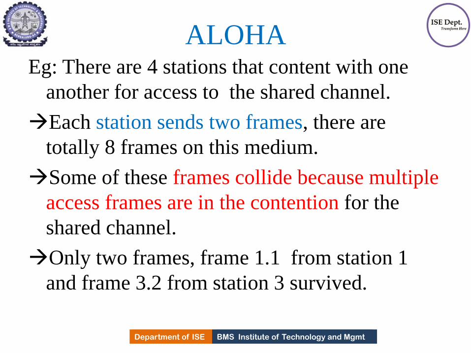
BMS Institute of Technology and Mgmt Department of ISE Department of ISE BMS Institute of Technology and Mgmt
ALOHA Eg: There are 4 stations that content with one
another for access to the shared channel.
Each station sends two frames, there are
totally 8 frames on this medium.
Some of these frames collide because multiple
access frames are in the contention for the
shared channel.
Only two frames, frame 1.1 from station 1
and frame 3.2 from station 3 survived.
446

BMS Institute of Technology and Mgmt Department of ISE Department of ISE BMS Institute of Technology and Mgmt
ALOHA
• Even if 1 bit of a frame coexists on the channel with
one bit from another frame, there is a collision and
both will be destroyed.
• Need to resend the frames that have been destroyed
during transmission.
• Pure ALOHA protocol relies on Ack. from the
receiver.
• If station does not receive ack. with in time-out
period, station assumes that frames have been
destroyed and resends it.
447

BMS Institute of Technology and Mgmt Department of ISE Department of ISE BMS Institute of Technology and Mgmt
Pure ALOHA
• A Collision involves two or more stations. If
all these stations resend frames again, frames
collide.
• PURE ALOHA dictates that when the time out
period passes, each station waits for random
amount of time before resending the frames.
• Randomness avoid more collisions .
• This is called Back-off time TB .
448

BMS Institute of Technology and Mgmt Department of ISE Department of ISE BMS Institute of Technology and Mgmt
Pure ALOHA • Second method to prevent congesting the channel
with retransmitted frames is after maximum number
of retransmission attempts Kmax the stations must give
up and try later.
• Time out period is equal to maximum possible RT
propagation delay, which is twice the the amount of
time required to send the frame between most widely
separated stations(2*Tp).
• Back-off time TB is a random value which depends
on value of K.
449
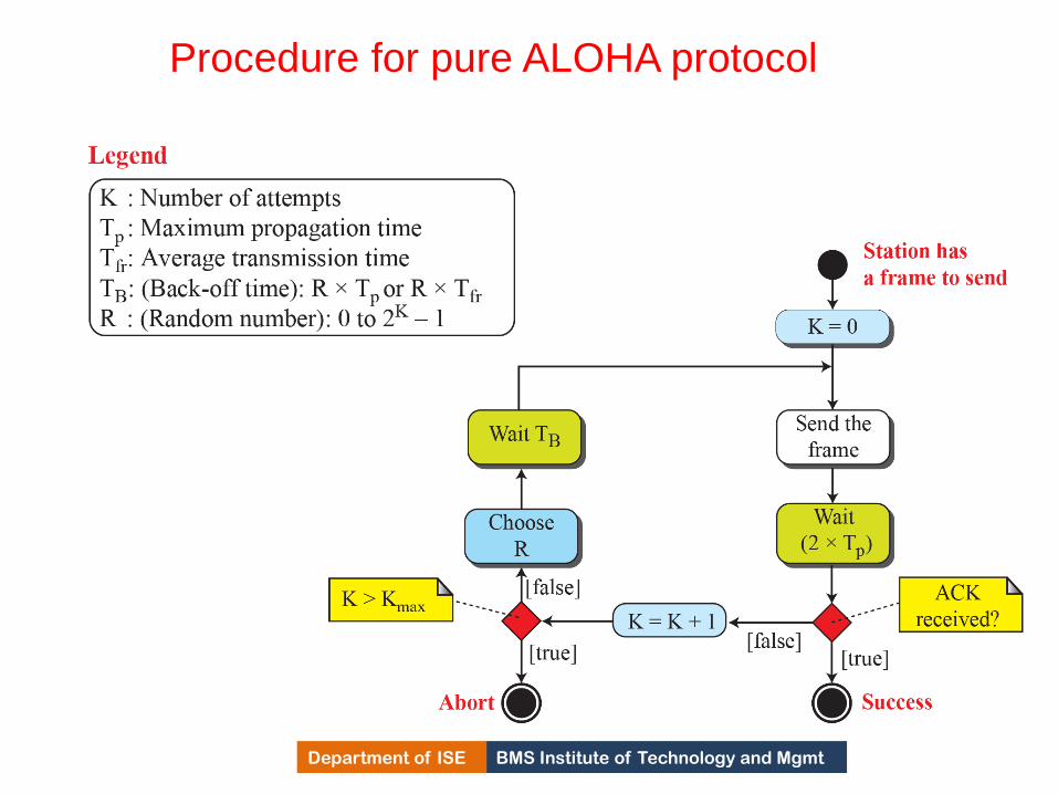
BMS Institute of Technology and Mgmt Department of ISE
Procedure for pure ALOHA protocol
450

BMS Institute of Technology and Mgmt Department of ISE
The stations on a wireless ALOHA network are a maximum
of 600 km apart.
If we assume that signals propagate at
3 × 10⁸ m/s, find Tp and TB .
Solution:
To find Tp = (600 × 103) / (3 × 10⁸) = 2 ms.
for K = 2, the range of R is {0, 1, 2, 3}.
This means that TB can be 0, 2, 4, or 6 ms, based on the
outcome of the random variable R.
Example 12. 1
451
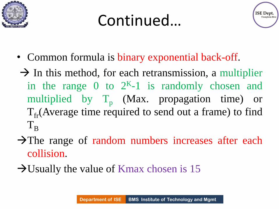
BMS Institute of Technology and Mgmt Department of ISE Department of ISE BMS Institute of Technology and Mgmt
Continued…
• Common formula is binary exponential back-off.
In this method, for each retransmission, a multiplier
in the range 0 to 2K-1 is randomly chosen and
multiplied by Tp (Max. propagation time) or
Tfr(Average time required to send out a frame) to find
TB
The range of random numbers increases after each
collision.
Usually the value of Kmax chosen is 15
452
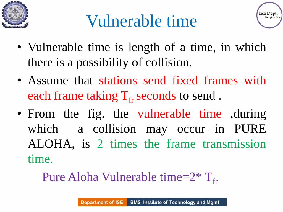
BMS Institute of Technology and Mgmt Department of ISE Department of ISE BMS Institute of Technology and Mgmt
Vulnerable time
• Vulnerable time is length of a time, in which
there is a possibility of collision.
• Assume that stations send fixed frames with
each frame taking Tfr seconds to send .
• From the fig. the vulnerable time ,during
which a collision may occur in PURE
ALOHA, is 2 times the frame transmission
time.
Pure Aloha Vulnerable time=2* Tfr
453

BMS Institute of Technology and Mgmt Department of ISE
Vulnerable time for pure ALOHA protocol
454

BMS Institute of Technology and Mgmt Department of ISE
A pure ALOHA network transmits 200-bit frames on a
shared channel of 200 kbps. What is the requirement to
make this frame collision-free?
Solution
Average frame transmission time Tfr is 200 bits/200 kbps or
1 ms.
The vulnerable time is 2 × 1 ms = 2 ms.
This means no station should send later than 1 ms
before this station starts transmission and no station should
start sending during the period (1 ms) that this station is
sending.
Example 12.2
455

BMS Institute of Technology and Mgmt Department of ISE Department of ISE BMS Institute of Technology and Mgmt
Throughput
• Let G be the average number of frames
generated by the system during one frame
transmission time.
• It can be proved that, average number of
successful transmission for pure ALOHA is
• The Maximum through put Smax =0.184 for G=1/2.
456

BMS Institute of Technology and Mgmt Department of ISE Department of ISE BMS Institute of Technology and Mgmt
Throughput
• In other words, if one-half frame is generated
during one frame transmission time, then
18.4% of these frames reach their destination
successfully.
• The throughput for pure ALOHA is
S = G × e −2G .
• The maximum throughput
Smax = 0.184 when G= (1/2).
457
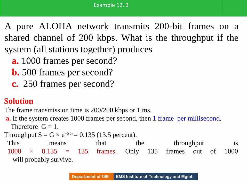
BMS Institute of Technology and Mgmt Department of ISE
A pure ALOHA network transmits 200-bit frames on a
shared channel of 200 kbps. What is the throughput if the
system (all stations together) produces
a. 1000 frames per second?
b. 500 frames per second?
c. 250 frames per second?
Example 12. 3
Solution The frame transmission time is 200/200 kbps or 1 ms.
a. If the system creates 1000 frames per second, then 1 frame per millisecond.
Therefore G = 1.
Throughput S = G × e−2G = 0.135 (13.5 percent).
This means that the throughput is
1000 × 0.135 = 135 frames. Only 135 frames out of 1000
will probably survive.
458

BMS Institute of Technology and Mgmt Department of ISE
b. If the system creates 500 frames per second, or 1/2 frames
per millisecond.
Therefore G = 1/2.
Throughput S=G×e−2G =0.184 (18.4 percent).
This means that the throughput is
500 × 0.184 = 92 and that only 92 frames out of 500 will
probably survive.
c. If the system creates 250 frames per second, or 1/4
frames per millisecond.
Therefore G = 1/4.
Throughput S = G × e−2G = 0.152 (15.2 percent).
This means that the throughput is 250 × 0.152 = 38. Only 38
frames out of 250 will probably survive
Example 12. 3 (continued)
459
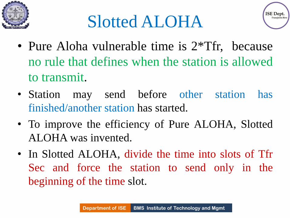
BMS Institute of Technology and Mgmt Department of ISE Department of ISE BMS Institute of Technology and Mgmt
Slotted ALOHA
• Pure Aloha vulnerable time is 2*Tfr, because
no rule that defines when the station is allowed
to transmit.
• Station may send before other station has
finished/another station has started.
• To improve the efficiency of Pure ALOHA, Slotted
ALOHA was invented.
• In Slotted ALOHA, divide the time into slots of Tfr
Sec and force the station to send only in the
beginning of the time slot.
460

BMS Institute of Technology and Mgmt Department of ISE
Frames in a slotted ALOHA network
461
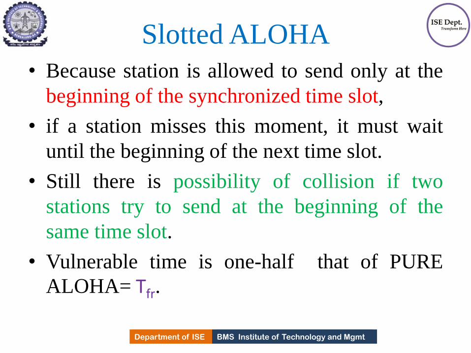
BMS Institute of Technology and Mgmt Department of ISE Department of ISE BMS Institute of Technology and Mgmt
Slotted ALOHA • Because station is allowed to send only at the
beginning of the synchronized time slot,
• if a station misses this moment, it must wait
until the beginning of the next time slot.
• Still there is possibility of collision if two
stations try to send at the beginning of the
same time slot.
• Vulnerable time is one-half that of PURE
ALOHA= Tfr.
462

BMS Institute of Technology and Mgmt Department of ISE
Vulnerable time for slotted ALOHA protocol
463

BMS Institute of Technology and Mgmt Department of ISE Department of ISE BMS Institute of Technology and Mgmt
Throughput
• The throughput for slotted ALOHA is
S = G × e−G .
• The maximum throughput
Smax = 0.368 when G = 1.
• If one frame is generated during one frame
transmission time, then 36.8% of these frames reach
the destination successfully.
• Because vulnerable time is equal to frame
transmission time., station generates only one frame
in this time.
464

BMS Institute of Technology and Mgmt Department of ISE
A slotted ALOHA network transmits 200-bit frames using a
shared channel with a 200-kbps bandwidth. Find the
throughput if the system (all stations together) produces
a. 1000 frames per second.
b. 500 frames per second.
c. 250 frames per second.
Solution
The frame transmission time is 200/200 kbps or 1 ms.
a. G =1. So throughput S = G × e−G = 0.368 (36.8
percent).
This means that the throughput is 1000 × 0.368 = 368
frames. Only 368 out of 1000 frames will probably
survive.
Example 12. 4
465

BMS Institute of Technology and Mgmt Department of ISE
b) G = 1/2.
In this case S = G × e−G = 0.303 (30.3 percent).
This means that the throughput 500 × 0.303 = 151.5.
Only 151 frames out of 500 will probably survive.
c) G = 1/4.
In this case S = G × e−G = 0.195 (19.5 percent).
This means that the throughput is 250 × 0.195 = 49.
Only 49 frames out of 250 will probably survive.
Example 12. 4 (continued)
466

BMS Institute of Technology and Mgmt Department of ISE
CSMA
To minimize the chance of collision and, therefore,
increase the performance, the CSMA method was
developed.
The chance of collision can be reduced if a station
senses the medium before trying to use it.
Carrier sense multiple access (CSMA) requires that
each station first listen to the medium (or check the
state of the medium) before sending.
In other words, CSMA is based on the principle
“sense before transmit” or “listen before talk.” 467

BMS Institute of Technology and Mgmt Department of ISE
Space/time model of a collision in CSMA
468

BMS Institute of Technology and Mgmt Department of ISE Department of ISE BMS Institute of Technology and Mgmt
Vulnerable time • Vulnerable time for CSMA is the Propagation
time Tp.
• Tp is the time needed for the signal to
propagate from one end of the medium to
other.
• When any station sends a frame during this time
,collision will occur.
• If the first bit of the frame reaches the end of the
medium, every station will already have heard the bit
and will refrain from sending.
469
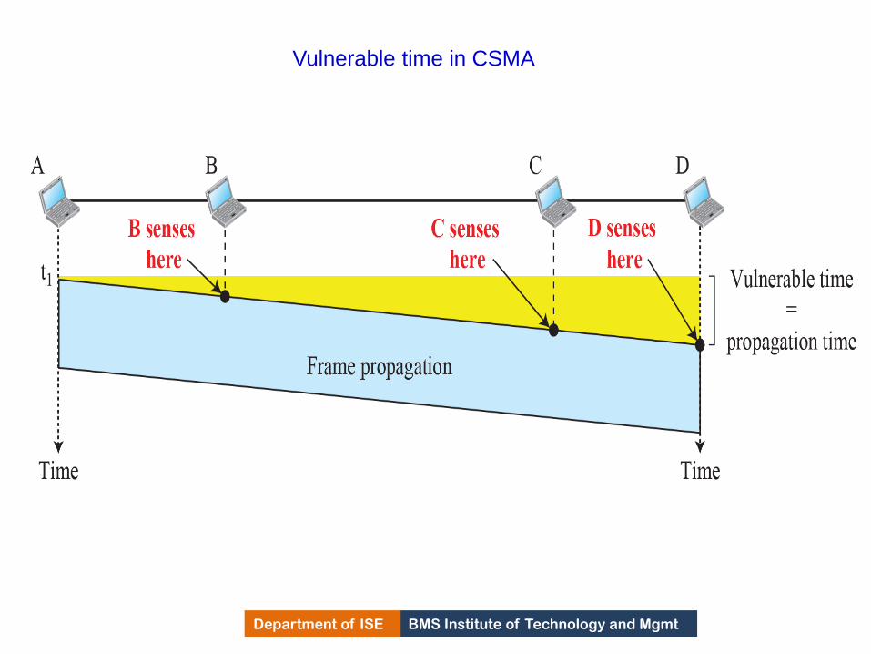
BMS Institute of Technology and Mgmt Department of ISE
Vulnerable time in CSMA
470
BMS Institute of Technology and Mgmt Department of ISE Department of ISE BMS Institute of Technology and Mgmt
Persistence Methods
What should station do if channel is busy/idle?
• Three methods to answer this
1) 1-Persistent method
2) Non persistent method.
3) p-Persistent method
• When a station finds channel is busy, behavior
of three persistence methods are shown below
471

BMS Institute of Technology and Mgmt Department of ISE
Behavior of three persistence methods
472
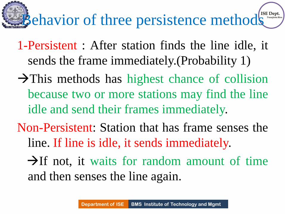
BMS Institute of Technology and Mgmt Department of ISE Department of ISE BMS Institute of Technology and Mgmt
Behavior of three persistence methods
1-Persistent : After station finds the line idle, it
sends the frame immediately.(Probability 1)
This methods has highest chance of collision
because two or more stations may find the line
idle and send their frames immediately.
Non-Persistent: Station that has frame senses the
line. If line is idle, it sends immediately.
If not, it waits for random amount of time
and then senses the line again.
473
BMS Institute of Technology and Mgmt Department of ISE Department of ISE BMS Institute of Technology and Mgmt
Continued.. P-persistent: This method is used if the channel has time
slot with the slot duration equal to or greater than
maximum propagation time.
It reduces the chance of collision and improves the efficiency.
After station finds channel is idle,
it follows the following steps
1) With probability p, the station sends its frame.
2) With probability q=1-p, the station waits for the beginning of
the next time slot and checks the line again.
3) If the line is busy, it acts as though a collision has occurred
and uses the back off procedure.
474

BMS Institute of Technology and Mgmt Department of ISE Department of ISE BMS Institute of Technology and Mgmt
Continued..
The Non-Persistent approach reduces the
chance of collision because it is unlikely that
two or more stations will wait for same amount
of time.
This method reduces efficiency of the n/w
because the medium remains idle when there
may be stations with frames to send.
475

BMS Institute of Technology and Mgmt Department of ISE
Flow diagram for three persistence methods
476

BMS Institute of Technology and Mgmt Department of ISE
CSMA/CD
•The CSMA method does not specify the procedure
following a collision.
•Carrier sense multiple access with collision detection
(CSMA/CD) augments the algorithm to handle the
collision.
In this method, a station monitors the medium after
it sends a frame to see if the transmission was
successful. If so, the station is finished. If, however,
there is a collision, the frame is sent again.
477

BMS Institute of Technology and Mgmt Department of ISE
Collision of the first bits in CSMA/CD
478

BMS Institute of Technology and Mgmt Department of ISE
Collision and abortion in CSMA/CD
479

BMS Institute of Technology and Mgmt Department of ISE Department of ISE BMS Institute of Technology and Mgmt
Minimum Frame size • CSMA/CD to work, need a restriction on the frame
size.
• Before sending the last bit of the frame, if sending
station detects a collision, if any, abort the
transmission.
• Because station once sends entire frame, does not
keep a copy of the frame and monitor the line for
collision detection.
• There fore frame transmission time Tfr must be at
least two times the maximum propagation time
Tp(2Tp).
480

BMS Institute of Technology and Mgmt Department of ISE
A network using CSMA/CD has a bandwidth of 10 Mbps. If
the maximum propagation time (including the delays in the
devices and ignoring the time needed to send a jamming
signal, as we see later) is 25.6 μs, what is the minimum size
of the frame?
Solution
The minimum frame transmission time is
Tfr = 2 × Tp = 51.2 μs.
This means, in the worst case, a station needs to transmit for
a period of 51.2 μs to detect the collision.
The minimum size of the frame is 10 Mbps × 51.2 μs =
512 bits or 64 bytes Which is actually the minimum size of
the frame for Standard Ethernet.
Example 12. 5
481

BMS Institute of Technology and Mgmt Department of ISE
Flow diagram for the CSMA/CD
482

BMS Institute of Technology and Mgmt Department of ISE
Energy level during transmission, idleness, or
collision
483

BMS Institute of Technology and Mgmt Department of ISE Department of ISE BMS Institute of Technology and Mgmt
Energy level
• Level of energy in a channel can have three
values zero, normal and abnormal.
At Zero level, channel is idle.
At Normal Level, station has successfully
captured the channel and is sending its frame.
At Abnormal level, there is a collision and
level of energy is twice the normal level.
The station that has frame to send, needs to
monitor the energy level of the channel.
484
BMS Institute of Technology and Mgmt Department of ISE Department of ISE BMS Institute of Technology and Mgmt
Throughput
• Is greater than PURE ALOHA.
• Maximum throughput occurs at a different
values of G and is based on Persistence
method and value p in p-persistent approach.
• For 1-persistent method the maximum through
put is around 50% when G=1.
• For non persistent method, the maximum
through put can go up to 90% when G is
between 3 and 8.
485
BMS Institute of Technology and Mgmt Department of ISE
CSMA/CA
Carrier sense multiple access with collision
avoidance (CSMA/CA) was invented for wireless
networks.
Collisions are avoided through the use of
CSMA/CA’s three strategies:
1) Inter frame space,
2) Contention window
3) Acknowledgments
486

BMS Institute of Technology and Mgmt Department of ISE
Contention window
487

BMS Institute of Technology and Mgmt Department of ISE Department of ISE BMS Institute of Technology and Mgmt
Inter frame Space(IFS) • Collisions are avoided by deferring the transmission
even if channel is idle.
• Station does not send immediately, it waits for a
period called IFS.
• Even though channel may be found idle when it is
sensed, a distant station may have already started
transmitting and the signal has not yet reached this
station.
• IFS time allows signal from the distant station to
reach this station.
488
BMS Institute of Technology and Mgmt Department of ISE Department of ISE BMS Institute of Technology and Mgmt
Inter frame Space(IFS) • After IFS time, if channel is found idle, the
station can send, but still need to wait a time
equal to contention time.
• IFS variable can be used to prioritize the
stations.
In CSMA/CA, the IFS can also be used
to define the priority of a station or a
frame.
489
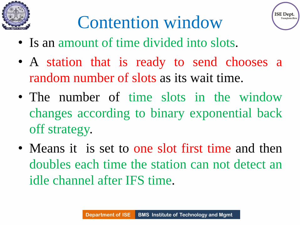
BMS Institute of Technology and Mgmt Department of ISE Department of ISE BMS Institute of Technology and Mgmt
Contention window • Is an amount of time divided into slots.
• A station that is ready to send chooses a
random number of slots as its wait time.
• The number of time slots in the window
changes according to binary exponential back
off strategy.
• Means it is set to one slot first time and then
doubles each time the station can not detect an
idle channel after IFS time.
490

BMS Institute of Technology and Mgmt Department of ISE Department of ISE BMS Institute of Technology and Mgmt
Contention window • Station needs to sense the channel after each time
slot.
• If station finds that channel is busy, it does not restart
the process; stops the timer and restarts it when the
channel is sensed as idle.
• This gives priority to the station with longest waiting
time.
In CSMA/CA, if the station finds the channel busy, it does not
restart the timer of the contention window;
it stops the timer and restarts it when the channel
becomes idle.
491

BMS Institute of Technology and Mgmt Department of ISE Department of ISE BMS Institute of Technology and Mgmt
Acknowledgment
• With all these precautions, data may get
corrupted during transmission resulting in
destroyed data.
• Positive ack. and the time-out timer guarantee
that receiver has received the frame.
492

BMS Institute of Technology and Mgmt Department of ISE Department of ISE BMS Institute of Technology and Mgmt
Frame exchange Time Line
1. Before sending the frame, the source station senses the
medium by checking the energy level at the carrier frequency.
a) Channel uses persistent strategy with back off until channel
is idle.
b) After the station is found idle, the station waits for a period
of time called DCF inter frame space(DIFS), then frame sends
a control frame called request to send(RTS).
2. After receiving the RTS & waiting a period time called short
inter frame space(SIFS), the destination station sends the a
control frame, called clear to send(CTS)
493

BMS Institute of Technology and Mgmt Department of ISE Department of ISE BMS Institute of Technology and Mgmt
Frame exchange Time Line
to the source station. The control frame indicates that
the destination is ready to receive data.
3. Source station sends data after waiting an amount of
time equal to SIFS.
4. Destination station after waiting an amount of time
called SIFS, sends an acknowledgment to show that
frame has been received.
Acknowledgment is needed in this protocol to
check for the successful transmission of its data at
the destination.
494

BMS Institute of Technology and Mgmt Department of ISE
CSMA/CA and NAV
495
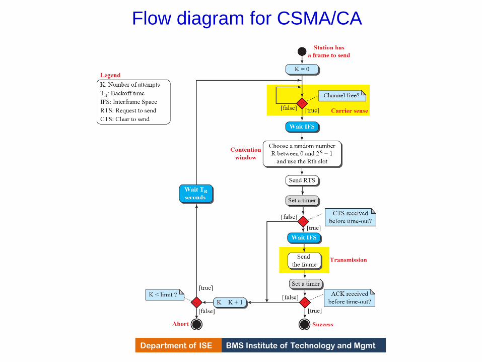
BMS Institute of Technology and Mgmt Department of ISE
Flow diagram for CSMA/CA
496

BMS Institute of Technology and Mgmt Department of ISE Department of ISE BMS Institute of Technology and Mgmt
Network Allocation vector
• How do other stations defer sending data when one of the
station acquire access i.e How collision avoidance aspect is
accomplished??
• Feature is NAV
I. When station sends an RTS frame, it includes the duration of
the time that it needs to occupy the channel.
The stations that are affected by this transmission creates a
times called Network Allocation Vector(NAV), that shows
how much time is passed and when these stations are
allowed to check the idleness of the medium.
Each time a station access the system and sends an RTS
frame, other stations starts their NAV.
i.e Each station before sensing the medium to see if it is idle,
it first checks NAV if it has expired.
497
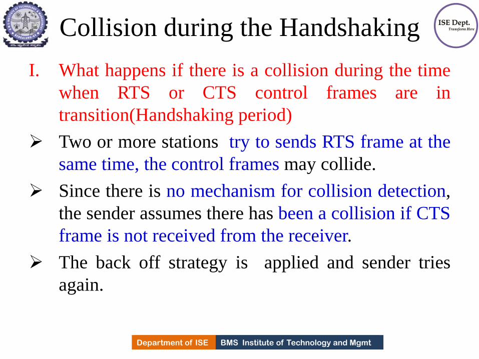
BMS Institute of Technology and Mgmt Department of ISE Department of ISE BMS Institute of Technology and Mgmt
Collision during the Handshaking
I. What happens if there is a collision during the time
when RTS or CTS control frames are in
transition(Handshaking period)
Two or more stations try to sends RTS frame at the
same time, the control frames may collide.
Since there is no mechanism for collision detection,
the sender assumes there has been a collision if CTS
frame is not received from the receiver.
The back off strategy is applied and sender tries
again.
498

BMS Institute of Technology and Mgmt Department of ISE Department of ISE BMS Institute of Technology and Mgmt
Hidden station Problem
• Solution is to use hand shake frames.
• When RTS message is sent from B to A, not C.
• Because both B & C are with in transmission range
of A, the CTS message, which contains the duration
of data transmission from B to A, reaches C.
• Station C knows that there is some hidden station is
using the channel and refrains from transmitting
until the duration is over.
499
BMS Institute of Technology and Mgmt Department of ISE
CONTROLLED ACCESS
In controlled access, the stations consult one another to find
which station has the right to send.
A station cannot send unless it has been authorized by other
stations.
Three controlled-access methods:
1) Reservation
2) Polling
3) Token passing
500

BMS Institute of Technology and Mgmt Department of ISE
Reservation
In the reservation method, a station needs to make
a reservation before sending data.
Time is divided into intervals.
In each interval, a reservation frame precedes the
data frames sent in that interval.
501

BMS Institute of Technology and Mgmt Department of ISE
Reservation access method
502

BMS Institute of Technology and Mgmt Department of ISE
Polling
Polling works with topologies in which one device
is designated as a primary station and the other
devices are secondary stations.
All data exchanges must be made through the
primary device even when the ultimate destination is
a secondary device.
The primary device controls the link; the secondary
devices follow its instructions.
It is up to the primary device to determine which
device is allowed to use the channel at a given time.
503

BMS Institute of Technology and Mgmt Department of ISE
Select and poll functions in polling-access method
504

BMS Institute of Technology and Mgmt Department of ISE Department of ISE BMS Institute of Technology and Mgmt
Polling
• If primary wants to receive data, it asks the
secondary's if they have anything to send.
• This is called Polling.
• If primary wants to send data, it tells the
secondary to get ready to receive.
• This is called Select function.
505
BMS Institute of Technology and Mgmt Department of ISE
Token Passing
In the token-passing method, the stations in a
network are organized in a logical ring.
In other words, for each station, there is a
predecessor and a successor.
The predecessor is the station which is logically
before the station in the ring;
The successor is the station which is after the
station in the ring.
506

BMS Institute of Technology and Mgmt Department of ISE
Logical ring and physical topology in token-passing
access method
507

BMS Institute of Technology and Mgmt Department of ISE
CHANNELIZATION
Channelization (or channel partition, as it is sometimes called) is a multiple-access
method in which the available bandwidth of a link is shared in time, frequency, or
through code, among different stations.
Discuss three protocols:
FDMA, TDMA, and CDMA.
508
BMS Institute of Technology and Mgmt Department of ISE
FDMA
In frequency-division multiple access (FDMA), the
available bandwidth is divided into frequency bands.
Each station is allocated a band to send its data.
In other words, each band is reserved for a specific
station, and it belongs to the station all the time.
Each station also uses a bandpass filter to confine
the transmitter frequencies.
To prevent station interferences, the allocates
bands are separated from one another by guard bands.
FDMA specifies a predetermined frequency band for
the entire period of communication
509

BMS Institute of Technology and Mgmt Department of ISE
Frequency-division multiple access (FDMA)
510

BMS Institute of Technology and Mgmt Department of ISE Department of ISE BMS Institute of Technology and Mgmt
FDMA
• FDMA is access method in DLL.
• DLL in each station tells the PL to make band pass
signal from the data passed to it.
• The signal must be created in the allocated band.
• There is no physical multiplexer at the physical layer.
• Signals created at each stations are automatically
band pass filtered and mixed when they are sent to
the common channel.
511

BMS Institute of Technology and Mgmt Department of ISE
TDMA
In time-division multiple access (TDMA), the
stations share the bandwidth of the channel in time.
Each station is allocated a time slot during which it
can send data.
Each station transmits its data in its assigned time
slot.
Main problem of TDMA lies in achieving
synchronization between different stations.
Each station needs to know beginning of its time
slot and location of its slot.
512
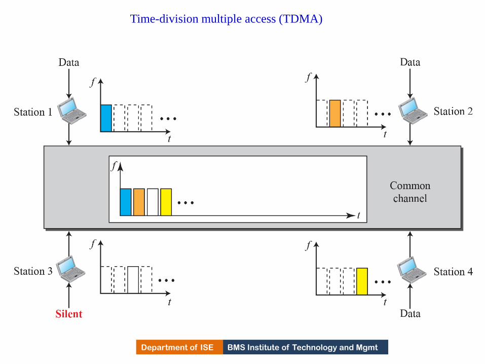
BMS Institute of Technology and Mgmt Department of ISE
Time-division multiple access (TDMA)
513

BMS Institute of Technology and Mgmt Department of ISE Department of ISE BMS Institute of Technology and Mgmt
TDMA • This may be difficult because of propagation delays
introduced in the system if the stations are spread
over a large area.
• Synchronization is normally accomplished by having
some synchronization bits at the beginning of each
slot.
• TDMA is an access method in DLL.
• DLL in each station tells its physical layer to use
allocated time slots.
• There is no physical multiplexer at the physical layer.
514

BMS Institute of Technology and Mgmt Department of ISE
CDMA
Code-division multiple access (CDMA) was conceived
several decades ago.
Recent advances in electronic technology have finally
made its implementation possible.
CDMA differs from FDMA in that only one channel
occupies the entire bandwidth of the link.
It differs from TDMA in that all stations can send data
simultaneously; there is no timesharing.
Idea: Assume that there are 4 stations 1,2,3 and 4 connected to
the same channel.
The data from station1 are d1, station2 are d2, station 3 are d3
and station 4 are d4.
The code for station1 is C1, station2 is C2, station 3 is C3 and
station 4 is C4.
515

BMS Institute of Technology and Mgmt Department of ISE Department of ISE BMS Institute of Technology and Mgmt
CDMA • Assume that assigned codes have two properties
1)If we multiply each code by another, we get 0.
2) if we multiply each code by itself, we get 4.
Station 1 multiplies its data by its code to get d1.c1.
Station 2 multiplies its data by its code to get d2.c2.
Station 3 multiplies its data by its code to get d3.c3.
Station 4 multiplies its data by its code to get d4.c4.
• The data that go on channel is sum of all these terms.
• CDMA is based on coding theory.
• Each station is assigned a code, which is a sequence
of numbers called Chips.
516

BMS Institute of Technology and Mgmt Department of ISE
Simple idea of communication with code
517

BMS Institute of Technology and Mgmt Department of ISE
Chip sequences
518

BMS Institute of Technology and Mgmt Department of ISE Department of ISE BMS Institute of Technology and Mgmt
Chips • Sequence is not choosen randomly.
• They are called orthogonal sequences and have following
properties.
1) Each sequence is made of N elements, where N is number of
stations.
2) If we multiply a sequence by a number, every element in the
sequence is multiplied by that number. This is called
multiplication of a sequence by a scalar.
Eg: 2.[+1 +1 -1 -1] = [+2 +2 -2 -2]
3) If we multiply two same sequences element by element, and
add the results, we get N. Where N is number of elements in
each sequence. This is called Linear product of two equal
sequences.
519

BMS Institute of Technology and Mgmt Department of ISE Department of ISE BMS Institute of Technology and Mgmt
Chips
Eg: [+1 +1 -1 -1]. [+1 +1 -1 -1]= 1+1+1+1=4.
4). If we multiply two different sequences, element by
element and add the results, we get 0.This is called
inner product of two different sequences.
Eg: [+1 +1 -1 -1]. [+1 -1 -1+1]= +1-1+1-1=0
5) Adding two sequences means adding the
corresponding elements. The result is another
sequence.
Eg: [+1 +1 -1 -1]+ [+1 +1 -1 -1]= [+2+2 0 0]
520

BMS Institute of Technology and Mgmt Department of ISE
Data representation in CDMA
521
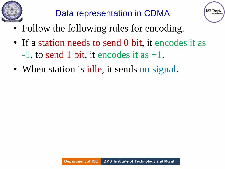
BMS Institute of Technology and Mgmt Department of ISE Department of ISE BMS Institute of Technology and Mgmt
Data representation in CDMA
• Follow the following rules for encoding.
• If a station needs to send 0 bit, it encodes it as
-1, to send 1 bit, it encodes it as +1.
• When station is idle, it sends no signal.
522

BMS Institute of Technology and Mgmt Department of ISE
Sharing channel in CDMA
523
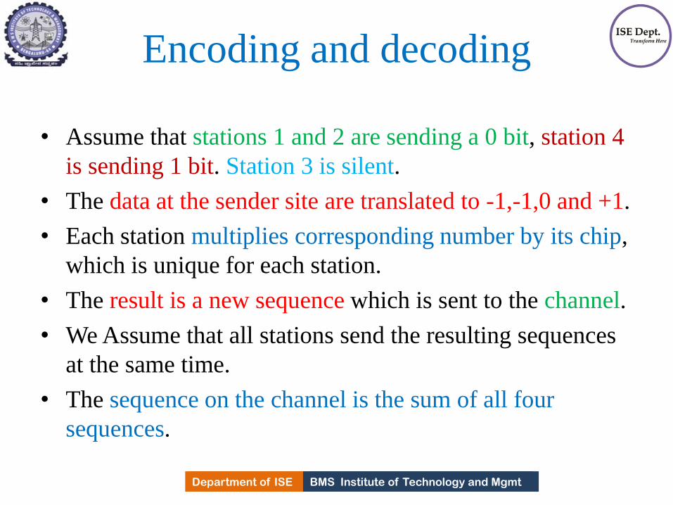
BMS Institute of Technology and Mgmt Department of ISE Department of ISE BMS Institute of Technology and Mgmt
Encoding and decoding
• Assume that stations 1 and 2 are sending a 0 bit, station 4
is sending 1 bit. Station 3 is silent.
• The data at the sender site are translated to -1,-1,0 and +1.
• Each station multiplies corresponding number by its chip,
which is unique for each station.
• The result is a new sequence which is sent to the channel.
• We Assume that all stations send the resulting sequences
at the same time.
• The sequence on the channel is the sum of all four
sequences.
524

BMS Institute of Technology and Mgmt Department of ISE Department of ISE BMS Institute of Technology and Mgmt
Continued..
• Imagine station 3, which is silent, listening to
station 2.
• Station 3 multiplies the total data on the
channel by the code for station 2, which is
[+1 -1 +1 -1], to get
[-1 -1 -3 +1[.[+1 -1 +1 -1]=-4/4=-1bit 0.
525
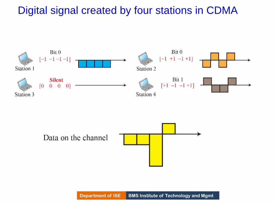
BMS Institute of Technology and Mgmt Department of ISE
Digital signal created by four stations in CDMA
526

BMS Institute of Technology and Mgmt Department of ISE
Decoding of the composite signal for one in
CDMA
527

BMS Institute of Technology and Mgmt Department of ISE Department of ISE BMS Institute of Technology and Mgmt
General rules and examples of creating Walsh
tables
• To generate chip sequences, walsh table is
used which is a two dimensional table with an
equal number of rows and columns.
528

BMS Institute of Technology and Mgmt Department of ISE Department of ISE BMS Institute of Technology and Mgmt
Walsh table • In walsh table, each row is a sequence of
chips.
• W1 for a one-chip sequence has one row and
one column.
• We choose -1 or +1 for the chip.
• According to Walsh, if we know the table for
N sequences Wn, we can create a table for 2N
sequences W2n.
• The number of sequences in a Walsh table
needs to be N = 2m.
529

BMS Institute of Technology and Mgmt Department of ISE
Prove that a receiving station can get the data sent by a
specific sender if it multiplies the entire data on the channel
by the sender’s chip code and then divides it by the number
of stations.
Example 12.8
530

BMS Institute of Technology and Mgmt Department of ISE Department of ISE BMS Institute of Technology and Mgmt
Example-2
• What is the number of sequences if we have 90
stations in our network?
Solution:-
• The number of sequences needs to be 2m.
• We need to choose m = 7 and N = 27 or 128.
• We can then use 90 of the sequences as the
chips.
531

BMS Institute of Technology and Mgmt Department of ISE
MODULE – 5
Wired LANs Ethernet
532

BMS Institute of Technology and Mgmt Department of ISE
ETHERNET PROTOCOL
The data-link layer and the physical layer are the territory of
the local and wide area networks
Discussed LAN whose sole purpose is to share the resources
Most of the LANs today is connected to WAN or Internet
Ethernet Protocol is most popular LAN technology because it
was able to update itself to meet the needs of organization with
the demand for higher data transmission.
533
BMS Institute of Technology and Mgmt Department of ISE
IEEE Project 802
In 1985, the Computer Society of the IEEE started a project,
called Project 802, to set standards to enable
intercommunication among equipment from a variety of
manufacturers.
Project 802 does not seek to replace any part of the OSI
model or TCP/IP protocol suite
Instead, it is a way of specifying functions of the physical
layer and the data-link layer of major LAN protocols
The relationship of the 802 Standard to the TCP/IP protocol
suite is shown in the Figure below
534
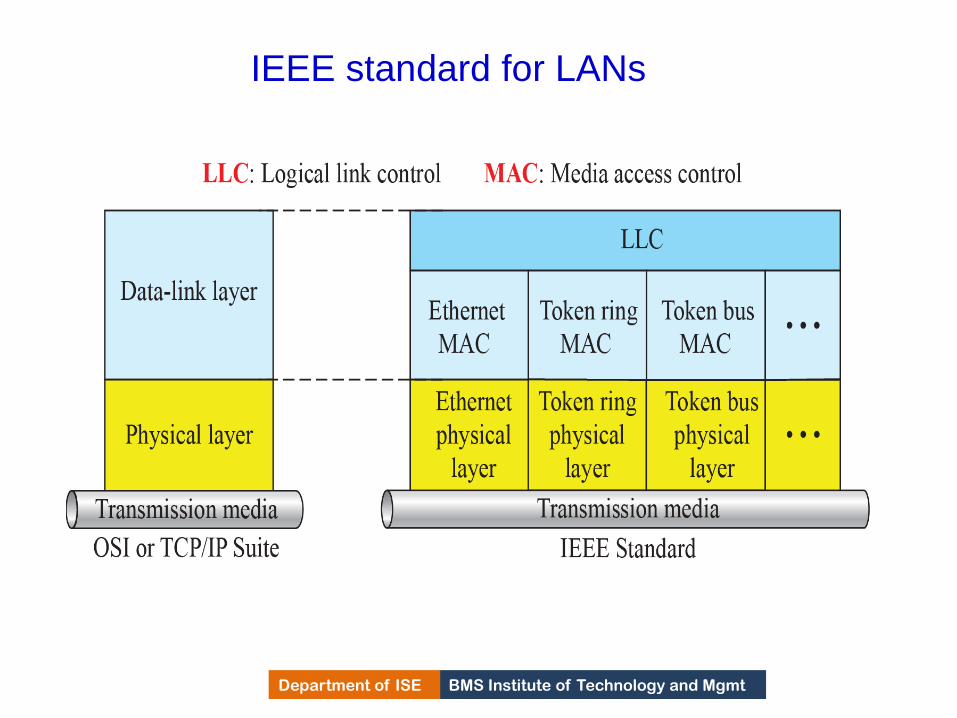
BMS Institute of Technology and Mgmt Department of ISE
IEEE standard for LANs
535

BMS Institute of Technology and Mgmt Department of ISE
IEEE Project 802
IEEE has subdivided the data link into two sub layers
i) Logical Link Control(LLC)
ii) Media Access Control(MAC)
Logical Link Control: In IEEE 802 project, Flow Control, Error
Control & part of framing duties are collected into this sub layer
Framing is handled in both LLC & MAC sub layers
LLC provides a single link layer control protocol for IEEE
LANs. i.e LLC protocol can provide inter connectivity between
different LANs
Media access Control that defines the specific access method for
each LAN 536

BMS Institute of Technology and Mgmt Department of ISE
Ethernet Evolution
The Ethernet LAN was developed in the 1970s by
Robert Metcalfe and David Boggs
It has gone through four generations:
1)Standard Ethernet (10 Mbps)
2)Fast Ethernet (100 Mbps)
3)Gigabit Ethernet (1 Gbps)
4)10 Gigabit Ethernet (10 Gbps)
537

BMS Institute of Technology and Mgmt Department of ISE
Ethernet evolution
538
BMS Institute of Technology and Mgmt Department of ISE
STANDARD ETHERNET
Original Ethernet technology with the data rate of 10 Mbps as the Standard
Ethernet.
Although most implementations have moved to other technologies in the Ethernet
evolution, there are some features of the Standard Ethernet that have not changed
during the evolution.
539

BMS Institute of Technology and Mgmt Department of ISE
Characteristics
Discuss some characteristics of the Standard Ethernet.
Connectionless and unreliable service.
Ethernet provides connectionless service i.e each frame
sent is independent of the previous or next frame.
Ethernet has no connection establishment or connection
termination phases.
Sender sends a frame whenever it has and receiver may
not be ready for it.
Sender may overwhelm the receiver buffer with frames,
which may result in dropping frames.
IP, connectionless protocol, which is using the services of
the Ethernet, which is also connectionless, will not know if
frame is dropped. If TL is also connectionless using UDP,
frame is lost 540
BMS Institute of Technology and Mgmt Department of ISE
Characteristics
This loss will come to know only from Application Layer
If TL is using TCP, Sender TCP segment if does not
receive acknowledgment for its segment and sends it again
Ethernet if connectionless, if frame is corrupted during
transmission, and receiver finds out about the corruption
because of CRC-32, the receiver drops the frame silently
It is the duty of high level protocols to find out
541

BMS Institute of Technology and Mgmt Department of ISE
Ethernet frame
542

BMS Institute of Technology and Mgmt Department of ISE Department of ISE BMS Institute of Technology and Mgmt
802.3 MAC frame
• Ethernet frame contains 7 fields.
• Ethernet does not provide any mechanism for Ack.ing the
received frames.
• Ack. must be implemented at the higher layers.
1. Preamble: contains 7 bytes(56 bits) of alternating 1s and 0s to
alert the station that frame is arriving and enables it to
synchronize its i/p timing.
Pattern provides only an alert and a timing pulse.
Preamble is actually added at the physical layer and is not
part of the frame.
2.Start frame delimiter(SFD):1 byte10101011 signals the
beginning of the frame.
543

BMS Institute of Technology and Mgmt Department of ISE Department of ISE BMS Institute of Technology and Mgmt
802.3 MAC frame
Warns the station/stations that this is the last chance of
synchronization.
Last 2 bits is 11 and alerts the receiver that the next field is the
destination address.
3.Destination address: is 6 bytes and contains the physical
address of the destination station/s to receive the packet. 4.Source address: is 6 bytes and contains the physical address of
the destination station/s to receive the packet.
5.Type: This field defines the upper layer protocol whose packet
is encapsulated in the frame. The protocols can be
IP,ARP,OSPF etc.,
It is used for multiplexing and demultiplexing.
544
BMS Institute of Technology and Mgmt Department of ISE Department of ISE BMS Institute of Technology and Mgmt
802.3 MAC frame
6.Data: This field carries data encapsulated from the upper layer
protocols. It is minimum of 46 bytes and maximum of 1500
bytes.
If data coming from upper layers is more than 1500 bytes, it
should be fragmented and encapsulated in more than one
frame. If less than 46 bytes, it should be padded with 0’s.
A padded data frame is delivered to upper layer
protocol as it is and it is the responsibility of the upper layer
protocol to remove the zeros.
7.CRC: Contains error detection mechanism(CRC-32). The CRC
is calculated over address, types and data field.
if receiver calculates CRC and finds that it is not zero, it
discards the frame.
545

BMS Institute of Technology and Mgmt Department of ISE Department of ISE BMS Institute of Technology and Mgmt
Frame Length • Ethernet imposed min and max lengths of a frame. The
minimum length restriction is required for the correct
operation of CSMA/CD.
546

BMS Institute of Technology and Mgmt Department of ISE Department of ISE BMS Institute of Technology and Mgmt
Frame Length • Ethernet frame needs to have a minimum length of
512 bits or 64 bytes.
• Part of this length is header and the trailer.
• 18 bytes of header and trailer, length,CRC, then
minimum length of data from upper layer protocols is
64-18=46 bytes.
• If upper layer packet is less than 46 bytes, padding is
added to make up the difference.
• The standard defines maximum length of a frame
without preamble and SFD is 1518 bytes.
• Max. length has two historical reasons
547
BMS Institute of Technology and Mgmt Department of ISE Department of ISE BMS Institute of Technology and Mgmt
Frame Length
1) Memory was expensive when Ethernet was designed.
Max. length restriction helped to reduce the size of
the buffer.
2) Max. length restriction prevents one station from
monopolizing the shared medium blocking other
stations that have data to send.
Minimum Frame length:64 bytes (512 bits)
Minimum data length:46 bytes (368bits)
Maximum frame length: 1518 bytes (12,144 bits)
Maximum data length : 1500 bytes(12000 bits)
548

BMS Institute of Technology and Mgmt Department of ISE
Addressing Each station on an Ethernet network (such as a PC, workstation, or
printer) has its own network interface card (NIC)
The NIC fits inside the station and provides the station with a link-
layer address
The Ethernet address is 6 bytes (48 bits), normally written in
hexadecimal notation, with a colon between the bytes
For example, the following shows an Ethernet MAC address:
The transmission is left to right, byte by byte. For each byte, the
LSB is sent first & MSB is sent last.
549

BMS Institute of Technology and Mgmt Department of ISE
Show how the address 47:20:1B:2E:08:EE is sent out
online.
Solution
The address is sent left to right, byte by byte; for each byte,
it is sent right to left, bit by bit, as shown below:
Example 13.1
550

BMS Institute of Technology and Mgmt Department of ISE
Unicast and multicast addresses
551
BMS Institute of Technology and Mgmt Department of ISE Department of ISE BMS Institute of Technology and Mgmt
Continued..
• Source address is always Uni cast address- frame
comes from only one station
• Destination can be Uni cast, Multi cast or Broad cast
• The least significant bit of the first byte
defines the type of address.
If the bit is 0, the address is unicast;
otherwise, it is multicast
• The broadcast destination address is a special case of
the multicast address in which all bits are 1s.
• The recipients are all stations on the LAN. Broad cast
destination address is forty eight 1s.
552

BMS Institute of Technology and Mgmt Department of ISE
Define the type of the following destination addresses: a. 4A:30:10:21:10:1A
b. 47:20:1B:2E:08:EE
c. FF:FF:FF:FF:FF:FF
Example 13.2
Solution
To find the type of the address,
look at the second hexadecimal digit from the left. If it
is even, the address is unicast.
If it is odd, the address is multicast.
If all digits are Fs, the address is broadcast. Therefore,
we have the following:
553

BMS Institute of Technology and Mgmt Department of ISE
Example 13.2 (continued)
a. This is a unicast address because A in binary is 1010
(even).
b. This is a multicast address because 7 in binary is 0111
(odd).
c. This is a broadcast address because all digits are Fs in
hexadecimal.
554

BMS Institute of Technology and Mgmt Department of ISE Department of ISE BMS Institute of Technology and Mgmt
Distinguish between Unicast, multicast & Broadcast
transmission
• Std. Ethernet uses coaxial cable(bus) or a set of twisted pair
cables with hub topology
• Transmission in standard Ethernet is always broadcast, even if
the intention is multicast, unicast or broadcast
• In bus topology, when station A sends frame to B, all stations
will receive it
• In star topology, when station sends frame to B, hub receives
it, since hub is a passive element, it does not check the
destination address of the frame, it regenerates the bits and
sends to all stations except A.
• Question is how unicast, broadcast and multicast transmission
are distinguished from each other????
555

BMS Institute of Technology and Mgmt Department of ISE Department of ISE BMS Institute of Technology and Mgmt
Distinguish between Unicast, multicast & Broadcast
transmission
• In Unicast transmission, all stations will receive a frame, only
the intended station will keep the frame rest will discard
• In Multi cast transmission, all stations will receive a frame, the
stations that are part of group will keep the frame rest will
discard
• In broad cast transmission, all stations will receive a frame
except the sender and all stations will keep the frame
556

BMS Institute of Technology and Mgmt Department of ISE
Implementation of standard Ethernet
557
BMS Institute of Technology and Mgmt Department of ISE
Access Method
Network that uses the standard Ethernet protocol is a broadcast
network, need to use an access method to control access to the
sharing medium
The standard Ethernet choose CSMA/CD with 1-persistent
method
Let us use a scenario to see how this method works for the
Ethernet protocol
Scenario –I
Assume station A has a frame to send to station D
1) Station A first should sense(carrier) if any other station is
sending. It measures the energy level of the medium for a short
period of time Eg:100microsec.
If no signal energy on the medium, it means no station is
sending data, station A interprets the medium as idle and starts
sending the frame 558

BMS Institute of Technology and Mgmt Department of ISE
Access Method(Continued..)
If signal energy on the medium is not zero, it means
medium is not idle. station A continuously monitors the
medium until it becomes idle for 100 microsecs and starts
sending the frame.
Station A needs to keep a copy of the frame in its buffer to
make sure that there is no collision.
Scenario-II
Medium sensing does not stop after station A has started
sending the frame. Station A needs to send & receive
continuosly.
Case 1:(With the Assumption of Length of cable 5120 mts)
Station has send 512 bits and no collision sensed, station
then makes sure that frame will go through and stops sensing.
559

BMS Institute of Technology and Mgmt Department of ISE
Access Method(Continued..)
If transmission rate of Ethernet is 10 Mbps, it means it takes
51.2microsec to send 512 bits.
With speed of propagation in cable (2*108 mts), the first bit
would have gone 10,240mts(one way) or 5120mts(Round trip)
If collision were to occur it should occur by the time the sender
has sent out first 512 bits(worst case) and first bit has made a
round trip of 5120 mts.
If collision happens in the middle of the cable, station A hears
the collision earlier and abort the transmission.
Case 2:Station A has sensed a collision before sending 512 bits.
Means one of the bit ahs collided with bit from other station.
Both stations refrain from sending and keeps a copy of the same
in the buffer for resending when the link will be free.
However station informs other stations that there is a collision
by sending 48 bit Jam signal 560

BMS Institute of Technology and Mgmt Department of ISE
Access Method(Continued..)
Station needs to increment the value of K. if k=15, station thinks
network is busy and abort its effort.
If K <15, the station can wait for back off time and restarts
process.
Station creates random number between 0 to 2k -1, which
means each time the collision occurs, the range of random
numbers increases exponentially.
K=1, random numbers in the range are 0 and 1.
K=2 range is 0,1,2,3 etc..
561
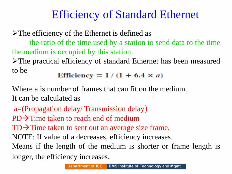
BMS Institute of Technology and Mgmt Department of ISE
Efficiency of Standard Ethernet
The efficiency of the Ethernet is defined as
the ratio of the time used by a station to send data to the time
the medium is occupied by this station.
The practical efficiency of standard Ethernet has been measured
to be
Where a is number of frames that can fit on the medium.
It can be calculated as
a=(Propagation delay/ Transmission delay) PDTime taken to reach end of medium
TDTime taken to sent out an average size frame,
NOTE: If value of a decreases, efficiency increases.
Means if the length of the medium is shorter or frame length is
longer, the efficiency increases. 562

BMS Institute of Technology and Mgmt Department of ISE
In the Standard Ethernet with the transmission rate of 10
Mbps, we assume that the length of the medium is 2500 m
and the size of the frame is 512 bits. The propagation speed
of a signal in a cable is normally 2 × 10⁸ m/s.
Example 13.3
The example shows that a = 0.24, which means only 0.24 of
a frame occupies the whole medium in this case. The
efficiency is 39 percent, which is considered moderate; it
means that only 61 percent of the time the medium is
occupied but not used by a station. 563
BMS Institute of Technology and Mgmt Department of ISE
Implementation
The Standard Ethernet defined several
implementations, but only four of them became
popular during the 1980s
Table below shows a summary of Standard
Ethernet implementations
In the nomenclature, 10 BaseX, number defines the
data rate 10Mbps, Base means base band signal, X
defines either maximum size of the cable in 100 mts
or the type of the cable
564
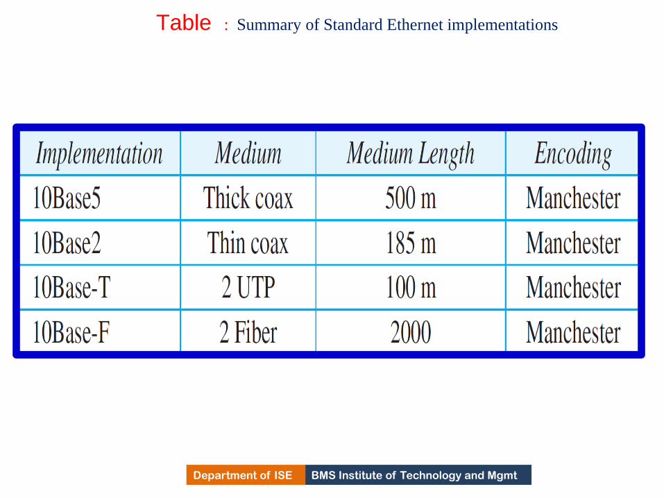
BMS Institute of Technology and Mgmt Department of ISE
Table : Summary of Standard Ethernet implementations
565
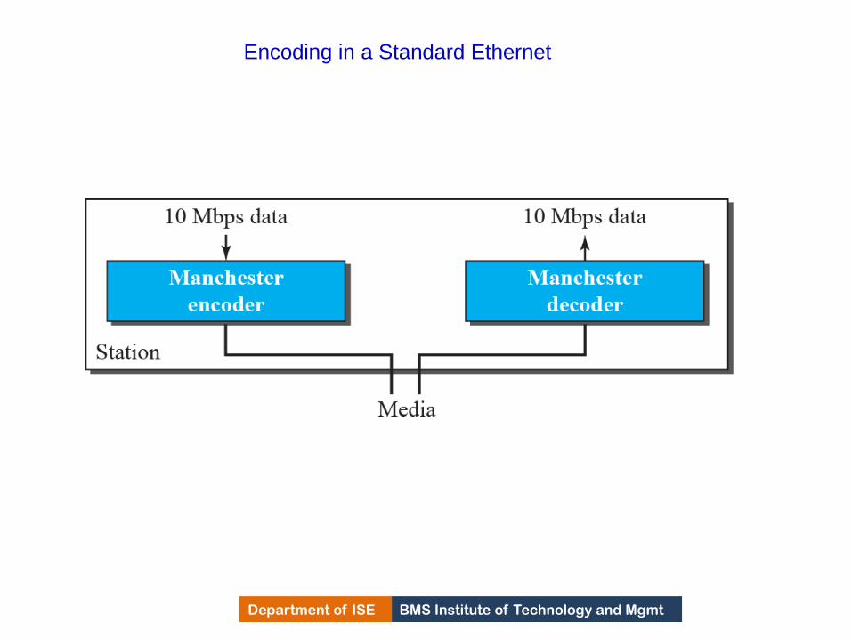
BMS Institute of Technology and Mgmt Department of ISE
Encoding in a Standard Ethernet
566
BMS Institute of Technology and Mgmt Department of ISE Department of ISE BMS Institute of Technology and Mgmt
Encoding in a Standard Ethernet
• All standard implementations use digital signaling at
10 Mbps
• At the sender site, data is converted to a digital signal
using Manchester scheme and at the receiver site,
received signal is decoded into data
• Manchester encoding is self synchronous, providing a
transition at each bit interval
567

BMS Institute of Technology and Mgmt Department of ISE
10Base5 implementation
568

BMS Institute of Technology and Mgmt Department of ISE Department of ISE BMS Institute of Technology and Mgmt
10Base5 implementation
• It is called 10Base5, thick Ethernet or Thick net
• Nick name derives from the size of the cable
• First Ethernet specification to use bus topology with an
external trans receiver connected via tap to a thick coaxial
cable
• Trans receiver is responsible for transmitting, receiving &
detecting collision
Trans receiver is connected to the station via a trans receiver
cable that provides separate paths for sending and receiving
Maximum length of co axial cable should not exceed 500 mts.
If greater than 500mts, there will be excessive degradation of
the signal. If length > 500mts is needed, five segments with a
maximum of 500 mts can be connected using repeaters
569
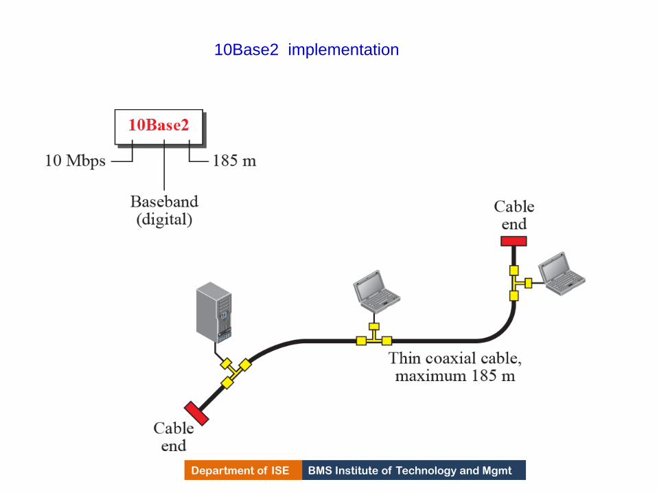
BMS Institute of Technology and Mgmt Department of ISE
10Base2 implementation
570

BMS Institute of Technology and Mgmt Department of ISE Department of ISE BMS Institute of Technology and Mgmt
10Base2-Thin Ethernet
• It is called 10Base5, thin Ethernet or Cheap net
• Nick name derives from the size of the cable
• Uses bus topology , but the cable is much thinner and more
flexible
• The cable can be bent to pass very close to stations
• Trans receiver is part of the NIC which is installed inside the
station
• As Thin co axial cable is very flexible, installation is flexible.
• Length of segment can not exceed 185 mts due to high level of
attention in thin coaxial cable
571

BMS Institute of Technology and Mgmt Department of ISE
10Base-T implementation
572
BMS Institute of Technology and Mgmt Department of ISE Department of ISE BMS Institute of Technology and Mgmt
10Base-T Ethernet
• It is called 10BaseT, twisted pair Ethernet.
• Uses Star topology.
• Stations are connected to a hub via two pair of twisted cables.
• Two pairs creates two paths between station and the hub.
• Any collision happens in the hub.
• Maximum length of twisted pair cable here is defined as 10mts
to minimize the effect of attenuation in the cable.
573

BMS Institute of Technology and Mgmt Department of ISE
10Base-F implementation
574

BMS Institute of Technology and Mgmt Department of ISE Department of ISE BMS Institute of Technology and Mgmt
10Base-F Ethernet
• It is called 10Base-F, Optical fiber 10Mbps Ethernet.
• Uses Star topology.
• Stations are connected to a hub via two pair of fiber-optic
cables.
• Two pairs creates two paths between station and the hub.
575
BMS Institute of Technology and Mgmt Department of ISE
Changes in the Standard
Discuss the changes that occurred to the 10-Mbps Standard
Ethernet.
These changes actually opened the road to the evolution of the
Ethernet to become compatible with other high-data-rate LANs.
Ethernet Evolution:
1) Division of LAN by bridges:
Bridges has two Effects on an Ethernet LANs
i) Raise the Bandwidth
ii) Separate Collision Domains.
In an un bridged Ether N/w, total of 10 Mbps capacity is
shared among all stations with a frame to send.
576
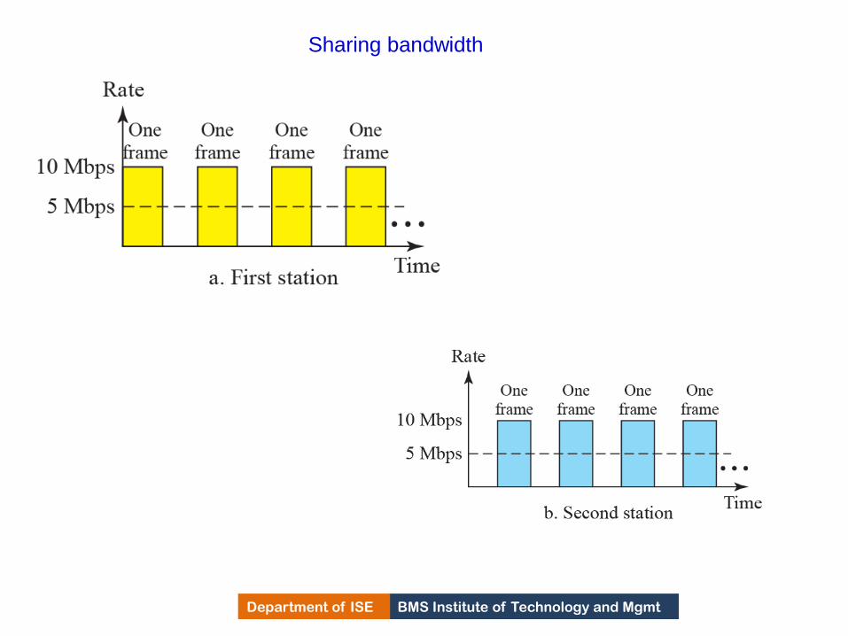
BMS Institute of Technology and Mgmt Department of ISE
Sharing bandwidth
577

BMS Institute of Technology and Mgmt Department of ISE
Raising the Bandwidth
The bridge divides the network into two or more networks.
Bandwidth of each network is independent
Fig. below a network with 12 stations is divided into two
networks each with 6 stations.
Each network has a capacity of 10 Mbps which is shared
between 6 stations and the bridge.
In a network with a heavy load, each station theoretically is
offered 10/7 Mbps instead of 10/12 devices.
If four port bridge is used, each station is offered bandwidth of
10/4. 578

BMS Institute of Technology and Mgmt Department of ISE
A network with and without bridging
579

BMS Institute of Technology and Mgmt Department of ISE
Separating collision domain
Another advantage of bridge is the separation of
collision domain
From the figure below, it is observed that the
probability of collision is reduced
With bridging 3 stations contend for the access for the
medium.
580

BMS Institute of Technology and Mgmt Department of ISE
Collision domains
581

BMS Institute of Technology and Mgmt Department of ISE
Switched Ethernet
The idea of bridged LAN can be extended to switched LAN
In Switched LAN , instead of 4 networks, there will be N
networks where N is the number of stations
Here N port switch is used and the bandwidth is shared between
the station and the switch
Collision domain is divided in to N domains
Evolution from a bridged Ethernet to switched Ethernet was a
big step that opened the way to an even faster Ethernet
582

BMS Institute of Technology and Mgmt Department of ISE
Switched Ethernet
583
BMS Institute of Technology and Mgmt Department of ISE
Full duplex Ethernet
One of the limitations of 10Base5 and 10Base2 is that communication is half
duplex
Full duplex mode increases the capacity of each domain from 10 to 20 Mbps
In Full duplex switched Ethernet, each station is connected to a switch via two
separate links, so there is no need for CSMA/CD
Each link has a point-to-point dedicated path between the station and switch
Job of MAC layer is easy as carrier sensing & collision detection
functionalities can be turned off
Std. Ethernet was designed as a connectionless protocol at MAC sub layer. To
Provide FC & EC in full duplex switched Ethernet, a new sub layer, MAC
control, is added between LLC & MAC
584
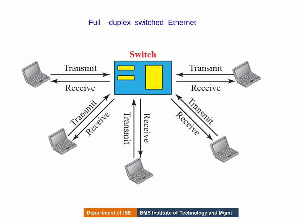
BMS Institute of Technology and Mgmt Department of ISE
Full – duplex switched Ethernet
585

BMS Institute of Technology and Mgmt Department of ISE
FAST ETHERNET(100 Mbps)
In the 1990s, Ethernet made a big jump by increasing the
transmission rate to 100 Mbps, and the new generation was
called the Fast Ethernet
The designers of the Fast Ethernet needed to make it
compatible with the Standard Ethernet
The MAC sub layer was left unchanged, means frame format,
min & max size of frame remain unchanged
By increasing the transmission rate, the features of the
Standard Ethernet that depend on the transmission rate, access
method, implementation had to be changed. 586

BMS Institute of Technology and Mgmt Department of ISE
Goals of Fast Ethernet
Upgrade the data rate to 100 Mbps.
Make it compatible with standard Ethernet.
Keep the same 48 bit address.
Keep the same frame format.
587
BMS Institute of Technology and Mgmt Department of ISE
Access Method
The proper operation of the CSMA/CD depends on
the transmission rate, the minimum size of the frame,
and the maximum network length.
If we want to keep the minimum size of the frame,
the maximum length of the network should be
changed.
In other words, if the minimum frame size is still
512 bits, and it is transmitted 10 times faster, the
collision needs to be detected 10 times sooner, which
means the maximum length of the network should be
10 times shorter (the propagation speed does not
change).
588

BMS Institute of Technology and Mgmt Department of ISE
Access Method
The Fast Ethernet came with two solutions
i)Drop bus topology & use a passive hub or a star topology
but make the maximum size of Ethernet 250 meters
instead of 2500 meters.
ii) Use Link layer switch with a buffer to store frames and
full duplex connection to each host to make the
transmission medium private for each host.
No need of CSMA/CD.
Since the connection to switch is full duplex, the
destination address can even send a frame to another
station at the same time.
New feature called Auto negotiation is added. Auto
negotiation allows two devices to negotiate the mode or
data rate of operation. 589

BMS Institute of Technology and Mgmt Department of ISE
Physical Layer
To be able to handle a 100 Mbps data rate, several
changes need to be made at the physical layer.
590

BMS Institute of Technology and Mgmt Department of ISE
Encoding for fast Ethernet
591

BMS Institute of Technology and Mgmt Department of ISE
Table Summary of Fast Ethernet implementations
592

BMS Institute of Technology and Mgmt Department of ISE
GIGABIT ETHERNET
The need for an even higher data rate resulted in the design of the Gigabit Ethernet
Protocol (1000 Mbps).
The IEEE committee calls it the Standard 802.3z.
The goals of the Gigabit Ethernet were to upgrade the data rate to 1 Gbps, but keep
the address length, the frame format, and the maximum and minimum frame length
the same.
593

BMS Institute of Technology and Mgmt Department of ISE
MAC Sublayer
A main consideration in the evolution of Ethernet was to
keep the MAC sub layer untouched
However, to achieve a data rate of 1 Gbps, this was no longer
possible
Gigabit Ethernet has two distinctive approaches for medium
access:
Half-duplex and Full-duplex
Almost all implementations of Gigabit Ethernet follow the
full-duplex approach.
594

BMS Institute of Technology and Mgmt Department of ISE
Physical Layer
The physical layer in Gigabit Ethernet is more
complicated than that in Standard or Fast Ethernet
Discuss some features of this layer.
595

BMS Institute of Technology and Mgmt Department of ISE
Encoding in Gigabit Ethernet
596

BMS Institute of Technology and Mgmt Department of ISE
Table : Summary of Gigabit Ethernet implementations
597

BMS Institute of Technology and Mgmt Department of ISE
10-GIGABIT EHTERNET
In recent years, there has been another look into the
Ethernet for use in metropolitan areas
The idea is to extend the technology, the data rate,
and the coverage distance so that the Ethernet can be
used as LAN and MAN (metropolitan area network)
The IEEE committee created 10 Gigabit Ethernet and
called it Standard 802.3ae
598

BMS Institute of Technology and Mgmt Department of ISE
Implementation
10 Gigabit Ethernet operates only in full-duplex
mode, which means there is no need for contention;
CSMA/CD is not used in 10 Gigabit Ethernet
Four implementations are the most common:
10GBase-SR, 10GBase-LR, 10GBase-EW, and
10GBase-X4.
599

BMS Institute of Technology and Mgmt Department of ISE
Table Summary of 10-Gigabit Ethernet implementations
600
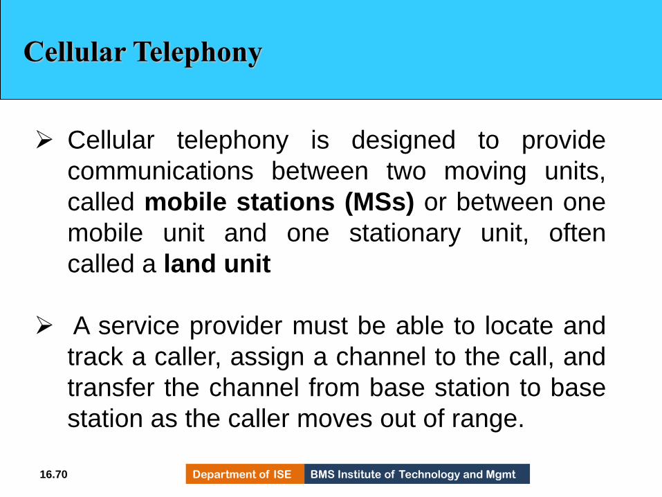
BMS Institute of Technology and Mgmt Department of ISE 16.70
Cellular Telephony
Cellular telephony is designed to provide
communications between two moving units,
called mobile stations (MSs) or between one
mobile unit and one stationary unit, often
called a land unit
A service provider must be able to locate and
track a caller, assign a channel to the call, and
transfer the channel from base station to base
station as the caller moves out of range.
601
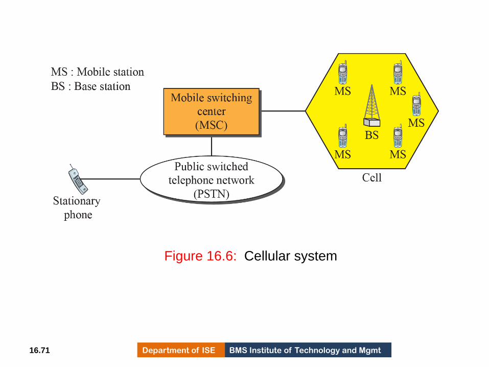
BMS Institute of Technology and Mgmt Department of ISE 16.71
Figure 16.6: Cellular system
602
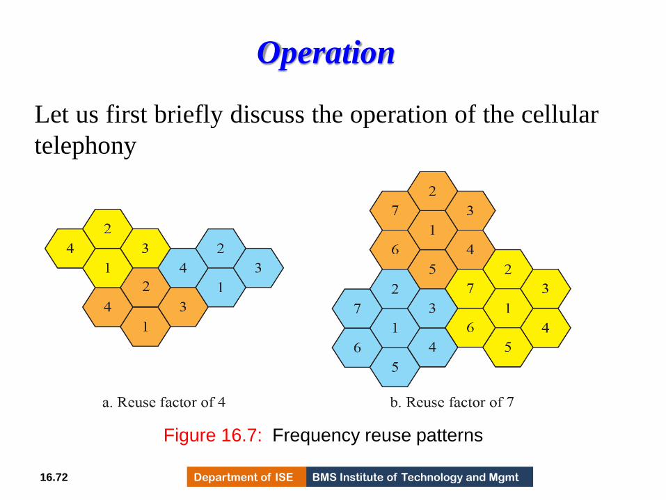
BMS Institute of Technology and Mgmt Department of ISE 16.72
Operation
Let us first briefly discuss the operation of the cellular
telephony
Figure 16.7: Frequency reuse patterns
603
BMS Institute of Technology and Mgmt Department of ISE Department of ISE BMS Institute of Technology and Mgmt
Frequency-Reuse Principle
In general, neighboring cells cannot use the same set of
frequencies for communication because doing so may create
interference for the users located near the cell boundaries
The set of frequencies available is limited, and frequencies
need to be reuse
A frequency reuse pattern is a configuration of N cells, N
being the reuse factor, in which each cell uses a unique set of
frequencies. When the pattern is repeated, the frequencies can
be reused
There are several different patterns. Figure 16.7 shows two of
them. 16.73 604
BMS Institute of Technology and Mgmt Department of ISE Department of ISE BMS Institute of Technology and Mgmt
Frequency-Reuse Principle ( Contd)
The numbers in the cells define the pattern. The cells with the same number in a pattern can use the same set of frequencies. We call these cells the reusing cells
As Figure 16.7 shows, in a pattern with reuse factor 4, only one cell separates the cells using the same set of frequencies
In a pattern with reuse factor 7, two cells separate the reusing cells.
16.74 605

BMS Institute of Technology and Mgmt Department of ISE Department of ISE BMS Institute of Technology and Mgmt
Transmitting
To place a call from a mobile station, the caller enters a code of 7 or 10 digits (a phone number) and presses the send button
The mobile station then scans the band, seeking a setup channel with a strong signal, and sends the data (phone number) to the closest base station using that channel. The base station relays the data to the MSC
The MSC sends the data on to the telephone central office. If the called party is available, a connection is made and the result is relayed back to the MSC
At this point, the MSC assigns an unused voice channel to the call, and a connection is established. The mobile station automatically adjusts its tuning to the new channel, and communication can begin.
16.75 606

BMS Institute of Technology and Mgmt Department of ISE Department of ISE BMS Institute of Technology and Mgmt
Receiving
When a mobile phone is called, the telephone central office
sends the number to the MSC
The MSC searches for the location of the mobile station by
sending query signals to each cell in a process called paging
Once the mobile station is found, the MSC transmits a ringing
signal
When the mobile station answers, assigns a voice channel to
the call, allowing voice communication to begin.
16.76 607

BMS Institute of Technology and Mgmt Department of ISE Department of ISE BMS Institute of Technology and Mgmt
Handoff
It may happen that, during a conversation, the mobile station
moves from one cell to another. The signal may become weak
To solve this problem, the MSC monitors the level of the
signal every few seconds. If the strength of the signal
diminishes, the MSC seeks a new cell that can better
accommodate the communication
The MSC then changes the channel carrying the call (hands
the signal off from the old channel to a new one).
16.77 608

BMS Institute of Technology and Mgmt Department of ISE Department of ISE BMS Institute of Technology and Mgmt
Types of handoffs
• Hard Handoff
• Soft Handoff
16.78 609
BMS Institute of Technology and Mgmt Department of ISE Department of ISE BMS Institute of Technology and Mgmt
Hard Handoff
Early systems used a hard handoff
In a hard handoff, a mobile station only
communicates with one base station
When the mobile station moves from one cell to
another, communication must first be broken with the
previous base station before communication can be
established with the new one
This may create a rough transition 16.79 610

BMS Institute of Technology and Mgmt Department of ISE Department of ISE BMS Institute of Technology and Mgmt
Soft Handoff
New systems use a soft handoff
In this case, a mobile station can communicate with
two base stations at the same time
During handoff, a mobile station may continue with
the new base station before breaking off from the old
one
16.80 611

BMS Institute of Technology and Mgmt Department of ISE Department of ISE BMS Institute of Technology and Mgmt
Roaming
One feature of cellular telephony is called roaming
Roaming means, in principle, that a user can have
access to communication or can be reached where
there is coverage. A service provider usually has
limited coverage
Neighboring service providers can provide extended
coverage through a roaming contract
16.81 612
BMS Institute of Technology and Mgmt Department of ISE 16.82
First Generation (1G)
Cellular telephony is now in its fourth generation
The first generation was designed for voice
communication using analog signals
We discuss one first-generation mobile system
used in North America, AMPS.
613

BMS Institute of Technology and Mgmt Department of ISE Department of ISE BMS Institute of Technology and Mgmt
AMPS
Advanced Mobile Phone System (AMPS) is one of the leading
analog cellular systems in North America
It uses FDMA
Bands
AMPS operates in the ISM 800-MHz band
The system uses two separate analog channels, one for forward
(base station to mobile station) communication and one for
reverse (mobile station to base station) communication
The band between 824 and 849 MHz carries reverse
communication; the band between 869 and 894 MHz carries
forward communication
16.83 614
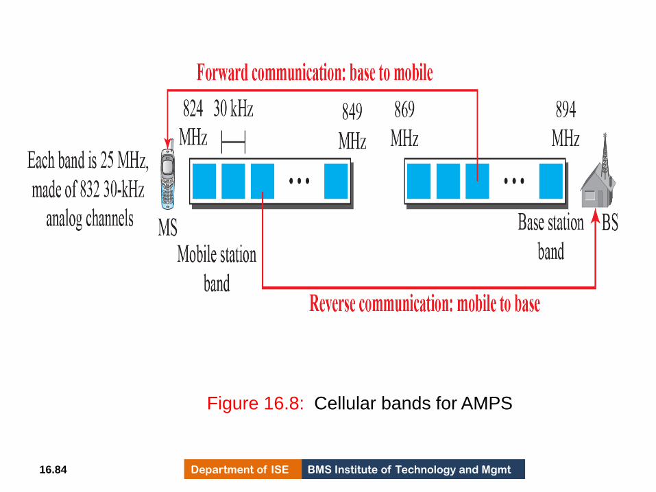
BMS Institute of Technology and Mgmt Department of ISE 16.84
Figure 16.8: Cellular bands for AMPS
615

BMS Institute of Technology and Mgmt Department of ISE 16.85
Figure 616.9: AMPS reverse communication band
616

BMS Institute of Technology and Mgmt Department of ISE 16.86
Second Generation (2G)
To provide higher-quality (less noise-prone)
mobile voice communications, the second
generation of the cellular phone network was
developed
The second generation was mainly designed for
digitized voice
Three major systems evolved in the second
generation: D-AMPS, GSM, and IS-95
617
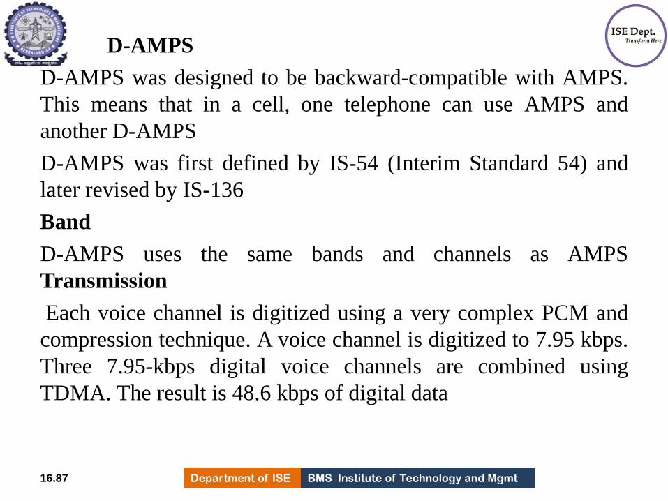
BMS Institute of Technology and Mgmt Department of ISE Department of ISE BMS Institute of Technology and Mgmt
D-AMPS
D-AMPS was designed to be backward-compatible with AMPS.
This means that in a cell, one telephone can use AMPS and
another D-AMPS
D-AMPS was first defined by IS-54 (Interim Standard 54) and
later revised by IS-136
Band
D-AMPS uses the same bands and channels as AMPS
Transmission
Each voice channel is digitized using a very complex PCM and
compression technique. A voice channel is digitized to 7.95 kbps.
Three 7.95-kbps digital voice channels are combined using
TDMA. The result is 48.6 kbps of digital data
16.87 618
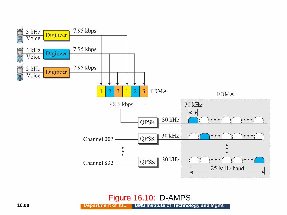
BMS Institute of Technology and Mgmt Department of ISE 16.88
Figure 16.10: D-AMPS 619
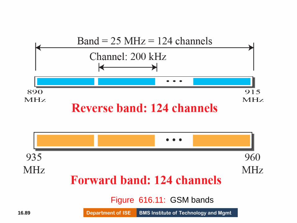
BMS Institute of Technology and Mgmt Department of ISE 16.89
Figure 616.11: GSM bands
620

BMS Institute of Technology and Mgmt Department of ISE Department of ISE BMS Institute of Technology and Mgmt
GSM
The Global System for Mobile Communication (GSM) is a
European standard that was developed to provide a common
second-generation technology for all Europe
The aim was to replace a number of incompatible first-
generation technologies
Bands
GSM uses two bands for duplex communication. Each band is
25 MHz in width, shifted toward 900 MHz
Each band is divided into 124 channels of 200 kHz separated
by guard bands
Transmission
Each voice channel is digitized and compressed to a 13-kbps
digital signal. Each slot carries 156.25 bits. Eight slots share a
frame (TDMA).
16.90 621

BMS Institute of Technology and Mgmt Department of ISE 16.91
Figure 16.12: GSM
622

BMS Institute of Technology and Mgmt Department of ISE 16.92 Figure 16.13: Multiframe components 623

BMS Institute of Technology and Mgmt Department of ISE 16.93
Figure 16.14: IS-95 forward transmission
624
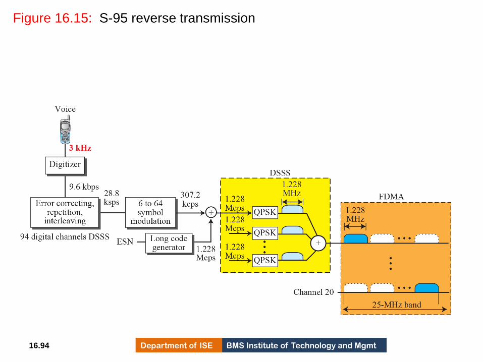
BMS Institute of Technology and Mgmt Department of ISE 16.94
Figure 16.15: S-95 reverse transmission
625
BMS Institute of Technology and Mgmt Department of ISE 16.95
Third Generation (3G)
The third generation of cellular telephony refers to a
combination of technologies that provide both digital data
and voice communication
Using a small portable device, a person is able to talk to
anyone else in the world with a voice quality similar to that
of the existing fixed telephone network
A person can download and watch a movie and listen to
music, surf the Internet or play games
The third-generation concept started in 1992, when ITU
issued a blueprint called the Internet Mobile
Communication 2000 (IMT-2000) 626

BMS Institute of Technology and Mgmt Department of ISE 16.96
Figure 16.16: IMT-2000 radio interfaces
627

BMS Institute of Technology and Mgmt Department of ISE 16.97
Fourth Generation (4G)
The fourth generation of cellular telephony is
expected to be a complete evolution in wireless
communications
628

BMS Institute of Technology and Mgmt Department of ISE Department of ISE BMS Institute of Technology and Mgmt
• Some of the objectives defined by the 4G working group are as follows:
a. A spectrally efficient system.
b. High network capacity.
c. Data rate of 100 Mbit/s for access in a moving car and 1 Gbit/s for stationary users.
d. Data rate of at least 100 Mbit/s between any two points in the world.
e. Smooth handoff across heterogeneous networks.
f. Seamless connectivity and global roaming across multiple networks. g. High quality of service for next generation multimedia support
h. Interoperability with existing wireless standards.
i. All IP, packet-switched, networks
The fourth generation is only packet-based (unlike 3G) and supports IPv6. This provides better multicast, security, and route optimization capabilities.
16.98 629

BMS Institute of Technology and Mgmt Department of ISE Department of ISE BMS Institute of Technology and Mgmt
• Access Scheme
To increase efficiency, capacity, and scalability, new access techniques are
being considered for 4G. For example, orthogonal FDMA (OFDMA) and
interleaved FDMA (IFDMA) are being considered respectively for the
downlink and uplink of the next generation Universal Mobile
Telecommunications System (UMTS). Similarly, multicarrier code division
multiple access (MC-CDMA) is proposed for the IEEE 802.20 standard.
• Modulation More efficient quadrature amplitude modulation (64-QAM) is
being proposed for use with the Long Term Evolution (LTE) standards.
.
16.99 630
BMS Institute of Technology and Mgmt Department of ISE Department of ISE BMS Institute of Technology and Mgmt
Radio System The fourth generation uses a Software Defined Radio (SDR)
system. Unlike a common radio, which uses hardware, the components of an
SDR are pieces of software and thus flexible. The SDR can change its program
to shift its frequencies to mitigate frequency interference.
Antenna The multiple-input multiple-output (MIMO) and multiuser MIMO
(MU-MIMO) antenna system, a branch of intelligent antenna, is proposed for
4G. Using this antenna system together with special multiplexing, 4G allows
independent streams to be transmitted simultaneously from all the antennas to
increase the data rate into multiple folds. MIMO also allows the transmitter
and receiver coordinates to move to an open frequency when interference
occurs.
16.100 631