D24x40 Series II Navigator®
292
D24x40 Series II Navigator ® Horizontal Directional Drill D24x40_Series_II_o3_06 Serial No. 381 - Order No. 105400Z86 Cabled Assembly Order No. 296296960 Operator’s Manual
-
Upload
khangminh22 -
Category
Documents
-
view
1 -
download
0
Transcript of D24x40 Series II Navigator®

D24x40 Series II Navigator®
Horizontal Directional Drill
D24x40_Series_II_o3_06Serial No. 381 -Order No. 105400Z86Cabled Assembly Order No. 296296960
Operator’s Manual

Introduction D24x40 Series II Navigator Directional Drill
IntroductionThis manual explains the proper operation of your machine. Study and understand these instructions thoroughly before operating or maintaining the machine. Failure to do so could result in personal injury or equipment damage. Consult your Vermeer dealer if you do not understand the instructions in this manual, or need additional information.
The instructions, illustrations, and specifications in this manual are based on the latest information available at time of publication. Your machine may have product improvements and features not yet contained in this manual.
Vermeer Corporation reserves the right to make changes at any time without notice or obligation.
Operation instructions are included in the two Operator’s Manuals provided with the machine. The tethered (cabled) manual must remain attached to the machine for ready reference. Store it in the manual storage box when not in use.
Lubrication and maintenance procedures are in the Maintenance Manual provided with the machine. Refer to it for all lubrication and maintenance procedures.
Additional copies of the manuals, and Operations and Safety video, are available from your dealer. Reorder numbers are listed on the front covers of the manuals and on the video.
Copies of this manual, and the Operations and Safety video, are available in Spanish from your dealer.
Su distribuidor dispone de ejemplares en español de este manual y del vídeo de Operaciones y Seguridad.
NOTICE TO OWNER You are requested to notify Vermeer Corporation when you have purchased a used Vermeer machine. Notify the Customer Data Department by telephone: 800-829-0051 or 641-628-3141; email: [email protected]; internet: www.vermeer.com or www.vermeerag.com; or, letter: Customer Data Dept., Vermeer Corporation, PO Box 200, Pella IA 50219 USA. Upon request, an owner of a used Vermeer machine will receive one free set of Operator’s, Maintenance and Parts manuals.

D24x40 Series II Navigator Directional Drill
NOTE: Right and left sides of this machine are determined by facing the power vises while seated at the controls.
TRADEMARKS
VERMEER, VERMEER Logo, NAVIGATOR and QUICKFIRE are trademarks of Vermeer Manufacturing Company.SPLINELOK and TRIHAWK are trademarks of Earth Tool Company, LLC.JOHN DEERE and COOL-GARD are trademarks of Deere & Company.DIGITRAK, ECLIPSE, and TENSITRAK are trademarks of Digital Controls.

D24x40 Series II Navigator Directional Drill
VERMEER NEW INDUSTRIAL EQUIPMENT LIMITED WARRANTY
(EFFECTIVE OCTOBER 1, 2008) WARRANTY PERIOD: 12 Months / 1000 HoursVermeer Corporation (hereinafter “Vermeer”) warrants each new Industrial product of Vermeer's manufacture to be free from defects in material and workmanship, under normal use and service for one (1) full year after initial purchase/retail sale or 1000 operating hours, whichever occurs first. This Limited Warranty shall apply only to complete machines of Vermeer's manufacture, parts are covered by a separate Limited Warranty. EQUIPMENT AND ACCESSORIES NOT OF VERMEER'S MANUFACTURE ARE WARRANTED ONLY TO THE EXTENT OF THE ORIGINAL MANUFACTURER'S WARRANTY AND SUBJECT TO THEIR ALLOWANCE TO VERMEER ONLY IF FOUND DEFECTIVE BY SUCH MANUFACTURER.
EXTENDED WARRANTY OPTIONS ARE AVAILABLE FOR PURCHASE.
WARRANTY TERMS
During the Limited Warranty period specified above, any defect in material or workmanship in any warranted item of Vermeer Industrial Equipment not excluded below shall be repaired or replaced at Vermeer's option without charge by any authorized independent Vermeer dealer. The warranty repair or replacement must be made by a Vermeer independent authorized dealer at the dealer's location. Vermeer will pay for replacement parts and such authorized dealer's labor in accordance with Vermeer's labor reimbursement policy. Vermeer reserves the right to supply remanufactured replacement parts as it deems appropriate.
RETAIL PURCHASER RESPONSIBILITY: This Limited Warranty requires proper maintenance and periodic inspections of the Industrial Equipment as indicated in the Operator’s/Maintenance Manual furnished with each new Industrial Equipment. The cost of routine or required maintenance and services is the responsibility of the retail purchaser. The retail purchaser is required to keep documented evidence that these services were performed.
This Vermeer New Industrial Equipment Limited Warranty may be subject to cancellation if the above requirements are not performed.
Vermeer Industrial Equipment with known failed or defective parts must be immediately removed from service.

D24x40 Series II Navigator Directional Drill
EXCLUSIONS AND LIMITATIONS
The warranties contained herein shall NOT APPLY TO:(1) Any defect which was caused (in Vermeer’s sole judgment) by other than normal use and service of the Industrial
Equipment, or by any of the following; (i) accident (ii) misuse or negligence (iii) overloading (iv) lack of reasonable and proper maintenance (v) improper repair or installation (vi) unsuitable storage (vii) non-Vermeer approved alteration or modification (viii) natural calamities (ix) vandalism (x) parts or accessories installed on Industrial Equipment which were not manufactured or installed by Vermeer authorized dealers (xi) the elements (xii) collision or other accident.
(2) Any Industrial Equipment whose identification numbers or marks have been altered or removed or whose hourmeter has been altered or tampered with.
(3) Any Industrial Equipment which any of the required or recommended periodic inspection or services have been performed using parts not manufactured or supplied by Vermeer or meeting Vermeer Specifications including, but without limitation, engine tune-up parts, engine oil filters, air filters, hydraulic oil filters, and fuel filters.
(4) New Industrial Equipment delivered to the retail purchaser in which the warranty registration has not been completed and returned to Vermeer within ten (10) days from the date of purchase.
(5) Any defect which was caused (in Vermeer’s sole judgment) by operation of the Industrial Equipment not abiding by standard operating procedures outlined in the Operator’s Manual.
(6) Engine, battery, and tire Limited Warranties and support are the responsibility of the respective product’s manufacturer.(7) Transportation costs, if any, of transporting to the Vermeer dealer. Freight costs, if any, of transporting replacement parts to
the Vermeer dealer. (8) The travel time of the Vermeer dealer’s service personnel to make a repair on the retail purchaser’s site or other location. (9) In no event shall Vermeer’s liability exceed the purchase price of the product, (10) Vermeer shall not be liable to any person under any circumstances for any incidental or consequential damages (including
but not limited to, loss of profits, out of service time) occurring for any reason at any time.(11) Diagnostic and overtime labor premiums are not covered under this Limited Warranty Policy. Oils and fluids are not covered
under this Limited Warranty.

D24x40 Series II Navigator Directional Drill
(12) Depreciation damage caused by normal wear, lack of reasonable and proper maintenance, failure to follow operating instructions, misuse, lack of proper protection during storage.
(13) Accessory systems and electronics not of Vermeer’s manufacture are warranted only to the extent of such manufacturer’s respective Limited Warranty if any.
(14) Downhole toolage is not covered under this warranty.(15) Wear items which are listed by product group as follows:
ENVIRONMENTAL: Bearing Seals, Bearings, Belts, Brake Pads, Bolts/Torqued Parts, Chain, Clutches, Clutch Components, Curtains, Cutter Wheels, Discharge Conveyor Belts, Fuel Filters, Hammers, Hoses, Infeed Conveyor Belts, Infeed Conveyor Chains, Knives, Oil Filters, Pockets, Rods, Rollers, Rotor Plates, Screens, Service Items, Shear Bar/Bedknife, Sprockets, Teeth, Wear Blocks, Wear Strips.
TRACK: Base Plates, Boom Wear Items, Buckets, Cable Fingers, Conveyor Belts, Clutches, Cups, Digging Chain, Digging Rims, Drums, End Idler, Flashings, Pins and Bushings, Pivot Rings, Plastic Wear Strips, Rooter Bands, Scraper Knives, Sprockets, Teeth, Track Chain, Track Rollers, Trench Cleaner (Crumber), Trip Cleaners, Truck Rollers, Wear Plates.
TRENCHLESS: Brushes, Clamping Vise Parts, Dies, Drive Chuck, Earth Stakes, Fan Belts, Jaws, Leaf Chain, Lights On Light Kits, Packing Assemblies, Rod, Rod Loader Parts, Rollers, Tooling, Track Chain, Track Guides, Track Idlers, Track Pads, Track Sprockets, Valve Seats, Wear Bars, Wear Blocks, Water Hoses, Water Swivels, Wear Bars.
UTILITY PRODUCTS: Augers, Belts, Bearings, Booms, Brake Pads, Bucket, Bushings, Chains, Clutches, Conveyor Belts, End Rollers, Flashings, Pins, Pivot Rings, Plow Blades, Rubber Shielding, Sprockets, Teeth, Tires, Track Chain, Track Idlers, Track Sprockets, Trench Cleaner (Crumber).
PARTS WARRANTY:
Parts replaced in the warranty period will receive the balance of the first year New Industrial Equipment Limited Warranty, during the first (12) months or 1000 hours, whichever comes first. Replacement parts after the original machine warranty, are warranted to be free from defects of material for ninety (90) days or the part will be repaired or replaced, without labor coverage for removal and reinstallation.

D24x40 Series II Navigator Directional Drill
EXCLUSIONS OF WARRANTIES: EXCEPT FOR THE WARRANTIES EXPRESSLY AND SPECIFICALLY MADE HEREIN, VERMEER MAKES NO OTHER WARRANTIES, AND ANY POSSIBLE LIABILITY OF VERMEER HEREINUNDER IS IN LIEU OF ALL OTHER WARRANTIES, EXPRESS, IMPLIED, OR STATUTORY, INCLUDING, BUT NOT LIMITED TO, ANY WARRANTIES OF MERCHANTABILITY OR FITNESS FOR A PARTICULAR PURPOSE. VERMEER RESERVES THE RIGHT TO MODIFY, ALTER AND IMPROVE ANY PRODUCT WITHOUT INCURRING ANY OBLIGATION TO REPLACE ANY PRODUCT PREVIOUSLY SOLD WITH SUCH MODIFICATION. NO PERSON IS AUTHORIZED TO GIVE ANY OTHER WARRANTY, OR TO ASSUME ANY ADDITIONAL OBLIGATION ON VERMEER’S BEHALF.
NO DEALER WARRANTY. The selling dealer makes no warranty of its own and the dealer has no authority to make any representation or promise on behalf of Vermeer or to modify the terms or limitations of this warranty in any way.
MANUFACTURED BY:VERMEER CORPORATION
Pella, Iowa 50219 USA

D24x40 Series II Navigator Directional Drill
VERMEER EQUIPMENT LIFETIME LIMITED WARRANTY RIDER
(Parts only coverage during extended term)Vermeer Corporation (hereinafter “Vermeer”) agrees to extend only the parts coverage of the applicable Vermeer Industrial New Equipment Limited Warranty (the “Standard Limited Warranty”) for the Covered Components of the Specified Models of New Vermeer Industrial Equipment for the Lifetime of the Equipment provided that such Equipment is operated and maintained in accordance with the directions and instructions set forth in the Operator's and Maintenance Manuals. All conditions, exclusions and limitations of the Standard Limited Warranty apply.
Models . . . . . . . . . . . . . . . . Serial Numbers of Included Units
D7x11 Series II . . . . . . . . . . . . .464 and aboveD9x13 Series II . . . . . . . . . . . . .101 and aboveD16x20 Series II . . . . . . . . . . . .101 and aboveD20x22 . . . . . . . . . . . . . . . . . . . .143 and aboveD20x22 Series II . . . . . . . . . . . .101 and aboveD20x22FX Series II . . . . . . . . . .101 and aboveD24x40 Series II . . . . . . . . . . . .281 and aboveD36x50 Series II . . . . . . . . . . . .143 and aboveD80x100 Series II . . . . . . . . . . .122 and aboveD100x120 Series II . . . . . . . . . .123 and aboveD200x300 . . . . . . . . . . . . . . . . . .110 and aboveD300x500 . . . . . . . . . . . . . . . . . .111 and aboveD330x500 . . . . . . . . . . . . . . . . . .101 and aboveSpecified Models: . . . . . . All Vermeer Navigator Horizontal Directional Drills built with rack and pinion
Covered Components: . . All rack gears and pinion gears. (Excludes carriage, carriage rollers and guide rollers)
Extended Term: . . . . . . . . Lifetime of Equipment. This warranty is extended to the original purchaser only. It is not transferable.
EXCEPT FOR THE STANDARD LIMITED WARRANTY AND THIS RIDER, VERMEER MAKES NO OTHER WARRANTIES, AND ANY POSSIBLE LIABILITY OF VERMEER HEREUNDER IS IN LIEU OF ALL OTHER WARRANTIES, EXPRESS, IMPLIED, OR STATUTORY, INCLUDING, BUT NOT LIMITED TO, ANY WARRANTIES OF MERCHANTABLILITY OR FITNESS FOR A PARTICULAR PURPOSE.

D24x40 Series II Navigator Directional Drill Receiving and Delivery Report i
Receiving and Delivery ReportDEALER PREP
Check or perform the following:
___ Check for shipping damage or shortage. ___ Check that work area cones are supplied with the machine. ___ Check that certificates for electrically insulated gloves (1 pair) and boots (2 pairs) are supplied with the machine. ___ Check machine for loose bolts. ___ Check installation and condition of all shields.___ Check tracks for proper tension. ___ Check condition of all safety signs. ___ Check Strike Alert system.___ Check rotation and thrust Neutral Start interlocks. (Engine will start with rotation and thrust handles out of
NEUTRAL, but motion does not occur until handles are returned to NEUTRAL and back out of NEUTRAL.)___ Check that the Operator Presence system functions.___ Check Remote Lockout system.___ Check oil in rotation gearbox.___ Check adjustment and operation of rod loader.___ Check operation of drilling fluid flow systems.___ Check operation of locator system if supplied.
Engine___ Check engine oil level. ___ Check condition of air cleaner. ___ Check air intake clamps.___ Check battery charge and electrolyte level.

ii Receiving and Delivery Report D24x40 Series II Navigator Directional Drill
___ Check belts for proper tension. ___ Check coolant level and antifreeze concentration.___ Check radiator hose clamps.___ Check engine for proper operation.
Hydraulics___ Check hydraulic fluid level. ___ Check controls for proper operation. ___ Check all hydraulic components for leaks or damage.___ Check pressure and operation of vises.___ Check rotation relief pressure - 6000 psi (413 bar).___ Check maximum thrust/pullback pressure.___ Check operation of stakedown units.
DELIVERYCheck and perform the following with the customer:___ Review contents of the HDD Resource Library
___ Review the DVD on Horizontal Directional Drilling___ Review all sections of the Operator’s Manual.___ Grease or oil all lubrication points.Review and demonstrate with the customer the various aspects of Navigator HDD:___ overall explanation of how the machine works___ directional drilling safety___ preparing the Navigator HDD for operation

D24x40 Series II Navigator Directional Drill Receiving and Delivery Report iii
DEALER/CUSTOMER INFORMATION
dealer owner
address address
city city
state / province state / province
zip / postal code zip / postal code
country country

iv Receiving and Delivery Report D24x40 Series II Navigator Directional Drill
MACHINE IDENTIFICATION NUMBER - RECORDModel Number
Serial Number
ENGINE IDENTIFICATION NUMBER - RECORDOn left side of engine
Engine Model Number
Engine Serial Number

D24x40 Series II Navigator Directional Drill Receiving and Delivery Report v
ENGINE CONTROL UNIT IDENTIFICATION NUMBER - RECORDModel Number
Serial Number

This page intentionally left blank.

D24x40 Series II Navigator Directional Drill Table of Contents vii
Table of ContentsReceiving and Delivery Report . . . . . . . . . . . . . . . . . . . . .i
Dealer Prep . . . . . . . . . . . . . . . . . . . . . . . . . . . . . . . . . . . . . . . . . iEngine. . . . . . . . . . . . . . . . . . . . . . . . . . . . . . . . . . . . . . . . . . iHydraulics . . . . . . . . . . . . . . . . . . . . . . . . . . . . . . . . . . . . . . . ii
Delivery . . . . . . . . . . . . . . . . . . . . . . . . . . . . . . . . . . . . . . . . . . . .iiDealer/Customer Information . . . . . . . . . . . . . . . . . . . . . . . . . . iiiMachine Identification Number - Record . . . . . . . . . . . . . . . . . . ivEngine Identification Number - Record . . . . . . . . . . . . . . . . . . . ivEngine Control Unit Identification Number - Record . . . . . . . . . v
Safety Messages . . . . . . . . . . . . . . . . . . . . . . . . 10-1Safety Symbol Explanation . . . . . . . . . . . . . . . . . . . . . . . . . .10-1Fire Extinguisher . . . . . . . . . . . . . . . . . . . . . . . . . . . . . . . . . .10-4
Welding Precautions . . . . . . . . . . . . . . . . . . . . . 11-1Welding Alert - Electronic Components . . . . . . . . . . . . . . . .11-1
Intended Use . . . . . . . . . . . . . . . . . . . . . . . . . . . 15-1
Controls . . . . . . . . . . . . . . . . . . . . . . . . . . . . . . . 20-1Strike Alert Controls . . . . . . . . . . . . . . . . . . . . . . . . . . . . . . . .20-1
Remote Lockout Controls . . . . . . . . . . . . . . . . . . . . . . . . . . .20-3Remote Transmitter Controls . . . . . . . . . . . . . . . . . . . . . . . .20-3
Indicator Lights . . . . . . . . . . . . . . . . . . . . . . . . . . . . . . . . 20-4Remote Lockout Machine Controls . . . . . . . . . . . . . . . . . . . .20-5
Indicator Lights . . . . . . . . . . . . . . . . . . . . . . . . . . . . . . . . 20-5
Remote Lockout Battery Charger . . . . . . . . . . . . . . . . . . . . . 20-6Remote Lockout Indicators . . . . . . . . . . . . . . . . . . . . . . . . . . 20-7
Engine Controls . . . . . . . . . . . . . . . . . . . . . . . . . . . . . . . . . . . 20-8Engine Operation Controls . . . . . . . . . . . . . . . . . . . . . . . . . . 20-8Engine Monitors . . . . . . . . . . . . . . . . . . . . . . . . . . . . . . . . . 20-10Engine Gauges . . . . . . . . . . . . . . . . . . . . . . . . . . . . . . . . . . 20-11Auxiliary Engine Controls . . . . . . . . . . . . . . . . . . . . . . . . . . 20-12
Transport Station Controls . . . . . . . . . . . . . . . . . . . . . . . . . 20-13Track/Ground Drive Controls . . . . . . . . . . . . . . . . . . . . . . . 20-13Tethered Transport Control - S/N 796, 909+ . . . . . . . . . . . 20-14
Auxiliary Controls . . . . . . . . . . . . . . . . . . . . . . . . . . . . . . . . 20-16Work Lights . . . . . . . . . . . . . . . . . . . . . . . . . . . . . . . . . . . . 20-16Engine Cover Latch . . . . . . . . . . . . . . . . . . . . . . . . . . . . . . 20-17Beacon . . . . . . . . . . . . . . . . . . . . . . . . . . . . . . . . . . . . . . . . 20-17
Setup Controls . . . . . . . . . . . . . . . . . . . . . . . . . . . . . . . . . . . 20-18Rack and Stabilizer Controls . . . . . . . . . . . . . . . . . . . . . . . 20-18Stakedown Controls . . . . . . . . . . . . . . . . . . . . . . . . . . . . . . 20-19
Drill Station Controls . . . . . . . . . . . . . . . . . . . . . . . . . . . . . . 20-20Operator Presence/Seat Controls . . . . . . . . . . . . . . . . . . . 20-20Auxiliary Outlets . . . . . . . . . . . . . . . . . . . . . . . . . . . . . . . . . 20-21Operator Station Cover (Option) . . . . . . . . . . . . . . . . . . . . 20-21Relays and Fuses . . . . . . . . . . . . . . . . . . . . . . . . . . . . . . . . 20-22Rod Loader Controls . . . . . . . . . . . . . . . . . . . . . . . . . . . . . 20-23Auto Grease Button (Option) . . . . . . . . . . . . . . . . . . . . . . . 20-24Row Selector Lever . . . . . . . . . . . . . . . . . . . . . . . . . . . . . . 20-25
Manual Row Selector (S/N 958+). . . . . . . . . . . . . . . . . 20-26

viii Table of Contents D24x40 Series II Navigator Directional Drill
Power Vise Controls . . . . . . . . . . . . . . . . . . . . . . . . . . . . . 20-27Drilling Controls - Rotation . . . . . . . . . . . . . . . . . . . . . . . . . 20-28Drilling Controls - Thrust . . . . . . . . . . . . . . . . . . . . . . . . . . 20-29Rod Joint Position Indicator . . . . . . . . . . . . . . . . . . . . . . . . 20-30Drill Mode Selector Switch . . . . . . . . . . . . . . . . . . . . . . . . . 20-30AutoDrill Controls . . . . . . . . . . . . . . . . . . . . . . . . . . . . . . . . 20-31R.A.T.T. Controls . . . . . . . . . . . . . . . . . . . . . . . . . . . . . . . . 20-33AutoDrill and R.A.T.T. Diagnostics . . . . . . . . . . . . . . . . . . 20-34Drilling Fluid Controls . . . . . . . . . . . . . . . . . . . . . . . . . . . . . 20-35
Cab (Option) . . . . . . . . . . . . . . . . . . . . . . . . . . . . 21-1Engine Controls . . . . . . . . . . . . . . . . . . . . . . . . . . . . . . . . . . 21-1Cab Swing . . . . . . . . . . . . . . . . . . . . . . . . . . . . . . . . . . . . . . 21-3Cab Exits . . . . . . . . . . . . . . . . . . . . . . . . . . . . . . . . . . . . . . . 21-4Access Panel . . . . . . . . . . . . . . . . . . . . . . . . . . . . . . . . . . . . 21-4Jump-Start Remote Post . . . . . . . . . . . . . . . . . . . . . . . . . . . 21-4Cab Air Control . . . . . . . . . . . . . . . . . . . . . . . . . . . . . . . . . . 21-5
Heater Coolant Shutoff Valves . . . . . . . . . . . . . . . . . . . . 21-5Controls Location . . . . . . . . . . . . . . . . . . . . . . . . . . . . . . . . . 21-6
Strike Alert . . . . . . . . . . . . . . . . . . . . . . . . . . . . . . . . . . . . 21-6Remote Lockout . . . . . . . . . . . . . . . . . . . . . . . . . . . . . . . 21-6Gauges . . . . . . . . . . . . . . . . . . . . . . . . . . . . . . . . . . . . . . 21-7Controls and Warning Lights . . . . . . . . . . . . . . . . . . . . . . 21-7Monitors. . . . . . . . . . . . . . . . . . . . . . . . . . . . . . . . . . . . . . 21-8Switches . . . . . . . . . . . . . . . . . . . . . . . . . . . . . . . . . . . . . 21-8Left Console Controls . . . . . . . . . . . . . . . . . . . . . . . . . . . 21-9
Digitrak Multi-Function Display (MFD) . . . . . . . 25-1Control Buttons . . . . . . . . . . . . . . . . . . . . . . . . . . . . . . . . . . 25-2Default Data Screen . . . . . . . . . . . . . . . . . . . . . . . . . . . . . . 25-2
Main Menu Screen . . . . . . . . . . . . . . . . . . . . . . . . . . . . . . . .25-3Setting the Mode . . . . . . . . . . . . . . . . . . . . . . . . . . . . . . . . . .25-4
DigiTrak Mark Series Mode. . . . . . . . . . . . . . . . . . . . . . . 25-4Eclipse Mode. . . . . . . . . . . . . . . . . . . . . . . . . . . . . . . . . . 25-5TensiTrak Mode . . . . . . . . . . . . . . . . . . . . . . . . . . . . . . . 25-5
Telemetry Region . . . . . . . . . . . . . . . . . . . . . . . . . . . . . . . . .25-6Setting Up the MFD . . . . . . . . . . . . . . . . . . . . . . . . . . . . . . . .25-8
Menu Options Matching . . . . . . . . . . . . . . . . . . . . . . . . . 25-8Viewing Data Screen. . . . . . . . . . . . . . . . . . . . . . . . . . . . 25-8Adjusting Screen Contrast . . . . . . . . . . . . . . . . . . . . . . . 25-9
Power Off . . . . . . . . . . . . . . . . . . . . . . . . . . . . . . . . . . . . . . .25-9Remote Modes . . . . . . . . . . . . . . . . . . . . . . . . . . . . . . . . . . .25-9
DigiTrak Mark Series Mode. . . . . . . . . . . . . . . . . . . . . . . 25-9Eclipse Mode . . . . . . . . . . . . . . . . . . . . . . . . . . . . . . . . . . . .25-12
Actual Depth Measurement. . . . . . . . . . . . . . . . . . . . . . 25-13Predicted Depth Reading . . . . . . . . . . . . . . . . . . . . . . . 25-14Target Steering . . . . . . . . . . . . . . . . . . . . . . . . . . . . . . . 25-15
TensiTrak Mode . . . . . . . . . . . . . . . . . . . . . . . . . . . . . . . . .25-16
Overview . . . . . . . . . . . . . . . . . . . . . . . . . . . . . . . 30-1Remote Lockout Overview . . . . . . . . . . . . . . . . . . . . . . . . . . .30-1
Remote Lockout System Intended Use . . . . . . . . . . . . . . . . .30-1Remote Lockout System Component Identification . . . . . . .30-3Remote Transmitter . . . . . . . . . . . . . . . . . . . . . . . . . . . . . . .30-3
Power ON/OFF Button . . . . . . . . . . . . . . . . . . . . . . . . . . 30-4Run Button . . . . . . . . . . . . . . . . . . . . . . . . . . . . . . . . . . . 30-4Lockout Button . . . . . . . . . . . . . . . . . . . . . . . . . . . . . . . . 30-5Remote Lockout - Hydraulic Lockout Test . . . . . . . . . . . 30-6Remote Lockout - Engine Shutdown Test. . . . . . . . . . . . 30-7
Loss of Remote Transmitter Signal . . . . . . . . . . . . . . . . . . . .30-8

D24x40 Series II Navigator Directional Drill Table of Contents ix
Remote Lockout Indicators . . . . . . . . . . . . . . . . . . . . . . . . . .30-8Fault Check/Processing Lights . . . . . . . . . . . . . . . . . . . . 30-9
Hydraulic Lockout or Engine Shutdown Option . . . . . . . . .30-10Hydraulic Lockout Backup Engine Shutdown . . . . . . . . 30-11Engine Shutdown Lockout . . . . . . . . . . . . . . . . . . . . . . 30-11
Remote Registration . . . . . . . . . . . . . . . . . . . . . . . . . . . . . .30-11Battery Condition . . . . . . . . . . . . . . . . . . . . . . . . . . . . . . . .30-13
Low Battery. . . . . . . . . . . . . . . . . . . . . . . . . . . . . . . . . . 30-13Discharged Battery . . . . . . . . . . . . . . . . . . . . . . . . . . . . 30-13Recharge Battery . . . . . . . . . . . . . . . . . . . . . . . . . . . . . 30-13
Remote Lockout System - Start . . . . . . . . . . . . . . . . . . . . .30-14Remote Lockout System - Shut Down . . . . . . . . . . . . . . . .30-14Lockout Procedure - With Remote Lockout . . . . . . . . . . . .30-15
Resuming Operation after Remote Lockout . . . . . . . . . 30-17Lockout Procedure - Without Remote Lockout System . . .30-18
Resuming Operation after Lockout . . . . . . . . . . . . . . . . 30-18
Drill Rod and Tools . . . . . . . . . . . . . . . . . . . . . . . . . . . . . . . .30-19Drill Rod . . . . . . . . . . . . . . . . . . . . . . . . . . . . . . . . . . . . . . .30-19Drill Tool Connections . . . . . . . . . . . . . . . . . . . . . . . . . . . . .30-20
Hex and QuickFire - Connect . . . . . . . . . . . . . . . . . . . . 30-20Hex and QuickFire - Disconnect . . . . . . . . . . . . . . . . . . 30-20Splinelok Drilling Head . . . . . . . . . . . . . . . . . . . . . . . . . 30-21Splinelok Connection - Assemble . . . . . . . . . . . . . . . . . 30-21Splinelok Connection - Disassemble . . . . . . . . . . . . . . 30-23
Drill Tool Assemblies . . . . . . . . . . . . . . . . . . . . . . . . . . . . .30-23Drill Head Assembly . . . . . . . . . . . . . . . . . . . . . . . . . . . 30-24Trihawk Drill Head Assembly . . . . . . . . . . . . . . . . . . . . 30-25Trihawk Drill Housing Assembly . . . . . . . . . . . . . . . . . . 30-26Armor Drill Housing Assembly . . . . . . . . . . . . . . . . . . . 30-27
Armor Multi-Tool . . . . . . . . . . . . . . . . . . . . . . . . . . . . 30-29
Rotary Tooth Installation/Extraction - Gauntlet Bit . . 30-30PVC Pipe Pulling (Option) . . . . . . . . . . . . . . . . . . . . . . . . . 30-31Reamer Installation . . . . . . . . . . . . . . . . . . . . . . . . . . . . . . 30-32
Swivel . . . . . . . . . . . . . . . . . . . . . . . . . . . . . . . . . . . . . . 30-32Reamer Carrier - Intended Use . . . . . . . . . . . . . . . . . . 30-32Reamer Carrier Styles . . . . . . . . . . . . . . . . . . . . . . . . . 30-32Reamer Carrier Components . . . . . . . . . . . . . . . . . . . . 30-33Reamer Carrier - Install/Remove . . . . . . . . . . . . . . . . . 30-34Reamer Carrier - Lift. . . . . . . . . . . . . . . . . . . . . . . . . . . 30-34Turnbuckle - Adjust . . . . . . . . . . . . . . . . . . . . . . . . . . . 30-35Reamer - Connect with Threaded Connection. . . . . . . 30-36Reamer - Connect with Hex Collar Connection . . . . . . 30-37Reamer - Connect with Splinelok Connection . . . . . . . 30-37Reamer Carrier Wear Pads - Replace . . . . . . . . . . . . . 30-37Chain Sling Alternative to Reamer Carrier -
Splinelok Only . . . . . . . . . . . . . . . . . . . . . . . . . . . . . . 30-38
Locator System . . . . . . . . . . . . . . . . . . . . . . . . . . . . . . . . . . 30-38
Rod Loader . . . . . . . . . . . . . . . . . . . . . . . . . . . . . . . . . . . . . . 30-39Rod Box . . . . . . . . . . . . . . . . . . . . . . . . . . . . . . . . . . . . . . . 30-39
Rod Box - Load . . . . . . . . . . . . . . . . . . . . . . . . . . . . . . 30-39Rod Box - Remove. . . . . . . . . . . . . . . . . . . . . . . . . . . . 30-40Rod Box - Install . . . . . . . . . . . . . . . . . . . . . . . . . . . . . . 30-40Drill Rod Bottom Support Pins - Removal . . . . . . . . . . 30-41Rod Lifter/Selector Identification . . . . . . . . . . . . . . . . . 30-41Rod Joints - Tighten . . . . . . . . . . . . . . . . . . . . . . . . . . . 30-42Drill Rods - Add to Drill String. . . . . . . . . . . . . . . . . . . . 30-42Row Selector - Drilling Out . . . . . . . . . . . . . . . . . . . . . . 30-44Auto Greaser (Option) . . . . . . . . . . . . . . . . . . . . . . . . . 30-45Drill Rods - Remove from Drill String . . . . . . . . . . . . . . 30-46Row Selector Lever - Pulling Back. . . . . . . . . . . . . . . . 30-48

x Table of Contents D24x40 Series II Navigator Directional Drill
Power Vises . . . . . . . . . . . . . . . . . . . . . . . . . . . . . . . . . . . . . 30-49Power Vise Operating Guidelines . . . . . . . . . . . . . . . . . . . 30-49
Drilling Modes Overview . . . . . . . . . . . . . . . . . . . . . . . . . . . 30-50Drilling Modes and Display Lights . . . . . . . . . . . . . . . . . . . 30-50
Normal Drilling Mode . . . . . . . . . . . . . . . . . . . . . . . . . . . 30-50Trihawk and RockFire Modes (Thrust Limits Only) . . . . 30-50R.A.T.T. (Rock Adaptable Terrain Tool) Mode . . . . . . . 30-51
R.A.T.T. Mode . . . . . . . . . . . . . . . . . . . . . . . . . . . . . . . . . . 30-52Disabling R.A.T.T. Drilling Mode When
Oscillation Mode Is Active. . . . . . . . . . . . . . . . . . . . . . 30-53Disabling R.A.T.T. Drilling Mode When
Straight Drilling Mode Is Active. . . . . . . . . . . . . . . . . . 30-53Disabling Default R.A.T.T. Drilling Pressure Limits . . . . 30-54Setting Manual Pressure Limits. . . . . . . . . . . . . . . . . . . 30-55
Setting Manual Thrust Limits . . . . . . . . . . . . . . . . . . . 30-56Setting Manual Rotation Limits . . . . . . . . . . . . . . . . . . 30-56
Rod Wrap and R.A.T.T. Oscillation . . . . . . . . . . . . . . . . 30-57AutoDrill . . . . . . . . . . . . . . . . . . . . . . . . . . . . . . . . . . . . . . . 30-58
AutoDrill Mode Uses . . . . . . . . . . . . . . . . . . . . . . . . . . . 30-58How AutoDrill Works . . . . . . . . . . . . . . . . . . . . . . . . . . . 30-59
AutoDrill - Enable (Normal Drilling) . . . . . . . . . . . . . . . . . . 30-60AutoDrill - Enable (R.A.T.T. Oscillation Mode) . . . . . . . . . 30-61
AutoDrill - Pause . . . . . . . . . . . . . . . . . . . . . . . . . . . . . . 30-63AutoDrill - Resume . . . . . . . . . . . . . . . . . . . . . . . . . . . . 30-63AutoDrill - Disable . . . . . . . . . . . . . . . . . . . . . . . . . . . . . 30-64
AutoDrill - Adjust . . . . . . . . . . . . . . . . . . . . . . . . . . . . . . . . 30-64Constant Thrust/Pullback Speed - Adjust . . . . . . . . . . . 30-66
Initial Speed . . . . . . . . . . . . . . . . . . . . . . . . . . . . . . . . 30-66Limits Exceeded . . . . . . . . . . . . . . . . . . . . . . . . . . . . . 30-66Adjusting to Higher Values . . . . . . . . . . . . . . . . . . . . . 30-67
Constant Thrust/Pullback Pressure - Adjust . . . . . . . . . 30-68Initial Pressure . . . . . . . . . . . . . . . . . . . . . . . . . . . . . . 30-68Limits Exceeded. . . . . . . . . . . . . . . . . . . . . . . . . . . . . 30-68Adjusting to Higher Values. . . . . . . . . . . . . . . . . . . . . 30-69
Constant Rotation Pressure . . . . . . . . . . . . . . . . . . . . . 30-69Initial Pressure . . . . . . . . . . . . . . . . . . . . . . . . . . . . . . 30-69Limits Exceeded. . . . . . . . . . . . . . . . . . . . . . . . . . . . . 30-70Adjusting to Higher Values. . . . . . . . . . . . . . . . . . . . . 30-70
Carriage Speed Manual Control Sensitivity (S/N 381–615) . . . . . . . . . . . . . . . . . . . . . . . . . . . . . . . . . .30-71
Carriage Speed Manual Control Sensitivity (S/N 616+) . . .30-72Memory Settings for Thrust/Rotation Pressure . . . . . . . . . .30-73
Drilling Fluid . . . . . . . . . . . . . . . . . . . . . . . . . . . . . . . . . . . . .30-73Drilling Fluid Pump Output Flow . . . . . . . . . . . . . . . . . . 30-73Adding Antifreeze to Drilling Fluid System . . . . . . . . . . 30-74
Preparation . . . . . . . . . . . . . . . . . . . . . . . . . . . . . 40-1Preparing Personnel . . . . . . . . . . . . . . . . . . . . . . . . . . . . . . . .40-1
Operator Qualifications . . . . . . . . . . . . . . . . . . . . . . . . . . . . .40-1Safety Conscious Operators and Workers . . . . . . . . . . . 40-1Training . . . . . . . . . . . . . . . . . . . . . . . . . . . . . . . . . . . . . . 40-2Safety Signs and Operating Instructions. . . . . . . . . . . . . 40-2
Radio Communication Requirements . . . . . . . . . . . . . . . . . .40-3Radio Communication to Stop Drilling Operation . . . . . . 40-4Radio Communication to Resume Drilling Operation . . . 40-4
Personal Protection . . . . . . . . . . . . . . . . . . . . . . . . . . . . . . . .40-6Sound and Vibration Levels . . . . . . . . . . . . . . . . . . . . . . 40-7
Underground Utility Contact . . . . . . . . . . . . . . . . . . . . . . . . .40-8Electrical Shock Protection . . . . . . . . . . . . . . . . . . . . . . . . . .40-9

D24x40 Series II Navigator Directional Drill Table of Contents xi
Electrocution Avoidance . . . . . . . . . . . . . . . . . . . . . . . . 40-10Electrically Insulated Gloves. . . . . . . . . . . . . . . . . . . . . 40-11
Electrically Insulated Gloves - Inspect . . . . . . . . . . . . 40-12Electrically Insulated Boots. . . . . . . . . . . . . . . . . . . . . . 40-13Strike Alert System Functions. . . . . . . . . . . . . . . . . . . . 40-14Soil Conductivity . . . . . . . . . . . . . . . . . . . . . . . . . . . . . . 40-15Hydraulic System Shutoff . . . . . . . . . . . . . . . . . . . . . . . 40-15
Preparing the Machine . . . . . . . . . . . . . . . . . . . . . . . . . . . . .40-15Operator Presence System . . . . . . . . . . . . . . . . . . . . . . . . .40-15Remote Lockout System Preparation . . . . . . . . . . . . . . . . .40-16
Remote Lockout System. . . . . . . . . . . . . . . . . . . . . . . . 40-16Range - Test . . . . . . . . . . . . . . . . . . . . . . . . . . . . . . . . . 40-16Remote Transmitter - Prepare . . . . . . . . . . . . . . . . . . . 40-16Remote Lockout System - Test . . . . . . . . . . . . . . . . . . 40-17
Preparing the Work Area . . . . . . . . . . . . . . . . . . . . . . . . . . .40-18Jobsite - Check . . . . . . . . . . . . . . . . . . . . . . . . . . . . . . . . . .40-18
Warning Cones . . . . . . . . . . . . . . . . . . . . . . . . . . . . . . . 40-19Power Line Locator System . . . . . . . . . . . . . . . . . . . . . 40-19
Laws and Regulations - Check . . . . . . . . . . . . . . . . . . . . . .40-19Planning the Bore . . . . . . . . . . . . . . . . . . . . . . . . . . . . . . . .40-19
Operation . . . . . . . . . . . . . . . . . . . . . . . . . . . . . . 50-1Starting Procedure . . . . . . . . . . . . . . . . . . . . . . . . . . . . . . . . .50-1
Starting the Engine . . . . . . . . . . . . . . . . . . . . . . . . . . . . . . . .50-1Cold Weather Starting . . . . . . . . . . . . . . . . . . . . . . . . . . . . . .50-2
Engine. . . . . . . . . . . . . . . . . . . . . . . . . . . . . . . . . . . . . . . 50-2Hydraulic Fluid . . . . . . . . . . . . . . . . . . . . . . . . . . . . . . . . 50-3Cold Weather Start System (Option) . . . . . . . . . . . . . . . 50-3
Shutdown Procedure . . . . . . . . . . . . . . . . . . . . . . . . . . . . . . . 50-4
Transporting the Machine . . . . . . . . . . . . . . . . . . . . . . . . . . . 50-5Driving the Machine . . . . . . . . . . . . . . . . . . . . . . . . . . . . . . . 50-5
Safe Operating Slope. . . . . . . . . . . . . . . . . . . . . . . . . . . 50-5Preparing for Transport . . . . . . . . . . . . . . . . . . . . . . . . . . . . 50-6Trailering the Machine . . . . . . . . . . . . . . . . . . . . . . . . . . . . . 50-7
Loading/Unloading . . . . . . . . . . . . . . . . . . . . . . . . . . . . . 50-7Retrieval . . . . . . . . . . . . . . . . . . . . . . . . . . . . . . . . . . . . . . . . 50-9Lifting Machine . . . . . . . . . . . . . . . . . . . . . . . . . . . . . . . . . . . 50-9
Setup . . . . . . . . . . . . . . . . . . . . . . . . . . . . . . . . . . . . . . . . . . . 50-10Bore Path - Walk . . . . . . . . . . . . . . . . . . . . . . . . . . . . . . . . 50-10Drill Unit Setup . . . . . . . . . . . . . . . . . . . . . . . . . . . . . . . . . . 50-10Strike Alert System - Test . . . . . . . . . . . . . . . . . . . . . . . . . . 50-11Strike Alert - Indicators and Controls . . . . . . . . . . . . . . . . . 50-12Machine - Anchor with Stakes . . . . . . . . . . . . . . . . . . . . . . 50-13
Stake - Removal/Install . . . . . . . . . . . . . . . . . . . . . . . . 50-14Locating Equipment - Prepare . . . . . . . . . . . . . . . . . . . 50-14Drilling Fluid Setup . . . . . . . . . . . . . . . . . . . . . . . . . . . . 50-15Rod Wiper - Install . . . . . . . . . . . . . . . . . . . . . . . . . . . . 50-15Entrance and Exit Sites - Prepare . . . . . . . . . . . . . . . . 50-16Warning Cones . . . . . . . . . . . . . . . . . . . . . . . . . . . . . . 50-16
Pilot Bore . . . . . . . . . . . . . . . . . . . . . . . . . . . . . . . . . . . . . . . 50-17Read Overview Section . . . . . . . . . . . . . . . . . . . . . . . . . . . 50-17Safety Precautions . . . . . . . . . . . . . . . . . . . . . . . . . . . . . . . 50-17
Utility Line Contact . . . . . . . . . . . . . . . . . . . . . . . . . . . . 50-17Electrical Line . . . . . . . . . . . . . . . . . . . . . . . . . . . . . . 50-17After Utility Company Has Shut Off the Power . . . . . 50-19Gas . . . . . . . . . . . . . . . . . . . . . . . . . . . . . . . . . . . . . . 50-19Fiber Optic Cable . . . . . . . . . . . . . . . . . . . . . . . . . . . 50-20

xii Table of Contents D24x40 Series II Navigator Directional Drill
Bottom Rod Support Pins . . . . . . . . . . . . . . . . . . . . . . . . . 50-20Drill Mode - Select . . . . . . . . . . . . . . . . . . . . . . . . . . . . . . . 50-20Drill Head - Connect to Starter Rod . . . . . . . . . . . . . . . . . . 50-21Before the Bore . . . . . . . . . . . . . . . . . . . . . . . . . . . . . . . . . 50-21
Drill Rod - Flush. . . . . . . . . . . . . . . . . . . . . . . . . . . . . . . 50-23Drill Rod - Lubricate. . . . . . . . . . . . . . . . . . . . . . . . . . . . 50-24Starting the Bore . . . . . . . . . . . . . . . . . . . . . . . . . . . . . . 50-24
Drill Rods - Add . . . . . . . . . . . . . . . . . . . . . . . . . . . . . . . . . 50-25While Drilling . . . . . . . . . . . . . . . . . . . . . . . . . . . . . . . . . . . 50-25
Monitor Gauges . . . . . . . . . . . . . . . . . . . . . . . . . . . . . . . 50-25Obstructions - Investigate . . . . . . . . . . . . . . . . . . . . . . . 50-26Plugged Drill Rod. . . . . . . . . . . . . . . . . . . . . . . . . . . . . . 50-26Rod Box - Changing . . . . . . . . . . . . . . . . . . . . . . . . . . . 50-26
Exiting the Bore . . . . . . . . . . . . . . . . . . . . . . . . . . . . . . . . . . 50-27Changing Tools at Remote Exit Pit . . . . . . . . . . . . . . . . . . 50-27
Remote Lockout Use . . . . . . . . . . . . . . . . . . . . . . . . . . . 50-28Communication Requirements . . . . . . . . . . . . . . . . . . . 50-28Reamer Carrier Use . . . . . . . . . . . . . . . . . . . . . . . . . . . 50-28Swivel Use. . . . . . . . . . . . . . . . . . . . . . . . . . . . . . . . . . . 50-29Pullback Tool - Install . . . . . . . . . . . . . . . . . . . . . . . . . . 50-30Resuming Operation . . . . . . . . . . . . . . . . . . . . . . . . . . . 50-31
Pullback . . . . . . . . . . . . . . . . . . . . . . . . . . . . . . . . . . . . . . . . 50-32Pullback - Start . . . . . . . . . . . . . . . . . . . . . . . . . . . . . . . . . 50-32
Breaking Rod Joints . . . . . . . . . . . . . . . . . . . . . . . . . . . 50-33Trailing Rod While Pre-Reaming . . . . . . . . . . . . . . . . . . . . 50-34
Swivel Use. . . . . . . . . . . . . . . . . . . . . . . . . . . . . . . . . . . 50-34Short-String Method of Adding Drill Rod
for Pre-Reaming . . . . . . . . . . . . . . . . . . . . . . . . . . . . . 50-35Resuming Operation. . . . . . . . . . . . . . . . . . . . . . . . . . 50-36
Pulling Back with Trailing Rod . . . . . . . . . . . . . . . . . . . . 50-36
Push-Through Method of Adding Drill Rod for Pre-Reaming. . . . . . . . . . . . . . . . . . . . . . . . . . . . . 50-37Resuming Operation . . . . . . . . . . . . . . . . . . . . . . . . . 50-38
Gauges - Monitor During Pullback . . . . . . . . . . . . . . . . . . .50-39Drill Rod - Remove . . . . . . . . . . . . . . . . . . . . . . . . . . . . . . .50-39
After Each Bore . . . . . . . . . . . . . . . . . . . . . . . . . . . . . . . . . . .50-40Power Vises - Clean . . . . . . . . . . . . . . . . . . . . . . . . . . . 50-40Drill Rods - Clean and Store . . . . . . . . . . . . . . . . . . . . . 50-41Flushing Bentonite/Polymers
from Drilling Fluid System . . . . . . . . . . . . . . . . . . . . . 50-41Machine - Wash . . . . . . . . . . . . . . . . . . . . . . . . . . . . . . 50-42
Supplemental Operations . . . . . . . . . . . . . . . . . 55-1Jump-Starting . . . . . . . . . . . . . . . . . . . . . . . . . . . . . . . . . . . . .55-1
Battery Explosion - Avoid . . . . . . . . . . . . . . . . . . . . . . . . . . .55-1Battery Burns - Avoid . . . . . . . . . . . . . . . . . . . . . . . . . . . . . .55-2Jump-Starting Procedure . . . . . . . . . . . . . . . . . . . . . . . . . . .55-2
Portable Breakout System . . . . . . . . . . . . . . . . . . . . . . . . . . .55-4Portable Breakout System Intended Use . . . . . . . . . . . . . . .55-4Portable Breakout Controls . . . . . . . . . . . . . . . . . . . . . . . . . .55-5Portable Breakout System Setup . . . . . . . . . . . . . . . . . . . . .55-7
Tongs - Position on Drill Rod Joint . . . . . . . . . . . . . . . . . 55-7Hydraulic Pump - Install . . . . . . . . . . . . . . . . . . . . . . . . . 55-9Cylinder - Install . . . . . . . . . . . . . . . . . . . . . . . . . . . . . . 55-10
Operating the Portable Breakout System . . . . . . . . . . . . . .55-11Portable Breakout System Torque Values . . . . . . . . . . . . .55-13
Portable Breakout System True Torque . . . . . . . . . . . . 55-14Portable Breakout System Tongs - Remove . . . . . . . . . . . .55-15Portable Breakout System Tong Chain - Adjust . . . . . . . . .55-15

D24x40 Series II Navigator Directional Drill Table of Contents xiii
Portable Breakout System Chain - Periodic Inspection . . .55-16
Pneumatic Rock Drilling . . . . . . . . . . . . . . . . . . . . . . . . . . .55-17Pneumatic Rock Drilling Overview . . . . . . . . . . . . . . . . . . .55-17Safety Precautions . . . . . . . . . . . . . . . . . . . . . . . . . . . . . . .55-18
Personal Protective Equipment - Use. . . . . . . . . . . . . . 55-18Electrocution Avoidance . . . . . . . . . . . . . . . . . . . . . . . . 55-19Underground Utility Contact . . . . . . . . . . . . . . . . . . . . . 55-19Utility Line Contact . . . . . . . . . . . . . . . . . . . . . . . . . . . . 55-19
Pneumatic Rock Drill Component Identification and Operation . . . . . . . . . . . . . . . . . . . . . . . . . . . . . . . . . .55-19
Pneumatic Rock Drill Head. . . . . . . . . . . . . . . . . . . . . . 55-19Pneumatic Rock Drill Rotation Speed. . . . . . . . . . . . . . 55-19Air Compressor - Set Up. . . . . . . . . . . . . . . . . . . . . . . . 55-20Oiler . . . . . . . . . . . . . . . . . . . . . . . . . . . . . . . . . . . . . . . 55-20Foam Delivery System . . . . . . . . . . . . . . . . . . . . . . . . . 55-20
Equipment Setup . . . . . . . . . . . . . . . . . . . . . . . . . . . . . . . .55-21Foam Delivery System - Set Up . . . . . . . . . . . . . . . . . . 55-21Oiler - Set Up . . . . . . . . . . . . . . . . . . . . . . . . . . . . . . . . 55-22Remote Control Box - Set Up . . . . . . . . . . . . . . . . . . . . 55-23
Drill Head - Connect . . . . . . . . . . . . . . . . . . . . . . . . . . . . . .55-23Sonde Housing - Splinelok Connection . . . . . . . . . . . . 55-24Sonde Housing - Pneumatic Rock Drill Assembly . . . . 55-24Pneumatic Rock Drill Splinelok Connection - Assemble 55-25Pneumatic Rock Splinelok Connection - Disassemble . 55-25
AS4 RockFire - Assembly . . . . . . . . . . . . . . . . . . . . . . . . . .55-26Front Bushing - Install . . . . . . . . . . . . . . . . . . . . . . . . . . 55-26Bitshaft and Striker - Install . . . . . . . . . . . . . . . . . . . . . . 55-27Bit - Install . . . . . . . . . . . . . . . . . . . . . . . . . . . . . . . . . . . 55-28
Sonde Housing - Inspect . . . . . . . . . . . . . . . . . . . . . . 55-29Valve - Install . . . . . . . . . . . . . . . . . . . . . . . . . . . . . . . . 55-30
Sonde Housing - Install . . . . . . . . . . . . . . . . . . . . . . . 55-30Preparing the Sonde Housing . . . . . . . . . . . . . . . . . . 55-31
Attaching the AS4 RockFire to Starter Rod . . . . . . . . . 55-32Pneumatic Rock Drilling . . . . . . . . . . . . . . . . . . . . . . . . . . . 55-34
Starting the Bore . . . . . . . . . . . . . . . . . . . . . . . . . . . . . 55-34Drilling the Hole . . . . . . . . . . . . . . . . . . . . . . . . . . . . . . 55-35Checking the Cut . . . . . . . . . . . . . . . . . . . . . . . . . . . . . 55-36Drill Rod - Add . . . . . . . . . . . . . . . . . . . . . . . . . . . . . . . 55-36Steering . . . . . . . . . . . . . . . . . . . . . . . . . . . . . . . . . . . . 55-37
Completing the Bore and Pulling Back . . . . . . . . . . . . . . . . 55-37
Mud Motors . . . . . . . . . . . . . . . . . . . . . . . . . . . . . . . . . . . . . . 55-38
Replacing Broken Drill Rod Underground . . . . . . . . . . . . . 55-38
Drilling with Front Load Wireline Locator System . . . . . . 55-40Initial Drill Rod Connection . . . . . . . . . . . . . . . . . . . . . . . . . 55-40Adding Drill Rod . . . . . . . . . . . . . . . . . . . . . . . . . . . . . . . . . 55-42Pullback . . . . . . . . . . . . . . . . . . . . . . . . . . . . . . . . . . . . . . . 55-43
Maintenance . . . . . . . . . . . . . . . . . . . . . . . . . . . . 60-1Safety Signs Maintenance . . . . . . . . . . . . . . . . . . . . . . . . . . 60-1Maintenance Manual . . . . . . . . . . . . . . . . . . . . . . . . . . . . . . 60-2Hourmeter - Check for Maintenance Interval . . . . . . . . . . . . 60-2Machine - Grease . . . . . . . . . . . . . . . . . . . . . . . . . . . . . . . . . 60-2Recommended Fluids . . . . . . . . . . . . . . . . . . . . . . . . . . . . . 60-2Engine Maintenance Intervals . . . . . . . . . . . . . . . . . . . . . . . 60-2Maintenance Intervals . . . . . . . . . . . . . . . . . . . . . . . . . . . . . 60-3

This page intentionally left blank.

D24x40 Series II Navigator Directional Drill Safety Messages 10-1
Section 10: Safety MessagesGeneral safety messages appear in this Safety Messages section. Specific safety messages are located in appropriate sections of the manual where a potential hazard may occur if the instructions or procedures are not followed.
A signal word “DANGER”, “WARNING”, or “CAUTION” is used with the safety alert symbol.
Safety signs with signal word “DANGER”, “WARNING”, or “CAUTION” are located near specific hazards.
SAFETY SYMBOL EXPLANATION
DANGER Indicates a hazardous situation which, if not avoided, will result in death or serious injury.
WARNING Indicates a hazardous situation which, if not avoided, could result in death or serious injury.
CAUTION Indicates a hazardous situation which, if not avoided, could result in minor or moderate injury.
This is the safety alert symbol. This symbol is used in combination with an exclamation mark or other symbols to alert you to the potential for bodily injury or death.
WARNING: Read Operator's Manual and safety signs, and watch the operations and safety video, before operating machine.

10-2 Safety Messages D24x40 Series II Navigator Directional Drill
WARNING: Check machine before operating. Machine must be in good operating condition and all safety equipment installed and functioning properly.
WARNING: Wear personal protective equipment. Dress properly. Refer to “Personal Protection,” page 40-6.
WARNING: Keep spectators away.
WARNING: Engine exhaust can asphyxiate. Operate only outdoors.
WARNING: Use Shutdown Procedure before servicing, cleaning, repairing or transporting machine. Follow Shutdown Procedure, page 50-4.

D24x40 Series II Navigator Directional Drill Safety Messages 10-3
WARNING: Pressurized fluid can penetrate body tissue and result in serious injury or death. Leaks can be invisible. Keep away from any suspected leak. Relieve pressure in the hydraulic system before searching for leaks, disconnecting hoses, or performing any other work on the system. If you must pressurize the system to find a suspected leak, use an object such as a piece of wood or cardboard rather than your hands. When loosening a fitting where some residual pressure may exist, slowly loosen the fitting until oil begins to leak. Wait for leaking to stop before disconnecting the fitting. Fluid injected under the skin must be removed immediately by a surgeon familiar with this type of injury.
WARNING: Fuel and fumes can explode and burn.
Shut off engine before refueling. No flame. No smoking.

10-4 Safety Messages D24x40 Series II Navigator Directional Drill
FIRE EXTINGUISHERA fire extinguisher, approved for mounting horizontally, (not supplied with machine) can be mounted on the stakedown valve cover (1) between the rod box and the stakedown guard.
WARNING: Hot fluid under pressure can scald.
Allow engine to cool before opening radiator cap.
WARNING: Failure to follow any of the preceding safety instructions or those that follow within this manual, could result in serious injury or death. This machine is to be used only for those purposes for which it was intended as explained in this Operator’s Manual.
1

D24x40 Series II Navigator Directional Drill Welding Precautions 11-1
Section 11: Welding PrecautionsWELDING ALERT - ELECTRONIC COMPONENTS
Attention: Electronic modules and controllers will be damaged from stray voltages and currents generated during welding if not unplugged before welding.
To prevent extensive and costly damage to the electrical components:
Step 1: Turn Battery Disconnect Switch (1) to DISCONNECT.
Step 2: Unplug three connectors (2) to the Remote Lockout module, (located under the seat), and two on the Engine Control Unit, ECU, (3).
NOTE: Access connectors (2) through foot panel in front of operator seat in cab machine; in non-cab machine, tip seat forward and lift panel.
IMPORTANT: Disconnecting the battery ground with the battery disconnect switch will not prevent damage to the electronic components during welding. Each of the modules must have the electrical connector unplugged from the module.
1
3
2
2
2

This page intentionally left blank.

D24x40 Series II Navigator Directional Drill Intended Use 15-1
Section 15: Intended UseThe Vermeer D24x40 Series II Navigator Horizontal Directional Drill is designed solely for use in creating horizontal bores through the earth. Utilities are typically installed in these underground bores during pullback.
Always use the machine in accordance with the instructions contained in this Operator’s Manual, safety signs on the machine, and other material provided by Vermeer Corporation.
Proper maintenance and repair is essential for safety, and for efficient operation of the machine. Do not use the machine if it is not in suitable operating condition.

This page intentionally left blank.

D24x40 Series II Navigator HDD Controls 20-1
Section 20: ControlsStrike Alert Controls
(1) Alarm Cancel ButtonPush after Strike Alert alarm sounds and the cause has been corrected, or to cancel alarm after a Strike Alert test.
(2) Test ButtonPush to test voltage and current sensing circuits.Alarm on drill unit must sound.
NOTE: Test Strike Alert system with the voltage stake fully inserted into the ground. Do not test with stake in its storage cradle, lying on the machine, or lying on the ground. If machine is on a dry hard surface, the auger stakes may need to be inserted into the ground, or the ground under the tracks moistened to increase electrical conductivity between machine and ground.
1
2

20-2 Controls D24x40 Series II Navigator HDD
(3) Green Indicator LightON: Strike Alert system test passedFLASHING: Sensor failure, ground stake not in ground or ground stake wiring problem. Refer to “Remote Lockout Indicators,” page 20-7.OFF: Bulb burned out or problem in wire harness
(4) Strike Alert HornWhen alarm sounds, the drill may have contacted an electrical line.Alarm will also sound while the Test Button is pushed.
4
3

D24x40 Series II Navigator HDD Controls 20-3
Remote Lockout ControlsREMOTE TRANSMITTER CONTROLS
NOTE: In order for the remote transmitter to function, machine ignition key must be ON.
(1) Power ON/OFF Button (black)Press and hold until yellow light flashes . . . . . . . . . . . . . . . . . . . . . . . . . . . . ONPress and hold until all lights are off . . . . . . . . . . . . . . . . . . . . . . . . . . . . . . OFF
NOTE: Remote shuts off automatically if there is no communication with machine after 20 minutes.
(2) Run Button (green)With transmitter ON:Press and hold until yellow light flashes . . . . . . . . . . . . . . . RUN mode requestedWhen green light comes on, Remote Lockout system is in RUN mode.
With transmitter OFF:Press and hold . . . . . . . . . . . . . . . . . . . . . . . . . . . . . . . . . . . . . . . . . . . . TEST mode
to initiate testing of transmitter buzzer, vibrator and indicator lights
1 2

20-4 Controls D24x40 Series II Navigator HDD
Indicator LightsFlashing or steady lights indicate various operating conditions
(3) Lockout Button (red)With transmitter ON:Momentarily press and release . . . . . . . . . . . . . . . . LOCKOUT mode requestedWhen lockout is complete, red light will come on (takes approximately 2–5 seconds).With transmitter OFF:Press and hold until yellow light flashes. . . . . . . . . . turns transmitter ON and. . . . . . . . . . . . . . . . . . . . . . . . . . . . . . . . . . . . . . . . . . . requests LOCKOUT modeWhen lockout is complete, red light will come on (takes approximately 2–5 seconds).
(1) LOCKOUT Mode LightRed steady. . . . . . . . . . . . . . . drill rotation, thrust/pullback, and fluid locked out
(2) RUN Mode LightGreen steady . . . . . . . . . . . . . . . . . . . . . . . . . . . .drill control returned to operatorGreen flashing. . . . . . . . . . . . . . . . . . lockout requested, waiting for confirmation
(3) Processing LightYellow flashing . . . . . . . . . . . . . . . . . . . . . . machine state unknown; attempting . . . . . . . . . . . . . . . . . . . . . . . . . . . . . . . . . . . . to establish radio communicationNOTE: Double flash rate indicates Registration mode.
(4) Low Battery LightBlue flashing . . . . . . . . . . . . . . . . . . . . . . . . . . . . . . . battery power less than 10%
3
1
23
4

D24x40 Series II Navigator HDD Controls 20-5
REMOTE LOCKOUT MACHINE CONTROLS
Indicator LightsFlashing or steady lights indicate various operating conditions.
(1) Alarm Cancel ButtonPress to cancel continuously sounding alarm (2) when radio communication is not established.
(2) AlarmAlarm sounds with a series of beeps or continuous tone to indicate various operating and Remote Lockout system conditions.
(3) LOCKOUT Mode LightRed steady. . . . .drill rotation, thrust/pullback, and fluid locked out
(4) RUN Mode LightGreen steady. . . . . . . . . . . . . . . . . drill control returned to operatorGreen flashing . . . . . . . lockout requested, waiting for confirmation
(5) Processing LightYellow flashing . . . . . . . . . . . . . . . . . . . . . . machine state unknown; . . . . . . . . . . . . . . . . . attempting to establish radio communicationNOTE: Double flash rate indicates Registration mode.
1
3
2
4
5

20-6 Controls D24x40 Series II Navigator HDD
REMOTE LOCKOUT BATTERY CHARGER
Tip seat (1) forward, then lift panel (2) to access.
Charge transmitter battery. Insert battery into charger (3).
Amber light flashes when battery is fully charged. Green light indicates charger is receiving power.
Plug battery charger cord into one of the 12-volt 150-watt electrical accessory outlets (4) on operator console.
Additional chargers may be purchased from your dealer for charging the battery in an auxiliary vehicle.
4
2
1
3

D24x40 Series II Navigator HDD Controls 20-7
REMOTE LOCKOUT INDICATORSTransmitter Indicators Indication Function/StatusGreen RUN Light Steady RUN mode. Machine not locked out.
Flashing Lockout requested; waiting for confirmation.Red LOCKOUT Light Steady LOCKOUT mode. Machine is locked out.Yellow Light Flashing No radio communication between transmitter and machine.
Double flashing Remote is in Registration mode. Blue Light Flashing Battery low.Sound 2 seconds RUN mode. Machine not locked out.
3+3+3 beeps LOCKOUT mode. Machine is locked out.60 seconds Lockout denied. Attempt to lockout machine has failed.
Vibration 60 seconds Lockout denied. Attempt to lockout machine has failed.
Machine Indicators Indication Function/StatusGreen RUN Light Steady RUN mode. Machine not locked out.
Flashing Lockout requested; waiting for confirmation.Red LOCKOUT Light Steady LOCKOUT mode. Machine is locked out.Yellow Light Flashing No radio communication between transmitter and machine.
Double Flashing Registration mode.Sound 2 seconds RUN mode. Machine not locked out.
3+3+3 beeps LOCKOUT mode. Machine is locked out.60 seconds Lockout denied. Attempt to lockout machine has failed.

20-8 Controls D24x40 Series II Navigator HDD
Engine ControlsENGINE OPERATION CONTROLS
(1) Keyswitch
Counterclockwise. . . . . . . . . . . . . . . . . . . . . . . . . . . . . . . . accessories
Vertical position. . . . . . . . . . . . . . . . . . . . . . . . . . . . . . . . . engine stop
1st position clockwise . . . . . . . . . . engine run/electrical system ON
2nd position clockwise. . . . . . . . . . . . . . . . . . . . . . . . . . . engine start
(2) Engine Shutoff Button (Transport Control Station)
Press . . . . . . . . . . . . . . . . . . . . . . . . . . . . . . . . . . . . to shut off engine
Pull out . . . . . . . . . . . . . . . . . . . . . . . . . . . . before restarting engine
1
2

D24x40 Series II Navigator HDD Controls 20-9
(3) Throttle Increase Button - Drill Station, Rotation HandlePress . . . . . . . . . . . . . . . . . . . . . . . . . . . . . . . . . increase engine RPM
(4) Throttle Decrease Button - Drill Station, Rotation HandlePress . . . . . . . . . . . . . . . . . . . . . . . . . . . . . . . . . decrease engine RPM
(5) Throttle Switches - Transport Station
Push top . . . . . . . . . . . . . . . . . . . . . . . . . . . . . . increase engine RPM
Push bottom . . . . . . . . . . . . . . . . . . . . . . . . . . . decrease engine RPM
3
4
5

20-10 Controls D24x40 Series II Navigator HDD
ENGINE MONITORS(1) Engine Status LED
Displays engine parameters. Press button (4) to scroll through display. The following standard engine messages are displayed:• engine oil pressure• coolant temperature• battery voltage• engine faultsRefer to the Engine Operation Manual supplied with the machine.
(2) Engine Warning LightRed light comes on whenever an engine system fault occurs.View LED display (1) to identify and correct problem.NOTE: Engine shuts down on low engine oil pressure and high coolant temperature faults.
(3) Hydraulic Filter Warning LightRed light comes on when hydraulic filter is dirty and needs to be replaced.
4
1
2 3

D24x40 Series II Navigator HDD Controls 20-11
ENGINE GAUGES(1) Tachometer/Hourmeter
The tachometer monitors engine speed. The hourmeter records the total number of hours engine has been in operation.
(2) Fuel GaugeGauge indicates how much fuel is in fuel tank.
(3) Coolant Temperature GaugeNormal operating range is from 170–200°F (77–93°C).
3
2
1

20-12 Controls D24x40 Series II Navigator HDD
AUXILIARY ENGINE CONTROLS(1) Hydraulic Enable Button
After starting, press button to enable the hydraulics for the rod loader, power vise circuits, and accessory circuits.
WARNING: Pressing Hydraulic Enable Button will result in vise movement if the vise control switch positions were changed while the engine was off. Crushing injury may result. Keep everyone clear of machine.
(2) Engine Reset ButtonPress to enable engine to be restarted and operate for 15 seconds after an engine ECU shutdown.NOTE: Use only in emergency situations. Extended use may damage engine.
(3) Battery Disconnect Switch
Rotate key counterclockwise. . . . . . . . . . . . . . . . . disconnect ground
Rotate key clockwise . . . . . . . . . . . . . . . . . . . . . . . . . .connect ground
1
2
15 S
3

D24x40 Series II Navigator HDD Controls 20-13
Transport Station ControlsTRACK/GROUND DRIVE CONTROLS
(1) Left Track
Push. . . . . . . . . . . . . . . . . . . . . . . . . . . . . . . . . . . . . . . . move forward
Pull . . . . . . . . . . . . . . . . . . . . . . . . . . . . . . . . . . . . . . .move backward
(2) Right Track
Push. . . . . . . . . . . . . . . . . . . . . . . . . . . . . . . . . . . . . . . . move forward
Pull . . . . . . . . . . . . . . . . . . . . . . . . . . . . . . . . . . . . . . .move backward
Push one lever ahead and pull other lever back to counter-rotate tracks.The levers will self-center when released.NOTE: Ground drive controls do not function with an operator in the seat.
12

20-14 Controls D24x40 Series II Navigator HDD
TETHERED TRANSPORT CONTROL - S/N 796, 909+
NOTE: Machine counter-rotates when joystick is pushed right or left.
(1) Engine Stop Switch
Press. . . . . . . . . . . . . . . . . . . . . . . . . . . . . . . . . . . . . . . . . . . . shut off engine
(2) Transport JoystickMulti-directional: push in the direction you wish to drive.Forward . . . . . . . . . . . . . . . . . . . . . . . . . . . . . . . . . . . variable speed forward
Back . . . . . . . . . . . . . . . . . . . . . . . . . . . . . . . . . . . . . . .variable speed reverse
Forward left . . . . . . . . . . . . . . . . . . . . . . . . steers left when moving forward
Forward right . . . . . . . . . . . . . . . . . . . . . steers right when moving forward
Back left . . . . . . . . . . . . . . . . . . . . . . rear turns left when moving in reverse
Back right . . . . . . . . . . . . . . . . . . .rear turns right when moving in reverse
1
2

D24x40 Series II Navigator HDD Controls 20-15
(3) ThrottlePress up. . . . . . . . . . . . . . . . . . . . . . . . . . . . . . . . . . . . . . . . . . . . . . . . increase
Press down . . . . . . . . . . . . . . . . . . . . . . . . . . . . . . . . . . . . . . . . . . . . decrease
(4) Ground Drive Range SwitchPress up. . . . . . . . . . . . . . . . . . . . . . . . . . . . . . . . . . . . . . . . . . . . . . . . . . . high
Press bottom . . . . . . . . . . . . . . . . . . . . . . . . . . . . . . . . . . . . . . . . . . . . . . . . low
(5) Operator Presence Switch (on back of control)Press . . . . . . . . . . . . . . . . . . . . . . . . . . . . . . . . . . . tethered controls enabledRelease . . . . . . . . . . . . . . . . . . . . . . . . . . . . . . . . . tethered controls disabledNOTE: Engine Stop Switch is functional at all times when tethered transport control is connected.
(6) Tethered Transport Control Connector Plug
3 4
56

20-16 Controls D24x40 Series II Navigator HDD
(7) Tethered Control Storage Box
(8) Tethered Transport Control Connector Receptacle
Auxiliary ControlsWORK LIGHTS
Refer to the Parts Manual for part numbers of lights and mounting brackets, and identification of the wire harness connectors for the lights.
(1) Light Switch
Press top . . . . . . . . . . . . . . . . . . . . . . . . . . . . . . . . . . . . . . work lights ON
Press bottom . . . . . . . . . . . . . . . . . . . . . . . . . . . . . . . . . . work lights OFF
7
8
1

D24x40 Series II Navigator HDD Controls 20-17
ENGINE COVER LATCHPress button (1) to release engine cover latch.
Raise cover to full upright position. Cover will stay in the raised position until lever (2) is pushed down, while bar (3) is pulled back slightly.
NOTE: Hold onto bar (3) to lower cover.
BEACONA beacon can be mounted to the top of the engine bay enclosure. Power can be supplied from the 12 vDC outlet at the operation station.
12
3

20-18 Controls D24x40 Series II Navigator HDD
Setup ControlsRACK AND STABILIZER CONTROLS
(1) Rack Angle (Transport Station)
Push . . . . . . . . . . . . . . . . . . . . . . . . . . . . . . . . . . . . . . . . . . lower rack
Pull . . . . . . . . . . . . . . . . . . . . . . . . . . . . . . . . . . . . . . . . . . . . raise rack
(2) Rear Stabilizer (Transport Station)
Press top . . . . . . . . . . . . . . . . . . . . . . . . . . . . . . . . . . lower stabilizer
Press bottom . . . . . . . . . . . . . . . . . . . . . . . . . . . . . . . . raise stabilizer
(3) Rear Stabilizer (Drill Station)
Press top . . . . . . . . . . . . . . . . . . . . . . . . . . . . . . . . . . lower stabilizer
Press bottom . . . . . . . . . . . . . . . . . . . . . . . . . . . . . . . . raise stabilizer
3
1
2

D24x40 Series II Navigator HDD Controls 20-19
STAKEDOWN CONTROLS(1) Power Stakedown Selector Switch
Press top . . . . . . . . . . . . . . . . . . . . . . . . . . . . . . . controls right stake
Press bottom . . . . . . . . . . . . . . . . . . . . . . . . . . . . . . controls left stake
(2) Hydraulic Stakedown Driver Cylinder Switch
Press top . . . . . . . . . . . . . . . . . . . . . . . . . drive stake into the ground
Press bottom . . . . . . . . . . . . . . . . . . . .remove stake from the ground
(3) Hydraulic Stakedown Driver Motor SwitchPress top . . . . . . . . . . . . . . . . . . . . . . . . . . . . . . stake turns clockwise(to auger stake into the ground)
Press bottom . . . . . . . . . . . . . . . . . . . . stake turns counterclockwise(to auger stake out of the ground)
1
2
3

20-20 Controls D24x40 Series II Navigator HDD
Drill Station ControlsOPERATOR PRESENCE/SEAT CONTROLS
(1) Operator Presence SwitchThe machine is equipped with an Operator Presence system in the seat. The operator must be sitting in the seat for drill rotation and drill thrust to function.
(2) Seat Pivot LatchLift rear lever or push front lever down to release seat pivot lock.
• Transporting – Rotate seat assembly fully in until pin locks.
• Operating – Rotate seat assembly out until pin locks in one of the four operating positions.
(3) Seat Slide LeverPush to the side so seat can be moved forward or backward.
(4) Armrest Adjustment KnobLoosen knobs on both sides of seat mount, tilt seat up or down. Tighten knobs.
(5) Seat Tilt Adjustment KnobLoosen knob (above fuses), tilt seat up or down, tighten knob.
3
1 2
5
4

D24x40 Series II Navigator HDD Controls 20-21
AUXILIARY OUTLETS
OPERATOR STATION COVER (OPTION)Cover has elastic and cords around the bottom. A padlock can be installed through loops in the cord, if desired.
(1) 12-Volt Accessory OutletsUse connectors (1) to operate 12-volt 150-watt electrical accessories. A 15-amp breaker protects the circuit. 1

20-22 Controls D24x40 Series II Navigator HDD
RELAYS AND FUSESRelays (1) and fuses (2) protect electrical circuits and are located on lower right side of operator’s seat platform. When replacing them, use fuses with the correct rating to prevent damaging electrical system.
Relay Location Function Fuse
Location Function
R1 Hydraulic enable latch F1-15A Left joystick greaseR2 Seat switch F2-15A Right joystick
R3 Remote lockout F3-15A Thrust slowdown/stop/anticrash, gearbox flush, psi transducer
R4 Load sense F4-15A LightsF6-15A Seat switch, hydraulic enable
F7-15A Stakedown, remote lockout relay, fleet manager
F8-15A 12 vDC outletF9-7.5A Large controllerF10-7.5A Small controller
12

D24x40 Series II Navigator HDD Controls 20-23
ROD LOADER CONTROLS(1) Rod Transfer Arm Retract Button (on back of handle)
Press and hold . . . . . . . . . . . . . . shift rod transfer arm in to rod box
Release . . . . . . . . . . . . . . . . . . . . . . . . . . . . . . . stop rod transfer arm
(2) Rod Transfer Arm Extend ButtonPress . . . . . . . . . . . . . . . . . . shift rod transfer arm out to drill string
Release . . . . . . . . . . . . . . . . . . . . . . . . . . . . . . . . . . . . .stop rod loader
(3) Rod Lifter Button
Press . . . . . . . . . . . . . . . . . . . lift rod into rod box from transfer arm
Press again. . . . . . . . . . . . lower rod from rod box onto transfer arm
(4) Anti-Crash LightIndicates carriage will not move because rod loader arms are extended.
3
1
4
2

20-24 Controls D24x40 Series II Navigator HDD
(5) Rod Transfer Arm Barrier
The barriers automatically move out with the first movement of the rod loaders arms. Fold barriers back in manually before transporting.
AUTO GREASE BUTTON (OPTION)The machine may be equipped with an auto greaser for lubricating drill rod threads. Press Auto Grease Button (1) on left joystick to release grease.
5
1

D24x40 Series II Navigator HDD Controls 20-25
ROW SELECTOR LEVER (1) Position 1
Loader under first row. . . . . . . . . . . . . . . . . . . . . . . . . . . . . . . . . . . .
(2) Position 2Loader under second row . . . . . . . . . . . . . . . . . . . . . . . . . . . . . . . .
(3) Position 3Loader under third row . . . . . . . . . . . . . . . . . . . . . . . . . . . . . . . . . .
(4) Position 4Loader under fourth row . . . . . . . . . . . . . . . . . . . . . . . . . . . . . . . . . .
(5) Position 5Loader under fifth row . . . . . . . . . . . . . . . . . . . . . . . . . . . . . . . . . .
4
5
3 2 1
21 3 4 5

20-26 Controls D24x40 Series II Navigator HDD
Manual Row Selector (S/N 958+)
If cable (1) from Row Selector Lever (refer to previous page) is frozen or stuck:
Step 1: Remove pin (2) to disconnect cable.
Step 2: Remove pin (3) and move bracket (4) up or down to desired position. Refer to decal on bracket.
Step 3: After completion of bore, re-attach bracket to spring assembly with pin (2).
700IF434
1
2
3
4

D24x40 Series II Navigator HDD Controls 20-27
POWER VISE CONTROLS(1) Front Vise Switch
Push forward . . . . . . . . . . . . . . . . . . . . . . . . . . .clamp lower drill rod
Pull back. . . . . . . . . . . . . . . . . . . . . . . . . . . . . . . . . . . . . . . . . . release
(2) Rear Vise Switch
Push forward . . . . . . . . . . . . . . . . . . . . . . . . . . clamp upper drill rod
Pull back. . . . . . . . . . . . . . . . . . . . . . . . . . . . . . . . . . . . . . . . . . release
(3) Vise Rotation ButtonPress once. . . . . . . . . . . . . . . . . . rotate vise to loosen upper drill rod so it can be unthreaded from lower rod
Press again. . . . . . . . . . . . . . . . . . . . . . . rotate vise to home position
12
3

20-28 Controls D24x40 Series II Navigator HDD
DRILLING CONTROLS - ROTATION(1) Drill Rotation Handle (self-centering handle)
Push . . . . . . . . . . . . . . . . . . . . . . . . . . . . . . . rotate counterclockwiseUse for uncoupling threaded drill rod.Pull . . . . . . . . . . . . . . . . . . . . . . . . . . . . . . . . . . . . . . rotate clockwiseUse for drilling forward or backreaming.In Manual Drill mode, releasing the Drill Rotation Handle stops rotation. In AutoDrill mode, moving a handle out of NEUTRAL stops rotation and thrust/pullback.IMPORTANT: Never rotate drill rod counterclockwise while drilling, pulling back, or backreaming. The threaded rod will come apart.
(2) 3-Speed Rotation Gearbox SwitchSwitch controls drill rod rotation speed.
Press top. . . . . . . . . . . . . . . . . . . . . . . . . . . . . . . . . . . . . . . . . . . . High
Center. . . . . . . . . . . . . . . . . . . . . . . . . . . . . . . . . . . . . . . . . . . Medium
Press bottom . . . . . . . . . . . . . . . . . . . . . . . . . . . . . . . . . . . . . . . . .Low
NOTE: Rotation gearbox changes to LOW when front vise is on.
(3) Drill Rotation Pressure/Torque Gauge
2
1
3

D24x40 Series II Navigator HDD Controls 20-29
DRILLING CONTROLS - THRUST(1) Thrust/Pullback Control Handle (self-centering handle)
Push . . . . . . . . . . . . . . . . . . . . . . . . . . . . . . . . . . . thrust drill forward
Pull . . . . . . . . . . . . . . . . . . . . . . . . . . . . . . . . . pull back (retract) drill
In Manual Drill mode, releasing the Thrust/Pullback Handle automatically stops thrust/pullback. In AutoDrill mode, moving a handle out of NEUTRAL stops rotation and thrust/pullback.
(2) Thrust/Pullback Pressure/Force Gauge
(3) 2-Speed Thrust/Pullback SwitchPress top. . . . . . . . . . . . . . . . . . . . . . . . . . . . . . . . . . . . . . . . . . . . .Low
Press bottom . . . . . . . . . . . . . . . . . . . . . . . . . . . . . . . . . . . . . . . . High
NOTE: AutoDrill cannot be enabled when this switch is in HIGH.
2
1
3

20-30 Controls D24x40 Series II Navigator HDD
ROD JOINT POSITION INDICATORWhen positioner (1) moves through indicator (2) it shows the position of rod joint and/or drill head drive spindle.
NOTE: Positions on the indicator are at the edge of the white portion.
• Position (3) - drill rods are in position for loosening lower joint.
• Position (4) - upper joint can be broken.
• Position (5) - drive spindle is completely out of rod.
DRILL MODE SELECTOR SWITCH(1) Drill Mode Selector Switch
Press top . . . . . . . . . . . . . . . . . . . Normal drill operation, with fluid
Center . . . . . . . . . . . . Trihawk operation, thrust limited, with fluid
Press bottom . . . . RockFire operation, thrust limited, without fluid
1
3 4 5
2
1
1 x
1/2 x
1/2 x

D24x40 Series II Navigator HDD Controls 20-31
AUTODRILL CONTROLS
(1) AutoDrill ButtonPress and release . . . . . . . . . . . . . . . . . . . . . . . . . . . activate AutoDrill modeNOTE: Move either Rotation or Thrust/Pullback Handle to pause AutoDrill mode.
(2) AutoDrill Resume ButtonHold for 1.5 seconds to resume AutoDrill after pausing. Rotation will continue for 2–3 seconds before thrust or pullback starts.
(3) AutoDrill LightSolid. . . . . . . . . . . . . . . . . . . . . . . . . . . . . .indicates AutoDrill mode is activeFlashing. . . . . . . . . . . . . . . . . . . . . . . . . indicates AutoDrill mode in standbyOff . . . . . . . . . . . . . . . . . . . . . . . . . . . . . . . . . . . . . . . . . . . . . . .AutoDrill OFF
(4) Carriage Speed Manual Control LightLights when manual speed is less than 100%.Refer to “Carriage Speed Manual Control Sensitivity (S/N 616+),” page 30-72.
2
3 4
1
AUTO
AUTO
AUTO

20-32 Controls D24x40 Series II Navigator HDD
(5) AutoDrill Selector SwitchToggle . . . . . . . . . . . . . . . . . . . . . .Constant Thrust/Pullback Speed. . . . . . . . . . . . . . . . . . . . . . . . . . . . . . . . . .SPEED shown on displayToggle second time . . . . . . . . . Constant Thrust/Pullback Pressure. . . . . . . . . . . . . . . . . . . . . . . . . . . . . . . . . (default in R.A.T.T. mode). . . . . . . . . . . . . . . . . . . . . . . . . . . . . . . . THRUST shown on displayToggle third time . . . . . . . . . . . . . . . . .Constant Rotation Pressure. . . . . . . . . . . . . . . . . . . . . . . . . . . . . . . . ROTATE shown on display
(6) Speed/Pressure Trim SwitchClockwise. . . . . . . . . . . . . . . . . . . . . . . . . . increase speed/pressureCounterclockwise . . . . . . . . . . . . . . . . . . .decrease speed/pressureHold, either direction . . . . . . . . . . continuously ramp up or down
First toggle will display mode of operation code and set point value. For example:ASPD25 . . . . . . . . . . . . auto speed @ 25% of maximum pump flowT-1900 . . . . . . . . . . . . . . . . . . . . . . . . . .thrust pressure @ 1900 psiR-2050 . . . . . . . . . . . . . . . . . . . . . . . . rotation pressure @ 2050 psiSecond toggle will increase or decrease the value displayed on the screen. Holding the toggle in either direction will ramp up or down the rate of change of the value displayed.
65

D24x40 Series II Navigator HDD Controls 20-33
R.A.T.T. CONTROLS(1) R.A.T.T. Mode Button
Activates R.A.T.T. Oscillation mode and then toggles between Oscillation mode and Straight Drilling mode
(2) Manual Limit KeyActivates and toggles between Thrust/Pullback Pressure limit,Rotation Pressure limit, and no pressure limits. Use Trim Switches to adjust limits. Refer to page 20-32.
(3) R.A.T.T. Mode Enabled LightComes on when button (1) is pressed; lit during both Straight Drilling and Oscillation modes.
(4) R.A.T.T. Oscillation Mode Enabled Light Indicates R.A.T.T. Oscillation mode is enabled. Light goes OFF (indicating Straight Drilling mode) when (1) is toggled.
(5) Rotation Limiter LightIndicates rotation pressure limiter is active
(6) Thrust Limiter LightIndicates the thrust/pullback pressure limiter is active
(7) Oscillation DegreesDegrees are displayed on upper left side of screen. Adjust in 6° increments using Oscillation Adjustment Buttons (8).
(8) Oscillation Adjustment ButtonsUse these switches to increase or decrease the degrees of oscillation.
85 61
2
7
34RATT

20-34 Controls D24x40 Series II Navigator HDD
AUTODRILL AND R.A.T.T. DIAGNOSTICS(1) Fault Light
If light is blinking, fault is present; press (2) to view on display (4).
(2) Service Screen ButtonPress to view any active faults.All except “-NONE” will disable machine operation.LT-HAN . . . . . . . . . . . . . . left handle out of range or not calibratedRT-HAN . . . . . . . . . . . . . right handle out of range or not calibratedT-SENS. . . . . . . . . . . . . . . . . . thrust/pullback pressure sensor faultR-SENS . . . . . . . . . . . . . . . . . . . . . . . rotation pressure sensor faultCRASH . . . . . . . . . . . . . . . . . . . . .anti-crash activated for rod loaderTHREDC . . . . . . . . . . . . . . . . . . . thrust/pullback EDC output faultROTEDC . . . . . . . . . . . . . . . . . . . . . . . . . rotation EDC output fault-NONE . . . . . . . . . . . . . . . . . . . . . . . . . . . . . . . . . . . no faults present
Four faults will cause light (1) to blink but machine will still operate:MUDCAN . . . . . . . . . . . . . . . . . . . . . . . . . . .mud controller is off lineBALOUT. . . . . . . . . . . . . . . . . . . . . . . . . . . . . ball valve output faultMUDOUT. . . . . . . . . . . . . . . .drilling fluid pump PWM output faultVISE . . . . vise initially clamped and then AutoDrill Button pressed
(3) Rotation Sensor Phase ButtonWhile rotating drill head, press Service Screen Button (2), then (3) to view the rotation sensor phase angle. Display should read 85–95; if it is different, refer to the Maintenance Manual, Maintenance As Required section, for adjustment procedure.
24
3
1

D24x40 Series II Navigator HDD Controls 20-35
DRILLING FLUID CONTROLS(1) Fluid System ON/OFF Switch
Push forward . . . . . . . . . . . . . . . . . . fluid system ON (variable flow)
Pull back. . . . . . . . . . . . . . . . . . . . . . . . . . . . . . . . . fluid system OFF
(2) Fluid Full Flow ButtonPress and hold . . . . . . . . . . . . . . . . . . . . . . . . . . . . . . . . . . . . full flowReleased . . . . . . . . . . . . . . . . . . . . . . . . . . . . . . . . . . . . . full flow OFFNOTE: Defaults to variable flow setting when button is released
(3) Fluid Pressure GaugeDisplays drilling fluid pressure
(4) Drilling Fluid Pump Trim SwitchClockwise . . . . . . . . . . . . . . . . . . . . . . . . . . . . . . . . increase by 1 gpmCounterclockwise . . . . . . . . . . . . . . . . . . . . . . . . . . decrease by 1 gpmHold, either direction. . . . . . . . . . . . .continuously ramp up or down
(5) Drilling Fluid Pump Flow Rate Display0 . . . . . . . . . . . . . . . . . . . . . . . . . . . . . . . . . . . . . . . . . . . . . . . . no flow1 to maximum rated flow of pump . . . . drilling fluid flow set point; . . . . . . . . . . . . . . . . . adjust with Drilling Fluid Pump Trim SwitchWW . . . . . . . . . . . . . . . . . . . . . . . . . . . . . . . . . . . . . . . wash wand ON, RF . . . . . . . . . . . . . . . . . . . . . . . . . . . . . . . .RockFire mode is selected
(6) Low Inlet Pressure Warning LightIndicates pump inlet pressure of less than 10 psi (69 kPA). Check water supply.
4
5
6
21
3

20-36 Controls D24x40 Series II Navigator HDD
(7) Wash Wand/Drill Fluid Selector Switch
Push top . . . . . . . . . . . . . . . . . . . . . . . . . . . .drilling fluid to drill rod
Push bottom . . . . . . . . . . . . . . . . . . . . . . drilling fluid to wash wand
NOTE: While in Wash Wand mode, ball valve supplying drilling fluid to the drill rod will remain closed regardless of position of Fluid System Switch or front vise.
(8) High/Low Pressure/Flow Switch(50-gal Aplex pump only)Push top . . . . . . . . . . . . . . . . . . . . . . . . . . . . . high pressure/low flow
Push bottom . . . . . . . . . . . . . . . . . . . . . . . . . . low pressure/high flow
(9) Wash Wand Quick Coupler
(10) Antifreeze System ValveRotate down (handle 90° to valve body) . . . . . . . . . . . . . . . flow OFFRotate up (handle in-line with valve body) . . . . . . . . . . . . . . flow ON
(11) Wash WandSqueeze . . . . . . . . . . . . . . . . . . . . . . . . . . . . . . . . . . . .spray wand ONRelease . . . . . . . . . . . . . . . . . . . . . . . . . . . . . . . . . . .spray wand OFF
10
11
8
7
9
D24x40 Series II Navigator Directional Drill Cab (Option) 21-1
Section 21: Cab (Option)ENGINE CONTROLS
(1) Keyswitch (located on back of machine at transport station)
Counterclockwise . . . . . . . . . . . . . . . . . . . . . . . . . . . . . . . accessories
Vertical position . . . . . . . . . . . . . . . . . . . . . . . . . . . . . . . . engine stop
1st position clockwise . . . . . . . . . . . engine run/electrical system ON
2nd position clockwise . . . . . . . . . . . . . . . . . . . . . . . . . . .engine start
(2) Start Button (located inside cab)Press to start engine.
Keyswitch at transport station must be turned to ON position.
Engine can be started either at the transport station or in the cab.
1
2

21-2 Cab (Option) D24x40 Series II Navigator Directional Drill
(3)
(4)
Engine Shutoff Button (inside cab)
Engine Shutoff Button (transport control station)
Press to shut off engine. . . . . . . . . . . . . . . . . . . . . . . . . . . . . . . . . . . .
Pull out before restarting engine . . . . . . . . . . . . . . . . . . . . . . . . . . . .
3
4

D24x40 Series II Navigator Directional Drill Cab (Option) 21-3
CAB SWINGSwing cab in for transport.
Swing cab out to enter and operate machine.
(1) Cab Swing Switch (inside cab, left of seat)Push top . . . . . . . . . . . . . . . . . . . . . . . . . . . . . . . . . swing cab in
Push bottom . . . . . . . . . . . . . . . . . . . . . . . . . . . . . . swing cab out
(2) Cab Swing Switch (on outside of cab)Push left . . . . . . . . . . . . . . . . . . . . . . . . . . . . . . . . . . swing cab in
Push right . . . . . . . . . . . . . . . . . . . . . . . . . . . . . . . . swing cab out
1
2

21-4 Cab (Option) D24x40 Series II Navigator Directional Drill
CAB EXITS(1) Door Handle
(2) Window Emergency Exit Latch
ACCESS PANELUnlock and unlatch door (1) to access wiring and storage area.
JUMP-START REMOTE POSTWhen jump-starting machine, use red positive terminal post (2).
1 2
1
2

D24x40 Series II Navigator Directional Drill Cab (Option) 21-5
CAB AIR CONTROL
Heater Coolant Shutoff ValvesLocated on left side of engine.
Valves (3) open - handle parallel with hose - engine coolant flow through heater, turning heat on
Valves (3) closed - handle perpendicular with hose - engine coolant flow off, turning heat off
NOTE: Both valves must be open or closed at the same time.
(1) Temperature SwitchPush top . . . . . . . . . . . . . . . . . . . . . . . . . . . . . . . . . . . . . . . . . . . coolValves (3) closed (perpendicular to hose)
Push bottom . . . . . . . . . . . . . . . . . . . . . . . . . . . . . . . . . . . . . . . warmValves (3) open (parallel to hose)
(2) Fan SwitchPush top . . . . . . . . . . . . . . . . . . . . . . . . . . . . . . . . . . . . .High speed
Push bottom . . . . . . . . . . . . . . . . . . . . . . . . . . . . . . . . . . Low speed
21HL
3

21-6 Cab (Option) D24x40 Series II Navigator Directional Drill
CONTROLS LOCATIONSome controls in the optional cab are arranged differently from the non-cab control panel. These pages show locations; refer to “Controls,” page 20-1, for complete description of controls.
Strike Alert(1) Alarm Cancel Button
(2) Test Button
(3) Green Indicator Light
Remote Lockout(1) Alarm Cancel Button
(2) Red Lockout Mode Light
(3) Green Run Mode Light
(4) Yellow Processing Light
123
4
23
1

D24x40 Series II Navigator Directional Drill Cab (Option) 21-7
Gauges(1) Engine Status LED
(2) Tachometer/Hourmeter
(3) Drill Rotation Pressure Gauge
(4) Drill Thrust/Pullback Pressure Gauge
(5) Fluid Pressure Gauge
(6) Engine Coolant Temperature Gauge
(7) Fuel Gauge
Controls and Warning Lights(8) AutoDrill Button
(9) Hydraulic Enable Button
(10) Engine Status LED Scroll Button
(11) Engine Shutdown Override Button
(12) Hydraulic Filter Warning Light
(13) Engine Warning Light
1
3
4
5
6
2
7
8
10
11
12
13
9

21-8 Cab (Option) D24x40 Series II Navigator Directional Drill
Monitors(1) DigiTrak Locator Monitor
(2) AutoDrill Controller
Switches(3) AutoDrill Mode Selector Switch
(4) Speed/Pressure Trim Switch
(5) Fluid Trim Switch
(6) 2-Speed Thrust/Pullback Switch
(7) Light Switch
1
2
6 753 4

D24x40 Series II Navigator Directional Drill Cab (Option) 21-9
Left Console Controls(1) Power Stakedown Selector
(2) Hydraulic Stakedown Driver Cylinder Switch
(3) Hydraulic Stakedown Driver Motor Switch
(4) Rear Stabilizer
(5) Wash Wand/Drill Fluid Selector Switch
(6) High/Low Pressure/Flow Switch (50-gal Aplex pump only)
(7) Drill Mode Selector Switch
(8) 3-Speed Rotation Gearbox Switch
321
65487

This page intentionally left blank.

D24x40 Series II Navigator Directional Drill Digitrak Multi-Function Display (MFD) 25-1
Section 25: Digitrak Multi-Function Display (MFD)The DigiTrak Multi-Function Display (MFD) is a panel-mounted remote display that can accept telemetry signals from the following systems:
• DigiTrak Mark III locating system
• DigiTrak Mark IV locating system
• DigiTrak Mark V locating system
• Eclipse locating system
• Eclipse TensiTrak system
This section provides information on
• how to set up the device to receive signals from your receiver
• how to read the display screens.
It does not tell how to operate the locating systems; refer to the operator’s manual for your locating system. For more information, call DCI’s Customer Service Department at 425-251-0559 or 800-288-3610 (U.S. only), or email [email protected].

25-2 Digitrak Multi-Function Display (MFD) D24x40 Series II Navigator Directional Drill
CONTROL BUTTONS(1) Up/Down/Right/Left Toggle Arrows
Use these to navigate through the MFD menus.
(2) Execute Button
Turn on HDD first, then Execute Button to turn on MFD.
Screen at right is displayed at start-up.
DEFAULT DATA SCREENPress the down arrow to exit the start-up screen and view the blank Eclipse data screen shown at right.
This default screen shows no drilling data, indicating the transmitter is off or the MFD unit is not set to the same channel as the receiver.
At initial start-up, set up the MFD unit to match the type of DCI locating system you are using. Refer to “Setting Up the MFD,” page 25-8. To change the MFD unit’s settings, access the main menu screen.
2
1

D24x40 Series II Navigator Directional Drill Digitrak Multi-Function Display (MFD) 25-3
MAIN MENU SCREENTo access the MFD main menu screen, press the down arrow from the default data screen.
The main menu screen shows:• software version• MFD unit’s serial number• telemetry region• telemetry channel• distance units• pitch units
Menu options (1) are listed along the bottom of the screen. The two arrows in the lower right corner of the display screen (>>) (2) indicate more menu options to the right. Two arrows in the lower left corner (<<) would indicate more menu options to the left.
Left/right arrows . . . . . . . . . . . . . . . . . . . navigate option menusWhen a menu is selected, it will be shown with reverse highlighting (the Remote menu is selected above).
Up/down arrows . . . . . . . . . . . . . . . . . . . . . . . select mode optionsThe current selection will be reverse highlighted. Then press the Execute Button. The desired mode will then be indicated by selection arrows around it (> <). In the example shown above, the DigiTrak Remote choice is selected.
1 2

25-4 Digitrak Multi-Function Display (MFD) D24x40 Series II Navigator Directional Drill
Some menu items have additional mode options (3) that display above the selected menu.
The MFD must be set to the correct mode to receive and display information from the receiver. (Refer to information that follows.) When the mode has been set after the initial start-up, the MFD will remember that mode and will be in that mode the next time you start up the MFD unit.
SETTING THE MODEEach remote mode has a different set of menus.
In all modes, set MFD unit and receiver to the same telemetry channel.
DigiTrak Mark Series ModeThe DigiTrak Remote mode has three main menu options: Remote, Power Off, and Tele. Channel.
3

D24x40 Series II Navigator Directional Drill Digitrak Multi-Function Display (MFD) 25-5
Eclipse ModeThe Eclipse Remote mode has six main menu options: Remote, Power Off, Tele. Channel, Tele. Mode, Pitch Units, and Distance Units. Set MFD unit and the receiver to the same pitch and distance units.
Select Metric mode for all metric units, including distance, force and pressure. Select Inches Only, Feet Only or English (Ft/In) for distance in the selected units; force and pressure will remain in lbs and psi respectively.
TensiTrak ModeThe TensiTrak mode has four main menu options: Remote, Power Off, Tele. Channel, and Distance Units. Set receiver to Tele Option B.
Select Metric mode for all metric units, including distance, force and pressure. Select Inches Only, Feet Only or English (Ft/In) for distance in the selected units; force and pressure will remain in lbs and psi respectively.

25-6 Digitrak Multi-Function Display (MFD) D24x40 Series II Navigator Directional Drill
TELEMETRY REGIONThe Tele. Region menu is on the far right on all of the remote modes, and is factory-set for your region, your MFD and your DCI locating equipment. Different frequencies are used in different parts of the world. The receiver and the MFD unit must be set to the same telemetry frequency, and that frequency must be correct for your geographic area.
Each receiver has its telemetry information printed near the bottom of the serial number label. The Eclipse receiver’s serial number label is located on the front of the unit, and the DigiTrak Mark series receivers’ serial number label is on the back of the unit.

D24x40 Series II Navigator Directional Drill Digitrak Multi-Function Display (MFD) 25-7
The following information appears on the receiver serial number labels.
Type of Telemetry Applicable Countries Telemetry Information on Receiver’s Serial Number Label
AU Australia and Asia ARBN 090 007 962 This device complies with Australian Radio-Communications Class License (low interference potential devices) Schedule 1 (Section 3), Item 24.
UK Europe, Africa, and Middle East
UK APPROVAL: MPT 1329, W.T. LICENSE EXEMPT; CE Important Notice on restrictive use in EU and EFTA member states: This device uses a UHF radio transmitter. Operation of the radio is subject to end-user license according to local legislation and frequency allocations. The manufacturer takes no responsibility for any unauthorized use of this device.
US United States, Canada, Mexico, and South America
FCC ID: KKG 007R CANADA 2213203228 This device complies with Part 15 of the Rules of the FCC. Operation is subject to the following two conditions: (1) this device may not cause harmful interference, and (2) this device must accept any interference received, including interference that may cause undesired operation.

25-8 Digitrak Multi-Function Display (MFD) D24x40 Series II Navigator Directional Drill
SETTING UP THE MFDMenu Options Matching
Ensure all MFD menu options match the receiver’s settings. For example, ensure pitch is shown in either percentages or degrees on both units.
Step 1: Use up/down arrows (1) to highlight the desired mode.
Step 2: Use left/right arrows (2) to highlight the specific menu item.
Step 3: Press Execute Button (3).
Viewing Data ScreenStep 1: Press left arrow until the Remote menu option is selected
(reverse highlighted).
Step 2: Press Execute button to advance to the data screen.
The information shown depends on the remote mode being used. Refer to “DigiTrak Mark Series Mode,” “Eclipse Mode,” and “TensiTrak Mode” under the Remote Modes section for information and instructions regarding each remote mode.
3
2
1

D24x40 Series II Navigator Directional Drill Digitrak Multi-Function Display (MFD) 25-9
Adjusting Screen ContrastPress and hold Execute Button while repeatedly pressing either the left or right toggle arrow.
• Left arrow . . . . . . . . . . . . . . . . . . . . . . . . . .darken display• Right arrow . . . . . . . . . . . . . . . . . . . . . . . . .lighten display
This operation can be done from any MFD mode.
POWER OFFTo shut off the MFD remote, use left/right arrows to select the Power Off menu option, and then press the Execute Button. The MFD unit will remember the last settings the next time it is turned on.
REMOTE MODES
DigiTrak Mark Series ModeThe DigiTrak Remote mode is used with a DigiTrak Mark III, Mark IV, or Mark V receiver. It has three main menus:• Remote• Power Off• Tele. Channel
Step 1: Choose DigiTrak Remote mode.Step 2: Set receiver and MFD remote to the same telemetry channel. • The MFD will automatically detect your type of receiver and show the appropriate screen. • The MFD in DigiTrak mode will automatically use the same depth measurement units as set on the
receiver.

25-10 Digitrak Multi-Function Display (MFD) D24x40 Series II Navigator Directional Drill
The symbols used on the DigiTrak mode data screens are identified on the Mark III data screen above. (1) Remote Steering Indicator
(2) Telemetry Channel
(3) Distance/Depth from Receiver to Transmitter
If the receiver is not positioned directly over the tool, the depth reading on a Mark III system may show the slant distance (angled distance from the receiver to the tool) rather than the actual depth. For the most accurate depth reading, position receiver directly over the tool using the locate point locating method. Refer to your locator manual for instructions.
(4) Transmitter Battery Status
(5) Clock/Roll
(6) Roll/Pitch Update Indicator
(7) Pitch
(8) Transmitter Temperature
Mark III
1
2
3
4 8
7
6
5

D24x40 Series II Navigator Directional Drill Digitrak Multi-Function Display (MFD) 25-11
Mark IV/V Data ScreenThe Mark IV/V data screen shown at right indicates that the receiver is set to the high-frequency mode (9). The dual-frequency Mark V transmitter set to the low-frequency mode would show “Low Freq.”
Mark IV/V Vertical DepthWhen positioning the receiver directly over the tool, the depth information will be displayed as shown. The vertical arrow (10) points to the drill tool, indicating that the reading is a actual depth measurement and not the slant distance to the tool.
When positioning the receiver over the front locate point, the predicted depth screen is shown (11). The vertical arrow points to the target (ball) in front of the tool; the number displayed is the predicted depth of the tool when it reaches the front locate point.
Mark IV/Mark V
9
1011

25-12 Digitrak Multi-Function Display (MFD) D24x40 Series II Navigator Directional Drill
ECLIPSE MODEThe Eclipse Remote mode is used with an Eclipse locating system. This mode has six main menu options: • Remote• Power Off• Tele. Channel• Tele. Mode• Pitch Units• Distance Units
Step 1: Set MFD remote and Eclipse receiver to the same telemetry channel and option setting, and to the same pitch and distance units.
Step 2: Press Execute Button to view the Eclipse data screen.
Shown are:
(1) Pitch
(2) Telemetry Channel
(3) Transmitter Temperature
(4) Transmitter Battery Status
(5) Clock/Roll
(6) Telemetry Update Indicator
1
2
3
4
5
6

D24x40 Series II Navigator Directional Drill Digitrak Multi-Function Display (MFD) 25-13
Actual Depth MeasurementActual depth (1) is displayed as shown when:
• receiver is positioned over the tool• locate line is in the box• trigger is squeezed
The small vertical arrow points to the drill tool, indicating that the reading is an actual depth measurement and not the slant distance (angled distance from the receiver to the tool).
NOTE: Screen on left shows ultrasonic setting; screen on right is without ultrasonic setting. Refer to your locator manual for more information on ultrasonic settings.
1

25-14 Digitrak Multi-Function Display (MFD) D24x40 Series II Navigator Directional Drill
Predicted Depth ReadingThe predicted depth measurement (1) is displayed when:• receiver is positioned over front locate point• trigger is squeezed
A vertical arrow points to the target point in front of the tool, indicating that the depth number displayed is the predicted depth of the tool when it gets to the front locate point.
NOTE: Screen on left shows ultrasonic setting; screen on right is without ultrasonic setting. Refer to your locator manual for more information on ultrasonic settings.
1

D24x40 Series II Navigator Directional Drill Digitrak Multi-Function Display (MFD) 25-15
Target SteeringIn the Target Steering function, the MFD automatically changes to Target Steering mode and displays Target Steering information as shown at right. (Refer to detailed information on the Target Steering function in the Eclipse system operator’s manual.)
(1) Calculated Horizontal Distance to Transmitter(2) Calculated Transmitter Depth(3) Steering Indicator
Distance (1) and depth (2) are only correct when the Eclipse receiver is properly positioned beyond the front locate point and within the range limits as defined in the Target Steering section of the Eclipse operator’s manual.
1 3
2

25-16 Digitrak Multi-Function Display (MFD) D24x40 Series II Navigator Directional Drill
TENSITRAK MODEThe TensiTrak mode has four main menu options: • Remote• Power Off• Tele. Channel• Distance Units
Step 1: Select TensiTrak mode.
Step 2: Set receiver and MFD remote to the same telemetry channel. (The Eclipse receiver must be set to Tele. Option B.)
The main TensiTrak data screen displays:
(1) Telemetry Channel
(2) TensiTrak Temperature
(3) TensiTrak Battery Status
(4) Instantaneous Force
(5) Maximum Force
(6) Mud/Fluid Pressure
To view the pull force in kilo-Newtons (kN), the mud pressure in kilo-Pascals (kPa), and the TensiTrak temperature in degrees Celsius (°C), set the MFD unit’s Distance Units menu to Metric mode.
1
2
3
4
5
6

D24x40 Series II Navigator Directional Drill Overview 30-1
Section 30: OverviewRemote Lockout Overview
IMPORTANT: The Remote Lockout system is not intended to replace good verbal radio communication. Radio communication is essential to the Remote Lockout system process. Refer to “Radio Communication Requirements,” page 40-3.
REMOTE LOCKOUT SYSTEM INTENDED USEThe Remote Lockout system is a communication and control tool that allows a worker, along the bore path or at the exit site, to directly lock out drill rod rotation, thrust, and fluid flow. Lights, sound, and vibration indicate various modes so the machine operator and remote user know that the lockout system is operating properly and whether drilling functions are locked out.
NOTE: When in Transport mode, the machine will not respond to Remote Lockout system commands until machine is returned to Drill mode.
Although the Remote Lockout system can stop thrust, rotation, and fluid flow while drilling, the purpose of the system is to prevent these functions from being started in the first place.

30-2 Overview D24x40 Series II Navigator Directional Drill
IMPORTANT: Do not rely on the Remote Lockout system as an emergency stop. Even on successful remote lockout attempts, it is very unlikely that disabling thrust and rotation could be done quickly enough to prevent death or serious injury.
IMPORTANT: The Remote Lockout system will not shut down the power units on stand-alone drilling fluid systems or air compressors. These external power units must be manually shut off.
Use the Remote Lockout system to lock out the machine before working on or near drill string. Examples include:
• Before approaching the drill head.
• Before attempting any tooling change or attaching a product to be pulled in.
• Before attempting to apply any wrench or other tool to drill string.
• Before manually adding or removing drill rod from drill string.
• Before entering an exit pit.

D24x40 Series II Navigator Directional Drill Overview 30-3
REMOTE LOCKOUT SYSTEM COMPONENT IDENTIFICATION
Refer to “Remote Lockout Controls,” page 20-3.
REMOTE TRANSMITTERThe remote transmitter (1) clips onto the user’s belt and has a range of 3300 ft (1 km). The range is dependent on usage in urban or rural areas, and on weather and environmental conditions. The remote transmitter is stored in the compartment under the seat.
The remote transmitter user can select either RUN or LOCKOUT mode, indicated by lights and buzzer.
A battery charger (2) for the transmitter is stored under the operator seat.
NOTE: A steady warning buzzer (3) will sound at the machine if radio communication is not established within 10 seconds of entering Drill mode and machine is not locked out. Refer to “Remote Lockout - Hydraulic Lockout Test,” page 30-6, or “Remote Lockout - Engine Shutdown Test,” page 30-7. If machine is locked out, the audible lockout signal will sound and red lockout light (4) will be on.
34
1
2

30-4 Overview D24x40 Series II Navigator Directional Drill
Power ON/OFF ButtonThe Remote Lockout system can be turned on by pressing Power ON/OFF Button (1) and holding for 2 seconds, or by pressing Lockout Button (2).
Press Power ON/OFF Button (1) and hold for 2 seconds to shut off transmitter power.
When the remote transmitter power is on, at least one light should be illuminated. If no lights are illuminated on the remote, the power is off, the battery is dead or the remote is not functioning.
Run ButtonThe drill unit ignition key must be ON before the Remote Lockout system is turned on. If not, a loss of radio signal will be indicated at the remote transmitter. Refer to “Loss of Remote Transmitter Signal,” page 30-8.
When Remote Lockout system is on, press green Run Button (3) and hold for 2 seconds to transfer control of drilling functions to the machine operator. Green lights on transmitter and machine come on, and buzzers at each location sound for two seconds.
When remote transmitter is OFF, pressing and holding the Run Button (3) for 2 seconds will test the remote transmitter buzzer, vibrator, and indicator lights.
1 2 3

D24x40 Series II Navigator Directional Drill Overview 30-5
Lockout ButtonWith the remote lockout transmitter power turned ON, pressing and releasing the red Lockout Button (2) sends a lockout command to stop drill string rotation, thrust and pullback, and fluid flow.
When remote transmitter is OFF, pressing and holding Lockout Button until the yellow light begins flashing will turn on the remote transmitter, then send a lockout command.
When the machine has confirmed successful lockout, the red light comes on steady, followed by three short beeps (beep, beep, beep, pause) repeated three times (9 beeps total).
The Remote Lockout system can take up to 5 seconds to process the lockout. During this time the green lights will flash. The lockout is not complete until the 9 beeps occur and the red light is on.
1 2 3

30-6 Overview D24x40 Series II Navigator Directional Drill
Remote Lockout - Hydraulic Lockout TestThe Remote Lockout system is equipped to operate as either a hydraulic lockout (default) or an engine shutdown system. Refer to “Hydraulic Lockout or Engine Shutdown Option,” page 30-10.
Step 1: Start machine and remain in operator’s seat.
Step 2: Press and hold black Power On/Off Button (1) for two seconds.
Step 3: Press and hold green Run Button (3) for two seconds. Green light will illuminate.
NOTE: Machine is now in Drill mode.
Step 4: Test thrust and rotation controls. They should work.
Step 5: Press and hold red Lockout Button (2) for two seconds. Red light will illuminate.
NOTE: Machine is now in Lockout mode.
Step 6: Test lockout of thrust and rotation by moving Thrust and Rotation Levers out of NEUTRAL. Thrust and Rotation must not function. If Thrust or Rotation moves, contact your Vermeer dealer.
After successful Lockout test, press and hold the green button (3) for two seconds to return to Drill mode.
IMPORTANT: Perform Remote Lockout Test before drilling each day.
1 2 3

D24x40 Series II Navigator Directional Drill Overview 30-7
Remote Lockout - Engine Shutdown TestThe Remote Lockout system is equipped to operate as either a hydraulic lockout (default) or an engine shutdown system. Refer to “Hydraulic Lockout or Engine Shutdown Option,” page 30-10.
Step 1: Start machine and remain in operator’s seat.
Step 2: Press and hold black Power On/Off Button (1) for two seconds.
Step 3: Press and hold green Run Button (3) for two seconds. Green light will illuminate.
NOTE: Machine is now in Drill mode.
Step 4: Test thrust and rotation controls. They should work.
Step 5: Press and hold red Lockout Button (2). Red light will illuminate.
NOTE: Machine is now in Lockout mode. Engine must shut down. If engine does not shut down, or if the engine can be restarted with Remote Lockout still in lockout mode, contact your Vermeer dealer immediately.
After successful Lockout test, press and hold the green button (3) for two seconds to return to Drill mode.
IMPORTANT: Perform Remote Lockout Test before drilling each day.
1 2 3

30-8 Overview D24x40 Series II Navigator Directional Drill
LOSS OF REMOTE TRANSMITTER SIGNALA loss of signal indicates that the remote transmitter and machine are not communicating with each other. Reasons for a loss of signal are:
• Remote transmitter is too far away from the machine. Range is up to 3300 ft (1 km).
• Remote transmitter signal is blocked by an obstruction between the transmitter and machine.
• Transmitter battery is fully discharged.
• Remote transmitter is turned on when machine is off.
• The system is not operating correctly.
NOTE: Range of signal can be significantly affected by any obstructions, such as buildings or equipment, located between the remote transmitter and machine.
When a loss of signal occurs in LOCKOUT mode and the Run Button is pressed, yellow light (1) will flash and the system will remain in LOCKOUT mode. If in RUN mode, yellow light will flash and the system will continue to allow drill operation. If Lockout Button is pressed, a “failure to lockout” signal is given.
REMOTE LOCKOUT INDICATORSRefer to “Remote Lockout Indicators,” page 20-7, for a table illustrating all Remote Lockout system indicators.
1

D24x40 Series II Navigator Directional Drill Overview 30-9
Fault Check/Processing LightsWhen green and/or yellow lights are flashing without the buzzers sounding, the system is processing a transition from one mode to another.
Green light flashing on remote transmitter and machine console indicates that a lockout request is in process and has not yet been confirmed.
When the yellow light flashes on the transmitter and the alarm sounds continuously at the operator station, either the transmitter is out of range or no radio communication is occurring between the transmitter and the machine. The lack of communication means the transmitter is either not turned on or not functioning.
If the remote transmitter is damaged and cannot be turned on and transmitting, the continuously sounding alarm at the operator station can be cancelled by pressing Alarm Cancel Button (1). The yellow light will continue to flash, a reminder that the Remote Lockout is not functioning or communicating. Turn on remote transmitter or contact your Vermeer dealer for repair of the lockout system.
Refer to “Troubleshooting” section in the Maintenance Manual for more information.
1

30-10 Overview D24x40 Series II Navigator Directional Drill
HYDRAULIC LOCKOUT OR ENGINE SHUTDOWN OPTIONThe Remote Lockout system is equipped with an option to operate as either a Hydraulic Lockout (default) or an Engine Shutdown system.
To change the system to engine shutdown:
Step 1: Move ignition key to OFF position.
Step 2: Open rear access panel located beneath operator seat.
Step 3: Remove jumper plug (1) from hydraulic connector (2) (red/106D and blue/780 wires), and attach to engine shutdown connector (3) (black/340A and blue/780A wires).
Step 4: Close rear access panel.
Step 5: Follow Starting Procedure, page 50-1.NOTE: When machine is in Drill mode, a lockout command will disable the fuel and start circuits. To restart machine after lockout, select Run mode and wait for the solid green light, then turn ignition key to START position.
To change system back to hydraulic lockout:
Step 1: Move ignition key to OFF position.
Step 2: Open rear access panel located beneath operator seat.
Step 3: Remove jumper plug (1) from engine shutdown connector (3) (black/340A and blue/780A wires), and attach to hydraulic connector (2) (red/106D and blue/780 wires).
Step 4: Close rear access panel.
Step 5: Follow Starting Procedure.A lockout command will now disable hydraulic functions.
1
2
3

D24x40 Series II Navigator Directional Drill Overview 30-11
Hydraulic Lockout Backup Engine ShutdownTo ensure drill remains locked out during a confirmed hydraulic lockout, rotation and thrust hydraulic pressures are monitored. If any of the hydraulic pressures increase, or if drilling fluid system is turned on, engine will be shut down. The engine cannot be restarted until Run Button on the remote transmitter is pushed.
Engine Shutdown LockoutThe engine can be started in Transport mode but will stop immediately when operator sits in seat.
REMOTE REGISTRATIONIf the Remote Lockout system base or transmitter are replaced, registration of the two components must take place.
NOTE: If light (1) is on and solid green, the remote is already registered.
Step 1: Turn Ignition Switch to ON.
Step 2: Open rear and side access panels located beneath operator seat.
Step 3: Remove 2-pin jumper (2) used to select Hydraulic Lockout (red/106D and blue/780 wires) or Engine Lockout (black/340A and blue/780A wires) mode. Wait for three seconds.
NOTE: Steps 3–6 must take place within 10 seconds; otherwise registration may not take place.
Step 4: Install jumper back into same connector.
Step 5: Turn remote transmitter ON.
2
1

30-12 Overview D24x40 Series II Navigator Directional Drill
Step 6: Press and hold red Lockout and black Power Buttons (3) simultaneously for two seconds until yellow “No Communications” light (4) begins to double flash. Remote is in the Registration mode.
In about three seconds Light B on the base controller (1) begins to double flash red. Base controller is in Registration mode.
NOTE: Light B on the base controller and yellow “No communications” lights on the remote and machine (5) will be flashing.
Step 7: Wait for registration results. Within 10 to 30 seconds, the yellow “No communications” lights on the remote and the machine should turn off. Remote is now registered to the base and all previous registration has been erased.
Step 8: Close rear and side access panels.
3
4
5

D24x40 Series II Navigator Directional Drill Overview 30-13
BATTERY CONDITION
Low BatteryNOTE: Low battery indication is only displayed on the remote transmitter.
When approximately 10% of battery power is left, blue light (1) will flash.
Discharged BatteryIf battery discharges and a loss of signal occurs in RUN mode, drilling will continue uninterrupted. If battery discharges in LOCKOUT mode, a new battery must be installed and RUN mode selected before drilling can start.
Recharge BatteryInstall battery in battery charger (2) with cord (3) plugged into connector (4). Battery will recharge even when machine ignition is off. It does not charge when the Battery Disconnect Switch is OFF. A spare battery may be kept in the charger for use in the event of battery failure.
Amber light on underside of charger will flash when battery is fully charged. Green light in same location will come on to indicate power to charger.
NOTE: Additional chargers may be purchased from your Vermeer dealer for charging the battery in an auxiliary vehicle.
1
2
4
3

30-14 Overview D24x40 Series II Navigator Directional Drill
REMOTE LOCKOUT SYSTEM - STARTStep 1: Remove battery from charger and install in remote transmitter.
Step 2: Sit in the operator’s seat and turn ignition key to RUN position.
Step 3: Turn remote transmitter on by pressing Power ON/OFF Button and holding for 2 seconds.
Step 4: Press and hold Run Button for 2 seconds to select RUN mode.
Step 5: Follow machine “Starting Procedure” instructions in the Operation section.
REMOTE LOCKOUT SYSTEM - SHUT DOWNIMPORTANT: If the machine is shut down in LOCKOUT mode, the remote transmitter must be available upon machine start-up to cancel LOCKOUT mode and enter RUN mode.
Step 1: Shut off machine and remove key.
Step 2: Press Power ON/OFF Button and hold for 2 seconds to shut off remote transmitter.
Step 3: Remove battery pack from remote transmitter and install in charger.
Step 4: Place remote transmitter in docking station.

D24x40 Series II Navigator Directional Drill Overview 30-15
LOCKOUT PROCEDURE - WITH REMOTE LOCKOUT
It is essential that the machine is locked out before entering an exit pit, changing tools, repairing drill rod, manually adding or removing drill rod, or performing any other work on the drill string or tools.
IMPORTANT: The Remote Lockout system will not shut down the power units on stand-alone drilling fluid systems or air compressors. These external power units must be manually shut off.
The following Lockout Procedure must be performed by remote transmitter operator.
Step 1: Communicate by radio with the machine operator that you intend to lock out the machine.
Step 2: Direct machine operator to idle engine down.
DANGER: Rotating drill string can kill. Unexpected start-up possible.
Lock out before working on drill string.

30-16 Overview D24x40 Series II Navigator Directional Drill
Step 3: Press red Lockout Button (1) on remote transmitter. Wait for 9 beeps to sound and red lockout light to come on, which indicates lockout is successful. Confirmation could take up to five seconds.
NOTE: To ensure maximum communication range of the transmitter, lock out machine before entering an exit pit.
Step 4: If lockout is not successful, a warning buzzer will sound and transmitter will vibrate for 60 seconds. The green light will flash until lockout is achieved or LOCKOUT command is canceled.
IMPORTANT: Never approach drill string or attempt to apply a tool to drill string until after Remote Lockout is confirmed by the 9 beeps and red lockout light, and by radio communication between the remote transmitter operator and the machine operator.
Step 5: If lockout is unsuccessful using Remote Lockout system, follow “Lockout Procedure - Without Remote Lockout System,” page 30-18.
NOTE: Anytime a remote lockout command is not successful, ensure machine is running, is in Drill mode (operator seated at controls), and that transmitter is within range. If problem still exists, contact your Vermeer dealer to determine the source of the problem.
NOTE: The Remote Lockout system is not operational when the machine is in Transport mode.
Step 6: Complete whatever work is required to change tools or repair and replace drill rod or tooling only after the machine is locked out.
1

D24x40 Series II Navigator Directional Drill Overview 30-17
Resuming Operation after Remote LockoutStep 1: Verify that drill rod and cutting tools are ready for operation.
Step 2: Warn everyone who may be exposed to drill string or cutting tools that operation will resume.
Step 3: Confirm everyone has evacuated the exit pit and is away from drill string and cutting tools, and that no wrenches or breakout tools are attached to drill string or cutting tools.
Step 4: Press Run Button (2) and hold for 2 seconds to return control of drilling functions to the machine operator.
NOTE: If RUN command is not successful and the remote lockout transmitter is within range, Remote Lockout system must be repaired before the machine can resume drilling.
Step 5: Communicate by radio with machine operator that normal operation can resume.
2

30-18 Overview D24x40 Series II Navigator Directional Drill
LOCKOUT PROCEDURE - WITHOUT REMOTE LOCKOUT SYSTEM
It is essential that the machine is locked out before entering an exit pit, changing tools, repairing drill rod, manually adding or removing drill rod, or performing any other work on the drill string or tools.
Step 1: Shut off machine and remove key.
Step 2: Bring key to the location where work will be performed on drill string or cutting tools. The key must remain at this location until start-up is permitted.
Resuming Operation after LockoutStep 1: Verify that drill string and cutting tools are ready for operation.
Step 2: Confirm everyone has evacuated the exit pit and is away from drill string and cutting tools, and that no wrenches, tongs, or breakout devices are attached to drill string or cutting tools.
Step 3: Warn everyone who may be exposed to the drill string or cutting tools that operation will resume.
Step 4: Refer to and follow “Radio Communication Requirements,” page 40-3, before start-up.
DANGER: Rotating drill string can kill. Unexpected start-up possible.
Lock out before working on drill string.

D24x40 Series II Navigator Directional Drill Overview 30-19
Drill Rod and ToolsDRILL ROD
• Before using a new drill rod, tap drill rod against a hard surface, such as a wood block, to dislodge scale and rust inside. Hard pounding of the rod ends on steel or rock will damage threads.
• Protect rod interiors by installing rod box cover when shutting down for the day and during transport.
• Ensure rods have been cleaned prior to use. Refer to “Drill Rod - Flush,” page 50-23.• Refer to the Fundamentals of Horizontal Directional Drilling User’s Guide for tool selection guides.
DANGER: Rotating drill string or cutters can kill.
Stay away from rotating drill string and cutting tool.
DANGER: Wrench on rotating drill string can strike you. Death or serious injury will result.
Use only drill rods, drilling tools, and breakout device described in this manual or approved by Vermeer Corporation.

30-20 Overview D24x40 Series II Navigator Directional Drill
DRILL TOOL CONNECTIONSDrill tools that must be removed to attach a backreamer to the drill string must have either the straight thread joint with hex collar or QuickFire Connection System or the Splinelok connection.
Drill tools with a straight thread joint and hex collar connection are not torqued and do not require breakout tools to uncouple the joint.
Hex and QuickFire - ConnectStep 1: Ensure all connecting surfaces are clean.
Step 2: Apply small amount of grease to threads (1).
Step 3: Slide hex coupler (2) completely onto starter rod (3).
Step 4: Turn tool (5) into starter rod (3) hand-tight.
Step 5: Line up flats and slide hex coupler (2) back over hole and onto tool (5).
Step 6: Install and tighten cap screw (6) in tapped hole (4) to hold hex coupler in place.
Hex and QuickFire - DisconnectStep 1: Remove cap screw (6).
Step 2: Tap hex coupler (2) with hammer to loosen. Apply heat, if necessary, to loosen coupler.
Step 3: Unthread tool (5).
36
4
215

D24x40 Series II Navigator Directional Drill Overview 30-21
Splinelok Drilling HeadRemoving and attaching drill tools with the Splinelok connection requires only a hammer and a suitable punch tool (1).
Step 1: Attach drill head (2) to the drill string starter rod (3) with solid pins (4).
Step 2: Lock solid pins (4) in place with roll pins (5).
Splinelok Connection - AssembleStep 1: Ensure mating areas and components are clean.
Step 2: Check O-ring (1); replace if damaged.
Step 3: Note keyed points on splines (2).
Step 4: Apply anti-seize to pin end (3) of starter rod.
Step 5: Align splines and slide box end of tool (4) onto starting rod pin end (3).
Step 6: Push together, ensuring holes (5) line up.
3
2
5
4
1
22
1
4
5
3

30-22 Overview D24x40 Series II Navigator Directional Drill
Step 7: Ensure holes are free of debris.
NOTE: Solid pins (6) and roll pins (7) can be installed/removed from either end of hole.
Step 8: Apply anti-seize to two solid pins (6) and insert, flat end first, into the two holes closest to the cutting head of the tool.
NOTE: If necessary, lightly tap on carbide crown with hammer. If the pin does not go into the hole easily, check bore and pin for cause of interference. Hitting the flat end of the pin hard may cause mushrooming.
Step 9: Align hourglass feature of shear pin to the cross (roll) pin hole. Use shaft of pin driver (8) to hold pins in place.
Step 10: Drive roll pins (7) into hole until centered to secure solid pins (9).
Step 11: Repeat process for the other two holes.
Step 12: Verify all four shear pins and two roll pins are centered and secure in holes.
WARNING: Eye protection must be worn when removing and installing roll pins. Serious eye injury can occur if struck by steel chips from the hammer, punch, or roll pin.
6
7
9
8

D24x40 Series II Navigator Directional Drill Overview 30-23
Splinelok Connection - DisassembleStep 1: Using suitable punch, drive out roll pins.
Step 2: Pull connection apart.
Step 3: Clean dirt and debris out of splines. Check for damaged or broken splines.
Step 4: Check roll pins; replace if damaged.
DRILL TOOL ASSEMBLIESRefer to Fundamentals of Horizontal Directional Drilling manual for tool selection guidelines.

30-24 Overview D24x40 Series II Navigator Directional Drill
Drill Head AssemblyStep 1: Choose a bill (1) to match soil
conditions, desired hole size, and type of service.
Step 2: Attach bill to drill head (2) using mounting bolts (3). Torque bolts to 35 ft-lb (47 Nm).
NOTE: A variety of transmitters (4) are available that fit inside drill head cavity.
Step 3: Follow instructions for transmitter (4) battery installation, and check function of transmitter.
Step 4: Either install three O-rings (5), or wrap electrical tape at each end and in center of transmitter to protect it from side load shock.
Step 5: Install transmitter in drill head cavity.
Step 6: Install drill head cover (6) and secure with roll pins (7).
WARNING: Eye protection must be worn when removing and installing roll pins. Serious eye injury can occur if struck by steel chips from the hammer, punch, or roll pin.
6 4 5 3
1
2
55
7 7

D24x40 Series II Navigator Directional Drill Overview 30-25
Trihawk Drill Head AssemblyThe Trihawk drill head (1) is used for digging in conditions too extreme for conventional drill heads. The Trihawk drill head uses different lengths of teeth (2) for different conditions encountered. The bit contains carbide buttons (3) for greater drill head durability.
Cutting teeth recommendations:
• Short teeth - Greatest strength, smallest chip, for hard and cobble conditions.• Medium teeth - Medium strength, larger chip, better steerability in conditions such
as sandstone and coral rock.• Long teeth - Aggressive steerability in hardpan or soft rock. Not recommended
for use in cobble or hard rock conditions.2
1
3

30-26 Overview D24x40 Series II Navigator Directional Drill
Trihawk Drill Housing AssemblyStep 1: Attach housing (1) to drill string starter rod with
solid pins (2). Refer to “Splinelok Connection - Assemble,” page 30-21.
NOTE: A variety of transmitters are available that will fit inside drill head cavity.
Step 2: Follow instructions of transmitter for battery installation and check function of transmitter.
Step 3: Either install three O-rings or wrap electrical tape at each end and in center of transmitter to protect it from side load shock.
Step 4: Install transmitter in drill head cavity.
Step 5: Attach cover (3) with lid-retaining pins (4) and roll pins (5).
Step 6: Ensuring O-ring (6) is present, attach bit (7) to housing using new roll pins (8).
NOTE: Bit (7) can be removed from the transmitter housing (1) by using a suitable punch tool to drive out roll pins (8).
73
6
84
15
2

D24x40 Series II Navigator Directional Drill Overview 30-27
Armor Drill Housing AssemblyStep 1: Attach housing (1) to drill string starter rod. Refer to“Hex
and QuickFire - Connect,” page 30-20.
NOTE: A variety of transmitters are available that fit inside the drill head cavity.
Step 2: Follow instructions of transmitter for battery installation and check function of transmitter.
Step 3: Place clocking key (2) and one isolater (3) in front part of the transmitter cavity. Place one isolator (4) in rear of cavity. Isolator with larger notch goes in rear.
Step 4: Place transmitter into transmitter cavity, ensuring clocking key (2) engages slot in the front of transmitter.
Step 5: Place second half of isolators (3) and (4) onto their respective ends of the transmitter, thus isolating side load shock.
1
23
4

30-28 Overview D24x40 Series II Navigator Directional Drill
Step 6: Attach cover (5) with roll pin (6). Install one socket head cap screw (7).
Step 7: Install O-rings (8), then bit (9) onto housing. Insert solid cross pin (10) chamfer first. Hammer only on the rounded side of the pin.
Step 8: Install other socket head cap screw (11).
NOTE: The Armor housing assembly with all its components can be assembled and disassembled using multi-tool (12) and a hammer. Refer to the following section.
5
6
7
8
9
12
10
11

D24x40 Series II Navigator Directional Drill Overview 30-29
Armor Multi-ToolRemove end cap (1) from handle of multi-tool and remove components.
• Screwdriver (2) - Used to scrape debris from holes in housing and bit.
• Hex Shaft (3) - Used to install and remove socket head cap screw that secures lid and bit cross pin. Slides into hexed hole (4). Use handle and wedge section for leverage to turn hex shaft.
• 3/8˝ Drive Pin (5) - Used to insert and extract bit cross pin and push out rotary teeth on Gauntlet bit. Slides into countersunk hole (6).
• 1/2˝ Drive Pin (7) - Used to insert and extract 1/2˝ roll pin used to secure lid. Slides into countersunk hole (6).
62
3
7
4
5
1

30-30 Overview D24x40 Series II Navigator Directional Drill
Rotary Tooth Installation/Extraction - Gauntlet BitInstallationAlign tooth shaft with mounting hole on bit. Place countersunk hole (6) over tooth. Hammer on back side of multi-tool, seating tooth fully.
ExtractionUsing the 3/8˝ drive pin (5), push teeth out from the bit, fully exposing groove on tooth. Slide U-shaped open end (8) of multi-tool onto tooth groove. Hammer on back of multi-tool.
Front Attachment RemovalAfter removing socket head cap screw and solid cross pin from bit, rotate drill housing assembly so transmitter cavity is facing down. Place wedge (9) between housing and bit, and hammer on flat (10) above wedge.
6
5
8
10
9
5

D24x40 Series II Navigator Directional Drill Overview 30-31
PVC PIPE PULLING (OPTION)
The PVC puller assembly is used to pull PVC pipe back through the bored hole. Three different sizes of PVC pipe can be pulled by using the respective size pulling kits for 2˝, 3˝, or 4˝ PVC pipe.
Step 1: Assemble pipe lengths (if more than one) with the PVC puller (1).
Step 2: Pass pull chain (5) through pipe.
Step 3: Assemble PVC puller to backreamer with a clevis pin (2) and cotter pin (3).
Step 4: Connect pull chain to PVC puller with a quick link (4).
Step 5: Pull chain tight between the puller and tensioner (6) with nylon strap (7) and ratchet (8).
Step 6: Connect tensioner anchor chain to pull chain with a quick link (4).
NOTE: Use caution when tensioning pipe together to prevent pipe from breaking.
Step 7: Release ratchet.
Step 8: Pull pipe into the bore.
Step 9: After backreaming is complete, release tension on quick link with the ratchet. If ratchet will not release tension, cut the link with a saw or bolt cutters.
12
3
4 5 67
84

30-32 Overview D24x40 Series II Navigator Directional Drill
REAMER INSTALLATION
SwivelThe reamer must be equipped with a swivel to prevent trailed rod or product from turning while reaming. If reamer does not have a built-in swivel, an external swivel must be installed. Refer to “Swivel Use,” page 50-29, for information on swivel installation and safety.
Reamer Carrier - Intended UseVermeer reamer carriers are used to lift heavier reamers weighing more than 50 lb (23 kg). The carrier provides an easy method of installing or removing reamers at the exit site while the machine is locked out. While holding the reamer with the carrier, the reamer can be turned by hand without rotating the drill string.
Reamer Carrier Styles
DANGER: Serious injury or death will result if you are struck by a wrench or entangled in the drill string or reamer. Never rotate drill string while installing or removing a reamer. Heavy reamers must be lifted using the Vermeer reamer carrier or similar device and turned by hand while the machine is locked out.
Vermeer Part No. Weight Limit Vermeer Part No. Weight Limit
296255-490 . . . . . . . . . . . . . . . . 296260-037 . . . . . . . . . . . . . . . .450 kg1000 lb
1100 kg2400 lb

D24x40 Series II Navigator Directional Drill Overview 30-33
Reamer Carrier ComponentsThe reamer carrier has a sliding frame (1) for adjustment to fit various size reamers and drill tools. Remove hairpin and pin (2) to adjust slide.
The pin end (3) of reamer carrier, located at bottom of sliding frame, connects to the reamer and can be exchanged with a variety of reamer types by removing pin (4). These include swivel, Splinelok connection, and a variety of threaded connections.
At the opposite end of carrier, the reamer connector rests in a cradle with replaceable wear pads (5).
4
3
2
5
1

30-34 Overview D24x40 Series II Navigator Directional Drill
Reamer Carrier - Install/RemoveNOTE: Using the reamer carrier requires a minimum of two persons, one to attach and guide reamer carrier, and one to operate the lifting device. It is recommended that two persons work together to install the reamer carrier onto the reamer.
To install reamer carrier:
Step 1: Remove hairpin (1) and pin. Remove sliding frame from end of reamer carrier.
Step 2: Remove pin (2). Attach back side (often swivel end) of reamer to connector and reinsert pin. Ensure reamer carrier connector is correct for reamer being used. Refer to “Reamer Carrier Styles,” page 30-32. The rear connection could be Splinelok or threads.
Step 3: Slide frame bar into sliding frame, inserting cradle underneath reamer as shown.
Step 4: When cradle is positioned securely beneath connector end of reamer, install pin and hairpin (1).
Reamer Carrier - LiftStep 1: Ensure drilling machine has been locked out.
Step 2: Attach chain to lift points (3) on reamer carrier.
Step 3: Securely attach chain to hook on a suitable lifting device, such as a backhoe.
Step 4: Carefully lift reamer carrier and position reamer to align reamer with drill rod/starter drill rod.
3
1
2

D24x40 Series II Navigator Directional Drill Overview 30-35
Turnbuckle - AdjustA turnbuckle (1) may be used for angular adjustment of reamer to drill rod/starter rod. Use appropriate-sized chain and turnbuckle for reamer and reamer carrier weight.
WARNING: Do not lift a reamer that exceeds the weight limit of the carrier.
WARNING: Falling load can injure you.
Do not work under raised load.
1

30-36 Overview D24x40 Series II Navigator Directional Drill
Reamer - Connect with Threaded ConnectionStep 1: Ensure drilling machine has been locked out.
Step 2: Ensure components are clean.
Step 3: Lubricate threaded end of reamer.
Step 4: Align reamer with drill string and manually turn reamer by hand until reamer is completely threaded onto drill string.
Step 5: Remove reamer carrier.
Step 6: Use Portable Breakout system to tighten connection. Refer to “Portable Breakout System,” page 55-4, for procedures. Refer to the following chart for makeup torque.
IMPORTANT: If using an API crossover connector (1), it is important to be aware that proper makeup torque of the crossover sub to the reamer is crucial. Failure to torque API joints to the following minimum specifications can result in joint separation or other failures of tooling. In some cases, properly torquing the joints will require the use of a Portable Breakout system.
API Connection Size Minimum Makeup Torque Suggested Maximum Operating Torque
2 3/8˝ API Regular 1,560 ft-lb (2115 Nm) 2,600 ft-lb (3526 Nm)
2 7/8˝ API Regular 3,000 ft-lb (4068 Nm) 5,000 ft-lb (6780 Nm)
3 1/2˝ API Regular 7,200 ft-lb (9763 Nm) 12,000 ft-lb (16272 Nm)
1

D24x40 Series II Navigator Directional Drill Overview 30-37
Reamer - Connect with Hex Collar Connection
Step 1: Ensure drilling machine has been locked out.
Step 2: Ensure components are clean.
Step 3: Lubricate threaded end (1) of reamer.
Step 4: When aligned with rod, manually rotate reamer to begin threading reamer into rod.
Step 5: Continue manually threading reamer onto rod until shoulders touch. Then back off to align to the nearest hex flat (2) in order to avoid applying torque to the connection.
Step 6: Slide hex collar over the connection, then install bolt.
Reamer - Connect with Splinelok ConnectionRefer to “Splinelok Connection - Assemble,” page 30-21.
Reamer Carrier Wear Pads - ReplaceReplace wear pads (1) when worn.
Step 1: Remove four bolts and worn pad.
Step 2: Install new pad. Install bolts.
2
1
1

30-38 Overview D24x40 Series II Navigator Directional Drill
Chain Sling Alternative to Reamer Carrier - Splinelok OnlyIMPORTANT: Tool installation using a chain sling should only be used when installing HDD tooling that have the Splinelok connection. This connection does not require the reamer to be turned. A chain sling on a reamer with a hex collar connection may prevent the reamer from being threaded by hand.
Step 1: Before lifting the tool with the chain sling, position tool or starter rod so that the splines line up (remember there is one master spline). Rotation up to 180° may be required to line up the spline on the joint and starter rod.
Step 2: Lift HDD tool (reamer) (1) with chain sling (2) positioned as shown. Align joints (3) and push joint together. The spline will engage.
Step 3: Install four solid pins. Refer to “Splinelok Connection - Assemble,” page 30-21. Install two retaining pins (coiled roll pins).
Step 4: Remove chain sling.
Locator SystemThe ability to locate the drill head is paramount to the success of any bore. Failure to use proper locating techniques can result in the drill head becoming lost, coming out in the wrong location, or missing the intended target altogether. Refer to the Fundamentals of HDD Manual for information on locator systems.
2
3
1

D24x40 Series II Navigator Directional Drill Overview 30-39
Rod LoaderROD BOX
Rod Box - LoadRemove keeper pins (1) and upper rod box retainer pins (2) to manually load rods into rod box. Load rods with male threads to the front.
WARNING: Falling load can crush. Never lift rod box over people.
Do not stand or work under raised rod box.
WARNING: Pinch points can result in serious crushing injuries. Keep hands and feet away from pinch points of rod loader. Keep red awareness bars lowered during rod loader operation.
1
2

30-40 Overview D24x40 Series II Navigator Directional Drill
Rod Box - RemoveStep 1: Move Row Selector Lever fully forward.
Step 2: Fully retract rod transfer arm.
Step 3: If removing rod box with rods, raise rod lifter to push rods into rod box.
Step 4: Install front and rear rod support pins (1) and snap pin. Lower rods and shut off engine.
Step 5: Connect chain to rings on five rod box lift points (2).
Step 6: Turn four rod box adjusting screws (3) outward.
Step 7: Remove rod box keeper bars (4).
Step 8: Remove rod box.
Rod Box - InstallStep 1: Connect hoist chain to lift eyes (2).
IMPORTANT: Lift rod box by top lift eyes only.
Step 2: Carefully lower rod box between guide plates.
NOTE: Install rod box with male threads to front.
Step 3: Install rod box keeper bars (4).
Step 4: Remove hoist chain.
Step 5: Adjust four screws (3) until rod box rods line up with selector plate.
Step 6: If installing rod box with rods, raise rod lifter to push rods into rod box.
Step 7: Remove both rod support pins (1) before drilling. Follow instructions on next page.
1
1
4
3
2
2

D24x40 Series II Navigator Directional Drill Overview 30-41
Drill Rod Bottom Support Pins - Removal
Push and hold rods up with rod lifter.
Remove snap pins and rod support pins (1) at each end of the rod box, and place in storage tubes (2) on drill rack.
The rod loader can now unload rod from the bottom of the rod box for drilling.
Rod Lifter/Selector Identification(1) Rod Lifter
(2) Rod Transfer Arm
1
2
1
2

30-42 Overview D24x40 Series II Navigator Directional Drill
Rod Joints - TightenRefer to Drill Rotation Gauge (1) when tightening rod joints to check rotation torque pressure. Tighten rod joints to 4000 psi (276 bar) reading on gauge.
NOTE: Tightening torque is limited to 4000 psi (276 bar) by a torque limiter that is enabled when front vise is clamped.
Drill Rods - Add to Drill StringTo unload rod from rod box for drilling:
Step 1: Set Row Selector Lever (1) to unload from first row (row closest to operator).
IMPORTANT: Rows must be emptied sequentially, from first row through the fifth row, to prevent rods from being dumped out of the rod box.
NOTE: As each row is emptied, move the Row Selector Lever to the next numbered row.
1
1

D24x40 Series II Navigator Directional Drill Overview 30-43
Step 2: Press Rod Lifter Switch to lift rod off rod transfer arm.
Step 3: Press Rod Transfer Arm Retract Button to move rod transfer arm to the selected row for removing rod.
Step 4: Press Rod Lifter Switch to lower rod lifter to load a rod into transfer arm.
Step 5: Press Rod Transfer Extend Button to move rod transfer arm to drill string.
Step 6: Insert drive chuck (2) into upper rod end (3).
Step 7: With minimum thrust and full rotation, begin to thread upper end of rod.
Step 8: While upper end is threading, slowly thrust rod forward until pin end is entered into box end of downhole rod.
(Step 2) (Step 3)
(Step 4) (Step 5)
2
3

30-44 Overview D24x40 Series II Navigator Directional Drill
Step 9: When rod begins to rotate, move rod transfer arm (4) back under rod box.
IMPORTANT: Failure to fully move rod transfer arm back under rod box will damage rod transfer arm.
Step 10: With minimum thrust, full rotation, and with front vise clamped on downhole rod, thread upper rod into downhole rod and tighten to 4000 psi (276 bar). Refer to “Rod Joints - Tighten,” page 30-42.
Step 11: Unclamp and drill rod into ground.
Step 12: Repeat previous steps to drill in additional rod.
Row Selector - Drilling OutMove Row Selector Lever (1) when row has been emptied.
Step 1: Raise rods with rod lifter.
Step 2: Extend rod transfer arm.
Step 3: Rotate handle (1) to next row.
Step 4: Continue adding rods to drill string.
4
(Step 9)
1

D24x40 Series II Navigator Directional Drill Overview 30-45
Auto Greaser (Option)The machine may be equipped with an auto greaser tube (1) or bucket (2) for lubricating drill rods threads. Press Auto Grease Button (3) on right joystick to release grease.
On bucket greaser, remove plug (4) at top of tube with Allen wrench, and rotate threaded screw inside in to increase grease amount, or out to decrease grease amount.
On tube greaser, loosen adjustment nut (5), and rotate threaded rod (6) in to increase grease amount, or out to decrease grease amount.
Refill or replace cartridge as needed. Refer to the Maintenance Manual for procedures.
1
2
4
6
5
3

30-46 Overview D24x40 Series II Navigator Directional Drill
Drill Rods - Remove from Drill String
To remove rod from drill string and load into rod box:
Step 1: Move Row Selector Lever (1) to load into row farthest from operator that is not full of rods.
NOTE: As each row is filled, move Row Selector Lever to the next numbered row.
Step 2: Pull drill string from ground until rod joint is centered between front and rear vises and stop. Positioner (2) aligns first mark (3) with indicator (4).
Step 3: Stop rotation.
Step 4: Clamp onto downhole rod with front vise.
Step 5: Clamp onto rod to be removed with rear vise.
Step 6: Rotate vise to break joint. Open rear vise and rotate back to home position.
Step 7: Using only rotation, unthread joint until rod joint positioner stops moving rearwards. While continuing to rotate in reverse, pull rod back until positioner (2) aligns second mark (5) with indicator (4).
Step 8: Stop rotation and pullback.
Step 9: Clamp onto rod to be removed with rear vise.
1
3 5
24

D24x40 Series II Navigator Directional Drill Overview 30-47
Step 10: Press Rod Transfer Arm Extend Switch to move rod transfer arm (6) from under rod box to rod (7) in the drill string.
Step 11: Lower rod lifter.
Step 12: Use reverse rotation to break and unthread upper end of rod. When joint indicator stops moving backwards, continue reverse rotation and pullback until gearbox is retracted completely back.
Step 13: Open rear vise.
Step 14: Press Rod Transfer Arm Retract Switch to move rod transfer arm (6) away from drill string to position rod (7) under rod box column to be loaded.
Step 15: Press Rod Lifter Switch to raise rod lifter (8) and lift rod into rod box.
Step 16: Repeat previous steps to remove additional rods from drill string and return rods to rod box.
(Step 10)6
7
(Step 14)
(Step 15)
8

30-48 Overview D24x40 Series II Navigator Directional Drill
Row Selector Lever - Pulling BackMove Row Selector Lever (1) when row has been completely filled.
Step 1: Extend rod transfer arm.
Step 2: Raise rods with rod lifter.
Step 3: Move lever to next row.
Step 4: Continue adding rods to rod box.
Step 5: Repeat moving the Row Selector Lever as needed.
1

D24x40 Series II Navigator Directional Drill Overview 30-49
Power VisesPOWER VISE OPERATING GUIDELINES
• Inspect vise jaws and grips and replace worn or damaged components before drilling.
• Stake drill unit down securely. If rack shifts during drilling, the rod will become misaligned between the jaws. Check alignment to prevent jaw or rod damage.
• Do not rotate a clamped rod.
• Do not thrust a rod through a closed vise.
• Keep rod centered between guide rollers. Do not continue the bore unless rod is centered between rollers.
WARNING: Pinch points in vise can crush.
Keep hands away.
DANGER: Wrench on rotating drill string can strike you. Death or serious injury will result. Always use the power vise to make or break joints at the machine.

30-50 Overview D24x40 Series II Navigator Directional Drill
Drilling Modes OverviewDRILLING MODES AND DISPLAY LIGHTS
Normal Drilling ModeIn the default Normal Drilling mode, maximum thrust and rotation pressures are determined by the drilling conditions and are limited by the system pressure (6000 psi/413 bar). No display lights are ON.
Trihawk and RockFire Modes (Thrust Limits Only)The Thrust Limiter Light (1) comes on when the Drill Mode Selection Switch (2) is placed in Trihawk or RockFire mode. RF will be displayed in RockFire mode. Change initial pressure with Speed/Pressure Trim Switch.
Initial Limiter Pressure Pressure RangeRockFire 3000 psi (207 bar) 500–3000 psi (34.5–207 bar)Trihawk 4000 psi (276 bar) 500–4000 psi (34.5–276 bar)
1
2

D24x40 Series II Navigator Directional Drill Overview 30-51
R.A.T.T. (Rock Adaptable Terrain Tool) ModeR.A.T.T. mode may be enabled in all drilling modes (Normal, Trihawk and RockFire).
When the R.A.T.T. Mode Button (1) is initially pressed, three lights come on automatically:
• Rotation Limiter Light (1)
• Thrust Limiter Light (2)
• R.A.T.T. Mode Enabled Light (3)
Pressing the R.A.T.T. Mode Button after that will change between:
• R.A.T.T. Oscillation (light on) • R.A.T.T. Straight Drilling (light off)
The rotation pressure limit cannot be adjusted, and is set at the maximum working limits for the R.A.T.T. tool.
The thrust pressure limit may be adjusted to 6000 psi (413 bar) with the Speed/Pressure Trim Switch. Maximum thrust limit pressure defaults to:
• 3000 psi (207 bar) in RockFire
• 4000 psi (276 bar) in Trihawk
4 1 2 3

30-52 Overview D24x40 Series II Navigator Directional Drill
R.A.T.T. MODETo switch from Normal Drill mode to R.A.T.T. mode, press R.A.T.T. Mode Button (1) once to activate Oscillation mode. Lights (2), (3), (4), and (5) will turn ON, indicating that R.A.T.T. and Oscillation modes and pressure limiters are ON.
• Rotation pressure is limited to a preset value and is not adjustable by the operator. Thrust pressure limits may be adjusted with the Speed/Pressure Trim Switch.
• The display will show oscillation in degrees. This can be adjusted using the Oscillation Adjustment Buttons (6).
Press R.A.T.T. Mode Button (1) a second time to activate Straight Drilling mode. Light (2) will turn OFF.
Pressing R.A.T.T. Mode Button (1) again will toggle between Oscillation and Straight Drilling modes.
IMPORTANT: Never operate with rotation limiter OFF and the R.A.T.T. tool attached. The tool will be damaged if the rotation torque exceeds the capacity of the tool.
1
32 46
5

D24x40 Series II Navigator Directional Drill Overview 30-53
Disabling R.A.T.T. Drilling Mode When Oscillation Mode Is Active
If R.A.T.T. Oscillation mode is active (lights 3, 4, 5, and 6 ON), the following sequence must be followed to disable it:
Step 1: Press (1) once to go from Oscillation to Straight Drilling mode. Light (3) will turn OFF.
Step 2: Press Manual Limit Key (2) once to turn off thrust limiter. Light (5) will turn OFF.
Step 3: Press (2) again to turn off rotation limiter. Light (4) will turn OFF; light (5) remains off.
Disabling R.A.T.T. Drilling Mode When Straight Drilling Mode Is Active
If R.A.T.T. Straight Drilling mode is active (lights 4, 5 and 6 ON), the following sequence must be followed to disable it:
Step 1: Press (2) once to turn off thrust limiter. Light (5) will turn OFF.
Step 2: Press (2) again to turn off rotation limiter. Light (4) will turn OFF; light (5) remains off.
1
2
43 5 6

30-54 Overview D24x40 Series II Navigator Directional Drill
Disabling Default R.A.T.T. Drilling Pressure LimitsThe factory-set default rotation and thrust pressure limits corresponding to the R.A.T.T. Straight Drilling mode are automatically activated when the engine is started.
NOTE: In R.A.T.T. mode, rotation pressures are limited by the controller.
To deactivate the factory default rotation and pressure limits on engine startup:
Step 1: Press Service Screen Button (2).
Step 2: Press and hold R.A.T.T. Mode Button (1).
Step 3: While holding R.A.T.T. Mode Button, press Return Button (3). Display (4) will flash RATOFF.
To change back to RATON, repeat Steps 1–3, or, while holding R.A.T.T. Mode Button (1), press Return Button (3). The RATON message will be displayed.
Press Service Screen Button (2) to exit the procedure.
NOTE: If the default settings are bypassed (RATOFF), they will become active (RATON) when the R.A.T.T. Mode Button (1) is pressed. However, if the engine is turned off in the RATOFF mode and then restarted, the RATOFF setting will be active and the rotation pressure is not limited.
IMPORTANT: Always have the RATON setting active when using the R.A.T.T. drilling tool. The tool will be damaged if the rotation torque exceeds the capacity of the tool.
2
1
3
4

D24x40 Series II Navigator Directional Drill Overview 30-55
Setting Manual Pressure Limits(1) Manual Limit Key(2) Rotation Limiter Light(3) Thrust Limiter Light
Press (1) once . . . . . . . . . . . . . . . . . . . . enable both Thrust/Pullback and Rotation limits; . . . . . . . . . . . . . . . . . . . . . . . . . . . . . .Rotation (2) and Thrust/Pullback (3) lights are ONPress (1) a second time . . . . . . . . disable Rotation limit, Thrust/Pullback limit enabled; . . . . . . . . . . . . . . . . . . . . . . . . . . . . Rotation light (2) OFF, Thrust/Pullback light (3) ONPress (1) a third time . . . . . . . . . . . . . disable both Thrust/Pullback and Rotation limits; . . . . . . . . . . . . . . . . . . . . . . . . . . . . .Rotation (2) and Thrust/Pullback (3) lights are OFF
The following table shows the maximum and/or range of thrust and rotation values which can be manually set:
Maximum Value/Range of Rotation and Thrust Pressure Limits (psi/bar)Thrust Rotation
Manual Limit Key
RATT Normal Trihawk RockFire Normal Trihawk RockFire
OFF OFF 6000/408 300–4000/20–272 300–3000/20–204 6000/408 6000/408 6000/408ON OFF 300–6000/20–408 Not applicable Not applicable 300–6000/20–408 300–6000/20–408 300–6000/20–408OFF ON 300–6000/20–408 300–4000/20–272 300–3000/20–204 Fixed Fixed FixedON ON 300–6000/20–408 300–4000/20–272 300–3000/20–204 Fixed Fixed Fixed
1
2 3

30-56 Overview D24x40 Series II Navigator Directional Drill
Setting Manual Thrust LimitsStep 1: Select drilling mode (Normal, Trihawk or RockFire) to be adjusted.
Step 2: Press Manual Limit Key (1).
Step 3: Turn R.A.T.T. ON or OFF as needed.
Step 4: Place AutoDrill Selector Switch (2) to the THRUST position.
Step 5: Adjust thrust pressure limit with the Trim Switch (3).
The display will show the thrust pressure value for 3 seconds. The last displayed thrust pressure value will automatically be saved to permanent memory.
Setting Manual Rotation LimitsStep 1: Select drilling mode to be adjusted.
Step 2: Press Manual Limit Key (1).
Step 3: Turn R.A.T.T. ON or OFF as needed.
Step 4: Place AutoDrill Selector Switch (2) to the ROTATE position.
Step 5: Adjust rotation pressure limit with the Trim Switch (3).
The display will show the rotation pressure value for 3 seconds. The last displayed rotation pressure value will automatically be saved to permanent memory.
32
1

D24x40 Series II Navigator Directional Drill Overview 30-57
Rod Wrap and R.A.T.T. OscillationAs drilling distance increases, drill string windup increases with the longer drill string. The result is rod wrap and the drill head rotates fewer degrees than the drive chuck.
To maintain the drill head rotation angle when steering with a long drill string, the drive chuck rotation angle must be increased to compensate for rod wrap. Failure to increase drive chuck rotation angle as the bore length increases may result in decreased productivity and eventual stoppage.
Rod wrap will vary based on drilling conditions and drill pipe diameters. Adjust rotation angle with Oscillation Adjustment Buttons (1) as needed to compensate for rod wrap.
1

30-58 Overview D24x40 Series II Navigator Directional Drill
AUTODRILLIn AutoDrill mode, the operator can release the Thrust/Pullback and Rotation Handles and the drill will continue to operate.
The AutoDrill may be used in all drilling modes (Normal, Trihawk and RockFire) and in combination with both R.A.T.T. modes (Oscillation and Straight Drilling).
The operator can set one of three constant control operating modes:
• constant thrust/pullback speed
• constant thrust/pullback pressure
• constant rotation pressure
AutoDrill Mode UsesConstant Thrust/Pullback Speed mode may be used when drilling pilot holes with a tri-cone rock tool in ground formation that is not too hard.
Constant Thrust/Pullback Pressure mode may provide better productivity when drilling or pulling back in hard conditions.
The Constant Rotation Pressure mode may be best suited for pulling back in formations with loose chunk rock that may move and bind the tool.

D24x40 Series II Navigator Directional Drill Overview 30-59
How AutoDrill WorksIn all three modes, the AutoDrill program maintains the constant speed or pressure by limiting the thrust pump output.
The AutoDrill program monitors both the rotation and thrust/pullback pressures for:
• how rapidly the pressures are rising
• the duration of the pressure increase
• whether the pressures are continuing to increase over time
If these values exceed their limits, then the thrust pump output is reduced until drilling conditions come back within limits.
When thrust pump output is reduced by 10%, the display screen will flash THRPSI (thrust pressure) or ROTPSI (rotation pressure). When the thrust pump output is reduced by 30%, THRPSI or ROTPSI is displayed steady.
NOTE: On S/N 585+, ROTPSI is not displayed if drill is in R.A.T.T. mode.
When drilling slows or stalls, a flashing or solid THRPSI or ROTPSI message is displayed and the pressures can be reset manually with the Speed/Pressure Trim Switch (1). The pressure is allowed to increase for whichever function is displayed.
If operation is in Constant Thrust/Pullback Speed mode and there is no THRPSI or ROTPSI message, either flashing or solid, then the carriage speed set point can be increased or decreased with the Speed/Pressure Trim Switch.
1

30-60 Overview D24x40 Series II Navigator Directional Drill
AUTODRILL - ENABLE (NORMAL DRILLING)Step 1: Select drilling mode (Normal, Trihawk or RockFire). Refer to “Drill Mode Selector
Switch,” page 20-30.Step 2: Select AutoDrill mode (Constant Thrust/Pullback Speed, Constant Thrust/
Pullback Pressure, or Constant Rotation Pressure) using AutoDrill Mode Selector Switch (2). Both joysticks must be in NEUTRAL. The mode name is displayed for three seconds.
Step 3: Move and hold Rotation and Thrust/Pullback Handles to obtain the desired rotation and thrust/pullback motion for the current drilling conditions.
Step 4: Momentarily press and release AutoDrill Button (1) and immediately release the Rotation and Thrust/Pullback Handles. When the AutoDrill Button (1) is pressed, the present thrust/pullback and rotation pressure set points are stored.
NOTE: The Rotation and Thrust/Pullback Handles must be centered within one second from the time the AutoDrill Button is pressed, not from the time the button is released.
1
2

D24x40 Series II Navigator Directional Drill Overview 30-61
Step 5: Use Speed/Pressure Trim Switch (3) to increase or decrease the speed/pressure settings. Holding the Trim Switch for 2 seconds initiates a process of ramping speed/pressure up or down.
If the Trim Switch (3) is not used for 3 seconds, the display automatically returns to show the previous display screen. If the R.A.T.T. mode has been activated, then the display will show the current oscillating degree setting.
Step 6: Move either Rotation or Thrust/Pullback Handles out of NEUTRAL to stop drill string motion and PAUSE AutoDrill.
AUTODRILL - ENABLE (R.A.T.T. OSCILLATION MODE)Step 1: Choose drilling mode (Normal, Trihawk or RockFire). Refer to “Drill Mode Selector
Switch,” page 20-30.Step 2: Locate sonde and determine steering direction.
Step 3: Enable R.A.T.T. Oscillation mode with R.A.T.T. Mode Button (1).
NOTE: Selecting R.A.T.T. mode will cause AutoDrill mode to default to Constant Thrust/Pullback Pressure.
Step 4: Pull Rotation Handle for clockwise rotation. Drill string will oscillate clockwise and counterclockwise.
Step 5: Apply desired thrust.
3
1

30-62 Overview D24x40 Series II Navigator Directional Drill
Step 6: Momentarily press and release AutoDrill Button (2) and immediately release the Rotation and Thrust/Pullback Handles.
The controller will drive the thrust/pullback pump output to maintain the pressures at which this mode was initiated.
NOTE: The Rotation and Thrust/Pullback Handles must be centered within one second from the time the AutoDrill Button was pressed, not from the time the button was released.
Step 7: Adjust thrust pressure limit with Speed/Pressure Trim Switch. Rotation pressure limit cannot be adjusted in R.A.T.T. mode (oscillation or straight drilling).
IMPORTANT: The rotation pressure limiter must be turned ON when using the R.A.T.T. tool in order to prevent damage to the tool components.
NOTE: To start AutoDrill in the R.A.T.T. Straight Drilling mode, the oscillation light (3) must be OFF. Press R.A.T.T. Mode Button twice, first to activate Oscillation mode, then press again to toggle to Straight Drilling mode.
2
3

D24x40 Series II Navigator Directional Drill Overview 30-63
AutoDrill - PauseMove either Rotation or Thrust/Pullback Handle out of NEUTRAL to pause AutoDrill mode.
NOTE: The Thrust/Pullback and Rotation Handles must both be returned to NEUTRAL for at least 1/2 second before the handles are enabled for manual control of rotation and thrust/pullback.
AutoDrill - ResumeIf the engine has not been shut off since the AutoDrill feature has been turned on, then AutoDrill may be RESUMED after PAUSING by holding the AutoDrill Resume Button (1) for 1.5 seconds. The AutoDrill will resume to the last stored thrust/pullback and rotation set points. Rotation will operate for 2–3 seconds before thrust or pullback starts.
NOTE: If thrust or rotation has not been active for five minutes, the AutoDrill mode will need to be reset.
Restarting the AutoDrill function by using the Resume command is only possible if the Front Vise Switch (2) is in the RELEASED position. If the Front Vise Switch is clamped and the operator tries to resume, the AutoDrill function will not work and the display will flash “VISE” until the operator moves the Front Vise Switch to the RELEASED position. When front vise is released, the display will return to previous display entry and the AutoDrill function can be restarted by pressing the Resume Button (1) for 1.5 seconds.
1
2

30-64 Overview D24x40 Series II Navigator Directional Drill
AutoDrill - DisableAutoDrill set points are cleared by shutting the engine off.
It is also disabled if both Thrust/Pullback and Rotation Handles have been placed in NEUTRAL for more than 5 minutes after pausing in AutoDrill. AutoDrill Light (1) will turn off.
AUTODRILL - ADJUSTThe speed and pressure set points can only be adjusted while AutoDrill is enabled.
The first input from the AutoDrill Mode Selector Switch (1) shows which AutoDrill mode is being controlled. The first input from the Speed/Pressure Trim Switch (2) changes the display screen (3) to show the current speed or pressure set point. Refer to “AutoDrill Controls,” page 20-31.
1
1 2
3

D24x40 Series II Navigator Directional Drill Overview 30-65
• If Constant Thrust/Pullback Speed is selected, additional inputs from the Trim Switch (2) result in approximately 1% increases in pump output (thrust speed).
• If Constant Thrust Pressure or Constant Rotation Pressure is selected, additional inputs from the Trim Switch (2) result in 10-psi (70-kPa) changes in the value of the initial pressure set point for the corresponding function.
• In all three modes, the changed value is displayed for 3 seconds.
• Holding the Trim Switch (2) for 2 seconds initiates a process of ramping speed/pressure up or down.
• To switch between modes, pause AutoDrill and place joysticks in NEUTRAL before selecting new mode. Use normal AutoDrill enabling procedures to set new drilling parameters, or press the AutoDrill RESUME button. If RESUME is used, drilling will resume at values used during the previously selected Constant Auto Drilling Mode.
The last set point is stored and becomes the set point when AutoDrill is resumed. (Refer to “AutoDrill - Resume,” page 30-63.) If the drilling conditions change since the AutoDrill was paused, then new set points corresponding to the new drilling conditions can be set by repeating Steps 1–4 in “AutoDrill - Enable (Normal Drilling),” page 30-60.
AutoDrill set points are stored until the engine is shut off. When the engine is started, the initial AutoDrill set points are zero.
If the Trim Switch is not used for 3 seconds, the display automatically returns to show the previous display screen. If the R.A.T.T. mode has been activated, then the display will show the current degree setting.
2

30-66 Overview D24x40 Series II Navigator Directional Drill
Constant Thrust/Pullback Speed - AdjustInitial Speed
When Constant Thrust/Pullback Speed mode is selected, the carriage speed will be limited to the initial carriage speed used when AutoDrill was started. This feature prevents the thrust/pullback from over-speeding when the load is suddenly reduced.
When AutoDrill is turned ON, the initial thrust and rotation pressures are reference pressures and are allowed to change depending on drilling conditions. The rotation and thrust reference points are continually updated by the controller.
Limits ExceededIf drilling conditions change rapidly, the thrust and rotation pressures are allowed to change, within allowable limits, while maintaining a constant carriage speed. Provided the actual rotation or thrust pressures remain within allowable limits, the rotation or thrust reference pressures are nearly the same as the function’s actual gauge pressure.
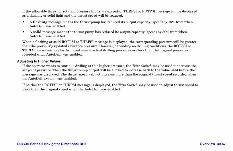
D24x40 Series II Navigator Directional Drill Overview 30-67
If the allowable thrust or rotation pressure limits are exceeded, THRPSI or ROTPSI message will be displayed as a flashing or solid light and the thrust speed will be reduced.
• A flashing message means the thrust pump has reduced its output capacity (speed) by 10% from when AutoDrill was enabled.
• A solid message means the thrust pump has reduced its output capacity (speed) by 30% from when AutoDrill was enabled.
When a flashing or solid ROTPSI or THRPSI message is displayed, the corresponding pressure will be greater than the previously updated reference pressure. However, depending on drilling conditions, the ROTPSI or THRPSI messages may be displayed even if actual drilling pressures are less than the original pressures recorded when AutoDrill was enabled.
Adjusting to Higher ValuesIf the operator wants to continue drilling at this higher pressure, the Trim Switch may be used to increase the set point pressure. Then the thrust pump output will be allowed to increase back to the value used before the message was displayed. The thrust speed will not increase more than the original thrust speed recorded when the AutoDrill system was enabled.
If neither the ROTPSI or THRPSI message is displayed, the Trim Switch may be used to adjust thrust speed to more than the original speed when the AutoDrill was enabled.

30-68 Overview D24x40 Series II Navigator Directional Drill
Constant Thrust/Pullback Pressure - AdjustInitial Pressure
When Constant Thrust/Pullback Pressure mode is selected, the thrust/pullback pressure is maintained by the AutoDrill system changing the thrust/pullback speed.
When AutoDrill is enabled, the desired drilling thrust pressure, thrust pump output (speed) and rotation pressure are recorded. The speed is normally controlled by thrust set point pressure. However, the controller continually monitors the actual rotation pressure and compares this value to the reference rotation pressure point. The rotation and thrust reference points are continually updated by the controller.
Limits ExceededDepending on drilling conditions, rotation pressure is allowed to increase within allowable limits. If the allowable rotation pressure limit is exceeded, the ROTPSI message will be displayed as a flashing or solid light, and the thrust speed will be reduced. Provided the actual rotation pressure remains within allowable limits, the thrust reference pressure is the same.
• A flashing message means the thrust pump has reduced its output capacity (speed) by 10% from when AutoDrill was enabled.
• A solid message means the thrust pump has reduced its output capacity (speed) by 30% from when AutoDrill was enabled.
NOTE: Even though ROTPSI may be on, the actual thrust pressure may be equal to the original thrust set point pressure, depending on the drilling conditions.
When a flashing or solid ROTPSI message is displayed, the rotation pressure will be greater than the previously updated reference pressure. However, depending on drilling conditions, the ROTPSI message may be displayed even if actual drilling pressure is less than the original pressures recorded when AutoDrill was enabled.

D24x40 Series II Navigator Directional Drill Overview 30-69
Adjusting to Higher ValuesIf the operator wants to continue drilling at this higher rotation pressure, the Trim Switch may be used to increase the thrust set point pressure.
When the rotation pressure set point is increased, the thrust pump output will be allowed to increase back to the value used before the ROTPSI message was displayed. The thrust speed will increase until the thrust pressure has been reached. However, the thrust speed will not increase more than the original thrust speed recorded when AutoDrill was originally enabled.
If the ROTPSI message is not displayed, the Trim Switch may be used to adjust the drilling thrust set point pressure. Depending on the drilling conditions, the carriage speed may also change.
Constant Rotation PressureInitial Pressure
When Constant Rotation Pressure mode is selected, the rotation pressure is maintained by the AutoDrill changing the thrust/pullback speed.
When AutoDrill is enabled, the desired drilling rotation pressure, thrust pump output (speed) and thrust pressure is recorded. Rotation pressure is normally controlled by changing the thrust pump output (carriage speed). However, the controller continually monitors the actual thrust pressure and compares this value to the reference thrust pressure point. The rotation and thrust reference points are continually updated by the controller.

30-70 Overview D24x40 Series II Navigator Directional Drill
Limits ExceededDepending on the drilling conditions, the thrust pressure is allowed to increase within allowable limits. If the allowable thrust pressure limit is exceeded, the THRPSI message will be displayed as a flashing or solid light and the thrust speed will be reduced. Provided the actual thrust pressure remains within allowable limits, the rotation reference pressure is nearly the same as the function’s actual gauge pressure.
• A flashing message means the thrust pump has reduced its output capacity (speed) by 10% from when AutoDrill was enabled.
• A solid message means the thrust pump has reduced its output capacity (speed) by 30% from when AutoDrill was enabled.
NOTE: Even though the THRPSI message may be on, depending on the drilling conditions, the actual rotation pressure may be equal to the original rotation set point pressure.
When a flashing or solid THRPSI message is displayed, the thrust pressure will be greater than the previously updated reference pressure. However, depending on drilling conditions, the THRPSI message may be displayed even if actual drilling pressure is less than the original pressures recorded when AutoDrill was enabled.
Adjusting to Higher ValuesIf the operator wants to continue drilling at this higher thrust pressure, the Trim Switch may be used to increase thrust set point pressure.
When the thrust pressure set point is increased, the thrust pump output will be allowed to increase back to the value used before the THRPSI message was displayed. The thrust speed will increase until the rotation pressure has been reached. However, the thrust speed will not increase more than the original thrust speed recorded when the AutoDrill system was enabled.
If the THRPSI message is not displayed, the Trim Switch may be used to adjust the drilling rotation set point pressure. Depending on the drilling conditions the carriage speed may also change.

D24x40 Series II Navigator Directional Drill Overview 30-71
CARRIAGE SPEED MANUAL CONTROL SENSITIVITY (S/N 381–615)
The sensitivity of the Thrust/Pullback Handle can be adjusted for improved control when manually drilling in harder ground formations where slower carriage speed is required.
Step 1: Hold Thrust/Pullback Handle steady at desired carriage speed.
Step 2: Press and hold AutoDrill Button (1) for 2 seconds.
Step 3: Return handle to NEUTRAL. This rescales the output of the pump to provide the desired carriage speed at full stroke of the Thrust/Pullback Handle.
Step 4: Increase or decrease carriage speed with the Speed/Pressure Trim Switch. The first toggle will display MSPD## where MSPD is Manual Speed and ## will be the set point in percentage of full pump output. Additional toggling of the trim switch when MSPD## is displayed will change the set point.
Step 5: To reset Thrust/Pullback Handle to 100% of full pump output at full stroke, return both the rotation and the thrust handles to NEUTRAL and then momentarily press the AutoDrill Set button.
NOTE: Setting the Manual Carriage Speed Control only affects the carriage speed in the direction for which the manual speed control was set. The carriage speed is not limited by the manual speed control in the opposite direction.
1

30-72 Overview D24x40 Series II Navigator Directional Drill
CARRIAGE SPEED MANUAL CONTROL SENSITIVITY (S/N 616+)The sensitivity of the Thrust/Pullback Handle can be adjusted for improved control when manually drilling in harder ground formations where slower carriage speed is required. It allows the full stroke of the handle to provide less than full pump output.
Step 1: Place both joysticks in NEUTRAL.
Step 2: Press AutoDrill Button (1). MSPD99 appears on LED display.
Step 3: Use the Speed/Pressure Trim Switch (2) to adjust to desired thrust/pullback speed.
Step 4: To reset Thrust/Pullback Handle to 100% of full pump output at full stroke, return both rotation and thrust handles to NEUTRAL, then momentarily press AutoDrill Button.
Step 5: MSPDxx will appear on the display; press AutoDrill Button again, and manual speed will be set to 100%.
NOTE: Anytime the manual speed is less than 100%, the lower right green light (3) will be illuminated on the LED display.
NOTE: Setting the Carriage Speed Manual Control only affects the carriage speed in the direction for which the manual speed control was set. The carriage speed is not limited by the manual speed control in the opposite direction.
NOTE: When the machine is started the manual speed will be reset to 100%.
1
2
3

D24x40 Series II Navigator Directional Drill Overview 30-73
MEMORY SETTINGS FOR THRUST/ROTATION PRESSUREDefault thrust/rotation pressure settings for various drill modes can be adjusted. The settings are displayed on the controller, and are saved to permanent memory. Settings can be stored for Trihawk (thrust only), RockFire (thrust only) and Normal Drill Limit (thrust and rotation) modes.
To adjust, place the machine in the preferred drill mode and use the Speed/Pressure Trim Switch (1) to increase or decrease in increments of 10 psi.
Drilling FluidDrilling fluid increases drilling efficiency in several ways. Refer to Fundamentals of Horizontal Directional Drilling User’s Guide for drilling fluid and drilling fluid system information.
Drilling Fluid Pump Output FlowUse Drilling Fluid Trim Switch (1) to increase or decrease flow. The initial switch input changes the display screen (2) to show the current pump output flow set point.
1
12

30-74 Overview D24x40 Series II Navigator Directional Drill
The second input from the increase/decrease of the Trim Switch results in a 1-gpm (3.8-L/min) change in the value of the initial set points. The changed value is displayed for 3 seconds at (2). Then the display automatically returns to show the previous display screen.
Adding Antifreeze to Drilling Fluid SystemStore antifreeze in tank (1).
Step 1: Drain and flush drilling fluid hoses and water pump. Refer to “Flushing Bentonite/Polymers from Drilling Fluid System,” page 50-41.
Step 2: Fill tank (1) with 6 gal (23 L) of antifreeze. Use at full strength; it will become diluted as it is used.
Step 3: Install cap (2) on coupler, open yellow valve (3), and operate mixing system until antifreeze comes out of drive chuck. Shut off engine.
Step 4: Connect wash wand to red quick coupler (4).
2
4
32
1

D24x40 Series II Navigator Directional Drill Overview 30-75
Step 5: Move Wash Wand/Drill Fluid Selector Switch (5) on control panel to WASH WAND position. Start engine.
Step 6: Spray fluid until antifreeze is visible in the spray from wand.
Step 7: Close valve. Follow Shutdown Procedure, page 50-4.
Step 8: Point wash wand away from people and squeeze handle to release pressure remaining in wand.
Step 9: Remove wash wand from drilling fluid pump quick coupler and store wash wand.
WARNING: High pressure water can penetrate skin. Serious injury possible. Fluid injected under the skin must be removed immediately by a surgeon familiar with this type of injury
Keep nozzles away from body.
5

This page intentionally left blank.

D24x40 Series II Navigator Directional Drill Preparation 40-1
Section 40: PreparationPreparing PersonnelOPERATOR QUALIFICATIONS
Allow only responsible, properly instructed individuals to operate machine.
Become familiar with the controls, operation, and use of the machine under the supervision of a trained and experienced operator.
The operator must be familiar with the workplace’s safety rules and regulations, and must be mentally and physically capable of operating the machine safely.
Safety Conscious Operators and WorkersOperators and workers should exercise reasonable accident-prevention measures. This includes properly locating all underground utilities.
WARNING: Read Operator's Manual and safety signs, and watch the operations and safety video, before operating machine.

40-2 Preparation D24x40 Series II Navigator Directional Drill
TrainingBefore operating the drill unit, the operator and crew should be trained in the operation of horizontal directional drills. Initial training should be conducted at a site free of underground utilities and should cover:
• all sections of this manual, the operation and safety video and the Fundamentals of Horizontal Directional Drilling User’s Guide
• processes and procedures used to locate underground utilities• jobsite safety, including safety barriers and protective clothing, as well as operating and emergency
procedures• machine lockout procedure and Remote Lockout system• two-way radio communication• transportation of the drill unit• setup of the drill unit• drilling and backreaming, including selection and installation of tools
Safety Signs and Operating InstructionsWarning safety signs and operating instructions provide information on potential safety hazards and safe operating instructions.

D24x40 Series II Navigator Directional Drill Preparation 40-3
RADIO COMMUNICATION REQUIREMENTSIMPORTANT: The Remote Lockout system is not intended to replace good verbal radio communication. Radio communication is essential to the Remote Lockout system process.
Use good quality two-way radios with sufficient range to provide clearly understood communication. Test radios at the site to ensure communications can be heard above background noise.
The radio at the exit location must be assigned to one designated person. This person will always communicate with the machine operator.
When sending a message, identify yourself and the receiver by name. This will help avoid confusion if more than one machine is operating on a jobsite.
All radio messages must be confirmed by the receiver. Confirmation from the receiver must acknowledge that the message was received and properly understood. Proper understanding must be demonstrated by repeating the original message back to the sender. The sender must always require confirmation of the message.
WARNING: Proper communication is essential to prevent unplanned start-up of the drill string and/or tool. Serious injury or death could result. Always follow communication requirements as explained below.

40-4 Preparation D24x40 Series II Navigator Directional Drill
Radio Communication to Stop Drilling OperationWhen the crew at the location of the exposed drill string or tool requests the operator to stop operation:
Step 1: The crew must communicate a stop command to the operator.
Step 2: When stop command is received, the operator must immediately stop the machine. After machine has stopped, the operator must return a message confirming that the message was received and understood.
Radio Communication to Resume Drilling OperationIf start-up is requested by the machine operator:
Step 1: The operator must request authorization from the crew at the location of the exposed rod or tool to resume rotation or thrust.
Step 2: The crew at the location of the exposed rod or tool must respond as appropriate, but must not give authorization to resume until everyone is away from the rod or cutting tool and everyone has been informed that start-up will occur.
Step 3: If authorization to resume has been received by the machine operator, the operator must require confirmation for start-up from the crew at the exit location.
Step 4: When confirmation is received, the operator may resume operation.

D24x40 Series II Navigator Directional Drill Preparation 40-5
If start-up is requested by the crew at the location of the exposed rod or tool:
Step 1: After checking that everyone at the location of the exposed rod or tool is away from the cutting tool and everyone has been informed that start-up will occur, a start-up command may be sent to the operator.
Step 2: When the start-up command is received, the operator must return a message confirming that the message was received and understood.
Step 3: The crew at the location of the exposed rod or tool must respond by providing confirmation of the machine operator's intention to start-up.
Step 4: When confirmation is received, the operator may resume operation.

40-6 Preparation D24x40 Series II Navigator Directional Drill
PERSONAL PROTECTION
Operating the machine will require you to wear protective equipment. Always wear a hard hat, wraparound eye protection or goggles, and electrically insulated boots. If working near traffic, you may need to wear reflective clothing.
The operator is not required to wear electrically insulated gloves while seated on this self-contained directional drilling machine. However, the operator must always wear electrically insulated boots to provide protection against electrical shock in case of inadvertently stepping off the machine during an electrical strike.
Hearing protection must be worn by machine operator. Other crew members may need to wear hearing protection when working close to the machine and/or support equipment
Eye protection must consist of wraparound safety glasses or goggles.
Other workers in the immediate area must also wear hard hats and eye protection.
Wear close-fitting clothing and confine long hair.
Avoid wearing jewelry, such as rings, wristwatches, necklaces, or bracelets.
WARNING: Wear personal protective equipment. To reduce the risk of being caught and entangled in moving components wear close-fitting clothing and confine long hair. Avoid jewelry, such as rings, wristwatches, necklaces, or bracelets.

D24x40 Series II Navigator Directional Drill Preparation 40-7
Sound and Vibration LevelsEquivalent Continuous A-Weighted Sound Pressureat Operator’s Ear as determined by ISO 6394 . . . . . . . . . . . . . . . . . . . . . . . . . . . . . with cab = 81 dB(A)
. . . . . . . . . . . . . . . . . . . . . . . . . . . . . . . . . . . . . . . . . . . . . . . . . . . . . . . . . . . . . . . . without cab = 94 dB(A)
Guaranteed Sound Power Level as determined by directive 2000/14/EC . . . . . . . . . . . . . . . 116 dB(A)
NOTE: The stated sound levels are representative for a given operating condition. Operating conditions may vary at each jobsite. The actual sound levels for your application and operating conditions may be different.
Hand/Arm Vibration Level as determined by ISO 5349 . . . . . . . . . . . . . . . . . . . . . . . less than 2.5 m/s2
Whole Body Vibration Level as determined by ISO 2631-1 . . . . . . . . . . . . . . . . . . . . . less than 0.5 m/s2

40-8 Preparation D24x40 Series II Navigator Directional Drill
UNDERGROUND UTILITY CONTACT
Before you start any digging project, do not forget to call the local One-Call system in your area and any utility company that does not subscribe to the One-Call system. For areas not represented by One-Call systems International, contact the appropriate utility companies or national regulating authority to locate and mark the underground installations. If you do not call, you may have an accident or suffer injuries; cause interruption of services; damage the environment; or, experience job delays.
The One-Call representative will notify participating utility companies of your proposed digging activities. Utilities will then mark their underground facilities by using the following international marking codes:
OSHA CFR 29 1926.651 requires that the estimated location of underground utilities be determined before beginning the excavation or underground drilling operation. When the actual excavation or bore approaches an estimated utility location, the exact location of the underground installation must be determined by a safe, acceptable and dependable method. If the utility cannot be precisely located, it must be shut off by the utility company.
WARNING: Electricity or gas explosion can kill. Laser light in cut cable can result in eye damage.
Locate utilities before drilling. Call 811 (U.S. only) or 1-888-258-0808 (U.S. or Canada) or local utility companies or national regulating authority.
Red Electric Green/Brown SewerYellow Gas, Oil or Petroleum White Proposed ExcavationOrange Communication, Telephone, TV Pink SurveyingBlue Potable Water

D24x40 Series II Navigator Directional Drill Preparation 40-9
ELECTRICAL SHOCK PROTECTION
DANGER: Electric shock can kill.
If strike occurs, do not step down. Keep feet on platform while operating.
DANGER: Contact with the drilling machine while standing on the ground could result in electrocution if an electrical strike occurs. Do not touch the drill unit or remote fluid mixing system while drilling or after an electrical strike occurs. See other portions of this manual regarding procedures and personal protection equipment to avoid electrocution.

40-10 Preparation D24x40 Series II Navigator Directional Drill
Electrocution AvoidanceElectrocution is possible. Serious injury or death may result if the drilling tool strikes an energized power line. Refer to the operating instructions, and take the following precautions to prevent electrocution:
• Call your One-Call system, and any utility company that does not subscribe to the One-Call system, before the start of your drilling project. Locate underground utilities by qualified persons.
• When drilling operation approaches the estimated location of a utility, the exact location of the underground installation must be determined by safe and acceptable means.
• Always wear the necessary electrically insulated gloves and boots that are required for each job function. Refer to “Electrically Insulated Gloves - Inspect,” page 40-12, and “Electrically Insulated Boots,” page 40-13.
• Never stand on the ground and touch metal parts on drilling unit or water truck when operating.• If a strike occurs, never step onto or off the machine.• Always test Strike Alert system before the start of every bore. Refer to “Strike Alert System - Test,” page
50-11. Never operate if Strike Alert system is not in operation and tested.• Disconnect from public water supply before drilling where electrical cables may be buried.If a strike occurs while you are touching the ground, you could be electrocuted when your body becomes a direct current path to the ground. Keep feet on the foot platform.
Anyone assisting the operator while standing on the ground during the bore must wear electrically insulated gloves and boots.
The drilling tool locator must wear electrically insulated boots. The ground may become electrically charged if a strike occurs.

D24x40 Series II Navigator Directional Drill Preparation 40-11
Electrically Insulated GlovesNOTE: If electrically insulated gloves are not available locally, they can be obtained through Vermeer Corporation. A one-pair purchase voucher is supplied with the machine.
Rubber electrically insulated gloves, when in good condition and properly used, help protect the wearer from serious injury, death, and electrical burns. Gloves must be at least Class 2, with a voltage rating of 17,000 volts or more. Wear leather protectors over gloves. They provide protection for the gloves, but do not provide any protection against serious injury, death or other potential dangers from electric shocks or burns.
The operator is not required to wear electrically insulated gloves while seated on this self-contained directional drill unit. Anyone assisting with installation of rack anchor stakes or assisting the operator during drilling must wear electrically insulated gloves and boots.
Proper care of gloves is essential to wearer safety.
• Visually inspect gloves and leather protectors prior to each use. Refer to “Electrically Insulated Gloves - Inspect,” page 40-12.
• Do not fold gloves. Folding causes dangerous cracking damage. Store gloves in glove bag when not in use.• Do not store gloves inside out. This causes damage from ozone and severely strains the rubber. • Keep gloves clean. The gloves will be more comfortable to wear, and any damage will be more visible. • Avoid snags. Do not wear rings, watches, jewelry, or other sharp objects on hands or arms when wearing gloves. • Avoid wood or metal splinters or other sharp objects which may damage gloves. • Avoid chemicals, which can damage gloves. If contact is made with chemicals, wipe gloves off immediately.
Clean gloves with a mild soap, then rinse with clear water and let them air dry.NOTE: The ASTM In-Service specifications call for an electrical retest of gloves at a test lab every six months. This test is to recertify the non-conductivity of the gloves. Contact your Vermeer dealer for the location of the test lab in your area or a listing of the test labs.

40-12 Preparation D24x40 Series II Navigator Directional Drill
Electrically Insulated Gloves - InspectVisually inspect insulated gloves and leather protectors prior to each use.
• Check for any signs of physical damage or chemical deterioration such as swelling, softness, hardening, stickiness, ozone deterioration, or sun-checking from prolonged exposure to sunlight.
• Check whether red or yellow inner layer shows through black outer layer, indicating gloves have been cut or snagged. If damaged at all, do not use them.
• Check leather protectors. Look for metal particles, imbedded wire, abrasive materials, or any substance that could cause puncture, abrasion, contamination, or deterioration. Adequate flashover distance of 2˝ (5 cm) between the top of protector and the bead of rubber glove should be maintained. Minimum uncovered distance must be 1˝ (2.5 cm) above the protector cuff top for each 10,000 volts.
• Check insides of each glove and air test for pinholes:Step 1: Place glove on your hand, and pull cuff up over your fingers, turning glove inside out.
Step 2: Holding glove downward, grasp cuff and twirl it upward toward your body to close the cuff.
Step 3: Squeeze rolled cuff into a “U” shape to trap air inside glove. Hold cuff with one hand and squeeze glove with your other hand. Hold glove near your ear and listen and feel for air escaping through a hole. Pop out glove fingers by squeezing inflated glove and check for damage.
Step 4: Turn glove right side out.
Step 5: Repeat with other glove.

D24x40 Series II Navigator Directional Drill Preparation 40-13
Electrically Insulated BootsNOTE: If electrically insulated boots are not available locally, they can be obtained through Vermeer Corporation. A two-pair purchase voucher is supplied with the machine.
Rubber electrically insulated boots, when in good condition and properly used, also protect the wearer from serious injury, death, and electrical burns. The boots must meet or exceed electrical hazard protection requirements when tested at 14,000 volts.
Inspect boots before each use. Check for cracking, holes, and unusual wear on the sole. If there is any damage, discard boots. Damaged boots will not provide adequate electrical protection.
After each use, rinse boots with water to remove mud, chemicals, and debris. Because of the natural rubber in the boots, it is crucial to use a rubber protectant or furniture polish to keep rubber soft and help prevent pinholes, stress cracks, dry rotting, and ozone deterioration.

40-14 Preparation D24x40 Series II Navigator Directional Drill
Strike Alert System FunctionsThe Strike Alert is only a warning device, not a protective device.
The Strike Alert system detects voltage on the machine and/or current running through the drill string in the event of drill striking an underground power line. An alarm sounds alerting operator and other personnel of a potentially dangerous situation.
The Strike Alert will not be set off by coming near a power source. If the Strike Alert Horn sounds, the drill may have contacted an energized electrical line. Other indications of an electrical strike are electrical arcing, explosion, smoke, or popping noises.
When an electrical strike occurs, large voltage differences may exist on the ground surface near machine and along drill string. Standing or walking in these areas may cause electrical shock from the difference in voltage between your feet. Anyone in the work area, including the locator, must wear electrically insulated boots. Keep all other personnel away from work area.

D24x40 Series II Navigator Directional Drill Preparation 40-15
Soil ConductivityFor the system to function properly, voltage stake must be fully inserted in soil through which a current can pass. If the machine is located on asphalt, the voltage stake or the drill string must be inserted into the ground through which current can pass. If the machine is on a dry hard surface, the auger stakes may need to be inserted into the ground, or the ground under the tracks moistened to increase electrical conductivity between machine and ground.
IMPORTANT:
To improve the conductivity of dry and loose sand or dry soil:
• Ensure voltage stake is fully inserted into the ground.• Soak soil around the stake with water.
Hydraulic System ShutoffHydraulic controls will not function if the voltage is too low for the Strike Alert system to operate (approximately 10.2 volts).
Preparing the MachineOPERATOR PRESENCE SYSTEM
The machine is equipped with an Operator Presence system. The track drive will not function if the operator is seated at the controls. Thrust and rotation will not function if the thrust and rotation controls are pushed when the operator is not in the seat. This system is intended for your safety and must be maintained in good functional condition

40-16 Preparation D24x40 Series II Navigator Directional Drill
REMOTE LOCKOUT SYSTEM PREPARATION
Remote Lockout SystemFor information on Remote Lockout system intended use, refer to “Remote Lockout System Intended Use,” page 30-1.
Range - TestTest range of radios and remote lockout transmitter along bore path to ensure good communication will be available between the operator, locator, and other crew members throughout the bore.
Remote Transmitter - PrepareThe remote transmitter operator must do the following:
Step 1: Ensure transmitter battery is fully charged at the beginning of the day. Approximate operational time for the battery is 30 hours. If unsure of remaining battery charge time, install a fully charged battery in the transmitter.
Step 2: Press Power ON/OFF Button to turn remote transmitter on.
Step 3: Test Remote Lockout system at the machine (refer to the following module).
Step 4: Clip remote transmitter onto user’s belt. The transmitter should remain ON throughout the bore.

D24x40 Series II Navigator Directional Drill Preparation 40-17
Remote Lockout System - TestIMPORTANT: Test Remote Lockout system at least once daily and at the start of every bore. Machine operator must be seated for machine to be in Drill mode.
NOTE: The Remote Lockout system is not operational when machine is in Transport mode.
Complete the following steps with transmitter located near the machine.
Step 1: Start engine and turn on remote transmitter.
Step 2: Press Lockout Button on remote transmitter. The red light must come on, and buzzer must sound 9 beeps to indicate that the machine is locked out.
Step 3: Machine operator must attempt to begin drilling. Drilling functions should remain stopped (locked out).
Step 4: Press Run Button and hold for 2 seconds. Green light comes on, and buzzer sounds for 2 seconds. Operator will be able to resume drilling.
If test is not successful, ensure transmitter is within range and that machine is running and is in Drill mode (operator seated at controls). If a problem still exists, contact your Vermeer dealer to determine source, and use the “Lockout Procedure - Without Remote Lockout System,” page 30-18, until the Remote Lockout system is repaired.

40-18 Preparation D24x40 Series II Navigator Directional Drill
Preparing the Work AreaJOBSITE - CHECK
The operator or job foreman should inspect the jobsite for:
• notices of underground placements • manhole covers • drop boxes • recent trenching activity • any evidence of possible underground placementsExamine work area for any obstructions, conditions, or situations which may impair machine operation or create a safety hazard for the operator or other persons. Use information in this manual combined with your own good judgment when identifying these hazards and implementing hazard avoidance measures.

D24x40 Series II Navigator Directional Drill Preparation 40-19
Warning ConesCheck that orange warning cones with warning decals are available for placement around the drill unit work area. Four orange warning cones are provided.
Power Line Locator SystemA locator system to locate underground power lines is not included with the system but may be purchased from Vermeer dealerships.
LAWS AND REGULATIONS - CHECKKnow and obey all federal, state, and local laws and regulations that apply to your work situation.
PLANNING THE BORECarefully plan the bore before drilling. Refer to Fundamentals of Horizontal Directional Drilling User’s Guide for information on bore planning.

This page intentionally left blank.

D24x40 Series II Navigator Directional Drill Operation 50-1
Section 50: OperationStarting Procedure
STARTING THE ENGINEStep 1: Shut off drilling fluid pump.
Step 2: Set Throttle at idle.
Step 3: Ensure Rotation and Thrust/Pullback Handles are in NEUTRAL.
Step 4: Start engine. Shut off engine if oil light does not go out within 15 seconds.
IMPORTANT: Never run starter motor for more than 30 seconds at a time. Allow starter motor to cool 2 minutes between attempts.
Step 5: Adjust Throttle to get an even idle speed and allow engine to warm up for 3–5 minutes.
IMPORTANT: Once engine reaches operating temperature, do not idle engine for more than 5 minutes. Low combustion chamber temperatures can cause crankcase oil dilution due to fuel not burning completely and permits formation of gummy deposits on valves, pistons, and piston rings.
WARNING: Read Operator's Manual and safety signs, and watch the operations and safety video, before operating machine.

50-2 Operation D24x40 Series II Navigator Directional Drill
Step 6: Turn remote lockout transmitter on.
NOTE: The Remote Lockout system self-tests upon start-up, indicated by two short beeps, and then enters whatever mode it was in when the machine was shut down.
Step 7: If machine was shut down in Lockout mode, press Run Button and hold for 2 seconds to select RUN mode.
Step 8: Press Hydraulic Enable Button.
COLD WEATHER STARTING
Engine Before operating in cold weather, refer to the Engine Operation Manual for recommended engine oil, fuel, and starting procedures.
WARNING: Pressing Hydraulic Enable Button will result in vise movement if the vise control switch positions were changed while the engine was off. Crushing injury may result. Keep everyone clear of machine.

D24x40 Series II Navigator Directional Drill Operation 50-3
Hydraulic Fluid Refer to Specifications section, “Lubricants,” in the Maintenance Manual for recommended hydraulic fluids.
When using ISO 68 hydraulic fluid below +23°F (-5°C) or ISO 100 hydraulic fluid below +41°F (+5°C):
• Warm up engine. • Gradually increase engine RPM for up to 30 minutes to allow hydraulic oil to warm up. To assist in
warming the hydrostatic system, force oil over relief by deadheading the stabilizer or rack tilt cylinder. Partially engage hydrostatic circuits to turn the hydrostatic motors slowly while warming the oil.
NOTE: Slow down engine if hydraulic pump squeals because it does not get enough oil.
For frequent starts below 10°F (-12°C), consult your Vermeer dealer.
Cold Weather Start System (Option)
Machine may be equipped with an optional automatic cold weather starting system.
Sensors automatically inject ether into the engine when the engine is turned over and the temperature is low enough. There are no machine gauges or indicators for this system.
Refer to the “Maintenance - As Required” section in the Maintenance Manual to change the ether cylinder.
WARNING: Starting fluid is highly flammable and can explode. Keep container away from heat, sparks, and open flame. Do not puncture or incinerate container.

50-4 Operation D24x40 Series II Navigator Directional Drill
Shutdown ProcedureStep 1: Shut off drilling fluid pump.
Step 2: Reduce engine speed to idle.
Step 3: Wait two minutes to shut off engine when shutting down after operating at full power.
Step 4: Shut off engine and remove key.
For your safety and the safety of others, use shutdown procedure before working on the machine for any reason, including servicing, cleaning, unplugging, or inspecting.
IMPORTANT: If working on the drill string or drill tools at a remote location away from the machine, follow “Lockout Procedure - With Remote Lockout,” page 30-15, or “Lockout Procedure - Without Remote Lockout System,” page 30-18.
A variation of the above procedure may be used if instructed within this manual or if an emergency requires it.

D24x40 Series II Navigator Directional Drill Operation 50-5
Transporting the MachineDRIVING THE MACHINE
Drive machine at a speed suitable for the terrain. Never operate machine faster than you can comfortably walk. Keep feet clear of the track when driving in reverse. Avoid sudden stopping, starting or turning unless it is necessary. Never drive machine with rack elevated.
Safe Operating SlopeSafe operating slope depends on many factors, including:
• Machine weight distribution, including front loading or absence of load
• Height of load
• Even or rough ground conditions
• Potential for ground giving way, causing unplanned forward, reverse, or sideways tilt
• Nearness of ditches, ruts, stumps, or other obstructions and sudden changes in slope
• Speed
• Turning
• Braking performance
• Skill of operator
WARNING: Rollover possible. Be alert and use extreme caution when operating on hillsides, or near ditches, gullies, holes, or obstructions where rollover could occur. Serious injury or death can result if crushed under the machine. Never allow anyone to be on the downhill side of the machine. Never allow anyone to ride on machine.

50-6 Operation D24x40 Series II Navigator Directional Drill
These varying factors make it impractical to specify a maximum safe operating angle in this manual. It is therefore important for the operator to be aware of these conditions and adjust operation accordingly. Maximum engine angle and braking performance are two absolute limits which must never be exceeded. These maximum design limits are stated below. These angles are not operating limits and therefore must never be used alone to establish safe operating angles for your varying conditions.
• Maximum engine lubrication angle – 20°
• Service brake retarding force – equal to traction of both tracks
• Secondary brake – equal to traction of one track
• Park brake holding force – equal to traction of both tracks
PREPARING FOR TRANSPORT• Store cable (1) and voltage stake (2) in storage bracket on side of fuel tank. • Ensure rod retainers are installed in top of rod box to prevent drill rods from
coming out of rod box during trailering.• Extend rod loader arms toward drill rack.• Rotate operator console fully towards drill rack.• Fold red rod transfer arm barrier in to prevent damage to the barrier.• To position rod transfer arm to the extended position if transporting with carriage
centered on rack:1. Retract rod transfer arms.2. Position carriage in center of rack so that rod transfer arms will not hit carriage.3. While standing, extend rod loader arms.
21

D24x40 Series II Navigator Directional Drill Operation 50-7
TRAILERING THE MACHINE
Loading/UnloadingBefore transporting machine on a truck or trailer, read truck or trailer manual for safety precautions and information. Ensure trailer bed and ramps are free of debris that will interfere with the loading process.
Ensure gross weight of the machine is within gross weight limits of the trailer and towing vehicle. Load and unload machine with the trailer on a level surface and attached to towing vehicle.
IMPORTANT: Insert upper and lower rod keeper pins before trailering machine with rods in rod box.
Step 1: Align centerline of machine with centerline of trailer to minimize steering while loading.
WARNING: Machine may slide down loading ramps or off trailer deck. Serious injury or death can result if struck or crushed by machine. Do not load onto slick trailer surface.
WARNING: Do not attempt to steer machine while its weight is balanced on the end of the trailer. Slight steering changes may cause the machine to turn abruptly and slide back down the loading ramps. Serious injury or death can occur if crushed by the machine.

50-8 Operation D24x40 Series II Navigator Directional Drill
Step 2: SLOWLY drive machine squarely onto trailer.
Step 3: Stop machine when tie-down position is reached. The tie-down position distributes machine weight on the trailer as recommended by trailer manufacturer.
Step 4: Lower rear stabilizer and drill rack frame.
Step 5: Follow Shutdown Procedure, page 50-4.Step 6: Use tie-down points on rack (1), track frames (2), and rear stabilizer (3) to secure drill to trailer with
chains and binders.
12
3

D24x40 Series II Navigator Directional Drill Operation 50-9
RETRIEVALThe following procedures are intended to be used when towing a machine which has become mired or disabled.
Connect tow chain/cable to the front tie-down ring.
IMPORTANT: Disengage park brakes and bypass ground drive pump to allow hydraulic fluid to circulate. Contact your Vermeer dealer for instructions.
IMPORTANT: Towing device (chain, cable, or strap) must have a minimum working load of 150% of machine weight.
IMPORTANT: Do not tow machine more than 500 ft (150 m), and do not exceed 1 mph (1.5 km/h).
LIFTING MACHINENo provisions are made for lifting the machine. If transport requires that machine be lifted, it must be loaded onto an appropriate skid.

50-10 Operation D24x40 Series II Navigator Directional Drill
SetupBORE PATH - WALK
Be sure to walk the bore path to double-check for signs of utility lines, potential causes of locator interference, and general assessment. Look for the following visual signs that could indicate presence of utility lines:
• Ditch lines or depressions where the ground has settled from previous excavation.• Buildings that have lights but no overhead wires; the power lines may be buried in the bore path.• Patch repairs in the street, which could indicate digging to bury or repair a utility line.• Poles with wires extending into the ground, which might power traffic-sensing loops or traffic lights.• Manholes, which can be used for utility line connections, not only for sewer connections.• Water and gas shutoff valves, likely indicators of utility lines in the area.
DRILL UNIT SETUPStep 1: Move drill unit to site and position it for drilling.
Step 2: Lower front of rack onto ground.
Step 3: Lower rear stabilizer until rack is at desired angle.
Step 4: Inspect power vise jaws and grips. Replace worn or damaged components before drilling. Refer to “Maintenance - As Required” section in Maintenance Manual.

D24x40 Series II Navigator Directional Drill Operation 50-11
STRIKE ALERT SYSTEM - TESTNOTE: Test the Strike Alert system before operating the drill unit. Do not operate drill unless the Strike Alert test confirms the system is operational.
Step 1: Ensure current sensing coil (1) and coil connectors are not damaged.
Step 2: Unwind voltage stake cable. Ensure cable and connections are clean and undamaged.
Step 3: Insert voltage stake (2) into the ground at least six ft (2 m) away from machine and not over the drill string.
NOTE: The voltage stake must be inserted in the ground for Strike Alert system test to pass.
Step 4: Press Test Button (3). The Strike Alert alarm (4) must sound. Release button to silence alarm.
NOTE: The alarm will sound when the Test Button is pressed. A successful test is indicated when the green light (5) remains steady ON after the test button is released. If there is a flashing green light after releasing the test button, the Strike Alert system is not functioning correctly. Confirm the voltage stake is fully inserted into the ground. The soil at the stake may need to be moistened to improve conductivity of the earth. Retest the system. If the test fails to pass, contact your Vermeer dealer.
3
5
4
1
2

50-12 Operation D24x40 Series II Navigator Directional Drill
NOTE: The Strike Alert system automatically runs a system check whenever the machine is powered up (ignition key turned from OFF to RUN). If the system is properly set up, a successful check is indicated by a steady ON green light. Failure to properly insert the voltage stake into the ground will result in a flashing green light. The alarm does not sound during the power-up system check.
STRIKE ALERT - INDICATORS AND CONTROLSINDICATOR INDICATION SIGNIFICANCE
Two-Tone HornOn Electrical strike occurred or Test Button pressedSilent No voltage detected above threshold
Green Light
Off Test in progress, light burned out, or wiring harness problem
Flashing Voltage Stake is not in the ground
Double FlashingCurrent Sensor failed
Triple FlashingVoltage Stake wiring problem
On Power-up check or Test passed. System is ready
CONTROL FUNCTIONAlarm Cancel Button Turns alarm off (only when voltage and current are not present)Test Button Tests sensors, controller, and alarm

D24x40 Series II Navigator Directional Drill Operation 50-13
MACHINE - ANCHOR WITH STAKES
Drive stakes completely into the ground.
WARNING: Contact with drill unit while standing on the ground may result in serious injury or death from electrical shock if anchor stakes make contact with underground electric power.• Drive anchor stakes only while seated at controls with both feet on platform.• Keep everyone away from machine when anchors are being installed.
WARNING: Contact with moving anchor stakes can result in serious injury. Stay away from rotating stakes. Ensure anchor stake shields are closed and everyone is away from anchor stakes before operating.

50-14 Operation D24x40 Series II Navigator Directional Drill
Stake - Removal/InstallTo remove or install stakes on machine:
Step 1: Remove top and bottom pins (1) of stakedown shield.
Step 2: Roll rubber ring (2) out of groove.
Step 3: Support stake while removing pin (3).
Step 4: Remove stake.
Reverse procedure to replace stake.
Locating Equipment - PrepareEnsure locator batteries are fully charged at the beginning of the day. Install new batteries in the transmitter every day. Standard “C” batteries generally last up to 15 hours.
Some locating systems need to be calibrated before drilling begins. Failure to do so could result in inaccurate depth readings on the locator. Refer to literature provided with locator device.
NOTE: It may be necessary to calibrate the locator while the drill head is lying on the ground with the transmitter in it.
1
2
3

D24x40 Series II Navigator Directional Drill Operation 50-15
Drilling Fluid SetupConnect drilling fluid hose from mixing systems to coupler (1) on fluid pump.
Rod Wiper - InstallUse rod wiper (1) to clean drill rod when drilling. Install rod wiper into rod wiper holder (2).
1
2 1

50-16 Operation D24x40 Series II Navigator Directional Drill
Entrance and Exit Sites - Prepare
If needed, dig entry and exit pits at the correct location and depth to properly complete the bore.
Warning ConesCheck that orange warning cones with warning safety signs are available for placement around drill unit work area. Four orange warning cones are provided.
Set up orange cones around the machine with warning safety signs facing outward before starting operation. The safety sign warns unauthorized persons to stay away.
Place pedestrian and traffic warning barriers around the jobsite in accordance with Federal, State, and local laws and regulations.
WARNING: Do not work in trench with unstable sides which could cave in. Specific requirements for shoring or sloping trench walls are available from several sources, including federal and state O.S.H.A. offices. Be sure to contact suitable authorities for these requirements before working in the trench.
DANGER: Electrically charged ground surface can kill.
Unauthorized persons must stay away.

D24x40 Series II Navigator Directional Drill Operation 50-17
Pilot BoreREAD OVERVIEW SECTION
Read and become familiar with Overview, page 30-1, before drilling. That section contains important information which is not repeated in this section.
SAFETY PRECAUTIONS
Utility Line ContactElectrical Line
DANGER: Contact with the drill unit while standing on the ground could result in electrocution if an electrical strike occurs. Do not touch the drill unit or remote fluid mixing system while drilling or after an electrical strike occurs. See other portions of this manual regarding procedures and personal protection equipment to avoid electrocution.
DANGER: Electric shock can kill.
If strike occurs, do not step down. Keep feet on platform while operating.

50-18 Operation D24x40 Series II Navigator Directional Drill
IMPORTANT: If a strike occurs, do not allow anyone to approach machine. The machine and ground will be electrically charged.
If seated on the machine:
• Do not get off machine. Contacting the machine and ground while stepping off may result in injury or death. • Fully retract drill or extend backreamer to try breaking contact with the electrical power line.• Have someone who is clear of the work area contact the utility company to shut off electrical power. • Do not shut off Strike Alert until utility company has confirmed that electrical power has been locked out.IMPORTANT: Do not continue drilling until utility company has declared the area safe to resume operation.
DANGER: Electric shock can kill.
Workers standing on the ground must not touch machine when alarm sounds.
DANGER: If the power has not been properly shut off, an automatically resetting circuit breaker could re-energize the power line, causing the equipment and ground to again become charged if the drilling tool is close to, or in contact with, the power line.

D24x40 Series II Navigator Directional Drill Operation 50-19
After Utility Company Has Shut Off the PowerStep 1: Push Strike Alert Alarm Cancel Button to shut off alarm.
Step 2: Push Strike Alert Test Button to test Strike Alert system. If alarm sounds while button is pressed and green light remains ON steady when the button is released, the Strike Alert system is undamaged. Release button to silence alarm.
IMPORTANT: The Strike Alert may not sense an electrical strike if the cutter shorts out a live voltage phase directly to the ground wire of the same power line. The only indication that a strike has occurred may be loss of power in the area.
If you strike an underground power line, it is possible to trip the power line circuit breaker, which will interrupt electrical power to that line. Many circuit breakers automatically reset and will re-energize the line.
If the horn has sounded, and you have pressed the reset button, the horn will stop if the circuit breaker has not yet reset automatically. Do not assume that power to the line has been permanently disconnected until you have confirmed that the utility company has locked out power to that line.
Gas
DANGER: Gas explosion can kill. If you strike a gas line, shut off engine and evacuate area immediately. Contact utility company and do not return until the utility company gives permission to do so. Do not attempt to disengage drill tool from buried line.

50-20 Operation D24x40 Series II Navigator Directional Drill
Fiber Optic Cable
BOTTOM ROD SUPPORT PINSStep 1: Push and hold up rods with
rod lifters.
Step 2: Remove two hairpins and two bottom rod support pins (1).
Step 3: Store rod support pins in their storage location (2).
Rods can now be removed or added to the rod box with the rod loader.
DRILL MODE - SELECTIf equipped with AutoDrill and R.A.T.T., refer to “Drilling Modes Overview,” page 30-50, to select among Normal, Trihawk, RockFire, R.A.T.T. (Oscillation or Straight Drilling), and AutoDrill.
WARNING: Fiber optic cables carry laser light which may damage your eyes. Do not look into the end. If you are not sure what kind of cable it is, do not look into the end. Contact appropriate utility company for assistance.
12

D24x40 Series II Navigator Directional Drill Operation 50-21
DRILL HEAD - CONNECT TO STARTER RODStep 1: Connect drill head to starter rod. Refer to “Drill Tool Connections,” page 30-20, and “Drill Tool
Assemblies,” page 30-23, in the Overview section.
Step 2: Lubricate drive chuck threads and starter rod threads.
Step 3: Slide starter rod into front vise and clamp.
Step 4: Thread drive chuck into starter rod. Refer to gauge and tighten joint to 4000 psi (276 bar). Disengage front vise.
BEFORE THE BORE
WARNING: Keep spectators away.
WARNING: Do not work in trench with unstable sides which could cave in. Specific requirements for shoring or sloping trench walls are available from several sources including federal and state O.S.H.A. offices. Be sure to contact suitable authorities for these requirements before working in the trench.

50-22 Operation D24x40 Series II Navigator Directional Drill
• If needed, refer to “Entrance and Exit Sites - Prepare,” page 50-16, for information on digging an exit pit to properly complete bore.
• If the drill is starting at a shallow angle or the ground is hard, dig a small hole so drill bit can start drilling perpendicular to the soil.
IMPORTANT: If drilling fluid additives are used, refer to manufacturer’s recommendations for handling precautions.
DANGER: Wrench on rotating drill string can strike you. Death or serious injury will result. Always use the power vise to make or break joints at the machine.
WARNING: Rotating drill string or cutters can kill.
Keep away.

D24x40 Series II Navigator Directional Drill Operation 50-23
Drill Rod - FlushIf the drill rod has not been used within the last 24 hours, or if there is debris inside the drill rod, slowly rotate rod and flush it with drilling fluid before connecting it to the drill head.
Step 1: Move Wash Wand/Drill Rod Selector Switch (1) to DRILL RODS.
Step 2: Push Flow Control Switch (2) to center position to turn drilling fluid system ON for variable flow.
Step 3: Push and hold Drilling Fluid Full Flow Button (3) to quickly fill drill rod with fluid and keep nozzle from plugging.
NOTE: Ensure drill string is filled with drilling fluid and the necessary fluid pressure is available before rotating, thrusting, or pulling back. Failure to do so may plug the drill head or reamer nozzles.
Step 4: Use Drilling Fluid Pump Trim Switch (4) to increase or decrease drilling fluid flow. View drilling fluid flow rate on display (5) to monitor desired flow.
Step 5: View Drilling Fluid Pressure Gauge (6) to read drilling fluid pressure.
IMPORTANT: If the drill becomes plugged, either dig down to the drill head, back out the drill rod and the drill head, or attempt to use fluid pressure to force out the plug. Refer to “Plugged Drill Rod,” page 50-26.
1
32
5
6
4

50-24 Operation D24x40 Series II Navigator Directional Drill
Drill Rod - LubricateRefer to Specifications section “Lubricants” in the Maintenance Manual for specifications.
Lubricate male rod threads and shoulders. Apply lubricant to clean, dry threads.
IMPORTANT: Keep electrically insulated gloves from coming in contact with lubricant. Petroleum-based products will chemically damage gloves.
NOTE: Do not thin lubricants to make them easier to apply. Thinning reduces the amount of available metal filler and makes lubricant ineffective.
Starting the BoreStep 1: With bill at 6:00 position, thrust until drill rod just enters the ground.
Step 2: Stop pushing and rotate drill head until rod is centered in the rod guide rollers.
Step 3: When centered, rotate and push remainder of drill rod into the ground.
IMPORTANT: If drill rack moves during drilling, reposition rack so drill rod is centered in rod guide rollers before continuing.
IMPORTANT: To prevent rod joint from pulling apart, never rotate drill rod counterclockwise while drilling, pulling back, or backreaming.
Step 4: Stop rotation, shut off fluid, and engage front vise to clamp rod.
NOTE: Fluid automatically shuts off when front vise closes.
Step 5: Engage front vise and rotate drive spindle in reverse to unthread from drill rod. The drive chuck will move backward as rod unthreads. Lubricate drive chuck threads.
Step 6: Move drive chuck fully back.

D24x40 Series II Navigator Directional Drill Operation 50-25
DRILL RODS - ADDRefer to “Drill Rods - Add to Drill String,” page 30-42.
WHILE DRILLING
Monitor GaugesMonitor gauges during drilling operation to ensure a good pilot bore. Watching the gauges will help establish a baseline for rotation and thrust/pullback pressures. Generally, the operator should try to keep rotation and thrust/pullback pressures as low as possible throughout the bore.
Rotation Pressure (1)–Rotation pressure will naturally rise as the bore progresses, due to friction on the increasing length of the drill string. But if rotation pressure rises substantially, even when not attempting to make forward progress, it could be a sign that soil is taking on water and swelling around the drill string. If this happens, it may be necessary to reevaluate the drilling fluid additives, increase flows, and redrill the pilot bore.
Thrust/Pullback Pressure (2)–Thrust/pullback pressure can be affected by product size and weight, bore path lubrication, soil conditions, and bends in the bore. If the pullback gauge hits the maximum pressure, maximum pullback force is being exerted, and the bore will be unable to continue.
Drilling Fluid Pressure (3)–The drilling fluid pressure gauge is best used as an indicator that flow is occurring. Pressure can vary based on flow rates and nozzle sizes used in the tooling. A maximum indication on the drilling fluid pressure gauge could be an indicator that flow has become restricted.
NOTE: Gauge reads hydraulic oil pressure, not water pressure.
2
1 3

50-26 Operation D24x40 Series II Navigator Directional Drill
Obstructions - InvestigateClosely monitor the drilling rate and investigate any obstruction to determine if it might be hazardous. Check to ensure tool is not in contact with a gas line, water line, electrical line, or some other underground obstruction that can be damaged or result in personal injury.
Plugged Drill RodIf a drill rod becomes plugged, follow “Lockout Procedure - With Remote Lockout,” page 30-15, or “Lockout Procedure - Without Remote Lockout System,” page 30-18. Either dig down to drill head, back out drill rod and drill head, or attempt to use fluid pressure to force out the plug. Ensure drill rod joint has been broken to relieve drilling fluid pressure in the drill string before unclogging or removing nozzle.
Clean drill head nozzle with a tip cleaner. A plugged drill can become too hot and damage the drill head transmitter.
Rod Box - ChangingRefer to “Rod Box - Remove,” page 30-40.
WARNING: Relieve drilling fluid pressure in the drill string before cleaning out nozzles with a tip cleaner. Drilling fluid under pressure can penetrate body tissue and result in serious injury or death. Fluid injected under the skin must be removed immediately by a surgeon familiar with this type of injury.

D24x40 Series II Navigator Directional Drill Operation 50-27
Exiting the BoreIt is critical to maintain good communication between the machine operator and locator operator. When the bore reaches the exit point, crew must ensure everyone is clear of the area.
The operator should be ready to turn off drilling fluid pump as drill head exits the ground. Once drill head exits the ground, follow “Lockout Procedure - With Remote Lockout,” page 30-15, or “Lockout Procedure - Without Remote Lockout System,” page 30-18, so that inadvertent start-up and rotation do not occur during the tooling change.
CHANGING TOOLS AT REMOTE EXIT PITExtreme care must be taken during any tooling changes on the machine. Clear and understandable communication between members of the directional drill unit’s crew is crucial for proper, complete, and efficient installation of the utility in a safe and timely manner. The distance between drill unit and drill string exit location may prevent visual contact and direct voice communication between the crew at the exit location and the machine operator.
DANGER: Rotating drill string can kill. Unexpected start-up possible.
Lock out before working on drill string.

50-28 Operation D24x40 Series II Navigator Directional Drill
Remote Lockout UseAlways follow “Lockout Procedure - With Remote Lockout,” page 30-15, or “Lockout Procedure - Without Remote Lockout System,” page 30-18, before changing tools.
Communication Requirements
Reamer Carrier UseIf using a reamer carrier to remove drill head and install pullback tool, refer to “Reamer Installation,” page 30-32, for information.
WARNING: Proper communication is essential to prevent unplanned start-up of the drill string and/or tool. Serious injury or death could result. Always follow communication requirements as explained in “Radio Communication Requirements,” page 40-3.

D24x40 Series II Navigator Directional Drill Operation 50-29
Swivel UseThe reamer must be equipped with a swivel to prevent trailed rod or product from turning while reaming. If reamer does not have a built-in swivel, an external swivel must be installed. Refer to the Fundamentals of Horizontal Directional Drilling User’s Guide, “Pullback Tips,” for additional information on reamer selection and swivels.
Step 1: Grease swivel and check that it turns freely by hand. A tool can be used to initially loosen swivel rotation. If, after loosening, swivel does not turn freely by hand, repair or replace it. If the product attached to the swivel rotates along with the reamer, replace swivel.
Step 2: Follow “Lockout Procedure - With Remote Lockout,” page 30-15, or “Lockout Procedure - Without Remote Lockout System,” page 30-18.
Step 3: Turn drilling fluid system OFF.
Step 4: Remove drill head from the drill string at Splinelok connection or hex collar connection. Refer to “Hex and QuickFire - Disconnect,” page 30-20, or “Splinelok Connection - Disassemble,” page 30-23.
DANGER: Entanglement in rotating drill string can result in death or serious injury. Rotating trailed string could whip and strike you. A properly functioning swivel is necessary to prevent the trailing drill string or product being pulled in from turning.

50-30 Operation D24x40 Series II Navigator Directional Drill
Pullback Tool - InstallThe drill unit must be equipped with the Vermeer Splinelok or hex collar connection. This connection between the drill rod and drill/pullback tools eliminates the use of pipe wrenches or power tongs to make or break connections. Drill tools with a straight thread joint and the hex collar connection are not torqued and do not require breakout tools to uncouple the joint. Removing or attaching drill tools with the Splinelok connection requires only a hammer and suitable punch tool.
IMPORTANT: Use communication procedures. Refer to “Radio Communication Requirements,” page 40-3.
Step 1: Install backreamer. Refer to “Hex and QuickFire - Connect,” page 30-20, or “Splinelok Connection - Assemble,” page 30-21.
DANGER: Wrench on rotating drill string can strike you. Death or serious injury will result. Never install tooling that requires the use of pipe wrenches or tongs. Always use tools which have the Splinelok or hex collar connection.
WARNING: Death or serious injury could occur if you are struck by whipping pipe or product. Never use a shackle when attaching swivel to backreamer. Shackle will not keep the swivel aligned with the reamer and may result in whip and rotation of trailing drill string or product.

D24x40 Series II Navigator Directional Drill Operation 50-31
Step 2: Attach swivel to reamer as shown, by inserting bolt (1) through clevis end of swivel. Secure with pin (2). Swivel must be aligned with the reamer before rotating the reamer.
NOTE: Vermeer double eye swivels are designed for use with Vermeer reamers to limit the angle between the reamer and swivel. Vermeer swivels and reamers aligned within this limited angle will reduce the possibility of whipping and rotation of the trailed product. The use of other swivels and reamers may not provide this inherent benefit.
Resuming OperationStep 1: Verify drill string and cutting tools are ready for operation.
Step 2: Confirm everyone is away from exit pit, drill string, and cutting tools, and that no wrenches or tongs are attached to the drill string or cutting tools.
Step 3: Warn everyone who may be exposed to the drill string or cutting tools that operation will resume.
Step 4: Press and hold Run Switch on transmitter for 2 seconds to enable drilling operation.
Step 5: Follow all communication requirements before resuming operation.
1
2

50-32 Operation D24x40 Series II Navigator Directional Drill
Pullback
IMPORTANT: Never rotate drill rod counterclockwise while pulling back or backreaming. Counterclockwise rotation will uncouple the drill string.
PULLBACK - STARTStep 1: Turn on drilling fluid.
To prevent reamer from moving sideways, pull tooling up to exit hole before rotating.
WARNING: Backreamer may not follow the bore path exactly. Because of increase in bore size and change in bore path, the backreamer may make contact with underground hazards that were missed during drilling.
DANGER: Drill string and tooling can rapidly move sideways along the ground at the exit location if rotation is started when drill rod or tooling is on the ground, away from the exit hole. The larger the diameter of the reamer and the more drill string exposed the faster and farther the reamer and drill string can travel. Death or serious injury will occur if anyone is entangled or struck by drill string or tooling.
Pull tooling up to exit hole before rotating. Everyone must be well away from exposed drill string and tooling before rotation is started.

D24x40 Series II Navigator Directional Drill Operation 50-33
NOTE: Each rotation of the drill rod can cause an 8˝ (20 cm) diameter reamer to rapidly travel 2 ft (60 cm) and a 16˝ (41 cm) reamer to travel 4 ft (1.2 m).
Step 2: Rotate clockwise and retract drill rod from the ground.
Step 3: Stop rotation and shut off drilling fluid.
Step 4: Actuate rear and front vises to break rod joint.
Breaking Rod JointsIf for any reason, a drill rod joint cannot be broken at the vise, repair the vise. Never put a pipe wrench or tong on the drill string and use drilling machine torque to break the joint. Never use a pipe wrench or tongs and apply force by using a backhoe. The wrench could slip off the drill string and strike you.
If a problem arises in drilling out or pullback which requires making or breaking a joint between the tool and the machine, it is very important not to use a pipe wrench, but to use only a compact Portable Breakout system.
A compact Portable Breakout system is required whenever you loosen a joint away from the machine. Serious injury or death can occur if drill rod rotation starts and you are struck by the wrench.

50-34 Operation D24x40 Series II Navigator Directional Drill
TRAILING ROD WHILE PRE-REAMINGPre-reaming can be used in difficult drilling conditions when the desired bore diameter cannot be attained with one pullback. One or more intermediate pre-reams can be made with increasingly larger reamers until reaching the full diameter. Time can be saved by pulling in additional rod behind each pre-reaming pass. The next size reamer can then be attached to the rod already in the bore. This process can be repeated as many times as needed.
Swivel UseRefer to “Swivel Use,” page 50-29, for information on swivel use when pre-reaming.
NOTE: Some swivels, such as a double-eye swivel, can be improperly aligned with the reamer. If the swivel is not straight in-line with the reamer, it might not swivel as intended. Instead it could turn like a crank, causing the product to turn and whip. Before starting rotation of the drill string, it is very important to position the reamer and product or trailing pipe so that the swivel is extended to be straight in-line with the reamer before pulling in.
WARNING: Product or trailing drill rod can turn or whip. Death or serious injury could occur if you are struck by a wrench, entangled, or struck by whipping pipe or product. Ensure swivel is straight in-line with reamer before pulling back.

D24x40 Series II Navigator Directional Drill Operation 50-35
Short-String Method of Adding Drill Rod for Pre-ReamingStep 1: Pre-assemble as many rods as practical at the exit location. These will be attached later to reamer
swivel. Before assembling rod joints, clean and lubricate threads.
Step 2: Join rods using pipe wrenches, and apply at least 400 ft-lb (540 Nm) torque to tighten snugly. It is not necessary to tighten joints to a higher torque.
Step 3: Attach rod recycler adapter to the first drill rod and tighten snugly.
Step 4: Follow “Lockout Procedure - With Remote Lockout,” page 30-15, or “Lockout Procedure - Without Remote Lockout System,” page 30-18.
Step 5: Attach rod recycler adapter to swivel.
WARNING: Never attach a pipe wrench or tool and apply force from a machine such as a backhoe to tighten or break a connection. If the wrench slips off the bucket, the wrench could rotate or be thrown and strike you. Death or serious injury may result.

50-36 Operation D24x40 Series II Navigator Directional Drill
Resuming OperationStep 1: Verify drill rod and cutting tools are ready for operation.
Step 2: Confirm everyone is away from the exit pit, drill string, and cutting tools, and that no wrenches are attached to the drill string or cutting tools.
Step 3: Warn everyone who may be exposed to the drill string or cutting tools that operation will resume.
Step 4: Press Run Button on transmitter and hold for two seconds to enable drilling operation, or return key to machine.
Step 5: Follow all communication requirements before resuming normal operation.
Pulling Back with Trailing Rod
Step 1: Begin reaming.
Step 2: Crew must watch trailing rods as they are drawn into the bore. If they rotate, the swivel must be repaired or replaced.
DANGER: Drill string and tooling can rapidly move sideways along the ground at the exit location if rotation is started when drill rod or tooling is on the ground, away from the exit hole. The larger the diameter of the reamer and the more drill string exposed the faster and farther the reamer and drill string can travel. Death or serious injury will occur if anyone is entangled or struck by drill string or tooling.
Pull tooling up to exit hole before rotating. Everyone must be well away from exposed drill string and tooling before rotation is started.

D24x40 Series II Navigator Directional Drill Operation 50-37
Step 3: Install additional drill rod and continue pulling back until reamer reaches drill unit.
Step 4: Remove reamer and attach trailing drill string to drill unit.
Step 5: Attach a larger reamer, and continue until bore is completed.
Push-Through Method of Adding Drill Rod for Pre-ReamingStep 1: When drill head exits the pilot bore, rotate drill head to 12:00 position.
Step 2: Continue adding more drill rods at the machine and pushing rods through the bore hole.
Step 3: Do not rotate drill string while pushing the drill head across the ground. If needed, the extending rod can be steered by pushing on the side of the drill string with a backhoe bucket.
Step 4: After enough drill rod have been pushed through, follow “Lockout Procedure - With Remote Lockout,” page 30-15, or “Lockout Procedure - Without Remote Lockout System,” page 30-18.
DANGER: Wrench on rotating drill string can strike you. Death or serious injury will result. Before installing additional drill rods and using pipe wrenches:• Swivel must be functioning properly, and• Machine must be locked out.
DANGER: Entanglement in rotating drill string or cutters can kill. Rotating trailed rods could whip and strike you. Do not rotate when the drill string and cutting tool have exited the bore. Keep everyone away from the exposed drill string.

50-38 Operation D24x40 Series II Navigator Directional Drill
Step 5: Position or support trailing drill string to relieve bending load at the joint where reamer will be installed.
Step 6: Use a compact remote power breakout device to loosen joint.
Resuming OperationStep 1: Remove breakout device and ensure no tools are attached to drill string.
Step 2: Press Run Button on transmitter and hold for two seconds to enable drilling operation.
Step 3: Ensure everyone is away from entire length of the drill string, then use drill unit to slowly reverse rotate the drill string until the two halves are fully separated.
Step 4: Separate the two drill strings far enough for reamer installation.
Step 5: Follow “Lockout Procedure - With Remote Lockout,” page 30-15, or “Lockout Procedure - Without Remote Lockout System,” page 30-18, and install reamer and swivel.
Step 6: Attach rod recycler adapter to drill rod and then attach to swivel.
Step 7: Follow Step 3 through remaining steps of “Short-String Method of Adding Drill Rod for Pre-Reaming,” page 50-35.
WARNING: If there is a bending load at the joint, the drill rods on both sides of the joint could move suddenly when the joint is separated. Serious injury could occur if you are struck.
DANGER: Wrench on rotating drill string can strike you. Death or serious injury will result. Ensure all tools are removed from the drill string before rotation is started.

D24x40 Series II Navigator Directional Drill Operation 50-39
GAUGES - MONITOR DURING PULLBACKMonitor gauges during drilling operation to ensure a good pilot bore. Watching the gauges will help establish a baseline for rotation and thrust/pullback pressures. Ideally, the pullback pressure will remain low while the reamer mixes drilling fluid with the soil to form a good slurry flow through the annular space.
Rotation Pressure (1)–If rotation pressure is spiking, you may be pulling back too fast for the ground conditions. A rise in rotation pressure can also mean that the reamer has encountered harder ground.
Thrust/Pullback Pressure (2)–A steady rise in pullback pressure could indicate a loss of fluid flow through the annular space, causing the product to become stuck or a frac-out to occur.
Drilling Fluid Pressure (3)–The drilling fluid pressure gauge is best used as an indicator that flow is occurring. Pressure can vary based on flow rates and nozzle sizes used in the tooling. A maximum indication on the drilling fluid pressure gauge could be an indicator that flow has become restricted.
NOTE: Gauge reads hydraulic oil pressure, not water pressure.
DRILL ROD - REMOVERefer to “Drill Rods - Remove from Drill String,” page 30-46.
2
31

50-40 Operation D24x40 Series II Navigator Directional Drill
After Each BorePower Vises - Clean
Fluid injected under the skin must be removed immediately by a surgeon familiar with this type of injury.
Flush power vise assemblies with clean water to remove accumulated polymers or dirt. Refer to “Flushing Bentonite/Polymers from Drilling Fluid System,” page 50-41, for information on using the wash wand.
IMPORTANT: The service life of the power vise is dependent on proper operating techniques and cleanliness of the mechanism.
Inspect vise jaws and grips and replace worn or damaged components before the next bore. Refer to “Maintenance - As Required” section in the Maintenance Manual.
WARNING: High pressure water can penetrate skin. Serious injury possible.
Keep nozzles away from body.

D24x40 Series II Navigator Directional Drill Operation 50-41
Drill Rods - Clean and Store• Clean and lubricate drill rod threads to prevent rusting. Refer to the Specifications section, “Lubricants,” in
the Maintenance Manual.• Protect drill rod from damage.• Store drill rods in the rod box on drill unit.• Install upper rod keeper pins to prevent drill rods from falling out during transport.
Flushing Bentonite/Polymers from Drilling Fluid SystemIf bentonite or polymers were added to drilling fluid, flush system with fresh water before stowing equipment.
To drain, clean, and add fresh water or antifreeze:
Step 1: Fill the 6-gallon (23-L) tank with clean water.
Step 2: Turn water system on and flush clean water through drill unit hoses and drive chuck. Shut off water system.
WARNING: High pressure water can penetrate skin. Serious injury possible. Fluid injected under the skin must be removed immediately by a surgeon familiar with this type of injury.
Keep nozzles away from body.

50-42 Operation D24x40 Series II Navigator Directional Drill
Step 3: Connect wash wand to drilling fluid pump quick coupler (1).
Step 4: Move Wash Wand/Drill Rod Fluid Selector Switch on operator console to wash wand position.
Step 5: Turn water system on and flush water through wash wand until water is clean and clear.
Step 6: Shut off water system.
Step 7: Point wash wand away from people and squeeze handle to release water pressure remaining in wand.
Step 8: Remove wash wand from drilling fluid pump quick coupler and store on transport vehicle.
NOTE: If freezing weather is expected, remove all water from drill unit or add RV-type antifreeze. Refer to “Adding Antifreeze to Drilling Fluid System,” page 30-74.
Machine - WashIMPORTANT: Machine controls and electrical/electronic devices are not rated to withstand high pressure water and temperature power washers. Water intrusion will likely cause malfunction or damage to any devices hit directly by the water spray. Keep pressure washer stream away from machine controls and electrical/electronic devices. Compressed air can also push moisture through some connector and component seals. Do not point air nozzle directly at seal areas.
1

D24x40 Series II Navigator Directional Drill Operation 50-43
Before loading onto transport vehicle, wash drill unit with clean water to remove accumulated polymers and dirt.
Step 1: Connect wash wand to drilling fluid pump quick coupler (1). Step 2: Move Wash Wand/Drill Rod Fluid Selector Switch to wash wand position.Step 3: Turn water system on.Step 4: Wash drill unit to remove accumulated polymers and dirt.Step 5: Shut off water system. Step 6: Point wash wand away from people and squeeze handle to release water
pressure remaining in wand.Step 7: Remove wash wand from drilling fluid pump quick coupler and store on
transport vehicle.Step 8: Install cap on drilling fluid pump quick coupler to prevent dirt from entering
high pressure fluid lines.Step 9: Install and secure operator station cover.
WARNING: High pressure water can penetrate skin. Serious injury possible. Fluid injected under the skin must be removed immediately by a surgeon familiar with this type of injury.
Keep nozzles away from body.
1

This page intentionally left blank.

D24x40 Series II Navigator Directional Drill Supplemental Operations 55-1
Section 55: Supplemental OperationsJump-StartingBATTERY EXPLOSION - AVOID
Do not jump-start or charge a battery that is frozen or low on electrolyte.
Avoid explosion hazard. If equipped with battery caps, they must be in place and tight to reduce risk of battery explosion.
Do not allow vehicle used to jump-start to be in contact with the disabled machine. Vehicles in contact have a ground connection which allows a spark to occur at the battery when the positive jumper cable is connected or removed. If equipped with battery caps, they must be in place and tight to reduce risk of battery explosion.
IMPORTANT: Use only a 12-volt system for jump-starting.
WARNING: Battery fumes are flammable and can explode. Keep all burning materials away from battery. Battery explosion can blind. Acid can blind and burn. Tools and cable clamps can make sparks.
Do not smoke. Shield eyes and face. Read instructions.

55-2 Supplemental Operations D24x40 Series II Navigator Directional Drill
BATTERY BURNS - AVOIDBattery contains sulfuric acid which can cause severe burns. Avoid contact with eyes, skin, and clothing.
In case of acid contact:
External: Flush with plenty of water. If eyes have been exposed, flush with water for 15 minutes and get prompt medical attention.
Internal: Drink large quantities of water or milk, follow with milk of magnesia, beaten egg, or vegetable oil. Call a physician immediately.
JUMP-STARTING PROCEDURE
WARNING: Battery post, terminals, and related accessories contain lead and lead compounds, chemicals known to the state of California to cause cancer and reproductive harm.
Wash hands after handling.
Pb

D24x40 Series II Navigator Directional Drill Supplemental Operations 55-3
IMPORTANT: Review battery service safety guidelines before jump-starting machine. Refer to battery maintenance instructions in the Maintenance Manual.
Step 1: Turn ignition switch OFF.
Step 2: Turn Battery Ground Disconnect Switch (A) counterclockwise to disconnect battery ground.
Step 3: Connect jumper cables in the following order:
a. Red to discharged battery POSITIVE (+) terminal (1).
b. Red to boost battery POSITIVE (+) terminal (2).
c. Black to boost battery NEGATIVE (-) terminal (3).
d. Black to frame of machine with discharged battery (4). Make connection away from battery, fuel lines, and moving parts. Do not attach to the negative terminal of the discharged battery.
NOTE: To avoid sparks near the battery, always disconnect black jumper cable from the frame before adjusting red jumper cable.
Step 4: Turn Battery Ground Disconnect Switch clockwise to connect battery ground.
Step 5: Start engine.
Step 6: Remove cables in REVERSE order and install red cover over positive battery cable clamp.
Discharged
Machine RED
BLACK
Boost battery
battery
frame
A
4
2
1
3

55-4 Supplemental Operations D24x40 Series II Navigator Directional Drill
Portable Breakout SystemPORTABLE BREAKOUT SYSTEM INTENDED USE
The Vermeer Portable Breakout system is a compact powerful breakout system with a hydraulic pump. This system provides a convenient method to loosen or tighten a threaded connection. In addition, the shorter length of breakout tools provides an inherent safety benefit compared to longer tools. Longer breakout tools are more likely to strike and injure workers if improper work practices result in unexpected drill rod rotation. There are three models of the Vermeer Portable Breakout system:
For more information, contact your Vermeer dealer.
Model Torque Outside Diameter (O.D.)2.6 K 2600 ft-lb (3520 Nm) 1.75–2.25˝ (44–57 mm)7.5 K 7500 ft-lb (10154 Nm) 2.875–4.875˝ (73–124 mm)15 K 15000 ft-lb (20307 Nm) 3.25–5.375˝ (83–137 mm)
WARNING: Improper use can cause device to fail. Read Operator’s Manual and watch operations and safety video. Use device properly. Proper use and maintenance of device is important to prevent failure of device.

D24x40 Series II Navigator Directional Drill Supplemental Operations 55-5
PORTABLE BREAKOUT CONTROLS(1) Pressure Gauge
Gauge displays hydraulic pressure as handle is pumped.
(2) Hydraulic Oil Fill/Drain/Breather Fitting . . . fill/drain hydraulic oil
NOTE: For replacement oil, use an ISO 10 or ISO 22 oil.
1
2

55-6 Supplemental Operations D24x40 Series II Navigator Directional Drill
(3) Hydraulic Control Lever
Left . . . . . . . . . . . . . . . . . . . . . . . . . . . . . . . . . . . extend cylinder
Middle . . . . . . . . . . . . . . . . . . . . . . . . . . . . . . . . . lock hydraulics
Right . . . . . . . . . . . . . . . . . . . . . . . . . . . . . . . . . . retract cylinder
(4) Hand LeverPush down . . . . . . . . . . . . . . . . . . . . . . . .pumps hydraulic fluid
Pull up. . . . . . . . . . . . . . . . . . . . . . . . . . . draws fluid into pump
(5) Chain Adjustment NutClockwise . . . . . . . . . . . . . . . . . . . . . . . . . . . . . . . . tighten chain
Counterclockwise . . . . . . . . . . . . . . . . . . . . . . . . . . .loosen chain
3
4
5

D24x40 Series II Navigator Directional Drill Supplemental Operations 55-7
PORTABLE BREAKOUT SYSTEM SETUPThe Portable Breakout system requires little assembly. The hydraulic pump and tongs are fully assembled. The operator must install tongs on drill rod to be separated/torqued, then install hydraulic cylinder that connects tongs. Hoses connect cylinder to pump.
IMPORTANT: It is recommended that a 2-person team position the tongs. Each tong weighs 17 lb (7.7 kg) for the 2600 ft-lb (3526 Nm) model, 41 lb (18.6 kg) for the 7500 ft-lb (10170 Nm) model, and 57 lb (26 kg) for the 15000 ft-lb (20340 Nm) model.
Tongs - Position on Drill Rod JointStep 1: Remove tongs (1) from storage. If desired, use a backhoe or other lifting device with lifting eye
and hanger cable (2).
DANGER: Unexpected rotation of drill rod can kill.
Lock out machine before using a breakout device.
1
2

55-8 Supplemental Operations D24x40 Series II Navigator Directional Drill
Step 2: Position tong (3) on drill rod.
NOTE: Position tongs one on each side of joint in either makeup or breakout position.
Step 3: Lay chain (4) over top of drill rod.
Step 4: With tong head on top of drill rod, wrap chain under drill rod and connect chain hook (5) onto tong head (6).
NOTE: If chain is too short or too long, refer to “Portable Breakout System Tong Chain - Adjust,” page 55-15, for information on shortening or lengthening chain.
Step 5: Repeat Steps 2–4 to install other tong.
Step 6: Install limit cable (7) on tong handles.
IMPORTANT: Limit cable prevents tongs from rotating farther than cylinder can reach.
4
3 5
6
7

D24x40 Series II Navigator Directional Drill Supplemental Operations 55-9
NOTE: In order for the cylinder to properly fit between the clevises, the cable loops must be put on opposite clevis legs of the two tongs, as shown.
Step 7: Hand tighten adjustment nuts (8).
Step 8: Slightly lift up on tong head and pull back on handle while hand tightening adjustment nut so that handle knob (9) is well off head rest (10).
Hydraulic Pump - InstallStep 1: Connect hoses (1) to cylinder.
Step 2: Move control lever (2) to EXTEND.
Step 3: Pump hand lever (3) to extend cylinder.
NOTE: While extending cylinder, pressure may reach 800 psi (55 bar) or higher, especially in cold weather operations.
78
9
10
2
1
3

55-10 Supplemental Operations D24x40 Series II Navigator Directional Drill
Cylinder - InstallStep 1: Install cylinder by sliding tong pins (1) through tong and cylinder clevises, as
shown.
NOTE: Small adjustments to tong positions will probably be necessary in order to align tong and cylinder clevises with tong pins.
Step 2: When tong pins are installed, secure with safety pins (2).
IMPORTANT: Tong dies and chains must adequately engage cylindrical portion of drill rod. Tong chains must be parallel to tong handles. Tong dies and chains must not be placed on transition area of drill rod. Failure to follow these instructions may result in decreased component life and/or overloading of components.
Step 3: Tighten adjustment nut with wrench (3).
NOTE: The 2.6 K model does not come with a wrench. A 1-1/8˝ wrench is required.
12
3

D24x40 Series II Navigator Directional Drill Supplemental Operations 55-11
OPERATING THE PORTABLE BREAKOUT SYSTEM
Step 1: Move hydraulic power unit (1) away from breakout tongs.
NOTE: Place hydraulic pump on level, stable ground near drill rod. Pump needs to be close enough for hydraulic hoses to reach cylinder. Never position pump next to breakout tongs.
IMPORTANT: Always operate portable breakout pump away from breakout device. Operator needs to be positioned on side of pump away from breakout device.
Step 2: Move control lever (2) to RETRACT.
Step 3: Pump hand lever (3) to retract cylinder.
Pressure gauge (4) should show a rise in hydraulic pressure. To determine torque, refer to decal on hydraulic pump or “Portable Breakout System Torque Values,” page 55-13.
Step 4: Continue pumping hand lever and monitoring gauge until specified pressure is reached.
WARNING: Failure of the remote breakout device can result in injury or death.
Operate with prohibited area clear.
3
1
2
4

55-12 Supplemental Operations D24x40 Series II Navigator Directional Drill
NOTE: If breaking a joint: At or near the maximum pressure, the pressure gauge will show a sudden large decrease in pressure, indicating that joint has been broken. If joint does not break, do not exceed maximum pressure of breakout system. If tightening a joint: The joint is fully tightened when specified pressure is reached.
NOTE: Torque will vary based on drill rod characteristics. Refer to International Association of Drilling Contractors, IADC, Drilling Manual, eleventh edition, 1992, Chapter B, Section 1, pages 30–34 for drill rod torque specifications. IADC can be contacted at P.O. Box 4287, Houston, TX, e-mail [email protected], phone (281)-578-7171 or fax (281)-578-0589.
Step 5: If breaking a joint: Continue extending and retracting cylinder until drill rod joint is judged to be loose enough to separate by hand.
NOTE: Operator may have to loosen nut (5) in order to extend cylinder.
Or:
Step 6: If tightening a joint: Continue extending and retracting cylinder until specified pressure is reached.
5

D24x40 Series II Navigator Directional Drill Supplemental Operations 55-13
PORTABLE BREAKOUT SYSTEM TORQUE VALUESTorque for 2.6K Tongs Torque for 7.5K Tongs Torque for 15K Tongs
Min/Max Dia. (in.): 1-3/4˝ (4.5 cm) to2-1/4˝ (5.7 cm) Min/Max Dia. (in.): 2-7/8˝ (7.3 cm) to
4-7/8˝ (12.4 cm) Min/Max Dia. (in.): 3-7/8˝ (9.8 cm) to5-3/8˝ (13.7 cm)
psi torque (ft-lb) bar torque (Nm) psi torque (ft-lb) bar torque (Nm) psi torque (ft-lb) bar torque (Nm)100 146 10 287 100 432 10 850 100 943 10 1826200 292 15 431 200 864 15 1274 200 1886 15 2740300 438 20 574 300 1296 20 1699 300 2829 20 3653400 584 30 861 400 1728 30 2549 400 3772 30 5479500 730 35 1005 500 2160 35 2973 500 4715 35 6393600 876 40 1148 600 2592 40 3398 600 5658 40 7306700 1022 50 1436 700 3024 50 4248 700 6601 50 9132800 1168 55 1579 800 3456 55 4672 800 7544 55 10046900 1314 60 1723 900 3888 60 5097 900 8487 60 10959
1000 1460 70 2010 1000 4320 70 5947 1000 9430 70 127851100 1606 75 2153 1100 4752 75 6371 1100 10373 75 136991200 1752 80 2297 1200 5184 80 6796 1200 11316 80 146121300 1898 90 2584 1300 5616 90 7646 1300 12259 90 164381400 2044 95 2727 1400 6048 95 8070 1400 13202 95 173521500 2190 100 2871 1500 6480 100 8495 1500 14145 100 182651600 2336 110 3158 1600 6912 110 9345 1600 15088 110 200911700 2482 115 3302 1700 7344 115 9769 115 210051800 2628 125 3589 1800 7776 125 10619

55-14 Supplemental Operations D24x40 Series II Navigator Directional Drill
Portable Breakout System True TorqueSince tongs rotate while being used, actual torque applied to a joint is affected by the change in geometry during use. For most applications, torque table provided in this manual or on pump unit will be sufficiently accurate. However, if it is desirable to obtain True Torque, use the following formula:
1. For ft-lb, use the following formula: True Torque (ft-lb) = Pressure on gauge (psi) x Effective Piston Area (1) x Moment Arm Length (ft)
2. For Nm, use the following formula: True Torque (Nm) = 10 x Pressure on gauge (bar) x Effective Area (1) (cm2) x Moment Arm Length (m)
Moment Arm Length (x) = Distance from drill rod joint center (2) to the center of the line between pin locations (3).
Effective piston area:
Tong Effective Area
2.6K 2.15 in2 (13.9 cm2)
7.5K 3.91 in2 (25.2 cm2)
15K 8.39 in2 (54.1 cm2)
1
x
2
3
TONGS

D24x40 Series II Navigator Directional Drill Supplemental Operations 55-15
PORTABLE BREAKOUT SYSTEM TONGS - REMOVEStep 1: Move control lever to EXTEND.
Step 2: Use hydraulic pump to slightly extend cylinder to remove pressure in order to remove the cylinder.
NOTE: Cylinder does not have to be fully extended in order to be removed.
Step 3: Remove cylinder.
Step 4: Loosen adjustment nut.
Step 5: Disconnect chain.
NOTE: Spray moving parts with a light lubrication oil to keep tongs in good operating order.
PORTABLE BREAKOUT SYSTEM TONG CHAIN - ADJUST
Tong chains have limited adjustment range. If chain is too long or short for connection, links must be added or removed.
Step 1: Remove chain pin nuts (1) with wrenches.
Step 2: Remove pins (2).
Step 3: Add or remove Vermeer-approved chain links (3) as necessary.
Step 4: Install chain pins and tighten nuts.
1122
3

55-16 Supplemental Operations D24x40 Series II Navigator Directional Drill
PORTABLE BREAKOUT SYSTEM CHAIN - PERIODIC INSPECTIONAppearance and/or Symptoms Probable Cause Correction
Excessive Length (Elongation) Normal wear Replace chain.
Permanent deformation (stretch) from overload. Replace chain and correct cause of overload.
Abnormal Protrusion of Pins
Overloading Replace chain and correct cause of overload.Inadequate lubrication Replace chain and improve lubrication.
Side loading Replace chain, correct cause of side loading.
Cracked Plates (fatigue)
Overloading Replace chain and correct cause of overload.
Side loading Replace chain and correct cause of side load.
Arc-Like Cracked Plates (Stress Corrosion)
Severe rusting or exposure to acidic or caustic medium, plus static stress at press fit between pin and plate.
Replace chain and protect from hostile environment.
Enlarged HolesOverloading Replace chain and correct cause of overload.
Cracked Plates (Corrosion Fatigue) Perpendicular to Pitch Line, plus rust or other evidence of chemical corrosion
Corrosive environment Replace chain and protect from hostile environment.
12.3˝/ft (31 cm/m)

D24x40 Series II Navigator Directional Drill Supplemental Operations 55-17
Pneumatic Rock DrillingPNEUMATIC ROCK DRILLING OVERVIEW
The RockFire pneumatic rock drill is designed to pass air through the bit exhaust hole when no forward pressure is applied. When more than 750 psi (52 bar) of thrust pressure is applied to the bit, the rock drill will begin to operate.
The carbide pressing against the rock creates cuttings. When the striker inside the rock drill strikes against the rear of bit (1), the carbide in turn strikes the rock, creating a chip. If bit is only pushed with no rotation, carbide chips into the rock until the steel face of the bit contacts rock, thereby stopping forward progress of the bit. The bit must be rotated while operating, enabling the pattern of carbides to cut a complete hole.
Fractured Plates (Tension Mode) Overloading Replace chain and correct cause of overload.
Tight Joints Dirt or foreign substance packed in joints. Clean and relubricate.
Corrosion and rust Replace chain and protect from hostile environment.
Bent Pins Replace chain.
Appearance and/or Symptoms Probable Cause Correction
1

55-18 Supplemental Operations D24x40 Series II Navigator Directional Drill
The rock drill must be used with a Foam Delivery system. Refer to the RockFire Pneumatic Rock Drilling Foam Delivery System Operator’s Manual for operating instructions and the recommended drilling fluid mixture.
Chip size should be watched very carefully, as the foam has a limit to the size of chip it can carry. Excessive production in some conditions may cause problems with material removal. Excessive chip size may cause chips to drop out of suspension and collect behind the drill head. This could eventually cause difficulty in pulling the rock drill back through the hole.
SAFETY PRECAUTIONS
Personal Protective Equipment - UseHearing protection must be worn when starting the bore using pneumatic rock drill.
Required personal protective equipment must be worn when using pneumatic rock drill. Refer to “Personal Protection,” page 40-6.
Rock debris from pneumatic rock drill impact can be ejected back towards the operator at high speed when starting the bore. High pressure exhaust can eject dirt, stones and other debris. Serious eye injury may result if struck by the ejected spoil. Wear safety goggles or safety glasses with side shields. Use diverter screen at the entry pit to impede ejected spoil. Keep everyone else away from the machine.
WARNING: Contact with the drill unit while standing on the ground could result in electrocution if an electrical strike occurs. Do not touch the drill unit or remote fluid mixing system while drilling or after an electrical strike occurs. See other portions of this manual regarding procedures and personal protection equipment to avoid electrocution.

D24x40 Series II Navigator Directional Drill Supplemental Operations 55-19
Electrocution AvoidanceRefer to “Electrocution Avoidance,” page 40-10.
Underground Utility ContactRefer to “Underground Utility Contact,” page 40-8.
Utility Line Contact Refer to “Utility Line Contact,” page 50-17.
PNEUMATIC ROCK DRILL COMPONENT IDENTIFICATION AND OPERATION
Pneumatic Rock Drill HeadThe drill head attaches to the drill string with a Splinelok connection. Refer to “Pneumatic Rock Drill Splinelok Connection - Assemble,” page 55-25. Carbide teeth (1) chip the rock as air pressure forces a striker against them while the tool rotates. The transmitter is located under cover (2).
The hollow drill rod supply a mixture of air and foam to the tool. The striker will not operate until thrust pressure reaches 750 psi (52 bar). Until then, air passes through an exhaust hole.
Pneumatic Rock Drill Rotation SpeedThe correct speed for cutting rock is unique for each location. Start by rotating slowly. Increase speed until maximum penetration rate is achieved without dragging the bit. If rotation is too slow, the operation of the tool can become rough, resulting in an irregularly shaped bore. This will break the carbide tips.
1
2

55-20 Supplemental Operations D24x40 Series II Navigator Directional Drill
Air Compressor - Set UpThe air compressor supplies compressed air to the striker. Maximum air pressure to the tool is 250 psi (17 bar). Do not exceed this pressure or personal injury or damage to the tool may result.
OilerThe oiler combines liquid from mix system hose (1), air from air compressor hose (2), and oil from tank (3) to provide foam lubrication through outgoing hose (4) to the drill head. The remote control (5) and the oiler adjustment screw (6) regulates the flow of foam; either control can be used. More detailed information is included in the RockFire Foam Delivery System Operator’s Manual.
Foam Delivery SystemThe RockFire Pneumatic Rock Drilling system drill head (1) must be used only with the RockFire Foam Delivery system. Refer to the RockFire Foam Delivery System Operator’s Manual for the recommended drilling fluid.
1
4
3
652
1

D24x40 Series II Navigator Directional Drill Supplemental Operations 55-21
EQUIPMENT SETUPMaximum air pressure that can be delivered to the tool is 250 psi (17 bar). Do not exceed this pressure or personal injury or damage to tool may result.
Foam Delivery System - Set UpAvoid locating the mixing system downhill from the drill unit. Pumping fluid uphill and using extended hose lengths will reduce pumping efficiency.
• Locate foam delivery mixing system in a stable, level place.• Chock wheels if on a transport vehicle.Connect foam drilling fluid hose to coupler (1) on drill unit.
WARNING: Do not disconnect the air supply without first shutting off the air supply and venting the pressure. Serious injury may result from the air under high pressure or from uncontrolled hose movement.
1

55-22 Supplemental Operations D24x40 Series II Navigator Directional Drill
IMPORTANT: Bentonite must not be used with the RockFire drill head. The drilling fluid system must be flushed with clean water prior to using the RockFire rock drilling system.
Prepare drilling fluid mixture of Poly-Bore and Quick-Foam. Refer to the RockFire Foam Delivery System Operator’s Manual for instructions.
NOTE: The drilling fluid supply hose is 50 ft (15 m) long. Contact Vermeer dealer for extension hoses.
Oiler - Set UpStep 1: Fill oiler with Hammerhead Mole oil at plug (1) and locate midway between
the air compressor and drill unit. Part numbers for Hammerhead Mole oil can be found in the Parts Manual.
Step 2: Connect fluid supply hose (2).
Step 3: Connect air supply hose (3) and outgoing foam hose (4). 2
43
1

D24x40 Series II Navigator Directional Drill Supplemental Operations 55-23
Remote Control Box - Set Up
Step 1: Place Remote Control Box (1) on the drill unit operator station within operator’s reach.
Step 2: Connect cable (2) to control box and to mixing system.
Step 3: Connect cable (3) to control box and to oiler.
DRILL HEAD - CONNECTStep 1: Connect drill head to starter rod.
Step 2: Slide starter rod into front vise and clamp.
Step 3: Lubricate threads of drive chuck.
Step 4: Thread drive chuck into starter rod. Refer to gauge and tighten joint to 4100 psi (283 bar).
Step 5: Release front vise.
13
2
3
2

55-24 Supplemental Operations D24x40 Series II Navigator Directional Drill
Sonde Housing - Splinelok ConnectionAttach sonde housing to drill string. Refer to “Splinelok Connection - Assemble,” page 30-21.
Sonde Housing - Pneumatic Rock Drill AssemblyNOTE: A variety of sondes are available that will fit inside the drill head locator cavity.
Step 1: Follow instructions for sonde (1) battery installation. Ensure sonde functions properly.
Step 2: Place two isolators (2) on each end of sonde to protect it from impact shock loads.
Step 3: Place sonde keys (5) on end of sonde isolator to keep it from rotating during operation.
Step 4: Install sonde in sonde housing cavity (3).
Step 5: Install housing cover (4) and secure with lid-retaining pins (6) and roll pins (7).
3
1
4
5
2
6
5
7

D24x40 Series II Navigator Directional Drill Supplemental Operations 55-25
Pneumatic Rock Drill Splinelok Connection - Assemble
The 6˝ (152 mm) rock drilling head weighs approximately 150 lb (70 kg).
Step 1: Ensure splines (1) are free of dirt and debris.
Step 2: Match up splines and slide pneumatic rock drill (2) onto transmitter housing (3).
Step 3: Push together until holes (4) line up.
Step 4: Drive roll pins (5) into holes to secure transmitter housing to pneumatic rock drill.
Pneumatic Rock Splinelok Connection - DisassembleStep 1: Using suitable punch tools, refer to “Splinelok Drilling Head,” page 30-21, and
drive out roll pins.
Step 2: Pull connection apart.
Step 3: Clean dirt and debris out of splines. Check for damaged or broken splines.
Step 4: Check roll pins; replace if damaged.
Step 5: Check cutting end of pneumatic rock drill for damage.
WARNING: Eye protection must be worn when removing and installing roll pins. Serious eye injury can occur if struck by steel chips from the hammer, punch, or roll pin.
2
43
1
5

55-26 Supplemental Operations D24x40 Series II Navigator Directional Drill
AS4 ROCKFIRE - ASSEMBLY
Front Bushing - InstallStep 1: Ensure internal body threads (1) are clean
and free of contaminants. Generously coat threads with anti-seize.
Step 2: Align drive pins in wrench collar (4) with drive holes in front bushing (2) and slide together.
Step 3: Slide wrench stem tool (3) into front bushing and collar assembly (2) and (4).
Step 4: With wrench cap (5) on bolt (6), thread bolt into wrench stem tool (3) and torque to 30 ft-lb (41 Nm).
NOTE: Do not attempt to install front bushing without wrench stem tool.
345
6
1
2

D24x40 Series II Navigator Directional Drill Supplemental Operations 55-27
Step 5: Apply anti-seize to front bushing threads (7) and thread into body. Using a chain vise to hold the tool body, torque assembly to 800 ft-lb (1,085 Nm).
Step 6: Remove bolt and wrench cap (5) to disassemble installation tool.
Step 7: Remove wrench collar (4).
Step 8: Remove wrench stem tool (3) from other end of body.
Bitshaft and Striker - InstallStep 1: Remove all debris from body and bitshaft.
Step 2: Install bitshaft (1) with drive key slot centered with the master key on the hammer body.
Step 3: Slide bitshaft halfway inside body.
Step 4: Ensure that striker and bitshaft are clean.
NOTE: Small end of striker goes into body first.
5
4
7
1 1

55-28 Supplemental Operations D24x40 Series II Navigator Directional Drill
Step 5: Slip small end of striker (2) over bitshaft (1) as shown. Slide striker and bitshaft into body until they stop. Parts must slide freely.
Step 6: With drive key slot still centered with master key on body, align splines and pull bitshaft through front bushing (3). Rotate bitshaft as necessary to engage splines.
Bit - InstallStep 1: Position drive key (1) into drive key slot (2).
Step 2: Slide bit onto bitshaft until slot (2) is centered in hole (3).
NOTE: Both retaining pins can not be installed from the same direction. The bit has stops machined in the holes so they can only be installed and removed from one direction.
Step 3: Position a punch in one hole to keep holes and grooves aligned.
2
1
3
3
2
1
2

D24x40 Series II Navigator Directional Drill Supplemental Operations 55-29
Step 4: Hammer retaining pin (1/2 x 2˝) (4) into other hole.
Step 5: Remove punch and install second pin from opposite direction.
Sonde Housing - InspectStep 1: Check O-ring (1) on mating end of sonde
housing for nicks, cuts and wear. Replace if necessary.
Step 2: Inspect the two O-rings (2) on the inside of the mating end of sonde housing.
4
1
2

55-30 Supplemental Operations D24x40 Series II Navigator Directional Drill
Valve - Install
Step 1: Slide valve (1) into mating end of sonde housing. It must seat on the rear O-ring. When properly seated, the groove in the valve will be aligned with the two front pin holes.
Step 2: Slide striker (2) slightly out of body. While keeping valve in sonde housing, align striker bore with valve and slide body assembly onto valve.
Step 3: Align master splines while sliding tool assembly (3) over valve and onto sonde housing (4).
Sonde Housing - InstallHammer four pins (1) into body and sonde housing – two from one side and two from the other side.
21
34
1

D24x40 Series II Navigator Directional Drill Supplemental Operations 55-31
Preparing the Sonde HousingNOTE: Install isolator with slot toward the front of tool.
Step 1: Thoroughly clean sonde pocket (1) and insert yellow sonde isolators (2) in each end of housing.
IMPORTANT: Failure to use the white locator cap in the sonde housing will result in inaccurate locating.
Step 2: Place white locator cap over slotted end of sonde. Key (3) must be aligned to engage both sonde (4) and sonde cap (5).
Step 3: Positioning locator slot (6) as shown, place sonde into housing.
Step 4: Install top halves of yellow sonde isolators (7).
NOTE: Cover will only fit one way.
4
1
2
3
5
6 7

55-32 Supplemental Operations D24x40 Series II Navigator Directional Drill
Step 5: Align holes in sonde cover with holes in housing and install cover. Tap lid retainer pins (8) in with a hammer until flush with cover surface.
Step 6: Install latch pin (9) (1/2 x 2-3/4˝) and keeper pin (10) into holes until flush with housing.
NOTE: Upon initial installation of latch pins, lubricate pin bores with anti-seize compound.
Attaching the AS4 RockFire to Starter RodStep 1: Check O-ring (1) on male end of starter rod
for nicks, cuts and wear. Replace if necessary.
Step 2: Aligning master splines (2) on starter rod and sonde housing, slide tool assembly (3) onto starter rod (4).
8
9
10
12
2
1
3 4

D24x40 Series II Navigator Directional Drill Supplemental Operations 55-33
Step 3: Insert four pins (5) into holes (6) as shown.
Step 4: Center pins in sonde housing as shown.
Step 5: Tap lock pins (7) in with a hammer.
6 6
5
7

55-34 Supplemental Operations D24x40 Series II Navigator Directional Drill
PNEUMATIC ROCK DRILLING
Starting the BoreStep 1: Refer to “Safety Precautions,” page 55-18, for important safety information before starting the bore.
Step 2: Prepare drilling fluid mixture of Poly-Bore and Quick-Foam. Refer to the RockFire Foam Delivery System Operator’s Manual for instructions.
Step 3: Position air compressor within 75 ft (23 m) of the drill unit. Refer to page 55-21.Step 4: Position horizontal directional drill at the start of the bore. Refer to “Drill Unit Setup,” page 50-10.Step 5: Prepare a shallow entry pit with a flat surface to start pneumatic rock drill head against.
Step 6: Start air compressor. Start drill unit; refer to “Starting the Engine,” page 50-1.
WARNING: Keep spectators away.
DANGER: Rotating drill string or cutters can kill.
Keep away.

D24x40 Series II Navigator Directional Drill Supplemental Operations 55-35
Drilling the HoleStep 1: Use rod loader to move a rod into drill string
area. Lubricate rod threads. Refer to the Lubricants section in the Maintenance Manual.
Step 2: Check rod alignment, then slowly thread drive spindle into rod. The drive head will move forward as joint tightens.
Step 3: Push Drill Mode Selector Switch (1) to the right for RockFire position.
Step 4: Push drill string to the start of the bore.
NOTE: During drilling procedure refer to Drill Thrust/Pullback Pressure Gauge (2) for thrust pressure.
Step 5: Use Thrust/Pullback Trim Switch (3) to adjust limits of thrust pressure.
Step 6: Push Remote Control Switch (4) up to turn on Foam Delivery system to quickly fill drill string with foam.
Step 7: Return Remote Control Switch (4) to center position and adjust flow with Pressure Control Knob (5).
Step 8: Start clockwise rotation of drill string at approximately 60 rpm.
Step 9: Thrust drill string forward with just enough pressure to make rock drill operate.
Step 10: Slowly advance drill string until rock bit has cut a hole that is deep enough to support more thrust.
Step 11: Increase thrust pressure to 1500 psi (103 bar).
2
31
45

55-36 Supplemental Operations D24x40 Series II Navigator Directional Drill
Checking the CutStep 1: Continue cut until rod is fully drilled into the hole.
Step 2: Stop thrust and pull drill string from the hole. Leave air and foam flow ON.
NOTE: It is recommended that after each rod is drilled in, it is pulled out and run back in. During this procedure, gelfoam return should be closely watched as well as the ease with which rock drill is withdrawn. This is done to check for blockages, and to get all cuttings out of the bore before airflow is stopped. Cuttings left in suspension in the drilled hole may settle during rod replacement. Chips settling out of gelfoam could be difficult or impossible to get back into the flushing solution.
Step 3: Run drill string back into the hole and continue to drill.
Drill Rod - AddStep 1: Stop rotation and shut off gelfoam.
Step 2: Refer to the Overview section, “Drill Rods - Add to Drill String,” page 30-42, to add additional rod.

D24x40 Series II Navigator Directional Drill Supplemental Operations 55-37
SteeringSteering in rock requires using partial rotation; a series of 180° rotations that remove rock in the desired direction of travel. For example, to steer up (12:00), most of the cutting is done from the 9:00 to 3:00 positions. Continuously repeating this process changes the angle of the bore, allowing the tool to steer.
To steer:
• Up (12:00): Start tool at 9:00 and rotate to 3:00.• Down (6:00): Start tool at 3:00 and rotate to 9:00.• Left (9:00): Start tool at 6:00 and rotate to 12:00.• Right (3:00): Start tool at 12:00 and rotate to 6:00.Step 1: Rotate drill head to proper position and place it against the bore face.
Step 2: Apply thrust until the pneumatic rock drill actuates (approximately 750 psi/52 bar).
Step 3: Rotate tool at a speed that gives the smoothest operation while maintaining a forward travel.
NOTE: The tool must be pulled back far enough that the bit will not catch during reverse rotation and run the risk of breaking a joint loose.
Step 4: Stop rotation at appropriate position and pull tool back.
Step 5: Rotate tool to Step 1 position and repeat process.
NOTE: The drill unit is equipped with a reverse torque limit valve to aid the operator in not breaking the joints while reverse rotating.
COMPLETING THE BORE AND PULLING BACKRefer to Pullback, page 50-32.

55-38 Supplemental Operations D24x40 Series II Navigator Directional Drill
Mud MotorsMud motors are long, cylindrical, lobed motors which use fluid pressure to turn the drill bit. Mud motors therefore require large drilling fluid flow rates to operate consistently and without cavitation.
Because mud motor requirements can exceed capabilities of starter rod, the mud motor may require direct connection to drill string to fully utilize motor.
Replacing Broken Drill Rod UndergroundStep 1: Retract drill string back to the drill unit until broken rod exits the ground. Keep track of the length of
drill rod retracted so you can determine the location of the underground break. Use power vises to break the joint and remove broken rod.
Step 2: Dig to the break location underground.
Step 3: Use a compact remote power breakout device to loosen joint of broken rod remaining in the ground. The use of a pipe wrench to continue to unthread the broken rod after it has been loosened with the breakout device is permitted.
Step 4: Install drill rod hole guide, such as a “football” or “balloon”, onto drill rod at the machine. Push it through pilot bore to the drill string still in the ground.

D24x40 Series II Navigator Directional Drill Supplemental Operations 55-39
Step 5: Follow “Lockout Procedure - With Remote Lockout,” page 30-15, or “Lockout Procedure - Without Remote Lockout System,” page 30-18.
Step 6: Remove football/balloon.
Step 7: Follow steps in “Lockout Procedure - With Remote Lockout,” page 30-15, or “Lockout Procedure - Without Remote Lockout System,” page 30-18, to resume machine operation after lockout.
Step 8: Ensure everyone is away from the exposed drill string. Use machine to push drill rod forward until male threads have engaged the downhole rod.
Step 9: Use slow forward rotation to turn drill string together until joint is tight. Proper makeup torque will be attained due to resistance provided by cutting tool on the far end of drill string.
DANGER: Rotating drill string can kill. Unexpected start-up possible.
Lock out before working on drill string.
DANGER: Wrench on rotating drill string can strike you. Death or serious injury will result. Ensure all tools are removed from the drill string before rotation is started.

55-40 Supplemental Operations D24x40 Series II Navigator Directional Drill
Drilling with Front Load Wireline Locator SystemINITIAL DRILL ROD CONNECTION
IMPORTANT: Test Emergency Stop Button (1) before the start of every bore. Engagement of button must disable thrust and rotation.
Step 1: Clamp drill head in front vise. Rotate drive chuck until line compression fitting (2) points towards the rear wireline connection station.
Step 2: With carriage fully back, use wireline hook to grab sonde wire from rear of drill head.
Step 3: Move first drill rod into position just short of being in-line with the drive chuck.
Step 4: Disable thrust and rotation with button (1).
Step 5: Push fish tape from lower end of drill rod up through rod.
WARNING: Unexpected travel or rotation can crush or entangle. Serious injury or death can result.
Disable thrust and rotation before making wireline connections.
1
2

D24x40 Series II Navigator Directional Drill Supplemental Operations 55-41
Step 6: Loosen compression fitting on drive chuck and push wire through compression fitting and out the drive chuck (4).
Step 7: Connect fish tape to wire pushed through drive chuck.
Step 8: Pull wire through drill rod.
Step 9: Splice the wire to the wire at the drill head. Seal with heat-shrink tubing or the like.
Step 10: Re-engage thrust and rotation by pulling out button (1).
Step 11: Thread drill rod to the drill head and the drive chuck.
Step 12: Disable thrust and rotation with button (1).
Step 13: At the drive chuck, pull slack out of the wireline and tighten the compression fitting. Cut and strip the end of the wire.
Step 14: Attach alligator clip (5) on wire connected to the bronze collector ring (6) to the stripped wire at the compression fitting on the drive chuck.
Step 15: Re-engage thrust and rotation by pulling out button (1).
Step 16: Drill rod fully into the ground.
4
5
6
2

55-42 Supplemental Operations D24x40 Series II Navigator Directional Drill
ADDING DRILL RODStep 1: Disable thrust and rotation with button (1).
Step 2: Remove alligator clip (5) and loosen compression fitting (2).
Step 3: Re-engage thrust and rotation by pulling out button (1).
Step 4: Slowly disconnect drive chuck from the drill rod and move gearbox back just enough to grab wireline with wireline hook. Pull wire out.
IMPORTANT: Do not allow wireline to slide down into the downhole drill rod.
Step 5: Return gearbox carriage to rear of drill rack.
Step 6: Rotate drive chuck until wireline compression fitting points towards the rear wireline connection station.
Step 7: Position next drill rod just short of being in line with the drive chuck and lower rod.
Step 8: Disable thrust and rotation with button (1).
Step 9: Run fish tape through the drill rod from the vise end of the rod.
Step 10: Push a new piece of wire through the compression fitting and out the drive chuck.
Step 11: Connect wire to the fish tape and pull wire through the drill rod.
Step 12: Splice wire to the downhole wire. Seal with heat-shrink tubing or the like.
Step 13: At the compression fitting, pull slack out of the wireline.
1
5 2

D24x40 Series II Navigator Directional Drill Supplemental Operations 55-43
Step 14: Re-engage thrust and rotation by pulling out button (1).
Step 15: Thread drill rod to the drive chuck and the downhole rod.
Step 16: Disable thrust and rotation with button (1).
Step 17: Pull remaining slack out of wireline and tighten the compression fitting. Cut and strip end of wire, and attach alligator clip.
Step 18: Re-engage thrust and rotation by pulling out button (1).
Step 19: Drill rod fully into the ground.
Step 20: Continue adding rods as required.
PULLBACKStep 1: At exit pit, remove drill head from drill string, leaving 18–24" (46–61 cm) of wire exposed.
Step 2: Cut the wire from the housing leaving 12–18" (30.5–46 cm) sticking out of the drill head.
Step 3: At rear wireline connection station, disable thrust and rotation with button (1).
Step 4: Loosen drive chuck compression fitting.
Step 5: Pull all existing wire from the drill rod and discard.
1

This page intentionally left blank.

D24x40 Series II Navigator Directional Drill Maintenance 60-1
Section 60: Maintenance
Visually inspect machine daily before starting the machine.
Make no modifications to your equipment unless specifically recommended by Vermeer Corporation.
SAFETY SIGNS MAINTENANCESafety signs located on your machine contain important and useful information that will help you operate your equipment safely. Refer to the Parts Manual and 20 for locations.
To assure that all safety signs remain in place and in good condition, follow the instructions given below:
• Keep safety signs clean. Use soap and water - not mineral spirits, abrasive cleaners, or other similar cleaners that will damage the sign.
• Replace any damaged or missing safety signs. When attaching safety signs, the temperature of the mounting surface must be at least 40°F (5°C). The mounting surface must be clean and dry.
• When replacing a machine component with a safety sign attached, replace the safety sign also.• Replacement safety signs can be purchased from your Vermeer equipment dealer.
WARNING: Use Shutdown Procedure before servicing, cleaning, repairing, or transporting machine. Refer to Shutdown Procedure, page 50-4, for instructions.

60-2 Maintenance D24x40 Series II Navigator Directional Drill
MAINTENANCE MANUALMaintenance Intervals are included for reference only. Before performing any maintenance, refer to the Maintenance Manual for safety guidelines and correct procedures.
HOURMETER - CHECK FOR MAINTENANCE INTERVALThe hourmeter on the machine is used to determine maintenance intervals for the machine. The hourmeter indicates the total number of hours the engine has been in operation.
Maintenance intervals are based on normal operating conditions. When operating under severe conditions, the maintenance intervals should be shortened.
MACHINE - GREASEAs a general rule, grease machine after it is shut down for the day or at 5 service hours if required. This protects metal under seals from corrosion caused by condensation as temperature drops.
Ensure all fittings and nozzle of grease applicator are clean before applying grease. If any grease fittings are missing, replace them immediately.
RECOMMENDED FLUIDSRefer to the Specifications section in the Maintenance Manual for fluid and lubricant requirements.
ENGINE MAINTENANCE INTERVALSRefer to the Engine Operation Manual, supplied with each machine, for maintenance instructions that are not included in this manual.

D24x40 Series II Navigator Directional Drill Maintenance 60-3
MAINTENANCE INTERVALSInitial = Initial maintenance on new machine. Regular maintenance interval may be different.
= Regular maintenance interval.
For Vermeer maintenance replacement part numbers, refer to the Parts Manual or call your Vermeer dealer.
Service
Maintenance Interval - Service Hours10 or Daily
50 or Weekly 100 250 500 1000 2000
As Required
Engine - Inspect for LeaksEngine Fan and Alternator Belts - CheckCooling System - CheckMachine - InspectAuto Greaser - Check/RefillEngine Crankcase Oil - Check/FillRadiator - Check/FillHydraulic Fluid Level - CheckFuel Tank - FillFuel/Water Separators - CheckAir Cleaner Restriction Indicator - CheckAir Intake Screens - Check/CleanRotation Gearbox Oil - CheckDrill Rod Care and InspectionRockFire Pneumatic Rock Drill - Inspect/Grease/Clean/StoreR.A.T.T. Tool - OilRotation Sensor Phase - Verify

60-4 Maintenance D24x40 Series II Navigator Directional Drill
Gearbox Guide Rollers - GreaseBolts - TightenControl Levers Linkage - OilTrack Planetary Gearbox Oil Level - CheckRack Frame Pivot - GreaseRack Frame Pivot Cylinders - GreaseRack Carriage Float - GreaseDrilling Fluid Pump Crankcase Oil Level - CheckRear Stabilizer - GreasePower Vise Cylinders - GreasePower Vise - GreaseFront Roller Guides - GreaseRotation Gearbox - GreaseEngine Oil and Filter - Change/Replace InitialRadiator and Oil Cooler - CleanSafety Signs MaintenanceOverall Machine - CheckBattery Voltage - CheckHydraulic System - CheckHydraulic Enable - CheckNeutral Start Interlock - CheckOperator Presence System - CheckDrilling Fluid System - Check
Service
Maintenance Interval - Service Hours10 or Daily
50 or Weekly 100 250 500 1000 2000
As Required

D24x40 Series II Navigator Directional Drill Maintenance 60-5
Ground Drive System - InspectR.A.T.T. Pulse Ring - Check/CleanEngine Mounts - CheckAutomatic Belt Tensioner - CheckEngine Oil and Filter - Change and ReplaceCooling System Additive - AddHydraulic Fluid Filters - Replace InitialR.A.T.T. Oil - ChangeCrankcase Vent Tube - CleanAir Intake System - CheckElectrical Ground Condition - CheckCooling System - Check/Pressure TestFuel Filters - ReplaceBattery MaintenanceHydraulic Fluid Filters - ReplaceDrilling Fluid Pump Crankcase Oil - Change InitialTrack Gearbox Oil - ChangeDrilling Fluid Pump Crankcase Oil - ChangeHydraulic Fluid - ChangeHydraulic Strainer - Remove, Clean and Inspect
Service
Maintenance Interval - Service Hours10 or Daily
50 or Weekly 100 250 500 1000 2000
As Required

60-6 Maintenance D24x40 Series II Navigator Directional Drill
Thermostats - CheckValve Clearance - AdjustCooling System - FlushFan and Alternator Belt - ReplaceFuses - Check/ReplaceFuel System - BleedEngine Compartment - CleanFuel/Water Separators - DrainAir Cleaner Element - ReplaceBattery - ReplaceStakedowns - Remove/InstallDrill Thrust - Rack and Pinion MaintenanceRod Guide Rollers - ReplaceVise Jaw Grips - ReplaceTrack Tension - AdjustGearbox Guide Rollers - Adjust/ReplaceEther Cylinder (Optional) - Check/ReplaceRotation Sensor Phase - Adjust Storage
Service
Maintenance Interval - Service Hours10 or Daily
50 or Weekly 100 250 500 1000 2000
As Required

D24x40 Series II Navigator Directional Drill
IndexAAccess Panel, 21-4Actual Depth Measurement, 25-13Adding Antifreeze to Drilling Fluid System, 30-74Adding Drill Rod, 55-42Adjusting Screen Contrast, 25-9Adjusting to Higher Values, 30-67, 30-69, 30-70After Each Bore, 50-40After Utility Company Has Shut Off the Power, 50-19Air Compressor - Set Up, 55-20Armor Drill Housing Assembly, 30-27Armor Multi-Tool, 30-29AS4 RockFire - Assembly, 55-26Attaching the AS4 RockFire to Starter Rod, 55-32Auto Grease Button (Option), 20-24Auto Greaser (Option), 30-45AutoDrill - Adjust, 30-64AutoDrill - Disable, 30-64AutoDrill - Enable (Normal Drilling), 30-60AutoDrill - Enable (R.A.T.T. Oscillation Mode), 30-61AutoDrill - Pause, 30-63AutoDrill - Resume, 30-63AutoDrill and R.A.T.T. Diagnostics, 20-34AutoDrill Controls, 20-31AutoDrill Mode Uses, 30-58AutoDrill, 30-58Auxiliary Controls, 20-16Auxiliary Engine Controls, 20-12
Auxiliary Outlets, 20-21
BBattery Burns - Avoid, 55-2Battery Condition, 30-13Battery Explosion - Avoid, 55-1Beacon, 20-17Before the Bore, 50-21Bit - Install, 55-28Bitshaft and Striker - Install, 55-27Bore Path - Walk, 50-10Bottom Rod Support Pins, 50-20Breaking Rod Joints, 50-33
CCab (Option), 21-1Cab Air Control, 21-5Cab Exits, 21-4Cab Swing, 21-3Carriage Speed Manual Control Sensitivity (S/N 381–615), 30-71Carriage Speed Manual Control Sensitivity (S/N 616+), 30-72Chain Sling Alternative to Reamer Carrier - Splinelok Only, 30-38Changing Tools at Remote Exit Pit, 50-27Checking the Cut, 55-36Cold Weather Start System (Option), 50-3Cold Weather Starting, 50-2Communication Requirements, 50-28Completing the Bore and Pulling Back, 55-37

D24x40 Series II Navigator Directional Drill
Constant Rotation Pressure, 30-69Constant Thrust/Pullback Pressure - Adjust, 30-68Constant Thrust/Pullback Speed - Adjust, 30-66Control Buttons, 25-2Controls and Warning Lights, 21-7Controls Location, 21-6Controls, 20-1Cylinder - Install, 55-10
DDealer Prep, iDealer/Customer Information, iiiDefault Data Screen, 25-2Delivery, iiDigiTrak Mark Series Mode, 25-4, 25-9Digitrak Multi-Function Display (MFD), 25-1Disabling Default R.A.T.T. Drilling Pressure Limits, 30-54Disabling R.A.T.T. Drilling Mode When
Oscillation Mode Is Active, 30-53Disabling R.A.T.T. Drilling Mode When
Straight Drilling Mode Is Active, 30-53Discharged Battery, 30-13Drill Head - Connect to Starter Rod, 50-21Drill Head - Connect, 55-23Drill Head Assembly, 30-24Drill Mode - Select, 50-20Drill Mode Selector Switch, 20-30Drill Rod - Add, 55-36Drill Rod - Flush, 50-23Drill Rod - Lubricate, 50-24Drill Rod - Remove, 50-39
Drill Rod and Tools, 30-19Drill Rod Bottom Support Pins - Removal, 30-41Drill Rod, 30-19Drill Rods - Add to Drill String, 30-42Drill Rods - Add, 50-25Drill Rods - Clean and Store, 50-41Drill Rods - Remove from Drill String, 30-46Drill Station Controls, 20-20Drill Tool Assemblies, 30-23Drill Tool Connections, 30-20Drill Unit Setup, 50-10Drilling Controls - Rotation, 20-28Drilling Controls - Thrust, 20-29Drilling Fluid Controls, 20-35Drilling Fluid Pump Output Flow, 30-73Drilling Fluid Setup, 50-15Drilling Fluid, 30-73Drilling Modes and Display Lights, 30-50Drilling Modes Overview, 30-50Drilling the Hole, 55-35Drilling with Front Load Wireline Locator System, 55-40Driving the Machine, 50-5
EEclipse Mode, 25-12, 25-5Electrical Line, 50-17Electrical Shock Protection, 40-9Electrically Insulated Boots, 40-13Electrically Insulated Gloves - Inspect, 40-12Electrically Insulated Gloves, 40-11Electrocution Avoidance, 40-10, 55-19

D24x40 Series II Navigator Directional Drill
Engine Control Unit Identification Number - Record, vEngine Controls, 20-8, 21-1Engine Cover Latch, 20-17Engine Gauges, 20-11Engine Identification Number - Record, ivEngine Maintenance Intervals, 60-2Engine Monitors, 20-10Engine Operation Controls, 20-8Engine Shutdown Lockout, 30-11Engine, 50-2Engine, iEntrance and Exit Sites - Prepare, 50-16Equipment Setup, 55-21Exiting the Bore, 50-27
FFault Check/Processing Lights, 30-9Fiber Optic Cable, 50-20Fire Extinguisher, 10-4Flushing Bentonite/Polymers from Drilling Fluid System, 50-41Foam Delivery System - Set Up, 55-21Foam Delivery System, 55-20Front Bushing - Install, 55-26
GGas, 50-19Gauges - Monitor During Pullback, 50-39Gauges, 21-7
HHeater Coolant Shutoff Valves, 21-5
Hex and QuickFire - Connect, 30-20Hex and QuickFire - Disconnect, 30-20Hourmeter - Check for Maintenance Interval, 60-2How AutoDrill Works, 30-59Hydraulic Fluid, 50-3Hydraulic Lockout Backup Engine Shutdown, 30-11Hydraulic Lockout or Engine Shutdown Option, 30-10Hydraulic Pump - Install, 55-9Hydraulic System Shutoff, 40-15Hydraulics, ii
IIndicator Lights, 20-4, 20-5Initial Drill Rod Connection, 55-40Initial Pressure, 30-68, 30-69Initial Speed, 30-66Intended Use, 15-1
JJobsite - Check, 40-18Jump-Start Remote Post, 21-4Jump-Starting Procedure, 55-2Jump-Starting, 55-1
KLLaws and Regulations - Check, 40-19Left Console Controls, 21-9Lifting Machine, 50-9Limits Exceeded, 30-66 30-68, 30-70Loading/Unloading, 50-7

D24x40 Series II Navigator Directional Drill
Locating Equipment - Prepare, 50-14Locator System, 30-38Lockout Button, 30-5Lockout Procedure - With Remote Lockout, 30-15Lockout Procedure - Without Remote Lockout System, 30-18Loss of Remote Transmitter Signal, 30-8Low Battery, 30-13
MMachine - Anchor with Stakes, 50-13Machine - Grease, 60-2Machine - Wash, 50-42Machine Identification Number - Record, ivMain Menu Screen, 25-3Maintenance Intervals, 60-3Maintenance Manual, 60-2Maintenance, 60-1Manual Row Selector (S/N 958+), 20-26Memory Settings for Thrust/Rotation Pressure, 30-73Menu Options Matching, 25-8Monitor Gauges, 50-25Monitors, 21-8Mud Motors, 55-38
NNormal Drilling Mode, 30-50
OObstructions - Investigate, 50-26Oiler - Set Up, 55-22Oiler, 55-20
Operating the Portable Breakout System, 55-11Operation, 50-1Operator Presence System, 40-15Operator Presence/Seat Controls, 20-20Operator Qualifications, 40-1Operator Station Cover (Option), 20-21Overview, 30-1
PPersonal Protection, 40-6Personal Protective Equipment - Use, 55-18Pilot Bore, 50-17Planning the Bore, 40-19Plugged Drill Rod, 50-26Pneumatic Rock Drill Component Identification & Operation, 55-19Pneumatic Rock Drill Head, 55-19Pneumatic Rock Drill Rotation Speed, 55-19Pneumatic Rock Drill Splinelok Connection - Assemble, 55-25Pneumatic Rock Drilling Overview, 55-17Pneumatic Rock Drilling, 55-17Pneumatic Rock Drilling, 55-34Pneumatic Rock Splinelok Connection - Disassemble, 55-25Portable Breakout Controls, 55-5Portable Breakout System Chain - Periodic Inspection, 55-16Portable Breakout System Intended Use, 55-4Portable Breakout System Setup, 55-7Portable Breakout System Tong Chain - Adjust, 55-15Portable Breakout System Tongs - Remove, 55-15Portable Breakout System Torque Values, 55-13Portable Breakout System True Torque, 55-14Portable Breakout System, 55-4

D24x40 Series II Navigator Directional Drill
Power Line Locator System, 40-19Power Off, 25-9Power ON/OFF Button, 30-4Power Vise Controls, 20-27Power Vise Operating Guidelines, 30-49Power Vises - Clean, 50-40Power Vises, 30-49Predicted Depth Reading, 25-14Preparation, 40-1Preparing for Transport, 50-6Preparing Personnel, 40-1Preparing the Machine, 40-15Preparing the Sonde Housing, 55-31Preparing the Work Area, 40-18Pullback - Start, 50-32Pullback Tool - Install, 50-30Pullback, 50-32, 55-43Pulling Back with Trailing Rod, 50-36Push-Through Method of Adding Drill Rod for Pre-Reaming, 50-37PVC Pipe Pulling (Option), 30-31
QRR.A.T.T. (Rock Adaptable Terrain Tool) Mode, 30-51R.A.T.T. Controls, 20-33R.A.T.T. Mode, 30-52Rack and Stabilizer Controls, 20-18Radio Communication Requirements, 40-3Radio Communication to Resume Drilling Operation, 40-4Radio Communication to Stop Drilling Operation, 40-4Range - Test, 40-16
Read Overview Section, 50-17Reamer - Connect with Hex Collar Connection, 30-37Reamer - Connect with Splinelok Connection, 30-37Reamer - Connect with Threaded Connection, 30-36Reamer Carrier - Install/Remove, 30-34Reamer Carrier - Intended Use, 30-32Reamer Carrier - Lift, 30-34Reamer Carrier Components, 30-33Reamer Carrier Styles, 30-32Reamer Carrier Use, 50-28Reamer Carrier Wear Pads - Replace, 30-37Reamer Installation, 30-32Receiving and Delivery Report, iRecharge Battery, 30-13Recommended Fluids, 60-2Relays and Fuses, 20-22Remote Control Box - Set Up, 55-23Remote Lockout - Engine Shutdown Test, 30-7Remote Lockout - Hydraulic Lockout Test, 30-6Remote Lockout Battery Charger, 20-6Remote Lockout Controls, 20-3Remote Lockout Indicators, 20-7, 30-8Remote Lockout Machine Controls, 20-5Remote Lockout Overview, 30-1Remote Lockout System - Shut Down, 30-14Remote Lockout System - Start, 30-14Remote Lockout System - Test, 40-17Remote Lockout System Component Identification, 30-3Remote Lockout System Intended Use, 30-1Remote Lockout System Preparation, 40-16Remote Lockout System, 40-16

D24x40 Series II Navigator Directional Drill
Remote Lockout Use, 50-28Remote Lockout, 21-6Remote Modes, 25-9Remote Registration, 30-11Remote Transmitter - Prepare, 40-16Remote Transmitter Controls, 20-3Remote Transmitter, 30-3Replacing Broken Drill Rod Underground, 55-38Resuming Operation after Lockout, 30-18Resuming Operation after Remote Lockout, 30-17Resuming Operation, 50-31, 50-36, 50-38Retrieval, 50-9Rod Box - Changing, 50-26Rod Box - Install, 30-40Rod Box - Load, 30-39Rod Box - Remove, 30-40Rod Box, 30-39Rod Joint Position Indicator, 20-30Rod Joints - Tighten, 30-42Rod Lifter/Selector Identification, 30-41Rod Loader Controls, 20-23Rod Loader, 30-39Rod Wiper - Install, 50-15Rod Wrap and R.A.T.T. Oscillation, 30-57Rotary Tooth Installation/Extraction - Gauntlet Bit, 30-30Row Selector - Drilling Out, 30-44Row Selector Lever - Pulling Back, 30-48Row Selector Lever, 20-25Run Button, 30-4
SSafe Operating Slope, 50-5Safety Conscious Operators and Workers, 40-1Safety Messages, 10-1, 55-18Safety Signs and Operating Instructions, 40-2Safety Signs Maintenance, 60-1Safety Symbol Explanation, 10-1Setting Manual Pressure Limits, 30-55Setting Manual Rotation Limits, 30-56Setting Manual Thrust Limits, 30-56Setting the Mode, 25-4Setting Up the MFD, 25-8Setup Controls, 20-18Setup, 50-10Short-String Method of Adding Drill Rod for Pre-Reaming, 50-35Shutdown Procedure, 50-4Soil Conductivity, 40-15Sonde Housing - Inspect, 55-29Sonde Housing - Install, 55-30Sonde Housing - Pneumatic Rock Drill Assembly, 55-24Sonde Housing - Splinelok Connection, 55-24Sound and Vibration Levels, 40-7Splinelok Connection - Assemble, 30-21Splinelok Connection - Disassemble, 30-23Splinelok Drilling Head, 30-21Stake - Removal/Install, 50-14Stakedown Controls, 20-19Starting Procedure, 50-1Starting the Bore, 50-24, 55-34Starting the Engine, 50-1Steering, 55-37

D24x40 Series II Navigator Directional Drill
Strike Alert - Indicators and Controls, 50-12Strike Alert Controls, 20-1Strike Alert System - Test, 50-11Strike Alert System Functions, 40-14Strike Alert, 21-6Supplemental Operations, 55-1Switches, 21-8Swivel Use, 50-29, 50-34Swivel, 30-32
TTarget Steering, 25-15Telemetry Region, 25-6TensiTrak Mode, 25-16, 25-5Tethered Transport Control - S/N 796, 909+, 20-14Tongs - Position on Drill Rod Joint, 55-7Track/Ground Drive Controls, 20-13Trailering the Machine, 50-7Trailing Rod While Pre-Reaming, 50-34Training, 40-2Transport Station Controls, 20-13Transporting the Machine, 50-5Trihawk and RockFire Modes (Thrust Limits Only), 30-50Trihawk Drill Head Assembly, 30-25Trihawk Drill Housing Assembly, 30-26Turnbuckle - Adjust, 30-35
UUnderground Utility Contact, 40-8, 55-19Utility Line Contact, 50-17t, 55-19
VValve - Install, 55-30Viewing Data Screen, 25-8
WWarning Cones, 40-19, 50-16Welding Alert - Electronic Components, 11-1Welding Precautions, 11-1While Drilling, 50-25Work Lights, 20-16
XYZ

This page intentionally left blank.

D24x40 Series II Navigator Directional Drill
Revision HistoryRevision Date Page(S) Description
o1_00 02/05 All First Edition Operator Manual released.
o2_00 05/05 ii, 11-1, 20-1, 20-14, 20-23, 40-10, 40-11, 40-12, 40-13, 50-9, 50-10, 50-15, 50-17 New strike alert added; updated information.
o2_01 07/06
Patents, Warranty, 20-1, 20-5, 20-7, 20-13, 20-17, 20-19, 20-22–20-29, 30-2, 30-4, 30-5, 30-49–30-60, 40-4, 40-6, 40-15, 50-2, 50-8, 50-17, 50-19, 50-21, 50-29, 50-30, 50-31, 50-33, 50-35–50-40, 55-29, 55-30, 55-31, Section 60
RLO battery charger location, 2-speed thrust/pullback switch, rod transfer barrier arm, R.A.T.T. and AutoDrill information, sound and vibration levels; remote lockout tests; one-call number, drilling fluid adjustment; pullback safety message; swivel; front load wireline locator system
o3_00 03/07 Cover, notice to owners, warranty, v, vi; Sections 11, 20, 30, 50, 55, back cover
Updated information; updated photos; Digitrak monitor added to console; Tier III engine; new row selector
o3_01 08/07 Trademarks, Patents, 20-17, 20-27, 20-28, Section 21, Section 25; 30-40–30-56
AutoDrill updated; miscellaneous updates; added cab option and expanded Digitrak MFD instructions
o3_02 09/08 Warranty, ii, 20-1, 20-2, 20-27, 30-8, 30-45, 30-54, 30-55, 30-58, 30-64, 30-65, 40-6, 55-35
Updated warranty; updated information; sound levels updated; manual calibration of joysticks updated
o3_03 10/09 Introduction, Patents,10-1, 30-18, 40-1, 40-2, 50-1, 50-37, 55-4
DVD language added; patents updated; “manufacturing” to “corporation”; machine washing note
o3_04 09/10 Front and back covers, Sections 20, 25, 30, 50, 55
Tethered transport control; wireline procedure; new boilerplate material; new joysticks.
o3_05 10/10 Section 20 Corrected Remote Lockout information.
o3_06 03/11 Section 30, 60 Armor tooling, greasable guide rollers

WARNINGThe engine exhaust from this product contains chemicals known to the State of California to cause cancer, birth defects, or other reproductive harm.
CALIFORNIAProposition 65 Warning
Diesel engine exhaust and some of its constituents are known to the State of California to cause cancer, birth defects, and other reproductive harm.
Copyright 2007–2011. All rights reserved.Vermeer Corporation
1210 Vermeer Road East, P.O. Box 200Pella, Iowa 50219-0200
When operated in California, any off-road diesel vehicle may be subject to the California Air Resources Board In-Use Off-Road Diesel Vehicle Regulation. It therefore could be subject to retrofit or accelerated turnover requirements to reduce emissions of air pollutants. For more information, please visit the California Air Resources Board website at http://www.arb.ca.gov/msprog/ordiesel/ordiesel.htm.