
Demus O. (1984) The Mosaics of San Marco Venice, University of Chicago Press, Chicago

Creating Full View Panoramic Image Mosaics and Environment Maps
Richard Szeliski and Heung-Yeung Shum
Microsoft Research
Abstract
This paper presents a novel approach to creating full view panoramicmosaics from image sequences. Unlike current panoramic stitchingmethods, which usually require pure horizontal camera panning,our system does not require any controlled motions or constraintson how the images are taken (as long as there is no strong motionparallax). For example, images taken from a hand-held digital cam-era can be stitched seamlessly into panoramic mosaics. Because werepresent our image mosaics using a set of transforms, there are nosingularity problems such as those existing at the top and bottomof cylindrical or spherical maps. Our algorithm is fast and robustbecause it directly recovers 3D rotations instead of general 8 pa-rameter planar perspective transforms. Methods to recover camerafocal length are also presented. We also present an algorithm forefficiently extracting environment maps from our image mosaics.By mapping the mosaic onto an artibrary texture-mapped polyhe-dron surrounding the origin, we can explore the virtual environmentusing standard 3D graphics viewers and hardware without requiringspecial-purpose players.
CR Categories and Subject Descriptors: I.3.3 [Computer Graph-ics]: Picture/Image Generation - Viewing Algorithms; I.3.4 [ImageProcessing]: Enhancement - Registration.
Additional Keywords: full-view panoramic image mosaics, en-vironment mapping, virtual environments, image-based rendering.
1 Introduction
Image-based rendering is a popular way to simulate a visually richtele-presence or virtual reality experience. Instead of building andrendering a complete 3D model of the environment, a collection ofimages is used to render the scene while supporting virtual cam-era motion. For example, a single cylindrical image surroundingthe viewer enables the user to pan and zoom inside an environmentcreated from real images [4, 13]. More powerful image-based ren-dering systems can be built by adding a depth map to the image[3, 13], or using a larger collection of images [3, 6, 11].
In this paper, we focus on image-based rendering systems withoutany depth information, i.e., those which only support user panning,rotation, and zoom. Most of the commercial products based on thisidea (such as QuickTime VR [22] and Surround Video [23]) usecylindrical images with a limited vertical field of view, althoughnewer systems support full spherical maps (e.g., PhotoBubble [24],Infinite Pictures [25], and RealVR [26]).
A number of techniques have been developed for capturingpanoramic images of real-world scenes (for references on computer-generated environment maps, see [7]). One way is to record an imageonto a long film strip using a panoramic camera to directly capture acylindrical panoramic image [14]. Another way is to use a lens witha very large field of view such as a fisheye lens. Mirrored pyramidsand parabolic mirrors can also be used to directly capture panoramicimages [27, 28].
A less hardware-intensive method for constructing full viewpanoramas is to take many regular photographic or video imagesin order to cover the whole viewing space. These images must thenbe aligned and composited into complete panoramic images usingan image mosaic or “stitching” algorithm [12, 17, 9, 4, 13, 18]. Moststitching systems require a carefully controlled camera motion (purepan), and only produce cylindrical images [4, 13]. In this paper, weshow how uncontrolled 3D camera rotation can be used.
The case of general camera rotation has been studied previously[12, 9, 18], using an 8-parameter planar perspective motion model.By contrast, our algorithm uses a 3-parameter rotational motionmodel, which is more robust since it has fewer unknowns. Since thisalgorithm requires knowing the camera’s focal length, we developa method for computing an initial focal length estimate from a setof 8-parameter perspective registrations. We also investigate howto close the “gap” (or “overlap”) due to accumulated registrationerrors after a complete panoramic sequence has been assembled.To demonstrate the advantages of our algorithm, we apply it to asequence of images taken with a handheld digital camera.
In our work, we represent our mosaic by a set of transformations.Each transformation corresponds to one image frame in the inputimage sequence and represents the mapping between image pixelsand viewing directions in the world, i.e., it represents thecameramatrix [5]. During the stitching process, our approach makes nocommitment to the final output representation (e.g. spherical orcylindrical), which allows us to avoid the singularities associatedwith such representations.
Once a mosaic has been constructed, it can, of course, be mappedinto cylindrical or spherical coordinates, and displayed using a spe-cial purpose viewer [4]. In this paper, we argue that such special-ized representations are not necessary, and represent just a particularchoice of geometry and texture coordinate embedding. Instead, weshow how to convert our mosaic to an environment map [7], i.e., howto map our mosaic ontoany texture-mapped polyhedron surround-ing the origin. This allows us to use standard 3D graphics APIs and3D model formats, and to use 3D graphics accelerators for texturemapping.
The remainder of our paper is structured as follows. Sections2 and 3 review our algorithms for panoramic mosaic constructionusing cylindrical coordinates and general perspective transforms.Section 4 describes our novel direct rotation recovery algorithm.Section 5 presents our technique for estimating the focal length fromperspective registrations. Section 6 discusses how to eliminate the“gap” in a panorama due to accumulated registration errors. Section7 presents our algorithm for projecting our panoramas onto texture-mapped 3D models (environment maps). We close with a discussionand a description of ongoing and future work.

2 Cylindrical and spherical panoramas
Cylindrical panoramas are commonly used because of their easeof construction. To build a cylindrical panorama, a sequence ofimages is taken by a camera mounted on a leveled tripod. If thecamera focal length or field of view is known, each perspectiveimage can be warped into cylindrical coordinates. Figure 1a showstwo overlapping cylindrical images—notice how horizontal linesbecome curved.
To build a cylindrical panorama, we map world coordinatesp =(X, Y, Z) to 2D cylindrical screen coordinates(θ, v) using
θ = tan−1(X/Z), v = Y/√
X2 + Z2 (1)
whereθ is the panning angle andv is the scanline [18]. Similarly,we can map world coordinates into 2D spherical coordinates(θ, φ)using
θ = tan−1(X/Z), φ = tan−1(Y/√
X2 + Z2). (2)
Once we have warped each input image, constructing thepanoramic mosaics becomes a pure translation problem. Ideally, tobuild a cylindrical or spherical panorama from a horizontal panningsequence, only the unknown panning angles need to be recovered.In practice, small vertical translations are needed to compensate forvertical jitter and optical twist. Therefore, both a horizontal trans-lation tx and a vertical translationty are estimated for each inputimage.
To recover the translational motion, we estimate the incremen-tal translationδt = (δtx, δty) by minimizing the intensity errorbetween two images,
E(δt) =∑
i
[I1(x′i + δt)− I0(xi)]2, (3)
wherexi = (xi, yi) andx′i = (x′
i, y′i) = (xi + tx, yi + ty) are
corresponding points in the two images, andt = (tx, ty) is theglobal translational motion field which is the same for all pixels [2].
After a first order Taylor series expansion, the above equationbecomes
E(δt) ≈∑
i
[gTi δt + ei]2 (4)
whereei = I1(x′i)−I0(xi) is the current intensity or color error, and
gTi = ∇I1(x′
i) is the image gradient ofI1 atx′i. This minimization
problem has a simple least-squares solution,(∑i
gigTi
)δt = −
(∑i
eigi
). (5)
Figure 1b shows a portion of a cylindrical panoramic mosaic builtusing this simple translational alignment technique. To handle largerinitial displacements, we use a hierarchical coarse-to-fine optimiza-tion scheme [2]. To reduce discontinuities in intensity and colorbetween the images being composited, we apply a simplefeather-ingalgorithm, i.e., we weight the pixels in each image proportionallyto their distance to the edge (or more precisely, their distance to thenearest invisible pixel) [18]. Once registration is finished, we canclip the ends (and optionally the top and bottom), and write out asingle panoramic image.
Creating panoramas in cylindrical or spherical coordinates hasseveral limitations. First, it can only handle the simple case ofpure panning motion. Second, even though it is possible to convertan image to 2D spherical or cylindrical coordinates for a knowntilting angle, ill-sampling at north pole and south pole causes bigregistration errors. Third, it requires knowing the focal length (or
equivalently, field of view). While focal length can be carefullycalibrated in the lab[19, 16], estimating the focal length of lens byregistering two or more images is not very accurate, as we willdiscuss in section 5.
3 Perspective (8-parameter) panoramas
To overcome these limitations, several authors have suggested usingfull planar perspective motion models [12, 9, 18]. The planar per-spective transform warps an image into another using 8 parameters,
x′ ∼Mx =
[m0 m1 m2m3 m4 m5m6 m7 1
][xy1
], (6)
wherex = (x, y, 1) andx′ = (x′, y′, 1) are homogeneous or pro-jective coordinates, and∼ indicates equality up to scale. This equa-tion can be re-written as
x′ =m0x + m1y + m2
m6x + m7y + 1(7)
y′ =m3x + m4y + m5
m6x + m7y + 1(8)
(in translational motion, only the two parametersm2 andm5 areused).
To recover the 8 paramters, we iteratively update the transformmatrix using
M← (I + D)M (9)
where
D =
[d0 d1 d2d3 d4 d5d6 d7 0
]. (10)
Resampling imageI1 with the new transformationx′ ∼ (I +D)Mx is the same as warping the resampled imageI1(xi) =I1(x′
i) by x′′ ∼ (I + D)x, i.e.,
x′′ =(1 + d0)x + d1y + d2
d6x + d7y + 1(11)
y′′ =d3x + (1 + d4)y + d5
d6x + d7y + 1. (12)
Again, we wish to minimize
E(d) =∑
i
[I1(x′′i )− I0(xi)]2 (13)
≈∑
i
[gTi JT
i d + ei]2 (14)
whered = (d0, . . . , d7) is the incremental update parameter, andJi = Jd(xi), where
Jd(x) =∂x′′
∂d=
[x y 1 0 0 0 −x2 −xy0 0 0 x y 1 −xy −y2
]T
(15)is the Jacobian of the resampled point coordinatex′′
i with respectto d. The entries in the Jacobian correspond to the optical flowinduced by the instantaneous motion of a plane in 3D [2]. The least-squares minimization problem (14) is solved usingnormal equationsanalogous to (5)
Ad = −b, (16)

whereA =
∑i
JigigTi JT
i (17)
is theHessian, andb =
∑i
eiJigi (18)
is theaccumulated gradientor residual.The 8-parameter perspective transformation recovery algorithm
works well provided that initial estimates of the correct transforma-tion are close enough. However, since the motion model containsmore free parameters than necessary, it suffers from slow conver-gence and sometimes gets stuck in local minima. For this reason,we prefer to use the 3-parameter rotational model described next.
4 Rotational (3-parameter) panoramas
For a camera centered at the origin, the relationship between a 3Dpoint p = (X, Y, Z) and its image coordinatesx = (x, y, 1) canbe described by
x ∼ TVRp, (19)
where
T =
[1 0 cx
0 1 cy
0 0 1
],V =
[f 0 00 f 00 0 1
], andR =
[rij
]are the image plane translation, focal length scaling, and 3D rota-tion matrices. For simplicity of notation, we assume that pixels arenumbered so that the origin is at the image center, i.e.,cx = cy = 0,allowing us to dispense withT (in practice, mislocating the imagecenter does not seem to affect mosaic registration algorithms verymuch). The 3D direction corresponding to a screen pixelx is givenby p ∼ R−1V−1x.
For a camera rotating around its center of projection, the mapping(perspective projection) between two imagesk and l is thereforegiven by
M ∼ VkRkR−1l V−1
l (20)
where each image is represented byVkRk, i.e., a focal length anda 3D rotation.
Assume for now that the focal length is known and is the samefor all images, i.e,Vk = V. To recover the rotation, we performan incremental update toRk based on the angular velocityΩ =(ωx, ωy, ωz),
M← VR(Ω)RkR−1l V−1 (21)
where the incremental rotation matrixR(Ω) is given by Rodriguez’sformula [1],
R(n, θ) = I + sin θX(n) + (1− cos θ)X(n)2 (22)
with θ = ‖Ω‖, n = Ω/θ, and
X(Ω) =
[0 −ωz ωy
ωz 0 −ωx
−ωy ωx 0
]
is the cross product operator. Keeping only terms linear inΩ, weget
M′ ≈ V[I + X(Ω)]RkR−1l V−1 = (I + DΩ)M, (23)
where
DΩ = VX(Ω)V−1 =
[0 −ωz fωy
ωz 0 −fωx
−ωy/f ωx/f 0
]
is the deformation matrix which plays the same role asD in (9).Computing the Jacobian of the entries inDΩ with respect toΩ
and applying the chain rule, we obtain the new Jacobian,
JΩ =∂x′′
∂Ω=
∂x′′
∂d∂d∂Ω
=
[−xy/f f + x2/f −y−f − y2/f xy/f x
]T
.
(24)This Jacobian is then plugged into the previous minimizationpipeline to estimate the incremental rotation vector(ωx ωy ωz),after whichRk can be updated using (21).
Figure 2 shows how our method can be used to register fourimages with arbitrary (non-panning) rotation. Compared to the 8-parameter perspective model, it is much easier and more intuitive tointeractively adjust images using the 3-parameter rotational model.
5 Estimating the focal length
In order to apply our 3D rotation technique, we must first obtainan estimate for the camera’s focal length. A convenient way toobtain this estimate to deduce the value from one or more perspectivetransforms computed using the 8-parameter algorithm. ExpandingtheV1RV−1
0 formulation, we have
M =
[m0 m1 m2m3 m4 m5m6 m7 1
]∼[
r00 r01 r02f0r10 r11 r12f0
r20/f1 r21/f1 r22f0/f1
](25)
whereR = [rij ].In order to estimate focal lengthsf0 andf1, we observe that the
first two rows (columns) ofR must have the same norm and beorthogonal (even if the matrix is scaled), i.e.,
m02 + m1
2 + m22/f0
2 = m32 + m4
2 + m52/f0
2 (26)
m0m3 + m1m4 + m2m5/f02 = 0. (27)
From this, we can compute the estimates
f02 =
√m02 + m12 −m32 −m42
m52 −m22 if m5 6= m2
or
f02 = −m0m3 + m1m4
m2m5if m5 6= 0 andm2 6= 0.
Similar result can be obtained forf1 as well. If the focal length isfixed for two images, we can take the geometric mean off0 andf1as the estimated focal lengthf =
√f1f0. When multiple estimates
of f are available, the median value is used as the final estimate.Alternative techniques for estimating the focal length are pre-
sented in [8, 16, 13, 10]. The first technique [8] uses more than twoframes and assumes a more general camera model (e.g., unknownoptical center and aspect ratio). The other techniques either assumeknown rotation angles or use a complete panorama (similar to thetechnique described in section 6).
Once an initial set off estimates is available, we can improvethese estimates as part of the image registration process, using thesame kind of least squares approach as for the rotation [15].
6 Closing the gap in a panorama
Even with our best algorithms for recovering rotations and focallength, when a complete panoramic sequence is stitched together,there will invariably be either a gap or an overlap (due to accumu-lated errors in the rotation estimates). We solve this problem by
registering the same image at both the beginning and the end of thesequence.
The difference in the rotation matrices (actually, their quotient)directly tells us the amount of misregistration. This error can bedistributed evenly across the whole sequence by converting the errorin rotation into a quaternion, and dividing the quaternion by thenumber of images in the sequence (for lack of a better guess).
We can also update the estimated focal length based on the amountof misregistration. To do this, we first convert the quaternion de-scribing the misregistration into agap angleθg. We can then updatethe focal length using the equation
f ′ =360 − θg
360 ∗ f. (28)
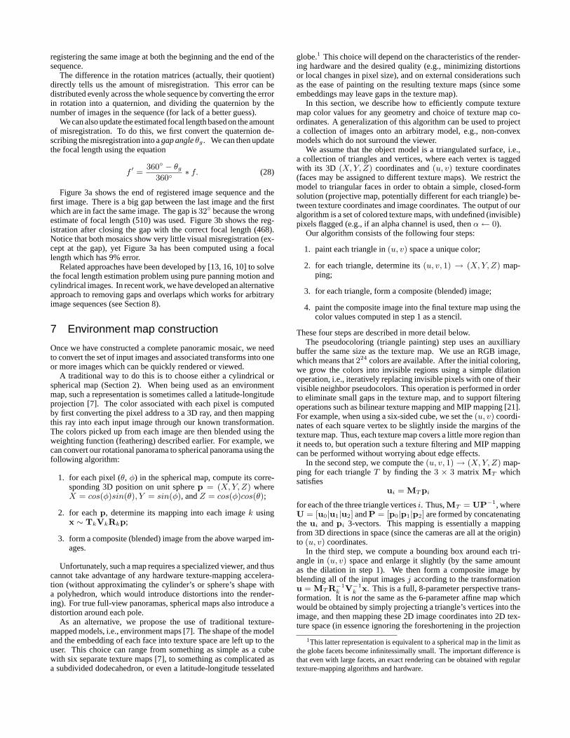
Figure 3a shows the end of registered image sequence and thefirst image. There is a big gap between the last image and the firstwhich are in fact the same image. The gap is32 because the wrongestimate of focal length (510) was used. Figure 3b shows the reg-istration after closing the gap with the correct focal length (468).Notice that both mosaics show very little visual misregistration (ex-cept at the gap), yet Figure 3a has been computed using a focallength which has 9% error.
Related approaches have been developed by [13, 16, 10] to solvethe focal length estimation problem using pure panning motion andcylindrical images. In recent work, we have developed an alternativeapproach to removing gaps and overlaps which works for arbitraryimage sequences (see Section 8).
7 Environment map construction
Once we have constructed a complete panoramic mosaic, we needto convert the set of input images and associated transforms into oneor more images which can be quickly rendered or viewed.
A traditional way to do this is to choose either a cylindrical orspherical map (Section 2). When being used as an environmentmap, such a representation is sometimes called a latitude-longitudeprojection [7]. The color associated with each pixel is computedby first converting the pixel address to a 3D ray, and then mappingthis ray into each input image through our known transformation.The colors picked up from each image are then blended using theweighting function (feathering) described earlier. For example, wecan convert our rotational panorama to spherical panorama using thefollowing algorithm:
1. for each pixel (θ, φ) in the spherical map, compute its corre-sponding 3D position on unit spherep = (X, Y, Z) whereX = cos(φ)sin(θ), Y = sin(φ), andZ = cos(φ)cos(θ);
2. for eachp, determine its mapping into each imagek usingx ∼ TkVkRkp;
3. form a composite (blended) image from the above warped im-ages.
Unfortunately, such a map requires a specialized viewer, and thuscannot take advantage of any hardware texture-mapping accelera-tion (without approximating the cylinder’s or sphere’s shape witha polyhedron, which would introduce distortions into the render-ing). For true full-view panoramas, spherical maps also introduce adistortion around each pole.
As an alternative, we propose the use of traditional texture-mapped models, i.e., environment maps [7]. The shape of the modeland the embedding of each face into texture space are left up to theuser. This choice can range from something as simple as a cubewith six separate texture maps [7], to something as complicated asa subdivided dodecahedron, or even a latitude-longitude tesselated
globe.1 This choice will depend on the characteristics of the render-ing hardware and the desired quality (e.g., minimizing distortionsor local changes in pixel size), and on external considerations suchas the ease of painting on the resulting texture maps (since someembeddings may leave gaps in the texture map).
In this section, we describe how to efficiently compute texturemap color values for any geometry and choice of texture map co-ordinates. A generalization of this algorithm can be used to projecta collection of images onto an arbitrary model, e.g., non-convexmodels which do not surround the viewer.
We assume that the object model is a triangulated surface, i.e.,a collection of triangles and vertices, where each vertex is taggedwith its 3D (X, Y, Z) coordinates and(u, v) texture coordinates(faces may be assigned to different texture maps). We restrict themodel to triangular faces in order to obtain a simple, closed-formsolution (projective map, potentially different for each triangle) be-tween texture coordinates and image coordinates. The output of ouralgorithm is a set of colored texture maps, with undefined (invisible)pixels flagged (e.g., if an alpha channel is used, thenα← 0).
Our algorithm consists of the following four steps:
1. paint each triangle in(u, v) space a unique color;
2. for each triangle, determine its(u, v, 1) → (X, Y, Z) map-ping;
3. for each triangle, form a composite (blended) image;
4. paint the composite image into the final texture map using thecolor values computed in step 1 as a stencil.
These four steps are described in more detail below.The pseudocoloring (triangle painting) step uses an auxilliary
buffer the same size as the texture map. We use an RGB image,which means that224 colors are available. After the initial coloring,we grow the colors into invisible regions using a simple dilationoperation, i.e., iteratively replacing invisible pixels with one of theirvisible neighbor pseudocolors. This operation is performed in orderto eliminate small gaps in the texture map, and to support filteringoperations such as bilinear texture mapping and MIP mapping [21].For example, when using a six-sided cube, we set the(u, v) coordi-nates of each square vertex to be slightly inside the margins of thetexture map. Thus, each texture map covers a little more region thanit needs to, but operation such a texture filtering and MIP mappingcan be performed without worrying about edge effects.
In the second step, we compute the(u, v, 1)→ (X, Y, Z) map-ping for each triangleT by finding the3 × 3 matrix MT whichsatisfies
ui = MT pi
for each of the three triangle verticesi. Thus,MT = UP−1, whereU = [u0|u1|u2] andP = [p0|p1|p2] are formed by concatenatingthe ui andpi 3-vectors. This mapping is essentially a mappingfrom 3D directions in space (since the cameras are all at the origin)to (u, v) coordinates.
In the third step, we compute a bounding box around each tri-angle in(u, v) space and enlarge it slightly (by the same amountas the dilation in step 1). We then form a composite image byblending all of the input imagesj according to the transformationu = MT R−1
k V−1k x. This is a full, 8-parameter perspective trans-
formation. It isnot the same as the 6-parameter affine map whichwould be obtained by simply projecting a triangle’s vertices into theimage, and then mapping these 2D image coordinates into 2D tex-ture space (in essence ignoring the foreshortening in the projection
1This latter representation is equivalent to a spherical map in the limit asthe globe facets become infinitessimally small. The important difference isthat even with large facets, an exact rendering can be obtained with regulartexture-mapping algorithms and hardware.

onto the 3D model). The error in applying this naive but erroneousmethod to large texture map facets (e.g., those of a simple unrefinedcube) would be quite large.
In the fourth step, we find the pseudocolor associated with eachpixel inside the composited patch, and paint the composited colorinto the texture map if the pseudocolor matches the face id.
Our algorithm can also be used to project a collection of imagesonto an arbitrary object, i.e., to do true inverse texture mapping,by extending our algorithm to handle occlusions. To do this, wesimply paint the pseudocolored polyhedral model into each inputimage using a z-buffering algorithm (this is called anitem bufferinray tracing [20]). When compositing the image for each face, wethen check to see which pixels match the desired pseudocolor, andset those which do not match to be invisible (i.e., not to contributeto the final composite).
Figure 4 shows the results of mapping a panoramic mosaic ontoa longitude-latitude tesselated globe. The white triangles at the topare the parts of the texture map not covered in the 3D tesselatedglobe model (due to triangular elements at the poles). Figures 5–7show the results of mapping three different panoramic mosaics ontocubical environment maps. We can see that the mosaics are of veryhigh quality, and also get a good sense for the extent of viewingsphere covered by these full-view mosaics. Note that Figure 5 usesimages taken with a hand-held digital camera.
Once the texture-mapped 3D models have been constructed, theycan be rendered directly with a standard 3D graphics system. Forour work, we are currently using a simple 3D viewer written ontop of the Direct3D API running on a personal computer with nohardware graphics acceleration.
8 Discussion
In this paper, we have developed some new techniques for build-ing full view panoramic image mosaics. Our system does not placeconstraints on how the input images are taken, and allows the im-ages to be taken with hand held cameras. By taking many overlap-ping images, we can significantly increase the field of view of theconstructed panorama and remove the need for expensive fisheyelenses. Our method is accurate and robust because we estimate only3 unknowns in the rotation matrix instead of 8 parameters in thegeneral perspective transforms. Our method greatly increases ac-curacy, flexibility, and ease of use of previous techniques. We havealso developed techniques for estimating the focal length from animage sequence, and for recovering from accumulated registrationerrors when a full panoramic mosaic is completed.
When building an image mosaic from a long sequence of im-ages, we have to deal with error accumulation problems. In thispaper we have presented a “gap closing” technique which updatesthe focal length and rotation matrices after a complete panorama isconstructed. More recently we have developed a new method basedon block adjustmentwhich simultaneously adjusts all rotation ma-trices and focal lengths so that the sum of registration errors betweenall matching pairs of images is minimized [15].
In theory, panoramas can only be constructed if all images aretaken by a camera whose optical centers never moves. In practice,this depends on the amount of camera translation relative to thenearest objects in front of the camera. With our 3-D rotation mo-saicing method, we have demonstrated that images taken by a handheld digital camera can be seamlessly stitched. To compensate forlocal misregistration caused by larger amounts of motion parallax(e.g., camera translation), we have recently developed adeghostingtechnique [15]. We divide each image into small patches and com-pute patch-based alignments. Each image is then locally warpedso that the overall mosaic does not contain visible ghosting. Thisdeghosting method has been used to build the image mosaic of theSpace Shuttle flight deck (Figure 8) from a sequence of images (with
significant motion parallax) taken by an astronant with a hand-heldcamera.
We have also presented an algorithm for extracting texture mapsfrom the image mosaics. We can map image mosaics onto any 3-D model and exploit 3-D graphics hardware and APIs. Comparedwith using special purpose players (e.g., cylindrical and sphericalviewers), our inverse texture mapping approach can be much moreeasily integrated as backdrops for virtual worlds and games. In thefuture, we would like to explore how to extract the three-dimensionalworld descriptions from full-view panoramic image mosaics.
References
[1] N. Ayache. Vision Stereoscopique et Perception Multisen-sorielle. InterEditions., Paris, 1989.
[2] J. R. Bergen, P. Anandan, K. J. Hanna, and R. Hingorani. Hier-archical model-based motion estimation. InSecond EuropeanConference on Computer Vision (ECCV’92), pages 237–252,Santa Margherita Liguere, Italy, May 1992. Springer-Verlag.
[3] S. Chen and L. Williams. View interpolation for image syn-thesis.Computer Graphics (SIGGRAPH’93), pages 279–288,August 1993.
[4] S. E. Chen. QuickTime VR – an image-based approach tovirtual environment navigation.Computer Graphics (SIG-GRAPH’95), pages 29–38, August 1995.
[5] O. Faugeras.Three-dimensional computer vision: A geometricviewpoint. MIT Press, Cambridge, Massachusetts, 1993.
[6] S. J. Gortler, R. Grzeszczuk, R. Szeliski, and M. F. Cohen.The lumigraph. InComputer Graphics Proceedings, AnnualConference Series, pages 43–54, Proc. SIGGRAPH’96 (NewOrleans), August 1996. ACM SIGGRAPH.
[7] N. Greene. Environment mapping and other applications ofworld projections. IEEE Computer Graphics and Applica-tions, 6(11):21–29, November 1986.
[8] R. I. Hartley. Self-calibration from multiple views of a rotatingcamera. InThird European Conference on Computer Vision(ECCV’94), volume 1, pages 471–478, Stockholm, Sweden,May 1994. Springer-Verlag.
[9] M. Irani, P. Anandan, and S. Hsu. Mosaic based representa-tions of video sequences and their applications. InFifth In-ternational Conference on Computer Vision (ICCV’95), pages605–611, Cambridge, Massachusetts, June 1995.
[10] S. B. Kang and R Weiss. Characterization of errors in com-positing panoramic images. Technical Report 96/2, DigitalEquipment Corporation, Cambridge Research Lab, June 1996.
[11] M. Levoy and P. Hanrahan. Light field rendering. InComputerGraphics Proceedings, Annual Conference Series, pages 31–42, Proc. SIGGRAPH’96 (New Orleans), August 1996. ACMSIGGRAPH.
[12] S. Mann and R. W. Picard. Virtual bellows: Constructinghigh-quality images from video. InFirst IEEE InternationalConference on Image Processing (ICIP-94), volume I, pages363–367, Austin, Texas, November 1994.
[13] L. McMillan and G. Bishop. Plenoptic modeling: Animage-based rendering system.Computer Graphics (SIG-GRAPH’95), pages 39–46, August 1995.

[14] J. Meehan.Panoramic Photography. Watson-Guptill, 1990.
[15] H.-Y. Shum and R. Szeliski. Construction and refinement ofpanoramic mosaics with global and local alignment. Submittedfor review, April 1997.
[16] G. Stein. Accurate internal camera calibration using rotation,with analysis of sources of error. InFifth International Con-ference on Computer Vision (ICCV’95), pages 230–236, Cam-bridge, Massachusetts, June 1995.
[17] R. Szeliski. Image mosaicing for tele-reality applications.In IEEE Workshop on Applications of Computer Vision(WACV’94), pages 44–53, Sarasota, Florida, December 1994.IEEE Computer Society.
[18] R. Szeliski. Video mosaics for virtual environments.IEEEComputer Graphics and Applications, pages 22–30, March1996.
[19] R. Y. Tsai. A versatile camera calibration technique for high-accuracy 3D machine vision metrology using off-the-shelf TVcameras and lenses.IEEE Journal of Robotics and Automation,RA-3(4):323–344, August 1987.
[20] H. Weghorst, G. Hooper, and D. P. Greenberg. Improvedcomputational methods for ray tracing.ACM Transactionson Graphics, 3(1):52069, January 1984.
[21] L. Williams. Pyramidal parametrics.Computer Graphics,17(3):1–11, July 1983.
[22] http://qtvr.quicktime.apple.com.
[23] http://www.bdiamon.com.
[24] http://www.omniview.com.
[25] http://www.smoothmove.com.
[26] http://www.rlspace.com.
[27] http://www.behere.com.
[28] http://www.cs.columbia.edu/cave/omnicam.
(a)
(b)
Figure 1: Construction of a cylindrical panorama: (a) two warpedimages; (b) part of cylindrical panorama composited from a se-quence of images.
Figure 2: 3D rotation registration of four images taken with a hand-held camera.

(a) (b)
Figure 3: Gap closing after sequentially registering 24 images: (a) a gap is visible when the focal length is wrong (f = 510); (b) no gap isvisible for the correct focal length (f = 468).
Figure 4: Tessellated spherical panorama covering the north pole (constructed from 54 images). The white triangles at the top are the parts ofthe texture map not covered in the 3D tesselated globe model (due to triangular elements at the poles).
Figure 5: Cubical texture-mapped model of conference room (from 75 images taken with a hand-held digital camera).

Figure 6: Cubical texture-mapped model of lobby (from 54 images).
Figure 7: Cubical texture-mapped model of hallway and sitting area (from 36 images).
Figure 8: Panorama of Space Shuttle flight deck from 14 images taken with a hand-held camera (usingdeghostingtechnique).
Copyright © 2022 FDOKUMEN