Installation & User Manual Model: Alchemy FB18 with Remote ...
Upload
khangminh22Category
view
1download
0
IMPORTANT: Read and save these instructions.
NOTICE:Installer: Leave this guide with the homeownerHomeowner: Keep this guide for future reference
DUAL FUEL RANGECOS-DFR304COS-DFR366COS-DFR486G
Installation & User Manual
Thank you for your purchase. We know that you have many brands and
products to choose from and we are honored to know that you have decided
to take one of our products into your home and hope that you enjoy it.
COSMO Appliances are designed according to the strictest safety and
performance standard for the North American market. We follow the
most advanced manufacturing philosophy. Each appliance leaves the
factory after thorough quality inspection and testing. Our distributors and
our service partners are ready to answer any questions you may have
regarding how to install, use and care for your products. We hope that this
manual will help you learn to use the product in the safest and most effective
manner.
Before using this product, please read through this manual carefully. Keep this
manual in a safe place for future reference. Please ensure that other
persons using this product are familiar with these instructions as well.
If you have any questions or concerns, please contact the dealer from whom you
purchased it, or contact our Customer Support at:
1-888-784-3108.
2
THANK YOU FOR YOUR PURCHASE
TABLE OF CONTENTS
SAFETY & WARNINGS ..........................................................4-5General Safety & Warnings ......................................................4Installation Safety & Warnings .................................................5
INSTALLATION MANUAL .....................................................6-20Legs ........................................................................................6Anti-Tip Device .........................................................................7Range .......................................................................................8Range Hood .............................................................................9Electrical Connection .............................................................10Power Cord Replacement ......................................................11Dimension Diagram: DFR304 ................................................12 Dimension Diagram: DFR366 .................................................13 Dimension Diagram: DFR486G ..............................................14 Circuit Diagram: DFR304 ........................................................15 Circuit Diagram: DFR366 ........................................................15 Circuit Diagram: DFR486G .....................................................16 Gas Connection ................................................................17-18 Gas Conversion ................................................................19-20 Before Use: Installation Checklist ..........................................21 Before Use: Final Preparation ................................................21
USER MANUAL ..................................................................22-42Operation & Safety Warnings ............................................22-23Burner / BTU Diagrams ...........................................................24 Cooktop Surface Cooking .................................................25-27 Oven Cooking ..................................................................28-38 Before Use / Tips ....................................................................28 Oven Functions .......................................................................29 Bake ........................................................................................30 Convection Bake & Turbo ..................................................31-32 Baking Recommendations .................................................33-34 Broil / Convection Broil ......................................................35-36 Broil/Roasting Recommendations ..........................................37 Care & Maintenance ................................................................38 Troubleshooting .................................................................39-41 Location of Appliance Tags ....................................................42
WARRANTY & SERVICE ....................................................43-44
3

SAFETY & WARNINGS
4
This appliance has been designed for non-professional, domestic use only.Do not use this appliance to heat a room.Do not place any pot or pan on the open oven door.The door is made of glass and it can break if loadedwith a weight.Before beginning installation, please read theseinstructions completely and carefully.Do not remove permanently affixed labels, warnings,or plates from the product. This may void thewarranty. Please observe all local and national codesand ordinances.Please ensure the range is properly grounded.The installer should leave these instructions with theconsumer who should retain for local inspector's useand for future reference.The plug should always be accessible.Installation must conform with local codes or in theabsence of codes, the National Fuel Gas CodeNSIZ223.1/NFPA54. Electrical installation must be inaccordance with the National Electrical Code, ANSI/NPA70 - latest edition and/or local codes. INCANADA: Installation must be in accordance with thecurrent CAN/CGA-fe 149.1 National Gas InstallationCode or CAN/CGA-B 149.2, Propane InstallationCode and/or local codes. Electrical installation mustbe in accordance with the current CSA C22.1Canadian Electrical Codes Part 1 and/or local codes.Installation of any gas-fired equipment should bemade by a licensed plumber. A manual gas shut-offvalve must be installed in the gas supply line ahead ofthe oven in the gas flow for safety and ease ofservice.
WARNING: This appliance shall not beinstalled with a ventilation system that blowsair downward toward the range; this type ofventilation system may cause ignition andcombustion problem with the gas applianceresulting in a personal injury or unintendedoperation.WARNING: An air curtain or other overheadrange/cooktop hood, which operates byblowing a downward airflow onto a range/rangetop/cooktop, shall not be used/installedin conjunction with this gas range.
the gas flow for safety and ease of service.WARNING: This appliance shall not beinstalled with a ventilation system that blowsair downward toward the range; this type ofventilation system may cause ignition andcombustion problem with the gas applianceresulting in a personal injury or unintendedoperation.WARNING: An air curtain or other overheadrange/cooktop hood, which operates byblowing a downward airflow onto a range/rangetop/cooktop, shall not be used/installedin conjunction with this gas range.
PLEASE READ AND FOLLOW THESEIMPORTANT INSTRUCTIONS FOR THE SAFETYOF YOUR HOME AND OF THE PEOPLE LIVINGIN IT.Save this Manual for local electrical inspector's use.Read and save these instructions for futurereference. Observe all governing codes, ordinancesand regulations. Installation and service must beperformed by a qualified installer, service agency orthe gas supplier.
WARNING: If the information in this manualis not followed exactly, a fire or explosionmay result causing property damage,personal injury, or death.WARNING: Do not store or use gasoline orother flammable substances in the vicinityof this or any other appliance.
WHAT TO DO IF YOU SMELL GAS:• Do not light any appliance.• Do not touch any electrical switch.• Do not use any phone in your building.• Immediately call your gas supplier from aneighbor's phone. Follow the gas supplier'sinstructions closely.• If you cannot reach your gas suppliers, call thefire department.In Massachusetts: All gas products must be installedby a "Massachusetts" licensed plumber or gasfitter.A "T" handle type manual gas valve must beinstalled in the gas line connected to this appliance.WARNING: NEVER use this appliance as a spaceheater to heat or warm the room. Doing so mayresult in carbon monoxide poisoning andoverheating of the oven.
WARNING: This range can tip over, causingpossible injury or death. Install the anti-tipdevice shipped with the range. See Page 7of this manual.WARNING: Read this instruction bookletbefore installing and using the appliance.The manufacturer will not be responsible forany damage to property or to personscaused by incorrect installation or improperuse of the appliance. The manufacturerreserves the right to make changes to itsproducts when considered necessary anduseful, without affecting the essential safetyand operating characteristics.
INSTALLATION SAFETY & WARNINGS
5
WARNING! Do not use aerosol sprays in the vicinity of this appliance while it is in operation.ROOM VENTILATIONAn exhaust fan may be used with the appliance;in each case it shall be installed in conformitywith the appropriate national and local standards.Exhaust hood operation may affect other ventedappliances; in each case it shall be installed inconformity with the appropriate national and localstandards.TYPE OF GASThis appliance is shipped from the factory for usewith natural gas. Propane Conversion Kit mustbe purchased separately. For use with propaneLP gas please follow the conversion proceduredescribed on pg. 17.GAS PRESSUREThe maximum inlet gas supply pressureincoming to the gas appliance pressure regulatoris 34 PSI (13,8 w.c. pr 3,5 kPa).The minimum gas supply pressure for checkingthe regulator setting shall be at least 1" w.c. (249Pa) above the inlet specified manifold pressureto the appliance (this operating pressure is 4"w.c. (1.00 kPa) for Natural Gas and 11" w.c.(2.75 kPa for LP Gas).
This appliance shall only be installed by anauthorized professional.This appliance shall be installed inaccordance with the manufacturer'sinstallation instructions.This appliance must be installed in accordancewith the standards of the country where it willbe installed. The installation of this appliancemust conform to local codes and ordinances. Inthe absence of local codes, Installations mustconforms to American National Standards,National Fuel Gas Code ANSI Z223.1 - latestedition/NFPA 54 or B 149.1.The appliance, when installed, must beelectrically grounded in accordance with localcodes or, in the absence of local codes, withthe National Electrical Code, ANSI/NFPA 70.If local codes permit, a flexible metal applianceconnection with the new AGA or CGA certifieddesign, max. 5 feet (1,5 m) long, 3/4" I.D. isrecommended for connecting this appliance tothe gas supply line. Do not bend or damage theflexible connector when moving the appliance.This appliance must be used with the pressureregulator provided. The regulator shall beproperly installed in order to be accessiblewhen the appliance is installed in its finallocation. The pressure regulator must be set forthe type of gas to be used. The pressureregulator has 3/4" female pipe thread. Theappropriate fitting must be determined basedon the size of your gas supply line, the flexiblemetal connector and the shutoff valve.The appliance must be isolated from the gassupply piping system by closing its individualmanual shutoff valve during any pressuretesting of the gas supply piping system at testpressures equal to or less than 34 PSI (13,8w.c. pr 3,5 kPa).All opening and holes in the wall and floor, backand under the appliance shall be sealed beforeinstallation of the appliance.A manual valve shall be installed in anaccessible location in the gas line external tothe appliance for the purpose of turning on orshutting off gas to the appliance
6
INSTALLATION: LEGS
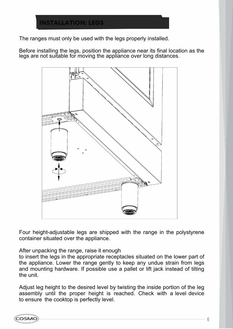
The ranges must only be used with the legs properly installed.Before installing the legs, position the appliance near its final location as thelegs are not suitable for moving the appliance over long distances.
Four height-adjustable legs are shipped with the range in the polystyrenecontainer situated over the appliance.After unpacking the range, raise it enoughto insert the legs in the appropriate receptacles situated on the lower part ofthe appliance. Lower the range gently to keep any undue strain from legsand mounting hardware. If possible use a pallet or lift jack instead of tiltingthe unit.Adjust leg height to the desired level by twisting the inside portion of the legassembly until the proper height is reached. Check with a level deviceto ensure the cooktop is perfectly level.
7
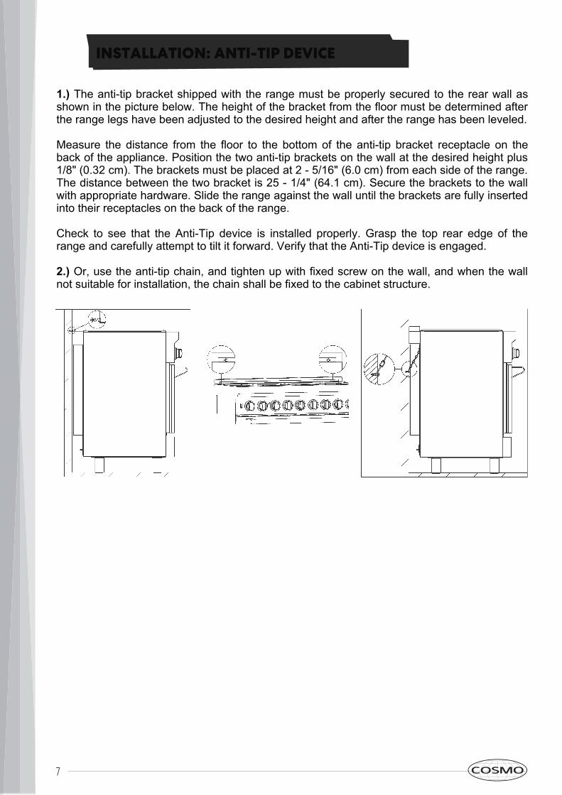
1.) The anti-tip bracket shipped with the range must be properly secured to the rear wall asshown in the picture below. The height of the bracket from the floor must be determined afterthe range legs have been adjusted to the desired height and after the range has been leveled.Measure the distance from the floor to the bottom of the anti-tip bracket receptacle on theback of the appliance. Position the two anti-tip brackets on the wall at the desired height plus1/8" (0.32 cm). The brackets must be placed at 2 - 5/16" (6.0 cm) from each side of the range.The distance between the two bracket is 25 - 1/4" (64.1 cm). Secure the brackets to the wallwith appropriate hardware. Slide the range against the wall until the brackets are fully insertedinto their receptacles on the back of the range.Check to see that the Anti-Tip device is installed properly. Grasp the top rear edge of therange and carefully attempt to tilt it forward. Verify that the Anti-Tip device is engaged.2.) Or, use the anti-tip chain, and tighten up with fixed screw on the wall, and when the wallnot suitable for installation, the chain shall be fixed to the cabinet structure.
INSTALLATION: ANTI-TIP DEVICE
8
INSTALLATION: RANGE
E
.
G
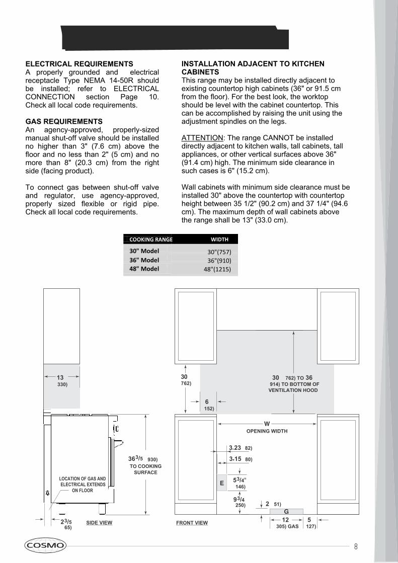
ELECTRICAL REQUIREMENTSA properly grounded and electricalreceptacle Type NEMA 14-50R shouldbe installed; refer to ELECTRICALCONNECTION section Page 10. Check all local code requirements.GAS REQUIREMENTSAn agency-approved, properly-sizedmanual shut-off valve should be installedno higher than 3" (7.6 cm) above thefloor and no less than 2" (5 cm) and nomore than 8" (20.3 cm) from the rightside (facing product).To connect gas between shut-off valveand regulator, use agency-approved,properly sized flexible or rigid pipe.Check all local code requirements.
INSTALLATION ADJACENT TO KITCHENCABINETSThis range may be installed directly adjacent toexisting countertop high cabinets (36" or 91.5 cmfrom the floor). For the best look, the worktopshould be level with the cabinet countertop. Thiscan be accomplished by raising the unit using theadjustment spindles on the legs.ATTENTION: The range CANNOT be installeddirectly adjacent to kitchen walls, tall cabinets, tallappliances, or other vertical surfaces above 36"(91.4 cm) high. The minimum side clearance insuch cases is 6" (15.2 cm).Wall cabinets with minimum side clearance must beinstalled 30" above the countertop with countertopheight between 35 1/2" (90.2 cm) and 37 1/4" (94.6cm). The maximum depth of wall cabinets abovethe range shall be 13" (33.0 cm).
E
.
G
COOKING RANGE WIDTH
30" Model 30"(757)36" Model 36"(910)48" Model 48"(1215)
3 23"(82)
FRONT VIEW
30"(762)
6"(152)
(65)
(930)TO COOKINGSURFACE
WOPENING WIDTH
30" (762) TO 36"(914) TO BOTTOM OFVENTILATION HOOD*
ELOCATION OF GAS AND ELECTRICAL EXTENDSON FLOOR
SIDE VIEW
.
13"(330)
3 15"(80).
12"(305) GAS 5"(127)
2" (51)G
53/4"(146)(250)93/4"
363/5"
23/5"
9
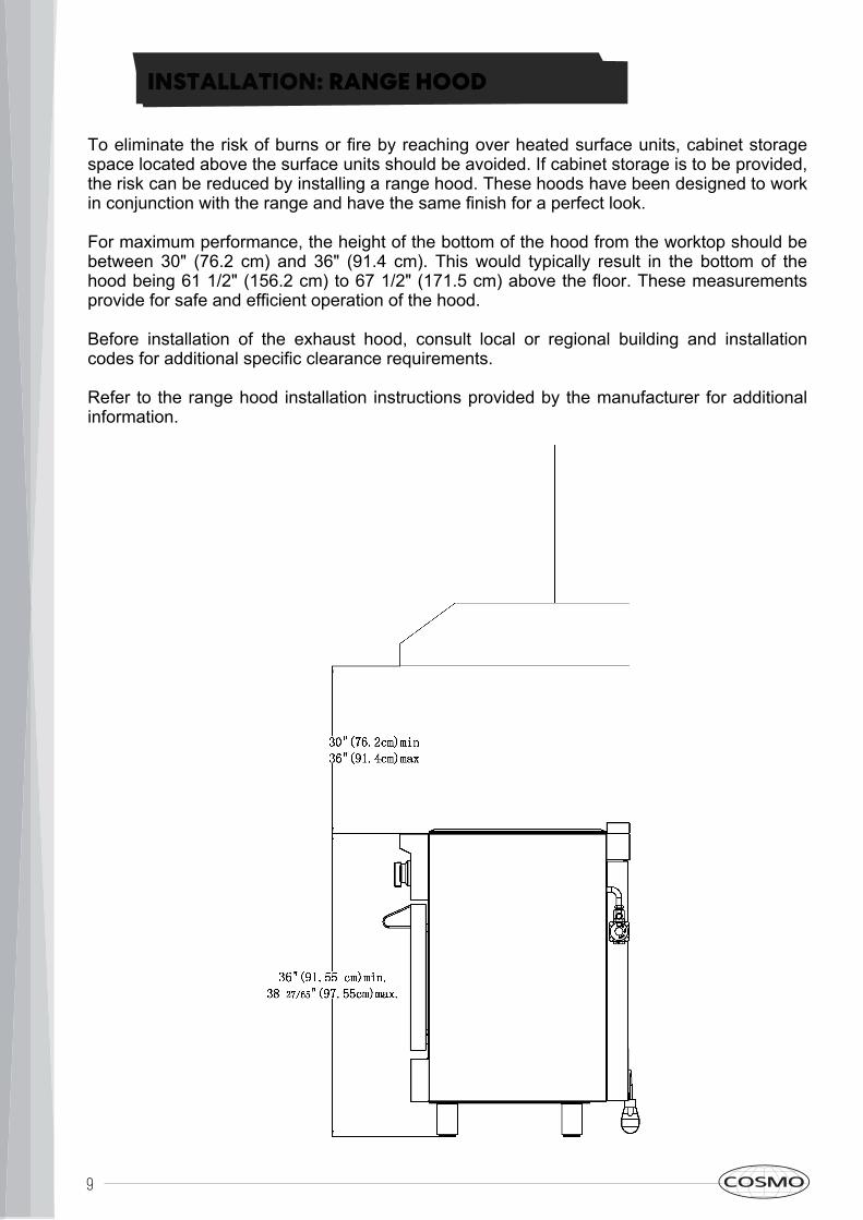
To eliminate the risk of burns or fire by reaching over heated surface units, cabinet storagespace located above the surface units should be avoided. If cabinet storage is to be provided,the risk can be reduced by installing a range hood. These hoods have been designed to workin conjunction with the range and have the same finish for a perfect look.For maximum performance, the height of the bottom of the hood from the worktop should bebetween 30" (76.2 cm) and 36" (91.4 cm). This would typically result in the bottom of thehood being 61 1/2" (156.2 cm) to 67 1/2" (171.5 cm) above the floor. These measurementsprovide for safe and efficient operation of the hood.Before installation of the exhaust hood, consult local or regional building and installationcodes for additional specific clearance requirements.Refer to the range hood installation instructions provided by the manufacturer for additionalinformation.
INSTALLATION: RANGE HOOD
10
Rating Label
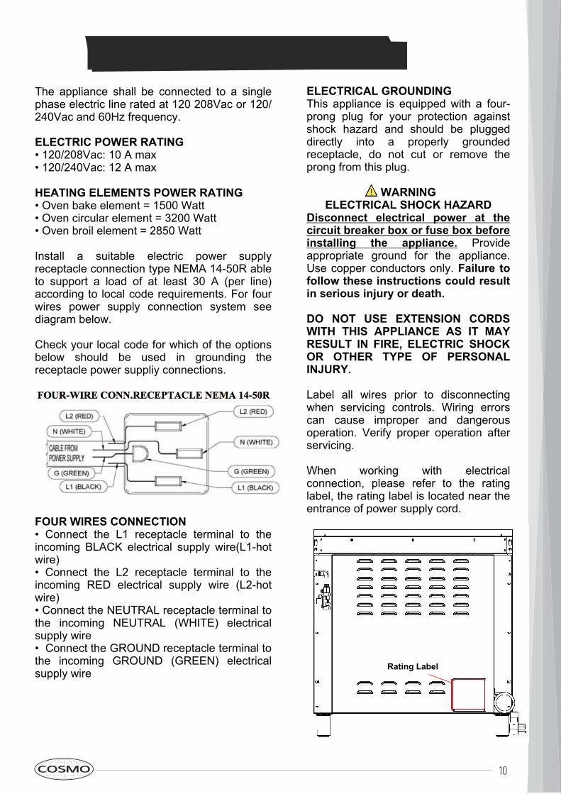
The appliance shall be connected to a singlephase electric line rated at 120 208Vac or 120/240Vac and 60Hz frequency.ELECTRIC POWER RATING• 120/208Vac: 10 A max• 120/240Vac: 12 A maxHEATING ELEMENTS POWER RATING• Oven bake element = 1500 Watt• Oven circular element = 3200 Watt• Oven broil element = 2850 WattInstall a suitable electric power supplyreceptacle connection type NEMA 14-50R ableto support a load of at least 30 A (per line)according to local code requirements. For fourwires power supply connection system seediagram below.Check your local code for which of the optionsbelow should be used in grounding thereceptacle power suppliy connections.
FOUR WIRES CONNECTION• Connect the L1 receptacle terminal to theincoming BLACK electrical supply wire(L1-hotwire)• Connect the L2 receptacle terminal to theincoming RED electrical supply wire (L2-hotwire)• Connect the NEUTRAL receptacle terminal tothe incoming NEUTRAL (WHITE) electricalsupply wire• Connect the GROUND receptacle terminal tothe incoming GROUND (GREEN) electricalsupply wire
ELECTRICAL GROUNDINGThis appliance is equipped with a four-prong plug for your protection againstshock hazard and should be pluggeddirectly into a properly groundedreceptacle, do not cut or remove theprong from this plug.WARNINGELECTRICAL SHOCK HAZARDDisconnect electrical power at thecircuit breaker box or fuse box beforeinstalling the appliance. Provideappropriate ground for the appliance.Use copper conductors only. Failure tofollow these instructions could resultin serious injury or death.
DO NOT USE EXTENSION CORDSWITH THIS APPLIANCE AS IT MAYRESULT IN FIRE, ELECTRIC SHOCKOR OTHER TYPE OF PERSONALINJURY.Label all wires prior to disconnectingwhen servicing controls. Wiring errorscan cause improper and dangerousoperation. Verify proper operation afterservicing.When working with electricalconnection, please refer to the ratinglabel, the rating label is located near theentrance of power supply cord.
ELECTRICAL CONNECTION

11
POWER CORD REPLACEMENT
DO NOT USE EXTENSIONCORDS WITH THIS APPLIANCEAS IT MAY RESULT IN FIRE,ELECTRIC SHOCK OR OTHERTYPE OF PERSONAL INJURY.The appliance is equipped atthe factory with an electricsupply cord set 4 wires typewith ring terminals (L1, L2, N,Ground) suitable for range useUL/CSA listed type SRDT/DRT2x6AWG (L1, L2)+2x8AWG (N,G) rated 300V, 40 or 50A withfused plug type NEMA 14-50P;cable length 1.5m in case thesupply cord set must be replaced,it must be replaced with anidentical set having the savetechnical specifications andinstalled using the followingdirections:1.) Disconnect appliance fromelectrical power supply receptacle2.) Slide out the appliance fromthe installation place to accessthe back enclosure3.) Remove back enclosure panelby removing the 6 screws asshown below.
4.) Loose strain reliefby unscrewing twostrain relief's screws indiagram
5.) Remove damagedsupply cord set by taking offthe 4 electrical connectionscrews (block L1, N, L2 andGround screw, seediagram)6.) Insert the new supplycord set in the strain reliefand lock it with two strainrelief’s screws in suitableposition7.) Fix well the ringterminals G, L1, N, L2 ofthe new supply cord set, asshown in diagram with its 4screws8.) Reinstall the backenclosure panel with 6screws9.) Slide the appliance backinto its proper location10.) Reconnect theappliance to the electricalpower
12
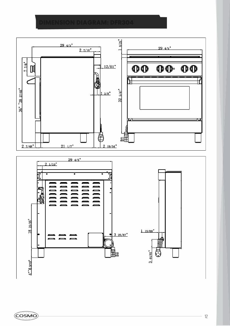
DIMENSION DIAGRAM: DFR304
13
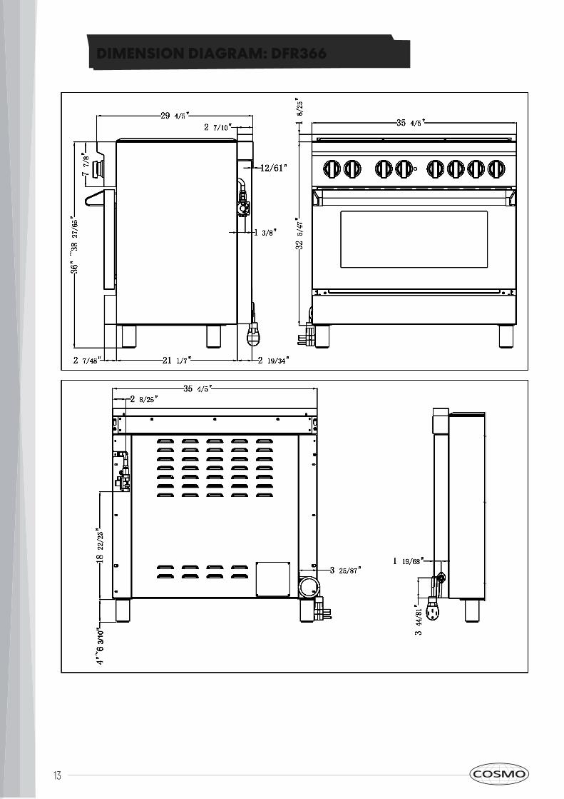
DIMENSION DIAGRAM: DFR366
14
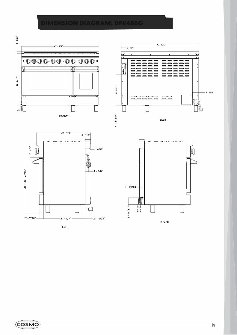
DIMENSION DIAGRAM: DFR486G
15
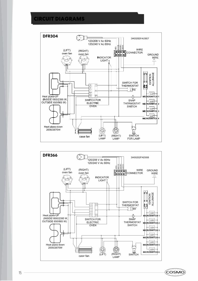
CIRCUIT DIAGRAMS
DFR304
DFR366
16
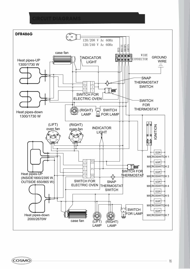
CIRCUIT DIAGRAMS
DFR486G
17
GAS CONNECTION
All gas connections must comply withnational and local codes. The gas supply line(service) must be the same size or greaterthan the inlet line of the appliance. Thisrange uses a 1/2" NPT inlet (see drawingbelow for details of gas connection). On allpipe joints use appropriate sealant resistantto gas.This range can be used with Natural or LP/Propane gas. The range is shipped from thefactory for use with natural gas.For LP/propane household installation, theappliance must be converted by the dealer,by a factory-trained professional or by aqualified licensed plumber or gas servicecompany.Gas conversion is important for safe andeffective use of the appliance. It is theresponsibility of the dealer and the owner ofthe range to perform the appropriate gasconversion following the directions of themanufacturer.THE PROPER GAS CONVERSION PROCEDURE IS DESCRIBED IN THIS MANUAL. REPLACEMENT NOZZLES CAN BE PURCHASED FROM COSMOAPPLIANCES.COM.Please provide the service person with thismanual before work is started on the range.WARNING: DO NOT USE AN OPENFLAME WHEN CHECKING FOR LEAKS.Leak testing of the appliance shall beconducted according to the manufacturer'sinstructions. Before placing the oven intooperation, always check for leaks with soapywater solution or other acceptable method.Check for gas leakage with soapy watersolution or other acceptable methods in allgas connections installed between inlet gaspipe of the appliance, gas regulator, till to themanual shut-off valve.
MANUAL SHUT-OFF VALVETHIS VALVE IS NOT SHIPPED WITH THEAPPLIANCE AND MUST BE SUPPLIED BY THEINSTALLER.The manual shut-off valve must be installed in thegas service line between the gas hook-up on thewall and the appliance inlet, in a position where itcan be reached quickly in the event of anemergency.In Massachusetts: A T handle type manual gasvalve must be installed in the gas supply line tothis appliance.FLEXIBLE CONNECTIONSIn case of installation with flexible couplings and/or quick-disconnect fittings, the installer must usea heavy-duty, AGA design-certified commercialflexible connector of at least 1/2" (1.3 cm) ID NPT(with suitable strain reliefs) in compliance withANSI Z21.41 and Z21.69 standards.In Massachusetts: The unit must be installedwith a 36" (3-foot) long flexible gas connector.In Canada: use CAN 1-6.10-88 metal connectorsfor gas appliances and CAN 1-6.9 M79 quickdisconnect device for use with gas fuel.PRESSURE TEST-POINT STOPPER VALVETo avoid gas leaks, the pressure test-pointstopper valve and gasket supplied with the rangemust be installed on the gas fitting at the back ofthe range according to the diagram below.
18
GAS CONNECTION
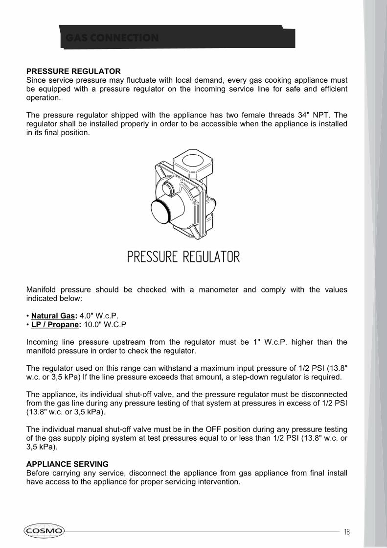
PRESSURE REGULATORSince service pressure may fluctuate with local demand, every gas cooking appliance mustbe equipped with a pressure regulator on the incoming service line for safe and efficientoperation.The pressure regulator shipped with the appliance has two female threads 34" NPT. Theregulator shall be installed properly in order to be accessible when the appliance is installedin its final position.
Manifold pressure should be checked with a manometer and comply with the valuesindicated below:• Natural Gas: 4.0" W.c.P.• LP / Propane: 10.0" W.C.PIncoming line pressure upstream from the regulator must be 1" W.c.P. higher than themanifold pressure in order to check the regulator.The regulator used on this range can withstand a maximum input pressure of 1/2 PSI (13.8"w.c. or 3,5 kPa) If the line pressure exceeds that amount, a step-down regulator is required.The appliance, its individual shut-off valve, and the pressure regulator must be disconnectedfrom the gas line during any pressure testing of that system at pressures in excess of 1/2 PSI(13.8" w.c. or 3,5 kPa).The individual manual shut-off valve must be in the OFF position during any pressure testingof the gas supply piping system at test pressures equal to or less than 1/2 PSI (13.8" w.c. or3,5 kPa).APPLIANCE SERVINGBefore carrying any service, disconnect the appliance from gas appliance from final installhave access to the appliance for proper servicing intervention.
19
GAS CONVERSION
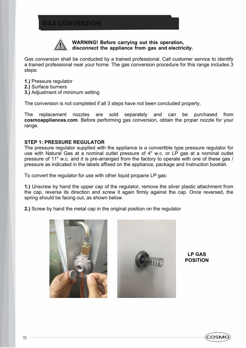
Gas conversion shall be conducted by a trained professional. Call customer service to identifya trained professional near your home. The gas conversion procedure for this range includes 3steps:1.) Pressure regulator2.) Surface burners3.) Adjustment of minimum settingThe conversion is not completed if all 3 steps have not been concluded properly.The replacement nozzles are sold separately and can be purchased fromcosmoappliances.com. Before performing gas conversion, obtain the proper nozzle for yourrange.STEP 1: PRESSURE REGULATORThe pressure regulator supplied with the appliance is a convertible type pressure regulator foruse with Natural Gas at a nominal outlet pressure of 4" w.c. or LP gas at a nominal outletpressure of 11" w.c. and it is pre-arranged from the factory to operate with one of these gas /pressure as indicated in the labels affixed on the appliance, package and Instruction booklet.To convert the regulator for use with other liquid propane LP gas:1.) Unscrew by hand the upper cap of the regulator, remove the silver plastic attachment fromthe cap, reverse its direction and screw it again firmly against the cap. Once reversed, thespring should be facing out, as shown below.2.) Screw by hand the metal cap in the original position on the regulator
WARNING! Before carrying out this operation,disconnect the appliance from gas and electricity.
LP GASPOSITION
20
·When use a wok ,make sure you hold the handle of a wok or a small one-handled pot while
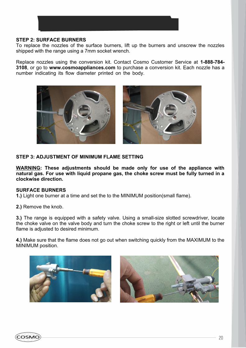
STEP 2: SURFACE BURNERSTo replace the nozzles of the surface burners, lift up the burners and unscrew the nozzlesshipped with the range using a 7mm socket wrench.Replace nozzles using the conversion kit. Contact Cosmo Customer Service at 1-888-784-3108, or go to www.cosmoappliances.com to purchase a conversion kit. Each nozzle has anumber indicating its flow diameter printed on the body.
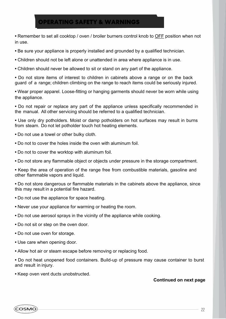
STEP 3: ADJUSTMENT OF MINIMUM FLAME SETTINGWARNING: These adjustments should be made only for use of the appliance withnatural gas. For use with liquid propane gas, the choke screw must be fully turned in aclockwise direction.SURFACE BURNERS1.) Light one burner at a time and set the to the MINIMUM position(small flame).2.) Remove the knob.3.) The range is equipped with a safety valve. Using a small-size slotted screwdriver, locatethe choke valve on the valve body and turn the choke screw to the right or left until the burnerflame is adjusted to desired minimum.4.) Make sure that the flame does not go out when switching quickly from the MAXIMUM to theMINIMUM position.
GAS CONVERSION
21
BEFORE USING RANGE HOOD
INSTALLATION CHECKLIST1.) Is the range mounted on its legs?2.) Is the back guard securely connected?3.) Has the anti-tip device been properlyinstalled?4.) Does the clearance from the side cabinetscomply with the manufacturers directions?5.) Is the electricity properly grounded?6.) Is the gas service line connected followingthe directions of the manufacturer?7.) Have all the proper valves, stoppers andgasket been installed between the range andthe service line?8.) Has the gas connection been checked forleaks?9.) Has the range been set for the type of gasavailable in the household?10.) Does the flame appear sharp blue, withno yellow tipping, shooting or flame lifting?11.) Has the minimum setting for all burnersbeen adjusted?
FINAL PREPARATIONAll stainless steel body parts should bewiped with hot, soapy water and with aliquid stainless steel cleanser.If build-up occurs, do not use steel wool,abrasive cloths, cleaners, or powders! If itis necessary to scrape stainless steel toremove encrusted materials, soak with hot,wet cloths to loosen the material, then usea wood or nylon scraper. Do not use ametal knife, spatula, or any other metaltool to scrape stainless steel! Scratchesare almost impossible to remove.Before using the oven for foodpreparation, wash the cavity thoroughlywith a warm soap and water solution toremove film residues and any dust ordebris from installation, then rinse andwiped dry.
22
• Remember to set all cooktop / oven / broiler burners control knob to OFF position when notin use.• Be sure your appliance is properly installed and grounded by a qualified technician.• Children should not be left alone or unattended in area where appliance is in use.• Children should never be allowed to sit or stand on any part of the appliance.• Do not store items of interest to children in cabinets above a range or on the backguard of a range; children climbing on the range to reach items could be seriously injured.• Wear proper apparel. Loose-fitting or hanging garments should never be worn while usingthe appliance.• Do not repair or replace any part of the appliance unless specifically recommended inthe manual. All other servicing should be referred to a qualified technician.• Use only dry potholders. Moist or damp potholders on hot surfaces may result in burnsfrom steam. Do not let potholder touch hot heating elements.• Do not use a towel or other bulky cloth.• Do not to cover the holes inside the oven with aluminum foil.• Do not to cover the worktop with aluminum foil.• Do not store any flammable object or objects under pressure in the storage compartment.• Keep the area of operation of the range free from combustible materials, gasoline andother flammable vapors and liquid.• Do not store dangerous or flammable materials in the cabinets above the appliance, sincethis may result in a potential fire hazard.• Do not use the appliance for space heating.• Never use your appliance for warming or heating the room.• Do not use aerosol sprays in the vicinity of the appliance while cooking.• Do not sit or step on the oven door.• Do not use oven for storage.• Use care when opening door.• Allow hot air or steam escape before removing or replacing food.• Do not heat unopened food containers. Build-up of pressure may cause container to burstand result in injury.• Keep oven vent ducts unobstructed. Continued on next page
OPERATING SAFETY & WARNINGS
23
OPERATING SAFETY & WARNINGS
• Always place oven racks in desired location when oven is cool. If rack must be moved whileoven is hot, do not let potholder contact hot heating element in oven.• Do not clean oven door gasket. The door gasket is essential for a good seal. Care should betaken not to rub, damage, or move the gasket.• Do not use oven cleaning products. No commercial oven cleaner or oven liner protectivecoating of any kind should be used in or around any part of the oven.• Clean only parts listed in manual.• Before cleaning the oven, remove broiler pan and other utensils.• Do not use water on grease fires. Smother fire or flames or use dry chemical or foam-type extinguisher.• The cooktop and surfaces facing the cooktop may be hot even though they are dark in color. Areas near these may become hot enough to cause burns. During and after use, do not touch, or let clothing or other flammable materials contact the cook-top and surfaces facing the cook-top until they have had sufficient time to cool.• WARNING: DO NOT TOUCH HEATING ELEMENTS OR INTERIOR SURFACES OF OVEN. Heating elements may be hot even though they are dark in color. Interior surfaces of an oven become hot enough to cause burns. During and after use, do not touch, or let clothing or other flammable materials contact heating elements or interior surfaces of oven until they have had sufficient time to cool. Do not touch any surface of the oven until they have had sufficient time to cool, as some surfaces become hot enough to cause burns, included: oven vent openings and surfaces near these openings, oven doors, and windows of oven doors.• Do not use an extension cord to connect this appliance. If the power supply cord is too short, have a qualified electrician or serviceman install an outlet near the appliance.• WARNING: Do not operate the range without the anti-tip device in place and engaged; a child or adult can tip the range and be killed. Verify the anti-tip device has been properly installed and engaged. Ensure the anti-tip device is re-installed when the range is moved; failure to do so can result in death or serious burns to children or adults.• ROOM VENTILATION: The use of a gas cooking appliance generates heat and humidity in the room where it is installed. Proper ventilation in the room is needed. Make sure the kitchen is equipped with a range hood of appropriate power (400 CFM minimum). Activate the exhaust fan/range hood when possible. Intensive and continuous use of the appliance may require additional ventilation, for example by opening a window.
24
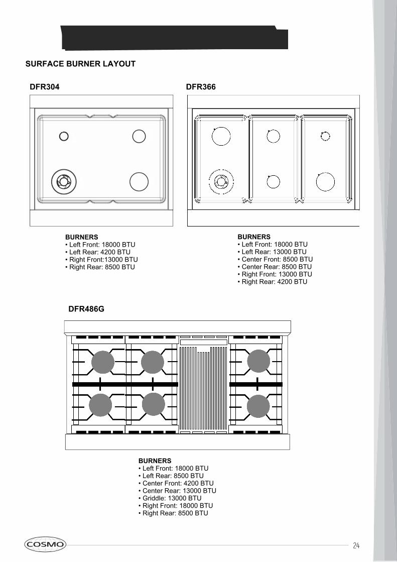
SURFACE BURNER LAYOUTDFR304 DFR366
DFR486G
BURNERS• Left Front: 18000 BTU• Left Rear: 4200 BTU• Right Front:13000 BTU• Right Rear: 8500 BTU
BURNERS• Left Front: 18000 BTU• Left Rear: 8500 BTU• Center Front: 4200 BTU• Center Rear: 13000 BTU• Griddle: 13000 BTU• Right Front: 18000 BTU• Right Rear: 8500 BTU
BURNERS• Left Front: 18000 BTU• Left Rear: 13000 BTU• Center Front: 8500 BTU• Center Rear: 8500 BTU• Right Front: 13000 BTU• Right Rear: 4200 BTU
BURNER BTU DIAGRAMS
25
OPERATING INSTRUCTIONS
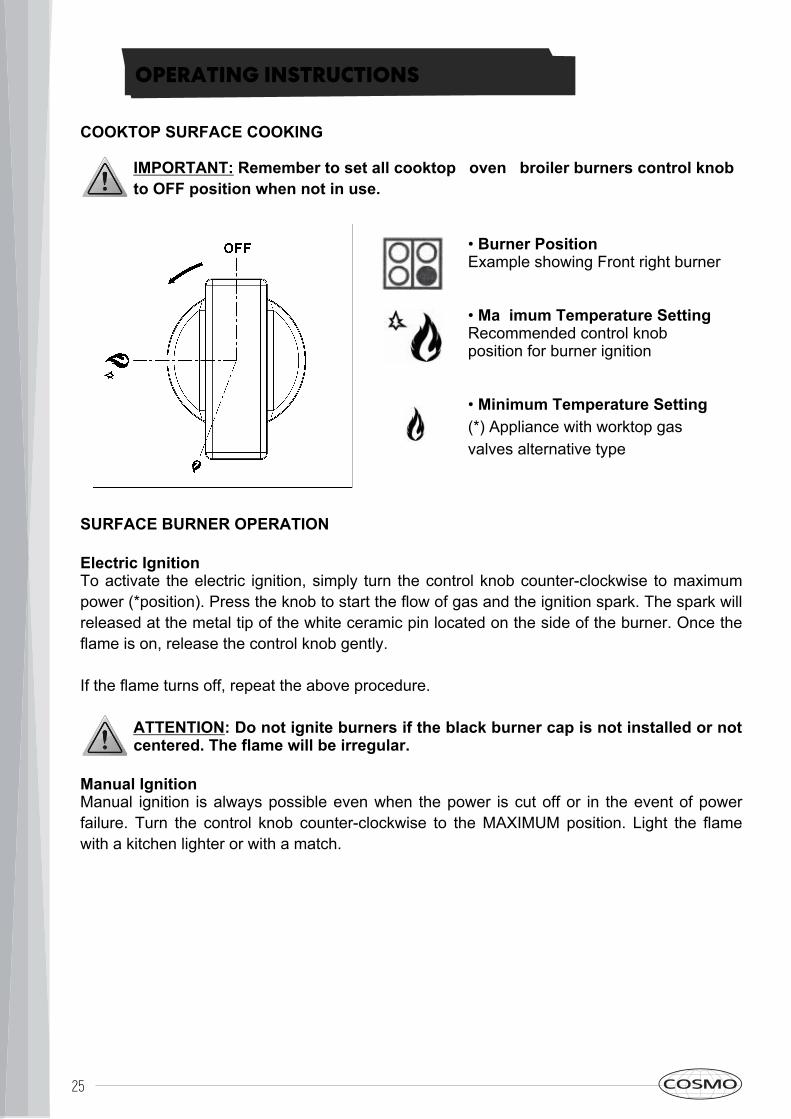
COOKTOP SURFACE COOKINGIMPORTANT: Remember to set all cooktop / oven / broiler burners control knobto OFF position when not in use.
SURFACE BURNER OPERATIONElectric IgnitionTo activate the electric ignition, simply turn the control knob counter-clockwise to maximum power (*position). Press the knob to start the flow of gas and the ignition spark. The spark will released at the metal tip of the white ceramic pin located on the side of the burner. Once the flame is on, release the control knob gently.If the flame turns off, repeat the above procedure.
ATTENTION: Do not ignite burners if the black burner cap is not installed or notcentered. The flame will be irregular.Manual IgnitionManual ignition is always possible even when the power is cut off or in the event of power failure. Turn the control knob counter-clockwise to the MAXIMUM position. Light the flame with a kitchen lighter or with a match.
• Burner PositionExample showing Front right burner• Maximum Temperature SettingRecommended control knobposition for burner ignition• Minimum Temperature Setting(*) Appliance with worktop gasvalves alternative type
26
OPERATING INSTRUCTIONS
TIPS FOR USING BURNERS CORRECTLYWARNING: KEEP CHILDREN AT A SAFE DISTANCE FROM THE APPLIANCEDURING OPERATING. DO NOT ALLOW CHILDREN TO OPERATE THEAPPLIANCE.IMPORTANT: Remember to set all cooktop / oven / broiler burners control knobto OFF position when not in use.
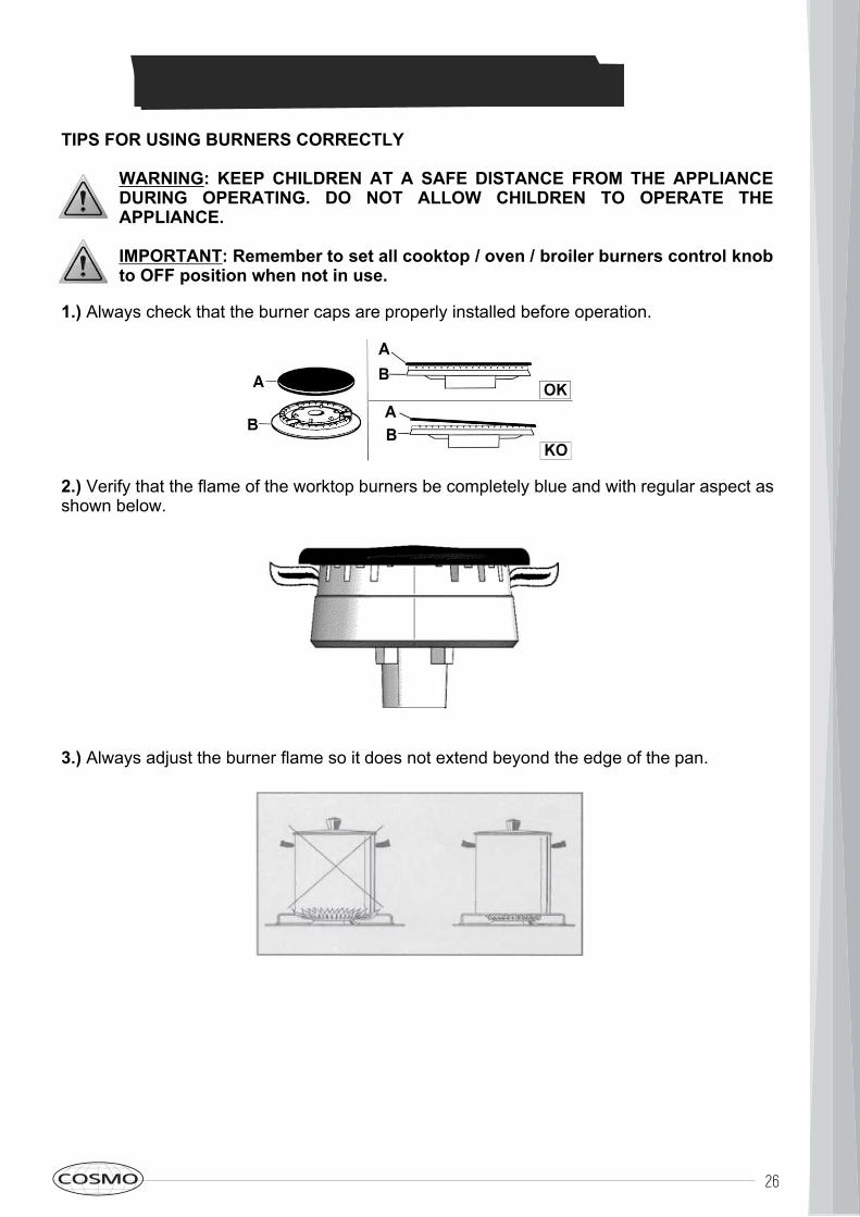
1.) Always check that the burner caps are properly installed before operation.
2.) Verify that the flame of the worktop burners be completely blue and with regular aspect asshown below.
3.) Always adjust the burner flame so it does not extend beyond the edge of the pan.
27
OPERATING INSTRUCTIONS
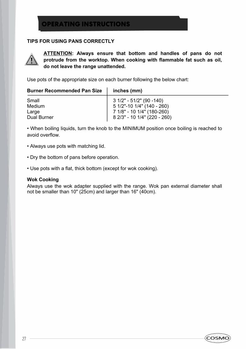
TIPS FOR USING PANS CORRECTLYATTENTION: Always ensure that bottom and handles of pans do not protrude from the worktop. When cooking with flammable fat such as oil, do not leave the range unattended.
Use pots of the appropriate size on each burner following the below chart:Burner Recommended Pan SizeSmallMediumLargeDual Burner• When boiling liquids, turn the knob to the MINIMUM position once boiling is reached toavoid overflow.• Always use pots with matching lid.• Dry the bottom of pans before operation.• Use pots with a flat, thick bottom (except for wok cooking).Wok CookingAlways use the wok adapter supplied with the range. Wok pan external diameter shallnot be smaller than 10" (25cm) and larger than 16" (40cm).
inches (mm) 3 1/2" - 51/2" (90 -140)5 1/2"-10 1/4" (140 - 260)7 1/8" - 10 1/4" (180-260)8 2/3" - 10 1/4" (220 - 260)
28
OPERATING INSTRUCTIONS
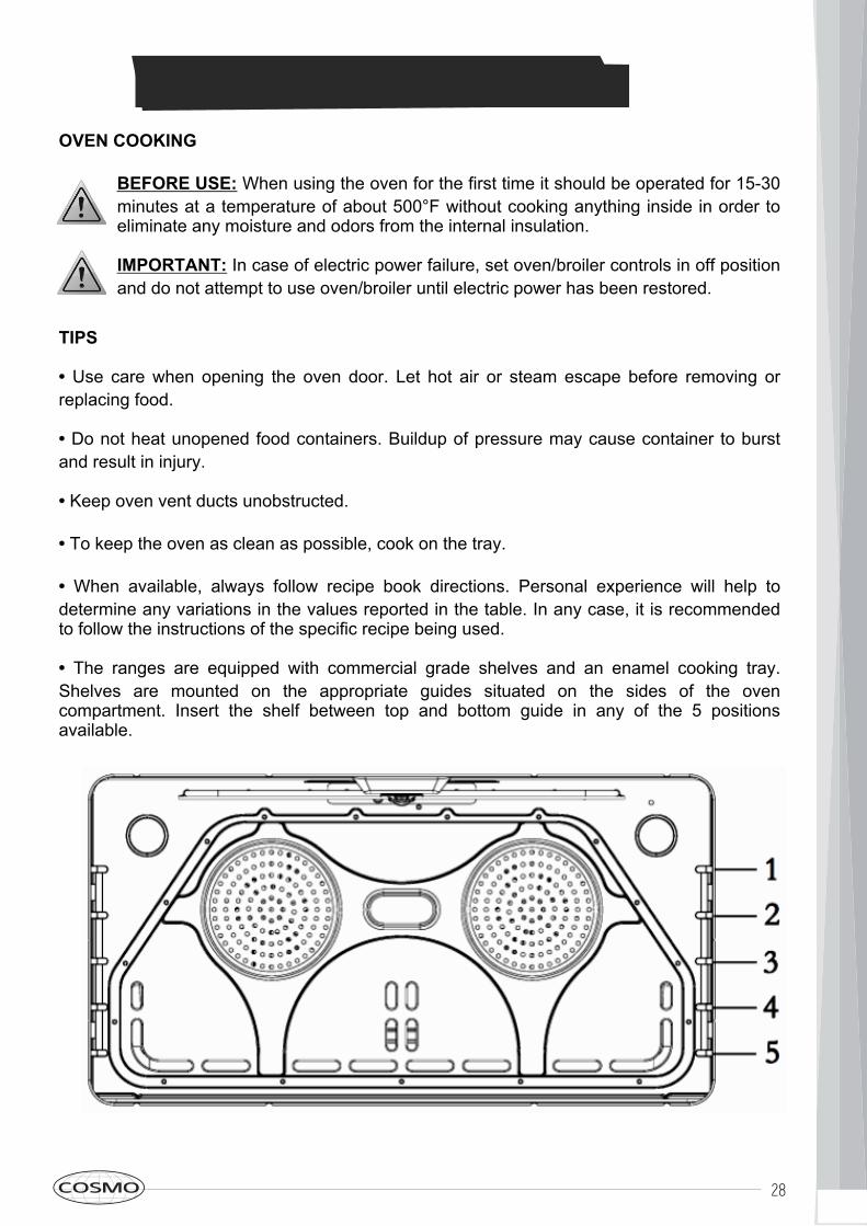
OVEN COOKINGBEFORE USE: When using the oven for the first time it should be operated for 15-30minutes at a temperature of about 500°F without cooking anything inside in order toeliminate any moisture and odors from the internal insulation.IMPORTANT: In case of electric power failure, set oven/broiler controls in off positionand do not attempt to use oven/broiler until electric power has been restored.
TIPS• Use care when opening the oven door. Let hot air or steam escape before removing orreplacing food.• Do not heat unopened food containers. Buildup of pressure may cause container to burstand result in injury.• Keep oven vent ducts unobstructed.• To keep the oven as clean as possible, cook on the tray.• When available, always follow recipe book directions. Personal experience will help todetermine any variations in the values reported in the table. In any case, it is recommendedto follow the instructions of the specific recipe being used.• The ranges are equipped with commercial grade shelves and an enamel cooking tray.Shelves are mounted on the appropriate guides situated on the sides of the ovencompartment. Insert the shelf between top and bottom guide in any of the 5 positionsavailable.
29
OPERATING INSTRUCTIONS
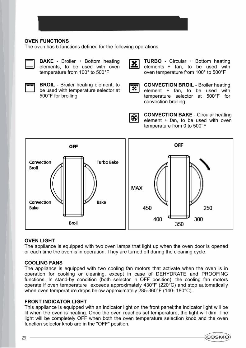
OVEN FUNCTIONSThe oven has 5 functions defined for the following operations:
OVEN LIGHTThe appliance is equipped with two oven lamps that light up when the oven door is openedor each time the oven is in operation. They are turned off during the cleaning cycle.COOLING FANSThe appliance is equipped with two cooling fan motors that activate when the oven is inoperation for cooking or cleaning, except in case of DEHYDRATE and PROOFINGfunctions. In stand-by condition (both selector in OFF position), the cooling fan motorsoperate if oven temperature exceeds approximately 430°F (220°C) and stop automaticallywhen oven temperature drops below approximately 285-360°F (140- 180°C).FRONT INDICATOR LIGHTThis appliance is equipped with an indicator light on the front panel;the indicator light will belit when the oven is heating. Once the oven reaches set temperature, the light will dim. Thelight will be completely OFF when both the oven temperature selection knob and the ovenfunction selector knob are in the "OFF" position.
BAKE - Broiler + Bottom heatingelements, to be used with oventemperature from 100° to 500°FBROIL - Broiler heating element, tobe used with temperature selector at500°F for broiling
TURBO - Circular + Bottom heatingelements + fan, to be used withoven temperature from 100° to 500°FCONVECTION BROIL - Broiler heatingelement + fan, to be used withtemperature selector at 500°F forconvection broilingCONVECTION BAKE - Circular heatingelement + fan, to be used with oventemperature from 0 to 500°F
30
When roasting meats, check internal temperature prior to time recommended by recipe toprevent over cooking. When roasting meats in convection mode, do not reduce temperaturesetting.CondensationIt is normal for a certain amount of moisture to evaporate from the food during any cookingprocess The amount depends on the moisture content of the food. The moisture willcondense on any surface cooler than, the inside of the oven, such as the control panel.Rack PositionsLarge Main Oven One Rack Baking When baking on one rack, best results are obtained inthe bake mode (see Bake). When roasting a turkey or a large piece of meat, convection bakemay be used. Rack 4 is the most appropriate rack.Two Rack BakingRacks 4 and 2 are most appropriate when using the convection bake mode. Round cakepans should be staggered on racks 4 and 2. Rectangular (9 x 13) cake pans and cookiesheets should be placed on rack 4 directly under the one on rack 2. This may be used forcakes, cookies, biscuits and other foods for which two rack baking is desirable. When severalcasseroles, frozen pies or cakes are to be baked, use racks 4 and 2. These two racks canalso be used for a large oven meal.Bakeware TypeAluminum bake ware gives the best browning results. Cookie sheets with only two sides givethe best results. Aluminum commercial half-sheets or professional cooking utensils may beused but baking times may be increased.PlacementFor better browning, utensils such as cookie sheets. Rectangular baking pans should beplaced crosswise on the rack with the shorter side facing right and left to allow better air flow.When baking on more than one rack, cookie sheets and rectangular (9 x 13) cake pansshould not be staggered; round cake pans should be staggered.Settings for BAKE/CONVECTION and BAKE/CONVECTION/TURBO Cooking ModesThese cooking modes are for baking, roasting or warming using one or two racks.
1.) Select BAKE/CONVECTION or BAKE/ CONVECTION/TURBO using the Selectorswitch.2.) Set the oven temperature using the oven temperature control knob (not over themaximum 500°F position). If using CONVECTION, set the oven control knob 25°F belowthe temperature suggested in the recipe. Do NOT change recipe temperature if roastingmeats or poultry.
Rack PositionsLarge Main Oven One Rack Baking When baking on one rack, best results are obtained in the bakemode (see Bake). When roasting a turkey or a large piece of meat, convection bake may be used.Rack 4 is the most appropriate rack.Two Rack BakingRacks 4 and 2 are most appropriate when using the convection bake mode. Round cake pans shouldbe staggered on racks 4 and 2. Rectangular (9 x 13) cake pans and cookie sheets should be placedon rack 4 directly under the one on rack 2. This may be used for cakes, cookies, biscuits and otherfoods for which two rack baking is desirable. When several casseroles, frozen pies or cakes are to bebaked, use racks 4 and 2. These two racks can also be used for a large oven meal.Bakeware TypeAluminum bake ware gives the best browning results. Cookie sheets with only two sides give the bestresults. Aluminum commercial half-sheets or professional cooking utensils may be used but bakingtimes may be increased.PlacementFor better browning, utensils such as cookie sheets. Rectangular baking pans should be placedcrosswise on the rack with the shorter side facing right and left to allow better air flow.When baking on more than one rack, cookie sheets and rectangular (9 x 13) cake pans should not bestaggered; round cake pans should be staggered.Settings for BAKE/CONVECTION and BAKE/CONVECTION/TURBO Cooking ModesThese cooking modes are for baking, roasting or warming using one or two racks.
1.) Select BAKE/CONVECTION or BAKE/ CONVECTION/TURBO using the Selector switch.2.) Set the oven temperature using the oven temperature control knob (not over the maximum500°F position). If using CONVECTION, set the oven control knob 25°F below the temperaturesuggested in the recipe. Do NOT change recipe temperature if roasting meats or poultry.
When baking on more than one rack, cookie sheets and rectangular (9 x 13) cake pans should not be staggered; round cakepans should be staggered.Settings for BAKE/CONVECTION and BAKE/CONVECTION/TURBO Cooking ModesThese cooking modes are for baking, roasting or warming using one or two racks.1.) Select BAKE/CONVECTION or BAKE/ CONVECTION/TURBO using the Selector switch.2.) Set the oven temperature using the oven temperature control knob (not over the maximum 500°F position). If usingCONVECTION, set the oven control knob 25°F below the temperature suggested in the recipe. Do NOT change recipetemperature if roasting meats or poultry.
OPERATING INSTRUCTIONS
BAKEPreheatingPreheat the oven before baking. The oven does not need to be preheated for large pieces ofmeat or poultry. See your recipe for preheating recommendation. Preheating time dependson the temperature setting and the number of racks in the oven.Tips for Getting the Best Results• Minimize opening the door.• Choose the right size bake ware.• Use the bake ware recommended in the recipe. Store the broiler pans outside the oven:extra pans without food affect the browning and cooking.• Browning can depend from the type of pan used:
◦ For tender, golden brown crusts, use light non-stick anodized or shiny metal pans.◦ For brown crisp crusts, use dark non-stick/anodized or dark, dull metal utensils orglass bake ware. These may require lowering the bake temperature 25°F.
Bakeware TypeMetal bake ware (with or without a non-stick finish), heat-proof glass, glass ceramic, pottery,or other utensils are suitable for the oven. Suitable cookie sheets have a small lip on oneside only. Heavy sheets or those with lips on more than one side may affect the baking time.Bake Rack PositionsRack level positions in the oven are numbered as in the diagram on Page 28.One Rack BakingThe Bake mode is best for baking on one rack with rack level 3 and 4 used for most bakeditems. When baking tall items, rack level 4 may be used. Pies are best baked on rack level 4or 5 to ensure the bottom of the crust is done without over-browning the top. When largepieces of meat or poultry are roasted such as a prime rib of beef or a turkey, rack level 4 isthe preferred rack.Two Rack BakingRack levels 3 and 5 may be used when baking on two levels. Cookies and biscuits can becooked properly using these two racks. Casserole dishes may al so be baked using thesetwo levels.

31
OPERATING INSTRUCTIONS
COOKING WITH CONVECTIONThere are many advantages to cooking with convection. In the convection system, a fan inthe back of the oven moves heated air evenly around the oven. The moving air provides evenheat so foods can be placed on any rack level with consistent results and without having torotate the pans. Convection also enables cooking simultaneously on multiple racks.Low, shallow bake ware should be used with convection cooking. This allows the heated airto properly move around the food. Pans with high sides or pans that are covered are notsuitable for convection cooking because high sides or lids prohibit the warm air fromcirculating around the food.Any food cooked uncovered will brown evenly and form a nice crust. Foods in covered dishes(casseroles, pot roast) or delicate custards are not suitable for convection cooking.
CONVECTION BAKE & TURBOTime can be saved by baking an entire batch of cookies at the same time. The cookies willbake evenly and be done all at once. The baking time may be shorter due to the warmcirculating air. For small items such as cookies, check to see if they are done one to twominutes before the recipe time. For larger baked items such as cakes, check five to sixminutes before the time indicated on the recipe.Convection cooking of meat and poultry will result in foods that are brown and crispy on theoutside and moist and juicy on the inside. Large meat or poultry items may cook up to 30minutes less than the suggested time so check them so they will not be over baked. A meatthermometer or an instant read thermometer will provide more accurate results than the"minute per pound" method. The larger the piece of meat or poultry, the more time you willsave.Converting Conventional Baking to Convection CookingTo convert most recipes for baked items (cookies, cakes, pies, etc.), reduce the oventemperature by 25°F. For meats and poultry, use the temperature recommended in recipesand cooking charts.throughout the oven cavity for all uses. Multiple rack use is possible for baking large amountsof food. When roasting, cool air is quickly replaced -searing meats on the outside andretaining more juices and natural flavor on the inside with less shrinkage.CONVECTION BAKEFull power heat is radiated from the bake element in the bottom of the oven and partial poweris radiated from the top element. Air is circulated by the fan in the rear of the oven.TURBO BAKEThe rear and bottom elements operate at full power. Air is circulated by the fan for evenheating. Use this setting to reduce pre-heating time of the oven or for recipes which requireuniform cooking with strong heat from bottom such as pizza and focaccia bread.
Continued on next page
32
OPERATING INSTRUCTIONS
CONVECTION BAKE & TURBO (Continued)PreheatingPreheat the oven before baking. The oven does not need to be preheated for large pieces ofmeat or poultry. See your recipe for preheating recommendation. Preheating time depends onthe temperature setting and the number of racks in the oven.Temperature SettingWhen using Convection Bake, reduce the temperature recommended in the recipe by 25°F.When roasting meats, check internal temperature prior to time recommended by recipe toprevent over cooking. When roasting meats in convection mode, do not reduce temperaturesetting.CondensationIt is normal for a certain amount of moisture to evaporate from the food during any cookingprocess The amount depends on the moisture content of the food. The moisture will condenseon any surface cooler than, the inside of the oven, such as the control panel.Rack PositionsLarge Main Oven One Rack Baking When baking on one rack, best results are obtained in thebake mode (see Bake). When roasting a turkey or a large piece of meat, convection bake maybe used. Rack 4 is the most appropriate rack.Two Rack BakingRacks 4 and 2 are most appropriate when using the convection bake mode. Round cake pansshould be staggered on racks 4 and 2. Rectangular (9 x 13) cake pans and cookie sheetsshould be placed on rack 4 directly under the one on rack 2. This may be used for cakes,cookies, biscuits and other foods for which two rack baking is desirable. When severalcasseroles, frozen pies or cakes are to be baked, use racks 4 and 2. These two racks can alsobe used for a large oven meal.Bakeware TypeAluminum bake ware gives the best browning results. Cookie sheets with only two sides givethe best results. Aluminum commercial half-sheets or professional cooking utensils may beused but baking times may be increased.PlacementFor better browning, utensils such as cookie sheets. Rectangular baking pans should beplaced crosswise on the rack with the shorter side facing right and left to allow better air flow.When baking on more than one rack, cookie sheets and rectangular (9 x 13) cake pans shouldnot be staggered; round cake pans should be staggered.Settings for BAKE/CONVECTION and BAKE/CONVECTION/TURBO Cooking ModesThese cooking modes are for baking, roasting or warming using one or two racks.
1.) Select BAKE/CONVECTION or BAKE/CONVECTION/TURBO using the Selectorswitch.2.) Set the oven temperature using the oven temperature control knob (not over themaximum 500°F position). If using CONVECTION, set the oven control knob 25°F belowthe temperature suggested in the recipe. Do NOT change recipe temperature if roastingmeats or poultry.
33
OPERATING INSTRUCTIONS
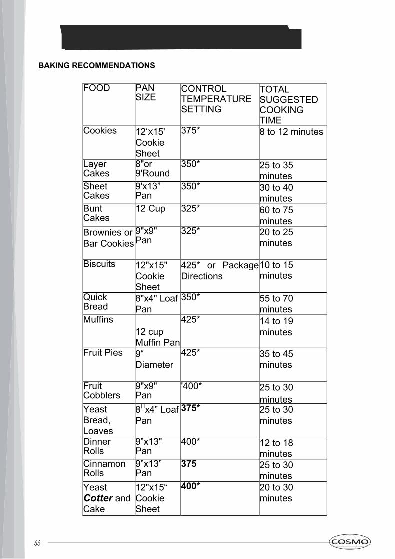
BAKING RECOMMENDATIONSFOOD PAN
SIZECONTROLTEMPERATURESETTING
TOTALSUGGESTEDCOOKINGTIME
Cookies 12„X15'CookieSheet
375* 8 to 12 minutes
LayerCakes
8"or9'Round
350* 25 to 35 minutes
SheetCakes
9'x13”Pan
350* 30 to 40 minutes
BuntCakes
12 Cup 325* 60 to 75 minutes
Brownies or Bar Cookies
9"x9"Pan
325* 20 to 25 minutes
Biscuits 12"x15"CookieSheet
425* or Package Directions
10 to 15 minutes
QuickBread
8"x4" Loaf Pan
350* 55 to 70 minutes
Muffins12 cup Muffin Pan
425* 14 to 19 minutes
Fruit Pies 9“Diameter
425* 35 to 45 minutes
FruitCobblers
9"x9"Pan
'400* 25 to 30 minutes
YeastBread,Loaves
8Hx4” Loaf Pan
375* 25 to 30 minutes
DinnerRolls
9”x13"Pan
400* 12 to 18 minutes
CinnamonRolls
9”x13”Pan
375 25 to 30 minutes
YeastCotter and Cake
12"x15“CookieSheet
400* 20 to 30 minutes
34
6.) Close oven door. The door should be closed throughout the broil cycle.6.) Close oven door. The door should be closed throughout the broil cycle.
OPERATING INSTRUCTIONS
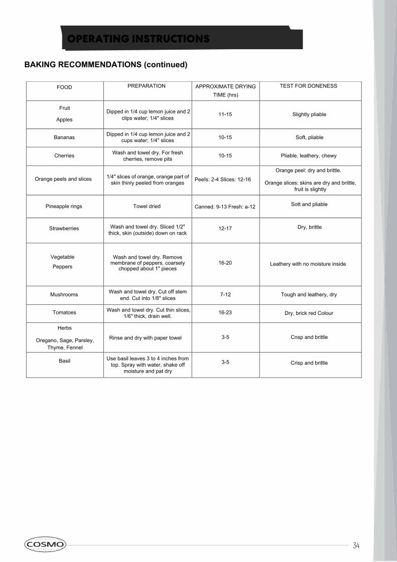
FOOD PREPARATION APPROXIMATE DRYING TIME (hrs)
TEST FOR DONENESS
Fruit
ApplesDipped in 1/4 cup lemon juice and 2
clips water; 1/4" slices11-15 Slightly pliable
Bananas Dipped in 1/4 cup lemon juice and 2cups water; 1/4" slices 10-15 Soft, pliable
Cherries Wash and towel dry. For fresh cherries, remove pits 10-15 Pliable, leathery, chewy
Orange peels and slices 1/4" slices of orange, orange part of skin thinly peeled from oranges PeeIs: 2-4 Slices: 12-16
Orange peel: dry and brittle.
Orange slices: skins are dry and brittle, fruit is slightly
Pineapple rings Towel dried Canned: 9-13 Fresh: a-12 Sott and pliable
Strawberries Wash and towel dry. Sliced 1/2"thick, skin (outside) down on rack
12-17 Dry, brittle
Vegetable
Peppers
Wash and towel dry. Removemembrane of peppers, coarsely
chopped about 1" pieces16-20 Leathery with no moisture inside
Mushrooms Wash and towel dry. Cut off stemend. Cut into 1/8" slices
7-12 Tough and leathery, dry
Tomatoes Wash and towel dry. Cut thin slices,1/6" thick, drain well.
16-23 Dry, brick red Colour
Herbs
Oregano, Sage, Parsley, Thyme, Fennel
Rinse and dry with paper towel 3-5 Cnsp and brittle
Basil Use basil leaves 3 to 4 inches fromtop. Spray with water, shake off
moisture and pat dry
3-5 Crisp and brittle
BAKING RECOMMENDATIONS (continued)
35
OPERATING INSTRUCTIONS
BROIL / CONVECTION BROILPreheatingBroiling requires constant exposure to high, intense heat. Only the upper element heats inthe BROILER mode. It is recommended that you preheat the broil element before starting tocook. Preheat until the "PRE-HEATING" light turns off (about 5-6 minutes).Tips for Getting the Best Results• Defrost food before broiling.• Keep oven door closed during broiling.• Steaks should be more than 1" thick if rare meat is desired. Use convection broil ifsteaks are over 1-1/2 inches thick. Turn food over once after half cooking time. It is notnecessary to turn very thin food (ham slices, fillets of fish, etc.). Liver slices must beturned over regardless of thickness.• Use a timer. Set it for the minimum time and check the food.• Center food directly under the broiling element for best browning.Rack PositionsBefore turning on the oven, place the rack in the desired position. After preheating the broiler,center the broil pan under the broil element.
• Position 2: Use this rack position when broiling beef steaks, ground meat patties, hamsteak and lamb chops 1 inch or less thick. Also use when browning food.• Position 3: Use this rack position when broiling meat 1 1/8 inches or more thick, fish,poultry, pork chops,ham steaks 1 inch or more thick.• Position 3 or 4: Use this rack when broiling chicken quarters or halves.Utensils• A porcelain enamel broil pan is included with the range.• Use metal or glass-ceramic bake ware when browning casseroles, main dishes, orbread.• DO NOT use heat-proof glass or pottery. This type of glassware cannot withstand theintense hear of the broil element.Broiling Using Meat ThermometerTo more accurately define the preparation of thick steaks or chops (at least 1 1/2 inchesthick), use a meat thermometer. Insert the point of the thermometer into the side of the meatreaching the center of the steak or chop.For rare steaks, cook the first side to 90°F. For medium or well done steaks, cook the firstside to 100°F. Turn and cook the second side to desired internal temperature.
Continued on next page
36
OPERATING INSTRUCTIONS
BROIL / CONVECTION BROIL (Continued)Setting BROILER or CONVECTION BROILERSelect CONVECTION BROIL to brown food slightly also on the bottom side. This mode ispreferred for browning food on both side that is too delicate for turning such as fish. Thedegree of browning of each side might be different.Set Oven to BROIL or CONVECTION BROIL
1.) Place oven rack in desired position.2.) Set Selector Switch to BROIL or CONVECTION BROIL.3.) Set oven temperature control knob to BROILER or CONVECTION BROILER settingcorresponding to 500° fixed BROILER setting (not over maximum temperature 500°F orunder 450°F)4.) Wait until PRE-HEATING light turns off, after approximately 5-6 minutes.5.) Place food in oven at desired rack position as referenced on Page 28.
37
OPERATING INSTRUCTIONS
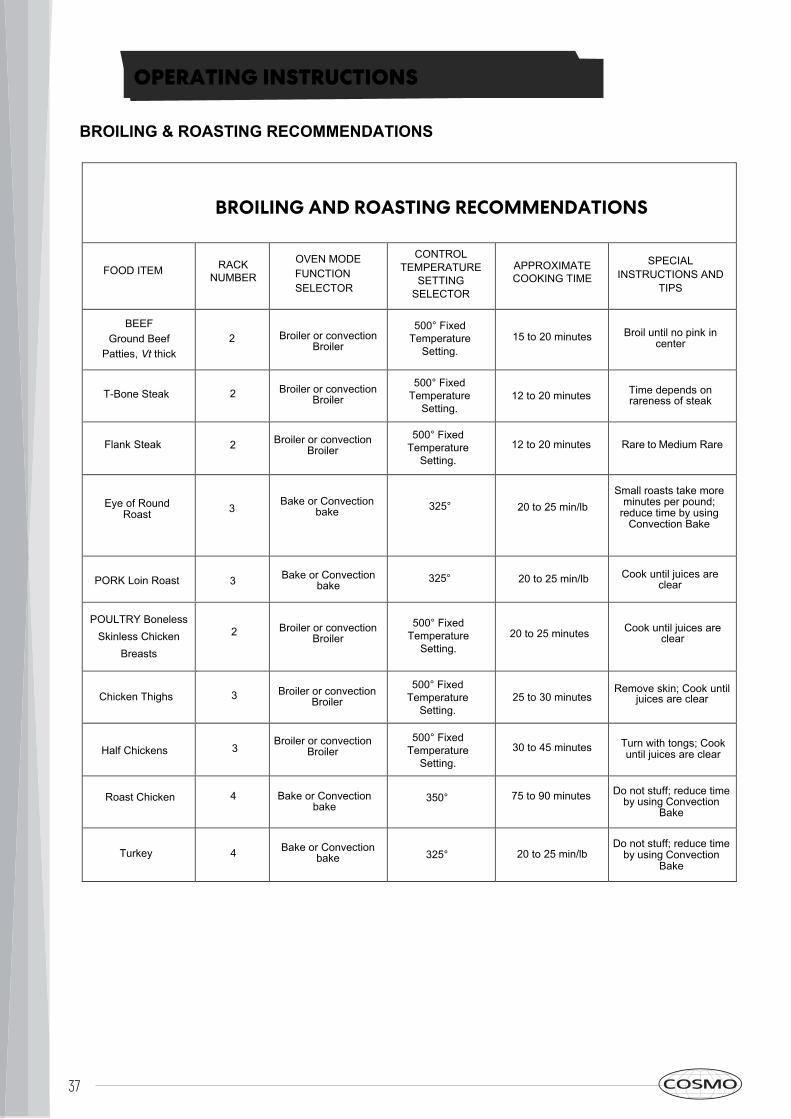
BROILING AND ROASTING RECOMMENDATIONS
FOOD ITEM RACK OVEN MODEFUNCTIONSELECTOR
CONTROLTEMPERATURE
SETTINGSELECTOR
APPROXIMATE SPECIAL INSTRUCTIONS AND
TIPS
BEEF Ground Beef
Patties, Vt thick 2 Broiler or convection
Broiler
500°15 to 20 minutes Broil until no pink in
center
T-Bone Steak 2 Broiler or convection Broiler 12 to 20 minutes Time depends on
rareness of steak
Flank Steak 2 Broiler or convection Broiler 12 to 20 minutes Rare to Medium Rare
Eye of Round Roast 3 20 to 25 min/lb
Small roasts take more minutes per pound;
reduce time by using Convection Bake
PORK Loin Roast 3 Bake or Convection bake 20 to 25 min/lb Cook until juices are
clear
POULTRY Boneless Skinless Chicken
Breasts
2 Broiler or convection Broiler 20 to 25 minutes Cook until juices are
clear
Chicken Thighs 3 Broiler or convection Broiler 25 to 30 minutes
Remove skin; Cook until juices are clear
Half Chickens 3 Broiler or convection
Broiler 30 to 45 minutes Turn with tongs; Cook until juices are clear
Roast Chicken 4 Bake or Convection bake
350° 75 to 90 minutes Do not stuff; reduce time by using Convection
Bake
Turkey 4 Bake or Convection bake 325° 20 to 25 min/lb
Do not stuff; reduce time by using Convection
Bake
500°
500°
Bake or Convection bake
500°
500°
500°
325°
325°
BROILING & ROASTING RECOMMENDATIONS
38
CARE & MAINTENANCE
REPLACING OVEN LIGHT BULBSWARNING! Disconnect power before servicing unit.
To replace the oven light bulb, unscrew the protection cap that projects out inside the oven.NOTE: Touching the bulb with fingers may cause the bulb to burn out. Always use protectiveglove or use a cloth to remove the bulb.CLEANING YOUR RANGE
ATTENTION: During cleaning operation never move the appliance from itsforeseen original installation position.• Never use abrasive cleaners. Scratches on the stainless steel surfaces are permanent.• Do not clean the range when hot.Cleaning After InstallationUse a stainless steel cleaning product or wipe to eliminate the glue residues of the blueprotection film after removal.Cleaning the CooktopPeriodically clean the burner heads, the cast iron pan supports and the burner caps usingwarm water. Remove burned food and fat residues with a rubber spatula . If food residueprevent the smooth operation of the control knobs, call the customer service hotline toschedule service by a factory-trained professional.Cleaning Stainless SteelFor best results, use a stainless steel cleaner product with a soft sponge or wipe. Alternativelyuse a soft sponge or cloth with a warm soap and water solution. Never use abrasive powdersor liquids.Cleaning the Burner CapsLift the burner caps from the burner heads and wash them in a warm soap and water solution.Dry thoroughly before using them again. Before reinstalling them on the burner head, checkthat the gas flow holes are not clogged with food residues or cleaning product residues.Cleaning EnamelEnamelled parts should be cleaned frequently with warm soap and water solution applied witha soft sponge or wipe. Never use abrasive powders or liquids. Do not leave acid or alkalinesubstances on the enamelled parts (such as vinegar, lemon juice, salt, tomato sauce, etc.).Use a rubber spatula to remove fat residues.Cleaning the Glass DoorClean the glass using a non-abrasive sponge or wipe with a warm soap and warm watersolution. Use a rubber spatula to remove fat residues.
ATTENTION: While cleaning the door, avoid spillage of food residues andcleaning products in the venting holes situated on the top side of the door. Toclean the inside of the oven door, call a qualified professional. If you have anyfurther questions regarding cleaning the appliance, please contact yourappliance retailer.
39
TROUBLESHOOTING
CauseBaking Problem
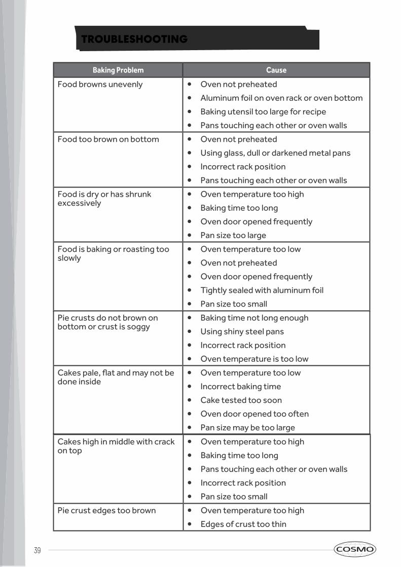
Food browns unevenly • Oven not preheated
• Aluminum foil on oven rack or oven bottom
• Baking utensil too large for recipe
• Pans touching each other or oven walls
Food too brown on bottom • Oven not preheated
• Using glass, dull or darkened metal pans
• Incorrect rack position
• Pans touching each other or oven walls
Food is dry or has shrunk excessively
• Oven temperature too high
• Baking time too long
• Oven door opened frequently
• Pan size too large
Food is baking or roasting too slowly
• Oven temperature too low
• Oven not preheated
• Oven door opened frequently
• Tightly sealed with aluminum foil
• Pan size too small
Pie crusts do not brown on bottom or crust is soggy
• Baking time not long enough
• Using shiny steel pans
• Incorrect rack position
• Oven temperature is too low
Cakes pale, flat and may not be done inside
• Oven temperature too low
• Incorrect baking time
• Cake tested too soon
• Oven door opened too often
• Pan size may be too large
Cakes high in middle with crack on top
• Oven temperature too high
• Baking time too long
• Pans touching each other or oven walls
• Incorrect rack position
• Pan size too small
Pie crust edges too brown • Oven temperature too high
• Edges of crust too thin
40
TROUBLESHOOTING
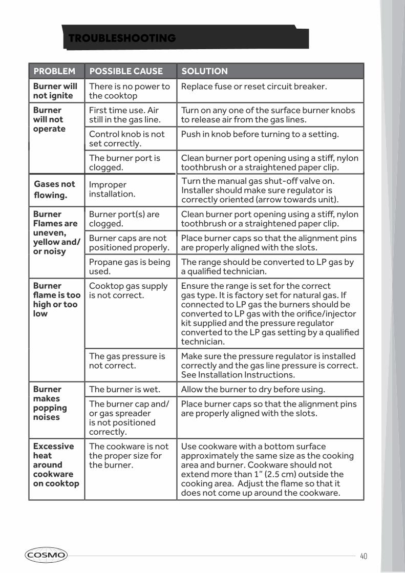
PROBLEM POSSIBLE CAUSE
Burner will not ignite
There is no power to the cooktop
SOLUTION
Replace fuse or reset circuit breaker.
Burner will not operate
First time use. Air still in the gas line.
Control knob is not set correctly.
Turn on any one of the surface burner knobs to release air from the gas lines.
Push in knob before turning to a setting.
The burner port is clogged.
Clean burner port opening using a stiff, nylon toothbrush or a straightened paper clip.
Burner Flames are uneven, yellow and/or noisy
Burner port(s) are clogged.
Clean burner port opening using a stiff, nylon toothbrush or a straightened paper clip.
Burner caps are not positioned properly.
Place burner caps so that the alignment pins are properly aligned with the slots.
Propane gas is being used.
The range should be converted to LP gas by a qualified technician.
Burner flame is too high or too low
Cooktop gas supply is not correct.
Ensure the range is set for the correct gas type. It is factory set for natural gas. If connected to LP gas the burners should be converted to LP gas with the orifice/injector kit supplied and the pressure regulator converted to the LP gas setting by a qualified technician.
The gas pressure is not correct.
Make sure the pressure regulator is installed correctly and the gas line pressure is correct. See Installation Instructions.
Burner makes popping noises
The burner is wet. Allow the burner to dry before using.
The burner cap and/or gas spreader is not positioned correctly.
Place burner caps so that the alignment pins are properly aligned with the slots.
Excessive heat around cookware on cooktop
The cookware is not the proper size for the burner.
Use cookware with a bottom surface approximately the same size as the cooking area and burner. Cookware should not extend more than 1” (2.5 cm) outside the cooking area. Adjust the flame so that it does not come up around the cookware.
Improper installation.
Gases not flowing.
Turn the manual gas shut-off valve on. Installer should make sure regulator is correctly oriented (arrow towards unit).
41
TROUBLESHOOTING
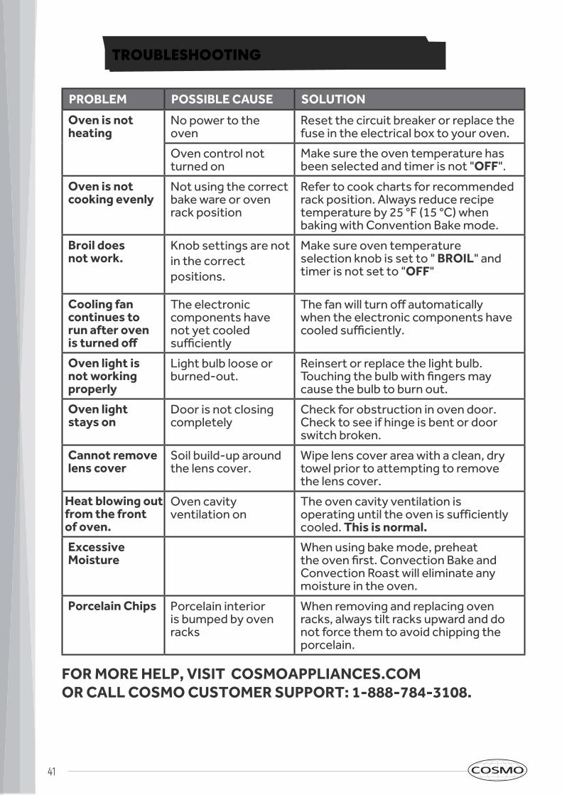
POSSIBLE CAUSE SOLUTIONPROBLEM
Oven is not heating
No power to the oven
Reset the circuit breaker or replace the fuse in the electrical box to your oven.
Oven control not turned on
Make sure the oven temperature has been selected and timer is not "OFF".
Oven is not cooking evenly
Not using the correct bake ware or oven rack position
Refer to cook charts for recommended rack position. Always reduce recipe temperature by 25 °F (15 °C) when baking with Convention Bake mode.
Broil does not work.
Knob settings are notin the correct positions.
Make sure oven temperature selection knob is set to " BROIL" and timer is not set to "OFF"
Cooling fan continues to run after oven is turned off
The electronic components have not yet cooled sufficiently
The fan will turn off automatically when the electronic components have cooled sufficiently.
Oven light is not working properly
Light bulb loose or burned-out.
Reinsert or replace the light bulb. Touching the bulb with fingers may cause the bulb to burn out.
Oven light stays on
Door is not closing completely
Check for obstruction in oven door. Check to see if hinge is bent or door switch broken.
Cannot remove lens cover
Soil build-up around the lens cover.
Wipe lens cover area with a clean, dry towel prior to attempting to remove the lens cover.
Heat blowing out from the frontof oven.
Oven cavity ventilation on
The oven cavity ventilation is operating until the oven is sufficiently cooled. This is normal.
Excessive Moisture
When using bake mode, preheat the oven first. Convection Bake and Convection Roast will eliminate any moisture in the oven.
Porcelain Chips Porcelain interior is bumped by oven racks
When removing and replacing ovenracks, always tilt racks upward and donot force them to avoid chipping theporcelain.
FOR MORE HELP, VISIT COSMOAPPLIANCES.COM OR CALL COSMO CUSTOMER SUPPORT: 1-888-784-3108.
42
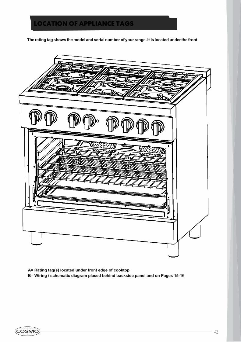
LOCATION OF APPLIANCE TAGS
The rating tag shows the model and serial number of your range. It is located under the front edge of the range cooktop, and is visible when the oven door is open (see illustration)
A= Rating tag(s) located under front edge of cooktopB= Wiring / schematic diagram placed behind backside panel and on Pages 15-16
43
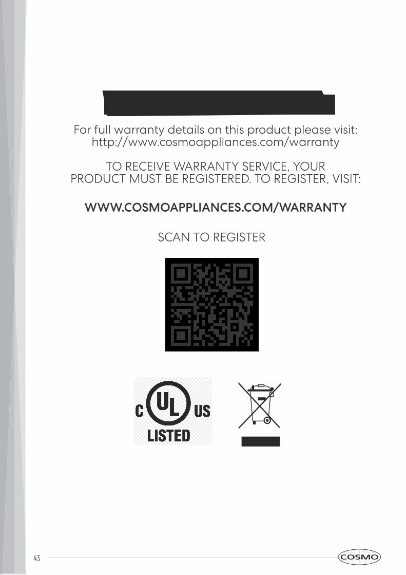
WARRANTY AND SERVICEFor full warranty details on this product please visit:
http://www.cosmoappliances.com/warranty
TO RECEIVE WARRANTY SERVICE, YOURPRODUCT MUST BE REGISTERED. TO REGISTER, VISIT:
WWW.COSMOAPPLIANCES.COM/WARRANTY
SCAN TO REGISTER
44
Correct Disposal of this product: This marking indicates that this appliance should not be disposed with other household wastes. To prevent possible harm to the environment or human health from uncontrolled waste disposal, recycle it responsibly to promote the sustainable reuse of material resources.
IMPORTANTDo Not Return This Product To The Store If
you have a problem with this product, please contact
Cosmo Customer Support at+1(888)784-3108
DATED PROOF OF PURCHASE, MODEL #, AND SERIAL #
REQUIRED FOR WARRANTY SERVICE
IMPORTANTNe pas Réexpédier ce Produit au Magasin
Pour tout problème concernant ce produit, veuillez contacter
le service des consommateurs Cosmo Customer Support au+1(888) 784-3108
UNE PREUVE D’ACHAT DATEE EST REQUISE POUR BENEFICIER DE
LA GARANTIE.
IMPORTANTENo regrese este producto a la tienda
Si tiene algún problema con este producto, por favor contacte el
AYUDA AL CLIENTE COSMO al
+1(888)784-3108 (Válido solo en E.U.A).
NECESITA UNA PRUEBA DE DE COMPRA FECHADA, NÚMERO DE
MODELO Y DE SERIE PARA EL SERVICIO DE LA GARANTÍA

NOTE:

Electronic version of this manual is available at: www.cosmoappliances.com
Cosmo is constantly making efforts to improve the quality andperformance of our products, so we may make changes to ourappliances without updating this manual.
Copyright © 2022 FDOKUMEN