convert to stereo for less than $100.00 - radio
118
CONVERT TO STEREO FOR LESS THAN $100.00 RADIO TV N EWS TRANSISTORIZED TACHOMETER SERVICE AWARD WINNERS SINGLE C ii NEL DESIGN FOR SHRED LATEST ON Leading Technical Magazine in the ELECTRONICS WORLD TUBES SES See Pages 37 & 39) www.americanradiohistory.com www.americanradiohistory.com
-
Upload
khangminh22 -
Category
Documents
-
view
0 -
download
0
Transcript of convert to stereo for less than $100.00 - radio

CONVERT TO STEREO FOR LESS THAN $100.00
RADIO TV N EWS
TRANSISTORIZED TACHOMETER
SERVICE AWARD WINNERS
SINGLE C ii NEL DESIGN FOR SHRED
LATEST ON
Leading Technical Magazine in the ELECTRONICS WORLD
TUBES SES
See Pages 37 & 39)
www.americanradiohistory.comwww.americanradiohistory.com

Ifs fWo year record
Speaks for itself!
SYLVANIA S -110 CHASSIS Only 10, ; lbs. without yoke
PeigfinanceAtoffed Better performance under the extremes of line voltage variation. The advanced high voltage design of the SYLVANIA S -110 Chassis adjusts automatically for maximum performance at both high- and low- voltage extremes.
Better performance under heat, humidity and freezing conditions. The rigid specifications of reliability of com- ponents in the SYLVANIA S -110 Chassis assures better perform- ance and longer trouble -free life under extremes of humidity and temperature conditions.
Alkyd Resin used in the high vDltage socket of the S -110 Chassis withstands moisture, dirt and even frost accumulations without any permanent damage, even if these conditions are severe enough to cause arcing. Top performance is assured regardless of warehouse locations.
Cuts repair time by 60%. The orderly arrangement of com- ponents in the SYLVANIA S -110 Chassis means that most defects can be located in seconds. Circuit can be traced easily from either side by shadow graph method over your bench light.
Designed for maximum szrengPi and minimum weight. The SYLVANIA S -110 Chassis has aL- around girder frame con- struction which gives it the mcst favorable strength to weight ratio in the industry. This means easier handling and faster servicing because of its light weight. Yet the S -110 is sturdy and rigid when mounted in the cabinet.
THE CHASSIS MODERN MANUFACTURING METHODS BUILT
Advanced printed circuitry and cornpcnents of the type used in the performance- pro.ed SYLVANIA S -110 Chassis are required and specified in the deslgh and production of guided missiles and space equipment where absolute reliability and ruggedness are demanded.
SYLVAN IA 7 Pioneer in modern manufacturing methods
www.americanradiohistory.comwww.americanradiohistory.com

Designed to meet the requirements of every specific space, budget, or decor
problem -and every listening preference...
1
asa,y offers
four
ways
to
stereo
Leading Metropolitan Opera Star Leonard Warren converted to stereo quickly, easily and inexpensively... using a compact Stereo flex -2 "add -on" speaker with his University "Troubadour"
This approach solves many problems for those already possessing a full -range monophonic system, as well as those planning to buy one now with an eye to stereo later. Thanks to the exclusive dual voice coil woofer used in all University stereo - adapted systems, only one such woofer is needed to reproduce the combined bass below 150 cyclest of both stereo channels. Thus all three models of University "add -on" speakers provide a perfect match by direct connection to the original speaker system. Stereoflex -1 is well suited for bookshelf installations. Stereoflex -2, with its narrow silhouette, makes a fine end table. Model SLC can be affixed to a wall or "lite- pole," its decorative fibreglas housing blending smartly with modern furnishings. Each can also be used with any brand monophonic system not having a dual voice coil woofer, by using a University Stereo Adapter Network Model A -1.
FAMOUS MEN OF MUSIC CROOSE UNIVERSITY
4 Internationally famed violinist Mischa Elmmar: prefe -^s his stereo all -in -one ... he selected the fabulous TMS -2', Trimensional' stereo speaker that in his words ... ̀approaches the authenticity of concert hall performance."
A totally integrated single- cabinet system, the TMS -2 literally adds a third dimension to stereo- phonic sound...the perception of depth. Designed to utilize the acoustical properties of the surround- ing walls of the room, the TMS -2 performs far beyond the scope of other single- cabinet stereo speakers. Its ingenious combination of electrical and acoustical principles permits placement in a corner or anywhere along a wall ... lets you and any number of friends enjoy exciting stereophonic sound from almost any position in the room.
2 Discriminating music lovers may also enjoy magnificent stereo by simply connecting two University "add -on" stereo speakers to a single dual voice coil woofer' in a suitable enclosure
ThIL approach offers great ver- satility. Since the woofer's posi- tion in the room is uncritical for stereot, it may be installed wherever most convenient ... in a small suitable enclosure, or in a wall, closet, etc. The two "add-on" speakers can then be placed to provide optimum stereo reproduction, without up- setting existing room decor.
3 Noted maestro Fred Waring chose a pair of University RRL5 Ultra Linear Response speakers for his stereo system
When planning his recent cross country concert tour, Hi Fi Holiday, Fred Waring turned to University engineers for a com- pact, quality high fidelity speaker system that could overcome the acoustical de- ficiencies of the theatres and auditoriums in which The Pennsylvanians would be playing. The performance of the S -11 Ultra Linear Response speakers, main- stays for the system, proved so outstand. ing that Mr. Waring chose two of them for his own home. Two such identical speakers are an excellent stereo solution in rooms where they can be placed in reasonably symmetrical positions. All University systems are ideally suited for this purpose, because they are stereo- tBass frequencies below ISO cycles do not contribute matched in production to within 1 dh. to the stereo enact.
RADIO S. TV NEWS Is puhl i.hed monthly h,v 7in.Da vis l'nhlishing Company, William II. Ziff. Chairman of the Hoard 41046 -1053.. at 494 S Wabash Ave.. Chicago .'. III. Secone- rh,.s ho.tage at Chicago. Illinois. '4 Authorized by eo., "nice Department. Canada. ml.CIa.s nutter. SUSCRIpTION RATES: one hear U. S. and poase.alona. and
amalfa 54.00: Pan American 1UniNn C,,untrir. S4. ll; all other, nreI4n ruuotrn. $5.110
J y, 1959 3
WHICH WAY TO STEREO IS IDEAL FOR YOU?
You'll find all the answers in University's FREE Informative guide to high fidelity stereo and monophonic speaker systems and components. Here, you'll find complete information on: how to select and place the four
major types of stereo speaker systems ... how to adapt your present monophonic system to stereo ... how to choose a monophonic system now for most efficient conversion to stereo later ... how to plan economical "do -it- yourself" monophonic /stereo speaker systems. See your dealer today or write Desk S -9, University Loudspeakers, Inc., 80 So. Kensico Ave., White Plains. N. Y.
Trademark and Patrnt Pending.
www.americanradiohistory.comwww.americanradiohistory.com

RADIO &TVNEWS
Ree. U. S. Pat. On.
Publisher
OLIVER READ, D. St, IVIED
Editor
WM. A. STOCKLIN, B. S.
Technical Editor
MILTON S. SNITZER, W2QY1
Service Editor
SIDNEY C. SILVER
A,soeiote Editor
P. B. HOEFER
Assistant Editor
J. JUSTER
T.levóion Caneultanf
WALTER H. BUCHSBAUM
Art Editor
MILTON BERWIN
Art and Drafting Dept.
J. A. GOLANEK JAMES A. ROTH MILTON WHELPLEY
Advertising Director
JOHN A. RONAN, JR.
Midw.d Adv. Manager W. ROBERT WOLFE
Western Adv. Manager JOHN E. PAYNE
ZIFF -DAVIS PUBLISHING COMPANY William Ziff, President; W. Bradford Briggs, Executive Vice- President; Michael Michaelson, Vice- President and Circulation Director; Hershel B. Sarbin, Secretary; Howard Stoughton, Jr., Trees ; Albert Gruen, A,- Director.
Editorial and Executive Offices One Park Avenue
New York 16, N. Y. OR. 9 -7200
sso. w
ABC= cu tas
Member Audit Bureau of
Circulations
tn:)1BE o l..n i. r
BRANCH OFFICES: Midwestern Office, 434 S. Wabash Ave., Chicano 5, III.; Western Office, Room 412, 215 W. 7th St., Los Angeles 14, Calif., John E.
Payne, manager. FOREIGN ADVERTISING REPFESENTA- TIVES: D. A. Goodall Ltd., London; Albert Milhado 8 Co., Antwerp and Dusseldorf.
4
.-iirSf in radio -television- audio- e[ecfronicd Average Net Paid Circulation 236,101
Radio a Television News . Radio News Television News Trademarks Rex. U. S. Pat. Off.
CONTENTS JANUARY, 1959 VOL. 61 NO. 1
ELECTRONICS- GENERAL Why 500 a Copy Spot News Industrial Tubes & Their Uses This Month's Cover Transistors -The Inside Story New Frequency Scanning Radar World's Fastest Message Printer Calendar of Events Electronic Terminology (Crossword
W. Stocklin 8 Washington Editor 33
David Saslaw 37 39
Edwin Bohr 66 69 86
113 Puzzle) John J. Gill 131
HIGH FIDELITY AND AUDIO Low -Cost Stereo System R J Meagher 44 Single Push -Pull Stage For Both Stereo Channels Norman H. Crowhurst 48 FM Multiplex -Its Present and Future (Part 1) Paul F. Hille, Jr. 57 HI -FI -Audio Product Review 88 The Heater -Cathode Leakage Problem Mannie Horowitz 116
Certified Record Revue Bert Whyte 120
Level Indicator for Hi -Fi (Lab Tested) 124
New Stereo System For AM Band 143
TELEVISION -RADIO A Compact, Low -Ripple Radio Battery Eliminator William V. Loebenstein 41
Airborne Relay for Intercontinental TV A Y J Martin 46 10 Service -Business Problems William Leonard 50
Practical Know -How for Multi -Set TV Installations Jack Beever 51
All- American Service Technician Awards: 1958 54 Mac's Service Shop John T. Frye 56
The Right Way to Stack Antennas Waiter H. Buchsbaum 60
The All- Transistor Portable Car Radio: 1959 W. C. Sahm 62
Problems in Horizontal Blanking Jesse Dines 70
Service Association of the Month (Associated Radio & TV Servicemen of Illinois) 100
Test Bench Puzzler: No. 4 Wayne E. Lemons 102
Transistorized Midget TV 105
Service Industry News 136
Service Notes 144
TEST EQUIPMENT A Transistorized Tachometer Richard H. Small and M. Michael Brady 42
New Tube Tester Data 130
AMATEUR AND COMMUNICATIONS The "Inverted L" Ham Antenna Robert M. See, WSLTD 64
Long Distance SSB Tropo- scatter Link 152
ELECTRONIC CONSTRUCTION Photoplastic Special Dials Ronald L. Ives 127
DEPARTMENTS Letters from Our Readers 12 Manufacturer's Literature 106
Within the Industry 22 What's New in Radio 132 Technical Books 153
Copyright C 1955 by ZiIDavis Publishing Company. All right. d.
SUBSCRIPTION SERVICE: Forms 3579 and all subscription correspondence should be addressed to Circulation Department 434 south Wabash Avenue.
venue. Chicago 5. Illinois.
new-enclosing if possible at least
address leksl for
change oft address. Include your old
CONTRIBUTIONS: Contributors are advised to retain a copy of their manuscripts and illustrations. Contributions should be ailed the New York Editorial Mee and must be accompanied by :et postage. Contribut.ons will be handled with
n reasonable care. but this magazine assumes no responsibility for their safety. Any Copy acceptecovers is subJectt to
adaptations and revisions are necessary to meet the requirements of this publication. Payment 11 author's. con- tributor`a, anÓpontaceptancre. rights.
photos and
and will be the
as accepted
of the mate lie
Ourchá our current rates
acceptance. will
& TV NEWS
www.americanradiohistory.comwww.americanradiohistory.com

MEN
77.55 Electronics Live -Wire
Employment Service
DeVry Tech's Placement Department is in contact with some of the best - known employers in the Electronics field. The serv- ice is free to all grad- sates -and DeVry Tech's record in he'ping to place men hos been outstand- i -5g.
AS
USED
IN
GUIDED MISSILES, ETC.
There are big opportunities for men 17 to 55 in the excit- ing, profitable fields of Electronics. For more than 27 years we have been preparing men in their spare time at home without interfering with their jobs. During these years, to name a few, we have trained laborers, farmers, clerks, factory workers and salesmen . . . following the same basic method used in our Chicago and Toronto training laboratories. So regardless of your experience, why don't you write for FREE facts today? There is no obligation.
Marvels of Electronics Satellites, guided missiles, and other marvels made possible by Electronics bring us into a new era of wonderment and opportunity!
A GUIDE TO A BETTER JOB, A BRIGHTER FUTURE
Communications Radar Computers Automation Electronics
Radio Industrial Electronics Television Micro -Waves
NO ADVANCED EDUCATION OR PREVIOUS
TECHNICAL EXPERIENCE NEEDED!
-
FREE Booklet!
Fill In Draft Age?
COUPON Below We have valuable information for
It may be your every man of
PASSPORT draft age; so if you are subject
To a more ta military serv-
SECURE ice, be sure to check the cou -
FUTURE! pon.
KAPP We'll give yov a free copy of an in- teresting booklet, "Electronics and YOU." See for yourself how you may take advantage of the opportunities in this fast- growing field.
"One of North America's
Foremost Electronics
it!' ptF! Training Centers"
DeVRY TECHNICAL INSTITUTE Formerly DeFOREST'S TRAINING, INC.
4141 BELMONT AVE. CHICAGO 41, ILLINOIS
J suuary, 1959
, Techjcil'' lisfityte f.
Accredited Member of National Home
Study Council
MAIL COUPON TODAY! DeVry Technical Institute 4141 Belmont Ave., Chicago 41, III., Dept. RN -1 -P
F' ease give me your FREE booklet, "Electronics and YOU," and roll me how I may prepare to enter one or more branches of E'ectronics as listed below.
dame Age PLEASE PRINT
S .reef Apt.
aty Zone_ State L7 Check here if subject to military training.
DeVry Tech's Canadian Training Center is located í6q7 at 626 Roselawn A , Taranto 12, Ontario
www.americanradiohistory.comwww.americanradiohistory.com

Use Delco Radio Service Parts! 8inch "Hi -Fi" speaker, No. 8007 offers the
most highs, the mos lows, the most watts in a medium -price speaker. Designed for replace- ment use and high fidelity audio systems.
Available everywhere through
Electronic Distributors associated with ...
TRANSISTORS
Your Delco Radio Electronic Parts Distributor carries the complete line, giving you fast, dependable service on the items you'll need for Delco Radio and other radio service work. Delco Radio also provides:
Wide selection of special application parts Effective warranty program Complete technical training program Dealer identification signs
Get the facts today on this truly profitable dealer setup, and grow with General Motors!
cMï U-M-S S UNITED MOTORS MEIN
TLNER PARTS
DELCO RADIO DIVISION OF GENERAL MOTORS, KOKOMO, INDIANA
TUBES
IRON CORES
6
TRANSFORMERS
COILS
t RESISTORS
VIBRATORS
Uo IV- - -,6^rif;,,----
CAPACITORS
CONTROLS
RADIO & TV NEWS
www.americanradiohistory.comwww.americanradiohistory.com

Every Essential Term in Physics
and Electronics -12,000 of Them
-now in one giant dictionary! Send today for a free- examination copy
of this 1000 -page reference work. Used in homes, offices, schools and laboratories.
HE INTERNATIONAL DICTIONARY OF PHYSICS AND ELECTRONICS is the I only book available today that gives you - right at your fingertips - definitions, equations, principles and thorough explanations of every important term in physics and electronics.
More than 12,000 laws, relationships, equations, basic princi- ples, instruments, apparatus and techniques are described in half a million words. You'll find everything from alphatopic, band and cybotaxis to Wronksian, ylem and Zwitterion.
16 Reference Books in One You've never seen so much useful information in one vol-
ume. It takes the place of a whole library of reference books on:
Electronics Meteorology Mechanics Gases Liquids Solids Acoustics Optics
Units and Dimensions General Principles Heat and Thermodynamics Atomic and Nuclear Physics Mathematical Physics Quantum Mechanics Electricity Relativity
No more hunting around from book to book for the information you need. No more wading through long texts to get a simple definition. Everything you need can be found simply and quickly in this one handy volume.
Answers Your Questions in Seconds A unique system of cross -referencing helps
you locate information instantly. Each article is arranged progressively, beginning with a con- cise definition and adding additional details in later paragraphs. Boldface "word signals" re- fer you to other articles relating to the one you are reading. You get the answers you want in a hurry!
Save Time - Avoid Costly Errors You'll turn to this giant, 1000 -page ref-
erence work dozens of times a day - to recheck your work, to clarify technical articles or engineering data, to increase your own understanding of the com- plex world of physics and electronics. Where you might otherwise trust your memory, you'll now turn to the Interna- tional Dictionary of Physics and Electronics to get an answer you can be sure of. This helpful volume can pay for itself many times over in just one avoided error!
Examine it For 10 Days FREE
To fully appreciate the usefulness of this big 21/4" thick book, we invite you to use it for ten days. If you do not find it to be one of the most valuable books you have ever owned, you may simply return it and owe nothing. Otherwise, remit payment on the easy terms indicated in coupon. You take no risk. Send coupon today to D. Van Nostrand Co., Inc., Dept 371A, 120 Alexander St., Princeton, N. J. (Established 1848).
r
i
UNITS ANO DIMENSIONS GENERAI PRI THE GASEOUS STATE INE I1OU1D STATE
NEAT AND THfEMOD YNAMICS ACOUSTICS vicrONKS METEOROLOGY ATOMIC ANO NU
MATHEMATICAL PHYSICS QUANTUM MECHANICS RELATIVITY
Acclaimed by Major Journals in Every Field of Science
"Unique. Useful. Presents a wide variety of terms" - SCIENTIFIC AMERICAN
"Remarkably complete. Highly useful. Provides defi- nite and concise answers to
myriad of questions." - PHYSICS TODAY
"Will undoubtedly make a
well- deserved place for it- self." - SCIENCE
"There has been a real need for such a work." - ELECTRONICS
"Recommended for all that do any reference work in physics." - LIBRARY JOURNAL
"Unique In its field and ex- ceptionally clear in its typog- raphy. It should prove a most useful reference."
- NUCLEONICS
"The best book of definitions available on the market to- day. Highly recommended. - TELE -TECH
MAIL FREE -EXAMINATION COUPON TODAY
D. Van Nostrand Company, Inc., Dept. 371 A 120 Alexander Street, Princeton, N..1.
Please send me - for 10 days' FREE examination - the "International Dictionary of Physics and Electronics" thumb - indexed edition. If not completely satisfied. I may return it and owe nothing. Otherwise I will remit $7.50 plus small shipping cost, and $5 a month for 3 months.
Name
Address
City Zone.... State Save! Enclose full payment ($22.501 and Shipping costs win be prepaid. Money back if not delighted.
In Canada: Order from D. Van Nostrand Co., Ltd., 25 Hol- linger Road, Toronto 16, Canada (Price slightly higher)] J
1
J y, 1959 7
www.americanradiohistory.comwww.americanradiohistory.com

You'll agree -
it's the
HANDIEST
PLIER
OF THEM
ALL
You'll like the all 'round useful-
ness of the Channellock No. 420
... its terrific gripping power ... its quick, non -slip adjustability
up to 1 -3/4" size. And you'll find
it easy to use in hard -to - get -at
places because of its compact
design. Mechanics everywhere
say no other plier does so many
jobs so well. You'll say so, too!
CHAMPION DeARMENT TOOL COMPARY
MEADVILLE, PENNSYLVANIA
8
ASK YOUR
TOOL
SUPPLIER
FOR
CHANNELLOCK
PLIERS
Be sure its a genuine CHANNELLOCK Look for the trademark on the handle
I.. or the Record. By W. STOCKLIN
Editor
Why 50e a copy TRADITIONALLY New Years is a
time for assessing past performances and planning changes and improve- ments. In this respect magazines are like individuals since we, too, indulge in stock -taking and soul- searching and re- solve to make each new year the best ever for our readers.
Unlike individuals, however, our "New Year's Resolutions" are the re- sult of innumerable staff meetings and editorial consultations with our readers and our advertisers. From this array of opinion and information we have formulated our editorial policy for the coming year -and we think you will like it.
First of all, we are going to bring you a bigger and better magazine than ever before. Not only will we provide authoritative and timely articles on a wide variety of subjects but we will give you more of them and cover an even wider scope.
In addition, we plan to institute a series of "fold- outs" which will bring you a wealth of pertinent and valuable data in permanent, easy -to- retain form. Each of these "gatefolds," as they are known in the trade, will carry informa- tion you can use in your work or your hobby -in a form which facilitates mounting on your shop or hobby room wall or filing for safekeeping along with your service information folders. The first of these "gatefolds" will ap- pear in next month's issue. This "Sound Chart" will include the "Fletcher -Mun- son curve," the frequency range of all musical instruments as well as that of the male and female voice, thresholds of hearing and feeling, sound levels of music and speech, etc.
The service technician will find more and more material designed to be of dollar- making and money -saving help to him in his day -to -day operations. The audiophile, whether professionally involved or an enlightened hobbyist, can look to this magazine for up-to- the- minute information on every facet of the field. We will keep you abreast of every new development in stereo - tapes and discs -and the equipment being produced to play them; of the progress in multiplexing, in FM net- working, simulcasting, TV simulcast- ing for stereo -in fact every single thing the hi -fi fan wants to know.
The general reader who prides him- self on keeping up with the world of electronics will find that his interests are being catered to as never before. Today's educated man is expected to be conversant with a multiplicity of topics not necessarily connected with his
everyday bread -and -butter job. To am- plify and round out the news coverage of important events -as provided by the daily papers and the weekly news magazines -we will bring you back- ground material and full details on the equipment and techniques making their mark in our exciting world of elec- tronics.
Physically, too, we are planning to increase the over -all attractiveness of the magazine by giving you a sturdier cover, changing some of our type faces for improved readability, and brighten- ing up our layout of the articles. You will find more color in the magazine- used in new and interesting ways. Our "New Year's Resolutions" are designed to make this magazine your Number One source for all that is best and most authoritative in the field of electronics. We want you to come to rely on us for an the information you should have and want on what is going on in the fascinating and dynamic world of the vacuum tube and transistor -the World of Electronics!
Making such an expansion possible entails a number of unusual expenses which are not now covered by the sub- scription price of the magazine or the advertising rates. In this period of the 46 -cent dollar the cost of physically producing any magazine (typesetting, printing, mailing, paper, and ink) has risen along with your grocery bill and the cost of every service you use. These increased production costs plus the ex- pense of the new projects we have in store for our readers necessitate a modest upward adjustment in the newsstand and subscription prices of this magazine. The decision to raise our price was not taken lightly but the consensus was that our readers would rather have a top quality magazine which brings them ALL the informa- tion they want about the world of electronics than settle for less -than- the -best at a pre- inflation price.
Next month when you step up to your newsstand for your copy of the bigger, brighter, and better RADIO & TV NEWS the man will ask you for 50 cents for your favorite publication -but we sincerely believe that the additional pages, additional information, and wider scope of the magazine will have you agreeing that it is the "best half buck I ever spent!"
Limited space prevents our revealing all of our plans now -but next month we will tell you more about the im- portant and exciting changes in store for you. See next month's "For the Record."
RADIO & TV NEWS
www.americanradiohistory.comwww.americanradiohistory.com

ALLII AD'S 1959 value- packed 452 -page
O ELECTRONIC SUPPLY CATALOG
the only COMPLETE guide
to everything in electronics
WORLD'S LARGEST STOCKS
Latest Stereo Hi -Fi Systems - Everything in Hi -Fi Components Money -Saving, Build- Your -Own KNIGHT -KITS -Latest Models Values in Recorders and Supplies Latest Public Address Systems, Paging and Intercom Equipment Amateur Receivers, Transmitters and Station Gear
Test & Laboratory Instruments Specialized Electronic Equipment for Industrial Application TV Tubes, Antennas, Accessories Huge Listings of Parts, Tubes, Transistors, Tools, Books
D
_, 1 Mq 5q ua r,c `9 p Ft .,.. L.L.E A A
WESiEN PVE - W00 100 N
1F1Fr40F 1vnu
1111.,t,111 -:A
featuring: MONEY - SAVING knight -kltss Finest electronic equipmoui in money- saving kit form. Complete selection cf latest Ili-l"i amplifier, tuner and speaker kits (new Stere3 units); Hobbyist k ta; Test Instruments and Amateur kits. KNIG/IT -KITS are an exclusive ALLIED product. HI -F I! STEREO! &e the world's largest selection of quality Hi -Fi music systems and famous name components. First with the latest in STEREO! Save on ALLIED- recommendeì complete systems. Own the best in Hi -Fi for less!
EASY PAY TERMS: Only 10% down; available on orders of $20 or more. Fast handling -no red tape.
ALLIED RADIO our 38th year
World's Largest Electronic Supply House
Send for ALLIED'S 1959 Catalog -it's the laading supply guide -452 pages packed with the
world's largest selection of quality electronic equipment at lowest, money- saving prices.
Get every buying advantage at ALLIED: fastest shipment, expert personal help, lowest prices,
guaranteed satisfaction...
send for the leading electronic supply guide
ALUED RADIO CORP., Dept. 1 -A9 100 N. Western Ave., Chicago 80, III.
Send FREE 452 -Page 1959 ALLIED Catalog
Name
Address
City Zone State
January, 1959 9
www.americanradiohistory.comwww.americanradiohistory.com

Now Kit or Wired
A new
VoltOhmyst
KÌt- WV11E(81
for only
RCA WV -77E VOLTOHMYST
(completely wired and cali- brated for only $49.95*)
User 'rice (Optional}
Look what you get in this
Easy -to- assemble VTVM Kit!
Meter electronically protected against burnout- PLUS- ohms -di- vider network fuse- protected. Unit is burnout proof!
Ultra -slim probes and flexible leads -easy -to -use in those tight spots!
Cables can stored in sleeve at- tached to fondle for increased portabilityi (Plenty of room for power cord, tool)
Separate scales for 1'/= volts rms and 4 volts peak -to -peak assure rated accuracy on low oc readings!
Famous RCA VoltOhmyst circuit means excellent stability under conditions of line voltage fluctua- tion -PLUS- special circuit mini- mizes effects of residual gas in bridge tube!
Easier, faster -to -read scales -meter scale color -coded to match range switch!
Extra -rugged 400 - microampere meter movement!
Metal case shields sensitive elec- tronic bridge from rf fields!
Front panel is brushed aluminum - all lettering is acid -etched to last the life of the unit!
Both kit and wired unit ava ilable locally from yotr RCA Distributor!
TV service technicians, hams, hobEyi >ts --tow you can buy this
easy -to- assemble RCA VTVM. kit! Step up and meet the new
RCA VoltOhn-yst which incorporates famous VoltOhmyst quality, accuracy, and performance -an instrument yDI'll be proud to display "on the iob!"
You get simplified step -by -step instructions, laminated circuit board construction, oversized drawings -all the help needed to accomplish
mechanical and electrical assembly faster than you've ever believed possible!
You can buy *his instrument, kit or wired "off the shelf" at your
local RCA Distributor. Either way, you are assured of an instrument which
can give you long, dependable performarce. See the
RCA WV -77E VoltOhmyst -Kit or Wired- today!
10
RADIO CORPORATION OF AMERICA Electron Tube Division Harrison, N. J.
.1111115
SPECIFICATIONS
Ranges:
DC -0.02 volt to 500 volts in 7 over- lapping ranges
RMá -0.I volt to 1500 volts in 7 over- topping ronges
Peak -to- peak -0.2 volt to 4000 volts in 7 overtopping ranges
Resistance -from 0.2 ohm to 1000 meg- ohms in 7 overlapping ranges. Zero -center indicaton for discriminator alignment
Accuracy-±3% of full scale on dc ranges -1-5% of full scale on ac ranges
Frequency Response -flat within ±-5%, from 40 cycles to 5 Mc on the 1.5, 5, and 15 -volt rms ranges and the 4, 14 and 40- volt peak -to -peak ronges
DC Input Resistance- standard 11 meg- ohms II megohm resistor in probe;
RADIO & TV NEWS
www.americanradiohistory.comwww.americanradiohistory.com

NOW al a price
you can afford!
eS BETTER... MORE COMPLETE... LOWER COST... WITH NATIONAL SCHOOLS SHOP- METHOD
HOME TRAINING! BETTER...Training that is proved and tested
in Resident School shops and laboratories, by a School that is the OLDEST and LARGEST of its kind in the world.
MORE COMPLETE...You learn ALL PHASES of Television-Radio-Electronics.
LOWER COST. -, Other schools make several courses out of the material in our ONE MASTER COURSE ... and you pay more for less training than you get in our course at ONE LOW TUITION!
TOP PAY... UNLIMITED OPPORTUNITIES LIFETIME SECURITY CAN BE YOURS!
You are needed in the Television, Radio, and Electronics industry !
Trained technicians are in growing demand at excellent pay- in ALL PHASES, including Servicing, Manuf acturing, Broadcasting and Communications, Automation, Radar, Government Missile Projects. NATIONAL SCHOOLS SHOP- METHOD HOME TRAINING, with newly added lessons and equipment, trains you in your spare time at home, for these unlim- ited opportunities, including many technical jobs leading to supervisory positions. YOU LEARN BY BUILDING EQUIPMENT WITH KITS AND PARTS WE SEND YOU. Your National Schools course includes thorough Practical training -YOU LEARN BY DOING! We send you complete standard equipment of pro- fessional quality for building various experimental and test units. You ad- vance step by step, perform more than 100 experiments, and you build a complete TV set from the ground up, that is yours to keep! A big, new TV picture tube is included at no extra charge. EARN AS YOU LEARN. We'll show you how to earn extra money right from the start. Many of our students pay for their course -and more -while studying. So can you!
LESSONS AND INSTRUCTION MATERIAL ARE UP -TO -DATE, PRACTICAL, INTERESTING. Every National Schools Shop -Method lesson is made easy to understand by numerous illustrations and diagrams. All instruction material has been de- veloped and tested in our own Resi- dent School Shops, Laboratories and Studios. SEND FOR INFORMATION TODAY ... it can mean the difference between SUCCESS and failure for you! Send for your FREE BOOK "Your Future in Television -Radio- Electronics" and FREE Sample Lesson. Do it TODAY, while you are thinking about your future. It doesn't cost you anything to investigate!
You get all information by mail ... You make
your own decision ... at home! NO SALESMAN
WILL CALL
GET THE BENEFITS OF OUR OVER
50 YEARS EXPERIENCE
Approved for CI Training o
z
Hi\
YOU GET... 19 Big Kits -YOURS TO KEEP! Friendly. Instruction and Guidance Job Placement Service Unlimited Consultation Diploma- Recognized by Industry EVERYTHING YOU NEED FOR SUCCESS!
SHOP- METHOD HOME TRAINING COVERS ALL PHASES OF INDUSTRY
1. Television, including Color TV 2. Radio AM & FM 3. Electronics for Guided Missiles 4. Sound Recording and Hi- Fidelity 5. FCC License 6. Automation and Computers 7. Radar & Micro -Waves 8. Broadcasting and
Communications
NATIONAL ,TEÇHÑIÇ SCHOOLS WORLD-WIDE TRAINING SINCE 1905
RESIDENT TRAINING AT LOS ANGELES
It you wish to take your training in our Resident School at Los Angeles, the world's TV capital, start NOW in our big, modern Shops, Labs and Radio-TV Studios. Here you work with latest Electronic equipment - professionally installed
finest, most complete facilities offered by any school. Expert, friendly instructors. Personal attention. Graduate Employment Service. Help in finding home near school - and part time job while you learn. Check box in coupon for full information.
It
MAIL NOW TO NATIONAL SCHOOLS, Dept RH -19
4000 S. FIGUEROA ST. LOS ANGELES 37, CALIF. ' Rush free TV- Radio "Opportunity" Book and sample lesson. No salesman will call.
I ADDRESS
AGE
NATIONAL SCHOOLS I CITY
ck it i NLY in Residen Scheel training at Les Angeles.
,,ETERANS: Cive date of Discharge Los Angeles 37, Calif.
www.americanradiohistory.comwww.americanradiohistory.com

UNBEATABLE!
SPAULDING " STRATO- TOWER"
FEATURING THE
ALL NEW SCREW ANCHOR BASE 1. No Concrete Necessary
2. Completely Self -Supporting
3. Unconditionally Guaranteed
Bose more satisfactory thon
concrete or your money back
4. Absolutely No Hole To Dig
5. Fast Installation ... Base in 15 Min.,
Tower in 90 Min. (2 men;
6. One Base Fits All Tower Sizes To
48 Ft.
7. Tower Completely Galvanized
8. All Riveted Construction
9. Beaded Channel Leg (Will not rust
inside like tubular type towel)
No. X4OB (ILLUSTRATED)
40 FT. HIGH
LIST $99.95 OTHER MODELS FROM $ FT. TO 61 FT.
How Tower
Mounts On
Screw Anchor
Base
WRITE today for complete liter- ature and details on where to get Spaulding Strata- Towers for TV- Ham -Civil Defense - Industrial Commun co- tions.
SPAULDING PRODUCTS COMPANY 550 went Barnet street frankfort, Indiana For our many readers who have re-
IN (AFADA: Delhi Metal Pro( acts Co., Delhi, Ontario quested the name and address of the
WHAT IS IT? To the Editors:
Here is a photograph of a piece of equipment which we have picked up in an old house. Can any of your readers tell us what the unit is? All we know is that it was made by RCA, and the
4- position switch in the center of the unit is labeled "frequency changer."
A. GALLO Vision Radio & Television Service Ford City, Pennsy'_vania
If any of our readers can identify this piece of equipment, we would cer- tainly like to hear from them.-Edi- tors.
* * * FRENCH HI -FI AMPLIFIER
To the Editors: I have just finished reading the
article on the French 3 -D hi -fi ampli- fier described in your July issue. Where can I get more information on this amplifier? I am very much interested in the circuit and would .ice to pur- chase a unit, if possible.
JOHN J. NALEPA RCA Mayaguez A. F. B. Patrick A.F.B., Florida
To the Editors: Your July issue was one of the best
I have seen. How about more informa- tion on the French amplifier described?
B. K. Baltimore, Maryland
12
manufacturer of the French hi -fi am- plifier, it is as follows: B.T.H. Cie Fran - caise, Tomson- Houston, Group Petite Materiel, 173, Boulevard Haussman, Paris 8, France. We suggest you con- tact them directly for further informa- tion.-Editors.
ASSOCIATION OF THE MONTH To the Editors:
The Electronic Service Association is very grateful to RADIO & TV NEWS for extending to us the honor of being the "Association of the Month" in your September, 1958 issue.
We, who are so often forgotten by the TV manufacturers whose sets we repair and for whom we retain so much good will, wish to thank the editors and the publisher for the time and trouble it must have taken to write and edit such a very fine article.
I, as corresponding secretary, have been receiving compliments from everyone who reads the article as well as from members of ESA for sending the information on to you.
HOWARD C. LARSEN Corresponding Secretary Electronic Service Association Detroit, Michigan
We are pleased to know that you and your Association liked the coverage received in "Service Association of the Month." We certainly would like to in- vite all service associations to give us the opportunity of telling their story as well. Simply fill in the coupon which usually appears along with our cover- age of the "Service Association of the Month. " -Editors.
* * *
IGNITION ANALYZER To the Editors:
I have received several letters con- cerning the lack of synchronization in the ignition analyzer described in the July issue. Actually, I should have fore- seen the difficulty and warned of it in the article.
For example, assume a 6- cylinder automobile engine is idling at 300 rpm. Since each cylinder fires only once every two revolutions, we get 150 dis- plays per cylinder a minute. This means that for a 6- cylinder engine, a scope's sweep must operate at 900 sweeps -per- minute or 15 sweeps -per- second. Many commercial scopes will not sweep at this slow rate.
There are two solutions to this prob- lem. The first is to slow the sweep of the scope by adding an external ca- pacitor. Many scopes have external jacks for such an addition. The second solution is to use the analyzer only at
RADIO & TV NEWS
www.americanradiohistory.comwww.americanradiohistory.com

BIG REWARDS for the most -wanted men in Radio -TV- Electronics
Genoral Llectrunics Technician
Radio -TV Engineer
Radio -TV Service Manager
That's right! There are big rewards for the most -wanted men in Radio -TV- Electronics.
You can be one of these men. With the right training you can qualify for a big -pay job in a vital industry. You can start yourself on an exciting, rewarding career in a field that offers unlimited opportunities.
But you must be thoroughly trained. You must know more than wires and tubes. You must think in electronic terms.
There's no short -cut to success in Radio -TV- Electronics. But there is a simple, sure way... the I.C.S. way.
I.C.S. is the world's oldest and largest technical training school. Sixty -seven years of experience in training 61/2 million students have made the I.C.S. system a success -proven method
HOW WILL YOUR I. C. S. SUCCESS STORY SOUND ?
"I took my diploma from your school in Radio Operating in 1917. In 3 years I became chief engineer of WKOK in Sunbury. Pa. Then I came to California as Audio Engineer for ABC in Hollywood. I still hold this position. I will always be grateful for your help in getting me in the type of profession that has so much to look forward to." William R. Dreese "I had been in the radio -repair business for SO years, when I enrolled in the I.C.S. Television Servicing Course.
"Now I am able to approach a television job in a systematic manner, while others are still operating on the hit-or -miss level."
Kelsey G. Cobb "Up to the time t enrolled, my interest in electronics was purely a hobby, but before completing my course I was able to do a considerable amount of radio work. Now I have a good part- time business." George .4. Chase
For Real Job Security -Get an I.C.S. Diploma!
Industrial Electronics Electrical Engineering Technician Technician
Electrical Draftsman
of home study. Today, there are more trained men from I. C. S. in supervisory and management jobs than from any other school.
Up- to- the -minute I. C. S. Courses make electronic funda- mentals clear, easy -to- follow. Personalized guidance helps you through each step.
You study at home - in your spare time - at your own pace. Everything you learn is practical, usable. Courses are prepared by experts who know what you need to know to go places.
Join the ranks of the most -wanted men in Radio -TV -Elec- tronics. Your first step is to send for your free I.C.S. Career Kit. You have nothing to lose. You can gain an exciting career in the fastest -growing industry of all time.
Send the coupon below for your
free I.C.S. Career Kit !
a
Sample lesson (Math) to
demonstrate I.C.S. method.
"How to Succeed," 36 -page guide to advancement.
Opportunity handbook for the field of your choice.
I.C. S., Scranton 15, Penna. Accredited Member.
National Home Study Counci
INTERNATIONAL CORRESPONDENCE SCHOOLS 'Cs BOX 02226M. SCRANTON 15. PENNA. (Partial list of 259 courses)
Without cost or obligation, send me "How to Succeed" and the opportunity booklet about the field BEFORE which I have marked X (plus sample lesson):
RADIO TELEVISION ELECTRON ICS
General Electronics Tech. Industrial Electronics Practical Radio -TV Eng'r'g Practical Telephony Radio -TV Servicing
BUSINESS Cost Accounting Managing a Small Business Purchasing Agent
DRAFTING Electrical Drafting
HIGH SCHOOL High School Diploma Good English High School Mathematics
ELECTRICAL Electrical Engineering Elec. Engr. Technician Elec. Light and Power Practical Electrician Professional Engineer (Elec.)
LEADERSHIP Industrial Foremanship Industrial Supervision Personnel -Labor Relations Supervision
Name Age Home Address
City Zone State Working Hours A M to P M
Occupation Canadian residents send coupon to International Correspondence Schools, Canadian, Ltd., Montreal, Canada.... Special tuition rates to members of the U. S. Armed Forces.
January, 1959 13
www.americanradiohistory.comwww.americanradiohistory.com

now a DCT0 1 M c
OSCILLOSCOPE KIT
by
P A c o Model S -55 $8750 5'" Wide -Band Oscilloscope 8 I Model S -55 is an outstanding addition
to the only line of kits engineered and produced under the auspices of a
major test equipment manufacturer. PACO kits are backed by over 26 years of PRECISION experience in the development of a world- renowned line of quality electronic instruments. This new, high -sensitivity, extra - wide band, DC oscilloscope has been especially engineered for ultra -low- frequency analysis as well as for high -frequency color TV applications.
PACO KITS ARE DISP:_AYED AND SOLD BY YOUR FAVORITE LOCAL ELECTRONIC PARTS DISTRIBUTOR. YOU CAN ALSO BUY THEM FACTORY- WIRED. TESTED AND CALIBRATED.
Model 8.10 Battery Urn nator
Kit, Net Price: $41.95
Model C-30 RF Signal tenerator
K t, Net Prie: $26.50
Model 0.50 5" Cathode Ray
0 cdlo.ope XII, N t Price: $49.50
14
Model C-20 Ne sistante.Capaeity-
9a:13 Brloge Kt Nel 'rice: 520.95
M3eel M -40 H ghSensitivity
K54 Net 'rice: $31.50
Mecel T -60 Tube Checker
K.t Het Price: $3$.75
A
SPECIFICATIONS
VERTICAL CHANNEL -3 stage push -pull SENSITIVITY: DC -70 my /in.
AC -25 my RMS /in. FREQ. RESPONSE:
DC- Within 3 db to 4.5 Mc. Within 5 db at 5 Mc.
AC- Within 3 db from 1 cps to 4.5 Mc. Within 5 db at 5 Mc.
RISE TIME: Better than .08 microseconds INPUT IMPEDANCE: 1.5 megohms shunted by 33 mmfd VERTICAL -INPUT STEP ATTENUATOR VERTICAL POLARITY REVERSAL SWITCH
HORIZONTAL CHANNEL -push -pull output SENSITIVITY: 0.6 v RMS /in. FREQ. RESPONSE: Within 3 db from 1 cps to 400 He
INPUT IMPEDANCE: 5 megohms shunted by 23 mmfd CATHODE -FOLLOWER HORIZONTAL INPUT CIRCUIT
LINEAR TIME BASE: 10 cps to 100 KC, TV -V and TV -H, plus provisions for external capacitor sweep to 1 cps. Auto- matic "positive" and "negative" synchronization.
BUILT -IN VOLTAGE CALIBRATOR
ILLUMINATED SCREEN GRATICULE AND CAMERA -MOUNT BEZEL
MODEL S -55: Complete with all tubes including CRT, PACO- detailed assembly -operating manual. In louvred steel cabinet with two -color, easy - reading panel. Size: 133/e" x 83'e" x 171/4 ".
Kit Net Price: $87.50 MODEL AS -1: OSCILLOSCOPE PROBE SET
Factory Wired Net Price: $14.95
Model T -65 Transistor and
Crystal Diode Tester Kit Net Price: $39.95
Model v -70 Vacuum Tube Voltmeter Klt, Net Price: $31.50
Model 2 -e0 RF-AF Signal Tracer
Kit, Net Price: $29.50
IO ELECTRONICS CO., INC. 70 -31 84th Street, Glendale 27, Long Island, New York
A DIVISION OF PRECISIONApparatus Company, Inc. - Export: 458 B'way, N. Y. 13, U.S.A., Canada: Atlas Radio Corp., Ltd., 50 Wingold Ave., Toronto 19.
the engine speeds where the scope will sync properly. Since it is at the higher speeds where most ignition difficulties appear, this does not represent a handi- cap of the equipment.
DANIEL P. PETERS Boonton, New Jersey
We have had quite a few letters con- cerning sync problems with this unit so that the above suggestions from the author of the article should certainly be useful. Editors.
MULTIPLEX ADAPTER To the Editors :
In the October issue of your maga- zine, there is an article on stereo broad- casting by M. Snitzer in which the topic of FM multiplexing is covered. I wonder if you could possibly send me a circuit of a multiplex adapter that would be suitable for use with this sys- tem.
D. McGowAN Willow Grove, Pennsylvania
To the Editors :
One of the good Washington FM sta- tions, WASH -FM, is now broadcasting stereo on a daily schedule by the multi- plex system, using a 67 kc. subcarrier. I would like to "get in on this," and would be very interested in seeing a construction article on a multiplex adapter.
EDWARD O. BASSETT Silver Spring, Maryland
We are sure that all of our readers who are interested in FM multiplex will find some excellent and definitive information in the two -part series on the subject by Paul Hille, which begins in this month's issue. The second part of the series, which will run next month, gives complete constructional details on an FM multiplex adapter designed and built by the author. Be- cause of the lack of standards for FM multiplex, it might not be too good an idea to proceed full speed with the project. However, for those who are in- terested, we will have complete infor- mation available. Editors.
* t .
BACK ISSUES To the Editors :
I am writing in an effort to obtain information which you may have cov- ered in some of your back issues deal- ing with electrostatic loudspeakers. Can you help me?
VARNER L. PADDACK Grand Forks, North Dakota
The above is typical of a good many requests we get for information con- tained in back issues of this magazine. For example, two such articles on the subject are "Electrostatic Loudspeak- ers- Questions and Answers" (June, 1958 issue) and "All About Audio and Hi -Fi - Electrostatic Speakers and Transient Response -Part 6" ( October, 1957 issue).
Back issues of RADIO & TV NEWS are available, commencing with the Febru-
RADIO & TV NEWS
www.americanradiohistory.comwww.americanradiohistory.com

What Does F.C.C. Mean To You? What is the F. C. C.?
F. C. C. stands for Federal Communications Commission. This is an agency of the Federal Government, created by Congress in 1934 to regulate all radio communication and radio and television broadcasting in the United States.
What is an F. C.C. Operator License? The F. C. C. requires that only qualified per-
sons be allowed to install, maintain, and operate electronic communications equipment, including radio and television broadcast transmitters. To determine who is qualified to take on such re- sponsibility, the F. C. C. gives technical exami- nations. Operator licenses are awarded to those who pass these examinations. There are different types and classes of operator licenses, based on the type and difficulty of the examination passed.
What are the Different Types of Operator Licenses?
The F. C. C. grants three different types (or groups) of operator licenses - commercial radio - telePHONE, commercial radioteleGRAPH, and amateur.
COMMERCIAL RADIOTELEPHONE oper- ator licenses are those required of technicians and engineers responsible for the proper opera- tion of electronic equipment involved in the transmission of voice, music, or pictures. For example. a person who installs or maintains two - way mobile radio systems or radio and television broadcast equipment must hold a radiotele- PHONE license. (A knowledge of Morse code is NOT required to obtain such a license.)
COMMERCIAL RADIOTELEGRAPH opera- tor licenses are those required of the operators and maintenance men working with communica- tions equipment which involves the use of Morse code. For example. a radio operator on board a merchant ship must hold a radioteleGRAPH license. (The ability to send and receive Morse is required to obtain such a license.)
AMATEUR operator licenses are those re- quired of radio "hams " - people who are radio hobbyists and experimenters. (A knowledge of Morse code is necessary to be a "ham ".)
What are the Different Classes of RadiotelePHONE licenses?
Each type for group) of license is divided into different classes. There are three classes of radio - telephone licenses, as follows:
(1) Third Class Radiotelephone License. No previous license or on- the -job experience is re- quired to qualify for the examination for this license. The examination consists of F.C.C. Ele- ments I and II covering radio laws, F.C.C. regulations, and basic operating practices.
(2) Second Class Radiotelephone License. No on- the -job experience is required for this exami- nation. However, the applicant must have already passed examination Elements I and II. The second class radiotelephone examination consists of F. C. C. Element III. It is mostly technical and covers basic radiotelephone theory (including electrical calculations), vacuum tubes, transistors, amplifiers. oscillators, power supplies. amplitude modulation, frequency modulation, measuring instruments, transmitters, receivers, antennas and transmission lines, etc.
(3) First Class Radiotelephone License. No on- the -job experience is required to qualify for this examination. However, the applicant must have already passed examination Elements I, II, and III. (If the applicant wishes, he may take all four elements at the same sitting, but this is
not the general practice.) The first class radio- telephone examination consists of F. C. C. Ele- ment IV. It is mostly technical covering ad- vanced radiotelephone theory and basic tele- vision theory. This examination covers generally the same subject matter as the second class ex- amination, but the questions are more difficult and involve more mathematics.
Which License Qualifies for Which Jobs? The THIRD CLASS radiotelephone license is
of value primarily in that it qualifies you to take the second class examination. The scope of authority covered by a third class license is extremely limited.
The SECOND CLASS radiotelephone license qualifies you to install, maintain, and operate most all radiotelephone equipment except com- mercial broadcast station equipment.
The FIRST CLASS radiotelephone license qualifies you to install, maintain, and operate every type of radiotelephone equipment (except amateur, of course) including all radio and tele- vision stations in the United States, and in its Territories and Possessions. This is the highest class of radiotelephone license available.
How Long Does it Take to Prepare for F. C. C. Exams?
The time required to prepare for FCC exami- nations naturally varies with the individual, de- pending on his background and aptitude. Grant - ham training prepares the student to pass FCC exams in a minimum of time.
In the Grantham Correspondence Course, the average beginner with NO previous experience or training in radioelectronics should obtain his second class radiotelephone license after from 200 to 300 hours of study. This same student should then prepare for his first class FCC license in approximately 100 additional hours of study.
In the Grantham Resident Course, the time required to complete the course and get your license (under normal circumstances) is as follows:
In the DAY course (5 days a week) you should get your second class license at the end of the first 9 weeks of classes. and your first class license at the end of 3 additional weeks of classes. This makes a total of 12 weeks (just a little less than 3 months) required to cover the whole course, from "scratch" through first class.
In the EVENING course (2 nights a week) you should get your second class license at the end of the 22nd week of classes and your first class license at the end of 8 additional weeks of classes. This makes a total of approximately
7 months required to cover the whole course. from "scratch ' through first class, in the evening course.
The Grantham course is designed specifically to prepare you to pass FCC examinations. All the instruction is presented with the FCC exami- nations in mind. In every lesson test and pre - examination you are given constant practice in answering FCC -type questions, presented in the same manner as the questions you will have to answer on your FCC examinations.
Why Choose Grantham Training? The Grantham Communications Electronics
Course is planned primarily to lead to an F.C.C. license, but it does this by TEACHING elec- tronics. This course can prepare you quickly to pass F. C. C. examinations because it presents the necessary principles of electronics in a simple "easy to grasp' manner. Each new idea is tied in with familiar ideas. Each new principle is presented first in simple, everyday language. Then after you understand the "what and why" of a certain principle, you are taught the tech- nical language associated with that principle. You learn more electronics in less time, because we make the subject easy and interesting.
Is the Grantham. Course a "Memory Course "? No doubt you've heard rumors about "mem-
ory courses" or "cram courses" offering "all the exact FCC questions ". Ask anyone who has an FCC license if the necessary material can be memorized. Even if you had the exact exam questions and answers, it would be much more difficult to memorize this "meaningless" mate- rial than to learn to understand the subject. Choose the school that teaches you to thoroughly understand - choose Grantham School of Elec- tronics.
Is the Grantham Course Merely a "Coaching Service "?
Some schools and individuals offer a "coach- ing service" in FCC license preparation. The weakness of the "coaching service" method is that it presumes the student already has a know- ledge of technical radio and approaches the subject on a "question and answer" basis. On the other hand, the Grantham course "begins at the beginning" and progresses in logical order from one point to another. Every subject is covered simply and in detail. The emphasis is on making the subject easy to understand. With each lesson, you receive an FCC -type test so you can discover daily just which points you do not understand and clear them up as you go along.
HERE'S PROOF that Grantham Students prepare for F.C.C. examinations in a minimum of time. Here is a list of a few of our recent graduates, the class of license they got, and how long it took them:
Robert H. Moore, 807 Grace St.. Baldwin, L.1., N.Y Otis A. Towns, 3638 Bates St., St. Louis, Mo... Robert A. Herrman, 608 Walker Ave., Baltimore, Md Walter Mengel, Jr., 423 James St., Crystal Lake. Ill. Serge C. Miller, 1315 W. 15th St.. San Pedro. Calif. John A. Hayes, 1519 Madison Ave., Memphis, Tenn. Franklin A. VanLeuven, 8061 Woodlawn Ave., Maywood, Calif Robert A. Morgan, 25 Barrow St., New York, N.Y OUR GUARANTEE: If you should fail the F.C.C. exam after finishing our course. we guarantee to give you additional training at NO ADDITIONAL COST. Read details in our free booklet.
THREE COMPLETE SCHOOLS
To better serve our many students throughout the entire country, Grantham School of Electronics maintains three complete schools - in Washington, D.C., Hollywood, Calif., and Seattle, Wash. All schools offer the same rapid courses in F.C.C. license preparation, either home study or resident classes.
License Wks. 1st 12 1st 12 1st 14 1st 8 1st 12 1st 14 1st 12 1st 9
For further details concerning F. C.C. licenses and our training, send for our FREE booklet, "Careers in Electronics ". Clip the coupon below and mail it to the School nearest you.
Get your First Class Commercial F. C. C. License Quickly by training at
GRANTHAM SCHOOL 821-19th Street, N.W.
Washington 6, D.C.
(Phone: ST 3 -3614)
OF ELECTRONICS 1505 N. Western Ave.
Hollywood 27, Calif.
408 Marion Street
Seattle 4, Wash.
(Phone: HO 7-7727) (Phone: MA 2-7227)
Mail This Coupon Now -No Salesman Will Call
January, 1959
MAIL TO SCHOOL NEAREST YOU
To: GRANTHAM SCHOOL OF ELECTRONICS 8221 -19th, NW 1.505 N. Westens 408 Marion Washington Hollywood Seattle
Gentlemen: Please send me your free booklet telling how I can
get my commercial F.C.C. license quickly. I understand there is no obligation and no salesman will call.
Name Age
Address
City State
Interested in ,^ House Study, Resident
L J 15
www.americanradiohistory.comwww.americanradiohistory.com

NO
s i RAP!
4 NEW COUPLERS In just a matter of seconds, new quality engineered B -T couplers featuring No- Strip' terminals provide a low loss, matched installation for superior multi -set performance.
B -T 'NO- STRIP' TERMINALS Speedy, Secure Positive Installation - No Stripping. Simply slide the 300 ohm ribbon into groove provided on the coupler and tighten slotted hex head terminal screws. 12 sharp teeth bite through the insulation making positive electrical contact...secure, weather -proof. Eliminates loss and impedance mismatch caused by exposed wires.
2 -SET COUPLER -MAXIMUM INTER -SET ISOLATION- MINIMUM SIGNAL LOSS
Model A -102 Two-Set Coupler delivers more signal to each TV or FM set, with greater inter -set isolation than other couplers. A new original B -T circuit with phase can- cellation feature automatically defeats interfering signals. No ghosts, no smears, ideal for color TV and FM. List 2.95.
NEW B -T COUPLERS - FOUR -SET, Hl -LO AND UHF -VHF A -104 FOUR-SET COUPLER - Low -loss 300 ohm directional coupler only 7.5 db insertion loss and 12 to 20 db inter -set isolation. Flat response 50 to 220 me. List 3.95.
A -105 HI -LO ANTENNA COUPLER - Combires low - band and high -band VHF antennas or provides sep- arate low and high outputs from a common line or antenna. List 3.50.
SMARTLY STYLED WEATHERPROOF
A -107 UHF -VHF ANTENNA COLPLER - Combines VHF and UHF antennas, or provides separate VHF and UHF outputs from a common line or antenna. List 3.50.
A -100 OUTDOOR MOUNTING KIT - Bracket and strap assembly for fast, easy mast mounting for Models A -102, A -104, A -105, A -107. List 90e.
NON -BREAKABLE CASE
Available at parta dietritutora. For further information write Dept. RTN -1.
BLONDER -TONGUE LABORATORIES, INC. 9 Alliny Street, Newark 2, N. J.
High Fidelity Components UHF Converters Master TV Systems Industrial TV Systems AM -FM Radios
16
ary, 1954 issue, from our Circulation Department, 434 South Wabash Ave- nue, Chicago 5, Illinois at a cost of $.40 each. Editors.
* * *
AUDIO "MIX -IT" BOX To the Editors:
I have had some correspondence with readers who are anxious to duplicate my audio "mix -it" box (September, 1958 issue).
One question that has come up is the identification of the various knobs that are on the front panel of the box. The four large knobs are, left to right, Ra, Rn, Ra:, and R.. A small screwdriver adjustment next to the meter is Rn. The two small knobs below are the "on- off" switch and R,,, the master volume control.
Another question has to do with whether a tape head could be used with the mix-it box. It might be pos- sible to connect some tape heads to J,. However, most heads require special equalization, which is not provided by my mixer. Therefore, a tape preamp would be needed.
Finally, some readers have wanted to know whether a microammeter could be used for M,. It would be possible to use a 50- microampere meter, for ex- ample, with a series diode rectifier or a bridge rectifier ahead of it for this pur- pose.
LEON A. WORTMAN New York, New York
We are glad to pass along Author Wortman's suggestions for those who are interested in constructing the mix- er he described. Editors.
e e
COUNTING COIL TURNS To the Editors :
Referring to the brief item "Count- ing Coil Turns" on page 134 of your October issue, I believe it would be easier to count the turns of the handle of the drill rather than its chuck. All you need to do is predetermine the gear ratio. For instance, the chuck on my drill turns 3% times for each turn of the handle, so when I want a coil of 300 turns, it is much easier to simply count 80 turns of the handle.
LAWRENCE DAVIS Columbus, Ohio
Reader Davis' suggestion is a good one, provided the relation between the handle turns and the chuck turns is fairly simple. Just as soon as some frac- tions start to enter the picture, the additional calculations involved and the resultant lack of accuracy may make it easier just to turn the drill more slowly and count the turns made by the chuck. Editors.
e s e
71/2 IPS 4 -TRACK STEREO TAPE To the Editors :
I was very interested in the articles "Stereo Tape or Disc ?" and "Behind the Stereo Scene," which appeared in your October issue.
I have had quite a bit of experience with tape recordings made at 33/a ips,
RADIO & TV NEWS
www.americanradiohistory.comwww.americanradiohistory.com

WE'RE MAKING IT EASIER THAN EVER TO BECOME A WELL PAID
RADIO -TELEVISION SERVICE TECHNICIAN
NOW-Just Starts You Training in
the SP R AY B E R RY - "LearnAIL by-Doing" Way .
25 BIG, COMPLETE KITS of PARTS & EQUIPMENT
To help you learn fast the practical site of Radio -Television. we send you expertly engi-
neered training kits to test and e.asem:1e for
intereatin ,
valuable shop -bench
practice!
The new Sprayberry Training Television Re- ceiver, built and tested in 5 sections.
Now offered ... th;s fine modern oscilloscope.
You build this powerful two -band superhetero- dyne radio receiver
it it it it This great industry is begging for trained men ... to step into good paying jobs or a profitable business of their own! Our new plan opens the doors of Radio -Television wide to every ambitious man who is ready to act at once! Men by the thousands... trained Radio -Television Service Techni- cians...are needed at once! Perhaps you've thought about entering this interesting, top paying field, but lack of ready money held you back. Now -just $6 enrolls you for America's finest, most up to date home study training in Radio -Television! Unbelievable? No, the explanation is simple! We believe Radio - Television must have the additional men it needs as quickly as possible. We are willing to do our part by making Sprayberry Training available for less money down and on easier terms than ever before. This is your big oppor- tunity to get the training you need...to step into a fine job or your own Radio -Television Service Business.
Complete Facts Free -Act Now; Offer Limited Only a limited number of students may be accepted on this liberal and unusual basis. We urge you to act at once... mail the coupon be- low and get complete details plus our big new catalog and an actual sample lesson -all free. No obligation... no salesman will bother you.
HOME STUDY TRAINING IN SPARE TIME Under world -famous 27 -year old Sprayberry Plan, you learn entirely at home in spare time. You keep on with your present job and income. You train as fast or as slowly as you wish. You get valuable kits of parts and equipment for priceless shop -bench practice. And every - hing you receive, lessons and equipment alike, is all yours to keep.
LET US PROVE HOW EASILY YOU CAN LEARN! Radio - Television needs YOU! And Sprayberry is ready to train you on better, easier terms, that any ambitious man can afford. Just $6 starts you! Mail coupon today ... let the facts speak for themselves. You have everything to gain. Let us prove the kind of opportunity that's in store for you!
SPRAYBERRY Academy of Radio- Television 1512 Jarvis A , Dept. 25-Q, Chicago 26, Illinois
You build the new Spray- berry tester -a complete 18- range Volt -Olan- Milliam- meter test
meter.
Mail This Coupon Now -No Salesman Will Call
INhM TO IOW MONTT IN
Radio-Television
TRAUUNG PtAN il
January. 1959
Sprayberry Academy of Radio- Television Dept. 25-Q, 1512 W. Jarvis Ave., Chicago 26, 111.
Please rush all information on your ALL -NEW Radio -Tele- visionTraining Plan. I understand this does not obligate me and that no salesman will call upon me. Include New Cat- alog and Sample Lesson FREE.
NAME Age.
ADDRESS.
CITY ,....._..- -_.._. ZONE STATE -------------- - - - --J 17
www.americanradiohistory.comwww.americanradiohistory.com

The Encineering Staffs of
H. H. Scott and London Records Introduce the new
ffss matched stereophonic arm and cartridge
"... in a class apart from all the others ... 19
- Saturday Review, September 27, 1958. Page 46
The Saturday Review went on to say: " ... the new (London- Scott) FFSS pick -up emerged as easily the outstanding stereo pick -up to be seen at Earl's Court (London, England High Fidelity Show) ... Only (this) pick -up is of quality to satisfy the exacting demands of most Hi -Fi addicts. This is a really first -class piece of design and, moreover, of great flexibility since, in addition to the normal pair of 45/45 coils, it contains a third coil which enables it to be used for monaural, single -channel performance ... The (London- Scott's) performance does place it in a class apart from all the others, and its price ... is by no means excessive for an instrument of its class ".
1 The Type 1000 is a completely matched arm and cartridge system designed to give optimum performance from wide frequency range recordings. 2 This integrated design minimizes tone arm resonance problems and assures proper alignment of stylus on record. This is extremely important when stereo -disks are played as it keeps cross -talk to almost unmeasurab.e levels (cross -talk- 20db). 3 Extremely low tip mass (less than 1 mg.) reduces record wear to an absolute minimum and assures accurate tracking even at high volume levels. This tip mass is at least 50% lower than cartridges of conventional design. 4 Frequency response 20 CPS to 20,000 CPS. This extended response is far beyond the range of ordinary pickups. 5 High vertical compliance of this pickup minimizes record wear and prevents damage even if cartridge is dropped on record. 6 Tracking pressure 3.5 grams for optimum response and minimum wear. 7 Output 4
millivolts. 8 Stylus tip of polished diamond, 0.5 mil radius. This small radius assures minimum distortion. 9 Length of arm from pivot to stylus 12.5 ". Height of arm adjustable. 10 Frictionless precision roller bearings minimize lateral tracking force. 11 Performance of this pickup on monaural records is superior to conventional monaural pickups because of the extremely low mass and extended frequency response. Price of arm and cartridge assembly: $89.95.
ffss
18
Write for full technical specifications and new catalog R -1
H. H. SCOTT, INC., LIL POWDERMIIL RO., MAYNARD, MASS.
WORT: TELESCO INTERNATIONAL CORP., 36 W. 40TH ST., N. Y. C.
and I have found that many tape re- corders develop quite a bit of wow at this speed after prolonged use. On the other hand, 7?. ips stereo tapes with just two tracks are too expensive to- day. Therefore, I think the solution to the tape dilemma is to use the higher speed but go to four tracks. So, how about some manufacturers thinking over the idea and coming out with recorded stereo tape that runs at 71i ips, but which has four tracks on it. In this way, we will get tape economy and high quality too.
EGON E. ECKERT Danbury, Connecticut
The arguments expressed by Reader Eckert certainly have merit. On the other hand, there is enough confusion in the tape market today so that the proposal of still another standard might not make too much sense. The fact remains, however, that the new, smaller heads that are suitable for four -track stereo ought to result in still better performance at 71/2 ips than the lower -speed machines for which they were designed.- Editors.
s s *
TRANSISTOR SUPERREGEN FM TUNER To the Editors:
When I came across the article on the transistor superregen FM tuner in the November issue, I was all enthused and ready to build it, that is, until I saw the price of the 3N25 tetrode tran- sistor. My catalogues list this little item at $16.00. This price, in conjunc- tion with the cost of the zener diode, transformer, and other components, probably make the cost of this project well over $25.00.
KENNETH GREENBERG Chicago, Illinois
Our article carefully mentioned the prices of all special items, and indicated that the total cost would not exceed $25.00. However, according to the in- formation available to the author at the time the manuscript was written, the 3N25 sold for $12.50. According to the latest catalogues, the price is now $16.00 so that Mr. Greenberg certainly appears to be right. The tuner would still be of interest to anyone who wants to experiment with the new tetrode transistor and who wants a simple cir- cuit that works well. However, we cer- tainly must warn our readers of the cost. Editors.
k Y f
SUPREME ROLL CHARTS To the Editors :
Can you supply me with a roll chart or reprints of articles for use with a Supreme Model 504A tube tester for newer type tubes?
WILLIAM WEBB Bellevue, Washington
The Supreme line of tube testers is no longer in production, and we know of no source from which up -to -date roll charts are available. However, we are planning a 2 -part article telling owners of older tube testers how they may be able to set up these instruments for testing newer tube types. -3--
RADIO & TV NEWS
www.americanradiohistory.comwww.americanradiohistory.com

Ht Peopl be`orE a Radi, spare ti qualif is -.nc. R
NEW CONTROLLED
Dynamic Life Tests...
...ASSURE UNIVERSAL TUBE REPLACEMENTS Testing tubes in sets is good ... but not the best way. We life -check tubes dynamically it TV sets ... in addi- tion to many other extensive tests for materials, produc- tion, design and static life. But there are interaction problems in set testing which obscure the causes of tube failure. And some models of TV sets operate tubes con- servatively. CBS -Hytron has, therefore, developed con- trolled dynamic life tests to examine all important char- acteristics under the most stringent TV set conditions.
...HELP PINPOINT AND CORRECT FAULTS Day in, day out, tubes are cycled and checked under accelerated conditions at low (105 v) and high (140 v) line voltages. Components and dynamic operating condi- tions are controlled to point the finger unrelentingly at the exact nature of tube failures. They may be opens, shorts, gas, gradual deterioration of electrical characteris- tics, etc. Once the tests locate the fault, the correction is J y, 1959
invariably he sa r.e: improvement of mamiläcturin:4 techniq;es
... CUT YOUR CALL -BACKS. This dynamic l e testing is your answer uni.ersal repk.cement tubes for all TV reason why C3S- Hytron tubes zan cut Be _ure to ask for CBS- 3ytron tubes.
tabe design or
nevi' controlled for dependable, sets. It is a big your call-backs.
Mc re reliable products through Adtanced- Engineering
CBS- HYTRON, Cawers, Massachusetts A Division of Columbia Broadcasting System, Inc.
21
www.americanradiohistory.comwww.americanradiohistory.com

Specify
Frarm iarm
M-500
Ferrule Mount
Pigtail Lead Mount
SILICON RECTIFIERS for simplified, economical replacement of all existing radio and TV rectifiers. Only two types to stock.
WRITE FOR DATA SHEETS
SARKES TARZIAN, INC., Rectifier Division DEPT. N -1, 415 N. COLLEGE AVE., BLOOMINGTON, IND.
IN CANADA: 700 WESTON RD., TORONTO 9. TEL. ROGERS 3 -7515
EXPORT; AO AURIEMA, INC., NEW YORK CITY
22
Within the
DR. PHILIP N. HAMBLETON has been ap- pointed supervisor of research and de- velopment, tubes, for CBS- Hytron, a division of Columbia Broadcasting Sys- tem, Inc.
Dr. Hambleton was previously sen- ior physicist in the tube research and development labora- tory. Prior to joining the firm he was associated with Sylvania Electric Prod- ucts and Philco Corporation. In addi- tion, he served as supervisor of Su- perior Tube Company's electronic laboratory.
He received his Doctorate in Physics from The Johns Hopkins University, and is a member of the Institute of Ra- dio Engineers, the American Institute of Physics, and the American Physics Society, among others.
HARRY L. BRYANT. vice- president and chief engineer at Radio Recorders, Hollywood, Calif., has been elected ex- ecutive vice -president of the Audio En- gineering Society.
Mr. Bryant is the first westerner ever to hold post in the association, the only national engineering society devoted exclusively to audio technol- ogy. He is a fellow of the organization and served previously as western vice - president.
HAROLD J. ADLER has been named vice - president in charge of operations at Shure Brothers, Inc. In this capacity he will be responsible for all engineering and manufacturing activity at the com- pany.
A licensed engi- neer and a senior member of the In- stitute of Radio Engineers, Mr. Adler was graduated in 1930 from Armour Institute, now part of the Illinois In- stitute of Technology, Chicago.
He was chief electrical engineer of the Sentinel Radio Co. for 17 years and was director of engineering of the Hallicrafters Co. for five years. Mr. Adler also was vice -president of Edwin I. Guthman Co. and for the past three years has been a private consultant to industry on engineering, manufactur- ing, and sales.
* .E t
COMPONENTS CORPORATION an- nounces the formation of its Nuclear Instrument Division. Jerry B. Minter will be in charge of this new division ... The entire master television an-
tenna business of AMY, ACEVES AND KING has been acquired by AMPLITEL INCORPORATED. The purchase includes patents and all existing contracts for service and future installations . .
DI -AN CONTROLS. INC. has been formed in Boston, Mass. Products planned in- clude magnetic logical elements, shift registers, special purpose computers, industrial control systems, digital stor- age systems, and servo amplifiers.
SID N. COTTIN has been appointed show director for the Institute of High Fi- delity Manufacturers.
He was formerly sales and advertis- ing manager for Crest Records and Shelley Products Ltd. Previously he had been an advertising and printing consultant.
Mr. Cottin will be responsible for the handling of all Institute -sponsored shows throughout the country.
WALTER L BROUGH has been named manager, manufacturing division, of ORRadio Industries, Inc., a new position with the company.
Prior to joining the firm Mr. Brough was associated with Hercules Motors Corp. as executive vice -president. He was also chief en- gineer, Union Drawn Steel Div., Re- public Steel Corp., and spent many years with Timken Roller Bearing Company.
Mr. Brough is a graduate of Fenn College, Cleveland, Ohio and saw serv- ice in the Navy during the Second World War. He is a member of the American Society cf Mechanical En- gineers.
5 t
E. LEON CHAFFEE is among those named to receive a 1959 award from the In- stitute of Radio Engineers. He is to receive the "Medal of Honor," the highest technical award in the radio - electronics field, for "his outstanding research contributions and his dedi- cation to training for leadership in radio engineering." Dr. Chaffee is the former director of the Cruft Labora- tory, Harvard University and is Rum- ford Professor of Physics, Emeritus, and Gordon McKay Professor of Ap- plied Physics, Emeritus.
In addition, the Morris Liebmann Memorial Prize will go jointly to Charles H. Townes, Professor of Phys- ics, Columbia University, and Nicolaas Bloembergen, Gordon McKay Profes- sor of Applied Physics, Harvard Univ- versity.
Jack W. Herbstreit will receive the
F.ADIO & TV NEWS
www.americanradiohistory.comwww.americanradiohistory.com

ownership of a complete and currently maintained
PHOTOFACT SERVICE DATA LIBRARY SPELLS SUCCESS FOR SERVICE TECHNICIANS
here's actual proof from the men who know!
We believe It is almost impossible to give Test and efficient service without PHOTOFACT.
Sams PHOTOFACTS are a great help in trouble- shooting and replacement parts.
They save time and money for us."
-Gerald L. Jells, Watertown, So. Dak.
(Operator of "Radio TV Center ")
HERE'S MORE PROOF.. OHIO "I find SAMS PHOTOFACT an absolute necessity in doing a job quickly and accurately...ex - tremely helpful..." -Dan M. Heinrich, West lake, Ohio
PENNSYLVANIA "PHOTOFACT is an invaluable 'piece of equipment' in our repair shop and It speeds our shop re- pairs 100 %." -Luther W. W Ilkes, Houtzdale,Pa.
NEW JERSEY "PHOTOFACT is used here every day, Ilke an extra brain."
-Joseph M. Decker Jr. Newton, N. J.
MASSACHUSETTS "I would be lost without PHOTO- FACT."
-Emilio Conzo, Newton, Mass.
MAINE "Having data on sets plus parts listings, etc., means the differ- ence between getting sets fixed and out In a reasonable length of time or having them tied up while securing such Information, as I
am located in a small town and have to depend on mail service for parts and Information."
-Samuel S. Sawyer, Kezar Falls, Maine
. FROM COAST -TO -COAST VIRGINIA "I don't know how we would get along without PHOTOFACT, as we work on all ma kes and models."
-Kenneth E. Jenkins. Big Stone Gap, Va.
CALIFORNIA "With PHOTOFACT, the infor- mation I need is always at hand. I don't have to worry about a re- pair job because I know I will have a schematic that gives me correct information in the simplest pos- sible form."
-J. R. Stukes, Norwalk, Calif.
WISCONSIN "In my business, I service all makes of TV sets. Without good serviceliterature such as PHOTO - FACT, this would be an impos- sible task -especially to do a
quick, intelligent job. In my esti- mation, Sams PHOTOFACTS is unequalled. I would hate to con- duct a business without them. Keep up the good work!"
-Willard F. Dumke, Menasha, Wis.
ILLINOIS "PHOTOFACT makes it possible to identify any part in any model TV ...lt is possible to locate trou- ble in almost any set through the use of Sams." -Sam Rogondino, Lake Forest, Ill.
(These are just a few of the hundreds of "Success with PHOTOFACT" letters in our files)
SEE YOUR SAMS DISTRIBUTOR TODAY, OR WRITE TO HOWARD W. SAMS FO - -
NEW! EASY -BUY PLAN -the money- saving way to build your complete profit- making PHOTOFACT Library! 'e0 INTEREST- NO CARRYING CHARGE -AS LITTLE AS $10 DOWN
4 - 1 {R ̀E I VALUABLE STEEL FILE
CABINETS FOR REGULAR
PHOTOFACT SUBSCRIBERS AND
PHOTOFACT LIBRARY PURCHASERS
GET THE FULL DETAILS
HOWARD W. SAMS & CO., INC. 2203 E. 46th St., Indianapolis 6, Ind.
Send me Free booklet Your Guide To Maximum Profits" ['I'm a Service Technician: full -time; part time
My Distributor is'
Shop name
Attn
Address
City Zone State
www.americanradiohistory.comwww.americanradiohistory.com

Harry Diamond Memorial Award and I
the Vladimir K. Zworykin Television Prize goes to Paul Weimer of RCA Laboratories.
These awards will be presented at the 1959 IRE National Convention to be held in New York City next March.
DR. ALFRED N. GOLDSMITH has been elected to the board of directors of RCA Communica- tions, Inc.
Dr. Goldsmith joined the parent company in 1919 and for 12 years served as director of re- search and then vice - president and general engineer. Since 1931 he has served as a technical consultant to the company.
He has been president of the Insti- tute of Radio Engineers and the So- ciety of Motion Picture and Television Engineers. In addition, he is a Fellow of the American Institute of Electrical Engineers, the Institute of Radio En- gineers, the Acoustical Society of America, and the American Associa- tion for the Advancement of Science, to mention just a few.
Among Dr. Goldsmith's citations are the Medal of Honor and Founders Awards of the IRE, the Progress Medal Award of the SMPTE, and the Modern Pioneers Award.
* *
ELECTRONIC INDUSTRIES ASSO- C I AT I O N's tube and semiconductor divi- sion is now operating the EIA Stand- ards Laboratory, 32 Green St., Newark, N. J.
The new agency performs test meas- urements for tube and semiconductor manufacturers of the Association in connection with the recommendations of the appropriate Joint Electron Tube Engineering Council committees, and operates under the direction of the As- sociation's engi nee ri ng department with supervision by the executive com- mittee of the tube and semiconductor division.
G. F. Hohn will head the Labora- tory's operations.
KENNETH C. MORITZ has been named sales manager of the semiconductor division for Raytheon Manufacturing Company . . . C. R. (RUSS) ROBERT- SON has been elected vice- president, sales, at Weller Electric Corp. . The appointment of G. W. TUNNELL to the post of manager, broadcast, systems, and shop repair service sales, has been announced by RCA Serrice Company
. AARON NEWMAN has been ap- pointed chief engineer of Lafayette Radio's kit division . . . JAMES A. HAN - NAN is now manager of the interna- tional division of Centralab, a division of Globe -Union, Inc. . . . Conrac, Inc. has named CHARLES V. DICKMAN na- tional sales manager for the firm's "Fleetwood" products ... The appoint- ment of F. J. VAN POPPELEN as sales manager of Motorola's semiconductor
(Continued on page 103)
How to Pass
An FCC License can be
t Your FCC License We Guarantee
to train you until you receive
Your FCC License
Completion of the Master Course (both Sections) will prepare you for a First Class Commercial FCC License with a radar endorsement. Completion of Section 1 only of the Master Course will prepare you tor a Second Class Commercial FCC Linse. We guarantee to train and coach you, without any additional cost, until you receive the FCC License as indicated above. This guarantee is valid for the entire period of your enrollment agreement.
Cleveland Institute Training F.esults in success with com- mercial FCC examinations ... easily ... and qui.=kly.
FIND OUT HOW: 1. The new electronic devices can be handled by you
2. To solve the problems that will stump your fellow technicians
3. Training is Job Insurance when employment is tough to find ... and more money for you when times are good
24 RADIO & TV NEWS
www.americanradiohistory.comwww.americanradiohistory.com

(Corn merciai)
FCC License Exams
your Guarantee of Success in Electronics
here's proof of good jobs Irving Laing: "Your lessons are helping me a lot in my Navy work. You cover topics that were not presented by the Navy at the E.T. School.... Your course has helped greatly to get my 2nd class FCC ticket. I am now a radio and T.V. engineer at WTVS and WDTR in Detroit, Michigan."
Irving L. Laing, 15887 Robson, Detroit 27, Michigan
Successful Electronics Training
Receive All These
Booklets FREE!
January, 1959
Gcta// 3 FREE
Accredited by The National Home Study Council
Cleveland Institute of Radio Electronics
Desk RN -25, 4900 Euclid Ave., Cleveland 3, Ohio
Please send FREE Booklets prepared to help me get ahead in Electronics. I have had train- ing or experience in Electronics as indicated below:
Military Radio -TV Servicing Manufacturing Amateur Radio
In what kind of work are you
now engaged?
Broadcasting Home Experimenting Telephone Company Other
In what branch of Electronics
are you interested?
Nome Age
Address
City Zone State
Special Tuition Rotes to Members of Armed Forces Desk RN -25 (
25
www.americanradiohistory.comwww.americanradiohistory.com

How far can you go in electronics . ,
"Just being called a Field Engineer -an impressive ti-le for a man without a degree -that really gives me a lift." This is Jim Pieratt talking. With a high school education and Navy Technical training behind him, Jim holds a key job in one of America's most important electronic projects. He's an IBM Computer Units Field Engineer on Project SAGE.
Jim is 25, lean, crew -cut and soft -spoken. He smiles modestly when you ask him about his accomplishments. We were curious to know whether he had been technically inclined when he was a youngster. "The truth is that I didn't become interested in electronics until I joined the Navy," says Jim. "Before that, the only technical thing I might have done was to take a couple of alarm clocks apart. I chose electronics in the Navy because I thought there was a future in it."
Change of attitude
"A lot of fellows may think, as I did, that a computer is too complicated for anybody but an Einstein to under- stand. It's not so. Even the largest computers like SAGE, which occupies space equivalent to a city block, can be comprehended by the ordinary man. But I didn't know this when I went for my employment interview -and I wondered if the algebra and trig I'd taken at Kalamazoo Central High would qualify me. Tben my interviewer told me a little about computers ... how they work and what my job would be after I finished IBM school. I made up my mind right then; I wanted this job."
26
Training school
Soon, Jim and 21 other fellows like himself started train- ing in Kingston, New York, getting on real intimate terms with IBM's electronic giant. Marvel of complexity though it is, when it sits on the floor and you study it part by part, the computer loses its mystery. Little by little, you begin to understand the whole from the sum of the components. "The 25 weeks I spent in training were very happy," says Jim. "It's interesting all the way. They encourage you to think for yourself and you're rewarded for your effort. Field Engineers can merit salary increases based on school performance."
Strategic job on Project SAGE
Jim is stationed in. Virginia, near Richmond. His duties include installing, checking and testing out computer units. The giant electronic computers are the very heart and mind of Project SAGE (Semi- Automatic Ground Environment). To the in -put section of the computer, comes data from radar sites, ships, reconnaissance planes and ground observer posts throughout the country. The display consoles give a visual representation of the complete air defense situation. Jim's prime responsibility is to keep the display consoles running.
8 pleasant hours a day
"I'm essentially my own boss and I'm encouraged to think for myself. For me, this is an ideal environment.
RADIO á TY NEWS
www.americanradiohistory.comwww.americanradiohistory.com

- Fising console assembly
. without a degree? What do I like best about my job? Trouble- shooting, I think. I enjoy being able to repair anything that isn't working properly. As a Field Engineer, I have opportuni- ties to assume other engineering functions. For instance, while I have nothing to do with design engineering, I do suggest changes for review by the Design Engineers. I also rewrite engineering procedures."
Where do you go from here, Jim? "There's plenty of room for me to grow at IBM. My next step up should be to Systems Engineer. This calls for more headwork. After that, if I display enough initiative, I may become a Group Supervisor."
Family, friends, recreation
Jim, his wife and three -year -old daughter live in a pleasant ranch home, just a few miles from the site. Social life? "We've made quite a few friends here," says Jim. "Mostly among the IBM fellows and their wives. We play golf together."
Where dc you go from here?
Can you look ahead, as Jim Pieratt does, and see yourself as a man on the way up? Maybe you should give some thought to IBM Military Products and the Project SAGE program. Opportunities are greater than ever. IBM's long - range program will continue to grow in importance and vast sums will be invested in hiring the right men to accomplish its vital objectives.
Adjusting console photo cell
If you have a minimum of 3 years' technical schooling - or equivalent experience -you may be eligible for ad- vanced training for 5 months as a Computer Units Field Engineer. While training, you receive full pay plus living allowance before assignment to a permanent location. You are paid a salary, not hourly wages, plus overtime.
From then on, you can go as far as your abilities and ambition will take you. IBM is the leader in a field that offers you unlimited horizons. And, as you may already know, at IBM you receive company -paid benefits that set standards for industry today.
Mr. N. H. Heyer
WRITE TODAY TO: Dept. No. 650A Military Products Division IBM Corp., Kingston, N. Y.
You'll get a prompt reply. Personal interviews arranged in all areas of the United States.
IRM MILITARY PRODUCTS
January, 1959 27
www.americanradiohistory.comwww.americanradiohistory.com

Dove Garroway, NBC -TV star, tells his viewers to replo:e their old antennas w'th T-W s.
Let Garroway show you ... how CHANNEL MASTER promotes antenna replacements on network TV, in national ads
There are millions upon millions of over -aged, obso- lete antennas in use today- - providing weak TV recept on for their owners. These antennas must be replaced immediately --and that's just what Channel Master has been telling the public in a no- punches- pulled ad campaign. We're also telling them that the best way to get good, clear reception and more years of peak performance is to re- place their old antennas with Channel Master T-W's --the word's most powerful and largest - selling fringe area antennas.
We've wheeled advertising's Big Berthas onto the firing line for this campaign. Leading the barrage is Dave Garroway on his "Today" show, with 134 NBC -TV stations from coast -to- coast. This is the first time that network TV has ever been used to advertise antennas. A battery of 6 top consumer magazines -- LIFE, SATUR- DAY EVENING POST, LOOK, TV GUIDE, FARM JOURNAL and PROGRESSIVE FARMER -- also takes aim on the antenna replacemert target.
m OMBE MGM A A A A o R ELLENV1LLE, NEW YORK Cop,,,,m,y Dunne! w...
www.americanradiohistory.comwww.americanradiohistory.com

Tame the Toughest TV Replacement Spot with a . . ...Mallory Gem
Capacitor This circuit should be familiar -half of a 6SN7 serving as the horizontal oscillator in a typical TV receiver circuit. The marked spot in the diagram is a tough assignment for a capacitor. If it opens, you lose raster. If it changes capacity, or if the replacement is beyond tolerances, the horizontal sweep will not sync in.
FP Capacitors -the original 85 °C filter
January. 1959
Sta -Loc Dual Controls - tailor -made in 30 seconds
When replacing this capacitor, always use a Mallory Gem. It's moisture-proof -won't drift in capacity or internal resistance. Conservative voltage ratings guarantee reliability -in this, or any circuit. Get Gems today from your Mallory Distributor in the handy 5 -pack.
Gold Label Vibrators - unequalled perfor- mance and life
Depend on Mallory components for service
RMC Discaps- world's leading ceramic capacitors
R R. MALLORY L CQ Inc
MALLORY P. 2. MALLORY A CO. Inc, INDIANAPOLIS 6, INDIANA
7n
www.americanradiohistory.comwww.americanradiohistory.com

Industry needs Electronic Technicians!
Lé RC train you in Advanced Electronics This is the college -level train; you need to work with professional engineers on research, development or production projects in su.± fields as: automation, guided missiles, rEdar, television computers and other advanced electroni2 appli cations. RCA Institutes Resident Scho. :l in New York City offers this comprehensive course that pre- pares you for any field of electronics you may choose. Other courses in TV & General E-ectron- ics, Radio & TV Servicing, and Radio Telegraph Operating. Classes start four times each year. Applications now being accepted. Approved for Veterans.
RCA INSTITUTES, INC. SCHOOL OF TELEVISION
AND ELECTRONIC -ECHNOLOGY 0 A Ser.ice of Rodio Corpo ction of Americo
RCA INSTITUTES DEPT. RNR -19
350 W. Fourth St., N. Y. 14, N. Y.
Please send me your FREE catalog of Resident School courses in New York.
NAME please print
ADDRESS
CITY ZO':
30
HOME STUDY COURSES
course Electronic Fundamentals
course II
course III
Color
Television¿
RCA Institutes offers you the finest of Home Study training. The equipment illustrated and text material you get with each course is yours to keep. Practical work with very first lesson. Courses for the beginner and the advanced stu- dent. Pay -as- you -learn. You neéd pay for only one study group at a time.
Send for Our vRvV, Complete Catalo
RADIO & TV NEWS
www.americanradiohistory.comwww.americanradiohistory.com

RCA INSTITUTES proudly announces a new home study course ... ELECTRONICS for AUTOMATION
Nucleonics, Photoelectronics, Digital Techniques, Synchros and Servomechanisms, Data Re- corders, Automatic Process Controllers, Telemetering and Remote Control, Ultrasonics, and Automatic Control Systems ... these are just a few of the many Industrial Electronics subjects covered in the new Electronics for Automation course. RCA Institutes - now celebrating 50 years of electronic training - adds this new home study course to prepare you for a career as an electronic technician. Pay -as- you -learn. You need pay
for only one study group at a time.
J y, 1959
RCA INSTITUTES, INC., Home Study School RN -19 A Service of Radio Corporation of America 350 West Fourth Street, New York 14, N. Y.
Without obligation, send me the FREE catalog of Home Study Courses. No salesman will call.
NAME PLEASE PRINT
ADDRESS
CITY ZONE STATE
Korean Vets! Enter discharge date
CANADIANS Take advantage of these same RCA Courses at no additional cost. No postage, no customs, no delay. Send coupon to:
RCA VICTOR COMPANY, LTD. 5001 Cote de Liesse Rd., Montreal 9, Que.
TO SAVE TIME. PASTE COUPON ON POSTCARD.
31
www.americanradiohistory.comwww.americanradiohistory.com

How to save 77 years The boy Galileo sat in the sanctuary of
Pisa's great cathedral, observing the movement of a lamp which had been set swinging by a
sudden gusty draft. The chain by which it was suspended from the high ceiling was of such a length that the arcs decreased but slowly. Strange thing, though. No matter how far the pendulum swung, its movement consumed the same time. Galileo made a note of that. The year was 1581.
The old man sat at his writing desk, sixty years and a thousand disputes later, writing down a new theory. The regularity of a swinging pen- dulum might be combined with a spring mechanism to improve the unreliable clocks of that day. So Galileo scribbled on and did nothing more about it. A number of years after his death Huygens took the notes and invented the pen- dulum clock. Seventy -seven years had elapsed since the
boy made the observation upon which it was based!
The creative thinker today still need not have a specific use in mind when, by equation or formula, he branches off from the accepted to the hitherto unknown. The classic invention of this decade, the transistor, evolved in the Bell Tele- phone Laboratories as scientists sought a deeper understanding of semiconductors. On the other hand, another great invention, the feedback am- plifier, came from the acutely creative mind of one Bell engineer faced with a specific problem.
Current Bell Laboratories activities -in such areas as data transmission, radar and submarine cable development -call for the coordinated efforts of all types of thinkers and all types of approaches. One type complements another.
Today, seventy -seven years would not have elapsed between the swinging lamp and the swinging clock pendulum -certainly not at Bell Labs, where ideas, though not rushed, are care- fully advanced toward fruitful application in national defense, industry and communications. An important part of this harvest is the efficiency of America's telephone service, unequalled any - where else in the world.
BELL TELEPHONE LABORATORIES WORLD CENTER OF COMMUNICATIONS RESEARCH AND DEVELOPMENT
32 RADIO & TV NEWS
www.americanradiohistory.comwww.americanradiohistory.com

Latest Information on the Electronic Industry
By RADIO & TV NEWS'
WASHINGTON EDITOR
TV TO JOIN TELESCOPES IN STRATOSPHERE BALLOON FLIGHTS -A new role for television in high -altitude astronomy is now being blueprinted by the National Science Foundation and the Office of Naval Research. The program calls for linking of a TV system to remote -controlled balloon- mounted 12 and 36 -inch telescopes which will probe celestial objects 80,000 feet above the earth.
THREE -DIMENSION RADAR DEVELOPED FOR ARMY --A three -dimensional tran- sistorized radar which detects airborne targets at extreme range and for the first time simultaneously computes distance, bearing, and altitude, has been announced by the Department of the Army. Called "Frescanar ", the new technique, developed by the Hughes Aircraft Company, Fullerton, Cal- ifornia, is the eye of a "missile monitor ", an Army air defense guided - missile fire distribution system for mobile use with a field army. Citing five basic advantages of the system over conventional radars, Army spokes- men said that "Frescanar" concentrates all available power in sharp pencil beams of energy flashing on and off in fan -shaped array to pinpoint targets at great distance with extreme accuracy; uses a single antenna and operator -conventional systems need two or more radars, operators, and master consoles to achieve similar results; computes range, bearing, and altitude at the same time; provides greater speed --all three types of data range, bearing, and altitude are transmitted to missile batteries, helping them to direct missiles on targets more rapidly; and sees targets more clearly. For more information and pictures, refer to page 69.
NO PAY -TV APPLICATIONS FILED THUS FAR WITH COMMISSION -- According to FCC Commissioner Robert T. Bartley no request for subscription TV service has as yet been received in Washington, and it appears as if the whole problem will have to be resolved by the Congressional committees now investigating the situation.
N. Y. INDUSTRIAL ELECTRONIC FIRMS CITED FOR LICENSE -INTERFERENCE VIOLATIONS -Two New York industrial electronic companies specializing in r. f. heating equipment have been ordered by the FCC to cease and desist from violating Part 18 of the rules by operating equipment which is neither licensed nor certified by a qualified engineer or the manufacturer and which is causing interference to TV and radio service in the New York City area.
CLOSED- CIRCUIT TV PROVIDES INSTRUCTION ON GUIDED MISSILES -Telecasting of a two -hour course on guided missiles over a 280 -mile closed- circuit has been inaugurated from the U. S. Army Ordnance Guided Missile School at the Redstone Arsenal, Huntsville, Alabama, to the U. S. Army Armor School at Fort Knox, Kentucky. The courses deal with the maintenance of six Army missiles: Nike -Ajax, Nike -Hercules, Corporal, Lacross, Hawk, and the Redstone. Cameras have been set up to make pickups from five locations and provide images to screens that measure 6' by 8'.
STEREOPHONIC BROADCASTING UNDER STUDY BY FCC --The Commission has invit- ed comments on the use of stereophonic techniques by TV, AM, and FM broad- casters. In the past, most test broadcasts have been by jointly operated AM and FM stations in the same locality reproducing the same program on their respective channels. Combination TV -AM or TV -FM broadcasts are now being demonstrated. Also a limited number of FM stations are experimenting, under a developmental authority granted by the Commission, with dual FM channel transmission -one on the regularly assigned channel and the other on a multiplex subchannel. In this system only one receiver is required but a special adapter is necessary to extract the sound from the multiplex subchannel.
J y. 1959 33
www.americanradiohistory.comwww.americanradiohistory.com

14
N
The familiar RCA carton
is the hallmark of a quality repair job.
You know, yourself, how comforting it is to see a familiar face among strangers. Well, to the majority of your customers, TV is strange, too. They don't understand it. They count on you to "keep 'em going ". And, the "familiar face" is the famous RCA monogram. When they see it on that famous red /black carton, they know you know your business ... and use the best replacement tubes and parts money can buy.
You can cash in on the built -in prestige of RCA. Make this best -known name your stock -in- trade. Your Authorized RCA Tube Distributor handles a complete line of RCA Tubes to meet your service needs.
34
RADIO CORPORATION OF AMERICA Electron Tube Division Harrison, N. J.
RAD;O & TV NEWS
www.americanradiohistory.comwww.americanradiohistory.com

STEREO the
AND experts
say... in HI -FI
the best buys are
M ONAURAL
World- famous EICO advantages guarantee your complete satisfaction:
Advanced engineering Finest quality components "Beginner- Tested," easy step -by -step instructions LIFETIME service & calibration guarantee IN STOCK - Compare, then take home any EICO
equipment -right "off the shelf" -from 1900 neighbor - f-ood EICO dealers.
Ste,eo Preamplifier HF85
FM Tuner HFT90
Stereo Amplifier- Preamp
HF81
Monaural Integrated Amplifiers: 50 30, 20, and 12 -Watt
(use 2 for Stereo)
Bookshelf Speaker System
HFS1
Monaural Preamplifiers: HF65, HF61
(stack 2 tor Stereo)
Speaker System HFS2 36" H x 154' N x 1142" D
Mon; ural Power Amplifiers: 60, 50, 35, 30, 22 and 14 -Watt
(use 2 for Stereo)
Over 1 MILLION EICO instruments in use throughout the world.
January, 1959
NEW STEREOPHONIC EQUIPMENT HF85: Stereo Dual Preamplifier is a complete stereo control system in "low silhouette" design adaptable to any type of installation. Selects, preamplifies, controls any stereo source -tape, discs, broadcasts. Superb-vari- able crossover, feedback tone controls driven by feed- back amplifier pairs in each channel. Distortion borders on unmeasurable even at high output levels. Separate to -level input in each channel for mag. phono, tape head, mike. Separate hi -level inputs for AM & FM tuners & FM Multiplex. One each auxiliary A & B input in each channel. Independent level, bass & treble controls in each Channel may be operated together with built-in clutch. Switched-in loudness compensator. Function Selector permits hearing each stereo channel individu- ally, and reversing them; also use of unit for stereo or monophonic play. Full -wave rectifier tube power supply. 5.12AX7 /ECC83, 1 -6X4. Works with any 2 high -quality power amplifiers such as EICO, HF14, HF22, HF30, HF35, HF50, HF60. Kit $39.95. Wired $64.95. Includes cover. HF81: Stereo Dual Amplifier -Preamplifier selects, amplifies & controls any stereo source - tape, discs, broadcasts -& feeds it thru self -contained dual 14W am- plifiers to a pair of speakers. Monophonically: 28 watts for your speakers; complete stereo preamp. Ganged level controls, separate focus (balance) control, independent full -range bass & treble controls for each channel. Identical Williamson -type, push -pull EL84 power ampli- fiers, excellent output transformers. "Service Selector" switch permits one preamp -control section to drive the internal power amplifiers while other preamp -control section is left free to drive your existing external ampli- fier. Kit $69.95. Wired $109.95. Incl. cover. MONAURAL PREAMPLIFIERS (stack 2 for Stereo) NEW HF65: superb new design, Inputs for tape head, microphone, mag -phono cartridge & hi -level sources. IM distortion 0.04% @ 2V out. Attractive "low silhouette" design. HF65A Kit $29.95, Wired $44.95. HF65 (with power Supply) Kit $33.95. Wired $49.95. HF61: "Rivals the most expensive preamps" - Marshall, AUDIOCRAFT. HF61A Kit $24.95, Wired $37.95, HF61 (with power supply) Kit $29.95. Wired $44.95.
MONAURAL POWER AMPLIFIERS (use 2 for STEREO)
HF60: 60 -Watt Ultra Linear Power Amplifier with Acro TO -330 Output Xfmr.; "One of the best -performing amplifiers extant; an excellent buy." AUDIOCRAFT Kit Report. Kit $72.95. Wired $99.95. Cover E -2 $4.50. HF50: 50 -Watt Ultra Linear Power Amplifier with extremely high quality Chicago Standard Output Trans- former. Identical in every other respect to HF60, same specs at 50W. Kit $57.95. Wired $87.95. Cover E -2 $4.50. NEW HF35: 35 -Watt Ultra- Linear Power Amplifier. Kit $47.95. Wired $72.95. Cover E -2 $4.50. HF30: 30 -Watt Power Amplifier. Kit $39.95. Wired $62.95. Cover E -3 $3.95. NEW HF22: 22 -Watt Power Amplifier. Kit $38.95. Wired $61.95. Cover E -2 $4.50. NEW HF14: 14 -Watt Power Amplifier. Kit $23.50. Wired $41.50. Cover E -6 $4.50.
MONAURAL INTEGRATED AMPLIFIERS (use 2 for STEREO)
HF52: 50 -Watt Integrated Amplifier with Complete "front end" facilities & Chicago Standard Output Trans. former. "Excellent value " -Hirsch -Houck Labs. Kit $69.95. Wired $109.95. Cover E -1 $4.50. HF32: 30 -Watt Integrated Amplifier. Kit $57.95. Wired $89.95. Both include cover. HF20: 20 -Watt Integrated Amplifier. "Well -engi- neered" - Stocklin, RADIO TV NEWS. Kit $49.95. Wired $79.95. Cover E -1 $4.50. HF12: 12 -Watt Integrated Amplifier. "Packs a wallop" -POP. ELECTRONICS. Kit $34.95. Wired $57.95.
SPEAKER SYSTEMS (use 2 for STEREO) HFS2: Natural bass 30-200 cps via slot -loaded 12 -ft. split conical bass horn. Middles & lower highs: front radi- ation from 81/2" edge -damped cone. Distortionless spike - shaped super -tweeter radiates omni -directionally. Flat 45-20,000 cps, useful 30-40,000 cps. 16 ohms. HWD 36 ", 151/4", 1142 ". "Eminently musical; would suggest unusual suitability for stereo." -Holt, HIGH FIDELITY. Completely factory-built: Walnut or Mahogany. $139.95; Blonde, $144.95. HFS1: Bookshelf Speaker System, complete with fac- tory -built cabinet. Jensen 8" woofer, matching Jensen compression -driver exponential horn tweeter. Smooth clean bass; crisp extended highs. 70- 12.000 cps range. Capacity 25 w. 8 ohms. HWD: 11" x 23" x 9 ". Wiring time 15 min. Price $39.95.
FM TUNER `:
HFT90: surpasses wired tuners up to 3X its cost. Pre- wired. pre -aligned, temperature -compensated "front end" - drift-free. Precision "eye -tronic" tuning. Sensitivity 1.5 uy for 20 db quieting - 6X that of other kit tuners. r. Response 20-20,000 cps ±1 db. K- follower & multiplex outputs. "One of the best buys you can get in high fidelity kits." - AUDIOCRAFT KIT REPORT. Kit $39.95'. Y
Wired $65.95". Cover $3.95.
BEFORE YOU BUY, COMPARE:
You may examine the complete EICO line at any of 1900 neighborhood EICO distributors coast to coast. Compare critically with equipment several times the EICO cost -then you Judge. You'll see why the experts recommend EICO, kit or wired, as your best buy. EICO, 33-00 NORTHERN BLVD., L. I. C. 1, N. Y. Fill out coupon on other side for FREE CATALOG
P
35
www.americanradiohistory.comwww.americanradiohistory.com

the specs prove it .
your BEST BUY is
for COLOR & Monochrome TV servicing
FREE CATALOG shows you HOW TO SAVE 50%
on 50 models of top quality
professional test equipment.
MAIL COUPON NOW!
NEW! TV -FM SWEEP
, GENERATOR &
. MARKER =368
aa to - KIT WIRED o_ s699"119"
Entirely electronic sweep circuit (no riechanical devices) with accurately- biased inereductor for excellent linearity. Extremely flat RF output: new ACC circuit automatically adjusts ose. for max. o rntput on each band with min. ampi. variations. Exceptional tuning accuracy: edge -lit hairlines eliminate parallax. Swept Ose. Range 3.216 mc in 5 fund. bands. Variable Marker Range 2 -75 mc in 3 fund. bands; 50.221 mc on harmonic band. 4.5 Inc Xtal Marker Oar., xtal supplied. Est. Marker provision. Sweep 1Viath 0.3 nie lowest trax. devia- tion to 0 -30 me highest max. dev. 2 -way blanking. Narrow range phasing. Atrenuators: Marker Size, RF Fine, RI' Coarse (4 -step decade). Cables: out- put, 'scope Ions_, 'scope vertical. Deep -etched svtìn aluminum panel; rugged grey wrinkle steel cabinet.
NEW! DYNAMIC
CONDUCTANCE
TUBE & TRANSISTOR
TESTER #666 KIT WIRED 569" '109,:
COMPLETE with steel cover and handle. SPEED, ease, unexcelled accuracy R thoroughness. Tests all receiving tubes (and picture tubes with adapter). Composite indication of Gm, Gp & peak emission. Simultaneous sel of any 1 of 4 combina. tions of 3 plate voltages. S screen voltages, 3 ranges of continuously variable grid voltage (with 5% accurate pot). New series -string voltages: for 600, 450, 300 ma types. Sensitive 200 ua meter. 5 ranges meter sensitivity (ISb shunts & 5% pot). 10 SIX -position lever switches: freepoint connec- tion of each tube pin. 10 pushbuttons: rapid insert of any tube element in leakage test circuit & speedy sel. of individual sections of multi -section tubes in merit tests. Direct -reading of inter- clement leakage in ohms. New gear -driven rollehart. Checks n -p -n & p -n.p transistors: separate meter readings of col- lector leakage current & Beta using internal dc power supply. Deep- etched satin aluminum panel; rugged grey nrinkle steel cabinet. CRA Adapter 54.50
nit M
COLOR and Monochrome
DC to 5 MC LAB & TV
5" OSCILLOSCOPE
#460 KIT WIRED
$7995 1295D 'T
c Features DC Amplifiers!
Flat from DC -4.5 mc, usable to 10 mc. VERT. AMPL.: sens. 25 rms mv/in; input Z 3 megs; direct -coupled & push -pull thruout; K- follower coupling bet. stages; 4 -step freqcompettsated attenuator up to 1000:1. SWEEP: perfectly linear IO cps -100 kc (ext. cap. for range to 1 cps); pre. act TV V & H positions; auto. sync. ampl. & lim. PLUS: direct or cap. coupling; bal. or unbal. inputs: edge -lit engraved lucite screen; dimmer; filter; bezel fits std photo equipt. High intensity trace CRT. 0.06 usec rise time. Push-pull hor. atnpl., flat to 400 kc, sens. 0.6 rms mv/in. Built -in olt. calib. Z -axis mod. Sawtooth & 60 cps outputs.
Astig. control. Retrace blanking. Phasing control. 5" PUSH -PULL Oscilloscope =425: Kit $44.95, Wind $79.95. 7_ PUSH-PULL Oscilloscope =470: Kit 579.95, Wired $129.50.
NEW! RF
SIGNAL GENERATOR /IP- 2x324 f! KIT WIRED ' #2695 $3995 o !é t
NEW! PEAK -to -PEAK
VTVM 232 & UNI- PROBE (pat. pend.) KIT WIRED $2995 '4995
Half -turn of probe tip selects DC or AC-Ohms.
UniPrebe - exclusive with EICO - only 1 p1óbe performs all functions!
Latest circuitry. high sensitivity & precision, wide ranges & versatility. Calibration without removing from cabinet. New balanced bridge circuit. High 7. input for negligible loading. 41" meter, can't burn -out circuit. 7 , -skip ranges on every function. 4 functions: +DC Volts. -DC Volts, AC Volts, Ohms. Uniform 3 to 1 scale ratio for extreme wide -range accuracy. Zero center. One zero -adj. for all functions & ranges. I% precision ceramic multi- plier resistors. Measure directly peak -to -peak volt- age of complex & sine waves: 0 -4, 14, 42, 140, 420, 1400, 4200. DC /RATS sine volts: 0 -1.5, 5, 15. 50, 150, 500, 1500 (up to 30,000 c with HVP probe & 250 mc with PRF probe). Ohms: 0.2 ohms to 1000 megs. 12A1.17, GAI.5. selenium rectifier; xfmr- operated. Deep- etched satin aluminum panel, rugged grey wrinkle steel cabinet.
150 ke to 435 me with ONE g tor! Better value than generators selling at 2 or r times its cost! Ideal for IFRF alignment, signal tracing & trouble- shooting of TV, FM, AM sets; marker gen.; 400 cps audio testing; lab. work. 6 fund. ranges: 150.400 be, 400.1200 Ice. 1.2.3.5 m 3.5.11 me, 11.37 me, 37.145 me; 1 harmonic band 111.435 me. Freq. accurate to ±1.5 %; 6'l vernier tuning Sr excellent spread at most impor- t .tit alignment fregs. Etched tuning dial, plcxi- glass windows, edge -lit hairlines. Colpitts RF ose. directly plate- modulated by K- follower for unproved mod. Variable depth of int. mad. 0.50 % 1.y 400 cps Colpitts ose. Variable gain ext. ampli- fier: only 3.0 y needed for 30% mod. Turret- mounted coils slug-tuned for max. accuracy. Fine S. Coarse (3 -step) RF attenuators. RF output 100,000 urn AF sine wave output to 10 y. 50 -ohm output Z. 5 -way jack -top binding posts for AF in/ out; coaxial connector R shielded cable for RF out. 12AU7, 12AV7, selenium rectifier; xmfr- operated. Deep -etched satin aluminum panel: rugged grey wrinkle steel cabinet.
New! Series /Parallel j R-C COMBINATION
- BOX r1140 KIT $13.95
WIRED $19.95
Send for FREE CATALOG
now
36
L.I.C. 1, N.T.
TUBE TESTER _ #625
KIT $34.95 wr -e. Wired $49.95 tests 600
mil series string type
tubes Illuminated roll -chart
Pit Tube Test :daoter $4.50
6V & 12V BATTERY ELIMINATOR
- & CHARGER e1050
- KIT $29.95 WIRED $38.95
Extra- filtered for transistor equipt. #1060 KIT $38.95
WIRED $47.95
News Miniaturized
MULTI-SIGNAL TRACER e14A
KIT $19.95 WIRED $28.95
20,000 Ohms /Volt V -O -M _565
KIT 24.95 Wired $29.95
tu á
^I+ It
1000 Ohms /Volt V -O -M _536
KIT $12.90 Wired $14.90
Reads 0.5 ohms -500 megs, 10
mmfd -5000 mfd, power factor.
R -C BRIDGE & R -C -L 950B
KIT
$19.95 Wired
$29.95
COMPARATOR
VTVM PROBES KIT Wired Peak -to -Peak ..... $4.95 $6.95 RF $3.75 $4.95 High Voltage Probe -1 $6.95 High Vcltage Fobs -2 $4.95
SCOPE PROBES
Deaodulator _ _. $3.75 $5.75 Direct 52.75 $3.95 Loa Caaacih $3.75 $5.75
y EICO. Ii coi. nren.r, PM.. R-1
Show me NOW TO SAVE 50 °0 on ' -' Test In- strume its Hi -Fi Han Gear. Send me FREE Catalog. name of neighborhood dealer.
Name
Address
City Zone State
RADIO & TV NEWS
www.americanradiohistory.comwww.americanradiohistory.com

By DAVID SASLAW Amperex Electronic Co.
ff
INDUSTRIAL TUBES & THEIR USES
The growing industrial electronics field relies on
special electron tubes designed to do special jobs.
NOWADAYS the magic words in the electronics industry are "transis- tor" and "micro- miniaturization."
Mere mention of these words induces visions of miniature components going into miniature equipment having mini- ature power requirements. However, this is only part of the picture; a more detailed examination of the industry reveals a strong upsurge in the use of large electron tubes which go into mas- sive industrial equipment having cor- respondingly high power requirements.
At first glance it is hard to under- stand how these apparently contradic- tory trends could be part of the same picture. The connection becomes clear only when we realize that the large tubes are an essential part of the pro- duction machinery used to produce transistors. In truth the transistor could not have been developed to its present state if it had not been for the prior development of large industrial tubes.
For instance, one of the obstacles which faced the would -be transistor manufacturer was to produce, in quan- tity, germanium crystals pure to with- in a few parts in a billion. It was not until specialized induction heating equipment was developed that large scale crystal growing became a reality. In turn, the induction heating equip- ment could not be developed until suit- able industrial tubes were available.
Let us not forget, however, that these advances in industrial electronics
J y, 1959
are relatively recent. Despite this the electronics industry has done a tre- mendous amount to further automa- tion technology by developing tubes and circuits to control production ma- chinery and also by developing tubes and circuits to increase the efficiency of the industrial processes. In fact, it is through processes such as induction and dielectric heating and ultrasonics that the extent of the upsurge in the use of large tubes can be measured. For example, in the case of the ultra- sonics industry, commercial volume in 1957 exceeded about $25,000,000, up from practically nothing several years earlier. It is predicted that within a few years sales may top $100,000,000. As for induction and dielectric heating, the volume of industrial equipment sales has increased from about $185,- 000,000 in 1954 to over $300,000,000 in 1957.
This rapid growth, in conjunction with its relative newness, makes the field of electronics of special interest to the technician. Although most of the present equipment is serviced by the manufacturer, the trend is away from this type of arrangement and towards servicing by individual com- panies within the neighboring area. This is one place where the independ- ent TV and radio technician, if he is alert, could find additional business in- come. To succeed he must understand the general scope of the field, the types of tubes and where they are used, and
37
www.americanradiohistory.comwww.americanradiohistory.com

Laminating press ready to bond inside panel of automobile door.
be able to identify the different types of equipment.
What Is an Industrial Tube?
Before going into the specific uses of high- frequency energy, we should get some idea of what an industrial tube is. After all, the tube is really the heart of industrial high- frequency equipment. In reality there are two operating conditions which clearly sep- arate the industrial tube from other similarly rated tubes. These are: 1. The industrial tube works into loads which vary widely in impedance. 2. The industrial environment includes constant vibration plus large inter- mittent shocks.
In the early development stages of high -frequency equipment, communica- tions tubes were used because they were immediately available and nomi- nally satisfied the frequency and power requirements. However, it soon be- came obvious that many of these tubes
Oscillator for large dielectric- heating plastic laminating press.
wouldn't hold up in industrial service. The first approach to solving the prob- lem involved decreasing the length of the tube elements to improve mechani- cal strength. This still didn't do it. The problem wasn't fully solved until the tubes were designed to withstand over- loads on the anode and grid caused by the varying load impedances. It was at this point that industrial tubes became really different from communications tubes. Massive graphite anodes were incorporated in the radiation -cooled tubes and very heavy copper anodes in water -or forced -air -cooled tubes. Na- turally the grids were made propor- tionately heavier too. The result is that for an equivalent power and frequency rating, the industrial tube is larger and more rugged than the communications tube. Table 1 lists some r.f. oscillator triodes and mercury vapor rectifiers used in various industrial applications.
Of all the applications of industrial electronics, induction and dielectric
heating, and ultrasonics represent the greatest potential to the technician - they are new enough for him to get in on the "ground floor." In addition, cir- cumstance is working in his favor since all three fields use similar high - frequency generators to power their working elements. By becoming famil- iar with the type of generator used in one field, a good insight is gained about the generators used in the other two.
Electronic generators are built with outputs ranging from a fraction of a kilowatt to several hundred kilowatts. However, no matter what the power output, the generator always contains both a rectifier and an oscillator sec- tion. Mercury vapor tubes are usually used in the rectifier section to provide the high -voltage d.c. used by the oscil- lator. The oscillator tube, in a suitable circuit, produces the required high - frequency energy.
Most industrial oscillator circuits are adaptations of the Colpitts and Hartley
Table 1. R.f. oscillator and mercury vapor rectifier tubes are listed here along with some of their applications.
PLATE TUBE POWER OUTPUT TYPE (watts)
APPLICATION
FREQUENCY* Induction (rncs) Heating
Dielectric Heating Ultrasonics
Power Rectifier
833A 1600 30 X
866AX - - X
872A - -_
X
5771 40000 25 X X
5868/AX9902 1690 100 X X X
6146 TO 60 X
6155/4 -125A I 375 120 X
6156/4 -250A 1000 75 X
6693 - - X
6800 33000 22.5 X X
6961 6000 50 X X
7092 2720 SO X X
7237 6000 50 1 X X
'Higher frequency operation possible at reduced power output.
38 RADIO á TV NEWS
www.americanradiohistory.comwww.americanradiohistory.com

circuits shown in Fig. 2. These circuits are essentially class C amplifiers in which part of the output power is fed back to the input to create the drive. The output power is coupled to the load by either inductive or capacitive action. The inductive coupling is achieved by making the work coil part of the output tank circuit. Capacitive coupling is accomplished by using a portion of the voltage across the tank circuit to develop an electrostatic field in the load.
In general, industrial oscillator cir- cuits are extremely simple to service although the high energy used does create special problems. The main diffi- culty for the technician will be his lack of familiarity with the effects of vary- ing load impedances. This is of special significance because the variations are very large; as much as 50% from the beginning of an operating cycle to the end.
Induction Heating
As early as 1900, attempts were made to heat metals by inducing cur- rents in them through the medium of a magnetic field. Many of these at- tempts were successful, but because of technical difficulties, the process re- mained essentially a laboratory phe- nomenon. In the period from 1930 -1940. advances in radio engineering laid the groundwork which made it possible for induction heating to come out of the laboratory. The high -frequency, high- energy radio tubes developed dur- ing this period were not actually suc- cessful for industrial applications, but the differences involved ruggedness rather than basic design. It didn't take long for the tube designers to make the required changes and for industry to find still more applications for the new tubes.
Before going into the applications, we should get some idea of how induc- tion heating works. The process basi- cally consists of inducing current in the work piece by placing it in a varying magnetic field. The induced current acts the same as any other current to produce heat as a simple PR func- tion. In non -magnetic materials eddy current losses do the heating while in magnetic materials it is a combination of eddy current and magnetic hyster- esis losses. Both these quantities are affected by frequency, but hysteresis losses vary directly with frequency while eddy losses increase as the square of frequency. Since induction heating generators usually operate at fairly high frequencies, the hysteresis losses become insignificant in relation to the eddy current losses. Also, be- cause eddy current losses increase as the square of frequency, it might be as- sumed that the heating action would increase by the same ratio. Unfortu- nately, this is only true at the lower frequencies. Table 2 indicates the pow- er and frequency range usually used in induction and dielectric heating and ultrasonics.
An additional effect of frequency is that the depth of current penetration
J y, 1959
COVER STORY
AUTOMATION, and the role played by the electronics industry in achieving it,
has been in the news so much of recent years that another story about it hardly creates much interest. On the other hand, a story about the continuing need for hand craftsmanship by an electron tube manu- facturer, presumably a prime mover in the trend towards automation, is both interest- ing and newsworthy. The cover picture il- lustrates just such a situation at the plant of Amperex Electronics Co., Hicksville, Long Island.
The intricately contoured glass bulbs of many large electron tubes are still shaped by essentially the same methods used in the early days of tube production; that is, by means of hand -held tools manipulated by a skilled operator. The cover photo shows a
craftsman shaping the bulb of a modern in- dustrial triode, Amperes Type 5771, using only the paddle in his left hand. He presses the paddle against the flame -soft- ened glass, slowly changing +he con +ours until the desired shape is reached. Work- ing as fast as the process will allow, it takes him fully 20 minutes to shape each 5771. Rotating at the same speed as +he enve- lope are the tube's elements at the right. Our photographer's photoflash and fast shutter speed "froze" the rotation.
Examination of the finished tube leaves no doubt that a great deal of skill is re- quired to produce its complex shape with precision and speed. But skill is not enough; there are so many differently shaped tubes made today that wide experience is also necessary. For example, Tom Fagan, the operator shown in the cover photo, has been shaping glass at Amperes for more than 20 years. In addition, his crew (Tom is the foreman) averages 10 years' experi- ence per man. This heavy concentration of experience is no accident however, it
L
clearly indicates the high calibre of crafts- man needed for +his job.
Turning the process back a few steps, we discover that the bulb started ouf as an ordinary cylinder of glass. In order to shape the glass it must be heated until it is plastic; soft enough to model with a pad- dle and yet firm enough to retain its im- parted shape. The glass is a special com- position (Corning Type 705) designed to facilitate metal -to -glass seals.
After being shaped, the bulb is joined to the mount assembly by a glass -to -glass seal, the operator again exercising his skill to make the joint "electrically invisible" (at radio frequencies heated glass becomes a
conductor thus raising the possibility of bulb failure in areas of varying thickness due to localized heating). The next step is to evacuate all gas from the tube. A mul- tiple -stage vacuum pump removes gas from the bulb while an induction heater frees any gas trapped in the metal tube ele- ments. When the vacuum reaches 10 -' mm. of mercury, the tube is sealed. Finally the completed tube is tested and inspected thoroughly to insure high quality. The com- pleted tube is a high -power triode and is used as an r.f. oscillator in induction and dielectric heating equipment and in radio transmitters. It operates in the frequency range from 2 -25 mc. at a plate power out- put of 40 kilowatts. It sells for $600.00.
(Cover photo by Dave Henderson)
The various stages of tube construction. (1) the glass bulb, (2) the metal tube elements, and (3) the assembled tube with its glass -to- glass seal after evacuation of all the gas.
39
www.americanradiohistory.comwww.americanradiohistory.com

Fig. 1. Current penetration for common -* materials at various applied frequencies.
Fig. 2. Basic Colpitts (A) and Hartley (B) oscillator circuits. Refer to text.
40
Automotive brake shoes being induction welded in unit shown directly above.
Fully assembled parking meter is being cleaned in Me ultrasonic bath at the left.
decreases as the frequency increases. Another way of looking at this is that the heating can be confined to the surface by choosing the appropriate frequency.
Now let us examine the applications. These can be divided into three cate- gories; processing, joining, and melting of metals. (Non -metals can be heated too, but the amount actually processed this way is so small that it can be ig- nored.) Metal processing includes sur- face hardening, annealing, drawing and normalizing; metal joining includes welding, brazing, and soldering; and metal melting includes growing ex- tremely pure crystals (like the ger- manium crystals mentioned before)
MM. IN. .450
10
1
10'
10-2
.400
.040
.004
.0004
and refining the special ores required. By examining these applications we
can draw some conclusions about the type of generator needed for each cate- gory. In metal processing only the sur- face is heated. This requires relatively high frequencies, the exact frequency depending upon the penetration re- quired. See Fig. 1. On the other hand, the amount of power required depends on both the depth of penetration and the material. For instance to case harden steel shafts 1% inch in diame- ter, to a depth of 0.030 inch requires a 25 kilowatt generator.
The power required for metal joining is roughly the same as for processing (see Table 3), but the operating fre- quency may be higher. For instance, frequencies up to 3 megacycles are used to seam -weld copper tubing. The power needed for metal melting varies widely from much greater than to about the same as the other areas. The much greater power is explained by the large mass of metal normally melted in an induction furnace. However, a re- cent application such as the zone re- fining (crystal growing) of silicon for transistors requires only a 10 kilowatt generator operating at 4 megacycles.
In general, then, it can be said that most induction heating generators op- erate in the frequency range from 10 to 500 kilocycles with some new appli- cations going up to 4 megacycles. Also the most commonly used size is 25 kilowatts, although there are applica- tions which require up to 1200 kilo- watts.
Dielectric Heating Dielectric heating, like induction
heating, is also a by- product of the (Continued on page 98)
--.... <!...... \ 01II 0111000 f\IIIINIII NEMIi!1111 IIIII=
Qo` /
00 eC
91111111 II C:'::: 10.1111=....-. FINWAIM....111 \\1Mi 801110 =í110.41111 i!.
s'-......
i... O ñ$ì !' N
- - -- ROOM TEMP
800 - 1000 °C
- - AS MARKED . ...- .1..1MIE.111 ....111 0111000-BIII II\. /0Q0e
C
111 11
hilliBilinii 1000 ---...----..
eC li!\U111.R111 C0A-¡ 111o\'sBIIIIBi!\-1111 pFR' 9ION 32§iM116:911
.047h II ' "N!1111111 ___.. =Minn1.,i-_\.i =M..1..1.. 1...1._ \-11 -IO..111=MIIMIN.1111 I. 11111M..11117.IMC!11.:
MINN01111001MM01110bell-E01M0111000\it0MN01 I
!
I MC:'.:::CC:'..'::CC::::::C.'.11 =Moon's Inn...111 m1.11 =mum
I03 104 105 106
FREQUENCY (CPS) RADIO & TV NEWS
I0T
www.americanradiohistory.comwww.americanradiohistory.com

A Compact, Low -Ripple Radio Battery Eliminator
Simple power supply replaces '4 " and
"B " batteries without introducing tium.
By WILLIAM V. LOEBENSTEIN
AS LONG as there are battery -oper- ated radios there will always be a certain species of individual who
will not rest until he has successfully eliminated the batteries. The reason the job isn't easy is because of the high degree of filtering that must be at- tained in order to eliminate hum caused by line frequency. Doing away with the "B" battery is relatively easy. The current drain is small and normal RC filtering is adequate with a convention- al power supply. The real problem arises in trying to eliminate the "A" battery because the current is rela- tively high and the filaments through which it flows serve also as the cath- odes, which are extremely sensitive to hum. A filter of the conventional LC or RC design, with sufficiently low rip- ple voltage to be acceptable, would be prohibitively expensive and quite bulky, to say the least. An extremely versa- tile network and one which is all too often overlooked is the parallel -T fil- ter. It fits the bill perfectly in this application.
Electrifying the battery radio could have been accomplished by rewiring the tube sockets and replacing the tubes with others of similar character- istics but with indirectly heated cath- odes. One excellent example which the author has seen described uti- lizes a very satisfactory arrangement in that there is no need for a sepa- rate a.c. operated power- supply chassis. In the present instance an auxiliary chassis is required for the composite power supply, as shown in Fig. 1. A distinct advantage, however, is the fact that the radio itself has not been modified in any way. In other words, while its versatility has been increased through complete electrification, the power pack can be disconnected and the batteries re- installed in less than two minutes!
The set for which the power supply was designed is an RCA Model BP -10 "Personal Radio" powered by one 671/2 volt Minimax "B" battery and one 11/2 volt flashlight -type "A" battery. Its tube complement consists of a 1R5, a
J yt 1959
Fig. 1. The portable connected to its a.c..powered pack.
Fig 2. Bottom view of power supply.
SRI
Rr -9000 ohm, 10 w. wirewound res. Re, R, -4t /2 ohm, 0 w. wirewound res. (see
text) Rs --2y. ohm, 10 w. reirewound res. (see text) Cr.C. -40/40 dd., 50 v. elec. capacitor Cs, Cí-500 itfd., 15 v. elec. capacitor Cs -700 uld.. 50 v.. elec. capacitor Ci-1000 ?dd., 15 r. elec. capacitor Tr-Power trans. 1f7 v. @ 30 ma.; 6.3 v. tgl
.6 ems. SRr -65 ma. selenium rectifier SR, -250 ma. selenium rectifier (modified, see
text)
Fig. 3. Schematic of the eliminator.
Fig. 4. Diagram for determining com- ponent vaiues `n the parallel.T fille .
R R
1T4, a 1S5, and a 1S4. By placing a milliammeter in series with each bat- tery, in turn, the current requirement was found to be 9 to 10 ma. for the "B" battery and about 1/2 ampere for the "A" battery. (These quantities could have been estimated from the average characteristics of the tubes. This is less reliable than the actual measurement, however, as any experi- menter will agree.) Ohm's Law can now be used to replace the radio by two dummy loads until the power sup- ply has been constructed. The example for the case at hand is : 67.5 / 0.0095 = 7000 ohms dummy load for the "B" supply and 1.5 / 0.25 = 6.0 ohms for the "A" load.
Construction of "B" Supply
The "B" supply is shown mounted on the top deck of the chassis in Fig. 1. It is a conventional half -wave rectifier consisting of an isolating transformer, selenium diode, and a single pi- section RC filter. The final step in completing the "B" supply is the choice of a suita- ble dropping resistor to place in the filter circuit. Again Ohm's Law came to the rescue. The capacitor -input fil- ter would charge to peak if it weren't for the internal impedance of the rec- tifier. Peak voltage is equal to the transformer high- voltage secondary multiplied by //2 or about 165 volts. The internal impedance of the 65 ma. selenium rectifier is about 500 ohms (assumed to be all resistive). The total resistance of the circuit is equal to the sum of the load resistance, the internal impedance, and the unknown filter re- sistance R. Remembering that the cur- rent is about 10 ma., we have:
7000 + 500 + R = 165 / 0.01 or: R = 9000 ohms Therefore, a resistance of this value was used and found to be about right.
Parallel -T Filter Before continuing with the "A" sup-
ply, it would be well to consider the basic circuit of the parallel -T filter. A comprehensive solution for the general
(Continued on page 148)
41
www.americanradiohistory.comwww.americanradiohistory.com

A TRANSISTORIZED TACHOMETER ._.
By RICHARD H. SMALL and
M. MICHAEL BRADY
A simple, electronic engine speed indicator, powered
by 6- or 12 -volt battery, for car driver or boat owner.
All components are mounted on a phenolic board disc fastened to meter terminals.
4
MANY car drivers or boat owners have a need to measure the speed of their engines and many, out of
curiosity, find tachometers interesting. Almost all sports cars and a good many power boats are equipped with tachom- eters which read engine speed in rpm.
Automotive tachometers are usually identical to an ordinary speedometer in construction, except that they obtain their mechanical drive from the engine instead of a portion of the transmission geared directly to the drive shaft. Ma- rine tachometers, on the other hand,
Fig. 1. Basic block diagram and wave- forms of the transistorized tachometer.
ROM
SW TCHM
D PRIMARY OF HIDMTION COIL
LOW -PASS FILTER
AMPLIFIER
OVE RDRIVEPI AMPLIFIER
PULSE COUNTER
42
are often of the generator- indicator type, because the distance between the engine and the instrument panel is usually too great to use a mechanical drive shaft. Both the speedometer -type and the generator- indicator type ta- chometers require a mechanical drive from the engine. To add such a me- chanical drive to an engine is often a cumbersome task requiring at least an extra pulley on the fan belt or an attachment to the distributor.
Another approach to indicating en- gine speed is to measure the frequency of voltage pulses from the ignition sys- tem. Tube circuitry could be used to build such a pulse- frequency measuring device, but the problem of providing filament and plate potentials to tubes almost offsets the advantage of not having a mechanical drive. Transistors, however, can function at low supply voltages and are thus logical devices to use in an electronic tachometer circuit.
The Basic Circuit The basic block diagram of an elec-
tronic tachometer is shown in Fig. 1. The input to the circuit is in the form of low- voltage pulses from the primary side of the ignition coil. In a four - stroke cycle engine, each spark plug
fires once every two revolutions of the crankshaft. If the engine has six cylin- ders, there is a total of three plug firings per revolution; if the engine has eight cylinders, there is a total of four plug firings per revolution. Each plug firing is produced by the opening of the breaker points in the primary circuit of the ignition coil. The direct relation between pulses -per -second from the primary of the ignition coil and engine rpm is: f = CN /120 where f is the pulse frequency, C is the number of cylin- ders, and N is the speed of the engine in rpm. For a two -stroke -cycle engine, each plug fires once every revolution of the engine, so this relationship be- comes f = CN /60. The input to the ta- chometer circuit can then be regarded as pulses of frequency f.
Because the low- voltage pulses from the breaker points are not perfectly square and may contain a good deal of noise and extraneous signal due to point contact bounce, a low -pass filter is needed at input to the tachometer to remove signals above the highest fre- quency expected. The pulses from the output of the filter are then amplified and clipped in an overdriven voltage amplifier and fed to a pulse counter circuit. The output o1 the pulse counter is a pulse train of total volt -time area
RADIO & TV NEWS
www.americanradiohistory.comwww.americanradiohistory.com

directly proportional to the pulse fre- quency of its input. The output of the counter is then amplified and fed to some integrating indicator device.
Circuit and Its Operation The schematic diagram of the tran-
sistorized tachometer for negative - ground electrical systems is shown in Fig. 2. This circuit is designed for op- eration on six or twelve volts, as indi- cated on the schematic. The circuit functions in exactly the same fashion as does the general block- diagram cir- cuit of Fig. 1. The input low -pass filter is formed by resistors R, and R. and capacitors C. and C.. The values of these components are chosen so that the filter attenuates above 350 cycles, which corresponds to an eight -cylinder engine speed of 5250 rpm. If a maxi- mum tachometer indication of greater than 5000 rpm is desired, then appro- priate values should be chosen to pro- vide a higher filter cut -off frequency. Capacitor C. couples the output of the filter to the common -emitter- connected clipper -amplifier transistor, V,, while resistor R. provides the necessary input bias resistance. R. is the load resistance for the first stage.
Capacitor C,, diode CR., and resistors R., R., and R. form the "pulse counter" circuit. The function of the counter is to convert constant -amplitude square pulses into constant volt -time area ex- ponential -fall pulses. The effective counter circuit is shown in Fig. 3. The transistor driver -clipper, V,, is repre- sented by an equivalent square -pulse generator in series with an internal re- sistance R., the diode CR, being repre- sented by a switch. With each rising edge of an input square pulse, the diode CR, conducts and capacitor C. charges almost to the peak value of the input pulse in a time determined by the rela- tively short time -constant R. -C,. When the input drops to zero with the fall of an input pulse, the diode CR, blocks and capacitor C4 discharges through the output resistance R. (R.-R.-R, in Fig. 2), with a rate of fall determined by the time constant R. -C,. In this manner the output of the circuit is an exponential fall pulse for each square pulse in.
The second transistor Vr, serves as a current amplifier to amplify the input pulses which are then integrated by the meter M,. Capacitor CA aids the inte- grating properties of the meter at low pulse frequencies.
Meter M, can be any standard 500 microampere to 1 milliampere meter. The meter used in the unit shown in the photo was removed from war -sur- plus aircraft electronic equipment. Be- cause the meter must be re- calibrated in rpm, almost any meter scale is ac- ceptable. A convenient scale conversion would be to use a 0 -500 microampere meter scale for a 0 -5000 rpm tachom- eter.
The component parts used in the circuit are standard miniature tran- sistor- circuit components. All resistors are ordinary 1/2-watt carbon units, while the potentiometer, R., is a minia-
J y. 1959
NOTE: FOR POSITIVE -GND SYSTEMS USE P -N -P TRANSISTORS (CK722, 2N107, ETC.), REVERSE DIODES, METERIMI) N -P -N AND CS 2N35
Vi
RI SIGNAL INPUT
R2 C3
I\
R4
04. SUPPLY VOLTAGE 6 -12V
Re -2700 ohm, 1/2 w. res. Re -4700 ohm, 1/2 w. res. Rs- 47,000 ohm, 1/2 w. res. Re -4700 ohm, s/2 w. res. (for 6 -volt systems)
10,000 ohm, s/2 w. res. (for 12 -volt systems) Rs -8200 ohm, s/2 w. res. Rs -1000 ohm miniature pot R, -470 ohm, y2 w. res. Rs -1000 ohm, 1/2 W. res. C. --.25 µ/d., 200 v. capacitor
s Cr , Cs, C -.1 Add., 200 v. capa itor Cs -20 pfd., 6 r. miniature de trolytic
capacitor CR, -134Á germanium diode. CRe -1N468 Zener diode (National Sesn,,o,,-
ductor, see text) Ms- -0.500 sta. to I ma. indicating meter (see
text) Vs, Vr- "n -p -n" audio transistor (2N35 n(1'
used)
Fig. 2. Complete diagram for negative -ground system. See note for positive ground.
ture unit. Capacitors C,, Ct, C., and C. are miniature 200 -volt units intended for printed- circuit transistor work. C. is a miniature electrolytic with a 6 working volt rating. Transistors V. and V. are ordinary n -p -n audio -frequency transistors. The operation of the circuit is such that the over -all parameters of transistors are not of prime impor- tance: almost any inexpensive tran- sistor will perform the function well. The counter diode CR, is an ordinary germanium diode. The entire circuit can be mounted on a phenolic board and fastened to the meter terminals, as shown in the photo.
Calibration and Operation The unit may be calibrated so that
the meter reads full -scale for any de- sired input frequency. As an example, a six -cylinder engine full -scale deflection of 500 microamperes could be set to correspond to an input pulse frequency of 250 pulses -per- second, or an engine speed of 5000 rpm. The unit should, of course, be calibrated using a pulse gen- erator with a known pulse frequency output. However, a very accurate cali- bration can be obtained using an or- dinary sine -wave audio oscillator to supply the input signal. The output amplitude of the oscillator should be set in such a way that further increases in amplitude do not affect the reading of meter M,. The circuit is then oper- ating on the positive peaks of alternate half -cycles of the oscillator output.
The potentiometer, R., should be ad- justed to give full -scale deflection of the meter for the computed maximum frequency corresponding to the desired full -scale rpm reading. Two or three other points should then be checked to determine if the meter reads linearly with input frequency.
The basic circuit of Fig. 2 may be modified in many ways to improve per- formance and increase the accuracy of the rpm indication. The regulation of the electrical- system voltage in most cars and boats is fairly good except when the engine is idling and the battery is discharging heavily. The
pulse counter of the tachometer circuit is partially sensitive to changes in input voltage. If the quiescent output voltage of transistor V. is not constant, then the tachometer will be in error by an amount proportional *the percent- age variation from the normal qui- escent voltage at which the unit was calibrated. The input voltage to the counter can be held constant by using a regulator diode (CR. in Fig. 2). The diode in the unit shown is a silicon Zener diode (diode operated at its breakdown voltage in the reverse di- rection) with a Zener voltage of about 4.5 volts. Many semiconductor manu- facturers make Zener diodes; the one in the authors' unit is a National Semi - conductor 1N468.
In operation the entire unit draws less than 2 milliamperes from its power source and, in addition, requires no mechanical connections to the engine. The electrical connections are simple: one ground, one power lead from the ignition switch, and one signal lead from the distributor breaker points. The wide variety of meters and com- ponents available makes the unit readi- ly adaptable to almost any dashboard or instrument panel layout. The au- thors have mounted their units in the space provided in the dashboard for the installation of a clock. The cost of the unit is relatively small compared to shaft -drive or generator- indicator types of tachometers. It should have a life expectancy limited only by the life of the transistors used. -3b-
Fig. 3. Effective pulse counter circuit.
VI SQUARE PULSE
GENERATOR
\RI Ro
43
www.americanradiohistory.comwww.americanradiohistory.com

` // .
"a.
ü,% \\
i .
'
W N vrfdi .\// a
ÑjI' \r- i- --.- .- - -
- - .- i - . Ì j-i--i / 1\..
MU `. `
ViW
Low el- Stereo System By R. J. MEAGHER
Senior Engineer, CBS -Hy ron
STEREOPHONIC sound can now be enjoyed without lavish outlays for equipment, as this article will
prove. The stereophonic sound system to be described can easily be built by anyone who has ever made a radio or audio amplifier.
The audiophile who considers any speaker costing less than $100 inferior may not appreciate this system since the amplifier and speakers together
TI
For less than $100, including speakers, you can enjoy stereo using this home -built dual 10 -watt amplifier.
in this setup cost less than this sum. The author had been enjoying long -
playing records using an old changer and a good fidelity amplifier unit. Then the new stereo records became avail- able and the problem of how to take advantage of this sound "bonus" with- out spending a small fortune cropped up. After looking at various units and reading many articles on the sub- ject, the author designed this particu-
T2 V5 CHI
CH-A
T3
lar system with two thoughts in mind. The first criterion was good stereo sound rather than a system having fancy specifications and the second was to keep costs at a minimum by using parts on hand where possible. Both objectives were met.
The Pickup
The stereo cartridge selected by the author was the Columbia CD com- patible stereo cartridge, Model SC -1. It was installed in the tone arm of the old changer with a second shielded cable (supplied with the cartridge) added for stereo. The arm was first balanced to have zero weight since the cartridge weight provides the proper tracking pressure. This was done by adjusting the spring load, but may he accomplished with lead weights on the rear of the arm. A pressure gauge can be used to verify the recommended stylus pressure of 5 to 7 grams.
The Amplifiers The dual -amplifier was then built
using the circuit of Fig. 3. One power V 7 supply feeds both amplifiers, and uses
an old TV power transformer. Such a transformer is easily obtained and pro-
Fig. 1. An over -all view of the dual am- plifier is shown in this illustration. Com- mon power supply circuits for both channels of amplification are located at the very back portion of the chassis.
44
Fig. 2. Under- chassis view of the ampli- fier is shown here. Input terminals are on both sides of the chassis near the front, while the output terminals are on the rear panel just behind the tapped voltage -adiusting resistor R..
RADIO & TV NEWS
www.americanradiohistory.comwww.americanradiohistory.com

vides high current with good regula- tion. The amplifiers are identical. The 7025 (the low -noise version of the 12AX7) was chosen for its low inherent noise and hum level and the 6BQ5 for its high gain. The first stages (6C4's) are included to take care of possible low -level inputs, but since a high -out- put cartridge was used (the Columbia SC -1 is rated at 0.4 volt) sufficient gain is derived in the 7025 stage to drive the 6BQ5's. Thus, with this type of car- tridge, a further cost saving can be effected by eliminating the 6C4 stage of each amplifier. No shielding was found necessary due to the short leads from the two -channel, separated lay- out as shown in Fig. 2. A hum balanc- ing potentiometer was not needed be- cause of the fortuitous choice of tubes and layout. The heater leads to the tubes should be twisted all the way and the heater ground should be made at the 6C4 end. If hum level should prove objectionable, an aluminum mesh cover can be used on the bottom of the chassis. Oscillation or motorboating
may occur in either amplifier and, if so, the blue and brown leads of the output transformer involved should be reversed.
All resistors and capacitors should be chosen for small physical size since space is at a premium in the front end. All potentiometers are small ?2 -watt units. Considerable saving was effected by using Merit #2904 output transformers. They are rated at 18 watts and exhibit very satisfactory response in this circuit (run within 10- watt rating).
The purpose of the 200 -ohm, 20 -watt resistor between the 5U4GB and filter choke is to adjust plate voltage to within 6BQ5 ratings. They operate at about 300 volts. This will vary with different power transformers so that, in some cases, a larger resistor may be needed. R,, R,,, R,, Rn, and C,, C. pro- vide equalization for the SC -1 car- tridge. If a different cartridge is used, these values should be changed to con- form to the manufacturer's suggestions.
The positions of the line switch, in-
put jacks, and pilot light (the latter is not shown in the schematic) were chosen only for convenience in the au- thor's built -in cabinet and may be re- located for each individual case, taking care to keep the leads from the jacks to the tubes short and the 117 -volt a.c. leads away from the high -gain inputs.
Little further need be said about the amplifier circuits, since they are straightforward. Figs. 1 and 2 show the parts layout. Except for keeping leads short to avoid the necessity for shield- ing, the parts layout is not critical. Be sure to place the power transformer so that its windings are at right angles to the output transformers to prevent induced 60 -cycle hum, since they are close to one another.
The Controls
Referring to the circuit diagram (Fig. 3) and the front -view photograph (Fig. 1), there is a single master gain control for both channels. This control is R,, R,,;, a dual potentiometer, shown
(Continued on page 104)
Fig. 3. Here is the complete schematic diagram and parts listing for the dual 10 -watt stereo power amplifier. The cir- cuit is designed to accommodate a ce- ramic stereo cartridge. If a magnetic cartridge is to be used, a preamp with proper equalization would be needed. In this case the RC networks across the in- put jacks must be removed. A 6 -volt pilot lamp may be wired across heater supply.
Re, R,s- 180,000 ohm, 1/2 w. res. Re, Res -1 megohm, 1/2 w. dual linear -taper pot Rs, Res -7500 ohm, t/2 w. res. R. Rs-- 150,000 ohm, V2 w. res. Rs. Re,-1 megohm, t/2 w. res. Rs, Res -470,000 ohm, l w. res. R2, Rs- 500.000 ohm, 1/2 w. dual linear -taper
pot Rs, Res, Rae, Rst- 270,000 ohm, 1/2 w. res. R,,, Rse -1000 ohm, 7 w. res. Rai, Res, Ru. Res- 50.000 ohm. y2 w. linear -
taper pot Res. Rs,- 10,000 ohm, 1/2 w. res. Res, Res -680 ohm, 1/2 w. res. RM. R,,, Res, Res. Rs,, Rs,, Rs,, R,o-1 megohm,
1/2 w. res. R., Rio -150 ohm, 2 w. res. Res -1000 ohm, 2 w. res. Res -4700 ohm, 2 w. res. Res -200 ohm, 20 w. adj. res. Cs, Ces-.002 pfd., 600 v. disc ceramic capaci-
tor Cs, Cs, Co, Cs, -.01 pfd., 600 r. disc ceramic
capacitor C,, C,e -.05 pfd., 600 V. disc ceramic capacitor Cs, Ce, Cs, Cn, Ce,, Ces -.02 pfd., 600 r. disc
ceramic capacitor Cs, Cee-.2 pfd., 200 v. capacitor Cs, Cs, -.0003 pfd., 600 r. disc ceramic capaci-
tor Cu, Ces -20 pfd., 50 v. elec. capacitor Cu- Cn- Ces-Ce,- 20/20/10/10 pfd., 450 v. elec.
capacitor S,- S.p.s.t. switch le, Jr- RCA -type phono jack CH,-2 hy., 200 ma. filter choke (Author used
old TV choke. Merit C2974 or equiv.) T,, T.-Uni I output trans. 4000/7000/
8000/10,000/14,000 ohms c.t. to .17 to 32 sec. (Merit A -2904 or equis',)
Ts-Power trans. 350 -0.350 v. @ 200 ma.; 5.0 v. @ 3 amps; 6.3 r. @ 4 amps (Triad R -20.8 or old TV transformer can be used)
V,, Vs-6C4 tube Vs, Vr -7025 tube Ve, Vs, Ve, Vs -68Q5 tube Ve -50468 tube Spkrs -6" :9" orals (Author used Lafayette
SR75)
J y, 1959
INPUT R
6C4
RS
200.
CI7 CIS 1434
R2B TSEBLE BASS 1435 R53
C2
CIS C20 556
e
OUTPUT
oITV C
w-e
45
www.americanradiohistory.comwww.americanradiohistory.com

Airborne Relay for Intercontinental TV
The French Air Force radar -tasting "Bretagne" bomber was specially outfitted as an intercontinental TV relay station.
By A. V. J. MARTIN Carnegie Institute of Technology
Successful French attempt links North Africa to Europe by means of single plane relay station.
THE first successful attempt at Jsing an airborne relay for intercontinental television trasmission took place last summer with Africa and Europe the continents involved.
Planned and developed by Radio Télévision Française (R.T.F.), this airborne relay was used twice. On July 14th, Bastille Day, programs originating in Algiers were relayed across the Mediterranean to France and telecast over the entire French television system, which covers roughly 80 percent of the country.
On September 4th, General de Gaulle's historic speech inaugurating the Fifth Republic was telecast throughout France and relayed across the sea to the North African television transmitters.
A single plane was used for both transmissions, the waves thus crossing the Mediterranean in two jumps. The first attempt will be described in some detail since both opera- tions were practically identical. The feat becomes all the more remarkable when it is realized that the decision to relay the first program was taken on July 8th -just six days before the actual telecast. Only the video signal was transmitted via the airborne relay system to be described.
The Links
A special transmitter, radiating towards the plane, was set up in Bouzarea. It received the signal through two microwave links, one coming from the control center in Algiers and the other one from the Cap Matifou TV trans- mitter. Two links were used to insure continuity of the program in case of a failure in one of the microwave sys- tems. Actually, no failure occurred.
The special transmitter had a peak power of 500 watts and used an antenna with a gain of 18 db. The antenna was oriented 15 degrees east of true north. The frequency was 173.4 mc. and the polarization horizontal.
This transmitted signal was received by the plane flying in circles of 12 -mile radius at an altitude of 20,000 feet. The flight was made within a carefully chosen zone, east of the Balearic Islands. In the plane the signal was demodu- lated, amplified, and used to modulate a 500 -watt trans- mitter which operated on 212.85 mc. and whose antenna was oriented toward France.
No automatic device could be relied upon to correctly orient the two antennas aboard the plane so two engineers, with the help of the gyro compass, continuously monitored and oriented the receiving and transmitting antennas. In
46
France, again for precautionary reasons, two receiving stations had been installed -one near Marseille and the other in the Black Mountain range. This latter installation was the one actua:ly used. Both receiving stations were linked by microwave to one of the TV transmitters of the national chain. The link used covered 120 miles in a single jump to feed the 200 kw. transmitter covering the south- western portion of France. From there the program was distributed throughout the country over the permanent microwave -coaxial system that links the thirty -odd trans- mitters comprising the national network.
The Audio Signals
As mentioned previously, only the video portion of the transmission was relayed over the airborne link. To avoid unnecessary risks and to eliminate over -elaboration of the
The engineer is orienting one of the directional antennas in- stalled on the plane. Receiving equipmelt is at the right.
equipment which had to be carried by the plane, the sound was transmitted over an entirely different route. The audio portion was sent through the trans- Mediterranean sub- marine telephone cable, then through post office telephone links to Paris -from which point it was distributed over the television chain.
It is the custom in France to telecast on a nationwide basis only such programs as would be of national interest. However, there is a permanent system, called "Eurovision," linking together the national chains of practically all Western European countries. This means that programs of
RADIO & TV NEWS
www.americanradiohistory.comwww.americanradiohistory.com

international interest could be telecast from England to Austria and from Norway to Italy at the flick of a switch. For example, the recent coronation of Pope John XXIII was transmitted from the Vatican via " Eurovision." Jet planes were used to carry both kinescope and video tape recordings of the ritual to the U. S. for early televiewing.
The French Air Force cooperated in these interconti- nental TV transmissions by lending a "Bretagne" bomber, equipped for flight test of radar units, for the project. It had available a 27's -volt, 7 kw. d.c. power supply plus a rotary converter which provided 5 kilowatts of 50- cycle, 117 -volt a.c. Because of weight limitations a 500 -watt trans- mitter was considered to be the largest that could be handled.
The receiver was a high quality commercial model, modi- fied to pass only 7 mc. instead of the 10.5 mc. of the 819 -line French picture. The small loss of detail was compensated
A- RENEES TV XMTR(200KW. B- 9..ACK MTN RCNR.
C- MARSEILLE RCVR
0- MARSEILLE "d XMTR (200KW.)
SAS MICROWAVE LINK PERMAMENT LINK
Two 4- element retractable yagis were used beneath the fuselage.
by an improved signal -to -noise ratio. At 20,000 feet every signal within the frequency range came in loud and clear - radar, beacons, marine traffic, FM and TV stations from Italy and Spain, etc. The reception was considered proof of the advantage of reduced bandwidth in this application.
The video output of the receiver was visually controlled and fed to a sync signal re- generator which reshaped the line and frame sync signals. This completely re- generated signal was then fed to the 500 -watt transmitter.
The transmitting and receiving antennas were simple 4- element yagis, connected to coaxial feeders through a bazooka circuit for good impedance matching. They were supported by retractable masts which could be extended to 8 feet below the fuselage after take -off.
The phone link on 77 mc. took care of intercom require- ments between engineers on board the plane and in Africa.
The intense field, generated by the transmitter, per- meated the entire plane and degraded the accuracy of the navigational equipment aboard. In addition, the engineers found it a full -time job keeping the transmitting antenna in line with the land -based receiving station. For this and other reasons, the signal received in France varied over very wide limits and a sync re- generator had to be brought into operation at the receiving sites. Although the recep- tion was of somewhat varying quality, on the average it was about on a par with "Eurovision" programs originat- ing in countries with 405- or 625 -line systems.
These original results were bettered in the September telecast in which the direction of the program transmission was reversed. Previous experience with the airborne relay was of great help and, as a result, the picture quality, as received in North Africa, was decidedly improved ranging from fair to good.
All -in -all it can be said that the experiments were suc- cessful- demonstrating to engineers and the public alike the feasibility of such transmissions. These trials now take their place alongside a number of R.T.F. "firsts" which include direct transmissions from submarines, from deep sea diving bells, from caves, coal mines, helicopters, jet test planes, racing cars, etc. Perhaps the day of trans- oceanic TV is not as distant as we thought! -30-
Map at the right shows how signals originating in North Africa were relayed by a high -flying plane to France. Link was also used for signals originating in France and destined for Africa.
January, 1959 47
212.85MC. VHF LINK
BALEARIC ISLANDS
173.4 MC. VHF LINK
T7 MC. SOVNI PHONE UNK
'b CABLE
hJ O q
E- 93CZAREA REL77 XMTR (500w.) F.-ALGIERS CONIRDL CNTR G -CAP MAT /FOU TV .XMTR S MICROWAVE LINK
",_.7- STANDEY LINK CABLE LINK
www.americanradiohistory.comwww.americanradiohistory.com

SINGLE PUSH -PULL STAGE FOR BOTH STEREO CHANNELS
By NORMAN H. CROWHURST
EDITOR'S NOTE: The circuit discussed in this article aroused considerable interest when it was introduced in a paper presented by CBS engineers be- fore the Audio Engineering Society. Here we evaluate the system, and an- swer some of the questions that have been asked about it.
The importance of the circuit lies in the fact that two output tubes and one full -power output transformer are able to handle both stereo channels. There are some limitations to the flexibility of the input and output cir- cuits, but front where we sit, it ap- pears that the circuit will find wide- spread use.
As we go to press, the Heath Co., Lander license by CBS Laboratories, is investigating an inexpensive stereo system utilizing an improved and more sophisticated version of the principles described herein.
IF STEREO can be recorded in a single groove, why cannot it be amplified by a single amplifier? As
with so many questions, this one has two possible answers: it can't be done; and the people who do it! In ths case the latter are CBS Laboratories, as reported in a paper before the Audio Engineering Society, jointly authored by B. B. Bauer, W. S. Bachman, J. Hollywood and G. Maerkle.
The question, "How does it work ? ", which this article aims to answer, can likewise be asked with different atti- tudes: the man who said it can't be
Simple simplex -type circuit for stereo does away with two output tubes and one output transformer.
done has objections, and doesn't think it can work properly; while the person who is unprejudiced just wants to know, in simple terms, the principles involved, as well as "Does it do a job as good as two separate amplifiers, of the same, or lower cost, or with the same total output ? ".
In an ordinary push -pull amplifier, all the tubes and other components of the push -pull part are in duplicate, and handle audio exactly the same, except that one "pushes" when the other "pulls ". For good push -pull operation, both "halves" of the amplifier carry identical waveforms, except that one swings up when the other swings down. Usually great care is exercised to en- sure the two halves are balanced so the waveforms really are identical.
But actually a push -pull amplifier is two separate amplifiers, the only tie together being at the input, or phase inverter, and the output, a push -pull transformer. Failure to maintain the ideal balance would not cause any trouble until the two are recombined at the output. So what is to stop each side of the "push- pull" stage being used for one channel of stereo, instead of going to all that trouble to get ex- act identity for just one output? And
when you look at it, the principle is quite simple (although one can always say that when someone else has al- ready done it!). In fact it's as simple as making each half carry the modu- lation from one side of the record groove in a 45 -45 record (Fig. 1).
By now it is well known that, when the two channels work together, as they do for a center -located sound, the groove moves from side to side without any change in depth (Fig. 1C)-. When only one channel carries program, due to a sound originating from one ex- treme side, only one wall of the groove is modulated (Fig. lA or 1B). And when the two work in opposition, the groove goes directly up and down (Fig. 1D).
This last condition does not normal- ly happen at lower frequencies, because it would represent a sound "off- stage ". But it can and does happen at higher frequencies, because the time differ- ence can then amount to several wave- lengths.
From Fig. 1 it will be seen that the center -located sound gives the normal push -pull waveform combination, while the out -of -phase condition gives "push - push". Stereo program would be mono if it only contained the push -pull com-
Fig. 2. The double -matrixing transformers operate push -pull and "push-push ", or single- ended, to produce these waveforms.
Fig. 1. The relationship between various types of grooves on a 45 -45 disc and the outputs from the stereo cartridge discussed in the article. Although coils are shown, ceramic elements would produce the same results. (A) and (3) show sound in one chan- nel only, while both channels have equal signals in (C) and (D). In (C) the cut is completely lateral in (D) it is vertical.
GROOVES -_ _ =KJ°
48
RIGHT
(A)
-EFT RIGHT
(B)
.EFT RIGHT
(C)
LEFT - RIGHT
(D)
:.EFT
PUSH -PULL TRANS.
ASSOCIATED WAVEFORMS
LEFT SPKR
R,--,- SPHR
SINGLE -ENDED TRANS.
O O (I) LEFT CHANNEL ONLY I;A:7 (2) RIGHT .
(3) BOTH CHANNELS, CENTERED SIGNAL
(4) BOTH CHANNELS, OUT -OF -PHASE
O
°vac, °,QAv Q V v Vso
RADIO & TV NEWS
www.americanradiohistory.comwww.americanradiohistory.com

Fig. 3
f
Fig. 3. With single -ended output trans- formers, a full -length, push -pull amplifier could be used as two separate single - ended amplifiers as described in the text.
Fig. 5
ICI (DI
Fig. 4. Schematic diagram of driver and output stages, showing use of feedback.
F z w o: Cr
U
I- < O.
Fig. 6. Class B operation is a condition not completely realizable in practice: it depends on "curves" with straight lines and sudden corners (Al; practical tubes have bends (Bi.
Fig. 6
OPERATING POINT
(1(/) PLATE VOLTS
(A)
OPERATING POINT
PLATE VOLTS
I B)
Fig. 5. The two possible ways a 3- terminal cartridge can be connected internally (A) for CBS push -pull system and (B) for "regular" separate system. A 4- terminal cartridge can be connected (C) for CBS system and (D) for "regular" stereo system.
bination, but on the other hand, very little of it reaches the completely push - push condition of simple up- and -down. Most of it lies somewhere between these extremes.
(Most common stereo cartridges are phased in such a way that lateral mo- tion produces in -phase signals. By sim- ply reversing the connections to one of the pickup elements, the phase condi- tions shown in the figure are obtained. With 4- terminal cartridges this is sim- ply a matter of transposing 2 leads; with 3- terminal cartridges the manu- facturer must provide the required phasing. See Ques. 2.- Editor)
If one pick -up output were fed into each side of the so- called push -pull stage, and each side had a separate output transformer feeding its own loudspeaker, we should have a couple of separate amplifiers working from a common power supply, of the quality normally expected using single -ended output stages (Fig. 3). The kernel of the new development is the double matrixing (mixing) output circuit that effects an economy in output trans- former requirements, and at the same time enables the normal advantage of push -pull output to be obtained.
Instead of using one output trans- former for each channel -left and right- separate transformers handle
J y. 1959
virtually the "lateral ", or push -pull and "vertical ", or push -push components (Fig. 2). Remember, the out -of -phase condition never normally happens in stereo program at low frequencies, and only stands a random chance of hap- pening at higher frequencies.
So the transformer that carries the two plate currents in parallel does not need a good bass response. Thus the normal objection to a single -ended out- put -loss of bass -is avoided in having the transformer acting single- ended. The CBS paper also claims an advan- tage in downgrading bass response to the "vertical " -a built -in vertical rum- ble rejection, that certainly can often be helpful.
The other transformer acts strictly push -pull, and thus is able to have all the qualities of a push -pull output transformer. Now we begin to see where the saving comes in. Only one high quality push -pull output trans- former is needed; the other can be smaller and much cheaper. And we need only one push -pull output stage, as regards all the other components, through which to feed stereo program material.
Feedback is taken from the resultant output to the voice coils, back to the cathodes of the driver stage (Fig. 4). This can reduce distortion in either
channel (left or right), correct fre- quency response, and reduce any error in the double -matrixing action of the output transformers.
That about tells the story as far as the principle is concerned. But a new idea like this will start (in fact it has started) some questions, with the idea "Does it really buy all this ? ". So let's take some of these questions, as a way of exploring the potentialities of this kind of amplifier.
1. You said the push -pull transformer has all the advantages of a normal push-pull output transformer. I can see that the static. or quiescent plate currents will balance and thus maintain its inductance and low frequency response; but isn't part of the function of a normal output transformer to cancel even order distor- tion from the amplifier? How can this happen when the amplifiers are handling different channels?
This objection would be true for sep- arate, single -ended output transform- ers (Fig. 3). But with this arrange- ment, the push -pull transformer only handles that part of the composite pro- gram content that is strictly push - pull. The "single- ended" component is handled by the smaller transformer. There is, in almost any stereo material, a dominance of high amplitude lower
(Continued on page 146)
49
www.americanradiohistory.comwww.americanradiohistory.com

By WILLIAM LEONARD
IN DISCUSSIONS about the manage- ment problems involved in the operation of an electronic service
business, it is interesting to observe the growing interest among dealers in the economics involved. The techni- cal facets of service, which once domi- nated the thoughts of the majority of the independent service dealers, are being gradually eclipsed by the urgent demands for increased income to meet mounting operating and living expenses.
While the operation of a service business follows the pattern of any in- dependently owned retail store in many ways, there is one significant difference: the service dealer must find ways and means to sell time, experi- ence, and transportation costs at a profit.
A retail merchant operating on an average gross profit of forty per -cent is required only to have the needed merchandise on his shelves when a customer comes in to buy it. The major problem of this retailer is to develop enough volume of business at forty per -cent gross profit to cover operat- ing costs, a better -than -average salary for himself, and a profit on his invest- ment.
Assuming that three dollars per. hour is a nominal price for the time, knowl- edge, and skill of an experienced tech- nician, the service dealer who charges five dollars for a home service call gets the same gross profit percentage for his technicians' time as the retailer gets on the merchandise he sells. How- ever, the service dealer has an addi- tional operating cost that the conven- tional retailer does not have: he must deliver this skilled service to the cus- tomer's home. Thus, out of his forty per -cent, he must pay transportation costs in addition to the normal operat- ing expenses of his business establish- ment.
The dual expense burden of main- taining a business location for the shop and transportation costs to perform service in the home led many dealers into some type of retail diversification as a means of taking a part of the shop's overhead load off the back of the consumer- service phase of the business. While this diversification has helped many dealers to lighten their
50
Service -Business Problems Unsound pricing, manufacturer service, and drug
store tubes are three that confuse set owners.
overhead burden, they still find it nec- essary to get adequate charges for service work. An analysis of the ten foremost problems in the management of small service businesses indicates that the governing factor in their suc- cess is this very ability to get adequate charges for service time and labor.
The first of these fundamental man- agement problems is that of maintain- ing an adequate volume of profitable business. This means that the gross profit over and above the cost of ma- terials purchased must be sufficient to pay overhead and operating costs, pro- vide the dealer with at least a normal income, and pay a return on the invest- ment in the business. To accomplish all of these objectives, the dealer must make a satisfactory profit on service time as well as the normal profit on the tubes and parts he sells in connec- tion with his service work.
Since a business must be managed if it is to prosper and grow, another dealer problem is that of allocating part of his time and attention to plan- ning and promotion. In order to afford the time necessary to manage his busi- ness, he must make an adequate profit on the time he is in the field servicing sets.
One of the most serious problems of service management is that of main- taining an adequate stock of tubes to handle any tube -failure service job in one call. Here the dealer is faced with a double -sided problem. First, he has the investment to consider. A repre- sentative stock of tube types including an adequate number of those most - used, will require more money than the average small dealer can afford to tie up in that one element of his business. The second part of the problem is that of handling a tube caddy stocked with all of the numerous types that may be
required in home servicing. As one dealer expressed it, "When one of the larger caddies is filled with tubes, it's one hell of a load to carry up three flights of stairs."
The fourth major management prob- lem is that of determining the type of advertising that will produce the best results with the amount of money available for this phase of business promotion. To determine how best to use his limited advertising budget, the dealer should experiment with direct mail, newspaper, cards, and handbills to determine which produces best in his location and community. It takes time and unfettered thinking to plan and to evaluate results. This time must be paid for out of adequate profits from service calls.
A basic weakness in service manage- ment generally has been the failure to pursue consistently a studied promo- tion program. While word -of -mouth advertising has been the promotional mainstay of most ethically operated shops. it also is business that can be lost quickly to competent part- timers whose service charges are less than those of full -time shops. There is a marked public preference for dealing with stable, successful businesses. The only way the public can know about a dealer's business is what they see in the appearance of his shop and the manner in which customers are han- dled by phone and in personal contacts.
In the development of any business, there come times when it is wise to ex- pand and other times when it is best to hold the line. The controlling factor in making the right decisions about ex- panding or maintaining the status quo is a sound understanding of the eco- nomic forces at work in the particular trading area. A service dealer should be personally acquainted with all of the other businessmen in his commu- nity to keep informed about what is going on business -wise.
Call- backs, another problem, are du- ally expensive. In the first place, it costs the dealer money to make them; in the second place, the average cus- timer goes through a period of loss of confidence when it is necessary to call for service shortly after a set was fixed. Some dealers have drastically reduced
(Continued on page 101)
RADIO & TV NEWS
www.americanradiohistory.comwww.americanradiohistory.com

Practical Know -How for Multi -Set TV Installations
1 hotels, and hospitals call for different techniques. By JACK BEEVER errold Electronics Corp.
Building type and structure are important. Motels,
NO HARD and fast rules for wiring TV distribution systems in build- ings with coaxial cable can be laid
down -but certain generalities apply to practically all jobs. Familiarity with general technique plus a little ingenu- ity usually produces a specific, suc- cessful installation.
One thing is certain -the particular application may modify the layout of the job. The simplest, cleanest, and generally most satisfying approach to a system installation is to be found in a new building where conduit and outlet boxes have been placed as the building was constructed. As long as the con- duit layout was made with a specific wiring plan in mind, the work of instal- lation is simple. The only special tool needed is an electrician's fish wire.
Beware the job however, where the conduit for a TV system has been laid out by an electrician or draftsman who thinks that TV can be wired like a nurse -call system in a hospital. On these you can lose your shirt, since the building owners will insist on concealed wiring and the conduit layout may make it almost impossible. The author recently turned down a 200 -room hos- pital installation because of this. Some runs had cable losses alone over 70 db! This ignorance of TV systems is a good break -in point for the tech- nician who is looking for this type of work. By offering his services on layout of systems to an architect, he can make a friend and write his own specs, thus getting an immediate bid- ding advantage.
The harder jobs (and also easier ones) will come when existing build- ings are being wired. Here is where
J y, 1959
much money and labor can be saved by a little preliminary cerebration, which is just a high -priced word for "horse sense."
The first thing to look for is the presence of "dead space" -areas which adjoin those to be wired, but in which it does not matter if the wire is not concealed. Such spaces are basements (unfinished), attics, or "crawl" spaces above or below finished rooms. Such spaces can accommodate feeder cables in the horizontal direction. When wiring is done so that feeders run vertically, "drops" (as in multi -floor buildings), air -vent ducts, elevator shafts, "furring" for pipe or conduit runs, and even closets such as broom closets may be used when these ele- ments are placed one above the other.
When none of these vertically aligned spaces are available, interior wiring can be considered; and then, as a final resort, wiring concealed in special molding may be the answer. Of course the use of unconcealed wiring, always possible, needs no real discussion.
Let's consider the case where a dead space is available over the ceiling of a motel. At first glance, it looks as if the cable could be run across the ceiling joists, down inside the wall, to an out- let of the combined isolation and matching type, then back up to the dead space, across to the next room, down, up, and so on. This can be done. However, in modern frame construc- tion, there will be a "fire stop" be- tween the studs, usually about half- way up, as in Fig. 1.
The purpose of these stops is to pre- vent drafts from developing in the walls, thus slowing the spread of fire if
one should occur. For the technician wiring a building, fire stops are a solid deterrent to running vertical wires in partition walls. If the job must be done, plaster must be broken above and below the fire stop and the stop itself notched to allow cable passage.
In the motel, advantage can often be taken of the closet. If the outlet can be placed on a wall that "backs up" on a closet, the cable may be brought through the ceiling of the closet, then through the wall of the closet into the back of the outlet, as in Fig. 1B. Usu- ally there is no objection to the ex- posure of the cable in a closet as long as none is visible in the room.
When wiring can be done from a basement or crawl space beneath a one -story building, the fire stop is no deterrent. The difficulty here is in lo- cating the points to drill up into the space between the plaster surfaces. The best technique here is to drill a small hole back an inch or two from the edge of the baseboard through the floor - a hole as small as possible, using a bit of about Sin ". Measure the distance to the face of the wall from the hole, drop a small piece of bright wire through the hole, then locate the wire below the floor. Knowing the distance from this point to the wall surface, add 2" to this measurement and then drill up into the wall. Fishing cable into the opening for the outlet is then no problem.
In either of these two wiring tech- niques note that the actual cable length has been increased over the point -to -point distances indicated on drawings. In wiring below the floor, an additional 4 or 5 feet may be added
51
www.americanradiohistory.comwww.americanradiohistory.com

Multi -Set
TV
Installations
Inside view, from the rear, of two wall -mounting outlets for feeding TV sets. The extra resistor in the unit to the left is shunted directly across the 300 -ohm line. It is used where the line is terminated in any given Jutlet. These units are used chiefly in modest. 300 -ohm, home distribution systems.
F Front view of receptacles shown above and -o the right, made by Jerrold.
One type of broadband v.h.f. distribution amplifier, the RCA SX -2LH, Is de- signed for medium gain, medium -power output, and optimum v.h.f. response.
per room, which is usually insignifi- cant. In the over -the -ceiling method, from 12 to 16 feet per room may be added -roughly an additional decibel of loss per room. This can be serious.
When confronted with this situation, a change in distribution technique may solve the trouble. We have been dis- cussing the type of tap that combines isolation and matching in one contain- er. By using the type that provides isolation in one unit and match in an- other, the over -all line length can be reduced.
Fig. 3 illustrates such an application. The isolation unit cuts into the line above the ceiling and a single coaxial line descends to the terminating outlet in the room. With this technique, the feeder cable itself remains very close to the length determined by point -to- point measurement. However, the set on a "drop" in such a wiring method sees the isolation loss of the tap -off unit plus the loss in the drop line. A building drop, usually only a few feet, can be neglected; but if some vagary of construction requires any consider- able length this loss must be taken into account when determing set levels of signal at the receiver.
The trick of mounting outlets back - to -back when adjoining rooms are be- ing wired should always be considered. Electrical outlet boxes are available that can be set into a wall in such a fashion that both sides are open, and each side will accept a standard outlet. When you are wiring a series of rooms, these can cut the number of descend- ing and ascending cables in half. Fig. 2 illustrates this.
62
Care should always be taken that coaxial cable does not rest on unin- sulated steam or hot -water pipes. The dielectric of these cables softens with heat and the center conductor can then "migrate" away from its central posi- tion. This changes the characteristics of the cable, causing a "lump" or dis- continuity in the line, which can be a source of reflections. By the same token cable fasteners should not be tightened excessively, since "cold flow" -a deformation resulting without heat -also occurs.
Many jobs must be done in buildings using solid walls, usually cement block but sometimes brick or tile. If the ceil- ings do not allow access or the dead space is too small to be usable, wiring can be run externally, usually under the eaves, but sometimes buried next to the wall. These cases almost in- variably require separated isolation and matching units. Part of a typical installation using this technique is shown in Fig. 4. The closet trick can
be used here, also : enter the closet high up, under the eave; then drop down to the appropriate level for the tap on the outside wall of the closet (interior of the room).
This method of installation is pecu- liarly adapted for existing hospitals, the feeder wires running around the sides of the building at a level just be- low the windows and drops going in through holes in the walls. The method has the advantage of very little inter- ference with the interior of the build- ing. If care is used, little or no plaster patching need be done. Each opening for a drop should be calked after the tap is mounted. Use an ordinary calk- ing gun or the self -applicator types of calking compound available in hard- ware stores.
Hotels pose a special problem, but are usually very easy to wire neverthe- less. Practically all hotels have verti- cal raceways built in, one raceway ris- ing between each pair of rooms. These raceways may be ventilating ducts,
RADIO & TV NEWS
www.americanradiohistory.comwww.americanradiohistory.com

wireways, or pipeways. They are usu- ally "furred" into a column or a wall corner. (The term "furred," in con- struction work, refers to a false con- struction to hide a hollow space.) For example, many of the huge columns seen in large, open buildings are not as large as they look -they have been furred out to provide space for ascend- ing and descending services.
When laying out a hotel installation, the wiring is done so that rooms are wired in "columns" vertically, not in horizontal "ranks," along a floor. The feeder lines are usually called "risers" (even though they may run down in- stead of up!). In nearly all cases, the outlet may be cut directly into the wall of the raceway. The feeder then drops from outlet to outlet. Where cutting the outlet into the wall is ruled out, the isolation tap can be used and a drop run exposed along a baseboard or un- der the molding to a terminating out- let. It is quite feasible to mix these tap -off units along a line so that one outlet is a combined type and the next the separated type. A peculiarity to note here is that there will be two rooms to each floor on each riser in most cases -watch this when figuring out line losses.
In any case, try to avoid exact peri- odicity in cutting taps into a line -try to keep a varying length of cable be- tween each tap. When taps are cut in at exactly equal spacings, the small discontinuities caused tend to pile up an error at one frequency, which may result in a "suckout" -heavy attenua- tion occurring at one frequency or one small band of frequencies.
In this connection, the author re- calls a case where some thousands of feet of RG -11 type cable had been run in the forming rolls during manufac- ture at a time when the forming rolls had picked up a quantity of some for- eign matter. This resulted in a slight
thickening of the cable's polyethylene dielectric, occurring regularly spaced at a length equal to the circumference of the rolls. This cable exhibited an attenuation of 56 db per thousand feet as compared to a normal attentuation of 18 db -but only at 69 mc. The net result was an impossibly distorted channel -4 picture. This was many years ago -and present -day manufac- turers take precautions against such occurrences -but it shows the danger of periodic discontinuities. Practically all manufacturers of coaxial cables to- day sell, at a slightly higher price, cable that has been "swept," that is, it has been inspected by measuring the results of feeding signals from a sweep generator through it, thus exposing ex- cessive losses at specific frequencies.
The sweeping technique, which is possible for a well -equipped service shop, is illustrated in block -diagram form in Fig. 6. The test is performed by first setting up the equipment as illustrated, but leaving the cable out, and using more attenuation in the variable attenuator than the expected cable loss. Thus a reference pattern can be developed on the scope that is really the combined response curve of the generator and amplifier. This may be recorded or traced.
Now the cable is inserted as shown in Fig. 6 and attenuation is reduced with the variable attenuator until the scope trace returns to the previously recorded height at any given frequency point. The amount of attenuation taken out is the loss of the cable, at the frequency involved. Since he curve will change shape, this check may have to be performed at various frequen- cies, which can be identified by mark- ers. These curves will invariably show a ripple across the tap. As long as the ripple does not exceed 3 db, it can be ignored. Fig. 5 shows some typical curves across a single channel. The
amount or depth of these ripples can be estimated closely by noting the amount of attenuation that must be taken out to bring the dip in the curve up to the average level. Two things need to be watched. The amplifier used must have more gain than the normal losses of the cable and care must be taken that the amplifier is not over- loaded.
Speaking of amplifiers, certain pre- cautions need to be observed in in- stalling them, the first of which in- volves safety. These units develop heat and care must be taken that such heat cannot accumulate to cause a fire or amplifier damage. When equipment cabinets are used, they must be louvred or ventilated in some way to keep am- plifier temperatures in the normal range.
The a. c. supply should be taken from lines not subject to sudden heavy loads that may produce excessive line - voltage variations. If installation must be made in areas of heavy vibration, such as occur in some elevator lofts (primarily those for freight elevators), shock -mount the amplifiers, using springs -not rubber. Springs of the type used on screen doors may be cut up and applied as in the old- fashioned microphone mountings.
Don't allow coaxial cables to flap or rub against surfaces. Perforation of the outer jacket allows moisture to creep in next to the braid, with conse- quent oxidation of this braid. This kind of rot can cause severe headaches for service personnel, since the cable slowly increases its losses. The process may take months, and the trouble is extremely hard to find. For the same reason, don't use coaxial cable that shows obvious signs of abuse.
One final word. Keep your instru- ments -field- strength meter, sweep generators, and marker generators -in calibration. } --
IA)
ROOM SPACE
TV OUTLET
Fig. Firestops (A) hamper vertical running of cables. However, closet space (B) can be used to hide wiring, with outlet on room wall of closet.
Fig. 2. Wiring outlets for adjacent rooms back -to -back cuts line lengths.
EEDER CABLE
January, 1959
ISOLATION UNIT
FEEDER LINE
TERMINATING WALL OUTLET
Fig. 3. Separate units for isolation and matching can reduce line lengths.
Fig. 4. if suitable wiring space is not available in the structure, external under- the.eave wiring can be used.
TV OUTLET, 1TNIIIMATINE AID
MATCM$S TYPE
EDGE OE ROOF
COAx FASTEM:D TO N`LLL RUNNMG INDER CAVE ALO.G BUiLDNG
DROP rut
RESPOANSOE .14NEEttOA
LESS THAN SOS
ACCEPTABLE
IRESPONSE THROUGH CABLEI
LESS THAN SOB NONE THAN SOB
ACCEPTABLE NOT USABLE
Fig. 5. To check cable by the sweep method, compare response of genera- tor and amplifier (upper left) with that observed when cable is added to set -up.
Fig. 6. This set -up for sweep-checking transmission line exposes undesired deviations in cable frequency response.
° 53
www.americanradiohistory.comwww.americanradiohistory.com

EDWIN B. HAINES
THEODORE W. FICKERT
ALBERT P. KAZUKONIS S-a.NLE` EVERETT
All-American Service
VERNON TOWNSEND
VERNON E. BROOKS
BRYCE F. McNEELY
www.americanradiohistory.comwww.americanradiohistory.com

T A PRESENTATION in Washington, D. C. on No- vember 21. ten men stepped out of the ranks of TV service and into the limelight to accept trophies and
$500 checks. They were receiving General Electric's 1958 All- American Awards from general manager Irvine D. Daniels of the G -E receiving tube department. Senator John Sparkman, of Alabama, one of the judges who helped select them, was speaker at the ceremony. Others on the award committee were Bennett Cerf, publisher and TV panelist, and Charles E. Shearer, 1957 -58 president of the National Junior Chamber of Commerce.
The winners make an interesting comparison with the group chosen for 1957. The first list showed more men hon- ored for single exploits, often involving their roles as hams in floods, plane crashes, and other emergencies. The 1958 group is stronger in men who have made marks in less dramatic, long -range projects reflecting civic and business responsibility. Many are active in service associations:
This year's list of ten television and electronic technicians honored by General Electric for unusual community services in 1958 reflects some interesting changes in emphasis as
compared to the award winners who were similarly honored for 1957.
Technician Awards: 1958
WAYNE E. LEMONS T. E. "BUCK" ADAMS
EDWIN B. HAINES, Bloomington, Minn. (O.xboro Radio cf TV ), was outstanding in a home -town. youth sports pro- gram involving over 2000 youngsters in several sports. A Boy Scout leader. he is also active in the Centennial, Lions Club, and Civic League.
ALBERT P. KAZUKONIS, Brockton, Mass. (Brockton TV), instructs Boy Scouts and other youth in radio funda- mentals, contributing time and materials. He is active in promoting better business ethics.
STANLEY EVERETT, Alhambra, Calif. (Everett's TV & Radio Sales), has contributed used TV sets to Parent - Teacher Association drives; developed a radio space hat to publicize fund drives for veterans' hospitals and other in- stitutions; leads in civic work in Kiwanis Club, Masonic Lodge, Valley Businessmen's Association, Valley Boulevard Associates Committee, and the Community Church.
VERNON TOWNSEND, Menomonie, Wisc. (Townsend's Radio), provided radio communications during a tornado last June; devotes much time to civil defense emergency radio facilities and networks in Dunn County.
BRYCE R. McNEELY, Kelso, Wash. (McNeely's Ace TV), assists in a wide range of work from child safety to soil con- servation; led a volunteer group in painting the home of an aging widow; donated a lot as a children's playground; is state v -p of the Junior Chamber of Commerce.
THEODORE W. FICKERT, Hatfield, Pa. (Hoover's Radio -TV
January, 1959
A. GEORGE CATAVOLO
Sales & Service), is a youth recreation leader: helped or- ganize and held office in the local Junior Chamber of Com- merce: served on the Boy Scout Council; is a Heart Fund leader; and promotes good community- business relations.
VERNON E. BROOKS, Norristown, Pa. (Brooks Electric Co.), led the American Business Club in sponsoring scholar- ships for therapists to work with paralytics, and in a fund drive for a school for the handicapped. He is active in the Chamber of Commerce, Red Cross, Community Chest, and other bodies, provides free service to religious and chari- table :vroups.
WAYNE E. LEMONS, Buffalo, Mo. (A -1 TV & Radio), con- ducted after -class electronics courses in Missouri schools and has been active in Little League baseball and Rotary.
T. E. (BUCK) ADAMS. Channing, Tex. (Adams Appliance & Hardware), donated material and laIor for electrical and plumbing work in his church. "He will do anything to help a fellow man," reports a booster, "repair a broken -down jalopy, pen a wild cow -where there is trouble, there you will find Buck at work."
A. GEORGE CATAVOLO, Somerville, Mass. (Elm Radio &
TV Serrice), donates equipment, time, and service to schools, churches, and youth groups to promote electronics education and reduce delinquency. He has bought full - page newspaper ads ( "Open Letter to President Eisenhow- er") urging improvement in education.
55
www.americanradiohistory.comwww.americanradiohistory.com

I
1
nr i
Se vice Shop
MONDAY was not Barney's best day. Weekend dating usually left the Number Two Man of Mac's Serv-
ice Shop pretty sleepy; so Mac was not astonished when he returned from lunch to find his assistant precariously perched on a high stool and slumped over the service bench with his tousled red head pillowed on his folded arms, sound asleep.
Mac glanced from the figure at the bench down to the tall round can he carried in his hands; then he noiseless- ly removed the protecting cap from the spray nozzle on top of the can and tip- toed quietly across the room. Holding the can several inches from the head of the sleeping youth, he depressed the valve. A white, disappearing cloud hissed forth and played around the nape of Barney's neck.
With a yowl of surprise the boy leaped to his feet. "Wow! What a draft! Must be getting lots colder out- side," he exclaimed as he rubbed the back of his neck. "Oh, oh!" he con- tinued as he spied the can in Mac's hands; "what are you up to ?"
"That's your cold draft," Mac said with a grin as he punched the valve again. "It's General Cement's 'Spray - Koat Circuit-Cooler'."
"So what's it good for besides going around annoying innocent people ?" Barney asked with a huge yawn.
"It's actually freon gas under high pressure," Mac explained. "You use it on a circuit component you suspect of being temperature- sensitive. When this gas hits a radio part, that part gets very, very cold in a great big hurry."
"Hm- m -m -m, you're filtering through to me. That ought to be just what the doctor ordered for those radio and TV sets that display intermittent symp- toms when they are first turned on. After these sets warm up a bit, the an- noying condition disappears until the set is turned off and allowed to cool down completely; then it's right back. When you're trying to troubleshoot one of these little dandies, you have to act fast and catch it cutting out when it's
56
By JOHN T. FRYE
Cold and Hot first turned on or you're out of luck. They are great time wasters. In the past I've seen you put these sets out- side in the winter or in the refrigerator in the summer to make them good and cold. Now we can put the chill on them right on the bench with that bottled north wind."
"And the good part is we can make that north wind blow exactly where we want it. We can cool off a small sec- tion of the circuit -or even a single part, such as a dubious capacitor - without affecting the rest of the cir- cuit. And don't overlook the fact that it can also be used on those sets that cut out after they get warm. You sim- ply spray a section of the circuit at a time until the set starts to operate again. That tells you where the defec- tive component is. When the set cuts out again, you can cool off a part at a time. When the right one is chilled, it will make the set come back on."
"Man! That's real cool!" "There are some horse -sense precau-
tions to observe in using the stuff. For one thing, don't play the spray on the skin at close range. It will actually freeze a chunk of the flesh in nothing flat. The salesman was telling me one of their boys was demonstrating the stuff by squirting it on the palm of his hand, and he developed a nasty 'burn' that was really a frostbite. The closer the nozzle is held to an object, the colder that object gets. You will see a sort of rime appearing on an object sometimes, but it disappears immedi- ately. I'm told the gas leaves no residue to interfere with electronic action."
"I suppose another horse -sense pre- caution is to see the spray doesn't fall on a hot glass tube," Barney observed. "I'll bet you could really crack a recti- fier bulb that way."
"You certainly could," Mac said as he placed the can on the shelf with the imposing array of chemicals used in service work. There was contact clean- er, corona dope, cement solvent, alco- hol, carbon tetrachloride marked with skull and crossbones, acrylic spray,
"Lubrip'ate" and silicon gel, and re- corder head cleaner.
Mac picked up a high -voltage door- knob capacitor from the bench and fa- vored it with a sour look.
"Wish I could work out a quick and accurate way of checking this cuss," he commented. "It really gave me a hard time. The set came in with no picture. Checking revealed the high voltage was only about three or four kilovolts. The first thing I did was put the ohmmeter of the v.t.v.m. that reads up to 1000 megohms across the capac- itor. It showed no leakage at all.
"A drooping high -voltage symptom is often a headache because it can be produced by so many different circuit defects. The accompanying symptoms did not help much, either. The boost voltage was low, but cutting in an out- board boost voltage supply did not re- store the high voltage. Neither did changing the horizontal oscillator, hori- zontal output, damper tube, or high - voltage rectifier. The waveform at the grid of the output tube was somewhat lower in amplitude than rated, but this was not enough to cause the trouble. I checked the output transformer for shorted turns, but nothing was wrong.
"I happened to touch this capacitor while I was making the last test, and it was noticeably warm. I determined to cut it entirely out of the circuit, even though this took a bit of doing. When I did so, the high voltage flipped right up. Replacing the capacitor re- stored everything to normal; however, it was necessary to replace the high - voltage rectifier that probably had been damaged by the heavy current drain.
"But then I started trying to find a check of this capacitor that I knew to be bad that would show it so. I had absolutely no luck. I used our ohm- meter that places 450 volts across the test leads and reads up to 20 megohms, but this capacitor showed no more leakage than a brand new unit. Next I tried our leakage tester that uses a neon bulb to indicate leakage resist- ance up to 500 megohms, but this also failed to show anything wrong.
"I've finally concluded the capacitor has no leakage until a certain critical voltage is reached; then it abruptly develops a comparatively low resist- ance. Any attempt to test the capac- itor with voltages below this critical potential must fail to show anything wrong. I was talking this over with my friend, John, who works in an ex- perimental laboratory and also does some TV service work. He was telling me he had run into identically the same thing and had decided to see what happened to the capacitor when it was subjected to an increasing volt- age. The lab has a source of d.c. volt- age that can be increased from zero up to twenty thousand volts and he put this on the defective capacitor. When the voltage reached about 5000 volts, the capacitor suddenly shorted and ex- ploded and blew bits of itself all over the lab."
(Continued on page 112)
RADIO 8 TV NEWS
www.americanradiohistory.comwww.americanradiohistory.com

II
;1'
I I I II IIII I IIII^II I IIII IIIIII IIIIIIIIII N
FM MULTIPLEX -ITS PRESENT AND FUTURE
By PAUL F. HILLE, Jr. Polarad Electronics Corp.
/Part 1. Authoritative article on basic principles of a
technique that promises stereo from a single FM station.
SEVERAL years ago the inception of color television provided the elec- tronic industry with a practical ex-
ample of r.f. spectrum conservation. To what was generally considered to be an already crowded television frequency band, engineers managed to add a sig- nificant amount of information neces- sary for the effective transmission of TV programs in full color. Concepts in- volving modulation and demodulation in suppressed- carrier processes, band limiting, and phase considerations were employed in addition to the previously common techniques associated with conventional amplitude- modulation systems. Of special significance is the fact that this color information was incorporated (theoretically, at least) into the standard monochrome trans- missions without appreciably affecting the technical quality of the latter.
The matter of spectrum conserva- tion has been of special import to FM broadcasters for some time. Many critics of frequency -modulation trans- missions have been able to argue effec- tively that the spread of a 50 to 15,000 cps audio band over an r.f. frequency realm some 200 kc. wide is, at best, ex- tremely extravagant when the lack of channel space for commercial and mili- tary applications is acute. Not at all impressed by the efficacy with which an FM system distributes its modula- tion energy over a wide spectrum, these critics have pointed out that the relative amount of energy per sideband pair is often very low in high- deviation transmissions. Faced with mounting objections from this quarter, and also
taking cognizance of the fact that many FM stations are having difficulty in marketing their programming com- mercially, the FCC finally allowed a limited type of non- broadcasting opera- tion within the standard frequency- modulation band from 88 to 108 mc. The fact that these point -to -point transmissions have been taking place for the past three years without the average FM listener being aware of them attests to the technical merits of the process. Practically, these allo- cations have enabled many FM sta- tions to offer long periods of high qual- ity classical music with few commer- cial interruptions while still allowing the station to sell other facilities to the industry and business at a reasonable profit. Strict engineering standards prevail, however, so that the normal broadcast aspects of FM transmissions are not adversely affected.
Fig. 1 shows the presently allocated audio spectrum of stations in the
standard commercial FM band. It is important to realize that we are con- sidering the audio -modulation spec- trum of the station and not the actual 200 kc. r.f. channel allocation. In ef- fect, it may be said that the multiplex spectrum is only available after the demodulation process at the receiver, although it will be apparent that the r.f. spectrum of the transmission will also reflect the additional information being transmitted by the fact that more sidebands are in existence in areas where none would normally be situated in standard simplex operation.
From Fig. 1 it may be observed that the audio -modulation spectrum has been defined as far as 75 kc., 55 kilo- cycles of which can be called the mul- tiplex region. The multiplex region itself is divided into two sections, a facsimile band occupying the spectrum from 22 to 28 kc. and a subsidiary com- munications band from 20 to 75 kc. With respect to facsimile broadcasting,
Fig. 1. Audio modulation spectrum of FM stations. In addition to the 15 kc. band reserved for the standard broadcast transmissions there are available sev- eral other services to a commercial consumer. The subcarrier modulation used in the facsimile band can be either FM or AM: in the SCA band, AM is not permitted. Stereo transmissions will probably be made in a part of this band. Refer to text.
MULTIPLEX REGION
APPROXIMATE REGION FOR TRANSMISSION OF SUPER- { SONIC TONES FOR MUTING f OF OB SOMEERjIAL
RECEIVERS SUBSIDIARY COMMUNICATIONS ALLOCATION (SCA) BAND
S (NUMBER OF CHANNELS NOT SPECIFIED)
MAIN CHANNEL (SIMPLEX) Ir/
I 15 20 22
FACSIMILE BAND 75 SPECTRUM M RC
J y, 1959 57
www.americanradiohistory.comwww.americanradiohistory.com

U2 .047 5691 Pfd.
INPUT
OUTPUT
CROSS -MIXING CONTROL POSITION
POLARITY SWITCH + CHANNEL I CHANNEL 2
OUTPUTS
POLARITY SWITCH - CHANNEL I CHANNEL 2
OUTPUTS
CCW A e A B
BETWEEN CCW AND MID A+k9 B +k5 A -k8 B-kA MID A+8 A+B A-B B-A
BETWEEN MIO AND CW B+kA Ak9 kA -8 kB-A CW e A -8 -A
k. FACTOR LESS THAN I
Fig. 2. A cross -mixing amplifier used to balance two stereo channels. This circuit is essentially that which is used for the AM /FM stereo transmission system shown in Fig. 3B. It may also he used to advantage in home music systems.
it will suffice to indicate that either amplitude- or frequency -modulation of the subcarrier is permitted; with the AM sidebands or instantaneous subcar- rier frequency not extending outside of the 6 kc. band. To protect the main channel from the raucous sounds asso- ciated with crosstalk from a facsimile transmission, the main FM carrier can- not be modulated beyond 5% (of ±75 kc.) by the subcarrier and its side - bands. The SCA (Subsidiary Communi- cations Allocation) band is restricted to use as a medium for the transmis- sion of commercial material of a non - broadcast nature, such as background music, news, stock quotations, and the
like. It is particularly important to re- member that, according to law, these are private point -to -point services and it is unlawful for unauthorized persons to derive remuneration from such transmissions. Unlike the obsolete method of muting certain portions of normal simplex FM programs by means of supersonic tones, the multiplex sys- tem effectively removes the commer- cial service from the home listener.
Technically, the SCA band is inter- esting because very little was specified concerning operation therein except that the system be frequency modu- lated and restricted to the allocated region. Persons familiar with FM
theory will realize that a relatively large number of possible modes of op- eration are practical within such a spectrum. As an example, consider the operations outlined in Table 1. Assume we have two modes of subcarrier modu- lation, the first with a peak -to -peak deviation occupying 3.5 kc. and the sec- ond with a p -p deviation of 16 kc. Al- though the sideband distribution of the latter extends to a maximum of 40 kc., as against 30 kc. for the former, both may be operated within the SCA band at the same time since their peak de- viations add up algebraically to only about 20 kc. In other words, the spec- trum allocation is based on instanta- neous frequency of the subcarrier and not on the position of the last side - band in the subcarrier modulation spec- trum. Because of crosstalk considera- tions, however, the average FM station is usually content with one, or at most two, subcarrier channels -with a guard band conveniently placed between. In addition, as Table 1 shows, it must al- ways be remembered that the mini- mum sideband distribution for an FM signal can, at best, be only equal to that of an AM signal with the same modulating frequency. This is another way of saying that there must be at least one pair of sidebands spaced f distance from the carrier, where f is the audio modulating frequency.
Crosstalk
Before moving on to a discussion of actual circuitry in connection with multiplex systems, it is worthwhile to mention briefly some of the aspects connected with the problem of cross- talk. As far as the FCC is concerned, the crosstalk problem connected with multiplex operation is significant only with respect to its effect on the main channel. Establishing limits on this in- terference assures, as was previously mentioned, the high quality of recep- tion associated with FM broadcasting. The actual specification, as applied to frequency modulation of the main car- rier by the multiplex operation(s),
Fig. 3. Several simplified versions of stereo transmission and reception. The method shown in (A) represents the con- ventional method of AM /FM stereo transmission which has been criticized on several counts. The system of (B) attempts to remedy one obvious fault of (A) in that listeners with only one mode of reception will receive only half the program information. The transmission system in (C) is obviously unsatisfactory for reasons similar to those rejecting (A). The "sum and difference" method proposes a matrix system at the transmitter itself. As a result of this important technique it is possible to obtain almost complete reception of program information by a listener with an ordinary FM receiver (D).
TRANSMITTERS
IA) RECEIVERS
TRANSMITTERS CAOSS-MIXING
SYSTEM IB7
Ci RECEIVERS
A PLUS A SMALL AMOUNT OF 8
9 PLUS A SMALL AMOUNT OF A
A B
Q O SUOCARRIER
I FM
A
FM OD
O SUBCARRIER
e FM
MATRIX MOD.
FM A +B MOD.
ICI
ID)
RECEIVER
MULTIPLE%I ADAPTER, r1._ le
A+B
RECEIVER
MULTIPLE%¡ + ADAPTER] IA
58 RADIO & TV NEWS
www.americanradiohistory.comwww.americanradiohistory.com

states that such interference must be at least 60 db below 100% modulation (the latter in FM transmission is equiv- alent to a deviation of ±75 kc.) in the simplex band from 50 to 15,000 cps. This means that if the main channel audio output of an FM receiver dis- criminator is 1 volt peak -to -peak for a simplex transmission, any residual audio modulation related to the multi- plex operation(s) can have a maximum superimposed amplitude of only one millivolt. Since most commercially available home receiver systems are not capable of resolving a dynamic range of this magnitude, it can be as- sumed that the multiplex operation will go unnoticed by the casual listener.
While the transmitted audio- inter- ference component of the multiplex channel impressed onto the main chan- nel should not exceed the -60 db level just indicated, the amount of modu- lated subcarrier superimposed on the main -channel detected audio output in the FM tuner may go as high as 10 db below 100% modulation. This corre- sponds to 30% modulation of the main carrier by the subcarrier(s) and would result in a .33 volt peak -to -peak signal riding on our previously established 1 volt p -p reference (see Figs. 4 and 5). For SCA operation, this .33 volt p -p component must be a frequency-modu- lated signal, so that with reasonable precautions following the discriminator in the receiver and in subsequent am- plifier systems there should be little difficulty in preventing undesired sub- carrier demodulation. This condition would be quite different if an AM sub- carrier were used, as is the possibility with facsimile multiplex transmissions. Since there are usually many possible sources of amplitude non -linearity in conventional home receivers and am- plifier systems, there would be a good chance that an AM subcarrier would be demodulated somewhere along the path from FM discriminator to loud- speaker. Depending on the amount of demodulation which could result, the existence of such an AM subcarrier might well be objectionable. This is one reason why modulation of the pri- mary FM carrier by the subcarrier in facsimile multiplex transmissions must be held to a maximum of 5% (of ±75 kc.), resulting in a maximum super- imposed subcarrier component of 50 mv. in the reference receiver.
In relating the relative amounts of the various components at the output of the receiver discriminator, it must also be mentioned that an FM station cannot legally exceed 100% modulation of the main carrier under any condi- tion, irrespective of the possible pres- ence of one or more subcarrier chan- nels. This explains why stations which engage in multiplex operation produce less volume in a conventional FM tuner than their counterparts without sub- carrier transmissions. In other words, the peak -to -peak amplitude of the com- posite modulating signal shown in Fig. 5B must not exceed the p -p amplitude of the signal in 5A, if the latter repre- sents 100% modulation.
.I y, 1959
In the matter of crosstalk just dis- cussed, there are two items of impor- tance which were ignored. One is the effect of the de- emphasis network which follows the detector in standard FM receivers. Because of the 6 db /oc- tave slope of this network, the sub - carrier component will be attenuated by at least 20 db relative to 1 kc. at the detector output, thereby consider- ably reducing the problem of cross- talk in following circuits. Of course, it must not be forgotten that any in- herent phase distortion in the circuitry preceding the discriminator in an FM
tuner will also play a part in raising the level of cross modulation and will produce effects which are far more detrimental to the multiplex channel than to the main channel. This may be readily conceived by considering the relative modulation energy contained in the main channel as opposed to the secondary channel. For these reasons most FM stations which operate a mul- tiplex service not related in modulation content to the main channel find it necessary to eliminate the subcarrier during silent periods in the multiplex
(Continued on page 139)
MODULATING MODULATION FREQUENCY INDEX /3
(cps)
NO. OF SIDEBAND PAIRS GREATER THAN 5% OF
UNMODULATED SUBCARRIER (Subcarrier Deviation = ±1.75 kc.)
REQUIRED CIRCUIT BANDWIDTH
(kc.)
75 23.40 21 3.75 300 5.80 6 4.80 1000 1.75 3 6.00 6000 0.29 1 12.00 10,000 0.18 1 20.00 15.000 0.12 1 30.00
(Subcarrier Deviation = ±8 kc.) 300 26.7 21 16.00 1000 8.00 10 20.00 6000 1.33 3 36.00 10.000 0.80 2 40.00 15.000 0.53 I 30.00
(Subcarrier Deviation = ±25 kc.) 1000 25.00 21 52.00 6000 4.16 5 60.00 10,000 2.50 4 80.00 15,000 1.66 3 90.00
Table 1. Sidebands and bandwidth for transmission with subcarrier having 6.4 %, 29 %. and 91 % modulation. A -!- 27.5 kc. deviation (covering the entire subcarrier band from 20 to 75 kc.) would be equivalent to 100% modulation.
Fig. 4. Block diagram of conventional FM receiver and single -channel multiplex adapter showing signal waveforms throughout the receiving system for the "sum and difference method" of stereo transmission. Most of the subcarrier is elimi- nated by the de- emphasis networks R and C. The waveforms are drawn for two pickup frequencies of 1 kc. and 7 kc. on stereo channels A and B respectively.
MODULATION SIMPLEX
IIII
BOTH ATIONEX AND PL ENERGY
F MULTIPLEX CHANNEL HERE
Are PLUS
0II
1
4IdUlll
5+8
R.F AMP AND
I. F.
AND i CONVENTIONAL
CONY.
IA LIMITERS
- DISCRIMINATOR FM TUNER OUTPUT
BB-1o8MC. (10.7 PAC.) (107MC.)
MODULATION ENERGY FOR MULTIPLEX CHANNEL ONLYs
(20- 75KC.)
LIMITER
120 -75KCI
A+B I/t_ N A-B
o
STEREO OUTPUT (CHANNEL Al
STEREO OUTPUT (CHANNEL B)
59
www.americanradiohistory.comwww.americanradiohistory.com

The
By WALTER H. BUCHSBAUM Television Consultant, RADIO & TV NEWS
If more signal is what you are looking for, haphazard connection of more than one unit won't get it. Here are the things to take into account.
Right Way to Stack Antennas
60
Arrays on this page suggest the bioad possibilities of stackirq. A 2 -bay conical appears at the upper right. a 2 -bay yagi at up- per left.. Two stacked dipoles are directly above, and a 4 -bcy conical is shown at the left.
WHENEVER the signal obtained from one antenna proves insuffi- cient, the possibility of using two
antennas immediately suggests itself. It is generally understood that the spacing and connections of two or more antennas must be arranged in a certain way to get stronger signals. Most of our readers also know that two antennas do not give simply twice as much signal. As a matter of fact, the theoretical maximum from two an- tennas is considered to be 1.56 times the (voltage) signal strength from a single antenna, or 3.86 db.
Whenever two antennas are brought near each other, they will affect each other's impedance and pickup char- acteristics as well. As they are spaced farther apart, this interaction will be less. However, if they are spaced too far apart, it becomes difficult to con- nect them together properly, and losses in the connecting lines eventu- ally nullify any advantage of using two antennas.
The simplest case of stacking in- volves the use of two identical anten- nas, spaced one above the other and connected by quarter wavelength matching stubs, as shown in Fig. 1A. Although half -wave dipoles are shown here, all of the data applies just as well to the stacking of yagis, conicals, or any other antenna types. Every an- tenna configuration has a characteris- tic impedance which is made up of a variety of different factors such as ra- diation resistance, inter -element mutu- al impedance, and others. For our purposes, only the sum total -the characteristic impedance at the anten- na terminals -is important. In the ex- ample of Fig. 1, this characteristic antenna impedance is called R. for the upper and R2 for the lower antenna. In the case of simple dipoles, this would be about 73 ohms for each; but most
TV antennas tend toward a 300 -ohm characteristic impedance. Before any stacking arrangements are considered, this impedance must be known : manu- facturer's data sheets should be con- sulted if any doubt exists. The second impedance that must be known is the characteristic impedance of the trans- mission line. For most TV installations, conventional 300 -ohm twin -lead is used.
Fig. 1B shows the electrical equiva- lent of the antenna stacking arrange- ment of Fig. 1A. Each antenna is rep- resented as a voltage source and a resistance (R, and R.) and each quarter wavelength (V4) matching stub is shown as a transformer. The primary of each transformer is connected to the antenna impedance. The two second- aries are connected in parallel to the terminals (T,) of the transmission line. We know that the impedance looking into the transmission line at T, should be 300 ohms. Therefore, the impedance looking out of each matching -stub transformer must be 600 ohms, so that the parallel combination is correct.
Fig. 2 shows the configuration of a matching stub that is one -quarter wavelength long. The same operation is obtained with 3/4, 5/4, etc. wavelengths -any odd multiple of a quarter wave. At one end is the antenna impedance R, and at the other the desired im- pedance Rr, which should be connected across the transmission line. If we as- sume that we wish to match two 300 -ohm TV antennas to a 300 -ohm transmission line -a usual case -then each matching stub must transform the 300 -ohm antenna impedance R. into a 600 -ohm impedance Er. This is ac- complished by making the characteris- tic impedance of the matching stub itself a value between the 300- and the 600 -ohm end impedances. To be precise, the matching -stub impedance R. must be the square root of the product of
RADIO & TV NEWS
www.americanradiohistory.comwww.americanradiohistory.com

the two end impedances, as shown by the first formula in Fig. 2. For our example, this turns out to be 424 ohms.
Just as the characteristic impedance of a parallel -wire transmission line is determined by the diameter of the con- ductors and their spacing, so is the matching -stub impedance. This rela- tionship is given by the second formula for R. shown in Fig. 2. For this ex- ample, R. is 424 ohms. This must therefore equal 276 tog 2D /d where D is the center -to- center separation and d is the diameter of each conduc- tor. The larger the diameter of con- ductors used, the greater will be the required separation D to obtain a given impedance for R.. Conversely, the low- er the impedance R., the closer the two conductors would be for a given tubing diameter. Since available wire or tub- ing would be used to make up the stub, R. and d would be known at the start, and the formula would be solved for D, the separation between conductors.
The wavelength in free air is the same for matching stubs and for an- tenna separations. However, if the matching stubs are made up of insu- lated twin -lead, wavelength measure- ments become shorter. Any insulating material, such as polyethylene, slows radio waves down; therefore, the wave- length will be shorter than in free space. For simplicity, then, stacking bars should be made up of bare rods or tubing.
In Fig. IA it appears as if the spac- ing S between antennas is less than a half wavelength. Actually, appreciable spacings up to a half wavelength will increase the signal strength. The maxi- mum gain possible with good imped- ance matching is shown in Fig. 1C for various spacing values. Note that half - wave spacing gives the best gain.
To illustrate how two typical 300 - ohm antennas can be stacked to give up to an additional 3.86 db of gain, con- sider the case where it is desired to im- prove reception on channel 4. (Since matching elements are resonant affairs, good broadband operation becomes less feasible as antennas are stacked. More will be said about this later.) We must first determine what a quarter wave- length is for channel 4. A wavelength in free air is determined by the for- mula 984/f, where f is the frequency in megacycles and wavelength is in feet.
Since the metal bars of which the matching transformers will be con- structed reduce wavelength to some extent, a better formula to use, which will take the reduction into account with sufficient accuracy for most cases, is 936 /f. The formula for a quarter wavelength, then, is 234/f. The mid - frequency of the channel -4 bandwidth (66 -72 mc.) is 69 mc. Thus 234/69 is 3.4 feet.
Having thus determined the length of the two parallel metal rods or wires, we must decide how far apart they must be spaced to obtain the desired impedance match. Let us assume that metal rods with a cross -sectional di- ameter (d) of half an inch are being used. R, and R, are each 300 ohms. The
J y, 1959
impedance of the line is also 300 ohms. Therefore Rr must be 600 ohms, since 600 in parallel with 600 is 300 ohms, which is the line impedance we wish to match. Thus, from the first formula in Fig. 2, the impedance of the stub (R.) must be the square root of 600 x 300. This is 424 ohms.
With R. and d known (1L -inch diam-
I
OS.
USX ICI
MAX MAMI
ZINN IGD!
-1°M --,rII-0-Wi
.: I.,
Fig. 1. Matching stubs (A) and antenna spacing are important in stacking. Equiv- alent electrical circuit (B) for two stacked units. Relationship (C) between gain of an array and antenna spacing.
Fig. 2. Critical values in matching stubs and formulas for deriving them.
TO MAKE RI APPEAR AS RI.,
Ro. RI X RT =STUB IMPEDANCE
Ro =276 LOG 2D
Fig. 3. Development of the matching network for an array of four antennas.
LINE
RI
ITI I
4R\ f `\ATCHING
STUB 4
3
41.
\\74i I
2 MATCHING STUB 3
4
R2
S MAX. GAIN
0.5T 6DB 0.35T 5.2 DB 0.25T. 3.4 DB
eter tubing is assumed), we can solve the second formula for the spacing (D) between the centers of the two conduc- tors. This comes out to 8.58 inches. Log tables or the log scales of a slide -rule can be used. For those who wish to avoid encounters with logarithms, the spacing just worked out will cover that multitude of cases where 300 -ohm an- tennas are being matched to 300 -ohm lines; i.e., where the matching imped- ance R. is equal to 424 ohms.
Where R, and R, are 72 ohms and Rr is 600 ohms, as is the case with other antennas, R. is 208 ohms. To obtain this impedance, spacing D should be 1.42 inches. Since there should be no particular problem in working out R. for any application, spacing D, using 1/z -inch diameter tub- ing, is given for several values of R.: for 200 ohms, 1.3 inches; for 300 ohms, 3 inches; for 400 ohms, 7 inches. If % -inch tubing is used, D will be : for 200 ohms, 1 inch; for 300 ohms, 2.3 inches; for 400 ohms, 5.5 inches.
Coming back to our attempt to ob- tain maximum gain for channel 4, we now have the elements we need to stack two antennas. Length for each quarter -wave bar is 3.4 feet. As for spacing S between the antennas : at best they should be half a wave apart. The free -air half -wave spacing is 7.1 feet. However, the combined length of the two 3.4 -foot quarter -wave sections is only 6.8 feet.
Since this discrepancy represents an error of less than 6 per -cent, reducing the spacing between antennas by this small amount to accommodate the size of the stubs will not produce any sig- nificant loss of efficiency. If every last drop of gain is considered important, each length of tubing in the stub can be made % of a wavelength, and the stubs can be connected at an angle, as shown in Fig. 1A. If the small compro- mise is tolerable, however, two lengths of 6.8 -foot tubing can be used between the two antennas and the antenna line can be connected at their midpoints.
When the signal from two antennas is still too weak, the obvious solution would be to add a third one. In actual practice, the use of three antennas is rare, but four can be matched con- veniently and with good results. The most widely used method of stacking, and also the simplest, is shown in Fig. 3. Here we have doubled up on the two antennas shown in Fig. 1 and, as shown in the table of Fig. 3, the gain increase is again less than double. Where two antennas with half -wave spacing give 3.86 db, four antennas give 6 db. Again a reduction in spacing results in less gain.
The impedance matching problem is treated here in the same way as for the double stack. Consider first the im- pedance which should appear at the transmission -line terminals T: in Fig. 3. To get 300 ohms at this point, each set of matching stubs 3 and 4 must pre- sent 600 ohms; but we have shown in Fig. 1 that the impedance which is present at each set of terminal points
(Continued on page 142)
61
www.americanradiohistory.comwww.americanradiohistory.com

The All- Transistor Portable Car Radio: 1959
WHAT'S new in automobile radios this year? The fully transistorized car receiver that may double as a
compact portable has been around since the 1958 autos began rolling along the nation's highways. With some re- finements, it is still the big news for 1959.
As evidence of its acceptance, the auto portable made by Delco Radio is being used in three of the General Motors lines. Buick has joined Olds- mobile and Pontiac in featuring it as an optional extra. Principal changes involve separate mechanical and elec- trical tuning arrangements for use in or out of the car. From this major shift, several advantages that did not exist a year ago accrue. (See "Delco's Portable Auto Radio," page 44, Decem- ber, 1957.)
Since a permeability- tuning system is recognized as the preferred one for satisfactory auto -radio operation, the first versions of the auto portable were somewhat larger and heavier than this year's model to accommodate such a front end. With its separate, variable - capacitor tuning system, the new ver- sion makes the neat, streamlined pack- age the young lady holds in Fig. 2. Helping to keep the receiver compact in its portable mode of operation is the fact that, like most transistorized port- ables, it does not include an r.f. stage. The latter, quite helpful for automo- tive use, is now consigned to the sub - chassis that remains in the car at all times, to be switched in and out auto- matically as needed. Shown at the lower left in Fig. 3, this r.f. stage is brought into play through the multi - contact connector mounted to the rear of the receiver when the latter is slipped into place in the vehicle.
With the single tuning system used last year, in-car station selection was limited to the simple tuning dial of the
62
Ey W. C. SAHM Delco Radio Div., veneral Motors Corp.
Two separate tuning systems
make this unit more like a
portable out of the car -and more like an auto radio in it.
Fig. 1. (left) in the car, the radio lits into the glove compartment, out of sight.
Fig. 2. (below) In the portable mode, this year's version is smaller than last year's.
RAD'O & TV NEWS
www.americanradiohistory.comwww.americanradiohistory.com

portable. This would not be acceptable to many automobile owners who are accustomed to such features as illu- minated, slide -rule dials of generous size and convenient push- button selec- tion of favored stations. The 1959 model thus can provide five push-but- tons along with a good -sized manual - tuning dial that remains in the car. A simpler tuning knob, driving the vari- able capacitor, is built into the portable body.
The independent tuning systems pro- vide another convenience. There is no longer any need to have the portable still accessible when it is plugged into the car. For this reason, the 1959 model is placed in a rack inside the glove compartment (see Fig. 2) instead of fitting into a hole in the instrument panel, as was the case last year. With the glove compartment closed, the radio is out of sight altogether. With the glove compartment locked, the portable is safe.
A number of design changes have been made in the radio's circuits, as well as in its size and physical appear- ance. The portable itself is a six -tran- sistor radio powered by four 1.5 -volt
Fig. 3. The 1959 version of the '
mercury cells. When being used in the automobile, two more transistors -an r.f. amplifier and an audio power am- plifier (lower right in Fig. 3) -are added to make an eight- transistor circuit.
The six transistors in the portable mode provide the same power output as was obtained with nine transistors in the 1958 version. This reduction was made possible by eliminating the a.g.c. amplifier and using only an a.g.c. de- tector diode, by combining the func- tions of the oscillator and the mixer stages into one converter stage, and by placing the r.f. amplifier in the car, instead of in the portable.
As the portable is plugged into its rack in the glove compartment, the ten -contact female connector in the portable and the male connector in the rack meet to provide all of the nec- essary switching to change from port- able operation to in -car operation. These connectors (the horizontal strips toward the bottom of Fig. 3) accom- plish several jobs simultaneously. They disconnect the capacitively tuned os- cillator and antenna circuits, the mer- cury -cell battery supply, the small
portable speaker, and the portable volume control with its "on -off" switch. The push- button tuning unit in the car is only one of many features now pro- vided. Power is supplied by the car battery. In place of the portable an- tenna, a slug -tuned automobile anten- na circuit and the r.f. amplifier (DS -19) are used to provide a higher level of input signal to the converter stage. The converter circuit itself is also changed by the connector. The capacitively tuned oscillator circuit is replaced by a slug -tuned circuit. In order that the radio have sufficient power output for easy listening at highway speeds, the connector replaces the portable speak- er with an added power amplifier (DS- 501, following the push -pull amplifier), which gives the radio a maximum audio output of 6.5 watts, and which feeds a large oval speaker.
The result of these efforts by engi- neers of Delco Radio is a design that retains all of the features expected in a quality automobile receiver with no sacrifice of the advantages found in transistorized portables when the radio is used in that mode of operation.
'double -life" Delco transistor radio. Circuits for in -auto use only are at the bottom.
DS -21 CONVERTER
c.
OS -12 I. F. AMP.
OS-16 AUDIO
DS -14 OUTPUT
3900 069
January, 1959 63
www.americanradiohistory.comwww.americanradiohistory.com

The "Inverted L" Ham Antenna By ROBERT M. SEE, WSLTD
Construction of simple antenna and matching network that provides a good compromise in height, cost, and coverage.
Al: TER moving into a new home it was hoped that a satisfactory solu- tion could be found to the problem
of installing an amateur antenna with- out detracting from the appearance of the neighborhood landscaping. This, of course, ruled out any type feedline which would hang suspended and flapping in the Oklahoma breeze. Na- turally the buried coax feedline and all - band vertical came to mind. After con- siderable thought (this is always the hard part), it was decided to modify the vertical radiator to include some horizontal polarization. It was believed that this might increase the field strength, on 80 and 40 meters, over that of a vertical -at least within a 300 -mile radius. In other words, we didn't want our signal to skip our local friends. As a consequence, the "In- verted L" antenna -which is a com- promise in height, cost, and coverage - was adopted.
The utility pole was set 5 feet into the ground and has withstood 70 mph wind gusts without guy wires. It is lo- cated on the rear of a city lot, nestled in a group of eastern red cedar trees. It takes a sharp eye to detect any dis- continuity in the landscape. The XYL believes this to be the best part of the entire installation, however, the au- thor is partial to its operation and the strong signal reports received.
Fig. 1 shows the horizontal radiation patterns on the three bands for which the antenna was designed. It would
Vertical portion of antenna is made of copper water tubing, fastened by stand -off insulators. Matching network is inside rural mailbox at base cf antenna. Adjustments are accessible through door and back of mailoox. Switch is for lightning protection.
' i-- 'r , !1.°. ,i 4 1 ,/¡ ', pì: :::?: OQ ,, .. ..e t. '`` II0¡..: , . ;..í% , ifipln,,11
I I)i ó VERTICAL
it*"iÚi ::'"`íí;: :iili!:í1Ì111S IVillnll,s::'' :jii/Ìjse!js11V{II(I \ ..,,,;: 1, " ' ,,,t. ':. ; :opp4q e. ``t],,',i ¡:::
1.4. I ÿ'lb, MI//,,,
```` ``,, [ú! I, a,`07iii' - 0" V"- ""Nq . C I . 'Iii : ̀ 1. :: Z
leg 4 , 1IlIl:: ey,l O:iSti1 11....._, -:;....Iñ'
to .41000101,-.
.
;, . , I
44,0
Ì ` 4ALpiIÌI `swap /
2-146.7Ear. ./.1
64
I'' ;` - j...s..=-4.. Q /' i,` //iji.. ` IIÌ¡ ;:;.,.. :p1 I, Ii t.:; ̂ ,..o i;11 illllliii::::c :iii11/1 1IIIIU.- ;npl 1 tI't.!s; Ile..
,l 10 ,,iÌ / 1 Q:'J.I % ,.:%'III ' I aICÌ
Fig. I. The horircntal radiation patterns for the "Inverted I" ama- teur transmitting an- tenna are shover- here on (A) the 20 meter, (B) the 40 meter, and (C) the 80 meter bands. Field strengths snown are all relatve. It would be possible to operate the antenna on 15 and 10 me ̂ ers with the proper match- ing networks but these bands have not been investigated as yet.
be possible to operate the antenna on 15 and 10 meters with the proper matching networks but these bands have not been investigated.
Antenna Construction The vertical portion of the antenna
is made from a 32.5 -foot section of %- inch i.d. copper water tubing. It is mounted on 4 -inch ceramic stand -off insulators which are, in turn, fastened to the telephone pole. The copper tub- ing can be purchased in coils of varying length and was used because it is easy to handle and workable. The horizon- tal portion of the antenna is 32.5 feet of #12 gauge stranded copper antenna wire. It is connected through an in- sulator to the top of the telephone pole for mechanical strength and Ih'n bonded to the top of the copper tubing. The other end is tied through an insula- tor to a tree some 40 feet away. The photographs show how the tubing is mounted on the pole and connected to the matching network.
The transmission line is buried about 6 inches in the sod and runs from the
house to the base of the antenna where it enters the housing for the impedance matching networks.
The ground radials are made of four lengths of #12 gauge copper wire, 35 feet long. They stretch out in four di- rections from the base of the pole and are buried about six inches into the turf. They are securely bonded to- gether at the pole to reduce losses and are connected to the matching network by a copper braid. In dry, sandy soil the radials should be made no less than 60 feet long and their number increased to six. It is imperative that the an- tenna have a good ground system, securely bonded to reduce losses.
The efficiency of this antenna on 80 meters is better than that of the 33- foot and 44 -foot verticals because the high current (and high radiation) por- tion of the antenna has been raised.
RADIO & TV NEWS
www.americanradiohistory.comwww.americanradiohistory.com

Almost any lcn ̂ th of wire or an- tenna configuration can be made to look like 50 ohms or any other trans- mission line impedance. This is the job of the impedance matching network. Since an r.f. bridge wasn't available, the impedance of the antenna was measured with a "Q" meter and a cali- brated s.w.r. meter. The results are given here as a matter of information only: 14.2 mc., Z = 650 -j100 ohms; 7.2 mc., Z = 5000 -j100 ohms; 3.8 mc., Z = 26 + j0 ohms.
As can be seen from the circuit dia- gram of Fig. 2 and the photographs, bandswitching was handled by three separate switches. If the builder sub- stitutes a ganged switch and a different parts layout, it is suggested that the coils be placed at right angles to each other to reduce mutual coupling.
All components were mounted on a plywood board which is slightly smaller than the inside dimensions of the RFD - type mailbox. The finished unit is slipped into the mailbox which provides excellent protection from the weather.
In the author's unit, C_ was made up of a 50 µµtd. unit and a 30 µµEd. vari- able capacitor in parallel since the variable was on hand. The actual ca- pacity needed is 70 µµEd. The 400 µµfd. mica capacitor used as part of C. should be of the high- current type. The one used here is a surplus Sangamo Type A2LH (2500 volts). The switches should also be able to withstand high
Fig. 2. Complete schematic diagram and parts list for the antenna matching unit.
AN
R,- 10.000 ohm. 5 w. res. C, -700 µpfd.. 1000 s'. var. capacitor Cs- 70.100 µpfd.. 1000 v. var. capacitor Cs-S00 µpfd. capacitor (400 µpfd. mica in
parallel with 100 ppfd. var. unit) L,-6 t. #3905 -1 B W "Inductor." 21/2n dia..
tapped 4 t. from output end
14-2V/2 t. #3905 -1 B &W "inductor, "tapped 41/2 t. from ant. end and 14 t. from input end
11-Coax receptacle RFC,--21/2 mhy. choke St, St, Ss- Single -pole, 3 -pos. low.lon switch
(see text)
assure a good impedance match. It is necessary, though, to have a standing - wave indicator in the line while making the adjustments for low s.w.r. on each band. Start your adjustments with the switches set on the 20 -meter band. While watching the s.w.r. indicator, rotate C, until the lowest reading is indicated. Small variables in the an- tenna installation may make it neces- sary to change the taps on the coils one or two turns. If this becomes neces- sary (it is if the s.w.r. indicator can- not be made to read a low value) the C, setting should be re- adjusted for a low reading after the taps are changed. When the s.w.r. has been made as low
C2 CI PART OF C2 PART OF C3 S3
Photo showing the construction of the network, which is built on a plywood board.
current if high power is to be used be- cause they will carry the full antenna current. The switches shown in the photographs were taken from an army surplus antenna tuning unit.
R, and RFC, were added to the cir- cuit to bleed off any static charge which might develop during thunder- storms. The knife switch mounted on the utility pole is used to short the antenna and protect the station equip- ment when the station is not on the air during heavy electrical storms. This matching network has handled a 400 - watt transmitter for a year and shows no signs of heating or arcing of com- ponents.
Calibration As mentioned earlier, it is not neces-
sary for anyone who plans to duplicate this antenna to do any design work to
J y, 1959
as possible on 20 meters the procedure is repeated on 40 and 80 meters while adjusting C. and C, respectively.
In addition to matching the 50 -ohm line impedance to the antenna input resistance this network also corrects for reactance in the antenna and there- by affords easier loading to the trans- mitter. Fig. 3 shows how the s.w.r. varies over the band in the author's installation. As can be seen, the lowest s.w.r. was made to fall in the center of the band because both c.w. and phone operation were to be used. If the builder plans only c.w. or phone op- eration he may shift this low s.w.r. on 80 and 40 by making his adjustments on the frequency to be used.
In conclusion, it might be well to add that if you are the "bandhopping" type of operator, remember that you will have to visit the base of the antenna to switch bands. However, even this small obstacle can be looked upon as a "bless- ing" when you consider that in this age of automation most of us could use a little exercise!
Although this antenna cannot com- pete with a good beam, it has proved to be the answer to a serious problem at W5LTD. We have a sneaking suspicion that it will be in use for many years to come since it has provided excellent contacts all over the globe. We believe you will like it as well!
Fig. 3. Voltage standing -wave ratio for the antenna on the three ham bands shown.
80 METERS
35 36 37 ,.e 3.9 4D MC (A)
40 METERS
O 71 72 MC (B)
20 METERS
7.3 140 14 14 2
MC. (C1
HD 144
65
www.americanradiohistory.comwww.americanradiohistory.com

co The Inside Story CC
Im H y mgc
By EDWIN BOHR
66
Don't throw away those defective transistors. You'll learn a lot about them by looking inside their cases.
OPENING the case of a transistor provides an educational experience that can not be duplicated in any
other way. With the case open, a per- son can get a first -hand perspective of the actual emitter and collector dot size, the germanium wafer thickness, and the methods of assembly used by the manufacturer.
Of course, we can read about these things but reading lacks the visual im- pact and stimulation that are so effec- tive in bringing about a quick under- standing of transistor construction.
Obviously, transistors that have burned out are the ones to open and examine since they are no longer use- ful. However, the low cost of tran- sistors now justifies opening even a new transistor. Fusion -alloy transistors sell for under a dollar and grown -junction types for as little as $1.50. These two transistor types, distinctively different in their manufacture, are representa- tive of the bulk of present transistor production.
Except for a very limited produc- tion destined for consumption within the Bell Telephone System, the point - contact transistor is virtually "ex- tinct." Another type, the surface - barrier transistor, is a fairly recent addition.
Even more sophisticated transistors -the tetrode and diffused -junction varieties -are now seeing use mainly in advanced electronic circuits for specialized applications where expense is no object. So, except for the surface - barrier transistor, let's forget about these latter types and talk about open- ing up some of the more interesting and available transistors.
Raytheon CK72I, CK722
When one of these transistors is opened you may be in for a surprise. While early CK722 transistors were
encapsulated in a plastic case that could be removed either by dissolving in solvent or heating and pulling off the case (careful, though, or the junction may be pulled. out too), newer units are very different.
The metal case for the newer -type CK722 is really no more than a shell around the subminiature transistor inside. This inside transistor has a case like the 2N130A series of Raytheon transistors.
To take a CK722 apart, peel off the thin outside case with ordinary side cutters or needle -nose pliers. Beneath this cover lies a cement filler or coating that can be pushed off easily with the heated end of a gun -type soldering iron.
With the "gunk" removed, the inside transistor case is visible. This 2N130A- type case may be opened by heating the bottom of the shell with a solder- ing iron and simultaneously pulling gently with pliers. Fig. 1 is a cross - section view of the CK722 package.
Now that the cover is off, the com- plete transistor assembly can be seen. The germanium has a beautiful lus- trous finish that is characteristic of etched germanium.
The emitter and collector dots are seen on either side of the germanium wafer. Somewhat more detail is visible with the aid of a magnifying glass. The larger dot forms the collector jun ̂ tion and the smaller one the emitter.
These emitter and collector dots are indium metal that, under heat, fuses into the n -type germanium forming re- gions of p -type germanium that are actually the emitter and collector. Ger- manium can be either p or n depending upon the type and relative concentra- tions of impurities. Arsenic added to the germanium makes it n -type and indium added to the n -type arsenic - doped germanium changes it to p -type.
All Raytheon transistors, including
RADIO & TV NEWS
www.americanradiohistory.comwww.americanradiohistory.com

the silicon types, are made by this fusion process.
G -E 2N43, 2N 107, 2N 135
Like the CK722, these transistors are fused or alloy types but they are hermetically sealed in a welded hous- ing. The germanium base is electrically attached to the case which acts as a heat sink. This type of construction gives the 2N43 a medium -power rating.
The welded hermetic case introduces no soldering fluxes or gasses that could possibly shorten the life of the tran- sistor.
A cloudy jelly -like material, probably a glyptal type, coats the junction. It can be removed with a small brush.
Slight modifications of the dot size and base thickness produce different characteristics. In the 2N135, for ex- ample, the dots are made smaller and the n -type germanium thickness be- tween the alloyed p -type layers is made thinner. All this results in superior high- frequency performance.
To open this transistor case, snip away the welded flange with cutters and the round cover lifts easily. Inside, the germanium wafer mounts on an angle bracket that is spot- welded to the header. Heavy lead strips connect the emitter and collector dots to the posts coming into the case through the glass seals.
Fig. 4 shows the general construc- tion of General Electric diffused al- loyed transistors.
G -E 2N78, 2N170
The 2N170 is a good example of an inexpensive grown -junction transistor. Grown- and fused -junction transistors are radically different.
Fused junctions are made by grow- ing a large n -type crystal, cutting it into hundreds of wafers and then fus- ing p -type impurities into the ger- manium.
By another method the emitter, base, and collector can be produced within
the crystal as it is grown. It can then be cut into hundreds of smaller slices each containing an n -p -n junction. These are known as grown junctions. Thus far the grown -junction transis- tors are made mainly with n -p -n junc- tions.
Using this method, the base thick- ness can be controlled to very close tolerances. For this reason, grown - junction transistors are particularly suited for high- frequency circuits. In fact, the first high- frequency junction transistors were all grown -junction types. However, alloy -junction tran- sistors have now caught up to the grown -junction in this respect.
The grown -junction is already a tran- sistor and it only remains to mount it in a suitable case. The ends of the junction -containing strip of germanium are attached to end tabs. These tabs are the collector and emitter connec- tions.
Since the extremely thin base zone has no distinctive appearance, the base wire is moved along the germanium strip until an electrical measurement indicates the base has been found. The base lead is then welded in place.
General Electric transistors of this type have a characteristically tall rec- tangular case with rounded corners plus a seal -off tube and bottom -welded flange. The metal header, because of its upside -down dishpan construction, is extremely rigid.
There are quite a few small parts and tabs used in the construction of this transistor type. The germanium strip is secured to tabs extending from the collector and emitter support posts. A metal strip runs parallel to the ger- manium and allows the base lead to be welded any place along the entire length of the germanium. This is nec- essary because, in some transistors, the base region may be at an extreme end of the germanium strip.
Like the 2N107, this case is also opened by cutting around the bottom
flange. The cover then lifts off easily without damaging the transistor. There is no "jelly" covering of the junction in this type. Fig. 3 shows the construc- tion.
The transistor can be operated with the cover removed for a very effective demonstration. Too, experiments to show moisture contamination and pho- toelectric effects can be carried out with the cover removed. Fig. 2 shows a simple circuit for demonstrating the photoelectric effect on any exposed transistor junction. Be sure to use a negative collector voltage for p -n -p transistors and positive for the n -p -n.
Sylvania 2N34, 2N35
The 2N34 and 2N35, appearance -wise, are identical both inside and outside; however, the 2N34 is a p -n -p unit and the 2N35 is an n -p -n transistor, Most n -p -n units are grown- junction, but the 2N35 is an exception. It is a true alloy - junction transistor.
This results in similar characteristics for the two units except for the re- versed polarity for bias and supply voltage. Consequently, a 2N34 and 2N35 pair is ideally suited for com- plementary symmetry circuits.
To open these transistors, unsolder the case at the bottom and pull off the cover. Fig. 5 illustrates the internal assembly.
Sylvania 2N68, 2N95, 2N 101, 2N 102
The 2N68 is more difficult to open. First, cut off the leads and chuck the case in a metal lathe. By cutting away the soldered seal and part of the alumi- num cooling fins, the transistor assem- bly will drop out, together with a small amount of white powder. Presumably, this white powder is a dessicant.
The 2N68 transistor assembly is rela- tively large and easily observed. For that reason, the 2N68 insides give a very good display of diffused -junction transistor construction. Furthermore, the 2N68 geometry is pretty repre-
CAVITY IS GERMANIUM CEMENT FILLED
WAFER
METAL OUTER CASE
SMALL TRANSISTOR CASE
LEADS
Fig. 1. Raytheon CK721, CK722 transistor.
Fig. 2. Demonstration of the photoelectric effect on an exposed junction is shown. LIGHT FALLING ON EMITTER JUNCTION
BASE ¡ LEAD-. OPEN
V- EITHER P -N -P OR N-P -N TRANSISTOR 3V
C
E
o MICROAMP. METER
L( -)FOR P -N -P ( +1 FOR N -P -N
SPO- WELL'.:
COLLECTOR
EMITTER WINDOW
TOP VIEW
CONNECTING LINK
SQUARE GERMANIUM SASE WAFER
BASE SUPPORT
BASE SAPPORO BRACKET
--CASE ACTS AS NEAT SINK
GLASS SEAL
METAL
TO CASE
NATTI 1=TTPE,
I añíi tNTTPE
RASI PSE.o MELDED 0 REGMN GERMANIUM GROMTf
UMCTWN STRIP \ 'SEAL-OPA-TUG[
SUPPORT TAE POR GERMANIUM
;1=17EMII -- CUT NERE
TO OPEN COLLECTOR GASE ESRTTER
CASE OUTLINE
SASE LEAD WIRE
RASE LEAD
1 Fig. 3. Mounting for G -E rate -grown "n -p -n" transistors such as 2N78, 2N170, and others.
f... Fig. 4. General Electric's mounting for diffused -junction types 2N43, 2N107, 2N135.
January, 1959 67
www.americanradiohistory.comwww.americanradiohistory.com

CASE OUTLINE GERMANIUM
METAL GLASS HEADER SOLDERED
EMITTER
BASE COLLECTOR
Fig. 5. Sylvania "n.p -n" and "p-n-p" alloy- inaction transistors type 2N34. 2N35.
WELDED BASE CONNECTION
RECTANGULAR GERMANIUM BAR GROWN JUNCTION
END SUPPORT
BASE
EMITTER COLLECTOR Fig. 8. Texas Instruments grown -junction Fig. 7. Bell Labs grown -junction transistor. silicon transistor TI 903, 904, 905, etc.
GLASS HEADER
COPPER
CASE MAKES ELECTRICAL CONNECTION TO COLLECTOR AND ACTS AS HEAT SINK
ALUMINUM COOLING FIN OUTLINE -I
BASE RSUPPORT
GLASS SEAL EMITTER
BA E COLLECTOR
MIONMENSI
SILICON BAR
-SOLDERED' CONNECTIONS
'HAIRLIKE" SASE CONNECTION WELDED TO SIL- ICON BAR
GI
GLASS HEADER
INDIUM COLLECTOR
DOT
I INDIUM EMITTER DOT
COLLECTOR LEAD CONNECTED TO CASE
Fig. 6. The internal construction of the Sylvania transistor types 2N68, 2N101, etc.
FILLED WITH SEMI -OPAQUE MATERIAL
I \`1 EMITTER
DOT HIDDEN
OUTSIDE PAINTED BLACK
ill
GLASS
COLLECTOR DOT
GERMANIUM
GLASS BEAD.
GLASS
Fig. 9. Amperex glass -cased 2N279, 2N280,
sentative of all power transistors. See Fig. 6.
The base is a square of germanium, roughly the thickness of aluminum foil, made rigid and supported by a metal ring. This ring, in turn, mounts to the base lead coming through the header. The collector makes connection to the heavy copper case, which carries away heat from the junction.
Western Electric 2N27 This is a germanium grown- junction
transistor with an interesting holder for the germanium bar. See Fig. 7. The supports at each end make a mar- velously exact -fitted connection to the germanium. The base connection is a tiny wire welded to the base region. This type of base connection is char- acteristic of all grown- junction tran- sistors.
The base connection, smaller than a fuse wire, usually is the part that burns out from an accidental short to the collector or some other high current input pulse. This base connection may be completely missing on some burned out grown -junction transistors.
Texas Instruments 903, 904
These are grown -junction silicon transistors. Internally, the construc- tion is similar to the 2N27 just dis- cussed, however, the silicon bar is sol- dered to the looped- around emitter and collector leads as shown in Fig. 8.
Silicon transistors are very expen- sive because of the extreme difficulties in processing the silicon. Silicon has a high melting point and must be heated in a crucible or pot fabricated of mate- rial having a melting point slightly higher than that of the silicon itself. Too, silicon is very active chemically and must be grown in an inert atmos-
68
phere. The difficulties in handling sili- con are tremendous.
One company in the Boston area, where plenty of know -how about these things exists, worked about a year on its first silicon melt.
Amperex 2N279, 2N280 Amperex transistors are sealed in a
tiny glass tube and look very much like a subminiature vacuum tube. The glass tube is painted black. To see the p -n -p fused junction inside, just scrape off the outside paint. See Fig. 9.
The cavity around the transistor junction is filled with an obscuring semi -opaque material; nevertheless, the junction is still visible.
This method of fabrication makes
Fig. 10. Philco surface -barrier SB -100.
MACHINED CAVITY IN GERMANIUM WAFER
CAVITY ELLY
FILLED
VERY TINY LEAD TO COLLECTOR
EMITTER ANO COLLECTOR DEPOSITED IN CAVITY BY PLATING I GERMANIUM METAL CASE
TO OPEN CUT f HERE THROUGH CASE
BASE
EMITTER
GLASS
COLLECTOR
the Amperex transistor ideal for class- room demonstration. Anyone can look inside, yet the junction is still pro- tected from moisture and handling by the glass hermetic case. Light falling on the junction has a photoelectric effect and this also makes the 2N279 very interesting in demonstrations.
Philco Surface- Barrier SB -I00 While all the other transistors have
contained two types of semiconducting material, produced during the crystal - growing or by fusion -alloy processes, the surface -barrier transistor contains only n -type germanium.
The emitter and collector are pro- duced by plating indium metal onto the surface of the germanium. The thick- ness of germanium between emitter and collector is made very small by an electrolytic machining process that produces two dimples in the germa- nium.
Fig. 10 shows a cross -sectional view of this type of transistor. There are no emitter or collector dots; other- wise, it looks much like a fused -junc- tion transistor.
If the transistor is opened and the protective jelly removed, two very tiny dimples with almost invisible lead wires running to them can be seen. The emitter and collector are plated in these dimples and the leads welded to them. The larger dimple, as seen with a magnifying glass, is the collector.
These emitter and collector leads, like the grown -junction base lead, are very easily burned out.
Don't throw away any defective tran- sistors that come your way. Open them and look inside first. It is an educa- tional experience that can not be du- plicated by any amount of reading or peering at diagrams! -®-
RADIO & TV NEWS
www.americanradiohistory.comwww.americanradiohistory.com

New Frequency Scanning Radar
Large mobile unit uses single antenna
for distance, bearing, and altitude data.
Scope at extreme left shows range and bearing data, while other display shows altitude. At right, entire indicator con- sole has been pulled out on rollers to provide easy servicing.
ANEW frequency scanning radar which detects airborne targets at extreme range and for the first time simul- taneously computes distance, bearing, and altitude, was
unveiled by the Army. Called "Frescanar," the radar which was developed by Hughes Aircraft Co. is the eyes of the "Missile Monitor," an Army air defense guided missile fire distribution system for mobile use with a field army. The entire system consists of one equipment van, one power truck, and one antenna trailer. The equipment van houses all radar gear except the antenna.
In principle, a frequency scanning radar is one that is able to cause the searching radar beam to be moved rapidly without actually moving the antenna physically. This is done by applying a succession of frequencies to a special antenna whose directivity is made sensitive to the applied frequency. By changing the frequencies at electronic
Plastic balloon, resting on mobile trailer bed, protects antenna.
speeds, the radar beam is caused to move far more rapidly than is possible by actual physical movement of the an- tenna. This beam is then able to monitor numerous high- speed aerial targets at many altitudes and bearings.
The special antenna is protected from the wind and weather by a radome of fabricated rubberized nylon - vulcanized to two layers of neoprene- coated fabric- weigh- ing about 600 pounds. The radome is inflated by two air blowers and kept that way by slight pressure from one blower.
Five basic advantages claimed for the new radar system over conventional radars are:
1. Range performance. "Frescanar" concentrates all available power in sharp pencil beams of energy flashing on and off in a fan -shaped array to pinpoint targets at great distance with extreme accuracy.
2. Single antenna and operator. Conventional systems need two or more radars, operators, and master consoles to achieve similar results. The new radar needs only one of each, sharply reducing weight, bulk, and personnel to make transportation with other Army field units easier. Use of transistors further cuts size and increases ruggedness for movement.
3. Triple function. The frequency scanning radar com- putes range, bearing, and altitude at the same time.
4. Greater speed. All three types of data -range, bearing, and altitude -are transmitted to missile batteries, helping them to direct missiles on targets much more rapidly.
5. Sees more targets clearer. The electronic beam scans rapidly and greatly increases the number of targets which can be tracked at the same time, provides better separation of closely spaced targets with minimum of ground clutter, and pinpoints targets faster.
All the units in the over -all fire control system are in- terconnected and can communicate with each other even with part of the system destroyed or inoperative. Thus a fragmented system could still operate. - U
Target is first detected, the data is processed to missile batteries, which are then fired automatically.
SEARCH
January. 1959
PROCESS DATA KILL
69
www.americanradiohistory.comwww.americanradiohistory.com

Problems in
Horizontal Blanking By JESSE DINES
Author of " "Servicing TV Sync Systems"
Blanking networks, increasingly used, prevent many retrace
faults. Learn about these circuits. Add them where needed.
WITHOUT much fanfare, there has been a trend toward incorporation of circuits to remove horizontal re-
trace lines in TV receivers. Their wide- spread use in color sets is not hard to understand. However, suppression of the horizontal return trace in mono- chrome sets was virtually non -existent until recent years. One may wonder why this is so at a time when features of marginal value are being dropped by receiver designers. What troubles, for example, might result if the return trace is not suppressed? Fig. 1 shows two of the difficulties which are pos- sible when, for one reason or an3ther, there is electron -beam conduction in the picture tube during the brief in- terval of the return trace.
In Fig. 1A, horizontal foldover exists at the left side of the picture and ex- tends over to the extreme right. This particular defect results when the re- trace time of the saw -tooth current flowing through the horizontal yoke windings is too slow. In Fig. 1B, a faint, vertical white line appears at the left of the picture. (The fine tun- ing control was adjusted to accentuate the symptom.) This particular defect was caused by a fault in the horizontal sweep circuit. If the steep, downward slope of the horizontal -sweep sawtooth (the portion representing the return trace) has its shape severely distorted by any defect, such a band may be the result.
Sometimes a bright vertical line or band that is "wavy" appears in the
70
Fig. 1. Foldover (A, above) and light has (B. below) may be retrace problems.
Fig. 2. Portion of composite video sig- nal, showing horizontal pulse area.
raster at certain times, as when station breaks occur. Excessive retrace time or radiation from the sweep circuit during this period can cause such ab- normal picture symptoms. This article explains the reasons for these abnor- malities, as well as how to eliminate them.
Horizontal Foldover
To understand what causes foldover due to slow retrace time, examine the horizontal sync and blanking portion of the composite video signal (Fig. 2). Note that the front porch (1.3 micro- seconds) is narrower than the back porch (3.6 µsec.). This is done to give the retrace more time to end before total blanking time (10 µsec.) ends. This is shown more specifically in Fig. 3 which indicates (A) the composite video signal, (B) horizontal sweep volt- age showing trace and retrace portions, and (C) a portion of the raster which is scanned. Proportions have been dis- torted to highlight certain details at the raster edges.
Consider the normal circumstances first. A raster line is scanned from point 1 to point 4 (beginning of the horizontal sync pulse as shown in Fig. 3B). The time from points 1 -2 and 3 -4 are blanked out, since horizontal blank- ing takes place at this time. The raster line produced is shown in Fig. 3C. Re- trace begins at point 4 and ends at point 5 which corresponds to point 1,
the beginning of trace, for the next scanned line.
RADIO & TV NEWS
www.americanradiohistory.comwww.americanradiohistory.com

As long as the retrace ends before blanking time ends (point X in Fig. 3A), the retrace line will not extend into the video portion of the composite video signal. If the retrace does extend beyond point X, some of the video will be "retraced" and horizontal foldover will occur at the-left side of the picture.
The combined duration of the sync pulse plus the duration of the back porch (refer back to Fig. 2) is equal to 5.1 + 3.6 or 8.7 µsec. This means that, in order not to have foldover, receiver retrace time should certainly be no greater than this 8.7 -µsec. interval. Actually, it is better to make this period shorter than 8.7 µsec. because retrace usually begins at point 4' (in Fig. 3) and not at point 4. This results from the inherent delay of the sync pulses through r.f., i.f., and particularly the sync- separator circuits of the re- ceiver before the pulses can trigger the horizontal oscillator.
In Fig. 3B, if retrace starts at point 4' it ends at point 5' which, although slightly beyond point 5, is still within acceptable limits to prevent foldover. However, if the retrace interval is too great, retrace will terminate at point 5" and foldover will occur.
Reducing Flyback Time
In receivers without blanking cir- cuits, problems like the one just dis- cussed can often be handled by short- ening the flyback period. The retrace time depends on inherent operation of the horizontal sweep (flyback) circuit. Although it is beyond the scope of this article to discuss flyback circuit opera- tion, certain facts will help us under- stand how retrace is produced. Fig. 4 shows three pertinent waveforms of the flyback circuit. Waveform (A) is the signal fed to the horizontal output tube grid. At point "A," the tube is cut off and the flyback circuit goes into self- oscillation. The oscillatory tank circuit is formed primarily by the in- ductances and distributed stray capaci-
Fig. 3. Relationship between video being scanned, scanning time includ- ing retrace period, and raster display.
UE
tel
In
MOM. SYNC
BACK
FFRROONT
PORCH
t
BLAAWNG. BEGINS
oro
NOW BLANKING
ENDS
THIOBETICAL RETRACE RETRACE TOO LONG
CTUAL RETRACE
ti .E
RETRACEEWIEN RE- TRACE IS TOO LONG
1.-TTAK BLANKING E
January, 1959
Iz
INPUT SIGNAL D 10HIZ IAI OUTPUT TUBE
CIRCUIT
VOLTAGE Ist CES
HOAR OUTPUT TUBE CUTOFF
GARBED OSCILLATIONS
NEGATIVE -HALF OSCILLATION
çutOFF
Fig. 4. Key horizontal -sweep waveforms.
tances of the flyback transformer, hori- zontal yoke windings, width coil, and all of their connecting leads.
The oscillations are damped as indi- cated by the yoke voltage waveform shown in Fig. 4B. The period of the first negative -half oscillation deter- mines the retrace current through the yoke. See the yoke current waveform shown in Fig. 4C. Thus, the higher the frequency, the shorter the period and the quicker the retrace; converse- ly, the lower the frequency, the longer the retrace period. Since we want the shortest possible retrace time, the in- herent resonant frequency of the fly- back circuit must be as high as pos- sible.
A frequency of 70 kc. or higher (even as high as 90 kc.) is necessary to pro- duce the correct retrace time. At a fre- quency of 70 kc., the period of one -half cycle for retrace is % x 1/ (70 x 10') or approximately 7 µsec. At 90 ke., the retrace time is only 5.5 µsec., which is still better.
How can we keep the resonant fre- quency of the flyback circuit as high as possible in order to keep the retrace period as short as possible? The answer is by reducing the stray capacitance of the circuit since frequency and ca- pacity are inversely proportional. This, in turn, can be done by keeping the horizontal output tube and high -volt- age rectifier plate leads, and other such leads, as far away as possible from the high -voltage cage or other ground points.
A yoke or flyback transformer that has lost some of its efficiency through the accumulation of moisture in its windings must be replaced since the moisture increases the distributed ca- pacitance across the windings. Sub- stituting the output, damper, and /or high -voltage rectifier tubes may de- crease retrace time, if the latter is marginal.
In some flyback circuits there is a capacitor connected across two taps of the flyback transformer secondary, fre- quently across the width coil. Although it serves to increase picture width, it
may also increase retrace time. If this capacitor is removed to reduce the fly- back interval and too much width loss results, other means can often be em- ployed to restore this loss. These schemes include: decreasing the value of the horizontal- output tube screen - grid resistor, increasing the horizontal drive voltage by re- adjusting the drive control, and /or re- adjusting the width coil.
If such methods fail to remove fold - over due to excessive retrace, then a retrace elimination circuit must be em- ployed. Such circuits will be discussed later. Of course, the use of these cir- cuits will also remove that portion of the video information that is folded over on the left side of the picture. However, this loss is not serious since it represents only a very small portion of the entire video signal.
Vertical Line Distortion Some video amplifiers are designed
to "overpeak" signal before feeding this information to the picture tube. Although this tends to sharpen picture quality, it sometimes causes overshoot- ing of the sync and blanking pulses as shown in Fig. 5A. Overshoots "A" and "B" are in the area of picture tube cut- off; thus they have no effect on the tube's beam current. Overshoot "C" ex- tends into the conduction area (gray region of the composite video signal), resulting in picture-tube conduction where cut-off should normally take place.
The effect on the raster is shown in Fig. 5B, where the picture -tube elec- tron beam is momentarily turned on every time it passes near the center of the screen, since overshoot "C" occurs at about the center of horizontal re- trace time. The result is a fuzzy rope - like vertical line. To remove this line, a retrace elimination circuit should be used; otherwise, it may be necessary to redesign the video amplifier peaking circuits to remove the overshoot.
Radiation (or spray) from the hori- zontal sweep circuit into the video cir-
Fig. 5. White. vertical raster lines can be caused by overpeaking of pulses (A. B) or by the color -sync burst (C).
IAI A
-- BLACKER THAN
BLACK
In
ICI
NONIG. BLANKING
ORIZ I
® M ÓCCURS M HERE
CRT CUTOFF
TRACE RETRACE
NTENSIFIED CRT SEAM
CYCLES
I R CUTOFF
SMC. SYNC CO OR PULSE
NORIZ. SYNC PULSE
71
www.americanradiohistory.comwww.americanradiohistory.com

cuits of the receiver can also cause a distorted sync pulse similar to the one shown in Fig. 5A. The same abnormal picture results as for overshoot. If the radiation from the horizontal sweep circuit cannot be removed by shielding or damping the circuit, a retrace eli- mination circuit should provide results.
In color sets, the 3.58 mc. color sync signal, which appears on the back porch of the horizontal blanking pulse, can also cause one or several vertical lines in the picture when the cut -off level of the picture tube is too close to the sync pulse. This is shown in Fig. 5C.
Elimination Circuits
Fig. 6 shows some horizontal- retrace elimination circuits used in TV sets. The voltage appearing at the output - tube grid in Fig. 6A (Motorola TS -525) is fed to the picture -tube control grid through an RC network. In Fig. 6B (RCA CTCS), a tap on the flyback transformer secondary connects to the first anode of the 21AXP22 color picture tube through a capacitor- divider net- work. In Fig. 6C (G -E 21T7), a sepa- rate horizontal blanking tube is used to supply positive blanking pulses to the 21EP4B cathode. The blanking tube, one half of a 12AX7, is a cathode fol- lower whose input comes from the width coil. Note that vertical blanking pulses also feed in at the 12AX7 cathode for the purpose of removing vertical retrace lines.
Another blanking circuit that uses a cathode follower -one half of a 6BL7- is shown in Fig. 6D (G -E 15CL100). Its input to the grid comes from a tap on the flyback transformer secondary; its output, taken from the cathode, feeds the three cathodes of the color picture
tube. Note that a similar blanking cir- cuit -one half of a 12BH7 -is used to feed vertical blanking pulses to the picture -tube cathodes, which results in the composite blanking signal at the junction of R.72 and R.T..
Adding a Blanking Circuit Any of the retrace elimination cir-
cuits just discussed may be incorpo- rated in various receivers. However, one very simple type that can be used is shown in Fig. 7. The high side of the horizontal yoke windings is connected to the picture tube's first anode (or screen grid). The yoke supplies this electrode with a negative -going blank- ing pulse. It also supplies the first anode with "B +" voltage.
To install the network, remove the yoke br.iancing capacitor, C, which connects across the high side of the horizontal coils. This capacitor is usu- ally 47, 56, or 100 p.fd. In its place, a piece of insulated, shielded cable is used, the distributed capacitance of which serves as the balancing capaci- tor. The exact length of cable used depends on the value of C desired. A wire about 8 to 12 inches long should be suitable. Try different lengths ex- perimentally for best results as indi- cated by observation of the left -hand side of the raster. (A piece of 75 -, 150 -, or 300 -ohm transmission line can also be used for this purpose but its length should run a foot or more.)
Disconnect the wire that supplied "B +" or boost voltage to the first anode of the picture tube and tape the open end properly with high -voltage tape. Connect the insulated shielded cable, as shown in Fig. 7. The center conductor connects to the high side of the yoke -usually the blue lead or pin
number 3. The shielded end of the cable is connected to the center tap of the horizontal coils.
Tape the cable against the neck of the picture tube to hold it in place. Do not ground the shielded end since the cable must be connected in the circuit in exactly the same way as was baianc- ing capacitor C. If this is not done, yoke ringing will occur. This results in several vertical lines appearing at the left side of the raster which gradually diminish in intensity as they approach the center.
In some yokes, balance is achieved without a capacitor. These include units in which both horizontal wind- ings are connected in parallel or their center tap connects to a tap on the fly- back transformer. In these cases, the method just described for introducing blanking generally cannot be recom- mended : the capacitance of the added length of wire might actually cause imbalance and disturb the left side of the raster. Instead, separate pickup coils, as shown in Fig. 8, can be used to obtain the blanking pulse.
Fortunately, such coils are commer- cially available. RCA, for example, has put them on the market. Whether the pulse induced in these added windings should be applied to the grid or cathode circuit of the picture tube may be de- termined experimentally by trying out both connections, reversing polarity of the leads in each case, and thus de- termining which connection provides the best results. Generally connection should be made to the CRT cathode if video signal is fed to the grid, and con- nection is best made at the grid if video is applied to the cathode. Detailed instructions for installing the coils are supplied by the manufacturer. -11-
C104 .005 R97
470 ó
6606 NORIZ
OUTPUT
TIS FLYBACK
TRANS
i R93 LL 330K
BRIGHT
R104 RI03 470K SMEG.
FLYBACK 550V TRANS.
(BOOST)
(AI
TO 21YP4A CONTROL GRID
8102 AMP OUTPUT !MEG.
ZCIII
1/2 12AK1 HORIZ
BLANKING
1' R376
WID H 33E
C371 COIL 1500
41Ö
36V P-P
R375 MEG.
1C)
20v
VERT ICA BLANKING PULSES (FROM VERT. OUTPUT CIRCUIT:
FLYBACK TRANS
2'53P22 COLOR TUBE
6801 DII .01
C457 R457 .01
FROM 100K VERT OUTPUT CIRCUIT R458
IMEG.
FLYBACK .,11
R473 IOOK
.0C4702
R471 !MEG
C459
IB)
BLUE R423 250K
400V.(BOOST)
V1278 1/2 128N7
VERT. BLANKING
R474 560
GREEN R424 250K
TO 3 CATHODES
COMPOSITE
BLANKING
R472 220
5000 RM463 IEG
OFISGP22
R249 75K
V12BB 200v. 1/2 68L7
HORA. BLANKING
200V.
HORIL OUTPUT
TUBE
FL BACK T ANS.
TO IST ANODE OF CRT
INSULATED
1 CABLE
: ON SIDE
DISCONNECT
CAPACITOR KWG
DAMPER TUBE
OR2 0 E w DINGS
LOW 5 DE
Bf DC.
CAPCI BLOCKING
OR
Fig. 7. An easy-to-add blanking circuit.
I-Fig. 6. Some horizontal blanking circuits in color and monochrome sets.
Fig. 8. Special coils may be used to pick up the desired horizontal pulse.
HOR12 OUTPUT
TUBE
FL BACK TRANS
TO DAMPER TUBE
.' PICKUP COILS
k>
DCA CITORR + + 8+ 70 CATHODE
OR ID) CRT
RID OF
72 RADIO & TV NEWS
www.americanradiohistory.comwww.americanradiohistory.com

SAVE V2 THE TIME Make Twice The Profit!
in TV
Trouble- Shooting
THIS EASY SIGNAL INJECTION
POINT-TO-POINT -
DIRECT VIEWING
Bg TellEVISIOM ANALYST `tT!
MODEL 1075
New Technique Makes TV Servicing Easier, Faster, More Profitable Thousands of service technicians already save thousands of hours every day with the amazing B &K TELEVISION ANALYST. Enables you to inject your own TV signal at any point and watch the resulting test pattern on the picture tube itself. Makes it quick and easy to isolate, pin -point, and correct TV trouble in any stage throughout the video, audio, r.f., i.f., sync, and sweep sections of black & white and color television sets - including intermittents. Makes external scope or wave -form interpretation unnecessary. Enables any serviceman to cut servicing time in half, service more TV sets in less time, really satisfy more customers, and make more money.
MODEL 1075 TELEVISION ANALYST. Complete with standard test pattern, white dot, and white line crosshatch pattern slide transparencies, and one clear acetate. Net, $259
See your B &K Distributor or Write for Bulletin ST21 -N
gK MANUFACTU1t3146 Co. 3726 N. Southport Ave. Chicago 13, Illinois Canada: Atlas Radio Corp., 50 Wingold, Toronto 10, Ont. Export: Empire Exporters, 458 Broadway, New York 13, U.S.A.
January, 1959
TELEVISION ANALYST
Y R.F. AMPLIFIER
Complete r.f. signal at all VHF channels. Isolates tuner trouble to the r.f. amplifier, converter, or to the r.f. oscillator stage.
ç
_ c°a
R.F. OSC.
4.5 MC AUDIO I.F.
Provides FM modulated 4.5 me sound channel. This audio carrier is modulated from the built -in 400 cycle tone generator.
1st, 2nd, 3rd I.F. Signals available at 20 me and 40 me í.f. Checks A.G.C. action. Isolates trouble to individual defective stage, i.f. transformer, or other component.
11 SYNC
Composite sync signals available for checking of these stages.
-mot AUDIO AMPLIFIER
AND AUDIO OUTPUT
Injection of 400 cycle tone signal simplifies trouble -shooting this section. Isolates the defect instantly.
VIDEO DET. I I VIDEO AMP.
Reproduces test pattern on picture tube. Injects signals into video detector or video amplifier stage of TV receiver for fast, visual trouble -shooting and correction. Makes it easy to check bandwidth, resolution, shading and contrast.
VERTICAL - Provides separate driving pulse to isolate defect between vertical oscillator and vertical output stage.
r HORIZONTAL - Driving pulse ap- plied to output stage produces full sweep and high voltage If out- put system is working. Eliminates uncertainty of B+ boost affecting horizontal oscillator operation.
{ 73
www.americanradiohistory.comwww.americanradiohistory.com

74
do so L many people buy
ATHKITS? every year more people every year more people
buy Heathkits than any other
Electronic Instruments
in kit form!
Here are a few reasons why... EASY TO BUILD Heathkits are engineered for easy kit construc- tion. You need no electronic or <it building ex- perience whatsoever to success-fully complete your own kit. Use of printed circuit boards and pre -wired, pre -aligned assemblies cut construc- tion time. Manuals are carefully prepared, em- ploying step -by -step instructions written in simple, non -technical language. Large pictorial diagrams and photographs show you exactly where each part goes.
LASTING QUALITY Only top quality components go into Heathkits, assuring you of a finished product that is unsur- passed in performance, dependability and endur- ance. Rigid quality control standards are main- tained at the Heath factory to see that each component lives up to its advertised specifica- tions. Heathkits are conservatively rated. No per- formance claims are madethat are not thoroughly proven and tested under the most stringent labo- ratory ccnditions.
ADVANCED ENGINEERING Progress in electronics engineering never stands still at Heath. The latest developments in circuit design and components are exaloited by Heath enginee-s, offering you superior performance at lower costs. New advances in all fields of elec- tronics are carefully watched by Heath engineers to keep abreast of the rapidly growing industry. The modern, up -to -date styling of Heathkits make them a handsome addition to your home or workshop.
WORLD -WIDE REPUTATION A pioneer in do- it- yourself electronics, Heath Company, over more than a decade, has estab- lished public confidence in its products both in the United States and abroad. Today, as the world's largest manufacturer of electronic kits, Heath stands as the leader in its field.
GREATER SAVINGS Do- it- yourself Heathkits save you up to % the cost of equivalent ready -made equipment. Direct factory -to -you selling, eliminating middle -man profit, plus the tremendous Heath purchasing power mean even further savings to you. And the converient Heath Time Payment Plan allows you to use and enjoy your Heathkit NOW, while you pay fcr it in easy installments.
HEATH COMPANY Benton Harbor "5. Michigan
RADIO & TV NEWS
www.americanradiohistory.comwww.americanradiohistory.com

TRANSISTOR PORTABLE RADIO KIT Fun for the whole family, this easy -to -build 6- transistor portable radio is ready to go wherever you go. The modern molded plastic case with pull -out carrying handle and fully enclosed back add beauty and convenience to this splendid kit. Six name -brand (Texas Instrument) transistors are used for good sensitivity and selectivity. The 4" x 6" PM speaker with heavy magnet provides "big set" tone quality. Use of this large speaker and roomy chassis make it unnecessary to crowd components adding greatly to the ease of construc- tion. Transformers are prealigned making the radio ready for use as soon as kit is assembled. A built -in rod -type an- tenna assures good reception in all locations. Six standard flashlight batteries are used for power, providing extremely long battery life (between 500 and 1,000 hours) and they can be purchased anywhere. Stylish cabinet is two -tone blue molded plastic with gold inlay and measures 9" L. x 7" H. x 33/" D. Shpg. Wt. 6 lbs.
MODEL XR -1L: Identical to XR -1P except in handsome leather case instead of plastic case. Leather carrying strap included. Shpg. Wt. 7 lbs.
LEATHER CASE: Can be purchased separately if de- sired. Fits all XR -1P and earlier XR -I chassis. No. 93 -1. Shpg. Wt. 3 lbs. $6.95.
NAVIGATE BY PORTABLE RADIO
HEATHKIT _' -- MODEL DF-2
$6995 2-BAND TRANSISTOR PORTABLE RADIO DIRECTION FINDER KIT
Enjoy the safety, convenience and entertain- ment of this self- contained, self -powered, six -transistor superheterodyne radio direc- tion finder. It receives aeronautical and ma- rine beacons as well as standard band broad- casts with startlingly clear tone reproduction over a long range. Covering the beacon band from 200 to 400 kc and broadcast band from 540 to 1620 kc, the DF -2 is designed to take directional "fixes" on both aircraft and marine beacons as well as standard broad - cast stations, while providing the entertain- ment of a high quality transistor portable radio. You are able to receive aircraft weather reports every thirty minutes and constant Coast Guard beacons on the 200 to 400 kc band. A dial light is provided for night operation. Power is supplied by six standard flashlight batteries which will last you up to one year under normal operation. Shpg. Wt. 9 lbs.
J y. 1959
MODEL XR -1L $3495
MODEL PC -1
$2495
POWER CONVERTER KIT
Now you can operate your TV set, radio, razor, and other AC electrical equipment directly from your 12 -volt boat or car bat- tery. With the Heathkit Power Converter you can enjoy the convenience of home electricity whether boat cruising or on automobile trips. Two power transistors are employed for years of trouble -free, de- pendable service. No moving parts to wear out, no tubes to replace. Shpg. Wt. 8 lbs.
MODEL IA -1
$ 5995
ELECTRONIC IGNITION ANALYZER KIT
Ideal for use on automobiles, boats, air- craft engines, etc., the IA -1 checks ignition systems with the engine in operation (400 to 5,000 RPM). Shows the condition of coil, condenser, points, plugs and ignition wiring. Shows complete engine cycle or just one cylinder at a time. Two test leads are supplied, each 10' long, which will enable you to reach either the breaker points or the spark plug wires. Shpg. Wt. 20 lbs.
MODEL TI -1
*2596
ELECTRONIC TACHOMETER KIT
Useful on inboard and outboard boats, as well as in automobiles, the TI -I operates directly from the spark impulse of the en- gine. Use on any spark ignited 2 or 4 cycle engine of any number of cylinders. Com- pletely transistorized, it works with 6, 8, 12, 24 or 32 volt DC systems. Indicates revolutions -per- minute from 0 to 6,000. Calibration control provided for adjusting to engine type. Easy -to -build and easy -to- install. Shpg. Wt. 4 lbs.
75
www.americanradiohistory.comwww.americanradiohistory.com

PROFESSIONAL OSCILLOSCOPE KIT Everything you could possibly want in an oscilloscope is found in the new Heathkit model OP -1. Featured are DC coup:ed amplifiers and also DC coupled CR tube un- blanking. The triggered sweep circuit will operate on either internal or external signals and may be either AC or DC coupled. The polarity of the triggering signal may also be selected, and any point on the waveform may be selected for the start of the sweep by using the "triggering level" control. An automatic position is also provided, in which the sweep recurs at 50 cycle rate, but can be driven over a wide range of frequencies with no additional adjustment. Prewired terminal boards are used for rapid, easy assem- bly of all critical circuits. Power supply is transformer operated utiliz. ing silicon diode rectifiers and is fused for protection. Handsome cabinet features silver anodized front panel with red and black lettering and matching knobs. Shpg. Wt. 34 lbs.
VARIABLE VOLTAGE REGULATED POWER SUPPLY KIT Invaluable in experimental and design work, the PS-4 eliminates the need for building up a sepa- rate power supply for each new circuit tried. It provides a con- venient source of variable regu- lated Bt, variable bias voltage and filament voltage for labs and work shops. The PS -4 supplies regulated B+ output continuously variable from 0 to 400 volts DC at up to 100 ma, bias voltage vari- able from 0 to -100 volts DC at I ma, and filament voltage of 6.3 volts AC at 4 amps. Separate panel meters continuously moni- tors voltage and current output. Rugged, top -rated components used throughout for long, reliable service. Shpg. Wt. 16 lbs.
TEST OSCILLATOR KIT Provides the test frequencies most often used by servicemen in re- pairing and aligning modern broadcast receivers. Five fixed - tuned frequencies (262 kc, 455 kc, 465 kc, 600 kc and 1400 kc) are quickly selected for troubleshoot- ing or' alignment of the IF fre- quency and high and low end of the broadcast band for proper tracking. Shpg. Wt. 4 lbs.
MODEL SG -8 $1950 RF SIGNAL GENERATOR KIT A "must" for any beginning serv- iceman, this indispensable instru- ment is used for aligning tuned circuits quickly and tracing signals in faulty RF, IF and audio cir- cuits. Covers 160 kc to 110 me on fundamentals in five bands and from 110 me to 220 me on cali- brated harmonics. Coils are pre - wound and calibrated. Complete with output cable and instruc- tions. Shpg. Wt. 8 lbs.
76
HEATH COMPANY LJ
a)spbsidiary of Daysf om, Inc.
"EX -RA DUTY" 5" OSCILLOSCOPE KIT Laboratory quality at utility scope price makes this instrument an unusual value. The Heath patented sweep circuit func- tions from 10 CPS to better than 500 kc in five steps, giving you five times the usual sweep obtained in other scopes. Vertical frequency response extends from 3 CPS to 5 me +1.5 db -5 db without extra switching. An automatic sync circuit with self- limiting cathode follower provides excellent linearity and lock -in character- istics. Extremely short retrace time and efficient blanking action are characteristic of this scope. Frequency response of the horizontal amplifier is within el db from I CPS to 200 kc. Horizontal sensitivity is 0.3 volts RMS -pe- -inch. Construction is simplified through the use of two etched metal circuit boards and precut, cabled wiring harness. Complete step -by -step instructions and large pictorial diagrams are supplied for easy assembly. An ideal scope for all service applications as well as in standard or color TV servicing. Shpg. Wt. 22 lbs.
MODEL AG -9A $3450 AUDIO SIGNAL GENERATOR KIT This unique generator uses three rotary switches to select two significant figures and a multi- plier to determine audio fre- quency, allowing return to the exact frequency previously mea- sured when making multiple fre- quency measurements. Covers IO CPS to 120 kc with lest than .1 of 1% distortion between 20 and 20,000 CPS. Shpg. Wt. IO lbs.
MODEL TS -4A $4950 TV ALIGNMENT GENERATOR KIT TV service technicians will ap- preciate the outstanding features found in this sweep generator. Provides essential facilities for aligning FM, monochrome TV or color TV sets. The all -elec- tronic sweep circuit employs a trouble -free controllable induc- tor which varies frequency by magnetic means. An unusual buy at this low price. Shpg. Wt. 16 lbs.
MODEL CD -1 $5995 COLOR BAR AND DOT GENERATOR The CD -I combines the two basic color servicing instru- ments, a color bar and white dot generator in one versatile ano portable unit, which has crystal controlled accuracy and stabil- ity for steady lock -in patterns. (Requires no external sync leads.) Easy -to -build and easy - to -use. No other generator on the market offers so many fea- tures at such a great price Bas- ing. Shpg. Wt. 13 lbs.
RADIO & TV MEWS
www.americanradiohistory.comwww.americanradiohistory.com

ETCHED CIRCUIT VTVM KIT Time proven for dependability, accuracy and overall quality, the V7 -A is one of the wisest investments you can make for your electronic workshop or lab. Its multitude of uses will make it one of the most often used instruments in your possession. Use it to measure all operating voltages and potentials such as B+ and AC -DC, or straight AC power supplies, filament voltage, bias voltage, AVC voltage, line voltage, etc. Ideal for measurements in all types of AM, FM and TV circuits. Checks discriminator or detec- tor operation, AVC or AGC performance, while the ohmmeter may be used to measure circuit continuity, circuit resistance, to test out individual components with resistance measure- ment, or to trace circuit wiring through cables or chassis openings. Front panel controls consist of rotary function switch and a rotary range selector switch, zero -adjust and ohms -adjust controls. Precision I% resistors are used in the voltage divider circuit for high accuracy and an etched circuit board is employed for most of the circuitry. The circuit board not only simplifies assembly but permits levels of circuit stability not possible with ordinary conventional wiring methods. Shpg. Wt. 7 lbs.
TUBE CHECKER KIT Brand new in every respect, the TC -3 features outstanding performance and ease of operation. Sockets are provided for 4 -pin, 5 -pin, 6 -pin, 7 -pin., large. 7 -pin miniature, 7 -pin sub -miniature, octal, foetal, and 9 -pin miniature tubes. Protection against obsolescence is provided by a blank socket to facilitate modification for checking newly added tube types. A 10 -lever switch makes it possible to connect any element to any other element regardless of the pin numbers involved. A neon bulb indicator shows filament circuit continuity and leakage or shorts between elements. A specially designed spring loaded roll chart mechanism permits the roll chart to run freely throughout its entire
length without binding. Thumb wheel drive knobs are provided on both sides of the panel to accommodate the left handed operator. Com- pact and small in size, the TC -3 is ideally suited for port- able applications. Both the roll chart and the meter are illuminated to facilitate use in darkened areas. Shpg. Wt. 12 lbs.
MODEL BE -5 $3995 LOW RIPPLE BATTERY ELIMINATOR KIT Completely up to date the BE -5 will power all the newest tran- sistor circuits requiring 0 to 12 volts DC, and the new hybrid automobile radios using both transistors and vacuum tubes. An extra low- ripple filter circuit is employed holding AC ripple down to less than Doubles as a battery charger or marine converter. Shpg. Wt. 21 lbs.
J y, 1959
MODEL T -4
$1995 VISUAL -AURAL SIGNAL TRACER KIT
in every respect the T -4 1cmures a built -in speaker and electron beam "eye" tube for signal indication, and a unique noise locator circuit. Ideal for use in AM, FM and TV circuit investigation. Transformer op- erated for safety and high effi- ciency. Complete with test leads and informative construction manual. Shpg. Wt. 5 lbs.
HANDITESTER KIT Ideal tor use in portable appli- cations when making tests away from the work bench or as an "extra" meter in the service shop. The combination function range switch simplifies opera- tion. Measures AC or DC volt- age from 0 to 10, 30, 300, 1,000 and 5,000 volts. Direct current ranges are 0 to 10 ma andOto 100 ma. Ohmmeter ranges are 0 to 3,000 and 0 to 300,000. Top quality, precision components used throughout. Small and compact, take it with you wher- ever you go. Very popular with home experimenters and elec- tricians. Test leads and 11/2 volt size C battery are included with the kit. Shpg. Wt. 3 lbs.
20,000 OHMS /VOLT VOM KIT Portable and accurate, this kit features a 50 ua 41/2' meter and 1% precision multiplier resis- tors for high accuracy. No ex- ternal power required. Provides a total of 25 meter ranges on a two -color scale. Sensitivity is 20,000 ohms -per -volt DC and 5,000 ohms -per -volt AC. Mea- suring ranges are 0 -1.5, 5, 50, 150, 500, 1,500 and 5,000 volts AC and DC. Measures direct current in ranges of 0 -150 ua, 15 ma, 150 ma, 500 ma and 15 a. Resistance multipliers are X 1, X 100 and X 10,000. Covers -10 db to +65 db. Housed in an attractive bakelite case with plastic carrying handle. Bat- teries and test leads included. Shpg. Wt. 6 lbs.
MODEL AV -3
$2995
MODEL -3 $1950 CONDENSER CHECKER KIT Check unknown condenser and resistor values quickly and ac- curately as well as their oper- ating characteristics with this fine instrument. All values are read directly on a calibrated scale. An electron beam 'bye" tube indicates balance and leak- age. A valuable addition to any service shop or lab. Shpg. Wt. 7 lbs.
AUDIO VTVM KIT This vacuum tube volt meter emphasizes stability, broad fre- quency response and sensitivity for accurate measurement of critical AC voltages. Features a large 41/2' 200 ua meter with increased damping in the meter circuit for stability in low fre- quency tests. Measures AC from a low value of 1 millivolt to a maximum of 300 volts AC (RMS). Voltage ranges are: 0-.01, .03, . I, .3, I, 3, 10, 30, 100 and 300 volts. Db ranges cover -52 to +52 db. 1% precision multiplier resistors used for maximum accuracy. Frequency response is essentially flat from 10 CPS to 200 ke. Shpg. Wt. 6 lbs.
MODEL CT -1 $795 IN- CIRCUIT CAPACI- TESTER KIT This handy kit checks capaci- tors for "open" or "short" right in the circuit. Detects open ca- pacitors from about 50 mmf, not shunted by an excessive low resistance value. Checks shorted capacitors up to 20 mfd (not shunted by less than IO ohms). Checks all bypass, blocking and coupling capacitors of tie paper, mica or ceramic types. (Does not detect leakage nor check electrolytic condensers.) Elec- tron beam "eye" tube is used for quick indication. A 5 -posi- lion function switch is featured which controls the power to the instrument and selects the test being made. Easy to build and easy to use. Test leads included Shpg. Wt. 5 lbs.
77
www.americanradiohistory.comwww.americanradiohistory.com
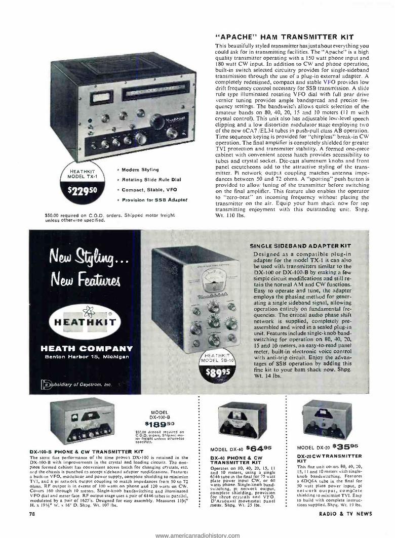
Modern Styling
Rotating Slide Rule Dial
Compact, Stable, VEO
Provision for SSB Adapter
$50.00 required on C.O.D. orders. Shipped motor freigl t unless otherwise specified.
HEATH COMPANY Benton Harbor 15, Michigan
"APACHE" HAM TRANSMITTER KIT This beautifully styled transmitter has just about everything you could ask for in transmitting facilities. The "Apache" is a high quality transmitter operating with a 150 watt phone input and 180 watt CW input. In addition to CW and phone operation, built -in switch selected circuitry provides for single -sideband transmission through the use of a plug -in external adapter. A completely redesigned, compact and stable VFO provides low drift frequency control necessary for SSB transmission. A slide rule type illuminated rotating VFO dial with full gear drive vernier tuning provides ample bandspread and precise fre- quency settings. The bandswitch allows quick selection of the amateur bands on 80, 40, 20, 15 and 10 meters (I 1 m with crystal control). This unit also has adjustable low -level speech clipping and a low distortion modulator stage employing two of the new 6CA7 /EL34 tubes in push -pull class AB operation. Time sequence keying is provided for "chirpless" break -in CW operation. The final amplifier is completely shielded for greater TVI protection and transmitter stability. A formed one -piece cabinet with convenient access hatch provides accessibility to tubes and crystal socket. Die -cast aluminum knobs and front panel escutcheons add to the attractive styling of the trans- mitter. Pi network output coupling matches antenna impe- dances between 50 and 72 ohms. A "spotting" push button is provided to allow tuning of the transmitter before switching on the final amplifier. This feature also enables the operator to "zero- beat" an incoming frequency without placing the transmitter on the air. Equip your ham shack now for top transmitting enjoyment with this outstanding unit. Shpg. Wt. 110 lbs.
SINGLE SIDEBAND ADAPTER KIT Designed as a compatible plug -in adapter for the model TX -I it can also be used with transmitters similar to the DX -100 or DX -100 -B by making a few simple circuit modifications and still re- tain the normal AM and CW functions. Easy to operate and tune, the adapter employs the phasing method for gener- ating a single sideband signal, allowing operation entirely on fundamental fre- quencies. The critical audio phase shift network is supplied, completely pre - assembled and wired in a sealed plug -in unit. Features include single -knob band - switching for operation on 80, 40, 20, 15 and 10 meters, an easy -to -read panel meter, built -in electronic voice control with anti -trip circuit. Enjoy the advan- tages of SSB operation by adding this fine kit to your ham shack now. Shpg. Wt. 14 lbs.
1
MODEL DX -100 -B
*18950 $50.00 deposit reouired on C.O.D. orders. Shipped mo- tor freight unless otlerwise specified.
DX100 -B PHONE & CW TRANSMITTER KIT The same fine performance of the time proven DX -100 is retained in the DX -100 -B with improvements in the crystal and loading circuits. The one- piece formed cabinet has convenient access hatch for changing crystals, etc and the chassis is punched t3 accept sideband adapter modifications. Features a built -in VFO, modulator and power supply, complete shielding to minimize TVI, and a pi network output coupling to match impedances from 50 to 72 ohms. RF output is in excess of 100 watts on phone and 120 watts on CW. Covers 160 through 10 meters. Single -knob bandswitching and illuminated VFO dial and meter face. RF output stage uses a pair of 6146 tubes it pa-allei, modulated by a pair of 1625's. Designed for easy assembly. Measures 113y" H. x 19íe W. x le D. Shpg. Wt. 107 lbs.
78
MODEL DX -40 56495 DX -40 PHONE & CW TRANSMITTER KIT Operates on 80, 40, 20, 15, 11 and 10 meters, using a single 6146 tube in the final for 75 watt plate power input CW, or 60 watts phone. Single -knob band - switching, pi network output, complete shielding, provision for three crystals and VFO. D'Arsonval movement panel meter. Shpg. Wt. 25 lbs.
MODEL DX -20 $3595 DX -20 CW TRANSMITTER KIT This fine unit covers 80, 40, 20, I5, I 1 and 10 meters with single - knob bandswitching. Features a 6DQ6A tube in the final for 50 watt plate power input, pi network output, complete shielding to minimize TVI. Easy to build with complete instruc- tions supplied. Shpg. Wt. 19 lbs.
RADIO & TV NEWS
www.americanradiohistory.comwww.americanradiohistory.com

"MOHAWK" HAM RECEIVER KIT Designed for ham band operation and for maximum stability and accuracy, the Heathkit "Mohawk" receiver will let you enjoy ham activities to the utmost. This 15 -tube receiver fea- tures double conversion with IF's at 1682 kc and 50 kc and covers all the amateur frequencies from 160 through 10 meters on seven bands. An extra band is calibrated to cover 6 and 2
meters using a converter. The "Mohawk" is specially designed for single -sideband reception with crystal controlled oscillators for upper and lower sideband selection. A completely pre - assembled, wired and aligned front end coil /bandswilch as- sembly assures ease of construction and top performance. Many more important features are provided in this outstand- ing receiver for dependable and effective amateur communi- cations. Ruggedly constructed with well rated components throughout. Shpg. Wt. 66 lbs. Matching accessory speaker kit; optional extra. Model AK -5. $9.95. Shpg. Wt. 8 lbs.
Prewired and Aligned Coil /Bandswitch Assembly
Crystal Controlled Oscillators for
Drift -Free Reception
HEATHKIT MODEL AR -3
(LESS CABINET)
ALL -BAND RECEIVER KIT A fine receiver for the beginning ham or short wave listener. Fre- quency coverage is from 550 kc to 30 me in four bands. Features in- clude bandswitch, bandspread tun- ing, phone- standby -CW switch, an- tenna trimmer, noise limiter, RF and AF gain controls and head- phone jack. Easy to build. Shpg. Wt. 12 lbs.
"SENECA" VHF TRANSMITTER KIT Brand new in every respect, the model VHF -I "Seneca" is the latest addition to our line of ham transmitters. This self -contained 6 and 2 meter transmitter features built -in VFO, modulator, and dual power supply. A pair of 6146 tubes are employed in the push -pull final am- plifier stage and features up to 120 watts input on phone and 140 watts input on CW in the 6 meter band. Slightly less in the 2 meter band to prolong amplifier tube life. Panel controls allow VFO or crystal control, phone or CW operation on both amateur bands. Four switch - selected crystal positions. Complete RF shielding to minimize TVI. Spotting push- button provided. The VFO slide rule type dial features edge -lighting and vernier tuning. An ideal transmitter for the ham who wants to extend operation into the VHF region. Shpg. Wt. 56 lbs.
MODEL AM -2 $15595 REFLECTED POWER
METER KIT Check the match of your an- tenna transmission system by measuring the forward and re- flected power or standing wave ratio from 1:1 to 6:1. Handles a peak power of well over I kilo- watt and may be left in antenna feed line. No external power re- quired. 160 through 6 meters. For 50 or 75 ohm lines. Shpg. Wt. 3 lbs.
January, 1959
BALUN COIL KIT Unbalanced coax lines can be matched to balance lines of either 75 or 300 ohms by using this balun coil kit. Use without adjustment from 80 through 10 meters at power up to 200 watts. May be located any distance from transmitter or antenna. Protective cover included. Shpg. Wt. 4 lbs.
MODEL OF-1
$996
"Q" MULTIPLIER KIT Use with any receiver with IF fre- quency between 450 and 460 kc to add additional selectivity for sepa. rating two signals or to reject one signal and eliminate heterodyne. A great help on crowded phone and CW bands. Not for use with AC -DC type receivers. Simple to connect with cable and plugs supplied. Shpg. Wt. 3 lbs.
MODEL CA -1
$1396
"AUTOMATIC" CONELRAD ALARM KIT
This easy -to -build device gives in- stant warning and cuts AC power to your transmitter when a monitored station goes "off- the -air ". Use with any radio receiver having an AVC circuit. A sensitivity control adjusts to various AVC levels. Incorporates a heavy duty six- ampere relay and manual "reset" button to reactivate the transmitter. Complete instruc- tions provided for connection to receiver. Shpg. Wt. 4 lbs.
MODEL VX -1 $2396 ELECTRONIC VOICE
CONTROL KIT This unique device lets you switch from receiver to trans- mitter merely by talking into your microphone. Provision is made for receiver and speaker connections and also for a 117 volt antenna relay. Adjustable to alt conditions by sensitivity and variable time delay controls provided. Shpg. Wt. 5 lbs.
MODEL VF -1 $1960 VARIABLE FREQUENCY
OSCILLATOR KIT Far below the cost of crystals to ob- tain the same frequency coverage this VFO covers 160, 80, 40, 20, 15, 11 and 10 meters with three basic oscillator frequencies. Better than 10 volts RF output on fundamen- tals. Requires only 250 volts DC at 15 to 20 ma, and 6.3 VAC at 0.45 a. Illuminated dial reads direct. Shpg. Vt. 7 lbs.
79
www.americanradiohistory.comwww.americanradiohistory.com

Beautifully Styled With Plenty of Room For The Most Complete
Stereo System
MO DEL SE-1 (:enter unit) $14995 shpg. Wt. 162lbs.
MODEL SC -1 speaker eiclosu-e; 3995 each Shpg. Wt. 42 lbs.
CHAIRSIDE ENCLOSURE KIT Combine all of your hi -fi equipment into one com- pact control center and, at the same time add a beau- tiful piece of furniture to your home. The CE -1 is designed to house AM and FM tuners (BC -1A and FM -3A) and the WA -P2 preamplifier along with the majority of record changers which will fit in the space provided. Changer compartment measures 173/4" L. x 16" W. x 9h" D. Adequate space is provided in the rear of the unit to house any of the Heathkit ampli- fiers designed to operate with the WA -P2. Good ventilation is achieved through properly placed slots in the bottom and back of the enclosure. Overall dimensions are 18" W. x 24 "H x 351" D. All parts are precut and predrilled for easy assembly. The Con- temporary cabinet is available in either mahogany or birch, and the Traditional cabinet is available in ma- hogany suitable for the finish of your choice. Beauti- ful hardware supplied. Shpg. Wt. 46 lbs.
STEREO EQUIPMENT CABINET KIT This superbly styled cabinet ensemble is designed to hold your complete home stereo hi -fi system, con- sisting of a "stereo equipment center" flanked by two individual "stereo wing speaker enclosures ". The unit has room for all the components required for stereo sound. Although designed to hold Heath - kit stereo components, it is not frozen to this ar- rangement. The kit is supplied with mounting panels precut to accommodate Heathkits, but interchange- able blank panels are also furnished so you can mount any equipment you may already have. The precut panels accommodate the Heathkit AM -FM tuner (PT -1), stereo preamplifier (SP-1 & 2), and record changer (RP -3). Record changer chassis pulls out easily for convenient loading and unloading. Adequate space is provided for record storage and a pair of matching Heathkit power amplifiers (from 12 to 70 watts). The stereo wing speaker enclosures are open backed, cloth grilled cabinets designed to hold the Heathkit SS -2 or similar speaker systems. The cabinets are available in beautifully grained 3 /e." solid core Phillipine mahogany or select birch plywood suitable for the finish of your choice. The matched grain sliding tape deck access door on top pops -up flush when closed. Entire top features a shaped edge. Hardware and trim of brushed -brass and gold finish. Rich toned grille cloth is flecked in gold and black. No woodworking experience required. All parts pre- cut and predrilled for easy assembly. Maximum overall dimensions (all 3 pieces): 823/4" W. x 361/2" H. x 20' D. Center Cabinet: 471/2" W. x 361/2.0 H. x 20' D.
HEATH COMPANY JSUbsidiary of Daystrom, Inc.
H EATHKIT MODEL RP -3
HIGH FIDELITY RECORD CHANGER KIT Every outstanding feature you could ask for in a record changer is provided in the HeathkitRP -3, the most advanced changer on the market today. The unique turntable pause during the change cycle saves wear and tear on your records by eliminating the grinding action caused by records dropping on a moving turntable or disk. Record groove and stylus wear are practically eliminated through proper weight distribution and low pivot point friction of the tone arm. Clean mechanical simplicity and precision parts give you turntable performance with the automatic convenience of a record changer. Flutter and wow, a major problem with automatic changers, is held to less than 0.18% RMS. An automatic speed selector position allows intermixing 331/2 and 45 RPM rec- ords regardless of their sequence. Four speeds pro- vided: 16, 331/2, 45 and 78 RPM. Changer is supplied complete with GE VR II cartridge with diamond LP and sapphire 78 stylus, changer base, stylus pressure gauge and 45 RPM spindle. Shpg. Wt. 19 lbs.
80 RADIO & TV NEWS
www.americanradiohistory.comwww.americanradiohistory.com

"BASIC RANGE" HI -FI SPEAKER SYSTEM KIT The popularity of this modestly priced speaker sys- tem attests to its high fidelity performance. The SS -2 provides an ideal basic speaker for your home hi -fi system. Flexibility of design allows it to be used as a
table top model or as an attractive consolette with optional legs. May also be used as a supplementary speaker in more advanced systems or as replacement speaker for TV sets, etc. The specially designed tweeter horn rotates 90 degrees allowing you to use the speaker in an upright position if desired, as in the Heathkit stereo wing speaker enclosures. Total fre- quency range is from 50 to 12,000 cycles -per -second. An 8' mid -range woofer covers from 50 to 1,600 CPS while a compression -type tweeter with flared horn covers 1,600 to 12,000 CPS. Both speakers are by Jensen. A variable balance control allows level ad- justment of the high frequency speaker. Power rating is 25 watts. Constructed of Ih" veneer- surfaced ply- wood suitable for light or dark finish. All wood parts are precut and predrilled for simple, quick assembly. An added feature of the SS -2 is that, although an outstanding performer in its own right, it may be combined with the SS-1B "range extending" speaker system later to extend the frequency range at the high and low ends of the audio range. Build in just one evening for many years of listening enjoyment. Shpg. Wt. 26 lbs.
ATTRACTIVE BRASS TIP ACCESSORY LEGS convert SS -2 into handsome consolette. 14" legs screw into brackets provided. All hardware included. Shpg. Wt. 3 lbs. No. 91 -26. $4.95.
Assemble it in
Just One Evening
DIAMOND STYLUS HI -Fl PICKUP CARTRIDGE
MODEL MF -1 $2695 Replace your present pickup with the MF -1 and enjoy the fullest fidelity your library of LP's has to offer. Designed to Heath specifica- tions to offer you one of the finest cartridges available today. Nominally flat response from 20 to 20,000 CPS. Shpg. Wt. I Ib.
Extended Frequency Range for Your SS -2
J y, 1959
"RANGE EXTENDING" HI -FI SPEAKER SYSTEM KIT
Designed exclusively for use with the SS -2, the SS-1B em- ploys a 15" woofer and a super tweeter horn to extend the range of the SS -2 to an overall response of t5 db from 35 to 16,000 CPS. When used to- gether the two units form an integrated four -speaker sys- tem and are designed to com- bine into a single piece of at- tractive furniture. Impedance of the SS-1B is 16 ohms and power rating 35 watts. A con- trol is provided to limit the output of the super tweeter. Constructed of beautiful 34' veneer -surfaced plywood suit- able for light or dark finish of your choice. All parts are pre- cut and predrilled for simple assembly. No woodworking experience required. All hard- ware included. Shpg. Wt. 80 lbs.
OPTIONAL LEGS NO. 31 -26 $4.95
"LEGATO" HI -FI SPEAKER SYSTEM KIT It is difficult to describe in words the performance of this magnificent speaker system. You may never find absolute perfection in reproduced sound, but the Legato comes as close to achieving it as anything yet devised. Perfect balance, precise phasing, and ade- quate driver design combine to produce the superb quality of reproduction inherent in this instrument. The crisp, clear high frequencies and rich full bass engulf you in a sea of life -like tone. Two 15" Altec Lansing low frequency drivers cover frequencies from 25 to 500 CPS while a specially designed ex- ponential horn with high frequency driver covers 500 to 20,000 CPS. The unique crossover network is built -in making electronic crossovers unnecessary. The legato emphasizes simplicity of line and form to blend with modern or traditional furnishings. Con- structed of ;/' veneer- surfaced plywood in either African mahogany or white birch suitable for light or dark finishes of your choice. All parts are precut and predrilled for easy assembly. Shpg. Wt. 195 lbs.
81
www.americanradiohistory.comwww.americanradiohistory.com

HEATH COMPANY Benton Harbor 15,
Michigan
High Fidelity AM and FM reception
in a Single Set
H EATHK IT MODEL PT -I
Professional Stereo -Monaural AM -FM Tuner Kit Enjoy stereophonic broadcasts as well as outstanchng individual AM and FM radio reception with this deluxe I6 -tube AM -FM- stereophonic tuner combination. Features include three etched circuit boards for high stability and ease of construction, prewired and prealigned FM front end, built -in AM rod antenna, tuning meter, FM -AFC (automatic frequency control) with on -off switch, and flywheel tuning. A multiplex jack is also provided. AM and FM circuits are tuned individually making it ideal for stereo applications since both AM and FM can be used at the same time. A switch selected tuning meter functions on either AM or FM. Cathode follower outputs with individual level controls are provided for both AM and FM. Other features include variable AM bandwidth, 10 kc whistle filter, tuned -cascode FM front end, FM AGC and amplified AVC for AM. Anywhere from 1 to 4 limiters or IF's assure smooth, non -flutter recep- tion on weak or strong stations alike. The silicon diode power supply is conservatively rated and is fuse -protected assuring long service life. Flywheel tuning combined with new edge- lighted slide -rule dial provide effortless tuning. Use of three printed circuit boards greatly simplifies construction. Vinyl -clad steel cover is black with inlaid gold design. Shpg. Wt. 20 lbs.
MODEL FM -3A
$2695 HIGH FIDELITY FM TUNER KIT The Heathkit FM -3A Tuner will provide you with years of inexpensive hi -fi enjoyment. Features broad - banded circuits for full fidelity and better than 10 uy sensitivity for 20 db of quieting. Covers the complete FM band from 88 to 108 mc. Stabilized, temperature - compensated oscillator assures neglible drift after initial warmup. Employs a high gain cascode IF am- plifier and has AGC. Power supply is built -in. IF and ratio transformers are prealigned as is the front end tuning unit. Two outputs provided, one fixed, one variable, with extra stage of amplification. Shpg. Wt. 8 lbs.
MODEL BC -IA $26só
HIGH FIDELITY AM TUNER KIT The BC -1A incorporates many features not usually ex- pected in an AM circuit particularly in this low price range. It features a special detector using crystal diodes and broad banè -width IF circuits for low signal dis- tortion. Audio response is f 1 db from 20 CPS to 9 kc with 5 db of pre- emphasis at IO kc to compensate for station rolloff. Covers the complete broadcast band from 550 to 1600 kc. Prealigned RF and IF coils eliminate the need for special alignment equipment. Incorporates AVC, two outputs, two antenna inputs and built -in power supply. Shpg. Wt. 9 lbs.
....-- rr MODEL W -6 $10995
"HEAVY DUTY" 70 WATT HI FI AMPLIFIER KIT Designed for "rugged duty" called for by advanced hi -fi systems and P.A. networks. Silicon diode rec- tifiers assure long life and heavy duty transformer provides excel- lent power supply regulation. Vari- able damping control provides optimum performance with any speaker system. Quick change plug selects 4, 8 and 16 ohm or 70 volt output and the correct ecdback resistance. Shpg. Wt. 52 lbs.
82
MODEL W -5 $5975 25 WATT HI FI AMPLIFIER KIT Enjoy the distortion -free high fi- delity sound from one of the most outstanding hi -fi amplifiers avail- able today. Features include a specially designed Peerless output transformer and KT66 tubes. Fre- quency response is ±I db from 5
to 160,000 CPS at I watt and wshin 2 db 20 to 20.000 CPS at full 25 watts output. Hum and noise are 99 db below 25 watts. Shpg. Wt. 31 lbs.
MODEL W -4AM $3975 SINGLE CHASSIS 20 WATT HI FI AMPLIFIER KIT A true Williamson -type high fidel- ity circuit, the W -4AM features 5881 push -pull output tubes and a special Chicago- Standard out- put transformer to guarantee you full fidelity at minimum cost. Har- monic distortion is 1.5% and IM distortion is below 2.7% at full 20 watt output. Hum and noise are 95 db below full output. Taps for 4, 8 or 16 ohm speakers. Shpg. Wt. 28 lbs.
S MODEL W -3AM $4975
DUAL CHASSIS 20 WATT HI FI AMPLIFIER KIT Another famous Williamson -type high fidelity circuit, the W -3AM features the famous Acrosound TO -300 " ultralinear" output trans- former and 5881 tubes. The power supply and main amplifier are on separate chassis for installation flexibility. Harmonic distortion is less than 1 %a and IM distortion is less than 1.2% at 20 watts. Shpg. Wt. 29 lbs.
RADIO & TV NEWS
www.americanradiohistory.comwww.americanradiohistory.com

HEAT HKIT MODEL SP -2
(STEREO)
Monaural -Stereo Preamplifier Kit (2- Channel Mixer) This unique kit allows you to purchase it in the monaural model if desired and then add the second or stereo channel later. The SP -2 features 12 separate inputs, six on each channel, with input level controls. Six dual con- centric controls consist of: two 8- position selector switches, two bass, two treble, two volume level and two loudness controls, a scratch filter switch and a 4- position function switch. A separate on -off switch is provided. The function switch provides settings for stereo, 2- channel mix, channel A or B for monaural use. Inputs consist of tape, mike, mag phono and three high -level inputs. NARTB equalization and RIAA, LP, 78 record compensation are provided. A remote balance control is included. Printed circuit boards for easy assembly. Built -in power supply. Shpg. Wt. 15 lbs.
MODEL SP-1 (MONAURAL)
$3795 Shpg. Wt. 13lbs.
MODEL C-SP-1 ;CONVERTS SP-1 TO SP-2)
$2I95 Shpg. Wt. 5lbs.
HEATHKIT MODEL WA -P2
MODEL W -7M
$5495
"EXTRA PERFORMANCE" 55 WATT HI FI AMPLIFIER KIT Enjoy this high fidelity power amplifier at less than a dollar per watt. Full audio output and maximum damping is conservatively rated at 55 watts from 20 CPS to 20 kc with less than 2% total harmonic distortión throughout the entire range. Features famous "bas -bal" cir- cuit, EL -34 output tubes and special 70 volt out- put. Shpg. Wt. 28 Ibs.
"UNIVERSAL" 12 WATT HI FI AMPLIFIER KIT The versatility and economy of this fine kit make it a truly "universal" hi -fi amplifier. An ideal basic amplifier for any hi -fi system or a
perfect addition to gear your present hi -fi sys- tem to stereo sound. Uses 6BQ5,í EL84 push - putt output tubes for less than 2% harmonic distortion throughout the entire audio range. Shpg. Wt. 13 lbs.
MODEL A -9C $3550 GENERAL -PURPOSE 20 WATT AMPLIFIER KIT Designed for home installation a, well as for PA requirements, the A9 -C combines a preamplifier. main amplifier and power supply all on one chassis. Four switch. selected inputs are provided a, well as separate bass and treble tone controls offering 15 db boost and cut. Detachable front plate allows for custom installation. Shpg. Wt. 23 lbs.
J y, 1959
MODEL SW -1 $2495 SPEEDWINDER KIT A real timesaver, the SW-1 leaves your tape recorder free for opera- tion while rewinding tape at the rate of 1200 feet in 40 seconds. Prevents unnecessary wear to the tape and recorder. Handles up to 101/2' tape reels. Handles 800' reels of 8 and 16 millimeter film as well. Automatic shutoff prevents whipping at end of re- wind. Shpg. Wt. 12 lbs.
"MASTER CONTROL" PREAMPLIFIER KIT Control your hi -fi system with this compact unit. Features 5
switch -selected inputs to accom- modate a record changer, tape recorder, AM tuner, FM tuner, TV receiver, microphone, etc., each with level control. Provision also for a tape recorder output. Equalization for records through separate turnover and rolloff switches for LP, RIAA, AES and early 78's. Shpg. Wt. 7 lbs.
MODEL XO -1
$1895 ELECTRONIC CROSSOVER KIT This unique instrument separates high and low frequencies and feeds them through 2 amplifiers into separate speakers. Located ahead of the main amplifier, it virtually eliminates IM distortion and matching problems. Note: Not for use with Heathkit Legato speaker system. Shpg. Wt. 6 lbs.
12" UTILITY SPEAKER KIT Replace inferior speakers in radio or TV sets to obtain better tone quality or set up an auxiliary speaker for testing purposes with this convenient, high quality speaker. The speaker will handle up to 12 watts with a frequency response of ±5 db from 50 to 9,000 CPS. Speaker impedance is 8 ohms and has a 6.8 oz. magnet. An outstanding dollar value. Shpg. Wt. 7 lbs.
MODEL TK -1 $995
COMPLETE TOOL SET These basic tools are all you need to build any Heathkit. The pliers, diagonal side cutters, 2 screw- drivers, and soldering iron are all of top quality case hardened steel for hard duty and long life. Pliers and side cutters are equipped with insulated rubber handles for safety. A good example of just how easy Heathkit building really is. Shpg. Wt. 3 lbs.
83
www.americanradiohistory.comwww.americanradiohistory.com

HIGH FIDELITY TAPE RECORDER KIT The model TR -IA tape deck and preamplifier combination provides all the facilities you need for top qual:ty monaural recording /playback with fast forward and rewind functions. 71/2 and 33/4 IPS tape speeds are selected by changing belt drive. Flutter and wow are held to less than 0.35%. Frequency response at 71/2 IPS 2.0 db 50- 10,000 CPS, at 334 :PS 2.0 db 50 -6,500 CPS. Both units may be mounted together or separately affording high flexibility in every application. Features include NARTB playback equalization -separate recording and playback gain controls -cathode follower output and provision for mike or line input. Signal -to -noise ratio is better than 45 db below normal recording Level with less than 1 . total harmonic distortion. A filament balance control allows adjustment for minimum hum level. Complete instructions provided for easy assembly. Overall dimensions of tape deck and preamp is 151/2" W. x 131/2" H. x 8" D. Shpg. Wt. 24 lbs.
Includes tape deck assembly, preamplifier and roll of tape.
HEATHKIT T E-1
$8995 Tape preamplifier sold separately if desired. Shpg. Wt. 10 Ibs.
Many more Heathkits to choose from hi -fi: Amplifiers -Preamplifiers- Speaker Systems -AM FM. Tuners- Equip-
ment Ca 3inets-Record Player -Tape Recorder -Electronic Crossover - Stereo Equipment.
test: Oscillcscopes- Voltmeters -RF Signal Generators -A.F Generators - Analyzers- Battery Eliminators -Tube Checkers- Condenser Checkers - Computer -Color Bar & Dot Generator -Sweep Generator- Impedance
Bridge -Power Supplies -Probe Kits -R /C Decade & Substitution Kits.
ham radio: Trcnsmitters- Receivers- Antenna Accessories -Voice Con -
trol-Conelrad Alarm- Variable Frequency Oscillator -SSB Adapter - "Q" Multiplier.
marine: Direction Finders - Marine Converter - Rudder Position Indicato- -Fuel Vapor Detector- Charge Indicator -Power Meter.
general: Tool Set -6- Transistor Portable Radio -Rad ation Counter - Electronic Timer -Crystal Receiver -Superheterodyne Receiver.
electronic instruments in ki
tion on Hi -Fi- Test -Ham
Save with H
/IA11AilUJtJ describing over 100 easy -to-build
form. Complete specifications and detailed informa-
and Marine kits.
athkits...the quality name in kit form electronics.
ge RA :';0 & TV NEWS
www.americanradiohistory.comwww.americanradiohistory.com

"BOOKSHELF" 12 WATT AMPLIFIER KIT Here are a few of the reasons why this attractive amplifier is such a tremendous dollar value. You get rich, full range, high fidelity sound reproduction with low distortion and noise . plus "modern styling ". The many features include full range fre- quency response 20 to 20,000 CPS I db with less
than 2 ° ¿, distortion over this range at full 12 watt output -its own built -in preamplifier with provision for three separate inputs: mag phono, crystal phono, and tuner -RIAA equalization- separate bass and treble tone controls- special hum control -and it's easy -to- build. Complete instructions and pictorial diagrams show where ever part goes. Cabinet shell has smooth leather texture in black with inlaid gold design. Cabinet measures 121/2" W. x 8'IC" D. x 43/8' H. Output transformer has taps at 4, 8 and 16 ohms to match the speaker of your choice. An ideal unit to convert your present hi -fi system to stereo sound. Shpg. Wt. 15 lbs.
An Amplifier, Preamplifier all in one!
HEATHKIT EA-2
Order direct by mail... Save % or more over equivalent ready -made products by buying direct and assembling them your- self. Heathkit Style, Performance and Quality are unsurpassed!
4 e
HEATHKIT
NOTE: all prices and speci- fications subject to change without notice.
Enclosed find 1 1 check 1 1 money order. Please ship C.O.D. 1 1
On Express orders do not include transportation charges -they will be col- lected by the express agency at time of delivery.
On Parcel Post Orders in- clude postage for weight shown. All prices are NET F.O.B. Benton Harbor, Michigan, and apply to Continental U.S. and Pos sessions only. 20% Deposit required on all C.O.D. orders.
J
the World's Largest Manufacturer of Electronic Instruments in Kit Form
HEATH COMPANY BENTON HARBOR 15, MICH.
Name SHIP VIA
Parcel Post
Express
Freight
Best Way
Address
City & Zone State (PLEASE PRINT)
QUANTITY ITEM MODEL NO. PRICE
POSTAGE E SEND FREE HEATHKIT CATALOG
TOTAL
HEATHKITS are also available at your Dealer onenhextt page
y. 1959 85
www.americanradiohistory.comwww.americanradiohistory.com

World's Fastest Message Printer New 3000 -word -a- minute teletypewriter prints at a speed 20 times faster than most people can talk.
Although you will find local prices for Heathkits higher than those listed in Heath Company adver- tising ... we're sure you will agree that this increase is justified. Your dealer pais all transportation charges, makes your kit immediately available, pro. vides demonstration facilities, offers you a reliable source for parts and fast se vice ... and stands ready to counsel or advise you on any problems that might arise.
Naturally, you have the continued privilege of dealing directly with the Heath Company if you wish. Now however, you have the added conven- ience of buying locally.
The following dealers have been carefully se- lected and are now ready to serve you.
CALIFORNIA
DUNLAP RADIO & TV 928 Main Street
Chico, California DUNLAP RADIO 6 TV
2617 Tulare Street Fresno. California
BUSHNELL SOUND CORP. 12026 Wilshire Blvd.
Los Angeles, California KIERULFF SOUND CORP.
820 West Olympic Blvd. Los Angeles, California DUNLAP RADIO & TV
5th & "J" Street Marysville, California
DUNLAP RADIO & TV 234 West 17th Street Merced, California
DUNLAP RADIO & TV 419 10th Street
Modesto, California
TEL -RAD ELECTRONICS 639 National
National City, California
ZACK RADIO SUPPLY CO. 654 High Street
Palo Alto, California
DUNLAP RADIO L TV 18th & "R" Street
Sacramento, California
TEL -RAD ELECTRONICS 3453 University Avenue San Diego, California
ZACK RADIO SUPPLY CO. 1422 Market Street
San Francisco. California
DUNLAP RADIO & TV 27 North Grant Street Stockton, California
VALLEY SOUND CORP. 18841 Ventura Blvd. Tanana, California
DUNLAP RADIO & TV 1725 Mooney Avenue
Visalia, California
MASSACHUSETTS AUDIONICS, INC.
1348 Boylston Street Boston 15, Massachusetts
MICHIGAN
VOLTA ELECTRONICS 6716 Park Avenue
Allen Park, Michigan
HI -FI WORKSHOP 16400 W. Seven Mile Road
Detroit 35, Michigan
NEW JERSEY FEDERATED PURCHASER
1021 US Route 22 Mountainside. New Jersey
FEDERATED PURCHASER 114 Hudson Street
Newark, New Jersey
NEW YORK CROSS ISLAND ELEC. INC.
247-40 Jericho Turnpike Bellerose, New York
ACME ELECTRONICS 59 Willoughby Street Brooklyn, New York GEM ELECTRONICS
34 Hempstead Turnpike Farmingdale, New York BEAM ELECTRONICS
101.10 Queens Blvd. Forest Mills, New York GEM ELECTRONICS
234 Broadway, Hicksville, N.Y. ARROW ELECTRONICS
525 Jericho Tpk., Mineola, N.Y. DAVIS RADIO DISTR.
70 East 3rd Street Mount Vernon, New York ARROW ELECTRONICS.
65 Cortlandt Street New York City. New York HARVEY RADIO CO.
103 West 43rd Street New York City, New York
OREGON ECCLES ELECTRIC CO.
237 N.E. Broadway Portland, Oregon
CECIL FARNES CO. 440 Church Street, N.E.
Salem, Oregon PENNSYLVANIA
FEDERATED PURCHASER 1115 Hamilton Street
Allentown, Pennsylvania FEDERATED PURCHASER
925 Northampton Street Easton, Pennsylvania
AUSTIN ELECTRONICS 1421 Walnut Street
Philadelphia, Pennsylvania RHODE ISLAND AUDIONICS, INC.
790 North Main Street Providence. Rhode Island
VIRGINIA KEY ELECTRONICS. INC.
126 South Wayne Street Arlington. Virginia WASHINGTON
SEATTLE RADIO SUPPLY 2117 Second Avenue
Seattle 1, Washington
Obviously, this is a limited number of dealers. Careful selection of reliable, qualified dealers is a slow process ... so please bear with us if your area has not yet been covered. Thank You.
HEATH COMPANY Benton
1ffHarbor,
Mich.
A Subsidiary of D strom, Inc.
e6
Officer is holding 3000 -word menage that has been typed by new Army teleprinter in just one minute fiat.
A NEW 3000- word -a- minute teletype- writer, the fastest general -purpose
message printer in communications history, has been announced by the Dept. of the Army. The printer, de- veloped jointly with the Burroughs Corp., prints four full lines of text a second -50 times faster than a news service teletypewriter, 45 times faster than an average typist, and 20 times faster than most people can talk.
Operating at a lower speed of 750 words a minute for the Army, the new electronic messenger will do the work of eight of today's military printers, promising substantial savings in per- sonnel and equipment. It also gets completed messages to their destina- tion eight times faster. The printer may have broad civilian applications. It can provide the vastly increased message speed long sought by weather forecasting networks, stock exchanges, telegraph offices, and news gathering enterprises.
A standard teletypewriter is an auto- matic typewriter that responds to elec- trical signals. Linked by radio or tele- phone lines, it can print at 60 words a minute messages sent from distant stations. The new teletypewriter does not use ordinary keys for its ultra -fast reception speed. At 750 wpm, they could barely get into the air or would jam up on the first word. Instead, let- ters are shot at the paper electronically by a bank of electrode "guns." Each "gun," or print head, forms a small charged area in the pattern of a single letter on a high - resistivity coated paper surface. The electrostatic latent image
formed by the charge area is made visible by application of powdered ink, permanently fixed by the application of heat.
The recording head is made up of 35 tiny wires leading into and through a triangular -shaped piece of plastic. The wires are polished flush with one cor- ner of the triangle, which is the print head, to form a rectangle seven wires high by five wires wide. This is the matrix -72 of them in a row to form a printing line. They do not touch the paper but are maintained at a fixed distance from the paper surface. Elec- tric pulses selectively charge the prop- er combination of wires in each head to form an image of a character. It requires only a small fraction of a sec- ond to set up the right charge pattern for an entire line of type. During the recording stage, the electrical dis-
FITINE ROLLER
IMTn
NEATER
nikf Rho.
A latent electrostatic image, formed by a row of 72 print heads, is made visible by powdered ink, then fixed by heating.
charge from the print head to a metal plate is used as the source of charge to form the electrostatic image on the paper. By using a low negative voltage on the point electrodes, tiny, round dots are produced that form the letters. This process is referred to as "electro- static recording."
The machine operates from standard code tape, or it can be plugged into long- distance radio or telephone cir- cuits to print out messages sent from across the continent or overseas. An- other use of this unique printing tech- nique will be to type out the calcula- tions of new military electronic corn - puters.
In mass production, the high -speed printer is expected to cost half as much as the bank of eight standard printers it can replace. And since there are no moving parts, except for the paper transport, maintenance should be cut by fifty per -cent. Repair of the elec- tronic circuits will be greatly simplified by the system's replaceable plug -in units. 30
RADIO a TV NEWS
www.americanradiohistory.comwww.americanradiohistory.com

Independen
THIS AD
Radio Service Dealers:
next time you cap TV-Radio Service Dealer..
ask Yourself these 4 questions
BUST HE HAVE
AN ESTABLISHED -. 4
BUSINESS FACILITY?
equipped big investment to set up eq d TV-Radio service
operation. Service Dealer
h a properly
in your D has
a place of b When the
plan-
ning u to community - you can benese -P e9
certain Y may. Your dependent small
business y a he'sg businessman
important to him. Aa the only
going do eseryt as he can toYsurfoyou. hy / his own future.
y you. It's DOES HE GUARANTEE
HIS WORK [ AND PARTS? °J Its standard practice to guarani Parts and most qualified
dealers do so. out the duration
guarantee work and kut
the of the guarantee Be sure to h
know however. long so that d
guarantee are Protect You wit/ by the deaf rovers
protected. Reme
tube er, no! eprvfhinR in th ¡ the Darla ryp ¡óß'
the dealer ompOnent fails during If some other cannot be held re., a the guarantee
period DOES
responsible.
HE CHARGE A FAIR PRICE FOR A HOME SERVICE CALL? charge hto co
Dealer you
transportation makes,
Imrge B sufficient Service D
Dealer Like any other businessman, and tur Baler has basic costa .
eaxment overhead, YOUr Service ... rent. taxes, incur
ante, salaries. when .etc, establishes expenses that must be
f F DO his service cal/ chargea "
ITEMIZED PROVIDE AN He
BILL? yours. Then
sh
which paht you dknow exactly
protection work w
well as replaced was done l'au both know what replacements
exactly how much each cost. guarantee in case of an early are covered
b Y failure. by the If the answer is yes to all four of these questions the
chances are you'll receive
What's service at prices that, competent.
reasonable. expert
Bonder fe the chancy re reasonable.
bonus for yo, Elect
el Technecins ndethat's a an work and parts These
expert technic. as ddy issued through guarantee that is rack
offer a 90 day
Panics. They oh one of America's
la backed
by ° Rona thica designed
serve a strict 8-Point et rnsuranee
corn- ea ca a Io all
protect you. F the quick safe, sure solution
ll TV-Radio servicing the
problems. safe, a
Bonded Electronic Technician. rble u9 caq
Raytheon For Your Convenience
Are hf t ry The Service Dealers J Yellow Your Telephone Directory
Pages of Rartheoe Quatiy Wand Radie e r« rw . Theo when
Service Tune Me *Y Ylh.On 4g l'ou'rs n e err'
Dealer replaces PronsXrx i
Better ree n .uprbrxid x4rndurd 1
^R life and IaalinRlo Id 1
P Immas
eh H Ihfon T g4 elirnnd fi ration. u »jar mlew 6! P^'r n ihn made to the s Gon of R .ih' A IoMn ¡rf mr to nee .Diodes t are da
Rned into the col
s,
x It:,Yth t! ti sr he devejin la of Ameries' Sea moon
n e'on TV an That a w Y. r^duetrm Pment ' O d R h 1 nd nd Pmdur. ^ rin9 Compenr.
GIe1Ne Tubfs. Y YOU nre sprtain of mfncl óln lroh. Excellence
n Electronics a or Propuale D111on, es
..... _ . - -
chPel alrwR Newton sa Iyeonu,nrt . Raytheon is running this a January 19, 1959 editions of NEWSWEEK and TIME magazines to help you. Read it carefully. It makes four simple suggestions to set owners that should result in substantial increases in service busi- ness for qualified Independent TV -Radio Service Dealers. It clarifies the set owners misunderstand.
In e
J y. 1959
ings about the standard work and parts guarantee Giant blow -ups of this advertisement are ovailobtr from your Raytheon Tube Distributor a> no cost to you Be sure to feature one In your drop window
B?
www.americanradiohistory.comwww.americanradiohistory.com

DYNACO STEREODYNE
PHONO PICK UP This new, unique pickup is made in Denmark by Bang and Olufsen. It features a push pull magnetic principle (pat- ent pending) which permits realization of the full potenti- alities of the most modern re- cording techniques. The special attributes which make the Stereodyne an outstanding stereo pickup make it equally exceptional for monophonic discs. On any type of record the Stereodyne offers smooth and natural sound -firm clean bass and sparkling treble - while its light tracking pres- sure insures negligible record wear.
BEST in every way . . .
Wide frequency response Smooth peak free response from 30 cps to over 15 Kc
True Stereo Highest channel separation over en- tire audio spectrum
Precision balance Both channels identical Some high compliance (5 x 10-0 cm /dyne) in all directions No hum pickup Balanced coil structure plus low im- pedance plus complete shielding eliminate hum from external fields
High output 7 millivolts per channel even on low level stereo discs provides gain to spare
No magnetic pull Special magnetic circuit eliminates attraction to steel turntables Easy installation Compact size and standard mount- ing centers simplifies mounting. 4 terminals to avoid hum loops
Low price Only $29.95 net including .7 mil dia- mond stylus (replaceable in 2 sec- onds)
Available from leading high fidelity dealers everywhere
DYNACO INC. Dept. RT, 617 N. 41st St., Phila. 4, Pa. Export Division: 25 Warren St.. New York, N. Y.
66
A/4"^o4 fniAl""-4"1\r'S
P
JBL- RANGER "METREGON" James B. Lansing Sound, Inc., 3249
Casitas Ave., Los Angeles 39, Calif. has recently introduced a new stereophonic loudspeaker system, the "JBL Ranger - Metregon".
The unit contains two complete two - way loudspeaker systems. Sound energy from the speakers is directed
from both sides of the enclosure to- ward a curved refractor panel. This integrates the two separate stereo channels into a single three- dimension- al sound source. This feature is said to eliminate annoying "hole- in -the- middle" effects.
Measuring six feet wide and thirty inches high, the new unit employs an integrated stereophonic reproducer de- veloped by the company in association with Colonel Richard H. Ranger. The enclosure (C45) is available in light or dark walnut, light or dark mahog- any, light oak, Salem maple, natural birch, korina, and ebony finishes.
For a data sheet giving complete specifications on this new stereo speak- er system, write the manufacturer direct and request additional informa- tion on the C45 enclosure.
STEREO- MONAURAL AMPLIFIER Lafayette Radio, 165 -08 Liberty Ave.,
Jamaica 33, N. Y. is now offering a dual -channel basic power amplifier in kit form as the Model KT -310.
The new amplifier is rated at 18 watts per channel and may be used with a stereo preamplifier to provide two 18 -watt stereo channels. It may
also be used monaurally as a single 36 -watt power amplifier feeding one or more speakers or as two separate 18- watt monaural amplifiers.
Dual inputs are provided, each with
individual volume control. Other con- trols include a channel -reverse switch and monaural- stereo mode selector. Speaker output impedances (available on each of the two sets of terminals) are 4, 8, 16, and 32 ohms, thus permit- ting parallel operation of two speaker systems with impedances of up to 16 ohms.
Input sensitivity per channel is .45 volt for full output. Response is flat at better than ±1/z db from 35 to 30,000 cps at 18 watts. Harmonic and IM distortion are below 1 %. The circuit employs seven tubes including rectifier.
The kit comes complete with per- forated metal cage and detailed assem- bly instructions. Over -all size is 93A6" (109úe" with controls) x 5%a" x 13% ". Write the company direct for further details and price.
SOUND LEVEL METER American Research Laboratories,
Fort Atkinson, Wisconsin has devel- oped an acoustic sound level meter to meet the re- quirements of the fast expanding hi -fi and audio amplifier field.
The Model D -50 includes a specially compen- sated microphone feeding a transistor amplifier. The am- plifier is a 4- stage, high -gain, one -piece printed circuit. It has flat response from 200 to 40,000 cps. Below 200 cps the response drops off at 6 db per octave. To compensate for this drop a special equalizing network is inserted between the microphone and the am- plifier input. This equalization pro- duces a substantially flat response from 80 to over 10,000 cps. For appli- cations where a greater range is needed, such as running over -all fre- quency tests on hi -fi equipment, a spe- cial chart is provided that shows the instrument response from 50 to about 15,000 cps.
When used to make frequency re- sponse tests on hi -fi set ups, this meter will provide a measurement that in- cludes the speaker enclosure and the room acoustics as part of the over -all test.
A data sheet giving full details on the unit and its applications is avail- able on written request.
TURNOVER STEREO CARTRIDGE Recoton Corporation, 52 -35 Barnett
Ave., Long Island City 4, N. Y. has released its new compatible Series RG- 745 magnetic stereo turnover cartridge
RADIO & TV NEWS
www.americanradiohistory.comwww.americanradiohistory.com

which has been designed for use on all turntables and changers and for all speeds and types of records.
Two models are available, the RG- 745-1SD "Piggy Back" and the RG745- 3SD. Using a diamond .7 mil stylus on
one side of the cartridge, compatible performance may be obtained on either stereo or monaural LP records. On the turnover side is a 1 mil sapphire needle, providing a standby monaural car- tridge.
The RG745 -3SD is mechanically and electrically the same as the 1SD but carries a .7 mil diamond on one side and a 3 mil sapphire for 78 rpm's on the turnover side.
NEW "CUSTOM" LINE Pine -eer Furniture, Inc., 4228 West
Compton Blvd., Lawndale, Calif. has entered the hi -fi field with a line of components plus the custom cabinets in which to house them.
One of the first items to be placed on the market is an AM -FM tuner which has been tradenamed "The Silva." The circuit provides FM stereo multiplex facilities in addition to covering AM and FM broadcasts. Sensitivity is .77 pv. for 20 db quieting on FM and 3 pv. at 6Or/r modulation for .5 volt output 6 db signal -to -noise ratio. Tuning range is 540 to 1600 kc. and 88 to 108 mc. Frequency response is 20 to 20,000 cps ±1/2 db on FM and 20 to 10,000 cps on AM. The tuner requires a total of eight tubes and draws 40 watts. A
new a.f.c. circuit combined with a low - drift oscillator provides a 16 db correc- tion which captures and holds a station precisely to a tolerance of ±1 kc.
The companion stereo preamp serves as a master control and preamplifier for both stereo and monaural repro- duction. The preamp includes two separate and distinct hi -fi channels on a single chassis plus four stereo out- puts and eight equalization settings for all types of recording programming. There are 12 inputs for all signal sources including ceramic phono, mag- January. 1959
TD -124 $99.75 net
WHAT MAKES THE TD's PS? ...finer for stereo...finer for mono If you move in circles where component hi-fi is a byword, you've no doubt heard about the Thorens TD-124 transcription turntable and its fabulous performance. But for late-corners we'd like to point up just a few of the really big features (non- technical readers may skip remarks in parentheses): Extra heavy table for con- stant speed (10 lb rim -concentrated table insures low wow and flutter; higher mo- ment of inertia than any similar table).
Exact speed ( ±3% adjustment on all speeds -162/3, 331/2, 45, 78 -with built- in illuminated strobe for setting after stylus is on record). Easy on records (unique two -table design permits starts
TD-134
;60.00 net
TD -184 ;75.00 net
iGU RhiEt tlI
* pMO S MAO6¡
after you've placed stylus, permits 2/3
rev. starts, makes cueing easy). Ex- tremely low rumble (mirror -finish main - bearing, nylon -seated ball -thrust- bearing reduce both vertical and horizontal rum- ble to a new low, so important for stereo).
2 -way motor rumble reduction (both an extra -large idler and an ultra- compli- ant belt -drive keep motor vibration and speed variations from table). Driving parts electronically balanced. No costly base necessary (only $9.00). 50/60 cy- cles, 100/250 volt operation.
These are just a few of the TD -124's features. Ask your dealer to tell you the whole story on the fabulous TD -124.
Now two budget -priced TD turntables
These 4 -speed turntables have same basic adjustable -speed precision -drive as famous 10.124 but you save two ways: (1) they come already equipped with stereo -wired professional arm without overhang making them ideal changer replacements. (2) Some TD features have been eliminated to save you money. But they still top the performance of every similar turntable and player on the market. TD -184 has semi -automatic operation. TD -134 is man- ually operated. Precision metal stroboscope (50/60 cycles) furnished with each unit. 100/250 volt operation. Wooden base only 56.00.
Thorens celebrates 75 years of progress in music reproduction
SWISS MADE PRODUCTS HI -Fl COMPONENTS LIGHTERS SPRING -POWERED SHAVERS MUSIC BOXES NEW HYDE PARK, NEW YORK
89
www.americanradiohistory.comwww.americanradiohistory.com

PefAvi
g12* 19-141 142
PREMIERE SOUND
P.A. sound, sparkling clear and natural ... high fidelity which exceeds broadcast specifications. Created and engineered for the highest quality installations. This new sound amplifier series com- bines rugged durability, smooth versatile operation and true nat. ural fidelity. Available in undis- torted 20, 30 and 50 watt mod- els. Ask your sound dealer for a Grommes Premiere Sound demon- stration or for complete details, write ...
GROMMES- precision Electronics Inc. Dept. R -1
9101 King St., Frank in Park, Ill.
l=1 Send details -Premiere Sound.
Name
Company
Street
City State
90
netic phono, tape head, high -level tape, TV, tuner, and multiplex FM. Fre- quency response is flat from 10 to 65,000 cps ±.1 db with IM of .02% at 1 volt output, each channel.
These two units are designed to be mounted on a special chassis panel which is etched to match whatever cabinet style is selected by the cus- tomer. Both modern and period en- closures are being offered by the firm, providing equipment and storage space as required.
For additional information on either the hi -fi equipment or the enclosures comprising this new line, write the manufacturer direct.
TANDBERG STEREO CONSOLE Tandberg of America Inc., 10 E. 52nd
St., New York 22, N. Y. has just re- leased a new stereo console which fea- tures a built -in intercom system.
The Model 10 console will play back stereo discs and stereo tapes as well as serving as the central sound system for the entire home. Provision is made for the connection of remote speakers
to provide coverage of the living area. The built -in intercom feature permits hook -ups between the console speakers and remote speakers which may be lo- cated anywhere in the home.
The AM -FM radio set in the console features a short -wave tuner with four bands and 12 -watt amplifier. There are four Tandberg speakers in the unit -two 8" and two tweeters with cross- over and dividing network. The con- sole is equipped with the company's Model 3- Stereo -4T tape unit with 4- track head and increased range of fre- quency response as well as a three - speed record changer. Power amplifi- cation for the second stereo channel is obtained through the Model 241 pre - amp.
The console is available in teak, mahogany, walnut, or blonde cabinets with brass -tipped tapered legs.
NORTRONICS STEREO AMPS The Nortronics Company, Inc., 1015
S. Sixth St., Minneapolis 4, Minn. has announced the development of two new amplifiers designed especially for stereo playback and recording.
The Model PL-100 playback ampli- fier is a single -channel amplifier with ample gain to match any stereo tape head or stereo phono cartridge. It can also be used as a preamp to drive a more powerful amplifier. An equaliza- tion control allows the frequency re- sponse to be varied 15 db at 10,000 cps. This unit is housed in a modern -look- ing gold and black cabinet. It is rated at 3 watts.
The RA -100 recording amplifier is especially adapted to converting tape
recorders to stereo recording. Two of the amplifiers will supply any mag- netic tape head with all necessary au- dio, bias, and erase power. The RA -100 has NARTB equalization, a vu meter, and an audio monitor jack for phones or amplifier. The low -level input for
microphones may also be used for tape head or magnetic phono cartridge in- put for re- recording, copying, or dub- bing. It is housed in a companion cabinet to the PL -100.
For full details on either or both of these new amplifiers, write the manu- facturer direct.
G -S STEREO CHANGER Glaser -Steers Corporation, 20 Main
St., Belleville 9, N. J. is now offering a new version of its "Seventy- Seven" record changer which has been re- designed for stereo applications.
According to the company, rumble, wow, and flutter have been virtually eliminated by improved motor design. Features of the unit include a stereo- monaural switch on the changer deck, quick- change cartridge holders, double - channel muting switch and RC net- work to eliminate noise during change cycle and at shut -off, service receptacle for automatic amplifier shut -off, auto- matic and full manual operation at 16 %, 33%, 45, and 78 rpm, four -pole, hum -shielded motor with dynamically balanced rotor, acoustically damped tonearm, variable stylus pressure, and jamproof mechanism.
The base measures 131/2" wide, 12" deep with 3" below motorboard and
51/2" above board. A wood base, mount- ing board, and automatic 45 rpm spindle are available as accessories at additional cost.
SMALL "DUCTED- PORT" ENCLOSURE Argos Products Company, Genoa,
Illinois has recently introduced a new small -size speaker enclosure that is es- pecially suited to stereo system appli- cations.
The Model TSE -1 will accommodate an 8" woofer and tweeter. It utilizes
RADIO & TV NEWS
www.americanradiohistory.comwww.americanradiohistory.com

PURCHASING A HI -FI
SYSTEM? Send Us
Your
List Of
Components
For A
Package
Quotation WE WON'T BE
UNDERSOLD! A l l merchandise is brand new, fac- tory fresh & guar - ,no I
AIREX RADIO
CORPORATION 64-R Cortlandt St., N. Y. 7, CO 7-2137
PARTIAL LIST
OF BRANDS
IN STOCK
Allec Lansing Electrovoice Jensen Hartley University Acoustic Research Janssen Wharfedale Karlson Viking Concereone Bell G.E. Weathers Harman- Kordon Eico Pilot Sherwood Acrosound Fisher Bogen Leak Dynak it H. H. Scott Pentron Ampro VM Revere Challenger Wollensak Garrard Miracord Glaser -Steers Rek -O -Kut Components Norelco Fairchild Pickering Gray Audio Tope
Full Line of Cabinets
WIDE LATITUDC
THE CASE
FOR BETTER
Why settle for ordinary tape when Sonoramic
gives you so many exclusive extras -
brilliant reproduction, permanent plastic
container, 3 -way indexing system
with pressure sensitive labels and V -slot self
SOUND threading Selection Finder reel.
'reasrr -- °
esoss use RECIOUS BOOKS
FREETape -time ruler. Gives you. footage aid recording time on reel. Write Dept.
January, 1959
two ducted ports (one on each end) for improved bass response. Although small enough to be used on a bookshelf (24" wide x 11" high x 101/x" deep), the TSE -1 is designed for either table or floor use (standing vertically). Two of these units are ideal for stereo because of their small size and modest cost.
The enclosure is covered with heavily ribbed pyroxylin fabric and uses a new decorator pattern grille cloth. It is being offered in either dark mahogany color or blonde. Internal volume of the enclosure is 2165 cubic inches.
G -E STEREO AMPLIFIERS The Specialty Electronic Components
Dept., General Electric Company, W. Genesee St., Auburn, N. Y. has an- nounced the availability of two new "Stereo Classic" stereophonic hi -fi am- plifiers, the Model MS -4000 and MS- 2000.
The former is a 40 -watt model with two integrated 20 -watt channels while the latter features two integrated 14- watt channels to provide 28 watts. Each model has two power amplifiers and two preamp control units on a single chassis. Both were designed to
handle stereo disc material as well as stereo and monaural tape and broad- cast, and monaural disc program ma- terial.
Each amplifier incorporates an un- usual and effective balance control which allows the listener to adjust the sound volume from both speakers for best stereo perspective. This adjust- ment is comparatively fine near the center point of the control, gradually raising the output from one speaker by one decibel while fading the other. As the knob is turned to its limit, the "faded" speaker is dropped to zero out- put. The other four of the seven knob controls are integrated dual types for simultaneous adjustment of both stereo channels. These knobs control volume, bass, treble, and contour.
Other features of these units include channel reversing to switch either channel to either speaker, rumble filter effective on all inputs, an independent switch position and input for monaural cartridges, low hum and noise, and bet- ter than 40 db channel separation.
Further information on these two new stereo amplifier /control units is available from the company.
LOW -HUM AUDIO TUBE The Electron Tube Division of Radio
Corporation of America, Harrison, N. J. has introduced a new triode -pentode tube which has been especially designed for high -fidelity audio applications where low hum and noise are primary design criteria.
The RCA -7199 plus a pair of the new 7027 high -perveance beam power tubes
for
LOWEST hum... noise... microphonics in a high -N dual triode ...
the
Amperex ECC83 A PLUG -IN
REPLACEMENT FOR THE 12AX7
MICROPHONICS:
Negligible in amplifiers requiring an input voltage of at least 50 my for an output of 5 watts. No special precautions against microphonios necessary even though the tube is mounted in the near vicinity of a loud- speaker with 5% acoustical efficiency.
HUM AND NOISE LEVEL:
Better than -60 db relative to 50 my when the grid circuit impedance is no greater than 0.5 megohms (at 60 cps), the center tap of the heater is grounded and the cathode resistor is by- passed by a capacitor of at least 100 mid.
OTHER Amperex TUBES FOR
HIGHFIDELITY AUDIO APPLICATIONS:
ELBA/6E105 9 -pin power pentode; 17 W PP
6CA7 /EL34 Highpower pentode; 100 W PP
EF86/6267 Low -noise high-At pentode ECC81 /12AT7 lownoise mediumµ dual triode ECC82/12AU7 tow-noise lowµ dual triode GZ34 Cathode -type rectifier; 250 ma.
EZ80 /6V4 9 -pin rectifier; cathode, 90 ma.
EZ81 /6CA4 9 -pin rectifier; cathode; 150 ma.
At All Leading Electronic Ports Distributors
1, Amperex m
ELECTRONIC CORP. 230 Dully Ave., Hicksville, Long Island, N.Y.
91
www.americanradiohistory.comwww.americanradiohistory.com

Of All TWEETERS Tested...
SHACK'S
-V7.50 REALISTIC
ELECTROSTAT-3
KAT by national
consumers' publication! at °n I
Rated "SUPERIOR" To
Tweeters
COSTING $150.00 and
MORE!
i 1: ' /e "w 5r /e "h 41/2"d Cider No. 36CX017Y
3 ELECTROSTATIC ELEMENTS!
Wide 120° sound dispersion angle is attained by the ex- clusive clusive Realistic three -eft-
' set element design.
BUILT -IN AC POWER SUPPLY! Provides all of the voltage necessary for true electro- static speaker operation. Double fused for absolute safety!
COMPATIBLE TO ANY SPEAKER!
Regardless of size shape or cost, the ELECfROSTAT -3 will measurably improve any speaker system!
RECOMMENDED INSTALLATION ACCESSORIES FOR THE REALISTIC "ELECTROSTAT -3"
Crossover Network Kit Includes coils, condensers and L pad. Com- plete with simplified assembly instructions. Ship. Wt. 2 lbs. Available for either 8 or 16 ohms. Ship. Wt. 2 lbs. Order No. Rá850 8 ohms $4.95 Order No. R-4851 16 ohms $4.95
University N2B Crossover Network Order No. 31CX494 Wt. 21/4 lbs. $13.72
Mallory "L" Pad Attenuators Order No. 090803 8 ohms, rh lb. $2.67 Order No. 098882 16 ohms, th lb. $2.67
REALISTIC in brand name, REALISTIC in price. REALISTIC in its smooth performance up to and beyond the range of human hearing, the fabulous Electrostat -3 is nationally recognized and "tops" among tweeters. Like all Realistic components- speakers, tuners, amplifiers, turntables -the Electrostat -3 is designed by Radio Shack audio engineers and fold only. by
Radio Shack by mail -order or through its three stores. Realistic products bring music lovers "wired hi -fi" al or below its kit prices and without sacrifice of any e...sential physical or electrical function!
IMPROVES EVEN THE FINEST SPEAKER SYSTEMS! Designed to fill a void in the reproduction of high fidelity sound, the Realistic ELECTRO- STAT-3 will extend the range of any speaker or speaker system to beyond 25,000 cycles. Its unbelievably wide sound dispersion angle opens a new world of acoustic brilliance!
When used with any cf the finer high com- pliance speaker systems auch as the KLH, Acoustic Research or the Realistic "Delta -7 ", the ELECTROSTAT -3 adds a smooth and silky high frequency response from 5000 cycles to the upper limit of audibility ... and beyond!
EASY TO CONNECT AND USE! The ELECTROSTAT -3 comes complete with simplified installation instructions for any speaker or system. All that is necessary is to plug in the AC power cord, conned an 8 or 1612 crossover network, (see Realistic Crossover Kit at left) and enjoy the finest high frequency response ever heard ! An 812, 5000 cycle crossover network is recom- mended for the AR -1, AR -2 and KLH -6, and a 1612, 5000 cycle network for the KLH -4 and the Realistic "Delta -7 ".
NO DELAY! We Ship fie Same Day We Receive Your Order!
NEW 1959 CATALOG
232 brand new pages! 84 Hi -Fi- Stereo systems! 30,000 electronic items!
RADIO SHACK CORPORATION 730 Commonwealth Ave., Boston 17, Mass. 167 Washington 58., Boston 8, Mass.
230.240 Crown St., New Haven 10, Conn.
92 RADIO & TV NEWS
www.americanradiohistory.comwww.americanradiohistory.com

OTHER RADIO SHACK EXCLUSIVE
ergr Bur i
REALISTIC DELTA -7 SPEAKER Ideally suited for use with the highly recom- mended Realistic Elec. trostat -3 for full range coverage 30- 25.000 cycles. Hand rubbed mahogany or oak cabinet 24%x13'Á x11" deep. 1612.
$8 Down $79.95 $7 Monthly
REALISTIC 15 -WATT AMPLIFIER Full 15 watts - 18- 30.0 cps -1 db @ 1 watt, 20- 20,000 cps -- 1 db @ full output. Wired for stereo. Gold metal case 9%x4%x 6¼". Reg. $66.95.
$5 Down, $5 Monthly $39,95 REALISTIC FM -AM TUNER
Loise noise cascode FM front end; sensitiv- ity 2 uy for 30 db quieting. Ultra quiet AM. Freq. resp. 20- 20,000 cps ±1 db. List $95.
$4 Down, $6 Monthly $57 .00 REALISTIC FM -II TUNER
Sensitivity: 3 uy for 30 db quieting. Freq. resp. 20. 20.000 +1 db. Gold cabinet: 9%x 4%x61/4". List $67.50.
$5 Down, $5 Monthly $39.50
REALISTIC "SOLO" SPEAKER Genuine mahogany fin- ish on 4 sides make it ideal for stereo twins. Dual -cone, 50- 14,000 cps, in solid. tuned enclosure with duct -type vent. Match- es 4.8 ohms. 14%xllx 101/2".
$15.95
RADIO SHACK CORPORATION, Dept. C
730 Commonwealth Avenue, Boston 17, Mass.
Please send me
Duan. Realistic Dese.
Electrostat 3
Delta -7 Sp
Solo Speaker
15 -watt Amplifier FM -AM TUNER
FM TUNER FM -II
Wt. Order No.
7 lbs. 36CX017Y 45 lbs. RX -7065Y 12 lbs. RX -9036 15 lbs. 33CX005Y 15 lbs. 36CX023Y
91/2 lbs. 36CX888.2Y
Sale $27.50
79.95 15.95
39.95 57.00 39.50
Rodio Shack 1959 Hi -Fi Buying Guide
Name Address
City Zone_ _State
J y, 1959
recently released by the company will provide from 30 to 40 watts amplifier output.
This new triode -pentode is of the nine -pin miniature type and utilizes a 6.3 -volt, 450 ma. heater. It features a pentode unit with controlled sharp cut- off characteristics and a high transcon- ductance (7000 µmhos) to provide high gain at low distortion. The triode unit has an amplification factor of 17.
Some of the important design fea- tures include folded -coil (single -heli- cal) heaters in both the pentode and triode units to assure low hum; cage assembly mounted on short, stiff stem leads to reduce noise and microphonic effects; interelectrode coupling and possibility of shorts minimized by suit- able location of stem leads; internal shield to minimize electrical coupling between triode and pentode units; sep- arate cathodes for each unit; and a new cage structure having fewer welds to increase reliability.
4- CHANNEL HEAD KIT Bell Sound Systems, Inc., 555 Marion
Road, Columbus 7, Ohio has announced the availability of a 4- channel -head conversion kit which can be installed on any of the firm's stereo tape trans- ports to handle the playback of 4 -track stereo tapes.
Although the current absence of 4- track open -ended tapes from the market makes the immediate employ- ment of the conversion kit problemati- cal, the company has taken this step to protect both past and future customers against obsolescence.
ESL STEREO TONEARM Electro -Sonic Laboratories, Inc., 35-
54 36th St., Long Island City 6, N. Y. has announced the development of a new tonearm which has been designed
to accommodate all standard stereo cartridges.
The "Gyro- Balance" arm is all new. With it turntable leveling is unneces- sary- according to the company -since the unit will play records at any angle up to 90 degrees! The arm is designed to track properly at two grams. Ball - bearing construction is used through- out for both vertical and horizontal motions. This tonearm is also suitable for monophonic applications.
Write the manufacturer direct for complete specifications and price.
AUDIO CATALOGUES CBS STEREO CARTRIDGE DATA
CBS -Hytron, Danvers, Mass., is offer- ing copies of a one -page data sheet giving complete specifications, an out- line drawing, a frequency response curve, and installation instructions for its "Constant Displacement Stereo Cartridge, Model SC -1."
This data sheet is available from the firm's Advertising Service, Parker St., Newburyport, Mass. Please specify Bulletin E -289.
JBL SPEAKER DATA James B. Lansing Sound, Inc., 3249
Casitas Ave., Los Angeles 39, Calif. has issued an illustrated folder on its "JBL- Ranger Paragon," model 44000.
The speaker system is designed as an integrated stereophonic reproducer and houses a 150-4C low- frequency driver, the 375 high- frequency driver, 075 ring radiator, and N500H and N7000 divid- ing networks.
For copies of the brochure on the en- closure and data sheets on the speaker components used in the system, write direct to the manufacturer at the above address. --
Using only one -tenth watt of power, this small transistorized radio transmitter beamed signals 16,000 miles in what is believed to be a new distance record for low -power radio transmission. With only two RCA "drift" transistors (circled), the transmitter sent a message from Ontario, California to Johannesburg. South Africa. The ham radio unit, constructed by one of our authors, Don L. Stoner, measures 3 by 4 by 6 inches without its 15 -volt battery pack. Complete construc- tion information appeared in our associate publication , "Popular Electronics" (the August, 1958 issue) under the title The Semiconductor Space Scanner."
93
www.americanradiohistory.comwww.americanradiohistory.com

aí ' Mt knight -kits A PRODUCT OF ALLIED RADIO
with exclusive "CONVENIENCE ENGINEERING" for easiest building
SAVE UP TO
O/
KNIGHT -KIT design goes beyond handsome styling, advanced circuitry and guaranteed specifications. KNIGHT -KIT "convenience engineering" means just that...it goes deep -down, with special attention to those small but vital details that count...details such as carded and identified resistors, plastic- bagged hardware, precut and strapped wire -details that make assembly far easier. that assure absolute accuracy, and finally reward you with proud enjcyment of the superior performance designed into your KNIGHT -KIT.
Gaéúcaa,LO&-&t HI-Fl aayoxe Casc, (Ord
THERE'S NOTHING FINER
Deluxe FM -AM Hi -Fi Tuner Kit The best -looking, best- perform.ng FM-AM tuner kit for the money. You'I enjoy builcing it; you'll be proud of its performance and beauty. FM sensitivity is a remarkable 2.5 microvolts for 20 db of quieting. AM is 3 microvolts for 10 db signal -to-noise ratio. Outstanding features incluc'e: s ngle large printed- circuit board with most critical wiring already done; AFC (with disabling feature); flywheel tuning; precisely pre -aligned RF and IF coils -no further alignment needed; tuned RF stage on FM; drift- compensated oscillator; neon glow tuning pointer; cathode follower output; rotatable built -in AM antenna. Beau - titui French -gray case, 4'/. x 134 K 8 ". Ready for interesting easy assembly. Shpg. wt., 12 lbs. '4995 Model Y -787. Net only
Easy Terms: Only $5.00 Down
STEREO High Fidelity...buiid your own at great savings
Stereo Preamp Control Center Kit In a class by itself -a control center that will do anything and everything you want. Fea- tures complete input flexibility -5 Stereo inputs (includhng tape heads), additional 4 inputs for monaural all can be permanently connected ano controlled from single switch. Six record equalizations for monaural; RI AA for Stereo. Volume, bass and treble controls on concentric shafts with special clutch for both individual channel and overall control. Single switch selects straight Stereo Stereo Reverse, either channel separately, or either channel into monaural output. Continuously variable loudr.ess control; cathode follower output and special recorder outputs; hum - free (DC on all tube filaments). Exclusive printed -circuit switches and boards. Custom styled case, 4 x 13 x 8 ". Shpg. 65U wt., 17;2 Z lbs. 1 Model Y -776. Net only . .
Easy Terms: Only $6.25 Down
50 -Watt Stereo Basic Amplifier Kit Absolutely the finest dual amplifier you can build -equal to highest -priced factory -built units. Ideal for use with the KNIGHT -KIT preamp, either as two 30 -watt stereo ampli- fiers or 60 -watt monaural an-plifier. Excep- tional response from 10 cps to 42,000 cps. Phenomenal 0.08% distortion at full 60 watts. Includes static plate current balancing ad- justments for each channel; absolute stability under all operating conditions; custom - quality transformers. Also has special built - in circuitry, with easy external adjustment, for precise balance of gain on each channel to acnìeve perfect monaural pe-`.ormance. Two printed- circuit boards for easy assembly. Beautiful black and chrome; 9 ä 14 ¡ /f x F.14". (Less cover.) 36 lbs. $X/15° Model Y -777. Net only J`
Easy Terms: Only $8.45 Down
Y -779. Gray metal cover. 4 lbs. Net.. .$6.50
EXCLUSIVE PRINTED CIRCUITRY KNIGHT -KITS incorporate the latest technical advances; many include exclu- sive printed -circuit switches. as well as printed circuitry. You save time and you can't go w-ong.
EXCLUSIVE CIISTOM STYLING KNIGHT -KIT hi -fi components, as easy to look at as they are to assemble, are professionally designed to take their place alongside the finest of home furnishings. You'll be proud of your finished work.
Top -Value 12 -Watt Complete Amplifier Kit... test Buy in Hi -Fi
Never before has -here been so much solid hi -fi value and quality performance at such low cost. Features smooth, clean output for truly rich reproduction. Guaranteed specifications: frequency response, 30- 15,000 cps ± 1i; db at half power; less than 1% distortion at full power. Has 15 db of inverse feedback. Has preamp stage equalized for magnetic cartridges; inputs for phono and tuner; separate bass and treble controls with both boost and attenuation, push -pull EL84 output tubes; virtually hum -free performance. Handsomely styled to look well anywhere; size with cover, 5 x 9% x T. 7'2 Its. $1995 Model Y-784. 12 -Watt Amplifier Kit, less cover. Net only. Y -783. Attractive French -gray cover for above. 3 15s. Net only . $3.95
$1995 ;less cover)
Only $2.00 Down
EASY TERMS ON knight -kit ORDERS AS LOW AS $20 www.americanradiohistory.comwww.americanradiohistory.com

GUARANTEED * SEE ALLIED'S 1959 CATALOG FOR COMPLETE DETAILS For full descriptions of the KNIGHT -KITS below, see the 452 -page 1959 ALLIED Catalog. If you haven't a copy, send for it today -use coupon on following page.
there's a honey -saving knight -kit far every quality Hi -Fi need
Universal Stereo Control Kit Provides full centralized stereo control (volume, balance and channel selection) for use with any two amplifiers. Handles up to 20 watts program material. Unit simply connects between speakers and output terminals of amplifiers (no amplifier re- wiring needed). Lets you bal- ance spealer system volume; provides master gain control for overall volume (can by used re- motely); lets you play either channel monaurally through one or both speakers; provides channel reversal; phase rever- sal switch tor best overall per- formance. d` /, x 7''/ a 4'. 3% lbs. Model Y-778. Net only ...$9.95
Deluxe Hi -Fi Preamplifier Kit Quality audio control center. 16 comb - nations of equalizalior; 8 inputs Including tape head; DC on all tube filaments; printed- circuit switches and boards. Custom -styled. 12' lbs. Model Y -754. Wet only . $39.95
25-Watt Hi -Fi Basic Amplifier Kit Williamson -type circuit. Response, ±0.5 db, 9- 70,000 cps at half power. Includes balance control; calibrated damping control; potted output trans- former. Shpg. wt., 25 tbs. Model Y -793. vet only . .....$44.50
*MONEY -SACK GUARANTEE
Every KNIGHT -KIT meets or exceeds published specifica- tions, or we refund your money in full.
18 -Watt Hi -Fi Amplifier Kit Superb hi -fi specificaions; deluxe cus- tom styling. Includes 8 inputs for every desired signal source; full equalization; printed- circuit switches and boards for easy assembly. Shpg. wt., 15 lbs. Model Y -797. Net only .........$39.95
30-Waft Hi -Fi Amplifier Kit Linear -deluxe Williarson -type circuit. Clear, rich 30 watts output; full equal- ization; 8 inputs; level and loudness controls; DC on filaments of preamp tubes; rumble filter; variable damping. Exclusive printed- circuit switches and boards. Custam -styled. 32 lbs. Model Y -762. Net omy $76.95
Hi-Fi Basic FM Tuner Kit Authentic Hi -Fi FM response. Includes AFC; flywheel tuning; pre -alig led RF and IF coils. 4 microvolt sensitivity guaranteed. Printed -circuit board for easy assembly. Custom- styled case. Shpg. wt., 12tbs. Model Y -751. Net only $38.95
2 -Way "Ducted Port" Hi -Fi Speaker System Kit Pre -finished enclosure; easy to assemble. -ti -fi response, 45- 14,000 cps. Includes 1r woofer and horn -type tweeter. Available in mahogany, blonde or walnut ( soecify finish). 26 x 29 x 14 -. Shpg. wt., 33 lbs. Medal Y -789, Net only $49.95
Deluxe "Ducted Port" 3 -Way Speaker System Kit
Pre -finished enclosure, ready for quick assemb Includes famous KNIGHT 3 -way, 12- speaker. Response, 35- 15,000 cps. Fea- tures "cucted port" for excellent bass re- sponse. Available in mahogany, blonde or walnut finish (specify). Shpg. wt., 47 lbs. Model DZ -262. Net only........... $73.45
knight -kits for the Radio Amateur
wad d* uc uada#iitaa gepteet
Amateur Communications Receiver Kit IT'S THE BEST BUILD IT YOURSELF AND SAVE!
Has all the selectivity, sensitivity and features of high -priced commercial units. Covers 540 kc to 31 mc in 4 ranges; cali- brated, electrical bendspread on 80 -10 meter Ham bands; slug -uned Iii -Q coils; continuous, VR tube -regulated 6+ applied to HF oscillator; built -in Q- multiplier; delayed AVC; provision for Y -255 crystal calibrator (below). Sensitivity, 1.5 microvolts for 10 db signal -to -noise ratio. Selectivity: vari- able from 300 cps to 4.5 kc at 6 db down. Exalted BFO injec- tion for SSB. Controls: Main tuning, bandspread, band selector, BFO pitch, RF gain, AF gain, BFO- MVC -AVC- ANL, off- stby -rec -cal, ant. trim. -plus Q mult. controls: null -off-peak, selectivity, tune. Phone jack on front panel. Exclusive printed -circuit bandswitch; printed- circuit boards. Handsome metal cabinet, 10 x 10 x 16W. (Less
$1045° speaker and S- meter.) 23 lbs. Model Y -726. Net only
Easy Terms: Only $10.45 Down
Y -727. S -Meter Kit for above. 1 lb. Net $10.75 Y -728. 4" speaker in matching cabinet. 3% lbs. Net. ,
POPULAR AMATEUR knight -kit VALUES!
50 -Watt CW Transmitter Kit Ideal for the rovice. Convenient band - switching, 80 through 10 meters. Effi- cient pi- network antenna coupler; effective TVI suppression. Uses 807 in final. Shpg. wt. 18 lbs. Model Y -255. Net only $38.95
Self- Powered VFO Kit With built -in power supply. High sta- bility; excellent key ng; full TVI sup- pression. Planetary vernier drive. Cali- brated for B0, 40, 20. 15 and 10 meters; output on 80 and 40 meters. Shpg. wt., 11 lbs. Model Y -725. Net only .. $29.50
Z- Bridge Kit Accurately measures SWR from 1 mc to 150 mc. Also measures antenna im- pedance. Has coax input and output. Invaluable for attaining peak antenna efficiency. Shog. wt , 1% lbs. Model Y -253. Net only $5.85
100-kc Crystal Calibrator Kit Crystal frequency standard for any receiver, at very low cost. Gives marker every 100 kc up to 32 mc. Trimmer for zero -beating with WWV. With crystal. Shpg. wt. 1 Ib. Model Y -256. Net onla.. á10.95
ORDER FROM ALLIED RADIO 100 N. WESTERN AVE. CHICAGO 80, ILL. www.americanradiohistory.comwww.americanradiohistory.com

ulq kn ì g ht= kits 060zéé.cfd Fun to bui!d...with performance you'll proudly demonstrate KNIGHT -KITS are the first choice of hobbyists, experimenters and students because they're truly "convenience- engineered" for easiest assembly.. absolute dependability and finest performance. You'll have more building fun, you'll have more enjoyable performance, you'll save more with KNIGHT -KITS.
with exclusive '
&94(9p fo" assured build -your -own success...
"Span- Master" 4 -Band World -Wide Receiver Kit Imagine the thrill of hearing overseas broadcasts on a precision receiver you've built yourself! At the flip of the bandswitch, you tune n the world- continuous 4 -band coverage from Broadcast to 30 mc- fascinating foreign broadcasts, ships -at -sea, aircraft, police and marine radio, amateur reception on 80, 40, 20, 15 and 1C meters -all this wonderful short -wave, plus enjoyable .ocal broadcast reception. Features sensitive regenerative circuit; easy bandspread tuning; built -in 4" Alnico V speaker; head- phone terminals; speaker cutout switch. Controls: Main Turing, Bandspreac, Bandswitch, Volume, Coarse and Fine Regeneration. Easy to build from marvelous instruc- tion manual. Handsome cabinet; 6' /. x 13% x 6%". For 110 -125 v. AC. Shpg. wt., 7 lbs. Model Y -258. Net only
Easy Terms: Only $2.50 Down
"Space Spanner" Receiver Kit Thriling 2 -band receiver, easy to build. fun to ooerate-a terrific value. Bandswitch selects exciting short -wave, including Foreign broadcasts, amateur, aircraft, police and marine radio (6.5 to 17 mc), and stand- ard broadcast. Highly sensitive regene ative circuit. Built -in 4" PM speaker and beam - power output for strong volume. Has head- phone jacks and switch to cut out speaker. Easy to assemble from step -by -step instruc- tions. Handsome cabinet, 7 x 10% r. 6 ". AC or DC operation. Shpg. wt., t 7% lbs. $1 895 Model Y -259. Net only 1 V
12 -In -1 Electronic lab Kit i asc nating way to learn electronics -:uilc any cne of 12 practical circuits! Change c r- cuits just by relocating a few wires. Safety - designed; no voltage exceeds 25v. Makes any one of the following: AM radio, a.rpli- fier, code oscillator; home "broadcaster "; electronic timer, switch or flasher; voice - operated, capacity- operated or photoslec- Ironic relay; CW "transmitter "; light control oscil ator. With all parts, mike, phototube, instructions for each project. For 110 -125v. AC. Shpg. wt., 3''/ lbs. Model Y -272. Net only '1495
"Ranger" Clock -Radio Kit You'll be proud of the performance of this easy -to -build clock- radio. Provides wonder- ful broadcast band reception. Includes Tele- chron clock with sleep- switc` timer plus automatic radio wake -up /alarm switch. Radio automatically shuts off at night and wakes you in morning; also turns on appli- ances automatically. Module plug -ir circuits and printed -circuit board for quick, easy assembly. Beautiful blue and white plastic cabinet. 6 x 9V,, x 5% ". For 60 cycle AC on y. Shpg. wt., 5 lbs. 52495 Model Y -737. Net only
Easy Terms: On& $2.50 Gown
l.aaegeeha oqua4.> 'dtlCd. "Ranger Ill" AC -DC Radio Kit
Superhet broadcast band re- ceiver. Built -in antenna; AVC; Alnico V speaker. Black plastic cabinet. AC Cr DC. Shpg. wt., 4y, lbs. Model Y -736. 4et only.... $16.95
"Ocean Hopper" Receiver Kit Regenerative receiver for broad- cast, long wave and short wave reception from 155 kc to 35 mc.
al With coil for broadcast band. For AC or DC. Shpg. wt., 7 lbs. Model Y -749. Net only....115.95 Y -748. Set of plug -in long wave and short wave coils. Net...$2.95
"Ranger III -PC" AC -DC Radio Kit Printed -circuit broadcast band
- ---7 superhet. Easy to assemble. Has AVC, built -in loop antenna, Alnico V speaker. Ivory plastic cabinet. AC or DC. Shpg. wt., 4 lbs. Model Y -738. Net only....$18.95
"Ranger" Radio -Intercom Kit AYE
It's a broadcast band radio -it's 1 an efficient 2 -way intercom -both
in one! Ivory plastic case for Mas- ter station /Radio; smartly styled Remote station. With 50-ft. cable. AC or DC. Shpg. wt.. 8 lbs. Model Y -739. Net only....$27.50
"Trans- Midge" Radio Kit Tiny 1- transistor radio for local broadcast reception. Works for months from single penlight cell supplied. Handsome plastic case. Fascinating to build. (Requires headphones and antenna.) 8 oz. Model Y -767. Net only 82.45
10- Circuit Transistor Lab Kit Builds any of 10 favorite projects. Entire kit on a printed circuit board. Just plug in leadsto change from project to project. 3 lbs. Model Y -299. Net only....$15.75
1- Transistor Radio Kit Offers fine local broadcast head- phone reception. Printed circuit board for easy assembly. Works
4 for months from penlight cell sup- plied. (Antenna and headphones required.) Shp.. wt., 1 Ib. Model Y -765. Wet only 93.95
www.americanradiohistory.comwww.americanradiohistory.com

awd Knight -kit ua ' 7écta ae BETTER BY FAR...ADVANCED DESIGN...GUARANTEED SPECS
DO THE EASY ASSEMBLY...SAVE OVER L¡ J MONEY -BACK GUARANTEE Every KNIGHT -KIT meets or exceeds published specifications -or we refund your money in full. EASY TERMS on orders as low as $20
5- Transistor Superhet Radio Kit Quality personal portable. Printed circuit for easy assembly. Built -in antenna; ä ,' speaker; prealigned IF's; phono jack; 200 -hour battery playing life. Handsome ivory and gold styling. Less battery ($1.43). 2 lbs. Model Y -771. Net only. .....325.95
2- Transistor Pocket Radio Kit Excellent for local broadcast recep- tion. Newest printed- circuit board for easy assembly. Built -in antenna; miniature dynamic earphone; plays for months lrorn single battery. In handsome carrying case; only 4 x 3'/, x1,4,-. Less battery ($1.25). 1, lbs. Model Y -253. Net only ..$11.50
2 -Way Intercom System Kit ^ Complete 2- station system; low -cost, easy to assemble. High gain, clear ;( toned, sensitive. Has 2 -stage ampli-
1.W., tier and 4' PM speakers. Hancsome - At metal cabinets. Includes master, re-
J,_ mote and 5C-ft. cable. AC or CC Bibs. Model Y -290. Net only .......$14.95
Electronic Photoflash Kit Fast 1 /700th -of -a- second Lash; 50 watt /second output. Synchronizes with any camera with X or O shutter. Less battery. Shpg. wt., 4 lbs. Model Y -214. Net only ..$29.50
Wireless Broadcaster- Amplifier Kit Play music or make announcements through your radio set, using mike or
V - also as audio
connection amplifier. Has built-
in inpreamo.. CorDC. Shpg.w'.,3lbs. Model Y -716. Net only .......$11.95
Transistor Code Practice Kit Ideal for beginners learning ace. 500 cps tone. Single penlight cell sup- plied operates unit for months. Jacks for headphones; screw terminals for key. Shpg. rt., 1 Ib. Model Y -219. Net only .......$3.95
Crystal Set Kit Gives clear headphone reception of local broadcast stations. Sensitive crystal diode; efficient "Hi -D" coil. (Antenna and headphone required.) Shpg. wt.,' lb. Model Y -241. Net only $2.35
Photoelectronic Relay Kit Ultra -sensitive relay at very low cost. Fire for autonatic control of lights, door openers, as a burglar alarm, etc. Shpg. wt., 3y, lbs. Model Y -702. Net only 513.50 Y -703. Light Source only .5 6.75
1959 452 -PAGE
ALLIED CATALOG See pages 241 -273 for detailed descriptions of all KNIGHT -KITS: Hi -Fi, Hobby, Test Instrun ant, Amateur. The 1959 Allied Ca :alog is your complete Buying Guile to the world's largest stocks of every- thing in Electronics.
38 years of e,19.3erience in electronic Kt design
MOM ma
Vacuum Tube Voltmeter Kit Top buy .n a quality VTVM. Entire chassis is printed- circuit board -easy to assemble. Balanced -bridge, push - pull circuit; 1% film -type resistors; 200 .sa movement; CA" meter; includes zero center scale and direct- reading db scale. Polarity reversing switch. Input Res.: 11 megs. DC and AC rms, 0 -1.5- 5 -15 -50 -150- 500 -1500; AC Peak -to -Peak, 0- 4- 14 -40- 140 -400 -14C0 -4000; Response, 30 cycles to 3 mc; Ohms, 0- 1000 -10K- 100K and 0- 10- 100 -1000 megs; db, -10 to +5. Includes battery and test leads. For 110- 125v., 50-60 cycles. Shpg. wt., 6 lbs. Model Y -125. Net only.
s2575 Easy Terms: Only $2.58 Down
Lowest Cost Tube Checker Kit A really tremendous value in a quality tube checker. Checks over 400 tubes. Features "Flip- Card" charts with tube settings in loss -proof pull -out storage drawer. Has sockets for 7 -pin miniature, 9 -pin miniature, octal and !octal base tubes. Checks for cathode emission, filament continuity, shorted elements. Meter has "Replace- Good" scale and special scale for checking diodes. With quick- setting, universal -type selector slide switches. Includes "Hi -Lo" line - voltage regulator switch. Compact and light -use anywhere. With tube charts. 6% lbs. Model Y -707. Net only...
$1995 Easy Terms: Only 82.00 Down
I
there is a knight -kit to fill every test equipment need For detailed descriptions, see the 1959 Allied Catalog.
5' Wide -Band 'Scope Kit . ......$65.75 5' General Purpose 'Scope Kit....... 42.00 20,000 Ohms /Volt VCM Kit 29.50 1,000 Ohms/ Volt VOM 16.95 'Scope Voltage Calibrator Kit 12.75 Counter Tube Checker Kit . 29.75 Portable Tube Checker Kit 34.75 TV -FM Linear Sweep Generator. .. . 44.95 RF Signal Generator Kit 19.75
High -Gain Signal Tracer Kit $26.50 Audio Generator Kit 32.95 Resistor- Capacitor Tester 19.50 "In- Circuit" Capacitor Checker Kit 12.50 Flyback Checker Kit 19.50 Transistor & Diode Checker Kit 8.50 Resistance Substitution Box Kit 5.95 Capacitance Substitution Box Kit 5.95 6V -12V Battery Eliminator Kit.... 32.95
ORDER BLANK Dept. 131 -A9
100 N. Western Ave., Chicago 80, III.
Ship me the follow no KNK HT -KITS:
Quariity Description Model No. Price
S enclosed. (For )i reel post include postage; express is shipped collect.) All prices Net F.O. B. Chicago
My Dow, Payrrert n the amount of S is enclosed. Send Time Payment form
N- ne
Address
City Zone State
El Send FREE 452 -Page 1959
Allied Catalog
www.americanradiohistory.comwww.americanradiohistory.com

QUALITY CUT QUARTZ FOR EVERY SERVICE
All crystals made from Grade "A" imported quartz -ground and etchec to exact frequen- cies. Unconditionally guaranteed! Supplied
in:
FT -243 holders. Pin spacing "2 ". Pia diameter .093.
HC /6U metal sealed holders. grf-YET.' Pin spacing .486 ". Pin di- WNW
- ameter 050 or .093.
was ".¢ eW DC -34 holders. Pin spacing K- 3/4 ". Pin diameter .156.
MC -7 holders. Pin spacing 3/4 ". Pin diameter .125. FT -171 holders. Pin spacing we. Banana pins.
MADE TO ORDER CRYSTALS 1001KC to 2500KC:
.01oú Tolerance.. 52.00 .005dó Tolerance.52.75 2501KC fo 9000KC:
.01o0 Tolerance.. 51.50 .005% Tolerance. 52.50 9001KC to 12,000KC: .0059/0 Tolerance.$3.00 Specify holder wonted.
3500 KC hermetically seolec frequency mark- er crystal .005% tolerance fits $1.75 octal tube socket ßtÌÌ 7
ANY AMATEUR BAND CRYSTAL .01°á Tolerance NOVICE BAND CRYSTALS CO 80 meters 3701- 3749KC e7 a 40 meters 7152- 7198KC 15 meters 7034- 7082KC each
6 METER TECHNICIAN BAND CRYSTALS 8335KC- 8550KC within 1Kr_- each 1e50
ASK YOUR LOCAL PARTS DISTRIBUTOR FOR TEXAS CRYSTALS LOOK FOR YELLOW & RED DISPLAY BOARD. SEALED OVERTONE CRYSTALS supplied in metal HC 6U holders -pin spacing .486, diameter .050. 10 to 30 MC .005 tolerance $3.B5 ea. 30 to 54 MC..005 tolerance $4.10 ea. 55 to 75 MC .005 tolerance $4.25 ea.
FUNDAMENTAL FREQ. SEALED CRYSTALS In HC 6U holders from 1400KC-10,000KC any fre- quency .005 tolerance $3.50 ea.
TEXAS CRYSTALS, TRA45ISTORIZMD 100 KC MARKER OSCILLATOR
Compact, portable, in attractive metal carrying case with handle. Sire: 4"H x 3 "W x 6"D. Connects to any receiver to get 100 KC markers from 100 KC to 50 MC. Factory wired with two transisto s, one 100 KC crystal, self -contained battery. Shipping weight, TO oz. Add 53c for prepaid parcel post. Net
MARINE FREQUENCII CRYSTALS All marine frequencies from 2000- 3200KC .005 tolerance $2.50 (Supplied in either FT -243, MC -7, or FT -171 holders.)
RADIO CONTROL CRYSTALS 27.225 MC sealed crystals (1/2" pin spacing .
specify pin diameter .093 or .050)....$2.50 ea. Stock crystals in FT -243 holders from 5675KC to B65OKC in 25KC steps 750 or 3 for $2.00 FT -241 lattice crystals in all frequencies from 370KC to 540KC (All except 455KC and 500KC.)
50$ Matched pairs ±15 cycles $2.50 per pair. 200KC Crystals..52.00 100KC Frequency 455KC Crystals..$1.50 Sta idard Crystals $4.50 50OKC Crystals..51.50 1000KC Frequency Standard Crystals $3.50 Dual Socket for FT -243 Crystals S .15 Ceramic socket HC 6U Crystals S .15
'Add 5C per crystal for pos'age and handling.) WRITE FOR CATALOG AND QUANTITY PRICES.
Texas Crystals The Biggest Buy in the U.S.
8538 W. GRAND AVENU2 RIVER GROVE, ILL.
ALL PHONES - GLADSTONE 3 -3555
Terms: All items subject to prig sale and change of price without notice. All crystal orders MUST be ac- companied by check. cash or M.O. WITH PAYMENT IN FULL. NO C.O.D.s. Postpcid shipments made in
U.S. and possessions only. Aid 5t per crystal for postage and handling charge.
98
Industrial Tubes (Continued from page 40)
radio engineering field. In the process of developing insulators for the high - frequency conductors used in radio transmission, the insulators became very hot despite the fact that they were poor electrical and thermal con- ductors. Investigation revealed what proved to be the basic theory behind dielectric heating.
To simplify the explanation, we will translate the high -frequency conductor into a parallel -plate capacitor with the insulator as the dielectric material be- tween the plates. When voltage is ap- plied to the plates of the capacitor, the electrons in the insulating material are attracted towards the positive plate while the atomic nuclei are at- tracted toward the negative plate. Both reactions occur simultaneously and are accompanied by an energy con- version which is manifested as heat. If the voltage polarity applied to the plates is reversed, the electrons and nuclei will also reverse direction and produce more heat. As the frequency of polarity reversal increases, so will the amount of heat produced.
Unlike induction heating, dielectric heating reaches all parts of a homogen- eous material equally. In fact, be- cause heat can escape faster from the surface of a work piece, it is possible to have higher temperatures at the center. One case is reported where the center of a 2 -inch thick plywood board was actually charred while the surface was unmarked. This characteristic in- volves both advantages and disadvan- tages; the thorough, rapid heating is a
definite advantav while the necessity for careful control and possible reduc- tion of power input is a disadvantage.
We are now in a position to look at some of the uses for dielectric heating. The largest areas of application are moisture removal, wood gluing and laminating, plastics processing and sealing, and food processing. Although the materials handled in these areas are obviously different, they all have one characteristic in common; each and every one of them is a poor ther- mal conductor. In fact, it is the ability to heat materials which are poor ther- mal conductors that makes dielectric heating such an important industrial tool.
For instance, consider the problem raised when wood pulp is shipped from the mill to the paper plant. Since wood pulp consists of wood fibers in a water solution, a significant percentage of the shipping costs is for hauling water. Naturally a solution to this problem would be to eliminate the water be- fore shipment and put it back in at the paper plant. But how? The conven- tional equipment to handle this job would be both enormous and expensive. On the other hand, a 20- kilowatt di- electric heater (size about 6 x 4 x 4 feet will remove one pound of water per minute at room temperature with a power input of only 40 kilowatts per hour. In addition, the dielectric heater raises the temperature of the water at a much faster rate than the wood fibers, thus the fibers remain relatively cool and unharmed. Conventional methods do not have that safety feature.
One of the most attractive features about dielectric heating is its rela- tively low -power requirements. Not
Table 2. Power and frequency ranges of industrial equipment discussed in text.
PROCESS FREQ. RANGE, APPROX. POWER, APPLICATIONS2
Induction Heating 10 -500 kc. or more
25 kw. Small soldering and welding units
Dielectric Heating 1 -500 mc. or more
2 kw. Restaurant ovens ( "Radarange ")
Ultrasonics 20 -30 kc.3 or 400 kc.
1 kw. Clothes and dish washers, small indus- trial cleaners
NOTES: 1. These are most popular ranges. See text for other ranges; 2. Im- mediate areas of opportunity for the technician starting now; 3. 20 -30 kc. for magnetostriction transducer, 400 kc. for piezoelectric.
Table 3. Listing of heating times and power requirements for solder operations.
PROCESS HEATING TIME (sec.)
POWER REQUIRED (kw.)
steel brass copper
Soft Soldering at 370T (per in." area)
20 2.0 4.0 8.4
40 1.0 2.4 5.5
Silver Soldering at 1300 °F (per in.2 area)
20 8.0 16.0 33.6
40 4.0 9.6 22.0
RADIO & TV NEWS
www.americanradiohistory.comwww.americanradiohistory.com

NO -NOISE NEW RUBBER COAT
SPRAY Ins labs where 6 Or. Spray Can ppind
Peeeee is ìnaeli- telr
tiortiny cor.osion Waterprootsthar-
.1Ì n- innammabl Contains no Pt.e- tlC Net To
25 Nricrtnen
NO -NOISE
TUNER -TONIC With PERMA -FILM
Nat little 6 Or. den a lot. Aerosol Can cleans. I.brital. ,
$ Includin,'rafer rs.
type.
ñ.mm:EIen non-In.
ana Em TV, radio
only is it a very efficient source of heat, but it uses considerably less floor space than an equivalent conventional source. For example, the most com- monly used generator is the 2- kilowatt model which is about equal in size to a modern TV console -a relatively small package for the heat produced.
Ultrasonics
Ultrasonics is concerned with the use of mechanical vibrations at fre- quencies above the audible range. The difference between audible sound and ultrasonics lies only in the ability of the human ear to respond. Many ultra- sonic generators operate between 20,- 000 and 30,000 cps while some operate as high as 400,000 cps.
The equipment consists of an elec- tronic generator of high -frequency en- ergy and a transducer to convert the electronic oscillations to mechanical vibrations. The generator is simply a power oscillator and is very similar to the induction and dielectric heating generators. The transducer is a device that converts electrical energy to me- chanical energy. An ordinary loud- speaker is one example of a transducer. This transducer uses air as the me- dium being operated on while the me- dium used for most ultrasonic trans- ducers is a liquid. frequently water. The ultrasonic transducer is in direct contact with the liquid and either pro- duces "cavities" in the fluid or waves, which travel through the liquid with- out disturbing it. As the holes or cavi- ties in the water collapse, a turbulence is created which provides a gentle, effective scrubbing action. The scrub- bing is so effective that it will even remove radioactive particles and yet it is gentle enough to clean a delicate missile control while it is still assem- bled. Cleaning is the largest industrial application for ultrasonics, although ultrasonic drills and soldering irons are also used.
There are many applications for the non -violent ultrasonic waves. The largest application in this category is underwater detecting equipment, such as sonar, depth indicators, and fish finders. Other uses are for liquid level sensing, non -destructive testing, and gauging.
Of the three high- frequency indus- trial applications, ultrasonics has the lowest power consumption. The most popular size is 1 kilowatt and some recent applications use less than 200 watts. The lower -power equipment is portable, being not much larger than a table radio.
Conclusion
Now that we have had a brief look at some industrial uses for electronics, we can get a small idea of the immen- sity of the field. We can see that there are a good many uses for electron tubes that are not directly related to consumer products, such as radio and TV receivers. The technician who wants to expand his scope would cer- tainly do well to learn as much about these applications as he can. N J y. 1959
Announcing . A BRAND -NEW Home Study Program - Equips you to enter the exciting, new and booming field of
and Industrial ELECTRONICS
Engineering Technology Automation: "Second industrial
revolution" . latest and most exciting development in our amaz- ing world of electronics. Current needs: 3,000 specialists per year, well- trained in automation and in- dustrial electronics ... to fill new jobs and draw top pay.
CREI's new complete home study course covers all phases of automa- tion and industrial electronics, in- cluding fundamentals of electronic engineering technology and a spe- cialization in: Machine control sys- tems ... Data processing systems
Instrumentation techniques .. .
Digital and Analogue Computers Servomechanism systems .
Telemetry systems ... Industrial processes. Leads to jobs like these:
NOW A TELEMETRY TECHNICIAN AT RCA MISSILE TEST PROJECT ... "On Decem- ber 31 I will be working for RCA at the Missile Test Project in Florida as a Telemetry Technician. I don't mind telling you that CREI
and your encouragement helped a lot in getting this job. "-John S. Treft, Box 133, Beulah, Mississippi NOW ASSISTANT CHIEF ENGINEER OF RADAR INSTRUMENTATION STATION . .
"Five years ago I started to work for my present employer as a Radio Repairer and Installer. I also started my CREI course at this time. Three years later I was a supervisory electronic engineer and a year later I was promoted to the position I now hold as assistant chief engineer of a large radar in- strumentation station at White Sands Proving Grounds." - Ralph Leo Gagnon, 1255 Gardner Ave., Las Cruces, N. M.
If you have had a high school education, and experience in elec- tronics -and realize the need of high -level technical knowledge to make good in the better electronic jobs - you can qualify for this brand - new CREI Home Study course. Write to Capitol Radio Engineering Institute, Dept. 111 -X, 3224 -16th St., N.W., Wash. 10. D. C.
To obtain fast, immediate service and to avoid delay, it is necessary that the following information be filled in:
Employed By
MAIL THIS COUPON FOR FREE BOOKLET!
CAPITOL RADIO ENGINEERING INSTITUTE ECPD Accredited Technical Institute Curricula Founded 1927
Dept. 111 -X, 3224 - 16th Street, N.W., Washington 10, D. C.
Pleose send me without cost or obligation your brochure describing your brand -new home study course in Automation
and Industrial Electronics Engineering Technology.
Name Age
Street
City Zone _._ State
Type of Present Work
Education: Yrs. High School
Other
Electronics Experience
IF ... you are interested in other CREI courses in Electronics please refer to CREI's 2 -page ad on pages 125 and 126 of this magazine.
servicemen everywhere insist on the
GENUINE
O OISE"
Beware Of Cheap Substitutes!
25 EenETUmn
NO -NOISE VOLUME CONTROL
and CONTACT RESTORER
Cleans Lub.m ates
cls
NOT A CARBON TET SOLUTION
\M/ 2 or. Bottle 6Oe.Seeer Can
$100 $225 Net To N.t To
ELECTRONIC CHEMICAL CORP. 813 eemmanipaw Avenue Jersey City 4, N. J.
99
www.americanradiohistory.comwww.americanradiohistory.com

These men are getting practical training in...
EeeePtence,4"
Train in NEW Shop -Labs of
COYNE in Chicago - Electronic Center of the World. Prepare for a better job and a successful future in TOP OPPORTUNITY FIELD. Tlain on real full size equipment at COYNE where thousands of success- ful men have trained for 60 years- largest. oldest, best equipped school of its kind. Professional and experienced instructors show you how, then do practical jobs yourself on more than a quarter of a million dollars worth of equipment. No previous experience or advanced education needed. Employ- ment Service to Graduates_ Start Now -Pay Later - Liberal Finance and Pay- ment Plans. Pay most of tuition after graduation. Part-time employment he:p for students. Choose from nine yearly Starting Dates. Mail Coupon For Free Book- "Guide to Careers." Whether you prefer ELECTRICITY- ELECTRONICS, TELE- VISION -RADIO ELECTRONICS Or COMBINED ELECTRONICS TRAINING, this book describes all training offered and gives all the facts to Vets and Non -Vets.
Information comes by mail. No obligation and NO SALESMAN WILL CALL. B. W. Cooke, Jr., Pres. Founded 1893
COYNE ELECTRICAL SCHOOL Chartered No For Profit
1501 W. Congress Pkwy., Cnicago 7. Ill., Dept.
MAIL COUPON FOR BOOK
Coyne Electrical School, Dept. 19-6A 1501 W. Congress Pkwy. Chicago 7, III. Send FREE book, "Guide to Careers" an details of all training you offer.
Name
Address
City State (I understand no Salesman will call)
ASSOCIATED RADIO & TV SERVICEMEN OF ILLINOIS
ALTHOUGH not a large group in terms of numerical strength, ARTS of Illi-
nois has made its presence felt on more than one occasion since its inception six years ago. The circumstance of its birth centers about an effort being made at that time to get service- licens- ing legislation approved by the Illinois state legislature.
Howard Wolfson, a small, independ- ent service dealer in Chicago who is now ARTS chairman, had little to do with association activities up to that time. However, he had deep convictions concerning the regulation of business by government. He felt that TV serv- ice licensing, to begin with, was dis- criminatory. With a long tradition of unfettered operation of those engaged in service and repair, whether it be of watches, autos, washing machines, or anything else, singling out of the TV technician for control would be to make him a scapegoat. In any case, interference from government could only bring harm to the industry, which must look to other approaches for the solution to its problems.
Disturbed over the threat he felt licensing to be for TV service, Wolfson began to contact other dealers in the state, by telephone, by mail, and in per- son, to let them know about the pro- posed legislation and to sound them out on their own attitudes. The group of like- minded dealers he got to join with him at that time to work for the defeat of the bill formed the basis for ARTS. The group stands today, along with such other groups as TEAM of St. Louis, as a leader in the fight against any licensing as being repressive, restrictive, and discriminatory.
ARTS relies heavily on the power of communication. It keeps in contact with many other groups in all parts of the country on matters of mutual con-
r
cern. It played a key role, for example, in the formation of the American Elec- tronic Alliance in 1956, and again in the more recently formed Midwest Electronic Alliance. Although its stand on licensing and other basic issues has kept it from affiliating with NATESA, it has worked with many local groups in and out of that national body.
"Back- door" selling by jobbers and bait advertising have been some of its targets. In connection with the latter, it has been one of the groups that have actively cried out against ads in tele- phone directories by service establish- ments that use such gimmicks as "free estimates" and "free service calls." Publishers of the directories and the telephone companies have agreed with the complainants that such advertising is not in the public interest and have stated that they will discourage it.
On the technical side, ARTS con- ducted one of the first color training schools for service in the midwest in 1954. It is now conducting a similar technical series on transistors.
Elected annually in September, its officers now include Howard Wolfson, chairman; Joseph Ehlinger, vice chair- man; Yuki Minaga, secretary- treasur- er; George Neize, sgt. -at -arms; An- thony Mallin, historian; and John So- tor, public relations. Its 30 -odd mem- bers are all full -time service business men with full -fledged establishments. Located at 433 S. Wabash Ave., Chi- cago 5, Ill., it issues its publication, "Common Sense," on a rather individu- al schedule. This mimeographed paper does not have a regular publication date: it comes out whenever its mem- bers have something to say.
ARTS feels that the industry will prosper through the constant educa- tion of shop owners, technicians, and the public.
Would you like us to feature your association here? Send in the coupon!
Service Editor RADIO & TV NEWS 1 Park Avenue New York 16, New York
We want to tell you more about our association. Please send us yot.r questionnaire.
Name of Association
Mailing Address
Name of President or Corresponding Sec'y
OD RADIO & TV NEWS
www.americanradiohistory.comwww.americanradiohistory.com

Service- Business Problems (Continued from page 50)
their percentages of call -backs by taking more time to check and analyze each set. Other dealers keep a close check on the stability of tubes by brands and types and standardize on those that show up best in perform- ance and reliability.
A serious problem that confronts all dealers -large and small -is the rela- tively low wage scale for TV techni- cians employed in the independent service industry. The U. S. Depart- ment of Labor, through its Bureau of Apprenticeships, has shown a keen in- terest in helping to develop standards and apprenticeship- training courses for TV technicians. Most of this effort will be lost to the independent service in- dustry unless dealers generally give serious thought to the adoption of serv- ice pricing schedules that are com- mensurate with the actual costs of operating in today's market.
The endless demands on the time of all people who operate small businesses make bookkeeping, cost accounting, and analysis a chore they must fit into the odd moments they can snatch be- tween doing other things. Since ac- curate records are the only "road maps" a dealer can have to show him where he is headed business -wise, slip- shod record -keeping often greases the path to failure. Excellent bookkeeping services are now available everywhere at a very nominal cost and many deal- ers have turned this specialized func- tion over to them.
Old customers, who are the main- stay of many small service businesses, often pose a serious credit problem. How to collect a service bill from a slow -pay old customer without offend- ing him is a problem that stymies many. Since the bulk of service work of all types is now handled on a strictly COD basis, a dealer faced with a lot of old customer -credit business could profit from the use of some of the standard collection systems now avail- able that nudge slow -pay accounts without offending them.
At the end of our list of service management problems, we come to the accumulation of completed service jobs which, for one reason or another, cus- tomers have not picked up or paid for. These are comparable to the "lay- away" headaches the average retailer finds piled on his shelves, on which the customers have paid inadequate small deposits. Numerous plans have been developed to anticipate such delays, to collect in advance for the time involved in handling the work, and to get cus- tomers to pick up the sets promptly after completion of the work. These will be covered in a future article.
This, in brief form, covers ten of the current top problems faced by mana- gers of electronic service businesses. They will be discussed in greater de- tail in subsequent issues.
January. 1959
HANDLE THE TOUGH
SERVICE JOBS: AS SLICK AS YOU DO THE EASY ONES...
QADI - WITELEVISION CIRCUITRY
and 0 AU°
This famous Chlrardl Service Library
shows you how to
HANDLE ANY JOB EASIER, BETTER and lots faster.
COMBINATION OFFER
SAVE $1.25 Almost 1500 pages of modern service
training for only $13.00 3 MONTHS TO PAY
These two giant how -to -do-it Ghirardi manuals make it easy for you to be an expert on all types of Radio -TV receiver service ... at only a fraction of the price you might expect to pay. From tough realignment jobs to tracking down " intermittents" . from analyzing response curves to "static" and "dynamic" test procedures, these books explain every step clearly as A -B -C. They point out time -saving short cuts and help you work better, more profitably! Use coupon. Practice from them 10 days AT OUR RISK!
1 COMPLETE Professional TRAINING IN MODERN SERVICE METHODS
Radio and Television TROUBLESHOOTING AND REPAIR gets right down to earth in guiding you through each service procedure ... from locat- ing troubles quickly to fixing them fast and right.
For beginners, this famous 822 -page book is an absolutely complete training course in professional methods. For experienced servicemen, it is the ideal way to develop better troubleshooting meth- ods and shortcuts, to find quick answers to puzzling problems and to handle tough jobs faster.
Block diagrams, oscilloscope patterns, response curves and other features speed your work make each step doubly clear. Handy troubleshooting
charts cover practically every type of job from trou- bleshooting television to AM and FM realignment, IF and Detector sections, car radios and many more.
Here are a few of the subjects covered in Radio and T1' Troubleshooting and Repair: Component Troubles: Basic Troubleshooting Methods; Short- cuts, Tips and Ideas; Complete Guide to TV Serv- ice: Realignment Made Easy: FM, Communica- tions Receivers, Record Players. etc.; Auto Radios: Loudspeakers; Tuner and Switching Mechanisms; and dozens more. 417 clear illustrations. Price only S7.50 separately. See MONEY- SAVING OFFER in coupon.
2 ¿earn al/ about circuits ... AND WATCH SERVICE HEADACHES DISAPPEAR!
lot Can repair any radio or TV set . even special electronic equipment far better and faster when you know all about its circuits! That's where this 669 -page Radio & TV CIRCUITRY AND OPERATION is worth its weight in gold.
You locate troubles in far less time ... because circuitry "know -how" teaches you exactly what to look for and where. You make repairs better and faster . because you eliminate useless testing and guesswork.
Radio & TV CIRCUITRY AND OPERATION deals fully with practically every circuit and cir- cuit variation used in modern receivers. It teaches you their peculiarities and likely trouble spots.
Over 110 pages explain Television . from scan- ning to signal to every circuit detail of each of the receiver sections.
Includes: AM . FM ... R -F Amplifiers and TRF AM Superhets . AM Detector and AVC Systems . . A -F Amplifiers . . . Speakers
. Power Supplies . Television . Antenna Systems . . . Pickups and Record Players .
Changers . . Mechanical Construction of Receiv- ers . . and lots more.
Throughout, this great book equips you with the kind of above -average service training that really pays off! Price only $6.75 ... or see MONEY - SAVING OFFER in coupon.
r__PRACTICE 10 DAYS FREE!-- I I I I
Dept. RN -19. RINEHART AND COMPANY. 232 Madison Ave.. NEW YORK 16, N. Y. send books checked for 10 -DAY FREE EXAMINATION. In 10 days. 1 will either
remit price indicated I iphis return books and Te: nded caaAwith order and u.
Pay pstag. Sa,ne10day re turn privilege owe
tth money promptly refunded.)
MONEY -SAVING COMBINATION
Both books only $13.00.. - Name you save $1.25. Payable at
rate of S4 (plus postage) after 10 days and S3 a Address month thereafter until $13.00
o Radio & TV Troubleshooting and Repair 137.50!
o Radio & TV Circuitry and Operation 156.751
has been paid. City, Zone, State
OUTSIDE U.S.A.-48.00 for TROUBLESHOOTING AND REPAIR: $7.25 for CIRCUITRY AND OPERATION; $14.00 for both. Cash with order only. Stoney funded If you turn books In IO days. -........ ------ ..... tJ
I
I I I
I I I
101
www.americanradiohistory.comwww.americanradiohistory.com

RADIO ELECTRONIC
SURPLUS BC683 FM RECEIVER
27 -39 mt. Equipped with 10 push buttons for selecting channels. Cont. variable tuning over the entire range. Unit complete with tubes, built -in loud speaker, squelch circuit, head phone jacks, schematic diagram on bottom of case. Approx. weight 34 lbs. $19.95 12- or 24 -volt D.C Dynamotor
each 53.95
BC603 FM RECEIVER Same description as BC683 except that range is 20 -27
c. This unit complete with tubes. Like New each $6.95 Manual with schematic for BC603 & BC604
$1.00 each
BC684 TRANSMITTER (Used with BC683 receiver.) Used, good.. $4.95 each CRYSTALS (set of 80) for BC604 transmitter.. $5.00
LATE MODEL FIELD RADIO IDEAL FOR MOBILE OR BACK -PACK
BC -1306. Basic component of Signal Corps SCR -694 -C. Receiver.transmit. ter, AM, for CW, tone, or voice. 3800 to 6500 KC. MO with crystal-calibrat- ing circuit or 2- channel crystal control. FT -243 crystal holders. Power out- puts in vehicular use are 20 watts CW, 7 watts tone or voice. Field -use dis- tance ratings are 30 miles CW, 20 miles tone, 15 miles voice. In new con- dition, with all tubes.
Price each $24.50
TEST SCOPE-SYNCHROSCOPE- PULSE ANALYZER
ID- 59 /APA -11. Late production. Modular subassembly construc- tion. Video amplifier is fat to 4
mc. 3 BPI presentation. Test -scope sawtooth 25- 20,000 cy. Has oll normal test -scope controls. As synchroscope and pulse analyzer, accepts positive or negative puls-
es. Video delay circuit permits leading edge of pulse to be seen. Calibrated -dial horizontal shift measures pulse durations from 0.5 to 100 microseconds. Sine- wave-oscillator calibrator measures recurrence rates from 200 to 6000 pps accurate within 0.4;{s. Built -in power
pylpoeeurequires 115v, 400 cy, 196 watts. Ex-
ternal 60 supply may be made to furnish plus 350 and -1300 vdc and 6.3 vac. In excellent condi- tion, with all 19 tubes, schematic with parts values, parts -location pictures, operating instructions, theory ex- planation, and maintenance charts. Shipping weight 60 lbs. Used, good. Price each $16.95
NEW VA X.P. GASOLINE ENGINE
Made by Jacobsen, 11/4 h.p., 3600 rpm, 2- cycle, ball - bearing crankshaft, 2' bore, 1 Vs ' stroke. Complete with carburetor. With addition of flywheel and ignition system (not included), makes on ideal engine for generators,
pumps, lawn mowers, midget cars, etc. Price $10.00
NT -6 WILLARD 6 -VOLT STORAGE BATTERY Rated 2.4 amp. hr. Approx. dimensions: 3V, I.x1'/' w.x2 s/' h. Weight: 1 lb. 3 oz. (plastic case). Dry charged. Price $2.50 ea.
30 -40 MC FM RECEIVER R- 43S /VRC -2X Single channel, crystal controlled, covering police and fire department freq. Double conversion super - het (455 kc and 4.3 inc. I.F.'s); both oscillator and crystal control. Noise squelch, double limiter stages, loud speaker out- put. Contains vibrator sup- ply, operates on 24 volts
D.C. Removable cover. Approx. dimensions, 9' X 12' X 15'. Unused, good condition. Price $19.50
PE120 POWER SUPPLY 6, 12 or 24 volt specify voltage) Used with BC659 and 620 57.95 each
NO C.O.D's. REMIT FULL AMOUNT WITH ORDER. ALL PRICES F.O.B. PASADENA.
C & H SALES CO. 2176 E. Colorado St. Pasadena 8. Calif
102
Test Bench PUZZLER: No. 4
By WAYNE E. LEMONS
The a.g.c. played hide -and -seek only with the set
in the cabinet -but the cause was really simple!
THIS DEFECT was simple -after we found it. Most of them are. The symp-
toms were loss of sync and improper a.g.c. action, with a capricious ad- diction to a sort of motorboating in- stability. The latter indication was much like that encountered on this KCS103 and other RCA receivers when the stability or noise -limiter control is misadjusted.
Some rough cases leave you swearing at the service business in general. This was one of them. In addition to being intermittent, it was also temperamen- tal, obstinately refusing to show up ex- cept when the chassis was inside its cabinet with all screws inserted and tightened!
We began by checking the a.g.c. volt- age at the tuner (a convenient termi- nal), where practically none was found. Rotating the a.g.c. control had no effect. Next, using a socket adapter, we shorted the grid of the a.g.c. keyer tube (point 1 in the diagram) to the cath- ode. Since this zero -biased the keyer, it should have produced maximum con- duction of this stage, if the keyer were operating properly, with a high nega- tive voltage on the a.g.c. line as a result. This step did produce an ap- propriately high negative voltage. In that case, we reasoned, the keyer was not getting proper conduction bias.
Using the socket adapter again -and holding our breath, hoping the set wouldn't decide to start working nor- mally again -we checked voltage at the plate of the 6AW8A video ampli- fier, point 2. The reading was below the normal 122 volts expected here. The tuner was then switched off -chan- nel. The change in plate potential at
point 2 produced by this switch was less than five volts. This could mean a high resistance in the plate circuit of this stage or inadequate grid bias.
In this circuit, which is shown here in simplified form although no impor- tant elements have been left out, the video amplifier grid is biased directly by the germanium -diode video detec- tor. Thus a stronger signal will normally cause the grid to go more negative. Measured with a strong sig- nal coming in, the grid voltage was about -2.5 volts. With the receiver switched off- channel, there was practi- cally no change in this reading.
Now convinced that the diode itself was defective, we made a resistance check from the grid of the video ampli- fier (output of the detector, point 3) to ground. 4000 ohms was measured one way; with the ohmmeter leads re- versed, the reading was 2500 ohms. Since this seemed like the trouble, the chassis was pulled from the cabinet, the diode was replaced, the set was restored to the cabinet, and turned on. It worked -for almost an hour. Then, the same symptoms appeared.
A re -check of the set brought us right back to the detector, where read- ings were as noted earlier.
You have all the facts available to the service technician before he finally won his bout with this dog. What do you think the trouble was? In case you're getting ideas, it was not a case of the replacement diode being as bad as the original. As the author states, it was really a simple thing. However, if you've had your share of rough jobs for the day, you can get the answer quickly by turning to page 156.
This nightmare involved the noise canceller, video amplifier, and a.g.e. keyer.
TO RATE Or SRO Lr. AMP: ecee
3
:mu 270 A4< CONTq6l
RADIO & TV NEWS
www.americanradiohistory.comwww.americanradiohistory.com

Service -Dealers: DO A
$50.000 TV BUSINESS ON A 5500 INVESTMENT
WITH THE t, Factory Agent Plan
Why this ban is BEST FOR YCU: You nave NO INVENTORY PROBLEM ecause you work from our MILLION- DOLLAR stock.
You get SPECIAL PRICES to enable you to undersell competition at a profit.
You get EXCLUSIVE TERRITORY benefits.
REQUIREMENTS: You must be a Radio -TV
Technician ;experienced only); and you
must have a presentable business place.
The TRANSVISION TV LINE is of the finest quality. Has the famous "A" chassis, housed in beautiful cabi- nets. 28 models. 17" or 19" Tubes.
Write for Details on
FACTORY AGENT PLAN today!
TRANSVISION, INC. Dept. RN NEW ROCHELLE, N. Y.
156
on 6.248, 9.833, 1L910. (Bellington, N. Y.)
FBS, Middle East, Malta, now signs on 2330 on 7.22, 6.14, and 6.015; off 0200. (Bellington, N. Y., Stark, Texas, others)
Lisbon noted on 15.38 and 11.04 open- ing 1230; off 1530 and back at 1600; final daily sign -off is 1800. (Belling - ton, N. Y.)
At press time, Moscow was announc- ing its evening transmission for North America, 1820 -2300, on 15.23, 11.89, 11.82, 9.67, 7.29, 7.25. (Fargo, Ga.) Same data received direct from Radio Moscow. (Schilling, Calif.)
Radio Douala, French Cameroons, in verifying listed frequency of ?.287, 1 kw. (Peddle, Newfoundland) ISWC, London, says is now using 7.287 and 9.150 in parallel daily 1230 -1515.
Lusaka, Northern Rhodesia, 3.914 and 7.220, noted 0900 -1230; has Eng- lish on Sundays and Tuesdays 0400- 0600. ZRB, 9.110, Pretoria, South Af- rica, is scheduled 2345 -1015. V3USE,
15.055V, Mauritius, is again audible in the United Kingdom around 1100; closes down 1230 with "God Save the King." (ISWC, London)
Schedules just in from Radio Paki- stan list news for 2100 on 9.645, 15.335; 0110, 15.270; 0210, 11.885, 15.270; 0700, 11.885, 11.570; and 1015, 9.645, 11.570. (Dary, Kans.)
Radio Sweden's winter schedule is 1900 -2030 on 6.065, 10.780; 0015 -0235, 6.065. 10.780; 0235 -1015, 11.705, 15.155; 1015 -1300, 10.780. 15.155; 1300 -1330, 6.065, 10.780; 1330 -1400, 10.780, 6.065; 1400 -1700, 10.780, 6.065; DX session is Saturdays 0215, 1015. 2015; stations are SBO, 6.065; SDB2, 10.780; SBP, 11.705, and SBT, 15.155.
Acknowledgment The winter DX season is off to a
good start! Please keep your reports coming -from anyone, anywhere in the world -to 948 Stewartstown Road, Morgantown, West Virginia, USA. Thanks, KRB.
AMATEUR TV STATION IN CANADA CO September 1st, a complete TV
transmitter, using equipment de- signed by J. R. Popkin -Clurman, W2LNP and described in the May, June, and July 1950 issues of RADIO & TELE- VISION NEWS, was set up at the home of John D. Woodlock, VE2HE in Iber- ville, Quebec, approximately 28 miles north of the United States border and 32 miles from the city of Montreal.
The equipment was on the air con- tinuously from September 1st to 5th putting out a test pattern and pictures. Propagation tests were mude using this equipment. The carrier frequency was 53.51 me. (6 meter amateur band) and standard television receivers, slightly modified by shifting the local oscillators down from Channel 2, were used for field tests. The transmitter radiated 25 watts peak and was fed into a "Vee -D- X" Type RD -13 -A array which was ro- tatable. Effective radiated power was estimated at 250 watts.
Strong signals were received at La-
colle, Quebec by VE2AMO, 21 airline miles away and at several places in the city of Montreal, about 32 miles away. The blanking bars were received at La- valtrie, Quebec at the station of VE2SV, approximately 51 miles distant, with a faint picture being seen.
A receiver was set up at the home of VE2JN in St. Johns, Quebec, and a pro- gram transmitted for his benefit. Oth- ers participating in this series of tele- vision tests were VE2WF. VE2AEZ, VE2SG, VE2RC, VE2AG, VE2LQ, and C. M. Berry of Montreal and O. Fon- taine. The effective resolution of the pictures up to 8 miles was better than 325 lines. VE2HE expects to start TV transmissions again within a month, probably with higher power.
Since September 8th. the transmitter has been on the air with test patterns and has been received in many of the suburbs of Montreal with good picture detail.
John D. Woodlock (right foreground) checking operation of his ham TV setup. Since this original item was written. word has been received that Mr. Woodlock died sud- denly is his sleep on October 31. 1950 at his home in IberviUe, Quebec. Canada.
RADIO R TELEVISION NEWS
www.americanradiohistory.comwww.americanradiohistory.com

Thyrite Resistors (Continued from page 51)
with the top output terminal positive as shown in 6D. As the applied voltage is lowered from the value required for null, the output voltage will re- verse polarity and increase to a maxi- mum in the opposite direction.
This circuit has two useful applica- tions; one as a polarity- reversing con- trol circuit, the other as a voltage regulator. Operation as a control cir- cuit results from the action just de- scribed. The output voltage of revers- ing polarity, produced by changes in value of the input voltage, may be applied to polarized relays or to thyra- tron grids. Voltage regulator action is obtained when the applied voltage is somewhat more positive or more negative than the value required for bridge null. Under these conditions, output voltage changes will be a small percentage of supply voltage changes. The closeness of voltage regulation will depend upon the Thyrite expo- nent (See Equation 1).
Fig. 6E shows a potentiometer (volt- age divider) in which the load taps are taken between series -connected Thy - rite resistors. When the load currents are small with respect to the current flowing through the Thyrite string, the load voltages will be fairly con- stant. Variations in load voltage re- sulting from variations in load cur- rent, while not entirely eliminated, are much lower with the Thyrite po- tentiometer than with a conventional unit using linear resistance sections.
A simple voltage regulator is shown in Fig. 6F. The ratio of linear re- sistance (R) to Thyrite resistance (T) is chosen such that the Thyrite re- sistor operates within the steepest portion of its volt- ampere character- istic. Large changes in Thyrite cur- rent, resulting from corresponding changes in applied voltage, accord- ingly will produce small changes in voltage drop across the Thyrite re- sistor. Since output voltage is taken across the latter, output variations will be a fraction of supply voltage changes. The effectiveness of this reg- ulator is enhanced when the output load current is small compared to cur- rent flowing through the Thyrite re- sistor. A particular advantage of the circuit is its ability to regulate alter- nating, as well as direct voltages.
The effectiveness of the voltage regulator may be increased by cas- cading several sections, as shown in Fig. 6G. Variations in the output of each section are a small percentage of variations in the voltage applied to that section. As the number of sec- tions is increased, the output voltage variation accordingly approaches zero. However, each regulator section at- tenuates the initial applied voltage, as well as the voltage variation. The practical limit to the number of cas- caded sections which can be used in a particular case is determined by the J y9 1951
i
jsdYEvlift ;s ~ sm** safPir/s !/fs G0 -9 XMITTER. Frequency range 3.18 MC and 300 -600 KC. Band switching 100 w output. Brand new. in original mfg. crates. Conies complete with tubes and spare parts kit. Comes in three units; high and low fre- quency smiller and rectifier. Dimensions: H- deep x 27" longs 29'/." high. Net wt. 137 lbs. Shpg. wt. approx. 250 lbs. Finished in black crackle, shock mounted. Has 7 meters for indicating plate and grid current, also
antenna current. Operates 110V 800 cycles. Single phase and 24V DC. Contains 2 -803 tubes. c-in 1 -807, 1 -801.2 -837. 1 -523. 2 -1616. Comes with maintenance manual and test data_ I L d
EXPORT QUANTITIES AVAILABLE. Write for complete information.
SURPLUS RADIO CONVERSION MANUAL NO. 2 containing conversion information for GO -9 to IO meters and 110V 60 cycles. Contains 18 other popular conversions and complete information $2.50 i
COMMAND RECEIVERS Tested Before Shipping
190-550 KC Used. Orig. $40. Now S 12.50
3 -6 MC Used. Ong. $30. Now 4.95
3 -6 MC New. Ong. $35. Now 7.95
6.9 -1 MC Used line new 7.95 1.5 -3 Meg Brand New 24.50
ARR.I, brand nee 9.95 4-
COMMAND XMITTERS T -22 ARC. S MC. Used. SAME as BC -4,o $ 9.95 T -22 ARC-5.7-9.I. New. Orig. $50. Now 1 2.7 5 3-4 MC. Used. Orig. $50. Now. 1 2.50 T -23 'ARC -510C -156 Mees. 4channel Xtal. Used. 2 5.00 MD7 ARCS Modulator Plate & Screen for
T23ARC5. with Dynamotor 1 5.00 T.21 ARC- 5.3 7. New. Orig. $40. Now B.9 5 4.5.3 MC. Used Orig. $30. Now 5.9 5 2.1.3 MC. LN. Orig. $40. Now 16.9 5
BC -906 ABSORPTION -TYPE FRED. METER
Ereo. range 150.225 Mc. Uses 0-500 DC Microammeter for in- dicator. In black crackle carrying use with handle I2554Ys a
6M ". Net 18 lbs. With tubes and calibration chart. $14.95
BC -221 FREQ. METER ... .. $72.50 BC -221 AK Modulated Freq. Meter... $92.50 BC -434 RADIO COMPASS CONTROL
BOX, contains tuning meter Brand new in original carton $2.95 each or 10 for $19.95
AN -29C ANTENNA for BC 659 FM Unit $2.95 nes
WESTERN ELECTRIC AUDIO AMPLIFIER TYPE D-150300
An excellent mod. driver or PA system with Sie quality compo. vents. Input state consists of 2--611% into 2 -6L Ts sfeeding 2 -6C5s. Impedance couple to 616's in PP parallel. Class A 40 W output 225 ohms output in pedance. Power supply 110V
l B il in lmi for and compression circuits. Maximum gain 110 DB.
Fits standard IY rack. Tube sub -chassis is longed and folds back. Comes in hwy. city. wood carrying case with 110V Cy. blower for air circulation. With TUBES, DIAGRAM. LIKE NEW INSIDE. Case scratched slightly $69.50
EXPORT INQUIRIES INVITED!
LARGE STOCK OF AIRLINE EQUIPMENT.
EST EQUIPMENT. RADAR SETS, ETC. WRITE FOR COMPLETE INFORMATION. ALL INQUIRIES ANSWERED IMMEDI- ATELY.
NO po it onwewt LESS THAN
m rar full a. Send o dove
C.I.D. charges. Do not send amount
g costs. It Will be C.O.D. only. Shipments sent via Railway Erpress unless other instruction. Prces s
Merchandise l change Jetta y
Prior to
i
BC 347INTERPHONE AMPLIFIER. Contains 6F8 Dual Triode and matching transformer. New
HS 33 HEAD SETS Used TRY VIBROPACK for TRY Transceiver. Suppl all voltages. Operates on 4 -volt source. Brand new. Only 785. APIS VHF TRANSMITTER. New. 350 to 1200 meg. 5 to 30 watts output. Brand new complete with tubes .
1.49 1.50
S12.50
559.50
BC-620 FM TRANSCEIVER AND PE 120 VIBROPACK 20 to 10.9 Megacycles. Xtal Controlled. Part of SCR -509. Includes PE -12u Vibrator Power Supply Battery Case, Shock Mounting. Used. 522.50 but in excellent condition
NEW STANDARD BRAND CHOKES SWINGING CHOKES
HY 8 -40 8 -30 5.25 5 -25 8 -25 5 -25 5 -25 8 -40
NY S
7 10
12 12 12 15 20 20 20
BRAND MILS OHMS PRICE VOLTAGE Slancor 175 100 2.75 3KV Stancor 200 80 3.25 3KV UTC 200 100 4.95 2KV UTC 300 90 9.95 5KV Stancor 300 80 5.95 5KV Stanton 300 80 4.95 3KV UTC 500 60 12.95 7KV UTC 1 amp 50 39.95 1014V
SMOOTHING CHOKES BRAND MILS OHMS PRICE VOLTAGE GTC 500 600 4.95 2KV Stanger 150 200 1.25 2KV UTC 500 60 12.95 714V Slancor 300 80 5.95 5KV
Thordarson 375 105 3.95 5KV Thordarson 400 400 6.95 2KV
Slanor 200 120 2.95 3KV Slancor 300 80 4.95 31(V UTC 300 90 4.50 4KV UTC 400 85 5.95 SKV
CASE
Closed Closed Closed Open Open Closed Closed
CASE Closed Open Closed Closed Closed Closed Open Closed Closed Closed
WT 3.5
55 18 8'G
28 58
WT. 4
2 28
9 8
15 4.5 lbs
9 Ihs lO ins
14 lb s.
SMOOTHING CHOKES WITH HUM BUCKING TAP HY BRAND MILS OHMS PRICE VOLTAGE CASE WT.
20 Series UTC IA 50 39.50 10K Closed 80 5 Parallel UTC 1A 12.5
16 Sanies UTC 175 96 515 2.5K Closed 15 4 Parallel UTC 350 24
26 Series UTC 200 112 6.95 3.5K Closed 15 6.25 Parallel UTC 400 28
TBYB TRANSCEIVER VHF Transmitter -Receiver 28 -80 MC in 4 Bands. Voice of MCW XTAL Calibrated on 130 Channels. Uses 2 -30 tubes, 1 -1E7 and I -959. Comes with carrying trunk. Vibropack, headset and mic. ant. spare tubes, Instruc- bon book, canvas carrying case. Like
$59.00 new. Originally $150 -now only slvl
VACUUM CONDENSERS 50 MMFD 5 Amps. 5 KV. .. $1.15 100 MMES 20 KV $7.95 12 MMFD 20 KV... 5.95 150 MMFD 20 KV 7.95 50 MMFD 20 KV 6.95 200 MMFD 20 KV 7.95
While They Last! PORTABLE FM XMITRS AND RCVRSI
Operate on 6v DC, 34 MC vaned either dnection depending stags, amtr and Rev has aluminum case with antenna relay. Xmtr uses 1073.125 KC extra! in osa stage followed by 4 doublers and 1 fin. amp. all using HY 65 tubes. Mike amp. and Fre. Mod. use ICIG tubes. /Pots stages have metering jacks. Rem is superhet. /OM Cont. local osc at 8060 KC. Power Supply on chassis using Cater 6v gen. output 450 v. 250 ma 6v vibrator power supply for receiver. All tubes Inst. heating. Included isonhol box. hand set, 8" speaker $45.00 ant extra microphone. Used, complete net only
Advance with ELECTRICITY Yen need Mm grasp of fundamentals to keep pare with these complex, fast- growing fields. In thorough 2 -year emirs.. learn electricity. electronics. physics, maUlenint-
Comlraft lug. etc. Employers want Franklin graduates. . C.1. approved. Day. evening. 4 rd year.
Write for entolnp. FRANKLIN TECHNICAL INSTITUTE
46 Berke.ey Street Boston 16. Mass.
gARGAIN RADIO NUNI/N6?
SERVICEMEN! Write for SENSATIONAL CATALOG
HENSHAW RADIO SUPPLY 3619 TROOST KANSAS CITY, MO.
RADIO & ELECTRONICS SUPPLY LOES ANGELES36. CALIFORNIA
No Experience Needed To
PRINT YOUR OWN
POST CARDS--- The GEM STENCIL DUPLI- CATOR saves money ...gets results quickly! Hundreds of
es for every type of business and organization. We ship the GEM complete with all supplies. Guide Board for accurate printing and 60 -page Book of Ideas at the special low price of only $8.50 (a 815.00 value)
u 21ar rear III
FREE TRW OFFER Use the GEM FREE at our expense! SEND NO
MONEY. Write and complete GEM outfit will b, rat you postpaid. After ten days, send u only
$11.50 or return WRITE TODAY.
the GEM. Y.,u roust for satisfied' El
BOND EQUIPMENT CO. Dept. 52 6633 Enri9hr St Louis 5, Mo.
1 57
www.americanradiohistory.comwww.americanradiohistory.com

i
OUTSTANDING - TV - VALUES ..2 MODEL ;300
Folded dipole c ,plete ..-its reflector d sign frequency adapter.
a 13 channels.
All alum. construction. Less
lbs. ̀ PRICE wL 7 $4.95
MODEL ;200 -D Stacked array. Consists of 2
fete icalc d Connect -
tio . Covers allil3 channels. Matches 300 Ohm or 72 Ohm. Center Impedance 150 Ohm. Ideal for low signal areas. An outstanding buy. Shpg. awt. 12
OFFER at, less mast. 59.75
MODEL #200 -S Single a ray. Same co Mon above. Shpg. wt. - lbs, Price, lesa mast 54.50
ao A, MODEL #500 Ì Tina .,tIdealed r riporoetator
channel. A Luse. Maximum gain on any
construction. Less mit shoe. ce S4.95 Klee
MODEL #Y -I00 5
eleeeny truaM
Hr -Gain helm designed
alum. nsction. C u tta to ea ec(ar channels. Snpg t. 4 Ins. Channel 67. 54.50; Channel
d O Chan. chann l
sá.15. The prices are less mast. V" type antenna. Price .25
13.
ANTENNA ACCESSORIES CM-100 WM -100
Chimney uMount. uPrice
11-100 -Universal" Ant. Mtg. Bkt. Offset to 8'. Price
0.200 Same as U -100 but Offset to 12 ". Price
5 -ft, I1/4" OD Steel Mast, Plated 5-ft. 1^ OD Alum. Mast.......... .
.31/2" 300 -ohm d -Off insulators fit cable). Per lóó. u53.00I per 500, 512.00:
20.00 per Beat Quality 300.015m twin lead,
for prices. High Quality 72.ohm Coax Cable.
Send for prices. Folded Dipole HI-Frequency Adapters 1.50 Conical hi-Frequency Adapters. 1.50 Straight Dipole HiFrequecy Adapters 1.50 FERIAE: All shipments F.O.B. Newark, New Jer-
25 %ar deposit with orders, balance C.O.D. Minimum order 82.00. Include ample postage.
Prices Subject to Change Without Notice
EAST COAST ELECTRONICS 40 St. Francis Street Newark 5. New Jersey
1.50 .98
3.95 6.95 1..25
90
vR+t
ITS NEW! ITS A NATIONAL!
he /notit eoinpaet general taorerat,/e rtetirtr tirer built!
540kc - 30mc
VOICE
MUSIC
CODE
Designed especially for the shortwave fan, the new
SW -54 covers ship, police, amateur, foreign and standard broadcast bands. Yet it's housed
in a smart, modern, t.nbreakable metal cabinet that measures
only 1 1" x 7" x 7 ". Uses new miniature tubes in siperhetero- dyne circuit, for astonishing
sensitivity. Unique adjustable plastic bandsprecd dial assures
logging accuracy over entire range. AC;'DC operation. Write for details and name of nearest supplier.
NATIONAL COMPANY, Inc. M A l D E N , M A S S A C H U S E T T S
158
amount of voltage reduction which can be tolerated.
The circuits of both 6F and 6G may ,be employed as signal limiters ahead of, or between the stages of a tube amplifier. Such limiters differ from clipper circuits in that they keep the signal amplitude reasonably constant without squaring the wave. However, the odd -harmonic distortion intro- duced by the Thyrite must not be neglected.
The circuit of 6H may be considered the inverse of the voltage regulator (Fig. 6F). Here, the non -linearity of the Thyrite resistor is used to multiply variations in the applied voltage. It should be noted that it is only the variation ratio which is multiplied by this circuit, and not the voltage itself. Actually, the input voltage is attenu- ated, although the ratio of change is increased in the output. The ratio may be increased still further by addi- tional sections in cascade, as shown in Fig. 6I. The practical limit to the number of sections which may be added is set by the permissible amount of voltage reduction. For best results, circuits 6H and 61 both should operate into high- impedance loads. Also, the linear resistances (R) must be small in comparison with the Thyrite re- sistances.
Operating Data The following properties of Thyrite,
which are of interest to circuit de- signers, are quoted directly from Gen- eral Electric Bulletin GEA- 4138B.
(1) Electrical Stability. (a) No change with time. (b) With proper application, Thyrite can be operated indefinitely without change in charac- teristic. (c) Unaffected by pressure or vibration. (d) Has same character- istics for impulses of microseconds duration as it has for d.c. or a.c. in- stantaneous values of current and voltage. (e) Free from polarization effects.
(2) Power Ratings. (a) Continuous. Depends upon permissible tempera- ture rise of Thyrite and provision made for dissipation of heat. A con- tinuous rating of 0.25 watt per square inch of Thyrite surface is usually al- lowable for separated discs, with the plane surfaces vertical, in still air. This conservative rating can be in- creased, where necessary, by the use of special provisions for cooling, such as radiating fins, forced -air draft, or immersion under oil, or Pyranol. (b) Short -time. Short -time rating depends on volume of disc. Assuming no time for radiation, a temperature rise of 80 C. results from energy input of 2000 watt -seconds per cubic inch of Thyrite.
(3) Effect of Temperature. An in- crease in Thyrite temperature tends to increase the current, the increase in current also being dependent upon the voltage applied. The change in resist- ance at constant voltage is from -0.4 per -cent to -0.73 per -cent per degree C. over the temperature range 0 to 100 C. To avoid undue oxidation of
ITV TUBES For Manufacturers
The tough -to-get TV tubes you want are at HY- GRADE -NOW! TV Receiving Tubes -all types! TV Picture Tubes -all types! Fully guaranteed under the Standard RMA Guarantee! Prompt Delivery! Write us your tube needs on your company letter- head -for our quotation. Get these scarce tubes now -from HY- GRADE -while the getting is still good!
PROFITS! Watch for HY- GRADE'S spectacular exclusive scoop on the newest invention in COLOR TELE- VISION Accessories -in next month's issue! It's your biggest money -making opportunity itS TV!
WRITE FOR DETAILS NOW Send us your name and address on a post card right now! We'll mail you the complete details about this sensational new invention on January 15th -a full 2 weeks before the ad itself appears. Then you'll be first to know all about it -and first to cash in on it! Only HY -GRADE has this terrific new profit - maker! Don't miss this chance-of-a-lifetime to be in on the ground floor -first in COLOR TELEVI- SION in your community! SEND YOUR POST CARD NOW!
Hy -Grade Electronics, inc. Dept R, 1509 EAST NEW YORK AVE., BROOKLYN 12, N. Y.
Notional Distributors of Electronic Ports and Equipment
RADIO R TELEVISION NEWS
www.americanradiohistory.comwww.americanradiohistory.com

the metallized surface and to preclude depreciation of impregnating com- pound, the operating temperature of Thyrite should not exceed 110 C. con- tinuously, nor exceed 150 C. for short times. However, proximity of Thyrite to other materials may dictate lower operating temperatures.
(4) Effect of Humidity. Effect on Thyrite volt- ampere characteristics is minimized by use of impregnating compound. At currents below one milliampere, and for high- humidity conditions, further precautions may be necessary.
BIBLIOGRAPHY The author has consulted the fol-
lowing references and recommends them to readers desiring a more ex- tensive treatment of Thyrite charac- teristics and applications.
1. Duhar; "Conductors Which Do Not Obey Ohm's Law," General Electric Re- view, Vol. 24, p. 153.
2. "Thyrite," General Electric Company. Bulletin G EA- 41388.
3. "Thyrite (Resistance Material)," Gen- eral Electric Company, Catalogue GEA- 424411, p. 56.
4. McEachron & Brinton; "Performance of Thyrite Arrestors," General Electric Re- view, Vol. 33, p. 350.
5. McEachron ; "Thyrite, a New Material for Lightning Arrestors," Transactions of the A.LE.E., Vol. 49, p. 350. Also General Electric Review, Vol. 33, p. 92.
6. Brownlee: "The Calculations of Cir- cuits Containing Thyrite," General Electric Review, Vol. 37, pp. 175 and 218.
7. Ashworth, Needham & Sillars; "Sili- con Carbide Non -Ohmic Resistors," Journal of the Institution of Electrical Engineers, Vol. 93, No. 69. P. 385.
R. Patchett ; "Theory of the Non -Linear Bridge Circuit as Applied to Voltage Sta- bilizers," Journal of the Institution of Elec- trical Engineer's, Vol. 93, No. 21, p. 16.
BYPASS REPLACEMENT By L. FLEMING
ACOMMON failure in transformer - oprate(1 1'V receivers, such as the
Pbileo Nlodel 48 -1000, is the shorting out of the 0.1 pfd. paper bypass en'''. denser connetcd between ground and the screen of the horizontal deflection output tube. When this condenser shorts, it places the full "II" supply voltage across the screen dropping re- sistor, which is usually a carbon unit of around 20(10 ohms. The result may be smoke, smells. and burned -out SLAG rectifiers.
An overheated earl resistor tends to go down in resistance. rather than up, so that the overloaded dropping resistor becomes practically a dead short across the plate supply. The failure is just the opposite of a "safe" failure. The usual fuse protect against cx- missive Plate earri'nni in the 6I1 6(: tube is of no help. because the short is ex- ternal to the tube.
This type of failure can be made "safe" 1w using of the new metal- lized paper a hnsers for the screen bypass replacement. Tite self- healing characteristic of metallized paper is just the thing for this applicat' . %: cording to the manufacturers, if of these a lnscrs breaks down. the re- sulting are discharged through the pa- per dielectric re s the weak spot in the paper and at the s: time vapor - izes the metal film around the spot, clearing the fault.
ftr
January, 1951
PRICES ARE BORN HERE RAISED ELSEWHERE
11111011/
BC605 INTER -PHONE AMPS. (See conversion of this Unit on Page 14(1 in April issue- Radio- Teiv. News). Ideal for Inter - Com; (Mice to ollice: airplane inter -corn, etc.; Complete with Tubes, Diagram and Case. Easily converted. ALL 9RAND NEW. t3.95 ea OUR LOW PRICE.... rY ea.
MINE DETECTOR. AN.PRS -1 Easy deposra bothamétallirrand nn-metall c
tor ow being
andExplorers. These sets Pre
brand new
and .me
complete with Detector eheadfewith antenna; Reflector
equ4 me t housing operating`
exploring rudoodenbat,' forest ,ring
or transporting unit when not In use. These `units contain Tubes. and instruction b,s,ks. s Shipping weight Is 125 Its. weight when nperatO,4 unit la 22 Its. All ñe -G,mplete with Batteries and ready o 6,1 9C
METERS
LYLO J
Westinghouse -G.E. Weston MILLIAMPERE D.C. KILOVOLT D.C.
59 .$3.95 Ea. 3 --0 to401IK;43.95 Ea. 1'-o to 11x1 . 3.99S Ea. 3 --0 to 5U0 DC. 3.95 Ea. 3 ^-0 to 2500
DC.. 3.95 Ea. 3.-0 to 1.5 3.95 Ea. 3 --0 to 4 3.95 Ea. 3 --0 to 20 3.95 Ea. (All are 1 Ma. femultipli- er.)
l ale, require external
1^-9to 1X0 3--0 to 2 3--41 to : 3 -0 tu 5>xl 3-ll to -.
. 3.95 Ea.
. 3.95 Ea.
. 3.95 Ea.
. 3.95 Ea.
VOLT METERS 3 --41 tu n AC..$2.95 Ea. 3 --11 to 15 AC. 3.95 Ea. 2 - -0 to :10 DC. 3.95 Ea. 3^ -0 tu 1511 DC. 3.9S Ea.
TIME HOUR METERS CODUI..)) Hrs.
10.12 Volts. Oil Cycle o r 110 Volta, 00 Cycle. 3 Inch ..59.911 Ea.
2° WESTON SPECIAL 0 to 'l0 V. DC and 0 to
120 Amps. DC 53.95 Ea. 0 to 30 V. DC and 0 to
240 Amps. DC .95 Ea.
MODEL GO-9 TRANSMITTER
w Iu:,nd r MCw..ml+nïon.Gy,iii.
orates from 110 rted V
800 Cycle converted
frequency
Il,g 1etfris11uency .1.11íW OKCKto pl frequency ^n E.C.O. t furnish tm ,pete c n data 1[h each transmit.
r. `°n'In'e1e with 559.95 >o Iws and schematics.
MIDGET SELSYNS .t1 I e operates from 6 -12 Volts OS Cy 1. U. as both transmitter and receiver. These compact little units draw alm"nt no and work line for all remote position indicating application.. OD 24/421/42". All New ,Anpr, wt. I 10.1 Each 98 L,
3' TRIUMPH O SC ILLOGRA PH
to be used , n TN. or 151 servicing.
on from
10 V O l , 60 Cy. A.C.
units Limited
have Supply.
eelen carefully 1
checked and are excel- lent
a Real Buy. SPECIAL 534.95 Ea.
PROP PITCH MOTORS For your Beam Antenna: 20 Volt to 32 Volt, A.C. or D.C. 444 H.P. Motor; 11/4 RPM Gear Reduction, 7000 to 1.
q ALL BRAND NEW
$13.95 ea,
ARMY FIELD TELEPHONES TypeEE.R
-Talk as far an 17 miles, .wonderful 2 -way unication at a very law cost. Ideal for homes, farms. factories, etc., m, to 0 phones can be used on e line. Hach
Battterries etc Used. butt good t ew $16.95 Pair 360 Foot Roll Wire for above $1.95 roll
annyy DYNAMOTORS
D Output -08íO D.0 O 1OÓ 1(Á
cops.
DY -82 -Input 28 V. D.C. ® 1.1 Amp. Output 230 V. D.C. ® 60 MA
53.95 51.50 e..
WILLARD 2 VOLT RADIO BATTERY NEW. Uncharged tAppr. wt. 4
It t.., ('1.45 Complete set of three with Box and Con- nections Battery Uncharged `í Appr., wt.Amp . Iles.
15 lbs.) Set 54.95 COMMAND RECEIVERS
190 KC to 550 KC (Apps. wt. 12 lbs.) a 58.95 e 3 MC to 9 MC >APpr. wt. 12 6.95 .a Ins.) All used but complete and in gond condition.
COMMAND TRANSMITTERS 3 to 4 MCS $5.95 sa, 5.3 to 7 Meg 44.95 ea Complete with Tubes and Crystals. excellent condition.
Dual Gyro Unit Y which
used conjunction with
Auto -Pilot equip. wlloth G Motor. mounted on sin- gle
used ir In parallel for or 24 Volt operation.
elevation control. When ordering these Units. Specify 12 or 24 Volt. $4.95 ea Our price Special
C -1 SERVO UNIT Part of C-1 Gyro. Contains 24 V. DC. Servo Motor Clutch 4 set of differential gears
control hich
rotation trol
of peed of output
shaft In either direction. Can be used speed
itself to tau born or boat rudder con- 54.95 vol. Excellent condition [a.
RU -16 RECEIVERS 190 KC.-12 Meg. In separate coils. All Brand New $5.95 Ea
Plug -In Coll. $1.50 ea. RU.19 Control Box for Re- $1.00 caver
11íi -430 Transmitter companion to RU -16 2 Meg. t, 11
Meg. in separate coils. Similar to G.F.-11 $5.95 Ea transmitter. All New .
Plug -in trolls $1.50 ea.
EDISON NICKEL ALKALINE 6 V. CELLS Five 1.25 Volt i - banked together. 75 Amp. (lour Al pIrand with r.... $22.50 per set All grand ith 1.
HI VOLTAGE MICA CAPACITOR TYPE G.I.
23/4- Dlam. x . Height, 02. 04, OS. ,i
.
Mr" ß g5Ú0 Vol..*
l $2.50 Ea.
All Mail Orders Promptly Pilled, P.O.S. San Fr cieco . . All Cali ornia O -Add 30/ Sales Tax . Do not d postage stamps, Write tor our free booklet listing stock and p.n.s on Radio. Electronics. Tools, Hardware.
Motors. Wire. Meters, flatteries, Aluminum Sheets, etc. 20es Dep. on all C.O.D. orders. Ail items subject to prior sale.
STANDARD SURPLUS 1230 Market St., San Francisco 3, Cal.
Telephone HEnllock 1 -3106
RADIO COURSES -a. - RADIO OPERATING CODE
SERVICING RVICINGEI ELECTRONICS
PREPARATION F 0 R CIVILIAN. MARITIME. ARMY AND NAVY LI- CENSE REQUIREMENTS.
Write for Catalog T.S.
TRADE & TECH. 229 W. 66 St., N. Y. 23
SCHOOL ENditott 2.111 17
ANOTHER OUTSTANDING JOBBER Westchester Electronic Supply Co.. In.
420 MAMARONECK AVENUE White Plains, N. Y.
HAS THE SENSATIONAL NEW
E /CO 425 -K s" SCOPE KIT
IN STOCK!
SAVE up to 70% on Electronic, Radio, Mechanical Equipmen+l
For home experimenters, laboratories, schools, etc. New fully guaranteed. Fraction of original cost. 10000 of items including:
2500 -w, 60 -c, 110 -v Plants $289.20 1500 -w, 400 -c, 110 -v (A -C Plant) 129.60
18.96 26.80
3.39 8.94 1.99 1.89 5.98 4.87
1000 -w, 800 -C, 115 -v generator.... G. E. Wall Heater. 3000 -w, 110.220 -v General Electric Selsyns (pair) Raytheon 110 -v Electric Timer Meg -A -Lite Continuity Tester Resistor Capacitor Asst. 4 Ib. City Desk Telephones Photo Cell Light Control Kit Other bargains - Compressors, Paint Spray Guns, Engines, Pumps, Tools, etc.
I8 yrs. in business in Lincoln. Satisfaction Guar- anteed. We prepay all shipments.
Card brings enbdog, 100n, bargain.
BURDEN SALES COMPANY Lina ola. N. Ihr.
159
www.americanradiohistory.comwww.americanradiohistory.com

RADAR, COMMUNICATIONS
AND
SONAR TECHNICIANS
W- A- N -T -E -D
For Overseas Assignments
Technical Qualifications: 1. At least 3 years practical ex-
perience in installation and maintenance.
2. Navy veterans ETM 1 'c or higher.
3. Army veterans TECH, SGT or higher.
Personal Qualifications: 1. Age, over 22 -must pass physi-
cal examination.
2. Ability to assume responsibility.
3. Must stand thorough character investigation.
4. Willing to go overseas for year.
Base pay, Bonus, Living Allowance, Vacation add -up to $7,000.00 per year. Permanent connection with company possible.
Apply by Writing to
D -4, P.O. Box 3575, Philadelphia 22, Pa.
Men qualified in RADAR, COMMUNICATIONS or SONAR give complete history. Interview will be arranged for successful applicants.
PEN -OSCIL -LITE Extremely convenient test oscillator for all radia servicing; alignment Small as a pen Self powered Range from 700 cycles audio to over 600 megacycles u.b.f. Output from zero to 126 v. Low in cost Used by Signal Corps
Write for information.
GENERAL TEST EQUIPMENT 38 Argyle Buffalo 22, N. Y.
STAR SPECIAL! GENERAL ELECTRIC
L PADS AND T PADS Properly designed to provide correct taper for attenuation or impedance In audio amplifiers and loud speaker systems. .5 to 30 db range in 90e rotation, last 10% affording infinite attenuation. Limited quantities available. Another great STAR special!
L PADS For constant impedance at either source or load. Ideal for individual volume controls in multiple speaker set -ups without affecting source impedance. URA-007 it ohms 9.95 URA -009 200 ohms $.95 UllA -008 15 ohms .95 UllA -010 500 ohms 1.15
T PADS Variable attenuators for use in circuits where line impedance to and front load must not be disturbed. URA-012 s ohms 9.95 URA-014 200 ohms 9.95 l'lttA -0la 15 ohms .95 UllA -015 500 ohms 1.15
COMPLETE STOCKS All Standard $rands Just off the press
S% BIG BARGAIN BULLETIN
sl ELECTRONIC DISTRIBUTORS, INC.
Dept. RN 2 -7736 S. Halsted, Chicogo 20, III.
160
RADIO -TV Service Itidustry News
AS REPORTED .BY THE TELEVISION TECHNICIANS LECTURE BUREAU
THE crystallization of a plan that was launched in Chicago in Sep- tember by a group of Chicago
television service contractors occurred at a conference held in Washington in late October. At this meeting, which was attended by service representatives from many sections of the country, the National Alliance of Television and Electronic Service Associations (NA- TESA) was formed. The general plan for the operation of the national fed- eration was agreed upon and a slate of officers selected.
Frank J. Moch, the dynamic president of the Television Installation Service Association of Chicago, was chosen president of the new organization. Al- bert M. Haas, president of the Televi- sion Contractors Association of Phila- delphia was named vice -president, while Jim Hustad of the Omaha Television Installation Service Association, Omaha, Nebraska, was named secre- tary. The duties of treasurer will be handled by Bertram L. Lewis of the
American Radio Technicians Guild of Rochester (N. Y.)
The philosophy and purpose of the National Alliance of Television and Electronic Service Associations is out- lined in a letter from Mr. Moch to the editor of your "NEWS" department:
"NATESA was formulated to give the service profession an equal footing with the rest of the industry. We are certain that this new national group, when it is giver. its rightful place at the council tables of the industry, can do a great service for the entire indus- try.
"As President of both TISA and NATESA I am pledged, as I have al- ways been in the past, to achieve full stature for the service profession. I am certain that such a goal can be reached very soon. Many conferences have al- ready been held with other elements of the industry; many others are sched- uled for the near future. One of the cardinal principles of NATESA is that it will not be a 'racket' It will be
What's the bestiringe area antenna -Yagi, conical, circle, or ion? Norman L. Chaffin answers gUesiions for a group of Alron technicians at a recent service lecture session.
It.\1111/ .11k TF,I.EVISI//N NF.WS
www.americanradiohistory.comwww.americanradiohistory.com

operated by service people. It will work unselfishly to the end that service will be recognized not as a necessary evil but as a very essential, integral element of the industry.
"NATESA will adopt a code of ethics and an emblem which will be the sym- bol of competence to the public. It will vigorously prosecute any service racket from without or within the profession. Among its goals will be:
1. Recognition of service as an hon- orable element of the industry.
2. The establishment of standards. 3. The establishment of "post grad-
uate" training. 4. The establishment of adequate
compensation for personnel and man- agement.
5. A place on industry's councils." Organizations that want to contact
NATESA should address their letters to: Frank J. Moch, President NATESA, 5908 South Troy Street, Chicago 29, Ill.
Manpower Situation Government agencies, the Armed
Services, and the television and elec- tronics manufacturers are taking ex- perienced field service technicians at a quickening rate. While the most seri- ous inroads on the ranks of experi- enced service personnel have occurred in the metropolitan areas its effects are being felt by the service industry throughout the country.
The seriousness of the situation is clearly reflected in a frank "open" let- ter recently released to the leaders of the television industry by Albert M. Haas, president of TCA in Philadelphia.
"In Philadelphia the picture is clear: The loss of service technicians in tele- vision to the Armed Services and to the manufacturers of television and elec- tronic equipment has become appreci- able. Service calls are now being handled in five days instead of 24 hours because there just aren't enough tech- nicians to handle them!
"Reports from members of this asso- ciation indicate that the spread in service time will become wider unless something is done to forestall it. Pub- lished reports in trade publications con- firm that Philadelphia is not alone in this predicament; other television cen- ters report that their situation is even more alarming."
That this situation will become ex- tremely critical was further evidenced in a talk given by E. C. Cahill, presi- dent of the RCA Service Company, be- fore a group of 200 technicians at the Electric Institute of Boston. Mr. Cahill pointed out that an additional 10,000 television service technicians are re- quired to handle the installation and service of the current television pro- duction output of the industry.
Citing the incredible speed of televi- sion's growth as one factor in the expanding need for trained service per- sonnel, Mr. Cahill pointed out the com- plications posed by the fact that it takes years to train a technician to full competence while the present field forces are being skimmed off by gov-
J y, 1951
YOU GET MORE FOR YOUR MONEY IN CHELSEA'S FAMOUS C -4 CHASSIS NOW BETTER-THAN-EVER!
A Great Buy Before! In the NEW, Improved, I -Knob Con- trol Chelsea Chassis you get all the
A Greater Value Today! quality -controlled features for which it has become nationally famous - PLUS many operational improvements
ti -at the low prices for which Chelsea
7 'X., is equally famous!
4,11' ' NEW, BETTER - THAN -EVER 1 -KNOB CONTROL C -4 -11
All FOR LESS CRT
I7 II9 :® ,1 .. \-; NEW, BETTER -THAN -EVER
1 -KNOB CONTROL C -4 -13 A SET- FOR LESS CRT
NOT A KIT $I95 ZOrr Full R M A Guarantee L
Free Chelsea Warranty rect. tube plus $1.40 Fed. Tax
JUST PLUG IT IN -AND IT WORKS! 13K anode voltage
Completely wired Improved ARC Phono jack & switch Super -power circuit Keyed AGC One -Knob Control Factory- engineered Front End down Greater Sensitivity aligned and tested to 45 microvolts Long Range Reception
GUARANTEED FACTORY -FRESH PICTURE TUBES IN SEALED CARTONS
I6 "- S4R Io "- SAl 17 "- $,1'591 19" round, $ fl95 round, I rectangular, T I rectangular, F 20" rec +., uu
ALSO AVAILABLE -630 TYPE CHASSIS
Write Dept. Z for latest literature and prices -AND COMPARE!
Phone and mail orders filled on receipt of certified check or Money Order for $25.00 as deposit. Balance C.O.D., F.O.B., N. Y.
The House of Bargains CHELSEA TELEVISION CENTER, INC.
Office and Showrooms 130 West 42nd Street, near Broadway New York 18, N. Y. LOngacre 5- 2254 -5 -6
Prices and Models wbieet to change without notice.
. You are buying or building a TAPE RECORDER
don't fail
dyno
.. you are a
RECORDER
ENTHUSIAST
to read A. C. shonay s
it next beeklet
ELEME -TS of
LINGLE AND DUAL
!RACK TAPE RECORDING
and
1001 APPL CATIONS
printing, increased to 144 pages!
Price still $1.00 postpaid Order today. Enclose dollar bill, check or money order
Booklet mailed same day
AMPLIFIER CORP. of AMERICA 398 -1 Broadway, New York 13, N. Y.
Complete R ad io Engi- neering course incl.Telev., U.H.F., and F.M. B.S. De- gree Courses also in Civil, Elect., Mech., Chem., and Aero Eng.; Bus. Adm., Acct. Visit campus, see well equipped labs. Low cost. Prep courses. Personalized instruction. Grads successful. Founded in 1884. Enter Jan., March, June, Sept. Write for catalog.
TRI-STATE COLLEGE 1611 COLLEGE AVENUE ANGOLA, INDIANA
161
www.americanradiohistory.comwww.americanradiohistory.com

15 -inch Coaxial FIRST IN
REPLACEMENT
, FIELD
FIRST FOR
ORIGINAL EQUIPMENT
3 -INCH With P.M. and Dynamic Speakers from a
3" model to a 15" coaxial speaker, there isn't a radio set built today that cannot be fitted with a Quam Adjust -A -Cone Speaker. And every one is designed for the superior, trou- ble -Tree performance that means customer sat- isfaction and more profitable business for you.
And remember, every Quam Speaker has the exclusive U- Shaped Coil Pot that increases speaker efficiency, plus the patented Adjust -A- Cone construction that makes a rubbing voice coil as lare as a Sahara snowball.
For customer satisfaction, it pays to "Replace with Quam."
Write for Complete Quam Catalog Also makers of Quam Focdiser Unit
and ION TRAPS
QUAM- NICHOLS COMPANY 522 E. 33rd Place CHICAGO 16, ILLINOIS
MAKERS OF QUALITY SPEAKERS FOR 27 YEARS. UNDER THE SAME MANAGEMENT
® RADIO a a d TELEVISION Thorough Training in All
Technical Phases APPROVED FOR VETERANS
WEEKLY RATES DAYS -EVENINGS FREE PLACEMENT SERVICE FOR
GRADUATES For Free Catalog write Dept. RN -81
RCA INSTITUTES, INC. A Service of Radio Corporation of Americo
350 West 4th St.. New York 14. N. T.
ON -THE BATTERY RECORDER SPOT
WALKIE- RECORDALL X11 ÉCORDEN- PLAYNACKY Continuous. permanent. accurate. Indexed recording at Pmy Sc per nr. tnntat,tnuooua. permanent playback.
ic s up nd Up to Aft. Ree,rds conferences, lec- wren. ridion, 2 .. t talks: -nlle washing. Idnnitgo tl. ., .I brlefcaee with -hidden il...
MILES REPRODUCER CO., INC. Otp'I RN 2 NEW YORK 3. N. Y
162
A group of Akron technicians take a breather between lectures presented by the Lecture Bureau in a recent Radio - Television Service Industry Day pro- gram in that city. From left to right are: W. O. Parsons, East Akron Radio Serv- ice; Bill McPherson, Medina Radio 4 TV; John Ablett, Mac's Radio Service: and Mike M. Strboya, Medina Radio & TV.
ernment agencies that are drawing heavily on the service industry for technicians for top priority work.
The statistics given in Mr. Haas' "open letter" are helpful in getting a clear picture of the problem:
"We understand that there are about 60,000 qualified electronics experts en- gaged in television service. This means that we have one man to handle 167 sets of the ten million now said to be in operation.
"Without losing any of these men the service job involved in keeping ten million sets functioning, aggravated by the parts and tube shortages, is stag- gering. For each man to handle the service on an average of 167 sets, un- der today's conditions, is impossible. The line has to break somewhere under the pressure."
But despite the known and widely recognized seriousness of the situation no industry plans of any kind have been advanced toward solving the prob- lem. In a few cities like Philadelphia and Chicago, where strong, active serv- ice organizations are operating, steps are being taken to put into operation planned programs to utilize the avail- able personnel most efficiently. But these local programs cannot solve the pressing problem of manpower deple- tion. The problem cannot be solved by the service industry alone.
The real solution lies in some aggres- sive, soundly- conceived industry -wide program that will take into account the technical manpower needs of all segments of the industry and operating
. under a plan that will capture the in- terest of more men and women in this great new opportunity that is Televi- sion.
Parts Problem Serious The service industry seems to have
acquired "Trouble" as its stepmother in these arduous days. Another facet of the problem of providing satisfac- tory service is the difficulty in getting replacement tubes and parts.
Many manufacturers continue to sell the "tied -in" 12 -month parts warranty contracts which, in the face of their in-
COLUMBIA Distributors, Inc_ ROUTE 8 iota school:. COLUMBIA N. J.
CARRIES THE ENTIRE LINE OF
EICOL7 KITS and Fadorwtred Instruments
ill -K
YTVM
KIT
$23.9S
HW -I HIGH VOLTAGI
PROBE (wiredl
$6.95
Write us about your TV needs!
TWIN -
TRAX
TAPE
RECORDERS
...give you more MORE MODELS
the most complete variety of recorders for professional, semi -professional and experimenter use.
MORE FEATURES for better quality, smoother perform- ance and easier operation.
MORE VALUE because our direct sales policy saves you dealer markups.
Send today for our catalog 5109 which lists complete technical specifications and performance ratings for all recorder models and accessories.. n ademo,k Rey.
AMPLIFIER CORP. OF AMERICA 398 Broadway New York 13, N. Y.
When answering advertisements please mention
RADIO & TELEVISION NEWS
SOLAR CAPACITOR ANALYZERS Model CBB- yb.aaures the capacity of any ,drrtrolyl is'. paper, mica or air capacitor between 10 mmf. and s o:,i card. Uses a Wien 111!d
circuit with a GM tub Indicate balance. Msa: the power factor of eL -..
ytle cond. Checks L ance from 100 Ohm, meg. and insulation n ances at voltages Up to V. DC. Operates on 11S V. 50 -6o etas. Complete ith tubes. test leads inatrue. !! lion ma ii *Mooing $4249 wet. 9 Ile.
20°/ deposit Witt order. Balance C.O.D. JOBBERS -WRITE FOR DISCOUNTS
ARMEE ELECTRONICS CO. ROOM 204 96 WARREN ST.. N. Y. CITY. N. Y.
Specialized Service Men CRYSTALS FOR LESS! If ycu are servicing aircraft, marine, police, mobile or industrial radio you may be
entitled to our SPECIAL DISCOUNT on highest q'tality quartz control units. Write for full details ... it will mean money to you!
RADIO SPECIALTY MFG CO. Dept. RT 2023 S.E. Sixth Ave. Portland 14, Oregon
R:1D1O fi TELEVISION NEWS
www.americanradiohistory.comwww.americanradiohistory.com

ability to meet replacement commit- ments on previous contracts for the past several months, will have some very unfavorable repercussions unless distributor "pipelines" are soon filled with the necessary replacement sup- plies.
At the beginning of this period of shortages practically all service oper- ators accepted distributor "due bills" for tubes and parts replaced under warranties and used parts and tubes from their own stocks. However when it became evident that their own stocks soon would be depleted leaving them holding the bag on the parts' invest- ment and without supplies to take care of their growing COD business needs, service contractors found it necessary to take drastic protective action.
TISA of Chicago advised its mem- bers: "In the case of inability to get a replacement part on "in warranty" sets, advise the customer that the parts replacement is the sole responsibility of the manufacturer and his distrib- utor since the factory collected the parts fee. If you have the part avail- able in your stock, use it in the set if the customer so requests, however, charge the customer full list price for the part and return the defective part to him with the instructions that he return it to the distributor otherwise a long delay will result."
And TCA of Philadelphia stated its position in a letter to the manufactur- ers of television receivers and their distributors in the Philadelphia area:
this association has gone on rec- ord (10- 19 -50) as advocating that all contractors charge the customer for the replacement of parts in warranty and to advise the customer that he should take up with the manufacturer the replaceability of the affected parts and reimbursement for any parts pro- vided by the contractor.
"We are impelled by the urgency of the present parts situation to take this step, much as we regret it. It is our hope that the manufacturers will take whatever steps are necessary to reduce the urgency and permit us to function in our accustomed role. When that happens we will be most happy to co- operate with the manufacturer in maintaining the customer's enjoyment and appreciation in his television re- ceiver."
Before the present serious interna- tional situation developed the manu- facturers of tubes and components were months behind in meeting the growing needs of the industry. They were allocating definite percentages of their production for distribution through regular replacement parts channels. Although the independent parts distributing pipelines were ade- quately stocked on most replacement items they were not overstocked.
The war -scare buying that boomed television and radio sales during the normally light summer months sent many set manufacturers scurrying into the replacement parts field to buy ad- ditional supplies of the components they needed to increase their set pro-
d y, 1051
SURPLUS 1
CIRCUIT BREAKERS Heinemann, 2 -pole. 120 VAC; IS A 52.25 Heinemann, 2 -pole 125 VA( ; 25 A 2.25 Cutler- Hammer, 2 -pole. 115 VAC; 25 A, with
tylle M)) rainproof container 3.65 AIRCRAFT GENERATORS
Eclipse NEA -3: output, 115 VAC; 10.4 A: 500 to 1,400 ('yc.. 10 and 30 VLIC; 60 A. brand new - Original Packing.. 538.50
Eclipse 1235 -IA: output. 30 VI(': IS A: Brand new -Original lark i ug $9.50
SELENIUM RECTIFIER STACKS FULL WAVE BRIDGE
Max. Input- In \ At NIax. input-40 VAC Max. output- II .S VIII' Nlax. output -34 VI)('
1.2 A $ 2.64 .6 A S 3.00 2.4 A 3.07 1.2 A 3.44 6.4 A 4.09 3.2 A 5.15
13.0 A 7.67 6.0 A 3.32 17.5 A 8.69 9.0 A 10.05 26.0 A 15.33 12.0 A 18.64 39.0 A 23.00 18.0 A 20.12 52.0 A 30.67 24.0 A 35.96 65.0 A 38.33 I 36.0 A 41.24
current ratings can be Inereav'd up to 2V. times m,a. vwltlt' by furred rooting.
COAXIAL CONNECTORS 83 -IAC. $0.42 83 -1T 51.12 UG -30 U $1.20 83 -1AP. .15 83 -22AP. . 1.10 UG-58 U. .63 83 -1F 1.12 83 -22R. .48 UG -85 U .88 83 -1H. .30 83 -22SP .85 UG -87 U. .79 83 -1J .80 UG -21 U. .67 UG -175 U. .15 83 -IR. .40 UG -27 U. .68 UG -176. U. .15 83 -1SPN .40 UG -29 U. .83 Full Line of JAN approved UHF. UG 8 British Coax Connectors In Stock. Prices Sent on Request.
1N21 1N21A 1N21R 11422
CRYSTAL DIODES S .79 1X23. S1.19 11445_ 1.19 1N23A 1.55 1X52. 2.75 1X27. 1.09 IN63.. .89 1N34. .79
f .94 1.05 1.39
COAXIAL CABLE RG -7 U 50.06 ft. RG -54A U.... 50.07 ft. RG -22 U .12 ft. RG -58 U .06 ft. RG -25 U .10 ft. RG -67, U .07 ft. RG -34 U .16 ft. RG -77/U .06 It. SPECIAL 14dcra) K -1125 72 ohm, 1KW twin lead (rise instead of Itl : -n 1'1 07 ft. Minimum order 51)0 ft. Add 50% for shorter leuethn.
SOUND POWERED PHONES TS -10 handsets ef rit S8.92 RCA head and chest sets.
t
:trh 8.92 RCA K.P. Units (use as mike or reg se I p :or 3.33
SELSYNS General El lc 2J1G1 pair 52.95
Caps for connecting to above pair 1.00 General Electric 2J1F1 generators each 2.85 C -78248 tran.n.l --- 110V., 60 Cyr.: 3)1'
1) x .5 .. I. pair 8.95 C -78249 differentials- 110V., 60 Cyc.; each 2.95 Extra Heavy Duty bronze- 4t,' D x 6' I.:
I ISV. fO ('ye... pair 13.95 Many other types m .tank including 5F. SO. :WT. etc.
ANTENNAS AT -38A APT (7(1 to 40) MC) AT -49 APR -4 (:300 to 3:300 MC) AT -43 UP :1('M horn antenna DZ -2 loop antenna with pedestal AN -74B )12S to 150 M(')... ... AN -65A (l' /O F('R -521) AN-66A, l'. 'O 141 1t -521 1
AIA 3t'NI conical scat) ..... ASB Yogi 5 element -450 to 5110 MC ASB Vogl double stacked fi element.. ASA Vogl double stacked 370 to 430 SIC...
Include Postage with Orders
$13.70 13.70 4.95
14.50 1.65 .95
1.15 125.00
7.00 12.70 29.40
AN CONNECTORS Large Stuck -Seed 1 , Your Inquiries
TROUBLE SHOOTING MANUALS
B C- 348 -J, N, (Includes ties) SCR-2
B C -779 BC -610 $1.00 ea. POSTAGE STAMP MICA CAPACITORS
MMF STANDARD SILVER 5 to 1000 50.05 each 50.10 each
I loo to 2510 .07 each .20 each 2600 to 4000 .12 each .20 each
.01 MI 1) .18 each .50 each PLUGS AND JACKS
PL -55.. 50.35 JK -33. 50.18 PL -68 .22 JK -34 .18
Mallory XP -2B . .28 I Mallory 7048 Jr.. .18 TUBES
3C24 S .44 815 .. S 1.92 958A. S .49 10Y .39 816.. 1.45 959 .49 RK-34 .28 826.. .89 1613.. .81 100TH 10.25 828.. . 13.48 1619 .29 VT -127A. 2.40 829 ... 6.95 1622 1.80 211 .62 830B 3.35 1624 .97 304TH 3.86 832 4.91 1625 .29 316A. .66 832A 7.95 1626 .29 446A .89 836.. . 1.09 1629 .29 803 4.87 837...... 1.38 8012 1.45 805 4.75 838 2.93 8125 3.95 807 1.60 866A 1.45 V11-75 ... 1.51 808 2.19 872A 1.88 VR -90... .95 809 2.40 954 .39 VR -105.. .95 810 10.95 955 .39 VR -150.. .89 813 7.25 956 .49 0A2 1.55 814 3.79 957 .49 OB2 1.85 We carry a full line of surplus receiving, transmitting .
cathode ray, pho ocell, klystron- magnetron and other special purpose tubes.
EQUIPMENT AN, APS -13 less tubes- excel. cond. ..........$12.95 AN APS -1 less tubes- excel. coed. 6.95 T -9 APO -2 les; tubes -excel. Gond........... 16.50 B C -645A complete -new 18.95 RCA AVR-15 beacon. receiver -new 15.50 T B Y 'Transmitter- receiver -complete....... 29.95 SCR -522 With tubes -good condition FL -5 Filter. Used
36.95 BC -1206 CM2 Complete -new 7.95
.92 FL -8A Fl lier. Used 1.37 T -17 Mikes. Used .79 B C -433 less tubes -good condition.......... 10.95 RM -29 Remote control Unit 8.95 RM -14 Remote control Unit 8.95 ASS Radar equipment- complete 69.75 AN APA -23 Recorder -new 147.50
METERS 500 Microamps, lIC- -'2t,' round- Sun... 54.30 1 ma, DC 3 R. (4 KV scale) -Kuller Smith. 4.17 1 ma. DC Fan type -4' scale (rem. from violin 3.95 500 ma. DC 2 ,' R.-General Electric..... 2.95 3 amp RF 3 R. -Welton 4,95 2 amp, RF 2''" Sq.- FImpaon 3.15 5 amp, AC 4 ." R. -JIT 4.11 1 ma. DC 4',' Sq. -Marlon 6.95 50 VAC 3 ' R. General Electric.. 2.95 50 amp. AC 3i, R.-General Electric 4.11 58 -62 Cycles .115V) 3',' It.- JIIT... 6.45 10 amp, RF 3.," R.- Fimps(n. 4.95
FILTER CHOKES 10 Henry, 411 nla.. S .44 10 Henry, lia ma .79 10 Henry, 100 ma, cased 1.75 15 29 Henry, ISO ma, swinging toll shield 2.45
4 Henry, 175 mfl. 1.95 10 Henry, 400 ma. HV Inful. berm. teaks! 4.88 15 Henry, 510 ma. cared. 9.20 14. 7 Henry, 570 ma, swinging cased 9.85 .2 .9 Henry. 3.45A., 211KV, Ins. 16.95 .02 Henry..; Atop, .211........ 3.95
Minimum Order $5.00, 25% with order, balance C.O.D.
LECTRONIC RESEARCH LABORATORIES 1021 -R Collowhill St. Philadelphia 23, Pa.
RADIO and TELEVISION Over 30 years N.E. Radio Training Center. Train for all types FCC operators' licenses. Also Radio and Television servicing. FM- AM broadcasting transmitters at school. Send for Catalog M.
MASS. RADIO SCHOOL 271 Huntington Avenue Boston 15, Massachusetts
Lit. by Comm. Mass. Dept. Educ.
SOUND POWERED PHONES RCA- M1.2154 Complete with I' "I gabber Covered \VI...
NEW EXPORT PACKED Shipping weight 6 lbs.
$6.45 PER SET 2 FOR $12.50
EACH SET GUARANTEED New. Govt. Cost. $42.
INCLUDE POSTAGE WITH ORDER
McCONNELL'S P5,15.,
Germantown S.
Ave. 8D3J
EMLUR TUNE
ON YOUR
TELEVISION Simply attach Tclemlor Finer to tnmt of y set and ruin)) air
f awrite programs in many shades of a gloriousr color tone In.tead eI 1,111 black and while.
Tele,olor Filter is guaranteed to wIll k on every make or "t Find n,', happiness In color depth and contrat. less .' nam nod
Fn, hu,nu :nlon. Dept. 51\ -1.
10 12 16 19
ORDER BY MAIL: inch inch inch inch
S 3.00 4.00 6.00
10.00 HARVARD LABORATORY 659 FULTON STREET BROOKLYN 1, N. Y.
163
www.americanradiohistory.comwww.americanradiohistory.com

-World Headquarters for TV *RADIO* * INDUSTRIAL * Test Equipment and Supplies
Dumont
Simpson
Sprague
Supreme
Eico
tr
Superior
Jackson
Precision
Hickok
R.G.A.
R.C.P.
ft
E.M.C.
Silver
Weston
Initial mono-
FRth with each
mont t
Famous
Simpson
Model
260
Portable
Tester
Black bakellte roll top nanny prevents Injury or damage t meter
0or tester. Ranges: Volts AC and DC
-2.5/10/50/250/1000 /5000 a t 20.000
olt. AC. Output and
volltss O- 2.5/10,50/250/1000 /5000.
volts micro- ninperes 0 -100. nllllamps
0.10.. 100r50í1. DC mmpps 0.10. Dec- Odes -10 G, plus 52 dl.. Resistance 0.2000/200.O0Ú ohms and 0.20 megohms. With test leads. 545.86 Snipping weight a Its..
Saas above less $38.11 roll-top fenbi.t l
RCP
Model 4478
Multltester 1000 ohms/volt. DC volts: 0 -5/50/ 250/500/2500. DC n
1
0 -1 /10/ 100/1000. DC amps: 0.1/10/ AC volts: 0.10/100/S00/1000. Ohms: 0.10M / 1 m g / 10 Meg ext. DB -8 to plus 65 db. Output ranges AC volts. Op r hrdwosame a
as case.
test leads. batter. 3x81,bxr'.
' ' '
.. $15.63 Sbpg. wt. Model 447 6P in portable hardwood case. Shpg wt. 5 lbs. 519.59
Sensational
F.M. Signal
Generator Stani. Accurate High Output Good Attenuation
Complete with tutus, shielded output Cable line cord and plug ready to op- e m rate- attractive hamertnne g r e y
and panel. Sire 3x65 314.95 23 Inches. Weight 2 lbs..
20% Deposit with Order Required, Balance C.O.D.
VARIETY ELECTRIC CO., INC. 601 BROAD ST. NEWARK 2, N. J.
DAY eeE- EVENING CLASSES
IEs. VIII N ELECTRONICS -RADIO
Modern Laboratory Instruction to
SERVICING BROADCAST OPERATING ELECTRONIC and
TV ENGINEERING
VIMILLUSTRATED
VI RCATSALOC
ELECTRONICS INSTITUTE, Inc. 21 HENRY, DETROIT 1, MICH.
duction. Several receiver manufactur- ers shipped tubeless television receivers to their distributors with instructions to pick up the necessary tubes from an independent parts distributor.
In the light of these developments it appears that receiver manufacturers have concentrated on the production of complete receivers without regard to their obligations to supply adequate stocks or replacement parts to main- tain these receivers in service. Perhaps their thinking is based on a gamble that the normal post- Christmas buying letdown will slow sales and permit the replenishment of distributors stocks of tubes and parts. It is a gamble all right. It is a gamble against a rising crescendo of customer complaints that will bring the great "White Fathers" in Washington with more ropes to hamstring our greatest potential in- dustry.
This problem harbors lots of trouble for service operators. They are power- less to do anything about it except to keep pounding away at other industry organizations urging them to take fast, concrete action toward a correction of the situation before it results in com- plete service chaos.
What Size TV Service Companies? Amidst all of the confusion created
by the impending defense demands of the industry, scare buying, and critical shortages of replacement parts and tubes, economic patterns for the effi- cient and profitable operation of inde- pendent service companies are becom- ing apparent. The editors of your "NEWS" department have been con- ducting an exhaustive survey of suc- cessful service business operations in all sections of the country. Our report to you will be carried in a feature ar- ticle in the February issue of RADTO & TELEVISION NEWS. Watch for it. You will find it interesting.
TV Set Conversions The best barometer of the great
differences in the activities of inde- pendent service business operators in various sections of the country is re- flected in what they are doing in the business of converting television re- ceivers. This business was a lifesaver to many of the smaller service con- tractors in metropolitan areas last Spring when the battle for installation and service business got rough. And it was a boon to the larger contractors in keeping their organizations busy during slack periods.
Yet in many cities independent serv- ice operators have been indifferent to the stable business possibilities of the television conversion business. Some said they had converted one set and found they could not handle the busi- ness at competitive prices. Others had paid no attention to it.
The conversion of television receiv- ers is a long -range business activity. Where we are now converting from 7 ", 10 ", and 12" picture tubes to the currently desirable larger sizes, we are also establishing a user acceptance
Dear Om: Wondering what to do with your excess tubes?
Send list of quantities and types.
l'll buy all types of new tubes in small or large quantity and pay you highest cash offer.
B. N. GENSLER W2LNI
New York 6, N. Y. ^36 Liberty St.
GIVE PRODUCTION LINE APPEARANCE TO YOUR ELECTRONIC EQUIPMENT:
EASY -TO- APPLY! PERMANENT! SAVES TIME! SAVES ERRORS!
Complete decal sets for labeling Trans. miner, Receiver, Audio, Instruments, Television and Dial markings. Each set labels several items. State type of decal set and color preference (block Or white letters) with order. See your local job. ber. If he cannot supply you - order direct and include his name and address. Price per set ... $1.35 net.
TEENI- LABELS COMPANY DPS
A N R
7 3. 2 CO
VORONRIY A
BUILD YOUR OWN 5 TUBE SUPERHET RADIO...
'2" We furnish all bLt the com- ponents.
A Beautiful Plastic IButerinet Cabinet A Copper Plated Chassis- Stamped for Mounting Parts A Name Plate A Calibrated Tuning Dial A Volume Control Roos A Stamped lute lack 3 Rubber Grommets Sheet Metal Screws -For Chassis t Sack Mounting S Miniature Tube Sockets. All yours to get you tarted on your own radio. $1.00 Deposit with C.O.D. orders. You pay postage. Send only 52.05 and we will pay postage.
THE LORRIES PRODUCTS CO. 10408 Superior Ave. Cleveland 9, Ohio
HIGH SPEED
I WITHOUT NERVOUS TENSION REVEALING BOOK shows how crack" operators de- v lop high speed and proficiency. Learn code for
Amateur or Commercial Radiotelegraph License. or
ys ehi`eeelps ddlelent ts° aSm
your sending raot ssreh the
e Candler
code hampions. CANDLER SYSTEM äe92:ggor.2-A.T -4 1- 1- 1 -nv "t e
300 OHM WIRE AVAILABLE .045 POLYETHELENE
Minimum Quantities 5,000 Ft. Prices on Request
Box 509
c/o Radio & Television News 185 N. Wabash, Chicago 1, III.
RADIO di TELEVISION NEWS
www.americanradiohistory.comwww.americanradiohistory.com

pattern for changing receivers to adapt them to the latest developments in the art. Color? Sure. Quite a number of technicians have converted 7" sets to receive the CBS color transmissions.
The secret of profitable television receiver conversion business for the small operator is in specializing in one make of receiver and size of picture tube at a time. Once you have solved the "mechanics" of converting a par- ticular type of receiver in your shop and have determined the cabinet changes that must be made, you can set up a simple "conversion line" and handle this type of receiver profitably.
If you are not a good "customer con- tact man" yourself you will have to get someone to solicit the business for you. Conversions are not hard to sell.
What Do You Do?
The question we are asked most often about customer relations is this: "How do you handle a customer and get him to pay for trouble he caused by tinkering with his TV receiver with- out making him mad ?"
For many years one of the basic faults of radio service operators in dealing with customers was the tend- ency to assume an almost apologetic attitude in quoting prices for service work or in telling a customer frankly all of the parts that should be replaced to put his receiver in first -class playing condition. Maybe it was because we were selling our service time in com- petition with $9.95 a.c: d.c. sets; or per- haps it was caused by our own feeling of inadequacy to turn the stuff out faster. Regardless of its cause it was an almost universal trait among serv- ice operators. They thought so little of their own abilities as business men that they applauded speakers who told them how lousy they were!
The men who have become success- ful television service operators have built their businesses on the sound the- sis that customers are justly entitled to receive the service they pay for but only the service they pay for.
Good customer relations are an es- sential element in any successful tele- vision service business. One of the most useful booklets for establishing sound customer relations with TV set owners that we have examined is the booklet published by the Better Business Bu- reau of New York called "Things you should know about the purchase and servicing of Television Sets." It is written for the TV receiver purchaser and owner and it sets out clearly what the user has a right to expect and what he is not entitled to receive.
If you do not have a satisfactory television user booklet available for distribution in your town you should get a couple of copies of this booklet and carry one of them with you when- ever you call on your service custom- ers. You can get these booklets at a cost of ten cents each from the Better Business Bureau. Here is the address: The Better Business Bureau of New York, Inc., 280 Broadway, New York 7, N.Y. - -
J y, 1051
BC -223 TRANSMITTER W :1 t t it II Crydal ll to O
control out ,our pie -se- levi d channels. ('W, \1(tiV eider f)eimousy
liange 2111e, -521111 KC.
y u or pinK ln ails. Complete v i t h tubes and choice of one Tun- ing Unit (listed helmet, Less ]Itg. Iriee.
NEW: S29.95 USED, $23.50
('ABLE -Trans, to Power Supply $2.00 TUNING I NIT$: TtT- 17- 21I1u1 -301111 Kt -. t TU-18- 3111111-4500 K('.; TU -25- 3500 -5250 K('..$3.50 LA('II SPARE TUILE KIT In metal lrox, f /ISC- 22:: $4.95 OPERATING MANUAL for BC -22: $2.00 PE -I25 POWER SUPPLY f /ILC -223 -12/24 Volt iopu! t
output 5110 Volt 150 MA NFW: $9.95 SPARE VIBRATOR & TUISF: KIT r /l'E- 125 $4.95 SHOCK SMOUNTIN(: for l'F: 125 51.50
BC -375 TRANSMITTER DC -375 Transmitter -100 Watt Voice. ('W, MCW rovers frequency range 200 KC. to 12 MC. by the use of Plug- In Tuning Units, as listed below. Complete. $18.95 with tubes, less Tuning Units...... USED: TUNING UNITS 1.011 BC -375 OIL BC-191 TILANS- MITTEILS (Listed Below) $3.95 KA. TIT -5- 15110 to :31100 KC. TLLO - 7700 to 100(10 1Q'. TU -0 -3000 to 4500 KC. TU -10 -104100 to 1250(1 KC. TI'- 7 -451w to 11200 KC. TIT -211 - 200 to 5110 KC, TU -8 -11201 to 7700 KC. BC -3.10- Antenna Loading FT -151 Shook Slonnting for B(7- 375 -191 $2.00 (' ARLES F/BC-375-Ill w /PL -114. 59,
or cl ea. end $2.00 EA.
PROP PITCH MOTOR for rotating 111 and 211 meter beams. Small size. NEW $ 1 4.95 TIL(NSF1111\IEIt for operating alawe motor Noon Ito \' roe,- t. -l 24 V. p,.. md:ra .... ..........$3.95
COMMAND TRANSMITTERS and RECEIVERS with SCHEMATICS
1-.1 I/ NIA%
S I 1.95 5.95 6.95 5.95 S8.95 5.95 8.95
14.95 24.95 14.95 24.95
ItC -453 Reeeirer -14,u 11 B(' -454 Receiver -3 to MI'
'411t' -455 Receirer -A to 3.1 MC 'I1C -457 Transmitter -1 to 5.3 MC `1i(' -450 Transmitter -5.3 to 7 MC
I B(' -4.59 Transmitter -7 to 9 MC ,
RC -096 Transmitter -3 to 4 Si T211;AIll -5 Trans.- 4 to 5.3 MC T23 %ARC 5 Trans. -100 to 156 MC
8.95 29.50
RECEIVER (MOBILE- BOAT -AIRCRAFT) r I.NDIS II.( -10 RECEIVER -8 Tube Set covering fret
he 1 .'ty range 1511 to 11110 IC('. and 2110(1 to 11101111 KC it lour bands by use of remote Control unit. Set size
I.. s lo ?v" W. x S1 a" Ii. Wt. 32'4 lbs, ('rame.. Omlete with remote control unit. dynamotor, atic i,s. BRAND NEW.
odor RA-10 (':( f/ 14 Volt DC Operation. miler RA -10 DA f/ 28 Volt DC operation. $49.95
3 4 RPM ANTENNA ROTATOR MOTOR II. --lily
r: l .l ̀ c
rucgeYde lky'
bp i:l
lu irIun'nl cinoau
u t ndenser. Light
,c i: lo oiner
.
built, positise stop. easily n,muned. Normally olor- ales tronc 110 Volt 41111 cycle. Complete -with i
n $4,95
scrod inns. NEtl' ln SIED 411(1 Volt ('lind... S 1 .00. S I'.$T Momentary' So itch. 35 C. DI'UT Momen- tary Swhvh. 75c. Resistor. 1011 ohm 25 Watt. 50c. 4 R'Ire Cal.
ATD TRANSMITTER 50 Watt, 540 to b'-u IU'. Mot n :l,I. etc unit Phone complete with tube. 14 t.I.OG. I- 1N. 12S1.7, VIIIo:,i, 24 V. Dynamotor. Control MMus. Spare Tubes, Parr. etc. BRAND NEW S 150.00
5C or N.
TDQ TRANSMITTER 45 Wyatt. 115 to 150 SI('. Crystal control. 5I) I1' and Phone complete with Tinges. 11(1/220 Volt MI cycle hitter Supply. and instruction Book. LIEE NEIV $450.00
DYNAMOTORS: IN I'UT OUTPUT: STOCK No. l'RII'F:
9 V. DC 450 V. MI SIA. 1)51-0450 Ge f, V. DC 275 V. 50 SIA. x /Blower $3.95
12 or 24 V. DC 440 V. 200 MA. & 220 V. 100 SIA. D -104 9.95
12 V. De 600 V. 300 SIA. ILD -R0 7,95 12 V. DC 3:40 V. 1511 MA. ILD -87 5.95 12 V. DC 375 V. 150 MA. 111183 6.95 12 V. DC 1000 V. 300 51.1. 1411-77 7.95
PERMANENT MAGNET FIELD DYNAMOTORS: 12 or 24 V. DC 275 V. 110 SL(. l'8,1. 0.1In 53.95 12 or 24 V. DC 500 V. 50 MA. USA /0515 2.95 (' V. Dl' 2411 V. 50 SIA. Tell Us Your Dynamotor, Inverter, & Small Motor Needs!
TRANSFORMERS 110 V. 60 CYCLE
PRIMARIES: SF:('.: 24 V. !zz amp. .91.50 24 V. 4!_ sum.. 3.95
21, 2.95
RG -8 /U COAXIAL CABLE
(W /PL -259 Plugs. ea. end):
5 Font length...54.95 SO Foot length... 3.95
Foot length... 2.95 Junction Connectors
cur l'1. -259. 75c
WHIP ANTENNA EQUIPMENT MAST BASES -INSULATED:
SIP -132- 1111utratedl U heart' roil spring. 2" insulator. ()retail length: 111/4". Weight 2T, lbs. Price $3.95 MP-22-spring action direction of bracket. 4 "%6" mounting, Price $2.95 MAST SECTIONS FOR ABOVE BASES: Tubular steel, copper coated, painted. 3 foot sections, screw -In type. SIS -53 ean he used to make any length, with SIS -52- 51-50-49 for taper. Price -any section Fa. 50e
SIS -54 or 55. Larger sections than 515.53...Ea. 75e BAU 11G -50 for carrying 5 Mast Sections 50e
Address DEPT. RN Mlnlmum Order 52.00 P Ices F.O.B., Lima 25% Deposit on C.O.D. Orders
FAIR RADIO SALES 132 SOUTH MAIN ST.
LIMA, OHIO
NOW FOR THE FIRST TIME! SIGNAL TRACING by SIGNAL SUBSTITUTION
OF ALL TV RECEIVER CIRCUITS!
MODEL LOI
SUBSTITUTION TESTER Has test speaker with
t
, e coil. transformer connections, range of rsistots. paper. ceramicou. elec-
trolytic condensers. variable pot. - and a simple signal tracer -ran hr ,.sed as audio signal tracer ter radin & TV. Deale,s' Net $11.95
MODEL 103
SIGNAL GENERATOR CO11ddm, 111a1I size. sturdiness, ACCURACY a n d dependability. leocates troub:e fast. front antenna to CRT or sS-aker. Parked with features to to a k e T\' rvicing
faster, and t `t profit- able! Dealers' Dealern Net $33.50
Designed for the TV Serviceman EXCLUSIVELY by OAK RIDGE
A group of revolotiunary net, StITSt.st'l',(t: In,tr ra 1 a,h 5'1'Jx21s" In black hakelite c 1 built to exacting standards `.0 HItHI 1'ILEI'lSl,,N sod servicing the u eolti s,.- l ,,.rmit
Tv servicemen to An 0\- TH'si'DT TV he stltnti"n! Included
ratty above group not Illustrated.. Is Mt,drl
Signal
102 High Voltage Meter for TV Testing. Dealer: \et 517.95 SEE THESE INSTRUMENTS AT YOUR JOBBERS
or write for information to
OAK RIDGE
MODEL 104
"SYNCHRO- SWEEP -, New ilitentIon I TV testing. xt lely endorsed by l experts. Sup- plies own sync. and sweep pulses for signal tracing sync. and sweep circuits with or without test pat- tern, scope, or bench equipment! Dealers Net -pat. App. For
$44.50
PRODUCTS VIDEO EILEVISION, INC. 31.01 -N Vernon Blvd., Long Island City I, N.Y.
www.americanradiohistory.comwww.americanradiohistory.com

Within the Industry (Continued from page 24)
division has been made known .
GEORGE TALLENT has been elevated to the post of manager of quality control, semiconductors, CBS -Hytron ... Mag- netic Amplifiers, Inc. has appointed ROBERT O. BAXTER assistant treasurer
, STEWART NELLIS has been named sales manager of Technical Wire Prod- ucts, Inc. . DAN W. BURNS and ROBERT T. CAMPION have been elected vice -presidents of The Siegler Corp.
WILLIAM T. WELSH has become vice -president and sales manager of Cook Electric Co. . . A. D. BOBROW has been appointed director of automo- tive sales of Van Norman Industries, Inc.... Zenith Radio Corp. announces the appointment of HAROLD F. DRIS- COLL as advertising manager ... RCA has named CHARLES M. ODORIZZI as group executive vice -president, con- sumer products and services . Syl- vania Home Electronics named G. T. STEWART manager of national distri- bution. 3Ó
ARMY MARS TECHNICAL BROADCASTS
LI ere is the January schedule for the First Army MARS SSB Technical Net
whose purpose is the dissemination of technical knowledge by radio communi- cation.
Transmissions are on Wednesday eve oings, 9 P.M. (N. Y. Time, EST) on 4030 ke. upper sideband.
Jan. 7 -"The Modern Approach To Front End Receiver Design" by M. M. Klein, Manager, Engineering, Research and Development, Lewyt Mfg. Corp. Jan. 14 -"TRAK -Morse Code To Tele- Printer Converter" by T. Waldron, Group Leader, Information Conversion Group, CGS Laboratories.
Jan. 21- "Phone Patches" by Robert W. Gunderson, Editor, Braille Technical Press.
Jan. 28- "Measurement of Nuclear and X -Ray Radiation" by William Mino- witz, Physicist, Nuclear Products Divi- sion, Amperex Electronics Corp. IV
Hobert Hobert C. Sprague, right, chairman of the board of the Sprague Electric Company. is shown congratulating Harry Balker, president of its subsidiary. Sprague Prod- ucts Company, on its 25th Anniversary. The firm was founded under Mr. Kalker's direction in 1933 as the distributor division of parent organization. The actual Anni- versary took place in the fall of last year.
January, 1959
FOR HIGH PROFIT ...and Little Competition...
GET INTO MOBILE-RADIO MAINTENANCE
Wherever you see the tell -tale vertical antenna ... on cars, trucks, or taxis ... atop a building or most ... it's your tip -off -for these outfits require first -rate, regular, radio maintenance ... and they pay high profit!
LAMPKIN METERS ARE THE PREFERRED TEST EQUIPMENT!
LAMPKIN 105-B MICROMETER FREQUENCY METER Heterodyne type. Range 0.7 to 175 MC (to 3,000 MC by checking moltipliers). Pinpoint VHF CW signal source. Weight 10 lbs. Width 13 ". Price $220.00 net.
LAMPION 205 -A FM MODULATION METER Indicates peak voice deviation, ± 12.5 KC and ± 25 KC. Tunes 25 -500 MC in one band. Speaker. Oscilloscope output. Relative field. strength meter. Weight 14 lbs. Width 12" Price 5240.00 net,
Ask for our booklet "HOW TO MAKE MONEY IN MOBILE RADIO MAINTENANCE ". Do it NOW! There's no charge.
' LAMPKIN LABORATORIES, INC. I MFM Division, Bradenton, Florida
I At no obligation to me, please send I booklet "How to Make Money in Mobile -Radio
Maintenance"
LAMPKIN LABORATORIES, INC. MFM Division, Bradenton, Florida
Name
Address
City
HAPPY SURPLUS NEW YEAR FOR '59
STANDARD 6 TRANSISTOR PORTABLES
A
B C
Here is a It Transistor Portable glcr mquality and fidelity of sound atched In any other portable n
germanium battery.
diode detector. operates with Speaker.
e. hour battery. T' A and B 8 s :, type C uses 2 x e speaker. All use prince, cuit design. a
ear complete with Ìeather car, rs erymrÌ
Purse. insert earphone and batters A. For Pocket or Purse. 2ay "xiV " $34.95 C. For Pocket or
Strap 2Ta 4`xIU $34.95
C. For Shoulder Strap or TahÌe, 3V "xs I/2.' al t/ 538.95
SYNCHRONOUS GEAR MOTOR Hal tzar -Cahot 00 RPM ( real l . I1" l' 60 Cy. 100 Oz. in Torune. - ,Iole 4` $mare mounun - ._ .,' Fa. $9`.95
VACUUM CONDENSERS Elmae 12 MMFD, 32 kl $4.95 Kimac 50 MMFD. 32 XV 85.9s C,. F.. 100 MAIM. 5 X V .... $1.95
BK -7 COCKPIT LITE Bakelite Box 3" x 314. x 4t /a" Lite assembly with 6 foot Retractable cord. NEW Fs. 81.00
VARIACS 115 V. 60 Cy. Input. 0 -135 V. Output I Amp. General Radio. Used. Exc. Cond. ..$6.50 3 Amp. Poweratatt. NEW $9.95 5 Amp. General Radio, Used. Exc. Cond. ...$12.50 10 Amp. Transtatt. Like New $19.95 18 Amp. General Radio. I.ike New $34.95 0 Amp. General Radio. 220 V.. 80 Cy. in 0.270 Output. Like New $34.95
-moi FIELD PHONES
sir / Type F.K.P. Magneto Ringer Phones. Use oaelas ire. RApp. for Power. -I Oper. ate over wire. ApprO %. 2 Z9a95 Miles. eext. cone Pair
See our previous ad for Spatial Surplus Items. All priers F.O.B. S. F.. Calif. Calif. orders add 3r. Sales Tar. 20r. Dep. on
all C.O.D..s. Purchases under
125.00 send full amount. hems ubfect to prior sale.
STANDARD SURPLUS 1230 Market St., San Francisco 3, Calif.
Telephone HEmlock 1 -3106
Stat-
Give You
110 A.C. HOUSE CURRENT ANYWHERE
You Drive or Cruise
"Chier": 75.125 watts 95 for 6 or 12 v. batteries. :$ 64e
Other models from 15 to 200 watts, with prises as low as $12.95.
NO INSTALLATION PORTABLE TV Just plug into cigar lighter on dash of car, truck, or boat -and away we go OPERATE PORTABLE TV, v ,,,,
SMALL DO- IT- YOURSELF 4d- TOOLS WHEREVER NEEDED rc!v One of the great conven- iences of our electronic age DICTATIOJ
I4144 ',Alt 4' At
ALL ELECTRIC DO -IT- YOURSELF SHAVERS HOBBY TOOLS
See Your Electronic Ports Dealer or Jobber
COMPANY DESIGNERS S. MFRS. OF ELECTRONIC EQUIPMENT SINCE 1927
1058 RAYMOND AVE., ST. PAUL Id, MINNESOTA IN CANADA- ATLAS RADIO CORPORATION LTD.. ONTARIO
103
www.americanradiohistory.comwww.americanradiohistory.com

'ORDER FROM RED ARROW II FOR IMMEDIATE DELIVERY
1
We : ialize in era Monts,
Resistors ton and Condens r to our quantity pri es )
SPECIAL! 0 300 ohm Twin Lead TV Line. loo ft.....$3.S9 3
Conducttor Flat Wire -Used for Rotor
per ft. 5 Conductor Flat Wire -Us.vl for Rotor
Antenna be per ft.
0 FILTER UNIT
the Uit
unit is excellent big fm the parts alone. omewhole
s are worth more than we're sktog for l -40 MFDf 450V 1-1000 MFD 12V 1 1- . 11
MFD su 00V 2- .5 MFD ft 50V I- .01 FD 0 400V
2 -20 watt Resistors 2- Filter Chokes
0 3 -RF Chokes 1DPST Toggle Switch Miscellaneous hardware,
wire. etc. SCANS NEW. ORIG- INAL PACKING.s9e ea. -
(10 for $7.50)
.4rIg // it_!
0 TEST SET PICK -UP ASSEMBLY T5.131 /Ap
Brand New $14.94 complete
0 DYNAMOTOR SALEI 111)77 -Brand New $9.95 PE04 -Used, e c 11 nt 4.95 PF.73 -Used. excelle t 4.95 DM33A -Used. excellent 1.45 H533 HANDSET TS -13 -C HEADPHONES , rid New. ft. cord with 1 .. 1. . \$e9 pair
vuol Pi S E CIAL! sa.95
If you don't see what you want listed, be sure 41 TERRIFIC TUBE SALE Brand New -Standard Brands- Immediate Delivery
1626/246 39c 10Y 39c
WARD LEONARD RESISTORS
5 ohm- 10 watt 145 85 ohm- 10 watt 15
2500 ohm- 25 watt 175 2500 ohm- 33 watt 20e 250 ohm- 50 watt, lamp base 24e 105 ohm -100 watt. 4 taps. 495 50 ohm Muter Resistor Se ea.
(58.00 per hundred) BATHTUB CONDENSERS 20 MFD 0 350
MFD W 14e each
á0Ó VDC (ilas0 .5-.5 MFD ft htn.
100 VDC deed) 3 1 MFD G. 400 VDC
G.E. 011 Condensers- 2- 1 -1 -.12 MU .F 000 VDC 59e I a.
CORDS CDa78 -5 ft. long with Alligator Clips.
can be used as test leads ABC air CD3O7A with l'L55 and 3E26 69e each
PL55 39Oee
each
P1.54 17e each MINIMUM ORDER- a2.uu..send 25Cc deposit with (N.Y.C.
balance C.O.D. Shipped . idents add
F.O.B N.Y.C.
RED ARROW SALES Dept. A 63 East Broadway, N.Y.
Phone COrtlandt 7 -5425
EVERY RADIOMAN
Can Use These
SERVICE HINTS! Valuable Manual Yours -FREE!
Bin- alit), packed i t h B b. o.the- enen practical Ideas. Contata photos. charts. diagrams- no fluff-no vague theory. In eplain every-day language it tions
you servicing Ideas.
You'll use and benefit from the experience of experta Partial list of contenta: How to Localise Trouble: How to
Tests for Amplifiers: How
How to Test Audio Circuite: How to Test Speakers: How to Find Faults In Oscillators: How to
lTyours- dFREE!ta 50 ind it',
gatton.
SEND COUPON OR PENNY POSTCARD FOR YOUR FREE COPY TODAY!
FEILER ENGINEERING CO.. Dept. 1N1 1601 5. I St., Chicago 16, Illinois
Please RUSH my FREE copy of "now ie Simplify Radio Repairs."
Name
Address
City J
MORE THAN
50,000 TV SETS MONTHLY
rightly rely on
J S C
TWIN LEAD
300 ohm
Television
Transmission
Wire
Tl, manufacturer, installation engineer. TV sponsor and televiewer all form an inseparable chain, securely linked by the world's finest television transmission wire. J S C is justly proud of its important role in the development and progress of television. Rigid ad- herence to the principle of "quality before quantity" will pave the way to greater accomplishments for J S C!
Write for th.rriçtin l'alnphF4.
Jersey Specialty Co. LITTLE FALLS NEW JERSEY
Ali Phut, Little Falls 4 -0784, 1404, 1405
RECEIVERS SUP HET 2 RF 4 IF'S 15 TUBES 19' MC IF COILS CONVERTS TO 2 -5 -10 MTR'S & 420 band now tunes 195 -210 MC
1 1 5 \'.\t' 61: rrclr l:, lour 2 11F B 4 IF stages on one chassis 25 "xl l "x8" in a metal ease :II, tier o it... no: tub. s and main parts Pw'R. Leal,,. Thor. 701162 chokes 4 Thor. I:IC30 filter tond. 4 Aerovox 8-8 oil idled. LIP A IF roil% and tubes shielded. 2 plate tuning Sund. has following tubes 1 -1155 5 -654 4 _SSK7 n io for each stage IF 2-6527
h-I157 1 -5T4 Rect. this is a super Rot circuit each unit cost the Govt. $292.95 orig. tunes 1115 to 210 megs w ave converted one to 2 meters A plenty hot. prig. print with ea. unit we furnish you with a print of our changes for
2 meters. all tn
inor changes. Condensers are nies salver mica Tubes except the acorns c metal. ('heck Feb. Issue CQ 1940 for hot 10 meter ,rite-up. This Hot 10 Meter Write -up with Print is Available free with ea. unit. The 115 VAC epw-r. unit has four section filter capaycitors anti chokes in place of the usual u this can ,t Ìw beat. the 40í0A i. there
lot is la aI IS
large .65 11PM (forward Land the
reversible sedAforhe riable freq. control. this motor otor can be used for a geared beam plenty f torque 75 ounce Inch units are later model with the same circuit and all like new. Send your order in early: send check or
l
Oder for the receiver but do not send the shipping charges: we will ship the units F.O.B. by freight. this is the greatest
S value on the surplus market: sold money bark
guarantee. Each unit with orig. print: we furnish e instructions and print for 2 meters and on
meters free.
MFG. W.E. COST GOVT. $292 BC406 $12.95 BC406A $15.95 McCONNELL'S 3631 Germantown a " °. XTALS 500KC standards 2 pin holder
Palla.. Penas. RA 5.6033 CR -2BIu brand new $1.50
l
Rate 50c per word. Minimum 10 words
RADIO ENGINEERING RADIO Engineering Broadcasting, Aviation and Pollee Radio, Servicing, Marine Operating and Electronics taught thoroughly. Expenses low. Write for catalog. Valparaiso Technical Institute. Dept. N. Valparaiso, Ind. PANELS for electronic, nucleonic construction projects. Complete service for designers, custom builders. Circular upon request. Gilpin Instru- ment Works, P. O. Box No. 8, Mt. Clemens, Mich.
SALE HEWLETT Packard 200 A Audio Oscillator, $85.00. Warren Plastics, Warren, Pa.
APPROVED A200 Generator 100KC, 75MC, Pre- cision 200 Tracer. Daco 606 Tube Tester, near new, with data. Sobey, 11814 McGowan, Cleveland 11, Ohio. RT -18 /ABC -1 VHF transceiver complete with an- tenna, cables, 9 crystals, etc. Tested and operat- ing, $525.00. Flight Radio Sales, Municipal Air- port, Cleveland 11, Ohio.
BARGAINS. New and reconditioned Hallicrafters. National, Collins, Hammarlund, RME. Meissner. other receivers, tuners, television receivers, trans- mitters, amplifiers, speakers, etc. Lowest whole- sale prices. Terms. Shipped on trial. Liberal trade -in allowances. Write Henry Radio, Butler. Mo., and 11240 W. Olympic. Los Angeles, Calif. HOTTEST surplus list ln the country. Elec- tronics- Hydraulics, Aircraft- Gadgets. Dick Rose, Everett. Wash.
RADIO Diagrams 50e ; Record Changers, Record- ers 60c; Television Diagrams with service data $1.00 up. State Manufacturer and model number. Kramer's Radio Service, Dept. RR, 36 Columbus Ave., New York 23. N. Y.
COLOSSAL bargain in radio parts, over 150 as- sorted radio parts including resistors, condensers. controls, coils, etc. AH new, $75.00 value, guar- anteed satisfaction or money refunded, postpaid in U. S. A., $2.50. Write for catalog. Buyers Syndicate, 30 N. Taylor St., Springfield 3, Mass.
RECORD Changer Parts for leading makes. We ship everywhere. Friend's Wholesale Distributors, 106 N. 6th St., Philadelphia 6, Pa.
STARTLING values! Example, hook -up wire the ft. Free lists. Airline Salvage, 1275 N.W. 33rd St., Miami 42, Fla. SURPLUS BC453, $12.95 ; BC457, BC458, $:5.9.1 each ; ßC1206, $4.95 Jan transmitting, receiving tubes, other Items, list free. Albert Arnold, Box 706, Amarillo, Tex. EDISON storage batteries, Nickel. Iron, Alkaline type. 32 volt complete sets 25 cells 19 ampere - hours, all assembled, perfect, only $40.00. Fine for laboratory testing, standby emergency lighting; will last many years. Also ampere -hour meters, Sangamo make 200 ampere -hour scale. each $5.00 ;
factory price was $60.00. John L. Polster, Bat- tery Specialist, 510A Audubon Bldg., New Or- leans 16, La. TCS 12 Transco. Rec. 110 volt A.C. TCS S Transco. Rec. 12 volt A.C. BC -191 Transmitter 12 volt A.C. ; BC -348Q Receiver 24 volt D.C.; 11C-221AK Modulated Freq. Meter : LM -15 Freq. Meter 110 volt ; 50UFS Link Transni. Rec. ; 1498 Link Transm. Rec. All complete, new. unconverted equipment. French -Van Breems, Inc., Chrysler Bldg., N. Y.
HIGHEST Bidder. Brand new T3154-APR4 2150 to 4000 mc., with schematics. W. C. Motz, 219 Elm St., Pittsburgh 18. l'a. 2 EA. .25mf 80.000V and .02mf 250,000 Condens- ers. Box 510, %0 Radio & Television News, 185 N. Wabash Ave., Chicago I, III. BARGAIN. 10BP4 Picture Tubes. Used, perfect, guaranteed 90 days, $9.95. Shipped anywhere. Express collect. Pacific Television, Box 703, Cul- ver City, Calif. GE 12DP7, new. $6.98. Philco TP400, new. $8.98. 100 Silver Mica Condensers, $5.98. Add postage. Free list. No Dealers. Betz, 73 Caroline Ave., Yonkers 5, N. Y. 53 OHM coax, prices reasonable. Inquire : Harry H. Van Dick, Little Falls. N. J.
CODE Practice Tapes for phototube keyers. De- signed for rapidly increasing your code speed. Manufactured by Ultradyne Electronics, Oswego, Ore. Write for complete information.
WANTED
WANTED: APR -4 receiver and tuning units. State condition and price. W2DR, 274 Boulevard, Scarsdale, N. Y.
RADIO & TELEVISION NEWS
www.americanradiohistory.comwww.americanradiohistory.com

SNII'EItSCOPE & Snooperscopes wanted. Any type, any condition. Needed Immediately. Box 495, io Radio & Television News, 185 N. Wabash Ave.. Chicago 1, III. Al'DIO Equipment, highest quality, used. Want amplifiers, changers, speakers. recorders. M. Wax, 85 -08 168 Place, Jamaica, N. Y. AN !A l'If -4, other "A I'It -," "Atilt -," "TS -," "lE -," ARC -1. ARC-3. everything surplus. Spe- cial tubes, Tech. Manuals, Lab. quality Test Equipment, etc. Describe, price in first letter. Lineal, Farhills, Box 26, Dayton 9, Ohio.
HELP WANTED EXPERIENCED T.V. Technician desirous moving Southern California. Capable taking full responsi- bility Service Dept. of large well financed estab- lished retail T.V. store. Write details of educa- tion, experience, age, Marital and draft status and rate desired. Teleeenter, 4096 30th St., San Diego, Cali t. EX l'ANDINC Southwest organization has need for Electrullie Engineers anti Technicians, Mechani- cal Engineers, Machinists, Draftsmen, Mech., cal and Electronic: to work with Cinetheod,d: Cameras, Radars, Computers and Telemeter., used for guided missile test Instrumentation. [Mmc consists of operation, maintenance, development and construction. Write for application forni. Salary offer based on application and personal in- terview are commensurate with education, train- ing, experience, job responsibility and other fac- tors. Particularly needed: Engineers and Tech- nicians experienced in small quantity production to JAN .specilleations. Address reply to C. E. Riggs, Jr.. Land -Air, Inc., Box 76, !Ullman, Air Force Rase N \l TECHNICIANS! Engineers! Interested in a top - paying electronic position? Send post card for in- formation on How, Why, Where. Mid- Continent Research Bureau, P. O. (cox 121, Wichita, Ran.
CORRESPONDENCE COURSE USED Correspondence Courses and Books sold and rented. Money back guarantee. Catalog free. (Courses bought.) Lee Mountain, Pisgah, Ala.
TISFID Correspondence l'ourses and Educational lici ta-a bough'. s II. rrl:I, -,I, stain;; tree. }Aiea- tiunnl Fn rhau;;r. Somin, rsill,-. lia.
PATENT ATTORNEYS
LANCASTER Allwi ice & Rommel Registered Patent Attorneys. Patent practice before U.S. Patent office. Validity and Infringement investi- gations and opinions. Booklet and form "Evi- dence of Conception" forwarded upon request. Suite 414, 815 15th St., N.W. Washington 5. D.C.
BERMAN Lewis Cordon, Registered Patent Attor- ney. Patent Investigations and Opinions. Warner Building, Washington, D. C.
MISCELLANEOUS ELECTRONIC Research. Equipment designed or built to specifications. Inventors. experimenters, inquiries invited. E. A. E. Research Laboratory, Box 62, Tarrytown, N. Y.
RADIOMEN, Servicemen, Beginners. Make more money, easily, quickly, 8250 weekly possible. We show Non how. Information free. Merit Products, 216 -3211 117 .t i, Springfield Gardens 13, N. T. QS1.s. ... \c I.'. eat, reasonable. W111.11 Press, 11n\ 3.2C )1 I L, ,lrr. N II
l11/1T11 CREDITS Page sa ,4,p lefO.. (tutn,corr»cr.
.
;in ,center,. :17, 'in An, 'ft,r1mt, u,...t
. 112 .tt'esllnahnus, Icicctric SO Art It:,. nll General Electric Cuu .. tnt linlients. Minina and Nn,u,rnetur, 116 RndinTelevialun M,nnun,ctur, 1112 Iea aimpson Electric t I n0 . U: 160, 162 .. . Peul wo,,.i..
ERRATUM Several errors occurred in the article.
"Noise Reduction for High Quality Repro- ducing Systems" (Matthews), appearing on page 70 of the September 1950 issue of this magazine.
In Fig. 3 (page 72) the arm of the potenti- ometer R,n should be connected to the lower end of Rip at its juncture to C,,. R,5, which is listed as 5000 ohms, should be a 51,000 ohm unit.
Some readers have reported erratic be- havior of the suppressor- This has been traced to the fact that an input of less than .1 volt appears at pin =I of V. At least this voltage, but not over I volt average signal level, should appear at this point.
January, 195 l
the chicago V.T. V.M. ELECTRONIC MULTITESTER A versatile new Chicago Vacuuri Tube Volt Meter with more ranges and greater utility -at the lowest price in the industry!
RANGES
Q 39 net DC VOLTS
0. 5,10,50, 100,500,1000,5000. Input impedance: 20 megohms (including 10 megohms in the DC probe)
AC VOLTS 0- 5,10,50,100,500,1000,5000 Input impedance: 10 megohms
OHMS 0 to 1000 megohms in b ranges with tenter scale readings of 10,100,1000,10K,1Meg.,lOMeg.
CAPACITANCE 50 MMF to 5000 MF in 6 ranges. Low voltage power source enables testing of electrolytic condensers.
MILLIAMPERES Dc 0- 1,10,100,500 (Not electronic) 50 millivolt drop. Operates on 115 V.A.C. Dimensions: 6?." Wide x
9'S ie High x 6' Overall Depth
The big 51/2 'meter is mounted in a handsome brown HAmriertoid case slanted to: easy reacing.
See Tour Pars Distributor or Write for Compete Information
CHICAGO INDUSTRIAL INSTRUMENT CO. 536 W. ELM ST. CHICAGO 10, ILL.
The Biggest Tool Kit Value in the Whole World of Television!
TV ALIGNING TOOL KIT MADE OF UNBREAKABLE NYLON
NO. TK 60 LIST PRICE $395 12 Essential Tools in One Handy Kit
Another JFD first... moulded of tough, unbreakable Nylon to provide the best combination of strength and durability. Each
of the six took furnishes two different tuning tips, for a total of 12 separate aligning ends to suit every TV or FM servicing adjustment. Each tool hos a different color for easy identification. Packed in a handy plastic case.
Each Tool Is Available Separately As Follows: JFD TV AllPurpose Aligning Tool; for tuners, trimmers
and IF transformer adjustments. No. 5.73 List, Each 454
JFD TV I.F. Oscillator Aligner; for I.F. midget trans. former and oscillator adjustments. No. 5.74- List, Each 751
JFD TV Extra Long Aligner; for tuning nested iron cores that are difficult to reach. No, 5 -78. List, Each 954
JFD TV Midget Duplex Aligner; for tight, difficult ad- od'ustments where space is limited. Ne, 5.79, List, Each 651
JFD TV Aligning Wrench; for KTran and Midget I.F. transformers. No. 5 -80. List, Each 754
JFD TV Tuning god; a vital necessity, extra thin and flexible. Ne. 5 -81. List, Each 754
O
©ns
O R
o
No. 5.78
No. 5-79 I r T
No. 5-80
/I6 O
.200
T
MANUFACTURING CO., loc. 61 17 161h Ave., B'klyn 4, N. Y. "Tbe 'Exclusiveness' Of lFD Is The Quality Of Its Products"
167
www.americanradiohistory.comwww.americanradiohistory.com

GET THE LATEST IN
RADIO & TELE VISION From These BRAND NEW
Yours for 1 Days
FREE TRIAL
COMPLETE SECTION IN FULL COLOR ON COLOR TELEVISION Handle the tough .
television and ad i.: with Coyne'. wand S- volume APPLIED PItAC- TIC.AI. RADIO.TF.I.EV I. .SION. Gives you practical working knowledge of Ra-
Includes latestn time- saviñg- trouble -shooting and serv- icing methods. Written In simple. down -to -earth Ian - gnate. Covers a rything from basic Prinrinlea to newest In Television and FM. Explains UHF and color TV. adapters and converters. picture tubes. testing instruments. alignments. as well as pubic
. address systems. short auto uto radio, aviation radio. other important phases. More than 1500 pages. town Illustrations. charts and diagrams you can work from.
UP-TO-DATE!
FREE TRIAL OFFER! SEND NO MONEY! Examine this new payralsing set of Looks for 7 days at our expense. Just fill in and mall coupon below. It is not an order. Merely a ee
., c c rooks, TV Picture Patterns & Wave Forms Book ... Free
Act promptly and receive FREE with APPLIED PRACTICA!. R.A. DIO.TFI.FVISTON. new hawk "TV SERVICING WITH PIC. 7URE TURF. PATTERNS. If after 7 d days d ä:i.í°0 a moonth until $16.50
and postage Is
satisfied ah with the s t0 lnot it
pollee
t ack ando nothings send
ither way, hook of TV PICTIIItE. PAT- TERNS Is yours FREE. Oder limited. Act now!
Educalonal Rook Publishing Division COYNE ELECTRICAL & TELEVISIONRADIO SCHOOL SOO S. Paulina St., Dept. 11 -T3, Chicago 12. III. O.K. Rush
u p'drerl Rad l fTel l f
, m FTRF.FICTUR
ATTERS. o er. Inciude FEE
Name Age
Address
Town Zone ... State
Where Employed J
ELECTRONIC SPECIALS 1 N34 CRYSTALS 69c tHROAT ?I I K 1. SIT 81 -A). 2 mikes in leather tipper ease wI h 'e. cord & PI.58 -Brand New 59c CARBON MIKE T -l7. Slightly used. Guaranteed.
l Ise .5-ft. cord and PL 68.. 89c VERNIER DIAL (From IC-221) : Die. 0-100 in 360°. Black with silver marks. III thumblock 85e
VERNIER DRUM (From 5C -221) 0-50 in 1S0° black with silver marks 85e
OIL FILLED CONDENSER SPECIALS I mid, 2.000 V. D.C.$3.75 S mid, 2.000 V.D.C.$4.75 J mid. 4.000 V.D.C. 2.50 ! 4 mid. 600 V.D.C. .79 h1AYDON Timing Motor. 4 R.P.M., 115 Volt. 0 cycle $1.79
FILAMENT TRANSFORMER l'rl., 115V.. 60 ('yc. -See.. 5 V.. I15 Amp. 6000 volt Insulation $9,95 each SELSYNS 11(11 -Brand New -400 d'e...51.8S SOUND POWERED Handset- Includes 6-ft. cord $17.60 pr. Minimum order $3.00 -All order. FOB, Phila.
RELIANCE Merchandizing Co. 2221 Arch Street Philadelphia 3, Pa.
Telephenei Rittenhouse 6 -4927
TELEVISION PREPARE FOR A GOOD JOB!
BROADCAST ENGINEER l'OMMERCIAL OPERATOR (CODE)
RADIO SERVICEMAN
I Television Servicing (Approved for Veterans)
SEND FOR FREE LITERATURE BALTIMORE TECHNICAL INSTITUTE 1425 EUTAW PLACE, BALT. 17, MD.
IUD
INDEX OF
JAN. 1951
7.77 II77.77rr. too
1111111 11111111111111 111111 1
/111111 111111 11111111111 1 1
1 11 111111111111 1111111111 LI. ''11.1ii
1 1111 1111 III" 111111111111 .1100
11111/11 1111111 1111 11/ 111111 1111 111111 11111111111111 III "111111 111111 SS
1 111 111111 11111 1111111 111 111111111111111111 .777.77.77.77..77 .777777.77.........77.7
111111 II 1111 11 11 11
.11111 11111 .41LIL(.
SecSecoonndd CCoovveerr.. 8080.. 8811
1111 111,111, 111 1111 11111 711.7. 1111
1111111111 1111
11111 11111/ 1/1/1 44. 4(4( 111111111111 111 1111 111111 111 11 111
.77.7 112222
/111111 111111111111111 71.1.1) 11111 7.7711.7 It /1111111 1111111 111111
114i 111111111111111111111111..
IL "At
11111111 1111111 11111111111 11/ 91:111
1.44444H 1111111 11 111
11111 /11111111 11111 11
/11111 1111 II 1111111/ I11 111111
111111 /11111111 H.H.Heelf 1111 1111111
160 111
111
li 1 1
.111
11111 111111111 1111111111 111 11111 1111111111r 11111111 1111 110) 111 11111 111111 111111111111111111 16-41
1111111 11111111 (1'(111
HAI
Jiff
Dn1
RADIO t& TELEVISION NEWS
www.americanradiohistory.comwww.americanradiohistory.com

.W( N' 1 I t. What
"Savings! "it5 1619- 1619 -1619
Octal Base Pentode A versatile Hioh Per- seance Tu
New 35C 5 for $1,50
ELECTROLYTICS Prong Mount D. Y. Type
MFD Volt Price 8 450 .25 30 450 .29 30 300 .25 40 450 .30 5 -8 450 .40
10 10 450 .40 24 24 400 .45 40 40 400 .70 NO 450 -50 .69 50 40 300 250 .60 80 10 450 .69 250' 10' .98
1000' 6' 20 -10 350 -300 .40 10
2-10 250
450, '
.29
10 -301 450 -4001 .59 30 I 300 f
10 20 25
151 3501 1
.49
10-SO1 Í
350 100 50
-1001 1
.69
202-020 1 4001 .69 í 251
20 10 450 S-O J
1 .59 501
20 1 1501 250 -1001 151
41300} 4505 -0150` .79
4e 40 50` f .69 2-0 J 14231
.49
.69
.79
1.10
1.10
.79
SO-50 1501l 40 25f
504:0) -51 2001
25' 80-401 400
150 1 511
90-920 0 200 50'
120-60l I50' 20 f 251
Many Others Write for I.Ist
S. etcher
Clamps 926 -CI5 926 -CI3 926A -14 926C -16 9261 -7 929 -1 9261 -I8 9265 -14 9265 lIc 100 for 510.50 1000 for 10c ea.
Fellist - Rerule Class
Type & Vitreous
167 270
lOw 1.27,7 15w 20w 2570 50w 90w
120w 140w 150w 175w 200w 275w 325w 350w 360w 375w 400w 500,
1000-, 1500., 1700., 2200, 3000,, 5000w 6000w 7000w 7500w
10,000, 15,0007, 20,000w 25,000w
1 -rge Qty. of Many Other Valves % e For
man Other
Potent
Variable. Rheo-
AUDIO TRANSFORMERS ITEM DESCRIPTION PRICE ATM6 Input 6o, 2 50Kw $0.79 AT Sub. 510111motrh Nub -
mineer 21110:15Kw l'.T.:11111Kw. 211Kw .69
AT070 Input to (;rill. 25(1w: 00Kw 111 1'1 1.19
AT566 Input to Grid, 50/ 200w 5(IKw .95
AT227 Output to Line 7500K:500w C.T. 200-5K Cy 1.45
AT353 Output PP 61.6 to 300/20/12/16w 25 watt 2.95
AT871 Univ. Output. III FI, PrI. 20Kw CT/ 16 Kw('T /5 K/4 Kw. Sec 15/7.5 /5/3.75/ I 25/5110w 2.79
AT554 Interxtnge 10Kw: 2511Kw 15116 Level 1.95
AT765 10001111111w to 51/Kw .79 AT707 I t terstage Du racer
IIIKw:125K/ 12íá:w .79 AT750 Input l'rl: 15/15w.
See: IN11Kw .59 AT449 Driver 5Kw to 4Kw
1'P61.6 to 1'1'805 [-lass It 3.89
AT2I Dual XFlt51R 300, 300w and 600, 2501440 1.35
AT083 Output 3500w:10w 25W 1.79
AT415 Output ISKre C.T. to Line 125w 175W 2.95 Many Others
Heineman ( kl Dkrs fi m.
AC -DC' Opera.
A16151051 7 AMP 1014 RO AMI' 614 50 AMI'
Pelee ludi ïó
P.11322 Dual 10 Amp. Price ea. ...52.25
C
All nierch. guar.
400 MA Choke 12 HY 0112 H.V. IN. SUI.. IIEIRM. Sealed.
$3.75 ea.
FILTER CHOKES ITEM RATINGS PRICE CH4148 10111' .11311:\ . $0.45 CH791 Dual 1.75- .125111 10051 I .59 CH9I7 WHY .4511A 12.95 CH IOC 20111' 01311:1 1.10 CH86C Dual .01- 3.511V 930 --7511 \ 1.10 C11081 1.511V .1111A 1.59 CH19 -I 2011V MIMA 1.49 CH921 7111' .111111A 29.00 CH22.1 111Y .1011.A .49 CH779 6HY .49114 .69 CH25A SW .09/.111511Y 3/.3A 8.95 CH528 21111Y .1(IOMA 1.69 CH922 1000011V ASIA 2.75 CH043 2.2HY SOMA .59 CH047 2 H V 200MA .79 CHC29 SW'15 /29HY I50A 3.25 CH867 1.511Y .1S11A .95 CH323 2.11IY 21111A 1.95 CH360 1511Y 15\1A .98 CHIA -1 .577HY ,.,MA 1.79 CH791 I.75HY 1(10% .59 CH161 Dual 3011Y .020A .98 CH373 11.5HY !IIIMA 1.39 CH21 -A .045HY 9(10A 1.69 CH045 511Y .040A .35
CH884 OIHY 2.5A 1.45 CH136 2513Y SOMA 2.25 CH381 141IY .250A 9.95 CH702 61IY .15(1A .99 CH163 25HY A7(IA 1.25 CH1L6 03(I1IY 2A 1.39 CHC52 101IY .91111A 12.95 CH917 1011Y .5011A 12.45 CH756 3011V 25MA . .79 CH67-I 3511Y .35A 2.49 CH38A Dual 20111' .100A 2.95 CH064 SW'.3/Fi1Il' .570/.130A 5.95 CH366 2011Y .3110A 7.95 CH110 25111' .065 1.00 CH480 .33311Y 1.12A 2.29 CH189 12011V 1751A 2.49 CH89A Dual 1.5213Y .167A 1.95 CH14A .lOUHY 1.44 1.95 CH012 5111 .300A 1.95 CH382 51IY .1511A 1.45 CH246 1511Y .11111A 1.39 CH141 Dual 7-1111Y 75fi0MA 1.29 CH961 Dual .22-.4411Y .6-.4A 1.75 CH351 A3311Y 7A - 15.95 CH583 .11611Y .150A 19.95 CHIAI 511Y .11111A ....... .... .79 CH007 3.511V .51111A. . . . . 4.95
Tuning Units for C375 6 191 Dian. for Conver to VHF Freq. Meter in Oct. 1950. Tl -S 1500- 3001K1- . .
7-1-0 3000- í500K1'. T1/7 451111- 020061'.. Tl'H 21M- 770080.. Tian 77n11- 11)01111 Ke .
TU2ü ,.1 1 I -5Kr. 2 Price $2.9 ea.
TUNING UNITS FOR BC 223 XMITTR
TU IS 3000- .15101Xc.
Pr lee $2.50 ca.
SCR274 Screen Mod. XFRMR for pair of 807'6 PP - PP or Peril Side - tone
W n 954
ARC5 Mod. XFMR P -P 807 to P -P or PAR 807'3 79446
51.65
6V Input Dynamotor
Output 150V/ 75MA or 12V Inut. 5011
51A Out`; 5
53.49
T. U. f BCAR230 or
430 3.2-4M C 5-6.2 MC I.2-1.5MC I-1.2MC Price 954 ea. 4-5MC WI 449SKC XTAL $1.69
ea.
J> Thru - Panel Insulator 2'a "H x I?á' dia. & Hard- ware. Glazed Ceramic.
5 for 45c
ARC S MODULATOR 51117 / A11CS Plate Mlul.
/ a>1- 12.tnr mpl25. 1 Tubes 1- 12.1.',. -1025. I-51150 . 0
1 cond. -rice ..5i.ä5 Ì'450 Se -a-en Sl ,d... $2.25 Voilage slablllcer VR:I 05- 13UV o-. A IIlla'y Id out 1 151' I2'I V 100 , Raytheon
/Ext. Its lit,. Soekeis. Ca- ble. Used but good Price $19.95 Voltage Regulator V'1102:1 05.130V 1.75A Ilflcy Id l'U 115V 1511W 100,"e:. SI ROOD
d E 11 t Price $19.95
GIBSON GIRL Tht 1:10arg1ney liadle. Trans
) nler. send s 0 .s s,gn:16 tnIatleally In I ilKl'. 1 t
r . Ne. f«rri..ge
pdred. Iles h:unldricrn g orator. ,1ra \ .
ny S3.95 Special Oil Condensers
5 MFD :1:111S'AC 1000VIlC 51.95
2 MFD 6011VD1:, 14 5It'U 330\'AC IUOUVUI'
53.95
MICA CAPACITORS SOLAR XM
TAPPED POLES MId. Price
2500 V Tut .00001 50.35 .000025 .00003 .00005 .000075 .000I .00015 .00025 .0003 .0004 .00OS .00075 .00055 .001 .0015 .0016 .0017 .0023 003 004
.005
.006
.0063
.0069
.0075
.0076
.001
.01
.015
.02
.025
.027
.03
.35
.35
.35 .35
.35
.35
.40
.40
.40 .50 .50 .55 .65 .15 .95 .95 .98 .98 .98 .98 .98 .98
2.05 1.25 1.25 1.30 1.30 1.35 1.45
5000 V Test .0015 1.75 .002 2.00
Solar xr3 Solder Luge 2500 V Test
.01 1.25
.015 1.30
.02 1.50 04 1.75 .001 .60 .0015 .60 .0022 .0023 .0024 .0025 .0027 .003 .004 .005 .0056 .006 .0063 .0075 .0076 .008 1.05 .0085 1.20 .00085 .70 -00015 .60
.75
.75
.75
.75
.75
.80
.80
.85
.90
.95
.95
.95 1.00 1.00
Write for Many Others Write for Catalogue of Xirmrs, Chokes, Cond.,
Etc.
TOP TRANSFORMER BUYS n Comb. Transformers- 11:. \'/ 50.00 eilt Input
These XFRM RS are Army Spat. All Underrated.
Item H V. Amp. Filsments . Price CT-861 2100VCT .175 7.SVCT'4A, 2.5V/10A $7.29 CT 142 645VCT .060 5V/TA,62V/1.2A 4.25 CT-825 360VCT .340 6.3VCT 3.6,6.3VCT/3A 295 CT-076 600V .100 2 t 12.6V/1 195 CT-626 15009 .160 25/12, 30/.100 9.95 CT-15A 3S0VCT .070 6.3/.6, 6.3/1.8 3 tbs. 2.95 CT-071 1109 .200 33,/.200, 59/10, 2.5/10 4.95 CT-378 2300V 4 MA 25/2 ... 6.95 C7-367 SIOVCT .050 SVCT/3A 225 CT-721 SSOVCT -100 6.3/L2.SVCT/2 295 CT-99A 24110VCT .010 6.3/1A, 2.SVCT/7A 3.25 CT-91A 726V .100 5V/3A, 6.3/3.5.. 225 CT-080 700VCT .205 5V/3,5V/2A._,,,.. 3.95 CT-441 509 .200 SV/2.1,5V/12 2.29 CT-408 350VCT .026 MA 5V/3A 275 CT-268 II00VCT 400 MA 6.3V/1.6.... 6.95 CT-931 58SVC1 .086 5V/3A 6.3V/6A : 4.25 CT-610 1250 .002 MA 2.5V/2.1A, 2.5V/1.75A... 4.95 CT-137 350VCT .026 MA 5V/3A. 2.75 CT-102 1080VCT -055 25V/3A 6.3V/1.8A, 6.3V/1.2A 5.95 CT-866 330V 665 6.3V/1.2,6.3V/600MA ...... 1.75 CT-M9 330VCT .085 5V/2, 6.3/7.5, 6.3.'.3 . 225 CT-526 510VCT .025 12.5/.900 MA, 6.3/.SA.. .. 1.95
Filament Transformers-115V/50-00 cps input
Item Rating Each FT-852 23V .35 S1.79 FT-30B 58V/2.2A 2.25 FT-599 78V/.300, 6.3V/2A .. 1.95 (T-719 1.3V/6A 79 FT-029 13.5V/1.11A .79 FT-074 2.SV/10A,&3/.9A... 1.79 FT-23-1 6.3V/3A 1.10 FT-316 5VCT/13/5, 5VCT/6.75, SVCT 6 75. . 5.95 FT-781 866 Trans. 2 4 2.5/5A 225 FT-36-4 6.3/2.6.3/4.5 1A9 FT-S11 3.IV/300A, 755H 4 10' 4 5' 2w 14.95 FIG-31 2.5V/2.5, 7V/1A (Tape (7. 2.59, 755), 16 lbs. .. .. 9.95 FT-674 8.1V/1.5A ... .. 1.10 FT-157 49/16A, 2.59/1.75A 295 FT-391 6.4V/3A - - 1.10 FT-736 2 s 6.3VCT/3.2.1.2A 1.49 FT-461 2 4 6.3VCT/IA 1.10 F7-899 245 9/5.5A 29000 Rms. 12.95 FT-118 6.3VCT/IA, 6.3VCT/7A 1.95 FT-735 6.3VCT/5A,6.3VCT/1A 1.79 FT-101 6V/.25A .79 FT-738 6.3VCT/IA,5V/2A 1.69 FT-774 6.3V/16A .79 PT-589 9V/1.6A ,49
Plate Transformers-115V/S060 cps Input
Rem Rating Each PT-976 Auto: 120VCT/10 MA $ .69 PT-31A 2 4 300V/5 MA . .. . .79 PT-465 1080VCT N.I. 3% to I r H 4 6' W 4 7'1 20 lbs. 29.95 PT-033 41509/400 MA I155 x 9'/. W 4 Y 0 70 lbs 49.95 PT-75-2 37807 3446/3112VCT/77 MA 1095 PT-28-1 4600VCT/.077 .............12.95 PT-403 Auto:70V/lA ._.. 229 PT-160 1120VCT/770 MA, 590VCT'82 MA. 25 lb) 2495 PT-170 Auto: 156. 146;137//128-.715 229 PT'648 3140VCT 750 MA Inc BC545, BC1069A 69.95 P1-139 42V 46V 50V/55V/15.2A 7$47' W 4 6%. H 1025 PT-637 400V 20 MA 28 PT-67-1 E2V 35A 2.95 PT-I2A 280VCTI.2A 195 PT-101 6905, 450 MA 425 PT-054 980V/150 MA 5.25 PT-997 78V/.00754 BVA...... AUTO . 1.49
SPECIAL
Item Pri. Output Price STF-946 210/220/130 2.5V/4A 31/2' H 4 PA' 1 2'/.' D $1.29 STF443 220/U0 IIVCT 125A 654' 1. 4 6W 4 8' IS Ibs 15.95 STF-638 230 5V/9A 555' H r 1/2 r 36.' 125 STF-05A 115/230 2459/7.57'H47'45'D ...1.25 STF-682 220 30-25-20V/1 MA . .. .69 5TF-968 230 259/6 5A ... ... .. .. . ....... .. 1.I0 STF-405 230/115 SV 11/9A .. . 2.95 5TF-370 220/440 3 t 2.5V/5A, 2.5V/15A, Syr 4 51455... 52$ STF-619 110/220 2.SV/500A, 7 4 51/2 1 5 .. 1295 STF-11A 220 24 40V/.0S/145V/6A,126/IA_. 2.95 STF-631 230 2 r SV/275 2 r SV/9A, 103/4H 4 5 4 7
30 Iss.. . .24,95 STF-608 220 24V/6110,5V/3A,24 63V/1A 225 STF-45A 43,-78;90 2 4 2.5/6.5, 6.3V/4 I Few 3.25
115/180/230 STF-306 100 /120 5VCT 10 amp 20000 V Test........ 13.95
200,240
STP-945 STP-444 STP-613 STP-823 STP-780 SiP-08B STP-311
STC-627
STC-611 STC-16A STC-607
STC-612
STC-622 STC-017
SPECIAL PLATE TRANSFORMER 210/20 30 230 460 230V 137V 82V 50V 30'3540
230V
230V 220V 220V
230V
230V 200V
1100VCT/3005V x4 355 095 230/105 /115 /125 15 lbs. 5% 4 6 4 415. 14.95 2 4 230/.05 1.29 222VCT/300 MA 295 4000V /.002 129 24750V/1 MA 28 95 NL -50VFL .1 Amp - .59
COMB. 1500/160, 1109 /200, 3.39/200, 5V /10,
2.5 -14/10 $5.95 2009 /ZOO, 4 4 6.3V/.9 2 95 260V/.13, 100V/í, 6.3V/4.2 2.95 700VCT/75 MA, 40VCT /.100,
15/10/159/100 MA 3.95 4009/20, 190/.30. 21 59/2.5 w /2.066
Socket . 3.95 250V, /100, 245V/2 -92-4 Prix. Sockets . 4.25 700V /110 MA, 110/.80 MA, 24V /e0 MA,
T.V. Transformer. 110v 00 Cy 7' or 9' score. 3000v /5 /MA. 720 vet /200 MA. 0.4 /8.7A. 6.4 /.OA, 5/3A. I.25/.3A.
HeW $3.95
L /21 LM Radio Compass Loop. Excellent iDon.
57.95
MICROWAVE
BATHTUB CAPACITORS MFD VOLT TYPE EACH
.5 600 2ST S .25
.5 400 287 .23
.5 600 2TT .25 3X.1 600 3fT .45 3 %.1 600 357 45 2X.1 400 3ST
.45
2X.1 600 3ST .28 2X.1 600 387 .28 2X.1 400 2TT .26 2 %.1 200 25T .23 28.1 600 261 .26 2X.1 600 3TT .26 -1-.1 -1100
3ST .28 02.1 .1 600 IST .22 .1 600 2ST .22 .1 600 2TT .22 .1 600 2S7 .22 .13 600 3ST .25
2X25 600 211 .30 .05 600 2T1 .21
1 10 ITT .23 20 50 2Sí .26
ID FOR $2.40 2.20 240 4.35 4.35 2.50 265 .
2.65 2.50 2.20 2.50 2.50
2.65
2.10 2.10 210 2.10 240 2.85 2.00 ::0
BC 605
INTERPHONE AMPLIFIER cou( Ia,1 to
InI nIdeal intercom. oáiiCatlonS se or
ce-home -or fac- tory. c sionpldiagram forconversion
operation.
New x4.49 Und -.03.95
Aircraft R e e . :429 for 10ob3le or Aircraft Covert from 201 Kr up b y Interchange) plug tuning unit s includes one Dual Tuning Unit: 400 KC. O1& 2 S Mc -4.7 Mc. Less tulles. Kee. Only a few left. 53.95 ea.
DYNAMO. TORS AT SURPLUS
PRICES. Type
PE 86 DM 416 DY -2'
ARR2 DM 36 DM 32A PE 73CM DM 21 DM 25 DY22/ARC3 DM 33A DM 42 DAG 33A PE 101C
BD AR 93 23350 35X0458 ZA .0515 ZA .0516 B -19 pack D -I04 DA -3A 175053 CW 2IAAX BD 77KM PE 94 Many others. Phone or write.
HEADSETS E. MIXES
1152 Used Gool 81100 Imp. $2.49 110:1 Used o 1
600 I m ,...52.49 H5311 lteplare Elements 60c va. Ruby Eagdugs for 11830......
lo for 25c tnieh,: x f' SI it 42410. I.rst 8c 145 to 5likes 98c T30 Tl,roat Mike
1D50T:t0 .'r "
Exlt . Couds
w' ft ; 141 l'm0da0e S1-25
Gas Mask Mike Elements ...49e Cords
n1eÁ ilg - pp . 42" 15e ea. Iidband 11131 25c i/dbnnd111130 25c BC604 FM XMTR
20.27.9 MC Contains. S 1111,c, less /dais. Makes krs
a well 51.1 trolled I NIT it
(
oh:nn,n+. Push button lector, :15 ratt. Used as Is. Fair ffn,dl'. $18.95 DC' 1{R4 Trnns- 'flitter tuls.e 27-:18:1 Mc. 25 watt, Corsi - = ..524.95
RL9orRLi Interphone A m- 1iller Convert to
1 i g h Fidelity Irone Amp. or Comp! Á12A11. . .' -' Ir' 1251.7, 2 Chokes, 1 XFI15fit. DVV for 24v operation, etc, a 52.29
FeeeiSiOn A carbon Resistors in stock. Write your Requirements.
0.30V DC Meter Westing. Type AX Aircraft type Price 52.9
WRITE FOR FLYERS OF SURPLUS PLUMBING AND
ACCESSORIES
Mail orders promptly filled. All price F.O.B. N. Y. C. send MO or Chk. Only shipping chgs. sent C.O.D. Rated Concerns send P.O.
COMMUNICATIONS EQUIPMENT CO. 131 liberty St., New York, N. Y. Dept. N -1 Chas. Rosen Phone: Digby 9- -1124
MIN. ORDER $3.00
Janunry, 1951 169
www.americanradiohistory.comwww.americanradiohistory.com

"TA B" THAT'S A BUY RELAYS -FAMOUS MAKE
CLARE -Octal 1 15VAC /DPNC SPNO 53.98 CH /98nper.7 to 34 VDC /2110 to 12004 2.98 SDUNN '12AXXIO Reset&o'load 10
ma &115VAC 4.95 ADVANCE 4001BAntenna DPDT&
SI'NO 15 Amp. Ceramic. HE inn 75
A -í0' 110V. dj I ç's:/15.2 1I 065 :1A. 3.96
OE Inst VRol Calib 70.85.110.1611V for 115VAC . 9.95
OE CR2702B I1743/285 ,0A:SPNO. 1.98 UHF ANTENNA
12./30CM AT5/
Ins Usable l r
& R Coax Terra Sits
Ham Copt
Wpf Cask & HIVare Mobile Mtg New. 39e; for $1.00
P1.259 for Above........ .65 TV CONICAL ANTENNA ID001 -%1
Sturdy Prefab Constr. Versatile 72. 150 or 300 hm Match. Incl 8 elements. Cross Bar & Hdoare. Brand New $4.98 aualStacked Conical Array Sim ilnr above. but with 16 ele-
ct s & all hardware ware plus 2 ossbars. Brand Ne 59.49 MICROWAVE ANT
New 56.49 AS12'./APR. 1000 t
(140011c w /1'0581' Term InBllt HIPns Fit, Flange Mtg Ins Wware..,.33.98 ANT AN1308, 3:1" Whip .98 ANT ÁN1314, lift. H sect 2.89 M 549- 52. 1
S1, Antennas :1.. ft. 51.69 x1549.53. 16 rt. 2.49 M549.53 & extra, 19 ft 3.69
BASES;fiMP22.3$2.65( 6P4Ó 2.85
STORAGE BATTERIES 36 Volt WII.LARD
RnMlni- BRAND.
3VFquip Mode..... 98eed,
Portable $
Volt Vibrator $1.98 6V /6AM Willa NÌ'9 /9B214Ú. 1.75 69 /404H Willd ER4O.6 5.98 a.,Hery Acid 0t.Expl 1 pt.. 59e; 2 pte..98e
Hydrometer 1.06 to 1.24 Sp Grao $1.98 Electrolyte Meas Tube. 12 Ig .25 Spec Grev Ind & More Thermom .98
SNOOPER SCOPE
Image -Converter Thud Hinen.i-
Willmite'pired design 'ap
to 350 lines/in. Conpplote data & tube,
RADIOACTIVE -7411. SPECIAL 11t each
screen-Resolution 94.98; 2 for $9.49
Bue. Boat. Clip Type ' for 23 U 24 ̀ aÌ Car.
in Metal Box. Slight Corrosion 98e
CIRCULAR SLIDE RULE
12' Equlv-21,B- Radius PRINT STAYS ON. Lam. Mated Plastic. Multiply Divide. L o g s. Dec Eq ivs, Case 98e PARALLEL RULES O. I.. NIP 1 1111' NI,'r:. 39e
END EQUIPMENT BUYS! SES 'tel. hci. Handset, As Is Couds 3.98 TGS Keyer. As la 5.98 E EO Ringing Gen Aaay, Like New,
Leas HoMaet TS -9) 7.98 Handset r Eé8 4.98
R9 /APN4 Few. Less Tubes. As Is.. 14.95 Tß10 Code Unit. Less Tubes. As le- 19.95 819 -M4 Varlometer Unit. As to.... 1.98 MN26 Como Rev. Lees Tubes. As Is 5.98 RM29 Control Unit. BRAND NEW.. 11.98 4734, APS13 Inc' 3OMe IF, Less
Tubes, As Is 7.98 R5,9í
Tubes Good Cond, As Is, Less
29.98 EEBS Telephone Teat Set, Fine Cond. 24.98 5E65 Time Interval Signal. Used 3.98 R74 /CRW Rem, Less Tubes, As la 2.49 R89 /ARKS lievr, Less Tubes. As Is 5.98 PE97 Plate Supply Unit, Less Tubes 9.98 1.108 Range Calib Metal Case. Good 29.98 PE10 Pwr Supply. Less Tubes. Used 9.98 168 115010 Emitter, w5/ Mackay
Metal Case, Less Vibrapack & Tubes. As Is 2.98
1 -198 Sig Gen Good, Lees Tubes., 14.95 0C212 Amp, 1á1[c Cond, Less Tubes. 1.49 M299 Mike Adaptor. Good Cond .69 BC3I0 Comp Row, Less Tubes. As Is 5.98 SCRS9S IFF4. Less Tubes, As Is 3.98 8C602 Cent Box for 522, As Is 1.29 S C605 Amp, Less Tubes, As Is 3.98 SCR895 IFE, Less Tubes, As Is .98 8C733 Revr. less Tubes, As Is 5.98 8CO 0Ç Freq. Mtr.. Exc.. Less Tubes 29.95
Unit, US Navy. NEW 1.98
DRY BATTERIES Sig Corps -B RAND NEW - Tested, Shelf Dated- Guaran 8A39 150/71 AV 98e: 6
8440 90/11 Volts 98e: 6 for..... 84.98 5443 90/45/I t/ Volts 89e; 8 for. 6.49 45 /3OVolt NEW 1949 Batty SImBUR
GESS XX30E, 1x23éx41/4" 79e; 3 2.00 for
LINE FILTERS
1041np /130vaMe Cad USN 0.1 to 1000 Me'e $1.29
30Amp /25Ovacdc Cad USN 11.1 to 1000 Mc's Ea. $3.98; 2 for $6.00.
SOAmp /600vde/250v5e. Fltrs both sides of line. SOI.Aiì Elim.OStat.' New $9.98:2416;5 :'539.
OOAmp /usuable 110 vacdc GE. SPECIAL 2 for $1.98.
866A KIT and XFORMER 2 Tubes, Sekts, xfmr 115V BOcyc Inpt. outpt 2..SVdt/ 104 /I0Kvine ..$5.95 8724 KIT: 2 Tubes. kts & 12KvinsXfrm ....$12.93
35mm and 16mm FILM Guaranteed Govt. Surplus
35mm PlusX Pan 36 Exp Cartridges
gMierogle 36 Exp $1.00
13Sm`md PlusX Pan. S Per 3.00
400 ft. Roll 16mm PAN film GSAP
camera dated. Gtr Perfect 54 rolls (1320 'ft.!
3.49
5.98
O.K. TUBE SPECIALS Tested Perfect- Standard Brands -Keys Broken-Guaranteed to Work. 111:307. 61.0, BAC í .. Ea. 51.15 5 for 35 6806G Ea, $1.71; 3 for 54
y /125V -Ul. Appvd HI- Nickel Finish. Remvd from Equip Mite Cad. CLEAN. A Real Buy! SPDT. 4 for 51; DPST. 3 for 98e Safety Interlock Switch, Gen. Elec. 49e
DIODE PROBE TUBE! Unexcelled for NOL055 UHF Testing Ultra.Sens hive Sub -Slin lature -Em el. lope APP. 1 V 'kRe ". Element & Probe at Tip. Low Pwr. Htr. BRAND NEW
si.°0a0tr- while8they ONLY Five fo(
BLOWERS Cool That Tube!
40 CFM 28vacdc..5 .98 70 CFM 115v/400
4.49 2SO Cí111' 2 livacdc: 9.95 250 CFM A 28 to
I15vac Trans. 100 CFM 11 vacdc 17.98 180 CFM 115vacdc 10.98 175 CFM 220vac.. 11,98
FOXBORO GRAPHIC TAPE RECORDER -Newt
115V /60c., : & Integrating. Me- h 1 1 l' S ti g h
ism Adaptable o Mechanical & Electric 116
GYRO BRAND NEW
UNIT I 12800.
11. Stabilizer
S[RVO UNIT eendix 126.8 FIIREH EXTINGUISR. Carbon TeL gal 200 lb. Self Charging w;MTR, Like New. Shipped dry $10.98 Hardened glee Wrenches 9 &11/32. & 15/64. Pair 25c
cement, per Jar 35c
RCA UNIV OUTPUT XFMR lOWatts to 10KC. Matches ANY Line Spkrs w /VCs 'I to 4 or 150 ohms to ANN Load A Tube IMP bet 50 &
binationalcrAct Over
EXC Band Pass
Dyn Nike Attn Hl's Unit
ion CWor Phone. Gets ONI.N Signal you WANT to hear. N' /data 51.89: 3 for 94.98
Hi Gain Dynamic Mike & Xfmr. Buy! Comb. hi -gain Dyn Mike Xfmr UTC /Su Elee 3 dg. 600 ohm CT A 4pÓ0 ohms Tapped 2504 ISO ohms. Fully Shielded Weld PLUS Exc. Fidelity Dyn Mike. Both for ONLY........ ..$1.98 Transformer only Sae: 10 for 97.98
043 /71275 ..81:2912Cí2 ]é.7ó "TAB" TESTED 71 L7OT " "5i:óó ió23*/1028 '53.9á'39z5 $0.49 19
0445 1.3L203/464Á .16.95 72 .93)OlA 1.03 .39 083 /11890 .. 1.2932C50 á:ás° & GUARANTEED ;;P72 ,;;,',0,/ °923' 1a s5 111660233291 :i °7
0C3 /119+05 . 1.03 3C5í 3.88 NRf4 .29 70]8 24.98 1633 .79 0D3 /VR150. .8512C52 3.06 ]9 03 710/1 /Boll .7911634 1.35 074 2.33 2521 1.13 f8 .O3 ]í3w 1.00.1633 í.4f 0E4 .88'2[3 1.16 77 .0319I5Á 6.98 í6u /Ri19Ö JS CIA 4.00 2E22 1.12 )8 .61 7158 ].98 2050 1.80 OSA .68 2E24 .. 4.50 7970 1 L6 RK30A 9 f0 788 .89 7í3C 22.88 2051 .59 143 1.10 2E25 /NY69.. 4.20 80 1.19 7í)A .61 84340 36.00 3Á4P .98 3E26 5.35 T$]
81 1.85 )20CY 15.00 5514 4.65 3A50T .85 3E30 2.25 30814 3.)5 )2íA 2.19 SSlB .70 IAB 1.78 2121 10.69 62 1.29 7224 /2674 2.]3 351, /CK1017 1.88 SAYOT 1.06 2í21A 10.e9 6211 1.39 723* 8.9515618 3.29 lac. 1.80 2.122 9.43 B 07 1.29 ]2]A /1 ..11.98 5858 9.88 183 /80í6a.. 2.83 2.128 8.98 8311 1.39 7244 / ... 2.89 5610 5.98 Soap .98 2J27 í3.9O 84/824 .... .95 ]254 8.39 5688 1.23 IBS /235 . . . .98 2130 39.50 107 254 1 20
05 1.10 ]2gÁ 7.98 5812 3.fB IB)GT .98 2J3í 8.90 89 .79 ]360 39.98 UX6653 .. .Bf 1021 471*.. 2.85 2.133 12.80 1 B VR93 -25 730A 9.89 80021 "99.5° 1822 3.19 2.133 18.45 S S 1 19 100th 8.99 801* .29 8012* 1.25 1823 8.29 2J34 19.38 84 L3 3 30 F6í04 í).1S 803 4.39 8013 3.]3 1624 4.39 2438 95.00 3306 FO lOS 8.89 803 3.00 8020 1.28 1826 ;.89 243] 12.80 POlOS 45 804 8.45 9001 1.38 182) 23.8; 2.138 9.93 887 .79 805 3.99 9003 1.65 1829 .98 2139 19.90 25 8 1 809 X.115 145 .)S 807 2.39 9003 3.96 1832 /433 *.. 1.71 2.140 34.30 1171.70 1.95 808 1.35 900q .78 14138 10.00 2J48 15.70 1 8S 3 O 117N7 6T 1.93 809 2.45 9005 /8111. 1.93 183) 18.00 3.118 ;8.43 6 RS 1.65 6 7ß7e 1 23
3 10 117P70T 1.95 830 11.96 9006 .. .27 1838 34.00 2.150 27.50 11713 .)9 811 2.89 C'Ray Tubes 1040 .85 3.155 O8.3S 12477. ] 20 26 788 1172407 . 1.45 812 2.80 2ÁP1 {.6! 1041 49.95 2.156 349.40 13ÁW6 27 3172697 . 1.20 813 51.75 ZAPS 7.96 1 812 7.30 2162 49.13 3 40 O 70 í1]2]0T 1.49 815 1.37 3ÁP1 4.89 1046 3.69 2K25 31.93 3 00 RK35A ... 1 63 Fí2]* .... 15.89 826 39 7íP1 2.49 1853 49.93 2K28 /mtd ..76.98 12506 3.00
380] 011148 4.95 SD828 .98 35 PIA ).5.96
IBSI 79.95 2K29 29.83 30* 89 í50T 31.30 839 7.20 3CP3.51 ... 2.20
1s5ó 40.95 2K39 69.80 128260 .... 1.80 Ny312 3.73 í5S .98 8298 127.529098 2.50 3D PI `.00
18 59 12.95 31116 3.29 3 13Bí6 64 31 .38 10188 19.00 832 ].96 3011 -52 ... .64
1980 64.99 2W30T .... .98 SAVI .... 80 83 OS í2H7* 3.10 ;2 .59 F°í]3 29.30 832/1 10.64 3[Pí 244 10567 1.09 2 %2 .89 B4W8 3.65 BT76 í2C6 1.39 3073 3.88 1828 1.20 8334 33.98 1FP7 1.60
IC. 89 1.19 2.90 90 12P5 .90 331,97 ,,,, 1,69 F0190 12 O 836 ]F P7Á 14.96
1C70 .98 .09 6856 1 34 GUEST 1.25 25 12116 1.80 33 889 2059 /Vß .. 1 69 83) B 30 P1 2.95 1O36P .98 1.25 33í3°T* .73 1071 8.90 CE208 3.15 833 21.93385
ID79 .98 3 1.90 13.1767 1.00 74 1.60 235 /11740 .1S 842 3,75 7MP14 14.98
10807 96 2 89 12K70T ... .98 33 /S1 1.00 g %215 9.95 843 .;9 3.1.72 19:99 í!8°P 98 6 6* Z 3S í2K8 1.0) 7543 9S WE113A .. .35 845 3.93 1[70 .98 12q]ß7 .. 90 35 {5 3.00 22)4 2.65 851 29.98 4 *P10 4.39
1F4 .79 í3380T .98 ;5115 2.00 231 1.20 860 3.70 SAPI 7.59
3FSO 98 382 135Ái °T . 3.10 3503 2.00 2490 1.95 861 30.69 55 1 2.25
lib ,98 3516670 1.65 250TH 18.75 864 29 sap. 4.50
íF70 .98 1 95 6 D 2.00 OT. 3 SO 125 FSGT 79 39W45 .. ... 1.23 23071 188.)5 883 1.39 5ßP1 1.75 meas. .98 3528 ) BS 134F)ß7 ... .79 35 %1 ,90 2318 5.49 888* 1.10 3CP7 3.39
1050 .90 308/ 6O F6 1.49 B 2::: 1230] 69 3523 90 HF300.304TH 9.98 866ír 1.13 SFP7 í.3B
308°7 1.19 S BS 60c 6G 2.25 6 123X) 1.30 .75 30171 ... 9.98 869 25.98 SFPS4 18.98
1H40 .988 125.1]07 89 1.30 307 * /R K)S.. .55 8)3A SG PI S 25
68g6GT 3.20 6 1 83 í34K7 1.60 R36 /BJ4 90 PT 4.93 135L)ß7 1.07 3 59 3í0A 6.98 6E812Á ... 29 P4 9.75 1860 .98 3í8A .69 874
1460 1.20 .65 134N)OT. .. 2.20 3 BB 3334 24.98 8)e 1.PI 39.93 .88 íL29 12 84 BC SGT ,83 úY7ß .96 32811707 3.30 .59 327* 2.50 884,8050 .. 1. P7 39.98
11.4 85 etb .59 625 /1328 .. 1.18 í23R] .98 38/44 69 350A .79 883 1.
ll *4 1.33 ;q f 507 1.28 SING 12X3 90 CR 40 .54 3508 2.25 920 2. P1 4.79
1LÁ6 q BC80 .98 BZYSO .98 1223 .98 41 79 ;SSA 3q.í5 922 08 í.88 1Lfd 99 0021 21.95 7Ál /X %L5 .. .98 ... 1.29 42 .79 3710 .98 933 ,q 7Pí 4.95 1105 BCSS 2.00 7AS 1.10 7 1.08 41 ........ .85 380* .79 927 /0[25
)e 7 4.83 811080 6.00 7A6 9° 1ÁF] /XXD. 1.18 434 /11742 .22 - 1.00 ,CPI 12.95
1136 4037 ' 3884 1.89 929 1.33 7JP4 38.49 1105 B 4C33 608 .89 158 1.88 4523 -99 39;* 3.75 1LE3 í.a3 4033 BDB .98 1.10 4323 -90 3.98
930 .87 90 P7 ......11.89 11.00 1.41 qe ;g BD7a .... .69 I1C3 1.29 48 .99 %400 14.88
93íw
1LH 1.33 íD33 12.93 8[5 1.10 1409 1.20 47 .89 WL414 63.95 959 .48 305P4 39.99 SLNS 88 íE2) /257 ..12.45
ill
1.30 11[6 1.10 RN46A ....34.85 4I7Á 9.49 956 .39 IOFP4 21.50
10.98
1NSOT .98 4.131 93.00 5E7 1.39 6 Ia[] 3.33 48 3.90 ßL434 3.89 857 .79 12DP7 12.13 SNGO .9O qí42 /]00 19.00 BFS .53 í4i] 1.30 49 .89 í46A /2040. 1.19 958 .39 12ßP1 49.95 IPSGT .96 444] 360.00 Bib 1.04 1. 1.33 SO 1.98 4488 1.73 90968 .988 í2J P4 2).00 1P24 3.39 4.152 380.00 6F6GT ... .85 í4M70' 1.20 2F40 .69 450TH 39.95 991 .25 12KP4 1].00 I [SGT .98 471'3 5.95 BF7 1.39 133 BOAS 1.35 45071 44.25 FM1000 . 1.50 I2LP4 24.35 íq28 89.00 SC22 59.99 6FBG. 1.49 1.33 SOBS* 1.80 ßL451 .89 CKIO05 .. .49 909 2.45 1Re /1391 .. .98 SC30 /1158 .. 9.99 6686 ,878 1.10 SOCS 1.03 460 NF200 .13.95 CK1006 ... .84 910/34.1 .. 4.83 11/5 1.02 SD21 24.30 BNB .99 O9 3íR7 1.29 3008 1.49 WL468 . , 5.89 CK1007 .89 912 89.98 154 1.20 3:23 13.43 118.1 1.40 ]CBs 1.62 11fí 1.33 S016ß7* 1.85 .14507 9.98 CK1089 : 3.98 9144 43.080 ISM .9S 5.129 13.10 614 6.98 707 1.33 30X6 1.30 537 12.98 CK1090 ... 2.89 TunOer Bulbs 3S21 3.95 yí33 98.00 8.14075 1.50 .00 14X7 3.33 507607 .... .90 0L530 49.89 81100 5.00 20 %e]1 .... 2.93 íT1 1.03 gg4GY I.SO 848 2.90 7[S 1301 1.20 507707 .... 99 WL531 . 3.75 81130 ..12.00 1890480[ .. 3.19 17507 1.33 574 1.72 8.1] 1.50 98 52 .99 01.534/1521. 3.89 1471231Z ... 5.39 859483 3.98 IU/6910 . 98 SU40 1.83 818° 1.39 53 1.33 544 4.98 MY1269 ... 5.39 %tai Freq. Stds SUS 95 5V40 3,10 BKSOT 1.18 53 1.06 111546 1.89 1273 1.15 100 Kt 7.98 IV .98 9W4 83 BKBOT. .... 1.85 9 .85 550P1 19.95 1809 .. ... 5.98 20OKt 3.98 íV2 10 5X40 .90 5K7 .75 70 8 .89 57SÁ/975 ..12.65 1613/6F6X.. 1.06 1000Ke .... 4.49 1 %2 2.65 SY3GT 1.25 BK8 1.07 .89 6019 .19 1618 .75 6700 KC .... -988 1225 3.98 STaG .75 BLS° ... .. .98 1.)B[HY615 .18 1619 .29 5000Ke ... 3.95 2A3 1.29 321 .98 24.95 WL818 .18.90.1620 4.95 NtrOVenXtals 2440 1.20 524 1 16 2.75,WL632A ... 8.98 1622 1.75 501trOven /MOSS 245 89 C64 1.39í701A 2.90!1624 1.05 Re, [a. ..14.98 248 .89 6113 1.39
2C2I /1642 . .38 648G7
ZA7 .89 6Áa 1.60 Tubes Gtd Ese. Open Fil t B'ka e 304 2.98 6450 3.10 Via Ez p. Only, Min. Tube Order $500.
646 287 . .98 1.33 THAT'S S // TA HAT' S z22/Ó1559 1.38 6 *) 1.03 Write for Your FREE "TA BOG M' 2C21 /7193 . .89 6484 1.05 BUY Y B U Y Money Back Guarantee (Cost of Mdse on
33 Min. Order FOB NYC. Add She
2CC334 /RK34 . .30 6487 /1893.', 1.42 DEPT. SRN SIX CHURCH ST. NEW YORK 6, N.Y., U.S.A. CORNER CHw OROCH * LIBERTY ITS. Charges & 25% Dep. Prices Subject
3C79 23.86 6*ß5G7 .... 1.28. 200 Change Ph: Worth 2.7230
2X2/1 344 3Ñ507 388 -98 387/1291 . .89 3822 2.45
1 3.98 3823 .60 31127
%% 1.60 3C23 3C31/C15 3.45 3C45
3021.Á2s8 "31.99
TUBES... *Critical Type --Write for Latest Prig.
Top Dollar Paid for Your Surplus Tubes -Send List & Prices BAC]. 8Á07W ....53:60 654 83.39 6407 1.80 8N8ß 1.98 RAES .99 6N]6T 1.28 8ÁE60 .]9 6PSCT. 1.28 BA FSO .89 6q) 89 64,60 1.33 R7 .98 SÁ°8 2.65 BRB 1.39 64670 3.88 654 1.60 BANS* 1.49 657 1.29 BAMB 3.90 65867 . 2.83 BADS 1.49 654707., : . 2.00 BANS 3.90 65877 ,,,, 1. GANGS 2.40 6507* 1.00
2.00 650707 .... í. 6ALSW* 2.90 65F5 93 6417°7. ... 3.85 65F7 .98 64145 6.00 6567 2.00 :LW8408 2.00 6511797e ,,, 2.20
.09 654) 6407ßT . 1.23 65N7CT 1.80 8498 1.98 65N7GT . 2.20 BÁ88 2.00 65M7WG7* . 2.90 8488 1.879 68597:7 . 1.80
8.78 855) 1.
BATE 1.50 6557 .90 BAUSGTe ,, 2.55 6577 1.37 84U8 2.00 65117GTY ... 3.37 8275675 ,. 2.63 6577 1.1
1.50 27 1. 1.29
BA %SOT 1.35 BT8 B B6G .98 BUS /8115* . 1.09 687 1.39 6U8GT .. -- 1.03 6284 1.39 6Ú7G .90
BRAS 1:96 gV6GT . 2.00 B9Á e 1.80 6VBGTy ... 2.43 B BÁ7 í.2o 6V7G 1.18 B BG 56 2.00 6W4GT 1.80
6W4W 68 E6 1.80 BWSGT ...
WBe W 70 1.33
69146 .. 2.00 6X4 1.60 6816 2.00 6%5ßT ,,,, 1.50
YS 1.65 6Y6ß 1.25
7070 $0.95 20 51.17 1.33 RX21 290
777 1.03 P.122/CE1C,. 1.48 7V7 1.33 22 .f8 7M170 2.63 24 .09 7X7/XXFM.. 3.33 5724 3.3s 7740 .90 244 3.10 7Z40 .95 240/3024 . .6B
3A .89 2547 3.2! 1245 1.39 2SACSOT .. .9
.98 25115 1247 1.49 2556 2.49
. 3.00 25111:16070 .
í24N707 .. 1.33 1.18 324L5 .... 2.00 25L807 ...
1.50 N 124770 . 2.90 25W4070 2.0 124119* . 2.00 2575 =AU?. . 2325 1 6! 124116. . 1.50 235607* . 1.80
.
2.85 .75 12A%70 F0274 .
2.40 1.39
1.33 1.33 1.33 1.33 .9
3LF4 1.31
3 367 1.15 341 íV1 .99
4.98 39.00 34.90 13.99
60
7A7* 1:62 7AD7. 2.39 74F7* .95 7407 1.15
7B4i 1.3
7880 1.80
7860 1.80 787 ,90 1447 7B6 .90 1467 7C4 /12034 . .89 1467 7C55
7223 73.95 14W7
7E6/ 1:10 1574 7E7 1.10 152 1.17
7F8 7/1232 133 RK17 .98 S!
7127* 2.00 18 .98 58 717 1.33 19 .89 59 7K7 1.33 19O80 6.00 RK65 7L7 1.33 19.180 3.20 NY69 7575 2.65 1973 2.9017047
°t sae í:é9 7.45 81.8940 .. 1.98
170 PRINTED IN C.S.A. II.AIIIO A: TELEVISION NEWS
www.americanradiohistory.comwww.americanradiohistory.com

The one millionth Teletron recently rolled off the production line. It was all in the day's work for Du Mont's vast Allwood plant geared to over a million TV picture tubes a year. Yet that tube established a
unique record, because it represented the one mil- lionth BIG TUBE. No other manufacturer has made that many BIG TUBES.
Ever since 1939 when Du Mont introduced the first commercial television set with its 14" Teletron, Du Mont has pioneered BIG TV TUBES. While others were offering 7" and 10" tubes, Du Mont was satis- fied with nothing less than 12 ". Even as early as 1939, Du Mont made 20" Teletrons. Since then the public and industry have followed the Du Mont lead, but Du Mont remains in the lead with still larger tubes climaxed by the 30" Teletron available shortly.
Obviously, in BIG TUBES the BIG NAME is DU MONT.
M Dir Z7`4,70 7'GY /eCeULOGdK
Literature on request \ha
ALLEN B. DU MONT LABORATORIES, INC. TUBE DIVISION 11110 , N. J.
www.americanradiohistory.comwww.americanradiohistory.com

'ecaa4e Break is Fast
and Clean...
Mallory Vibrators Give Pear Performance !
Fast, clean break of contacts minimizes arcing and pitting. It teams up with gentle contact impact for less wear, and high contact pressure for low resistance -to produce a combination of features attainable only with the patented, tuned mechanism in Mallory Vibrators. That's the secret of their peak performance.
Mallory Vibrators are a result of Mallory's unique facilities in electronics, electro- chemistry and metallurgy. The perfect tuning is accomplished by an exclusive design and individual adjustment by skilled technicians. The contacts are made by Mallory's Contact Division, among the largest in the world. They possess an unusual "self -cleaning" action which prevents oxidation in service.
That's why more Mallory Vibrators are used in original equipment than all other makes combined. When you use Mallory Vibrators for replacement you can be sure of long life, dependable starting and high output efficiency. See your Mallory distributor now!
More Mallory Vibrators Are Used in Original Equipment Than All Other Makes Combined.
P MALLORY ti CO I ,
MALLOR CAPACITORS CONTROLS VIBRATORS SWITCHES RESISTORS
RECTIFIERS VIBRAPACK" POWER SUPPLIES FILTERS 'Peg. U.S. Pat. Off.
"DUCT P. R. MALLORY & CO., Inc., INDIANAPOLIS 6, INDIANA
www.americanradiohistory.comwww.americanradiohistory.com