Control Unit Gematic CR03 - Gema Powder Coating
97
Operating instructions and spare parts list Control Unit Gematic CR03 En V 07/04 IMPORTANT: This documentation deals with the operation of the CR03 Gematic Reciprocator Control Unit with the Soft- ware version 3.00.F00. Version number; see parameter SP2 in section "Global Parameters".
-
Upload
khangminh22 -
Category
Documents
-
view
0 -
download
0
Transcript of Control Unit Gematic CR03 - Gema Powder Coating
Operating instructions and spare parts list
Control Unit Gematic CR03
En
V 07
/04
IMPORTANT: This documentation deals with the operation of the CR03 Gematic Reciprocator Control Unit with the Soft-ware version 3.00.F00. Version number; see parameter SP2 in section "Global Parameters".

2 V. 07/04 Gematic Control Unit

Gematic Control Unit V. 07/04 3
Table of Contents
About this manual ........................................................................................................................7 Pictograms ......................................................................................................................7
1 Safety notes ..........................................................................................................................8 1.1 Intended use .................................................................................................................8
2 Gematic CR03 Control Unit .................................................................................................9 2.1 Special Characteristics................................................................................................9 2.2 Definition of the CR 03 Gematic Reciprocator Control Unit ..................................10 2.3 Layout principle..........................................................................................................10 2.4 Addressing / Address distribution ...........................................................................11
3 Start-up................................................................................................................................12 3.1 Preparation to the Start-up........................................................................................12
3.1.1 Electrical wiring and screening concept...........................................................12 3.1.2 Setting the maximum stroke limits ...................................................................13
4 Operating unit .....................................................................................................................15 4.1 Operating panel ..........................................................................................................15 4.2 Special key functions.................................................................................................16 4.3 LED Display Functions ..............................................................................................17
5 Operating modes ................................................................................................................18
5.1 Reference operation mode ............................................................................19
5.2 Manual operation mode ..................................................................................20 5.2.1 Start Travel programs ......................................................................................21 5.2.2 Change programs ............................................................................................22 5.2.3 Edit programs...................................................................................................23
5.2.3.1 Online Program Editor for Z Axes-Programs....................................23 5.2.3.2 On-line Editor for X-Axes Program...................................................24
5.3 Program Editor for Travel programs ............................................................26 5.3.1 Working with existing programs ............................................................27 5.3.2 Preparing a new program ......................................................................28
5.3.2.1 Editor for Z-Axis Programs ...............................................................29 5.3.2.2 Editor for X-Axis Programs (101 – 200)..................................29
5.3.3 Delete Programs ....................................................................................29
5.4 Service .............................................................................................................31 5.4.1 Parameter Setting ............................................................................................32
5.4.1.1 Global parameters ..................................................................33 5.4.1.2 Axis parameters ....................................................................36 5.4.1.3 Station parameters ...............................................................38
6 Control function "Program Change on the OptiTronic".................................................40 6.1.1 Switching programs .........................................................................................40
7 Messages.............................................................................................................................41 7.1 Error messages ..........................................................................................................41
7.1.1 Eliminating errors on the Front Panel ..............................................................43 7.1.1.1 ID Number, Baud Rate and Contrast setting....................................43

4 V. 07/04 Gematic Control Unit
7.1.2 Optical status display on the CPU module...................................................... 44 7.1.2.1 Start the PLC when LED 4 (red) blinks:........................................... 45 7.1.2.2 Load new firmware:.......................................................................... 45
7.1.3 CM-CAN2 Communication Module - LED-Status display ............................... 45 7.1.4 Setting the Axis address (ID Number) on the CAN Module ............................ 46 7.1.5 Troubleshooting and elimination of faults on the Frequency converter .......... 47
7.1.5.1 Light Emitting Diodes....................................................................... 47 7.1.5.2 Error messages................................................................................ 48 7.1.5.3 Error response ................................................................................. 49
7.1.5.3.1 Resetting errors (after eliminating the cause)................ 49 Resetting errors with Response numbers 1 to 4:............................................ 49 Resetting errors with Response number 5:..................................................... 49
7.2 Warnings .................................................................................................................... 50 8 Spare parts list ................................................................................................................... 51
8.1 Ordering spare parts ................................................................................................. 51 8.2 CR03 Gematic - Spare Parts ..................................................................................... 52
8.2.1 Gematic CR03 – View inside .......................................................................... 54 APPENDIX A Tables of System Parameter ......................................................................... 55
Global Parameters ............................................................................................ 55 Axis parameters ................................................................................................ 57 Station Parameter ............................................................................................ 58
Values A5 – A8............................................................................................... 59 APPENDIX B Program-Table ................................................................................................. 60
Documentation CR 03 Gematic ...................................................................... 64
Gematic CR03 Control Extended Functions .................................... 65
9 Automatic Operation .............................................................................................. 69 10 Extended Functions .......................................................................................................... 70
10.1 Gematic-Control: Installation options ..................................................................... 70 10.2 Master functions........................................................................................................ 70
10.2.1 Control signals 70 10.2.2 Functions 70
10.2.2.1 Definition of the functions ................................................................ 71 10.3 Gap Control System .................................................................................................. 72
10.3.1 Gap Control System modes ............................................................................ 72 10.3.1.1 Time varying (time controlled) Gap Control System........................ 72 10.3.1.2 Clocked/synchronous Gap Control System..................................... 73
10.3.2 Parameter of the Gap Control System ................................................ 74 10.3.3 Fitting the incremental pulse generator (encoder) to the chain conveyor....... 77
10.3.3.1 Setting the Terminal Resistance...................................................... 78 10.3.3.2 Setting the user address (ID number) and the Bit rate .................... 79 10.3.3.3 Calibrating the Encoder ................................................................... 80
11 Booth functions ................................................................................................................. 81
11.1 Booth parameter ............................................................................................ 81 12 Cleaning functions............................................................................................................. 84
13 Editor for Special Programs (201 – 250).............................................................. 86 13.1 Special Structure Program ....................................................................................... 86 13.2 Creating Special Programs....................................................................................... 86 13.3 Program Line Definition............................................................................................ 88

Gematic Control Unit V. 07/04 5
13.4 Command Description ...............................................................................................89 13.4.1 Commands for positioning the axis..................................................................89 13.4.2 Commands for extended control......................................................................89 13.4.3 Commands for synchronizing the process sequence......................................90
13.5 "Command details" Editor.........................................................................................91 13.6 Simple programming example..................................................................................93 13.7 Programming example with Path-Time Diagram ....................................................94
APPENDIX C I/O Interface allocation table (if SP10 = FALSE)...........................................95 APPENDIX C I/O Interface allocation table (if SP10 = TRUE)............................................97
6 V. 07/04 Gematic Control Unit

Gematic Control Unit V. 07/04 7
About this manual
These operating instructions contain all important information which you require for the working with the CR03Gematic Control Unit. It will safely guide you through the installation process and give you information and advice for the optimum operation of your new Control Unit.
You will find information about the working principles of the individual system components - reciprocators, booths, powder gun controls, powder guns, etc in the respective documentation
Pictograms
DANGER! Danger from electric voltage or moving parts. Possible consequences: Death or serious injuries.
ATTENTION! Faulty operation can lead to damage or malfunction of the control or the reciprocator. Possible consequences: Light injuries or damage to the equipment.
NOTE! Useful tips and useful information.
8 V. 07/04 Gematic Control Unit
1 Safety notes
1. The CR03 Gematic Control Unit should only be switched on and operated after carefully reading these operating instructions.
Incorrect operation of the Gematic control can lead to accidents, malfunctions or damage to the control itself or to the plant.
2. NOTE! The force of the reciprocator axes is much greater than that of humans! All axes must be secured against access during operation (see local regulations). Never stand under the Z carriage when the reciprocator is not operating! 3. The plug-in connections between the reciprocator control, the power section and the re-
ciprocator may only be removed when the power supply is switched off. 4. The cable connections between the control and the reciprocator must be laid out in such a
way that they cannot be damaged during the operation of the axes. Observe local safety regulations!
5. The upper stroke limit of the reciprocator should only be set at the maximum height of the gun slots of the booth. If an incorrect (too high) stroke limit is set, this can lead to the damage of the reciprocator and/or the booth!
6. With repairs to the reciprocator, both the reciprocator control equipment and power sec-tion must be disconnected from the Mains according to the local safety regulations!
7. Only original ITW Gema spare parts may be used. Damage caused by the use of foreign parts excludes any warranty claim.
8. Repairs may be made only by authorized ITW Gema Service Centres. Arbitrary, unauthor-ized repairs can lead to injuries, and damage to the equipment. The ITW Gema AG guar-antee will be invalid.
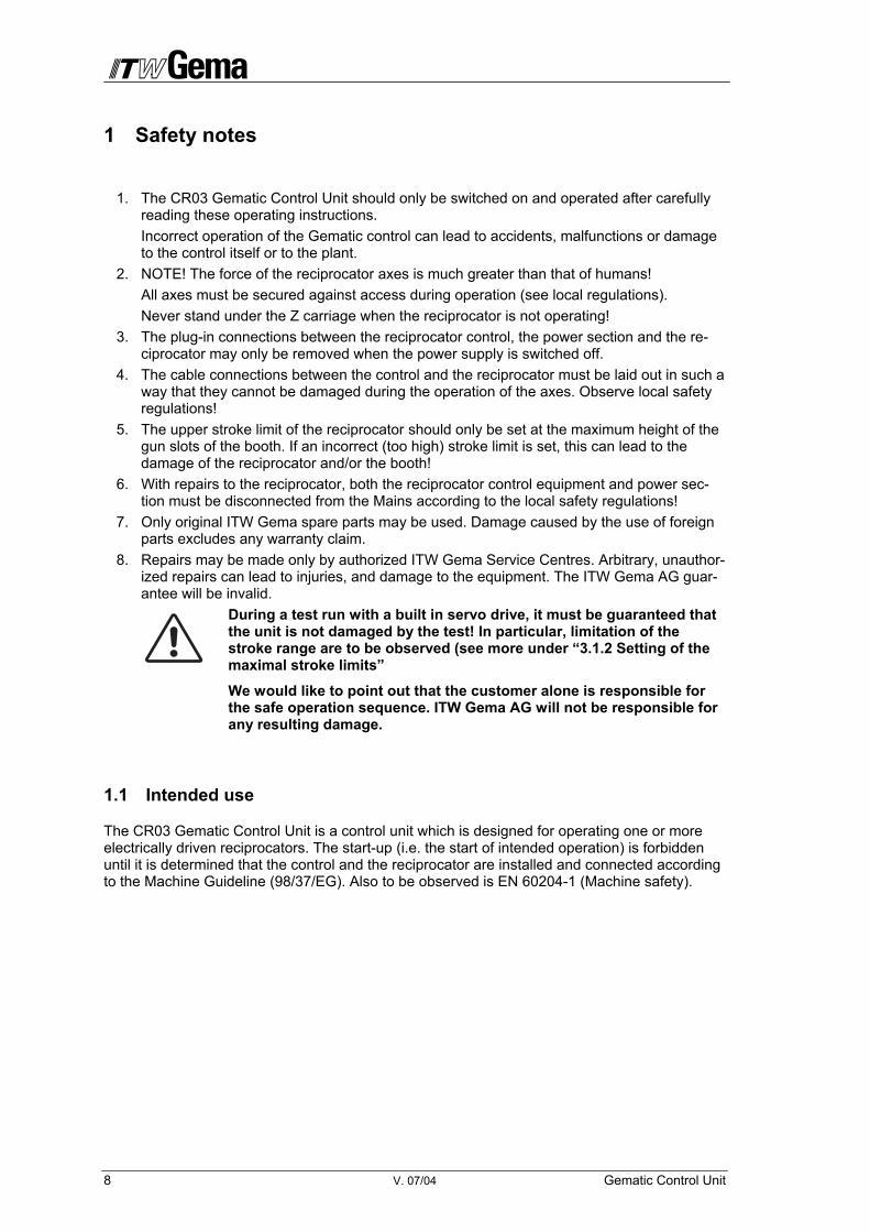
During a test run with a built in servo drive, it must be guaranteed that the unit is not damaged by the test! In particular, limitation of the stroke range are to be observed (see more under “3.1.2 Setting of the maximal stroke limits”
We would like to point out that the customer alone is responsible for the safe operation sequence. ITW Gema AG will not be responsible for any resulting damage.
1.1 Intended use
The CR03 Gematic Control Unit is a control unit which is designed for operating one or more electrically driven reciprocators. The start-up (i.e. the start of intended operation) is forbidden until it is determined that the control and the reciprocator are installed and connected according to the Machine Guideline (98/37/EG). Also to be observed is EN 60204-1 (Machine safety).

Gematic Control Unit V. 07/04 9
2 Gematic CR03 Control Unit
The Gematic CR03 Control unit is a complex control with different control functions, whereby all can be called up and released on a single operating panel. The Gematic CR03 control unit combines:
A sole reciprocator control
Program switch on gun controls OptiTronic
Expanded Control functions such as:
- Master-Functions
- Gap Control System for reciprocators and guns
- Cleaning functions for colour change systems
Booth Controls
The expanded control functions and the booth control are described in a separate documenta-tion (chapter 9-13).
2.1 Special Characteristics
Special characteristics of the CR03 control unit are:
• Connection of up to of 8 new intelligent drive regulators for positioning the axes. A number of linear axes can be controlled. The axis movements take place separately for each axis, according to a freely defined sequence chosen by the operator, whereby the dependencies of the axes of a station can be defined.
• One axis per station can be synchronized with an external pulse generator (Increment - 5 VDC). The synchronization of position, and speed takes place synchronously. The resolution of the pulse generator can be adapted.
• Programming of the axes is station oriented.
• Each axis can be positioned manually through the control panel.
• Control of the Frequency converter takes place through the CAN Bus.
• Operation of the CR03 Gematic reciprocator control unit takes place through the control panel.
• Operation of the CR03 Gematic Reciprocator control is kept independent of language largely due to the use of pictograms.
• It is possible to start other axes or to switch outputs or change the speed in certain posi-tions in an already moving axis in the Sequence program.

10 V. 07/04 Gematic Control Unit
2.2 Definition of the CR 03 Gematic Reciprocator Control Unit
Programs can be created for the Z and X axes with the CR 03 Gematic Control Unit, which re-spectively move only the corresponding axes of the station. These programs can be created simply with the necessary parameters.
• Z axes program - starts the continuous oscillating movement of the Z axis.
• X axes program - completes an advance movement of the X axis of the station.
• Special Program - starts a sequence of a number of program steps
The Gematic Control Unit can manage a number of axes, which are regulated through a fre-quency converter. This frequency converter is defined (as described in section “7.1.4 Setting the Axis address on the CAN Module”) in the CAN Network through the Node ID (Axis index or identity number).
2.3 Layout principle
Station A Station B
Servoverstärker
XT08
CAN-Bus
Modul
Kettenförderer-Drehgeber
mit Abschlußwiderstand
CR03 mit
Abschlußwiderstand
Servoverstärker
ZA02
3 4
21
Chain conveyor withTerminal resistance
CR03 with Ter-minal resistance
Servo-amplifierXT08
Servo-amplifierZA02
3
1
4
2
Gematic Control Unit V. 07/04 11
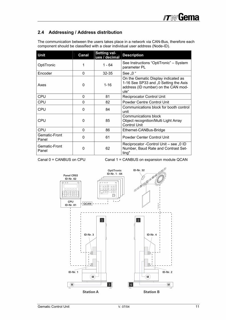
2.4 Addressing / Address distribution
The communication between the users takes place in a network via CAN-Bus, therefore each component should be classified with a clear individual user address (Node-ID).
Unit Canal Setting val-ues / decimal Description
OptiTronic 1 1 - 64 See Instructions “OptiTronic” – System parameter PL
Encoder 0 32-35 See „0 “
Axes 0 1-16
On the Gematic Display indicated as 1-16 See SP33 and „0 Setting the Axis address (ID number) on the CAN mod-ule“
CPU 0 81 Reciprocator Control Unit CPU 0 82 Powder Centre Control Unit
CPU 0 84 Communications block for booth control unit
CPU 0 85 Communications block Object recognition/Multi Light Array Control Unit
CPU 0 86 Ethernet-CANBus-Bridge Gematic-Front Panel 0 61 Powder Center Control Unit
Gematic-Front Panel 0 62
Reciprocator -Control Unit – see „0 ID Number, Baud Rate and Contrast Set-ting"
Canal 0 = CANBUS on CPU Canal 1 = CANBUS on expansion module QCAN
Station A Station B
ID-Nr. 3
CPU
ID-Nr. 81
OptiTronic
ID-Nr. 1 - 64
ID-Nr. 4
ID-Nr. 32
ID-Nr. 1 ID-Nr. 2
3 4
21
Panel CR03
ID-Nr. 62
QCAN
12 V. 07/04 Gematic Control Unit
3 Start-up
3.1 Preparation to the Start-up
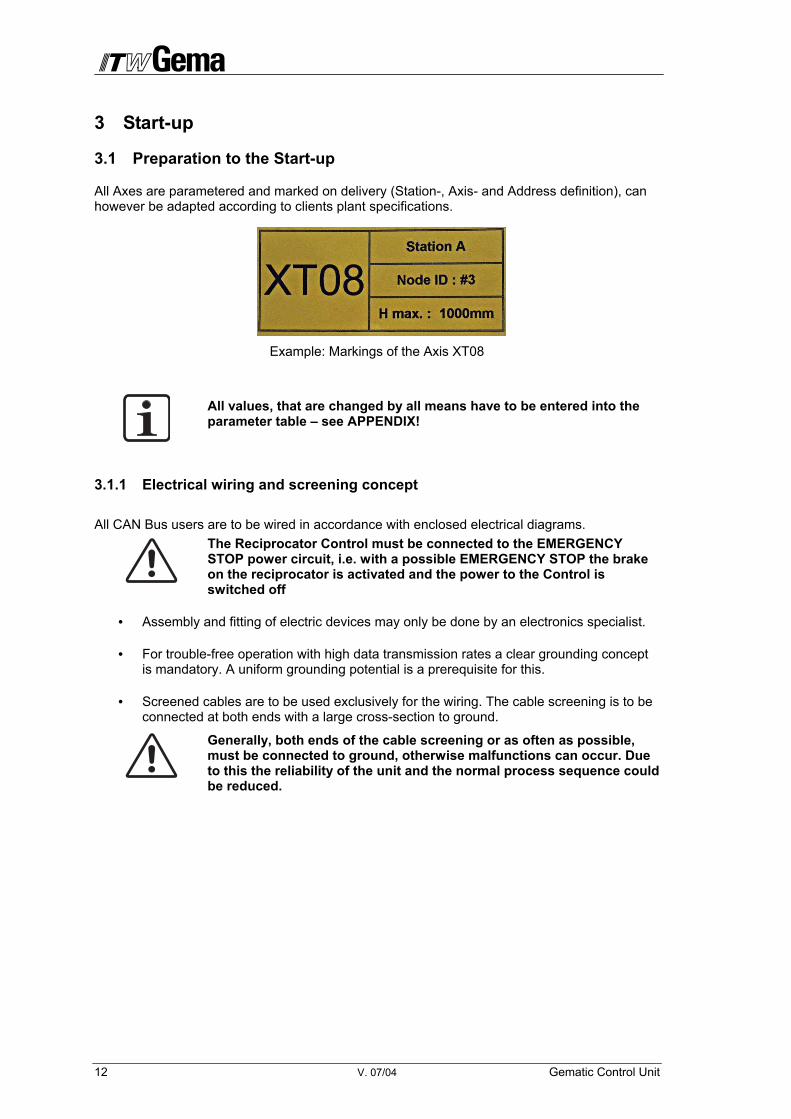
All Axes are parametered and marked on delivery (Station-, Axis- and Address definition), can however be adapted according to clients plant specifications.
Example: Markings of the Axis XT08
All values, that are changed by all means have to be entered into the parameter table – see APPENDIX!
3.1.1 Electrical wiring and screening concept
All CAN Bus users are to be wired in accordance with enclosed electrical diagrams. The Reciprocator Control must be connected to the EMERGENCY STOP power circuit, i.e. with a possible EMERGENCY STOP the brake on the reciprocator is activated and the power to the Control is switched off
• Assembly and fitting of electric devices may only be done by an electronics specialist.
• For trouble-free operation with high data transmission rates a clear grounding concept is mandatory. A uniform grounding potential is a prerequisite for this.
• Screened cables are to be used exclusively for the wiring. The cable screening is to be connected at both ends with a large cross-section to ground.
Generally, both ends of the cable screening or as often as possible, must be connected to ground, otherwise malfunctions can occur. Due to this the reliability of the unit and the normal process sequence could be reduced.

Gematic Control Unit V. 07/04 13
3.1.2 Setting the maximum stroke limits
After the mechanical and electrical installation the maximum stroke limits have to be set, this means that the axes have to be adapted to the plant.
The maximal stroke limit is set at a minimum value in production.
The maximum stroke limit is set using the operating panel. The operat-ing mode can only be reached by using a password. During the setting of the parameters the axes are not connected. After ending the operat-ing mode Service, a re-start of the Software has to be made!
1. Switch-on the Gematic Control Unit After switching on, the basic menu is shown on the display. The symbol shows, that the reference point path has not yet been carried out. The LEDs of all connected and applied axes (A1 ...) are blinking.
Should an error message appear on the display or the start display not appear after start up, please consult the chapter „Troubleshooting“!
2. Press key F5 for approx. 5 seconds, until the mask requesting the password is shown.
????

14 V. 07/04 Gematic Control Unit
3. Enter the four digit user password using the keypad and confirm with the
ENTER key . The Service mask is shown. Should the correct four digit number code not be entered, no access is given to the pa-rameters of the Gematic Control Unit.
4. Press F2 key . The mask „Parameter: Axis 1“ is shown. LED A1 lights up
5. Press ENTER key . The input field is darkly marked.
6. Enter the plant specific values using the keypad. The initial point is the reference point with the path position 0. Should an incorrect value be entered, the same can be deleted using the DELETE-Key
.
Always pay attention to the gun positions and the maximum height of the gun slits in the booth. Should a wrong (too high) stroke limit be set, this could damage the reciprocator and/or the booth!
7. Press ENTER key , to confirm the entry.
8. Press A2 key , to choose the next axis and to enter the value for the maximum stroke limit. The mask „Parameter: Axes 2“ is shown. LED A2 lights up.
9. The process above applies in the same way for further axis.
10. Press the ESCAPE key 2 X , to leave the service mask.
11. Re-starting the control unit. After switching on, the basic menu is shown on the display. The symbol shows, that the reference point path has not yet been run. The LEDs of all connected and applied axis (A1 ...) are blinking
12. Release the reference point travel. (see chapter 5.1 Reference operation)
Parameter: Axis 1
SP30 maximum position (mm): 800
Gematic Control Unit V. 07/04 15
4 Operating unit
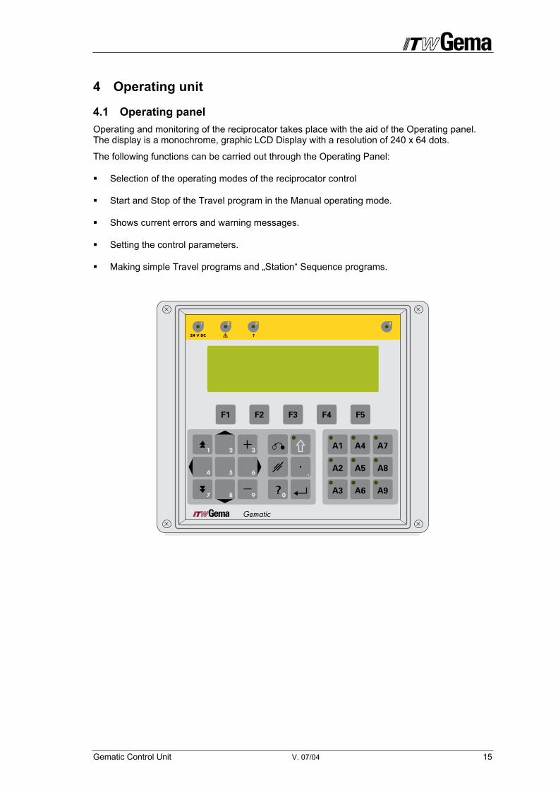
4.1 Operating panel Operating and monitoring of the reciprocator takes place with the aid of the Operating panel. The display is a monochrome, graphic LCD Display with a resolution of 240 x 64 dots.
The following functions can be carried out through the Operating Panel:
Selection of the operating modes of the reciprocator control
Start and Stop of the Travel program in the Manual operating mode.
Shows current errors and warning messages.
Setting the control parameters.
Making simple Travel programs and „Station“ Sequence programs.

16 V. 07/04 Gematic Control Unit
4.2 Special key functions
The keys of the input field should only be pressed with fingertips and under no circumstances with fingernails or hard objects!
Function keys F1 - F5 The function keys serve to carry out operating modes and menu dependent functions. The corresponding functions are displayed in the lower part of the LCD display.
Keys for Axis selection A1 - A8 These keys serve to select the axes or station. In general, after pressing a key, information is displayed about the corresponding axis or station. In axis related menus such as Axis pa-rameters the keys serve to select or deselect the axis. In operating mode, such as Manual or Automatic, the keys serve to select or deselect the axes. In order to select or deselect an axis the corresponding key must be pressed for longer than 1 second. The axis condition is displayed by the corresponding LED. Keys pressed for less than 1 second serve to switch from one axis to the other.
• A9 (Option: when OptiTronic is controlled by CAN bus) This key serves to switch the OptiTronic gun controls connected to the CAN Bus on or off. The desired program number, which is to be activated on the OptiTronic, can be prese-lected on the Gematic Reciprocator Control. The key must be pushed for longer than 1 second. The key diode illuminates.
SHIFT key This key serves to switch the keyboard between the normal and the numeric keyboard. Each time the key is pressed it is switched backwards and forwards between these states. The LED in the SHIFT key illuminates when the second function is active.
Cursor keys and Switching between the input fields can be done with these keys. The values can be browsed through when Input is active.
Numeric keys (Second function) The numeric keys serve to input values in the corresponding input fields in connection with the preceding sign (+ or -) keys and the decimal point.
DELETE key The input field is deleted with this key
ENTER key The input window is opened or the input value is saved in the memory with this key.
ESCAPE key This key closes the current display and switches to the previously opened window or closes the input without saving the values when the input was opened with Enter
HELP key By pressing this key, errors at the OptiTronic controls can be acknowledged, or the ac-knowledged error messages at the Gematic control be shown (as long as the error was not acknowledged).
Gematic Control Unit V. 07/04 17
4.3 LED Display Functions
SHIFT key LED This LED indicates the keyboard assignment. The LED is illuminated when the second func-tion is active; it remains dark by normal keyboard assignment. Numeric values can be input with an active SHIFT key.
Green LED – Axis keys A1-A8
This LED indicates three axis conditions: - LED blinking = Axis selected, that is, the axis is selected and the
Frequency converter is in Standby mode. - LED illuminated = Axis running, that is, the corresponding axis is moving. - LED extinguished = Axis deselected Green LED – Key A9 (Option: when OptiTronic is controlled by CAN bus) This LED indicates the condition of the OptiTronic Powder Gun Control: - LED illuminated = OptiTronic activated, guns spraying powder - LED extinguished = OptiTronic deactivated - LED blinking = OptiTronic controls are selected and can be switched on by the
F1 key
Red LED - Axis keys A1-A8 This LED indicates a fault in the axis.
LED No. 1 24 VDC This LED is statically controlled and indicates that the Panel is switched on and is con-nected with the PLC.
LED No. 2 Fault This LED serves the general display of a fault condition. If the fault is corrected or ac-knowledged, the LED is extinguished. After the Gematic Reciprocator Control is switched on the LED is illuminated immediately and is extinguished only after a Reference travel has been carried out.
LED No. 3 Help? This LED is activated when the operator calls up a Help text by pressing the Help key. With the return to a normal display condition the LED is extinguished again.
LED No. 4 Green (upper right) This LED indicates that the axes are ready for operation, that is, the position is regulated and the brakes are released
18 V. 07/04 Gematic Control Unit
5 Operating modes
The following operating modes can be selected on the Gematic Reciprocator Control:
• Reference point travel
• Manual operation
• Editor for Travel program
• Service / Set-up / Parametry for approx. 5 seconds
• Automatic operation (activated by corresponding parameter settings, see Appendix C)
The operation level of the Gematic Reciprocator Control is set out with Pictograms so that only the really essential parameters are displayed and the operator can therefore reach his solution quickly.
Basically, the control is in the Reference operating mode after switching on or after a restart. The operating modes are selected on the Panel. Switching only takes place when it is possible in the presently active operating mode, e.g. when the automatic operation program has termi-nated. Basically, mode changes are only possible when the axes are at a standstill.
The Axis movements can be stopped independent of the operating mode. There are two possi-ble types of Stop:
• Immediate stop (by Emergency Stop key)
• Stop with program abort by F2 key - that means, at the next start the program starts again from the beginning
Program 64 for Z axes or program 164 for X axes is called up, if a negative flank is detected at IN10.
The reciprocator control can be in only one operating mode. This operating mode applies to all axes, which are controlled by the reciprocator.
Die Steuerung kann sich nur in einer Betriebsart befinden. Diese Betriebsart gilt für alle Achsen, die von der Steuerung gesteuert werden.
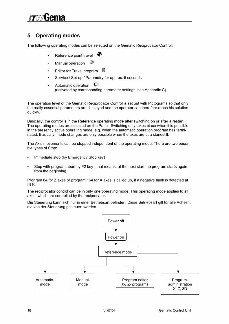
Power off
Power on
Reference mode
Automatic-mode
Manual-mode
Program editorX-/ Z- programs
Program-administration
X, Z, 3D
Gematic Control Unit V. 07/04 19
A
Reference operation mode
So that the CR03 Gematic Reciprocator Control can enter the position of each individual axis as accurately as possible during operation, all triggered axes must first travel to the Reference point each time they are switching on. The prerequisite for this is that the Reference point is already set correctly - see also the corresponding instructions in the respective axes operating instructions.
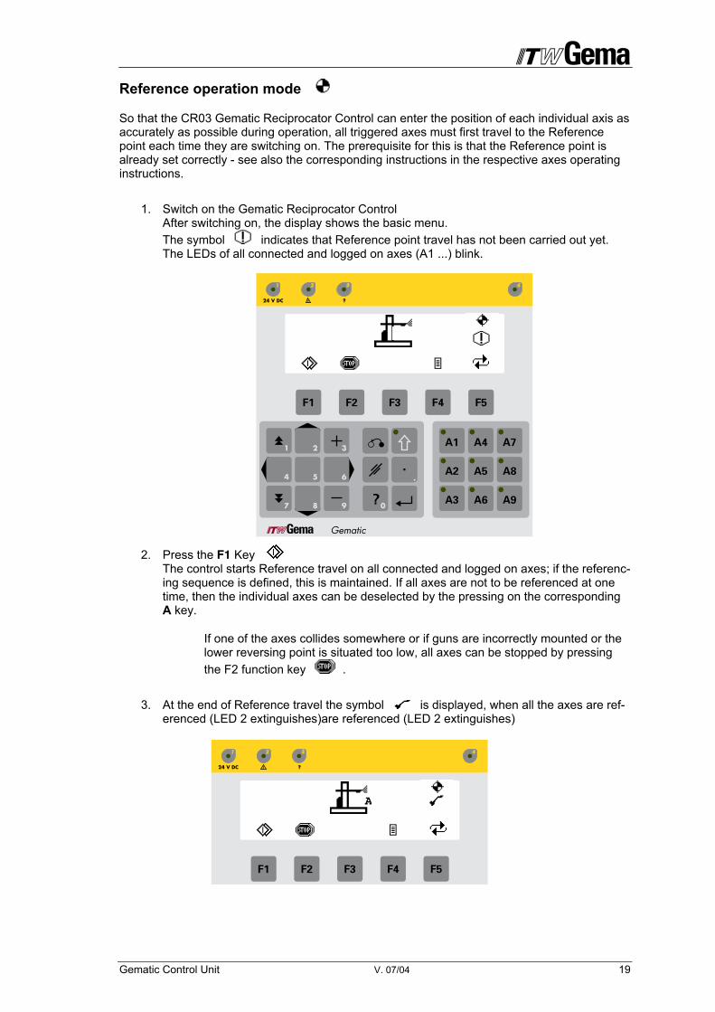
1. Switch on the Gematic Reciprocator Control After switching on, the display shows the basic menu. The symbol indicates that Reference point travel has not been carried out yet. The LEDs of all connected and logged on axes (A1 ...) blink.
2. Press the F1 Key The control starts Reference travel on all connected and logged on axes; if the referenc-ing sequence is defined, this is maintained. If all axes are not to be referenced at one time, then the individual axes can be deselected by the pressing on the corresponding A key.
If one of the axes collides somewhere or if guns are incorrectly mounted or the lower reversing point is situated too low, all axes can be stopped by pressing the F2 function key .
3. At the end of Reference travel the symbol is displayed, when all the axes are ref-erenced (LED 2 extinguishes)are referenced (LED 2 extinguishes)
A

20 V. 07/04 Gematic Control Unit
5.2 Manual operation mode
Manual operation permits the selection and start of the travel program by the operator on the Panel. In addition, the operator has the possibility to change the program number or directly modify the running Z, X or 3D program.
In this operating mode individual axes can be selected or deselected with the help of the Axis selection key A. Each axis must, however, already be defined in the Axis definition (see section "Axis Parameter" ) with its own CAN Bus Axis address.
1. Initiate reference point travel (see section 3.6 Reference Operation) The following message appears on the display at an attempt to select the manual op-eration without previously referencing the axes:
NOTE! Reference not set
2. Press the F5 key several times, until the symbol for manual operation ap-pears on the display.
3. Press the ENTER key The display changes to the „Manual operation“ mask.
• Indicates the current operating mode
• A Current station
• 3 Current Z program number (1...100) or Current 3D Program number (201... 255)
• 101 Current X Program number (101... 200)
A
3
101
A1
Gematic Control Unit V. 07/04 21
• ... 1 Current program number of the OptiTronic Powder Gun Con-trol (optional function). By pressing the key A9, the third imput field is highlighted. By entering the program number, all programs of the OptiTronic controls will be switched on the selected station. The key di-ode illuminates.
• . F1 Key: Starts all selected axes and by repeated pressing of the F1 key, the OptiTronic gun controls are started
• F2 Key: Stops all axes and the OptiTronic gun controls
• Axis keys A1-A … LEDs of the logged on and selected axes blink
• Pressing the F4 key briefly: Opens the Program Editor with the program number in the selected field . Pressing F4 key for 1 second: Opens the Program Editor for Travel programs (see Section 5.4 Editor for Travel Programs)
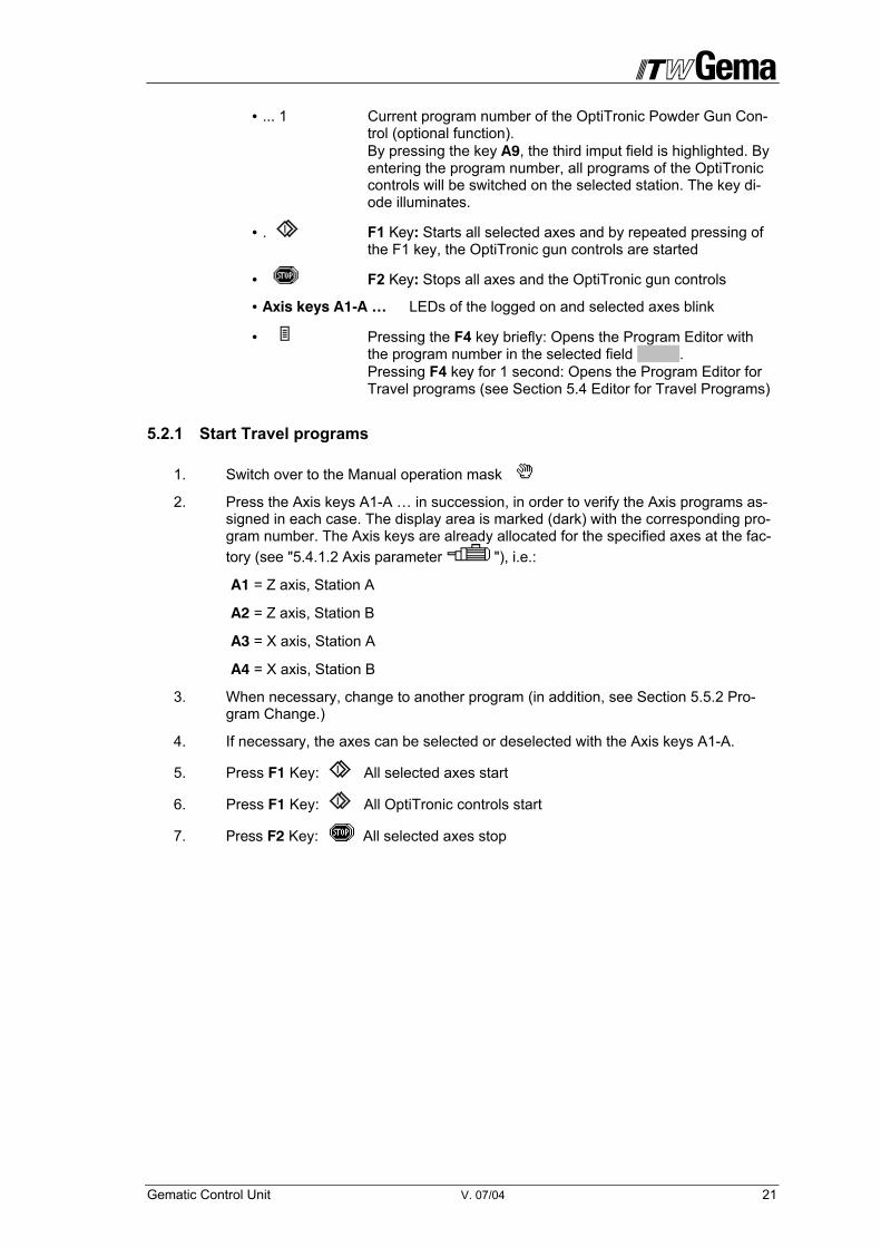
5.2.1 Start Travel programs
1. Switch over to the Manual operation mask 2. Press the Axis keys A1-A … in succession, in order to verify the Axis programs as-
signed in each case. The display area is marked (dark) with the corresponding pro-gram number. The Axis keys are already allocated for the specified axes at the fac-tory (see "5.4.1.2 Axis parameter "), i.e.:
A1 = Z axis, Station A
A2 = Z axis, Station B
A3 = X axis, Station A
A4 = X axis, Station B
3. When necessary, change to another program (in addition, see Section 5.5.2 Pro-gram Change.)
4. If necessary, the axes can be selected or deselected with the Axis keys A1-A.
5. Press F1 Key: All selected axes start
6. Press F1 Key: All OptiTronic controls start
7. Press F2 Key: All selected axes stop
22 V. 07/04 Gematic Control Unit
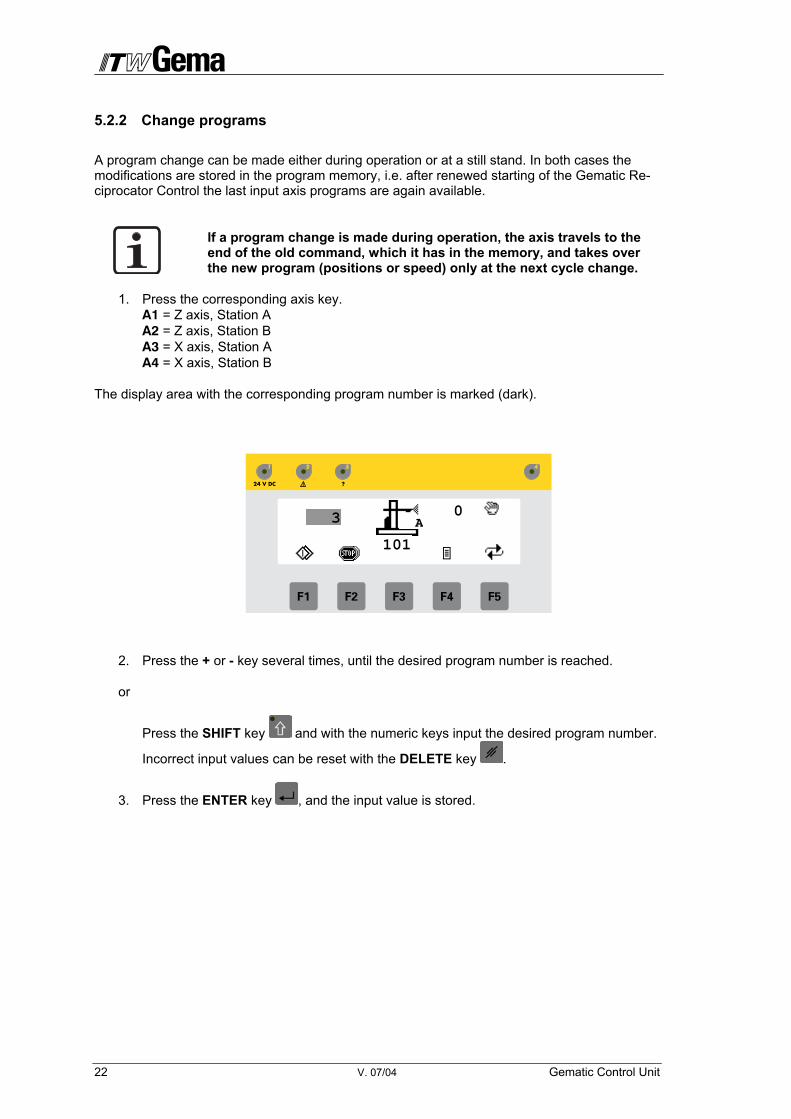
5.2.2 Change programs
A program change can be made either during operation or at a still stand. In both cases the modifications are stored in the program memory, i.e. after renewed starting of the Gematic Re-ciprocator Control the last input axis programs are again available.
If a program change is made during operation, the axis travels to the end of the old command, which it has in the memory, and takes over the new program (positions or speed) only at the next cycle change.
1. Press the corresponding axis key. A1 = Z axis, Station A A2 = Z axis, Station B A3 = X axis, Station A A4 = X axis, Station B
The display area with the corresponding program number is marked (dark).
2. Press the + or - key several times, until the desired program number is reached.
or
Press the SHIFT key and with the numeric keys input the desired program number.
Incorrect input values can be reset with the DELETE key .
3. Press the ENTER key , and the input value is stored.
3
101
A0

Gematic Control Unit V. 07/04 23
5.2.3 Edit programs
Both the Z or X axis programs can be edited during operation and also at a still stand. The modifications in both cases are stored in the program memory, i.e. after renewed starting of the Gematic Reciprocator Control the last input program values are again available.
Special programs, which contain the program steps for both axes (Z, and X) and which have an effect on both axes can also edited.
If a program is edited during operation, the axis runs until the old command, which is still in the memory, is finished and takes over the new program values (positions or speed) only with the next cycle change.
1. Press the corresponding Axis key. A1 = Z axis, Station A A2 = Z axis, Station B A3 = X axis, Station A A4 = X axis, Station B The display area with the corresponding program number is marked (dark)
2. Press the F4 key briefly. The online Program Editor for the selected field is opened with corresponding parameters, which can be edited - the Z axis editor for Z axes and the X axis editor for X axes.
5.2.3.1 Online Program Editor for Z Axes-Programs
• Upper position in mm
• Lower position in mm
• F Speed of the axis in mm/s
• A-Z Axis designation and allocation in the station
• 3 Active program number (see also section 5.4 „Travel program Editor“)
• Key F1 The selected axis starts
• Key F2 The selected axis stops
F
A-Z1050 mm
10 mm350 mm/s
3
24 V. 07/04 Gematic Control Unit
• Key The axis, which was selected with the keys A1-A8, travel in a positive direction
• Key The axis, which was selected with the keys A1-A8, travel in a negative direction
If the input field for Position is active, the actual position is displayed
when pressing the or key. If the ENTER key is pressed after-wards, the displayed value is accepted.
1. Switching between the input fields is done with the Cursor keys and . The selected input field is marked (dark).
2. Keep the + or – key pressed until the desired value is reached. or
Press the SHIFT key and input the desired value with the numeric keys.
An incorrect input value can be reset with the DELETE key . or
Keep the or key pressed until the desired position is reached.
If the same value is selected for the input of the upper and lower posi-tions, this results in a positioning command, i.e. the axis stops in this position.
3. Press ENTER key and the input value is stored.
4. Press the ESCAPE key in order to return to the Manual operation mask.
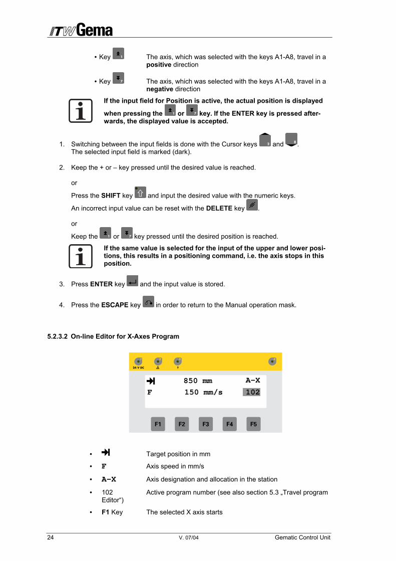
5.2.3.2 On-line Editor for X-Axes Program
• Target position in mm
• F Axis speed in mm/s
• A-X Axis designation and allocation in the station
• 102 Active program number (see also section 5.3 „Travel program Editor“)
• F1 Key The selected X axis starts
102F
A-X850 mm
150 mm/s
Gematic Control Unit V. 07/04 25
• F2 Key The selected X axis stops
• Key The axis, which was selected with the keys A1-A8, travel in a positive direction
• Key The axis, which was selected with the keys A1-A8, travel in a negative direction
If the input field for Position is active, pressing the or key will display the actual position. If the ENTER key is pressed afterwards, the displayed value is accepted.
1. Switching between the input fields is done with Cursor keys and . The selected input field is marked (dark).
2. Keep the + or - key pressed until the desired value is reached. or
Press the SHIFT key and input the desired value with the numeric keys.
An incorrect input value can be reset with the DELETE key . or
Keep or key pressed until the desired position is reached.
3. Press the ENTER key and the input value is stored.
4. Press the ESCAPE key in order to return to the manual operation mask.

26 V. 07/04 Gematic Control Unit
5.3 Program Editor for Travel programs
If the F4 key is pressed for 2 seconds in one of the operating masks, the Editor for the Travel program, with corresponding options, is opened automatically.
• Opens a menu for the selection of all stored programs from the list in order to work an existing program (see below).
• Opens the menu for preparing a new program (see below).
• Opens the dialogue for resetting a stored program. It opens the selection menu for selecting all stored programs (see be-low).
• 0 Input field for program number
If a program number other than „0" is displayed in the input field, then the program displayed is opened directly by pressings the F1 key.
• Number keys Direct input of the program number with active SHIFT key.
• Closes the Program Editor program and returns to the Opera-tion mask
0

Gematic Control Unit V. 07/04 27
5.3.1 Working with existing programs
All programs stored in the PLC are set out in a list in the Program selection menu. In addition to the program numbers are more data representing program type (X, Z, Special program), pro-gram length and memory size.
1. Call up the Editor for Travel programs
2. Press the F1 key when the program number 0 is displayed in the input field) A menu for selection from the list of all stored programs is opened in order to work an ex-isting program.
• Program type Z = Z-axis program, X = X axis program and 3D = Special program
• 1 one to three-figure program number
• SIZE Length of the program in program lines
• SEG The programs are stored into memory blocks to 256 program lines. Several programs are stored in a block. The index of the memory area is represented here.
• 327: Indicates how many program lines are placed in the memory block in total.
3. The list can be browsed through with the Cursor keys and . If the list is longer than 6 programs the display is scrolled. The selected program is marked (dark) or
Press the SHIFT key and input the desired value through the numeric keys. The program in the menu is displayed with the input of a three-figure number. All pro-grams are displayed with the input of „000“. All programs with the number 0xx are dis-played with the input of „0", and all programs starting with 12x etc are displayed with the input of „12...“. Thus a selection can be carried out according to the program number.
4. Press the ENTER key . The corresponding Program Editor (Z, X or 3D) is opened.
5. Edit the program (see also section 5.2.3 Edit programs)
6. Press ESCAPE key in order to exit the Program Editor mask.
Z 2 SIZE: 2 SEG: 0 Z 6 SIZE: 2 SEG: 0 Z 7 SIZE: 2 SEG: 0 Z 8 SIZE: 2 SEG: 0
327
Z 1 SIZE: 2 SEG: 0
28 V. 07/04 Gematic Control Unit
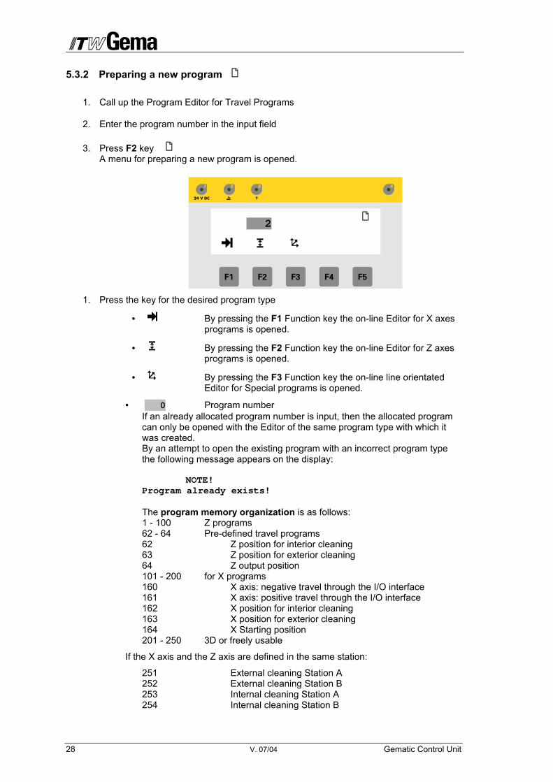
5.3.2 Preparing a new program
1. Call up the Program Editor for Travel Programs
2. Enter the program number in the input field
3. Press F2 key A menu for preparing a new program is opened.
1. Press the key for the desired program type
• By pressing the F1 Function key the on-line Editor for X axes programs is opened.
• By pressing the F2 Function key the on-line Editor for Z axes programs is opened.
• By pressing the F3 Function key the on-line line orientated Editor for Special programs is opened.
• 0 Program number If an already allocated program number is input, then the allocated program can only be opened with the Editor of the same program type with which it was created. By an attempt to open the existing program with an incorrect program type the following message appears on the display: NOTE! Program already exists! The program memory organization is as follows: 1 - 100 Z programs 62 - 64 Pre-defined travel programs 62 Z position for interior cleaning 63 Z position for exterior cleaning 64 Z output position 101 - 200 for X programs 160 X axis: negative travel through the I/O interface 161 X axis: positive travel through the I/O interface 162 X position for interior cleaning 163 X position for exterior cleaning 164 X Starting position 201 - 250 3D or freely usable
If the X axis and the Z axis are defined in the same station:
251 External cleaning Station A 252 External cleaning Station B 253 Internal cleaning Station A 254 Internal cleaning Station B
2

Gematic Control Unit V. 07/04 29
Programs 64 and 164, in connection with a PLC, are called up through the program number 0 or through a negative flank at the input IN10
5.3.2.1 Editor for Z-Axis Programs
The keyboard functions are identical to the Online Program Editor (see section 5.2.3.1). The program is stored on exiting the menu.
Standard values serve as default values; the input values for position above, below and speed are checked for their maximum values, which were defined in the Axis parameters (see section 5.4.1.2 Axis parameters )
5.3.2.2 Editor for X-Axis Programs (101 – 200)
The keyboard functions are identical to the Online Program Editor (see section 5.2.3.2). The program is stored on exiting the menu.
Standard values serve as default values; the input values for position and speed are checked for their maximum values, which were defined in the Axis parameters
5.3.3 Delete Programs
1. Call up the Program Editor for Travel programs (keep F4 key pressed for 1 second in the main menu)
2. Press the F3 key A menu for selection from the list of all saved programs is opened in order to delete an existing program. When a program number has already been entered, the program can be deleted directly.
• Program type „Z"= Z Axes program, „X"= X Axes program and
„3D"=Special program
Z 5 SIZE: 2 SEG: 0 Z 6 SIZE: 2 SEG: 0 Z 7 SIZE: 2 SEG: 0 Z 8 SIZE: 2 SEG: 0
323
Z 4 SIZE: 2 SEG: 0
0
30 V. 07/04 Gematic Control Unit
• 1 One to three-figure program number
• SIZE Length of the program in program lines
• SEG The programs are stored in memory blocks of 256 program lines. Several programs are stored in a block. The index of the memory block is displayed here.
• 323: Indicates how many program lines are occupied in the mem-ory block in total.
• This mask is exited by pressing the ESCAPE key.
3. The list can be browsed through with the Cursor keys and . If the list is longer than 6 programs the representation is scrolled. The selected program is marked (dark). OR
Press the SHIFT key and input the desired value with the numeric keys. The program is displayed in the menu with the input of a three-figure number. All pro-grams are displayed with the input of „000". All programs with the number 0xx are dis-played with „0 ", and with the input of “12”, all programs that start with 12x etc. A selection can be carried out according to the program number.
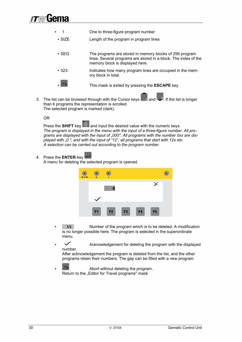
4. Press the ENTER-key A menu for deleting the selected program is opened.
• 55 Number of the program which is to be deleted. A modification is no longer possible here. The program is selected in the superordinate menu.
• Acknowledgement for deleting the program with the displayed number. After acknowledgement the program is deleted from the list, and the other programs retain their numbers. The gap can be filled with a new program
• Abort without deleting the program. Return to the „Editor for Travel programs" mask
4

Gematic Control Unit V. 07/04 31
5.4 Service
All parameters necessary for operation can be input in the Service operating mode. All parame-ters are summarized in a list according to their importance. These lists are attainable in sub-menus. These are:
• Global parameters = System parameter of the plant, (F1 key)
• Axis parameter = Basic parameter of the axes, (F2 key)
• Station parameter (optional visible) = Definition of the stations (reciprocators), (F3 key)
• Gap control (optional visible), (F4 key)
• Booth control (optional visible), (F5 key) The programming of the parameters or programs is done through the operating panel. The operating mode is selected through a password only. During programming and Para metering triggering of the axes does not take place. After terminating the Service operating mode a re-start of the software must take place, if necessary!
1. F2 key: press in order to stop all running axes
2. Press the F5 key for approximately 5 seconds, until the password mask is displayed. The following message appears on the display at an attempt to switch over to service operation without having stopped the axes beforehand:
NOTE! Axes are still running!
3. Input a four-digit user password through the numeric keys and acknowledge with the
ENTER key . The service mask is displayed. Access to the parameter data of the Gematic Reciprocator is not possible without the correct input of a four-digit number code
????

32 V. 07/04 Gematic Control Unit
• Changes to the “Global parameter“ mask
• Changes to the „Axis parameter“ mask
• Terminates the „Service" operating mode and switches to the base menu
5.4.1 Parameter Setting
The Service mode is started automatically if an error occurs during boot-up or after an error message of the Service mode is selected.
The parameters of the Gematic Reciprocator are divided into equipment, axes, and station pa-rameters and summarized in corresponding parameter records. All parameter records are pro-grammed in a Parameter Program Editor.
The input of the parameters depends on the data type of the parameter. Here are the following types:
• Number The input can take place directly with the numeric keys. Cursor Up/Down increases or decreases the value set.
• Selection A selection of plain text settings for the parameters is avail-able, which can be browsed through with the Cursor keys.
• Boolean Binary settings are represented with the values TRUE/FALSE. These two values can be browsed through with the cursor keys.
The following key functions are active:
• Cursor Up/Down Browsing in parameter values when input is open or brows-ing in the parameter list. If the list is longer than 6 parame-ters, the representation is shifted upward or downwards.
• Enter Opens the input of the parameter on which the cursor is or closes the input with the value saved to memory. If numeric values are to be input in the input field the SHIFT key is automatically activated on opening Input.
• Numeric keys Serve to input of numeric values when the SHIFT key is ac-tive.
• ESC Closes the input without saving the value to memory, if Input was opened with Enter or closes the Parameter Editor if no input is active.
• A1-A8 Serves the selection of the corresponding axis or station with the open Parameter Editor. Switching between the axes or between the stations can be done with the open Parameter Editor. The corresponding LED on the keys A1-A8 is acti-vated with the selection.
• Delete Deletes the input field, i.e. a numeric parameter is set to 0 and a selection parameter on the first selection option.
• Key +/- Serves to input of the preceding sign with numeric values with a negative range of values

Gematic Control Unit V. 07/04 33
5.4.1.1 Global parameters
All Global Parameters are represented in the Service/Global Menu and can be edited by the operator. These parameters are all general definitions and settings which are relevant for the Gematic Reciprocator and connected components. These are:
Parameter: Global
SP1 Language selection : german
SP2 Firm ware Version : x.xxxxx
SP3 CAN-sender existing : FALSE
SP4 Increments per 2 Meter : 81920
SP5 Conveyor preceding sign : FALSE
SP6 Distance per pulse (mm) : 10
SP7 Maximum number of axes : 8
SP8 Maximum number of stations : 4
SP9 Maximum number of guns : XX
SP10 Extended Control function : FALSE
SP11 Common Program Number : FALSE
SP12 Booth function : FALSE
SP13 Object recognition : FALSE
SP14 Cleaning function : FALSE
SP15 Ext.Axis.Stat.Param : FALSE
SP16 PRC-Interface : FALSE
SP17 PZ existing : FALSE
SP18 Manual doors FALSE
SP19 Automatic doors FALSE
SP20 External booth FALSE
SP21 BoltDevConvBooth FALSE
SP22 ConvStopFireProt FALSE
SP23 Gun on over Seqe FALSE
SP1 Language selection
This value defines the language of the user display. The following languages can be se-lected: German, English, French, Spanish, Italian, and Portuguese.
SP2 Firmware Version
Shows the actual Software version in the equipment (display only).
SP3 Conveyor speed (mm/min)
Value for the speed of the conveyor. This value is necessary when the chain conveyor is not fitted with a pulse generator (Encoder) so that the control can calculate the correct se-quences.
SP4 Increments per 2 Meter
With this parameter the Gematic Control can count and display the pulses (increments) from the pulse generator in order to determine the relationship between the chain conveyor pulses and the distance travelled in pulses/mm. The input ist only necessary with activated synchronisation or Gap control system. At negative indication, change the preceding sign in the SP5.
SP5 Conveyor preceding sign
Adaptation of the incremental direction
34 V. 07/04 Gematic Control Unit
SP6 distance per pulse (mm)
Value for the pulse length to define the starting points using the Gap control system - see chapter „Gap Control System“
SP7 Maximum number of axes
Value for the number of available axes (1-8)
SP8 Maximum number of stations
Value for the number of definable stations (1-8)
SP9 Number of guns
Value for the number of available guns
SP10 Expanded Control function
On/Off of the expanded optional control functions in a separate parameter mask - see chap-ter 0 Gap Control System Parameter. Simultaneously the loading of the digital in- and out-puts are changed
SP11 Common Program Number
This parameter defines if only the chosen axis or all axes at all stations are switched to the same program number during a change in program. The same applies when switching the gun control OptiTronic. FALSE = for each axis a separate program number is used TRUE = the same program number is applied at all stations
Program change Z-Axes = all Z-Axes Program change X-Axes = all X-Axes Program change OptiTronic = all OptiTronic
SP12 Booth function
Activates the booth parameter, that are displayed in a separate Parameter mask
SP13 Object recognition
Activated further parameters, that are displayed in a separate Parameter mask
SP14 Cleaning function
Activates cleaning function, that can be chosen on the basic mask. To show the symbols of these, the Parameter SP10 must be set on TRUE in advance.
SP15 Expans.Axis.Param
Activates further Parameters, that enable parametering of further axes and stations. The mask with the axes parameters ist extended, and the mask „Station-Parameter“ is activated and displayed.
SP16 PRC-Interface
Activates the PRC compatible interface. The Parameter SP10 is set on FALSE.
SP17 PZ existing
If a powder center is being connected by CAN bus, this Parameter must be set on TRUE.
SP18 Manual doors
If manual doors are available, this Parameter must be set on TRUE.
SP19 Automatic doors
SP20 External booth
SP21 BoltDevConvBooth
In the manual operation mode, axes and guns can be started only if this Parameter is set on TRUE and the conveyor is running. If the conveyor stops, the axes and the guns are also stopped.
Gematic Control Unit V. 07/04 35
SP22 ConvStopFireProt
If this Parameter is set on TRUE, the control unit stops the conveyor if there is a fire protec-tion malfunction. SP23 Gun on over Seqe
Guns are started/stopped by the SetGun command in the sequence program (3D-program).
36 V. 07/04 Gematic Control Unit
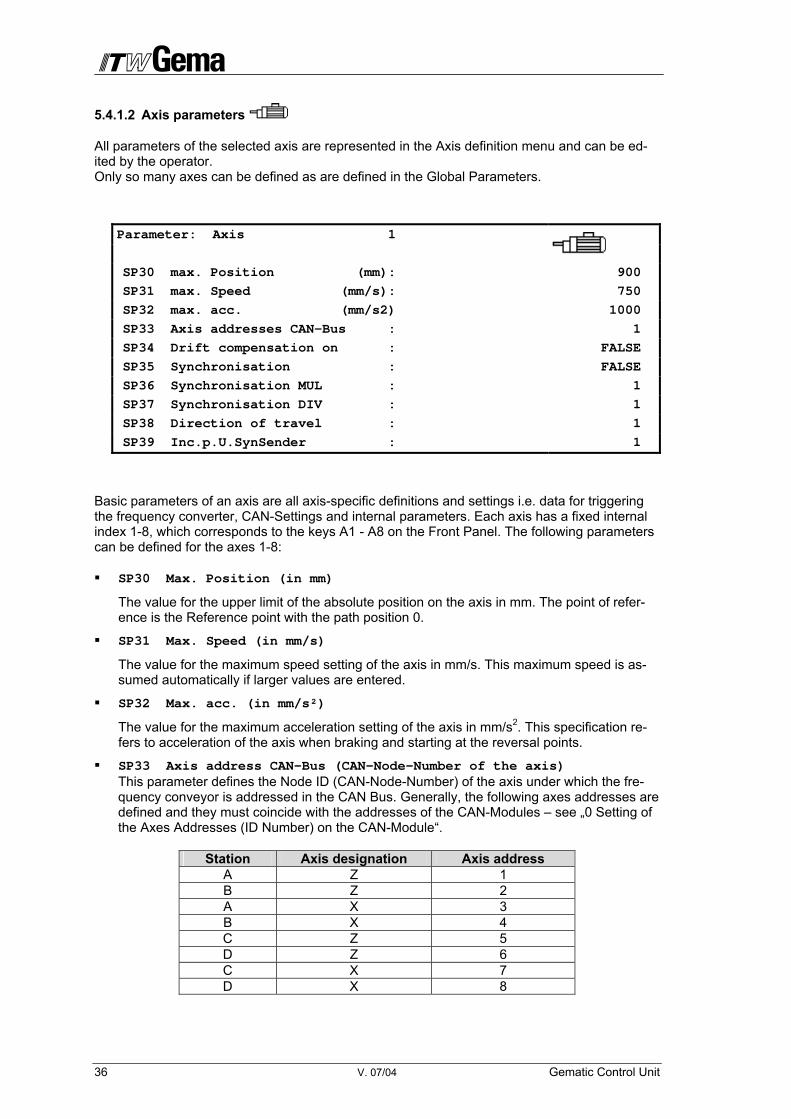
5.4.1.2 Axis parameters
All parameters of the selected axis are represented in the Axis definition menu and can be ed-ited by the operator. Only so many axes can be defined as are defined in the Global Parameters.
Parameter: Axis 1
SP30 max. Position (mm): 900
SP31 max. Speed (mm/s): 750
SP32 max. acc. (mm/s2) 1000
SP33 Axis addresses CAN-Bus : 1
SP34 Drift compensation on : FALSE
SP35 Synchronisation : FALSE
SP36 Synchronisation MUL : 1
SP37 Synchronisation DIV : 1
SP38 Direction of travel : 1
SP39 Inc.p.U.SynSender : 1
Basic parameters of an axis are all axis-specific definitions and settings i.e. data for triggering the frequency converter, CAN-Settings and internal parameters. Each axis has a fixed internal index 1-8, which corresponds to the keys A1 - A8 on the Front Panel. The following parameters can be defined for the axes 1-8:
SP30 Max. Position (in mm)
The value for the upper limit of the absolute position on the axis in mm. The point of refer-ence is the Reference point with the path position 0.
SP31 Max. Speed (in mm/s)
The value for the maximum speed setting of the axis in mm/s. This maximum speed is as-sumed automatically if larger values are entered.
SP32 Max. acc. (in mm/s²)
The value for the maximum acceleration setting of the axis in mm/s2. This specification re-fers to acceleration of the axis when braking and starting at the reversal points.
SP33 Axis address CAN-Bus (CAN-Node-Number of the axis) This parameter defines the Node ID (CAN-Node-Number) of the axis under which the fre-quency conveyor is addressed in the CAN Bus. Generally, the following axes addresses are defined and they must coincide with the addresses of the CAN-Modules – see „0 Setting of the Axes Addresses (ID Number) on the CAN-Module“.
Station Axis designation Axis address A Z 1 B Z 2 A X 3 B X 4 C Z 5 D Z 6 C X 7 D X 8

Gematic Control Unit V. 07/04 37
Not existing axes must have the address 0! The addressing has to be continuous and may not have spaces/gaps!
SP34 Drift compensation on/off
The drift compensation serves the adjustment of a Z axis speed to the drift of the chain con-veyor speed. The purpose is to maintain a certain coating speed. If the workpiece moves past the station more rapidly, the up and down movement of the powder gun must be like-wise accelerated, so that the coating thickness remains constant. This option decides whether the speed of the axis is to be adapted to that of the chain conveyor.
SP35 Synchronisation release/locked
Theoretically, each axis can be synchronized with the chain conveyor. Which axes are to be synchronized particularly, depends on this option. Practically, the Y axis of the station is synchronized with the chain conveyor in order to be able to coat the workpiece in motion. Station and workpiece form such a system with the same speed. The control of the syn-chronous movement effected through the Frequency converter, and the PLC only sets the start/end commands.
SP36 Gear factor for synchrononous travel MUL
A certain speed factor must be set for synchronizing the axis with the chain conveyor, which more or less represents a speed ratio of the pulse generator signal to the axis path. This factor is required by the Frequency converter for synchronous travel.
Example: The chain travels 500mm per rotation of the Encoder
If the Y-Axis travels in the wrong direction during a synchronous travel, then the SP36 can be entered as negative. The adaptation factor is to select in such a way that the result is not higher than 32000. The SP36 may not be entered higher than 32000.
SP37 Gear factor for synchronous travel DIV
Example:
SP38 Direction of travel Changes the direction of travel of the axes
SP39 Incr.p.U.SynSender Defines the number of pulses per rotation of the sender during synchronization. (see “Ex-panded Control Functions - Gap Control System“)
500
mm/Encoder rotation
64 *
Adaptation factor
= 32000
SP36 result
18.875621
Predefined value
64 *
Adaptation factor is the same as SP36
= 1208
SP37 result
38 V. 07/04 Gematic Control Unit
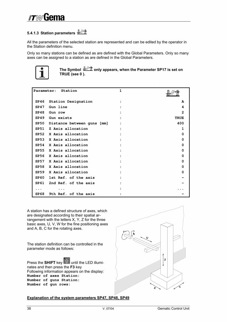
5.4.1.3 Station parameters
All the parameters of the selected station are represented and can be edited by the operator in the Station definition menu.
Only so many stations can be defined as are defined with the Global Parameters. Only so many axes can be assigned to a station as are defined in the Global Parameters.
The Symbol only appears, when the Parameter SP17 is set on TRUE (see 0 ).
Parameter: Station 1
SP46 Station Designation : A
SP47 Gun line : 4
SP48 Gun row : 2
SP49 Gun exists : TRUE
SP50 Distance between guns [mm] : 400
SP51 Z Axis allocation : 1
SP52 X Axis allocation : 0
SP53 X Axis allocation : 0
SP54 X Axis allocation : 0
SP55 X Axis allocation : 0
SP56 X Axis allocation : 0
SP57 X Axis allocation : 0
SP58 X Axis allocation : 0
SP59 X Axis allocation : 0
SP60 1st Ref. of the axis : -
SP61 2nd Ref. of the axis : -
... ... : ...
SP68 9th Ref. of the axis : -
A station has a defined structure of axes, which are designated according to their spatial ar-rangement with the letters X, Y, Z for the three basic axes, U, V, W for the fine positioning axes and A, B, C for the rotating axes.
The station definition can be controlled in the parameter mode as follows:
Press the SHIFT key until the LED illumi-nates and then press the F3 key Following information appears on the display: Number of axes Station: Number of guns Station: Number of gun rows:
Explanation of the system parameters SP47, SP48, SP49
Z
YX
U
BA
Gematic Control Unit V. 07/04 39
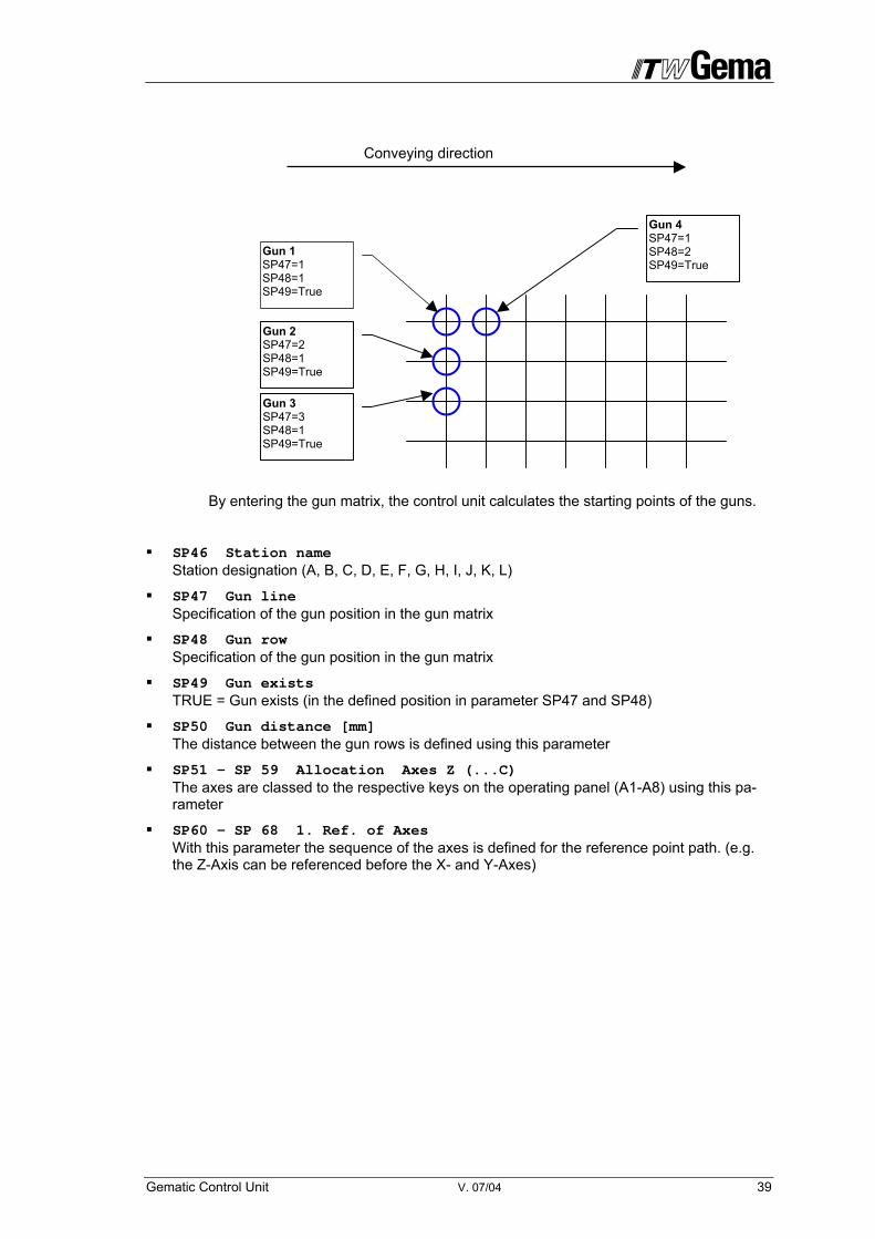
By entering the gun matrix, the control unit calculates the starting points of the guns.
SP46 Station name Station designation (A, B, C, D, E, F, G, H, I, J, K, L)
SP47 Gun line Specification of the gun position in the gun matrix
SP48 Gun row Specification of the gun position in the gun matrix
SP49 Gun exists TRUE = Gun exists (in the defined position in parameter SP47 and SP48)
SP50 Gun distance [mm] The distance between the gun rows is defined using this parameter
SP51 - SP 59 Allocation Axes Z (...C) The axes are classed to the respective keys on the operating panel (A1-A8) using this pa-rameter
SP60 - SP 68 1. Ref. of Axes With this parameter the sequence of the axes is defined for the reference point path. (e.g. the Z-Axis can be referenced before the X- and Y-Axes)
Gun 1 SP47=1 SP48=1 SP49=True
Gun 2 SP47=2 SP48=1 SP49=True
Gun 3 SP47=3 SP48=1 SP49=True
Gun 4 SP47=1 SP48=2 SP49=True
Conveying direction

40 V. 07/04 Gematic Control Unit
6 Control function "Program Change on the OptiTronic"
With this function the program switch and the ON/OFF of the gun controls can be easily and quickly made on the Gematic-Operating Panel. Following conditions have to prevail:
- The gun controls OptiTronic must be equipped with CAN-Bus
- Correct addressing of the OptiTronic - see Manual OptiTronic, System parameter PL
- Correct setting of the parameters on the Gematic-Control: - SP11 = TRUE, Program changeover is done collectively on all OptiTronic - SP11 = FALSE, SP9 (Max. no. of guns) and SP47-49, Program changeover is done per station
6.1.1 Switching programs
1. Start-up the Gematic control The display shows the mask for program change. The LED A9 blinks
2. Press the key A1 , when programs for the pistols at station A have to be switched. For Station B press key A2
3. Press the key A9 The display field with the respective program number is highlighted
4. Press keys + or – until the required program number is reached or
Press SHIFT key and enter the program number using the numeric keys
Incorrect entries and be deleted using the DELETE key
5. Press the ENTER key , and the entered value is saved
6. Press key F1 . All OptiTronic Controls are switched on, and the pistols begin to spray. The LED A9 lights up continuously
7. Press key F2 . All OptiTronic Controls are switched of. The LED A9 blinks
A 64

Gematic Control Unit V. 07/04 41
7 Messages
7.1 Error messages
Errors which can be identified by the PLC are displayed at the Panel and must be acknowl-edged by the operator. Depending on the error the processing sequence is terminated or con-tinued without interruption.
01 CANBus CDD control 02 General error 03 Parameter error 04 Progress program 05 CAN error 06 Error message CDD 20 Reference not set! 21 No axis defined! 22 No station defined! 23 Program not found! 24 Please restart control! 25 Please enter password! 26 Password is false! 27 Axes are still running! 28 Password is incorrect! 29 Axis not free! 30 Program already exists! 31 Program does not exist!
Axes control
32 Powder hopper 1 empty 33 Powder hopper 2 empty 34 Wrong program type 35 General motor protection 36 Fire protection 37 Cabinet temperature 38 Earth protection 39 40 No powder in powder center 41 Powder center wrong mode 42 Powder center not ready 43 Door open 44 Thermo monitoring ventilator 45 Ventilator 1 low pressure 46 Ventilator 1 high pressure 47 Ventilator 2 low pressure 48 Ventilator 2 high pressure 49 Funnel open 50 Cyclone open 51 Squeegee malfunction 52 Booth not ready 54 Door not open 55 AZO-Sieve-Cover open 56 OptiTronic error 57 Air pressure error 58 CANBUS Encoder error
with booth
42 V. 07/04 Gematic Control Unit
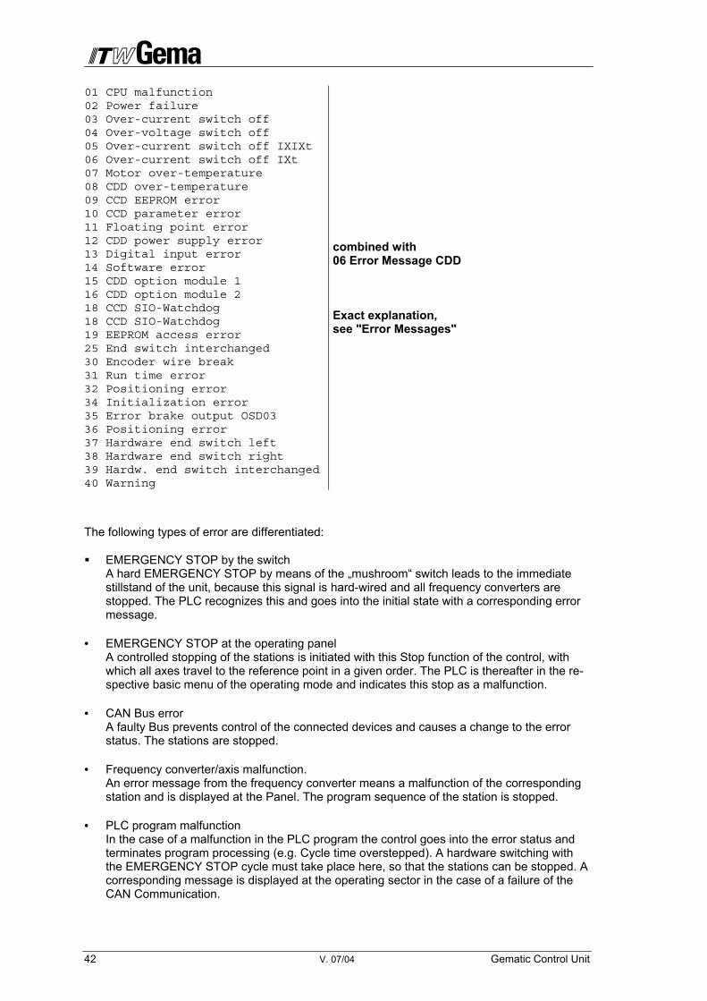
01 CPU malfunction 02 Power failure 03 Over-current switch off 04 Over-voltage switch off 05 Over-current switch off IXIXt 06 Over-current switch off IXt 07 Motor over-temperature 08 CDD over-temperature 09 CCD EEPROM error 10 CCD parameter error 11 Floating point error 12 CDD power supply error 13 Digital input error 14 Software error 15 CDD option module 1 16 CDD option module 2 18 CCD SIO-Watchdog 18 CCD SIO-Watchdog 19 EEPROM access error 25 End switch interchanged 30 Encoder wire break 31 Run time error 32 Positioning error 34 Initialization error 35 Error brake output OSD03 36 Positioning error 37 Hardware end switch left 38 Hardware end switch right 39 Hardw. end switch interchanged 40 Warning
combined with 06 Error Message CDD Exact explanation, see "Error Messages"
The following types of error are differentiated:
EMERGENCY STOP by the switch A hard EMERGENCY STOP by means of the „mushroom“ switch leads to the immediate stillstand of the unit, because this signal is hard-wired and all frequency converters are stopped. The PLC recognizes this and goes into the initial state with a corresponding error message.
• EMERGENCY STOP at the operating panel A controlled stopping of the stations is initiated with this Stop function of the control, with which all axes travel to the reference point in a given order. The PLC is thereafter in the re-spective basic menu of the operating mode and indicates this stop as a malfunction.
• CAN Bus error A faulty Bus prevents control of the connected devices and causes a change to the error status. The stations are stopped.
• Frequency converter/axis malfunction. An error message from the frequency converter means a malfunction of the corresponding station and is displayed at the Panel. The program sequence of the station is stopped.
• PLC program malfunction In the case of a malfunction in the PLC program the control goes into the error status and terminates program processing (e.g. Cycle time overstepped). A hardware switching with the EMERGENCY STOP cycle must take place here, so that the stations can be stopped. A corresponding message is displayed at the operating sector in the case of a failure of the CAN Communication.

Gematic Control Unit V. 07/04 43
7.1.1 Eliminating errors on the Front Panel
Fault Possible Cause Solution
Frontpanel defect Replace
Can Bus Cable not con-nected or broken Connect or replace
No terminal resistor Fit
von 24 V power supply Check the power supply
The display on the Front Panel is either completely dark or completely bright after switching on
Contrast set incorrectly Set contrast (see below)
CAN Bus Cable connected or broken Connect or replace
No terminal resistor Fit
ID Number of the panel is not 62
Set correct ID Number (see be-low)
Baud rate is not 125 kBd Set correct Baud rate (see be-low)
The following appears on the display, in the upper cell only, when switching on
CPU not started See also „Optical Status display on the CPU Module“
Key A1 – A8 remain dark of switching on Axes addresses were not
defined
Call up Axes parameters and define Axes Addresses. Should not all Axes parameters be seen, set SP17 on TRUE in GLOBAL PARAMETERS
7.1.1.1 ID Number, Baud Rate and Contrast setting
As the Gematic-Front Panel is integrated in the CANBus-network, the user address 62 (hexadecimal) is assigned. The address entry takes place manually directly on the panel.
1. Hold the key A9 pressed and switch on the Gematic Control
2. Press the ENTER key . The Cursor moves from one parameter to the other.
3. Change the corresponding Parameter values with the Cursor keys and .
CAN Node ID (ID Number) = 62 Baud rate = 125 kBd Contrast = approx. 10 - 15
44 V. 07/04 Gematic Control Unit
4. Switch off the control unit The set values remain saved
By pressing the HELP key all three Parameter values are returned to the factory settings.
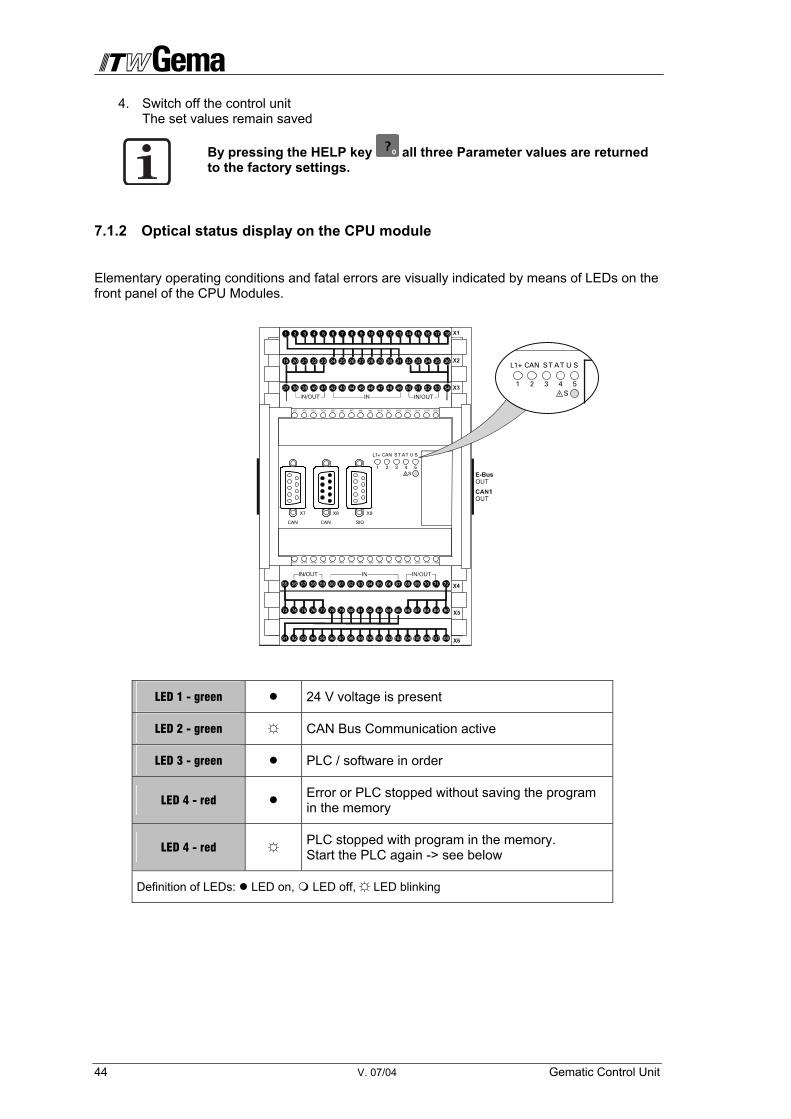
7.1.2 Optical status display on the CPU module
Elementary operating conditions and fatal errors are visually indicated by means of LEDs on the front panel of the CPU Modules.
LED 1 - green 24 V voltage is present
LED 2 - green CAN Bus Communication active
LED 3 - green PLC / software in order
LED 4 - red Error or PLC stopped without saving the program in the memory
LED 4 - red PLC stopped with program in the memory. Start the PLC again -> see below
Definition of LEDs: LED on, LED off, LED blinking
CAN
X7 X8 X9
CAN SIO
CANL1+ S T A T U S
1 2 3 4S
5
91 92 93 94 95 96 97 98 99 100 101 102 103 104 105 106 107 108
73 74 75 76 77 78 79 80 81 82 83 84 85 86 87 88 89 90
55 56 57 58 59 60 61 62 63 64 65 66 67 68 69 70 71 72
1 2 3 4 5 6 7 8 9 10 11 12 13 14 15 16 17 18
19 20 21 22 23 24 25 26 27 28 29 30 31 32 33 34 35 36
37 38 39 40 41 42 43 44 45 46 47 48 49 50 51 52 53 54
CANL1+ S T A T U S
1 2 3 4S
5
Gematic Control Unit V. 07/04 45
7.1.2.1 Start the PLC when LED 4 (red) blinks:
When pressing the key S all plant specific parameters are lost, The Software of the plant is restored to the condition of delivery and has to be parametered once more.
1. Press key S LED 3 illuminates (green)
2. When the LED 3 illuminates (green), press key S again The PLC starts
7.1.2.2 Load new firmware:
1. Press key S LED 4 and 5 illuminate
2. When LED 4 and 5 illuminate, press the key S again LED 4 and 5 start to blink (alternating 1:1)
3. Load the new software, then press key S LED 4 and 5 extinguish
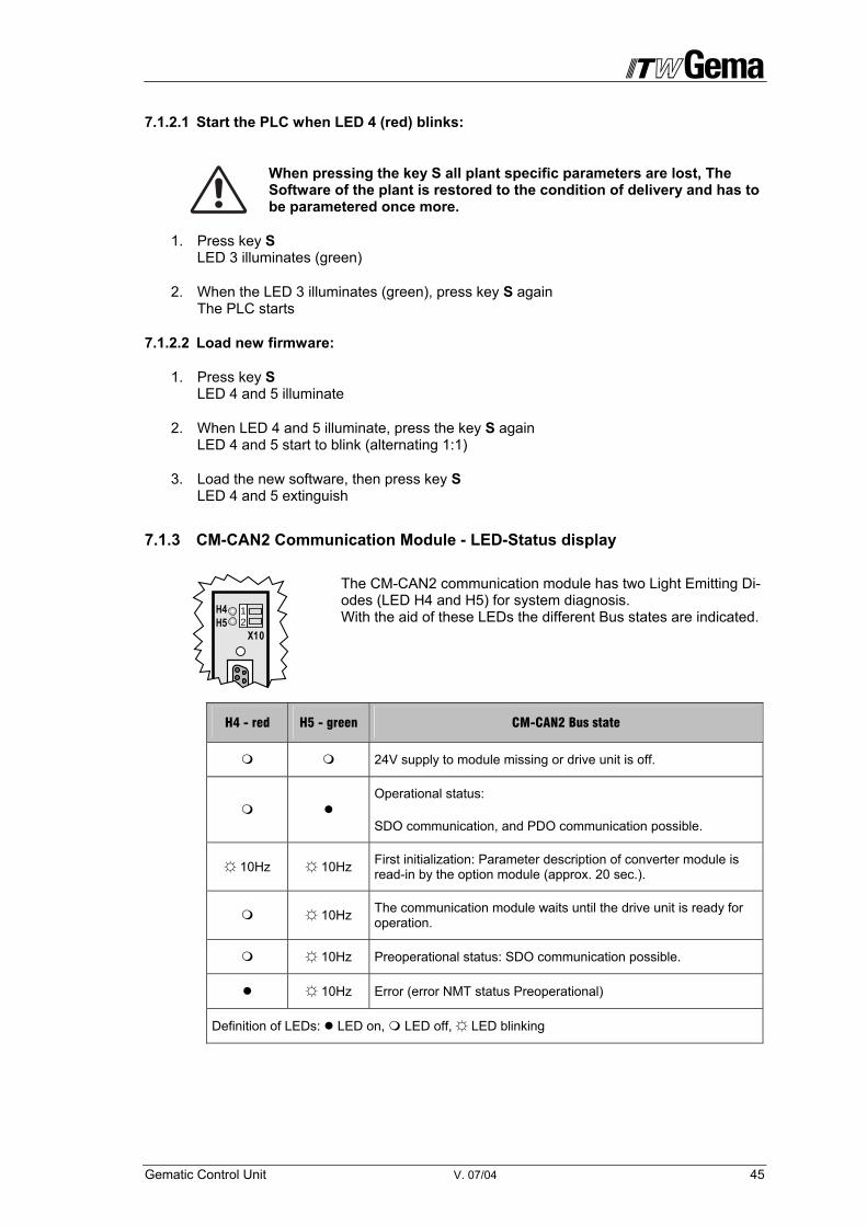
7.1.3 CM-CAN2 Communication Module - LED-Status display
The CM-CAN2 communication module has two Light Emitting Di-odes (LED H4 and H5) for system diagnosis. With the aid of these LEDs the different Bus states are indicated.
H4 - red H5 - green CM-CAN2 Bus state
24V supply to module missing or drive unit is off.
Operational status:
SDO communication, and PDO communication possible.
10Hz 10Hz First initialization: Parameter description of converter module is read-in by the option module (approx. 20 sec.).
10Hz The communication module waits until the drive unit is ready for operation.
10Hz Preoperational status: SDO communication possible.
10Hz Error (error NMT status Preoperational)
Definition of LEDs: LED on, LED off, LED blinking
H4H5
X10
12
46 V. 07/04 Gematic Control Unit
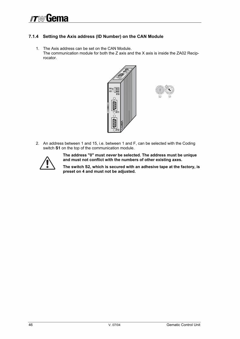
7.1.4 Setting the Axis address (ID Number) on the CAN Module
1. The Axis address can be set on the CAN Module. The communication module for both the Z axis and the X axis is inside the ZA02 Recip-rocator.
2. An address between 1 and 15, i.e. between 1 and F, can be selected with the Coding switch S1 on the top of the communication module.
The address "0" must never be selected. The address must be unique and must not conflict with the numbers of other existing axes.
The switch S2, which is secured with an adhesive tape at the factory, is preset on 4 and must not be adjusted.

Gematic Control Unit V. 07/04 47
7.1.5 Troubleshooting and elimination of faults on the Frequency converter
When errors occur during operation this is indicated by the blinking of the red LED (H1) on the Servo controller. (Blink code; see table “Light Emitting Diodes”)
7.1.5.1 Light Emitting Diodes
Three Status LEDs – red (H1), yellow (H2) and green (H3) can be found in the upper right of the servo controller.
Device status Red LED (H1) Yellow LED (H2) Green LED (H3)
Power on
Servo controller ready (ENPO set)
Control enabled
Error (Blink code)
Warning (in “ready” condition)
Warning (in “control enabled” condition)
Definition of LEDs: LED on, LED off, LED blinking

48 V. 07/04 Gematic Control Unit
7.1.5.2 Error messages
If an error occurs during operation this is indicated by the LED H1 (red) blinking on the Servo controller. If a Display unit (KEYPAD) is connected, this indicates the error type as an abbrevia-tion.
Display on GEMATIC control
Blink code of red LED
H1
Display KEY-PAD
Response No.
Explanation Cause/Remedy
01 1x Various messages 0-5 See table
02 2x E-OFF 1 Undervoltage shut-off Check power supply. Also occurs briefly in re-sponse to normal power-off.
03 3x E-OC 3 Current overload shut-off
Short-circuit, ground fault: Check cabling connec-tions, check motor coil, check neutral conductor and grounding (see also the Section “Installa-tion”). Device set-up not correct: Check parameters of control loops. Check ramp setting.
04 4x E-OV 3 Voltage overload shut-off
Voltage overload from mains: Check mains volt-age. Restart the device. Voltage overload resulting from feedback from motor (regenerative operation): Slow down brak-ing ramps. If not possible, use a braking resistor.
05 5x E-OLM 3 Motor protection shut-off
Motor overloaded (after I x t monitoring): Slow down process cycle rate, if possible. Check motor dimensioning.
06 6x E-OLI 3 Device protection shut-off
Device overloaded: Check dimensioning. Possibly use a larger device.
07 7x E-OTM 3 Motor temperature too high
Motor PTC correctly connected?: Motor PTC evaluation set correctly? Motor overloaded? Allow motor to cool down. Check dimensioning.
08 8x E-OTI 3 Overheating in
Servo controller
Ambient temperature too high: Improve ventilation in switch cabinet. Load too high during driving/braking: Check di-mensioning or use a braking resistor.
Table A. 1 Error messages / blink code

Gematic Control Unit V. 07/04 49
7.1.5.3 Error response
When an error occurs the servo controller responds with a specific function sequence. This is allocated to a corresponding Response number.
Error response table
Response no. Function
0 Indicate error only, no further response (warning).
1 Indicate error and disable power stage.
2 Indicate error, quick stop and wait for cancellation of start signal.
3 Indicate error, disable power stage and secure against auto-matic restart 1).
4 Indicate error, quick stop, wait for cancellation of start signal and secure against automatic restart 1).
5 Indicate error, disable power stage and wait for error reset; error reset only possible by complete cutting of power.
1) only relevant with programmed Autostart function
7.1.5.3.1 Resetting errors (after eliminating the cause)
Resetting errors with Response numbers 1 to 4:
• Acknowledge the error on the panel
Resetting errors with Response number 5:
Errors with Response number 5 are serious device errors. They can only be reset by switching all supply voltages (Mains or possibly 24V) off and then on again.
Errors in power switching
Error Cause Remedy
Power on. Servo control-ler shows no response (LEDs off).
If switching is too fre-quent, the device protects itself by means of high-resistance isolation from the system.
After a rest phase of a few minutes the device is ready to start once again.
50 V. 07/04 Gematic Control Unit
7.2 Warnings
Warnings are notes for the operator, in order to indicate an incorrect input. All parameters are checked when programming of the Gematic Reciprocator Control and on exceeding the input limits the corresponding limiting value (according to Parameter definition) is accepted as the value. At the same time a corresponding warning is output, in order to make the operator aware of an incorrect input. Only correct inputs are accepted.
The software is arranged in such a way that operators only transmit requests to the control (e.g. mode change or program start). The control decides whether the request is transferred in the current state of the unit. If this cannot be done, a corresponding warning is displayed.
If a warning is present, this appears on the display.
The warning is to be acknowledged. Afterwards the last illustration shown appears on the dis-play.
Gematic Control Unit V. 07/04 51
8 Spare parts list
8.1 Ordering spare parts
When you order spare parts for your powder coating device, we require the following specifica-tions:
1. Type and Serial No. of your powder coating equipment
2. Order No., Quantity, and description of each spare part
Example:
1. Type CR03 Gematic Serial No.: xxxx.xxxx
2. Order No.: 221 872, 1 piece, Fuse, 2 AT
When ordering cables and hoses the required length must be always be given. This "meter" ware is always marked with an *.
Wear parts are always marked with a #.
All dimensions of plastic hoses are given with the outside, and the inside diameter:
e.g.: ø 8/6 mm, = 8 mm outside diameter / 6 mm inside diameter.
52 V. 07/04 Gematic Control Unit
8.2 CR03 Gematic - Spare Parts
2 1 Rear wall 387282 3 1 Mounting plate 387274 4 1 Carrier profile 386817 5 1 Cable connection - complete 388408 10 1 CanBus Cable CR03 internal 387118 11 1 CanBus Cable L=20 m 387100 12 1 CanBus terminal plug 384917 13 1 Cable set CR03 387126 20 1 18 pin Socket rail No. 1-18 264580 21 1 18 pin Socket rail No. 19-36 264598 22 1 Display unit 263621 23 1 CPU unit 263605 24 1 Power pack - phased 24 VDC / 0,92 A 264091 25 0.34 m Moos rubber profile 104418 26 6 Cable 3x1 mm2 100170 30 2 Cap screw M6x12 238163 31 1 Cap screw M4x18 201910 32 4 Cap screw M3x6 202355 33 4 Spacer holder M3/SW5,5x8i 256250 40 2 Hex. Shakeproof nut M6 244430 41 1 Hex. Nut M4 205192 42 4 Hex. Nut M3 202142 45 3 Shakeproof washer Type A M4 216038 46 8 Shakeproof washer Type A M3 205885

Gematic Control Unit V. 07/04 53
1 2223
5
4; 30; 40
12
13
23
24; 32; 33; 42; 46
31; 41; 45
25
10
11
26
20
21

54 V. 07/04 Gematic Control Unit
8.2.1 Gematic CR03 – View inside

Gematic Control Unit V. 07/04 55
APPENDIX A Tables of System Parameter
Fill in the new values for the Gematic Parameters for reference later!
Global Parameters
Para-meter
Designation Value Range Default Units
SP1 Language Selection
German English
Francais Spanisch
Italian Portug.
german -
SP2 Firmware Version 1.01T06 -
SP3 CAN-Sender available True / False FALSE mm/min
SP4 Increments per 2 metre 1000 – 2097152 Incr.
SP5 Encoder preceding sign
Accom. the pulse generator direction True /
False BOOL
SP6 Distance per Pulse 10-100 20 mm
SP7 Number of axes -
SP8 Number of stations -
SP9 Number of guns -
SP10 Expanded Control Function True / False FALSE BOOL
SP11 Common program number True / False FALSE BOOL
SP12 Booth function True / False FALSE BOOL
SP13 Object Recognition True / False FALSE BOOL
SP14 Cleaning function True / False FALSE BOOL
SP15 Ext. AxisStationParameters True / False FALSE BOOL
SP16 PTC-Interface True / False FALSE BOOL
SP17 Powder center exists True / False FALSE BOOL
SP18 Manual doors True / False FALSE BOOL

56 V. 07/04 Gematic Control Unit
SP19 Automatic doors True / False FALSE BOOL
SP20 External booth True / False FALSE BOOL
SP21 BoltDevConvBooth True / False FALSE BOOL
SP22 ConvStopFireProt True / False FALSE BOOL
SP23 Gun on over Seqe True / False FALSE BOOL

Gematic Control Unit V. 07/04 57
Axis parameters
Value A1 – A4
Values A5 – A8
Para-meter Designation Value
A1 Value
A2 Value A3 Value A4 range Units
200 200 1000 1000 0-9999 mm SP30 Maximum Position
750 750 200 200 5-50 mm/s SP31 Maximum Speed
1000 1000 Not relevant Not relevant 200-2000 mm/s2 SP32 Maximum Accelera-
tion 1 2 3 4 SP33 Axis Address mm/s
FALSE FALSE FALSE FALSE True / False BOOL SP34 Drift Compensation
FALSE FALSE FALSE FALSE True / False BOOL SP35 Synchron Travel released
1 1 1 1 +/-1-32767 INT SP36 Synchron. MUL
1 1 1 1 1-65535 UINT SP37 Synchron DIV
1 1 1 1 0-1 UINT SP38 Direction of Travel UINT SP39 Inkremente pro Umdrehung
Synch. Geber
Para-meter Designation Value
A5 Value
A6 Value A7 Value A 8 Range Units
200 200 1000 1000 0-9999 mm SP30 Maximum Position
750 750 200 200 5-50 mm/s SP31 Maximum Speed
1000 1000 Not relevant Not relevant 200-2000 mm/s2 SP32 Maximum Accelara-
tion 5 6 7 8 SP33 Axisaddress mm/s
FALSE FALSE FALSE FALSE True / False BOOL SP34 Drift Compensation on
FALSE FALSE FALSE FALSE True / False BOOL SP35 Synchron. Travel released
1 1 1 1 +/-1-32767 INT SP36 Synchron MUL
1 1 1 1 1-65535 UINT SP37 Synchron DIV
1 1 1 1 0-1 UINT SP38 Direction of Travel UINT SP39 Increments per rotation
Synch. Sender
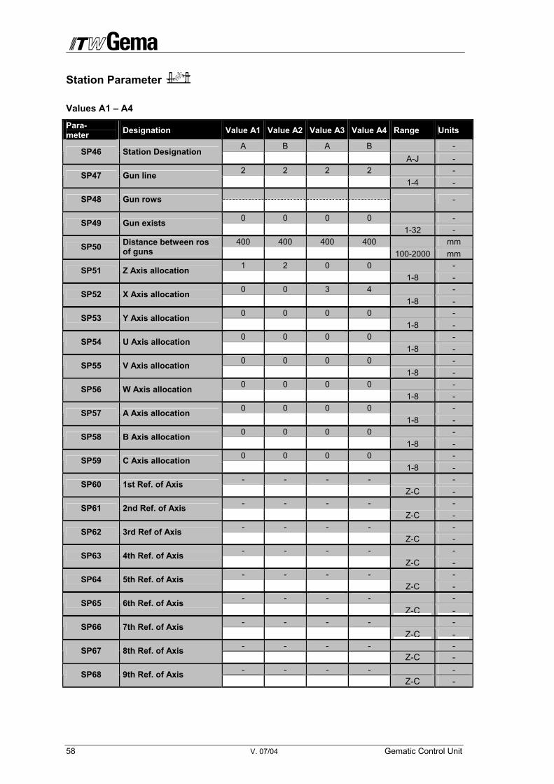
58 V. 07/04 Gematic Control Unit
Station Parameter
Values A1 – A4
Para- meter Designation Value A1 Value A2 Value A3 Value A4 Range Units
A B A B - SP46 Station Designation
A-J - 2 2 2 2 - SP47 Gun line 1-4 - SP48 Gun rows
-
0 0 0 0 - SP49 Gun exists 1-32 -
400 400 400 400 mm SP50 Distance between ros of guns 100-2000 mm
1 2 0 0 - SP51 Z Axis allocation 1-8 -
0 0 3 4 - SP52 X Axis allocation 1-8 -
0 0 0 0 - SP53 Y Axis allocation 1-8 -
0 0 0 0 - SP54 U Axis allocation 1-8 -
0 0 0 0 - SP55 V Axis allocation 1-8 -
0 0 0 0 - SP56 W Axis allocation 1-8 -
0 0 0 0 - SP57 A Axis allocation 1-8 -
0 0 0 0 - SP58 B Axis allocation 1-8 -
0 0 0 0 - SP59 C Axis allocation 1-8 - - - - - - SP60 1st Ref. of Axis Z-C - - - - - - SP61 2nd Ref. of Axis Z-C - - - - - - SP62 3rd Ref of Axis Z-C - - - - - - SP63 4th Ref. of Axis Z-C - - - - - - SP64 5th Ref. of Axis Z-C - - - - - - SP65 6th Ref. of Axis
Z-C -- - - - - SP66 7th Ref. of Axis
Z-C -- - - - - SP67 8th Ref. of Axis Z-C - - - - - - SP68 9th Ref. of Axis Z-C -
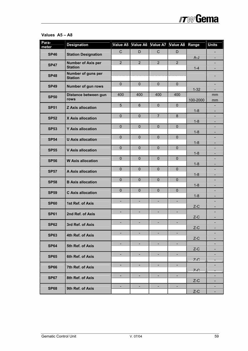
Gematic Control Unit V. 07/04 59
Values A5 – A8
Para- meter Designation Value A5 Value A6 Value A7 Value A8 Range Units
C D C D - SP46 Station Designation
A-J - 2 2 2 2 - SP47 Number of Axis per
Station 1-4 - SP48 Number of guns per
Station -
0 0 0 0 - SP49 Number of gun rows 1-32 -
400 400 400 400 mm SP50 Distance between gun rows 100-2000 mm
5 6 0 0 - SP51 Z Axis allocation 1-8 -
0 0 7 8 - SP52 X Axis allocation 1-8 -
0 0 0 0 - SP53 Y Axis allocation 1-8 -
0 0 0 0 - SP54 U Axis allocation 1-8 -
0 0 0 0 - SP55 V Axis allocation 1-8 -
0 0 0 0 - SP56 W Axis allocation 1-8 -
0 0 0 0 - SP57 A Axis allocation 1-8 -
0 0 0 0 - SP58 B Axis allocation 1-8 -
0 0 0 0 - SP59 C Axis allocation 1-8 - - - - - - SP60 1st Ref. of Axis Z-C - - - - - - SP61 2nd Ref. of Axis Z-C - - - - - - SP62 3rd Ref. of Axis Z-C - - - - - - SP63 4th Ref. of Axis Z-C - - - - - - SP64 5th Ref. of Axis Z-C - - - - - - SP65 6th Ref. of Axis
Z-C -- - - - - SP66 7th Ref. of Axis
Z-C -- - - - - SP67 8th Ref. of Axis Z-C - - - - - - SP68 9th Ref. of Axis Z-C -

60 V. 07/04 Gematic Control Unit
APPENDIX B Program-Table
Prog.-Nr. Designation Position top (mm) Position Bottom (mm)
Speed F (mm/s)
1 Z- Stroke
2 Z- Stroke
3 Z- Stroke
4 Z- Stroke
5 Z- Stroke
6 Z- Stroke
7 Z-Stroke
8 Z- Stroke
9 Z- Stroke
10 Z- Stroke
11 Z- Stroke
12 Z- Stroke
13 Z- Stroke
14 Z- Stroke
15 Z- Stroke
16 Z- Stroke
17 Z- Stroke
18 Z- Stroke
19 Z- Stroke
20 Z- Stroke
21 Z- Stroke
22 Z- Stroke
23 Z- Stroke
24 Z- Stroke
25 Z- Stroke
26 Z- Stroke
27 Z- Stroke
28 Z- Stroke
29 Z- Stroke
30 Z- Stroke
31 Z- Stroke
32 Z- Stroke
33 Z- Stroke
34 Z- Stroke
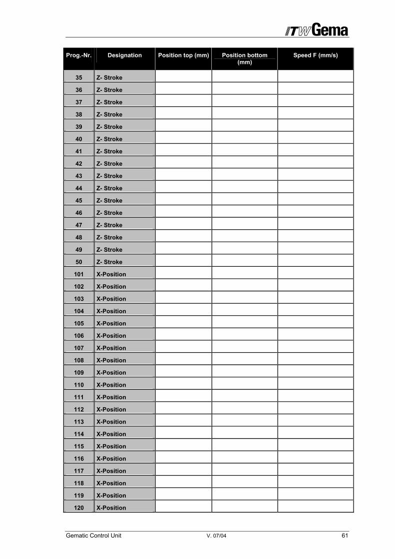
Gematic Control Unit V. 07/04 61
Prog.-Nr. Designation Position top (mm) Position bottom (mm)
Speed F (mm/s)
35 Z- Stroke
36 Z- Stroke
37 Z- Stroke
38 Z- Stroke
39 Z- Stroke
40 Z- Stroke
41 Z- Stroke
42 Z- Stroke
43 Z- Stroke
44 Z- Stroke
45 Z- Stroke
46 Z- Stroke
47 Z- Stroke
48 Z- Stroke
49 Z- Stroke
50 Z- Stroke
101 X-Position
102 X-Position
103 X-Position
104 X-Position
105 X-Position
106 X-Position
107 X-Position
108 X-Position
109 X-Position
110 X-Position
111 X-Position
112 X-Position
113 X-Position
114 X-Position
115 X-Position
116 X-Position
117 X-Position
118 X-Position
119 X-Position
120 X-Position

62 V. 07/04 Gematic Control Unit
Prog.-Nr. Designation Position top (mm) Position bottom (mm)
Speed F (mm/s)
131 X-Position
132 X-Position
133 X-Position
134 X-Position
135 X-Position
136 X-Position
137 X-Position
138 X-Position
139 X-Position
140 X-Position
141 X-Position
142 X-Position
143 X-Position
144 X-Position
145 X-Position
146 X-Position
147 X-Position
148 X-Position
149 X-Position
150 X-Position
201 Special program
202 Special program
203 Special program
204 Special program
205 Special program
206 Special program
207 Special program
208 Special program
209 Special program
210 Special program
211 Special program
212 Special program
213 Special program
214 Special program
215 Special program
216 Special program

Gematic Control Unit V. 07/04 63
Prog.-Nr. Designation Position top (mm) Position bottom (mm)
Speed F (mm/s)
217 Special program
218 Special program
219 Special program
220 Special program
221 Special program
222 Special program
223 Special program
224 Special program
225 Special program
226 Special program
227 Special program
228 Special program
229 Special program
230 Special program
231 Special program
232 Special program
233 Special program
234 Special program
235 Special program
236 Special program
237 Special program
238 Special program
239 Special program
240 Special program
241 Special program
242 Special program
243 Special program
244 Special program
245 Special program
246 Special program
247 Special program
248 Special program
249 Special program
250 Special program

64 V. 07/04 Gematic Control Unit
Documentation CR 03 Gematic
© Copyright 2000 ITW Gema AG., CH-9015 St. Gallen All rights reserved.
This publication is protected by copyright. Unauthorized copying is prohibited by law. No part of this publication may be reproduced, photocopied, trans-lated, stored on a retrieval system or transmitted in any form or by any means, for any purpose, neither as a whole nor partially, without the express written consent of ITW Gema AG. OptiTronic, OptiGun, EasyTronic, EasySelect, EasyFlow and SuperCorona are registered trademarks of ITW Gema AG. OptiMatic, OptiMove, OptiMaster, OptiPlus, OptiMulti and Gematic are trade-marks of ITW Gema AG. All other product names are trademarks or registered trademarks of their re-spective holders. Reference is made in this manual to different trademarks or registered trade-marks. Such references do not mean that the manufacturers concerned ap-prove of or are bound in any form by this manual. We have endeavoured to retain the preferred spelling of the trademarks, and registered trademarks of the copyright holders. To the best of our knowledge and belief, the information contained in this pub-lication was correct and valid on the date of issue. ITW Gema AG makes no representations or warranties with respect to the contents or use of this publi-cation, and reserves the right to revise this publication and make changes to its content without prior notice.
Printed in Switzerland
ITW Gema AG Mövenstrasse 17 9015 St.Gall Switzerland Tel.: +41-71-313 83 00 Fax: +41-71-313 83 83 www.itwgema.ch E-Mail: [email protected]
Gematic Control Unit V. 07/04 65
Gematic CR03 Control Extended Functions
Before using this additional manual you should read the main manual, to receive information on the functioning and the operating of the Ge-matic CR03 control. Specific processes described in the main manual shall not be repeated in this addition manual, only respective cross-references shall be made.
66 V. 07/04 Gematic Control Unit
Table of Contents
About this manual ....................................................................................................................... 7 Pictograms ..................................................................................................................... 7
1 Safety notes.......................................................................................................................... 8 1.1 Intended use................................................................................................................. 8
2 Gematic CR03 Control Unit................................................................................................. 9 2.1 Special Characteristics ............................................................................................... 9 2.2 Definition of the CR 03 Gematic Reciprocator Control Unit ................................. 10 2.3 Layout principle......................................................................................................... 10 2.4 Addressing / Address distribution........................................................................... 11
3 Start-up ............................................................................................................................... 12 3.1 Preparation to the Start-up ....................................................................................... 12
3.1.1 Electrical wiring and screening concept .......................................................... 12 3.1.2 Setting the maximum stroke limits .................................................................. 13
4 Operating unit .................................................................................................................... 15 4.1 Operating panel ......................................................................................................... 15 4.2 Special key functions................................................................................................ 16 4.3 LED Display Functions ............................................................................................. 17
5 Operating modes ............................................................................................................... 18
5.1 Reference operation mode ........................................................................... 19
5.2 Manual operation mode ................................................................................. 20 5.2.1 Start Travel programs...................................................................................... 21 5.2.2 Change programs............................................................................................ 22 5.2.3 Edit programs .................................................................................................. 23
5.2.3.1 Online Program Editor for Z Axes-Programs................................... 23 5.2.3.2 On-line Editor for X-Axes Program .................................................. 24
5.3 Program Editor for Travel programs ........................................................... 26 5.3.1 Working with existing programs ........................................................... 27 5.3.2 Preparing a new program ..................................................................... 28
5.3.2.1 Editor for Z-Axis Programs .............................................................. 29 5.3.2.2 Editor for X-Axis Programs (101 – 200) ................................. 29
5.3.3 Delete Programs ................................................................................... 29
5.4 Service ............................................................................................................. 31 5.4.1 Parameter Setting ........................................................................................... 32
5.4.1.1 Global parameters ................................................................. 33 5.4.1.2 Axis parameters ................................................................... 36 5.4.1.3 Station parameters .............................................................. 38
6 Control function "Program Change on the OptiTronic" ................................................ 40 6.1.1 Switching programs......................................................................................... 40
7 Messages............................................................................................................................ 41 7.1 Error messages ......................................................................................................... 41
7.1.1 Eliminating errors on the Front Panel.............................................................. 43 7.1.1.1 ID Number, Baud Rate and Contrast setting ................................... 43
7.1.2 Optical status display on the CPU module...................................................... 44
Gematic Control Unit V. 07/04 67
7.1.2.1 Start the PLC when LED 4 (red) blinks: ...........................................45 7.1.2.2 Load new firmware: ..........................................................................45
7.1.3 CM-CAN2 Communication Module - LED-Status display................................45 7.1.4 Setting the Axis address (ID Number) on the CAN Module.............................46 7.1.5 Troubleshooting and elimination of faults on the Frequency converter ...........47
7.1.5.1 Light Emitting Diodes........................................................................47 7.1.5.2 Error messages ................................................................................48 7.1.5.3 Error response..................................................................................49
7.1.5.3.1 Resetting errors (after eliminating the cause) ................49 Resetting errors with Response numbers 1 to 4:.............................................49 Resetting errors with Response number 5: .....................................................49
7.2 Warnings .....................................................................................................................50 8 Spare parts list....................................................................................................................51
8.1 Ordering spare parts..................................................................................................51 8.2 CR03 Gematic - Spare Parts......................................................................................52
8.2.1 Gematic CR03 – View inside ...........................................................................54 APPENDIX A Tables of System Parameter..........................................................................55
Global Parameters ............................................................................................55 Axis parameters ................................................................................................57 Station Parameter .............................................................................................58
Values A5 – A8 ...............................................................................................59 APPENDIX B Program-Table..................................................................................................60
Documentation CR 03 Gematic .......................................................................64
Gematic CR03 Control Extended Functions .....................................65
9 Automatic Operation ...............................................................................................69 10 Extended Functions ...........................................................................................................70
10.1 Gematic-Control: Installation options......................................................................70 10.2 Master functions.........................................................................................................70
10.2.1 Control signals 70 10.2.2 Functions 70
10.2.2.1 Definition of the functions .................................................................71 10.3 Gap Control System...................................................................................................72
10.3.1 Gap Control System modes.............................................................................72 10.3.1.1 Time varying (time controlled) Gap Control System.........................72 10.3.1.2 Clocked/synchronous Gap Control System......................................73
10.3.2 Parameter of the Gap Control System .................................................74 10.3.3 Fitting the incremental pulse generator (encoder) to the chain conveyor........77
10.3.3.1 Setting the Terminal Resistance.......................................................78 10.3.3.2 Setting the user address (ID number) and the Bit rate.....................79 10.3.3.3 Calibrating the Encoder ....................................................................80
11 Booth functions ..................................................................................................................81
11.1 Booth parameter .............................................................................................81 12 Cleaning functions .............................................................................................................84
13 Editor for Special Programs (201 – 250) ..............................................................86 13.1 Special Structure Program........................................................................................86 13.2 Creating Special Programs .......................................................................................86 13.3 Program Line Definition.............................................................................................88 13.4 Command Description ...............................................................................................89

68 V. 07/04 Gematic Control Unit
13.4.1 Commands for positioning the axis ................................................................. 89 13.4.2 Commands for extended control ..................................................................... 89 13.4.3 Commands for synchronizing the process sequence ..................................... 90
13.5 "Command details" Editor........................................................................................ 91 13.6 Simple programming example ................................................................................. 93 13.7 Programming example with Path-Time Diagram.................................................... 94
APPENDIX C I/O Interface allocation table (if SP10 = FALSE).......................................... 95 APPENDIX C I/O Interface allocation table (if SP10 = TRUE)........................................... 97
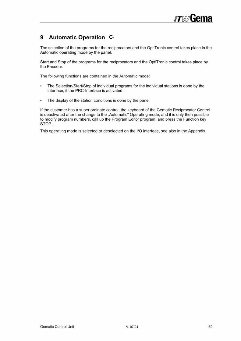
Gematic Control Unit V. 07/04 69
9 Automatic Operation
The selection of the programs for the reciprocators and the OptiTronic control takes place in the Automatic operating mode by the panel.
Start and Stop of the programs for the reciprocators and the OptiTronic control takes place by the Encoder.
The following functions are contained in the Automatic mode:
• The Selection/Start/Stop of individual programs for the individual stations is done by the interface, if the PRC-Interface is activated
• The display of the station conditions is done by the panel
If the customer has a super ordinate control, the keyboard of the Gematic Reciprocator Control is deactivated after the change to the „Automatic" Operating mode, and it is only then possible to modify program numbers, call up the Program Editor program, and press the Function key STOP.
This operating mode is selected or deselected on the I/O interface, see also in the Appendix.

70 V. 07/04 Gematic Control Unit
10 Extended Functions
Following control functions are available:
- Master functions
- Gap Control System for reciprocators and guns
- Cleaning function for color change systems
10.1 Gematic-Control: Installation options
Should extended functions be realized for a powder coating plant, following to installation possi-bilities are available for the Gematic CR03 Control:
- Plant without booth control --> Gematic-Control and operating panel are in-stalled in the OptiMatic control cabinet
- Plant with booth control --> Gematic-Control is installed in the booth control cabinet and the Gematic operating panel in the OptiMatic control cabinet
10.2 Master functions
To enable a supervised control of an electrostatic powder coating plant, various locking-, alarm- and release functions are necessary. The Gematic CR03 control ensures all these functions, which allows for an individual adaptation on all plant specific requirements.
10.2.1 Control signals
- Gema ready - Exit
- Booth ready - Entry
- Release conveyor - Exit
- Release gun control insert OptiTronic
- Release main solenoid valve
- Release level control
- Release Pre-fluidizing / fluidizing
- Release spraying at conveyor stop
- Release Gap flushing
- Fire- and earthing protection
- Run-on- and collision protection
10.2.2 Functions
- Release of the main magnetic valve
- Release gun control OptiTronic (switch on power supply)
- Flushing of guns with OptiPlus-C
Gematic Control Unit V. 07/04 71
- Powder container: Pre-fluidizing and permanent fluidizing (Control OptiPlus-A) Supervision of 2 levels (Powder full / Powder empty) with alarm
- Require Fresh Powder
- Potential free Contact for 2 Fresh Powder Supply-Systems
- Control Alarm-hooter or - lamp
- Confirm alarm: Entry (for external key)
- Gap Control System
- Gun Control OptiTronic collective on/off
10.2.2.1 Definition of the functions
Release Gun Control OptiTronic
After switching on the main power supply, the power supply of the OptiTronic gun controls and reciprocators is switched on, if the booth is ready. With the release of the control voltage with the key switch, the devices are released for coating.
Main solenoid valve
When the three locking signals "booth ready", "fire protection o.k." and "earthing check o.k." are given, the main magnet valve is switched on.
Fluidizing
When switching on the main magnet valve the pre-fluidizing ist started. The pre-fluid valve switches alternately on for 0.5s and off for 0.5s. The time for pre fluidizing can be set in the pa-rameters SP78, SP79 and SP80. After each switching on of the main magnet valve, the process repeats itself.
Level Control
After the pre fluidizing the level control is activated. When the top measuring head is covered, the control receives the signal „Powder full“. Should the top measuring head be free for a prede-fined period, fresh powder is called for. Should the bottom measuring head be free for a prede-fined period, the message „time check FP“ is shown. Simultaneously the alarm hooter is heard. The alarm hooter can be acknowledged with the F3 key, which switches off the hooter and the message „time check FP“ is displayed once more. By confirming the "time check", the process can be restarted.
Flushing at Conveyor Stop
When the Gematic-Control realizes a stop of the conveyor, the guns are flushed (only when powder tube flush insert OptiPlus-C and respective injectors are in use).
The flushing time is set in parameter SP77.
Gap flushing
The condition for it is the intended regulation of the gun groups for HRC rinsing. The gun groups can create the rinsing conditions. If within a gun group, a gun control is switched off, the high voltage and the powder output are set on value 0 and the total air volume is set on 5 Nm3. After all gun controls of the same gun group are set in this condition, the guns are rinsed. The rinsing time (opening time of the HRC solenoid valve) is adjusted with SP77.
72 V. 07/04 Gematic Control Unit
10.3 Gap Control System
The Gap control system is an extended control function which allows guns and reciprocators to be switched on or off, depending on the existence of objects to be coated.
So that the Gap control system can functioning properly, the complete coating plant has to be equipped with CAN bus and the Gematic con-trol must be switched to the automatic operating mode!
The Gap control system can be extended with the function „Flushing at Gap“ (when an object is recognized). The Powder tube flushing insert OptiPlus-C is necessary. In addition the parameter SP88 must be set on TRUE and the times set in the other respective parameters.
10.3.1 Gap Control System modes
10.3.1.1 Time varying (time controlled) Gap Control System
This Gap control system mode is provided for the operation with only one conveyor speed and without encoder.
The hangers or objects are recognized with the help of a photo cell. An integrated timer simulates the encoder and is responsible for the correct reading of the in-formation by the control.
Each booth side, the distance between the light array and the 1st gun row, the pretravel as well as the posttravel for the switching off of the gun, can be adjusted. Should the conveyor be stopped during the coating, the process of the timer is interrupted.
When no objects are around, the reciprocators also switch off after a predefined period.
Conditions:
- SP3 = FALSE
- SP10 = TRUE
- SP17 = TRUE
- Station parameter set
- SP70 = effective conveyor speed set
- SP70-76 = activated (value set)
- Start light array (installed and connected)

Gematic Control Unit V. 07/04 73
10.3.1.2 Clocked/synchronous Gap Control System
This Gap Control System mode ist provided for the operation with variable conveyor speeds and with an encoder.
The hangers or objects are recognized with the help of a photo cell. The encoder, connected to the conveyor, ensures that the control unit processes correctly the readed information. Each booth side, the distance between the light array and the 1st gun row, the pretravel as well as the posttravel for the switching off of the gun, can be adjusted. When no objects are around, the reciprocators also switch off after a predefined period.
Conditions:
- Encoder (installed, parametered and connected) - see „Fitting the incremental pulse generator (encoder) to the chain conveyor“
- SP3 = TRUE
- SP4 = Encoder calibrated – see „Calibrating the Encoder“
- SP5 = eventually re-adjust the preceding sign (may not be negative)
- SP6 = set pulse length
- SP10 = TRUE
- SP17 = TRUE
- Station parameter set
- SP70 = set the effective conveyor speed
- SP70-76 = activated (set value)
- SP89 = eventually set on TRUE (installed and connected)
- Start light array (installed and connected)
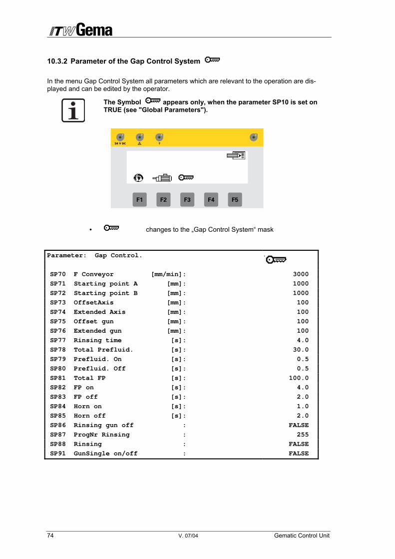
74 V. 07/04 Gematic Control Unit
10.3.2 Parameter of the Gap Control System
In the menu Gap Control System all parameters which are relevant to the operation are dis-played and can be edited by the operator.
The Symbol appears only, when the parameter SP10 is set on TRUE (see "Global Parameters").
• changes to the „Gap Control System“ mask
Parameter: Gap Control.
SP70 F Conveyor [mm/min]: 3000
SP71 Starting point A [mm]: 1000
SP72 Starting point B [mm]: 1000
SP73 OffsetAxis [mm]: 100
SP74 Extended Axis [mm]: 100
SP75 Offset gun [mm]: 100
SP76 Extended gun [mm]: 100
SP77 Rinsing time [s]: 4.0
SP78 Total Prefluid. [s]: 30.0
SP79 Prefluid. On [s]: 0.5
SP80 Prefluid. Off [s]: 0.5
SP81 Total FP [s]: 100.0
SP82 FP on [s]: 4.0
SP83 FP off [s]: 2.0
SP84 Horn on [s]: 1.0
SP85 Horn off [s]: 2.0
SP86 Rinsing gun off : FALSE
SP87 ProgNr Rinsing : 255
SP88 Rinsing : FALSE
SP91 GunSingle on/off : FALSE
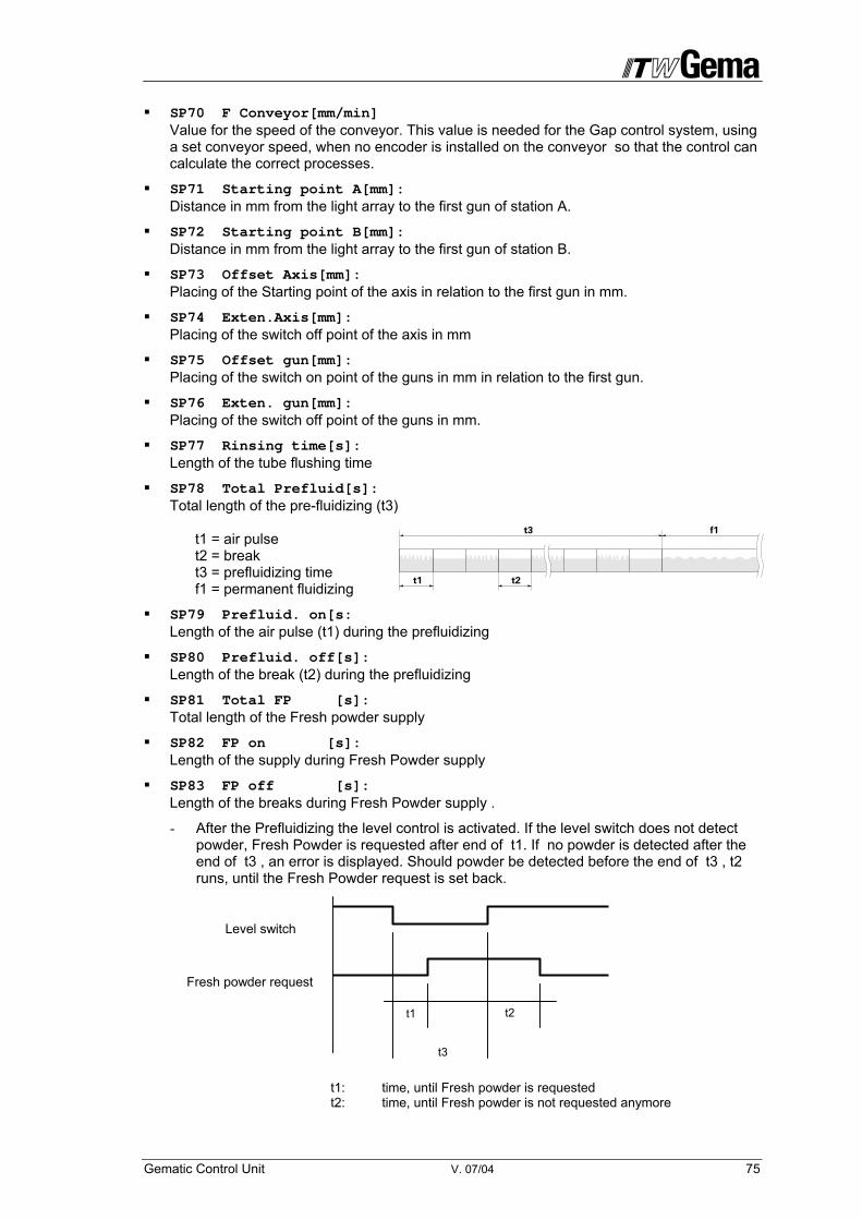
Gematic Control Unit V. 07/04 75
SP70 F Conveyor[mm/min] Value for the speed of the conveyor. This value is needed for the Gap control system, using a set conveyor speed, when no encoder is installed on the conveyor so that the control can calculate the correct processes.
SP71 Starting point A[mm]: Distance in mm from the light array to the first gun of station A.
SP72 Starting point B[mm]: Distance in mm from the light array to the first gun of station B.
SP73 Offset Axis[mm]: Placing of the Starting point of the axis in relation to the first gun in mm.
SP74 Exten.Axis[mm]: Placing of the switch off point of the axis in mm
SP75 Offset gun[mm]: Placing of the switch on point of the guns in mm in relation to the first gun.
SP76 Exten. gun[mm]: Placing of the switch off point of the guns in mm.
SP77 Rinsing time[s]: Length of the tube flushing time
SP78 Total Prefluid[s]: Total length of the pre-fluidizing (t3) t1 = air pulse t2 = break t3 = prefluidizing time f1 = permanent fluidizing
SP79 Prefluid. on[s: Length of the air pulse (t1) during the prefluidizing
SP80 Prefluid. off[s]: Length of the break (t2) during the prefluidizing
SP81 Total FP [s]: Total length of the Fresh powder supply
SP82 FP on [s]: Length of the supply during Fresh Powder supply
SP83 FP off [s]: Length of the breaks during Fresh Powder supply .
- After the Prefluidizing the level control is activated. If the level switch does not detect powder, Fresh Powder is requested after end of t1. If no powder is detected after the end of t3 , an error is displayed. Should powder be detected before the end of t3 , t2 runs, until the Fresh Powder request is set back.
Level switch
Fresh powder request
t1 t2
t3
t1: time, until Fresh powder is requested t2: time, until Fresh powder is not requested anymore
76 V. 07/04 Gematic Control Unit
SP84 Horn on[s]: Horn active, when error message
SP85 Horn off[s]: Horn inactive
SP86 Rinsing Guns off: Activates the tube flushing, when guns are switched off
SP87 ProgNr Rinsing: Activates the tube flushing using the gun control (Special program with switched off high-voltage and maximum additional air)
SP88 Rinsing: Activates the flushing
SP91 Gun singl. on/off: Switching on/off the guns by row
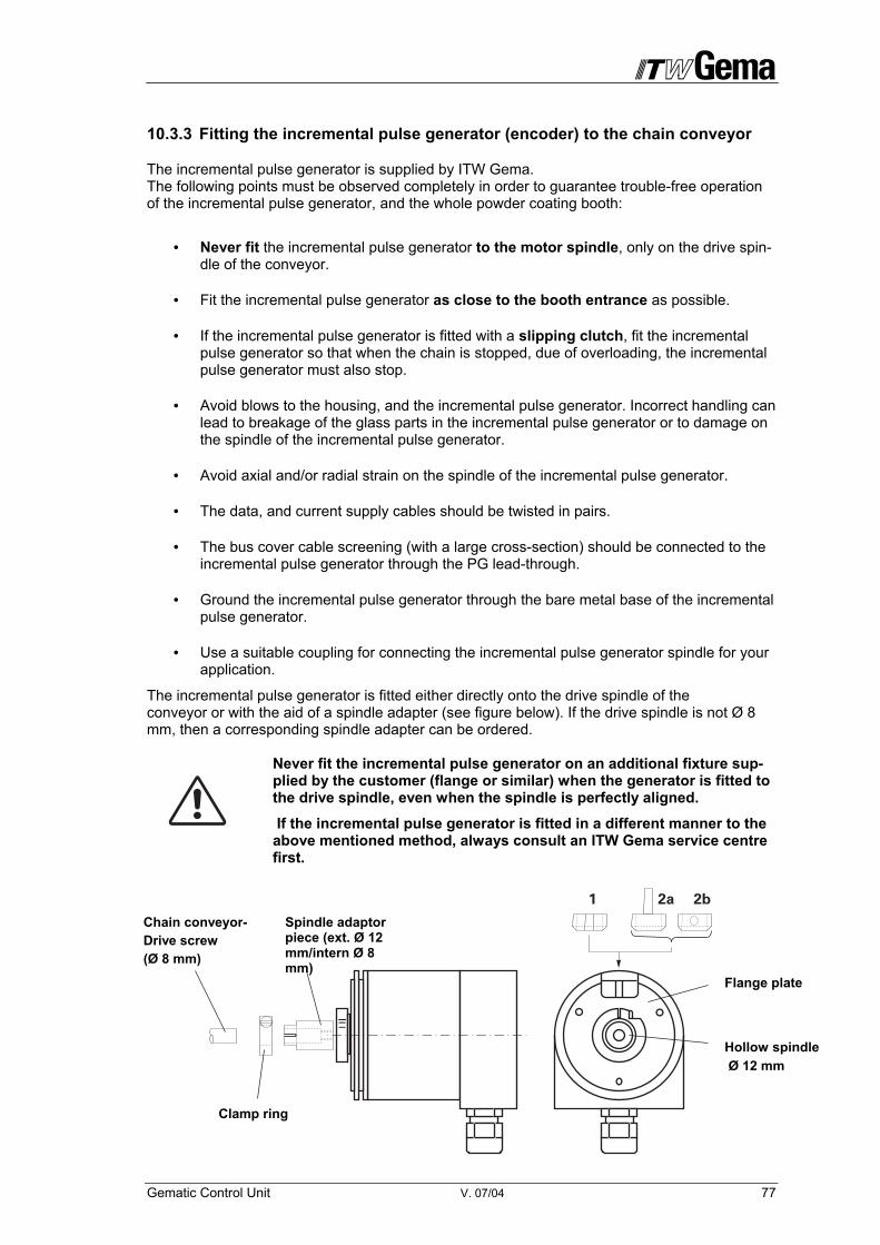
Gematic Control Unit V. 07/04 77
10.3.3 Fitting the incremental pulse generator (encoder) to the chain conveyor
The incremental pulse generator is supplied by ITW Gema. The following points must be observed completely in order to guarantee trouble-free operation of the incremental pulse generator, and the whole powder coating booth:
• Never fit the incremental pulse generator to the motor spindle, only on the drive spin-dle of the conveyor.
• Fit the incremental pulse generator as close to the booth entrance as possible.
• If the incremental pulse generator is fitted with a slipping clutch, fit the incremental pulse generator so that when the chain is stopped, due of overloading, the incremental pulse generator must also stop.
• Avoid blows to the housing, and the incremental pulse generator. Incorrect handling can lead to breakage of the glass parts in the incremental pulse generator or to damage on the spindle of the incremental pulse generator.
• Avoid axial and/or radial strain on the spindle of the incremental pulse generator.
• The data, and current supply cables should be twisted in pairs.
• The bus cover cable screening (with a large cross-section) should be connected to the incremental pulse generator through the PG lead-through.
• Ground the incremental pulse generator through the bare metal base of the incremental pulse generator.
• Use a suitable coupling for connecting the incremental pulse generator spindle for your application.
The incremental pulse generator is fitted either directly onto the drive spindle of the conveyor or with the aid of a spindle adapter (see figure below). If the drive spindle is not Ø 8 mm, then a corresponding spindle adapter can be ordered.
Never fit the incremental pulse generator on an additional fixture sup-plied by the customer (flange or similar) when the generator is fitted to the drive spindle, even when the spindle is perfectly aligned.
If the incremental pulse generator is fitted in a different manner to the above mentioned method, always consult an ITW Gema service centre first.
Clamp ring
Hollow spindle Ø 12 mm
Chain conveyor- Drive screw (Ø 8 mm)
Spindle adaptor piece (ext. Ø 12 mm/intern Ø 8 mm)
Flange plate

78 V. 07/04 Gematic Control Unit
The rotation of the incremental pulse generator with the drive spindle is stopped by a buffer (1) or a stop pin (2), which fits onto the fixing flange (supplied by the customer) and into the spe-cially made cutout in the incremental pulse generator flange plate. It is recommended to stick the torque buffer/stop pin to the flange plate of the incremental pulse generator with commer-cially available Cyan acrylic adhesive (Sicomet 50 or Loctite 406).
The electrical connection to the incremental pulse generator is done with the supplied plug.
10.3.3.1 Setting the Terminal Resistance
For reliable operation in a Bus system the start and end user must be connected with 120 Ω between the data lines in every case. The terminal resistance is switched on or off with the 2 contact DIP switch according to the CAN Bus configuration. Pulse generator as user X in the CAN Network Pulse generator as final user in the CAN Network
Datenleitung CAN_L, CAN_H Paar 2
1
ON
2
1
ON
2
Datenleitung CAN_L, CAN_H Paar 1
Terminal resistor Power supply
1
CL
S1 S2
CH
PG 9
CL CH GN
D
+Vs
4 1 4
ID NumberS1-4, S2-1 to S2-4
Bit Rate S1-1 to S1-3

Gematic Control Unit V. 07/04 79
10.3.3.2 Setting the user address (ID number) and the Bit rate
The setting of the user addresses (ID-Nummer) is done with the 5 right-hand DIP-switches. The pulse generator must be set on the ID-Nummer 32. Otherwise, values from 1 to 32 are possible. If the value „0“ is set, the setting of the ID-Number is done by the Bus.
The setting of the Bit rate is done with the 3 left-hand DIP switches.
The Bit rate with 125 kBits is selected as standard. This setting permits a maximum cable length of approximately 500 m from the first to the last CAN Bus user. When long cables are used the Bit rate is to be selected lower.
Decimal value of
the 3 DIP-Switches
S1-1 S1-2 S1-3 Bit rate (kBit / s)
0 0 0 0 10 1 1 0 0 20 2 0 1 0 50 3 1 1 0 125 4 0 0 1 250 5 1 0 1 500 6 0 1 1 800 7 1 1 1 1000
ID-Nummer = 32 Bit rate = 125 kBit/s
1
ON
2
S1 S2
3 4 1
ON
2 3 4

80 V. 07/04 Gematic Control Unit
10.3.3.3 Calibrating the Encoder
With this process, the used increments by the Gematic-Control an be counted and dis-played, to define the relation between the conveyor pulse and the conveying distance in pulse/mm.
1. Call up parameter SP4 in menu „Global Parameters“
2. Define a 2 m long path on the conveyor
3. Define a recognition sign (plate, hook etc.)
4. Switch on conveyor and choose a slow speed
5. When the recognition sign reaches the starting point of the measuring path, press the ENTER key. The counter start and counts positively. Is a negative value dis-played, this is an indication, that the pulse generator is running in the wrong direc-tion. The adaptation of the pulse generator direction must be made in Parameter SP5.
6. When the recognition sign reaches the end point of the measuring path, press key ENTER again, to end the counting process.
7. The displayed value is automatically saved as parameter value.
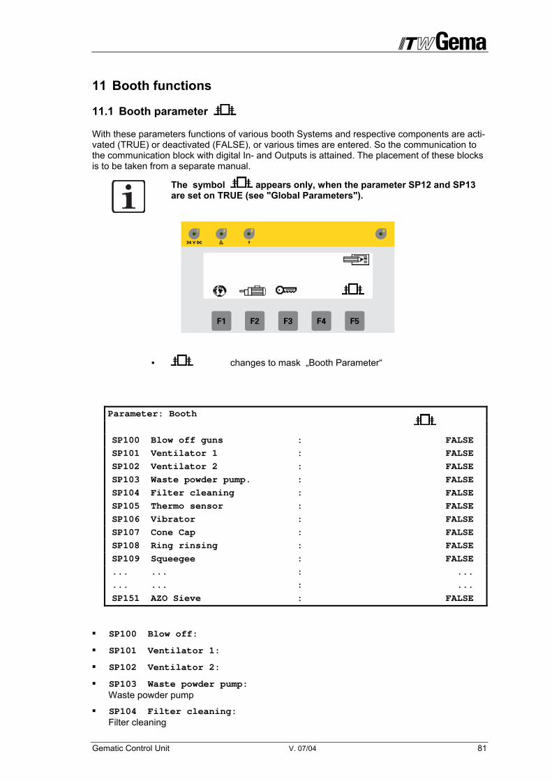
Gematic Control Unit V. 07/04 81
11 Booth functions
11.1 Booth parameter
With these parameters functions of various booth Systems and respective components are acti-vated (TRUE) or deactivated (FALSE), or various times are entered. So the communication to the communication block with digital In- and Outputs is attained. The placement of these blocks is to be taken from a separate manual.
The symbol appears only, when the parameter SP12 and SP13 are set on TRUE (see "Global Parameters").
• changes to mask „Booth Parameter“
Parameter: Booth
SP100 Blow off guns : FALSE
SP101 Ventilator 1 : FALSE
SP102 Ventilator 2 : FALSE
SP103 Waste powder pump. : FALSE
SP104 Filter cleaning : FALSE
SP105 Thermo sensor : FALSE
SP106 Vibrator : FALSE
SP107 Cone Cap : FALSE
SP108 Ring rinsing : FALSE
SP109 Squeegee : FALSE
... ... : ...
... ... : ...
SP151 AZO Sieve : FALSE
SP100 Blow off:
SP101 Ventilator 1:
SP102 Ventilator 2:
SP103 Waste powder pump: Waste powder pump
SP104 Filter cleaning: Filter cleaning

82 V. 07/04 Gematic Control Unit
SP105 Thermo sensor: Thermo sensor in Control Cabinet
SP106 Vibrator:
SP107 Cone cap: Cone cap (Booth Magic Cylinder)
SP108 Ring rinsing: Ring flushing (Booth Magic Cylinder)
SP109 Squeegee: Squeegee (Booth MRS)
SP110 Squeegee preceding sign: Squeegee premise = Left- or right operation (Booth MRS)
SP111 Filter conveyor: Filter conveyor motor (Booth MFR)
SP112 Side channel blower: Side channel blower (Booth MFR)
SP113 LG Lumiflex: Light array
SP114 LG Reglomat: Light array
SP115 Light array:
SP116 Object number:
SP117 Level sensor SF1: Level Sensor Pulse conveying 1
SP118 Level sensor SF2: Level Sensor Pulse conveying 2
SP119 SF 1 existing: Pulse conveying 1
SP120 SF 2 existing: Pulse conveying 2
SP121 Vavle1 Start[s]: 5.0 Start-up time Ventilator 1
SP122 Valve2 Start[s]: 5.0 Start-up time Ventilator 1
SP123 V.PressureRetard[s]: 30.0 Activation of the pressure control at the Ventilator only during start-up
SP124 Blinker on [s]: 0.5
SP125 Blinker off[s]: 0.5
SP126 BlowOut on[s]: 0.1
SP127 BlowOut.off[s]: 0.5
SP128 Vibrator.on[s]: 3.0 Vibrator-running time
SP129 Vibrator.off[s]: 30.0 Vibrator pause
SP130 Ring rinsing.on[s]: 5.0 Ring rinsing activated (Booth MagicCylinder)
SP131 Ring rinsing.off[s]: 30.0 Ring rinsing deactivated (Kabine MagicCylinder)

Gematic Control Unit V. 07/04 83
SP132 Ring rinsing.Ver[s]: 3.0 Ring rinsing
SP133 Squeegee forward[s]: 30.0 Squeegee-forward movement
SP134 Squeegee backward[s]: 2.0 Squeegee backward movement
SP135 Fluid channel [s]: 30.0 Duration of the Fluidizing in the Fluid channel (Booth MRS)
SP136 Fluid belt [s]: 60.0 Duration of the Fluidizing in the Filter Fluid floor (Booth MRS)
SP137 Sqeegee super[s]: 60.0 Duration of the squeegee movement. If the time is surpassed, the alarm is set off.
SP138 DPC filling time[s]: 7.0 Filling Duration at pulse conveying
SP139 DPC waiting time [s]: 2.0 Duration of Pause at pulse conveying
SP140 DPC DelConv[s]: 0.7 Retardation of Conveying air at pulse conveying
SP141 DPC ConvTime[s]: 5.0 Duration of conveyance at pulse conveying
SP142 Del LevelS1[s]: 10.0 Retardation Level Sensor 1
SP143 Del LevelS2[s]: 10.0 Retardation Level Sensor 2
SP144 min.ConvTime1[s]: 20.0 Minimum Conveying time at pulse conveying 1
SP145 min.ConvTime2[s]: 20.0 Minimum Conveying time at pulse conveying 2
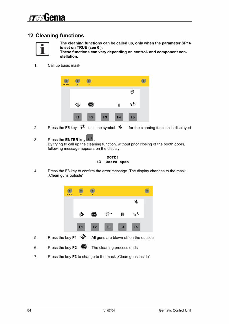
84 V. 07/04 Gematic Control Unit
12 Cleaning functions The cleaning functions can be called up, only when the parameter SP16 is set on TRUE (see 0 ). These functions can vary depending on control- and component con-stellation.
1. Call up basic mask
2. Press the F5 key until the symbol for the cleaning function is displayed
3. Press the ENTER key . By trying to call up the cleaning function, without prior closing of the booth doors, following message appears on the display:
NOTE! 43 Doors open
4. Press the F3 key to confirm the error message. The display changes to the mask „Clean guns outside“
5. Press the key F1 : All guns are blown off on the outside
6. Press the key F2 : The cleaning process ends
7. Press the key F3 to change to the mask „Clean guns inside“

Gematic Control Unit V. 07/04 85
8. Press the key F1 : All guns are blown out
9. Press the key F2 : The cleaning process ends
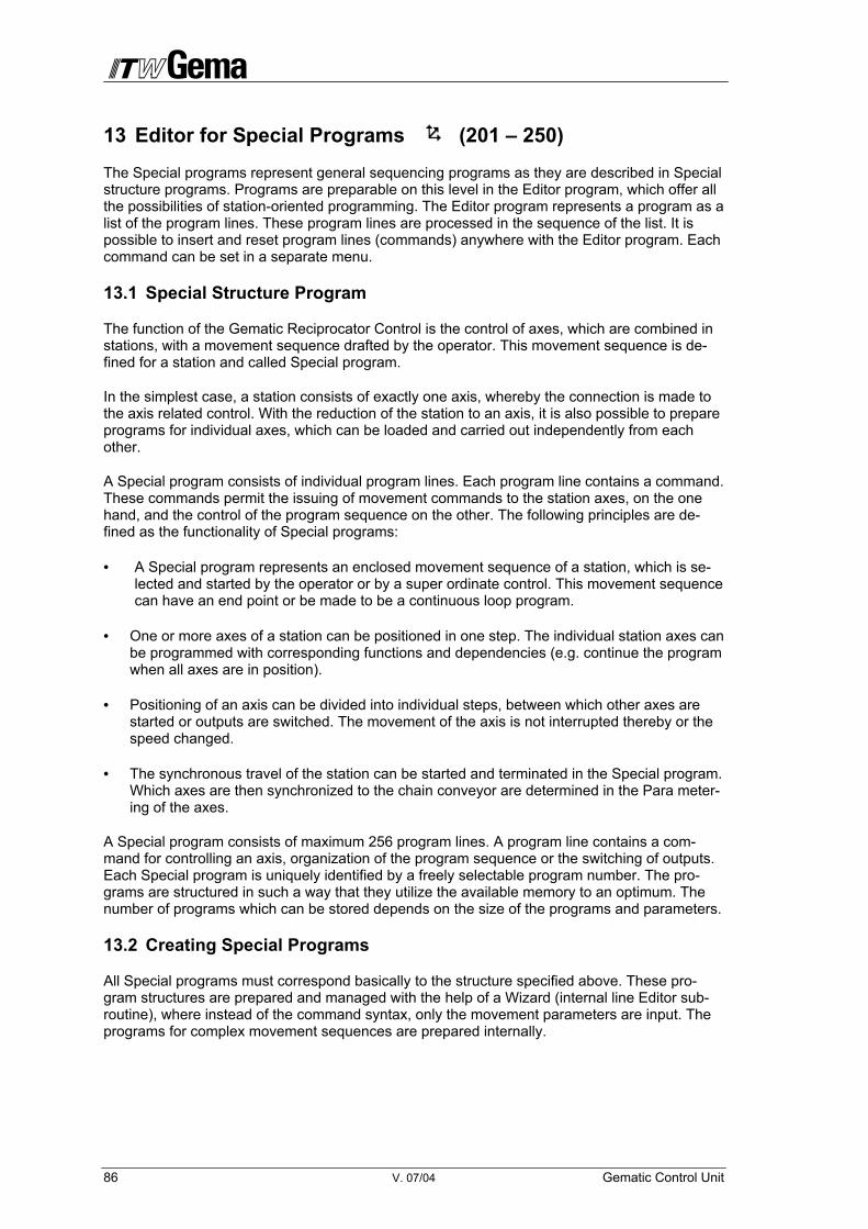
86 V. 07/04 Gematic Control Unit
13 Editor for Special Programs (201 – 250)
The Special programs represent general sequencing programs as they are described in Special structure programs. Programs are preparable on this level in the Editor program, which offer all the possibilities of station-oriented programming. The Editor program represents a program as a list of the program lines. These program lines are processed in the sequence of the list. It is possible to insert and reset program lines (commands) anywhere with the Editor program. Each command can be set in a separate menu.
13.1 Special Structure Program
The function of the Gematic Reciprocator Control is the control of axes, which are combined in stations, with a movement sequence drafted by the operator. This movement sequence is de-fined for a station and called Special program.
In the simplest case, a station consists of exactly one axis, whereby the connection is made to the axis related control. With the reduction of the station to an axis, it is also possible to prepare programs for individual axes, which can be loaded and carried out independently from each other.
A Special program consists of individual program lines. Each program line contains a command. These commands permit the issuing of movement commands to the station axes, on the one hand, and the control of the program sequence on the other. The following principles are de-fined as the functionality of Special programs:
• A Special program represents an enclosed movement sequence of a station, which is se-lected and started by the operator or by a super ordinate control. This movement sequence can have an end point or be made to be a continuous loop program.
• One or more axes of a station can be positioned in one step. The individual station axes can be programmed with corresponding functions and dependencies (e.g. continue the program when all axes are in position).
• Positioning of an axis can be divided into individual steps, between which other axes are started or outputs are switched. The movement of the axis is not interrupted thereby or the speed changed.
• The synchronous travel of the station can be started and terminated in the Special program. Which axes are then synchronized to the chain conveyor are determined in the Para meter-ing of the axes.
A Special program consists of maximum 256 program lines. A program line contains a com-mand for controlling an axis, organization of the program sequence or the switching of outputs. Each Special program is uniquely identified by a freely selectable program number. The pro-grams are structured in such a way that they utilize the available memory to an optimum. The number of programs which can be stored depends on the size of the programs and parameters.
13.2 Creating Special Programs
All Special programs must correspond basically to the structure specified above. These pro-gram structures are prepared and managed with the help of a Wizard (internal line Editor sub-routine), where instead of the command syntax, only the movement parameters are input. The programs for complex movement sequences are prepared internally.
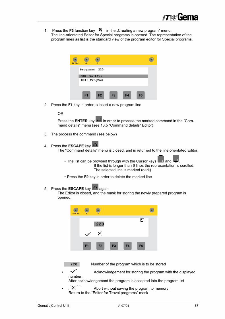
Gematic Control Unit V. 07/04 87
1. Press the F3 function key in the „Creating a new program" menu. The line-orientated Editor for Special programs is opened. The representation of the program lines as list is the standard view of the program editor for Special programs.
2. Press the F1 key in order to insert a new program line OR
Press the ENTER key in order to process the marked command in the “Com-mand details” menu (see 13.5 “Command details“ Editor)
3. The process the command (see below)
4. Press the ESCAPE key . The “Command details” menu is closed, and is returned to the line orientated Editor.
• The list can be browsed through with the Cursor keys and . If the list is longer than 6 lines the representation is scrolled. The selected line is marked (dark)
• Press the F2 key in order to delete the marked line
5. Press the ESCAPE key again The Editor is closed, and the mask for storing the newly prepared program is opened.
220 Number of the program which is to be stored
• Acknowledgement for storing the program with the displayed number. After acknowledgement the program is accepted into the program list
• Abort without saving the program to memory. Return to the “Editor for Travel programs” mask
220
Programm 220
001: ProgEnd 000: WaitTrs

88 V. 07/04 Gematic Control Unit
13.3 Program Line Definition
The Special programs of the Gematic Reciprocator Control represent a simple line orientated sequence programming language.
A program line contains exactly one action which is to be carried out during the transition to this step. The individual program lines are processed consecutively. Additional commands permit the synchronization of the program sequence with events, like wait times, axis positions, and repetitions of loops.
The number of program lines is variable, but limited to 256. A program is organized as a simple linked list of program lines. As an example, the following figure represents the structure of a sequence of program lines:
• Command This field contains the program instruction. The following commands are possible: Commands for positioning the axes
GoAbs Position axis on absolute position GoCont Start the continuous stroke movement GoInkr Position axis incrementally (chain dimension)
Commands for extended control (synchronous travel, set outputs....)
SyncON Start synchronous travel SyncOF Terminate synchronous travel SetOut Set an output SetGun Switching of/off the guns
Commands for sequence synchronization
WaitTi Wait for one time interval (in 100 ms units) WaitPnt Wait for feedback signal of the axis cam control WaitTrs Wait for the positioning of the running axes LoopSt Start of a program loop with n repetitions LoopEnd End of the program loop WaitPls Wait for pulse quantity from the encoder
• Axis This field contains the identification letters of the axes to can be controlled. The allocation of the physical axis takes place in the System parameters of the axes. Prepared programs can be transmitted to other stations, without having to adapt the axis numbers, with this abstrac-tion. The program is more understandable because station designations of the axes are used, such as Z for the Z axis etc.
Programm 220 000: SyncOn 001: GoAbs Z +1200 250 003: SetOut 2 ON005: ProgEnd
Program 220 000: SyncOn 001: GoAbs Z +1200 250 003: SetOut 2 ON005: ProgEnd

Gematic Control Unit V. 07/04 89
• Distance The commands for positioning the axis target position (absolute or incremental) are dis-played here as a distance in mm.
• Speed This field contains the speed with which the axis is to be positioned. The unit is mm/s.
• Output The output number is entered here with commands for setting the outputs.
• Level Output level 1/0 when switching the outputs.
13.4 Command Description
13.4.1 Commands for positioning the axis
• GoAbs Position axis on absolute position. This command starts the absolute positioning on the axis. Program processing does not wait until the position is reached, so several axes which apparently start to move at the same time, can be started consecutively with this com-mand. The setting, and monitoring of an intermediate position with a WaitPoint is possible after this command.
• GoCont Start of the continuous stroke movement This command starts the stroke movement, which consists of a continuous up and down movement, in the Frequency con-verter. The parameters end point, and speed are defined in the program. The movement is only terminated with a program stop through the Panel or the interface.
• GoInkr Position axis incrementally (chain dimension) This command starts an incremental positioning of the axis. Program proc-essing does not wait until the position is reached, so that several axes can be started consecutively with this command.
13.4.2 Commands for extended control
• SyncOn Start synchronous travel. The synchronous travel of the corresponding axes starts.
• SyncOf Terminate synchronous travel. Terminates the synchronous travel of the corresponding axes.
• SetOut Set an output. A signal can be switched with this command. Each station is assigned 16 logical outputs, which can be switched in the program sequence. These signals can be set on hardware outputs or flags in the control configuration.
• SetGun Switch on/off the guns by the sequence program. Therefore, SP23 must be set on TRUE.

90 V. 07/04 Gematic Control Unit
13.4.3 Commands for synchronizing the process sequence
• WaitTi Wait time interval The command WaitTi inserts one stand-by time of n x 100 ms into the program sequence. The program continues to process the following command only after this time has elapsed.
• WaitPnt Wait at the intermediate position This command permits the synchronization of the program sequence on overriding a certain position on an axis. This command sets the transferred absolute position as intermedi-ate position on the axis and waits until the feedback signal ar-rives that the position has been overridden. The command can take effect only after a GoAbs. The commands, which fol-low the command WaitPoint, are only processed when the po-sition on the axis has been overridden.
• WaitTrs Wait for the positioning of the running axes This command must be inserted whenever a GoAbs or a GoInkr for the positioning of the axes has to be waited for. Without this command the start of positioning with the next command will continue immediately. The command following the WaitTrs command is only carried out if all axes of the sta-tion are in the desired position. The axis arriving later must not be stopped if it is to be used in the next sequence.
• LoopSt Start of a program loop with n repetitions This command represents the beginning of a program loop according to a FOR-NEXT loop. Nesting of up to 9 program loops is possible. The individual loop levels are defined by the loop index. The number of repetitions of loops is variable, a Number = 0 causes a continuous loop.
• LoopEnd End of the program loop The command represents the End point of a program loop (NEXT to FOR). The connection with the appropriate LoopSt is made through the loop index.
• WaitPls This command waits until the pulse quantity from the encoder is counted down. 1 pulse is corresponding to the distance of SP6 distance per pulse.

Gematic Control Unit V. 07/04 91
13.5 "Command details" Editor
1. The list in the line orientated Editor for special programs can be browsed through
with the CURSOR key and in order to mark the desired program line. If the list is longer than 6 lines the display is scrolled.
2. Press the ENTER key The „Commands details" Editor is opened and the commands with maxi-mum 5 parameters are listed
3. The list can be browsed through with the Cursor-Keys and in order to mark the desired line.
In this view the command or only the parameters can be modified. Varying parameters are displayed depending on the actual command.
4. Press the ENTER key The command or the parameter which is to be modified is marked.
Programmbefehl :
Programm 220
Achse : Z Absolutposition (mm) : 1200 Geschwindigkeit (mm/s) : 250
GoAbs
Programm 220
002: ProgEnd
000: GoAbs Z +1200 250
Programm 220
Achse : Z Absolutposition (mm) : 1200 Geschwindigkeit (mm/s) : 250
GoAbs Programmbefehl :
Program 220
Axis : Z Absolute position (mm) 1200 Speed (mm/s) : 250
GoAbs Program command

92 V. 07/04 Gematic Control Unit
5. Select the desired command or parameter with cursor keys and . After pressing the ENTER key, when the command is modified, then the conversion of the parameter display to the newly selected command takes place automatically. The input of the parameters depends on the data type of the parameter. Here are the following types:
• Number Direct input with the number keys. Cursor Up/Down increases or decreases the set value.
• Selection Selection of the parameter in plain text settings is available, which can be browsed through with the Cursor keys.
• Boolean Binary settings are represented with the values TRUE/FALSE, which can be browsed through with the Cursor keys between these two values.
During input, apart from the cursor keys, the following key functions are still active:
• SHIFT key is automatically activated, when numeric values are to be in-put in the input field.
• Number keys serve the input of numeric values with the active SHIFT key.
• Closes the input without saving the value in the memory, if the input was opened with Enter or closes the Parameter Editor if no input is active.
• Deletes the input field, i.e. a numeric parameter is set to 0 and a selection parameter on the first selection option.
• Keys + / - Serves to input of the preceding sign with numeric values with a negative range of values.
6. Press the ENTER key , in order to close the input and to save the input value
7. Press the ESCAPE key . The “Command details” menu is closed, and it is returned to the line orientated Editor.
8. Press the ESCAPE key again. The Editor is closed, and the mask for saving the program is opened.
Programm 220
Achse : Z Inkremental pos.(mm) : +200 Geschwindigkeit (mm/s) : 50
GoInkr Programmbefehl :
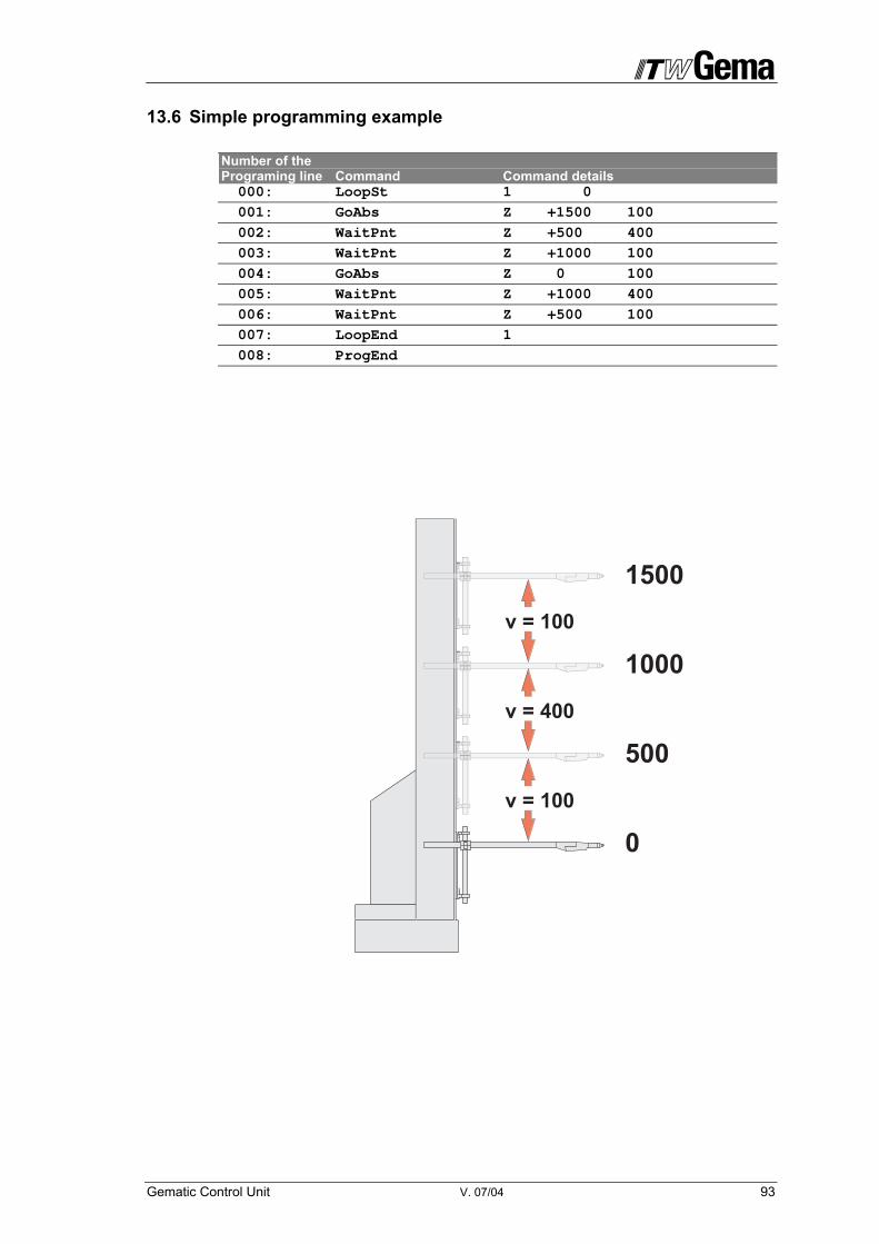
Gematic Control Unit V. 07/04 93
13.6 Simple programming example Number of the Programing line Command Command details 000: LoopSt 1 0
001: GoAbs Z +1500 100
002: WaitPnt Z +500 400
003: WaitPnt Z +1000 100
004: GoAbs Z 0 100
005: WaitPnt Z +1000 400
006: WaitPnt Z +500 100
007: LoopEnd 1
008: ProgEnd
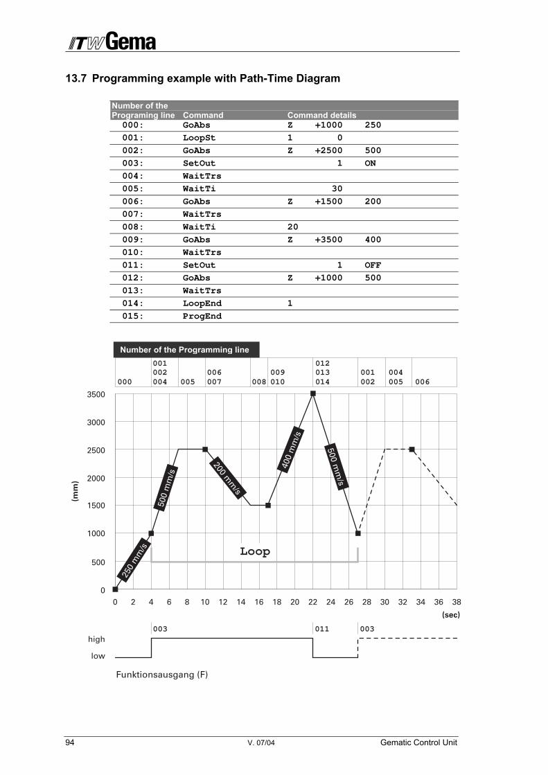
94 V. 07/04 Gematic Control Unit
13.7 Programming example with Path-Time Diagram Number of the Programing line Command Command details 000: GoAbs Z +1000 250
001: LoopSt 1 0
002: GoAbs Z +2500 500
003: SetOut 1 ON
004: WaitTrs
005: WaitTi 30
006: GoAbs Z +1500 200
007: WaitTrs
008: WaitTi 20
009: GoAbs Z +3500 400
010: WaitTrs
011: SetOut 1 OFF
012: GoAbs Z +1000 500
013: WaitTrs
014: LoopEnd 1
015: ProgEnd
Number of the Programming line
0 2 4 6 8 10 12 14 16 18 20 22 24 26 28 30 32 34 36 380
low
high
500
1500
1000
2000
2500
3000
3500
(mm
)
(sec)
Funktionsausgang (F)
250
mm
/s
500
mm
/s
400
mm
/s
200 mm
/s
500 mm
/s
000 004
003 003
005 007 008 010 014002
005 006004006 013
012001
011
002001009
Loop

Gematic Control Unit V. 07/04 95
APPENDIX C I/O Interface allocation table (if SP10 = FALSE)
Prog No Program number I/O1 = Binary value 1 .... IN8 = Binary value 128
Automatic Switches to automatic operation mode StoppInProg Calls up the program number 64 for Z and 164 for X axis Start Start axis Synchron Start axis synchronously with chain conveyor Strobe The program numbers present at the inputs I/O1 – IN8 (binary value range =
Program number 1-255) are read in when the 24 V (high) signal goes to 0 V (low) (= negative flank).
Start Ref Reference axis Ready Axis ready Running Axis running (in motion) Ref Ok Axis is referenced FktBit Function bit
This output is set on high or low when the instruction „SetOut 1 ON " or „Set-Out 1 OFF“ is input in the special program.
Q KN OUTPUT Q KN OUTPUT
I KN INPUT I KN INPUT
0.1 38 PRGNo 2**0 0.17 56 A-Z Ready 0.2 39 PRGNo 2**1 0.18 57 A-Z Running 0.3 40 PRGNo 2**2 0.19 58 A-Z Ref OK 0.4 41 PRGNo 2**3 0.20 59 A-Z FktBit 0.5 42 PRGNo 2**4 0.21 60 A-Z Start 0.6 43 PRGNo 2**5 0.22 61 A-Z Synchron 0.7 44 PRGNo 2**6 0.23 62 A-Z Strobe 0.8 45 PRGNo 2**7 0.24 63 A-Z Start Ref 0.9 46 Automatic 0.25 64 B-Z Start
0.10 47 Stop in program 0.26 65 B-Z Synchron 0.11 48 PRC open activated 0.27 66 B-Z Strobe 0.12 49 0.28 67 B-Z Start Ref 0.13 50 0.29 68 B-Z Ready 0.14 51 0.30 69 B-Z Running 0.15 52 Chain pulse 0.31 70 B-Z Ref OK 0.16 53 Preceding sign chain pulse 0.32 71 B-Z FktBit
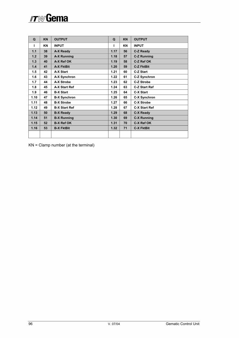
96 V. 07/04 Gematic Control Unit
Q KN OUTPUT Q KN OUTPUT
I KN INPUT I KN INPUT
1.1 38 A-X Ready 1.17 56 C-Z Ready 1.2 39 A-X Running 1.18 57 C-Z Running 1.3 40 A-X Ref OK 1.19 58 C-Z Ref OK 1.4 41 A-X FktBit 1.20 59 C-Z FktBit 1.5 42 A-X Start 1.21 60 C-Z Start 1.6 43 A-X Synchron 1.22 61 C-Z Synchron 1.7 44 A-X Strobe 1.23 62 C-Z Strobe 1.8 45 A-X Start Ref 1.24 63 C-Z Start Ref 1.9 46 B-X Start 1.25 64 C-X Start
1.10 47 B-X Synchron 1.26 65 C-X Synchron 1.11 48 B-X Strobe 1.27 66 C-X Strobe 1.12 49 B-X Start Ref 1.28 67 C-X Start Ref 1.13 50 B-X Ready 1.29 68 C-X Ready 1.14 51 B-X Running 1.30 69 C-X Running 1.15 52 B-X Ref OK 1.31 70 C-X Ref OK 1.16 53 B-X FktBit 1.32 71 C-X FktBit
KN = Clamp number (at the terminal)

Gematic Control Unit V. 07/04 97
APPENDIX C I/O Interface allocation table (if SP10 = TRUE)
Q KN OUTPUT Q KN OUTPUT
I KN INPUT I KN INPUT
0.1 38 Main solenoid valve 0.17 56 Function bit A 0.2 39 Prefluidizing 0.18 57 Function bit B 0.3 40 Error lamp 0.19 58 Function bit C 0.4 41 Alarm horn 0.20 59 Function bit D 0.5 42 Light barrier object 0.21 60 Fire protection 0.6 43 Light barrier door 0.22 61 Grounding protection 0.7 44 Motor protection 0.23 62 Door open 0.8 45 Temperature of control cabinet 0.24 63 Door closed 0.9 46 Chain running 0.25 64 Control voltage
0.10 47 Air pressure 0.26 65 Error acknowledgement 0.11 48 Powder level 1 OK 0.27 66 External booth ready
0.12 49 Powder level 2 OK 0.28 67 Pump button/Sieve (PS2 / AZO) on/off
0.13 50 Powder requirement level sensor 1 or from Powder center 0.29 68 Pump/Sieve (PS2 / AZO) on
0.14 51 Powder requirement level sensor 2 or from Powder center 0.30 69 Pump lamp/Sieve (PS2 / AZO) off
0.15 52 Conveyor release 0.31 70 Start button lock 0.16 53 Gema ready 0.32 71
KN = Clamp number (at the terminal)