Control-Plane Protocol Interactions in Mobile Networks
156
UNIVERSITY OF CALIFORNIA Los Angeles Control-Plane Protocol Interactions in Mobile Networks A dissertation submitted in partial satisfaction of the requirements for the degree Doctor of Philosophy in Computer Science by Guan-Hua Tu 2015
-
Upload
khangminh22 -
Category
Documents
-
view
2 -
download
0
Transcript of Control-Plane Protocol Interactions in Mobile Networks

UNIVERSITY OF CALIFORNIA
Los Angeles
Control-Plane Protocol Interactions in Mobile Networks
A dissertation submitted in partial satisfaction
of the requirements for the degree
Doctor of Philosophy in Computer Science
by
Guan-Hua Tu
2015


ABSTRACT OF THE DISSERTATION
Control-Plane Protocol Interactions in Mobile Networks
by
Guan-Hua Tu
Doctor of Philosophy in Computer Science
University of California, Los Angeles, 2015
Professor Songwu Lu, Chair
The 3G/4G mobile network is a wireless infrastructure that offers universal coverage and ubiqui-
tous data and voice services. It is a large-scale, global network system on a par with the Internet.
In recent years, the demand for mobile data access grows exponentially. The traffic volume is
projected to increase three times by 2018, according to a recent CISCO estimate. The demand will
be further accelerated by the increasing popularity of smartphones, tablets, and wearable devices.
However, its control-plane design is much more complex and offers many more utility func-
tions (e.g., mobility support, radio resource control, and device-level security) than its Internet
counterpart. They communicate with one another along three dimensions of cross layers, cross
(circuit-switched and packet-switched) domains, and cross (3G and 4G) systems. Despite their
significance, the correctness verification on their protocols remains largely unexplored.
In this dissertation, we examine control-plane protocol interactions in mobile networks. We
propose CNetVerifier, a two-phase signaling diagnosis tool to detect problematic interactions in
both design and practice. CNetVerifier first performs protocol screening based on 3GPP standards
ii

via domain-specific model checking, and then conducts phone-based empirical validation in oper-
ational 3G/4G networks. With CNetVerifier, we have uncovered six types of troublesome interac-
tions, along three dimensions of cross layers, cross domains, and cross systems. Such control-plane
issues span both design defects in the 3GPP standards and operational slips by carriers. Some are
caused by necessary yet problematic cooperation (i.e., protocol interactions are needed but they
misbehave), whereas others are due to independent yet unnecessary coupled operations (i.e., pro-
tocols interactions are not required but actually coupled). They all result in performance penalties
or functional incorrectness.
We further quantify the real world impact of control-plane protocols from end-user’s perspec-
tive. We conduct two empirical studies on three essential mobile network services for mobile
users: user mobility support, voice and data services in operational networks. Specifically, we fo-
cus on whether the improper control-plane (i.e., mobility support) operations affect the accounting
(management-plane) for roaming users’ mobile data access or have negative impacts on both data
and voice services.
There are three lessons learnt from our work. First, the current control-plane design in mo-
bile networks does not honor layering structure which has been strictly examined in the Internet
community and does not well recognize differences of domains and systems. The problematic
control-plane protocol interactions are almost observed anywhere in practice. Coupling unnec-
essary inter-layer actions leads to longer call setup time or packet delivery latency than usual;
Coupling CS and PS services at the shared radio resource state (RRC) may deprive mobile user of
4G network connectivity; Inconsistent regulations for the context shared by two different systems
may get mobile users into “out-of-service” state for tens of seconds. Second, the control-plane
and management-plane (e.g., data usage accounting) do not cooperate with each other in a coor-
dinated manner. For example, the data usage accounting is not suspended while an inter-system
handoff (e.g., 3G→4G) is triggered by the control-plane due to user mobility. The mobile devices
iii

cannot receive any packets until the handoff procedure is finished (caused by hardware limitation,
e.g., single radio). The roaming users still pay for all packets lost during the handoff procedure.
Third, the control-plane does not honor diversity in the demands of voice and data services. The
voice service is an essential service (or even the most important service) for carriers. It is always
granted higher serving priority than the data service. We discover that the not-well-justified design
principle leads to serious performance issues (e.g., up to 83.4% data throughput slumps or Internet
applications get aborted) to data service or even have negative impacts (e.g., missed incoming call)
on voice service.
iv
The dissertation of Guan-Hua Tu is approved.
Mau-Chung Frank Chang
Mario Gerla
Lixia Zhang
Songwu Lu, Committee Chair
University of California, Los Angeles
2015
v

To my parents and my wife Yi-Shiuan
and my children Elton, Allen and Olivia
without whom I would not complete my PhD study.
vi

TABLE OF CONTENTS
1 Introduction . . . . . . . . . . . . . . . . . . . . . . . . . . . . . . . . . . . . . . . 1
1.1 Our Contributions . . . . . . . . . . . . . . . . . . . . . . . . . . . . . . . . . . . 3
1.1.1 Detection of Problematic Control-Plane Protocol Interactions . . . . . . . 3
1.1.2 Impacts of Control-Plane Protocols on Roaming Users’ Accounting . . . . 4
1.1.3 Studies of Interplay between Voice and Data Services . . . . . . . . . . . . 5
1.2 Dissertation Structure . . . . . . . . . . . . . . . . . . . . . . . . . . . . . . . . . 7
2 Background & State-of-Art . . . . . . . . . . . . . . . . . . . . . . . . . . . . . . 8
2.1 Mobile Network Architecture . . . . . . . . . . . . . . . . . . . . . . . . . . . . . 8
2.2 Control-Plane Protocol Primer . . . . . . . . . . . . . . . . . . . . . . . . . . . . 10
2.2.1 Connectivity Management (CM) for Voice and Data Services . . . . . . . . 11
2.2.2 Mobility Management (MM) . . . . . . . . . . . . . . . . . . . . . . . . . 11
2.2.3 Radio Resource Control (RRC) . . . . . . . . . . . . . . . . . . . . . . . 12
2.3 Mobile Data Access Accounting . . . . . . . . . . . . . . . . . . . . . . . . . . . 13
2.4 State-of-Art on Mobile Networks . . . . . . . . . . . . . . . . . . . . . . . . . . . 13
2.4.1 Protocol Verification . . . . . . . . . . . . . . . . . . . . . . . . . . . . . 13
2.4.2 Accounting for Roaming Users Mobile Data Access . . . . . . . . . . . . 14
2.4.3 Interplay between Voice and Data Services . . . . . . . . . . . . . . . . . 14
3 Detection of Problematic Control-Plane Protocol Interactions . . . . . . . . . . . . 16
3.1 Methodology . . . . . . . . . . . . . . . . . . . . . . . . . . . . . . . . . . . . . 16
vii

3.1.1 CNetVerifier Overview . . . . . . . . . . . . . . . . . . . . . . . . . . . . 16
3.1.2 Domain-Specific Protocol Screening . . . . . . . . . . . . . . . . . . . . . 18
3.1.3 Phone-based Experimental Validation . . . . . . . . . . . . . . . . . . . . 21
3.2 Overview of Findings . . . . . . . . . . . . . . . . . . . . . . . . . . . . . . . . . 22
3.3 Improper Cooperation . . . . . . . . . . . . . . . . . . . . . . . . . . . . . . . . . 26
3.3.1 Unprotected Shared Context in 3G/4G . . . . . . . . . . . . . . . . . . . . 26
3.3.2 Out-of-Sequenced Signaling in Inter-Protocol Communications . . . . . . 31
3.3.3 Inconsistent Cross-Domain/Cross-System Protocol State Transition . . . . 34
3.4 Problematic Coupled Actions . . . . . . . . . . . . . . . . . . . . . . . . . . . . . 37
3.4.1 HOL Blocking for Independent Updates . . . . . . . . . . . . . . . . . . 37
3.4.2 Fate Sharing for Voice and Data . . . . . . . . . . . . . . . . . . . . . . . 41
3.4.3 3G Failures Propagated to 4G System . . . . . . . . . . . . . . . . . . . . 44
3.5 User Study . . . . . . . . . . . . . . . . . . . . . . . . . . . . . . . . . . . . . . 45
3.6 Solution . . . . . . . . . . . . . . . . . . . . . . . . . . . . . . . . . . . . . . . . 48
3.7 Prototype and Evaluation . . . . . . . . . . . . . . . . . . . . . . . . . . . . . . . 50
3.7.1 Layer Extension . . . . . . . . . . . . . . . . . . . . . . . . . . . . . . . 51
3.7.2 Domain Decoupling . . . . . . . . . . . . . . . . . . . . . . . . . . . . . 51
3.7.3 Cross-system Coordination . . . . . . . . . . . . . . . . . . . . . . . . . . 53
4 Impacts of Control-Plane Protocols on Roaming User’s Accouting . . . . . . . . . 54
4.1 Experimental Methodology . . . . . . . . . . . . . . . . . . . . . . . . . . . . . . 54
4.2 Accounting Gap for Roaming Users . . . . . . . . . . . . . . . . . . . . . . . . . 59
viii

4.2.1 All Tested Routes . . . . . . . . . . . . . . . . . . . . . . . . . . . . . . . 59
4.2.2 Case Study on An Example Route . . . . . . . . . . . . . . . . . . . . . . 62
4.3 Diversified Root Causes . . . . . . . . . . . . . . . . . . . . . . . . . . . . . . . . 63
4.3.1 Root-Cause Event Classification in Traces . . . . . . . . . . . . . . . . . . 64
4.3.2 Findings . . . . . . . . . . . . . . . . . . . . . . . . . . . . . . . . . . . 65
4.4 We Pay for Handoff . . . . . . . . . . . . . . . . . . . . . . . . . . . . . . . . . . 67
4.4.1 Impact of Handoff Types . . . . . . . . . . . . . . . . . . . . . . . . . . . 67
4.4.2 Certain Intra-System Handoff Incurs Accounting Gap But Others Do Not . 75
4.4.3 Inter-System Handoff Always Incurs Accounting Gap . . . . . . . . . . . 76
4.4.4 Shorter Suspension Time May Incur Larger Accounting Gap . . . . . . . . 78
4.5 Insufficient Coverage . . . . . . . . . . . . . . . . . . . . . . . . . . . . . . . . . 81
4.6 Factor impact . . . . . . . . . . . . . . . . . . . . . . . . . . . . . . . . . . . . . 83
4.7 Solutions . . . . . . . . . . . . . . . . . . . . . . . . . . . . . . . . . . . . . . . 91
5 Studies of Interplay between Voice and Data Services . . . . . . . . . . . . . . . . 93
5.1 Studying CSFB in Operational LTE Networks . . . . . . . . . . . . . . . . . . . . 93
5.1.1 Experimental Methodology . . . . . . . . . . . . . . . . . . . . . . . . . 94
5.1.2 Issues to Study . . . . . . . . . . . . . . . . . . . . . . . . . . . . . . . . 95
5.2 Throughput Slump . . . . . . . . . . . . . . . . . . . . . . . . . . . . . . . . . . 97
5.2.1 An Illustrative Example . . . . . . . . . . . . . . . . . . . . . . . . . . . 97
5.2.2 TCP/UDP under Normal Voice Calls . . . . . . . . . . . . . . . . . . . . 99
5.2.3 Worse Than Expected . . . . . . . . . . . . . . . . . . . . . . . . . . . . 100
ix

5.3 Losing 4G Connectivity . . . . . . . . . . . . . . . . . . . . . . . . . . . . . . . . 104
5.3.1 OP-I: When the Call Fails to Establish . . . . . . . . . . . . . . . . . . . . 104
5.3.2 OP-II: Once the Call Attempt is Made . . . . . . . . . . . . . . . . . . . . 108
5.3.3 RRC Loop Under Data Services . . . . . . . . . . . . . . . . . . . . . . . 109
5.3.4 Performance Impact . . . . . . . . . . . . . . . . . . . . . . . . . . . . . 114
5.4 Data Application Abort . . . . . . . . . . . . . . . . . . . . . . . . . . . . . . . . 117
5.4.1 Popular Applications . . . . . . . . . . . . . . . . . . . . . . . . . . . . . 117
5.4.2 How Often Application Aborts . . . . . . . . . . . . . . . . . . . . . . . . 120
5.4.3 Root Cause: Being Detached . . . . . . . . . . . . . . . . . . . . . . . . . 121
5.5 Reverse Impact: Missed Calls . . . . . . . . . . . . . . . . . . . . . . . . . . . . 123
5.6 Solutions . . . . . . . . . . . . . . . . . . . . . . . . . . . . . . . . . . . . . . . 124
6 Conclusion and Future Work . . . . . . . . . . . . . . . . . . . . . . . . . . . . . 127
6.1 Summary of Results . . . . . . . . . . . . . . . . . . . . . . . . . . . . . . . . . . 127
6.2 Insights and Lessons . . . . . . . . . . . . . . . . . . . . . . . . . . . . . . . . . 128
6.3 Future Work . . . . . . . . . . . . . . . . . . . . . . . . . . . . . . . . . . . . . . 130
References . . . . . . . . . . . . . . . . . . . . . . . . . . . . . . . . . . . . . . . . . 133
x

LIST OF FIGURES
2.1 4G/3G mobile network architecture. . . . . . . . . . . . . . . . . . . . . . . . . . 9
2.2 Control-plane protocols on mobile phone. . . . . . . . . . . . . . . . . . . . . . . 9
3.1 CNetVerifier Overview . . . . . . . . . . . . . . . . . . . . . . . . . . . . . . . . 17
3.2 The 4G→3G inter-system switching flow. . . . . . . . . . . . . . . . . . . . . . . 28
3.3 Recovery time from the detached event. . . . . . . . . . . . . . . . . . . . . . . . 31
3.4 Device is detached by lost/duplicate signals. . . . . . . . . . . . . . . . . . . . . . 32
3.5 RRC states in various inter-system switching options. . . . . . . . . . . . . . . . . 35
3.6 Call setup time and RSSI on Route-1 in OP-I. . . . . . . . . . . . . . . . . . . . . 40
3.7 CDF of location update durations in OP-I and OP-II. . . . . . . . . . . . . . . . . 41
3.8 Downlink and uplink data speed (maximum, median and minimum) with/without
CS calls in both carriers. . . . . . . . . . . . . . . . . . . . . . . . . . . . . . . . 42
3.9 An example protocol trace (64QAM is disabled during CS voice call, OP-I). . . . . 43
3.10 Solution overview. . . . . . . . . . . . . . . . . . . . . . . . . . . . . . . . . . . 48
3.11 Left: the number of detach varies with drop rate. Right: the call delay call varies
with the location update time. . . . . . . . . . . . . . . . . . . . . . . . . . . . . . 52
3.12 The data speeds vary with/without the coupled data and voice: downlink (Left) and
uplink (Right). . . . . . . . . . . . . . . . . . . . . . . . . . . . . . . . . . . . . . 52
4.1 Median accounting gaps, ratios and unit-gaps on all the routes in preliminary ex-
periments. The dash lines denote 3 MB gap, 10% ratio and 500 KB gap per km. . . 60
4.2 An example of network status trace and packet delivery log on Route 12 using OP-I. 61
xi

4.3 An example of composite handoff (1 inter-HO, 5 intra-HOs). . . . . . . . . . . . . 69
4.4 Accounting gap (MB) and time duration (s) with handoff types. . . . . . . . . . . . 71
4.5 Accounting gap varies with handoff types. Top: Inter-system handoff; Bottom:
intra-system handoff. . . . . . . . . . . . . . . . . . . . . . . . . . . . . . . . . . 73
4.6 Suspension duration varies with handoff types. Top: Inter-system handoff; Bot-
tom: intra-system handoff. . . . . . . . . . . . . . . . . . . . . . . . . . . . . . . 74
4.7 Packet reception. Top: during buffer experiment; Middle: packet travel time during
buffer experiment; Bottom: with an inter-system handoff. . . . . . . . . . . . . . . 79
4.8 Buffer size in 2G, 3G and 4G networks . . . . . . . . . . . . . . . . . . . . . . . . 81
4.9 Accounting gap in OP-II hybrid network . . . . . . . . . . . . . . . . . . . . . . . 83
4.10 TCP sequence numbers with handoff occurrences in time scale (s). . . . . . . . . . 85
4.11 Accounting gap with source rate. . . . . . . . . . . . . . . . . . . . . . . . . . . . 87
4.12 Handoff occurrence with mobility speed. . . . . . . . . . . . . . . . . . . . . . . . 89
5.1 Alice calls Bob while he is downloading a file. . . . . . . . . . . . . . . . . . . . . 97
5.2 CSFB event flow for an incoming call. . . . . . . . . . . . . . . . . . . . . . . . . 97
5.3 Logs of data throughput (4G:+, 3G:×), network type (LTE, HSPA, UMTS) and
call event (marked by black dashed lines) observed at Bob’s phone in normal case
of answering Alice’s call. (a) OP-I: one 4G→3G handoff triggered; (b): OP-I:
multiple handoffs triggered; (c): OP-II: no handoff back to 4G when the call ends. . 102
5.4 TCP logs of sequence number, congestion window and retransmission timeout ob-
served at Bob’s TCP Server in the example of Figure 5.3(a). . . . . . . . . . . . . 103
xii

5.5 Data throughput observed at Bob’s phone if Alice immediately hangs (the outgoing
call) up in OP-I carrier. . . . . . . . . . . . . . . . . . . . . . . . . . . . . . . . . 105
5.6 Simplified RRC state transition machine and call setup procedure. . . . . . . . . . 106
5.7 Duration stuck in 3G versus packet intervals for two 1B/1KB packets in case of an
unestablished call via OP-I. . . . . . . . . . . . . . . . . . . . . . . . . . . . . . . 110
5.8 Duration stuck in 3G versus packet intervals for two 1B/1KB packets in case of a
complete call via OP-II. . . . . . . . . . . . . . . . . . . . . . . . . . . . . . . . . 110
5.9 Illustration of event traces for data flows with various packet intervals and packet
sizes. . . . . . . . . . . . . . . . . . . . . . . . . . . . . . . . . . . . . . . . . . . 111
5.10 Duration stuck in 3G with UDP flows vis OP-I. . . . . . . . . . . . . . . . . . . . 114
5.11 Portions of network status logs on a 12-mile route. . . . . . . . . . . . . . . . . . 115
5.12 3G/4G speed at different hours of a day via OP-I (Left: uplink; Right: downlink). . 116
5.13 An example of FTP application abort. . . . . . . . . . . . . . . . . . . . . . . . . 117
5.14 10-day FTP downloading abort ratio (OP-I). . . . . . . . . . . . . . . . . . . . . . 120
5.15 Cause of being kicked out and reattach time. . . . . . . . . . . . . . . . . . . . . 122
xiii

LIST OF TABLES
1.1 Studied protocols on network elements and devices. . . . . . . . . . . . . . . . . . 2
2.1 Major mobile network technologies. . . . . . . . . . . . . . . . . . . . . . . . . . 10
3.1 Finding summary. . . . . . . . . . . . . . . . . . . . . . . . . . . . . . . . . . . . 25
3.2 PDP context deactivation causes. . . . . . . . . . . . . . . . . . . . . . . . . . . . 30
3.3 Scenarios trigger location/routing area update. . . . . . . . . . . . . . . . . . . . . 38
3.4 Summary of user-based study on S1-S6. . . . . . . . . . . . . . . . . . . . . . . . 46
3.5 Duration in 3G after the CSFB call ends (S3). . . . . . . . . . . . . . . . . . . . . 46
4.1 Route information. . . . . . . . . . . . . . . . . . . . . . . . . . . . . . . . . . . 56
4.2 An example of mobile network trace. . . . . . . . . . . . . . . . . . . . . . . . . . 59
4.3 Event classification. . . . . . . . . . . . . . . . . . . . . . . . . . . . . . . . . . . 64
4.4 Time durations (minute) for four events. . . . . . . . . . . . . . . . . . . . . . . . 65
4.5 Accounting gaps (MB) for four events. . . . . . . . . . . . . . . . . . . . . . . . . 66
4.6 Unit-time gap (MB/min) for four events. . . . . . . . . . . . . . . . . . . . . . . . 66
4.7 List of handoff types observed. . . . . . . . . . . . . . . . . . . . . . . . . . . . . 72
4.8 Median accounting gap (MB) and data suspension duration (second) for intra-
system handoffs. . . . . . . . . . . . . . . . . . . . . . . . . . . . . . . . . . . . 77
4.9 Median accounting gap (MB) and data suspension duration (second) for inter-
system handoffs. . . . . . . . . . . . . . . . . . . . . . . . . . . . . . . . . . . . 77
4.10 Average accounting gap ratio (Gap/Vop(%)) with real applications on Route 12. . . 84
xiv

4.11 Accounting gap for driving commuters during March 18-29, 2013. . . . . . . . . . 86
5.1 Finding summary. . . . . . . . . . . . . . . . . . . . . . . . . . . . . . . . . . . . 95
5.2 Rules for 3G → 4G switch upon an unestablished call (i.e., the call state is not
Call Received) for OP-I. . . . . . . . . . . . . . . . . . . . . . . . . . . . . . 111
5.3 Application behavior when voice call arrives . . . . . . . . . . . . . . . . . . . . . 118
5.4 Logs of network status at the mobile phone. . . . . . . . . . . . . . . . . . . . . . 121
xv

ACKNOWLEDGMENTS
I am indebted to my advisor Professor Songwu Lu for his patient and insightful guidance
through my Ph.D. study. He spent time on interacting with me frequently, and usually gave me
valuable feedback and constructive suggestions. He carefully led me to go through the difficulties
of thinking, writing, and experiments in doing scientific research. He also taught me how to do high
quality of research and good presentation. I really appreciate his guidance and support throughout
these years.
I am grateful to my committee members, Professors Lixia Zhang, Mario Gerla, and M. C.
Frank Chang, for their insightful comments on my research. Professor Zhang inspired me to
think deeper in each work, and emphasize its insights and philosophy. She also taught me the
importance of being precise on the wording and presentation. Professor Gerla helps me with his
valuable comments and friendly discussions on my research projects. Professor Chang’s technical
comments about his expertise of wireless radio technologies, are very helpful for my work.
I also want to thank my colleagues in the Wireless Networking Group (WiNG) at UCLA. I
am especially grateful to Chunyi Peng for her guidance on the early stage of my research. She
motivates me to be aggressive and hard-working in the way of achieving my goals. I would like
also to thank Yuanjie Li and Chi-Yu Li for their cooperation on the projects of mobile networks.
xvi

VITA
1997 - 2001 B.S., Computer Science, NCU, Taiwan
2001 - 2003 M.S., Computer Science and Information Engineering, NTU, Taiwan
2003 - 2009 Senior Engineer, MediaTek Inc., Taiwan
2010 - 2013 M.S., Computer Science, UCLA
2010 - 2015 Graduate Student Researcher, Computer Science, UCLA
PUBLICATIONS
Guan-Hua Tu, Yuanjie Li, Chunyi Peng, Chi-Yu Li, Songwu Lu, “Detecting Problematic Control-
Plane Protocol Interactions in Mobile Networks,” To appear in IEEE/ACM Transactions on Net-
working, 2015.
Guan-Hua Tu, Chi-Yu Li, Chunyi Peng, Songwu Lu “How Voice Call Technology Poses Security
Threats in 4G LTE Networks,” Accepted to IEEE Communication and Network Security (CNS),
2015.
Chi-Yu Li*, Guan-Hua Tu*, Chunyi Peng, Zengwen Yuan, Yuanjie Li, Songwu Lu, Xinbing
Wang “Insecurity of Voice Solution VoLTE in LTE Mobile Networks,” Accepted to ACM CCS,
xvii

2015. (*:Co-Primary)
Guan-Hua Tu, Yuanjie Li, Chunyi Peng, Chi-Yu Li, Hongyi Wang, Songwu Lu, “Control-plane
Protocol Interactions in Cellular Networks,” ACM SIGCOMM, Chicago, Illinois, Aug. 2014.
Guan-Hua Tu, Chunyi Peng, Hongyi Wang, Chi-Yu Li, Songwu Lu, “How Voice Calls Affect
Data in Operational LTE Networks,” ACM MOBICOM, Miami, Florida, Sept. 2013.
Guan-Hua Tu, Chunyi Peng, Chi-Yu Li, Xingyu Ma, Songwu Lu, “Accounting for Roaming Users
on Mobile Data Access: Issues and Root Causes,” ACM MOBISYS, Taipei, Taiwan, Jun. 2013.
Shiqiang Wang, Guan-Hua Tu, Raghu Ganti, Ting He, Kin Leung, Howard Tripp, Katy Warr,
Murtaza Zafer, “Mobile Micro-Cloud: Application Classification, Mapping, and Deployment,”
AMITA, Oct. 2013.
Chunyi Peng, Chi-Yu Li, Guan-Hua Tu, Songwu Lu, Lixia Zhang, “Mobile Data Charging: New
Attacks and Countermeasures,” ACM CCS, Raleigh, NC, Oct. 2012.
Chunyi Peng*, Guan-Hua Tu*, Chi-Yu Li, Songwu Lu, “Can We Pay for What We Get in 3G
Data Access?,” ACM MOBICOM, Istanbul, Turkey, Aug. 2012. (*:Co-Primary)
Phone Lin, Guan-Hua Tu, “An Improved GGSN Failure Restoration Mechanism for UMTS,”
ACM/Springer Wireless Networks, 12(1):91-103, Feb. 2006.
S.-M. Cheng, Phone Lin, Guan-Hua Tu, L.-C. Fu, and C.-F Liang, “An Intelligent GGSN Dis-
xviii

patching Mechanism for UMTS,” Elsevier Computer Communications, 28(8): 947-955, May 2005.
xix

CHAPTER 1
Introduction
The 3G/4G mobile network is the largest wireless infrastructure deployed today, serving billions of
mobile users with ubiquitous data and carrier-grade voice services. A salient feature of its design is
its control-plane protocols. Compared with the Internet, these components provide more complex
signaling functions. They follow the layered protocol architecture (see Figure 2.1 for an illustra-
tion), and run at both network infrastructure and end devices. These protocols work together to
offer control utilities vital to mobile networks, including radio resource control, mobility support,
session management for data and voice, etc..
In this dissertation, we study control-plane protocol interactions in mobile networks. We focus
on a set of critical functions (see Table 1.1 for the list), and seek to uncover problems during inter-
protocol communications. Our research is motivated by three factors. First, problematic inter-
protocol signaling each leads to functional incorrectness or performance penalty. For example,
mobility management may make a wrong decision upon receiving duplicate signaling messages
from the underlying radio resource control layer, thereby leading to network failure in that the user
device unnecessarily loses its network access (out of service). Second, although each signaling
protocol may be well designed individually, proper interactions among them in the networked
environment are not guaranteed. Despite prior empirical assessment effort (e.g., conformance
testing, field testing), verification for correctness on multiple protocol interactions through formal
methods is still missing. Third, patterns of inter-protocol communication on the control plane are
1

Function Name Net. Element Standard Description
PS/CS
CM/CC 3G MSC TS24.008 CS Connectivity Management
SM 3G Gateways TS24.008 PS Session Management
ESM 4G MME TS24.301 4G Session Management
Mobility
MM 3G MSC TS24.008 CS Mobility Management
GMM 3G Gateways TS24.008 PS Mobility Management
EMM 4G MME TS24.301 4G Mobility Management
Radio3G-RRC 3G BS TS25.331 Radio Resource Control
4G-RRC 4G BS TS36.331 Radio Resource Control
Table 1.1: Studied protocols on network elements and devices.
much richer and more complex than their Internet counterparts. They call for domain-specific
verification. In addition to the cross-layer1 (between layers of the protocol stack) case, protocol
interactions exhibit in both cross-domain (between packet switching (PS) and circuit switching
(CS) domains) and cross-system (between 3G and 4G systems) scenarios in mobile networks.
Since both data and carrier-grade voice are indispensable services, signaling protocols thus regulate
both PS and CS domains. Moreover, inter-system switching between 3G and 4G is also common
due to incremental deployment, hybrid operation, user mobility, or even voice calls for 4G LTE
users. Signaling protocols consequently need to work cross 4G and 3G systems.
To this end, we devise CNetVerifier, a two-phase signaling diagnosis tool. We first adopt pub-
licly available 3GPP standard specifications as the reference design, and perform protocol screen-
ing using domain-specific model-checking methods. It helps us to determine a candidate set of
potential design defects based on design documents only. Given this candidate set, we further
instrument the device for empirical validation over operational 3G/4G networks. Through the val-
1We use inter-layer and cross-layer interchangeably in this work.
2

idation phase, we not only identify real design defects, but also discover operational slips that may
not show up during the screening phase. The use of 3GPP standards addresses the challenge due
to a relatively closed system. Compared with the Internet, mobile networks remain rather closed:
signaling exchanges are not readily accessible from carriers, nor from devices during normal op-
erations. It is thus difficult to both detect potential issues and validate them. To address state
explosion issues in model checking, we exploit domain knowledge to model protocol behaviors
and usage scenarios, and perform property checking with aggregation.
In this dissertation, we first apply our tool and delve into all above three dimensions to identify
the possible problematic signaling protocol interactions. Second, we conduct two empirical studies
on three essential mobile network services for mobile users: user mobility support, voice and data
services in operational networks. We aim to quantify the real world impact of control-plane pro-
tocols from end-user’s perspective. Specifically, we study (1) how the control-plane (i.e., mobility
support) affects the accounting for roaming users’ mobile data access? (2) how data and voice
services are influenced by the control-plane protocol interactions (i.e., cross-domain/system)?
1.1 Our Contributions
1.1.1 Detection of Problematic Control-Plane Protocol Interactions
We devise CNetVerifier, a signaling diagnosis tool to study complicated control-plane protocol
interactions and generate counter examples (will be elaborated in Chapter 3). It helps us to not
only identify possible design flaws of mobile network standards but also capture the operational
slips.
Our study yields interesting findings. We show two classes of problematic interactions among
signaling protocols. They are exemplified using six concrete instances, spanning cross-layer, cross-
3

domain, and cross-system dimensions (see Table 5.1). In the first class, we show that some inter-
protocol communications are necessary yet troublesome. The necessity of signaling synergy is
partly driven by the requirement for carrier-grade voice support, partly by inter-system switching
in hybrid 3G/4G deployments, and partly by mobility management. However, interactions among
signaling protocols are not always designed and operated right: (S1) a user device is temporarily
out of service because its vital context in 4G is shared but not well protected (being deleted after
inter-system switching); (S2) Users are denied network access right after being accepted because
higher-layer protocols make unrealistic assumptions on lower layers; (S3) 4G users get stuck in
3G because inconsistent policies are used for CS and PS domains in 3G and 4G. The second class
concerns independent operations by protocols. We discover that, some are unnecessarily coupled
and have unexpected consequence: (S4) outgoing calls are delayed for unjustified location updates
because cross-layer actions are “improperly” correlated and prioritized; (S5) PS data sessions suf-
fer from rate reduction (51%− 96% drop observed) when traffic in both domains shares the same
channel; (S6) User devices are out of service when the failure is propagated to another system. We
further conduct a two-week user study to assess their real-world impact. We propose and evaluate
solutions that help to resolve above issues.
1.1.2 Impacts of Control-Plane Protocols on Roaming Users’ Accounting
The seamless mobility support has been an appealing highlight of control-plane of mobile net-
works. At a first glance, we think that mobility seems a non-issue for data accounting. However,
our experiments contradict our initial belief and reveal some interesting, yet not necessarily com-
mon cases.
Our study yields several findings. First, we discover that accounting gap indeed exists for the
mobility scenario. The gap can be as large as 69.6% in our road tests. The volume discrepancy
is route dependent and operator specific. Second, we further find that, the root causes are also
4

diversified. Accounting gap is observed even with strong signal (measured in RSSI) settings. The
key factor is the associated handoff, which may play a dominant role in certain scenarios. Third,
various types of handoffs are triggered in operational 2G/3G/4G networks with distinctive quality
of packet delivery. Operators have been using all deployed systems simultaneously whenever they
can, and thus various handoffs are triggered. This practice is partly for offloading traffic from the
high-end 4G/3G systems, partly due to partial deployment of high-end technology. As expected,
intra-system handoff (across cells with the same radio access technology) works well and incurs
little or no loss in 3G/4G systems. However, inter-system handoff (across radio technologies, e.g.,
between 3G and 2G, 4G and 3G) is problematic for data accounting. It leads to visible overcharging
in many test routes; we observe the accounting gap ratios greater than 5% in 9 test routes. In one
discovered setting, a popular handoff implementation, which uses buffering to improve wireless
link performance, may negatively increase the observed accounting gap (in the range of tens to
hundreds KBs). Fourth, low mobility speed may incur more occurrence of inter-system handoff
(e.g., three times of that observed at high mobility speed), which leads to a larger accounting gap
than the high-speed case. Fifth, we uncover a slightly new case for insufficient coverage. Certain
regions are covered by legacy 2G/3G networks but not by high-end 3G/4G systems. The observed
gap thus differs from that in the no-coverage case. Finally, we see the average accounting gap
ratio between 0.0-40.1% when using five real applications: Web browsing, Email, FTP, Youtube
and PPS Streaming, and 0.0-3.6% for a few mobile-phone users in their daily commute.
1.1.3 Studies of Interplay between Voice and Data Services
We conduct a study to understand the inter-play between voice calls and data services in operational
LTE networks. We identify the scenarios where they may interfere with each other in both expected
and unanticipated manners. It covers the cross-domain (CS and PS) and cross-system (3G and 4G)
control-plane protocol interactions. We also quantify their mutual impact, identify root causes, and
5

design solution fixes.
Our experiments over two US operational LTE carriers (called as OP-I and OP-II) have yielded
four findings, one expected and three unanticipated. First, we indeed observe throughput slump
for data sessions up to 83.4% when the 4G LTE user falls back to 3G for voice calls. This drop
is caused by the speed gap between LTE and 3G, but also incurred by data suspension and losses
during CSFB-triggered handoffs between 4G and 3G. The good news is that this degradation occurs
mainly during the voice call for OP-I ; However, for OP-II, the degradation may last even after the
call ends. Second, we discover that 4G LTE users may lose 4G connectivity due to voice calls.
They will not return to 4G afterwards. The lost connectivity lasted more than 10 hours and showed
no sign of limit. The issue occurs when certain background data traffic is running in some voice
call scenarios. In particular, it happens when the voice call fails to be established (for OP-I), or
no matter if the call is established (for OP-II). We identify that it is caused by the state machine
“loophole” that 3G is unable to switch back to 4G under certain scenario. Third, data applications
may abort (about 2-5% on average and 15% in the worst case in our tests) when a voice call ends.
The network may implicitly detach the user, despite ongoing data sessions, when migrating the
user back to 4G after CSFB calls. Consequently, the state or signaling triggered by CS voice also
affects PS data service. Last, we discover that PS data may also affect CS voice. CS calls may not
be available when the mobile turns on its PS service. The network state can then be changed by
PS, thus leading to transient unavailability of CS. Table 5.1 summarizes all these four findings.
The above findings confirm that, the interference between voice and data in CSFB-capable
LTE is mutual. Although these experimental cases do not necessarily represent the common usage
scenarios, they do showcase worst, yet possible settings. It indeed reveals complicated dependency
and coupling effects between voice and data. These effects are induced by the fundamental design
of CSFB, as well as its implementation loopholes.
6

1.2 Dissertation Structure
The rest of the dissertation is structured as follows. Chapter 2 introduces the background on mobile
network architecture, control-plane protocols, mobile data accounting and present the state-of-art
for protocol verification, etc .
Chapter 3 describes how identify problematic control-plane protocol interactions. Chapter 3.1
describes CNetVerifier, our tool for protocol analysis. Chapter 3.2 show two classes of problem-
atic interactions among signaling protocols. They are exemplified using six concrete instances,
spanning cross-layer, cross-domain, and cross-system dimension. Chapter 3.3 shows that some
inter-protocol communications are necessary yet troublesome in first class, Chapter 3.4 reports
three problematic coupling instance in second class. Chapter 3.5 conducts a two-week user study
to assess their real-world impact and Chapter 3.6 presents the proposed solution to prevent prob-
lematic control-plane protocol interactions.
Chapter 4 studies how the control-plane (i.e., mobility support) affects the accounting for roam-
ing users’ mobile data access. Chapter 4.1 describes the study methodology. Chapter 4.2 and 4.3
summarize the results and root causes. Chapter 4.4 and 4.5 discuss the root causes of accounting
gap observed in handoff and insufficient coverage, respectively. Chapter 4.6 describes other factors
contributing to the accounting gap. Chapter 4.7 provides possible solutions to the accounting gap.
Chapter 5 introduce how voice and data service are influenced by cross-domain/cross-system
control-plane protocol interactions. Chapter 5.1 describes our study methodology and the ad-
dressed issues. Chapter 5.2 discusses how TCP/UDP protocols are affected by CSFB voice. Chap-
ter 5.3 shows that users may lose their 4G connectivity under certain call operations. Chapter 5.4
indicates that applications may abort due to voice calls. Chapter 5.5 discovers that user may miss
incoming calls when enabling data service in LTE networks. Chapter 5.6 proposes our solution fix.
Chapter 6 summarizes this dissertation and presents our future work.
7

CHAPTER 2
Background & State-of-Art
In this chapter, we introduce the background of mobile network infrastructure, control-plane proto-
cols for voice/data services, mobility management, radio resource control and accounting involved
in this dissertation. We further present the related state-of-the-art mobile network studies.
2.1 Mobile Network Architecture
Figure 2.1 illustrates mobile network architecture for circuit-switched (CS) and packet-switched
(PS) mobile networks, which are widely used in the 3G and 4G systems. It consists of core network
(CN), radio access network (RAN), and mobile devices. The major components in RAN are base
stations (BSes), which provide wireless access to the mobile devices and relay packets between
CN and mobile devices. The core network connects mobile devices to the wired Internet or the
public telephony network.
The 4G LTE network offers PS data service only. It has three core elements: (1) MME (Mo-
bility Management Entity) to manage user mobility (e.g., location update or paging), (2) 4G gate-
ways that route PS packets between the Internet and the 4G BSes, and (3) HSS (Home Subscriber
Server), which stores user subscription information.
In contrast, the 3G network supports both CS and PS services. Its core network consists of: (1)
MSC (Mobile Switching Center), which pages and establishes CS services (i.e., voice calls) with
8

�������
��� �
���
���
�
������������������
��������������������������������
������������
������
���
���������������������
���� �
��������������������������������
�����
…���
…���
�����������
����������
��������������������������������
Figure 2.1: 4G/3G mobile network architecture.
mobile devices, (2) 3G Gateways, which forward PS data packets, and (3) HSS, which is similar
to its counterpart in 4G.
PHY
MAC
PDCP
IP
L1
L2
L3
4G-PHY
4G-MAC
4G-RLC
IP
PDCP
Data Plane
3G 4G LTE
RLC
Control Plane
Data Plane
Radio Resource Contol
Mobility Management
Connectivity Mangement
2
1
1 Cross-Layer2 Cross-Domain3 Cross-System
Connectivity Management
Mobility Management
Radio Resource Control
SessionManagement
(SM)
SessionManagement
(ESM)
Mobility Management
(GMM)
Radio Resource Control(3G-RRC)
4G LTE3G
Call Control(CM/CC)
Mobility Management
(MM)
Radio Resource Control
(4G-RRC)
MobilityManagement
(EMM)
3
PS DomainPS DomainCS Domain
1
Figure 2.2: Control-plane protocols on mobile phone.
In addition, in the past two decades, mobile networks have been evolving to provide higher
speed, e.g., from 9.6 Kbps (2G GSM) to 2 Mbps (3G UMTS) and further to 300 Mbps (4G LTE).
Different generations of mobile networks mainly vary in their RAN technology. Table 2.1 sum-
marizes the major operational mobile network technologies [3GP06a, VV04, HT07, HT11]. In
9

practice, an operator continues to upgrade its mobile network technologies; a hybrid network is
usually deployed at any given time.
Acronym Term Generation Predecessor MaxRate
GSM Global System for Mobile communications 2G - 9.6Kbps
GPRS General Packet Radio Service 2.5G GSM 56-114 Kbps
EDGE Enhanced Data Rates for GSM Evolution 2.5G GRPR 384 Kbps
UMTS Universal Mobile Telecommunications System 3G EDGE 2 Mbps
HSPA High Speed Packet Access 3.5G UMTS 14.4-42 Mbps
HSPA+ Evolved HSPA 3.5G HSPA 84 Mbps
cdmaOne Code Division Multiple Access One 2G – 14.4 Kbps
EVDO Evolution-Data Optimized or Evolution-Data Only 3G cdma2000 2.4 Mbps
eHRPD Evolved High Rate Packet Data 3.5G EVDO tens of Mbps
LTE Long Term Evolution 4G HSPA/eHRPD 150-300 Mbps
Table 2.1: Major mobile network technologies.
2.2 Control-Plane Protocol Primer
Similar to the Internet, mobile network protocols have adopted a layered structure as shown in Fig-
ure 2.2. The protocol family spans both data and control planes. The data plane is responsible for
actual data and voice transfer, whereas the control plane provides a variety of signaling functions
to facilitate the data plane. Specifically, there are three major control functions provisioned at three
sub-layers: (1) Connectivity Management (CM), which is responsible for creating and mandating
voice calls and data sessions; (2) Mobility Management (MM), which provides location update
and mobility support for call/data sessions; (3) Radio Resource Control (RRC), which controls
radio resources and helps to route signaling messages. We next introduce major procedures at each
sublayer.
10

2.2.1 Connectivity Management (CM) for Voice and Data Services
CM regulates data and voice services within mobile networks, through Call Control (voice) and
Session Management (data) in CS and PS domains. Specifically, to enable data service, the mobile
device has to first establish a bearer with the core network in advance. This bearer offers a virtual
pipe between the device and the 4G/3G gateway, which carries the subsequent IP data packets. This
is realized through Evolved Packet System (EPS) Bearer Setup Activation procedure [3GP11a] in
4G, or Packet Data Protocol (PDP) Context activation procedure [3GP06a] in 3G, which is man-
dated by Evolved Session Management (ESM in 4G) or Session Management (SM in 3G). Once it
succeeds, the core network assigns an IP address, reserves resources to meet QoS requirements and
establishes the routing path for the device. The essential configuration for data sessions (e.g., IP
address and QoS parameters) is stored and maintained in the 4G EPS bearer (or 3G PDP context)
at both the device and the 4G/3G gateways.
In 3G, voice calls are supported in the CS domain and handled by the Call Control (CC) pro-
tocol at the phone and MSC. In 4G, they are designed to run over PS via Voice-over-LTE (VoLTE)
technique [vol]. However, due to high deployment cost and complexity of VoLTE, most operators
adopt another voice solution, Circuit-Switched Fallback (CSFB), which switches 4G users to 3G
and uses CS voice services in 3G [3GP12a].
2.2.2 Mobility Management (MM)
Mobility management is to offer wide-area coverage and ubiquitous services for user devices. In
terms of involved control protocols, mobility support is realized through MM, GMM, and EMM in
3G CS, 3G PS and 4G PS (see Figure 2.1), respectively. In essence, it provides two core functions:
location update (knowing where the mobile device is) and handoff/switch (changing its serving
base station if needed). Location update is done through one of the following procedures: location
11

area update via MSC (3G CS), routing area update via 3G Gateways (3G PS) or tracking area
update via MME (4G). Mobile networks use two types of handoff: intra-system and inter-system.
In an intra-system handoff, the user roams within 3G or 4G only, whereas in an inter-system switch,
the user migrates between 3G and 4G. Once the migration succeeds, the device still updates its
location to the new serving network via the above procedure.
In addition to mobility support, the attach/detach procedure is mandated by Mobility Manage-
ment control protocols (i.e., MM, GMM and EMM) running on mobile devices, 3G MSC, 3G
Gateways and 4G MME, respectively. The mobile device must attach to the mobile network be-
fore using any network service1 (e.g., data or voice). It happens when the device powers on. Once
completed, the device is “registered” and allowed to use network services until being detached.
The detach procedure can be triggered either by the device (e.g., the phone powers off) or the net-
work (e.g., under resource constraints). Once detached, the device enters the “deregistered” (i.e.,
“out-of-service”) state and cannot access any service.
2.2.3 Radio Resource Control (RRC)
RRC controls radio resources between the device and the BS. An established RRC connection
is the prerequisite for any communication (data, voice or signaling) with the mobile network.
RRC defines two states of IDLE and CONNECTED to represent whether the RRC connection has
been established or not. To improve energy efficiency, RRC adopts multiple connected sub-states.
Specifically, 3G possesses three sub-states of DCH, FACH and PCH, while 4G uses three modes
of Continuous Reception, Short and Long Discontinuous Reception. Both DCH and Continuous
Reception modes consume more power but send packets faster, whereas others sustain low-rate
communication with less radio resource and power consumption.
1The only exception is to make emergency calls.
12

2.3 Mobile Data Access Accounting
Accounting is a critical feature to enable the mobile network carriers to realize their profit. Most
carriers adopt a usage-based scheme to charge mobile users. As shown in Figure 2.1, the 3G/4G
gateways record the volume of data packets that traverse them in both uplink (i.e., from the mobile
device to the Internet) and downlink (i.e., from the Internet to the mobile device) directions. The
status of data packets turns from unaccounted to accounted after they pass those gateways.
2.4 State-of-Art on Mobile Networks
we next present the state-of-the-art of mobile network research including protocol verification,
mobile data accounting, interplay between data and voice services.
2.4.1 Protocol Verification
Protocol verification has been investigated on the Internet protocols [Hol91, ME04, Smi96, LHS].
Recent efforts seek to validate the correctness of packet forwarding and processing, to eliminate
loops, blackholes and/or crashes. Various techniques have been proposed, including controller
program validation with symbolic execution [CVP12], data-plane validation [MKA11] [ZZY14,
KZC12, DA], header space analysis [KVM12], etc.. Different from these studies, our verification
is on the signaling protocol interactions part.
In mobile networks, most individual protocols/functions have been formally modeled and stud-
ied. For example, process calculus is applied to verify the functional correctness of mobility sup-
port [OP92, FGM03]. Formal models are also constructed for mobile network mutual authentica-
tion protocol, and used to uncover the security loopholes [Tan13,3GP01]. Our work differs in both
the studied problem and the proposed solution. We study the interactions between protocols, and
13

propose two-phase verification.
2.4.2 Accounting for Roaming Users Mobile Data Access
Mobility-related performance issues in mobile networks have been reported in several earlier stud-
ies. [TTJ10] offers comprehensive mobility performance assessment of a commercial HSPA (High-
Speed Packet Access) network. Regarding handoffs, it notes that the triggers and the consequences
of handoffs are not predictable and favorable in many cases. It shows that in nearly 30% of all
handoffs, selecting a base station with poorer signal quality has happened. [LSS08] states that the
maximum time for handover is 114 to 140 seconds and the average time is 20 to 30 seconds. The
instability and unpredictability of handovers on performance is observed, but accounting-related
issues are not addressed.
In 3G/4G mobile networks, subscribers are charged based on the traffic volume of mobile users.
[PTL12] has studied the discrepancy of the 3G accounting system. It reported several scenarios
where users are charged for what they do not receive. It identifies the root cause as open-loop
operations in 3G accounting without taking proper feedback from users. In contrast, our work
focuses on data accounting under the mobility scenario, where users handover from one network
to another.
2.4.3 Interplay between Voice and Data Services
Mobile networks have been an active research area in recent years. However, the interplay of
voice calls and data services in 4G LTE networks has remained largely unaddressed in the research
community.
How to better support voice calls in LTE networks has appeared in the literature [vol, Kee12,
JG12, NV11, DSP10]. [vol] describes the VoLTE as the ultimate solution to voice calls in LTE
14

networks, but [Kee12] challenges its complexity and deployment cost. [JG12] compares different
voice solutions and argues that VOLGA, a non-standardized solution that tunnels CS voice traffic
to the packet core, is the best choice for LTE networks. [SHT09] discusses three call handoff
mechanisms in different deployment scenarios; [NV11] seeks to model and minimize the delay of
voice handoffs in the context of CSFB. [DSP10] studies how to use the voice channel to transmit
data. All such studies seek to improve the voice service quality, but do not study the potential
mutual impact of voice and data, which is the focus of this dissertation. Various performance
aspects of 2G/3G/4G networks have been studied, and new solutions have been proposed, e.g.,
[HQG12, LSS08, PDD12, ABG12, PTL12, PLT12, TPL13].
They include traffic characterization and analysis [FLM10, HXT10], LTE performance mea-
surement [HQG12], TCP over 3G/4G networks and its refined protocol design [LSS08, PDD12],
energy-efficient designs [ABG12], and data accounting [PTL12, PLT12, TPL13], to name a few.
These studies mainly focus on wireless data, whereas we examine interactions between voice and
data.
Our proposed solution fix also bears similarity to existing designs. Our goal is to address the
four identified new issues. We thus borrow several ideas freely from the literature and do not claim
novelty. The general middlebox-based solution is a popular industry practice [WQX11]. How
to improve TCP under mobility-triggered handoffs has been well documented in early papers,
e.g., [LSS08, PDD12], though our handoff events are induced by CSFB voice calls.
15
CHAPTER 3
Detection of Problematic Control-Plane Protocol Interactions
In this chapter, we introduce the methodology to detect problematic control-plane protocol in-
teractions in mobile networks. We first show how CNetVerifier, a tool that conducts two-phase
protocol diagnosis, is designed and then describe six instances of problematic interactions over
cross-layer, cross-domain and cross-system. We deduce root causes, present the solutions, as well
as the implementation and evaluation of them.
3.1 Methodology
We develop CNetVerifier, a tool that conducts two-phase protocol diagnosis, as shown in Figure
3.1. It helps to uncover two types of issues: (i) design problems originated from the 3GPP stan-
dards, and (ii) operational slips originated from the carrier practice.
3.1.1 CNetVerifier Overview
CNetVerifier takes a two-phase approach. During the screening phase, CNetVerifier first explores
possible logical design defects in control-plane protocols via model-checking techniques, and pro-
duces counterexamples due to design defects. Once they are found, we move to the validation
phase. For each counterexample, we set up the corresponding experimental scenario and conduct
measurements over operational networks for validation.
16

Cellular
Standards
Protocol
Model
Cellular-specific
Properties
Property Violation
+Counterexamples
Property
SatisfactionModel
Checker
Scenario Setup
Operational
Flaws
Design Flaws
Validation
Phase 1: Protocol Screening
Usage
Scenarios
Common
Demands
Phase 2: Validation
Mobile
Network
User Device
Trace
Collector
Network Model
Figure 3.1: CNetVerifier Overview
We use the two-phrase approach since both phases are necessary. The issues discovered during
the first phase are implementation- and measurement-independent ones, since they come from the
3GPP design standards. Moreover, its outputs (i.e., these counterexamples) offer us hints to config-
ure the experiments to validate possible design problems. The second phase alone may not uncover
all problematic issues since it is measurement dependent. This phase is needed for validating the
design problems and studying their impact. Moreover, it helps to identify operational slips or
implementation bugs. For example, S5 and S6 are found during the S3’s validation experiments.
Before elaborating techniques for each phase, we rush to point out several downsides of CNetVer-
ifier. First, it focuses on the control-plane protocol interactions, thus simplifying data-plane opera-
tions (e.g., ignoring packet communication time and call durations). Second, the defined properties
are from the user’s perspective. It may not uncover all issues at base stations and in the core net-
work which operators are interested in. Third, using random sampling for usage scenarios, some
parameter-sensitive defects may not be exposed. The impact could be alleviated by increasing sam-
17
pling rates. Fourth, due to limited access to mobile networks, some findings may not be validated
by experiments. For example, S2 is discovered by protocol screening but not observed through
phone-based experiments. We cannot confirm whether it rarely happens or it is not a real defect.
Finally, we mainly conduct experiments according to those counterexamples reported during the
screening phase. Not all operational slips may be identified.
3.1.2 Domain-Specific Protocol Screening
During protocol screening, we discover the issues originated from mobile network design. To
this end, we develop a cellular-specific model-checking tool, which is written in Spin [Hol91].
It works as follows. First, we model signaling protocol interactions, and define cellular-oriented
properties. Second, given these inputs, CNetVerifier checks whether a set of desired properties
are satisfied. It thus generates a counterexample for each concrete instance of property violation,
which indicates a possible design defect. To make the above idea work in the mobile context, we
address three domain-specific issues: (1) How to model mobile networks? (2) How to define the
desired properties? (3) How to check the property given the mobile network model?
3.1.2.1 Modeling
Our modeling effort covers both parts of 3G/4G protocol stacks and usage scenarios. The protocol
interactions occur between protocols in the stack, and are driven by usage scenarios.
Modeling 3G/4G protocol stacks. The modeling of mobile network protocols is derived from
the 3GPP standards [3GP12b, 3GP06b, 3GP13, 3GP12d], which specify the operations for each
protocol. Table 1.1 lists the studied mobile network protocols, including PS/CS services, mobility
management and radio resource control. We model each mobile network protocol as two Finite
State Machines (FSMs), one running at the user device and the other operating in the specific net-
18

work element (for instance, CM/MM, SM/GMM, ESM/EMM are operated at MSC, 3G Gateways
and MME, respectively).
Modeling usage scenarios. Modeling usage scenarios is more challenging. They are not
formally defined by the 3GPP standards, and largely depend on user demands and operation poli-
cies. Ideally, we should test all combinations of usage scenarios, so that all possible design
defects can be found. However, some usage scenarios may have unlimited choices. Enumeration
is thus deemed unrealistic. Consequently, we take the random sampling approach. We assign
each usage scenario with certain probability, and randomly sample all possible usage scenarios.
Specifically, for scenarios with limited options (e.g., device switch on/off, all types of accept/reject
requests, all inter-system switch techniques), we enumerate all possible combinations. For scenar-
ios with unbounded options (e.g., user mobility at various speed, arrival patterns of PS/CS service
requests), we implement a run-time signal generator that randomly activates these options at any
time. Specifically, we model user demands and operator responses as follows.
◦ User demands In our model, the phone device uses at most one network at a time, and
cannot concurrently access both 3G and 4G networks. This is the default practice for most smart-
phones in reality. Once the device powers on, it randomly attaches to 3G or 4G. Afterwards, a
run-time signal generator randomly creates user-specific events, such as starting voice or data ser-
vice, location change or user-initiated detach (i.e., switch off). These events thus trigger relevant
protocol entities at the device to respond accordingly and further activate procedures towards the
network.
◦ Operator responses Upon receiving a user request, the network accepts or rejects it. We
equally test with all the possibilities, including the reject with various error causes. For example,
more than 30 error causes are defined in the 4G attach procedure [3GP13]. In the meantime, the
run-time signal generator randomly produces network-specific events, e.g., inter-system switch
19

and network-oriented detach. Similarly, corresponding procedures towards the user device are
triggered. Note that all options for network-specific events are stipulated by the standards and will
be enumerated in our model. More details will be given later.
3.1.2.2 Defining Desirable Properties
In this dissertation, we seek to check those problematic protocol interactions that incur user-
perceived problems. The properties to be checked represent the services offered to users. Thus,
we define three cellular-oriented properties: (1) PacketService OK: Packet data services should be
always available once device attached to 3G/4G, unless being explicitly deactivated. (2) CallSer-
vice OK: Call services should also be always available. In particular, each call request should not
be rejected or delayed without any explicit user operation (e.g., hanging up at the originating de-
vice). (3) MM OK: inter-system mobility support should be offered upon request. For example,
a 3G↔4G switch request should be served if both 3G/4G are available. We consider inter-system
mobility only because intra-system mobility is seamlessly supported in practice. Note that Pack-
etService OK and CallService OK represent the expected behaviors for network services, while
MM OK is for mobility support. In CNetVerifier, these properties act as logical constraints on the
PS/CS/mobility states.
3.1.2.3 Property Checking
We perform the formal model checking procedure. First, the model checker creates the entire
state space by interleaving all FSMs for each individual protocol. With the constraints of three
properties, some states will be marked with “error.” Then we run the depth-first algorithm to
explore the state transitions from the initial state (i.e., the device attempting to attach to 3G/4G
networks) under various usage scenarios. Once an error state is hit, a counterexample is generated
20

for the property violation. The model checker finally generates all counterexamples and their
violated properties for further experimental validation.
3.1.3 Phone-based Experimental Validation
Given counterexamples for design defects, the validation phase needs to conduct experiments, col-
lect protocol traces from real networks and compare them with the anticipated operations. The
main challenge is trace collection. The core mobile network is operated as a black box, so it is
not easy to obtain protocol traces from mobile network operators. Therefore, we seek to retrieve
protocol traces from user devices. Fortunately, most mobile network modem vendors (e.g., Qual-
Comm or Mediatek) allow for developers to power on the debugging mode and obtain protocol
traces1. Based on this, we collect five types of information: (1) timestamp of the trace item using
the format of hh:mm:ss.ms(millisecond), (2) trace type (e.g., STATE), (3) network system (e.g.,
3G or 4G), (4) the module generating the traces (e.g., MM or CM/CC), and (5) the basic trace
description (e.g., a call is established).
To facilitate PS and CS signaling exchanges, we further devise automatic test tools on the
phone. One is to automatically dial out, answer and terminate an incoming voice call. The other
is to keep turning on and off data services. We use Speedtest [Spe] to measure the uplink and
downlink speed of the Internet access on the phone. Each experiment has 10 runs unless explicitly
specified.
We conduct experiments over two major US operators, denoted as OP-I and OP-II, for privacy
concerns. They together serve more than 140M subscribers. We use five smartphone models that
support dual 3G and 4G LTE operations: HTC One, LG Optimus G, Samsung Galaxy S4 and Note
2, and Apple iPhone5S. They cover both Android and iOS. All phones are used in all validation
1For example, both QXDM (http://www.qualcomm.com/qxdm) and XCAL-Mobile (http://www.accuver.com) sup-
port this mode.
21

experiments. The experimental settings are constructed based on the counterexamples from the
screening phase. We also test with common use scenarios to explore whether any operational slip
is observed to break three properties in practice.
3.2 Overview of Findings
We uncover signaling interaction problems in both design and operations through CNetVerifier.
We examine standards specification to identify design issues, and collect protocol traces to infer
improper operational practice. Our findings are summarized in Table 3.1. They are grouped into
two classes. The first class, necessary yet problematic cooperations, refers to the protocol inter-
actions that are required but misbehave. The second class, independent yet unnecessarily coupled
operations, refers to the protocol interactions that are not necessary but indeed occur and result
in negative impact. The troubling inter-protocol signaling each leads to functional incorrectness
or performance penalty. Not all the issues are operational slips, so they cannot be fully fixed by
simply updating their implementations. For design problems, 3GPP standards should be revised to
address them. Specifically, we first identify four instances S1-S4 in the screening phrase and then
uncover two more operational issues S5 and S6 in the validation phrase. In fact, other issues are
revealed by CNetVerifier, but they are not reported here because they do not belong to problematic
protocol interactions. Both classes of issues are found in all three dimensions.
• Cross-layer Protocols in the upper-layer and low-layer directly interact with each other
via the interfaces between them. Two representative instances are found in this category. In both
cases, the principle of protocol layering is not properly honored. In the first case (Chapter 3.3.2),
the low-layer RRC protocol fails to offer reliable and in-sequence signal delivery required by the
upper-layer EMM protocol. EMM thus should have implemented its own end-to-end mechanism
but does not. Subsequently, the signaling exchange between the device and the network can be lost
22

or delayed, triggering wrong reactions from EMM. It denies user’s network access right after ac-
cepting the access request. In the second case (Chapter 3.4.1), CM/SM and MM/GMM protocols,
running on different layers in 3G, should act on outgoing call/data requests and location updates
independently and concurrently. However, they prioritize location updates over call/data requests.
The head of line blocking is experienced, and the outgoing calls and data are unnecessarily delayed.
• Cross-domain In cross-domain protocol interactions, protocol variants are developed for
different domains and indirectly coupled over the common lower-layer protocols (e.g., RRC). The
cross-domain category also has two cases. In principle, the CS-domain voice and the PS-domain
data have distinct requirements. Data prefers high throughput whereas voice values timely delivery.
They should be treated differentially. However, in both cases, identical operations are performed on
traffic from both domains. In the first case (Chapter 3.3.3), RRC keeps its state for the aggregated
CS and PS data traffic. When the CS traffic terminates, the PS data may get stuck in 3G without
returning to 4G networks. In the second case (Chapter 3.4.2), carriers use RRC to assign PS and
CS sessions on a shared channel, using a single modulation scheme for both voice and data. The
PS data rate may drop significantly over the shared channel.
• Cross-system Cross-system interactions occur with an 3G↔4G switch. Two instances are
further uncovered in this category. In this scenario, both systems may be motivated to share or even
act on certain state information. On one hand, correct information should be properly protected
and shared during the cross-system operations. This is exemplified by the first case (Chapter 3.3.1).
To enable data services, the user and the network must keep the PDP context in 3G and the EPS
bearer context in 4G. However, such states are not well protected during inter-system switching.
3G may delete the PDP context, and then the 4G network cannot recover its EPS bearer context.
The user device is thus out of service in 4G after the inter-system handover. In the second case
(Chapter 3.4.1), 3G and 4G share information on location update failures. The actions on such
failures should be confined between 3G and 4G networks. However, 4G takes action on the user
23

device when handling failure signals from 3G. The user consequently loses its network access.
In following Chapter 3.3 and Chapter 3.4, we elaborate on each problematic case. Given each
instance, we describe its concrete procedure, deduce its root cause, validate and assess its negative
impact over US carriers.
24

Category Problems Type Protocols Dimension Root Causes
Necessary
but prob-
lematic
coopera-
tions
S1: User device is temporar-
ily “out-of-service” during
3G→4G switching.
Design SM/ESM,
GMM/
Cross-
system
States are shared but unprotected
between 3G and 4G; States are deleted
during inter-system switching
(Chapter 3.3.1).EMM
S2: User device is temporar-
ily “out-of-service” during
the attach procedure.
Design EMM,
4G-RRC
Cross-
layer;
MME assumes reliable transfer of sig-
nals by RRC; RRC cannot ensure it
(Chapter 3.3.2).
S3: User device gets stuck in
3G.
Design 3G-RRC,
CM, SM
Cross-
domain;
RRC state change policy is inconsis-
tent for inter-system switching (Chap-
ter 3.3.3).
Cross-
system
Independent
but
coupled
operations
S4: Outgoing call/Internet
access is delayed.
Design CM/MM,
SM/GMM
Cross-
layer
Location update does not need to be,
but is served with higher priority than
outgoing call/data requests
(Chapter 3.4.1).
S5: PS rate declines (e.g.,
96.1% in OP-II) during on-
going CS service.
Operation 3G-RRC,
CM, SM
Cross-
domain
3G-RRC configures the shared channel
with a single modulation scheme for
both data and voice (Chapter 3.4.2).
S6: User device is tem-
porarily “out-of-service” af-
ter 3G→4G switching.
Operation MM,
EMM
Cross-
system
Information and action on location up-
date failure in 3G are exposed to 4G
(Chapter 3.4.3).
Table 3.1: Finding summary.
25

3.3 Improper Cooperation
We describe three instances S1-S3 that exhibit troubling interactions in cross-system, cross-layer,
and cross-domain settings.
3.3.1 Unprotected Shared Context in 3G/4G
The first is on cross-system signaling interactions between 3G and 4G. When the user device
switches from 4G to 3G during mobility or CSFB calls, the data service is indeed migrated ac-
cordingly. However, under certain conditions, when the user switches back to the 4G network
(e.g., after completing a CSFB call or roaming back to a 4G BS), the device might be temporarily
out of service. Our experiments validate its existence, and show that this out-of-service status may
last from several to tens of seconds in operational networks. It is also quite common in reality. The
root cause lies in improper cross-system interactions, and the involved protocols are SM/GMM in
3G and ESM/EMM in 4G, running at two signaling layers of session control and mobility support.
These protocols should interact, because they need to support seamless PS data sessions when user
devices switch between 3G and 4G. They thus share contexts in 3G and 4G. However, 4G man-
dates such shared states but 3G may have deleted them, thus causing state recovery failure after
successful inter-system handover.
3.3.1.1 Inter-System Switch
The inter-system switch is commonly observed between 3G and 4G in practice. It occurs in three
popular usage settings. First, in hybrid 3G/4G deployment, the mobile user leaves the coverage of
current system, enters the cell of another system, and then roams back to the old system. Second, a
user makes a CSFB-based call in 4G LTE networks, which triggers two handoffs, i.e., one from 4G
to 3G to start the voice call in 3G, and one from 3G to 4G after the call completes. Third, carriers
26

may initiate such switching for users for load balancing or better resource availability. In case PS
data access is enabled (when the mobile data network is ON), a 3G↔4G information migration
will be performed accordingly. Note that, critical information and states are stored in PDP or EPS
bearer context in 3G or 4G before the switching. To ensure smooth migration, the PDP context
in 3G and the EPS bearer context in 4G are translated and kept consistent. For example, the IP
address, etc.. remains the same before and after the switching.
Figure 3.2 shows how signaling protocols interact during 4G→3G switching2 [3GP11a]. There
are three steps. First, 4G RRC at the device receives the command from the 4G base station,
disconnects the RRC connection between the device and the base station, and informs EMM.
Second, 3G RRC at the device connects to the 3G base station using the information carried in the
above command. It informs MM and GMM of such an inter-system switching for both CS and PS
domains. MM and GMM subsequently initiate the location update procedure in both 3G CS and
PS domains. If any data service was initiated when the device was in 4G, the gateways and MME
(in Figure 2.1) collaborate to transfer the 4G EPS bearer context into the 3G PDP context during
the location update procedure. After the conversion, the resources reserved for the 4G EPS bearer
will be released. Third, MM/GMM in 3G informs EMM in 4G regarding the successful switching.
The procedure for 3G→4G switching is similar. The 3G PDP context is migrated to the 4G EPS
bearer context during the location update performed in 4G.
3.3.1.2 Issues and Root Causes
In the instance S1, our tool reports that the above protocols violate the property of PacketSer-
vice OK. We find that the user becomes out-of-service after an inter-system switching.
The scenario is as follows. The user device is initially in 4G and has its EPS bearer context
2The scenario shown here is “RRC connection release with redirect”, which is a typical inter-system switching
mechanism.
27

Mobility Management
Radio Resource Control
PS Mobility Management
(GMM)
Radio Resource Control(RRC)
4G LTE3G
CS Mobility Management
(MM)
4G Radio Resource Control
(RRC)
4G PS MobilityManagement
(EMM)
12
3
2
Figure 3.2: The 4G→3G inter-system switching flow.
activated. It then switches to 3G in one of the three usage scenarios. The EPS bearer context is
subsequently deleted from 4G to release resource reservation. While in 3G, the PDP context can
also be deactivated for various reasons (listed in Table 3.2). However, when later switching back
to 4G, the device cannot register to the 4G network, since 4G only supports PS services and EPS
bearer context is required. It detaches itself and becomes out of service in 4G. We next understand
the root cause and the impact in three aspects.
We first see why the PDP context is deleted in 3G. The EPS bearer context or the PDP context is
essential to enabling PS services. Since 4G only supports PS, its EPS bearer context is mandatory
for data service and signaling exchange. Whenever it cannot be constructed, no service access is
available based on the 4G standards [3GP13]. On the other hand, the PDP context in 3G is allowed
to be deactivated. It is not mandatory in 3G. Since 3G supports both CS and PS, a user can still
use the CS voice service without the PDP context. Deactivation of the PDP context is common in
3G. Both the network and the user device can initiate it. It can also be triggered by various reasons
(listed in Table 3.2).
We next look into whether it is a serious issue and how bad its negative impact is. Note that
most smartphones do not support dual radios for both 3G and 4G. Each phone thus access one
28

network at any time. Once being detached by 4G, the device has access to neither 4G nor 3G. This
can last a few seconds. Of course, the device may immediately seek to re-register to 4G. It leaves
the ”out-of-service” state once registration succeeds. Otherwise, it keeps trying until the maximum
retry count is reached. When all retries fail, the device may start to try 3G.
We finally see whether the above problem can be eliminated. The issue can be fully addressed
since it stems from a design defect. First, the 3G PDP context does not need to be deactivated in
all cases. Therefore, the 4G EPS bearer context can be re-constructed and the device obtains data
access after switching from 3G to 4G. For example, the reason “QoS not accepted” in Table 3.2
states that the QoS cannot be satisfied at the user device. If so, the PDP context can be kept while
changing to a lower QoS policy at the phone. The factor “Incompatible PDP context” implies
that the active PDP context is not compatible for all PS services, e.g., MMS and Internet. The
PDP context can also be modified rather than being deleted. The cause “Regular deactivation”
is triggered by the user (e.g., when turning off the mobile data) or by the network. The PDP
context can also be kept until the switching to 4G succeeds. Second, even the PDP context has to
be deactivated in 3G for compelling reasons, the user device can still avoid out-of-service after the
inter-system switching. The reason is that, now the user device is still in registered state in 4G,
it can reactivate a EPS bearer rather than being detached. This way, the device recovers from the
PDP context deactivation.
3.3.1.3 Experimental Validation
We next conduct experiments to validate and assess the above issue. We run tests to switch phones
between 3G and 4G networks and collect protocol traces at the phone. The switching is done
through two methods: (1) by CSFB call, and (2) by driving back and forth between two areas
covered by 3G and 4G networks. We verify the instance in both OP-I and OP-II in our tested
phones. When the device switches to 3G, the PDP context is deactivated by the network. After
29

Originator Cause
User device Insufficient resources
User device QoS not accepted
User device/Network Low layer failures
User device/Network Regular deactivation
Network Incompatible PDP context
Network Operator determined barring
Table 3.2: PDP context deactivation causes.migrating back to 4G, the phone is detached by 4G due to “No EPS Bearer Context Activated”
error.
We also observe the same issue when users disable mobile data services or switch to WiFi
networks. For most smartphones, they will disable the mobile data service whenever a local WiFi
network is accessible. While staying in 3G, some (here, HTC One and LG Optimus G) deactivate
all PDP contexts. As a result, when users later switch to 4G, they become out of service for the
same error.
We further observe an implementation issue that is complementary to S1. The tested phone
may stay in the out-of-service state longer than expected. When no PDP context is found during
switching to 4G, the phone does not detach immediately by following the 3GPP standards. Instead,
it initiates the attach procedure until receiving the message of location update reject from networks.
Note that it is not designed in 3GPP standards but observed in our tested phones. Figure 3.3 plots
the median, minimum and maximum recovery time measured on Samsung S4 over more than 50
runs in both carriers. The recovery time is the one from the time when the tracking area update
reject is received to the time when re-attach succeeds. We see that the device takes 2.4s to 24.7s to
complete the attach procedure. Similar results are observed at other phones (median gap < 0.5s).
It is because the re-attach is mainly controlled by operators. The phone is unreachable (i.e., out of
30

service) during the recovery time.
Insight 1: For the contexts shared between different systems, the actions and policies shall be
consistent across systems. Otherwise, cross-system issues may arise.
OP-I
OP-II
0 5 10 15 20 25Recovery Time(s)
Figure 3.3: Recovery time from the detached event.
3.3.2 Out-of-Sequenced Signaling in Inter-Protocol Communications
The instance S2 appears during cross-layer protocol interactions in 4G networks. The two involved
protocols are EMM and RRC. We find that, the user device may temporarily be “out-of-service”
and lose 4G access. It is induced by the improper action taken by EMM when communicating
with RRC. The EMM protocol relies on RRC to transfer signals, but assumes reliable, in-sequence
signaling messages. The underlying RRC protocol does not provide it. Even worse, the design
of EMM does not anticipate any lost or delayed signaling exchange. This leads to unexpected
consequence. The user is detached from 4G right after successful attach.
3.3.2.1 Issues and Root Causes
We find that the above protocol interaction violates the property of PacketService OK. The device
enters the “deregistered” state (i.e., out of service in 4G), after receiving error signals of either
attach reject or location update reject. There are two cases.
31

1. Attach Request2. Attach Accept3. Attach Complete
4. Tracking Area Update Request5. Tracking Area Update Reject
(Implicit Detach)
User Device MME
(a) Lost signal
1. Attach Request
3. Attach Accept
User Device MME
2. Attach Request
4. Attach Complete
(b) Duplicate signal
Figure 3.4: Device is detached by lost/duplicate signals.
◦ Lost signaling messages. The first case happens when the attach request message is lost.
Figure 3.4(a) plots the signaling sequence during the attach procedure. Initially, EMM at the device
sends an attach request to MME in the core network (Step 1), which replies an attach accept (Step
2). The device establishes the EPS bearer , and responds to MME with an attach complete signal
(Step 3). However, this signal may be lost when invoking the RRC protocol for transmission to the
base station, which further relays it to MME. According to the standards [3GP12d], RRC does not
always ensure reliable delivery and the signal can be lost (e.g., over the air). Since MME does not
receive the attach complete message, inconsistent EMM states exist between the device and MME.
On the user side, he believes the attach procedure succeeds, while MME does not think so.
Once the tracking area update (i.e., location update in 4G) is triggered , the problem worsens.
During this operation, the user sends the tracking area update request to MME (Step 5). However,
upon receiving it, the EMM protocol at MME does not process it since it believes the attach
procedure has not completed yet. EMM thus rejects it with error type “implicitly detach” and
deregisters (i.e., detaches) the device from 4G, which subsequently deletes the EPS bearer context.
When receiving this reject message, the user device has to detach itself from the network after the
prior attach success.
◦ Duplicate signaling messages. The second case is observed when duplicate attach requests
32

are received at MME (shown in Figure 3.4(b)). After sending the attach request (Step 1) through
BS1, the mobile user roams to BS2. However, BS1 is under heavy load and defers the delivery of
this signal to MME. Since it does not receive the reply message on time, the device retransmits the
request signal (Step 2) via BS2 and receives the attach accept from MME. This completes the attach
procedure at both the device and MME. However, the duplicated attach request finally arrives at
MME via BS1. Given this duplicate signal, standards [3GP13] stipulate that the EPS bearer context
is deleted and MME processes the duplicate attach request. Two outcomes are possible. One is
that the duplicate request is rejected. The device becomes “out-of-service”. The other is that it is
accepted. The EPS bearer has to be re-constructed, and packet service is unavailable during the
transition.
The EMM protocol at MME seems to have valid reasons to take above actions. Whenever it
observes incomplete attach (in the first case), EMM has no reason to retain the EPS bearer context
for the device. When receiving a new attach request at the registered state for the device, EMM
has to reprocess it. Otherwise, it may lead to inconsistent states (i.e., registered or deregistered) at
MME and the user device. EMM indeed needs to reprocess the request to resolve inconsistency in
other settings. Assume that the device is suddenly out of battery and cannot notify MME. MME
still keeps the device in the registered state, thus leading to inconsistency between the device and
MME. When the device later powers on after recharge and sends attach request to MME, EMM
should process it to recover consistency.
There are two causes rooted in improper cross-layer interaction. First, EMM protocol itself is
not prepared for out-of-sequenced signaling exchange. It makes the assumption that the underlying
protocols ensure reliable, in-sequence signal delivery. Its design does not consider cases of lost and
duplicate signals. Second, end-to-end (i.e., from the device to MME through intermediate base
stations) reliable delivery for signals is not readily ensured. This holds true even when reliable
delivery is assured between user device and base station, as well as between the base station and
33

MME. The exception arises during user mobility. Signals can be relayed by two different base
stations, and the signals may still lose their original sequencing when arriving at MME.
3.3.2.2 Experimental Validation
In the experiments, we use three approaches to trigger the attach/reattach procedure in 4G: (1)
power on and off the 4G-only devices, (2) manually change the network type between 3G-only
and 4G-only on the device, and (3) reuse the experiments conducted in Chapter 3.3.1. To make
signals lost in the air, we conduct experiments in the areas with weak signal coverage (i.e., RSSI is
below -110dBm).
Our tests indeed show that EMM signaling messages are lost when the radio transmission is
bad. However, we do not observe the implicit detach due to lost signals. The most common
scenario we observe is that user device keeps retransmitting the attach requests, while no attach
accept message is received. It is because mobile networks are still closed systems, we are unable
to drop or delay specific EMM signals from 4G base stations/MME to validate this design detect.
In the future work, we plan to cooperate with operators to investigate network elements at the
validation phase.
Insight 2: During cross-layer protocol interactions, the key functionality of upper layer protocols
should not merely rely on the non-always-guaranteed features in lower layer protocols. Otherwise,
they are operating at the risk of failures.
3.3.3 Inconsistent Cross-Domain/Cross-System Protocol State Transition
The third instance S3 is both cross-domain (between 3G CS and 3G PS ) and cross-system (between
3G and 4G). We find that, a 4G user device may get stuck in 3G, thus losing its 4G connectivity
and high-speed access, after completing a CSFB voice call. This occurs when the device still
34

carries a high-rate data session, regardless of whether the user is roaming or not. Note that this
is against the design of CSFB, which should move the device back to 4G after the call. This
scenario complements our recent study [TPW13], which only uncovers similar problems but when
the device uses low-rate data service. The root cause lies in inconsistent state transition for the RRC
protocol when handling both CS-domain voice and PS-domain data in the process of inter-system
switching.
3.3.3.1 Issues and Root Causes
Both instance S3 and that in [TPW13] violate the property MM OK (i.e., inter-system mobility
support). The device thus gets stuck in 3G, and cannot go back to 4G after the CSFB call. It hap-
pens when a CSFB call has terminated. Specifically, when making the call, the 4G user switches
to 3G but still uses data service in the PS domain. Once the call completes, the device intends to
switch back to 4G. However, this inter-system switching cannot be activated (the property MM OK
is violated). We have two observations. First, there is an ongoing PS data session since the PDP
context is active. Second, the 3G RRC state is at either FACH or DCH (i.e., CONNECTED).
(a) Inter-system switch options (b) High-rate data + CSFB
Figure 3.5: RRC states in various inter-system switching options.
The root cause lies in the RRC protocol, which regulates both the CS domain and the PS domain
35

during the inter-system switching between 3G and 4G. Figure 3.5(a) illustrates RRC transitions in
three inter-system switching options. The first option, “RRC connection release with redirect”,
starts with RRC non-IDLE state and forces an RRC connection release before the inter-system
switching. It migrates the device back to 4G but disrupts the ongoing high-rate data session.
Second, an inter-system handover is invoked. It supports the direct transition between 3G DCH and
4G CONNECTED. It mitigates interruption of data session but incurs operation overhead for carriers
(e.g., buffering and relaying packets during the handover). The third option is “inter-system cell
selection”. It works for RRC IDLE state and it is triggered by the mobile device to look for better
3G/4G cells for subsequent switching.
The standard gives the carriers freedom to choose these switching options. However, the state
transition for inter-system switching has design defects. Figure 3.5(b) shows the simplified RRC
state transition in this CSFB case. When the CSFB call starts, the RRC state migrates from 4G
to 3G DCH (Step 1) due to the high-rate data service. When the CSFB call in the 3G CS domain
completes, RRC remains at the DCH state since the high-rate data is still ongoing. It is stuck in
3G if inter-system cell selection option is selected by operators. We see that the RRC state is
determined by both CS-domain voice and PS-domain data. Although PS and CS domains do not
interact directly, both domains rely on RRC for control. They share the same RRC state. This
shows that, signaling interaction between CS and PS domains is done through the RRC protocol.
The cross-domain signaling is needed because CS and PS domains are dependent. As long as the
CS-based call is ongoing, data session in the PS domain has to stay in 3G. It may move to 4G only
after the call terminates.
Carriers should not be held responsible for the deadlock. They do follow the standards. It is
understandable for carriers to use “inter-system cell selection” to switch back to 4G after the CSFB
call ends. First, it reduces the network loading to monitor and respond to each CSFB call state,
since it is triggered by mobile device. Second, it does not interrupt current data sessions. However,
36

the fundamental problem is that, 3G/4G standards fail to design the bullet-proof RRC protocol,
which should handle all cross-domain, cross-system scenarios.
3.3.3.2 Experimental Validation
We start a 60-min UDP uplink/downlink data session at high rate (200kbps) in both OP-I and OP-
II. We make a CSFB call from the LTE phone and hang it upon after the call starts. We confirm
that the RRC state at the phone remains at DCH after the call hangs up. In OP-I, the phone switches
to 4G in a few seconds through the option of RRC Connection Release and Redirect. Its data
session is disrupted. In OP-II, the device gets stuck in 3G. It is the same as the duration of data
sessions (about 60 minutes in our experiments).
Insight 3: The original well-designed features can become error-prone as new functions are en-
abled. Design options should be prudently justified, tested and regulated. Otherwise, the desirable
benefit may be compromised by various unregulated option choices.
3.4 Problematic Coupled Actions
We now report three problematic coupling instances, discuss the root causes, and evaluate their
impact on users.
3.4.1 HOL Blocking for Independent Updates
The instance S4 is on unnecessary coupling between cross-layer protocols in 3G. Both voice and
data services may suffer from Head of Line (HOL) Blocking and thus extra latency due to indepen-
dent, yet unnecessarily prioritized location update at underlaying layers. The involved protocols
are CM/MM and SM/GMM for the CS domain and the PS domain, respectively.
37

No Scenario Category
1 Cross location area Location area updating
2 Periodic location update Location area updating
3 CSFB call ends Location area updating
4 Cross routing area Routing area updating
5 Periodic routing update Routing area updating
6 Switch to 3G system Location and routing area updating
Table 3.3: Scenarios trigger location/routing area update.
3.4.1.1 Issues and Root Causes
The network needs to know the location of the device. Without it, the network cannot route incom-
ing calls to the user. Table 3.3 lists various usage scenarios that may trigger location update. This
update is performed for roaming users, and it is also used for periodic refresh without mobility or
after inter-system switching. In 3G CS domain, the location update is initiated by MM protocol
on user device, and sent to MSC. In 3G PS domain, the location update is performed by GMM via
routing area update, and 3G gateway is responsible for accepting/rejecting it.
CNetVerifier reports that outgoing CS/PS service requests from the CM/SM layer can be de-
layed while the MM/GMM layer is doing location/routing area update. In CS, the issue arises
when an outgoing call is initiated and CM sends the request3 to MM. However, the CM service
request is delayed (or even rejected based on the standards [3GP12b]) when MM is running the
location update. Similar results can be observed on the cross-layer interaction of GMM and SM
in the PS domain. Note that both the outgoing call request and the location update are initiated by
the user device in S4 here.
At first sight, the above decision seems to be plausible. Two requests are waiting to be served.
3It is used to establish the signaling connection between the device and MSC for call setup.
38

One is the CS/PS service request at CM/SM, while the other is the location update request at
MM/GMM. The service request should be deferred and yield to the location update. Without
correct location information updated at the network, the device is not reachable by others. Location
updates should be processed with high priority.
However, this is not well grounded. Note that the call/data request is outbound. The device can
always send it out. If this call request is served first, MSC also implicitly updates the location for
the device as a byproduct of call serving. Therefore, inbound services are not affected by whether
the location update request or the call request is served first. There is no need to serve the location
update request in the expedited manner. Implicit update can be realized without any extra resource.
The service requests on upper-layer CM/SM protocols are independent of the location updates at
lower-layer MM/GMM. Artificially correlating and prioritizing them incur unnecessary latency to
user service requests.
3.4.1.2 Experimental Validation
Call service. In the experiment, the caller repeatedly dials the callee, and immediately dials again
once the callee hangs up. It is done when we drive along two routes: Route-1 (15-mile freeway)
and Route-2 (28.3-mile freeway+local), in both OP-I and OP-II. The observed phenomenon is
similar between carriers and across test runs. We show results in OP-I only. We indeed see that
phones delay the call request until location update is completed. Figure 3.6 plots the call setup
time on Route-1 (i.e., from dialing to connected call) and the measured signal strength (RSSI). The
average setup time is around 11.4 seconds, and RSSI varies within the good-signal range [-51dBm,
-95dBm]. We observe two location updates at two spots of the route, 9.5 mile (RSSI:-73dBm) and
13.2 mile (RSSI:-87dBm). When the call is initiated during location update, the call setup time
increases to 19.7 seconds, about 8.3 seconds longer than the average. Since the measured RSSI is
39

strong, we infer that the extra time is caused by the location update. Figure 3.7(a) plots the CDF of
duration for location area update. In OP-I, all updates take longer than 2 seconds, and the average
is about 3 seconds. In OP-II, 72% of routing area updates take 1.2–2.1 seconds, and the average is
1.9 seconds.
We also notice a chain effect for delayed call services. The call requests are delayed for 8.3
seconds, whereas location update takes 4 seconds. It turns out, the extra 4.3 second gap is incurred
by MM while it process both cross-layer MM and RRC related commands in the state “MM-WAIT-
FOR-NET-CMD” [3GP12b] after the location update. In this state, all the call requests will be
unnecessarily delayed until new commands from network arrive.
10 15 20 25
Cal
l set
up
Tim
e (S
ec)
Location Area Update
-110-90-70-50
0 2 4 6 8 10 12 14
RSS
I
Distance (Mile)
(dB
m)
Figure 3.6: Call setup time and RSSI on Route-1 in OP-I.
Internet data service. In this test, we first turn on the data service and transfer data packets
to an Internet server, and then disable the PS service. Our experiments show that, the SM data
requests are not immediately processed during the routing area update. Figure 3.7(b) plots the
CDF of duration for routing area update. In OP-I, around 75% of updates take 1-3.6 seconds. In
OP-II, 90% of routing area updates take from 1.6 seconds to 4.1 seconds. Therefore, the impact of
routing area update in the PS domain is a little bit smaller than location update in the CS domain.
This is because GMM does not process RRC related functions, whereas MM has to. However,
40

0
25
50
75
100
0 1 2 3 4 5
CD
F (
%)
Update (sec)
OP-IOP-II
(a) Location area update (CS)
0
25
50
75
100
0 1 2 3 4 5
CD
F (
%)
Update (sec)
OP-IOP-II
(b) Routing area update (PS)
Figure 3.7: CDF of location update durations in OP-I and OP-II.
routing area update is performed more frequently than location update. The user is more likely to
experience delayed data service than a deferred outgoing call.
Insight 4: Some procedures in upper and lower layers seem independent but are coupled by their
execution order. Without prudent design, HOL blocking may happen.
3.4.2 Fate Sharing for Voice and Data
The instance S5 is an operational problem in dual-domain operations. In our experiments, we keep
observing fate-sharing on transmission rates between PS and CS domains. When both PS and CS
are accessing the 3G network on the phone, the PS data rate decreases significantly, compared with
the case of accessing 3GPS only. This is due to improper cross-domain (CS/PS) coupling between
PS and CS in 3G. It is implemented by carriers, and does not appear to be a design slip in the
standards.
Figure 3.8 plots the downlink and uplink speed when the PS service is enabled with/without
the CS call at different hours of a day. When both services are concurrently enabled, downlink
and uplink data rates (expect the uplink rate in OP-I) decrease. It seems reasonable since PS
and CS are competing for the shared radio resource. However, given that the best 3G CS voice
41

0
3
6
9
12
15
8-11 11-14 14-17 17-20 20-23 23-2
Sp
ee
d (
Mb
ps)
24-hour Time
w/ callw/o call
(a) Downlink (OP-I)
0
3
6
9
12
15
8-11 11-14 14-17 17-20 20-23 23-2
Sp
ee
d (
Mb
ps)
24-hour Time
w/ callw/o call
(b) Downlink (OP-II)
0
0.6
1.2
1.8
2.4
3
8-11 11-1414-1717-2020-23 23-2
Sp
ee
d (
Mb
ps)
24-hour Time
w/ callw/o call
(c) Uplink (OP-I)
0
0.6
1.2
1.8
2.4
3
8-11 11-1414-1717-2020-23 23-2S
pe
ed
(M
bp
s)
24-hour Time
w/ callw/o call
(d) Uplink (OP-II)
Figure 3.8: Downlink and uplink data speed (maximum, median and minimum) with/without CS
calls in both carriers.
is 12.2kbps [HT07], the actual PS data rate degrades beyond expectation (a small or mild drop
expected). The downlink decline is up to 3.5-5.8 Mbps, about 73.9% in OP-I and 74.8% in OP-II.
The uplink speed drop in OP-II reaches 96.1% (for OP-I, one 51.1% drop observed).
We figure out that, the large rate drop in PS is due to the inappropriate cross-domain channel
sharing. In general, CS voice and PS data have different requirements. The CS traffic requires
high resilience and low loss to ensure timely delivery and reduce voice message retransmission. It
thus prefers the more robust, low-rate modulation scheme (e.g., 16QAM). In contrast, PS traffic
prefers high data rate for faster access. It thus prefers high-rate modulation (e.g., 64QAM). Our
protocol trace analysis shows that, both carriers configure the phone via the RRC protocol. The
phone transfers both CS and PS traffic over the shared channel and apply the same modulation
42

Figure 3.9: An example protocol trace (64QAM is disabled during CS voice call, OP-I).
scheme. The modulation scheme is chosen so that the CS traffic is satisfied first, at the cost of PS
rate degradation. Figure 3.9 gives an example trace collected in OP-I. We see that, before the voice
call is made, the used modulation scheme is 64QAM, thus offering downlink speed up to 21Mbps.
Once the voice call starts, both OP-I and OP-II disable 64QAM. The highest-rate modulation turns
16QAM, thus reducing the theoretical downlink speed to 11Mbps. The user thus suffers from
large rate drop in its data service. Certainly, a tradeoff between performance and radio resource
control exists. Sending CS and PS traffic over the shared channel may reduce carriers’ resource
waste [Qua]. However, it is achieved at the cost of large PS rate decline. The above measurements
indicate that current tradeoff is not a good practice from users’ perspective.
A different sharing scheme may yield better results. Consider each shared channel used by
multiple users allow each to adopt his own modulation scheme; The modulation scheme may
change over time due to varying signal strength. Also, one device can use multiple channels.
Instead of coupling the CS and PS traffic from the same device on the shared channel, we can
cluster PS sessions from multiple devices and let them share the same channel while CS sessions
are grouped together and sent over the shared channel using the same modulation scheme. An
alternative approach is to allow CS and PS to adopt their own modulation scheme. This way,
diverse requirements of CS and PS traffic can both be met.
43

Insight 5: When two domains have different goals and properties, their services should be decou-
pled as possible. Otherwise at least one domain’s demands can be sacrificed.
3.4.3 3G Failures Propagated to 4G System
S6 is a cross-system coupling case found from our experiments. The involved protocols are MM in
3G and EMM in 4G. The usage scenario is to make phone calls in 4G from the LTE phone. In this
setting, CSFB is again used. The 4G carrier thus uses its legacy 3G system for the call. During the
inter-system changes due to CSFB, location updates are performed in both 3G and 4G. However,
such updates may fail. In both OP-I and OP-II, the error message on location area update failure
in 3G is propagated to 4G. The 4G user may consequently become out of service, and the operator
gains no benefit. Note that, location update is triggered during periodic refresh or CSFB calls, in
addition to user mobility. The problem appears to be partly due to improper operational practice,
and partly due to the standards that fail to specify the procedure.
Two location updates in 3G are performed when using CSFB for voice calls. The first update is
needed after the 4G→3G switching once the call starts. It is initiated by the device. The standards
state that this update action can be deferred until the call completes [3GP12a]; this helps to reduce
the latency when serving the call in 3G. When the call completes, the second location update in
4G is done after the device switches back to 4G. It is done by the network. The update is first
processed by MME in 4G, which relays the update request to MSC in 3G. Therefore, based on the
standards, two location updates in 3G are activated.
Among the two location updates, one is deemed redundant. It yields no benefit, but incurs
penalty. Which specific update does harm depends on the carrier. In OP-I, the first update hurts.
The reason is that the delayed update is done once the call terminates. Since the inter-system
switching back to 4G is fast, the device-initiated first update is disrupted. This incomplete update
44

status is propagated from 3G to 4G, which sends the device a message with error type “implicitly
detach”. Upon receiving the error, the device enters the “out-of-service” state. Note that the 3G
system already completes the second update, and the first one is unnecessary. In OP-II, the second
update causes damage. The first update is completed first, since it takes more time for the carrier
to switch from 3G back to 4G. The success of the first update may trigger MSC in 3G to refuse
the second update that is relayed by MME to 3G. It thus replies to 4G MME with an error type
“MSC temporarily not reachable”. A detach request is sent by 4G to the device, and user enters
the “out-of-service” state.
Note that both carriers make their decision with plausible excuses. If location update in 3G
fails, it does harm the 4G LTE user. The user may miss incoming calls. Such incoming calls cannot
reach the mobile user if its location update fails. This is why both carriers share and act on the error
messages regarding location update failures in 3G and 4G. However, this error-handling process
should be confined between 3G MSC and 4G MME inside the network infrastructure. Indeed,
they can collaborate to resolve the failures. The error-handling actions should not be directed and
exposed to the device. This malpractice can be avoided.
Insight 6: For the same functions in different networks, they should be coordinated to reduce the
conflict. Particularly, the internal failure from one network should not be propagated to another
network.
3.5 User Study
To assess the real-world impact, we conduct two-week user study with 20 volunteers, including
students, faculty members, engineers and technology-unsavvy people. 12 people use 4G-capable
phones, while others use 3G-only phones. We observe 190 CSFB calls, 146 CS calls in 3G, 436
inter-system switches (380 switches are caused by 190 CSFB calls), and 30 attaches induced by
45

(re)starting user devices or auto recovery from the out-of-service state. Table 3.4 summarizes the
results for six instances S1-S6.
S1 (Chapter 3.3.1): In S1, a user in 3G fails to switch to 4G if its PDP context is deactivated. In
our study, we observe 218 4G→3G switches due to CSFB calls (190), user mobility (10) and carrier
operations4 (8). 129 of them are made while mobile data is ON, and 4 S1 events are observed. This
results in about 3.1% (4/129) for S1 events in case of 4G→3G switches with enabled mobile data.
S2 (Chapter 3.3.2): S2 results in the attach failure. 30 attaches are observed but none of them
fails. It implies that S2 rarely occurs. This can be due to that all are performed in the area with
good coverage (the weakest signal strength is -95dBm).
Problem S1 S2 S3 S4 S5 S6
Observed√ × √ √ √ √
Occurrence 3.1% 0.0% 62.1% 7.6% 77.4% 2.6%
Prob. (4/129) (0/30) (64/103) (6/79) (113/146) (5/190)
Table 3.4: Summary of user-based study on S1-S6.
Operator Min Median Max 90th percentile Avg
OP-I 1.1s 2.3s 52.6s 13.7s 6.2s
OP-II 14.7s 24.3s 253.9s 34.7s 39.6s
Table 3.5: Duration in 3G after the CSFB call ends (S3).
S3 (Chapter 3.3.3): In S3, users do not immediately return to 4G when a CSFB call ends.
Among 190 CSFB calls, 103 (39 in OP-I and 64 in OP-II) are made while mobile data is enabled.
Table 3.5 shows the duration in 3G after their CSFB calls end. OP-I users usually switch back to
4G within 3 seconds. It is because OP-I uses “RRC Connection Release with redirect,” which can
4Note that it may be still triggered by user mobility. However, we cannot justify it since GPS is not always turned
on by participants.
46

be triggered at RRC Non-IDLE state. However, OP-II users get stuck in 3G much longer because
OP-II performs “inter-system cell selection,” which occurs only at RRC IDLE state. We note that
all are shorter than that in validation experiments. This is because the duration of getting stuck in
3G depends on the lifetime of ongoing data sessions.
S4 (Chapter 3.4.1): We mainly consider the HOL blocking for 3G CS calls. We check whether
there is any location area update done in 1.2 s right after the outgoing call starts, because this update
takes at least 1.2 s to complete (Chapter 3.4.1). We observe 79 outgoing calls out of 146 CS calls
in 3G. Six (i.e., 7.6%) are affected. In case of longer location area updates (>1.2 s), the ratio is
larger.
S5 (Chapter 3.4.2): We examine how often CS calls affect PS data traffic and how much data
is affected during a call. It is observed that 77.4% 3G CS calls (113 out of 146) happen while data
traffic is ongoing. For these calls, the average duration is 67s, and the average affected data volume
is 368KB. Most calls (109/113) affect the data volume less than 550KB, whereas the remaining
four calls have impact on more than 4MB data (the largest one is 18.5MB).
S6: (Chapter 3.4.3): In addition to S1, the failure of location update required by CSFB calls
make the users fail to switch back to 4G after a CSFB call. It turns out to happen in 5 out of 190
calls (2.6%).
This study with small samples may not accurately quantify the real-world impact and can be
further improved with more participants. The result partly confirms that current mobile networks
are largely successful. However, it also shows that the found issues do occur in our daily life
and affect our real mobile usage. Moreover, though some issues arise with small or negligible
probability during normal usage, they may be manipulated and inflated if malicious exploits are
launched against mobile networks or users.
47

3.6 Solution
We now present our solution, as shown in Figure 3.10. It has three modules of layer extension,
domain decoupling and cross-system coordination. We next elaborate on each component.
MSCMME
3G Gateway
Cross-system
Coordination
3G 4G
Core Network
User Device
PS CS
Base Station 3G-RRC
MMGMM
CMSM
Domain Decoupling 4G-RRC
EMM
ESM
Layered Extension
Layer Extension
Figure 3.10: Solution overview.
Layer Extension. We propose a slim layer with reliable transfer for the out-of-sequence sig-
naling in Chapter 3.3.2 at the EMM, and then parallelize independent operations in Chapter 3.4.1.
In the former, the slim layer is inserted between EMM and RRC. Its reliable transfer ensures the
end-to-end in-order signal exchange between the phone and MME. To be compatible with the cur-
rent system, it bridges the interfaces between EMM and RRC and encapsulates the information of
reliable transfer function. For the latter, location update should be decoupled from the CS or
PS service request for MM and GMM, respectively. Each of MM/GMM maintains two parallel
threads. One is for the location update, whereas the other is for remaining functions including the
outgoing CS/PS service request. The outgoing CS/PS service request is given higher priority than
location update, since the former procedure implicitly does the latter.
Domain Decoupling. Two domains are coupled at the RRC layer. Therefore, we propose a do-
main decoupling module in RRC. It aims to eliminate the unnecessary interference (e.g., triggered
48

events in Chapter 3.3.3, modulation downgrade in Chapter 3.4.2) from one domain to another. For
the triggered events, one domain should not be constrained by another domain. That is, when
CSFB is triggered in the CS domain, it should perform 3G→4G switch when the call ends. If the
switch condition is satisfied (e.g., 4G is available), the switch will be executed, not blocked by the
operations in the PS domain. To this end, the base station adds a CSFB tag to assist the subsequent
inter-system switching.
To avoid the modulation downgrade, the 3G RRC can decouple PS and CS services by assign-
ing different channels. Therefore, PS and CS services can be transmitted with different modulation
schemes (e.g., 64QAM for PS and 16QAM for CS). To enable the decoupling, we distinguish
CS/PS traffic and assign radio resource independently. Both can be satisfied within the current
standard and system. First, Radio Link Control (RLC, refer to Figure 2.2) can exploit the source of
traffic (different modules and interfaces used for CS and PS) to differentiate voice and data traffic.
Second, the standard allows to assign one device multiple radio channels, each of which can be
configured separately.
Cross-system Coordination. The similar functions in different systems should be coordinated
because they seek to serve the similar purpose, despite using (slightly) different system-specific
approaches. The key is to (1) share the information with each other and (2) collaborate to enforce
proper operation. Specifically, 4G EPS bearer context and PDP context are equivalently critical
to enable data services. Two systems should enforce the proper transition when the user device
switches across 3G and 4G. We recommend that one detach condition should be removed in the
standard. It is triggered when the user device without active PDP context switches from 3G to 4G.
Instead of detaching itself, the device should immediately activate EPS bearer after inter-system
3G→4G switching. Thus seamless system change can be ensured (Chapter 3.3.1).
In case of failures in one system, the other system should help on recovery if possible. For
49

example, in the second issue (Chapter 3.4.3), the 4G MME should not detach the user device upon
the failure of location update in the 3G. Instead, it should recover the devices’ location update with
the 3G MSC on behalf of the device. In the standard, it is not stipulated that the MME should
detach the user device upon the 3G failure. We suggest the operators abolish it.
3.7 Prototype and Evaluation
We describe the solution prototype and assess its effectiveness.
Prototype of Control Plane. We prototype the control plane functions at three major compo-
nents, user device, base station, and core network in the mobile network. The user device uses a
programmable Android phone. We use two commercial machines (both Lenovo X230) to emulate
the base station and the core network. Note that our prototype is based on our own proof-of-concept
3G/4G stacks, since the operational stacks are not accessible.
We implement the modules of connectivity management (CC/SM/ESM) and mobility manage-
ment (MM/GMM/EMM) at both the user device and the core network. For connectivity manage-
ment, there are two functions: CS/PS service establishment/release, and the activation/deactivation
of PDP context/EPS bearer. The mobility management module provides three functions: at-
tach/detach, location update, and signaling establishment of SM/CM/ESM. We also implement
the RRC layer at the device and the base station. Since the transmission at the RRC layer is not
reliable, we use UDP to emulate it. We use TCP to forward (relay) RRC payloads between the
base station and the core network, since their transmission is assumed to be reliable. All functions
are implemented in the application layer.
50

3.7.1 Layer Extension
We show that our reliable shim layer in Chapter 3.6 prevents the detach caused by the duplicate
or the lost EMM signaling messages. To emulate the lost of EMM messages, the RRC at the
base station drops the message according to a given drop rate. For each test, user device does
both attach and tracking area update for 100 times. Figure 3.11 (left) shows that the number of
detach varies with the given drop rate with/without our solution. Note that the detach times linearly
increase with the drop rate when no solution is used. With our solution, there is no detach while
the drop rate increases.
To decouple the location update from the CS service, both the device and core network’s MM
create two threads to handle them concurrently. The location update and the PS service for GMM
are also decoupled in the same way. We examine the CS/PS service delay incurred by the location
update in MM/GMM. We show only the result of the CS service, and PS service’s result is similar.
The MM function is configured to do location update every 30 seconds. When the location update
is triggered, CM at the user device immediately triggers a call service through MM. Figure 3.11
(right) shows that the call service delay at MM varies with the processing time of location update.
Note that the processing time may vary with the loading of signalling at the core network. Without
enabling our solution, the service delay linearly increases with the processing time. However, our
solution does not have delay since MM has two threads to deal with location update and call service
concurrently.
3.7.2 Domain Decoupling
We decouple the CS/PS service with two actions. First, we apply different modulations (channels)
to CS and PS traffic. Since we have no BS access, we use WiFi Rate Adaptation (RA) module
to emulate 16QAM and 64QAM modulation in the CS/PS decoupling case. This can be approx-
51

0
2
4
6
8
10
0 2 4 6 8 10
Deta
ch T
imes
Drop Rate (%)
w/ Solutionw/o Solution
0 1 2 3 4 5 6
0 1 2 3 4 5 6
Ca
ll S
erv
ice
De
lay(s
)
Location Update Time(s)
w/ Solutionw/o Solution
Figure 3.11: Left: the number of detach varies with drop rate. Right: the call delay call varies with
the location update time.
0 5
10 15 20 25
Coupled Decounpled
Sp
ee
d (
Mb
ps) VoIP
Data
0 5
10 15 20 25
Coupled Decounpled
Sp
ee
d (
Mb
ps) VoIP
Data
Figure 3.12: The data speeds vary with/without the coupled data and voice: downlink (Left) and
uplink (Right).
imated by using two 48 Mbps and 24 Mbps rates in 802.11a. Note that the overhead could be
different between 3G and WiFi, but the result is similar. Figure 3.12 shows the speed for voice
and data in both coupled and decoupled cases. Voice traffic is generated by Skype’s VOIP calls. It
is observed that the speed of data traffic at the decoupling can be improved by about 1.6 times for
both downlink and uplink. In the mean time, the voice can still be carried by a robust modulation.
The difference between the speeds of voice and data at the coupling, comes from the voice’s small
packet size. It incurs more overhead on transmission.
Second, to prevent the CSFB inter-system switching from being blocked in the PS domain, we
add a new function into the BS’s RRC. It asks the user device to switch its RRC state to a proper
state for inter-system switching, once the switching is used to complete the CSFB procedure. It is
52

verified that the user device’s CSFB switching is never blocked, by enabling our solution.
3.7.3 Cross-system Coordination
We prototype two remedies for the cross-system coordination between 3G and 4G. First, the user
device always activates the EPS bearer if it does not have active PDP context, after inter-system
3G→4G switching. We test it in the scenario that the user device without PDP context switches
from 3G to 4G. The remedy can prevent the device from being detached, so the switch takes only
0.1-0.4s (median is 0.27s). Without the remedy, it takes 0.3-1.3s (median is 0.9s) since the device
has to re-attach to 4G network after being detached. This delay may be much larger due to more
complicated procedure or the heavy loading at the operator’s core network. It is observed as large
as 24.7s (Chapter 3.3.1).
In the second remedy, two actions are taken by MME once it receives the failure message of
3G location update for a user device. First, it does not forward this failure message to the device.
Second, it triggers the recovery process by updating the device’s location to the 3G MSC. It is
verified that the MME does not detach the user device upon the failure of location update in the
3G, and further recover it by updating device’s location with the MSC later.
53

CHAPTER 4
Impacts of Control-Plane Protocols on Roaming User’s
Accouting
In this chapter, we study how control-plane (mobility support) affects mobile data accounting,
which records the usage volume for each roaming user. We first introduce the experimental
methodology, uses an example route to show that the data usage accounting gap (difference be-
tween mobile user and carriers) can be up to 69.6%. We further discover that the root causes are
diversified and propose solutions.
4.1 Experimental Methodology
We now describe our experimental methodology to study the impact of mobility on data account-
ing.
Experiment setting We test all three major US operators, which serve about 243 million mobile
subscribers and cover 75.3% of the US market [CNE12]. We denote them as OP-I, OP-II and
OP-III for privacy concerns. Hybrid 2G/3G/4G networks are used in these carrier networks. For
instance, all three technologies of LTE (4G), UMTS (3G) and EDGE (2G) are observed in the
same area.
We perform experiments in two largest metropolitan areas in the US, New York (NY) and
54

Los Angeles (LA). The test area covers 16 towns and 4 major freeways in two 29 × 64 square
kilometers and 48×58 square kilometers regions. We have tested with 13 routes, which cover four
types of roads: (1) local in rural areas, (2) local in urban areas, (3) freeway in rural areas and (4)
freeway in urban areas. The basic route information is shown in Table 4.1. The first five routes
are located in NY while the others are in LA. The route distance ranges from 1.9 to 40.9 km, with
the median value being 15 km. The short route (i.e., 1.9-km Route-10) is explored because of
its interesting network deployment. Difference also exists between the routes in NY and those in
LA. The NY routes are located in the rural area around a medium-sized town (north NYC). Six
routes in LA are close to the downtown area, and the other two are near the mountain and coastal
areas. We select routes mainly by their importance to mobile users, e.g., roads with heavy traffic
or necessary pathways between a rural area and an urban area. For example, Routes 7 and 13 are
major freeways connecting north/south and west/east LA areas, respectively. Route 12 is a major
route between Malibu city and Westwood area.
Note that, we do not intend to use these 13 routes to represent all possible cases (i.e., the
statistics may be biased). Constrained by the time spent on each experiment (we need to wait
for the data volume charged by the operators before we continue another experiment), we use real
traces to analyze a few cases and demonstrate what happens for accounting on the go. These routes
sample diverse geographic regions and different network deployment, thus shedding light on how
mobile accounting works in reality.
We have run driving tests during three months (from August 1 to October 31, 2012). While
driving on a test route, we establish a data session from the mobile device to our deployed server
(via UDP or TCP) or popular Internet services (e.g., Youtube and PPStream). We then collect the
data volume recorded by operators and mobile devices, as well as log network status traces. In
our tests, we use six Android phone models, including Samsung Galaxy S1/S2/Note/Stratosphere,
and HTC Incredible S/Sensation that run on 2.3.5, 2.3.6, 4.0.3 or 4.0.4 OS versions. To ensure
55

Name City Area Type Distance (km)
Route-1 NY Rural Freeway 28.5
Route-2 NY Rural Freeway 19.8
Route-3 NY Rural Local 11.7
Route-4 NY Urban Local 8.8
Route-5 NY Rural Local 9.8
Route-6 LA Rural Freeway 31.7
Route-7 LA Urban Freeway 19.2
Route-8 LA Urban Local 9.4
Route-9 LA Urban Freeway 7.2
Route-10 LA Urban Local 1.9
Route-11 LA Rural Freeway 15.0
Route-12 LA Rural Local 28.3
Route-13 LA Urban Freeway 41.0
Total 232.3
Table 4.1: Route information.
clean runtime environment (i.e., no more background services), we conduct factory reset first and
disable “Background data” and “Auto-sync” features before each test [PTL12, PLT12].
Collected results For each test, we record data volume observed by different parties. In partic-
ular, we collect (1) Vue, the data volume perceived by mobile devices, (2) Vop, the data volume
accounted by the operator, and (3)Vsr, the one recorded by our deployed server if used. To en-
sure that the Vue is accurately recorded, the mobile data usage is collected from two tools. One is
Traffic Monitor [Traa], an Android application in Google Play to collect data usage for WiFi and
56

mobile interfaces. It records data volume for each application with 0.01 KB accuracy. The other
is our developed tool that uses the TrafficStates class [Trab] in Android SDK to retrieve the data
volume of mobile devices on a per-application basis. Note that the data volume recorded by both
tools contains the headers of both network layer (i.e., IP) and transport layer (i.e., TCP/UDP) in
our experiments. We use both to record the mobile data volume and verify whether the volume is
consistent or not.
The data volume Vop charged by the operator is obtained via two methods [PTL12]. One is to
dial a special number to retrieve the current monthly data usage and calculate the used data volume
during experiments. It usually takes 5–30 minutes for the operators to update the usage record.
We disable the network access (i.e., packet-switched service) of mobile devices until they update
data records. To further mitigate the impact of the updating latency, we have multiple mobile user
accounts (e.g., multiple sim cards) for each operator. Before the operator finishes updating data
usage of mobile user account A, we use another mobile user account B to run experiments. The
other is to log onto the operators’ Web sites and access itemized data usage records. All three
operators support the DIAL-IN method, while OP-I and OP-III also support the second online
method. All three support data usage with 1 KB accuracy. [3GP07] specifies that the data usage
recorded by operators covers both application data volume as well as network-layer and transport-
layer headers.
In order to verify the accuracy of traffic monitor tools and how the operators account data usage
(whether they consider network layer and transport layer headers or not) in current practices, we
conduct an experiment to send/receive several UDP datagrams, each of which carries 1 byte UDP
payload. If carriers do not account IP/UDP headers, the data usage recorded by operators should
increase by 1 KB after 1024 UDP datagrams are sent/received. However, we observe that the
recorded data usage already achieves 1 KB after tens of UDP datagrams are sent/received. The data
usage collected by both TrafficMonitor and our tool also exceeds 1KB; the volume is consistent
57

with those accounted by operators.
In addition to data volume, we also collect real-time mobile network status and packet delivery
logs at the phone. In the network trace, we periodically log the following information: timestamp,
operator, network type, cell identifier, signal strength, and location (i.e., GPS latitude and longi-
tude). The record interval is 250 ms. Table 5.4 shows an example of mobile network traces using
OP-I network. We use relative time1 to record timestamps. The network type (TYPE) denotes the
used radio access network, and our data set covers eight 4G/3G/2G technologies: LTE, HSPA+,
HSPA, HSDPA, UMTS, EVDO, EDGE and GPRS, introduced in Chapter 2. The cell identifier
(CID) is the associated cell ID. We use TYPE and CID to determine whether a handoff occurs;
details are given in Chapter 4.2. The signal strength (RSSI) records the strength of perceived radio
signals from the associated cell; it may vary greatly upon a handoff.
The packet delivery trace is logged in an event-triggered manner. When a new packet is
sent/received, the mobile phone logs the following attributes: timestamp, sequence number of
the packet received/sent, and the accumulative delivery information including the number of re-
ceived/sent bytes or packets. To obtain the sequence number and timestamp of sent packets, we
insert them in each packet that is sent from our deployed server. For popular Internet services,
packet traces do not contain such information.
1The time starts recording once the experiment begins.
58

TIME(ms) OP TYPE CID RSSI LAT LON
7590 OP-I EDGE 37605 -103 34.0513862 -118.50484915
8777 OP-I UMTS 58873657 -109 34.05124171 -118.50496962
. . . . . . . . . . . . . . . . . . . . .
72194 OP-I UMTS 56645543 -113 34.04644347 -118.50847563
73221 OP-I UMTS 588735920 -113 34.04644347 -118.50847563
. . . . . . . . . . . . . . . . . . . . .
157982 OP-I unknown2 n/a -113 34.03924701 -118.50924827
Table 4.2: An example of mobile network trace.
4.2 Accounting Gap for Roaming Users
In this chapter, we first offer an assessment of the mobility impact on accounting over all tested
routes. We then use an example to illustrate where the charging gap occurs. We seek to answer
two key questions:
• Does nonnegligible accounting discrepancy exist for roaming users?
• Is there any other factor contributing to such gap beyond the no-signal factor identified in
prior work [PTL12]?
4.2.1 All Tested Routes
We first run simple experiments to study whether accounting gap exists over test routes or not.
We download UDP datagrams from our deployed server at a constant rate (say, 200 kbps). Note
that, our test does not seek to capture the common-case scenario, but identify accounting issues
in simple mobility settings. We drive at the full speed (e.g., 104 km/h (65 mph) on freeways or
56 km/h (35 mph) at local) in the absence of heavy vehicle traffic. The results depend on several
59

factors, e.g., the adopted applications, source rate, driving speed and operator policy. We will
address their impacts in later chapters. We run experiments at least three times on each route. For
those routes with small or even no gap (< 1MB), we observe that the gap results are stable. For
the routes of interest, e.g., those with large accounting gap, we repeat 10-15 runs and still observe
that the gap be consistently large. Figure 4.1 plots the median accounting gap (VOP − Vue), gap
ratio (Gap/VOP ) and unit-distance gap (Gap/Distance) from top to down. Note that it only shows
results under the given experiment setting (i.e., the mobile device is constantly transferring data
during the test runs) and does not plot results for all mobility scenarios and real applications. The
other experimental settings and applications, e.g., Youtube, will be elaborated in Chapter 4.6.
05
102030
Gap
(MB)
OP-I OP-II OP-III
020406080
Gap
/VO
P(%
)
0123
1 2 3 4 5 6 7 8 9 10 11 12 13
Uni
t-Gap
(MB/
km)
Figure 4.1: Median accounting gaps, ratios and unit-gaps on all the routes in preliminary experi-
ments. The dash lines denote 3 MB gap, 10% ratio and 500 KB gap per km.
60

0 300 600
Kbps
-113-85-55
dBm
0 3 6 9 12 15 18 21 24 27 30Time (Minute)
Inter-handoff Intra-handoff
Figure 4.2: An example of network status trace and packet delivery log on Route 12 using OP-I.
We make three observations. First, our experiments show that the accounting gap caused by
user mobility indeed exists and may affect many people. The gap is observed in both rural and
urban areas, and on local roads and freeways with heavy traffic (e.g., annual average daily traffic
reaches 374,000 vehicles). In some routes, the accounting gap ratio even reaches up to 69.6%. For
instance, on Route 12, the data volume accounted by OP-II is 44.3 MB while that recorded by the
mobile device is only 13.5 MB.
Second, the accounting gap is route dependent. For example, in OP-I, the accounting gap
varies from 0.0 MB to 20.2 MB (49.0%). The unit-distance gap ranges from zero (or several KB)
to 2.7 MB per km (OP-II, Route-10). Significant accounting gaps do not exist in most routes. For
instance, only 6 out of 39 cases (i.e., route plus operator) have more than 500 KB gap per km or
10 cases have the gap ratios larger than 10%. However, large accounting gap does exist in certain
routes, e.g., Route 12 for all the three operators, and Routes 9 and 10 for OP-II and OP-III.
Third, the accounting gap is operator specific. For example, on Route 3, the accounting gaps
and ratios for OP-I, OP-II and OP-III are 0.06 MB (0.2%), 0.7 MB (2.4%) and 6.6 MB (22.7%),
respectively. Nine routes have ratio differences larger than 5% among three operators. They are
Routes 1, 2, 3, 5, 6, 9, 10, 12 and 13 in our test. In terms of the accumulative volume gap on all
test routes, OP-I, OP-II and OP-III yield the gap as large as 20.6 MB (5.3%), 48.9 MB (12.7%),
61

and 52.4 MB (13.4%), respectively. OP-II and OP-III perform worse than OP-I.
4.2.2 Case Study on An Example Route
To better understand what is going on, we first use an OP-I trace on Route-12 for a case study.
The route takes about 30-minute drive. Our measurement shows that OP-I charges the mobile user
of Vop = 41.1 MB while the phone only sends and receives Vue = 21.0 MB. The accounting gap
reaches 20.1 MB, about 49.0% of the accounting volume. For OP-II and OP-III, the measured
discrepancy turns into 30.8 MB (69.6%) and 23.4 MB (51.9%), respectively.
We seek to find answers to three issues: (1) Why does accounting gap occur? (2) What factors
contribute to the gap? (3) Are there other factors in addition to the no-signal case discovered
before [PTL12]? To this end, we plot the phone traces of packet reception, RSSI and detected
events over time (minute) in Figure 4.2.
The top plot of Figure 4.2 shows the reception rate at the phone in one-second bin. We find
that, the accounting gap is incurred by the failure in packet delivery, which is the norm rather
than an exception in the mobility setting. In the case, the client reception rate is expected to be
200 kbps, the same as the source. However, the actual link rate fluctuates and even falls to zero
occasionally. For example, packet delivery pauses more than six times (e.g., during [1, 3] and
[19.4, 24.5] minutes). Unfortunately, our prior study shows that the accounting system is based on
the local view at the core network [PTL12]. Operators count the data packets traversing the core
network gateway, no matter whether those packets have been successfully delivered to end users
or not. Failure to deliver those packets that have been accounted by the core network results in
accounting gap.
The next issue is on which factor leads to failure of packet delivery in the mobility scenario.
We first observe that packet loss occurs when the RSSI is low. The middle plot of Figure 4.2
62

shows that RSSI fluctuates along the route. The minimal observed RSSI value is -113 dBm, which
infers that the phone enters into a dead zone3. As expected, the time window of low (or no) packet
reception matches well with the one with low RSSI, for example, during the intervals of [1.5, 3],
[14.5, 16], [19.4, 23.2] and [28, 30] (min). This finding also confirms the no-signal/weak-signal case
of [PTL12].
However, we find that the accounting gap may also occur with relatively high RSSI setting, e.g.,
during the interval of [3, 4.5]. Our trace analysis shows that the decisive factor is handoff. Sur-
prisingly, even though handoff generally works well in 2G/3G/4G networks, it may occasionally
incur large amount of packet delivery loss. The bottom plot of Figure 4.2 marks all the handoff
events learned from the network trace. It turns out that handoff can be classified into two cate-
gories: intra-system handoff and inter-system handoff. Upon an intra-system handoff, the mobile
device still uses the same RAN and CN, but different base stations. In contrast, the mobile device
switches to different RAN and CN after an inter-system handoff. In this example, we observe 4
inter-system handoffs and 31 intra-system handoffs. We also note that the events of weak-signal,
no-signal coverage and handoff are not orthogonal. Handoff often occurs when the RSSI value
is small (e.g., around −113 dBm). It is usually triggered in a weak-signal or no-signal zone. A
phone performs handoff to another base station with stronger RSSI when it leaves the coverage of
its original base station.
4.3 Diversified Root Causes
In this chapter, we show that the root causes for overcharging are more diversified beyond the no-
signal/weak-case factors identified in prior work [PTL12]. We further identify which factor plays
a dominant role.
3 [3GP11b] indicates that the lowest signal strength measured at phones is -113 dBm, which is too weak to enable
data links.
63

Handoff (HO) Non-Handoff (NH)
RSSI various HO types
SC: RSSI > −105 dBm
WC: RSSI ∈ (−113,−105] dBm
NC: RSSI = −113 dBm
or network TYPE is “Unknown”
Table 4.3: Event classification.
4.3.1 Root-Cause Event Classification in Traces
To identify root cause events and their impact, we classify all events into two nonoverlapping
categories: Handoff (HO) and Non-Handoff (NH), based on the occurrence of handoff. In the HO
category, more sub-events are defined based on the handoff type (Chapter 4.4). The NH category
is further divided into three sub-cases based on RSSI values: strong coverage (SC), weak coverage
(WC) and no coverage (NC). Table 4.3 lists our event classification. We mainly use two RSSI
thresholds, -113 dBm and -105dBm. −113 dBm is the minimal RSSI observed on test phones, or
when the network operation mode turns into “UNKNOWN”; regarding weak signal strength, there
is no agreed definition in the literature. We define it based on the end-user perception. When RSSI
is smaller than -105 dBm, the signal strength icon on the test phones is retreated to the weakest
signal strength level, e.g., Level 1 of four levels.
We next seek to compute the accounting gap for each event. Based on the operator’s record,
it is easy to calculate the total accounting gap between mobile users and the operator. To further
understand which factor or event is more crucial, we need to learn the accounting gap during each
cause event. There are two methods to do that. The first is to re-do experiments for each event. To
this end, we first identify when and where each event happens; for example, the first inter-system
handoff happens at the 3rd minute in the example of Chapter 4.2.2; then we re-run this experiment
only on this sub-route. This method looks reasonable but not feasible in practice. First, it is hard
64

and even impossible to guarantee to cover only a single event in any experiment. The start and end
of the experiments cannot be accurately controlled; some events only last several seconds (e.g.,
the intra-system handoff around the 13th minute). Moreover, the action depends on the historical
status. The phone performs handoff at certain time instant because it is associated with another BS
before but the signal strength from that BS degrades later. By repeating experiments only around
handoff, the phone may not even connect to the original BS. The second method is to decouple
the accounting gap for each event from the complete route trace. This is our processing choice.
There are two steps. We first extract all time windows of each event, and single out those for
handoffs and non-handoffs. We then classify them according to RSSI values or handoff types,
and finally calculate the accounting gap (i.e., packet loss) during each event window based on the
packet reception log.
4.3.2 Findings
SC WC NC HO
Dur Ratio Dur Ratio Dur Ratio Dur Ratio
OP-I 190.4 90.7% 5.3 2.5% 0.9 0.4% 13.4 6.4%
OP-II 202.8 88.1% 3.8 1.7% 15.5 6.7% 8.0 3.5%
OP-III 201.0 86.9% 3.0 1.3% 1.1 0.1% 27.2 11.8%
Table 4.4: Time durations (minute) for four events.
Table 4.4 shows the total time duration for four events on all thirteen test routes. Note that,
the number of experimental runs differs on each route. Thus, for each single event, we calculate
the average time duration in all experiment runs performed on one route. It shows that these three
operational mobile networks have good coverage; SC occupies more than 86-90% of the test time
and OP-I is slightly better than OP-III in this test case. WC and NC are rare for OP-I and OP-III,
65

SC WC NC HO
Gap Ratio Gap Ratio Gap Ratio Gap Ratio
OP-I 1.5 7.1% 0.6 2.8% 1.9 9.4% 16.6 80.4%
OP-II 13.0 26.5% 0.7 1.5% 25.4 51.9% 9.8 20.0%
OP-III 15.1 28.7% 0.0 0.0% 0.0 0.0% 37.4 71.3%
Table 4.5: Accounting gaps (MB) for four events.
SC WC NC HO
OP-I 0.0 0.1 2.1 1.2
OP-II 0.1 0.2 1.6 1.2
OP-III 0.1 0.0 0.0 1.4
Table 4.6: Unit-time gap (MB/min) for four events.
because they usually trigger handoffs when signal strength degrades and both operators have good
BS deployment coverage. For OP-II, NC time is longer because of the dead zone where the phone
cannot connect with any OP-II base station (more details will be discussed in Chapter 4.5). OP-III
has longer handoff duration; this is due to its radio access technology. It will be further discussed
in Chapter 4.4.
Table 4.5 summarizes the accounting gap for four events on all test routes. From this table, we
can find out which event plays an important role to affect accounting gap for mobile users. We
observe that major root-cause events for the accounting gap vary with operators. For OP-I and
OP-III, HO contributes to the majority of the accounting gap (80.4% and 71.3%). For OP-II, in
addition to HO, NC contributes to the main portion (51.9%). It is deployment specific and OP-II
fails to provide sufficient coverage for mobile users. It is not surprising to see that the SC event
also contributes a relatively large portion of the accounting gap (about 26-28% for OP-II and OP-
III). In most times, mobile users stay in the SC zone, even when driving. In terms of unit-time gap
66

(Gap/duration), the gap is much smaller in SC, see Table 4.6. Moreover, we see that NC and HO
have higher unit-time gap than the other two events. This is not difficult to understand. Mobile
users experience their worst packet delivery when there are no signals, or handoffs are triggered
when signals fluctuate. However, three more issues remain to be addressed: (1) How do HO and
NC events affect packet loss and thus accounting misalignment? (2) Are there hidden mechanisms
or insights to improve the current system? (3) How do other factors, such as mobility speed, traffic
types/source rates, and network deployment, affect the result? We next elaborate on these aspects.
4.4 We Pay for Handoff
In this chapter, we explore how handoff affects accounting gap and leads to overcharging for users.
We identify different cases and their root causes. Handoff incurs accounting gap because data
transmission suspends during it. The mobile device must disconnect with the serving BS to connect
with another BS, because the device is usually unable to concurrently connect to both BSes. The
data transmission suspension starts from the time when last packet is received before a handoff,
and continues until a new packet is received after a handoff. Different types of handoffs result in
distinctive suspension durations.
4.4.1 Impact of Handoff Types
Handoff can be broadly classified into two categories: intra-system handoff and inter-system hand-
off. During an intra-system handoff, the mobile device still uses the same RAN and CN. In con-
trast, after an inter-system handoff, the mobile device switches to different RAN and CN. Using
this criterion, we have four network sets: S2G = {EDGE,GPRS}, S3G1 = {HSPA,UMTS},
S3G2 = {EVDO}, and S4G = {LTE}. Inter-system handoff implies that users move from one
set to another. For intra-system handoff events, there are two cases: (1) users move from one net-
67

work to another network within the same set, e.g., from EDGE to GPRS; (2) users stay at the same
network but move to another cell, e.g., within GPRS RAN.
Handoff Occurrences From the traces of the 13 test routes, we have discovered 22 inter-system
handoffs (OP-I: 5, OP-II: 9, OP-III: 8) and 554 intra-system handoffs (OP-I: 46, OP-II: 50, OP-
III: 458). Note that the number of handoff occurrence is the average of all DL-UDP-200kbps
experimental runs performed on each test route. The number of handoff occurrence is influenced
by other factors to be discussed in Chapter 4.6.
We make two observations. First, most handoff events are intra-system handoffs. The number
of intra-system handoffs represents 90.2%, 84.7%, 98.3% of the total number of handoffs within
OP-I, OP-II and OP-III, respectively. Therefore, inter-system handoff events are not widely ob-
served, since operators deploy the same radio access networks in most of 13 test routes.
Second, the number of intra-system handoff events within OP-I and OP-II is much smaller than
that in OP-III. We find that, our test phones are mainly using OP-I and OP-II’s 3G HSPA networks
on Routes 2, 3, 6-11 and 13. When 3G HSPA networks are used, the cell identifier is not going to
be changed. However, this scenario is not observed on other radio access technologies including
4G LTE, 3G EVDO/UMTS and 2G EDGE/GPRS. It may be caused by specific implementations of
phone vendors or operator deployment policy. [hsp08] states that HSPA operators such as Telstra
in Australia are reporting mobile broadband downlink speed of 2.3 Mbps with the range up to
192 km from the cell site. Our longest test route is 41 km and the sending rate of UDP is 200 kbps.
Thus, this observation may be caused by operator deployment policy. In Chapter 4.6, we conduct
another experiment to study the root cause.
Composite Handoff From our experimental results, we find that more than one handoff may
be performed within the same data transmission suspension period. We define it as a composite
68

-113
-85
-55
dBm
GPRSEDGEUMTSHSPA
0 15 30 45 60 75 90 105Time (sec)
Cell53
Cell 57 Cell 53
Inter handoffIntra handoff
Figure 4.3: An example of composite handoff (1 inter-HO, 5 intra-HOs).
handoff. In contrast, if only one handoff occurs, we denote it as a single handoff in this dissertation.
We observe that the composite handoff occurs in three scenarios: (1) RSSI is close to (or equal
to) -113 dBm; (2) high mobility speed; (3) upgrade or downgrade of RAT. For the first scenario, we
find that when the phone is unable to associate with a cell that has strong signals, it keeps switching
RATs within the same cell, e.g., alternating between HSPA and UMTS, or switching among a set
of cells (e.g., two or three cells) using the same RAT. When users are stuck in such a “jumping”
scenario, users do not receive any packets and incur large accounting gap until they move away
from this area. We illustrate this scenario in Figure 4.3, which plots the RSSI and network type
of a 112.9s composite handoff. It contains one inter-system handoff and five intra-system handoff
events. The RSSI degrades to -113 dBM during [10, 104] seconds. The phone is initially stuck
in the “jumping” scenario between HSPA and UMTS networks during [32,35] seconds, followed
by in two HSPA cells (53 and 57) within [35, 78] seconds. This situation disappears when the
phone moves away from this area and uses the GRPS networks at the 105th second. In the second
69

scenario, a user moves to the next new cell and triggers another handoff before data suspension
incurred by the previous handoff completes.
In the third scenario, we find that the inter-system handoff between 3G HSPA and 2G EDGE
networks does not always directly move users to the target RAN. For example, users may traverse
some intermediate RANs before reaching the final RAN. An inter-system handoff from 3G HSPA
to 2G EDGE may go through HSPA, UMTS, GPRS and EDGE networks. The sequence of tra-
versed RANs is highly dependent on operator deployment history. Most operators would upgrade
their existing GPRS and UMTS base stations to EDGE and HSPA BSes, respectively, to offer
higher rate. Users are thus able to access four RATs at the same place. The selection of RANs is
determined by the signal strength of each RAN measured at the mobile device.
In this dissertation, we further define a composite handoff as a composite inter-system handoff
if an inter-system handoff is observed among the associated handoff events; otherwise, we denote
it as a composite intra-system handoff.
4.4.1.1 Accounting Gap and Duration of Single/Composite Handoff
In addition to the regular three experimental runs on each test route, we perform the DL-UDP-
200kbps experiments on where inter-system handoffs occur with extra 10 runs. For intra-system
handoffs, we only analyze the results collected from three runs, since the number of intra-system
handoffs observed for each operator is more than 120. Figure 4.4 plots the accounting gap and the
transmission suspension time for single/composite inter-system and intra-system handoffs, which
are denoted as inter-S/inter-C and intra-S/intra-C, respectively. The bar, upper line, and lower line
mark the median, maximum, and minimum values of accounting gap or transmission suspension
duration in each case, respectively.
We make three observations. First, the accounting gap is always observed when inter-system
70

0
2
4
6
Inter-C Inter-S Intra-C Intra-S
Gap
(MB)
OP-IOP-II
OP-III
0 50
100 150 200 250
Inter-C Inter-S Intra-C Intra-S
Dur
atio
n (s
ec) OP-I
OP-IIOP-III
Figure 4.4: Accounting gap (MB) and time duration (s) with handoff types.
handoffs occur no matter they are single or composite handoffs. The minimum gaps for single and
composite inter-system handoffs within in OP-I, OP-II and OP-III are 1.3 MB, 0.1 MB, 0.2 MB,
0.6 MB, 0.5 MB and 0.3 MB, respectively. Second, the accounting gaps for most intra-system
handoffs are almost zero, i.e., the median accounting gaps for single intra-system handoffs within
OP-I, OP-II and OP-III are all 0.0 MB and those for composite intra-system handoffs within OP-
I, OP-II and OP-III are 0.5 MB, 0.1 MB and 0.0 MB, respectively. Third, the time duration of
most inter-system handoffs is longer than that of most intra-system handoffs. For example, the
median time durations of single and composite inter-system handoffs within OP-I are 13.2s and
42.6s, respectively, but those of single and composite intra-system handoffs are merely 0.0s and
71

0.1s, respectively. Hence, we believe that the inter-system handoffs play an important role in terms
of accounting gap.
From \ To 4G 3G 2G
LTE HSPA UMTS EVDO EDGE GPRS
4G LTE OP-III × × OP-III × ×
3G
HSPA × OP-I,II OP-I,II × OP-II OP-I, OP-II
UMTS × OP-I,II OP-I × OP-II ×EVDO OP-III × × OP-III × ×
2GEDGE × OP-I,II OP-I,II × OP-I, OP-II ×GPRS × × × × OP-I, OP-II ×
Table 4.7: List of handoff types observed.
4.4.1.2 Accounting Gap and Duration of Handoffs with Same or Different RATs
To understand why inter-system handoffs cause larger accounting gap and longer time duration
than most intra-system handoffs, we further study handoff events with the same or different RATs.
Table 4.7 lists the observed handoff types in terms of RATs4. Both OP-I and OP-II support S2G
and S3G1 networks, but GPRS is not observed in OP-II. Handoffs are observed within and between
LTE and EVDO networks for OP-III, but OP-III does not deploy S2G and S3G1 networks. Though
both OP-I and OP-II claim to support LTE (S4G), we do not observe it due to phone hardware
constraint.
Figures 4.5 and 4.6 plot the accounting gap and the duration of data transmission suspension
with respect to different handoff types. The bar, upper line, and lower line denote the median,
maximum and minimum values, respectively. Note that we do not differentiate single or composite
4In the current practice, carriers deploy several RATs simultaneously, which affect what types of handoffs are
observed.
72

0 0.5
1 1.5
2 2.5
3
2G->3G 3G->2G 3G->4G 4G->3G
Gap
(MB)
OP-I OP-II OP-III
00.40.81.21.6
6.06.4
2G 3G 4G
Gap
(MB)
OP-I OP-II OP-III
Figure 4.5: Accounting gap varies with handoff types. Top: Inter-system handoff; Bottom: in-
tra-system handoff.
handoffs, since they have similar behaviors in terms of accounting gap and time duration of inter-
system and intra-system handoffs. The composite handoffs only contribute 21.1%, 16.9% and
3.4% of all handoff events in OP-I, OP-II and OP-III, respectively. Our results show that they may
significantly affect the maximum accounting gap, but not the median value, for each handoff type.
We make three observations. First, we find that most 3G/4G intra-system handoffs do not incur
accounting gap and have almost zero data transmission suspension duration. However, 2G intra-
system handoffs contradict this finding. Second, the accounting gap with an inter-system handoff
73

0 30 60 90
120
2G->3G 3G->2G 3G->4G 4G->3G
Dur
atio
n (s
ec) OP-I OP-II OP-III
06
12606672
252258
2G 3G 4G
Dur
atio
n (s
ec) OP-I OP-II OP-III
Figure 4.6: Suspension duration varies with handoff types. Top: Inter-system handoff; Bottom:
intra-system handoff.
is larger than that with an intra-system handoff. For example, for OP-II, the accounting gap for
inter-system handoff from 2G to 3G networks is about 1 MB while the intra-system handoff within
2G networks is about 0.22 MB. The intra-system handoff within 3G network even does not incur
any volume gap. Third, longer data transmission suspension time usually leads to larger accounting
gap. For instance, for OP-III, the data transmission durations for inter-system handoff from 3G to
4G networks and from 4G to 3G networks are about 24s and 66s, leading to 0.61 MB and 1.34 MB
volume gap, respectively. However, there exists an exception and counter-intuitive finding in OP-I.
74

The data transmission suspension for inter-system handoff from 2G to 3G networks is longer but
the gap is smaller.
Based on the above findings, we would like to ask three questions: (1) Why do all intra-system
handoffs within 2G networks have accounting gap while most intra-system handoffs within 3G and
4G network have no gap? (2) Why do all inter-system handoffs cause accounting gap? (3) Why
may shorter data transmission suspension time create larger accounting gap?
4.4.2 Certain Intra-System Handoff Incurs Accounting Gap But Others Do Not
Table 4.8 shows the accounting gap and data transmission suspension for eight intra-system hand-
offs. We make two observations. First, for the intra-system handoffs within 4G LTE, 3G EDVO,
3G HSPA and 3G UMTS networks, no accounting gap is seen in OP-I, OP-II and OP-III. The data
transmission suspension time is around 0.04 to 0.05 seconds, close to the packet inter-arrival time
at the sending rate of 200 kbps with 1KB packet size, i.e., 1/(200/8) = 0.04s. The underlying reason
is that current 3G/4G standards support soft handover/handoff [HT11], which enables to simulta-
neously connect to multiple base stations and send/receive data to/from them. In contrast, in hard
handoff, the mobile device breaks the connection to the original base station before the connection
to the new base station is established. The soft handoff consequently provides seamless access to
the original and new base stations. However, soft handoff requires extra signal processing and ra-
dio resources. For example, the UMTS soft handoff [HT11] requires different codes for downlink
transmissions, so that the mobile device is able to distinguish signals from different base stations.
In summary, 3G/4G mobile devices are able to connect to multiple base stations simultaneously.
The data suspension duration during intra-system handoff is thus significantly reduced.
However, in some exception cases, intra-system handoffs within 3G/4G networks still incur ac-
counting gap. Since soft handoff cannot be applied to two base stations using different frequency
75

bands [HT11], mobile users suffer from the issues similar to the inter-system handoff. In prac-
tice, to improve the spatial diversity of mobile networks, operators configure base stations to use
different frequency bands. If the mobile device is moving to a new base station using a different
frequency band, it has to disconnect with the current base station and then connect to the new base
station. Accounting gap is thus observed in this scenario.
Moreover, intra-system handoffs within 2G networks lead to larger accounting gap and longer
data transmission suspension than those within 3G/4G networks. 2G networks are using TDMA [Yi
01], where a mobile device only sends or receives packets at given time slots over a specific fre-
quency band, and soft handoff is not supported. The 2G mobile device cannot receive packets
from multiple base stations concurrently. Moreover, GPRS and EDGE adopt different Modulation
and Coding Schemes [Yi 01] so that the device requires extra time to synchronize with new base
stations. In summary, the intra-system handoff between EDGE and GPRS networks takes longer
time than that within pure EDGE or GPRS networks.
4.4.3 Inter-System Handoff Always Incurs Accounting Gap
Table 4.9 shows the median accounting gap and data transmission suspension for three types of
inter-system handoffs. We can see that inter-system handoffs always incur larger accounting gap
than its intra-system counterparts. For example, the accounting gap of inter-system handoff be-
tween 3G HSPA and 2G EDGE within OP-II is 0.6 MB, whereas the accounting gap of 3G HSPA
and 2G EDGE intra-system handoffs is 0.0 MB and 0.23 MB, respectively. The major cause is
that the mobile device uses different radio access technologies, such as 3G EVDO and 4G LTE for
OP-III, TDMA-based 2G and CDMA-based 3G for OP-I and OP-II. Most mobile devices cannot
connect to two base stations using different RATs due to hardware constraints (e.g., only a single
antenna to receive data on one frequency). They have to disconnect with the original BS during
handoff. This leads to inevitable suspension time. Another reason is that the core network also
76

varies. It takes time to update/modify states in core network components before establishing a new
radio access bearer [3GP12e].
TypeOP-I OP-II OP-III
Gap Dur Gap Dur Gap Dur
4G LTE<>LTE n/a n/a 0 0.04
3G
EVDO<>EVDO n/a n/a 0 0.04
HSPA<>HSPA 0 0.04 0 0.04 n/a
HSPA<>UMTS 0 0.05 0 0.05 n/a
UMTS<>UMTS 0 0.04 0 0.04 n/a
2G
EDGE<>EDGE 0.19 7.95 0.23 8.12 n/a
EDGE<>GPRS 0.5 18.71 0.28 8.16 n/a
GPRS<>GPRS n/a n/a n/a
Table 4.8: Median accounting gap (MB) and data suspension duration (second) for intra-system
handoffs.
TypeOP-I OP-II OP-III
Gap Dur Gap Dur Gap Dur
4G<>3G LTE<>EVDO n/a n/a 1.3 65.6
3G<>2GHSPA<>EDGE 0.5 17.5 0.6 10.8 n/a
UMTS<>EDGE 0.5 18.0 0.6 10.5 n/a
Table 4.9: Median accounting gap (MB) and data suspension duration (second) for inter-system
handoffs.
77

4.4.4 Shorter Suspension Time May Incur Larger Accounting Gap
Table 4.9 further shows a counter-intuitive result: shorter suspension time may incur larger ac-
counting gap. According to the related work [PTL12], the accounting gap would be given by
data suspension time × application sending rate in principle. However, this equality does not
hold for the mobility scenario. Its root cause is related to buffering and the operator’s policy on
buffer management.
We first verify that buffering indeed exists in 2G/3G networks. We set the sending rate at our
UDP server slightly higher than that can be accommodated by the receiving mobile device, and
observe the reception behavior at the mobile. Figure 4.7 (Top) and (Middle) plots the sequence
number of received packets and packet travel time (that measures the time spent from the server
to the device during the packet travel process) using an OP-II 3G network, respectively. At the
beginning, the device receives packets without any loss and the packet travel time gradually in-
creases, possibly due to queueing delay at the buffer. It then receives packets intermittently (since
the buffer becomes full) and the packet travel time is limited by the receiving speed and stabilizes
around 10 seconds. If the buffer were nonexistent, packets would be received intermittently since
the beginning. We thus infer that buffering does exist.
We next show that buffering does not help data accounting during inter-system handoffs. To
analyze the impact of buffer management during an inter-system handoff on accounting gap, we
repeat the experiment in the inter-system handoff area and configure the sending rate of our UDP
server at 400kbps and 800kbps. Intuitively, the buffer cannot be observed if the receiving rate at
the mobile device is higher than the sending rate of UDP server. Before the experiment, we use
the Speedtest.net [Spe] to measure the maximum transmission rate at the mobile device. If the
rate is higher than 800 kbps, we go to the place with weaker signal strength within the coverage
of the same base station. Once an experiment starts, we wait for 5 seconds (to ensure full buffer)
78

Lost
Recv
0 100 200 300 400 500 600Sequence Number
200 210 220
0
3
6
9
12
0 100 200 300 400 500 600Pack
et T
rave
l Tim
e (s
ec)
Sequence Number
Lost
Recv
0 200 885 10501200 1400Sequence Number
Handoff starts
Data suspension
Figure 4.7: Packet reception. Top: during buffer experiment; Middle: packet travel time during
buffer experiment; Bottom: with an inter-system handoff.
79

and drive through the handoff area. Figure 4.7(Bottom) plots packet reception before and after an
inter-system handoff. We make two observations. First, the buffer is full when the inter-system
handoff occurs. The mobile device receives all packets without loss before the 180th packet. Upon
receiving the 180th packet, the mobile device starts receiving packets intermittently until the 885th
packet is received. Based on the packet reception trace, we infer that the buffer is full when data
transmission suspension starts. Second, the user does not receive the packets that are stored in the
buffer at the time of the inter-system handoff occurrence. The data suspension starts from the time
when the 885th packet is received to the instant when the 1400th packet is received. The mobile
device does not receive any packets from 886 to 1399. If the packets in the buffer were not lost,
the mobile device would intermittently receive packets from 886 to 1399. However, we do not
observe such events after data transmission suspension completes. We believe that the user has
lost all packets stored in the buffer when the inter-system handoff occurs.
The mobile user loses all packets in the buffer when the inter-system handoff occurs, even
though the data transmission suspension is short. This is the reason why shorter data transmission
suspension may incur larger accounting gap. It depends on how many packets are buffered within
the RAN when an inter-system handoff occurs. Along this direction, the buffer size does affect
the accounting gap. Larger buffer can potentially store more packets, thereby incurring larger
accounting gap upon inter-system handoffs.
We further quantify how bad the accounting gap due to buffering can be in practice. Figure 4.8
shows that, the estimated buffer size varies from 18KB to 356KB in operational networks. Such a
buffer size also offers a worst-case upper bound for the accounting gap. The buffer size for 4G is
not observed because we do not find a spot where the rate in 4G is lower than 800kbps5.
Note that the accounting operations specified by the standard [3GP07] do not take into account
the buffer drops triggered by the inter-system handoff events. Therefore, operators should not be
5This is the maximum transmission rate supported by our ISP.
80

0 100 200 300 400
400 800 400 800
Buffe
r Siz
e (K
B)
Source Rate (Kbps)
N/A
2G 3G 4G
OP-I OP-II OP-III
Figure 4.8: Buffer size in 2G, 3G and 4G networks
held accountable for the incurred accounting gap. The handoff of a mobile device is triggered
when its signal strength is weak. During the handoff, it may be charged for the packets that it
does not receive. Although carriers may be aware of such handoff-incurred accounting gap, they
are unable to avoid billing users based on current accounting operations without new mechanisms,
which will be discussed in Chapter 4.7.
4.5 Insufficient Coverage
Insufficient coverage is commonly observed [dea, ope], and hybrid networks (e.g., 2G and 3G) in
the same region are also common practice in reality. We now study their impact on data accounting
for mobile users.
Insufficient Coverage Prior work demonstrates that accounting gap exists in no-signal zones
in static cases [PTL12]. It also holds true in mobility scenarios. Due to insufficient coverage,
mobile users may cross no-signal zones on a regular basis while driving. For example, on Route
81

12, we discover no coverage on an 8-km sub-route in a residential area near mountains; RSSI
is -113 dBm and no handoffs occur within OP-II. The no-coverage area contributes 71.1% of
accounting gap on Route 12 using OP-II. Among all three operators, OP-II experiences severe
issues due to insufficient coverage (shown in Chapter 4.3.2).
Hybrid Network One more interesting case is insufficient coverage due to hybrid network de-
ployment, where both high-speed (e.g., 3G/4G) and low-speed (e.g., 2G) mobile network tech-
nologies coexist. Uncovered by high-speed networks, but covered by low-speed networks, mobile
users might experience accounting gap due to the improper switching between these two networks.
When users leave the coverage of the high-speed network, operators migrate them to the low-speed
network through inter-system handoff. If the application source rate is higher than that can be ac-
commodated by the low-speed technology, packets have to be dropped, thus incurring accounting
gap. Our tests show that, the accounting gap strongly depends on how long the user stays in the
low-speed network and the receiving rate at the mobile device. We present the results in OP-II,
and the other two carriers are similar. Figure 4.9 shows the average accounting gap of different
rates and durations. We make two observations. First, given the same application source, longer
duration leads to larger accounting gap. For instance, the accounting gap for 1-min and 2-min is
2 MB and 4 MB, respectively, when the rate is 400kbps. Second, given the same duration, faster
application source leads to larger accounting gap. For example, the accounting gap of 400kbps and
800kbps is 2 MB and 4.9 MB, respectively, when the duration is 1 minute.
We note that the root cause differs from the conventional case of insufficient coverage. In this
case, the gap ratio grows faster than the source rate increase. For example, the accounting gap
increases to 245% (i.e, (800 − 123)/(400 − 123) = 2.45) if the application source rate increases
from 400kbps to 800kbps. The reason is that, the mobile device is able to receive packets in
the low-speed network. Thus, we have to consider the receiving rate in this example. In this
82

experiment, the average transmission rate in OP-II is about 123kbps. We find that the accounting
gap is roughly given by (Application Source Rate- Mobile Receiving Rate) × duration.
The accounting gap caused by hybrid networks is not as large as that with insufficient coverage.
However, it is more often observed than the former case, and it may last for longer time. In current
practice, even 4G LTE device still makes a voice call through the legacy 2G network.
0 5
10 15 20 25
200 400 800
Gap
(MB)
Source Rate (Kbps)
1-min2-min4-min
Figure 4.9: Accounting gap in OP-II hybrid network
4.6 Factor impact
We assess how six factors affect mobile data accounting.
Real Applications We now quantify the impact of applications on the accounting gap. We con-
duct experiments with five applications including Web browsing (Webkit [Web]), Email (Gmail
[Gma]), FTP (AndFtp [And]), Youtube and PPS [pps], on Route 12. The first four applications are
running over TCP, whereas the last one, a popular peer-to-peer video streaming application [pps],
is using UDP. During driving, we keep on fetching the homepage of CNN.com in Webkit and re-
freshing the inbox in Email. For the FTP test, we download a 2.9GB file. We play a 1-hour 360p
83

video in both Youtube and PPS. The applications are stopped once we arrive at the destination.
Each application is performed three runs.
Web Browsing Email FTP Youtube PPS
OP-I 0.0% 0.0% 0.6% 0.7% 24.8%
OP-II 0.0% 0.0% 0.6% 1.6% 40.1%
OP-III 0.0% 0.0% 0.6% 0.7% 21.3%
Table 4.10: Average accounting gap ratio (Gap/Vop(%)) with real applications on Route 12.
Table 4.10 shows the average accounting gap ratio (Gap/Vop) for real applications. We make
three observations. First, there is no accounting gap observed on both Web browsing and Email
applications for all three operators. The reason is that, the downlink data traffic is triggered by the
phones’ request messages. If the requests are not successfully delivered to the Web or Email server,
web pages or emails will not be sent to the phones. Second, only small accounting gap exists for
both FTP and Youtube applications. This is because they rely on the TCP flow and congestion
control to adapt their sending rates. The reason that the gap still exists is that the ongoing session
is not immediately stopped when a handoff occurs or a no-coverage area is encountered. Moreover,
prior to the inter-system handoff event, as the signal strength gets worse, the TCP sender congestion
window and transmission rate become smaller and slower, respectively. It thus leads to a smaller
number of packets stored in the buffer than that in UDP. Mobile users do not experience severe
accounting discrepancy like UDP. We also observe that the frozen session is then resumed by the
TCP retransmission mechanism. Figure 4.10 shows the traces of one FTP test over time for OP-I.
They include the TCP sequence numbers observed at the phone, RSSI, and network type. We see
that a handoff does suspend the data transmission, which is during [210, 290] seconds. However,
the accounting gap is very small, since the FTP server does not keep on sending packets during
handoff. Third, the accounting gap ratios incurred by PPS are 24.8%, 40.1%, 21.3% for OP-I,
84

OP-II and OP-III, respectively. We discover that the ratios are much smaller than those in our DL-
UDP-200kbps experiments, though the PPS streaming rate is higher than 200 kbps. Despite a rate
control mechanism, PPS responds much slower than those TCP-based applications, thus leading to
larger accounting gap. The volume gap is closely related to the application/transport-layer control,
so applications with an inert rate control may degrade. This is consistent with the results in the
static scenarios [PTL12].
1100020003000400050006000
Sequ
ence
#
-113-85
-55
dBm
HSPAUMTSGPRSEDGE
0 40 80 120 160 200 240 280 320 360Time (sec)
DataSuspension
Intra handoff Inter handoff
Intra handoff
Figure 4.10: TCP sequence numbers with handoff occurrences in time scale (s).
Real Mobile Users We also study the impact of mobility on data accounting for five commuters
who drive in the LA area (driving distance ranges from 18.8 km to 89.6 km) and have data plans
with OP-I, OP-II and OP-III. We record the data usage measured at the mobile devices and the
one accounted by operator for two weeks (March 18-29, 2013) in Table 4.11. In this field trial, we
85
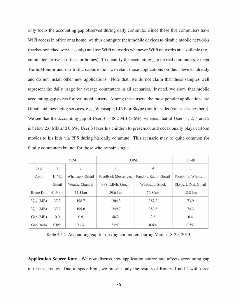
only focus the accounting gap observed during daily commute. Since these five commuters have
WiFi access in office or at home, we thus configure their mobile devices to disable mobile networks
(packet-switched services only) and use WiFi networks whenever WiFi networks are available (i.e.,
commuters arrive at offices or homes). To quantify the accounting gap on real commuters, except
TrafficMonitor and our traffic capture tool, we retain those applications on their devices already
and do not install other new applications. Note that, we do not claim that these samples well
represent the daily usage for average commuters in all scenarios. Instead, we show that mobile
accounting gap exists for real mobile users. Among these users, the most popular applications are
Gmail and messaging services, e.g., Whatsapp, LINE or Skype (not for video/voice services here).
We see that the accounting gap of User 3 is 48.2 MB (3.6%), whereas that of Users 1, 2, 4 and 5
is below 2.6 MB and 0.6%. User 3 takes his children to preschool and occasionally plays cartoon
movies to his kids via PPS during his daily commute. This scenario may be quite common for
family commuters but not for those who remain single.
OP-I OP-II OP-III
User 1 2 3 4 5
Apps LINE Whatsapp, Gmail FaceBook Messenger, Pandora Radio, Gmail Facebook, Whatsapp
Gmail WeatherChannel PPS, LINE, Gmail Whatsapp, Stock Skype, LINE, Gmail
Route Dis. 41.9 km 75.5 km 89.6 km 76.8 km 18.8 km
VUE (MB) 37.2 198.7 1204.3 387.2 73.9
VOP (MB) 37.2 199.6 1249.7 389.8 74.3
Gap (MB) 0.0 0.9 48.2 2.6 0.4
Gap Ratio 0.0% 0.4% 3.6% 0.6% 0.5%
Table 4.11: Accounting gap for driving commuters during March 18-29, 2013.
Application Source Rate We now discuss how application source rate affects accounting gap
in the test routes. Due to space limit, we present only the results of Routes 1 and 2 with three
86

different source rates. Figure 4.11 plots the accounting gap of these two routes. We observe that
the accounting gap increases with the application source rate. For example, in OP-II, the overall
accounting differences of Route 1 are 0.05 MB, 2.6 MB and 9.6 MB for the 200kbps, 400kbps and
800kbps sources, respectively.
We also observe that the source rate may affect the number of intra-system handoff occurrences.
On Route 7 (19.2 km), we observe only one intra-system handoff for both OP-I and OP-II, but 76
times for OP-III, when the source rate is 200kbps. However, when the source rate decreases to
1.6kbps, the numbers of handoffs for OP-I and OP-II increase to 14 and 15, respectively. Similar
results are observed on our all Samsung and HTC phones. We think that this phenomenon may
be induced by the operator’s network deployment or its packet forwarding mechanism similar to
Mobile IP [RFC96], which is used to reduce handoffs and packet losses during an ongoing data
session. Unfortunately, due to lack of information on the practices by OP-I and OP-II, we are
unable to verify our conjecture.
0 10 20 30 40
200 400 800 200 400 800
Gap
(MB)
Route-1 Route-2(Kbps)
OP-IOP-II
OP-III
Figure 4.11: Accounting gap with source rate.
87

Mobility Speed We now examine how mobility speed affects the accounting gap incurred by
handoff. There are two findings. First, low mobility speed incurs more inter-system handoffs.
We perform the DL-UDP-200kbps experiments on our test routes in the absence of no-coverage
areas but in the presence of hybrid networks, e.g., Route 1 or 10, at three speeds: low, medium
and high. In local routes, the low, medium, and high speeds are 24 km/h, 40 km/h and 56 km/h,
respectively. In freeway routes, they are 72 km/h, 88 km/h and 104 km/h, respectively. We find that
the speed will not directly affect the accounting gap caused by handoff. Note that our speed does
not exceed the speed limit for a roaming terminal that mobile networks support (e.g., 560 km/h
over LTE [SB09]). We observe that lower mobility speed leads to more inter-system handoff
occurrences.
To understand the root cause, we use an example (in OP-II) to illustrate what happens at both
low and high speeds. In Route 10, we observe 6 and 2 handoff occurrences for low mobility
speed and high mobility speed, respectively. To illustrate the impact of mobility speed on handoff
occurrence, we look into the first 0.35 km of Route 10, when the first inter-system handoff is
observed during driving at low speed mobility. Figure 4.12 shows the RSSI changes over time and
distance on the test route. The dash line specifies when and where inter-system handoffs occur at
low and high speeds, respectively. When a mobile device stays longer in the zone with weak RSSI
(i.e., < -106 dBm), an inter-system handoff is more likely to be observed. For example, the RSSI
within the distance range of [0.08, 0.16] on the route is around -108 dBm to -113 dBm. The mobile
device stays in this area for 13 seconds and 4 seconds at low and high speeds, respectively. An
inter-system handoff occurs at the distance of 0.18 km when the mobility speed is low. The RSSI
improves to -93 dBm at the distance of 0.19km due to this handoff. In contrast, the mobile device
does not have any inter-system handoff triggered at the same spot at high mobility speed. However,
its RSSI quickly improves to -106 dBm at the distance of 0.19 km. The mobile carrier does not
initiate an inter-system handoff unless the mobile device stays in the zone with weak signals longer
88

than a pre-specified time threshold. We have not fully analyzed the precise, triggering threshold
for an inter-system handoff. Based on our experimental estimate, the time threshold is about 5 to
15 seconds and varies with operators.
-113-105-97-89
0 10 20 30 40 50
0 0.1 0.2 0.3
RSS
I (dB
m)
Speed: 24 km/h
(km)
(sec)
-113-105-97-89
0 4 8 12 16 20
0 0.1 0.2 0.3
RSS
I (dB
m)
Speed: 56 km/h
(km)
(sec)
Figure 4.12: Handoff occurrence with mobility speed.
Second, we observe that the 3G radio access technology adopted by OP-III is not as dependable
at high mobility speed as that used by OP-I and OP-II. When we remain static, the transmission
rate of EVDO is around 452 kbps with the RSSI being -95 dBm. We then configure phones to
use 3G networks only and perform the DL-UDP-200kbps experiment on Route 13 at the speed
of 104 km/h. We find that the average transmission rate of 3G EVDO for OP-III is reduced to
160 kbps (with the RSSI being between -75 dBm and -95 dBm). Accounting gap is observed and
mostly due to the SC events. In contrast, the average transmission rate is close to 200 kbps for both
89

OP-I and OP-II, and there is no visible accounting gap (i.e., the gap ratio below 1%).
Vehicle traffic In order to gauge the impact of vehicle traffic on the accounting gap, we per-
form the DL-UDP-200kbps experiments on Route 13, which traverses the LA downtown area.
The experiments are conducted during both rush hours (6pm-7pm, weekdays) and non-rush hours
(9pm-10pm, weekdays), during the two-week period (from October 1st to October 12th, 2012).
We do not observe any inter-system handoff occurrence for both OP-I and OP-II. However, in OP-
III, we observe that two inter-system handoffs were triggered during non-rush hours when traffic
jam was observed on October 5th, and six inter-system handoffs occurred during rush hours on
Oct-1st, Oct-2nd and Oct-12th. Since the RSSI is strong (i.e., from -75 dBm to -85 dBm) at the
spot where inter-system handoffs are triggered, there is no reason for OP-III to migrate users to
another system (e.g., 3G EDVO) due to low RSSI. Therefore, we presume that this migration is
mainly due to its system capacity limit. However, an inter-system handoff is not always observed
within OP-III even during rush hours, though heavy vehicle traffic implies more roaming users and
may potentially consume more capacity. We speculate that vehicle traffic may not have strong cor-
relations with the inter-system handoff occurrence. Not all vehicles during rush hours use OP-III
networks and request radio resources for data transfer or voice calls. Consequently, heavy vehicle
traffic does not imply that all carriers always experience resource shortage.
Gray Zone We observe gray zones similar to the spots shown in [dea] on some test routes. On
Route 4, there is 0.5-km road nearby a shopping mall. When we drive through it, we do not receive
any packets, and an accounting gap thus occurs within OP-I. However, the interesting thing is that
the RSSI of the road is from -76 dBm to -87 dBm and no handoff occurs. Moreover, this is also
observed on Route 11 for OP-III. Although gray zones are not commonly observed (i.e., there are
only two zones within 232 km for all three operators), they may affect a large number of users. The
90

first one is nearby a shopping mall in city, and the second one is on the freeway with the heaviest
traffic in LA. Both zones observe many users on a daily basis.
4.7 Solutions
In this chapter, we discuss several possible solutions to mitigating the accounting gap caused by
handoff or insufficient coverage. Each solution has its pros and cons. Which one is more appropri-
ate highly depends on the usage scenario.
Suspend Accounting Stop accounting incoming packets until handoff is completed. The merit
of this approach is that, users completely eliminate the accounting gap caused by handoff. How-
ever, it does not reduce the accounting gap incurred by insufficient coverage. The perceived quality
for data transfer is worse due to longer data transmission suspension time.
Report Unsent Packets The RAN records the volume of packets that are not successfully sent
to the phone, and reports this volume to internal routers (i.e., accounting elements). Then internal
routers deduct the unsent data volume from the user’s data usage. The merit of this proposal is to
minimize the accounting gap caused by both handoff and insufficient coverage. However, its pre-
requisite is that reliable delivery mechanism, e.g., acknowledgement mode [3GP12c], is enabled in
RAN. Without the feedback from the mobile device, RAN does not know whether packets are de-
livered or not. Therefore, if the unreliable delivery mechanism, e.g., unacknowledged transmission
mode [3GP12c], is used, RAN cannot provide such information to internal routers.
Client-Based Each application server shall effectively control its sending rate when delivering
data to the mobile device depending on the mobile device’s feedback. In the absence of feedback
91

from the device, the application server shall immediately decrease its rate. Accounting gap is then
mitigated (i.e., little data will be sent to the mobile during handoff). However, it is not quite
practical to expect all applications to implement efficient rate control mechanisms.
Proxy-Based Setup a proxy for mobile devices. All packets for such devices shall be relayed
to this proxy and then forwarded to mobile devices. The proxy can dynamically enable/disable
packet forwarding to mobile devices through mobile networks. The merit of this proposal is that
users are able to control packet forwarding at the proxy depending on the network status (e.g.,
when approaching handoffs or insufficient coverage areas), and reduce the accounting gap without
modifying current applications. Unfortunately, deployment and operations of the proxy raise con-
cerns. In current practice, carriers distribute user data traffic to various deployed middle-box (e.g.,
http proxy or NAT) machines. If our proxy-based solution can be combined with these middle-box
functionalities at the deployed servers, the maintenance cost will be reduced.
92

CHAPTER 5
Studies of Interplay between Voice and Data Services
In this chapter, we study interplay between voice and data services in operational 4G LTE networks.
We assess how the popular CSFB-based voice service affects the IP-based data service in 4G LTE
networks. It covers cross-domain (CS, voice service and PS, data service) and cross-system (3G
and 4G) control-plane protocol interactions. We first introduce our experimental methodology, de-
scribe problems to study and present our findings. Our study reveals that the interference between
them is mutual. On one hand, voice calls may incur throughput drop, lost 4G connectivity, and ap-
plication aborts for data sessions. One the other hand, users may miss incoming voice calls when
turning on data access. The fundamental problem is that, signaling and control for circuit-switched
voice and packet-switched data have dependency and coupling effect via the LTE phone client. We
further propose fixes to the identified issues.
5.1 Studying CSFB in Operational LTE Networks
In this chapter, we describe our experimental methodology and identify the key problem aspects to
be studied.
93

5.1.1 Experimental Methodology
We conduct experiments in two major US LTE operators, denoted as OP-I and OP-II, for privacy
concerns. They together serve more than 138M mobile subscribers and cover almost 50% US
market share [CNE12]. We use six phone models of LG Optimus G, Samsung Galaxy S3, S4
and Stratosphere, HTC One, and Apple iPhone5, running two mobile operating systems: Android
and iOS. For OP-II, we use Galaxy S4 and iPhone5 only. They run popular applications (e.g.,
YouTube) or conduct data sessions with our deployed servers, including Apache Web server, FTP
and TCP/UDP servers. For further performance analysis, our deployed TCP/UDP server adds a
sequence number in each data packet to/from the UE. We primarily collect and analyze traces from
Android phones, and Apple iPhone5 is used for verification experiments.
In each experiment, we collect five traces if available: (1) Wireshark: We use the Wireshark
for packet capture traces on mobile devices and our deployed servers. (2) TcpParms: We use
getsockopt, a socket API to periodically log TCP parameters, such as retransmission timeout or
congestion window, on both our TCP server and mobile devices (root is required) . (3) UdpSeq: To
verify whether out-of-order delivery is observed by CSFB-induced inter-system handoffs, we log
the sequence number carried in the received UDP datagram and timestamps on our deployed UDP
servers and mobile devices. (4) NetworkStatus: Mobile devices also record network status infor-
mation given by Android PhoneStateListener class. The NetworkTrace periodically collects
phone status information including timestamp, operator, network type, cell identifier, RSSI (Signal
Strength) and IP address. The record interval is 100ms. (5) CallEvents: Mobile devices also log
all incoming-call events on phones via PhoneStateListener and outgoing-call events, e.g.,
ringing, and current timestamp.
94

Finding Operators Detail Root Cause Chapter
Throughput slump OP-I, OP-II Data throughput decreases (up
to 83.4% observed); OP-I: only
during the call, OP-II: during
and after the call
Handoffs triggered by CSFB and
speed gap between 3G and 4G
Chapter 5.2
Losing 4G connectivity OP-I, OP-II Never returns to 4G after the
CSFB call under certain data
traffic; OP-I: when the call fails
to be established, OP-II: any
CSFB call
State machine “loophole” in
3G→4G transition
Chapter 5.3
Application aborts OP-I, OP-II Application aborts occasionally
(3.4% for OP-I, 5.7% for OP-
II) after the call;
Network state changed by CS-
domain operation (here, network
detach caused by CSFB voice
calls)
Chapter 5.4
Missing incoming call OP-I, OP-II Misses all incoming calls tem-
porally (for several seconds)
while enabling the PS service
Network state changed by PS-
domain operations
Chapter 5.5
Table 5.1: Finding summary.
5.1.2 Issues to Study
In operational LTE networks, data service is offered via the IP-based, PS service, while the voice
service is provided through mechanisms such as CSFB. Since CSFB is probably the most popular
mechanism in current practice to support voice in LTE networks, we focus on it in this study.
Conventional wisdom states that such data and voice will not interfere each other, or at least
not to the degree beyond expectation. Anyway, data is going through the 4G LTE infrastructure,
while voice is going through the separate 3G/2G networks. However, our study shows that this is
not the case. We carry out our research along both directions: (I) How does CSFB voice affect
the ongoing data service in LTE networks? and (II) How does the data session in LTE networks
95

affect the voice service? While the results for (II) are presented in Chapter 5.5, the details for (I)
need more elaboration and are given in Chapters 5.2 - 5.4. As data service becomes increasingly
important for mobile devices, it deserves more attention. In particular, we cover three aspects,
expected, and unexpected, even certain worst-case scenario, regarding how voice affects data in
the context of LTE networks:
1. How much is the performance degradation when voice calls occur? This is the somewhat
expected case for performance penalty. The data session falls back to 3G/2G networks dur-
ing a CS voice call and then returns to 4G data networks while the call ends. We seek to
understand how TCP and UDP transport protocols react to such scenarios, as well as worse-
than-expected instances (Chapter 5.2).
2. Can the data session go wrong when call completes or is never established? If it indeed
occurs, it will be unanticipated exceptions for CSFB. We seek to show certain extreme cases
of losing LTE connectivity and getting stuck in 3G even when voice calls complete or never
start and explore their root causes (Chapter 5.3).
3. Can voice calls incur other negative performance impact beyond throughput degradation? In
particular, we will illustrate cases of application abort when voice calls are underway and
identify their root causes (Chapter 5.4).
4. Can the PS data also affect the CS voice call under certain conditions? If it is indeed ob-
served, it shows that both data and voice have mutual interference on each other’s operations
(Chapter 5.5). We also explore its root cause.
Table 5.1 summarizes our findings over two US carriers on the above four issues. We elaborate
them in Chapters 5.2 to 5.5.
96

5.2 Throughput Slump
In this chapter, we first examine how data performance is affected by voice calls using CSFB in the
normal case. The user might experience throughput slump during voice calls due to the handoff
from 4G to 3G. This observation matches our expectation and recent reports [iph13]. We elaborate
on what happens to TCP/UDP based data sessions and study the impact of regular CSFB calls.
We finally report worse-than-expected findings: performance degradation under multiple handoffs
(OP-I) or even after the voice call (OP-II).
�������
����������������� ����� �
��������������������
Figure 5.1: Alice calls Bob while he is downloading a file.
�������� ������ �������� �
����������
�������
� � �� ��
Figure 5.2: CSFB event flow for an incoming call.
5.2.1 An Illustrative Example
We use an example to illustrate the normal case performance. Bob is downloading a file to his
Samsung Galaxy S3 via the high-speed 4G LTE network. Everything goes well until he receives
a call from Alice. The call lasts about 22 seconds. The procedure is illustrated in Figure 5.1.
Figure 5.3(a) records the data throughput, network type, and call events observed at Bob’s phone
97

using OP-I carrier. At the beginning (up to 29.8th second before the call), Bob enjoys high-speed
data access up to 14 Mbps; During the voice call (during the interval [42s, 64s]), the throughput
drops from 14 Mbps to 9 Mbps; When the call ends (about 64th second), the throughput increases
to 14 Mbps in about 2 seconds. That is, the data throughput decreases by 35.7% (i.e., (14− 9)/14)
during the call.
Cause: The observed throughput slump is caused by CSFB. Figure 5.2 shows the CSFB event
flow for an incoming call. We make four observations. First, when answering the incoming call,
a handoff procedure from 4G to 3G is triggered. This inter-system handoff takes place (Step 3)
even before the call is fully established (Step 4). Figure 5.3(a) shows that, Bob’s phone call starts
ringing around 33th second and is answered at 42th second. In contrast, the first handoff (LTE
to 3G UMTS) completes at 31st second, earlier before the events of ringtone and call answering.
Interestingly, at 35.4th second right after the first handoff, the network performs a second handoff
(UMTS to 3G HSPA), which upgrades to higher-speed 3G HSPA networks (14.4 - 42Mbps theo-
retically). Second, the call proceeds during [42s, 64s] until the call hangs up. The phone stays in
the 3G HSPA network during this period. Third, once the call completes, the phone switches back
to 4G after two handoffs (HSPA to UMTS, followed by UMTS to 4G) at 65th and 66.4th seconds.
Note that, the 4G CSFB standard [mob] does not require that users be immediately switched back
to 4G after the call ends, or how many handoffs be triggered to switch to 4G. The sixth step is
OP-I’s implementation choice. We will see OP-II’s behaviors later. Last, we observe two data
transmission suspensions (i.e., rate is 0 Mbps): 6.4 seconds during [29.8s, 36.2s] and 1.5 seconds
during [64.3s, 65.8s]. Both periods are accompanied with handoffs. These handoffs lead to data
transmission suspension [mob]. Once the handoff is completed, the data transmission resumes.
We next address two issues: (1) How does TCP/UDP react to the above case? (2) Is there any
worse-than-expected result, except the performance degradation caused by staying in 3G during
the call? In particular, is there any difference between the handoff triggered by CSFB calls and the
98

traditional, mobility-induced handoff?
5.2.2 TCP/UDP under Normal Voice Calls
TCP In the above example, TCP data transmission is suspended during [29.8s, 36.2s] and [64.3s,
65.8s]. Figure 5.4 plots TCP logs in [29s, 38s] at the TCP server in the example of Figure 5.3(a).
Note that the server clock is slightly out of sync (about 0.2s to 0.3s) from the mobile’s trace. We
make three observations on the TCP trace. First, no packet delivery during handoffs results in mul-
tiple TCP timeouts. Around the 29.7th second, no ACKs are received for the packet with sequence
number 44636389. Accordingly, the server retransmits it four times (at 29.7s, 30.6s, 32.3s, 35.8s,
respectively). Second, large RTO may impede fast TCP recovery. The retransmission timeout
(RTO) gradually doubles, here, 0.436s, 0.872s, 1.744s, 3.488s, 6.976s during [29.1s, 35.6s]. Large
RTO values imply that TCP responds slowly once the network connection resumes. In this case,
the fourth retransmission succeeds (another packet sent at 35.9s) and the suspension lasts around
6 seconds. Third, the TCP congestion window is about 244 MSS during [29s, 36s]. It does not
reduce immediately upon retransmission timeout, thus different from the TCP specification (RFC
5681). The congestion window update is deferred when data transmission resumes. We believe
this is a TCP implementation variant in Linux.
UDP We observe behaviors similar to TCP, except that the suspension time for UDP is shorter.
Since UDP does not have congestion and flow control mechanisms, its transmission resumes im-
mediately after the PS service is available. In contrast, TCP RTO may not expire yet though the PS
service resumes. We conduct experiments to test this hypothesis. Before a voice call comes, we
start a 100 Kbps UDP downlink session and a TCP downlink flow on our 4G phone. As expected,
average data suspension durations for UDP and TCP are 5.4 and 6.4 seconds, respectively. It takes
99

longer for TCP to resume its transmission. We further observe out-of-order data delivery upon
4G→3G and 3G→4G handoffs.
5.2.3 Worse Than Expected
As expected, data performance degrades during the voice calls due to the speed gap1 between
4G and 3G and data suspension during handoffs triggered by CSFB. Next, we are curious about
whether any worse-than-expected results happen. We uncover two cases of further performance
degradation: (1) due to more handoffs (OP-I), and (2) even after the call (OP-II).
More handoffs (OP-I) Handoffs are critical to data performance. Upon handoff, data trans-
mission suspends, thus incurring TCP/UDP throughput decrease. Each CSFB call triggers two
network switches: 4G → 3G upon call arrival and 3G → 4G after the call ends. In OP-I (Fig-
ure 5.3(a)), one 4G → 3G switch is enabled by two handoffs of LTE→ UMTS (before the phone
rings) and UMTS→ HSPA (before the call is answered).
We next examine whether there is any difference between the handoff triggered by CSFB voice
calls and the conventional handoff induced by mobility. Our study shows that the difference indeed
exists; More handoffs may be triggered by call-related events. We run a 100 Kbps UDP session
while answering an incoming voice call. We repeat this experiment for 367 runs. In 218 runs,
the handoff results are the same as the above example. However, in the remaining 149 runs, two
additional handoffs ( HSPA→ UMTS and UMTS→HSPA) are triggered by the call-answering op-
eration, as shown in Figure 5.3(b). Consider the speed of HSPA and UMTS (up to 14.4-42 Mbps
and 2 Mbps for HSPA and UMTS, respectively). The mobile user suffers from another perfor-
mance drop at around 40th second. Note that, the additional HSPA↔UMTS handoffs differ from
the mobility-induced one. It is triggered by a call-answering event while the phone remains at
1More measurements can be found in Chapter 5.3.4.
100

the same location, performing data and voice services. In contrast, the traditional handoff to 3G
UMTS typically occurs upon mobility (i.e., users move out of a HSPA cell).
No handoff back to 4G (OP-II) We observe similar performance drop during the call in both
carriers. However, after the call ends, data throughput still remains low for OP-II, different from
the throughput increase for OP-I. Figure 5.3(c) plots the mobile trace at Bob’s phone using OP-II.
In this example, Bob experiences a throughput slump from 19Mbps to 12.7Mbps during the call
[31s, 61s]. However, the throughput still remains around 12.7Mbps after the call. We observe
similar behaviors with different phone models (e.g., Galaxy S4 and iPhone5): the handoff occurs
before the phone rings and the throughput remains similar after the call ends. Undoubtedly, it
adversely imposes larger impact on data throughput. The mobile loses its 4G connectivity even
after the voice call. This occurs because no handoff is invoked immediately after the call ends. We
will explore its root cause in Chapter 5.3.
We further explore why these handoffs are invoked and whether they can be eliminated for
performance improvement. Unfortunately, the inter-system handoff (4G→3G) is mandatory to
support CSFB in order to access the 2G/3G circuit-switched service for voice calls. The addi-
tional handoff (HSPA ↔ UMTS) is the OP-I’s implementation choice; it is not required in OP-II.
The handoff back to 4G is also part of the operator’s design choice. The CSFB standard never
specifies when to switch back to 4G networks. In practice, OP-I decides to perform this handoff
immediately, while OP-II does not.
101

LTE HSPA UMTS
0 5
10 15 20
0 20 40 60 80 100
Thro
ughp
ut
x-th second
(Mbp
s)
Ring Answer Hang Up
(a) OP-I
LTE HSPA UMTS
0 5
10 15 20
0 10 20 30 40 50 60
Thro
ughp
ut
x-th second
(Mbp
s)
Ring Answer
(b) OP-I, more handoffs
LTE HSPA
0 5
10 15 20
0 20 40 60 80 100
Thro
ughp
ut
x-th second
(Mbp
s)
Ring Answer Hang Up
(c) OP-II
Figure 5.3: Logs of data throughput (4G:+, 3G:×), network type (LTE, HSPA, UMTS) and call
event (marked by black dashed lines) observed at Bob’s phone in normal case of answering Alice’s
call. (a) OP-I: one 4G→3G handoff triggered; (b): OP-I: multiple handoffs triggered; (c): OP-II:
no handoff back to 4G when the call ends.
102

440 445 450 455 460
Seq#
(105 )
0 4 8
29 30 31 32 33 34 35 36 37 38
RTO
x-th second
(sec
)
0 100 200 300
Cw
nd(p
kt)
Figure 5.4: TCP logs of sequence number, congestion window and retransmission timeout ob-
served at Bob’s TCP Server in the example of Figure 5.3(a).
103

5.3 Losing 4G Connectivity
We observe that LTE users permanently lose 4G connectivity due to CS voice calls under certain
conditions. In an extreme test scenario, the mobile phone is stuck in 3G networks longer than 10
hours and shows no sign of exiting. It remains in 3G networks even when the user drives on the
route with stronger 4G signal. The condition of losing 4G connectivity varies among two operators.
Compared with OP-II, OP-I has more complex settings.
5.3.1 OP-I: When the Call Fails to Establish
Our test scenario can be illustrated via the Alice-Bob example. However, after Alice calls Bob,
she immediately hangs up because she realizes that it is too late to call Bob at 10PM. For Bob, his
phone never rings and the call is never established. Assume that Bob has been downloading a file
before the call. Contrary to our expectation, we discover that Bob gets stuck in the 3G network for
a long time (or even unlimited duration). Figure 5.5 plots the data throughput measured at Bob’s
phone. It shows that Bob never returns to the 4G network even after the download halts at 100th
seconds. The same is observed on all phone models using OP-I. Note that only some background
data service keeps on running. Throughout this process, Bob is not even aware of what happens!
We now explore the root cause to lose 4G connectivity. It turns out that a loophole (in fact, a
loop) in Radio Resource Control (RRC) state transition forces the 4G user to remain in 3G. RRC is
the function that regulates the connection establishment and release between the UE and the core
network.
Figure 5.6(a) plots the simplified RRC state transition in 3G/4G standards [mob]. We do not
consider 2G here since it is not observed in our experiments. We make two observations. First,
the switch between 3G and 4G networks is enabled via the handover procedure (that occurs be-
104

0
5
10
15
20
0 20 40 60 80 100 120 140
Thr
ough
put(
Mbp
s)
x-th second
Hang up before ring
4G3G
Figure 5.5: Data throughput observed at Bob’s phone if Alice immediately hangs (the outgoing
call) up in OP-I carrier.
tween 3G FACH/DCH2 and 4G CONNECTED states) or the cell reselection procedure [mob] (that
is invoked between 3G IDLE and 4G IDLE states). Second, within 3G or 4G, the state transition
(e.g., 3G FACH/DCH ↔IDLE or 4G CONNECTED↔IDLE) is determined by the connection es-
tablishment/release. For example, a RRC connection shall be established before the PS/CS service
is used, or be released when the CS/PS service is in no use or remains idle for a long time.
The above RRC state machine brings an inherent risk of getting stuck in one network (e.g.,
3G). In case the loop between 3G FACH/DCH and 3G IDLE is formed, the mobile user will be
unable to escape from 3G. Unfortunately, our experiments confirm that such a loop indeed exists
under certain conditions in OP-I. In particular, for an unestablished call, the RRC enters into the
3G loop with some ongoing data services.
2FACH and DCH are two RRC states that offer RRC connections for data delivery. FACH offers a RRC connection
at lower speed with low power consumption, whereas DCH offers it at full speed with higher power consumption [mob,
QWG10].
105

����
��
������
����
� ������
��
����������
���� ��������� ���
��� ������
����������
���� ��������� ���
��������
(a) 3G/4G standard [mob]
����
��
���������
����
���� ���
!�
�����������
���������
������
������ ������
���
���������
������
��� ������������� ��
������
��� ������������� ��
(b) CSFB for OP-I
����
��
������
����
� ������
��
�����������
���������
���������������������
�����������
���������
���������������������
��
(c) CSFB for OP-II
�� ������� �����
������������ ���
������������ �����
������� �����
�������
������������������
(d) Call setup procedure
Figure 5.6: Simplified RRC state transition machine and call setup procedure.
Unestablished Call State In the normal case, the mobile user moves back to the 4G network
quickly (in about 2–4 seconds) after the call ends. However, the time prolongs if the call is not
established. It occurs in two scenarios. One is that the 4G user is called but the caller hangs up
immediately (usually within 4–6 seconds). The other is that the user makes an outgoing call and
immediately hangs up after the handoff to the 3G network is done. In both cases, the mobile phone
falls back to the 3G network though no call has been established.
The unestablished call state does make it longer move back to the 4G network. Figure 5.6(d)
shows the call setup procedure (Step 4 of Figure 5.2) for the incoming call case. When the MSC
sends a call-setup request to a 4G phone, it waits for the response from the phone in order to
update its state as Call Received. However, when the call is canceled before entering the
106

Call Received state (in the above two scenarios), the MSC will not update its call state. The
user thus stays longer in the 3G network. This implies that the call state plays a critical role in the
handoff operation. The unestablished call changes the trigger condition for handoffs, thus taking
longer time to go back to 4G.
The duration to stay in 3G is largely independent of locations and phone models. We test with
all phone models at four locations with different base stations. Each test repeats 20 runs. In the
absence of data service, the duration to remain in 3G ranges from 7 to 8 seconds, varying slightly
with locations. With background data traffic, we observe similar results independent of locations.
We figure out that the duration is determined by other factors to be discussed in Chapter 5.3.3.
Data Services in Parallel We discover that, the phone can stay in the 3G network for an extended
period of time if some data service is ongoing in parallel. We run a large number of tests to study
when and under what conditions the switch (back to 4G) takes place. We run the unestablished call
experiments with a constant-rate UDP uplink session to our deployed server on Samsung Galaxy
S3 and LG Optimus G. We vary the inter-packet spacing (i.e., packet interval) from 1 to 24 seconds,
using 1B and 1KB UDP payload sizes. Each test repeats 20 runs. We observe similar results for
both phone models, and only describe the results on Samsung Galaxy S3. Figure 5.7 plots the
duration in 3G since the phone moves to 3G. The upper and lower lines mark the maximal and
minimal durations in 3G. The 180-second duration implies that the phone never returns to 4G in
3 minutes. It clearly shows that the phone might get stuck in 3G under certain conditions. The
condition specifics will be elaborated in Chapter 5.3.3.
In summary, we infer the RRC state transition machine for OP-I in Figure 5.6(b). The 4G→3G
handoff is triggered when the call arrives (or is initiated), and the 3G→4G handoff occurs when
the call ends after its establishment. However, if the call is not established (i.e., hanging up too
early), the 3G→4G handoff will not be invoked. Note that, no handoff for the unestablished call is
107

not designed without rationale. If the call is not successfully established, the caller would probably
redial shortly. For a call terminated in the unestablished call state, immediate handoff from 3G to
4G could trigger more handoffs. Consequently, the UE still stays at the 3G FACH/DCH state. In
this case, the cell reselection procedure turns out to be the only way back to 4G. Note that the
cell reselection is only triggered in the 3G IDLE state. Our study demonstrates that under certain
data operations (the details are in Chapter 5.3.3), the UE may not enter the 3G IDLE state, or
switch back to 3G FACH/DCH before triggering the cell reselection. Consequently, a RRC loop
(marked by bold blue lines in Figure 5.6(b)) is created when the call is not established under certain
background data traffic.
5.3.2 OP-II: Once the Call Attempt is Made
Losing 4G connectivity becomes easier in OP-II than in OP-I. The user is prone to losing 4G con-
nectivity, no matter whether the call is established or not. Figure 5.3(c) shows an example of losing
4G connectivity after the call completes. We test various call operations (answering/rejecting an
incoming call, unestablished incoming call, or making an outgoing call) to examine its dependency
on the call event. We find out that, once the 4G→3G handoff is triggered under any call attempt,
the UE gets stuck in 3G as long as some background data traffic is present.
Similar to the OP-I test, We run constant-rate UDP uplink session tests with different packet
sizes and intervals. The only difference is that the call is established and completes in this exper-
iment. Figure 5.8 plots the duration being stuck in 3G with packet intervals for 1B/1KB packets.
We observe that, the rule in OP-II is much simpler. When the packet interval is smaller than 9s (1B
packet) or 13s (1KB packet), the 4G user is unable to return to the LTE network.
Consequently, we deduce the RRC state transition for OP-II in Figure 5.6(c). Different from
OP-I, no handoff path (back to 4G) exists when the call ends. The switch from 3G to 4G is thus
108

invoked only through the cell reselection. Similarly, when the RRC loop in 3G FACH/DCH and
3G IDLE (marked by red bold lines) is formed, the UE loses its 4G connectivity. The conditions
to form the 3G RRC loop will be discussed in Chapter 5.3.3.
5.3.3 RRC Loop Under Data Services
We now examine when or under what data services the 3G RRC loop is formed. We mainly address
the OP-I case that is more complicated, and then describe the OP-II case.
5.3.3.1 OP-I Case
Figure 5.7 plots the 3G duration under various packet intervals for OP-I. We make four observa-
tions. First, when the packet interval is smaller than certain threshold (10 seconds for 1B packets
and 15 seconds for 1KB packets), the phone never returns to 4G. Second, when the packet interval
is larger than another threshold (15 seconds for 1B packets and 20 seconds for 1KB packets), the
phone definitely returns to 4G. Third, for both packet sizes, there exist two interesting transition
intervals. For 1B packets, these two intervals are 10 seconds and 15 seconds (with larger duration
variance). The phone is likely to return to 4G with these packet intervals. For packet intervals in
between (i.e., 11–14s), the phone never returns to 4G. For 1KB packets, the pattern is similar but
the two transition intervals are 15s and 20s. Finally, compared with no data transmission, it stays
longer (about 40 seconds) in 3G even when it can return to the 4G network.
At the first glance, these findings are not anticipated, particularly the inconsistent performance
with packet intervals in the transition zone. Three questions need to be answered: (1) Why does
the switch remain sensitive to several packet intervals and yield the non-monotonic pattern for all
packet intervals? (2) What occurs when the packet interval is set as 10s, 15s, and 20s? (3) How is
it related to packet sizes? We examine event traces and finally derive the trigger conditions for the
109

0
40
80
120
160
200
0 2 4 6 8 10 12 14 16 18 20 22 24
Dur
atio
n in
3G
(se
c)
Packet Interval (sec)
1B1KB
Figure 5.7: Duration stuck in 3G versus packet intervals for two 1B/1KB packets in case of an
unestablished call via OP-I.
0
40
80
120
160
200
0 2 4 6 8 10 12 14 16 18 20 22 24
Dur
atio
n in
3G
(se
c)
Packet Interval (sec)
1B1KB
Figure 5.8: Duration stuck in 3G versus packet intervals for two 1B/1KB packets in case of a
complete call via OP-II.
3G RRC loop. We summarize these rules for 3G → 4G switch in OP-I in Table 5.2, and then use
our trace analysis to explain what happens and how each rule is applied. In summary, the above
observations reveal how such mechanisms interact with each other.
These rules exhibit both standard specifications and carrier-specific operations. They also cor-
110

0 20 40 60 80
100
0 2 4 6 8 10 12 14
CD
F (%
)
Duration (s)
FirstOther
(a) Intra-3G handoff time
� � �� �� �� ��
����
���
� � �� �� �� ���� �
� � �� �� �� � �
��
��
�
���
���
����
� �����
����
����
���� ����
�
� �
� �
����
�
� � �� �� �� � ��� ���
��������� � �
�
�
sB
101
sB
151
sKB
151
sKB
101
����
(b) Example traces
Figure 5.9: Illustration of event traces for data flows with various packet intervals and packet sizes.
Rule 1 The phone immediately performs the switch back to 4G when the timer T3G→4G
times out; T3G→4G is only started when the UE enters into the 3G IDLE state;
Rule 2 The RRC state switches from DCH/FACH to IDLE when the timer Tidle times out;
It switches to FACH/DCH immediately upon any data delivery;
Rule 3 T3G→4G is reset once an intra-3G3 handoff occurs.
Rule 4 The intra-3G handoff occurs when a data transmission request occurs in either con-
dition: (1) the UE is in 3G IDLE state, (2) the packet size is larger than a threshold
(210-220B in our measurement) or for the first packet.
Table 5.2: Rules for 3G → 4G switch upon an unestablished call (i.e., the call state is not
Call Received) for OP-I.
respond to the state machine derived in Chapter 5.3.1. Note that the UE can be switched from 3G
RRC IDLE to 4G RRC IDLE only via the cell re-selection procedure. Rule 1 states that this cell
reselection is triggered by a timer T3G→4G, which is set to 5s according to our measurements. Note
that the timer T3G→4G is not specified by the standards, but chosen by the operator’s implementa-
tion.
Rule 2 regulates the traditional 3G RRC transition between DCH/FACH and IDLE. The tran-
sition is controlled by another timer Tidle. When this timer expires, RRC jumps from DCH/FACH
to IDLE; Upon packet delivery, it immediately switches to DCH/FACH and resets Tidle. In our
111

experiments, we find that Tidle = 10 seconds and is operator specific, consistent with prior stud-
ies [QWG10].
Rule 3 implies that the users will not go back to 4G LTE when it is at the FACH/DCH state,
which is specified in [mob]. This is because the user triggers an intra-3G handoff to perform
data transmission (Rule 4), its RRC state is hence changed from IDLE to FACH/DCH. The timer
T3G→4G should be reset since the user leaves the IDLE state.
In Rule 4, we observe that intra-3G handoffs (i.e., HSPA↔UMTS) might happen. The operator
usually switches the mobile device to proper radio access technologies (e.g., UMTS or HSPA)
based on its transmission rate and data volume. The first condition in Rule 4 is obtained from our
traces. It is not in the standard specifications; we believe it is also an operator-dependent choice.
Our measurements also indicate that, an intra-3G handoff typically takes about 5 seconds, but
8–10 seconds for the first time. Figure 5.9(a) plots the CDF for the intra-3G handover duration. To
derive the packet size threshold used in Rule 4, we run experiments using variable-sized payloads
at 8-second intervals (i.e., it remains in 3G). It turns out that the payload threshold is 210–220B.
These parameter settings are also operator specific.
We briefly illustrate how these rules are applied so that the 3G duration varies with packet
intervals as shown in Figure 5.7. In all our experiments, the first packet is immediately sent out
once the phone switches to 3G, shown by those packet boxes at time 0 in Figure 5.9(b). We
look at two easy-to-understand cases. In the first case, when the interval is smaller than Tidle,
the phone never returns to 4G. It has no chance to enter the 3G IDLE state and trigger the timer
T3G→4G back to 4G. In the second case, when the packet interval is larger than 20 seconds (i.e.,
Tidle + T3G→4G + T3G−HO ≈ 10 + 5 + 5 = 20), the phone can always return to 4G. No matter
whether an intra-3G handoff is triggered or not, the packet interval is large enough to enter the
IDLE state and trigger the 3G → 4G timeout. This also explains why the transition interval for 1B
112

is 5 seconds smaller than that for 1KB. The decisive factor for the 1B/1KB discrepancy is whether
an intra-3G handoff is triggered. By Rule 4, 1KB packet delivery always triggers such an intra-3G
handoff as long as it is still in 3G, whereas 1B packet does so only when the RRC state is 3G
IDLE. The intra-3G handoff takes about 5 seconds. We confirm that the duration in 3G is mainly
determined by how the RRC state and the two timers of T3G→4G and Tidle evolve under these rules.
5.3.3.2 OP-II Case
We next derive the trigger conditions for the RRC loop for OP-II. Our trace analysis shows that
OP-II follows the above four rules but Rule 4 and the parameters vary slightly. Figure 5.8 shows
that the transition intervals for 1B and 1KB packets are around 9s and 13s, respectively. Our
traces indicate that the difference between 1B and 1KB packets lies in whether intra-3G handoffs
are incurred; Intra-3G handoffs (HSPA→HSPA+) occur for 1KB packets, but not for 1B packets
(except for the first packet, the same as OP-I). Moreover, we test with various packet sizes and find
out that the occurrence of intra-3G handoffs only depends on the packet size (here, the threshold
is about 940–950B). This slightly differs from Rule 4 for OP-I. In OP-II, Rule 4 works under the
second condition (an intra-3G handoff occurs when the packet size is larger than 940-950B or for
the first packet). Our measurements show that an intra-3G handoff takes about 4–5 seconds (but
8-12 seconds for the first time), similar to Figure 5.9(a). We infer that the 3G→4G switch is also
controlled by two timers, T3G→4G for the cell reselection and Tidle for the state transition from 3G
FACH/DCH to IDLE. Based on our measurements, we infer that T3G→4G ≈ 6s, Tidle ≈ 3s. The
derivation is similar to that for OP-I, and is omitted due to space limit. Note that, these parameters
are operator-specific choices.
For both cases of OP-I and OP-II, some may argue that the loss of 4G connectivity is an operator-
specific implementation issue. We admit that the operator’s choice does matter. Indeed, the stan-
113

dards do not stipulate under what conditions the handoff/switch should be initiated, though they
do specify such handoff/switch mechanisms for CSFB [mob]. They leave the flexibility to the car-
riers. For example, the operator can decide whether a handoff back to 4G is triggered immediately
after the call ends or not. However, our study shows that, the loss of 4G connectivity is caused
by the flaw (i.e., the state loop) between CSFB and the RRC finite state machine. The interplay
of functions and states used in both CS and PS domains results in unanticipated effect. The two
timers create the 3G RRC loop so that the phone never returns to 4G.
5.3.4 Performance Impact
We examine the impact of being stuck in the 3G network from three aspects: duration in 3G,
mobility, and throughput gap.
2
4
6
8
10
1 2 3 4 5 6 7 8 9 10
Dur
atio
n in
3G
(hr
)
Session Duration (hr)
UplinkDownlink
Figure 5.10: Duration stuck in 3G with UDP flows vis OP-I.
Duration in 3G In the unestablished call case, we run an 8s-interval UDP data flow for various
durations from 1 hour to 10 hours. Figure 5.10 plots the average duration in 3G with downlink and
uplink data flows. Specifically, we measure the interval from the time when the call ends to the
114

instant when the UDP session stops. It is not surprising to see that the phone gets stuck in 3G as
long as the data flow is alive (10 hours are observed and there is no sign of limit). Interestingly,
we find that the duration in 3G for the downlink case is usually shorter than the uplink case, e.g.,
we observed 2 hours in 3G networks during a 3-hour data session test. This is because not all
UDP downlink packets can be sent successfully under packet loss. The longer the session lasts, the
more likely a packet interval goes beyond the transition threshold (15/20 seconds). We also test
with TCP flows; Both uplink and downlink flows perform similarly to the UDP uplink case (never
expires), because TCP retransmits packets upon losses.
4G 3G 2G
w/ dataw/o data
-113-100
-75
-50
8 8.5 9 9.5 10 10.5 11 11.5 12
RSS
I
Distance (miles)
w/o data w/ data
Figure 5.11: Portions of network status logs on a 12-mile route.
Mobility We also examine whether a 4G user may go back to LTE networks under mobility
where handoffs are triggered. We repeat the above experiment when driving on a 12-mile local
route. It takes about 35∼45 minutes. Note that the call ends before driving, i.e., the 4G user gets
stuck in 3G before driving starts. In the meantime, we bring another 4G phone without any data
session. It is used to collect network status events such as network type and RSSI. Figure 5.11 plots
115

1
10
100
9am 1pm 5pm 9pm
UL
Spe
ed (
Mbp
s) Wired 4G 3G
1
10
100
9am 1pm 5pm 9pm
DL
Spe
ed (
Mbp
s) Wired 4G 3G
Figure 5.12: 3G/4G speed at different hours of a day via OP-I (Left: uplink; Right: downlink).
a portion of the network status logs at two phones over this route via OP-I. The results for OP-II
are similar. It is easy to see that, the 4G phone freely switches among 2G, 3G and 4G networks in
the absence of data; however, the 4G phone with data only switches among 2G and 3G networks.
It never goes back to 4G LTE networks, even though the 4G LTE network signals are stronger than
2G/3G in certain areas, e.g., [11.5, 12].
3G/4G Speed Gap To quantify the performance impact of being stuck in 3G networks, we
measure the speed of 4G LTE and 3G HSPA networks at different hours of a day. We use the
SpeedTest tool [Spe]. Figure 5.12 plots the average uplink and downlink speed of 3G/4G networks
at different times. 4G outperforms 3G in most cases, especially at midnight (with lighter traffic) and
for the uplink. For example, 4G users experience 83.4% uplink improvement and 53.8% downlink
gain at 11PM. Over all test hours, the average improvement is 70.4% and 31.9% for uplink and
downlink, respectively. However, the downlink gap between 3G and 4G shrinks at other times. To
our surprise, 4G performs worse than 3G at 3PM (1.8 Mbps vs. 4 Mbps). This shows that, the
deployed LTE network might not achieve what it claims at all times. We also note that, the 3G/4G
speed varies with locations (depending on the radio link quality and the traffic load). In general,
throughput drop occurs when 4G users get stuck in 2G/3G networks.
116

5.4 Data Application Abort
We find that voice calls might even result in data application aborts in operational LTE networks. In
this chapter, we first show real application behaviors under various call operations, such as dialing
and answering a call. We then diagnose the root cause for application aborts.
5.4.1 Popular Applications
We test eight popular mobile applications while receiving a CS voice call. These applications
include web browsing (via WebKit), FTP downloading, Gmail, Facebook, Skype voice calls,
Youtube, PPStream (P2P video streaming), and Pandora (music playback over radio broadcast).
We observe that these applications might behave abnormally when the voice conversation ends
on all the phone models for both carriers. Upon voice call completion, five applications except
Youtube, PPStream and Pandora might abort, and Pandora suspends for tens of seconds until the
playback status turns from “stopped” to “playing.” YouTube and PPStream might abort in other
calling scenarios.
(a) Error at the client (b) Wireshark traces at the server
Figure 5.13: An example of FTP application abort.
117

Application Type TCP/UDP Behavior
Webkit Bursty TCP Respond slowly, seldom abort
Gmail Bursty TCP Respond slowly, occasionally abort
Facebook Interaction TCP Respond slowly, seldom abort
AndFtp Transferring TCP Transmit slowly or abort later
Skype Interaction UDP Suspend, abort later
Youtube Streaming TCP Suspend (abort if call unestablished)
PPStream Streaming UDP Suspend (abort if call unestablished)
Pandora Streaming TCP Suspend
Table 5.3: Application behavior when voice call arrives
FTP downloading In our experiment, a mobile client downloads a 121 MB file from our FTP
server. Figures 5.13(a) and 5.13(b) show the error dialog at the mobile client and the TCP trace
captured by Wireshark at our FTP server. When the voice call ends around the 47th second, the
mobile client experiences a socket exception error, i.e., sendto failed, in Android OS. File
downloading stops afterwards. On the FTP server side, it first attempts to retransmit packets (10
retries over 33 seconds are observed) to the client and finally tears down the TCP connection, since
no response is heard from the client. Note that mobile phone aborts earlier at 48s before the server
tears down the TCP connection at 82s.
Skype voice calls When the CS call ends, Skype is designed to resume its original call session;
However, it may still fail similarly to FTP, and the root cause will be discussed in Chapter 5.4.3.
The difference is, during the CS voice call, Skype holds its ongoing call but FTP download keeps
going. Skype is not allowed to simultaneously work with CS voice calls due to the conflicting
118

usage of the speaker. So are YouTube, PPStream and Pandora.
Web, Facebook and Gmail Similar to FTP, they are unable to fetch the attempted web content
when they abort upon call completion. It is clearly observed when they fetch big-sized data, e.g., a
high-resolution image or an email attachment. For short data sessions (e.g., fetching a html page),
the abort takes places but with negligible effect.
Youtube and PPStream Upon call arrival, both video streaming operations pause. They never
automatically resume when the call ends (i.e., a manual replay is required). However, when an
incoming call hangs up before reaching the client, Youtube and PPStream might still abort.
Pandora Similar to Skype call, it is suspended upon the call arrival and resumed automatically
after the call ends.Except that the suspension lasts tens of seconds, no other abnormal (i.e., being
aborted) behaviors are observed.
Table 5.3 summarizes these application behaviors, including application aborts and “slow re-
sponse” due to throughput slump described in Chapter 5.2. In fact, application aborts depend on
how these applications handle the failure of data sessions, which is triggered by an completed call,
in their own manners. The first five applications abort because they do nothing once the original
data sessions terminate, whereas Pandora automatically starts a new session once the old one fails.
Youtube and PPStream do not take action since they already stop their data sessions once a voice
call starts. Note that applications do not abort every time a call completes. We next study when
and how often these applications abort.
119

0
5
10
15
20
2/242/25
2/262/27
2/283/01
3/023/03
3/043/05
Abo
rt R
ate
(%)
Morning Afternoon Evening
Figure 5.14: 10-day FTP downloading abort ratio (OP-I).
5.4.2 How Often Application Aborts
We conjecture that these application aborts are caused by voice calls. In our test scenario, a 4G
user dials out and hangs up the outgoing call later. In the meantime, we run FTP downloading. The
results for other applications are similar. For OP-I, we use Samsung Galaxy S3 and LG Optimus
G at two locations (home and campus), during the morning (9am-12pm), the afternoon (1-5pm),
and the evening (7-10pm), for 10 days, from February 24 to March 4, 2013. For OP-II, we test
Samsung Galaxy S4 and iPhone 5 from June 17–21, 2013. Each test has at least 15 runs. We
observe similar abort ratios, independent of the phone model.
Figure 5.14 plots the 10-day abort percentage for OP-I. The applications do abort but only with
certain probability. It confirms that operational LTE networks are still largely successful. In two
worst-case settings (a morning slot and an evening slot), about 15% of tests fail. However, over the
10-day period, the average failure percentages for the morning, afternoon and evening are merely
2.4%, 2.7%, and 5.1%. For OP-II, the average abort ratio is 5.7% in the 5-day test.
120

5.4.3 Root Cause: Being Detached
We now explore the root cause for application aborts. We find that it is because the mobile phone is
detached from the mobile network when performing an 3G→4G handoff to return to the LTE net-
work after a voice call. Table 5.4 logs the network status at the phone when an application aborts
using OP-I. The call conversation ends at 52.84s. In 2.42 seconds, the user is kicked out of the
carrier network (indicated by “unknown”). It also loses its original IP address. This disconnection
lasts for about 14 seconds before the 4G phone reconnects to the network. However, upon recon-
nection, the phone is assigned a brand new IP address. Consequently, the original data session fails
and those applications not supporting automatic application-level recovery finally abort.
Seconds OP EVENT TYPE CID RSSI IP
52.84 OP-I CALL HANG UP 10.xx.xx.51
53.41 OP-I NET UMTS 5****075 -67 10.xx.xx.51
54.30 OP-I NET UMTS 5****075 -67 10.xx.xx.51
55.26 Unknown NET Unknown n/a -113 n/a
56.28 Unknown NET Unknown n/a -113 n/a
. . . . . . . . . . . . . . . . . . . . .
69.26 OP-I NET LTE 1*****223 -70 10.yy.yy.11
Table 5.4: Logs of network status at the mobile phone.
Another plausible root cause is that power consumption at the UE exceeds the permissible
budget when initiating and maintaining radio access bearers for simultaneous voice call and data
service. If it were correct, we would observe it when users concurrently access voice and data
services, and application abort rate may also depend on phone models. However, our experiments
show that this never occurs. Application abort only happens after the call ends, i.e., the UE is being
switched back to 4G. The application abort rate observed on different phones is also similar.
121

(a) Implicit detach
0
20
40
60
80
100
0 5 10 15 20 25
CD
F (%
)
Duration (sec)
OP-IOP-II
(b) CDF of Reattach time
Figure 5.15: Cause of being kicked out and reattach time.
To find out why 4G users are kicked outside the mobile network, we enable the service mode of
Samsung S3 where low-level mobile network traces can be observed. Figure 5.15(a) displays the
screen snapshot when an application aborts. It states that, the GMM (GPRS Mobility Management)
operation [mob] is rejected due to an error (cause ID: 10). In this case, an inter-system handoff
(from 3G to 4G) request is rejected because it has been implicitly detached [mob]. The “Implicit
Detached” indicates that the phone is detached by the network without any notification. It typically
occurs when the network fails to communicate with the UE. Once this error occurs, the UE has to
perform re-attach procedure to associate with carrier networks again [mob]. A new IP address will
be assigned for OP-I, whereas the same IP address is used for OP-II. However, the NAT (Network
Address Translation) mapping for the UE is no longer available. The UE is thus unable to receive
packets using the same data session no matter whether the IP address changes. No packet delivery
is allowed until this procedure completes. Figure 5.15(b) plots the CDF of reattach time. It shows
that, 90% of re-attaches would finish within 15 seconds for OP-I, and 95% of re-attaches is shorter
than 11s for OP-II.
We are not sure why the network detaches the user when a CSFB call ends, due to lack of
status information inside the network. It might be caused by the failure of inter-system (3G to
122

4G) handoff, due to insufficient resources (resource occupied by CSFB) or unsynchronized user
information between 3G and 4G [mob].
5.5 Reverse Impact: Missed Calls
We next show how the PS data service may adversely affect CS voice calls. We find that 4G LTE
users may miss their voice calls while starting PS data access. When the caller makes a call but the
callee starts PS data access almost simultaneously, the caller hears success signals (e.g., alerting
tone) so that he/she believes that the call has been made but is not answered. In the meantime, the
callee receives no incoming-call request (e.g., no ringing or vibrating). Everything else operates
normally, but the callee is unaware of missing a call.
We test it with two experiments. First, we make a call while the callee starts to turn on its PS
data network (i.e., network attach). In all test runs (> 20), all calls have been missed. Second, we
make a call when the data network is either off or already on, i.e., the callee does not turn on his/her
PS data network while caller makes call; In this case, all calls have succeeded. The same results
are observed on all phones for both carriers. We note that, in case of missing calls, the caller may
have an option to leave a message if his/her voice-mailbox feature is enabled. The voice-mailbox
feature is free in the US, so the adverse effect of missing calls can be greatly relieved. However,
not all operators support free voice-mailbox features, so missed calls may incur inconvenience.
Root cause We analyze the NetworkStatus trace logged on the callee’s phone. With an incoming
call request, the callee is implicitly detached by the network (same as Chapter 5.4). During the
period (before network re-attach completes), the mobile loses connectivity with carrier networks.
We next seek to understand why the caller hears an alerting tone, thus misinterpreting that the call
has been established.
123

We examine the incoming CSFB call flow of Figure 5.2. In Step 2 (Paging), the MSC pages
the UE through MME. Following the mobile terminated call procedure [mob] in the CSFB stan-
dard, the UE will respond with Service Request [mob] to the MSC, then the MSC sends an
indication (i.e., an alerting tone) to the caller. In fact, it happens before the handoff to 3G networks
occurs; The caller is acknowledged no matter whether the callee is kicked out of carrier networks
or fails to handover to 2G/3G networks. This results in asynchronous call status at the caller and
the callee. This scenario differs from the call establishment process in 3G networks, where the
caller hears the alerting tone only after the callee is found by the network via paging. We believe
that it is a fundamental issue in mobile networks, rather than a operator-specific implementation
choice (despite observed in both operators). PS data and CS voice are performed independently on
their data plane, but share common network states on the control plane. Imprudent control in one
domain may impose unexpected impact on the other domain.
5.6 Solutions
We now describe our solution to mitigating the negative impact incurred by CSFB voice calls in
4G LTE networks. We use a combination of techniques to address all four issues: performance
degradation of TCP-based data sessions in the presence of CSFB calls, unexpected application
abort, lost 4G connectivity, and missed calls during PS service.
Mitigating TCP performance degradation We first note that the TCP issue is due to inter-
system handoffs; it cannot be fixed from the CSFB protocol itself since the handoffs are a fun-
damental feature of CSFB. We follow the popular middlebox-based approach [WQX11] in our
solution. Our scheme differs from the related work [LSS08, PDD12, BPS96] in that we focus on
voice-triggered handoffs rather than mobility-induced handoffs. We split the TCP connection into
two sessions: one between the middlebox and the application server, and the other between the
124

middlebox and the UE. The UE detects handoffs induced by CSFB, and sends suspension request
to the middlebox. Upon receiving a suspension request, the middlebox freezes its retransmission
timer and caches data packets from the application server for about 15 seconds. The parameter
is chosen because 90% of data suspension time is less than 15 seconds (Figure 5.15(b)) in both
handoff and application-abort cases. Once receiving a resumption request from the UE after the
handoff completes, the middlebox immediately retransmits its cached packets to the UE. Note that
the timeout value in CSFB is decided by the UE, rather than the operator, thus different from the
mobility-induced handoff case. Our prototype implementation on Android phones and the middle-
box proxy shows that, our solution is 2-50% faster in packet reception recovery than the standard
TCP, and the average improvement is 18%. The main merit of our solution is that it can be readily
integrated with existing carrier middleboxes, but it also incurs more complexity and handles only
the TCP flows.
Handling lost 4G connectivity In our solution, we let the carrier initiate the inter-system
handoff (i.e., 3G → 4G) to switch the user back to 4G when both conditions are met: (1) no
ongoing voice call exists; (2)the duration the user stays in the 3G network is longer than certain
threshold (e.g., 60 seconds). Our scheme not only addresses the issue of lost 4G connectivity, but
also avoids unnecessary handoffs. The downside is that, the carrier has to maintain a timer for
each 4G user to record how long (s)he stays in 3G. In contrast, another possible solution is that
the operator immediately switches the user back to the 4G LTE network once the call completes.
However, it may lead to more CSFB-induced handoffs since the caller may redial for incomplete
call conversation (e.g., the Operator-I’s scenario). Moreover, it may lead to a potential security
loophole that incurs significant inter-system handoffs on the 4G user via repetitively dialing and
hanging calls up from the malicious user.
Handling application abort This issue can be addressed by either an in-network approach
125

(e.g., following Operator-II’s IP assignment policy that assigns the same IP address to the UE
and keeps the NAT mappings after the UE reattaches to carrier networks), or an out-of-network
approach (e.g., via the middlebox).
Our solution is still based on the middlebox. We borrow ideas from Cisco AnyConnect [Any],
which offers a mobile VPN scheme that allows for the UE to reconnect its VPN server via different
IP addresses to proceed the session established earlier. We do not require secure connections that
encrypt each transmitted packet, but enable the mobile device to connect to the proxy server with
a different IP address. The UE is thus able to resume data sessions that are established earlier
between the middlebox and the application server. Our scheme thus saves computing power and
energy consumption at the mobile device. The downside is that the middlebox may pose as the
bottleneck for the transmission rate to the UE.
Handling missed call Our solution slightly modifies the current CSFB specification. Upon
receiving Service Request (introduced in Chapter 5.5), the MSC does not send an indication
of user alert to the caller. This notification is deferred until Call Setup Response arrives at
the MSC. Consequently, Alice will not hear the alert tone before Bob successfully hands over to the
3G network and enters Call Received state. Our tests show that, in the current practice of 4G
LTE CSFB, Alice hears the alert tone about one second before Bob’s phone rings. Therefore, our
solution may increase only one second based on our estimate to establish the voice call when the
caller hears the alert tone. We thus address the issue with little cost (about 1-second extra waiting
time). The downside is that our proposal requires modifications on the CSFB specification.
126

CHAPTER 6
Conclusion and Future Work
In this chapter, we provide a quick summary of our work. We further share the gained insights and
learned lessons. We finally identify a few topics for future research.
6.1 Summary of Results
We now summarize our three main results in this dissertation.
Detect Problematic Control-Plane Protocol Interactions. We show that, some interactions
are not well designed, whereas others are not properly operated. The inter-dependent signaling
protocols may not take concerted actions. The independent ones are unnecessarily coupled. The
incurred damages include both functional incorrectness and performance degradation. The penalty
is more pronounced than data-plane faults in data transfer. They may get mobile users stuck in 3G,
or deny them 4G access.
Accounting for Roaming Users’ Mobile Data Access. Our study shows that roaming users
do not receive packets but are charged by operators during inter-system handoffs (mobility sup-
port across 2G, 3G, and 4G systems) and when driving through no-signal zones. This is mainly
because packet drops during handoff events are not taken into consideration during the standard-
ized accounting operations. The problem is that, data accounting is not halted when handoff is
performed and buffered packets are dropped. Consequently, mobile users pay for what they do
127

not receive during inter-system handoffs. Despite being operator specific and route dependent, the
accounting gap is largely predictable since handoffs and insufficient coverage can be traced and
gauged over time. Our ongoing effort seeks to build an accounting map that logs the observed gap
volume for roaming users. Once constructed, users can prefetch it and act accordingly to minimize
the potential overcharging.
Interplay between Voice and Data Services. We use experiments to study how the CSFB-
enabled voice interacts with the PS-based data in operational LTE networks. To our surprise,
voice and data indeed interfere with each other. Voice may cause data to reduce throughput, abort
applications, and lose 4G connectivity. Data may also cause the voice service to miss incoming
calls. Our analysis shows that the identified issues lie in both the design of the CSFB technology
and its engineering implementation. The key features, including the finite state machine, the inter-
dependency between data and signaling, and the third-party triggered handoff, are all fundamental
to CSFB.
6.2 Insights and Lessons
We now present the insights and lessons from our study.
Control-plane should honor layering structure and recognize differences of domains and sys-
tems . Three domain-specific lessons in current mobile networks are learnt from our work. First,
in the cross-layer case, the well-tested layering rule from the Internet should be honored. If the
lower layer does not provide certain functions, the higher layer has to do so, or to be prepared
to work without those functions. Coupling inter-layer actions is also not a good practice unless
properly justified. Second, in the cross-domain case, signaling design should recognize the inter-
domain difference. Treating domains identically seems to reduce design and operational complex-
ity, but makes it overly simplistic and error prone. Third, in the cross-system case, failure messages
128

can be shared and even acted upon between systems. It is better not to expose such failure-handling
operations outside the system unless absolutely needed.
In addition, we believe that the fundamental approach is to reduce the complexity/dimension
of control-plane protocol interactions. For example, we should use a unified mobility management
handles both 3G CS/PS and 4G PS mobility procedures instead of three components (i.e., MM,
GMM, EMM).
Control-plane should better interact with management-plane. While a mobile user leaves
the coverage of current system (says 4G LTE) and enter another system (says 3G), there are several
inter-system switches options (e.g., inter-system handoff, RRC connection release and reconnect,
cell reselection) for carriers to move the user from 4G LTE to 3G. Our researches have shown
that both of two major US carriers choose the “RRC connection release and reconnect” instead
of “inter-system handoff” while the roaming user has a ongoing data service session (e.g., access
Internet).
Both of two approaches will introduce the inevitable suspension of data transmission since
most mobile phones do not support dual radio in hardware. However, the former differ from the
latter is that it does not forward packets from old system (4G) to new system (3G) before mobile
device tear down the connection with the old system base station. Those packets in the old system
base station will be further discarded. Unfortunately, the roaming user has to pay for those packets
which they never receive since they have been accounted by 4G gateways.
Carriers may have their own reason not to deploy inter-system handoff for roaming users (e.g.,
for fault tolerance or no strong business incentives). However, from the end-user’s perspective, we
believe that the roaming users’ mobility can be better supported, at least, in accounting aspect. For
example, the old system base station reports the volume of packets undelivered to the bill system.
Control-plane should equally honor diversity in the essences of voice and data services.
129

Both voice and data services are essential mobile network services. In practice, they share the
same mobile network infrastructure and compete with resources at the same time. However, the
demands for each of them are quite different. The voice traffic requires high resilience and low loss
to ensure timely delivery and reduce voice message retransmission. It thus prefers the more robust,
low-rate transmission approach (dedicated resources). In contrast, data traffic prefers high data
rate for faster access. It thus prefers high-rate delivery mechanism (shared resources, transmission
with best-efforts).
However, we observe that both of mobile network standards and carriers usually grant voice
service higher serving priority. While a voice service is launched (dials out or receives a incoming
call), carriers will do their best to serve it at cost of possible interruption or performance downgrade
of data service. Such design principle leads to many problems including (1) deadlocked state
transitions in the finite state machine of RRC, (2) unexpected coupling between signaling and data;
and (3) arbitrary triggering of handoffs by a third party without security protection. Throughout
the life cycle of a voice call, any procedure may go wrong. Consequently, any failure or exception
in the process may affect both voice and data through the phone.
We believe that carriers should equally honor the demand for both voice and data service.
Otherwise, mobile users suffer from not only sporadic performance downgrade (even stops1) but
also malicious attacks based on voice call (e.g., launch many CSFB calls towards victims and seek
for the suspension of data services).
6.3 Future Work
Along the line of this thesis, there are three topics that are worth more research efforts in the future.
Software Tool for Collecting Control-plane Protocols Traces In nowadays, researchers are
1A 4G CSFB user may be switched to 2G system which does not support concurrent voice and data services.
130

required to license/purchase commercial software, e.g., QXDM or XCAL-Mobile, to collect the
detailed traces of control-plane protocols on mobile devices. The high software royalty (up to
$29,498 after 50% discount in 2013) is a barrier to stop more academic researchers to study mobile
networks. Therefore, in this topic, we seek to develop an open-source, phone-based software tool to
collect control-plane protocols traces from mobile devices. Since the traces varied with different
communication chipset vendors (e.g., Qualcomm or Intel), they shall be converted to a unified
trace format. We plan to use the Wireshark traces format here for two reasons. First, it supports
the decoding of most cellular protocols (RRC, EMM, ESM, etc.) and the concise user interface
to show the control-plane protocol signals exchange. Second, it is well known by the research
community and many open-source tools (e.g., pypcap or dpkt) are developed to access Wireshark
traces. We believe that this tool can attract more researchers to this important area.
Device-to-Device Communication: The D2D is an exciting and innovative feature proposed
by 4G LTE (release 12). It allows two nearby devices to have direct communications without
routing through 4G base stations or the core network. It has been considered as an important
feature for the future mobile network. The users can benefit from lower end-to-end delay, less
energy consumption, and better radio resource utilization. However, its control plane still has
several challenges to be addressed, e.g., efficient device discovery, security, user privacy (location
inference), devices synchronization, and interference to non-D2D devices. In this topic, we would
like to study its technical specifications defined by 3GPP, identify possible design issues, propose
solutions or new designs, and build the D2D testbed based on software-defined radios to evaluate
these results.
Self-Healing Networks: In this topic, we plan to enhance interactions between control-plane
and management-plane of current mobile networks with the self-healing capability. This can sup-
port network heterogeneity (e.g., 3G/4G/5G) and enable emerging communication patterns (e.g.,
131

human-to-machine, machine-to-machine). Specifically, the self-healing infrastructure consists of
three parts: self-configuration (plug in/out new infrastructures), self-optimization (assign resources
based on real-time monitoring), and self-recovery (automatic failure recovery). We will harness
techniques from various computer science fields, e.g., big data analytics, machine learning, and
distributed computing, etc., to design an intelligent and adaptive network infrastructure for the
upcoming mobile Internet.
132

REFERENCES
[3GP01] 3GPP. “TR33.902: Formal Analysis of the 3G Authentication Protocol.”, 2001.
[3GP06a] 3GPP. “TS23.060: GPRS; Service description; Stage 2.”, 2006.
[3GP06b] 3GPP. “TS25.331: Radio Resource Control (RRC).”, 2006.
[3GP07] 3GPP. “TS32.298:Telecommunication management; Charging management; Charging
Data Record (CDR) parameter description.”, Sep. 2007.
[3GP11a] 3GPP. “TS23.401: GPRS Enhancements for E-UTRAN Access.”, 2011.
[3GP11b] 3GPP. “TS27.007: AT command set for User Equipment (UE).”, 2011.
[3GP12a] 3GPP. “TS23.272: CSFB in EPS.”, 2012.
[3GP12b] 3GPP. “TS24.008: Mobile Radio Interface Layer 3.”, 2012.
[3GP12c] 3GPP. “TS25.322: Radio Link Control (RLC) protocol specification.”, Sep. 2012.
[3GP12d] 3GPP. “TS36.331: Radio Resource Control (RRC).”, 2012.
[3GP12e] 3GPP. “TS43.129: GSM/EDGE Radio Access Network; Packet-switched handover for
GERAN A/Gb mode.”, Sep. 2012.
[3GP13] 3GPP. “TS24.301: Non-Access-Stratum (NAS) for EPS; .”, Jun. 2013.
[ABG12] Pavan K Athivarapu, Ranjita Bhagwan, Saikat Guha, Vishnu Navda, and et.al. “Radio-
Jockey: mining program execution to optimize cellular radio usage.” In ACM Mobi-Com, Aug. 2012.
[And] “AndFTP - LYSESOFT, v2.9.8.” http://www.lysesoft.com.
[Any] “Cicso AnyConnect Secure Mobility Client.” http://www.cisco.com.
[BPS96] Hari Balakrishnan, Venkata N. Padmanabhan, Srinivasan Seshan, and Randy H. Katz.
“A Comparison of Mechanisms for Improving TCP Performance over Wireless Link.”
In ACM SIGCOMM, 1996.
[CNE12] CNET. “Competitive wireless carriers take on AT&T and Verizon.”, 2012.
http://news.cnet.com/8301-1035 3-57505803-94/competitive-wireless-carriers-take-
on-at-t-and-verizon.
[CVP12] Marco Canini, Daniele Venzano, Peter Peresini, Dejan Kostic, and Jennifer Rexford.
“A NICE Way to Test OpenFlow Applications.” In NSDI, 2012.
[DA] Mihai Dobrescu and Katerina Argyraki. “Software dataplane verification.” In
NSDI’14.
133

[dea] “Dead Cell Zones.” http://www.deadcellzones.com/.
[DSP10] Aditya Dhananjay, Ashlesh Sharma, Michael Paik, Jay Chen, and et.al. “Hermes: Data
Transmission over Unknown Voice Channels.” In MobiCom, 2010.
[FGM03] Gian-Luigi Ferrari, Stefania Gnesi, Ugo Montanari, and Marco Pistore. “A model-
checking verification environment for mobile processes.” ACM Transactions on Soft-ware Engineering and Methodology (TOSEM), 12(4):440–473, 2003.
[FLM10] Hossein Falaki, Dimitrios Lymberopoulos, Ratul Mahajan, Srikanth Kandula, and Deb-
orah Estrin. “A first look at traffic on smartphones.” In ACM IMC, Nov. 2010.
[Gma] “Gmail.” https://play.google.com/store/apps/details?id=com.google.android.gm.
[Hol91] Gerard J. Holzmann. Design and Validation of Computer Protocols. Bell Laboratories,
1991.
[HQG12] Junxian Huang, Feng Qian, Alexandre Gerber, Zhuoqing Mao, Subhabrata Sen, and
Oliver Spatscheck. “A Close Examination of Performance and Power Characteristics
of 4G LTE Networks.” In ACM MobiSys, 2012.
[hsp08] “4G Americas - 3GPP White Paper for release 7 and release 8.”, 2008.
http://www.4gamericas.org/documents/3GPPRel-7andRel-8 White Paper07-08-
08.pdf.
[HT07] H. Holma and A. Toskala. WCDMA for UMTS - HSPA Evolution and LTE. Wiley,
2007.
[HT11] H. Holma and A. Toskala. LTE for UMTS: Evolution to LTE-Advanced. Wiley, 2011.
[HXT10] Junxian Huang, Qiang Xu, Birjodh Tiwana, Z Morley Mao, Ming Zhang, and Paramvir
Bahl. “Anatomizing application performance differences on smartphones.” In ACMMobiSys, June 2010.
[iph13] “iPhone 5 review.”, 2013. http://www.anandtech.com/show/6330/the-iphone-5-
review/18.
[JG12] Youness Jouihri and Zouhair Guennoun. “Best selection for operators starting LTE
deployment towards voice services.” In IEEE ICMCS, May 2012.
[Kee12] Michael Keeley. “Deployment Challenges Await In VoLTE QoS User Equipment.”,
2012.
[KVM12] Peyman Kazemian, George Varghese, and Nick McKeown. “Header Space Analysis:
Static Checking for Networks.” In NSDI, 2012.
[KZC12] Ahmed Khurshid, Wenxuan Zhou, Matthew Caesar, and P Godfrey. “VeriFlow: Veri-
fying Network-Wide Invariants in Real Time.” ACM SIGCOMM Computer Communi-cation Review, 42(4):467–472, Sep. 2012.
134

[LHS] Boon Thau Loo, Joseph M. Hellerstein, Ion Stoica, et al. “Declarative Routing: Exten-
sible Routing with Declarative Queries.” In SIGCOMM’05.
[LSS08] Xin Liu, Mukund Seshadri, Ashwin Sridharan, Hui Zang, and Sridhar Machiraju. “Ex-
periences in a 3G Network: Interplay between the Wireless Channel and Applications.”
In ACM MobiCom, Sep. 2008.
[ME04] Madanlal Musuvathi and Dawson R. Engler. “Model Checking Large Network Proto-
col Implementations.” In NSDI, 2004.
[MKA11] Haohui Mai, Ahmed Khurshid, Rachit Agarwal, et al. “Debugging the data plane with
anteater.” ACM SIGCOMM Computer Communication Review, 41(4):290–301, Oct.
2011.
[mob] “3GPP Specification: TS23.060, TS23.401, TS23.228, TS23.272, TS24.008,
TS36.331, TS36.304.” http://www.3gpp.org.
[NV11] J Namakoye and R Van Olst. “Performance evaluation of a voice call handover scheme
between LTE and UMTS.” In AFRICON, 2011.
[OP92] Fredrik Orava and Joachim Parrow. “An algebraic verification of a mobile network.”
Formal Aspects of Computing, 4(6):497–543, Nov. 1992.
[ope] “Open Signal.” http://opensignal.com/coverage-maps/US.
[PDD12] Christoph Paasch, Gregory Detal, Fabien Duchene, Costin Raiciu, and et.al. “Explor-
ing Mobile/WiFi Handover with Multipath TCP.” In CellNet, Aug. 2012.
[PLT12] Chunyi Peng, Chi-yu Li, Guan-Hua Tu, Songwu Lu, and Lixia Zhang. “Mobile data
charging: new attacks and countermeasures.” In ACM CCS, pp. 195–204, 2012.
[pps] “PPS.” http://www.pps.tv/.
[PTL12] Chunyi Peng, Guan hua Tu, Chi yu Li, and Songwu Lu. “Can We Pay for What We
Get in 3G Data Access?” In ACM MOBICOM, 2012.
[Qua] Qualcomm. “Circuit-Switched Voice Services over HSPA.”.
[QWG10] Feng Qian, Zhaoguang Wang, Alexandre Gerber, Zhuoqing Mao, and et.al. “Charac-
terizing Radio Resource Allocation for 3G Networks.” In IMC, Nov. 2010.
[RFC96] “RFC 2002: IP Mobility Support.”, 1996. RFC 2002.
[SB09] I. Toufik S. Sesia and M. Baker. LTE - The UMTS Long Term Evolution: From Theoryto Practice. Wiley, 2009.
[SHT09] Apostolis Salkintzis, Mike Hammer, Itsuma Tanaka, and Curt Wong. “Voice Call Han-
dover Mechanisms in Next-Generation 3GPP Systems.” Communications Magazine,IEEE, 47(2):46–56, 2009.
135

[Smi96] Mark AS Smith. “Formal Verification of Communication Protocols.” In FORTE, pp.
129–144, 1996.
[Spe] “Speedtest.net - Ookla.” http://www.SpeedTest.net.
[Tan13] Chunyu Tang. Modeling and Analysis of Mobile Telephony Protocols. PhD thesis,
Stevens Institute of Technology, 2013.
[TPL13] Guan-Hua Tu, Chunyi Peng, Chi-Yu Li, Xingyu Ma, Hongyi Wang, Tao Wang, and
Songwu Lu. “Accounting for Roaming Users on Mobile Data Access: Issues and Root
Causes.” In ACM MobiSys, 2013.
[TPW13] GuanHua Tu, Chunyi Peng, Hongyi Wang, ChiYu Li, and Songwu Lu. “How Voice
Calls Affect Data in Operational LTE Networks.” In MobiCom, 2013.
[Traa] “Traffic Monitor - RadioOpt GmbH.” https://play.google.com/store/apps/details?id=com.radioopt.widg
[Trab] “TrafficStats.” http://developer.android.com.
[TTJ10] Fung Po Tso, Jin Teng, Weijia Jia, and Dong Xuan. “Mobility: A Double-Edged Sword
for HSPA Networks.” In ACM MobiHoc, Sep. 2010.
[vol] “Voice over LTE.” http://www.gsma.com/technicalprojects/volte.
[VV04] A. Damnjanovic V. Vanghi and B. Vojcic. The cdma2000 System for Mobile Commu-nications: 3G Wireless Evolution. Pearson Education, 2004.
[Web] “WebKit, Defatult Web Browser in Android.”
http://developer.android.com/reference/android/webkit/package-summary.html.
[WQX11] Zhaoguang Wang, Zhiyun Qian, Qiang Xu, Zhuoqing Mao, and Ming Zhang. “An
Untold Story of Middleboxes in Cellular Networks.” In ACM SIGCOMM, Aug. 2011.
[Yi 01] Imrich Chlamtac Yi-Bing Lin. Wireless and mobile network architectures. Wiley,
2001.
[ZZY14] Hongyi Zeng, Shidong Zhang, Fei Ye, Vimalkumar Jeyakumar, Mickey Ju, Junda Liu,
Nick McKeown, and Amin Vahdat. “Libra: divide and conquer to verify forwarding
tables in huge networks.” In NSDI, 2014.
136


![4.1.1] plane waves](https://static.fdokumen.com/doc/165x107/6322513728c445989105b845/411-plane-waves.jpg)