Contributory presentations/posters
61
A Presentation on FIBER OPTICS - BEYOND HORIZON
-
Upload
independent -
Category
Documents
-
view
1 -
download
0
Transcript of Contributory presentations/posters

A Presentation on
FIBER OPTICS - BEYOND HORIZON

SUBHADEEP BISWAS – EIE – 071690105006
AMBARISH CHATTERJEE – EIE – 071690105008
AVIRUP DE – EIE – 071690105011
ACADEMY OF TECHNOLOGY
WEST BENGAL
PARTICIPATED BY

Introduction
TOFIBER OPTICS
Fiber+Optics=Fiber Optics
Clearly, the subject is an application of fibers and Optics for communication .Let’s see the phenomena and basic concepts of Optics, that are very much required to understand the subject.
Refraction:- It is the bending of light when it passes from one kind of material into another. Because light travels at a different speed in different materials, it must change speeds at the boundary between two materials.
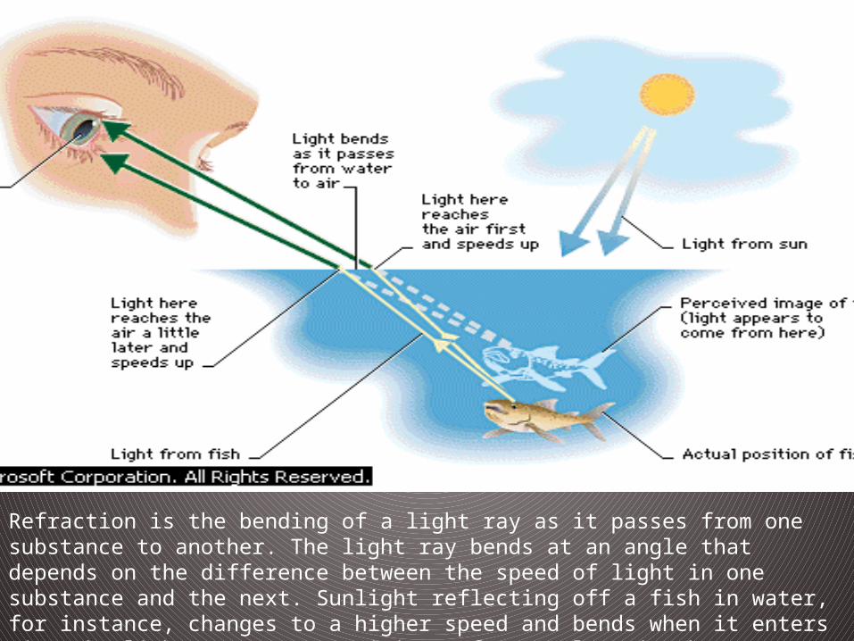
Refraction is the bending of a light ray as it passes from one substance to another. The light ray bends at an angle that depends on the difference between the speed of light in one substance and the next. Sunlight reflecting off a fish in water, for instance, changes to a higher speed and bends when it enters air. The light appears to originate from a place in the water above the fish’s actual position.
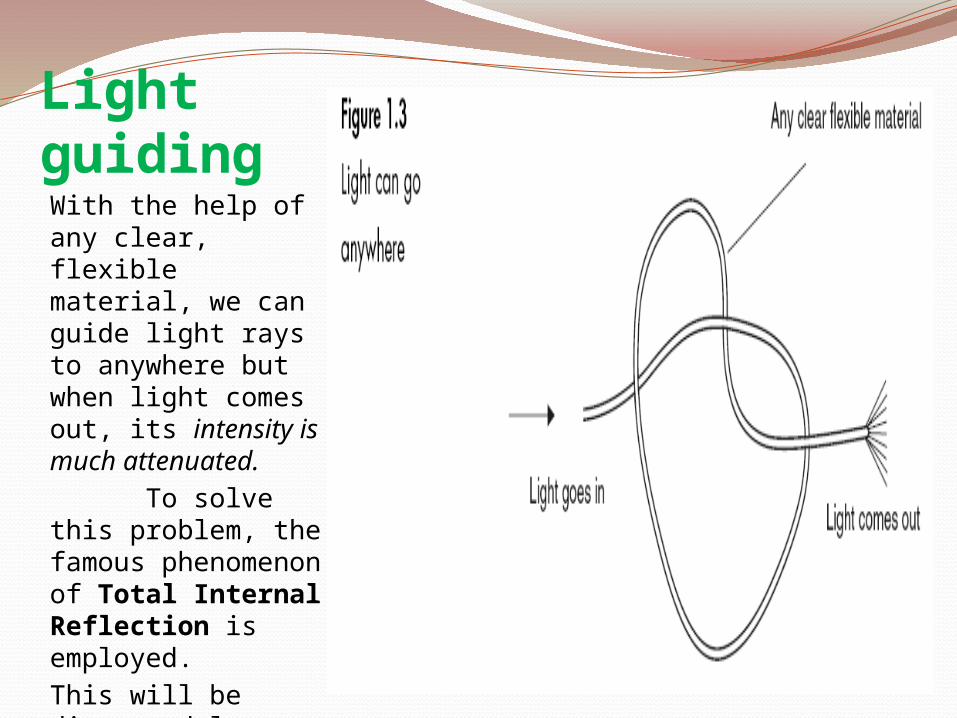
Light guidingWith the help of any clear, flexible material, we can guide light rays to anywhere but when light comes out, its intensity is much attenuated. To solve this problem, the famous phenomenon of Total Internal Reflection is employed.This will be discussed later in detail.
Fiber optics is a branch of physics that utilizes a fine glass or plastic fiber with refraction properties that allow light to pass around curves without any loss of intensity. It is the overlap of applied science & engineering concerned with the design & application of optical fibers.

Communication: Transfer of information from one point to
another. When the information is to be conveyed over any distance,
a communication system is required. Communication System
Generally used: Modulating the information with a carrier wave like radio wave .
Most advanced Technique: Using an electromagnetic carrier selected from optical range of frequencies.
Optical fibers are being used world-wide today as the medium of communication within a wide range of frequencies.
Why Optical Fibers?
It is because of the principle that, Light in a glass medium can carry more information over longer distances than electrical signals in a copper or coaxial medium or even radio frequencies through a wireless medium. The purity of today’s glass fibers ,combined with improved systems of electronics, enables the fiber to transmit digitized light signals hundreds of kms. without attenuation or amplification. With few transmission losses, low interference, and high bandwidth potential,Optical Fibers is an almost ideal transmission medium.

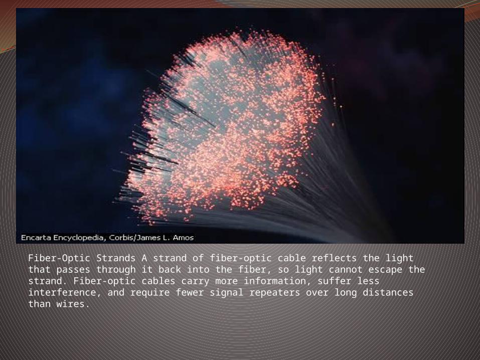
Fiber-Optic Strands A strand of fiber-optic cable reflects the light that passes through it back into the fiber, so light cannot escape the strand. Fiber-optic cables carry more information, suffer less interference, and require fewer signal repeaters over long distances than wires.

History of fiber optics evolution
Roman Times: Glass is drawn into fibers.1713: Rene de Reaumur makes spun glass fibers.1790 : Claude Chappe persuaded the French government to install a system of ‘optical telegraph’ using semaphore signals.1841: Daniel Colladon demonstrates light guiding in jet of water , Geneva.

Magic of Refraction
Daniel Colladon’s expt.


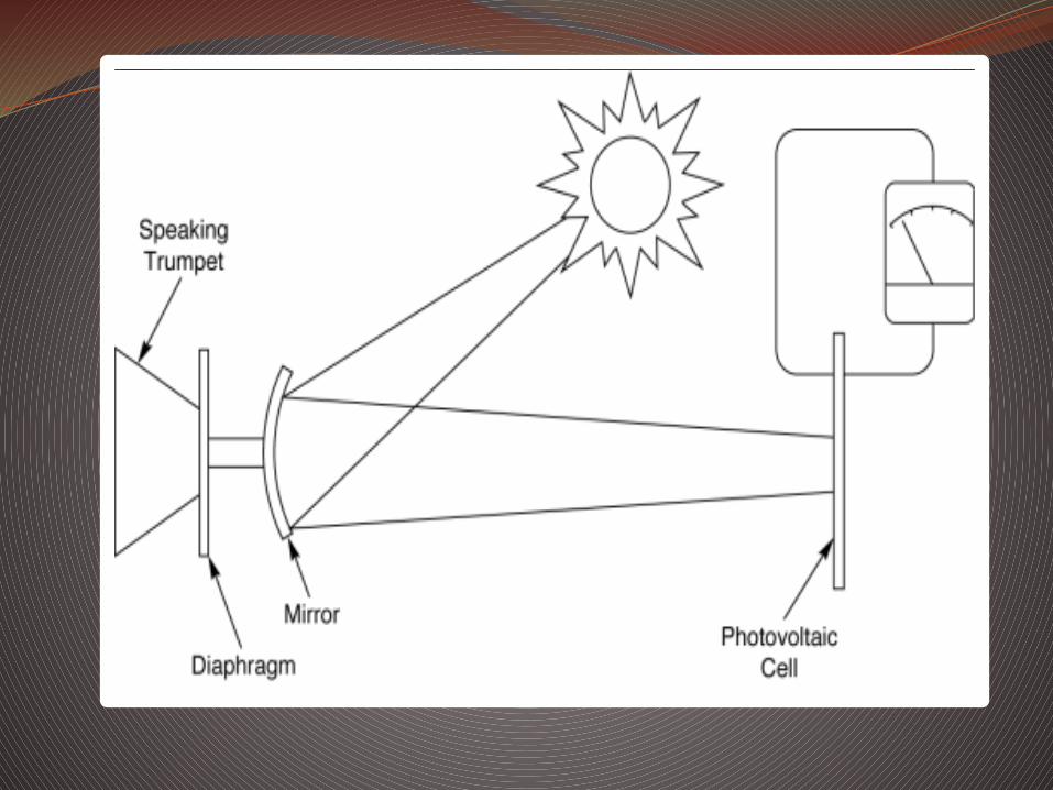
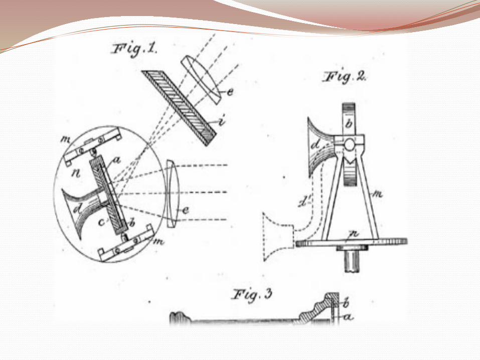
1842: Jacques Babinet reports light guiding in water jets and bent glass rods , Paris.1853: Paris Opera uses Colladon's water jet in the opera Faust.1880: Alexander Graham Bell invents Photophone , Washington.
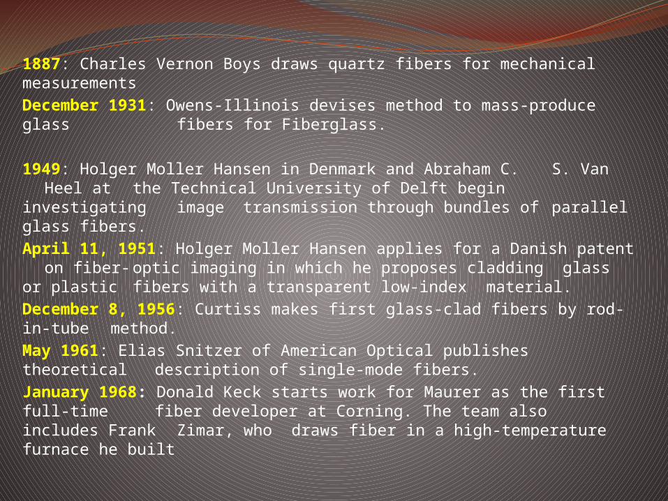
1887: Charles Vernon Boys draws quartz fibers for mechanical measurementsDecember 1931: Owens-Illinois devises method to mass-produce glass fibers for Fiberglass.
1949: Holger Moller Hansen in Denmark and Abraham C. S. Van Heel at the Technical University of Delft begin
investigating image transmission through bundles of parallel glass fibers.April 11, 1951: Holger Moller Hansen applies for a Danish patent
on fiber-optic imaging in which he proposes cladding glass or plastic fibers with a transparent low-index material.December 8, 1956: Curtiss makes first glass-clad fibers by rod-in-tube method.May 1961: Elias Snitzer of American Optical publishes theoretical description of single-mode fibers.January 1968: Donald Keck starts work for Maurer as the first full-time fiber developer at Corning. The team also includes Frank Zimar, who draws fiber in a high-temperature furnace he built
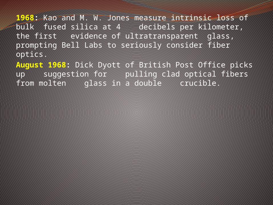
1968: Kao and M. W. Jones measure intrinsic loss of bulk fused silica at 4 decibels per kilometer, the first evidence of ultratransparent glass, prompting Bell Labs to seriously consider fiber optics.August 1968: Dick Dyott of British Post Office picks up suggestion for pulling clad optical fibers from molten glass in a double crucible.

Summer 1970: Maurer, Donald Keck, Peter Schultz, and Frank Zimar at Corning develop a single-mode fiber with loss of 17 dB/km at 633 nanometers by doping titanium into fiber core.1971-1972: Focus shifts to graded-index fibers because single- mode offers few advantages and many problems at 850 nanometers.June 1972: Maurer, Keck and Schultz make multimode germanium- doped fiber with 4 decibel per kilometer loss and much greater strength than titanium- doped fiber.December 1972: John Fulenwider proposes a fiber-optic communication network to carry video and other signals to homes at International Wire and Cable Symposium.Early 1976: Masaharu Horiguchi (NTT Ibaraki Lab) and Hiroshi Osanai (Fujikura Cable) make first fibers with low loss -- 0.47 decibel per kilometer -- at long wavelengths, 1.2 micrometers.

Late 1977: AT&T and other telephone companies settle on 850 nanometer gallium arsenide light sources and graded- index fibers for commercial systems operating at 45 million bits per second.August 1978: NTT transmits 32 million bits per second through a record 53 kilometers of graded-index fiber at 1.3 micrometers. Late 1978: NTT Ibaraki lab makes single-mode fiber with record 0.2 decibel per kilometer loss at 1.55 micrometers.February 1996: Fujitsu, NTT Labs, and Bell Labs all report sending one trillion bits per second through single optical fibers in separate experiments using different techniques.

CONSTRUCTION & WORKINGThe Physics Behind Fiber Optics

Optical Fiber types

Optical Fiber Sizes

Several individual optical cables easily pass through the eye of this needle.

Single mode fiber
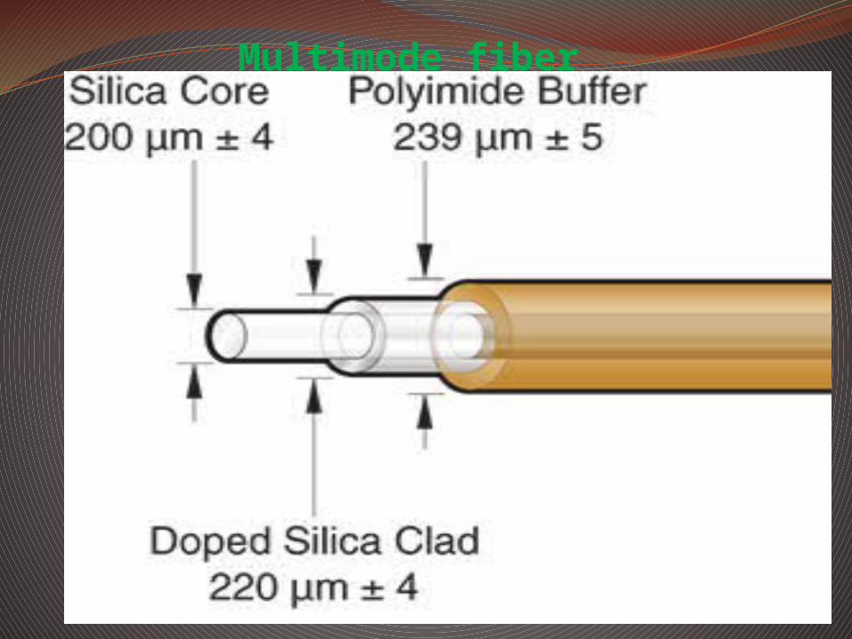
Multimode fiber
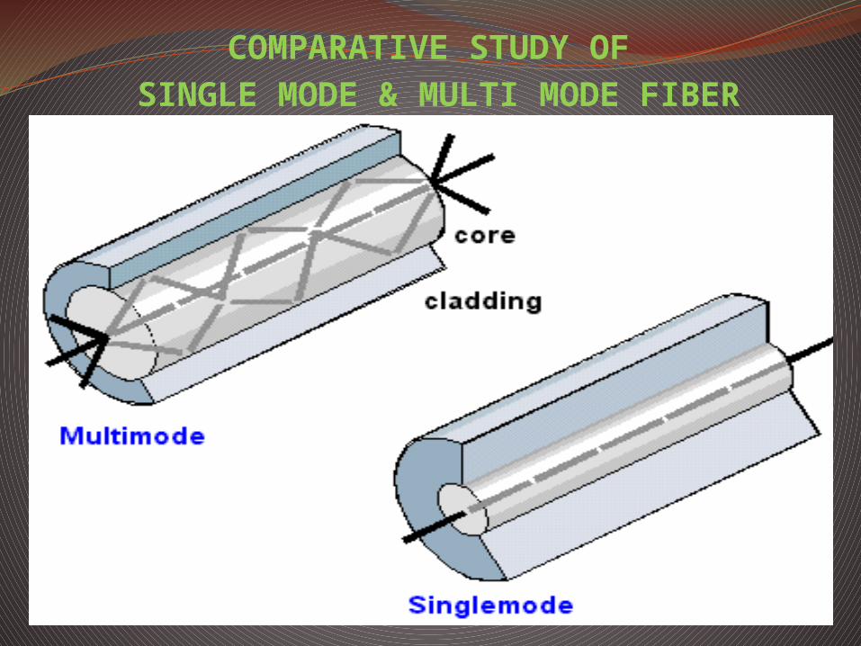
COMPARATIVE STUDY OF SINGLE MODE & MULTI MODE FIBER
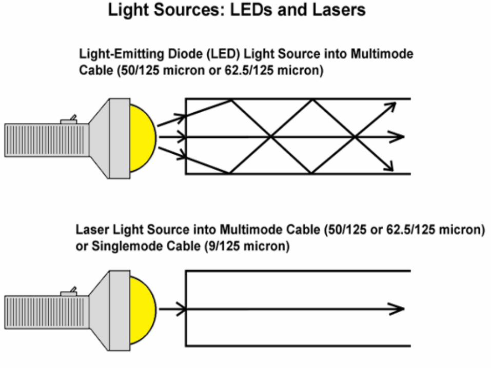

LIGHT PROPAGATION THROUGH OPTICAL FIBER

WHAT IS MULTIPATH TIME DISPERSION?

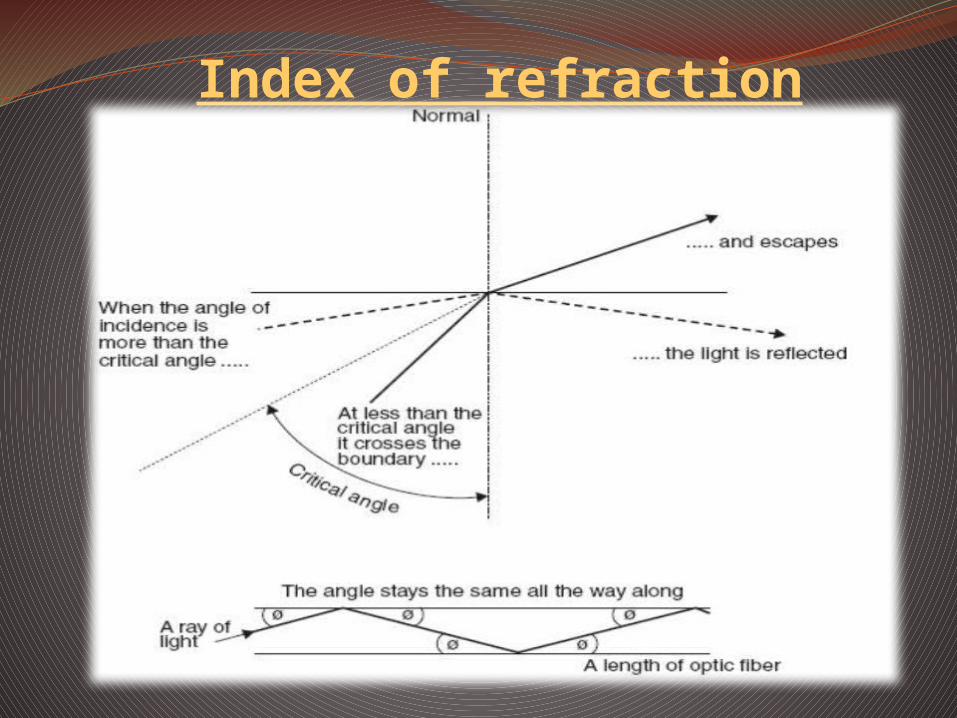
Index of refraction

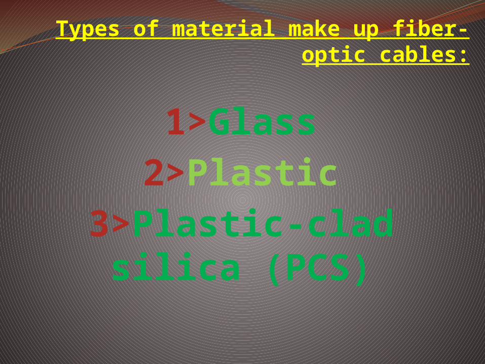
Types of material make up fiber-optic cables:
1>Glass2>Plastic
3>Plastic-clad silica (PCS)


APPLICATIONS

PUBLIC NETWORK APPLICATIONS
The public telecommunication network provides a variety of applications for optical fibre communication systems. It was, in fact, in this area that optical fibre for transmission made its first impact. The current plans of the major PTT administrations around the world feature installation of increasing numbers of optical fibre links as an alternative to coaxial and high frequency pair cable systems.
TRUNK NETWORKThis network requires the use of transmission systems which have a high capacity in order to minimize costs per circuit. Transmission distance can vary from under 20km to over 300km, and sometimes to as much as 1000km. Thus systems which exhibit low attenuation are the most economically viable. Optical fibre systems with their increased bandwidth and repeater spacing offer a distinct advantage.
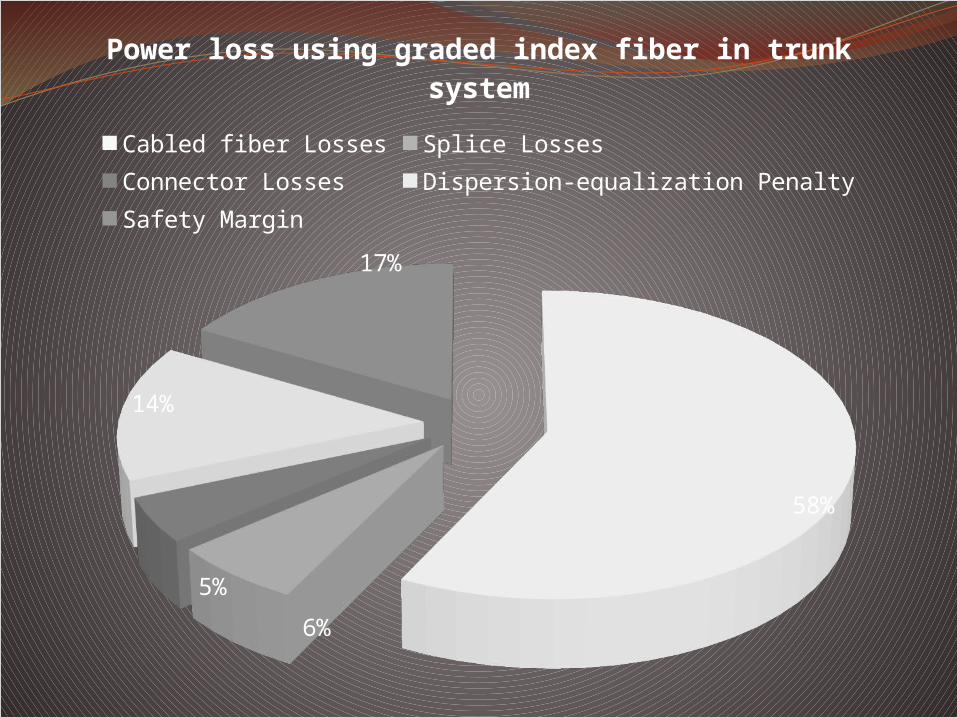
58%
6%5%
14%
17%
Power loss using graded index fiber in trunk system
Cabled fiber Losses Splice LossesConnector Losses Dispersion-equalization PenaltySafety Margin

SUBMERGED SYSTEMSUndersea cable systems are an integral part of the international telecommunications network. On longer routes, they provide route diversity in conjunction with satellite links.


MILITARY APPLICATIONSEconomics do not negate the attributes of optical fibre communication systems to military use.
MOBILESThe most promising areas of military application for optical fibre communications is within military mobiles such as aircrafts, ships and tanks.

COMMUNICATION LINKS


COMPUTER APPLICATIONSModern computer systems consist of a large number of interconnections. These range from lengths of a few micrometers (when considering on-chip, very large scale integration (VLSI) connections) to perhaps thousands of kilometres for terrestrial links in computer networks. The transmission rates over these interconnections also cover a wide range from around 100Mbit/s for some teletype terminals to several 100Mbit/s for the on-chip connections. Optical fibres are starting to find application in this connection hierarchy where secure, interference-free transmission is required.

CIVIL, CONSUMER AND INDUSTRIAL APPLICATIONS
CIVILOptical fibres are eminently suitable for video transmission and thus find applications in commercial television transmission. These include short distance links between studio and outside broadcast vans, links between studios and broadcast or receiving aerials and close circuit television (CCTV) links for security and traffic surveillance.


CONSUMERA major consumer application for optical fibre systems is within automotive electronics. Work is progressing within the automobile industry towards this end together with the use of microcomputers for engine and transmission control as well as control of convenience features such as power windows and seat controls.


INDUSTRIALIndustrial uses for optical fibre communications cover a variety of generally on-premises applications within a single operating site. Hence, majority of industrial applications tend to fall within the following design criteria:Digital transmission at rates from d.c. to 200Mbit/s, synchronous or asynchronous, having with a common logic family (i.e. TTL or CMOS), being independent of the data format and with bit error rates less than 10-
9.Transmission distances from several meters up to a maximum of kilometres, although generally 1km will prove sufficient.

SOUND MEASUREMENT The measurement of sound level can be done with either with:1) An intensity fibre optic transducer .2) An interferometric type transducer.

TEMPERATURE MEASUREMENTOptical fibres can also be used for measurement of temperature. This is because the temperature induces changes in refractive index of the fibre. The core and claddings of the fibres have different indices of refraction because of the difference in their composition. The refractive index is a function of both composition and temperature, and it changes at different rates in response to a temperature change. A higher temperature change causes the critical angle of the fibre to change slightly, which in turn changes the amount of light lost through leakage in the cladding.


CONCLUSION

Thank you

Query