Contribution to a better FBE selection for 3 layer polyolefin ...
16
HAL Id: hal-02475716 https://hal-ifp.archives-ouvertes.fr/hal-02475716 Submitted on 12 Feb 2020 HAL is a multi-disciplinary open access archive for the deposit and dissemination of sci- entific research documents, whether they are pub- lished or not. The documents may come from teaching and research institutions in France or abroad, or from public or private research centers. L’archive ouverte pluridisciplinaire HAL, est destinée au dépôt et à la diffusion de documents scientifiques de niveau recherche, publiés ou non, émanant des établissements d’enseignement et de recherche français ou étrangers, des laboratoires publics ou privés. Contribution to a better FBE selection for 3 layer polyolefin coatings V. Sauvant-Moynot, S. Duval, J. Kittel, Xavier Lefebvre To cite this version: V. Sauvant-Moynot, S. Duval, J. Kittel, Xavier Lefebvre. Contribution to a better FBE selection for 3 layer polyolefin coatings. 16th International conference on pipeline protection, Nov 2005, Paphos, Cyprus. hal-02475716
-
Upload
khangminh22 -
Category
Documents
-
view
0 -
download
0
Transcript of Contribution to a better FBE selection for 3 layer polyolefin ...

HAL Id: hal-02475716https://hal-ifp.archives-ouvertes.fr/hal-02475716
Submitted on 12 Feb 2020
HAL is a multi-disciplinary open accessarchive for the deposit and dissemination of sci-entific research documents, whether they are pub-lished or not. The documents may come fromteaching and research institutions in France orabroad, or from public or private research centers.
L’archive ouverte pluridisciplinaire HAL, estdestinée au dépôt et à la diffusion de documentsscientifiques de niveau recherche, publiés ou non,émanant des établissements d’enseignement et derecherche français ou étrangers, des laboratoirespublics ou privés.
Contribution to a better FBE selection for 3 layerpolyolefin coatings
V. Sauvant-Moynot, S. Duval, J. Kittel, Xavier Lefebvre
To cite this version:V. Sauvant-Moynot, S. Duval, J. Kittel, Xavier Lefebvre. Contribution to a better FBE selection for3 layer polyolefin coatings. 16th International conference on pipeline protection, Nov 2005, Paphos,Cyprus. �hal-02475716�

Contribution to a better FBE selection for 3 layer polyolefin coatings
V. Sauvant-Moynot, S. Duval, J. Kittel, X. Lefèbvre IFP - Material Department
ABSTRACT
Recent case studies reported large scale disbondments of three-layer polyolefin (3-LPE)
coatings, which could favour corrosion beneath the coating and lead to possible major
damage. Therefore, it is necessary to better investigate the adhesion strength of fusion-bonded
epoxy (FBE) primer to steel taking into account the water diffusing through the topcoat within
the lifetime of pipeline.
A methodology was developed to examine the adhesion of sublayers to steel under wet
exposure: peel tests were carried out on pipe rings industrially coated with FBE and adhesive
layers only, aged in vapour to simulate the water ingress through the topcoat. This
methodology could be included in selection or pre-qualification tests.
1 BACKGROUND
Among the two great families of external coatings of pipelines - FBE coatings and 3-LPE -
each one has its advantages and disadvantages. In both cases, FBE is applied in direct contact
to the freshly grit blasted pipe in order to provide good anchoring to steel.
1.1 FBE as external coating
As an example, FBE are appreciated because they are considered as fail safe (1). In other
words, if FBE coatings are disbonded, they are not shielding, because their electrical
resistance is low enough to allow cathodic protection (CP) to prevent corrosion of pipe. One
must consider the origin of these electric resistances, which are sufficient to reduce the current
demand considerably but low enough to let the current pass through it. In fact, at the time of
the synthesis of the monomers, in particular of epoxy, the stages of alkaline neutralisation
lead to the NaCl formation. This sodium chloride is washed out but remains with the
concentration of some ppb. Thus the ions present in the epoxy resin confers a resistance of

some 108 .m
2 at the dry state and low temperature to a resistance of few 10
2 .m
2 for
temperatures close to the glass transition temperature (Tg) and/or at the wet stage. One of the
disadvantages is a greater brittleness at the time of handling and installation.
1.2 Three layer polyolefin as external coating
Polyolefins offer the advantage of a much less brittle material during installation: they offer a
good mechanical protection with respect to the internal layers and in particular the FBE.
However, the polyolefins contain only very few ions contrary to the epoxy resins; thus they
have a very large electric resistance and they can lead to shielding effect, in particular in
onshore application. Some water can flow along the metal surface and because of the high
dielectric strength of polyolefin, CP current is unable to reach the pipe surface. Kehr roughly
estimates that CP protects pipe underneath coating a distance of 3 to 10 times the distance
between pipe and disbonded coating (1). But this statement obviously depends on the water
conductivity: if pipe is offshore pipe, shielding effect is unlikely to occur (2) and recent
laboratory results showed the same tendency (3, 4). .
1.3 Recent studies
Recent case studies reported large scale disbondments of 3-LPE coatings, which could favour
corrosion beneath the pipe coating and lead to possible leakage or other major damage (2, 5,
6). In order to overcome this problem, a better understanding of disbonding mechanisms is
necessary. A large parametric study was launched by GDF (7) using a specific testing device
developed for plant applied extruded 3-LPE coating systems (8). Scarified 3-LPE coated pipe
rings were aged under various conditions, then peeled off with an original protocol adapted
from standard NF A49-710 to discuss the respective influence of cathodic potential,
electrolyte conductivity and electrolyte circulation on long term 3-LPE adhesion to steel.
However, the influence of FBE wet ageing on adhesion performance could not be distinguish
from cathodic disbonding mechanisms. But pre-aged FBE coatings, e.g. exposed to water for
a long period, may give larger disbonded area. In addition, the polyolefin has a very harmful
role, which is unfortunately and regularly underestimated: it works as a permselective
membrane, i.e. only the molecules such as water, oxygen, carbon dioxide diffuse but ionic
species remain in the external medium. This can induce a catastrophic osmotic pressure effect
which results in an increased water uptake in the FBE layer, that can undergo from internal
blistering up to partial or total dissolution depending on the epoxy chemistry. These possible
phenomena related to FBE wet ageing will considerably reduce the adhesion .
1.4 Pre-qualification tests (PQT)
3-LPE coatings are currently specified in the oil, gas and water pipeline industries. However,
industrial practices for the selection, application and quality control of 3-LPE coatings hardly
ever consider moisture induced adhesion loss of the FBE layer. As a matter of facts, the
complete set of PQT on 3-LPE coated pipes usually comprises:
- thickness measurement,
- holiday testing,
- impact resistance,
- adhesion test,
- indentation,
- coating resistivity,
- elongation of the polyolefin layer,
- thermal and UV ageing,

- cathodic disbondment.
These methods are well described in standard documents, for example NF A 49-710 or
DIN 30670 for polyethylene (PE) and NF A 49-711 or DIN 30678 for polypropylene (PP).
Adhesion tests are performed on production rings. Cathodic disbondment test also
characterises adhesion properties, but in the particular case of cathodic protection while water
directly enters the macroscopic defect intended through the coating. Then, it is clear that none
of the proposed tests address the risks of long term adhesion loss of the FBE when wetted by
permeated moisture. Therefore, selection or pre-qualification tests should include soaked test
not only to detect surface contamination/pollution, good coating application/cure but also
resistance to osmotic pressure - to test the long-term adhesion performance of the FBE primer
layer. But immersion tests on 3-layer systems could be too much time demanding. Moreover,
the permeation through the polyolefin topcoat may mask differences among FBEs in too short
term tests. Then, under layers (FBE and adhesive) should be inspected as stand-alone systems
to provide relevant data to service conditions.
1.5 Water permeation through polyethylene top-coat
Polyolefin are semi-crystalline thermoplastics used as top-coat in 3-LPE coating systems to
provide toughness and good damage resistance. Their barrier properties depend on their
molecular structure and operating conditions. In a general way, the permeation of small
molecules through polymers depends on both their solubility and diffusion coefficients. The
permeability of a molecule through a polymer is defined by (9):
Pe = D.S
with S the solubility coefficient given in m3.m
-3.Pa
-1,
D the diffusion coefficient given in m2.s
-1.
The coefficient of permeability of the main semi-crystalline materials used in the oil
industries have been determined under a wide range of pressure and temperature in the IFP
laboratories (10). Results concerning the polyethylene permeability towards water are given
in Table 1 (11).
Taking into consideration a high density PE (HDPE) membrane exposed to liquid water on
one side, it is possible to calculate the time necessary for a given amount of water to diffuse
on the other side under given conditions, under the hypothesis of a steady state unidirectional
diffusion regime, using the relation (11):
At
lQPe
with Q the amount of water in kg,
l the thickness of membrane in m,
t the time in s,
A the polymer membrane area to cross in m2.
As an example, at 60°C, only 267 days are necessary to fill a 100x10-6
m gap between a top-
coat (3x10⁻³
m thick) and steel pipe. This preliminary calculation has been reinforced by
unidirectional modelling of water diffusion according to Fick's law (9) through a complete 3-
LPE coating system, at both 60°C and 20°C. 3-LPE coating systems under consideration were

typically industrial systems similar to those called "type A" in the experimental part of this
work. Concentration of water at saturation and diffusion coefficients used for modelling are
summarised in Table 2.
The water concentration profiles in 3-LPE modelled after various times at 20°C and 60°C are
illustrated, respectively, on Figure 1 and Figure 2. The saturation level in the FBE layer
should be reached within one or two years time, under isothermal conditions investigated.
This modelling underlines that the intrinsic permeability of polyethylene to moisture does not
prevent water ingress into sub layers (adhesive and primer layers) within the life time of
pipeline. This phenomenon will affect the adhesion performance of the primer layer to the
steel (wet ageing), which is a crucial functionality required from coating along the pipe
lifetime.
In this work, a methodology was developed to examine the strength of the bond between steel
and primer layer taking into account the water diffusion through the PE top-coat. The coating
application protocol was to subdivide a steel pipe into three parts: one coated with only FBE,
the second with FBE + adhesive and last with the 3 layers during the same application run.
The main objective of the work was to submit bi-layer coating (FBE + adhesive) systems to
humid atmosphere to simulate the high purity water ingress through the top-coat. Besides,
cathodic disbondment tests were also carried out on scarified three-layer coated pipe rings.
This methodology is then discussed as an additional test during selection or PQT or even
production tests.
2 EXPERIMENTAL SECTION
2.1 Coating composition and application
The steel preparation and coating application were performed in a plant according to GDF
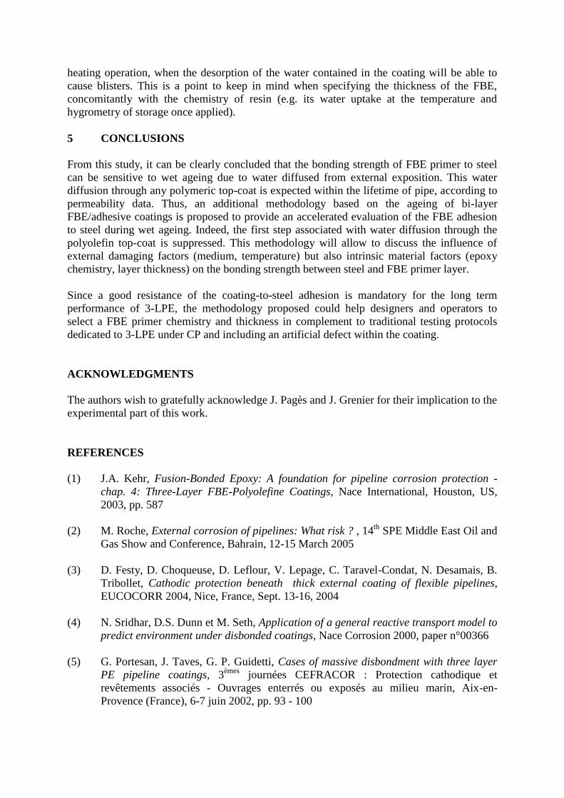
specification SPEC PC Rv 06 on a 6 m long steel pipe. Bi-layer and three-layer coated pipe
rings (0.11 m diameter and 0.3 m long) are presented in Figure 3 as received. Rings named
"A" had a 70x10-6
m thick FBE primer and "B" a 100x10-6
m thick FBE primer. The related
3-LPE systems are called, respectively, A-3LPE and B-3LPE in this paper.
2.2 Ageing conditions
In the case of bi-layer coating systems, ageing were performed at 60 °C on rings as received
exposed in a specific cell (Figure 4) to 95 % relative humidity vapour following standard DIN
50008 to simulate the electrolyte filtered by the PE top-coat. In the case of 3-LPE coatings,
ageing at 60 °C were performed on pipe rings immersed in 3 % NaCl water scarified every
28.10-3
m until steel and submitted to cathodic protection by potentiostatic polarisation
(-1,1 V vs. Ag/AgCl). Note that the graphite counter electrode was placed in a separate cell
filled with sodium sulphate and isolated by a cationic membrane to avoid any anodic
dichloride formation by chloride oxidation. pH adjustment with HCl were conducted regularly
to maintain pH values between 8 and 10.
2.3 Peel tests
Coating peel strengths were measured on pipe rings at ambient atmosphere on a tensile
machine at constant peeling velocity of 8.33x10⁻⁵
m.s-1
(5 mm.min-1
). Note that a counter
roller maintained a constant peel angle of 90 degrees (8).

3 RESULTS
3.1 3-LPE coating systems
Peeling off 3-LPE coating at the initial state (e.g. production ring) was very difficult due to
the high level of adhesion for FBE primer to steel. In most cases, PE failure (cohesive)
occurred preferentially to 3-LPE disbonding. Nevertheless, it was possible to measure an
average peel strength on a very short displacement (Figure 5). The peel energy calculated by
dividing the peel strength of 800 N by the band width is 29x103 J.m
-2 which is in agreement
with values reported in the literature (8).
As an example, the peel test of aged 3-LPE coating is illustrated in Figure 6 after three weeks
immersion in 3 % NaCl solution under cathodic protection. Two areas can be observed from
the peeled strip as previously reported in the literature (7, 8):
- the exterior areas exhibiting pure adhesive failure (at steel/epoxy interface) that can be
attributed to cathodic delamination in the vicinity of the scarified metal;
- the central area exhibiting cohesive failure may be affected by wet ageing only. Therefore,
the width of the central area should be the width taken into account to calculate the peel
energy along ageing and discuss the evolution of the bonding strength between steel and
primer layer due to water diffusing from scarified defects.
Results after 21, 28 and 42 days ageing are reported in Table 3. It appears that this calculation
of peel energy is almost impossible when the recorded strength values are highly dispersed
and the adhesive band width is discontinuous. This happened in most cases with the thin
primer A, showing one limit of this method of characterisation. In addition, such a testing
protocol applied on scarified 3-LPE under cathodic protection does not allow to discuss the
wet ageing of the adhesive bond between FBE primer and steel properly, due to overlapping
of both cathodic disbonding and wet ageing mechanisms.
3.2 FBE/adhesive coating systems
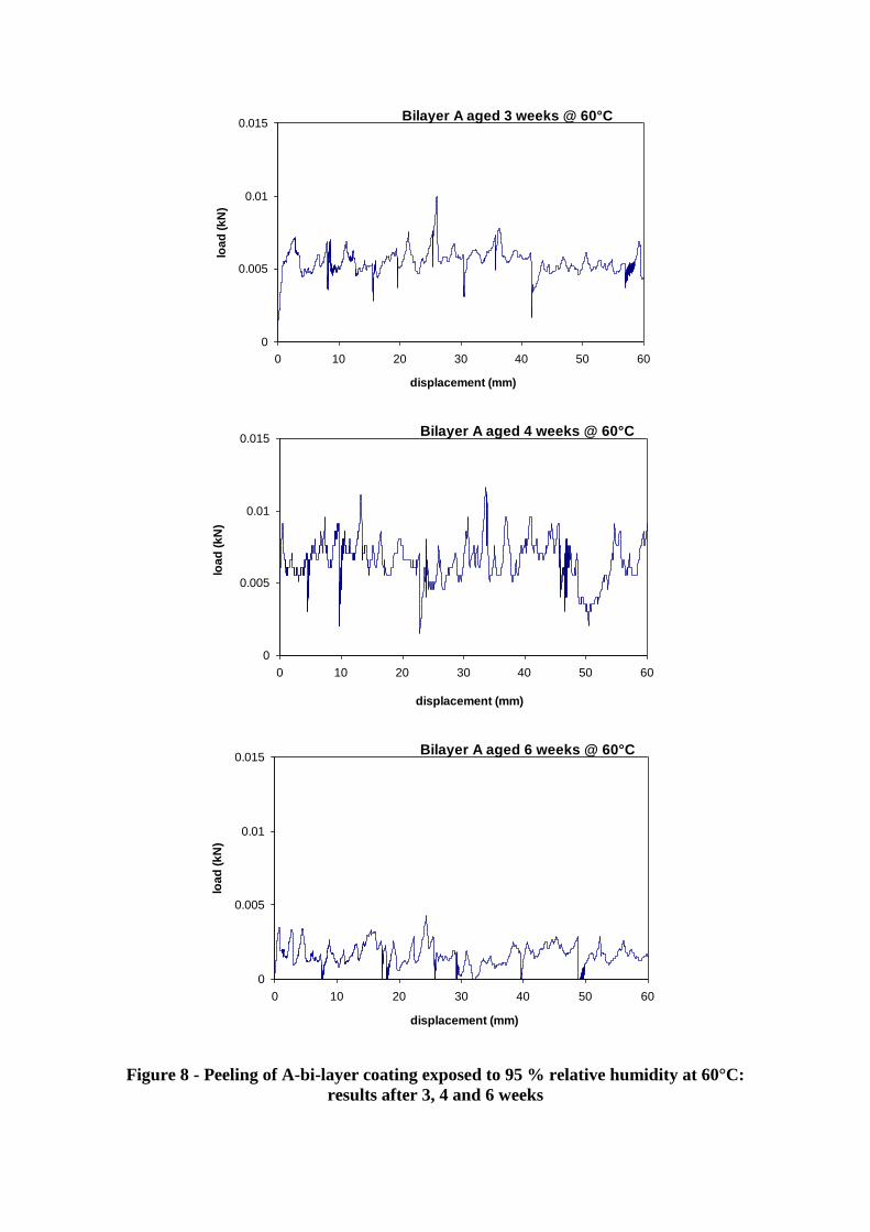
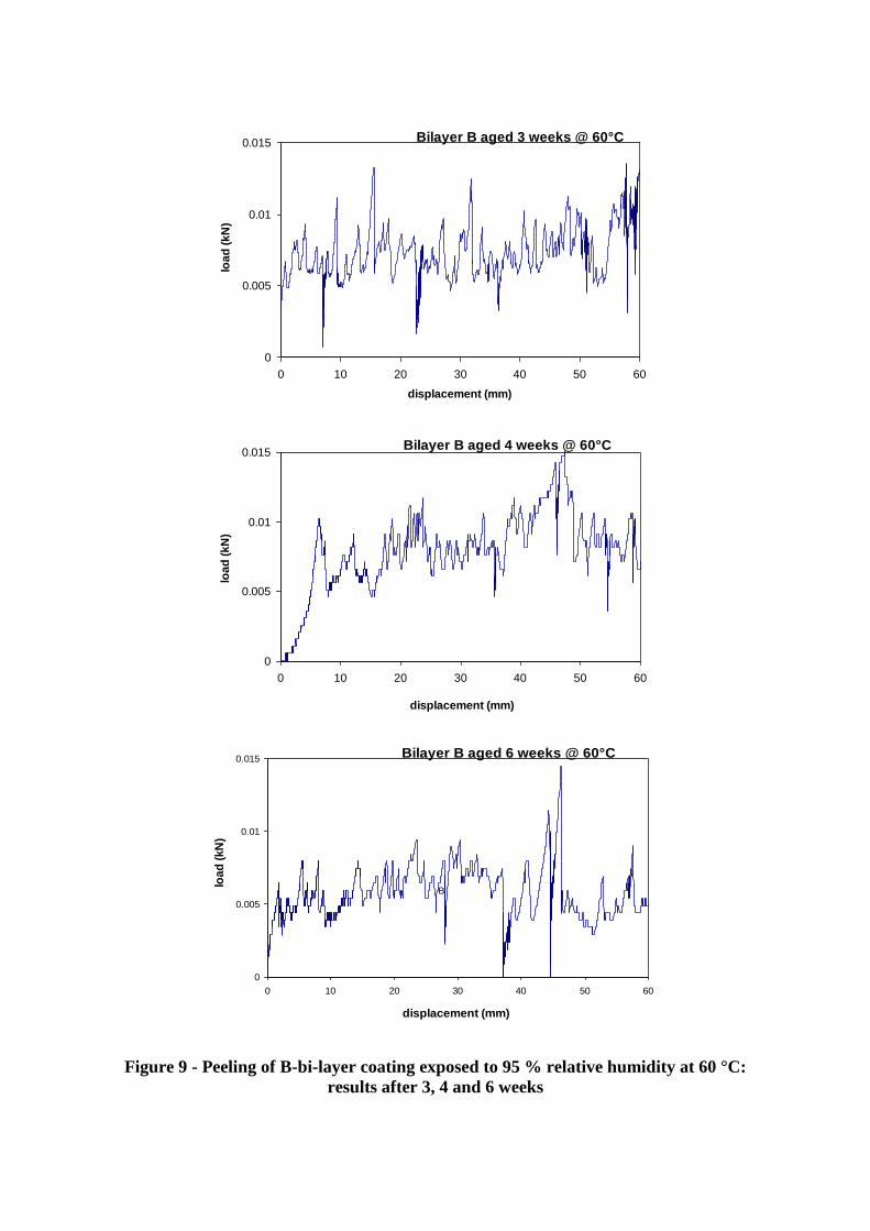
The peel test applied to the bi-layer coating is illustrated on Figure 7. A strip of 20x10-3
m
width was cut just before the peeling test. By performing some knife cut within the bi-layer
coating, it was noticed that adhesive separation occurred systematically after a few days
ageing at 60°C. One should note that metal appeared white under the peeled area whatever the
case. The peel strengths recorded at various ageing time for both A and B bi-layer coatings
(see Figure 8 and Figure 9) are summarised in Table 4. Calculated peel energies are reported
as well.
The peel strengths tend to decrease with ageing time, showing the progressive weakening of
the adhesive strength from primer on steel due to wet ageing. Therefore, this new
methodology gives a measure sensitive to wet ageing that could be reliable for FBE
evaluation and selection. Comparison between A and B-bilayer systems also underlines the
stronger adhesion to steel for the 100x10-6
m primer layer compared to the 70x10-6
m primer
layer, whatever the ageing time. These results are two major outcomes of this work.
4 DISCUSSION
4.1 FBE pre-selection
To summarise, a methodology has been presented to study the wet ageing of the adhesion
bonds between FBE primer and steel for 3-LPE coating systems. As was discussed above,

ageing on scarified three-layer coatings submitted to cathodic protection as described in
international standard cathodic disbondment test cannot allow to discriminate properly
between wet ageing and cathodic delamination mechanisms. Preliminary results showed that
wet ageing was achieved in reasonable time tests through the study of primer/adhesive bi-
layer coatings. In the particular example presented in this paper, bi-layer systems were
exposed 6 weeks to 95 % relative humidity air at 60°C in order to simulate the water filtered
by the top-coat. As a result, the FBE adherence strength is measured by peeling during
ageing, offering a unique and reliable manner to quantitatively follow the weakening of FBE
primer adherence due to wet ageing.
During FBE selection or pre-qualification, this methodology devoted to bi-layer coating
systems can complete the testing method used to measure practical adhesion (peeling test) in
comparison with the conventional method that is being used for stand alone epoxy primer
layer, namely the pull-off test; or the adhesion rating as per Nace 0394-2002. Indeed, peeling
a bi-layer strip with a hydraulic testing machine avoids the use of any adhesive to bond dollies
to the wet coating that require time to cure and very caution handling to be sure a continuous
film covers the entire surface - moreover trimming is claimed to create cracks within the
system which are responsible for a large decrease in the measured parameters (12). Perhaps
more important, though, is that the pull-off test on bi-layer coating will be able to effectively
evaluate adhesion strength on industrially coated prototypes whereas pull-off tests specified
by ISO 4624 are recommended on flat samples. However, during production, the hot water
soak test described in Nace 0394-2002 can be easily extended to the first two layers of 3 layer
coating.
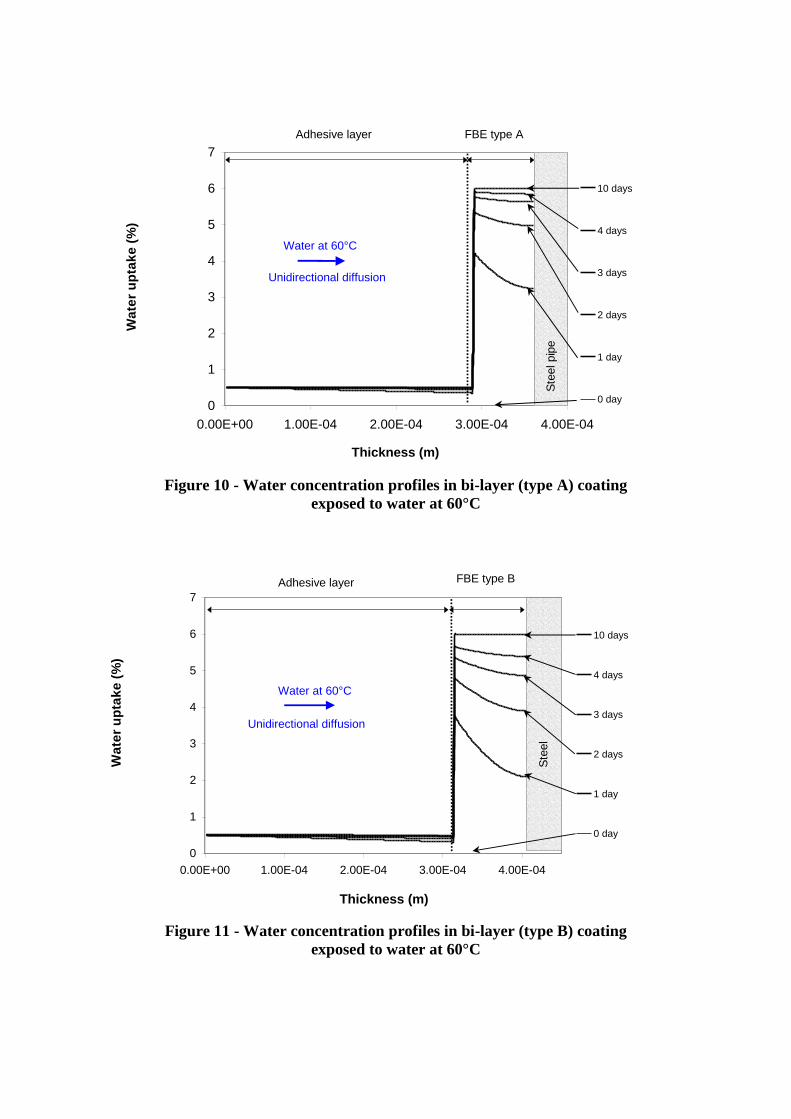
Modelling of water diffusion were conducted on bi-layer coatings exposed to water at 60 °C
(Figure 10 and Figure 11). The objective was to determine the concentration profiles of water
within the coating until saturation in order to discuss the experimental results obtained in very
similar conditions (95 % relative humidity) after 21, 28 and 42 days. Both water profiles
obtained after 10 days have reached their saturation level, assessing that the adhesive bonds
between FBE and steel surface undergo wet ageing within the time of our experiences. The
very short time required to reach the saturation that is necessary to investigate further ageing
mechanisms is a clear benefit of the methodology described above. As a matter of fact, the
pre-selection test devoted to the wet ageing assessment could last typically 14 days in water
maintained at 60 °C minimum with thickness in the range of 100x10-6
m (parameter to adjust
in function of service conditions).
4.2 FBE thickness
Several cases of loss of adhesion of FBE were reported in the literature due to water
absorption during outdoor storage period (1, 13). Coated pipe storage in hot and humid
atmospheres can conduct to a water uptake of FBE at cut back and through bulk polyolefin.
Initially, FBE was applied to a low thickness to ensure a good anchoring of top coat to steel.
Recently, from bad field experiments, this view is falling out of favour, and now thicker
layers are specified from 150x10-6
m for ambient temperature to 400x10-6
m for higher
temperature. Use of thicker FBE layer goes into a higher anticorrosion protection and higher
adhesion. However, Norman has recently reported blistering phenomenon during field joint
coating (14). This blistering is generally explained through problems during coating
application/cure or surface preparation. However, water uptake should also be considered,
because a thicker coating will absorb more water, and thus drying operation is more difficult
(to triple the thickness multiplies by nine the duration of drying), in particular during fast
heating operation, when the desorption of the water contained in the coating will be able to
cause blisters. This is a point to keep in mind when specifying the thickness of the FBE,
concomitantly with the chemistry of resin (e.g. its water uptake at the temperature and
hygrometry of storage once applied).
5 CONCLUSIONS
From this study, it can be clearly concluded that the bonding strength of FBE primer to steel
can be sensitive to wet ageing due to water diffused from external exposition. This water
diffusion through any polymeric top-coat is expected within the lifetime of pipe, according to
permeability data. Thus, an additional methodology based on the ageing of bi-layer
FBE/adhesive coatings is proposed to provide an accelerated evaluation of the FBE adhesion
to steel during wet ageing. Indeed, the first step associated with water diffusion through the
polyolefin top-coat is suppressed. This methodology will allow to discuss the influence of
external damaging factors (medium, temperature) but also intrinsic material factors (epoxy
chemistry, layer thickness) on the bonding strength between steel and FBE primer layer.
Since a good resistance of the coating-to-steel adhesion is mandatory for the long term
performance of 3-LPE, the methodology proposed could help designers and operators to
select a FBE primer chemistry and thickness in complement to traditional testing protocols
dedicated to 3-LPE under CP and including an artificial defect within the coating.
ACKNOWLEDGMENTS
The authors wish to gratefully acknowledge J. Pagès and J. Grenier for their implication to the
experimental part of this work.
REFERENCES
(1) J.A. Kehr, Fusion-Bonded Epoxy: A foundation for pipeline corrosion protection -
chap. 4: Three-Layer FBE-Polyolefine Coatings, Nace International, Houston, US,
2003, pp. 587
(2) M. Roche, External corrosion of pipelines: What risk ? , 14th
SPE Middle East Oil and
Gas Show and Conference, Bahrain, 12-15 March 2005
(3) D. Festy, D. Choqueuse, D. Leflour, V. Lepage, C. Taravel-Condat, N. Desamais, B.
Tribollet, Cathodic protection beneath thick external coating of flexible pipelines,
EUCOCORR 2004, Nice, France, Sept. 13-16, 2004
(4) N. Sridhar, D.S. Dunn et M. Seth, Application of a general reactive transport model to
predict environment under disbonded coatings, Nace Corrosion 2000, paper n°00366
(5) G. Portesan, J. Taves, G. P. Guidetti, Cases of massive disbondment with three layer
PE pipeline coatings, 3èmes
journées CEFRACOR : Protection cathodique et
revêtements associés - Ouvrages enterrés ou exposés au milieu marin, Aix-en-
Provence (France), 6-7 juin 2002, pp. 93 - 100

(6) P. Carpentiers, R. Gregoor, A. Pourbaix, Corrosion under disbonded cotings of
cathodically protected pipelines, EUCOCORR 2004, Nice, France, Sept. 13-16, 2004
(7) M. Meyer, X. Campaignolle, Impact of aging process of three layers extruded
polyethylene coatings on their adhesion on pipelines steels, BHR Group 15th
International Conference on Pipeline Protection, ed. J. Duncan and D. Norman,
Aachen, Germany, 29-31 October 2003, pp. 59 - 79
(8) F. Coeuille, Revêtements polymères de canalisation de fluide : caractérisation et
évolution de l'adhésion en milieu agressif, PhD ENSMP, Paris, France, 9 July 2002
(9) J. Crank, G.S. Park, Diffusion in Polymers, Academic Press, London and New York,
1968
(10) Permeability of gases in polymer materials, Special Issue edited by M.H. Klopffer, Oil
& Gas Science and Technology Vol. 56 n°3 may-june 2001, pp. 312
(11) B. Flaconnèche, M-H. Klopffer, J. Martin, C. Taravel-Condat, High pressure
permeation of gases in semicrystalline polymers: measurement method and
experimental data, Oilfield Engineering with Polymers 2001, London (UK), 28-29
November 2001, pp. 81-98
(12) A. A. Roche, P. Dole, M. Bouzziri, Measurement of the practical adhesion of paint
coatings to metallic sheets by the pull-off and three-point flexure tests, J. Adhesion
Sci. Technol. Vol. 8, No. 6, (1994) pp. 587-609
(13) D. Norman, Are we protecting our assets ? BHR Group 15th
International Conference
on Pipeline Protection, ed. J. Duncan and D. Norman, Aachen, Germany, 29-31
October 2003, pp. 81 - 90
(14) D. Norman, Excellent pipeline coatings require excellent pipeline substrates, Nace
Corrosion 2004, paper n°04035

Table 1- Water permeation results for HDPE (11)
Temperature
(°C)
Thickness
x 10-3
m
Permeability
10-11
kg.m/m2.s
40 0.52 0.3 9 %
53 0.52 1.0 8 %
60 0.55 1.3 4 %
80 0.54 5.5 1 %
Table 2- Water diffusion coefficient and concentration at saturation in a 3-LPE system
Layer
Diffusion coefficient
( 10-12
m2/s)
Concentration at saturation
(%)
Origin
20°C 60°C 20°C 60°C
HDPE 1.2 14 0.1 0.1 IFP data
Adhesive 0.34 4 0.5 0.5 IFP hypothesis
FBE 6.10-3
7.10-2
2.0 6.0 IFP data
Table 3 - Evolution with time of the peel strength (mean value),
the adhesive band width (mean value) and peel energy
for A and B 3-LPE coatings aged in 95 % relative humidity at 60°C
A-3LPE coating B-3LPE coating
Ageing time
(days)
Strength
(N)
Adhesive
band (m)
Peel energy
x103 J/m
2
Strength
(N)
Adhesive
band (m)
Peel energy
x103 J/m
2
0 800 0.028 29
21 50 to 300 0 to 0.011
discontinuous
200-500 0.010
regular
20-50
28 10 to 300 0 to 0.008
discontinuous
< 300 0.008
regular
< 37
42 < 10 None < 15 0 to 0.005
discontinuous
Table 4 - Evolution of the mean strength with time for A and B bi-layer coatings
aged in 95% relative humidity at 60°C
A-bi-layer coating B-bi-layer coating
Ageing time
(days)
Strength
(N)
Peel energy
x103 J/m
2
Strength
(N)
Peel energy
x103 J/m
2
0 No measure - No measure -
21 6.0 300 7.5 375
28 6.0 300 7.5 375
42 2.0 100 5.0 250

0
0.5
1
1.5
2
0.00E+00 1.00E-03 2.00E-03 3.00E-03 4.00E-03
thickness (m)
Wate
r u
pta
ke (
%)
600 days
360 days
240 days
120 days
60 days
30 days
0 day
HDPE top-coat
adhesiv
e
FB
E
Ste
el pip
e
Water at 20°C
Unidirectional diffusion
Figure 1 - Water concentration profiles in 3-LPE (type A) exposed to water at 20°C
0
1
2
3
4
5
6
7
0.00E+00 1.00E-03 2.00E-03 3.00E-03 4.00E-03
thickness (m)
Wate
r u
pta
ke (
%)
300 days
30 days
0 jour
HDPE top-coat
adhesiv
e
FB
E
Ste
el pip
e
Water at 60°C
Unidirectional diffusion
Figure 2 - Water concentration profiles in 3-LPE (type A) exposed to water at 60°C
0 day
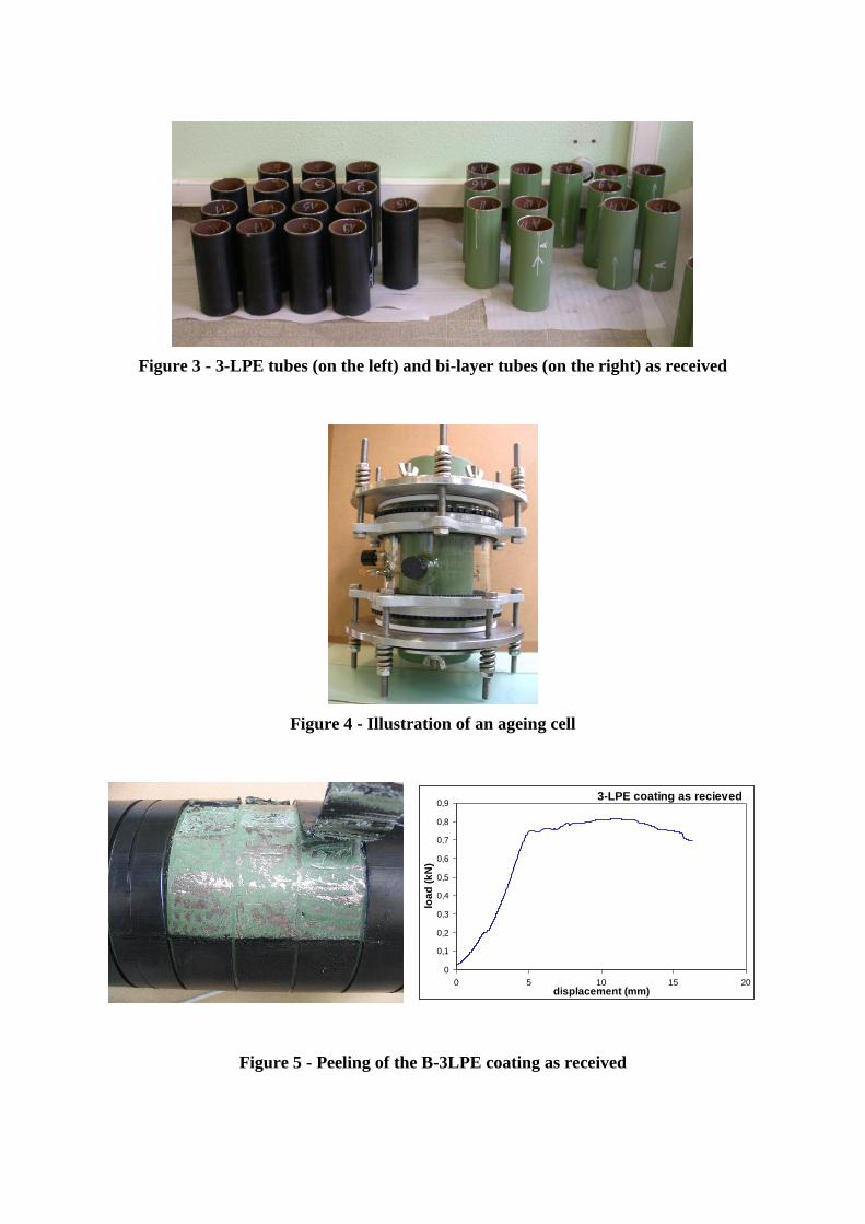
Figure 3 - 3-LPE tubes (on the left) and bi-layer tubes (on the right) as received
Figure 4 - Illustration of an ageing cell
3-LPE coating as recieved
0
0,1
0,2
0,3
0,4
0,5
0,6
0,7
0,8
0,9
0 5 10 15 20displacement (mm)
loa
d (
kN
)
Figure 5 - Peeling of the B-3LPE coating as received

Figure 6 - Peeling of the B-3LPE coating aged 21 days in 3 % NaCl solution
under -1,1 V vs. Ag/AgCl
Figure 7 - Peeling of the bi-layer coating after a few weeks ageing at 60°C
0
0.005
0.01
0.015
0 10 20 30 40 50 60
displacement (mm)
loa
d (
kN
)
Bilayer A aged 3 weeks @ 60°C
0
0.005
0.01
0.015
0 10 20 30 40 50 60
displacement (mm)
loa
d (
kN
)
Bilayer A aged 4 weeks @ 60°C
0
0.005
0.01
0.015
0 10 20 30 40 50 60
displacement (mm)
loa
d (
kN
)
Bilayer A aged 6 weeks @ 60°C
Figure 8 - Peeling of A-bi-layer coating exposed to 95 % relative humidity at 60°C:
results after 3, 4 and 6 weeks
0
0.005
0.01
0.015
0 10 20 30 40 50 60
displacement (mm)
loa
d (
kN
)
Bilayer B aged 3 weeks @ 60°C
0
0.005
0.01
0.015
0 10 20 30 40 50 60
displacement (mm)
loa
d (
kN
)
Bilayer B aged 4 weeks @ 60°C
0
0.005
0.01
0.015
0 10 20 30 40 50 60
displacement (mm)
loa
d (
kN
)
Bilayer B aged 6 weeks @ 60°C
B
Figure 9 - Peeling of B-bi-layer coating exposed to 95 % relative humidity at 60 °C:
results after 3, 4 and 6 weeks
0
1
2
3
4
5
6
7
0.00E+00 1.00E-04 2.00E-04 3.00E-04 4.00E-04
Thickness (m)
Wa
ter
up
tak
e (
%)
10 days
4 days
3 days
2 days
1 day
0 day
Adhesive layer
Ste
el pip
e
Water at 60°C
Unidirectional diffusion
FBE type A
Figure 10 - Water concentration profiles in bi-layer (type A) coating
exposed to water at 60°C
0
1
2
3
4
5
6
7
0.00E+00 1.00E-04 2.00E-04 3.00E-04 4.00E-04
Thickness (m)
Wa
ter
up
tak
e (
%)
10 days
4 days
3 days
2 days
1 day
0 day
Adhesive layer FBE type B
Water at 60°C
Unidirectional diffusion
Ste
el
Figure 11 - Water concentration profiles in bi-layer (type B) coating
exposed to water at 60°C