CONSTRUCTION OF BABATAS CPA BULK WATER SUPPLY ...
295
CONSTRUCTION OF BABATAS CPA BULK WATER SUPPLY TENDER NO. NC/001/2021 TENDERER: TELEPHONE: EMAIL: TOTAL PRICE (INCL. VAT) CONTRACT PERIOD CLOSING DATE TIME COMPILED FOR: SIOC Community Development Trust Chief Executive Officer Mr Vusani Malie SIOC Office Park, Block A, Ground Floor, Cnr Hendrick van Eck & Ian Flemming Road, KATHU 8446 CONSULTANT: IX ENGINEERS Contact person: Mr A Khumalo Montrio Corporate Park, Block 3, North Wing, 1 st Floor 10 Oliver Road, Monument Heights, Kimberley, 8301 PO Box 50, Kimberley 8300, South Africa Telephone: +27(0)53 830 0460 [email protected].za www.ixengineers.co.za
-
Upload
khangminh22 -
Category
Documents
-
view
0 -
download
0
Transcript of CONSTRUCTION OF BABATAS CPA BULK WATER SUPPLY ...

CONSTRUCTION OF BABATAS CPA BULK WATER SUPPLY
TENDER NO. NC/001/2021
TENDERER:
TELEPHONE: EMAIL:
TOTAL PRICE (INCL. VAT)
CONTRACT PERIOD
CLOSING DATE
TIME
COMPILED FOR:
SIOC Community Development Trust Chief Executive Officer Mr Vusani Malie SIOC Office Park, Block A,
Ground Floor, Cnr Hendrick van Eck & Ian Flemming Road,
KATHU 8446
CONSULTANT: IX ENGINEERS Contact person: Mr A Khumalo Montrio Corporate Park, Block 3, North Wing, 1st Floor 10 Oliver Road, Monument Heights, Kimberley, 8301 PO Box 50, Kimberley 8300, South Africa Telephone: +27(0)53 830 0460 [email protected]
www.ixengineers.co.za
(i)
TENDER
CONSTRUCTION OF BABATAS CPA BULK WATER SUPPLY
TENDER NO. NC/001/2021
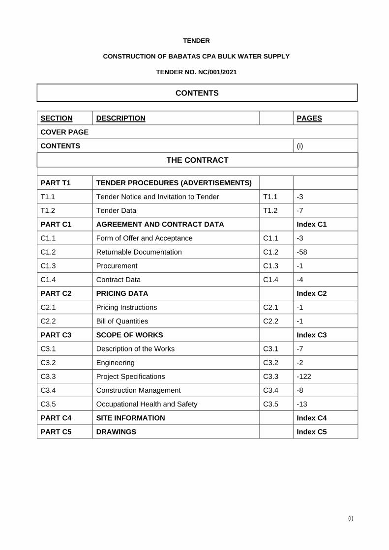
CONTENTS
SECTION DESCRIPTION PAGES
COVER PAGE
CONTENTS (i)
THE CONTRACT
PART T1 TENDER PROCEDURES (ADVERTISEMENTS)
T1.1 Tender Notice and Invitation to Tender T1.1 -3
T1.2 Tender Data T1.2 -7
PART C1 AGREEMENT AND CONTRACT DATA Index C1
C1.1 Form of Offer and Acceptance C1.1 -3
C1.2 Returnable Documentation C1.2 -58
C1.3 Procurement C1.3 -1
C1.4 Contract Data C1.4 -4
PART C2 PRICING DATA Index C2
C2.1 Pricing Instructions C2.1 -1
C2.2 Bill of Quantities C2.2 -1
PART C3 SCOPE OF WORKS Index C3
C3.1 Description of the Works C3.1 -7
C3.2 Engineering C3.2 -2
C3.3 Project Specifications C3.3 -122
C3.4 Construction Management C3.4 -8
C3.5 Occupational Health and Safety C3.5 -13
PART C4 SITE INFORMATION Index C4
PART C5 DRAWINGS Index C5
Tender Notice and Invitation to Tender
T1.1-1
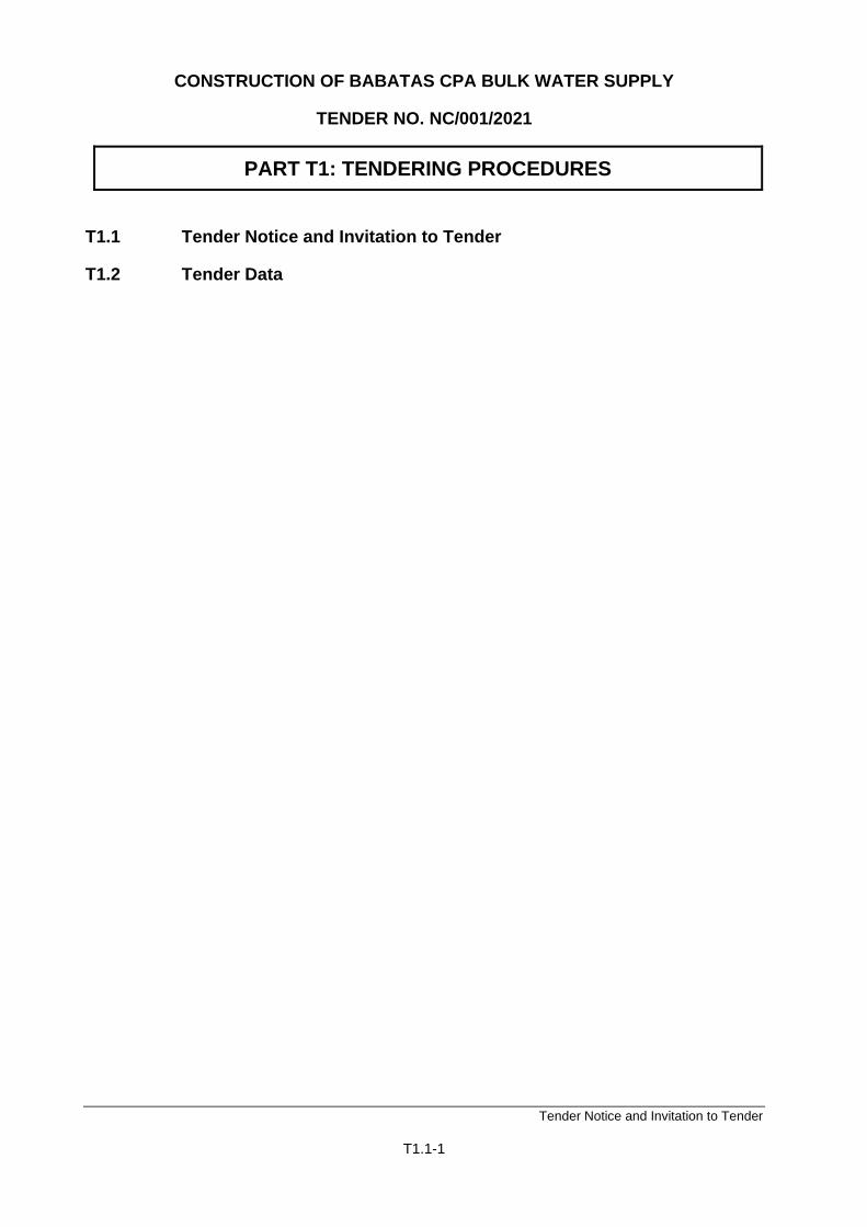
CONSTRUCTION OF BABATAS CPA BULK WATER SUPPLY
TENDER NO. NC/001/2021
PART T1: TENDERING PROCEDURES
T1.1 Tender Notice and Invitation to Tender
T1.2 Tender Data

Tender Notice and Invitation to Tender
T1.1-2
CONSTRUCTION OF BABATAS CPA BULK WATER SUPPLY
TENDER NO. NC/001/2021
T1.1 : TENDER NOTICE AND INVITATION TO TENDER
Tender Notice and Invitation to Tender
T1.1-3
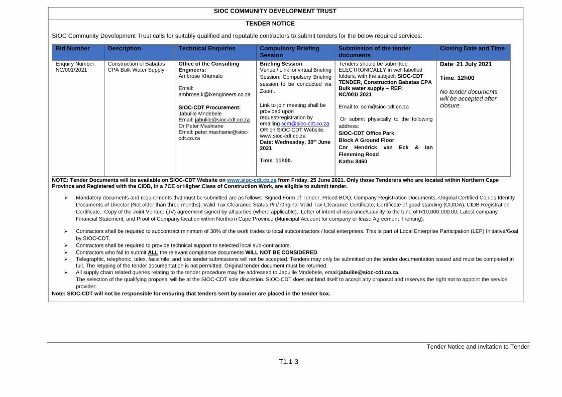
SIOC COMMUNITY DEVELOPMENT TRUST
TENDER NOTICE
SIOC Community Development Trust calls for suitably qualified and reputable contractors to submit tenders for the below required services:
Bid Number Description Technical Enquiries
Compulsory Briefing Session
Submission of the tender documents
Closing Date and Time
Enquiry Number: NC/001/2021
Construction of Babatas CPA Bulk Water Supply
Office of the Consulting Engineers: Ambrose Khumalo Email: [email protected]
SIOC-CDT Procurement: Jabulile Mndebele Email: [email protected] Or Peter Mashiane Email: [email protected]
Briefing Session: Venue / Link for virtual Briefing
Session: Compulsory Briefing
session to be conducted via
Zoom.
Link to join meeting shall be provided upon request/registration by emailing [email protected] OR on SIOC CDT Website. www.sioc-cdt.co.za Date: Wednesday, 30th June 2021 Time: 11h00.
Tenders should be submitted ELECTRONICALLY in well labelled folders, with the subject: SIOC-CDT TENDER, Construction Babatas CPA Bulk water supply – REF: NC/001/ 2021 Email to: [email protected] Or submit physically to the following
address:
SIOC-CDT Office Park
Block A Ground Floor
Cnr Hendrick van Eck & Ian
Flemming Road
Kathu 8460
Date: 21 July 2021 Time: 12h00 No tender documents will be accepted after closure.
NOTE: Tender Documents will be available on SIOC-CDT Website on www.sioc-cdt.co.za from Friday, 25 June 2021. Only those Tenderers who are located within Northern Cape Province and Registered with the CIDB, in a 7CE or Higher Class of Construction Work, are eligible to submit tender.
➢ Mandatory documents and requirements that must be submitted are as follows: Signed Form of Tender, Priced BOQ, Company Registration Documents, Original Certified Copies Identity
Documents of Director (Not older than three months), Valid Tax Clearance Status Pin/ Original Valid Tax Clearance Certificate, Certificate of good standing (COIDA), CIDB Registration
Certificate, Copy of the Joint Venture (JV) agreement signed by all parties (where applicable), Letter of intent of insurance/Liability to the tune of R10,000,000.00, Latest company
Financial Statement, and Proof of Company location within Northern Cape Province (Municipal Account for company or lease Agreement if renting).
➢ Contractors shall be required to subcontract minimum of 30% of the work trades to local subcontractors / local enterprises. This is part of Local Enterprise Participation (LEP) Initiative/Goal
by SIOC-CDT.
➢ Contractors shall be required to provide technical support to selected local sub-contractors.
➢ Contractors who fail to submit ALL the relevant compliance documents WILL NOT BE CONSIDERED.
➢ Telegraphic, telephonic, telex, facsimile, and late tender submissions will not be accepted. Tenders may only be submitted on the tender documentation issued and must be completed in
full. The retyping of the tender documentation is not permitted. Original tender document must be returned.
➢ All supply chain related queries relating to the tender procedure may be addressed to Jabulile Mndebele, email:[email protected].
The selection of the qualifying proposal will be at the SIOC-CDT sole discretion. SIOC-CDT does not bind itself to accept any proposal and reserves the right not to appoint the service
provider:
Note: SIOC-CDT will not be responsible for ensuring that tenders sent by courier are placed in the tender box.
Tender Data
T1.2 - 1
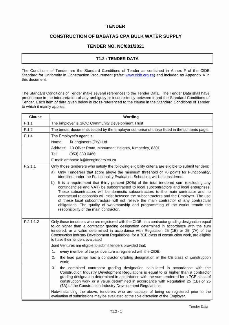
TENDER
CONSTRUCTION OF BABATAS CPA BULK WATER SUPPLY
TENDER NO. NC/001/2021
T1.2 : TENDER DATA
The Conditions of Tender are the Standard Conditions of Tender as contained in Annex F of the CIDB Standard for Uniformity in Construction Procurement (refer: www.cidb.org.za) and included as Appendix A in this document.
The Standard Conditions of Tender make several references to the Tender Data. The Tender Data shall have precedence in the interpretation of any ambiguity or inconsistency between it and the Standard Conditions of Tender. Each item of data given below is cross-referenced to the clause in the Standard Conditions of Tender to which it mainly applies.
Clause Wording
F.1.1 The employer is SIOC Community Development Trust
F.1.2 The tender documents issued by the employer comprise of those listed in the contents page.
F.1.4 The Employer’s agent is:
Name: iX engineers (Pty) Ltd
Address: 10 Oliver Road, Monument Heights, Kimberley, 8301
Tel: (053) 830 0460
E-mail: [email protected]
F.2.1.1 Only those tenderers who satisfy the following eligibility criteria are eligible to submit tenders:
a) Only Tenderers that score above the minimum threshold of 70 points for Functionality, identified under the Functionality Evaluation Schedule, will be considered.
b) It is a requirement that thirty percent (30%) of the total tendered sum (excluding any contingencies and VAT) be subcontracted to local subcontractors and local enterprises. These subcontractors will be domestic subcontractors to the main contractor and no contractual relationship will exist between the subcontractors and the Employer. The use of these local subcontractors will not relieve the main contractor of any contractual obligations. The quality of workmanship and programming of the works remain the responsibility of the main contractor.
F.2.1.1.2 Only those tenderers who are registered with the CIDB, in a contractor grading designation equal to or higher than a contractor grading designation determined in accordance with the sum tendered, or a value determined in accordance with Regulation 25 (1B) or 25 (7A) of the Construction Industry Development Regulations, for a 7CE class of construction work, are eligible to have their tenders evaluated
Joint Ventures are eligible to submit tenders provided that:
1. every member of the joint venture is registered with the CIDB;
2. the lead partner has a contractor grading designation in the CE class of construction work;
3. the combined contractor grading designation calculated in accordance with the Construction Industry Development Regulations is equal to or higher than a contractor grading designation determined in accordance with the sum tendered for a 7CE class of construction work or a value determined in accordance with Regulation 25 (1B) or 25 (7A) of the Construction Industry Development Regulations.
Notwithstanding the above, tenderers who are capable of being so registered prior to the evaluation of submissions may be evaluated at the sole discretion of the Employer.
Tender Data
T1.2 - 2
Clause Wording
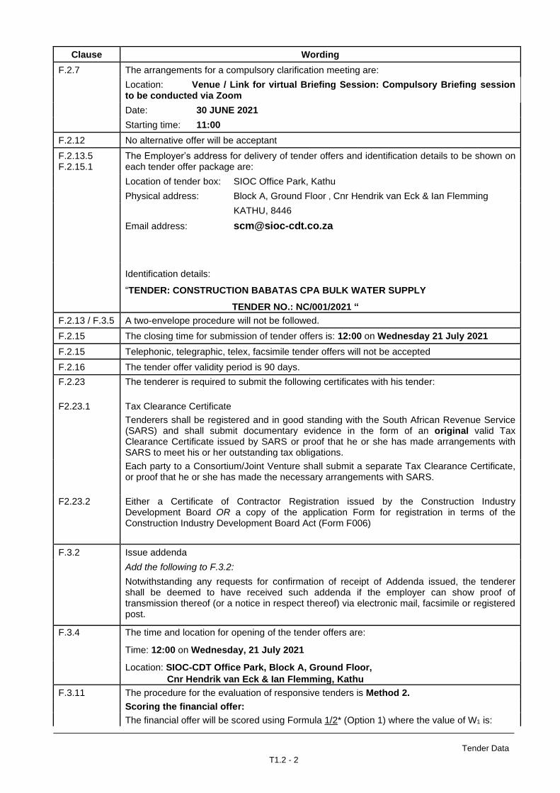
F.2.7 The arrangements for a compulsory clarification meeting are:
Location: Venue / Link for virtual Briefing Session: Compulsory Briefing session to be conducted via Zoom
Date: 30 JUNE 2021
Starting time: 11:00
F.2.12 No alternative offer will be acceptant
F.2.13.5 F.2.15.1
The Employer’s address for delivery of tender offers and identification details to be shown on each tender offer package are:
Location of tender box: SIOC Office Park, Kathu
Physical address: Block A, Ground Floor , Cnr Hendrik van Eck & Ian Flemming
KATHU, 8446
Email address: [email protected]
Identification details:
“TENDER: CONSTRUCTION BABATAS CPA BULK WATER SUPPLY
TENDER NO.: NC/001/2021 “
F.2.13 / F.3.5 A two-envelope procedure will not be followed.
F.2.15 The closing time for submission of tender offers is: 12:00 on Wednesday 21 July 2021
F.2.15 Telephonic, telegraphic, telex, facsimile tender offers will not be accepted
F.2.16 The tender offer validity period is 90 days.
F.2.23 The tenderer is required to submit the following certificates with his tender:
F2.23.1 Tax Clearance Certificate
Tenderers shall be registered and in good standing with the South African Revenue Service (SARS) and shall submit documentary evidence in the form of an original valid Tax Clearance Certificate issued by SARS or proof that he or she has made arrangements with SARS to meet his or her outstanding tax obligations.
Each party to a Consortium/Joint Venture shall submit a separate Tax Clearance Certificate, or proof that he or she has made the necessary arrangements with SARS.
F2.23.2 Either a Certificate of Contractor Registration issued by the Construction Industry Development Board OR a copy of the application Form for registration in terms of the Construction Industry Development Board Act (Form F006)
F.3.2 Issue addenda
Add the following to F.3.2:
Notwithstanding any requests for confirmation of receipt of Addenda issued, the tenderer shall be deemed to have received such addenda if the employer can show proof of transmission thereof (or a notice in respect thereof) via electronic mail, facsimile or registered post.
F.3.4 The time and location for opening of the tender offers are:
Time: 12:00 on Wednesday, 21 July 2021
Location: SIOC-CDT Office Park, Block A, Ground Floor,
Cnr Hendrik van Eck & Ian Flemming, Kathu
F.3.11 The procedure for the evaluation of responsive tenders is Method 2.
Scoring the financial offer:
The financial offer will be scored using Formula 1/2* (Option 1) where the value of W1 is:
Tender Data
T1.2 - 3
Clause Wording
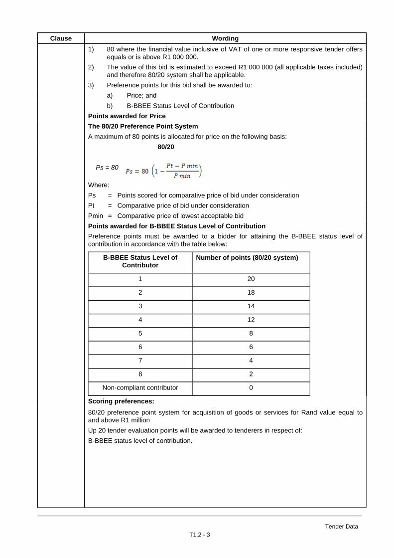
1) 80 where the financial value inclusive of VAT of one or more responsive tender offers equals or is above R1 000 000.
2) The value of this bid is estimated to exceed R1 000 000 (all applicable taxes included) and therefore 80/20 system shall be applicable.
3) Preference points for this bid shall be awarded to:
a) Price; and
b) B-BBEE Status Level of Contribution
Points awarded for Price
The 80/20 Preference Point System
A maximum of 80 points is allocated for price on the following basis:
80/20
Ps = 80
Where:
Ps = Points scored for comparative price of bid under consideration
Pt = Comparative price of bid under consideration
Pmin = Comparative price of lowest acceptable bid
Points awarded for B-BBEE Status Level of Contribution
Preference points must be awarded to a bidder for attaining the B-BBEE status level of contribution in accordance with the table below:
B-BBEE Status Level of Contributor
Number of points (80/20 system)
1 20
2 18
3 14
4 12
5 8
6 6
7 4
8 2
Non-compliant contributor 0
Scoring preferences:
80/20 preference point system for acquisition of goods or services for Rand value equal to and above R1 million
Up 20 tender evaluation points will be awarded to tenderers in respect of:
B-BBEE status level of contribution.
Tender Data
T1.2 - 4
Clause Wording
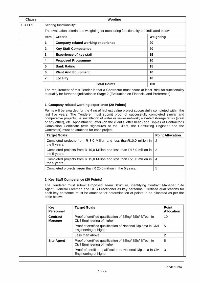
F.3.11.9 Scoring functionality:
The evaluation criteria and weighting for measuring functionality are indicated below:
Item Criteria Weighting
1. Company related working experience 20
2. Key Staff Competence 20
3. Experience of key staff 15
4. Proposed Programme 10
5. Bank Rating 15
6. Plant And Equipment 10
7. Locality 10
Total Points 100
The requirement of this Tender is that a Contractor must score at least 70% for functionality to qualify for further adjudication in Stage 2 (Evaluation on Financial and Preference).
1. Company related working experience (20 Points)
Points will be awarded for the 4 no of highest value project successfully completed within the last five years. The Tenderer must submit proof of successfully completed similar and comparative projects, i.e. installation of water or sewer network, elevated storage tanks (steel or any other), etc. Appointment Letter (on the client’s letter head) and Copies of Contractor’s Completion Certificate (with signatures of the Client, the Consulting Engineer and the Contractor) must be attached for each project.
Target Goals Point Allocation
Completed projects from R 8,0 Million and less thanR10,0 million in the 5 years.
2
Completed projects from R 10,0 Million and less than R15,0 million in the 5 years.
3
Completed projects from R 15,0 Million and less than R20,0 million in the 5 years.
4
Completed projects larger than R 20,0 million in the 5 years. 5
2. Key Staff Competence (20 Points)
The Tenderer must submit Proposed Team Structure, identifying Contract Manager, Site Agent, General Foreman and OHS Practitioner as key personnel. Certified qualifications for each key personnel must be attached for determination of points to be allocated as per the table below:
Key Personnel
Target Goals Point Allocation
Contract Manager
Proof of certified qualification of BEng/ BSc/ BTech in Civil Engineering of higher
10
Proof of certified qualification of National Diploma in Civil Engineering of higher
5
Less than above 2
Site Agent Proof of certified qualification of BEng/ BSc/ BTech in Civil Engineering of higher
5
Proof of certified qualification of National Diploma in Civil Engineering of higher
3
Tender Data
T1.2 - 5
Clause Wording
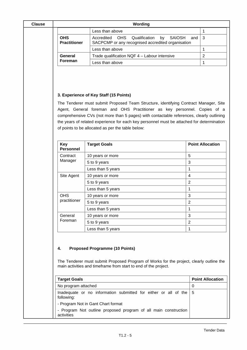
Less than above 1
OHS Practitioner
Accredited OHS Qualification by SAIOSH and SACPCMP or any recognised accredited organisation
3
Less than above 1
General Foreman
Trade qualification NQF 4 – Labour intensive 2
Less than above 1
3. Experience of Key Staff (15 Points)
The Tenderer must submit Proposed Team Structure, identifying Contract Manager, Site
Agent, General foreman and OHS Practitioner as key personnel. Copies of a
comprehensive CVs (not more than 5 pages) with contactable references, clearly outlining
the years of related experience for each key personnel must be attached for determination
of points to be allocated as per the table below:
Key Personnel
Target Goals Point Allocation
Contract Manager
10 years or more 5
5 to 9 years 3
Less than 5 years 1
Site Agent 10 years or more 4
5 to 9 years 2
Less than 5 years 1
OHS practitioner
10 years or more 3
5 to 9 years 2
Less than 5 years 1
General Foreman
10 years or more 3
5 to 9 years 2
Less than 5 years 1
4. Proposed Programme (10 Points)
The Tenderer must submit Proposed Program of Works for the project, clearly outline the main activities and timeframe from start to end of the project.
Target Goals Point Allocation
No program attached 0
Inadequate or no information submitted for either or all of the following:
- Program Not in Gant Chart format
- Program Not outline proposed program of all main construction activities
5
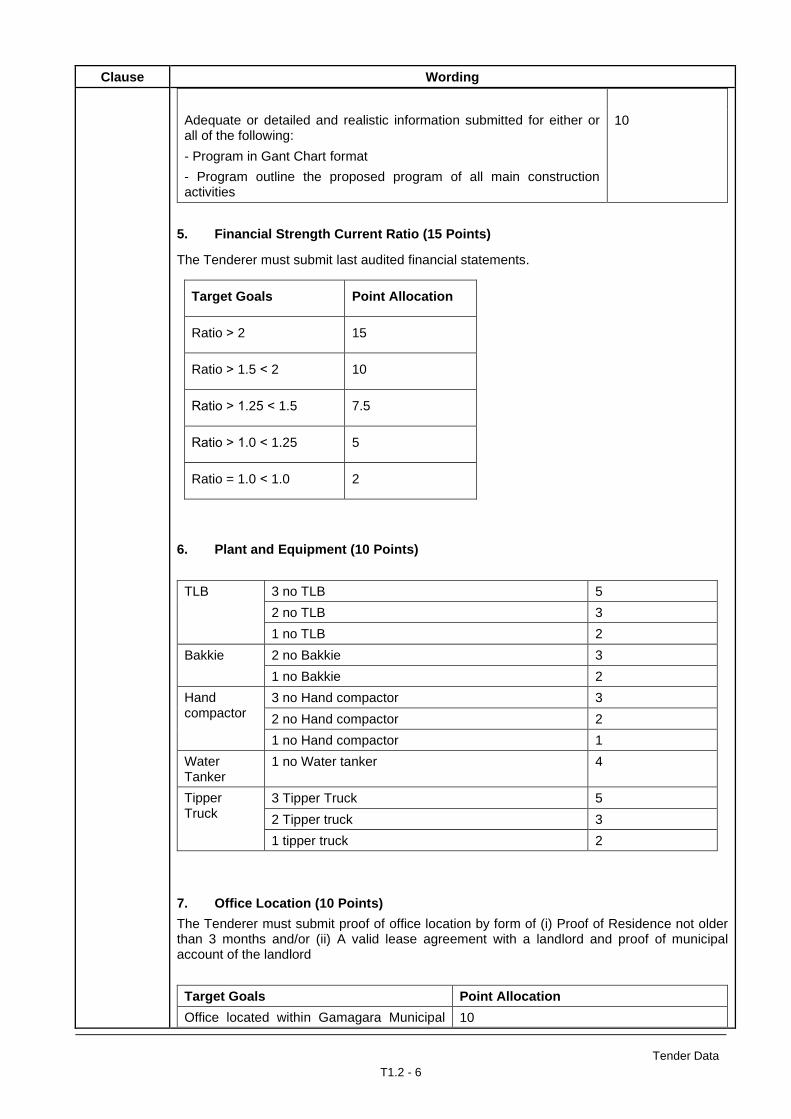
Tender Data
T1.2 - 6
Clause Wording
Adequate or detailed and realistic information submitted for either or all of the following:
- Program in Gant Chart format
- Program outline the proposed program of all main construction activities
10
5. Financial Strength Current Ratio (15 Points)
The Tenderer must submit last audited financial statements.
Target Goals Point Allocation
Ratio ˃ 2 15
Ratio ˃ 1.5 ˂ 2 10
Ratio ˃ 1.25 ˂ 1.5 7.5
Ratio ˃ 1.0 ˂ 1.25 5
Ratio = 1.0 ˂ 1.0 2
6. Plant and Equipment (10 Points)
TLB 3 no TLB 5
2 no TLB 3
1 no TLB 2
Bakkie 2 no Bakkie 3
1 no Bakkie 2
Hand compactor
3 no Hand compactor 3
2 no Hand compactor 2
1 no Hand compactor 1
Water Tanker
1 no Water tanker 4
Tipper Truck
3 Tipper Truck 5
2 Tipper truck 3
1 tipper truck 2
7. Office Location (10 Points)
The Tenderer must submit proof of office location by form of (i) Proof of Residence not older than 3 months and/or (ii) A valid lease agreement with a landlord and proof of municipal account of the landlord
Target Goals Point Allocation
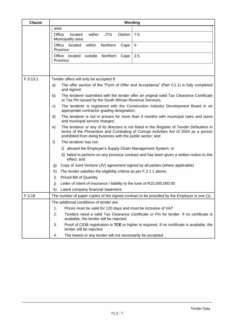
Office located within Gamagara Municipal 10
Tender Data
T1.2 - 7
Clause Wording
area
Office located within JTG District Municipality area
7.5
Office located within Northern Cape Province
5
Office located outside Northern Cape Province
2.5
F.3.13.1 Tender offers will only be accepted if:
a) The offer section of the “Form of Offer and Acceptance” (Part C1.1) is fully completed and signed;
b) The tenderer submitted with the tender offer an original valid Tax Clearance Certificate or Tax Pin issued by the South African Revenue Services;
c) The tenderer is registered with the Construction Industry Development Board in an appropriate contractor grading designation;
d) The tenderer is not in arrears for more than 3 months with municipal rates and taxes and municipal service charges;
e) The tenderer or any of its directors is not listed in the Register of Tender Defaulters in terms of the Prevention and Combating of Corrupt Activities Act of 2004 as a person prohibited from doing business with the public sector; and
f) The tenderer has not:
i) abused the Employer’s Supply Chain Management System; or
ii) failed to perform on any previous contract and has been given a written notice to this effect; and
g) Copy of Joint Venture (JV) agreement signed by all parties (where applicable)
h) The tender satisfies the eligibility criteria as per F.2.1.1 above.
i) Priced Bill of Quantity
j) Letter of intent of insurance / liability to the tune of R10,000,000.00
k) Latest company financial statement.
F.3.18 The number of paper copies of the signed contract to be provided by the Employer is one (1).
The additional conditions of tender are:
1. Prices must be valid for 120 days and must be inclusive of VAT
2. Tenders need a valid Tax Clearance Certificate or Pin for tender. If no certificate is available, the tender will be rejected.
3. Proof of CIDB registration is 7CE or higher is required. If no certificate is available, the tender will be rejected.
4. The lowest or any tender will not necessarily be accepted.
Index C1
TENDER
CONSTRUCTION OF BABATAS CPA BULK WATER SUPPLY
TENDER NO. NC/001/2021
PART C1 : AGREEMENT
C1.1 Form of Offer and Acceptance
C1.2 Returnable Documentation
C1.3 Procurement
C1.4 Contract Data

Form of Offer
C1.1 - 1
TENDER
CONSTRUCTION OF BABATAS CPA BULK WATER SUPPLY
TENDER NO. NC/001/2021
C1.1 : FORM OF OFFER AND ACCEPTANCE
1. OFFER
The employer, identified in the acceptance signature block, has solicited offers to enter into a contract for the procurement of:
CONSTRUCTION OF BABATAS CPA BULK WATER SUPPLY INTERNAL RETICULATION
The Tenderer, identified in the offer signature block, has examined the documents listed in the tender data and addenda thereto as listed in all the schedules, and by submitting this offer has accepted the conditions of the quotation.
By the representative of the tenderer, deemed to be duly authorized, signing this part of this form of offer and acceptance, the tenderer offers to perform all of the obligations and liabilities of the Contractor under the contract including compliance with all its terms and conditions according to their true intent and meaning for an amount to be determined in accordance with the Conditions of Contract identified in the contract data.
The offered total of the prices inclusive of Value-Added Tax is ...........................................................
..................................................................... Rand (in words); R ......................................... (in figures)
This offer may be accepted by the employer by signing the acceptance part of this form of offer and acceptance and returning one copy of this document to the tenderer before the end of the period of validity stated in the document, whereupon the tenderer becomes the party named as the contractor in terms of the conditions of contract identified in the contract data.
Signature(s) ................................................... ............................................................
Name(s) ..................................................... ............................................................
Capacity ..................................................... ............................................................
for the TENDERER ....................................................................................................................................... (Name and address of organization)
Name of witness .....................................................
Signature of witness ..................................................... Date ................................................

Form of Offer
C1.1 - 2
2. ACCEPTANCE
By signing this part of this form of offer and acceptance, the employer identified below accepts the tenderer’s offer. In consideration thereof, the employer shall pay the contractor the amount due in accordance with the conditions of contract identified in the contract data. Acceptance of the tenderer’s offer shall form an agreement between the employer and the tenderer upon the terms and conditions contained in this agreement and in the contract that is the subject of this agreement.
The terms of the contract are contained in
Part C1: Agreements and contract data (which includes this agreement)
Part C2: Pricing data
Deviations from and amendments to the documents listed in the quotation data and any addenda thereto, as listed in the schedules as well as any changes to the terms of the offer agreed by the tenderer and the employer during this process of offer and acceptance, are contained in the schedule of deviations attached to and forming part of this agreement. No amendments to or deviations from said documents are valid unless contained in this schedule.
The tenderer shall, within two weeks after receiving a completed copy of this agreement including the schedule of deviation (if any), contact the employer’s agent (whose details are given in the contract data) to arrange the delivery of any bonds, guarantees, proof insurance and any other documentation to be provided in terms of the conditions of contract identified in the contract data. Failure to fulfil any of the obligations in accordance with those terms shall constitute a repudiation of this agreement.
Notwithstanding anything contained herein, this agreement comes into effect on the date when the tenderer receives one fully completed original copy of this document, including the schedule of deviations (if any). Unless the tenderer (now contractor), within five (5) working days of the date of such receipt, notifies the employer in writing of any reason why he cannot accept the contents of this agreement, this agreement shall constitute a binding contract between the parties.1
Signature(s) .................................................. ............................................................
Name(s) .................................................. ............................................................
Capacity .................................................. ............................................................
for the Employer SIOC COMMUNITY DEVELOPMENT TRUST Block A, Ground Floor , Cnr Hendrik van Eck & Ian Flemming KATHU 8446
Name of witness .....................................................
Signature of witness ..................................................... Date ................................................

Form of Offer
C1.1 - 3
3. SCHEDULE OF DEVIATIONS
Notes:
1. The extent of deviations from the documents issued by the employer before the closing date is limited to those permitted in terms of the conditions of the quotation.
2. A tenderer’s covering letter shall not be included in the final contract document. Should any matter in such letter, which constitutes a deviation as aforesaid, be the subject of agreements reached during the process of offer and acceptance, the outcome of such agreement shall be recorded here.
3. Any other matter arising from the process of offer and acceptance either as a confirmation, clarification or change to the tender documents, and which it is agreed by the Parties becomes an obligation of the contract, shall also be recorded here.
4. Any change or addition to the documents arising from the above agreements and recorded here, shall also be incorporated into the final draft of the contract.
1. Subject .........................................................................................................................................................
Details ..........................................................................................................................................................
2. Subject .........................................................................................................................................................
Details ..........................................................................................................................................................
3. Subject .........................................................................................................................................................
Details ..........................................................................................................................................................
4. Subject .........................................................................................................................................................
Details ..........................................................................................................................................................
5. Subject .........................................................................................................................................................
Details ..........................................................................................................................................................
By the duly authorized representatives signing this schedule of deviations, the employer and the tenderer agree to and accept the foregoing schedule of deviations as the only deviations from and amendments to the documents listed in the quotation data and addenda thereto as listed in the schedules, as well as any confirmation, clarification or changes to the terms of the offer agreed by the tenderer and the employer during this process of offer and acceptance.
It is expressly agreed that no other matter whether in writing, oral communication or implied during the period between the issue of the documents and the receipt by the tenderer of a completed signed copy of this Agreement shall have any meaning or effect in the contract between the parties arising from this agreement.
Signature(s) .........................................................................
for the Tenderer ........................................................................................................................................... (Name and address of organization)
Signature(s) .........................................................................
for the Employer, SIOC COMMUNITY DEVELOPMENT TRUST, Block A, Ground Floor , Cnr Hendrik van Eck & Ian Flemming, KATHU, 8446

Contract Data
C1.3 - 4
Returnable Documents
C1.2 - 1
TENDER
CONSTRUCTION OF BABATAS CPA BULK WATER SUPPLY
TENDER NO. NC/001/2021
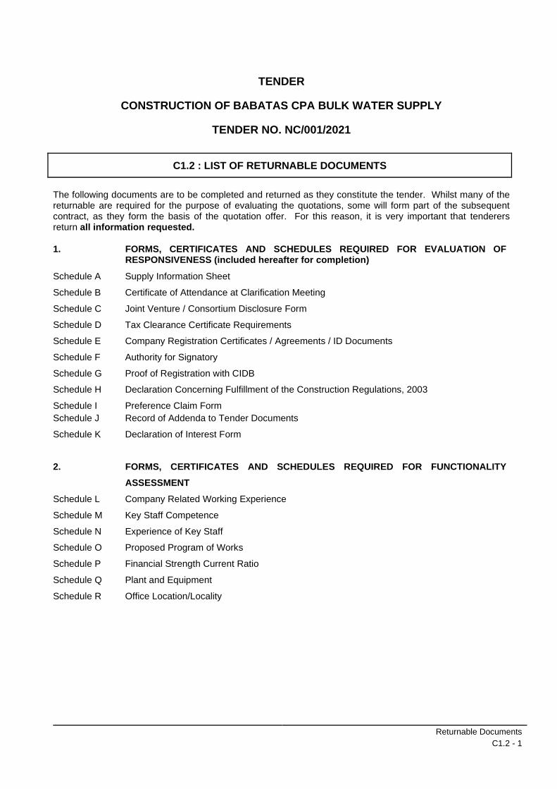
C1.2 : LIST OF RETURNABLE DOCUMENTS
The following documents are to be completed and returned as they constitute the tender. Whilst many of the returnable are required for the purpose of evaluating the quotations, some will form part of the subsequent contract, as they form the basis of the quotation offer. For this reason, it is very important that tenderers return all information requested.
1. FORMS, CERTIFICATES AND SCHEDULES REQUIRED FOR EVALUATION OF RESPONSIVENESS (included hereafter for completion)
Schedule A Supply Information Sheet
Schedule B Certificate of Attendance at Clarification Meeting
Schedule C Joint Venture / Consortium Disclosure Form
Schedule D Tax Clearance Certificate Requirements
Schedule E Company Registration Certificates / Agreements / ID Documents
Schedule F Authority for Signatory
Schedule G Proof of Registration with CIDB
Schedule H Declaration Concerning Fulfillment of the Construction Regulations, 2003
Schedule I Preference Claim Form
Schedule J Record of Addenda to Tender Documents
Schedule K
Declaration of Interest Form
2. FORMS, CERTIFICATES AND SCHEDULES REQUIRED FOR FUNCTIONALITY
ASSESSMENT
Schedule L Company Related Working Experience
Schedule M Key Staff Competence
Schedule N Experience of Key Staff
Schedule O Proposed Program of Works
Schedule P Financial Strength Current Ratio
Schedule Q
Schedule R
Plant and Equipment
Office Location/Locality

Returnable Documents
C1.2 - 2
TENDER
CONSTRUCTION OF BABATAS CPA BULK WATER SUPPLY
TENDER NO. NC/001/2021
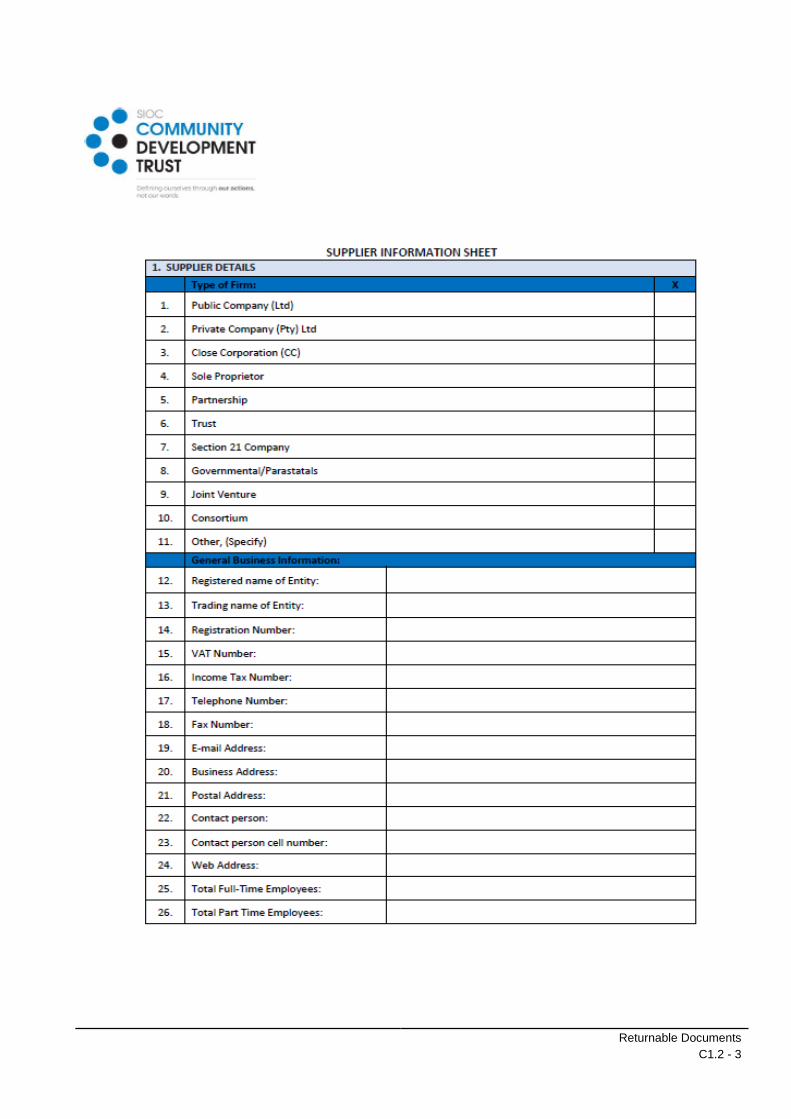
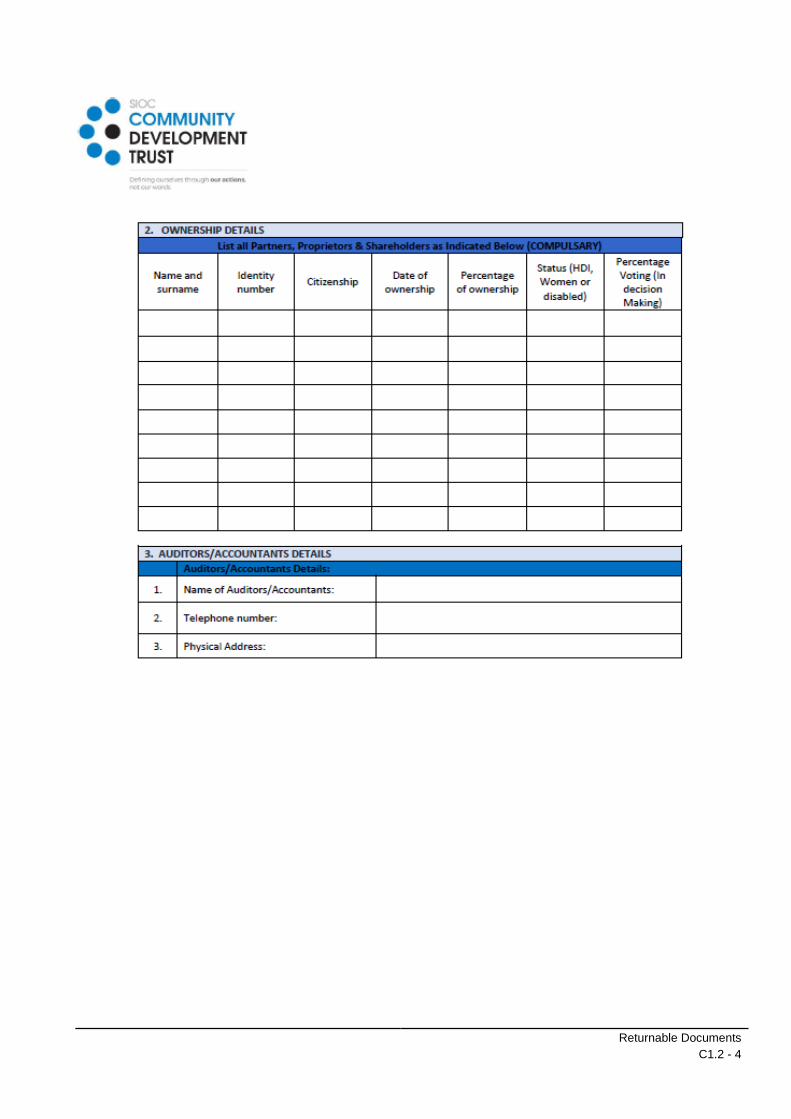
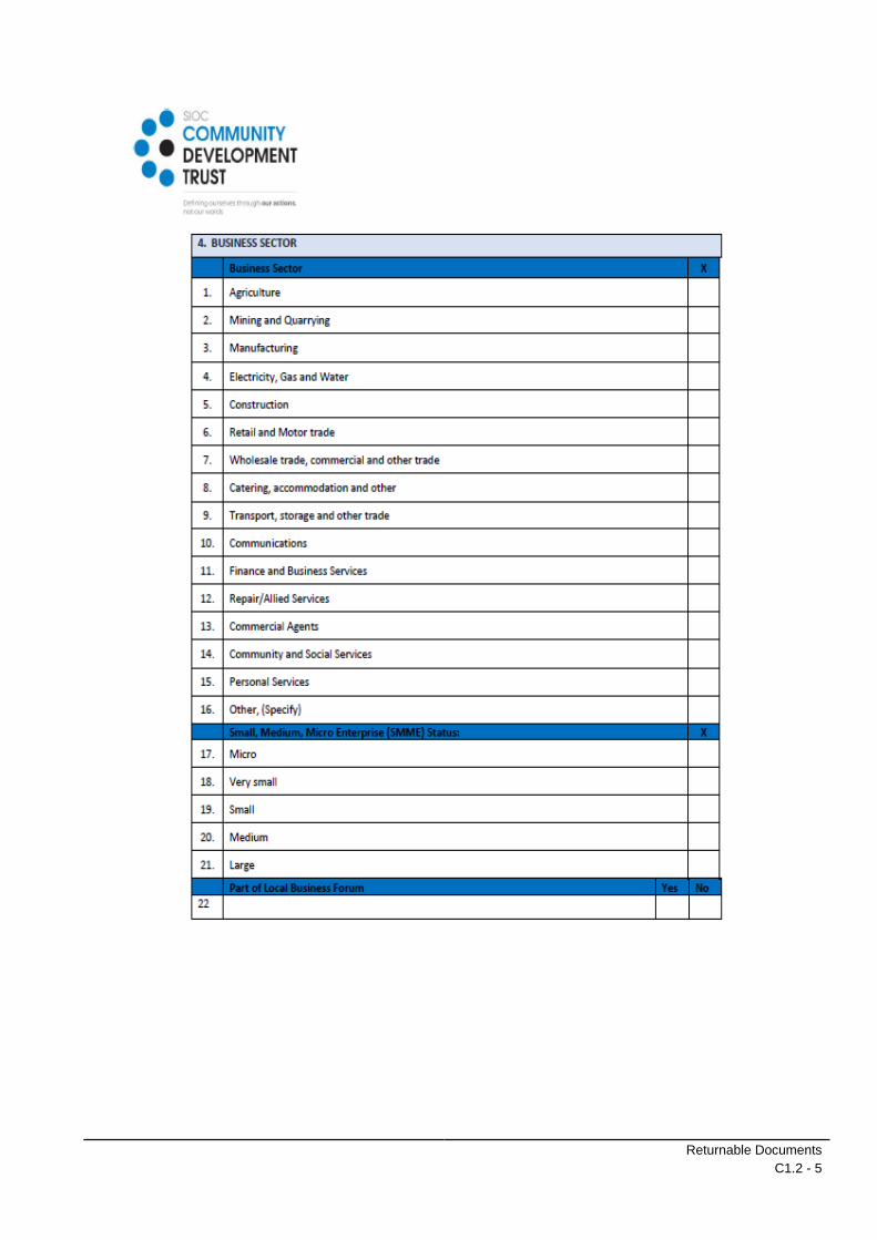
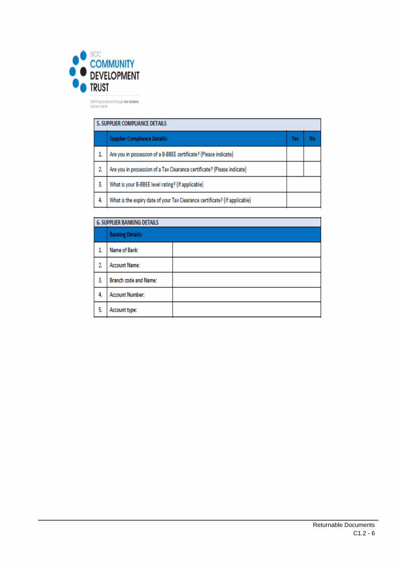
SCHEDULE A: SUPPLIER INFORMATION SHEET
Returnable Documents
C1.2 - 3
Returnable Documents
C1.2 - 4
Returnable Documents
C1.2 - 5
Returnable Documents
C1.2 - 6

Returnable Documents
C1.2 - 7

Returnable Documents
C1.2 - 8

Returnable Documents
C1.2 - 9
TENDER
CONSTRUCTION OF BABATAS CPA BULK WATER SUPPLY
TENDER NO. NC/001/2021
SCHEDULE B : CERTIFICATE OF ATTENDANCE AT CLARIFICATION MEETING
This is to certify that
.......................................................................................................................................... (Tenderer)
of ......................................................................................................................................... (address)
...........................................................................................................................................................
was represented by the person(s) named below at the compulsory meeting held for all tenderers at .
…………………………. (location) on ................................ (date), starting at . ......................................
We acknowledge that the purpose of the meeting was to acquaint ourselves with the site of the
works and / or matters incidental to doing the work specified in the tender documents in order for us
to take account of everything necessary when compiling our rates and prices included in the tender.
Particulars of person(s) attending the meeting:
Name .............................................................. Signature .................................................
Capacity ..............................................................
Name .............................................................. Signature .................................................
Capacity ..............................................................
Attendance of the above persons at the meeting is confirmed by the Employer’s representative,
namely:
Name : A Khumalo Signature .................................................
Capacity : Engineer Date & Time .................................................
Returnable Documents
C1.2 - 10
TENDER
CONSTRUCTION OF BABATAS CPA BULK WATER SUPPLY
TENDER NO. NC/001/2021
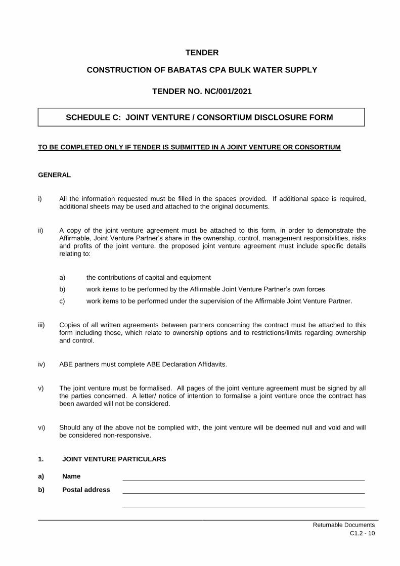
SCHEDULE C: JOINT VENTURE / CONSORTIUM DISCLOSURE FORM
TO BE COMPLETED ONLY IF TENDER IS SUBMITTED IN A JOINT VENTURE OR CONSORTIUM
GENERAL
i) All the information requested must be filled in the spaces provided. If additional space is required, additional sheets may be used and attached to the original documents.
ii) A copy of the joint venture agreement must be attached to this form, in order to demonstrate the Affirmable, Joint Venture Partner’s share in the ownership, control, management responsibilities, risks and profits of the joint venture, the proposed joint venture agreement must include specific details relating to:
a) the contributions of capital and equipment
b) work items to be performed by the Affirmable Joint Venture Partner’s own forces
c) work items to be performed under the supervision of the Affirmable Joint Venture Partner.
iii) Copies of all written agreements between partners concerning the contract must be attached to this form including those, which relate to ownership options and to restrictions/limits regarding ownership and control.
iv) ABE partners must complete ABE Declaration Affidavits.
v) The joint venture must be formalised. All pages of the joint venture agreement must be signed by all the parties concerned. A letter/ notice of intention to formalise a joint venture once the contract has been awarded will not be considered.
vi) Should any of the above not be complied with, the joint venture will be deemed null and void and will be considered non-responsive.
1. JOINT VENTURE PARTICULARS
a) Name
b) Postal address

Returnable Documents
C1.2 - 11
c) Physical address
d) Telephone
e) Fax
2. IDENTITY OF EACH NON-AFFIRMABLE JOINT VENTURE PARTNER
2.1 Name of Firm
Postal address
Physical address
Telephone
Fax
Contact Person for matters pertaining to Joint Venture Participation Goal
2.2 Name of Firm
Postal address
Physical address
Telephone
Fax
Contact Person for matters pertaining to Joint Venture Participation Goal
3. IDENTITY OF EACH AFFIRMABLE JOINT VENTURE PARTNER
3.1 Name of Firm
Postal address
Physical address
Telephone
Fax

Returnable Documents
C1.2 - 12
Contact Person for matters pertaining to Joint Venture Participation Goal
3.2 Name of Firm
Postal address
Physical address
Telephone
Fax
Contact Person for matters pertaining to Joint Venture Participation Goal
3.3 Name of Firm
Postal address
Physical address
Telephone
Fax
Contact Person for matters pertaining to Joint Venture Participation Goal
(Continue as required for further Affirmable Joint Venture Partners)
4. BRIEF DESCRIPTION OF THE ROLES OF THE AFFIRMABLE JOINT VENTURE PARTNERS IN THE JOINT VENTURE

Returnable Documents
C1.2 - 13
1. OWNERSHIP OF THE JOINT VENTURE
a) Affirmable Joint Venture Partner ownership percentage(s) %
b) Non-Affirmable Joint Venture Partner ownership percentage(s) %
c) Affirmable Joint Venture Partner percentages in respect of:*
(i) Profit and loss sharing
(ii) Initial capital contribution in Rands
(*Brief descriptions and further particulars should be provided to clarify percentages).
(iii) Anticipated on-going capital contributions in Rands
(iv) Contributions of equipment (specify types, quality and quantities of equipment) to be provided by each partner

Returnable Documents
C1.2 - 14
2. RECENT CONTRACTS EXECUTED BY PARTNERS IN THEIR OWN RIGHT AS PRIME CONTRACTORS OR AS PARTNERS IN JOINT VENTURES
NON-AFFRIMABLE JOINT VENTURE PARTNERS
PARTNER NAME
a)
b)
c)
d)
e)
AFFRIMABLE JOINT VENTURE PARTNERS PARTNER NAME
a)
b)
c)
d)
e)
3. CONTROL AND PARTICIPATION IN THE JOINT VENTURE
(Identify by name and firm those individuals who are, or will be, responsible for, and have authority to engage in the relevant management functions and policy and decision making, indicating any limitations in their authority e.g. co-signature requirements and Rand limits).
(a) Joint Venture cheque signing

Returnable Documents
C1.2 - 15
(b) Authority to enter into contracts on behalf of the Joint Venture
(c) Signing, co-signing and / or collateralising of loans
(d) Acquisition of lines of credit
(e) Acquisition of performance bonds
(f) Negotiating and signing labour agreements

Returnable Documents
C1.2 - 16
(g) Anticipated on-going capital contributions in Rands
4. MANAGEMENT OF CONTRACT PERFORMANCE
(Fill in the name and firm of the responsible person).
(a) Supervision of field operations
(b) Major purchasing
(c) Estimating
(d) Technical management
5. MANAGEMENT AND CONTROL OF JOINT VENTURE
(a) Identify the “managing partner”, if any

Returnable Documents
C1.2 - 17
(b) What authority does each partner have to commit or obligate the other to financial institutions, insurances companies, suppliers, subcontractors and/or other parties participating in the execution of the contemplated works?
(c) Describe the management structure for the Joint Venture’s work under the contract
MANAGEMENT FUNCTION / DESIGNATION
NAME PARTNER*
* Fill in “Affirmable Joint Venture Partner” or “non-Affirmable Joint Venture Partner”.
6. PERSONNEL
(a) State the approximate number of operative personnel (by trade/function/discipline) needed to perform the Joint Venture work under the Contract.
TRADE/FUNCTION/
DISCIPLINE
NUMBER AFFIRMABLE JOINT VENTURE
PARTNERS
NUMBER NON-AFFIRMABLE JOINT
VENTURE PARTNERS

Returnable Documents
C1.2 - 18
(b) Number of operative personnel to be employed on the Contract who are currently in the employ of partners.
(i) Number currently employed by Affirmable Joint Venture Partners
(ii) Number currently employed by the Joint Venture
(c) Number of operative personnel who are not currently in the employ of the respective partner and will be engaged on the project by the Joint Venture
(d) Name of individual(s) who will be responsible for hiring Joint Venture employees
(e) Name of partner who will be responsible for the preparation of Joint Venture payrolls
7. CONTROL AND STRUCTURE OF JOINT VENTURE Briefly describe the manner in which the Joint Venture is structured and controlled.

Returnable Documents
C1.2 - 19
The undersigned warrants that he/she is duly authorised to sign this Joint Venture Disclosure Form and affirms that the foregoing statements are true and correct and include all material information necessary to identify and explain the terms and operations of the Joint Venture and the intended participation of each partner in the undertaking.
The undersigned further covenants and agrees to provide the Employer with complete and accurate information regarding actual Joint Venture work and the payment therefore, and any proposed changes in any provisions of the Joint Venture agreement, and to permit the audit and examination of the books, records and files of the Joint Venture, or those of each partner relevant to the Joint Venture, by duly authorised representatives of the Employer.
Signature
Duly authorised to sign on behalf of
Name
Address
Telephone
Date
Signature
Duly authorised to sign on behalf of
Name
Address
Telephone
Date
Signature
Duly authorised to sign on behalf of
Name
Address
Telephone
Date

Returnable Documents
C1.2 - 20
Signature
Duly authorised to sign on behalf of
Name
Address
Telephone
Date
Signature
Duly authorised to sign on behalf of
Name
Address
Telephone
Date
Signature
Duly authorised to sign on behalf of
Name
Address
Telephone
Date

Returnable Documents
C1.2 - 21

Returnable Documents
C1.2 - 22
TENDER
CONSTRUCTION OF BABATAS CPA BULK WATER SUPPLY
TENDER NO. NC/001/2021
SCHEDULE D : TAX CLEARANCE CERTIFICATE REQUIREMENT
It is a condition of tender that the taxes, of the successful tenderer must be in order, or that
satisfactory arrangements have been made with South African Revenue Service (SARS) to meet the
bidder’s tax obligations.
Tenderer’s original valid tax clearance certificate or declaration by the South African Revenue Services to be
attached hereto. From 1 July 2016, SARS no longer issues hard copies of Tax Clearance Certificates. As
such, bidders are required to log into the SARS e-filing system to request a Tax Clearance Certificate for
“Tender” purposes.
The following link can be followed to obtain more information regarding the procedure to request the required
certificate:
http://www.sars.gov.za/ClientSegments/Individuals/TCS/Pages/How-to-request-your-TCS.aspx
IMPORTANT NOTES:
1. The following is an abstract from the Preferential Procurement Regulations 2011 promulgated with the
Preferential Policy Framework Act No 5 of 2000:
“Tax clearance”
Section 14. No Tender may be awarded to any person whose tax matters have not been declared by
the South African Revenue Service to be in order.”
2. In the case of Joint Venture/Consortium Tenders, each party must submit a separate Tax Clearance
Certificate of Declaration by SARS that tax matters are in order for all entities individually.
3. Failure of Tenderer to comply with the above will result in the invalidation of the Bid and the Bidder will
be disqualified for being non-responsive.
4. The company VAT number should be quoted on the Tax Clearance Certificate.
5. The tax clearance certificate should be for tender purposes and should clearly indicate “Tender”.
**NB. STAPLE TAX CLEARANCE CERTIFICATE TO THIS PAGE!

Returnable Documents
C1.2 - 23
TENDER
CONSTRUCTION OF BABATAS CPA BULK WATER SUPPLY
TENDER NO. NC/001/2021
SCHEDULE E : COMPANY REGISTRATION DOCUMENTS / IDENTITY DOCUMENTS
Attach hereto certified copies of Registration Certificates for Companies and Closed Corporations and certified
copies of Identity Documents for Partnerships and Sole proprietors as well as signed Agreements and Powers
of Attorney for Joint Venture / Consortium if applicable.
In the case of a Joint Venture/ Consortium, registration certificates should be attached for all parties
concerned.
**NB. STAPLE REQUESTED DOCUMENTATION TO THIS PAGE

Returnable Documents
C1.2 - 24
TENDER
CONSTRUCTION OF BABATAS CPA BULK WATER SUPPLY
TENDER NO. NC/001/2021
SCHEDULE F : AUTHORITY FOR SIGNATORY
Indicate the status of the tenderer by ticking the appropriate box hereunder. The tenderer must complete the certificate set out below for the relevant category and attach any supporting documentation to the relevant schedule.
A Company
B Partnership
C Joint Venture
D Sole Proprietor
E Close Corporation
A. Certificate for Company
I, ............................................................................... , chairperson of the board of directors of ....... …
................................................................................... , hereby confirm that by resolution of the board
(copy attached) taken on .......................................... 20…., Mr/Ms .....................................................
acting in the capacity of ............................................ , was authorized to sign all documents in
connection with this tender and any contract resulting from it on behalf of the company.
As witnesses :
1. Chairman :
2. Date :
B. Certificate for Partnership
We, the undersigned, being the key partners in the business trading as ................................................
................................................... hereby authorize Mr/Ms ........ , .............................................................
acting in the capacity of ............ ............................................... to sign all documents in connection
with the tender for Contract ...... ............................................... and any contract resulting from it on
our behalf.
NAME ADDRESS SIGNATURE DATE
NOTE : This certificate is to be completed and signed by all of the key partners upon whom rests
the direction of the affairs of the Partnership as a whole

Returnable Documents
C1.2 - 25
C. Certificate for Joint Venture
We, the undersigned, are submitting this tender offer in Joint Venture and hereby authorise Mr/Ms
..................................................... , authorised signatory of the company ............................................
..................................................... , acting in the capacity of lead partner, to sign all documents in
connection with the tender offer for Contract ......................... and any contract resulting from it on
our behalf.
This authorization is evidenced by the attached power of attorney signed by legally authorized signatories of all the partners to the Joint Venture.
NAME OF FIRM ADDRESS
AUTHORISING SIGNATURE, NAME & CAPACITY
Lead partner
D. Certificate for Sole Proprietor
I, .................................................. hereby confirm that I am the sole owner of the business trading as
.....................................................
As witnesses:
1. Signature : Sole owner :
2. Date :
E. Certificate for Close Corporation
We, the undersigned, being the key members in the business trading as ...........................................
...................................................................... hereby authorize Mr/Ms ................................................
acting in the capacity of ............................... , to sign all documents in connection with the tender for
Contract ....................................................... and any contract resulting from it on our behalf.
NAME ADDRESS SIGNATURE DATE

Returnable Documents
C1.2 - 26
NOTE: This certificate is to be completed and signed by all of the key-partners upon who rests the direction of the affairs of the Partnership as a whole.

Returnable Documents
C1.2 - 27
TENDER
CONSTRUCTION OF BABATAS CPA BULK WATER SUPPLY
TENDER NO. NC/001/2021
SCHEDULE G: PROOF OF REGISTRATION WITH CIDB
The Bidder shall attach hereto the Contractors proof of registration with CIDB. CRS number(s) also to be
provided.
In the case of Consortium/Joint Venture Tenders, each partner shall provide their own CIDB registration
certificate as well as a combined CIDB rating calculation.
In all cases above, a printout/ copy of the CIDB registration check on the CIDB Register of Contractors
website would be sufficient (https://registers.cidb.org.za/PublicContractors/ContractorSearch) .
For Joint Ventures, a combined CIDB grading should be calculated and attached in addition to proof for each
individual partner and can be found on:
(https://registers.cidb.org.za/PublicContractors/JVGradingDesignationCalc)
**NB. STAPLE PROOF OF REGISTRATION TO THIS PAGE!

Returnable Documents
C1.2 - 28
TENDER
CONSTRUCTION OF BABATAS CPA BULK WATER SUPPLY
TENDER NO. NC/001/2021
SCHEDULE H : DECLARATION CONCERNING FULFILMENT OF THE CONSTRUCTION REGULATIONS, 2014
In terms of regulation 4(4) of the Construction Regulations, 2014 (hereinafter referred to as the Regulations), promulgated on 18 July 2003 in terms of Section 43 of the Occupational Health and Safety Act, 1993 (Act No. 85 of 1993) the Employer shall not appoint a contractor to perform construction work unless the Contractor can satisfy the Employer that his/her firm has the necessary competencies and resources to carry out the work safely and has allowed adequately in his/her tender for the due fulfilment of all the applicable requirements of the Act and the Regulations.
Tenderers shall answer the questions below:
1. I confirm that I am fully conversant with the Regulations and that my company has (or will acquire/procure) the necessary competencies and resources to timeously, safely and successfully comply with all of the requirements of the Regulations.
(Tick)
YES
NO
2. Indicate which approach shall be employed to achieve compliance with the Regulations.
(Tick)
Own resources, competent in terms of the Regulations (refer to 3 below)
Own resources, still to be hired and/or trained (until competency is achieved)
Specialist subcontract resources (competent) - Specify:
3. Provide details of proposed key persons, competent in terms of the Regulations, who will form part of the Contract team as specified in the Regulations (CVs to be attached):
..............................................................................................................................................
..............................................................................................................................................
..............................................................................................................................................

Returnable Documents
C1.2 - 29
4. Provide details of proposed training (if any) that will be undergone:
..............................................................................................................................................
..............................................................................................................................................
..............................................................................................................................................
..............................................................................................................................................
..............................................................................................................................................
..............................................................................................................................................
5. List potential key risks identified and measures for addressing risks:
..............................................................................................................................................
..............................................................................................................................................
..............................................................................................................................................
..............................................................................................................................................
..............................................................................................................................................
..............................................................................................................................................
6. I have fully included in my tendered rates and prices (in the appropriate payment items provided in the Schedule of Quantities) for all resources, actions, training and any other costs required for the due fulfilment of the Regulations for the duration of the construction and defects repair period
(Tick)
YES
NO
SIGNATURE OF PERSON(S) AUTHORISED TO SIGN THIS TENDER:
1. ........................................................................ ID NO: ..............................................
(Name in Print): ............................................
2. ........................................................................ ID NO: ..............................................
(Name in Print): ............................................
Returnable Documents
C1.2 - 30
TENDER
CONSTRUCTION OF BABATAS CPA BULK WATER SUPPLY
TENDER NO. NC/001/2021
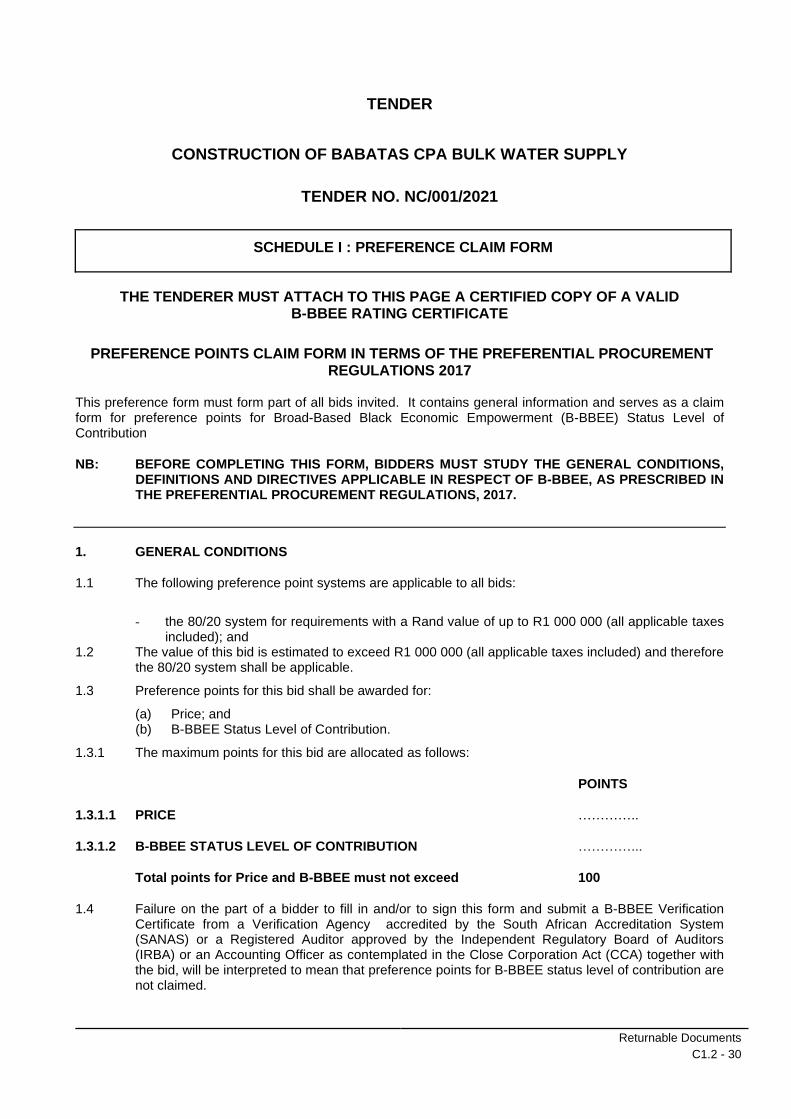
SCHEDULE I : PREFERENCE CLAIM FORM
THE TENDERER MUST ATTACH TO THIS PAGE A CERTIFIED COPY OF A VALID B-BBEE RATING CERTIFICATE
PREFERENCE POINTS CLAIM FORM IN TERMS OF THE PREFERENTIAL PROCUREMENT REGULATIONS 2017
This preference form must form part of all bids invited. It contains general information and serves as a claim form for preference points for Broad-Based Black Economic Empowerment (B-BBEE) Status Level of Contribution
NB: BEFORE COMPLETING THIS FORM, BIDDERS MUST STUDY THE GENERAL CONDITIONS, DEFINITIONS AND DIRECTIVES APPLICABLE IN RESPECT OF B-BBEE, AS PRESCRIBED IN THE PREFERENTIAL PROCUREMENT REGULATIONS, 2017.
1. GENERAL CONDITIONS
1.1 The following preference point systems are applicable to all bids:
- the 80/20 system for requirements with a Rand value of up to R1 000 000 (all applicable taxes included); and
1.2 The value of this bid is estimated to exceed R1 000 000 (all applicable taxes included) and therefore the 80/20 system shall be applicable.
1.3 Preference points for this bid shall be awarded for:
(a) Price; and (b) B-BBEE Status Level of Contribution.
1.3.1 The maximum points for this bid are allocated as follows:
POINTS
1.3.1.1 PRICE …………..
1.3.1.2 B-BBEE STATUS LEVEL OF CONTRIBUTION …………...
Total points for Price and B-BBEE must not exceed 100
1.4 Failure on the part of a bidder to fill in and/or to sign this form and submit a B-BBEE Verification Certificate from a Verification Agency accredited by the South African Accreditation System (SANAS) or a Registered Auditor approved by the Independent Regulatory Board of Auditors (IRBA) or an Accounting Officer as contemplated in the Close Corporation Act (CCA) together with the bid, will be interpreted to mean that preference points for B-BBEE status level of contribution are not claimed.

Returnable Documents
C1.2 - 31
1.5. The purchaser reserves the right to require of a bidder, either before a bid is adjudicated or at any time subsequently, to substantiate any claim in regard to preferences, in any manner required by the purchaser.
2. DEFINITIONS
“B-BBEE” means broad-based black economic empowerment as defined in section 1 of the Broad-Based Black Economic Empowerment Act; “B-BBEE status level of contributor” means the B-BBEE status of an entity in terms of a code of good practice on black economic empowerment issued in terms of section 9(1) of the Broad-Based Black Economic Empowerment Act; “black designated groups” has the meaning assigned to it in the codes of good practice issued in terms of section 9(1) of the Broad-Based Black Economic Empowerment Act; “black people” has the meaning assigned to it in section 1 of the Broad-Based Black Economic Empowerment Act; “Broad-Based Black Economic Empowerment Act” means the Broad-Based Black Economic Empowerment Act, 2003 (Act No. 53 of 2003); “co-operative” means a co-operative registered in terms of section 7 of the Cooperatives Act, 2005 (Act No. 14 of 2005); “designated group” means- (a) black designated groups; (b) black people; (c) women; (d) people with disabilities; or (e) small enterprises, as defined in section 1 of the National Small Enterprise Act, 1996 (Act No. 102 of 1996); “designated sector” means a sector, sub-sector or industry or product designated interms of regulation 8(1)(a); “EME” means an exempted micro enterprise in terms of a code of good practice on black economic empowerment issued in terms of section 9(1) of the Broad-Based Black Economic Empowerment Act; “functionality” means the ability of a tenderer to provide goods or services in accordance with specifications as set out in the tender documents; “military veteran” has the meaning assigned to it in section 1 of the Military Veterans Act, 2011 (Act No. 18 of 2011); “National Treasury” has the meaning assigned to it in section 1 of the Public Finance Management Act, 1999 (Act No. 1 of 1999); “people with disabilities” has the meaning assigned to it in section 1 of the Employment Equity Act, 1998 (Act No. 55 of 1998); “price” includes all applicable taxes less all unconditional discounts; “proof of B-BBEE status level of contributor” means- (a) the B-BBEE status level certificate issued by an authorised body or person; (b) a sworn affidavit as prescribed by the B-BBEE Codes of Good Practice; or (c) any other requirement prescribed in terms of the Broad-Based Black Economic “QSE” means a qualifying small business enterprise in terms of a code of good practice on black economic empowerment issued in terms of section 9(1) of the Broad-Based Black Economic Empowerment Act; “Rand value” means the total estimated value of a contract in Rand, calculated at the time of the tender invitation; “rural area” means- (a) a sparsely populated area in which people farm or depend on natural resources, including villages and small towns that are dispersed through the area; or (b) an area including a large settlement which depends on migratory labour and remittances and government social grants for survival, and may have a traditional land tenure system; “stipulated minimum threshold” means the minimum threshold stipulated in terms of regulation 8(1)(b); “the Act” means the Preferential Procurement Policy Framework Act, 2000 (Act No. 5 of 2000); “township” means an urban living area that any time from the late 19th century until 27 April 1994, was reserved for black people, including areas developed for historically disadvantaged individuals post 27 April 1994;
Returnable Documents
C1.2 - 32
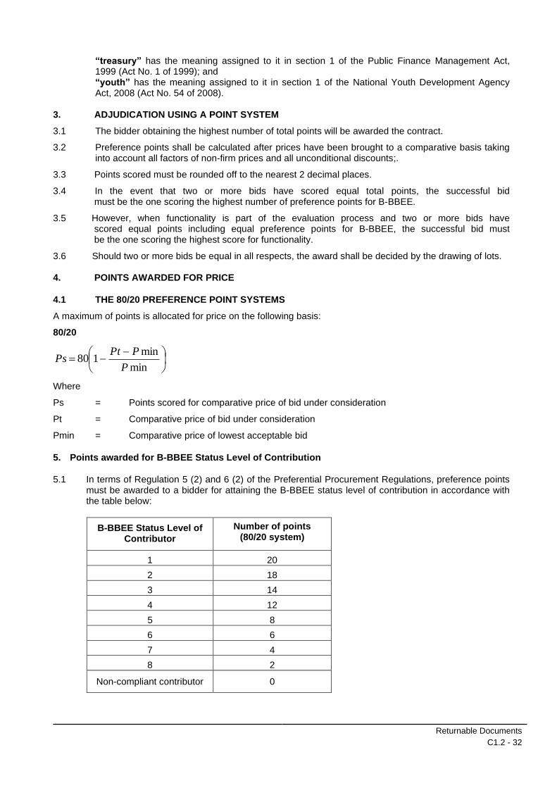
“treasury” has the meaning assigned to it in section 1 of the Public Finance Management Act, 1999 (Act No. 1 of 1999); and “youth” has the meaning assigned to it in section 1 of the National Youth Development Agency Act, 2008 (Act No. 54 of 2008).
3. ADJUDICATION USING A POINT SYSTEM
3.1 The bidder obtaining the highest number of total points will be awarded the contract.
3.2 Preference points shall be calculated after prices have been brought to a comparative basis taking into account all factors of non-firm prices and all unconditional discounts;.
3.3 Points scored must be rounded off to the nearest 2 decimal places.
3.4 In the event that two or more bids have scored equal total points, the successful bid must be the one scoring the highest number of preference points for B-BBEE.
3.5 However, when functionality is part of the evaluation process and two or more bids have scored equal points including equal preference points for B-BBEE, the successful bid must be the one scoring the highest score for functionality.
3.6 Should two or more bids be equal in all respects, the award shall be decided by the drawing of lots. 4. POINTS AWARDED FOR PRICE
4.1 THE 80/20 PREFERENCE POINT SYSTEMS
A maximum of points is allocated for price on the following basis:
80/20
−−=
min
min180
P
PPtPs
Where
Ps = Points scored for comparative price of bid under consideration
Pt = Comparative price of bid under consideration
Pmin = Comparative price of lowest acceptable bid
5. Points awarded for B-BBEE Status Level of Contribution
5.1 In terms of Regulation 5 (2) and 6 (2) of the Preferential Procurement Regulations, preference points must be awarded to a bidder for attaining the B-BBEE status level of contribution in accordance with the table below:
B-BBEE Status Level of Contributor
Number of points (80/20 system)
1 20
2 18
3 14
4 12
5 8
6 6
7 4
8 2
Non-compliant contributor 0

Returnable Documents
C1.2 - 33
5.2 Bidders who qualify as EMEs in terms of the B-BBEE Act must submit a certificate issued by an Accounting Officer as contemplated in the CCA or a Verification Agency accredited by SANAS or a Registered Auditor. Registered auditors do not need to meet the prerequisite for IRBA’s approval for
the purpose of conducting verification and issuing EMEs with B-BBEE Status Level Certificates.
5.3 Bidders other than EMEs must submit their original and valid B-BBEE status level verification certificate or a certified copy thereof, substantiating their B-BBEE rating issued by a Registered Auditor approved by IRBA or a Verification Agency accredited by SANAS.
5.4 A trust, consortium or joint venture, will qualify for points for their B-BBEE status level as a legal entity, provided that the entity submits their B-BBEE status level certificate.
5.5 A trust, consortium or joint venture will qualify for points for their B-BBEE status level as an unincorporated entity, provided that the entity submits their consolidated B-BBEE scorecard as if they were a group structure and that such a consolidated B-BBEE scorecard is prepared for every separate bid.
5.6 Tertiary institutions and public entities will be required to submit their B-BBEE status level certificates in terms of the specialized scorecard contained in the B-BBEE Codes of Good Practice.
5.7 A person will not be awarded points for B-BBEE status level if it is indicated in the bid documents that such a bidder intends sub-contracting more than 25% of the value of the contract to any other
enterprise that does not qualify for at least the points that such a bidder qualifies for, unless the intended sub- contractor is an EME that has the capability and ability to execute the sub-contract.
5.8 A person awarded a contract may not sub-contract more than 25% of the value of the contract to any other enterprise that does not have an equal or higher B-BBEE status level than the person concerned, unless the contract is sub-contracted to an EME that has the capability and ability to execute the sub-contract.
6. BID DECLARATION 6.1 Bidders who claim points in respect of B-BBEE Status Level of Contribution must complete the following:
7. B-BBEE STATUS LEVEL OF CONTRIBUTION CLAIMED IN TERMS OF PARAGRAPHS 1.3.1.2 AND 5.1
7.1 B-BBEE Status Level of Contribution: …………. = ……………(maximum of 10 or 20 points)
(Points claimed in respect of paragraph 7.1 must be in accordance with the table reflected in paragraph 5.1 and must be substantiated by means of a B-BBEE certificate issued by a Verification Agency accredited by SANAS or a Registered Auditor approved by IRBA or an Accounting Officer as contemplated in the CCA).
8 SUB-CONTRACTING
8.1 Will any portion of the contract be sub-contracted? YES / NO (delete which is not applicable)
8.1.1 If yes, indicate:
(i) what percentage of the contract will be subcontracted? ............……………….…%
(ii) the name of the sub-contractor? …………………………………………………………..
(iii) the B-BBEE status level of the sub-contractor? ……………..
(iv) whether the sub-contractor is an EME? YES / NO (delete which is not applicable)
9 DECLARATION WITH REGARD TO COMPANY/FIRM
9.1 Name of firm : .............................................................................................
9.2 VAT registration number : .............................................................................................
9.3 Company registration number ……………………………………………………………………. :

Returnable Documents
C1.2 - 34
9.4 TYPE OF COMPANY/ FIRM
Partnership/Joint Venture / Consortium
One person business/sole propriety
Close corporation
Company
(Pty) Limited [TICK APPLICABLE BOX]
9.5 DESCRIBE PRINCIPAL BUSINESS ACTIVITIES
………….. ..................................................................................................................................................
……………… .............................................................................................................................................
…………….. ...............................................................................................................................................
9.6 COMPANY CLASSIFICATION
Manufacturer
Supplier
Professional service provider
Other service providers, e.g. transporter, etc.
[TICK APPLICABLE BOX]
9.7 MUNICIPAL INFORMATION
Municipality where business is situated …………………………………………………….
Registered Account Number …………………………….
Stand Number ……………………………………………….
9.8 TOTAL NUMBER OF YEARS THE COMPANY/FIRM HAS BEEN IN BUSINESS?
……………………………………
9.9 I/we, the undersigned, who is / are duly authorised to do so on behalf of the company/firm, certify that the points claimed, based on the B-BBE status level of contribution indicated in paragraph 7 of the foregoing certificate, qualifies the company/ firm for the preference(s) shown and I / we acknowledge that:
(i) The information furnished is true and correct;
(ii) The preference points claimed are in accordance with the General Conditions as indicated in paragraph 1 of this form.
(iii) In the event of a contract being awarded as a result of points claimed as shown in paragraph 7, the contractor may be required to furnish documentary proof to the satisfaction of the purchaser that the claims are correct;
(iv) If the B-BBEE status level of contribution has been claimed or obtained on a fraudulent basis or any of the conditions of contract have not been fulfilled, the purchaser may, in addition to any other remedy it may have –
(a) disqualify the person from the bidding process;

Returnable Documents
C1.2 - 35
(b) recover costs, losses or damages it has incurred or suffered as a result of that person’s conduct;
(c) cancel the contract and claim any damages which it has suffered as a result of having to make less favourable arrangements due to such cancellation;
(d) restrict the bidder or contractor, its shareholders and directors, or only the shareholders and directors who acted on a fraudulent basis, from obtaining business from any organ of state for a period not exceeding 10 years, after the audi alteram partem (hear the other side) rule has been applied; and
(e) forward the matter for criminal prosecution
WITNESSES:
1. ……………………………………… ……………………………………………. SIGNATURE(S) OF BIDDER(S)
2. ……………………………………… DATE: ……………………………….
ADDRESS: …………………………………….. ….…………………………………….
……………………………………….
………….…………………………….
**NB. STAPLE PROOF OF BEE CERTIFICATION TO THIS PAGE!

Returnable Documents
C1.2 - 36
TENDER
CONSTRUCTION OF BABATAS CPA BULK WATER SUPPLY
TENDER NO. NC/001/2021
SCHEDULE J : RECORD OF ADDENDA TO TENDER DOCUMENTS
I/We confirm that the following communications received from the Employer before the submission of this
tender offer, amending the tender documents, have been taken into account in this tender offer:
No. Date Title or Details
1.
2.
3.
4.
5.
6.
7.
8.
9.
10.
Attach additional pages if more space is required.
Signed ............................................................. Date ....................................................
Name ............................................................. Position ....................................................
Tenderer ............................................................................................................................................................

Returnable Documents
C1.2 - 37
TENDER
CONSTRUCTION OF BABATAS CPA BULK WATER SUPPLY
TENDER NO. NC/001/2021
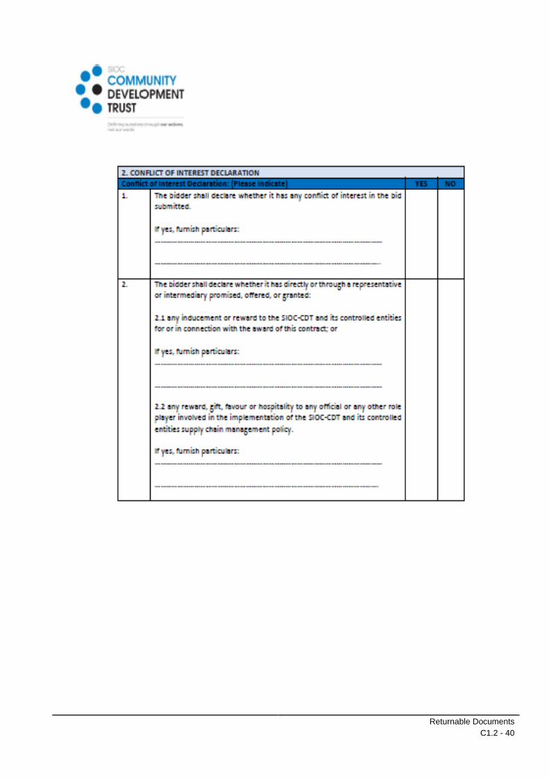
SCHEDULE K : DECLARATION OF INTEREST FORM
Returnable Documents
C1.2 - 38
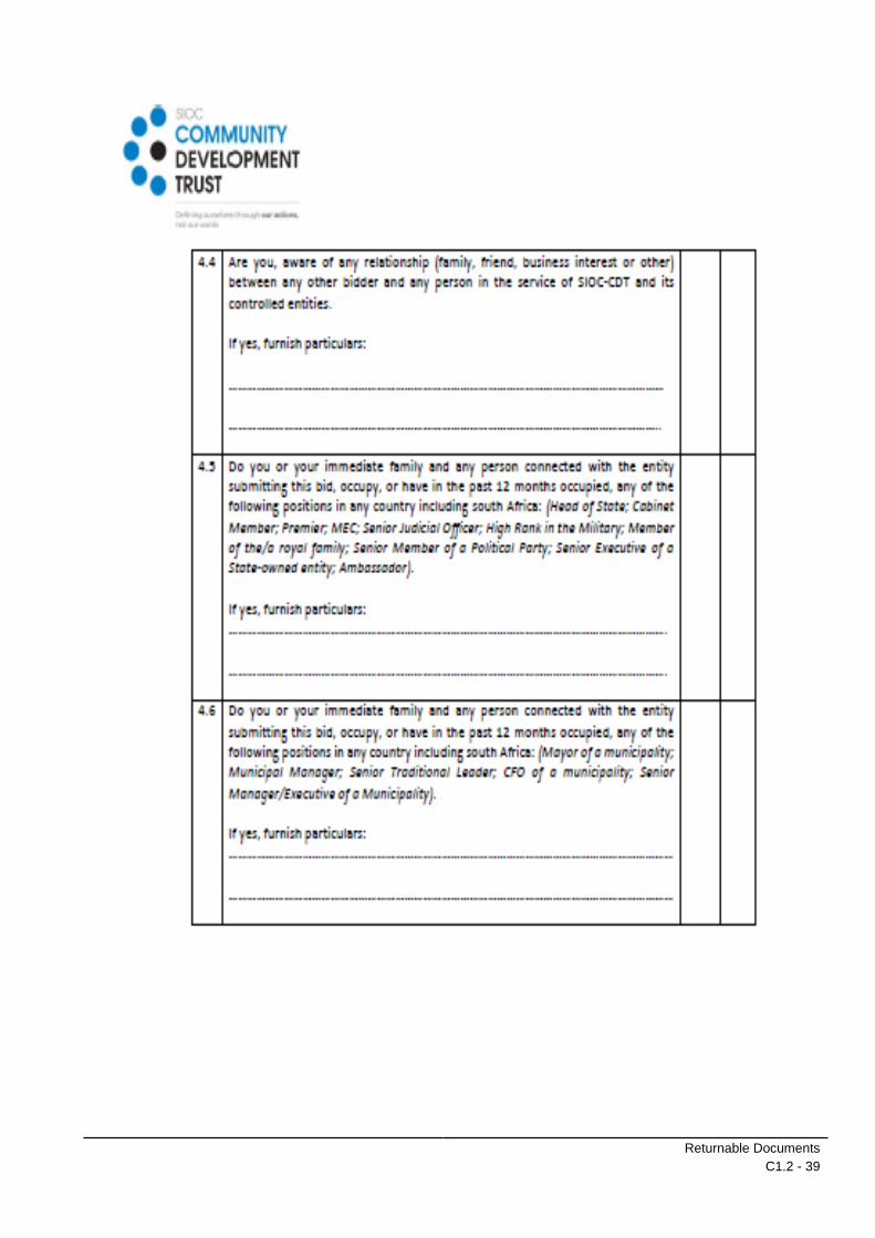
Returnable Documents
C1.2 - 39
Returnable Documents
C1.2 - 40

Returnable Documents
C1.2 - 41

Returnable Documents
C1.2 - 42

Returnable Documents
C1.2 - 43
TENDER
CONSTRUCTION OF BABATAS CPA BULK WATER SUPPLY
TENDER NO. NC/001/2021
SCHEDULE L : COMPANY RELATED WORK EXPERIENCE
The experience of the respondent as a company (as opposed to key staff members) on works of similar
nature.
The information shall be within the previous 5 years and can include contracts that are not complete prior to
closing date for submissions.
*Completed projects stated in summarised table must be confirmed by FINAL COMPLETION CERTIFICATE
attached to be recognised as a “Successful Project”. Projects not confirmed by final completion certificates will
not be considered.
NOTE: ONLY THE FOLLOWING TABLES, COMPLETED BY HAND, WILL BE CONSIDERED IN THE
EVALUATION. NO ATTACHED EXPERIENCE INFORMATION EXCEPT COMPLETION CERTIFICATES
WILL BE CONSIDERED.
**NB. STAPLE COMPANY PROFILE TO THIS PAGE!
Signed ............................................................. Date ....................................................
Name ............................................................. Position ....................................................
Tenderer ............................................................................................................................................................

Returnable Documents
C1.2 - 44
Project 1
Employer:
………………………………………………………..…….
Contact Person:
……………………………………………………..……….
Telephone Number:
……………………………………………………..……….
E-mail:
…………………………………………………..………….
Contract Start Date:
………………………………………….
Completion Date/ Expected Completion:
………………..………………………..
Works Description:
Contract Value/ Final Certification (Including VAT):
…………………………………………………………………
Returnable Documents
C1.2 - 45
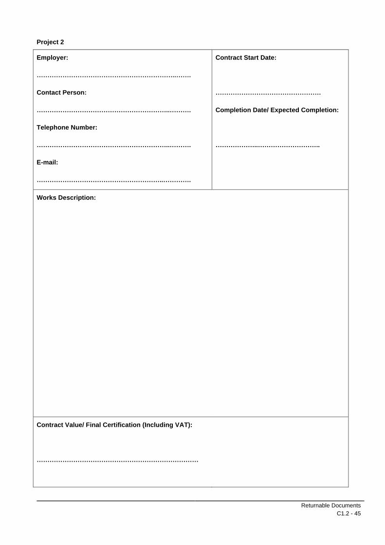
Project 2
Employer:
………………………………………………………..…….
Contact Person:
……………………………………………………..……….
Telephone Number:
……………………………………………………..……….
E-mail:
…………………………………………………..………….
Contract Start Date:
………………………………………….
Completion Date/ Expected Completion:
………………..………………………..
Works Description:
Contract Value/ Final Certification (Including VAT):
…………………………………………………………………
Returnable Documents
C1.2 - 46
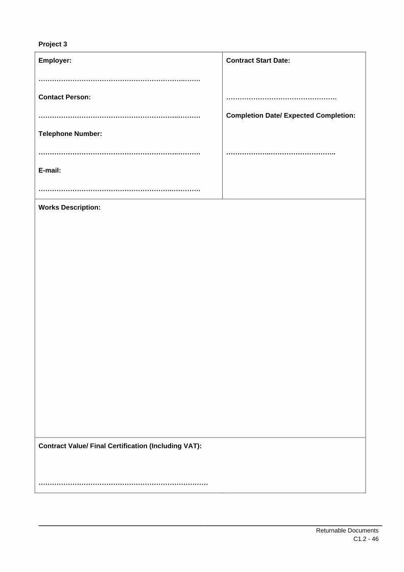
Project 3
Employer:
………………………………………………………..…….
Contact Person:
……………………………………………………..……….
Telephone Number:
……………………………………………………..……….
E-mail:
…………………………………………………..………….
Contract Start Date:
………………………………………….
Completion Date/ Expected Completion:
………………..………………………..
Works Description:
Contract Value/ Final Certification (Including VAT):
…………………………………………………………………
Returnable Documents
C1.2 - 47
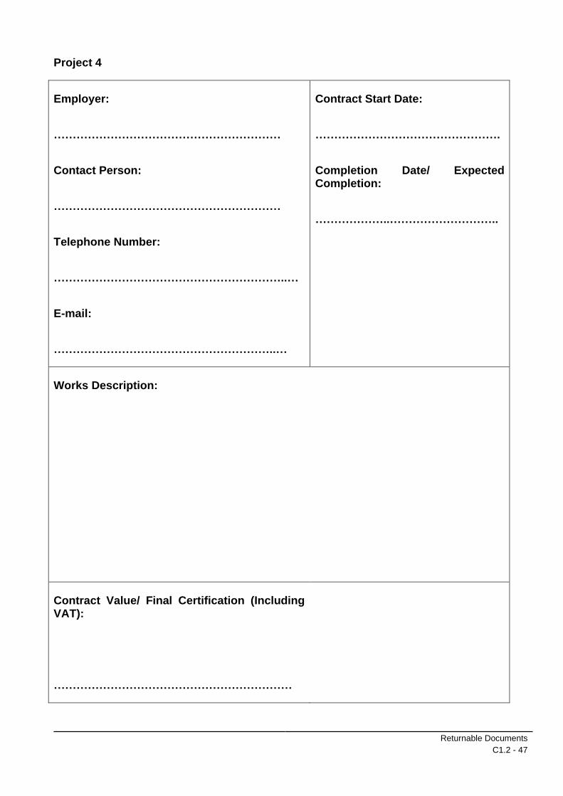
Project 4
Employer:
……………………………………………………
Contact Person:
……………………………………………………
Telephone Number:
……………………………………………………..…
E-mail:
…………………………………………………..…
Contract Start Date:
………………………………………….
Completion Date/ Expected Completion:
………………..………………………..
Works Description:
Contract Value/ Final Certification (Including VAT):
………………………………………………………

Returnable Documents
C1.2 - 48
TENDER
CONSTRUCTION OF BABATAS CPA BULK WATER SUPPLY
TENDER NO. NC/001/2021
SCHEDULE M : KEY STAFF COMPETENCE
The competence of Key Personnel will be evaluated in relation to the scope of work from three different points
of view:
The Tenderer must submit Proposed Team Structure, identifying Contract Manager, Site Agent, General
Foreman and OHS Practitioner as key personnel. Certified qualifications for each key personnel must be
attached for determination of points to be allocated as per the table below:
Key Personnel
Target Goals Point Allocation
Contract Manager
Proof of certified qualification of BEng/ BSc/ BTech in Civil Engineering of higher
10
Proof of certified qualification of National Diploma in Civil Engineering of higher
5
Less than above 2
Site Agent Proof of certified qualification of BEng/ BSc/ BTech in Civil Engineering of higher
5
Proof of certified qualification of National Diploma in Civil Engineering of higher
3
Less than above 1
OHS Practitioner
Accredited OHS Qualification by SAIOSH and SACPCMP or any recognised accredited organisation
3
Less than above 1
General Foreman
Trade qualification NQF 4 – Labour intensive 2
Less than above 1
**NB. STAPLE PROOF OF QUALIFICATION’S TO THIS PAGE!

Returnable Documents
C1.2 - 49
TENDER
CONSTRUCTION OF BABATAS CPA BULK WATER SUPPLY
TENDER NO. NC/001/2021
SCHEDULE N : EXPERINCE OF KEY STAFF
The experience of Key Personnel will be evaluated in relation to the scope of work from three different points
of view:
The Tenderer must submit Proposed Team Structure, identifying Contract Manager, Site Agent, General
foreman and OHS Practitioner as key personnel. Copies of a comprehensive CVs (not more than 5 pages)
with contactable references, clearly outlining the years of related experience for each key personnel must be
attached for determination of points to be allocated as per the table below:
Key Personnel
Target Goals Point Allocation
Contract Manager
10 years or more 5
5 to 9 years 3
Less than 5 years 1
Site agent 10 years or more 4
5 to 9 years 2
Less than 5 years 1
OHS Practitioner
10 years or more 3
5 to 9 years 2
Less than 5 years 1
General Foreman
10 years or more 3
5 to 9 years 2
Less than 5 years 1
**NB. STAPLE PROOF OF CV’S PAGE!

Returnable Documents
C1.2 - 50
TENDER
CONSTRUCTION OF BABATAS CPA BULK WATER SUPPLY
TENDER NO. NC/001/2021
SCHEDULE O : PROPOSED PROGRAM
The Tenderer must submit Proposed Program of Works for the project, clearly outline the main activities and timeframe from start to end of the project.
The program should comply with the following but not limited:
- Program in Gant Chart format
- Program outline the proposed program of all main construction activities
- Clear activity start and end dates and activity duration
**NB. STAPLE PROPOSED CONSTRUCTION PROGRAM TO THIS PAGE!

Returnable Documents
C1.2 - 51
TENDER
CONSTRUCTION OF BABATAS CPA BULK WATER SUPPLY
TENDER NO. NC/001/2021
SCHEDULE P : FINANCIAL STRENGTH CURRENT RATION
The Tenderer must submit last audited financial statements.
Target Goals Point Allocation
Ratio ˃ 2 15
Ratio ˃ 1.5 ˂ 2 10
Ratio ˃ 1.25 ˂ 1.5 7.5
Ratio ˃ 1.0 ˂ 1.25 5
Ratio = 1.0 ˂ 1.0 2
**NB. STAPLE PROOF TO THIS PAGE!
The Employer undertakes to treat the information thus obtained as confidential, strictly for the use of
evaluation of the Tender submitted by the Tenderer.
Signed ............................................................. Date ....................................................
Name ............................................................. Position ....................................................
Tenderer ............................................................................................................................................................
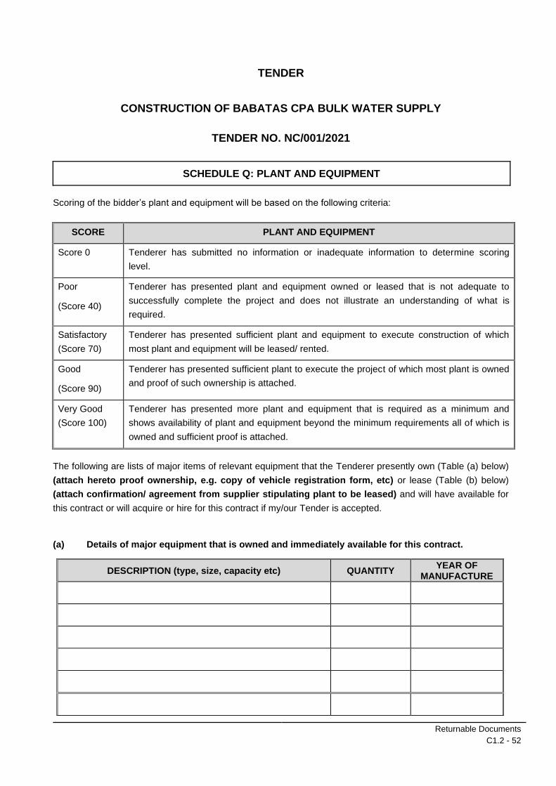
Returnable Documents
C1.2 - 52
TENDER
CONSTRUCTION OF BABATAS CPA BULK WATER SUPPLY
TENDER NO. NC/001/2021
SCHEDULE Q: PLANT AND EQUIPMENT
Scoring of the bidder’s plant and equipment will be based on the following criteria:
SCORE PLANT AND EQUIPMENT
Score 0 Tenderer has submitted no information or inadequate information to determine scoring
level.
Poor
(Score 40)
Tenderer has presented plant and equipment owned or leased that is not adequate to
successfully complete the project and does not illustrate an understanding of what is
required.
Satisfactory
(Score 70)
Tenderer has presented sufficient plant and equipment to execute construction of which
most plant and equipment will be leased/ rented.
Good
(Score 90)
Tenderer has presented sufficient plant to execute the project of which most plant is owned
and proof of such ownership is attached.
Very Good
(Score 100)
Tenderer has presented more plant and equipment that is required as a minimum and
shows availability of plant and equipment beyond the minimum requirements all of which is
owned and sufficient proof is attached.
The following are lists of major items of relevant equipment that the Tenderer presently own (Table (a) below)
(attach hereto proof ownership, e.g. copy of vehicle registration form, etc) or lease (Table (b) below)
(attach confirmation/ agreement from supplier stipulating plant to be leased) and will have available for
this contract or will acquire or hire for this contract if my/our Tender is accepted.
(a) Details of major equipment that is owned and immediately available for this contract.
DESCRIPTION (type, size, capacity etc) QUANTITY YEAR OF
MANUFACTURE

Returnable Documents
C1.2 - 53
DESCRIPTION (type, size, capacity etc) QUANTITY YEAR OF
MANUFACTURE
Attach additional pages if more space is required
(b) Details of major equipment that will be hired, or acquired for this contract if Bid is accepted.
Agreement with supplier to be attached.
DESCRIPTION (type, size, capacity, etc.)
QUANTITY
HOW ACQUIRED
HIRE/ BUY
SOURCE
Attach additional pages if more space is required
The Tenderer undertakes to bring onto site without additional cost to the Employer any additional plant not
listed but which may be necessary to complete the contract within the specified contract period.

Returnable Documents
C1.2 - 54
Signed ............................................................. Date ....................................................
Name ............................................................. Position ....................................................
Tenderer ............................................................................................................................................................

Returnable Documents
C1.2 - 55
TENDER
CONSTRUCTION OF BABATAS CPA BULK WATER SUPPLY
TENDER NO. NC/001/2021
SCHEDULE R : OFFICE LOCATION
The Tenderer must submit proof of office location by form of (i) Proof of Residence not older than 3 months and/or (ii) A valid lease agreement with a landlord and proof of municipal account of the landlord not older than 3 months
**NB. STAPLE PROOF TO THIS PAGE!
Signed ...................................................... Date ..............................................
Name ...................................................... Position ..............................................
Tenderer ............................................................................................................................................................

Contract Data
C1.3 - 1

Procurement
C1.3 - 1
TENDER
CONSTRUCTION OF BABATAS CPA BULK WATER SUPPLY
TENDER NO. NC/001/2021
C1.3 : PROCUREMENT
C1.3.1 PREFERENTIAL PROCUREMENT PROCEDURES
C1.3.2 Requirements
The following are conditions by the Employer regarding procurement of the project and will be utilised to adjudicate tenders.
C1.3.3 ACCEPTANCE OR REJECTION OF TENDERS
The Employer does not bind himself to accept the lowest or any tender and reserves the right to accept any tender. No reason for the acceptance or rejection of any tender will be given.
Tenders are considered in terms of the Preferential Procurement Regulations 2011.
C1.3.4 Tax Clearance Certificate
The Tenderer shall submit a valid original Tax Clearance Certificate from the South African Revenue Service (“SARS”) certifying the taxes of the Tenderer to be in order or that suitable arrangements have been made with SARS, as stipulated in Regulation 16.
Failure to submit the Tax Clearance Certificate will result in the tender being rendered incomplete and the tender will be rejected.
C1.3.5 Employment Targets
C1.3.5.1 Employment of Local Community Labour
The maximum possible number of workers is to be employed from the currently unemployed persons in the local community.
To this end the Contractor is required to give preference to the use of local community labour and limit the use of non-local to key personnel only.
Key personnel are defined as supervisors and skilled labourers without whom a specific task cannot be executed. As far as possible these people should impart their management and building skills to individuals within the community workforce.
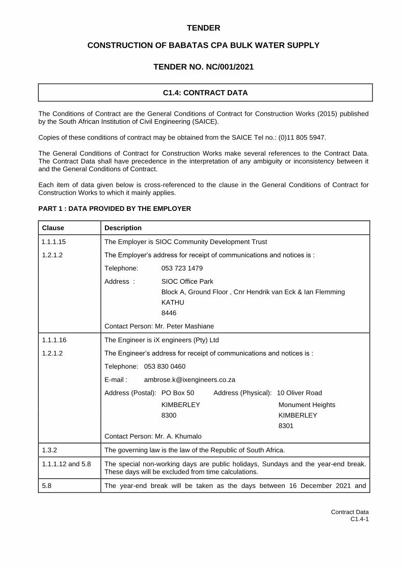
Contract Data C1.4-1
TENDER
CONSTRUCTION OF BABATAS CPA BULK WATER SUPPLY
TENDER NO. NC/001/2021
C1.4: CONTRACT DATA
The Conditions of Contract are the General Conditions of Contract for Construction Works (2015) published by the South African Institution of Civil Engineering (SAICE).
Copies of these conditions of contract may be obtained from the SAICE Tel no.: (0)11 805 5947.
The General Conditions of Contract for Construction Works make several references to the Contract Data. The Contract Data shall have precedence in the interpretation of any ambiguity or inconsistency between it and the General Conditions of Contract.
Each item of data given below is cross-referenced to the clause in the General Conditions of Contract for Construction Works to which it mainly applies.
PART 1 : DATA PROVIDED BY THE EMPLOYER
Clause Description
1.1.1.15 The Employer is SIOC Community Development Trust
1.2.1.2 The Employer’s address for receipt of communications and notices is :
Telephone: 053 723 1479
Address : SIOC Office Park
Block A, Ground Floor , Cnr Hendrik van Eck & Ian Flemming
KATHU
8446
Contact Person: Mr. Peter Mashiane
1.1.1.16 The Engineer is iX engineers (Pty) Ltd
1.2.1.2 The Engineer’s address for receipt of communications and notices is :
Telephone: 053 830 0460
E-mail : [email protected]
Address (Postal): PO Box 50 Address (Physical): 10 Oliver Road
KIMBERLEY Monument Heights
8300 KIMBERLEY
8301
Contact Person: Mr. A. Khumalo
1.3.2 The governing law is the law of the Republic of South Africa.
1.1.1.12 and 5.8 The special non-working days are public holidays, Sundays and the year-end break. These days will be excluded from time calculations.
5.8 The year-end break will be taken as the days between 16 December 2021 and
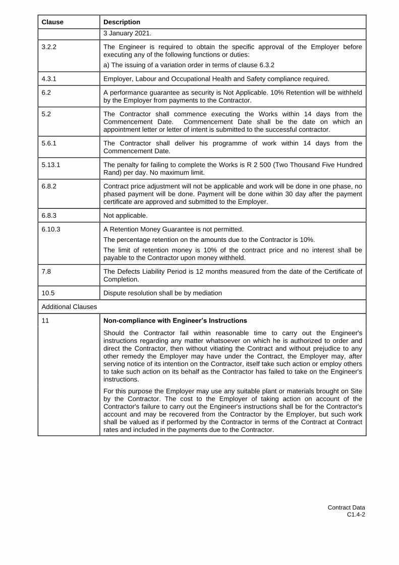
Contract Data C1.4-2
Clause Description
3 January 2021.
3.2.2 The Engineer is required to obtain the specific approval of the Employer before executing any of the following functions or duties:
a) The issuing of a variation order in terms of clause 6.3.2
4.3.1 Employer, Labour and Occupational Health and Safety compliance required.
6.2 A performance guarantee as security is Not Applicable. 10% Retention will be withheld by the Employer from payments to the Contractor.
5.2 The Contractor shall commence executing the Works within 14 days from the Commencement Date. Commencement Date shall be the date on which an appointment letter or letter of intent is submitted to the successful contractor.
5.6.1 The Contractor shall deliver his programme of work within 14 days from the Commencement Date.
5.13.1 The penalty for failing to complete the Works is R 2 500 (Two Thousand Five Hundred Rand) per day. No maximum limit.
6.8.2 Contract price adjustment will not be applicable and work will be done in one phase, no phased payment will be done. Payment will be done within 30 day after the payment certificate are approved and submitted to the Employer.
6.8.3 Not applicable.
6.10.3 A Retention Money Guarantee is not permitted.
The percentage retention on the amounts due to the Contractor is 10%.
The limit of retention money is 10% of the contract price and no interest shall be payable to the Contractor upon money withheld.
7.8 The Defects Liability Period is 12 months measured from the date of the Certificate of Completion.
10.5 Dispute resolution shall be by mediation
Additional Clauses
11 Non-compliance with Engineer’s Instructions
Should the Contractor fail within reasonable time to carry out the Engineer's instructions regarding any matter whatsoever on which he is authorized to order and direct the Contractor, then without vitiating the Contract and without prejudice to any other remedy the Employer may have under the Contract, the Employer may, after serving notice of its intention on the Contractor, itself take such action or employ others to take such action on its behalf as the Contractor has failed to take on the Engineer's instructions.
For this purpose the Employer may use any suitable plant or materials brought on Site by the Contractor. The cost to the Employer of taking action on account of the Contractor's failure to carry out the Engineer's instructions shall be for the Contractor's account and may be recovered from the Contractor by the Employer, but such work shall be valued as if performed by the Contractor in terms of the Contract at Contract rates and included in the payments due to the Contractor.

Contract Data C1.4-3
Clause Description
12 Implementation of the Occupational Health and Safety Act No. 85 of 1993
The Employer and the Contractor hereby agree, in terms of
the provisions of Section 37(2) of the Occupational Health and Safety Act, Act no. 85 of 1993 and the relevant Regulations made thereunder, with specific reference to the Construction Regulations of 2014, hereinafter referred to as "the Act", that the Contractor as an Employer in its own right and in its capacity as Contractor for the execution of the Works, shall have certain obligations and that the following arrangement shall apply between them to ensure compliance by the Contractor with the provisions of the Act, namely:
i)The Contractor undertakes to acquaint the appropriate officials and the employees of the Contractor with all the relevant provisions of the Act, and the regulations promulgated in terms of the Act, and
ii)The Contractor undertakes that all relevant duties, obligations and prohibitions imposed in terms of the Act and regulations will be fully complied with, and
iii)The Contractor shall be obliged to report forthwith to the Employer any investigation, complaint, or criminal charge which may arise as a consequence of the provisions of the Act and regulations pursuant to work performed on behalf of the Employer, and shall, on written demand, provide full details in writing of such investigation, complaint or criminal charge.
13 Employment of Labour Force
The Contractor shall employ all unskilled labourers required for the execution of the Contract locally from the local residents. The minimum wage for unskilled labourers shall be in accordance with the Basic Conditions of Employment Act, No. 75 of 1997, as published in the Government Gazette from time to time for the Civil Engineering Sector, and for the specific Magisterial District.
14 EXTENSION OF TIME FOR ABNORMAL RAINFALL
Extension of time in respect of Clause 5.12 in respect of abnormal rainfall shall be calculated using the following formula for each calendar month or part thereof:
V = (Nw – Nn) + Rw – Rn X
Where:
V = Extension of time in calendar days in respect of the calendar month under consideration.
Nw = Actual number of days during the calendar month on which a rainfall of 10 mm or more has been recorded.
Nn = Average number of days in the relevant calendar month, as derived from existing rainfall records, as stated in the Site Information, on which a rainfall of 10 mm or more has been recorded for the calendar month.
Rw = Actual rainfall in mm recorded for the calendar month under consideration.
Rn = Average rainfall in mm for the calendar month as derived from existing rainfall records as stated in the Site Information.
For the purpose of this Contract the values of Nn, Rn and X shall be those assigned to them in the Description of Works – Abnormal Rainfall .
If V is negative and its absolute value exceeds Nn, then V shall be taken as equal to minus Nn.
The total extension of time shall be the algebraic sum of all monthly totals for the period under consideration, but if the total is negative the time for completion shall not

Contract Data C1.4-4
Clause Description
be reduced due to subnormal rainfall.
Extension of time for part of a month shall be calculated using pro rata values of Nn and Rn.
This formula does not take into account flood damage which could cause or concurrent delays and will be treated separately as far as extension of time is concerned.
The factor (Nw – Nn) shall be considered to represent a fair allowance for variations from the average in the number of days during rainfall exceeds 10 mm. The factor (Rw – Rn) shall be considered to represent a fair allowance for variations from the average in the number of days which the rainfall did not exceed 10 mm but wet conditions prevented or disrupted work.
For the purpose of applying the formula, accurate rain gauging shall be taken at a suitable point on the Site and the Contractor shall at his own expense, take all necessary precautions to ensure that rain gauges cannot be interfered with by unauthorised persons.

Pricing Data
C2
TENDER
CONSTRUCTION OF BABATAS CPA BULK WATER SUPPLY
TENDER NO. NC/001/2021
PART C2: PRICING DATA
C2.1 Pricing Instructions
C2.2 Bill of Quantities

Pricing Instructions
C2.1
TENDER
CONSTRUCTION OF BABATAS CPA BULK WATER SUPPLY
TENDER NO. NC/001/2021
C2.1: PRICING INSTRUCTIONS
C2.1.1 PREAMBLE TO THE BILLS OF QUANTITIES
C2.1.1.1 All prices shall be quoted in the currency of the Republic of South Africa and will be held to be firm unless otherwise stated, in which case sufficient information must be afforded at the time of tendering to indicate the basis on which payments shall be adjusted.
C2.1.1.2 The tenderer shall enter a price against each item in the schedule of prices. If the tenderer fails to enter a price against any item in the schedule of prices the relevant cost for such item shall be regarded as being covered by other prices in the schedule of prices.
C2.1.1.3 The prices quoted against each item of these schedules shall cover the full inclusive cost, value added tax excluded, of everything required for the execution of the work under the item plus an apportionment of any costs involved in meeting the obligations and liabilities.
C2.1.1.4 The tenderers shall calculate value added tax and enter it at the end of the summary of the schedule of prices.
C2.1.1.5 The prices quoted for the supply of plant and equipment shall include for all handling, loading, transporting and off-loading required for the delivery of the plant and equipment to the site, including in the case of off-site storage for double handling at the store.
C2.1.1.6 The prices quoted for erection and/or installation shall include for all handling, loading, transporting and off-loading to take plant and equipment to place on site where required, erection, installation, painting, guaranteeing for a period of twenty four (24) months and upholding for a period of twelve (12) months, all as specified.
C2.1.1.7 The prices quoted for commissioning of plant include for operating, mechanical and electrical testing, adjusting and handling over in a proper working order and for the provision of operating and maintenance manuals, where applicable.
C2.1.1.8 Any additional charges in connection with off-site storage which there may be over and above the prices quoted in the various sections of this schedule of prices shall be set-out in detail by the tenderer.
C2.1.1.9 The work of installation, erection and testing of the plant and equipment shall as far as possible be carried out in one continuous operation and the cost of transporting personnel between the Contractors’ headquarters and the site will be paid at the quotation amount for same for only one return trip for such continuous operation. No additional payment will be made for any weekend or holiday trips back to the Contractor’s headquarters. Additional trips for personnel will only be paid for if authorised, or when requested by the Engineer in writing.
C2.1.1.10 Amounts allowed for contingencies will be spent in part or as a whole at the sole discretion of the Engineer.
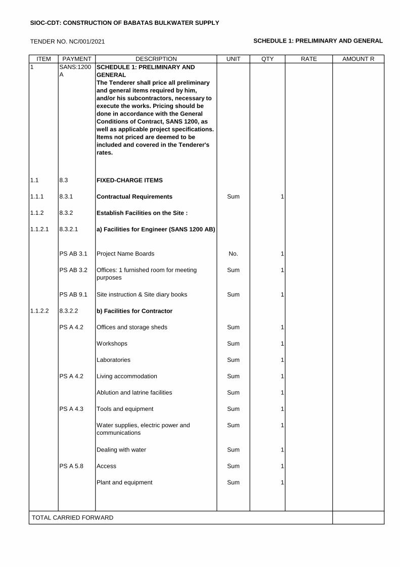
TENDER NO. NC/001/2021 SCHEDULE 1: PRELIMINARY AND GENERAL
ITEM PAYMENT DESCRIPTION UNIT QTY RATE AMOUNT R
1 SANS:1200
A
SCHEDULE 1: PRELIMINARY AND
GENERAL
The Tenderer shall price all preliminary
and general items required by him,
and/or his subcontractors, necessary to
execute the works. Pricing should be
done in accordance with the General
Conditions of Contract, SANS 1200, as
well as applicable project specifications.
Items not priced are deemed to be
included and covered in the Tenderer's
rates.
1.1 8.3 FIXED-CHARGE ITEMS
1.1.1 8.3.1 Contractual Requirements Sum 1
1.1.2 8.3.2 Establish Facilities on the Site :
1.1.2.1 8.3.2.1 a) Facilities for Engineer (SANS 1200 AB)
PS AB 3.1 Project Name Boards No. 1
PS AB 3.2 Offices: 1 furnished room for meeting
purposes
Sum 1
PS AB 9.1 Site instruction & Site diary books Sum 1
1.1.2.2 8.3.2.2 b) Facilities for Contractor
PS A 4.2 Offices and storage sheds Sum 1
Workshops Sum 1
Laboratories Sum 1
PS A 4.2 Living accommodation Sum 1
Ablution and latrine facilities Sum 1
PS A 4.3 Tools and equipment Sum 1
Water supplies, electric power and
communications
Sum 1
Dealing with water Sum 1
PS A 5.8 Access Sum 1
Plant and equipment Sum 1
TOTAL CARRIED FORWARD
SIOC-CDT: CONSTRUCTION OF BABATAS BULKWATER SUPPLY
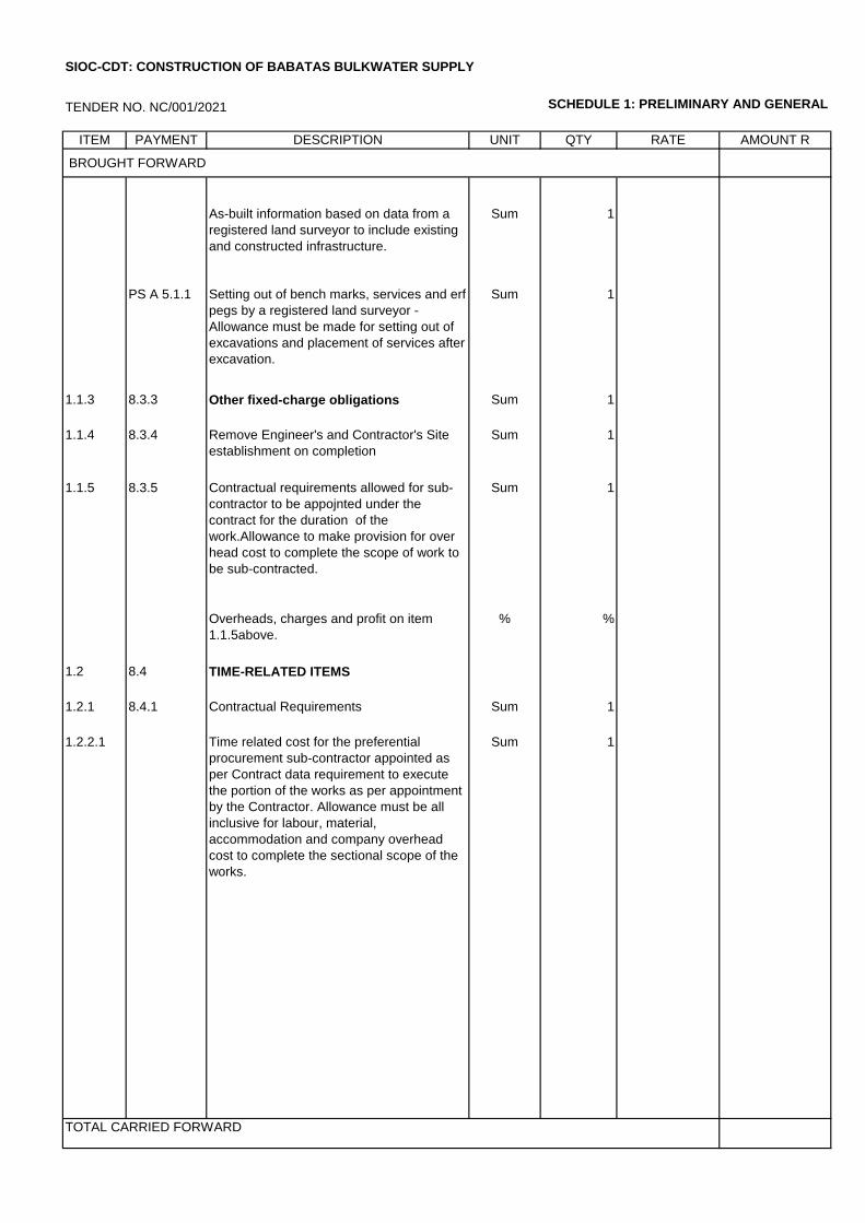
TENDER NO. NC/001/2021 SCHEDULE 1: PRELIMINARY AND GENERAL
ITEM PAYMENT DESCRIPTION UNIT QTY RATE AMOUNT R
BROUGHT FORWARD
As-built information based on data from a
registered land surveyor to include existing
and constructed infrastructure.
Sum 1
PS A 5.1.1 Setting out of bench marks, services and erf
pegs by a registered land surveyor -
Allowance must be made for setting out of
excavations and placement of services after
excavation.
Sum 1
1.1.3 8.3.3 Other fixed-charge obligations Sum 1
1.1.4 8.3.4 Remove Engineer's and Contractor's Site
establishment on completion
Sum 1
1.1.5 8.3.5 Contractual requirements allowed for sub-
contractor to be appojnted under the
contract for the duration of the
work.Allowance to make provision for over
head cost to complete the scope of work to
be sub-contracted.
Sum 1
Overheads, charges and profit on item
1.1.5above.
% %
1.2 8.4 TIME-RELATED ITEMS
1.2.1 8.4.1 Contractual Requirements Sum 1
1.2.2.1 Time related cost for the preferential
procurement sub-contractor appointed as
per Contract data requirement to execute
the portion of the works as per appointment
by the Contractor. Allowance must be all
inclusive for labour, material,
accommodation and company overhead
cost to complete the sectional scope of the
works.
Sum 1
TOTAL CARRIED FORWARD
SIOC-CDT: CONSTRUCTION OF BABATAS BULKWATER SUPPLY
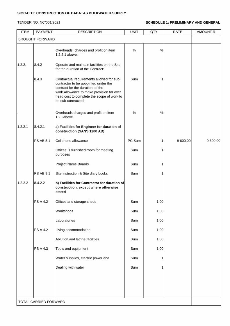
TENDER NO. NC/001/2021 SCHEDULE 1: PRELIMINARY AND GENERAL
ITEM PAYMENT DESCRIPTION UNIT QTY RATE AMOUNT R
BROUGHT FORWARD
Overheads, charges and profit on item
1.2.2.1 above.
% %
1.2.2. 8.4.2 Operate and maintain facilities on the Site
for the duration of the Contract:
8.4.3 Contractual requirements allowed for sub-
contractor to be appojnted under the
contract for the duration of the
work.Allowance to make provision for over
head cost to complete the scope of work to
be sub-contracted.
Sum 1
. Overheads,charges and profit on item
1.2.2above
% %
1.2.2.1 8.4.2.1 a) Facilities for Engineer for duration of
construction (SANS 1200 AB)
PS AB 5.1 Cellphone allowance PC Sum 1 9 600,00 9 600,00
Offices: 1 furnished room for meeting
purposes
Sum 1
Project Name Boards Sum 1
PS AB 9.1 Site instruction & Site diary books Sum 1
1.2.2.2 8.4.2.2 b) Facilities for Contractor for duration of
construction, except where otherwise
stated
PS A 4.2 Offices and storage sheds Sum 1,00
Workshops Sum 1,00
Laboratories Sum 1,00
PS A 4.2 Living accommodation Sum 1,00
Ablution and latrine facilities Sum 1,00
PS A 4.3 Tools and equipment Sum 1,00
Water supplies, electric power and
communications
Sum 1
Dealing with water Sum 1
TOTAL CARRIED FORWARD
SIOC-CDT: CONSTRUCTION OF BABATAS BULKWATER SUPPLY
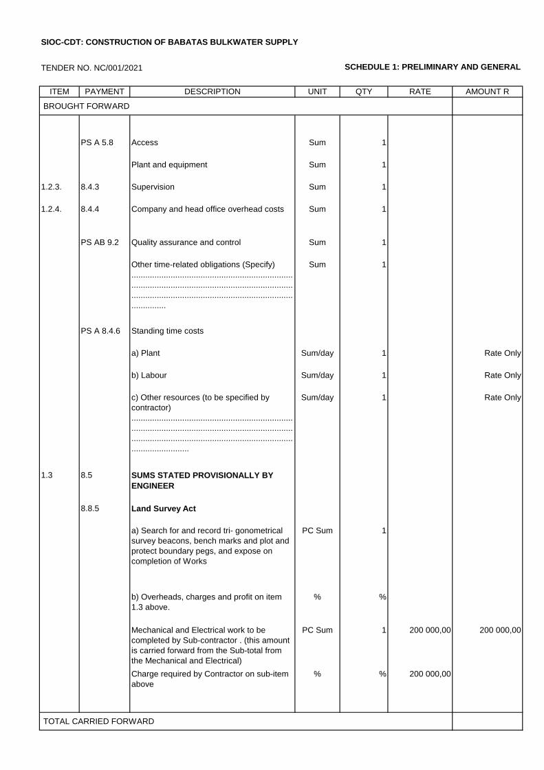
TENDER NO. NC/001/2021 SCHEDULE 1: PRELIMINARY AND GENERAL
ITEM PAYMENT DESCRIPTION UNIT QTY RATE AMOUNT R
BROUGHT FORWARD
PS A 5.8 Access Sum 1
Plant and equipment Sum 1
1.2.3. 8.4.3 Supervision Sum 1
1.2.4. 8.4.4 Company and head office overhead costs Sum 1
PS AB 9.2 Quality assurance and control Sum 1
Other time-related obligations (Specify)
......................................................................
......................................................................
......................................................................
...............
Sum 1
PS A 8.4.6 Standing time costs
a) Plant Sum/day 1 Rate Only
b) Labour Sum/day 1 Rate Only
c) Other resources (to be specified by
contractor)
......................................................................
......................................................................
......................................................................
.........................
Sum/day 1 Rate Only
1.3 8.5 SUMS STATED PROVISIONALLY BY
ENGINEER
8.8.5 Land Survey Act
a) Search for and record tri- gonometrical
survey beacons, bench marks and plot and
protect boundary pegs, and expose on
completion of Works
PC Sum 1
b) Overheads, charges and profit on item
1.3 above.
% %
Mechanical and Electrical work to be
completed by Sub-contractor . (this amount
is carried forward from the Sub-total from
the Mechanical and Electrical)
PC Sum 1 200 000,00 200 000,00
Charge required by Contractor on sub-item
above
% % 200 000,00
TOTAL CARRIED FORWARD
SIOC-CDT: CONSTRUCTION OF BABATAS BULKWATER SUPPLY
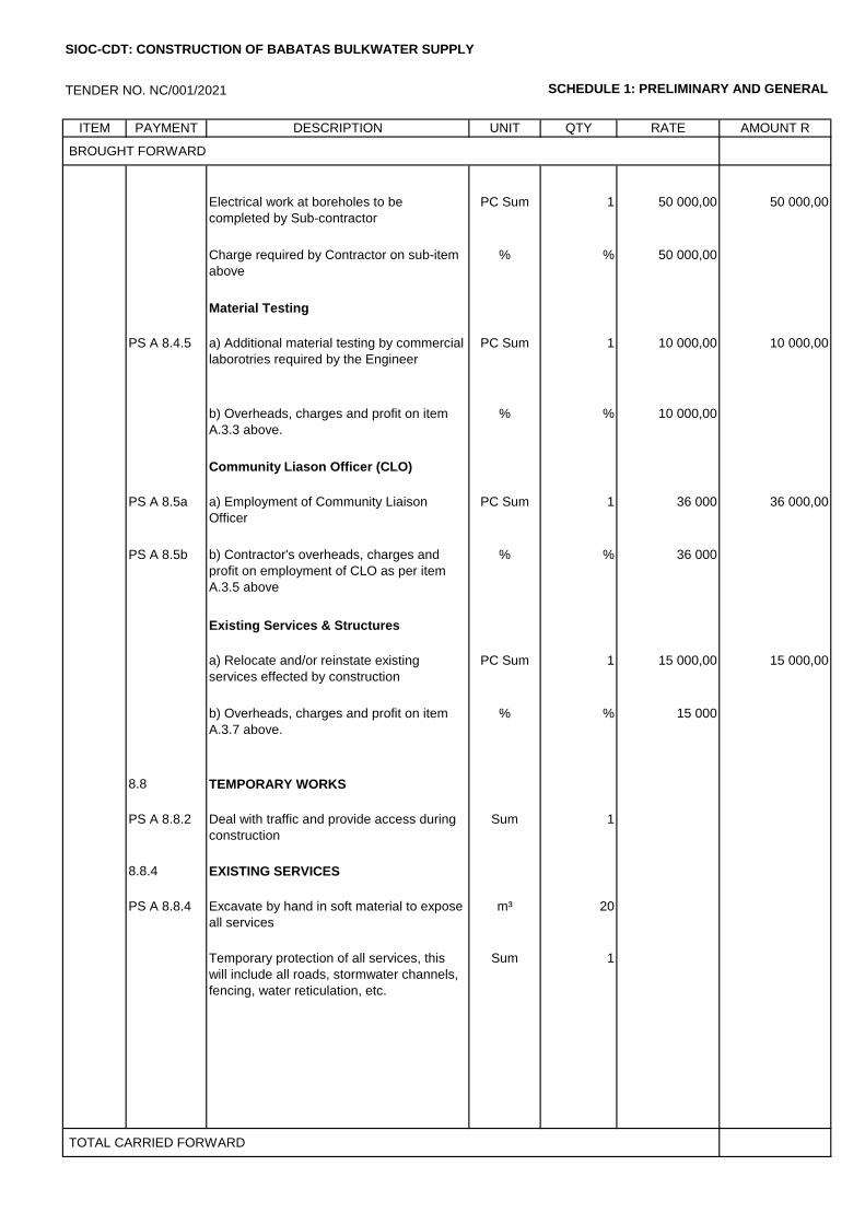
TENDER NO. NC/001/2021 SCHEDULE 1: PRELIMINARY AND GENERAL
ITEM PAYMENT DESCRIPTION UNIT QTY RATE AMOUNT R
BROUGHT FORWARD
Electrical work at boreholes to be
completed by Sub-contractor
PC Sum 1 50 000,00 50 000,00
Charge required by Contractor on sub-item
above
% % 50 000,00
Material Testing
PS A 8.4.5 a) Additional material testing by commercial
laborotries required by the Engineer
PC Sum 1 10 000,00 10 000,00
b) Overheads, charges and profit on item
A.3.3 above.
% % 10 000,00
Community Liason Officer (CLO)
PS A 8.5a a) Employment of Community Liaison
Officer
PC Sum 1 36 000 36 000,00
PS A 8.5b b) Contractor's overheads, charges and
profit on employment of CLO as per item
A.3.5 above
% % 36 000
Existing Services & Structures
a) Relocate and/or reinstate existing
services effected by construction
PC Sum 1 15 000,00 15 000,00
b) Overheads, charges and profit on item
A.3.7 above.
% % 15 000
8.8 TEMPORARY WORKS
PS A 8.8.2 Deal with traffic and provide access during
construction
Sum 1
8.8.4 EXISTING SERVICES
PS A 8.8.4 Excavate by hand in soft material to expose
all services
m³ 20
Temporary protection of all services, this
will include all roads, stormwater channels,
fencing, water reticulation, etc.
Sum 1
TOTAL CARRIED FORWARD
SIOC-CDT: CONSTRUCTION OF BABATAS BULKWATER SUPPLY

TENDER NO. NC/001/2021 SCHEDULE 1: PRELIMINARY AND GENERAL
ITEM PAYMENT DESCRIPTION UNIT QTY RATE AMOUNT R
BROUGHT FORWARD
PS A
8.9
OCCUPATIONAL HEALTH AND SAFETY
(PROVISIONAL)
PS A
8.9.1
Cost of health and safety measures in
terms of the Construction Regulations
(2014) of the Occupational Health and
Safety Act
Sum 1
PS A
8.9.2
Compilation and maintenace of a Health
and Safety Plan, including Risk
Assesments, Safe Works Procedures and
Methods Statements
Sum 1
PS A
8.9.3
Compilation and maintenance of the Health
and Safey File
Sum 1
ENVIRONMENTAL MANAGEMENT
PS A 8.3.6 Requirements in terms of the Environmental
Management Programme
Sum 1
TOTAL CARRIED FORWARD TO SUMMARY
SIOC-CDT: CONSTRUCTION OF BABATAS BULKWATER SUPPLY
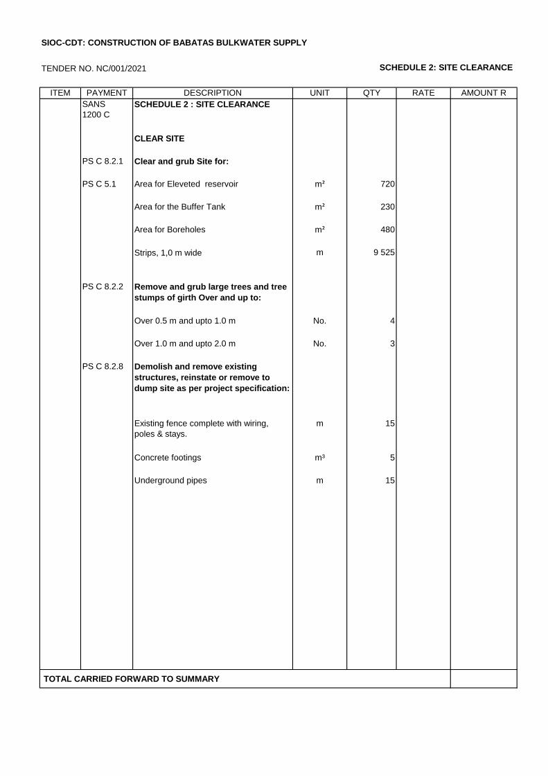
TENDER NO. NC/001/2021 SCHEDULE 2: SITE CLEARANCE
ITEM PAYMENT DESCRIPTION UNIT QTY RATE AMOUNT R
SANS
1200 C
SCHEDULE 2 : SITE CLEARANCE
CLEAR SITE
PS C 8.2.1 Clear and grub Site for:
PS C 5.1 Area for Eleveted reservoir m² 720
Area for the Buffer Tank m² 230
Area for Boreholes m² 480
Strips, 1,0 m wide m 9 525
PS C 8.2.2 Remove and grub large trees and tree
stumps of girth Over and up to:
Over 0.5 m and upto 1.0 m No. 4
Over 1.0 m and upto 2.0 m No. 3
PS C 8.2.8 Demolish and remove existing
structures, reinstate or remove to
dump site as per project specification:
Existing fence complete with wiring,
poles & stays.
m 15
Concrete footings m³ 5
Underground pipes m 15
TOTAL CARRIED FORWARD TO SUMMARY
SIOC-CDT: CONSTRUCTION OF BABATAS BULKWATER SUPPLY

TENDER NO. NC/001/2021 SCHEDULE 3: BULK WATER SUPPLY & STORAGE
ITEM PAYMENT DESCRIPTION UNIT QTY RATE AMOUNT R
3 SCHEDULE 3: BULK WATER SUPPLY
& STORAGE
3.1 SANS: 1200
DB
EXCAVATION
PS DB
8.3.2(a)
Excavate in all materials for trenches,
800mm wide, 1m deep, select, backfilled
and compacted to 93% of MAASHTO
density (100% for sand), including spoil
of surplus material for main pipes with:
3.1.1 Diameter up to 250 mm m 7 500
8.3.2(b) Extra-over items B.2.1 for (provisional):
3.1.2 Intermediate excavation m³ 2 238
3.1.3 Hard rock excavation m³ 1 119
3.1.4 8.3.2(c) Excavate unsuitable material from trench
bottom (provisional)
m³ 10
3.1.5 8.3.8.1(c) Hand excavation to expose existing
services
m³ 15
PS DB
8.3.2(e)
Extra-over PS DB 8.3.2(a) for temporary
stockpiling of material
m³ 50
8.3.3 EXCAVATION ANCILLARIES
PS DB
8.3.3.1
Make up deficiency in backfill material
(unlimited freehaul distance)
8.3.3.1(a) From other necessary excavations on
site
m³ 150
8.3.3.1(c) From commercial sources m³ 150
8.3.5 EXISTING SERVICES
PS DB
8.3.5(a)
Services that intersect a trench
Water main pipes No 2
PS DB
8.3.5(b)
Services that adjoin a trench
Security fence m 22
Water pipes m 15
TOTAL CARRIED FORWARD
SIOC-CDT: CONSTRUCTION OF BABATAS BULKWATER SUPPLY
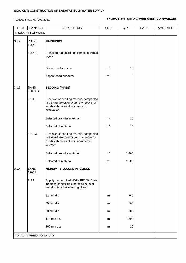
TENDER NO. NC/001/2021 SCHEDULE 3: BULK WATER SUPPLY & STORAGE
ITEM PAYMENT DESCRIPTION UNIT QTY RATE AMOUNT R
BROUGHT FORWARD
3.1.2 PS DB
8.3.6
FINISHINGS
8.3.6.1 Reinstate road surfaces complete with all
layers
Gravel road surfaces m² 10
Asphalt road surfaces m² 3
3.1.3 SANS
1200 LB
BEDDING (PIPES)
8.2.1 Provision of bedding material compacted
to 93% of MAASHTO density (100% for
sand) with material from trench
excavation
Selected granular material m³ 10
Selected fill material m³ 10
8.2.2.3 Provision of bedding material compacted
to 93% of MAASHTO density (100% for
sand) with material from commercial
sources
Selected granular material m³ 2 400
Selected fill material m³ 1 300
3.1.4 SANS
1200 L
MEDIUM-PRESSURE PIPELINES
8.2.1 Supply, lay and bed HDPe PE100, Class
10 pipes on flexible pipe bedding, test
and disinfect the following pipes:
32 mm dia m 750
50 mm dia m 800
90 mm dia m 700
110 mm dia m 7 500
160 mm dia m 20
TOTAL CARRIED FORWARD
SIOC-CDT: CONSTRUCTION OF BABATAS BULKWATER SUPPLY
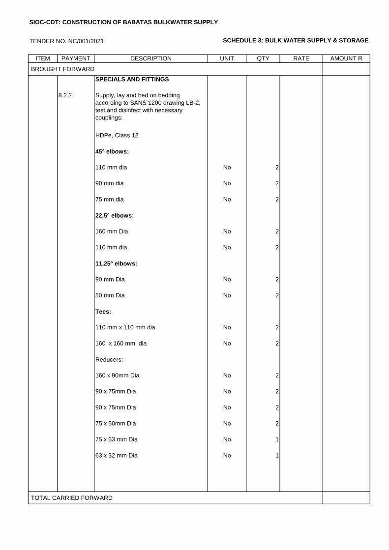
TENDER NO. NC/001/2021 SCHEDULE 3: BULK WATER SUPPLY & STORAGE
ITEM PAYMENT DESCRIPTION UNIT QTY RATE AMOUNT R
BROUGHT FORWARD
SPECIALS AND FITTINGS
8.2.2 Supply, lay and bed on bedding
according to SANS 1200 drawing LB-2,
test and disinfect with necessary
couplings:
HDPe, Class 12
45° elbows:
110 mm dia No 2
90 mm dia No 2
75 mm dia No 2
22,5° elbows:
160 mm Dia No 2
110 mm dia No 2
11,25° elbows:
90 mm Dia No 2
50 mm Dia No 2
Tees:
110 mm x 110 mm dia No 2
160 x 160 mm dia No 2
Reducers:
160 x 90mm Dia No 2
90 x 75mm Dia No 2
90 x 75mm Dia No 2
75 x 50mm Dia No 2
75 x 63 mm Dia No 1
63 x 32 mm Dia No 1
TOTAL CARRIED FORWARD
SIOC-CDT: CONSTRUCTION OF BABATAS BULKWATER SUPPLY
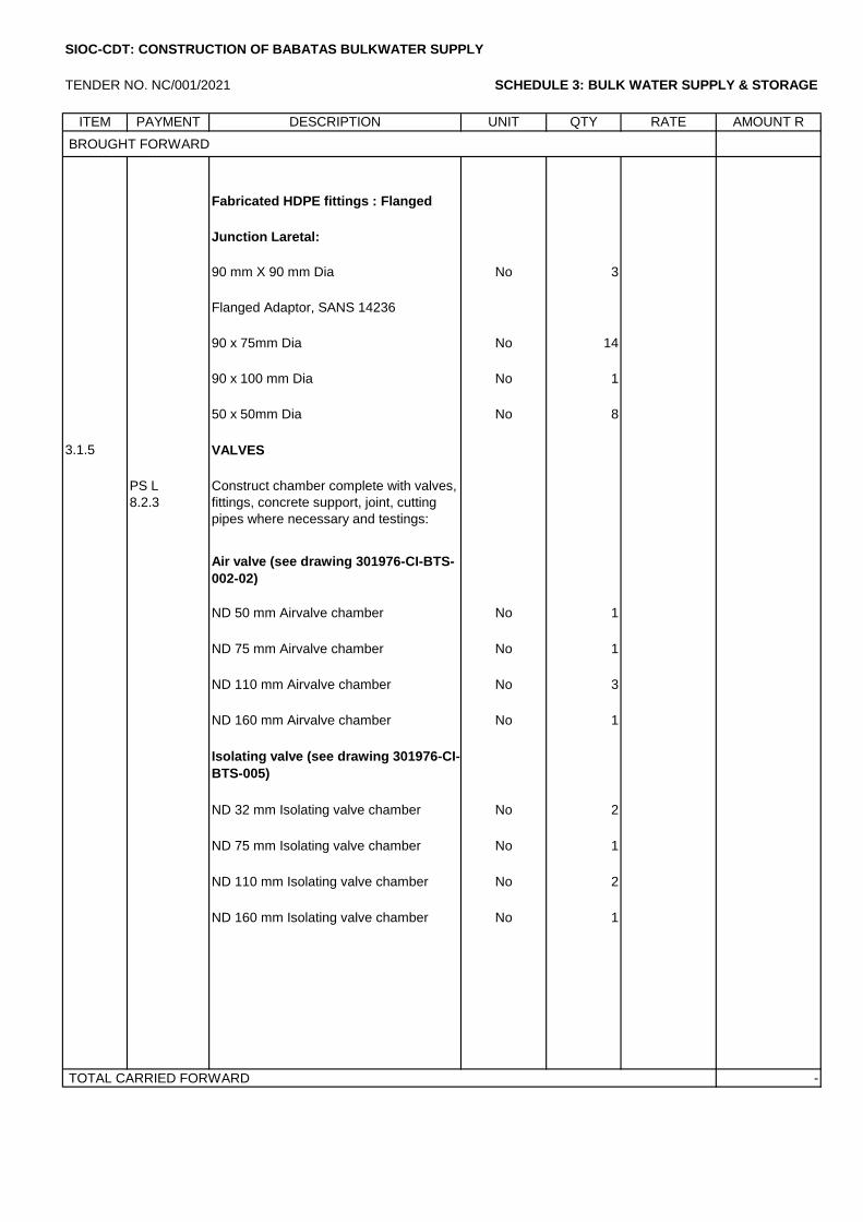
TENDER NO. NC/001/2021 SCHEDULE 3: BULK WATER SUPPLY & STORAGE
ITEM PAYMENT DESCRIPTION UNIT QTY RATE AMOUNT R
BROUGHT FORWARD
Fabricated HDPE fittings : Flanged
Junction Laretal:
90 mm X 90 mm Dia No 3
Flanged Adaptor, SANS 14236
90 x 75mm Dia No 14
90 x 100 mm Dia No 1
50 x 50mm Dia No 8
3.1.5 VALVES
PS L
8.2.3
Construct chamber complete with valves,
fittings, concrete support, joint, cutting
pipes where necessary and testings:
Air valve (see drawing 301976-CI-BTS-
002-02)
ND 50 mm Airvalve chamber No 1
ND 75 mm Airvalve chamber No 1
ND 110 mm Airvalve chamber No 3
ND 160 mm Airvalve chamber No 1
Isolating valve (see drawing 301976-CI-
BTS-005)
ND 32 mm Isolating valve chamber No 2
ND 75 mm Isolating valve chamber No 1
ND 110 mm Isolating valve chamber No 2
ND 160 mm Isolating valve chamber No 1
TOTAL CARRIED FORWARD -
SIOC-CDT: CONSTRUCTION OF BABATAS BULKWATER SUPPLY
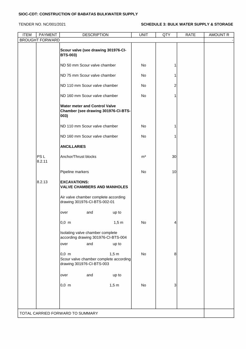
TENDER NO. NC/001/2021 SCHEDULE 3: BULK WATER SUPPLY & STORAGE
ITEM PAYMENT DESCRIPTION UNIT QTY RATE AMOUNT R
BROUGHT FORWARD -
Scour valve (see drawing 301976-CI-
BTS-003)
ND 50 mm Scour valve chamber No 1
ND 75 mm Scour valve chamber No 1
ND 110 mm Scour valve chamber No 2
ND 160 mm Scour valve chamber No 1
Water meter and Control Valve
Chamber (see drawing 301976-CI-BTS-
003)
ND 110 mm Scour valve chamber No 1
ND 160 mm Scour valve chamber No 1
ANCILLARIES
PS L
8.2.11
Anchor/Thrust blocks m³ 30
Pipeline markers No 10
8.2.13 EXCAVATIONS:
VALVE CHAMBERS AND MANHOLES
Air valve chamber complete according
drawing 301976-CI-BTS-002-01
over and up to
0,0 m 1,5 m No 4
Isolating valve chamber complete
according drawing 301976-CI-BTS-004
over and up to
0,0 m 1,5 m No 8
Scour valve chamber complete according
drawing 301976-CI-BTS-003
over and up to
0,0 m 1,5 m No 3
TOTAL CARRIED FORWARD TO SUMMARY
SIOC-CDT: CONSTRUCTION OF BABATAS BULKWATER SUPPLY
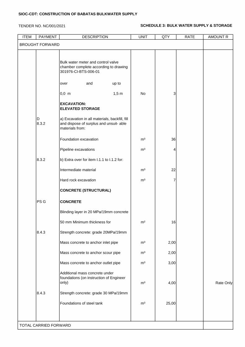
TENDER NO. NC/001/2021 SCHEDULE 3: BULK WATER SUPPLY & STORAGE
ITEM PAYMENT DESCRIPTION UNIT QTY RATE AMOUNT R
BROUGHT FORWARD
Bulk water meter and control valve
chamber complete according to drawing
301976-CI-BTS-006-01
over and up to
0,0 m 1,5 m No 3
EXCAVATION:
ELEVATED STORAGE
D
8.3.2
a) Excavation in all materials, backfill, fill
and dispose of surplus and unsuit- able
materials from:
Foundation excavation m³ 36
Pipeline excavations m³ 4
8.3.2 b) Extra over for item I.1.1 to I.1.2 for:
Intermediate material m³ 22
Hard rock excavation m³ 7
CONCRETE (STRUCTURAL)
PS G
8.1.3
CONCRETE
Blinding layer in 20 MPa/19mm concrete
50 mm Minimum thickness for
foundations
m² 16
8.4.3 Strength concrete: grade 20MPa/19mm
Mass concrete to anchor inlet pipe m³ 2,00
Mass concrete to anchor scour pipe m³ 2,00
Mass concrete to anchor outlet pipe m³ 3,00
Additional mass concrete under
foundations (on instruction of Engineer
only) m³ 4,00 Rate Only
8.4.3 Strength concrete: grade 30 MPa/19mm
Foundations of steel tank m³ 25,00
TOTAL CARRIED FORWARD
SIOC-CDT: CONSTRUCTION OF BABATAS BULKWATER SUPPLY
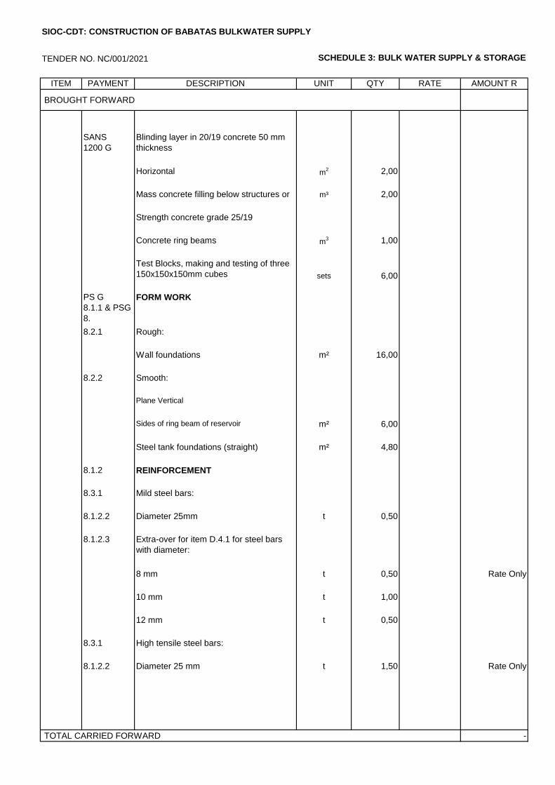
TENDER NO. NC/001/2021 SCHEDULE 3: BULK WATER SUPPLY & STORAGE
ITEM PAYMENT DESCRIPTION UNIT QTY RATE AMOUNT R
BROUGHT FORWARD
SANS
1200 G
Blinding layer in 20/19 concrete 50 mm
thickness
Horizontal m2 2,00
Mass concrete filling below structures or
where ordered
m³ 2,00
Strength concrete grade 25/19
Concrete ring beams m3 1,00
Test Blocks, making and testing of three
150x150x150mm cubes sets 6,00
PS G
8.1.1 & PSG
8.
FORM WORK
8.2.1 Rough:
Wall foundations m² 16,00
8.2.2 Smooth:
Plane Vertical
Sides of ring beam of reservoir m² 6,00
Steel tank foundations (straight) m² 4,80
8.1.2 REINFORCEMENT
8.3.1 Mild steel bars:
8.1.2.2 Diameter 25mm t 0,50
8.1.2.3 Extra-over for item D.4.1 for steel bars
with diameter:
8 mm t 0,50 Rate Only
10 mm t 1,00
12 mm t 0,50
8.3.1 High tensile steel bars:
8.1.2.2 Diameter 25 mm t 1,50 Rate Only
TOTAL CARRIED FORWARD -
SIOC-CDT: CONSTRUCTION OF BABATAS BULKWATER SUPPLY
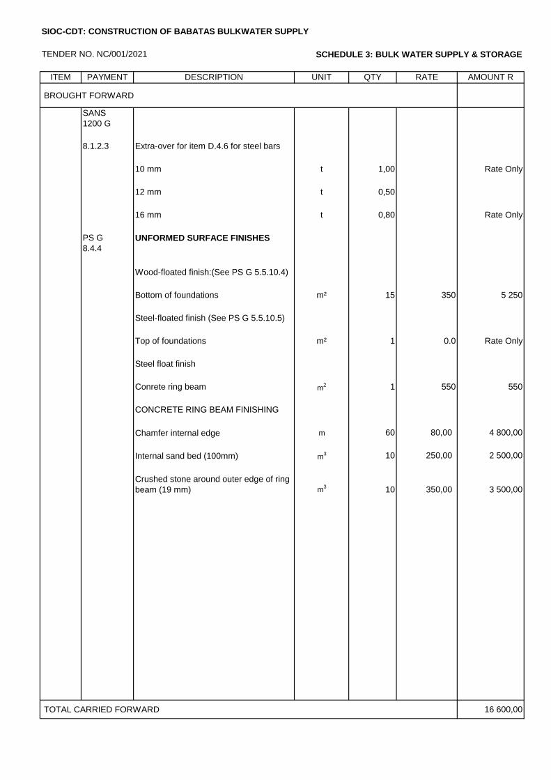
TENDER NO. NC/001/2021 SCHEDULE 3: BULK WATER SUPPLY & STORAGE
ITEM
NO
PAYMENT DESCRIPTION UNIT QTY RATE AMOUNT R
BROUGHT FORWARD
SANS
1200 G
8.1.2.3 Extra-over for item D.4.6 for steel bars
with diameter:
10 mm t 1,00 Rate Only
12 mm t 0,50
16 mm t 0,80 Rate Only
PS G
8.4.4
UNFORMED SURFACE FINISHES
Wood-floated finish:(See PS G 5.5.10.4)
Bottom of foundations m² 15 350 5 250
Steel-floated finish (See PS G 5.5.10.5)
Top of foundations m² 1 0.0 Rate Only
Steel float finish
Conrete ring beam m2 1 550 550
CONCRETE RING BEAM FINISHING
Chamfer internal edge m 60 80,00 4 800,00
Internal sand bed (100mm) m3 10 250,00 2 500,00
Crushed stone around outer edge of ring
beam (19 mm) m3 10 350,00 3 500,00
TOTAL CARRIED FORWARD 16 600,00
SIOC-CDT: CONSTRUCTION OF BABATAS BULKWATER SUPPLY
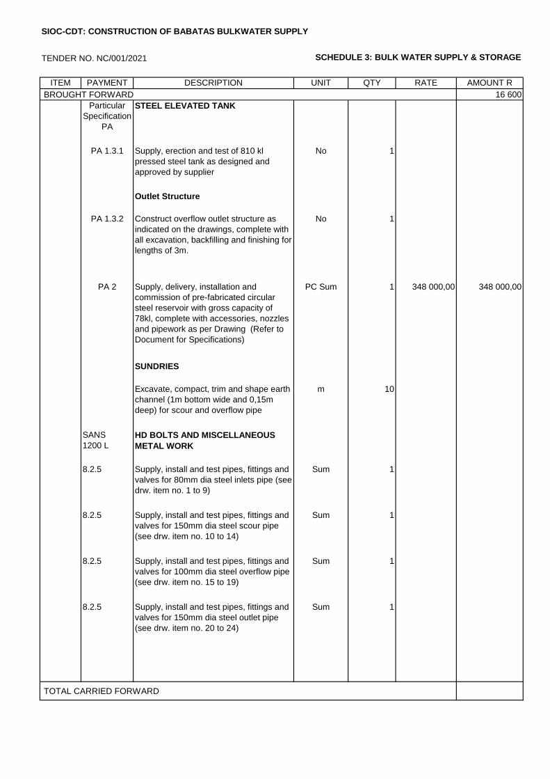
TENDER NO. NC/001/2021 SCHEDULE 3: BULK WATER SUPPLY & STORAGE
ITEM PAYMENT DESCRIPTION UNIT QTY RATE AMOUNT R
BROUGHT FORWARD 16 600
Particular
Specification
PA
STEEL ELEVATED TANK
PA 1.3.1 Supply, erection and test of 810 kl
pressed steel tank as designed and
approved by supplier
No 1
Outlet Structure
PA 1.3.2 Construct overflow outlet structure as
indicated on the drawings, complete with
all excavation, backfilling and finishing for
lengths of 3m.
No 1
PA 2 Supply, delivery, installation and
commission of pre-fabricated circular
steel reservoir with gross capacity of
78kl, complete with accessories, nozzles
and pipework as per Drawing (Refer to
Document for Specifications)
PC Sum 1 348 000,00 348 000,00
SUNDRIES
Excavate, compact, trim and shape earth
channel (1m bottom wide and 0,15m
deep) for scour and overflow pipe
m 10
SANS
1200 L
HD BOLTS AND MISCELLANEOUS
METAL WORK
8.2.5 Supply, install and test pipes, fittings and
valves for 80mm dia steel inlets pipe (see
drw. item no. 1 to 9)
Sum 1
8.2.5 Supply, install and test pipes, fittings and
valves for 150mm dia steel scour pipe
(see drw. item no. 10 to 14)
Sum 1
8.2.5 Supply, install and test pipes, fittings and
valves for 100mm dia steel overflow pipe
(see drw. item no. 15 to 19)
Sum 1
8.2.5 Supply, install and test pipes, fittings and
valves for 150mm dia steel outlet pipe
(see drw. item no. 20 to 24)
Sum 1
TOTAL CARRIED FORWARD
SIOC-CDT: CONSTRUCTION OF BABATAS BULKWATER SUPPLY
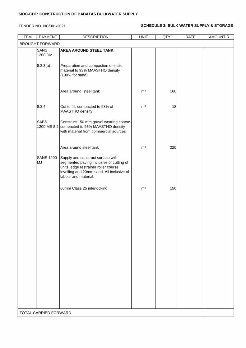
TENDER NO. NC/001/2021 SCHEDULE 3: BULK WATER SUPPLY & STORAGE
ITEM PAYMENT DESCRIPTION UNIT QTY RATE AMOUNT R
BROUGHT FORWARD
SANS
1200 DM
AREA AROUND STEEL TANK
8.3.3(a) Preparation and compaction of insitu
material to 93% MAASTHO density
(100% for sand)
Area around steel tank m² 160
8.3.4 Cut to fill, compacted to 93% of
MAASTHO density
m³ 18
SABS
1200 ME 8.2
Construct 150 mm gravel wearing coarse
compacted to 95% MAASTHO density
with material from commercial sources
Area around steel tank m² 220
SANS 1200
MJ
Supply and construct surface with
segmented paving inclusive of cutting of
units, edge restrainer roller course
levelling and 20mm sand. All inclusive of
labour and material.
60mm Class 25 interlocking m² 150
TOTAL CARRIED FORWARD
SIOC-CDT: CONSTRUCTION OF BABATAS BULKWATER SUPPLY
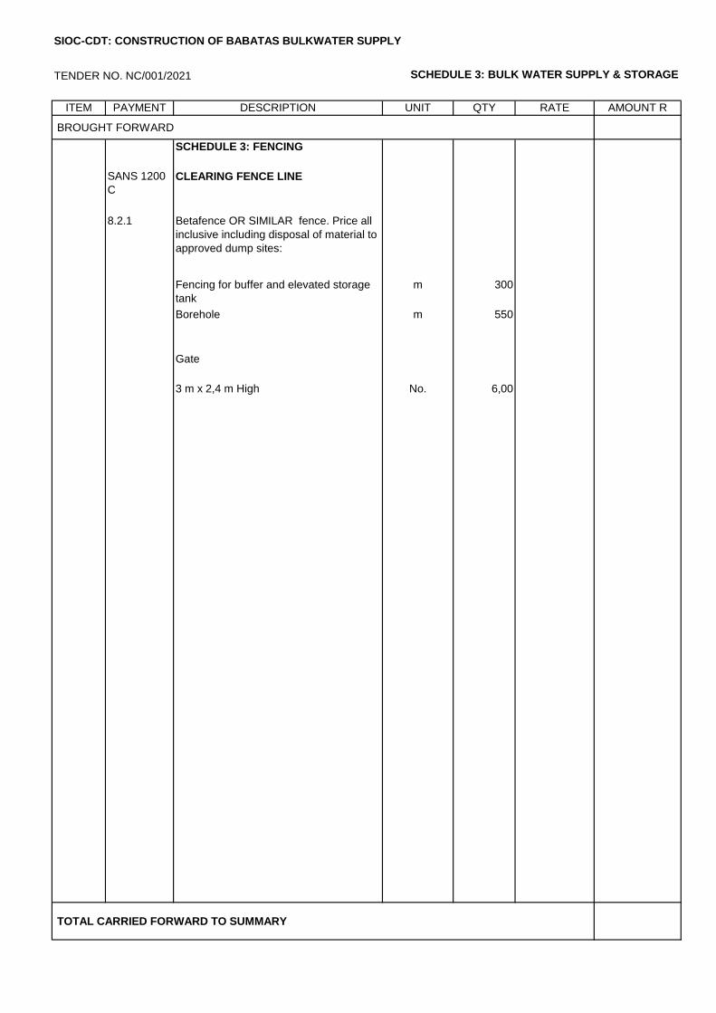
TENDER NO. NC/001/2021 SCHEDULE 3: BULK WATER SUPPLY & STORAGE
ITEM PAYMENT DESCRIPTION UNIT QTY RATE AMOUNT R
BROUGHT FORWARD
SCHEDULE 3: FENCING
SANS 1200
C
CLEARING FENCE LINE
8.2.1 Betafence OR SIMILAR fence. Price all
inclusive including disposal of material to
approved dump sites:
Fencing for buffer and elevated storage
tank
m 300
Borehole m 550
Gate
3 m x 2,4 m High No. 6,00
TOTAL CARRIED FORWARD TO SUMMARY
SIOC-CDT: CONSTRUCTION OF BABATAS BULKWATER SUPPLY
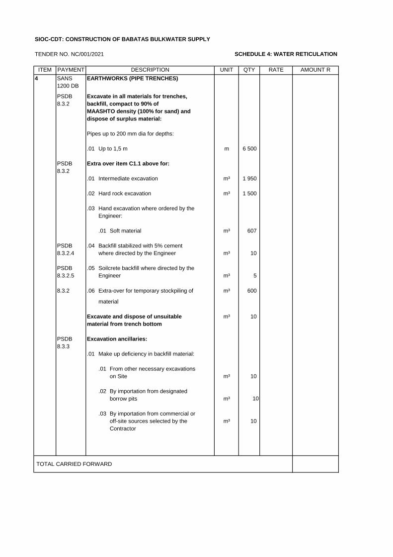
TENDER NO. NC/001/2021 SCHEDULE 4: WATER RETICULATION
ITEM PAYMENT UNIT QTY RATE AMOUNT R
4 SANS EARTHWORKS (PIPE TRENCHES)
1200 DB
PSDB Excavate in all materials for trenches,
8.3.2 backfill, compact to 90% of
MAASHTO density (100% for sand) and
dispose of surplus material:
Pipes up to 200 mm dia for depths:
.01 Up to 1,5 m m 6 500
PSDB Extra over item C1.1 above for:
8.3.2
.01 Intermediate excavation m³ 1 950
.02 Hard rock excavation m³ 1 500
.03 Hand excavation where ordered by the
Engineer:
.01 Soft material m³ 607
PSDB .04 Backfill stabilized with 5% cement
8.3.2.4 where directed by the Engineer m³ 10
PSDB .05 Soilcrete backfill where directed by the
8.3.2.5 Engineer m³ 5
8.3.2 .06 Extra-over for temporary stockpiling of m³ 600
material
Excavate and dispose of unsuitable m³ 10
material from trench bottom
PSDB Excavation ancillaries:
8.3.3
.01 Make up deficiency in backfill material:
.01 From other necessary excavations
on Site m³ 10
.02 By importation from designated
borrow pits m³ 10
.03 By importation from commercial or
off-site sources selected by the m³ 10
Contractor
TOTAL CARRIED FORWARD
SIOC-CDT: CONSTRUCTION OF BABATAS BULKWATER SUPPLY
DESCRIPTION
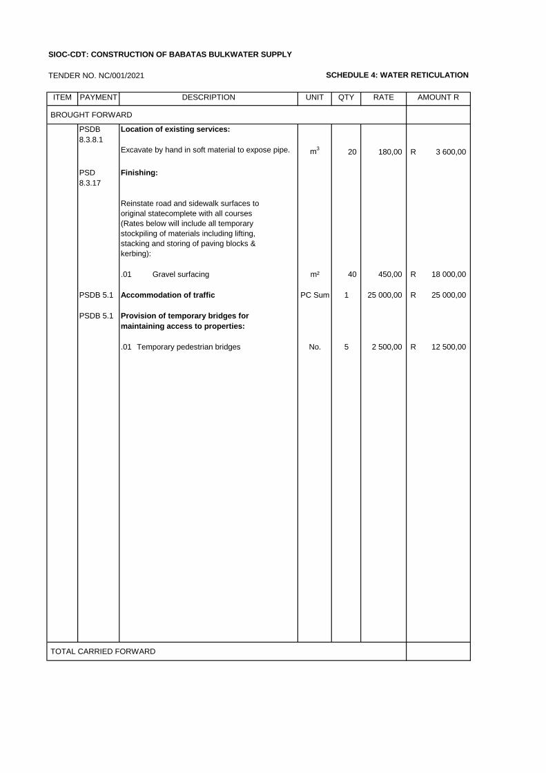
TENDER NO. NC/001/2021 SCHEDULE 4: WATER RETICULATION
ITEM PAYMENT UNIT QTY RATE AMOUNT R
BROUGHT FORWARD
PSDB
8.3.8.1
m3
20 180,00 3 600,00R
PSD Finishing:
8.3.17
Reinstate road and sidewalk surfaces to
original statecomplete with all courses
(Rates below will include all temporary
stockpiling of materials including lifting,
stacking and storing of paving blocks &
kerbing):
.01 Gravel surfacing m² 40 450,00 18 000,00R
PSDB 5.1 Accommodation of traffic PC Sum 1 25 000,00 25 000,00R
PSDB 5.1 Provision of temporary bridges for
maintaining access to properties:
.01 Temporary pedestrian bridges No. 5 2 500,00 12 500,00R
TOTAL CARRIED FORWARD
SIOC-CDT: CONSTRUCTION OF BABATAS BULKWATER SUPPLY
DESCRIPTION
Location of existing services:
Excavate by hand in soft material to expose pipe.
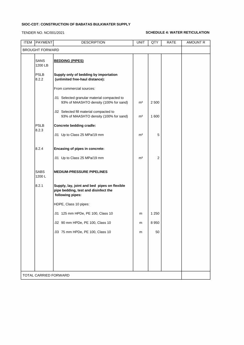
TENDER NO. NC/001/2021 SCHEDULE 4: WATER RETICULATION
ITEM PAYMENT UNIT QTY RATE AMOUNT R
BROUGHT FORWARD
SANS BEDDING (PIPES)
1200 LB
PSLB Supply only of bedding by importation
8.2.2 (unlimited free-haul distance):
From commercial sources:
.01 Selected granular material compacted to
93% of MAASHTO density (100% for sand) m³ 2 500
.02 Selected fill material compacted to
93% of MAASHTO density (100% for sand) m³ 1 600
PSLB Concrete bedding cradle:
8.2.3
.01 Up to Class 25 MPa/19 mm m³ 5
8.2.4 Encasing of pipes in concrete:
.01 Up to Class 25 MPa/19 mm m³ 2
SABS MEDIUM-PRESSURE PIPELINES
1200 L
8.2.1 Supply, lay, joint and bed pipes on flexible
pipe bedding, test and disinfect the
following pipes:
HDPE, Class 10 pipes:
.01 125 mm HPDe, PE 100, Class 10 m 1 250
.02 90 mm HPDe, PE 100, Class 10 m 8 950
.03 75 mm HPDe, PE 100, Class 10 m 50
TOTAL CARRIED FORWARD
SIOC-CDT: CONSTRUCTION OF BABATAS BULKWATER SUPPLY
DESCRIPTION
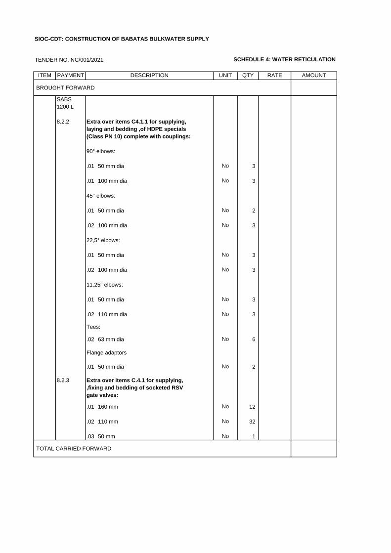
TENDER NO. NC/001/2021 SCHEDULE 4: WATER RETICULATION
ITEM PAYMENT UNIT QTY RATE AMOUNT
BROUGHT FORWARD
SABS
1200 L
8.2.2 Extra over items C4.1.1 for supplying,
laying and bedding ,of HDPE specials
(Class PN 10) complete with couplings:
90° elbows:
.01 50 mm dia No 3
.01 100 mm dia No 3
45° elbows:
.01 50 mm dia No 2
.02 100 mm dia No 3
22,5° elbows:
.01 50 mm dia No 3
.02 100 mm dia No 3
11,25° elbows:
.01 50 mm dia No 3
.02 110 mm dia No 3
Tees:
.02 63 mm dia No 6
Flange adaptors
.01 50 mm dia No 2
8.2.3 Extra over items C.4.1 for supplying,
,fixing and bedding of socketed RSV
gate valves:
.01 160 mm No 12
.02 110 mm No 32
.03 50 mm No 1
TOTAL CARRIED FORWARD
SIOC-CDT: CONSTRUCTION OF BABATAS BULKWATER SUPPLY
DESCRIPTION
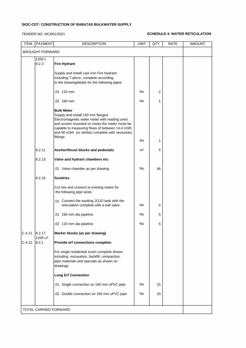
TENDER NO. NC/001/2021 SCHEDULE 4: WATER RETICULATION
ITEM PAYMENT UNIT QTY RATE AMOUNT
BROUGHT FORWARD
1200 L
8.2.3 Fire Hydrant
Supply and install cast iron Fire Hydrant,
including T-piece, complete according
to the drawingdetails for the following pipes:
.01 110 mm No 2
.02 160 mm No 1
Bulk Meter
No 1
8.2.11 Anchor/thrust blocks and pedestals m³ 5
8.2.13 Valve and hydrant chambers etc:
.01 Valve chamber as per drawing No 46
8.2.16 Sundries
Cut into and connect to existing mains for
the following pipe sizes:
.01No 5
.01 160 mm dia pipeline No 5
.02 110 mm dia pipeline No 5
C.4.11. 8.2.17 Marker blocks (as per drawing)
1200 LF
C.4.12. 8.2.1 Provide erf connections complete:
For single residential erven complete shown
including excavation, backfill, compaction,
pipe materials and specials as shown on
drawings
Long Erf Connection
.01 Single connection on 160 mm uPVC pipe No 15
.02 Double connection on 160 mm uPVC pipe No 20
TOTAL CARRIED FORWARD
Supply and install 150 mm flanged
Electromagnetic water meter with reading uniot
and screen mounted on meter.the meter muist be
capable to measuring flows of between 14,4 m3/h
and 90 m3/h (or similar) complete with necessary
fittings
SIOC-CDT: CONSTRUCTION OF BABATAS BULKWATER SUPPLY
Connect the exsiting JOJO tank with the
reticulation complete with a ball valve
DESCRIPTION
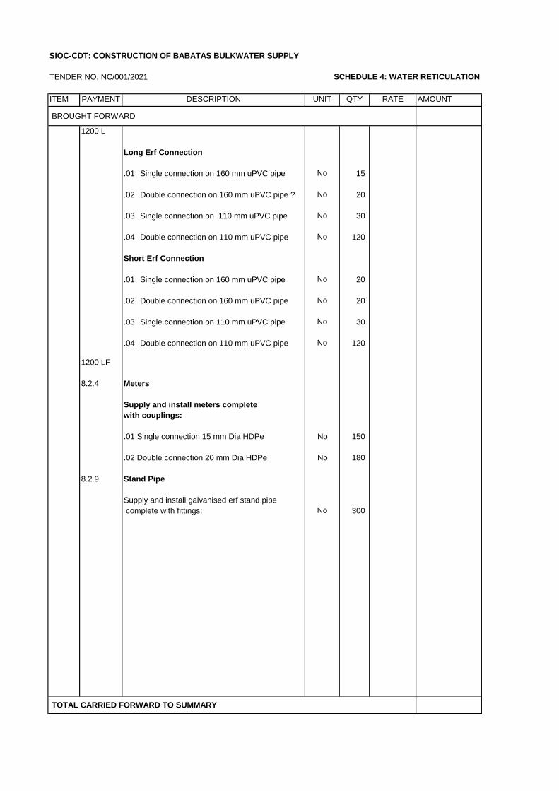
TENDER NO. NC/001/2021 SCHEDULE 4: WATER RETICULATION
ITEM PAYMENT UNIT QTY RATE AMOUNT
BROUGHT FORWARD
1200 L
Long Erf Connection
.01 Single connection on 160 mm uPVC pipe No 15
.02 Double connection on 160 mm uPVC pipe ? No 20
.03 Single connection on 110 mm uPVC pipe No 30
.04 Double connection on 110 mm uPVC pipe No 120
Short Erf Connection
.01 Single connection on 160 mm uPVC pipe No 20
.02 Double connection on 160 mm uPVC pipe No 20
.03 Single connection on 110 mm uPVC pipe No 30
.04 Double connection on 110 mm uPVC pipe No 120
1200 LF
8.2.4 Meters
Supply and install meters complete
with couplings:
.01 Single connection 15 mm Dia HDPe No 150
.02 Double connection 20 mm Dia HDPe No 180
8.2.9 Stand Pipe
Supply and install galvanised erf stand pipe
complete with fittings: No 300
TOTAL CARRIED FORWARD TO SUMMARY
DESCRIPTION
SIOC-CDT: CONSTRUCTION OF BABATAS BULKWATER SUPPLY
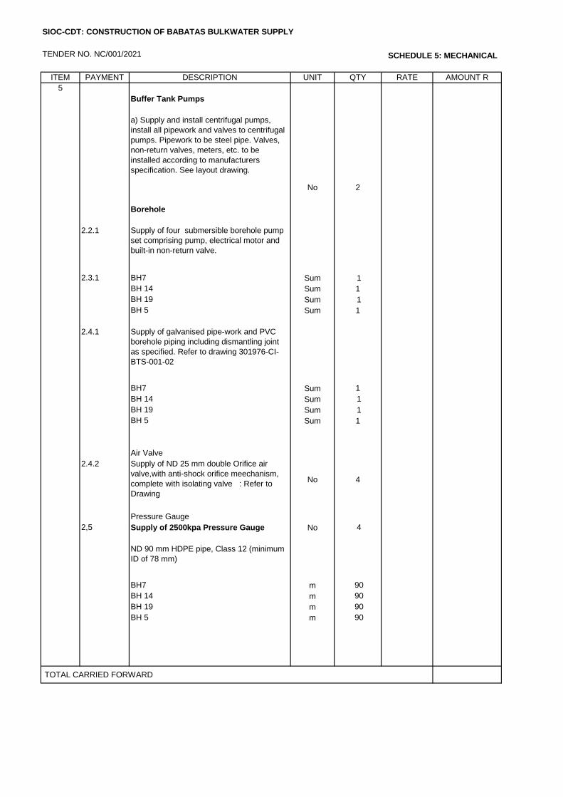
TENDER NO. NC/001/2021 SCHEDULE 5: MECHANICAL
ITEM PAYMENT DESCRIPTION UNIT QTY RATE AMOUNT R
5
Buffer Tank Pumps
a) Supply and install centrifugal pumps,
install all pipework and valves to centrifugal
pumps. Pipework to be steel pipe. Valves,
non-return valves, meters, etc. to be
installed according to manufacturers
specification. See layout drawing.
No 2
Borehole
2.2.1 Supply of four submersible borehole pump
set comprising pump, electrical motor and
built-in non-return valve.
2.3.1 BH7 Sum 1
BH 14 Sum 1
BH 19 Sum 1
BH 5 Sum 1
2.4.1 Supply of galvanised pipe-work and PVC
borehole piping including dismantling joint
as specified. Refer to drawing 301976-CI-
BTS-001-02
BH7 Sum 1
BH 14 Sum 1
BH 19 Sum 1
BH 5 Sum 1
Air Valve
2.4.2 Supply of ND 25 mm double Orifice air
valve,with anti-shock orifice meechanism,
complete with isolating valve : Refer to
Drawing
No 4
Pressure Gauge
2,5 Supply of 2500kpa Pressure Gauge No 4
ND 90 mm HDPE pipe, Class 12 (minimum
ID of 78 mm)
BH7 m 90
BH 14 m 90
BH 19 m 90
BH 5 m 90
TOTAL CARRIED FORWARD
SIOC-CDT: CONSTRUCTION OF BABATAS BULKWATER SUPPLY
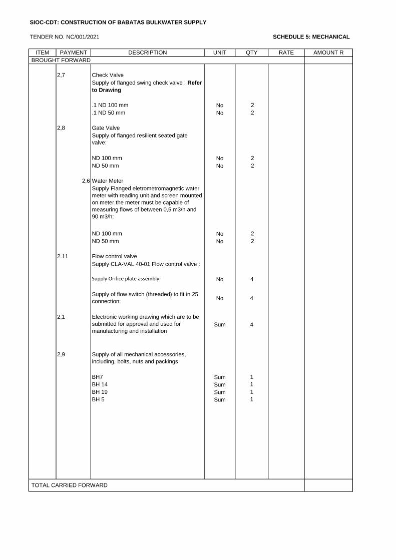
TENDER NO. NC/001/2021 SCHEDULE 5: MECHANICAL
ITEM PAYMENT DESCRIPTION UNIT QTY RATE AMOUNT R
BROUGHT FORWARD
2,7 Check Valve
Supply of flanged swing check valve : Refer
to Drawing
.1 ND 100 mm No 2
.1 ND 50 mm No 2
2,8 Gate Valve
Supply of flanged resilient seated gate
valve:
ND 100 mm No 2
ND 50 mm No 2
2,6 Water Meter
Supply Flanged eletrometromagnetic water
meter with reading unit and screen mounted
on meter.the meter must be capable of
measuring flows of between 0,5 m3/h and
90 m3/h:
ND 100 mm No 2
ND 50 mm No 2
2.11 Flow control valve
Supply CLA-VAL 40-01 Flow control valve :
Refer to Drawing
Supply Orifice plate assembly: No 4
Supply of flow switch (threaded) to fit in 25
connection: No 4
2,1 Electronic working drawing which are to be
submitted for approval and used for
manufacturing and installationSum 4
2,9 Supply of all mechanical accessories,
including, bolts, nuts and packings
BH7 Sum 1
BH 14 Sum 1
BH 19 Sum 1
BH 5 Sum 1
TOTAL CARRIED FORWARD
SIOC-CDT: CONSTRUCTION OF BABATAS BULKWATER SUPPLY
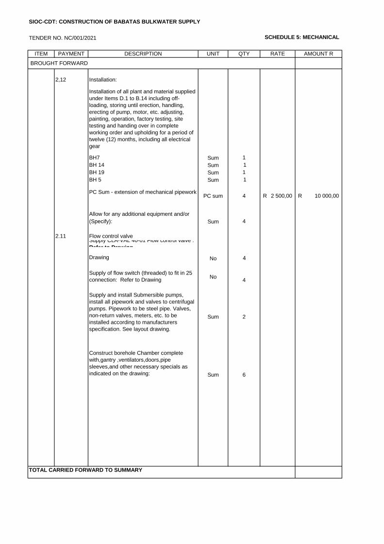
TENDER NO. NC/001/2021 SCHEDULE 5: MECHANICAL
ITEM PAYMENT DESCRIPTION UNIT QTY RATE AMOUNT R
BROUGHT FORWARD
2,12 Installation:
Installation of all plant and material supplied
under Items D.1 to B.14 including off-
loading, storing until erection, handling,
erecting of pump, motor, etc. adjusting,
painting, operation, factory testing, site
testing and handing over in complete
working order and upholding for a period of
twelve (12) months, including all electrical
gear
BH7 Sum 1
BH 14 Sum 1
BH 19 Sum 1
BH 5 Sum 1
PC Sum - extension of mechanical pipeworkPC sum 4 2 500,00R 10 000,00R
Allow for any additional equipment and/or
services to fully complete the installation to (Specify): Sum 4
2.11 Flow control valveSupply CLA-VAL 40-01 Flow control valve :
Refer to DrawingSupply Orifice plate assembly: Refer to
Drawing No 4
Supply of flow switch (threaded) to fit in 25
connection: Refer to DrawingNo
4
Supply and install Submersible pumps,
install all pipework and valves to centrifugal
pumps. Pipework to be steel pipe. Valves,
non-return valves, meters, etc. to be
installed according to manufacturers
specification. See layout drawing.
Sum 2
Construct borehole Chamber complete
with,gantry ,ventilators,doors,pipe
sleeves,and other necessary specials as
indicated on the drawing: Sum 6
SIOC-CDT: CONSTRUCTION OF BABATAS BULKWATER SUPPLY
TOTAL CARRIED FORWARD TO SUMMARY
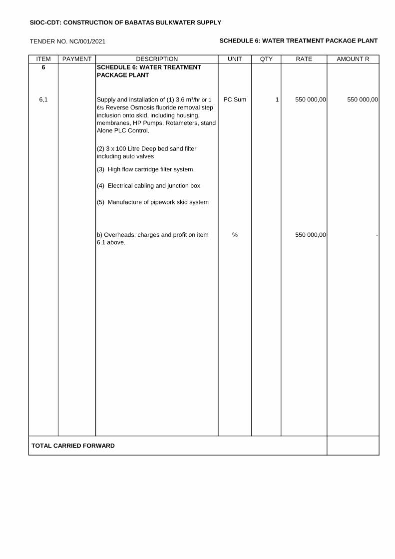
TENDER NO. NC/001/2021 SCHEDULE 6: WATER TREATMENT PACKAGE PLANT
ITEM PAYMENT DESCRIPTION UNIT QTY RATE AMOUNT R
6 SCHEDULE 6: WATER TREATMENT
PACKAGE PLANT
6,1 Supply and installation of (1) 3.6 m³/hr or 1
ℓ/s Reverse Osmosis fluoride removal step
inclusion onto skid, including housing,
membranes, HP Pumps, Rotameters, stand
Alone PLC Control.
PC Sum 1 550 000,00 550 000,00
(2) 3 x 100 Litre Deep bed sand filter
including auto valves
(3) High flow cartridge filter system
(4) Electrical cabling and junction box
(5) Manufacture of pipework skid system
b) Overheads, charges and profit on item
6.1 above.
% 0% 550 000,00 -
TOTAL CARRIED FORWARD
SIOC-CDT: CONSTRUCTION OF BABATAS BULKWATER SUPPLY
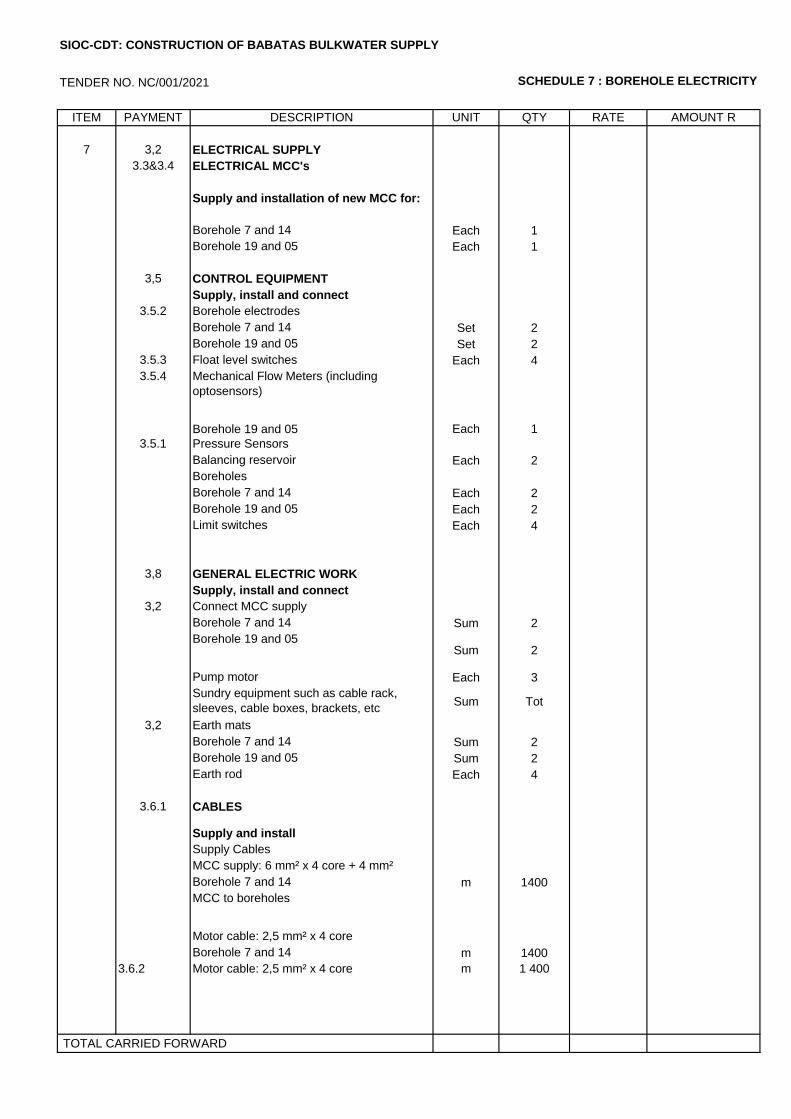
TENDER NO. NC/001/2021 SCHEDULE 7 : BOREHOLE ELECTRICITY
ITEM PAYMENT DESCRIPTION UNIT QTY RATE AMOUNT R
7 3,2 ELECTRICAL SUPPLY
3.3&3.4 ELECTRICAL MCC's
Supply and installation of new MCC for:
Borehole 7 and 14 Each 1
Borehole 19 and 05 Each 1
3,5 CONTROL EQUIPMENT
Supply, install and connect
3.5.2 Borehole electrodes
Borehole 7 and 14 Set 2
Borehole 19 and 05 Set 2
3.5.3 Float level switches Each 4
3.5.4 Mechanical Flow Meters (including
optosensors)
Borehole 19 and 05 Each 1
3.5.1 Pressure Sensors
Balancing reservoir Each 2
Boreholes
Borehole 7 and 14 Each 2
Borehole 19 and 05 Each 2
Limit switches Each 4
3,8 GENERAL ELECTRIC WORK
Supply, install and connect
3,2 Connect MCC supply
Borehole 7 and 14 Sum 2
Borehole 19 and 05Sum 2
Pump motor Each 3
Sundry equipment such as cable rack,
sleeves, cable boxes, brackets, etc Sum Tot
3,2 Earth mats
Borehole 7 and 14 Sum 2
Borehole 19 and 05 Sum 2
Earth rod Each 4
3.6.1 CABLES
Supply and install
Supply Cables
MCC supply: 6 mm² x 4 core + 4 mm²
b.c.e.cBorehole 7 and 14 m 1400
MCC to boreholes
Motor cable: 2,5 mm² x 4 core
Borehole 7 and 14 m 1400
3.6.2 Motor cable: 2,5 mm² x 4 core m 1 400
TOTAL CARRIED FORWARD
SIOC-CDT: CONSTRUCTION OF BABATAS BULKWATER SUPPLY
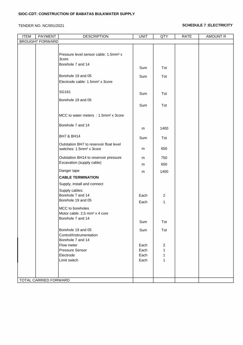
TENDER NO. NC/001/2021 SCHEDULE 7 :ELECTRICITY
ITEM PAYMENT DESCRIPTION UNIT QTY RATE AMOUNT R
BROUGHT FORWARD
Pressure level sensor cable: 1.5mm² x
3core
Borehole 7 and 14Sum Tot
Borehole 19 and 05 Sum Tot
Electrode cable: 1.5mm² x 3core
SG161 Sum Tot
Borehole 19 and 05
Sum Tot
MCC to water meters : 1.5mm² x 3core
Borehole 7 and 14m 1400
BH7 & BH14 Sum Tot
Outstation BH7 to reservoir float level
switches: 1.5mm² x 3core m 650
Outstation BH14 to reservoir pressure
probe: 1.5mm² x 3core SWA Cu PVC
m 750
Excavation (supply cable) m 650
Danger tape m 1400
CABLE TERMINATION
Supply, install and connect
Supply cables:
Borehole 7 and 14 Each 2
Borehole 19 and 05 Each 1
MCC to boreholes
Motor cable: 2,5 mm² x 4 core
Borehole 7 and 14Sum Tot
Borehole 19 and 05 Sum Tot
Control/Instrumentation
Borehole 7 and 14
Flow meter Each 2
Pressure Sensor Each 1
Electrode Each 1
Limit switch Each 1
TOTAL CARRIED FORWARD
SIOC-CDT: CONSTRUCTION OF BABATAS BULKWATER SUPPLY
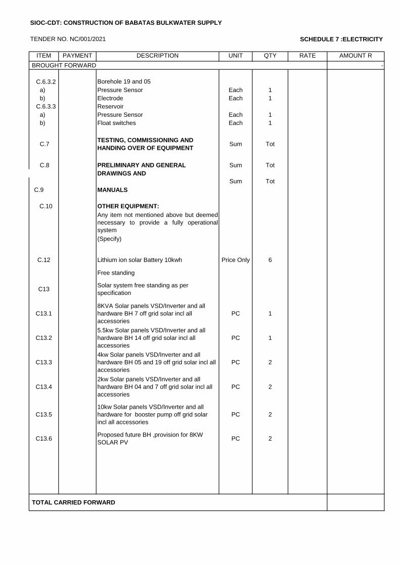
TENDER NO. NC/001/2021 SCHEDULE 7 :ELECTRICITY
ITEM PAYMENT DESCRIPTION UNIT QTY RATE AMOUNT R
BROUGHT FORWARD -
C.6.3.2 Borehole 19 and 05
a) Pressure Sensor Each 1
b) Electrode Each 1
C.6.3.3 Reservoir
a) Pressure Sensor Each 1
b) Float switches Each 1
C.7 TESTING, COMMISSIONING AND
HANDING OVER OF EQUIPMENT Sum Tot
C.8 PRELIMINARY AND GENERAL Sum Tot
DRAWINGS AND
C.9 MANUALS
C.10 OTHER EQUIPMENT:
Any item not mentioned above but deemed
necessary to provide a fully operational
system
(Specify)
C.12 Lithium ion solar Battery 10kwh Price Only 6
Free standing
C13Solar system free standing as per
specification
C13.1
8KVA Solar panels VSD/Inverter and all
hardware BH 7 off grid solar incl all
accessories
PC 1
C13.2
5.5kw Solar panels VSD/Inverter and all
hardware BH 14 off grid solar incl all
accessories
PC 1
C13.3
4kw Solar panels VSD/Inverter and all
hardware BH 05 and 19 off grid solar incl all
accessories
PC 2
C13.4
2kw Solar panels VSD/Inverter and all
hardware BH 04 and 7 off grid solar incl all
accessories
PC 2
C13.5
10kw Solar panels VSD/Inverter and all
hardware for booster pump off grid solar
incl all accessories
PC 2
C13.6Proposed future BH ,provision for 8KW
SOLAR PV PC 2
TOTAL CARRIED FORWARD
SIOC-CDT: CONSTRUCTION OF BABATAS BULKWATER SUPPLY
Sum Tot
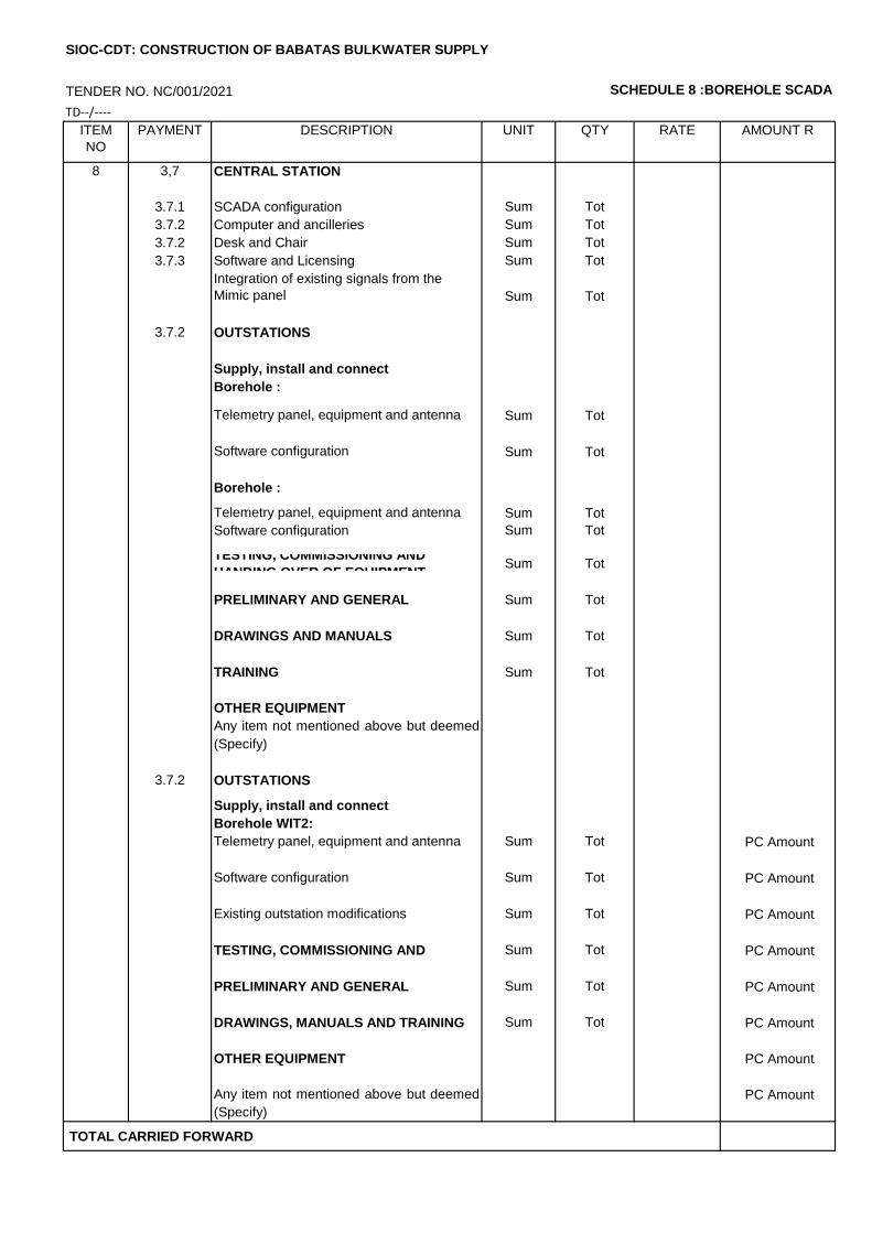
TENDER NO. NC/001/2021 SCHEDULE 8 :BOREHOLE SCADA
TD--/----
ITEM
NO
PAYMENT DESCRIPTION UNIT QTY RATE AMOUNT R
8 3,7 CENTRAL STATION
3.7.1 SCADA configuration Sum Tot
3.7.2 Computer and ancilleries Sum Tot
3.7.2 Desk and Chair Sum Tot
3.7.3 Software and Licensing Sum Tot
Integration of existing signals from the
Mimic panel Sum Tot
3.7.2 OUTSTATIONS
Supply, install and connect
Borehole :
Telemetry panel, equipment and antenna Sum Tot
Software configuration Sum Tot
Borehole :
Telemetry panel, equipment and antenna Sum Tot
Software configuration Sum Tot
TESTING, COMMISSIONING AND
HANDING OVER OF EQUIPMENT Sum Tot
PRELIMINARY AND GENERAL Sum Tot
DRAWINGS AND MANUALS Sum Tot
TRAINING Sum Tot
OTHER EQUIPMENT
Any item not mentioned above but deemed
necessary to provide a fully operational (Specify)
3.7.2 OUTSTATIONS
Supply, install and connect
Borehole WIT2:
Telemetry panel, equipment and antenna Sum Tot PC Amount
Software configuration Sum Tot PC Amount
Existing outstation modifications Sum Tot PC Amount
TESTING, COMMISSIONING AND
HANDING OVER OF EQUIPMENT
Sum Tot PC Amount
PRELIMINARY AND GENERAL Sum Tot PC Amount
DRAWINGS, MANUALS AND TRAINING Sum Tot PC Amount
OTHER EQUIPMENT PC Amount
Any item not mentioned above but deemed
necessary to provide a fully operational
PC Amount
(Specify)
TOTAL CARRIED FORWARD
SIOC-CDT: CONSTRUCTION OF BABATAS BULKWATER SUPPLY
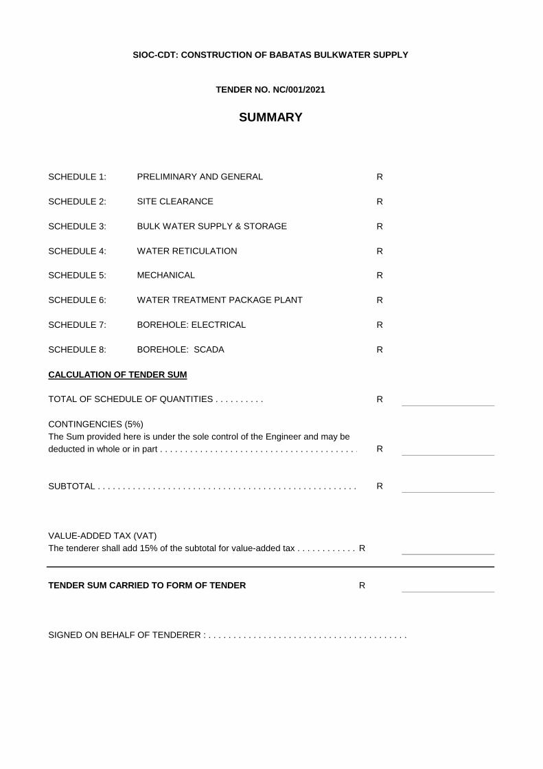
SCHEDULE 1: R
SCHEDULE 2: R
SCHEDULE 3: R
SCHEDULE 4: R
SCHEDULE 5: R
SCHEDULE 6: R
SCHEDULE 7: R
SCHEDULE 8: R
CALCULATION OF TENDER SUM
R
CONTINGENCIES (5%)
The Sum provided here is under the sole control of the Engineer and may be
deducted in whole or in part . . . . . . . . . . . . . . . . . . . . . . . . . . . . . . . . . . . . . . . . . . . . . . . . . . . . .R
SUBTOTAL . . . . . . . . . . . . . . . . . . . . . . . . . . . . . . . . . . . . . . . . . . . . . . . . . . . . . . . . . . . . . . . . . . .R
VALUE-ADDED TAX (VAT)
The tenderer shall add 15% of the subtotal for value-added tax . . . . . . . . . . . . . . . . . . . . . . . . .R
TENDER SUM CARRIED TO FORM OF TENDER R
SIGNED ON BEHALF OF TENDERER : . . . . . . . . . . . . . . . . . . . . . . . . . . . . . . . . . . . . . . . .
SIOC-CDT: CONSTRUCTION OF BABATAS BULKWATER SUPPLY
TENDER NO. NC/001/2021
TOTAL OF SCHEDULE OF QUANTITIES . . . . . . . . . .
. . . . . . . . . . . . . . . . . . . . . . . . . . . . . . . . . . .
SUMMARY
PRELIMINARY AND GENERAL
SITE CLEARANCE
WATER RETICULATION
MECHANICAL
BULK WATER SUPPLY & STORAGE
BOREHOLE: ELECTRICAL
WATER TREATMENT PACKAGE PLANT
BOREHOLE: SCADA
Scope of Works
C3.1 - 0
TENDER
CONSTRUCTION OF BABATAS CPA BULK WATER SUPPLY
TENDER NO. NC/001/2021
PART C3: SCOPE OF WORKS
C3.1 Description of the Works
C3.2 Engineering
C3.3 Project Specifications
C3.4 Construction Management
C3.5 OHS

Engineering
C3.2 - 1
TENDER
CONSTRUCTION OF BABATAS CPA BULK WATER SUPPLY
TENDER NO. NC/001/2021
C3.1: DESCRIPTION OF THE WORKS
EMPLOYER’S OBJECTIVES
The employer’s objectives are to explore additional groundwater source and upgrade the existing borehole for the current community and proposed future community expansion, and construction of new bulk water and internal water network infrastructure, new pressed steel storage reservoir and fire in Babatas Community Property Trust.
The site is within the Babatas Community Property Association and can be reached via N14 road between Kuruman and Kathu.
OVERVIEW OF THE WORKS
The contract comprises of the following:
• Supply and install a new bulk pipeline ND 100 mm, ND 90 mm, ND 90 mm water supply pipework with associated valves.
• Supply and install a new reticulation pipeline ND 125 mm, ND 90 mm, ND 76 mm water supply pipework, and stand pipes with associated valves.
• Installation of 78 kℓ steel buffer tank and 810 kℓ elevated steel tank with pumps, valves and associated fittings
• Supply and install 3.6 m³/hr Reverse Osmosis package plant.
• Supply and installation of new MCC and SCADA for 4 boreholes complete with electrical work.
• Supply and installation of solar panels and lithium ion solar battery with all hardware for 4 boreholes.
EXTENT OF THE WORKS
Work included in this contract involves the following:
a) Establishment of camp and plant on site.
b) Provision of a site office.
c) Site clearance.
d) Accommodation of traffic.
e) Earthworks to shape existing ground levels.
f) Detection and adjustment of existing services.
g) Trench excavation, bedding, blanket fill and backfill of trenches.
h) Construction of water pipework, valve chamber and related works.
i) Erection Elevated Steel Storage reservoir and fire storage reservoir
j) Erection Steel Buffer Tank
k) Installation of borehole solar panels and batteries, MCC and SCADA
l) Cleaning and tidying up of site.

Construction
C3.1 - 2
Construction methods must be such that no property or life is endangered. The Employer accepts no responsibility for work that is done outside the site boundaries without the Engineer’s approval.
The compilation of the construction programme and any amendments thereto during the course of construction shall be at the cost of the Contractor and shall not be measured elsewhere in this contract.
LOCATION OF WORKS
Babatas CPA is situated in the area of Gamagara Local Municipality, 25 km from Kathu.
The exact location of the site is as follows:
• Latitude (S) 27°32'44"
• Longitude (E) 23°13'19"
Access to the site is via existing surfaced roads.
ABNORMAL RAINFALL
The source for rainfall statistics shall be taken as listed in WB 40 of the Weather Bureau, Department of Environment Affairs, for the determination of Rn and Nn as specified in GCC 5.12.2.2 (see Contract Data (Part 1)).
The Contractor shall keep daily rainfall records and submit them to the Engineer at every site meeting. No additional costs shall be made for the supply and installation of the rain gauge or for the keeping of the rainfall records and all costs must be included in the appropriate items.
Add the following to GCC 5.12.2.2
a) Abnormal climatic conditions
No extension of the time for completion shall be granted on the grounds of normal rainfall conditions, but extension of time in terms of clause 5.12.2.2 of the General Conditions of Contract (2015) on the grounds of abnormal rainfall or wet conditions shall be calculated separately for each calendar month or part thereof, according to the following formula. It shall be calculates as follows for the time of completion, including any extension thereof:
V = (Nw – Nn) + RW -Rn
X
V = Extention of time for calendar days of the calendar month concerned.
If the Value of V is negative and the absolute value thereof is greater than Nn, V
is taken as negative Nn.
Nw = Actual number of days during calendar month on which a rainfall of 10 mm or
more is recorded.
Nn = Average number of days in the calendar month concerned on which a rainfall of
10 mm or more is recorded in terms of existing rainfall data.
Rw = Actual rainfall for the calendar month concerned in mm
Rn = Average rainfall for the calendar month in mm deduced from existing rainfall data.
The total extension of time is the algebraic sum of the monthly totals for the period concerned. Extension of time for parts of a month shall be calculated by using pro rata values of Nn and Rn. If the algebraic sum of the monthly totals is negative, no reduction of the time for completion as a result of rainfall shall be applicable.
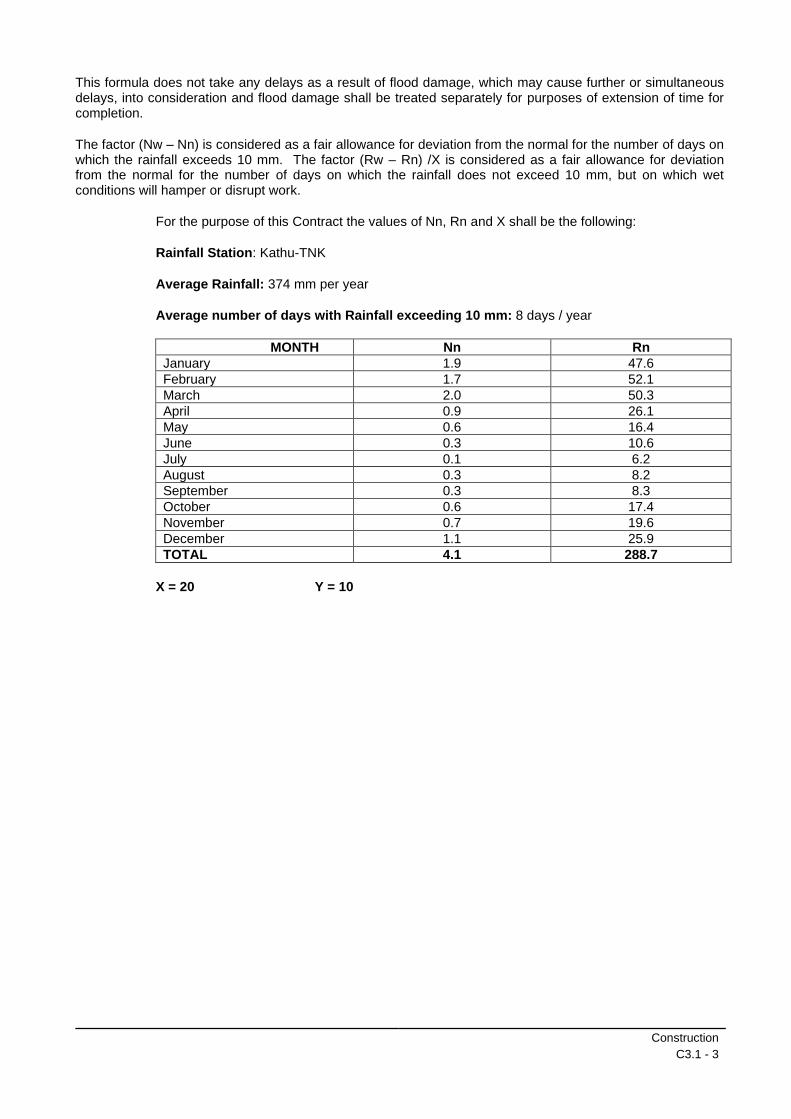
Construction
C3.1 - 3
This formula does not take any delays as a result of flood damage, which may cause further or simultaneous delays, into consideration and flood damage shall be treated separately for purposes of extension of time for completion.
The factor (Nw – Nn) is considered as a fair allowance for deviation from the normal for the number of days on which the rainfall exceeds 10 mm. The factor (Rw – Rn) /X is considered as a fair allowance for deviation from the normal for the number of days on which the rainfall does not exceed 10 mm, but on which wet conditions will hamper or disrupt work.
For the purpose of this Contract the values of Nn, Rn and X shall be the following:
Rainfall Station: Kathu-TNK
Average Rainfall: 374 mm per year
Average number of days with Rainfall exceeding 10 mm: 8 days / year
MONTH Nn Rn
January 1.9 47.6
February 1.7 52.1
March 2.0 50.3
April 0.9 26.1
May 0.6 16.4
June 0.3 10.6
July 0.1 6.2
August 0.3 8.2
September 0.3 8.3
October 0.6 17.4
November 0.7 19.6
December 1.1 25.9
TOTAL 4.1 288.7
X = 20 Y = 10
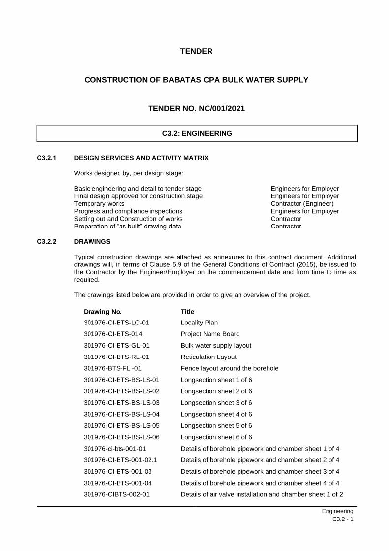
Engineering
C3.2 - 1
TENDER
CONSTRUCTION OF BABATAS CPA BULK WATER SUPPLY
TENDER NO. NC/001/2021
C3.2: ENGINEERING
C3.2.1 DESIGN SERVICES AND ACTIVITY MATRIX
Works designed by, per design stage:
Basic engineering and detail to tender stage Engineers for Employer Final design approved for construction stage Engineers for Employer Temporary works Contractor (Engineer) Progress and compliance inspections Engineers for Employer Setting out and Construction of works Contractor Preparation of “as built” drawing data Contractor
C3.2.2 DRAWINGS
Typical construction drawings are attached as annexures to this contract document. Additional drawings will, in terms of Clause 5.9 of the General Conditions of Contract (2015), be issued to the Contractor by the Engineer/Employer on the commencement date and from time to time as required.
The drawings listed below are provided in order to give an overview of the project.
Drawing No. Title
301976-CI-BTS-LC-01 Locality Plan
301976-CI-BTS-014 Project Name Board
301976-CI-BTS-GL-01 Bulk water supply layout
301976-CI-BTS-RL-01
301976-BTS-FL -01
301976-CI-BTS-BS-LS-01
301976-CI-BTS-BS-LS-02
301976-CI-BTS-BS-LS-03
301976-CI-BTS-BS-LS-04
301976-CI-BTS-BS-LS-05
301976-CI-BTS-BS-LS-06
301976-ci-bts-001-01
301976-CI-BTS-001-02.1
301976-CI-BTS-001-03
301976-CI-BTS-001-04
301976-CIBTS-002-01
Reticulation Layout
Fence layout around the borehole
Longsection sheet 1 of 6
Longsection sheet 2 of 6
Longsection sheet 3 of 6
Longsection sheet 4 of 6
Longsection sheet 5 of 6
Longsection sheet 6 of 6
Details of borehole pipework and chamber sheet 1 of 4
Details of borehole pipework and chamber sheet 2 of 4
Details of borehole pipework and chamber sheet 3 of 4
Details of borehole pipework and chamber sheet 4 of 4
Details of air valve installation and chamber sheet 1 of 2
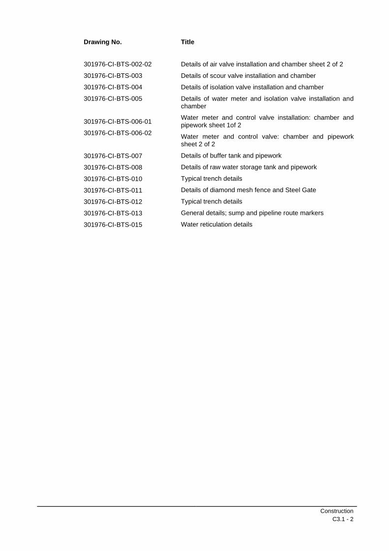
Construction
C3.1 - 2
Drawing No. Title
301976-CI-BTS-002-02
301976-CI-BTS-003
301976-CI-BTS-004
301976-CI-BTS-005
301976-CI-BTS-006-01
301976-CI-BTS-006-02
301976-CI-BTS-007
301976-CI-BTS-008
301976-CI-BTS-010
301976-CI-BTS-011
301976-CI-BTS-012
301976-CI-BTS-013
301976-CI-BTS-015
Details of air valve installation and chamber sheet 2 of 2
Details of scour valve installation and chamber
Details of isolation valve installation and chamber
Details of water meter and isolation valve installation and chamber
Water meter and control valve installation: chamber and pipework sheet 1of 2
Water meter and control valve: chamber and pipework sheet 2 of 2
Details of buffer tank and pipework
Details of raw water storage tank and pipework
Typical trench details
Details of diamond mesh fence and Steel Gate
Typical trench details
General details; sump and pipeline route markers
Water reticulation details
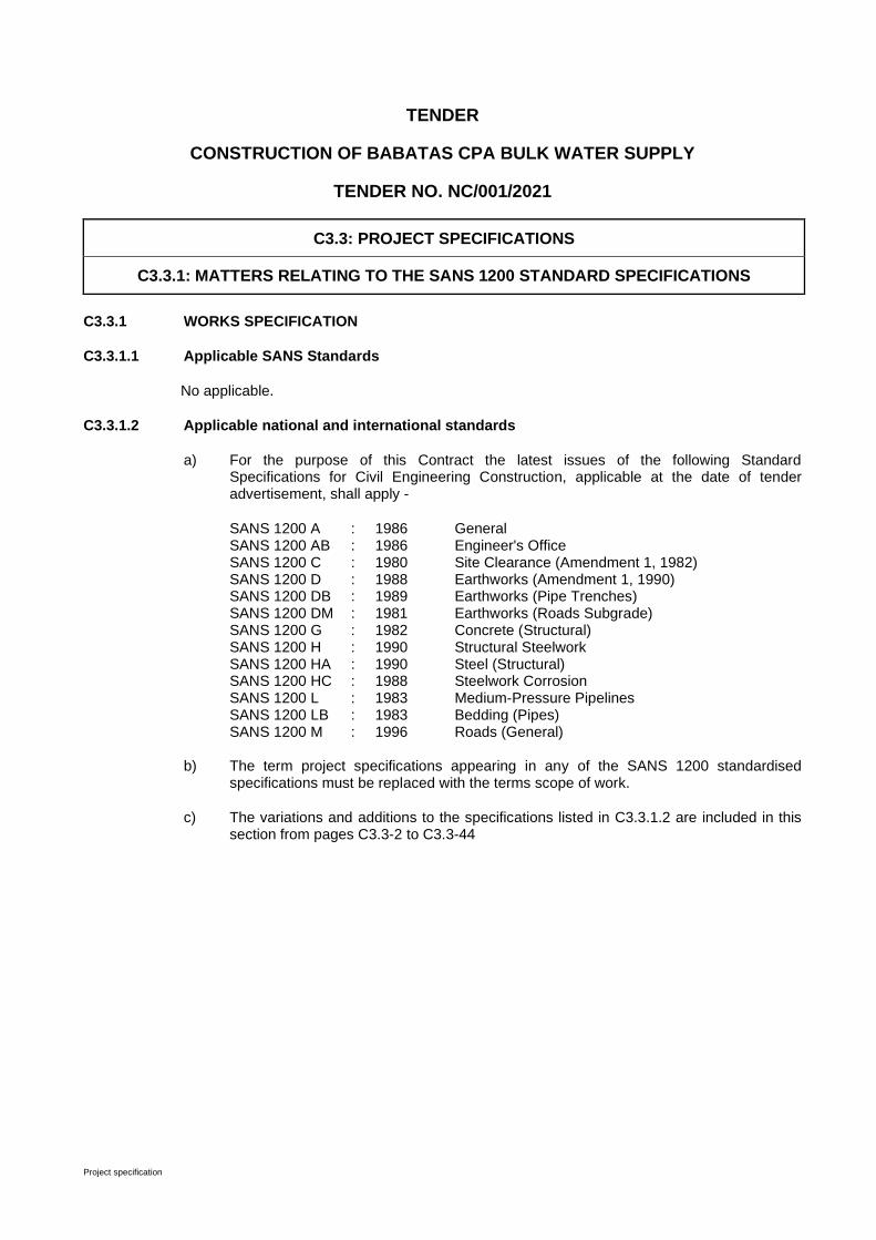
Project specification
TENDER
CONSTRUCTION OF BABATAS CPA BULK WATER SUPPLY
TENDER NO. NC/001/2021
C3.3: PROJECT SPECIFICATIONS
C3.3.1: MATTERS RELATING TO THE SANS 1200 STANDARD SPECIFICATIONS
C3.3.1 WORKS SPECIFICATION
C3.3.1.1 Applicable SANS Standards
No applicable.
C3.3.1.2 Applicable national and international standards
a) For the purpose of this Contract the latest issues of the following Standard Specifications for Civil Engineering Construction, applicable at the date of tender advertisement, shall apply -
SANS 1200 A : 1986 General SANS 1200 AB : 1986 Engineer's Office SANS 1200 C : 1980 Site Clearance (Amendment 1, 1982) SANS 1200 D : 1988 Earthworks (Amendment 1, 1990) SANS 1200 DB : 1989 Earthworks (Pipe Trenches) SANS 1200 DM : 1981 Earthworks (Roads Subgrade) SANS 1200 G : 1982 Concrete (Structural) SANS 1200 H : 1990 Structural Steelwork SANS 1200 HA : 1990 Steel (Structural) SANS 1200 HC : 1988 Steelwork Corrosion SANS 1200 L : 1983 Medium-Pressure Pipelines SANS 1200 LB : 1983 Bedding (Pipes) SANS 1200 M : 1996 Roads (General)
b) The term project specifications appearing in any of the SANS 1200 standardised specifications must be replaced with the terms scope of work.
c) The variations and additions to the specifications listed in C3.3.1.2 are included in this section from pages C3.3-2 to C3.3-44
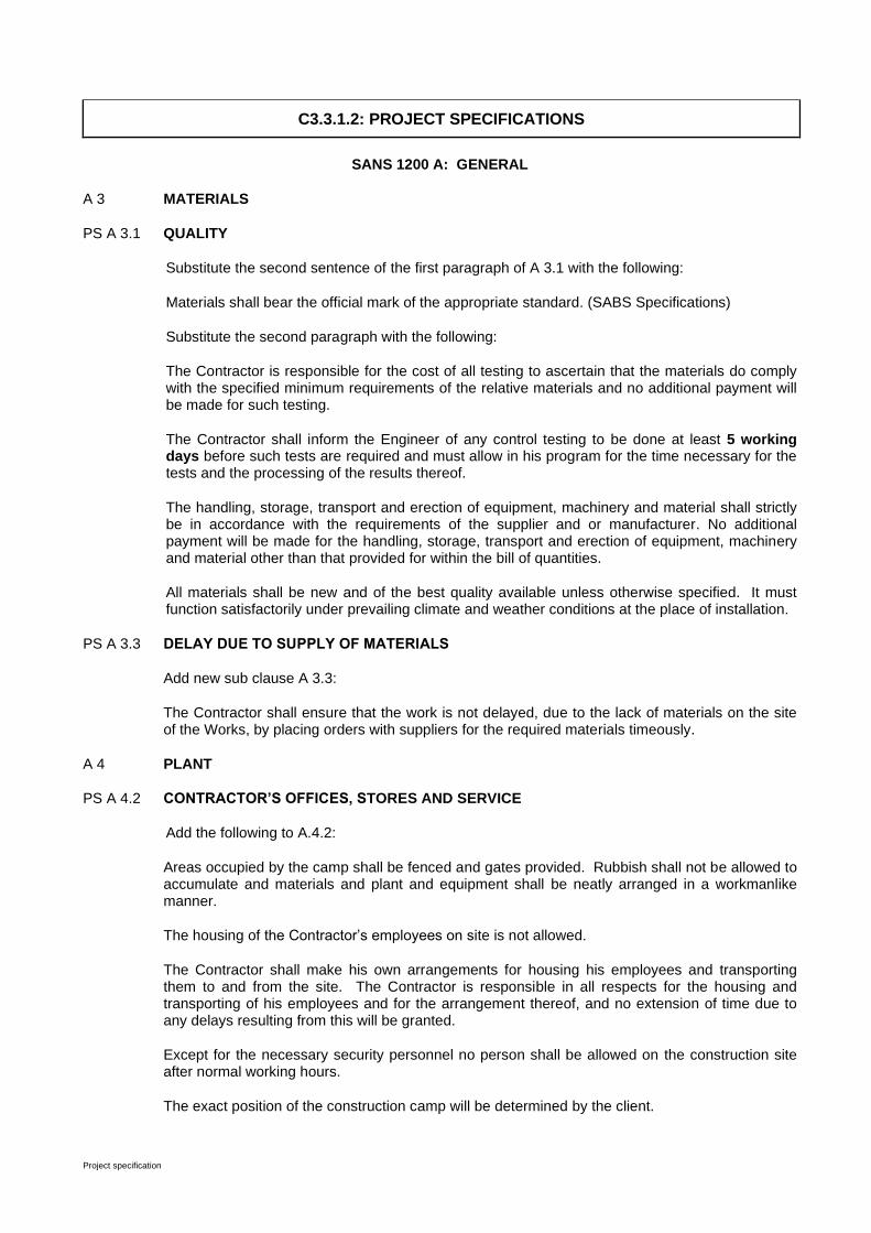
Project specification
C3.3.1.2: PROJECT SPECIFICATIONS
SANS 1200 A: GENERAL
A 3 MATERIALS
PS A 3.1 QUALITY
Substitute the second sentence of the first paragraph of A 3.1 with the following:
Materials shall bear the official mark of the appropriate standard. (SABS Specifications)
Substitute the second paragraph with the following:
The Contractor is responsible for the cost of all testing to ascertain that the materials do comply with the specified minimum requirements of the relative materials and no additional payment will be made for such testing.
The Contractor shall inform the Engineer of any control testing to be done at least 5 working days before such tests are required and must allow in his program for the time necessary for the tests and the processing of the results thereof.
The handling, storage, transport and erection of equipment, machinery and material shall strictly be in accordance with the requirements of the supplier and or manufacturer. No additional payment will be made for the handling, storage, transport and erection of equipment, machinery and material other than that provided for within the bill of quantities.
All materials shall be new and of the best quality available unless otherwise specified. It must function satisfactorily under prevailing climate and weather conditions at the place of installation.
PS A 3.3 DELAY DUE TO SUPPLY OF MATERIALS
Add new sub clause A 3.3:
The Contractor shall ensure that the work is not delayed, due to the lack of materials on the site of the Works, by placing orders with suppliers for the required materials timeously.
A 4 PLANT
PS A 4.2 CONTRACTOR’S OFFICES, STORES AND SERVICE
Add the following to A.4.2:
Areas occupied by the camp shall be fenced and gates provided. Rubbish shall not be allowed to accumulate and materials and plant and equipment shall be neatly arranged in a workmanlike manner.
The housing of the Contractor’s employees on site is not allowed.
The Contractor shall make his own arrangements for housing his employees and transporting them to and from the site. The Contractor is responsible in all respects for the housing and transporting of his employees and for the arrangement thereof, and no extension of time due to any delays resulting from this will be granted.
Except for the necessary security personnel no person shall be allowed on the construction site after normal working hours.
The exact position of the construction camp will be determined by the client.

Project specification
PS A 4.3 HAND TOOLS
Add new sub clause A 4.3:
The Contractor shall provide and maintain all hand tools required for the execution of the Works and all such costs shall be deemed to be included in the tendered rates and no separate payment will be made for it.
PS A 4.4 MEDICAL FACILITIES AND SAFETY EQUIPMENT
Add new sub clause A 4.4:
In addition to the requirements stipulated within the Contract, the Contractor shall provide a First Aid cabinet fully equipped and maintained with the minimum contents as listed in the Annexure (Regulation 3) to the General Safety Regulations of the Occupational Health and Safety Act (Act 85 of 1993), to deal with accidents and ailments which are likely to occur during the construction period.
The Contractor shall provide personal safety equipment and facilities as required by Regulation 2 of the General Safety Regulations of the Occupational Health and Safety Act (Act 85 of 1993) and the specific safety requirements of the client as required in terms of the contract.
The Contractor shall designate his Safety Officer and Qualified First Aider. The Contractor shall give copies of the minutes of the site safety meetings to the Engineer.
A 5 CONSTRUCTION
A 5.1 SURVEY
PS A 5.1.1 Setting Out of Works
Substitute the first sentence in A 5.1.1 with the following:
Setting out of the works must be done by a registered land surveyor and provision must be made to stake pegs for excavation and placement of services within excavations. Setting out of the works is the sole responsibility of the Contractor and shall be checked against survey pegs along erf reserve boundaries and from benchmarks being placed by a registered land surveyor. The Contractor shall, within two (2) weeks after all the drawings are in their possession or the site has been handed over to him, ascertain himself of the correctness of all pegs and benchmarks. Any discrepancy shall immediately be reported in writing to the Engineer. Any costs or subsequent costs arising from discrepancies, which had not been reported to the Engineer within the aforementioned period, shall be the sole responsibility of the Contractor.
The Engineer may alter any part of the Works to suit local conditions. The Contractor must therefore contact the Engineer immediately after the preliminary setting out of any part of the Works before starting with detail setting out, or construction. Only after the Engineer has approved a specific site or part of the Works may the detail setting out and construction commence.
PS A 5.2 WATCHING, BARRICADING, LIGHTING AND TRAFFIC CROSSINGS
Add the following to A 5.2:
The crossing of main streets must be done in half widths while the total traffic is accommodated on the other lane.
Road traffic signs shall comply with the requirements of the “South African Road Traffic Signs Manual” and shall be approved by the Engineer before construction commences.
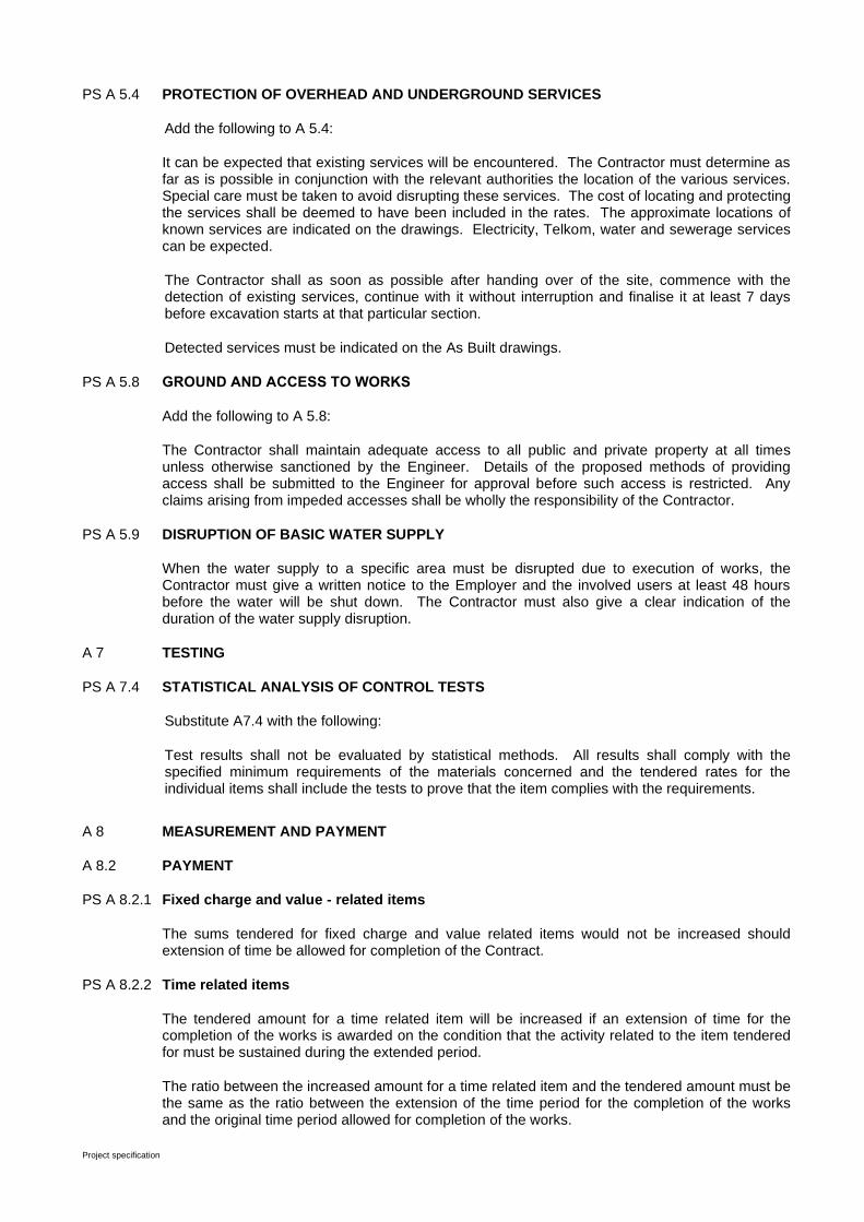
Project specification
PS A 5.4 PROTECTION OF OVERHEAD AND UNDERGROUND SERVICES
Add the following to A 5.4:
It can be expected that existing services will be encountered. The Contractor must determine as far as is possible in conjunction with the relevant authorities the location of the various services. Special care must be taken to avoid disrupting these services. The cost of locating and protecting the services shall be deemed to have been included in the rates. The approximate locations of known services are indicated on the drawings. Electricity, Telkom, water and sewerage services can be expected.
The Contractor shall as soon as possible after handing over of the site, commence with the detection of existing services, continue with it without interruption and finalise it at least 7 days before excavation starts at that particular section.
Detected services must be indicated on the As Built drawings.
PS A 5.8 GROUND AND ACCESS TO WORKS
Add the following to A 5.8:
The Contractor shall maintain adequate access to all public and private property at all times unless otherwise sanctioned by the Engineer. Details of the proposed methods of providing access shall be submitted to the Engineer for approval before such access is restricted. Any claims arising from impeded accesses shall be wholly the responsibility of the Contractor.
PS A 5.9 DISRUPTION OF BASIC WATER SUPPLY
When the water supply to a specific area must be disrupted due to execution of works, the Contractor must give a written notice to the Employer and the involved users at least 48 hours before the water will be shut down. The Contractor must also give a clear indication of the duration of the water supply disruption.
A 7 TESTING
PS A 7.4 STATISTICAL ANALYSIS OF CONTROL TESTS
Substitute A7.4 with the following:
Test results shall not be evaluated by statistical methods. All results shall comply with the specified minimum requirements of the materials concerned and the tendered rates for the individual items shall include the tests to prove that the item complies with the requirements.
A 8 MEASUREMENT AND PAYMENT
A 8.2 PAYMENT
PS A 8.2.1 Fixed charge and value - related items
The sums tendered for fixed charge and value related items would not be increased should extension of time be allowed for completion of the Contract.
PS A 8.2.2 Time related items
The tendered amount for a time related item will be increased if an extension of time for the completion of the works is awarded on the condition that the activity related to the item tendered for must be sustained during the extended period.
The ratio between the increased amount for a time related item and the tendered amount must be the same as the ratio between the extension of the time period for the completion of the works and the original time period allowed for completion of the works.

Project specification
If the works is completed before the end of the original time period allowed for completion of the works, the tendered amount of a time related item that is influenced by the earlier completion will be reduced similarly.
The payment to the Contractor for time-related items shall be adjusted in accordance with the following formula in the event of the contract being extended.
PS A 8.2.5 Adjusted Payment for Time-related Items
The payment to the Contractor for time-related items shall be adjusted in accordance with the following formula in the event of the contract being extended by means of a variation order: Extended contract period as authorised by Sum of Tendered amounts for time- X variation order related items Tendered contract period
The above-mentioned adjustment of the payment for time-related items shall be made in the Completion Payment Certificate and shall be the only payment for additional time-related costs.
PS A 8.3.6 Compliance with Environmental Management Programme…………….......Unit: Sum
Add new payment clause A 8.3.6:
The tendered rates shall include full compensation to the Contractor for compliance with all the requirements of the Environmental Management programme.
PS A 8.4 SCHEDULED TIME-RELATED ITEMS
PS A 8.4.5 Other Time-Related Obligations
Add the following to A 8.4.5:
(01) Material testing required by the Engineer (Pipe pressure testing ± 2000 m)
…………….………………Unit: Provisional Sum
(02.) Overheads, charges and profit………………… ……………………………………………Unit: %
A provisional sum has been included in the Bill of Quantities for the pipe pressure tests of approximately 2000 m of installed pipework done by another Contractor that should tested by the appointed Contractor or independent Contractor.
In addition to the above amount, provision is made in the Bill of Quantities for a mark-up on the amount to be paid. The mark-up shall be regarded as full compensation for overheads, charges and profits as provided for in Clause 6.6 of the General Conditions of Contract for Construction Works (Third Edition, 2015)
PS A 8.4.6 Standing Time Costs
a) plant ………………………………………………………….. Unit : Sum per working day
b) labour …………………………………………………………Unit : Sum per working day
c) other resources (to be specified by Contractor) ….… Unit : Sum per working day
The tendered sum for each item shall include full compensation for all standing time costs of the specified resource of whatever nature and approved by the Engineer, which are not recoverable by way of the provision made in PS A 8.2.5 for the adjusted payment of time-related items.

Project specification
For the purposes of calculating the total standing time cost, a working week shall be held to consist of five working days and a working day of 8 hours.
Payment for the partial standing of any of the scheduled resources for a day or part thereof, or the standing of a complete resource for a part day, will be made pro rata in proportion to an appropriate factor assessed by the Engineer.
The amount by which the standing time costs is adjusted shall be subject to the contract price adjustment formula as defined in the conditions of contract.
The Contractor shall take note that this payment item shall only apply to delays which, in the opinion of the Engineer, are incurred as a result of riot, commotion, politically motivated sabotage and acts of terrorism or disorder outside the Contractor's control. This item shall also apply to standing time incurred as a result of labour boycotts, except that only sub-items (a) and (c), as applicable, will be paid where the Contractor did not pay his labour for the time boycotted. Costs for delays incurred for all other circumstances shall be treated as provided for in the conditions of contract.
The provision of this clause shall in no way prejudice the right of either the Employer or the Contractor to determine the contract in terms of the provisions of clause 9.3, 10.2 and 10.3 of the general conditions of contract.
The Contractor shall take note that no payment will be considered for additional cost or time lost for any daily removal of plant and equipment from the site, any additional costs incurred in protecting his plant and site establishment, or loss incurred in respect of damage to construction plant, equipment and materials supplied and the Works.
In the event that GCC clause 5.13.1 becomes applicable, the time on which such penalties are calculated shall be reduced by the total standing time approved by the Engineer.
PS A 8.5 SUM STATED PROVISIONALLY BY ENGINEER
Add new payment clauses:
(a) Remuneration of Community Liaison Officer
A provisional sum has been included in the Bill of Quantities for a salary to be paid to the Community Liaison Officer.
In addition to the above amount, provision is made in the Bill of Quantities for a mark-up on the amount to be paid. The mark-up shall be regarded as full compensation for overheads, charges and profits as provided for in Clause 6.6 of the General Conditions of Contract for Construction Works (Third Edition, 2015)
(b) Overhead Charges
A provisional sum has been included in the Bill of Quantities for a salary to be paid to the Community Liaison Officer.
In addition to the above amount, provision is made in the Bill of Quantities for a mark-up on the amount to be paid. The mark-up shall be regarded as full compensation for overheads, charges and profits as provided for in Clause 6.6 of the General Conditions of Contract for Construction Works (Third Edition, 2015)
PS A 8.7 DAYWORK
Replace A 8.7 with the following:
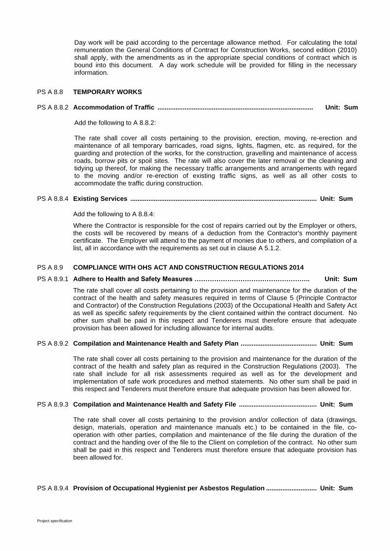
Project specification
Day work will be paid according to the percentage allowance method. For calculating the total remuneration the General Conditions of Contract for Construction Works, second edition (2010) shall apply, with the amendments as in the appropriate special conditions of contract which is bound into this document. A day work schedule will be provided for filling in the necessary information.
PS A 8.8 TEMPORARY WORKS
PS A 8.8.2 Accommodation of Traffic ...................................................................................... Unit: Sum
Add the following to A 8.8.2:
The rate shall cover all costs pertaining to the provision, erection, moving, re-erection and maintenance of all temporary barricades, road signs, lights, flagmen, etc. as required, for the guarding and protection of the works, for the construction, gravelling and maintenance of access roads, borrow pits or spoil sites. The rate will also cover the later removal or the cleaning and tidying up thereof, for making the necessary traffic arrangements and arrangements with regard to the moving and/or re-erection of existing traffic signs, as well as all other costs to accommodate the traffic during construction.
PS A 8.8.4 Existing Services ....................................................................................................... Unit: Sum
Add the following to A 8.8.4:
Where the Contractor is responsible for the cost of repairs carried out by the Employer or others, the costs will be recovered by means of a deduction from the Contractor's monthly payment certificate. The Employer will attend to the payment of monies due to others, and compilation of a list, all in accordance with the requirements as set out in clause A 5.1.2.
PS A 8.9 COMPLIANCE WITH OHS ACT AND CONSTRUCTION REGULATIONS 2014
PS A 8.9.1 Adhere to Health and Safety Measures …………………………………………….. Unit: Sum
The rate shall cover all costs pertaining to the provision and maintenance for the duration of the contract of the health and safety measures required in terms of Clause 5 (Principle Contractor and Contractor) of the Construction Regulations (2003) of the Occupational Health and Safety Act as well as specific safety requirements by the client contained within the contract document. No other sum shall be paid in this respect and Tenderers must therefore ensure that adequate provision has been allowed for including allowance for internal audits.
PS A 8.9.2 Compilation and Maintenance Health and Safety Plan .......................................... Unit: Sum
The rate shall cover all costs pertaining to the provision and maintenance for the duration of the contract of the health and safety plan as required in the Construction Regulations (2003). The rate shall include for all risk assessments required as well as for the development and implementation of safe work procedures and method statements. No other sum shall be paid in this respect and Tenderers must therefore ensure that adequate provision has been allowed for.
PS A 8.9.3 Compilation and Maintenance Health and Safety File ........................................... Unit: Sum
The rate shall cover all costs pertaining to the provision and/or collection of data (drawings, design, materials, operation and maintenance manuals etc.) to be contained in the file, co-operation with other parties, compilation and maintenance of the file during the duration of the contract and the handing over of the file to the Client on completion of the contract. No other sum shall be paid in this respect and Tenderers must therefore ensure that adequate provision has been allowed for.
PS A 8.9.4 Provision of Occupational Hygienist per Asbestos Regulation ............................ Unit: Sum

Project specification
.01) Perform surveys, monitoring and develop a procedure as per Asbestos Regulation
……………………..…………………Unit: Prov Sum
.02) Percentage adjustment for Contractor’s overheads, charges and profit …………Unit: %
A provisional sum has been included in the Bill of Quantities for the cost to be paid to the Occupational Hygienist (SANAS accredited) to conduct air monitoring, asbestos sampling and analysis, risk assessment and develop of a work procedure as per the requirements of the Asbestos Regulation.
In addition to the above amount, provision is made in the Bill of Quantities for a mark-up on the amount to be paid. The mark-up shall be regarded as full compensation for overheads, charges and profits as provided for in Clause 6.6 of the General Conditions of Contract for Construction Works (Third Edition, 2015)
PS A 8.10 Overhaul and Additional Transport
Add new payment clause A 8.10:
Notwithstanding any clause in any standardized specification in respect of the definition, no payment will be made for overhaul and all transport shall be regarded as free haul and the costs thereof shall be covered by the relevant tendered rates in the Schedule of Quantities.
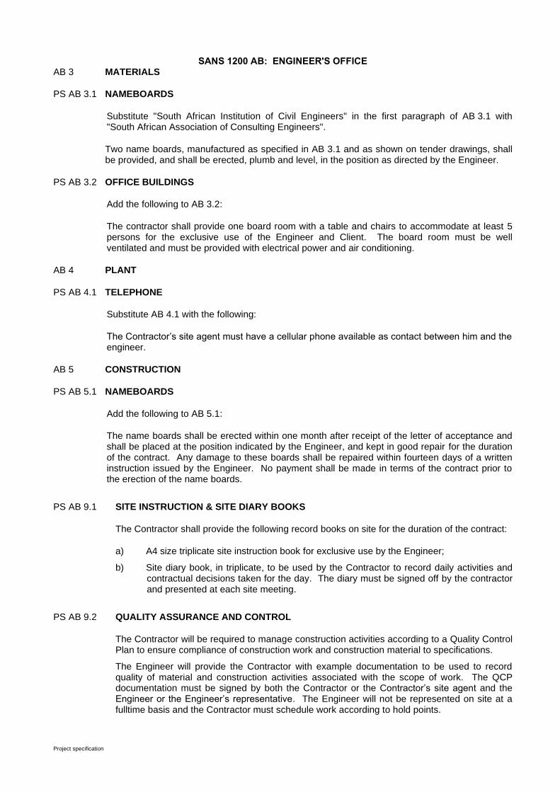
Project specification
SANS 1200 AB: ENGINEER'S OFFICE AB 3 MATERIALS
PS AB 3.1 NAMEBOARDS
Substitute "South African Institution of Civil Engineers" in the first paragraph of AB 3.1 with "South African Association of Consulting Engineers".
Two name boards, manufactured as specified in AB 3.1 and as shown on tender drawings, shall be provided, and shall be erected, plumb and level, in the position as directed by the Engineer.
PS AB 3.2 OFFICE BUILDINGS
Add the following to AB 3.2:
The contractor shall provide one board room with a table and chairs to accommodate at least 5 persons for the exclusive use of the Engineer and Client. The board room must be well ventilated and must be provided with electrical power and air conditioning.
AB 4 PLANT
PS AB 4.1 TELEPHONE
Substitute AB 4.1 with the following:
The Contractor’s site agent must have a cellular phone available as contact between him and the engineer.
AB 5 CONSTRUCTION
PS AB 5.1 NAMEBOARDS
Add the following to AB 5.1:
The name boards shall be erected within one month after receipt of the letter of acceptance and shall be placed at the position indicated by the Engineer, and kept in good repair for the duration of the contract. Any damage to these boards shall be repaired within fourteen days of a written instruction issued by the Engineer. No payment shall be made in terms of the contract prior to the erection of the name boards.
PS AB 9.1 SITE INSTRUCTION & SITE DIARY BOOKS
The Contractor shall provide the following record books on site for the duration of the contract:
a) A4 size triplicate site instruction book for exclusive use by the Engineer;
b) Site diary book, in triplicate, to be used by the Contractor to record daily activities and contractual decisions taken for the day. The diary must be signed off by the contractor and presented at each site meeting.
PS AB 9.2 QUALITY ASSURANCE AND CONTROL
The Contractor will be required to manage construction activities according to a Quality Control Plan to ensure compliance of construction work and construction material to specifications.
The Engineer will provide the Contractor with example documentation to be used to record quality of material and construction activities associated with the scope of work. The QCP documentation must be signed by both the Contractor or the Contractor’s site agent and the Engineer or the Engineer’s representative. The Engineer will not be represented on site at a fulltime basis and the Contractor must schedule work according to hold points.

Project specification
SANS 1200 C: SITE CLEARANCE
C 3 MATERIALS
PS C 3.1 DISPOSAL OF MATERIAL
Substitute the first sentence of C 3.1 with the following:
Material obtained from clearing and grubbing and demolition structures shall be disposed of at the dumpsite as arranged with the Municipality by the Contractor.
No payment will be made for overhaul and all transport shall be regarded as freehaul and the costs thereof shall be covered by the relevant tendered rates in the Schedule of Quantities.
C 5 CONSTRUCTION
PS C 5.1 AREAS TO BE CLEARED AND GRUBBED
Substitute the first sentence of C 5.1 with the following:
Unless otherwise indicated by the engineer, clearing and grubbing are limited to the street reserve width only where required and a 2.5m wide strip for trench excavations outside the street reserve.
The Contractor may proceed with clearing and grubbing after the handing over of the site. It is essential that the contractor protect all reference pegs and site boundary pegs before commencing with clearance. Measurement and payment for clearing and grubbing shall only occur for areas as requested in writing by the Engineer.
Substitute the last paragraph with the following:
The Contractor shall schedule his work in such a manner that re-clearing will not be necessary. The cost of re-clearing shall be for the Contractor’s account.
PS C 5.2 CUTTING OF TREES
Add the following to C 5.2.3.2:
Trees outside pipeline routes and more than 1m from the outside of the edge beam must be left standing and undamaged, except where otherwise ordered in writing by the Engineer. Authorization and a permit must be obtained from Department of Forestry for the removal of any endangered and / or protected trees (especially Camel thorn trees).
A penalty of R5 000.00 (five thousand rand) per tree for trees damaged and/or removed will be charged.
PS C 5.9 EXISTING FENCING
Existing fencing will only be removed and/or re-erected upon written instruction from the Engineer
and paid under the appropriate measured items.
Damage to any other fencing must be repaired immediately at the Contractor’s expense.

Project specification
C 8 MEASUREMENT AND PAYMENT
C 8.2 SCHEDULED ITEMS
PS C 8.2.1 Clear and Grub .................................................................................................................. Unit: m2
Add the following to C 8.2.1:
The removal of all rocks and boulders on site over 0,15 m³ will be paid under subclause D 8.3.2(b).
The removal of hard rock other than boulders will be paid under subclause DB 8.3.2(b).
PS C 8.2.2 Remove trees and cutting of large branches ................................................................. Unit: No
Replace C 8.2.2.a to c with the following:
a) The removal of any size tree with a trunk circumference larger than 1m
b) The cutting of tree branches as requested by the engineer
PS C 8.2.8 Demolish and Remove Structures/Buildings and Dismantle Steelwork, etc…Unit: Sum
Replace C 8.2.8 with the following:
The rate shall cover the cost of the removal of all structures on the site, channel- and/or sewer mainline routes, the disposal thereof at the dumping site, the levelling and shaping of the site and the backfilling of any holes with material of at least the same quality as that of the in situ material. The rate shall also cover the cost of removing cleaning and handing over of all usable material to the Employer.
Payment for the removal of individual structures will be made pro rata in the relation of the area thereof to the total area of structures that has to be demolished and removed.
PS C 8.2.11 Remove and re-erect existing fences ................................................................................ Unit: m
Add new payment clause C 8.2.11:
The rate shall cover the cost of removal and stacking of fencing material, including all gates, as well as the re-erection thereof with the existing material. No payment will be made for the replacement of fencing material that has been damaged by the Contractor and all costs for this are deemed to be covered by the rate for the appropriate items.
Material that is unsuitable for re-erection must be viewed by the Engineer before it is removed. Only by written approval from the Engineer can the Contractor claim advance compensation for such material.
Project specification
SANS 1200 D: EARTHWORKS
D 2 INTERPRETATIONS
PS D 2.3 DEFINITIONS
Add the following to D 2.3:
Sand (cohesionless and non-cohesive)
For the purposes of the compaction requirements, a non-plastic material of which not less than 95 % by mass passes a sieve of nominal aperture size 4,75 mm, and not more than 10 % passes a sieve of nominal aperture size 0,075 mm.
D 3 MATERIALS
D 3.1 CLASSIFICATION OF CUTTINGS
PS D 3.1.2 Cutting classes
Add the following to D 3.1.2
Soft and intermediate cuttings will be measured under this contract as “soft”. Hard rock and boulder excavations will be measured as “hard”.
D 3.3 SELECTION
PS D 3.3.1 General
Substitute the second paragraph of D 3.3.1 with the following:
The Contractor shall deal selectively with material from general excavation. Any imported material in road reserves that do not comply with the minimum requirements for the respective layers, shall be removed and replaced with suitable material, all at the Contractor's expense.
The Contractor shall deal in such a way with materials from all excavations for streets, channels or pipe trenches to ensure that usable material is not contaminated with unsuitable material. If usable material is contaminated, such contaminated material shall be removed and replaced with suitable material, all at the Contractor's expense. No additional payment shall be made in respect of this and all relevant costs shall be deemed to be included in the tendered rates.
All unsuitable material shall be removed prior to importing fill material to such areas.
D 5 CONSTRUCTION
D 5.1 PRECAUTIONS
PS D 5.1.2 Existing Services
PS D 5.1.2.2 Detection, location and exposure
Add the following to D 5.1.2.2:
If existing services are not shown on the drawings but the existence thereof can be reasonably expected, the Contractor shall, in conjunction with all relevant authorities, determine the exact depth and location of such services before the commencement of construction. After locating the exact position of services, whether indicated on the drawings or not, such services shall be deemed to be known services and the Contractor shall be liable for all costs and subsequent costs arising from the damage thereof as a result of the Contractor's activities. These services
Project specification
must also be indicated on the "As Built" drawings. Postal and Telecommunication Services have to be contacted in advance to clarify all relevant cable positions before any excavations can commence.
All services must be located and opened for inspection by the Engineer before commencing trench excavation. Any costs or losses suffered by the Contractor as a result of not abiding by this specification will be for the Contractor's account.
PS D 5.1.2.3 Protection of Cables
Substitute "estimated position" in the second sentence of D 5.1.2.3 with "actual or exposed position".
PS D 5.1.4 Nuisance
PS D 5.1.4.1 Dust nuisance
Add the following to D 5.1.4.1:
The Contractor is responsible for dust control and is liable for all claims that may result from dust nuisance on all parts of the site and at all times from the date of handing over of the site to the completion date of the contract. No payment regarding the above-mentioned will be made and all costs shall be deemed to be covered by the tendered rates.
PS D 5.1.6 Road Traffic Control
Add the following to D 5.1.6:
a) Sufficient road signs must be erected in such a way that motorists will be warned in time of works, eg. at the closing of a street sufficient signs to direct traffic must be erected at the preceding intersection.
b) Bypasses and/or road signs shall be provided and/or erected at all locations where the free flow of traffic is obstructed and shall be approved by the Engineer before the commencement of construction. Where main roads are crossed, detours and temporary traffic signs must be provided as shown on the attached drawings.
c) Where a trench crosses a street or any place where a trench crosses the direction of traffic flow, drums must be placed in the street and not just along the sides of the street with danger tape in between.
d) Danger tape must be put up between drums and tied around the drums.
e) Drums may not be filled with stones. The spacing of drums must be in such a way (maximum 5 m) that they are visible from all directions.
f) Sufficient safety measures must be utilised for pedestrians.
g) Road traffic signs shall comply with the requirements of the “South African Road Traffic Signs Manual” and shall be approved by the Engineer before construction commences.
No additional payment for compliance with the abovementioned conditions will be made and all costs (labour, road traffic signs, etc.) shall be included under PS A 8.8.2.
Project specification
D 5.2 METHODS AND PROCEDURES
D 5.2.1 Site Preparation
PS D 5.2.1.2 Conservation of topsoil
Add the following to D 5.2.1.2:
Removal of topsoil shall only occur in areas as approved, in writing, by the Engineer. The topsoil shall be conserved for use elsewhere.
D 5.2.2 Excavation
PS D 5.2.2.3 Disposal
Substitute the second sentence of D 5.2.2.3 with the following:
All surplus and unsuitable material shall be dumped and neatly finished off at a commercial dump site of the Contractors choice. No payment will be made for overhaul and all transport shall be regarded as free haul and the costs thereof shall be included in the tendered rate.
PS D 5.2.2.4 Excavation by hand around existing services
Add new sub clause D 5.2.2.4:
Where hand excavation is required around existing services it shall be done within 3,0 m above and on both sides of cables and within 300 mm above and on both sides of pipes, as well as underneath the services.
PS D 5.2.2.5 Utilisation of excavated material
Excavated material and material recovered from temporary work shall, in so far as it is suitable, be utilised for backfill. Material unsuitable for use as backfill or in excess of the quantity required to complete the backfill shall be spoiled and neatly finished off at a commercial dump site of the Contractors choice. No payment will be made for overhaul and all transport shall be regarded as free haul and the costs thereof shall be included in the tendered rate.
PS D 5.2.3 Fill and compaction
PS D 5.2.3.1 Embankments
Add the following to D 5.2.3.1:
Embankments and terraces shall be constructed of approved material from excavations and shall be compacted to 95 % of MAASHTO density, in layers not exceeding 150 mm in depth.
PS D 5.2.3.2 Back filling of trenches and back filling against structures
Add the following to D 5.2.3.2:
Back filling around structures shall be compacted to 95 % (100 % for sand) of MAASHTO density.
When specified or ordered by the Engineer the back filling against structures shall be done using a mixture of soil cement. The mixture shall contain 12 % cement and just sufficient water for it to be placed and compacted like ordinary back filling material.
Project specification
D 5.2.4 Finishing
PS D 5.2.4.1 Final grading
Add the following to D 5.2.4.1:
Embankments shall be trimmed to an even grade of 1 in 2, and all other terraces to an even grade on 1 in 1,5 unless shown otherwise on construction drawings.
PS D 5.2.4.2 Topsoiling
Add the following to D 5.2.4.2:
Topsoil shall be placed on the sides and on the tops of embankments and other terraces where no paving is specified, or in areas where directed by the Engineer. All conserved topsoil must be spread evenly over disturbed areas.
D 5.2.5 TRANSPORT FOR EARTHWORKS
PS D 5.2.5.1 Freehaul
Substitute D 5.2.5.1 with the following:
Notwithstanding any clause in any standardized specification in respect of the definition, no payment will be made for overhaul and all transport shall be regarded as freehaul and the costs thereof shall be covered by the relevant tendered rates in the Schedule of Quantities.
PS D 5.2.5.2 Overhaul
Substitute D 5.2.5.2 with the following:
Notwithstanding any clause in any standardized specification in respect of the definition, no payment will be made for overhaul and all transport shall be regarded as freehaul and the costs thereof shall be covered by the relevant tendered rates in the Schedule of Quantities.
D 8 MEASUREMENTS AND PAYMENT
D 8.3 SCHEDULED ITEMS
PS D 8.3.8 Existing Services
PS D 8.3.8.1 Location
PS D 8.3.8.1(c) Excavate by hand in soft material to expose services ............................. Unit: m3
Add the following to D 8.3.8.1(c):
Excavation by hand to expose existing services shall only be measured and paid for if so ordered in writing by the Engineer. After the excavation of trial holes to determine the exact position and depth of existing services, at intervals as required by the Engineer, the excavation to a level of 300 mm above such services shall be measured and paid for as normal excavation, independent of the depth of such excavation. Only excavation within 300 mm of the existing services will be measured and paid for as excavation by hand and then only if ordered in writing by the Engineer.
If such services are damaged or removed, it has to be repaired or replaced immediately to its original position and condition, which is acceptable for the Engineer.

Project specification
SANS 1200 DB: EARTHWORKS (PIPE TRENCHES)
DB 3 MATERIALS
PS DB 3.1 CLASSES OF EXCAVATION
Substitute DB 3.1 with the following:
The excavation of materials shall be classified as follows:
a) Soft excavation shall be all excavations which are not classified as hard rock in (b) underneath.
b) Hard rock is solid rock present in mass, banks or bands for which the use of explosives would be the normal practical method of excavation or boulders over 0,52 m³ in volume.
If the Contractor chooses to drill through material other than rock to underlying rock before excavating the trench, then the volume of rock, as defined above, will be measured after the excavations have been completed.
No intermediate material will be paid under this contract. Only soft or hard material will be paid.
PS DB 3.5 BACKFILL MATERIALS
a) Substitute "from trenches" in DB 3.5(a) with "from trenches, channels or other excavations".
Add the following to DB 3.5(b):
c) All pipe trenches in street reserves shall be classified as areas subject to loads from road traffic.
d) All pipe trenches underlying or adjacent to the carriageway shall be backfilled with sand complying with the requirements for A3 materials.
DB 3.6 MATERIALS FOR REINSTATEMENT OF ROADS AND PAVED AREAS
PS DB 3.6.1 Sub-base and Base
Substitute DB 3.6.1 with the following:
Where trenches cross or run adjacent to surfaced roads and paved areas of which the surfaces are scheduled to be reinstated, the material excavated from the existing base and/or* sub-base pavement layer(s) shall be set aside and used in the reconstruction of the sub-base layer. Where applicable, new material complying with the requirements of SABS 1200 MF shall be used in the re-construction of the base layer. Any shortfall in material for the reconstruction of the sub-base layer shall be made up by the use of material complying with the requirements of SABS 1200 ME.

Project specification
PS DB 3.7 SELECTION OF MATERIAL FOR REPAIR WORK
Add the following to DB 3.7:
If the excavation of a pipeline damages an existing road surface, the Contractor must stockpile material from the top 200 mm of such a road surface in order to re-use it as sub-base for the repairing of the road crossing.
If necessary gravel material that is suitable for the reparation of road surfaces must be imported.
The Contractor must make provision in his tariffs for compaction in road reserves and for the selection of excavated material as specified above.
DB 4 PLANT
PS DB 4.1 EXCAVATION EQUIPMENT
Add the following to DB 4.1:
An adequate number of suitable tools, including hand stampers, wheelbarrows and hose pipes shall be provided by the Contractor. The Contractor will supply mechanical compaction equipment and when required pneumatic and rock breaking equipment.
All excavations exceeding the specified widths shall be back filled with approved selected material. No payment shall be made for this and all relevant costs shall be deemed to be included in the tendered rates.
PS DB 4.4 DEWATERING EQUIPMENT
One set of dewatering equipment shall consist of pumps, pipes, well points and other equipment necessary for dewatering excavations up to 7 m depth and a trench length of 45 m for either sides or 70 m on one side.
DB 5 CONSTRUCTION
DB 5.1 PRECAUTIONS
PS DB 5.1.1 Water in trenches
Water in pipe trenches may cause movement of the pipe due to flotation and backfilling must be completed as soon as possible. If there was any movement, the contractor must remove and relay the pipes at his own cost and to the satisfaction of the Engineer.
PS DB 5.1.2 Stormwater, Seepage and Dewatering of Excavations
The costs of dealing with water shall be deemed to be included in the tendered rates for excavation and no additional payment shall be made in this respect.
PS DB 5.1.3 Provision for traffic and access to properties
Add the following to DB 5.1.3
Construction must be done in half widths back filled completely and the surface reinstated before the next half is done in order to accommodate the traffic flow at all times.
PS DB 5.1.4 Existing services alongside or crossing excavations.
Add the following to DB 5.1.4
The conditions of PSA 5.4 shall apply mutatis mutandis.
PS DB 5.2 MINIMUM BASE WIDTHS SPECIFIED

Project specification
Substitute paragraph (b) of DB 5.2 with the following:
The minimum base width for all pipes shall be 600 mm plus the outside diameter of the pipes, irrespective of the depth at which they are laid.
PS DB 5.4 EXCAVATION
Add the following to DB 5.4:
Excavation and backfilling of pipe trenches on sidewalks in the residential area shall be done in such a way as to ensure the least possible disruption to the public and entrances to properties. No additional payment shall be made for this and all relevant costs shall be deemed to be included in the tendered rates. Electric cable trenches shall be dug in lengths as requested by the Electrical Contractor.
The provisions of PS D 5.2.2.4 shall apply mutatis mutandis for hand excavation.
PS DB 5.5 TRENCH BOTTOM
Substitute "90 %" in the second paragraph of DB 5.5 with "93 % (100 % for sand)".
PS DB 5.5.1 Over-Excavation of Trenches
Add new subclause DB 5.5.1:
Where pipe trenches are excavated wider and deeper than specified or shown on the drawings, these excavations must be backfilled with suitable approved selected material in layers of not more than 150 mm un-compacted thickness and must be compacted to the thickness of the adjoining in-situ material or as prescribed by the Engineer.
Where the Engineer views these backfilling methods as not sufficient he may require that the over excavation or part thereof be filled with mass concrete of a prescribed grade. All backfilling as a result of over-excavation will be at the own cost of the Contractor.
DB 5.6 BACKFILLING
PS DB 5.6.1 General
Add the following to DB 5.6.1:
Backfilling in road reserves must be compacted in 100 mm layers up to natural ground level.
Where prescribed by the Engineer all surplus material must be neatly piled over the real trench width to a height not more than 150 mm higher than the adjoining level.
PS DB 5.6.2 Material for Backfilling
Substitute "from trench excavations" in the first paragraph of DB 5.6.2 with "from trench, channel or street excavations".
PS DB 5.6.3 Disposal of Soft Excavation Material
Add the following to DB 5.6.3:
All surplus and unsuitable material as described in DB 5.6.3 shall be disposed of at the spoil site, (as described in PS D 5.2.2.3) and levelled. No payment will be made for overhaul and all transport shall be regarded as freehaul and the costs thereof shall be included in the tendered rate.
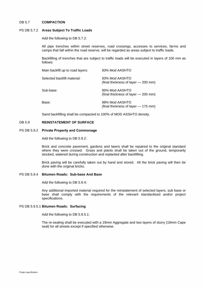
Project specification
DB 5.7 COMPACTION
PS DB 5.7.2 Areas Subject To Traffic Loads
Add the following to DB 5.7.2:
All pipe trenches within street reserves, road crossings, accesses to services, farms and camps that fall within the road reserve, will be regarded as areas subject to traffic loads.
Backfilling of trenches that are subject to traffic loads will be executed in layers of 100 mm as follows:
Main backfill up to road layers: 93% Mod AASHTO
Selected backfill material: 93% Mod AASHTO (final thickness of layer — 200 mm)
Sub-base: 95% Mod AASHTO (final thickness of layer — 200 mm)
Base: 98% Mod AASHTO (final thickness of layer — 175 mm)
Sand backfilling shall be compacted to 100% of MOD ASSHTO density.
DB 5.9 REINSTATEMENT OF SURFACE
PS DB 5.9.2 Private Property and Commonage
Add the following to DB 5.9.2:
Brick and concrete pavement, gardens and lawns shall be repaired to the original standard where they were crossed. Grass and plants shall be taken out of the ground, temporarily stocked, watered during construction and replanted after backfilling.
Brick paving will be carefully taken out by hand and stored. All the brick paving will then be done with the original bricks.
PS DB 5.9.4 Bitumen Roads: Sub-base And Base
Add the following to DB 5.9.4:
Any additional imported material required for the reinstatement of selected layers, sub base or base shall comply with the requirements of the relevant standardised and/or project specifications.
PS DB 5.9.5.1 Bitumen Roads: Surfacing
Add the following to DB 5.9.5.1:
The re-sealing shall be executed with a 19mm Aggregate and two layers of slurry (19mm Cape seal) for all streets except if specified otherwise.
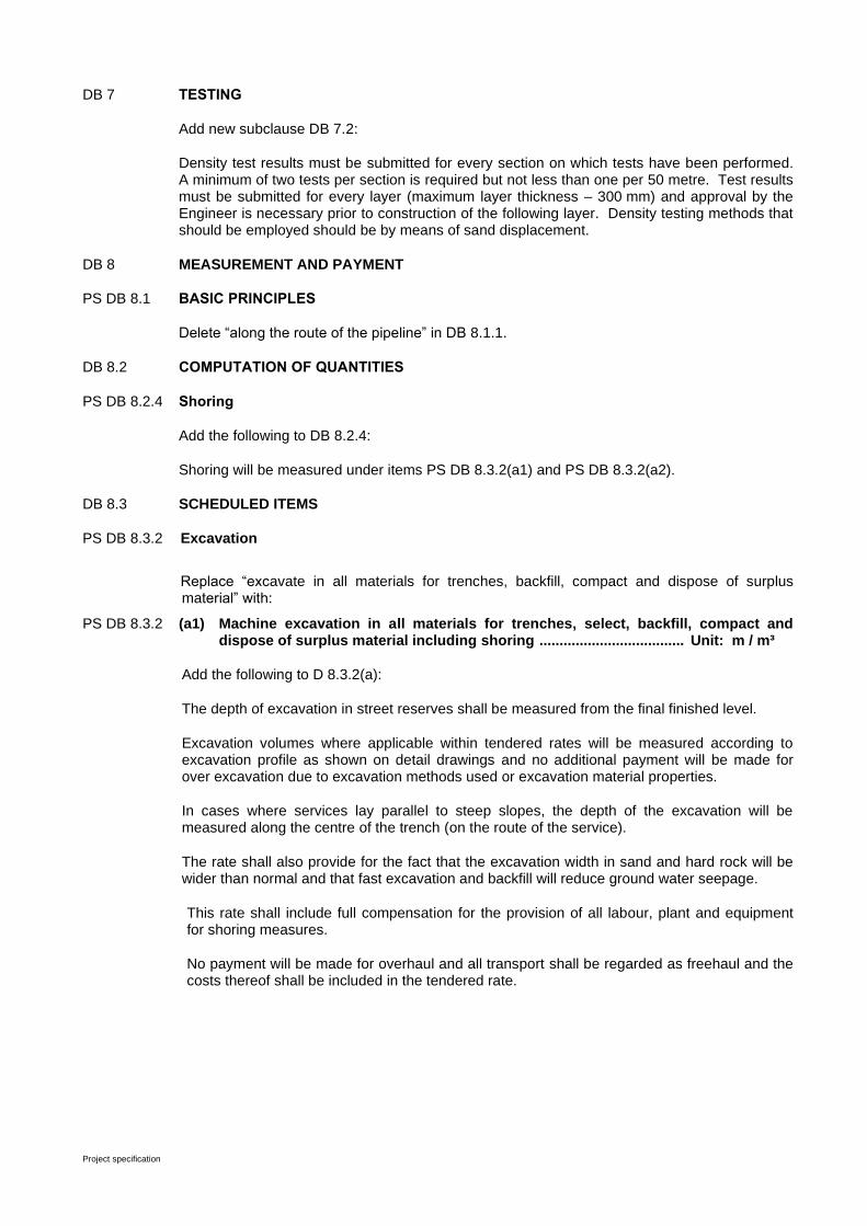
Project specification
DB 7 TESTING
Add new subclause DB 7.2:
Density test results must be submitted for every section on which tests have been performed. A minimum of two tests per section is required but not less than one per 50 metre. Test results must be submitted for every layer (maximum layer thickness – 300 mm) and approval by the Engineer is necessary prior to construction of the following layer. Density testing methods that should be employed should be by means of sand displacement.
DB 8 MEASUREMENT AND PAYMENT
PS DB 8.1 BASIC PRINCIPLES
Delete “along the route of the pipeline” in DB 8.1.1.
DB 8.2 COMPUTATION OF QUANTITIES
PS DB 8.2.4 Shoring
Add the following to DB 8.2.4:
Shoring will be measured under items PS DB 8.3.2(a1) and PS DB 8.3.2(a2).
DB 8.3 SCHEDULED ITEMS
PS DB 8.3.2 Excavation
Replace “excavate in all materials for trenches, backfill, compact and dispose of surplus material” with:
PS DB 8.3.2 (a1) Machine excavation in all materials for trenches, select, backfill, compact and dispose of surplus material including shoring .................................... Unit: m / m³
Add the following to D 8.3.2(a):
The depth of excavation in street reserves shall be measured from the final finished level.
Excavation volumes where applicable within tendered rates will be measured according to excavation profile as shown on detail drawings and no additional payment will be made for over excavation due to excavation methods used or excavation material properties.
In cases where services lay parallel to steep slopes, the depth of the excavation will be measured along the centre of the trench (on the route of the service).
The rate shall also provide for the fact that the excavation width in sand and hard rock will be wider than normal and that fast excavation and backfill will reduce ground water seepage.
This rate shall include full compensation for the provision of all labour, plant and equipment for shoring measures.
No payment will be made for overhaul and all transport shall be regarded as freehaul and the costs thereof shall be included in the tendered rate.
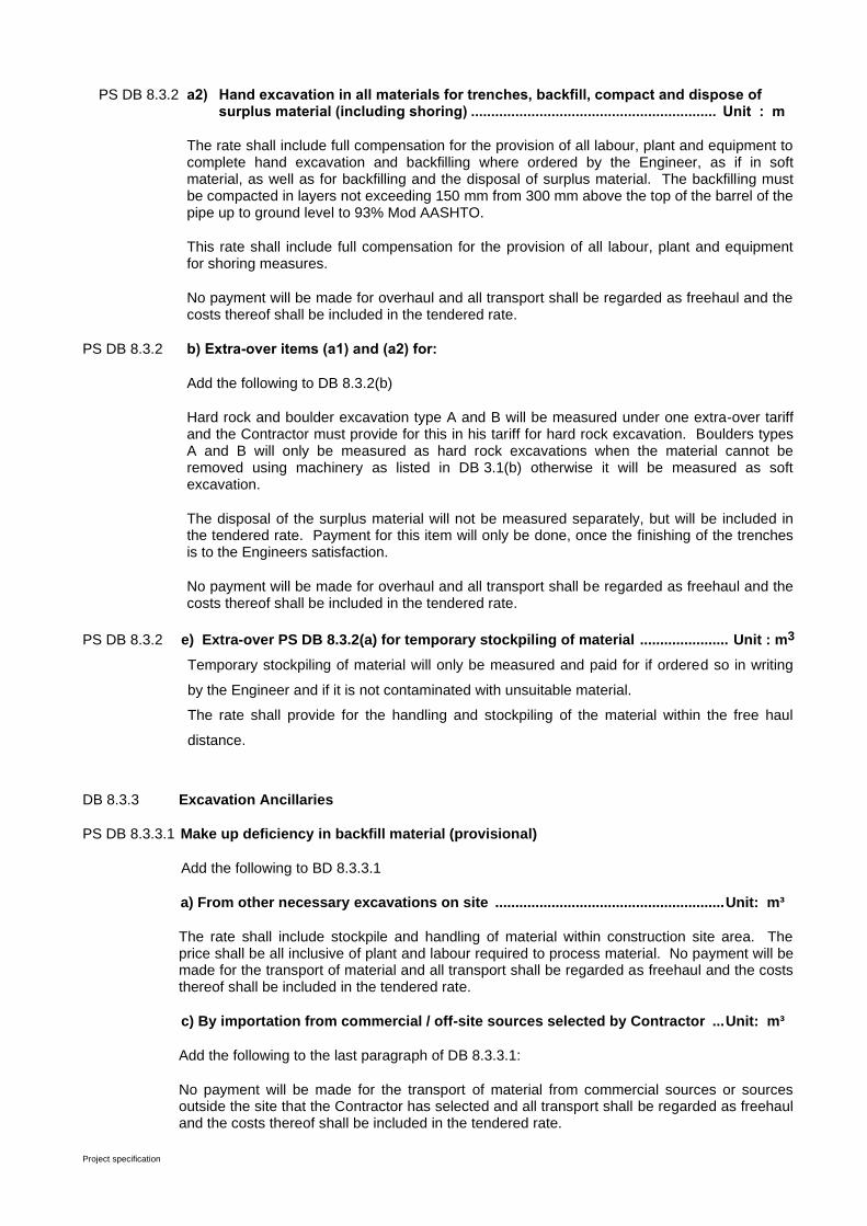
Project specification
PS DB 8.3.2 a2) Hand excavation in all materials for trenches, backfill, compact and dispose of surplus material (including shoring) ............................................................. Unit : m
The rate shall include full compensation for the provision of all labour, plant and equipment to complete hand excavation and backfilling where ordered by the Engineer, as if in soft material, as well as for backfilling and the disposal of surplus material. The backfilling must be compacted in layers not exceeding 150 mm from 300 mm above the top of the barrel of the pipe up to ground level to 93% Mod AASHTO.
This rate shall include full compensation for the provision of all labour, plant and equipment for shoring measures.
No payment will be made for overhaul and all transport shall be regarded as freehaul and the costs thereof shall be included in the tendered rate.
PS DB 8.3.2 b) Extra-over items (a1) and (a2) for:
Add the following to DB 8.3.2(b)
Hard rock and boulder excavation type A and B will be measured under one extra-over tariff and the Contractor must provide for this in his tariff for hard rock excavation. Boulders types A and B will only be measured as hard rock excavations when the material cannot be removed using machinery as listed in DB 3.1(b) otherwise it will be measured as soft excavation.
The disposal of the surplus material will not be measured separately, but will be included in the tendered rate. Payment for this item will only be done, once the finishing of the trenches is to the Engineers satisfaction.
No payment will be made for overhaul and all transport shall be regarded as freehaul and the costs thereof shall be included in the tendered rate.
PS DB 8.3.2 e) Extra-over PS DB 8.3.2(a) for temporary stockpiling of material ...................... Unit : m3
Temporary stockpiling of material will only be measured and paid for if ordered so in writing
by the Engineer and if it is not contaminated with unsuitable material.
The rate shall provide for the handling and stockpiling of the material within the free haul
distance.
DB 8.3.3 Excavation Ancillaries
PS DB 8.3.3.1 Make up deficiency in backfill material (provisional)
Add the following to BD 8.3.3.1
a) From other necessary excavations on site ......................................................... Unit: m³
The rate shall include stockpile and handling of material within construction site area. The price shall be all inclusive of plant and labour required to process material. No payment will be made for the transport of material and all transport shall be regarded as freehaul and the costs thereof shall be included in the tendered rate.
c) By importation from commercial / off-site sources selected by Contractor ... Unit: m³
Add the following to the last paragraph of DB 8.3.3.1:
No payment will be made for the transport of material from commercial sources or sources outside the site that the Contractor has selected and all transport shall be regarded as freehaul and the costs thereof shall be included in the tendered rate.

Project specification
PS DB 8.3.3.3 Compaction in road reserves ................................................................................... Unit: m³
Add the following to DB 8.3.3.3:
This item is only applicable to the backfill above the bedding and fill blanket and require 95% Mod AASHTO compaction of material as supposed to 93% Mod AASHTO elsewhere.
PS DB 8.3.4 Particular Items
Add the following to DB 8.3.4:
b) Control of groundwater …………………………………...………………………. Unit: m
The tendered rate for the effective control of ground water shall cover for all equipment, plant, material as well as the labour involved to use the well points, pumps and pipes, etc. to control the groundwater before and during excavation. The rate shall also cover the maintenance of the equipment for the total contract period. Payment for this item will only be made if the Contractor used well points and pumps to control ground water before or during excavation and measurement will be done on the length of pipe laid in trenches where ground water control had been applied.
DB 8.3.5 Existing Services That Intersect or Adjoin A Pipe Trench
PS DB 8.3.5 a) Services that intersect a trench ........................................................................... Unit: No
Add the following to DB 8.3.5(a):
Existing services with a depth of cover exceeding 300 mm, measured from the bottom of excavation to the top of the existing service shall not be measured and paid for. There will be distinguished between existing trunk services and existing erf connection.
The rate shall also allow for the following costs:
i) Sufficient photo's have to be taken of existing services and handed over to the Engineer before they are being crossed, if there is a possibility of a difference in opinion over the condition of those services, especially on private property.
ii) If such a service is damaged, it has to be repaired to its original condition or if possible, to a standard agreed to in writing with the relevant owner. This agreement has to be approved by the Engineer.
iii) If such a service is removed, it has to be replaced as per original.
PS DB 8.3.5 b) Services that adjoin a trench ...................................................................... Unit: No or m
Add the following to DB 8.3.5 (b):
The unit "number" will only be used for services such as poles and trees.
The cost for shoring shall be deemed as covered by the listed items and no additional payment will be made for this.
No payment will be made for overhead services that do not rest directly on the ground except where allowance is made for this in the schedule of quantities.
Existing services that rest directly on the ground e.g. poles, trees, walls and structures are handled in the same way as underground services, but the axis of the service will be determined as follows:
The vertical axis is defined as the nearest side or corner of the existing structure to the excavation, measured at the point where the structure and natural ground level intersect.

Project specification
The horizontal axis will be at the point where the structure and the natural ground level intersect. In this instance, where the excavation falls above the 45° line but within 1,0 meter horizontally from the structure, the service will also be measured as adjoining.
If the structure, according to the above-mentioned, does not qualify as an adjoining service but the foundation of the structure is such that if a 45° line drawn from the nearest bottom corner thereof cuts through the excavation, the structure will be measured as an adjoining service if approved by the Engineer.
If there is more than one service adjoining the same trench and such a service is on the same side of the trench, payment will only be made for the nearest service to the trench, or if they are the same distance from the trench for the top one. The maximum number of services that will be paid for, is therefore one on each side.
There will be distinguished between existing trunk services and existing erf connection.
DB 8.3.6 Finishing
PS DB 8.3.6.1 Reinstate Road surfaces complete with all courses ................................................. Unit: m²
Replace DB 8.3.6.1 with the following:
1) Gravel……………………………… ......................................................... . Unit: m²
2) Asphalt of thickness 40 mm (Surfaced Road) ................................. Unit: m²
3) Concrete slab (Class 25 MPa or higher ……....................................... Unit: m³
4) Sidewalk paving bricks (60 mm with layerworks) ........................... Unit: m²
5) Kerbing……………………………………………………......................... Unit: m
The rate shall cover the cost of temporary accommodation of traffic (including the signs and bypasses), selective excavation (including the equipment that is required to break up, remove and, if necessary, stockpile the original surface material), and subsequently of reinstating and compaction and shall include the cost of delays and the cost of any risk of having to repair damage as specified in DB 5.10. Compaction must be according to PS DB 5.7.2.
PS DB 8.3.6.2 Extra Over DB 8.3.6.1 for imported material ............................................................. Unit: m³
Add new payment clause DB 8.3.6.2:
The quantity will be calculated according to the actual volume of material placed in the final position according to the specified dimension.
The rate is an “extra-over” PS DB 8.3.6.1 and includes all costs of supplying and placing of imported material in the final position with material from commercial sources.
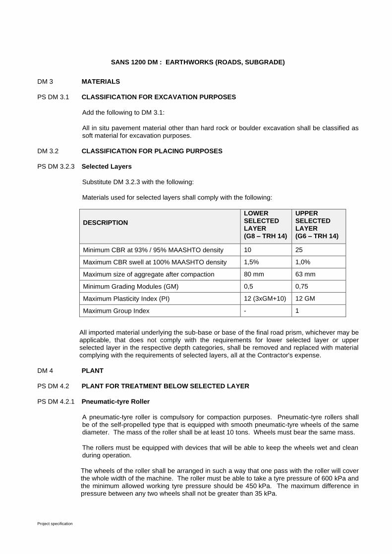
Project specification
SANS 1200 DM : EARTHWORKS (ROADS, SUBGRADE)
DM 3 MATERIALS
PS DM 3.1 CLASSIFICATION FOR EXCAVATION PURPOSES
Add the following to DM 3.1:
All in situ pavement material other than hard rock or boulder excavation shall be classified as soft material for excavation purposes.
DM 3.2 CLASSIFICATION FOR PLACING PURPOSES
PS DM 3.2.3 Selected Layers
Substitute DM 3.2.3 with the following:
Materials used for selected layers shall comply with the following:
DESCRIPTION
LOWER SELECTED LAYER (G8 – TRH 14)
UPPER SELECTED LAYER (G6 – TRH 14)
Minimum CBR at 93% / 95% MAASHTO density 10 25
Maximum CBR swell at 100% MAASHTO density 1,5% 1,0%
Maximum size of aggregate after compaction 80 mm 63 mm
Minimum Grading Modules (GM) 0,5 0,75
Maximum Plasticity Index (PI) 12 (3xGM+10) 12 GM
Maximum Group Index - 1
All imported material underlying the sub-base or base of the final road prism, whichever may be applicable, that does not comply with the requirements for lower selected layer or upper selected layer in the respective depth categories, shall be removed and replaced with material complying with the requirements of selected layers, all at the Contractor's expense.
DM 4 PLANT
PS DM 4.2 PLANT FOR TREATMENT BELOW SELECTED LAYER
PS DM 4.2.1 Pneumatic-tyre Roller
A pneumatic-tyre roller is compulsory for compaction purposes. Pneumatic-tyre rollers shall be of the self-propelled type that is equipped with smooth pneumatic-tyre wheels of the same diameter. The mass of the roller shall be at least 10 tons. Wheels must bear the same mass.
The rollers must be equipped with devices that will be able to keep the wheels wet and clean during operation.
The wheels of the roller shall be arranged in such a way that one pass with the roller will cover the whole width of the machine. The roller must be able to take a tyre pressure of 600 kPa and the minimum allowed working tyre pressure should be 450 kPa. The maximum difference in pressure between any two wheels shall not be greater than 35 kPa.
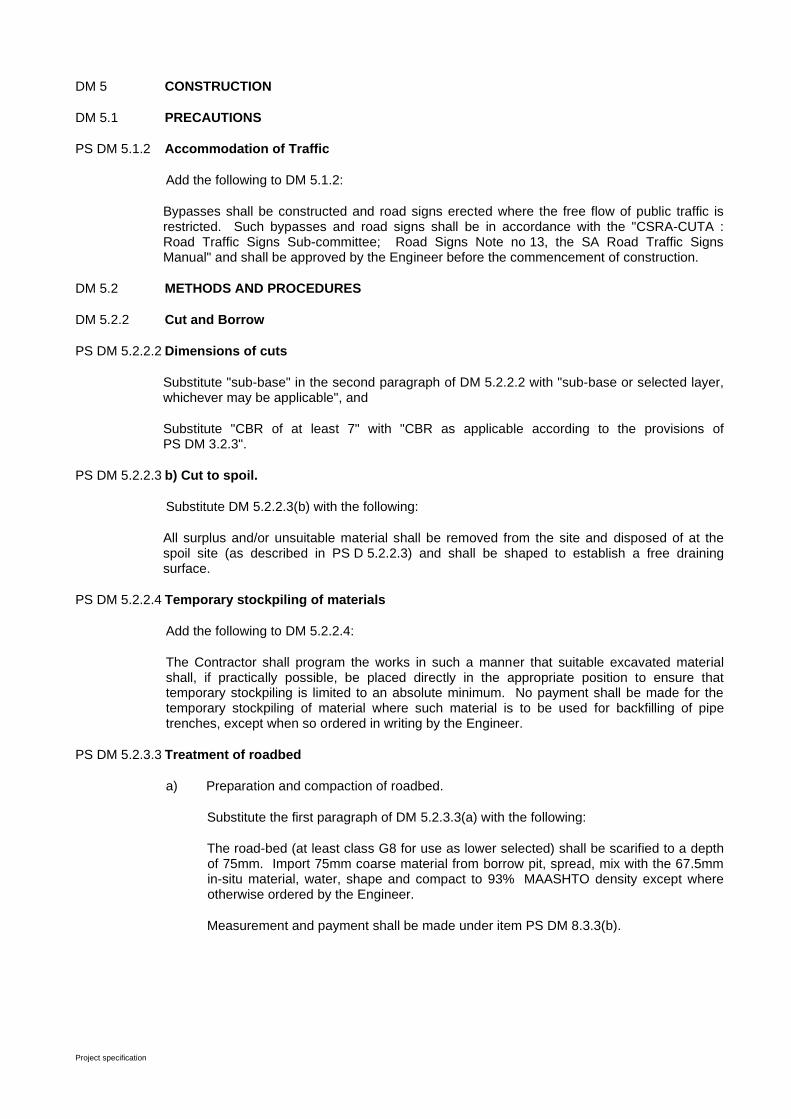
Project specification
DM 5 CONSTRUCTION
DM 5.1 PRECAUTIONS
PS DM 5.1.2 Accommodation of Traffic
Add the following to DM 5.1.2:
Bypasses shall be constructed and road signs erected where the free flow of public traffic is restricted. Such bypasses and road signs shall be in accordance with the "CSRA-CUTA : Road Traffic Signs Sub-committee; Road Signs Note no 13, the SA Road Traffic Signs Manual" and shall be approved by the Engineer before the commencement of construction.
DM 5.2 METHODS AND PROCEDURES
DM 5.2.2 Cut and Borrow
PS DM 5.2.2.2 Dimensions of cuts
Substitute "sub-base" in the second paragraph of DM 5.2.2.2 with "sub-base or selected layer, whichever may be applicable", and
Substitute "CBR of at least 7" with "CBR as applicable according to the provisions of PS DM 3.2.3".
PS DM 5.2.2.3 b) Cut to spoil.
Substitute DM 5.2.2.3(b) with the following:
All surplus and/or unsuitable material shall be removed from the site and disposed of at the spoil site (as described in PS D 5.2.2.3) and shall be shaped to establish a free draining surface.
PS DM 5.2.2.4 Temporary stockpiling of materials
Add the following to DM 5.2.2.4:
The Contractor shall program the works in such a manner that suitable excavated material shall, if practically possible, be placed directly in the appropriate position to ensure that temporary stockpiling is limited to an absolute minimum. No payment shall be made for the temporary stockpiling of material where such material is to be used for backfilling of pipe trenches, except when so ordered in writing by the Engineer.
PS DM 5.2.3.3 Treatment of roadbed
a) Preparation and compaction of roadbed.
Substitute the first paragraph of DM 5.2.3.3(a) with the following:
The road-bed (at least class G8 for use as lower selected) shall be scarified to a depth of 75mm. Import 75mm coarse material from borrow pit, spread, mix with the 67.5mm in-situ material, water, shape and compact to 93% MAASHTO density except where otherwise ordered by the Engineer.
Measurement and payment shall be made under item PS DM 8.3.3(b).

Project specification
Add the following sub-clause:
(c) In situ preparation of roadbed with eight roller passes.
Any part of the roadbed that lies within the selected layer and which, regardless of its density, is suitable according to the Engineers opinion can be used in situ if so instructed by the Engineer.
If due to the nature of material, the degree of compaction cannot be controlled by means of in situ density tests, the Engineer may instruct compaction to be done by eight roller passes as specified in PS DM 4.2. The Engineer may further request that the compaction effort be altered by increasing or reducing the number of passes and that payment be amended accordingly.
The surface of the roadbed shall be shaped true in respect of line and level within the tolerances as specified in clause 6. During the shaping of the road bed, all material that has to be removed and cannot be re-used, shall be disposed of and will be paid for under item PS DM 8.3.7. If necessary, additional material that has been approved by the Engineer shall be imported to meet the required levels.
The engineer will apply no strict measurements about soil moisture content during compaction. The Contractor must however convince the Engineer that all possible efforts have been made to use favourable soil moisture conditions. Compaction must be done during periods when the roadbed is not to wet or to dry. The Engineer has full authority to decide whenever conditions are favourable for compaction and may at any stage instruct the Contractor to water the road-bed at the Contractors expense if he, in the Engineer's opinion, neglected to satisfy the above-mentioned requirements.
PS DM 5.2.5 Selected Layer
Add the following to DM 5.2.5:
The Engineer may, depending on the quality of the in situ material, order the omission of one or both of the selected layers. To determine the number of selected layers, if any, the Engineer may order the Contractor to dig test holes with maximum dimensions of 1,5 m x 1,5 m and 1,0 m deep at positions indicated by the Engineer, before construction commences.
The Contractor shall backfill all test holes with selected material and compact it to 95% of MAASHTO density, after the Engineer has taken samples and profiled the holes.
PS DM 5.2.7 Stabilization
The sub-base course shall be stabilized to C4 standards and the initial cement demand to comply with the specifications shall be included in the rates for stabilization of the layer. UCS and ITS strength tests for each stabilized section shall be included in the tendered rate and these tests have to be performed within the prescribed period for lime or cement.
PS DM 5.2.9 Shaping and Compacting Below Selected Layer
Each portion of the road-bed below the selected layer which, by virtue of its inadequate natural density, is directed by the Engineer to be compacted by means of a pneumatic-tyred roller, shall be prepared by shaping where necessary, and each such portion shall be compacted by means of at least eight complete passes by a pneumatic-tyred roller. One pass shall consist of the complete area being systematically passed in the longitudinal direction so that each pass overlaps the previous by half.
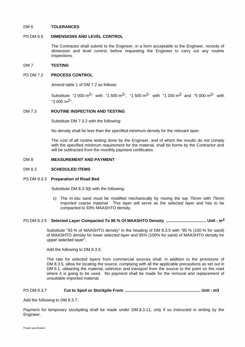
Project specification
DM 6 TOLERANCES
PS DM 6.5 DIMENSIONS AND LEVEL CONTROL
The Contractor shall submit to the Engineer, in a form acceptable to the Engineer, records of dimension and level control, before requesting the Engineer to carry out any routine inspections.
DM 7 TESTING
PS DM 7.2 PROCESS CONTROL
Amend table 1 of DM 7.2 as follows:
Substitute "2 000 m2" with "1 500 m2", "1 500 m2" with "1 200 m2 and "5 000 m2" with
"3 000 m2".
DM 7.3 ROUTINE INSPECTION AND TESTING
Substitute DM 7.3.2 with the following:
No density shall be less than the specified minimum density for the relevant layer.
The cost of all routine testing done by the Engineer, and of which the results do not comply with the specified minimum requirement for the material, shall be borne by the Contractor and will be subtracted from the monthly payment certificates.
DM 8 MEASUREMENT AND PAYMENT
DM 8.3 SCHEDULED ITEMS
PS DM 8.3.3 Preparation of Road Bed
Substitute DM 8.3.3(b with the following:
c) The in-situ sand must be modified mechanically by mixing the top 75mm with 75mm imported coarse material. This layer will serve as the selected layer and has to be compacted to 93% MAASHTO density.
PS DM 8.3.5 Selected Layer Compacted To 95 % Of MAASHTO Density ................................... Unit : m3
Substitute "93 % of MAASHTO density" in the heading of DM 8.3.5 with "95 % (100 % for sand) of MAASHTO density for lower selected layer and 95% (100% for sand) of MAASHTO density for upper selected layer”.
Add the following to DM 8.3.5:
The rate for selected layers from commercial sources shall, in addition to the provisions of DM 8.3.5, allow for locating the source, complying with all the applicable precautions as set out in DM 5.1, obtaining the material, selection and transport from the source to the point on the road where it is going to be used. No payment shall be made for the removal and replacement of unsuitable imported material.
PS DM 8.3.7 Cut to Spoil or Stockpile From .................................................................. Unit : m3
Add the following to DM 8.3.7:
Payment for temporary stockpiling shall be made under DM 8.3.11, only if so instructed in writing by the Engineer.
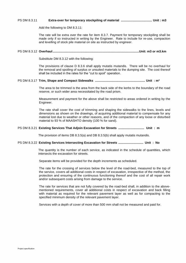
Project specification
PS DM 8.3.11 Extra-over for temporary stockpiling of material .................................... Unit : m3
Add the following to DM 8.3.11:
The rate will be extra over the rate for item 8.3.7. Payment for temporary stockpiling shall be made only if so instructed in writing by the Engineer. Rate to include for re-use, compaction and levelling of stock pile material on site as instructed by engineer.
PS DM 8.3.12 Overhaul .................................................................................................... Unit: m3 or m3.km
Substitute DM 8.3.12 with the following:
The provisions of clause D 8.3.6 shall apply mutatis mutandis. There will be no overhaul for the removal and spoiling of surplus or unsuited materials to the dumping site. The cost thereof shall be included in the rates for the “cut to spoil” operation.
PS DM 8.3.17 Trim, Shape and Compact Sidewalks .......................................................... Unit : m³
The area to be trimmed is the area from the back side of the kerbs to the boundary of the road reserve, or such wider area necessitated by the road prism.
Measurement and payment for the above shall be restricted to areas ordered in writing by the Engineer.
The rate shall cover the cost of trimming and shaping the sidewalks to the lines, levels and dimensions as shown on the drawings, of acquiring additional material to compensate for any material lost due to weather or other reasons, and of the compaction of any loose or disturbed material to 93 % of MAASHTO density (100 % for sand).
PS DM 8.3.21 Existing Services That Adjoin Excavation for Streets .............................. Unit : m
The provision of items DB 8.3.5(a) and DB 8.3.5(b) shall apply mutatis mutandis.
PS DM 8.3.22 Existing Services Intersecting Excavation for Streets ............................. Unit : No
The quantity is the number of each service, as indicated in the schedule of quantities, which intersects the excavation for streets.
Separate items will be provided for the depth increments as scheduled.
The rate for the crossing of services below the level of the road-bed, measured to the top of the service, covers all additional costs in respect of excavation, irrespective of the method, the protection and ensuring of the continuous functioning thereof and the cost of all repair work and/or subsequent costs arising from damage to the service.
The rate for services that are not fully covered by the road-bed shall, in addition to the above-mentioned requirements, cover all additional costs in respect of excavation and back filling with material as required for the relevant pavement layer as well as for compacting to the specified minimum density of the relevant pavement layer.
Services with a depth of cover of more than 500 mm shall not be measured and paid for.
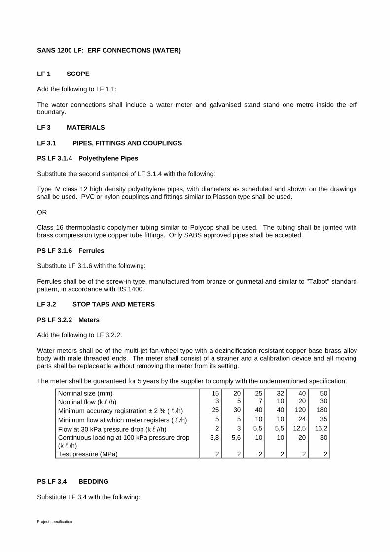
Project specification
SANS 1200 LF: ERF CONNECTIONS (WATER)
LF 1 SCOPE
Add the following to LF 1.1:
The water connections shall include a water meter and galvanised stand stand one metre inside the erf boundary.
LF 3 MATERIALS
LF 3.1 PIPES, FITTINGS AND COUPLINGS
PS LF 3.1.4 Polyethylene Pipes
Substitute the second sentence of LF 3.1.4 with the following:
Type IV class 12 high density polyethylene pipes, with diameters as scheduled and shown on the drawings shall be used. PVC or nylon couplings and fittings similar to Plasson type shall be used.
OR
Class 16 thermoplastic copolymer tubing similar to Polycop shall be used. The tubing shall be jointed with brass compression type copper tube fittings. Only SABS approved pipes shall be accepted.
PS LF 3.1.6 Ferrules
Substitute LF 3.1.6 with the following:
Ferrules shall be of the screw-in type, manufactured from bronze or gunmetal and similar to "Talbot" standard pattern, in accordance with BS 1400.
LF 3.2 STOP TAPS AND METERS
PS LF 3.2.2 Meters
Add the following to LF 3.2.2:
Water meters shall be of the multi-jet fan-wheel type with a dezincification resistant copper base brass alloy body with male threaded ends. The meter shall consist of a strainer and a calibration device and all moving parts shall be replaceable without removing the meter from its setting.
The meter shall be guaranteed for 5 years by the supplier to comply with the undermentioned specification.
Nominal size (mm) 15 20 25 32 40 50
Nominal flow (k /h) 3 5 7 10 20 30
Minimum accuracy registration ± 2 % ( /h) 25 30 40 40 120 180
Minimum flow at which meter registers ( /h) 5 5 10 10 24 35
Flow at 30 kPa pressure drop (k //h) 2 3 5,5 5,5 12,5 16,2
Continuous loading at 100 kPa pressure drop
(k /h)
3,8 5,6 10 10 20 30
Test pressure (MPa) 2 2 2 2 2 2
PS LF 3.4 BEDDING
Substitute LF 3.4 with the following:
Project specification
The bedding shall be as specified in PS LB 3.1.
LF 3.5 VALVE AND METER CHAMBERS
PS LF 3.5.3 Surface Boxes
Add the following to LF 3.5.3:
Lockable cast iron combination meter/valve chambers are to be provided.
These chambers are to be of an approved manufacture and samples are to be provided to the Engineer for approval prior to installation. The cast iron chambers shall be installed one meter into the erven.
PS LF 3.6 MARKINGS AND MARKER POSTS
Add the following to LF 3.6:
House connections shall be marked by painting a 15 mm thick blue line on the kerb opposite the connection.
The water pipe shall be sealed effectively 1 m inside the erf boundary and the position shall be marked with a blue ± 40 mm wooden stake, planted above the pipe end, so that it protrudes 750 mm above ground level.
LF 5 CONSTRUCTION
LF 5.2 LAYING FROM MAIN TO ERF
PS LF 5.2.2 Pipe Laying
Add the following to LF 5.2.2:
Erf connection pipes shall be laid to a depth so that the top of the pipe is not less than 450 mm nor more than 600 mm below the final road surface or sidewalk level, with the provision that where construction traffic is liable to cross the connections the pipes shall have a cover of at least 450 mm.
Erf connections shall be bedded as for flexible pipes except that the selected fill blanket will not be required. The bedding thickness above and below the pipe shall be 100 mm.
Where the erf connections cross areas subject to traffic loads the trench shall be backfilled in accordance with the requirements of PS DB 3.5 and PS DB 5.7.2.
PS LF 5.2.3 Service Connections
PS LF 5.2.3.1 General
Add the following to LF 5.2.3.1:
The working pressure in the mains for determining the test pressure at which tests for erf connections shall be done, will be as specified in PS L 7.3.1.
LF 8 MEASUREMENT AND PAYMENT
PS LF 8.2 SCHEDULED ITEMS
PS LF 8.2.1 Provide Erf Connections Complete ............................................................................. Unit: No
Substitute LF 8.2.1 with the following:
Measurement and payment for erf connections as shown on the drawings shall differentiate between double and single erf connections, as well as between short and long connections, each for the various pipe diameters and for each diameter of water main.

Project specification
Connection rates shall cover the cost of all excavations (300 mm wide) backfilling, bedding, removal of surplus material, as well as the following, complete as indicated on the drawings:
• a) a saddle, ferrule and coupling to fit the relevant diameter of water main specified;
• b) all HDPE Type IV Class 12 piping for each type of connection required;
• c) all tees, 90° bends and reducers for each type of erf connection;
• d) the marking on the kerb as specified;
• e) the effective sealing of the connection pipe;
• f) lockable cast-iron water meter chambers complete with Optima 2000 water meter, stop tap and adaptors.
Short connections are defined as connections to erven nearest to the main pipe in relation to the road and long connections as connections to erven across the road.
Pipe lengths for measurement and payment purposes shall be as follows:
Single short connection = 2,0 m
Single long connectio = 16,0 m
Double short connection = 13,0 m (bigger pipe dia)
= 5,2 m (smaller pipe dia)
Double long connection = 18,0 m (bigger pipe dia)
= 5,2 m (smaller pipe dia)
Extra-over items for variation in pipe lengths are provided for connections, shorter or longer than specified and the rates shall cover the cost of the necessary excavation, bedding, backfill, all material, etc. If the variation is negative the payment will be reduced accordingly.
Imported material for bedding, blanket and main fill will be measured under the relevant items for main pipes
Project specification
SANS1200 G : CONCRETE (STRUCTURAL)
G 3 MATERIAL
PS G 3.2.1 Applicable Specifications
Substitute G 3.2.1 with the following:
All cement types shall comply with the requirements of SANS EN 197-1.
For this contract CEM I portland cement shall be used.
Where Malmesbury hornfels (shale) is used as aggregate in concrete, a blend (by mass) of 50 % CEM I 42,5 or CEM I 42,5R and 50 % milled granulated blast-furnace slag shall be used in the concrete mix.
PS G 3.2.3 Storage of Cement.
Add the following to G 3.2.3:
Consignments of cement shall be used in the same sequence as that in which they are delivered to site. No cement shall be used which has been stored on site for a longer period than 6 (six) weeks. All cement so stored for a longer period than 6 (six) weeks, all cement damaged in any way, and all cement which does not comply with the specification, shall be removed immediately and permanently from the site.
PS G 3.5.2 Air-entraining Agents
Substitute G 3.5.2 with the following:
Air-entraining agents shall not be used in concrete.
G 4 PLANT
PS G 4.5.3 Ties
Add the following to G 4.5.3:
Permanent metal ties shall have a minimum concrete cover of 40 mm after formwork has been removed.
Tie holes shall be filled with an approved expansive cementitious grout similar to "Durabed" of ABE. The product shall be prepared to a non-slump consistency, but where no cracking occurs when pressed into a firm ball. Trial mixes shall be made to arrive at the required working consistency.
G 5 CONSTRUCTION
G 5.1 REINFORCEMENT
PS G 5.1.3 Cover
Substitute G 5.1.3 with the following:

Project specification
The cover of concrete over reinforcement, unless otherwise indicated on the drawings, shall in no case be less than 40 mm.
Project specification
PS G 5.2.1 Classification of Finishes
Add the following to G 5.2.1:
The following surface conditions are required on the various portions of the finished concrete:
(a) Rough
Concealed surfaces and surfaces more than 150 mm below final ground level.
(b) Smooth
All surface finishes not classified as "rough" in paragraph (a) shall be classified as "smooth". All exposed arrises (i.e., where the angle between adjacent sides is 110° or less) unless otherwise indicated on the drawings, shall be chamfered 20 mm x 20 mm by means of triangular fillets fixed to the formwork.
PS G 5.2.5 Removal of formwork
In Table 2 of G 5.2.5.2, substitute “portland cement and portland cement 15” in columns 2, 3 and 4 with “CEM 1 portland cement, delete columns 5, 6 and 7 and substitute “portland blast-furnace cement” in columns 8, 9 and 10 with “CEM III blast-furnace cement or blends of CEM I portland cement with milled granulated blast-furnace slag”.
PS G 5.4 Pipes and Conduits
Add the following to G 5.4:
All pipes and specials which must be installed in the floors and walls of structures shall be embedded in the concrete during the casting of such concrete. No holes shall be left for the later installation of pipes and specials, without the written approval of the Engineer.
Where such holes have been approved by the Engineer, the Contractor shall be responsible for the grouting-in of such pipes or specials with an approved expansive cementitious grout as specified in PS G 4.5.3, regardless of whether or not these have been supplied by himself. The Contractor shall provide a smooth, dense and waterproof finish around the pipes or specials.
The clear space between pipes of any kind embedded in reinforced concrete and the clear space between such pipes and reinforcement shall at any point be not less than -
(a) 40 mm, or
(b) 5 mm plus the maximum size of coarse aggregate,
Whichever is the greater.
G 5.5 CONCRETE
PS G 5.5.1.5 Durability
Substitute G 5.5.1.5 with the following:
Concrete shall be so proportioned to ensure that the water/cement ratio does not exceed 0,5 and, to ensure workability, water-reducing admixtures of approved manufacture shall be used in preference to increasing the cement content.
Project specification
PS G 5.5.1.7 Strength concrete
Add the following to G 5.5.1.7:
The grade of strength concrete and the maximum nominal size of coarse aggregate for each portion of the works, unless otherwise indicated on the drawings, shall be as follows:
(a) Mass concrete under floors and foundations ........................................... 20 MPa/19 mm
(b) Blinding layers .......................................................................................... 10 MPa/19 mm
(c) Encasing of pipes ..................................................................................... 20 MPa/19 mm
(d) Strip foundations ...................................................................................... 30 MPa/19 mm
(e) Benching and screeds ............................................................................. 25 MPa/10 mm
(f) All reinforced concrete ............................................................................. 30 MPa/19 mm
PS G 5.5.7 Construction Joints
Add the following to G 5.5.7.1:
Construction joints shall be limited to the minimum and shall only be made in positions as shown on the drawings or in positions as specifically approved by the Engineer. Construction joints between tank bottoms, floors, or wall bases, and the walls standing on them shall not be made flush with the supporting surface, but shall be made in the wall 150 mm above the base. The 150 mm high riser wall shall be cast as an integral part of the bottom, floor or base, i.e. the concrete in the riser shall be deposited simultaneously with the concrete in the bottom, floor or base adjacent to it. Where there is a fillet at the bottom of a wall, the construction joint shall be made 150 mm above the fillet.
A PVC waterstop without centre bulb shall be installed at all construction joints in walls of water-retaining structures. The size of the waterstops shall be 150 mm in walls thinner than 200 mm and 200 mm in walls of 200 mm thickness and more.
PS G 5.5.7.4 Expansion joints
Expansion joints shall be formed in positions and in accordance with details as shown on the drawings. All expansion joints shall be formed with an approved closed cell polyethylene fill material similar to "SPV 120" as supplied by Sondor, with a single part polyurethane sealant similar to Silkaflex – PRO 2HP as supplied by Sika. Rearguard S-type PVC waterstops with centre bulbs shall be installed under floors and Hydrofoil PVC waterstops with centre bulbs in walls, as shown on the drawings.
All sealants, fill material and waterstops shall be installed strictly in accordance with the specification of the manufacturers and to the satisfaction of the Engineer. The sealant shall be installed in one operation and jointing to already hardened sealant will not be permitted.
PS G 5.5.7.6 Bond breaker under floor
A 500 micrometre polyethylene bond breaker shall be installed between the blinding layer and the floor, where indicated on the drawings.
Project specification
PS G 5.5.9 Adverse Weather Conditions
Add the following to G 5.5.9.1:
No material having a temperature of below 5 °C shall be used for concrete, and no concrete shall be deposited when the ground or air temperature is below 2 °C. Furthermore, if the air or ground temperature is likely to fall below 2 °C within twelve (12) hours after depositing of concrete, no concreting shall be done without the written consent of the Engineer. If such consent is given the Contractor shall heat the aggregate stockpiles and mixing water, and defrost the formwork and reinforcement.
PS G 5.5.10 Concrete Surfaces
Add the following to G 5.5.10.1:
Concrete surfaces under screeds, granolithic floor finishes or benching, and surfaces of strip foundations and footings shall be brought up to a plane, uniform surface with a suitable screed board.
PS G 5.5.10.4 Wood-floated finish
Where wood floating is specified or scheduled, the surface shall first be given a finish as specified in G 5.5.10.1 and after the concrete has hardened sufficiently, it shall be floated to a uniform surface free from trowel marks. The screeded surface shall be wood-floated, either by hand or machine, only sufficiently to produce a uniform surface free from screed marks.
PS G 5.5.10.5 Steel-floated finish
Where steel floating is specified or scheduled, the surface shall be treated as specified in PS G 5.5.10.4 except that, when the moisture film has disappeared and the concrete has hardened sufficiently to prevent laitance from being worked to the surface, the screeded surface shall be steel trowelled under firm pressure to produce a dense, smooth, uniform surface free from trowel marks.
PS G 5.5.11 Watertight Concrete
Substitute G 5.5.11 with the following:
PS G 5.5.11.1 General
All structures that are designed to retain water or to keep water out, shall be regarded as watertight structures.
PS G 5.5.11.2 Requirements and tests for watertightness of structures
The completed structure shall be watertight, and the quality and finish of the work shall be such that no after-treatment of the work such as plastering, or cement wash is necessary to ensure compliance with this requirement.
The works will not be certified complete until the structures enumerated in PS G 5.5.11 has been proved by testing to be watertight.
Upon completion of construction and when so agreed by the Engineer, the structure shall be filled by the gradual admission of water until, the water level reaches the designed maximum level. The water level shall then be carefully noted and recorded by the Engineer in relation to a fixed benchmark, and the structure shall be allowed to remain filled for a period of two (2) weeks or such longer time as may be required to permit complete saturation of the concrete. During this period, readings will be taken by the Engineer and the results so obtained will be available for the information of the Contractor.
At the end of this period more water shall be added, if necessary, to bring the water level back to the designed maximum level and the water shall be left undisturbed for a period of at least
Project specification
four (4) days during which time the level shall again be recorded by the Engineer at regular intervals. The structure shall be considered to be watertight if the drop in water level does not exceed 6 mm in 96 (ninety-six) hours in the case of a roofed structure and if no leakage is apparent.
The acceptable drop in level in the case of an unroofed structure shall be such that it allows for normal evaporation during the time of the test.
If appreciable leakage is evident at any stage of the filling or testing or if, in the opinion of the Engineer, the degree of watertightness is unsatisfactory, the Contractor shall, when so ordered by the Engineer, discontinue the test immediately and at his own expense take approved steps to rectify the work. The work of rectification shall be continued assiduously until, on repetition of the test procedure, a satisfactory test result is obtained, and the degree of watertightness is acceptable.
The Engineer shall have the right to retest the structure before the expiry of the period of maintenance and the results of these tests will be made available to the Contractor. If these tests indicate to the Engineer that the degree of watertightness is unsatisfactory, the Engineer (before issuing the final certificate) will be entitled to order the Contractor to rectify the work at his own expense in such a manner as will cause least interruption to the running of the works and will ensure that the degree of watertightness of the structure is satisfactory.
Backfilling around structures shall not commence until a satisfactory test result has been obtained.
The watertightness of the dry well of the pump station shall be monitored visually until the end of the defects liability period. If any damp penetration from the outside is noticed, the Contractor shall take immediate remedial steps.
The Engineer shall have the right to retest the structure before the expiry of the period of maintenance, and the results of these tests will be made available to the Contractor. If these tests indicate to the Engineer that the degree of watertightness is unsatisfactory, the Engineer (before issuing the final certificate) will be entitled to order the Contractor to rectify the work at his own expense in such a manner as will cause least interruption of the water supply to consumers and will ensure that the degree of watertightness of the structure is satisfactory.
PS G 5.9 JOINING NEW CONCRETE TO EXISTING
Where partial demolition is required for extension work to existing structures, the contact face shall be cut to predetermined line and level, and any loose and fragmented material shall be removed, and projecting steel cleaned and bent as directed by the Engineer. Where partial demolition is not required but extension work only, the contact surface shall be scabbled and cleaned of all dirt and loose particles.
If dowels are required, they shall be installed in holes drilled into the existing structure, in accordance with the details shown on the drawings, and secured by means of an approved type of epoxy bonding compound such as EPIDERMIX 372 or similar.
Fresh concrete shall be bonded to the old concrete with an approved type of epoxy bonding compound, such as EPIDERMIX 344 or similar.
Project specification
G 8 MEASUREMENT AND PAYMENT
G 8.1 MEASUREMENT AND RATES
PS G 8.1.1 Formwork
Delete the following in G 8.1.1.3(c):
"and for different prop heights for beams and slabs".
PS G 8.1.3 Concrete
Add the following to PS G 8.1.3.1(d):
Strip foundations and encasement of pipes shall be cast directly against the sides and bottoms of excavations. No payment shall be made for additional concrete in overbreak.
Delete the full stop at the end of G 8.1.3.3(a) and add the following:
"and special steps necessary before depositing concrete during cold weather, as prescribed in PS G 5.5.9".
G 8.4 SCHEDULED CONCRETE ITEMS
PS G 8.4.4 Unformed Surface Finishes ......................................................................................... Unit: m2
Add the following to G 8.4.4:
The concrete surface finishes under screeds, granolithic finishes or benching as prescribed in PS G 5.5.10 shall not be measured separately. The rates for the related concrete items shall also cover the cost of these surface finishes.
PS G 8.4.8 Concrete complete with formwork and/or trowel finish ....................................... Sum or m3
The rate shall cover the cost of the provision of concrete (made from ordinary Portland cement, unless otherwise scheduled), mixing, testing, placing, compacting, the forming of stop-ends and unforeseen construction joints, striking-off or levelling as applicable, trowelling and curing and repairing where necessary, together with the cost of all parts of formwork in contact with the concrete and the necessary bearers, struts, and other supports, plus the layout and plant necessary to erect and strike such formwork.
Project specification
SANS 1200 L: MEDIUM PRESSURE PIPELINES
PS L 3.1 GENERAL
Substitute the first sentence of L 3.1 with the following:
Types and classes of pipes shall be as scheduled.
Pipes and jointing systems suitable for the pressures must be offered.
All valves must be able to open or close under full differential pressure.
PS L 3.8 JOINTING MATERIALS
PS L 3.8.4 Loose Flanges
Substitute the first sentence of the last paragraph of L 3.8.4 with the following:
Bolts and nuts shall comply with the requirements of SABS 135.
PS L 3.9.5 Joints, Bolts, Nuts and Washers
Substitute L 3.9.5 with the following:
All joints, bolts, nuts and washers shall be cadmium-plated or stainless steel.
PS L 3.10 VALVES
PS L 3.10.1 Gate Valves
All gate valves shall comply with the requirements of SABS 664 and shall be suitable for a maximum working pressure of 5 MPa. All gate valves must be supplied with a square spindle nut, suitable to be used with a valve key.
Gate valves shall have flanged unless shown differently on the drawings and shall open anti-clockwise. The direction for opening and closing shall be permanently displayed on the valves. Valves shall have rising spindles.
Compression shut-off valves with rubber protected gate and smooth finish without recess inside, may be used.
All flanged gate valves shall be drilled according to SABS 1123 Table 1600/3. Pipes shall not be tested against a closed valve. Thrust blocks for test sections shall be approved by the Engineer prior to testing of pipes.
L 3.11 MANHOLES AND SURFACE BOXES
PS L 3.11.4 Step Irons
Substitute L 3.11.4 with the following:
Step irons shall consist of polypropylene coated 12 mm high tensile steel such as Calcamite or similar. The installation of the step irons shall be in accordance with the specification of the manufacturer.
PS L 3.11.6 Surface Boxes
Add the following to L 3.11.6:
The type of cast iron boxes shall be as specified on the drawings.
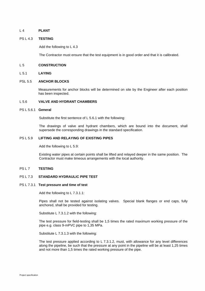
Project specification
L 4 PLANT
PS L 4.3 TESTING
Add the following to L 4.3
The Contractor must ensure that the test equipment is in good order and that it is calibrated.
L 5 CONSTRUCTION
L 5.1 LAYING
PSL 5.5 ANCHOR BLOCKS
Measurements for anchor blocks will be determined on site by the Engineer after each position has been inspected.
L 5.6 VALVE AND HYDRANT CHAMBERS
PS L 5.6.1 General
Substitute the first sentence of L 5.6.1 with the following:
The drawings of valve and hydrant chambers, which are bound into the document, shall supersede the corresponding drawings in the standard specification.
PS L 5.9 LIFTING AND RELAYING OF EXISTING PIPES
Add the following to L 5.9:
Existing water pipes at certain points shall be lifted and relayed deeper in the same position. The Contractor must make timeous arrangements with the local authority.
PS L 7 TESTING
PS L 7.3 STANDARD HYDRAULIC PIPE TEST
PS L 7.3.1 Test pressure and time of test
Add the following to L 7.3.1.1:
Pipes shall not be tested against isolating valves. Special blank flanges or end caps, fully anchored, shall be provided for testing.
Substitute L 7.3.1.2 with the following:
The test pressure for field-testing shall be 1,5 times the rated maximum working pressure of the pipe e.g. class 9-mPVC pipe to 1,35 MPa.
Substitute L 7.3.1.3 with the following:
The test pressure applied according to L 7.3.1.2, must, with allowance for any level differences along the pipeline, be such that the pressure at any point in the pipeline will be at least 1,25 times and not more than 1,5 times the rated working pressure of the pipe.
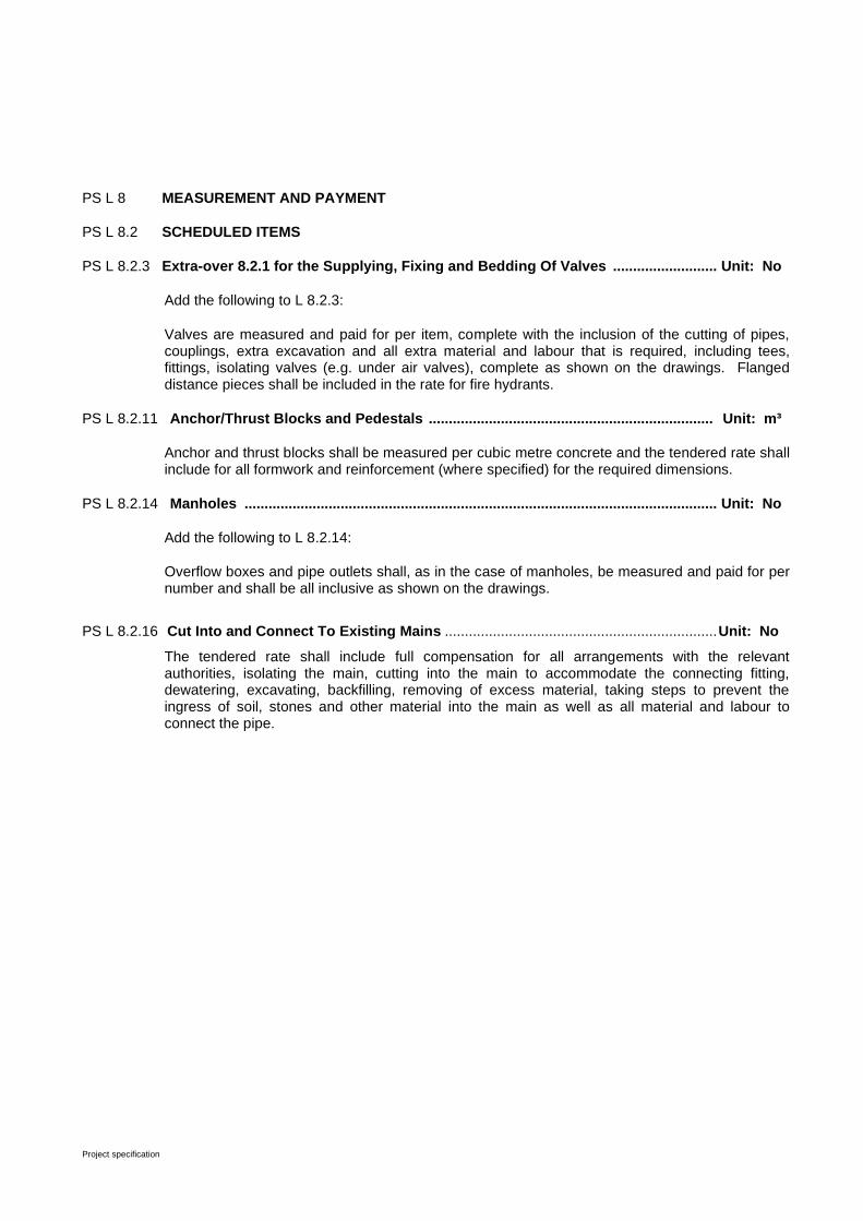
Project specification
PS L 8 MEASUREMENT AND PAYMENT
PS L 8.2 SCHEDULED ITEMS
PS L 8.2.3 Extra-over 8.2.1 for the Supplying, Fixing and Bedding Of Valves .......................... Unit: No
Add the following to L 8.2.3:
Valves are measured and paid for per item, complete with the inclusion of the cutting of pipes, couplings, extra excavation and all extra material and labour that is required, including tees, fittings, isolating valves (e.g. under air valves), complete as shown on the drawings. Flanged distance pieces shall be included in the rate for fire hydrants.
PS L 8.2.11 Anchor/Thrust Blocks and Pedestals ....................................................................... Unit: m³
Anchor and thrust blocks shall be measured per cubic metre concrete and the tendered rate shall include for all formwork and reinforcement (where specified) for the required dimensions.
PS L 8.2.14 Manholes ...................................................................................................................... Unit: No
Add the following to L 8.2.14:
Overflow boxes and pipe outlets shall, as in the case of manholes, be measured and paid for per number and shall be all inclusive as shown on the drawings.
PS L 8.2.16 Cut Into and Connect To Existing Mains .................................................................... Unit: No
The tendered rate shall include full compensation for all arrangements with the relevant authorities, isolating the main, cutting into the main to accommodate the connecting fitting, dewatering, excavating, backfilling, removing of excess material, taking steps to prevent the ingress of soil, stones and other material into the main as well as all material and labour to connect the pipe.
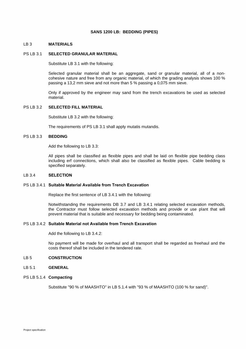
Project specification
SANS 1200 LB: BEDDING (PIPES)
LB 3 MATERIALS
PS LB 3.1 SELECTED GRANULAR MATERIAL
Substitute LB 3.1 with the following:
Selected granular material shall be an aggregate, sand or granular material, all of a non-cohesive nature and free from any organic material, of which the grading analysis shows 100 % passing a 13,2 mm sieve and not more than 5 % passing a 0,075 mm sieve.
Only if approved by the engineer may sand from the trench excavations be used as selected material.
PS LB 3.2 SELECTED FILL MATERIAL
Substitute LB 3.2 with the following:
The requirements of PS LB 3.1 shall apply mutatis mutandis.
PS LB 3.3 BEDDING
Add the following to LB 3.3:
All pipes shall be classified as flexible pipes and shall be laid on flexible pipe bedding class including erf connections, which shall also be classified as flexible pipes. Cable bedding is specified separately.
LB 3.4 SELECTION
PS LB 3.4.1 Suitable Material Available from Trench Excavation
Replace the first sentence of LB 3.4.1 with the following:
Notwithstanding the requirements DB 3.7 and LB 3.4.1 relating selected excavation methods, the Contractor must follow selected excavation methods and provide or use plant that will prevent material that is suitable and necessary for bedding being contaminated.
PS LB 3.4.2 Suitable Material not Available from Trench Excavation
Add the following to LB 3.4.2:
No payment will be made for overhaul and all transport shall be regarded as freehaul and the costs thereof shall be included in the tendered rate.
LB 5 CONSTRUCTION
LB 5.1 GENERAL
PS LB 5.1.4 Compacting
Substitute "90 % of MAASHTO" in LB 5.1.4 with "93 % of MAASHTO (100 % for sand)".
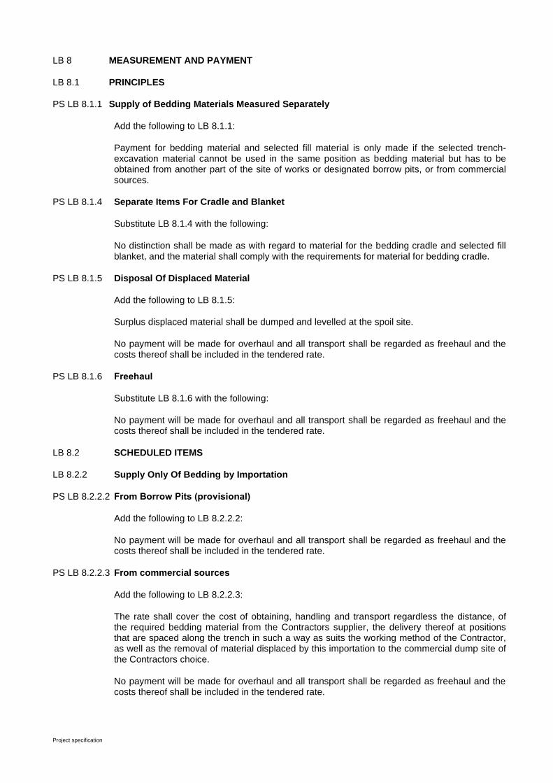
Project specification
LB 8 MEASUREMENT AND PAYMENT
LB 8.1 PRINCIPLES
PS LB 8.1.1 Supply of Bedding Materials Measured Separately
Add the following to LB 8.1.1:
Payment for bedding material and selected fill material is only made if the selected trench-excavation material cannot be used in the same position as bedding material but has to be obtained from another part of the site of works or designated borrow pits, or from commercial sources.
PS LB 8.1.4 Separate Items For Cradle and Blanket
Substitute LB 8.1.4 with the following:
No distinction shall be made as with regard to material for the bedding cradle and selected fill blanket, and the material shall comply with the requirements for material for bedding cradle.
PS LB 8.1.5 Disposal Of Displaced Material
Add the following to LB 8.1.5:
Surplus displaced material shall be dumped and levelled at the spoil site.
No payment will be made for overhaul and all transport shall be regarded as freehaul and the costs thereof shall be included in the tendered rate.
PS LB 8.1.6 Freehaul
Substitute LB 8.1.6 with the following:
No payment will be made for overhaul and all transport shall be regarded as freehaul and the costs thereof shall be included in the tendered rate.
LB 8.2 SCHEDULED ITEMS
LB 8.2.2 Supply Only Of Bedding by Importation
PS LB 8.2.2.2 From Borrow Pits (provisional)
Add the following to LB 8.2.2.2:
No payment will be made for overhaul and all transport shall be regarded as freehaul and the costs thereof shall be included in the tendered rate.
PS LB 8.2.2.3 From commercial sources
Add the following to LB 8.2.2.3:
The rate shall cover the cost of obtaining, handling and transport regardless the distance, of the required bedding material from the Contractors supplier, the delivery thereof at positions that are spaced along the trench in such a way as suits the working method of the Contractor, as well as the removal of material displaced by this importation to the commercial dump site of the Contractors choice.
No payment will be made for overhaul and all transport shall be regarded as freehaul and the costs thereof shall be included in the tendered rate.

Project specification
LB 8.2.2.4 From stockpile (provisional)
a) Selected granular material .......................................................................... Unit : m³
b) Selected fill material .................................................................................... Unit : m³
The rate shall cover the cost of obtaining, handling and transport regardless the distance, of the required bedding material from the stockpile, the delivery thereof at positions that are spaced along the trench in such a way as suits the working method of the Contractor, as well as the removal of material displaced by this importation to the dump site which will be indicated during the site inspection.
No payment will be made for overhaul and all transport shall be regarded as freehaul and the costs thereof shall be included in the tendered rate.
PS LB 8.2.5 Overhaul Of Material For Bedding Cradle And Selected
Substitute LB 8.2.5 with the following:
No payment will be made for overhaul and all transport shall be regarded as freehaul and the costs thereof shall be included in the tendered rate.
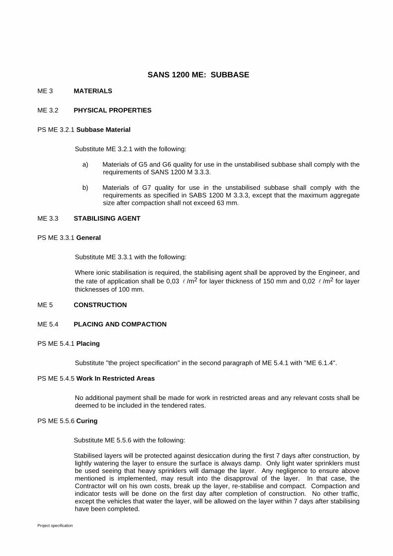
Project specification
SANS 1200 ME: SUBBASE
ME 3 MATERIALS
ME 3.2 PHYSICAL PROPERTIES
PS ME 3.2.1 Subbase Material
Substitute ME 3.2.1 with the following:
a) Materials of G5 and G6 quality for use in the unstabilised subbase shall comply with the requirements of SANS 1200 M 3.3.3.
b) Materials of G7 quality for use in the unstabilised subbase shall comply with the requirements as specified in SABS 1200 M 3.3.3, except that the maximum aggregate size after compaction shall not exceed 63 mm.
ME 3.3 STABILISING AGENT
PS ME 3.3.1 General
Substitute ME 3.3.1 with the following:
Where ionic stabilisation is required, the stabilising agent shall be approved by the Engineer, and
the rate of application shall be 0,03 /m2 for layer thickness of 150 mm and 0,02 /m2 for layer
thicknesses of 100 mm.
ME 5 CONSTRUCTION
ME 5.4 PLACING AND COMPACTION
PS ME 5.4.1 Placing
Substitute "the project specification" in the second paragraph of ME 5.4.1 with "ME 6.1.4".
PS ME 5.4.5 Work In Restricted Areas
No additional payment shall be made for work in restricted areas and any relevant costs shall be deemed to be included in the tendered rates.
PS ME 5.5.6 Curing
Substitute ME 5.5.6 with the following:
Stabilised layers will be protected against desiccation during the first 7 days after construction, by lightly watering the layer to ensure the surface is always damp. Only light water sprinklers must be used seeing that heavy sprinklers will damage the layer. Any negligence to ensure above mentioned is implemented, may result into the disapproval of the layer. In that case, the Contractor will on his own costs, break up the layer, re-stabilise and compact. Compaction and indicator tests will be done on the first day after completion of construction. No other traffic, except the vehicles that water the layer, will be allowed on the layer within 7 days after stabilising have been completed.
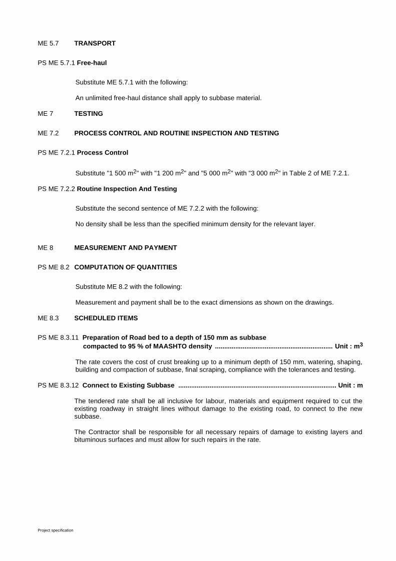
Project specification
ME 5.7 TRANSPORT
PS ME 5.7.1 Free-haul
Substitute ME 5.7.1 with the following:
An unlimited free-haul distance shall apply to subbase material.
ME 7 TESTING
ME 7.2 PROCESS CONTROL AND ROUTINE INSPECTION AND TESTING
PS ME 7.2.1 Process Control
Substitute "1 500 m2" with "1 200 m2" and "5 000 m2" with "3 000 m2" in Table 2 of ME 7.2.1.
PS ME 7.2.2 Routine Inspection And Testing
Substitute the second sentence of ME 7.2.2 with the following:
No density shall be less than the specified minimum density for the relevant layer.
ME 8 MEASUREMENT AND PAYMENT
PS ME 8.2 COMPUTATION OF QUANTITIES
Substitute ME 8.2 with the following:
Measurement and payment shall be to the exact dimensions as shown on the drawings.
ME 8.3 SCHEDULED ITEMS
PS ME 8.3.11 Preparation of Road bed to a depth of 150 mm as subbase
compacted to 95 % of MAASHTO density ................................................................ Unit : m3
The rate covers the cost of crust breaking up to a minimum depth of 150 mm, watering, shaping, building and compaction of subbase, final scraping, compliance with the tolerances and testing.
PS ME 8.3.12 Connect to Existing Subbase ...................................................................................... Unit : m
The tendered rate shall be all inclusive for labour, materials and equipment required to cut the existing roadway in straight lines without damage to the existing road, to connect to the new subbase.
The Contractor shall be responsible for all necessary repairs of damage to existing layers and bituminous surfaces and must allow for such repairs in the rate.

Project specification
SECTION MJ: SEGMENTED PAVING
MJ 3 MATERIAL MJ 3.1 UNITS PS MJ 3.1.2 Class, Strength, And Type Add The following to MJ 3.1.2 Street surfacing as indicated in drawings shall be paved with 60 mm thick Type S-A Class 25
precast concrete blocks (interlocking type). Sidewalks shall be paved with 50 mm thick type S-C Class 25 Pre-cast concrete blocks. Colour of paving will be determined on site.
MJ 5 CONSTRUCTION PS MJ 5.7 JOINT FILLING Joint filling shall be done with sand (A3 Specification). MJ 6 TOLERANCES PS MJ 6.2 PERMISSIBLE DEVIATIONS Add the following to MJ 6.2: The degree of accuracy shall be degree I. MJ 8 MEASURED AND PAYMENT MJ 8.2 SCHEDULED ITEMS PS MJ 8.2.2 Construction of Paving Complete .............................................................................. Unit ; m² Add the following to MJ 8.2.2 The rate shall also cover the cost of the joint filling as specified in PS MJ 5.7. PS MJ 8.2.6 Connection to Existing Road Surface ......................................................................... Unit ; m
The tendered rate shall be all inclusive for labour, materials and equipment required to cut the existing road surface in straight lines without damage to the existing road, to connect to the new road surface.
The Contractor shall be responsible for all necessary repairs of damage to existing road surface and must allow for such repairs in the rate.
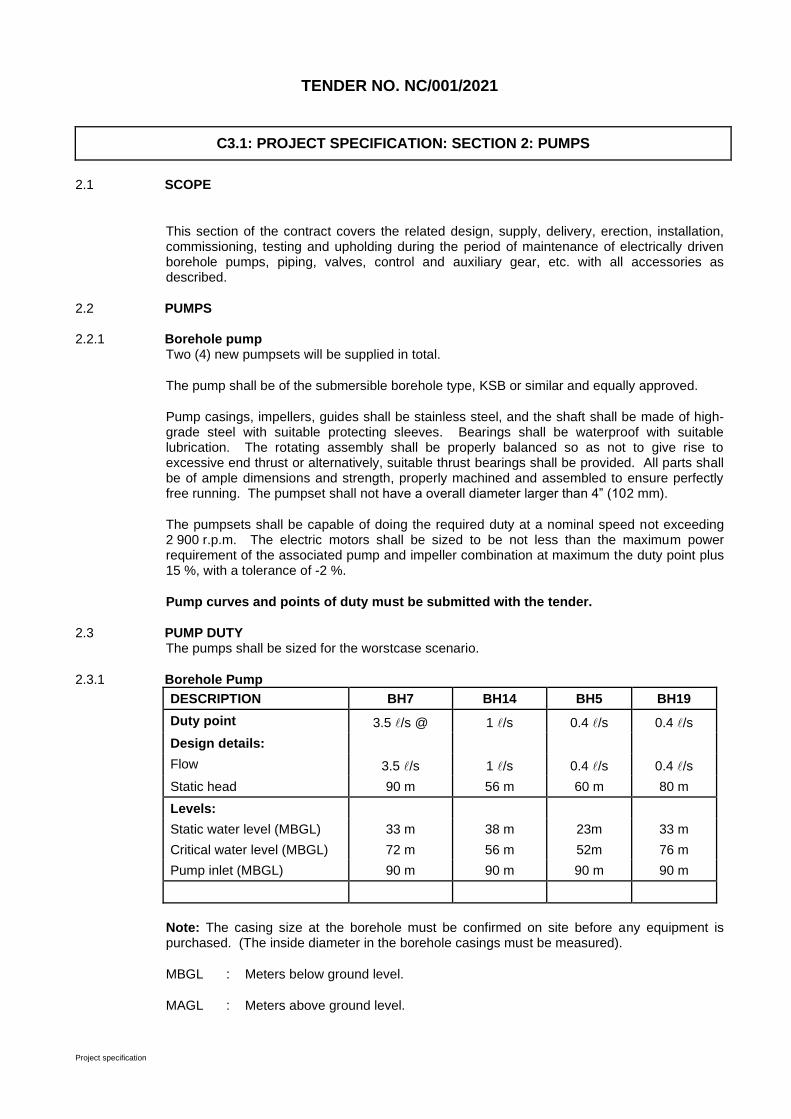
Project specification
TENDER NO. NC/001/2021
C3.1: PROJECT SPECIFICATION: SECTION 2: PUMPS
2.1 SCOPE
This section of the contract covers the related design, supply, delivery, erection, installation, commissioning, testing and upholding during the period of maintenance of electrically driven borehole pumps, piping, valves, control and auxiliary gear, etc. with all accessories as described.
2.2 PUMPS
2.2.1 Borehole pump Two (4) new pumpsets will be supplied in total.
The pump shall be of the submersible borehole type, KSB or similar and equally approved.
Pump casings, impellers, guides shall be stainless steel, and the shaft shall be made of high-grade steel with suitable protecting sleeves. Bearings shall be waterproof with suitable lubrication. The rotating assembly shall be properly balanced so as not to give rise to excessive end thrust or alternatively, suitable thrust bearings shall be provided. All parts shall be of ample dimensions and strength, properly machined and assembled to ensure perfectly free running. The pumpset shall not have a overall diameter larger than 4” (102 mm).
The pumpsets shall be capable of doing the required duty at a nominal speed not exceeding 2 900 r.p.m. The electric motors shall be sized to be not less than the maximum power requirement of the associated pump and impeller combination at maximum the duty point plus 15 %, with a tolerance of -2 %.
Pump curves and points of duty must be submitted with the tender.
2.3 PUMP DUTY The pumps shall be sized for the worstcase scenario.
2.3.1 Borehole Pump
DESCRIPTION BH7 BH14 BH5 BH19
Duty point 3.5 /s @ 1 /s 0.4 /s 0.4 /s
Design details:
Flow 3.5 /s 1 /s 0.4 /s 0.4 /s
Static head 90 m 56 m 60 m 80 m
Levels:
Static water level (MBGL) 33 m 38 m 23m 33 m
Critical water level (MBGL) 72 m 56 m 52m 76 m
Pump inlet (MBGL) 90 m 90 m 90 m 90 m
Note: The casing size at the borehole must be confirmed on site before any equipment is purchased. (The inside diameter in the borehole casings must be measured).
MBGL : Meters below ground level.
MAGL : Meters above ground level.
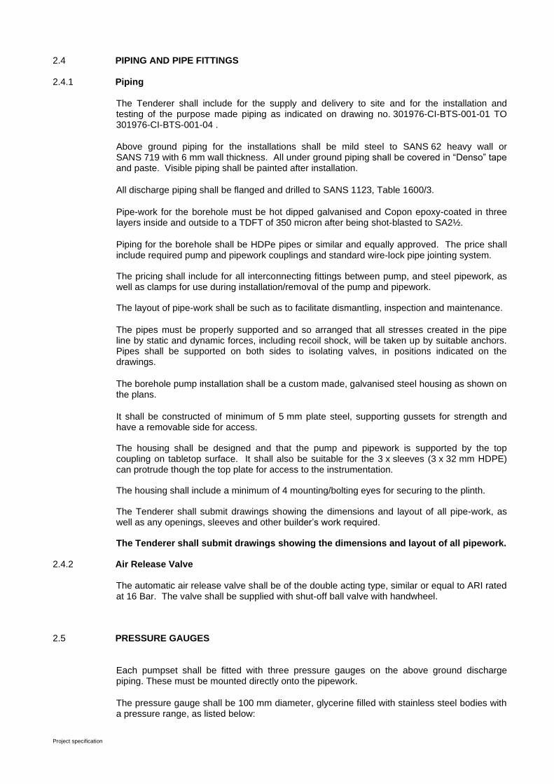
Project specification
2.4 PIPING AND PIPE FITTINGS
2.4.1 Piping The Tenderer shall include for the supply and delivery to site and for the installation and testing of the purpose made piping as indicated on drawing no. 301976-CI-BTS-001-01 TO 301976-CI-BTS-001-04 .
Above ground piping for the installations shall be mild steel to SANS 62 heavy wall or SANS 719 with 6 mm wall thickness. All under ground piping shall be covered in “Denso” tape and paste. Visible piping shall be painted after installation.
All discharge piping shall be flanged and drilled to SANS 1123, Table 1600/3.
Pipe-work for the borehole must be hot dipped galvanised and Copon epoxy-coated in three layers inside and outside to a TDFT of 350 micron after being shot-blasted to SA2½.
Piping for the borehole shall be HDPe pipes or similar and equally approved. The price shall include required pump and pipework couplings and standard wire-lock pipe jointing system.
The pricing shall include for all interconnecting fittings between pump, and steel pipework, as well as clamps for use during installation/removal of the pump and pipework.
The layout of pipe-work shall be such as to facilitate dismantling, inspection and maintenance.
The pipes must be properly supported and so arranged that all stresses created in the pipe line by static and dynamic forces, including recoil shock, will be taken up by suitable anchors. Pipes shall be supported on both sides to isolating valves, in positions indicated on the drawings.
The borehole pump installation shall be a custom made, galvanised steel housing as shown on the plans.
It shall be constructed of minimum of 5 mm plate steel, supporting gussets for strength and have a removable side for access.
The housing shall be designed and that the pump and pipework is supported by the top coupling on tabletop surface. It shall also be suitable for the 3 x sleeves (3 x 32 mm HDPE) can protrude though the top plate for access to the instrumentation.
The housing shall include a minimum of 4 mounting/bolting eyes for securing to the plinth.
The Tenderer shall submit drawings showing the dimensions and layout of all pipe-work, as well as any openings, sleeves and other builder’s work required.
The Tenderer shall submit drawings showing the dimensions and layout of all pipework.
2.4.2 Air Release Valve The automatic air release valve shall be of the double acting type, similar or equal to ARI rated at 16 Bar. The valve shall be supplied with shut-off ball valve with handwheel.
2.5 PRESSURE GAUGES Each pumpset shall be fitted with three pressure gauges on the above ground discharge piping. These must be mounted directly onto the pipework.
The pressure gauge shall be 100 mm diameter, glycerine filled with stainless steel bodies with a pressure range, as listed below:
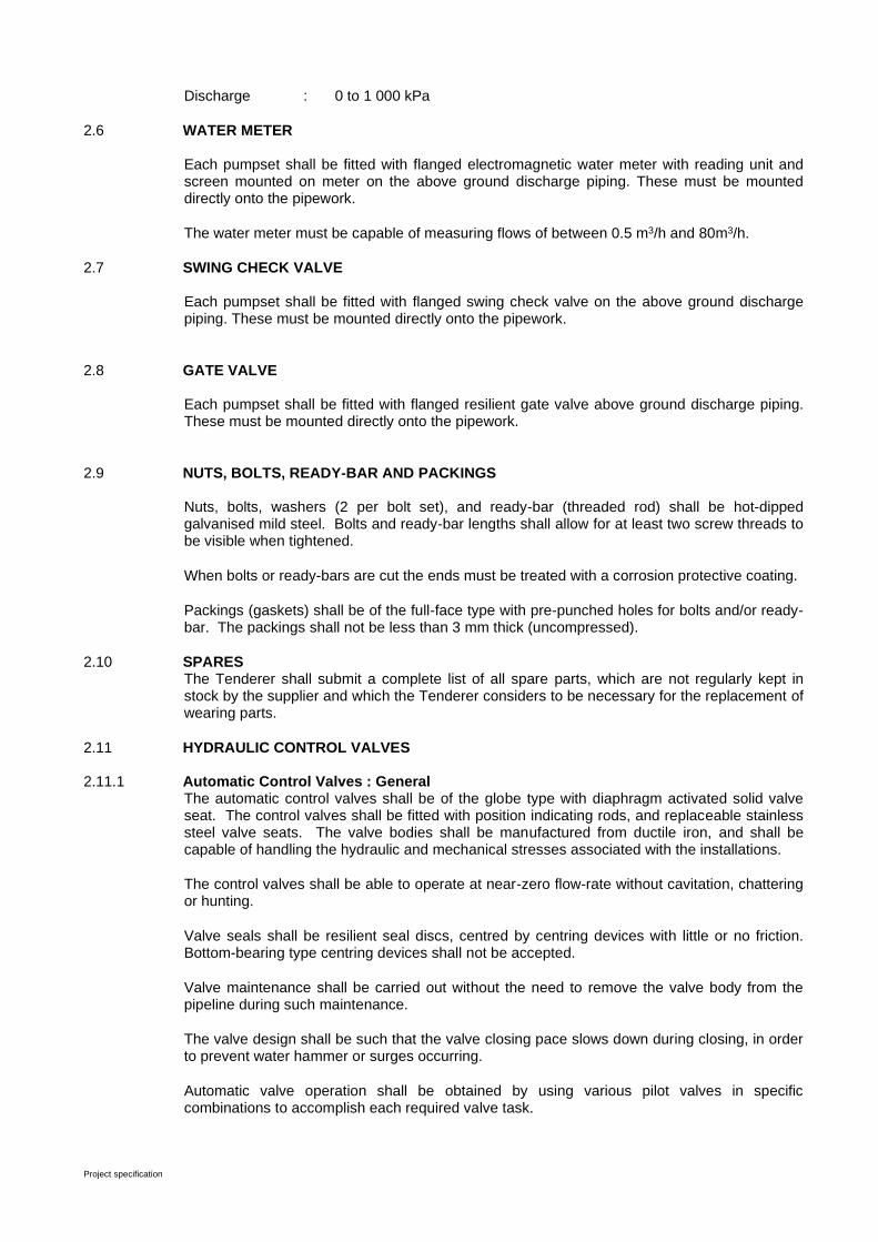
Project specification
Discharge : 0 to 1 000 kPa
2.6 WATER METER Each pumpset shall be fitted with flanged electromagnetic water meter with reading unit and screen mounted on meter on the above ground discharge piping. These must be mounted directly onto the pipework.
The water meter must be capable of measuring flows of between 0.5 m3/h and 80m3/h.
2.7 SWING CHECK VALVE Each pumpset shall be fitted with flanged swing check valve on the above ground discharge piping. These must be mounted directly onto the pipework.
2.8 GATE VALVE
Each pumpset shall be fitted with flanged resilient gate valve above ground discharge piping. These must be mounted directly onto the pipework.
2.9 NUTS, BOLTS, READY-BAR AND PACKINGS
Nuts, bolts, washers (2 per bolt set), and ready-bar (threaded rod) shall be hot-dipped galvanised mild steel. Bolts and ready-bar lengths shall allow for at least two screw threads to be visible when tightened.
When bolts or ready-bars are cut the ends must be treated with a corrosion protective coating.
Packings (gaskets) shall be of the full-face type with pre-punched holes for bolts and/or ready-bar. The packings shall not be less than 3 mm thick (uncompressed).
2.10 SPARES The Tenderer shall submit a complete list of all spare parts, which are not regularly kept in stock by the supplier and which the Tenderer considers to be necessary for the replacement of wearing parts.
2.11 HYDRAULIC CONTROL VALVES
2.11.1 Automatic Control Valves : General The automatic control valves shall be of the globe type with diaphragm activated solid valve seat. The control valves shall be fitted with position indicating rods, and replaceable stainless steel valve seats. The valve bodies shall be manufactured from ductile iron, and shall be capable of handling the hydraulic and mechanical stresses associated with the installations.
The control valves shall be able to operate at near-zero flow-rate without cavitation, chattering or hunting.
Valve seals shall be resilient seal discs, centred by centring devices with little or no friction. Bottom-bearing type centring devices shall not be accepted.
Valve maintenance shall be carried out without the need to remove the valve body from the pipeline during such maintenance.
The valve design shall be such that the valve closing pace slows down during closing, in order to prevent water hammer or surges occurring.
Automatic valve operation shall be obtained by using various pilot valves in specific combinations to accomplish each required valve task.
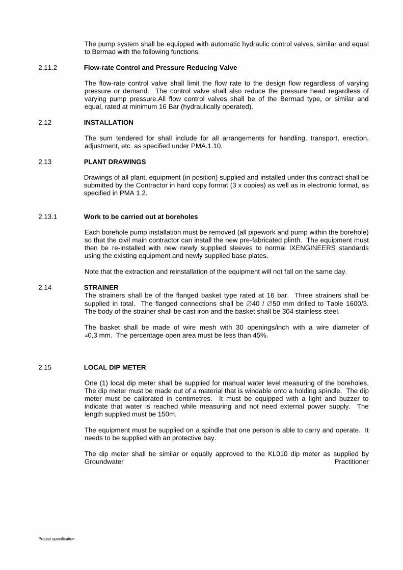
Project specification
The pump system shall be equipped with automatic hydraulic control valves, similar and equal to Bermad with the following functions.
2.11.2 Flow-rate Control and Pressure Reducing Valve The flow-rate control valve shall limit the flow rate to the design flow regardless of varying pressure or demand. The control valve shall also reduce the pressure head regardless of varying pump pressure.All flow control valves shall be of the Bermad type, or similar and equal, rated at minimum 16 Bar (hydraulically operated).
2.12 INSTALLATION The sum tendered for shall include for all arrangements for handling, transport, erection, adjustment, etc. as specified under PMA.1.10.
2.13 PLANT DRAWINGS Drawings of all plant, equipment (in position) supplied and installed under this contract shall be submitted by the Contractor in hard copy format (3 x copies) as well as in electronic format, as specified in PMA 1.2.
2.13.1 Work to be carried out at boreholes
Each borehole pump installation must be removed (all pipework and pump within the borehole) so that the civil main contractor can install the new pre-fabricated plinth. The equipment must then be re-installed with new newly supplied sleeves to normal IXENGINEERS standards using the existing equipment and newly supplied base plates.
Note that the extraction and reinstallation of the equipment will not fall on the same day.
2.14 STRAINER The strainers shall be of the flanged basket type rated at 16 bar. Three strainers shall be
supplied in total. The flanged connections shall be 40 / 50 mm drilled to Table 1600/3. The body of the strainer shall be cast iron and the basket shall be 304 stainless steel.
The basket shall be made of wire mesh with 30 openings/inch with a wire diameter of
≈0,3 mm. The percentage open area must be less than 45%.
2.15 LOCAL DIP METER One (1) local dip meter shall be supplied for manual water level measuring of the boreholes. The dip meter must be made out of a material that is windable onto a holding spindle. The dip meter must be calibrated in centimetres. It must be equipped with a light and buzzer to indicate that water is reached while measuring and not need external power supply. The length supplied must be 150m.
The equipment must be supplied on a spindle that one person is able to carry and operate. It needs to be supplied with an protective bay.
The dip meter shall be similar or equally approved to the KL010 dip meter as supplied by Groundwater Practitioner

Project Specification
C3.3 - 1
ELECTRICAL 21/3/08 BABABTAS BWS
Scope of Works
C3.1 - 1
TENDER
CONSTRUCTION OF BULK WATER SUPPLY IN BABATAS CPA
TENDER NO: NC/001/201
PART C3.3: PROJECT SPECIFICATION (ELETRICAL & MECHANICAL)
3.1 Project Specification
• Section 1: General
• Section 2: Mechanical Specification
• Section 3: Electrical Installation
3.2 Particular Specifications
• PMA : Mechanical Installation
• PMT : Web based Monitoring Installation
3.3 Annexes
• Tender Drawings
• Health and Safety Specification
• Commissioning Test Report
ELECTRICAL 21/3/08 BABABTAS BWS
Scope of Works
C3.1 - 1
TENDER
CONSTRUCTION OF BULK WATER SUPPLY IN BABATAS CPA
TENDER NO: NC/001/201
C3.1 : PROJECT SPECIFICATION: SECTION 1: GENERAL
1.1 GENERAL
This contract covers the related design, supply, delivery installation, commissioning and maintenance during the defects liability period of mechanical and electrical equipment required for four (4) boreholes installations and 2 centrifugal pumps installations in Babatas CPA
1.2 DESCRIPTION OF THE SITE AND ACCESS
The project consists out of four sites outside the town of Kathu, Northern Cape.
1.3 DETAILS OF THE CONTRACT
This contract will be executed as a nominated subcontract. The mechanical contractor under this contract shall liaise closely with the civil contractor, where civil work is done concurrently under a separate contract.
The major item of work to be carried out under this contract is:
a) Two (4) submersible multistage borehole pumps including piping, electrical switchboard, cables and automatic control for starting and stopping of the pumps.
b) One (1) new switchboard for each borehole installation.
c) Installation of seven baseplate boxes and sleeves for monitoring purposes.
d) Installation of Solar system as power source per borehole and monitoring by telemetry system of these boreholes.
Note: The Employer reserves the right to accept this tender in part only.
Note : All solar equipment to be confirmed with Engineer before purchase and installation, solar installation to be a specialized sub contractor.
1.4 CONSTRUCTION PROGRAMME
The Contractor shall submit a programme for approval by the Engineer.
1.5 SITE FACILITIES AVAILABLE
The Contractor shall make his own arrangement for any sanitary or other facilities he may require.
1.6 STATUS
The particular specification sections forming part of this contract, have been written to cover all phases of work usually encountered in contracts of this nature and may therefore cover items

ELECTRICAL 21/3/08 BABABTAS BWS
Scope of Works
C3.1 - 2
of work not encountered in this particular contract. In case of any discrepancy or conflict with any part or parts of the particular specification section, these project specification amendments shall apply.
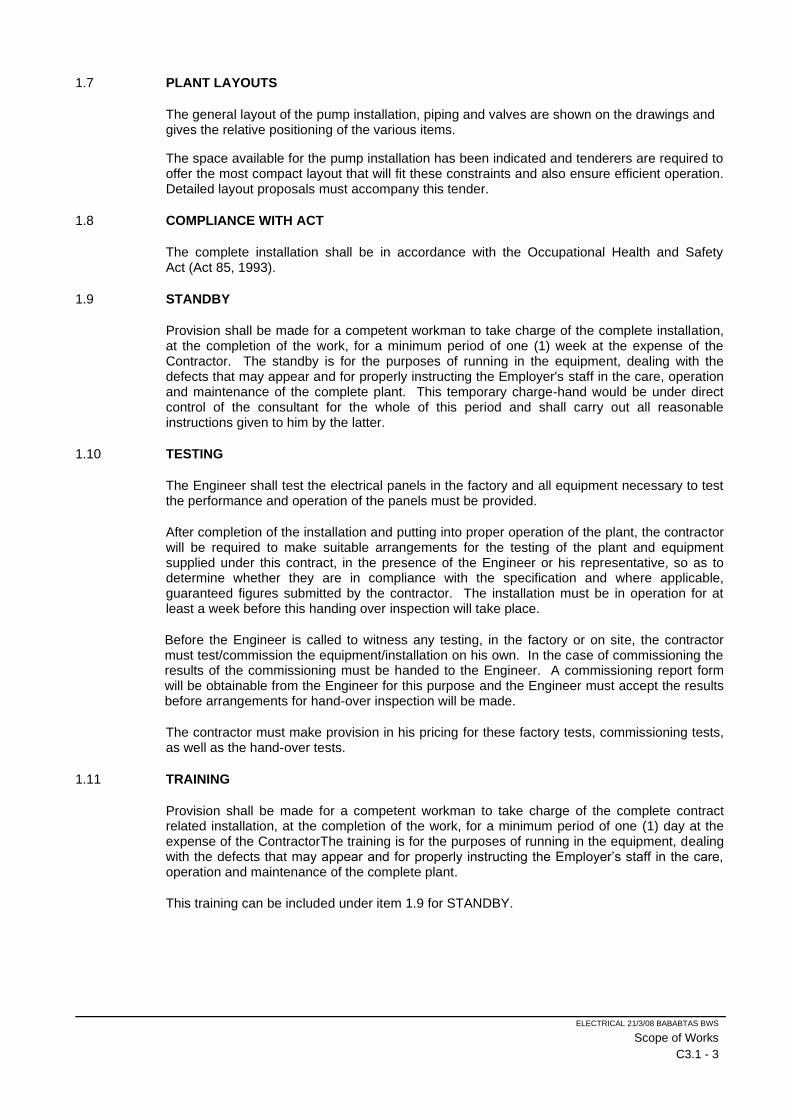
ELECTRICAL 21/3/08 BABABTAS BWS
Scope of Works
C3.1 - 3
1.7 PLANT LAYOUTS
The general layout of the pump installation, piping and valves are shown on the drawings and gives the relative positioning of the various items.
The space available for the pump installation has been indicated and tenderers are required to offer the most compact layout that will fit these constraints and also ensure efficient operation. Detailed layout proposals must accompany this tender.
1.8 COMPLIANCE WITH ACT
The complete installation shall be in accordance with the Occupational Health and Safety Act (Act 85, 1993).
1.9 STANDBY
Provision shall be made for a competent workman to take charge of the complete installation, at the completion of the work, for a minimum period of one (1) week at the expense of the Contractor. The standby is for the purposes of running in the equipment, dealing with the defects that may appear and for properly instructing the Employer's staff in the care, operation and maintenance of the complete plant. This temporary charge-hand would be under direct control of the consultant for the whole of this period and shall carry out all reasonable instructions given to him by the latter.
1.10 TESTING
The Engineer shall test the electrical panels in the factory and all equipment necessary to test the performance and operation of the panels must be provided.
After completion of the installation and putting into proper operation of the plant, the contractor will be required to make suitable arrangements for the testing of the plant and equipment supplied under this contract, in the presence of the Engineer or his representative, so as to determine whether they are in compliance with the specification and where applicable, guaranteed figures submitted by the contractor. The installation must be in operation for at least a week before this handing over inspection will take place.
Before the Engineer is called to witness any testing, in the factory or on site, the contractor must test/commission the equipment/installation on his own. In the case of commissioning the results of the commissioning must be handed to the Engineer. A commissioning report form will be obtainable from the Engineer for this purpose and the Engineer must accept the results before arrangements for hand-over inspection will be made.
The contractor must make provision in his pricing for these factory tests, commissioning tests, as well as the hand-over tests.
1.11 TRAINING
Provision shall be made for a competent workman to take charge of the complete contract related installation, at the completion of the work, for a minimum period of one (1) day at the expense of the ContractorThe training is for the purposes of running in the equipment, dealing with the defects that may appear and for properly instructing the Employer’s staff in the care, operation and maintenance of the complete plant.
This training can be included under item 1.9 for STANDBY.
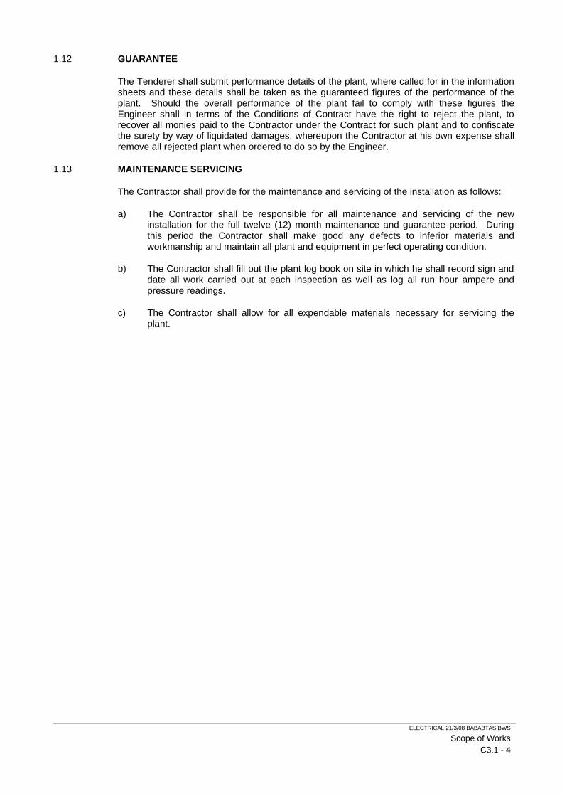
ELECTRICAL 21/3/08 BABABTAS BWS
Scope of Works
C3.1 - 4
1.12 GUARANTEE
The Tenderer shall submit performance details of the plant, where called for in the information sheets and these details shall be taken as the guaranteed figures of the performance of the plant. Should the overall performance of the plant fail to comply with these figures the Engineer shall in terms of the Conditions of Contract have the right to reject the plant, to recover all monies paid to the Contractor under the Contract for such plant and to confiscate the surety by way of liquidated damages, whereupon the Contractor at his own expense shall remove all rejected plant when ordered to do so by the Engineer.
1.13 MAINTENANCE SERVICING
The Contractor shall provide for the maintenance and servicing of the installation as follows:
a) The Contractor shall be responsible for all maintenance and servicing of the new installation for the full twelve (12) month maintenance and guarantee period. During this period the Contractor shall make good any defects to inferior materials and workmanship and maintain all plant and equipment in perfect operating condition.
b) The Contractor shall fill out the plant log book on site in which he shall record sign and date all work carried out at each inspection as well as log all run hour ampere and pressure readings.
c) The Contractor shall allow for all expendable materials necessary for servicing the plant.
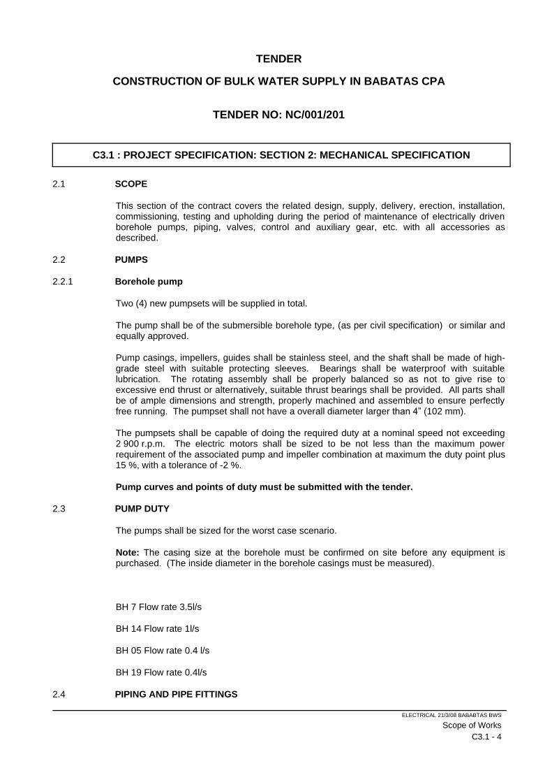
ELECTRICAL 21/3/08 BABABTAS BWS
Scope of Works
C3.1 - 4
TENDER
CONSTRUCTION OF BULK WATER SUPPLY IN BABATAS CPA
TENDER NO: NC/001/201
C3.1 : PROJECT SPECIFICATION: SECTION 2: MECHANICAL SPECIFICATION
2.1 SCOPE
This section of the contract covers the related design, supply, delivery, erection, installation, commissioning, testing and upholding during the period of maintenance of electrically driven borehole pumps, piping, valves, control and auxiliary gear, etc. with all accessories as described.
2.2 PUMPS
2.2.1 Borehole pump
Two (4) new pumpsets will be supplied in total.
The pump shall be of the submersible borehole type, (as per civil specification) or similar and equally approved.
Pump casings, impellers, guides shall be stainless steel, and the shaft shall be made of high-grade steel with suitable protecting sleeves. Bearings shall be waterproof with suitable lubrication. The rotating assembly shall be properly balanced so as not to give rise to excessive end thrust or alternatively, suitable thrust bearings shall be provided. All parts shall be of ample dimensions and strength, properly machined and assembled to ensure perfectly free running. The pumpset shall not have a overall diameter larger than 4” (102 mm).
The pumpsets shall be capable of doing the required duty at a nominal speed not exceeding 2 900 r.p.m. The electric motors shall be sized to be not less than the maximum power requirement of the associated pump and impeller combination at maximum the duty point plus 15 %, with a tolerance of -2 %.
Pump curves and points of duty must be submitted with the tender.
2.3 PUMP DUTY
The pumps shall be sized for the worst case scenario.
Note: The casing size at the borehole must be confirmed on site before any equipment is purchased. (The inside diameter in the borehole casings must be measured).
BH 7 Flow rate 3.5l/s
BH 14 Flow rate 1l/s
BH 05 Flow rate 0.4 l/s
BH 19 Flow rate 0.4l/s
2.4 PIPING AND PIPE FITTINGS
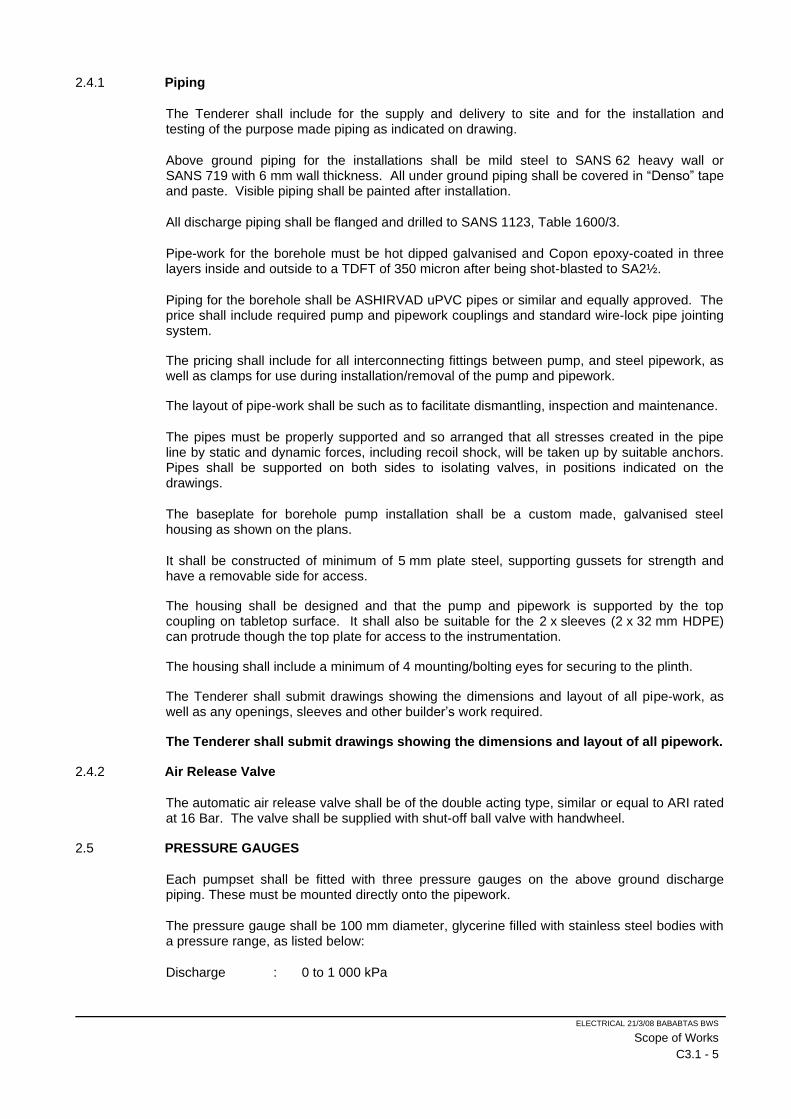
ELECTRICAL 21/3/08 BABABTAS BWS
Scope of Works
C3.1 - 5
2.4.1 Piping
The Tenderer shall include for the supply and delivery to site and for the installation and testing of the purpose made piping as indicated on drawing.
Above ground piping for the installations shall be mild steel to SANS 62 heavy wall or SANS 719 with 6 mm wall thickness. All under ground piping shall be covered in “Denso” tape and paste. Visible piping shall be painted after installation.
All discharge piping shall be flanged and drilled to SANS 1123, Table 1600/3.
Pipe-work for the borehole must be hot dipped galvanised and Copon epoxy-coated in three layers inside and outside to a TDFT of 350 micron after being shot-blasted to SA2½.
Piping for the borehole shall be ASHIRVAD uPVC pipes or similar and equally approved. The price shall include required pump and pipework couplings and standard wire-lock pipe jointing system.
The pricing shall include for all interconnecting fittings between pump, and steel pipework, as well as clamps for use during installation/removal of the pump and pipework.
The layout of pipe-work shall be such as to facilitate dismantling, inspection and maintenance.
The pipes must be properly supported and so arranged that all stresses created in the pipe line by static and dynamic forces, including recoil shock, will be taken up by suitable anchors. Pipes shall be supported on both sides to isolating valves, in positions indicated on the drawings.
The baseplate for borehole pump installation shall be a custom made, galvanised steel housing as shown on the plans.
It shall be constructed of minimum of 5 mm plate steel, supporting gussets for strength and have a removable side for access.
The housing shall be designed and that the pump and pipework is supported by the top coupling on tabletop surface. It shall also be suitable for the 2 x sleeves (2 x 32 mm HDPE) can protrude though the top plate for access to the instrumentation.
The housing shall include a minimum of 4 mounting/bolting eyes for securing to the plinth.
The Tenderer shall submit drawings showing the dimensions and layout of all pipe-work, as well as any openings, sleeves and other builder’s work required.
The Tenderer shall submit drawings showing the dimensions and layout of all pipework.
2.4.2 Air Release Valve
The automatic air release valve shall be of the double acting type, similar or equal to ARI rated at 16 Bar. The valve shall be supplied with shut-off ball valve with handwheel.
2.5 PRESSURE GAUGES
Each pumpset shall be fitted with three pressure gauges on the above ground discharge piping. These must be mounted directly onto the pipework.
The pressure gauge shall be 100 mm diameter, glycerine filled with stainless steel bodies with a pressure range, as listed below:
Discharge : 0 to 1 000 kPa
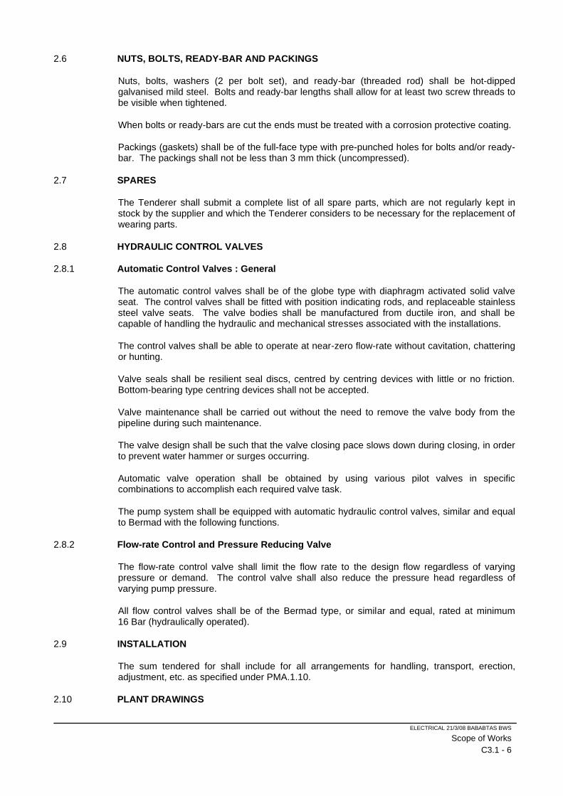
ELECTRICAL 21/3/08 BABABTAS BWS
Scope of Works
C3.1 - 6
2.6 NUTS, BOLTS, READY-BAR AND PACKINGS
Nuts, bolts, washers (2 per bolt set), and ready-bar (threaded rod) shall be hot-dipped galvanised mild steel. Bolts and ready-bar lengths shall allow for at least two screw threads to be visible when tightened.
When bolts or ready-bars are cut the ends must be treated with a corrosion protective coating.
Packings (gaskets) shall be of the full-face type with pre-punched holes for bolts and/or ready-bar. The packings shall not be less than 3 mm thick (uncompressed).
2.7 SPARES
The Tenderer shall submit a complete list of all spare parts, which are not regularly kept in stock by the supplier and which the Tenderer considers to be necessary for the replacement of wearing parts.
2.8 HYDRAULIC CONTROL VALVES
2.8.1 Automatic Control Valves : General
The automatic control valves shall be of the globe type with diaphragm activated solid valve seat. The control valves shall be fitted with position indicating rods, and replaceable stainless steel valve seats. The valve bodies shall be manufactured from ductile iron, and shall be capable of handling the hydraulic and mechanical stresses associated with the installations.
The control valves shall be able to operate at near-zero flow-rate without cavitation, chattering or hunting.
Valve seals shall be resilient seal discs, centred by centring devices with little or no friction. Bottom-bearing type centring devices shall not be accepted.
Valve maintenance shall be carried out without the need to remove the valve body from the pipeline during such maintenance.
The valve design shall be such that the valve closing pace slows down during closing, in order to prevent water hammer or surges occurring.
Automatic valve operation shall be obtained by using various pilot valves in specific combinations to accomplish each required valve task.
The pump system shall be equipped with automatic hydraulic control valves, similar and equal to Bermad with the following functions.
2.8.2 Flow-rate Control and Pressure Reducing Valve
The flow-rate control valve shall limit the flow rate to the design flow regardless of varying pressure or demand. The control valve shall also reduce the pressure head regardless of varying pump pressure.
All flow control valves shall be of the Bermad type, or similar and equal, rated at minimum 16 Bar (hydraulically operated).
2.9 INSTALLATION
The sum tendered for shall include for all arrangements for handling, transport, erection, adjustment, etc. as specified under PMA.1.10.
2.10 PLANT DRAWINGS
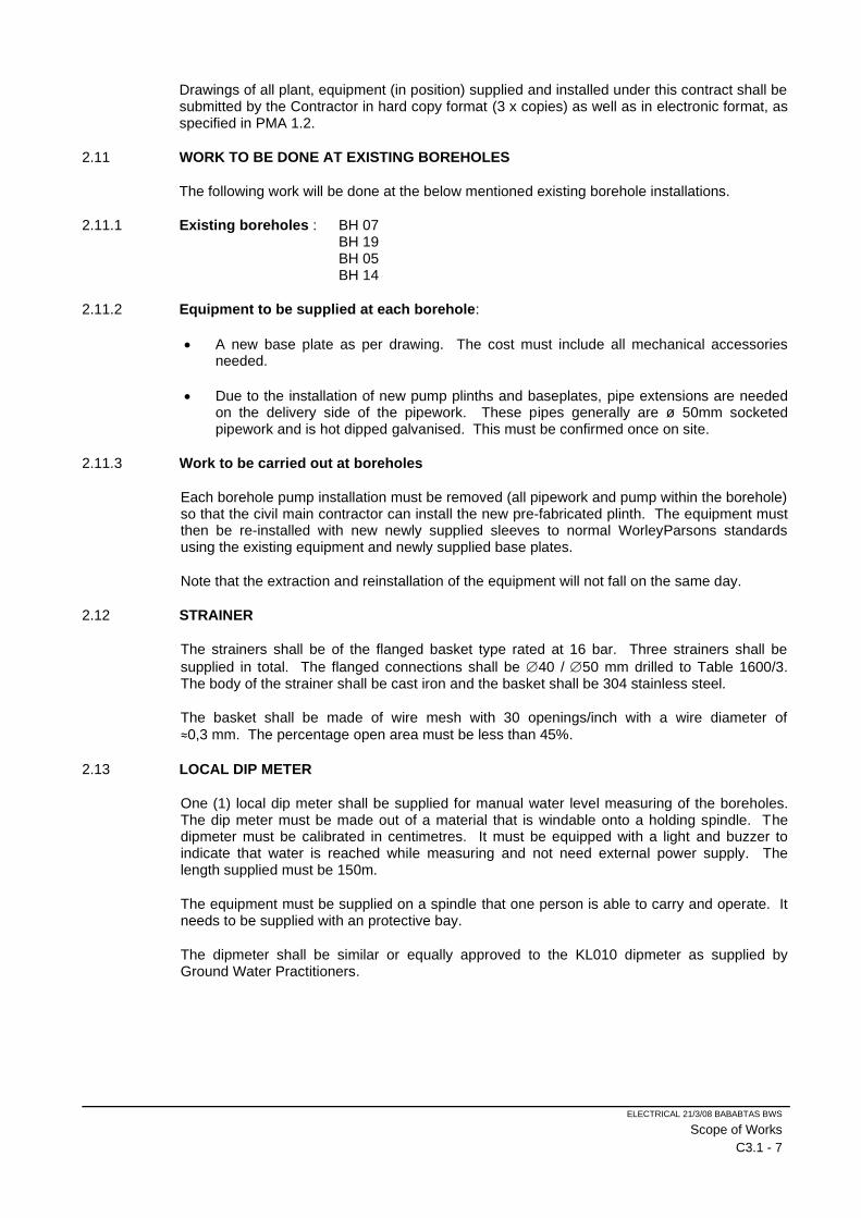
ELECTRICAL 21/3/08 BABABTAS BWS
Scope of Works
C3.1 - 7
Drawings of all plant, equipment (in position) supplied and installed under this contract shall be submitted by the Contractor in hard copy format (3 x copies) as well as in electronic format, as specified in PMA 1.2.
2.11 WORK TO BE DONE AT EXISTING BOREHOLES
The following work will be done at the below mentioned existing borehole installations.
2.11.1 Existing boreholes : BH 07 BH 19 BH 05 BH 14
2.11.2 Equipment to be supplied at each borehole:
• A new base plate as per drawing. The cost must include all mechanical accessories needed.
• Due to the installation of new pump plinths and baseplates, pipe extensions are needed on the delivery side of the pipework. These pipes generally are ø 50mm socketed pipework and is hot dipped galvanised. This must be confirmed once on site.
2.11.3 Work to be carried out at boreholes
Each borehole pump installation must be removed (all pipework and pump within the borehole) so that the civil main contractor can install the new pre-fabricated plinth. The equipment must then be re-installed with new newly supplied sleeves to normal WorleyParsons standards using the existing equipment and newly supplied base plates.
Note that the extraction and reinstallation of the equipment will not fall on the same day.
2.12 STRAINER
The strainers shall be of the flanged basket type rated at 16 bar. Three strainers shall be
supplied in total. The flanged connections shall be 40 / 50 mm drilled to Table 1600/3. The body of the strainer shall be cast iron and the basket shall be 304 stainless steel.
The basket shall be made of wire mesh with 30 openings/inch with a wire diameter of
≈0,3 mm. The percentage open area must be less than 45%.
2.13 LOCAL DIP METER
One (1) local dip meter shall be supplied for manual water level measuring of the boreholes. The dip meter must be made out of a material that is windable onto a holding spindle. The dipmeter must be calibrated in centimetres. It must be equipped with a light and buzzer to indicate that water is reached while measuring and not need external power supply. The length supplied must be 150m.
The equipment must be supplied on a spindle that one person is able to carry and operate. It needs to be supplied with an protective bay.
The dipmeter shall be similar or equally approved to the KL010 dipmeter as supplied by Ground Water Practitioners.
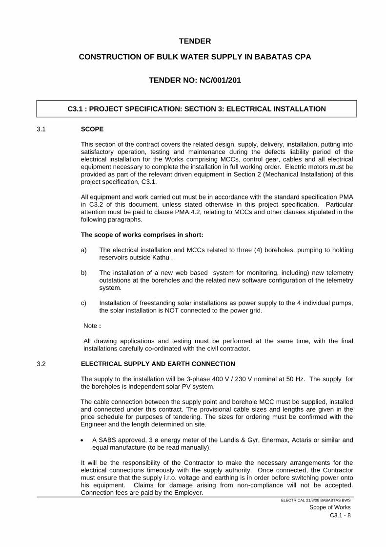
ELECTRICAL 21/3/08 BABABTAS BWS
Scope of Works
C3.1 - 8
TENDER
CONSTRUCTION OF BULK WATER SUPPLY IN BABATAS CPA
TENDER NO: NC/001/201
C3.1 : PROJECT SPECIFICATION: SECTION 3: ELECTRICAL INSTALLATION
3.1 SCOPE
This section of the contract covers the related design, supply, delivery, installation, putting into satisfactory operation, testing and maintenance during the defects liability period of the electrical installation for the Works comprising MCCs, control gear, cables and all electrical equipment necessary to complete the installation in full working order. Electric motors must be provided as part of the relevant driven equipment in Section 2 (Mechanical Installation) of this project specification, C3.1.
All equipment and work carried out must be in accordance with the standard specification PMA in C3.2 of this document, unless stated otherwise in this project specification. Particular attention must be paid to clause PMA.4.2, relating to MCCs and other clauses stipulated in the following paragraphs.
The scope of works comprises in short:
a) The electrical installation and MCCs related to three (4) boreholes, pumping to holding reservoirs outside Kathu .
b) The installation of a new web based system for monitoring, including) new telemetry outstations at the boreholes and the related new software configuration of the telemetry system.
c) Installation of freestanding solar installations as power supply to the 4 individual pumps, the solar installation is NOT connected to the power grid.
Note :
All drawing applications and testing must be performed at the same time, with the final installations carefully co-ordinated with the civil contractor.
3.2 ELECTRICAL SUPPLY AND EARTH CONNECTION
The supply to the installation will be 3-phase 400 V / 230 V nominal at 50 Hz. The supply for the boreholes is independent solar PV system.
The cable connection between the supply point and borehole MCC must be supplied, installed and connected under this contract. The provisional cable sizes and lengths are given in the price schedule for purposes of tendering. The sizes for ordering must be confirmed with the Engineer and the length determined on site.
• A SABS approved, 3 ø energy meter of the Landis & Gyr, Enermax, Actaris or similar and equal manufacture (to be read manually).
It will be the responsibility of the Contractor to make the necessary arrangements for the electrical connections timeously with the supply authority. Once connected, the Contractor must ensure that the supply i.r.o. voltage and earthing is in order before switching power onto his equipment. Claims for damage arising from non-compliance will not be accepted. Connection fees are paid by the Employer.
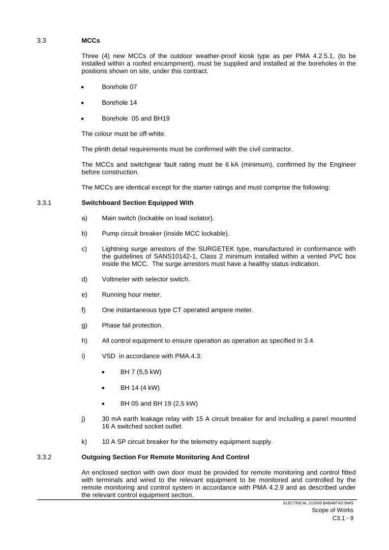
ELECTRICAL 21/3/08 BABABTAS BWS
Scope of Works
C3.1 - 9
3.3 MCCs
Three (4) new MCCs of the outdoor weather-proof kiosk type as per PMA 4.2.5.1, (to be installed within a roofed encampment), must be supplied and installed at the boreholes in the positions shown on site, under this contract.
• Borehole 07
• Borehole 14
• Borehole 05 and BH19
The colour must be off-white.
The plinth detail requirements must be confirmed with the civil contractor.
The MCCs and switchgear fault rating must be 6 kA (minimum), confirmed by the Engineer before construction.
The MCCs are identical except for the starter ratings and must comprise the following:
3.3.1 Switchboard Section Equipped With
a) Main switch (lockable on load isolator).
b) Pump circuit breaker (inside MCC lockable).
c) Lightning surge arrestors of the SURGETEK type, manufactured in conformance with the guidelines of SANS10142-1, Class 2 minimum installed within a vented PVC box inside the MCC. The surge arrestors must have a healthy status indication.
d) Voltmeter with selector switch.
e) Running hour meter.
f) One instantaneous type CT operated ampere meter.
g) Phase fail protection.
h) All control equipment to ensure operation as operation as specified in 3.4.
i) VSD in accordance with PMA.4.3:
• BH 7 (5,5 kW)
• BH 14 (4 kW)
• BH 05 and BH 19 (2,5 kW)
j) 30 mA earth leakage relay with 15 A circuit breaker for and including a panel mounted 16 A switched socket outlet.
k) 10 A SP circuit breaker for the telemetry equipment supply.
3.3.2 Outgoing Section For Remote Monitoring And Control
An enclosed section with own door must be provided for remote monitoring and control fitted with terminals and wired to the relevant equipment to be monitored and controlled by the remote monitoring and control system in accordance with PMA 4.2.9 and as described under the relevant control equipment section.

ELECTRICAL 21/3/08 BABABTAS BWS
Scope of Works
C3.1 - 10
3.4 BOREHOLES CONTROL
3.4.1.1 Control Mode
The pump must be operated both automatically and manually, by means of a three position selector switch on the control panel marked MANUAL/OFF/AUTO. It shall not be possible to start the pump in the OFF position, and a running pump shall STOP when switched to OFF.
a) MANUAL mode
The pump must be started and stopped by means of start and stop pushbuttons on the MCC.
The pump must also be emergency controlled as per (c) below. Note the requirement if the telemetry system is not functional.
ELECTRICAL 21/3/08 BABABTAS BWS
Scope of Works
C3.1 - 11
b) AUTO mode
Demand (Primary) control
The pump must START when the remote holding reservoir is at a predetermined low level, provided the secondary control conditions are met as described below, and STOP when the reservoir is full. This signal is derived from the level pressure sensor at the reservoir. The analogue signal will be relayed to the borehole outstation and the digital start/stop signal must be generated within the borehole outstation RTU, as a voltage free output contact from the outstation to the MCC. The start signal must switch an indicating light labelled RESERVOIR LEVEL START DEMAND on at the reservoir low level and the stop signal must switch it off at the full level. Loss of the analogue signal must result in a STOP signal. The signal configuration must be liaised between the MCC manufacturer and the SCADA vendor.
Secondary Control : Suction
When the water level in the borehole has dropped to a predetermined low level, the pump must STOP and only restart under primary control once the level has risen to a predetermined high (reset) level. A 0-3-hour adjustable recovery time delay must be provided to delay the reset. The level signal must be derived from a borehole level sensor, provided under item 3.5.1.
At the low level, a BOREHOLE LOW LEVEL indication light must switch ON and reset automatically at the reset level, after the delay timer has timed out.
The sensor must be connected to the telemetry RTU and the suction control signal must be processed in the telemetry RTU with a stop/reset signal as a digital output from the outstation to the MCC control by means of single voltage free contact.
The borehole analogue water level (m above pump) must be displayed on a LCD display as described under the outstation schedule section.
Secondary control : Time
A 24 hour time clock must be provided which will allow the pump to operate an (adjustable) set period only per day.
The pump must start at the pre-set start time and stop at the pre-set stop time subject to the primary level control. An indication light must be provided to indicate when the timing cycle is ON in TIMER Position, labelled TIMING CYCLE ON.
The pump must also be emergency controlled as per (c) below. Note the requirement if the telemetry system is not functional.
A BYPASS/TIMER selector switch must be provided to bypass the time control.
c) EMERGENCY control
The high level alarm in the remote holding reservoir (Witpoort for SG159 and balancing for SG161) must STOP the borehole pumps, in all control modes, with corresponding RESERVOIR HIGH LEVEL indication light, with manual reset at the borehole and from the SCADA central station, provided the high level alarm float switch is in the normal position.
The configuration must be that should the telemetry system not be functional, it will not inhibit starting of the pump in MANUAL mode.
ELECTRICAL 21/3/08 BABABTAS BWS
Scope of Works
C3.1 - 12
3.4.1.2 Protection
The pump set must be protected, in all control modes, against damage from the conditions described below.
Protection devices must have manual resets, unless specified to the contrary elsewhere. The motor may only restart once the protection device has been reset.
a) Motor protection relay (NewElec KD200 or similar), with the following facilities:
• Overload
• Underload
• Under voltage and phase imbalance with time delayed (up to 15 min adjustable) auto reset
• Earth leakage
b) Borehole low level by means of an extra low level electrode.
c) No flow by means of a limit switch on a non-return valve
3.4.1.3 Alarm And Status Indication Facilities
a) MCC
Status Indication must be provided in accordance with PMA 4.2.8 for:
• RUN
• OVERLOAD
• MPR TRIP
• EARTH LEAKAGE
• BOREHOLE LOW LEVEL
• BOREHOLE EXTRA LOW LEVEL
• REMOTE RESERVOIR START DEMAND
• RESERVOIR HIGH LEVEL
• TIMING CYCLE ON (FROM TIME CLOCK)
• NO-FLOW
3.4.1.4 Remote Monitoring And Control
Signals must be provided for monitoring and control, by the SCADA system in accordance with 3.3.2 and 3.7.
The following signals from the telemetry to the MCC must be provided for:
a) Remote reservoir start demand
b) Remote reservoir high level alarm
ELECTRICAL 21/3/08 BABABTAS BWS
Scope of Works
C3.1 - 13
c) Remote level alarm reset
d) Borehole suction low level
The following signals from the MCC to telemetry must be provided for:
a) All status signals
b) Remote reservoir high level alarm (latched signal)
Note: That the format of the signals must be coordinated with the telemetry contractor
3.4.1.5 Control Mode
The pump must be operated both automatically and manually, by means of a three position selector switch on the control panel marked MANUAL/OFF/AUTO. It shall not be possible to start the pump in the OFF position, and a running pump shall STOP when switched to OFF.
a) MANUAL mode
The pump must be started and stopped by means of start and stop pushbuttons on the MCC.
The pump must also be emergency controlled as per (c) below. Note the requirement if the telemetry system is not functional.
b) AUTO mode
Demand (Primary) control
The pump must START when the balancing reservoir is at a predetermined low level, provided the secondary and tertiary level control conditions are met as described below, and STOP when the reservoir is full. This signal is derived from the level pressure sensor at the reservoir. The analogue signal will be relayed to the borehole outstation and the digital start/stop signal must be generated within the borehole outstation RTU, as a voltage free output contact from the outstation to the MCC. The start signal must switch an indicating light labelled RESERVOIR LEVEL START DEMAND on at the reservoir low level and the stop signal must switch it off at the full level. Loss of the analogue signal must result in a STOP signal. The signal configuration must be liaised between the MCC manufacturer and the SCADA vendor.
Secondary control : Suction
When the water level in the borehole has dropped to a predetermined low level, the pump must STOP and only restart under primary control, once the level has risen to a predetermined high (reset) level. A 0-3 hour adjustable recovery time delay must be provided to delay the reset. The level signal must be derived from a borehole level sensor.
At the low level, a BOREHOLE LOW LEVEL indication light must switch ON and reset automatically at the reset level, after the delay timer has timed out.
The sensor must be connected to the telemetry RTU and the suction control signal must be processed in the telemetry RTU with a stop/reset signal as a digital output from the outstation to the MCC control by means of single voltage free contact.
ELECTRICAL 21/3/08 BABABTAS BWS
Scope of Works
C3.1 - 14
The borehole analogue water level (m above pump) must be displayed on a LCD display as described under the outstation schedule section.
Secondary control : Demand
When the Witpoort reservoir has reached its full stop level (even though there is still a START demand level from the balancing reservoir) the pump must STOP and only restart under primary control once the Reservoir level has fallen to the start level.
At the reservoir full level, indication light must switch on, cancelled by the BH start level.
Secondary control: Time
A time clock must be provided which will allow the pump to operate an (adjustable) set period only per day.
The pump must start at the pre-set start time and stop at the pre-set stop time subject to the primary level control. An indication light must be provided to indicate when the timing cycle is ON in TIMER position, labelled TIMING CYCLE ON.
The pump must also be emergency controlled as per (c) below. Note the requirement if the telemetry system is not functional.
A BYPASS/TIMER selector switch must be provided to bypass the time control.
c) EMERGENCY control
The high level alarm in either remote holding reservoirs must STOP the borehole pump, in all control modes, with corresponding RESERVOIR HIGH LEVEL indication light, with manual reset at the borehole and from the SCADA central station, provided the high level alarm float switch is in the normal position.
The configuration must be that should the telemetry system not be functional, it will not inhibit starting of the pump in MANUAL mode.
3.4.1.6 Protection
The pump set must be protected, in all control modes, against damage from the conditions described below.
Protection devices must have manual resets, unless specified to the contrary elsewhere. The motor may only restart once the protection device has been reset.
a) Motor protection relay (NewElec KD200 or similar), with the following facilities:
• Overload
• Underload
• Under voltage and phase imbalance with time delayed (up to 15 min adjustable) auto reset
• Earth leakage
b) Earth leakage by means of a 250 mA earth leakage relay.
c) Borehole low level by means of an extra low level electrode.
d) No-flow by means of a limit switch on a non-return valve.
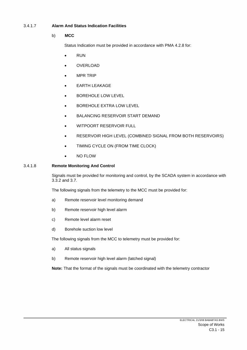
ELECTRICAL 21/3/08 BABABTAS BWS
Scope of Works
C3.1 - 15
3.4.1.7 Alarm And Status Indication Facilities
b) MCC
Status Indication must be provided in accordance with PMA 4.2.8 for:
• RUN
• OVERLOAD
• MPR TRIP
• EARTH LEAKAGE
• BOREHOLE LOW LEVEL
• BOREHOLE EXTRA LOW LEVEL
• BALANCING RESERVOIR START DEMAND
• WITPOORT RESERVOIR FULL
• RESERVOIR HIGH LEVEL (COMBINED SIGNAL FROM BOTH RESERVOIRS)
• TIMING CYCLE ON (FROM TIME CLOCK)
• NO FLOW
3.4.1.8 Remote Monitoring And Control
Signals must be provided for monitoring and control, by the SCADA system in accordance with 3.3.2 and 3.7.
The following signals from the telemetry to the MCC must be provided for:
a) Remote reservoir level monitoring demand
b) Remote reservoir high level alarm
c) Remote level alarm reset
d) Borehole suction low level
The following signals from the MCC to telemetry must be provided for:
a) All status signals
b) Remote reservoir high level alarm (latched signal)
Note: That the format of the signals must be coordinated with the telemetry contractor
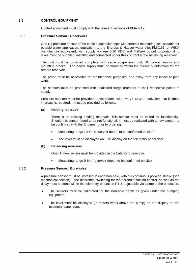
ELECTRICAL 21/3/08 BABABTAS BWS
Scope of Works
C3.1 - 16
3.5 CONTROL EQUIPMENT
Control equipment must comply with the relevant sections of PMA 4.12.
3.5.1 Pressure Sensor : Reservoirs
One (1) pressure sensor of the cable suspension type with ceramic measuring cell, suitable for potable water application, equivalent to the Endress & Hauser water pilot FMX167, or WIKA manufacture equivalent, with supply voltage 0-30 VDC and 4-20mA output proportional to level, must be supplied, installed and connected under this contract at the balancing reservoir.
The unit must be provided complete with cable suspension unit, DC power supply and mounting bracket. The power supply must be mounted within the telemetry outstation for the remote reservoir.
The probe must be accessible for maintenance purposes, and away from any inflow or pipe work.
The sensors must be protected with dedicated surge arrestors at their respective points of supply.
Pressure sensors must be provided in accordance with PMA.4.12.3.2, equivalent. No fieldbus interface is required. It must be provided as follows:
(a) Holding reservoir
There is an existing holding reservoir. This sensor must be tested for functionality. Should this sensor found to be not functional, it must be replaced with a new sensor, to be confirmed with the Engineer prior to ordering.
• Measuring range : 0-6m (reservoir depth; to be confirmed on site).
• The level must be displayed on LCD display on the telemetry panel door.
(b) Balancing reservoir
One (1) new sensor must be provided in the balancing reservoir.
• Measuring range 0-6m (reservoir depth, to be confirmed on site).
3.5.2 Pressure Sensor : Boreholes
A pressure sensor must be installed in each borehole, within a continuous polycop sleeve (see mechanical section). The differential switching for the borehole suction control, as well as the delay must be done within the telemetry outstation RTU, adjustable via laptop at the outstation.
• The sensors must be calibrated for the borehole depth as given under the pumping equipment.
• The level must be displayed (in meters water above the pump) on the display on the telemetry panel door.
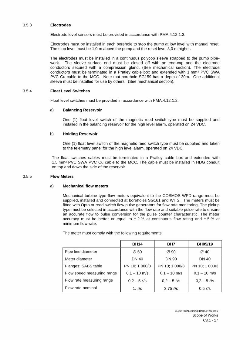
ELECTRICAL 21/3/08 BABABTAS BWS
Scope of Works
C3.1 - 17
3.5.3 Electrodes
Electrode level sensors must be provided in accordance with PMA.4.12.1.3.
Electrodes must be installed in each borehole to stop the pump at low level with manual reset. The stop level must be 1,0 m above the pump and the reset level 3,0 m higher.
The electrodes must be installed in a continuous polycop sleeve strapped to the pump pipe-work. The sleeve surface end must be closed off with an end-cap and the electrode conductors secured with a compression gland. (See mechanical section). The electrode conductors must be terminated in a Pratley cable box and extended with 1 mm² PVC SWA PVC Cu cable to the MCC. Note that borehole SG159 has a depth of 30m. One additional sleeve must be installed for use by others. (See mechanical section).
3.5.4 Float Level Switches
Float level switches must be provided in accordance with PMA.4.12.1.2.
a) Balancing Reservoir
One (1) float level switch of the magnetic reed switch type must be supplied and installed in the balancing reservoir for the high level alarm, operated on 24 VDC.
b) Holding Reservoir
One (1) float level switch of the magnetic reed switch type must be supplied and taken to the telemetry panel for the high level alarm, operated on 24 VDC.
The float switches cables must be terminated in a Pratley cable box and extended with 1,5 mm² PVC SWA PVC Cu cable to the MCC. The cable must be installed in HDG conduit on top and down the side of the reservoir.
3.5.5 Flow Meters
a) Mechanical flow meters
Mechanical turbine type flow meters equivalent to the COSMOS WPD range must be supplied, installed and connected at boreholes SG161 and WIT2. The meters must be fitted with Opto or reed switch flow pulse generators for flow rate monitoring. The pickup type must be selected in accordance with the flow rate and suitable pulse rate to ensure an accurate flow to pulse conversion for the pulse counter characteristic. The meter accuracy must be better or equal to ± 2 % at continuous flow rating and ± 5 % at minimum flow-rate.
The meter must comply with the following requirements:
BH14 BH7 BH05/19
Pipe line diameter 50 90 40
Meter diameter DN 40 DN 90 DN 40
Flanges; SABS table PN 10; 1 000/3 PN 10; 1 000/3 PN 10; 1 000/3
Flow speed measuring range 0,1 – 10 m/s 0,1 – 10 m/s 0,1 – 10 m/s
Flow rate measuring range 0,2 – 5 /s 0,2 – 5 /s 0,2 – 5 /s
Flow rate nominal 1. /s 3.75 /s 0.5 /s
ELECTRICAL 21/3/08 BABABTAS BWS
Scope of Works
C3.1 - 18
3.5.6 Limit Switch
One weatherproof limit switch with an adjustable roller lever must be provided for the no-flow protection and installed in such a way that the counterweight from the non-return valve will activate a switch signal as soon as water flows through the valve. The limit switch must operate on 24 VDC.
3.6 GENERAL ELECTRICAL INSTALLATION
3.6.1 Cables And Sleeves
Tenderers must allow for the supply and installation of all necessary cables of appropriate size to all electrical equipment specified in accordance with the standard specification PMA 4.9 in C3.2 of this document
NOTE:
All power and control cable necessary to provide a fully operational system as specified, must be provided.
Cable sizes, where specified, are for purposes of tender only. Tenderers must verify these sizes against the requirements of their equipment offered and must qualify their tender accordingly. No claims in this regard will be accepted after appointment for cables that are not suitable, which must then be rectified at the Tenderer’s cost.
Cable sizes given in the price schedule and not qualified, must be confirmed with the Engineer before ordering. Cable lengths in the price schedule must be verified on site before ordering. Cables within the same building or in close proximity of the equipment served, are not measured individually.
Remuneration for cable will be for the installed length as measured from point to point, allowing for cable ends, against the tendered unit rates. Tenderers must allow for slack and wastage in the rates.
3.6.1.1 Cables in trenches
Trenching and backfilling must be provided under this contract.
Cable must be installed at a depth of 750 mm with danger tape 300 mm above the cable, on a 150 mm sand bedding with a 150 mm sand cover on top, for excavation other than stone free soil.
3.6.1.2 Instrumentation / control cable
The cable from instrumentation / control switches must be terminated in a Pratley cable box and extended with 1,5 mm2 multi-core PVC SWA PVC cable to the switchboard. All external surface mounted cable must be installed within galvanised steel conduit, and flexible PVC conduit from the end of the steel conduit to the cable termination / entry point.
3.6.2 Borehole Pump Connection
Refer to PMA 4.9.5.
Any excess cable must be looped underneath the MCC.
3.6.3 Earthing
Earthing of equipment shall be done strictly in accordance with the particular specification PMA.4.10 in Part C3.2 of this document. The borehole pipe work must be bonded to earth.
ELECTRICAL 21/3/08 BABABTAS BWS
Scope of Works
C3.1 - 19
The earthing must be tested by the Contractor, under this contract, to determine whether it complies with SANS 10142-1. These values must be presented to the Engineer, after which, in conjunction with the Client, a decision will be made whether the earth mat as stated below, is required.
The earth mat bill item will be omitted from the contact, should the earthing be satisfactory.
A 1,0 m x 1,0 m x 70 mm2 bare copper earth conductor earth-mat CADWELDED with a 200 mm grid, must be installed outside the pump station and connected to the MCC with a 70 mm2 b.c.e.c., to obtain a earth reading of one ohm or less, failing which additional earth spikes must be installed to obtain earthing resistance of less than one ohm.
Earthing of equipment shall be done strictly in accordance with the particular specification PMA.4.10. Cable rack and the pumps bases and pipe work must all be bonded to earth.
3.6.4 Building Electrical Installation
Not applicable to this contract.
3.6.5 Site Lighting
Not applicable to this contract.
3.6.6 Redundant Equipment
All redundant equipment must be delivered to the municipal stores against a signed and dated receipt and photos taken of all the delivered equipment, to be provided to the Engineer.
3.7 SCADA AND TELEMETRY SYSTEM
The project involves the monitoring and control of the pumping system by means of a radio telemetry SCADA system, as an extension of the existing telemetry system at Babatas ( outside Kathu) in compliance with the standard specification PMT (R). A specialist subcontractor must be appointed for this installation.
The new Web based Telemetry system and the equipment offered must in all aspects be equivalent and directly compatible/interchangeable with this.
The work comprises in short the supply, installation, connection, commissioning and guarantee of:
• new outstations with the necessary telemetric equipment at each new borehole (3 No).
• provision of a new central station, including the setup and commissioning of the new Web based Zednet software for the required monitoring and control function of the new boreholes.
• The refurbishing of the existing system as described below under the relevant section and re-commissioned.
Note : Refer Section 3, clause 3.1 relating to this project, encompassing two distinct phases and provision must be made for the complete monitoring implementation of the boreholes, and Reservoirs , the final system configuration includes all monitored sites.
ELECTRICAL 21/3/08 BABABTAS BWS
Scope of Works
C3.1 - 20
3.7.1 Central Station
The central station can be anywhere and login members of authorized personnel can log onto the system from any device with internet connection.
3.7.2 Computer
The minimum requirement for the computer (desktop) is an Intel dual core processor 2,7 GHz with ITB hard disk, 4Gb extendible RAM, minimum of three USB ports, DVD writer and 19” LCD flat screen with keyboard and mouse.( If client has the need for this hardware)
The computer must be pre-loaded with Windows 7 and MS 2010 latest version complete with all certification and licensing.
A printer is not required.
A suitably sized computer desk and chair must also be provided as part of this contract.
3.7.3 Software
The Telemetry system package proposed must be the latest version of Zednet software Tenderers must state the utilisation of the package under this contract.
The system must be configured for the new outstations and functions as specified, all in accordance with PMT.4.
3.7.4 Graphic Display
Graphic display of status and analogue parameters monitored, as well as trend screens must be provided as per PMT.4.4. The specific arrangement of the graphic screens layout must be determined in conjunction with the Engineer after award of tender. A general screen depicting an overview of the system must be provided, along with three graphic screens for the boreholes (one for each) and a graphic screen for the town’s booster pump station, as well as all other existing signals (digital and analogue) at the existing mimic panel.
3.7.5 New Outstations
The outstations must comply with PMT 3.2 and all be of the outdoor type in accordance with PMT 3.8:
A 50 mm overhang must be provided to prohibit rain water from seeping onto the enclosure door.
Each outstation must be provided with a four line digital display on the panel door for reservoir level, borehole level, borehole level reset delay countdown and flow rate. A one line digital display will not be accepted.
3.7.6 Communication
The communication system must be by means of sim cards on the Zednet Platform app.

ELECTRICAL 21/3/08 BABABTAS BWS
Scope of Works
C3.1 - 21
The Tenderer must acquaint himself with the existing communication arrangement and provide the system accordingly. The successful Tenderer will be responsible to establish communication paths and make provision for the necessary repeater stations (additional to any repeaters allowed in the pricing schedule) should direct radio communication with the new outstations not be possible. The overall number of repeaters and positions must be confirmed within one week of appointment and later claims in this regard will not be accepted.
All external cabling between the antenna and telemetry panel must be within underground sleeves or surface mounted hot dipped galvanized sleeves. There may be no exposed cabling.
The antenna earth resistance readings must be provided as part of the commissioning documentation.
3.7.7 Web based Monitoring
The monitoring and control of the system must be done in accordance with Zednet platform and software. The I/O requirements must be determined by the Tenderer from the specification. The summary in the schedules below is for convenience only.
3.7.7.1 Graphic display
The graphic display must be generally in accordance with Zednet software and parameters.
3.7.7.2 Parameter processing
The parameter processing must follow Zednet software. Any conflict in terms of the existing system must be confirmed with the Engineer.
3.7.7.3 Interfacing with equipment
Interfacing must comply with PMT.5. Provision for I/O between the MCCs and telemetry equipment are provided for within the MCC at terminals. It will be the responsibility of the successful contractor to ensure that the necessary coordination is done between the MCC manufacturer and telemetry contractor in terms of the specific I/O requirements.
All I/O must be galvanically isolated and surge protected for maximum protection against lightning.
3.7.8 Borehole Level Sensing
The borehole analogue level sensor must be monitored by the telemetry system to provide an analogue level display and processed to provide a borehole level suction control for the borehole pump, by means of a voltage free contact.
The borehole water level must be graphically displayed on screen and all installation parameters (borehole pump depth, level sensor installation depth referenced from surface ground level).
The dynamic water level must be displayed as water level above the pump, as well as the low level and reset level switch points.
The water dynamic level and reset countdown delay must be displayed on the four line LCD display on the telemetry panel door.
3.7.9 Testing And Commissioning
Testing and commissioning must be carried out in accordance with PMT.6.

ELECTRICAL 21/3/08 BABABTAS BWS
Scope of Works
C3.1 - 22
During the commissioning phase, the contractor is responsible for providing adequate training to the Client, and any additional employees. Training must formally be carried out for a minimum of 2 days, after which a formal training register must be signed and provided to the Engineer as proof.
3.7.10 Operation And Maintenance Manual
The existing operation and maintenance manual must be updated with the new installation, in accordance with the existing format, with a copy to the Engineer. The following must be included irrespective:
a) System description
b) I/O schedules
c) Wiring diagrams
d) Cable and connection schedules
e) Software I/O configuration
f) Technical description of hardware
3.7.11 SCHEDULE OF OUTSTATIONS
3.7.11.1.1 MCC
The MCC is new and all I/O are ready for connection at terminals to provide the monitoring and control
3.7.11.1.2 Monitoring and control
The input parameters as per the I/O schedule below must be monitored, with alarm on an abnormal condition.
3.7.11.1.3 I/O schedule
PARAMETER DEVICE DI AI CI DO AO
a) Telemetry panel door Microswitch 1
b) Power failure Telemetry power supply Zednet system
1
c) Battery voltage 1
d) Communication failure Telemetry Zednet system
e) Borehole pump status MCC
• Circuit breaker ON/OFF 1
• Control MANUAL (local) 1
• Control AUTO 1
• Run 1
• Trip (All; common trip) 1
f) Borehole status and control
• Analogue level Borehole level sensor 1
• Low level / reset Borehole level sensor 1
• X-Low level Borehole electrode 1
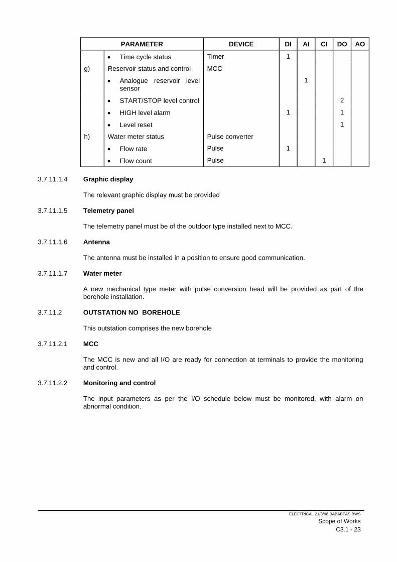
ELECTRICAL 21/3/08 BABABTAS BWS
Scope of Works
C3.1 - 23
PARAMETER DEVICE DI AI CI DO AO
• Time cycle status Timer 1
g) Reservoir status and control MCC
• Analogue reservoir level sensor
1
• START/STOP level control 2
• HIGH level alarm 1 1
• Level reset 1
h) Water meter status Pulse converter
• Flow rate Pulse 1
• Flow count Pulse 1
3.7.11.1.4 Graphic display
The relevant graphic display must be provided
3.7.11.1.5 Telemetry panel
The telemetry panel must be of the outdoor type installed next to MCC.
3.7.11.1.6 Antenna
The antenna must be installed in a position to ensure good communication.
3.7.11.1.7 Water meter
A new mechanical type meter with pulse conversion head will be provided as part of the borehole installation.
3.7.11.2 OUTSTATION NO BOREHOLE
This outstation comprises the new borehole
3.7.11.2.1 MCC
The MCC is new and all I/O are ready for connection at terminals to provide the monitoring and control.
3.7.11.2.2 Monitoring and control
The input parameters as per the I/O schedule below must be monitored, with alarm on abnormal condition.
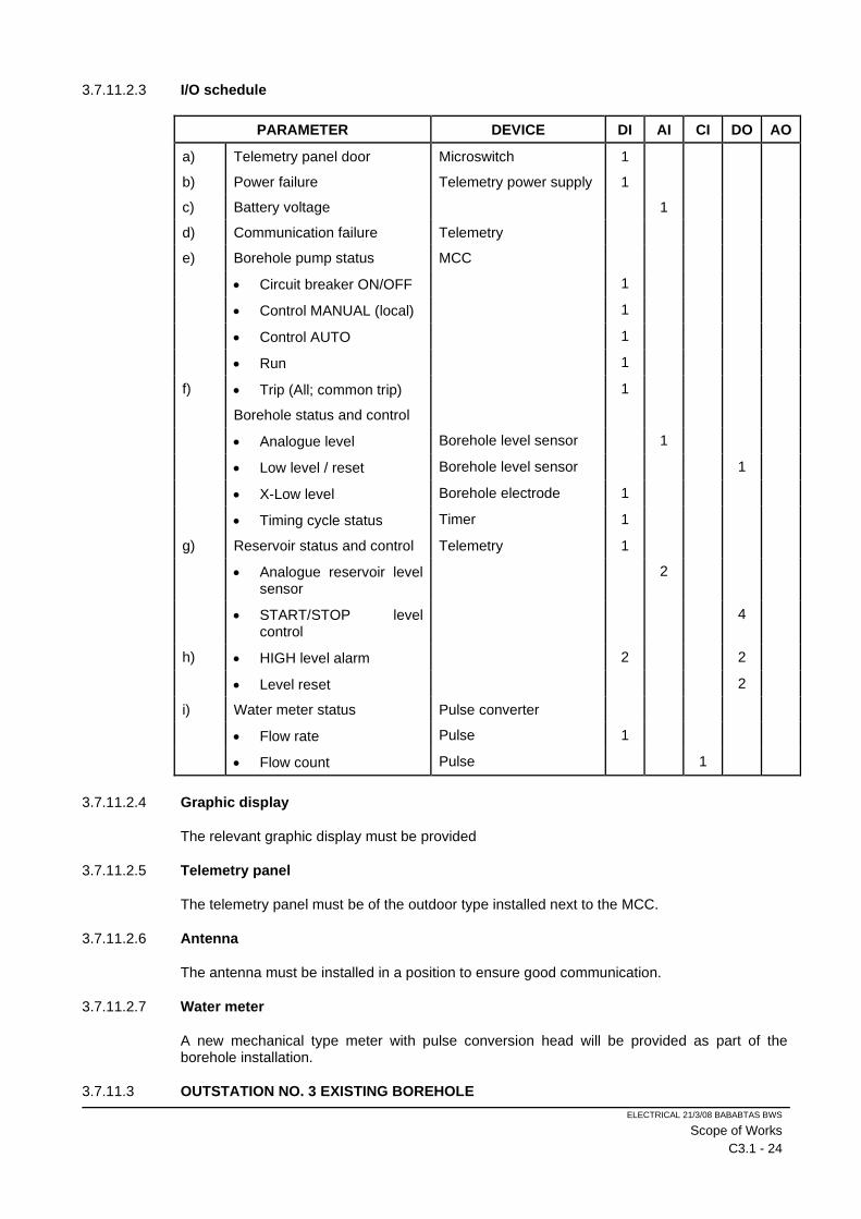
ELECTRICAL 21/3/08 BABABTAS BWS
Scope of Works
C3.1 - 24
3.7.11.2.3 I/O schedule
PARAMETER DEVICE DI AI CI DO AO
a) Telemetry panel door Microswitch 1
b) Power failure Telemetry power supply 1
c) Battery voltage 1
d) Communication failure Telemetry
e) Borehole pump status MCC
• Circuit breaker ON/OFF 1
• Control MANUAL (local) 1
• Control AUTO 1
• Run 1
f) • Trip (All; common trip) 1
Borehole status and control
• Analogue level Borehole level sensor 1
• Low level / reset Borehole level sensor 1
• X-Low level Borehole electrode 1
• Timing cycle status Timer 1
g) Reservoir status and control Telemetry 1
• Analogue reservoir level sensor
2
• START/STOP level control
4
h) • HIGH level alarm 2 2
• Level reset 2
i) Water meter status Pulse converter
• Flow rate Pulse 1
• Flow count Pulse 1
3.7.11.2.4 Graphic display
The relevant graphic display must be provided
3.7.11.2.5 Telemetry panel
The telemetry panel must be of the outdoor type installed next to the MCC.
3.7.11.2.6 Antenna
The antenna must be installed in a position to ensure good communication.
3.7.11.2.7 Water meter
A new mechanical type meter with pulse conversion head will be provided as part of the borehole installation.
3.7.11.3 OUTSTATION NO. 3 EXISTING BOREHOLE
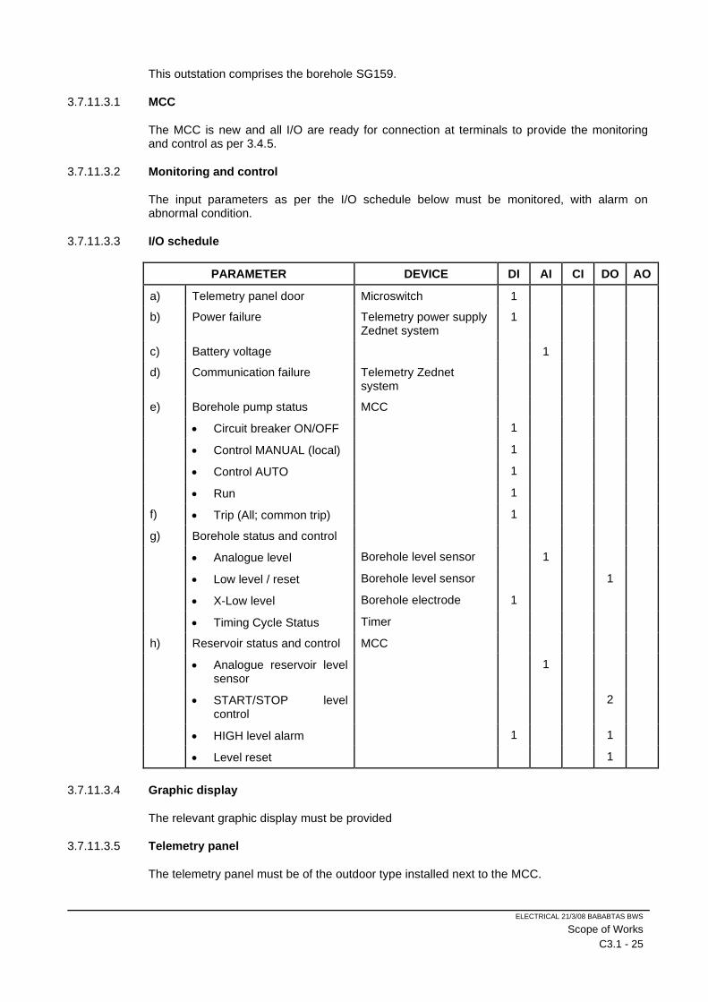
ELECTRICAL 21/3/08 BABABTAS BWS
Scope of Works
C3.1 - 25
This outstation comprises the borehole SG159.
3.7.11.3.1 MCC
The MCC is new and all I/O are ready for connection at terminals to provide the monitoring and control as per 3.4.5.
3.7.11.3.2 Monitoring and control
The input parameters as per the I/O schedule below must be monitored, with alarm on abnormal condition.
3.7.11.3.3 I/O schedule
PARAMETER DEVICE DI AI CI DO AO
a) Telemetry panel door Microswitch 1
b) Power failure Telemetry power supply Zednet system
1
c) Battery voltage 1
d) Communication failure Telemetry Zednet system
e) Borehole pump status MCC
• Circuit breaker ON/OFF 1
• Control MANUAL (local) 1
• Control AUTO 1
• Run 1
f) • Trip (All; common trip) 1
g) Borehole status and control
• Analogue level Borehole level sensor 1
• Low level / reset Borehole level sensor 1
• X-Low level Borehole electrode 1
• Timing Cycle Status Timer
h) Reservoir status and control MCC
• Analogue reservoir level sensor
1
• START/STOP level control
2
• HIGH level alarm 1 1
• Level reset 1
3.7.11.3.4 Graphic display
The relevant graphic display must be provided
3.7.11.3.5 Telemetry panel
The telemetry panel must be of the outdoor type installed next to the MCC.

ELECTRICAL 21/3/08 BABABTAS BWS
Scope of Works
C3.1 - 26
3.7.11.3.6 Antenna
The antenna must be installed in a position to ensure good communication.
3.7.11.3.7 Existing Signals
The following number of signals at the existing mimic panel must be linked to the new Telemetry system:
• Twenty-two (22) Digital signals
• Four (4) Analogue signals
3.8 TESTING AND ACCEPTANCE
Switchboard factory tests and testing on site will be carried out in accordance to specification Travelling cost for re-inspection will be for contractors account.

2021-06-24 301976 BABATAS
Standard Specification
TENDER
CONSTRUCTION OF BULK WATER SUPPLY IN BABATAS CPA
TENDER NO: NC/001/201
C3.2 : STANDARD SPECIFICATION
PMA : MECHANICAL INSTALLATION
PMT : SCADA SYSTEMS FOR CIVIL SERVICES

2021/03/08 BABATAS ELECTRICAL BWS
TENDER
CONSTRUCTION OF BABATAS CPA BULK WATER SUPPLY
TENDER NO. NC/001/2021
PARTICULAR SPECIFICATION: PMA : MECHANICAL INSTALLATIONS
ITEM DESCRIPTION PAGE
SECTION 1 : GENERAL ................................................................................................................................. 1
PMA.1.1 DATA TO BE SUPPLIED BY TENDERERS ............................................................................ 1
PMA.1.2 PLANT DRAWINGS ................................................................................................................. 1
PMA.1.3 PACKING .................................................................................................................................. 1
PMA.1.4 QUALITY OF MATERIAL AND ACCEPTANCE ....................................................................... 1
PMA.1.5 TIME OF DELIVERY AND COMPLETION ............................................................................... 2
PMA.1.6 IMPORT PERMITS ................................................................................................................... 2
PMA.1.7 OPERATING AND MAINTENANCE MANUAL ........................................................................ 2
PMA.1.8 PROGRAMME OF WORK ....................................................................................................... 4
PMA.1.9 CONSTRUCTION WORK ........................................................................................................ 4
PMA.1.10 ERECTION, ADJUSTMENT AND OPERATION ...................................................................... 4
SECTION 2 : MATERIALS ............................................................................................................................. 6
PMA.2.1 STANDARD SPECIFICATIONS ............................................................................................... 6
PMA.2.2 MATERIALS GENERALLY ....................................................................................................... 6
PMA.2.3 CORROSION............................................................................................................................ 6
PMA.2.4 STRUCTURAL STEELWORK .................................................................................................. 6
PMA.2.5 PIPES AND FITTINGS ............................................................................................................. 6
PMA.2.6 VALVES AND FITTINGS .......................................................................................................... 7
PMA.2.7 JOINTING MATERIAL .............................................................................................................. 7
PMA.2.8 SOLAR PV INSTALLATION BORE HOLES SUPPLIES .......................................................... 8

2021/03/08 BABATAS ELECTRICAL BWS
ITEM DESCRIPTION PAGE
SECTION 3 : PAINTING AND FINISHING ..................................................................................................... 9
PMA.3.1 GENERAL ................................................................................................................................. 9
PMA.3.2 METAL PREPARATION ........................................................................................................... 9
PMA.3.3 PAINTING ................................................................................................................................. 9
PMA.3.3.1 General ..................................................................................................................................... 9
PMA.3.3.2 Preparing Paint for Use .......................................................................................................... 10
PMA.3.3.3 Paint Application ..................................................................................................................... 10
PMA.3.4 Detail Paint Specification ........................................................................................................ 11
PMA.3.5 GALVANISING ....................................................................................................................... 12
PMA.3.6 EPOXY COATING .................................................................................................................. 12
PMA.3.7 REPAIRS TO DAMAGED SURFACES .................................................................................. 12
SECTION 4 : ELECTRICAL EQUIPMENT, INSTRUMENTATION AND INSTALLATION (R) ................. 13
PMA.4.1 GENERAL ............................................................................................................................... 13
PMA.4.2 MOTOR CONTROL CENTRES (MCCS) GENERAL REQUIREMENTS ............................... 13
PMA.4.2.1 Statutory Requirements .......................................................................................................... 13
PMA.4.2.2 Switchgear General ................................................................................................................ 14
PMA.4.2.3 Starter General Requirements................................................................................................ 14
PMA.4.2.4 Ratings .................................................................................................................................... 14
PMA.4.2.5 General Construction .............................................................................................................. 14
PMA.4.2.5.1 Outdoor Type MCCS .............................................................................................................. 16
PMA.4.2.6 Ancillary and Control Equipment ............................................................................................ 17
PMA.4.2.7 Protection/Alarm Devices ....................................................................................................... 17
PMA.4.2.8 Alarm and Status Indication .................................................................................................... 18
PMA.4.2.9 Remote Monitoring ................................................................................................................. 18
PMA.4.2.9.1 Terminal / marshalling enclosure............................................................................................ 18
PMA.4.2.10 Power Factor Correction ......................................................................................................... 19
PMA.4.2.11 Spatial Requirements ............................................................................................................. 19
PMA.4.2.12 MCC Drawings........................................................................................................................ 19
2021/03/08 BABATAS ELECTRICAL BWS
ITEM DESCRIPTION PAGE
PMA.4.2.13 Payment for MCCS .............................................................................................................. 19
PMA.4.3 MOTOR STARTERS ........................................................................................................... 20
PMA.4.3.1 STARTER ASSEMBLY CONFIGURATION ........................................................................ 20
PMA.4.3.2 Soft Starters ......................................................................................................................... 21
PMA.4.3.2.1 General ................................................................................................................................ 21
PMA.4.3.2.2 Application ............................................................................................................................ 21
PMA.4.3.2.3 Technology ........................................................................................................................... 21
PMA.4.3.2.4 Climatic operating conditions ............................................................................................... 22
PMA.4.3.2.5 Standards ............................................................................................................................. 22
PMA.4.3.2.6 Supply .................................................................................................................................. 22
PMA.4.3.2.7 Rating ................................................................................................................................... 22
PMA.4.3.2.8 Control functions .................................................................................................................. 22
PMA.4.3.2.9 Protective features ............................................................................................................... 22
PMA.4.3.2.10 Status display (LED) ............................................................................................................ 23
PMA.4.3.2.11 Output relays ........................................................................................................................ 23
PMA.4.3.2.12 Cabinet installation ............................................................................................................... 23
PMA.4.3.2.13 Power factor equipment ....................................................................................................... 23
PMA.4.3.3 Variable Frequency Controllers (VFCS) .............................................................................. 24
PMA.4.3.3.1 General ................................................................................................................................ 24
PMA.4.3.3.2 Application ............................................................................................................................ 24
PMA.4.3.3.3 Technology ........................................................................................................................... 24
PMA.4.3.3.4 Operator/Controller interface ............................................................................................... 24
PMA.4.3.3.5 Drive (Starter) assembly configuration ................................................................................ 25
PMA.4.3.3.6 Ambient conditions, cooling and ventilation ......................................................................... 25
PMA.4.3.3.7 Standards ............................................................................................................................. 25
PMA.4.3.3.8 Harmonics ............................................................................................................................ 26
PMA.4.3.3.9 Supply .................................................................................................................................. 26
PMA.4.3.3.10 Rating ................................................................................................................................... 26
2021/03/08 BABATAS ELECTRICAL BWS
ITEM DESCRIPTION PAGE
PMA.4.3.3.11 Control functions ................................................................................................................ 26
PMA.4.3.3.12 Protection ........................................................................................................................... 27
PMA.4.4 PROGRAMMABLE LOGIC CONTROLLERS (PLCS)............................................................. 28
PMA.4.4.1 General ................................................................................................................................ 28
PMA.4.4.2 Inputs and Outputs ............................................................................................................... 28
PMA.4.4.3 Software and Programming ................................................................................................. 28
PMA.4.4.4 Communication .................................................................................................................... 28
PMA.4.4.5 Interlocks .............................................................................................................................. 29
PMA.4.4.6 Functional Testing ................................................................................................................ 29
PMA.4.5 CONTACTORS .................................................................................................................... 29
PMA.4.6 SWITCHGEAR ..................................................................................................................... 29
PMA.4.6.1 Circuit Breakers.................................................................................................................... 29
PMA.4.6.2 Miniature Isolators ................................................................................................................ 29
PMA.4.6.3 Fused Switches .................................................................................................................... 29
PMA.4.7 METERING AND INDICATION EQUIPMENT ..................................................................... 30
PMA.4.7.1 KWH Meters ......................................................................................................................... 30
PMA.4.7.2 Ampere Meters..................................................................................................................... 30
PMA.4.7.3 Voltmeters ............................................................................................................................ 30
PMA.4.7.4 Voltmeter Switches .............................................................................................................. 30
PMA.4.7.5 Voltmeter Fuses ................................................................................................................... 31
PMA.4.7.6 Current Transformers ........................................................................................................... 31
PMA.4.8 MOTORS ............................................................................................................................. 31
PMA.4.9 CABLES ............................................................................................................................... 32
PMA.4.9.1 Cables in Trenches .............................................................................................................. 32
PMA.4.9.2 Cables within Buildings ........................................................................................................ 32
PMA.4.9.3 Instrumentation / Control / Communication Network Cable ................................................. 33
PMA.4.9.4 Cable Termination ................................................................................................................ 33
PMA.4.9.5 Borehole Pump Connection ................................................................................................. 33
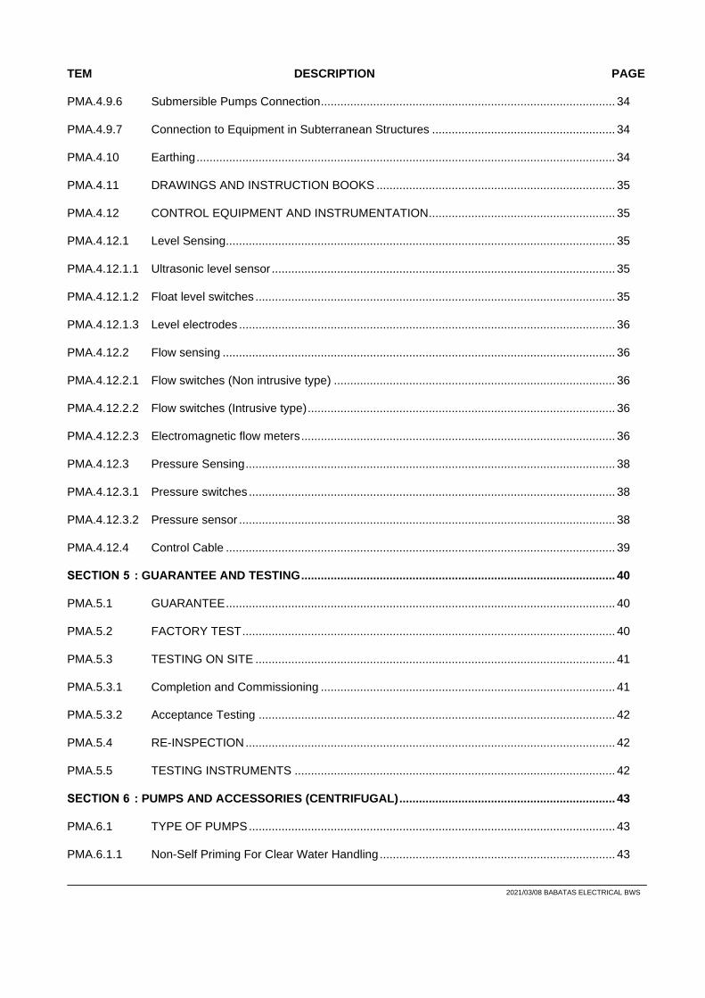
2021/03/08 BABATAS ELECTRICAL BWS
TEM DESCRIPTION PAGE
PMA.4.9.6 Submersible Pumps Connection .......................................................................................... 34
PMA.4.9.7 Connection to Equipment in Subterranean Structures ........................................................ 34
PMA.4.10 Earthing ................................................................................................................................ 34
PMA.4.11 DRAWINGS AND INSTRUCTION BOOKS ......................................................................... 35
PMA.4.12 CONTROL EQUIPMENT AND INSTRUMENTATION ......................................................... 35
PMA.4.12.1 Level Sensing....................................................................................................................... 35
PMA.4.12.1.1 Ultrasonic level sensor ......................................................................................................... 35
PMA.4.12.1.2 Float level switches .............................................................................................................. 35
PMA.4.12.1.3 Level electrodes ................................................................................................................... 36
PMA.4.12.2 Flow sensing ........................................................................................................................ 36
PMA.4.12.2.1 Flow switches (Non intrusive type) ...................................................................................... 36
PMA.4.12.2.2 Flow switches (Intrusive type) .............................................................................................. 36
PMA.4.12.2.3 Electromagnetic flow meters ................................................................................................ 36
PMA.4.12.3 Pressure Sensing ................................................................................................................. 38
PMA.4.12.3.1 Pressure switches ................................................................................................................ 38
PMA.4.12.3.2 Pressure sensor ................................................................................................................... 38
PMA.4.12.4 Control Cable ....................................................................................................................... 39
SECTION 5 : GUARANTEE AND TESTING ................................................................................................ 40
PMA.5.1 GUARANTEE ....................................................................................................................... 40
PMA.5.2 FACTORY TEST .................................................................................................................. 40
PMA.5.3 TESTING ON SITE .............................................................................................................. 41
PMA.5.3.1 Completion and Commissioning .......................................................................................... 41
PMA.5.3.2 Acceptance Testing ............................................................................................................. 42
PMA.5.4 RE-INSPECTION ................................................................................................................. 42
PMA.5.5 TESTING INSTRUMENTS .................................................................................................. 42
SECTION 6 : PUMPS AND ACCESSORIES (CENTRIFUGAL) .................................................................. 43
PMA.6.1 TYPE OF PUMPS ................................................................................................................ 43
PMA.6.1.1 Non-Self Priming For Clear Water Handling ........................................................................ 43

2021/03/08 BABATAS ELECTRICAL BWS
ITEM DESCRIPTION PAGE
PMA.6.1 PUMP EQUIPMENT AND SPARES .................................................................................... 44
PMA.6.2 LUBRICATION ..................................................................................................................... 44
PMA.6.3 SHAFT SEALING ................................................................................................................. 44
PMA.6.4 BEDPLATES ........................................................................................................................ 44
PMA.6.5 PIPE-WORK ......................................................................................................................... 45
PMA.6.6 ALIGNMENT OF PUMP SETS ............................................................................................ 45
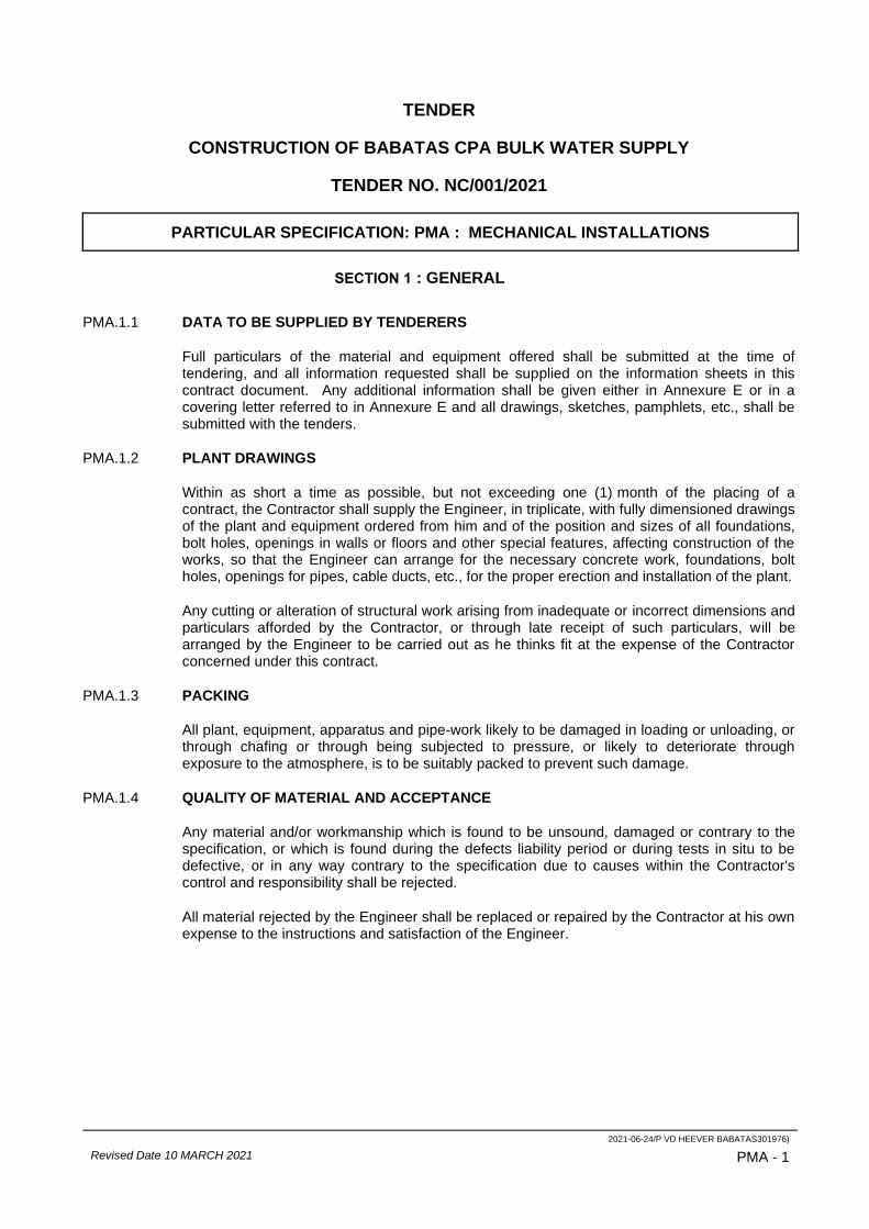
2021-06-24/P VD HEEVER BABATAS301976)
Revised Date 10 MARCH 2021 PMA - 1
TENDER
CONSTRUCTION OF BABATAS CPA BULK WATER SUPPLY
TENDER NO. NC/001/2021
PARTICULAR SPECIFICATION: PMA : MECHANICAL INSTALLATIONS
SECTION 1 : GENERAL
PMA.1.1 DATA TO BE SUPPLIED BY TENDERERS
Full particulars of the material and equipment offered shall be submitted at the time of tendering, and all information requested shall be supplied on the information sheets in this contract document. Any additional information shall be given either in Annexure E or in a covering letter referred to in Annexure E and all drawings, sketches, pamphlets, etc., shall be submitted with the tenders.
PMA.1.2 PLANT DRAWINGS
Within as short a time as possible, but not exceeding one (1) month of the placing of a contract, the Contractor shall supply the Engineer, in triplicate, with fully dimensioned drawings of the plant and equipment ordered from him and of the position and sizes of all foundations, bolt holes, openings in walls or floors and other special features, affecting construction of the works, so that the Engineer can arrange for the necessary concrete work, foundations, bolt holes, openings for pipes, cable ducts, etc., for the proper erection and installation of the plant.
Any cutting or alteration of structural work arising from inadequate or incorrect dimensions and particulars afforded by the Contractor, or through late receipt of such particulars, will be arranged by the Engineer to be carried out as he thinks fit at the expense of the Contractor concerned under this contract.
PMA.1.3 PACKING
All plant, equipment, apparatus and pipe-work likely to be damaged in loading or unloading, or through chafing or through being subjected to pressure, or likely to deteriorate through exposure to the atmosphere, is to be suitably packed to prevent such damage.
PMA.1.4 QUALITY OF MATERIAL AND ACCEPTANCE
Any material and/or workmanship which is found to be unsound, damaged or contrary to the specification, or which is found during the defects liability period or during tests in situ to be defective, or in any way contrary to the specification due to causes within the Contractor's control and responsibility shall be rejected.
All material rejected by the Engineer shall be replaced or repaired by the Contractor at his own expense to the instructions and satisfaction of the Engineer.
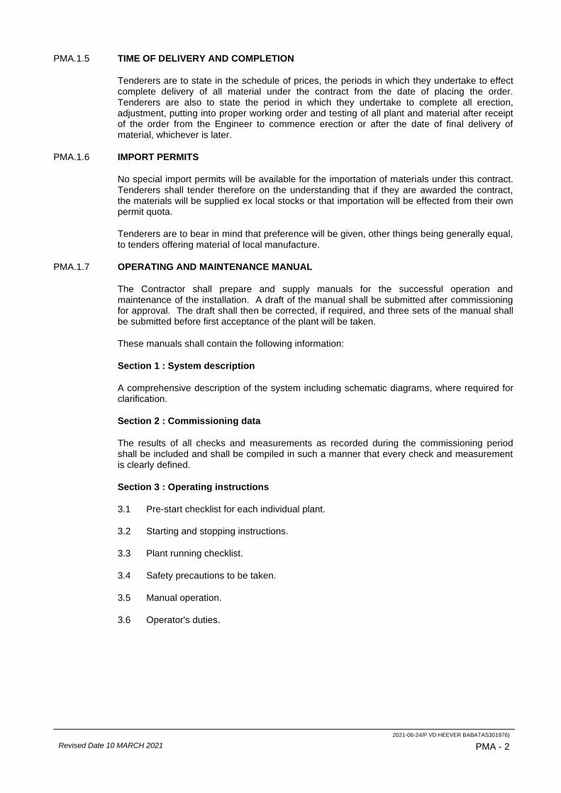
2021-06-24/P VD HEEVER BABATAS301976)
Revised Date 10 MARCH 2021 PMA - 2
PMA.1.5 TIME OF DELIVERY AND COMPLETION
Tenderers are to state in the schedule of prices, the periods in which they undertake to effect complete delivery of all material under the contract from the date of placing the order. Tenderers are also to state the period in which they undertake to complete all erection, adjustment, putting into proper working order and testing of all plant and material after receipt of the order from the Engineer to commence erection or after the date of final delivery of material, whichever is later.
PMA.1.6 IMPORT PERMITS
No special import permits will be available for the importation of materials under this contract. Tenderers shall tender therefore on the understanding that if they are awarded the contract, the materials will be supplied ex local stocks or that importation will be effected from their own permit quota.
Tenderers are to bear in mind that preference will be given, other things being generally equal, to tenders offering material of local manufacture.
PMA.1.7 OPERATING AND MAINTENANCE MANUAL
The Contractor shall prepare and supply manuals for the successful operation and maintenance of the installation. A draft of the manual shall be submitted after commissioning for approval. The draft shall then be corrected, if required, and three sets of the manual shall be submitted before first acceptance of the plant will be taken.
These manuals shall contain the following information:
Section 1 : System description
A comprehensive description of the system including schematic diagrams, where required for clarification.
Section 2 : Commissioning data
The results of all checks and measurements as recorded during the commissioning period shall be included and shall be compiled in such a manner that every check and measurement is clearly defined.
Section 3 : Operating instructions
3.1 Pre-start checklist for each individual plant.
3.2 Starting and stopping instructions.
3.3 Plant running checklist.
3.4 Safety precautions to be taken.
3.5 Manual operation.
3.6 Operator's duties.
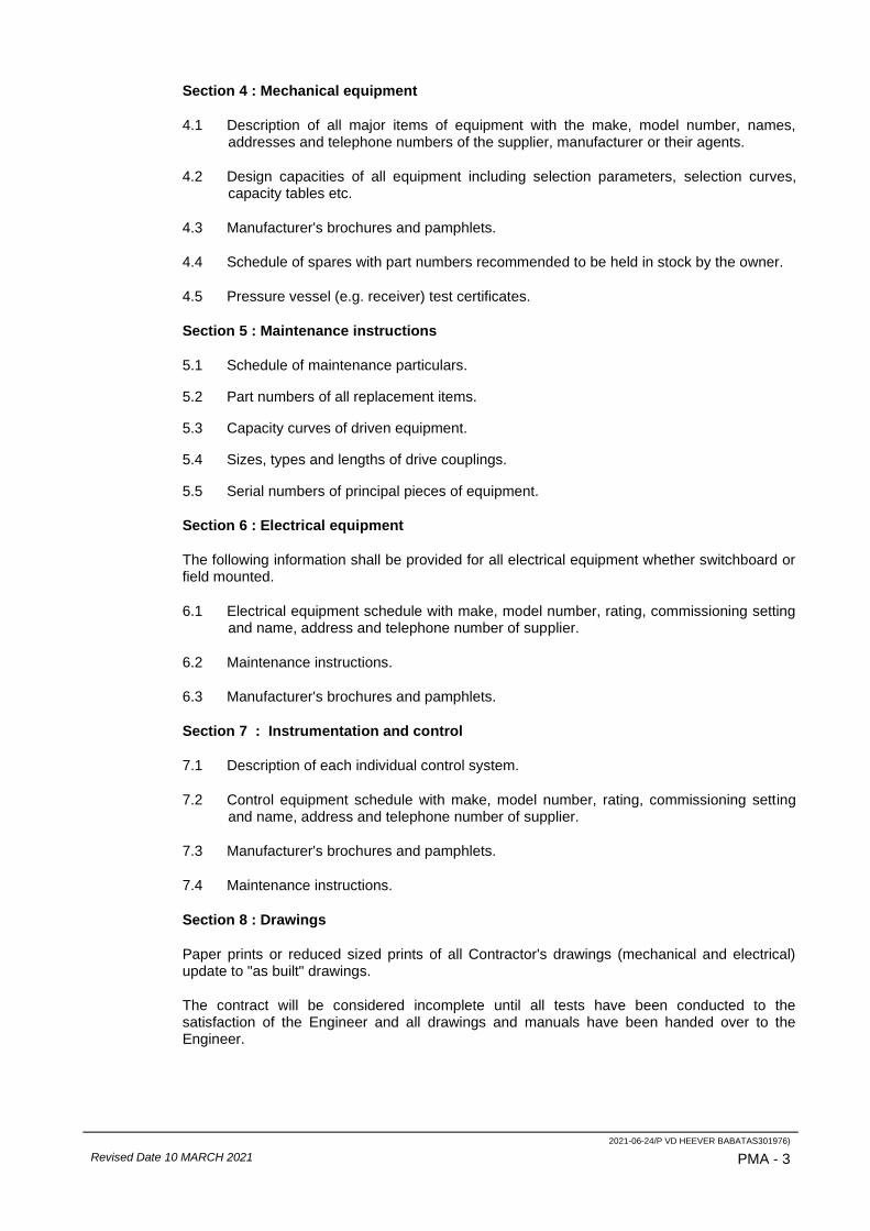
2021-06-24/P VD HEEVER BABATAS301976)
Revised Date 10 MARCH 2021 PMA - 3
Section 4 : Mechanical equipment
4.1 Description of all major items of equipment with the make, model number, names, addresses and telephone numbers of the supplier, manufacturer or their agents.
4.2 Design capacities of all equipment including selection parameters, selection curves, capacity tables etc.
4.3 Manufacturer's brochures and pamphlets.
4.4 Schedule of spares with part numbers recommended to be held in stock by the owner.
4.5 Pressure vessel (e.g. receiver) test certificates.
Section 5 : Maintenance instructions
5.1 Schedule of maintenance particulars.
5.2 Part numbers of all replacement items.
5.3 Capacity curves of driven equipment.
5.4 Sizes, types and lengths of drive couplings.
5.5 Serial numbers of principal pieces of equipment.
Section 6 : Electrical equipment
The following information shall be provided for all electrical equipment whether switchboard or field mounted.
6.1 Electrical equipment schedule with make, model number, rating, commissioning setting and name, address and telephone number of supplier.
6.2 Maintenance instructions.
6.3 Manufacturer's brochures and pamphlets.
Section 7 : Instrumentation and control
7.1 Description of each individual control system.
7.2 Control equipment schedule with make, model number, rating, commissioning setting and name, address and telephone number of supplier.
7.3 Manufacturer's brochures and pamphlets.
7.4 Maintenance instructions.
Section 8 : Drawings
Paper prints or reduced sized prints of all Contractor's drawings (mechanical and electrical) update to "as built" drawings.
The contract will be considered incomplete until all tests have been conducted to the satisfaction of the Engineer and all drawings and manuals have been handed over to the Engineer.

2021-06-24/P VD HEEVER BABATAS301976)
Revised Date 10 MARCH 2021 PMA - 4
PMA.1.8 PROGRAMME OF WORK
In carrying out erection, a definite scheme of operation shall be observed by the Contractor, and such scheme shall at all times be subject to the approval of the Engineer, and be in accordance with his requirements.
The Engineer may, from time to time, by order in writing, without in any way invalidating the contract or giving to the Contractor any claim for additional payment, require the Contractor to proceed with the execution of the works in such order as in his opinion may be necessary, and may alter the order and suspend any part of the work at such time and times as he may deem desirable.
When the work must of necessity be carried out in conjunction with the work of other Contractors or with that of the Employer, it shall be co-ordinated and arranged in such a manner so as to interfere as little as possible with the progress of such other work, and so as to offer every reasonable facility to other Contractors or to departmental employees of the Employer.
PMA.1.9 CONSTRUCTION WORK
The erection and completion of the building work to house the plant and equipment, will be carried out either departmentally or under separate contract in advance of the delivery of the plant. Holes will be left in walls and foundations to accommodate piping, foundation bolts and other equipment to be erected under this contract, so that the Contractor will generally only be required to grout up these holes after the installation of the piping and equipment has been completed, unless specified otherwise in the project specifications.
PMA.1.10 ERECTION, ADJUSTMENT AND OPERATION
The Contractor shall make his own arrangements for handling and transporting all material to the site of works in a proper and careful manner to avoid damage, and shall be responsible for properly storing and protecting all plant and equipment against damage by water, weather, fire and any other interference before and during erection.
This contract is to include for the erection, adjustment, putting into proper working order and upholding of all plant, equipment and materials supplied by the Contractor. The work of erection of the plant is to be carried out under a skilled and experienced erector and the plant, when erected is to be of neat and workmanlike appearance, solidly and evenly supported true to line and level, plumb and in proper working order. The erection is to include for the proper grouting in of all bolts, pipes, fittings and holes left by the building contractor for the reception of the equipment and pipes, as well as properly making good any damage to completed work, caused by the Contractor under this contract.
In the event of the Contractor not commencing erection when required by the Engineer, or his speed or quality of erection not being to the satisfaction of the Engineer, the Employer shall have the right to commence erection or to assist in or to complete erection with his own staff, or to engage another Contractor to do the work, in which case all expenditure so directly incurred by the Employer, plus the addition of twenty (20) percent thereon for administration and supervision will be debited to the Contractor and shall be recoverable from him in such manner as the Employer may elect.
On completion of erection, unless otherwise specified, the Contractor is to clean all exposed metalwork, polish parts to be left bright and paint all other parts, as instructed.
The Contractor is to finish off neatly all grouting and painting carried out by him and is generally to leave all his work under this contract clean, tidy and in an efficient working order.

2021-06-24/P VD HEEVER BABATAS301976)
Revised Date 10 MARCH 2021 PMA - 5
After completion of erection, the Contractor is to operate his plant for at least seventy two (72) hours or such longer time as may be necessary in order to put all equipment into proper adjustment and working order, using for this purpose the water and electricity provided free of charge by the Employer.
Before handing over the plant, the Contractor is to ensure that every part of the equipment is operating satisfactorily. The contract will not be considered complete until the Engineer is fully satisfied in this connection.
In the event of the Contractor being unable to test and adjust the plant and equipment at the time of installation through circumstances beyond his control, it may be necessary for him to return to site at a later date to undertake this work. An item has been provided in the schedule of prices to cover the cost of returning to site, if ordered by the Engineer to do so, in order to carry out this work.
The completion date will be taken as the date on which the plant is commissioned or when all the tests specified have been completed to the satisfaction of the Engineer, whichever date is the later.

2021-06-24/P VD HEEVER BABATAS301976)
Revised Date 10 MARCH 2021 PMA - 6
SECTION 2: MATERIALS
PMA.2.1 STANDARD SPECIFICATIONS
Reference made hereinafter to specifications of the South African Bureau of Standards (SABS) or the British Standards Institution (BS) shall be deemed to include all the latest revisions of and/or additions to such specifications, where applicable.
PMA.2.2 MATERIALS GENERALLY
All materials used shall be of the best of their respective kinds and shall be suitable for working at the pressures and temperatures involved under all working conditions without deteriorating or distorting or the setting up of undue stresses in any part. No welding, burning, filling or plugging of defective castings shall be permitted without the written approval of the Engineer.
PMA.2.3 CORROSION
Where corrosion of metal may be expected from contact with water or sewage or from any other cause, the Contractor shall supply materials which are resistant to corrosion. Any material showing signs of corrosion, tuberculation or pitting before expiry of the defects liability period shall be replaced by the Contractor at this own expense with materials to the Engineer's approval.
PMA.2.4 STRUCTURAL STEELWORK
All joists, angles, channels, plates and structural steel are to conform to BS 4369, Part 2.
PMA.2.5 PIPES AND FITTINGS
1. Galvanised screwed and socketed tubes
All screwed and socketed pipes shall conform to SABS 62 so far as it may apply and if not amended by any other conditions in this contract. Pipes shall be medium class and galvanised.
2. Steel and malleable iron pipe fittings
Pipe fittings to be used in conjunction with screwed and socketed pipes shall, as far as applicable, comply with the appropriate requirements of BS 1387 and BS 143, and shall be galvanised.
3. Copper tubes
All copper tubes shall conform to SABS 460 class 2, unless specified otherwise in the project specifications.
4. Cast iron pipes and fittings
All cast iron pipe, fittings and specials shall conform to SABS 509.
Tenderers are at liberty to put forward any type of flexible coupling suitable for cast iron pipes, but must submit full particulars at the time of tendering.
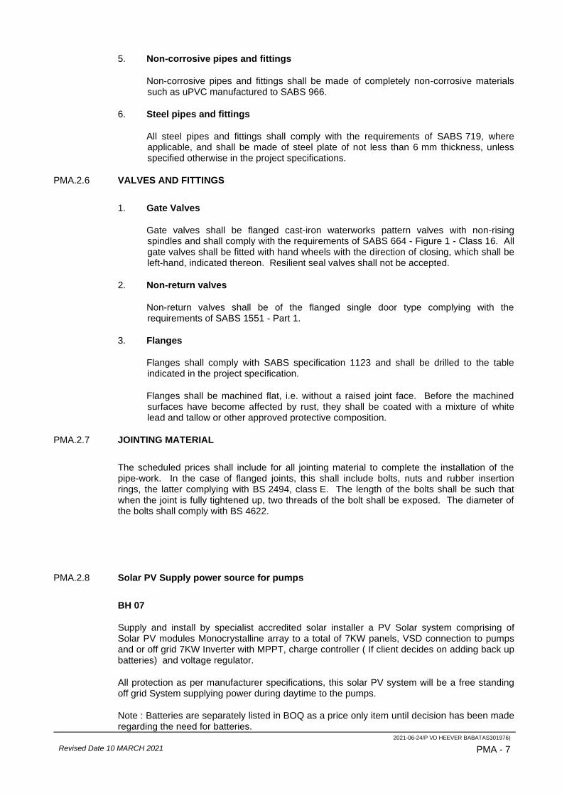
2021-06-24/P VD HEEVER BABATAS301976)
Revised Date 10 MARCH 2021 PMA - 7
5. Non-corrosive pipes and fittings
Non-corrosive pipes and fittings shall be made of completely non-corrosive materials such as uPVC manufactured to SABS 966.
6. Steel pipes and fittings
All steel pipes and fittings shall comply with the requirements of SABS 719, where applicable, and shall be made of steel plate of not less than 6 mm thickness, unless specified otherwise in the project specifications.
PMA.2.6 VALVES AND FITTINGS
1. Gate Valves
Gate valves shall be flanged cast-iron waterworks pattern valves with non-rising spindles and shall comply with the requirements of SABS 664 - Figure 1 - Class 16. All gate valves shall be fitted with hand wheels with the direction of closing, which shall be left-hand, indicated thereon. Resilient seal valves shall not be accepted.
2. Non-return valves
Non-return valves shall be of the flanged single door type complying with the requirements of SABS 1551 - Part 1.
3. Flanges
Flanges shall comply with SABS specification 1123 and shall be drilled to the table indicated in the project specification.
Flanges shall be machined flat, i.e. without a raised joint face. Before the machined surfaces have become affected by rust, they shall be coated with a mixture of white lead and tallow or other approved protective composition.
PMA.2.7 JOINTING MATERIAL
The scheduled prices shall include for all jointing material to complete the installation of the pipe-work. In the case of flanged joints, this shall include bolts, nuts and rubber insertion rings, the latter complying with BS 2494, class E. The length of the bolts shall be such that when the joint is fully tightened up, two threads of the bolt shall be exposed. The diameter of the bolts shall comply with BS 4622.
PMA.2.8 Solar PV Supply power source for pumps
BH 07
Supply and install by specialist accredited solar installer a PV Solar system comprising of Solar PV modules Monocrystalline array to a total of 7KW panels, VSD connection to pumps and or off grid 7KW Inverter with MPPT, charge controller ( If client decides on adding back up batteries) and voltage regulator.
All protection as per manufacturer specifications, this solar PV system will be a free standing off grid System supplying power during daytime to the pumps.
Note : Batteries are separately listed in BOQ as a price only item until decision has been made regarding the need for batteries.

2021-06-24/P VD HEEVER BABATAS301976)
Revised Date 10 MARCH 2021 PMA - 8
BH 14
Supply and install by specialist accredited solar installer a PV Solar system comprising of Solar PV modules Monocrystalline array to a total of 6KW panels, VSD connection to pumps and or off grid 5 KW Inverter with MPPT, charge controller ( If client decides on adding back up batteries) and voltage regulator.
All protection as per manufacturer specifications, this solar PV system will be a free standing off grid System supplying power during daytime to the pumps.
Note : Batteries are separately listed in BOQ as a price only item until decision has been made regarding the need for batteries.
BH 05 and BH 19
Supply and install by specialist accredited solar installer a PV Solar system comprising of Solar PV modules Monocrystalline array to a total of 3KW panels, VSD connection to pumps and or off grid 3 KW Inverter with MPPT, charge controller ( If client decides on adding back up batteries) and voltage regulator.
All protection as per manufacturer specifications, this solar PV system will be a free standing off grid System supplying power during daytime to the pumps.
Note: Batteries are separately listed in BOQ as a price only item until decision has been made regarding the need for batteries.
Solar Note: All panels, mounting structures, cables and consumables must form part of the
price for each solar installation for each BH position individually as each BH is seen as a
standalone entity and the PV solar installation will supply each BH pump individually.
2021-06-24/P VD HEEVER BABATAS301976)
Revised Date 10 MARCH 2021 PMA - 9
SECTION 3: PAINTING AND FINISHING
PMA.3.1 GENERAL
The following clauses shall apply to all items to be painted under this specification:
1. No paint will be applied unless the surface to be painted has been thoroughly cleaned to remove all traces of dust, grease, oil, mill scale, rust or corrosion of any nature.
2. All metal surfaces shall be moisture dry before paint is applied. All paint surfaces shall be "hard" dry before a further coat may be applied, unless otherwise specified.
3. All surfaces which will be inaccessible after installation, shall receive the specified application before installation.
4. If the shop coat was left for a few months, the surface shall be rubbed down with emery paper or steel wool before final coats are applied. Washing down and scrubbing with clean water and hard brush is recommended.
5. The painter shall satisfy himself that the final coat completely covers the previous coat.
6. The dry film thickness shall be measured using a non-destructive thickness gauge similar to MIKROTEST.
7. In all cases the manufacturer's instructions must be strictly adhered to.
PMA.3.2 METAL PREPARATION
1. All steel surfaces shall be sandblasted to a minimum of Sa. 2½ (off-white) finish, to the Swedish specification S.I.S. 05/59/00.
2. The abrasive shall comply in all respects to SABS code 064 and shall be free of any traces of oil, grease, foreign objects or corrosive contaminants such as chlorides, etc.
3. The abrasive and blast cleaning shall be adjusted to ensure that the minimum amount of abrasive remains embedded in the steel.
4. Blast cleaning shall not be done when there is dew on the metal or in the case of nozzle blasting, when the atmospheric humidity is such that moisture condenses at the nozzle during work.
5. Blasted surfaces shall be brushed or cleaned by vacuum before painting. It is essential to apply the primary coat within the shortest possible time after blasting and certainly within four (4) hours.
PMA.3.3 PAINTING
PMA.3.3.1 General
The ideal temperature for painting lies within the range 13 to 32 °C (55 to 90 °F). The steel surface should be clean and dry and the ambient relative humidity below 90 %. Painting should be suspended under the following conditions:
(a) When the temperature of the ambient atmosphere falls below 4 °C (40 °F), or its relative humidity rises above 90 %. (It may be possible to paint satisfactorily outside under these conditions by erecting some form of temporary shelter).
(b) For outdoor work, during periods of inclement weather, i.e. rain, snow, fog or mist.
2021-06-24/P VD HEEVER BABATAS301976)
Revised Date 10 MARCH 2021 PMA - 10
(c) Generally when the conditions are such that condensation has occurred or is likely to occur on the steel.
Because of the possibility of condensation when cold material that is brought into a warm shop for painting after having stood in the open, ample time should be given to reach the ambient temperature, e.g. stand in the shop overnight before work is begun.
PMA.3.3.2 Preparing Paint For Use
Correct preparation of paint immediately before use is highly important.
All paints should be supplied from the stores and the painters, ready for application (with the exception of mixing). Any instructions given on the containers by the manufacturers should be strictly followed for example, any paint not used within its specified "pot life", should be discarded. No paint should be used after the expiry of the safe "shelf life" indicated on the container. The quantity of paint mixed at one time should be restricted according to its "pot life".
All paints should be thoroughly mixed under the supervision of the foreman in a manner approved by the project engineer. During the progress of the work, only the minimum number of containers needed should be open at any one time and partly full containers should be temporary sealed.
PMA.3.3.3 Paint Application
A zinc rich (epoxy) primer conforming to SABS 926, must be applied within four (4) hours after blast cleaning, to a dry film thickness of at least 15 micron. It is preferable that the primer be applied by brush.
After fabrication a coat of zinc-chromate or similar undercoat, shall be applied, as described in the detailed specification. Prior to applying this coat the painter shall ensure that the entire surface is free of contamination.
Final coats shall conform to the detailed specification set-out hereunder.
When painting over blast cleaned surfaces which are unavoidably rough, it is essential that sufficient thickness of priming paint be applied to ensure that the high spots of steel surface are adequately covered. Should inspection reveal that this is not the case, the number of priming coats should be increased accordingly.
Each coat should be allowed to become sufficiently cured before the next is applied. Unduly long curing periods may impair adhesion between successive coats and the interval between successive coats should not exceed two (2) days.
If the curing interval has been so long as to endanger the adhesion of the following coat, the paint already applied should be lightly rubbed down with fine abrasive paper before applying the next coat.

2021-06-24/P VD HEEVER BABATAS301976)
Revised Date 10 MARCH 2021 PMA - 11
PMA.3.4 DETAIL PAINT SPECIFICATION
A. Ordinary Steelwork
Primers : One coat zinc-chromate plus one coat universal undercoat
Finishing coats : Two coats gloss enamel of approved manufacture
Total film thickness 0,1 mm
B. Steelwork in sea environment
Primer : One coat zinc rich epoxy primer with dry film thickness of 15 microns
Undercoat : One zinc-chromate
Finishing coats : Two coats micaeous iron oxide structural paint of different colours to a total film thickness of 38 microns per coat
C. Steel work in contact with water
Primers : One coat zinc-chromate plus one coat red-lead undercoat
Undercoat : Two coats "Chemgard" undercoat or similar of different colours (Plascon ref no A.R.1)
Finishing coats : Two coats "Chemgard" enamel or similar (Plascon ref no. A.R.6) with top coat light grey, unless otherwise specified
Film thickness of all "Chemgard" coats to be at least 25 microns.
D. Galvanised steel
All traces of protective coatings must be removed with an approved cleaning agent.
Primer : One coat of approved galvanising etching agent
Undercoat : One coat universal undercoat
Finishing coat : Two coats approved gloss enamel
E. Cast iron
Remove as much as possible of the bitumen covering layer.
Primer : One coat aluminium based paint
Undercoat : One coat universal undercoat
Finishing coat : Two coats approved gloss enamel
2021-06-24/P VD HEEVER BABATAS301976)
Revised Date 10 MARCH 2021 PMA - 12
F. Aluminium
Primer : One coat of approved etching agent
Further coats : As D. and E. above
G. PVC
Primer : One coat of approved etching agent
Further coats : As D. and E. above
PMA.3.5 GALVANISING
1. Surface treatment
The surface must be completely free from rust, dirt, grease, millscale and any other contaminants and must in general be cleaned to the same standards laid down in clause PMA.3.2 of the specification.
Further cleaning must be carried out by acid pickling. As soon as the product to be galvanised has been sufficiently cleaned and rinsed, a coating of flux must be applied.
2. Zinc coating
When hot-dip galvanising, the composition of the steel, the zinc temperature and the immersion items, shall comply to the standards generally accepted for that type of item. All aspects of hot-dip galvanising shall comply with the requirements of SABS 763. A coating of at least 765 g/m2 must be achieved.
PMA.3.6 EPOXY COATING
1. Surface treatment
The surface must be completely free from rust, dirt, grease, millscale and any other contaminants and must in general be cleaned to the same standards laid down in clause PMA.3.2 of the specification.
2. Epoxy coating
Epoxy coating of piping shall be done to the manufacturer’s specification and shall be similar or equal to COPON KS 16 W. The epoxy coats shall be applied in layers of 40 to 60 µm to form a total thickness of 120 µm.
PMA.3.7 REPAIRS TO DAMAGED SURFACES
Damage to any previous paint coats should be made good by re-coating the affected areas in the same or in an equivalent manner to that originally specified. They should first be cleaned to bare metal if necessary and the edges of the undamaged paint should then be bevelled and sand papered. The patches of new paint shall overlap the old paint by at least 20 mm.
PMA - 13
SECTION 4: ELECTRICAL EQUIPMENT, INSTRUMENTATION
AND INSTALLATION (R)
PMA.4.1 GENERAL
This specification covers the general items of equipment for electrical installations related to mechanical installations. All materials and installation of such materials shall comply with the following:
1. The latest edition of the SABS “The Wiring of Premises” SANS 10142-1 and 2.
2. The Occupational Health and Safety Act (Act 85 of 1993).
3. The Local Supply Authority’s Regulations and Fire Insurance Regulations.
4. Any special conditions implied in this specification.
Note: That where reference is made to any Standard, Act or statutory requirements, the latest amendment / replacement shall apply.
PMA.4.2 MOTOR CONTROL CENTRES (MCCs) GENERAL REQUIREMENTS
This specification covers indoor MCCs, as well as outdoor kiosk type MCCs.
PMA.4.2.1 Statutory Requirements
MCCs (low voltage assemblies) must be provided as detailed below and conform to the requirements of the OHS Act in terms of SANS 10142-1 in general and specifically in terms of SANS 1973 (latest editions), as briefly summarised below. Note that this interpretation serves as a guideline only, and tenderers/contractors must acquaint themselves fully with the relevant SANS requirements, since they will be responsible in terms of the Act and in case of conflict in interpretation or clarity, the SANS requirements shall apply.
• MCCs rated at 10 kA and less must comply with SANS 1973-3.
• MCCs rated at more than 10 kA, must comply with SANS 1973-1 and the MCC must be certified to comply with the relevant type provided for within SANS 1973-1.
• Tenderers must state in the data sheets whether and how they comply with the relevant requirements and the type of assembly offered based on which compliance is claimed. A copy of the applicable SABS certification in terms of SANS 1973 must be submitted with the tender, if so required in the data sheet.
• On completion the MCC manufacturer must certify that the MCC complies with the OHS Act in terms of the relevant SANS certification, before delivery will be taken. SABS permit holders must apply the mark to the MCCs. This certification, as well as a routine test report, must be provided to the installation electrician for purposes of the COC.
• In the case where the MCC populator is not the steelwork and busbar manufacturer, the steelwork and busbar manufacturer must inspect the populated switchboard and certify that the populated switchboard has not compromised his certification and that the populated switchboard complies with the relevant code.
PMA - 14
PMA.4.2.2 Switchgear General
Switchgear for the main offer must be Moeller Electric, Siemens, Telemecanique, ABB, Rockwell or Mitsubishi. Any other switchgear offered for the main offer will have to be changed to one of the above on the Engineer’s decision, at no extra cost. Equivalent alternatives may be offered, but only as a separate alternative offer. Circuit breakers must provide short-circuit and overcurrent protection, suitable for motor starting.
The main and motor starter circuit breakers must have panel door mounted, door interlock padlockable handles. Circuit breaker handle extended shafts coupling to the circuit breaker must be an integral part of the circuit breaker body, or screw fixed into a threaded receptacle in the body. A clip or clamp-on adaptor will not be acceptable. Rear access MCCs, rear panel doors, must be fitted with square key locks and padlockable handle.
PMA.4.2.3 Starter General Requirements
Starters must conform strictly to clauses PMA.4.3, unless specified otherwise in the project specification and must be equipped with auxiliaries, as stated. Comprehensive motor protection shall include, overload, underload, phase fail/under voltage and phase rotation.
Note: That all drives, including ancillary equipment e.g. motor driven grease pumps etc. associated with the relevant equipment, must have a separate starter included in the MCC, even if not mentioned in the project specification.
PMA.4.2.4 Ratings
The MCC and all switchgear must be rated for the specified fault level as specified in the project specification under the relevant MCC. Single pole circuit breakers on MCCs with a fault level in excess of 10 kA, may be rated at 10 kA with suitable HRC backup fuses.
Fault levels given at the relevant MCCs, are based on the position of MCCs as shown on the tender drawings and cable sizes in the schedule of cables. Should there be any deviation, the fault levels must be re-evaluated.
MCCs shall be rated to a protection degree of IP54 for external use and lP44 for use inside buildings
Ratings given for equipment are based on the estimated power requirements of new driven equipment, but must be determined according to the specific motors as installed. Starters may not be rated at less than the motor rating.
PMA.4.2.5 General Construction
The MCC must be floor or wall-mounted and be manufactured from 3CR-12 sheet steel not less than 1,6 mm thick. The MCC shall be arranged for front access to live parts if placed against the wall and front and rear access for MCCs not placed against a wall. Rear access doors must be padlockable
The MCC must be constructed in tiers, subdivided in separate panels, one each per individual drive and control section, each with own door. For switchboards with a fault level of 10 kA and more, the panels must be fully compartmentalised and for less than 10 kA, open construction may be used, subject to the requirements of SANS 1973-3.

PMA - 15
A push lock twist unlock emergency stop which will stop all running equipment (via auxiliary relays in each panel) must be provided on the incoming section door, with corresponding indication light if the E-stop is operated. In the case where individual motors and / or panels are fitted with E-stops, each E-stop must have an indication light and the active status must be wired to the Terminal/Marshalling enclosure for remote monitoring.
All interactive equipment must be installed on doors. Doors must be hinged and fitted with rubber door seals. MCCs for external use must have outside weather-proof doors and both the internal and external doors must be fitted with rubber gaskets, to prevent ingress of dust and sand. The door construction must provide a continuous sealing edge against the gasket. Cut outs for overlapping doors or locks will not be permitted. Coin slot type screws shall be used for securing the front panels and doors must be removable.
The grouping of equipment on panels must be logical and neat and shall be done on the following basis:
a) Incoming section with main incoming breaker, metering and incoming cable access.
b) Outgoing sections for each motor circuit with sub-main breaker, starter, dedicated control, ancillary equipment and status indication.
c) Separate control panel, for each group of related equipment operating together such as a duty and standby pump and all common controls and indication lights.
d) Outgoing section for plant room auxiliaries and general control circuits, power and lighting.
All connections, including motor connections must be extended to terminals above the gland plate, within dedicated terminal compartments with own doors. Connections to starter panels situated at the bottom of a tier may be accommodated within that starter panel, but no others.
Tiers with enclosed starter compartments must be provided with separate full length vertical wiring compartments of minimum width 250 mm between tiers, for wiring to terminals in the terminal compartments. Terminals to signal and control cabling may be installed within such tiers.
Hot air from electronic starters, unless fitted with a bypass contactor, must be ducted to the top or back of the switchboard with aid of extraction fans at the point of exit. Starters with a combined rating of 100 kW or more, must be vented to the outside of the building. Air entry openings must be fitted with filters in a removable frame for easy removal for cleaning. Screens must be fitted to air exits to prevent ingress of foreign bodies.
Sufficient space must be provided between the base of the panel, the gland plate and the main circuit breaker to allow easy connection of the supply cable. In the case of free-standing switchboards, there must be at least 300 mm clearance between the base and gland plate with additional space below in a trench, to allow for the cable bending radii. In absence of a trench, the additional height must be provided by means of a raised platform from angle iron.
Painting must be in accordance with section 3 on painting and the final coat must be electric orange or light grey baked enamel baked or powder epoxy. Outdoor MCCs for pump stations must be olive green.
The electrical equipment to be provided in the MCC must comply with the requirements of the project specification and other relevant sections hereafter.
The MCC must have a totally enclosed air insulated busbar chamber running the length of the main switch panel.
PMA - 16
Internal busbars, of solid copper of each phase and neutral, wiring and terminals shall be of suitable size and rating and terminals shall be of brass and comply with SANS 60947-3. Busbars must be solidly mounted on insulting supports with bolted lug connections to conductors. Screw type connections with clamps shall be acceptable for conductors up to and including 10 mm2. Neutral and earth busbar of solid brass with one way for each circuit and for each conductor, must be provided.
The wiring must be installed in PVC trunking, or within dedicated wire-ways by means of neatly arranged vertical and horizontal runs and laced together by means of “Helen Strap” or equal material. Wire looms not in trunking must be strapped to rails, secured to the steelwork. Self- adhesive type securing material shall not be accepted. All control wiring and terminals shall be numbered with approved wire and terminal markers.
All equipment must be clearly labelled by means of plastic engraved labels in a clearly readably position.
External door mounted labels must be fixed to the boards immediately below the equipment by means of screws. A label must be provided at the incomer and outgoing circuit breakers depicting the point of supply / equipment served and cable size.
Note: That all supporting structures for freestanding switchboards, such as over cable trenches, must be provided under this contract and included in the switchboard price.
PMA.4.2.5.1 Outdoor type MCCs
The following additional requirements are applicable to outdoor (kiosk) type MCCs.
Outdoor MCCS must be of the weather-proof type rated at IP 54 and manufactured from 3CR12 sheet steel. MCC within residential areas must be green and outside residential areas, off-white, to be confirmed with the Engineer, before manufacture.
MCCs must have a double slope roof with a minimum of 50 mm overhang and be of the hinged double door construction. The inner doors must be hinged with square key locks utilised for the mounting of indication and control equipment and the outer door as total weather protection, hinged, with padlockable rotary handles operating a stainless steel sliding locking rod. The outer doors must be fitted with hold-open stays.
Refer to General Construction i.r.o. door seals.
MCCs must be installed on a hot-dipped galvanised angle iron framework bolted to a concrete plinth, provided as part of the contract. The bottom end of the kiosk may not be less than 600 mm from ground level (including the plinth height above ground). The operating side must face south.
Shade canopies manufactured from 1,6 mm 3CR12 sheet steel (unfolded) must be provided for MMCs, if so specified in the project specifications. The canopy must have a double slope and overhang the MCC by 200 mm on all sides. Full length side panels must be provided. The canopy must be fixed to the MCC stand.
Where specified in the project specification, the MCC must be provided with a back to back section with own padlockable hinged door, as for the front door. This section is for use by other parties specified in the project specification and the dimensions must be liaised with such parties.
The Contractor must establish the incoming cable size from the supply authority before construction of the board starts if not supplied as part of this contract. Suitable terminals must be provided for the incoming cable if the main circuit breaker terminals are inadequate.
PMA - 17
Sewage pump stations
Kiosk type outdoor MCCs for sewage pump stations may not be installed over the access opening to the sump so that the panel encloses the opening. The panel must be installed on a hot-dipped galvanised steel framework bolted to the concrete plinth so that any sewage gas from the cable opening is vented to the atmosphere. This framework must raise the panel ± 200 mm above the concrete plinth. The sides of the framework must be covered with removable galvanised diamond mesh grilles to allow free circulation of air under the panel.
The panel bottom plate shall serve as gland plate and must be totally sealed against ingress of sewage gas.
The switchboard operating side shall not be closer than 1,0 m from the pump sump access opening.
PMA.4.2.6 Ancillary And Control Equipment
Control relays must be of the type indicating switched status and have an external manual switching facility. Connection pins must be sturdy in construction and of ample dimension. Thin pin type, prone to bending and misalignment, will not be acceptable.
Rotary switches must be of the wafer type with through fixing bolts and not of the multiple in line switch block type.
The framework and canopy detail drawing must be submitted to the Engineer for approval before manufacture, as well as a drawing of the concrete plinth detail.
PMA.4.2.7 Protection/Alarm Devices
Unless stated to the contrary, motor protection devices must be of the following type:
a) Overload : Thermal overload relay
b) Overheat : Motor winding embedded thermal protection device
c) Phase fail : Phase fail relay with AUTO reset (300 s time delayed, adjustable) for protection against phase loss, phase rotation and undervoltage. (This protection must include control equipment such as contactor coils).
Where comprehensive motor protection is specified as a separate electronic protection relay, it must have at least the above facilities. Soft starter and variable frequency controllers, must have integral comprehensive protection. The specific fault must be identified on the unit by means of a LED or LCD display and a single trip contact must also be provided for a common TRIP indication light on the external panel door. Comprehensive motor protection relays may be offered, even if not specifically specified.
All protection/alarm devices must have manual resets, unless specified to the contrary elsewhere in the project specification. Electrically latches alarms, must be reset by a manually operated pushbutton on the relevant MCC, or remotely via a telemetry system, if so specified in the project specification. It must be possible to reset an alarm as soon as the alarm detection unit is in the normal state again. An equipment drive motor may only restart once the protection device has been reset.
Protection devices for other plant equipment are specified in the project specification.
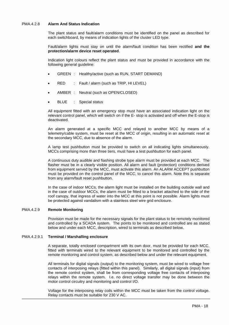
PMA - 18
PMA.4.2.8 Alarm And Status Indication
The plant status and fault/alarm conditions must be identified on the panel as described for each switchboard, by means of indication lights of the cluster LED type.
Fault/alarm lights must stay on until the alarm/fault condition has been rectified and the protection/alarm device reset operated.
Indication light colours reflect the plant status and must be provided in accordance with the following general guideline:
• GREEN : Healthy/active (such as RUN, START DEMAND)
• RED : Fault / alarm (such as TRIP, HI LEVEL)
• AMBER : Neutral (such as OPEN/CLOSED)
• BLUE : Special status
All equipment fitted with an emergency stop must have an associated indication light on the relevant control panel, which will switch on if the E- stop is activated and off when the E-stop is deactivated.
An alarm generated at a specific MCC and relayed to another MCC by means of a telemetry/cable system, must be reset at the MCC of origin, resulting in an automatic reset at the secondary MCC, due to absence of the alarm.
A lamp test pushbutton must be provided to switch on all indicating lights simultaneously. MCCs comprising more than three tiers, must have a test pushbutton for each panel.
A continuous duty audible and flashing strobe type alarm must be provided at each MCC. The flasher must be in a clearly visible position. All alarm and fault (protection) conditions derived from equipment served by the MCC, must activate this alarm. An ALARM ACCEPT pushbutton must be provided on the control panel of the MCC, to cancel this alarm. Note this is separate from any alarm/fault reset pushbutton.
In the case of indoor MCCs, the alarm light must be installed on the building outside wall and in the case of outdoor MCCs, the alarm must be fitted to a bracket attached to the side of the roof canopy, that ingress of water into the MCC at this point is not possible. Alarm lights must be protected against vandalism with a stainless steel wire grid enclosure.
PMA.4.2.9 Remote Monitoring
Provision must be made for the necessary signals for the plant status to be remotely monitored and controlled by a SCADA system. The points to be monitored and controlled are as stated below and under each MCC, description, wired to terminals as described below.
PMA.4.2.9.1 Terminal / Marshalling enclosure
A separate, totally enclosed compartment with its own door, must be provided for each MCC, fitted with terminals wired to the relevant equipment to be monitored and controlled by the remote monitoring and control system, as described below and under the relevant equipment.
All terminals for digital signals (output) to the monitoring system, must be wired to voltage free contacts of interposing relays (fitted within this panel). Similarly, all digital signals (input) from the remote control system, shall be from corresponding voltage free contacts of interposing relays within the remote system. I.e. no direct voltage transfer may be done between the motor control circuitry and monitoring and control I/O.
Voltage for the interposing relay coils within the MCC must be taken from the control voltage. Relay contacts must be suitable for 230 V AC.
PMA - 19
The following points must be monitored:
a) Motor status (each):
• Motor circuit breaker ON/OFF status : Auxiliary switch on motor circuit breaker wired to interposing relay (open in OFF);
• Mode selector switch MANUAL and AUTO positions wired to interposing relays (closed in monitored position; open in OFF);
• Motor RUN status: Auxiliary switch on starter wired to interposing relay (closed in RUN);
• Equipment TRIP status: All driven equipment protection devices, including emergency stop, wired to a common interposing relay (closed in TRIP).
• All other alarm and status indication as per the control description of the driven equipment in the relevant project specification.
PMA.4.2.10 Power Factor Correction
Power factor correction equipment must comprise a suitable circuit breaker or fused on-load isolator, switching contactor and capacitors to provide correction to 0,98 lagging. Discharge resistors must be provided to discharge the capacitors to less than 10 % of the system voltage within 30s of disconnection.
In the case of free-standing rear access MCCs, the PFC capacitors must be installed at the back of the associated starter panel. In the case of front access only MCCs, the capacitors must be installed in the motor starter compartment, but separated from the starter and control equipment by means of a solid barrier plate.
PFC capacitors used in conjunction with soft starters, must be arranged that the capacitors are not switched to the starter outgoing terminals, by means of a suitable contactor arrangement, isolating the soft starter during running (including start up and stopping).
PMA.4.2.11 Spatial Requirements
MCCs sizes must be verified against spatial provision on the tender drawings. Any constraints must be qualified in the offer.
After appointment, prior to submission of drawings for comment, the MCCs sizes must be verified against the spatial provision for construction. Failure to do so resulting in additional cost for special measures required to overcome such constraints, will be for the contractor’s account.
PMA.4.2.12 MCC Drawings
All MCC drawings must be done in CAD format as per PMA 4.1.2. Drawings submitted for comment must be paper copies in A3 size. Once the Engineer has commented on a drawing, construction can proceed, unless there are unresolved issues. A copy of the updated drawings must be issued to the Engineer for record. All revisions must be listed on drawings. Note that no additional payment will be made for amendments to drawings.
PMA.4.2.13 Payment For MCCs
MCCs are considered as complete functional units and no progress payments will be made on uncompleted MCCs. Payment will only be certified once the MCC has passed the factory test and installed on site.

PMA - 20
PMA.4.3 MOTOR STARTERS
Starter types will be specified in the project specification.
Unless specified to the contrary in the project specification, starters must conform to the requirements as set out below. The following starter panel configuration and functional requirements will also be applicable to electronic controllers/drives.
PMA.4.3.1 Starter Assembly Configuration
Should the starter type, duty or torque characteristics specified in the project specification not be suitable for the application of the tendered equipment, a suitable starter must be offered as an alternative in the annexure together with price implication and full particulars similar to that required in the information sheets.
Starters shall be rated for not less than 15 starts per hour and consist of the following:
a) Circuit breaker with padlockable handle;
b) CT operated ampere meter;
c) 6-digit running hour meter;
d) Controllers/contactors and current limiting devices in accordance with the motor starting and control requirements;
e) Protection devices which shall be provided as follows:
• Motor overload relay with adjustable thermal trips and single phasing protection;
• Winding overheat protection in accordance with the type of temperature sensing devices in the motor. In the case of thermistor relays, it must be ensured that the thermistor resistance curve and the thermistor relay tripping characteristics are compatible;
• Earth leakage protection for motors liable to flooding, i.e. subterranean installations. Earth leakage protection shall be provided for submersible motors, irrespective.
• Earth leakage relays shall be purpose made, similar to the E.P.C. manufacture;
• Protection equipment for moisture sensing probes (submersible motors only).
All protection devices must trip the associated motor and individual fault indication must be given by means of a red pilot lights. Flush mounted push buttons must be provided for resetting electrically latched protection equipment.
f) Control devices which shall be provided as follows:
• Manual starting and stopping must be provided by means of a green and red push button respectively. Automatic starting must be provided in accordance with the project specification requirements.
A green pilot light operated by the motor “RUN” contactor must be provided to indicate when the motor is running;
• Starters used in conjunction with automatic starting and stopping equipment, shall be fitted with a red mushroom-head stop-lock type emergency stop, which must also be operative in manual mode;
PMA - 21
• A lamp test pushbutton must be provided which will switch on all pilot lights simultaneously, when operated;
• The motor circuit breaker (with auxiliary switches as required) shall disconnect all power and control connections to the motor served. It shall however be possible to test the control circuit (applicable to motors 15 kW and higher only) without switching the motor (i.e. the motor circuit breaker off) by means of a selector switch inside the panel marked normal/test.
The control circuit voltage must be taken from the load side of the motor circuit breaker (normal position) and from the live side (test position), via this changeover switch. The test position must be interlocked with an auxiliary switch on the motor circuit breaker, that the test line will be disconnected when the motor is on. For example, it shall not be possible to start the motor with the motor circuit breaker on and the C/O facility in test.
The starters shall be fitted with approved terminals of ample dimensions to suit the cables to be supplied from this equipment. The terminals must be installed directly above the gland plate for the outgoing cables.
An approved earth terminal shall be provided on the frame of each starter housing gear and provision shall be made for earthing each starter.
g) Comprehensive simulation facilities must be provided in the factory to test starters and all protection equipment.
PMA.4.3.2 SOFT STARTERS and VSD (variable speed drives)
PMA.4.3.2.1 General
The general requirements as per PMA.4.3.1 will be applicable, as starter in this section refers to the electronic controller.
Soft starters must provide smooth acceleration during run up, reducing voltage drop, current and torque peaks, by means of reduced voltage at start-up, which is increased to full value on an adjustable time ramp, with an adjustable maximum motor current limit.
The motor and starter combination must be carefully selected to ensure compatibility of the torque requirements and motor insulation class for the operating cycle and starter to prevent thermal tripping of the starter due to overheating of the motor (prolonged starting times).
They must be in accordance with the type(s) specified in the project specification and must conform to the following minimum requirements.
PMA.4.3.2.2 Application
Soft starters will in general be specified for purposes of torque control rather than current limit. The reduced voltage at start-up and degree of current limit (if specified) may reduce starting torque considerably. Tenderers must ensure that the starter and conditions specified, comply with the requirements of the driven machinery offered and should qualify their tender including financial implications, accordingly.
Any financial implication arising due to non compliance with this stipulation, will be borne by the Tenderer.
PMA.4.3.2.3 Technology
The unit must consist of a microprocessor controlled control unit and a power unit with 3 banks of 2 thyristor modules back to back with protection devices and gamma firing angle control.
PMA - 22
PMA.4.3.2.4 Climatic operating conditions
a) Ambient temperature : 0 °C -40 °C
b) Humidity : 93 % at 40 °C without condensation
PMA.4.3.2.5 Standards
a) Vibration resistance : to lEC 68-2-6
b) Shock resistance : to IEC 68-2-27
c) Radio electrical interference : to lEC 801-3
PMA.4.3.2.6 Supply
400 V3 phase - 15%,+10 % at 50 Hz.
PMA.4.3.2.7 Rating
The starter must be suitable for the continuous rated motor connected load plus 10% and 12 starts per hour, for single motors (refer to 6.0 for multiple motor starting). This is a minimum requirement and the application as per 2.0 must be taken into account with the selection.
PMA.4.3.2.8 Control functions
a) Starting
• Voltage ramp (starting acceleration) : Adjustable 1-30 seconds from a fixed threshold of 0,33 rated voltage.
• Current limit: Adjustable form 2-5 times motor rated current.
• Start voltage boost facility: Switch selectable full voltage starting for 100 ms.
b) Stopping (switch selectable)
• Uncontrolled free-wheel stop by switching of the supply to the motor.
• Controlled stop with voltage ramp (deceleration) : Adjustable 2-60 seconds.
c) Switch selectable automatic and manual fault reset.
d) Motor thermal protection by adjustment of the motor current setting.
PMA.4.3.2.9 Protective features
a) Starter short circuit protection by means of fast acting fuses or other approved (by manufacturer) method.
b) Self diagnostic internal fault check before starting.
c) Thermal:
• Protection of the starter against over-load and over-temperature shutting the unit down. Units fitted with a cooling fan must have a fan fail alarm.
PMA - 23
• Protection of the motor against overload (slow, medium and fast overheating exceeding the motor thermal capacity) by setting the motor operating current. It must incorporate a thermal memory, taking into account previous starts, which will prevent a restart once the thermal capacity has been exceeded until the motor has cooled down sufficiently. This facility must remain operational even if the starter is bypassed once the motor is up to speed.
d) Voltage Phase failure and phase imbalance must stop the motor.
PMA.4.3.2.10 Status display (LED)
a) Starting/stopping
b) Normal operation
c) Cooling down
d) Internal fault (starter)
e) Thermal fault (starter)
f) Overload (motor)
g) Phase failure
NOTE:
The status indication must be visible without opening the panel door (in case of panels with an inner and outer door such as weatherproof panels, this applies to the inner door only).
PMA.4.3.2.11 Output relays
a) Fault : (1 x N/O; 1 x N/C)
b) Overload : (1 x N/O)
c) End of starting : (1 x N/O)
NOTE:
These conditions must be displayed external to the enclosure in which the starter is mounted, by means of pilot lights.
PMA.4.3.2.12 Cabinet installation
When installed in a general-purpose enclosure protection degree IP23, sufficient space must be provided around the starters to ensure adequate air flow in accordance with the manufacturers requirements. If sufficient cooling cannot be obtained by natural ventilation fan(s) must be fitted. In case of IP54 enclosures an internal cooling fan must be fitted and adequate heat exchanging surfaces must be provided (calculation to be provided on request).
PMA.4.3.2.13 Power factor equipment
If power factor equipment has been specified in the project specification steps must be taken that the power factor correction equipment is never connected to the starter output terminals. I.e. in the case of individual motor correction, the motor must be directly connected to the main supply after run up and the starter output disconnected, by means of interlocked contactors, before the power factor equipment is switched into the motor circuit. In these cases motors must be provided with separate overload relays since the starter overload protection is then out of circuit. Note the starter thermal memory must be retained when the motor is disconnected, to be functional if the motor is restarted.
PMA - 24
PMA.4.3.3 VARIABLE FREQUENCY CONTROLLERS (VFCs)
PMA.4.3.3.1 General
The general requirements as per PMA.4.3.1 will be applicable, referenced as electronic controllers.
VFCs must provide smooth linear acceleration during starting and stopping, by means of increasing the motor supply frequency from zero to the desired operational speed (maximum 55 Hz), on an adjustable time ramp during run-up and the reverse on deceleration to standstill.
The motor and starter combination must be carefully selected to ensure compatibility of the torque requirements and motor insulation class for the operating cycle and starter.
They must be in accordance with the type(s) specified in the project specification and must conform to the following minimum requirements.
PMA.4.3.3.2 Application
VFCs will in general be specified for three phase induction motor torque and dynamic speed control. In some instances it may be for superior acceleration and deceleration characteristics, reduced current at starting and stopping in standby power applications, or (reduced) fixed speed pumping applications providing for future pumping capacity upgrade by increasing the operational speed.
PMA.4.3.3.3 Technology
The unit must consist of a microprocessor controlled six or twelve pulse rectifier section, DC link and final inverter section with associated protection devices. The project specification will state whether six or twelve pulse units are to be provided. If not specified, the default option will be six pulses. If a six pulse unit, whether by specification or default, does not meet the harmonic distortion requirements (refer to PMA.4.3.3.8), necessitating a twelve pulse unit, the latter must be provided irrespective.
Vector torque control must be provided and deceleration braking of rotary loads must be via vector control. The use of resistors for absorbed braking energy dissipating is not acceptable.
VFCs must have serial communication capability to communicate on a Modbus protocol/Ethernet communication bus to a controlling PLC, MMI, VFCs on a multiple drive system and other network connected field devices.
PMA.4.3.3.4 Operator/controller interface
An operator interface must be provided via a keypad for navigation and programming/parameter setup with LCD message display window. This interface must be removable for remote mounting.
The message window must provide status display of all preset operational parameters, all dynamic functional parameters such as frequency/speed, supply voltage, phase/line currents, power, kVA etc. and protection/alarm facilities.
A USB port must be provided for laptop access for control programming facilities.
PMA - 25
PMA.4.3.3.5 Drive (starter) assembly configuration
VFC drives will generally be configured on a discrete component basis. The standard VFC drive configuration must comply with the starter assembly configuration as per PMA 4.3.1, i.e. comprising an upstream circuit breaker in accordance with the specified fault level, the controller itself with fast acting HRC fuses between the circuit breaker and controller and relevant control and protection equipment. This assembly (or assemblies in case of multiple drives), must be mounted within a purpose built MCC to the requirements as set out in the project specification, in compliance with the statutory requirements as per PMA 4.2.1. In high power applications, modular configuration of the controller power sections will be acceptable, whereby multiple stacks can be used to achieve a specific power rating.
Where a single drive is housed in more than one panel, the doors must be interlocked that it shall not be possible to open any panel door without switching the main circuit breaker for that drive off.
In the case of an imported pre-manufactured standalone cabinet assembly, for a high power application, this assembly must still comply with the stated statutory requirements. These units may be combined as a composite MCC in a multi-drive application, only if the system has been designed that way, where adjoining assemblies and main incoming section are linked by means of solid busbar. All sections such as the main incoming section, drive sections, PLC/control/marshalling sections, must be part of an integrated system, designed on a modular extendable basis, i.e. not standard pre-manufactured cabinet assemblies linked with flexible cable, since the composite MCC must still comply with the abovementioned statutory requirements for a composite MCC.
PMA.4.3.3.6 Ambient conditions, cooling and ventilation
The VFC must be able to function under the following unconditioned ambient conditions:
a) Temperature : 0 °C to 50 °C
b) Humidity : 93 % at 40 °C without condensation.
VFC power modules must be force ventilated by means of fans. Hot air must be expulsed to the outside of the MCC room, by means of ductwork and extraction fans at the point of exit. Refer to the general MCC requirements PMA.2.5 in this regard.
The onus is on the Tenderer to determine the operating conditions relating to the above and the cooling requirements of the VFCs, especially in multiple VFCs and/ or high power applications, where, in addition to the abovementioned measures, the heat load of the equipment or specific site ambient conditions, will necessitate air conditioning. The air conditioning installation must by default be provided as part of the Contract, unless stated to the contrary in the project specification and the Tenderer must qualify his tender, should air conditioning be required and not provided for under the Tender.
The Tenderer must provide the heat load of the installed equipment, whether for own determination of the air-conditioning requirements, or where the AC installation is provided by a third party.
PMA.4.3.3.7 Standards
The VFCs must comply with the following standards:
a) Vibration resistance : to lEC/EN 60068-2-6
b) Shock resistance : to IEC/EN 60068-2-27
c) EMC : to SANS 61800/61000 (latest editions), as well as NRS 048-2 (latest edition)
PMA - 26
PMA.4.3.3.8 Harmonics
Harmonic suppression must be provided in accordance with the above-mentioned standard, specifically SABS 61000-3-4. The VFCs must be fitted as standard with a built in DC link reactor for controllers rated at 16 A to 75 A. For larger units, additional measures must be taken, such as passive line filters and/or using a higher order rectifier section (refer PMA.4.3.3.3), with or without a DC reactor, depending on the THD requirements to be met (THD refers to both THDu and THDi, if not specifically stated). Line compensation components may be separate from the controller module, but still incorporated in the controller panel assembly.
Harmonic suppression of the VFC in general must be provided to ensure the integrity and reliable operation of the VFC related installation, but also to ensure the integrity of the supply to other users, upstream of the VFC.
The THD is thus referenced to the point of common coupling. In the case of a LV connection from a distribution network with other users, it will be the point of connection. In the case of a dedicated HV supply, it will be the supply transformer MV terminals. The inherent suppression of the supply system between the point of common coupling and the VSD installation must be taken into account when the THD is calculated.
A general guideline is 6 % for THDu and 10 % for TDDi, but subject to the abovementioned standard. The THDu and THDi of offered equipment must be stated in the data sheets and may deviate from the guideline, but the onus remains on the Contractor to comply with the stated standards, irrespective of the acceptance of such equipment.
PMA.4.3.3.9 Supply
The system supply will be 3 phase at 400 V nominal, - 15%,+10 % at 50 Hz, unless stated otherwise in the Project Specification.
PMA.4.3.3.10 Rating
The starter must be suitable for the continuous rated motor connected load, plus 10% and 12 starts per hour. This is a minimum requirement and the application as per PMA 4.3.3.2 above, must be taken into account with the selection.
PMA.4.3.3.11 Control functions
The VFCs must have the following minimum control facilities:
a) Manual starting and stopping:
• Acceleration and deceleration times to be separately adjustable, on a linear ramp scale.
b) Facility for automatic starting and stopping.
c) 16 programmable speeds.
d) PID control function for dynamic speed control.
e) Master/slave functionality to allow multiple drives to be locked onto a specific frequency.
f) Frequency skips function to prevent the drive to operate at resonant/critical speeds.
g) PLC programming capability.
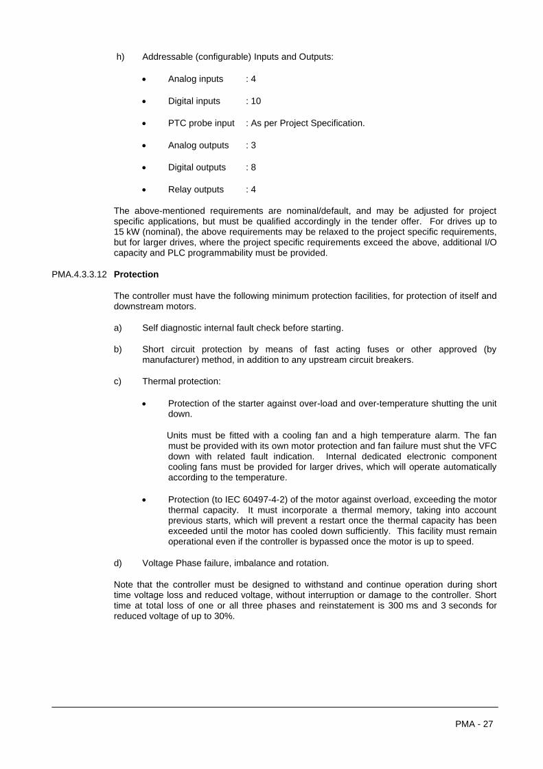
PMA - 27
h) Addressable (configurable) Inputs and Outputs:
• Analog inputs : 4
• Digital inputs : 10
• PTC probe input : As per Project Specification.
• Analog outputs : 3
• Digital outputs : 8
• Relay outputs : 4
The above-mentioned requirements are nominal/default, and may be adjusted for project specific applications, but must be qualified accordingly in the tender offer. For drives up to 15 kW (nominal), the above requirements may be relaxed to the project specific requirements, but for larger drives, where the project specific requirements exceed the above, additional I/O capacity and PLC programmability must be provided.
PMA.4.3.3.12 Protection
The controller must have the following minimum protection facilities, for protection of itself and downstream motors.
a) Self diagnostic internal fault check before starting.
b) Short circuit protection by means of fast acting fuses or other approved (by manufacturer) method, in addition to any upstream circuit breakers.
c) Thermal protection:
• Protection of the starter against over-load and over-temperature shutting the unit down.
Units must be fitted with a cooling fan and a high temperature alarm. The fan must be provided with its own motor protection and fan failure must shut the VFC down with related fault indication. Internal dedicated electronic component cooling fans must be provided for larger drives, which will operate automatically according to the temperature.
• Protection (to IEC 60497-4-2) of the motor against overload, exceeding the motor thermal capacity. It must incorporate a thermal memory, taking into account previous starts, which will prevent a restart once the thermal capacity has been exceeded until the motor has cooled down sufficiently. This facility must remain operational even if the controller is bypassed once the motor is up to speed.
d) Voltage Phase failure, imbalance and rotation.
Note that the controller must be designed to withstand and continue operation during short time voltage loss and reduced voltage, without interruption or damage to the controller. Short time at total loss of one or all three phases and reinstatement is 300 ms and 3 seconds for reduced voltage of up to 30%.

PMA - 28
PMA.4.4 PROGRAMMABLE LOGIC CONTROLLERS (PLCs)
PMA.4.4.1 General
PLCs must conform to the general requirements set out below. User specific preferences will be given in the project specification, as applicable.
PLCs shall be provided to perform logic sequence switching, arithmetical calculations to do switching based on field instruments inputs and process control requiring PID control.
The PLC shall be configured on a modular basis, with power supply, CPU, input, output, communication and process sections as separate modules slotted into a mounting rack.
Field wiring shall terminate on separate terminal sections, that modules can be removed without disconnection of wiring.
PMA.4.4.2 Inputs And Outputs
Provision shall be made for digital and analogue inputs and outputs.
Digital inputs shall be from potential free contacts and digital outputs shall be by means of solid state relays and electro-mechanical relays. Analogue inputs shall be suitable for O-5V, O-10V, and 4-20 mA and analogue outputs shall be of minimum 12 Bit resolution.
All I/O must be:
• galvanically isolated (by means of Opto isolator), surge and lightning protected;
• provided with status LEDs, to indicate the active (ON) status.
Failure of the CPU shall cause all outputs to revert to inactive (OFF) status. I/O modules must have suitable labelling facilities that I/O can be clearly labelled. The contractor must use a logic labelling system, to be submitted and approved by the Engineer before implementation.
PMA.4.4.3 Software And Programming
The PLC must be provided with propriety software or as specified in the project specification, inclusive of licensing cost. Proprietary software shall comply with IEC 116-1-3 standard.
Programming shall be executed via laptop and it shall be possible to execute program changes without in interrupting the PLC operation. The program display on screen must shown I/O active statuses and it shall be possible to force I/O to an active / non-active status for system functional testing.
The program must be saved on non-volatile memory, independent of any battery supply, to be off-loaded on CD ROM for backup storage.
Hard copy printouts of the program, as well as electronic copies on CD must be provided for the Operation and Maintenance Manual. Completion / taking over shall not be given without this documentation.
PMA.4.4.4 Communication
The PLC shall be able to communicate with other PLCs, field instruments, HMI and SCADA systems on all the major protocols such as Modbus and Profibus (or other as specified in the project specification) on a Ethernet communication bus.
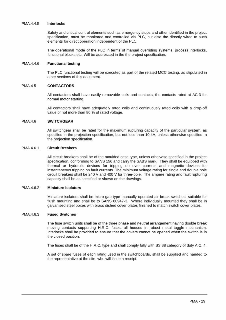
PMA - 29
PMA.4.4.5 Interlocks
Safety and critical control elements such as emergency stops and other identified in the project specification, must be monitored and controlled via PLC, but also the directly wired to such elements for direct operation independent of the PLC.
The operational mode of the PLC in terms of manual overriding systems, process interlocks, functional blocks etc, Will be addressed in the the project specification.
PMA.4.4.6 Functional testing
The PLC functional testing will be executed as part of the related MCC testing, as stipulated in other sections of this document.
PMA.4.5 CONTACTORS
All contactors shall have easily removable coils and contacts, the contacts rated at AC 3 for normal motor starting.
All contactors shall have adequately rated coils and continuously rated coils with a drop-off value of not more than 80 % of rated voltage.
PMA.4.6 SWITCHGEAR
All switchgear shall be rated for the maximum rupturing capacity of the particular system, as specified in the projection specification, but not less than 10 kA, unless otherwise specified in the projection specification.
PMA.4.6.1 Circuit Breakers
All circuit breakers shall be of the moulded case type, unless otherwise specified in the project specification, conforming to SANS 156 and carry the SABS mark. They shall be equipped with thermal or hydraulic devices for tripping on over currents and magnetic devices for instantaneous tripping on fault currents. The minimum voltage rating for single and double pole circuit breakers shall be 240 V and 400 V for three-pole. The ampere rating and fault rupturing capacity shall be as specified or shown on the drawings.
PMA.4.6.2 Miniature Isolators
Miniature isolators shall be micro-gap type manually operated air break switches, suitable for flush mounting and shall be to SANS 60947-3. Where individually mounted they shall be in galvanised steel boxes with brass dished cover plates finished to match switch cover plates.
PMA.4.6.3 Fused Switches
The fuse switch units shall be of the three phase and neutral arrangement having double break moving contacts supporting H.R.C. fuses, all housed in robust metal toggle mechanism. Interlocks shall be provided to ensure that the covers cannot be opened when the switch is in the closed position.
The fuses shall be of the H.R.C. type and shall comply fully with BS 88 category of duty A.C. 4.
A set of spare fuses of each rating used in the switchboards, shall be supplied and handed to the representative at the site, who will issue a receipt.
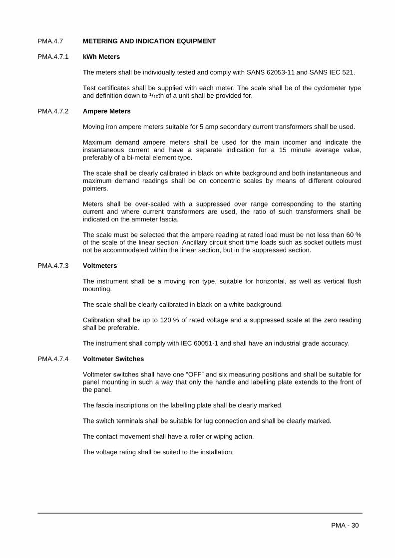
PMA - 30
PMA.4.7 METERING AND INDICATION EQUIPMENT
PMA.4.7.1 kWh Meters
The meters shall be individually tested and comply with SANS 62053-11 and SANS IEC 521.
Test certificates shall be supplied with each meter. The scale shall be of the cyclometer type and definition down to 1/10th of a unit shall be provided for.
PMA.4.7.2 Ampere Meters
Moving iron ampere meters suitable for 5 amp secondary current transformers shall be used.
Maximum demand ampere meters shall be used for the main incomer and indicate the instantaneous current and have a separate indication for a 15 minute average value, preferably of a bi-metal element type.
The scale shall be clearly calibrated in black on white background and both instantaneous and maximum demand readings shall be on concentric scales by means of different coloured pointers.
Meters shall be over-scaled with a suppressed over range corresponding to the starting current and where current transformers are used, the ratio of such transformers shall be indicated on the ammeter fascia.
The scale must be selected that the ampere reading at rated load must be not less than 60 % of the scale of the linear section. Ancillary circuit short time loads such as socket outlets must not be accommodated within the linear section, but in the suppressed section.
PMA.4.7.3 Voltmeters
The instrument shall be a moving iron type, suitable for horizontal, as well as vertical flush mounting.
The scale shall be clearly calibrated in black on a white background.
Calibration shall be up to 120 % of rated voltage and a suppressed scale at the zero reading shall be preferable.
The instrument shall comply with IEC 60051-1 and shall have an industrial grade accuracy.
PMA.4.7.4 Voltmeter Switches
Voltmeter switches shall have one “OFF” and six measuring positions and shall be suitable for panel mounting in such a way that only the handle and labelling plate extends to the front of the panel.
The fascia inscriptions on the labelling plate shall be clearly marked.
The switch terminals shall be suitable for lug connection and shall be clearly marked.
The contact movement shall have a roller or wiping action.
The voltage rating shall be suited to the installation.
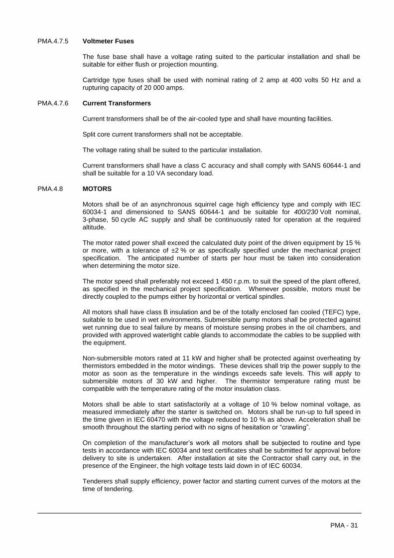
PMA - 31
PMA.4.7.5 Voltmeter Fuses
The fuse base shall have a voltage rating suited to the particular installation and shall be suitable for either flush or projection mounting.
Cartridge type fuses shall be used with nominal rating of 2 amp at 400 volts 50 Hz and a rupturing capacity of 20 000 amps.
PMA.4.7.6 Current Transformers
Current transformers shall be of the air-cooled type and shall have mounting facilities.
Split core current transformers shall not be acceptable.
The voltage rating shall be suited to the particular installation.
Current transformers shall have a class C accuracy and shall comply with SANS 60644-1 and shall be suitable for a 10 VA secondary load.
PMA.4.8 MOTORS
Motors shall be of an asynchronous squirrel cage high efficiency type and comply with IEC 60034-1 and dimensioned to SANS 60644-1 and be suitable for 400/230 Volt nominal, 3-phase, 50 cycle AC supply and shall be continuously rated for operation at the required altitude.
The motor rated power shall exceed the calculated duty point of the driven equipment by 15 % or more, with a tolerance of ±2 % or as specifically specified under the mechanical project specification. The anticipated number of starts per hour must be taken into consideration when determining the motor size.
The motor speed shall preferably not exceed 1 450 r.p.m. to suit the speed of the plant offered, as specified in the mechanical project specification. Whenever possible, motors must be directly coupled to the pumps either by horizontal or vertical spindles.
All motors shall have class B insulation and be of the totally enclosed fan cooled (TEFC) type, suitable to be used in wet environments. Submersible pump motors shall be protected against wet running due to seal failure by means of moisture sensing probes in the oil chambers, and provided with approved watertight cable glands to accommodate the cables to be supplied with the equipment.
Non-submersible motors rated at 11 kW and higher shall be protected against overheating by thermistors embedded in the motor windings. These devices shall trip the power supply to the motor as soon as the temperature in the windings exceeds safe levels. This will apply to submersible motors of 30 kW and higher. The thermistor temperature rating must be compatible with the temperature rating of the motor insulation class.
Motors shall be able to start satisfactorily at a voltage of 10 % below nominal voltage, as measured immediately after the starter is switched on. Motors shall be run-up to full speed in the time given in IEC 60470 with the voltage reduced to 10 % as above. Acceleration shall be smooth throughout the starting period with no signs of hesitation or “crawling”.
On completion of the manufacturer’s work all motors shall be subjected to routine and type tests in accordance with IEC 60034 and test certificates shall be submitted for approval before delivery to site is undertaken. After installation at site the Contractor shall carry out, in the presence of the Engineer, the high voltage tests laid down in of IEC 60034.
Tenderers shall supply efficiency, power factor and starting current curves of the motors at the time of tendering.
PMA - 32
PMA.4.9 CABLES
Cables for general use shall be 600/1 000 V grade polyvinyl chloride (PVC) insulated steel wire armoured and PVC served overall in accordance with SANS 1574 general purpose grade.
All cables which might be submerged shall be of a similar standard to the VIRTRS 660 Volt grade submersible power cable.
NOTE:
All power and control cable necessary to provide a fully operational system as specified, must be provided. Cable sizes and lengths are given in the price schedule, but any cable not scheduled and required for full operation, must be qualified by the Tenderer in the cable schedule; if not it will be considered as included in the price and the contractor will have no additional claim.
Cables with long runs and or provisional routes, subject to change, are measured per meter. Such cable is re-measureable and remuneration for will be for the installed length as measured from point to point, allowing 1.5°m for cable ends (each), against the tendered unit rates. Tenderers must allow for slack and wastage in the rates. Cable lengths in the price schedule must be verified on site before ordering. Cables, within the same building and/or fixed routes with short runs to the equipment served, are not measured individually and will not re-measured. Only in a case where the layout has changed substantially affecting cable lengths, will adjustment be considered.
Cable sizes where specified, are for purposes of tender only. Tenderers must verify these sizes against the requirements of their equipment offered and must qualify their tender accordingly. No claims in this regard will be accepted after appointment, for cables that are not suitable, which must then be rectified at the Contractor’s cost.
Cable sizes given in the price schedule and not qualified, must be confirmed with the Engineer before ordering.
Where so indicated in the price schedule, the Tenderer must fill in the type and quantity of instrumentation and network communication cable, in accordance with his specific communication network design.
PMA.4.9.1 Cables In Trenches
Trenching and backfilling must be provided under this contract.
MV and LV cable must be installed at a depth of 1000 mm and 750 mm below ground level respectively, with danger tape 300 mm above the cable, on a 150 mm sand bedding with a 150 mm sand cover on top, for excavation other than soil. Cable may be installed in the same trench as a water line, but separated with at least 400 mm and not on top of the water line. The mechanical contractor must liaise with the civil contractor in this regard.
PMA.4.9.2 Cables Within Buildings
Cables within buildings must be installed on cable rack (ladder or wired tray, but not perforated steel tray) fixed to the walls, or bottom (and sides if space is limited) of constructed cable ducts. Sleeves must be cast in floor slabs of new buildings for equipment away from the walls, if not serviced by a cable duct.
It shall be the responsibility of the mechanical contractor to timeously supply the sleeve requirements to the builder and verify the positions before any slabs are cast or walls built. In absence of the initial information, or incorrect placement by the builder, remedial action will be for the account of the Contractor under this contract.
PMA - 33
In existing buildings without sleeves or ducts, the racking must be installed on the wall to a point where the racking can be installed on the floor to equipment; in case of pump stations, underneath the pipe work to the pump motor. Where cables have to cross a floor, or in an exposed area, a purpose made galvanised steel top hat section must be placed over the cable. All cable entries from outside into a building, must be covered with an appropriate top hat section.
Single core cable must be installed in Trefoil formation and special care must be taken that all parallel cables are exactly the same length. Unarmoured cable must be protected by concrete slabs.
PMA.4.9.3 Instrumentation / Control / Communication Network Cable
The cable from instrumentation / control switches must be terminated in a Pratley cable box and extended with instrumentation cable or 1,5 mm2 multi-core PVC SWA PVC cable to the switchboard as required, in the case of discrete wiring. All external surface mounted cable must be installed within galvanised steel conduit, with flexible PVC conduit from the end of the steel conduit to the cable termination / entry point. In the case of field bus communication networks, the cabling must be provided to the requirements of the system design.
PMA.4.9.4 Cable Termination
All cable ends are to be properly made off with cable glands to suit the cable type . Cable glands for external terminations or inside pump houses shall have a compression type outer sheath seal.
In the case of compression glands, only one cable per gland will be allowed, inclusive of small instrumental / control cables. Gland sizes must be carefully selected to ensure a tight grip on small diameter cables. Where the smallest gland size does not fit the cable, the cable outer diameter must be increased with successive layers of heat shrink tubing.
PRATLEY or CCG weatherproof cable connection boxes shall be used as cable junction boxes above ground level. If the number of cables does not permit this weatherproof polycarbonate or galvanised steel enclosures of approved design equipped with fixed terminal strips will be used.
PMA.4.9.5 Borehole Pump Connection
The cables from the switchboard to the borehole must be installed in a sleeve to a PRATLEY cable box installed against the borehole base as a junction between the pump motor cable and the cable from the switchboard from where the cables must be installed in a vertical loop, through an opening in the baseplate, with slack above to ensure that the cables are not under tension. The cable must be secured to an L-bracket by means of a compression gland. A compression gland must also be fitted to the cable at the opening through the baseplate, to protect the cable against the flange hole sharp edge. The cable loop above the bracket must be installed within a flexible PVC tubing for protection.
The pump motor and control cables conduit must be tied to the borehole pipe at 1,5 m spacing, that the weight of the cable is not taken by the compression gland.
Two separate continuous polycop sleeves must be tied to the borehole pipe for water level monitoring and electrode level control. (The sleeve ID for the pressure sensor must be 28 mm). Suitable holes must be made in the baseplate for access to the sleeves directly below.
PMA - 34
PMA.4.9.6 Submersible Pumps Connection
3 x 110 Sleeves must be installed from the sump and terminate for the sewage pumps below the switchboard, flush with the concrete plinth. The sleeves must be sealed with expanding foam after installation of the cables.
Two sleeves are for the motor cables and one for the level sensors. The sleeves must be fixed to the sump soffit and extended to reaching distance of the access openings, that the sleeves can be easily accessed for installation/removal of the cable when installing/removing the pumpset.
Pump motor and control cables from the sump must be directly terminated on the switchboard bottom plate.
Excavation and backfilling for the required sleeves must be provided under this contract (excluding the supply cable).
PMA.4.9.7 Connection To Equipment In Subterranean Structures
In the case of pump stations installed in drywell structures below ground level, special attention must be given to cable entries into the pump chamber and adjoining sumps, to prevent ingress of water.
No penetration for cable connections may be made through the wall between the sump and pump chamber, and interconnection cable must be routed via the outside of the structure. To this end, level detection equipment cables must be terminated in a watertight cable connection box directly adjacent to the level detection equipment mounting bracket. The extension cable to the MCC, must be installed in hot dipped galvanised tubing installed from this cable box, fixed to the underside of the soffit, to exit just below the soffit end extended to 500 mm below ground level. The entry into the adjacent pump chamber, must be done in a similar way. The extension cable must be installed on cable rack within the chamber and terminated on the MCC bottom.
The conduit wall penetrations must be sealed to prevent water ingress.
PMA.4.10 EARTHING
All starters, motors, pumps and associated equipment must be earthed by means of a separate bare copper stranded earth conductor, connected to the earth bar of the relevant switchboard serving that equipment. The Contractor is required to lay and properly connect the earth conductors between the motors, starters, switchboards and the earth mat.
Earth conductors must be run alongside and strapped to its associated cable, equal in size to
the cable conductors, with a minimum of 6 mm² and maximum of 70 mm² at the ends it must
be fitted with sweated or crimped lugs, solidly bolted to the equipment to be earthed and the earth bar.
If there is a spare core in a cable, this may be used as an earth conductor instead of the separate bare copper earth conductor, as specified above.
Wire armouring of cables shall not be used as an earth conductor but must nevertheless be earthed.
A suitable earth mat must be supplied at each switchboard, connected with a 70 mm² earth conductor, marked “earth mat” to the switchboard earth bar. If possible the earthing system must be bonded to the water reticulation system at least once, preferably at the main switchboard.
PMA - 35
PMA.4.11 DRAWINGS AND INSTRUCTION BOOKS
Within three (3) weeks after receiving written acceptance of the tender, the Contractor shall supply the following information in duplicate:
1. Plant room layout drawings showing the main items of equipment, as well as all cable and wiring diagrams.
2. Switchboard and control board outline and equipment layout drawings and details of manufacturing.
3. Single line and wiring diagrams detailing all control metering and indication circuits inclusive of a description of circuit operation.
NOTE:
Drawings must be neat and clearly legible. Circuit diagrams must be done on a grid system with elements of control equipment referred to applicable (grid) line numbers in a schedule directly below the relevant control device.
The function of each control element must be clearly stated on the drawings.
PMA.4.12 CONTROL EQUIPMENT AND INSTRUMENTATION
PMA.4.12.1 Level Sensing
PMA.4.12.1.1 Ultrasonic level sensor
Ultrasonic level sensors must be equal and similar to the type specified in the project specification, with 4-20 mA analogue output proportional to level and four programmable level switching relays.
The sensor must be mounted on a sturdy stainless steel bracket of not less than 3 mm thickness, fitted higher than the structure overflow level. The bracket must be fixed to the holding structure soffit with stainless steel or brass fasteners (except sewage applications), to suit the structure, in an easily accessible position but not where it can be damaged by removal of equipment or interference (echo) from nearby equipment and/or structures.
The control unit must be installed within the controlled equipment MCC behind a Perspex see through window, or within a separately mounted polycarbonate enclosure with clear lid as otherwise specified in the project specification.
PMA.4.12.1.2 Float level switches
Float level switches must be of the magnetic reed switch type, operated on 24V DC.
The level switches must be mounted on a sturdy stainless steel bracket of not less than 3 mm thickness, fixed to the holding structure soffit with stainless steel or brass fasteners, to suit the structure, in an easily accessible position but not where it can be damaged by removal of equipment or interfere with the operation of other equipment such as ultrasonic level sensors. The level switch cable must be secured to this bracket by means of compression glands and identified as to its function at the mounting point, by means of plastic cable markers e.g. labelled HIGH ALARM.
The float switches must be tied to an h.d.g. chain or weighted down nylon rope.
Note: That float switches used for LOW LEVEL protection and alarm purposes must be wired failsafe, i.e. with the float switch in the hanging position, the contact must be open.

PMA - 36
PMA.4.12.1.3 Level electrodes
Level electrodes must operate on the principle continuity of the medium, by means of electrodes submerged in the liquid and a liquid level relay.
The sensitivity of the relay must be adjustable and it must have suitably rated switching contacts. The electrodes must be suitable for the medium, e.g. rigid stainless steel probes or flexible PVC insulated conductors for use in boreholes.
Electrodes in boreholes must be installed in a suitable diameter continuous polycop sleeve.
PMA.4.12.2 Flow Sensing
PMA.4.12.2.1 Flow switches (non intrusive type)
Flow switches must be of the weatherproof (IP67) type operating on the calorimetric principle, similar and equal to the Weber manufacture.
PMA.4.12.2.2 Flow switches (intrusive type)
Flow switches must be of the weatherproof type (IP67) with brass or stainless steel insertion paddle, operating a micro-switch.
Construction must be such that the mechanism operating the micro-switch cannot let water through to the switch chamber.
Sensing voltage must be 24 V DC.
PMA.4.12.2.3 Electromagnetic flow meters
Electromagnetic flow meters must be similar and equal to the types specified in the Project Specification, installed in the position as indicated on the drawings, for flow rate and volume recordal and any control function as specified in the project specification.
The meter must conform to the following requirements:
Type : Electromagnetic flow-meter
Sensor diameter : To suit pipe diameter as per project specification
Flanges : PN16 to SANS 1123 table 1600/3 or as per Project Specification
Lining : Suitable for potable water or as per project specification
Flow speed measuring range : 0,01 – 10 m/s
Flow rate operational range : As per project specification
Accuracy (maximum measured error):
• Pulse output : ± 0,4 % (max) of reading at 0,8 m/s; 0,2 % (max) of reading 2 m/s – 10 m/s
• Current output : ± 5 µa
Repeatability : 0,1 % of reading max

PMA - 37
Alarm signal : Current output fail
Pulse / frequency fail
Relay output de-energised by fault or power supply failure
Switching output : 60V / 0,1A DC configurable for:
Error messages
Empty pipe detection
Flow direction
Limit values
Low flow cut-off : Selectable switch point
Water temp (max) : 40°C
Enclosure : IP 68
Electrodes : Stainless steel
Transmitter : Remote mounted
Enclosure : IP 67
Power supply : 9 - 32 VDC
Display : 4 Line “Touch Control” display
Output : Current:
4 - 20 mA proportional to flow; full scale value selectable
Pulse/frequency: Potential free contact 24V DC/25 mA (250 mA max for 20 ms)
Frequency output: Full scale 2 – 10 kHZ; on/off ratio 1:1; pulse width max 10s
Pulse output : Pulse value and polarity adjustable; pulse width (0,05 ms – 2000 ms)
All outputs must be separately adjustable for forward and reverse flow
Field bus interface : Profibus DP
The meter must be fitted with a remote display, installed in the local MCC control panel or in a separate wall mount polycarbonate enclosure with clear lid as otherwise specified in the project specification.
Specific attention must be paid to the offered meter grounding requirements across flanges to ensure current and potential equalisation in metallic pipes.

PMA - 38
In the case of lined pipelines where grounding rings are used between flanges, the corrosion resistance of the grounding rings must be verified for the pumped fluid and material electrolytic compatibility.
Special care must be taken in areas with strong electrical interference (such as where variable frequency controllers are used) to ensure full electromagnetic compatibility. It may be advisable to link the flanges, bond to earth and connect to the meter earth potential terminal.
PMA.4.12.3 Pressure Sensing
PMA.4.12.3.1 Pressure Switches
Pressure switches must be provided as per the project specification and indicated on the layout drawings. The pressure switches must be of the mechanical dial display type with adjustable switch point, equivalent to the SAUTER or WIKA Manufacture. The pressure switch ranges must be selected to detect a low/high condition, as specified, with adjustable hysteresis at the switching point.
PMA.4.12.3.2 Pressure Sensor
Pressure sensors must be equivalent to the types as specified in the project specification, conforming to the following:
• Measuring range : As per project specification
• Overpressure : As per project specification
• Type : Capacitive measuring cell with ceramic diaphragm, or as per project specification
• Output : 4-20 mA proportional to pressure, with adjustable scale value
• Field bus interface : Profibus DP
• Accuracy : ± 0,2 % of set span
• Power supply : 12 to 45V DC
• Ambient temperature : -40 to 50°C
The sensor must be provided with analogue LCD display with the following functions (Profibus option):
• 4 digit pressure display
• Bar graph displaying current pressure value relative to the measuring range
• Error code
Pressure sensors used for control applications must be provided with an associated pressure controller with LCD display and four programmable switching relays and keypad for programming parameters, unless specified to the contrary in the project specification with PLC applications.

PMA - 39
PMA.4.12.4 Control Cable
Instrumentation cable must be installed within galvanised steel conduit, for mechanical and UV protection. The last section at the instrument may be installed in PVC flexible conduit.
In cases where the cable cannot be installed in a continuous run between the instrument and the switchboard, a junction may be made within a PRATLEY cable junction box. From the box the cable must be extended with the same type, or 1,5 mm2 PVC SWA PVC multi-core cable if instrumentation cable is not a requirement.
PMA - 40
SECTION 5: GUARANTEE AND TESTING
PMA.5.1 GUARANTEE
The Contractor shall submit the following characteristic curves for the performance of the plant:
Pumps
1. Head quantity curve
2. Efficiency curve
3. Kilowatt curve
Motors
1. Efficiency curve
2. Power factor curve
The Tenderer is to state in his tender the percentage tolerances within which he is prepared to guarantee:
(a) The rate of delivery at the specified duty head;
(b) The pump efficiency at the specified duty;
(c) The head quantity curve.
The Employer shall have the right to refuse acceptance of a pumping set which, under test in terms of clauses set out below, fails to deliver the specified duty discharge at the specified duty head. If the manufacturer specifies any tolerance in the delivery of the pump, the Tenderer must make do allowance for this in his design.
In the event of such refusal of acceptance the Contractor will be afforded an opportunity to effect refinements or adjustments to overcome the deficiencies of the pump, failing the success of which he shall replace the pump with a new one, which will be subject to the same conditions in regard to tests and guarantees as herein specified. Pending such replacement or agreement as to delivery and use of the pump, in which case the Contractor shall deliver the pump and the Employer shall have the right to use and continue using it until it is replaced by a satisfactory new pump.
Any costs involved in any refinements, adjustment or replacement shall be at the Contractor's expense.
PMA.5.2 FACTORY TEST
The electrical panels shall be demonstrated in the factory to the Engineer and all equipment necessary to test the performance and operation of the panels shall be provided.
Before the Engineer is called to witness any testing, the Contractor must test the equipment on his own and confirm in writing to the Engineer that the equipment conforms to specification.
PMA - 41
PMA.5.3 TESTING ON SITE
PMA.5.3.1 Completion and Commissioning
On completion of the erection of the installation the Contractor must commission the plant to ensure the plant operation complies with the specification and performance figures tendered.
The testing of the pumps shall be carried out strictly in accordance with BS 599 except insofar as may be amended or amplified by any other condition of this contract. During the testing of the pumping unit, careful records are to be kept of the power consumed, the power factor, the quantity delivered and the head against which the pump operates. The pumping head is to be determined from calibrated pressure gauges on the delivery and suction pipes. The power consumed is to be determined by a calibrated kilowatt hour meter while the power factor is to be recorded by means of a suitable instrument. The quantity delivered is to be measured by displacement in the sump, or other suitable means.
From records kept, the capacity, efficiency and power input for the pumping unit shall be calculated to determine whether these are in compliance with the guaranteed figures submitted by the Contractor at the time of tendering.
An item has been included in the schedule to cover the cost of providing equipment, which must be adequately calibrated and standardised to carry out the test, as well as the cost of all labour necessary to complete the testing of the plant offered.
In the event of the Contractor being unable to test the pumps at the time of its installation through circumstances beyond his control, it may be necessary for him to return to the site at a later date to undertake this work. An item has been provided in the schedule to cover the cost of returning to site, if ordered to do so, in order to carry out the test.
The water and electric power required for the tests will be supplied free of charge by the Employer.
The following electrical tests must be carried out on the installation by the Contractor or a competent person appointed by him:
(a) Before commissioning
1. Insulation test;
2. Continuity test;
3. Test for correct direction applied to every motor;
4. Prove the correct connection and rotation of any energy meters;
5. Settings of all overload and other adjustable protective devices shall be set to the requirements of the equipment.
(b) At commissioning
1. Motor currents using instruments of which the errors, if any, have been established;
2. Speed of rotation;
3. Control of the equipment;
PMA - 42
4. The commissioning results, both mechanical and electrical, must be submitted to the Engineer for scrutiny, before he is called out for the site acceptance testing. Commissioning test reports must be obtained from the Engineer for this purpose.
PMA.5.3.2 Acceptance Testing
On completion of commissioning of the plant, and submission of the test results for evaluation by the Engineer, the Contractor will be required to make suitable arrangements for demonstrating the plant and equipment supplied under this contract in the presence of the Engineer or his representative, to prove they comply with the specification. Any or all of the test results must be demonstrated to the Engineer at his request.
A competent person, fully conversant with all aspects of operation, must be present to carry out the demonstration.
PMA.5.4 RE-INSPECTION
Before the Engineer is called for an inspection to witness any final test or demonstration in the factory or on site, the Contractor must test the equipment himself to ensure that the equipment and performance comply with the specification.
Should the result of such an inspection be that a re-inspection is required at the Engineer's discretion, due to non-compliance by the Contractor, the full cost of this re-inspection will be for the account of the Contractor. Such amounts will be recovered from the Contractor by deduction from any payment certificates due, at SAICE rates.
PMA.5.5 TESTING INSTRUMENTS
The Contractor must provide all test instruments. They must be of a high quality and calibrated yearly by an approved calibration authority. The calibration certificates must be presented on request.
Note that should the plant not be accepted at this acceptance test due to inadequate commissioning, non compliance with the specification or guaranteed performance figures, requiring a return visit, the full cost of the Engineer and the Contractor for this re-inspection, will be for the account of the Contractor.
PMA - 43
SECTION 6: PUMPS AND ACCESSORIES (CENTRIFUGAL)
PMA.6.1 TYPE OF PUMPS
PMA.6.1.1 NON-SELF PRIMING FOR CLEAR WATER HANDLING
Pumps shall be of the centrifugal, non-overlaid, volute type of horizontal split double suction, multistage or of vertical split end suction design. Operating speed shall be selected taking cognisance of the size, type of pump and the dynamic head.
Pumps shall be directly coupled by means of flexible couplings of approved manufacture. Where belt driven or close coupled pumps are required it shall be specifically indicated in the project specification.
Pumps shall be of manufacturer’s standard and approved design, capable of doing the duty required at a speed as specified in the project specification and shall be so balanced that there will be no undue residual thrust when the pump is new or after wear has taken place and suitable thrust bearings must be provided to take residual thrust. Pumps shall be selected to suit the static suction lift or positive suction head, the static discharge head, the total head, the liquid handled and the net positive suction head available and shall be of single or multi-stage design with or without seal flushing and balance piping as may be required for the specific project. Pump casings are to be of high grade cast iron or other approved material, rigidly secured to a neat, properly designed bedplate or base The pump casing shall be selected on the basis of the above-mentioned criteria and taking into consideration the site conditions. Impellers and guides shall be of bronze or other suitable metal selected for the medium to be handled - the diameter being sufficient to withstand and transmit without slip and with ample margin or safety all torsional and bending stresses to which it may be subjected. Bearings are to be of ample bearing area, dust proof with suitable provision for continuous lubrication.
The pump motors offered are to be selected for a kW rating of 10 % above the maximum kW rating for the impeller size installed. Performance particulars and characteristic curves shall be submitted at the time of tendering.
High points of pump casings shall be provided with air vent cocks. Low points of casings shall be provided with valved drains and inlet and outlet connections shall be provided with properly located pressure gauge tappings. Removable parts weighing over 40 kg shall be provided with a lifting lugs
PMA - 44
PMA.6.2 PUMP EQUIPMENT AND SPARES
The pumps are to be fitted with all the necessary air-cocks, and are to be provided with automatic air release equipment if necessary, including all pipe-work. The pumps shall be fitted with drains, which shall discharge into pipes leading to the outside of the building as shown on the drawings. All drains and air release pipes shall be either copper or galvanised steel and shall be properly supported along their entire length.
Each pump is to be provided with 100 mm dial glycerine filled stainless steel cased pressure gauges calibrated in metres head and kPa to register the suction and delivery pressures. Such gauges shall be in accordance with BS 1780 table 1, with bottom connection for direct mounting. The suction gauges shall cover a range from 50 % below and above the operating suction pressure. The delivery gauges shall cover a range from zero to at least 50 % in excess of the shut-off head of the pump. Calibration certificates for all gauges must be supplied by the Contractor. All the gauges shall be fitted with shut-off valves.
Complete sets of spanners, keys and tools required for operation and overhauling and adjustment of the pumps are also to be supplied with a lockable wall mounted cupboard, mounted in a convenient position in the pump station. A separate item is included in the schedule of prices for the supply of all spare pump and motor parts which are not regularly kept in stock by the Contractor and which he considers to be necessary for the replacement of wearing parts, a complete list of which is to be submitted by the Contractor with this tender.
PMA.6.3 LUBRICATION
Efficient means of lubrication shall be provided for all bearings with provision for grease or oil lubrication, full details of which shall be submitted at the time of tendering.
PMA.6.4 SHAFT SEALING
The pump shaft shall be sealed against leakage by a balanced mechanical seal, the stationery seal seat of which shall be double floating and self-aligning during shock loads that will cause deflection, vibration and axial or radial movement of the pump shaft.
The mechanical seal shall be installed within a separate oil filled reservoir of the pump pedestal, the oil being both lubricating and cooling media.
The seal shall be removable and replaceable through the cover plate opening.
PMA.6.5 BEDPLATES
Each pump and motor is to be mounted on a bedplate of rigid construction, provided with suitable openings for pouring in grout and all necessary holding down bolts for securing to the foundations which will be constructed under another contract to the dimensions and details to be supplied by the Contractor under this contract. Concrete work to the foundations will be finished off to approximately 25 mm below the underside of the bedplate, and in erecting the pumps and motors, the Contractor shall arrange for the setting of each unit to exact line and level by means of steel wedges, and shall thereafter grout up the bedplates and finish off the foundations around them with chamfered or rounded edges.
PMA - 45
PMA.6.6 PIPE-WORK
Tenders under this contract are to include for the supply, delivery and erection of all the necessary suction and delivery pipe-work, guide bars and discharge connections in order to complete the installation as shown on the relevant drawings. Tenderers should note however, that they should adhere to the floor area as shown, unless they find it imperative to increase the size.
Each suction branch shall be provided with a sluice valve. Each delivery branch shall be provided with a gunmetal faced reflux valve and sluice valve. Bends and branches shall provide streamlined flow conditions and the layout of the pipe-work shall be such as to facilitate dismantling and inspection. The pipes are to be properly supported and so arranged that all stress created in the pipeline being static or dynamic forces, including recoil shock, will be taken up by suitable anchors. Tenderers are to note on the drawing that piping passing through concrete work is to be provided with puddle flanges and that certain reducers are to be manufactured with flat tops.
The prices tendered for pipe-work shall include for bolting up flanged ends and assembling flexible couplings in position.
Tenderers are required to submit a pipe schedule of the pipe-work offered with their tenders, and if an alternative pipe-work layout is proposed, a detailed drawing of the pipe-work arrangement must be supplied with the tender.
PMA.6.7 ALIGNMENT OF PUMP SETS
Pump and motor sets with short flexible couplings shall be laser aligned to comply with ANSI standards for vertical and horizontal offsets and angularity as follows:
ROTATIONAL SPEED OFFSET (mm) ANGULARITY (mm) PER 100 mm DIAM
1 500 < 0,09 < 0,07
3 000 < 0,06 < 0,04
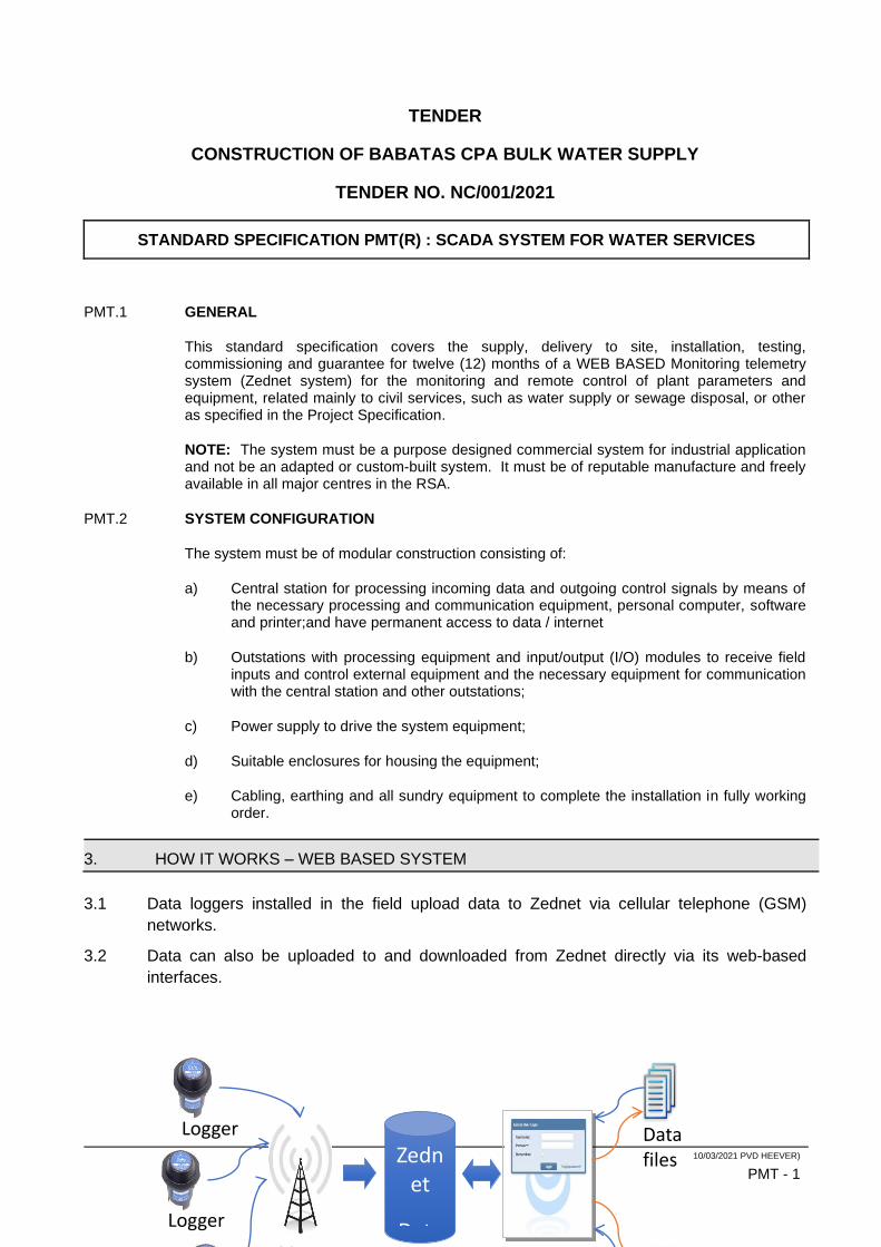
10/03/2021 PVD HEEVER)
PMT - 1
TENDER
CONSTRUCTION OF BABATAS CPA BULK WATER SUPPLY
TENDER NO. NC/001/2021
STANDARD SPECIFICATION PMT(R) : SCADA SYSTEM FOR WATER SERVICES
PMT.1 GENERAL
This standard specification covers the supply, delivery to site, installation, testing, commissioning and guarantee for twelve (12) months of a WEB BASED Monitoring telemetry system (Zednet system) for the monitoring and remote control of plant parameters and equipment, related mainly to civil services, such as water supply or sewage disposal, or other as specified in the Project Specification.
NOTE: The system must be a purpose designed commercial system for industrial application and not be an adapted or custom-built system. It must be of reputable manufacture and freely available in all major centres in the RSA.
PMT.2 SYSTEM CONFIGURATION
The system must be of modular construction consisting of:
a) Central station for processing incoming data and outgoing control signals by means of the necessary processing and communication equipment, personal computer, software and printer;and have permanent access to data / internet
b) Outstations with processing equipment and input/output (I/O) modules to receive field inputs and control external equipment and the necessary equipment for communication with the central station and other outstations;
c) Power supply to drive the system equipment;
d) Suitable enclosures for housing the equipment;
e) Cabling, earthing and all sundry equipment to complete the installation in fully working order.
3. HOW IT WORKS – WEB BASED SYSTEM
3.1 Data loggers installed in the field upload data to Zednet via cellular telephone (GSM)
networks.
3.2 Data can also be uploaded to and downloaded from Zednet directly via its web-based
interfaces.
Zednet
DatabaseGSM
Logger
Logger
Zednet
Data files
10/03/2021 PVD HEEVER)
PMT - 2
PMT.3 TELEMETRY
PMT.3.1 CENTRAL STATION
The detail of the central station and computer will be specified in the project specification.
All cabling between the computer and telemetry equipment must be done in PVC trunking, surface mounted. The antenna cable and earth connection must also be installed in trunking within the building. On the outside it must be installed in surface mounted galvanised smooth end conduit and accessories.
A computer desk must be provided against a provisional sum in the price schedule. The detail must be determined in conjunction with the user.
The telemetry equipment must be housed in an indoor enclosure as per PMT.3.8.
PMT.3.2 OUTSTATIONS
Outstations must be provided at remote installations as the link (Sim card) between the central station and the remote equipment to be monitored at and controlled from the central station.
The parameters to be monitored and equipment to be controlled must be connected to the outstation telemetry equipment. Outstations must be provided in accordance with the detail requirements in the schedule of outstations.
Equipment to be monitored / controlled in close proximity of each other has been grouped under an outstation as per the schedule of outstations. The Tenderer may regroup these locations, should it be more economical to link them by means of cable to a common outstation, or provide an additional outstation in lieu of a cable connection specified. The tender must be qualified accordingly, with an alternative offer. The main offer must be in accordance with the specification. Alternatives will be considered at adjudication and appointment can be on the main offer or on alternatives offered.
Input signals for monitoring and output signals for control must be provided in accordance with the functional project specification, in conjunction with any specific I/O schedules given. I/O given can be used as a guide for determining the I/O count, but the Tenderer remains responsible to determine the correct I/O count from the parameters stated and the project specification.
The outstations are scheduled in the project specification.
PMT 3.2.1 I/O Modules
The system must accommodate both digital- and analogue I/O modules.
a) Digital
Inputs must be suitable for operation with voltage free contacts, protected against over-voltage input. Contacts must be rated for the application voltage.
Outputs must be rated for 24 VDC and 200 mA current, suitably protected for the equipment to be driven such as relay coils.
b) Analogue
Both inputs and outputs must be suitable for 0-5 VDC, 0-10 VDC, 0-20 mA and 4-20 mA signals.

10/03/2021 PVD HEEVER)
PMT - 3
Unless specified to the contrary in the project specification, I/O must always be field connected via separate buffer interface modules.
Input buffers can be opto isolated for digital inputs to separate different voltages, or surge arrestor type to protect against over-voltages and lightning both for digital and analogue inputs.
Lightning protection shall be by means of surge arrestors rated to 5 kA for 8/20 µs lightning discharge, with additional protection by means of fusing and tranzorbs. Output buffers must be of the relay type for digital outputs.
Digital I/O status must be displayed by means of LEDs on the I/O modules and analogue I/O must be digitally displayed on the CPU.
10/03/2021 PVD HEEVER)
PMT - 4
PMT 3.2.2 CPU
The CPU must be able to communicate both by means of analogue and digital radio, as well as via serial port (RS232, RS485 or other recognised standard) and a cable link to other CPU’s. CPU’s must have on board data storage memory (128 kb min. expandable to 1 Mb), as well as PLC type local logic programming and control capability.
PMT.3.3 GENERAL CONSTRUCTION
Modules must be mounted on an approved rail for easy detachment. Access to all terminals must be from the front. All electronic components must be mounted on and soldered to glass fibre printed circuit boards with a single layer of tracks (maximum) on one or both sides of the board. Circuitry must be of the low power consumption type for efficient operation from mains or solar power with battery back-up power.
Connection between the communication equipment and CPU must be by means of robust connectors and wiring harness.
Interconnection between the CPU and I/O modules must be by means of ribbon cable and quick connect plug in connectors. Field connections to I/O modules must by means of plug in screw termination strips. I.e. it shall be possible to remove I/O modules by unplugging without disturbing field connections. Plugs and sockets must be designed to prevent misalignment when plugging in.
PMT.3.4 COMMUNICATION
The method of communication between the central station and outstations shall be specified in the project specification. By default, it shall be radio based.
PMT 3.4.1 ANTENNA
The antenna must be suitable for the communication requirements, in accordance with the system operating parameters and site conditions.
10/03/2021 PVD HEEVER)
PMT - 5
The antenna mast must be manufactured from 50 mm ø (min) tubular 3 mm (min) thick hot dipped galvanised steel tubing, bolted to a concrete base by means of a heavy duty galvanised steel bracket, all provided as part the contract. It may be wall-mounted where there is an existing building, the bracket providing off-set as required by the roof overhang. All mounting brackets fixing bolts, rawl bolts etc., must be stainless steel or hot dipped galvanised.
Masts for outstations shall be self supporting. Up to 9 m high masts shall be of the flag pole type, and be able to withstand wind loads up to 140 km/h. Masts in an excess of 9 m must be of the lattice type.
The co-axial antenna cable must be as follows:
• VHF : RG 213AV
• UHF : 13 mm foam Heliax low loss
All cables are to be provided for in the tender.
PMT 3.4.2 EARTHING
Earthing must be provided by means of a 35 mm2 bare copper earth conductor taken from the junction between the antenna and mast to a 1,2 m earth rod as close as possible to the mast. A separate 10 mm2 bare copper earth conductor must be installed with the co-axial antenna cable to the equipment enclosure. From the equipment enclosure earth stud a 35 mm2 bare copper earth conductor must be installed to the earth rod.
The ground resistance must be measured and may not exceed one (1) ohm. If more than one (1) ohm, additional rods must be installed until the correct value is obtained. The specific measurements taken must be submitted to the Engineer.
PMT 3.4.3 LAND LINE LINKED SYSTEM
The communication cabling network must be provided in accordance with the field bus requirements and suitably protected.
Unprotected cabling used indoors must be installed in galvanised steel conduit, PVC trunking or cable rack depending on the amount of cabling and the environment.
Unprotected cable for external use mounted on buildings must be installed in galvanised steel conduit. Cable for installation directly in ground must be wire armoured, with PVC or similar hard wearing protective outer sheath.
PMT.3.5 DATA TRANSMISSION
a) Format
Data shall be transmitted in digital format according to recognised international standards. Coded words shall be compiled to allow comprehensive error detection techniques to ensure maximum data integrity.
b) Communication bus (land line systems)
The communication system must be a high performance open architecture network designed for industrial application on internationally recognised and accepted standards, with high noise immunity.
The system must support equipment from other Vendors, supporting the specific communication bus systems. Full particulars on the communication bus system, applicable standards and equipment Vendors supporting the system, must be provided with the tender.
10/03/2021 PVD HEEVER)
PMT - 6
c) Message acknowledgement (radio based systems)
A switch selectable facility must be available for the transmitted messages to be acknowledged by the receiving station. If the message has not been acknowledged after a preset time, the message must be re-transmitted. This procedure must be repeated for a fixed number of attempts.
d) Multiple transmission (radio based systems)
Provision must be made on the CPU for single or multiple transmission command by means of switch selection.
e) Addressing
Each station must have an address, to be set locally and remotely via a telephone modem, to allow easy field maintenance replacement and set up of modules. No specialised equipment other than that forming permanent part of the installation must be required to set up addresses.
f) Operational modes
The system must be able to operate on change of state of any of the inputs, as well as on a time basis where transmission of data is at regular time intervals, the interval to be user selectable.
It shall be possible to interrogate a station from any other station with the station activities displayed on the CPU unit.
PMT.3.6 POWER SUPPLY
The telemetry system must be operable from the following power sources, the specific one or combination to be specified in the project specification.
a) Mains supply
An industrial type power supply operating off 230 V 50 Hz AC must be provided to the system requirements. The power supply must be capable to provide at least 50 % more than the peak demand of the system.
b) Mains with battery back up
A sealed maintenance free battery must be provided to supply the total static load for the system to be fully operational for twelve (12) hours. The charger must recharge the battery within ten (10) hours whilst delivering total static load and must have an automatic boost facility. Once on trickle charge, the output must be automatically adjusted not to over-charge the battery.
c) Solar panel with battery
A solar panel with voltage regulator must be used to charge the batteries, with recharge from fully run-down to fully charged within 48 hours, based on 5 h sunlight per day.
The batteries must be rated to provide fully operational back-up for four (4) days.
The regulator must be specifically designed for telemetry use and solar power. It must have a over-voltage cut out if the battery voltage exceeds a preset limit, as well as a under-voltage cut out if the battery voltage falls below a set limit. The load must reinstate automatically once the battery voltage is normal again.
10/03/2021 PVD HEEVER)
PMT - 7
PMT.3.7 PERIPHERAL EQUIPMENT
It shall be possible to interface the telemetry equipment to peripheral equipment, such as a printer or PC, by means of adding a standard RS232 interface module.
PMT.3.8 ENCLOSURE
Indoor enclosures must be manufactured from 1,6 mm mild steel with epoxy powder coat finish and wall mounted. Protection degree must be IP44. It must be fitted with a hinged door, with quarter turn coin slot screws or square key type locks.
Note: That the enclosure must have sufficient space for the battery and all equipment/terminals must be accessible without moving the battery.
A termination strip for incoming and outgoing cables must be provided at the bottom of the cabinet for all outgoing and incoming wiring. No wiring shall be directly connected to processing or I/O equipment.
Outdoor enclosures must be of similar construction, but manufactured to protection degree IP55. The enclosure must be hot dipped galvanised after manufacture, or manufactured from 3CR12. It must be installed within a glass fibre or 3CR12 sheet steel outer enclosure, for protection against direct sunlight. It must provide sufficient ventilation for the inner enclosure to prevent heat build up. Doors must be padlockable, the padlock type and number must be obtained from the employer. All hinges, hasp and staple must be brass or stainless steel.
The outer enclosure must be mounted at least 800 mm above ground level against a hot dipped galvanised angle iron frame, bolted to a concrete base, all provided as part of the tender.
Web-Based Remote Monitoring System
- The system should be a web-based monitoring system that displays data on flows, bulk meter
readings, pressure and reservoir levels.
- Users should be able to access the data from anywhere, via the internet, using any recent internet
browser.
- Raw data should be stored and backed up on a central server in a cloud-based environment.
- Data acquisition should be possible from a range of remote logging devices deployed in the field.
- The system must allow for multiple user access. Users should be issued with a username and
password.
- The system must be capable of displaying logging data in a graph format. The start and end date of
the data to be viewed on the graph should be user selectable.
- The system must be capable of providing customised reports to allow users to receive scheduled data
summaries and charts through email.
- The system must provide e-mail alarm notifications when the logging data profile falls outside a user
defined range.
- The system must provide a mechanism to import and display data from other water monitoring
systems.
- The system should provide a facility to export and import logging data in CSV format. The system
should provide a facility to export logging graphs in pdf or jpg format.
- The system should provide an option to view the location of logging stations on an aerial photo or map
background.
Remote Monitoring Equipment
Battery Battery powered with a battery life of 3 years and higher. Battery should be user replaceable.
Communication Remote communication with GSM Modem / RF communication
Protection Classification IP68

10/03/2021 PVD HEEVER)
PMT - 8
Casing Casing must be robust and rust protected.
Recording Interval Programmable between 1 minute and 1 hr.
Data Transmission Flow measurement – once per day
Level, pressure, pump status measurement – four times per
day default with option for additional daily transmissions.
Programming and Data Download Logger should be programmable and downloadable using a standard laptop or mobile device.
Software Windows based software to be used for programming and downloading of the data logger and for the viewing of logged data.
User Manual Softcopy of user manual should be provided.
Water Meters
All new/replacement water meters will be in accordance with the specification indicated as follows;
- The meter must be a woltman type mechanical water meter
- The meter must be flanged to SABS 1123 Table 16
- The meter must be class 16 (PN 16)
- The meter must be capable of producing a pulse output by attaching a reed switch or pulsar.
- The meter must be SABS approved.
- Meter must comply to 2% accuracy at flow rate between the transitional flow rate and the Maximum
flow rate
- Meter must comply to 5% accuracy between the minimum Flow Rate and the Transitional flow Rate
- The performance measurement capability of the meter must comply with the table below.
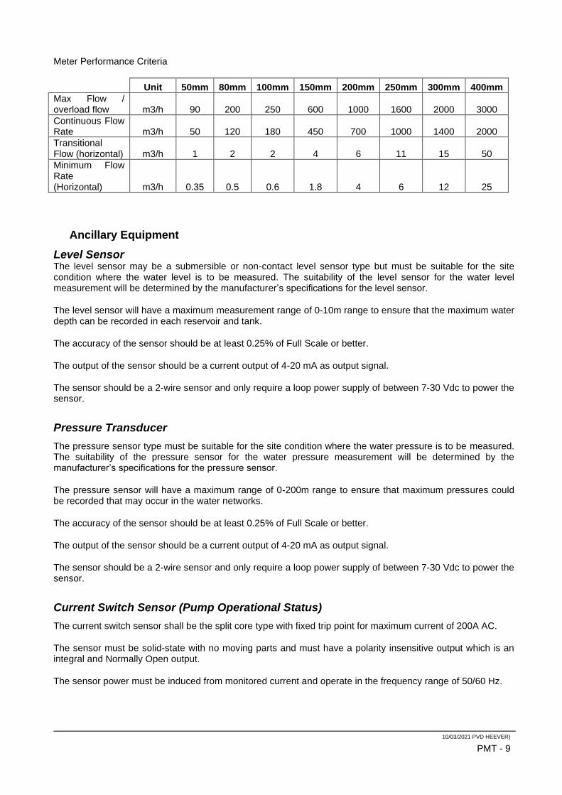
10/03/2021 PVD HEEVER)
PMT - 9
Meter Performance Criteria
Unit 50mm 80mm 100mm 150mm 200mm 250mm 300mm 400mm
Max Flow / overload flow m3/h 90 200 250 600 1000 1600 2000 3000
Continuous Flow Rate m3/h 50 120 180 450 700 1000 1400 2000
Transitional Flow (horizontal) m3/h 1 2 2 4 6 11 15 50
Minimum Flow Rate (Horizontal) m3/h 0.35 0.5 0.6 1.8 4 6 12 25
Ancillary Equipment
Level Sensor The level sensor may be a submersible or non-contact level sensor type but must be suitable for the site condition where the water level is to be measured. The suitability of the level sensor for the water level measurement will be determined by the manufacturer’s specifications for the level sensor.
The level sensor will have a maximum measurement range of 0-10m range to ensure that the maximum water depth can be recorded in each reservoir and tank.
The accuracy of the sensor should be at least 0.25% of Full Scale or better.
The output of the sensor should be a current output of 4-20 mA as output signal.
The sensor should be a 2-wire sensor and only require a loop power supply of between 7-30 Vdc to power the sensor.
Pressure Transducer
The pressure sensor type must be suitable for the site condition where the water pressure is to be measured. The suitability of the pressure sensor for the water pressure measurement will be determined by the manufacturer’s specifications for the pressure sensor.
The pressure sensor will have a maximum range of 0-200m range to ensure that maximum pressures could be recorded that may occur in the water networks.
The accuracy of the sensor should be at least 0.25% of Full Scale or better.
The output of the sensor should be a current output of 4-20 mA as output signal.
The sensor should be a 2-wire sensor and only require a loop power supply of between 7-30 Vdc to power the sensor.
Current Switch Sensor (Pump Operational Status)
The current switch sensor shall be the split core type with fixed trip point for maximum current of 200A AC.
The sensor must be solid-state with no moving parts and must have a polarity insensitive output which is an integral and Normally Open output.
The sensor power must be induced from monitored current and operate in the frequency range of 50/60 Hz.
10/03/2021 PVD HEEVER)
PMT - 10
Flow Meter Pulsars
The flow pulser units shall be the compatible with the existing/new bulk meter.
The pulser shall use load-free inductive scanning of the meter’s pointer and shall provide an electronic pulse output with no switch bouncing.
The pulse weight value shall be such that a high-resolution pulse output is obtained in relation to the flow rate through the bulk meter.
The pulse output mode shall be balanced pulses which means backward pulses are compensated by suppressing the same quantity of forward pulses.
Vandal Proof Logger Enclosures
The vandal proof logger enclosure would be to protect any equipment or data logger installations done on the rooftops of any reservoirs.
This enclosure should be heavy duty, very strong and lockable as the rooftops are open areas with no security at all. Very high levels of vandalism and theft occurs at these locations.
This heavy-duty vandal resistant enclosure should be made of at least 3mm thick steel and especially engineered to keep vandals out and to protect the instrumentation on the inside. An example of such an enclosure can be seen at http://www.interlock.co.za/EnclosuresVaults/FieldTelemetryCabinet.aspx.
Steel Meter Cover
The light duty steel meter cover would protect the meter register from vandalism and tampering. The steel meter enclosure would also serve as a logger enclosure and protect any reed switches or pulsers connected to the registers or data loggers installed on the meter installation. An example of such steel meter cover can be seen in Photo 45 and Photo 46 in Annexure A.
The meter cover should be a light duty (±1.5mm thick) steel cover that fits around the meter register and protects the meter register and equipment installed on the meter. It should be sturdy and strong enough to withstand tampering and vandalism at sites where the bulk meters are not located inside a locked pump room but are still behind a closed fence or encampment.
The steel meter cover should be bolted down on the water meter using minimum two of the meter insert bolts or at least one of the flange bolts on either side of the meter. It is mandatory that the bolts for the cover be replaced with hexagon socket head cap screw bolts to bolt down the cover securely. These bolts cannot be loosened with an ordinary spanner key, but only with a hex socket for added security and tamper protection.
Provision must also be made to allow for the meter reading to be visible through a slot or opening in the cover. These openings must be as small as possible to still allow the meter reading to be visible through the openings.
The steel meter cover should be appropriately painted for exterior use or powder coated to prevent it from rusting.
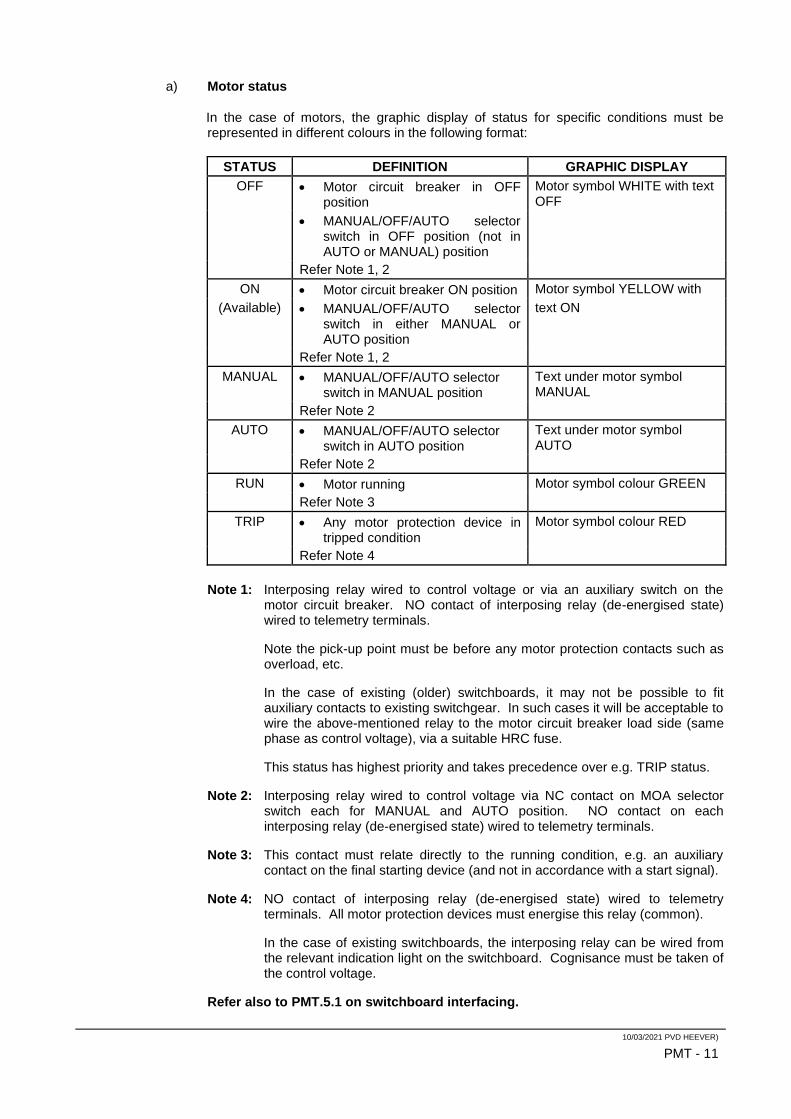
10/03/2021 PVD HEEVER)
PMT - 11
a) Motor status
In the case of motors, the graphic display of status for specific conditions must be represented in different colours in the following format:
STATUS DEFINITION GRAPHIC DISPLAY
OFF • Motor circuit breaker in OFF position
Motor symbol WHITE with text OFF
• MANUAL/OFF/AUTO selector switch in OFF position (not in AUTO or MANUAL) position
Refer Note 1, 2
ON • Motor circuit breaker ON position Motor symbol YELLOW with
(Available) • MANUAL/OFF/AUTO selector switch in either MANUAL or AUTO position
text ON
Refer Note 1, 2
MANUAL • MANUAL/OFF/AUTO selector switch in MANUAL position
Text under motor symbol MANUAL
Refer Note 2
AUTO • MANUAL/OFF/AUTO selector switch in AUTO position
Text under motor symbol AUTO
Refer Note 2
RUN • Motor running Motor symbol colour GREEN
Refer Note 3
TRIP • Any motor protection device in tripped condition
Motor symbol colour RED
Refer Note 4
Note 1: Interposing relay wired to control voltage or via an auxiliary switch on the motor circuit breaker. NO contact of interposing relay (de-energised state) wired to telemetry terminals.
Note the pick-up point must be before any motor protection contacts such as overload, etc.
In the case of existing (older) switchboards, it may not be possible to fit auxiliary contacts to existing switchgear. In such cases it will be acceptable to wire the above-mentioned relay to the motor circuit breaker load side (same phase as control voltage), via a suitable HRC fuse.
This status has highest priority and takes precedence over e.g. TRIP status.
Note 2: Interposing relay wired to control voltage via NC contact on MOA selector switch each for MANUAL and AUTO position. NO contact on each interposing relay (de-energised state) wired to telemetry terminals.
Note 3: This contact must relate directly to the running condition, e.g. an auxiliary contact on the final starting device (and not in accordance with a start signal).
Note 4: NO contact of interposing relay (de-energised state) wired to telemetry terminals. All motor protection devices must energise this relay (common).
In the case of existing switchboards, the interposing relay can be wired from the relevant indication light on the switchboard. Cognisance must be taken of the control voltage.
Refer also to PMT.5.1 on switchboard interfacing.
10/03/2021 PVD HEEVER)
PMT - 12
b) Alarms
With any one graphic layout on display, an alarm condition at any other station must bring up a visible alarm on the current display, as well as an audible alarm with alarm accept facility.
Alarm conditions which are not provided with a hard wired latched facility in the switchboard, must be provided with a software latch and on-screen reset pushbutton.
• .
• ACTIVATE/CONCEAL on-screen the selected mode of remote SCADA CONTROL, being REMOTE MANUAL CONTROL and/or REMOTE ALGORITHM CONTROL.
• Selecting REMOTE MANUAL ON/OFF must activate/conceal on-screen pop-up START (Green) and STOP (Red) pushbuttons, for starting/stopping the selected equipment for manual starting and stopping.
• Selecting REMOTE ALGORITHM ON/OFF, must activate/conceal on-screen the auto SCADA switching algorithm, in the selected position. (Refer PMT.4.3.2.2 TIME SCHEDULE).
Note:
1. that switching SCADA CONTROL ON, must not change the running status of field equipment, until further action is taken such as manual START/STOP or algorithm auto START/STOP;
2. that switching from SCADA CONTROL ON to SCADA CONTROL OFF, the equipment (e.g. a pump) control must revert back to the status for switchboard AUTO operation at that moment. I.e. if the equipment is running under remote control and REMOTE CONTROL is switched OFF with a start signal present, the pump must continue running, or stop if no start signal is present. Note this transition must be smooth without a momentary interruption.
a) REMOTE SCADA CONTROL must be operative only if the controlled equipment is in auto mode (selected on equipment control panel). I.e. switching the local (MCC) MANUAL/OFF/AUTO selector switch to MANUAL or OFF, must STOP the pumps.
b) All protection devices usually operational in auto mode (selected on equipment control panel) must be functional in REMOTE CONTROL.
c) A reset pushbutton must be provided on the outstation panel door to reset all I/O, in case of communication or central SCADA failure, to cancel remote control and resume normal auto (direct) control.
PMT.3.8.1.1 Manual control
Individual on-screen buttons, accessed via the mouse, must be provided for the following functions for each group of associated equipment, to be controlled as a unit, e.g. two pumps operating in conjunction:
• Motor START.
• Motor STOP.
This function must operate as follows:
10/03/2021 PVD HEEVER)
PMT - 13
a) SCADA control must be selected by means of the on-screen selector switch labelled SCADA MANUAL CONTROL: ON/OFF.
b) The motor must be STARTED/STOPPED as relevant (Refer to note under 4.3.2.(a)):
• starting of equipment must be delayed for 30 seconds after initiating the SCADA START command. An on-screen time-box labelled START DELAY must be activated that the operator can observe the delay time counting down;
• starting of equipment via the SCADA START demand, must CLOSE a N/O contact in the outstation as a control signal to the MCC (parallel to AUTO signal);
• stopping of equipment via the SCADA STOP demand, must OPEN a NC contact in the outstation panel as a control signal to the MCC (in series with the AUTO START signal).
PMT.3.8.1.2 Auto algorithm
a) Remote SCADA control must be selected by means of the on screen selector switch labelled SCADA ALGORITHM ON/OFF.
The specific auto algorithm will be specified in the project specification. In the case of a borehole time management schedule, the algorithm must function as follows:
The boreholes must be set out on a grid divided in 24 hourly intervals, starting at 0:00 to 24:00.
Each hour segment must have an on-screen ON/OFF selection facility. I.e. if the running time for a specific borehole is selected as 14 hours, the pump may only run for the preset time (max.) and only if there is a demand for water, such as level control from a holding reservoir. I.e. if the pump allowed pumping time is set at 14 hours, but there was only a demand for 9 hours, the pump will only operate for that time. Conversely, if the allowed time has run out and there is still a demand from the reservoir, the pump must not run.
Note:
1. The auto START/STOP signals must be provided at terminals in the outstation and wired into the control wiring of existing switchboards as per PMT.4.3.2.
2. If the SCADA is non functional, the pump normal auto control as per switchboard, must resume, without any field adjustments.
PMT.3.8.1.3 Remote alarm reset
Specific alarms, noted in the project specification must be re-settable via an on-screen reset pushbutton located at the relevant alarm (such as the high level alarm indication of a reservoir).
This action must be directly accessible on-screen, without activating the REMOTE SCADA CONTROL facility, if any.
This function must operate as follows:
a) Remote acceptance of an alarm must pulse a NC contact in the outstation panel OPEN.
b) Remote alarm reset must pulse a NC contact in the outstation panel OPEN.
Note:
10/03/2021 PVD HEEVER)
PMT - 14
The configuration of these signals must be liaised with a third party MCC manufacturer, if involved.
PMT.3.9 GRAPHIC DISPLAY
Graphic layouts must be provided in accordance with the requirements set out below. These screens must be called up by selecting the individual item from the menu (1) and by means of an on-screen button on (2) and (3), with a main menu select button on each screen.
The following is required:
1. Selection menu listing all installations (e.g. pump stations, reservoirs etc.) forming part of the overall system.
2. Total system layout line diagram depicting all installations comprising the system. It must be possible to select any individual installation from this screen.
The following specific parameters must be displayed:
a) Equipment status: ON/OFF, RUN, ALARM (the display must be in accordance with the specification for motor status);
b) Reservoirs analogue levels.
3. Individual subsystems schematic layouts from the line diagram, comprising e.g. feed pump station, intermediate booster pump station(s) and final holding reservoir(s).
The same parameters as for (2) must be displayed.
4. Detail schematic layout for each outstation on the schedule of outstations, depicting all status monitoring at that specific outstation.
a) A text status table with all parameters monitored (except motor status) must be provided on the display. Each parameter must have a status block which changes colour with status change.
E.g. “START LEVEL 1” will display an empty status block, turning green at the start level; “FLOW FAIL” will display an empty block turning red with a flow fail condition.
Note: That level control status block must be displayed adjacent to the relevant holding structure.
b) Level alarm status must latch, with an on-screen reset push-button.
c) Any alarm must activate a hidden red ALARM block on all screens and on the affected outstation on the summary screen (refer 6) which will flash until accepted (reset).
5. Screen with all reservoirs in bar graph format with reference lines at 50 %, 75 % and 100 %.
6. A summary screen for al outstations depicting INTRUDER (door alarm) POWER FAIL, COMMUNICATION FAIL and GENERAL ALARM must be provided. The information must be in block format with healthy status green and alarm status red. An outstanding interrogate button must be provided for each outstation on this screen.
7. Dynamic trend screens as per schedule of outstations for the following:
a) All analogue levels, e.g. Reservoir levels.
10/03/2021 PVD HEEVER)
PMT - 15
b) Pumps RUN/OFF; totalised pump hours must be shown on the detail schematic layout (4) above.
c) Water meters flow rate.
8. Water meters flow rate and totalised flow must be displayed on the schematic layout depicting the specific meter. Totalised flow must be displayed in the format depicting yesterday’s count (total), today’s count (running) total to date. The running count must be reset once a day and the historic counters updated simultaneously.
A summary page for all meters must be provided to display the above in a table, including this week, this month, last month and year to date, totals.
PMT.4 INTERFACE TO EQUIPMENT AND INSTRUMENTATION
PMT.4.1 SWITCHBOARD INTERFACING
All digital parameters (signals) to be monitored from switchboards and controlled from the telemetry panel must be via voltage free contacts from interposing relays. Voltage sensing must be from the same phase as the control circuit phase and applied to the coil of the interposing relay, switching the voltage free status indication contacts. I.e. no direct voltage transfer may be done between the motor control circuitry (wiring) and the telemetry I/O.
Any voltage status not taken from the motor control voltage must be protected by an HRC fuse as close as possible to the pick up point, but must be taken from the same phase as the control voltage.
10/03/2021 PVD HEEVER)
PMT - 16
Parameters of existing equipment to be monitored and controlled that are available within existing switchboards at the equipment have not been wired to terminals, unless stated to the contrary below for a specific outstation. The signals must be taken from the existing wiring and wired to terminals as part of this contract, inclusive of all equipment such as auxiliary relays, switches, etc. Generally the signals can be picked up from the switchboard status indication lights. The proposed wiring changes must be submitted to the Engineer for approval before implementation. Cognisance must be taken of the control voltage for the input buffer relays.
The terminals must be fitted in a separate junction box mounted in close proximity of the equipment to be monitored. The junction box must be rated at IP65 and manufactured from polycarbonate for indoor applications and GRP or polypropylene for outdoor applications. Tenderers will have the opportunity to inspect the existing installation at the time of the site inspection to price accordingly. Parameters of new equipment to be monitored must be provided at terminals within switchboards/terminal boxes, as part of this contract.
Note:
• All wiring to, from and within the telemetry panel must be uniquely numbered, as well as all terminals, including terminals within the telemetry panel.
• The Contractor must ensure that switchboard modifications and all other electrically related construction work are executed by suitably qualified personnel and that proper safety procedures be adhered to at all times.
PMT.4.2 CONTROL CABLE
The wiring to the outstation from equipment to be monitored and controlled, must be done in PVC SWA PVC multi-core cable or, if unprotected cable is used indoors, it must be installed in galvanised steel conduit or trunking.
The cables from sensors must be terminated in a Pratley watertight cable box. From the cable box a 1,5 mm2 x multi-core cable (Number of cores determined by number of sensor signals) must be installed to the telemetry panel / switchboard. Cable from level sensors must be strapped to the access ladder or installed in galvanised steel conduit fixed to the reservoir structure with galvanised saddles, Fisher plugs and brass screws.
Excavations for cables will be provided by the Employer or third party as specified. Any request for trenching must be arranged directly with the Employer or third party, at least two weeks before the required time. No claims due to non-compliance will be accepted.
Note:
1. All cable lengths given, including in the schedule of prices are provisional for purposes of tender and must be measured on site before ordering.
2. Cables within a building or in close proximity of the telemetry panel are not scheduled as a separate cost items in the schedule of prices, but must be included in the overall price.
3. Cable sizes specified must be verified with the Engineer in respect of I/O requirements before ordering.
PMT.4.3 STRUCTURAL OPENINGS
Structural openings required for cable access and equipment installation and making good afterwards must be provided by the Contractor, included in the overall price.
10/03/2021 PVD HEEVER)
PMT - 17
In the case of reservoirs the access holes must be drilled through the access cover raised section or adjacent to the cover if it is flush with the soffit. Holes into underground structures, housing e.g. water meters, must be above ground and sealed after installation of the cable, to prevent ingress of water. The position of holes must be confirmed with the Engineer before drilling.
PMT.4.4 LEVEL DETECTION
PMT 4.4.1 Ultrasonic Level Sensing Unit
Ultrasonic level sensors are specified in the project specification. Ultrasonic level sensors must have, a digital level display, (both (m) and percentage), a 4-20 mA output for monitoring purposes, as well as four programmable switching relays.
The level display controller must be installed within the telemetry enclosure for outdoor installations and on the telemetry panel door for indoor installations.
The sensor heads must be mounted on a sturdy 2 mm thick stainless steel bracket, fixed to the soffit of the reservoir/sump with stainless steel screws and Fischer plugs. The unit must be easily accessible and nearby structures must be considered in respect of possible echo interference.
PMT 4.4.2 Float Level Switches
Float switches, where specified, must be of the non-mercury type and of Powerflyte manufacture. They must be suspended from stainless steel eye bolts fixed to the soffit of the structure.
Float level switches must be operated on 24 VDC.
PMT.4.5 WATER METERS
Water meters must be monitored for flow rate, as well as totalised flow.
Existing mechanical water meters must be fitted with pulse generation conversion heads. The Opto pulse unit gives one pulse/litre. However the specific pulse rate must be confirmed in all cases, before implementation. The unit must not be provided with a frequency converter, and the pulse unit must be directly connected to the telemetry counter input. Tenderers must confirm whether this direct connection is possible with their equipment and qualify their tenders accordingly. If the pulse rate is too slow for accurate integration to flow rate, a frequency converter must be used. The specific model numbers of all the water meters and thus availability of the conversion heads will be established during construction.
A provisional sum per meter is allowed for the conversion heads in the price schedule. The successful Tenderer will be responsible for the meter type identification and procurement of these conversion heads against the provisional sum.
Electromagnetic meters will have a 4-20 mA output proportional to flow-rate and a pulsed output for flow volume.
PMT.5 TESTING, COMMISSIONING AND HANDOVER
The system shall be fully factory tested and demonstrated to the Engineer.

10/03/2021 PVD HEEVER)
PMT - 18
Once the installation has been tested and commissioned, the Contractor shall notify the Engineer in writing that the installation has been tested, is fully operational and ready for hand-over inspection and a handover date will be arranged. A schedule depicting all I/O, software alarms and trend screens and copy of the control specification, with each item, marked off as tested and signed by senior supervision must accompany this notification. At handover the complete installation will b e inspected and tested functionally for conformance with the specification. Should the installation at the arranged inspection be found not ready for taking over, the cost of the fruitless inspection will be for the Contractor’s account and will be deducted from the contract amount.
The Contractor must ensure that suitably qualified personnel is doing the switchboard modifications and all other electrical work during construction, commissioning and hand-over testing and that safety procedures shall be strictly adhered to at all times.
Suitably qualified personnel shall also be available at hand-over testing to do signal simulation including switching and simulation within switchboards, (up to 400 V nominal) sumps and reservoirs.
Any instructions given by the Engineer to do signal simulation will be given with the understanding that the personnel doing such simulation are competent and suitably qualified.
It must provide sufficient information on the hardware for routine type maintenance, as well as full descriptions of start up and set up procedure and operation.
PMT.6 OPERATION AND MAINTENANCE MANUAL AND TRAINING
On completion three copies of a comprehensive operating and maintenance manual must be provided and handed over.
The manual must amongst others include:
a) System description;
b) I/O schedules;
c) Wiring diagrams;
d) Cable and connection schedules;
e) Adroit I/O configuration;
f) Technical description of hardware.
After hand-over, the Contractor shall be responsible to give full training on site in operation and maintenance of the system to designated personnel of the Employer until they are fully conversant with the installation.

Management
C3.4 - 1
TENDER
CONSTRUCTION OF BABATAS CPA BULK WATER SUPPLY
TENDER NO. NC/001/2021
C3.4 : CONSTRUCTION MANAGEMENT
C3.4 MANAGEMENT OF THE WORKS
C3.4.1 Applicable SANS and SABS standards
The provisions of these SANS 1200 take precedent over the provisions of any part of SANS 2001 that is applicable to the contract. The variations and additions to these specifications are described in the section “Applicable SANS 1200 standardised specifications.”
The SANS 1200 Standardised Specifications for civil engineering construction applicable to this contract are stated in Section C3 : Construction.
C3.4.2 Particular / Generic specifications
The following particular and generic specifications are applicable to this contract :
i) Environmental Management Plan
ii) Occupational Health and Safety Specifications
C3.4.3 Planning and programming
It is a prerequisite of this contract that minimal disruption of the public is ensured during construction. The Contractor shall draw up his programme to ensure that no delays are experienced on contract.
The Contractor shall indicate in his construction programme the number of construction teams he envisage will be required including the date when each team will start, chainage where each team will commence from and the estimated period for which each team will be engaged.
Construction methods must be of such nature that no property or life on site or adjacent to the works is endangered. The Employer accepts no responsibility for work that is done outside the site boundaries without the Engineer's approval.
All open excavations on site must be clearly demarcated and safeguarded before it is left overnight, during weekends and on public holidays. All excavations shall be backfilled and finished to the complete satisfaction of the Engineer.
The Contractor shall program separately for the detection, exposing and modification of existing services at the start of the contract at least fourteen (14) days prior to the proposed crossings. The position and levels thereof must be recorded and forwarded to the Engineer so that any adjustments to the design can be made if necessary. No extension of time arising out of any delay in completing this work will be considered.
The Contractor shall submit within two (2) weeks after site-handover to the Engineer an updated construction program indicating all construction activities, phasing, handing over of sections, resources, timelines, monthly expenditure and critical path with specific reference to criteria in C3.5.1 for the duration of the construction period indicated for approval. The Contractor will not be allowed to commence with any work before this program has been agreed upon and approved by the Engineer.

Management
C3.4 - 2
The Contractor himself is responsible for liaison and the necessary arrangements with property owners, relevant local and road authorities, Eskom, Telkom and Neotel in respect of service crossings and the finalisation and approval of the works program.
The compilation of the construction program and any amendments thereto during the course of construction shall be at the cost of the Contractor and shall not be measured elsewhere in this contract.
The Contractor shall record progress against the program. The Contractor shall draw the Engineer’s attention immediately to any activities that fall behind program and shall inform the Engineer how he proposes to get back on program. Progress meetings shall be held monthly on site. Failure to comply with these requirements will entitle the Engineer to use a programme based on his own assumptions for the purpose of evaluating claims for extension of time or additional payments.
The Contractor himself is responsible for liaison with property owners with regards to the programming of construction activities through private properties and the crossing of access ways to properties at least fourteen (14) days before such construction activities commence. No additional payment will be made in this regard.
The Contractor shall be responsible to inform all property and business owners by written confirmation of any road closures and the arrangements must be completed at least seven (7) days in advance. No additional payment will be made in this regard and it shall be deemed to be covered by the relevant items.
However both vehicle and pedestrian access to businesses, commercial properties and municipal and state institutions i.e. SAPS buildings, provincial clinics, traffic departments and schools must be provided at all times and arrangements for temporarily alternative parking must be discussed and arranged with the relevant businesses or institutions.
Sufficient photos of existing structures, walls and areas that have to be crossed must be taken by the Contractor and handed over to the Engineer before such operations commence. No payment will be made in this regard and it shall be deemed to be covered in the preliminary and general items.
A Mechanical and electrical contractor will be on site during the contract period. The Contractor must note that no additional payment is applicable for re-programming of the works and/or any delays that may be caused by bad co-ordination, unless otherwise agreed by the Engineer. All costs associated with liaison with the Mechanical and electrical contractor and the accommodation of the main contractor’s activities on the site must be allowed for in the schedule of quantities.
Existing services shall remain in operation throughout the duration of the contract.
C3.4.4 Methods and procedures
C3.4.4.1 Maintenance of accesses and streets
The operation of construction vehicles on existing roads or streets, or on streets which have been completed to the level of sub-base or base or bituminous surface treatment, shall be limited to traffic with an axle load not exceeding that allowed by the Road Traffic Ordinance of the authority concerned, or any amendment thereof. Hauling is strictly forbidden on sections of streets that have been completed as described above. The Contractor shall make use of temporary haul roads, or where not practically possible, programme his work in such a manner that the haulage of materials shall be restricted to that required for the particular section of street. No additional payment shall be made for the use of temporary haul roads and all relevant costs shall be deemed to be covered by the appropriate rates.
The Contractor must note that no additional payment will be made for the construction of temporary access roads to the construction site, borrow areas or to the spoil sites, except for payment made under payment item A 8.3.2.2 of SANS 1200 A.

Management
C3.4 - 3
If the Contractor does make use of existing streets for the hauling of materials to or from the site, he shall be held responsible to clear any spillage caused by his activities on or near the roads by whatever means necessary, within one (1) day after such spillage has occurred. No additional payment will be made for the clearance of spillage and all relevant costs will be deemed to be covered under the relevant items.
C3.4.4.2 Blasting operation
Any blasting required shall be carried out by a competent, registered blaster. All permits required to purchase, transport, use and dispose of unused, blasting material shall be obtained and copies given to the Engineer before any blasting may take place. The commander of the local South African Police Services (SAPS) shall be informed of the time and date that blasting operations will take place at least 6 hours before blasting.
No blasting operations may take place on weekends or holidays or after 17:00 on week days.
The Contractor shall ensure that sufficient suitable cover material, to the satisfaction of the blaster, is available and in place before a blast is initiated.
C3.4.4.3 Normal working hours
Normal working hours shall be between 07:00 and 17:00 on weekdays from Mondays to Fridays and between 07:00 and 13:00 on Saturdays, should the Contractor choose to work on Saturdays, excluding Public holidays.
C3.4.4.4 Quality plans and control
The Contractor shall have a well-documented Quality Assurance system depicting his approach to guarantee quality control and the procedures for preventative and corrective actions in order to ensure compliance with the specified standards and requirements of this contract.
The Contractor is required to carry out his own control testing, but if he so wishes, and agrees to abide by the results of the Engineer’s check test, he may dispense with his own tests. However, should the Contractor wish to use the Engineer’s testing facilities, he will be charged for the various tests at the rates ruling at the time.
Any additional tests requested by the Contractor or any retests required, due to failure of the initial tests, will be charged to the Contractor at the rates ruling at the time.
C3.4.4.5 Interference with Municipal staff and operations
N/A.
C3.4.4.6 Access for other Contractors
The Contractor shall provide reasonable access to other Contractors carrying out work on the site from time to time, as and when such access is required. The Contractor is entitled to request reasonable notification of at least 24 hrs before access by others is required.
C3.4.4.7 Giving notice of work to be covered up
The Contractor shall give the Engineer reasonable time to accommodate examinations in his program, in which case times for inspections can be agreed on. Requests for examination of work shall be made with an inspection request form 72 hrs before the examination is required.
If the Engineer attends with the purpose of examining any part or materials of the works at the time and date as agreed upon with the Contractor, and it is found that the works or materials are not yet ready for inspection, the Contractor shall be responsible for the costs of such a visit by the Engineer.

Management
C3.4 - 4
C3.4.4.8 Cost of test specimens and tests
It is deemed that the Contractor has made provision in his tender for all such services and tests that are required from him. It is the duty of the Contractor, at his own cost and by means of the necessary tests, to prove to the Engineer that the works and compaction where prescribed, comply with the specification.
C3.4.5 Sequence of the works
Sequencing of the works shall be agreed to between the Contractor, the Engineer and the client.
C3.4.6 Quality plans and control (Testing)
Refer SANS 1200 A : General
C3.4.7 Environmental Management Plan
C3.4.7.1 Demarcation of the site
For the purpose of the EMP, the site shall be divided into two areas identified by the Engineer and the Contractor:
(i) The construction camp comprising all buildings, hostels, offices, lay down yards, vehicle wash areas, fuel and material storage areas, batching areas and other infrastructure that is required for the running of the job.
(ii) The working area in which construction activity is permitted to take place. No infrastructure, permanent lay down or storage areas shall be established in this working area unless specified in the project specification or prior approval is obtained from the Engineer.
C3.4.7.2 Construction camp
The Contractor shall provide the Engineer with a plan showing the positions of all buildings, yards, vehicle wash areas, batching areas and other infrastructure for approval by the Engineer at least ten (10) days prior to the commencement date. The construction camp shall be planned in such a way so as to affect as small an area as practically possible. The Engineer shall approve the location and layout of the construction camp prior to establishment.
C3.4.7.3 Fencing of the site
If a temporary fence is required, the Contractor shall erect and maintain such a fence (demarcating the boundary of the working area, construction camp and access roads) to the satisfaction of the Engineer. The erection of this fence shall be one of the first tasks undertaken by the Contractor after the commencement date. The boundaries between the construction camp area and the working area within the site shall also be fenced. The Contractor shall ensure that the erection of the fencing causes minimal disturbance to flora, fauna, natural, historical and cultural features. A method statement shall be submitted to the Engineer prior to erection to ensure proper positioning of the fence.
All material left over from fencing operations shall be collected after the fence has been erected and removed from site. Fences shall not be moved or removed without the written consent of the Engineer. The Contractor throughout the construction period shall maintain fences.
C3.4.7.4 Workshops
Any workshops shall be located inside the demarcated construction camp area. The exact location and design of the workshop shall be as approved by the Engineer prior to establishment. The workshop shall have a smooth impermeable (concrete) floor. The floor shall be bunded and
Management
C3.4 - 5
sloped towards an oil trap or sump to contain any spillages of substances (e.g. oil). When servicing equipment, drip trays shall be used to collect the waste oil and other lubricants. All waste material shall be disposed of in accordance with national, regional and local laws, regulations and by-laws. This waste material shall be regularly removed off site and disposed of at an approved waste site.
C3.4.7.5 Eating areas
The Contractor’s employees shall eat in the designated eating area indicated on the Contractor’s drawing of the construction camp that has been approved by the Engineer. No changes to the eating area shall be made without the approval of the Engineer. The Contractor shall provide shade and adequate scavenger-proof and weatherproof refuse bins in this area. Any cooking on site shall only be undertaken in the eating area and be done on well maintained gas cookers with fire extinguishers present. No cooking shall be done anywhere else on site and no fires are permitted.
C3.4.7.6 Watchmen
The Contractor shall ensure that a watchman is present on site during all non-working hours, including public holidays unless otherwise agreed with the Engineer to ensure the safety of sensitive areas.
C3.4.7.7 Ablution facilities
The exact location of the toilets shall be as approved by the Engineer. The Contractor shall provide toilets and shall be responsible for their maintenance and servicing on a daily basis. The contractor shall ensure that no spillage occurs when the toilets are cleaned or emptied. Burial of waste from toilets on site is strictly prohibited. The toilets shall be maintained in a clean state. Performing ablutions anywhere other than in toilets is strictly prohibited. Leaking toilets shall be repaired immediately or removed from site.
C3.4.7.8 Solid waste collection areas
“Solid waste” refers to all solid waste, including construction debris, chemical waste, excess cement/concrete, wrapping materials, timber, tins and cans, drums, wire, nails, food and domestic waste (e.g. plastic packets and wrappers).
The Contractor shall set up a waste control and removal system. The Contractor shall submit a method statement for waste control and removal to the Engineer for approval prior to commencement. Bins shall be closed, weatherproof and scavenger-proof.
Waste shall be collected from these bins on a daily basis and shall be stored in a central collection area prior to removal off-site. This central collection area shall have appropriate storage containers (closed and weatherproof) bunded and lined with plastic or concrete. The waste from this central collection area shall be disposed of off-site at an approved waste site. Waste shall be removed from site on a regular basis as approved by the Engineer. Waste shall not be burnt or buried on site or in the surrounding area. Where possible, appropriate material shall be reused or recycled.
C3.4.7.9 Wastewater
Water shall be used sparingly on site and where possible wastewater shall be recycled. A wastewater management plan shall be submitted to the Engineer for approval 10 days prior to commencement date. This management plan shall detail the expected extent of contamination of each wastewater stream and how the Contractor plans to deal with each wastewater stream.
C3.4.7.10 Fuel storage areas
Fuels required for use during construction shall be stored in a depot at the construction camp at a location as agreed upon by the Engineer. The Contractor shall ensure that all liquid fuels (petrol and diesel) are stored in tanks with lids, which are kept firmly shut. The tanks shall be situated
Management
C3.4 - 6
on a smooth impermeable (plastic or concrete) base with an earth bund. The impermeable lining shall extend to the crest of the bund and the volume inside the bund shall be 1,5 x the total capacity of the storage tanks. The bunded area shall be emptied of water following rainfall events. The floor of the bund shall be sloped towards an oil trap or sump to enable any spilled fuel and / or fuel-soaked water to be removed.
The Contractor shall keep fuel under lock and key at all times.
C3.4.7.11 Concrete batching area
Cement and concrete are regarded as hazardous to the environment due to the high pH of the material and the chemicals it contains.
The Contractor shall submit a method statement for mixing of concrete for approval by the Engineer indicating where the mixing will take place and the methods to ensure that waste water and materials are contained in the batching area and disposed of correctly. Concrete shall not be mixed directly on the ground.
C3.4.7.12 Equipment maintenance and storage
All vehicles and equipment shall be kept in good working order and serviced regularly. Leaking equipment shall be repaired immediately or removed from the site. Where possible, all maintenance of equipment and vehicles shall be performed in the workshop. If it is necessary to do maintenance outside of the workshop area, the Contractor shall obtain agreement from the Engineer prior to commencing activities.
The Contractor shall demarcate an area in which equipment and vehicles may be stored. The location of this area shall be as approved by the Engineer. The Contractor shall take measures to ensure that there is no pollution of this storage area by leaks or drips.
C3.4.7.13 Materials handling, use and storage
The Contractor is responsible for ensuring that any material delivery drivers are informed of all procedures and restrictions (e.g. which access roads to use, “no go” areas, speed limits, dust control, etc) required to comply with the EMP before they arrive at site and off load any materials. The Contractor shall ensure that the delivery drivers are supervised during off-loading by someone with an adequate understanding of the requirements of the EMP, so as to ensure that all relevant requirements of the EMP are followed.
Hazardous Substances
The Contractor shall comply with all relevant national, regional and local legislation with regard to the transport, use and disposal of hazardous materials.
The Contractor shall provide the Engineer with a list of all hazardous materials to be used on site, together with the storage, handling and disposal procedures of the materials. This information shall be available to all personnel on site.
The location of the hazardous material store shall be within the demarcated construction camp area. The location and design of the store within this area shall be approved by the Engineer prior to establishment.
Fuel (Petrol and Diesel) and Oil
Where possible, the Contractor shall ensure the refuelling of vehicles takes place only at the fuel storage area in the construction camp. Where this is not possible, the Contractor shall notify the Engineer to get his approval of the refuelling method to be used. The surface under the refuelling area shall be protected against pollution to the satisfaction of the Engineer prior to any refuelling activities. All equipment that leaks shall be repaired immediately or removed from the site. Refuelling shall be carried out by means of pumps, rather than funnels.

Management
C3.4 - 7
C3.4.7.14 Emergency procedures
The Contractor shall ensure that emergency procedures for the following situations are submitted for approval to the Engineer prior to establishment of the site.
Fire
The Contractor shall advise the relevant authority of a fire as soon as one starts and shall not wait until he can no longer control it. The Contractor shall ensure that his staff and the staff of Subcontractors are aware of the procedure to be followed in the event of a fire.
Accidental leaks and spillages
The Contractor shall ensure that his staff and the staff of Subcontractors are aware of the procedure to be followed for dealing with spills and leaks, which will include notifying the Engineer and relevant authorities. The Contractor shall also ensure that the necessary materials and equipment for dealing with spills and leaks are present on site at all times. The clean up of spills and any damage caused by the spill or leak shall be for the Contractor’s account. The Contractor shall submit a method statement for management of accidental leaks and spillage’s of any liquid material to the Engineer for approval.
C3.4.7.15 Care of surrounding areas
The Contractor shall ensure that no contamination of or damage to the surrounding areas or watercourses shall occur as a result of any of his activities during construction.
Care shall be taken to ensure no accidental spillage or leakage occurs whilst temporary bypass facilities are in use. Should any spillage or leakage occur the Contractor shall immediately stop his operations and clean up the spillage. He shall then rectify the cause of the spillage or leakage before proceeding further to ensure that no further spillages occur.
The clean up of spillage and any damage caused by the spillage or leakage shall be for the Contractor’s account. The Contractor shall submit a method statement for management of accidental leaks and spillages of any sewage to the Engineer for approval.
The Contractor shall ensure that no pollution of the surrounding areas occurs due to wind-blown or other litter emanating from the site or from his activities during construction. No fires are permitted, neither is the cutting down of or any damage to trees and other vegetation outside of the demarcated site.

Management
C3.4 - 8
C3.4.8 Other Contractors on site
A mechanical / electrical contractor will be on site during the contract period, who will be working on the instalment of certain mechanical components of the new sewer pump station. The contractor responsible for delaying other contractors shall be liable for all costs associated with the delay.
Programming and liaison in this regard must be taken into account.
C3.4.9 Format of communications
All communication regarding the contract shall be channelled through the Engineer and/or his duly authorised representative.
C3.4.10 Key personnel
The contractor shall furnish satisfactory evidence that they dispose of sufficient staff and workmen with the necessary experience in work of a similar nature as that described in this document. For this purpose the contractor shall duly complete a personnel schedule and past experience.
C3.4.11 Management meeting
Monthly site meetings will take place at the site office of the Contractor at dates and time to be communicated at the award of the contract. The Employer, Engineer, Contractor and Project Steering Committee will attend the monthly site meetings. The Engineer will act as the chair for the monthly site meetings. Other planning meetings between the Contractor’s personnel and the Engineer’s Representative can take place on a fortnightly basis or as required in terms of the contract progress.
C3.4.12 Daily records
The Contractor will be required to keep a daily record of the site activities (including plant, personnel, site and weather conditions) in the Site Diary which will be inspected during each management meeting and when the Engineer or Employer visits the site.
C3.4.13 Payment certificates
Payment on this contract will be made in accordance with Contract clauses. The Contractor and the Engineer’s Representative shall compile and agree on the quantity of work certified for payment and submit the payment certificate to the Engineer 7 days before the monthly site meeting. The Engineer will draw up the payment certificate to be certified at the monthly site meeting by the Engineer and the Employer. Payment certificates will only be certified at the site meeting if the Engineer and Employer are in agreement as to work certified, contractual obligations fulfilled by the contractor, etc. following a site inspection on the day of the site meeting. Payment certificates will be certified by the Engineer and Employer should there be an agreement as to the issues previous mentioned or the payment certificate will be edited.
No retention money will be certified for payment unless the list setting out the work to be completed to justify the issue of the Certificate of Completion, has been fully complied with.
The quantities in the Bill of Quantities are provisional only and do not necessarily represent the actual and final amount of work to be done. Unless otherwise stated, items will be measured nett in accordance with the drawings and no allowance will be made for waste.
The Contract amount for the complete contract shall be computed from the actual measured quantities of authorised work done to the satisfaction of the Engineer, valued at prices tendered against the respective items in the Bill of Quantities.

C3.5
TENDER
CONSTRUCTION OF BABATAS CPA BULK WATER SUPPLY
TENDER NO. NC/001/2021
C3.5 - OCCUPATIONAL HEALTH AND SAFETY

ANNEXURE: OH&S Contractor’s Specification
1
TENDER
CONSTRUCTION OF BABATAS CPA BULK WATER SUPPLY
TENDER NO. NC/001/2021
OHS CONTRACTOR SPECIFICATION
INDEX PAGE
1. Scope
2. Objectives
3. Definitions
4. Notification of Construction
5. Registration with the Workmen’s Compensation or Licensed Insurer
6. Mandatory Form
7. Assigned Persons
8. Health & Safety Plan
9. General Health & Safety Requirements
10. Occupational Health Medical services
11. Liquor, drugs, dangerous weapons, firearms
12. Internal/External Audit
13. Schedule of information

ANNEXURE: OH&S Contractor’s Specification
2
1. SCOPE
This Specification is intended for all Service Providers and Contractors
2. OBJECTIVE
• To ensure that Service Providers and Contractors comply with the requirements of the Occupational Health and Safety Act No. 85 of 1993 and the Regulations thereto including any relevant standards and SABS codes of practice that may apply.
• To minimise and eliminate contractor’s health and safety risks.
• To ensure that contractors submitting tenders make provision for the cost of health and safety measures to be implemented during the duration of the contract / during the construction process.
3. DEFINITIONS
Client means any person for whom construction work is performed.
Contractor (also referred as Mandatary), including a labour-only contractor, who carries out a trade, business or other undertaking (whether for profit or not) in connection with which he or she:
(a) carries out or undertakes to carry out or manages construction work; or
(b) arranges for any person at work under his control (including an employee of his, where he is the employer) to carry out or manage construction work; or
(c) provides a person or persons to perform work for a client
Construction work means any work in connection with
(a) the erection, maintenance, alteration, renovation, repair, demolition or dismantling of or addition to a building or any similar structure;
(b) the installation, erection, dismantling or maintenance of a fixed plant where such work includes the risk of a person falling;
(c) the construction, maintenance, demolition or dismantling of any bridge, dam, canal, road, railway, runway, sewer or water reticulation system or any similar civil engineering structure; or
(d) the moving of earth, clearing of land, the making of an excavation, piling, or similar type of work.
(e) Any work in addition to the above which by agreement between the principal and the contractor may be agreed to be construction work, or any work which may be described as construction work in terms of the Construction Regulations to the OHS Act GN 1010 of the 18th July 2003.
Competent person means any person having the knowledge, training, experience and qualifications specific to the work or task being performed. Qualifications and training must be inline with the South African Qualification Authority Act No. 58 of 1995.

ANNEXURE: OH&S Contractor’s Specification
3
Designer means a person who prepares a design; arranges for any person at work under his control(including an employee of his, where he is the employer) to prepare a design; an architect or engineer contributing to, or having overall responsibility for the design; building services engineer designing details for fixed plant; surveyor specifying articles or drawing up specifications; contractor carrying out design work as part of a design and build project; temporary works engineer designing formwork and false work; and interior designer, shop-fitter and landscape architect.
Fall Prevention Equipment means equipment used to arrest the person in a fall from an elevated position, including personal equipment, body harness, lanyards, lifelines or physical equipment, guardrails, toe-boards, screens, barricades, anchorages or similar equipment.
Fall Arrest Equipment means equipment used to arrest the person in a fall from an elevated position, including personal equipment, body harness, lanyards, deceleration devices, lifelines or similar equipment, but excluding body belts.
Hazard means a source of or exposure to danger
Hazard identification means the identification and documenting of existing or expected hazards to the health and safety of persons, which are normally associated with the type of construction work being executed or to be executed
Risk assessment is an activity conducted by competent person which includes
(a) the identification of the risks and hazards to which persons may be exposed to;
(b) the analysis and evaluation of risks and hazards identified;
(c) a documented plan of safe work procedure to mitigate, reduce or control the risks and hazards that have been identified;
(d) monitoring plan; and
(e) a review plan.
Excavation work means making of any man-made cavity, trench, pit or depression formed by cutting, digging or scooping
Ergonomics means application of scientific information concerning humans to the design of objects, systems and the environment for human use in order to optimise human well-being and the overall system performance
4. NOTIFICATION OF CONSTRUCTION
Any contractor who intends to carry out construction which includes the construction work listed below must notify the Provincial Director prior commencement of any work at least 3 days after being officially notified that he/she has been awarded the tender to carry out such work. Proof of such notification must be submitted for reference purposes.
(a) the demolition of a structure exceeding a height of 3 meters; or
(b) the use of explosives to perform construction work; or
(c) the dismantling of fixed plant at a height greater than 3 meters;
(d) when the construction work exceeds 30 days or will involve more than 300 person days of construction work;
(e) excavation work deeper than 1 meter; or
(f) working at a height greater than 3 meters above ground or a landing.

ANNEXURE: OH&S Contractor’s Specification
4
5. REGISTRATION WITH THE WORKMEN’S COMPENSATION OR LICENSED INSURER
Contractors shall ensure that the client is provided with a letter of good standing including a registration number with the Compensation for Occupational Injury and Diseases Fund or an alternative scheme approved in writing by the Commissioner to the COID Fund at least 3 days prior commencement of construction work.
Contractors shall ensure that the client is provided with a letter of good standing including a registration number with the Compensation for Occupational Injury and Diseases Fund or an alternative scheme approved in writing by the Commissioner to the COID Fund at least three (3) days prior commencement of construction work.
6. MANDATARY FORM
Not applicable
7. ASSIGNED PERSON IN TERMS OF OCCUPATIONAL HEALTH & SAFETY ACT OF 1993 & ITS REGULATIONS
A written letter of appointment shall be forwarded to the client duly signed by responsible persons at least 3 days prior commencement of construction work for the following duties:
(a) Person assigned duties in terms of the 16.2 appointees of the Act
(b) Construction Work Supervisor
(c) Assistant Construction Work Supervisor
(d) Full-time or part-time Construction Safety Officer
(e) Scaffolding Erector
(f) Scaffolding Inspector
(g) Excavation Supervisor
(h) Explosive Powered Tool Supervisor
(i) Fire Equipment Supervisor
(j) Portable Electrical Equipment Supervisor
(k) Ladder Supervisor
(l) Personal Protective Equipment Supervisor
(m) Electrical Supervisor
(n) Lifting Machine Supervisor
(o) Lifting Tackle Supervisor
(p) Stacking and Housekeeping Supervisor
(q) Workshop and Plant Supervisor
(r) Oxy-acetylene Gas Cutting/Welding Supervisor
(s) Safety Representatives
(t) Competent Person in Risk Assessment
(u) Hazardous chemical substances Controller/Co-ordinator
(v) First Aider
(w) Incident Investigator
(x) Formwork and Support work Supervisor

ANNEXURE: OH&S Contractor’s Specification
5
8. HEALTH AND SAFETY PLAN
A contractor shall provide the client with a Health and Safety Plan document that shall includes the following during tendering process, before commencement of construction work and during construction:
8.1 Contractor’s Health & Safety Policy
A Contractor shall provide a health & safety policy signed by the Chief Executive Officer (CEO).which outlines contractor’s commitment towards health and safety
8.2 Health and Safety Organogram
A Contractor shall provide a health & safety organogram which outlines the team leaders, 16.2 appointees, construction work supervisor, assistant construction work supervisor, safety representatives, safety committee members and other related appointments in terms of the OHSAct. The contact numbers should also be provided for easy reference.
8.3 Risk assessment
A risk assessment shall be conducted by a competent person, this includes:
1. identification of risks and hazards to which persons may be exposed; this is also to include ergonomic related
2. hazard analysis and evaluation of the identified risks and hazards;
3. a documented plan of safe work procedure to mitigate, reduce or control the risks and hazards that have been identified;
4. a monitoring and review plan of risks and hazards
5. relevant personal protective equipment or clothing to be provided which is SABS approved
6. fall protection plan for work carried in elevated position(s)
The contractor shall ensure that all employees are informed, instructed and trained by a competent person regarding any hazard and the related procedure before any work commences.
8.4 Fall Protection Plan
A contractor shall submit a risk assessment conducted by a competent person outlining the procedure and methods used to address all risks identified per location. A contractor shall ensure that employees working in such elevated positions undergo a medical examination conducted by a registered occupational health practitioner. A certificate of fitness (that is employee’s physical and psychological fitness) valid for a year, shall be submitted prior commencement of construction. A contractor shall ensure that employees working from elevated positions receive proper training and such records are kept on file for reference purposes.
A contractor shall ensure that no person works in an elevated position, unless such work is performed safely as if working from a scaffold or ladder.
A contractor shall ensure that fall prevention and fall arrest equipment is inspected for its suitability and strength before use to ensure that it is safe for use and such inspections shall be recorded and kept on file for reference.
A contractor shall ensure that fall arrest equipment is used only if not reasonably practicable to use fall prevention equipment. Precautionary measures shall be taken by the contractor to ensure that in the event of fall by any person, the fall arrest equipment or the surrounding environment does not cause injury to the person.

ANNEXURE: OH&S Contractor’s Specification
6
8.5 Health and Safety Representatives
A contractor shall ensure that Health and Safety Representative(s) is/are elected and delegated in writing and necessary training has been provided by a competent person. A proof of training certificate shall be provided to THE CLIENT prior commencement of construction work.
Health and Safety Representatives shall conduct regular inspections by completing a mutually acceptable form of checklist developed by the contractor. Safety defects noted shall be recorded and reported to the supervisor for remedial action. Health and Safety Representative Inspection findings shall be made available to THE CLIENT for reference and audits purposes.
Health and Safety Representatives and their reports shall form part of the safety committee which shall meet on a regular bases as stated by the contractor.
8.6 Health and Safety Committee
A contractor shall hold health and safety meetings on site. Minutes of such meetings and action taken by management shall be kept on file and made available to THE CLIENT for reference purposes. Members of the committee shall receive proper training and a proof of such training shall be made available.
The contractor shall ensure that THE CLIENT Safety Department is invited to such meetings. These meetings do not substitute for Contractor’s Site meetings.
8.7 HEALTH & SAFETY TRAINING
ENVIRONMENTAL HEALTH & SAFETY INDUCTION
A contractor shall attend an Induction training session conducted by THE CLIENT Safety at least 3 days prior commencement of construction work. An attendance register shall be provided to the contractor to keep it on their health and safety file.
For any construction work to be conducted on the Airside, an Airside Safety Induction training shall be attended by all persons entering who are to enter Airside and a course fee determined by THE CLIENT shall be paid by the Contractor. A security permit to access airside shall be issued on production of proof of attendance.
INDUCTION CONDUCTED BY CONTRACTOR & COMPETENT PERSON
A contractor must make sure that their personnel and persons visiting the site undergo an induction conducted by a competent person prior commencement of construction work. Every employee on site shall be in a possession of proof of the health and safety induction training
A contractor shall ensure that all visitors to a construction site undergo health and safety induction pertaining to the hazards prevalent on the site.
A manual /copy of such training shall be provided to THE CLIENT for reference purposes.
As a risk assessment determines, a contractor shall ensure that all employees under his/her control are trained by a competent person and a proof of such training is kept on file for reference.
Toolbox Talks
A Contractor shall ensure that employees attend a formal Toolbox conducted at least on a weekly basis. Toolbox Talks shall cover a wide variety of topics related to health and safety. An attendance register shall be completed by employees who attended such Talks. The register shall indicate the topic covered, presenter, date and signatures of employees attended. Records for Toolbox Talks shall be kept in a health and safety file and be made available to THE CLIENT for perusal.

ANNEXURE: OH&S Contractor’s Specification
7
First Aid Training
A contractor shall appoint First Aider(s) in writing. A letter of appointment shall be kept on file for reference made available to THE CLIENT Safety. Duly designated First Aider(s) shall undergo for training conducted by an accredited institution prior commencement of construction work and a proof of certificate be submitted to THE CLIENT for reference.
The Contractor shall ensure that the first aid box(es) is/are controlled by qualified First Aider(s) and kept fully stocked with necessary first aid contents related to the hazards and risks identified. A first aid box must be accessible and location of such boxes) is clearly displayed on site.
8.8 Fire prevention and Protection
A contractor shall ensure that adequate fire equipment is provided in strategic places (that is, where there is a mobile distribution board, flammable liquids, vessels under pressure, confined spaces, hot work etc). A contractor shall ensure that such equipment is inspected by a competent person on a regular basis and such inspections are recorded on a register. A contractor shall ensure that all fire equipment is serviceable and person(s) have been properly trained on how to use the equipment. A proof of such training shall be provided prior commencement of construction work.
8.9 EMERGENCY PREPAREDNESS
A contractor shall provide THE CLIENT with an emergency plan and procedure which will include, but not limited to emergencies such as fire, bomb threat, civil unrest, medical treatment, environmental incidents, accidents to employees and other persons other than their employees.
Emergency procedure shall be communicated to employees and a proof of such training shall be kept on file for reference. A list of emergency contact numbers shall be conspicuously displayed on site for ease reference. An evacuation plan shall be displayed in strategic places.
A contractor shall provide THE CLIENT Safety with a full record of any incidents which may occur on site.
8.10 Incidents/Accidents Reporting and Investigation
A Contractor shall ensure that all incidents/accidents (this includes near miss, first aid cases and section 24 cases) are reported by employees immediately to the Construction Work Supervisor for further investigation and remedial action. A Contractor shall ensure that all section 24 incidents/accidents and incidents other than employees are reported to the Department of Labour immediately and preliminary investigation is conducted by a competent person within seven days. If construction work will be finished within 3 days after occurrence, an investigation shall be conducted before such construction work is ceased. Proof of such records shall be submitted to THE CLIENT immediately or within 24 hours.
8.11 Personal Protective Clothing/Equipment
A contractor shall ensure that personal protective equipment or clothing needs analysis is conducted and incorporated into the risk assessment. Records shall be provided by the contractor prior commencement of construction work. A contractor shall ensure that SABS approved personal protective equipment or clothing is provided to personnel The contractor shall ensure that no personnel are allowed to work on site without necessary personal protective equipment or clothing. A contractor shall ensure that PPE or Clothing is kept in good working order.
A contractor shall clearly stipulate procedures to be followed when PPE or Clothing is lost or stolen, worn or damaged. THE CLIENT shall remove any person from construction site who is working without necessary personal protective equipment and/or clothing. Worn or tattered personal protective clothing shall not be permitted on airport premises.

ANNEXURE: OH&S Contractor’s Specification
8
9. GENERAL HEALTH & SAFETY REQUIREMENTS
9.1 Roof Work
A contractor shall ensure that all necessary health and safety precautions stated in the General Safety Regulations and Construction Regulations are taken into consideration when conducting any roof work. A contractor shall ensure that no person(s) is /are permitted to work on roof during inclement weather conditions.
9.2 Structure
A contractor shall provide THE CLIENT with necessary precautionary safety measures to be taken as stipulated in Construction Regulation 9 to obviate any uncontrolled collapse of new structure or existing structure or any part thereof which may become unstable or is in temporary state of weakness or instability due to carrying out of construction work.
9.3 Designer
The designer shall conduct regular inspections to ensure that a contractor is erecting a structure according to the designs and records of inspections shall be kept on site for reference. The frequency of inspections shall be determined by the nature of construction.
A designer can stop any contractor from executing any construction work which is not in accordance with the relevant design. A certificate of commissioning shall be issued by the designer after completion of structure.
9.4 Scaffolding Erection/Dismantling
A contractor shall ensure that scaffolding is erected and dismantled under the supervision of a competent person. A letter of appointment of the scaffold erector and inspector and their proof of competency shall be provided prior commencement of work. A contractor shall ensure that all safety standards stipulated in Construction Regulation are adhered to.
A proof of weekly inspections and inspection conducted after inclement weather shall be kept on file for reference.
9.5 Excavation Work
A contractor shall ensure excavation work is conducted under supervision of a competent person who has been appointed in writing. A letter of appointment shall be provided to THE CLIENT Safety prior commencement of work. A risk assessment outlining safe work procedures to be adhered to if excavation is more than 1.5m deep must be provided to THE CLIENT prior commencement of work. A contractor shall ensure that no person works in an excavation which is not adequately braced or shored. Other safety precautions stated in annexure A should be taken into consideration.
A contractor shall ensure that every excavation including bracing and shoring are inspected daily prior each shift starts and such records are kept on site for reference.
A contractor shall ensure that all precautionary measure as stipulated for confined spaces as stated in the General Safety Regulation are complied with when entering any excavation. A contractor shall ensure that warning signs are conspicuously displayed where excavation work involves the use of explosives and a method statement developed by a competent person is provided to THE CLIENT prior commencement.
A contractor shall communicate, train and enforce safe work procedures pertaining to excavation work to his/her employees.
ANNEXURE: OH&S Contractor’s Specification
9
9.6 Demolition Work
A contractor shall ensure that a detailed structural engineering survey is conducted by a competent person and a method statement on the procedure to be followed is provided to THE CLIENT Safety. A contractor shall ensure that demolition work is conducted under the supervision of a competent person appointed in writing.
A contractor shall ensure that safety precautionary measures stipulated in Asbestos Regulations is adhered to if demolition work involves asbestos material and that asbestos work is conducted under the supervision of a registered Asbestos Contractor.
9.7 Explosive Power Tools
A contractor shall ensure that no person uses explosive power tools unless they have been properly trained, tools are properly guarded and inspected daily before use by a competent person who has been appointed in writing. A proof of such appointment and competency is kept on file for reference. A contractor shall ensure that warning signs are conspicuously displayed when explosive power tools are in use. A contractor shall ensure that all safety precautions are adhered to as stipulated in the Explosive Regulations and Construction Regulations
9.8 Portable Electrical Tools and Electrical Installation
A contractor shall ensure that all portable electrical tools are properly maintained, inspected before use by a competent person who is appointed in writing to perform such duties.
A contractor shall ensure that the electrical power tools are provided with earth leakage protection and are of double insulated type.
A contractor shall ensure that portable electrical tools are numbered and identified and entered onto a register. Regular inspections shall be recorded onto a register and kept on site.
A contractor shall ensure that prior notice is given to THE CLIENT Electrical Engineer of any work involving electrical isolation. A lock-out certificate shall be issued to the relevant Contractor. A contractor shall ensure that a lock-out procedure is adhered to by his/her employees whenever required. A contractor shall ensure that safety measures stipulated in the Electrical Installation Regulations, Machinery Regulations, General Machinery Regulations and Construction Regulations are adhered to at all times.
9.9 Lifting Equipment, Tackle, Material Hoist & Cranes
A contractor shall ensure that all lifting equipment and tackle is inspected before use and a monthly register is completed by a competent person. Proof of such inspections shall be recorded and kept on file for reference. A contractor shall ensure that a safe working load is conspicuously displayed on lifting equipment and tackle and service certificate is provided prior commencement of work. A contractor shall ensure operators are properly trained on how to operate the above equipment and a proof of competency is provided prior commencement of work.
A Contractor shall provide information on a procedures to be followed in the case of :
(a) the malfunctioning of equipment; and
(b) the discovery of a suspected defect in the equipment
A contractor shall ensure that safety measures stipulated in Driven Machinery Regulation and Construction Regulation with regard to above equipment are adhered to at all times.
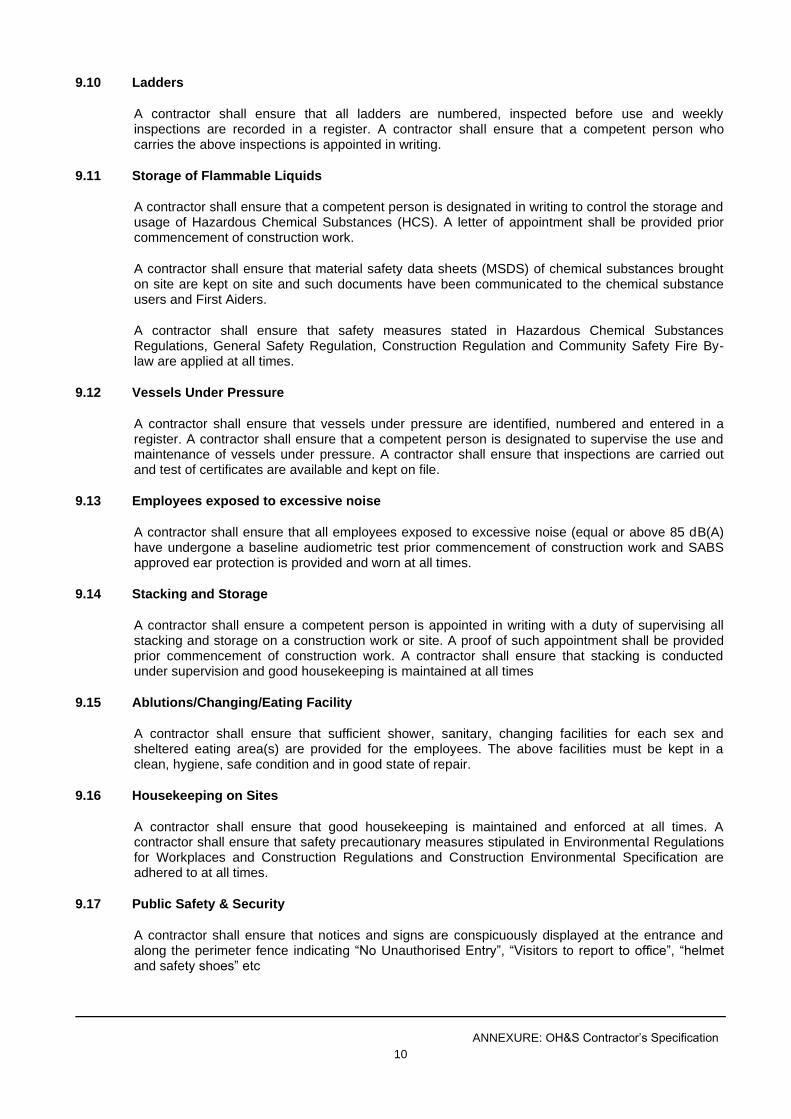
ANNEXURE: OH&S Contractor’s Specification
10
9.10 Ladders
A contractor shall ensure that all ladders are numbered, inspected before use and weekly inspections are recorded in a register. A contractor shall ensure that a competent person who carries the above inspections is appointed in writing.
9.11 Storage of Flammable Liquids
A contractor shall ensure that a competent person is designated in writing to control the storage and usage of Hazardous Chemical Substances (HCS). A letter of appointment shall be provided prior commencement of construction work.
A contractor shall ensure that material safety data sheets (MSDS) of chemical substances brought on site are kept on site and such documents have been communicated to the chemical substance users and First Aiders.
A contractor shall ensure that safety measures stated in Hazardous Chemical Substances Regulations, General Safety Regulation, Construction Regulation and Community Safety Fire By-law are applied at all times.
9.12 Vessels Under Pressure
A contractor shall ensure that vessels under pressure are identified, numbered and entered in a register. A contractor shall ensure that a competent person is designated to supervise the use and maintenance of vessels under pressure. A contractor shall ensure that inspections are carried out and test of certificates are available and kept on file.
9.13 Employees exposed to excessive noise
A contractor shall ensure that all employees exposed to excessive noise (equal or above 85 dB(A) have undergone a baseline audiometric test prior commencement of construction work and SABS approved ear protection is provided and worn at all times.
9.14 Stacking and Storage
A contractor shall ensure a competent person is appointed in writing with a duty of supervising all stacking and storage on a construction work or site. A proof of such appointment shall be provided prior commencement of construction work. A contractor shall ensure that stacking is conducted under supervision and good housekeeping is maintained at all times
9.15 Ablutions/Changing/Eating Facility
A contractor shall ensure that sufficient shower, sanitary, changing facilities for each sex and sheltered eating area(s) are provided for the employees. The above facilities must be kept in a clean, hygiene, safe condition and in good state of repair.
9.16 Housekeeping on Sites
A contractor shall ensure that good housekeeping is maintained and enforced at all times. A contractor shall ensure that safety precautionary measures stipulated in Environmental Regulations for Workplaces and Construction Regulations and Construction Environmental Specification are adhered to at all times.
9.17 Public Safety & Security
A contractor shall ensure that notices and signs are conspicuously displayed at the entrance and along the perimeter fence indicating “No Unauthorised Entry”, “Visitors to report to office”, “helmet and safety shoes” etc
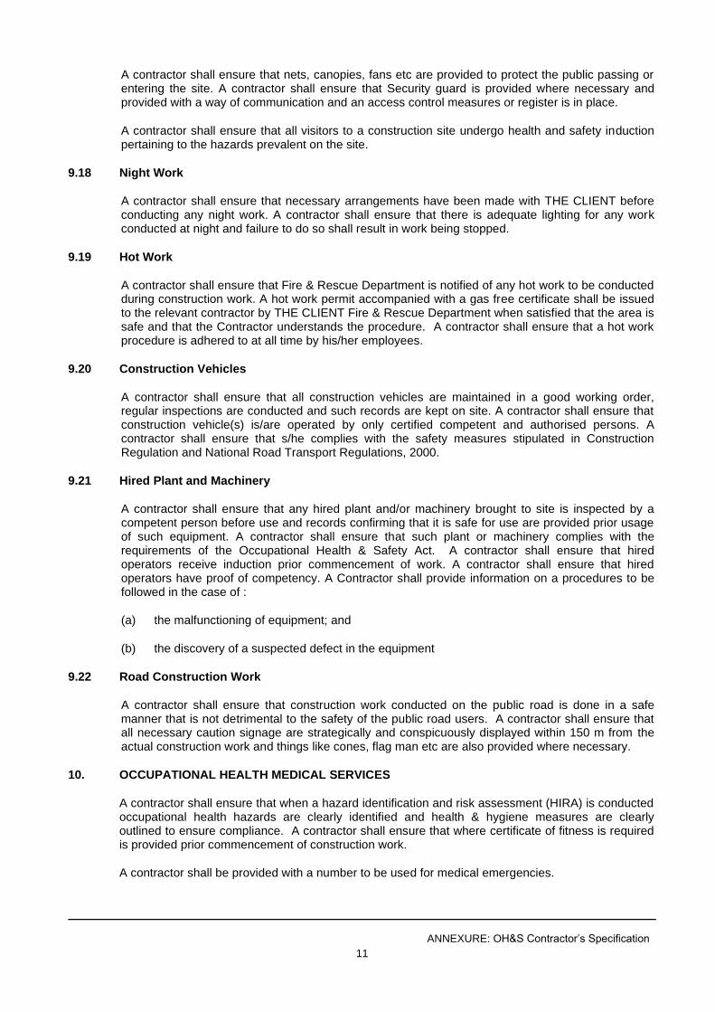
ANNEXURE: OH&S Contractor’s Specification
11
A contractor shall ensure that nets, canopies, fans etc are provided to protect the public passing or entering the site. A contractor shall ensure that Security guard is provided where necessary and provided with a way of communication and an access control measures or register is in place.
A contractor shall ensure that all visitors to a construction site undergo health and safety induction pertaining to the hazards prevalent on the site.
9.18 Night Work
A contractor shall ensure that necessary arrangements have been made with THE CLIENT before conducting any night work. A contractor shall ensure that there is adequate lighting for any work conducted at night and failure to do so shall result in work being stopped.
9.19 Hot Work
A contractor shall ensure that Fire & Rescue Department is notified of any hot work to be conducted during construction work. A hot work permit accompanied with a gas free certificate shall be issued to the relevant contractor by THE CLIENT Fire & Rescue Department when satisfied that the area is safe and that the Contractor understands the procedure. A contractor shall ensure that a hot work procedure is adhered to at all time by his/her employees.
9.20 Construction Vehicles
A contractor shall ensure that all construction vehicles are maintained in a good working order, regular inspections are conducted and such records are kept on site. A contractor shall ensure that construction vehicle(s) is/are operated by only certified competent and authorised persons. A contractor shall ensure that s/he complies with the safety measures stipulated in Construction Regulation and National Road Transport Regulations, 2000.
9.21 Hired Plant and Machinery
A contractor shall ensure that any hired plant and/or machinery brought to site is inspected by a competent person before use and records confirming that it is safe for use are provided prior usage of such equipment. A contractor shall ensure that such plant or machinery complies with the requirements of the Occupational Health & Safety Act. A contractor shall ensure that hired operators receive induction prior commencement of work. A contractor shall ensure that hired operators have proof of competency. A Contractor shall provide information on a procedures to be followed in the case of :
(a) the malfunctioning of equipment; and
(b) the discovery of a suspected defect in the equipment
9.22 Road Construction Work
A contractor shall ensure that construction work conducted on the public road is done in a safe manner that is not detrimental to the safety of the public road users. A contractor shall ensure that all necessary caution signage are strategically and conspicuously displayed within 150 m from the actual construction work and things like cones, flag man etc are also provided where necessary.
10. OCCUPATIONAL HEALTH MEDICAL SERVICES
A contractor shall ensure that when a hazard identification and risk assessment (HIRA) is conducted occupational health hazards are clearly identified and health & hygiene measures are clearly outlined to ensure compliance. A contractor shall ensure that where certificate of fitness is required is provided prior commencement of construction work.
A contractor shall be provided with a number to be used for medical emergencies.
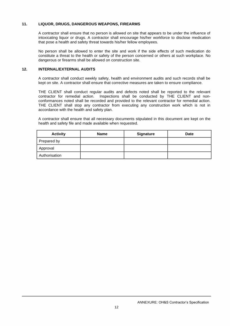
ANNEXURE: OH&S Contractor’s Specification
12
11. LIQUOR, DRUGS, DANGEROUS WEAPONS, FIREARMS
A contractor shall ensure that no person is allowed on site that appears to be under the influence of intoxicating liquor or drugs. A contractor shall encourage his/her workforce to disclose medication that pose a health and safety threat towards his/her fellow employees.
No person shall be allowed to enter the site and work if the side effects of such medication do constitute a threat to the health or safety of the person concerned or others at such workplace. No dangerous or firearms shall be allowed on construction site.
12. INTERNAL/EXTERNAL AUDITS
A contractor shall conduct weekly safety, health and environment audits and such records shall be kept on site. A contractor shall ensure that corrective measures are taken to ensure compliance.
THE CLIENT shall conduct regular audits and defects noted shall be reported to the relevant contractor for remedial action. Inspections shall be conducted by THE CLIENT and non-conformances noted shall be recorded and provided to the relevant contractor for remedial action. THE CLIENT shall stop any contractor from executing any construction work which is not in accordance with the health and safety plan.
A contractor shall ensure that all necessary documents stipulated in this document are kept on the health and safety file and made available when requested.
Activity Name Signature Date
Prepared by
Approval
Authorisation

TENDER
CONSTRUCTION OF BABATAS CPA BULK WATER SUPPLY
TENDER NO. NC/001/2021
PART C4: SITE INFORMATION

Index C4
TENDER
CONSTRUCTION OF BABATAS CPA BULK WATER SUPPLY
TENDER NO. NC/001/2021
PART C4: SITE INFORMATION
C4.1 SCOPE
C4.2 SUBSOIL INVESTIGATIONS
Site Information
C4 - 1
TENDER
CONSTRUCTION OF BABATAS CPA BULK WATER SUPPLY
TENDER NO. NC/001/2021
C4: SITE INFORMATION
C4.1 SCOPE
The documentation included in this section describes the site as at the time of tender to enable the tenderer to price his tender and to decide upon his method of working and programming.
Only actual information about physical conditions on the site and its surroundings has been included in this section and interpretation is a matter for the tenderers.
C4.2 SUBSOIL INVESTIGATIONS
No formal geotechnical investigation has been done on this project. Prospective tenderers shall acquaint themselves with the nature of the materials found on site. Certain portions of the total excavation may have to be done by mechanical breakers and / or blasting.
No claims whatsoever that may arise because of unforeseen ground and subsoil conditions will be considered. It is the responsibility for the Contractor to ascertain for himself the nature of the ground and subsoil as well as the conditions on site.
It is the Contractor's responsibility to supply and deliver all materials that comply with the minimum standards as well as for the building and maintaining of access roads to the works on site, haul areas or dumping sites. No additional payment will be applicable to the above-mentioned other than the relevant items in the schedule of quantities.
C4.3 “AS BUILT” DRAWINGS – WATER RETICULATION NETWORK
No data for existing services could be obtained and data for existing services on drawings are based on field observations done with representatives of the local municipality. Prospective tenderers shall acquaint themselves with existing site services.
No claims for damage to services may arise because of incorrect or incomplete data provided by the Engineer or the Client and it is the responsibility for the Contractor to ascertain himself of services encountered.
The Contractor must update a drawing with existing services encountered during construction and submit to the Engineer at practical completion stage.

TENDER
CONSTRUCTION OF BABATAS CPA BULK WATER SUPPLY
TENDER NO. NC/001/2021
PART C5: DRAWINGS
The drawings listed below are provided in order to give an overview of the project.
Drawing No. Title
301976-CI-BTS-LC-01 Locality Plan
301976-CI-BTS-014 Project Name Board
301976-CI-BTS-GL-01 Bulk water supply layout
301976-CI-BTS-RL-01
301976-BTS-FL -01
301976-CI-BTS-BS-LS-01
301976-CI-BTS-BS-LS-02
301976-CI-BTS-BS-LS-03
301976-CI-BTS-BS-LS-04
301976-CI-BTS-BS-LS-05
301976-CI-BTS-BS-LS-06
301976-ci-bts-001-01
301976-CI-BTS-001-02.1
301976-CI-BTS-001-03
301976-CI-BTS-001-04
301976-CIBTS-002-01
301976-CI-BTS-002-02
301976-CI-BTS-003
301976-CI-BTS-004
301976-CI-BTS-005
301976-CI-BTS-006-01
301976-CI-BTS-006-02
301976-CI-BTS-007
301976-CI-BTS-008
301976-CI-BTS-010
301976-CI-BTS-011
301976-CI-BTS-012
301976-CI-BTS-013
301976-CI-BTS-015
Reticulation Layout
Fence layout around the borehole
Longsection sheet 1 of 6
Longsection sheet 2 of 6
Longsection sheet 3 of 6
Longsection sheet 4 of 6
Longsection sheet 5 of 6
Longsection sheet 6 of 6
Details of borehole pipework and chamber sheet 1 of 4
Details of borehole pipework and chamber sheet 2 of 4
Details of borehole pipework and chamber sheet 3 of 4
Details of borehole pipework and chamber sheet 4 of 4
Details of air valve installation and chamber sheet 1 of 2
Details of air valve installation and chamber sheet 2 of 2
Details of scour valve installation and chamber
Details of isolation valve installation and chamber
Details of water meter and isolation valve installation and chamber
Water meter and control valve installation: chamber and pipework sheet 1of 2
Water meter and control valve: chamber and pipework sheet 2 of 2
Details of buffer tank and pipework
Details of raw water storage tank and pipework
Typical trench details
Details of diamond mesh fence and Steel Gate
Typical trench details
General details; sump and pipeline route markers
Water reticulation details