Composites realized by hand lay-up process in a civil engineering environment: initial properties...
21
ORIGINAL ARTICLE Composites realized by hand lay-up process in a civil engineering environment: initial properties and durability Sofie `ne Marouani Laurence Curtil Patrice Hamelin Received: 28 February 2006 / Accepted: 19 July 2007 / Published online: 12 September 2007 Ó RILEM 2007 Abstract The repair, the reinforcement as well as the setting in safety of buildings and existing reinforced and/or pre-stressed concrete structure is a real technological stake and a socio-economic problem for the near future. The introduction of composites in civil engineering is an interesting answer to these goals, but they brought an important amount of new problems that have to be solved for safe structural applications under combined mechan- ical and environmental loadings. In fact during the past five years, we have witnessed exponential growth in research or field demonstrations of fiber- reinforced composites in civil engineering. Manufac- turers and designers have now access to a wide range of composite materials. However, they face great problems with forecasting the reliability of composite materials. Their introduction in civil engineering applications is a difficult operation due to working environment and weathering conditions. The objec- tive of this paper is to study the effect of these conditions and their consequences on the mechanical properties of the final composite. An analysis of the rheological (viscoelastic) properties was carried out in order to observe the glass transition temperature evolution according to reactive mixture stoichiometry and weathering conditions. Re ´sume ´ La re´paration, le renforcement ainsi que la mise en se´curite´des ouvrages en be´ton arme´et/ou pre´contraint est un enjeu technologique et un proble`me socio-e´conomique dans un futur proche. L’introduction des composites est, certes, une solu- tion inte´ressante mais pose plusieurs proble`mes. En effet, les conditions climatiques et mate´rielles, dans lesquelles s’exe´cutent les chantiers de ge´nie civil de re´paration ou de renforcement, rendent la mise en œuvre difficile et de´licate des composites a` matrice polyme`re. Pour ces raisons, nous allons par l’interme´diaire de cette e´tude, essayer de mettre en e´vidence l’importance de ces conditions afin d’e´valuer leurs re´percussions sur les proprie´te´s finales du composite et par la suite sur sa durab- ilite´. Pour conduire cette e´tude, des mesures de proprie´te´s rhe´ologiques (visco-e´lasticime´trie) sont effectue´es pour suivre l’e´volution de la tempe´rature de transition vitreuse T g en faisant varier des parame`tres tels que la stœchiome´trie du me´lange re´actif et les conditions d’humidite´ et de tempe´rature. Keywords Composites Hand lay-up process Repair Implementation conditions Durability Civil engineering S. Marouani (&) L. Curtil P. Hamelin Laboratoire de Ge ´nie Civil et d’Inge ´nierie Environnementale (LGCIE) – Site Bohr, Universite ´ Lyon I, Villeurbanne Cedex, France e-mail: sofi[email protected] Materials and Structures (2008) 41:831–851 DOI 10.1617/s11527-007-9288-z
Transcript of Composites realized by hand lay-up process in a civil engineering environment: initial properties...

ORIGINAL ARTICLE
Composites realized by hand lay-up process in a civilengineering environment: initial properties and durability
Sofiene Marouani Æ Laurence Curtil ÆPatrice Hamelin
Received: 28 February 2006 / Accepted: 19 July 2007 / Published online: 12 September 2007
� RILEM 2007
Abstract The repair, the reinforcement as well as
the setting in safety of buildings and existing
reinforced and/or pre-stressed concrete structure is
a real technological stake and a socio-economic
problem for the near future. The introduction of
composites in civil engineering is an interesting
answer to these goals, but they brought an important
amount of new problems that have to be solved for
safe structural applications under combined mechan-
ical and environmental loadings. In fact during the
past five years, we have witnessed exponential
growth in research or field demonstrations of fiber-
reinforced composites in civil engineering. Manufac-
turers and designers have now access to a wide range
of composite materials. However, they face great
problems with forecasting the reliability of composite
materials. Their introduction in civil engineering
applications is a difficult operation due to working
environment and weathering conditions. The objec-
tive of this paper is to study the effect of these
conditions and their consequences on the mechanical
properties of the final composite. An analysis of the
rheological (viscoelastic) properties was carried out
in order to observe the glass transition temperature
evolution according to reactive mixture stoichiometry
and weathering conditions.
Resume La reparation, le renforcement ainsi que
la mise en securite des ouvrages en beton arme et/ou
precontraint est un enjeu technologique et un
probleme socio-economique dans un futur proche.
L’introduction des composites est, certes, une solu-
tion interessante mais pose plusieurs problemes. En
effet, les conditions climatiques et materielles, dans
lesquelles s’executent les chantiers de genie civil de
reparation ou de renforcement, rendent la mise en
œuvre difficile et delicate des composites a matrice
polymere. Pour ces raisons, nous allons par
l’intermediaire de cette etude, essayer de mettre
en evidence l’importance de ces conditions afin
d’evaluer leurs repercussions sur les proprietes
finales du composite et par la suite sur sa durab-
ilite. Pour conduire cette etude, des mesures de
proprietes rheologiques (visco-elasticimetrie) sont
effectuees pour suivre l’evolution de la temperature
de transition vitreuse Tg en faisant varier des
parametres tels que la stœchiometrie du melange
reactif et les conditions d’humidite et de
temperature.
Keywords Composites � Hand lay-up process �Repair � Implementation conditions �Durability � Civil engineering
S. Marouani (&) � L. Curtil � P. Hamelin
Laboratoire de Genie Civil et d’Ingenierie
Environnementale (LGCIE) – Site Bohr, Universite Lyon I,
Villeurbanne Cedex, France
e-mail: [email protected]
Materials and Structures (2008) 41:831–851
DOI 10.1617/s11527-007-9288-z

Mots cle Composites � Moulage au contact �Reparation � Conditions de mise en œuvre �Durabilite � Genie civil
1 Introduction
According to the geographical localization, physical
properties and, more particularly, the mechanical
behavior of concrete structures are modified under
various environmental conditions [1]. This can be
observed in the deterioration of buildings, bridges
and other structures due to the corrosion of the steel
reinforcement. In addition, there are many instances
where concrete structures need strengthening. These
may include increase in seismic, wind or snow load
bearing capacity due to the revision of the building
codes. In such cases, extending the service life of
structures is usually less expensive than replacement
and can be accomplished in a shorter period of time
with fewer inconveniences.
Considering the limited resources available to
solve the deterioration problems, it is important to
find innovative and cost effective techniques and
explore new materials for the strengthening of
existing structures [2]. Conventional strengthening
and/or repair techniques often used include section
enlargement, polymer concrete overlays, post-ten-
sioning, and bonded steel plates [3]. However, within
the last 10 years Fiber Reinforced Polymer materials
(FRP) have been introduced and are becoming
increasingly popular choices for many repair/
strengthening projects. In this context, the repair,
the reinforcement and the protection of concrete
structures can be achieved by hand lay-up of
composite materials [4].
The reliability and the durability of civil
engineering structures reinforced by FRP depend on
parameters that can be divided into two categories:
the first consists of the durability of the concrete
structure; the second is related to the durability of
composite materials, which depends on the raw
material, quality of interfaces, implementation con-
ditions and service constraints.
Difficult workability conditions (Fig. 1) might
have a significant influence on initial properties of
composite; for example it’s durability during service.
The quality of processing of a component governs its
initial physico-chemical [5] and mechanical proper-
ties [6] as well as its long-term behavior [7]. Process
optimization requires control of the curing process
(i.e. curing parameters).
The implementation conditions include several
parameters (Fig. 2), in particular the:
(1) proportion of components (resin and hardener)
in the reactive mixture (stoichiometric ratio).
(2) postcuring operation
(3) environment temperature and relative humidity
(4) temperature of the concrete structure at the time
of stratification.
This paper analyses the implementation conditions
and their influence on the durability of the reinforced
structure. The objective is to examine the recom-
mendations published by the AFGC [9] regarding the
control and the characterization of polymers as a
function of their in situ transformation conditions, in
other words, to evaluate the influence of initial
properties on the durability of composite materials
under environmental conditions specific to civil
engineering applications.
The parameter studied to answer the raised ques-
tions is the glass transition temperature Tg. The
objective is to systematically study the variation of Tg
as a function of workability parameters (Fig. 2) and
to analyze their influence on the mechanical
characteristics.
In order to understand the methodology that we
followed during these researches, we will present:
(1) the mechanism of polymerization of the epoxy
and vinyl ester resins.
repair of a bridge (IREX) [8] mixing of resin and hardener on civil engineering building site
(IREX)
Fig. 1 Examples of composites implemented in civil engi-
neering building sites
832 Materials and Structures (2008) 41:831–851

(2) the experimental procedure.
(3) the results recorded as well as the comments
carried out.
2 The implementation of the composites: cure of
vinyl ester (VE) and epoxy (EP) resins
The cure process plays a key role in determining the
properties of a thermoset material. The changes occur
during cure: the stiffness develops and the volume
decreases, determining the final structure and thereby
the properties of the polymer matrix itself. In order to
use the full potential of a thermosetting material a
thorough understanding phenomena and changes in
the material during cure is required. An important
aspect of thermoset cure is the reaction mechanism.
Polymer networks may be formed by two principally
different mechanisms; step-wise reaction (EP resin)
and chain-wise reaction (VE resin). Both the structure
of the resulting network and the events during the
reaction depend strongly on the reaction mechanism,
on the process of composite elaboration and espe-
cially on implementation conditions (role of
weathering conditions).
2.1 Cure of Vinylester (VE) resin
Vinylester resins are formed by the copolymerization
of styrene monomer and dimethacrylate monomer
based on the diglycidyl ether of bisphenol A (Fig. 3).
The styrene monomer is a reactive diluent. The
percentage of the styrene rises up to 36%.
Curing of the VE is governed by a free-radical
polymerization. The chain-wise mechanism proceeds
by way of active species that initiates chain poly-
merization reactions; each species rapidly forms a
large number of primary bonds on different locations
in the system. The reacting system is composed of a
catalyst, an accelerator and an inhibitor. The role of
catalyst (organic peroxide R–O–O–R0) is to raise the
resin to an energy level which makes the reaction of
copolymerization possible under selected implemen-
tations conditions.
The accelerator is necessary, especially in the case
of polymerization at low temperatures to induce free
radical production by chemical reduction of the
peroxide. It is used according to its compatibility
with the catalyst. The inhibitor adapts the reactivity
of the catalytic system at some implementing
processes (composite implemented at high tempera-
ture). In our case, the retained catalyst is the
methylethylketone peroxide (MEKP), the accelerator
is a cobalt salt (Co) associated with dimethylaniline
(DMA).
2.2 Cure of epoxy (EP) resin
The crosslinking of epoxy resins can be achieved
through two different reaction mechanisms, polymer-
ization by addition and by steps. The most common
curing process is based on the addition reaction of a
hardener (amines or anhydrides). There are several
works in which the chemistry and technology of
epoxy resins is discussed in detail [10–12]. With cure
Stoechiometric ratio r=[Hardener]/[resin]
Postcuring Temperature of concrete support
Environmental temperature and moisture
∆ of Tg
∆ initial properties of composite
∆ durability ofcomposite
Fig. 2 Implementation parameters
O
CH2
HC OH
CH2
O
C
C
O
CH3
CH2
O
CH2
HC OH
CH2
O
C
C
O
CH3
CH2
O
CH2
HC OH
CH2
O
C
C
O
CH3
CH2
CH2 CH2
n
Fig. 3 Chemical structure of Vinyl ester monomer system
Materials and Structures (2008) 41:831–851 833
involving reaction of epoxy groups with curing agent,
there is a reduction in the volume occupied by the
system, the free volume decreases which leads to an
increased ‘‘resistance’’ to conformational changes.
The importance of various factors that affect the
Tg of an epoxy network has been evaluated by Chang
[13]. Their estimates were based on a DGEBA resin
cured with catalyst that promotes the homopolymer-
ization of epoxy groups to form ether linkages.
3 Tg as an indicator of the evolution of composite
properties
Studies of implementation parameters can be con-
ducted by a number of methods, among these, the
follow-up of the glass transition temperature ‘‘Tg’’ can
be an effective method of characterization. Tg is
defined as the transition between the entropy and the
elastic state energy at its largest difference. Relations
exist between Tg and the evolution of global properties
of composites. The polymeric matrices of fiber
reinforced composites exhibit a glass transition, Tg, a
temperature above which the properties of the material
degrade significantly. Mechanical properties depend
on the rigidity of polymeric chains. The Eqs. (1) and
(2) (theory of rubber elasticity) relate the mechanical
properties to the crosslink density q, whereas, accord-
ing to the laws of DiMarzio [14] and DiBenedetto [15],
the Eq. (3) establishes a relation between Tg and the
degree of crosslinking. It is well known that the
crosslink density of the formed network has a
pronounced effect not only on the Tg but also on the
lower temperature processes, especially at low
crosslink extent, although the influence of other
factors—such as free volume at high crosslink densi-
ties—remains to be clearly evidenced [16–18].
E0 ¼ 3 R T qm ðelastic modulusÞ ð1Þ
G0 ¼ R T qm ðshear storage modulusÞ ð2Þ
q (mol/cm3): the crosslink density expressed in moles
of elastically effective chains per cubic centimeter of
sample.
T(K): the absolute temperature
R (J mol�1 K�1): the gas constant (R = 8.314)
m (mol/kg) = 1/Mc: the concentration of elastically
effective network chains.
Mc (g/mol): molecular weight between junction
points
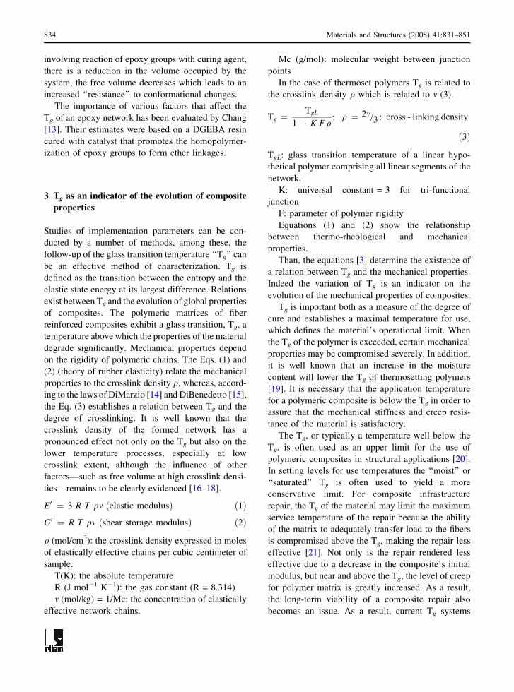
In the case of thermoset polymers Tg is related to
the crosslink density q which is related to m (3).
Tg ¼TgL
1 � K Fq; q ¼ 2m=3 : cross - linking density
ð3Þ
TgL: glass transition temperature of a linear hypo-
thetical polymer comprising all linear segments of the
network.
K: universal constant = 3 for tri-functional
junction
F: parameter of polymer rigidity
Equations (1) and (2) show the relationship
between thermo-rheological and mechanical
properties.
Than, the equations [3] determine the existence of
a relation between Tg and the mechanical properties.
Indeed the variation of Tg is an indicator on the
evolution of the mechanical properties of composites.
Tg is important both as a measure of the degree of
cure and establishes a maximal temperature for use,
which defines the material’s operational limit. When
the Tg of the polymer is exceeded, certain mechanical
properties may be compromised severely. In addition,
it is well known that an increase in the moisture
content will lower the Tg of thermosetting polymers
[19]. It is necessary that the application temperature
for a polymeric composite is below the Tg in order to
assure that the mechanical stiffness and creep resis-
tance of the material is satisfactory.
The Tg, or typically a temperature well below the
Tg, is often used as an upper limit for the use of
polymeric composites in structural applications [20].
In setting levels for use temperatures the ‘‘moist’’ or
‘‘saturated’’ Tg is often used to yield a more
conservative limit. For composite infrastructure
repair, the Tg of the material may limit the maximum
service temperature of the repair because the ability
of the matrix to adequately transfer load to the fibers
is compromised above the Tg, making the repair less
effective [21]. Not only is the repair rendered less
effective due to a decrease in the composite’s initial
modulus, but near and above the Tg, the level of creep
for polymer matrix is greatly increased. As a result,
the long-term viability of a composite repair also
becomes an issue. As a result, current Tg systems
834 Materials and Structures (2008) 41:831–851
need to be evaluated to determine their temperature
limits.
4 Experimental procedure
4.1 Materials
We have considered two composite materials formu-
lations with the same textile reinforcement and
different polymer matrix: Epoxy and Vinyl ester
polymer.
Unidirectional carbon fabric was used for rein-
forcement (Table 1), the sizing is made with epoxy-
polyurethane (15–85%), 1% by weight.
The composites are obtained by wet-lay up
technique and their characteristics are presented in
Tables 2 and 3.
The samples were then cut into small specimens
using a diamond saw, suitable for thermal scans and
mechanical characterization.
4.2 Instrumentation
4.2.1 Experimental glass transition temperature
The glass transition temperature was determined by a
‘‘kinemat’’ apparatus (Fig. 4a, b) on 50 mm · 10
mm · 1.2 mm samples which were tested in torsion
with an angle varying between 5� and 25� (Fig. 5).
The heating rate is 3�C/min and the required torque
was measured instantaneously and after 2 s of
relaxation (Fig. 6).
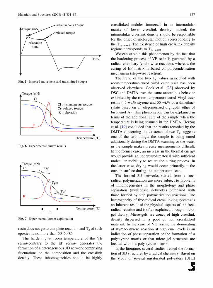
Tg is measured at the maximum difference between
the instantaneous and relaxed torques (Fig. 7).
The imposed strain is in the range of small
deformations (linear viscoelasticity), the temperature
varies between 20�C and 240�C. The glass transition
temperature, Tg, of the composite was determined on
a first Kinemat scan, performed at 3�C/min, Tg value
was measured on the extrapolated onset (glass
transition range, i.e. the onset of the change in the
slope of the instantaneous torque) Tg-onset (Fig. 7).
Legrand and Bellenger [22] have determined the Tg
of prepreg glass/epoxy material by DMTA and
Kinemat. The mean discrepancy between these two
measurements techniques is about 2�C.
Tg-onset (�C), Tg-midpoint (�C), Tg-endset (�C): the
temperatures corresponding respectively to the onset,
the midpoint and the endset of glass transition.
L (�C): size of the glass transition range.
4.2.2 Experimental mechanical characteristics
To determine ultimate mechanical characteristics (ff,
rf, ef), tensile mechanical tests were carried on a
universal testing machine ‘‘ZWICK/1475’’. Test
results are expressed in terms of stress–strain curves
(Fig. 8a).
The ends of the specimens are reinforced by glass-
epoxy laminate heels (Fig. 8b).
Table 1 Technical characteristics of the carbon fiber
reinforcement
Linear density (tex) 1600
Number of filaments 24 k
Filament diameter (lm) 7
Twist (t/m) 0
Running length per kg (m/kg) 625
Density 1.76
Tensile strength (MPa) 4300
Tensile modulus (GPa) 238
Elongation at break (%) 1.8
Thermal conductivity (W/mK) 17
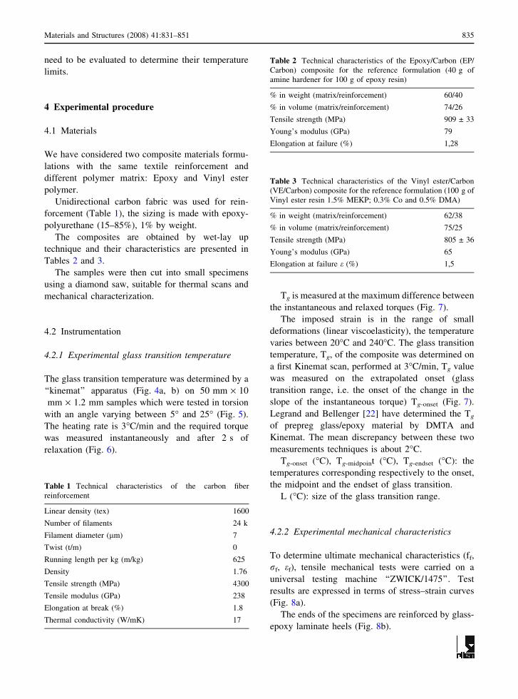
Table 2 Technical characteristics of the Epoxy/Carbon (EP/
Carbon) composite for the reference formulation (40 g of
amine hardener for 100 g of epoxy resin)
% in weight (matrix/reinforcement) 60/40
% in volume (matrix/reinforcement) 74/26
Tensile strength (MPa) 909 ± 33
Young’s modulus (GPa) 79
Elongation at failure (%) 1,28
Table 3 Technical characteristics of the Vinyl ester/Carbon
(VE/Carbon) composite for the reference formulation (100 g of
Vinyl ester resin 1.5% MEKP; 0.3% Co and 0.5% DMA)
% in weight (matrix/reinforcement) 62/38
% in volume (matrix/reinforcement) 75/25
Tensile strength (MPa) 805 ± 36
Young’s modulus (GPa) 65
Elongation at failure e (%) 1,5
Materials and Structures (2008) 41:831–851 835

The displacement rate is fixed at 1 mm/min
according to standard NF EN ISO 527-5.
5 Results and discussion
5.1 Viscoelastic properties of VE and EP
Figure 9 shows kinemat analyze of the two compos-
ites system VE/Carbon and EP/Carbon after 2 weeks
of stratification at room temperature.
The composite with EP matrix has a single Tg
(Tg-onset) near 52�C (Fig. 9a).
The composite with EP matrix has a single Tg
(Tg-onset) near 54�C (Fig. 9a). Whereas, in the case of
composite with VE matrix, the graph of the Fig. 9b
shows the existence of two apparent Tg values, as
shown by the two apparent Tg values, as shown by
the two changes in the slope of the Ci
(Tg1�onset � 51�C and Tg2�onset � 141�C). These
transitions are related to thermosets morphology.
With most room-temperature-curing epoxies, the
Table 5 Tested formulations reactive mixture of the VE/Carbon system
Reference
formulation
Variation of the % of MEKP
(% of DMA and Co are maintained
constant 0.3% and 0.5%)
Variation of the % of Co
(% of MEKP and DMA
are maintained constant
1.5% and 0.5%)
Variation of the % of
DMA (% of MEKP
and Co are maintained
constant 1.5% and 0.3%)
Weight-percent MEKP = 1.5% 0.5; 1; 1.5; 2; 2.5; 3; 3.5; 4 and 5% 0.1; 0.2; 0.3 and 0.5% 0.1; 0.2; 0.5 and 0.8%
Co = 0.3%
DMA = 0.5%
Hand lay-up conditions T = 20 ± 2�C
RH = 50 ± 4%
Table 4 Tested formulations reactive mixture of the EP/Carbon system
mHardener ðgÞMResin ðgÞ
16/100 24/100 32/100 40/100 48/100 56/100 64/100
r 0.4 0.6 0.8 1 1.2 1.4 1.6
Fig. 4 The ‘‘Kinetech’’
apparatus
836 Materials and Structures (2008) 41:831–851
resin does not go to complete reaction, and Tg of such
epoxies is no more than 50–60�C.
The hardening at room temperature of the VE
resins-contrary to the EP resins- generates the
formation of a heterogeneous 3D network comprising
fluctuations on the composition and the crosslink
density. These inhomogeneities should be highly
crosslinked nodules immersed in an internodular
matrix of lower crosslink density; indeed, the
internodular crosslink density should be responsible
for the onset of molecular motion corresponding to
the Tg1�onset: The existence of high crosslink density
regions corresponds to Tg2�onset:
We can explain this phenomenon by the fact that
the hardening process of VE resin is governed by a
radical chemistry (chain-wise reaction), whereas, the
curing of EP matrix is based on polycondensation
mechanism (step-wise reaction).
The trend of the two Tg values associated with
room-temperature-cured vinyl ester resin has been
observed elsewhere. Cook et al. [23] observed by
DSC and DMTA tests the same anomalous behavior
exhibited by the room temperature cured Vinyl ester
resins (45 wt.% styrene and 55 wt.% of a dimethac-
rylate based on an oligomerized diglicydil ether of
bisphenol A). This phenomenon can be explained in
terms of the additional cure of the sample when the
temperature is being scanned in the DMTA. Herzog
et al. [19] concluded that the results recorded by the
DMTA concerning the existence of two Tg suggests
one of the two things: the sample is being cured
additionally during the DMTA scanning or the water
in the sample makes precise measurements difficult.
In the former case, an increase in the thermal energy
would provide an undercured material with sufficient
molecular mobility to restart the curing process. In
the latter case, drying would occur primarily at the
outside surface during the temperature scan.
The formed 3D networks started from a free-
radical polymerization are more subject to problems
of inhomogeneities in the morphology and phase
separation (multiphase networks) compared with
those formed by step polymerization reactions. The
heterogeneity of free-radical cross-linking systems is
an inherent result of the physical aspects of the free-
radical reaction and is often explained through micro-
gel theory. Micro-gels are zones of high crosslink
density dispersed in a pool of non crosslinked
material. In the case of VE resins, the dominating
of styrene-styrene reaction at high cure levels is an
indication of phase separation or the formation of a
polystyrene matrix or that micro-gel structures are
located within a polystyrene matrix.
In the literature, several studies treated the forma-
tion of 3D structures by a radical chemistry. Based on
the study of several unsaturated polyesters (UPE)
instantaneous Torque
relaxed torque
relaxation time
Time
Torque (mN)
Fig. 5 Imposed movement and transmitted couple
Ci
Cr
R
Temperature (°C)
Torque (mN)
Ci : instantaneous torque Cr :relaxed torque R : relaxation
Fig. 6 Experimental curve: results
Ci
Cr
R
Temperature (°C)
Torque (mN) Tgd
Tgm
Tgf
L
Fig. 7 Experimental curve: exploitation
Materials and Structures (2008) 41:831–851 837

[24–26] networks, it was possible to show that the
two transition detected could be attributed to the
chain formations comprising the crosslinking nodes
in the structure of the prepolymer chain rather than
the formation of polystyrene between microgels or
between crosslinking nodes.
These studies converged to the same conclusions:
heterogeneity of the formed network. In reality, the
transition zone detected corresponds to infinity of
microdomains which are set in motion one by one
under the effect of a rise in temperature. In parallel,
the view of the researchers diverges concerning a
multiphase network.
We note that the comparison of the values of Tg
recorded by the DMTA in the studies of [23] as well
as [19] shows for the same reactive system formu-
lation (same % of catalyst and accelerators) a light
difference (3�C) compared to the values recorded by
the kinemat.
To conclude, we remind that the hand lay-up of
composites in civil engineering application gener-
ally is not conducted in an oven or in an
autoclave, but instead a catalyzed resin is used to
permit room-temperature curing. If these ambient
conditions do not lead to a Tg associated with a
fully cured composite matrix, the system either
gels or vitrifies before a complete cure is achieved
and the obtained networks present lower Tg.
Therefore, epoxies, as well as vinyl esters, needs
to be postcured to achieve a high degree of
crosslinking.
5.2 Influence of errors in the reactive system
formulation
First of all, a preliminary study was conducted in situ
on civil engineering building sites in order to estimate
induced incertitude on the percentages of catalyst and
accelerator. This incertitude is estimated from 0.5%
to 5% in the case of catalyst, and from 0.1% to 0.8%
in the case of accelerator. Concerning the EP/Carbon
system, the incertitude applied to stoichiometric
epoxy-amine ratio ‘‘r’’ reveals a variation between
0.4 to 1.6.
To simulate these errors inherent to the transfor-
mation conditions of composite, essentially induced
by difficult implementation conditions, we intention-
ally varied the reactive mixtures formulation
(Table 2, 3).
ff
εf
Ef
Stress (MPa)
Strain (%)
ff : failure strength
E f : Young modulus
ε f : failure strain
a-Experimental curve: results of tensile tests
b-Specimen after tensile test
Fig. 8 Mechanical test
838 Materials and Structures (2008) 41:831–851

5.2.1 Effect of epoxy-amine stoichiometry on cured
composite materials properties
Seven stoichiometric ratios of amine to epoxy were
analyzed. The systems studied consisted of three
excess amine systems (r = 1.2; 1.4 and 1.6), a
stoichiometric system (r = 1), and three excess epoxy
systems (r = 0.4; 0.6 and 0.8).
Figure 10 is a plot of the Tg as a function of the
stoichiometric ratio ‘‘r’’. The maximum value occurs
at the stoichiometric point. The Tg depends strongly
on the used hardener (amine) quantity. Amounts in
excess or paucity of the stoichiometric composition
result in drastically lower value of Tg. The crosslink-
ing density of epoxy-amine thermosetting system is
affected by the amount of curing agent used. The use
of more or less amine than the stoichiometric quantity
required for stoichiometrically balanced cure, leads to
a final structure having lower crosslink density and
therefore lower Tg. If the quantity of amine is in
excess or in paucity of the stoichiometric composi-
tion, gelled networks will not form. Such limits can
be predicted using Flory’s theory of gelation.
For the epoxy-amine system used for this inves-
tigation limits are r = 0.4 and r = 1.6.
Under such conditions the concept of network
stiffening crosslinks is not applicable. The decrease
in Tg in amine-rich mixtures can be attributed to the
increasing numbers of chain ends. This can be
explained by the free volume argument. Chain ends
have in excess free volume associated with them that
can ease the movement of molecules and therefore
lower the value of Tg. The significant decrease in the
Tg of epoxy-rich mixtures with r < 0.8, compared
with mixtures having a composition near to stoichi-
ometry could be attributed to the fact that unreacted
epoxy groups can have some plasticization effect on
the crosslinked networks.
Our purpose for investigating the effects of
stoichiometry on material properties of epoxy-amine
systems is to eventually relate these properties to
predicted interphase composition profiles. Existing
methods for the prediction of Tg for crosslinked
off-stoichiometry compositions epoxy systems are
based on empirical and theoretical considerations.
However, in order to obtain reliable Tg values for
epoxy-amine systems with varying amounts of curing
agent, direct measurement is recommended.
5.2.2 Influence of catalyst (MEKP) percentage
The variation of Tg as a function of the percentage of
MEKP is presented in Fig. 11. The percentage of
accelerator (Co and DMA) is unchanged and repre-
sents respectively 0.3% and 0.5% of weight-percent.
In the phase I, the evolution of Tg1�onset with
respect to the percentage of catalyst can be divided in
two stages as shown in the Fig. 11a. During the first
stage, Tg is quasi proportional to the percentage of
MEKP; the increase is approximately 10�C. During
a-Epoxy /Carbon system
b-Vinyl ester /Carbon system
Tg-onset
Temperature (°C)
Torque (mN.m) Relaxation (mN.m)
Tg2-onset
Tg1-onset
Temperature (°C)
Torque (mN.m) Relaxation (mN.m)
Fig. 9 Analyze Kinemat of VE/Carbon & EP/Carbon com-
posites polymerized at 20�C and 50% RH
15
30
45
60
Stoichiometric amine/epoxy ratio "r"
Ttesno-g
)C°(
0 0,4 0,8 1,2 1,6
Fig. 10 Tg versus stoichiometric epoxy-amine ratio
Materials and Structures (2008) 41:831–851 839

the second stage (Fig. 12b), Tg2�onset is almost
constant. In phase II, Tg2�onset shows a light increase
for MEKP between 0.5% and 1% than decreases
abruptly by loosing about 20�C for percentages of
MEKP between 1% and 5%.
These result can be explained by the fact that the
increase of the percentage of catalyst leads to the
growing of the concentration of free radicals, thus to
the increase of the reactivity of the mixture, and of
the reticulation density. Hence Tg is increased. It is
well known that one of the factors that affect the Tg,
is the crosslinking introduced into the polymer to
form a network. An increase of the crosslinking
density reduces the chain mobility and, consequently,
increases the Tg. Nevertheless, when the percentage
of catalyst continues to increase, the value of Tg
stabilizes or decreases lightly.
This phenomenon suggests two things: on the one
hand, an increase in the MEKP concentration,
generate an excess in free radicals which can cause
some secondary reactions and homopolymerization
of styrene and/or the Vinyl ester prepolymer which
create an effect of plasticization [27].
On the other hand, with an increase in the MEKP
concentration, the exotherm peak (corresponding to
the maximum reaction rate) will be shifted to lower
temperature as would be expected for a faster
reacting system, and this may cause the early (but
limited) initiation of vinyl resins [28].
5.2.3 Influence of accelerator percentage variation
Cure of Vinyl ester resin involves initiator (MEKP)
and accelerator (Co and, as an option, DMA). The
chemistry of the initiation is quite complex, but in the
simplest terms, the initiator (catalyst) is the active
element and the accelerator, having no direct effect
on the resin system, catalyzes the initiator process.
The percentage of catalyst is fixed at 1.5% by
weight.
The graphs a and b of the Fig. 12 enable us to
deduce that Tg varies slightly as a function of
accelerator (Co or DMA) percentage.
These results are logical. In fact the cobalt salt
accelerates the catalyst by debonding the MEKP
oxygen–oxygen bond (O–O) through redox decom-
position and the debonding of the prepolymer carbon-
carbon double bonds (C=C) allows creation of free
radicals. Li and Lee [29] state the same conclusions
after studying cure reaction of Vinyl ester resin
‘‘Derakane 411–350’’ containing bisphenol A.
In general, the amount of accelerator is related to
its compatibility with the catalyst, hence its presence
in the reactive mixture does not seem to affect the Tg
of the composite. These results agree with the fact
that the accelerator accelerates the curing process and
20
30
40
50
60
70
0 2 4 6
catalyst percentage (% MEKP)
Tg
)C°(
tesno-1
a-Tg1-onset versus catalyst percentage
110
120
130
140
150
160
0 2 4 6
catalyst percentage (% MEKP)
)C°(tes
no-2gT
b-Tg2-onset versus catalyst percentage
Fig. 11 Tg versus percentage of catalyst (MEKP)
0 0,2 0,4 0,6 0,8 1% of accelerator (Co and DMA)
a-Tg1-onset versus accelerator percentage
100110120130140150160
0 0,2 0,4 0,6 0,8 1
% of accelerator (Co and DMA)
Tg
2-on
set
(°C
)T
g 1-
onse
t (°
C)
Tg (°C) = f (% of DMA)Tg (°C) = f (% of Co)
b-Tg2-onset versus accelerator percentage
30354045505560
Tg (°°C) = f (% of DMA )Tg (°°C) = f (% of Co)
Fig. 12 Tg versus percentage of accelerator (Co and DMA)
840 Materials and Structures (2008) 41:831–851

enable it to take place at room temperature. Never-
theless, the kinetic process of chemical reduction and
the possibility of solely partial initiator decomposi-
tion imply that the material formed will be partially
cured.
This conclusion is confirmed by the low variations
recorded in size of the glass transition zone (Fig. 13)
with respect to the percentage of accelerator in the
reactive mixture.
These results contradict those of Yildiz and
Hazar [30] and Pryor & Hendrickson [31] which
affirms that the use of accelerator in Vinyl ester/
styrene polymerizations has significant conse-
quences. The increase in the DMA concentration
causes an increase in the Mc (average molecular
weight of the chain sections between crosslinks)
values of the network.
The explanation is that the increase in the DMA
concentration further retards the crosslinking level
which results in the decrease of the swelling. The
same conclusions were advanced by Cook et al. [23]
concerning the inhibition effect of the cobalt.
From these experimental results it can be con-
clude that for a very low amount of catalyst the
curing reaction takes place and the varying of the
amount of catalyst (high quantity), produces a poor
crosslinked material. The results obtained agree
with the fact that the accelerator accelerates the
curing process and enable it to take place at low
temperatures. Without post-cured thermal treatment,
the VE matrix composite specimen can remain
partially cured.
The properties of the cured VE matrix composites,
as well as the EP matrix composites appear to depend
on the initiator system, but these require a more detail
study of the free mechanism.
5.3 Evolution of mechanical properties
5.3.1 Sensitivity of the mechanical properties to
implementation parameters
The mechanical and sometimes chemical adhesion
which characterizes the fiber–resin interface is liable
for the transfer of load or stress between fiber and
resin.
The mechanical adhesion, often associated with
surface inhomogeneities, is also the result of the
normal pressure on the fiber due to chemical shrink-
age of the resin during the crosslinking process, as
well as the shrinkage of the resin via thermal
contraction after cooling.
It is common practice in the civil engineering
applications for composite parts to be cured at room
temperature or to realize only a low-temperature
postcure. Under-cure of the resin will not generally
produce optimal tensile properties and in applications
where corrosive environments are experienced by the
material, further degradation of the mechanical
properties can occur [32]. The loss of strength or
stiffness over time can produce unexpected material
failure resulting in, at least in costly downtimes or
needless expenses.
It was thought that the initial cure of the resin may
limit the degradation of mechanical properties.
Research that varied the cure conditions has shown
that the level of the residual stress depends on
implementation conditions (cure temperature, curing
agent concentration...). In the literature this aspect
of current industrial practice is slightly examined
[33, 34].
In summary, the normal pressure exerted on
reinforcement fibers embedded in a polymeric matrix
depends on implementation parameters as well as
implementation conditions of the composites. In the
first case, it has shown qualitatively that failure of the
interface between the fiber and resin is a function of
the following parameters: materials, sample loading,
Young’s modulus, Poisson’s ratio of the two mate-
rials and mismatch between the thermal expansion
coefficients of the two materials [35]. On the other
hand, the interfacial shear stress and coefficient of
friction are related through the pressure in the system.
Considering the sensitivity of the mechanical
properties of composites to their stratification condi-
tions, mechanical tests were carried out in order to
10
20
30
40
50
60
% of accelerator ( Co and DMA)
L (
°°C)
L (°C) = f (% of Co)L (°C) = f (% of DMA)
0 0,2 0,4 0,6 0,8 1
Fig. 13 Width of the glass transition zone ‘‘L’’ versus the
percentage of accelerator
Materials and Structures (2008) 41:831–851 841

evaluate the tensile strength, strain, and Young
modulus as a function of variation in catalyst and
accelerator percentage at the time of implementation.
5.3.2 Results and discussion
Figure 14a shows that the failure stress of the
composite increases with increasing percentage of
catalyst. For the variation of catalyst from 0.5% and
2%, we observe an increase of 250 MPa (from
800 MPa to 1050 MPa) i.e. an increase of approxi-
mately 31%. At 2% of MEKP, the failure stress
decrease slightly to reach 900 MPa at 5% of catalyst.
The Young modulus increases slightly in the first
time to reach 80 GPa at 1.5% of catalyst, then
decreases and stabilizes to 65 GPa for 3.5% of
catalyst, that represents a fall of approximately 20%
(Fig. 14b).
As reported in the Fig. 14, the mechanical prop-
erties of the composites in term of modulus and
failure stress containing matrix VE evolve differently
according to the quantity of catalyst. Whereas failure
stress starts to decrease from 2% of catalyst, the
Young modulus changes behavior when the percent-
age of MEKP reaches 1.5%. This phenomenon can be
explained by modification in the rigidity of the
composite.
The effect of the increase in the quantity of
catalyst appears certainly by an improvement of
chemical adhesion i.e. the improvement of the
interface matrix-reinforcement, which explains the
variations’, recorded on the mechanical properties. A
network with greater intermolecular cross-links will
require the rupture of many more bonds, and
therefore require more energy.
Results shown in Fig. 15 indicate that the Young
modulus is not influenced by the variation of
accelerator’s percentage (Co and DMA) in the
reactive system. Increasing the DMA content, subse-
quently increases failure stress (from 800 MPa to
1000 MPa); accelerated initiation with DMA results
in maximum failure stress value between 0.1% and
0.5%, 200 MPa was recorded when the percentage of
DMA reach 0.5%. In this DMA concentration, tensile
strength reaches 1000 MPa. This phenomenon can be
explained by the fact that employing DMA for the
curing at lower temperatures increase elastic energy
stored, which could be the result of greater stress
within system. The excess of elastic energy is stored
in the sample at the moment of failure and expended
in the creation of increased fracture surface area
giving rise to rough surfaces.
The quantity of Co in the reactive system seems
without effect in the mechanical properties.
Figure 16 shows the evolution of failure stress and
Young modulus as a function of amine used for cure.
For the two plots one maximum is apparent: one at
600700800900
100011001200
0 1 2 3 4 5 6
% of catalyst (MEKP)a-Failure stress versus catalyst percentage
55000
6000065000
70000
7500080000
85000
% of catalyst (MEKP) a-Young modulus versus catalyst percentage
You
ng m
odul
us (
MP
a)F
ailu
re s
tres
s (M
Pa)
0 2 4 6
b-
Fig. 14 Evolution of mechanical properties as a function of
catalyst percentage for the composite with VE matrix
0
200
400
600
800
1000
1200
% of accelerator (Co and DMA)
Failure Stress = f( % of DMA)Failure Stress = f( % of Co)
40000
50000
60000
70000
80000
90000
100000
% of accelerator (Co and DMA)
E (MPa) = f (% of DMA)E (MPa) = f (% of Co)
0 0,2 0,4 0,6 0,8 1
0 0,2 0,4 0,6 0,8 1
You
ng M
odul
us (
MP
a)F
ailu
re s
tres
s (M
PA
)
Fig. 15 Evolution of mechanical properties as a function of
accelerator percentage for the composite with VE matrix
842 Materials and Structures (2008) 41:831–851
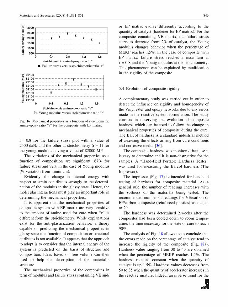
r = 0.8 for the failure stress plot with a value of
2500 daN, and the other at stoichiometry (r = 1) for
the young modulus having a value of 82000 MPa.
The variations of the mechanical properties as a
function of composition are significant: 67% for
failure stress and 82% in the case of Young modulus
(% variation from minimum).
Evidently, the change in internal energy with
respect to strain contributes strongly to the determi-
nation of the modulus in the glassy state. Hence, the
molecular interactions must play an important role in
determining the mechanical properties.
It is apparent that the mechanical properties of
composite system with EP matrix are very sensitive
to the amount of amine used for cure when ‘‘r’’ is
different from the stoichiometry. While explanations
exist for the anti-plasticization behavior, a theory
capable of predicting the mechanical properties in
glassy state as a function of composition or structural
attributes is not available. It appears that the approach
to adopt is to consider that the internal energy of the
system is predicted on the basis of structure and
composition. Ideas based on free volume can then
used to help the description of the material’s
structure.
The mechanical properties of the composites in
term of modulus and failure stress containing VE and/
or EP matrix evolve differently according to the
quantity of catalyst (hardener for EP matrix). For the
composite containing VE matrix, the failure stress
starts to decrease from 2% of catalyst, the Young
modulus changes behavior when the percentage of
MEKP reaches 1.5%. In the case of composite with
EP matrix, failure stress reaches a maximum at
r = 0.8 and the Young modulus at the stoichiometry.
This phenomenon can be explained by modification
in the rigidity of the composite.
5.4 Evolution of composite rigidity
A complementary study was carried out in order to
detect the influence on rigidity and homogeneity of
the Vinyl ester and epoxy networks due to any errors
made in the reactive system formulation. The study
consists in observing the evolution of composite
hardness which can be used to follow the change in
mechanical properties of composite during the cure.
The Barcol hardness is a standard industrial method
of assessing the effects arising from cure conditions
and corrosive media [36].
The composite hardness was monitored because it
is easy to determine and it is non-destructive for the
samples. A ‘‘Hand-Held Portable Hardness Tester’’
was used for measuring the Barcol hardness (The
Impressor).
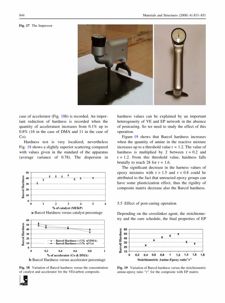
The impressor (Fig. 17) is intended for handheld
testing of hardness for composite material. As a
general rule, the number of readings increases with
the softness of the materials being tested. The
recommended number of readings for VE/carbon or
EP/carbon composite (reinforced plastics) was equal
to 29.
The hardness was determined 2 weeks after the
composites had been cooled down to room temper-
ature, the time necessary for the state of cure to reach
90%.
The analysis of Fig. 18 allows us to conclude that
the errors made on the percentage of catalyst tend to
increase the rigidity of the composite (Fig. 18a),
Hardness value ranging from 30 to 43 are obtained
when the percentage of MEKP reaches 1.5%. The
hardness remains constant when the quantity of
catalyst is up 1.5%. Hardness values decreases from
50 to 35 when the quantity of accelerator increases in
the reactive mixture. Indeed, an inverse trend for the
500
1000
1500
2000
2500
3000
Stoichiometric amine/epoxy ratio "r"
a- Failure stress versus stoichiometric ratio "r"
2210032100421005210062100721008210092100
Stoichiometric amine/epoxy ratio "r"
b- Young modulus versus stoichiometric ratio "r"
0 0,4 0,8 1,2 1,6
0 0,4 0,8 1,2 1,6You
ng m
odul
us (
MP
a)F
ailu
re s
tren
gth
(da
N)
Fig. 16 Mechanical properties as a function of stoichiometric
amine-epoxy ratio ‘‘r’’ for the composite with EP matrix
Materials and Structures (2008) 41:831–851 843
case of accelerator (Fig. 18b) is recorded. An impor-
tant reduction of hardness is recorded when the
quantity of acceleratuor increases from 0.1% up to
0.8% (16 in the case of DMA and 11 in the case of
Co).
Hardness test is very localized, nevertheless
Fig. 18 shows a slightly superior scattering compared
with values given in the standard of the apparatus
(average variance of 0.78). The dispersion in
hardness values can be explained by an important
heterogeneity of VE and EP network in the absence
of postcuring. So we need to study the effect of this
operation.
Figure 19 shows that Barcol hardness increases
when the quantity of amine in the reactive mixture
increases up to a threshold value r = 1.2. The value of
hardness is multiplied by 2 between r = 0.2 and
r = 1.2. From this threshold value, hardness falls
brutally to reach 28 for r = 1.6.
The significant decrease in the harness values of
epoxy mixtures with r > 1.5 and r < 0.8 could be
attributed to the fact that unreacted epoxy groups can
have some plasticization effect, thus the rigidity of
composite matrix decrease also the Barcol hardness.
5.5 Effect of post-curing operation
Depending on the crosslinker agent, the stoichiome-
try and the cure schedule, the final properties of EP
Fig. 17 The Impressor
0
10
20
30
40
50
6
% of catalyst (MEKP)
Bar
col H
ardn
ess
a-Barcol Hardness versus catalyst percentage
0
10
20
30
40
50
60
0 0,2 0,4 0,6 0,8 1
% of accelerator (Co & DMA)
Bar
col H
ardn
ess
Barcol Hardness = f (% of DMA)Barcol Hardness = f (% of Co)
b-Barcol Hardness versus accelerator percentage
0 1 2 3 4 5
Fig. 18 Variation of Barcol hardness versus the concentration
of catalyst and accelerator for the VE/carbon composite.
10
20
3040
50
60
Stoichiometric Amine-Epoxy ratio"r"
0 0,2 0,4 0,6 0,8 1 1,2 1,4 1,6 1,8
Bar
coll
Har
dnes
s
Fig. 19 Variation of Barcol hardness versus the stoichiometric
amine-epoxy ratio ‘‘r’’ for the composite with EP matrix
844 Materials and Structures (2008) 41:831–851

and VE network are different. When the curing
process occurs at room temperature, it is slow and the
resin (the matrix) does not go to complete reaction,
and Tg is no more than 50–60�C. Therefore the
obtained networks present a high ability to carbonate
and to absorb water. For these reasons, epoxies, as
well as vinyl esters, need to be postcured to achieve a
high degree of crosslinking.
The postcuring of VE/carbon sample is realized at
100�C for 3 h and 1 h at 150�C. The EP/specimen is
postcured at 100�C for 4 h.
The effect of post-cure is shown in Fig. 20. For the
VE/carbon sample cured at room temperature, two Tg
appear. In contrary, the sample cured at room
temperature and postcured exhibit one glass transition
region and a reduction of the glass transition zone.
The room temperature cured material was only partly
cured, having vitrified during the curing process. As
the temperature is raised further, the thermal energy
provides sufficient molecular mobility to restart the
curing process, causing a shift in the transition region
and allowing a restructuration of the network.
Thereafter Tg increases and reaches a value between
Tg1�onset and Tg2�onset (&123�C). Morchat et al. [37]
share the same reasoning; they showed that post-
curing directly influences the amount of residual
styrene and the density of reticulation, thus it
improves the mechanical properties of material. In
absence of post-cure, Zang et al. [38] and Lietard
et al. [39] also confirm that the VE resin has two
distinct glass transition temperatures corresponding
to two different phases.
In the case of EP/carbon composite, it is evident
that the post-curing (Fig. 21b) of the material above
its Tg allows for additional crosslinking due to
thermally activated diffusional mechanisms. The
result is an increase in stiffness and a decrease in
viscous losses due to decreased chain mobility caused
by additional crosslinking in the post-cured specimen.
Through additional curing via postcuring, Tg
increased to approximately 78�C. This was in agree-
ment with values found in the literature.
a-VE/carbon before post-cure
a-VE/carbon after post-cure
Tg 123 °C
Tg1 51° C
Temperature (°C)
Torque (mN.m) Relaxation (mN.m)
Tg2 141° C
Temperature (°C)
Torque (mN.m) Relaxation (mN.m)
Fig. 20 Influence of the post-cure operation on the VE/carbon
composite
a-EP/carbon before post-cure
Tg 54°C
Temperature (°C)
Torque (mN.m) Relaxation (mN.m)
Tg 78.1 °C
Temperature (°C)
Torque (mN.m) Relaxation (mN.m)
≈
≈
Fig. 21 Influence of the post-cure operation on the EP/carbon
composite
Materials and Structures (2008) 41:831–851 845
5.6 Influence of the temperature of cure (Tcure) on
Tg and on the adhesive properties of
composites
In this paragraph, we present the effect of the cure
temperature Tcure for different implementation con-
ditions. The main objective is to determine the
influence of civil engineering environment on the
initial properties, the strength and the durability of
composite joints.
Generally, the implementation of composite mate-
rial on a building site requires in situ hardening of
thermosets resins. The polymerization reaction (hard-
ening or cure) is extremely sensitive to temperature
and relative humidity at the time of implementation
and at the time of curing. For this reason, we studied
the variation of Tg as a function of cure temperature
as well as concrete slabs temperature.
5.6.1 Influence of environment temperature
During their cure reaction, VE and EP resins undergo
an exotherm and so it is instructive to study how the
cure temperature (Tcure) determines the degree of
cure and the resulting Tg.
Five values of cure temperature (Tcure) are con-
sidered: 10, 20, 30, 40 and 60�C
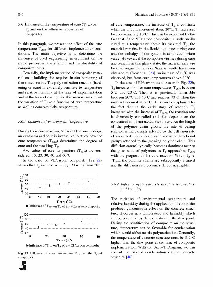
In the case of VE/carbon composite, Fig. 22a
shows that Tg increase with Tcure. Starting from 20�C
of cure temperature, the increase of Tg is constant:
when the Tcure is increased about 20�C, Tg increases
by approximately 10�C. This can be explained by the
fact that if the VE/carbon composite is isothermally
cured at a temperature above its maximal Tg, the
material remains in the liquid-like state during cure
and the enthalpy of the system is at its equilibrium
value. However, if the composite vitrifies during cure
and remains in this glassy state, the material may age
by slow segmental motion. Similar results have been
obtained by Cook et al. [23], an increase of 11�C was
observed, but from cure temperatures above 80�C.
In the case of EP/carbon, as also seen in Fig. 22b,
Tg increases first for cure temperatures Tcure between
5�C and 20�C. Then it is practically invariable
between 20�C and 40�C and reaches 70�C when the
material is cured at 60�C. This can be explained by
the fact that in the early stage of reaction, Tg
increases with the increase of Tcure, the reaction rate
is chemically controlled and thus depends on the
concentration of unreacted monomers. As the length
of the polymer chain grows, the rate of curing
reaction is increasingly affected by the diffusion rate
of unreacted monomers and/or unreacted functional
groups attached to the growing polymer chain. This
diffusion control typically becomes dominant near to
the glass state of polymers as Tg approaches Tcure
with the progress of the cure reaction. When Tg &Tcure, the polymer chains are subsequently vitrified
and the diffusion rate becomes all but negligible.
5.6.2 Influence of the concrete structure temperature
and humidity
The variation of environmental temperature and
relative humidity during the application of composite
produces condensation effect on the concrete struc-
ture. It occurs at a temperature and humidity which
can be predicted by the evaluation of the dew point.
During the stratification of composite on the struc-
ture, temperature can be favorable for condensation
which would affect matrix polymerization. Generally,
the temperature of concrete structure must be 3–5�C
higher than the dew point at the time of composite
implementation. With the Skew-T Diagram, we can
control the risk of condensation on the concrete
structure [40].
20
40
60
80
100
T cure (°°C)
T cure (°°C)
Tg
-ons
et (°°
C)
Tg
-ons
et (°°
C)
cure on Tg of the VE/carbon composite a-Influence of T
20
40
60
80
100
b-Influence of Tcure on Tg of the EP/carbon composite
0 10 20 30 40 50 60 70
0 20 40 60 80
Fig. 22 Influence of cure temperature Tcure on the Tg of
composites
846 Materials and Structures (2008) 41:831–851

It is necessary to know three parameters to
determine the temperature of the dew point: the
ambient temperature and relative humidity as well as
the temperature of the concrete support.
The concrete is a heavy and bulky material, thus it
has a good thermal capacity, and i.e. it is able to store
and to restore important quantities of heat and/or of
freshness. However, this capacity is not dissociable of
certain slowness: more the inertia is important; the
material takes a long time to be heated or cooled.
This thermal inertia plays an important role at the
time of the Hand Lay-up of composite and its bounds
on the concrete structure. Indeed, the polymerization
reaction is exothermic; therefore the temperature of
composite material at the time of the cure is
controlled by: the environmental temperature, the
temperature of the concrete structure as well as the
temperature released by the polymerization reaction.
Concrete slabs (100 · 100 · 5 cm) were tested at
three different temperatures Ts: 5, 20 and 40�C. For
the first case, the slab remained 1 month in a
refrigerator regulated at 5�C. In these conditions we
cannot avoid condensation because the temperature is
lower than the dew point. For the second case, the
slab remained at ambient temperature and for the
third case; it remained in an oven at 40�C during
1 month.
Figure 23a shows for the VE/carbon composite
that Tg increases with increasing temperature of
concrete slab. Tg for 40�C is practically double than
for 5�C. The same trend was observed in the case of
EP/carbon composite (Fig. 23b), nevertheless a dif-
ference equal to 32�C in the value of Tg was recorded
between Ts, 20�C and Ts, 40�C.
These variations of Tg modifie the viscoelastic
properties of composites and influence their adhesive
behavior.
5.6.3 Influence of environmental conditions on
adhesive properties of VE/carbon and EP/
carbon composites
The adhesion properties and durability depends on
many and opposites parameters, such as mechanical,
thermodynamical adhesion. Therefore, it is necessary
to study the effect of the nature of the adhesive (VE
or EP matrix), and the properties of the adherent: the
roughness, superficial characteristics, the environ-
mental conditions, etc.
In this paragraph, the influence of the temperature
of the concrete support on the adhesive capability of
the composite is monitored.
The adhesive behavior was studied by the pull-off
method.
This approach has been developed to measure the
in-situ tensile strength of concrete by applying a
direct tensile force. The method may also be useful
for measuring the bonding capability of the surface to
be repaired or reinforced. Procedures are covered by
BS 1881: Parts 207. The loading equipment is a
dynamometer having 10 KN capacity. A rod screwed
axially into a 50 mm diameter disk allows to apply a
tensile force normally to the composite surface.
Before the gluing of the disk (Fig. 24) on the
composite surface, a circular surface, having the
same diameter as the disk, is cut out from this latter
with a diamond coring equipment. The disk is glued
to this surface with an epoxy resin. Then the force
necessary to pull-off the composite or the concrete
beneath the composite is measured.
It is obvious that the temperature of the concrete
support influences considerably the Tg of the com-
posite independently from the type of the used
matrix. At 5�C, Tg is too low and the interface
properties are very poor particularly in the case of the
composite with EP matrix (Fig. 23). The polymeri-
zation reaction did not take place and the rupture is
30405060708090
Temperature of slab "Ts" (°°C)a-Influence of Ts on Tg of the VE/carbon composite
1030507090
110
Temperature of slab "Ts" (°°C)
Tg-
onse
t (°°
C)
Tg-
onse
t (°°
C)
b-Influence of the Ts on Tg of the EP/carbon composite
0 10 20 30 40 50
0 10 20 30 40 50
Fig. 23 Influence of the temperature of slab Ts on the Tg of
composites
Materials and Structures (2008) 41:831–851 847
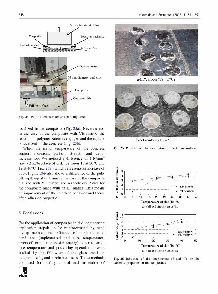
localized in the composite (Fig. 25a). Nevertheless,
in the case of the composite with VE matrix, the
reaction of polymerization is engaged and the rupture
is localized in the concrete (Fig. 25b).
When the initial temperature of the concrete
support increases, pull-off strength and depth
increase too. We noticed a difference of 1 N/mm2
(i.e &2 KN/surface of disk) between Ts at 20�C and
Ts at 40�C (Fig. 26a), which represents an increase of
35%. Figure 26b also shows a difference of the pull-
off depth equal to 4 mm in the case of the composite
realized with VE matrix and respectively 2 mm for
the composite made with an EP matrix. This means
an improvement of the interface behavior and there-
after adhesion properties.
6 Conclusions
For the application of composites in civil engineering
application (repair and/or reinforcement) by hand
lay-up method, the influence of implementation
conditions (implemented and cure temperatures,
errors of formulation (stoichiometry), concrete struc-
ture temperature and postcuring operation...) were
studied by the follow-up of the glass transition
temperature Tg and mechanical tests. These methods
are used for quality control and inspection of
Concrete support
Epoxy resin adhesiveComposite
50 mm diameter steel disk
Failure surface
Concrete slab
Composite
50 mm diameter steel disk
Dynamometer
Failure surface
Fig. 24 Pull-off test: surface and partially cored
a-EP/carbon (Ts = 5°C)
b-VE/carbon (Ts = 5°C)
Fig. 25 Pull-off test: the localization of the failure surface
0
1
2
3
4
5
0 10 15 20 25 30 35 40 45
Temperature of slab Ts (°C)
Pul
l-of
f st
ess
(N/m
m2)
EP/ carbon
VE/ carbon
a- Pull-off stress versus Ts
02468
1012
0 10 20 30 40 50
Temperature of slab Ts (°C)
Pul
l-of
f de
pth
(mm
)
EP/ carbonVE/ carbon
a- Pull-off depth versus Ts
5
Fig. 26 Influence of the temperature of slab Ts on the
adhesive properties of the composites
848 Materials and Structures (2008) 41:831–851

composites properties. These following conclusions
are retained:
(1) The composites with Vinyl ester matrix imple-
mented at ambient temperature have two glass
transition temperatures. This implies the exis-
tence of two different phases: a postcuring
operation is recommended to stabilize and to
ensure a whole reticulation of the obtained
network.
(2) Implementation of composites at building site is
a difficult operation. Errors in the reactive
system formulation can be made during the
hand lay-up procedure. The material properties,
including the Tg, modulus and failure stress, of
vinyl ester/carbon and epoxy/carbon systems
used in external strengthening have been mea-
sured. The results of this study show that the
materials properties are significantly affected
even by relatively small variations in stoichi-
ometry. A reduction of 20% of Tg due to errors
in reactive system formulation, corresponds to
the same reduction in tensile modulus.
For the reliability of implemented composites,
the AFGC (French association of civil Engi-
neering) [9] recommended that Tg should not go
below 45�C; and operating temperature ‘‘T’’
should remain in the range of 20�C < T < Tg
10�C. The newly approved ASME post-Con-
struction Repair Standard, which governs the
use of composites in construction, requires that
the Tg of the repair material be at least 20�C
above the temperature of the repair [41]. The
MIL-HDBK-17 utilizes the Tg reduced by some
temperature margin Tg � DT, for composites
with epoxy resin (DT = 20�C). In all cases, the
maximum use temperature for a polymeric
material used in a structural application is often
set a certain number of degrees below Tg. That’s
why errors made in system formulation should
be controlled.
From the point of view of the durability, the
formulation errors result not only in loss of
mechanical properties, but also in an increase of
the macromolecular network sensitivity to water
absorption. For these reasons, the safety factors
af and aad (Eqs. (4) and (5)) suggested by the
AFGC (French Association of Civil Engineer-
ing) [2] and which takes into account the
durability and reliability of composite should
be modified.
ff ;d ¼af ffcf ;u
ð4Þ
sad;d ¼ aad �sad;e
cad
ð5Þ
ff,d: tensile strength of the composite
sad,d: shear stress in the interface composite-
concrete
a (af,aad): reduction factors to take account of
the long-term effect (safety and reliability
factors).(3) The post-curing improves physico-chemical
properties of polymeric matrix which increases
the performances of composite and interface
properties, hence the lifetime of the rehabili-
tated or strengthened civil engineering structure.
In practice, this operation is difficult to achieve.
Nevertheless, this could be done by heating the
structure to a higher temperature or by applying
an electrical heating around the structure for a
period of time.
(4) Other parameters are tested e.g. the implemen-
tation temperature and the temperature of the
concrete structure. The characterization by
Kinemat apparatus showed that Tg and adhesion
properties of composite increase proportionally
with these two parameters.
The use of ambient cure based process for the
rehabilitation and/or strengthening concrete
structure through hand lay-up based placement
of external polymeric matrix composite can be
an extremely flexible and efficient method.
However, the sensibility of overall initial prop-
erties of theses materials to implementation
conditions, rise the question of the estimation of
long-term durability and service life.
References
1. Perchat J (1998) Beton arme – Regles BAEL -13. Pathol-
ogie et reparation des ouvrages Sciences et Techniques de
l’ingenieur Traite Construction (C2317):3–5
2. Hamilton III HR, Dolan CW (2000) Durability of FRP
reinforcement for concrete. Prog Struct Eng Mater 2:139–
145
Materials and Structures (2008) 41:831–851 849

3. Emmons PH, Vaysburd AM, Thomas J (2000) Strength-
ening concrete structures, Part I. Concrete Int 20:57–58
4. Hamelin P (2002) Renforcement des ouvrages d’art par
materiaux composites. Sciences et Techniques de l’ing-
enieur Traite Construction (AM5615):4–6
5. Chang TD, Carr SH, Bittain JO (1982) Studies of epoxy
resin systems, part B: effect of crosslinking on the
physical properties of an epoxy resin. Polym Eng Sci
22:1213–1220
6. Jordan C, Galy J, Pascault JP (1992) Measurement of the
extent of reaction of an epoxy-cycloaliphatic amine sy-
steme and influence oft he extent of reaction on its
dynamic and static mechanical properties. J Appl Polym
Sci 46:859–871
7. Diamant Y, Marom G, Brouthman LJ (1981) the effect of
network structure on moisture absorption of epoxy resins
epoxy. J Appl Polym Sci 26:3015–3025
8. Projet COMAC (2005) Etude de faisabilite sur les mat-
eriaux composites en Genie Civil, pilote par l’IREX, mai
2005
9. Hamelin P et al (2003) Reparation et renforcement des
structures en beton au moyen des materiaux composites
‘‘Document scientifique et technique’’ Association
francaise de genie civil (AFGC) BAGNEAUX 2003,
pp 8–10
10. Potter GW (1970) Epoxide resins. Iliffe Books, London
11. May CA (1988) (ed) Epoxy resins chemistry and tech-
nology, 2nd edn., Marcel Dekker Inc., New York, pp 4–
25
12. Ellis B (ed) (1993) Chemistry and technology of epoxy
resins, Blackie Academic & Professional (Chapman &
Hall), Glasgow, pp 7–38
13. Chang S-S (1992) Effect of curing history on ultimate glass
transition temperature and network structure of crosslink-
ing polymers. Polymer 33:4667–4888
14. Trotignon JP, Verdu J, Dobraczynski A, Piperaud M
(1996) in Matieres plastiques: structures-proprietes, Mise
en Œuvre, Normalisation, Ed. (Nathan, Paris), pp 10–22
15. Boey FYC, Song XL, Rath SK, Yue CY (2002) Cure
reaction for modified Diallylbisphenol A/ Diaminodi-
phenylsulfone/ Bismaleimide. J Appl Polym Sci 85:227–
235
16. Och M, Lesako H, Shimbo M (1985) Mechanical relaxa-
tion mechanism of epoxide resins cured with diamines.
Polymer 26:457–461
17. Pangrle S, Wu CS, Geil PH (1989) Low temperature
relaxation of DGEBA epoxy resins: A thermally stimulated
discharge current (TSDC) study. Polym Compos 10:173–
183
18. Gerard JF, Glay J, Pascault JP, Cukierman S, Halary JL
(1991) Viscoelastic response of model epoxy networks
in the glass transition region. Polym Eng Sci 31:615–
621
19. Herzog B, Gardner DJ, Lopez-Anido R, Goodell B (2005)
Glass-transition temperature based on dynamic mechanical
thermal analysis techniques as an indicator of the adhesive
performance of Vinyl ester resin. J Appl Polym Sci
97:2221–2229
20. Pascault JP, Sautereau H, Verdu J, William R (2002)
Thermosetting polymers. Marcel Dekker, Inc., New York,
pp 22–23
21. Goertzen WK, Kessler MR (2006) Dynamic mechanical
analysis of carbon/epoxy composites for structural pipeline
repair. Composites: Part B 38:01–09
22. Legrand M, Bellenger V (2001) Estimation of the cross-
linking ratio and glass transition temperature during curing
of amine-cross-linked epoxies. Comp Sci Technol
61:1485–1489
23. Cook WD, Simon GP, Burchill PJ, Lau M, Fitch TJ (1997)
Curing kinetics and thermal properties of Vinyl ester res-
ins. J Appl Polym Sci, 64:769–781
24. Mortaigne B, Vivien B (1996) Influence of the styrene-
maleate ratio on the structure-property relationships of
unsaturated polyester networks. Polym Adv Technol
7(10):813–821
25. Jelcic Z, Hedvig P, Ranogajec F, Dvornik I (1985) Study of
crosslinking of unsaturated polyester resins by relaxation
methods. Angewandte Makromolekulare Chemie
130(1):21–40
26. Huang YJ, Chu CJ, Dong JP (2000) Effects of chemical
structure of polyurethane-based low-profile additives on
the miscibility, curing behavior, volume shrinkage, glass
transition temperatures, and mechanical properties for
styrene/unsaturated polyester/low-profile additive ternary
systems. I: miscibility, curing behavior, and volume
shrinkage. J Appl Polym Sci 78(3):543–557
27. Canard P (1993) Resines polyesters insatures, Techniques
de l’Ingenieur, traite Plastiques et Composites. (AM 3450)
28. Grentzer TH, Rust DA, Lo SK, Spencer CJ, Hackworth JW
(1991) 46th SPI reinforced plastics/Composites Confer-
ence, 1991, paper IB
29. Li L, Lee J (2001) Effect of inhibitors and retarders on low
temperature free radical crosslinking polymerization
between styrene and vinyl ester resin. Polym Eng Sci 4:53–
66
30. Yildiz U, Hazer B (2000) Dispersion redox copolymeri-
zation of methyl methacrylate with macromonomeric
azoinitiator as a macrocrosslinker. Polymer 41:539–544
31. Pryor WA, Hendrickson H (1983) The mechanism of
radical production from the reaction of N,N-dimethylani-
line with benzoyl peroxide. Tetrahedron Lett 24(14):1459–
1462
32. Kootsookos A, Burchill PJ (2004) The effect of the degree
of cure on the corrosion resistance of vinyl ester/glass fibre
composites. Composites: Part A 35:501–508
33. Liao K, Shultheisz CR, Hunston DL, Brinson LC (1998)
Long-term durability of fiber-reinforced polymer-matrix
composite materials for infrastructure applications: a
review. J Adv Mater 3:03–40
34. Case SL, O’Brien EM, Ward TC (2000) Micro-heteroge-
neity of urethane Vinyl ester resin networks. Polymer
41:6843–6849
35. DiFrancia C, Ward TC, Claus RO (1996) The single-fibre
pull-out test. 2: quantitative evaluations of an uncatalysed
TGDDM/DDS epoxy cure study. Composites: Part A
27:613–624
36. Norwood H (1984) GRP in contact with acidic environ-
ments—a case study. Comp Struct 2(1):1–22
37. Morchat RM (1990) Effect of post cure and antimony tri-
oxide addition on the glass transition temperature of
polyester and Vinyl ester systems. DREA-TM-90/208,
Technical Memo 1990, NP26
850 Materials and Structures (2008) 41:831–851

38. Zhang J, Richardson MOW (2000) Micro-heterogeneity of
urethane Vinyl ester resin networks. Polymer 41:6843–
6849
39. Lietard V., Krawczak P, Pabiot J (2000) Influence de la
post-cuisson sur le comportement a long terme en fissu-
ration sous tension dans l’eau de composites verre/Vinyl
ester. Eur Polym J 36(3):555–570
40. SIKA (1998) – Renforcement par le procede Sika Carbo-
dur. Cahier des clauses techniques, CCT 37
41. ASME PCC-2 (2005) Repair and testing standard, Section
4, nonmetallic repair, 2005
Materials and Structures (2008) 41:831–851 851