
Communication module - CES
37
CESeasy Communication module Assembly and Operating Manual English Version VB BRO2280-2
-
Upload
khangminh22 -
Category
Documents
-
view
0 -
download
0
Transcript of Communication module - CES

CESeasyCommunication module
Assembly and Operating Manual
English
Version VB
BRO2280-2

Contents
1 About this manual 4
1.1 Design characteristics 4
1.2 Target group of this manual 4
2 Manufacturer’s information 5
2.1 Manufacturer and service 5
2.2 Manufacturer’s warranty 5
3 For your safety 6
3.1 EU Declaration of conformity 6
3.2 Intended use 6
3.3 Basic safety instructions 6
3.4 Notes on dealing with batteries 7
4 CESeasy communication module 9
4.1 About communication modules 9
4.2 Scope of application 9
5 Scope of delivery 10
6 Assembly 11
7 Connections 14
7.1 How to connect the power supply unit 14
7.2 How to connect the inputs and outputs 15
8 Batteries 21
8.1 Required batteries 21
8.2 Battery consumption 21
8.3 Battery warnings 21
8.4 Check the battery status 22
8.5 How to insert and change batteries 23
8.6 Battery disposal 23
9 How to couple a lock 24
Page 2 of 37 CESeasy communication module

9.1 Coupling 24
9.2 Decoupling 26
9.3 Coupling to a new lock 26
10 Administration 27
10.1 Firmware 27
10.2 Reset of the communication module 27
11 Operation 29
11.1 Privacy mode 29
11.2 Night locking mode (only motor cylinders) 29
12 Technical data 31
12.1 Equipment features 31
12.2 Dimensions 32
13 Disposal 33
13.1 Notes on disposal 33
14 Index 35
CESeasy communication module Page 3 of 37

1 About this manualThese assembly and operating instructions, hereinafter referred to as the “manual”, will help you
with the assembly and in a proper, safe, and beneficial use of the CESeasy products acquired.
Anyone who assembles, administers, maintains, or disposes of CESeasy products, must have read
and understood the complete contents of this manual.
If you do not understand the functions of the CESeasy products, please contact your CES partner
for further information.
Always use the latest version of this manual. The version number of this manual is shown
on the cover page. You can get the latest version free of charge fromwww.ces.eu
1.1 Design characteristics
Refers to other documents.
Marks additional information and tips.
Marks warnings in step-by-step instructions and specially important information.
1.2 Target group of this manualThis manual is intended for
l Trained service and assembly personnel
l Maintenance personnel
l Operators
The necessary expertise regarding the intended use of the product is presumed for the use of this
manual.
The necessary product training is conducted by your CES partner. If this has not yet taken place,
please contact your CES partner to get the product training.
Page 4 of 37 CESeasy communication module
1 About this manual

2 Manufacturer’s information
2.1 Manufacturer and serviceC.Ed. Schulte GmbH
Zylinderschlossfabrik
Friedrichstr. 243
42551 Velbert
Tel: +49 (0) 2051-204-0
Fax: +49 (0) 2051-204-229
www.ces.eu
2.2 Manufacturer’s warrantyThe following damage is not covered by the manufacturer’s warranty:
l Damage to the exterior mechanical parts as well as subsequent damage arising from nor-
mal wear and tear.
l Damage caused by external events or influences
l Damage caused by deficient assembly
l Damage caused by deficient maintenance
l Damage caused by false operation
l Damage caused by overvoltage
l Damage caused by fire, water or smoke
All technical data and features are subject to change without prior notice. All information and
data contained in this document is subject to change without prior notice. Without express
written approval from C.Ed. Schulte GmbH Zylinderschlossfabrik, no part of this document may be
copied or transmitted for any purposes whatsoever.
© 2018 C.Ed. Schulte GmbH Zylinderschlossfabrik, Velbert/Germany
VB
BRO2280-2
CESeasy communication module Page 5 of 37
2 Manufacturer’s information

3 For your safety
3.1 EU Declaration of conformityYou can find the EU Declaration of conformity on the Internet atwww.ces.eu.
3.2 Intended useCESeasy products are intended to control access at doors. They are exclusively intended for this
purpose andmay only be used for this. They may never be altered in any way without written
permission from C.Ed. Schulte GmbH Zylinderschlossfabrik.
All other uses are regarded as improper use andmay lead to material damage or even personal
injuries. C.Ed. Schulte GmbH Zylinderschlossfabrik assumes no liability for damage caused by
improper use.
3.3 Basic safety instructionsCESeasy products have been built with state-of-the-art technology and established safety
regulations. Nevertheless, their use may constitute function-related hazards for the user or third
parties andmay impair the handle set and other material assets.
Please observe all warnings and notices in this manual while assembling, configuring and using
CESeasy products.
3.3.1 Life-threatening danger
l CESeasy products have not been developed, tested and/or approved for access in
life-threatening situations. Do not use CESeasy products on fire doors or panic doors.
l CESeasy products must be suitable for your door system. If you are in doubt, please contact
the manufacturer of the door or lock to check suitability.
l All components which are required for a complete installation at your door must be CE-
compliant. Please check before installation whether all components used are CE-compliant.
3.3.2 Danger of personal injury
Danger of explosion
l Live parts may cause explosion. Do not use parts in potentially explosive areas.
Page 6 of 37 CESeasy communication module
3 For your safety

3.3.3 Danger of damage to material assets
Transportation
l Do not drop the device on the floor, on hard surfaces or objects.
Assembly
l The device contains highly sensitive electronic components, which can be damaged or
destroyed through electrostatic charges. Therefore, do not assemble the handle set in
areas affected by electrostatic charge.
l For assembly and dismantling, use the tools indicated in the "Assembly" section only.
l Only use a dry or protected or indoors place for device installation.
Operation
l Protect the electronic components against water and other fluids.
Maintenance
l Always have repairs performed by qualified personnel.
l Use only the accessories and spare parts recommended by CES.
Danger through climatic influences
l Do not use the device in corrosive atmosphere (chlorine, ammonia, lime water)
l Do not use the device in areas with high dust formation.
l Do not use the device near heat sources.
Please observe the maximum permissible temperatures and the information on air humidity in
the section “Technical Data".
3.4 Notes on dealing with batteries
l Always insert new batteries only. Never use old and new batteries together.
l Before inserting the batteries, check whether the contacts in the device and on the bat-
teries are clean. Otherwise, clean them. Do not touch the contacts after the cleaning pro-
cess.
l When inserting the batteries, ensure that the polarity is correct (+/-).
l Never try to recharge the batteries. There is a risk of explosion!
l Do not short-circuit the batteries.
l Store batteries in a cool and dry place. Direct heat may damage the batteries. Therefore, do
not expose battery-operated devices to any strong heat source, and do not throw the bat-
teries into fire.
CESeasy communication module Page 7 of 37
3 For your safety

l If you do not use devices for a longer time, take out the batteries.
l Remove leaking batteries immediately from the device. Clean the contacts before inserting
new batteries. There is danger of injury from battery acid.
l Remove the empty batteries from the device.
l Please take note of the information on battery disposal (see "Disposal" on page 33).
Page 8 of 37 CESeasy communication module
3 For your safety

4 CESeasy communication module
4.1 About communication modulesA CESeasy communication module allows you to control CESeasy motor cylinders and CESeasy
door controllers with devices from other manufacturers.
A communication module can control both a motor cylinder and a door controller.
Therefore, the term “lock” is used as an umbrella term. This can refer to either a motor
cylinder or a door controller.
The communication module has several inputs through which orders are forwarded to the lock.
There are additional outputs which reflect the lock status. The communication module and the
lock communicate wirelessly.
4.2 Scope of applicationDue to the available inputs and outputs and the functions which are linked to them, the
communication module can be used in a very versatile manner. The communication module is to
be used together with a CESeasy motor cylinder or a CESeasy door controller.
CESeasy products have not been developed, tested and/or approved for access to escape
and emergency routes. Do not use CESeasy products on fire doors or panic doors.
The device must be installed in a dry and protected place in the building.
CESeasy communication module Page 9 of 37
4 CESeasy communication module

5 Scope of delivery
1 1 Communication module
2 2 Batteries
3 1 Power supply unit
Page 10 of 37 CESeasy communication module
5 Scope of delivery

6 Assembly
Distance between the communication module and the lock
A communication module can control both a motor cylinder and a door controller.
Therefore, the term “lock” is used as an umbrella term. This can refer to either a motor
cylinder or a door controller.
The maximum distance for the wireless communication between the communication module
and the lock linked to it strongly depends on the environment, the building materials used, and
other items found in the proximity. These factors can absorb or reflect the radio signal, which is
why it is not possible to make a general statement about the maximum distance. In most cases, a
distance of up to 10m within a building will be possible. You have to find out the maximum
distance for your situation.
Notes on the installation
l The device has to be fixed to a level surface.
l The device must be installed in a dry and protected place in the building.
Tools required
Tool Required for
PH1 Phillips screwdriver Open the cover
PZ2 Phillips screwdriver Wall assembly
0.5 mm x 3 mm slot-head screwdriver How to connect the ports
CESeasy communication module Page 11 of 37
6 Assembly
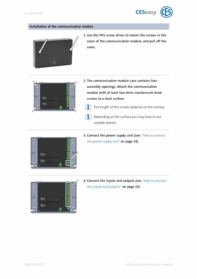
Installation of the communication module
1. Use the PH1 screw driver to loosen the screws in the
cover of the communication module, and pull off the
cover.
2. The communication module case contains four
assembly openings. Attach the communication
module with at least two 4mm countersunk head
screws to a level surface.
The length of the screws depends on the surface.
Depending on the surface you may have to use
suitable dowels.
3. Connect the power supply unit (see "How to connect
the power supply unit" on page 14).
4. Connect the inputs and outputs (see "How to connect
the inputs and outputs" on page 15).
Page 12 of 37 CESeasy communication module
6 Assembly

5. Insert the batteries (for details about batteries, please
refer to section "Batteries" on page 21.)
Please ensure that the batteries are inserted
according to the labelling in the battery
compartment which indicates the correct polarity.
6. Link the communication module to your lock (see
"How to couple a lock" on page 24).
7. Check if the communication module is working
correctly.
8. Screw the cover back onto the case.
The communication module is now completely mounted
and ready for use.
CESeasy communication module Page 13 of 37
6 Assembly

7 Connections
7.1 How to connect the power supply unit
The port intended for connection of the power supply
unit is located at the screw terminal marked "12VCD"
and "GND".
Make sure to connect the power supply unit correctly
to the positive and negative terminal.
Run the connecting cables through the recess of the
case towards the outside.
Before connecting the power supply unit to the power
source, connect the inputs and outputs first.
Page 14 of 37 CESeasy communication module
7 Connections

7.2 How to connect the inputs and outputs
Please always note the instructions of third-party manufacturers when you connect their
devices.
The communication module is equippedwith 4 inputs and 6 outputs
which can be connected bymeans of the screw terminals on the
right side of the circuit board.
7.2.1 Inputs
The communication module is equippedwith 4 inputs labelled IN1 to
IN4.
Functions of the inputs
Input Function Reaction upon
activation
Reaction upon
deactivation
Remarks
IN1 Open The order “Open” is sent to
the coupled lock
No reaction If IN1 and IN2 are bridged so that both can
be switched simultaneously, they react as
follows:
- If both inputs are activated, the order
“Open” is sent to the coupled lock
- If both inputs are deactivated, the order
“Close” is sent to the coupled lock
IN2 Close The order “Close” is sent to
the coupled lock
No reaction
IN3 Privacy
mode
The order “Privacy mode
ON” is sent to the coupled
lock
The order “Privacy mode
OFF” is sent to the coupled
lock
Please take note of the information on "Pri-
vacy mode" on page 29.
IN4 Night
locking
mode
The order “Night locking
mode ON” is sent to the
coupled lock
The order “Night locking
mode OFF” is sent to the
coupled lock
The night locking mode is only relevant for
motor cylinders.
Please take note of the information on
"Night locking mode (only motor
cylinders)" on page 29.
CESeasy communication module Page 15 of 37
7 Connections
Information on the activation and deactivation of the inputs
The inputs are digital inputs with a high input resistance. The inputs are low-active and are fitted
with an internal pull-up resistor. Inputs are connected between INx and GND bymeans of a
potential-free contact.
Example: The moment input 1 is activated, the order “Open” is sent to the coupled lock. If input
1 afterwards still remains activated and e.g. a “Close” order is sent by the CESeasy app, the lock
will carry out the “Close” order but will not react to input 1 anymore although it is still active.
Only if input 1 is deactivated first and then activated again, another “open” order will be sent.
The input is either active or inactive if the status changes and the input voltage is between the
following values:
Status Uin (min) Uin (max) Contact between INx and GND
Active 0 VDC 0.5 VDC closed
Inactive 2.5 VDC 12 VDC open
Page 16 of 37 CESeasy communication module
7 Connections

Examples which show how the inputs can be connected
Example 1 - Potential-free contact
A: Potential-free contact
B: Device with an output
C: Communication module
Between INx and GND a potential-free contact is connected (e.g.
a switch or a relay). As soon as the contact closes, INx is con-
sidered to be ‘active’.
Example 2 - Open-collector output
A: Open-collector output
B: Device with an output
C: Communication module
A device with an open-collector output is connected to INx of the
communication module. As soon as the output is activated, INx is
considered to be ‘active’.
CESeasy communication module Page 17 of 37
7 Connections

7.2.2 Outputs
The communication module is equippedwith 6 outputs
labelled OUT1 to OUT6.
Functions of the outputs
Output Function Activated by Deactivated by Remarks
OUT1 Batteries
nearly empty
Is activated if the
batteries of the
communication
module of the
coupled lock are
nearly empty.
Is deactivated if the battery voltage
of the communication module is
high again and the “Batteries nearly
empty” message of the coupled lock
has been reset.
OUT2 Communications
error
Is activated if it is
not possible to
establish wireless
communication
with the coupled
lock.
Is deactivated as soon as wireless
communication with the coupled
lock has been re-established.
The output status is updated
by controlling the
communication with the
coupled lock:
- Whenever orders are
exchanged between the
communication module and
the coupled lock.
- The connection is checked by
means of a polling procedure
once per minute.
OUT3 Privacy mode
active
Is activated if the
privacy mode is
activated.
Is deactivated if the privacy mode is
deactivated.
Please take note of the inform-
ation on "Privacy mode" on
page 29.
OUT4 Night locking
mode
active
Is activated if the
night locking mode
is activated.
Is deactivated if the night locking
mode is deactivated.
The night locking mode is only
relevant for motor cylinders.
Please take note of the
information on "Night locking
mode (only motor cylinders)"
on page 29.
OUT5 Door unlocked Is activated if the
coupled lock
unlocks the door.
Is deactivated when “Open” has
been completed. This depends on
the lock settings (e.g. opening times
The locks have to meet the
following conditions:
- Motor cylinder: latch and
Page 18 of 37 CESeasy communication module
7 Connections

Output Function Activated by Deactivated by Remarks
for the motor cylinder, or the reac-
tion time limit for controlling the
door controller).
deadbolt are drawn in
- Door controller: as long as
the relay is activated (status
“Open”)
OUT6 Door status Is activated if the
door contact of the
coupled lock signals
“Door closed”.
Is deactivated if the door contact of
the coupled lock signals “Door open”.
To use this output, a door con-
tact is required for the lock.
Information on the outputs
The outputs of the communication module are open-collector outputs which can switch max.
150mA. The maximum voltage is 28V.
An open-collector output is not a potential-free contact. The output consists of a transistor
(semiconductor) which depends on the status of the output (conductive or non-conductive). If it is
conductive (output is active), a connection to GND is established. It means that:
1. Either the devices to be connected have to be supplied by means of an external power sup-
ply, and ‘GND’ or ‘-’ of the power supply have to be connected to ‘GND’ of the com-
munication module
2. Or the devices to be connectedmust be equippedwith an input which is low-active and
has a high input resistance.
CESeasy communication module Page 19 of 37
7 Connections

Situation 1: Circuit with an inductive load
A: Communication module
B: Flyback diode
C: Relay
D: External power supply (DC)
A relay is connected to OUTx. The relay is connected to
an external power source.
The fact that a relay is an inductive loadmeans that
the relay coil has to be equippedwith a flyback diode.
When you want to switch inductive loads like
magnets, relays, coils, etc. always use a
flyback diode directly on the load. The device
may be damaged if no flyback diode has been
used, or if it was connected falsely!
Situation 2: Circuit with an input
A: Communication module
B: Device with an input
OUTx is directly connected to the input of another
device. The input has to meet the following conditions:
l Input current max. 150mA
l Voltage, measured between IN and GND, max.
28V
l Internal pull-up resistor, or an external pull-up
resistor can be connected
l The entry is low-active (if not, the device must
be able to invert its status)
Page 20 of 37 CESeasy communication module
7 Connections

8 Batteries
8.1 Required batteriesYou need 2 AA alkaline batteries.
These batteries serve as an emergency power supply in the event of a power outage.
8.2 Battery consumptionIf the power supply unit fails, the communication module can continue to work for some days
with a new set of batteries.
8.3 Battery warningsIf the batteries of the communication module are nearly empty, the communication module
activates output 1 (see "Outputs" on page 18).
Output 1 is also activated if the batteries of the coupled lock are nearly empty.
CESeasy communication module Page 21 of 37
8 Batteries

8.4 Check the battery statusYou can check the battery status of the communication module when the cover is open (e.g.
during installation or maintenance).
To be able to check the battery status, the following prerequisites need to be met:
l The communication module has to be switched on.
l Firmware has to be installed on the communication module (see "Firmware" on page 27).
1. Press the coupling button.
Now the red LED next to the coupling button indicates the
battery status:
It is permanently
illuminated
Batteries are full
It flashes Batteries are nearly empty. Insert new bat-
teries.
It is not illu-
minated
Batteries are empty, or there are no bat-
teries. Insert new batteries.
Page 22 of 37 CESeasy communication module
8 Batteries

8.5 How to insert and change batteries
Tools required
Tool Required for
PH1 Phillips screwdriver Open the cover
How to insert and change batteries
1. Use the PH1 screw driver to loosen the screws in the
cover of the communication module, and pull off the
cover.
2. If necessary, take out the two empty batteries. Insert
the two new batteries.
Please ensure that the batteries are inserted
according to the labelling in the battery
compartment which indicates the correct polarity.
3. Screw the cover back onto the case.
The batteries are now inserted or have been changed.
8.6 Battery disposalSee "Disposal" on page 33.
CESeasy communication module Page 23 of 37
8 Batteries

9 How to couple a lock
9.1 Coupling
A communication module can control both a motor cylinder and a door controller.
Therefore, the term “lock” is used as an umbrella term. This can refer to either a motor
cylinder or a door controller.
To be able to control your lock via the communication module, you have to connect it to the
communication module (= to couple it). Having coupled your lock, the communication module
enables you to send orders to your lock using your third party device. The device transmits the lock
status (e.g. open, closed, or batteries nearly empty) to the communication module, which then
can be displayed by our third party device.
Only one lock (one motor cylinder or door controller) can be coupled to a communication
module at the same time.
Prerequisites for coupling:
l The latest firmware version is installed on your lock.
For details, please refer to the CESeasy manual for motor cylinders.
Or
For details, please refer to the CESeasy door controller manual.
Coupling between communication module and lock
1. To couple a door controller:
Press the coupling button of the door controller for
approx. 1 second.
For details, please refer to the CESeasy door
controller manual.
Now, the door controller periodically emits an acoustic
signal.
Page 24 of 37 CESeasy communication module
9 How to couple a lock

1. To couple a motor cylinder:
Press the coupling button of the motor cylinder for
approx. 1 second.
For details, please refer to the CESeasy manual for
motor cylinders.
Now, the motor cylinder periodically emits an acoustic
signal.
Now, do not couple the door controller or the motor
cylinder to the CESeasy app, and do not start a
manual firmware update. Otherwise, no device can
be coupled to the communication module.
2. Press the coupling button of the communication
module for approx. 1 second.
If the communication module was able to couple to the
lock, the lock will emit a long acoustic confirmation signal.
As soon as the coupling has been accomplished, the
firmware required for the communication module
will be transmitted from the lock to the
communication module. This process lasts about 10
seconds.
CESeasy communication module Page 25 of 37
9 How to couple a lock

9.2 DecouplingCoupling consists of connections between two devices:
l From the communication module to the lock, and
l from the lock to the communication module.
For this reason, decoupling has to occur for both devices:
For the lock By means of the configuration menu
For details, please refer to the CESeasy manual for motor cylinders.
Or
For details, please refer to the CESeasy door controller manual.
For the
communication
module
By resetting the communication module (see "Reset of the communication module"
on the facing page)
9.3 Coupling to a new lockYou can couple the communication module to a second lock without having to end the coupling
connection to the communication module beforehand (= reset). The old connection information is
automatically overwritten.
Do not forget to delete the coupling in the first lock. Otherwise, the lock will permanently
and unsuccessfully try to connect to the communication module.
Page 26 of 37 CESeasy communication module
9 How to couple a lock

10 Administration
10.1 Firmware
A communication module can control both a motor cylinder and a door controller.
Therefore, the term “lock” is used as an umbrella term. This can refer to either a motor
cylinder or a door controller.
The lock which is coupled to the communication module controls the firmware version of the
communication module. If the coupled lock detects the fact that new or different firmware is
required for the communication module, it transmits the new or different firmware to the
communication module. This ensures that the firmware in the communication module is always
compatible with the firmware in the lock.
Firmware updates
l The firmware is always automatically updated after a lock has been coupled to the module
(see "How to couple a lock" on page 24). Consequently, the firmware in the communication
module is always compatible with the firmware in the lock.
l If required, the firmware is updated after a firmware update has been carried out in the
coupled lock.
It is not possible to carry out a manual firmware update for a communication module.
10.2 Reset of the communication moduleYou can delete the communication module data completely. It means that:
l The coupled lock is deleted from the memory of the communication module
l The firmware is deleted from the communication module
CESeasy communication module Page 27 of 37
10 Administration

Reset of the communication module
1. Switch the communication module off completely by
disconnecting the power supply unit and taking out
the batteries.
2. Keep the coupling button pressed.
3. While you keep the coupling button pressed, switch
the communication module back on by restoring the
power supply with the power supply unit, or by
reinserting the batteries.
4. Release the coupling button.
The coupled lock and the firmware have now been deleted
from the communication module.
Due to the fact that the communication module
does not have any firmware, the battery status
cannot be checked (see "Check the battery status"
on page 22).
Page 28 of 37 CESeasy communication module
10 Administration

11 Operation
With a communication module you can control a
CESeasy motor cylinder or a CESeasy door controller.
The way you issue orders depends on the third party
device you have connected to the communication mod-
ule.
Next to the standard functions “Open” and “Close”, the communication module allows you to use
the following additional functions:
l Privacy mode (for the motor cylinder and door controllers)
l Night locking mode (only motor cylinders)
11.1 Privacy modeWhen the privacy mode is activated, the employees of an organisation cannot open the lock. The
lock can be opened only with keys which you have issued directly to someone.
Example: You have issued a key to a nursing service, which passes on the key to several
employees. You have issued two additional keys to your children. When you activate the privacy
mode, the employees of the nursing service can no longer open your lock. However, your
children can still open the lock, because they have received the key directly from you.
When in privacy mode, the lock can still be openedmanually or via remote control.
11.2 Night locking mode (only motor cylinders)If in night locking mode, the motor cylinder locks the door, which then no longer can be
mechanically opened. If someone tries to turn the rotary knob in the opening direction, the motor
cylinder exerts some force turning it in the closing direction. The night locking mode is a break-in
resistance property intended e.g. to prevent someone from turning the rotary knob of the motor
cylinder from the outside through the mail slot.
The night locking mode is deactivatedwhen the lock is opened by remote control or the
CESeasy app.
To be able to open a door which is in night locking mode, you must have a remote control
or the CESeasy app. In an emergency, this could lead to life-threatening situations!
CESeasy communication module Page 29 of 37
11 Operation

Before you activate the night locking mode, be sure to note all requirements concerning
escape routes and fire protection (e.g. certain doors must not be locked).
When in night locking mode, the motor prevents the knob from being manually turned by
exerting force in the opposite direction. This uses a lot of battery energy, which is why they
may empty more quickly when in night locking mode.
Page 30 of 37 CESeasy communication module
11 Operation

12 Technical data
12.1 Equipment featuresCESeasy communication moduleArticle number 347102VDimensions 152 mm x 104 mm x 28 mmMaterial ABS, black
Power supplyPower input (screw connector) 5 … 12 VDC / 100 mA / stabilisedPower supply unit A suitable plug-in power supply (Euro plug) is included in deliveryEmergency power supply 2 x AA alkaline or lithium batteries
Inputs and outputsInputs (screw connectors) 4 inputs with standard assignmentOutputs (screw connectors) 6 outputs with standard assignment
Maximum load 28V / 150 mA
RF-TransceiverRF-Transceiver 868 MHz for wireless communication with compatible CESeasy devicesEncryption AES128
Service lifeBattery service life without powersupply unit
Max. 4 days at 20°C, low temperatures shorten the battery life
EnvironmentDevice environment The product is intended for indoor use onlyOperating temperature 0 … + 50°CHumidity during operation 5 … 90%, non-condensingUnsuitable climates Do not use in corrosive environments (chlorine, ammonia, lime water)
Tests and certificatesCE label NEN EN 300330-02, NEN EN 301489-03
CESeasy communication module Page 31 of 37
12 Technical data

12.2 Dimensions
Page 32 of 37 CESeasy communication module
12 Technical data

13 Disposal
13.1 Notes on disposal
Device
In accordance with the Waste Electrical and Electronic Equipment recycling (WEEE) Regulations,
every consumer has a duty to dispose of old electronic/electrical appliances safely and separately
from household waste. It is forbidden to dispose of electronic devices in the household waste. You
can bring old devices free of charge to the local (council's) collection points. Or you can send the
device to C.Ed. Schulte GmbH Zylinderschlossfabrik, Velbert/Germany. Please make sure correct
postage is paid for the return.
The symbol with the crossed-out dust bin signifies old electrical appliances must not
be disposed of as household waste.
Electronic devices contain many different substances andmaterials. If old electronic devices are
not disposed of appropriately, the contaminants contained in them can lead to health and
environmental hazards. In addition, appropriate disposal allows recovery and re-use of recyclable
materials, which is a substantial contribution to maintaining natural resources.
Batteries
In accordance with the Waste Batteries and Accumulators Regulations 2009, every consumer has
a duty to return used and empty batteries. It is illegal to dispose of them in the household waste.
You may bring all batteries free-of-charge to any local (council’s) collection point that is part of the
waste battery collection scheme. You can also send used batteries that were delivered by CES
back to C.Ed. Schulte GmbH Zylinderschlossfabrik, Velbert/Germany. Please make sure correct
postage is paid for the return.
Used batteries may contain contaminants or heavy metals which can pose a health and
environmental hazard. Batteries are recycled, as they contain important raw materials like iron,
zinc, manganese, or nickel.
CESeasy communication module Page 33 of 37
13 Disposal

The symbol with the crossed-out dust bin signifies that batteries and rechargeable
batteries must not be disposed of as household waste. Beneath the symbol you may
also find the chemical designation of the substances contained, e.g.:
l (Pb) lead
l (Cd) cadmium
l (Hg) mercury
Collection points for batteries and rechargeable batteries are identified by a variety of
symbols.
Package
Packaging of the components is made from environmentally friendly, reusable materials. In detail,
these are:
l Outside packaging and inlays from cardboard
l Inlays and protective foils from Polyethylene (PE)
Please dispose of the packaging in an environmentally friendly way through waste
separation streams.
Page 34 of 37 CESeasy communication module
13 Disposal

14 Index
B
Batteries 21
Safety instructions 7
Battery consumption 21
Battery replacement 23
D
Declaration of conformity 6
E
EU Declaration of conformity 6
F
Flyback diode 20
N
Night locking 29
Night locking mode 29
Night locking mode ON/OFF 29
P
Privacy mode 29
CESeasy communication module Page 35 of 37
14 Index

S
Safety instructions 6
Page 36 of 37 CESeasy communication module
14 Index

C. Ed. Schulte GmbHZylinderschlossfabrikFriedrichstraße 243D-42551 Velbert
+49 2051 204 0
+49 2051 204 229
United Kingdom
CES Security Solutions Ltd.Unit 4 Kendon Business ParkMaritime Close, Medway City EstateRochester, Kent ME2 4JF
+44 1 634 713 369
+44 1 634786833
CESnederland B.V.Lage Brink 9NL-7317 BD Apeldoorn
+31 55-52 66 89 0
+31 55-52 66 89 9
Middle East
A.G.P Advanced German Products LLCPO Box 102761UAE Dubai
+971 4 885 7050
+971 4 369 7051
+971 4 390 8935
CESfrance SARL8 Impasse Charles PetitF-75011 Paris
+33 1 44 87 07 56
+33 1 43 07 35 78
Austria
César A. CárcamoBüro: Wiener Bundesstrasse 33A-4050 Traun
+43 660-73 20 311
+43 732-21 00 22 2681
CESitalia srlV. d. vecchie Fondamenta, 4Straße d. A. Gründungen 4I-39044 Egna / Neumarkt (BZ)
+39 0471 812 294
+39 0471 812 294
Belgium
LockingSystemsGuy LambrechtsVan Haeftenlaan 10BE-2950 Kapellen
+32 497 946267
CESrom srl.Str. Metalurgistilor 3 DRO-550137 Sibiu
+40 269-206 00 2
+40 269-206 00 5
Spain
Benidorm Locks S.L.Av. Marina Baixa s / nPartida TorrentES-03530 La Nucia, Alicante
+34 96 689 79 79
+34 96 689 79 78
www.ces.eu