Muutoksia Suomen kärpästen luetteloon: heimo Lauxaniidae (Diptera)
Upload
khangminh22Category
view
1download
0
GEOLOGINEN TUTKIMUSLAITOS
BULLETIN
OE LA
COMMISSION GEOLOGIOUE DE FINLANDE
N:o 180
SUOMEN GEOLOGISEN SEURAN JULKAISUJA MEOOELANOEN FRÄN GEOLOGISKA SÄLLSKAPET I FINLANO COMPTES RENOUS OE LA SOCIETE GEOLOGIQUE OE FINLANOE
xxx
HELSINKI MARS 1958

GEOLOGINEN TUTKIMUSLAITOS BULLETIN OE LA COMMISSION GEOLOGIQUE OE FINLANDE N : o 180
SUOMEN GEOLOGISEN SEURAN JULKAISUJA MEDDELANDEN FRAN GEOLOGISKA SÄLLSKAPET
I FINLAND COMPTES RENDUS DE LA SOCIETE GEOLOGIQUE
DE FINLANDE
XXX
HEL S IN KI MARS 1958

TOIMITUSKUNTA - EDITORIAL COMMITTEE
AAR E LAITAKARI
MARTTI SAKSELA
MATTI SAURAMO
ARTI SIMONEN
K. VIRKKALA , ex officio
TOIMITTAJA - EDITOR
J URANI SEITSAARI
INSTITUTE OF· GEOLOGY, UNIVERSITY OF HELSINKI
SNELLMANINK. 5, HELSINKI, FINLAND
Helsinki 1958. Valtioneuvoston kirjapaino

SISÄLLYSLUETTELO - CONTENTS
Sivu -Page
J ÄSENLUETTELO - 31. 12. 1957 - MEMBERSHIP LIST . . . . . . . . . . . . . . V
MARTTI SAKSELA SECHZIG JAHRE ALT xv
KIRJOITUKSIA - PAPERS
1. VLADI MARMO, Serpentinites of Central Sierra L eone ...... . . .. ....... 1 2. L. K. KAURANNE, On prospecting for molybdenum on the basis of its
dispersion in glacial till .... ... . . ................................... 31 3. MAUNU HÄRME, Examples of the granitization of plutonic rocks ....... 45 4 . JOHN PRESTON, Quartz lamellae in some Finnish quartzites ......... . 65 5. JOAKIM DONNER, The Late-Glacial period and its correlation with the
retreat stages of the ice in Finland ................................. 79 6. K. VmKKALA, Stone counts in the esker of Hämeenlinna, South Finland 87 7. VLADI MARMO, Chloritoid schists of Central Sierra L eone ............ . . 105 8. VEIKKO OKKO and ESKO PELTOLA, On the Outokumpu boulder train .... 113 9. HEIKKI IGNATIUS, On the rate of sedimentation in the Baltic Sea ...... 135


SUOMEN GEOLOGINEN SEURA
THE GEOLOGICAL SOCIETY OF FINLAND
JÄSENLUETTELO - 31. 12. 1957 - MEMBERSHIP LIST
Kunniapuheenjohtaja - Honorary President
Eskola, Pentti, Prof. Kauppiaankatu 8-10 B, Helsinki
Wahl, Walter, Prof.
Kunniajäsen - Honorary Member
Bergmansg. 7 D, Helsingfors
Kirjeenvaihtajajäsenet - Corresponding members
Cloos, Ernst, Dr.
von Eckermann, Harry, Prof. Flint, Richard F., Prof.
Lougee, Richard J., Prof.
Magnusson, Nils, Prof.
Sander, Bruno, Prof. Dr. Wegmann, C. Eugen, Prof. Vendl, A., Prof. Wojno, Tadeusz, Prof. Öpik, Ar., Dr.
The Johns Hopkins Univ., Baltimore 18, Md., U.S.A.
Edeby Gärd, Ripsa, Sverige Dept. of Geology, Yale Univ., New Haven,
Conn., U.S.A. Clark Univ., 936 Main St., Worcester 10,
Mass., U.S.A. Sveriges Geologiska Undersökning, Stock-
holm 50, Sverige Alte Universität, Innsbruck, Österreich N euchätel, Suisse Rezeda utca 7, Budapest, Magyarorszag Politechnica, Warszava, Polska Bureau of Mineral Resources, 485
Bourke St., Melbourne C. 1, Victoria, Australia
Ulkomaiset jäsenet - Foreign members
Adamson, Olge J., Fil. dr. Barbour, George B., Prof. Behr, Hansjürgen, Mag.
Brognon, Georges, Ingenieur Civil des Mines
Brotzen, Otto, Fil. lic. Bütler, H., Dr.
Postboks 42, Smestad, Oslo, N orge Univ. of Cincinnati, Cincinnati, Ohio, U.S.A. Geol. Inst., Bergakad. Freiberg, Sachsen,
Deutschland 7, Avenue des Chenes, Rhode St. Genese,
Bruxelles, Belgique Bolidens Gruv A. B., Boliden, Sverige Rheinhaldenstr. 105, Schaffhausen,
Schweiz

VI Bulletin de Ia Commission geoIogique de Finlande N: 0 180.
Carstens, Harald, Cand. real.
Chen, Kwan Yan, Fil. lic.
Collet, Leon W., Prof.
Collini, Bengt, Fil. lic., Laborator
Dahlström, Elis, Fil. lic., Chefgeolog Disler, Jürg, Dr.
Du Rietz, Torsten, Fil. dr.
Ebert, Heinz, Prof. Dr. Eriksson, Tryggve, Fil. lic., Statsgeo
log Franco, Rui Ribeiro, Prof. Fromm, Erik, Fil. lic., Statsgeolog
Fuster, Jose M., Prof.
F0yn, Sven, Dr., Direkt0r
von Gaertner, Hans Rudolf, Dr.
Gavelin, Sven, Prof. Gevers, T. W., Prof.
Gjelsvik, Tore, Dr., Statsgeolog
Graeter, Paul, Dr.
Grip, Erland, Fil. lic., Chefgeolog Günthert, A. W., Dr.
Hagner, Arthur F., Dr.
Hall, A. J ean, M. A. Hejtman, Bohuslaw, Dr.
Hessland, lvar, Prof.
Heurtebize, Georges, Geologue
Hjelmqvist, Sven, Prof. Homma, Fujio, Prof.
Jaanusson, Valdar, Fil. lic. Joensuu, Oiva, Fil. maist.
Statens Rästofflaboratorium, 0stmark-naeset, Trondheim, N orge
Dept. of Geology, National Univ., Peking, China
Laboratoire de Geologie de l'Universite, Quai de l'Ecole de Medecine, Geneve, Suisse
Lantbrukshögskolan, Uppsala 7, Sverige
Promenaden 17- 19, Falun, Sverige 909- 85 Richmond Street W., Toronto,
Ont., Canada Bolidens Gruv A. B., Boliden, Sverige
Univ. do Recife, Recife, Brasil Sveriges Geologiska Undersökning, Stock
holm 50, Sverige Alameda Glete, 463, Sao Paulo, Brasil Sveriges Geologiska Undersökning, Stock
holm 50, Sverige Labor. de Geologia, San Bernardo 51,
Madrid, Espana N orges Geologiske Unders0kelse, J osefins
gate 34, OsIo, Norge Reichsamt für Bodenforschung, Wiesen
strasse 74, Hannover, Deutschland
Stockholms Högskola, Stockholm, Sverige Geol. Dept., Univ. of Witwatersrand,
Johannesburg, South Africa N orges Geologiske Unders0kelse, J osefins
gate 34, Oslo, N orge Mineralog. lnst., Bernoullianum, Birmanns
gasse 48, Basel, Schweiz Bolidens Gruv A.B., Boliden, Sverige c /o Cosrnin S.p.A., Largo degli Abeli 10,
Palermo, Italia
Dept. of Geology, Univ. of Illinois, Urbana, Ill., U.S.A.
P. O. Box 709, Kitwe, Northern Rhodesia Sekaninova 16, Praha XIV, Czechoslova
kia Geol. lnst., Stockholms Högskola, Stock
holm, Sverige Labor. de Geologie de la Sorbonne, 1, rue
Victor Cousin, Paris 5e, France
Geol. lnst., Lund, Sverige lnst. of Petrology & Geology, Imperial
University, Kyoto, Japan
Paleontol. lnst., Uppsala, Sverige D ept. of Geology, Univ. of Chicago, Chi
cago 37, Ill., U.S.A.

Suomen Geologinen Seura. N: 0 30. Geologiska Sällskapet Finland. VII
Järnefors, Björn, Fi!. lic., Statsgeolog
Kautsky, Gunnar, Fil. dr., Statsgeolog
Koark, Hans Joachim, Dr. Kranck, E. H., Prof. Kuenen, Ph. H., Prof.
Kullerud, Gunnar, Dr.
Kulling, Oscar, Fi!. dr., Docent, Statsgeolog
Landergren, Sture, Laborator, Docent
Lelubre, Maurice, Dr.
Linnman, Gunnel, Fi!. mag. MacLeod, J ohn, M. Sc. Makela, Anna M., Dr.
Marklund, Nils, Fi!. lic. Martna, Jüri, Fi!. lic. Meier, Otto, Fil. dr.
Melcher, Geraldo, Geologue Mellis, Otto, Prof.
Mineralogisch-petrologisches Institut Moore-Lewy, Georg, Dr.
Niemczynow, Grazyna, Mag. Noe-Nygaard, Arne, Prof.
Pilava-Podgurski, N., Fi!. lic. Preston, John, Dr.
Roubault, Marcel, Prof.
Ryan, J. Donald, Dr.
Sahlin, Anders, Fi!. mag. San Miguel, Alfredo, Prof.
Schachner, Doris, Prof. Dr.
Schermerhorll, L. J. G., Dr.
Shaw, Denis M., Ph. D.
Shuiab, S. M., Dr.
Sveriges Geologiska Undersökning, Stockholm 50, Sverige
Sveriges Geologiska Undersökning, Stock-holm 50, Sverige
Geol. lnst., Uppsala, Sverige McGill Univ., Montreal, Canada Geol. lnst., Melkweg I, Groningen, Neder
land Geophysical Laboratory, 2801 Upton St.,
N . W ., Washington 8, D . C., U.S.A. Östermalmsg. 44, Stockholm, Sverige
Sveriges Geologiska Undersökn!ng, Stockholm 50, Sverige
Service de la Carte geologique, 14, Bd. Baudin, Alger, Algerie
Stormästarevägen 15, Lidingö, Sverige 23 Avalon Place, Hamilton, Ont., Canada U.S. Geo!. Survey, Washington 25, D.C.,
U.S.A. Geo!. lnst., Uppsala, Sverige Torsvikssvängen 16III, Lidingö, Sverige Svenska Diamantbergborrnings A.ß.,
Kungsg. 44, Stockholm C, Sverige Alameda Franca 1329, Sao Paulo, Brasil Mineral. lnst., Stockholms Högskola,
Stockholm, Sverige Bernoullianum, Basel, Schweiz Woodtown Park, Rathfarnham, Co. Dublin,
Ireland Zakopianska 8 m . I, Warszawa 33, Polska 0stervoldgade 7, K0benhavn K, Danmark
Lustigknoppsvägen 4 C, Falun, Sverige Dept. of Geology, Queen's Univ., Belfast,
N orth Ireland Univ. de Nancy, 94, Avenue de Stras
bourg, Nancy, France Dept. ofGeology, Lehigh Univ., Bethlehem,
Pa., U .S.A. Geol. lnst., Uppsala, Sverige Labor. de Petrografia, Univ. de Barcelona,
Barcelona, Espaiia Techn. Hochschule, Wüllnerstr. 2, Aachen,
D eutschland Empresa de Cobre de Angola, Mavoio,
Angola, Portug. W est Africa Geol. D ept., McMaster Univ., Hamilton,
Ont., Canada Mineral. Dept., Univ. of P lmjab, Lahore,
W. Pakistan

VIII Bulletin de la Commission geologique de Finlande N: 0 180.
van Straaten, L. M. J. U., Dr.
Suisse, M., Geologue
Tisler, Janko, Dr. de Waard, Dirk, Prof. Dr. Warren, Harry V., Prof.
Watanabe, Takeo, Prof.
Welin, Eric, Fil. lic. Wells, M. K., M. Sc.
Wenk, Eduard, Dr.
Wickman, Frans E., Prof. Yoder, Hatten S., Dr.
Zäns, Verners, State Geologist Zeidler, Waldemar, Bergsingeniör Ahman, Erik, Fil. lic.
Ödman, Olof H., Prof.
Geol. lust., Melkweg 1, Groningen, Nederland
Boite postale 210, Bouake, Cote d'Ivoire, Afrique Occidentale Fran9aise
Maksima Gorkog. 22, Novi Sad, Jugoslavija Djalan Taman Sari 64, Bandung, Indonesia Dept. of Geology, Univ. of British Columbia,
Vancouver 8, B.C., Canada Geol. Inst., FacultyofScience, Tokyo Univ.,
Tokyo, Japan Fredrikslundsg. 14, Bromma, Sverige Geol. Dept., University College, London,
W. C. 1, England Mineralog.-petrolog. Inst. der Universität,
Basel, Schweiz Riksmuseet, Stockholm 50, Sverige Geophysical Laboratory, 2801 Upton St.,
N. W., Washington 8, D. C., U.S.A. 7 Tucker Ave., Kingston, Jamaica, B. W. I. Närkes Kvarntorp, Sverige Sveriges Geologiska Undersökning, Stock
holm 50, Sverige Kgl. Tekn. Högskolan, Stockholm Ö, Sverige
Kotimaiset jäsenet - Members Aario, L eo, Prof. Ahlfors, Bruce, Dipl. ing. Aho, Lea Tuulikki, Fil. kand. Alenius, P., Dipl. ins. Arvela, A., Dipl. ins. Auer, Väinö, Prof. Aulanko, Heikki, Dipl. ins. Aurola, Erkki, Fil. toht. Backman, A. L., Fil. dr. Borg, Torvald, Fil. kand. Boström, Rolf, Fil. maist. Carlson, C. E., Dipl. ins. Donner, Joakim, Fil. toht. Edelman, Nils, Fil. dr. Enkovaara, Antti, Fil. kand. Ervamaa, Pentti, Fil. kand. Erämetsä, Olavi, Prof. Eskola, Salli, Apulaisprof. Friberg, Sven, Fil. mag. Granö, Olavi, Fil. toht. Grönros, Y., Ins. Haapala, Olavi, Dipl. ins. Haapala, Paavo, Fil. toht. Hacklin, B., Johtaja Halme, Erkki, Tutk. assist.
Yliopiston maantieteen lai tos, Helsinki Adolf Lindforsv. 7 A, Haga Geologinen Tutkimuslaitos, Otaniemi Lauttasaarentie 48, Lauttasaari Koroistentie 6- 8 F 14, Helsinki Fredrikink. 66 B, Helsinki Outokumpu Oy, Outokumpu Otalaakso B 18, Otaniemi St. Robertsg. 25 A, Helsingfors Lönnrotink. 45 B 56, Helsinki Koskitie 28 B 15, Oulu Suomen Mineraali Oy, Bulevardi 28, Helsinki Pohjoisranta 12 A 3, Helsinki Torgg. 33, Mariehamn Oulainen Geologinen Tutkimuslaitos, Otaniemi Otakallio, Otaniemi Pihlajatie 49 B 27, Helsinki - Töölö Varkaus 9, Irr Iitintie 6, Helsinki Vänr. Stoolink. 3 A 14, Helsinki Outokumpu Oy, Tampere Otakallio B, Otaniemi Reposaari, Pori Geologinen Tutkimuslaitos, Otaniemi

Suomen Geologinen Seura. N: 0 30. Geologiska Sällskapet i Finland. IX
Halonen, Olli J., Yliopp. Halonen, T. 0., Fil. kand. Hausen, H., Prof. Heikkinen, Aulis, Fil. rnaist. Heino, Eino, Dipl. ins. Heinonen, Leo, FiL toht. Heiskanen, Erkki, Fil. kand. Heiskanen, V. A., Prof. Helkavaara, Eero K., FiL rnaist. Heloma, Erkki, Yliopp. Helovuori, Olavi, FiL kand. Himmi, Reino, FiL rnaist . Hirvonen, Yrjö, FiL rnaist. Hoffren, Väinö, FiL rnaist. Holm, Caj, Vuori·ins. Huhma, Aarto Olavi, FiL kand. Huhrna, Maija, FiL rnaist. Huhta, Jussi, FiL kand.
Hukki, Risto, Prof. Huopanierni, Pertti, FiL kand. Hyppönen, Viljarni, FiL rnaist. Hytönen, Kai, FiL rnaist. Hyvärinen, Lauri, FiL kand. Hyyppä, Esa, Fil. toht. Hyyppä, Jussi, FiL kand. Häkli, Tauno Aulis, FiL kand. Hämäläinen, Kaisa, FiL kand. Hämäläinen, Viljo, FiL maist. Härme, Maunu, FiL toht. Ignatius, Heikki, FiL toht. Isokangas, Pauli, FiL kand. Jalander, Holger, DipL ins. Juurinen, Aarno, FiL toht. Jäntti, L. Olavi A., FiL lis. Järvinen, Kauko, Prof. Järvinen, Matti, FiL kand. Kahma, Aarno, FiL toht. Kalla, J uha, FiL rnaist. Kanerva, Reino, FiL toht. Kantele, Helvi, FiL maist. Kauranne, Kalevi, FiL lis. Keränen, Jaakko, Prof. Keto, Leijo, Yliopp. Kivinen, Erkki, Prof. von Knorring, Oleg, FiL rnaist.
Konttinen, Lauri, Fil. kand. Koponen, Olavi, DipL ins. Korpela, Kauko, Fil. rnaist.
2
P. Robertink. 4-6 N 78, Helsinki Paakkila, Tuusniemi Södra Strandv. 5, Brändö Geologinen Tutkimuslaitos, Otaniemi Ohjaajantie 30 C, Pohjois-Haaga Männikkötie 9 B 55, Maunula 1 pp. Arava A, Myllykoski Messeniuksenk. 10 A, Helsinki Härneentie 3, Malrni Pengerk. 19 A 12, Helsinki Outokumpu Oy, Outokumpu Outokumpu Oy, Tampere Imatran Voima, Vanhakaupunki, Helsinki Geologinen Tutkimuslaitos, Otaniemi Tytyrink. 3, Lohja Outokumpu Oy, Outokumpu Outokumpu Oy, Outokumpu GeoL Dept., New England, Freetown,
Sierra Leone, B.W.A. Otakallio, Otaniemi Luikonlahti Pekank. 3, Rovaniemi 5. linja 14 B 63, Helsinki Geologinen Tutkimuslaitos, Otaniemi Geologinen Tutkimuslaitos, Otaniemi Geologinen Tutkimuslaitos, Otanierni Maurinkatu 8-12 C 32, Helsinki Mechelinink. 40 A 16, Helsinki Santavuorentie 7 B 31, Helsinki Geologinen Tutkirnuslaitos, Otanierni Otalaakso A 2, Otanierni Outokurnpu Oy, Larnpinsaari Tukholmank. 7 A, Helsinki Pihlajatie 50 A 5, Helsinki Laivurink. 10, Helsinki Bulevardi 34a A, Helsinki Kotalahti Geologinen Tutkimuslaitos, Otaniemi Aallonk. 2 B, Rovaniemi Koskelantie 23 H, Helsinki Vilhonk. 3 D 50, Mikkeli Geologinen Tutkimuslaitos, Otanierni Topeliuksenk. 1, Helsinki Pitkänsillanranta 17 A 7, Helsinki Mariank. 13b B, Helsinki GeoL Survey, Batu Gajah, Perak, Federa-
tion of Malay Kuninkaank. 15 H, Tampere Kupittaan Savi Oy, Turku Oulujoki Oy, Leppiniemi, Muhos

x Bulletin de la Commission geologique de Finlande N: 0 180.
Koskinen, Juhani, Fil. kand. Kotilainen, Mauno J., Prof. Kouvo, Olavi, Fil. kand. Kuhmonen, H., Fil. maist. Kulonpalo, Max, Fil. maist. Kurppa, Reino, Dipl. ins. Laatio, Gunnar, Vuori·ins. Laitakari, Aarne, Prof. Laitakari, Aatto J., Fil. kand. Laitakari, Ilkka, Fil. kand. Laitakari, Lauri, Kapt. evp . Laitala, Matti, Fil. kand. Laiti, Ilpo, Fil. kand. Lammela, Torsti, Fil. kand. Lauerma, Raimo, Fil. lis. Laurila, Matti, Fil. kand. Lehijärvi, Mauno, Fil. lis. L eveinen, Antero, Herra Lindberg, Eric, Tutk. assist. Lindholm, OIe, Fil. kand. Linna, Antti, Dipl. ins. Lokka, Lauri, Prof. Lonka, Anssi, Yliopp. Lukkala, O. J., Prof. Lupander, Kurt, Fil. mag. Lyytikäinen, Erkki, Fil. kand. Löfgren, Arvo, Fil. maist. Maijala, Paavo, Dipl. ins. Makkonen, Väinö, Fil. maist. Markkanen, Pentti, Yliopp. Marmo, Vladi, Fil. toht. Marttila, Erkki, Fil. maist. Matisto, Arvo, Fil. maist. Mattila, J orma, Fil. maist. Mattila, Tatu, Fil. maist. Maunula, T. E., H erra Meriläinen, Kauko, Fil. kand. Metzger, A. A. Th., Prof. Mikkola, Aimo, Fil. toht. Mikkola, Toini, Fil. maist. Mikkola, Toivo, Fil. kand. Mikkonen, Antti, Fil. kand. Mäntynen, Matti, Fil. maist. Mölder, Karl, Fil. toht. Neuvonen, K. J., Fil. toht. Nieminen, Kalervo, Dipl. ins. Niini, Risto, Prof. Nisonen, Eino, Fil. maist. Nordenswan, Einar A. 0., Fil. rr:aist. Nortio, Jaakko, Fil. maist.
Outokumpu Oy, Outokumpu Korkeavuorenk. 8 C, Helsinki Outokumpu Oy, Outokumpu Ikaalinen Geologinen Tutkimuslaitos, Otaniemi Outokumpu Oy, Tampere Outokumpu Oy, Lampinsaari Geologinen Tutkimuslaitos, Otaniemi Geologinen Tutkimuslaitos, Otaniemi Erkki Melartinintie ll, Pukinmäki Savio Geologinen Tutkimuslaitos, Otaniemi Pohjoisranta 20 C 60, H elsinki Alppikatu 25 aso 30, H elsinki Geologinen Tutkimuslaitos, Otaniemi Outokumpu Oy, Outokumpu Geologinen Tutkimuslaitos, Otaniemi Rontsa, Juuka Geologinen Tutkimuslaitos, Otaniemi Otanmäki Oy, Otanmäki Messukylä Mannerheimintie 35 A, H elsinki Huvilak. 21 A 3, H elsinki Aurorank. 19 A, H elsinki Grundvägen 24 A 18, Munksnäs Geologinen Tutkimuslaitos, Otaniemi Geologinen Tutkimuslaitos, Otaniemi Mäntytie 3, H elsinki Pate nie mi L eppäsuonk. 7 A 308, Helsinki Geologinen Tutkimuslaitos, Otaniemi Ikaalinen Geologinen Tutkimuslaitos, Otaniemi Menninkäisentie 6, Tapiola Outokumpu Oy, Lampinsaari Siitama Geologinen Tutkimuslaitos, Otaniemi Pargas Outokumpu Oy, Lampinsaari Geologinen Tutkimuslaitos, Otaniemi Kimmeltie 16, Tapiola Kimmeltie 11 C 35, Tapiola H einävesi kk. Geologinen Tutkimuslaitos, Otaniemi Geologinen Tutkimuslaitos, Otaniemi Jääkärink. 10 A ll, H elsinki Snellmanink. 23 E, H elsinki Töölönk. 36 B 32, H elsinki Runebergink. 17 A, H elsinki Ruskealan Marmori Oy, Savonlinna

Suomen Geologinen Seura. N: 0 30. Geologiska Sällskapet Finland. Xl
Nousiainen, Erkki, Isännöitsijä Nurmi, Aimo, Fil. maist. Nuutilainen, Juhani, Fil. kand. Nyberg, Harald, Labor.mest.
Nykänen, Osmo, Fil. kand. NystEm, Henrik, Dipl. ing. Näykki, Ossi, Fil. maist. Ohlsson, Birger, Fil. lic. Oivanen, Paunu, Fil. kand. Ojanperä, Pentti, Fil. maist. Okko, Veikko, Fil. toht. Oksanen, E. V., Johtaja Paarma, Heikki, Fil. maist. Palin, Urpo, Fil. kand. Palosuo, Erkki, Fil. toht. Parras, Kauko, Fil. lis. P ehkonen, Eero, Fil. kand. P ehrman, Gunnar, Prof. P eltola, Esko, Fil. kand. P enttilä, Aarne K., Fil. kand. Penttilä, Esko, Yliopp. P enttilä, Seppo, Fil. lis. Pesola, Pentti, Dipl. ins. Piirainen, Tauno A., Yliopp. Pipping, Fredrik, Fil. kand. Pipping, Gisela, Fil. maist. Pohjanlehto, V. 0., Herra Puranen, Maunu, Fil. maist. Purokoski, Paavo, Fil. lis. Pääkkönen, Veikko, Fil. maist. Raja-Halli, Heikki, Dipl. ins. Rancken, Ragnar, Fil. lic. Re nvall , Age, Fil. mag. Repo, Reino, Fil. toht. Rosblom, Heikki, Fil. kand. Rouhunkoski, Pentti, Fil. kand. Ruhanen, Veikko, Kapteeni Runolinna, Urmas, Dipl. ins. Räsänen, Veikko, Fil. kand. Saastamoinen, Jyry, Fil. kand.
Sahama, Th. G., Prof.
Saksela, Martti, Prof. Salli, Ilmari, Fil. kand. Sallinen, Kalevi, Fil. maist. Salmi, Martti, Fil. toht. Salminen, Kyllikki, Fil. maist. Saraste, Ahti, Herra
Ruskealan Marmori Oy, Savonlinna Geologinen Tutkimuslaitos, Otaniemi Otanmäki Oy, Otanmäki Yliopiston geologian laitos, Snellmanink. 5,
H elsinki Geologinen 'i'utkimuslaitos, Otaniemi Karlavägen 3 A 16, Drumsö Pihlajatie 43 A 5, Helsinki Handelshögskolan vid Abo Akademi, Abo Geologinen Tutkimuslaitos, Otaniemi Geologinen Tutkimuslaitos, Otaniemi Hakolahdentie 5 B, Lauttasaari P. Esplan. 25 A, Helsinki Malmi A 1, Otanmäki Tuhkimontie 16 D 36, Roihuvuori Merentutkimuslaitos, Helsinki Tytyrink. 3, Lohja Geologinen Tutkimuslaitos, Otaniemi V. Strandg. 17, Abo Outokumpu Oy, Outokumpu Valtak. 60 A, Lappeenranta Viestitie 1, Pitäj änmäki Geologinen Tutkimuslaitos, Otaniemi Paakkila, Tuusniemi Maratontie 35, Rajakylä Gyldenintie 10 E 81, Lauttasaari Gyldenintie 10 E 81, Lauttasaari Harjunpää, Pori Geologinen Tutkimuslaitos, Otaniemi Mariank. 18 A 20, Helsinki Geologinen Tutkimuslaitos, Otaniemi Suomen Malmi Oy, Otakallio, Otaniemi Lönnrotsg. 7 B 13, Helsingfors Haveri Gruva, Viljakkala Geologinen Tutkimuslaitos, Otaniemi Linnavuori Hietalahdenranta 15 A, Helsinki Erottajank. 37, Hämeenlinna Otanmäki Oy, Otanmäki Geologinen Tutkimuslaitos, Otaniemi HYY:n asuntola, Pohjoiskaari 25, Lautta-
saari Yliopiston geologian laitos, Snellmanink. 5,
Helsinki Temppelik. 21, Helsinki Geologinen Tutkimuslaitos, Otaniemi Porvoo Geologinen Tutkimuslaitos, Otaniemi Geologinen Tutkimuslaitos, Otaniemi Topeliuksenk. 37 A 11, Helsinki

XII Bulletin de la Co=ission geologique de Finlande N: 0 180.
Sauramo, Matti, Prof. Savolahti, Antti, Fil. toht. Savolainen, E., Fil. maist. Schröder, H enning, Fil. maist. Seitsaari, Juhani, Apulaisprof. Siikarla, Toivo, Dipl. ins. Similä, Pentti, Dipl. ins. Simola, Kaarlo, Kaivosmittaaja Simola, Torsti, Dipl. ins. Simonen, Ahti, Fil. toht. Sipilä, Esko, Yliopp. Siren, Arne, Fil. dr. Soveri, Urpu, Fil. toht. Stenberg, Aarre, Fil. kand. Stigzelius, Herman, ·Tekn. dr. Stolpe, Tor Björn, Fil. kand. Strandström, Georg, Fil. kand. Suila, Matti, Fil. kand. SundelI, 1. G., Direktör Suominen, Eero, Fil. maist. Suominen, Paavo, Yliopp. Suvenmaa, L., Herra Syvänen, Marjatta, Fil. kand. Säynäjärvi, Klaus, Fil. maist. Talvitie, J ouko, Yliopp. Tammekann, August, Prof. Tanner, Heikki, Vuori-ins. Tavela, Matti, Fil. lis. von Timroth, Michael, Dipl. ins. Toivonen, A. V. P., Fil. maist. Toivonen, N. J., Prof. Tuominen, Heikki, Fil. toht.
Turunen, Eero, Dipl. ins. Tyni, Matti, Yliopp. Tynni, Risto, Fil. kand. Tyrväinen, A., Yliopp. Vaasjoki, Oke, Fil. toht. Vaasjoki, Pirjo, Rouva WaIden, Olavi, Fil. kand. Valovirta, Veikko, Metsänhoit. Vanhala, Risto, Fil. maist. Vanninen, Mikko, Fil. kand. Varma, Arno, Fil. kand. Veijola, Erkki, Fil. kand. Veltheim, Valto, Fil. maist. Wennervirta, H eikki, Fil. kand. Vesasalo, Arvo, Fil. maist. Wessman, Curt, Fil. mag. Wessman, Tor H., Fil. mag.
Tunturik. 4, Helsinki Jääkärink. 10 A 12, Helsinki Geologinen Tutkimuslaitos, Otaniemi Nakkila Runebergink. 49 A 19, H elsinki Geologinen Tutkimuslaitos, Otaniemi Asemakatu 5- 7, Lohja Raivionmäki, Outokumpu Ilmarink. 4 B, Helsinki Geologinen Tutkimuslaitos, Otaniemi Korkeavuorenk. 27 A 1, Helsinki Mecheling. 26 B 23, Helsingfors Meritullink. 21 A, Helsinki Susitie 10 A 12, Herttoniemi Bulevarden 26 A 10, Helsingfors Mannerheimintie 79 B 40, Helsinki Koroistentie 15 A 10, Helsinki Oy Vuoksenniska Ab, Imatrankoski Museig. 17 A 9, Helsingfors Tehtaank. 1 A, Helsinki Savilank. 2 C, Helsinki Somero Geologinen Tutkimuslaitos, Otaniemi Muscokatu 44 A 12, Helsinki Pitkänsillanranta 17 A 7, Helsinki Kampink. 8 C, Helsinki Isokaari 38 A, Lauttasaari Tytyri, L ohja Ojamon kaivos, Lohja Geologinen Tutkimuslaitos, Otaniemi HalIitusk. 3, Helsinki Dept. of Geology, Lehigh Univ.,
Bethlehem, Pa., U.S.A. Aijala Pietarinkatu 7 A 8, Helsinki Vakkola, Askola Mäkelä, Elanto, J olIas Geologinen Tutkimuslaitos, Otaniemi Otsolahdentie 20 A 3, Tapiola Geologinen Tutkimuslaitos, Otaniemi Geologinen Tutkimuslaitos, Otaniemi Geologinen Tutkimuslaitos, Otaniemi Kauklahti Aijala SnelImanink. 23 E 15, Helsinki Geologinen Tutkimuslaitos, Otaniemi Atomienergia Oy, Lönnrotink. 3, H elsinki Geologinen Tutkimuslaitos, Otaniemi Toivolag. 27, Abo I Forsbyvägen 31 A 9, Helsingfors

Suomen Geologinen Seura. N: 0 30. Geologiska Sällskapet Finland. XIII
Viento, Aimo, J ohtaja Wiik, Hugo Birger, Fil. dr. Willman, Jussi, Autoilija Viluksela, Erkki, Fil. kand. Virkkala, Kalevi, Fil. toht. Virkkunen, Marjatta, Fil. kand. Virtanen, Pentti, Yliopp. von Volborth, A ., Fil. toht.
Vorma, Atso, Fil. kand. Vormisto, Kauno, Fil. kand . Vuorelainen, Yrjö, Herra Vuorjoki, Aarre, Fil. maist. Vähätalo, Veikko, Fil. toht. Väänänen, Paavo, Fil. maist. Yletyinen, V., Fil. maist. Aberg, Ragnar, Fil. mag. Öhman, Börje, Fil. mag.
Messeniuksenk. 8 A 33, Helsinki Geologinen Tutkimuslaitos, Otaniemi Vesanto kk. Outokumpu Oy, Outokumpu Geologinen Tutkimuslaitos, Otaniemi Tuhkimontie 10 E 71, Roihuvuori Castrenink. 12 A 11, Helsinki NevadaMin. Anal. Labor., Univ. ofNevada,
Reno, Nevada, U.S .A. Koivistontie 11, Leppävaara Outokumpu Oy, Tampere Outokumpu Oy, Outokumpu Kotipolku 16, Käpylä Outokumpu Oy, Outokumpu Geologinen Tutkimuslaitos, Otaniemi Geologinen Tutkimuslaitos, Otaniemi Pargas Kalkberg, Lappeenranta Granbacka II A, Pargas


MARTTI SAKSELA SECHZIG .JAHRE ALT
am 5. April 1958
Rofessor Saksela (Saxen bis 1930) wurde in Viipuri geboren. Im Jahre 1916 bestand er die Reifeprüfung. Das Cand.phil. Examen legte er 1921 ab, und schon zwei Jahre später vollendete er seine Dissertation: » Über die Petrologie des Otravaaragebietes im östlichen Finnland». Das Lic. phil. Examen bestand er 1926, und 1927 wurde er zum Doktor der Philosophie promoviert. Als Assistent am Mineralogisch-geologischen Institut der Universität Helsinki wirkte Saksela in den Jahren 1921- 25 sowie 1928- 30. Lehrer für Geologie in der Landwirtschaft- und Forstwissenschaftlichen Fakultät der Universität Helsinki war er 1924- 31, Hilfsgeologe an der Geologischen Landesanstalt 1930- 36 und Staatsgeologe sowie Direktor der Erzabteilung 1936- 41. Zum Dozenten an der Technischen Hochschule wurde er 1934 ernannt, und er erteilte den zu der Professur für Mineralogie und Geologie gehörenden Unterricht an dieser Hochschule im Jahre 1938. Zum Hilfsprofessor der Geologie und Mineralogie an der Universität Helsinki wurde Saksela 1945 und zum ordentlichen Professor desselben Lehrfaches 1954 ernannt.

XVI Bulletin de la Commission geologique de Finlande N: 0 180.
In Aufgaben praktischer Geologie, im Dienste verschiedener Prospektierungsgesellschaften hat Saksela ebenfalls ein umfassendes Tagewerk geleistet. Direktor der Firma Malmikaivos Oy (AG Erzgrube) ist er 1941- 49 gewesen.
Die Tätigkeit Sakselas als Geologe ist recht vielseitig gewesen. In erzgeologischen Beauftragungen ist er dazu gekommen, sich weitgehend in verschiedenen Gegenden Finnlands zu bewegen und auch im Ausland vergleichende Untersuchungen anzustellen. In den Fragen dieses Gebietes hat er sich gründliche theoretische wie auch praktische Kenntnisse erworben, was die zahlreichen von ihm veröffentlichten erzgeologischen und -mineralogischen Untersuchungen sowie seine gemeinverständlichen Aufsätze über Erzschürfen beweisen. Ausserdem aber hat Saksela auch in weitem Umfange reine Felsgrundforschung und -kartierung betrieben, als deren Ergebnis er u.a. zwei geologische Übersichtskartenblätter von Ostbottnien sowie Spezialforschungen über den Bau des Felsgrundes und die Verteilung von Tiefengesteinen auf tektonischer Grundlage veröffentlicht hat. Diese Arbeiten haben den Namen Sakselas in weiten Geologenkreisen bekannt gemacht.
Die Verdienste Sakselas beschränken sich nicht ausschliesslich auf die Ge biete theoretischer Forschung und angewandter Geologie. Nachdem er in den verschiedenen Abschnitten seiner langjährigen Geologenlaufbahn mit mancherlei Lehraufträgen für Mineralogie und Geologie betraut gewesen war, fand er im Kreise der Universität Helsinki seine endgültige Lebensaufgabe.
Die Finnische Geologische Gesellschaft bringt Professor Martti Saksela, ihrem langjährigen Mitglied und früheren Vorsitzenden, ihre besten Glückwünsche zum Ausdruck in der Hoffnung, dass ihm noch viele Jahre erfolgreicher Tätigkeit beschieden sein mögen.

1
SERPENTINITES OF CENTRAL SIERRA LEONE 1
BY
VLADI MARMO
Geological Survey 01 Finland, Otaniemi
ABSTRACT
In Central Sierra Leone, along the eastern side of the Kangari Hills, there is a serpentinite belt 25 km in length. Ultrabasic rocks also occur within the Sula Mountains, north of the Kangari Hills, but there a widely distributed lateritization hampers petrological observations.
, In the present paper, the petrology of the serpentinites of the Kangari Hills will be discussed in particular. Special attention will be paid to the mineral associations typical of the serpentinites of the Kangari Hills. .
In regard to the origin of the serpentinites, the conclusion is reached that the ultrabasic rocks have primarily evolved into serpentinite.
CONTENTS
INTRODUCTION ...... . .. . . . . ........ . . .. . . . . ........ . ... . ....... .
GEOLOGY OF THE KANGARI HILLS AND VICINITY ................. . . .
STRUCTURE
GEOLOGY OF THE KANGARI HIILS .... . .. . ... • . . ................ . .... . . ..
SERPENTINITES OF THE KANGARI HILLS ...• . ..... . ..... . .............. • .
GEOLOGY OF THE MAMANSU AREA . . ...... • .............................
METAMORPHIC FEATURES ...... . ...... . .. . ..... . .........•• .. ....
THE RELATION OF OLIVINE TO SERPENTINE ........................ . .... .
TREMOLITE AND PILITIZATION OF OLIVINE ...................... . ... . .. .
CHLORITE .. .........• . ........................ ' . .. . ......... . ....... .
TALC ................................ . ..... . ...................... . . .
INTRODUCTION OF CO z ............ . ..• .. ... . ........ . .......... . ......
ON THE TEMPERATURE OF FORMATION OF THE SERPENTINITES .. . ... . .
ORIGIN OF THE SERPENTINITES
Page
2
3 3 5 6 8
10 10 17 20 21 22
24
26 CONCLUSIONS ..... .. ...... . ...... ........ .... . ... ... . . ...... . .. 29
REFERENCES ... .. . . .. ....... . . . . .. . .... . . ... . .. ... .•. . ... . ... . 30
1 Received December 29, 1956.
3 5290-57/2,

2 Bulletin de la Commission geologique de Finlande N: 0 180.
INTRODUCTION
The Sula Mountains and the Kangari Hills form aschist belt in the central part of Sierra Leone. The geology of the Sula Mountains is described by Wilson, Marmo, and Pollett (in press). That of the Kangari Hills will be briefly discussed in the following.
The combined length of the Sula Mountains and the Kangari Hills (see Fig. 1) is about 130 km, and the width of the schist belt varies in general from 10 to 15 km .
FlRENCH $ . r-- ·\""'· ""'O
GaU NE A. ./ / • Kabale
IFRIf.NlClHI \
· l. GUiNIEA /
f
Makeni •
SIlE·RIR'A ILIEONE
... .~ .
r ( ,...).
/ / . ~....... !
(
."_/
/ ~------~~------------+--..Bo ---.e.8L--+I----~' ----~
• Kerema)
o 20 50 /
I /'
/1·-/ f LIBERIA
r
Fig. 1. Location of Sierra Leone. The schist belt of the Sula Mountains and Kangari Hills is hatched.
The schists are embraced by synkinematic gneisses, granodiorites, and granites, with minor late-kinematic granite intrusions in the northern part of the Sula Mountains.
The ultrabasic rocks occur within the schist belt and especially along the eastern margin of the Kangari Hills, between the amphibolite and the synkinematic granodiorite gneiss. In the Sula Mountains the ultrabasic rocks form a zone in their northwestern part. In the north, the schist belt continues within the gneiss and granodiorite area in the form of narrow greenschist strips.

Suomen Geologinen Seura. N: 0 30. Geologiska Sällskapet i Finland. 3
In the Kangari Hills, the ultrabasic rocks terminate in the west upon fine-grained amphibolite showing a relict pillow-lava structure, and both rocks occupy well-rounded hill ridges covered by a thick rain forest (Fig. 2).
Fig. 2. General view northwards of Baomahun, south of the Kangari Hills. 'l'he hills are composed of serpentinites and covered by rain forest. 'l'he distance to the nearest hills is
approx. 3.5 km, to the remotest ones 5 km.
In the present paper, general attention will be devoted to the ultrabasic rocks of the Kangari Hills, where such rocks are more extensive and better exposed than in the Sula Mountains. In the latter region, a thick and large laterite duricrust capping makes field observations uncertain and masks contacts and fresh rocks, thus considerably hampering geological study of the area.
GEOLOGY OF THE KANGARI HILLS AND VICINITY
STRUCTURE
Fig. 3 shows the area south of the River Pampana. At this river, the arch-shaped schist belt (see Fig. 1) is abruptly narrowed off, and west of Makali (Fig. 3) it is only three km wide. To the south of Makali, a remarkable splitting of the schist belt occurs. It virtually forks here into two parts, the eastern part forming an isolated body, predominantly composed of ultrabasic rocks between Mamansu and the River Pampana.
Within the whole schist belt, jointing, fracturing and shearing in a south-north direction are common; this direction is also favoured by the streams and rivers in which numerous real shear zones marked by mylonitization occur.
Five km south of Makong (Fig. 4) a distinct east-westerly shearing appears, and the strike of the schist is locally almost perpendicular to the general strike of the schist belt, occurring there in a sudden bend, obviously indicating a displacement according to the said shear direction.
Such a structure is assumed to be due to a push from the northeast, which movement separated the ultrabasic rocks of the Mamansu area from the main schist belt, and also caused the aforementioned displacement south of Makong. In addition, it resulted in a displacement, from north to south, of the whole schist belt portion between Makong and Masaba. It also affected the structure of displacement, west of Kowama (Fig. 4).

4
I
o ,
Bulletin de la Commis si on geologique de Finlande N: 0 180.
5 10 , ,
1- I· "I:·:-:I:<:?1 1 234
I
I
I
I
/
Fig. 3. A generalized geolögical map of the Kangari Hills and environs. 1. Granorliorite, granite, and gneiss. 2. Amphibolite, acid tuffs , tuffaceous quartzites, quartzites, etc. 3. Ultrabasic rocks, predominantly serpentinites. 4. Ultrabasic strips within the granodiorite, granite, and gneiss area. I = Kangari area; II = Mamansu area.
The area between the ultrabasic rocks near Mamansu and the main schist belt is mainly composed of synkinematic granites, granodiorites, and gneisses, which contain numerous minor strips of tremolite schist and serpetinite, and also, in a few cases, are composed of a rock that may be most appropriately termed antigorite olivinite.
In the main, along the western margin of the schist belt, between Dandavu and the River Pampana, there are schists of sedimentogeneous nature, often tuffaceous. They may contain portions which obviously have been acid volcanics originally. The central part of the schist belt contains amphibolites which, between the upper flow of the River Tebenko and Dandavu (Fig. 4), attain a considerable width, up to 8 km (W of Mafuri).

BULL. COMM. GEOL. FINLANDE N:o 180
; I I " " ;::: r' !
; ; ;
I ; I I !
I I ! ;
I ! ;
( I I I
I I ? I
; I
, \ \
"
, -,
I "
"
8'30'
l.
\ \ \
\
1.
~ 1. 1. ..
.. .. 0
.. +\;00 .. 0 ..
• \ 0 .. \ t \. 0 ..
4- 0 ~
.. .. .. '" 9 14
1. ..
I / I 0 0 0-0 . " ...... 2 10 15 •
'/',/'/ 0 - 0 ~ .. .. ;) 6 C- U ~nd -::. 16
/ \ , 6 .. , / / C- e,
.::-:,-.::--:-~-: 4 12 17 . . . .. - ---- 5 18 .. - - ..
6 DI~ 19 \. .. . . . .. 7
p 20 \. - p - p
\. .. corb 8 / /"" 21
\. \.
\.. \ \ \ ~I
0 '12 2 :5 4 KM \. \. \. \. \. \.
Fig. 4. Geological map of the eastern part of the Kangari I-lills. 1. Olivine serpentinite. 2. Olivine-tremolite serpentinite. 3. Tremolite serpentinite. 4. Sheared olivinc-tremolite serpentinite. 5. Tremolite schist. 6. Talc-tremolite (-chlorite) schist. 7. Chlorite-tremolite (-tale) schist. 8. Contains carbonates. 9. Fine-grained amphibolite, primarily mostly basaltic lava. 10. Pillow lava. 11. Brecciated fine-grained amphibolite. 12. Diorite gneiss. 13. »Knotenschiefer» (cordierite-andalusite-almandine-biotite schist). 14. Tuffaceous quartzite. 15. Tuffaceous almandine quartzite. 16. Tuffaceous staurolite quartzite. 17. Gneissose (»granitized») quartzite. 18. Banded ironstone. 19. Granodiorite and
granite gneiss. 20. Pegmatite. 21. Strike and dip.
Vladi .~farmo: Serpentinites of Central Sierra Leone

Suomen Geologinen Seura. N: 0 30. Geologiska Sällskapet i Finland. 5
This width, however, is presumably due to the aforementioned N- S displacement. The true width of the amphibolite zone is probably about 4 km, which thickness appears to the west of Lablama.
Along the eastern margin of the schist belt, serpentinites and related rocks occur.
GEOLOGY OF THE KANGARI HILLS
Fig. 4 illustrates the geology of the Kangari Hills (Area I in Fig. 3). The fine-grained amphibolites on the western side of the serpentinites
are in many instances rich in quartz. They contain bluish green hornblende, usually forming narrow prisms and thin needles, frequently in a radial arrangement. Not seldom, there are rounded spaces, a few millimetres in diameter, filled with quartz. Minute grains of epidote are sometimes present in the marginal parts of such clusters, which obviously have primarily been vesicles. The hornblende is embedded in a very fine-grained mass, mainly consisting of plagioclase (probably albitic) and quartz. The sulphides, pyrite and chalcopyrite, as weIl as pyrrhotite, are often present, but not in abundance. The chemical composition of the rock is that of a basalt.
Within the amphibolite, a pillow lava structure occurs. The pillow lava zones (see map, Fig. 4) are on an average from 100 m to 200 m wide,' and on their western side there is usually a zone, more or less of similar width, consisting of angular amphibolite fragments in a matrix of similar composition. The fragments vary in size from a few millimetres to almost 5 decimetres. The rock closely resembles certain portions of, for instance, the volcanic breccias overlying the late pre-Cambrian pillow lavas at Suoju, East Karelia (Marmo, 1949). Presumably also here a volcanic breccia is in question; and, being west of the pillow lavas, the older formations are in the east, where serpentinites also occur.
The western part of the Kangari Hills is composed of acid rocks frequently approaching in their texture quartz-, plagioclase-, and graniteporphyries, but usually in a much recrystallized condition, and intercalated with quartzites, usually garnet-bearing. The grading of garnetbearing beds indicates that these rocks are above the amphibolite, thus proving the bottom determination based on the pillow lavas.
North and nortwest of Dandavu, there are several strips, less than 300 metres wide, which in their texture and structure may be classed with spotted schists, or with »Knotenschiefer», a German term which hardly has any equivalent in the English nomenclature. It is aschist characterized by conspicuous subspherical clots composed of cordierite, to a minor extent of andalusite.

6 Bulletin de la Commission geologique de Finlande N: 0 180.
SERPENTINITES OF THE KANGARI HILLS
Among the ultrabasic rocks of the Kangari Hills serpentinites and tremolite schists predominate. They are mainly composed of antigorite and of varying amounts of tremolite. In certain parts, olivine grains are frequent, and in minor strips within the granodiorite, olivinite has been met with. Between Belihun and Kongopa, the ultrabasic strip consists of olivine, enstatite, hornblende, and pleonaste (Fig. 5).
Fig. 5. Ultrabasic rock E of Naiaguehun, N of the Yandeye River, and of Belihun. 1. Olivine. 2. Colourless or slightly greenish amphibole (c/\y = 18° - 21°). 3. Green spinel. Solid black is magnetite
and ilmenite. N ic. / / .
Chlorite occurs only in sheared portions, and tale occasionally except for a limited area 3.5 km S of Makong, where the tale forms smaIl lenses, a few inches in length.
Carbonates, both magnesite and calcite, as weIl as dolomite, perhaps, are typical of some narrow zones, and they seem to be restricted to sheared zones.
The serpentinites of the Sula Mountains are very similar to those of the Kangari Hills. In Table 1 two analyses of the Sula Mountains serpentinites are included, and because the presence of chlorite could not be microscopically ascertained, the aluminum content of the rocks is taken as present in aluminous serpentine, in accordance with the experimental findings of Yoder (1952).

Suomen Geologinen Seura. N: 0 30. Geologiska Sällskapet i Finland. 7
The serpentinites richest in olivine occur along the contact between the serpentinites and the granodiorite and granite gneis ses (see map, Fig. 4). The 200 m wide zone of true olivine serpentinite grades westwards into olivine-tremolite serpentinite and into tremolite serpentinite. A similar gradation is common also in the north, b~tween Magbema and the River Tebenko. There various amounts of carbonates, mostly calcite, are often present, too, and patches of calcite are sometimes visible to the naked eye. The major part of the serpentinite area consists of tremolite serpentinite, which contains tremolite needles in an antigorite mass. Magnetite, and occasionally pyrite and chalcopyrite, may be present as weIl.
Fig. 6. Tremolite sehist. Near Makong. Laths are tremolite, the interstitial material antigorite. Blaek
is orc. Nie. / / .
Along the whole serpentinite belt a zone composed of tremolite schist occurs. Its width is on an average from a half to one km. The tremolite schist (Fig. 6) is composed predominantly of tremolite. In limited areas, magnetite and clinochlore are present (Table 1, Anal. 3) .
Most of the narrow ultrabasic strips within the granodiorite and granite gneiss area are composed of tremolite schist; but, as mentioned, some of them consist even of antigorite olivinite.
Northeast of Kowama a 600 m wide strip occurs. Its marginal parts are composed of tremolite schist, sometimes olivine-bearing; but the central part of the strip is of amphibolite, with abundant pleonaste at the southern end of the strip.

8 Bulletin de la Commission geologique de Finlande N: 0 180.
T able 1. Chemical and mineral composition of some serpentinites from the Sula Mountains and the Kangari Hills, Sierra Leone. Analyst, A. M. Freke,
Colonial Geological Surveys, Mineral Resources Division
1 j 2 I
3 % I % %
Si02 .••.• 45.80 37.88 41.09 Fe-serpentine Ti0 2 .. .. 0.08 0.12 0.16 (3FeO . 2Si0 2 • aq) ..... Al20 a ··· . 6.21 4.34 5.88 Mg-serpentine FezOs · .. 3.80 7.64 5.48 (3MgO· 2Si0 2 • aq) . . . .. FeO . . ... 4.03 2.49 4.07 Al-serpentine MnO . .. , 0.13 0.14 0.17 (5MgO' Al20 a ' 3SiO z ' aq) MgO . ... 29.03 35.20 29.17 Forsterite ......... ..... , CaO . . .. . 3.15 2.10 4.77 Tale (3MgO' 4Si0 2 • H 2O) Na20 .... 0.97 0.43 0.08 Tremolite .. . ........ .. . .. K 20 . .. .. n. d. 0.02 n. d. Actinolite ............ .... P 20 S . . .. 0.01 0.01 0.04 Albite ... . .. . ............ HzO + ' " 6.24, 9.13 7.75 Fluorite .... . . ...... . ... , H 2O- ... 0.13 0.38 0.32 Calcite .. ................ F - - 0.12 Magnetite ... , ...... . .... CO 2 . . , ., n. d. - 0.16 Haematite . . .... . ........ S ..... .. - - 0.15 Chromite .... o. , ...•..... NiO - - 0.22 Pyrite .............. . .... Cr20 a · .. 0.36 0.45 0.27
99.94
I 100.33
I 99.90 Niggli numbers
Less for F - - 0.05 si . . ......... . . . ......... Less for S - - 0.06 al .. , .............. ... ..
I I 99.79 fm ..................... .
Sp.gr. I 2.80 I 2.85 I 2.82 c ........ ... ... . ........ · . . alk . ...... . ............. mg .... ... ..............
1 Clinochlore of the same composition.
1. Tremolite serpentinite. The Sanfanto Stream (Sula Mts.). 2. Olivine serpentinite. The Mawaia Stream (Sula Mts.). 3. Tremolite-chlorite serpentinite. SE of Jagbwema (Kangari).
n. d. = not detected.
GEOLOGY OF THE MAMANSU AREA
1
I 2
I 3
% % %
3.70 - -
30.46 16.44 14.6
24.33 21.99 129.5 - 31.78 -
4.43 - 10.8 22.68 15.39 32.5
- - 3.6 8.38 3.67 -
- - 0.11 - - 0.4,
5.37 7.66 7.9 - 2.40 0.3
0.45 0.67 0.45 - - 0.18
100.00 I 100.00 I 100.34
82.5 66.0 68.5 6.5 4.0 6.0
86.0 92.0 85.5 6.0 3.5 8.5 1.5 0.5 0.0 0.87 0.87 0.85
The geology of the Mamansu area is shown in Fig. 7 (Area II in Fig. 3). Petrologically, the Mamansu area is extremly complicated. In fact ,
there are several ultrabasic strips, embraced and separated from each other by synkinematic gneissose rocks. These are mostly of granodiorite composition in the eastern part of t he area; in the west they are usually of diorite composition. All the rocks separating the ultrabasic strips are conspicuously poor in potassium. Within the diorite gneisses, as the gneissose rocks of dioritic composition have been termed by the present author, biotite is also sparse. These rocks often contain diopside, and the epidote-bearing varieties, near Masuri and to the south of Mawruka, frequently grade into epidosite-like rock, mainly consisting onIy of epidote

BULL. COMM. GEOL. FINLANDE N:o 180
=
o 2 3km
-(
'" r'-( + -(
j"
\ \
1
2
+,-' :3 t'
4 -(
5 -{ -{
6 ..( -{
7 -(
-{ ..( 8
-< ..(
.{ 9 -( .{
..( .{
.{ ..(
..( ..( -{ ..(
'!il
A " . ••.. -:::. ..... .
-( -(
-<
-(
-,-
-(
'" '" 11 '" ./ 12
/ dol 1:;
14 ... . ...
+ • 15
+ ... 16
>->- 17 >-18
A A 19
'Y/ll 20
-{
-(
-(
~
"
-( . f:'" :I) -(
-(
SO 42 30"
" "
8"40'
8' 37'J[)'
Fig. 7. Geologieal map of the Mamansu area (Area II in Fig. 3). 1. Antigorite olivinite and olivine serpentinite rieh in olivine. 2. Olivine serpentinite. 3. Tremolite serpentinite. 4. Tremolite-antigorite sehist. 5. Schistose tremolite serpentinite. 6. Talc-tremolite sehist. 7. Sehistose portions in different serpentinites. 8. Anthophyllite rock, in plaees developed into asbestos. 9. Lenses of massive tale (open squares), or magnetite-tale sehist (black triangles). 10. Pegmatite (P) and large quartz veins (q). 11. Amphibolite. 12. Seam consisting only of hornblende. 13. Pyroxene diabase dyke. 14. Diorite gneiss. 15. Pyroxene diorite gneiss. 16. Epidote diorite gneiss. 17. Granodiorite and granite. 18. Gneiss
and veined gneiss. 19. Microcline granite, aplitic.. 20. Strike, dip, sheared portion.
Vladi Marmo: Serpentinites of Central Sierra Leone
Suomen Geologinen Seura. N: 0 30. Geologiska Sällskapet i Finland. 9
and quartz. Such portions, however, are seldom more than a few metres wide.
Quartz veins occur everywhere, but they are especially large and abundant within the area between Masuri and Mawruka. There they are up to 50 m in width and cut the ultrabasic rocks.
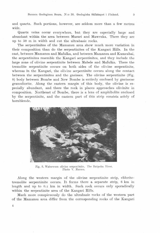
The serpentinites of the Mamansu area show much more variation in their composition than do the serpentinites of the Kangari Hills. In the east, between Mamansu and Mafulka, and between Mamansu and Kumrabai, the serpentinites resemble the Kangari serpentinites, and they include the large zone of olivine serpentinite between Mabele and Mafulka. There the tremolite serpentinite occurs on both sides of the olivine serpentinite, whereas in the Kangari, the olivine serpentinite occurs along the contact between the serpentinites and the gneisses. The olivine serpentinite (Fig. 8) body between Bombe and New Bombe is entirely enclosed by gneissose granodiorite. Along the eastern margin of this body, the olivine is especially abundant, and there the rock in places approaches olivinite in composition. Northeast of Bombe, there is a lens of amphibolite enclosed by the serpentinite, and the eastern part of this strip consists solely of hornblende .
Fig. 8. Watenvorn olivine serpentinite. The Batpoka River. Photo V. Marmo.
Along the western margin of the olivine serpentinite strip, chlorite tremolite serpentinite occurs. It forms there a separate strip, 6 km in length and up to 0.5 km in width. Such rock occurs only sporadically within the serpentinite area of the Kangari Hills.
Much more conspicuously do the ultrabasic rocks of the western part of the Mamansu area differ from the corresponding rocks of the Kangari
4
l

10 Bulletin de la Commission geologique de Finlande N: 0 180.
Hills. There anthophyllite schists are abundant, frequently having evolved into asbestos, or, owing to talcitization of anthophyllite, turned into talcose rocks. These may be schistose, but the varieties richest in tale , which virtually are monomineralic tale rocks, may have the tale flakes in a random orientation.
The anthophyllite-bearing rocks within the Mamansu area are definitely restricted to such places where the diopside- and epidote-rich varieties of diorite gneiss are best developed.
The geology of the anthophyllite asbestos of this area has been described by Marmo (1957) who reached the conclusion, regarding the origin of this asbestos, that the anthophyllite has been formed under the conditions of the epidote-amphibolite facies , in the presence of abundant water and silica, and characterized by expanding volume. The anthophyllite is assumed to have originated at the expense of antigorite.
METAMORPHIC FEATURES
THE RELATION OF OLIVINE TO SERPEN'fINE
The olivine occurs in the serpentinites he re under consideration in the form of minute, rounded crystals in a mass mainly consisting of antigorite, sometimes containing chlorite and always accompanied by tremolite .
Notwithstanding the presence of serpentine pseudomorphs containing chrysotile and having a form resembling that of olivine crystals, the latter mineral, in most cases, does not show any signs of serpentinization, and in its cracks only a magnetite coating occurs. One gets the impression that the olivine has crystallized from the serpentine and not the serpentine from the olivine. The chemical relation between these minerals may be expressed by the following equation:
(1) 3 (2MgO· Si0 2) + Si0 2 + aq ~ 2(3MgO . 2Si0 2 • aq) olivine serpentine
Hence, under hydrothermal conditions, the serpentinization of olivine involves an addition of silica, a fact that may explain the difficulty of serpentinizing olivine in the experiments of Yoder (1952, p. 584). But, on the other hand, if the mass yielding serpentine was ·nitially deficient in silica, the simultaneous origin of olivine is most probable. This statement is in fun agreement with the experiments of Yoder. During the thermal treatment of the powders of the composition of serpentine, olivine was formed as wen (Yoder, 1952, p . 575): »- - usually the mass contained crystals of forsterite, presumably the result of a change of bulk composition affected by the loss of silica. Longer runs yielded more forsterite, and the buffer contained more forsterite than the charge.»

Suomen Geologinen Seura. N: 0 30. Geologiska Sällskapet i Finland. 11
The serpentinization of olivine has been described in the overwhelming majority of papers dealing with the serpentinites, and often the formation of huge masses of serpentinites has been ascribed to this phenomenon. The presence of small rounded grains of olivine in a serpentine mass has
Fig. 9. Olivine serpentinites. VM 4045: The Masankoi Stream near Maiyonko. VM 4103: Olivinptremolite-tale serpentinite. The Matanka Stream, Kangari. VM 3998: Olivine-tremolite-talc serpentinite. Near Makele. Vl\f 4052: Sheared olivine-bearing tale-tremolite sehist. The Masankoi Stream, near Maiyonko. -1. Olivine. 2. Mainly antigorite. 3. Chrysotile. 4. Tale. 5. Trernolite.
6. Mixture of antigorite and tremolite. Nie. / / . In the seale there should be 0. 3 mm instead of 3 mm.
Fig. 10. Tremolite serpentinite. Near Mafulka (Mamansu area). 1. Chrysotile. 2. Antigoritll . 3.
Tremolite. 4. Olivine. 5. Magnetite. Nie. / / .

12 Bulletin de la Commission geologique de Finlande N: 0 180.
been most commonly interpreted by assuming the olivine to be a relic, and to be a proof of the origin of the serpentinite by serpentinization of a dunitic rock.
In Figs. 9 and 10 illustrating the olivine of serpentinites, such olivine grains are seen whose form, sharp contours and total lack- as far as has been observed-of any gradational alteration into serpentine strongly contradict the idea that all these grains should be relics of olivine in the process of serpentinization.
An additional argument against the )relic theory) is the fact that the main mass of the serpentinites here under consideration is antigorite and not chrysotile, which usually occurs along the cracks and margins of olivine crystals. Hence, where serpentinization of olivine takes place, chrysotile first forms from olivine and not antigorite. The )antigoritizatiom of chrysotile or of olivine, however, has ne ver been seen in the serpentinites of Central Sierra Leone.
Chrysotile and antigorite , in common opinion, have the same chemical composition, but definitely different structures. The former is typically tubular fibrous, the latter platy. The conditions governing the formation of platy antigorite are unknown. This question has been discussed by Roy and Roy (1954). They started from the aluminian serpentine, first discovered by Yoder (1952), and arrived at the conclusion that )--while this phase (antigorite) is here referred to as aluminian serpentine, it may very weIl correspond to 'antigorite' in nature- indicating therefore that the essential difference between platy antigorite and tubular chrysotile is compositional, the additional R 2Ü a gives rise to the formen> (Roy and Roy, 1954, p. 158).
As a matter of fact, aIl the serpentinites of the Kangari Hills seem to contain alumina (see Table 1) in spite of the fact that in most cases no chlorite minerals could be microscopically detected. This finding supports the possibility that the antigorite contains an aluminous component, as already was assumed in calculating chemical analyses (Table 1). If such an assumption is correct, the )antigoritizatiom either of olivine or chrysotile would become still more unlikely, because, in addition to the necessary incorporation of water and silica, the introduction of alumina would be needed as weIl. 'According to Roy and Roy (1952, p. 1 294), the magnesian serpentine admits about 10 mol. per cent Al 2Ü a into solid solution, thereby raising its temperature of stability at least 15° and changing its habit from tubular to platy.
The alumina content of the antigorites has been noticed elsewhere as weIl. Hess, Smith, and Dengo (1952) published an analysis of antigorite from an olivine-bearing serpentinite from the vicinity of Caracas, Venezuela, where the antigorite contains 1.03 % Al 2Ü a.

Suomen Geologinen Seura. N: 0 30. Geologiska Sällskapet i Finland. 13
Eskola (1951) described antigorites from the Pitkäranta area which formerly belonged to Finland, and one of his chemical analyses of antigorites (Ristaus) contained 0.00 % AlzOa. The two others (Hopunvaara), on the other hand, were rather rich in alumina and contained 5.14 % and 2.26 % AlzOa. Consequently, the alumina content may not be the entirely necessary condition for the formation of antigorite instead of chrysotile. On the other hand, Roy and Roy did not take AlzO a but RzO a as their requisite for the formation of antigorite instead of chrysotile; and it is very important to note that the antigorite of Ristaus with no alumina contained 1.73 % FezO a (Eskola, 1951, p. 53, Anal. 3). His aluminous antigorites contained only 0.66 % and 0.39 % FezOa, while their Al z0 3
contents were 5.14 % and 2.26 %, respectively. Thus also this antigorite is rich in RzOa.
In the antigorite of Central Sierra Leone, the alumina seems to be invariably present, and the transformation of chrysotile into antigorite has not been observed there. In the Kangari Hills there occur, however, comparatively numerous narrow veinlets of chrysotile asbestos, up to 10 mm wide, penetrating the antigorite serpentinite and filling small fissures in such a fashion that the chrysotile fibres are perpendicular to the fissure walls. The present writer got a feeling that the chrysotile had grown into the pre-existing fissures, but even if they are considered as having formed by areplacement of antigorite, the phenomenon is the reverse to that of »antigoritizatiom of chrysotile.
Hess, Smith, and Dengo (1952, pp. 73-74) believe that the transformation chrysotile -7 antigorite may be possible under conditions of the albite-epidote amphibolite facies, and »antigorite develops generally in rocks which have been subjected to strong shearing stress - - - -. Pure thermal metamorphism such as where basaltic magmas intrude serpentinites does not generally result in the development of antigorite, even up to temperatures where regenerated olivine is being developed in the ultramafic.»
In the case of Central Sierra Leone, such a statement does not hold because antigorite is the main constituent also of such serpentinites in which hardly any shear effects can be recognized. In the sheared portions, on the contrary, chlorite and tremolite serpentinites and tremolite schists predominate.
Chrysotile often penetrates and envelops the olivine crystals (Maschenstruktur), a structure understood to be a result of crack- and randwise serpentinization of olivine.
In Fig. 9 four thin sections are depicted, showing different degrees of crushing of olivine as a result of shearing. Chrysotile fills up the cracks in the leftmost slide (VM 4045) only. There the shearing has been weak,

14 Bulletin de la Commission geologique de Finlande N: 0 180.
as is also the breaking of the olivine crystals. In other slides, the stress has been more effective, and in the rightmost thin section the olivine has been crushed into small fragments, which have moved in the direction of shearing and now form strips of fragments that, under the microscope, all extinguish exactly at the same time and, consequently, are probably derived from one single crystal. But serpentinization has not taken place there; and in the cracks only a magnetite coating occurs. In VM 4103 and VM 3998, olivine crystals are also crushed up and the fragments are separated by tremolite, but no serpentinization has taken place.
In many cases, there are narrow chrysotile veinlets penetrating several olivine crystals as well as the antigorite mass between the olivine crystals. Such a case is described also by Turner among the serpentinites of N ew Zealand (Turner and Verhoogen, 1951, p. 240): »Most partly serpentinized peridotites that I have seen show clear evidence that serpentinization proceeded metasomatically from cracks that often are continuous through several crystals.»
In Fig. 9, all the fragments of a crushed olivine crystal have a simultaneous extinction. There the shearing of the rock displaced the fragments but was not able to disturb the parallel orientation of the fragments. In this case, magnetite filled up the cracks, but there are similar crushed olivine crystals with a chrysotile infilling of similar cracks.
On the other hand, there are also chrysotile pseudomorphs likewise containing minor amounts of tremolite. These pseudomorphs frequently contain minute grains of olivine as weIl, and their form resembles that of an olivine crystal (Fig. 10). Such a feature strongly supports the possibility of serpentinization of olivine. Quite similar chrysotile pseudomorphs have been described by the present author (Marmo, 1949) among the picritic rocks of Suoju, in East Karelia, and there the olivine ancestry of these pseudomorphs could be proved by measuring the angles of the pseudomorphs and comparing these angles with those of an olivine crystal. Hence, serpentinization of olivine undoubtedly may take place.
But there is other evidence, not yet discussed, which may even give the impression that the chrysotile occurring in cracks and along the margins of olivine crystals may not have formed at the expense of olivine, but was virtually an external product. In other words, the »maschenstructure» of olivine may be produced in two ways: either, if siliceous solutions are circulating, through crackwise serpentinization of olivine, which process may result in the formation of chrysotile pseudomorphs; or by the cracks of olivine crystals filling with chrysotile that grows from the materials circulating in the rock, which materials in a highly magnesian rock may contain all the constituents of chrysotile, particularly when the rock mainly consists of antigorite. Hence, such a structure may also be formed

Suomen Geologinen Seura. N: 0 30. Geologiska Sällskapet i Finland. 15
by a process similar to that by which may be explained the origin of the narrow chrysotile veinlets often penetrating antigorite serpentinite (Marmo, 1956).
In the serpentinites of the Kangari Hills, the pseudomorphs are sparse, and there the formation of the »maschenstructure» through the infilling of cracks with external materials seems to be more likely. This theory i~ supported by the fact that similar structures occur in very different minerals. In many such cases, any replacement or stright alteration theory must be abandoned in view of too large differences in the chemistry of both minerals partaking in the formation of such structures.
Fig. 11. H 16: Broken chromite crystal in olivine-antigorite mass. Hangha chromite mine, southern Sierra Leonc. VM 4046: Olivine-tremolite serpentinite, Central Kangari Hills. -1. Chrysotile. 2. Olivine. 3. Tremolite. 4. Chlorite. 5. Chromite.
6. Antigorite. Nie. / / .
In Fig. 11 (H 16), the chromite grain is broken and the cracks are filled with chrysotile, which also occurs along the margins of the chromite. There are no reasons to postulate replacement or »serpentinizatioll» of the host, and still the texture is identical with that of the »maschenstructure» of the olivine (Fig. 11). Areplacement of chromite by serpentine would mean the complete removal of all the constituents of the chromite and their replacement by all the constituents of chrysotile, which is an extremly unlikely phenomenon. The broken chromite grain has been healed by materials available in the pore solution and able to form chrysotile. Such a feature is rather common within the chromite ore at Hangha, Sierra

16 Bulletin de la Commission geologique de Finlande N: 0 180.
Leone, and there the ore grains are often enclosed by a chrysotile rim and embedded in an olivine-antigorite serpentinite. Similar »maschenstructures» occur, even in the same thin section, both in the chromite and olivine. Why should these minute chrysotile veinlets, if occurring in olivine, be products ' of serpentinization, but simple fis sure fillings if occurring in chromite~
I Fig. 12. Pyroxene amphibolite. Central Kangari. 1. Pyroxene. 2. Hornblende. Black = magnetite, the fissures in which are filled by chlorite and by chrysotile.
Nie. / / .
In Fig. 12 a related phenomenon is illustrated. There the magnetite grain of a pyroxene amphibolite is penetrated by and enveloped in a mixture of chlorite and chrysotile. In this case, the »Maschenstructure» is obviously the result of an infilling of cracks by extern al materials.
Of course there are numerous instances, around the globe, in which the serpentinization of olivine can be definitely proved. Such instances have also been described by the present author (Marmo, 1949). In the circumstances of the serpentinites of the Kangari Hills, however, the serpentinization seems to have played a minor röle only. There the antigorite should be mainly considered as a primary constituent of the serpentinites, and, in the opinion of the writer, the presence of olivine grains and of »maschenstructures» in a serpentinite are insufficient criteria for supposing, for instance, a dunitic origin of certain serpentinites. The arguments against such a conclusion, as may be understood from the foregoing, are as folIows:
1. Serpentinization of olivine under hydrothermal conditions, as revealed from Yoder's experiments (Yoder, 1952), is a rather difficult or at least sluggish reaction.
Suomen Geologinen Seura. N: 0 30. Geologiska Sällskapet i Finland. 17
2. The main mass of serpentinites consists of antigorite. The product of the serpentinization of olivine is mainly chrysotile. According to Roy and Roy (1954), there is probably a compositional difference between chrysotile and antigorite, and not only a structural one.
3. The »maschenstructure», in the serpentinites of Central Sierra Leone, is not typical of olivine only, but the chrysotile may form similar structures also with chromite and magnetite.
4. As Yoder (1952) has shown, the crystallization of olivine, in his experiments, always accompanies the crystaIlization of serpentine, due to local deficiencies in silica.
In addition, it may be mentioned that the stability of olivine under hydro thermal conditions (excess of water vapour), according to experiments performed by Bowen and Tuttle (1949), and by Yoder (1952), is still possible almost 70°C below the temperature at which the serpentine turns into forsterite, and even more below the upper stability limit of the aluminous serpentine (antigorite1) .
TREMOLITE AND PILITIZATION OF OLIVINE
Chudoba (1932, p. 172) understands by »pilite» an alteration product that appears as a feit (»Filz») of amphibole needles together with sparse serpentine or chlorite and magnetite, which replace olivine.
Such an alteration is comparatively common in olivine-bearing rocks. It also occurs in the serpentinites of the Kangari Hills. Since the olivine does not contain lime, the pilitization must be connected with the introduction of calcium:
(2) 4(2MgO . Si0 2) + 2CaCOa + 6Si0 2 + aq :;:::- 2CaO . 5MgO . 8Si0 2 • aq + olivine
3MgO . 2Si0 2 • aq + 2C0 2
serpentine
tremolite
If alumina is also present, chlorite will be formed instead of serpentine.
The pilitization is almost complete in VM 1634 in Fig. 13. There the accumulations of tremolite needles still contain remnants of olivine, and they are surrounded by a rim of magnetite grains. In the same figure, also randwise pilitized olivine occurs.
Of greater interest than the pilitization is the abundance of tremolite in general. The antigorite serpentinites always contain some tiny needles of tremolite as weIl. The rocks especially rich in tremolite, however, are distributed in definite zones. In aIl cases the tremolite is undoubtedly
5 5290-57

18 Bulletin de la Commission g6ologique de Finlande N: 0 180.
younger than the serpentine (and chlorite). specimens containing large tremolite needles 13, VM 3027).
This is especially clear in in a serpentine mass (Fig.
The majority of about 400 slides of serpentinites from the area here under consideration strongly suggest that the initial material yielding serpentinites contained enough calcium for the formation of minor amounts of tremolite. The concentration of calcium into definite zones of the present tremolite-rich rocks (p. 7) appears to be a result of the migration of lime into the rocks during dynamic events connected with the metainorphic processes, perhaps excluding the true tremolite schists, the formation of which probably is due to the presence of interlayers exceptionally rich in lime. The formation of the tremolite throughout the whole serpentinite area took place at a later stage than the formation of the antigorite and the olivine.
Two generations of tremolite are often present (Fig. 13, VM 3027). The earlier is usually featured by finer needles than the latter. The main mass of the rock consists of antigorite (and chlorite) and contains accumulations of very fine tremolite needles, suggesting tremolite pseudomorphs after pilitized olivine. The coarse tremolite needles penetrate the pseudomorphs and are consequently younger.
The li me necessary for the formation of tremolite has often been ~ttributed to pre-existing dolomite, the MgC0 3 component reacting first with silica. In any case, the presence of tremolite indicates that the initial

Suomen Geologinen Seura. N: 0 30. Geologiska Sällskapet i Finland. 19
material contained calcium, and this initial content is evidently responsible for the formation of the older tremolite. The coarse, younger tremolite, on the other hand, indicates an introduction of calcium at a later stage, either by removal from other places in the rock, or by introduction from the outside (along shear zones, joints, etc.).
Wiik (1953) calls attention to the röle of carbon dioxide in the formation of tale. The importance of this gaseous compound should not be neglected in the evolution of serpentinites either. Evidently also calcium, to some extent, was introduced into the rock in the form of carbonate (or hydroxide, the rock being rich in water). Thus the formation of tremolite at the expense of serpentine may follow the equation:
(3) 5(3MgO' 2SiOz ' aq) + 60a00 3 + 14Si02:::::':: 3(20aO . 5MgO . 8Si02 . aq) + serpentine tremolite
600 2 + aq
Reactions (2) and (3) yield carbon dioxide, which will be discussed on p. 23. There the formation of magnesite will be assumed to be facilitated by the released 002' The magnesite, however, is sparse in the Kangari Hills. Therefore, the formation of tremolite without liberation of .carbon dioxide 1S more expectable:
(4) 5(3MgO . 2Si0 2 • aq) + 6(OaO . Si0 2) + 8SiO z :::::':: serpentine
3(20aO . 5MgO . 8Si0 2 . aq) + aq tremolite
(5) 5(2MgO' SiOz) + 4(OaO ' Si0 2) + 7Si0 2 + aq:::::':: 2(20aO ' 5MgO· 8Si0 2· aq) olivine
In general,the formation of tremolite is accompanied by magnetite in varying amounts, but there are several instances where, instead of iron oxide, sulphides accompany the tremolite. Fig. 14 illustrates a specimen in which magnetite is mainly bound to olivine, but the sulphides mostly occur together with tremolite, and they comprise pyrrhotite and
Fig. 14. Olivine-tremolite serpentinite. Kangari Hills. 1. Chaleopyrite. 2. Tremolite. 3. Olivine. 4. Mainly antigorite. Blaek = magnetite. Nie. j j .
tremolite

20 Bulletin de la Commission geologique de Finlande N: 0 180.
chalcopyrite. UsuaIly, chalcopyrite forms narrow veinlets, which cut the pyrrhotite. In the same figure, the tremolite needles penetrate the sulphides, consequently being definitely younger than the sulphides.
CHLORITE
In Fig. 15, some flakes of clinochlore are seen on the margin of olivine. Occasionally the chlorite may form the matrix of the rock. Within the Mamansu area such rocks form an extensive zone (p. 9). In the sheared portions of serpentinite, the chlorite may be almost the exclusive constituent; otherwise, the chlorite matrix may contain scattered olivine grains and tremolite needles.
Fig. 15. Olivine-tremolite serpentinite. Kangari Bills. 1. Olivine. 2. Clinoehlore. Tho groundmass eonsists of antigorite and tremolite (minute needles). Blaek = magnetite.
Nie. / / . Magn. 40 x .
The presence of chlorite illustrates the abundance of alumina in the rock, and this content is probably attributable to the initial composition of the rock. Whether any replacement of serpentine by chlorite takes place or not cannot be stated with certainty. Durrell (1940, p . 82) explained all the clinochlore of Sierra Nevada as a product ofreplacement of serpentine, alumina being derived from the quartz monzonite stock of Rocky Hill, an opinion also held by MacDonald (1941, p. 239). The chloritization of serpentine needs only the addition of alumina, silica being released in the reaction.
Distinguishing chlorite and antigorite in a mass composed of fine flakes is no't always possible under the microscope. The chemical analyses of Table 1, however, suggest the presence of chlorite as weIl, or, perhaps, of aluminous serFentine. This was reported by Yoder (1952) from his hydrothermal study of the system MgO-Al20 a-Si02-H20, and had the
Suomen Geologinen Seura. N: 0 30. Geologiska Sällskapet i Finland. 21
eomposition of elinoehlore (5MgO · Al 20 a . 3Si0 2 • aq) . It is probably impossible to deteet Yoder's aluminous serpentine mieroseopieally, but it was supposed to oeeur in the serpentinites of the Kangari Hills.
In regard to the ehloritization proper of the serpentine, eertain reservations are to be made. The transformation of aluminous serpentine into elinoehlore takes plaee, aeeording to Yoder, weIl above 500°0. Aeeording to Roy and Roy (1954), an inereased pressure faeilitates the ehloritization of serpentine. Below 500°0 this transformation, if possible at aIl, is 0 bviously extremly slow, and under such eonditions, aeeording to Bowen and Tuttle (1949), serpentine may turn into forsterite (at 480°0: serpentine + brueite yield forsterite + water). Oonsequently, the transformation of aluminian serpentine into chlorite requires a temperature weIl above 500°0 unless suffieient press ure is available. This is the ease in sheared portions of the serpentinite where elinoehlore seems espeeially to oeeur in the Kangari Hills.
TALe
The serpentinites of the Kangari Hills are poor in tale, the oeeurenee of whieh is mainly restrieted to sheared portions of serpentinites. It is more abundant in the less basic greensehists of the southern part of the Sula Mountains. In the Mamansu area, however, the anthophyllite sehists are often exeeptionally rieh in tale, and small patehes may eonsist solely of tale. At Mabandu (Fig. 7), tale is not bound to shear zones but flakes of it oeeur in random orientation.
In the River Tebenko, S of Makong (Fig. 4), the rock is weIl sheared and rieh in quartz veinlets. There the tale forms minute, steatite-like lenses in the chlorite serpentinite (Fig. 13, J 277) .
Wiik (1953) proposed several reaetions for the formation of tale. True »soapstones», in the sense of Wiik, are not present in Oentral Sierra Leone, exeepting minor portions of the anthophyllite serpentinites near Mabandu.
Remembering that tale may be eonsidered as »silieeous serpentine»:
(6) 3MgO· 2Si0 2 • 2H20 + 2Si0 2 ~ 3MgO . 4Si0 2 • H 20 + H 20, serpentine tale
its origin from serpentine may take plaee by joint action of shearing and ineorporation of siliea, and, if the taleitization take,s plaee in a sheared environment, the stress may be responsible for the expulsion of one half of the water of the serpentine. This may be more easily understood if the formula of serpentine is written otherwise:
(7)

22 Bulletin de la Commission geologique de Finlande N: 0 180.
according to which formula the composition of tale is already represented by the siliceous part of the serpentine. Hence, conversion of serpentine into tale actually means the silification of the magnesium hydroxide component of the serpentine, which partial re action means arelease of half of the water in the serpentine.
Near Mabandu (Fig. 7), where the tale flakes occur in a random orientation, the talcitization of serpentine (and of anthophyllite) has taken place under tensional rather than stress conditions (p. 10). There, consequently, the conditions were such that the silica introduced was able to react with the pre-existing magnesium silicates poorer in silica. Thus, the shortage of tale within the Kangari Hills may be a consequence of a deficiency in silica rather than of conditions different from those of the Mamansu area where ample quartz veins indicate that the silica was available in a sufficient amount even for the talcitization of anthophyllite (7MgO . 8Si0 2 •
H 20), which is richer in silica than the serpentine.
INTRODUCTION OF 002
In the northern part of the Kangari Hills there are narrow zones within the serpentinites (Fig. 4) containing carbonate minerals in abundance. Contrary to the findings of Wiik (1953, p . 46), who states that the soapstones never contain carbonates and tremolite simultaneously, the serpentinites of the Kangari Hills, also those richest in tale and carbonates,
Fig.16. Carbonate-bearing olivine-tremolite serpentinite. SE of Makong. VM 1286: Carbonate and magnetite »pseudomorphic.) in a tremolite-antigorite matrix. VM 2692: Coarse-grained calcite, and chrysotile containing grains of olivine and magnetite. 'l'he mass between outlined grains is antigorite. Nic. 11. VM 1357: Large grains of calcite (1) in a fine-grained mixt ure (2) of magnesite, calcite, talc, and tremolite; both are embedded in a mass of
tremolite (3) and antigorite (4). Nic. 11. - Magn. 80 x .

Suomen Geologinen Seura. N: 0 30. Geologiska Sällskapet i Finland. 23
always contain tremolite as weIl . In Fig. 16, the main mass of the rock consists of serpentine, minute needles of tremolite, and a little talc and chlorite. In this groundmass there occur accumulations of carbonates. Sometimes the patches are surrounded by a magnetite rim, and their form suggests that they are pseudomorphs after some other mineral, possibly olivine.
The carbonate is both calcite and magnesite. The formation of the latter, at the expense of olivine, may have taken place according to the following equation:
(8) olivine magnesite
If small amounts of calcium are present, the released silica may react with serpentine to form tremolite (Equations 4 and 5) .
The distribution of carbonates is different in rocks where the calcite grains follow the schistosity. There the calcite must have been introduced into the rock as calcium carbonate.
VM 1357 in Fig. 16 illustrates a serpentinite containing patches rich in carbonates. Their central part consists of large single crystals enveloped in a mass of very small carbonate grains with tiny needles of tremolite. The environment of such clusters consists of a serpentine mass containing abundant tremolite. The impression is gained of some kind of »reaction rim». In VM 2692 in Fig. 16, this rim is so fine -grained that the presence of carbonates there can be revealed only with a greater magnification. The large carbonate crystals of such rocks are never in direct contact with the surrounding mass, but always separated from it by a rim consisting of a fine-grained mixture rich in carbonates.
The coarse carbonate of these clusters is definitely calcite. The finegrained carbonate, however, according to the colouring test, seems to consist mainly of magnesite, and, in addition, dolomite may be present there as weIl (n .
Such a distribution of carbonates between the coarse center and the fine-grained rim suggests that the latter may, indeed, be areaction rim. Its formation may be a result of a slow inter action between the calcite and the surrounding serpentine:
serpentine tremolite
+ 200 2 + aq
The limitation of the spots characterized by the carbonate content of the serpentinites indicates that the incorporation of carbon dioxide has

24 Bulletin de la Commission geologique de Fiulande N: 0 18U.
not been equal over the whole area, but took place within especially favoured places.
No connection between shear zones and carbonatization in general can be observed, but, strikingly, in the southern part of the Sula Mountains and in the northern part of the Kangari Hills, where carbonates are abundant, numerous quartz veins and minor gold and sulphide mineralizations also occur. There are, furthermore, adjacent zones containing tale and chlorite, often of mylonitic character. Also the geology of the area suggests a strong displacement of the rocks (p. 3), tearing off of the serpentinites of the Mamansu area, and a fault-like feature which strongly bent the strata at the upper flow of the Tebenko River.
In the localities mentioned the carbon dioxide ~as evidently introduced in the form of calcite, and reaction (3) between serpentine and calcite yielded the carbon dioxide necessary for the reaction according to equations (8) and (9).
ON THE TEMPERATURE OF FORMATION OF THE SERPENTINITES
Epitomizing the records discussed in the foregoing paragraphs in regard to the serpentinites of the Kangari Hills, the following sequence of formation of their constituents is surmised, embracing sustained constancy in the bulk composition during stages (1) and (2): (1) olivine and serpentine; in aluminous varieties also chlorite and clinochlore; (2) pilitization of olivine (formation of tremolite); (3) formation of tale; (4) formation of carbonates (magnesite mainly at the expense of olivine) by the action of introduced or liberated carbon dioxide.
The fundamental mineral associations found in the Kangari Hills' serpentinites are as follows: (1) olivine-serpentine-tremolite; (2) olivine (-chlorite)-tremolite; (3) olivine-tremolite; (4) serpentine-tremolite; (5) (chlorite-)tremolite. Any of the assemblages (1) to (5) may contain tale; any of the aforementioned mineral associations may contain calcite, or magnesite, or dolomite.
Tentatively the mineral association olivine-serpentine is regarded as »primary». In the mineral definition »serpentine», the aluminous serpentine and clinochlore may or may not be included. This mineral association belongs to the system MgO- Al 20 3-Si0 2- H 20, studied in detail by Yoder (1952) and by Roy and Roy (1954).
Yoder found that all the minerals of this assemblage are still stable together at 500°C, which is the upper limit of the stability of serpentine. According to Bowen and Tuttle (1949, p. 443), serpentine (chrysotile) can be formed at any temperature below 500°C ± 10°C. Yoder observed the regular formation of forsterite in addition to serpentine when glass of a

Suomen Geologinen Seura. N: 0 30. Geologiska Sällskapet i Finland. 25
composition corresponding to that of serpentine was used. Furthermore, Yoder stated that the reactions of this system are essentially pressure insensitive; but Roy and Roy (1954) suggested that transformation of serpentine into clinochlore may be facilitated by an increasing pressure.
From Yoder's equilibrium diagrams one can see that forsterite, in the presence of an excess of water vapour, is stable at 430°0, but serpentine is not stable above 500°0. Aluminous serpentine is supposed to be stable up to 525°0; after that clinochlore takes its place.
Amesite could not be produced artificiaIly. For that reason, direct data concerning amesite cannot be obtained from the work of either Yoder or Roy and Roy. Below 600°0 the powders of amesite composition yielded aluminous serpentine. If this compound is taken instead of amesite (see p. 12), one finds that the combination forsterite-serpentine-aluminous serpentine, in the presence of excess water vapour, is stable at temperatures between 430°0 and 500°0. The occasional presence of clinochlore (p. 20) indicates that the latter temperature, at least in places, probably was exceeded, and, hence, on the average, for the formation of serpentinites with the fundamental mineral association here considered, a temperature of about 500°0 was necessary. This temperature is within the range of the amphibolite facies of Eskola.
Talc is stable at all temperatures of the amphibolite and greenschist facies, and could be formed, practicaIly, at any temperature within the facies here considered.
The conditions of formation of tremolite are uncertain because the necessary data of the system OaO-MgO-Si0 2-H20 are missing. Some faint ideas about the conditions of formation of tremolite in the system of serpentinite rocks may be obtained from the descriptions of serpentinite in the foregoing. The tremolite occurs in Oentral Sierra Leone in two generations, both distinctly younger than serpentine minerals. The appearance of two generations is ascribed to an initial and to a subsequently introduced calcium (p. 19). Particularly the grain sizes of the older and of the younger tremolite are rather different, and it seems that the age difference between both generations is large enough to postulate a change in temperature conditions as weIl. Oonsequently, the stability field of tremolite is probably comparatively large.
Furthermore, it seems that after the formation of serpentinite, hardly any increase in temperature took place, and therefore the formation of tremolite definitely took place at the temperature below 500°0 (p. 24).
Tremolite is younger than chalcopyrite and pyrrhotite (p. 19). Unfortunately there are no intergrowths or exsolutions in the sulphides that could serve as any kind of geological thermometers, but such a small sulphide dissemination in a rock formed below 500°0 obviously has been
6

26 Bulletin de la Commission geologique de Finlande N: 0 180.
deposited after the main mass of the rock was formed, hence at a temperature weH below 500°0. In the amphibolites overlying 0) the serpentinites of the Kangari Hills (p. 5), cubanite lamellae have been seen in the chalcopyrite, which indicates that the deposition of the sulphides took place there at temperature not higher than 400°0 to 450°0, which may weH be the temperature of the precipitation of sulphides of the serpentinites as weH. On such an assumption, the upper limit of the formation of tremolite may be 450° O. But there does not see m to be any criteria for the lower limit of its formation.
ORIGIN OF THE SERPENTINITES
In the main, there are two theories concerning the origin of serpentinites that may be adopted for the interpretation of the serpentinites of the Kangari Hills: (1) metasomatic alteration of magnesian ultrafemic rocks; (2) serpentinization of dolomitic layers. According to the former theory, the serpentinization is explained as being due to the action of water on the pre-existing olivine or pyroxene rocks; or there was material rich in water that contained all the elements for the formation of serpentinite, and this material (serpentine magma) immediately yielded by crystallization the mineral assemblages of serpentinite, the primarily formed olivine being serpentinized autometasomatically already at the stage of its formation. These theories will be critically discussed in the foHowing.
The serpentinization of olivine into antigorite was discussed on pp. 12-13. It was also pointed out that the product of a crack-wise serpentinization of olivine is exclusively chrysotile, but that the main mass of the rock consists of antigorite. There are no signs indicating transformation of chrysotile into antigorite, which transformation is not only a structural one, but is obviously bound to a compositional change as weIl (p. 12). Thus also »antigoritizatiom of olivine is less likely to take place. Furthermore, the presence of olivine grains in the antigorite mass may be satisfactorily explained as being due to a local deficiency in silica in the serpentinite-forming mass.
All the evidence brought out in connection with the petrography of the serpentinites of the Kangari Hills makes the post-depositional serpentinization theory less attractive. Thus the first alternative of the formation of serpentinites in the Kangari Hills will be reduced into direct crystallization of serpentinites, either from extruded or intruded ultrabasic melts rich in water, or from some as yet unknown material of appropriate composition. This means that two fundamentally different possibilities are still held out by the first alternative: either the material yielding serpentinites has been extruded or intruded; or it is of sedimentary origin

Suomen Geologinen Seura. N: 0 30. Geologiska Sällskapet i Finland. 27
and exceptionally rich in magnesium. In addition, there is still the second primary alternative: serpentinization of dolomitic layers.
As is revealed by the geology of the area containing serpentinites, the main serpentinite body of the Kangari Hills, everywhere in the east, borders upon granodiorite and gneiss which, near the contact, is usually rich in pegmatite. In the west it borders upon amphibolites of basaltic character and including beds of pillow lavas.
Within the Mamansu area, the serpentinite strips are conformably embraced by synkinematic diorite-, granodiorite-, and granite-gneisses. Within the granodiorite and gneiss area between the main schist belt and the Mamansu area there are several minute serpentinite strips which strictly follow the strike of the strata.
The contacts between the serpentinites and the adjoining rocks are always sharp, and they do not show any signs of thermal metamorphism or of any other feature typical of intrusive contacts. This finding is identical to the observations made in other serpentinite areas, and also in regard to the dunitic peridotites (e.g. Turner and Verhoogen, 1951, of New Zealand; Ross, Foster, and Myers, 1954, of North Carolina; Du Rietz, 1935, of Sweden; Haapala, 1936, of Finland; etc.). Malde (1954) described serpentinites in Arizona, where they form pipes dated as being Tertiary. Several xenoliths of igneous and sedimentary rocks occur in the serpentinite there, and »xenoliths in the serpentine are not visibly altered, and wall alteration is local and weak» (Malde, 1954, p. 1 381).
The granodiorite and gneiss rocks to the east of the serpentinites of the Kangari Hills have been interpreted as being ultrametamorphic clay sediments (Wilson, Marmo, and Pollett, in press). According to the observed rock sequence in the Kangari Hills (p. 5), these ancient sediments underlie the serpentinites. Thus, if the emplacement of the serpentinites is due to aN. extrusion or intrusion, it must have happened after the deposition of the above-mentioned clay sediments, but before-if extrusivethe eruptions of the basaltic lavas, now represented by the fine-grained amphibolites (p. 5). If the serpentinites are intrusive, they could be younger than the basaltic lavas, providing they intruded along the contact between sediments and lavas. Serpentinites, however, are conformable with the strata, and deviations from this rule are seemingly caused only by a later tectonic evolution resulting in faulting and thrusting. Even then, if the intrusion of the serpentinites would have taken place at such a stage of geosynclinal orogenie evolution when an opening of huge consistent faults along the soles of mountain chains could be expected (e.g. Barth, 1952; Hess, 1955), the striking regularity of the Kangari serpentinite belt exactly between ancient clays and basaltic lavas could hardly be possible. For this reason, the present writer prefers to consider the

28 Bulletin de la Commission geologique de Finlande N: 0 180.
serpentinites as having deposited before the emplacement of basaltic lavas took place .
All the serpentinites of Central Sierra Leone contain comparatively little titanium (Table 1, p. 8), in all the rocks analyzed less than 0.2 % TiO z. Such a low content of TiO z is unusual in extrusive basic or ultrabasic rocks. The fine-grained amphibolite of the Kangari Hills contains 0.82 % TiO z. Kimberlites contain more than 1 % and even more than 2 % TiO z. In Russian Karelia, at Suoju, the serpentinites (»picrites») are definitely extrusive lavas, and they contain from 1.32 % to 1.82 % Ti02 (Marmo, 1949), and the adjoining basaltic rocks in that area (older than »picrites») 1.20 % Ti02. Also the tremolite schists (from 0.27 % to 0. 56 % Ti02) and peridotites (1.25 % Ti02) of Gold Coast (Junner, 1943, p. 13) are richer in titanium than the Kangari serpentinites.
Also the P 201) content of the serpentinites of Central Sierra Leone is very low (from 0.01 % to 0.04 %) if compared with that of the Suoju »picrites» (from 0.14 % to 0.17 %).
This comparison does not support the possibility of the extrusive origin of the serpentinites of Central Sierra Leone. They also differ from the extrusive ultrabasic rocks in their high contents of Ni and Cr.
Serpentinites occupy in the syncline of the Kangari Hills (Wilson, Marmo, and Pollett, in press) a position underneath the basaltic lavas and above the pelitic sediments. In this syncline, limestone and graphitic shells are missmg. Even portions containing carbonates are there restricted to very li mi ted areas.
Geosynclines do not necessarily contain any other sediments than those appearing in the Kangari Hills, but if the serpentinites are regarded as being sedimentogeneous, then it is necessary to assume that in the Kangari geosyncline some other sediments have existed between the pelitic beds and the lava beds. Among them, dolomitic limestone layers are most likely, because they are a typical feature in many geosynclines.
All the serpentinites, however, which so far have been explained as having formed through the serpentinization of dolomite, occur together with dolomite, as for instance at Pitkäranta (Eskola, 1951) or W of Kanye, Bechuanaland (Poldervaart, 1950). Such serpentinites are also poorer in Ni and Cr than are the serpentinites of the Kangari Hills.
The chemistry of the Kangari serpentinites is in reasonably good agreement with that of the ophiolites belonging to the »initial magmatism» of Stille. To this group belong also the serpentinites of Karelia in Finland.
Hess (1938) holds the opinion that there may exist a magma rich both in MgO and in HzO and that an extrusion of such a magma may explain the formation of serpentinites. Bowen (1947) did not accept the theory of Hess and remarked that such a magma should contain up to 13 % water,

Suomen Geologinen Seura. N: 0 30. Geologiska Sällskapet i Finland. 29
being necessarily extremly explosive. According to hirn, the formation of serpentinites is due to the serpentinization of the olivine crystal raft by the water derived from the intruded sediments. Marmo (1949) adopted such an explanation for the ultrabasic rocks of Suoju, but he remarked that the water was obtained at a very early stage, and serpentine was formed instead of olivine.
Perhaps, in the case of the Kangari Hills, Marmo's explanation (1949) for the Suoju picrites could be adopted, but after certain modification.
In the Kangari area, the basaltic intrusions are submarine. Hence also the underlying serpentinites, if extrusive, must have discharged into the water, and their extrusion evidently took place through sediments rich in water. In other words, their extrusion took place under hydro~hermal conditions, and it directly yielded their present mineral composition, antigorite-olivine, in good agreement with Yoder's experimental findings (1952) concerning the magnesian materials in the presence of an excess of water vapour.
There still remain certain unanswered questions; the most important one is that concerning the material whose eruption brought it into a hydrothermal environment. According to the composition of the serpentinites, this material must have been ultrabasic. Bowen, however, has theoretically explained that such a magma would be extremly tough, and it should appear as a raft of olivine crystals. His theory, however, postulates the serpentinization cf olivine, considered in the foregoing as being unlikely in the case of the serpentinites of the Kangari Hills. But it should be particularly stressed that the formation of more or less fresh dunites can most satisfactorily be explained as Bowen did it.
CONCLUSIONS
1. The formation of the serpentinites of the Kangari Hills is assumed to have taken place as a result of the contemporaneous crystallization of antigorite and olivine, and not through the serpentinization of olivine.
2. The formation of the Kangari serpentinites through the serpentinization of pre-existing dolomitic limestone layers or of some pre-existing, unknown magnesian sediments is improbable.
3. The formation of the serpentinites of the Kangari Hills is ascribed to extrusion or intrusion of ultrabasic material through an environment where hydrothermal conditions governed. The thesis of the extrusive nature of the emplacement is advocated on account of the contact relations and the position of the serpentinites in the Kangari geosyncIine.

30 Bulletin de la Commission geologique de Finlande N: 0 180.
REFERENCES
BARTH, TOM. F. W. (1952) Theoretical petrology. New York and London. BowEN, NORMAN L. (1947) Magmas. BuB. Geol. Soc. Am. 58, p. 263. -»- and TUTTLE, 0. F. (1949) The system MgO-Si0 2- H 20. BuB. GeoI. Soc.
Am. 60, p. 439. CHUDOBA, KARL (1932) Gesteinsbildende Mineralien. Freiburg i. Br. Du RIETZ, TORSTEN (1935) Peridotites, serpentines, and soapstones of northern
Sweden. Geol. Fören. i Stockholm Förh. 57, p. 133. DURRELL, CORDELL (1940) Metamorphism in the southern Sierra Nevada, northeast
of Visalia, California. Univ. Calif. PubI. Dept. GeoI. Sei. BuB. 25, 1. ESKOLA, PENTTI (1951) Around Pitkäranta. Ann. Acad. Sei. Fennicae, Sero A, III, 27. HAAPALA, P. (1936) On serpentine rocks in Northern Karelia. BuB. Comm. geoI.
Finlande 114. HESS, H. H. (1938) A primary peridotite magma. Am. J. Sei., 5th Ser., 35, p. 321. -»- (1955) Serpentines, orogeny, and epeirogeny. GeoI. Soc. Am. Special paper
62, p. 391. HESS, H. H., SMITH, R. J., and DENGO, G. (1952) Antigorite from the vicinity of
Caracas, Venezuela. Am. Mineral. 37, p. 68. JUNNER, N. R. (1943) The diamond deposits of the Gold Coast, with notes on other
diamond deposits in West Africa. Gold Coast GeoI. Surv. BuB. 12. MACDONALD, GORDON (1941) Geology of the Western Sierra Nevada b etween the
Kings and San Joachuin Rivers, California. Univ. Calif. PubI. D ept. GeoI. Sei. BuB. 26, p. 215.
MALDE, HAROLD E. (1954) Serpentine at Garnet Ridge, Arizona. BuB. GeoI. Soc. Am. 65, p. 1 381. (Abstract.)
MARMO, VLADI (1949) Ein vulkanischer Komplex der früh.jotnischen Zeit bei Suoju in Ost·Karelien. Ann. Acad. Sei. Fennicae, Sero A, III, 19.
-»- (1956) Sur la serpentinisation de l 'olivine . BulI. Soc. fran<;. Miner. Crist. 79, p. 318.
-»- (1957) Anthophyllite asbestos in Central Sierra Leone. Schweiz. min. p etr. Mitt. 37, p. 31.
POLDERVAART, A. (1950) Chrysotile asbestos produced by dolerite intrusions in dolomite. CoI. GeoI. Min. Res. 1, p. 239.
Ross, CLARENCE S., FOSTER, MARGARET D., and MYERS, ALFRED T. (1954) Origin of dunites and of olivine-rich inclusions in basaltic rocks. Am. Mineral. 39, p. 693.
Roy, DELLA M. and Roy, RUSTUM (1952) Studies in the system MgO- A1 20 3-
Si0 2-H20. BuB. Geol. Soc. Am. 63, p. 1 293. (Abstract.) -»- (1954) Synthesis and stability of minerals in the system MgO- Al 20
3- Si0
2-
H 20. Am. Mineral. 39, p. 147. TURNER, F. J. and VERHOOGEN, JEAN (1951) Igneous and metamorphie petrology.
New York. WIIK, H. B. (1953) Composition and origin of soapstones. BuB. Comm. geoI. Finlande
165. WILSON, N. W., MARMO, VLADI, and POLLETT, D. J. (in press) Geology, geomor
phology, and mineral resources of the Sula Mountains, Sierra Leone. BuB. Geol. Surv. Sierra Leone 1.
YODER, H. S., Jr. (1952) The MgO-Al 20 3- Si0 2- H 20 system and the related metamorphie facies . Am. J. Sei. (Bowen voI.), p. 569.

2
ON PROSPECTING FOR MOLYBDENUM ON THE BASIS OF ITS DISPERSION IN GLACIAL TILL 1
BY
L. K. KAURANNE
Geological Survey 01 Finland, Otaniemi
ABSTRACT
The Geological Survey of Finland carried out diamond drillings in the parish of Rautio in 1952-1953 and in the parish of Ylitornio in 1953- 1955 and, in addition to other ore prospecting methods, an experimental investigation into tho distribution of molybdenum in glacial drift. The molybdenum content of glacial drift varied b etween 0 and 50 ppm, the treshold value for anomalies being regarded as 3 ppm. The molybdenum was determined colorimetrically as thiocyanate-the spectrographie comparative analyses did not prov€l to be equally reliable. The molybdenum was observed to have been enriched into the glacial till with the smallest grain sizes. The results indicate that the method is suitable for ore prospecting.
CONTENTS Page
INTRODUCTION ........ . .. . ....... .. ... . . .. ..... . .. ... . • . . ... . .. 31
METHOD .... . ........ ...... . ..... . . . . . ............ . .... ... ... .. 32 SAMPLING AND TREATMENT ... ..... .. ... .......... .. ................... 32 CHEMICAL ANALYSIS ................ .. . ........ •• ..................... 33 APPLICATIONS .................................•...................... 34
CONCLUSIONS . . . . . . . . . . . . . . . . . . . . . . . . . . . . . . . . . . . . . . . . . . . . . . . . . .. 41
ACKNOWLEDGMENTS ..... . ... . . . . . .. ... ...... ... ... . .••. ... . . . . .. 42
REFERENCES 43
INTRODUCTION
In ore prospecting ever new methods are being tried out and developed to supplement older ones. The exposed ore bodies having been found, numerous geophysical methods have been used in the search for soil-covered ores. There are, however, ore types that are out of reach of these methods,
1 Received February 13, 1957.

32 Bulletin de la Commission geologique de Finlande N: 0 180.
and new ones are again needed. Systematic boulder tracing is an old method, much used in glaciated regions; out of it has evolved a new method of prospecting for »infinitesimal boulders»-chemical analysis of mineral soils.
Chemical ore prospecting is currently making vigorous progress, and both biogeochemical research and the investigation of natural waters appear to have gained widespread favor. Analysis of the trace elements present in soils, known as pedogeochemical research, has likewise given good results in experiments carried out in various parts of the world. The most succes has been achieved in analyzing residual soils, which have originated by weathering on the spot.
In the case of soils in a secondary position, material from country rocks have become mixed during transportation with the material deriving from ore, and the mixture thereby created is poorer in the metals of the ore than the original source. This imposes hej1vy demands on the methods of analysis applied. However, metallic trace elements are also likely to become enriched into both sorted and unsorted sediments, depending on the nature of the transporting force and the physico-chemical properties of the transported ore minerals.
Geochemical investigations carried out in Canada (Warren, Delavault and Routley, 1953), in Finland (Okko, 1951; Marmo, 1953) and in U.S.S.R. (Tikhomirov and Miller, 1946) have shown molybdenum to become enriched into plants, peat and alluvium, which would indicate that it is abundantly transported also in solution. According to Warren et al. , the Mo-content of plants in areas where the element occurs in the bedrock is likely to rise to 2- 60 ppm, whereas elsewhere the content varies between 0.1 ppm and 0. 5 ppm. The concentrations obtained from the peat sampies collected in the Susineva area in the parish of Rautio ranged from 3 ppm to 30 ppm (Okko, 1951). Marmo reports having obtained values of 5-35 ppm Mo from the wild rosemarys (Ledum palustre) of Susineva, Rautio.
In the bedrock the molybdenum has become enriched primarily into the granitic rocks: quartz dikes, aplites and microcline granites. Its mean content in granite is l.1 ppm (Kuroda and Sandell, 1954). In Finland 108 Mo-mineralizations of different sizes have been met with (Kulonpalo and Marmo, 1955), one of which, Mätäsvaara, was mined during the war.
METHOD
SAMPLING AND TREATMENT
The sampies were taken, insofar as the terrain made it possible, from lines at right angles to the direction of transport at intervals of 25- 200 m. The sampies were takEn from fresh till by digging through the humus

Suomen Geologinen Seura. N: 0 30. Geologiska Sällskapet i Finland. 33
surface and diffusion and enriching layers. A ground auger was used to obtain sampIes from under peat layers; in the winter the frozen surface had to be broken up with explosives. In the summer the specimens were dried in the sun and sieved with iron wire screen in the field; in the winter the drying and sieving processes were carried out in the laboratory.
Among the Susineva sampIes the elutriated and decanted fraction o < 0.01 5 mm was analyzed, whereas in the case of the sampIes from the Kallijärvi-Kivilompolo area the fr action 0 < 0.2 5 mm was used, on account of the difficulty of sieving in the field. After sieving the material was chemically analyzed.
In the mineralizations of both Rautio and Ylitornio the molybdenum occurs in the form of the molybdenite, MoS2• It is a soft but chemically relatively resistant mineral. The Mo-content of the various grain size classes of the till sampIes from the Susineva area in the parish of Rautio indicates the MoS2 as having been enriched into the finer fractions. Table 1 presents the Mo-contents of two fractions, each measuring 0 0.01 5-
0 . 1 25 mm and under 0.015 mm in diameter, from sampIes 1, 2 and 9. The position of the sampIes is shown in Fig. 3.
Table 1. The Mo-content of various grain Slze classes (Rautio)
Sarnple No .
1 2 9
13 0.016-0 . 12~ rnrn
1.0 ppm 1.5 .)
traces
13 < O.OH rnrn
50 ppm 10 o
The table shows that the finer fr action of SampIe No. 1 contains more Mo than the corresponding fraction of SampIe No. 2. In the coarser fraction on the other hand, the Mo-content of the Sampie No . 2 is higher. Since SampIe No. 1 comes from a site farther from the ore body, grinding is evidently involved. The values obtained result from the MoS2 occurring as amineral, for these fine fractions were separated from each other by means of elutriation and decantion, whereby the water-soluble Mo was eliminated.
CHEMICAL AN AL YSIS
The colometric determination of molybdenum was carried out by measuring the intensity of the reddish brown color, induced in an acid molybdate solution by potassium thiocyanate and stannous chloride.
From the dried and finely ground sampIe, 1 g was taken and the MoS2
contained therein oxidized by m6:1nS of bromine and hydrochloric acid into molybdic acid. It was heated in an HN0 3 + Hel (1: 1) solution; H 2S0 4 was added, and then it was evaporated until heavy sulphuric acid fumes arose. To the solution were added boiling H 20 and Fe2(S04h as
7 5290- 57

34 Bulletin de la Commission geologique de Finlande N: 0 180.
weIl as sulphuric acid and thereafter KSCN and SnCl2• In the solution with a high content of sulphuric acid there was produced reddish brown molybdenum thiocyanate Mo(SCNh (SandeIl, 1953). To the solution was added ether, in which the color dissolved. The reddish brown ether layer was separated and its absorbing power measured alongside that of distilled water, with the aid of a bluish green filter; and the result was compared with the values yielded by standard solutions.
The chemical analysis was hampered by the strong brownish color of the humus-rich material from Susineva, material that appeared in abundance in nearly every sample taken from this swampy area. It is thus likely that the very weak Mo-color was covered by the strong humus brown. Such specimens, in respect to the negativeness of which there is no certainty, are marked as »traces» on the map, Fig. 2. It was endeavored to eliminate the humus material by burning, but, in part, to no avail.
The colorimetric method is relatively rapid and very sensitive, its accuracy being about ± 5 %. Disturbing ions are Cu, which often occurs in Mo-mineralizations, as weIl as Co, V, W, Ta and Nb.
At first the specimens collected from Rautio were analyzed spectrographically as weil, but the liquid method seemed to be better, on account of the evenness of the results . The comparative spectrographic analyses were made by Mr. Oiva Joensuu, University of Chicago. Table 2 presents some comparative analyses.
Table 2. Comparative spectrographic and colorimetric determinations of sampies from Rautio. Material 0 < 0.015 mm
Sa mpIe No. Colorimeter Spectrogra ph
ppm Mo ppm Mo
1 50 150 2 10 9 3 20 24 4 7 0 5 traces 0 6 0 7 0 8 30 5 9 0 0
10 0 0 11 50 65
APPLICA.TIONS
Susineva, Rautio, Gentral Finland. The bedrock of the Susineva area is quite monotonous: granitized granodiorite and granite (Marmo and Hyvä· rinen, 1953). In connection with the granitization the bedrock has apparently received small amounts of CuFeS2, MoS2 and Fe30 4 •

Suomen Geologinen Seura. N: 0 30. Geologiska Sällskapet i Finland. 35
The ground of the region consists of glacial drift strewn with boulders; in places it alters into extensive streches totally covered with boulders (»felsenmeen» probably through the action of ground frost or intensive washing. Under the covering of boulders the bed of drift is still between five and six meters thick. A large part of the region is 'boggy, the thickness of the peat layer in some places exceeding six meters. Of the till 22 sieving analyses were made, the mean of the results of which is shown in Fig. 1.
i , , I , , , 100 %
, , , , , , , , , I , , , , , , , , , , , , , , , , , , , , , , ,
80
60 I
, , , , , ,
: ~/ , , , , I ,
'/ ' , I , , ,
, , , ~. ' , ,
1/' , I I '
, , , , I , I
V~ : ,
, 1 , , ,
~/~/ , , , 1 , I 1 I 1 1 , 1 . ' 1 1 ,
, , I ,
40
'20
o 0.02 0 0 .062 0.125 0 .20 0.25 0.50 Loo 2 .00 m m
Fig. 1. Mean of the results of sieving analyses of 22 glacial till sa tnples, Susine va, Rautio. Cumulati ve curve.
Ore prospecting was started by boulder tracing. The results of this investigation are shown on the accompanying map, Fig. 2. The ore boulders are concentrated in three main sites, but some of them are' rustributed over a wide area. The boulders are almost without exception granite or granodiorite, and the ore minerals occuring in them (molybdenite, chalcopyrite, pyrrhotite and pyrite as weil as small amounts of sphalerite, valleriite and covellite) are associated with quartz dikes 'or appear as fine disseminations (Marmo and Hyvärinen, 1953).
The counts made of stones measuring less than 10 cm in diameter did not appreciably help. MoS2-bearing stones were found in only two pits (Fig. 3). In the figure are also to be seen the margins of the fan formed by the geochemical anomaly.
The pedogeochemical prospecting operation carried out experimentally gave a very good result (see the appended map, Fig. 2). The Mo-contents vary from 0 to 50 ppm. The anomalous values are grouped in a fan-shaped area and in only three sampies outside this area was a low content met with. The width of the fan may result from the fact that the Mo-contents derive from several different outcrops. The direction of the bisector of
7 5290-57

36 Bulletin de la Commission geologique de F inlande N : 0 180.
,." 50. 50 .
05 Jtr~-..".;.
5 U 51 N E VA ..:iT~-~J 'l-~= Results of chemicol onolyses of f ines! _.5'_2
froclions of glociol tiR seAL' , t • ! , ! • , :::::s
o 100 2m 300 «lO 500 600 700 _ m ~
o sampie station ::::;-~.,..~ 10 Mo-content in ppm (of materiaI1ll<0.0I2 mm)II-----,-=!"""'----""'-'-------j-__ --::_-'3;...,.. tr Eithertraces of Mo or,mor-e proboblU,co 0 0 .6 "05 2- bf':oring bou ld er of humus ~ Diamond drill hole ,wher e MoS 2 W O !5 rnet with
........... Pedogeochemico l onomoly
Fig. 2. Results oi boulder t racing and pedogeochemical investigation in the Susine va area, Rautio.
SUSINEVA I \ I ®J\
/ \
/ o 100m
.10
, I , ,
.,9
® 1\
I \
I I
I
, , I , ,
, , , ,
®!
.3
.4
Mo-bearing stones
.6
Boundaries of geochemicol anomaly Sfone counting site
N
.7
Fig. 3. Distribution of Mo-bearing stones in stone counts in the Susineva area, Rautio.

Suomen Geologinen Seura. N: 0 30. Geologiska Sällskapet i Finland. 37
the fan, N50oW, is the same as the direction of the glacial striae met with in the region. An orientation analysis of the till stones, made by Mr. Urpo Kauranne, gave a maximum of N48°W.
The electrical, inductive, exploration did not help in finding mineralizations. The weak anomalies detected followed the boundaries between the bog and the dry land, resulting presumably from the differences in the conductivity between the aforementioned formations (Siikarla, 1954). Magnetie measurements did not help to any greater extent.
The biogeochemieal investigations condueted in the region have been already referred to (p. 32).
On the initiative of the Geologieal Survey, seven holes were drilled in the region, prineipally in aeeordanee with the eleetrieal anomalies; but the maximum Mo-eontent found was only 0.01 % (Marmo and Hyvärinen, 1953). The drillings were suspended for aperiod of the follow-up investigations; later, they were resumed by the prospecting eompany Suomen Malmi Oy. The next holes were drilled aeeording to the indieations given by the boulders and the geoehemieal anomaly, and the very first two ran into a rieh but narrow Mo-mineralization (Fig. 2). Subsequent explorations led to the finding of more mineralized zones (their positions are not known to me), but none of them apparently proved to be worth exploiting eommercially, for the prospeeting operations have been interrupted for the present.
Kallijärvi- Kivilompolo, Ylitornio, North Finland. According to Yletyinen (1956), the bedrock of the region may be divided into two elearly distinguishable parts, the West by East boundary of whieh, with its miea gneiss zones, runs along the southern margin of the area explored pedogeoehemieally. On the southern side of the boundary there is a broad belt of phyllite and other sehists, together with dolomite layers. On the northern side, in the exploration area proper, there are varying, mainly granitie gneisses, whieh eontain garnet-rieh parts and narrow miea-schist horizons. It is a granitized series of sediments. The miea sehists inelude skarn-like spots. The gneiss belt has two quartz dike systems of different ages; the younger distinetly cuts the sehistosity (N600- 700E), but the older roughly eonforms with it. The older system includes an Mo-mineralization, containing the ore minerals MoS2, CuFeS2' FeS2 and / or FeS.
The exploration area is eomparatively flat, even though the region otherwise varies fairly mueh in elevation. In the lower plaees there are rather thin strata of sorted sediments, and in higher levels shore formations; but for the most part the region is eovered with glaeial drift. The till, varying in thickness between 1 m and 11 m, is eovered over broad stretches by bog, the peat bed of whieh reaches a thiekness of as mueh as four meters.

38 Bulletin de la Commission geologique de Finlande N: 0 180.
Yletyinen (1956) divides the Mo-bearing boulders into four groups: (i) In the NW -corner of Lake Kivilompolo is a local accumulation of gneiss boulders containing pyrrhotite, chalcopyrite and molybdenite, forming a short and broad fan. (2) Granite boulders with patted MoS2 grains. (3) MoS2-bearing sericite quartzite boulders, of which only two were found. The Mo-content of one was analyzed, being 0.8 %. (4) The largest group, gneiss boulders, in which the MoS2 is associated with quartz dikes. The boulders are scattered over a large area (Fig. 5).
The stone counts made of the 0 < 10 cm stones proved that the glacial drift also contained material transported from a distance. Mo-bearing stones were met with in only seven pits (Fig. 4).
KALLlJÄRV\ - I<\V\ LOMPOLO I 37
I 0 ) km
36
0 35 34 .33 32 .31 30 • 29
• 24 23 • 22
18 • )7 16 .15 ----• 10
19
2 03 • 1
I @ Mo - bearing stones
~-_.,.\ Boundaries of geachemicol anamallj \ '
Stone caunting site
Fig. 4. Distribution of Mo-bearing stones in stone counts in the Kallijärvi-Kivilompolo area, Ylitornio.
An electrical (Slingram) survey brought to light three separate zones of anomaly oriented N800E (Yletyinen, 1956). The northernmost of them appears to have been induced by aschist zone of various composition and the one in the center by mica schist. The southern anomaly was investigated by diamond drilling and it was caused by small amounts of pyrrhotite and chalcopyrite.
Diamond drillings were concentrated on the SE shore of Lake Kallijärvi, where Yletyinen discovered a gneiss exposure cut by quartz dikes

50ß 509 510 511 512
735BI,------- -...-----------;-.----U,---..;;:---------- ;----------------,,--------------7338 +t
+
13S6L ____________ ---.l ___ ---.JL-__ --1. _____ .L-____________ ---.J __________ -----17356
+ Ma-beoring gneiss baulder o granite o sericite quartzite baulder
'" Expasure called Kohvikollio \ Diomond drill hole
~:-'\ Boundaries of geochemical anomoly
o O.5km
According to YLETYINEN,1956
Fig. 5. MoS.-bearing boulders and diamond drilling holes in the Kallijärvi-Kivilompolo area, Ylitornio.

40 Bulletin de la Commission geologique de Finlande N: 0 180.
rich in MoS2• This exposure is now known as Kahvikallio (Fig. 5) . I n studying the possible differences between the Mo-contents of the channel sampies and the drill cores, two holes measuring 30 mm at the core were drilled through the aforementioned rock exposure. The highest Mo-content of one of the holes was 11.18 %/0.5 m. It was now undertaken to follow the zone, and it proved to continue to cut the schistosity (N600-700E) gently in the direction N55°E.
Altogether thirty-two holes were drilled in the region (Fig. 5). The highest Mo-concentrations were met with in the proximity of Kahvikallio, over a distance of 200 m; the length of the entire drilled zone is 1 300 m . At the apex of the boulder fan on the NW shore of Lake Kivilompolo, the parent zone of the boulders was found by both digging and drilling; this zone consisted of gneiss with a low content of sulphides.
According to Yletyinen (1956), the drilling results point to the possibility that a number of mineralized zones exist in the region. Part of the area of Kahvikallio remains to be explored and the parent rock of the sericite quartzite boulders has not been found.
The pedogeochemical anomaly is extensive, but rather clearly bounded (Fig. 6). Its NW margin follows the mineralization found by drillings, falling somewhat farther back in relation to the direction of transport towards the northeast. This is explained by the fact that glacial drift, which has a thickness of only about 0.5 m in the proximity of Kahvikallio, gradually grows thicker towards the northeast, achieving a thickness of more than 11 m near Mikkelinjoki river. South of the sharp SW margin of the anomaly, surprisingly many MoS2-bearing boulders have been found. The mineralization discovered by diamond drilling operations continues also somewhat to the south of the said boundary. The only Mo-bearing till sampie taken from outside the big anomaly field came from the boulder fan at the NW shore of Lake Kivilompolo.
Okko (1941) has carried out two orientation analyses of the till stones in the region, both of which gave a maximum of N78°W; the striae directions N75°W and N800W have been measured in the region. The boundaries of the geochemical anomaly cannot wholly be explained by means of these directions, but the region also has an older striae direction, N 45°W (op. cit.). The ore material of the glacial drift would appear to have traveled principally in the direction of this earlier movement, just as the till farther north (op. cit.). Because the NW boundary of the geochemical anomaly is on the NW side of the mineralized zone found by drillings, there must be another concordant ore-bearing horizon farther northwest.
Salmi has carried out an extensive investigation of the trace element content of peat here, as in Rautio too, but the results have not yet been published. One of the highest values of the Mo-content here occurs near

Suomen Geologinen Seura. N: 0 30. Geologiska Sällskapet Finland.
o o
o o
N
o o o
E E on '" ci v 'S. Ci ' [ ., " E
E <:& .~ c 0:': _c '" ., .,<= -0 0..., E ' 0 0 "':!;
E o o !e
., o u Vl
o
.... o
41
the maximum concentration met with in the glacial drift (Salmi, personal communication).
CONCLUSIONS
Pedogeochemical investigation in both of the cases described in the foregoing has yielded such good results that one is encouraged to recommend
8

42 Bulletin de la Commission geologique de Finlande N: 0 180.
the performance of a corresponding investigation as extensively as possible always before undertaking expensive drilling operations. The investigations are facilitated by the favorable physico-chemical nature of MoSz as weIl as the fact that an exceedingly ,sensitive method of analysis has been developed for Mo. The best results were obtained from grain size class o < 0.015 mm, but, on account of sieving difficulties, a coarser fraction of 0 < 0.25 mm was also used. In order that the investigation might be made more economical, smaller sampIes should be used and the taking of the sampIes would have to be speeded up. Tests have been made of different types of drills, but so far a sufficiently light and durable one has not been found.
Molybdenum has distributed over the terrain rather evenly, though minor differences in content do occur. The glacial drift in itself is quite non-homogeneous, as shown e.g. by the grain size composition. Two sampIes from each of sampling pits 1, 2, and 9 in Rautio were sieved, the mean error of the sieving analyses being 2.29 %. As many sampIes as possible must thus be taken in order to correct errors caused by the non-homogeneity of the material. The margins of the anomaly areas are rather clear. The highest values of the anomalies were in each case 50 ppm, and 3 ppm was regarded as the background. The anomalies appear to disappear about a kilometer from the parent rock, as measured in the direction of transport.
ACKNOWLEDGMENTS
This work was carried out under the direction of Dr. Aarno Kahma on a commission from the Geological Survey of Finland. The manuscript was checked by Prof. Pentti Eskola and Dr. Ahti Simonen. Considerable useful advice was received from Drs. Veikko Okko and K. J. Neuvonen. Liberal assistance was given by Messrs. V. Yletyinen, M. A., L. Hyvärinen, M. A., and Urpo Kauranne, Yletyinen being in charge of diamond drilling operations in the parish of Ylitornio and Hyvärinen in the parish of Rautio. The chemical analyses were made by Miss Kaija Karhunen, under the direction of Mr. E. Savolainen, M. A. The maps and drawings were made by Miss K. Dahl. The English translation was done by Mr. Paul Sjöblom, M. A . Suomen Luonnonvarain Tutkimussäätiö (The Finnish Foundation for the Investigation of Natural Resources) and Emil Aaltosen Säätiö have supported the work with grants. To all those mentioned I wish to extend wholehearted thanks.

Suomen Geologinen Seura. N: 0 30. Geologiska Sällskapet i Finland. 43
REFERENCES
K ULONPALO, MAX ja MARMO, VLADI (1955) Suomen molybdeenihohteista. (English Summary: On the molybdenite of Finland.) Geoteknillisiä julkaisuja 58. Geologinen tutkimuslaitos - The Geological Survey of Finland.
KURODA, P. K. and SANDELL, E. B. (1954) Geochemistry of molybdenum. Geochimica et Cosmochimica Acta 6, 1, p. 35.
MARMO, VLADI (1953) Biogeochemical investigations in Finland. Econ. Geo1. 48, p. 211.
-')- and HyvÄRINEN, LAURI (1953) Molybdenum bearing granite and granodiorite, Rautio, Finland. Econ. Geo1. 48, p. 704.
OKKO, VEIKKO (1941) Über das Verhältnis der Gesteinszusammensetzung der Moräne zum Felsgrund in den Gebieten der Kartenblätter von Ylitornio und Rovaniemi im nördlichen Finnland. Geo1. Rundsch. 32, 4 /5, p. 627.
-')- (1951) Selostus kvartäärigeologisesta tutkimuksesta Raution Susinevan mo1ybdeenilohkarealueella. Field Report M/17/Rt-51/1. Archives of the Geological Survey of Finland.
SANDELL, E. B. (1953) Colorimetric determination of traces of metals. 2nd Ed. New York and London.
SIIKARLA, T. (1954) Selostus geofysikaalisista tutkimuksista Rautiossa. Field Report M/17 /Rt- 54. Archives of the Geological Survey of Finland.
TIKHOMIROV, N. I. and MILLER, S. D. (1946) On a physicochemical method of prospecting for molybdenum in the semidesert c1imate of the northern Lake Balkash area. Razvedka i ohrana n edr (Pa3BeJl:Ra H oxpaHa HeJl:p) 12,2, p. 34 (Russian). English translation in: Selected Russian papers on geochemical prospecting for ores. U.S. Geo1. Survey, February, 1950, p. 97.
~TARREN, HARRY V., DELAVAULT, ROBERT E. and ROUTLEY, D. G. (1953) Preliminary studies of the biogeochemistry of molybdenum. Trans. Roy. Soc. Canada 47, p. 71.
YLETYINEN, VEIJO (1956) Selostus Ylitornion tutkimusalueen malmitutkimuksista. Field Report M / 17/Yt-56. Archives of the Geological Survey of Finland.


3
EXAMPLES OF THE GRANITIZATION OF PLUTONIC ROCKS 1
BY
MAUNU HÄRME
Geological Survey 01 Finland, Otaniemi
ABSTRACT
The character of the granitization process of plutonic rocks is elucidated by means of chemical analyses. The fundamental phenomenon of the process is an increase in the potassium content and a decrease in the calcium content. This makes possible, without essentially changing the amount of aluminium, the production of aluminium-rich minerals, like cordierite, almandite and sillimanite. The process of granitization is discussed. A short comparison is made between this potassium metasomatism and the sodium metasomatism (fenitization-nephelinization).
CONTENTS Page
INTRODUCTION ................................................. 45
SOME EXAMPLES OF GRANITIZATION ......................... . . . . . . 47
CONCLUSIONS .................................................. 56
A SHORT COMPARISON WITH FENITIZATION .... . ..... . .. . ... .. . . . . . . 60
REFERENCES 62
INTRODUCTION
Studying the Svecofennian formations in the coastal area of southern Finland, one seldom finds rocks totally unaffected by the late-kinematic microcline granite. Occasional veins of microcline granite exist nearly everywhere and very often the rock is cut by a network of granitic veins. For such veined, mixed rock Sederholm (1907, p. 110) proposed the term »migmatite». This collective appellation does not describe the origin and the composition of the older component of the rock or the bulk composition
1 Received March 12, 1957.

46 Bulletin de la Commission geologique de Finlande N:o 180.
of the present rock. In this inhomogenous rock the older constituent may be of various origin; it is only cut by younger veins of granitic composition. These granitic veins may either fol1ow the schistosity of the host rock or also cut it. If the older rock was foliated, then the migmatite is generally veined gneiss; and if it had only a weakly orientated structure, then the mixed rock is breccia. There are always, however, some exceptions to this rule.
WeIl known is the controversy between Sederholm and Holmqvist about arterites and venites. Their dispute led to the common conclusion that both arterites and venites exist. This question arose in connection with the study of Svecofennian rocks and it is still linked to the origin of the Svecofennian late-kinematic potassium granite, the most important factor to produce migmatites in the Archean rock crust of southern Finland.
The veins of the microcline granite are, however, evidently arteritic when cutting a rock that primarily has been very poor in potassium. The manner of occurrence of these veins suggests that their invasion took place in a liquid state. We shall pass over here the question of the origin of the microcline granite magma and consider only some metasomatic changes, the granitization, caused by it.
The arteritic network often follows the schistosity of the host rock, but it mayaIso deviate from it in varying degree. The veins may be as thin as 1-2 mm, and the spaces between the veinlets may be of the same size. The grain size of the host rock may be of the same order. Thus the bulk composition of such veined rock approaches the granitic composition, irrespective of the primary composition of the older rock (Fig. 1, Plate I). This process we may call physical granitization. Commonly the changes in the host rock are not, however, restricted to the formation of the granitic network but a,re at the same time accompanied by chemical processes, by metasomatic granitization.
In an earlier paper, the present writer (Härme and Laitala, 1955) described an example of the initial granitization of gabbro . In this example, a fragment of gabbro was surrounded by microcline granite. In the metasomatic processes brought about by the granite, the injected potassium had caused among other things an alteration of the amphibole into biotite. In connection with granitization, this is a very common phenomenon, which may begin with the hydration of pyroxene. Examples of differing cases are to be found. Amphibole may alter into biotite only to a degree; another part of the injected potassium may produce separate grains of microcline also in a basic rock (Fig. 2, Plate I). Sometimes such a microcline grain is surrounded by a plagioclase rim (Väyrynen, 1923, p . 34; Wilkman, 1938, p. 99; Edelman, 1949, p. 73; Härme, 1954, p . 28) . The formation of microcline porphyroblasts is not dependent on the kind of

Suomen Geologinen Seura. N: 0 30. Geologiska Sällskapet i Finland. 47
host rock; such a phenomenon has been met with in gabbro, diorite and oligoclase granite (Fig. 3, Plate I; see also Härme, 1949, Figs. 22 and 23, p . 36) .
In the granitization of an acid host rock, biotitization does not need potassium to any noticeable degree and therefore microcline is in trus case frequently produced. The microcline grains may be of approximately the same size as the other grains of the host rock, but often they are metacrysts (porphyroblasts). True porphyritic granites may be yielded through such far advanced granitization (Härme, 1949, p . 36; Eskola, 1952, p . 136; Salli, 1953, pp. 24, 36; Härme, 1954, p. 28).
SOME EXAMPLES OF GRANITIZATION
In the coastal area of southern Finland, the synkinematic silicic plutonic rocks have in general been originally rich in sodium and poor in potassium while the late-kinematic granites are dominated by potassium (see Simonen, 1948 a). These facts were pointed out by Eskola in his lecture at the VI Northern Geologists' Congress (Eskola, 1954a, p. 36; cf. Eskola, 1956, p. 89). In this connection, Eskola mentioned also that in most cases the potassium-rich varieties of the synkinematic intrusives have proved to be granitized, or, in other words, they have got a secondary addition of potassium.
Such is actually the case. To this may be added that the granitization of silicic synkinematic plutonic rocks in the coastal area of southern Finland is a more common phenomenon than was known earlier.
In metasomatic granitization, the chemical composition of the rock changes. To study the character of this process of change, the author has selected for chemical analysis some specimens of plutonic rocks from several localities in the coastal area of southern Finland. At least two specimens were taken from each locality, one being of the most unchanged rock type and the other of a strongly granitized type. The pair of specimens were taken from the same outcrop so that their primary compositions would correspond as nearly as possible. It was thus not possible to obtain any specimen of strictly unchanged rock, but in each case an incipiently changed rock type has to be compared with a more conspicuously changed one. To eliminate slips in the choise of specimens and in the analyses, the specimens were taken from seven places, thus making the test of the process of change at least in part statistical.
In all the cases described here th.e primary rock was poor in potassium and the microcline did not belong-at least not typically- to the primary composition of the rock. Therefore the cutting veins must in these cases be arterites and not venites. The granitic material then infiltrated from

48 Bulletin de la Commission geologique de Finlande N: 0 180.
the veins into the wall rock, where it caused metasomatic processes. In connection with the areal geological investigation, it was also verified that the microcline granite is essentially younger in age and accordingly any autometasomatism is out of question.
For analyses the following specimens were collected:
1. (a) Quartz diorite, initially granitized. Hanko. (b) Partly granitized quartz diorite . Hanko.
2. (a) Granodiorite, initially granitized. Suomusjärvi. (b) Partly granitized granodiorite. Suomusjärvi.
3. (a) Oligoclase granite, initially granitized. Vihti. (b) Granitized oligoclase granite. Vihti. (c) Microcline granite containing remnants of oligoclase granite. Vihti.
4. (a) Oligoclase granite, partly granitized. Virkkala. (b) Granitized oligoclase granite. Virkkala.
5. (a) Trondhjemite, partly granitized. Orimattila. (b) Granitized trondhjemite. Orimattila.
6. (a) Granitized trondhjemite. Järvenpää. (b) Microcline granite containing remnants of trondhjemite. Järvenpää.
7. (a) Granitized trondhjemite. Kerava. (b) Microcline granite containing remnants of trondhjemite. Kerava.
Normally, the unchanged primary rock types have had a more or less parallel texture, which feature, as is known, favours the migration of the elements. Almandite occurs in most cases already in partly granitized rocks either unevenly distributed (Fig. 4, Plate II), as small accumulations (Fig. 5, Plate II) or following the veins of the microcline granite (Fig. 6, Plate II).
The mineral compositions of the analyzed specimens were as follows:
1. (a) The rock contains plagioclase, quartz, amphibole, biotite, microcline, sphene, epidote, apatite, zircon and ore. The plagioclase is normally zoned (center An32- 33 , margin An 27 - 28 ). The microcline grains are small. A little myrmekite occurs. The quartz is crushed and it has a strong undulatory extinction. (b) The rock contains plagioclase, quartz, biotite, microcline, amphibole, epidote, sphene, zircon, apatite and ore. The plagioclase is in part normally zoned (center An34- 38, margin An 24- 2S ) and the center is often partly saussuritized. Myrmekite occurs. The amphibole is altered into biotite, which occurs in flecks containing epidote. The texture is blastohypidiomorphic and even-grained.
2. (a) The rock contains plagioclase (An 40 ), quartz, biotite, microcline and zircon. Myrmekite occurs. The texture is blastohypidiomorphic, partly granulated. The quartz has a strong undulatory extinction. (b) The rock contains quartz, plagioclase (An 27 _ 32 ), microcline, biotite and zircon. Myrmekite occurs abundantly (Fig. 7, Plate III). The microcline contains typical flame perthite. Sometimes the microcline has grown like a net into the plagioclase (Fig. 8, Plate III). The structure is evidently schist.ose, the texture is partly granulated.

Suomen Geologinen Seura. N: 0 30. Geologiska Sällskapet Finland. 49
3. (a) The rock contains plagioclase (An25_ 30), quartz, microcline, biotite, almandite, zircon and apatite. The plagioclase is incipiently saussuritized. A little myrmekite occurs at the contact against the microcline. The almandite occurs as porphyroblasts containing mineral inclusions. The texture is granoblastic. (b) The rock contains plagioclase (An 25_ 27 ), quartz, microcline, biotite, almandite, zircon and apatite. The microcline contains flame perthite. At the border against the microcline the plagioclase contains myrmekite. The texture is granoblastic. (c) The rock contains microcline, quartz, plagioclase, biotite, apatite and zircon. The microcline contains flame perthite. The texture is granoblastic. The rock is in part coarse -grained.
4. (a) The rock contains plagioclase (An 25 - 2S )' quartz, biotite, microcline, carbonate, epidote, zircon and apatite. The plagioclase is altered, partly along twinning lamellae (Fig. 9, Plate III), and carbonate as weIl occurs as an alteration product. The structure is distinctly schistose. (b) The rock contains plagioclase (An 24_27 ), quartz, microcline, biotite, almandite, sericite, and zircon. The m icrocline contains typical flame perthite. At the border against the microcline the plagioclase contains myrmekite.
5. (a) The rock contains plagioclase (An 25_ 27 ), quartz, biotite, microcline, epidote and zircon. The plagioclase is incipiently altered, in part along twinning lamellae. The texture is granoblastic. (b) The rock contains plagioclase (An25_ 26 ), microcline, quartz, biotite, almandite, sericite and zircon. The microcline contains rich flame perthite. The texture is granoblastic.
6. (a) The rock contains plagioclase (An 22 ), microcline, quartz, biotite, almandite and zircon. The plagioclase has a clear, recrystallized and more albitic rim against the microcline (Fig. 10, Plate III). Myrmekite occurs abundantly (Fig. 11, Plate III). The microcline contains flame perthite (Fig. 12, Plate III). The microcline occurs as veins in broken quartz grains. The texture is granoblastic. (b) The rock contains microcline, plagioclase (An24 ), quartz, biotite, almandite and zircon. The plagioclase has a clear, more albitic rim against the microcline (Fig. 13, Plate III). Myrmekite occurs in abundance. The microcline contains flame perthite. The texture is granoblastic.
7. (a) The rock contains microcline, plagioclase (AnSS_34 )' quartz, biotite, almandite and zircon. The plagioclase is dirn, but against the microcline it has often a narrow clear rim. Myrmekite occurs. Sometimes the quartz is round in shape, especially when it occurs as inclusions in the microcline. The texture is granoblastic. (b) The rock contains microcline, quartz, plagioclase (An U _ 32), biotite, almandite, epidote and zircon. The quartz is sometimes round in shape. Rags of plagioclase occur between the microcline grains. At the contact against the microcline, the plagioclase contains myrmekite and in places it has a clear albitic rim against the microcline (Fig. 14, Plate III). The texture is granoblastic.
The analyses of the afore-mentioned plutonic rocks are presented in weight percentages in Table la and in cation percentages (Eskola, 1954b) in Table lb . The corresponding weight norms and Niggli values as weH as one-cation molecular norms have been calculated.
9 5290-57

50 Bulletin de la Commission geologique dc Finlande N: 0 180.
Table Ja . Chemical analyses of some granitized plutonie rocks as presented
1 2 3
a I b " I b a I b I
Si0 2 .. . .• •.• .•• 62.14 63.82 64.71 72.95 69.43 70.62 I Ti0 2 ·· ······· · . 0.89 0.75 0.75 0.21 0.46 0.24 A120 3 •••. . .. .. . 16.25 15.66 16.30 14.70 15.94 15.69 Fe20 3 ··· · ••·•• • 1.47 1.58 0.61 0.10 0.50 0.33 FeO .. . ... ... .. 4.54 3.85 3.85 1.32 2.28 1.89 MnO ........... 0.10 0.10 0.06 0.02 0.02 0.03 MgO ........... 2.19 1.90 2.89 OA1 1.15 0.96 CaO . .. . ..... . . 5.02 4.16 3.93 2.14 3.00 2.55 Na20 •. . • . •.• o . 3.39 3.02 3.88 3.60 4.26 3.95 K 20 ........... 2.73 3.98 2.05 3.96 2.34 2.92 P20S .. . ....... 0. 30 0.26 0.21 0.05 0.12 0.17 CO 2 ..... . .... . 0.20 0.19 0.11 0.06 0.00 0.00 H 2O+ ........ . 0.72 0.69 0.57 0.33 0.49 0.32 H 20 - ... . ... . . 0.09 0.06 0.05 0.06 0.04 0.04
100.03 I 100.02 I 99.97 I 99.91 I 100.03 I 99.71 I
qu . . .. .. .. . ... . 16.53 18.18 19.67 30.88 26.51 28.76 or . .... . ....... 16.15 23.55 12.14 23.38 13.81 17.26 ab ............ . 28.69 25.54 32.83 30.47 36.04 33.41 an .. . ..... . .... 21.06 17.39 18.11 10.27 14.14 11.55 en . ............ 5.45 4.73 7.20 1.02 2.86 2.39 fs ............. 5.84 4.71 5.43 2.05 3.05 2.85 wo . . . . . . ..... . 0.79 0.66 - - - -cor .... .. ... . . . - - 1.06 0.73 1.23 1.81 mt ............ 2.13 2.30 0.88 0.14 0.72 0.48 il ... . .... . ..... 1.69 1.43 1.43 0.39 0.88 0.45 ap .. . ......... . 0.69 0.59 0.49 0.13 0.26 0.39
si .......... . .. . 220.1 241.5 240.3 388.4 312.3 336.9 al . . ... , ...... . 33.9 34.8 35.7 46.1 42.2 44.1 fm . ...... . .. . . 29.2 27.7 29.8 9.7 18.0 15.7 c . .. .. .. ....... 19.1 16.8 15.7 12.2 14.5 13.1 alk ............ 17.8 20.7 18.8 32.0 25.3 27.1 qz . ..... . . . .... 48.8 58.9 64.9 160.3 111.2 128.3 k ... . . . . ....... 0.35 0.46 0.26 0.42 0.27 0.33 mg .... . . ... ... 0.40 0.39 0.54 0.34 0.43 0.44 o ...... . . . ... . . 0.13 0.15 0.57 0.04 0.09 0.08 c/fm ... . . .. .... 0.35 0.6 1 0.52 1.26 0.80 0.83
1. (a) Quartz diorite, initially granitized. Hanko. Analyst, P. Ojanperä. (b) Partly granitized quartz diorite. Hanko. Analyst, P . Ojanperä.
C
?lA6 0.24
15.12 0.23 1.33 0.03 0.59 1.74 3.13 5.16 0.08 0.00 0.62 0.09
99.82
28.26 30.51 26.49
8.07 1.46 1.91
-1.43 0.33 0.45 0.20
370.6 46.2 11.3
9.7 32.8
139.4 0.52 0.40 0.08 0.85
2. (a) Granodiorite, initially granitized. Suomusjärvi. Analyst, A . H eikkinen. (b) Partly granitized granodiorite. Suomusjärvi. Analyst, A . H eikkinen.
3. (a) Oligoclase granite, initially granitized. Vihti. Analyst, Kyllikki Pelto-Timperi. (b) Granitized oligoclase granite. Vihti. Analyst, Kyllikki Pelto-Timperi . (c) Microcline granite containing remnants of oligoclase granite. Vihti . Analyst, P . Ojanperä.

Suomen Geologinen Seura. N: 0 30. Geologiska Sällskapet i Finland. 51
111 weight percentages. The weight norms and the Niggli numbers
4 I 5 6 7
a I b a I b " I b a I b
70.00 72.60 71. 77 I 72.5 8 73.45 73.07 73.71 74.00 0.44 0.19 0.21 0.13 0.17 0.1 5 0.14 0.09
14.81 14.60 15.68 I 14.87 14.30 14. 50 13.89 14.09 0.71 0.34 0.29 0.29 0.1 6 0.43 0. 38 0.36 2.67 1.14 1. 51 1.10 1.1 8 1.07 1.10 0. 82 0.04 0.03 0.01 0.01 0.02 0.04 0.01 0.01 1.12 0.44 0.6 3 0. 31 0.09 0. 38 0.21 0.17 2.66 1.96 2.76 1.5 3 1.80 1.30 0.90 0.64 4.00 3.78 5.00 3.52 3.31 2.99 3.00 2.71 2.49 4.02 1.22 4.89 5. 22 5.60 5.5 7 6.44 0.1 8 0.16 0.06 0.08 0.04 O.O! 0.0 5 0.06 0.20 0.1 5 0.00 0.00 0.00 0.0 4 0.68 0.40 0. 51 0.40 0.64 0. 52 0. 36 0.42 0.0 5 0.02 0.04 0.04 0.0 5 0.06 0.02 0.05 0.08 0.05
99.87 99.85 99.83 I 99.89 100.12 100.08 99.77 99.86
28.70 30.09 30.29 29.17 29. 57 30.40 32.19 31.63 14.70 23.77 7.2 4 28.89 30. 84 33.07 32.90 38.08 33.83 32.00 42.33 29.79 27.96 25.28 25.39 22.92 11.99 8.71 13.33 7.0 4 8.66 6.15 4.09 2.81
2.79 1.10 1. 57 0.77 0.22 0.94 0. 52 0.42 3.68 1. 54 2.20 1.59 1. 79 1.44 1.48 1.07
- - - - - - - -1.15 0. 84 1.24 1.20 0.05 1.27 1.4 3 1.63 1.02 0.49 0.42 0.42 0.23 0.6 3 0.56 0.53 0.83 0.36 0. 39 0. 24 0. 32 0.2 9 0.27 0.17 0.43 0.36 0.13 0.20 0.10 0.10 0.13 0.13
325.4 385.8 354.4
I 391. 5 404.8 401.1 430.3 436.7
40.6 45.7 45.6 47. 3 46. 5 46.9 47. 8 49.0 20. 8 10.0 12.0 8.7 6.9 10.0 8.9 7.2 13.2 11.2 14.6 8.8 1 10.6 7.6 5.6 4.0 25.4 33.1 27. 8 35.2 36.0 35.5 37.7 39.8
123.9 153.3 143.2 150.6 160. 8 158.1 179.4 177.7 0.29 0.41 0.12 0.48 0.51 0. 55 0. 55 0.61 0.37 0.3 5 0.39 0.29 0.11 0.31 0.20 0.21 0.12 0.13 0.09 0.13 0.10 0.1 8 0.19 0.23 0.64 1.12 1.22 1.02 1.5! 0. 76 0.63 0. 5&
4. (a) Oligoclase granite , partly granitized. Virkkala . Analyst, P . Ojanperä. (b) Granitized oligoclase granite . Virkkala. Analyst, P . Ojanperä.
5. (a) Trondhjemite, partly granitized. Orimattila. Analyst, P. Ojanperä. (b) Granitized trondhjemite. Orimattila. Analyst, P. Ojanperä.
6. (a) Granitized trondhjeInite . Järvenpää. Analyst , A. Heikkinen. (b) Microcline granite containing remnants of trondhjemite. Järvenpää. Analyst~
A. Heikkinen. 7. (a) Granitized trondhjemite. Kerava. Analyst, A. H eikkinen.
(b) Microcline granite containing remnants of trondhjemite. K erava. Analyst~
A. H eikkinen.

52 Bulletin de la Commission geologique de Finlande N: 0 180.
Table lb . Chemical analyses of the rocks (the same as in Table la, respec-
1 2 3
a I b a I b a I b I c
Si ............. 58.53 60.19 60.36 68.36 64.80 66.10 67.27 Al ........ . .... 18.04 17.40 17.92 16.24 17.54 17.31 16.78 FeH ........ -, 1.04 1.12 0.43 0.07 0.35 0.23 0.16 Fe 2+ ..•••••. o. 3.58 3.04 3.00 1.04 1. 78 1.48 1.05 Mn ....... . .... 0.06 0.08 0.04 0.02 0.02 0.02 0.02 Mg ... . .. -, .... 3.08 2.67 4.02 0.57 1.60 1.34 0.83 Ca . ............ 5.07 4.21 3.93 2.15 3.00 2.56 1. 7 5 Na ............ 6.19 5.52 7.02 6.54 7.70 7.17 5.71 K ............. 3.28 4.80 2.44 4.73 2.79 3.49 6.20 Ti .. . .......... 0.63 0.53 0.53 0.15 0.32 0.17 0.17 P ..... . ........ 0.24 0.20 0.17 0.05 0.10 0.13 0.06 C .............. 0.26 0.24 0.14 0.08 0.00 0.00 0.00
100.00 I 100.00 I 100.00 I 100.00 I 100.00 I 100.00 I 100.00
Q ....... - ..... 15.59 17.11 18.37 28.97 24.77 26.89 26.59 Or .... . ........ 16.40 24.00 12.20 23.65 13.95 17.45 31.00 Ab ........ " ,- 30.95 27.60 35.10 32.70 38.50 35.85 28.55 An , .. . .. ,- , ... 21.43 17.70 18.25 10.35 14.15 11. 70 8.25 En ,- .......... 6.16 5.34 8.04 1.14 3.20 2.68 1.66 Fs ............ . 4.98 4.06 4.59 1. 7 5 2.61 2.43 1.64 Wo .. . . . .... .. . 0.77 0.68 - - - - -Cor . . ........ . . - - 1.16 0.83 1.39 1.97 1.57 Mt ............ 1.56 1.68 0.64 0.10
I 0.52 0.34 0.24
11 ............. 1.26 1.06 1.06 0.30 0.64 0.34 0.34. Ap ............ 0.64 0.53 0.45 t 0.13 0.27 0.35 0.16
Anions per 100 I I I I I I I cations....... 166.85 167.53 167.51 172.23 170.51 170.93 172.00
Considering the changes in the total chemical compositions in these examples of granitization, we observe some specific regularities. The amounts of Si0 2 increase; example 6 alone represents a slight deviation. All the examples show a distinct increase in the potassium. The amounts of Ti, Fe2+, Mg (except in case 6), Ca and Na decrease in all the examples, as do to some degree also the amounts of Al (except in cases 6 and 7) and Fe3+ (except in cases 1 and 6). The changes in the proportions of K 20 and Na20 are illustrated in Fig. 1. The main deviations from the regular changes occur in examples 6 and 7. It is, however, to be noted that in these cases even the (a)-examples represent types of far advanced granitization. Their further granitization causes only slight changes in the quantities of thecations. Such deviations may 'also derive from the inhomogeneity of the rocks and in part from the inaccuracy of the analyses. Mainly the changes in composition shown by these two analyses likewise follow the general tendency indicated by the other examples.
The changes in the weight percentages and in the cation percentages are revealed also by the weight norms and by the one-cation molecular

Suomen Geologinen Seura. N: 0 30. Geologiska Sällskapet i Finland. 53
tively) as presented in cation percentages. The one-cation molecular norms
4 5 6 7
a I b a I b a I b a I b
65.73
I 68.02 67.02 68.10 68.83 68.61 69.70
I 69.71
16.40 16.12 17.26 16.45 15. 80 16.05 15.48 15.64 0. 50 0.2 4 0.20 0.20 0.11 0.31 0.27 0.2 5 2.1 0 0. 89 1.1 8 0.86 0.92 0. 84 0.87 0.64 0.04 0.02 0.01 0.01 0.02 0.03 0.01 0.01 1.57 0.6 1 0.88 0.43 0.1 2 0. 53 0.3 0 0.24 2.68 1.97 2.76 1.54 1. 81 1. 30 0.91 0.6 5 7.28 6.87 9.0 5 6.41 6.00 5.44 5.50 4.95 2.98 4.81 1.45 5.85 6.24 6.70 6.72 7.74 0.31 0.1 4 0.1 5 0.09 0.11 0.11 0.10 0.06 0.1 5 0.12 0.0.1, 0.06 0.04 0.0 3 0.04 0.0 5 0.26 0.19 0.00 0.00 0.00 0.0 5 0.10 0.06
100.00 I 100.00 I 100.00 I 100.00 I 100.00 I 100.00 100.00 I 100.00
26.94 28. 18 28.32 27.33 27.74 28.56 30.42 29.80 14.90 24.0 5 7.2 5 29.2 5 31.20 33.50 33.60 38.70 36.40 34.35 45.25 32.05 30.00 27.20 27.50 24.75 12.1 5 8.85 13.45 7.20 8.70 6.25 4.20 2.85
3.14 1. 22 1. 76 0.86 0.24 1.06 0.60 0.48 3.16 1. 30 1.88 1.36 1. 55 1. 21 1.29 0.93
- - - - - - - -
1.28 0.90
I 1.38 1.31 0.0 8 1.4 1 1.58 1.81
0.75
I 0. 36 0.30 0.30 0.16 0.46 0.40 0.37
0.62 0.28 0.30 0.18 0.2 2 0.2 2 0.20 0.12 0.40 0.32 0.11 0.16 0.11 0.08 0.11 0.1 3
171.45 I 172.13 I 171.53 I 172.12 I 171.29 I 172.2 5 173.88 I 172.78
norms. The changes in the proportions of or, ab and an are illustrated in Fig. 2. It will be observed that in these cases the amounts of an and ab decrease through the granitization, while the amount of or increases.
Most examples show an increase in the amounts of Q and qu, but there also occur exceptions, which show that the increase of silica is not an essential feature in the granitization of more silicic rocks.. The amounts of an, ab, il and 18 show a clear decrease, as does also the amount of en, except in case 6. The relative abundance of alumina revealed by Gor and cor makes possible the production of aluminium-rich minerals (almandite, cordierite, etc.) . Only example 1 contains sufficient Ca to form wo.
The changes in the Niggli values al, Im, c and alk are illustrated in Fig. 3. The values of al and alk increase while those of Im and c decrease. Some exceptions occur again in example 6. All the examples show an increase of k, while mg decreases except in cases 6 and 7.
Table lb reveals that the amounts of anions per 100 cations have increased in all the examples except in case 7.

54 Bulletin de la Cornrnission geologique de Finlande N: 0 180.
k cal %
7
5
4
- 3
2
Fig. 1.
• "\',
\7
""'"
"<: .. ,\, , , . .
\0 "\\ 0\, ,\ " \ \
\\ \ \ ,,' ,
\ \\' '\ . , . .. \ ~\ \\ \ .. \ \ \ 4 \ \ b \ '\ 2 l.3 \\
\\ "f
6 7 'x.5 Na 9 cat %
Changes in the cation percentages of the potassium and sodium.
or
Fig. 2. Changes in the proportions of or, ab and an in weight norms.
an

Suomen Geologinen Seura. N: 0 30. Geologiska Sällskapet i Finland. 55
c 20 f e _. __ •
10
alk 40
2
7
6
7
1/ x &?6 7i
Fig. 3. Changes in the Niggli values al, Im, c and alk.
450
450
56 Bulletin de la Commission geologique de Finlande N: 0 180.
CONCL USIONS
The addition of the potassium content in the process takes place in such a manner that the plagioclase becomes more albitic (Figs. 10 and 14, Plate III), and the potassium substitutes for the calcium in anorthite. The reaction may be illustrated as follows:
3(OaO . Al 20 a ' 2Si0 2) + K 20 ~ K 20 . Al 20 a . 6Si0 2 + 2Al 20 a + 30aO
On the other hand, the biotitization of amphibole requires aluminium and gives (Mg,Fe)O. The re action may begin even from pyroxene:
8[(Mg,Fe)0' Si0 2] + H 20 ~ 7(Mg,Fe)0 . 8Si0 2 • H 20 + (Mg,Fe)O
7(Mg,Fe)0' 8Si0 2 • H 20 + K 20 + Al20 a + H 20 ~
K 20· 6(Mg,Fe)0 . A1 20 a . 6Si0 2 • 2H 20 + (Mg,Fe)O + 2Si0 2
In some cases, it is obvious that the main part of OaO is leached out, but OaO mayaIso associate with the 00 2 of the volatile constituents of the granitizing magma to form calcite (Härme, 1955, p. 98). Under appropriate conditions, OaO mayaIso form epidote (Simonen, 1948b, p. 50; Härme, 1949, p. 36; Salli, 1953, pp. 23, 36; Härme, 1954, p. 28).
The albitization of the plagioclase and the production of the epidote may sometimes also lead to albite-epidote rocks, such as helsinkites. This possibility has been pointed out by Mellis (1932) . He considers the epidote of the helsinkites as a secondary product of a cataclase followed by metasomatic processes. This metasomatism is assumed by him to be an autometasomatism, even though he does not exclude the possible action of an outside magma.
The Al 20 a released in the alteration of the anorthite and the (Mg,Fe)O released in the biotitization of the amphibole associate with free Si0 2 to form almandite. The same components also make possible the formation of cordierite. The almandite contains relatively less A1 20 a and more (Mg,Fe)O than the cordierite. Eskola (1946, p. 300) assumes that the occurrence of almandite 01' cordierite is dependent on the incomplete diadochy of Mg- and Fe2+-ions, but in part it may be also a question of the available relative quantities of Al 20 a and (Mg,Fe)O. In part the cordierite- and almandite-bearing gneisses, kinzigites, of southern Finland have originated through metasomatic granitization from an intermediate tuffitic material (Härme, 1954, p. 13; Härme and Laitala, 1955, p. 98; Eskola, 1955, p. 124; cf. Lehijärvi, 1957, p. 15 ). Wegmann and Kranck (1931, pp. 62, 89) have verified that cordierite and almandite occur in the gneis ses in the very zone of granitization. Hietanen (1947, p. 1 073) has described the Kakola granite as an almandite- and cordierite-bearing

Suomen Geologinen Seura. N: 0 30. Geologiska Sällskapet i Finland. 57
microcline granite. Such microcline granites are very common in southern Finland; and, in addition to the Kakola granite, we now know of many other occurrences where the microcline granite contains both almandite and cordierite (Fig. 15, Plate IV; cf. Sederholm, 1926, p. 63).
The granitization of the oligoclase granite mayaIso yield sillimanite. An example of this phenomenon is presented in Fig. 16, Plate IV. This rock contains sillimanite lenses, which are surrounded by a red circle of hematite pigment. The rock was originally relatively poor in femic minerals and the small FeO amount released in the metasomatic process has not in full reacted to form almandite, but it has been oxidized to hematite whereas Al 20 3 has been associated with Si0 2 to form sillimanite.
The process of the metasomatic granitization described in the foregoing may be schematically presented as follows:
sillirnanite albite i S'O ~ epidote
/' + K 20 . + 1 2 / + Si0 2 + H 20 Plagioclase -+anorthite~microcline + A1 20 a + CaO
""- "" + CO 2
"'" ""- -+ calcite
~---_.-+ {alrnandite /--+ cordierite
,..---J' •
Amphibole + K 20 + A1 20 a + H 20 -----+ biotite + (Mg,Fe )O + Si0 2
The albite mayaIso in part alter by the action of the potassium, while Na20 is liberated:
Na20 . Al 20 3 • 6Si0 2 + K 20 -+ K 20 . Al 20 3 • 6Si0 2 + Na20
In the examples described previously the Na20 percentage has decreased and thus apart of the sodium of the rock has been leached out. On the other hand, Simonen (1948b, p. 48) has presented some examples of granitization in which besides the addition of potassium also the amount of sodium has increased.
The author (Härme, 1954, p . 28) has earlier briefly described a granitized rock where microcline porphyroblasts are surrounded by a rim of plagioclase. Here, as weIl as in the other corresponding cases, the host rock did not originally contain such large grains of plagioclase that such a rim could possibly represent only the shell of a plagioclase grain corroded by potassium from the inside. The ring structure on the whole has been formed in the granitization metasomatism. At the final stage of the process, . the solutions may have contained sodium enough for the plagioclase to crystallize around the microcline grain as areverse process.
10

58 Bulletin de la Commission geologique de Finlande N: 0 180.
Eskola has considered the flame perthite as characteristic of miCl'oclines of the migmatites. It represents the unmixed plagioclase component, originally crystallized together with microcline into a solid solution.
In the examples described in the foregoing, the myrmekite has been of common occurrence. In general, it did not occur in the unchanged granodiorites. It has been observed in greatest abundance in the rocks of the initial stage of granitization, whereas it again often diminishes in amount after more advanced granitization. It seems that the myrmekite occurs especially at the borders of the plagioclase grains against the microcline (Drescher-Kaden, 1940; cf. Simonen, 1948b, p. 29). At the contact against the microcline, the plagioclase is often more albitic. This albiteoligoclase rim (Figs. 10 and 14, Plate III) is also clearer than the main part of the turbid and more or less saussuritized plagioclase. Starting from this contact, the myrmekite fans out into the plagioclase (Figs. 7 and 11, Plate III).
Commonly in the albitization of plagioclase the end product is not pure albite, but the process stops in an equilibrium, where the albite component predominates over the anorthite component. Consequently the plagioclase in the microcline granite is albite-oligoclase.
The addition of potassium is peculiar to the granitization process presented in the foregoing. Some earlier investigators (Sirnonen, 1948b, p. 47; Eskola, 1950, p. 6) have noted this fact as well as the removal of CaO and (Mg,Fe)O. The content of Al 20 3 remains essentially unchanged or slightly decreases although Al-rich minerals occur in the rock. The growth of the Si0 2-content is more plainly evident if the rock has originally been relatively poor in silica. In the examples presented, the decrease of the Na 20-content is obviously due to the relatively high Na 20 percentage of the primary rock.
Concerning the analyses presented, it should be noted that only the analyses 3 c, 6 band 7 b approach the composition of the ideal granites (Eskola, 1950, p. 5), in which composition the process ends. Instead, the other analyses of the (b)-group represent now the intermediate stage, from which the granitization still continues.
The potassium-granitic magma is able to change nearly all rocks independent of the basicity. In its field of action, which may be very extensive, it has been like a cancer, forcing itself everywhere, so that in these regions it is difficult to find any rock that has been entirely preserved from its action. The so-called Hanko granite (Sederholm, 1926; Eskola, 1956, p. 89) in southwestern Finland is a good example of this phenomenon. It is a product of fairly advanced granitization of an older synkinematic gneissose granodiorite converted into late-kinematic microcline granite. This mixed granite is very inhomogenous, it contains relics

Suomen Geolog inen Seura . N: 0 30. Geologiska Sällskapet i Finland. 59
in abundance. The potassium content is, however, fairly high and usually potassium dominates over sodium. The next stage of both physical and chemical granitization is represented by the so-called Perniö granite. This granite contains portions crystallized from true melt as weIl as portions produced through metasomatism. At the end stage of the granitization the bulk composition of the rock approaches the composition of granitizing melt. At many places the Perniö granite encloses portions indicating such far advanced granitization. The rock contains so me ghostly relics which give an impression of a weak schistosity. The chemical composition of this granite is more constant and the amount of potassium is still higher than in the Hanko granite (Eskola, 1956, p. 88). -The microcline granite is working with a great mass action, it infects and destroys older rocks and at last drowns them in its own abundance.
The granitizing matter of the potassium-granite has been in a liquid state, as is shown by the cutting veins, which occur in such cases abundantly. The veins and massives of the microcline granite are often coarsegrained, which, for its part, also points to its crystallization from liquid. These granites are not, in spite of their coarseness, pegmatites proper by nature; but the author is inclined to consider them as true granites. In southwestern Finland the microcline granite is the dominant rock in a belt (Riihimäki- Loppi- Salo-Nauvo; Härme, in press) about 300 kilometres long and 40- 50 kilometres broad. This belt coincides with an older tectonic zone. In the belt there occur remnants of older rocks, although their granitization is often very strong. The Perniö granite belongs to this belt , too. Most of the granite in this belt is truly intrusive, but it also encloses considerable portions that are products of metasomatism. Therefore, this granite contains very often almandite and sometimes cordierite.
Eskola (1950, p. 5; cf. Eskola, 1956, p . 89) proposed the following oxide percentages in the composition of the ideal granites:
Si0 2 68- 75 % CaO 1- 3 .)
Na20 2- 3 .)
K 20 5- 7 >I
In his evaluation Eskola no doubt is right, for the potassium metasomatism has a tendency to change any rock into this granitic composition.
In recent times many investigators have considered the microcline granite to be of palingenic origin. In southern Finland it occurs so abundantly, however, that one is entitled to ask which species of rocks have contained sufficient potassium for the formation of microcline granite to such a great extent. Recent field observations do not entitle us to suppose that the Svecofennian formations have contained potassium-rich leptites

60 Bulletin de la Commission geologique de Finlande N: 0 180.
of volcanic origin in such quantities that only their fusion could have yielded so much microcline granite. The supracrustal rocks of sedimentary origin only seldom contain primary microcline in some layers. The main part of the Svecofennian phyllites, mica schists and mica gneisses are originally graywacke sediments (Simonen, 1953, pp. 25, 45) and thus, in aH probability, did not contain adsorbed potassium in sufficient quantities at the sedimentary stage. The potassium content of the micas was in no case adequate for the formation of the microcline granite.
With regard to the veined gneisses, we can not in every case determine whether the veins are of arteritic 01' venitic origin. The occurrence of venites is most likely, although the palingenesis alone is not sufficient to explain the existence of the huge masses of the microcline granite. Therefore we must assume also at least a partial addition of juvenile potassium.
A SHORT COMPARISON WITH FENITIZATION
The granitization process described in the foregoing calls attention to fenitization (Brögger, 1921) and to nephelinization (von Eckermann, 1950). In the granitization as weH as in the fenitization-nephelinization, we assume that alkali-rich liquids acted on a solid rock, and we can state that the active factor really has been a liquid without paying attention to its origin. In both processes the volatile constituents of the liquids are involved in the reactions. In both cases the immediate factor of the metasomatism has been an alkali: in the granitization K and in the fenitizationnephelinization Na.
Generally the end products of these processes are, however, in many respects the reverse. The granitization may corrupt basic rocks and change them into more acid types, which contain free silica and sometimes also an excess of alumina. The granitization also changes the most acid rocks, like quartzite; but the end product is always granitic, 01' in other words, a rock rich in silica. On the other hand, the fenitization-nephelinization may alter silicic rocks into alkali rocks, which are relatively pOOl' in silica.
The facies conditions are also to some degree contrary to each other. The potash metasomatism hydrates the pyroxenes and the amphiboles and alters them into mica. The mica remains permanent even though the granite may contain garnet and cordierite. In the fenitization-nephelinization adehydration takes place, yielding alkali amphiboles and even alkali pyroxenes and also a relative desilication occurs. In both processes an alkali causes its reactions under different facies conditions (but in both processes water and volatile constituents are present), and its own alkali is characteristic of the facies of each process.

Suomen Geologinen Seura. N: 0 30. Geologiska Sällskapet i Finland. 61
In both cases the one alkali can not completely replace the other. von Eckermann (1950, p. 91) mentions that the Alnö nepheline is rich in potashnepheline and contains on an average 33 per cent of this matter. In the granitization of the rocks with a relatively high N a 2ü percentage, the sodium does not entirely escape, but the process ends in a specific equilibrium between sodium and potassium. Eskola (1950) states the alkali ratio of the ideal granites to be: K 2ü = 5-7 % and Na 2ü = 2-3 %. Thus the sodium metasomatism as wen as the potassium metasomatism each seem to stop at a specified balance, in which their own alkali prevails and the alkali ratios of the equilibriums are almost inverse.
Acknowledgments-The author wishes to express his sincere thanks to Miss Kyllikki Pelto-Timperi, Mr. A. Heikkinen, M. A., and Mr. P. Ojanperä, M. A., for the chemical analyses. The Finnish State Board of Natural Sciences supported this work by means of a research grant, which is gratefully acknowledged.

62 Bulletin de la Co=ission geologique de Finlande N : 0 180.
REFERENCES
BRÖGGER, W. C. (1921) Das Fengebiet in Telemark, Norwegen. Wid.·selsk. SkI'. 1. Mat.-naturv.Kl. 1920, 9.
DREscHER-KADEN, F. K . (1940) Beiträge zur Kenntnis der Migmatit- und Assimilationsbildungen, sowie der synantetischen Reaktionsformen. 1. Über Schollenassimilationsverlauf im Bergeller Granit. Chemie der Erde 12, p. 304.
von ECKERMANN, HARRY (1950) The process of n ephelinization. Internat. Geol. Congr. Report 18th Session, Great Britain 1948, In, p. 90.
EDELMAN, NILS (1949) Microcline porphyroblasts with myrmekite rims. Bull. Comm. geol. Finlande 144, p. 73 .
ESKOLA, PENTTI (1946) Kristalle und Gesteine. Springer-Verlag. Wien. -,)- (1950) The nature of metasomatism in the processes of granitization. Internat.
Geol. Congr. Report 18th Session, Great Britain 1948, In, p. l. -,)- (1952) A discussion of domes and granites and ores . Bull. Comm. geol. Finlande
157, p. 125. -,)- (1954a) Om indelningen av Finlands granitiska bergarter. Geologi 5, p. 36. - ,)- (1954b) A proposal for the presentation of rock analyses in ionic percentage.
Ann. Acad. Sei. Fennicae, Sero A, In, 38. -')- (1955) About the granite problem and some masters of the study of granite.
Bull. Comm. geol. Finlande 168, p. 117. - ,)- (1956) Postmagmatic potash metasomatism of granite. Bull. Comm. geol.
Finlande 172, p. 85. HIETANEN, ANNA (1947) Archean geology of the TW'ku district in southwestern
Finland. BuH. Geol. Soc . Am. 58, p. 1 019. HÄRME, MAUNU (1949) On the stratigraphical and structural geology of the Kemi
area, northern Finland. BuH. Comm. geol. Finlande 147. -,)- (1954) Suomen geologinen kartta. Geological map of Finland. Lehti - Sheet
---:- 2042 - Karkkila. Kallioperäkartan selitys. Explanation to the map of rocks. Geologinen tutkimuslaitos - Geological Survey of Finland.
HÄRME, MAUNU (in press) Suomen geologinen yleiskartta. General geologie al map of Finland. Lehti - Sheet - B 1 - Turku. Geologinen tutkimuslaitos -Geological Survey of Finland.
-,)- and LAITALA, MATTI (1955) An example of granitization. Bull. Comm. geol. Finlande 168, p. 95 .
LEHIJÄRVI, MAUNO (1957) Suomen geologinen kartta. Geological map of Finland. Lehti - Sheet - 2021 - Salo. Kallioperäkartan selitys. Explanation to the map of rocks. Geologinen tutkimuslaitos - Geological Survey of Finland.
MELLIS, OTTO (1932) Zur Genesis des Helsinkits. Geol. Fören. i Stockholm Förh. 54, p. 419.
SALLI, ILMARI (1953) Suomen geologinen kartta. Geological map of Finland. Lehti - Sheet - 2111 - Loimaa. Kallioperäkartan selitys . Explanation to the map of rocks. Geologinen tutkimuslaitos - Geological Survey of Finland.

Suomen Geologinen Seura. N: 0 30. Geologiska Sällskapet Finland. 63
SEDERHOLM, J. J. (1907) Om granit och gneis . "Vith an English Summary. BuH. Comm. geol. Finlande 23 .
-,)- (1926) On migmatites and associated pre-Cambrian rocks of southwestern Finland. Part II. The region around Barösundsfjärd W of Helsingfors and neighbouring areas . BuB. Comm. geol. Finlande 77.
SIMONEN, ABTI (1948a) On the petrochemistry of the infracrustal rocks in the Svecofennidic territory of southwestern Finland. BuH. Comm. geol. Finlande 14l.
-,)- (1948b) On the petrology of the Aulanko area in southwestern Finland. Bull. Comm. geol. Finlande 143.
- ,)- (1953) Stratigraphy and sedimentation of the Svecofennidic, early Archean supracrustal rocks in southwestern Finland. BuH. Comm. geol. Finlande 160.
VÄYRYNEN, HEIKKI (1923) Petrologische Untersuchungen der granito-dioritischen Gesteine Süd-Ostbothniens. BuH. Comm. geol. Finlande 57.
WEGMANN, C. E . und KRANCK, E. H. (1931) Beiträge zur Kenntnis der Svecofenniden in Finnland I -II. BuB. Comm. geol. Finlande 89.
WILKMAN, W. W. (1938) Suomen geologinen yleiskartta. Lehti C 3. Kuopio. Kivilajikartan selitys. With an English Summary. Suomen Geologinen toimikunta.

64 Bulletin de la Commissiou gevlogique de Finlande N: 0 180.
EXPLANATION TO PLATES
PLATE I
Fig. 1. Veined gneiss. The left side is undisturbed sedimentogeneous gneiss, whieh does not eontain mieroeline. Towards the right, thin veinlets of mieroeline granite begin gradually to appear along the sehistosity planes. Degerby. Fig. 2. Granitized fragment of gabbro in mieroeline granite. Isolated porphyroblasts of mieroeline oeeur in the gabbro. Mäntsälä. % natural size. Fig. 3. Porphyroblasts of mieroeline in diorite. Kuhmoinen.
PLATE II
Fig. 4. Granitized trondhjemite. Light bands are mieroeline granite and dark spots almandite. Järvenpää. Fig. 5. Granitized trondhjemite. Dark spots are aggregates of almandite. Orimattila. 1/8 natural size. Fig. 6. Granitized oligoelase granite. Light bands of mieroeline granite are followed by dark streaks of almandite, whieh oeeurs also as seattered grains in the partly granitized oligoelase granite. Pansio. 1/8 natural size.
PLATE III
Fig. 7. Myrmekite fans out into plagioclase (p). A narrow stripe of mieroeline (m) oeeurs between the plagioclase grains. Granitized granodiorite. Suomusjärvi. Nie. +. Magn. 35 x . Fig. 8. Mieroeline (dark) has grown like a net into plagioelase. Granitized granodiorite. Suomusjärvi. Nie. +. Magn. 18 x . Fig. 9. Plagioclase altered along twinning lamellae. Oligoelase granite, partly granitized. Virkkala. One nie. Magn. 20 x . Fig. 10. Plagioclase (p) has a elear, reerystaJlized and more albitie rim against mieroeline (m). Granitized trondhjemite. Järvenpää. Nie. +. Magn. 35 x . Fig. 11. Myrmekite in plagioclase (p) at the border against mieroeline (m). Granitized trondhjemite. Järvenpää. Nie. +. Magn. 40 x . Fig. 12. Flame perthite in mieroeline. Granitized trondhjemite. Järvenpää. Nie. +. Magn. 35 x . Fig. 13. Contaet between plagioelase (p) and mieroeline (m) grains. The plagioelase eontains myrmekite and has a clear rim against the mieroeline, whieh eontains perthite. Mieroeline granite. Järvenpää. Nie. +. Magn. 20 x . Fig. 14. Plagioclase (p) has a elear reerystallized rim against mieroeline (m). Myrmekite oeeurs. Mieroeline granite. Kerava. Nie. +. Magn. 35 x .
PLATE IV
Fig. 15. Lenses of partly pinitized eordierite in mieroeline granite. Orimattila. 1/7 natural size. Fig. 16. Sillimanite lenses surrounded by red hematite pigment in almandite-bearing, granitized oligoelase granite. Sipoo. Photo: E. Halme.

BULL. COMM. GEOL. FINLANDE :0 180 PLATE I
Fig. l
Fig.2 Fig . 3 Maunu H ä1'1JW: Exarnples of the gran itization of plutonic r ock s

BULL. COMM. GEOL. FINLANDE N:o 180 PLATE 11
Fig . 4
Fig. 5
Fig . 6
"'I1aunu Härme: Examples of the grani1; ization of p lutonic r ocks

BULL. COMM. GEOL. FINLANDE N:o 180 PLATE III
Fig . 7 Fig.8
Fig.9 Fig.l0
Fig.ll Fig.12
Fig.13 Fig.14 l11aunu Heil·me: Examples of the granitization of plutonic rocks

BULL. COMM. GEOL. FINLA 'DE N:o 180 PLATE IV
Fig.15
Fig.16 Maunu Härme; Examples of the granitization of p luton ic rocks

4
QUARTZ LAMELLAE IN SOME FINNISH QUARTZITES 1
BY
JOHN PRESTON
Department 0/ Geology, Queen's University, Bel/ast
ABSTRACT
Kinahmi and Kuopio quartzites are described and pictured which show excellent examples of lamellae (deformation lamellae and Böhm striations) in the quartz grains. A crystallographic analysis is given and an attempt is made to interpret from the results the mechanism of quartz deformation, the conditions of formation, and the relationship between the different varieties of lamellae observed.
CONTENTS Page
INTRODUCTION . ...... ........ .. .. ......... ...... .... . ..... .. ... 65
LAMELLAE OF THE FRIABLE KINAHMI QUARTZITE ..... ... ........... 67
LAMELLAE OF THE GLASSY QUARTZITES OF KUOPIO AND KINAHMI . . . . . 70
RELATIONS HIP BETWEEN THE TWO VARIETIES OF LAMELLAE ....... . 71
LAMELLAE ORIENTATION .. ...... ... _. . . . . . . . . . . . . . . . . . . . . . . . . . . . . 72
SUMMARy...... ... . . ... . . ........ .. .... . .. . . .. ... .............. 76
ACKNOWLEDGEMENTS .... . .... ... .. . ................... . ........ 76
REFERENCES 77
INTRODUCTION
A structural study of the Kuopio-Kinahmi quartzite horizon undertaken during the past two years, 1955-56, has revealed lamellar structures in quartz which merit special attention and description independent of the region'al study of quartzite fabrics as yet unpublished.
Briefly, the geological setting may be envisaged as a stratigraphical horizon of quartz-rich sediments metamorphosed to glassy, sillimanite-
1 Received March 13, 1957.
11 5290-57
66 Bulletin de la Commission geologique de Finlande N:o 180.
bearing rocks, some even felspathized by a later potash metasomatism. These rocks occur in the mantle of gneiss domes at Kuopio and can be traced north-eastwards across a major shear belt to the continuous outcrops of Kinahmi Ridge. Here a younger deformation has broken the glassy quartzite and muscovite-rich quartz schists into friable sugar-textured rocks, readily excavated for use by the glass industry.
The available literature on quartz lamellae describes two contrasting varieties; early investigators described zones of bubble inclusions and interpreted them as deformation lamellae and such zones across quartz grains have become generally known as »Böhm Lamellae» or »Striations». Hietanen (1938) identifies such in many Finnish quartzites and invokes translation gliding elose to the basal plane to explain them.
Later workers have noted, measured, and briefly described lamellae of different appearance. These show as narrow welts of different refractive index and lattice orientation across the host grain. They lack bubble inclusions of any size and have been termed deformation lamellae though so far no evidence of translation has been recorded.
Suggestions have been made that the Böhm variety represents partially healed deformation lamellae (Fairbairn, 1949), but Ingerson and Tuttle (1945) mention planes of brownish material between deformation lamellae that in some cases can be identified as minute and even liquid inclusions. These authors draw attention to the confusion arising from the descriptions by different workers of these structures and suggest a great variability of the lamellae as a cause.
In both cases evidence of movement along the lamellae has been sought for with little or no success. No offsets are visible at the grain boundaries and only the end results of folding and rupture (Hietanen, 1938) when translation ceased, together with their correlation to fabric axes and expected shear planes, can be cited as indirect evidence of movement.
Many workers (Becke, 1892; Mügge, 1896; Sander, 1948; Hietanen, 1938; and Fairbairn, 1949) have sought too for some rational crystallographic orientation for these lamellae and for the directions of movement within them. This relationship has proved most elusive; a study of the lattice in both high and low quartz reveals certain planes (0001), (10Il), and (1010), which are most favourable for translation gliding and even certain directions within these planes which could act as glide lines, but innumerable measurements c (c axis) to ~ L (pole to lamellae) only illustrate their irrational behaviour in respect of both glide plane and glide line.
The Kinahmi quartzites evidence that relationship between the Böhm and deformation lamellae which Ingerson and Tuttle hint at, whilst both these and the neighbouring Kuopio rocks possess lamellae that commonly

Suomen Geologinen Seura. N: 0 30. Geologiska Sällskapet i Finland. 67
show a steeper inclination to the basal pinacoid. It is very difficult to make comparisons with the descriptions of other workers regarding the detailed structure of quartz lamellae, yet these occurrences seem to be sufficiently unusual to merit description.
Not all the internal structures of the quartz grains are readily seen and many slides were examined during an earlier investigation when lamellae were overlooked. To facilitate the study various techniques were used, Firstly, the examination of all thin sections under oblique incident light proved of great value in a preliminary investigation as any bubble zones show up by light scatter as white lamellae; dark ground illuminatioI). is just as effective. Binocular examination of polished surfaces and especially of the individual grains from the friable quartzites often supplanted the petrological microscope under such lighting conditions. Secondly, phase contrast microscopy was used to great advantage, it being regretted that this illumination could not be used with the universal stage when the measuring of lamellae positions would have been greatly enhanced. Smithson (1948) has already stressed the advantages to mineralogist and petrologist of this and other special kinds of illumination and his photograph of strained quartz may be compared with the photomicrographs, Figs. 1, 2, 3, 10, and 12 (Plates land II), which serve to further illustrate his point. It should be noticed that any inclusion, any slight refractive index difference is exaggerated, as unfortunately are dust particles, abrasive powder, or the ground surfaces of the glass slips. The latter can effectively obscure everything but the grain boundaries.
LAMELLAE OF THE FRIABLE KINAHMI QUARTZITE
N ear basal lamellae were 0 bserved in almost all the specimens collected from the Kinahmi quarries, though the best sections were cut off a sam pIe of this rock type taken from the Lapinlahti railway station bunkers. Fig. 4 (Plate I) illustrates this sugar-textured rock which can indeed be rubbed down between finger and thumb into a loose sand resembling granulated sugar. The polyhedral grains average so me 0.1 5-0. 20 mm in diameter and are bounded by relatively plane facets with no instance of suturing into the neighbouring crystal. Occasional muscovite flakes occur along the interface but these surfaces are characteristically flecked with tiny crystals of pyrophyllite, a feature which must be as important as the grain shape in determining the behaviour of the aggregate.
The relations between the c axes and the lamellae poles are pictured in the usual way (Fig. 1). Good maxima. for the lamellae poles are always developed and although one set can usually be describe.d as dominant there is little difference betwe~n the two.
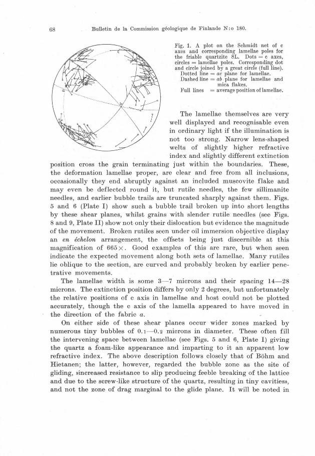
68 Bulletin de la Commission geologique de Finlande N: 0 180.
Fig. 1. A plot on the Sehmidt net of c axes and eorresponding lamellae poles for the friable quartzite 8L. Dots = e axes, cireles = lamellae poles. Corresponding dot and eirele joined by a great circle (fullline).
Dotted line = ac plane for lamellae. Dashed line = ab plane for lamellae and
miea flakes. Full lines = average position oflamellae.
The lamellae themselves are very weIl displayed and recognisable even in ordinary light if the illumination is not too strong. N arrow lens-shaped welts of slightly higher refractive index and slightly different extinction
position cross the grain terminating just within the boundaries. These, the deformation lamellae proper, are clear and free from all inclusions, occasionally they end abruptly against an included muscovite flake and may even be deflected round it, but rutile needles, the few sillimanite needles, and earlier bubble trails are truncated sharply against them. Figs. 5 and 6 (Plate I) show such a bubble trail broken up into short lengths by these shear planes, whilst grains with slender rutile needles (see Figs. 8 and 9, Plate II) show not only their dislocation but evidence the magnitude of the movement. Broken rutiles seen under oil immersion objective display an en echelon arrangement, the offsets being just discernible at this magnification of 665 x. Good examples of this are rare, but when seen indicate the expected movement along both sets of lamellae. Many rutiles lie oblique to the section, are curved and probably broken by earlier penetrative movements.
The lamellae width is so me 3-7 microns and their spacing 14-28 microns. The extinction position differs by only 2 degrees, but unfortunately the relative positions of c axis in lamellae and host eould not be plotted aeeurately, though the c axis of the lamella appeared to have moved in the direetion of the fabric a.
On either side of these shear planes oeeur wider zones marked by numerous tiny bubbles of 0.1-0.2 mierons in diameter. These often fill the intervening spaee between lamellae (see Figs. 5 and 6, Plate I) giving the quartz a foam-like appearanee and imparting to it an apparent low refractive index. The above description follows closely that of Böhm and Hietanen; the latter, however, regarded the bubble zone as the site of gliding, »increased resistance to slip produeing feeble breaking of the lattiee and due to the serew-like structure of the quartz, resulting in tiny cavities», and not the zone of drag marginal to the glide plane. It will be noted in

Suomen Geologinen Seura. N: 0 30. Geologiska Sällskapet i Finland. 69
Fig. 7 (Plate II) that these bubbles are arranged regularly in parallellines, the spacing within and between iines being approx. 0.6 microns. Again it should be apparent that these bubbles, as in normal bubble trails, form a planar structure in the quartz which is sub-normal to the lamellae and approximately parallel to the c axis. The spacing of such planes is difficult to gauge; the detail can be measured only under oil immersion objective which allows of no rotation and the best example, that of the figure, shows two such planes greatly inclined to the section. They may be 4 or 40 microns apart judging from the few examples which could be estimated. By analogy with Fairbairn's (1949) and Tuttle's (1949) explanations of normal bubble trails these too probably represent partially healed cracks in the quartz.
A possible interpretation of these structures may be that translation gliding takes place along relatively widely but variably spaced planes with some ben ding of the lattice at the place of shear, resulting in a slightly different orientation and higher refractive index. The observed and measured movement is in agreement with that required to bend the lattice 2 degrees, i.e. the difference in extinction position between lamellae and host, out of straight across a shear zone 3-7 microns wide; this movement is about 0.33 microns or some 33 X the size of the mosaic blocks. Movement at this plane then accentuates the mosaic flaws on one or both sides producing tiny fractures sub-parallel to c, a direction of fracture common to all quartz grains. Partial healing of these fractures leaves behind the
Fig. 2. Histogram of C 1\ 1. L values. The frequency is given in number of grains, and the angles in degrees.
The lower plot represents the friable quartzites of Kinahmi. The upper plot represents the glassy quartzites of Kuopio and Kinahmi.

70 'Bulletin de la Commission geologique de Finlande N: 0 180.
bubble zone or Böhm striation. Fig. 11 in Hietanen's work pictures a similar relationship, but is interpreted as the result of two periods of gliding, the bubble »trails» in the striations making an angle of 40° with striations themselves.
Such a mechanism must occur at the initiation of a stress field, the duration of which in time would lead to complete obliteration of all the intragranular structures. It is significant that most authorities date the origin of the lamellae late in the deformation history of the rock.
A frequency histogram of the c 1\ -.-l L relationship allows a close comparison with similar diagrams published by Fairbairn (1949) and Ingerson and Tuttle (1945). This diagram (Fig. 2) summarizes the lamellae orientations for all the friable quartzites collected and again indicates a marked tendency for the glide planes to lie between 8- 25 degrees from the basal plane with 15 degrees as the most favoured position. At greater inclinations than 25 degrees very few lamellae are developed and none were recorded with a c A -.-l L angle greater than 65 degrees. The maximum at 15 degrees ac cords well with the results of Fairbairn but these rocks show only a very faint tendency to give a second maximum between 25 and 30 degrees.
None of the lamellae can be related to grain elongation, another factor limiting the amount of displacement along them. Occasionally two sets of lamellae are preserved within a single grain and intersect at low angles of 18- 23 degrees (Fig. 10, Plate II); usually one set is dominant and the other almost obliterated and obviously the first formed. Rotation of the quartz grain may have produced this effect since both sets belong to one maximum of lamellae poles. The term deformation lamellae with Böhm striations seems most appropriate for describing this variety.
LAMELLAE OF THE GLASSY QUARTZITES OF KUOPIO AND KINAHMI
These glassy rocks of coarse grains, often elongate parallel to the mica foliation and united by suturing at their margins, offer ~ contrasting type of deformation lamellae to those described above. They are invisible in reflected or transmitted ordinary light, being seen best under crossed nicols close to the extinction position of the host grain (see Fig. 13, Plate III) or by phase contrast illumination (see Fig. 12, Plate II) . It will be appreciated that here, in rocks of far coarser grain, the whole quartz is involved in this plastic deformation. The planes of shear again have a higher refractive index (see Fig. 12, Plate II) and are but 1-2 microns in thickness occurringat one margin of a broader zone 3-14 microns in thickness which differs in extinction angle from neighbouring lamellae by 1 degree. Riley (1947), for what must be similar structures, gives a spacing of 2.5-17

Suomen Geologinen Seura. N: 0 30. Geologiska Sällskapet i Finland. 71
microns. Bubble zones are characteristically absent and the lamellae more irregular in their form, often curving and lens-shaped. This latter feature probably explains the difficulty in observing them, for too thick a slide or too steep an inclination on the U-stage will show overlapping lamellae. A section of standard thickness cut normal to both sets is therefore ideal for their study. Rutile needles again evidence the scale of the deformation, which is of a similar order to the contrasting variety but far more penetrative.
The frequency histogram (Fig. 2) brings out a far greater scatter of values for c 1\ ~ L with a far higher proportion of the lamellae, than previously recorded, more steeply inclined to the basal plane than 50 degrees. A continuous spread of orientations from 10-90 degrees c 1\ --.l L is seen with two maxima, one at 22-23 degrees, very elose to the second maximum recorded by Fairbairn (1949), and another at 69- 70 degrees not previously observed. Both maxima were found in the readings from a single slide of a Kuopio quartzite but that at 69°-70° was subordinate, being emphasized in Fig. 2 by observations from other rocks; one Kinahmi sam pIe showed only the high angle lamellae.
Quite commonly two sets of lamellae exist in the same grain (Fig. 14, Plate III) and usually intersect at an angle approaching 90 degrees; each set then belongs to different lamellae pole maxima. Many grains show a vague cross-hatching, particularly those having a similar orientation to grains with well-developed lamellae. Sometimes this appearance is but an asterism seen in the 45 degree directions between crossed nicols where the quartz is strained around any foreign inelusions; at other times it is due to intersecting sets of lamellae.
RELATIONSHIP BETWEEN THE TWO V ARIETIES OF LAMELLAE
Many specimens collected from Kinahmi Ridge show all stages in the breakdown of glassy quartzites to friable granular rocks. Such specimens often possess both types of lamellae, near basal and near rhombohedral deformation lamellae in the larger relict grains, and near basal deformation lamellae with Böhm striations in the small granules broken from them. In these instances the lamellae pole maxima for both varieties are coincident though but few readings of each type are obtainable from each thin section. This identity of the 8 planes within the quartz implies a common stress field but different degrees of freedom during their formation. Those of the small granules experienced a high degree of freedom allowing the quartz grains to occupy a larger space and rotate into a position most favourable for translation gliding. Both these requirements are witnessed by the open grain boundaries which exist in these rocks; Fig. 11 (Plate II) illustrates

72 Bulletin de la Commission geologique de Finlande N: 0 180.
this point. Tiny fragments of quartz, still possessing sharp corners and edges like shards, occur loose in the wide open intergranular space. The whole rock must be impregnated before cutting and possesses a flexibility approaching that of an itacolumite. Moreover, the radiating sillimanite clusters typical of the glassy rock have obviously been partially destroyed by grain rotation.
Translation and the associated fracturing of the lattice must have proceeded with almost complete freedom to increase in volume. In the compact rocks, however, where grains are still sutured and welded together, this increase in volume would be restricted. Consequently, open fractures would be inhibited and no bubbles would be observed.
No complete gradation has been observed between these lamellae types; those with accompanying Böhm striations can be seen in compact rocks, and with some the foam-like zones are almost lacking. No lamellae free of Böhm striations, however, occur .in the friable rocks (see Fig. 1), suggesting that under conditions of least restraint upon the quartz grains during deformation translation occurs on I;lear basal planes, but with greater restraint other planes more steeply inclined to the c axis are utilised, thus allowing a plastic deformation on a greater number of quartz grains less favourably orientated.
The healing of the tiny tension cracks produced by slip suggests the presence of some pore fluid though its volume and influence must have been small. Similar environments were reproduced in the Griggs and Bell (1938) experiments, when translation lamellae failed to appear and it may be that the time-stress relationship is all-important; shock loading of metal single crystals according to Maddin and Ohen (1954) results in a greater incidence of slip lines more closely spaced across the test piece.
LAMELLAE ORIENTATION
Measurements of the c 1\ ~ L angles offer no evidence of slip on rational crystallographic planes. Indeed the theoretically ideal translation planes seem to be avoided despite the wide scatter of all the lamellae positions. It may be that slip occurs so easily in these directions that it leaves no evidence behind, an ease contradicted by the Griggs and Bell experiments and by lack of elongation in the grains of the friable quartzites. Alternatively, slip may be too difficult and the usual considerations of close packing have no control in the quartz lattice. This would be contrary to the mechanism of translation gliding in other silicate minerals. One seems left then with the hypothesis ohFrontwendung>} (change of front) advocated by Schmidt and Hietanen. Here the necessary rotation of the c axis under the influence of shear couples could occur on blocks of sub-microscopic

Suomen Geologinen Seura. N: 0 30. Geologiska Sällskapet i Finland. 73
size, possibly the mosaic blocks, when the actual displacement of inclusions at any one point would be too small to observe even with a rotation equivalent to 20-30 degrees. In this respect it must be noted that not only does the single maximum of Fig. 2 occur some 15 degrees away from the basal plane, which would in this case be the assumed plane of gliding, but this value would vary for each particular rock giving maxima in slightly different positions and indeed may vary for each set of s-planes developed within one rock producing a double maximum.
In the c 1\ -.l L relations for the glassy quartzites both peaks are some 20- 25 degrees away from the positions of basal and rhombohedral planes; the second maximum of 69- 70 degrees could even point to slip on a prism face as weIl.
Such rotations of the lattice have been used by metallurgists to explain the rotation of the slip planes of a rigidly clamped test piece into orientations normal to the compressive or parallel to the tensile stress. Recrystallization of this order might look unusual in the friable rocks where no such process has affected the marginal and intergranular fragments. The rotation is smaller than that for the compact rock and healing of small tension cracks has occurred within the grains themselves.
This mechanism of change of front may ac count for another character observed by Ingerson and Tuttle (1945) and Riley (1947) and noted also from these Finnish rocks. Plots of the c axes, the corresponding lamellae poles, and the great circles on which they both lie, from any one section, always show the pole positioned between c and a of the fabric . Ingerson and Tuttle offer an explanation of this which presupposes orientation of the quartz grain in a certain position. The resolved shear stress along one of the two possible glide planes inclined at 15-20 degrees to (0001) will then be greater than for the other. When the grains are free to rotate this explanation no Ion ger applies but any change of front, resulting from the couple acting on the quartz between neighbouring lamellae, might rotate the c axis away from a in the direction of the fabric c. Coupled with this may be the tendency for low quartz to recrystallize with its c axis parallel to the shear plane due to a difference in compressibility normal and parallel to this c axis (Sonder, 1933; Hietanen, 1938; Eskola, 1939; and Fairbairn, 1949).
The deformation lamellae of Fig. 1 show many departures from this rule , the great circles joining c to L are widely divergent from the ac plane. This could be due to glide line control of slip on planes inclined to (0001) and to explore this possibility the poles to these great circles were plotted. These fall on a fairly narrow zone through b, the ac plane being markedly avoided, but no favoured positions occur, the distribution being even. In Fig. 3 these c 1\ -.l L great circles are more parallel to one another but
12

74 Bulletin de la Commission geologique de Finlande N: 0 180.
Fig. 3. A plot on the Sehmidt net of e axes (dots) and lamellae poles (eu eIes) for t he glassy quartzite 37KIN. Great eireles join the eorresponding e axis and larnella pole.
Full line = average position oflarnellae. Dotted line = ac plane of lamellae. Dashed lines = spread of rniea s planes.
Fig. 4. Contoured dia gram of 200 e axes frorn the glassy quartzite 37KIN (Sehmidt net). Non-seleetive. Contoured 1, 2, 3, 4 %.
Max. > 4 %.
inclined to the ac plane at approximately 60 degrees for each maximum. This is but one example, yet the value could be significant and indicate glide line control for slip on the rhombohedral plane.
Finally, all the rocks studied indicate that although lamellae are produced early in response to a compression which must occur at the close of aperiod of deformation for them to be preserved at all , they do induce a preferred orientation of their own on the quartz grains. This is contrary to the conclusion of Ingerson and Tuttle (1945), though invoked by many workers to account for the various preferred orientations observed in quartz-bearing rocks. As noted in the introduction all the Kuopio and Kinahmi quartzites have been metamorphosed to the sillimanite grade and their quartz grains have been oriented in a strong girdle. Much later a second deformation has led to granulation at certain localities and a new strain imposed asymmetric to the older fabric. In many cases parts of the girdle have been favourably orientated with respect to the later stresses for lamellae to develop in the quartz without its rotation in space being required. Fig. 4 shows such an example; lamellae for both sets of shear planes are derived from two close maxima on the girdle, which shows a spread of some 30 degrees at this point and would allow for any change in front of the grain after translation. Some deformation lamellae have a c /\ ~ L of 13- 17 degrees and possess Böhm striations; these occur in small grains, products of incipient granulation in the rock which is still

Suomen Geologinen Seura. N: 0 30. Geologiska Sällskapet i Finland. 75
massive in the hand specimen. Such grains have their c axes on an ac girdle referable to the last stress field.
This development of new maxima and even of girdles is even better exemplified in the friable rock. Aseparate diagram (Fig. 5) has been made to show up the distribution of c axes of grains with or without lamellae. The older girdle by chance cuts one new maximum, but where it intersects the new ac plane it becomes drawn out into a partial second girdle (Fig. 6) .
. ' . °
0, . ; .. ' ~ ...... --... -~ -- - -
0 •. ··
°0 .··· \
.. /" OQ
!k
;t 0 .. 00 0 ; i
. /
\ . .
---"' .... ..,.6.r; 0
'"i,' . 00 00
.e 00 ~
,,:: . .~,~ ..
0:;' 0 . .. /., ,,0
' .q. .' •
"'0 ,~.,/
' ,>;~<.
Fig. 5. A plot on the Sehmidt net of e axes for the friable quartzite 8L.
Dots denote grains with no lamellae. Cireles denote grains with lamellae. Dotted line represents the great eirele joining lamellae pole maxima. Dashed line represants the trend of the major girdle (see Fig. 6).
Fig. 6. Contoured dia.gram of sorne 400 e axes from the friable quartzite (Sehmidt net). Non-seleetive. Contours at 1, 2, 3,
4 %. Max. >4 %.
This new preferred orientation will be limited so long as lamellae can still be seen. The distribution of these follows no regular pattern within the confines of a thin section. Quartz grains with lamellae of similar orientation tend to occur in small groups and the whole fabric shows groups of quartz with the same interference colour and extinction position. This grouping is probably the only relic of the larger sutured quartzes and any sub se quent recrystallization would quickly lead to grain enlargement along the foliation.
The angle between the lamellae sets around c of the fabric call be estimated to the nearest 5 degrees and is, in all the friable rocks, an acute one, values such as 67°, 76°, 81° being recorded. This compares weIl with the value of 82 degrees between shear planes in compressed quartz test pieces quoted by Griggs and Bell (1938), and with corresponding values from the work of Fairbairn, Riley, Ingerson, and Tuttle.

76 Bulletin de la Commission geologique de Finlande N: 0 180.
The glassy rocks are at variance with such an intersection showing obtuse values of 130 degrees around the fabric c. The acute angle .would agree weil with that required for the initiation of shear planes, some internal friction causing adeparture from the ideal position, but it seems unlikely that as a result of continued deformation the lamellae of the sutured quartzes could have rotated into the planes of flattening. More probably the preexisting mica 8 planes determine the directions of movement within the rock and Fig. 3 illustrates this point; here one direction of the lamellae lies parallel to the dominant mica foliation. The friable quartzites are notably free from muscovite; a preferred orientation can just be discerned under the binocular microscope. These mica 8 planes are symmetrical to the quartz lamellae and the b axes of both coincide, though their angle about c is always obtuse. Since the micas are intergranular flakes, they must have borne a greater movement during granulation and have been free to rotate into the plane of flattening. In the sericite quartz schists of Kinahmi no quartz lamellae are developed, a feature noted by Riley (1947), and ascribed to the ease of slip on the mica.
SUMMARY
The principal conclusions resulting from this study might be conveniently listed below. (1) .The deformation lamellae and Böhm lamellae or striations appear to be complementary structures which under certain conditions appear in quartz as a result of translation gliding. The former marks the site of the glide plane and the latter evidence the frictional drag on either side of it. (2) Deformation by translation gliding can produce a new lattice orientation of the quartz grains, the pattern being an ac girdle with maxima between a and c. (3) The relationship between c axis, lamella pole, and direction of transport might weIl be explained by a change in orientation of the quartz during and after gliding.
ACKNOWLEpGEMENTS
The laboratory work has been carried out in the Geology Department of Queen's University, Belfast. To Professor A. Williams and my colleagues on the staff I offer my thanks for help and encouragement. Dr. W. Schwarzacher has patiently discussed the problems, proffered advice through all its stages, and criticised the final manuscript. My wife has undertaken the onerous task of correcting my English and presentation. The phase contrast illumination was achieved with the excellent unit supplied by Messrs. Cooke, Troughton and Simms.

Suomen Geologinen Seura. N: 0 30. Geologiska Sällskapet i Finland. 77
REFERENCES
BECKE, F. (1892) Petrographische Studien am Tonalit der Rieserferner. Tscherm. min. petr. Mitt. 13, p. 447.
BÖHM, A. (1883) Ueber die Gesteine des Wechsels. Tscherm. min. petr. Mitt. 5, p. 197. ESKOLA, P. E. (1939) Die metamorphen Gesteine. In BARTH - CORRENS - ESKOLA:
Die Entstehung der Gesteine, p. 263. Springer.Verlag, Berlin. FAIRBAIRN, H. W. (1949) Structural Petrology of the Deformed Rocks. Addison
Wesley Press, Inc., Cambridge, Massachusetts. GRIGGS, D. and BELL, J. F. (1938) Experiments bearing on the orientation of quartz.
BuH. Geol. Soc. Am. 49, p. 1 723. HIETANEN, A. (1938) On the petrology of the Finnish quartzites. BuH. Comm. gaol.
Finlande 122. INGERSON, E. and TUTTLE, O. F. (1945) Relations of lameHae and crystaHography
of quartz and fabric directions in some deformed rocks. Trans. Geophy!l. Union 26, 1, p. 95.
MADDIN, R . and CHEN, N. K. (1954) Progress in Metal Physics 5. Pergamon Press, London.
MÜGGE, O. (1896) Der Quarzporphyr der Bruchhäuser·Steine in Westfalen. N. Jahrb. Min. Beil. Bd. 10, p. 757.
RILEY, N. A. (1947) Structural petrology of the Baraboo quartzites. J. Geol. 55; p. 453.
SANDER, B. (1948) Einführung in die Gefügekunde dE'J geologischen Körper. SpringerVerlag, Wien und Innsbruck.
SMITHSON, F. (1948) The application of phase-contrast microscopy to miner!l>logy and petrology. Miner. Mag. 28, p. 384.
SONDER, R . A. (1933) Ueber Spannungsverteilung, etc. Schweiz. min. petr. Mitt. 13, p. 471.
TUTTLE, O. F. (1949) Structural petrology of planes of liquid inclusions. J. Geol. 57, p. 331. .

78 Bulletin de la Commission geologique de Finlande N:o 180.
EXPLANATION TO PLATES
PLATE I
Fig. 1. Friable quartzite 8L. Ordinary light. Ma.gn. 140 x . The lamellae are just diseernible and belong to both sets. The bubble zones show up as dark shadows aeross the grains.
Fig. 2. Friable quartzite 8L. Nie. +. Magn. 140 x . Lamellae elearly seen in some grains as welts of different extinction position.
Fig. 3. Friable quartzite 8L. Phase eontrast illumination. Magn. 140 x . Lamellae elearly seen in all grains.
Fig. 4. Friable quartzite 8L. Nie. +. Magn. 4 x . Sugar-grained texture of the rock illustrated -the two larger reliet grains are shown elongate in the ab plane. Tendeney exists for a grouping of grains with similar interferenee eolour.
Fig. 5. Friable quartzite 8L, single grain. Ordinary light. Magn. 930 x . Böhm striations seen as foam-like areas erossing the photo graph diagonally; the individual bubbles are not quite resolved. Shear zones of elear quartz oeeur between the striations. In the bottom left-hand corner an older bubble trail is sharply truneated against these shear zones.
Fig. 6. Friable quartzite 8L, single grain as in Fig. 5. Phase eontrast illumination. Magn. 930 x . The refraetive index differenee between quartz in the shear and bubble zone is now greatly exaggerated.
PLATE II
Fig. 7. Friable quartzite 8L, single grain. Nie. +. Magn. 850 x. Shear and bubble zones readily identified with the individual bubbles resolved- these appear in sharp foeus at two points along any one striation indieating their loeation on planes inclined to the photograph.
Fig. 8. Friable quartzite 8L, single · grain. Nie. +. Magn. 700 x . Trend of lamellae not well seen; they cross the photograph diagonally but are inelined to the plane 01 the seetion. En ech~loJ'( rutile needles are well developed but diffieult to relate to the lamellae. Some breakage must be attributed to an early period of translation gliding.
Fig. 9. Friable quartzite 8L, single grain. Dark field illumination. Magn. 560 x . Lamellae direetion just visible as light shadows, almost parallel to the E- W eross-hair. Broken rutile needles show up well under these conditions.
Fig. 10. Friable quartzite 8I., single grain. Phase eontrast illumination. Ma'gn. 560 x . Two sets of lamellae cross at a small angle. One set (subordinate) is parallel to the E- W eross-ha.ir, the other (dominant) is inelined so me 20° to it. The grain boundaries are flecked with tiny flakes of pyrophyllite.
Fig. 11. Friable quartzite 7KIN. Nie. +. Magn. 140 x . The figure illustrates the open boundary (dark) between two illuminated quartz grains. The spaee is partially filled with loose quartz »shards».
Fig. 12. Glassy quartzite 560ak. Phase eontrast illumination. Magn. 120 x . The fine lamellae are elosely spaeed and in plaees strongly eurved and lens-shaped. They are made visible by the narrow welts of lligher refraetive index quartz along their boundaries.

BULL. COMM. GEOL. FINLANDE N:o ISO PLATE 1
Fig. 2
Fig o 5 Fi 90 6
John Preslon: Quartz la m ellae in som e Finnish quartzites

BULL. COMM. GEOL. FINLANDE N:o 180 PLATE Il
F'9' 9 Fi g. 10
Fig./I Fig" 12. J ohn p.reston: Quartz lamellae in some Finnish quartziteR

BULL. COMM. GEOL. FI JLANDE N:o 180 PLATE III
Fig. 13. Glassy qnartzite 560ak. :;\"ic. +. Magn. 175 x. Same grain as in Fig. 12 (Plate !T) , but illustrating better the true width of the lamellae and their slightly different
optical orientatioll.
Fig. H. Glassy q uart,zitc 560ak. l'iic. -1- . Magn. 280 x . Single grain showillg two sets 01
lamellae intersecting at a large angle.
John P1·eston: Quartz lamellac in same Finnish quartzites


5
THE LATE-GLACIAL PERIOD AND ITS CORRELATION WITH THE RETREAT STAGES OF THE ICE IN FINLAND 1
BY
JOAKIM DONNER
Institute 01 Geology, University 01 Helsinki
ABSTRACT
After correlating the Late-Glacial retreat stages of the ice in Finland with the vegetational periods, the difficulties in pollen analytical investigations of LateGlacial deposits in Finland are described.
CONTENTS Page
INTRODUCTION 79 THE LATE-GLACIAL RETREAT STAGES IN FINLAND AND THEffi DATING . . 80
THE POLLEN ANALYTICAL INVESTIGATION OF THE LATE-GLACIAL PERIOD
IN FINLAND .. . . ...... . .... ... .................. ... ...... . ... 81
REFERENCES .................................................. . 85
INTRODUCTION
In recent years our knowledge of the vegetational development during the Late-Glacial period has greatly increased through the detailed investigations carried out in the British Isles and Central and Northern Europe. In connection with the study of the vegetational history an attempt has also been made to correlate the main Late-Glacial vegetation al periods with the retreat stages of the ice. This has so far been one of the main problems in the pollen analytical investigations in Finland. In the more detailed study of the history of the vegetation and flora it is naturally
1 Received May 2, 1957.

80 Bulletin de la Commission geologique de Finlande N: 0 180.
of great importance to know the chronology and the relationship between the vegetation al periods and the stages of the ice retreat before, for instance, the immigration of the plants can be explained. It has been suggested that in southern and central Finland the change-over from an open vegetation to a more or less closed forest took place at the beginning of the Post-Glacial period, which corresponds to the beginning of the Finiglacial ice recession (Donner, 1951). However, the above-mentioned vegetation al change is not a magic formula to be used indiscriminately. In the present paper, after a general summary is given of the Late-Glacial period in Finland, an attempt is made to explain some reasons for the erroneous conclusions reached about this period in Finland.
THE LATE-GLACIAL RETREAT STAGES IN ,FINLAND AND THEIR DATING
The most striking marginal features formed during the retreat of the ice in Finland are the Salpausselkä ridges in the southern and southeastern parts of the country. Salpausselkä. I and II are well developed but Salpausselkä III is only clear in the south-west. The belt of the three Salpausselkä ridges can not with certainty be followed in the eastern and northern parts of Finland. The dating of the retreat stages here is still uncertain. The marginal terraces of Salpausselkä were formed during various stages of the Baltic ice-Iake, and the final drainage of this lake down to the sea-Ievel (= the Y oldia level) corresponds to the beginning of the ice retreat from Salpausselkä III (Sauramo, 1934, 1937, 1940). According to Sauramo's chronology based on varved clays (Sauramo, 1918, 1923, 1940) the above-mentioned last drainage of the Baltic ice-Iake occurred at 7 858 B.C. (the corresponding date determined by De Geer, 1940, being at 7912 B.C.), and the first halt of the ice at Salpausselkä I was at 8 810 B.C. Thus the period during which the three Salpausselkä ridges were formed is ca. 8800-7 900 B.C. The results obtained from pollen analytical investigations of mainly organic sediments from southern Finland, Finnish and R ussian Carelia and Sweden (Donner, 1951) suggest that the Younger Dryas period, zone III, corresponds to the formation of the Fennoscandian moraines, including the three Salpausselkä ridges, and that the beginning of the Post-Glacial period corresponds to the beginning of the ice retreat from Salpausselkä III. Furthermore, it is suggested that the Alleröd period, zone II, corresponds to the retreat of the ice to the Fennoscandian moraines. At the beginning of the PostGlacial period there was a general expansion of the forest. During the Younger Dryas period the ice-free supra-aquatic areas in Finland had an open vegetation (Donner, 1951).

- ------ ----
Suomen Geologinen Seura. N: 0 30. Geologiska Sällskapet i Finland. 81
Summarising the above-mentioned results in Finland, we get the following correlation between the Late-Glacial retreat stages, the pollen analytical zones and the chronology based on varved clays:
R etreat stages
Salpausselkä III Salpausselkä II Salpausselkä I
Zones IV
III
II
Varve chronology
7900 B .C.
8800 B .C.
This correlation is confirmed by ·radiocarbon datings of Late-Glacial deposits in Denmark (Anderson, Levi and Tauber, 1953; Iversen, 1953; Krog, 1954) and other parts of Europe (see summary by Gross, 1952, 1954). In Finland the dates obtained for the Late-Glacial periods (zones) are indirectly based on the chronology of varved clays, but elsewhere they are directly based on radiocarbon dating. Thus the pollen analytical zones have been correlated in two different ways with the absolute chronology.
There has so far been no serious dis agreement in the interpretation of the results. In Finland there are so me contrary results which might, however, be interpreted differently and in agreement with former results if they are reconsidered. So me of the reasons for the confusion in the interpretation of the Late-Glacial period in Finland will be discussed in the next chapter.
THE POLLEN ANAL YTICAL INVESTIGATION OF THE LATE·GLACIAL PERIOD IN FINLAND
On the basis of investigations in different parts of Europe it can be said that the Y ounger Dryas period, zone III, is a synchronous stage; a cold oscillation in the improving climate after the last ice age. It can also be said that the correlation of the Y ounger Dryas period with the formation of the Fennoscandian moraines is likely to be correct. The conclusion that the change of vegetation in southern Finland from tundra to closed forest is at the beginning of the Post-Glacial period is based mainly on the marked decrease of non-tree pollen in the diagrams, but also on relative changes in the tree pollen, the absolute frequency of pollen and the pollen density (Donner, 1951). This interpretation is to a large extent based on Aario 's (1940) results from recent surface-samples of peat from PetsamoLapland. In the sampIes of late zone III deposits the non-tree pollen are 30- 200 per 100 tree pollen, and the main components are Ohenopodi-
13 5290-57
l

82 Bulletin de la Commission geologique de Finlande N: 0 180.
aceae, Oyperaceae, Ericales and Gramineae; but Artemisia, Salix and Hippophae are also common (Donner, 1951). Of the tree pollen Betula is dominating but Pinus has higher values than in the later zone IV deposits. This relatively high amount of Pinus is caused by long distance transport of tree pollen to the woodless area, whereas in the birch region the local Betula pollen are dominating (= the Pre-Boreal birch maximum). ' The non-tree pollen / tree pollen ratio, together with the absolute pollen frequency and pollen density, used for demontsrating tundra conditions in Finland have primarily local value and are not necessarily directly applicable in other regions (see Livingstone, 1955).
The above-mentioued change in pollen composition, reflecting a development from tundra to forest, is found in deposits representing the changeover from the Late-Glacial to the Post-Glacial period, but it can also be found in deposits representing other periods. This can either be caused by secondary pollen or by ecological conditions and / or historical factors reflecting a local »tundra», which is not the same as the Late-Glacial tundra.
The investigation by Heinonen (1957) of tills and glacial clays has proved that they contain a surprisingly great amount of pollen and diatoms, and even some macrofossils, which mainly originate from deposits of the last interglacial period. All the main tree pollen and non-tree pollen found in organic Late- or Post-Glacial deposits are present in the tills; it may also be mentioned that Heinonen found Oarpinus pollen north of the Gulf of Bothnia. Often the percentages for the different pollen types are the same in the tills as in the glacial clays of the same area. It is clear from Heinonen's work that the secondary influence is so strong in minerogenie deposits that an interpretation of the vegetational development can not be based on pollen analysis of glacial clays, unless it is possible to subtract the secondary pollen from the total amount of pollen, as done by Iversen in Denmark (Iversen, 1936). The clays often contain a relatively high amount of non-tree pollen. Consequently a stratigraphie al change from elay to organic sediments often shows a clear fall of the non-tree pollen curves, as if there had been a change from open vegetation to closed forest. On the other hand there can be cases where the lowermost organic sediments have high non-tree pollen values and the underlying clay has lower non-tree pollen values. Then the stratigraphie change reflects a false change from closed forest to tundra, which is not to be confused with the boundary between the Alleröd and Y ounger Dryas periods. One can also find seemingly regular changes in the non-tree pollen / tree pollen ratio in a long clay profile. If the said changes in the pollen composition in L ate- and Post-Glacial clays are used for dating these clays, we soon have the Finnish chronology in a very confused state. In areas where the shore-line displacement and the retreat of the ice are weIl known it

Suomen Geologinen Seura. N: 0 30. Geologiska Sällskapet i Finland. 83
is of course possible to date the clays. In this way Kanerva (1956), for instance, was able to show the presence of Late-Glacial deposits in Hyrynsalmi in north-eastern Finland. The clays laid down in the Baltic icelake can be said to represent the Younger Dryas period, and the clays laid down in the older Gothiglacial Yoldia sea to represent the Alleröd period, but an interpretation of the vegetational or climatic development during these periods can hardly be based on the pollen composition in these clays. In some clays formed further away from the ice margin, or formed during the Post-Glacial period, the secondary influence might be so small that the pollen analytical zones can be recognised, even if the pollen curves are slightly different from wh at they are in corresponding organic sediments.
N s
A . LATE-GLACIAL, YOUNGER ORYAS
Ice iiili ii~a
-~=::------------=---_---_---_-- Balt ie Sea
B . EARLY POST-GLACIAL
Tundra? ~......-.. Forest " " - ~ra
--=~=-------------
C PRESENT
Fore st "'''iClJ'':U''IIIIO:lIltDlI:nirII:~ra''
---~=------
Fig. 1. Schematical profiles of southern Finland showing three different stages of vegetational development.
Even if the above-mentioned influence by secondary pollen is taken into account in the interpretation of the pollen diagrams, there are sOme Post-Glacial diagrams in which the pollen composition in the lowermost organic sediments reflects an open vegetation. An attempt will now be made to explain why Post-Glacial pollen spectra can reflect »tundra» con-

84 Bulletin de la Commission geologique de Finlande N: 0 180.
ditions even after the general spread of the forest in the beginning of the Post-Glacial period. In Fig. 1 three schematical profiles of southern Finland are given of three different stages of vegetation al development. In Fig. 1 A shows the conditions during the Younger Dryas period when the Salpausselkä ridges were formed. The Baltic ice-lake covered most parts of the ice-free areas in southern Finland; only the highest parts of the Salpausselkä ridges and so me islands rose above the level of the icelake. These small areas of dry land had an open vegetation. In eastern Finland, where the area of dry land was larger, the vegetation was also open near the ice margin, but further east, in eastern Carelia, there was probably park-tundra. The tundra stage of the Younger Dryas period is found in a number of pollen diagrams from sites outside the Salpausselkä ridges (Donner, 1951). During the beginning of the Finiglacial retreat of the ice, in the early Post-Glacial period, the forest followed close after the retreating ice margin, but there was probably, at least in some areas, a narrow tundra belt near the ice margin (Fig. 1, B). In some cases deposits inside the Salpausselkä ridges might reflect this short period of open vegetation. Thus the fall of the non-tree pollen in the diagrams can be delayed and it does not always represent the true Late-Glacial / PostGlacial boundary. This is shown to be the case in Scotland, where the zone IV period still had an open vegetation (Donner, 1957). The early Post-Glacial retreat of the ice occurred at the same time as the Y oldia regression of the sea. Thus the forest not only expanded northwards after the retreating ice, but it also expanded southwards after the retreating sea. We know that the often broad archipelago off the Baltic coast of Finland has an outer woodless belt. There is no reason to think that this belt was formed very recently; it is likely to have followed the receding sea during all periods of the relative uplift of land since the ice retreated. Consequently one can expect to find sediment series where the lowermost sampIes represent the »tundra» vegetation of the archipelago or so me forest sociation of it. It is interesting to note that there are some forest types which resemble the North-Finnish types, as, for instance, the Empetrum- Vaccinium type (Skult, 1956). It can be mentioned that so me pollen diagrams from the southern coastal area have high percentages of Empetrum (Donner, 1952), which is in agreement with what is known about. the present vegetation of the archipelago. Through a closer analysis of the non-tree pollen and the geological conditions it ought to be possible to distinguish between the two above-mentioned »tundras» of the PostGlacial period, i.e. that following the ice and that following the sea. Furthermore, if the Late- and Post-Glacial history is taken into account, these »tundras» ought not to be confused with the tundra of the LateGlacial period.

Suomen Geologinen Seura. N: 0 30. Geologiska Sällskapet i Finland. 85
In Fig. 1 C gives the conditions in southern Finland at present. There is still the woodless zone of the archipelago; the rest is covered by forest.
The schematical profiles in Fig. 1 only show the development in southern Finland. In the present woodless area and near it the vegetational history must be quite different from what it is in central and southern Finland, and therefore the changes in the pollen diagrams during the Lateand Post-Glacial period are also different. Thus the demonstration of tundra has not the same significance as it has further south in the recognition of the Late-Glacial period.
Apart from all the above-mentioned cases where Post-Glaeial sampIes ean refleet »tundra» eonditions, i.e. high non-tree pollen values in the pollen diagrams, there is still another faetor whieh ean be mentioned. In the arehipelago and also around the larger lakes the shore vegetation sometimes ean have a rather strong influenee on the pollen ra~n. The most striking influenee is probably that of Alnus glutinosa whieh at present is very eommon around shores. It sometimes oeeurs in Post-Glaeial pollen diagrams already before its general spread in the beginning of the Atlantie period. In the Helsinki area, for instanee, it was eommon already during the early Boreal period (Sauramo, 1936, 1954; Donner, 1954). This was probably due to suitable local conditions during that period. Probably not only the amount of Alnus pollen is different from »normah> diagrams; one mayaIso expeet to find the effect of non-tree pollen from plants growing on shores, and this might somewhat inerease the non-tree pollen percentage.
The above-mentioned pitfalls in interpreting the pollen diagrams have not been discussed in detail, but the discussion might give an idea of some of the difficulties in the study of the Late-Glacial period in Finland. It is hoped that the diseussion shows the necessity for further detailed pollen analytical work where the geologie al and eeologieal conditions are taken into aeeount more than has been done previously.
REFERENCES
AARIO, L. (1940) Waldgrenzen und subrezenten Pollenspektren m Petsamo Lappland. Ann. Acad. Sei. Fennicae, Sero A, 54, 8.
ANDERSON, E. C., LEVI, H. and TAUBER, H. (1953) Copenhagen Natural Radiocarbon Measurements, 1. Science 118, 3 053, p. 6.
DE GEER, G. (1940) Geochronologia Suecica, Principles. Kungl. Svenska Vet.Akad. Handl. 18, 6.
DONNER, J. J. (1951) Pollen-analytical studies of Late-Glacial d eposits in Finland. BuH. Comm. geol. Finlande 154, p. 1.
-,)- (1952) On the early Post-Glacial shore-line displacement in Southeast Finland. Ann. Acad. Sei. Fennieae, Sero A, III, 29.

86 Bulletin de la Commission geologique de Finlande l-: 0 180.
DONNER, J. J. (1954) Measurements of pollen of AInus glutinosa and A. incana. Bul1. Comm. geol. Finlande 166, p. 49.
-~- (1957) The geology and vegetation of Late-Glacial retreat stages in Scotland. Trans. Roy. Soc. Edinburgh 63, p. 221.
GROSS, H. (1952) Die Radiokarbonmethode, ihre Ergebnisse und Bedeutung für die spätquartäre Geologie, Paläontologie und Vorgeschichte. Eiszeitalter und Gegenwart 2, p. 68.
-»- (1954) Der Alleröd-Interstadial als Leithorizont der letzten Vereisung in Europa und Amerika. Eiszeitalter und Gegenwart 4/5, p. 189.
HEINONEN, L. (1957) Studies on the microfossils in the tills of the North-European glaciation. Ann. Acad. Sei. Fennicae, Sero A, 111, 52.
IVERSEN, JOHS. (1936) Sekundäres Pollen als Fehlerquelle. Danmarks Geo1. Unders0gelse, IV Raekke, 2, 15.
-1)- (1953) Radiocarbon dating of the Alleröd period. Science 118, 3053, p. 9. KANERVA, R. (1956) Pollenanalytische Studien über die Spätquartäre Wald- und
Klimageschichte von Hyrynsalmi in NO-Finnland. Ann. Acad. Sei. Fennicae, Sero A, 111, 46.
KROG, H. (1954) Pollen analytical investigation of a C U-dated Alleröd section from Ruds Vedby. Danmarks Geo1. Unders0gelse, 11 Raekke, 80, p. 120.
LIVINGSTONE, D. A. (1955) Some pollen profiles from arctic Alaska. Ecology 36, 4, p. 587.
SAURAMO, M. (1918) Geochronologische Studien über die Spätglaziale Zeit in Südfinnland. Bul1. Comm. geo1. Finlande 50; Fennia 41, 1.
- »- (1923) Studies on the Quaternary varve sediments in Southern Finland. Bul1. Comm. geo1. Finlande 60, p. 1.
- »- (1934) Zur spätquartären Geschichte der Ostsee. Bull. Comm. geo1. Finlande 104, p. 28.
- »- (1936) Der von der Ancylustransgression begrabene Erlenwald in RuotsiIikylä. Helsinki.
- »- (1937) Das System der spätglazialen Strandlinien im südlichen Finnland. Soc. Sei. Fennica, Comm. Phys.-Math. 9, 10.
- 1)- (1940) Suomen luonnon kehitys jääkaudesta nykyaikaan. Porvoo-Helsinki. - »- (1954) Das Rätsel des Ancylussees. Geo1. Rundschau 42, 2, p. 197. SKULT, H. (1956) Skogsbotaniska studier i Skärgärdshavet. Acta Bot. Fennica 57.

6
STONE COUNTS IN THE ESKER OF HAMEENLINNA, SOUTHERN FINLAND 1
BY
K. VIRKKALA
Geological Survey 01 Finland, Otaniemi
ABSTRACT
This paper deals with stone counts, made in different grain sizes, of the material of the H ämeenlinna esker. The results of the stone counts are compared with the pre-Quaternary rocks of the area, with the topography and with the lithologie composition of the till.
CONTENTS Page
INTRODUCTION .......•...........•... . ...............••........ 88
THE METHODS OF INVESTIGATION . . . . . . . • • . . . . • • . . . . . . . . . . . . . . . . . . 89
PRE-QUARTERNARY ROCKS . .. .................................... 90
THE MORPHOLOGY OF THE ESKER •..... .. . .. . . . .. .... .. .......... 91
STONE COUNTS . . ..... . . .... ..• ........... ... .•. . .... . ..... . . .. . 91
MICROCLINE GRANITE ....................... .............. . ... . .. ... . . 91
MICA SCHIST . ........... ..... ... . .......•............ .. ........... . .. 93
GRANODIORITE .... . ....... ............... ............ .. ..•.......... . 95 TUFFITE .......... . .......................... . ...... . ...... •. ..... ... 96 OTHER KINDS OF ROCKS ..... . ........................... . ............ 98
COMPARISON WITH THE PETROGRAPHIC COMPOSITION OF THE TILL .. .. 99
TRANSPORTATION OF THE STONE MATERIAL IN THE ESKER ...... . . .. 101
SUMMARY. . . . . . . . . . . . . . . . . . . . . . . . . . . . . . . . . • . . • • . . . . . . . . . . . . . . .. 102
REFERENCES ......... ... ........ .. .... .. . .......... . ......... . . 103
1 Received May 15, 1957.

88 Bulletin de la Commission geologique de Finlande N: 0 180.
INTRODUCTION
The petrographie composition of Finnish eskers has received relatively little attention. Scattered informations about the petrographie composition of our eskers exist in the explanations of the newer superficial maps. Hellaakoski (1930) has investigated in most detail the stone material in the esker of Laitila in SW-Finland. He has especially observed the transportation of the esker stones and compared their petrographie composition with that of morainic drift.
Esker stones have been carried, according toHellaakoski, only a few kilometers from their source. The stone material in the esker is more local and more homogeneous than in the morainic drift of the vicinity. Okko (1945) later obtained about the same results in regard to the stone material of the esker of Mikkeli. He further observed vertical changes in the petrographie composition of the esker stones.
The present investigation is connected with the mapping of superficial deposits performed by the writer during aperiod of several years in the area of the Hämeenlinna map sheet. The petrographie composition of esker stones has been an object of detailed investigation because: 1) a new map of the area, with an explanation of the pre-Quaternary rocks, is available (Sirnonen, 1949a, 1949b); 2) the pre-Quaternary rocks in the Hämeenlinna area are rather variable and it is thus possible to elucidate the tranportation of the different kinds of rocks in more detail than in an area of more homogen~ous bedrock. The mapping of the pre-Quaternary rocks carried out by Dr. Härme immediately north of the Hämeenlinna area is taken advantage of in this investigation, too.
The esker of Hämeenlinna is in this publication understood to be the esker chain beginning from the first Salpausselkä ridge near the Hikiä railway station, some kilometers east of the town of Riihimäki, and continuing nearly uninterruptedly about 60 km past the town of Hämeenlinna and ending finally at the southern shore of Vanajavesi. Separate parts of the esker chain are called by different names.
The part of the esker under investigation includes altogether 38 kms of the esker chain on both sides of the town of Hämeenlinna. Stone counts were made at 22 observation points and the average distance between different observation localities was thus 1.7 km. Fig. 1 presents the esker of Hämeenlinna with the observation localities and the kinds of rocks in the environment of the esker. Some stone counts were made, furthermore, in the lateral esker branching from the esker of Hämeenlinna on the south shore of Lehijärvi.
The stone counts were made by Mr. K. Korpela, M. A., Mr. R. Vanhala, M. A., and the writer. To both investigators the writer is deeply obliged for their valuable aid.

Suomen Geologinen Seura. N: 0 30. Geologiska Sällskapet i Finland. 89
CJ1 P7:"l4 ~
~7 @ 10
0 2
l~;:J 5
f:::=llB
l1li3 E==::=1 6
+1-22 9
Fig. 1. The esker of Hämeenlinna, the localities of the stone counts, and the pre-Quaternary rocks in the surroundings of the esker. 1 = the esker; 2 = microcline granite; 3 = mica schist; 4 = granodiorite; 5 = basic tuffite; 6 = acid tuffite; 7 = hornblende gabbro; 8 = hornblende gneiss; 9 = stone count of the esker; 10 = stone count of till. Mainly according to Bimonen
(1949a).
THE METHODS OF INVESTIGATION
N umerous stone counts were earried out to determine the petrographie composition of the esker material. They were made separately from material measuring 5-10 em and 20-100 em. The petrographie eomposition of 4-7 mm grains is determined in the laboratory under the mieroseope.
All stone counts were made in the existing gravel pits, whieh were very eommon in the esker, too. Determining the depth of the stones counted has been possible only in a very few eases beeause the walls of the gravel pits had mostly eollapsed. Thus the stone counts may be eonsidered to represent the average petrographie eomposition at the same
14

90 Bulletin de la Commission geologique de Finlande N: 0 180.
depth of t he esker material as the gravel pit. Usually the gravel pits penetrate to the basal parts of the esker.
At least a hundred grains of each of the three sizes were counted, whenever possible, at every single observation point. In two cases, so few of the larger stones could be found, however, that the count had be restr icted to 50 stones. At least 300 grains were so counted in every observation locality, at many points considerably more. In all , nearly 20 000 grains have been counted in connection with this investigation.
The division of the pre-Quaternary rocks used by Simonen (1949, a and b) was followed in the determination of the kinds of rock. It has not always been possible in the smallest grain size, from 4 mm to 7 mm, to distinguish basic and acid tuffites. Therefore tuffites are represented in one group.
Monomineralic grains appeared in the stone counts· carried out with 4 to 7 mm material. Feldspar grains were in this category included in the microcline granite, being the only kind of rock in the area containing feldspar grains of 4- 7 mm size in notable quantity. The quartz grains were counted separately. It is possible that some lack of accuracy may appear in the stone counts made from 4-7 mm material because determining rock kinds among grains of such small size-even under the microscope - has not always been exact.
PRE-QUATERNARY ROCKS
Figure 1 presents in slightly generalized form apart of the map of the pre-Quaternary rocks made by Simonen (1949a) in the Hämeenlinna area and by Dr. Härme in the area north of it. The figure illustrates the description of the pre-Quaternary rocks in the immediate environment of the esker, too, about 5 km on both sides of it. The rock map is, of course, correct only where outcrops exist. Relatively extensive areas without rock outcrops were situated, however, in the environment of the esker. The map of the pre-Quaternary rocks is at these points only presumptive.
The pre-Quaternary rocks on the northeastern side of the esker deviate somewhat from those on the southwestern side. The percentages of the different kinds of pre-Quaternary rocks of the land area on both sides of the esker and about 5 km from it are presented in the following.
On the NE-side of the esker, per cent of the land area
granodiorite ....................... 47. 3 microcline granite . ................ 35.0 tuffite .. .... . ... ..... . . ...... . .. . . 14.7 hornblende gabbro ................ 3. 0 mica schist ... ... ... ...... ....... .
On the SW-side of the esker, per cent of t he Ja nd arca
4. 1 57.7 22 . 4
4.4 11.4

Suomen Geologinen Seura. r : 0 30. Geologiska Sällskapet i Finland. 91
The distribution of the pre-Quaternary rocks underlying the esker deposits is as folIows, according to Simonen and Härme:
microcline granite ........ . granodiorite ............. . uralite porphyrite ........ . hornblende gabbro ....... .
46.0 per cent 24.4 21. 6 »
8.0
THE MORPHOLOGY OF THE ESKER
The esker of Hämeenlinna is situated mainly on the western shore of Lake Vanajavesi and its southern extension 1/2-3 km from the lake. A ridgelike form by no means prevails. Only in certain places and in short sections is there a typical esker ridge. The esker of Hattelmala, south of the town of Hämeenlinna, is the best known among these. North of Lake Lehijärvi the esker in places likewise forms a typical ridge. The esker is broken commonly in kettle and knob topography, caused by stagnant ice. This is especially the case a few kilometers NW and SE of the village of Turenki. Some kettles are here as much as 60-70 meters deep .
Near Hämeenlinna the top of the esker forms even plateaus situated at the same altitude. The plateau around the Ahvenisto sanatorium, the vicinity of the Army school for dogs and the hill of Pullerinmäki are examples.
The esker r~aches its greatest height about 80 meters above its surroundings. The summits of the esker on both sides of the Turenki village attain an altitude of 160 meters above sea level. They do not exceed 135 meters to the NW from here.
STONE COUNTS
MICROCLINE GRANITE
Microcline granite is met with in the esker almost solely in its SE part, as might be expected on the basis of the map of the pre-Quaternary rocks. Only gravel material in observation locality 17 makes an exception. Microcline granites here surprisingly and suddenly account for altogether 40 per cent of the grains of 4- 7 mm size.
Figure 2 presents the appearance of the microcline granites in the esker. Every grain size is represented with its own line. Microcline granite appears among the esker material in a small degree as soon as the esker reaches the area of microcline granite in the bedrock. The amount increases relatively slowly. It first forms about a half of the stone material 7- 9 km from the proximal contact, although extensive and homogeneous areas of microcline granite spread on both sides of the esker. The stone material first reaches maximal values (70- 90 per cent) of the microcline granites

92 Bulletin de la Commission geologique de Finlande N: 0 180.
y,
90
dO 0-------<>--<> 2 -IDem _______ _ 0---0---0 > 20cm
70 I _____ ~==~==~.~4~-~7~mm~ _____ ~n_-~~~~~ I- 70
dO 1-----1 60
~O ·v-------1~
40 ß-------__I4O
.Ja I----/~\-----------:~~~-------__Ix
20 \---------~~----------~M
10 I---·I--~-----~=-J~~----------__I~
o 0 .Ja 2d Z6 Z;, ZZ ZO 18 I" 12 10 8 6 ;, 2 Okm f---f gr I m I
17 16 15 14 13 121110 9 8 7 5 4 3 2 1
Fig. 2. The appearance of microcline granites in the esker of Hämeenlinna. Numbers 0-30 present the distance from the most southeastern observation locality, numbers 1- -17 are different observation localities. 'fhe lowermost line represents the kind of bedrock underlying the esker, according to Simonen (1949a); m = microcline granite; gr = granodiorite; t = tuffite.
about 13 km from the proximal eontaet. The eorresponding pereentages are reaehed in the esker of Laitila, aeeording to Hellaakoski (1930) , at a distanee of about 13 km and 17 km from the proximal eontaet.
Figure 2 shows further that the amount of mieroeline granites inereases in the different grain sizes rather similarly and simultaneously. Farther from the eontaet the pereentage of the 20- 100 em grain sizes is slightly greater than that of the smaller grain sizes, to be sure, but this relation is not very eIe ar and not without exeeptions.
A rather extensive tongue of mieroeline granite is situated immediately SW of the esker and NW from its proximal eontaet (Fig. 1). This area has given very little if any mieroeline granite to the stone material of the esker, as is shown in observation loealities 11- 14. Its influenee on the 4- 7 mm grain size has also been very slight, even if barely pereeptible. Mieroeline granites appear in the stone counts (numbers 7- 12) of the neighborhood of the proximal eontaet more abundantly in the 4-7 mrn grain size than in the 5-10 em and 20-100 em grain sizes, although eoarser material should be supposed to dominate where the transportation has been shorter and the possibilities of erosion by glaeiofluvial streams thus have been smaller.
Topographie relations may be one explanation to the small influenee of the said mieroeline granite area to the petrographie eomposition of the neighboring esker. The summit of the esker rises here about 135 m above

Suomen Geologinen Seura. N: 0 30. Geologiska Sällskapet i Finland. 93
sea level and its base is about 100-105 m a .s.l. The highest points of the aforesaid microcline granite area situated SW of observation localities 11-14 rise 120 m a.s.l. and the average altitude of the land surface is about 100-110 m a.s.l. It is thus evident that the meltwater streams which here possibly flowed lacked the topographie conditions to carry from here more material into the esker.
The lack of microcline granites in observation localities 11-14 might also be explained on the basis of the direction of the meltwater streams. If the meltwater streams had flowed only in the direction of the esker, they would not have had any possibilities to carry microcline granites. If, again, meltwater streams had flowed from the side to the esker, too, the local topography would have prevented their transport in the esker.
MICA SOHlST
According to the map' of pre-Quaternary rocks (Fig. 1), mica schists do not at all occur under the esker in the bedrock. In the surroundings of the esker it is met with, on the contrary, in two separate areas. Tl;le smaller one is situated to the west of the town .of Hämeenlinna, on the northern shore of Lake Alajärvi, and the larger one exists between Lake Lehijärvi and Lake Vanajavesi. The former area is situated to the west of observation localities 12-15, at a distance of about 2-3 km from the esker. Its nearest known outcrops are situated at a distance of about 3 km from the esker. The aforesaid microcline granite area is thus situated between the esker and the area of mica schist. The nearest outcrops of the later mica schist area are situated 1/2-3 km from the esker. Mica schists comprise in the surroundings of the esker, and only on its SW-side a total of 11. 4 per cent of the land area.
The occurrence of mica schists in the esker is shown in Fig. 3. A distinct maximum is evident between observation localities 9 and 16, with peaks at points 12 and 13. This area of mica schists corresponds exactly to the point where they are met with in the bedrock north of Lake Alajärvi. It is quite evident that the mica schists in the esker have their source here. Attention is paid to the relatively abundant occurrence of mica schists in the esker, although mica schist comprises in the bedrock an area of only about 10 km 2 and situated at least 2 - 3 km from the esker. Mica schists account for 28 per cent of the 4- 7 mm material, 26 per cent of the 5-10 cm material, and 20 per cent of the larger stones. Thus the rise in the percentage of mica schists with a decreasing grain size reveals a soft rock, which can easily be wo rn even during a short transportation.
The unexpected abundant occurrence of mica schists in the esker points to an effective western transportation. The evidence seems to indicate

94 Bulletin de la Commission geologique de Finlande N: 0 180.
that this has been here stronger than the transportation from any other direetion. The transportation from the west has been aided by favorable topographie conditions. Numerous bedrock outcrops of mica schists rise higher than the uppermost summits of the esker and evidently the whole mica schist area lies higher than the main part of the esker.
In order to evaluate the apparently important role of the topography with respect to the stone material carried by meltwater streams, the occurence of mica schists and microcline granites at observation localities 10- 15 may be compared. As mentioned, the microcline granite area of 2-3 km breadth is situated between mica schists and the esker. Hardly any stone material has been carried from this area to the esker. Instead, material from the mica schist area equal in size and situated a little farther away has been carried to this point, an average of 19 per cent among the 4-7 mm and 5-10 cm grains sizes of the esker material. The lack of microcline granites here is thus caused not only by the transpOl'tation of material parallel to the trend of the esker, bu~ also and mainly by the topographie conditions.
y. x ~.-------------------------------~j2
~~--------------/~-~~---------------~24
~r------------~ \,-------------116
8 I-----------------_/_ ~~\---~~.-~~-------~ 8
1~~~~~~~:s~~~~~-J_~ __ ~~~\~~~~~~-~-~-2-~~~~~~~=:~ o ~ 0 :JtJ ,J6 .)4 j2')0 25 24 22 .)0 18 /5 tI, 12 10 lJ 6 " 2 Okm
I/l-g"---+-9-+9"igll------ I -----1II---gr--I-I---------- ------------11 22 21 20 19 18 17 16 /5 /4 I~ /21110 9 8 7 5 4 J 2 1
Fig. 3. The appearance of mica schists in the esker of Hämeenlinna; g = gabbro. Other explanations in Fig. 2.
But mica schists have been transported in the direction of the esker, too. This is shown in Fig. 3 by a slight decrease of mica schists in the distal direction. Yet 8 km from their distal contact to the southeast mica schists appear among the 4-7 mm and 5- 10 cm grain sizes to the extent of 13 per cent, but among the large stones only 4 per cent. The influence of mica schist is shown clearly in the petrographie eomposition at a distance of 13 km in observation locality No . 5. The amount of mica schists in the esker is from here to the southeast only two or three per cent.
Mica schist is met with to the extent of at most 4 per cent to the northwest from observation locality No. 16. It does not appear among the esker material to any noteworthy degree even in observation localities 19--21 situated in the immediate vicinity of the much greater mica schist area than that north of Lake Alajärvi. This is evidently caused again by the

Suomen Geologinen Seura. N: 0 30. Geologiska Sällskapet i Finland. 95
topographie conditions. The mica schist area between Lake Lehijärvi and Lake Vanajavesi lies relatively low, the highest points of it being situated below the 100 meters contour line. The average altitude of the land surface is below 90 m. The surface of the mica schist forms the lowest depressions of this area. On the other hand, the esker in the vicinity rises as much as 140 m in height and the base of the esker is situated 85-100 m a.s.l. It is thus evident that the transportation of mica schists by the meltwater streams is not favored by the topography. Further, it is possible that the main transportation has he re occurred along the esker from the basin of Lake Vanajavesi.
Some stone counts were carried out also in the esker chain turning from the main esker to the northwest south of Lake Lehijärvi. This esker crosses the Lehijärvi-Vanajavesi mica schist area mentioned above. Mica schists here represent 10-12 per cent among 20-100 cm grain size, 18-22 per cent among the 5-10 cm material and 22-31 per cent among 4- 7 mm grains.
GRANODIORITE
The occurrence of granodiorite in the bedrock and in the esker is presented in Figs. 1 and 4. Gneissose granites are included among the granodiorites, although in very smaIi amounts, especially in the northern part of the Hämeenlinna area (Simonen, 1949b, pp. 20- 22).
Contrary to the mica schist, granodiorite is met with in the bedrock almost solely in the northeastern side of the esker, comprising he re about 47.3 per cent of the bedrock of the vicinity of the esker.
The amount of granodiorites is, in contrast to mica schist and to microcline granite, among 50- 100 cm stones on the average twice as great as among the 5-10 cm and 4-7 mm material. This is mainly the case with that part of the esker where granodiorite forms the base of the esker. Granodiorites appear immediately to the southeast from the distal contact
% Y. ~Or--------------------------------,so
~1 _-~~--------~~_~~~~4~---------'-------~~ r r- \ / ".... // \
.30 I--->.,,-------;>~----y------------------j .:J0
/ 0----0..." ~,d \>-"G 40 / 'D"" 20
1
20 L - 10
.... - ---.Q-~ ..... ~LJ~d~~.:J6~~.:J4~:.:J=2-.:J~0~~U~~2~6-2~4-~~~~20~-/~d~'~6~~~c=~a~~~~O==8~~6~~4~~2~~0%m
Itf---gr----f-g-tg"i9f-- f ------il---,gr I m ----------11 22 21 20 19 f8 t7 f6 15 14 13 121110 9 6 7 6 5 4 ;, 2
Fig. 4. 'l'he appearance of granodiorites in the esker of Hämeenlinna.

96 Bulletin de la Commission geologique de Finlandc N: 0 180.
among large stones approximately in the same degree as among smaH stones and gravel. Decisively the greater amount of the local bedrock is thus discernible in granodiorites. The same difference can not be ascertained between smaH stones and gravel. Both appear approximately in the same degree in the different observation localities.
The distinct areas of granodiorites underlying the esker are shown further by clear maxima in the esker material. This is shown distinctly by the petrographic composition of observation localities 14 and 21 (Fig.
4). The amount of granodiorite in the esker is not so great as might be
expected. In the area where there should be plenty of granodiorites according to the map of the pre-Quaternary rocks (observation localities 6-22) they are only met with among large stones to the extent, on the average, of 22.4 per cent and among smaH stones only 10 per cent. Granodiorite forms, however, nearly half the underlying bedrockof the esker. Likewise, it comprises about half the pre-Quaternary rocks to the northeast of the esker. At point 14 granodiorites comprise 45 per cent of the large stones, but 27 per cent of the sllaH stones and not more than 14 per cent of the gravel. This site is located in the immediate vicinity of a rather high and extensive granodiorite bedrock area. Granodiorites appear further in extensive areas to the northeast of the esker between observation localities 6-10, extending only 1- 2 km from the esker. In this part of the esker the amount of granodiorites represents not more than 7 per cent on the average of the esker material. These granodiorites have been evidently transported by the meltwater streams in the direction of the esker, too.
When the amount of granodiorites among the esker material is compared with that of the mica schist situated on the opposite side of the esker, it is to be noted that the latter occurs among the esker material as much as the granodiorites. The lastmentioned comprises, however, a much more extensive area than the mica schist. The topographic conditions see m to be quite similar in the areas of both mica schists and granodiorites. N umerous granodiorite outcrops rise higher than the uppermost parts of the esker and the surface of the bedrock is here situated at least on the level of the main parts of the esker. The conception that the transportation of the meltwater streams has occurred in this part of the esker noticeably more from the west than from the sector between the north and the east is thus confirmed by the occurrence of granodiorites among the esker stones.
TUFFITE
The main area of tuffites is limited to the southern shore of Lake Lehijärvi (Fig. 1). Both acid and basic tuffites occur here. The last-mentioned

Suomen Geologinen Seura. N: 0 30. Geologiska Sällskapet i Finland. 97
m ~ ______________ ~~ ____ ~ ______ ~ ________________ ~~OY~. ______ ~
Fig. 5. The appearance of tuffites in the esker of Hämeenlinna.
are mainly uralite porphyrites. An area of several square kilometers ex;ists to the southeast of Lake Lehijärvi.
Tuffites occur in the most northern stone counts (numbers 18--22) only to a very slight degree. In amount they do not here exceed 6 per cent (Fig. 5). The uralite porphyrite area to the east of the northern end of the esker, comprising about 10--15 km 2, seems to have given hardly any material to the esker. But the uralite porphyrite here comprises the lowest parts of the terrain as weIl. Granodiorite he re forms the highest peaks of the bedrock, as is shown by the stone counts, too (Fig. 4).
Tuffites appear strongly at observation point 17, about 4--5 km south of the proximal contact of the Lehijärvi tuffites area. Among the small stones they account for altogether 54 per cent. The tuffites are here mainly acid. Locality 17 is situated at a distance of 3--4 km from the next outcrop of tuffites on the southern shore of Lake Lehijärvi. Tuffites thus form a noticeable and most important part of the stone material of the esker after these meltwater streams had combined to form the esker, carrying material from the area of the tuffitic bedrock.
The amount of tuffites in the esker remains considerable in the distal direction. The maximum tuffite count occurs among the small stones near the proximal contact, among the large stones about 7 km to the southeast from the distal contact, and in the gravel as much as 11--12 km from the distal contact. Tuffites account for 12 to 21 per cent of the different grain sizes as far as the village of Turenki, about 16 km to the southeast from the tuffite area. This reflects abm-e all the lithology, for the hard and tough tuffite has been able to resist erosion by the meltwater streams better than other kinds of rock.
Quartz-feldspar schists form the majority among the tuffites as far as locality number 8 to the south of Hämeenlinna. They disappear entirely among the esker stones at locality number 6, about 20 km to the south-
15 5290-57

98 Bulletin de la Commission geologique de Finlande N: 0 180.
east of their distal contact in the bedrock. In gravel they are still met with a few kilometers to the southeast. The plentiful occurrence of acid tuffites seems to suggest that they might occur also to the southeast of Lake Lehijärvi in the uralite pophyre area without outcrops.
Basic tuffites, mainly uralite porphyrites, are first met with more noticeable (more than 10 per cent) in the microcline granite area, about 6 km to the southeast of their distal contact. Large uralite porphyrite boulders disappear entirely in the esker at a distance of about 18 km from the distal contact in the bedrock. Among the small stones and gravel they represent two or three per cent even in the most southeastern observation localities.
The distribution of tuffites in the Hämeenlinna esker shows that resistant rocks may be carried by the meltwater streams at least about 20 km and to a rather high degree (10-20 per cent).
OTHER KINDS OF ROOKS
Among these should be mentioned above all mica gneiss which, according to Simonen, is not found in the bedrock of the area investigated. The main occurence of mica gneiss is limited in the esker between Lakes Lehijärvi and Vanajavesi. Its occurrence here among so me grain sizes is as high as 50 per cent. These mica gneisses evidently originate from the vicinity of Lake Vanajavesi, where extensive mica gneiss areas exist, according to Sederholm (1903). Their amount decreases to the southeast of Lake Lehijärvi by a few per cent and increases again in the part of the esker between Hämeenlinna and Turenki on the average of about 14 per cent (among large st6nes 9.5 per cent, among small stones 12. 5 per cent, and in gravel 19.9 per cent). So high a amount of mica gneiss cannot be due to the mica gneis ses of Vanajavesi, because they are almost entirely lacking in the intervening space of the esker. It must be supposed that numerous small mica gneiss areas are situated here near the esker.
Gneissose granite is met with in more abundance only in the northern part of the esker, in the area between Lakes Lehijärvi and Vanajavesi. Its amount varies here in the different grain sizes from 17 to 38 per cent. As mentioned in the foregoing, gneissose granites are closely related to granodiorites. They are not distinguished from each other in the map of Simonen. They appear in the esker rather plentifully (10-20 per cent) in the area of the town of Hämeenlinna but are almost lacking to the south.
Hornblende gneiss is found, according to Simonen (1949b), in many small areas. Their amount in the esker stones is thus very inconstant and scattered, varying from zero to 17 per cent. Hornblende gneiss is met with among large stones on the average of 2.6 per cent, among small stones

Suomen Geologinen Seura. N: 0 30. Geologiska Sällskapet i Finland. 99
6.3 per cent, and among gravel 7.3 per cent, or in all grain' sizes on an average of 5.4 per cent.
Gabbro occurs in the area in two smaller groups. The more southern one is situated to the northwest from the Alajärvi mica schist area and the more northern one to the north of Lake Lehijärvi. The last-mentioned occurrence here forms the base of the esker. Gabbro occurs at this point and about 7 km to the south from its distal contact to an extent of one to four per cent in the esker distinctly originating from the gabbro bedrock area mentioned.
The influence of the more southern gabbro area is reflected in the esker material. Gabbro occurs among the esker stones in observation localities 7-12 to the south of the town of Hämeenlinna to an extent of from one to six per cent and among gravel as far as Turenki from one to five per cent. It is noteworthy that the influence of so small a gabbro area (about 10 km 2) can be followed distinctly even if in slight degree in the esker stones, in spite of the fact that its location is on the average about 5 km to the side from the esker. The maximum of the gabbro stones in the esker exists some kilometers to the south from the maximum of mica schist stones. But the gabbro area is situated on the average two kilometers farther away than the mica schist area. The transportation to the esker from the side, especially from the west, has thus been about 11 km and that of gravel respectively 18 km. Gabbro stones have not been found elsewhere in the esker.
Quartz appears in the esker material only in the gravel. In gravel it is found throughout the entire esker, but in slight degree. Its amount in different observation localities varies from one to six per cent .
. Sandstones found in connection with the stone counts should still be mentioned. These occur in nearly all the gravel pits of the area investigated. Sandstones have been mainly small, from one to three cm in diameter, but some as large as 20 cm in diameter have been found, too. The amount of sandstones is so small as not to be apparent in the stone counts. Sandstones represent the longest transportation distance in the area. The nearest known sandstone bedrocks in the commune of Köyliö and in the hill of Lauhavuori, situated a distance of about 110 km from the central parts of the area to the west-northwest and about 170 km to the northwest, respectively.
COMPARISON WITH THE PETROGRAPHIe COMPOSITION OF THE TILL
Till deposits suitable for stone counts are rather scarce in the immediate vicinity of the esker of Hämeenlinna. Some stone counts of till material, made from 5-10 cm stones and at a distance of about 1/2-3 km from

100 Bulletin rle la Commission g6ologique cle Finlande N:o 180.
-1-2
----- 3H--{4
,_i 60
\/\y/\
\ ^'-- t1' '1-
-----a\
It.---
\\
26 26 24 22 20 t8 t8 t4 t2
-9.---1-ro@oFis. 6. Some stone counts of till in the immediate vicinity of the esker ofHämeenlinna from the stone material less than 10 cm in dianieter. 1 : tuffite;
2: rnicrocline granite; $ : granodiorite; 4: mica schist.
the esker, are represented in X'ig. 6. These stone counts cannot be compareddirectly vith the stone counts of the esker material, because the bedrockof the area investigated is very variable. Some circumstances can beascertained, however, in Fig. 6.
The same main features as in the esker stones seem to dominate inthe till stones as well. The steep increase of microcline granites, the effectof the local granodiorite bedrock on the till stones and the influence of theAlajärvi mica schist area are also reflected in the stone counts of till. Thetongue of microcline granite situated between the mica schist and theesker and not evident in the esker stones is clearly observed in the stonecounts number 4 of till. The topography does not seem to be as controllinga factor in the till stones as in the esker stones.
The transportation seems to be shorter in till than in the esker material.This seems logical if the esker is assumed to have originated mainly frommaterial picked up from till by the meltwater streams. The locality ofthe till stones and their greater dependence on local bedrock appea,r some-what more clearly than in the esker stones. Material of long-distanceorigin is thus less represented in the till than in the esker.
Tuffites are found in the till noticeably less than in the correspondingsite in the esker. This is due to the greater influence of the local bedrock.This local origin of the till stones is more striking in the larger stones.

Suomen Geologinen Seura. N: 0 30. Geologiska Sällskapet i Finland. 101
50 1-----1 __ --==- \
40 ~---+_I--___=_;Ooo;::--\
:30 1-----/1
~ ~-~~~-----~-r----~L~----------~
m~ __ ~~---~--~-----------------~~~~
o L7~~7J6~~J~4 ~:3~2-~~~~U~~2~6-2~4-2~Z~~M~~'~6-'~6-~~-~/27--/~0-~6-~6~~4L--2~~0%m Itr-gr--t-g-tgrlgl f ----+I--gr·---II------ ffl----------<I 2Z 21 20 19 16 17 16 15 14 13 12ttiO 9 6 7 6 5 4 3 2 1
Fig. 7. The appearance of the material of different grain sizes from a distance of at least 5 km in the esker at different observation localities. Thc middle parts of the lines are most reliable.
TRANSPORTATION OF THE STONE MATERIAL IN THE ESKER
The transport distance of the esker material from its source in the bedrock is presented in Fig. 7. The amount of the long-distance material, transported at least 5 kilometers, is presented in it at the different localities and among the different grain sizes. The figure cannot be very accurate, but it gives a certain picture of the category in question. Mica gneiss is thus reckoned for the local material in the two most northern localities (numbers 21 and 22), and in other 10caIities for the long-distance material. This causes in Fig. 7 the strong decrease in the amount of material transported a long distance in the part of the mica gneisses situated on the left. Similarly it is possible that the decrease of the long-distance material on the right side of Fig. 7 is deceptive. The esker is situated here within an extensive microcline granite area where apart of the granitic material in the esker could have been carried more than 5 kilometers. The middle parts of the broken lines in Fig. 7 (numbers 6-16) thus give the most reIiable picture of the amount of stones carried from afar. This material varies here from 20 % to 58 % or, considering all grain sizes, on an average of 41 per cent. It can be roughly estimated that about 40 per cent of the esker material has been carried from a distance of more than 5 kilometers. Different grain sizes exist in approximately the same degree among the long-distance material.
The transport distance is influenced decisively by the capacity of the different kinds of rock to resist wear by the glaciofluvial meltwaters. The main part of the microcline granites evidently originates at a distance of less than 10 kilometers, while, e.g., tuffites are carried to a noticeable extent at least about 20 kilometers. Only small differences can be noticed in this connection between gravel and large stones.

102 Bulletin de la Commission geologique de Finlande N: 0 180.
Important data concerning the transportation trend of the esker material are presented by the stone counts mentioned in the foregoing. The transversal transport to the esker seems to have been very noticeable, at least in places.
As the inland ice retreated from the area on the average to the northwest, the transport from the west and northwest has been stronger than from the east and northeast. The transport in the direction of the esker seems to be dominant in the northern part of the esker.
The topography has played a very important röle in the meltwater transportation of the esker material. Areas in the immediate vicinity of the esker have not given material to the esker if situated on lower niveaus than the esker. Relatively small areas have yielded rather many stones to the esker, on the other side, if situated on a higher altitude than the summits of the esker. It is easy to understand that the stone material exists in till even if the source of the stones is situated downhill. The meltwaters that accumulated the esker thus flowed under the influence of the topography and, accordingly, near the land surface below the ice or in its lower parts. They have worked their way down to the lowest parts of the terrain and deposited their load there. The Hämeenlinna esker chain is thus situated entirely in the valley of Lake Vanajavesi and its southern continuation. Accordingly, there should be found in the surface parts of the esker a petrographie composition unlike that in the basal parts, as Okko (1945) ascertained in the esker of Mikkeli. Such is not the case, however, in those examples where the lowermost layers of the esker are found. Stone counts were made in the town of Hämeenlinna at different depths in two great gravel pits reaching to the basal parts of the esker. No difference has been noticed in the vertical direction between different parts of the esker.
The local bedrock does not always appear to be represented more among the large stones than in the gravel. On the contrary, it is obvious in most cases that the character of the stone material has only slightly been influenced by the size of the stones.
SUMMARY
1) The material of the esker of H ämeenlinna is of an origin representing slightly longer transportation than that of the till. Very little true longdistance transportation has occurred among the esker material. On the average about 40 per cent of the material has its source at a distance more than 5 km.
2) Transversal transport, above all from the west, has played a considerable röle in the origin of the esker. It varies in amount, however, in

Suomen Geologinen Seura. N: 0 30. Geologiska Sällskapet i Finland. 103
different parts of the esker. The topography has often played a decisive röle in the amount and trend of the transportation.
3) Most kinds of rock appear in the esker both among the large stones and the gravel approximately in the same degree. The kind of rock has not decisively been influenced by its size.
4) The length of the transport is dependent on the dur ability of the kind of rock, on the size of the source area and on the local topography. Resistant rocks have been transported in a noticeable degree as far as 20 km from their source. The distance of the transport seems to be less than 10 km in the corresponding circumstances among less resistant rocks.
5) The source areas of the gravel and stone material of the esker can be traced with rather great prob ability if the bedrock, the topography, and the retreat of the inland ice are known with sufficient accuracy.
REFERENCES
HELLAAKOSKI, AARo (1930) On the Transportation of Materials in the Esker of Laitila. Fennia 52, 7.
OKKO, VEIKKO (1945) Untersuchungen über den Mikkeli-Os. F ennia 69, 1. SEDERROLM, J. J. (1903) Suomen geologinen yleiskartta. L ehti B 2. Tampere.
Vuorilajikartta. Geologinen toimisto. SIMONEN, ARTI (1949a) Suomen geologinen kartta. Geological map of Finland. Lehti
- Sheet-2131- H ämeenlinna. Kallioperäkartta. Map of pre-Quaternary rocks. Geologinen tutkimuslaitos - Geological Survey of Finland.
-»- (1949b) Suomen geologinen kartta. Geological map of Finland. L ehti Sheet - 2131- Hämeenlinna. Kallioperäkartan selitys. Explanation to the map of rocks. Geologinen tutkimuslaitos - Geological Survey of Finland.


7
CHLORITOID SCHISTS OF CENTRAL SIERRA LEONE 1
BY
VLADI MARMO
Geological Survey 01 Finland, Otaniemi
ABSTRACT
An occurrence of chloritoid in Sierra Leone is described. The chloritoid has grown in an area of strong dislocation, but its formation was probably not advanced by shear or stress, which presumably only established the concentration of materials necessary for the growth of chloritoid. The formation of the chloritoid, consequently, is supposed to have taken place under non-stress conditions.
CONTENTS
TECTONICS OF THE AREA ..... _ ...... .. .... ..... .... ... .... ..... .
PETROLOGY . .... ... . ........ . .. . ... ............... .. . . .... . . .. _
PETROCHEMISTRY . . .... ........... .... ..... ...... . .... . . .. ... .. .
DISCUSSION . ...... .... .. ...... . ............... . .. .. ... .. . ..... .
REFERENCES
TECTONICS OF THE AREA
Page 105 108
110
111
112
The Sula Mountains and the Kangari Hills comprise, in Central Sierra Leone, a large schist belt of early pre-Cambrian age. This schist belt is composed of v:arious rocks including large amounts of serpentinites, amphibolites, acid volcanics, mica schists and quartzites. It has predominantly a subvertical dip, and on all si des the schist belt is embraced by synkinematic granodiorites, granites and gneisses.
1 Received December 21, 1957.
16

106 Bulletin de la Commission geologique de Finlande N: 0 180.
o 5 10 20 '-'-__ ... __ -" _____ -', km
Fig. 1. Southern part of the Sub Mts. - Kangari Hills schist belt. The crosshatched area indicates the schist belt. A = area containing chloritoid schist. The major faults and shear zones of the southern part of the schist belt are indicated. The double arrow 15 km N of Makali indicates the direction of thc supposed push from the northeast. Single arrows indicate
the cOlupression caused by it.
The schlst belt has undergone several strong dislocations. The major shear zones of a longitudial trend and the east-westerly ruptures, weIl portrayed by the trend of streams, are typical of this area, These displacements have been especiaIly strong within the southern part of the sphist belt (Fig. 1). At Makali, they have resulted in the forking of the schist

Suomen Geologinen Seura. N: 0 30. Geologiska Sällskapet i Finland. 107
belt into two branches. It is within the western branch that the chloritoid schists occur (Area »A» in Fig. I ).
The forking of the schist belt is seen on the map in F ig. 1. This forking is believed to be due to the bending of the schist belt. Oontemporaneously, materials from the NE, in the direction of the double arrow in Fig. I, were pushed into the space remaining between the two branches on both sides of Makali. This caused a strong compression within the area between the branches, resulting in the eastward displacement of the eastern branch of the schist belt (Marmo, 1958). Oonsequently, the area occupied by the acid synkinematic rocks, northwards from Makong and east of the river Tebenko, is mainly characterized by a compression, despite the fact that, owing to the bending of the schist belt, this compression undoubtedly was preceeded by a tension, signs of wh ich are still visible at the sharp bend of the Pampana, at the NE corner of the map in Fig. I, where anthophyllite asbestos occurs (Marmo, 1957). It is on the western edge of this compressed area that the occurrence of the chloritoid schists is situated.
Thus, from the point of view of the major tectonics, the location of the chloritoid schists of Oentral Sierra Leone is in good agreement with wh at we know about the occurrence of chloritoid schists in general: they occupy an area that has been intensely disturbed tectonically, and the chloritoid schist is there mainly associated with quartzose mica schists. This area is rather smaH, 2 km by 3 km only.
The most disturbed portions of this area are just around the strips of chloritoid schist, and there are two very marked shear zones, which are indicated by the mylonitization and intense schistosity of the quartzites, mica schists and acid volcanics. The chloritoid schists, however, do not occur within the mylonitized portions, which are mainly composed of quartz or of quartz and chlorite, but are outside such zones.
Around the area containing strips of chloritoid schist, the aforementioned bending of the schist belt and the subsequent push (Fig. I) obviously caused a local folding with a vertical axis. From such adeformation it may be deduced that in this particular locality both areas characterized by tension and others characterized by compression have to occur (Fig. 2) . From the field observations it is to be deduced that the chloritoid seams occur in, or elose to, the compressed areas (Fig. 2). In such places, however, where stress has caused the mylonitization, chloritoid schist does not occur. In the quartz conglomerate of the same area, there is also a shear zone. Within the sheared portion there, the chloritoid is absent, but it is weH developed in the matrix of the conglomerate on both sides of the shear zone, whereas this matrix elsewhere, in most cases, consistssolely of quartz. Furthermore, there it can be concluded that the chloritoid is younger than the mylonitization, because the chloritoid grains are weH formed and never broken;

108 Bulletin de la Commissiol1 geologique de Finlande N: 0 180.
11
11
Fig. 2. Schematic distribution of tension and compression in and around the area with the chloritoid-bearing seams. Solid black = chloritoid schist.
and chloritoid growing across a slickensided fracture has been observed . in a boulder from a stream.
PETROLOGY
The chloritoid of this area forms a fine dissemination through<mt the schists. Neither the schists nor the chloritoid itself bears any signs of later deformations. Since the formation of chloritoid, consequently, no kind of deformation of the rock can have taken place; but the schistosity caused by shear had definitely developed prior to the growth of the chloritoid.
It is important to note that in the petrological composition of the chloritoid-bearing schists marked variations occur. There are quartzites containing only a little chloritoid, but these grade into chloritoid-rich quartzites and mica schists. This is contrary to the findings of Atkinson (1956) regarding the chloritoid in Spitsbergen, where »chloritoid is confined to rocks of a single lithological type. It occurs only in gray or green pelitic rocks which are not very rich in quartz» (Atkinson, 1956, p. 68).
It may be said, however, that also in Sierra Leone the rocks richest in chloritoid are, in general, poorer in quartz than the rocks containing only a little chloritoid. This is also petrochemically to be expected, because the formation of chloritoid requires an abundance of Al 20 a and FeO.
A rock especially rich in chloritoid is illustrated by Fig. 3 (J 5174). Megascopically, the rock is greenish gray, fine-grained and distinctly

Suomen Geologinen Seura. N: 0 30. Geologiska Sällskapet i Finland. 109
schistose. Chloritoid is coarse enough to be seen with a hand lens as minute blackish spots. Microscopically, the rock consists of quartz, chloritoid and magnetite. Chloritoid forms narrow laths of very high relief. It is pleochroic with a = pale olive green, ß = indigo blue, y = colourless; C 1\ Y = 30°.
Fig. 3. J 5174: chloritoid schlst; J 5128: chloritoid in anda]usite-serici~e sehist. 1 .= ehloritoid; 2 = quartz; 3 = andalusite; 4 = serieite. Blaek = magnetIte. One ruc.
Fig. 4. Chloritoid quartzite. 1 = chloritoid; 2 = quartz. Black = magnetite. One nie.
110 Bulletin de la Commission geologique de Finlande N:o 180.
In J 5128 in the same figure, the mineral composition is more complicated. Chloritoid is less abundant, but there are fresh grains of andalusite filled with magnetite inclusions. The matrix consists of sericite quartzite. In one thin section also garnet was seen. It is slightly broken and chloritoid grows into it. Magnetite is abundant, and the matrix consists mainly of quartz.
In specimen J 5315 (Fig. 4), chloritoid is sparse, but forms minute, well-formed prisms in a matrix consisting entirely of quartz. Prior to the formation of chloritoid, the matrix had been strongly deformed, and the boundaries of separate quartz grains are serrate.
In some other sections, a rock similar to that in J 5174 (Fig. 3) contains patches of chlorite. There the only sign of any kind of deformation appears in the undulating extinction of the quartz.
There does not appear any particular tendency for the chloritoid to be arranged parallel to the schistosity. Rather does it seem to have grown where it could find space. Particularly in Fig. 4 the chloritoid seems to have grown »interstitially» to the serrated quartz grains.
Consequently, despite the fact that the chloritoid seems to occupy the tectonically disturbed places in the schist belt, there is no definite evidence to prove a connection between the intense stress movements and the formation of chloritoid. The petrological study rather supports the views of Seki (1954) that the movements have just initiated the creation of a suitable chemical environment for the formation of chloritoid, but have not necessarily been responsible for the development of this particular mineral.
The mylonite portions near the chloritoid schists are composed of strongly crushed quartz, often accompanied by chlorite in a perfectly parallel arrangement.
PETROCHEMISTRY
In Table 1, an analysis of a chloritoid schist consisting of quartz, chloritoid, and small amounts of andalusite and magnetite is given. The calculation based on this analysis revealed that the chloritoid of this rock contains considerable Mg and is sismonditic. Because neither rutile nor sphene has been microscopically observed in the rock, also the Ti0 2 in the analysis is probably bound to the chloritoid, titanium being able to proxy for Fe in the structure of this mineral. Hence, the approximate composition of the chloritoid here may be given as follows:
FeO . Al 20 3 • Si0 2 • H 20 MgO . Al 20 3 • Si0 2 • HzO TiO z . Al Z0 3 • SiO z . HzO
72 % ~9 % 9%

Suomen Geologinen Seura. N : 0 30. Geologiska Sällskapet i Finland. 111
Table 1. Ohemical composition of chloritoid schist, n~ar Malumpo, Oentral Sierra Leone. Analyst, Aulis Heikkinen
Si0 2 ••••••••
Ti0 2 .......
Al 20 3 ••••••
Fe20 3 .. .. ..
FeO . .. . ... . MnO .. .. .. . MgO ..... .. OaO . ...... . Na20 . . .. . . . K 20 ....... . P20S . . .... . 00 2 .... . . ..
H 20 + .... . H 2ü -
%
60.77 1.00
19.90 3 . 33 9.12 0 . 30 1. 29 0 . 09 0.29
0.02 0.07 0.00 3.61 0.04
99.83
Modal composition (calculated)
Quartz Albite Ohloritoid Andalusite Magnetite Rest
47.69 % 1. 99
38.97 5.83 4 . 83 0.52
99.83
The surplus of water (see Table 1), however, indicates that this chloritoid is somewhat richer in water than the chloritoids in general, and it may contain as much as 1. 3 H 20 in its formula.
Furthermore, the analyzed chloritoid schist appears to be especially rich in quartz.
DISCUSSION
Oloos and Hietanen (1941) considered movement to facilitate the growth of chloritoid, in place of which in less stressed areas chlorite would develop. Of course, a change in chemistry must then be assumed, because chloritoid and chlorite are not isochemieal, the former being an ir on mineral and the latter predominantly a magnesian one.
Read (1951), who has described chloritoid from strongly sheared localities, admits that the chloritoid in the contact aureole of the Bushveld sheet (in andalusite-chloritoid hornfelses) may have grown under conditions of no stress. Also Michot (1955) has described a chloritoid formed hydrothermally under non-stress conditions.
Atkinson (1956, p. 70) writes about the chloritoid of the Prince Oharles Foreland, Spitsbergen: »- - no doubt that a very elose connection exists between the incidence of intense movements and the development of chloritoid, for the mineral is in many cases limited to a zone only a few tens of feet wide, which is demonstrably a zone of dislocation.»
Seki's (1954) opinion has already been quoted in the foregoing (p. 1l0). In the case of the chloritoid of Oentral Sierra Leone there is a definitely
sheared area in question, but nevertheless the formation of chloritoid seems

112 Bulletin de la Commission geologique de Finlande N: 0 180.
to have taken place without any independent influence of stress. The stress probably caused the necessary accumulation of materials for the chloritoid, but its formation, however, took place after the stress had ceased.
It is of interest to find out what kind of material can'yield chloritoid. The examples from Spitsbergen (Atkinson, 1956) and from Sierra Leone lead to the deduction that quartz either may or may not be present in abundance. The composition of chloritoid is that it may grow from materials of aluminous and ferruginous clays.
Its formation from some aluminian mineral, for instance from andalusite, may proceed as follows:
Al 20 3 • Si0 2 + Fe (OHh -* FeO . Al 20 3 • Si0 2 • H 20 andalusite chloritoid
Appropriate compositions are more to be expected in a rock poor in quartz than, say, in quartzites. In Sierra Leone, however, also the quartzose material is exceptionally rich in alumina (the presence of andalusite in quartzite), and its alumina content may have been increased to some extent by the movements expelling this element (and iron) from the very strongly compressed areas, as is revealed by the evidence from the chloritoid-bearing conglomerate at its sheared portion (p. 107).
Thus it may be concluded: In Sierra Leone, the formation of chloritoid took place in an area characterized by strong dislocations and an abundance of shear zones. This mineral, however, does not occur in the most sheared (mylonitized) portions but close to them. Thus the chloritoid probably obtained its materials as the result of stress, but grew under non-stress conditions.
REFERENCES
ATKINSON, D. J. (1956) The occurrence of chloritoid in the Hecla Hoek formation of Prince Charles Foreland, Spitsbergen. Geol. Mag. 93, p. 63.
CLOOS, E. and HIETANEN, ANNA (1941) Geology of the ,)Martic overthrust,) and the Glenarm series in Pennsylvania and Maryland. Geol. Soc. Am. Special Paper 35.
MARMO, VLADI (1957) Anthophyllite asbest os in Central Sierra Leone. Schweiz. min. petr. Mitt. 37 , p. 31.
- ,)- (1958) Serpentinites of Central Sierra Leone. BuH. Comm. geol. Finlande 180, p. 1.
MICHOT, J. (1955) Genese de chloritoide en milieu statique. Ann. Soc. geol. Belg. 78, p. 3.
READ, H. H. (1951) Metamorphism and granitization. Trans. Geol. Soc. S. Africa 54, annex.
SEKI, Y. (1954) On chloritoid rocks in the Kitami median metamorphie zone, North-Eastern Japan. Sei. Repts. Saitama Univ., Sero B, I, p. 223.

8
ON THE OUTOKUMPU BOULDER TRAIN 1
BY
VEIKKO OKKO
I nstitute 01 Geography, University 01 H elsinki
AND
ESKO PELTOLA
Outokumpu Oompany, Outokumpu
ABSTRACT
On the SSE and ESE sides of the two known Outokumpu copper ore outcrops, new ore boulders have been found, the ore type and chemical composition of which are compared with the Outokumpu ore. After establishing the origin of the boulders, the authors construct a new boulder train, compare it with the trends of the glacier movements and consider the mode of transport and deposition of the glacifluvial drift.
CONTENTS
PREFACE
Page 114
INTRODUCTION ....... ............. . .. ............ .. ........ ... 114
NEW BOULDER FINDINGS AND THEIR GENERAL CHARACTERISTICS .... 117
DETERMINATION OF THE BOULDER TRAIN .. . . . . . . . . . . . . . . . . . . . . . . . . 122
THE GLACIAL TRANSPORT ....... ......... ......... .......... . .. 124
COMP ARISON WITH PREVIOUS RESULTS ... .... ... ...... ... ... . . . .. . 132
SUMMARY 133
REFERENCES .. .................... . ...... ... . ... . . ... .... ..... 134
1 Received January 15, 1958.
17 5290-57

114 Bulletin de la Commission geologique de Finlande N: 0 180.
PREFACE
This paper contains a few additional observations regarding the distribution of boulders deriving from the copper ore deposit at Outokumpu. Most of the boulders have come to light in connection with the digging of trenches for water-conduits and other excavation work in the environs of Outokumpu. The undersigned Peltola made the boulder observations, marked the sites of the finds on a map and brought out the character of the boulders. Working in collaboration, the undersigned Okko studied the glacial geology of the Outokumpu vicinity and made observations regarding the transport of glacial drift. In putting together this paper, Peltola wrote the chapter entitled »New Boulder Findings and Their General Characteristics», while Okko wrote the remaining chapters.
The authors wish to express their appreciation to the Outokumpu Company, in the service of which they carried out their observations, for granting them permission to publish this paper.
January, 1958
Esko P eltola Veikko Okko
INTRODUCTION
This year (1958) half a century will have passed since an ore boulder containing chalcopyrite was found at Kivisalmi, in the commune of Rääkkylä, eastern Finland. The find led to the establishment of the Outokumpu copper mine, the greatest in Finland. The his tory of the discovery of the ore deposit was thoroughly elucidated by Saksela ten years ago (Saksela, 1948). Saksela related that the discoverer of the Outokumpu ore Mr. Otto Trüstedt, a mining engineer, met with ore boulders, upon approaching the Outokumpu area, near the Sysmä inn and in the vicinity of Matovaara, both in the commune of Kuusjärvi, as early as 1908 (op. cit., pp. 12-13). These localities lie SE and E of the ore outcrops discovered later. The maps drawn by Trüstedt show, rnoreover, that ore boulders were found as early as 1910 on the NE side of the Outokumpu hill, or in the proximity of the ore outcrops (op. cit., p. 17).
The mapping of the ore boulders did not take place until 1914, or four years after the discovery of the ore. Boulders were found along the line of advance of the glacial ice (Frosterus and Wilkman, 1917, p. 31), i.e. on the SSE side of the ore outcrops. By 1922 a total of 49 ore boulders had been found in the surroundings of Outokumpu, being grouped in the shape of a broad fan on the SSE side of the two known ore outcrops (Kumpu

Suomen Geologinen Seura. N: 0 30. Geologiska Sällskapet i Finland. 115
\ \ \ .
·························,···············.:·V , ... / '
,
s~o
, , , , " ",
" ~ " .
Fig. 1. Distribution of ore boulders in the Outokumpu area. The crosses indicate the places of ore boulders fOlmd before the year 1923, and the dotted lines, the boundaries of the boulder train. The black narrow areas represent the ore outcrops (Kaasila and Kumpu B). - According to Sauramo
(1924) and Väyrynen (1924).
Band Kaasila in Fig. 1). The sides of the fan are drawn so as to extend in the directions 140° and 170°, as may be measured on the map drawn by Sauramo (Sauramo, 1924; Väyrynen, 1924) . As pointed out by Saksela (1948, p. 26), the fan is composed of two subsidiary fans, the inner sides of which intersect. The majority of the boulders are situated on the SSE side of the ore outcrops, but the three boulders farthest north were found farther east than the general direction of transport would presuppose (Saksela, 1948, p . 26; Aurola, 1955, p. 49; Repo, 1957, p. 78) .
The sides of the boulder fan form a 30° angle. The direction of the bisecting line of the fan (335° -+ 155°) deviates 15° to the east from the direction of the glacial striae marked on the map (N100W = 350°), which

116 Bulletin de la Commission geologique de Finlande N: 0 180.
indieates, aeeording to Trüstedt (Saksela, 1948, pp. 14, 17), Frosterus and Wilkman (1917, p. 31) and Repo (1957, Beilage 1), the main direetion of the iee movement prevailing in the Outokumpu area. The right flank (as viewed from the apex of the fan) of the boulder fan, on the other hand, is preeisely in aeeordanee with the direetion of the iee movement. The boulder fan, therefore, is not symmetrie, for its biseetor does not aeeord with direetion of transport of the glaeial iee as in a normal fan (ef., e.g., Sauramo, 1924, pp. 14, 24; Saksela, 1949, pp. 185, 203; Aurola, 1955, pp. 36, 38). The loeal relief does not reveal any eause for the turning of the fan. Rad the ore boulders moved to the plaees where they have been found only during the iee movement taking plaee from the direetion 350°, some of them ought to be found even between Matovaara and Outolampi (Fig. 1) in order to have the fan take on a symmetrical shape in relation to the direction of transport.
Since the map presented in Fig. 1 was drawn up, no new boulder observations from the near surroundings of Outokumpu have been published. EIsewhere in North Karelia and the Savo region, the Outokumpu Company, in particular, has clarified the transport of the glacial ice. The observations made have been generalized to include the Outokumpu region as weil (Aurola, 1955; Repo, 1957). Aurola considers it likely that boulders deriving from the Outokumpu ore were transported by glacial action in two different directions: the older ice movement advanced from the NNW toward the SSE, and the later from the W toward the E. The latter movement may be traeed on the basis of clear glacial erosion marks on the southern side of the J aamankangas end moraine running south and southeast of Outokumpu (Frosterus and Wilkman, 1917, p. 31), but, concurring with the conception of Frosterus and Wilkman, Aurola assumes the western movement to have been feIt as far as the N side of Jaamankangas, i.e., also at Outokumpu itself (Aurola, 1955, p. 49).
Raving recently dealt with the directions of movement of the glacier iee in North Karelia, Repo reaches the same conclusion as Frosterus and Wilkman in regard to the Outokumpu area: the ice first advanced over Outokumpu from the NNW direction, then from direction WNW and finaily from direction NNW anew (Repo, 1957). According to Repo (1957, p. 80), boulders could have been transported from the Outokumpu ore to a distance during the periods of the first and the second advance. The boulder train could become difficult to interpret, as also the final ice movements, varying in direction locaily, could have moved the boulders. Repo's till fabric analyses (1957, Fig. 52b) indicate that a NNW orientation prevails in the till of the Outokumpu environs.
Till fabric analyses earried out by Kauranne (1951) show the orientation maximum in most cases to be WNW-ESE (an exception being the till
Suomen Geologinen Seura. N: 0 30. Geologiska Sällskapet i Finland. 117
l~ the vicinity of the Outokumpu railroad station, where the orientation is NNE-SSW). The west-east orientation is understood by Kauranne (1951, p. 15) to be the result of the fact that a younger ice movement from a westerly direction had acted on the till underneath.
According to the data available up to now, therefore, boulders originating from the Outokumpu ore deposit form a boulder fan on the SSE side of the outcrops at Kumpu Band at Kaasila. This fan is situated obliquely to the direction of the ice movement taking place last and revealed by clear signs of erosion, as weIl as being brought out by the orientation analyses performed by Repo. The direction of the bisecting line points more to transportation taking place from the NW, which would appear to be the oldest direction of the glacial movement indicated by the erosion forms in N orth Karelia. The location of certain ore boulders on the E side of Kaasila would indicate, furthermore, that material has also shifted eastward from the ore outcrops. On the map drawn up by Trüstedt at the Outokumpu Company, the borders of the boulder fan have been marked as running in the directions 100° and 165°, with the result that the direction of the bisecting line of the fan is 312.5° --+ 132.5°.
NEW BOULDER FINDINGS AND - THEIR GENERAL CHARACTERISTICS
When in the spring of 1957 work started on the laying of conduits between Kalaton and Outokumpu (see Fig. 2), it opened up opportunities, thanks to the location, for making new boulder observations in the immediate vicinity of the Outokumpu ore outcrops. The trench lies partly in the boulder train of the ore outcrops that had been previously investigated and then runs on the SE and E side of the outcrops of Kaasila and Kumpu B. In order to make comparisons, the ore boulders met with earlier at Partalanmäki (Fig. 2, sites 4 and 5) have also been included in the study. In order to clarify the general features of the boulders, the principal metallic components of the ore, together with a nu mb er of trace elements, were analyzed by using the available outcrop and boulder material (Table 1).
The Outokumpu Company had a large ore boulder, measuring nearly a meter in diameter and located in till reaching to the surface, dug out at Partalanmäki (Fig. 2, site 4) some 1 650 in to the SSE from Kumpu B. In the same locality, situated 104 m above sea level, there are three other similar but smaller ore boulders (Fig. 2, site 5), which, like the aforesaid larger one, are in till, rounded at the edges and c~)Vered by a thin weathered crust. The thickness of this crust varies between 0.5 mm and 2 mm. The host rock of the boulders is quartzite, and for the most part they are of the disseminated ore type (Vähätalo, 1953, p. 54), containing pyrite in abundance (Table 1, Anal. 4 and 5). Thin pyrite and quartzite layers alternate. These

118 Bulletin de Ia Commission geoIogique de Finlande N : 0 180.
------ 1 " o 500 !OOOm"
I I
., 1 X 2
Fig. 2. Distribution of ore boulders in the Outokumpu area, and the new boulder train. 1 = outerop of ore (Kaasila and Kumpu B); 2 = loealities of ore boulders found before the year 1923; 3 = sites of new boulder findings; 4 = upstream direetion of the iee movement (in degrees); 5 = the site of a till fabrie analysis earried out by Mr. Kauranne; 6 = boulder
train with its bisecting line; 7 = boundaries of the Outokumpu boulder train.
Table 1. Metal contents of Outokumpu ore outcrops and boulders. Analyses carried out in the Outokumpu Company's laboratories at Pori and Outokumpu
!2l gol oS . '*"1
Slte
'
CU, S ' Fe 'zn , Ni , Co , Pb 'sn , Cr , Mo , Mn , V , Se 'AU' Ag % % % % % % % % % % % % % g/t g/t
1 Kumpu B ... 4.50 26.60 31. 70 0048 0.24 0.17 10.007 0.01 0.005 0.002 0.03 0.007 0.0016 004 8.0 2 » ... 9.80 26.50 24040 5.92 0.06 0.05 0.007 0.04 0.003 n.d. 0.12 0.005 0.001 0.3 18.0 3 Kaasila ..... 1.60 25.50 27.20 0.79 0.11 0.35 0.008 0.01 0.01 0.003 0.08 0.005 0.0008 0.1 5.0
4 Partalanmäki 1.60 23.80 24.40 0.17 0.08 0.12 0.008 0.01 0.007 0.005 0.03 0.007 0.0006 0.1 4.0 5 » 3.38 33.10 29.30 0041 0.03 0.31 0.007 0.01 0.003 n.d. 0.015 n.d. n.d. 0.2 11.0 6 Torikatu .... 3.60 24.90 26.00 0.36 0.13 0.25 0.008 0.01 0.01 0.003 0.05 0.007 0.0008 0.6 10.0 7 Maatila ..... 1.20 28040 25.85 1.04 0.07 0040 0.005 0.01 0.01 0.002 0.05 0.005 0.0006 0.1 5.0 8 Koivikko ... . 4040 21.05 20.900045 0.18 0.11 0.005 0.02 0.01 0.007 0.07 0.0150.0006 004
1
9.0 9 Kalaton ..... 2.30 34.80 30.3010.55 0.07 0043 0.015 0.01 0.005 0.003 0.07 0.005 0.001 0.3 7.0

Suomen Geologinen Seura. " :0 30. Geologiska Sällskapet i Finland. 119
layers are cut by veins of chalcopyrite and pyrrhotite, which are also to be observed, thinner and parallel to the schistosity, in the polished section. The rock is folded. The pyrite is partly euhedral, part being corroded and replaced by chalcopyrite and pyrrhotite along the fissures . Sphalerite occurs in spots. The boulders now met with are located near the surface of the earth, where the local till bed likewise extends. Among other boulders might be mentioned a number of black schist boulders rich in quartz and pyrite, as well as so me scattered skarn rock boulders containing Cr. Diggings on the site did not reach bedrock yet at a depth of 2.0 m .
The part of the conduit trench running across the street (Torikatu) on the E side of the present central office (Fig. 2, area 6) yielded numerous boulders. The site lies about 300 m from Kumpu B to the SSE (160°), at the foot of the eastern slope of Outokumpu hilI. The elevation is 133 m . Only a thin gravelly sand layer covers in places the ground mo raine , the thickness of which could not be determined, for the diggings did not reach bedrock. The ore boulders lay at a depth of 1.5-2.0 m and their diameter varies betw'een 0.1 m and 0. 5 m. They are generally sharply angular and rounded at the edges only in places. The host rock is in these cases quartzite, too, layers of quartzite and sulphide ore of various thickness alternating in places. For the rest the ore is more compact, being the normal ore type (Vähätalo, 1953, p . 55). The sulphide ore minerals consist mainly of pyrite, replaced by chalcopyrite and, occasionally, pyrrhotite. A thin, in places filmy, weathered crust envelopes the boulders, and the only evidence of true weathering is met with along occasional fissures. In addition to the ore boulders all the types of rocks belonging to the Outokumpu schist belt are met with here, the eye being struck by the boulders of Cr-bearing skarn rocks and dolomite-bearing serpentinite.
More ore boulders were met with in the Maatila area along the road leading to Kalaton (Fig. 2, locality 7). The terrain at this locality is flat, and the distance to Kumpu B is 500 m, the direction being 290°; the corresponding figures relating to Kaasila are 300 m and 360°. The site lies 117.5 m above sea level. In size the boulders vary between 0.05 m and 0.3 m, and they are angular, with the edges only slightly rounded.
The ore boulders most nearly resemble (see, e.g., Table 1, Anal. 7) the normal ore type, wherein pyrite generally occurs as the compact main component (massiger Erz; Disler, 1953, p. 55). In pI aces they still exhibit a disseminated structure, the stronger pyrite layers alternating with thinner quartzite layers. In polished section the pyrite is partly euhedral, but in many pI aces it is replaced by chalcopyrite and pyrrhotite. At Maatila boulders were also found containing abundant pyrrhotite and exhibiting no disseminated structure. In their quartzitic host rock there are occasional skarn minerals. Chalcopyrite forms in pI aces net-like breccia. The size
120 Bulletin de la Co=ission geologique de Finlande N: 9 180.
of the boulders here varies between 5 cm and 20 cm and the degree of weathering is higher than elsewhere. The thickness of the weathered crust varies greatly, and some of the small boulders have weathered into porous rock.
Among other boulders mention should be made of Cr-bearing skarn rocks (measuring nearly 1 m in diameter) and smaller, considerably weathered serpentinite boulders. The ground here consists of till, the thickness of which has been ascertained to be nearly 2.0 m. Against the bedrock lies a thin layer of -:layey till, on which the boulders rested.
Alongside the road leading to Kalaton, at Koivikko (Fig. 2, locality 8) and 200 m E from there, some smaller ore boulders, measuring 0.1- 0.2 m, were found. The direction and distance from here to the Kaasila outcrop are 2800~and 600-800 m, respectively. The boulders were found at a depth of 1. 5 m in the gravelly till, and both sites rise above the surroundings, comprising moraine mounds. At a lower level the till is covered over by clayey sediments. The elevation is 104 m. The boulders here, too, are sharp-edged and covered by only a thin rusty film. They like'Yise contain pyrite in abundance, while in respect to structure and chalcopyrite content they represent the normal Outokumpu ore (Table 1, Anal. 8) . The host rock is quartzite, some layers of which may by chance contain skarn minerals. The pyrrhotite of the Koivikko boulders is of secondary origin, having in many places altered to hydropyrrhotite. In one boulder a few stronger pyrite layers may be seen to alternate with thinner quartzite layers. One corner of the same boulder has weathered into porous quartz, out of which the sulphides have dissolved. At Koivikko several pyrite- and pyrrhotitebearing quartzite and black schist boulders were found in addition. In the last-mentioned chalcopyrite and sphalerite were observed in places, and they contain, further, abundant pyrrhotite. The quartzite boulders occasionally contain uvarovite crystals. There are also considerably weathered serpentinite boulders, met with at Maatila as well. Two hundred meters to the east from Koivikko there occurred, moreover, Cr-bearing boulders of skarn rocks, which, like all the other boulders here, are sharp-edged.
The boulders found at the Kalaton road triangle (Fig. 2, locality 9) were buried to a depth of 2.0 m in the till, which is covered by a layer of sand 1. 5 m thick. The distance from here to the Kaasila outcrop is 1 700 m in the direction 280°. The distance to Kumpu B is 2200 m in the direction 270°. The elevation is approximately the same as at Koivikko. These, like the boulders found at Koivikko, represent . an exceptionally eastward transportation direction. The ones found here are slightly more rounded than the boulders of Maatila and Koivikko. The thickness of the weathered crust varies between 0.2 mm and 5 mm; weathered fissures are also met with. All the boulders contain an abundance of pyrite (Table 1, Anal. 9), and pyrrhotite occurs only as infilling of thin fissures. In one boulder

Suomen Geologinen Seura. N: 0 30. Geologiska Sällskapet i Finland. 121
chalcopyrite . and sphalerite are met with in abundance, and they even replace the brecciated pyrite in places. Also in this boulder the host rock is quartzite, which contains only a scattering of skarn minerals. Noteworthy among the other boulders are the pyrite-bearing black schists ·and skarn rocks. The till in which the boulders lie is covered over by a sand layer 1. 5 m thick, the strata of which are observed to slope gently southwestward.
The aim in the foregoing has been to describe the sites of the newly found ore boulders as weIl as the general characteristics of the boulders. In the boulder descriptions only relations between the opaque minerals have been considered. It would have been appropriate in this connection to study in more detail also the host rock in the boulders and the non-opaque minerals therein. For this would have a significance of its own in comparing the two outcrops of Outokumpu ore, Kumpu Band Kaasila (Fig. 2, localities 1-2 and 3), with the boulders now found. Carrying out a more thorough study of polished and thin sections, also from the two outcrops, would be necessary in the same connection; but for tha present there has been no opportunity to do this, inasmuch as both the Kaasila and Kumpu B outcrop have been completely buried under loose earth. Only at Kumpu B is a small part opposite the hanging wall of the ore exposed at its eastern margin. From this part, as from apart of the Kaasila outcrop detached previously, sampIes have been taken to be analyzed for the sake of comparison (Table 1, Anal. 1-3). - Analyses 2 and 5 have been kindly put at the disposal of the authors by Mr. Aarto Huhma of the Ore Prospecting Department of the Outokumpu Company.
The ore types of Kumpu B have earlier been studied by Saksela (1951, p. 155) and Vähätalo (1953). The quartzitic host rock of the disseminated ore type against the foot wall was observed to alter in pI aces through the said ore type into a phyllitic black schist rich in quartz. The quartzite and black schist layers vary in grain size and sulphide content. Also the grain size of the pyrite varies in the sulphide-bearing layers. In these, just as in the sampIes now taken, the chalcopyrite and pyrrhotite bands intersect the aforedescribed layers. The few local sphalerite bands behave the same way. In the sampIes from the part of the Kumpu B outcrop exposed at present as well as in those taken previously from Kaasila, ore rich in pyrrhotite, mainly of the normal type, is met with. The host rock in both places is quartzite, containing skarn minerals here and there, but not, however, intercalated skarn layers. Pyrrhotite and, in spots, chalcopyrite occur as compact bands, replacing pyrite.
Since it is not possible to obtain material suitable for making comparisons at either outcrop toward identifying the boulders now found, it has not been desired to carry the study farther at present than, in view of the
18

122 Bulletin de la Co=ission geologique de Finlande N: 0 180.
general characteristics of the boulders, has been necessary. Moreover, a more detailed study of the boulder material now collected and conceivably still to be collected, including a comparison with earlier investigations (Saksela, 1951), remains a likelihood, opening up the possibility of a more accurate identification of the boulders.
Although considerable variations do occur in the main components (Cu, S, Fe, Zn, Ni and Co) of the analyzed sampIes, there exist bases for comparison between the amounts of trace elements, among them precious metals (see Table 1). Among the trace elements, Pb, Sn, Mo, V and Se fulfill the requirements for making comparisons, for their range of variation is characteristically rather narrow elsewhere, too, in the Outokumpu ore. The cobalt content appears to exceed that of nickel in the boulders on the whole.
Comparing the general megascopic features noted in the polished sections and the results of the present analyses with the general characteristics of the Outokumpu ore, it becomes evident that the boulders now under investigation represent the Outokumpu ore. Considering the transportation distance, it is significant that nearly all the boulders now studied are angular and only in part have rounded edges. Although the investigation does leave open the identification of the boulders in detail, it may be noted that the boulders found along the route from Maatila to Kalaton (Fig. 2, localities 7-9) contain an abundance of pyrite, being identical to each other in respect to structure and chalcopyrite content and representing the normal type of Outokumpu ore. In addition, black schist, which occurs in part as the host rock in the Kumpu B outcrop, has not been met with in the aforesaid area as the host rock in the ore boulders, but boulders of it occurred in sites 7-9.
DETERMINATION OF THE BOULDER TRAIN
Because the growth of the factory community in the Outokumpu area has wrought changes in the map picture, certain difficulties are involved in re-determining the sites where the boulders were found, indicated in Fig. 1. That is why the sites marked in Fig. 1 have been transferred to the revised map (Fig. 2). On it, in addition, have been marked the ore outcrops (Nos. 1 and 2 signify the Kumpu B outcrop and No. 3 the Kaasila outcrop) as well as the places where the newly found ore boulders, described in the foregoing, were met with (triangles 4, 5, 6, 7, 8 and 9). Sites 4-7 lie in the same area as had previously yielded the most ore boulders. On the other hand, sites 8 and 9 lie outside the boulder fan shown in Fig. 1 in the direction 98° from the NE tip of the Kaasila outcrop. In the same direction, moreover, lies the northernmost boulder in Fig. 1.

Suomen Geologinen Seura. N: 0 30. Geologiska Sällskapet i Finland. 123
As has been demonstrated in the preceding chapter, the boulders of sites 8 and 9 have originated from the outcrops of the Outokumpu ore deposit. Since, in addition, they have lain in undisturbed till, these boulders must have been transported to where they were discovered by glacier ice. Farther north ore boulders have not been found, to the knowledge of the authors, so the left flank of the boulder fan has been drawn from the NE top of the Kaasila outcrop in the direction 98°.
The right flank of the boulder fan runs from the W margin of the Kumpu B outcrop to Matovaara, or in the direction 178°, for no ore boulders have been found farther west. No boulders are known to have been found on the hills of Outokumpu and Sänkivaara, situated to the S, although a straight line drawn from the Kumpu B outcrop to the westernmost boulder of Matovaara runs over these elevations. Evidently the topography has affected the glacial movement in such a way that the flow of basal ice has wound around these rocky hills, transporting the boulders around their eastern side (cf. Lundqvist, 1935, p. 34) . The fan was not able to spread out until the southern end of the hills had been reached, whereupon its right flank gained the aforesaid general direction.
Saksela (1948, p. 26) considers it possible that boulders other than those deriving from the Outokumpu ore outcrops might have been marked on the boulder map, with the result that the number of the latter may be smaller than the map indicates. Since the identification of the boulders was not carried out during the search and no samples were taken of the boulders, the question can no longer be decided, wh at with the disappearance of the boulders as the area became settled. Though Saksela's assumption may be correct, Fig. 2 nevertheless gives a fairly good conception of the distribution of boulders deriving from the Outokumpu ore outcrops. The new sites of finds, Nos. 4, 5, 6 and 7, are located on the SSE side of the outcrops. Since the boulders in these locations, too, have been met with in undisturbed till, and since the boulders have been demonstrated to originate from the ore outcrops, it is certain that also these boulders had been transported to the sites of their discovery by glacier ice.
The fan formed by the boulders deriving from the outcrops of Outokumpu ore thus is exceptionally broad, for its flanks form an 80° angle. The angle bisector would lie in the direction 318° -+ 138°, thus indicating the direction of the bisecting line of the joint train formed by the boulders deriving from the two outcrops. This direction must. also be that of the bisector of the two subsidiary trains, for obviously the left flank of the fan starting from the Kumpu B outcrop runs parallel to the corresponding flank of the Kaasila fan. Likewise, the right flank of the Kaasila fan runs parallel to the corresponding flank of the Kumpu B fan. If the fan sectors be drawn (Fig. 2), the trains can be observed to mix together so soon that

124 Bulletin de la Commission geologique de Finlande N: 0 180.
the ore boulders met with at site 7 might originate from either one of these outcrops. Also the boulders of sites 4 and 5 are situated in the common area of the two train sectors, whereas the boulders of locality 6 appear to have come from the Kumpu B outcrop and those of localities 8 and 9 from the Kaasila outcrop.
The breadth of the boulder fan perforce excites the suspicion that the boulders have been transported to their present locations by ice movements advancing from different directions. This conception is supported by another fact, too. Rad the boulder transport occurred as the result of ice advancing only in the direction of the bisector of the fan, there ought to be a denser distribution of boulders around the biscetor of each train. In the total boulder train the heaviest frequency ought to occur in the area between the two bisectors, inasmuch as both concentrations are located in the same area. Fig. 2, however, shows that between the two bisectors there occur only nine old and one new discovery sites or 18 % of the total finds. The frequency of the boulders is greatest in the southern part of the total train and least in the eastern part. The majority of the boulders seem to have been carried to their present locations by glacier ice moving from NNW. It is hard to imagine that this movement would have diverged in the flat terrain to the extent that part of the boulders would have moved in the direction 98°, which forms an angle of about 70° with the main direction of transport.
The boulder train of the Outokumpu ore thus appears to be exceptional in two respects: first, it constitutes a total train comprising boulders deriving from two outcrops; and, second, it has formed as the result of ice movements advancing from different directions.
THE GLACIAL TRANSPORT
In order to elucidate the glacial transport of the ore boulders, the linear distance of each of the sites of a boulder find from the nearest ore outcrop was measured. The minimum values of the transport thus obtained are presented in Fig. 3.
The nearest boulders have been found 110 m, 150 m and 160 m to the ESE from the outcrops. They had, as far as is known, lain on the surface of the earth; but the data on the thickness of the till bed at the sites of the finds are missing. The authors do not know the thickness of the till layer at the other localities, excepting No. 7, either (see p. 120).
The farthest ore boulders of the train lie 1 920 m and 2030 m from the outcrops. It has not been possible to trace the boulder train farther, because the till is covered by glacifluvial drift, in which no boulder~ have been found. To the best knowledge of the authors, south of these accumulations

Suomen Geologinen Seura. N; 0 30. Geologiska Sällskapet i Finland. 125
:I ""k, j I 11111 I I
o 500 1000 1500 2000 m
~ 33X
0 ~
I I ,
0 500 1000 1500 2000m
Fig. 3. Distribution of the ore boulders as a function of the distance from the nearest ore outcrop. The top figure presents the old and new (numbered) Iocalities and the number of boulders found (vertical scaIe). In the figure beiow the boulder frequencies are grouped according to 100 m and 500 m intervals and exprcssed in percentages of the number of
boulders found.
boulders of the Outokumpu ore type have not been found nearer than Kivisalmi, in the commune of Rääkkylä, or Selkie and Röksä, east of the town of Joensuu. Since these finds have been made several dozen miles away from Outokumpu and since boulder finds are lacking in the area in between, the authors will not deal with the origin of the said boulders - noting merely that the places where they were found would be situated in between the extensions of the flanks of the new boulder fan presented in Fig. 2. In the same sector would also be included the copper ore boulder found in 1938 still farther to the southeast, at Sortavala.
The grouping of the boulders has been marked in Fig. 3 as a function of the transport distance. Most boulders have been found in three zones, situated 200-400 m, 1000-1 100 m and 1 600-1 800 m from the outcrops. If the number of the boulders be compared on the basis of 500 m distances, it will be observed that the greatest number of boulders has been found within the 0-500 m and 1 500-2000 m intervals (33 % and 37 %, respectively). It is hard to say whether the distribution of boulders results from the movement mechanism of glacier ice or from the occurrence of the till and the diggings made in it. The impression is gained in the terrain that glaciogeological factors are responsible for the concentration of ore boulders at sites 4 and 5. On the other hand, the lack of boulders on the western

126 Bulletin de la Commission geologique de Finlande N: 0 180.
side of Matovaara is evidently a primary feature, which means that the right flank of the boulder fan runs parallel to the direction of the last advance of the glacier ice (cf. p. 116).
The cause of the exceptional breadth of the boulder train was sought in the marks of glacial erosion. On the map drawn by Frosterus and Wilkman (1917, p. 13) of glacial striae, only two observations from the environs of Outokumpu appear. They would indicate that the glacier had advanced from the direction N3°W (357°) and N5°W (355°). Also on Repo's (1957) glacial striae map only these two selfsame observations are marked.
The marks of NNW erosion are to be seen along the Polvijärvi road on the mica schist rocks in the village of Perttilahti. Glacial striae were observed there on three exposures. They were in places coarse, ragged furrows cutting across the strike, but on one outcrop on the eastern side of the road microstriations were met with running in the NNW direction on the surface of a quartz vein. No marks of ice advancing from other directions could be discovered on these rocks. Since the NNW movement of the ice had given a clear erosion form to the exposures and since the microstriations thereby caused could be seen fresh on the elevated quartz surface, it was concluded that the advance of the glacier from the NNW was the last to erode the rocks of Perttilahti.
In the habitation center of Outokumpu, a quartzite exposure, situated about 100 m ENE of the Kumpu B outcrop, exhibited the marks of glacial erosion quite conspicuously. This exposure, which rises 3-4 m above its immediate surroundings, had been formed under erosion caused by glacier ice advancing from the NNW. On the surfaces sloping to the N, NNW and NW there occurs a uniform system of glacial striae, which indicates that the ice had moved over the rock from the direction 340° (N200W). On the southern slope of the exposure, i.e., on the lee side of the aforesaid direction, there are facets with striations, which reveal the fact that the ice had advanced over the rock also from the direction 280° (N800W). Marks of this direction of movement could not, on the other hand, be found any longer on the northern or northwestern sides of the exposure, where, as already pointed out, only marks of the more northerly erosion exist. This kind of grouping of striations indicates that the glacier ice had advanced across the locality first almost from the west and thereafter from the NNW. The age relation of the systems of glacial striae is indisputable.
The discovery of the western striations near the Outokumpu outcrops (see Fig. 2) clears up the problem of the breadth of the boulder fan. The left flank of the fan runs parallel to the western striations. It is apparent that the ice advancing from the direction 280° carried along with it the ore boulders found at sites 8 and 9. It is also possible that boulders originating from the Outokumpu ore may still be found on the northern side

Suomen Geologinen Seura. N: 0 30. Geologiska Sällskapet i Finland. 127
of the Outokumpu-J oensuu highway; the fan may still broaden out in this direction. .
The glacier ice thus at first transported boulders from the Outokumpu ore outcrops eastward. After this stage the advance of the ice changed in direction and it moved from the direction NNW to the SSE, leaving abundant erosion marks on the rocks in the Outokumpu vicinity, judging by which the till likewise was carried during this stage. It is possible that the glacier once more eroded the ore outcrops, carrying boulders from them to the SSE. The boulders that had previously traveled eastward could also have moved in the same direction. The scarcity of boulder findings in the eastern part of the train may indicate this, though it may also result from the fact that the western moraine was covered over by layers of till poor in ore originating from the north. The boulders of sites 8 and 9 were found only after excavation operations. Kauranne (1951) carried out a till fabric analysis at a depth of two meters at a cut in the highway situated between sites 7 and 8 (Fig. 2), obtaining as the orientation maximum 275°. On the other hand, Repo's analyses (1957, Fig. 52b) indicate only a northerly and a north-northwesterly orientation.
The absence of boulder findings from the area covered over by glacifluvial drift cannot be explained exclusively as a consequence of the general poverty of this drift in respect to boulders. In places it contains beds consisting of cobbles and pebbles, among which one might assume Outokumpu ore to be present inside the boulder fan. It has not, however, been found either on the surface or in gravel pits; accordingly, the causes appear to be primary in nature.
The glacifluvial accumulations situated on the southern side of Outokumpu belong as its western part to the J aamankangas end moraine, which runs in an extensive curve from east to west on the southern side of the large lakes of Röytiäinen and Viinijärvi. South of Outokumpu the belt turns toward the NW and from there separates into esker chains running toward both the north and the NW (Joensuu Map of Superficial Deposits, Sheet D 3, Geological Survey of Finland, 1910, as weil as Frosterus and Wilkman, 1917, p. 31).
East of site No. 9 of the boulder findings, the belt forms the approximately flat-topped ridge of Kalaton. Its surface extends about 15 m above the surrounding area and 120 m above sea level. Steep slopes separate the top plane, which is slightly inclined toward the SW, from the surrounding terrain. The large sand pits dug into the southwestern slope show that the formation is built up of sand beds inclined regularly from the NE to the SW (cf. Repo, 1957, Figs. 96a and 96b) . Since the cut extends approximately to a depth of 15 m, it exposes the formation's primary structure and proves it to be a glacifluvial delta, the material of which has become

128 Bulletin de la Commission geologique de Finlande N: 0 180.
stratified through deposition by melt waters flowing from the NE. The surface of the delta apparently seeks the highest shore level, which, according to Sauramo (1937, p. 8), lies here at an elevation of 120 m. Sediments of fine sand and clay begin on the distal side of the delta.
On the southern side of Outokumpu, the elevation of J aamankangas diminishes and it spreads out into an extensive sandy heath, the surface of which is left below the highest shore. The main part of the deposit is evidently composed of sands in a secondary position. Only on the SW side of Outokumpu does Jaamankangas again begin to rise above its surroundings. Its top reaches an elevation of 119 m at the northern end of the plane, on the southern shore of the small lake known as Hautalampi. The accumulation is called Ruutunkangas.
Ruutunkangas is the same kind of accumulation of glacifluvial drift as Kalattomanharju. According to the results of borings carried out by the Outokumpu Company, Ruutunkangas is built up of layers of gravel and fine and coarse sand, which dip southwestward, i.e., toward the distal side of the formation. In this case, too, the glacifluvial drift must have come from the NE and accumulated into delta, the uppermost level of which reached the highest shore level. According to Repo 's orientation analyses (1957, p. 96), at a depth of 1 m the orientation maximum of the Ruutunkangas material is in the direction 265° and at a depth of 3.5 m in the direction 305°. If the stones have taken a position at right angles to the flow of the water transporting the material, as is generally the case with glacifluvial drift (Richter, 1936; Lundqvist, 1948; J ohnsson, 1956, p. 363; Okko, 1956, p . 107), they indicate - taking into account the aforedescribed structure of the deposit - the lower part of the drift to have come from the direction 40° (N400E) and the upper part from the direction 355° (N5°W). Also according to Repo 's observations (1957, p. 96), the orientation maxima of broad glacifluvial accumulations lie at right angles to the direction of transport, but notwithstanding this he has marked the arrows indicating the flow of water on his map (op. cit., p. 97) to coincide with the orientation maxima.
Ruutunkangas forms, however, only part of a larger complex, which includes as its northern sector the surroundings of three lakes (Hautalampi, Lietukka and Suu-Särkijärvi) lying in a row west of Keretti, the new shaft of the Outokumpu mine. Ruutunkangas c :>mprises the flattest and lowest part, or distal side of the marginal formation, of the complex. Its proximal side is higher and more uneven. The lower areas there consist of narrow lakes, which are kettle holes full of water. Their winding shorelines bear ice contact features . The ridges between the lakes undulate irregularly, and their tops rise above the 120 m level. Fig. 4 shows the terrain between Lietukka and Suu-Särkijärvi, where the ridge running from Keretti pro-

Suomell Geologinen Seura. N: 0 30. Geologiska Sällskapet i Finland. 129
ceeds toward the southwest. The summit of the ridge is divided into mounds, which separate the channels worn out by the water flowing from the NE to the SW (marked on Fig. 4 with the numbers I, II, III and IV). Water once obviously flowed across the ridge, at first along several channels; but gradually only those channels were left to accommodate the passage of water that were worn down deepest by erosion.
135 (3JO jNkI -::::;; __ -~----::=--""---:7r 135
SE (730") II '<------+'30
o I(}() 150 lOO 250 300 J50 .J8Qm
SV M 122 (2 20 ; ---------:~------::!:~~ ... I 122
~--_+!20
115
o 50 100 150 200 230m Fig. 4. Two profiles of the glaeifluvial aeeumulations between the lakes Lietukka and SuuSärkijärvi, W of Outokumpu. The upper profile presents the erest of the highest ridge bctween the lakes that runs NW- SE. The ehannels aeross the ridge are marked I-IV. The lower profile represents an aeeumulation SW of the SW shore of Lake Suu-Särkijärvi (to the right in the figure). Area A indieates thc gravel pit where the strueture of the deposit
can be seen (Fig. 5). The upper profile indieatcs the supra-aqueous and the lower the subaqueous part of the end moraine complex. The da ta are based on the topographieal map 1 : 1000, eontour
interval 1 m, prepared by the Outokumpu Company.
Glacifluvial drift also came down from the NE with the flowing waters, as evidenced by the sand pit dug on the southwestern shore of Suu-Särkijärvi (Figs. 4 and 5). On the western side of Suu-Särkijärvi there runs , furthermore, a narrow esker from the SW to the NE. On the other hand, on the northern and northeastern side of the lake, both the marks of erosion by flowing water and glacifluvial accumulations are missing, signifying that the afore-described cut is located at the proximal edge of the complex. The structure revealed by it - with the layers dipping southwestward (Fig. 5) - indicates melting ice to have last been on the northeastern side of the marginal formation, judging from the fact that glacifluvial material had come from the said direction. The structure of the formation also reveals that the water carrying the material flowed above the level of the ground (122 m above sea level), i .e., either englacially or supraglacially (cf. Okko, 1957b). The water flowing above did not come into contact
10 5290- 57

130 Bulletin de la Commission geologique de Finlande :0 180.
NE .50
Fig. 0. Structure of the proximal part of the glacifluvial delta at Suu-Särkijärvi. In the NW wall of the gravel pit thc strata dip 15° SW (5a). Similar structure is to be seen in the opposite SE wall, although the material has slumped down (5bt In the SW wall a cross profile of a delta is exposed (5c). The glacifluvial drift was trans-
ported from the NE. Photo V. Okko.

Suomen Geologinen Seura. ~: 0 30. Geologiska Sällskapet i Fillialld. 131
with the bedrock underneath the glacier or with the ground moraine, either, but it reworked the ablation moraine as weil as the englacialload, or material originating from a greater distance than that represented by the ground moraine (Sauramo, 1924, p. 19; Saksela, 1949, p. 43) . The glacifluvial drift has, to be sure, been ascertained to come on the average from a distance four km farther away than the material of the moraine (Hellaakoski, 1930; cf. also Okko, 1945).
The formation starting at Ruutunkangas must be regarded on the whole as quite a distinct end moraine with a subaqueous distal side and supra-aqueous proximal side extending above the 120 m level and characterized by holes , crests and channels. The structure of both the distal and the proximal parts reveals that the transport of the material took place from the NE to the SW. Since glacial striations running in this direction have not been noted in the surroundings of Outokumpu, any more than other signs of erosion by ice, the direction of transport of the glacifluvial drift cannot, at least in this case, be judged from the directions revealed by the glacial striae. Evidently, the glacifluvial formations have originated on the western side of the Keretti shaft at the margin of a passive glacier (cf. Okko, 1957a, p. 18). The age difference between the glacifluvial drift and the boulder transport is also proved by observations made elsewhere in Finland, according to which an esker is likely to run obliquely across a boulder train (personal communication from Dr. O. Vaasjoki and Mr. Aatto Laitakari, M. A .).
Thus, as the present writer sees it, the melt water carrying the glacifluvial drift to J aamankangas in the vicinity of Outokumpu flowed so high in the glacier ice that it did not come into contact with the Outokumpu ore outcrops or with the material detached from them and deposited in the ground moraine. Herein may lie one reason for the fact that ore boulders have not been met with in the glacifluvial drift situated on the southern side of Outokumpu.
The oblique position of the Outokumpu boulder train in relation to the last direction of transport (p. 126) cannot be explained yet on the basis of the two directions of transport described in the foregoing. It seems most likely that the main part of the boulders had been carried to their present locations by glacier ice advancing in a line almost from the northwest to the southeast. The authors have not, however, been able to distinguish the erosion forms originating during this stage of transportation on the surfaces of the rocks investigated. If such a direction is found in the surroundings of Outokumpu, it will have to date, in the opinion of the authors , from a still earlier period than the west-east direction, in which case it corresponds to Wilkman's oldest glacial movement (Frosterus and Wilkman, 1917, p . 34).

132 Bulletin de la Commission geologique de Finlande N: 0 180.
COMPARISON WITH PREVIOUS RESULTS
In the explanation accompanying the Map of Superficial Deposits for the Joensuu region, Frosterus and Wilkman (1917) show the glacier ice to have advanced across the Outokumpu region first between the directions N25°W and N35°W (or 335° and 325°), then from the direction WNW and finaIly from the directions NNW and N. The youngest movement extended only as far as the northern part of the said map sheet, and after the conclusion of this stage the end moraine known as J aamankangas formed in front of the ice lobe.
The boulder findings and striae observations described in the foregoing support the conception of Frosterus and Wilkman regarding the ice movements. The trend of the maximum boulder frequency may be best interpreted by assuming the glacier to have advanced across the entire area under consideration from the general direction of 325°-335°, although marks of erosion revealing this direction have not been detected on the rocks of Outokumpu. The western transportation, on the other hand, was confirmed by Kauranne's orientation analyses (Kauranne, 1951), the boulder findings discussed in the foregoing and the striae observations. Moreover, this movement stage of the ice sheet proved, as Frosterus and Wilkman had already maintained, to be older than the NNW stage of advance, additional signs of which were noted in the surroundings of Outokumpu.
The structure and morphology of Kalattomanharju and Ruutunkangas, which belong to J aamankangas, are likewise in accord with the conception of Frosterus and Wilkman. These formations consist for the most part of glacifluvial drift, which meltwaters had carried from the melting ice situated on the northern side of J aamankangas and then deposited into deltas at the margin of the glacier. The subaqueous part of the deltas grew and leveIled out at an elevation of approximately 120 m , i.e., it reached a level corresponding to Sauramo's highest local shore (Sauramo, 1937).
The exceptional breadth of the boulder fan becomes understandable upon viewing it as the result of three different transport stages. Broad boulder fans have been studied, on the initiative of the Outokumpu Company, elsewhere as weIl on the northern side of Jaamankangas (Haapala, 1937; Repo, 1957), or in the area of crossing striae. It is less often that on the northern side of J aamankangas narrow boulder trains created by only a single stage in the glacial advance are met with, trains of the kind described by Aurola (1955, p. 36) from Suovaara, on the northern side of Outokumpu. Such trains, on the other hand, are common on the southern side of Jaamankangas, where a transportation from the west appears to

Suomen Geologinen Seura. N: 0 30. Geologiska Sällskapet i Finland. 133
have been strongest (Saksela, 1949, p. 167; Aurola, 1955, pp. 38, 41; Repo, 1957, p . 77). As far as Varislahti, on the eastern shore of Lake Juojärvi (some 16 km W from Outokumpu), the local ore boulders have traveled from the west, as ascertained during investigations recently carried out by the Outokumpu Company (personal communication from Mrs. Maija Huhma, M. A.).
The same transport direction from the west is to be noted, as pointed out in the foregoing, also in the Outokumpu area, where one flank of the Outokumpu boulder fan was turned so as to run from the west toward the east. The fan consequently proves to be broader than was previously known. It most closely resembles the one drawn by Trüstedt (see p . 117), but differs from that drawn subsequently in that the left flank of the new fan points toward the east and not the southeast (cf. Figs. 1 and 2). The fan broadened out in this way encloses the earlier boulder findings and the newly found boulders.
SUMMARY
In recent years more than twenty ore boulders have been found in six localities in the surroundings of Outokumpu, dug out of till. In structure and in chemical composition, these ore boulders are identical to the ore contained in the ore outcrops of Outokumpu.
Part of the new boulders were found on the SSE side of the ore outcrops, in the same localities where ore boulders had previously been met with, but part came to light almost due east of the outcrops. The boulder fan thus spreads out wider than had been known earlier.
The trend of the maximum frequency of the train indicates that the main transportation of the till took place approximately from the direction 325°-335°, or in the same line as the oldest glacial advance noted by Frosterus and Wilkman (1917). Thereafter the transportation took place from the west toward the east, and finally in an almost north-south line, as local glacial striae prove. The breadth of the fan is thus the outcome of glacial erosion and transport taking place in three directions.
The drift of the Kalattomanharju and Ruutunkangas glacifluvial accumulations, belonging to the J aamankangas was carried to its present locations from ice melting on the northern and northeastern si des of Jaamankangas. The structure of the accumulations indicates supra- or englacial transport, which would explain the absence of boulders from the glacifluvial deposits.

134 Bulletin de la Commission geologique de Finlande N: 0 180.
REFERE CES
AUROLA, ERKKI (1955) Über die Geschiebeverfrachtung in Nordkarelien. Geotekn. julkaisuja 56. Geologinen tutkimuslaitos - Geological Survey of Finland.
DISLER, JÜRG (1953) Die Kupferkieslagerstätte von Outokumpu, Finnland. BuH. Comm. geol. Finlande 16l.
FROSTERUS, BENJ. ja WILKMAN, W. W. (1917) Suomen geologinen yleiskartta. Lehti D 3. Joensuu. Maalajikartan selitys. Geologinen Toimisto.
HAAPALA, P. (1937) Lohkaretutkimukset Pohjois-Karjalassa kesäHä 1936. BuH. Comm. geol. Finlande 119, p. 25.
HELLAAKOSKI, AARo (1930) On the Transportation of Materials in the Esker of Laitila. Fennia 52, 7.
JOHNSSON, GUNNAR (1956) Glacialmorfologiska studier i Södra Sverige. English Summary: Glacial Morphology in Southern Sweden. Meddelanden fr_ Lunds Univ. Geogr. Inst., Avh. 30.
KAURANNE, L. K. (1951) Outokummun lohkarevastan moreenin mineraalikokoomuksesta. Manuscript in the archives of the Institute of Geology, University of Helsinki.
LUNDQVIST, G_ (1935) Blockundersökningar. Historik och metodik. Sveriges Geol. Undersökn., Sero C, 390.
-»- (1948) Blockens orientering i olika jordarter. Sveriges Geol. Undersökn., Sero C, 497.
OKKO, VEIKKO (1945) Untersuchungen über den Mikkeli-Os. Fennia 69, l. -»- (1956) Glacial Drift in Iceland. BuH. Comm. geol. Finlande 170. -»- (1957a) Sulavan jäätikönreunan geomorfologisesta työstä. English Summary:
On the Geomorphological Work of the Melting Glacier Margin. Terra 69, 1, p. 12. -»- (1957b) The Second Salpausselkä at Jylisjärvi, East of Hämeenlinna. Fennia
81, 4. REPO, REINO (1957) Untersuchungen über die Bewegungen des Inlandeises in Nord
karelien. BuH. Comm. geol. Finlande 179. RICHTER, KONRAD (1936) Gefügestudien im Engebrae, Fondasbrae und ihren Vor
landsedimenten. Z. Gletscherkunde 24, p. 22. SAKSELA, MARTTI (1948) Outokummun kuparimalmin löytö. Geotekn. julkaisuja 47.
Geologinen tutkimuslaitos - Geological Survey of Finland. -»- (1949) Malminetsintä. Gummerus Oy. Jyväskylä. -»- (1951) Über einige in Ostfinnland angetroffene Kieserzgeschiebe_ BuH. Comm.
geol. Finlande 154, p. 137. SAURAMO, MATTI (1924) Tracing of Glacial Boulders and Its Application in Pros
pecting. BuH. Comm. geol. Finlande 67. - »- (1937) Das System der spätglazialen Strandlinien im südlichen Finnland.
Soc. Sci_ Fennica, Comment. Phys.-Math., 9, 10. YÄHÄTALO, VEIKKO O. (1953) On the Geology of the Outokumpu Ore Deposit in
Finland. BuH. Comm. geol. Finlande 164. Y_~YRYNEN, HEIKKI (1924) Outokummun etsinnästä ja tutkimisesta. T ekn. Aika
kauslehti 10, p. 459.

9
ON THE RATE OF SEDIMENTATION IN THE BALTIC SEA 1
BY
HEIKKI IGNATIUS
Geological Survey 01 Finland, Otaniemi
ABSTRACT
This paper is essentially apart of a leeture, dealing with the working m ethods and preliminary results of eurrent Finnish marine geologieal studies, delivered before the .)Baltie Sea Committee.) on May 21, 1957, in Stockholm.
Stratigraphie sequenees obtained by piston eoring from the deep basins of the Baltie Sea have revealed a striking upward deereasing rate of sedimentation: in general the amount of annual deposition has dropped from a few or even scores of eentim eters to 0.2- 2 millimeters. This is eonsidered to be a r esult of the normal sueeession from late -glaeial to postglaeial sedimentary eonditions.
CONTENTS
INTRODUCTION ......................... . ... . ................. .
SAMPLING AND METHODS OF STUDY ............................. .
RATE OF SEDIMENTATION
S U MMARY
REFERENCES ........... . ........... . .. .................. . .. . . .
INTRODUCTION
Page 135
137
138
142
142
Among the previous sedimentary investigations carried out in the Baltic Sea, of greatest importance are undoubtedly the pioneer studies of Gripenberg (1934, 1939). Her extensive material dealt principal1y with the chemieal and physieal aspeets of the sediments. Unfortunately, the sampling t eehnique available permitted obtaining only short eores. Thus in eaeh sampling area only a very limited stratigraphie sequence eould be taken.
1 Received January 21, 1958.

136 Bulletin de la Commission geologique de Finlande N: 0 180.
The construction of new corers has revolutionized the submarine sampling. The ingenious Kullenberg piston corer (Kullenberg, 1947) has been recently used within the Baltic region (Kullenberg and Fromm, 1944; 0dum, 1951; Kullenberg, 1952; Granar, 1956; Ignatius, 1956; Debyser, 1957).
In July of 1955, during the summer cruise of the Finnish research vessel M/S Aranda, the Institute of Marine Research, Helsinki, undertook a marine geological investigation in the Baltic Sea. The program was arranged in elose co-operation with the Oceanographic Institute, Gothenburg, l'Institut Franyais du Petrole, and the Geological Survey of Finland. The main purpose was to obtain cores rich in organic material for the participating French scientists. Areport on these studies has recently been published (Debyser, 1957). Three cores, each one measuring about 10 meters, with an apparently excellent stratigraphic record, ineluding varved elay in the basal part, were obtained for Finland. In addition, five successful corings were made in August in the Gulf of Bothnia in connection with the regular pro gram of the Institute of Marine Research.
From the point of view of late Pleistocene chronology and stratigraphy, originally rather experimental, the study of these cores was highly encouraging. In 1956 the Finnish activities were continued with a more extensive program, including chemical and biological studies, particularly in the Gulf of Bothnia and the N orth Baltic. Altogether 63 corings were made. The work was conducted in co-operation with Dr. O. Oaldenius from Sweden; and also two ob servers from the U.S .S.R., Oandidates Petelin and Gorshkowa, participated in the July cruise of the M/S Aranda. Five supplementary cores were taken in June of 1957.
The study of the cores obtained has revealed a general stratigraphic sequence, starting at the base with glacial varved clay and silt and grading upwards to postglacial homogeneous clay and elay gyttja, which is sometimes characterized by a distinct, exceedingly thin lamination, possibly an annual varve microstructure with 0.1-2 mm layers. It has been possible by measurerrients to determine a continuous rate of sedimentation curves for the lower parts of the cores. As a rule, the basal formation, with a varve thickness of 1-15 cm, gradually changes into the overlying elay, with 0.1- 0.5 cm microvarves. More than 2500 basal varves have been traced in one core from the Oentral Baltic. Thus it has been possible to establish a time-scale in the basal parts of the cores. Pollen analysis has been used in the dating of the cores, and the zones of the standard pollen diagrams from the surrounding regions can be recognized in the new pollen profiles from the Baltic. The basal parts, however, are often practically sterile of pollen; yet, because the counting of varves has not only covered

Suomen Geologinen Seura. N: 0 30. Geologiska SälIskapet i Finland. 137
these sections but also overlapped the basal parts of the pollen profiles, the two chronologies can be tied together. The significance of this combination is obvious: firstly, estimates for the rate of sedimentation can be made also for these sections in which varves are uncertain or entirely absent; and, secondly, the time-scale obtained by pollen analysis may be continued and also controlled in certain important sections by counting the varves .
. The pollen diagrams and the stratigraphy of the co res will be presented later in a more extensive paper under preparation.
SAMPLING AND METHODS OF STUDY
In the sampling piston corers with 1.5, 3, 5, and 10 m tub es were used. The sediments obtained with the Kullenberg piston corers were, as a rule, only slightly deformed, as evidenced by the exceedingly well-preserved, delicate microvarves (Plate I) . It is to be noted, however, that the topmost layer, measuring up to 30 cm, might be missing in some cases. For study of the surface layer of the bottom, often quite loose in consistency, a sampIer designed by Züllig (1953) seems very appropriate. Züllig's sampIer has been used in the current investigations since the summer of 1957, but only in an experimental way. Nevertheless, it is likely that this apparatus will prove to be an excellent tool in the study of the most recent sedimentation in the basins of the Baltic Sea.
Mter coring, most of the sampIes were removed from the lining tubes in the fashion described by Kullenberg (1955). The surface was trimmed, and a preliminary description of the sampIe was made, paying particular attention to any visible structural features. The sampIe was then carefully placed into a storing tube.
In the laboratory the samples were cut into two halves - though only on exceptional occasions during the cruise - , using either a thin met al wire or a knife. One half was gradually dried, whereas the other was stored while still in a mo ist condition. During the drying each sampIe was frequently examined, changes, such as the appearance of the structures , being noted.
In the counting and measuring of microvarves and other structural features, the following method was used: the sampIe was viewed through a stereomicroscope (with an ocular hairline) while slowly moved by rotating a specially arranged, graded wheel. The apparatus was constructed so as to permit a measuring accuracy of 0 . 00 1 mm. In measuring microstructures the readings were usually made with a 0.01 mm accuracy, although it is not claimed that such an accuracy actually was reached. In fact, 0.1 mm would be a conservative figure, and even this was possible to attain only when dealing with exceptionally delicate and well-developed microstructures.
20

138 Bulletin de la Commission geologique de Finlande N: 0 180.
Photographs and photomicrographs of the sampIes have been highly useful in checking measurements made directly from the sediments.
The use of echo sounders was · of great aid in the selection of coring sites. Echograms have also been invaluable in the lateral tracing of sediments.
RATE OF SEDIMENTATION
The rate of sedimentation is of great geological interest for, as has been pointed out by many workers, it affords a method of estimating time. Glacial varved clay is undoubtedly an ideal sedimentary formation in this respect because the annual structure can, as a rule, be determined without difficulties. Varved clay chronological studies have been made particularly in Fennoscandia. Varved structure has been recognized also in postglacial clays, notably in Northern Sweden, where De Geer's geochronology has been extended up to the present time.
In general, however, when dealing with truly postglacial deposits, Pleistocene geologists have practiced other methods in chronologie al determinations. One of the main reasons is, of course, the general concept that postglacial deposits, as a rule, are more 01' less »homogeneous», i.e. no annual structure is in evidence. That the lack of a clear structure in certain cases is only an apparent feature was convincingly demonstrated by Perfiliew (1931). By careful sampling and proper treatment Perfiliew was able to recognize strikingly well-developed microstructures, »microzones» in lake sediments. His »limnological geochronology» started from the present time and was claimed to have yielded time-stratigraphie columns of considerable duration, 6700 years in the case of Lake Pert in East Carelia (Perfiliew, 1931, p. 304; Schostakowitsch, 1931). An extension of the »limnological geochronology» to the varved clay chronology by additional work was also suggested by Perfiliew (1931).
Although Perfiliew (1933, p. 7) was of the opinion that the counting of »microzones» would be useful in studies of Baltic sediments, Gripenberg concluded that the original stratifications have disappeared from the Baltic sediments, the structures visible being of later origin and resulting from chemical changes: » .. the 'layers' have been united to 'reducing areas' of varying dimensions» (Gripenberg, 1934, p. 97; cf. Perfiliew, 1933). The last statement referred to the »stratified muds» of the Baltic, i.e. sediments of postglacial origin.
The new material from the Baltic sedimentary basins obtained by piston coring has revealed in many cases exceedingly well-developed microstructures within postglacial sediments (Plate I, C). The layering is sometimes quite regular and shows an alternating pattern of lighter and darker laminae. The dark bands are characterized by a high amount of organic

Suomen Geologinen Seura. N: 0 30. Geologiska Sällskapet i Finland. 139
material whereas the light ones contain more mineral grains and also chemical precipitates, notably carbonates. A striking similarity exists between these thin-Iayered Baltic sediments and the lake sediments described by Perfiliew. It mayaiso be pointed out that some of the postglacial Baltic sediments seem to be practically identical wirth certain delicate varved shales of the well-known Green River formation of Eocene age in the western U.S.A. Bradley (1929) has presented heavy arguments supporting the inferred annual nature of the Green River microvarves. He has also called attention to the · occurrence of similar features in fine-grained marine rocks of different ages (Bradley, 1931). The varving in question resulted, according to hirn, from the annual plankton cycle.
It is quite likely that at least some of the microstructures in the postglacial Baltic sediments are annual records of primary deposition or physicochemical and biochemical features of an annual nature. The rate of sedimentation suggested by the thickness of varves - in general 0.1 mm to 2 mm - seems reasonable after comparison with re cent lake sediments (cf. Tutin, 1955). The values measured see m to be in good agreement with the rates of sedimentation inferred by pollen dating of well-defined stratigraphic units (cf. Welten, 1944).
Nevertheless, additional detailed work is still needed before it may be firmly established which structures are true annual layers and which ones due to such factors as incidental current action or chemical changes not connected with the annual cycle.
As to the basal part of many cores, the varved structure evident in them is of a rather mormal» type (Plate I, A), undoubtedly representing conditions of deglaciation. Same of them show typical graded bedding; in other words, they are diadactic varves, while others are of the type known as symminct varves in Sauramo's classification (cf. Arrhenius, 1947).
When the clay samples were trimmed after coring for preliminary description, only the basal parts seemed to be varved clay. In connection with laboratory treatment, including careful drying of the sampies, it was discovered that the immediately overlying clay, originally described as »homogeneous», also turned out to be varved (Plate I, B). Distinct varving became visible in same cores as much as 2 to 3 meters ab ave the supposed upper limit of varved clay.
A striking feature was the decreasing thickness of varves toward the top. This is a well-known fact from earlier investigations (De Geer, Sauramo; recently Järnefors, 1956), and has been explained by the diminishing supply of detritus owing to the retreat of ice-margin.
In the Baltic cores, however, the varved structure starting from the bottom was found to cover an impressive period of time, up to 2 500 years

140 Bulletin de la Commission geologique de Finlande N: 0 180.
in one core. The chronologie value of counting these varved sections became obvious at once when it was discovered that the uppermost section represented by the )microvarves) was overlapped by a pollen analysis, started from the top of the core. Thus the two chronologies could be joined together, the basal varves forming a continuation of the pollen diagram, rather than serving for purposes of lateral correlation at this stage of the investigation (cf. Fromm, 1938).
The basal varves were easy to measure, and also the upper on es could be counted and measured by me ans of the technique described in the foregoing (p. 137). After construction of diagrams for the average rate of sedimentation by grouping successive varves together in sets of 10 to 100 varves, it was discovered that the decreasing rate of sedimentation upward seemed to be an exponential rather than a linear change (cf. Pettijohn, 1949, p. 139; Järnefors, 1956). When plotted against the time indicated by the varves on semilogarithmic paper, the sedimentation values indeed have a tendency to form log normals. This is demonstrated in Fig. 1, where the basal measure-
YE: ARS FROM BASE. OF C:ORE 1600
1500
1400
1:l00
1200
11 00
1000
900
600
700
600
500
400
300
200
100
2 x
xl I I" I Ix I
><\ I Ix
x I I
x I \ I " I \ .\ ,
x' ''I<
'l,.t~ "x ",l' "'" 1-8_0 _ CI 3 '!t'x.,.
--~~ .-.--_..:~ f9 --_ x .... ,~_._._. •
O~ __ ~~~-L~~~ __ o~o~O~--L-~-~~~~~_'~~~-~·-~~~-~-~-L-~-~~~~~~ Imm IOmm IQOmm
THICKNESS OF' VARVES
Fig. 1. Measured rates of sedimentation indicated as average values.
1. 3 m-core, depth 112 m; lat. 62°31'15", long. 20°09'00" . 2. 10 m- >} >} 249 m ,) 57°20'00", ,) 19°57'00". 3. 10 ffi- ,) 279 m » 60°11'30", 19°09'00".
IOOOmm
Tbe beginning of the time scale refers only to the base of ,t core. Actually the sections represented by graphs 1 and 3 are of younger age than that represented by graph 2.

Suomen Geologinen Seura. N:o 30. Geologiska Sällskapet i Finland. 141
ments of three sample series have been marked. Graph No. 2 in the figure shows an upward bend when the sedimentation rate has dropped from 2 em to about 2 mm; in other words, the rate of deerease has slowed down. This is a natural phenomenon for a stratigraphie sequenee including younger (postglaeial) sediments. The measurements of the upper mierostruetures, presumably varves, have in fact referred to a rather uniform rate of sedimentation after the supply of glaeial detritus was terminated (cf. Gripenberg, 1934, 1939).
The measured values for the rate of sedimentation in the upper seetion ean be eheeked by means of pollen dating. Fig. 2 illustrates the general trend of the sedimentation rate eurve in the deep water faeies of the Baltie Sea, as suggested by the new investigations.
It is realized that the rate of sedimentation is influeneed by many faetors not diseussed in this eonneetion. Thus the effeet of loeal topography, eurrent aetivity, and distanee to major river mouths (cf. Granar, 1956) eertainly are to a great extent responsible for deposition, non-deposition, and erosion. This paper has attempted to present the general sueeession of deposition rate in the deep Baltie sedimentation basins, loeated far from the eoast.
PRE5ENT TIME
'tl Homogeneous c/oy 0 U>
or clay-gyttjaj 0/';0 ., Gl
<I' r ~
w/Yh microJtrucfure M n
Vorve; (7) O./-2mm 0 ~
3: r M Z 'tl Clay wilh micro--I ;0
0 varved .struclure » G)
p r (occoJiona/1y grave/ , l> n and pebb/e; or "TI l> homogeneous clay) l>
r VorveJ 0.5 - 5mm
n 1'1 n Ji/ty & sandy
f'l
'" I varved clay 3: including grove/ l> ;0 and pebb/es ~ z VorveJ.5-200mm l>
-~ r
DEGLACIATION 0 /0 20 JO 80 90 /DOmm
,.. THICKNESS OF VARV E.3
Fig. 2. A generalized CUl've sbowing tbe succession o~ cbanges in thc r ate of sedimentation in the deep basins of t be Baltic Sea frorn the
time of deglaciation until tbe present.

142 Bulletin de la Co=ission geologique de Fiulande N: 0 180.
SUMMARY
Glacial varves in the basal sections of deep-water cores from the Baltic Sea have revealed a striking yearly sedimentation decreasing upward. It is quite likely that certain microstructures in the postglacial deposits are also re cords of the slow re cent annual sedimentation.
Connected with other studies, such as pollen analysis, the measurements of sedimentation rates can be of considerable chronologie value in the Baltic region. The application of sedimentation curves mayaIso be useful in the tracing and dating of submarine ice-marginal positions.
Acknowledgements - The author wishes to express his gratitude to the members of the ,)Baltic Sea Committee') for co -operation; and to all the participants in the cruises of the M/S Aranda for aid in piston co ring.
REFERENCES
ARRHENlUS, G. (1947) Den glaciala lerans varvighet. En studie över Uppsalatraktens varviga märge1. Sveriges Geo1. Undersökn., Sero C, 486.
BRADLEY, W. H. (1929) The varves and climate of the Green River epoch. U. S. Geo1. Survey Prof. Paper 158-E, p. 86.
- ,)- (1931) Non-glacial marine varves. Am. J. Sei. 22, p. 318. DEBYSER, J. (1957) Contribution a l'etude des sediments de la mer Baltique. R ela·
tion entre le pH, le Eh et la diagenese. Rev. Inst. Frany. du Petrole 12, 1, p. 1. DE GEER, G. (1940) Geochronologia Suecica principles. Kung1. Svenska Veto Akad.
Hand1. 18, 6. FROMM, E. (1938) Geochronologisch datierte Pollendiagramme und Diatomeenana
lysen aus Angermanland. Geo1. Fören. i Stockholm Förh. 60, p. 365. GRANAR, L. (1956) Dating of recent fluvial sediments from the estuary of the
Angerman River. Geo1. Fören. i Stockholm Förh. 78, p. 654. GRIPENBERG, S. (1934) A study of the North Baltic and adjoining seas. Fennia 60,3. - ')- (1939) Sediments of the Baltic Sea. In: Recent Marine Sediments, p. 298.
Am. Assoe. Petrol. Geologists. IGNATIUS, H. (1956) Sedimenttitutkimuksia Itämerellä. Geologi 6-7, p. 65. JÄRNEFORS, B. (1956) Isrecessionen inom Uppsalaomrädet. Geo1. Fören. i Stockholm
Förh. 78, p. 301. KULLENBERG, B. (1947) The piston core sampier. Sv. Hydrogr. Biol. Komm.,
Sero 3, 1, 2. - ,)- (1954) On the presence of sea water in the Baltic lee-Lake. Tellus 6, 3, p . 221. - ,)- (1955) Deep-sea coring. Reports ofthe Swedish deep-sea expedition 4,2, p. 37. - ,)- and FROMM, E. (1944) Nya försök att upphämta länga sedimentprofiler frän
havsbottnen. Geol. Fören. i Stockholm Förh. 66, p. 50l. PERFILIEW, B. W. (1931) Das Gesetz der Periodizität der Sclammbildung und die
Tiefwasserbohrung. Verh. Intern. Ver. theor. u. angew. Limnologie V, 1, p. 298. - ')- (1933) Über die nächsten Probleme der Erforschung der Schlammablagerl..\ngen
im Ostseebecken. IV Hydrol. Konferenz der Baltischen Staaten, Leningrad 1933, Rapport 44.

Suomen Geologinen Seura. N: 0 30. Geologiska Sällskapet Finland. 143
PETTIJOHN, F. J. (1949) Sedimentary rocks. New York. SAURAMO, M. (1929) The quaternary geology of Finland. Bull. Comm. geol.
Finlande 86. SCHOSTAKOWITSCH, W. B. (1931) Die B edeutung der Untersuchungen der Boden·
ablagerungen der Seen für einige Fragen der Geophysik. Verh. Intern. Ver. theor. u. angew. Limnologie V, 1, p. 307.
TUTIN, W. (1955) Preliminary observations on a year's cycle of sedimentation in Windermere, England. Mem. Ist. Ital. Idrobiol. 8, p. 467.
WELTEN, M. (1944) P ollenanalytische, stratigraphische und geochronologische Unter· suchungen aus dem Faulenseemoos bei Spietz. Veröff. Geobot. Inst. Rübe] in Zürich 21.
ZÜLLIG, H. (1953) Ein neues Lot zur Untersuchung der obersten Schlammschichte n , zur Messung des Sedimentabsatzes und zur Erfassung bodennaher Wasserschichten. Schweiz. Z. Hydro!. 15, 2, p. 275.
0DUM, H. (1951) En faelles dansk-svensk unders0gelse af 0sters00mrädets sen- og postglaciale sedimenter. Medd. fra Dansk Geol. Foren. 12, p. 175.

1-11 Bulletin de la Commissioll geologique de Finlande N: 0 180.
EXPLANATION TO PLATE I
Three sections of a 10 Ill-core from the Gotland Deep (5,°20'30", 19°57'00", depth 249 m).
A.~ Basal part (»ice-marginal»). B. Central part (»proglacjal~). C. Upper part (»postglacial»).

BULL. COMM. GEOL. FINLANDE N:o 180 PLATE 1
A B c H eikki Ignatius: On the rate of sedimentation in the Baltic Sea


Copyright © 2022 FDOKUMEN


![Onko Suomen kansalla musiikinhistoriaa? [Does Finnish People Have a Music History?]](https://static.fdokumen.com/doc/165x107/6314796e3ed465f0570b29bb/onko-suomen-kansalla-musiikinhistoriaa-does-finnish-people-have-a-music-history.jpg)