
City-zen catalogue of measures
255
NEW URBAN ENERGY City-zen catalogue of measures Part of city transition and development methodology for EU- wide application P ART OF D ELIVERABLE D4.5
-
Upload
khangminh22 -
Category
Documents
-
view
2 -
download
0
Transcript of City-zen catalogue of measures

N E W U R B A N E N E R G Y
City-zen catalogue of
measures
Part of city transition and
development methodology for EU-
wide application P A R T O F D E L I V E R A B L E D 4 . 5

The opinion stated in this report reflects the opinion of the authors and not the opinion of the European Commission. The European Union is not liable for any use that may be made of the information contained in this document. All intellectual property rights are owned by the City-zen consortium members and are protected by the applicable laws. Except where otherwise specified, all document contents are: “© City-zen project - All rights reserved”. Reproduction is not authorised without prior written agreement. The commercial use of any information contained in this document may require a license from the owner of that information. All City-zen consortium members are also committed to publish accurate and up to date information and take the greatest care to do so. However, the City-zen consortium members cannot accept liability for any inaccuracies or omissions nor do they accept liability for any direct, indirect, special, consequential or other losses or damages of any kind arising out of the use of this information.
This project has received funding from the European Union’s Seventh Programme for research, technological development and demonstration under grant agreement No 608702.

City-zen – GA n° 608702
DELIVERABLE D4.5(1) | CO confidential p. 1
PR O J E C T I N F O R M A T I O N
Project Acronym and Full title City-zen, a balanced approach to the city of the future
Call Identifier FP7-ENERGY-SMARTCITIES-2013
Grant Agreement n° 608702
Funding Scheme Collaborative Project
Project Duration 60 months
Starting Date 01/03/2014
MAIN COORDINATOR
Name Sarah Bogaert
Organization VITO
Address Boeretang 200, 2400 Mol (Belgium)
Phone +32 14 33 58 14
E-mail [email protected]
CONSORTIUM PARTNERS
N° DoW Organization Acronym Country
1 Vlaamse instelling voor technologisch onderzoek VITO BE
2 Stichting Amsterdamse Economic Board AIM NL
3 Universiteit van Amsterdam UVA NL
4 Westpoort Warmte B.V. WPW NL
5 Alliander LIAN NL
6 HESPUL Association HESP FR
7 The Queens University of Belfast QUB UK
8 Th!nk E THNK BE
9 KEMA Nederland BV KEMA NL
10 Technische Universiteit Delft TUD NL
11 Stichting Waternet WAT NL
14 AEB Exploitatie BV AEBE NL
15 Daikin Airconditioning Netherlands B.V. DAIK NL
16 Siemens Nederland NV SIEM NL
17 Universita’degli Studi di Siena UNIS IT
18 Ville de Grenoble MUNG FR
19 Commissariat a l’Energie Atomique et aux Energies Alternatives
CEA FR
20 Compagnie de Chauffage Intercommunale de l’ Agglomeration Grenobloise
CCIA FR
21 Gaz Electricite de Grenoble GEG FR
22 SAS ATOS Worldgrid ATOS FR
23 Clicks and Links Ltd&L C&L UK
24 Sanquin SANQ NL
25 Grenoble-Alpes Métropole METRO FR
26 Greenspread Projects BV GREE NL
27 Agence Locale de l'Energie et du Climat de la Métropole Grenobloise
ALEC FR

City-zen – GA n° 608702
DELIVERABLE D4.5(1) | CO confidential p. 2
DE L I VE R A B L E I N F O R M A T I O N
Number D 4.5 (1)
Title Catalogue of Measures
Lead organization TUD
Main author(s) Siebe Broersma (TUD)
Contributors Siebe Broersma, Tess Blom (TUD)
Reviewers NN
Nature R – Report
Dissemination level PP – Restricted to other programme participants (including the Commission Services);
Delivery Date M48 M55 (01/03/2018 01/12/2018)
VERSION HISTORY
Version Date Author/Reviewer Description
0.1 27/08/2018 Siebe Broersma 1st
draft
1.0 03/09/2018 Tess Blom 2nd
, used in SWAT Studio
1.1 2/11/2018 Tess Blom 3rd
draft

City-zen – GA n° 608702
DELIVERABLE D4.5(1) | CO confidential p. 3
T A B L E O F CO N T E N T S
PROJECT INFORMATION _________________________________________________________________ I
DELIVERABLE INFORMATION ____________________________________________________________ II
TABLE OF CONTENTS ___________________________________________________________________ III
CHAPTER 1 – Introduction City-zen Catalogue of measures ___________________________ 5
CHAPTER 2 – City-zen Catalogue of Measures _________________________________________ 6

City-zen – GA n° 608702
DELIVERABLE D4.5(1) | CO confidential p. 5
CHAPTER 1 – Int roduct ion C ity -zen Catalogue of
measures
This deliverable is a first, preliminary version of the City-zen catalogue of measures, as part of the full deliverable D4.5 Complete city transition and development methodology for EU-wide application. The detailed description of the related task WP4.2 and deliverable 4.5 are given below: Complete city transition and development methodology for EU-wide application including:
A documented methodology
workable templates providing all relevant information on technological
example process solutions This will be translated in next of 3 parts for the full deliverable:
The City-zen methodology
The City-zen catalogue of measures
The City-zen book of inspiration
This combination of documents can be applied to develop Urban Energy Transition Roadmaps, such as deliverable 4.6. Roadmap Amsterdam and deliverable 4.7 Roadmap Grenoble that are under development. All information of this report is the result of TUD work within WP4 task 2 and with input from WP2 task 1 and 2. The final version is due M64, after the final update of deliverable D2.2. Next chapter consists of the full City-zen catalogue of measures.

City-zen – GA n° 608702
DELIVERABLE D4.5(1) | CO confidential p. 6
CHAPTER 2 – C i ty -zen Catalogue of Measures
2.1. CITY-ZEN ENERGY TRANSITION METHODOLOGY
European cities usually have ambitious goals in becoming more sustainable, but often are not on track towards their short-term (e.g. EU2020) targets. The pathways to move forward in the transition towards a sustainably built environment are complex to outline. The City-zen methodology helps provide structure within these complex tasks. The output of this is an ‘Energy Master Plan’ for a city or neighbourhood, based on an energy analysis of several energy maps (demand and potentials) of the city, with a roadmap that will head for a preliminary set of targets and goals (also beyond 2020). The roadmap exists of several energy interventions and measures, both at the technical and strategic level, which are attached to a timeline.
The City-zen energy transition methodology: Step 1: Energy Analysis (mapping the technical geographical present) Step 2: Present planning and trend (mapping the near future for energy plans) Step 3: Society & stakeholder analysis (mapping the political-legal-social-economic climate) Step 4: Scenarios for the future (defining external influencing variables) Step 5: Energy vision with targets and guiding principles (from book of inspiration & catalogue of measures) Step 6: Roadmap with energy strategies and actions (by means of the Catalogue of Measures)

City-zen – GA n° 608702
DELIVERABLE D4.5(1) | CO confidential p. 7
2.2. CATALOGUE OF MEASURES
In the last step of the Cityzen energy transition methodology the roadmap needs to be created for a certain city or neighbourhood, this roadmap exists out of several quantified energy interventions and measures at technical and strategic level. The Catalogue of Measures intends to support this step by providing relevant information about a wide range of possible measures that can contribute to the realisation of an integrated sustainable energy system. Thereby this catalogue will be useful for building owners (private and corporation), commercial parties and policy makers (like municipalities) to choose the most suitable measures for their specific location in order to contribute to the transformation of the urban energy system. The scope of this catalogue can be described as an overview of energy measures that will be implemented into the roadmap in order to contribute to the realisation an integrated energy system. To really implement these interventions some barriers should be taken away first at non-technical level: political/legal, economical/financial or social. Those challenges should be taken away by changes in the current laws and policies by decision-makers.
STRUCTURE The Catalogue of Measures does not only consists out of individual measures, but it also combines these in order to create new measures, the in the catalogue so called systems. In the sustainable heat systems and sustainable electricity systems diagrams an overview is provided of the individual measures and how they can work together in an energy system. In the next paragraphs these diagrams are described. These individual measures and systems are ordered in the catalogue according to four main sections: energy retrofit, heating & cooling, electricity and the challenges. Each of the sheets is created according to a fixed template describing the principle of the technology, cost-benefits, involved stakeholders, implementation strategy (the most suitable way and/or location of the implementation) and the carbon/energy gains. Finally the sheet is concluded with an overview of the potentials, barriers and solutions.

City-zen – GA n° 608702
DELIVERABLE D4.5(1) | CO confidential p. 8
2.3. SUSTAINABLE HEAT SYSTEMS DIAGRAM
This diagram supports the last step of the Cityzen energy transition methodology, in which the roadmap will be created, and gives a visual overview of most of the measures that are included in the Catalogue of Measures. The measures are structured according to different characteristics: scale (individual and collective), heating system and temperature of the by the measure provided heat. In the diagram four main heat systems can be distinguished: divided into individual and collective systems. The individual systems biomass (I), biogas (I) and all-electric (II) heating are found on the left side of the diagram and on the right the collective heat networks on different temperatures (III-VI). Beside these differentiations the diagram is organized according to the temperature levels for heating divided into high (90-65°C), mid (65-40°C), low (40-25°C) and very low temperatures (25-15°C). Each heating temperature requires a certain extent of building insulation, visualized with the energy label. To what extent the buildings in a certain neighbourhood can be retrofitted will be determined within the first step of the Cityzen energy transition methodology. The black icons show the measures that can supply the heat demands within a certain heat system. The site-specific available sources and suitable technologies are found with the Energy Potential Mapping method that is used in the first step of the methodology. Finally the installations/elements that are required inside the building in combination with the chosen measures are visualised. In this way the diagram gives an overview of:
- The different sources and technologies that can supply heat in a sustainable way and the
heat system in which they can be used;
- The requirements for the insulation and the (heating) installation in the building when a
certain heat source is used;
- The temperature range a certain heat system and its sources can supply;
- The suitable heat systems when choosing for an individual or a collective system.
2.4. SUSTAINABLE ELECTRICITY SYSTEMS DIAGRAM
The electricity diagram provides a visual overview of the sustainable technologies to generate electricity in the city, its surroundings and in and around the buildings. With the Energy Potential Mapping method that is applied in the first step of the Cityzen methodology (Energy analysis) the potential electricity sources will be found.
The use of renewables to supply the electricity demands will result in fluctuating energy supplies by solar and wind energy; resulting in abundances or shortages of electricity. The effect of these fluctuations can be minimized by electricity storage or conversion, creating a more stable and reliable electricity grid will be created. An overview of the technologies for electricity storage and conversion on urban, neighbourhood and building scale is given in the last row of the diagram.

City-zen – GA n° 608702
DELIVERABLE D4.5(1) | CO confidential p. 9

City-zen – GA n° 608702
DELIVERABLE D4.5(1) | CO confidential p. 10

CATALOGUE OF
URBAN ENERGY MEASURES
ENERGY RETROFIT 1. Retrofit of residences
2. Retrofit monumental buildings
3. Retrofit: zero-on-the-meter (NL)
4. All-electric retrofit
5. Positive energy blocks
6. Case study: residential building tower retrofit (MISTRAL)
7. Case study: Retrofit of Airey apartments
HEATING & COOLING
SYSTEMS
8. District heating networks with cascading temperature levels
9. District heat network with PVT and seasonal storage
10. Sewage water heat exchanger
11. Mini district heat network on effluent with individual heat pump
12. High temperature district heat network with solar collectors and storage
13. Biomass in district heat network
14. District heat network on industrial waste heat
15. Mid temperature district heat network on residual waste heat
16. Power-to-Heat in a district heat network
17. Heat pump on sea and surface water
18. Low temperature district heat network with heat pumps on mine water
19. Biogas and heat from waste water treatment (bio refinery)
20. Waste incineration with combined heat power
21. Usage of cooling and heat from drink water infrastructures
22. District cooling
GENERATION
23. Heat pump
24. Air-source heat pump
25. Ground-source heat pump
26. Hybrid heat pump
27. Biogas
28. Biomass
29. Geothermal energy
30. Solar collectors
1

31. Asphalt/road solar collectors
SAVINGS
32. Smart heat reduction measures for buildings
33. Modular façade panels
STORAGE
34. Heat hub
35. Borehole thermal energy storage (BTES)
36. Aquifer thermal energy storage (ATES)
37. High temperature seasonal thermal energy storage in underground closed systems
38. High temperature storage in the ground
39. Seasonal storage for zero-energy-buildings (emporium concept)
40. Smart district heat network with PCM
ELEMENT
41. Booster heat pump
42. Heat network
43. Enlarged radiators
44. Fuel cell micro CHP
SMART
45. Advanced control for smart heat grid
ELECTRICITY
SYSTEMS
46. Case study: PV plant with storage (ESP’ACE)
GENERATION
47. PV on buildings
48. PV in the city
49. PV power plant
50. PVT
51. Power windows
52. PowerNEST (integrated wind & solar energy system)
53. Small scale wind turbine
54. Wind turbine
55. Small, micro & mini hydropower
56. Solar e-bike stations
57. Car as power plant
REDUCTION
58. Smart electricity reduction measures in buildings
2

STORAGE
59. Electricity storage in mines
60. Kinetic energy storage systems (flywheel)
61. The neighbourhood battery
62. Home battery systems
63. Virtual power plant
CONVERSION
64. Power-to-Gas
65. Power-to-Heat
SMART
66. Vehicle to grid (V2G)
67. End-2-End smartification
68. Electric vehicle supported by PV (EV-PV)
69. Sustainable smart micro grid (SOPRA)
CHALLENGES
70. Netting (NL) 71. Need for flexibility 72. Spatial planning and energy transition 73. Renovation of buildings with renters 74. Binding legal instruments for local governments 75. Legal instruments energy retrofit existing housing 76. Governance of transition to sustainable cities 77. Energy performance fee (EPV) 78. Energy performance gap 79. Phasing-out the existing gas network 80. Renewable electricity at odds with EU ETS 81. Energy taxes and levies 82. Cold and heat from pipelines 83. Comfort cooling 84. Expanding district heat networks 85. Bio refinery 86. Postal rose 87. User behaviour change
3

1 ENERGY RETROFITTING OF RESIDENCES REDUCTION, RE-USE AND PRODUCTION TO REDUCE THE ENERGY DEMANDS
OF THE BUILDING AND INCREASE THE INDOOR CLIMATE CONDITIONS
CATEGORY
SCALE
COSTS
COMBINES WITH
PRINCIPLE Energy retrofitting can be defined as upgrading the energy consuming systems of a building and thereby increasing the buildings energy efficiency. These systems include installations for heating, cooling, domestic hot water supplies, ventilation and lighting. Beside energy savings energy retrofit also results in improvements of the indoor climate; by less draughts, condensation, no moisture, etc. The largest share of the total energy demands of residences is coming from heating. Therefor the main focus of energy retrofit of residences is on sustainable heating and prevention of heat losses. The first step of the energy retrofit is to reduce the energy demands of the building. This can be done in an active and passive way. Passive measures are for example changes in the building layout and/or façade design to benefit more from the solar radiation and improvements of the air tightness and insulation values of the building envelope to reduce energy losses. In this way the temperature demand and the leakiness of the building is reduced. Active reduction measures are more efficient ventilation, lighting, DHW, heating and cooling systems.
The next step is to re-use the energy streams with for example heat recovery or energy storage to make more efficient use of the energy supplies. In the last step the remaining energy demands should be generated in a more sustainable and efficient way. Energy retrofitting of buildings can be divided into 3 different levels: minor, major and deep energy retrofit. Minor retrofitting measures are easy to implement and do have relatively low costs. Examples are more efficient lighting systems, adding insulation and sealing. Major retrofit results in 15-40% energy savings but is more difficult to implement and has higher costs. Those measures include replacement of the existing windows and doors to increase the insulation levels, more efficient heating and cooling systems, low flow water heads of showers and sub-metering.
Post-Insulation of the air-cavity (www.kingspan.com) Insulating the roof with Unilin panels (www.unilininsulation.com)
MORE INFO & MANUFACTURERS
1. https://www.nrcan.gc.ca/energy/efficiency/buildings/20707
4
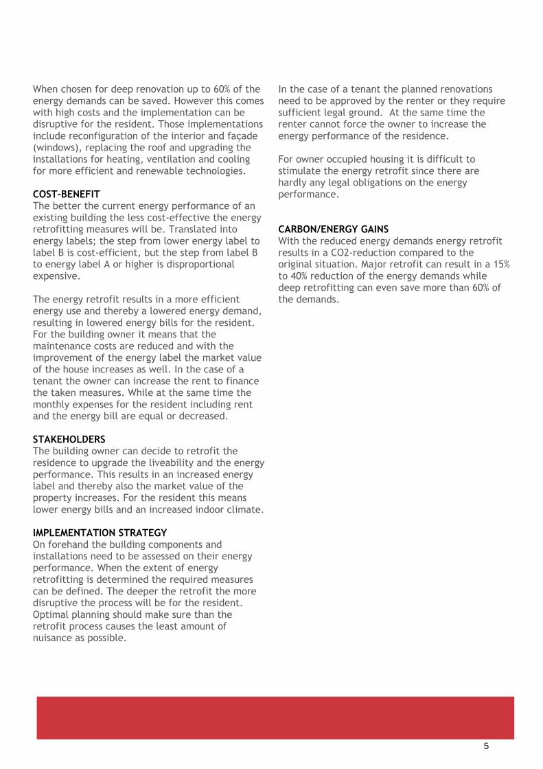
When chosen for deep renovation up to 60% of the energy demands can be saved. However this comes with high costs and the implementation can be disruptive for the resident. Those implementations include reconfiguration of the interior and façade (windows), replacing the roof and upgrading the installations for heating, ventilation and cooling for more efficient and renewable technologies. COST-BENEFIT The better the current energy performance of an existing building the less cost-effective the energy retrofitting measures will be. Translated into energy labels; the step from lower energy label to label B is cost-efficient, but the step from label B to energy label A or higher is disproportional expensive. The energy retrofit results in a more efficient energy use and thereby a lowered energy demand, resulting in lowered energy bills for the resident. For the building owner it means that the maintenance costs are reduced and with the improvement of the energy label the market value of the house increases as well. In the case of a tenant the owner can increase the rent to finance the taken measures. While at the same time the monthly expenses for the resident including rent and the energy bill are equal or decreased. STAKEHOLDERS The building owner can decide to retrofit the residence to upgrade the liveability and the energy performance. This results in an increased energy label and thereby also the market value of the property increases. For the resident this means lower energy bills and an increased indoor climate. IMPLEMENTATION STRATEGY On forehand the building components and installations need to be assessed on their energy performance. When the extent of energy retrofitting is determined the required measures can be defined. The deeper the retrofit the more disruptive the process will be for the resident. Optimal planning should make sure than the retrofit process causes the least amount of nuisance as possible.
In the case of a tenant the planned renovations need to be approved by the renter or they require sufficient legal ground. At the same time the renter cannot force the owner to increase the energy performance of the residence. For owner occupied housing it is difficult to stimulate the energy retrofit since there are hardly any legal obligations on the energy performance. CARBON/ENERGY GAINS With the reduced energy demands energy retrofit results in a CO2-reduction compared to the original situation. Major retrofit can result in a 15% to 40% reduction of the energy demands while deep retrofitting can even save more than 60% of the demands.
5

Increased energy performance and indoor climate conditions of the building
By the various amount of potentials a suitable approach can be found for each existing building to
reduce it demands in a cost-effective way.
Subsidies are available
The building owner can apply for a green loan at the bank if the energy performance of the building
increases with the renovation. This loan has lower interest rate than normal bank loans (NL).
There are almost no legal obligations to force house owners to retrofit their residence.
Tenants need to approve the plans for the renovation before they can be executed.
Tenants cannot force the building owner to energy retrofit their house.
Increased market value of the property, by increase indoor climate and energy label.
Lower monthly expenses for the resident
Lower maintenance costs
Energy retrofit from low label to label >B is cost-efficient, renovating label B residences to a higher
label is disproportional expensive.
More pleasant and healthy environment for the same or lower rent.
Deep retrofitting will cause nuisance for the residence. Often they even need to move out for a
certain period.
Reduced energy demands by decreased energy losses and increased efficiencies will result in less
CO2-emission.
With deep retrofitting energy will be generated with the use of renewables.
Major retrofit will reduce the demands with 15-40%; deep energy retrofit will reduce the demands
with more than 60%.
TECHNICAL / GEOGRAPHICAL
POLITICAL / LEGAL
FINANCIAL / ECONOMIC
SOCIAL
ENVIRONMENTAL
POTENTIALS, BARRIERS & SOLUTIONS Energy retrofitting of residences
6

2 ENERGY RETROFIT OF MONUMENTS PROBLEMS AND POSSIBILITIES FOR RENOVATION OF MONUMENTAL BUILINGS
(NL)
CATEGORY
SCALE
COSTS COMBINES WITH
PRINCIPLE Monumental buildings face large problems concerning energy performance and lack of comfort. Most of these building are uninsulated, resulting in large energy losses. Energy retrofitting will not only increase the energy performance and the thermal comfort of the building but the whole condition, like noise insulation. In general most heat is lost by the windows and roofs after that the walls. Insulating these three elements will result in the largest improvements. While renovating monumental buildings large problems will be faced by its monumental status and the building properties. Monumental buildings often haves special window, roof and façade structures that determine the overall look of the building, therefor they should be adapted with care. When insulating the building this should be done integrally to prevent condensation on non-insulated parts. Since historical buildings consist many porous materials that absorb moisture it is required to still let the building breath to release this humid for the durability of the building and for a healthy indoor climate. This should be taken into account while insulating and sealing the building.
Windows The replacement of the window frames and glazing is not always allowed. Pre-war (bubbled) glass may not be removed and therefor the only option is to place a window pane behind the existing glazing. Walls Insulating the monument from the outside will be the most efficient. However due to the protected status this is not possible. Monumental buildings are often constructed before we made use of cavity walls. Thereby the only option is to insulate the building from the inside. However this is only possible if these inside walls do not have an important cultural-historical value. At the same time with insulation from the inside it is difficult to remove cold bridges. Solar generation on roof For all monuments a permit is required to install PV panels. Placing photovoltaics on the roof is not allowed for monuments with a cultural, historical value, a roof with a special shape, tiles in special patterns, roof with less commonly used materials (like thatch, meal, slate) or a roof that is part of a special historical roof landscape.
Heat losses average monument (drawing & percentages by E.J. Nusselder)
Thermographical photograph (by E.J. Nusselder)
MORE INFO & MANUFACTURERS
1. monumenten.nl/duurzaamwonen
2. http://www.stichtingerm.nl/doc/WAAIER%20DUURZAAMHEID%20def.pdf
7

To increase the energy performance beside by increasing insulation values and adding PV, the heat installations and ventilation system can be replaced. Even after renovation monuments will mostly still require high temperature heating. Therefor potential heat systems will be pellet boiler (wood), high efficiency boilers or collective heat networks on high temperature heat. Ground or air-source heat pumps can also be an option; however their efficiency will be low by the high heating temperature. For ventilation of the building often natural ventilation will be kept, but heat recovery units will be added to save heating costs. COST-BENEFIT Currently residents of monumental buildings have very high energy bills to keep their buildings warm. Energy retrofitting can even with simple measures result in large energy savings. At the same time the higher energy label will increase the market value of the building. STAKEHOLDERS The building owner, building operator, user, the municipality, provincial or national government (legislation that prevents or encourages the retrofitting), designers and architects, contractors (execute the actual retrofit), financial institutions, NGO’s (non-profit citizen groups – want to preserve cultural heritage of the city). IMPLEMENTATION STRATEGY A qualified architectural historian can indicate the cultural values of a building and thereby the possibilities and limitations for the energy retrofit. To maintain the historical value of the building a renovation architect or designer would be helpful. Besides adding new technologies and materials it is also helpful to study the potential within the currently available sources. Like the use of existing window shutters to keep the heat in during the winter and the keep solar heat out during the summer. CARBON/ENERGY GAINS With the energy retrofit the energy performance of the building will increase significantly, decreasing the CO2-emissions released by the energy demands of the building.
8

By restrictions by the monumental status it is often technically not possible to implement low
temperature heating in these buildings. This decreases the possibilities for sustainable heat
supply.
There are a lot of limitations to the possibilities concerning energy retrofitting monumental
buildings. These limitations are caused by the historical and cultural value of facades, windows,
roofs and even the interior of the building. An architectural historian can help to indicate the
possibilities and limitations for the renovation.
Currently there is no obligation for an energy label when selling or renting the monumental
building (municipality, provincial and national monument). For most other buildings an energy
label is obligated. The obligation of an energy label would stimulate energy retrofitting the
building.
Even with simple retrofitting measures large improvement to the energetic performance of the
building can be achieved, resulting in large savings of the energy bill.
Beside an increased energy performance and lowered energy bill the indoor climate quality
will increase.
Energy retrofitting the building can be a complex process for the building owner due to all the
limitations by its monumental status. The help of a professional team will be necessary to
optimize the energy performance for that specific building.
The energy performance will increase, resulting in reduction of the CO2-emissions. In the
Netherlands there are a lot of monumental buildings; savings in this sector will have a large
impact on the energy demands of the city.
TECHNICAL / GEOGRAPHICAL
POLITICAL / LEGAL
FINANCIAL / ECONOMIC
SOCIAL
ENVIRONMENTAL
POTENTIALS, BARRIERS & SOLUTIONS Of Energy retrofitting of Monumental buildings
9

3 RETROFIT: ZERO-ON-THE-METER (NL) A FULL PROPERTY UPGRADE FOR POOR PERFORMING DETACHED HOUSES INTO FUTURE PROOF DWELLINGS WITH ZERO ENERGY BILLS
CATEGORY
SCALE
EFFICIENCY
COSTS
COMBINES WITH
100%
e-neutral HP
PRINCIPLE With a 'zero on the meter' house, all incoming and outgoing energy flows are annually in balance. 'Zero on the meter' is a Dutch concept to make the transformation of existing buildings into zero energy buildings, simpler, cheaper and faster. The concept of 'zero on the meter' provides a local structure, professional advice and cheap financing in the form of a foundation at district or village level. It allows homeowners to realize energy savings and sustainability without investing own money. Every building needs a specific approach to make the house zero energy with the lowest budget. But the first step is always lowering the energy demand and avoiding heat losses as much as possible. Principles like energy efficient lighting, demand-response appliances, home energy manager, wall and roof insulation, high performance thermal windows/doors, geothermal heating and cooling system and high efficiency heat pumps may be used. In the next step the energy demands will be reduced by the re-use of energy streams in the building; for example by the use of heat recovery in the ventilation system. The
final step is to fulfil the remaining energy demands by adding principles that produce energy like wind power systems, solar thermal heating systems and solar panels1. COST-BENEFIT The zero-on-the-meter concept results in an energy concept in which the energy demands over the year are in balance with the amount of energy generated. This means that over the year the final energy demands are zero, resulting in an energy bill of zero. The final payback time of the renovation towards zero-on-the-meter depends on the energy costs before the renovation, building characteristics and the chosen concept. When the building is owned by a housing corporation the tenant pays a certain amount each year for the energy supply, the so called ‘Energieprestatievergoeding’ (EPV). In this way not only the resident benefits from the renovations by living in a zero-on-the-meter house with high comfort levels for the same or even lower monthly expenses as before the renovations, but also the investment by the corporations will (partly) be paid back with the income of the EPV.
Before renovation: Heerhugowaard, BAM (foto by Rick Akkerman)
After renovation: Heerhugowaard, BAM (foto by Rick Akkerman)
MORE INFO & MANUFACTURERS
1. nulopdemeter.eu 2. www.olino.org/articles/2015/10/27/nul-op-de-meter-woning/ 3. www.energielinq.nl/wp-content/uploads/2016/08/Nul_op_de_Meter_gegarandeerd_goed.pdf 4. materia.nl/article/zuringhof-smart-facade-isolation/
10

STAKEHOLDERS Home owners (private or corporation), the tenant (if applicable), municipality, investors, local energy coordinators IMPLEMENTATIO N STRATEGY The easiest way to upgrade a building block to zero-on-the-meter is when the building is owned by a corporation. Especially the transformation of land bound single-family housing constructed between 1945 and 1980 into zero-on-the-meter housing will currently be achievable3. An energy coordinator should be involved in the project to study the local energy potentials. CARBON/ENERGY GAINS Because the annual energy demands are the same as the annual amount of sustainable generated energy the CO2-emissions after the renovation will be zero, the building will be energy neutral. Thereby the amount of CO2-emissions that can be saved per year can be calculated by multiplying the current energy demands for electricity and gas with their emission-factors. This means that the amount of CO2 that is currently released is equal to the amount of CO2 that will be saved each year with the realisation of the zero-on-the-meter housing.
11

In general all land bound single family housing can be transformed into ‘zero-on-the-meter’ housing
(especially when constructed between 1945 and 1980).
The application of zero-on-the-meter in a certain neighbourhood on large scale will result in the
need to intensify the electricity network. By the large amount of electricity that will be delivered to
the network on sunny days and the demand on cloudy day the peak loads on the grid will increase
the current capacity. Most of the zero-on-the-meter concepts work with heat pumps and PV-panels.
Municipalities can and should support and stimulate local ‘zero-on—the-meter’ projects by the
existing housing corporations.
Investment will be somewhere in a wide range around € 45.000. No energy bills after the retrofit but
an EPV for the resident (mostly lower than current energy bill). This EPV is payed to the corporation
to pay-back the investments for the renovation.
The corporation needs to be willing to make large investments that will have a long payback time.
Home-owners do not have to invest their own money.
Chance for a rebound effect: tenants might heat more rooms or enjoy warmer house now the
residence is well insulated. This might have a negative effect on the actual energy savings. Therefor
clear communication and a manual need to be provided to the residents. Together with monitoring
installations that give the tenants insight in the current energy use.
The quality of the indoor environment of the building increases in terms of health and comfort.
Every ‘zero-on-the-meter’ house is carbon neutral.
TECHNICAL / GEOGRAPHICAL
POLITICAL / LEGAL
FINANCIAL / ECONOMIC
SOCIAL
ENVIRONMENTAL
POTENTIALS, BARRIERS & SOLUTIONS Of Zero-on-the-Meter energy retrofit
12

4 ALL-ELECTRIC RETROFIT ALL ENERGY DEMANDS OF THE BUILDING SUPPLIED BY ELECTRICITY
CATEGORY
SCALE
EFFICIENCY
COSTS
COMBINES WITH
100% electric
HP
PRINCIPLE All-electric means that all the energy demands of the building, including energy for heating, cooling, and domestic hot water are supplied by electricity. To do so heating is provided with a heat pump, mostly with an air- or ground-source. To increase the efficiency of the heat pump the temperature for heating should be low and the temperature for cooling high. Thereby a high energetic performance of the building is required. This is done by increasing the insulation values with adding insulation to the façade, roof and ground floor, replacing single pane windows and fixing thermal bridges. Also the heat system needs to be replaced by for example floor heating to supply the low temperature heating. In most cases even more energy savings are achieved by replacing the natural ventilation system for a balanced system (mechanical) with heat recovery. The difference with zero-on-the-meter is that not all of the electricity needs to be generated at the building plot; the electricity can also be supplied by the electricity grid. However all-electric buildings are still often combined with photovoltaic panels to decrease the electricity
demands from the grid. The disadvantage of the all-electric concept is that it increases peak demands for the electricity grid by the use of the heat pump. These peak demands mainly cause a problem when multiple buildings in a certain area use all-electric heating. Since these peak demands determine the capacity of the network and power plants. An advantage is that only a connection to the electricity grid is needed, no infrastructure for heating has to be constructed or maintained. COST-BENEFIT Although gas is much cheaper than electricity the high efficiency of the heat pump and the decreased energy demands result in a lowered energy bill. This energy bill can be lowered even more when the building is equipped with PV-panels. Beside the energy bill also the costs for the energy retrofitting process and placement of the installations should be taken into account. These costs variate per building type and will require a significant amount of years to be paid back.
Retrofitted residences to all-electric in Arnhem, NL (www.stroomversnelling.nl & Dura Vermeer)
Zero energy concept (fenixgroup.cz)
MORE INFO & MANUFACTURERS
1. 2.
13

However these measures will also increase the energy label and thereby the market value of the building. Costs can partly be reduced with by subsidies. STAKEHOLDERS The initiative should mostly be taken by the building owner; this can be the corporation or a private building owner. The resident will need to learn how to use the new energy system and will notice the changes in the thermal comfort of the building. In the case of large scale projects the electricity network administrator should get involved to make sure the network can deal with the increased demand. IMPLEMENTATION STRATEGY The first step will be to decrease the energy demands of the building by minimizing the energy losses, the next step is the re-use of waste energy streams with for example heat recovery integrated in the ventilation system. The last step is to implement the new installations and the heat system. CARBON/ENERGY GAINS Within the all-electric concept all the energy demands of the building are supplied with electricity. The heat demands are provided by a heat pump that has a COP of about 4. In this way the electricity that is taken from the grid is used very efficient. Since a part of the electricity demands is coming from the grid (not all of the electricity demands are generated by PV on the building) still fossils are used to generate the required energy for the building.
14

High efficiency heating with a HP
Only one energy network connection needed; the electricity grid, no network for heating required.
Low energy losses through building skin
If the all-electric concept is applied to multiple buildings in an area large peak demands in the
electricity network will occur. Resulting in the need to intensify the electricity network. The
implementation of home or neighbourhood batteries can help to limit those peaks (peak shaving).
Subsidies are available
No permits required
Reduced energy bills
Subsidies available
High investment costs for the renovation process towards low temperature heating.
Increased comfort level of the building.
Lot of nuisance for the resident since the complete building needs to be retrofitted.
Lower energy demands and bill by the reduced energy losses and by the use of more energy efficient
installations for heating, cooling and DHW supplies.
Still CO2-emissions will be released by using electricity from the electricity grid. However in the
future this network will also be supplied by renewable electricity sources.
TECHNICAL / GEOGRAPHICAL
POLITICAL / LEGAL
FINANCIAL / ECONOMIC
SOCIAL
ENVIRONMENTAL
POTENTIALS, BARRIERS & SOLUTIONS Of All electric retrofit
15

5 POSITIVE ENERGY BLOCKS BUILDINGS THAT ANNUALLY PRODUCE MORE THAN THEY USE
CATEGORY
SCALE
EFFICIENCY
COSTS
COMBINES WITH
100% energy
HP
PRINCIPLE A Positive Energy Block (PEB) is a group of at least 3 connected neighbouring buildings that annually produce more energy than used in terms of lighting, heating, cooling and ventilation. In Positive Energy Blocks, the focus is on mixed and complementary usage of buildings, typically consisting of residential apartments, offices and shops. The advantage is that they have complementary load profiles, automatically leading to peak shaving of the consumption. They contain local renewable energy production units, such as photovoltaic panels, solar thermal panels, ground source heat pumps, biomass cogeneration, and so on. Positive Energy Blocks are new or retrofitted, highly insulated buildings owned by public and private actors such as housing corporations. An example of a realized project is the Hikari building in Lyon. Those 3 buildings are designed as a positive energy block as part of the Lyon Confluence project. The buildings are a mixed use of dwellings, offices and shops. To be able to generate all the required energy three kinds of renewable energy sources that were available on
the location are used: solar energy (PV on roof and facade), biomass (CHP unit source providing heat and electricity) and river water for cooling (absorption cooler). COST-BENEFIT The costs contain the investment costs for the retrofitted or new highly insulated buildings and the renewable energy technologies. The benefits are the production of renewable energy, leading to maximised own consumption. Since the building blocks generate more energy than required the remaining amount can be sold to the public energy networks. This will often be electricity. Over the whole year the energy demands of the buildings, and thereby the energy bill will be zero. However the tenants still have to pay for their energy use. This is done by paying a certain amount to the owner of the building. With this money and the gains from the energy that is delivered to the public network owner can compensate a part of the initial investment to create the Positive Energy Block.
Hikari buildings Lyon (Source: New Energy and Industrial Technology Development Organization, NEDO).
Overview energy system design Hikari building, Lyon (Manaslu Ing)
MORE INFO & MANUFACTURERS
1. https://eu-smartcities.eu/initiatives/71/description
2. http://zenodo.org/record/834534/file/6DO.7.1.pdf
3. https://www.bouygues-immobilier-corporate.com/en/press-release/lyon-bouygues-immobilier-leading-
way-hikari-europes-first-positive-energy-mixed-use
16

STAKEHOLDERS Building project developers, social housing corporations, private households and tenants IMPLEMENTATION STRATEGY The European Innovation Partnership on Smart Cities and Communities (EIP-SCC) is an initiative supported by the European Commission bringing together smart city actors. They have an action cluster on Positive Energy Block with the aim to stimulate the realisation of 100 positive energy blocks throughout Europe in the next years. This initiative can help to implementation these energy blocks in the city. CARBON/ENERGY GAINS The CO2 reduction and energy contribution of this measure can be calculated for a certain location with certain dimensions, when information is available on types of used technologies, insulation grade of the new and retrofitted buildings. Since these buildings will generate all their energy demands with renewables their CO2-emissions over the year will be zero.
17

Positive Energy Blocks can be built in any climate or geographic situation and can be new built
buildings or retrofitted buildings
They can use any kind of renewable energy production, such as photovoltaic panels, solar thermal
panels, (geothermal) heat pumps, biomass cogeneration, …
For residential consumers, in some countries there is a system of net metering (e.g. up to 10 kW in
Belgium), allowing extra benefit from own produced renewable energy;
In some European countries, renewable energy production is still subsidized. The subsidy
mechanisms can differ per country: feed-in tariffs, rewarding for all electricity production.
It is possible that mixed usage is not allowed within the building permit, as specific areas are for
residential or other specific purposes. Municipalities should therefor give more flexibility for the
building permit requirements.
Costs depend highly on the used renewable technologies and the insulation grade.
Initial cost will partly be compensated by the owner/investor by the feed-in tariffs of the surplus
energy and by the monthly bill for the energy use by the tenants.
By the mixed use people can live close to their jobs and above that there is social control during all
times of the day, preventing against unwanted visitors and/or thieves.
Increase of local production of renewable energy, leading to a cleaner overall energy mix.
TECHNICAL / GEOGRAPHICAL
POLITICAL / LEGAL
FINANCIAL / ECONOMIC
SOCIAL
ENVIRONMENTAL
POTENTIALS, BARRIERS & SOLUTIONS Of positive energy blocks
18

6 CASESTUDY RETROFIT MISTRAL TOWERS SOCIAL HOUSING BUILDING TOWER RETROFIT IN GRENOBLE
CATEGORY
SCALE
EFFICIENCY
COSTS
COMBINES WITH
-50% demands
PRINCIPLE Retrofitting social housing is one of the strategic axes of the Grenoble Energy Climate Plan, which aims a 25% reduction of the energy consumption for its inhabitants in 2020. The MISTRAL Retrofitting program is one of the most important on-going projects in Grenoble with more than 200 dwellings. The goal is to half the energy consumption of these 3 iconic towers in this working class district. The buildings are connected to an existing heat network, energy reduction will be achieved by adding external insulation, window replacement, replacing the existing radiators and controlled ventilation with heat recovery. Because inhabitant behaviour is one of the most important criteria to reach the energy performance, the SPIRAL method would be tested among groups of inhabitants. With this method, inhabitant will co-construct their own well-being indicators dedicated to the energy consumption field. The method aims to increase energy awareness in the social housing district. COST-BENEFIT The reduction of the regulatory energy performance should significantly reduce the tenant’s energy bills. The Vivacité monitoring will
specify the proportion of the savings made, in terms of euros, kWhEP and CO2 emissions. STAKEHOLDERS The social housing corporation, the tenants, district heat network operator IMPLEMENTATION STRATEGY The SPIRAL Methodology (Societal Progress Indicators for the Responsibility of All) is deployed in 3 cycles (preparation, mobilization, integration) of 8 steps. The SPIRAL methodology helps to understand the expectations for the energy savings by the inhabitant. In this way the municipality, local energy supplier and housing corporations can take these expectations into account while defining the energy retrofitting measures. CARBON/ENERGY GAINS The goal is to achieve energy savings of 50% with the energy demands of 130kWh/m2 before the renovation and 64kWh/m2 per year after the renovation. Beside the energy savings by technical measures also energy savings are expected by the user behaviour by increased energy awareness.
Impression Mistral (www.rehabilition-mistral-actis.com) The SPIRAL methodology (http://www.cityzen-smartcity.eu)
MORE INFO & MANUFACTURERS
1. cityzen-smartcity.eu/ressources/building-retrofitting/retrofitting-towards-zero-energy-buildings-in-grenoble/ 2. http://www.sei.cmu.edu/reports/00sr008.pdf 3. http://www.actis.fr
http://www.rehabilitation-mistral-actis.com/
19

Target is to reduce the energy bill/demands with +/-50%.
The Vivacité tool (multi-energy monitoring interface) is applied, the SPIRAL methodology helps to
improve the design of this Vivacité tool.
The Local Urbanism Plan allows the retrofitting works (external insulation)
The energy performance is based on the French Low Energy Performance standards
The VivaCité tool (multi-energy monitoring interface) would propose a buying purchase approach of
energy saving.
SPIRAL method, dedicated to the self-being indicators, will be adapted and tested for the energy
citizen approach. The method will increase the awareness of energy performance.
However energy remains the minor factor of well-being for the tenants regarding other social issues:
security, unemployment and education.
The Social housing retrofitting is one of the strategic axis of the Grenoble Energy Climate Plan (25%
reduction of the inhabitant consumption).
The SPIRAL approach is expecting to help stakeholders to share the energy awareness in the social
housing districts, where this topic isn’t a priority. It should also help the Social Landlord, the
municipality and the local energy supplier to better understand the inhabitant’s energy savings
expectations and motivations.
TECHNICAL / GEOGRAPHICAL
POLITICAL / LEGAL
FINANCIAL / ECONOMIC
SOCIAL
ENVIRONMENTAL
POTENTIALS, BARRIERS & SOLUTIONS Of retrofitting the mistral towers
20

7 CASESTUDY: RETROFIT OF AIREY
APARTMENTS IN AMSTERDAM NIEUW-WEST RENOVATION OF 5 APARTMENT BLOCKS BUILD IN THE FIFTIES
CATEGORY
SCALE
EFFICIENCY
COSTS
COMBINES WITH
-761 tonnes
Co2/year
PRINCIPLE This Airey complex is owned by housing corporation Eigen Haard, located in Amsterdam Nieuw-West. The apartments will be equipped with insulation, PV Panels, mechanical ventilation with CO2-sensors and high-efficiency boilers. The complex consists out of 13 apartment blocks, of which 5 are renovated within City-zen. The blocks were constructed after WOII using the prefab Nemavo-Airey system, with this system houses could be built quickly. Narrow concrete frames were covered by interior and exterior concrete slabs, all with the same size. The steel window frames fit into this framework. Due to poor indoor conditions and a minimal construction which did not allow for improvements, many of those apartments have been demolished. During the renovation process of the Eigen Haard apartment in Amsterdam Nieuw-West the full interior is removed, only the 2 floors and the staircases were kept. COST-BENEFIT The residents successfully opposed an earlier
demolition plan. By renovation of these blocks the small and affordable apartments were maintained. The rent is increased but remained within the limits of the social sector. The investment was done by the housing corporation Eigen Haard. The investment for the PV panels on the roof of the building was done by a commercial company: HuurDeZon. Each tenant rents 4 PV panels for a lower price than the savings on their energy bill. STAKEHOLDERS Residents in the building, municipality, the Van Eesteren museum, the housing corporation Eigen Haard, the PV rental company HuurDeZon and local lobby groups. IMPLEMENTATION STRATEGY The success of this energy retrofit project has given the possibilities for renovation of other Airey apartments in the Netherlands with the same principles. To be able to perform the renovation the resident is temporary moved to another apartment, since apart from the structure and stair cases, the full interior and façade will be replaced.
Airey complex in Amsterdam Nieuw-West (Photo: Erik Swierstra, 16 January 2012)
Principle renovation façade (bureau Hooyschuur Architecten)
MORE INFO & MANUFACTURERS
1. http://www.cityzen-smartcity.eu/wp-content/uploads/2016/01/kif-renovation-amsterdam-airey_vf.pdf 2. http://vaneesterenmuseum.nl/?s=airey&lang=nl
21

CARBON/ENERGY GAINS By the increased insulation values, the new ventilation and heating installations and the added PV-panels the total building related energy demands are decreased from 427 to 70kWh per m2 per year. Thereby the CO2-emissions are reduced with 761tonnes per year.
22

This project showcases how to retrofit Airey system apartments in an energy efficient way. Eigen Haard
is sharing their experiences with other owners of Airey apartment blocks.
With the limited load bearing capacity of the structure the placement of new elements need to be
calculated carefully, like the replacement of the bathroom, larger balconies and the placement of the
PV panels.
Implementing sufficient amounts of insulation was a challenge by the narrow frames of the structure.
In the Netherlands the feed in tariff equals the buying tariff, as long as production does not exceed the
household use over the year (see Netting). When the generation of PV panels exceeds the yearly demands
the tenant will receive a compensation for this energy (low than the buying tariff).
Building permit required of the municipal monument commission. Therefor hardly any changes to the
exterior outlook where possible.
Since the Dutch housing corporations agreed to improve their properties to an average of energy label B
there is no incentive to improve the energy performance even more.
The investments for the renovations where done by the housing corporation. The costs related to the
energy measures where €25.000 per apartment. These investments are partly earned back by increased
rent for the tenants, however since the apartments are in the social sector the rent increase is limited.
Rental PV panels were added by the commercial party: HuurDeZon. The tenant rents 4 panels for a lower
amount than the savings on their energy bill.
Change for a rebound effect: tenants might heat more rooms or enjoy warmer house now the residence
is well insulated. This might have a negative effect on the actual energy savings. Therefor clear
communication and a manual need to be provided to the residents. Together with monitoring
installations that give the tenants insight in the current energy use.
The tenant benefits from the renovation in terms of health and comfort. The apartments were
notoriously noisy, draughty and damp before the renovation.
Before the renovation process could start 70% of the tenants needed to approve with the plans.
The building related energy after renovation will be 70kwh/m2 per year. Before the renovation the
demands where 427kWh/m2 per year. Thereby the CO2-emissions are reduced with 761 tonnes per year.
TECHNICAL / GEOGRAPHICAL
POLITICAL / LEGAL
FINANCIAL / ECONOMIC
SOCIAL
ENVIRONMENTAL
POTENTIALS, BARRIERS & SOLUTIONS Of the energy retrofit of the Airey Apartments of Eigen Haard in Amsterdam Nieuw-West
23

8 DISTRICT HEATING NETWORKS WITH
CASCADING TEMPERATURE LEVELS INCREASED ENERGY EFFICIENCY THROUGH SMARTER APPLICATION OF
EXISTING DHN’S
CATEGORY
SCALE
COSTS
COMBINES WITH
PRINCIPLE Traditional DHN’s distribute heat with high temperatures (90-70°C or even higher). When new energy efficient buildings are connected to the DHN or when a part of the existing buildings are retrofitted with improved insulation the temperature of the DHN could be lowered for this part. Lowering the temperature will result in a reduced net heat loss by the transportation. This can be done by dividing the DH network in several sections, each with a cascading temperature level. Part of the network is operated at the traditional temperature supplying energy to the existing (not yet retrofitted) buildings. With a heat exchanger on their return line this heat can be used as heat supply for other parts of the DHN with a lower heat temperature demand. This principle can be repeated of few times. In this way the energy is used multiple times, while the quality (temperature) of the energy decreases in each step. This principle is called heat cascading. In some cases heat cascading is implemented in the district heat network with as main goal to lower the return temperature to the source. A lower return temperature towards a geothermal
heat sources will increase the overall efficiency of the source. COST-BENEFIT The benefits are twofold: the lower temperatures result in lower heat losses and at the same time the existing transport infrastructure can be maintained. Thereby the introduction of cascading temperatures in an existing network requires relatively small additional investments. The decreased final return temperature to the heat source by the cascade can be both an advantage and disadvantage. This depends on the type of heat source. A geothermal source for example requires a low return temperature into the cold well. In this case the lowered return temperature is desired. However for most other sources the heat needs to be upgraded again to the high temperature. STAKEHOLDERS The relevant stakeholders can be found along the whole supply chain from heat producer, to the DHN transport system operator and end-users. Certainly the end-users are important since the supply of low temperature heat requires an
Different temperatures of heat sources and demands of
consumers2 Heat cascade (Studio Marco Vermeulen: www.marcovermeulen.eu)
MORE INFO & MANUFACTURERS
1. https://www.energy-innovation-austria.at/wp-content/uploads/2015/04/eia_01_15_E_FIN.pdf2
2. O. Pol and R.-R. Schmidt, 15 – “Development of district heating and cooling in the urban planning
context”, In Woodhead Publishing Series in Energy, edited by Robin Wiltshire, Woodhead Publishing,
Oxford, 2016, Pages 319-337, Advanced District Heating and Cooling (DHC) Systems, ISBN 9781782423744,
http://dx.doi.org/10.1016/B978-1-78242-374-4.00015-X
3.
24

adaption in the resident’s behaviour and comfort perception. IMPLEMENTATION STRATEGY Lowering the supply temperatures in (parts of) the DHN can be considered for two specific locations and conditions: 1) When the existing buildings connected to the DHN are retrofitted with improved insulation and modifications, and/or; 2) When new energy efficient buildings are connected to the DHN. Since one of the attractive advantages of a DHN, the ample and unlimited supply of hot water, might require adaptation after application of cascading temperature levels, the hot water supply deserves attention in the implementation strategy, both technical as in the communication. CARBON/ENERGY GAINS The heat loss reduction contribution can be calculated straightforward from the overall heat balance (produced versus nett delivered). The efficiency improvement can be assessed from the fuel consumption and the usable heat produced.
25

District Heating Networks with cascading temperature levels can be applied at all locations where there
is a substantial source of (preferentially sustainable) heat in the close vicinity of buildings (either
residential or utility) with a heat demand. The buildings should be adapted to accommodate low
temperature heat supply, but other than that there are little limitations.
The availability of an existing heat network is preferred due to the high construction costs of a district
heat network.
Heat cascade will result in a lower return temperature at the heat source. This can result in an
increased energy demand because the temperature difference between the highest demand and the
return temperature is increased.
The realization of a DHN with traditional or (partly) reduced temperature levels is a long term
investment which requires a set of guarantees for both the investors and the consumers. These
guarantees should be provided at a (local) political-legal level.
DHN are typically connected with high up-front investment costs and a complex start-up phase in which
the heat supply and the demands need to be balanced. These initial investments must be earned back
during the long DHN lifespan. The introduction of cascading temperatures in an existing network
requires relatively small additional investments and might help to secure and/or enhance the
operational lifetime of the DH network.
The high investment costs and the resulting long anticipated DHN lifetimes introduce an undesirable
uncertainty for investors. The (local) community and the authorities should therefor provide some form
of shared guarantees.
DHN provides a safe and secure heat supply, with a good potential for sustainable energy, to the
residents in the connected buildings. The residents do not have to make large investments and also the
maintenance and replacement costs are shared collectively by the operator.
The addition of a DHN in an existing environment with already double infrastructure in place has
significant additional costs and moreover creates a serious nuisance of the neighbourhood. Therefor
smart planning (for instance in combination with other construction activities) and well-orchestrated
communication with the local community can reduce the inconveniences.
DHN’s with cascading temperatures have the potential to be operated with increased efficiency.
Moreover, a DHN can be powered with sustainable thermal energy.
TECHNICAL / GEOGRAPHICAL
POLITICAL / LEGAL
FINANCIAL / ECONOMIC
SOCIAL
ENVIRONMENTAL
POTENTIALS, BARRIERS & SOLUTIONS Of a DHN with cascading temperature levels
26

9 DHN WITH PVT AND UNDERGROUND HEAT STORAGE REGENERATION OF THE HEAT SOURCE WITH HEAT FROM THE PVT PANELS
CATEGORY
SCALE
EFFICIENCY
COSTS
COMBINES WITH
COP 4-6
HP
PRINCIPLE PV-thermal panels can be added to a district heat network that uses seasonal thermal energy storage as a heat source to regenerate the heat source during the summer. The advantage of PVT above solar collectors for the regeneration is not only the additional generation of electricity but also the lower temperature of the generated heat that fits the temperature of the heat storage in the ground. The heat in the ground can be used as heat source when the amount of heat extracted during the winter is equal the amount of cooling extracted during the summer. However for a residential building in a cold or temperate climate the heat demands are higher than the cooling demands which means that the system will become out of balance. In this situation the heat generated by the PVT-panels can be used to regenerate the heat source during the summer. The electricity generated with the PVT-panels will be used to decrease the electricity demands of the building; including the heat pump demands. Those heat pumps will upgrade the heat of 15-25ºC to the required temperature for space heating and domestic hot water supplies.
COST-BENEFIT With the regeneration of the heat cold storage not only seasonal thermal energy storage is provided, but also a heat source. This additional function is made possible by the regeneration with the PV panels. STAKEHOLDERS The municipality, the DHN administrator, the residents /house owners of the neighbourhood, the investor IMPLEMENTATION STRATEGY Seasonal thermal energy storage systems respond to the temperature differences between the different seasons, therefor STES is mostly suitable for temperate climates. The system will be most efficient when applied to buildings with a low temperature heat demand. This will optimize the efficiency of the heat pump and thereby limit the electricity demands. The micro grid requires a reliable demand and a high density of the costumers to be cost efficient. Other criteria for the location are the suitability of the ground for ATES or BTES systems.
Park Inn, Cape town: large scale PVT project (solarus.com) PVT with underground storage (http://abora-solar.com)
MORE INFO & MANUFACTURERS
1. https://infoscience.epfl.ch/record/213373/files/6_VETTERLI.pdf; 2. https://ac.els-cdn.com/S1876610217328874/1-s2.0-S1876610217328874-main.pdf?_tid=f4a413bf-6659-4cb4-ab8f-43e92df46a4b&acdnat=1527494114_2685521dc3f9cfe04fbd19c2c55140ab
27

CARBON/ENERGY GAINS With the realisation of the DHN with thermal energy storage and PVT the heat demands will be supplied by the heat from the ATES/BTES system in combination with the heat pump. This heat pump will have a COP of 4-6. The heat supply with the heat pump will result in an increased electricity demand. This demand will (partly) be compensated by the PVT-panels.
28

To create a more reliable micro grid can be expanded or connected to other low temperature
networks and other heat sources in the future.
There are geographical limitations to the application of ATES/BTES systems; the ground needs to be
suitable for the storage. ATES systems require the availability of aquifers.
Seasonal thermal energy storage systems work with the temperature differences between the
different seasons and are thereby mostly suitable to apply in temperate climate zones.
Depending on the county subsidies or tax reduction are provided for the installation of PVT-panels.
For the ground storage system special permits are required in accordance to the groundwater
regulations (NL).
PVT panels are more expensive than PV and solar collectors but have to potential to become less
expensive when more commonly used.
The realisation of both the micro grid and the installations and renovation at building scale are
expensive.
With the regeneration of the heat source an additional function (heat source) is given to the seasonal
heat storage facility.
Increased comfort level of the building after renovation.
If applied to existing buildings this system requires adaptations to the building envelope and
installations for space heating and DHW.
Sustainable heat source for the buildings, increased electricity demands by the use of the heat pumps
is partly compensated by the PVT panels on the roofs.
TECHNICAL / GEOGRAPHICAL
POLITICAL / LEGAL
FINANCIAL / ECONOMIC
SOCIAL
ENVIRONMENTAL
POTENTIALS, BARRIERS & SOLUTIONS Of DHN with PVT and underground heat storage
29

10 SEWAGE WATER HEAT EXCHANGER USING IN SEWAGE WATER FOR HEATING AND COOLING
CATEGORY
Example heat network with sewage heat exchanger (www.tauw.nl)
Sewage heat exchanger used for heating swimming pool (www.tauw.nl)
SCALE
EFFICIENCY
COSTS
COMBINES WITH
70-80% heating
HP
PRINCIPLE The waste and rain water discharged into the sewage system consist thermal energy (of for example showers and washing machines) that has the potential to provide both low temperature heating and cooling to buildings. This energy can be extracted with the integration of heat exchangers in the sewer pipes. The temperature in the sewer pipes over the year is between 8-23ºC1. Thereby this heat source can be connected to a heat pump to upgrade the heat to the required heating temperature. In some cases also a gas boiler is integrated to supply the peak demands in the winter when the heat of the sewage pipes is very low. Currently sewage water heat exchangers are mostly applied to heat swimming pools and schools. But it also has the potential to heat offices or social housing blocks. COST-BENEFIT With the long lifespan of the heat exchangers and the sewer pipes of about 50years the use of the heat source is cost-efficient. Especially when the sewer pipes needed to be replaced the
additional cost of the sewer pipes with heat exchanger will be earned back in a relatively short time span. STAKEHOLDERS Municipality, manager/administrator of the sewage system, building owner/corporation IMPLEMENTATION STRATEGY The advantage of this system is that the thermal energy source is available in the built environment, at the location of the demand, at about 2-3m depth. Therefor the most optimal location for the connected buildings is closely to the sewer pipes. Sewage pipes need to be replaced every few decades during the replacement the system can easily be implemented. The building itself needs to be suitable for low temperature heating with a heat pump. Another location aspect to consider for the heat exchanger is that the closer to the discharge point, the higher the temperature of the waste water. But on the other hand the smaller and more variable the flow.
MORE INFO & MANUFACTURERS
1. https://www.velsen.nl/sites/default/files/riothermie_kansenkaart_gemeente_velsen.pdf 2. https://www.marsaki.nl/riothermie-hollandiaplein/
30

CARBON/ENERGY GAINS With the water temperature of 8ºC in the winter the individual heat pumps in the buildings will have a relatively low COP; therefor it is important that the required temperature for space heating of the buildings is as low as possible to optimize the COP. At the Hollandia square in Goes (the Netherlands) sewage heat exchangers combined with heat pumps are currently heating 60 new built apartments. The sewage heat exchange system provides about 70-80% of the total heat demands during the year. The other 20-30% is
supplied by natural gas heating during the coldest days of the winter. With the use of the thermal energy in the sewage pipes the apartment block saves 2.000kg CO2 per year2.
31

The heat source is located at the same location as the heat demand.
Only applicable at locations with a large heat demand at a low temperature. Therefor high
insulation values of the building are required.
Rain water lowers the temperature of the waste water in the sewer pipes, decreasing the
efficiency of the individual heat pumps in the buildings.
Low temperature output, lower efficiency of the heat pumps, especially in the winter. Therefor
mostly a back-up system for heating during cold winter days is integrated; often a (gas) boiler.
The most optimal location of the connected buildings will be closely to the sewer pipes.
The sewage pipes are in principle owned by the municipality which don’t necessary benefit from
the use of the heat of the sewage pipes.
Due to lifespan of this system and the reliable availability of the source the costs are relatively
low.
The intervention is located 2-3m under the ground and is thereby not visible.
CO2-neutral energy source
Use of heat from wastewater that otherwise wouldn’t be used.
Low temperature output, low efficiency of the heat pumps, high electricity demands.
Often the system is combined with a gas boiler for heating in the winter.
The sewage pipes are located only 2-3m underneath the ground, thereby the installation can easily
be removed after the exploitation.
TECHNICAL / GEOGRAPHICAL
POLITICAL / LEGAL
FINANCIAL / ECONOMIC
SOCIAL
ENVIRONMENTAL
POTENTIALS, BARRIERS & SOLUTIONS Of sewage water pipe heat exchanger
32

11 MINI HEAT NETWORK ON EFFLUENT LOW TEMPERATURE HEAT NETWORK AS SOURCE FOR INDIVIDUAL HEAT
PUMPS
CATEGORY
SCALE
EFFICIENCY
COSTS
COMBINES WITH
COP 4
HP
PRINCIPLE The effluent of a water treatment plant is the remaining product after the water treatment process and is normally discharged into surface water. However this effluent has the potential to be a heat source since it has a temperature of +/- 7°C in the winter and +/-20°C during the summer. With the use of a heat exchanger the effluent can be used to feed a low temperature heat network. Individual heat pumps should be added on building scale to be able to use the effluent for heating purposes of residential or commercial buildings. The closer the heating temperature of the building to the temperature of the effluent, the higher the efficiency of the heat pump will be. Therefor low temperature heating is preferred. As addition a heat pump booster can be applied for domestic hot water supplies. COST-BENEFIT The advantage of this heat system is that the heat source is already present, only little changes are required in the current water treatment plant (placement heat exchanger). Beside that a low temperature heat network has relatively low investment costs compared to higher temperature
heat networks (limited insulation of the heat pipes). However with the low temperature of the source during the winter the COP of the heat pumps will be low, increasing the electricity demands. STAKEHOLDERS Water treatment plant (producer), building owners (private/corporation), DHN transport system operator. IMPLEMENTATION STRATEGY To reduce the heat losses and to limit the investment costs the appointed neighbourhood should be located nearby the water treatment plant. For the same reasons the location of the heat network requires a high density to get a lot of connections. When the heat network is constructed the users can be connected with heat pumps. Energy retrofitting of these buildings will increase the efficiencies of the heat pumps and thereby limit the electricity demands.
Water treatment plant Harnaschpolder Delft (www.delfluent.nl) Waste water heat exchanger installed in a waste water treatment plant (HUBER SE)
MORE INFO & MANUFACTURERS
1. http://edepot.wur.nl/258338 2. http://delfluent.nl/innovations/warmtebenutting-uit-effluent/ 3. https://www.duurzaamgebouwd.nl/project/20121214-restwarmte-uit-rioolwater
33

CARBON/ENERGY GAINS The CO2-emissions will be decreased by the replacement of the natural gas heating by the effluent in the heat network and the individual heat pumps. The energy required for the water treatment process and the thereby released CO2-emissions should be taken into account. The final CO2-emissions do also depend on to what extent the final electricity demands for heating by the heat pump are generated with sustainable sources, like PV-panels.
34

The heat source is already present, but currently unused. Water treatment plants are mostly
located just outside cities and thereby the effluent can be used in neighbourhoods that are
located closely to the water treatment plant with a low temperature heat demand.
The heat supply is stable and predictable over the year.
Low temperature of the effluent during the winter and relatively high temperature during the
summer. This decreases the efficiency of the heat pumps.
Can be combined with seasonal thermal energy storage to use the higher temperatures during the
winter and the lower temperatures during the summer. This will also increase the efficiency of
the individual heat pumps.
The use of the effluent as heat source requires only little adaptations to the water treatment
process. With the use of this source no additional heat sources needs to be constructed.
When applied in an existing neighbourhood the buildings need to be retrofitted to be suitable for low
temperature heating. This will not only decrease the energy bill, but will also increase the comfort
level of the building.
This heat system will decrease the current CO2-emissions for heating and cooling.
To perform the water treatment process the plant currently uses fossils. The effluent is the end-
product of this process, thereby the effluent cannot be seen as a fully sustainable energy source.
The water treatment process should therefore be optimized and based on renewables in the future.
TECHNICAL / GEOGRAPHICAL
POLITICAL / LEGAL
FINANCIAL / ECONOMIC
SOCIAL
ENVIRONMENTAL
POTENTIALS, BARRIERS & SOLUTIONS Of a mini heat network on effluent heat
35

12 SOLAR DISTRICT HEATING PLANTS WITH
SEASONAL ENERGY STORAGE HIGH TEMPERATURE DISTRICT HEAT NETWORK FED BY A SOLAR COLLECTOR
FARM AND SEASONAL THERMAL ENERGY STORAGE
CATEGORY
SCALE
EFFICIENCY
COSTS
COMBINES WITH
100% heating
PRINCIPLE Solar district heating (SDH) plants are large scale solar collector farms that are connected to a district heat network. When combined with seasonal thermal energy storage the efficiency can be increased by using the heat generated during the summer months as heat source for the heating season. This system can fulfil the demands of residential, commercial and industrial use. The thermal energy storage can be done with a water basin. This water basin makes use of the high heat capacity of water and can store heat at a higher temperature than the other storage systems, like ATES. However large volumes are required to seasonally store the thermal energy, which currently mostly results in the choice for storage in the ground. Vojens, Denmark, currently makes use of a SDH system with seasonal storage in a water basin. With a solar collector field size of 70.000m2 and a water basin of 200.000m3, 50 percent of the annual heat demands of 2.000 households and 10 schools and industries can be provided with high temperature heat of about 75°C1.
COST-BENEFIT Expected lifespan of a solar district heating system with water basin storage is about 25 years. For the Vojens case study the costs per MWh of the storage and solar collectors are comparable to heating with natural gas2. However the initial investment costs are still very high due to the limited amount of implementation of these kinds of systems. STAKEHOLDERS The municipality, land-owner, costumers (citizens and companies), district heat network administrator/operator IMPLEMENTATION STRATEGY To fulfil the demands of a heat network a large storage pit and solar collector field size are required. To make the construction of the heat network cost efficient a dense urban area with reliable heat demands are mandatory. For high temperature networks the basin storage will be suitable, for lower temperatures the energy can better be stored with borehole or aquifer storage (ATES/BTES).
Vojens Demark (Photo: Acron-Sunmark) Gram Denmark (Photo: Acron-Sunmark)
MORE INFO & MANUFACTURERS
1. http://www.solarthermalworld.org/content/denmark-52500-m2-additional-collector-area-vojens 2. www.estif.org/fileadmin/estif/content/publications/downloads/UNEP_2015/factsheet_solar_district_heating _v05.pdf
36

CARBON/ENERGY GAINS Reference: Vojens Denmark, total installation generates 49MW covering about 50% of the heat demands. The remaining heat demands are covered by gas boilers, gas engines, an electric boiler and an absorption heat pump4. Thereby 50% of the demands are supplied in without carbon emissions, by the solar collectors.
3. https://www.sciencedirect.com/science/article/pii/S0306261909002694 4. http://arcon-sunmark.com/cases/vojens-district-heating 5. https://ens.dk/sites/ens.dk/files/Forskning_og_udvikling/sol_til_fjernvarme_brochure_endelig.pdf
37

Solar District Heating Plants can be installed at each location with a large space available; in the
South of Europe the output will be higher than in the North.
Water basin storage makes seasonal high temperature heating possible and can thereby increase the
efficiency of a high temperature heat network.
Water basin storage doesn’t require special characteristics for the ground, as with ATES/BTES.
The larger the solar heating system, the lower the heating costs.
Comparable annual cost as heating with gas.
Construction of a high temperature heat network is expensive. A lot of connection and a reliable
heat supply are required.
This heat system is currently not applied a lot in practice yet; therefore the initial costs for
installation and construction are still high.
Combined with storage the DHN will provide a safe and stable heat supply to the residents in the
connected buildings. The residents do not have to make large investments and also the maintenance
and replacement costs are shared collectively by the operator.
Local protest against the placement of the large solar collector farm (esthetical). Providing
information about the urgency of the project is needed to prevent these obstructions.
The full or a part of the heat demands of the connected neighbourhood will be delivered by the
solar collectors (combined with the storage) therefor this part of the demands will be supplies by
renewables, without CO2-emissions.
TECHNICAL / GEOGRAPHICAL
POLITICAL / LEGAL
FINANCIAL / ECONOMIC
SOCIAL
ENVIRONMENTAL
POTENTIALS, BARRIERS & SOLUTIONS Solar district heating plants with seasonal energy storage
38

13 DHN ON BIOMASS COMBUSTION OF BIOMASS TO FEED THE DHN
CATEGORY
Heat
SCALE
EFFICIENCY
COSTS
COMBINES WITH
100% heat
-
PRINCIPLE Plants convert solar energy into chemical energy with photosynthesis. In this way energy is stored in biomass and can be released by combusting the biomass when needed. Examples of biomass sources are wood, household waste (vegetable, fruit and garden waste), animal manure, sludge of water treatment plants, specially grown energy crops (like rapeseeds) or seaweed. To supply a district heat network with this heat the conversion of biomass into heat needs to take place in a large scale boiler. When using wood pellets or chips these will be combusted in a so called pellet boiler. The heat station will deliver high temperature heat to the DHN that will provide heat for both space heating and hot water in a building. When this system is combined with a cogeneration unit both electricity and heat is generated. However the sustainability of biomass is under discussion. Wood pellets and chips are mostly imported from Scandinavia or Canada. This results in large CO2-emissions during the transportation. At the same time the use of wood for biomass should not lead to deforestation. Another example
is the production of energy crops, which often conflicts with food production. A sustainable example is the DHN of Purmerend which uses biomass in the form of wood chips as heat source. These wood chips are delivered by the Dutch forest authority (Staatsbosbeheer). The wood is a waste product of the maintenance of Dutch forest and landscapes: no importation and deforestation is applicable. COST-BENEFIT For this type of DHN the municipality or investor can apply for subsidies by the government according to the SDE+ regulation (Netherlands). When looking at the example Purmerend the final heat price for the customers (€24,05/GJ3) is only little bit more expensive as the current gas price in the Netherlands (€22,87/GJ4).
STAKEHOLDERS Wood supplier (like Staatsbosbeheer), DHN administrator, municipality, residents and/or house owners
Combustion process biomass with CHP(kisspng,com) Heat station Purmerend (Copyright Evert Ruis)
MORE INFO & MANUFACTURERS
1. http://www.smartcityembassy.nl/initiative/biomass-heating-installation-de-purmer/ 2. http://www.ehpcongress.org/archive-2015/wp-content/uploads/2015/04/45_Marie-Therese_TETTEROO-MATHIJSEN.pdf
3. www.stadsverwarmingpurmerend.nl
39

IMPLEMENTATION STRATEGY In order to consider the heat source as sustainable a biomass source needs to be found that is located at a relatively small distance from the proposed heat network. At the same time this heat network needs to be located in a district with a constant and reliable (high temperature) heat demand. For the realisation the heat network needs to be constructed together with the heat station in which the boiler and storage facilities will be located. CARBON/ENERGY GAINS While burning wood 109,6kg CO2 per GJ is released2. However biomass is still considered as low carbon since the amount of CO2 that is absorbed by the tree during its lifespan is about the same as the amount of CO2 that will be released while generating heat. However the CO2-emissions by the transportation of the source should also be taken into account. The energy density of wood depends on the quality of the wood. The higher the quality, the lower the moisture content and the higher the energy density will be5. High quality wood pellets do consist out of <10% water and have an energy density of 3100kWh/m3. High grade wood chips have a lower energy density of 690-930kWh/m3 because the moisture content is 30%5.
4. http://www.milieucentraal.nl 5. https://ec.europa.eu/energy/intelligent/projects/sites/iee-
projects/files/projects/documents/forest_guide_for_designers_and_architects_en.pdf
40

High temperature heat source
Mostly produced in Canada and Scandinavia
Possibility to receive subsidies for the realisation of the heat network
Lacking subsidy possibilities by the questions about the sustainability of the wood (by emissions from
transportation)
Possibility to receive subsidies for the realisation of the heat network
The final costs for the costumers are about equal to the costs of heat supply by gas.
Construction of the required HT DHN is expensive. Lot of connections in dense area are required to
make it cost effective.
This heating system doesn’t require renovations to the building since it makes use of high
temperature heat, only the heat exchanger needs to be installed. This results in limited nuisance
and investment by the resident.
Wood can be seen as almost carbon neutral, when the emissions by transportation are excluded or
minimal.
Use of waste wood from maintenance of forest or landscapes for the generation of energy
High carbon emission by transportation if the wood is imported from other countries like Canada or
Scandinavia.
TECHNICAL / GEOGRAPHICAL
POLITICAL / LEGAL
FINANCIAL / ECONOMIC
SOCIAL
ENVIRONMENTAL
POTENTIALS, BARRIERS & SOLUTIONS Of DHN with biomass
41

14 DHN ON INDUSTRIAL WASTE HEAT USE OF HEAT PRODUCED WITH INDUSTRIAL PROCESSES OR WASTE
INCINERATION IN A HIGH TEMPERATURE DHN
CATEGORY
SCALE
EFFICIENCY
COSTS
COMBINES WITH
100% heating
PRINCIPLE Currently the heat that is produced during industrial production processes or waste incineration is discharged into the air or water. However this heat can also be used for heating purposes of buildings. The re-use of this residual heat will increase the efficiency of the used energy. A district network is required for the transportation of the heat from the source to the neighbourhood. As for example the plan for the heat roundabout in South-Holland which will transport the waste heat of the Rotterdam harbour to surrounding cities. However the sustainability of industrial waste heat is questionable because this heat is released while burning fossil fuels. Still this heat can be useful to start-up the energy transition since it will decrease the total amount of fossil fuels that is used in total. Finally in the last phase of the energy transition the residual heat source needs to be replaced by a sustainable source. COST-BENEFIT Since the heat source is not considered as sustainable and also the future supplies are not
guaranteed, the most difficult part of the realisation of a DHN on industrial waste heat is to find investors. The realization of a DHN is very expensive, especially for high temperature networks which require insulation around the heat pipes. Therefor the investors should be convinced that in the future (in the final phase of the transition) these heat sources will be replaced by sustainable source. The cost-benefit is that the heat source is already available and doesn’t need to be generated. STAKEHOLDERS Industries (heat suppliers), municipalities, heat network administrators and residents IMPLEMENTATION STRATEGY For the construction of the heat network a neighbourhood with a high density and a guaranteed heat demand needs to be found. The residual heat will supply high temperature heat; thereby energy retrofitting of the residences isn’t required. Only the current boiler for gas needs to be replaced by a heat exchanger. Already at the
MORE INFO & MANUFACTURERS
1. http://marcovermeulen.eu/files/1505_Vergroening/ 2.
District heat network on industrial waste heat (www.kyotherm.com)
Use of heat from production processes in the DHN (www.warmtebedrijfamersfoort.nl)
42

start of the project the possibilities for the sustainable energy source that will replace the industrial heat should be analysed. CARBON/ENERGY GAINS If the total CO2-emissions (of the full heat network, including the industrial heat source) are taken into account the amount of carbon savings can be set equally to the amount of natural gas that was used for heating buildings before the construction of the DHN. The fossils used for the industrial process will now be used more efficient by using the produced heat for heating the buildings, for this process the amount of fossils used will remain the same.
43

Stable heat supply throughout the year.
The future sustainable sources that can replace this high temperature heat source are limited
(geothermal, solar collectors)
In some EU countries project subsidies are given for heat networks that use waste heat (e.g. in Belgium,
based on call system).
The construction of the DHN requires permits
The energy source is free, no additional costs are involved to generate the heat
The construction of a high temperature district heat network is expensive. It is hard to find investors
because of the non-sustainable character of the heat source
Because the heat is delivered at high temperature the consequences for the residents are limited (no or
limited energy retrofitting measures required)
Construction of the DHN causes nuisance for the neighbours.
Decrease of CO2-emissions by more efficient use of the fossil energy that is used for the industrial
processes.
The heat is originating from industrial processes that are based on fossil fuels. This heat should only be
used to start-up the energy transition and should in a later stage be replaced by a more sustainable
energy source.
TECHNICAL / GEOGRAPHICAL
POLITICAL / LEGAL
FINANCIAL / ECONOMIC
SOCIAL
ENVIRONMENTAL
POTENTIALS, BARRIERS & SOLUTIONS Of industrial waste heat in DHN
44

15 MID TEMP.DHN WITH RESIDUAL HEAT THE USE OF RESIDUAL HEAT OF SUPERMARKET, DATACENTER AND OTHER
COOLING PROCESSES
CATEGORY
SCALE
COSTS
COMBINES WITH
PRINCIPLE Functions that require cooling all year do have a large amount of residual heat. This heat can potentially be used to heat surrounding buildings with a low temperature demand. Examples of such cooled functions are supermarkets, datacentres and offices. The temperature of the heat supply depends per function. A datacentre for example can provide 40°C heating, a supermarket 20-25°C. These functions can be connected to a heat network to provide this heat to a certain neighbourhood. In the building the temperature of the LT heat network will be upgraded with individual heat pumps. The overall efficiency of the DHN can be increased when thermal energy storage is connected to the system. Beside functions with excess heat there are also functions that require heating throughout the whole year; these functions will thereby have a lot of excess cold that can be used for cooling of other buildings throughout the year. COST-BENEFIT The functions with excess heat will get paid for the energy that they would otherwise have thrown
away. In this way they can finance the measures that they had to take (installations) to be able to supply the heat to the network. With these heat sources the individual heat pumps in the buildings will have a high efficiency (COP), resulting in a lower energy bill for the residents. STAKEHOLDERS Owner of the function with the residual heat source, the DHN administrator, the municipality, the resident and/or house owner. IMPLEMENTATION STRATEGY The first step is to map the functions that can potentially provide their excess heat to a new or existing DHN. If the DHN does not exist yet the preferred conditions are a neighbourhood with a mid or low temperature heat demand (or potential after retrofitting) and a reliable demand in a high density. Depending on the size of the demand multiple functions with excess heat need to be connected, or a combination with other low/mid temperature heat sources should be found.
Datacentre providing heat to district heat network (www.opendistrictheating.com)
Supermarket as heat supplier (www.danfoss.com)
MORE INFO & MANUFACTURERS
1. https://apolitical.co/solution_article/stockholm-recycles-excess-heat-data-centres-warm-homes/ 2. http://smart-cities-centre.org/wp-content/uploads/Torben-Green_CITIESWorkshopAugust.pdf 3. https://progrss.com/sustainability/20160428/how-danish-supermarkets-make-cities-energy-efficient/
45

CARBON/ENERGY GAINS With the use of the excess heat for heating of the supermarket and surrounding buildings the total CO2-emissions of the supermarket and the buildings will be decreased. The remaining CO2-emissions are caused by the electricity demands of the functions. However this electricity will now also be used more efficient since it is also used for the heating purposes without increase of the CO2-emissions. The amount of heat that is produced by a supermarket or a datacentre can be roughly calculated with the following assumptions: Datacentre The electricity demands of a datacentre are on average 3,45MWh/m2 per year4. The total amount of MWh electricity use per year can be set equal to the amount of heat that is produced by the installations4. This amount of generated heat will have a temperature of about 40°C. Supermarket The released condenser heat by the refrigerators can be calculated with: (COP * electricity demands for cooling) + electricity demands for cooling. About 87% of the electricity demands of a supermarket are used for cooling, with a total electricity use of on average 401kWh/m2. For the efficiency of the fridge a COP of 3 is average5,6. The outcome will be the amount of heat with a temperature of 20-25°C that can be supplied to a heat grid.
4. Afman, M.R. (2014). Energiegebruik Nederlandse commerciële datacenters2014-2017: Niewbouwplannen en ontwikkeling energiegebruik. Delft: CE Delft. 5. Meijer, P.H., & Verweij, R. (2009). Energieverbruik per funtie voor Senternovem. Den Haag: Meijer Energie & Milieumanagement 6. Pennartz, A.M.G., & van den Bovenkamp, M.V.. (2016). Het elektrisch energieverbruik en het warmteaanbodvan koelinstallaties
voor een veertigtal bedrijfssectoren. Den Haag: Rijksdienst voor Ondernemend Nederland.
46
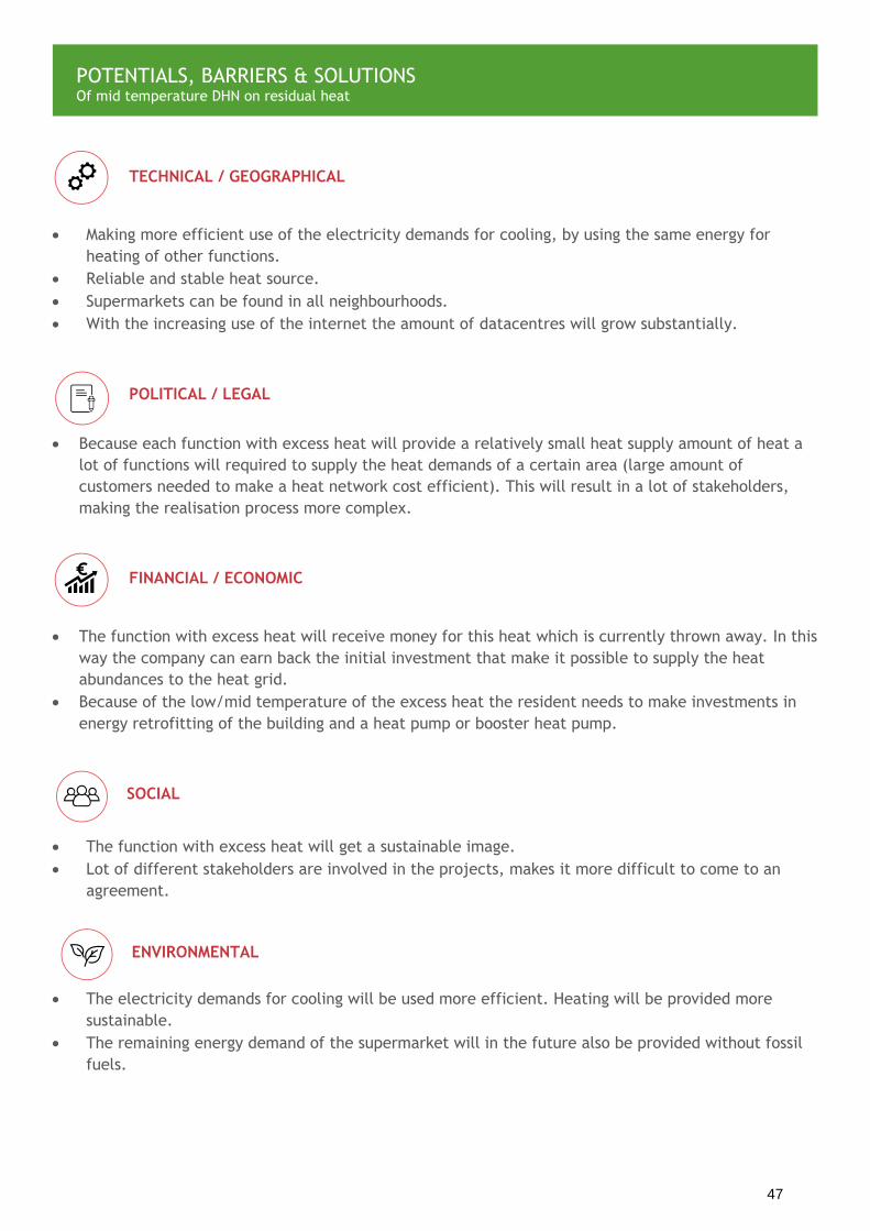
Making more efficient use of the electricity demands for cooling, by using the same energy for
heating of other functions.
Reliable and stable heat source.
Supermarkets can be found in all neighbourhoods.
With the increasing use of the internet the amount of datacentres will grow substantially.
Because each function with excess heat will provide a relatively small heat supply amount of heat a
lot of functions will required to supply the heat demands of a certain area (large amount of
customers needed to make a heat network cost efficient). This will result in a lot of stakeholders,
making the realisation process more complex.
The function with excess heat will receive money for this heat which is currently thrown away. In this
way the company can earn back the initial investment that make it possible to supply the heat
abundances to the heat grid.
Because of the low/mid temperature of the excess heat the resident needs to make investments in
energy retrofitting of the building and a heat pump or booster heat pump.
The function with excess heat will get a sustainable image.
Lot of different stakeholders are involved in the projects, makes it more difficult to come to an
agreement.
The electricity demands for cooling will be used more efficient. Heating will be provided more
sustainable.
The remaining energy demand of the supermarket will in the future also be provided without fossil
fuels.
TECHNICAL / GEOGRAPHICAL
POLITICAL / LEGAL
FINANCIAL / ECONOMIC
SOCIAL
ENVIRONMENTAL
POTENTIALS, BARRIERS & SOLUTIONS Of mid temperature DHN on residual heat
47

16 POWER-TO-HEAT COMBINED WITH
DISTRICT HEATING (BUFFER) AN OPTION TO PROVIDE FLEXIBILITY FOR PEAKS IN RENEWABLE
ELECTRICITY PRODUCTION
CATEGORY
SCALE
EFFICIENCY
COSTS
COMBINES WITH
≈100%
PRINCIPLE Renewable electricity sources, like wind and solar, generate energy completely independent from the current demand. At times this may lead to an unplanned production which can result in excess power with negative electricity prices or the decision to switch the renewable sources off. An option to provide some additional grid stability and much sought-for flexibility to the integrated energy system is the application of “Power-to-Heat”. Electric power is rapidly converted with an almost 100% efficiency to high quality heat (as hot water or steam) using a direct electrode boiler. Beside the electrode boiler also more innovative technologies like the Rotation heat pump of ECOP are available. The generated thermal energy can directly be fed into a district heating network, or into a thermal buffer to create an increased flexibility. Direct electrode boilers are available on the market in the multi MW range, which is required since the power excess occurs at the large-scale production side of the energy supply chain. Furthermore, the direct electrode boilers have very rapid response time which enables them to respond to the fast
unexpected fluctuations in power generation. Once the boilers are in place they can also be used to generate heat during extreme peaks in heat demand. In this way the boilers play an integrating role between the electricity grid and the district heat network. COST-BENEFIT Given their high power capacity the direct electrode boilers themselves are relatively cheap. When there is an existing thermal energy network present Power-to-Heat is a cheap method to respond to the fluctuations in the electricity grid. The electrode boiler only needs 200 operation hours per year to be cost efficient since they make use of cheap electricity prices and the initial and maintenance costs are low as well. The lifespan of a 25-30MW electrode boiler that is connected to a district heat network is about 20 years. STAKEHOLDERS The relevant stakeholders can be found on both sides of the integrated energy supply chain: from large scale (renewable) power producers to local district heating network operators. An important position is also reserved for the regulator since the
P2H with electricity and heat network (DIW berlin, Discussion Paper/DIW; 1677)
Power-to-Heat with rotation heat pump (www.ecop.at)
MORE INFO & MANUFACTURERS
48

combination of a high-power grid connection with a low number of running hours can be seriously expensive, whereas the equipment is meant to solve the collective grid stability challenge and facilitate the integration of renewables. IMPLEMENTATION STRATEGY It can be complicated to find a location to place the boilers since they need both a high voltage connection to the electric grid and a high-power connection to the district heating network or buffer. CARBON/ENERGY GAINS The useful application of otherwise excess power makes a significant CO2-reduction. This amount can be calculated correctly by assessing the CO2-emission when an equal amount of heat had to be produced by the first alternative available technique. However, opponents of P2H (Power to Heat) might argue that the high exergy (or quality) electricity should not be converted to low quality heat and that the emission numbers for the incremental electricity production should be connected to the thermal energy produced.
49

Power-to-Heat can be applied at locations where there is an existing district heating network or near
buildings (either residential or utility) with a steady heat demand. The combination with a buffer
can decouple the heat production and consumption in time. As indicated before the high voltage
connection to the grid is another prerequisite.
The electrode boiler plays an integrating role between the electricity network and the heat
network, since it can convert electricity into heat when the electricity supplies are in abundance
and when there is an extreme heat demand.
The direct conversion of high exergy (or quality) electricity to low quality heat might result in
criticism from certain opponents. However, with the growing share of renewable power generation
the subjects of excess power and flexibility will become more familiar in the public domain.
Power-to-Heat provides additional flexibility and stability to the integrated energy grid which
represents a high value. Since these benefits are difficult to monetize, the direct value of the
produced heat has to be balanced by the ‘costs’ of the consumed electricity and the boiler
investments.
Power-to-Heat installations contribute to the increasing share of renewable power generation which
in turn makes a positive contribution to society.
Power-to-Heat installations contribute to the increasing share of renewable power generation by
using the electricity that is in abundance and that otherwise would be thrown away or not produced.
Power-to-heat will provide flexibility and stability to the electricity network and can thereby
respond to the fluctuations of supplies by solar and wind energy.
TECHNICAL / GEOGRAPHICAL
POLITICAL / LEGAL
FINANCIAL / ECONOMIC
SOCIAL
ENVIRONMENTAL
POTENTIALS, BARRIERS & SOLUTIONS Of Power-to-Heat supply to district heat networks
50

17 CENTRAL HP ON SURFACE OR SEA WATER PROVIDING HEATING OR COOLING TO A DISTRICT HEAT NETWORK
CATEGORY
SCALE
EFFICIENCY
COSTS
COMBINES WITH
HP
COP=3-4
PRINCIPLE By their thermal inertia and heat capacity surface waters, like lakes or rivers, and sea water have the potential to be an efficient heat and cold source for heat pumps. As result of these characteristics the water temperature in the winter is higher than the outside temperature, while in the summer the water temperature is lower. This makes surface and sea water an efficient source for heat pumps. Above that the large volume of the water ensures that the water temperature doesn’t increase significantly when extracting heat1. Hybrid water heat pumps systems can use this thermal energy to provide both heating and cooling to a certain neighbourhood. When needed the heat pump or chillers will increase or decrease the temperature to the desired temperature of the DHN; when the water temperature is already optimal the sea or surface water will be exchanged with the DHN directly. The water will be pumped towards the heat station by the intake pump and supplied by the heat exchanger to the central hybrid water heat pump that upgrades the water temperature if required (temperature of the heat grid 10-20ºC). In
the winter the heat pump increases the temperature of the water to >10ºC. This temperature is close enough to the soil temperature so that the heat pipes can remain uninsulated while the heat losses and costs are limited. The total heat losses from the water source towards the nearby neighbourhood will be about 3%. Finally the heat is extracted from the DHN by the individual heat pumps in the residences which increase the temperature to 30-45ºC for floor heating and 55-60ºC for domestic hot water supplies2. In the summer the heat pump is not needed since the water can often directly be provided to the DHN by heat exchangers. However when the temperature of the water increases too much in the summer the cooling machine will cool down the water before it is transported to the consumers by the DHN.
District cooling with seawater (www.danfoss.com) Detroit college powerhouse, redevelopment, using river water cooling (© Studio Gang)
MORE INFO & MANUFACTURERS
1. https://www.icax.co.uk/SWSHP.html 2. Gommans, L.J.J.H.M., Broersma, S., & van den Dobbelsteen, A.A.J.F. (2017). Nieuwe energievoor Duindorp: Onderzoek naar alternatieve energieconcepten voor de zeewatercentrale en ‘’warmterivier’’, die moeten leiden tot een hoger(re) reductie van CO2-uitstoot tegen lage(re) kosten. Delft:TU Delft, Faculteit Bouwkunde,
leerstoel Climate Design & Sustainability.
51

COST-BENEFIT The initial costs are the construction of the heat station with central heat pump and cooling machine, the low temperature district heat network and the individual heat pumps of the building. Costs are limited by the free heat and cooling source and the low temperature of the heat network that results in a high COP of the central HP and low heat losses in the DHN without insulation of the transportation pipes. However with this low supply temperature the individual heat pumps in the buildings use a lot of electricity to meet the heat demands. This high electricity use should be taken into account when determining the costs for the DHN energy supply, to make sure that the user doesn’t pay more than with a conventional system. STAKEHOLDERS District network operator, the investor and operator of the heat station, the residents of the neighbourhood IMPLEMENTATION STRATEGY The buildings require high energy performance (high insulation, low energy losses) since they need to be heated with low temperature heat. The high density neighbourhood should be located closely to a sea, river or lake. A low temperature heat network should be constructed together with the heat station that will be situated near the water source. CARBON/ENERGY GAINS With the low temperature in the district heat network the energy losses in the district heat network are limited to only 3%. The COP of the central heat pump will be high by the thermal inertia of the water; relatively high source temperature in winter and low in summer compared to the outside temperature. The individual heat pumps have a lower COP (around 5) since the difference between the heating temperature and the network is bigger.
3. https://www.diva-portal.org/smash/get/diva2:821758/FULLTEXT01.pdf
52

Due to the thermal inertia of water the temperature of the sea, lake or river is higher in winter and
lower in summer than the outside temperature, making these waters an efficient source for the
heat pump (high COP).
By the large volume of the water the effect of the heat extraction on the water temperature is
small; thereby the water can be extracted unlimitedly.
The water temperature in the summer is often low enough to use the water for cooling directly
without the use of the heat pump (free-cooling).
The heat exchanger and pump need to be resistant to the corrosion effect of salt water.
Permit required for the district heat network and the heat station.
The initial cost for the construction of the DHN and heat station is high.
The electricity bill of the users will increase by the use of the heat pumps, this should be taken into
account when determining the price of the heat from the DHN.
Construction of the DHN will cause nuisance for the inhabitants
Increased comfort of the residence by providing cooling in the summer and low temperature heating
High efficiency heat pump that uses a renewable and infinite heat source to heat the network, this
reduces the CO2-emissions for heating in the neighbourhood.
TECHNICAL / GEOGRAPHICAL
POLITICAL / LEGAL
FINANCIAL / ECONOMIC
SOCIAL
ENVIRONMENTAL
POTENTIALS, BARRIERS & SOLUTIONS Of HP sea and surface water
53

18 HEAT PUMP ON MINE WATER & DHN USE OF ABANDONED MINES AS HEAT SOURCE AND THERMAL ENERGY
STORAGE FACILITY
CATEGORY
SCALE
EFFICIENCY
COSTS
COMBINES WITH
COP 4-6
HP
PRINCIPLE Abandoned mines flood since the pumps are switched off. Mines reach till a depth of 300-600m and due to the geothermal energy in the earth at this depth the water has a temperature of 20-40ºC. This heat can be used as low temperature heat source to heat buildings. The potential for this mine water energy supply is large. In the UK, for example, a quarter of all houses are built on the mine fields. The heat of the mines can be used for heating of these buildings when combined with a district heat network, heat exchangers and heat pumps. In this way communities built on coal field that once experienced disadvantages by their location will now benefit from the heat in the mines. To make sure that the heat source won’t get exhausted (cool down) the extraction rate should not exceed the natural recharge speed of the heat source. In this case the continuously recharging heat source by the geothermal heat can be used as seasonal storage of heat and cold. In this way the buildings can be heated during the winter and cooled during the summer by using the water in the mines as thermal energy source, without exhausting the source. This stable energy supply
results in a reliable network and in flexibility to respond to fluctuations between demands and supplies. In addition the existing mine shafts can be used for short term thermal energy storage. COST-BENEFIT Geothermal energy has the potential to be a low cost energy source. However the initial investment costs are high with the construction of the heat network and installation of heat exchangers and pumps and individual heat pumps in the building. The costs are limited by the fact that the existing network of the mine can be used so that no wells have to be drilled, like with ATES or BTES thermal energy storage. STAKEHOLDERS The current owner of the abandoned mine (if applicable), the municipality, district heat network operator, investor, clients (companies and residents) and the citizens IMPLEMENTATION STRATEGY The impact on the landscape and its local residents is minimized. This increases the
Principle of heat storage in mines (The Coal Authority -
ww.gov.uk/government/organisations/the-coal-authority) Use mine water heat in Heerlen NL (www.mijnwater.com)
MORE INFO & MANUFACTURERS
1. https://utilityweek.co.uk/coal-mines-energy-storage/
2. www.mijnwater.com
54

probability of public acceptation. There are many mines available, which result in a lot of potential locations for thermal energy supply and storage with mines. To supply the heat to the consumers a LT district heat network needs to be constructed. At building scale renovations are required to make the property suitable for low temperature heating also individual heat pumps are required to provide the desired heating or cooling temperature. CARBON/ENERGY GAINS With the use of the mine water heat substantial savings of fossil usage can be achieved. When the extraction rate of the energy taken from the mine is lower than the natural recharge rate the source can be considered as a renewable heat source. With the large volume of the mines the district heat network will be able to fulfill the heat demands of a lot of consumers.
55

There are a large amount of mines available that are already abandoned or that will be abandoned in
the future. When the mine is inactive, the pumping installations will be switched of and the mine
will get filled with water. This water will be heated by the geothermal energy of the earth and
thereby the water will become a sustainable low temperature heat source for the built environment.
The mines have a large volume and can thereby provide heating and cooling to a large amount of
customers.
High initial investment concerning the construction of a heat network, pumping installations and
installations like the heat pump at building scale.
The existing network of the mines can be used; thereby no wells have to be drilled as with other type
of underground seasonal energy storages.
Since the system makes use of an existing, underground source there will be no resistance from local
residents. Only the construction of the required heat network will cause some nuisance for the
citizens.
When the heat is extracted at the natural recharge rate of the heat source it is a renewable, infinite,
heat source.
With thermal energy storage the energy demands of the area will decrease and at the same time the
same time reliable and clean energy will be provided.
TECHNICAL / GEOGRAPHICAL
POLITICAL / LEGAL
FINANCIAL / ECONOMIC
SOCIAL
ENVIRONMENTAL
POTENTIALS, BARRIERS & SOLUTIONS Of the use of abandoned mines as heat source and thermal energy storage facility
56

BIO REFINERY FOR THE TREATMENT OF SEPARATED WASTE WATER
CATEGORY
SCALE
EFFICIENCY
COSTS
COMBINES WITH
19 BIOGAS & HEAT FROM WASTE WATER TREATMENT
PRINCIPLE The bio refinery, part of the development of the ‘circular city district’ of Amsterdam Buiksloterham, is a waste water treatment facility that produces energy and raw materials, in contrast to traditional waste water treatment systems that consume energy. Energy will be produced in the in the form of biogas and thermal energy (warmth). Waste water carries raw materials (like plant nutrients) and energy (heat and biogas). Most of these are lost in our current waste water systems. In the Buiksloterham area a separated waste water system (called ‘new sanitation’) will be implemented. With the separation of grey and black water collection the amount of biogas that is produced can be increased. Black water (from toilets and food waste grinders) consist organic matter that can be fermented into biogas. This fermentation is the most effective when black water is collected in a high concentration. Therefore vacuum toilets and vacuum sewage pipelines should be used. The black water can now be fermented to biogas while at the same time a lot of drinking water is saved5.
Thereby it benefits a circular economy: decentralized, circular and water saving. Beside the generation of biogas also low temperature heat can be generated by heat exchange with the effluent. This heat can be used in combination with a seasonal storage system and a heat pump. COST-BENEFIT With bio refinery more energy is produced than needed for the water treatment process. Thereby the water treatment plant can supply its own energy and at the same time heat and biogas to a neighbourhood. Thereby the energy bill of the water treatment plant is reduced to zero while the remaining amount of generated energy can be sold to the neighbourhood. Beside the investment at the water treatment plant and the new, separated water collection
system also extra investments are needed for in-house installations (around €900 per house).
Amsterdam Buiksloterham district (google maps) Floating bio refinery (cityzen-smartcity.eu)
MORE INFO & MANUFACTURERS
1. www.stowa.nl/upload/publicatie2014/STOWA%202014%2038%20webversie_LR3.pdf
2. Nieuwesanitatie.stowa.nl
3. www.cityplot-buiksloterham.nl
57

STAKEHOLDERS Local government, the waste water company, the local energy provider and the inhabitants Other stakeholders are the users of plant nutrients i.e. parties involved in different forms of agriculture. The local legislation concerning waste water may be an impediment to the recycling of these plant nutrients. IMPLEMENTATION STRATEGY Bio refinery is suitable for any climate and/or geographic situation. Technical requirements:
Extra space needed for vacuum black
water tubes and for local treatment
Installation of vacuum toilets in the
waste water supplying buildings.
ATEX requirements should be
implemented because of biogas
production
Seasonal storage (ATES or PCM) is needed
for optimal heat recovery
CARBON/ENERGY GAINS The biogas production with the fermentation of black water per person is about 13 to 19 litres methane per day, this equals to 190-280MJ per person per year6. The total amount of generated biogas and heat that can be taken from the water treatment plant should be extracted from the energy use of the plant to determine the total energy supplies to the neighbourhood. The CO2-reductions by the fermentation of the organic content in black water to biogas are equal to 10,7-15,7kg per person (carbon emission factor natural gas 56,1kg/GJ).
4. schoonschipamsterdam.org/#site_header 5. www.waternet.nl/werkzaamheden/nieuwe-sanitatie 6. http://stowa.nl/Upload/publicaties/STOWA%202010%2035%20LR.pdf
MORE INFO & MANUFACTURERS
58

The bio refinery will produce energy in the form of low-temperature heating and biogas
(conventional treatment plants consume energy).
Recovery of phosphate and other raw materials.
Needs separate and vacuum collection of ‘black water’ (faeces and organic waste). The current
piping system and toilets are not suitable for this separated collection of grey and black water.
Heat recovery could be combined with seasonal heat storage systems (such as ATES) and a heat
pump to increase the efficiency.
Suitable in any climate and/or geographic situation
In the Netherlands, building regulations need to be eased to allow for separate waste water tubing
in houses. The current Dutch ‘Crisis- and recovery law’ and the future ‘Environment act’ make this
possible1.
In the long run a bio refinery system plus heat recovery is expected to be 35% cheaper for society
(utilities companies + house owners) than the combination of traditional sewage and district
heating.
However the initial investment costs for the households are high.
Citizens can expect more energy savings and lower costs.
Heat providers and municipalities should be involved in the realisation process.
Savings of the drink water use by the vacuum toilets
Generation of renewable biogas and heat that will supply the energy demands of the water
treatment plant and will also deliver energy to the neighbourhood.
TECHNICAL / GEOGRAPHICAL
POLITICAL / LEGAL
FINANCIAL / ECONOMIC
SOCIAL
ENVIRONMENTAL
POTENTIALS, BARRIERS & SOLUTIONS Of Bio refinery
59

20 WASTE INCINERATION & CHP WASTE-TO ENERGY BY INCINERATION (COMBUSTION), COMBINED WITH CHP;
GENERATING BOTH HEAT AND ELECTRICTY.
CATEGORY
SCALE
EFFICIENCY
COSTS
COMBINES WITH
50% output
renewable
PRINCIPLE With waste-to-energy municipal solid waste (MSW) can be converted into energy. One of the possibilities for waste-to-energy is with thermochemical waste-to-energy, for example waste incineration. Waste incineration is the combustion of MSW for the generation of energy. This process takes place in the waste incineration plant. After the collection of waste the municipal solid waste is combusted on high temperature. During this process the moisture contained in the MSW is evaporated by the heat; arising gasses. The released gasses are ignited to start the combustion process: converting the waste into flue gas, ash and heat. The heat is used to generate high-pressure steam from water. This steam is used to activate the combined heat power installation. The steam activated the motor of the CHP system which will thereby generate electricity. The thereby generated heat is recovered and can be fed to a building or district heat network.
The gas that is released during the combustion process needs to be treated to minimize the air pollution. Currently the incinerator is equipped with pollution improvement systems to reduce the air pollution by the incinerator. Finally the ash is the remaining landfill product. Waste incineration results in a 95-96 percent mass reduction of the waste. However this ash contains heavy metals, which are injurious even in small amounts. Ash as landfill product does thereby contaminate the soil and the ground water. These heavy metals are one of the reasons for the debate about waste incineration. The other reasons for this debate are the emissions of furans (chemical waste) and dioxins that are released with the gas, even though there are regulations and restrictions. This results in local opposition against incineration plants. However on the other hand incineration is capable of the production of energy and thereby replacing power generating plants based on fossil fuels.
Waste incineration process (source: www.ecomaine.org) Incineration plant - Roskilde, Denmark (tvdv© photography)
MORE INFO & MANUFACTURERS
1. http://www.wrfound.org.uk/articles/incineration.html 2. https://www.worldenergy.org/wp-content/uploads/2017/03/WEResources_Waste_to_Energy_2016.pdf3 3.https://www.rvo.nl/sites/default/files/2013/10/Joosen%202003%20(NL)%20Afvalverbrandingsinstallaties,%20Notitie%20in%20het%20kader%20van%20Marktmonitoring%20Duurzame%20Energie.pdf
60

COST-BENEFIT Since the initial investment costs are high they can only be covered through long contract periods for incineration plants. This means that both the energy demand and the supply of solid municipal waste should be guaranteed for a long period. In most of the European countries no subsidies are provided for the energy generation from waste incineration. The addition of a co-generation installation (CHP) will increase the efficiency of the energy generation, compared to a regular power plant. This improved efficiency will increase the output of the plant, and thereby increase the income by the energy production. STAKEHOLDERS The waste incineration plant, the municipality, citizens. IMPLEMENTATION STRATEGY Support of the citizens is an obstruction in the process towards the realisation of the waste incineration plant. The incinerator needs to be designed in optimal way to limit the released emission and to meet the local regulations and restrictions. Beside that a heat network needs to be constructed to supply the by the cogeneration unit recovered heat to surrounding buildings. Energy retrofit of the connected buildings is not required by this high temperature heat supply. CARBON/ENERGY GAINS Waste incineration is in general not considered to be a 100% renewable energy source since not all of the waste particles are renewable. Every EU member state can determine their percentage of renewables in the MSW. For the Netherlands about 50% of the energy generated with incineration is considered to be renewable3. Since not all of the generated energy can be considered as sustainable the total amount of avoided CO2-emissions can be calculated with the amount of CO2-emissions by the original energy source minus the CO2-emissions by the fraction of non-renewables in the MSW.
61

High efficiencies are reached with the implementation of a cogeneration unit.
Waste is produced at all locations and thereby waste incineration has a high worldwide potential.
Regulations and restrictions for the emissions resulted in the implementation of new technologies
that reduced the emissions.
Diversity in policy approaches to waste-to-energy across all levels by acceptance of waste as
renewable fuel.
High initial investment cost for the construction of the waste incinerator.
Long contracts for the energy demands and the supply of waste are required to deal with the high
investment costs.
In most European countries no subsidies are provided for waste incineration.
Local opposition against the waste incineration plant.
Waste incineration is not considered to be a 100% renewable energy source. In the Netherlands
about 50% of the energy generation is considered to be sustainable.
The ash contains heavy metal that contaminates the soil and ground water.
Emissions of furans (chemical waste) and dioxins are released with the gas.
Conflicts with other waste-to-energy potentials, like the fermentation of waste into biogas.
TECHNICAL / GEOGRAPHICAL
POLITICAL / LEGAL
FINANCIAL / ECONOMIC
SOCIAL
ENVIRONMENTAL
POTENTIALS, BARRIERS & SOLUTIONS Of Waste incineration plants with CHP
62

CATEGORY
21 USAGE OF COOLING AND HEATING
FROM DRINK WATER INFRASTRUCTURE
FOR PHARMACEUTICAL PROCESSES OR IN COMBINATION WITH ATES
SCALE
EFFICIENCY
COSTS
COMBINES WITH
-1.900
tonnes CO2
PRINCIPLE In the winter the temperature in the drinking water infrastructure drops below the desired temperature. This results in an abundance of cold energy which can be extracted and stored in an aquifer thermal energy storage system for usage in the summer. With as result that the temperature of the drinking water increases. In this way a win-win situation is created since sustainable and cost-efficient cold is generated and on the other and the temperature of the drink water infrastructure is more desirable. This also decreases the heat demands of the citizens since the supply temperature of their water will be higher in the winter. Another option is to use the cold directly to cool buildings that require cooling even during winter. For example companies with pharmaceutical processes, which do require a lot of cooling. Sanquin, the Blood bank, is such an institution. An establishment of Sanquin in Amsterdam currently extracts its cooling demand from the drink water supply system of Waternet. In the winter the cold is directly extracted from the network to fulfill the cooling demands while at the same time the cold source of the ATES is regenerated so it can be used for cooling during the summer. For Sanquin the application of this system results in a 1.900 tonnes CO2 reduction per year. The principle is also replicable to extract summer heat from drinking water. Since the water temperature can increase till about 20°C in this season this heat can be stored with ATES for use in the winter.
COST-BENEFIT Extracting cold from a nearby water pipeline is a new, relatively cheap and simple alternative: heat exchanger technology is widely available, distances to water pipelines are typically quite short (in contrast with deep lakes), heat exchangers in drinking water require less maintenance than in surface water, and the constant stream of drinking
Use of heat from drink water system Sanquin, Amsterdam
(www.trouw.nl)
MORE INFO & MANUFACTURERS
1. http://www.cityzen-smartcity.eu/waternet-delivers-winter-cold-out-of-drinking-water-to-sanquin/
2. https://www.trouw.nl/groen/bloedbank-heeft-primeur-met-energie-uit-koud-drinkwater~afb587c9/
63

water guarantees delivery of cold and heat for direct or indirect (ATES) use. STAKEHOLDERS - The public drinking water supplier would have to act as an energy supplier and also main piping lines should be near the direct demand or ATES. This new role as energy supplier results in the establishment of an independent company that will be responsible for the energy supply, since the EU restricts public companies to become a large energy supplier. - Suppliers of district heating: district heat networks should be near enough; - Municipalities: the realization of ATES systems requires a permit. - The consumers that use the cooling or low temperature heat. IMPLEMENTATION STRATEGY The system requires that the drink water infrastructure is located closely to the consumer. When used in combination with an ATES system a permit is required. Beside the situation close to the drink water infrastructure a heat network needs to be present to transport the heat and cold to the consumers. CARBON/ENERGY GAINS In the case of pharmaceutical or industrial processes the energy demand of the production processes that involve cooling units and clean room air conditioning will significantly be lowered. There by the installation of a large conventional new cooling plant is avoided. Also heating can be used from the district heating network instead of using gas as an energy source. In the case of Sanquin this reduced the CO2 emission by 1.900 tonnes per year (1.100 in cooling and 800 in heating).
Beside CO2-reduction other environmental effects are: the temperature of the drinking water infrastructure will be higher in the winter, reducing energy expenses in the households.
64

Using the winter cold from the drink water infrastructure whereby a win-win situation is created since
sustainable and cost-efficient cold is generated and on the other and the temperature of the drink
water infrastructure is more desirable. Resulting is smaller energy savings for households.
Energy balancing of ATES systems with cold from drinking water systems is very compact and quiet in
contrast to the space consuming dry-coolers or cooling towers.
Main piping infrastructures of district heating and drinking water infrastructure should be near.
The conditions of the subsoil need to be suitable for ATES systems and at the same time there
shouldn’t be to many ATES systems in the surroundings since they will influence each other.
There are some risks for the drink water network like pressure loss or high growth rate of micro-
organisms.
Public infrastructures can be used to supply energy, replacing fossil fuels.
The public water company will get a new role by supplying heat and cold. According to EU laws
public companies cannot become a large energy supplier since this can result in distorts of
competition. This kind of companies shall in this case establish an independent company that will be
responsible for the energy supply.
Positive business-case when included all relevant aspects such as impact on electrical grid including
positive effect on needed emergency power, noise reduction measures, energy consumption,
maintenance (preventive and corrective) and technical overhauls.
The system is only economically feasible when major drink water and heat networks are relatively
nearby.
Citizens will receive warmer water during the winter time, saving them energy (local emissions) and
money on DHW and heating.
Noise reduction will be realized by reducing the use of noise producing cooling systems.
The project will demonstrate the use of sustainable energy in a pharmaceutical process industry.
TECHNICAL / GEOGRAPHICAL
POLITICAL / LEGAL
FINANCIAL / ECONOMIC
SOCIAL
POTENTIALS, BARRIERS & SOLUTIONS Of cooling and heating from drink water infrastructure
65

Sustainable cooling from drinking water and heating energy from district heating is an innovative
source of energy for pharmaceutical processes. In the case of Sanquin-Waternet 1.900 tonnes CO2
reduction will yearly be realized.
By the increased temperature of the water during the winter the citizens will receive warmer water
which reduces their energy demands for hot water generation.
Taking cold from the heat network to a certain extent will also benefit the drink water
infrastructure during the winter since the temperatures will not become too low. The same applies
for taking heat from the network during the summer; this will decrease the temperature, which is
desired.
ENVIRONMENTAL
66

22 DISTRICT COOLING PROVIDING COLLECTIVE COOLING WITHOUT AIR CONDITIONING UNITS
CATEGORY
SCALE
EFFICIENCY
COSTS
COMBINES WITH
PRINCIPLE The use of individual air conditioning systems does increase the peak demands of the electricity grid and at the same time they result in large CO2-emissions. A cooling network can release the pressure of the electricity grid and save a lot of energy by the high efficiency of the grid. At the same time a lot of space in the buildings or on their roofs is saved because no individual spilt systems, chillers and cooling towers are required. Another advantage of district cooling is that the district cooling chillers can work outside the peak hours, so no peak demands are generated during the day. The high efficiency is especially achieved in high density areas. The district cooling network consists out of 4 main parts: the heat rejection system (remove of the excess heat of the cooling system), the central chiller plant, the distribution system (the cooling network) and the end-user (cooling supplied by heat exchangers with the network). When local renewable energy potentials are integrated in the district cooling system the greenhouse gasses are reduced a lot. A frequently
used source is surface water (lake, ocean or river water used as cold source for the chillers). When the water temperature is cold enough the energy demands are decreased with a large share because the heat station/chiller do not need to cool the source. Other sustainable sources that can be used are the cold source of geothermal (precooling chilled water with groundwater) and the use of the heat from solar energy or biomass in absorption chillers. However the application of these sources are more commonly used in district heating systems because in that case they can be used at a high efficiency, while the application for cooling requires conversion which results in heat losses. COST-BENEFIT Reduced initial and operation costs compared to tradition individual air condition systems, due to less frequent maintenance and a smaller electricity demand. At the same time a lot of space is saved inside or on top of the building, this estate space can now be rented or sold. STAKEHOLDERS Local governments, network administrator, the cold suppliers (when applicable), the resident and building owner.
District cooling network in Paris, France (https://www.climespace.fr)
MORE INFO & MANUFACTURERS
1. https://ac.els-cdn.com/S1364032115009144/1-s2.0-S1364032115009144-main.pdf?_tid=aea28d31-8cfa-422f-9fbb-ee0c57169d1e&acdnat=1528270275_d34b45416e9394d6ff74310ce6e8b62a 2. https://www.siemens.com/press/pool/de/feature/2014/corporate/2014-06-middleast/factsheet-cooling-plant-e.pdf
67

IMPLEMENTATION STRATEGY The realisation of a district cooling network is mostly beneficial in high density areas. This can be urban areas or industrial complexes. The highest efficiency is achieved when the cooling demand of the buildings are similar. This minimizes the start and stops counts of the chillers and ensures a high stability. Thereby an area should be found with a high density and with similar building functions. At building scale the existing air conditioning unit needs to be replaced by a heat exchanger and a cooling system, like floor heating. CARBON/ENERGY GAINS The district cooling system works the most efficient with a stable cooling demand and in all year round operation. Compared to traditional air conditioning systems the CO2-emissions can be reduced up to 75% by the increased efficiency of the cooling system and the use of sustainable cold sources4.
3. https://www.climespace.fr/en/district-cooling/
4. https://corporate.vattenfall.com/about-energy/energy-distribution/district-heating/district-cooling
68

Low maintenance
High reliability
Decreased peak demands for the electricity grid, since the use of individual air conditioning units
are not necessary anymore and the chillers of the cooling network can work outside of the peak
hours.
Permits are required for the construction of the cooling network.
Relatively small operational and initial costs
Saves estate space in buildings
Lower energy bill for the building owner.
Aesthetics (no air conditioning units of the roofs of buildings or attached to facades)
Replacement of the air conditioning system for a heat exchanger and a cooling system.
Small carbon emissions especially when compared to air conditioning systems.
Energy efficient
TECHNICAL / GEOGRAPHICAL
POLITICAL / LEGAL
FINANCIAL / ECONOMIC
SOCIAL
ENVIRONMENTAL
POTENTIALS, BARRIERS & SOLUTIONS Of district cooling
69

23 HEAT PUMP SUPPLY HEAT WITH A VERY HIGH EFFICIENCY
CATEGORY
SCALE
EFFICIENCY
COSTS
COMBINES WITH
COP 4
HP
PRINCIPLE A heat pump can upgrade the temperature of a heat source to a higher temperature to fulfill the heat demands of a building. To do so the heat pump works according to the following principle (see the figure on the left): In the heat pump a fluid is undergoing phase transitions from liquid to gas and gas to liquid. This liquid is called a refrigerant. In the evaporator the heat source evaporates the refrigerant into vapour (low pressure, cold gas). In the next phase the compressor will bring this vapour under high pressure. By this high pressure the gas will become hot. For this process the compressor makes use of electricity. This hot gas in transported to the condenser where the high pressure hot gas releases its heat. This heat is exchanged with the building. After that the cooled down high pressure gas is released by the expansion valve. After that the full process can start again1. Besides for heating the heat pump can also be used for cooling. The closer the final heating or cooling temperature to the temperature of the source the more efficient the heat pump works.
With as result that the heat pump works the most efficient in combination with low temperature heating and high temperature cooling. Therefor the heat pump works the best in combination with floor heating. The heat source for the heat pump variates per application and can be the exhaust ventilation air, ground, outside air, heat network, heat of a PVT panel, surface water and so on. COST-BENEFIT A heat pump has a very high efficiency which reduces the energy demands and thereby the energy bills significantly. Beside that the heat pump requires only limited maintenance and has a lifespan mostly over 25 years. However the initial investment costs of the heat pump are high and it takes (almost) the full lifespan to earn back these investments. STAKEHOLDERS The stakeholders involved are the manufacturer of heat pumps, but mainly the resident or house owner.
Heat pump principle Efficiency of a heat pump for the temperature difference between source and demand (Leo Gommans).
MORE INFO & MANUFACTURERS
1. https://www.renewablesfirst.co.uk/water-source-heat-pumps/heat-pump-introduction/
2. https://www.renewableenergyhub.co.uk/heat-pumps-information
3. www.daikin.nl
70

IMPLEMENTATION STRATEGY Because the heat pump has the highest efficiency when the temperature difference between the source and the supply are small, the building should be suitable for low temperature heating and high temperature cooling. This means that high insulation levels are required. Thereby the heat pump can be applicable for new buildings or buildings that are renovated to a high energetic performance. Above that the building or the surroundings of the building do need to have the potential for sustainable electricity generation to compensate the increased electricity demands by the heat pump. CARBON/ENERGY GAINS The compressor in the heat pumps uses electricity. This electricity is used with a very high efficiency; expressed in CoP: Coefficient of Performance. The closer the heating or cooling temperature to the temperature of the source the more efficient (the higher the CoP) the heat pump. The CoP of 4 is a common efficiency for heat pumps. This means that with four times more thermal energy will be generated than the amount of electricity that is used by the compressor. COP = useful heat (heat supply by HP) / electricity demand of the compressor The carbon savings are determined by the amount of energy savings by energy retrofitting the building and by the increased efficiency of the heat installation. While a high efficiency gas boiler has the efficiency of 95% the heat pump generally has the efficiency of about 400% (COP 4). This reduces the energy demands significantly, thereby also reducing the CO2-emissions. At the same time the CO2-emissions per GJ electricity are lower than the CO2-emissions per GJ gas. An energy neutral heat system can be achieved when the electricity required for the demands of the heat pump can be supplied by sustainable energy (like PV on the roof of the building).
71

Heat pump can provide both heating and cooling at a high efficiency.
No geographical restrictions
Possibility for subsidy (NL: except for air-air heat pump).
No permit required
High efficiency for both heating and cooling decreases the total energy demands of the building and
lowers the energy bill.
The initial investment costs of the heat pump are high. It takes about the full lifespan of the HP to
earn back the initial investments.
Installation of the heat pump can also increase the thermal comfort level and air quality of the
building
Complicated to understand the working principle of the heat pump and the sources for the users.
For existing building the insulation quality of the building needs to be increased to be suitable for
low temperature heating. Beside that also the installations in the building together with the heating
system needs to be replaced.
By the high efficiency and the lower emission factor of electricity the CO2-emission do decrease
significantly with the use of heat pumps. The system can even become energy neutral when enough
PV-panels are integrated in the system.
The use of heat pumps for heating and DHW results in higher peak demands for the electricity
network.
TECHNICAL / GEOGRAPHICAL
POLITICAL / LEGAL
FINANCIAL / ECONOMIC
SOCIAL
ENVIRONMENTAL
POTENTIALS, BARRIERS & SOLUTIONS Of heat pumps
72

24 AIR SOURCE HEAT PUMP HEAT PUMP WITH AN AIR HEAT EXCHANGER AS HEAT SOURCE
CATEGORY
SCALE
EFFICIENCY
COSTS
COMBINES WITH
COP 3-4
PRINCIPLE The air-source heat pump extracts the heat from the outside air by blowing this air across heat exchangers. The heat pump upgrades this heat until the required temperature for the space heating is reached. Because the heat pump works the most efficient when the source temperature and heating temperature are close to each other low temperature heating is a must. This also means that the use of this typology is mostly recommended in mild and moderate climates, where the outside temperatures variates between 0ºC and 30ºC. Because of the temperature difference between the seasons the air source heat pump has a lower efficiency during the winter, when the outside temperature drops. This also results in the fact that the overall efficiency (COP) of this type of heat pump is lower than the efficiency of a ground source heat pump where the temperature over the year is around 12ºC. Other disadvantages are the noise that is generated by the fan and the energy that is needed to keep this fan running. The main
advantage of an air-source heat pump compared to
a ground source heat pump is that the cost of this type of heat pump is much lower. There are two types of air-source heat pumps: air-to-water and air-to-air. Air-to-water This type of air source heat pump is by far the most popular. After extraction the air with the fan, the heat is absorbed by water in the heat exchanger. This water is used as medium in the distribution system. An air-to-water heat pump can be used for both hot water supply and space heating. Air-to-air Extracts heat from the air and transports this with a fan in or outside the building depending on the season. Inside the building the heat or cold is also transported by air. With this typology the heat cannot be used for domestic hot water supplies and at the same time additional heating is required since the heating provided during the winter won’t be sufficient. Above that the system cannot be combined existing floor heating or
radiators.
Air source heat pump principle (wolf.eu) NIBE Air source for heat pump (www.nibe.co.uk)
MORE INFO & MANUFACTURERS
1. www.nibe.eu 2.
73

COST-BENEFIT The efficiency of the air source heat pump is lower than the efficiency of a ground source heat pump. This results in less energy savings and thereby a higher energy bill. However on the other hand the installation costs of this heat pump are much lower, because no heat exchanger needs to be placed under the ground. The air-water heat pump can receive subsidies to compensate a part of the investment costs. However the air-air heat pump cannot apply for these subsidies (Netherlands). STAKEHOLDERS The stakeholders involved are the manufacturer of heat pumps, the installer, but mainly the resident or house owner. IMPLEMENTATION STRATEGY The heat pump works the most efficient when the temperature difference between the source and the required temperature for heating and cooling is small. Therefor low temperature heating is desired. This requires high insulation values of the building and floor heating. The heat exchanger needs to be located outside to extract the heat. For this process a fan is installed in the unit, however this fan will give noise. Therefor the location of this unit should be well considered. CARBON/ENERGY GAINS When the outside temperature is 10ºC the COP will be about 3,3. Even with very low outside temperatures the efficiency of the heat pump will still be higher than the efficiency of a gas heater. The application of an air-source heat pump will on average result in 50% carbon savings.
74

Heat pump can provide heating and cooling with a high efficiency. Air-water heat pump can also
provide domestic hot water, only the efficiency is higher when DHW and heating are separated.
Because the heat source is the air this typology can be implemented to all building typologies (like
apartment blocks).
The air-source heat pump has a low efficiency during the winter, when the heating demands are
high.
Subsidies are available for the air-water heat pumps, but not for the air-air heat pump (NL).
Subsidy is available for the air-water heat pump.
Easy implementation compared to other types of heat pumps.
Noise production by the fan of the heat exchange unit.
By the high efficiency both energy and carbon emissions will be saved.
Lower efficiency than other types of heat pumps, results in smaller energy savings.
TECHNICAL / GEOGRAPHICAL
POLITICAL / LEGAL
FINANCIAL / ECONOMIC
SOCIAL
ENVIRONMENTAL
POTENTIALS, BARRIERS & SOLUTIONS Of air-source heat pumps
75

25 GROUND SOURCE HEAT PUMP HEAT PUMP WITH A GROUND HEAT EXCHANGER AS HEAT SOURCE
CATEGORY
SCALE
EFFICIENCY
COSTS
COMBINES WITH
COP 4
PRINCIPLE A heat pump can use different source for the heat supply. Currently a ground source is the most applied and efficient heat source for a heat pump. This heat is exchanged with the heat pump at the evaporator after which the heat pump increases the temperature of the heat pump efficiently by using electricity. When making use of a ground source heat pump a liquid is circulated through the pipes of the ground heat exchanger during which it absorbs the heat from the ground. Finally an efficient, all-electric heating system for the building is created. This type of heat pump system is more efficient (ground temperature closed to the required indoor temperature of the year) than an air-source heat pump. The ground source heat exchanger can be placed horizontally (trench) or vertically (borehole) in the ground.
Horizontal loops/trenches A horizontally placed closed circuit of pipes that exchange the heat with the ground at about 2m depth. The advantage of this shallow depth is that the trenching costs are much lower than when the loops are placed vertically. However the disadvantages are that the ground temperature at 2m depth is affected to seasonal changes in the temperature, anti-freeze in the fluid is required, longer pipe length. All these disadvantages also increase the amount of pumping energy required and thereby this results in a lower efficiency. Vertical loops or boreholes Located in neutral zone (15-150m depth) where the ground has a constant temperature over the year of about 10ºC. Above that the pipe length is smaller, which requires less pumping energy. Finally a small ground area is only required. However the drilling costs are much higher.
Working principle of the ground source heat pump in winter (Source: U.S. Environmental Protection Agency)
Working principle of the ground source heat pump in summer (Source: U.S. Environmental Protection Agency)
MORE INFO & MANUFACTURERS
1. www.nibe.eu 2. https://ac.els-cdn.com/S1364032106001249/1-s2.0-S1364032106001249-main.pdf?_tid=0cc4f0a4-573f-4a73-8f10-5adb6512f684&acdnat=1527842376_7fd2b75f428f70b4168965a94e67643c
76

COST-BENEFIT The ground source heat pump has a very high efficiency. While the construction costs of the vertical or borehole heat exchanger are much higher, the efficiency is higher than the horizontal heat exchanger. The higher efficiency will result in a lower electricity demand and thereby a lower energy bill or a lower amount of required PV panels to compensate the electricity demands. A part of the cost is compensated by subsidies provided by the government. STAKEHOLDERS The stakeholders involved are the manufacturer of heat pumps, but mainly the resident or house owner. IMPLEMENTATION STRATEGY The heat pump works the most efficient when the temperature difference between the source and the required temperature for heating and cooling is small. Therefor low temperature heating is desired. This requires high insulation values of the building and floor heating. The horizontal ground heat exchanger requires a lot of space while the vertical exchanger only requires little space. On the other had a permit is required for the vertical exchanger since there will be drilled at a depth of more than 4m. CARBON/ENERGY GAINS A ground source heat pump in general has a CoP of 4; resulting in carbon savings of about 60 percent compared to a gas heating system. When the electricity demands are compensated with sustainable generated energy the carbon emissions can be decreased to zero.
77

Depending on the amount of space available a choice can be made for which system is used.
Supply of both heat and electricity with a very high efficiency
Subsidies can be requested for the installation of a heat pump
Vertical heat exchangers that reach below 4m depth do require a permit.
The costs for a ground source heat pump are lower than the cost for a heat pump that uses an air-
source, due to the high efficiency.
Installation of the heat pump can also increase the thermal comfort level and air quality of the
building.
The high efficiency results in lower energy demands and lower CO2-emisisons. When the electricity
demands are fulfilled with PV-panels energy neutrality can be achieved.
TECHNICAL / GEOGRAPHICAL
POLITICAL / LEGAL
FINANCIAL / ECONOMIC
SOCIAL
ENVIRONMENTAL
POTENTIALS, BARRIERS & SOLUTIONS Of a ground-source heat pump
78

26 HYBRID HEAT PUMP HEATPUMP COMBINED WITH BOILER TO SELECT MOST COST-EFFICIENT
HEATING MODE
CATEGORY
SCALE
EFFICIENCY
COSTS
COMBINES WITH
PRINCIPLE Hybrid Heat pumps are in principle a combination of a boiler and an air-source heat pump. They can provide heating between 25ºC and 80ºC. With these temperatures they can be used with each heat system. Thereby the existing piping system and radiators can be kept by renovations. Also the insulation quality of the building doesn’t needs to be upgraded since the hybrid heat pump can provide high temperature heat. The hybrid heat pump is controlled with smart hybrid logic which determines and selects the most efficient and economic mode at that moment. It therefore takes into account external temperatures, the internal heat and hot water demand and even the relative cost of both gas and electricity. There are three operation modes:
1. Heat pump only: about 60% of the year
when the outdoor temperatures are mild.
2. Hybrid mode: for about 20% of the year the
heat pump and condensing boiler work
together when the outdoor temperatures
are between -2ºC and 3ºC.
3. Boiler only: remaining 20% of the year,
when the temperatures drop below -2ºC.
Thereby about 70-80% of the energy for space heating is provided by the air source of the heat pump (renewable). The domestic hot water supplies are provided by the boiler, however pre-heating with the heat pump is possible in combination with a water storage tank to increase the efficiency. COST-BENEFIT The hybrid heat pump has about 25% less initial costs than a standard, standalone, heat pump. This in mainly caused by maintaining the existing heat system (radiators). The costs of the unit vary between €4.300- and €9.600. Also during its lifespan the costs will be lower since the price for gas is lower than the electricity price, but these gas prices are expected to increase in the future. For new buildings with a high energy performance both the initial costs and the running costs for normal HPs are lower than the hybrid heat pump costs, making this heat pump mostly suitable for existing buildings.
Hybrid heat pump with outside (left) and indoor (right) air-source (www.kemkens.nl)
MORE INFO & MANUFACTURERS
1. ww.daikin.co.uk/minisite/hybridheatpump/hybridtechnology/ 2. hybridsimulator.daikin.eu/en/Calculate/ 3. https://www.rehva.eu/fileadmin/REHVA_Journal/REHVA_Journal_2013/RJ_issue_2/p20-25_Hybrid_heat_pumps_RJ1302.pdf
Hybrid heat pump in combination with a storage tank (rehav.eu)
Efficiency 1.2-1.5
79

STAKEHOLDERS The main stakeholder is the home owner, needs to take the initiative and make the investment. Manufacturers:
Bosch (Compress 3000)
Daikin (Altherma)
Remeha (Calora Tower Gas, Tzerra, Hera) IMPLEMENTATION STRATEGY The initial and running costs for the hybrid heat pump compared to a standalone heat pump are the lowest for existing buildings. Also the implementation of the hybrid heat pump in existing buildings is an advantage since the existing piping system and radiators can be maintained. Therefor only the heat installations need to be replaced. CARBON ACCOUNT APPROACH For an average European house with radiators and a water flow temperature of 60-70ºC the efficiency is 30-60% higher than high efficiency gas boiler: efficiency 1,2 to 1,5 instead of 0,9. This efficiency can even be higher when the heating temperature of the hybrid heat pump decreases. The carbon savings can be calculated when the amount of natural gas savings is determined. For a Dutch household with an annual heat demand of 22500 kWh, the Hybrid heat pump can save about 2000 kg CO2 per year, compared to a gas non-condensing boiler having an emission of 5300 CO2 per year2.
80

Heat pump only: ideal in mild temperatures. Heat pump capacity and efficiency is high enough to
satisfy total demand.
Hybrid mode: comes into use when the outdoor temperature drops and the heat pump efficiency
reduces. The flow rate is decreased and thereby the efficiency of the heat pump is increased for as
long as possible before switching totally to boiler mode.
Boiler only: When the outdoor temperature is very low, the system temperature demand is the
highest. In these conditions, the pump is less economical, so only the boiler operates.
The system can also be used as an air-conditioner in summer, by reversing the direction of the
refrigerant flow.
Mostly suitable for renovations or to replace the existing boiler, since the radiators and piping
system can be maintained.
Subsidies are provided
No permits required
When applied to an existing building with a low energetic performance the costs for the hybrid heat
pump are lower than the costs for a standalone heat pump; both investment and running costs.
Available options for subsidies
The investment costs for a conventional high efficiency (gas) boiler are much lower than the costs of
a hybrid heat pump.
The application of a hybrid heat pump compared to a standalone heat pump is only cost efficient in
the case of an energy retrofit. For new building with a high energy performance the standalone heat
pump is more cost-efficient.
Easy to implement in an existing building. However it requires extra space since the hybrid heat
pump contains both a boiler and a heat pump.
The hybrid heat pump always selects the most efficient working mode, and when the system is
working as a heat pump, it is more efficient compared to a classical gas fired boiler. In total less gas
is used, which results in the reduction of CO2.
However the disadvantage is that it makes use of fossils: natural gas, resulting in lower CO2-
reduction than with standalone heat pumps.
TECHNICAL / GEOGRAPHICAL
POLITICAL / LEGAL
FINANCIAL / ECONOMIC
SOCIAL
ENVIRONMENTAL
POTENTIALS, BARRIERS & SOLUTIONS Of hybrid heat pumps
81

27 BIOGAS HEATING BY USING THE INFRASTRUCTURE AND INSTALLATIONS OF NATURAL GAS
CATEGORY
SCALE
EFFICIENCY
COSTS
COMBINES WITH
Replace 5-10% of
gas
CHP
PRINCIPLE Biogas is generated with the fermentation of biomass in an anaerobic digester. This can for example be food waste, energy crops (crops specially grown for biomass), seaweed, sludge and animal manure. When the generated biogas is upgraded to the same quality of natural gas by the gas treatment plant it can be transported in the existing gas network towards the buildings. This upgraded biogas is also called green gas. In the buildings biogas will be converted into high temperature heating by the existing boiler. This means that the installations can remain the same and no energy retrofitting measures are required. Another advantage of biogas is that it is gradually available over the year, while at the same time the biogas generated outside the heating season can be stored in the existing gas network or in the solid biomass form (before the conversion). Another option to use biogas is to convert biogas into both electricity and heat with a Combined Heat Power (CHP) installation. This principle is also called co-generation and does not only generate electricity but also uses the heat that is released during this process. Thereby the CHP has
a high efficiency of up to 90%. A micro-CHP can be used to supply the heat and electricity demands of a single building, large scale CHP are used to supply heat to a DHN. The disadvantage of biogas is that the availability is only limited. A way to generate more sustainable gas is with Power-to-Gas installations. However this system is currently financially not feasible and it is questionable if it will ever become feasible. COST-BENEFIT The replacement of natural gas by biogas doesn’t require any changes to the building envelope and the building installations. At the same time the existing gas network can be used for the transportation. However the expectation is that gas will become more expensive in the future, by the decrease of availability of natural gas and the price of biogas. STAKEHOLDERS Gas network administrator, building owner and the operator/investor of the anaerobic digester, the biomass producer: the waste separation company, farmers, water treatment plant, etc.
Biogas generation in Harderwijk, NL(www.vallei-veluwe.nl) Anaerobic digester (www.clarke-energy.com)
MORE INFO & MANUFACTURERS
1. https://irjet.net/archives/V4/i10/IRJET-V4I10155.pdf 2. https://ec.europa.eu/energy/en/news/new-study-focuses-potential-biogas-source-clean-energy 3. https://ec.europa.eu/energy/sites/ener/files/documents/ce_delft_3g84_biogas_beyond_2020_final_report.pdf
82

IMPLEMENTATION STRATEGY When biogas is upgraded to the same qualities as natural gas it can be fed into the current heat network. This will directly increase the share of renewable energy. With the limited potential to replace about 5-10% of the current natural gas supplies, this energy should only be used for location where heat supply by other sustainable energy sources is not possible. As for example to supply high temperature heating to monumental buildings since they lack the potential for energy retrofitting due to the protected status. By simply replacing the natural gas supply by biogas the installations and the building envelope can remain the same. CARBON/ENERGY GAINS When using the biogas to generate heat with a boiler or both heat and electricity with a CHP unit CO2-emissions will be released. However the use of biogas is still considered as low carbon, since the biomass has absorbed those released CO2-emissions first during its lifespan. Thereby the CO2 emissions will reduce when using biogas to replace 5-10% of the current natural gas use.
83

Biogas can be upgraded to the same quality as natural gas and can thereby be mixed into the
existing gas network.
Biogas can be generated flexible, in contrast to the renewable sources solar and wind energy. It can
be stored and the generation can be switched on and off when needed.
The availability of biogas is limited; therefore biogas should only be used at location where other
sustainable heat methods are no option.
Absence of policies that promote the use of biogas in European countries. Results in not fully use of
the potential of biogas2. Lack of access to finance, supporting taxes3.
Lacking support from the heat and transportation sectors2.
The CHP installation has a very high efficiency of 90%
The use of biogas doesn’t require any changes to the current heat system of the building, no
retrofitting required.
Power-to-Gas installations to increase the potential for sustainable gas are currently financially not
feasible.
Biogas upgraded to green gas or converted into electricity with CHP will be about 1,3-2,0 times more
expensive than the current EU price for natural gas and electricity3.
The resident doesn’t need to make any change to the current state of the building and its
installations. This heat system is the easiest to implement.
Biogas generated from available waste that cannot be re-used for other purposes.
Biogas has the potential to replace 5-10% of the natural gas supplies.
Biogas is a potential for buildings with lacking opportunity for heating with other sustainable energy
sources.
TECHNICAL / GEOGRAPHICAL
POLITICAL / LEGAL
FINANCIAL / ECONOMIC
SOCIAL
ENVIRONMENTAL
POTENTIALS, BARRIERS & SOLUTIONS Of biogas heating
84

28CENTRAL HEATING WITH BIOMASS BY MAKING USE OF A WOOD OR PELLET BOILER
CATEGORY
SCALE
EFFICIENCY
COSTS
COMBINES WITH
100% heat
PRINCIPLE Plants convert solar energy into chemical energy with photosynthesis. This thermal energy will be released with the combustion of the biomass. This means that energy is stored in biomass and can be released when needed. Examples of biomass sources are wood, seaweed, energy crops and so on. The combustion of wood can take place in a wood boiler, stove or pellet boiler. The energy can be used for heat and domestic hot water supply. While stoves do only provide space heating for a single room, the boiler can provide both heating and hot water to a building. The existing heat system can be used (probably radiators). However a large storage space is required for the storage of wood and the storage tank. However the sustainability of heating with wood biomass is under discussion. Wood pellets and chips are mostly imported from Scandinavia or Canada. This results in large CO2-emissions during the transportation.
COST-BENEFIT A wood or pellet boiler is more expensive than a gas boiler. Because of the discussion about the sustainability the subsidies for the pellet boiler are cancelled. STAKEHOLDERS The main stakeholder will be the resident or owner of the building. IMPLEMENTATION STRATEGY To implement the pellet boiler heating first a wood source should be found that can be considered as sustainable (in the close vicinity of the building and not leading into deforestation). The building should have space for the storage facility of the wood and the installation. Beside these requirements no further adaptations to the building are required; since the pellet boiler will deliver high temperature heat the building envelope and heat system remain the same.
Pellet boiler – OkoFEN Pellematic (picture: ÖkoFEN)
Pellet boiler with storage (picture: ÖkoFEN)
MORE INFO & MANUFACTURERS
1. https://www.cse.org.uk/advice/renewable-energy/biomass-heating 2. https://www.rvo.nl/sites/default/files/2017/05/Nederlandse%20lijst%20van%20energiedragers%20en%20standaard%20CO2%20emissiefactoren%202017.pdf
85

CARBON/ENERGY GAINS While burning wood 109,6kg CO2 per GJ is released2. However biomass is still considered as low carbon since the amount of CO2 that is absorbed by the tree during its lifespan is about the same as the amount of CO2 that will be released while generation heat. However while making use of heating with wood pellets or chips the CO2-emissions that are released by the transportation of the source should be taken into account. The energy density of wood depends on the quality of the wood. The higher the quality, the lower the moisture content and the higher the energy density will be3. Wood chips of 1m3 have the caloric value of 80m3 gas. However they will need to dry at least one year since wet chips have only a low output and burning these wet chips result in pollution.
3.https://ec.europa.eu/energy/intelligent/projects/sites/iee-
projects/files/projects/documents/forest_guide_for_designers_and_architects_en.pdf
86

Central heating with a pellet boiler doesn’t require any infrastructure for heating. Thereby only an
electricity grid connection will be needed.
Lacking subsidy possibilities by the questions about the sustainability of the wood (by
transportation)
Stable price
Pellet boilers are more expensive than gas boilers, this price will partly decrease when the use of
pellet boilers becomes more common.
Beside the placement of the pellet boiler and the need of the storage facility wood the wood
chips/pellets the impact on the installations and building envelope is relatively small.
To keep the pellet boiler it takes more time than regular boilers because the boiler should
constantly be supplied with wood.
Large storage facility required for the wood pellets and the pellet boiler.
Wood can be seen as almost carbon neutral, when the emissions by transportation are excluded or
minimal.
Use of waste wood from maintenance of forest or landscapes for the generation of energy
Large emissions by the transportation of the wood from other countries makes the sustainability of
the pellet heating questionable, the source will be sustainable when the wood is originating from
forests or landscape in the vicinity of the building.
TECHNICAL / GEOGRAPHICAL
POLITICAL / LEGAL
FINANCIAL / ECONOMIC
SOCIAL
ENVIRONMENTAL
POTENTIALS, BARRIERS & SOLUTIONS Of central heating with biomass
87

29 DEEP GEOTHERMAL HEAT FOR A DHN AN OPTION TO PROVIDE SUSTAINABLE AND EMISSION-FREE HEAT TO THE
BUILT ENVIRONMENT
CATEGORY
SCALE
EFFICIENCY
COSTS
COMBINES WITH
100% heating
PRINCIPLE The inner part of the earth consists out of magma which constantly generates heat. This inner part is covered with the relatively thin earth crust (5-50km) with a high insulation value. The heat in this layer can be extracted with a doublet system: consisting out of a production and an injection pipe. The production pipe pulls warm water up that will be injected back in the earth layer after usage by the building connected to the high temperature district heat network. In general the temperature of the soil increases the deeper below the earth’s surface. In locations with volcanic activity, like Iceland, high temperatures can be found relatively close to the surface. But for instance in the Netherlands the pipes need to reach till a depth about 2km to generate heat with a temperature of 60°C or more. With very deep geothermal at 4km depth also electricity can be generated with a turbine that is activated by the released steam. However the implementation of very deep geothermal isn’t feasible in all countries, like the Netherlands, yet. Advantages of geothermal energy are the constant availability and independency from the weather and climate circumstances. Another advantage is that the generation can be switched on and off when needed; unlike energy generation with fossil fuels which should be done gradually over the year to be efficient. COST-BENEFIT The application of geothermal energy requires a relatively large up-front investment to drill and install the two deep wells. The initiator and owner/operator of the geothermal installation will only make this large investment when there is a reliable large energy demand and supply. In other words, there needs to be a group of heat
consumers with the intention to use the produced sustainable heat of the reliable source over a longer period. Once installed the geothermal installation requires relatively little pump energy to bring the heat to the surface. The sustainable heat production makes a clear contribution towards an emission-free energy supply with a highly predictable price.
Depth differences of geothermal and heat storage (www.tno.nl)
MORE INFO & MANUFACTURERS
1. www.geothermie.nl 2. http://geo-energy.org
88

Furthermore, there is always the possibility that the geothermal well does not deliver the amount or quality of energy as expected from the seismic underground tests. Especially the prolonged permeability carries some uncertainty. Such risks can be covered through a mutual fund and/or some guarantees provided by the government. STAKEHOLDERS The owner/operator of the geothermal installation, the DHN operator/administrator, the municipality, the consumer and/or resident/property owner, government (for providing subsidies) IMPLEMENTATION STRATEGY Favourable locations for geothermal extraction can be found by using geographic information systems (or maps) with information about the underground earth layers. Such information has in many cases been collected for oil and gas production surveys. When this information is lacking, it has to be generated through geological studies using seismic tests. When suitable geothermal production sites can be identified close to areas with a concentrated and constant heat demand at a matching power range, the essentials are there to consider a first feasibility. CARBON/ENERGY GAINS Geothermal energy provides a sustainable heat source. When operated in a good way the well can deliver energy for many years with little loss in quality or quantity. This means that the thermal energy needs to be extracted at the natural flow at which the heat is already flowing out of the earth in order to prevent exhaustion of the well. There is little pumping energy required to deliver the heat with COP’s in the order of 20 to 50, and also this energy can be taken from renewable sources to make the heat completely ‘green’. The net CO2-reduction can be calculated correctly by assessing the CO2-emission when an equal amount of heat had to be produced with the current heat supply.
89

Although some locations are better suited than other locations, or the geological information about
the subsurface is better known, geothermal energy can be applied at many locations.
Geothermal heat, when extracted according to it natural flow rate (to prevent exhaustion), is a
renewable heat source with a high temperature. Currently other potentials for high temperature
renewable heat are limited.
A large enough and year-round heat demand is another decisive factor. A steady heat demand can be
created with the inclusion of a thermal buffer mitigating both the daily and seasonal peaks in the
heat demand.
New geothermal energy production sites have the risk that the geothermal well does not deliver the
amount or quality of energy as expected.
The drilling of deeps wells is only allowed with the correct sets of permits. Geothermal energy
production might conflict with other sub-surface activities like oil and gas production or drinking
water collection. However, with the ambition to increase the share of renewable power generation
the willingness to corporate and combine functions will grow. The provision of some form of
guarantees is another decision from the political arena.
Since there is a possibility that the geothermal well doesn’t produce the amount and quality of
energy as expected mutual funds or guarantees should be provided by the government.
With an increase for the appreciation for renewable energy and the clear collective ambition to
replace fossil heat sources in the built environment, large investments in geothermal will become
more feasible and the required capital can be made available.
These large upfront investments need to be earned back over many years; this long term investment
introduces uncertainties.
Geothermal installations increase the share of renewable power generation which in turn makes a
positive contribution to society. Little objections can be expected since the visual impact of a
geothermal plant is small.
Geothermal installations contribute to the increasing share of renewable power generation.
When heat is not extracted at his natural rate the source will become exhausted and cannot be
considered as sustainable
TECHNICAL / GEOGRAPHICAL
POLITICAL / LEGAL
FINANCIAL / ECONOMIC
SOCIAL
ENVIRONMENTAL
POTENTIALS, BARRIERS & SOLUTIONS Of deep geothermal heat for a DHN
90

30 SOLAR THERMAL COLLECTORS GENERATING HEAT FOR SPACE HEATING AND DHW FROM THE SOLAR
RADIATION
CATEGORY
SCALE
EFFICIENCY
COSTS
COMBINES WITH
35-70%
PRINCIPLE A solar collector absorbs solar radiation and converts this into heat. This heat is absorbed by a fluid that is running through the pipes of the solar collector, mostly water or a mixture of water and glycerol (prevents fluid from freezing).The heated fluid can be used to supply the DHW demands and can also give a contribution to space heating. In spring and autumn it will be more efficient to use the generated heat for low temperature heating than for DHW, since the temperature output during these seasons will be too low to directly use as hot water supply. The solar collector is used for residential and industrial purposes. There are multiple types of solar collectors. The most common types are stationary (fixed position). The flat plate collector is mostly applied is sunny and warm climates. This is the simplest type of collector that consists out of a glass plate, an absorber plate (absorbs the heat and transfers this heat to the liquid tubes) and an insulation layer. The compound parabolic collector reflects the incident radiation within wide limits to the liquid tube by its parabolic shape.
The evacuated tube collector pipes are located inside vacuum sealed tubes. In this way the convection and conduction losses are reduced, resulting in higher temperatures. Thereby this type of collector is suitable for colder climates. However this is also the most expensive system. The solar thermal heating system Cold water is supplied by the grid and fed to a water tank. This storage tank is heated directly or indirectly by the solar collectors. Directly means that the water running to the solar collector pipes is the same water as the content of the tank. In this case the hot water supply is coming from the top layer of the tank (the warmest part). Indirect heating makes use of a heat exchanger. The fluid runs through the solar collector in a closed system and heats the storage tank with the heat exchanger. Thereby the hot water supply of the building doesn’t come in contact with the solar collector. Also for direct heating a storage tank will be included in the system since it can store the produced heat of later use.
Example of a solar thermal system providing hot water (www.greensunrising.com)
MORE INFO & MANUFACTURERS
1. https://www.renewableenergyhub.co.uk/solar-thermal-information 2.
Evacuated tube collector (www.solaradvice.co.za)
91

The amount of heat produced won’t be sufficient to supply the full hot water demands of a building. Thereby an extra system needs to be integrated like an electric boiler, a biogas boiler or a heat pump. COST-BENEFIT The solar collector decreases the amount of energy that needs to be generated with the conventional heat source. Thereby the energy demand decreases. The solar collector has a payback time between 10 and 15 years and has a life expectancy of 20-25 years. The payback time is expected to drop in the future by the increased gas prices. To compensate a part of the initial costs subsidies are available if the aperture surface doesn’t exceed 200m2. STAKEHOLDERS The building owner/resident, manufacturer, municipality (large scale projects) IMPLEMENTATION STRATEGY The choice for the type of solar thermal panel depends on the climate and budget. For colder climates the evacuated tube collector will be the most efficient since the heat losses by the cold outdoor temperatures are minimal. For warmer climates the energy losses will be less and thereby flat plate collectors will be sufficient. The solar thermal collector will be placed on the roof of the building. Depending on the climate there can be chosen for direct or indirect heating. However in both cases a storage tank and a backup heater (like boiler) need to be integrated in the system. CARBON/ENERGY GAINS The use of the solar collector decreases the amount of hot water that needs to be generated with the boiler or heat pump. These energy savings can be converted into CO2-savings. An evacuated tube collector has an efficiency of 70%. The efficiencies of other types of collectors are about 35% which is much lower by the heat losses. The temperature output will be about 50ºC.
92

Simple technology that can decrease the energy demands of the building by using solar energy.
There are different types of solar collectors available for different climates.
The solar collector can provide the domestic hot water supplies in warmer climates and during
warmer seasons and can give a contribution to the space heating of a building.
The output depends on the seasonal and daily weather conditions and does thereby result in
fluctuations of the supplies. A higher efficiency of the overall system can be reached when the
system is combined with heat storage. On short term this can be done with a water tank, for
seasonal storage a water basin or HT storage in the ground (currently not allowed) can be used.
Subsidies available for systems with an aperture surface until 200m2.
System is paid back at the half of its lifespan.
Easy to implement and to maintain
Decreased CO2-emissions since a part of the heating and DHW demands are generated by the use of
solar energy.
TECHNICAL / GEOGRAPHICAL
POLITICAL / LEGAL
FINANCIAL / ECONOMIC
SOCIAL
ENVIRONMENTAL
POTENTIALS, BARRIERS & SOLUTIONS Of solar thermal collectors
93

31 ASPHALT SOLAR COLLECTORS INTEGRATION OF SOLAR COLLECTORS IN THE TOP LAYER OF ASPHALT
CATEGORY
SCALE
EFFICIENCY
COSTS
COMBINES WITH
15% solar heat
absorbed
HP
PRINCIPLE During the summer asphalt heats up till about 70ºC by solar radiation. In general the asphalt is around 15ºC warmer than the air temperature3. This and the fact that large areas of asphalt are available, makes asphalt a large potential sustainable heat source. In the last decade technologies have been developed to extract this heat from the asphalt pavement. A suitable solution is to integrate solar collectors in the asphalt: the so called asphalt collector. This is done by integrating water pipes in the reinforced top layer of asphalt. When water runs through those pipes it absorbs the heat of the asphalt. This heat can be supplied to a low temperature heat network. These asphalt collectors are mostly used in combination with seasonal thermal energy storage in the ground. Beside the advantage of energy generation there are also advantages for the road itself. The water that is running through the pipes will prevent the road from freezing and becoming slippery in winter. While in the summer the water will cool down the asphalt and will thereby reduce the chance of deformation by the heat.
COST-BENEFIT The additional costs of adding asphalt collectors to a road that needs to be (re)constructed are less then 100euro per m2. This is lower than the costs for placing solar collectors on roofs (per m2)2. However the output will be lower as well (both in GJ and the temperature). STAKEHOLDERS Most of the roads are property of national and local governments; these governments need to take the initiative for asphalt collector placement. The generated heat needs to be supplied to a network; a network administrator and investor will thereby become part of the project. The final actors are the owners and residents of the connected buildings. IMPLEMENTATION STRATEGY The asphalt collector can be integrated when a new road needs to be constructed or the asphalt of an existing road needs to be replaced. The lifespan of the piping system is similar to the lifespan of the asphalt (12-15 year)2.
Asphalt collector melts the snow (www.icax.co.uk) Asphalt collector placement (www.zonnigekempen.kenvoet.be)
MORE INFO & MANUFACTURERS
1. http://www.ibpsa.org/proceedings/BS2003/BS03_0745_752.pdf 2. https://www.cyclifier.org/project/asphalt-collector/
3. https://www.icax.co.uk/asphalt_solar_collector.html
94

CARBON/ENERGY GAINS The collectors absorb the heat from the asphalt with an average efficiency of 15%4. This efficiency can be increased to about 20% when the thermal conductivity and the heat absorption of the asphalt are optimized and the depth of the pipes is minimized. However the heat absorption will decrease over the years, since the colour of the asphalt will fade. The average yearly potential of asphalt collectors in the Netherlands is 0,8GJ/m2.
4. https://ac.els-cdn.com/S0306261915014518/1-s2.0-S0306261915014518-main.pdf?_tid=2ac18cbe-e6ec-4e9e-ac28-494f52aebd97&acdnat=1528292713_575bf0f90af0b176e08201af7a871eb4
95

Large surface of asphalt is available.
Efficiency can be increased by improving the thermal conductivity and the heat absorption of the
asphalt.
Increased temperature of the road in winter prevents the road from freezing and the reduced
temperature in the summer will minimize deformations of the asphalt.
Low output and temperature of the heat.
Increased efficiency when combined with seasonal thermal energy storage (BTES/ATES).
Over the year the efficiency of the collectors will decrease since the heat absorbed by the asphalt
decreased by the faded colour.
No permits required
Most roads are property of the municipality
Relatively cheap to implement when the asphalt road needs to be (re)constructed.
No visibility
Increased safety of the road when it is freezing.
Reduced CO2-emissions by generating low temperature heat from the asphalt.
Reduced use of salt during the winter.
Longer lifespan of asphalt roads (less deformations).
TECHNICAL / GEOGRAPHICAL
POLITICAL / LEGAL
FINANCIAL / ECONOMIC
SOCIAL
ENVIRONMENTAL
POTENTIALS, BARRIERS & SOLUTIONS Of asphalt solar collectors
96

32 SMART HEAT SAVING TECHNOLOGIES EXAMPLES OF INSTALLATIONS THAT HELP TO DECREASE THE HEAT DEMANDS IN RESIDENCES
CATEGORY
SCALE
COSTS
COMBINES WITH
PRINCIPLES There are multiple smart technologies that help to reduce the heat demands of a residence. In this sheet multiple examples will be given. Smart thermostats These thermostats are self-learning, in this way they know how fast the building heats up and cools down within a certain timespan. Temperature schedules can be set by the user and the thermostat will know how far in advance it should start heating the room. Thereby it also takes into account the outside temperature. The thermostat also generates knowledge about the behaviour of the inhabitant. When combined with an app the thermostat will switch off the heating when the resident leaves the house and will switch on when they approach home. Smart design radiators These radiators are very efficient, do have optimal heat transfer properties, a high heat output and extreme durability (+30years). Due to the large surface of the plastic interior similar performance is realized as with conventional steel radiators. The environmental impact by less material use, transportation and waste processing is minimized.
Shower heat exchanger This exchanger preheats the cold water that is flowing towards shower with the hot water that is drained while taking the shower before it is heated by boiler. This increases the efficiency of the boiler. Smart electric thermal energy storage (SETS) STES installations can supply and store heat in electrically heated buildings. The SETS has the option to the store the electricity from renewables as heat. In this way the energy can be used on a later moment for (decentralized) space heating and hot water demands. This daily storage option provides more flexibility to the grid and reduces the peak demands and supplies (peak shaving). Heat recovery Part of a mechanical ventilation system including a heat exchanger. The used warm air exchanges its heat with the fresh air from outside that is this way will be pre-heated. COST-BENEFIT The benefit of these installations is that they are easy to implement and paid back in a few years by the energy savings and reduced energy bill.
Honeywell Smart Thermostat (www.getconnected.honeywell.com)
MORE INFO & MANUFACTURERS
Ecodrain shower heat exchanger (www.ecodrain.ca
97

STAKEHOLDERS These technologies do need to be implemented by the house owner. IMPLEMENTATION STRATEGY The house owner needs to take the initiative and do the investment by itself. The installation of these technologies requires a professional, but does only take little time and causes little nuisance. The installation requires no changes to other installations in the building. CARBON/ENERGY GAINS With all of these measures heat will be saved by more efficient use of the available energy.
98

The smart thermostat can influence the energy behaviour of the resident and results in energy
savings since the heat system will be used in the most efficient way.
The STES can respond to daily fluctuations in renewable energy electricity generation and demands
in an electrical heated residence and thereby limit the peak demands and supplies of the electricity
grid.
Shower heat exchanger and heat recovery of ventilation systems will reduce the energy demands by
preheating the water or air.
Smart radiators are more efficient while at the same time they can provide the same amount of
heat.
No permits are required to install these installations
Short payback times by the decreased energy bills
Easy and relatively cheap installations to implement in the building and do directly result in a lower
energy demand.
Installation causes little nuisance.
With the smart thermostat the user gets real time insight on their energy use and can influence their
heat settings in different ways.
The implementation of these technologies result is more efficient energy use and thereby in a
decreased heat demands.
The smart design radiator requires less materials, is smaller which reduces the emission due to
transportation and is increases sustainability of the processing of waste.
TECHNICAL / GEOGRAPHICAL
POLITICAL / LEGAL
FINANCIAL / ECONOMIC
SOCIAL
ENVIRONMENTAL
POTENTIALS, BARRIERS & SOLUTIONS Of smart heat saving technologies
99

33 MODULAR FACADE PANELS MODULAR PREFABRICATED FAÇADE PANELS ALLOWING FOR A STEPWISE
RENOVATION
CATEGORY
SCALE
COSTS
COMBINES WITH
PRINCIPLE The modular façade panels of th!nk E are prefabricated panels that cover a part of the building envelope on the exterior. These panels will supply additional thermal insulation to the building façade. They overcome the main challenges that people hold back from renovating their house. Only those parts of the building envelope where the return on investment is the highest are insulated with the panels. All the work is done on the exterior, so there is no need to move out during the work, which reduces the disturbance for the inhabitants and saves costs as well. Each panel installation exists on its own, so a step by step approach is possible. In this way the whole building doesn’t needs to be retrofitted all in once, but can be done room-by-room. Between the modules innovative and smart connectors and fixing and adhesive sealants and PUR foam will be applied to avoid thermal bridges and to minimize air leakage and convection. The main innovation compared to existing technologies is the modularity of the façade panel. Existing façade panels typically cover the whole façade. By using modular façade panels, the cost
effectiveness is increased, as only the parts of the façade that needs to be insulated are insulated. However the fact that the panels often come in fixed size makes it difficult to implement them to existing buildings; which have variable dimensions. COST-BENEFIT This modular façade panel contributes to an increased energy performance of the building, and therefore also reduces greenhouse gases, as less energy is needed to heat the building, reducing the energy bill. At the same time the costs and renovation time are reduced compared to other ways of post insulating the façade. The modular façade panel will contribute to creation of jobs and thereby stimulate the economy, as there is a higher potential for renovating buildings with these panels, compared to the complete insulation of a façade (as it is cheaper). STAKEHOLDERS The innovation is meant to be simple and fast. It might require a building permit, but that depends on the local legislation. The process needs the involvement of the module manufacturer, the building owner/occupant, the contractor/installer and in some cases the architect. IMPLEMENTATION STRATEGY The panel does not require specific structures of the building. Although, the prototype is being designed for existing brick buildings, there is no reason why wood structures or massive concrete buildings can not be equipped with the modular panel. The main advantages are the spread in renovation costs, allowing a room by room approach.
MORE INFO & MANUFACTURERS
1. http://www.cityzen-smartcity.eu/ressources/building-retrofitting/modular-facade-panels-enable-step-by-step-insulation/ 2. https://www.think-e.be/
Modular façade panel (www.cityzen-smartcity.eu)
100

CARBON ACCOUNT APPROACH It is expected that the U-value will at least be half of the original value. Thereby the insulation value of the façade increases, reducing the heat losses, the energy demand and CO2-emissions. The concept of the modular façade panel will typically use less building material and is therefore more sustainable and environmentally friendly then insulating the whole façade.
101

Increased insulation value of the façade, reduced energy losses.
The panel can be used in all climates and geographic situations.
The modular façade panels can be used on all walls of the building.
Step by step approach for insulating different parts of the building is possible.
Quick installation of the panels
Fitting the fixed sized modules onto the façade. Flexible panels should fit a large range of facades.
Transportation and mounting of big panels can be difficult.
Energy efficiency measures are promoted in a lot of European countries (with Energy Efficiency Directive
and Energy Performance of Buildings Directive as a basis)
Belgium as a property tax rebate for deep renovations.
Building permit may be required for the installation of the façade modules.
The modular façade panel increases the ROI of renovations, as only the room that needs insulation will
be insulated.
Step by step renovation is possible.
The payback time is expected to be around 7 years.
The cost of a modular façade panel will be around 100 €/m².
Often a cheaper and faster way to renovate the façade than alternative methods.
The benefit for citizens is that they can more easily afford renovation/ insulation, and therefore
increase their thermal comfort at a reasonable price.
The overall look of the building will change by the façade panels; this change is or is not favoured by the
inhabitant.
Less materials are needed for the insulation (as only these parts of the building are insulated that needs
to be insulated)
With the increased insulation value of the façade the heat losses and the energy demands are reduced.
TECHNICAL / GEOGRAPHICAL
POLITICAL / LEGAL
FINANCIAL / ECONOMIC
SOCIAL
ENVIRONMENTAL
POTENTIALS, BARRIERS & SOLUTIONS Of renovation with modular façade panels
102

34 HEAT HUB SHORT THERM HEAT STORAGE FOR A DISTRICT HEAT NETWORK
CATEGORY
SCALE
COSTS
COMBINES WITH
PRINCIPLE The heat hub aims to reduce the peak demands and supplies in the thermal energy network. By the implementation of short term energy storage in the network flexibility and ability to match the demands with the supply is created. This short term thermal energy storage is created with a heat buffer tank. Instead of the traditional placement next to the heat production (like a CHP) this buffer is located near the heat transportation infrastructure and the end-user. The heat hub consist out of three main components; the water storage tanks, the heat distribution centre (connects the existing heat network systems) and the smart ICT-system. By monitoring and predicting the developments in the heat network the ICT system can help to optimize the use of the buffer and thereby balance the heat in the network. COST-BENEFIT No need to expand the heat transport infrastructure or to increase the energy production by the more efficient use of the district heat network (peak shaving). The costs of the construction of the heat hub including the energy
buffer and the ICT systems can compete with the added investments for expanding the DHN and the energy production. STAKEHOLDERS The main stakeholder is the district heat network operator, since they will benefit from and need to invest in the heat hub. Other stakeholders are the ICT-system companies that will need to install sensors and other installations in the heat network. IMPLEMENTATION STRATEGY The heat hub needs to be constructed adjacent to the district heat network and close to the end-users. The hub requires an available plot that meets these requirements. It is also possible to construct the heat hub underground. CARBON/ENERGY GAINS The CO2-emissions are reduced by more efficient use of the energy in the DHN. The peaks in the network are limited which reduces the need for boilers that can respond to those fluctuations.
Heat hub Rotterdam (www.wearchitecten.nl, photo by Filip Dujardin)
Heat hub Rotterdam (www.wearchitecten.nl, photo by Filip Dujardin)
MORE INFO & MANUFACTURERS
1. https://www.e-hub.org 2. www.celsiuscity.eu 3. www.warmtebedrijfrotterdam.nl
103

The excess night capacity can be stored to increase the daytime output; thereby the peak demands
and supply in the thermal energy network are reduced.
The storage functions as backup heat source in case of network disruptions between production and
distribution areas.
A suitable parcel of land is required close to the district heat network; if no land is available there
is an option for subterranean realisation, however this will increase the costs.
Permit for the construction of the heat hub.
Increase of the network output, by increased effectivity without the need to expand the capacity of
the network in terms of new transport infrastructure or by additional heat sources.
The storage can facilitate both the conventional and bio based cogeneration plants to produce heat
based on electricity price, rather than thermal demand.
Reduces the CO2-emissions by conventional peak boilers, since the use of these boilers will reduce
by limited peaks in the network.
More efficient use of the heat in the district heat network.
TECHNICAL / GEOGRAPHICAL
POLITICAL / LEGAL
FINANCIAL / ECONOMIC
SOCIAL
ENVIRONMENTAL
POTENTIALS, BARRIERS & SOLUTIONS Of a heat hub
104

35 BTES BOREHOLE THERMAL ENERGY STORAGE
CATEGORY
SCALE
EFFICIENCY
COSTS
COMBINES WITH
COP 4-8
HP
PRINCIPLE Renewable energy sources wind and solar energy are highly dependent on weather and climate circumstances and the implementation of such technologies does thereby result in fluctuations of the energy supplies. Seasonal thermal energy storage can respond to those fluctuations by the storage of the abundance of generated heat. Thereby this heat can be used when there is a heat demand. A way to do this is with borehole thermal energy storage (BTES). BTES consists out of closed U-shaped pipes which are placed vertically in the ground till 50-200m depth. A fluid is circulating through these pipes while exchanging the heat with the soil. The size ranges between 2 pipes for a single house, to more than 500pipes for large scale community systems. A large borehole system is built up in a cylindrical shape (see figures) in which heat is sequentially built up. The flow direction reverses seasonally. In this way the BTES system can be
used for both heating in winter and cooling during the summer. To achieve the required heating temperature of the building the system is combined with individual heat pumps. COST-BENEFIT The construction costs of a BTES system are significant due to the high drilling costs. Especially for large scale BTES systems compared to an ATES system, which requires only few thermal wells to reach its needed capacity. However BTES systems are easier to operate and realize and have low maintenance and manufacturing costs (modular construction). STAKEHOLDERS Stakeholders that need to be involved to get the technology implemented are mainly the building owners. When implemented on a larger scale, system and network operators/managers need to be involved. In the Netherlands a permit is only required for systems bigger than 70kW or when the borehole will be located in an interference area with other thermal energy storage systems.
Aerial view of BTES (Natural Resources Canada) Example BTES in heat network (dlsc.ca)
MORE INFO & MANUFACTURERS
1. Natural Resources Canada 2. http://www.underground-energy.com/BTES.html
105

IMPLEMENTATION STRATEGY Because BTES is a closed-loop geothermal technology, there should be little difficulty in obtaining permits (when required). Typically, the most common constraint is that for large scale BTES systems a large land area. Beside that the building(s) should be made ready for the new heat system (requires low temperature heating) and when needed a heat network needs to be constructed. Seasonal thermal energy storage is mainly suitable for climates with significant temperature differences during the year (temperate climate). In the design phase there should be taken into account that a community scale BTES requires a few years of charging before the design system temperature is reached. CARBON/ENERGY GAINS The heat losses by the energy storage with the use of BTES systems are large compared to water tank storage. Thereby the efficiency (ratio between the energy input and output in the BTES system) is relatively low with 70-90%. This performance depends on the thermal properties of the used soil. With the use of BTES the amount of heat that is generated when there is no heat demand can be stored in the borehole storage and can later be used with an efficiency of 70-90%. This amount of heat should normally be generated from fossil fuels, resulting in extra CO2-emissions. A BTES system is often used in combination with (individual) heat pumps. The heat pump in this configuration can achieve COP values from 4 to about 8, compared to COP values of around 3.5 for a conventional ground source heat pump. 3. http://www.dlsc.ca/borehole.htm
Borehole U-pipe (Natural Resources Canada)
106

The ground has in general very large seasonal storage capacities (at all locations).
BTES systems have geographically less limitations than ATES systems.
Seasonal thermal energy storage of higher temperatures is technically possible with BTES systems.
However it is not allowed (yet).
Even with sunny weather, it will take approximately three year to fully charge the BTES field. In the
first years of operation, the field will operate at relatively low temperatures, and the recoverable
energy will be largely depleted before the end of the heating season. After a few years of operation,
the core temperature of the BTES field will reach high temperatures by the end of summer, with a
sufficient amount of heat for almost the entire heating season.
For larger scale systems a large area is needed to construct the heat exchanger.
In the Netherlands permits for BTES systems are only required for systems larger than 70kW.
In the Netherlands it is not allowed to heat the underground above 25°C by ATES or BTES because of
unknown effects to the underground water that may be used for drinking water. However many
underground water layers are very salty and will not be used for drinking water purposes. The law
should be adapted for this reason.
Low maintenance and manufacturing costs (modular construction).
High investment costs by drilling of the boreholes.
Increased comfort in the buildings, as both heat (in winter) and cold (in summer) are supplied with
same system
Combination of all components (heat cold storage, PV, heat pumps, ..) makes it difficult to calculate
the payback time. Therefor specialized consultants need to be involved in the project.
The efficiency and thereby the CO2-reduction is relatively low compared to other thermal energy
storage options.
Sustainable solution for heating and cooling
Significant energy savings and therefore reduced CO2 emissions (avoidance of natural gas – or other
fossil fuels- use)
TECHNICAL / GEOGRAPHICAL
POLITICAL / LEGAL
FINANCIAL / ECONOMIC
SOCIAL
ENVIRONMENTAL
POTENTIALS, BARRIERS & SOLUTIONS Of borehole thermal energy storage
107

36 AQUIFER THERMAL ENERGY STORAGE SEASONAL HEAT AND COLD STORAGE SYSTEM (ATES)
CATEGORY
SCALE
EFFICIENCY
COSTS
COMBINES WITH
COP 4-6
HP
PRINCIPLE Thermal energy storage systems make use of the insulating character of the top earth layers and takes place at a depth of 50-250m. At this depth the aqueous layers (aquifers) of the earth are found. In these aquifers thermal energy can be stored seasonally with the use of a doublet system; this is called Aquifer Thermal Energy Storage (ATES). A doublet system consists out of two open sources in the aquifer: the heat and the cold source. These sources are connected by means of a transport pipe and pass through a heat exchanger that transfers the heat or cold to the building. The distance of these two sources varies between 50-150m. During the summer (left image) cold water is pumped up from the cold source, heated with heat from the building by going through the heat exchanger and pumped towards the heat source. While at the same time the cold is transferred towards the building by the heat exchanger. In the winter this principle works the other way around: warm water is pumped up to heat the building and the cold from the building is pumped back into the cold source.
In most cases, the heat from the heat source will not be enough to heat the whole building in winter time, but it foresees preheating. An additional heating system is required. Typically, a ground source heat pump is used. This can be combined with PV panels to increase the self-sufficiency of the building. The ATES-system has the potential to store thermal energy between 5ºC and 25ºC. The heat pump can upgrade the temperature of the heat source to the required space heating temperature. To use the ATES system as energy use and not only as storage facility, the amount of energy taken from the heat and cold source should be in balance. This balance can be achieved by regenerating the overused source. For example residences in a temperate climate will require more heating than cooling over the year, resulting in an unbalanced ATES system. Therefor the heat source will need to be regenerated during the summer.
ATES applied to building summer situation (Westway Beacons by GSA studios)
ATES applied to building winter situation (Westway Beacons by GSA studios)
MORE INFO & MANUFACTURERS
1. http://greeninglease.com/en/heat-cold-storage/
2. http://www.iftechinternational.com/files/Lesson
s_from_100_ATES_projects-TKio9a.pdf
108

COST-BENEFIT The costs of the HCS installation include the cost of the system including the aquifers. When applied in a neighbourhood, additional costs of a heat grid (if not yet available) must be foreseen. The cost-benefits include the avoidance of a natural gas connection (when combined with a heat pump) and when combined with PV panels also a lower electricity bill. Electricity consumption will also go down as electricity for cooling is avoided. STAKEHOLDERS Stakeholders that need to be involved to get the measure/ technology implemented are municipalities (need to provide a permit) and building owners. When implemented on a larger scale system and network operators/managers need to be involved. IMPLEMENTATION STRATEGY Before the ATES system can be constructed the location should be checked on his suitability first: depending on the geology of the ground and presence of nearby ATES systems. After that the permit should be requested. If approved the building(s) should be made ready for the new heat system (requires low temperature heating). The HCS installation can be used for heating and cooling of (detached) houses, offices, apartment buildings, hospitals, greenhouses and (industrial) processes. It can also be used to heat and cool a group of buildings, such as a neighbourhood. For this last application a heat network is required. Seasonal thermal energy storage is mainly suitable for climates with significant temperature differences during the year (temperate climate). CARBON ACCOUNT APPROACH The CO2 reduction and energy contribution of this measure depends on all choices made for the technologies, such as PV panels, heat pumps (related to SPF) and size of the HCS system. Detailed engineering is required to make this calculation. With the temperature of the ATES heat source of 20-25ºC the COP of the heat pump for low temperature heating will be between 4 and 6. Energy neutrality can be reached when the ATES system is combined with a heat pump and a sufficient amount of PV-panels.
109

Storage at higher temperatures is technically also possible. However this isn’t legally allowed yet.
When the extraction from the heat and cold source (by regeneration) are in balance the ATES system
can also be used as heat and cold source for the building (not only for storage). Should be combined
with heat pump to fulfill the heat demands.
Not all location are suitable, depending on the geology in the ground layers; availability of an aquifer.
Multiple ATES system in the same area can decrease the output of the system; because systems will
influence each other when located to close each other.
Allowance of thermal energy storage at higher temperatures.
Special permits are required.
In the Netherlands it is not allowed to heat the underground above 25°C by ATES or BTES because of
unknown effects to the underground water that may be used for drinking water. However many
underground layers are very saltly and will not be used for drinking water purposes. The law should be
adapted for this reason.
The initial investment for a heat cold (seasonal) storage system can be quite considerable.
Total price for storage system is about 1 €/litre.
Price for heating/cooling network is about 1000 €/m.
Payback periods of 3-6 years are no exception.
In winter cost of natural gas is saved and in summer cost of electricity for cooling.
Improves the energy label of the building
Combination of all components (heat cold storage, PV, heat pumps, and so on) makes it difficult to
calculate the payback time and ROI. Therefor specialized consultants needs to be involved in the
project.
Increased comfort in the buildings, as both heat (in winter) and cold (in summer) are supplied with
same system
Sustainable solution for heating and cooling
Significant energy savings and therefore reduced CO2 emissions (avoidance of natural gas – or other
fossil fuels- use)
TECHNICAL / GEOGRAPHICAL
POLITICAL / LEGAL
FINANCIAL / ECONOMIC
SOCIAL
ENVIRONMENTAL
POTENTIALS, BARRIERS & SOLUTIONS Of Aquifer thermal energy storage
110

37 HT STES STORAGE IN UNDERGROUND
CLOSED SYSTEMS ECOVAT AND HOCOSTO AS SEASONAL THERMAL ENERGY STORAGE SYSTEM
CATEGORY
SCALE
EFFICIENCY
COSTS
COMBINES WITH
91-95%
HP
PRINCIPLE This principle stores heat in an underground storage buffer filled with water. In this way heat can be stored during times of surplus and be used in times of scarcity. With this system it is possible to get independent from the existing grid. The principle will be applied to a large single building or a few buildings in combination with solar collectors for the heat supply. With this principle heat can stored at a high temperature. With as result that in the beginning of the winter the heat (+/- 75ºC) can directly be fed to the heat system of the building without the use of a heat pump. However when in the end of the winter the temperature of the water has dropped the heat pump will be activated to upgrade the temperature with a minimal COP of 82. The most important principle is that no water is pumped out of the barrel. This makes the system cheaper in usage and more efficient. Two examples of these systems are the Ecovat® and the Hocosto installations.
Ecovat® The Ecovat® is a concrete subterranean barrel. The thermal energy storage system basically consists of a heat buffer: a modular integration of various wall sections and a system for energy exchange. The modular construction is innovative and patented. The heat exchange within the barrel takes place through heat exchangers integrated in the wall sections. The different segments in the barrel can be charged and discharged at different temperatures. Through this the temperatures can be optimally adapted to the situation. The energy in the barrel is being exchanged through the inner wall of the barrel. This is possible because of the “barrel in barrel” principle1. Hocosto-installation This installation is based on the same principle of the Ecovat®. However an important difference is the construction principle of the buffer. While the Ecovat® makes use of a concrete barrel the Hocosto construction is comparable to a K’NEX structure. With this system the Hocosto can be realized in one week with decreases the cost of the storage2.
ECOVAT (www.ecovat.eu) The Hocosto-installation (www.vvplus.nl)
MORE INFO & MANUFACTURERS
1. www.ecovat.eu 2. VV+ magazine February 2018 p. 32-35: ‘Ondergrondse opslag levert vrijwel jaarrond benodigde warmte’ 3. https://www.vvplus.nl/artikelen/intro/ondergrondse-opslag-levert-vrijwel-jaarrond-benodigde-warmte
111

COST-BENEFIT The costs include the investment cost of the buffer and the installation cost. The benefits include a more efficient use of available renewable energy production and optimal use of demand and supply, eliminating the risk of rising energy costs. For the financing of system subsidies are provided. In the Netherlands for example people can reach out to the EIA-regulation and the SDE+ subsidy. The Hocosto is due to the short realized period of week much cheaper than the Ecovat®, of which the construction takes a few months2. This results in a payback time of maximally 10 years2. STAKEHOLDERS Constructors, energy planners, consultancy companies and building owners IMPLEMENTATION STRATEGY Seasonal thermal energy storage is mainly suitable for climates with significant temperature differences during the year (temperate climate). Underground thermal energy storage can be implemented at locations where there is a misbalance between thermal demands and supplies over the year: often an abundance of heat during the summer and a shortage of heat during the winter. The system can be connected to a single building or a heat network. They require a large open space under which the barrel can be placed. CARBON/ENERGY GAINS With the implementation of the storage facility the renewable high temperature heat generated with solar collectors can be used more efficient since the generated heat outside the heating period can be stored seasonal to use during the winter. In this way the share of renewables to supply the heat demands increases.
Ecovat® can store thermal energy with a temperature between 0-95 ºC. The efficiency of this storage is between 91 and 95%. This means that only 9-5% of the stored heat will be lost during the storage process1. The CO2-reduction will depend on the amount of layers, depth and diameter of the Ecovat®.
112

Can be used in all climate conditions, as it is suitable both for heating as well as for cooling.
Perfectly suited for existing buildings.
A big hole in the soil in needed, so there must be enough space for underground positioning of the
barrel.
There are no political or legal instruments to promote these storage systems.
For the Hocosto there is no hindering legislation: there is no permit required due to the maximal
depth of the buffer of 4m. The Ecovat® will reach deeper than 4m and thereby requires a permit.
In combination with heat pumps and/or renewable energy production, a business case can be made.
The savings in energy costs compensate for the investment cost and give an interesting pay-back
time.
The Hocosto installation has a short payback time of 10years.
The system can be linked to a heat pump which operates on electricity, in ideal circumstances
provided by renewable energy (photovoltaic panels).
The system is perfectly suitable in combination with renewable energy production, increasing the
overall renewable energy production in the energy mix by increasing the own-consumption of locally
produced renewable energy. This reduces the negative impact of decentralized production and
allows for a better electricity production planning and a cleaner overall energy mix.
TECHNICAL / GEOGRAPHICAL
POLITICAL / LEGAL
FINANCIAL / ECONOMIC
SOCIAL
ENVIRONMENTAL
POTENTIALS, BARRIERS & SOLUTIONS Of underground STES in closed systems
113

38 HIGH TEMPERATURE AQUIFER THERMAL ENERGY STORAGE MAKING MORE EFFICIENT USE OF HIGH TEMPERATURE HEAT NETWORKS
CATEGORY
SCALE
EFFICIENCY
COSTS
COMBINES WITH
90%
PRINCIPLE The use of sustainable energy will result in a more variable energy supply. The mismatch between the demands and the supplies can be compensated with energy storage. With heat storage the heat generated during the summer can be stored in an aquifer and used in the winter, the heating season. Underground heat storage is a relatively cheap way to do so, while at the same time space is saved. Currently the storage temperature of heat is maximally 25ºC. This is much lower than the temperature of most of the current sustainable heat sources (MT 25-60 ºC, HT 60-90ºC). Also future sustainable heat sources will be around this temperature. The sustainability of the heat networks that make use of these heat sources can be increased when combined with high temperature heat storage instead of low temperature storage. Higher temperature energy storage (25-90ºC) will make it possible to supply the heat demands of a certain building without the need of a heat pump. This makes the network much more sustainable since no electricity is needed for the heat pump. Another advantage is that with this higher temperature heat networks the heat can be supplied to the building with relatively small measures: the replacement of the radiators to low temperature (enlarged radiators) will be sufficient; no additional insulation will be needed. However storage above 25ºC is currently not allowed due to the potential risks for the groundwater quality and the drink water production3. To limit these risks HT storage can be done in brackish or salty aquifers. These aquifers are in the Netherlands available at 10-100m depth.
COST-BENEFIT Underground heat storage is a relatively cheap way to seasonally storage heat. When done on large scale the heat losses will be small due to the smaller volume to edge ratio. This will increase the efficiency of the heat storage. The higher temperature in the network requires a better insulated heat network which makes it more expensive to construct the network. But on the other hand it will require no or limited use of heat pumps and at the same time the measures that need to be taken in the building are smaller; saving a lot of costs for the resident.
MORE INFO & MANUFACTURERS
1. VV+ magazine, September 2017 – ‘Duurzame warmte gaat ondergronds’. P26-31 2. https://www.kasalsenergiebron.nl/nieuws/ondergrondse-warmteopslag-met-hogere-temperaturen/ 3. https://www.kasalsenergiebron.nl/content/user_upload/MTO_en_HTO.pdf
114

STAKEHOLDERS To realize the project the government needs to adapt the regulations to make high temperature storage possible. Other stakeholders are the heat network administrator, the heat suppliers and the consumers. IMPLEMENTATION STRATEGY Seasonal thermal energy storage is mainly suitable for climates with significant temperature differences during the year (temperate climate). Currently already high temperature heat storage pilots are started. When the technology is optimized and the risks for the ground- and drink water quality are minimized, the next step is to make changes in the law to make HT storage possible. The aquifer HT storage will be connected to an existing or newly constructed heat network. This heat network needs to be insulated to limit the heat losses. Since the heat network transports high temperature heat only the heating systems needs to be replaced in the building; to enlarged (LT) radiators. CARBON/ENERGY GAINS The efficiency of the storage is the share of the amount of stored heat during the summer that can be used again in the winter. The amount of stored heat depends on the amount of water [m3] that is pumped from the cold to the heat source during the summer and the temperature difference between the water ejected the cold source and the ground water temperature that infiltrates the heat source. The amount of heat that can be used for heating in the winter is determined by the amount of water [m3] with a useful temperature that is extracted from the heat source to the cold source during the winter and the temperature difference between the water extracted from the heat source and the water that is infiltrated in the cold source. The energy losses decrease when the heat is stored in the ground at large scale since the length of the edges compared to the volume is relatively small. The expectancy is that with large scale HT storage projects efficiencies of 90% can be achieved.
The carbon and energy savings compared to a heat network with low temperature storage can be defined by the energy that was used by the heat pump to make the low temperature heat suitable for heating of the buildings. Beside that with the introduction of mid and high temperature storage the efficiency of heat networks with sustainable sources of these temperatures will increase.
115

Seasonal storage of heat with mid (25-60 ºC) and high temperature (60-90 ºC).
The integration of MT and HT seasonal energy storage in MT or HT heat networks will increase the
efficiency of the heat networks.
Currently high temperature thermal energy storage in the ground is not allowed due to ground and
drink water regulations. However storage of high temperature heat in brackish or salty aquifer will
minimize the risks the ground- and drink water quality and will thereby be a solution if permitted.
Relatively cheap way to seasonally storage mid and high temperature heat.
No visibility above the ground
Only the heating system has to be replaced, further renovations of the building is not necessary for
these heating temperatures.
Making more efficient use of high temperature heat sources and networks (25-90ºC)
Heating buildings without the use of a heat pump or a more efficient heat pump.
TECHNICAL / GEOGRAPHICAL
POLITICAL / LEGAL
FINANCIAL / ECONOMIC
SOCIAL
ENVIRONMENTAL
POTENTIALS, BARRIERS & SOLUTIONS Of MT or HT aquifer thermal energy storage
116

39 SEASONAL STORAGE FOR ZERO-ENERGY BUILDINGS
THE EMPERIUM BUILDING CONCEPT
CATEGORY
SCALE
EFFICIENCY
COSTS
COMBINES WITH
100% heating
PRINCIPLE The Emporium plan can be applied to new zero-energy buildings or building with economic use of materials and energy. Within the concept space heating and domestic hot water is supplied by solar collectors combined with seasonal thermal energy storage water tanks. At the same time a cold water storage tank combined with the solar collectors provides cooling. With the prefabricated and collapsible storage tanks located above the ground and the solar collector (evacuated tube collectors) integrated in the façade the roof will remain available for electricity generation with PV. Within the Emporium plan the water circulates through the storage tank and the solar panel without any pumps. Instead thermosiphon is used. Thermosiphon is a passive heat exchange process that makes use of natural convection, in this way a mechanical pump isn’t needed. COST-BENEFIT By the use of prefabricated elements the onside construction period is only one day. This reduces the investment costs. Since the concept isn’t
applied in reality yet the costs for the implementation are high. Part of the concept is that the storage tanks will be an affordable way to integrate seasonal energy storage into an existing district heat network. STAKEHOLDERS Local government, the construction industry, knowledge institutes, building owners, district heat network operators IMPLEMENTATION STRATEGY The full system is prefabricated, in this way the onsite construction period is just one day. At the moment the current capacity of the factory is 500 dwellings per year2. However the concept isn’t realized in reality yet. Since the storage facility can also facilitate the needs of the nearby district heat network the optimal location for the new Emporium buildings is in an area with a DHN where the buildings will be renovated. By adding a few Emporium buildings seasonal thermal energy storage is integrated into the DHN in an affordable way. CARBON/ENERGY GAINS The realized building will have zero energy consumption over the year since the demands for DHW, space heating and cooling are supplied by the storages and solar collectors in the façade. The remaining electricity demands will be supplied by the PV-panels that will be integrated on the roof. At the same time the seasonal thermal energy storage tanks can increase the efficiency of the nearby located district heat network, since this network makes use of the storage facility. Evacuated tube collectors in façade (Philippon – Kalt architects,
www.philippon-kalt.fr)
MORE INFO & MANUFACTURERS
1. www.wansdronk.com 2. https://eu-smartcities.eu/sites/default/files/2017-10/Zero-Energy%20Buildings%20-Smart%20Cities%20Stakeholder%20Platform.pdf
117

The building concept is suitable for free-standing, connected, or high-rise home and utility buildings
in all climate zones.
Although the technical feasibility has been proven and confirmed with a demonstration project the
technology is not yet widely used or deployed.
The water container has the same height as the building; thereby it can be a challenge to install the
storage for a multiple storey building.
Since the thermos-siphon principle is used no energy is required to pump the water from the tanks
through the solar collectors.
The seasonal thermal energy storage tanks can not only be used by the residence but also by a
nearby located district heat network.
By integrating the evacuated collector pipes in the façade the roof remains available for PV-panels.
Permit to place the buildings will be obligated.
The economic feasibility is characterized by zero-emission, biodiversity, safety, health, comfort and
lifelong durability.
The concept isn’t applied in reality yet which makes the initial costs very high.
By moving the building construction from the building site to the workshop (prefab), safety and
working conditions will improve drastically
The building concept combines natural ventilation with low temperature radiation ceilings, providing
a healthy and comfortable inner climate
The integration of the water column in the centre of the building reduces the useful area of the
building for existing buildings.
TECHNICAL / GEOGRAPHICAL
POLITICAL / LEGAL
FINANCIAL / ECONOMIC
SOCIAL
POTENTIALS, BARRIERS & SOLUTIONS Of the Emporium concept
118

Using zero-energy buildings with a light wooden construction, where water for energy storage
replaces the building mass, reduces the CO2 emissions
Lightweight constructions save building material as well as the extraction of raw material and
reduces building transportation
By using heating and cooling ceilings in the rooms, with low temperature, a perfect combination can
be made with solar energy production, and better ventilation
Prefabrication of the residences is a zero-waste process. Above that the re-use and recycling of all
construction elements of the building can be organized in advance.
By facilitating thermal energy storage to the district heat network the efficiency of this DHN
increases.
ENVIRONMENTAL
119

40 SMART DHN WITH PCM STORAGE IMPLEMENTATION OF PHASE CHANGE MATERIAL STORAGE IN DHN
CATEGORY
SCALE
COSTS
COMBINES WITH
PRINCIPLE A PCM (Phase Change Material) stores heat with heat absorption and release when the material undergoes a phase change, mostly from solid to liquid2. Compared to sensible storage materials PCM’s do have a higher storage density. At the same time the temperature of these latent materials is not affected by adding or removing heat. The technology that is currently used for heat storage in DHN is based on hot water tanks, with a quite low storage density (~35 kWh/m3 for a DHN of 40-70°C), PCM storage up 100kWh/m3 (about 3x higher storage capacity than water). By this reduced volume PCM storage is particularly interesting where the space to install a storage facility is limited. When the PCM is integrated in a district heat network it balances the available solar energy with the heat required by the building, using the PCM. This smooths the peak load of the network in order to limit the use of expensive combustibles and to decrease CO2-emissions. Previous PCM storages have been built by CEA for solar application. In the Flaubert substation project PCM is used for storage. The objective of
this project is to adapt the PCM technology for urban heating networks. The two main modifications concern on the one hand the selection of a new PCM with a melting temperature adapted to urban heating network application and on the other hand the optimization of the internal heat exchanger to a different fluid and a different power objective than in the solar application. Currently the implementation of PCM storage in the substation of an urban heating network is an innovative solution with no previous reference. COST-BENEFIT The opportunity to build a heat storage system in a DHN should be studied carefully using dedicated simulation tools that will allow quantifying the benefits in terms of money and CO2-reduction for each city. The energetic mix of the network, the power demand shape and the local prices of renewable energy and fossil energy are some of the key parameters to be considered. Urban heating network with cogenerations plants or with solar panels fields are an example of particularly well adapted situations for heat storage. Currently the heat storage with PCM is much more expensive than other options, but this price is expected to
PCM storage with DHN (www.cityzen-smartcity.eu) Crystallisation process of PCM (www.glassx.ch)
MORE INFO & MANUFACTURERS
1. http://www.cityzen-smartcity.eu 2. https://www.diva-portal.org/smash/get/diva2:956741/FULLTEXT01.pdf
120

decrease in the following years by research2. STAKEHOLDERS The district network administrator and the heat suppliers are the stakeholders that will want to save energy and to cut off peak demands in the network by thermal energy storage. IMPLEMENTATION STRATEGY To reach the optimal benefits expected from the storage it is recommended to connect it to an advanced smart control system of the network, in particular to define the better periods to store and release energy. In general the problem of PCM is the complexity of designing suitable interfaces between the PCM, the heat source and the heat sink2. Two main challenges will be addressed in the framework of the City-zen project: 1 - The design of the PCM heat storage to reach the requirements of the urban heating application in term of operating temperature, power of discharge and safety. In particular the PCM must have the adequate melting temperature and must be safe (non-flammable, non-oxidant, non-explosive and non-toxic). Moreover, the heat exchanger should be designed to reach a full discharge time of 3 hours to accommodate the expected duration of morning peak consumption. 2 – The implementation of the storage on the network, with the connection to the smart control system to define the best periods for charging and discharging and with the management of the hydraulically interaction between the storage and the network. CARBON ACCOUNT APPROACH The effective performances in terms of energy and CO2 savings will be measured during the City-zen demonstration. The advantage of PCM storage compared to other types of thermal energy storage is that the storage capacity per m3 is higher, thereby less space is needed or with the same area a larger amount of energy can be stored. By adding thermal energy storage the efficiency of the DHN increases.
121

Increase the efficiency of the heating network by adding thermal energy storage.
The heat storage capacity per unit is higher compared to other thermal energy storage materials: 5-
6x higher than rock, 2-3x more than water. Thereby PCM storage will also be suitable for high
temperature storage due to the high storage density (>100kWh/m3).
The PCM heat storage coupled with an advanced management of the network aims to limit the use of
fossil energy in the global energy mix of the Flaubert district. Renewable energies such as biomass,
solar energy or waste incineration will be stored during low demand periods (night). The energy
stored will be released during consumption peaks on the morning to limit the use of fossil energy
such as coal, fuel or natural gas.
There is no previous reference for implementing PCM storage in a substation of a district heat
network.
Safety is of prime importance therefore the selected PCM should be non-flammable, non-oxidant,
non-explosive and non-toxic.
Economical opportunity to build PCM heat storage must be studied carefully. Urban heating network
with a high potentiality of substitution of fossil energy by renewable energy will be better adapted.
Urban heat network with cogeneration plants are also well adapted.
At long term (dissemination), lower prices for users
The costs for PCM storage are currently much more expensive than other types of thermal energy
storage; however the prices are expected to drop by research towards PCM’s.
The objective is to limit CO2 emission by replacing fossil energy by renewable energy
The efficiency of the DHN will increase by adding thermal energy storage to the DHN.
TECHNICAL / GEOGRAPHICAL
POLITICAL / LEGAL
FINANCIAL / ECONOMIC
SOCIAL
ENVIRONMENTAL
POTENTIALS, BARRIERS & SOLUTIONS Of Smart DHN with PCM storage
122

41 BOOSTER HEAT PUMP HEAT PUMP FOR DOMESTIC HOT WATER SUPPLIES
CATEGORY
SCALE
EFFICIENCY
COSTS
COMBINES WITH
COP 3-4
HPB
PRINCIPLE When low temperature heating is used for space heating a (decentral) heat pump booster can be added to supply domestic hot water. This heat pump booster extracts thermal energy from the distribution heat network that is used for space heating and upgrades (boosts) this heat, when needed, to the required temperature for the domestic hot water supplies (max 70°C). In this way a low temperature heat supply that is sufficient to heat the building can also be used for the hot water supplies with a minimal energy and distribution losses; since it is upgraded close to the exhaust location. The booster heat pump at least boost the water in the domestic hot water storage tank 1 or 2 a week to a temperature of minimally 60ºC for salmonella prevention. COST-BENEFIT A heat pump booster is much more expensive than a comparable electric boiler. An electric boiler also uses electricity to upgrade the temperature of the domestic hot water supplies; however the efficiency is lower (+/- 90%), instead of the high
efficiency of the booster heat pump of COP 3-4. At the same time the booster HP requires lower maintenance, has lower running costs and a long lifespan. STAKEHOLDERS Resident or corporation (the building owner), the building developer, installer IMPLEMENTATION STRATEGY The heat pump booster is mostly applied in residences that are connected to a low temperature heat network. But can also be implemented in all-electric heat systems. To limit the transport losses each residence will have an individual heat pump booster. CARBON/ENERGY GAINS The other option for decentral domestic hot water generation is with a gas boiler or an electric boiler. Compared to both boilers a lot of energy is saved since the efficiency of the booster heat pump is much higher (>3x), with a COP of 3-4. Thereby the carbon emissions will be reduced compared to the other water heating options.
The GMO booster heat pump, air source (GMO water heater) Principle of the GMO booster heat pump, air source (GMO water heater)
MORE INFO & MANUFACTURERS
1. http://hpc2017.org/wp-content/uploads/2017/05/P.1.7.5-Booster-Heat-Pump-development-of-test-procedure-and-calculation-methodology.pdf 2.
123

There are no geographical limitations towards this system.
Limited maintenance required.
Reliable system
The initial costs of the booster heat pump are high, electric boilers are less expensive and are
thereby a strong concurrent in the market.
With the limited maintenance and long lifespan the heat pumps is an efficient investment on long
term.
Decrease of CO2-emissions by high efficiency and the generation of domestic hot water with
electricity.
Minimal heat losses due to short transportation distances.
TECHNICAL / GEOGRAPHICAL
POLITICAL / LEGAL
FINANCIAL / ECONOMIC
SOCIAL
ENVIRONMENTAL
POTENTIALS, BARRIERS & SOLUTIONS Of a booster heat pump
124

42 DISTRICT HEAT NETWORK SUPPLYING COLLECTIVE HEAT TO THE BUILDINGS
CATEGORY
SCALE
EFFICIENCY
COSTS
COMBINES WITH
100% heating
PRINCIPLE District heating is introduced in the 1880s and has improved since then. This first generation of DHNs supplied steam of <200°C to the buildings. This steam was coming from non-sustainable, fossil energy sources. With the second generation (1930-1980) the efficiency increased with the lowered temperature of >100°C. However the energy is still supplied by non-sustainable sources. The heat networks of the last decades (3th generation) are supplied with heat lower than 100°C, originating in both sustainable and non-sustainable sources. However with the realization of low temperature networks in the future (4th generation) the efficiency will increase even more while at the same time all of the energy will be supplied by sustainable heat sources1. With the construction of heat networks heat supply by further located heat sources becomes possible. In this way heat of industries, solar collector farms, geothermal heat and other sources can be supplied to the buildings. These collective heat sources do each have a different temperature and thereby heat networks with different temperatures need to be constructed: roughly divided into low,
mid and high temperature heat networks. Although high temperature heat networks are considered to be less sustainable since the amount of sustainable heat sources that can fed these networks are limited, they will still be used for the transportation of heat from for example geothermal heat. However the construction of a high temperature DHN will be more expensive due to the amount insulation around the heating pipes to limit the heat losses. For low temperature heat networks this insulation layer isn’t required. The heat network consists out of a supply and a return heat pipe. The heat from the supply pipe is extracted at building scale with a heat exchanger. This heat is transported through the heat system of the building, after which the temperature is decreased. This cooled heat will be supplied to the return pipe (by the heat exchanger). COST-BENEFIT The initial costs of a heat network are high. These costs include the construction of the network, the connections of the buildings and the construction of thermal plants and storage facilities.
Heat pipes heat network (© Courtesy of CEEQUAL at BRE Global Ltd) )
MORE INFO & MANUFACTURERS
1. UNEP. (2015). District energy in cities: unlocking the potential of energy efficiency and renewable energy.
4 generations DHN (Thorsen, J. E., Lund, H., & Mathiesen, B. V. "Progression of District Heating – 1st to 4th generation”).
125

The initial costs can be limited by the construction of a heat network in an area with a high density (less length required per GJ heat supply) and at the same time by the limitation of the amount of connections. These connections are very expensive and thereby the connection of apartment blocks instead of individual housing can save a lot of money. On the other hand the operation costs of a DHN (daily running costs) are relatively low. Thereby the energy demand and the energy supplies should be guaranteed over a long period to compensate the high investment costs. Especially for high temperature heat networks, which are even more expensive by the required insulation layer, it is difficult to find investors. In the first years of the transition high temperature heat will mainly be supplied by industrial waste heat which is not considered as sustainable heat. And at the same these heat supply is not guaranteed for the future. Thereby the investors should be convinced that the DHN will not only be used for this waste heat, but will in the future be fed with sustainable heat sources, like geothermal energy. STAKEHOLDERS Local governments, network administrator, the heat suppliers, the resident and building owner IMPLEMENTATION STRATEGY A heat network requires a high density area and a sufficient amount of sustainable heat potentials. The construction of the heat network will cause a lot of nuisance for the neighbour citizens. Therefor an optimal planning needs to be created to minimize this nuisance. For the citizens this also means that they need to replace their heating installation by a heat exchanger. Above that the building needs to be energy retrofitted if connected to low temperature heat network. Simultaneously with the construction of the network the sources need to be implemented. In case of the use of residual heat the company need to be convinced first.
Currently it is easier for companies to dump their waste heat than to deliver this heat to the heat network. Since this gives requirements for the temperature, flow, continuity, pressure, etc. To meet these requirements the companies do need to do large investments. Thereby it is mostly not economical interesting for the companies. CARBON/ENERGY GAINS The lower the temperatures in a heat network the higher the efficiency by the decreased amount of heat losses during the transportation through the network. These heat losses can also be reduced by a high energy density, which decreases the total length of the heat network and thereby minimizes the energy losses. While at the same time also the pumping energy is decreased. The final carbon savings do depend on the used energy source, the heat losses and the energy source for the pumping installations in the network.
126

Supply heat of collective heat sources to the buildings
Increased efficiency with the use of low temperature heat networks
Mainly for the sustainable low temperature heat sources the supplies are fluctuating over the day
and the year due to daily and seasonal weather circumstances. Adding seasonal and daily thermal
energy storage facilities to the DHN will help to deal with those fluctuations.
Application of national or European subsidies for the heat network.
Permits required for the construction of heat networks.
Low running costs of the network and cheap energy supply to the network by the sources can result
in a cost effective heat supply for buildings when the network is used for a long period in a high
density area. In this way the low running cost can compensate the high initial investment costs.
High investment costs. This can be reduced by: a high density (limited length of the DHN), fewer
connections (apartment blocks instead of single houses) and a guaranteed demand and supply over
long period.
Difficult to find investors for a high temperature heat network, since a lot of high temperature heat
sources are not considered as sustainable.
When high or mid temperature heat network are applied the resident doesn’t need to do a lot of
transformation in the building. The heater (mostly radiators) and insulation of the building can be
kept.
Low temperature heat networks require energy retrofitting for existing buildings.
Replacement heating installation by heat exchanger.
Citizens find that they are force to use the heat of the heat network. They cannot choose their own
heat supplier.
Nuisance by the construction of the heat network.
Carbon savings by the use of sustainable heat sources.
The higher the temperature of the heat in transported in the district heat network, the higher the
energy losses and the lower the efficiency of the heat network.
TECHNICAL / GEOGRAPHICAL
POLITICAL / LEGAL
FINANCIAL / ECONOMIC
SOCIAL
ENVIRONMENTAL
POTENTIALS, BARRIERS & SOLUTIONS Of a district heat network
127

43 MID AND LOW TEMPERATURE RADIATORS OVERSIZED RADIATORS
CATEGORY
SCALE
EFFICIENCY
COSTS
COMBINES WITH
-30% energy use
HP
PRINCIPLE Low temperature radiators are an optimal solution for renovations where the use floor heating is no preferred option. In this way the low temperature heat supply can be provided by simply replacing the old radiators by new radiators with an extra-large surface area. These radiators are called LT (low temperature) or oversized radiators. Beside the size there is no difference with conventional radiators. LT-radiators can supply heat with a maximal temperature of 55°C. Therefor the house needs to be insulated according to the current standards. The increased efficiency makes the use of these radiators both cheaper and more sustainable. Other benefits are the healthier of the indoor climate, because the less powerful air flows in the house result in less dust particles in the air. A disadvantage of low temperature heating is that it takes longer to heat up the building. Thereby these radiators are less suitable from rooms that need to be heated up quickly for a short time, like a bedroom.
COST-BENEFIT By the energy savings the energy bill will decrease. The other advantage is that in case of a renovation it takes only small measures to make the heating system suitable for low temperature heating. STAKEHOLDERS The house owner/resident IMPLEMENTATION STRATEGY In the case of a renovation project towards low temperature heating the existing radiators can simply be replaced by the LT, oversized radiators. CARBON/ENERGY GAINS LT-radiators use about 30% less energy than regular radiators1.
Low temperature radiator (www.mevaba.com) Jaga Strada low temperature radiator (www.jaga.nl)
MORE INFO & MANUFACTURERS
1. www.vasco.eu 2.
128

Increased efficiency compared to conventional radiators: about 30% less energy use.
By renovations towards low temperature heat supply the heating system can simply be made
suitable by replacing the radiators.
No political or legal barriers
Lower energy bills by increased efficiency of the radiators
The replacement of the radiators can be implemented easily.
It will take longer for the building to heat up.
Less energy use compared to the energy used by the conventional radiators.
TECHNICAL / GEOGRAPHICAL
POLITICAL / LEGAL
FINANCIAL / ECONOMIC
SOCIAL
ENVIRONMENTAL
POTENTIALS, BARRIERS & SOLUTIONS Of oversized radiators
129

44 FUEL CELL MICRO CHP COMBINED GENERATION OF BOTH ELECTRICITY AND HEAT WITH A HIGH
EFFICIENCY
CATEGORY
SCALE
EFFICIENCY
COSTS
COMBINES WITH
80-95%
PRINCIPLE A fuel cell is a system that converses hydrogen and oxygen directly into electrical energy via an exothermal electrochemical process. With this process water is created and pushed out the cell with the excess flow of oxygen. This warm water by-product is can be used for heating of the building and DHW supplies. Beside hydrogen other sources for the fuel cell micro-CHP can be LPG and natural gas. Compared to other (micro) cogeneration fuel cell CHP has a low heat-to-power ratio. A relatively low amount of heat is produced and a relatively high amount of electricity1. However still the percentage of heat generated is higher than the percentage of generated electricity. The installation is often combined with a conventional gas boiler and a hot water storage tank as back up for the peak heat demands. Because of this direct conversion (without a step in between of burning and mechanical power production) this technology can reach very high electrical efficiencies. However energy will be lost with the conversion of the DC generated power to the AC power of the grid.
COST-BENEFIT Currently the capital and maintenance costs for the fuel cell micro-CHPs are significantly more expensive than conventional heating systems. However these prices are expecting to lower when the production will increase. Mass commercialisation is expected after 20201. In addition to these high costs the fuel costs do need to be paid. These are also higher than with a conventional system. Nevertheless, with this fuel also electricity is produced, reducing the electricity bill. When combined with a battery a fuel cell can provide enough electricity for the overall energy consumption of the whole house and throughout the full year. This gives independency from the rising electricity prices. STAKEHOLDERS The house owner and when applicable the tenant, the installer, European governments (define consistent frameworks for fuel cell micro-CHP), projects like Ene field and PACE that aim to increase the application of the fuel cell micro-CHPs.
Viessmann Vitalor 300-P (www.viessmann.nl)
Viessmann Vitalor 300-P (www.viessmann.nl)
MORE INFO & MANUFACTURERS
1. www.pace-energy.eu 2. www.enefield.eu
3. www.viessmann.be
130

Manufacturers: - Viessmann (Vitovalor 300-P)
- Dantherm power (PEMmCHP G5)
- RBZ (inhouse5000+)
- Hexis (Galileo 1000 N)
- Elcore (Elcore 2400)
- Vaillant Group (Vaillant G5+)
IMPLEMENTATION STRATEGY The fuel cell micro-CHP unit can be applied for both domestic and commercial use; with an electricity capacity variating between300W-5kW. They work the most efficient with a high amount of operation hours; the higher the generated energy the higher the amount of generated energy and the more cost efficient the installation will be. Therefor the installation can ideally be installed in a climate with a reasonable heat demand (DHW and space heating). The technology can be implemented in existing buildings with a relatively simple retrofit or in newer low temperature buildings. CARBON/ENERGY GAINS About 36% of the primary energy savings are expected. There are two main types of fuel cell micro-CHP available: the SOFC and PEM fuel cell. The SOFC, solid oxide fuel cell, operates at very high temperatures between 600ºC and 850ºC. The polymer electrolyte membrane (PEM) fuel cell operates at lower temperatures of 60-160ºC1. THE SOFC fuel cell has an efficiency of 80-95%, with the efficiency of 35-40% for electricity generation. The PEM fuel cell can achieve 85-90% efficiency with 35% for the electricity output1.
131

The higher the operation hours, the higher the generated energy, therefore the installation is ideally
installed in a climate with a reasonable heating demand (both sanitary hot water and house heating).
Combined with a battery it can supply the total electricity demands of the building throughout the full
year.
Efficiency between 80-95% can be reached; 35-40% of the energy input will be converted into electricity
and around 60% into heat.
Can provide flexibility and stability to the grid since it can supply electricity and heat at times of energy
peak demands or capacity shortages, thereby the fuel cell micro-CHP can back-up renewables like solar
and wind energy. In that way the installation can potentially be implemented for integration into smart
grid.
Fuel cells are often considered as local generation systems, comparable to how e.g. PV panels are
treated. As a consequence, in e.g. Belgium, fuel cells owners have to be an annual fee for injection of
electricity in the grid.
There is a lack of a common and consistent framework for European standards; this variety of standards
throughout Europe gives problems for the manufactures that want to commercialize this fuel cell micro-
CHP1. A coherent and stable policy framework will be required to achieve application of the fuel cell
micro-CHP on large scale. The current regulations do mostly refer to general CHP-systems.
The total price is about 2.000euro for the whole system, which is more than for other heating systems.
However with this system also electricity is produced, reducing the electricity bill of the residence.
With self-supply of a part of the electricity demands the user will become more independent from the
rising electricity prices.
The pay-back time is about 15 years and is expected to drop in the coming years by the
commercialisation of the application.
The device provides local production that is constant throughout the year and not hindered by weather
conditions.
TECHNICAL / GEOGRAPHICAL
POLITICAL / LEGAL
FINANCIAL / ECONOMIC
SOCIAL
POTENTIALS, BARRIERS & SOLUTIONS Of fuel cell micro-CHP
132

Primary energy savings are expected to be up to 36% for combined decentralized generation. Resulting in
a lower amount of CO2-emissions.
In most cases natural gas is still used as energy source.
ENVIRONMENTAL
133

45 ADVANCED CONTROL FOR SMART
HEATING GRID DEVELOPMENT AND DEMONSTRATION OF ADVANCED DISTRICT HEATING
MANAGEMENT IN ZAC FLAUBERT, GRENOBLE
CATEGORY
SCALE
COSTS COMBINES WITH
PRINCIPLE Nowadays, most DH systems are operated relying on a combination of empirical laws and expert judgement. As such, they often lack capacities for anticipation and forecasting the developments in the network. This leads to poor efficiencies when dealing with systems with multiple energy sources and equipped with thermal storage solutions. Within the City-Zen project, CCIAG the operator of the Grenoble DH network and CEA a French research institute will demonstrate the use of an advanced controller to operate the future ZAC Flaubert DH loop. With advanced controlling the loads on the district heat network can be predicted and the supplies and demands balanced according to the available energy sources (e.g. waste incinerator, biomass, gas, solar energy …) and the use of heat storage facilities. One feature of the demonstration project is to value free and available building thermal inertia to increase heat storage capacity without sacrificing thermal comfort for end-users. This can be seen as a first step towards smart heating grids.
The current approach to determine the control variables of the DHN often relies on heuristic methods: formalization of common sense, simple logic or expert judgement. These variables are for example the supply temperature, differential pressure and load distribution between different sources. The efficiency of these existing control methods is always limited when applied to systems that have to deal with several energy sources, variable energy prices and energy storage units. This is partly due to the fact that anticipative control strategies are difficult if not impossible to formulate in this framework. Another difficulty lies in the fact that production goals may be multiple and conflicting (e.g. power and heat generation in combined heat-and-power units). To overcome these difficulties, a Model Predictive Control (MPC) scheme is an interesting alternative. The MPC approach consists of a load prediction and an optimization model and is used to determine the best possible trajectory for control variables. Depending on the formulation of the quantitative objective to minimize, operating costs and/or CO2 contents of the delivered heat may be significantly improved.
ZAC FLAUBERT GRENOBLE DH NETWORK - 250 KM IN LENGTH
MORE INFO & MANUFACTURERS
1. http://www.cityzen-smartcity.eu
2. http://www.cciag.fr/
134

COST-BENEFIT Advanced control for smart heating grid yields production cost reduction ranging from 2–10 %. Many factors may influence this figure (e.g. local energy purchase price spread, presence of cogeneration units …). However, this innovation is accessible through limited financial investments since the mainly software based solution has a high potential for replication. The operation costs of the DHN will decrease by the use of the smart control system; this will lead into lower energy prices for the citizens. STAKEHOLDERS Integrated measures combining multiple of the domains: buildings, smart grids and district heating and cooling requires the involvement of the district heat network operator, the companies that generate the renewables, the consumers (citizens, companies). CARBON/ENERGY GAINS The present innovation will be coupled to thermal solar energy and phase change material heat storage. These implementations will limit the use of fossil energy in the global energy mix of the Flaubert district by better using renewable energies such as biomass, solar energy or waste incineration.
Improvements in the CO2 content of delivered heat and in the local air quality by substituting renewable energy for fossil energy used in peak generators.
135

Advanced control for smart heating grid leads to higher flexibility and improved performances for
DHN systems.
In the demonstration project the objective is to use the free and available building thermal inertia
in order to increase heat storage capacity without sacrificing thermal comfort for end-users.
However this thermal comfort will be difficult to assess.
Advanced control for smart heating grid yields production cost reduction ranging from 2 – 10 %.
Many factors can influence the production costs reduction (e.g. local energy purchase price spread,
presence of cogeneration units.
Lowering operating/maintenance costs will lead to lower energy prices for citizens.
No significant impact on end-users thermal comfort
Impact on end-users’ thermal comfort offset by financial incentives.
Improvements in the CO2 content of delivered heat and local air quality by substituting renewable
energy for fossil energy used in peak generators.
TECHNICAL / GEOGRAPHICAL
POLITICAL / LEGAL
FINANCIAL / ECONOMIC
SOCIAL
ENVIRONMENTAL
POTENTIALS, BARRIERS & SOLUTIONS Of advanced control for smart heating grid
136

46 CASE STUDY: PV PLANT WITH STORAGE PV PLANT WITH ON SITE STORAGE AND SMART POWER MANAGEMENT ON
THE ROOF OF THE ESP’ACE BUILDING
CATEGORY
SCALE
EFFICIENCY
COSTS
COMBINES WITH
30% e-demands
PRINCIPLE Implementation of a PV plant with smart power management and storage features with the aim to maximise the self-consume of the photovoltaic electricity produced. Implementation of a PV plant on the roof of the “ESP’ACE” tertiary building with smart power management and storage features in order self-consume the energy produced as PV systems on flat roofs cannot benefit from a feed-in tariff in France, and the conditions of a new business model for PV with onsite storage and consumption, applicable more largely on tertiary buildings. The main innovation of this principle lays in the installation of a micro-storage as such systems are very rare in France with no legal framework in place although commercial products are available elsewhere in Europe. COST-BENEFIT Self-consumption of PV will be the future business model for PV. This new business model will contribute to an increased share of PV in the local electricity mix.
STAKEHOLDERS -The project combines building (technical possibilities, energy demand) and grid management; - The Grid Operator should mainly get involved in the RES production management on grid. Storage is one of the tools to store power when necessary and use it in peak demand; - The implication of citizen can be enhanced to take part in financing the projects, for more acceptance and replicability. IMPLEMENTATION STRATEGY There are still two technical options: either the design of a system composed of several devices integrated on-purpose or the use of an integrated solution proposed by a supplier. Concerning the socio-economic viability ESP’ACE building owners, and among them ALEC, have agreed to implement such a project and now wait for the confirmation to have this funded by the EC within City-zen. CARBON/ENERGY GAINS The PV system will produce 30% of the total energy consumption of the ESP’ACE building. Storage itself has no impact on the reduction of greenhouse gas emission.
PV with storage principle (www.cityzen-smartcity.eu) PV storage system on the façade (www.cityzen-smartcity.eu)
MORE INFO & MANUFACTURERS
1. http://www.cityzen-smartcity.eu/ressources/smart-grids/pv-plant-with-storage-design-in-grenoble/
137

Wide deployment of PV production in France at existing buildings, and especially at tertiary and
collective housing flat roofs.
Roughly 15 kWp maximum power can be installed on ESP’ACE for a production close to 18.000 kWh
per year.
Load matching between production/demand in offices building
South facing tilted PV panels, giving optimal yields
Storage will help electricity networks to reduce the peak demands.
Increase largely PV production in France to reach the “Energy Transition Law” objectives.
In France there are no specific regulations to make the link between on -site storage and external
grid easy, especially for PV plants below 100kWp.
In case of onsite storage it is difficult to deliver abundances of production to the external grid since
the national grid operator imposes hard technical specifications.
How to contract the building users? The savings on the global energy bill should be gained by the
plant owner.
In FR costs for classic integrated PV systems on buildings are around €2-3 per KWp depending on
power (1€/kWp for panels only), €4 per KWp incl. batteries and smart management ( batteries cost
about €800 per kWh storage capacity)
Pay-back time can be 30 years if energy price increase with 3% per year (15 Years incl. subsidies)
A business case can be made if the material prices decrease (panels, batteries) and the electricity
prices increases (the plant reduces the electrical bill in a larger amount).
To be cost-efficient 90% of the PV production should be used inside the building. For existing
buildings to roof should be able to carry the loads of the PV panels and should be compatible for a
significant production.
RES production development has mainly positive impact on social aspects (employment, reduced
dependence on fossil fuels.
Greenhouses gazes avoided: 2 tons CO2equivalent per year for at least 20 years
Equivalent to 14000 kms/yr with a car (130gCO2 eq./km)
Life cycle analysis of the used battery should be considered.
TECHNICAL / GEOGRAPHICAL
POLITICAL / LEGAL
FINANCIAL / ECONOMIC
SOCIAL
ENVIRONMENTAL
POTENTIALS, BARRIERS & SOLUTIONS Of the PV plant with storage on the roof of the ESP’ACE building
138

47 PV ON BUILDINGS CONVERTING SOLAR ENERGY INTO ELECTRICITY WITH PV CELLS
CATEGORY
SCALE
EFFICIENCY
COSTS
COMBINES WITH
10-20% electricity
HP
PRINCIPLE Photovoltaic panels convert solar radiation into electricity. With the connection of the panels to the electricity grid, the electricity can be delivered to the public network when more energy is generated then demanded. Covering the roofs of residences with PV or integrating PV in the façade will only provide enough energy to reduce a sufficient part of the personal electricity usage of the resident. The final output depends on the placement of the panel; the location, orientation, angle and the way the panel is ventilated. COST-BENEFIT The costs include the investment costs, installation costs and very limited maintenance costs (replacement of the invertors after 12 years). The panel is paid back by the reduction of the electricity demands. This payback time is mostly around 10years. With the average lifetime of a PV panel of 25 years this means that the other 15 years money will be saved by using the electricity generated by the PV system. Often it is also possible to get subsidies for placing photovoltaics on your building (roof).
In the Netherlands the amount of electricity that is delivered to the net (surplus of energy produced) can be extracted from the annual energy bill. The amount of energy that can be subtracted from the energy use by the grid is restricted by the netting limit. This amount is equal to the amount of electricity taken from the grid. If more energy is delivered to the grid than taken from the grid the remaining amount is compensated by a feed-in fee. This principle is called netting. STAKEHOLDERS The building owner is the main stakeholder. IMPLEMENTATION STRATEGY To stimulate the implementation of PV panels by building owners different support tools are available, like subsidies and the netting method in the Netherlands. However the initiative and investment has to come from the building owner. The disadvantage of conventional photovoltaics is the obstructive visual appearance and the rigid structure that they require to be connected to the surface. To integrate the PV panels in a better way with its surrounding new typologies are under development: the solar roof tile of Tesla creates
MORE INFO & MANUFACTURERS
1. Broersma, S., Steigenga, T., Fremouw, M., & van den Dobbelsteen, A.A.J.F. (2013). Energiepotentiestudie Oostland: met een regionale energie-analyse naar lokale duurzame ingrepen. Delft: Rabobank Zuid-Holland Midden.
2. www.ifc.org/wps/wcm/connect/f05d3e00498e0841bb6fbbe54d141794/IFC+Solar+Report_Web+_08+05.pdf?MOD=AJPERES
PV integrated on glazed roof of the Kings Cross Station, London (www.romag.co.uk)
Thin film PV (www.eviax.nl)
139

new opportunities for PV on monumental buildings; flexible and foldable panels are very light weighted and can even be connected to curved surfaces, translucent and coloured solar panels that are more attractive and enable the architect to integrate them with building structures like on the façade. All these innovations make the implementation of PV panels more attractive by giving more options to integrate the PV on the building or other objects. CARBON/ENERGY GAINS The final output of the PV panel in GJ can be multiplied with the emission factor of the currently used electricity source. This results in the annual CO2-reduction for the PV-system. At the moment commercially available PV-panels do have an efficiency of 10-20%, in 2020 efficiencies above 20% are expected. With this efficiency the annual solar radiation at the location of the panel is converted into electricity. The output of the panel does beside the topographic location also depend on the orientation, angle and shading of the panel. The yield of the PV panel degrades over the years, with about 0,3-1% per annum2. Usually the lifespan of the PV panel is 25 to 30 years by the degradation of the panel. After this period the output of the panel isn’t sufficient any more. The potential for photovoltaics on building roofs in a city can roughly be determined by taking 29% the total amount of roof surfaces (m2). This factor of 29% is the limiting factor of roofs that are not suitable by the orientation, shading, public acceptation, etc. and is determined at 29% for the EU1. To estimate the electricity output potential by PV in the city the outcome in m2 should be multiplied by the annual solar radiation factor for this city in kWh/m2.
140

Increased efficiencies in the future (higher output)
More variants are under development to make the PV panel more aesthetic and to optimize the
integration in the built environment (like the coloured or foldable PV).
Since the output depends on the daily and seasonal weather circumstances the output of the panels
do fluctuate, the demands and supplies won’t be in balance. Thereby the PV results in stress (peak
loads) in the electricity grid. Storage will be required to respond to these fluctuations.
Stimulation the placement of PV panels on private roofs with subsidies.
Netting (NL) is a legal support instrument that stimulated the use of PV panels by giving the
possibility to extract the amount of energy that is supplied to the network from the yearly energy
bill.
The placement of PV panels on monumental building roofs is currently not allowed. The
development of panels that can be better integrated with the aesthetics of the building can give
new opportunities for this group. Like the use of the Solar roof tiles of Tesla.
Stimulation the placement of PV panels on private roofs with subsidies.
Future increased efficiencies will decrease the payback time of the PV panel by increased output.
In Spain the subsidies for PV are stopped and the taxes on the panels are increased. These measures
should be cancelled to keep increasing the amount of PV in the city.
Making roofs available for solar panels that other people, who for example don’t have place for PV,
can rent (as in the project: www.delftsolarcity.nl)
PV panels are a relative easy option for citizens to make a contribution to the energy transition.
The current visual impact of the PV panel on the building is a barrier to choose for this sustainable
technology. However new technologies make the integration with the overall outlook of the building
better.
Increased efficiencies in the future will result in increased savings of CO2-emissions.
However the CO2-emissions released in the production process of the panels give discussion about
the sustainability.
TECHNICAL / GEOGRAPHICAL
POLITICAL / LEGAL
FINANCIAL / ECONOMIC
SOCIAL
ENVIRONMENTAL
POTENTIALS, BARRIERS & SOLUTIONS of PV on buildings
141

48 PV PROJECTS IN THE CITY PHOTOVOLTAICS ON NON-BUILDING ROOFS
CATEGORY
SCALE
EFFICIENCY
COSTS
COMBINES WITH
Self-sufficient
PRINCIPLE Beside the most common placement of photovoltaics on the roofs of buildings PV panels can also be integrated in the public space of the city. Think about PV on top of street lighting, with PV covered canopies, photovoltaic noise barriers (PVNB) along highways and railways, electricity generating roads, PV integrated in street furniture and so on. Most of these objects do not generate enough energy to really contribute to the electricity demands of the city, but they can generate their own demands and in that way be self-sufficient. Like electricity generating street furniture or a solar tree that can provide a meeting place for citizens, while at the same time they can use the Wi-Fi and charge their phone or electric bicycle. Those kinds of implementations are mostly contributing to the energy transition by increasing the awareness of sustainability and renewable energy generation by the citizens. Larger scale projects can also generate more energy. The Dutch company SolaRoad investigates how to develop roads that can convert solar
energy into electricity. With as first implementation a solar energy generating cycle path that is constructed in Krommenie, the Netherlands. The path consists out of concrete modules with a hardened glazed and translucent top layer. Below this layer the PV cell is located, generating more than 70kWh per m2. The electricity generated with the SolaRoad can be used for street lighting, traffic installations, charging of electric bikes along the roads or by surrounding households for example. Photovoltaic noise barriers (PVNB) along highways and railways can also supply a sufficient amount of electricity. However the location of the panels should be optimized to prevent distraction of the motorists by the reflectivity of the panels. City busses are equipped with an increasing number of electrical devices that improve the work of the driver and comfort of passengers. By installing PV panels on the roof these demands can be supplied by renewable energy, resulting in lower fuel consumption.
PVNB Würmbrücke – Germany (ww.kohlhaurer.com) Solar tree (Inframarks - www.inframarks.nl)
MORE INFO & MANUFACTURERS
1. www.solaroad.nl 2. https://inframarks.nl/solar-tree/
3. https://www.kohlhauer.com/en/products/noise-barrier-kohlhauer-volta 4. http://www.soundsolarpanel.com
142

COST-BENEFIT The implementations are self-sufficient and can thereby generate their own energy. For the small scale projects the financial benefits are lower than the investment costs. For larger projects like a photovoltaic noise barrier the investments can be earned back in approximately 25 years4 by the delivery of electricity to the national grid. The SolaRoad is currently not yet profitable since the production costs are still very high. STAKEHOLDERS The municipality will mostly be the party that needs to take the initiative for the implementation of these kinds of PV projects; they will also be the party that finally needs to do the investment. Other parties that can suggest the implementation of these projects can be urban planners or landscape designers in case a redevelopment of a certain area. Since the objects do generate electricity also the electricity grid administrator needs to get involved. Finally one of the goals is to increase the awareness of sustainable energy by the citizens; the user of the public space. Thereby their input is important in these kinds of projects as well. IMPLEMENTATION STRATEGY The initiative for these kinds of measures mostly needs to come from the municipality itself. However in case of redevelopment of a certain area the involved designers can propose the implementation as well. The implementation mostly needs to stimulate social interaction between citizens and increase their awareness of sustainable energy generation. Thereby the design of the surrounding space needs to be attractive as well. Beside that the implementation can be implemented at all kinds of locations. The PVSB will require a large road with an existing sound barriers or a road that currently causes noise pollution for the neighbours.
CARBON/ENERGY GAINS Small scale projects won’t result in large energy savings. The electricity demands of the object itself will be provided and thereby the object will become energy neutral in its energy use. The SolaRoad and the PVNB will do not require energy and thereby to total amount of electricity that is generated is equal to the energy savings. The carbon savings are equal to the energy savings times the emission factor for electricity. The SolaRoad generates about 70kWh/m2 and has a surface of 70m2, thereby the annual output is 4900kWh. Thereby the carbon savings per year are 2597kg (37,1kg/m2).
143

In the future PV-panels with higher efficiencies will become available, which will increase the
output and the CO2-savings.
Further development of the SolaRoad can in the future result in more commonly implementation of
electricity generation roads, not only for light weight traffic but also for high weight traffic
(motorways).
Since most of the projects are implemented by the municipality itself the legal and political barriers
are minimal.
The larger scale projects can deliver electricity to the national grid. Thereby the PVNB will have a
payback time of 25 years.
The costs of the SolaRoad will decrease by further development and implementation of the system.
Especially for the small scale implementations the economical and energetic benefits are small. This
makes it more difficult to be implemented on larger scale.
Providing meeting spaces for the citizens
Increasing the awareness of sustainable energy generation and sustainability in general.
Creating self-sufficient objects that can be used be the citizens.
PVNB and SolaRoad can provide renewable electricity to the surrounding buildings.
TECHNICAL / GEOGRAPHICAL
POLITICAL / LEGAL
FINANCIAL / ECONOMIC
SOCIAL
ENVIRONMENTAL
POTENTIALS, BARRIERS & SOLUTIONS Of PV projects in the city
144

49 PV POWER PLANT WITH FIXED OR TRACKING PV PANELS
CATEGORY
SCALE
EFFICIENCY
COSTS
COMBINES WITH
10-20%
PRINCIPLE PV power plants include many PV modules that are connected in strings together to produce a large amount of electricity. These power plants are also called solar farms. While the electricity network makes use of Alternating current (AC) the output of the PV power plant is direct current (DC). Therefor an inverter is needed to convert the power output. After this conversion the electricity should be brought to the right voltage level, depending on the grid connection and the country standards. The PV modules can be installed mounted, with a fixed angle and orientation or as tracking modules. Tracking modules exists in single or double axis. These panels move (track) the sun automatically and will thereby have a smoother power output and increased yield with 27% for single-axis and 45% of double-axis tracking PV1. However they are more expensive to install and produce, require more land to avoid shading and at the same time they require more maintenance than fixed panels.
COST-BENEFIT Since 2008 the costs for PV power plants decreased substantially with 80%1. Thereby the energy generation with PV power plant can compete better with other technologies. Beside the generation of sustainable energy the main benefit of PV power plants is the quick generation within 6 to 12 months. The choice for fixed angle or tracking PV results in large difference concerning the costs of the project. Tracking PV come with larger power output but also higher maintenance, installation and production costs. STAKEHOLDERS The project developer (investor and or project owner), engineering, production and construction company, the electricity network operator, landowner of the location, (local) government, financer and the local community.
Tracking PV, single axis (Source: DEGER) 75MW PV plant in Kalkbult, South Africa (www.sma.de)
MORE INFO & MANUFACTURERS
1. www.ifc.org/wps/wcm/connect/f05d3e00498e0841bb6fbbe54d141794/IFC+Solar+Report_Web+_08+05.pdf?MOD=AJPERES 2. www.solar-tracking.com 3. www.solarpowerworldonline.com 4. www.enfsolar.com 145

IMPLEMENTATION STRATEGY Of large area should be available to construct these large scale solar power plants. Contracts to buy or rent this land from the current land-owner should be set-up for the 25-30 year of the lifespan of the PV plant. Together with the construction of the plant itself also inverters from DC to AC and for the right power voltage output level is required1. The choice for fixed, single-axis tracing or double axis tracing PV depends on the financial possibilities, climatic circumstances, available land, and so on. Tracking PV will smooth the power output mainly in areas with a high direct irradiation1. CARBON/ENERGY GAINS Commercial photovoltaics currently have efficiencies around 10-20%. With this efficiency the solar irradiation is converted into electricity. In 2020 efficiencies of 20% and higher are expected. The output of PV panels degrades over the years. This degradation rate is 0,3-1% per annum1. Usually the lifespan of the PV panel is 25 to 30 years by the degradation of the panel. After this period the output of the panel isn’t sufficient any more. The degradation potential is caused by many factors: material use, manufacturing process, quality of assembly and packaging of the cell into the module. Maintenance has little effect. Tracking panels will have a smoother power output and increased yield with 27% for single-axis and 45% of double-axis tracking PV1 The CO2-reduction with the PV power plant depends on the choice for tracking (singe/double) or fixed, the size and location of the PV plant.
146

The efficiencies of PV panels are expected to increase in the future, resulting in a larger electricity
output of the power plant.
Since the output depends on the daily and seasonal weather circumstances the output of the panels
do fluctuate, the demands and supplies won’t be in balance. Thereby the PV results in stress (peak
loads) in the electricity grid. Storage will be required to respond to these fluctuations.
PV panels have a DC power output; this should be converted into AC power that is used in the
electricity network. This results in power losses.
Permissions are required to be able to construct the power plant on a large, empty plot.
With the reduced cost in the last year the PV power plant can better compete with other electricity
generating technologies.
Tracking PV have a larger and more stable power output, however the costs for production,
placement and maintenance are higher. Therefor the choice between fixed and tracking panels
should be well considered.
Complaints about the aesthetics of solar farms since the PV panels will cover a large land surface.
Contracts with the current land-owner will be required.
Increased efficiencies in the future will result in increased savings of CO2-emissions.
However the CO2-emissions released in the production process of the panels give discussion about
the sustainability.
TECHNICAL / GEOGRAPHICAL
POLITICAL / LEGAL
FINANCIAL / ECONOMIC
SOCIAL
ENVIRONMENTAL
POTENTIALS, BARRIERS & SOLUTIONS Of PV power plants
147

50 PV-THERMAL COLLECTORS A COMBINATION OF PHOTOVOLTAIC PANELS AND THERMAL PANELS
CATEGORY
35ºC
&electricity
SCALE
EFFICIENCY
COSTS
COMBINES WITH
PRINCIPLE PVT panels combine both thermal energy and electricity generation in the same panel by integrating a PV panel and solar thermal collector into one system. The solar thermal collector will be installed in the back of the panel. With this combination the efficiency of the electricity generation compare to the conventional PV-panel increases because the water of the solar collector will cool down the panel (the higher the temperature of a PV-panel, the lower the output). The heat generated with the PVT-panel will have a lower temperature (about 35ºC) than the output of a solar thermal collector but can still provide low temperature heating of the building. If this generated heat will be used for domestic hot water an electric boiler or a heat pump booster needs to be added to the installation system of the building. COST-BENEFIT The PVT-panel is still relatively new on the market and has the biggest concurrency of PV-panel s and solar thermal collectors. These panels do have a larger market share and thereby a lower production cost2. However when the PVT panel will
become more commonly used this will result in lower production costs and thereby also in a lower market price. Since the PVT panel combines the technology of the PV and the solar thermal collector the price will remain higher than these
individual options. STAKEHOLDERS The resident/home owner and the manufacturer:
- Fototherm (AL series)
- Fototherm (CS series)
- CGA technologies
- Climpac (ianus hybride)
IMPLEMENTATION STRATEGY The PVT panel can be placed on building roofs or buildings, but also on the objects in the city or on large scale as solar power plant. CARBON/ENERGY GAINS Currently there are no standards yet to determine the performance of a PVT panel. The output depends largely on the irradiation (including weather conditions, location and temperature)2. Depending on the composition of the PVT panel the output of electricity or heat will be higher.
PVT panels (www.triplesolar.eu) PVT combined with HP for DHW and space heating (www.triplesolar.eu)
MORE INFO & MANUFACTURERS
1. www.horizon2020-story.eu/story_case_study/case-study/ 2. www.fototherm.com/en/ 3. www.cgatech.it 148

The efficiency of a PV panel increases with decreasing temperatures. By using a thermal collector
underneath the PV panel, the temperature of the PV panel is lowered, resulting in a higher
electrical efficiency on the one hand, and in the availability of hot water on the other hand. The
water can also be buffered into a tank for later use.
There are no general standards to determine the output of the PVT panel.
Depending on the county subsidies or tax reduction are provided for the installation of PVT-panels.
The placement of PVT panels of roofs is not always allowed. As for example on monumental
buildings.
PVT panels are more expensive than PV and solar collectors since they combine the two technologies
and at the same time they are not commonly applied yet. The production costs of PVT panels can
decrease when their use becomes more common.
The technology of PVT is in general less known in the market of residential housing. This could be
improved to increase the application of PVT and promotion of the panel.
PVT panels are a relative easy option for citizens to make a contribution to the energy transition.
Generation of both thermal energy and electricity in the same panel. While at the same time the
output of electricity will increase compared to PV-panels.
TECHNICAL / GEOGRAPHICAL
POLITICAL / LEGAL
FINANCIAL / ECONOMIC
SOCIAL
ENVIRONMENTAL
POTENTIALS, BARRIERS & SOLUTIONS Of PV-Thermal collectors
149

51 POWERWINDOWS WINDOWS THAT CONVERT LIGHT INTO ELECTRICITY
CATEGORY
SCALE
COSTS
COMBINES WITH
PRINCIPLE PowerWindows are patented and transparent double-paned windows that convert light into electricity with integrated photovoltaics in the window spacers. PowerWindows in households harvests energy from sunlight and charges devices like smart phones on the kitchen window (for instance). While conventional glass reflects about 30% of the incoming light, PowerWindows instead collect this light with a coating on the outside windowpane, transport it through the glass to the edges of the window, and convert it with the solar cell strips inside the window frame. This PowerWindow can be combined with the SmartWindow that measures the outside conditions with sensors and uses this gained information to adapt the indoor conditions. COST-BENEFIT The costs include the investment cost purchasing power windows and costs of changing current windows with the new windows. Limited maintenance cost.
Benefits are that these windows can simply start providing power for the household appliances without requiring the electricity form the grid, with a payback time of 3-5 years. STAKEHOLDERS Individual house owners and housing companies are the main stakeholders, who should invest on these windows. The government can also act as a facilitator for adoption of this technology and provide subsidies. IMPLEMENTATION STRATEGY OVG Real Estate (which is the largest Dutch commercial real estate developer that aims to deliver the most innovative and sustainable buildings of the world) has successfully validated the technology during first pilot project at the Rabobank office in Eindhoven, where 10 PowerWindows are installed. The PHYSEE PowerWindow can be implemented during renovation or new building projects. The window can simply be implemented by replacing the old window frames.
PowerWindow impression (www.physee.eu) Section of the PowerWindow (www.physee.eu)
MORE INFO & MANUFACTURERS
1. http://www.physee.eu/powerwindow/
150

CARBON/ENERGY GAINS PowerWindow is the Ecological, Economical, and Aesthetical innovation that helps to make the built environment energy neutral. Combined with a thermal storage system, PowerWindows can save up to 50% of the total energy demand (electricity and heating) when renovating conventional commercial buildings, and up to 100% of new constructed commercial buildings1.
151

Ideal for countries with abundant sunlight and also for high rise buildings with limited shadow from
other buildings in an urban area.
Promoting independence from grid and self-sustainability of people in urban areas from the power
grid.
The estimated payback time is roughly 3-5 years, after that the investor can benefit from the
generated energy.
Subsidies or taxes need to stimulate the investment in these systems, since not all individual do
have the financial means to invest in such systems.
Relying on own energy production and being more independent from the grid.
Low visibility, integrated in the window frames.
Reduction of the emissions by producing clean energy, specifically from urban areas, where most
emissions are emitted.
However solar energy comes with fluctuating supplies since it depends on the daily and seasonal
weather circumstances.
TECHNICAL / GEOGRAPHICAL
POLITICAL / LEGAL
FINANCIAL / ECONOMIC
SOCIAL
ENVIRONMENTAL
POTENTIALS, BARRIERS & SOLUTIONS Of the PHYSEE PowerWindow
152

52 POWERNEST INTEGRATED ROOF WIND & SOLAR ENERGY SYSTEM
CATEGORY
SCALE
EFFICIENCY
COSTS
COMBINES WITH
2-3x more output/m2
than PV HP
PRINCIPLE Currently solar technologies on building roofs are only able to provide the demands of a building up to 3 levels. A high rise building has a too small roof surface compared to the floor space to fulfill its demands with photovoltaics. The PowerNEST provides a new solution that integrates both PV panels and wind turbines in one module. Thereby it has a high power output per area. By placing PV panels on the building roofs in a conventional way only about 70% of the roof surface will be available for the panels. With the PowerNEST module the roof is lifted up 4m and extends the existing roof surface. Thereby 120% of the roof surface can be covered with PV. Underneath these panels a wind turbine system is integrated, catching wind from all directions. Funnels accelerate the wind and lead it to the centre of the system where the turbine is placed. Beside that the wind cools down the PV panels and thereby its efficiency increases.
COST-BENEFIT The PowerNEST has a relatively short payback time of 8-9 years, by the significant reduction of the energy bill and the easy and short assembly and installation. Also a part of the initial investment can be covered by subsidies. Above that the PowerNEST will increase the buildings energy label and thereby increase the market value of the building. STAKEHOLDERS The building owner/corporation of the high building and IBIS power (manufacturer of the PowerNEST). IMPLEMENTATION STRATEGY The PowerNEST needs to be implemented on flat roofs of high rise buildings with a minimum height of 5 floor levels. To maximize the output the PowerNEST system should be placed with the long side in the most common wind direction. The installation can be assembled very quickly and can be placed on the building roof within one day. The installation can even be disassembled and transferred to other locations.
PowerNEST inside (www.ibispower.eu) Impression of the PowerNEST on building roof (www.ibispower.eu)
MORE INFO & MANUFACTURERS
1. http://www.ibispower.eu/products/powernest-2/ 2. www.elektrotechniek365.nl/nieuws/dit-systeem-voor-op-het-dak-wekt-zowel-zonne-als-windenergie-op
153

The system can be integrated in the looks of the building. Colours, texture and materials can be adapted. CARBON/ENERGY GAINS The PowerNEST wind turbine has a maximal power output of 3,5kWp and will be active at wind speeds between 3-15m/s. In total the PowerNEST can generate about 2-3 times more energy per area than a PV covered roof by the enlarged usable surface, the wind-solar combination and the increased efficiency of the PV-panels by the air flow of the wind. The PowerNEST can generate up to 200MWh per year when placed in a Dutch coastal area of which about 80 apartments can be supplied with energy.
154

Suitable solution for high rise buildings with a flat roof (at least 5 storeys).
With the integration of wind and solar energy the module has a high power output per area roof
surface.
There is the possibility that there are too many hindering obstructions on the roof, however these
are only an issue when they are placed within 3 meters from the roof edge at the wind side.
The wind turbine already produces electricity at low wind speeds (starting at 3m/s).
In some European countries, renewable energy (wind energy and solar energy) is subsidized.
There is no legislation that hinders the installation of wind and solar energy.
The system has a payback time of 8 – 9 years
Decreased energy bill
Increased market value of the building by increased energy label
The system provides local electricity production throughout the whole year, as it is a combination
of wind and solar energy (with complementary load profiles for wind and sun).
Remote monitoring of the system assures good working of the system, as immediate intervention is
possible in case of unexpected problems
The main benefit is an increased production (and own-consumption) of locally produced renewable
energy, leading to a cleaner overall energy mix. Thereby also the energy label of the building
increases.
About 2-3 more sustainable energy generation per roof area than with a roof covered with PV
panels in the conventional configuration by the increased roof surface, wind-solar energy
combination and the higher efficiency. Thereby the output per roof area is high and it is a suitable
solution to supply sufficient amount of electricity to high rise buildings.
TECHNICAL / GEOGRAPHICAL
POLITICAL / LEGAL
FINANCIAL / ECONOMIC
SOCIAL
ENVIRONMENTAL
POTENTIALS, BARRIERS & SOLUTIONS Of the PowerNEST
155

53 SMALL SCALE WIND TURBINE A SMALL SCALE WIND TURBINE GENERATES RENEWABLE ELECTRICITY AND CAN BE PLACED ON TOP OF A HOUSE OR IN THE NEIGHBOURHOOD
CATEGORY
SCALE
EFFICIENCY
COSTS
COMBINES WITH
15-25%
PRINCIPLE The wind spins the blades and this movement drives a turbine, which converts this energy into electricity. Windmills come in all shapes and sizes. Generally, at a height of less than 30m, urban wind systems are used. These systems are mountable on roofs and their axis is sometimes not horizontal, but vertical, whereby the rotational movement is less noticeable. Generally, the small windmills are less effective, because the length of the blades and the wind strength have a crucial role in the generation of electricity. COST-BENEFIT There are wide variations between the yield of various models and revenue per location; depending on the local wind conditions, performance onsite and the level of the feed-in tariffs of the electricity to the grid. For small windmills a depreciation period of 10 years should be calculated. Other renewable energy technologies, like photovoltaics, are more cost efficient than small scale wind due to the long payback time. Prices range between 1.500 EUR/kW and 9.000 EUR/kW.
STAKEHOLDERS Urban planners, area/estate developer, energy network operator and the residents. IMPLEMENTATION STRATEGY To be cost-efficient the small scale wind turbine requires an adequate wind supply with an average of at least 5m/s. In the city there are lots of obstacles present that can reduce the intensity of the wind speeds. For these reasons the wind speeds at the location should be measured first. Also noise by wind vibrations should be taken into account to prevent noise pollution in the neighbourhood. When the wind turbine is placed the wind turbine should be connected to the electricity network, or when applied off-grid battery electricity storage needs to be combined. CARBON/ENERGY GAINS Well-designed small wind turbines can achieve an efficiency of 35% in optimal conditions. However the average efficiency often is between 15 and 25%3. Wind is a renewable energy source and thereby the total electricity output results in reduction of fossil fuel usage and CO2-emisisons.
Horizontal axis wind turbine; Bergey Excel 10kW (www.bergey.com)
Vertical axis wind turbine on building roof (www.hi-vawt.com.tw)
MORE INFO & MANUFACTURERS
1. www.fcirce.es/static/2014_SmallWindWorldReport.pdf 2. small-wind.org/wp-content/uploads/2014/12/Summary_SWWR2015_online.pdf 3. https://ac.els-cdn.com/S0167610515001555/1-s2.0-S0167610515001555-main.pdf?_tid=41b4125d-e45c-41eb-9769-f9209d8cc137&acdnat=1529397010_a712c339030952e1f2c0873e5f4765fd
156

A small scale wind turbine can be used in order to reach a higher consumption of renewable
electricity, as the generated electricity can be used directly when there is wind.
A small scale wind turbine can be placed on the roof of a renovated building, but also in the close
vicinity of the building. When the wind turbine is placed on a roof the construction should be strong
enough in order to hold the forces caused by the wind.
In the city there are a lot of obstacles that can reduce the intensity of the wind and thereby the
output of the wind turbine. Thereby the location, influence of obstacles and the wind speeds should
be studied in advanced; an average wind speed of at least 5m/s is required to be efficient.
The use of wind energy results in fluctuations in electricity supplies, shortages and abundances of
electricity will occur. Storage with batteries can provide a short term solution, however for seasonal
fluctuations the storage options are limited.
In most situations a permit is required in order to install the small wind turbine. Local policies may
put restrictions on the location and type. These policies can even forbid the placement of the
turbine.
Cost is one of the main factors and challenges in the dissemination of small wind. Prices range
between 1.500 EUR/kW and 9.000 EUR/kW. With the long payback time and relatively small
electricity output the financial benefits are small; other renewable technologies like PV are more
cost-efficient.
Disapproval by neighbours with complaints about noise pollution, aesthetics and bird mortality.
Measuring and optimal installation will decrease the noise pollution. Bird mortality is only rare in
reality.
In more general terms small scale wind turbines can contribute to the lowering of CO2 emissions,
prevent global warming and contribute to the European goals of 20% renewable energy by 2020.
TECHNICAL / GEOGRAPHICAL
POLITICAL / LEGAL
FINANCIAL / ECONOMIC
SOCIAL
ENVIRONMENTAL
POTENTIALS, BARRIERS & SOLUTIONS Of small wind turbines
157

54 WIND TURBINES LARGE SCALE TURBINES
CATEGORY
SCALE
EFFICIENCY
COSTS
COMBINES WITH
Load factor NL 22%
PRINCIPLE Wind turbines convert wind into electricity and deliver this energy to the national grid. This is done by the rotation of the generator which is activated by the rotation of the rotor blades that are rotated by the wind.
A disadvantage of electricity generation with wind turbines is the fluctuating energy supplies by variating wind speeds due to daily and seasonal weather circumstances. This can result in abundances and shortages of electricity supplies since seasonal storage of electricity is technically not possible yet in a lot of countries.
COST-BENEFIT Wind energy is one of the cheapest renewable energy sources. The largest share of the costs is the purchase of the wind turbine itself. In general a commercial wind turbine does cost about 1-2million per MW. Other costs are by the installation, the connection to the grid, the foundation of the turbine, transport costs etc. Although the initial cost per wind turbine are high the payback time is about 7-8 years1, with a life expectancy of 20years.
STAKEHOLDERS The (energy) company that wants to place the turbine, the electricity network administrator, the municipality and the inhabitants of the planned location. IMPLEMENTATION STRATEGY Wind turbines can be placed both on land as offshore. Offshore wind turbines have the advantages that no land space is required and that there will be no complaints about noise and shadows of the rotor blades. Also the output will be higher by more steady and heavier wind. However still there are complaints about horizon pollution and at the same time the placement of the turbines at the sea and the connection with electricity cables to the main land is more expensive. When placing wind turbines on land high restrictions for the planned location should be checked. Also the consequences of placing a wind turbine for the area need to be weighted: noise, shadows and vibrations. After that permits can be requested and the local citizens should be convinced.
Wind turbine mechanics (open source). Size evolution of turbines over the years (www.vestas.com)
MORE INFO & MANUFACTURERS
1. https://www.rvo.nl/sites/default/files/2016/05/140220-01%20RVO_Windmolens%20voor%20de%20industrie_04.pdf 2.
158

When multiple wind turbines will be constructed it is important to take the recommended minimal distances between the turbines into account. Thereby the distance between to turbines in the common direction of the wind should be minimal 7 times the rotor diameter. In the transverse wind direction the distance should be at least 3 times the rotor diameter. When small distances are used the output of the turbine will decrease. CARBON/ENERGY GAINS The wind turbine starts running by wind speeds of 3-5m/s and stops when the wind speeds get to high (>25m/s). The final output of the wind turbine is calculated with the capacity of the turbine multiplied by the typical load factor. This typical load factor is the percentage of time that the wind conditions are (very close to) optimal. At a windy location in the Netherlands for example this is 22% of the year. The maximal output depends on the size and placement height of the rotor blades.
159

One single wind turbine can produce a large amount of electricity.
Potential placement on the land or coast.
Subsidies are available for the placement of wind turbines.
Permits are required for the placement of a turbine
Height restrictions can limit the possibilities for the placement of turbines.
Relatively cheap technology to generate renewable electricity.
Possibility to get subsidies.
Placement of a wind turbine with company logo can increase the sustainable appearance of a
company.
Resistance and complaints against the placement of the wind turbines by neighbours: shadows rotor
blades, noise, horizon pollution.
Large carbon savings per wind turbine, there are only CO2-emissions released during the production
and placement process.
Makes use of renewable energy source.
Fluctuations in supplies by weather circumstances
TECHNICAL / GEOGRAPHICAL
POLITICAL / LEGAL
FINANCIAL / ECONOMIC
SOCIAL
ENVIRONMENTAL
POTENTIALS, BARRIERS & SOLUTIONS Of wind turbines
160

55 SMALL, MICRO AND MINI HYDROPOWER RUN-OF-RIVER HYDROPOWER SYSTEMS
CATEGORY
SCALE
EFFICIENCY
COSTS
COMBINES WITH
60-80%
PRINCIPLE Hydropower systems do use the flow of water to generate electricity. The water flow spins the blades of a turbine which activate a generator that generates electricity. These hydropower systems are divided in categories according to their output from pico to large systems. However the range per category variates per division since the values is not internationally agreed. In Europe micro, mini and small hydropower systems can be defined according to following the output in kW resulting in the electricity supply of a certain amount of residences3: Micro: <100kW Mini: 100kW-1MW Small: 1MW-50MW These smaller scale turbines do require smaller height drops than other hydropower systems, only a small dam or barrage is needed and at the same time no or little water is stored. Thereby these smaller variants do not have the adverse effect on the environment. These small systems that generate the electricity from the flow of water (instead of power from falling water over a large height drop) without a
reservoir and large dam are called run-of-river hydropower systems. In run-of-river systems the water usually flows down through a channel or penstock. In this channel the running water drives through the turbine; that generated the electricity. After that the water flows back to the main river. COST-BENEFIT The investment costs for hydro installation do variate because they are largely dependent on the location: the water flow and the drop height. However these small hydro systems are considered to be one of the most cost efficient ways to generate electricity in rural areas of less developed countries where no electricity grid is available). But also in more developed countries this can be a cost efficient way to generate renewable energy. The investment costs are compensated by the high number of operation hours and thereby the high amount of energy production, resulting in affordable payback times. Above that small hydropower has a very long lifespan of about 20 years and does above that require only little maintenance2.
Principle of run-of-river hydropower (practicalaction.org) River with sudden drop (www.turbulent.be)
MORE INFO & MANUFACTURERS
1. https://ac.els-cdn.com/S1364032102000060/1-s2.0-S1364032102000060-main.pdf?_tid=f063ac2a-900f-40d0-919d-c5057f0bd722&acdnat=1528383882_6b76f096ed2b7159be5531c4e40fb54a 2. http://info.cat.org.uk/hydro/
3. http://energyeducation.ca/encyclopedia/Run-of-the-river_systems
161

STAKEHOLDERS The local community that will be supplied by this energy, when applicable the development aid organisation, the local government, retailers. IMPLEMENTATION STRATEGY These small hydropower systems are mostly suitable for small communities living in rural areas, off the electricity network. The advantage of run-of-river hydroelectric systems is that it works without large height drops, large dam and a water reservoir thereby it can be installed in small rivers as well as long as there is a sufficient water flow and speed all year round. CARBON/ENERGY GAINS Small hydropower systems can deliver clean, reliable and affordable electricity. This generation is done without harming the local ecosystems (like the fish) and with minimal impact to the environment, especially when compared to large hydropower installations. Hydropower systems do practically generate electricity without CO2-emissions, only CO2 is released during the production, installation and transportation of the system. The output depends on two main factors: the head (height of the water drop) and the flow rate4. The higher the head the lower the required flow rate to generate the same amount of energy. Other factor is the seasonal and yearly variations in water availability. Water flow needs to be above a certain minimum to produce electricity all year around. The best efficiency of large hydropower systems is between 80-90%. However the efficiency decreases with the size. Micro-hydro system efficiencies range between 60-80%1.
4. www.turbulent.be
162

Suitable technology for rural areas in development countries that aren’t connected to the
electricity grid.
Power is continuously available and the amount of available energy is predictable.
No large dam, large height differences or water reservoir are needed.
Efficiency of smaller hydropower systems is lower than the efficiency of large systems.
Specific requirements for the location regarding a constant and high flow and speed.
Expansion options of the system when the energy demands get higher are limited.
The maximum output depends on the minimum river flow, thereby in for example the monsoon-
season only a small fraction of the possible output can be generated1.
Initiative often taken by development aid organisations
Cost efficient way to generate electricity in rural areas that are not connected to the electricity
grid due to the high number of operation hours.
Long life expectancy and only little maintenance required.
Potential to provide electricity to poorer communities
Conflicts with local fisheries
Minimal impact on local ecosystems and the environment especially when compared to larger
hydropower systems.
When excluding the CO2-emissions released by transportation and production, the technology can
generate energy without CO2-emisisons.
Although the environment impact compared to large system is much higher still the effects on the
ecology should be taken into account
Careful design of the system to for example limit the effects on the local fish population by
maintaining the flow levels.
TECHNICAL / GEOGRAPHICAL
POLITICAL / LEGAL
FINANCIAL / ECONOMIC
SOCIAL
ENVIRONMENTAL
POTENTIALS, BARRIERS & SOLUTIONS OF SMALL, MICRO & MINI HYDRO POWER SYSTEMS
163

56 SOLAR E-BIKE STATION STAND-ALONE SOLAR POWER E-BIKE CHARGING STATION
CATEGORY
SCALE
EFFICIENCY
COSTS
COMBINES WITH
100% electricity
PRINCIPLE The goal of the e-bike station of the TU Delft is to create a stand-alone solar powered E-bike charging station which is power neutral1. Another aim is to motivate the use of bikes (E-bikes) in urban areas by offering frequent and easy to use charging station. COST-BENEFIT The costs include the investment cost on solar panels, installation cost and a very limited maintenance cost (replacement of the invertors after 12 years). Both investment and installation cost are rather high. Benefits are that these stations will encourage the use of e-bikes in the urban areas and help people to easily switch from car to bikes for their daily commute. STAKEHOLDERS Stakeholders that need to be involved to install solar e-bike stations are owners of big buildings (e.g. offices, universities, shopping centres, educational centres, hospitals) and the municipality to provide the land.
IMPLEMENTATION STRATEGY At TU Delft campus there is a live demonstration site for such stations and there is a research team which is willing to provide further information. The installation can be placed on any kind of land where there is space and demand for a charging system for electric bikes. Of course shadows on the site must be taken into account. CARBON ACCOUNT APPROACH The CO2 reduction and energy contribution of these charging station can be calculated for the amount of electricity saved by charging bikes via solar energy rather than at home or office using the power grid. Moreover, the emissions saved (for amount of kilometres driven) for those people who decided not to commute with personal cars or public transport and switch to e-bikes, due to accessibility of free charging stations.
PV E-bike station (TU Delft, PVMB group and IDE faculty)
MORE INFO & MANUFACTURERS
1. www.ewi.tudelft.nl/en/the-faculty/departments/electrical-sustainable-energy/dc-systems-energy-conversion-storage/research/solar-e-bike-station/
PV E-bike station (TU Delft, PVMB group and IDE faculty)
164

Very useful to promote the use of e-bikes for countries with medium to high sun shine.
Promoting alternative modes of transport rather than personal vehicles or public transport for daily
commuting.
Can create jobs for building the infrastructure and also kick start potential bike manufacturers to
offer e-bikes to market.
Encourage commuting with non-vehicle means and also contributes to health of the society for the
activity required for travelling by bike
Presence of a biking culture: some countries may not have the cultural background for commuting
with bike which can be promoted by local authorities.
The reduction of the emissions for not charging the e-bikes form grid and reduction in use of
vehicles in urban areas instead of pollution vehicles.
TECHNICAL / GEOGRAPHICAL
POLITICAL / LEGAL
FINANCIAL / ECONOMIC
SOCIAL
ENVIRONMENTAL
POTENTIALS, BARRIERS & SOLUTIONS Of the solar E-bike station
165

57 CAR AS POWER PLANT (CAPP) USING A FUEL CELL TO GENERATE THE ELECTRICITY FOR THE CAR AND THE
BUILT ENVIRONMENT
CATEGORY
SCALE
EFFICIENCY
COSTS
COMBINES WITH
PEM 60% Overall
45%
PRINCIPLE A fuel cell car powers its electricity motor with its fuel cell that uses hydrogen and oxygen. Cars are used for only 5 to 10% of the time and thereby the remaining 90% of the time their fuel cells can be used for electricity, heat and eventually fresh water generation. This energy can be used in the built environment. The CaPP project aims to thereby provide a sustainable virtual power station for urban applications. The fuel cell car as power plant proposed by Professor dr. Ad van Wijk of the TY Delft, has the potential to replace all electricity production power plants worldwide, creating an integrated, efficient, reliable, flexible, clean and smart energy and transport system. COST-BENEFIT The costs to purchase the hydrogen fuel cell cars and building the hydrogen refuelling infrastructure are high. At the same the lifetime of the fuel cell is only about 4.000 operation hours3. Benefits are that these fuel cell cars do not only contribute to a more efficient and cleaner transportation, but also that when parked they can produce electricity more efficiently than the present electricity
system and with useful and clean “waste” products heat and fresh water. STAKEHOLDERS To realize this CaPP project multiple stakeholders need to be involved. The car park operators; hydrogen fuelling stations; local power, heat and water distribution companies; gas suppliers; hydrogen producer; equipment, system and software manufacturers; municipalities, regulators and policy makers; investors e.g. banks; researchers and the car owners/users3. IMPLEMENTATION STRATEGY Based on application and implementation steps taken by a research consortium, led by professor Ad van Wijk from department of Process & Energy, faculty 3ME at TU Delft, modifying a Hyundai Fuel cell car which now is connects to the grid. The converted Hyundai fuel cell car, with a socket which serves as an electric outlet, has capacity of 10 kW. That is sufficient to power on average ten homes. CARBON/ENERGY GAINS The PEM fuel cell that produces electricity by using hydrogen has an efficiency of 60%. The
Principle of fuel cell electric car (www.toyota-europe.com) Pilot of the CaPP project in the Green Village of the TU Delft (TU Delta)
MORE INFO & MANUFACTURERS
1. https://www.thegreenvillage.org/innovation-programmes/car-power-plant 2. http://www.sciencedirect.com/science/article/pii/S0306261916304445 3. Our car as power plant - Ad van Wijk (free download online via: www.profadvanwijk.com)
166

production of hydrogen from gas is done with an efficiency of 70-80%. Thereby the overall efficiency is about 45%. This is higher than the <40% efficiency of the conventional power plants3. With the capacity of 50-100kW for fuel cell cars the worldwide potential will be about 8.000GW which is more than the worldwide total electricity production of 5.000GW per year. Thereby the CaPP system will be sufficient to replace the large scale power plants3. Since the hydrogen power fuel cells are pollution free the CO2-reductions will reduce for both the electricity and heat supplies and for the use of hydrogen cars instead of the currently used cars.
167

Very useful to promote clean cars and investment on such virtual power plants
Fuel cell currently has a lifetime of 4000hours, this needs to be improved with at least factor 5 to
make it suitable for the CaPP principle.
The extraction of water and steam from the tail pipe for water and heating is a challenge.
Promoting self-sustainability for electricity generation and less use of national budgets to build large
and inefficient conventional power plants and rather invest on providing subsidised for people to
purchase such cars.
Safetly issues for fuelling stations and the fuel cell cars.
Free access to electricity and water grid is required.
Permissions to produce and use hydrogen locally need to be provided.
The development of fuel cell cars is stimulated by the government.
Much cheaper to invest on such cars (by offering subsidies) rather than building expensive power
plants form tax income.
Initial investment: some countries may not have the financial means to provide subsidies for people
to buy these cars in large numbers.
Relying on people investment power for clean transport and clean energy
Using public participation in clean energy production.
Safety and reliability of the car and the driving distance of 100km per kg hydrogen (tank of 4-6kg)
need to be improved to make it more attractive for the users
Clean transport & clean energy generation since hydrogen powered fuel cells are pollution free.
TECHNICAL / GEOGRAPHICAL
POLITICAL / LEGAL
FINANCIAL / ECONOMIC
SOCIAL
ENVIRONMENTAL
POTENTIALS, BARRIERS & SOLUTIONS Of the car as power plant (CaPP)
168

58. SMART ELECTRICITY REDUCTION MEASURES
IN BUILDINGS MORE EFFICIENT USE OF ELECTRICITY BY SMART HOME APPLIANCES AND
LED-LIGHTING.
CATEGORY
SCALE
COSTS
COMBINES WITH
PRINCIPLE There are multiple ways to easily save electricity in buildings; like more efficient and smart installations/appliances and LED-lighting. Smart home appliances These smart appliances can communicate with tablets or smartphones that allows users to control these appliances remotely. They are also able to communicate with the smart grid. In this way the system can remind the consumers to use the appliances during off-peak periods. Examples are smart washers/dryers, smart water heaters, smart ovens and smart security devices. LED lighting (re-lighting) Relighting is the replacement of the light bulbs for LED-lighting. LED uses much less energy and at the same time they have a longer lifespan (25x longer than traditional light bulbs1). The LED light bulbs are up to 6-7 times more efficient than conventional bulbs. Thereby they can cut the energy bill for lighting with at least 75%1. Above these benefits LED lighting has a comparable or better light quality as other types of light.
COST-BENEFIT Smart home appliances are more expensive than non-smart appliances. However they can save the maximal amount of energy when the appliances can communicate with a smart electricity grid. LED lighting is also more expensive than conventional light bulbs, however due to the energy saving and the long lifespan these cost are easily paid back. Both applications are easy to install, this installation can be done by the user itself. STAKEHOLDERS The building user should both finance the LED lighting and the smart home appliances, but would also be the one that benefits from the electricity savings. IMPLEMENTATION STRATEGY The LED lighting can replace all lights with 40, 60 or 75W. This replacement can easily be done by the inhabitant itself. The same applies to the smart home appliances. Both applications can be used everywhere, there are no limitations by location.
Comparison LED vs halogen light bulb (U.S. EPA ENERGY STAR) Smart home system; Atmos Smart Home 2.0 (www.atmoshome.tech)
MORE INFO & MANUFACTURERS
1. https://www.energy.gov/energysaver/save-electricity-and-fuel/lighting-choices-save-you-money/led-lighting 2.
169

CARBON/ENERGY GAINS The use of smart home applications will respond to the fluctuations in the supply of renewable energy by using the electricity when there is an abundance of energy and use energy more efficient when there is a shortage of energy. At the same time with the more efficient energy use energy will be saved. LED-lighting will result in a 6-7x more efficient use of the required electricity. This will not only reduce the energy bill and demands but also the CO2-emissions.
170

Smart home appliances can react on price signals from a smart gird, consuming energy at the
moment the electricity price is low (surplus of renewable energy available) and save energy at the
moment the electricity price is high ( shortage of energy).
LED lighting last 25 times longer than conventional light bulbs, produces less heat and are up to 6-7
times more efficient.
No legal barriers for the implementation of these applications.
Smart home appliances can save the maximum amount of money, when they are connected to a
smart grid in which price signals are given.
Smart appliances are in general more expensive than non-smart appliances.
LED lighting is more expensive than conventional lighting, however by the long lifetime and the
electricity bill reduction with 75% for lighting these cost are paid back easily.
Easy to implement can be done by the user him/herself.
Smart appliances can be used everywhere, to replace the non-smart appliances.
Smart homes offer enhanced energy-efficiency. Lights can shut off automatically when no one is
present in a room, and the thermostat can be set to let the indoor temperature drop during the day
before returning it to a more comfortable level just before residents arrive in the evening. All of
these automated tasks, along with modern, energy-efficient appliances, combine to save on
electricity, water and natural gas, thereby reducing the strain on natural resources.
LED lighting is 6-7 times more efficient and thereby result in less electricity use for lighting.
The use of LED lighting results in less toxic waste and thereby in a better environment.
TECHNICAL / GEOGRAPHICAL
POLITICAL / LEGAL
FINANCIAL / ECONOMIC
SOCIAL
ENVIRONMENTAL
POTENTIALS, BARRIERS & SOLUTIONS Of smart electricity reduction measures in buildings
171

59 ELECTRICITY STORAGE IN MINES FOR EXCESS SOLAR AND WIND ELECTRICITY
CATEGORY
SCALE
COSTS
COMBINES WITH
PRINCIPLE With underground hydro-electric pumped storage electricity will be used to pump water from a lower reservoir into a higher reservoir during off-peaks, using excess solar and wind energy. When electricity is in demand this used electricity will be regenerated by flowing the water from the higher reservoir into the lower reservoir whereby the water passed through a hydro-electric turbine that generates electricity. In this way it is possible to respond to the fluctuations in the electricity supplies by renewables (wind and solar energy)2. This underground PSH can be done by using abandoned mines (tunnels) as lower reservoir. The higher reservoir can thereby be located on the surface. Although mine tunnels have a unusual geometry for a storage system it has high potential by its large volume and deep depths. With those deep depths there is a higher head differences between the reservoirs resulting in a higher electricity generation. Other advantages are the limited impact on the environment, high possibility of social acceptance and the amount of potential locations (also in flat areas)2. However the effect of the UPSH to the surrounding aquifers and ground water quality needs to be researched first2. The state of North-Rhine Westphalia is set to turn its Prosper-Haniel hard coal mine into a 200MW pumped-storage hydroelectric reservoir, which acts like a battery and will have enough capacity to power more than 400.000 homes, said state governor Hannelore Kraft. The town of Bottrop, where people worked the 600 meter deep mine since 1974, will keep playing a role in providing uninterrupted power for the country, she said.
COST-BENEFIT To conversion of a coal mine into a pumped-hydro-storage station may solve two of the most intractable challenges created by its shift to clean power. On a local level, it provides new economic activity in a region where generations of workers have relied on fossil fuel for their livelihoods. On a regional level, it catalyses the expansion of renewable energy by helping to maintain electric capacity even when the wind doesn’t blow or the sun doesn’t shine1. STAKEHOLDERS The crucible of Germany’s industrial revolution, North-Rhine Westphalia generates a third of the nation’s power -- much of using aging coal plants.
Underground PSH (www.efzn.de)
MORE INFO & MANUFACTURERS
1. University of Duisburg-Essen 2. https://www.imwa.info/docs/imwa_2017/IMWA2017_Menendez_6.pdf
172

But as Europe’s biggest economy continues its so-called Energiewende, German for energy transition, the need for bigger and better storage has become more glaring. The federal government needs to plot a road-map toward better storage, said Kraft, a Social Democrat who studied economics at Kings College in London. North-Rhine Westphalia, Germany’s most populous state, contributes a fifth of the nation’s economic output and is home to utilities -- RWE AG, EON SE, Steag GmbH, Uniper SE and Innogy SE -- that highlight its traditional links to coal and power generation. IMPLEMENTATION STRATEGY When mines are abandoned the mining tunnels will be flooded by the surrounding ground water since the pumps that during the usage period pumped this water out of the mines are switched off. This water can be used to pump to the higher reservoir through the shafts. Before the exploitation of the mine as lower reservoir the effects on the surrounding aquifers and ground water quality need to be researched. Also there should be determined if the existing shafts can be used for the storage or that a new network of tunnels needs to be constructed for the lower reservoir. CARBON/ENERGY GAINS Pumped hydro-electric storage is an important factor in the energy transition. This storage facility will be able to respond to the fluctuation in the electricity supplies (and demands) by the use of solar and wind energy. When there is abundance of electricity the generation doesn’t needs to be switched off but can be stored for later use. In this way PSH will help to succeed the transition and thereby increase the share of renewables.
173

On a regional level, it catalyses the expansion of renewable energy by helping to maintain electric
capacity even when the wind doesn’t blow or the sun doesn’t shine.
Large number of potential sites; lot of abandoned mines available
Makes hydro-electric storage possible in flat areas.
Unusual geometry for energy storage
Upper reservoir can be situated on the surface
Large capacity
Mines reach till high depths; the differences between the reservoirs with UPSH are larger than with
normal PSH thereby the reservoirs capacities can be smaller to generate the same amount of
electricity.
The federal governments needs to plot a roadmap towards better storage
It provides new economic activity in a region where generations of workers have relied on fossil fuel
for their livelihoods.
High possibility of social acceptance. The mine is already present, will be used for sustainable
energy generation, no visibility.
Around the mine shafts there are often building located of cultural heritage, these cannot be
demolished.
Limited impact on the landscape.
Study is required towards the effects of the UPSH to surrounding aquifers and the groundwater
quality.
TECHNICAL / GEOGRAPHICAL
POLITICAL / LEGAL
FINANCIAL / ECONOMIC
SOCIAL
ENVIRONMENTAL
POTENTIALS, BARRIERS & SOLUTIONS Of electricity storage in mines
174

60 KINETIC ENERGY STORAGE ENERGY STORAGE WITH A DYNAMIC SOURCE
CATEGORY
SCALE
EFFICIENCY
COSTS
COMBINES WITH
85-90%
PRINCIPLE Energy storage plays a key role in ensuring grid stability and the expansion of electro mobility. Electrochemical storage methods (like batteries, etc.) suffer from capacity losses with every charging cycle (degradation) and are not efficient for storing peak power. Kinetic storage makes use of a mechanical flywheel for storing energy as rotational energy using a motor. The cylinder will be rotated by electricity input. Since the flywheel is operated in a vacuum the drag is reduced and the efficiency increase to 85-90%. The higher the rotation speed of the flywheel the better the energy to mass-ratio. Low speed flywheel energy storage systems (FESS ) can store energy with 10.000RPM, while high speed/optimal FESS reach above 100.000 rotations per minute3. Afterwards the energy is harvested by using the motors braking power as a current generator. In this way short term electricity storage can be provided to the electricity grid. Only a few seconds are needed to go from a fully discharged to a fully charged storage.
The FESS is modular and thereby multiple units can be combined to provide energy storage to a micro grid or neighbourhood. In this way the generated sustainable electricity can be used more optimally, creating a more stable electricity grid. COST-BENEFIT The system can increase the own use of the generated electricity and thereby reduce the electricity demands and costs for a neighbourhood or micro-grid. The flywheel storage unit has a long lifespan of up to 100.000 full discharge cycles3 and does require only little maintenance. A flywheel is an expensive technology, however the cost variate depending on the material of the rim. This material is often solid steel or carbon composite. Steel is less expensive but since steel is much heavier and less strong than carbon it achieves lower rotation speeds and thereby a lower storage capacity. STAKEHOLDERS Public transport sector (train, metro, tram), EV charging sector (electric bus, cars), power distribution companies (regulators), industrial companies with heavy machinery (peak shaving),
EnWheel Kinetic storage units (www.stornetic.com)
EnWheel Kinetic storage unit (www.stornetic.com)
MORE INFO & MANUFACTURERS
1. www.stornetic.com 2. www.calnetix.com 3. www.energystorage.org/energy-storage/technologies/flywheels
175

data centres, residents of neighbourhoods, etc. Example manufacturers:
- Stornetic (EnWheel)
- Calnetix
- PowerTHRU
- Active Power, Piller Power Systems Inc.
IMPLEMENTATION STRATEGY The system is modular, scalable and movable since everything is housed in a standard shipping container. It is best used in high duty applications with continuous demand and many load cycles (40-120 full load cycles per day). Possible applications are near power & frequency regulation stations, train & metro stations, wind turbine installations, quick charging stations, cranes and industrial sites. CARBON/ENERGY GAINS The system is scalable from several kilowatts to multi-megawatts and can store or deliver energy in the range of seconds up to 15 minutes. This makes it particularly useful for peak management, wind farming, grid stabilization, UPS, etc. The efficiency of the storage is 85-90%. The higher the speed of the flywheel the higher the energy storage capacity will be. Therefor a light weight but strong material for the cylinder will result in the higher storage capacity. This storage method does not depend on electrochemical or other hazardous substances, making the FESS environmentally friendly.
4. www.power-thru.com 5. www.activepower.com
176

Operation in wider temperature range than electrochemical storage
More than 20 years maintenance free operation
Long lifespan of more than100.000 full discharge cycles, no degradation.
Peak shaving, high round trip efficiency: 85-90%
Scalable and easy to relocate (can be located in standard shipping container).
Since the installation is movable it could require special permits and recertification when moved to a
different site.
The initial investment costs of the installation are high
Leasable
Limited maintenance cost
By energy storage the abundances of electricity can be stored and used when the electricity prices are
high. This reduces the price of peak power.
Can act as a short-term UPS to limit downtime
This technology can leverage higher electro-mobility since it removes the possible overload on the
distribution grid caused by parallel charging of EVs. It therefore becomes possible to charge more EVs in
parallel on busy public locations.
The FESS can increase the own-use of the renewable energy generated in a neighbourhood.
Recyclable with salvage value
Emission free (no CO2, limited noise)
TECHNICAL / GEOGRAPHICAL
POLITICAL / LEGAL
FINANCIAL / ECONOMIC
SOCIAL
ENVIRONMENTAL
POTENTIALS, BARRIERS & SOLUTIONS Of kinetic energy storage
177

61 THE NEIGHBOURHOOD BATTERY COLLECTIVE DAILY STORAGE OF ELECTRICITY IN THE NEIGHBOURHOOD
CATEGORY
SCALE
EFFICIENCY
COSTS
COMBINES WITH
Increased self-
sufficiency
PRINCIPLE The neighbourhood battery can store the electricity that is locally generated from solar or wind energy. Smart meters will register the amount of energy that is stored per household, in this way they can use this amount of electricity at a different moment. In this way the self-sufficiency of the neighbourhood will be increased while at the same time it makes sure that during an outage of the electricity network the critical parts of the residences will still be fed with electricity. The implementation of a neighbourhood battery for daily storage can help to release the pressure on the electricity grid (peak shaving). COST-BENEFIT For the resident the neighbourhood battery can reduce the energy bill since a larger share of the energy generated by the PV panels can be used by the resident itself. Instead of selling the electricity for a low price when the generated amount of electricity is higher than the demands and buying expensive electricity when the demands are higher.
For the network administrator the placement of a neighbourhood battery will be less expensive than the placement of an extra electricity cable to enlighten the network. STAKEHOLDERS The electricity network administrator, municipality and residents of the neighbourhood Examples of manufacturers:
- Imergy
- Honda
- SolarCity, Tesla
IMPLEMENTATION STRATEGY The initiative for the placement of the battery needs to come from the residents of the neighbourhood together or from the network administrator to enlighten the network and to exclude the need for an extra electricity cable. The residents will take the initiative to be able to store the electricity of their PV panels. A 250kW battery system can be installed in a 12m long container can, for instance, store solar energy from the PV panels of a 40 home neighbourhood2.
Tesla Powerpacks by Tesla-SolarCity (www.tesla.nl)
Neighbourhood battery Rijsenhout, NL (tegenstroom.nl)
MORE INFO & MANUFACTURERS
1. https://drift.eur.nl/wp-content/uploads/2017/12/Buurtbatterij-A-neighbourhood-battery-and-its-impact-on-the-Energy-Transition-Report.pdf 2. https://www.theatlantic.com/technology/archive/2014/04/the-forever-battery/361167/
178

CARBON/ENERGY GAINS The increased consumption of locally produced renewable energy by the households will increase the self-sufficiency of the household. However in total this doesn’t result in carbon energy savings. The amount of stored electricity is equal to the amount of electricity that doesn’t need to be taken from the grid anymore. However in total the energy demands do not decrease since the total amount of energy generated with PV panels is subtracted from the total energy demands. The output of the battery will degrade over the years.
179

Batteries of which the output doesn’t decrease of the year are currently under development.
Currently available batteries that do not degrade over the years are still very expensive.
In some EU countries batteries are considered as energy suppliers and are restricted. In Belgium and
the Netherlands they are not restricted, but the owner is not remunerated for increasing his self-
consumption. In Germany and Sweden batteries are supported by the government if they comply
with a set of predefined rules.
Become more self-sufficient; decrease the energy bill by using more of the electricity produced by
the PV panels by the household itself
Although neighbourhood batteries are expensive, the placement of this battery is a cheaper solution
than placing an extra electricity cable to enlighten the electricity network.
Buy electricity when it’s cheapest and use it when you need it.
Increasing the amount of self-consumption, makes the households more independent and protects
them from energy price peaks and black outs.
Decreased pressure on the electricity grid by PV panels (peak shaving)
Increases degree of self-sufficiency of the households
TECHNICAL / GEOGRAPHICAL
POLITICAL / LEGAL
FINANCIAL / ECONOMIC
SOCIAL
ENVIRONMENTAL
POTENTIALS, BARRIERS & SOLUTIONS Of neighbourhood batteries
180

62 DESIGN AND HOME SOLAR BATTERY A STORAGE BATTERY DEVELOPED IN ORDER TO INCREASE THE AMOUNT OF SELF-SUPPLY BY RENEWABLE ENERGY GENERATION
CATEGORY
SCALE
EFFICIENCY
COSTS
COMBINES WITH
Increased self -
sufficiency
PRINCIPLE A home storage battery is used in combination with solar panels. The battery can provide daily storage of the generated electricity. Thereby the degree of self-sufficiency and self-consumption by renewable energy generation increases. A storage battery can be charged, discharged and recharged many times and provides daily electricity storage. In this way the excess solar energy that is normally transported to the energy grid can now be used for the resident’s energy demands. Thereby the solar energy generated during the day, when the resident is not home, can be used when the resident comes home and uses electricity. The battery can also make sure that during an outage of electricity the critical parts of the house can be powered so that it won’t get dark. Another usage for the battery storage is that electricity from the grid can be taken and stored when the electricity prices are low (off-peak times). In this way the stored electricity can be used when the prices are high, decreasing the electricity bill.
COST-BENEFIT Like in your laptop the electricity output, when fully charged, decreases over the years. Since the home storage battery is very expensive it needs to payback itself before the output decreases significantly. The payback is done by a reduced energy bill1.This energy bill is reduced by use of the stored electricity; conventionally this energy was sold for a cheap price to the electricity grid and later bought back for a higher price. With a warranty period of 10 years or more it is save to expect that the battery will payback itself during its lifespan. However when this period is limited to 8 years or less the battery is a risky investment. However this still depends on the energy use and type of battery1. With the technical developments the batteries are improving and the payback times are getting shorter. There are even batteries on the market of which the output doesn’t decrease over the years; however these batteries are still too expensive to be commonly applied. At the same time it is possible to reduce the peak demands with the battery storage. With those
TESLA POWERWALL (www.tesla.com) ORISON TOWER (orison energy)
MORE INFO & MANUFACTURERS
181

lower peaks it will be possible to get a smaller grid connection (peak shaving), this will reduce the fixed expenses for the electricity connection. STAKEHOLDERS Resident/house owner IMPLEMENTATION STRATEGY The use of battery storage will mostly be beneficial when used in combination with PV panels. Because solar energy is mostly generated during the day the technology is only suitable for households that do not fully use this amount of electricity, for example because they aren’t home during the day. A large increase in the amount of PV panels results in the need to intensify the electricity grid. When a lot of electricity is generated during sunny days this means that the amount of electricity in the network also increases. When most households combine batteries with their PV panels this means that the pressure on the electricity grid is reduced, since most of the energy is stored in the battery and used later. CARBON/ENERGY GAINS The increased consumption of locally produced renewable energy by the household itself will increase the self-sufficiency of the household. However in total this doesn’t result in carbon energy savings. The energy gains are explained in the image on the right. For the household this means that the amount of stored electricity is equal to the amount of electricity that doesn’t need to be taken from the grid. However in total the energy demands do not decrease since the total amount of energy generated with PV panels is subtracted from the total energy demands.
1. https://www.resourcesandenergy.nsw.gov.au/__data/assets/pdf_file/0005/728816/NSW-Home-Solar-Battery-Guide_WEB.pdf 2. www.ampere-energy.com
The effect of using solar panels and/or batteries to the electricity demands (NSW Home Solar Battery Guide, © State of New South Wales and Department of Planning and Environment (2017), www.resourcesandenergy.nsw.gov.au).
182

The output of the affordable and most commonly applied batteries does decrease over the years.
Batteries of which the output doesn’t decrease of the year are currently under development.
Combing PV panels with batteries increases the self-consumption of the generated electricity and
thereby increases the self-sufficiency.
In some EU countries batteries are considered as energy suppliers and are restricted. In Belgium and
the Netherlands they are not restricted, but the owner is not remunerated for increasing his self-
consumption. In Germany and Sweden batteries are supported by the government if they comply with
a set of predefined rules.
Buy electricity when it’s cheapest and use it when you need it.
Become more self-sufficient; decrease the energy bill by using more of the electricity produced by
the PV panels by the household itself.
The initial costs of buying a home battery are very high and not always paid back during the lifespan
of the battery.
In combination with renewable energy generation such as photovoltaic panels (or a small scale wind
turbine), batteries will enable citizens to supply themselves with clean energy, maximise the
amount of self-consumption, making them more independent and protecting them from energy price
peaks and black outs
Batteries are still envisaged as dangerous, therefor information should be provided to the citizens.
Decreased pressure on the electricity grid by PV panels
Increases degree of self-sufficiency of the household
The final CO2-emission do not decrease by the use of batteries
TECHNICAL / GEOGRAPHICAL
POLITICAL / LEGAL
FINANCIAL / ECONOMIC
SOCIAL
ENVIRONMENTAL
POTENTIALS, BARRIERS & SOLUTIONS Of design & home battery storage
183

63 VIRTUAL POWER PLANT INTEGRATION OF DECENTRALIZED (RENEWABLE) ENERGY RESOURCES INTO A SMART GRID TO BALANCE THE DEMANDS AND SUPPLIES
CATEGORY
SCALE
COSTS
COMBINES WITH
PRINCIPLE A virtual power plant (VPP) combines multiple decentralized energy resources into one network to balance the demands and supplies in the network. Thereby the VPP plays the same grid balancing role as a normal power plant while at the same time the renewable units will generate a similar output as a mid-sized power plant. Examples of these energy resources are batteries, PV, wind turbines, electric vehicle or micro-CHP. Although the sources are integrated into one smart grid system they are independently operated and owned. The collaboration is provided by the IT control system that monitors, predicts and dispatches the network units. A demonstration project of the VPP in Amsterdam Nieuw-West is based on batteries that are installed by about 50 households. These batteries are connected to an IT control system that can determine when to store, use or sell the electricity generated by the PV panels on the roofs. At the same time this smart grid also supports the local electricity network3. Thereby the VPP accounts for the energy usage and production of the individuals
and controls the batteries depending on the collective energy profile. In the City-Zen VPP project all facets of real life implementation of a VPP will be encountered. The innovation will demonstrate technology integration of hard- and software in combination with the social interactions with citizens. COST-BENEFIT Although the integration of IT solutions into the electricity network will increase the costs for the network, money will be saved by preventing black-outs and by making optimal use of the price fluctuations in the network. The benefit of combining PV with batteries is that it enables possibilities for additional renewable energy production; there are no additional investments in grid and production infrastructure. The current energy regime is a top-down system. Energy suppliers own production units and thereby they are in possession of power and benefits. In a bottom-up energy system, as applied in this project, the power shifts from energy suppliers to prosumers, creating revenues and possibilities for end-users on a playing field with energy suppliers.
PV - Battery – Grid connections (www.cityzen-smartcity.eu) Virtual power plant (Next Kraftwerke GmbH)
MORE INFO & MANUFACTURERS
1. http://www.cityzen-smartcity.eu/virtual-power-plant/ 2. https://www.next-kraftwerke.com/vpp/virtual-power-plant
3. https://www.alliander.com/nl/media/nieuws/award-voor-virtual-power-plant
184

STAKEHOLDERS Since the virtual power plant consists out of multiple independently owned energy resources there are a lot of stakeholders involved in these projects. Beside these small energy producers or storage facility operators, the electricity network operator, the conventional power system operators, energy retailers, the IT control system operator and large or small energy consumers (prosumers) should be involved in the project. IMPLEMENTATION STRATEGY The implementation of a VPP requires several technical adaptions. Smart meters need to be installed to monitor the production and consumption, batteries need to be installed, communication will be set up and soft-and hardware need to be integrated. Without consumers the virtual power plant is not viable. Therefore, participants need to be recruited. These citizens need to be motivated based on two key aspects: comfort, financial incentives and sustainability (socio-economic viability). To control the batteries and inverters, software needs to be developed by the manufacturer of inverters and aggregators.
CARBON/ENERGY GAINS The virtual power plant will provide more flexibility to the electricity grid, resulting in a more reliable and efficient energy network. At the same time the virtual power plant can provide a similar amount of energy as a moderate power plant, however the energy will be generated decentral and with sustainable sources. Thereby the virtual power plant can reduce the CO2-emissions by replacing an existing or prevent the construction of a new (polluting) power plant.
185

Small to mid-size, decentralized renewable energy sources can be combined into the virtual power
plant resulting in both sustainable energy generation and a reliable electricity grid.
The IT control system can monitor, predict (generation, energy prices) and dispatch the
developments in the network system.
For southern countries the potential could be even higher due to higher rate of return of PV.
Most battery systems aren’t able yet to communicate or link to the virtual power plant due to
default settings and chosen protocols.
Market regulation need to have variable energy prices available for consumers
Net metering has negative effect on the business case of the virtual power plant
DSO is not allowed to reward flexibility of demand and supply
Increased cost by the implementation of IT solutions into the electricity network.
Make optimal use of the electricity price fluctuations
Multiple energy markets can be served by the Virtual Power Plant
The current business case for PV storage in the NL is not yet viable due to cost issues of the
hardware and lack of financial incentives.
The investment costs of batteries are expected to go down as fast as solar systems over the last
decade.
The need of customers to have direct influence on the virtual power plant
Consumers can become prosumers; the end-user can become energy suppliers and will thereby be
able to make profit with their energy generation (shift to bottom-up energy system).
Increase of self-consumption of renewable energy
Energy losses by the system need to be accounted for in the load strategy.
VPP (based on renewables) can replace an existing or prevent the construction of a new polluting
power plant
TECHNICAL / GEOGRAPHICAL
POLITICAL / LEGAL
FINANCIAL / ECONOMIC
SOCIAL
ENVIRONMENTAL
POTENTIALS, BARRIERS & SOLUTIONS Of a virtual power plant
186

64 POWER-TO-GAS (P2G) CONVERSION OF ELECTRICITY INTO HYDROGEN OR SYNTHETIC METHANE TO
RESPOND TO PEAK DEMANDS AND SUPPLIES BY RENEWABLES
CATEGORY
SCALE
EFFICIENCY
COSTS
COMBINES WITH
75%
P2G
PRINCIPLE Water can be converted into hydrogen and oxygen by using electrolysis. This can for example take place in a PEM fuel cell (Proton Exchange Membrane). The produced hydrogen can directly be used for industrial processes and transportation purposes. Another option is to mix the hydrogen into the existing natural gas network. Power-to-Gas can respond to peak demands and supplies by renewable energy sources by the possibility to store wind and solar energy with Power-to-Gas. However the use of hydrogen in the existing gas network is restricted by the Dutch law that states that the maximal admixture of hydrogen in natural gas is 0,1% (1‰). This restriction is implemented to limit the risks since the effects on the natural gas network and the current gas applications by hydrogen are unknown. In Germany for example an admixture of 10% is allowed. When CO2 is added to hydrogen this mixture is called synthetic methane. Methane can be added to the natural gas network without any restrictions since the added CO2 makes sure that no problems occur in the installations. However the disadvantages are that the CO2-emissions are
released by burning this gas and at the same time it is even more expensive than hydrogen. COST-BENEFIT The investment and capital cost of Power-to-Gas are still too high, especially when compared to the amount of hours that the installations will be active. More research is needed to make the technology profitable on long term. Synthetic methane is even more expensive than hydrogen since it requires an extra step to be generated. STAKEHOLDERS The most important stakeholders are the gas network operators, the producers and investors in hydrogen and the national government. IMPLEMENTATION STRATEGY More research will be needed to determine the effects of using hydrogen in the existing gas network to both the network and the installations that use the gas from the network. There should be determined which installations need to be replaced when the network is fed with a mixture of hydrogen and natural gas, and finally fully on hydrogen. By using Power-to-Gas the gas and
Principle electrolysis. Source: courtesy of AEG Power Solutions www.aegps.com
Example Power-to-Gas with electrolysis (www.energystock.com)
MORE INFO & MANUFACTURERS
1. https://www.ecn.nl/publicaties/PdfFetch.aspx?nr=ECN-E--14-026
187

electricity network can work together to respond to the fluctuations in both energy demands and supplies. CARBON/ENERGY GAINS Power-to-Gas can help to decrease the CO2-emissions since the abundances of electricity that occur by the energy generation with renewable sources: wind and solar energy can be converted into gas and in this way be used or stored in the existing gas network. In existing situations the abundances of renewable energy will simply be unused or not generated by switching of the generation. The efficiency of the conversion is relatively high with 75%. Thereby 75% of the electricity coming from wind and solar energy that is used to generate hydrogen will result in CO2-emissions. However only when this amount of energy would otherwise be unused since it was in abundance. Adding CO2 to hydrogen in order to create methane has an efficiency of 90%. The CO2-reductions will be minimal since with the generation of heat with methane the added CO2 is released.
188

Power-to-Gas can respond to abundances of renewable electricity in the electricity network and at
the same time to shortages of heat (peak demands) in a district heat network.
The effects of the admixture of hydrogen in natural gas on the network and the installations are still
unknown. Thereby only small percentages of hydrogen are allowed in the network. More research is
needed to increase the share of hydrogen.
Adding synthetic methane to natural gas has no legal restrictions since CO2 is added to the gas.
However in this case still CO2-emissions will be released when the gas is used for heating and at the
same time synthetic methane is even more expensive than hydrogen.
Hydrogen consists out of very small molecules thereby it is important to make the installations extra
leak proof.
There are only small percentages of hydrogen allowed in the network. More research is needed to
increase the share of hydrogen. In the Netherlands this percentage is 0,1% and in Germany 10%.
The investment costs of Power-to-Gas are still too high, especially compared to amount of hours that
the installations will be active. Further research is required to make the technology cost-effective.
Resistance against the use of hydrogen, since the effects and thereby safety of the usage are unknown.
Power-to-Gas can reduce CO2-emissions by using the abundances of solar and wind energy that would
otherwise be unused.
CO2 is added to methane to make synthetic methane; this CO2 will be released when using the gas.
TECHNICAL / GEOGRAPHICAL
POLITICAL / LEGAL
FINANCIAL / ECONOMIC
SOCIAL
ENVIRONMENTAL
POTENTIALS, BARRIERS & SOLUTIONS Of Power-to-Gas
189

65 POWER-TO-HEAT BENEFIT FROM LOW ELECTRICTY PRICES WITH AN ELECTRIC BOILER THAT
CONVERTS ELECTRICITTY INTO HEAT
CATEGORY
SCALE
EFFICIENCY
COSTS
COMBINES WITH
99%
P2H
Thermodyne electrode boiler (www.thermodyneboilers.com)
P
PRINCIPLE An electric boiler can rapidly convert electricity into heat. Within 3 to 10 minutes the boiler will go from zero to maximum output. With this fast response the boiler can profit from price fluctuations in de electricity network due to electricity abundances. These fluctuations will occur more commonly in the future when the application of wind and solar energy increases. For large applications an electrode boiler is applied this boiler converts electricity into high temperature heat with an efficiency of 99%. This boiler can be used centralized (in district heat network) or decentralized (flat, house, building block). COST-BENEFIT The electrode boiler has a wide range of investment costs depending on its location, nominal capacity, type of installation, temperature etc. It is a relatively cheap technology compared to other options that can convert electricity into heat, like the heat pump.
The solution pays itself back in about 200 operating hours by the use of low cost electricity to generate heat. It benefits from the low energy prices caused by a surplus of electricity from solar and wind energy. Large electrode boilers in a district heat network with an output of 25-30MW have a life expectancy of 20 years. STAKEHOLDERS Which stakeholders are involved depends on the choice for decentralized or centralized boilers. The implementation of decentralized builders requires the involvement of the building owner(s) and the electricity network administrator. Centralized boilers involve also the heat network administrator. IMPLEMENTATION STRATEGY There are multiple types of boiler available; the choice depends on the required output (W) and the temperature. The temperatures can roughly be divided in high temperature applications >1000°C, mid temperature 120-1000°C and low temperature <120°C.
MORE INFO & MANUFACTURERS
1 Hers, S., Afman, M., Cherif, S., & Rooijers, F. (2015). Potential for Power-to-Heat in the Netherlands. Delft: CE
Delft.
Electrode boiler (www.zeta.se)
190

CARBON/ENERGY GAINS Electrode boilers are available with an output from a few MWs up to 25-30MW. They can be controlled between 10 and 100% of the nominal load. With the efficiency of 99% the generated heat is almost equal to the amount of electricity used. The use of power-to-heat system results in energy savings and a decrease in CO2-emissions since in periods with electricity abundances this energy is converted into useful heat. This renewable energy would otherwise not be used or the generation of this energy was temporary stopped. Another benefit is that the power-to-heat system can respond to the fluctuations that are caused by the usage of wind and solar energy and can thereby contribute to a more stable electricity price.
191

High efficiency (99%) of converting electricity into high temperature heat, almost no energy is lost.
The boiler can respond to the fluctuations in electricity supply very quickly due. The boiler can go
from zero to maximum output in 3-10minutes.
The direct conversion of high exergy (or quality) electricity to low quality heat might result in
criticism from certain opponents. However, with the growing share of renewable power generation the
subjects of excess power and flexibility will become more familiar in the public domain.
Convert low cost electricity into heat, whereby it benefits from low energy prices caused by a surplus
of electricity from solar and wind energy.
With the possibility to respond to the fluctuations of electricity by wind and solar energy the
electricity price will become more stable.
The solution pays itself back within 200 operation hours. The life expectancy is 20 years.
More stable electricity price
Power-to-Heat provides additional flexibility and stability to the integrated energy grid which
represents a high value. And can thereby respond to the fluctuations by the electricity generation with
solar and wind energy.
Power-to-heat uses electricity from renewable sources that otherwise wasn’t used or generated (by
temporary stopping the production).
TECHNICAL / GEOGRAPHICAL
POLITICAL / LEGAL
FINANCIAL / ECONOMIC
SOCIAL
ENVIRONMENTAL
POTENTIALS, BARRIERS & SOLUTIONS Of Power-to-Heat
192

66 VEHICLE TO GRID (V2G) INTEGRATION OF ELECTRIC VEHICLES AND VEHICLE TO GRID
CATEGORY
SCALE
EFFICIENCY
COSTS
COMBINES WITH
Reduced peak
demands
v
PRINCIPLE With the use of renewable energy there is a mismatch between the demands and supplies in the electricity network. This mismatch is strengthened by the use of electric vehicles (EV). That will be charged in the evening, when the user comes home, increasing the evening peak demand. However EV can also decrease the mismatch in the electricity network with the vehicle to grid (V2G) concept. V2G is the concept where the battery of an electric car is used for temporary storage of electricity. The EV will be charged when a lot of electricity is available and discharged when there is a demand for electricity. Developing technologies and services that support bi-directional charging of electric vehicles makes it possible to unlock the storage potential in EV-batteries. By using multiple EV’s and (bi-directional) chargers, the V2G technology and -services can influence and support the grid stability. Through the demonstration project in Amsterdam for City-zen1 the effect of V2G on the electricity-grid is demonstrated and tested, whereby social and regulatory barriers will become visible. Also new services, delivered by market parties such as aggregators, will be tested in the
demonstration project. For example how aggregated storage in EV-batteries and energy management systems which arrange for flexible demand, can be made available for the distribution system operator (DSO) in regions with grid-congestion problems. COST-BENEFIT The initial investment cost to realize the V2G are high since it requires multiple systems to be functional. EVSE (electric vehicle supply equipment), all the technologies that comes with car charging and discharging, two of these are required per car, one for at work and one at home. At the residence the Home Energy Management (HEM) gateway needs to be installed that controls the energy in the residence and tells when energy storage is required. Each EVSE requires a smart meter and software to respond to the HEMs. Mainly the EVSE systems are very expensive. Including all systems the outcome is more than 10.000euro per vehicle. These costs will be
Electricity peaks without V2G ([email protected])
MORE INFO & MANUFACTURERS
3. https://reader.elsevier.com/reader/sd/4F0363A03686E6F53E15C2830F36F73DA92CE85F689B5CBAC6258
66606C8D1F3CBE87F27BEF85E17E533143DE4B21603
1. http://www.cityzen-smartcity.eu/vehicle2grid 2. http://large.stanford.edu/courses/2014/ph240/wolkoff2/
Flattened electricity peaks with V2G ([email protected])
193

decreased when it is more commonly applied in the future and when the costs savings by the EVSE owners is included, by charging and discharging. STAKEHOLDERS There will be multiple actors responsible for the realisation of V2G. First the citizens do need to change to EV and need to install the EVSE system and their homes. Beside that EVSE systems need to be placed in public spaces (municipality) and at the offices of the citizens (companies, institutions, etc). Other stakeholders will be the electricity network operator and controllers. IMPLEMENTATION STRATEGY V2G system does not have limitations towards location or climate. It can be applied wherever
there are electric vehicles and an electricity grid present. To be able to use the EV for electricity storage the equipment as described above needs to be installed at the homes of the citizens and in the public space. CARBON/ENERGY GAINS The V2G technology will stimulate self-consumption of own produced electricity (with PV). Facilitation of PV generated energy will reduce the use of carbon (gas/coal) generated energy, thus reducing CO2 emissions. This quantity is not pre-determined. Also the technology provides for even more benefits in electric driving, which will stimulate people to switch from gas-powered to electrical powered mobility, thus reducing the CO2 emissions.
194

V2G technology enables more efficient usage of local produced electricity (PV) and/or supporting
the stability of the local electricity grid, by making available battery storage capacity that is already
present in EV’s.
The technology can be used at household-and building-level, or (through aggregation of multiple
chargers) at the level of streets or city-districts.
Often charging and discharging of batteries results in battery degradation.
Owners of EV’s can charge their EV at home, at the office or at public chargers. Therefor EVSE
systems need to be installed at the offices, homes and in public spaces.
Currently home-owners in the Netherlands may feed up to 5.000 kWh (netting) into the grid, which
takes away the incentive to storage electricity that is not being consumed directly.
Private household are not allowed to trade energy themselves
DSO’s are not allowed to use tariffs that are flexible over time; this legislation should be adapted to stimulate the development of V2G.
The business case for V2G can be validated in practice within the City-zen project
The cost for V2G technology can be lowered when mass-produced
There is no financial incentive for households to store energy when there is over production of PV-
electricity.
Citizens can benefit from battery capacity that allows for more efficient usage of own PV-production
and the EV
Electric vehicle owner can be afraid to lose flexibility in the use of their EV, since it needs to be
connected to the charger more often. However based on results from Citizen V2G doesn’t necessary
mean less flexibility in usage of the EV. The user should experience this in a demo-environment.
TECHNICAL / GEOGRAPHICAL
POLITICAL / LEGAL
FINANCIAL / ECONOMIC
SOCIAL
POTENTIALS, BARRIERS & SOLUTIONS Of V2G
195

More efficient usage of sustainable produced electricity.
Stimulates the self-consumption of own produced electricity with for example PV-panels.
Stimulation of driving in EV when there are more benefits from electric driving like an reduced
energy bill by the storage of locally produced electricity.
ENVIRONMENTAL
196

67 END-2-END SMARTIFICATION INSIGHT IN REAL-TIME POWER FLOWS AND VOLTAGES OF THE ELECTRICITY
NETWORK
CATEGORY
SCALE
COSTS
COMBINES WITH
E2E
RINCIPLE Insight in (near) real-time power flows and voltage profile makes it possible for the district system operators (DSO) to act quicker and more proactive regarding customer service and facilitation. This insight is provided by IT solutions; communication systems, sensors and automation of certain processes that help to secure the supply and quality of the energy and manage variable supplies and demands. This insight enables us to develop capabilities which will enable the DSO to operate the grid more closely to its limits in a safe and reliable way. Monitoring local trends and developments enables the DSO to plan grid investments better and more efficiently. Part of this is the collection of asset condition data for condition-based maintenance. Furthermore, this insight is needed for the development of future smart energy / customer services. The result of E2E smartification of an electricity network will be a quicker resolve/prevention of power outages; monitor and control the effects of PV systems, electric vehicles, heat pumps and home battery storage on the grid; and to give real-
time information to all users about the optimal timing for transportation, storage and trading of energy1. COST-BENEFIT Integrating more IT solutions into the electricity network will increase the costs for the network. However money will be saved by preventing black-outs and by making optimal use of the price fluctuations in the network. STAKEHOLDERS Energy suppliers, energy network operators, IT companies/ IT control system operator, consumers IMPLEMENTATION STRATEGY The more (household) data the citizens in the area are willing to share, the broader are the possibilities for optimal grid monitoring, control and analysis. For the DSO the grid and meter data is available, but the energy usage within the household by different appliances is a more blind spot. Again, the basic assumption is that insight on all grid levels will be achieved with network modelling /state estimation with minimal, but sufficient, measurements on strategic locations to achieve the required data accuracy.
E2E smartification (www.cityzen-smartcity.eu) Smart grid Amsterdam Nieuw-West (www.cityzen-smartcity.eu)
MORE INFO & MANUFACTURERS
1. http://www.cityzen-smartcity.eu/end-2-end-smartification/
197

CARBON/ENERGY GAINS With E2E smartification insight in power flows and voltages will result in a more reliable and efficient electricity grid. Better insight in the effects of sustainable technologies (heat pumps, PV, EV and battery storage) on the electricity grid can in the future take away current barriers for these implementations, resulting in lower carbon emissions.
198

Digitalization of the secondary electrical grid components in an existing situation is the ideal field
test of smart grid technology.
Combining grid technology with distributed energy generation (DEG) technology gives insight in the
value of an integrated system.
E2E smartification will make it possible to respond quicker to power outages, and can even prevent
these outages. This will lead to a more reliable network.
With the IT solutions the effects of PV systems, EVs, HPs and battery storage to the electricity
network can be monitored and controlled.
The E2E smartification will give real time information to all users of the network about the optimal
moment for transportation, storage and trading of energy.
Since existing electricity grids are in some cases older than 10-20 years, the lay-out and design can
cause difficulties.
Residents have the possibility to have a smart meter installed, but also to refuse the installation of
the meter.
The business case for an end-2-end smart grid can be validated in practice, since the monitoring is
costly and the value is undetermined.
Less power outages and lower duration of the outages.
Make optimal use of the fluctuations (abundances, shortages) of the electricity in the network.
Citizens benefit from a more stable grid, with faster resolved power outages.
Better knowledge of the impact on the grid of PV, EV, HPs and battery storage technologies, and
better able to adapt to this will stimulate future implementation of these sustainable technologies.
TECHNICAL / GEOGRAPHICAL
POLITICAL / LEGAL
FINANCIAL / ECONOMIC
SOCIAL
ENVIRONMENTAL
POTENTIALS, BARRIERS & SOLUTIONS Of E2E smartification
199

68 EV-PV ELECTRIC VEHICLE SUPPORTED PV SMART GRID
CATEGORY
SCALE
EFFICIENCY
COSTS
COMBINES WITH
1.5 GJ/M2
PRINCIPLE The EV-PV project aims at combing the two technologies by creating an electric vehicle charging infrastructure using PV panels. The focus is to reduce the energy demand on the grid due to electric vehicles by locally producing the charging power in a ‘green’ manner through solar panels. The battery of the electric vehicle doubles up as an energy storage mechanism for the PV system. A power converter will connect the vehicle, the solar panels and the electricity grid providing both normal and fast charging for the customers in a safe and reliable manner. COST-BENEFIT The initial costs are the purchase of the solar PV panels, building the suitable infrastructure to locate the PVs and enable cars to be connected to them easily. The electric car user will pay for the amount of electricity that they use to recharge the battery of their car. STAKEHOLDERS Stakeholders need to be involved by installing the suitable places for car parking with PV installations. The municipality needs to promote
the initiative, stimulate the citizens to purchase electric cars and allow their cars to be utilised for power storage and supply. Investors e.g. banks should provide loan to the citizens to purchase these cars and to realize the solar panels. Local power grid owners should support the connection of these cars to the grid. IMPLEMENTATION STRATEGY Current car parks that have large open space can ideally be roofed with solar PVs installed on top of them. These PVs can directly charge the EVs that arrive at these cars parks or can feed the excess electricity to the grid if all the vehicles are fully charged. Also parking spaces along the roads can be covered with PV structures; these can eventually act as the street lights during the night time as seen in picture below. CARBON/ENERGY GAINS The CO2 reduction and energy storage contribution of these cars are substantial given that PV power production suffers from variations in sunlight on daily and seasonal basis. There is the need for battery storage technology and this can be foreseen by the EVs.
PV acting as street lights in the night (TU Delft, M. Leendertse)
MORE INFO & MANUFACTURERS
1. www.tudelft.nl/ewi/over-de-faculteit/afdelingen/electrical-sustainable-energy/dc-systems-energy-conversion-storage/research/electric-vehicle-supported-pv-smart-grid/
2.
EV-PV impression (TU Delft)
200

Very useful to promote clean cars and investment on such virtual power plants.
There may be no possibility to connect EVs to the grid which may cause barriers for these
innovations. These can be overcome by modernising the grid and installing smart meters for such car
parks.
Promoting self-sustainability for electricity generation and less use of national budgets to build large
and inefficient conventional power plants and rather invest on providing subsidised for people to
purchase such cars or to cover up the open space car parks with PVs.
Much cheaper to invest on EVs and PV car parks (by offering subsidies) rather than building
expensive power plants form tax payers money
Some countries might not have the financial means to provide subsidies for people to buy EV in large
numbers or to build PV roofed car parks.
Relying on people investment power for clean transport and clean energy.
Using public participation in clean energy production.
Clean energy and clean transport
TECHNICAL / GEOGRAPHICAL
POLITICAL / LEGAL
FINANCIAL / ECONOMIC
SOCIAL
ENVIRONMENTAL
POTENTIALS, BARRIERS & SOLUTIONS Of EV supported by PV smart grid
201

69 SUSTAINABLE SMART MICRO GRIDS SUSTAINABLE OFF-GRID POWER-STATION IMPLEMENTED IN THE SOPRA AND
CSGRIP PROJECT
CATEGORY
SCALE
EFFICIENCY
COSTS
COMBINES WITH
100% electricity
PRINCIPLE SOPRA is an off-grid power station that gives rural areas for which a grid connection is too expensive the potential to be supplied with electricity. This modular power station uses renewable energy sources (wind, solar and/or hydropower), electricity storage (like batteries) and as back-up diesel power. The multi-source hybrid inverter (MHI) with smart data control forms the core of the SOPRA system. This inverter connects all sources and enables them to generate and store energy in the most efficient way. Currently this inverter is implemented into the CSGriP project: Cellular Smart Grid Platform. The central electricity grid is divided into many small cells that can function autonomously for each other. These cells are connected to each other with a backbone and will take over by a power outage in the central grid. In that case they will restore the balance between the local energy sources and the distribution between the local consumers with the use of the electricity storage units. When this balance is restored they will connect to other cells to help them recover their balance. In this way they will quickly rebuilt the larger power grid and thereby reduce both the size
and the duration of the power outage. COST-BENEFIT The costs of the SOPRA project costs include the investment on solar panels, local wind turbines and/or the hydropower system and above that also the inverter (MHI unit). While the investment and installation cost are rather high, the system has only limited maintenance cost: replacement of the invertors after 12 years, checking the optimum functioning of the MHI and the functioning of the energy generator. The estimated payback time of the SOPRA system is about 5 years, making the investment in this system very cost-efficient. However since the system will mostly be implemented in less developed areas the financing of these initial costs can still be a problem. Benefits are that these micro grids will encourage the residents of remote and sub urban areas to come together and invest on such micro grids and eventually become grid independent. Above that being able to use energy does increase welfare of the users.
Cellular smart grid (www.dvngl.com)
Micro grid on test site ACRRES (Wageningen University & Research (www.wur.nl) MORE INFO
& MANUFACTURERS
1. https://www.rvo.nl/subsidies-regelingen/projecten/cellular-smart-grid-platform
2. https://alfen.com/nl/projecten/cellular-smart-grid-platform-0
3. www.dnvgl.com/news/-first-storage-solution-for-self-healing-power-grids-in-the-world-
-102859
202

STAKEHOLDERS The project is developed by: Alfen, TU Delft, Alliander, AVANS Hogeschool and other partners. These are institutions that are in the front line of developing this innovation. Beside them other stakeholders that will be involved when implementing these projects in reality will be the municipality, the local electricity network administrator and investor. IMPLEMENTATION STRATEGY The SOPRA system is most suitable for remote areas without a current connection to the electricity grid and with potential for solar, wind or hydropower. The system will fit into a container and will thereby be easy to transport and replace. With the right technologies one SOPRA-container can supply reliable electricity to about 10.000users2. The CSGriP project will be suitable for areas with an existing well-developed grid to make it ready
for the future that will be more decentral and renewable oriented3. At the same time the technique will be suitable for the still to be electrified world. CARBON/ENERGY GAINS The CO2 reduction by these micro grids can be calculated with the amount of electricity saved by using solar or wind energy rather than using the fossil energy. The use of the SOPRA system can also decrease the deforestation process in the less developed areas since this biomass isn’t necessary as energy source anymore. Moreover, emissions will be saved by not expanding the electricity grid to connect those people that live in remote areas. The CSGriP project will allow the implementation of more wind and solar energy into the electricity network. Thereby the share of energy generated with renewables will increase.
203

The SOPRA project is very useful to promote micro grids in countries with a less developed national grid
or countries with very isolated rural areas.
Beside remote villages the micro grid can also be an outcome for other functions like military
compounds, refugee camps, field hospitals, and so on.
With the micro grids in which energy can be stored and the backbone connections the reliability of the
electricity network is increased and at the same time the implementation of renewables is supported.
Promoting independence from an electricity grid connection and self-sufficiency of people in areas that
are very remote from the power grid.
The estimated payback time is roughly 5 years and then the local investors or participants can enjoy
very cheap and clean energy. Thereby the SOPRA system is a cost-effective way to provide energy to
rural areas.
Not all developing countries will have the financial means to kick-start such initial investments in large
numbers.
The ability to use energy will also increase the welfare of the users.
Relying on own energy production and being independent.
Providing affordable energy and hence welfare for under-developed areas, that often did not have an
energy connection before.
Reduction of the emissions due to clean and local energy use
Reduction of deforestations for connecting remote areas to the grid
TECHNICAL / GEOGRAPHICAL
POLITICAL / LEGAL
FINANCIAL / ECONOMIC
SOCIAL
ENVIRONMENTAL
POTENTIALS, BARRIERS & SOLUTIONS Of sustainable smart micro grids
204

70 CHALLENGE: NETTING (NL) FINANCIAL SUPPORTING INSTRUMENT FOR LOCAL RENEWABLE ENERGY
PRODUCTION
PROJECT In the Netherlands there are two supporting instruments to stimulate citizens to invest in local renewable energy production, mostly solar panels: netting (individual systems) and postal rose (collective systems). The netting legislation allows small end users that produce renewables, to deduct the total amount of kWh produced in a year from the total amount of kWh consumed in the same year. The result is that all electricity is traded between end-user and supplier against the same kWh-price, independent of time in the year (day-night, summer-winter). The amount of energy that can be subtracted from the energy use by the grid is restricted by the netting limit. This amount is equal to the amount of electricity taken from the grid. If more energy is delivered to the grid than taken from the grid the remaining amount is compensated by a feed-in fee. With netting the producer can feed the surplus of energy produced into the grid and extract the amount at a later time when renewable generation is insufficient, using the grid as ´storage´. The largest benefit for the end user of the present netting legislation is that they do not only save money on the commodity price, but also are released from paying energy taxes and sustainability surcharges, which stands for a significant part of the electricity price for small-end-users.
CHALLENGES Even though the instrument has been so successful the setup of the instrument is also experienced as impeding for certain projects. Inequality An often-heard argument against netting is that the instrument is only available for wealthy people. Homeowners that can afford the high up-front costs or ´qualify´ for a loan can invest in an installation and use the netting instrument. Whether it is the lack of financial instruments or a lack of information, only less than 20% of low-income households use this support instrument.2 Behind the meter One of the most important conditions for netting is that consumption and production takes place ‘behind the meter’. That means that a system or consumption before the meter is excluded from netting. Storage Approximately 30% of the energy produced is consumed directly1. This legislation provides no incentives to align production and consumption, because there is no (financial) incentive; the grid is essentially used as free storage for the (costless) solar power they produce.
MORE INFO & MANUFACTURERS
Netting: production (left), electricity use (right). Normal tariff paid for the remaining 500kWh (www.energie.vanons.org)
More produced than used from the grid; no energy bill, receive feed-in fee for the remaining 2000kWh (www.energie.vanons.org)
1. PWC, December 2016 2. CE Delft, Wie profiteert er van klimaatbeleid? Verdeling van subsidies tussen armere en rijkere huishoudens, April 2017
205

RECOMMENDATIONS
The netting legislation could be improved
by looking into how lower income
households also can make optimal use of
the instrument.
Another disadvantage of the condition that
netting can only take place behind the
meter is that it does not support optimal
use of the roof. Homeowners or renters will
only be stimulated to install the amount of
kWh corresponding with their (current)
annual use. At the same time there are
many homeowners dealing with a lack of
space, especially in dense cities like
Amsterdam. In addition, the electrical
consumption might change in the future if
the homeowner switches from a gas-based
heating system to an all-electric
alternative. Lifting this administrative
barrier could support a more optimal use of
available roof space.
A future instrument should stimulate
demand site management of households.
206

POTENTIALS, BARRIERS & SOLUTIONS Of netting
Changing the instrument in an instrument that would support renewable energy production that is
not bound to the geographic location of the user’s consumption, would support more small scale
production units.
Changing the instrument could contribute to demand side management of household consumers,
which is a topic that is high on the political agenda.
The current instrument is successful because individual installations have a return time below 7 years
and the instrument is easy to understand. These two aspects are valuable to safeguard if the
instrument is adjusted.
Access to loans and funds is also important in relation to this instrument and improved access to loans
and funds could allow low-income households to also participate in producing renewable energy.
Stimulate the use of renewable technologies with the netting system.
TECHNICAL / GEOGRAPHICAL
POLITICAL / LEGAL
FINANCIAL / ECONOMIC
SOCIAL
ENVIRONMENTAL
207

71 CHALLENGE: NEED FOR FLEXIBILITY BALANCING DEMAND WITH RENEWABLE PRODUCTION
PRINCIPLE In order to make optimal use of growing shares of variable renewable energy sources (particularly solar and wind power) in the urban generation mix, the need for flexibility to balance the fluctuations that come with renewable energy production is growing. CHALLENGES Promoting flexibility is not embedded in the current legal framework of the Netherlands, resulting in challenges concerning the development of flexibility. Challenges in the current legal framework: Balance responsibility Small end-users are obligated to transfer their balance responsibility (the responsibility to match its demand and supply) to the supplier. This takes away the incentive to adjust demand (and supply) to the actual ‘needs’ of the system. The non-existing small-scale trade floor To make the system more flexible it requires a system in which all end users have direct or indirect (by a third party) access to a market where they can trade with other consumers or with larger market parties. Many barriers are rooted in the practical limitations of administrating energy transactions, but with present IT systems, these barriers miss ground.
Energy supplier Only suppliers with an energy supply permit are allowed to supply consumers. Consumers will not qualify for such a permit and this makes it impossible for consumers to sell their surplus and supply directly, without interference of a professional supplier, their neighbour or friend. Netting legislation The lack of incentives to adjust and be flexible is also reflected in the netting legislation, which allows small-end-users to deduct the total amount of KWh produced in a year from the total amount of KWh consumed in a year. Resulting in a stable price for produced energy, but eventually also in using the grid as free storage. This hinders the development of implementing real energy storage by households and as a result it makes the small-end-users less flexible in their supply and demand. One sided tariffs and taxes Network charges are only imposed on the final use. Electricity generators do not pay network charges. Resulting in paying double energy taxes for electricity storage: both when charging and when discharging. RECOMMENDATIONS To mitigate these challenges, we suggest looking into the possibilities of adjusting network tariffs and energy taxation and to replace the netting of homemade electricity by a more market based system.
MORE INFO & MANUFACTURERS
1.
208

To be able to provide flexibility all end-users need smart meters. By 2020 all small end users should
have a smart meter (except those that refused)
A legal framework that supports end-users to be more flexible in their energy consumption and
production supports the development of numerous technical solutions, like application of smart
grids, smart home appliances, home energy storage etc.
There are several legal limitations, as described on this sheet that prevent end users to become more
flexible in their energy consumption. These limitations are often well-founded and valid, protecting
more vulnerable customers. Changing the legislation should be studied carefully.
Household customers lack an incentive to invest in storage.
Allowing household customer to become more flexible could also involve increased financial exposure
to extra charges.
Directly participating for end users might be complicated and time consuming. Third parties like a so
called aggregator could carry out these tasks.
Higher share of renewables in the energy mix
Less back up capacity needed
More optimal use of the grid
POTENTIALS, BARRIERS & SOLUTIONS On the need for flexibility to balance the demands with renewable production
TECHNICAL / GEOGRAPHICAL
POLITICAL / LEGAL
FINANCIAL / ECONOMIC
SOCIAL
ENVIRONMENTAL
209

72 CHALLENGE: SPATIAL PLANNING AND
ENERGY TRANSITION LEGAL INSTRUMENTS FOR LOCAL GOVERNMENTS
PRINCIPLE/ CHALLENGE In the ambition to create a sustainable city, the energy supply and performance of the city needs to be carefully planned. The integration of renewables is often small scale and energy -production and – efficiency, therefore, also, need to be addressed locally. Local governments should have a clear overview of the instruments available to them to stimulate and enforce this sustainable energy transition.
RECOMMENDATIONS Legal instruments could be used to stimulate sustainable development. An example would be to plan areas which allow for ‘off-grid’ housing. Another example is the planning of sustainable and efficient infrastructure, like smart grids or geothermic heating infrastructure. It is important that local government have sufficient local tools to make qualitative demands on the energy infrastructure and spatially plan the transition to a sustainable energy system. In addition, obligating municipalities to integrate the energy transition, energy infrastructure and climate goals in spatial planning would prevent municipalities from making plans that will not contribute to the climate objectives.
MORE INFO & MANUFACTURERS
1. 2.
210

Local authorities could support technical developments by reserving space in their plans for such
developments.
Local authorities do not always have a clear overview on the legal instruments they have to actively
contribute to the development of RES and energy efficiency.
Local governments might not be committed to increase or support RES and efficiency. There are no
legal obligations for local governments on this subject.
Legal obligations might be needed to reach the national climate goals.
The political commitment and active use of legal tools of local governments will lead to more
sustainable development. There are many instruments available to local authorities.
x
X
A clear direction and commitment on sustainable city development will contribute to more optimal
energy infrastructure and better use if local possibilities (resources)
TECHNICAL / GEOGRAPHICAL
POLITICAL / LEGAL
FINANCIAL / ECONOMIC
SOCIAL
ENVIRONMENTAL
POTENTIALS, BARRIERS & SOLUTIONS Of spatial planning and energy transition
211

73 CHALLENGE: RENOVATION OF BUILDINGS
WITH RENTERS
PRINCIPLE Renovations that are planned and executed by the owner require the approval of renters, or sufficient legal ground. On the other hand, renters can desire improved efficiency of their homes. In that case, they will need to convince their landlord and fellow renters that will also be affected (i.e. due to a rent increase) to take and/or approve of the required steps. CHALLENGES Both renters and landlords can experience barriers in upgrading the energy performance of their housing. Landlords under the current system do largely depend on the approval of renters and their individual circumstances. Convincing and informing those individual renters is said to be time-consuming. At the same time, we see that the legal instruments for renters to enforce energy performance improvements, or produce renewable energy, are limited. Tenants that for example would like to use their roof for photovoltaics are depending on the permission of the landlord. RECOMMENDATIONS Legal instruments that can stimulate landlords to implement retrofitting measures and help to get the support of the renters would be desirable. But also instruments will be necessary to stimulate the landlord to make energy performance improvements when desired by the tenant.
MORE INFO & MANUFACTURERS
1. 2.
212

Legislation that facilitates the upgrade of rental housing will have a positive effect on the
development of all techniques and designs involved in upgrading the energy performance of existing
buildings.
Housing associations have to first of all provide affordable housing.
Energy upgrades are expensive and might endangers the affordability of social housing
There is a split incentive between landlords and renters: the landlord does not benefit from
upgrading the energy efficiency of the building. The `Energy Performance Fee scheme’ tries to solve
this split incentive (see sheet on the Energy performance fee).
Apart from the nuisance caused by the renovation process the tenant benefits from this process by
decreased energy bills and an increased comfort level.
Energy retrofitting of the rental sector will result in decreased energy savings and thereby a
reduction of the CO2-emissions.
TECHNICAL / GEOGRAPHICAL
POLITICAL / LEGAL
FINANCIAL / ECONOMIC
SOCIAL
ENVIRONMENTAL
POTENTIALS, BARRIERS & SOLUTIONS By renovation of buildings with renters
213

74. CHALLENGE BINDING LEGAL INSTRUMENTS FOR LOCAL GOVERNMENTS TO IMPROVE THE ENERGY PERFORMANCE OF RENOVATION PROJECTS
PRINCIPLE Renovations and transformations are major opportunities to upgrade the energy efficiency of buildings. Given that approximately 75% of the 2050 building stock is already built today, improving the energy efficiency of the existing housing stock is of vital importance. CHALLENGE This is also supported by EU regulations and initiatives. Despite the many efforts that have been made, legal requirements on European, national and local level are lacking. Especially in relation to bigger renovation and transformation projects, which have a lot in common with new housing projects, municipalities should be equipped with legal instruments to improve the energy performance of these buildings. Legal framework European Unlike provisions regulating new housing, legal requirements on existing buildings in EU directives are limited (EPBD and EE directive: insulation requirements to major renovations, public buildings and energy certificates). There is no obligation and the certificates purely have informing function). National The Dutch national energy efficiency requirements on upgrading the energy performance of existing buildings are laid down
in the Building act, paragraph 5.1. The building act hardly poses any obligations on home owners, except the minimum obligations implemented from EU directives (EPBD). Local governments that would like to impose stricter rules on energy efficiency in buildings are limited by the Housing act, article 122, which states that municipalities cannot perform legal acts under civil law regarding the topics that are regulated with regard to building and environmental law. This means roughly that the municipality does not have binding legal instruments (neither public, nor private) to enforce higher energy performance demands than are laid down in the Building Act.
RECOMMENDATIONS The current building law should explicitly allow local governments to demand higher energy performance on renovation and transformation projects. Another possibility would be to increase the energy performance demands in the Building Act. Risk is that this could be disproportional in relation to smaller projects. Giving local governments the instrument(s) to legally demand a higher energy performance then laid down in the Building Act, has therefor our preference. Local governments can use their freedom of policy to demand higher energy performance tailored to the size, budget and possibilities of the project.
MORE INFO
1. http://bpie.eu/uploads/lib/document/attachment/59/Template_AR5_-_Buildings_v10_-_Web_Pages.pdf 2. Implementing the Energy Performance of Building Directive (EPBD) featuring Country Reports 2012, published by ADENE, Lisbon, June 2013, ISBN 978-972-
8646-27-1
IMAGE
214

The Dutch Building Act demands a certain energy performance in the form of a so called ´Energy
Performance Coefficient´ (EPC). This system is ´technically neutral´, which means that the choice
for which technique is used is not regulated. Giving municipalities instruments to demand higher an
EPC will stimulate implementation of all techniques that will contribute to achieving a higher EPC.
Within the current framework, municipalities can only enter into (not binding) voluntary agreements
on achieving a higher energy performance level.
There are only little legal instrument available to enforce energy performance upgrades in existing
housing. Therefor a recommendation is to give local governments freedom to impose higher EPC
requirements (more stringent demands than laid down in the Building Act) in renovation projects.
Given the long cycle for building renovation (40 years), renovations are a major opportunity to
reduce the energy needs and restructure energy infrastructure in the building. There will be
financial advantages in combining energy performance improvements with normal renovation
activities.
Energy upgrades are costly and pay off time by the reduced energy bill is unclear.
In many transformation projects a developer will develop the building while the future homeowner
is not yet involved. By giving the municipality instruments to improve the energy efficiency of the
buildings, the future inhabitants’ energy needs are more efficiently provided. Especially in dense
area´s with a high demand on housing, developers need an extra ´push´ to deliver high quality
housing.
There is little knowledge on the importance of the energy performance upgrade and the energy
consumption. Education, stricter regulations, higher energy bills and providing insight in the energy
consumption with technical appliances will increase this knowledge.
TECHNICAL / GEOGRAPHICAL
POLITICAL / LEGAL
FINANCIAL / ECONOMIC
SOCIAL
POTENTIALS, BARRIERS & SOLUTIONS Of the EU Energy Trading System
215

40% of the European Union’s energy consumption is used in buildings (EE Directive 2012/27/EC).With
an energy savings potential of 50 to 90 % in existing and new buildings in the member states, energy
efficiency in buildings is one of the key considerations in EU policy on urban sustainability1.
By 2050 energy supply should be CO2 neutral. Given this objective and that deep renovations of
buildings only happen every 30 to 40 years, all existing buildings undergoing major renovations
should be upgraded in the best possible way, depending on the scale of the renovation, the current
performance and the financial possibilities.
ENVIRONMENTAL
216

75 CHALLENGE: RETROFITTING EXISTING, OWNER OCCUPIED, HOUSING IMPROVING THE ENERGY PERFORMANCE OF EXISTING HOUSING
PRINCIPLE By 2050 substantial increases in energy efficiency of the existing buildings stock must be realised. In order to achieve this goal, huge investments are needed to retrofit the existing building stock. In this challenge we will look at the barriers impeding these investments for owner occupied housing. CHALLENGES Legal challenges NL - There are hardly any legal obligations on the energy performance of existing housing in the Netherlands. Only in case of renovations, there might be obligations, depending on the scale and part of the building that is renovated. Homeowners that are not renovating cannot be obligated to improve the energy performance of the dwelling under the current Dutch law. FR- In France the national government had the ambition to establish an energy renovation obligation on housing with a high energy demand. The Constitutional Council revoked the article, not on the content, but on the form, finding that the article was not accurate enough and could harm laws on private property. EU - Many European countries are exploring laying down energy performance obligations on existing buildings. So far the focus is more on professional building owners and not on private homeowners. Financial challenges Not only legal obligations can support energy efficiency upgrades, also appropriate financial instruments (loans, subsidies) to support citizens to finance the upgrades are crucial. - In the Netherlands different subsidies and (energy efficiency) loans are available. These are often spend on wealthy citizens. Low-income households might experience barriers to qualify for a loan. In the City-zen project MURMUR in France, subsidies were income-depended, meaning that the subsidies were mostly given to low-income households.
- Another financial barrier is that all support systems address single buildings. Developing financial schemes that finance a retrofit on street or even neighbourhood level are needed and will support collective sustainable (production or efficiency) investments. -The payback time on investments in building upgrades are long (30 + years). - Market scale: Large investors, such as pension funds, show interest to invest in long-term energy efficiency projects. However, there is a mismatch between project scale (often decentralised/ local projects) and project size desired by these investors. Large banks and pension funds typically prefer large-scale projects with low risk, meaning projects with an investment volume of minimally 5 - 10 million euros, dealing with one party and preferably against a minimum return on investment of 10% within 5 to 10 years. - Guarantees on energy efficiency measures are experienced as complex. RECOMMENDATIONS By the current lack of legal retrofit obligations, there is a need to mobilize the huge available investment capital from large banks and pension funds for financing of smaller-sized, non-standard projects. A second recommendation here is that, before considering legal obligations, the general public needs to be (made) more aware of all the financing options available for investments into improved sustainability of a home. Thirdly, it is important that these funds (or alternatives) also need to be made available to low-income households. Fourth, (available) financial schemes may be further innovated to accommodate the second point, and address the issue of the so-called split incentive between investor/ current owner and (future) user. The energy savings could be taken into account in the creditworthiness assessment. For example, instead of looking at maximum loan capacity of the individual alone, the savings on energy expenses could be added to the amount of
MORE INFO & MANUFACTURERS
3. 4.
1. 2.
217

loan capacity the buyer has. Allowing this will require a careful assessment of which measure would lead to real energy savings. Finally, financial schemes should not only be targeted at the individual building owner, but also support neighbourhood upgrades. Overall we see that the homeowner has a vulnerable position in this market, as being highly dependent on the expertise of professionals. Many risks are to be taken by the homeowners of which they may not be aware. More tailored small-scale financial products (loans) with (partial)
governmental guarantees (e.g. through public-private partnerships offering loans) to mitigate higher financial risk attached to these loans could improve the position of homeowners Regulation and a well-developed guarantee system could also help to strengthen the position of the consumer and make the market more transparent. Again a homeowner that makes real energy-savings will have the financial means to pay back an energy efficiency loan.
218

Improving the legal and financial conditions to support energy efficiency improvements in housing will
support the technical developments of energy efficiency measures and hopefully also reduce the price of
retrofitting.
A more stimulating legal framework could improve the energy performance of the existing housing stock.
Local governments could (financially) support improvements among citizens that are difficult to reach.
Financial support systems (loans and subsidies) could be better targeted.
Banks and large investors could improve the available loans and support to scale up the market.
Energy savings could be part of the creditworthiness assessment and this would increase the possibilities
for low-income households to get a loan.
Creating collective loans should be explored as a support for neighbourhood upgrades.
Reduce the fee for adding an additional energy efficiency mortgage. This will support not only new
buyers, but also current homeowners to invest in energy efficiency measures.
The general public needs to be (made) more aware of all the financing options available for investments
into improved sustainability of a home. Financial experts dealing with (new) homeowners should mention
the possibilities on taking up an extra loan/mortgage.
40% of the European Union’s energy consumption is used in buildings (EE Directive 2012/27/EC). With an
energy savings potential of 50 to 90 % in existing and new buildings in the member states, energy
efficiency in building is one of the key considerations in EU policy on urban sustainability.1
1 EU’s Energy Efficiency Action Plan (2007–2012) and Chalmers, P. (2014). Climate Change: Implications for Buildings. Key findings from the Intergovernmental Panel on Climate Change (IPCC) 5th Assessement Report. http://bpie.eu/uploads/lib/document/attachment/59/Template_AR5_-_Buildings_v10_-_Web_Pages.pdf. Accessed 12 June 2014. Implementing the Energy Performance of Buildings Directive (EPBD) featuring Country Reports 2012, published by ADENE, Lisbon, June 2013, ISBN 978-972-8646-27-1.
POTENTIALS, BARRIERS & SOLUTIONS Of retrofitting existing, owner occupied housing
TECHNICAL / GEOGRAPHICAL
POLITICAL / LEGAL
FINANCIAL / ECONOMIC
SOCIAL
ENVIRONMENTAL
219

76 CHALLENGE: GOVERNANCE OF THE TRANSITION TO SUSTAINABLE CITIES
PRINCIPLE Coordination between the various governance levels involved in decision-making to establish sustainable cities is a challenge, because there is no fixed framework available to effectively structure coordination between these levels regarding realization of national/local ambitions.
CHALLENGES There are two major governance issues:
- Will the transition be predominantly solved by the market or by the government?
- Which level of local government should be involved/ responsible?
The Netherlands and France do both approach these issues in a different way. In the Netherlands the transition will mainly be the responsibility of both the market and the citizens. The local government should be responsible as much as possible; there is only little national coordination. In France also the local government develops and executes the energy transition plans. RECOMMENDATIONS The variations in the overall (national) approach and differences in focus, show that to provide effective measures for the implementation of sustainable measures in the built environment, it is important to recognize the fact that various governance levels are involved in the decision-making processes.
Local conditions and culture are crucial in developing effective policy frameworks for the energy transition throughout Europe. This means that there is no ‘one size fits all’-solution in terms of a fixed framework for coordination between the different governance levels.
Nevertheless we see, especially, in the Netherlands a need for an overall stronger coordinating (not directive) and monitoring role, both at the central level as within the other governance levels. From this perspective, the ‘coordinator(s)’ can oversee the developments between and within the different levels and recognize inefficiencies, overlaps, and general sub- optimization with respect to the overall national (and ultimately European) goals.
Installing a coordinating or monitoring role should be created in cooperation with local interests and initiatives.
MORE INFO & MANUFACTURERS
1. 2.
220

There is no fixed framework available to effectively structure the coordination between different
governance levels regarding the realization of national and local energy ambitions.
It is important to understand that different governance levels are involved in the decision making
process
The local conditions and culture differs per country, since these factors have a crucial effect on the
development of the policy framework of the energy transition there is no general solution or fixed
framework for the coordination between the different governance levels.
A stronger coordination between the different governance levels will increase the potential to reach
the national and local energy transition goals.
TECHNICAL / GEOGRAPHICAL
POLITICAL / LEGAL
FINANCIAL / ECONOMIC
SOCIAL
ENVIRONMENTAL
POTENTIALS, BARRIERS & SOLUTIONS Of the governance of transition to sustainable cities
221

77 CHALLENGE: ENERGY PERFORMANCE FEE SPLIT INCENTIVE ENERGY PERFORMANCE FEE
PRINCIPLE Housing corporations and tenants have different energy incentives and this may lead to overconsumption and inefficient use of energy. This can occur in two directions: when then the occupant doesn’t pay for the energy bills directly (included in the rent) the tenant is less likely to limit its energy use. While on the other hand when the tenant directly pays the energy bill the corporation will have less motivation to increase the energy performance of the building since they don’t benefit from the decreased demands. This is called the split incentives and concerns the lack of incentives to invest in the energy performance of the house because costs and benefits lay not with the same party. CHALLENGES The challenge is to find a system which stimulates the corporations to energy retrofit the buildings and at the same time encourages the tenant to use less energy during the year.
RECOMMENDATIONS Since the Netherlands has a substantial rental housing market, the Dutch government has introduced a new law in spring 2016, to overcome this split incentive and financially stimulate the landlords in refurbishing rental housing to ‘nearly-zero’ housing. This new law concerns the Energy Performance Fee (Energieprestatie- vergoeding, or EPF) which allows housing associations to charge renters an extra fee in return for upgrading their housing to zero carbon housing (‘nul-op-de- meter’, or ‘NOM’ houses). Because it is likely that it will be practically impossible to solve all the related difficulties upfront (in legislation), an important part of the solution might be in acknowledgement of the fact that developing a CO2-neutral housing stock is important to all parties involved: it is a key factor in preventing severe global climate change, and further pollution of one’s direct environment. (Structured) Communication on all levels (national/ local/ between housing associations and their renters), and between all the stakeholders involved, might therefore be the strongest tool available to highlight the common interests and discuss/ mitigate adverse effects to either party in each project. National laws/government should recognize the need for coping with a large multitude of interest- conflicts. To stimulate the tenant to use less energy real time feedback should be provided to the tenant to make them aware of their energy use and the thereby released CO2-emissions.
MORE INFO & MANUFACTURERS
1. http://environment.yale.edu/gillingham/Gillinghametal_SplitIncentives_EJ.pdf
222

The EPF will stimulate the development of low carbon housing and will so contribute to low carbon
home appliances and architecture/building design.
Home energy storage is not stimulated by the current model. This is a risk given that the EPF is
largely leaning on the current netting rules and the netting rules will change in the near future.
The EPF is trying to cope with the difficulties around upgrading the energy performance of
rental/social housing. There are many uncertainties (energy prices, technical developments,
changing netting rules) that can impact the achievements of this law.
Actual energy use is difficult to predict and can deviate from the energy use that is attributed to
the dwelling. This poses a financial risk. The predicted energy savings might be lower than
expected.
The EPV allows landlords to charge an extra fee in return for upgrading the energy performance of
a house to ´nearly zero´, and increases the possibilities to make a sound business case.
Renters might be ambivalent towards renovations and paying an extra fee. Even though renters are
given a ‘same living costs guarantee’ question remains how much tenants are protected against
changing regulations and energy prices etc. There is no sound guarantee that the living expenses of
tenants will not go up as a result of the EPF in the future.
Real time information about the energy use of the tenant needs to be provided to make the tenant
aware of their energy use and the CO2-emissions.
The EPV allows housing associations, which own an extensive part of the Dutch housing stock, to
invest on a larger scale in energy performance refurbishments. This will stimulate the building
sector to develop better and cheaper building solutions.
POTENTIALS, BARRIERS & SOLUTIONS Of split incentive energy performance investment
TECHNICAL / GEOGRAPHICAL
POLITICAL / LEGAL
FINANCIAL / ECONOMIC
SOCIAL
ENVIRONMENTAL
223

Expected energy use
Energy gap
78 CHALLENGE: ENERGY PERFORMANCE GAP INCONSISTENCY BETWEEN THEORETICAL ENERGY CONSUMPTION AND THE
ACTUAL ENERGY CONSUMPTION OF A BUILDING
PRINCIPLE/ CHALLENGE The energy performance of a building is qualified by so-called: ́Energy Performance Certificates ́. These certificates are based on a theoretical consumption of the house. The inconsistencies between theoretical energy consumption and the actual energy consumption of a building are significant. Housing with a theoretical low energy performance, perform better than expected and the same hold true for the opposite: housing with a theoretical high energy performance, have a much lower performance than expected. This gap between theoretical and actual performance is not only a barrier in achieving CO2-emission goals, but it also has a significant impact on the financial feasibility of a project1. The most important incentive to invest in efficiency retrofits, amongst energy prices2 and market value of energy efficient real estate, is often said to be utility savings. These utility savings might be disappointing by the energy performance gap.
This energy performance gap is caused by factors like inefficiency caused by insufficient maintenance, unprecise installation or by having more occupants in the building than expected. RECOMMENDATIONS The ‘in-use’ energy performance of the building should be part of the Energy Performance Certificate system. In addition the certification system should validate a wide range of energy efficiency measures. Today’s certification system only validates a very limited amount of measures. The EPBD (Energy Performance of Building Directive) supports both innovative designs and allows labelling based on actual use. Also, increased responsibility for builders and experts, by energy performance guarantees on new build or retrofitted houses could prevent bad installation and building, and would lead to more testing, in case there is doubt about the performance of the property.
MORE INFO & MANUFACTURERS
1. D. Majcen, Predicting energy consumption and savings in the housing stock, A performance gap analysis in the Netherlands, ABE, TUD,2016, uitg. 4
2. K. Gillingham & K. Palmer, Bridging the Energy Efficiency Gap: Policy Insight from Economic Theory and Empirical Evidence, Review of Environmental Economics and Policy Advance Access, 2014, p. 4 4. www.ruukki.com
Energy performance gap (www.nef.org.uk)
224

Current certification system is based on a limited amount of parameters and can exclude innovative
solutions. Result is that a well-designed house could not get the high-energy certificate it deserves,
because the techniques used to make the house energy efficient do not count in the current
certification system.
An energy certification labelling system that reflects real energy use of a building will need to
incorporate and validate more complex energy efficiency and production measures. I.e. the design
of the building, position towards the sun. By including a variety of aspects that form the basis for
calculating the energy performance of the building, builders and architects will be able to find
more building and site-specific solutions.
Difficult to make a sound law including all measures. New solutions might need testing before they
can be included in the system. Building regulations allow builders to find alternative ‘equal
solutions’. Approval of these ‘equal solutions’ by the local government can be experienced as
complex.
The energy performance gap can lead to under or over estimation of the energy performance of a
dwelling. This will have an impact on the energy bill.
Examples to mitigate this gap are: Including the actual energy use in the certification system,
demanding an energy performance guarantee of the builder and allowing more parameters into the
measuring system, like design of the building.
Improving the energy label system will inform homeowners more accurately about their expected
energy consumption and costs.
The energy usage can also be higher or lower by the way the building is used by the occupant. For
offices for example more occupants and equipment will result in higher energy demands.
More accurate estimation of expected energy consumption will give a more realistic assumption of
the total energy savings that can be achieved with a certain retrofitting measure.
POTENTIALS, BARRIERS & SOLUTIONS On the energy performance gap
TECHNICAL / GEOGRAPHICAL
POLITICAL / LEGAL
FINANCIAL / ECONOMIC
SOCIAL
ENVIRONMENTAL
225

79 CHALLENGE: PHASING OUT THE EXISTING GAS INFRASTRUCTURE TRANSITION TOWARDS MORE SUSTAINABLE ENERGY SOURCES
PRINCIPLE In the Netherlands 95% of the heat and hot water demands is supplied by natural gas. However to achieve the Paris climate agreement goals we need to change to an energy system without natural gas. The Netherlands will need to find sustainable heating sources and, as a result of this, phase out the existing gas infrastructure. CHALLENGE Changing the energy source for heating and changing the energy infrastructure is a complex process. Today there is no legal framework to sufficiently support this transition. Under the current legal framework removing a gas network can only take place with the approval of all of those that are connected. Meaning that all connected buildings need to be connected to a renewable energy source first, before the network can be deconstructed. However the transition towards an energy system that is fully based on renewables results in the high initial costs. Above that it will require changes to the installations in the buildings of the consumer. Thereby the social resistance against phasing out the natural gas heating will occur.
RECOMMENDATIONS Currently every household and company in the Netherlands has the right to be connected to the gas network. The gas network needs to be expanded when the customer request the connection, this in incorporated in the existing gas law. At the moment the Dutch government wants to adapt this law to a technique neutral right of heat supply. This will be a good first step towards phasing out the natural gas network. Beside that an integrated approach on how to phase out existing gas networks, is needed. That means an evaluation of all relevant laws involved. It is of high importance that laws will give new heating techniques equal possibilities. Today’s framework has the tendency to either choose for gas or district-heating. This approach can form a barrier for the development of other heating alternatives. Changing out infrastructure is costly. The allocation of these costs should be studied. Also tools should be provided to help local governments to find out which areas have the potential to get off the gas network first. In this way the gas supplies can be reduced gradually.
MORE INFO & MANUFACTURERS
226

The transition from gas based heating in buildings to renewable heating sources is a challenge and
will stimulate the development of more sustainable alternatives.
For each location the most suitable renewable energy potentials should be determined.
Most renewable heat sources will deliver low temperature heat; this requires energy retrofitting
measures for the buildings to become suitable for this low temperature heat supply.
There is currently no legal framework for phasing out the existing gas network. Although the
planned adaptation of the gas law in the Netherlands (to a technique neutral right of heat supply)
will stimulate the use of other, more sustainable, heat sources than gas.
A framework should be created that allows phasing out the existing gas infrastructure. Together
with a package of supporting instruments to change to a sustainable heat source.
By phasing out the gas system, a new market for alternative heating solutions will develop. This
will hopefully lead to the development of more affordable solutions.
The alternatives for natural gas are often more expensive therefor the costs and tariffs should well
reflect the overall benefits to a sustainable source. The distribution of these costs should be
studied.
For consumers of energy the change to a new energy source will result in high initial costs,
subsidies and tax reductions should be provided to compensate these high costs.
End-users are used to the easy operable gas heaters and have a lack of knowledge about the
potentials for sustainable heat systems and the consequences of implementing those into their
building.
The transition towards more sustainable energy sources and thereby phasing out the natural gas
supply, results in lower energy emissions.
POTENTIALS, BARRIERS & SOLUTIONS Of phasing out the gas infrastructure
TECHNICAL / GEOGRAPHICAL
POLITICAL / LEGAL
FINANCIAL / ECONOMIC
SOCIAL
ENVIRONMENTAL
227

80 CHALLENGE RENEWABLES ELECTRICITY AT ODDS WITH EU ETS EU EMISSIONS TRADING SYSTEMS
PRINCIPLE The EU ETS system (Energy Trading System) works according to the Cap & Trade principle. The gap is the total amount of certain greenhouse gasses that can be emitted by a certain installation. The companies buy or receive allowances for the emissions which they can trade (sell or buy) with other companies. Over the year the company needs to have a sufficient amount of allowances that covers all of the emissions, if not they will receive a fine3. The cap will be reduced over the years so that the emission will decrease. In 2020 the emissions covered by the system will be 21% lower than in 2005, in 2030 43%3. CHALLENGES Decentralized renewable energy generation does not contribute to the reduction of CO2-emissions due to the fixed emission ceiling of the ETS-sector. Large power plants are part of the European Emission Trading Scheme and must buy emission rights for their CO2-emissions. The demand for electricity from these large plants decreases by the increase of local renewable energy generation, their need for emission rights decreases accordingly. Nevertheless, if the CO2-ceiling (the total of available emission rights) in the ETS is not decreased accordingly, the total CO2-emissions from ETS-regulated industries will remain the same.1
Moreover, the decrease in central electricity generation gives the electricity industry an extra
margin in its CO2-emission, which is detrimental to the price of CO2-emission rights.2
Thereby the positive effect on CO2-emissions by locally generated renewable electricity is not harvested as the electricity industry can generate the reduced demand under the not-reduced emission ceiling. A secondary effect is a decrease of the CO2 emission price, which weakens the stimulus for CO2- emission reduction. Thereby the subsidies by the governments for renewable generation are less effective. There are too many CO2 permits on the European market. With the introduction of the system in 2005 governments overestimated the amount of currently present emissions to justify excessive allocations. This was even increased by the financial crisis in 2009, when the recession caused in a huge over-supply of allowances; resulting in permanently depressed prices4. RECOMMENDATIONS Member States and EU-Commission should act by taking CO2-emission allowances from the market whenever local renewable electricity projects are built. Especially when these projects rely on financial support from a government (EU, national or local), one could conclude that this translates to financial support to fossil fired power plants in the form of extra free CO2-rights.
MORE INFO
3. https://ec.europa.eu/clima/policies/ets_en 4. https://www.ft.com/content/15f8e290-46d0-
11e8-8ee8-cae73aab7ccb
1: Interactie milieubeleidsinstrumenten met het ETS, CPB-notitie van 8 januari 2013, p. 16
2: Energy Policy, vol. 60/2013, p. 656-666.
228

Emissions aren’t tangible products, thereby the allowances tend to be estimated instead of
measured and thereby frauds occur.
The government (local, national or European) has to acknowledge that all CO2-reduction from
local generation is gratefully absorbed by power plants under the EU ETS. Reducing the CO2-
emission rights when a renewable energy project is realized will take away this problem and
will strengthen the EU-ETS system.
Eliminating the CO2-emission allowances will increase the price for the emissions.
Local support will decrease by the fact that under the current ETS the CO2-reduction from
local generation is absorbed by the power plants.
Reducing the amount of allowances will result in a decreased amount of CO2-emissions since
it will stimulate companies to invest in renewable energy. However total amount of CO2-
emissions could be reduced even more when the realisation of a renewable energy project
will directly decrease the total amount of available allowances.
TECHNICAL / GEOGRAPHICAL
POLITICAL / LEGAL
FINANCIAL / ECONOMIC
SOCIAL
ENVIRONMENTAL
POTENTIALS, BARRIERS & SOLUTIONS Of the EU Energy Trading System
229

81 CHALLENGE ENERGY TAXES AND LEVIES ENERGY TAXES HAVE A MAJOR IMPACT ON THE BUSINESS CASE OF CLEAN ENERGY AND ENERGY EFFICIENCY PROJECTS
PRINCIPLE The Cityzen research shows that the lack of a CO2-price, either through taxes or ETS (Emissions Trading System), is a financial challenge in many of the demonstration projects. CHALLENGES In both France and the Netherlands over half of the electricity price is imposed with taxes and levies. Currently green and grey energy are taxed equally. Thereby the principle the polluter pays is not reflected in the Dutch energy taxes. Changing this system is complex, because it will affect all of the existing business cases. Taking into account the current stimulation rules for private green energy production, it can even have a negative impact on the business case of small-end-users producing green energy. Currently large consumers pay much less energy than small-end-users (€0,00053/kWh against €0,10/kWh).The digressive energy tax only contributes to energy efficiency of small consumer. It does not encourage the energy savings of large energy consuming companies,
since the more energy they use, the smaller the taxes. RECOMMENDATIONS We recommend that the Dutch government is clear on the policy objectives of the energy tax system. When taxes are used to have influence on the choices people make, transparency about what is included in these relatively high taxes is important for consumers to understand why they pay these costs, and will give thought to how they could reduce them. If the objective is to support a sustainable and more energy efficient system, carbon emissions may be considered as the leading indicator in energy taxation of energy sources. Slowly increasing the energy tax on large users, would not only support the energy efficiency of the industry, but also increase the fairness of the tax system. The current division between large and small consumers can be experienced as disproportional and unfair.
230

Tax reforms, especially affecting the industry, will have an impact on the business climate of heavy
industry. Finding common tax policies in the EU on supporting the energy efficiency of large
consumers would support member states to demand higher ambitions.
Both in France and recently in the Netherlands, there are political ambitions to make CO2 a more
leading factor in the energy tax system. Slowly changing from an output to an input tax, could
improve the steering effects (supporting green energy) of the energy tax incentives.
To implement a CO2-based system will be complex, given that the existing business cases are based
on the current system. But there are successful options that can be studied. Changing the tax system
could improve the business case of many of the City-zen projects, like the bio-refinery, comfort
cooling, and sustainable cooling and heat projects.
Today’s energy tax systems can be experienced as unfair. Energy taxes reflecting the polluter pays
principle would improve the fairness of the system.
In none of the City-zen demonstration projects the business case was improved because of the
sustainable aspects of the project. The environmental gain was only calculated to measure what the
co2 imprint was, but it had no effect on the business case itself.
POTENTIALS, BARRIERS & SOLUTIONS Of the energy taxes and levies
TECHNICAL / GEOGRAPHICAL
POLITICAL / LEGAL
FINANCIAL / ECONOMIC
SOCIAL
ENVIRONMENTAL
231

82 CHALLENGE: HEAT AND COLD FROM DRINKING WATER MAKING OPTIMAL USE OF LOCAL RESOURCES IN AMSTERDAM
PROJECTS The City-zen project has contributed to three different cold and heat projects connected to drink water and sewage pipes, only one project has been realized, the other two projects were terminated in earlier stages, both for different reasons.
CHALLENGES Project 1: Heating office buildings with sewage water in the Amsterdam business area. The project was terminated because offices have a relatively low heat- and a high cold demand and the thermal energy storage managers were anxious that additional heat would bring the thermal energy storage system out of balance. Adding heat was experienced as too complex by the managers.
Project 2: Cold extracted from the drink water supply system to cool Schiphol. Initially Schiphol received the project positively; in a later stage many arguments were found to terminate the initiative: - The cold delivered by Waternet was not as cold
as traditional coolers.
- Schiphol was not aware of its cold demand.
- Schiphol had many contracts with third parties
to supply cold. An agreement with Waternet
would lead to renegotiating all these contracts.
- Change of management: the new team was not
as enthusiastic as the previous.
- Business case remained unclear and changed
from a 30 to a 10-year period.
- Finally the environmental advantages of using
sustainable cold were never part of the
business case.
Project 3: Cold extracted from the drink water supply system to cool Sanquin, the ‘blood bank’ The blood bank has a high cold demand due to their pharmaceutical processes and Sanquin wanted to reduce its CO2 footprint. A challenge in the project is that the temperature of water can vary. Waternet will have to guarantee a certain supply and can therefore most likely not connect other customers to the pipeline. The project with Sanquin was successful because of a couple of ingredients in the cooperation: - The project is cooperation between two (non-
profit) organizations/foundations that are mutually transparent about their respective business cases;
- A successful business case; - Geographically Sanquin had the right distance
to the pipeline; - Sanquin was keen on using a more sustainable
cold source.
RECOMMENDATIONS All sustainable cold and heating projects suffer from a lack of CO2 price. Projects like the cooperation between Waternet and Sanquin should be used as a role model and a possibility for all water companies to develop this (new) product. In order to have the market taking up such projects, at least transparency and completeness in business cases should be offered, total cost of ownership considered on the mid- or long term and trust between contracting partners needs to be secured. Public actors may, by setting examples to follow, help in establishing these new practices.
MORE INFO
232

The success of a project depends largely on geographic factors, how close is the customer to a large
pipeline, and the willingness of the parties involved to explore new techniques.
Waternet is in the first place a public water company. Supplying heat and cold is a new role. According to
EU laws public companies, like Waternet, cannot become a large energy supplier since this can result in
distorts of competition. Companies like Waternet shall in this case establish an independent company that
will be responsible for the energy supply.
The Sanquin-Waternet project was successful because both partners were willing to be transparent about
their business case. Another important financial ingredient was that the business case was based on a long
remuneration period of 30 years.
From the perspective of social acceptance, improving the CO2 footprint of energy intensive industry is
important. Sanquin can be an example for other large energy consumers to reduce their footprint in a
financially responsible manner: the objective was to reduce CO2 emissions and the result was both a CO2
reduction and an improved business case.
Taking cold from the heat network to a certain extent will also benefit the drink water infrastructure
during the winter since the temperatures will not become too low. The same applies for taking heat from
the network during the summer; this will decrease the temperature, which is desired.
POTENTIALS, BARRIERS & SOLUTIONS Of Heat and cold from drinking water
TECHNICAL / GEOGRAPHICAL
POLITICAL / LEGAL
FINANCIAL / ECONOMIC
SOCIAL
ENVIRONMENTAL
233

83 CHALLENGE COMFORT COOLING IN THE
HOUTHAVENS LEGAL AND FINANCIAL BARRIERS
PRINCIPLE AEB and Westpoort Warmte (WPW) developed a surface water regeneration plant and a district-cooling network in the Houthaven area. The goal is to chill new built homes, offices and schools during the summertime and avoid the use of traditional cooling sources, such as individual air conditioners. The cooling is extracted from surface water of the IJ-river in Amsterdam and combined with an ATES system (Aquifer thermal energy storage). During the wintertime cold is stored in the ATES, and distributed to the buildings during summer. This is the first large scale sustainable cooling-network supplying households (not businesses) in Amsterdam. CHALLENGES Legal Contrary to heat, cold tariffs and the obligatory connection to a cold network are not regulated. In this project all new houses had an obligation to connect to the cold network and the question remains what the legal basis is for the obligatory connection as exercised by the municipality. Whether the obligation is laid down in communal regulation or in a private lease agreement between the owner and the municipality does not solve the question if the municipality has the power to obligate households to connect and pay for the cold.
The comfort-cooling project triggers many questions in relation to the organisation and regulation of households connected to a cold network. Since this is the first project to supply households it also exposes the existing legal gap. Financial In general, these types of projects need a large amount of connections to cover the high infrastructural costs; such a network is – according to the developer – only possible in new built areas. This means that cold networks can only be developed if most of the houses are connected to the system. RECOMMENDATIONS The current and also the new Heat Act does not regulate the cold-tariffs of these types of cooling systems and the building Act does not regulate a mandatory connection for certain area´s. Regulating this market is recommended. If the end-user is obliged to connect to the network, regulated prices are needed. Obliging households to pay for a connection and a product is a strong instrument, known now for essential services like electricity and heat or gas. However, due to increasing insulation requirements and the predicted increase of summer temperatures, cooling could be very valuable and even necessary in making buildings more comfortable during summertime and preventing the use of (polluting) conventional cooling units. This product would certainly be interesting in other regions with at present already a higher cold demand.
MORE INFO & MANUFACTURERS
1. www.cityzen-smartcity.eu
234

This system could be developed in area´s with available cold surface water in winter. In the
Netherlands the demand for cold is relatively low, but this product could be especially interesting in
other warmer regions or for functions with a higher cooling demand.
Comfort cooling is a way to cool better-insulated housing during summer.
By the combination of aquifer thermal energy storage with surface water cooling, the low river
temperature in the winter can be used to cool the buildings in the summer. However it can be a
challenge to find suitable ground conditions for the cold water storage (aquifer for the ATES).
In the Netherlands there is relatively little experience with this product. Given the current political
debates, it seems that this product and systems are still unknown. There are no voices to properly
regulate cold connections and tariffs.
Amsterdam introduced a new act that obligates the citizens and social housing corporation to
connect the DHN for new built housing areas.
Large cold networks do depend on a large amount of connected customers to make the system
affordable. While the initial costs are high, the operating costs are relatively low. With a good
source, users could use the cooling unlimitedly. In Amsterdam they were able to develop the cooling
system against relatively low costs.
The customers have to pay a connection fee (one time 3500euro) and a fixed fee for the use of the
comfort cooling throughout the year.
Obligatory connection to the system should be regulated. If not, there is a good change that the
obligated fee for the connection and the annual fixed fee for the use of the cooling will be
experienced as unfair and results in resistance from the citizens.
Comfortable temperature in the residence during (hot) summers.
POTENTIALS, BARRIERS & SOLUTIONS Of comfort cooling in the Houthavens
TECHNICAL / GEOGRAPHICAL
POLITICAL / LEGAL
FINANCIAL / ECONOMIC
SOCIAL
235

This system could replace the use of traditional coolers, depending on the cold demand of the
building and the temperature of the cold delivered by the network. Whether or not traditional
coolers are polluting, depends on which electricity source is used.
ENVIRONMENTAL
236

84 CHALLENGE: EXPANDING DISTRICT HEAT NETWORK POLITICAL, SOCIAL AND ECONOMICAL CHALLENGES
PRINCIPLE Depending on the source, district heating can be a sustainable alternative to gas based heating in buildings. Many cities are planning to expand the amount of connections to district heating systems. This expansion is possible from both a technical and an energy potential point of view. CHALLENGES The development process of the expansion of an existing heat network differs a lot between different counties since it depends a lot on the unique local conditions: concerning legislation, standards, (financial) support schemes, taxes, subsidies and existing experiences. Today’s legal framework does not provide a proper legal basis for rolling out a district heating system in existing, gas-heated areas. There are no legal instruments for municipalities to obligate connection of existing housing to the district-heating network under the current legal framework. However by the high cost and long term investment the demands over the years should be guaranteed to be cost-efficient. However this obligation to connect to the heat network also leads to resistance from the citizens since they will have no freedom to choose their energy supplier. This resistance against the expansion will be enlarged by the nuisance the
construction of the DHN will give for the surrounding neighbors. Currently one of the main barriers for the expansion of heat networks is the lacking investments by a misunderstanding between the financial sector, political decision makers and the promoters of the district heat network. The right type of investor should be found that values the stable return over time since the district heat network is a long term investment without quick profit. The investor should be motivated by the green aspects of the district heat network. However this aspect of the district heat network will also lead to discussion since the sustainability of a DHN is often under discussion since the heat source is often not fully sustainable. Other risks for the investors are the availability of the heat source over time, like waste heat from industries of which the supplies over the years aren’t guaranteed; RECOMMENDATIONS An integrated approach on switching from one heat source and infrastructure to another is missing. The National government will need to provide a legal framework and guide local governments and investors in this complex transition. At the same time social programs should be start up for the local citizens to provide information about the DHN and to integrate their ideas and requests into the design and construction process.
MORE INFO
1. http://www.all-
energy.co.uk/__novadocuments/226968?v=63593
8936496670000
237

DHN often involve large infrastructure and are not suitable for every location
DHN’s (fed by renewable sources) provide a sustainable alternative in heating premises with fossils
Current legal framework does not support the obligation of end-users in existing –gas-heated-
neighbourhoods to change to a sustainable heating source (like DH or an alternative that is equally
sustainable). There is a need for a legal framework that provides local governments with an
instrument that would allow them to force end-users to change to a sustainable heat source, like
district heating (fed by renewable sources) or an equally sustainable solution. Financial
compensation might be needed.
The legal framework already supports the roll out of DHN in new build areas.
Depending on the location, density of the area and amount of connections, DHN can be an
affordable alternative for gas heating.
To be cost efficient the heat network requires a constant, high demand in a high density area.
The investor should value the stable return over the years and the green aspects of the DHN and
shouldn’t want to have quick profit.
DHN is perceived as expensive. Customers have no freedom of choice; monopoly, and the heating
source is often not fully sustainable.
The advantages are (sustainable) heated homes.
Collective solution: Unburdening households of finding individual solutions.
The heat sources for the DHN are often not fully sustainable and therefor it is needed to explore
more sustainable options like geothermal energy.
Sustainable heating for households (depending on the source).
POTENTIALS, BARRIERS & SOLUTIONS On expanding district heat network
TECHNICAL / GEOGRAPHICAL
POLITICAL / LEGAL
FINANCIAL / ECONOMIC
SOCIAL
ENVIRONMENTAL
238

85 CHALLENGE: BIO REFINERY DEVELOPMENT OF NEIGHBOURHOOD SCALE INNOVATIVE INSTALLATIONS
PROJECT/PRINCIPLE In the new built area of Buiksloterham, Waternet (the public water company) will build a bio refinery installation. This is a small-scale wastewater treatment plant that will become the central part of a new sanitation system. This sanitation system separates the collection grey and black waste water. Thereby the recuperation of energy and nutrients from wastewater is maximized on a neighbourhood level. The bio refinery installation can substitute a traditional centralized large-scale wastewater treatment plant. CHALLENGE The project experiences many challenges:
The project is new and involves changes to
essential elements of housing, namely the
plumbing systems (and possible insulation
and low temperature heating). Housing
associations and local governments are
unwilling to allow new housing to connect
to such a new system.
The Netherlands struggles with a high
surplus of phosphates from animal manure
and in addition, the Netherlands produces a
large amount of chemical fertilizers. On top
of that, the use of these phosphates,
nitrogen and potassium are legally limited,
both on EU and national level.
Supplying heat is a new activity for the public water company (Waternet). Since public companies cannot become energy suppliers according to the European law, a separate company should be established.
Many of the (financial) risks in this project lie with Waternet.
Financial barriers: High investment costs
The business case is limited, because the
municipality does not allow recovering the
heat yet.
The CO2 savings do not have an impact on
the business case.
No direct financial benefits for customers,
because sewage tariffs are equalized.
Customers will have additional costs for
installing vacuum toilets. Upside:
households will save approx. 30% on their
water bill since vacuum toilets use less
water for flushing.
RECOMMENDATIONS
Reconsider legal framework around
nutrients.
Local government could more actively
support initiatives (reserve space in a plan
and provide stable support).
Consider the use of low-temperature heat
sources in area´s with well insulated
housing (new build area´s).
Make CO2 savings financially attractive: EU
ETS/ CO2 taxes.
MORE INFO & MANUFACTURERS
3. 4.
1. URL / reference 2.
239

Although the bio refinery is relatively small, it will demand space and can´t be placed directly next
to housing. Making space in dense cities can be a barrier. Local governments should early in the
urban planning process reserve space for these types of installations/plants.
Treating wastewater on small scale in a neighbourhood has the advantage that valuable raw
materials can be recovered.
According to Waternet treating wastewater in small-scale plants is technically not complicated.
Developing new innovative installations can conflict with other political ambitions like protecting
citizens from depending on a possibly malfunctioning system. Developing new systems can also slow
down the building process and conflict with the political ambitions to quickly increase the housing
stock.
Although the initial investment costs for a new sanitation plant are higher than a traditional sewage
plant, the TCO (total cost of ownership) of the new sanitation plant are lower, due to low operating
costs. In addition, there is environmental gain, which are expected and will hopefully play a role in
the future business case.
Wastewater treatment could encounter resistance by citizens (fear for smells). On the other hand,
the bio-refinery is much more environmental friendly and fits the ´circular economy´ princple, this
project can also engage habitants and support awareness about waste streams.
Wastewater is one of the essential ´products´ in our built environment and this project
demonstrates to that it can be a very resourceful product (raw materials, heat, gas).
POTENTIALS, BARRIERS & SOLUTIONS Of Bio refinery
TECHNICAL / GEOGRAPHICAL
POLITICAL / LEGAL
FINANCIAL / ECONOMIC
SOCIAL
ENVIRONMENTAL
240

86 CHALLENGE: POSTAL ROSE (NL) FINANCIAL SCHEME FOR LOCAL COLLECTIVE RENEWABLE ENERGY PRODUCTION
PROJECT To stimulate renewable energy production by collective initiatives, a low energy tax tariff for renewable energy produced by cooperatives, called the postal rose (postcoderoos) was created in 2014. The reason to create this special tariff for cooperatives was to facilitate in particular homeowners that share a roof or do not have a suitable roof. Co-owners can use the owners association (vereniging van eigenaren) and are exempted from creating a new legal entity. The tax reduction applies to small-scale renewable energy production, which is not subsidized by the state and is produced in the direct environment. To amount of tax reduction depends on the size of the share in this renewable energy project and will be extracted from their energy bill at the end of the year. CHALLENGES Both in the City-zen projects and in other projects it appears that the postal rose arrangement is a complex instrument. There are different causes underlying this complexity.
First of all the postal rose arrangement is
always used in a cooperative between
people (and sometimes businesses):
involving different parties in a financial
investment is a challenge by itself.
Another barrier that is experienced by
cooperatives is that it is difficult to find a
suitable roof. Since the system has a long
lifespan, many roof owners will have well-
founded objections against 20 years of
encumbrances with a long leasehold-
contract on the property.
The business case of the postal rose does
not allow the cooperation to pay a large
fee in return for the lease of the roof. This
means that the roof owner should merely
allow the lease due to social involvement
and wanting to contribute to a more
sustainable environment.
Cooperatives have difficulties to find a
suitable investor. Many banks are not
willing to invest in these projects because
they need a relatively small investment,
with a low return and the projects are
experienced as complex, because there are
many people involved.
The financial returns per kWh that are fed
into the net are lower using this instrument
then by using the netting instrument for
individual systems behind the meter.
RECOMMENDATIONS
Lift the difference between individual
systems behind the meter and cooperative
production by allowing netting on another
roof or design one instrument that covers
both systems.
In the future, legal changes are needed, so
that the PV system could be combined with
smart deployment of storage, to maximise
use of own produced power and limit any
adverse impacts on the (local) network.
The complexity is a challenge and requires
that potential users either invest a large
amount of time or money, to buy expertise.
There is a need for a secure/ stable,
simpler and more comprehensive policy, in
which equal access for citizens is an
important condition.
MORE INFO & MANUFACTURERS
1. Dutch Parliament document: Kamerstukken II 2013-14 33 752, 3, p. 10 2.
241

POTENTIALS, BARRIERS & SOLUTIONS On postal rose in the Netherlands
Changing the instrument so that it supports renewable energy production that is not so strongly
bound to the geographic location or to the users consumption would support more small-scale
renewable energy production.
Changing the instrument could support demand side management and more flexibility of household
consumers, which is a topic that is high on the political agenda, see also netting.
Difficult to find investors for postal rose projects since they require a relative small investment
with a low return, and the projects are experienced as complex by the large amount of people that
are involved.
Financial institutions could contribute by developing financing schemes for these types of
cooperative projects. A professional third party can improve the chances of success.
Supporting collective energy production does not only support the energy independency of citizens,
but it will also contribute in engaging citizens to actively contribute to the energy transition and
eventually a sustainable energy system.
..
TECHNICAL / GEOGRAPHICAL
POLITICAL / LEGAL
FINANCIAL / ECONOMIC
SOCIAL
ENVIRONMENTAL
242

87 CHALLENGE: USER BEHAVIOUR CHANGE NON-TECHNICAL MEASURES TO REDUCE THE ENERGY USAGE
PRINCIPLE/ CHALLENGES Energy efficiency is often achieved with technological interventions. However efficiency also depends on the behaviour of people concerning their energy consumption. This behaviour is difficult to change but will be an important part of the energy transition. RECOMMENDATIONS Initiatives to influence the energy consumptions of individuals can be divided into three main types: 1. Communication and engagement
- Real time insight in the energy consumption with smart meters can stimulate a more efficient energy use. Also ways to feedback the energy use of households, like more frequent energy bills can stimulate this. The effect will be increased when combined with target setting.
- Energy audits: provides information about the energy use of the building, thereby specific recommendations can be given for implementations that will increase the energy efficiency of the building2.
- Public engagement campaigns2. - Community-based initiatives: those
initiatives will often result in long term behaviour changes by the introduction of social norms which will give the participants a reference for their energetic behaviour2.
- Carbon literacy project: this project of the city Manchester aims to give understanding
(educate) about the carbon impacts of actions, of climate change and the individual and collective contribution to it to the people that work, live or study in Manchester1. It aims to achieve cultural change that integrates low carbon thinking into lifestyles and operations in the city1.
2. Economic incentives and disincentives2
Like subsidies, levies, taxes and other financial instruments.
3. Regulatory2
- With law and rules, regulated vs dynamic energy pricing.
- Building certification and labels. - Eco-design requirements.
When residences are energy retrofitted the rebound effect should be avoided. The rebound effect is the extent to which the energy savings expected by energy efficiency measures are minimized by consumers in the form of higher energy consumption, caused by an increased quantity of energy (to increase the comfort level) or higher quality of energy2. This rebound effect can be divided into direct and indirect rebound effect. The direct rebound effect is an increased consumption since it is cheaper to use energy by the increased efficiency. With the indirect rebound effect the increased efficiency enables more money to be spent on other services and products2.
MORE INFO & MANUFACTURERS
1. www.carbonliteracy.com
2. https://www.eea.europa.eu/publications/achieving-energy-efficiency-through-behaviour/file
243

Non-technical interventions to decrease the energy use of individuals.
Laws and rules can stimulate changes in people’s energy consumption.
Energy labels and certificates for buildings energy performance can stimulate energy savings.
Energy retrofitting can be stimulated with financial instruments like taxes, subsidies, levies, and so
on.
Make people more aware of their energy use and their impact on the environment with public
campaigns, real time insight in energy use and education.
Community project often result in long term behaviour changes
The rebound effect after retrofitting buildings should be prevented by clear communication and
information.
By changes in the user behaviour and energetic performance of the building the energy use will
decrease.
The rebound effect will result in lower energy savings than expected.
TECHNICAL / GEOGRAPHICAL
POLITICAL / LEGAL
FINANCIAL / ECONOMIC
SOCIAL
ENVIRONMENTAL
POTENTIALS, BARRIERS & SOLUTIONS Of use behaviour change
244