
Chemical Process Safety
304
-
Upload
khangminh22 -
Category
Documents
-
view
1 -
download
0
Transcript of Chemical Process Safety

Chemical Process Safety

This page intentionally left blank
Chemical Process Safety
Learning from Case Histories
Roy E. Sanders
B U T T E R W O R T HE I N E M A N N
Boston Oxford AucklandJohannesburg Melbourne New Delhi
Copyright © 1999 by Butterworth-Heinemann
^ A member of the Reed Elsevier group
All rights reserved.
No part of this publication may be reproduced, stored in a retrieval system, or transmitted in anyform or by any means, electronic, mechanical, photocopying, recording, or otherwise, withoutthe prior written permission of the publisher.
|DO Recognizing the importance of preserving what has been written, Butterworth-Heinemann prints its books on acid-free paper whenever possible.
Butterworth-Heinemann supports the efforts of American Forests and the GlobalReLeaf program in its campaign for the betterment of trees, forests, and ourenvironment.
Library of Congress Cataloging-in-Publication Data
Sanders, R. E. (Roy E.)Chemical process safety : learning from case histories / Roy E.
Sanders.p. cm.
Includes bibliographical references and index.ISBN 0-7506-7022-3 (alk. paper)1. Chemical processes—Safety measures. I. Title.
TP155.7.S25 1999660'.2804—dc21 98-44791
CIP
British Library Cataloguing-in-Publication DataA catalogue record for this book is available from the British Library.
The publisher offers special discounts on bulk orders of this book.For information, please contact:
Manager of Special SalesButterworth-Heinemann225 Wild wood AvenueWoburn,MA01801-2041Tel: 781-904-2500Fax: 781-904-2620
For information on all Butterworth-Heinemann publications available, contact our World WideWeb home page at: http://www.bh.com
1 0 9 8 7 6 5 4 3 2
Printed in the United States of America

Contents
PREFACE xi
ACKNOWLEDGMENTS xiii
1. Perspective, Perspective, Perspective 1
Introduction 1The Media Rarely Focuses on the Benefits of the Chemical Industry 1A Glance at the History of Chemical Manufacturing before the Industrial
Revolution 2The Modern Industrial Chemical Industry Modifies Our Way of Living 3Risks Are Not Necessarily How They Are Perceived 4Plant Employee Safety versus Lifestyle Choices 7The Chemical Industry's Excellent Safety Record 8Who Has the Most Dangerous Jobs? 9Just How Dangerous Is It to Work in a U.S. Chemical Plant? 15Just How Dangerous Is It to Work in a Chemical Plant in T
United Kingdom? 15Fatal Risks Data for Various Activities in the United Kingdom 16How Do Chemical Plants Compare on Nonfatal Accident Rates? 17The Chemical Manufacturing Industry Needs Continuous Improvement
to Gain Universal Credibility 18
2. Good Intentions 21
Modifications Made with Good Intentions 21A Tank Truck Catastrophically Fails 21Siphoning Destroys a Tender Tank 25A Well-Intended Change Yields a Storage Tank Collapse 30A Water Drain Line Is Altered and a Reactor Explodes 35An Air System Is Improved and a Vessel Blows Up 37A New Air System Improved Economics, but Jeopardized Safety 40Another Incident with Nitrogen Backup for a Compressed Air Supply 41Concerns for Safety on a Refrigerated Ethylene Tank 43Beware of Impurities, Stabilizers, or Substitute Chemicals 44Good Intentions on Certain New Protection Systems Lead to Troubles 45A Gas Compressor Is Protected from Dirt, But the Plant Catches Fire 46

/i Contents
The Lighter Side 46A Review of Good Intentions 47
3. Focusing on Water and Steam: The Ever-Presentand Sometimes Evil Twins 49
A Hydrotest Goes Awry 50A Flooded Column Collapses as Water Is Being Drained from the System 54Water Reacting with Strong Chemicals 57Easy-to-Use Steam Heat Can Push Equipment beyond Safe Design Limits 58Heating Water in a Confined System 60Steam Condenses and a Mega-Vessel Is Destroyed during Commissioning 61A Tragedy Develops When Hot Oil Is Pumped on a Layer of Water 64
4. Preparation for Maintenance 69
Some Problems When Preparing for Maintenance 69A Tank Vent Is Routed to a Water-Filled Drum to "Avoid" Problems 70Preparing to Paint Large Tanks 71Preparing a Brine Sludge Dissolving System for Maintenance 71A Violent Eruption from a Tank Being Prepared for Maintenance 74An Explosion While Preparing to Replace a Valve in an Ice Cream Plant 75A Chemical Cleaning Operation Kills Sparrows, But Improves Procedures 78Other Cleaning, Washing, Steaming, and Purging Operations 79A Tragedy When Preparing for Valve Maintenance 79A Review of Changes Made to Prepare for Maintenance 81
5. Maintenance-Induced Accidents and Process Piping Problems 83
Planning and Communication 84Filter Cartridges Are Replaced and an Iron-in-Chlorine Fire Develops 84Repairs to a Pipeline Result in Another Iron-in-Chlorine Fire 84Repaired Reboiler Passes the Hydrotest and Later Creates a Fire 85A Tank Explodes during Welding Repairs after Passing a Flammable
Gas Test 86A Phenol Tank's Roof Lifts as Repairs Are Made 87Catastrophic Failures of Storage Tanks as Reported by the Environmental
Protection Agency 88Repair Activity to a Piping Spool Results in a Massive Leak from a Sphere 90The Phillips 66 Incident: Tragedy in Pasadena, Texas 90A Massive Fire, BLEVEs, and $5 Million Damages after a Mechanic Improperly
Removes a Valve Actuator 94Misdirected Precautions on a Reactor System Isolation Plug Valve Results
in a Vapor Cloud Explosion 97A Breathing Air System on a Compressed Air Main Is Repaired 98A Hidden Blind Surprises the Operators 99Poor Judgment by Mechanics Allowed a Bad Steam Leak to Result
in a Minor Explosion 103

Contents vii
The Flixborough Disaster and the Lessons We Should Never Forget 105Do Piping Systems Contribute to Major Accidents? 106Specific Piping System Problems Reported as Major Incidents 107OS HA Citations 108Four Case Histories of Catastrophic Pipe Failures 109Piping Problems Review 111
6. One-Minute Modifications: Small, Quick Changes in a PlantCan Create Bad Memories 113
Explosion Occurs after an Analyzer Is Repaired 113Just a Little of the Wrong Lubricant 114When Cooling Methods Were Changed, a Tragedy Occurred 114Instrument Air Backup Is Disconnected 114An Operator Modifies the Instrumentation to Handle an Aggravating Alarm 115A Furnace Temperature Safeguard Is Altered 115The Wrong Gasket Material Creates Icicles in the Summer 119Another Costly Gasket Error 119As Compressed Asbestos Gaskets Are Phased Out, Other Leaks Will Occur 122Other Piping Gasket Substitution Problems 123New Stud Bolts Fail Unexpectedly 124Hurricane Procedures Are Improperly Applied to a Tank Conservation
Vent Lid 124Painters Create Troubles 127Pipefitters Can Create Troubles When Reinstalling Relief Valves 128Another Pipefitter's Error 128A Cooling Water System Is Safeguarded and an Explosion Occurs Some
Months Later 129Lack of Respect for an Open Vent as a Vacuum-Relief Device Results in a
Partial Tank Collapse 130Lack of Respect for an Open Vent as a Pressure-Relief Device Costs
Two Lives 131The Misuse of Hoses Can Quickly Create Problems 132One-Minute Modification Review 135
7. Failure to Use, Consult, or Understand Specifications 137
Failure to Provide Operating Instructions Cost $100,000in Property Damages 137
Other Thoughts on Furnaces 140Low-Pressure Tank Fabrication Specifications Were Not Followed 140Explosion Relief for Low-Pressure Tanks 140Tinkering with Pressured Vessel Closure Bolts Ends with a
Harmless Bang 142Piping Specifications Were Not Utilized 143Pump Repairs Potentially Endanger the Plant—But Are Corrected in Time
to Prevent Newspaper Headlines 150Plastic Pumps Installed to Pump Flammable Liquids 151

viii Contents
Weak Walls Wanted—But Alternate Attachments Contributedto the Damage 152
An Explosion Could Have Been Avoided If Gasket SpecificationsWere Utilized 152
Surprises within Packaged Units 153Review 153
8. "Imagine If* Modifications and Practical Problem Solving 155
"Imagine If Modifications—Let Us Not Overexaggerate the Dangersas We Perform Safety Studies 155
New Fire-Fighting Agent Meets Opposition—"Could Kill Men as Wellas Fires" 155
A Process Safety Management Quiz 156Gullible Individuals Worried about Dangerous Chemicals 158New Fiber Production Methods Questioned 158Practical Problem Solving 159
9. The Role of Mechanical Integrity in Chemical Process Safety 163
Mechanical Integrity in a Chemical Plant 163A Regulatory View of Mechanical Integrity 164Mechanical Integrity Programs Must Be Tailored to the Specific Site 165Mechanical Integrity in Design and Installation 165Equipment Covered by Mechanical Integrity 166Regulatory Enforcement of Mechanical Integrity 167An Industry View of Mechanical Integrity 168Written Procedures and Training 168Classification of Equipment by Hazard Potential 169Mechanical Integrity Programs for Pumps/Compressors 170Thermography Techniques for Rotating and Stationary Equipment 176Mechanical Integrity Programs for Piping, Pressure Vessels, Storage Tanks,
and Process Piping 178Inspecting Pressure Vessels, Storage Tanks, and Piping 180Inspection of Pressure Vessels and Storage Tanks 180Inspection of Above-Ground Piping 191Mechanical Programs for Safety-Critical Instruments and Safety
Relief Valves 192Mechanical Integrity Program for Process Safety Interlocks and Alarms 202Protective Process Safety Interlocks at a DuPont Plant 202Another Company—A Different Emphasis on Safety Critical
Instrument Systems 203Another Approach—Prooftesting at a Louisiana Plant 204Additional Information on Mechanical Integrity 212
10. Effectively Managing Change within the Chemical Industry 215
Preliminary Thoughts on Managing Change 215Are Management of Change Systems Like Snowflakes? 216

Contents ix
A Reality Check Provided by Previous Chapters 217Keeping MOC Systems Simple 218Losing Tribal Knowledge 218Some Historical Approaches to Plant Changes 218The U.S. OSHA Process Safety Management Standard Addresses
"Management of Change" 218Principles of an Effective Management of Change System That Prevents
Uncontrolled Change and Satisfies OSHA 221An Overall Process Description to Create or Improve a Management
of Change System 221Clear Definitions Are Imperative 222Key Steps for an Effective Management of Change System for a Medium
or Large Organization 225Key Steps for an Effective Management of Change System for
a Small Company 231Multidisciplined Committee Can Provide an In-Depth Look When
Identifying Hazards 233Variances, Exceptions, and Special Cases of Change 234Delays to Safety Critical Instrument Test and Equipment
Inspection Frequencies 236Management of Change Approvals, Documentation, and Auditing 236Closing Thoughts on a Management of Change Policy 237Appendix A 239Some Historical Approaches to Plant Changes 239How Are Chemical Plants Addressing Plant Modifications during the 1980s
and Beyond? 240The Center for Chemical Process Safety 242New Recommendations and New Regulations 242Appendix B 243How Should Potential Hazards Be Identified and Evaluated? 243
11. Investigating and Sharing Near-Misses and Unfortunate Incidents 249
What Does the Regulation Say about Incident Investigations? 250Plant Cultures Can Affect Investigations 251More Guidelines on the Culture of Incident Reporting 253An OSHA Program Coordinator's View 254Layers of Incident Causes 254A Furnace Tube Failure Case History Is Revisited 255Process Safety Incident Investigation Techniques 256Applying Root Cause Analysis 257Some Chemical Manufacturers' Approaches to Incident Investigation 258What Is a Root Cause? 259Some Thoughts on Process Safety Incident Investigation Techniques 259Complying with the OSHA Element on Incident Investigation 260Conclusions 264Appendix A—Interviewing Tips 265General Concepts and Preplanning 265

x Contents
Opening the Interview 265Conducting the Interview 265Closing the Interview and Documenting It 265
12. Sources of Helpful Information for Chemical Process Safety 267
The Best Seven Books on Chemical Process Safety—From a ProcessEngineer's Viewpoint 267
General Chemical Process Safety Books 269Practical Information on Safety Critical Instruments and Pressure Vessels,
Tanks, and Piping 271Internet Resources 272Other Helpful Resources 272
INDEX 279
Look around the bookshelves. There are many good recent books and articles onChemical Process Safety theory and procedures. These texts offer sound advice on iden-tifying chemical process hazard analysis, training, audits, and guidelines addressing theelements of OSHA's Process Safety Management Law. However, only a few people suchas Trevor A. Kletz offer many authentic case histories that provide opportunities tolearn fundamentals in process safety.
Trevor Kletz encouraged me to write a book on plant modifications in 1989. At thattime, we were working together teaching an American Institute of Chemical EngineersContinuing Education Course entitled "Chemical Plant Accidents—A Workshop onCauses and Preventions." I hope that my books in some way mimic Trevor Kletz's styleof presenting clear, interesting anecdotes that illustrate process safety concepts. Hope-fully, my recorded case histories can be shared with chemical process operators, opera-tions supervisors, university professors studying chemical process safety, chemical plantpipefitters, welders, and maintenance supervisors.
The first book was successful and this is a sequel. It contains two new chapters, manynew incidents, and plenty of vivid photos.
In February 1992, the U.S. Department of Labor's Occupational Safety and HealthAdministration (OSHA) issued "Process Safety Management of Highly HazardousChemicals: Final Rule." In this book I attempt to interpret three sections of the stan-dards that deal with "Mechanical Integrity," "Management of Change," and "IncidentInvestigation" based on nearly a quarter century of experience in Process Safety prac-tice, significant literature studies, consulting with associates at other plants, and fromregulators. An OSHA Representative may or may not agree with each suggested spe-cific procedure. OSHA Representatives may chose additional approval steps or addi-tional documentation.
The reader should be aware that all my experiences were within a major chemicalplant with about a $2 billion replacement cost, 1,650 employees, and over 250 acres ofplant facilities. There are toxic gases, flammable gases, flashing flammable liquids,combustible liquids, and caustic materials, but there were no significant problems withcombustible dusts and no significant problems with static electricity.
The information in this book came from a number of sources, including stories frommy experiences in the now-defunct Louisiana Loss Prevention Association; students inthe AIChE's "Chemical Plant Accidents" course; members of the Lake Area Industries—McNeese State University Engineering Department's OSHA Support meetings; andcoworkers, friends, and the literature. I believe the case history stories are true, but someare hearsay and are not supported with any documentation. The approaches and recom-
XI
Preface

xii Preface
mendations made on each case seemed appropriate. However, the author, editor, andpublisher specifically disclaim that compliance with any advice contained herein willmake any premises or operations safe or healthful, or in compliance with any law, rule,or regulation.
Acknowledgments
Second EditionI am grateful for Michael Forster of Butterworth-Heinemann for encouraging a sec-
ond edition of this book. He has been a steady support for this challenge for severalyears. Without his energy and support this second edition would not have happened.
The professional proofreading skills of my daughter Laura Sanders and her husbandMorgan Grether have be instrumental in adding life and clarity to about half of thechapters. And the project could not be finished without the guidance, keenly developedproofreading skills, and candid critiques of Selina Cascio. I would also be remiss if I didnot thank the PPG Professionals in Monroeville, Pennsylvania, for their technical re-view. The Monroeville supporters include David McKeough, Maria Revetta, and IrwinStein.
I am grateful to Dr. Mark Smith, of the Institution of Chemical Engineers, for ex-tending the permission granted in the first edition to use a few sketches and photos to en-hance several case histories.
Also a note of thanks to Manuel David and Warren Schindler, talented drafters, whoprovided several excellent sketches to add visual images to clarify important concepts.Naturally, I am very grateful and appreciate the continuing support of Dr. Trevor A.Kletz; he has never been too busy to provide guidance.
To my wife Jill, and to my two daughters Julie and Lisa, who live with me, thanks forunderstanding. When you have a full-time job, a project like this requires sacrifice. I ap-preciate their patience as I had to avoid some family activities for over a year while Iwhittled away on this project.
First Edition
A number of people deserve thanks for encouraging me and helping me with this chal-lenge. As an engineer within a chemical manufacturing facility, opportunities to writearticles did not seem realistic to me. In the early 1980s after submitting a rather primi-tive proposed technical paper, Bill Bradford encouraged me to draft a manuscript. Myfirst technical paper was on the subject of Plant Modifications and it was presented to theAIChEin 1982.
In 1983, Trevor A. Kletz asked me to help him teach an American Institute of Chem-ical Engineers Continuing Education Course. I was shocked and elated to be considered.It was such a great opportunity to learn from this living legend in Loss Prevention. It hasbeen educational and enjoyable ever since; he has become my teacher, my coach, andmy friend.
xiii

xiv Acknowledgments
I assisted Trevor Kletz in teaching a two-day course entitled "Chemical Plan!Accidents—A Workshop on Causes and Preventions." We periodically taught thecourse for six years, and then he encouraged me to consider writing this book on PlantModifications. Jayne Holder, formerly of Butterworth, was extremely supportive withall my concerns and questions.
Before I got started, I was searching for help and William E. Cleary, Jack M. Jarna-gin, Selina C. Cascio, and Trevor A. Kletz volunteered to support the project. Then thehard part came. Again, Trevor Kletz and Jayne Holder encouraged me to get started.
I am grateful to Bill Cleary for his technical and grammatical critique, and to SelinaCascio for her skill in manuscript preparation, including endless suggestions on style andpunctuation, and to Trevor for his continuous support. Jack Jarnagin's drafting assistanceprovided the clear illustrations throughout the text.
Also, thanks to my wife Jill, for both her patience and her clerical help, to my daugh-ter Laura for proofreading, and to Warren H. Woolfolk for his help on Chapter 8. Thanksto Bernard Hancock of the Institution of Chemical Engineers (U.K.) for his generouspermission to use a number of photos to enhance the text. I also thank the managementof PPG Industries' Chemicals Group, rny employer, for their support. Finally, I appre-ciate the many contributors of incidents and photographs who, because of the situation,wanted to remain anonymous.
Perspective, Perspective,Perspective
IntroductionPerspective, perspective, perspective—chemical manufacturing industries are often
the targets of misperceptions. In this opening chapter, be prepared to see a more accu-rate representation of the U.S. chemical industry, including its value to humanity, its his-tory, and its high degree of safety. The first section is a brief review of the countlessbenefits of the chemical industries that surround us, increase our life span, and enhanceour enjoyment of life. The second section is a glimpse of the history of the vital chemi-cal manufacturing industry. However, the concept of comparative risks is the main em-phasis of this chapter. The perceived risks of the chemical industry and its occupationsare often misunderstood.
Working in the chemical industry is safer than most individuals realize. We shall pro-vide a perspective of the risks of working within this industry by comparing that riskwith actual statistical dangers encountered with other well-understood occupations,commonplace activities, and lifestyles. Later chapters focus on costly errors in the chem-ical industry along with practices and procedures to reduce the occurrence and severityof such incidents. Viewed in isolation, case histories alone could easily lead to the inac-curate picture that the chemical industry is dangerous. In fact, the chemical industry hasan impressive safety record that is considerably better than most occupations. The newsmedia does not often speak of the safety of the chemical plants because these passivetruths lack news-selling sizzle.
The Media Rarely Focuses on the Benefits of theChemical Industry
Chemical manufacturing and petroleum refining have enriched our lives. Few indi-viduals in the developed world stop to realize how the chemical industry has improvedevery minute of their day. The benefits of the industries are apparent from the time ourplastic alarm clock tells us to wake up from a pleasant sleep on our polyester sheets andour polyurethane foam mattresses. As our feet touch the nylon carpet, we walk a fewsteps to turn on a phenolic light switch that allows electrical current to safely pass
CHAPTER 1
2 Chemical Process Safety
through poly vinyl chloride insulated wires. At the bathroom sink, we wash our face inchemically sanitized water using a chemically produced soap.
We enter the kitchen and open the plastic-lined refrigerator cooled by fluorochlorohy-drocarbon chemicals and reach for the orange juice, which came from chemically fertilizedorange groves. Many of us bring in the morning newspaper and take a quick look at thenews without thinking that the printing inks and the paper itself are chemical products.Likewise, other individuals choose to turn on the morning news and do not think twice thatpractically every component within the television or radio was made of products producedby the chemical industry. In short, we just do not think we are surrounded by the benefitscreated from chemicals and fail to recognize how the industries have enriched our lives.
A recent publication distributed by the American Chemical Society states:
The chemical industry is more diverse than virtually any other U.S. industry. Itsproducts are omnipresent. Chemicals are the building blocks for products thatmeet our most fundamental needs for food, shelter, and health, as well as productsvital to the high technology world of computing, telecommunications, and biotech-nology. Chemicals are a keystone of U.S. manufacturing, essential to the entirerange of industries, such as Pharmaceuticals, automobiles, textiles, furniture,paint, paper, electronics, agriculture, construction, appliances and services. It isdifficult to fully enumerate the uses of chemical products and processes. . . . Aworld without the chemical industry would lack modern medicine, transportation,communications, and consumer products. [1]
A Glance at the History of Chemical Manufacturingbefore the Industrial Revolution
Humanity has always been devising ways of trying to make life a little better or eas-ier. In the broad sense, prehistoric people practiced chemistry, beginning with the use offire to produce chemical changes such as burning wood, cooking food, and firing potteryand bricks. Clay was shaped into useful utensils and baked to form water-resistive hardforms as crude jars, pitchers, and pots at least as far back as 5000 B.C. [2]
The oldest of the major industrial chemicals in use today is soda ash. It seems to dateback to 3000 to 4000 B.C. because beads and other ornaments of glass, presumably madewith soda ash, were found in Egyptian tombs. It seems a natural soda ash was used as anarticle of trade in ancient Lower Egypt. [3]
From what we know today, even the earliest civilized man was aware of the practicaluse of alcoholic fermentation. The Egyptians and Sumerians made a type of ale before3000 B.C., and the practice may have originated much earlier. Wine was also made in an-cient Egypt before 3000 B.C. by treading the grapes, squeezing the juice from the crashedgrapes, and allowing the juice to ferment in jars. In addition to the ale and grape-wine,the ancients drank date-wine, palm-wine, and cider. [4]
The Romans and Greeks before the Christian era seem to have been without soap aswe know it and to some of us today their cleaning methods seem unrefined. The Greeksused oil for cleansing the skin, and supplemented it with abrasives such as bran, sand,ashes, and pumice-stone. Clothes and woolen textiles were cleaned by treading the ma-terial or beating the fabric with stones or a wooden mallet in the presence of fuller'searth together with alkali, lye, or more usually ammonia in the form of stale urine.
Perspective, Perspective, Perspective 3
Roman fullers put out pitchers at the street corners to collect urine. As repugnant as itseems to many, it should be noted that stale urine was used for cleaning clothes fromRoman times up to the nineteenth century, when it was still in use on sailing ships. [5]
During the 900s, Europeans only lived for about 30 years, and life was a matter ofmuch toil for very few rewards. Food was scarce, monotonous, and often stale or spoiled,Homes offered minimal protection from the elements and clothing was coarse andrough. War, disease, famine, and a low birth rate were ever present. Fewer than 20 per-cent of the Europeans during the Middle Ages ever traveled more than 10 miles (16 km)from the place they were born. The age that followed these bleak years brought forth aburst of inventiveness as mankind began to understand how science could take oversome of their burdens. [6, 7]
In Europe, the harvesting and burning of various seaweeds and vegetation along theseashore to create a type of soda ash product is one of the earliest examples of recordedindustrial chemical manufacturing. No one is sure when this type of chemical process-ing began, but it was fairly widespread before modern recorded history. In fact, the Ara-bic name for soda, al kali, comes from the word kali, which is one of the types of plantsharvested for this early industrial chemical-producing activity. The desired product ofthis burned vegetation was extracted with hot water to form a brown-colored lye. Theprocess yielded primarily sodium carbonate (or by its common name, soda ash), whichwas used to manufacture soap and glass. Soda ash is by far the oldest of the major in-dustrial chemicals used today. [3]
During the 1600s and 1700s, scientists laid the foundations for the modern chemicalindustry. Germany, France, and England initially manufactured inorganic chemicals topreserve meat and other foods, make gunpowder, dye fabrics, and produce soap. In1635, the first American chemical plant started up in Boston to make saltpeter for gun-powder and for the tanning of hides. [8]
The chemical industry was being formed as the Industrial Revolution began, but aslate as 1700, only 14 elements had been identified. The early chemical manufacturingprocess development can be accredited to Nicolas LeBlanc, a physician to the Duke ofOrleans, who outlined a method of making soda ash starting with common table salt,The Duke of Orleans gave Dr. LeBlanc sufficient funds to build a plant not far fromParis in the 1790s. [9] Other soda plants sprang up in France, England, Scotland, Aus-tria, and Germany. [10]
The LeBlanc Process was the first large-scale industrial chemical process. The processproduced large quantities of gaseous hydrochloric acid as a by-product that released intothe air and caused what was probably the first large-scale industrial pollution. It was laterfound that this waste gas could be captured and that it reacted with manganese dioxide toproduce gaseous chlorine. The LeBlanc Process was used until about 1861, after whichit began to be replaced by the more efficient Solvay Process. [7]
The Modern Industrial Chemical Industry ModifiesOur Way of Living
During the 1800s, chemists discovered about half of the 100 known elements. After1850, organic chemicals, such as coal-tar dyes, drugs, nitroglycerin explosives, and cel-luloid plastics, were developed and manufactured. The two world wars created needs fornew and improved chemical processes for munitions, fiber, lightweight metals, synthetic
4 Chemical Process Safety
rubber, and fuels. [8] The 1930s witnessed the production of neoprene (1930), polyeth-ylene (1933), nylon (1937), and fiberglass (1938), which signaled the beginning of anera that would see plastics replace natural materials. These "plastics" would radically in-fluence how things were designed, constructed, and packaged. [11]
After World War II, the expansion of the petroleum refining and chemical process in-dustries far outstripped that of the rest of the manufacturing industries. The chemical in-dustry also was different than the older established industries due to the nature of toxicand flammable liquids and gases. [12] Naturally, the handling and storage of hazardousmaterials presented a potential peril that was often far greater than posed by the tradi-tional industries.
By the 1950s and 1960s chemical processing became more and more sophisticated,with larger inventories of corrosive, toxic, and flammable chemicals, higher tempera-tures, and higher pressures. It was no longer acceptable for a single well-meaning indi-vidual to quickly change the design or operation of a chemical or petrochemical plantwithout reviewing the side effects of these modifications. Many case histories of signif-icant process accidents vividly show examples of narrowly focused, resourceful indi-viduals who cleverly solved a specific, troubling problem without examining otherpossible undesired consequences. [13-21]
This book focuses on a large number of near misses, damaging fires, explosions,leaks, physical injuries, and bruised egos. A flawed "plant modification," impropermaintenance, poor operating practices, or failure to follow procedures was determinedto be at least a contributory cause in many case histories cited in the chapters that fol-low. Strangers to the chemical industry might be tempted to think that it is one of themost hazardous of industries; the opposite is true. The U.S. Chemical Industries (andmost European Chemical Industries) are among the safest of all industries. The factsshow that it requires a high degree of discipline to handle large quantities of flammable,combustible, toxic, or otherwise hazardous materials.
The chemical industry generally handles business so well that it is difficult to find largenumbers of recent incidents for examples. Many of the featured case histories in this bookoccurred over 15 years ago; however, the lessons that can be learned will be appropriateinto the twenty-first century. Tanks can fail from the effects of overpressure and under-pressure in the 1990s just as easily as they failed in the 1970s. Incompatible chemicals areincompatible in any decade and humans can be forgetful at any time. Before we reviewa single case history, it is time to boast about the chemical industry's safety record.
Risks Are Not Necessarily How They Are PerceivedTrue risks are often different than perceived risks. Due to human curiosity, the desire
to sell news and current trends, some folks have a distorted sense of risks. Somethoughts on risk and the perception of risk are provided by a variety of authors [22–29].
Splashy and Dreadful versus the Ordinary
John F. Ross in a recent article states that the public tends to overestimate the proba-bility of splashy and dreadful deaths and underestimates common but far more deadlyrisks. [22] The Smithsonian article says that individuals tend to overestimate the risk ofdeath by tornado, but underestimate the much more widespread probably of stroke and
Perspective, Perspective, Perspective 5
heart attack. Ross further states that the general public ranks disease and accidents on anequal footing, although disease takes about 15 times more lives. About 400,000 indi-viduals perish each year from smoking-related deaths. Another 40,000 people per yeardie on American highways, yet a single airline crash with 300 deaths draws far more at-tention over a long period of time. Spectacular deaths make the front page; many ordi-nary deaths barely receive mention in an obituary column.
A tragic story of a three-year-old Florida boy illustrates this point. In March 1997, thisyoung boy was in knee-deep water picking water lilies when he was attacked and killedby an 11 -foot alligator. The story was covered on television and in many newspapersaround the nation. The Florida Game Commission has kept records of alligator attackssince 1948, and this was the seventh recorded fatality.
I am sure that many loving parents instantly felt that alligators are a major concern.However, it could be that the real hazard was minimum supervision and shallow water.Countless young children unceremoniously drown, and little is said of that often pre-ventable possibility. The National Safety Council shows that, in 1995, drowning claimed4,500 lives, of which 500 were under four years old. [23] Of these figures, 300 childrenbetween newborn and four years old drowned at home. [24]
ABC News estimated that 50 young children drown in buckets each year, but we arefamiliar with buckets and do not see them as hazards. [25]
Voluntary versus Involuntary
When people feel they are not given choices, they become angry. When communitiesfeel coerced into accepting risks, they feel furious about the coercion, not necessarily therisk. Ultimately the risk is then viewed as a serious hazard. To exemplify the distinction,Martin Siegel [26] writes that to drag someone to a mountain and tie boards to his feetand push him downhill would be considered unacceptably outrageous. Invite that sameindividual to a ski trip and the picture changes drastically.
Some individuals don't understand comparative risks. They can accept the risk of alifetime of smoking (a voluntary action), which is a gravely serious act, and driving amotorcycle (one of the most dangerous forms of transportation), but they insist onprotesting a nuclear power plant that, according to risk experts, has a negligible risk.
Moral versus Immoral
Professor Trevor Kletz points out that far more people are killed by motor vehiclesthan are murdered, but murder is still less acceptable. Mr. Kletz argues that the publicwould be outraged if the police were reassigned from trying to catch murderers, or childabusers, and instead just looked for dangerous drivers. He claims the public would notaccept this concept even if more lives could be saved by going after the bad drivers. [27]
Detectable Risks versus Undetectable Risks
It is normal for people to fear what they cannot detect. An experienced war corre-spondent said of the accident at Three Mile Island, "At least in a war you know youhaven't been hit yet" Similarly, risks that may take years to show up are more likely tobe feared. [26]
In contrast, Professor Kletz documented that more people have been killed by the col-lapse of dams than by any other peacetime artifact. [28] He explains that in August 1979,

6 Chemical Process Safety
a dam collapsed in India killing a large number of people. Various reports state variouscounts of fatalities between 1,400 and 25,000. This collapse could have accounted formore deaths than the dreaded Bhopal Tragedy. Kletz asked the question: Why are peo-ple more concerned about chemical engineering disasters than civil engineering disas-ters? It could be that water is a familiar chemical and pesticides or radioactive menacesare both poorly understood and not detectable by the person on the street.
Natural versus Man-made
Generally, the community more readily accepts natural risks, such as those of hurri-canes, floods, storms, natural foods, and drugs, than man-made risks such as those fromindustry, nuclear power plants, pesticides, food additives, and synthetic drugs. Whatcould be more natural than enjoying a bright sunny day? Yet this activity involves a se-rious risk: skin cancer for starters. The National Cancer Institute has determined that oneserious sunburn can increase the risk of skin cancer by as much as 50 percent. However,many individuals are not concerned enough to apply protective sunscreen lotions. Be-cause the sun is "natural" it doesn't carry the same emotion as exposure to asbestos (amaterial once used for fireproofing, insulation, and other building products). It has beensaid that the risk of asbestos poisoning is an insignificant threat to Americans, whencompared to cancer caused by sun worship. [22]
Agricultural pesticides, air pollution, and related chemicals (often substances bearingunfamiliar or unpronounceable names) have worried a number of people. Bruce Ames,a respected and renowned professor of molecular and cellular biology at the Universityof California at Berkeley, contends it is a waste of time to worry about man-made pes-ticides and air pollution. He argues:
Every plant has 40 to 50 pesticides it makes to kill off predators and fungi. Theycouldn't survive if they were not filled with toxic chemicals. They don't have teethand claws, and they can't run away. So throughout evolution they've been makingnewer and nastier pesticides. They're better chemists than Dow and Monsanto. [29]
Dr. Ames also indicates that almost every plant product in the supermarket is likely tocontain natural carcinogens. He estimates that the typical American eats about ten thou-sand times more natural pesticides than the residue of man-made agricultural pesticidesingested. Thus about 99.99 percent of the pesticides we take in each day are "natural" andonly 0.01 percent are man-rnade. (The referenced article provides a detailed discussionfocusing on the fact that the human body is a marvelous machine, designed to survive andprosper in a hostile world. A major section of the article describes the work of the en-zymes that successfully deal with carcinogen chemical damage to our DNA.)
Bruce Ames proposes that Americans should recognize all risks in their lives and de-velop an approach to controlling them. He states that we should not worry about minor(and perhaps even nonexistent) risk, but consider eliminating major causes of cancer.Ames lists the risks: "First, of course, is smoking. Then there is the lack of fruits andvegetables in the diet. And, finally chronic infections."
Are We Scaring Ourselves to Death?
Several years ago, ABC News aired a special report entitled, "Are We Scaring Our-selves to Death?" In this powerful piece, John Stossel reviews risks in plain talk and cor-

Perspective, Perspective, Perspective 7
TABLE 1-1 Potential Risks and the Estimated Loss of Life Expectancy
Airplane Travel 1 DayHazardous Waste 4 DaysHouse Fires 18 DaysPesticides (an Extreme Position) 27 DaysAir Pollution 61 DaysCrime Threats (Murder) 113 DaysDriving 182 DaysSmoking (the Affects on the Smoker) 5 1/2 YearsPoverty (lower 20 percent Standard of Living) 7 to 10 Years
rects a number of improperly perceived risks. Individuals who play a role in defendingthe chemical industry from a barrage of bias and emotional criticism should consider thepurchase of this reference. [25]
Mr. Stossel provides the background to determine the real factors that can adverselyaffect your life span. He interviews numerous experts, and concludes that the media gen-erally focuses on the bizarre, the mysterious, and the speculative—in sum, their attentionis usually directed to relatively small risks. The program corrects rnisperceptions aboutthe potential problems of asbestos in schools, pesticide residue on foods, and some Super-fund Sites. The video is very effective due to the many excellent examples of risks.
The ABC News Special provides a Risk Ranking table that displays relative risks anindividual living in the United States faces based on various exposures. The study mea-sures anticipated loss of days, weeks, or years of life when exposed to risks of planecrashes, crime, driving, and air pollution.
Mr. Stossel makes the profound statement that poverty can be the greatest threat to along life. According to studies in Europe, Canada, and the United States, a person's lifespan can be shortened by an average seven to ten years if that individual is in the bottom20 percent of the economic scale. Poverty kills when people cannot afford good nutrition,top-notch medical care, proper hygiene, and/or safe, well-maintained cars. Also poverty-stricken people sometimes consume more alcohol and tobacco than the general population.
ABC News' experts developed a Risk Ranking table (see Table 1–1), based on threeyears of research with risk management experts. The assumption is that each of these ac-tivities is measured as an independent variable and each has a detrimental effect on yourlife span.
Plant Employee Safety versus Lifestyle Choices
The Chemical Manufacturers Association, CMA, publishes a 57-page booklet enti-tled Risk Communication, Risk Statistics, and Risk Comparisons: A Manual for PlantManagers. [30] It is a practical guide that effectively explains information on chemi-cal risks. The booklet provides concrete examples of risk comparisons and offers twopages of warnings on use of such data. "Warning notes" within the publication suggestthat the accuracy of the data cannot be guaranteed, and some of the data could be out-dated. Additional warning notes state that the typical risk data is a hodgepodge of in-formation or risks characterized by different levels of uncertainty. However, thisbooklet offers 13 tables or charts of very interesting comparisons, as many of the

8 Chemical Process Safety
TABLE 1-2 Estimated Loss of Life Expectancy by Lifestyle and Other Causes
Cigarette Smoking (Males) 2250 DaysBeing 30-percent Overweight 1300 DaysBeing a Coal Miner 1100 DaysBeing 20-percent Overweight 900 DaysCigarette Smoking (Female) 800 DaysCigar Smoking 330 DaysDangerous Jobs (Accidents) 300 DaysMotor Vehicle Accidents 207 DaysAlcohol (U.S. average) 130 DaysBeing Murdered (Homicide) 90 DaysAverage Jobs (Accidents) 74 DaysDrowning 41 DaysFalls 39 DaysSafest Jobs (Accidents) 30 DaysCoffee 6 DaysDiet Drinks 2 Days
factors that are hyped as dangerous are low in these tables. The data in Table 1—2 ispart of the CMA's booklet and it was adapted from "A Catalog of Risks." [31] Table1–2 only lists 16 of the 48 causes.
The Chemical Industry's Excellent Safety RecordMany individuals who depend on television and radio for information probably be-
lieve that working in a chemical plant is a hazardous occupation. This myth is exposedby facts from the Bureau of Labor Statistics: chemical plant employees enjoy one of thesafer occupations. With all the federal pressures on the chemical industry to reduce in-juries even further, it is astonishing that the second leading cause of death for the entireU.S. workplace was HOMICIDE in 1995.
Yes, according to the 1995 U.S. Bureau of Labor Statistics, 16 percent of the deathsin the workplace were homicides. [32] The leading cause of deaths in the workplacewere highway traffic vehicle-related accidents, which accounted for 21 percent of the6,210 deaths in the workplace.
A serious knowledge gap looms between informed individuals and many of the skep-tics. Risks and perceptions of risks from the presence of chemical plants are often mis-understood. Note this quotation on Perceptions (author unknown):
We are measured not by what we are,but by the perception of what we seem to be;not what we say, but how we are heard,and not what we do, but how we appear to do it.
The chemical industry is typically held to much higher standards and viewed with sus-picion of the risks by the public at large. This is due to the experience of plants in coun-tries like India and Mexico following reports of casualties among hundreds of innocent
Perspective, Perspective, Perspective 9
people living in the shadow of a plant, refinery, or terminal that released a poisonous gasor experienced a massive fire. This is not the experience of the American and Britishchemical plants in the United States and the United Kingdom, because they have handledtheir business much better. In a recent article in Chemical Engineering, Isodore (Irv)Rosenthal, a Senior Research Fellow of the Warton School's Risk Management andDecision Processes Center (Philadelphia), states that no person has been killed outsidethe fence-line of a U.S. plant during an accident during the last 50 years. [33] TrevorKletz has reported that no person has been killed outside of a British plant during anaccident in over 100 years. However, there have been individuals killed by chemicalsreleased during transportation accidents.
Who Has the Most Dangerous Jobs?You might be surprised who has the most dangerous jobs. They are not the employ-
ees you first think about. The U.S. Bureau of Labor Statistics (BLS) provides an inter-esting insight into the safety of workers. The Census of Fatal Occupational Injuriesadministered by the BLS, in conjunction with participating state agencies, compilescomprehensive and timely information on fatal work injuries occurring in the 50 statesand the District of Columbia.
Guy Toscano, an economist in the Office of Safety, Health and Working Conditions,Bureau of Labor Statistics, provides the following easy-to-understand, thought-provokingarticle. It is quoted verbatim with his permission. [32]
Dangerous Jobs
What is the most dangerous occupation in the United States? Is it truck driver, fisher,or elephant trainer? The public frequently asks this question, as do the news media andsafety and health professionals. To answer it, BLS used data from its Census of FatalOccupational Injuries (CFOI) and Survey of Occupational Injuries and Illnesses (SOII).1
How to Identify Dangerous Jobs
There are a number of ways to identify hazardous occupations. And depending on themethod used, different occupations are identified as most hazardous. One method countsthe number of job-related fatalities in a given occupation or other group of workers. This
1Data on fatal work injuries are from the Bureau of Labor Statistics' Census of Fatal Occupational Injuries(CFOI), 1995. This program, which has collected occupational fatality data nationwide since 1992, uses diversedata sources to identify, verify, and profile fatal work injuries. Information about each workplace fatality (oc-cupation and other worker characteristics, equipment being used, and circumstances of the event) is obtainedby cross-referencing source documents, such as death certificates, workers' compensation records, and reportsto federal and state agencies. This method assures counts are as complete and accurate as possible.
The Survey of Occupational Injuries and Illnesses (SOII) collects information from a random sample ofabout 250,000 establishments representing most of private industry. Worker characteristics are collected onlyfor those workers sustaining injuries and illnesses that require days away from work to recuperate.
Because the scope and methodology of CFOI and SOII are slightly different, comparison of the fatal andnonfatal data is problematic.
For more information on either CFOI or SOII, access the World Wide Web at http://stats.bls.gov/oshhome.htm or e-mail ([email protected]).
10 Chemical Process Safety
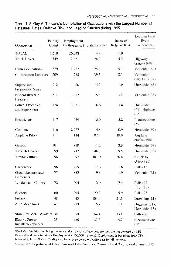
generates a fatality frequency count for the employment group, which safety and healthprofessionals often use to indicate the magnitude of the safety and health problem. Forexample, truck drivers have the largest number of fatalities and accounted for about 12percent of all the job-related fatalities in 1995 (see Table 1-3). But this number is influ-enced not only by the risk workers face in that occupation, but also by the total numberof workers in the occupation.
The second method, fatality rates, takes into account the differing total numbersamong occupations. It is calculated by dividing the number of job-related fatalities for agroup of workers during a given period by the average number of workers during thatperiod.2 This rate depicts a worker's risk of incurring a fatal work injury within the em-ployment group and is expressed as the number of fatalities per a standard measure. Forexample, the fatality rate for truck drivers is 26.2 deaths per 100,000 workers (see Table1–3). When occupations are ranked by fatality rates, truck drivers become the ninth mostdangerous occupation.
The fatality rates in Table 1-3 relate the total number of job-related deaths in 1995 tothe annual average number of workers facing that risk for various groups. These mea-sures are considered experimental because they do not reflect the movement of personsinto and out of the labor force, the length of their work week or work year, or the effectof holding multiple jobs.
Another method of expressing risk is an index of relative risk. This measure is calcu-lated for a group of workers as the ratio of the rate for that group to the rate for all work-ers.3 The index of relative risk compares the fatality risk of a group of workers with allworkers. For example, the relative risk for truck drivers in Table 1-3 is 5.3, whichmeans that they are roughly five times as likely to have a fatal work injury as the aver-age worker.
Analysis of dangerous jobs is not complete, however, unless data on nonfatal job-related injuries and illnesses are examined. Table 1–4 shows those occupations with thelargest number of nonfatal injuries and illnesses, along with days away from work to re-cuperate. This table shows that truck drivers also lead the list for the occupations withthe largest number of nonfatal injuries and illnesses. It also shows the chance of incur-ring an occupational injury or illness which is expressed as the total number of workersin the employment group compared with the number of workers injured in that group.
2There is more than one method to calculate fatality rates that measure the incidence of fatal work injuriesfor groups of workers. An hours-based rate measures the risk of fatality per standardized length of exposure;an employment-based rate measures the risk for those employed during a given period of time.
An employment-based fatality rate measures the incidence of a fatal injury for all workers in a group, re-gardless of exposure time. It does not account for fewer fatalities among part-time workers than for full-timeworkers because of their reduced hours exposed to the work environment. An hour-based fatality rate accountsfor different exposure durations among workers. Hours-based measurements are especially useful in industryand occupational comparisons in which the number of workers at risk can vary among industry or occupationalgroups for a particular period. Fatality counts from the Census of Fatal Occupational Injuries can be combinedwith information on employment or hours at work to produce a fatal work-injury rate. Because neither hoursat work nor number of persons employed were collected in the BLS census, the fatality rates in this report werecalculated using the employment estimates from the Current Population Survey (CPS)—a household survey.The CPS annual average employment estimates are based on the number of workers employed during theweek of the 12th of each month.
3Report on the American Workforce, U.S. Department of Labor, 1994, pp. 95–138.
Perspective, Perspective, Perspective 11
TABLE 1-3 Guy A. Toscano's Compilation of Occupations with the Largest Number ofFatalities, Rates, Relative Risk, and Leading Causes during 1995
FatalityOccupation Count
TOTAL 6,
Truck Driver
Farm Occupations
Construction Laborers
Supervisors,Proprietors, Sales
NonconstructionLaborers
Police, Detectives,and Supervisors
Electricians
Cashiers
Airplane Pilots
Guards
Taxi cab Drivers
Timber Cutters
Carpenters
Groundkeepers andGardeners
Welders and Cutters
Rooters
Fishers
Auto Mechanics
Structural Metal Workers
Electric PowerInstallers/Repairers
210
749
579
309
212
212
174
117
116
111
101
99
98
96
77
72
60
48
47
38
35
Employment(in thousands)
126,248
2,861
2,282
780
4,480
1,337
1,051
736
2,727
114
899
213
97
1,255
832
604
205
45
819
59
126
Fatality Ratea
4.9
26,2
25.3
39.5
4.7
15.8
16.6
15.9
4.3
97.4
11.2
46.5
101.0
7.6
9.3
12.0
29.3
104.4
5.7
64.4
27.8
Leading FatalIndex of Event
Relative Risk (in percent)
1.0
5.3
5.1
8.1
1.0
3.2
3.4
3.2
0.9
19.9
2.3
9.5
20.6
1.6
1.9
2.4
5.9
21.3
1.1
13.1
5.7
Highwaycrashes (68)
Vehicular (50)
Vehicular(28); Falls (27)
Homicide (63)
Vehicular (36)
Homicide(47); Highway(28)
Electrocutions(59)
Homicide (92)
Airplanecrashes (98)
Homicide (58)
Homicide (70)
Struck byobject (81)
Falls (43)
Vehicular (31)
Falls (22);Fires (18)
Falls (75)
Drowning (81)
Highway (21);Homicide (13)
Falls (66)
Electrocutions(60)
aExcludes fatalities involving workers under 16 years of age because they are not covered by CPS.Rate = (Fatal work injuries + Employment x 100,000 workers). Employment is based on 1995 CPS.Index of Relative Risk = Fatality rate for a given group •*• Fatality rate for all workers.
Source: U.S. Department of Labor, Bureau of Labor Statistics, Census of Fatal Occupational Injuries, 1995,
12 Chemical Process Safety
For example, the chance of a truck driver having a serious injury is 1 in 15, meaning thatfor every 15 truck drivers 1 will have a serious injury during the year. But laborers andnursing aides and orderlies have a greater chance of injury or illness than truck drivers(see Table 1–4).
Median days away from work to recuperate is yet another measure that can be usedto evaluate dangerous jobs. (Median days is an average such that half of those injuredtake more than the median days to recuperate while the other half require fewer days.)The median days to recuperate from an injury for the 10 occupations listed are highestfor track drivers and carpenters, each showing a median of 8 days to recuperate, com-pared to all workers who had a median of 5 days.
Based on the index of relative risk in the chart, truck driver is not the most dangerousoccupation. This distinction belongs to fishers. Commercial fishers are about four timesas likely as truck drivers to be killed by a fatal work incident (21.3 and 5.3, respectively).
Using this method of analysis, one could in fact identify even more dangerous occu-pations, such as elephant trainers, who in some years have had two work fatalities. Basedon employment figures of about 600 known elephant trainers in the United States, thiswould produce a fatality rate of 333 per 100,000 workers and a relative risk that is 68times greater than for the typical worker. Clearly, in this analysis an elephant trainer hasthe highest risk of a fatal work injury even though the frequency is low or nonexistentin some years. The purpose of this example is to illustrate the importance of viewing fre-quency counts, fatality rates, and indexes of relative risk to discern dangerous jobs.
The occupations identified by the frequency risk techniques and a chance of injurycan be used to target prevention efforts and may reduce both the number and rates of fa-talities and injuries for those workers at highest risk.
Characteristic of Dangerous Jobs
Today, the jobs that have the highest fatality rates and frequency counts are found inoutdoor occupations or occupations where workers are not in an office or factory. Theseinclude truck drivers, farmers, construction laborers, and airplane pilots. Most of theseworkers have one thing in common: they are affected by severe weather conditions,while driving on highways, flying airplanes, performing farm chores, or working on con-struction sites. Highway crashes are the primary cause of trucker fatalities, falls are theleading cause of death for construction laborers, and tractor rollovers account for one ofevery three farm-worker fatalities.
Homicide is another serious concern in some job settings. In 1995, homicide ac-counted for 16 percent of job-related fatalities. Workers most at risk are those who worklate at night, work alone, and handle money. Taxicab drivers are the most susceptibleand have a relative risk about 10 times higher than the typical worker. Other occupationsthat have a high relative risk of homicide include police and guards.
For jobs with high numbers of nonfatal injuries and illnesses, overexertion is the lead-ing event. These injuries result from lifting objects or, in the case of nursing aides andorderlies, patients. Injuries from overexertion accounted for about one-third of all thenonfatal injuries in 1994; it took a median of five days for those injured to recuperate.
Two occupations appear on both the fatal and nonfatal lists: truck drivers and con-struction laborers. But the leading event for fatal and nonfatal incidents for each occu-pation is different. For track drivers, 68 percent of the job-related fatalities are from

Perspective, Perspective, Perspective 13
TABLE 1–4 Guy A. Toscano's Compilation of Occupations with the Largest Number ofInjuries and Illnesses with Days Away from Work to Recuperate during 1994
Occupation
ALL OCCUPATIONS
Occupations Listed
Truck Drivers
NonconstructionLaborers
Nursing Aides andOrderliesJanitors and Cleaners
Construction Laborers
Assemblers
Carpenters
Stock Handlers andBaggers
Cooks
Cashiers
TotalNonfatal
Cases(in
thousands)
2,252.6
726.5
163.8
147.3
101.8
60.6
55.7
53.0
37.4
37.2
36.3
35.6
Employment(in
thousands)
92,973
14,636
2,438
1,137
1,359
1,407
674
1,167
869
1,121
1,838
2,626
MedianDays to
Recuperate
5
6
8
5
5
6
6
6
8
5
5
6
Chance ofInjury
1:41
1:20
1:15
1:08
1:13
1:23
1:12
1:22
1:23
1:30
1:51
1:74
LeadingNonfatal.
Event(in percent)
Overexertion(27)
Overexertion(29)
Contact withobject (35)
Overexertion(59)Overexertion(27)
Contact withobject (39)
Contact withobject (31)
Contact withobject (38)
Overexertion(37)
Contact withobject (33)
Overexertion(27)
Chance of Occupational Injury or Illness = Employment -*• Total Nonfatal Cases. Employment is based on1994 CPS.
Source: U.S. Department of Labor, Bureau of Labor Statistics, Survey of Occupational Injuries andIllnesses, 1994.
highway crashes, whereas Overexertion is the leading nonfatal event, accounting for 29percent of the incidents. For construction laborers, the leading fatal events are falls andvehicular-related incidents such as being struck by a backhoe. For nonfatal incidents, theleading event is contact with objects, primarily equipment and tools used on construc-tion sites.
This difference between the leading cause of a fatal and nonfatal injury for truck dri-vers is important because it suggests different kinds of prevention efforts. For example,to reduce highway crashes, driver training and proper maintenance of trucks is essential,whereas, to reduce the incidence of overexertion, proper lifting techniques must betaught along with proper use of lifting equipment. For construction laborers, prevention
14 Chemical Process Safety
programs for fatal events require awareness of the hazards of falling off buildings, lad-ders, scaffoldings, and other structures while for serious nonfatal injuries, preventionwould focus on the proper use of tools.
Relative Risks Compared to the Chemical Industry Jobs
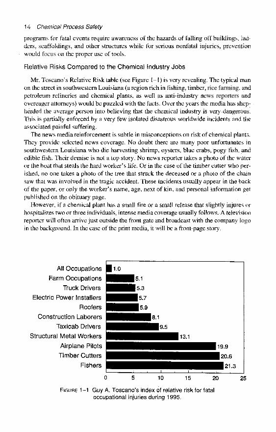
Mr. Toscano's Relative Risk table (see Figure 1–1) is very revealing. The typical manon the street in southwestern Louisiana (a region rich in fishing, timber, rice farming, andpetroleum refineries and chemical plants, as well as anti-industry news reporters andovereager attorneys) would be puzzled with the facts. Over the years the media has shep-herded the average person into believing that the chemical industry is very dangerous.This is partially enforced by a very few isolated disastrous worldwide incidents and theassociated painful suffering.
The news media reinforcement is subtle in misconceptions on risk of chemical plants.They provide selected news coverage. No doubt there are many poor unfortunates insouthwestern Louisiana who die harvesting shrimp, oysters, blue crabs, pogy fish, andedible fish. Their demise is not a top story. No news reporter takes a photo of the wateror the boat that steals the hard worker's life. Or in the case of the timber cutter who per-ished, no one takes a photo of the tree that struck the deceased or a photo of the chainsaw that was involved in the tragic accident. These incidents usually appear in the backof the paper, or only the worker's name, age, next of kin, and personal information getpublished on the obituary page.
However, if a chemical plant has a small fire or a small release that slightly injures orhospitalizes two or three individuals, intense media coverage usually follows. A televisionreporter will often arrive just outside the front gate and broadcast with the company logoin the background. In the case of the print media, it will be a front-page story.
FIGURE 1 -1 Guy A. Toscano's index of relative risk for fataloccupational injuries during 1995.
Perspective, Perspective, Perspective 15
The chemical industry is held to a higher standard of safety. Those of us in the indus-try must accept that burden of responsibility and strive even harder to reach the goal ofan accident-free environment.
Just How Dangerous Is It to Work in a U.S. Chemical Plant?Mr. Toscano provides some 1995 relative risk fatality statistics that compare several in-
dustries' relative risk with the occupations described in his "Dangerous Jobs" article.These numbers are specific to 1995 and involve fatalities, not major injuries. On a typi-cal day about 17 workers in the United States are killed on the job. Thank goodness thatjob-related fatalities are relatively infrequent for specific standard industry classifica-tions (SIC code), but a major incident in any industry may skew the information fromyear to year.
The statistics about truck driving show the job to be relatively dangerous. However, iftrucking is considered as an industry, the risk numbers are diluted since the employees ofthat industry include not only the drivers (a dangerous job) but also the clerical, sales, dis-patching, repair, and other support groups that have significantly lower exposures.
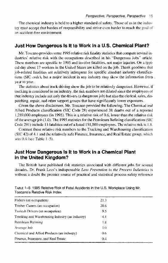
Given the above disclaimers, Mr. Toscano provided the following: The Chemical andAllied Products classification (SIC Code 28) experienced 38 deaths out of a reported1,289,000 employees (in 1995). This is a relative risk of 0.6, lower than the relative riskof the average job (1.0). The 1995 statistics for the Petroleum Refining classification (SICCode 291) include 13 fatalities out of a listed 151,000 employees. The relative risk is 1.8,
Contrast these relative risk numbers to the Tracking and Warehousing classification(SIC 42) of 4.1 and the relatively safe Finance, Insurance, and Real Estate group, whichwas 0.4 (see Table 1-5).
Just How Dangerous Is It to Work in a Chemical Plantin the United Kingdom?
The British have published risk statistics associated with different jobs for severaldecades. Dr. Frank Lees's indispensable Loss Prevention in the Process Industries iswithout a doubt the premier source of practical and statistical process-safety reference
TABLE 1–5 1995 Relative Risk of Fatal Accidents in the U.S. Workplace Using Mr.Toscano's Relative Risk Index
Fishers (an occupation) 21.3
Timber Cutters (an occupation) 20.6
Taxicab Drivers (an occupation) 9.5
Trucking and Warehousing Industry (an industry) 4.1
Petroleum Refining 1.8
Average Job 1.0)
Chemical and Allied Products (an industry) 0.6
Finance, Insurance, and Real Estate 0.4
16 Chemical Process Safety
TABLE 1–6 1987–1990 Fatal Accident Rate in Different Industries and Jobsin the United Kingdom
Industry or Activity Fatal Accident Rate
Offshore Oil and Gas 62
Deep Sea Fishing 42
Construction 5
Agriculture 3.7
Chemical and Allied Industries 1.2
All Manufacturing Industries 1.2
Clothing Manufacture 0.05
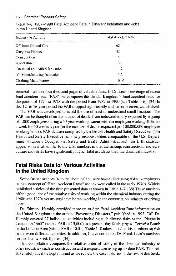
material—almost four thousand pages of valuable facts. In Dr. Lees's coverage of recentfatal accident rates (FAR), he compares the United Kingdom's fatal accident rates forthe period of 1974 to 1978 with the period from 1987 to 1990 (see Table 1–6). [34] Inthat 12- to 16-year period the FAR dropped significantly and, in some cases, were halved.
The FAR was developed to avoid the use of hard-to-understand small fractions. TheFAR can be thought of as the number of deaths from industrial injury expected by a groupof 1,000 employees during a 50-year working career with the employee working 40 hoursa week for 50 weeks a year (or the number of deaths expected per 100,000,000 employeeworking hours). FAR data are compiled by the British Health and Safety Executive. (TheHealth and Safety Executive has many responsibilities comparable to the U.S. Depart-ment of Labor's Occupational Safety and Health Administration.) The U.K. statisticsappear somewhat similar to the U.S. numbers in that the fishing, construction, and agri-culture industries have significantly higher fatal accidents than the chemical industry.
Fatal Risks Data for Various Activitiesin the United Kingdom
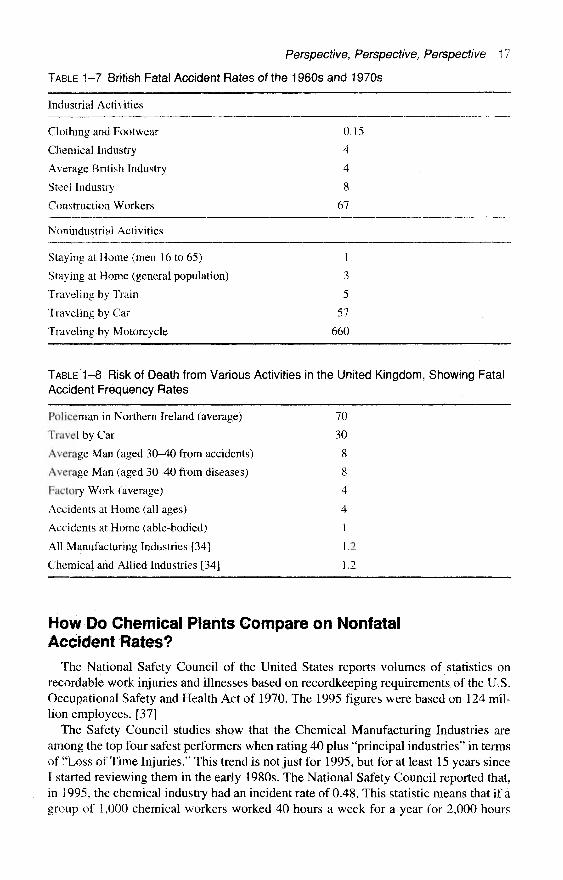
Some British authors from the chemical industry began discussing risks to employeesusing a concept of "Fatal Accident Rates" as they were called in the early 1970s. Widelypublished articles of the time presented data as shown in Table 1-7. [35] These numbersoffer a good idea of the relative risks of working within the chemical industry during the1960s and 1970s versus staying at home, working in the construction industry or drivinga car.
Dr. Edmund Hambly provided more up-to-date Fatal Accident Rate information onthe United Kingdom in the article "Preventing Disasters," published in 1992. [36] Dr.Hambly covered 27 individual activities including such diverse risks as the "Plague inLondon in 1665" (with a FAR of 15,000) to a present-day fatality by a "Terrorist Bombin the London Area (with a FAR of 0.01). Table 1–8 takes a look at his numbers on riskfrom seven different activities. In addition, I have compared Dr. Frank Lees's numbersfor the last two risk figures. [34]
This compilation compares the relative order of safety of the chemical industry toother industries such as construction and transportation using up-to-date FAR. This rel-ative safety must be kept in mind as we review the case histories in the rest of this book.
Perspective, Perspective, Perspective 17
TABLE 1–7 British Fatal Accident Rates of the 1960s and 1970s
Industrial Activities
Clothing and Footwear
Chemical Industry
Average British Industry
Steel Industry
Construction Workers
0.15
4
4
8
67
Nonindustrial Activities
Staying at Home (men 16 to 65)
Staying at Home (general population)
Traveling by Train
Traveling by Car
Traveling by Motorcycle
1
3
5
57
660
TABLE 1-8 Risk of Death from Various Activities in the United Kingdom, Showing FatalAccident Frequency Rates
Policeman in Northern Ireland (average) 70
Travel by Car 30
Average Man (aged 30–40 from accidents) 8
Average Man (aged 30–40 from diseases) 8
Factory Work (average) 4
Accidents at Home (all ages) 4
Accidents at Home (able-bodied) 1
All Manufacturing Industries [34] 1.2
Chemical and Allied Industries [34] 1.2
How Do Chemical Plants Compare on NonfatalAccident Rates?
The National Safety Council of the United States reports volumes of statistics onrecordable work injuries and illnesses based on recordkeeping requirements of the U.S.Occupational Safety and Health Act of 1970. The 1995 figures were based on 124 mil-lion employees. [37]
The Safety Council studies show that the Chemical Manufacturing Industries areamong the top four safest performers when rating 40 plus "principal industries" in termsof "Loss of Time Injuries." This trend is not just for 1995, but for at least 15 years sinceI started reviewing them in the early 1980s. The National Safety Council reported that,in 1995, the chemical industry had an incident rate of 0.48. This statistic means that if agroup of 1,000 chemical workers worked 40 hours a week for a year (or 2,000 hours
18 Chemical Process Safety
each) then the chemical industry could expect about 5 individuals to experience a loss-of-time injury. By contrast this rate is one-third of the 1.64 rate of cases involving daysaway from work and deaths for the All Industries average. The Trucking Industry expe-riences rates of 5.67 or about 11.8 times higher than the Chemical Industries.
However, the average person on the street probably perceives that working for achemical industry is a lot more dangerous than working for the trucking industry,Cliques within the often chemophobic news media appears addicted to grossly magni-fying our blemishes and maligning our value to society. Fires, explosions, and releasesof disagreeable gases make front-page newspaper coverage, yet few people realize thehigh degree of safety within a chemical plant. The Chemical Industry must find betterways to educate the public on just how safe the industry really operates.
The Chemical Manufacturing Industry Needs ContinuousImprovement to Gain Universal Credibility
However, it is time for a reality check. The chemical manufacturing and petroleum re-fining industries are not blemish free. In late 1997, President William J. Clinton chosenot to exercise his line item veto against funding for the Chemical Safety and Hazard In-vestigation Board. The Chemical Safety Board, which was modeled after the NationalTransportation Safety Board, is designed to investigate explosions and other accidentsat chemical manufacturing and other industrial facilities.
The U.S. Congress funded the board at $4 million for 1988. One key assumption, asstated in the Overview of the Chemical Safety Board's operations, is that there would be330 catastrophic accidents annually. It was further assumed that within this total, be-tween 10 and 15 of these accidents would be major catastrophic accidents with an aver-age of two deaths per incident. [38] The industry must perform better than the predicted330 catastrophic accidents for the public to fully earn our trust.
References1. A Technology Vision, The American Chemical Society, American Institute of Chemical En-
gineers, The Chemical Manufacturers Association, The Council of Chemical Research, and theSynthetic Organic Manufacturers Association, available from American Chemical Society, Wash-ington, D.C., 1996, pp. 17–18.
2. Taylor, F. S. A History of Industrial Chemistry. London: W. Heinemann Ltd., 1957, pp. 21, 59.3. Soda Ash, Columbia-Southern Chemical Corporation—Subsidiary of Pittsburgh Plate Glass
Co., 1951, pp. 3–7.4. Taylor, History of Industrial Chemistry, pp. 153–55.5. Ibid., p. 130.6. Groner, A. et al. The American Heritage History of American Business and Industry. New
York: American Heritage Publishing Co. Inc., 1972, pp. 10–21.7. "Middle Ages," in The World Book Encyclopedia. Chicago: World Book—Childcraft Inter-
national, Inc. 1980, p. 13:432.8. "Chemical Industry," in The World Book Encyclopedia. Chicago: World Book—Childcraft
International, Inc. 1980, pp. 3:310–3:314.9. Te-Pang, Hou, Manufacture of Soda with Special Reference to the Ammonia Process—A
Practical Treatise. New York, 1933, pp. 15-17.
Perspective, Perspective, Perspective 19
10. "Chemical Industry and History of Chemistry," Academic American Encyclopedia. Dan-bury, Conn.: Grolier Inc. 1983, pp. 4:317–4:325.
11. Industrial Risk Insurers, The Sentinel. Hartford, Conn.: Oct.–Nov. 1980, pp. 4–5.12. The Institution of Chemical Engineers, A First Guide to Loss Prevention. Rugby, U.K.:
1977, p. 2.13. Kletz, Trevor A., "A Three-Pronged Approach to Plant Modifications," Chemical Engi-
neering Progress, Nov. 1976: pp. 48-55.14. Russell, W. W., "Hazard Control of Plant Process Changes," Loss Prevention, American
Institute of Chemical Engineers, New York, 1976, pp. 10:80–10:87.15. Booth, G., "Process Changes Can Cause Accidents," Chemical Engineering Progress,
Nov. 1976: pp. 76-78.16. Sanders, R. E., "Plant Modifications: Troubles and Treatment," Chemical Engineering
Progress, New York, Feb. 1983: pp. 73-77.17. Kletz, Trevor A., Learning from Accidents in Industry, 2d ed. Oxford, U.K.: Butterworth-
Heinemann, 1996.18. Kletz, Trevor A., Critical Aspects of Safety and Loss Prevention. London: Butterworth &
Co., 1990, pp. 220–22.19. Kletz, Trevor A., What Went Wrong? Case Histories of Process Plant Disasters, 3d ed., ch.
2. Houston: Gulf Publishing, 1995.20. Sanders, Roy E., "Human Factors: Case Histories of Improperly Managed Changes in
Chemical Plants," Process Safety Progress 15, no. 3, Fall 1996: pp. 132-39.21. Dowell, Art M. Ill and Dennis C. Hendershot, "No Good Deed Goes Unpunished: Case
Studies of Incidents and Potential Incidents Caused by Protective Systems," Process SafetyProgress 16, no. 3, Fall 1997: pp. 150-53.
22. Ross, John F. "Risk: Where Do Real Dangers Lie?" Smithsonian 26, no. 8., Nov. 1995:pp. 42-53.
23. National Safety Council, Accident Facts—1996 Edition, Itasca, I1l., 1996: p. 8.24. Ibid., pp. 130–31.25. Stossel, John, "Are We Scaring Ourselves to Death," ABC TV News Special, 1993. Avail-
able for $ 19.98 via MPI Video, Orland Park, Ill. The video distributor can be reached by phoning(800) 777-2223 or (708) 460-0555. Ask for MPI's catalog number MP-8088.
26. Siegel, Martin, "Explaining Risk to the Public," Chemical Engineering Progress, NewYork, May 1989, p. 20.
27. Kletz, Trevor A., "Risk—Two Views: the Public's and the Experts," Disaster Preventionand Management 5, no. 4, 1996: pp. 41–46.
28. Kletz, Trevor A., HAZOP and HAZAN, Identifying and Assessing Process Industry Haz-ards, 3d, ed. Rugby, U.K.: Taylor & Francis, 1992, pp. 125-26.
29. Trefil, James, "How the Body Defends Itself from the Risky Business of Living," Smith-sonian 26, no. 9, Dec. 1995: pp. 42–49.
30. Covello, V. T., P. M. Sandman, and P. Slovic, Risk Communication, Risk Statistics, andRisk Comparisons: A. Manual for Plant Managers, Chemical Manufacturers Association, Wash-ington, D.C., 1988.
31. Cohen, B. and I. Lee "A Catalog of Risks," Health Physics 36, June 1979: pp. 707–22.32. Toscano, Guy A. "Dangerous Jobs" in Fatal Workplace Injuries in 1995: A Collection of
Data and Analysis, Report 913, U.S. Department of Labor, Bureau of Labor Statistics, Washington,D.C., April 1997, pp. 38–41. This excerpt appeared in "Compensation and Working Conditions,Summer 1997."
33. "Risk and the CPI," Chemical Engineering 102, no. 2, Feb. 1995: pp. 20–23.34. Lees, Dr. Frank P., Loss Prevention in the Process Industries Hazard Identification,
Assessment and Control, 2d ed. Oxford, U.K.: Butterworth-Heinemann, 1996, pp. 1:2–l:9.

20 Chemical Process Safety
35. Kletz, Trevor A., "Evaluate Risk in Plant Design," Hydrocarbon Processing 56, Houston,Tex., May 1977, pp. 297–324.
36. Hambly, Dr. Edmund C., Preventing Disasters, Royal Institution Discourse, London, May1992, pp. A1–A2.
37. National Safety Council, Accident Facts—1996 Edition, Itasca, Ill., 1996: p. 69.38. "Dedicated to Industrial Chemical Safety—Business Plan for the Chemical Safety and
Hazard Investigation Board," August 1997. An attachment to a memo provided by the ChemicalManufacturers Association.

CHAPTER 2
Good Intentions
Modifications Made with Good IntentionsAs chemical manufacturers, we must continually modify our facilities to survive in our
dynamic industry. Without the appropriate changes, our clever competition or our gov-ernmental regulators will surely drive us out of business. The goal of these modificationsmay be to increase production, to compensate for unavailable equipment, to add storagecapacity, to improve yields, to reduce costs, to enhance safety, or to reduce pollution po-tentials. The means to achieve these goals may be changes in piping or equipment, new op-erating procedures, new operating conditions, changes in material of construction, as wellas the process chemical changes in feedstocks, catalyst, fuels, or their method of delivery.
The first series of modifications featured in this chapter were all motivated by "GoodIntentions." In spite of creative ideas and considerable effort, these modifications failedbecause no one took the time to examine and expose their weaknesses. These undetectedweaknesses caused undesired side effects.
A Tank Truck Catastrophically Fails
In late 1991, a tank truck catastrophically collapsed as it was unloading a productfrom a nearby plant (see Figure 2-1). The 6,300-gallon (24,000 L) tank on the trailer,which had a name-plate design pressure of 30 psig (2.0 bar), appeared to be very wellmaintained and in excellent condition prior to the accident. [1] The assistant trucking ter-minal manager described the ruined equipment as the worst tank truck collapse that hehad witnessed in his 25 years of trucking.1
Investigators started reviewing the situation just an hour or so after the incident. Thesmall investigating team, learned that the truck arrived about 9:00 A.M. and was set up forunloading about 9:15 A.M. The chemical process operator connected a 3-inch (7.6 cm) un-loading hose to the track and to the plant's unloading pump (see Figure 2-2). Next, sheconnected a 3/4-inch (1.9 cm) nitrogen hose from the supply station to a manifold thatwas just forward of the rear wheels on the trailer. Someone modified the truck's nitrogen
1This case history of the tank truck collapse has been reproduced with the permission of the American In-stitute of Chemical Engineers. Copyright © 1993. It first appeared in "Don't Become Another Victim of Vac-uum," Chemical Engineering Progress, 1993. All rights reserved.
21
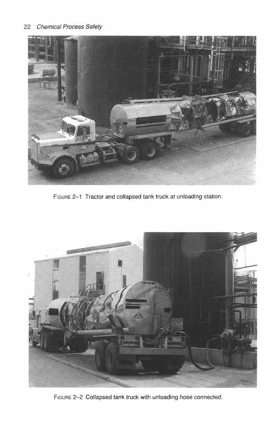
22 Chemical Process Safety
FIGURE 2-1 Tractor and collapsed tank truck at unloading station.
FIGURE 2-2 Collapsed tank truck with unloading hose connected.
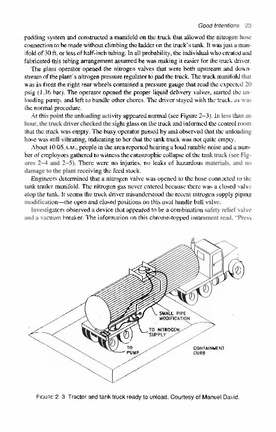
Good Intentions 23
padding system and constructed a manifold on the truck that allowed the nitrogen hoseconnection to be made without climbing the ladder on the truck's tank. It was just a man-ifold of 30 ft, or less of half-inch tubing. In all probability, the individual who created andfabricated this tubing arrangement assumed he was making it easier for the truck driver,
The plant operator opened the nitrogen valves that were both upstream and down-stream of the plant's nitrogen pressure regulator to pad the truck. The truck manifold thatwas in front the right rear wheels contained a pressure gauge that read the expected 20psig (1.36 bar). The operator opened the proper liquid delivery valves, started the un-loading pump, and left to handle other chores. The driver stayed with the truck, as wasthe normal procedure.
At this point the unloading activity appeared normal (see Figure 2-3). In less than anhour, the truck driver checked the sight glass on the truck and informed the control roomthat the truck was empty. The busy operator passed by and observed that the unloadinghose was still vibrating, indicating to her that the tank truck was not quite empty.
About 10:05 A.M., people in the area reported hearing a loud rumble noise and a num-ber of employees gathered to witness the catastrophic collapse of the tank truck (see Fig-ures 2–4 and 2–5). There were no injuries, no leaks of hazardous materials, and nodamage to the plant receiving the feed stock.
Engineers determined that a nitrogen valve was opened to the hose connected to thetank trailer manifold. The nitrogen gas never entered because there was a closed valveatop the tank. It seems the truck driver misunderstood the recent nitrogen supply pipingmodification—the open and closed positions on this oval handle ball valve.
Investigators observed a device that appeared to be a combination safety relief valveand a vacuum breaker. The information on this chrome-topped instrument read, "Press
CONTAINMENTCURB
FIGURE 2-3 Tractor and tank truck ready to unload. Courtesy of Manuel David.
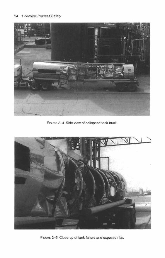
24 Chemical Process Safety
FIGURE 2-4 Side view of collapsed tank truck.
FIGURE 2-5 Close-up of tank failure and exposed ribs.
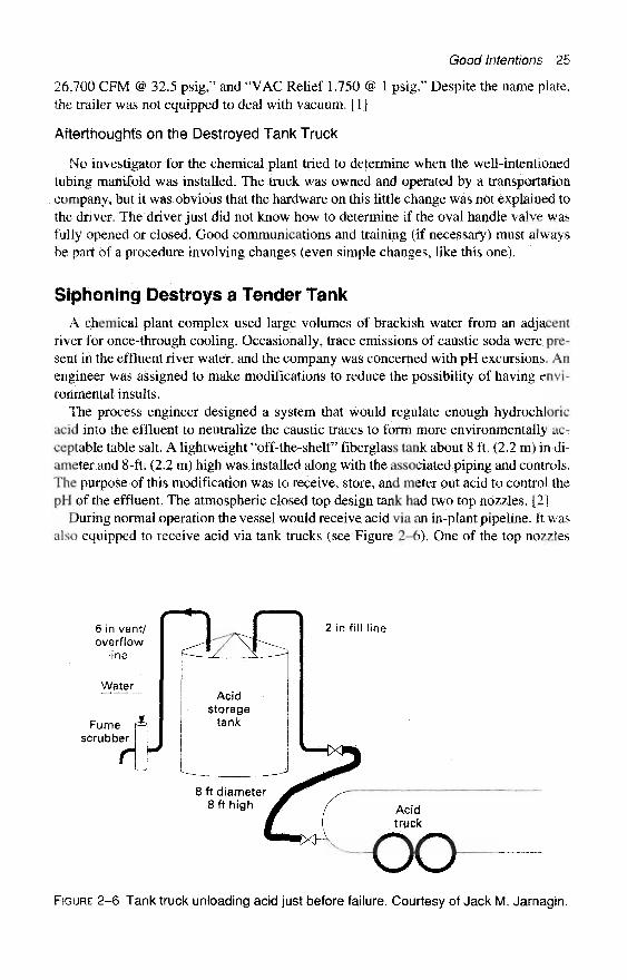
26,700 CFM @ 32.5 psig," and "VAC Relief 1,750 @the trailer was not equipped to deal with vacuum. [1]
Afterthoughts on the Destroyed Tank Truck
Good Intentions 25
1 psig." Despite the name plate,
No investigator for the chemical plant tried to determine when the well-intentionedtubing manifold was installed. The truck was owned and operated by a transportationcompany, but it was obvious that the hardware on this little change was not explained tothe driver. The driver just did not know how to determine if the oval handle valve wasfully opened or closed. Good communications and training (if necessary) must alwaysbe part of a procedure involving changes (even simple changes, like this one).
Siphoning Destroys a Tender Tank
A chemical plant complex used large volumes of brackish water from an adjacentriver for once-through cooling. Occasionally, trace emissions of caustic soda were pre-sent in the effluent river water, and the company was concerned with pH excursions. Anengineer was assigned to make modifications to reduce the possibility of having envi-ronmental insults.
The process engineer designed a system that would regulate enough hydrochloricacid into the effluent to neutralize the caustic traces to form more environmentally ac-ceptable table salt. A lightweight "off-the-shelf fiberglass tank about 8 ft. (2,2 m) in di-ameter and 8-ft. (2.2 m) high was installed along with the associated piping and controls.The purpose of this modification was to receive, store, and meter out acid to control thepH of the effluent. The atmospheric closed top design tank had two top nozzles. [2]
During normal operation the vessel would receive acid via an in-plant pipeline. It wasalso equipped to receive acid via tank trucks (see Figure 2-6). One of the top nozzles
6 in vent/overflow
line
Water
Fumescrubber
2 in fill line
FIGURE 2-6 Tank truck unloading acid just before failure. Courtesy of Jack M, Jarnagin.

26 Chemical Process Safety
was the fill line and the other was piped to a small vent scrubber to eliminate fumesgiven off during the filling operation.
The intentions to improve the environment were noble, but the simple vent system de-sign possessed an unrecognized flaw that allowed a minor overfill situation to suddenlyand completely destroy the vessel. The acid tank project was rather simple, so the pro-posal was accepted and no one asked pointed questions like, "What happens if the acidstorage tank is overfilled by a tank truck?" (As we shall see, many unforeseen problemshave occurred on equipment so simple that a detailed examination of the proposal mayhave been considered unnecessary in years past.)
About a year after the system was put in service, the tank was filled via a tank truck,instead of being supplied by the usual pipeline. As the delivery tank truck was unloaded,the acid level rose in the small storage tank. The company representative wanted to topoff the tank.
Before the acid truck was unloaded, acid started to overflow and pour through the 6-inch (15 cm) line into the scrubber. The alert truck driver quickly responded. Heabruptly shut the delivery valve on his track. Unexpectedly, the partial vacuum createdby the siphoning action of the overflowing liquid exceeded the tank's vacuum rating andthe storage tank was totally destroyed (see Figures 2-7, 2-8, and 2-9). [2]
Afterthoughts on the Acid Tank
Storage tanks are more fragile than many experienced Operations, Engineering, andMaintenance employees realize. The Institution of Chemical Engineers in Warwick-shire, England, offers a training kit with slides, booklets, and an instructor's guide for in-piant training. The name of the kit is "Over- and Under-Pressuring of Vessels," HazardWorkshop Module 001. I highly recommended the kit for in-plant training. [3]
FIGURE 2-7 Tank truck parked next to damaged acid tank.

Good Intentions 27
FIGURE 2-8 Acid tank just after failure.
FIGURE 2-9 Close-up of collapsed acid tank.
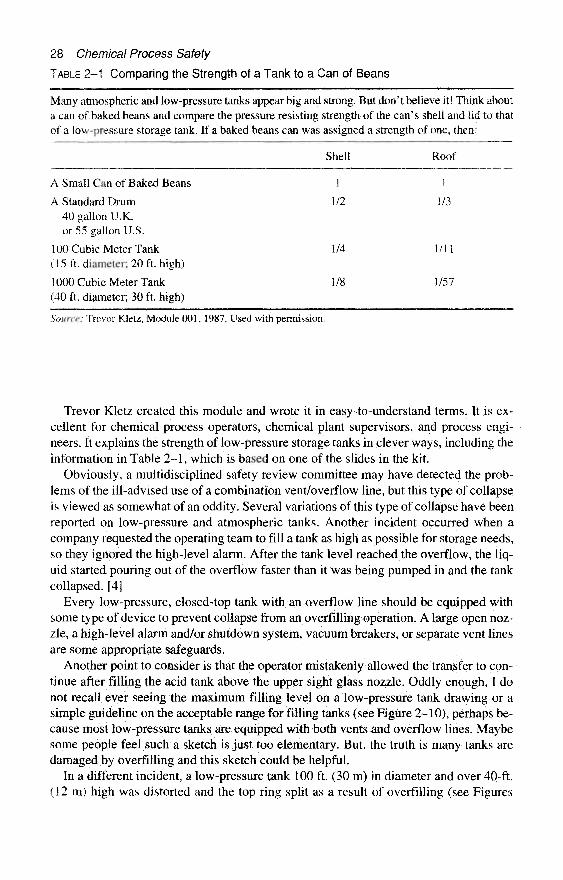
28 Chemical Process Safety
TABLE 2–1 Comparing the Strength of a Tank to a Can of Beans
Many atmospheric and low-pressure tanks appear big and strong. But don't believe it! Think abouta can of baked beans and compare the pressure resisting strength of the can's shell and lid to thatof a low-pressure storage tank. If a baked beans can was assigned a strength of one, then:
Shell Roof
A Small Can of Baked Beans 1 1
A Standard Drum 1/2 1/340 gallon U.K.or 55 gallon U.S.
100 Cubic Meter Tank 1/4 1/11(15 ft. diameter; 20 ft. high)
1000 Cubic Meter Tank 1/8 1/57(40 ft. diameter; 30 ft. high)
Source: Trevor Kletz, Module 001, 1987. Used with permission.
Trevor Kletz created this module and wrote it in easy-to-understand terms. It is ex-cellent for chemical process operators, chemical plant supervisors, and process engi-neers. It explains the strength of low-pressure storage tanks in clever ways, including theinformation in Table 2-1, which is based on one of the slides in the kit.
Obviously, a multidisciplined safety review committee may have detected the prob-lems of the ill-advised use of a combination vent/overflow line, but this type of collapseis viewed as somewhat of an oddity. Several variations of this type of collapse have beenreported on low-pressure and atmospheric tanks. Another incident occurred when acompany requested the operating team to fill a tank as high as possible for storage needs,so they ignored the high-level alarm. After the tank level reached the overflow, the liq-uid started pouring out of the overflow faster than it was being pumped in and the tankcollapsed. [4J
Every low-pressure, closed-top tank with an overflow line should be equipped withsome type of device to prevent collapse from an overfilling operation. A large open noz-zle, a high-level alarm and/or shutdown system, vacuum breakers, or separate vent linesare some appropriate safeguards.
Another point to consider is that the operator mistakenly allowed the transfer to con-tinue after filling the acid tank above the upper sight glass nozzle. Oddly enough, I donot recall ever seeing the maximum filling level on a low-pressure tank drawing or asimple guideline on the acceptable range for filling tanks (see Figure 2-10), perhaps be-cause most low-pressure tanks are equipped with both vents and overflow lines. Maybesome people feel such a sketch is just too elementary. But, the truth is many tanks aredamaged by overfilling and this sketch could be helpful.
In a different incident, a low-pressure tank 100 ft. (30 m) in diameter and over 40-ft.(12 m) high was distorted and the top ring split as a result of overfilling (see Figures
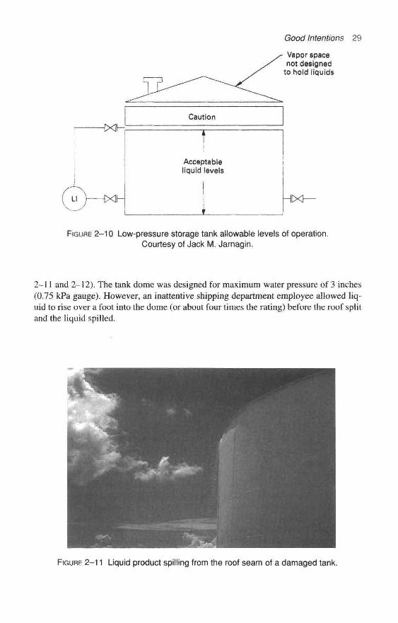
Li XJ
Caution
Acceptableliquid levels
Good Intentions 29
Vapor spacenot designed
to hold liquids
HDXK
FIGURE 2–10 Low-pressure storage tank allowable levels of operation.Courtesy of Jack M. Jarnagin.
2–11 and 2–12). The tank dome was designed for maximum water pressure of 3 inches(0.75 kPa gauge). However, an inattentive shipping department employee allowed liq-uid to rise over a foot into the dome (or about four times the rating) before the roof splitand the liquid spilled.
FIGURE 2–11 Liquid product spilling from the roof seam of a damaged tank.

30 Chemical Process Safety
FIGURE 2–12 Large tank (100-ft. diameter) damaged by overfilling.
A Well-Intended Change Yields a Storage Tank CollapseA well-maintained low-pressure solvent tank ended up as scrap metal after the vent
system had been "improved." This late 1993 Management of Change mistake cost about$100,000 to correct. Fortunately, there were no leaks and only egos were injured whenthe 20 ft. (6.1 m) diameter and 30 ft. (9.1) tall vessel was destroyed. Prior to the incident,this plant was step-wise reducing volatile organic emissions within a tank farm by re-placing simple hinged breather vents with a more sophisticated near-zero leakage sys-tem. Several tanks had already been converted.2
Plant supervision properly recognized this environmental improvement project as re-quiring a simple Management of Change (MOC) review. The prescribed MOC evalua-tion was made on this nonflammable organic handling system project. Pre-startuptraining for the newly installed but not yet operational vent compressor system wasbeing provided, but had not been given to each shift of operators. However, the focus ofthe training was the new compressor system. The training did not cover the newly in-stalled piping and the unique valving associated with the new over- and under-pressuredevices.
The roof and top two courses of 1/4-inch (0.64 cm) thick vertical walls were dramat-ically sucked in the first time the contents were pumped out following the piping modi-fications. The tank was filled after it had been out of service, the product was analyzed,and a transfer from the tank was started around 5:30 P.M. The collapsed sections of thetank were observed before sunrise about 6:00 A.M. the next morning.
2This case history on a solvent tank failure has been reproduced with the permission of the American in-stitute of Chemical Engineers. Copyright © 1995. It first appeared as "Human Factors: Case Histories of Im-properly Managed Changes in Chemical Plants" in Process Safety Progress, 1996. All rights reserved.
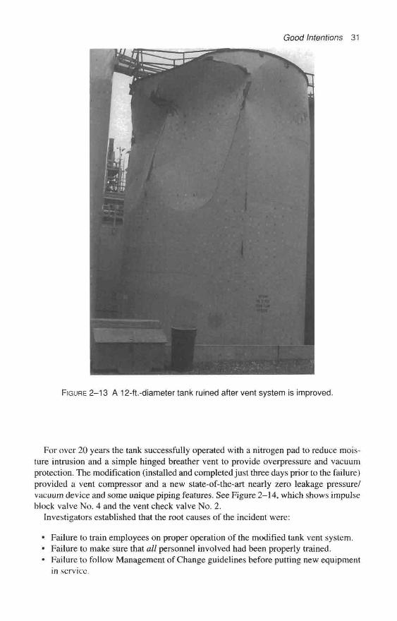
Good Intentions 31
FIGURE 2–13 A 12-ft.-diameter tank ruined after vent system is improved.
For over 20 years the tank successfully operated with a nitrogen pad to reduce mois-ture intrusion and a simple hinged breather vent to provide overpressure and vacuumprotection. The modification (installed and completed just three days prior to the failure)provided a vent compressor and a new state-of-the-art nearly zero leakage pressure/vacuum device and some unique piping features. See Figure 2-14, which shows impulseblock valve No. 4 and the vent check valve No. 2.
Investigators established that the root causes of the incident were:
• Failure to train employees on proper operation of the modified tank vent system.« Failure to make sure that all personnel involved had been properly trained.« Failure to follow Management of Change guidelines before putting new equipment
in service.

32 Chemical Process Safety
EXISTINGN2 VH
REGULATOR
VENTCOMPRESSORS
(PRE START-UPSTATUS)
PS–2
(20'0 x 30'H)
VALVE jj
VALVE #2 =
VALVE #3 =
VALVE #4 =
= ISOLATION VALVE TO VENT SYSTEM
"BREATHER* VALVE OR CHECK VALVE FORVENT LINE OFF TANK
P/V = 3-INCH PRESSURE/VACUUM RELIEF VALVE
SETTINGS:
13-INCH WATER PRESSURE
1.5-INCH WATER VACUUM
FIGURE 2–14 Storage tank sketch displaying the improved vent system piping—prior tothe collapse. Courtesy of John Hawkins and Cindy Ottenweller.
With all due respect to the findings of the investigating team, the root cause appearsto me to be a human factors situation. The new piping system looked simple but in factthis unique system was confusing. A check valve (valve no. 2) was installed on the ventheader to prevent cross-contamination. A small block valve (valve no. 4) was installedon the vacuum relief impulse line to provide easy isolation. [5]
A small block valve is usually installed at the tank on any instrument impulse line justin case a leak develops on the small tubing. In this unit, block valves are generallyavoided on overpressure or vacuum-relief devices. If a block valve that can defeat anoverpressure device cannot be avoided, such a valve is chained and locked open or car-sealed open and a protocol is developed to administratively control accidental closing ofsuch a prime safety feature.
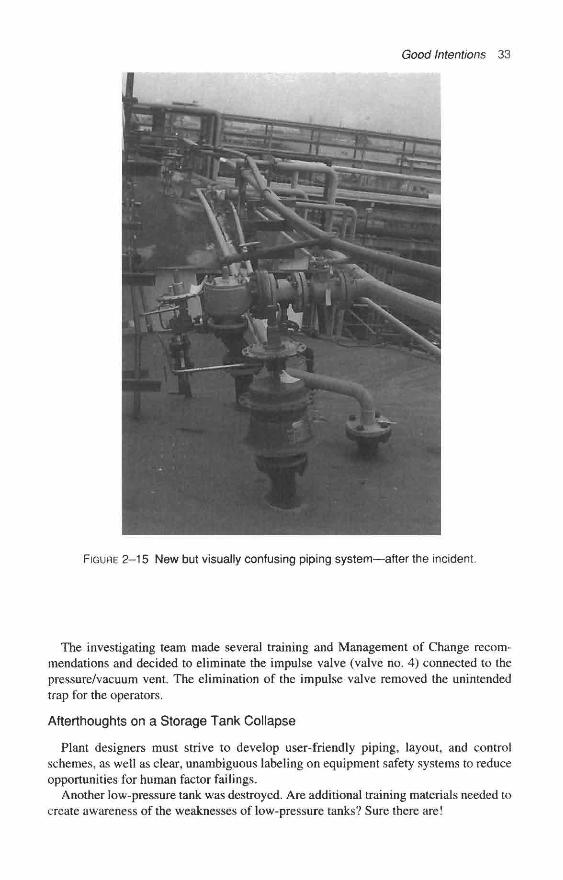
Good Intentions 33
FIGURE 2–15 New but visually confusing piping system—after the incident.
The investigating team made several training and Management of Change recom-mendations and decided to eliminate the impulse valve (valve no. 4) connected to thepressure/vacuum vent. The elimination of the impulse valve removed the unintendedtrap for the operators.
Afterthoughts on a Storage Tank Collapse
Plant designers must strive to develop user-friendly piping, layout, and controlschemes, as well as clear, unambiguous labeling on equipment safety systems to reduceopportunities for human factor failings.
Another low-pressure tank was destroyed. Are additional training materials needed tocreate awareness of the weaknesses of low-pressure tanks? Sure there are!

34 Chemical Process Safety
FIGURE 2–16 Crushed tank in the tank farm.
Dr. Ronald J. Willey of Northeastern University in Boston prepared an excellent35mm slide training package entitled "Seminar on Tank Failures." Professor Willey de-veloped this instructional lecture material under the direction and guidance of the Amer-ican Institute of Chemical Engineers' Undergraduate Education Committee of theCenter for Chemical Process Safety (CCPS).3
Professor Willey concluded the training session with this statement: "Remember thattanks are fragile. An egg shell can withstand more pressure and vacuum on a per unitbasis. If we approach tanks with this concept, fewer tank failures will occur because weare aware of the care that must be taken with handling eggs and tanks. Routine mainte-nance is a must as well as periodic inspections."
3The "Seminar on Tank Failures" was completed in 1993 for use in universities by SACHE (Safety andChemical Engineering Education) members. To inquire about cost and delivery, call 1-800-AIChernE; fromoutside of the United States, call (212) 705-8100; or by e-mail—[email protected].
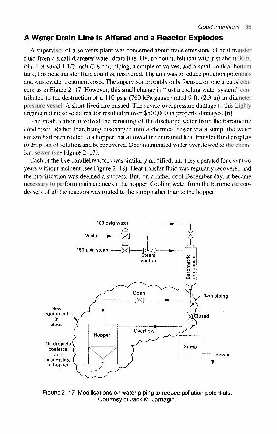
Good Intentions 35
A Water Drain Line Is Altered and a Reactor Explodes
A supervisor of a solvents plant was concerned about trace emissions of heat transferfluid from a small diameter water drain line. He, no doubt, felt that with just about 30 ft.(9 m) of small 1 1/2-inch (3.8 cm) piping, a couple of valves, and a small conical bottomtank, this heat transfer fluid could be recovered. The aim was to reduce pollution potentialsand wastewater treatment costs. The supervisor probably only focused on one area of con-cern as in Figure 2–17. However, this small change in "just a cooling water system" con-tributed to the destruction of a 110 psig (760 kPa gauge) rated 9 ft. (2.3 m) in diameterpressure vessel. A short-lived fire ensued. The severe overpressure damage to this highlyengineered nickel-clad reactor resulted in over $500,000 in property damages. [6]
The modification involved the rerouting of the discharge water from the barometriccondenser. Rather than being discharged into a chemical sewer via a sump, the waterstream had been routed to a hopper that allowed the entrained heat transfer fluid dropletsto drop out of solution and be recovered. Decontaminated water overflowed to the chem-tcal sewer (see Figure 2-17).
Each of the five parallel reactors was similarly modified, and they operated for over twoyears without incident (see Figure 2-18). Heat transfer fluid was regularly recovered andthe modification was deemed a success. But, on a rather cool December day, it becamenecessary to perform maintenance on the hopper. Cooling water from the barometric con-densers of all the reactors was routed to the sump rather than to the hopper.
100 psig water
^Vents —H* [X]
150 psig steam
Newequipment
incloud
Oil dropletscoalesce
andaccumulatein hopper
11/2ih'n piping
Sewer
FIGURE 2–17 Modifications on water piping to reduce pollution potentials.Courtesy of Jack M. Jarnagin.

36 Chemical Process Safety
150 psig steam
FIGURE 2–18 Solvents reactor system just before the explosion.Courtesy of Jack M. Jarnagin.
Shortly after the valve to the sump was opened and the valve to the hopper wasclosed, the No. 4 Reactor began experiencing erratic pressure problems. The systempressure troubles continued for about 15 minutes. As the supervisor and operator weretroubleshooting the problem, the relief valve on the reactor heat transfer chest openedwith a loud report, signaling real troubles. The two employees started to head out of theunit. About 20 seconds later a large section of a 9-ft. (2.7 m) diameter expansion jointburst. The initial explosion and the resulting thrust shifted the massive reactor.
A cloud of hot, combustible heat transfer fluid jetted out of the damaged vessel. Thefire-water deluge system was activated. Approximately 10 minutes after the explosion,a 20-minute smoldering fire occurred. The operating and the emergency squad re-sponded well and quickly extinguished the burning heat transfer oil that had sprayedover the adjacent piping and vessels. Two individuals experienced eye irritations, butfortunately there were not any serious injuries. [6]
The investigating team concluded that the drain line to the sump was plugged or par-tially plugged, perhaps as a result of frozen heat transfer fluid above the block valve tothe sump. Either well water or steam condensate backed into the high-temperature hotoil system. The explosive vaporization of the water created pressures in excess of 600psig (4,100 kPa gauge) in a system designed for just 110 psig (760 kPa gauge).
Afterthoughts on the Steam Explosion
The operations team in this area of the plant was convinced that if changes were to bemade in any equipment, reactants, intermediates, catalyst, or if any operating conditionsof the process were modified, the system would be first reviewed by a committee. In theoperations team's mind, this was just a waste water line. As apparent in Figure 2–18, the

Good Intentions 37
danger of just blocking the water drain lines at any time the system is in operationwould cause physical explosion.
Plant management wisely insisted on a full review before the plant could be restarted,Equipment inspectors examined each of the five barometric condensers to determine ifthere were any significant calcium deposits in the drain lines. The barometric condenserdrain piping was simplified by routing it directly to the hopper without a valve and with-out a branch connection. Plant supervision initiated an engineering study to determine ifinherently safer vacuum engines should be used as an alternate to barometric systems.
An Air System Is Improved and a Vessel Blows UpTalented supervisors often need to make improvements, but with their zeal to improve
they may fail to see the need for all of the fanfare of a committee review for a small changein a utility system. In a previous example, the operating team made a small change in "justa waste water line" that yielded damages of over a half-million dollars.
This case involves a 50 psig (345 kPa gauge) utility air system. It was probably easyto justify not initiating a committee review for decreasing moisture within a 40-year-oldcompressed air system. No one envisioned this improvement could create a problem. Itis easy to see the narrow focus of the innovators now.
Two air dryers contained activated alumina desiccant, and moist compressed air wasrouted through one dryer until it was ready to be regenerated. The moist air was thenswitched to the companion dryer, and the spent dryer was heated by internal steam coilsuntil it achieved a certain temperature. The moisture was drawn out of the "hot" dryer bythe blower. However, the blower was sucking in ambient air from a very humid environ-ment. [6] (See Figure 2–19.)
Cooling withhigh humidityambient air
Dryerin
service
Steamcondensate
C = closed0 = open
FIGURE 2–19 Air dryer regeneration before modifications. Courtesy of Jack M. Jarnagin,

38 Chemical Process Safety
This compressed air system had supplied air with undesirable moisture content for anumber of years. For several years prior to this incident this small air system was idle,Innovators decided to use compressed, dry air to purge out the moisture and coo! clownthe "hot" unit after it achieved the appropriate temperature. They first used hoses to con-nect to a dry air system, and this "improvement" led to better dew points and longerdryer cycles. The temporary hose system seemed so beneficial that it was replaced withpiping. (See Figure 2-20.)
One evening, just about five minutes after a newly trained operator switched the dryerfrom the heating to the cooling cycle, the dryer exploded. The 30-inch (76 cm) diame-ter air dryer top head suddenly tore from the shell. The explosive release of air violentlypropelled activated alumina desiccant throughout the building. A large window panelabout 6 ft. (1,8 m) by 8 ft. (2.4 m) blew out of the brick wall of this large building intoa road. Luckily no one was in the building when the vessel ruptured! There were no in-juries. (See Figures 2-21 and 2-22.)
These creative individuals had set up a scheme to purge through the top of the airdryer and out of a partially opened ball valve on the lower piping. They, no doubt, failedto realize that the dryers were not individually equipped with safety relief valves. Theoverpressure protection was on the compressors. A new operator to the area did not openthe exit valve sufficiently during the cool-down step.
SRVL
0•"i i i g i,, »1l S \
X* cc v^
Steam
C = closedO = open
FIGURE 2-20 Modified dryer regeneration sequence at time of explosion.Courtesy of Jack M. Jarnagin.
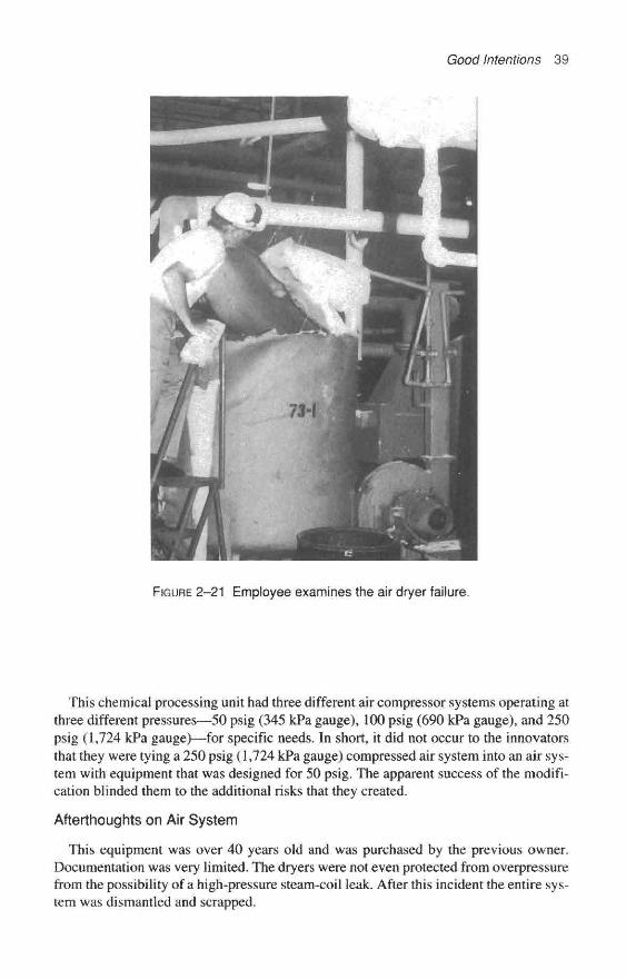
Good Intentions 39
FIGURE 2-21 Employee examines the air dryer failure.
This chemical processing unit had three different air compressor systems operating atthree different pressures—50 psig (345 kPa gauge), 100 psig (690 kPa gauge), and 250psig (1,724 kPa gauge)—for specific needs. In short, it did not occur to the innovatorsthat they were tying a 250 psig (1,724 kPa gauge) compressed air system into an air sys-tem with equipment that was designed for 50 psig. The apparent success of the modifi-cation blinded them to the additional risks that they created.
Afterthoughts on Air System
This equipment was over 40 years old and was purchased by the previous owner.Documentation was very limited. The dryers were not even protected from overpressurefrom the possibility of a high-pressure steam-coil leak. After this incident the entire sys-tem was dismantled and scrapped.

40 Chemical Process Safety
FIGURE 2–22 Close-up of the failed air dryer.
A New Air System Improved Economics,but Jeopardized Safety
Here is another case history of a compressed air system that was modified to neardisaster. Details of this incident are unavailable, but some years ago a chemical plantor refinery with multiple reciprocating air compressors and pneumatic instruments sys-tems decided to modernize. The modernization project replaced the air supply system.Economics favored one large centrifugal air compressor, and no backup air supply wasinstalled.
A well-meaning engineer modified the original system when he chose to use the plantnitrogen supply as a backup for this single air compressor. Several years after the new

Good Intentions 41
compressor system was in operation, an instrument air supply tubing fitting or the tub-ing itself broke behind the control panel in a manned control room. This occurred at thesame time the single large air compressor was shutdown for maintenance and the backupnitrogen system was supplying the instruments.
Disaster was adverted when a safety technician entered the control room as part of anunrelated confined space entry permit. The technician's portable oxygen-measuring in-strument was activated and in the operating mode. The low-level oxygen alarm sounded,warning the people in the control room of the very serious condition.
Another Incident with Nitrogen Backupfor a Compressed Air Supply
Similar undocumented stories have been shared at inter-plant safety meetings. Therewas a story about an individual in a small enclosed operator's shelter who became sus-picious about his surroundings when his cigarette would not stay lit. Some months be-fore, an operator created some relief from the sweltering heat by installing a smallpneumatically driven fan or a direct air stream in the shelter. During the shutdown of anair compressor, a nitrogen supply was utilized. The operator was being exposed to sig-nificantly reduced levels of oxygen. The details are blurry, but I remember hearing thatthe oxygen content was checked and it had dropped below 16 percent; this concentrationseemed to be below the minimum oxygen concentration for cigarette tobacco.
Afterthoughts on Incident with Nitrogen Backupfor a Compressed Air Supply
Over the years, a number of schemes have been provided to backup compressed airsystems with a gas from a highly dependable nitrogen system, if the occasion wouldarise. Depending on the system, various approaches to safely handling this situationhave been effectively employed. In modern plants there can be installations in whichsmall local buildings that shelter chromatographs and other instruments that depend oncompressed air for a number of reasons including purging the housing. If these buildingscan receive any backup nitrogen, they are provided combinations of procedural checks,with bright, eye-catching lights to warn of a temporary use of nitrogen. Any such sys-tem must be very carefully engineered, fully reviewed, and periodically audited forcompliance to the procedures.
One company, which relies on a compressed nitrogen supply to backup the com-pressed air system, has this long-standing procedure: The operator monitors the failingair supply and sounds the area evacuation siren just prior to switching gas supply sys-tems. The siren alerts all nonessential personnel to leave and especially anyone workingwithin several of these small specialty buildings that rely on compressed air. The oper-ator quickly travels to each small, enclosed instrument building to ensure that no one isin the building. Next the operator padlocks the door until this situation has passed. In ad-dition each building has an oxygen monitor mounted on the exterior wall adjacent to theentrance door.

42 Chemical Process Safety
FIGURE 2–23 Typical pressurized and purged analyzer buildings found in chemicalplants handling flammables.
FIGURE 2-24 Signs found on the typical pressurized and purged analyzer buildingsfound in chemical plants handling flammables.

Good Intentions 43
Concerns for Safety on a Refrigerated Ethylene Tank
A number of years ago, a nationally known corporation fabricated their first largeatmospheric liquid ethylene tank within a chemical complex. This tank was equippedwith a single refrigeration unit to maintain the low storage temperature. They engi-neered the refrigeration unit to maintain the –155° F (–101° C) required to keep the eth-ylene vapor pressure below the 1.5 psig (10.4 kPa gauge) setting of the safety reliefvalve. In the event of problems with the refrigeration unit, the design concept was toallow the safety relief valve to open and the autorefrigeration of the escaping vapor tocool down the remaining liquid in the tank. [7]
While construction was in progress, a process safety review revealed that problemscould occur during refrigeration unit outages. On days when the safety relief valve openedand there was little wind, the cold vapors could slump down or drift down to groundlevel, where they might find a source of ignition. The relief valve stack was too short tobe used as a flare stack, and besides, the tank structure, surrounding equipment layout,and prudent engineering would not support the concept of a flare stack in that locationanyway. [7]
A creative but inexperienced engineer suggested that during the time the relief valvewas relieving, steam could be injected into the relief valve discharge piping. At the properflow rate the steam would disperse the vapor and reduce the chance of a possible un-wanted fire. The plant adopted the simple proposal and piped steam into the 8-inch (20.3cm) relief valve discharge piping (see Figure 2-25).
Relief valveset @ 1.5 psig
Liquid ethylene// storage tank
8-in stack
HX— Steam
Drain
FIGURE 2-25 Well-intended vent modifications. Courtesy of T. A. Kletz.
44 Chemical Process Safety
During a several-day outage of the refrigeration unit, the ethylene tank absorbed ambient heat and the internal pressure increased. The backup plan to cool by auto- refrigeration as vapor escaped via the open relief valve was underway. As planned, a flow of steam was routed to the stack in hopes of safely dispersing the cold gases.
However, about 12 hours later, a small tank seam leak developed. Steam hoses were directed near the leak to heat and disperse the vapor as the tank was emptied as sales conditions allowed. The large atmospheric liquid ethylene tank could not be emptied quickly, for there were no other tanks available in which to store the liquid ethylene.
The 8-inch (20.3 cm) safety relief valve discharge line had frozen solid. It is easy to understand that hot steam does not stay warm very long when it contacts -155” F (-101” C) ethylene. The steam quickly condensed and then the water froze. No one seemed to anticipate the shortcomings of the original faulty suggestion.
Afterthoughts on the Ethylene Tank
Operators traveled to the area every hour to read the pressure on the tanks. The pres- sure gauge had a maximum pressure indication of 2 psig (13.8 kPa gauge), and it was pegged on the highest value, but no one noticed that the higher pressure or the lack of steam from the stack could signal a problem. It was later determined, for 11 hours be- fore the tank cracked, operators recorded “2.0 psig” on the log sheet. No one noticed that this 2.0 psig reading was above the relief valve setting.
This incident, as well as a number of other problems with plant modifications, has been published by Trevor Kletz under the title “Some Loss Prevention Case Histories.” [7] It is now also available as part of a training kit with 35mm slides, presenter’s guides, and booklets. The kit is entitled “Hazards of Plant Modifications,” Hazard Workshop Module 002, and can be purchased from the Institution of Chemical Engineers, War- wickshire, England. I highly recommended it for in-plant training.
Beware of Impurities, Stabilizers, or Substitute Chemicals Early one Sunday morning an explosion occurred in a nonflammable solvents plant.
The explosion created a hole about 7 ft. (2 m) in diameter and 3-ft. (1 m) deep in the soil. The explosive forces were created within a temporary vessel that was 15 inches (38 cm) in diameter and 6-ft. (1.8 m) high.
The top and bottom of this temporary vessel were constructed of 24-inch (61 cm) di- ameter, 3/4-inch (1.9 cm) thick flat steel plate. Each flat head was attached using 16 bolts which were 1/2 inch (1.27 cm) in diameter. The explosive forces ripped apart the bolts and propelled the top-mounted heavy disk over 450 ft. (140 m) away. The bottom plate was found in the big hole in the ground. A fire occurred and was quickly extin- guished. Fortunately the only injuries were a bruised knee and an eye irritation.
On the previous Friday, a tank of an organic solvent product was found to be high in acidity and was out of spec in color. The solvent was a nonflammable cleaning fluid used to clean grease and soil from common metals. The solvent contained an inhibiting stabilizer (nitro-methane) that is added to keep the fluid from corroding metals.
It was the practice to neutralize slight acidity in such solvents in a pressure vessel (called a neutralizer) that was filled with solid caustic soda flakes or beads. Such treat-
Good Intentions 45
ment was a common method to improve tainted inventories of solvent intermediates andproducts. The operating team was pleased to secure the equipment and caustic soda toimprove this product.
However, this particular product was a solvent treated with about 2 percent of nitre-methane stabilizer and not like the other intermediates or products. If any chemist fromthe control lab had been contacted, he would have opposed this neutralization scheme.
The nitro-methane's contact with the caustic soda probably created a highly unstablesodium fulminate. The explosion occurred after about 1,600 gallons of the solvent hadbeen successfully neutralized.
Afterthoughts on Impurities, Stabilizers, or Substitute Chemicals
This accident occurred more than 25 years ago, but it serves as a good example of theneed to study any chemical modifications. Nearly every experienced chemical plantworker understands the problems of just a few percent of flammables in air or just asmall amount of acid transferred into a nonresistive system, but we sometimes take theother chemicals for granted. Sometimes production-minded chemical engineers thinkmore like plumbers than chemists.
Good Intentions on Certain New Protection SystemsLead to Troubles
Art M. Dowell, III, and Dennis Hendershot presented a technical paper entitled, "NoGood Deed Goes Unpunished: Case Studies of Incidents and Potential Incidents Causedby Protective Systems" in March 1997. [8] All the material in that paper complementsthis chapter.
One case presented was the review of a release of a toxic that created an acute healthalert in several units and required evacuations after a system was "improved" to reducepollution potentials. A low-pressure feed tank designed to withstand only a few ounces ofpressure was originally provided with a lifting lid for normal and emergency venting in ac-cordance with good engineering practices adopted more than 30 years ago for such tanks.As the concern for the environment increased during the 1960 to 1990 period, the plant in-stalled vent collection headers on surrounding operating equipment and this low-pressurevessel.
Innovators designed this environmentally friendly system to eliminate the emissionsfrom routine tank operations of emptying and filling, ambient temperature changes, etc.by routing such fumes to a flare system. [8] The low-pressure lifting lid was still avail/8able for emergencies such as fire exposure to the tank.
However, the vent collection system that served the low-pressure feed tank alsoserved a nearby distillation column that operated at nearly 15 psig and contained a toxiccomponent. Physically the low-pressure tank was on the vent piping between the distil-lation column and the flare stack. During a distillation column upset, there was an in-creased flow to the flare. The vent header pressure increased. The vent piping diameterbetween the distillation column and the flare proved to be too small. Toxic fumes fromthe higher pressure system column were released from the low-pressure tank emergencylifting lid.
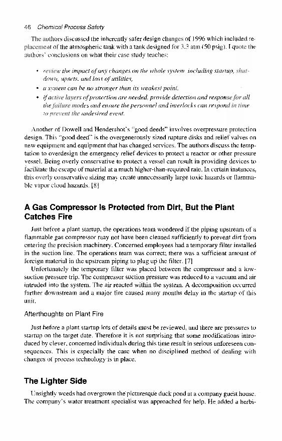
46 Chemical Process Safety
The authors discussed the inherently safer design changes of 1996 which included re-placement of the atmospheric tank with a tank designed for 3.3 atm (50 psig). I quote theauthors' conclusions on what their case study teaches:
* review the impact of any changes on the whole system, including startup, shut-down, upsets, and loss of utilities,
» a system can he no stronger than its weakest point,
* if active layers of protection are needed, provide detection and response for allthe failure modes and ensure the personnel and interlocks can respond in timeto prevent the undesired event.
Another of Dowell and Hendershot's "good deeds" involves overpressure protectiondesign. This "good deed" is the overgenerously sized rapture disks and relief valves onnew equipment and equipment that has changed services. The authors discuss the temp-tation to overdesign the emergency relief devices to protect a reactor or other pressurevessel. Being overly conservative to protect a vessel can result in providing devices tofacilitate the escape of material at a much higher-than-required rate. In certain instances,this overly conservative sizing may create unnecessarily large toxic hazards or flamma-ble vapor cloud hazards. [8]
A Gas Compressor Is Protected from Dirt, But the PlantCatches Fire
Just before a plant startup, the operations team wondered if the piping upstream of aflammable gas compressor may not have been cleaned sufficiently to prevent dirt fromentering the precision machinery. Concerned employees had a temporary filter installedin the suction line. The operations team was correct; there was a sufficient amount offoreign material in the upstream piping to plug up the filter. [7]
Unfortunately the temporary filter was placed between the compressor and a low-suction pressure trip. The compressor suction pressure was reduced to a vacuum and airintruded into the system. The air reacted within the system. A decomposition occurredfurther downstream and a major fire caused many months delay in the startup of thisunit.
Afterthoughts on Plant Fire
Just before a plant startup lots of details must be reviewed, and there are pressures tostartup on the target date. Therefore it is not surprising that some modifications intro-duced by clever, concerned individuals during this time result in serious unforeseen con-sequences. This is especially the case when no disciplined method of dealing withchanges of process technology is in place.
The Lighter Side
Unsightly weeds had overgrown the picturesque duck pond at a company guest house.The company's water treatment specialist was approached for help. He added a herbi-

Good Intentions 47
cide to kill the weeds, but failed to realize that the herbicide also contained a wettingagent. This modification wetted the ducks' feathers and the ducks sank. [9]
A Review of Good IntentionsEach of the items covered as "Good Intentions" showed a flaw in judgment. None of
the principles were unique and no decision was so urgent that the change needed to beaccomplished immediately. All technical plant employees could easily understand theproblems after they occurred and most of the technical employees could have spottedthe weaknesses prior to the incident, if they had been afforded the opportunity for a well-disciplined review (see Chapter 10). Happily there were no significant injuries reportedin these accidents, which caused more than $1 million of losses. However, we don'tknow about the ducks. And yet, some accidents resulting from similar modificationshave caused injuries and even deaths.
References1. Sanders, R. E. "Don't Become Another Victim of Vacuum," Chemical Engineering
Progress, New York, Sept. 1993: pp. 54–57.2. Sanders, R. E. "Plant Modifications: Troubles and Treatment," Chemical Engineering
Progress, New York, Feb. 1983: pp. 73–77.3. "Over- and Under-Pressuring of Vessels," Hazard Workshop, Module 001 (available as a
training kit with 34 35mm slides, booklets, teaching guides, etc. by the Institution of Chemical En-gineers, 165-171 Railway Terrace, Rugby CV21 3HQ, Warwickshire, England).
4. Kletz, Trevor A., private communication, Sept. 1978.5. Sanders, R. E. "Human Factors: Case Histories of Improperly Managed Changes in Chem-
ical Plants," Process Safety Progress, New York, Fall 1996, pp. 150–53.6. Sanders, R. E., D. L. Haines, J. H. Wood, "Stop Tank Abuse," Plant/Operations Progress,
New York, Jan. 1990: pp. 61–65.7. Kletz, Trevor A., "Some Loss Prevention Case Histories," Chemical Engineering Progress
70, April 1974: p. 80. Also available as "Hazards of Plant Modifications—Hazard Workshop,"Module 002 (available as a training kit with 38 35mm slides, booklets, teaching guide, etc., by theInstitution of Chemical Engineers, Warwickshire, England).
8. Dowell, A. M., Ill and D. C. Hendershot, "No Good Deed Goes Unpunished: Case Studiesof Incidents and Potential Incidents Caused by Protective Systems," Process Safety Progress, Fall1997, pp. 132–139.
9. Kletz, Trevor A., Critical Aspects of Safety and Loss Prevention. London: Butterworth,1990, p. 221.

This page intentionally left blank

CHAPTER 3
Focusing on Water and Steam:The Ever-Present and SometimesEvil Twins
Water and steam are nearly always present in most chemical processes. Their physicalproperties are generally well understood. Process perils are sometimes related to the in-famous deeds of water and steam. The thrust of OSHA's Process Safety ManagementLaw of 1992 focused on the processes that handled a list of 140 highly hazardous chem-icals as well as processes that contained more than 10,000 pounds (4,540 Kg) of flam-mable liquids or gases. Even after those chemicals are handled with higher levels ofmechanical integrity and additional scrutiny, we will still need to keep our eye on waterand its sometimes evil twin, steam.
This chapter reviews basics on the hazards of water and steam within the chemicaland petroleum refinery industries. To the youthful, this chapter can be instructive withits eye-opening reality of fundamentals. To more seasoned individuals these case histo-ries can serve as a reminder of the potential hazards of water and steam through vividexamples that were costly in disappointments, dollars, professional reputation, andinjuries.
Some years ago, Standard Oil Company (Indiana) published a 70-page booklet enti-tled Hazards of Water in Refinery Process Equipment. [1] This booklet appears to be abible for hands-on refinery employees, and it provides easy-to-understand fundamentalson the hazards. The booklet concludes with these thoughts:
The hazard of water in process units has been present throughout the entire historyof petroleum refining. Many persons have been injured or killed because of the un-controlled mixing of water and hot oil or the heating of bottled-in liquids with noprovisions for pressure relief. Stills have ruptured, vessels have exploded violentlyand exchangers have been blown apart. . . . A knowledge of how water reacts,where it can be expected and how to eliminate or control it will make your unitsafer and your job easier.
Amoco Oil Company Refining and Engineering now publishes a two-inch thick hard-cover book entitled Process Safety Booklets. [2] I highly recommend this book. It con-tains numerous sketches and photos and incorporates nine previously published booklets,
49

50 Chemical Process Safety
including Hazards of Water, Hazards of Air, Safe Furnace Firing, Hazards of Steam, andSafe Handling of Lights Ends. It is economically priced at $50 per copy.1
Even before refineries, about 100 years ago, poorly designed, constructed, main-tained, and operated boilers (along with the steam that powered them) led to thousandsof boiler explosions. Between 1885 and 1895 there were over 200 boiler explosions peryear, and things got worse during the next decade: 3,612 boiler explosions in the UnitedStates, or an average of one per day. [3] The human toll was worse. Over 7,600 indi-viduals (or on average two people per day) were killed between 1895 and 1905 fromboiler explosions. The American Society of Mechanical Engineers (ASME) introducedtheir first boiler code in 1915, and other major codes followed during the next 11 years.[3] As technology improved and regulations took effect, U.S. boiler explosions taperedoff and are now considered a rarity. However, equipment damages resulting from prob-lems with water and steam still periodically occur.
The fundamentals of the sometimes destructive nature of water and steam within achemical plant or petroleum refinery will be discussed and illustrated via case histories.Seven sketches of incidents will be reviewed:
« An improperly conducted hydrotest creates $35,000 more unanticipated repairs.• An 82-ft. (25 rn) tall distillation column is accidentally filled with water and, while
the column is quickly drained, it suddenly collapses and topples.• A 73-percent caustic soda tank is partially filled with water to clean it and a steam/
caustic mix erupts from the vessel.• Steam is improperly applied to a chlorine cylinder and an ammonia cylinder in sep-
arate incidents.• A brand new refinery coker is being steamed out in a prestartup activity and as the
steam condenses, the vessel catastrophically collapses.• A tragic explosion and fire occurs in a fluid catalytic cracking unit during a startup
after a turnaround when superheated oil is allowed into a vessel that had acciden-tally accumulated water.
A Hydrotest Goes AwryThe destructive hydraulic forces of mild-mannered water were displayed in a classic
style on a summer evening in 1996. A Gulf Coast chemical plant that had just rejuvenateda recovery tank and started a hydrotest when things went wrong. The poorly executed testadded $35,000 to the repair costs. Other than embarrassment, no one was injured. In theprevious three weeks this tank had received repairs consisting of a new floor and newwalls in the lower section.
The metallic victim was a vertical API 620 tank that is 12 ft. (3.66 m) in diameter and20-ft. (6.1 m) high with a 16,900-gallon (64,200 L) capacity. The flat-bottom, dome-shaped roof vessel was designed for a 12 psig (83 kPa gauge) maximum allowableworking pressure rating. Environmental regulations required a hydrotest at the conclu-sion of the extensive repairs to ensure fitness for service.
'Copies can be obtained from Mr. Matt L. Smorch, (312) 856-7232, or via the mail from Amoco Oil Com-pany, Process Safety Coordinator, Mail Code 1204B, 200 East Randolph Dr., Chicago, IL 60601.
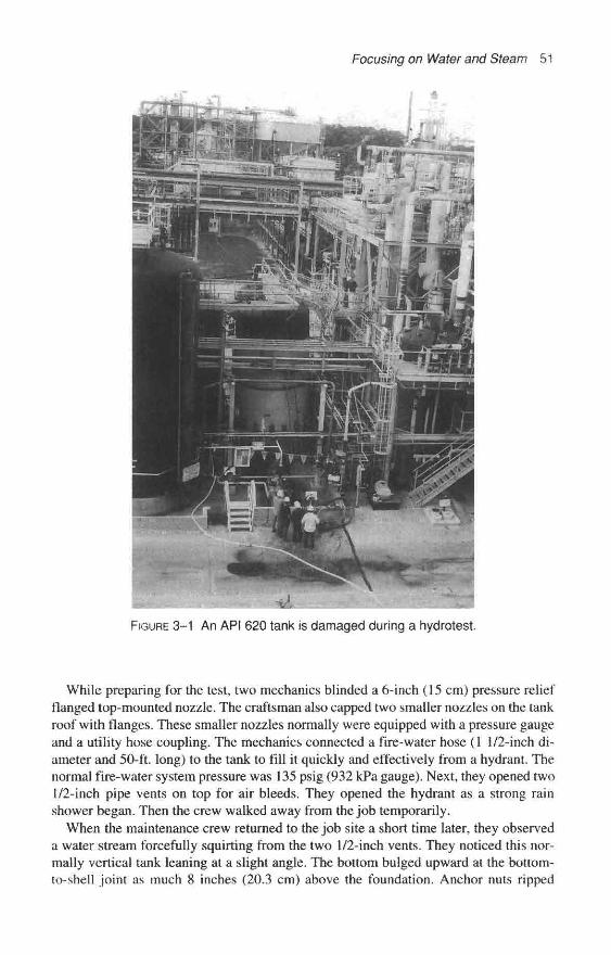
Focusing on Water and Steam 51
FIGURE 3-1 An API 620 tank is damaged during a hydrotest.
While preparing for the test, two mechanics blinded a 6-inch (15 cm) pressure reliefflanged top-mounted nozzle. The craftsman also capped two smaller nozzles on the tankroof with flanges. These smaller nozzles normally were equipped with a pressure gaugeand a utility hose coupling. The mechanics connected a fire-water hose (1 1/2-inch di-ameter and 50-ft. long) to the tank to fill it quickly and effectively from a hydrant. Thenormal fire-water system pressure was 135 psig (932 kPa gauge). Next, they opened two1/2-inch pipe vents on top for air bleeds. They opened the hydrant as a strong rainshower began. Then the crew walked away from the job temporarily.
When the maintenance crew returned to the job site a short time later, they observeda water stream forcefully squirting from the two 1/2-inch vents. They noticed this nor-mally vertical tank leaning at a slight angle. The bottom bulged upward at the bottom-to-shell joint as much 8 inches (20.3 cm) above the foundation. Anchor nuts ripped

52 Chemical Process Safety
FIGURE 3-2 A closer look at the slightly leaning tank and the walkwaythat was torn off during the hydrotest.
through the anchor chairs, and catwalks attached to the tank roof had torn away fromwelded clips.
At this section of the plant in the past, chemical process operators (not maintenancemechanics) handled the tank-filling step in the hydrotest process. Operators would typ-ically drape a fire hose into an oversize roof nozzle and fill the tank from the nearest hy-drant. In this case, it was reported that the two mechanics asked their maintenancesupervisor if they could connect the hose to a flanged lower-valved nozzle on the tank.The supervisor remembers requesting the mechanics to roll a blind flange at the top forventing purposes if they used the lower nozzle for filling. There must have been a mis-communication. Obviously the mechanics failed to understand the dynamics of the fill-ing operation when they chose to open only the two 1/2-inch top vents.

Focusing on Water and Steam 53
FIGURE 3-3 Tank bottom is bulged during a hydrotest.
FIGURE 3-4 Tank bottom is bulged and anchor nuts are pulledthrough the anchor chairs.

54 Chemical Process Safety
Two 1/2-inch diameter pipe openings provided only 0.46 square inches of relievingarea. These openings were sufficient for the air being expelled, but not for the water thatwould follow. A Loss Prevention Engineer calculated the flow of fire-water from a 135psig supply through 50 ft. of 1 1/2-inch hose and into the low-pressure tank. During theinitial filling as air was being expelled an effective orifice area of only 0.09 squareinches was required in order to keep the system pressure below the maximum allowablevessel rating of 12 psig (83 kPa gauge). Once the air was displaced and water was flow-ing out of the tank, a relieving area of 2.5 square inches was required. The required re-lief area for the water stream was about five times the area of the openings provided.
Total restoration costs approached $35,000. Foundation repairs including resetting theanchor bolts and other support work cost about $5,000. An additional $30,000 was spentto lift the tank, fabricate and install a new tank bottom, and to reinstall and reconnect thepipe to the vessel.
Afterthoughts on Hydrotest Incident
The mechanics in this area wanted to do a good job and then this incident occurred. How-can you impress upon the craftsmen the weaknesses of low-pressure tanks? The main-tenance superintendent in this area wanted practical training to reduce the probability ofa repeat. Concerned supervision scheduled 100 mechanics in this section of the plant toa "tender tank" presentation patterned after the Institution of Chemical Engineers* Haz-ards Workshop Module 001, "Over- and Under-Pressurizing of Vessels." [4] Proce-dural changes for hydrotests were also made.
A Flooded Column Collapses as Water Is BeingDrained from the System
Late one night, a vacuum created by a fast-draining stream of water helped wreck animproperly protected distillation system. Around midnight, during some pre-op steps,operators determined a leaking water valve had accidentally flooded two idle columnsin a distillation system. A destructive vacuum condition was created while draining andpumping water from the system. The vacuum sucked in the lower section of the strippercolumn walls. As a result, the 82-ft. (25 m) tall stainless steel vessel toppled over ontoa vacant piece of property. It missed other expensive, hard-to-replace, critical equipmentincluding some adjacent tubular reactors and a similar nearby reabsorber. No one was in-jured; there was no fire or significant release. [5]2
The stainless steel stripper column stood about 82-ft. (25 m) tall, which included acolumn skirt base of about 15-ft. (4.6 m) tall. The stripper collapsed in the lower 9-ft. di-ameter (2.7 m) section just below the conical transition section that tapered down to con-nect with the upper 5-1/2-ft. (1.7 m) diameter section. The vessel was designed tooperate about 5 psig (34.5 kPa gauge) and was mechanically rated for about 25 psig(173 kPa gauge).
*This case history has been reproduced with the kind permission of the American Institute of Chemical En-gineers. Copyright © 1993. It first appeared in "Don't Become Another Victim of Vacuum," Chemical Engi-neering Progress, 1993. All rights reserved.

Focusing on Water and Steam 55
FIGURE 3-5 A stripper column collapses. Courtesy of Guido DeJesus.
At the time of the incident, the operating team was preparing to simulate operationsby circulating water in the system. Shortly after midnight, operators noticed water com-ing from the reabsorber vent. Pre-op engineers concluded that water had flooded boththe stripper and the reabsorber. They later determined that a leak in the recycle watervalve was the culprit that had filled the system. [5]
The vent line from the stripper was designed to connect to the reabsorber feed line andthe reabsorber had an atmospheric vent. When the reabsorber was flooded, the vent linefrom the stripper could not provide vacuum relief because it was not in the normal gasservice. Vacuum relief devices were not originally provided on the stripper. (See Figure3-6, Reabsorber/Stripper sketch.)
The crew decided to open the drain valves on the 3-inch (7.6 cm) suction lines fromthe reabsorber and stripper bottoms pumps. About an hour later, when the level in the re-absorber reached about 75 percent, the crew closed the suction drains' valves. They con-tinued to operate the feed stripper bottoms pump, creating an even greater partialvacuum as the water stream was routed to the reactor. About 10 minutes later at 1:15A.M., an employee observed the column slowly start tilting, and then toppling from thevertical position. By the time the stripper dropped to a 45-degree angle, the eyewitnessreported it was falling very fast.
No one was injured; there was no fire or significant release. After this incident, the op-crating company had vacuum breakers installed on all of the vessels in this process that

56 Chemical Process Safety
FILLED WITH WATER"LEAKING WATER VALVEFILLED SYSTEM
THIS COLUMNDESTROYEDBY VACUUM
TO REACTQR
FIGURE 3-6 The design of the reabsorber/stripper system.Courtesy of Guido DeJesus and Warren Schlindler,
FIGURE 3-7 A close-up of a collapsed stripper column. Courtesy of Guido DeJesus.

Focusing on Water and Steam 57
were not designed for full vacuum. In addition, they rerouted the stripper vent line. Op-erations started up without this stripper and operated for nearly a month during whichtime a new column was being built in the United States on an emergency basis and air-lifted to the Caribbean island. [5]
Water Reacting with Strong Chemicals
The Hazards of Water booklet [1 ] reviews the risks of mixing strong acids and water.In part, it states that a basic chemistry lab maxim should always be observed: POURACID IN WATER—NEVER POUR WATER INTO ACID. It is even more importantwhen applied to the large quantities of acids in refineries and chemical plants. Seriousoverheating or dangerous eruptions of acid can occur if you add water or water solu-tions to strong acids. The dilution of some strong acids by water makes the acid morecorrosive.
Some operators who have been asked to wash out and prepare vessels for inspectionor repairs understand these problems. Energetic reactions are likely with strong sulfuricacid, some salts like calcium chloride, and some alkalis. A violent eruption of steam anddilute caustic soda occurred when preparing a 73-percent caustic soda storage tank formaintenance. This incident appeared in the British Loss Prevention Bulletin about adecade ago. [6]
Observant operators discovered a small, seeping caustic soda leak at the bottom of a20-ft. (6 m) diameter storage/tank car shipping tank in a somewhat congested tank farm.The tank was oozing 73-percent caustic soda at 250° F (121° C). Maintenance waspromptly scheduled but the tank had to be emptied and cleaned.
To quickly empty the tank, the Shipping Department had intended to load a numberof rail tank cars with the hot 73-percent caustic soda from the leaking low-pressure, flat-bottom, straight-sided tank. Tank cars were to be loaded during the day and eveningshifts. The evening shift chemical process operators were left written instructions to di-lute the remaining soda with hot (140° F or 60° C) water as the first step in a cleaningand clearing process. This 73-percent caustic readily freezes if you do not keep it hot ordilute it during a tank-clearing process.
The Shipping Department loaded one less rail tank car than the operations foremananticipated. Much more caustic soda remained in the tank than the operations supervi-sor expected when he wrote the tank-clearing instructions. There were perhaps 90 tonsof 73-percent caustic soda remaining when operational supervision believed only a smallheel would be left.
Operations followed the instructions in the Log Book and started adding hot water tothe vessel. It took about 11 hours to increase the tank level by 11 ft. (3.4 m) with hotwater. The operator completed adding the prescribed amount of water early in the morn-ing or about 5:45 A.M. About 15 minutes later, the operator opened up a compressed airvalve to the lance to "roll" or mix the contents within the tank as the Log Book instruc-tions directed. The caustic soda was about 250° F (121 ° C) (well above the boiling pointof water) and mixing of water and strong caustic soda solutions is strongly exothermic.
Thirty minutes later, about 6:40 A.M., the tank started making a roaring sound like ajet plane. The vessel buckled upward and a mixture of steam and diluted caustic blew outof the large manway shooting up 80 ft. (25 m) into the air. The explosive release onlylasted about 30 seconds, and was followed by nonviolent steaming for an additional 30minutes. [6]

58 Chemical Process Safety
Violent boiling spewed several tons of caustic soda droplets from an open manway onthe roof of the tank. These droplets rained down in the vicinity of the tank and traveleddownwind inside the plant. A light wind carried the caustic soda over rail cars on anearby in-plant railroad spur and further to employee automobiles in the several acrechemical plant's main parking lot. Corrosive chemical fallout was detected over 1-1/4-miles (2 km) away. The Plant Emergency Brigade used fire hoses to wash down the af-fected areas.
Thirty rail tank cars required new paint jobs and some of the employees' cars requiredcosmetic repairs. Property damages for repainting rail cars and other cleanup totaledover $125,000 (U.S., 1985). Although there were no serious injuries, a female employeein the parking lot received enough caustic droplets in her hair to require a visit to thebeauty parlor. If this incident had occurred about 30 minutes later, the day shift wouldhave been arriving and there would have been a potential for more injuries as the park-ing lot filled with activity.
Afterthoughts on Water Wash of a Caustic Soda Tank
After this embarrassing and potentially dangerous incident, management implementedtwo new procedures. Precise operating procedures were issued for diluting caustic sodasolutions. The procedure required air-rolling to be simultaneously started during anywater addition so that only a little material at a time can release the heat of solution.
Easy-to-Use Steam Heat Can Push Equipmentbeyond Safe Design Limits
Chlorine Cylinders
Loss Prevention Engineers and Safety Professionals have repeated stories in Louisianaabout the misapplication of steam on one-ton chlorine cylinders. Two similar stories werediscussed at inter-plant loss prevention meetings a couple decades ago. Naturally, the de-tails are now a little vague but the stories were from companies located over 100 milesapart in two separate petro-chemical sections of the state.
Process engineers who have requirements for low flow rates of chlorine can purchasechlorine in 150-pound and one-ton cylinders. These containers are very robust and in-dustries have safely used them for decades. The one-ton cylinders are 2 1/2 ft. (0.75 m)in diameter and just under 7-ft. (2.1 m) long with extended cylinder walls to protect thevalves. Chlorine ton cylinders are hydrotested at 500 psig (3,450 kPa gauge).
Chlorine can be provided from the ton cylinders as a liquid or a gas. The dischargerate depends on the pressure within the cylinder and this is a function of the temperature.In order to withdraw gas, you must vaporize liquid chlorine. Withdrawal tends to reducethe temperature and hence the vapor pressure and the surrounding air must supply suf-ficient heat to boost the vapor pressure. Typical maximum discharge rate for a one-tonchlorine cylinder in a 70° F environment is about 15 pounds per hour.
When chlorine gas is withdrawn from a chlorine cylinder at a rapid rate, the cylinderwill cool down. Some companies who need to boost the gaseous chlorine flow rate haveplaced warm water spray or utility water on the cylinder to add a well-controlled heat

Focusing on Water and Steam 59
input on cool days. However, some individuals were reported to have become more creative and blew live steam via a hose to even further increase the rate of vaporization.That would seem like a good idea—unless you took the time to read the precautions.
Each chlorine ton cylinder has three fusible plugs on each end of the tank to protectit from over-temperature. These plugs are designed to rnelt between 158° and 165° F(70° to 74° C). They are designed to protect the tank from overpressure if the cylinderis accidentally exposed to fire or other sources of excessive heat. In fact, if you acci-dentally heat steel containing chlorine to over 483° F (250° C), a steel-in-chlorine firecan be ignited.
The protection philosophy seems to be to protect the cylinder from overpressure byprotecting it from over-temperature that would vaporize the liquid chlorine. Each of thefusible plugs is in a 3/4-inch threaded plug. If the fuse melts, the resulting hole is about11/32 inch in diameter.
Stories from plant safety professionals indicate that live steam was exhausted on thecylinders to make a crude vaporizer to increase chlorine flow. The frightful result wasmore chlorine, but it was to the atmosphere, not to the process. There were no reports ofinjuries when these memorable stories were told.
Ammonia Cylinders
An ammonia cylinder catastrophically ruptured in a medium-sized plant on a sum-mer's evening and two employees required hospitalization. There was no fire and the au-tomatic sprinklers were not triggered into action. There was extensive damage to a small"pilot" plant-like operation and the small metal building (approximately 20-ft. wide by30-ft. long) that housed the operations. The catastrophic rupture blew most of the metalsheeting from the steel frame on one side of the building. Some structural damage oc-curred, all the glass windows shattered, and engineering estimated the damages to bemore than $50,000 a couple of decades ago.
The operation used ammonia from a 150-pound cylinder. For over eight years, thisunit used steam to heat the ammonia cylinder. To provide the heat, the unit had a prac-tice of wrapping a length of copper tubing around the cylinder. The tubing was con-nected to a 15 psig (1 bar) steam supply that flowed around the cylinder and exhaustedfrom the pinched end of the tubing. The cylinder was also loosely wrapped with fiber-glass insulation. The purpose of the steam was to ensure a consistent ammonia gas flowwith 150 to 200 psig (10 to 13.3 bar) pressure on the upstream side of the regulator. Itwas seldom necessary to make adjustments to the steam valve in this crude system.None of the plant employees had noticed anything unusual about the cylinder or its in-stallation prior to the incident.
All evidence indicated that the cylinder ruptured due to the hydrostatic pressure of ex-panding liquid ammonia due to excessive heat on the cylinder. Fragments of the cylin-der were sent to a testing laboratory for failure analysis. The ruptured cylinder was a fullcylinder just put in service. According to the company's literature search, a full cylinderwould become hydrostatically full of liquid ammonia at about 130° F (54.4° C). If theliquid was further heated, tremendous pressures would be developed. An alternate pos-sibility was that the cylinder was heated to 250° F (121° C) (the steam supply tempera-ture). Raising the temperature that high is unlikely with the crude heating methods andthe expected heat losses, but if they were, the internal cylinder pressure could reach

60 Chemical Process Safety
1,350 psi (92 bar). This high pressure would generate a very high stress that wouldclosely approach the tensile strength of the cylinder material.
Heating Water in a Confined SystemWe all need to understand thermal expansion of liquids. I have often heard that heat-
ing a completely liquid-full container, such as piping, a vessel, or a heat exchanger, willresult in tremendous pressures. I always try to ensure that the situation not arise by en-couraging procedures to avoid the situation or providing overpressure protection, butuntil now I had not taken the time to calculate the ultimate pressures that could develop.
The Hazards of Water in Refinery Process Systems booklet [1] states that confinedwater will increase 50 psi (345 kPa) for every degree Fahrenheit in a typical case ofmoderate temperatures. In short, a piece of piping or a vessel that is completely liquid-full at 70° F and 0 psig will rise to 2,500 psig if it is warmed to 120° F. This concept isdisplayed better in Figure 3-8.
FIGURE 3-8 Unbelievable destructive pressures developed by piping that is full of wateras the temperatures increase. Courtesy of Manuel David from Hazards of Water in
Refinery Process Systems.
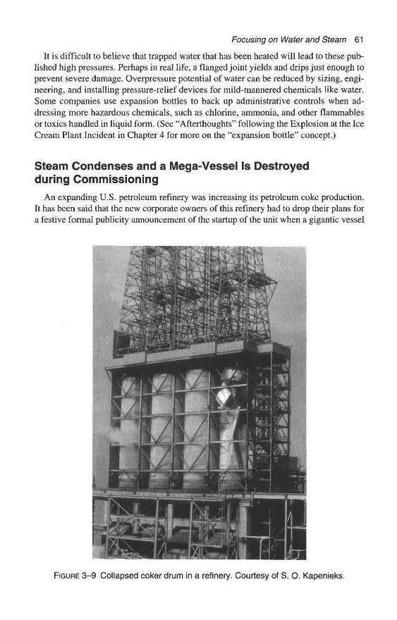
Focusing on Water and Steam 61
It is difficult to believe that trapped water that has been heated will lead to these pub- lished high pressures. Perhaps in real life, a flanged joint yields and drips just enough to prevent severe damage. Overpressure potential of water can be reduced by sizing, engi- neering, and installing pressure-relief devices for mild-mannered chemicals like water. Some companies use expansion bottles to back up administrative controls when ad- dressing more hazardous chemicals, such as chlorine, ammonia, and other flammables or toxics handled in liquid form. (See “Afterthoughts” following the Explosion at the Ice Cream Plant Incident in Chapter 4 for more on the “expansion bottle” concept.)
Steam Condenses and a Mega-Vessel Is Destroyed during Commissioning
An expanding U.S. petroleum refinery was increasing its petroleum coke production. It has been said that the new corporate owners of this refinery had to drop their plans for a festive formal publicity announcement of the startup of the unit when a gigantic vessel
FIGURE 3-9 Collapsed coker drum in a refinery. Courtesy of S. 0. Kapenieks.
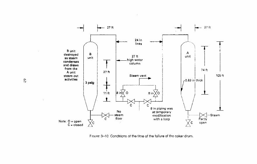
ON
B unitdestroyedas steam
condensesand drawsfrom the
A unitsteam outactivities
27 ft
k3n't
sig
/
T27ft
1
1
11
Jft
L
Note: O = openC = closed
24 inlines
27ft• high water
column
Steam vent
H h- 27ft
8 in piping wasat temporarymodificationwith a loop
105ft
SteamPartly
C open
FIGURE 3-10 Conditions at the time of the failure of the coker drum.

Focusing on Water and Steam 63
was destroyed. Project engineers designed, fabricated, installed, and were pre-operatingfour world-class-sized coker drams. One of these vessels became a victim of the behav-ior of water's evil twin, steam. A large volume of steam condensed, there were some flawsin design or procedures, and the vessel collapsed.
These gigantic pressure vessels were over 100-ft. (30 m) high, 27 ft. (8.2 m) in diam-eter, and the main body was a 74-ft. (23 m) long straight-side cylinder. The cokers weredesigned for 55 psig (380 kPa) internal pressure. The coker drum had a dome-shaped topand the lower section was a cone. The lower shell wall thickness was about 0.836-inches (2.1 cm) thick, but the unit was not designed for full vacuum.
The pre-op team steam tested the equipment with up to 50 psig (345 kPa gauge)steam to check for any system leaks. Prior to the steam test, temporary 8-inch (20 cm)diameter piping was installed on the pre-engineered 24-inch (61 cm) vent to release thesteam into the atmosphere. The "A Unit" and the "B Unit" coker shared a common ventline to the atmosphere. Unfortunately, the design of the piping modification created aloop that could collect water as the steam condensed.
The pre-op crew steamed out the "B Unit" first and vented it through the 8-inch steamvent piping. The failure occurred about four days later. An eyewitness in the operators'shelter heard what sounded like a muffled explosion and ran out the backdoor to see ifhe could locate fire or smoke. Fortunately, no fire could be seen, but the collapsed cokerdrum was very visible.
Other witnesses said the coker appeared to be crushed in like an aluminum beer canbeing squeezed in the middle. The vessel tore away from levels of decking and was sodistorted it could not be salvaged.
Further study revealed that the "A Unit" was being steamed out just after the pre-opcrew shut off steam to the "B Unit." The steam in the "B Unit" continued to condenseas the unit cooled while steam continued in the "A Unit" for two additional days. The
FIGURE 3-11 Close-up of the destroyed coker drum—crushed in like an aluminumbeer can. Courtesy of S. O. Kapenieks.
64 Chemical Process Safety
range of the pressure transmitter on the "B Coker Drum" was 0 to 60 psig, therefore itcould not indicate a negative pressure.
Evidence indicated that the steam to the "A Unit" was the condensate supply whichfilled a 27-It. (8.2 m) section of the 24-inch (61 cm) vertical line. The height of the watercolumn is based on the fact that the internal temperature of the "B Unit" was 144° F.
The investigation team recommended that the vent line be modified to eliminate anypossibility of a trap in the vent line. The team also recommended that a low-pressurealarm be engineered and installed to alert the control room operator of low-pressure con-ditions within the coker drums.
Afterthoughts on Mega-Vessel Destroyed during Commissioning
Water has the unique ability to expand 1,570 times when changing from a liquid toa vapor, and to contract 1,570 times when it is condensing. To visualize this dramaticcontraction, just think that a typical rail tank car filled with steam at atmospheric pres-sure could condense to the volume of 10 or 11 gallons of water. [11 These propertiescan result in destructive vacuum damage as just shown. The explosive expansion fromwater to steam can result in a catastrophic incident, as the next case history graphicallydemonstrates.
A Tragedy Develops When Hot Oil Is Pumpedon a Layer of Water
An explosion and fire occurred about 11:00 P.M. in a cracking unit on March 3,1991.Operators were starting-up a world-class-sized fluid catalytic cracking (FCC) unit aftera seven-week turnaround for maintenance. During the startup, a drain valve at the bot-tom of a pressure vessel was improperly closed, inadvertently allowing water to accu-mulate in the vessel. When superheated oil was routed into the vessel and it mixed withthe water, a steam explosion resulted, catastrophically rupturing the vessel. Oil was pro-pelled from the vessel, was ignited, and the fire engulfed the catalytic cracking unit.After the explosion, plant operators isolated the involved FCC unit and two other simi-lar units at the refinery. The fire burned itself out by about 1:30 A.M. [7]
Marsh & McLennan Protection's Large Property Damage Losses in the Hydrocarbon-Chemical Industries—A Thirty-Year Review reported that the property damage was $23million and the business-interruption loss associated with the incident was estimated at$44 million.
A newspaper report stated that one worker saw "a bright flash" shortly before the ex-plosion rocked the area. The article also stated, "The blast rattled windows over a wideportion of South Lake Charles and the fire caused the sky to glow for miles around theSulphur Plant." [8] Tragically, six workers lost their lives and eight other were injuredin this incident.
OSHA investigated this incident and applied Process Safety Management (PSM)standards to the company, despite the fact the PSM Law did not apply to other industriesuntil May 1992. The initial OSHA fine of about $8.2 million in proposed penalties wasreduced to a record $5.8 million for alleged safety violations. The gut-wrenching emotionsof the company were expressed when a spokesman stated, "You have to understand we
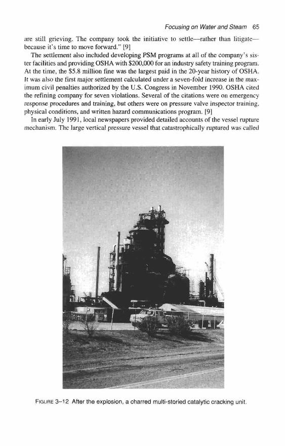
Focusing on Water and Steam 65
are still grieving. The company took the initiative to settle—rather than litigate—because it's time to move forward." [9]
The settlement also included developing PSM programs at all of the company's sis-ter facilities and providing OSHA with $200,000 for an industry safety training program.At the time, the $5.8 million fine was the largest paid in the 20-year history of OSHA.It was also the first major settlement calculated under a seven-fold increase in the max-imum civil penalties authorized by the U.S. Congress in November 1990. OSHA citedthe refining company for seven violations. Several of the citations were on emergencyresponse procedures and training, but others were on pressure valve inspector training,physical conditions, and written hazard communications program. [9]
In early July 1991, local newspapers provided detailed accounts of the vessel rupturemechanism. The large vertical pressure vessel that catastrophically raptured was called
FIGURE 3-12 After the explosion, a charred multi-storied catalytic cracking unit.
66 Chemical Process Safety
an F-7 Slurry Drum, and its function was to separate heavy oil and catalyst dust. News-papers explained that the company schedules the three cracking units for periodic main-tenance turnarounds once every three years. Furthermore, during these turnarounds thecatalytic cracking unit is shut down, oil is drained out, and all equipment is cleaned, in-spected, and refurbished to be fit for service. A normal startup of a cat cracker is about48 hours. [10]
Several local newspaper articles explained that during these startups, steam is pro-vided to displace any air in the system prior to the introduction of any oil. At the begin-ning of the startup, temperatures in the unit are cool enough to condense some of thesteam into water. Water (steam condensate) collects in the E-1 Fractinator and then ispumped into another part of the unit, the F-7 Drum. Under normal startup procedures theoperating crew drains all the water from the F-7 Dram before the hot oil is admitted.
The vice president of Refining sent a letter to each employee and to the local news-papers. One newspaper quoted the vice president as saying:
For some period of time on March 3rd, the block valve . . . was in the closed posi-tion, which prevented waterfront draining out. As oil began flowing in the reactorand the E-lfractionator rose to normal operating levels. When the block valve waslater opened establishing flow from the bottom of the F-7 drum, the hot oil. . .came into contact with the water remaining in the bottom of the F- 7 drum.. . . Thiswater then instantly converted into steam. The enormous and rapid volume expan-sion of water to steam resulted in an explosive rupture of the F-7 drum, throwingout hot oil which ignited. The drum was equipped with a properly functioning pres-sure relief valve, but no other pressure relieving device could have relieved theamount of pressure that was suddenly created within the F-7 drum at the time of theexplosion. [11 ]
In the public's mind, a tragedy like this will erase years of excellent operations—here,it took just one instance of a superheated oil being routed on to an undetected layer ofwater. In one of his statements to the press, the vice president stated, "This is the first ac-cident of this type in 48 years of operations at the Lake Charles Refinery." [ 10]
Afterthoughts on Steam Explosions
Many other reports of steam explosions involve hot oil being unintentionally pumpedover a hidden layer of water. Water is unique in that though many organic chemicals willexpand 200 to 300 times when vaporized from a liquid to a vapor at atmospheric pres-sure, water will expand 1,570 times in volume from water to steam at atmospheric con-ditions. These expansion and condensation properties makes it an ideal fluid for steamboiler, steam engines, and steam turbines, but those same properties can destroy equip-ment, reputations, and lives.
It seems appropriate to conclude this chapter by repeating a quote from Hazards ofWater in Refinery Process Systems:
The hazard of water in process units has been present throughout the entire history!of petroleum refining. Many persons have been injured or killed because of the un-controlled mixing of water and hot oil or the heating ofbottled-in liquids with noprovisions for pressure relief. Stills have ruptured, vessels have exploded violently
Focusing on Water and Steam 67
and exchangers have been blown apart. . , . A knowledge of how water reacts,where it can be expected and how to eliminate or control it will make your unitsafer and your job easier, [1]
References1. Standard Oil Company, Hazards of Water in Refinery Process Systems. Chicago, 111., 1960.2. Amoco Oil Company, Refining and Engineering, Process Safety Booklets. Chicago, 111.,
1984.3. Woods, Glynn E., P. E., and Roy B. Baguley, P. E., "Process Piping," Practical Guide Book
Series™, vol. 3. Edmonton, Canada: CASTI Publishing Inc., 1996: p. 4.4. Institution of Chemical Engineers, "Over- and Under-Pressurizing of Vessels," Hazards
Workshop Module 001, Rugby, U.K., 1987 (available as a training kit with 34 35mm slides,booklets, guides, etc.).
5. Sanders, Roy E., "Don't Become Another Victim of Vacuum," Chemical EngineeringProgress 89, no. 9, Sept. 1993: pp. 54-57.
6. Institution of Chemical Engineers, "Articles and Case Histories from Process Industriesthroughout the World," Loss Prevention Bulletin 78, Rugby, U.K., 1987: pp. 26-27.
7. Mahoney, David, Editor, Large Property Damage Losses in the Hydrocarbon-ChemicalIndustries—A Thirty-Year Review, 16th ed. New York: Marsh & McLennan Protection, 1995,p. 10.
8. Lake Charles American Press, Lake Charles, La., Mar. 4, 1991.9. Ibid., Aug. 30, 1991.
10. Ibid., July 4, 1991.! 1. Westlake/Moss Bluff News, Sulphur, La., July 10, 1991.

This page intentionally left blank
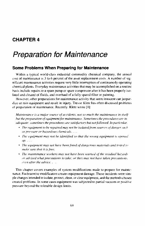
CHAPTER 4
Preparation for Maintenance
Some Problems When Preparing for MaintenanceWithin a typical world-class industrial commodity chemical company, the annual
cost of maintenance is 3 to 6 percent of the asset replacement costs. A number of sig-nificant maintenance activities require very little interruption of continuously operatingchemical plants. Everyday maintenance activities that may be accomplished on a routinebasis include repairs to a spare pump or spare compressor after it has been properly iso-lated and cleared of fluids, and overhaul of a fully spared filter or painting.
However, other preparations for maintenance activity that seem innocent can jeopar-dize or ruin equipment and result in injury. Trevor Kletz has often discussed problemsof preparation of maintenance. Recently, Kletz wrote [1]:
Maintenance is a major source of accidents, not so much the maintenance in itselfbut the preparation of equipment for maintenance. Sometimes the procedures are in-adequate; sometimes the procedures are satisfactory but not followed. In particular:
• The equipment to be repaired may not be isolated from sources of danger suchas pressure or hazardous chemicals. . . .
• The equipment may not be identified so that the wrong equipment is openedup. . . .
• The equipment may not have been freed of dangerous materials and tested tomake sure that it is free.
• The maintenance workers may not have been warned of the residual hazardsor advised what precautions to take; or they may not have taken precautions,even after the advice. . . .
This chapter covers examples of system modifications made to prepare for mainte-nance. Each unwise modification creates equipment damage. These incidents were sim-ple changes intended to isolate, protect, clean, or clear equipment, and the methods chosencreated problems. In some cases equipment was subjected to partial vacuum or positivepressure beyond the tolerable design limits.
69

70 Chemical Process Safety
A Tank Vent Is Routed to a Water-Filled Drum to"Avoid" Problems
It was necessary to perform welding near the roof on a 10-ft. (3 m) diameter atmos-pheric tank within a cluster of 25-ft, (8 m) high tanks containing flammable liquids. Theconscientious foreman was concerned that a fire hazard would exist if operationspumped alcohol into the tank during the welding operation. The foreman believed thatany flammable fumes released from the goose-neck top vent was too much of a risk dur-ing maintenance requiring burning and welding in the immediate vicinity. [2]
Knowing that water could readily absorb these alcohol fumes, the foreman arrangedto have a hose connected to the top vent. The hose routed any fumes "safely" to a dramof water. Figure 4-1 shows the significant points. As the welding job proceeded, oper-ations started to pump out the tank with the "safe guarded" vent. The tank top partiallycollapsed, though the damage was minor.
The foreman failed to appreciate the frail nature of these standard low-pressure tanks.Many low-pressure tanks are designed for positive pressures of just 8 or 10 inches (2 to2.5 kPa gauge) of water and just 3 or 4 inches (3/4 to 1 kPa) of water vacuum. Using ahose to modify the system addressed the immediate problem of dissolving any alcoholfumes, but the presence of the hose routed to a drum containing water created a situationin which the tank could be damaged by positive pressures and vacuum conditions wellbeyond its design specifications.
As a point of reference, typical healthy human lungs can develop 50 or more inches(12.5 kPa gauge) of water pressure. Compare the pressure that lungs can supply to thetypical 10-inch (2.5 kPa gauge) water pressure positive design pressure of low-pressure
Vent modified with a hose
Drum filledwith water
FIGURE 4-1 Avoiding problems using a hose creates them instead. Sketch courtesy ofManuel David. Concept courtesy of Trevor Kletz.
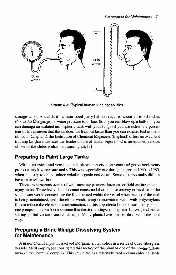
Preparation for Maintenance 71
50 inwater
FIGURE 4-2 Typical human lung capabilities.
storage tanks. A standard medium-sized party balloon requires about 25 to 30 inches(6.3 to 7.5 kPa gauge) of water pressure to inflate. So if you can blow up a balloon, youcan damage an isolated atmospheric tank with your lungs (if you are extremely persis-tent). This assumes that the air does not leak out faster than you can exhale. Just as men-tioned in Chapter 2, the Institution of Chemical Engineers (England) offers an excellenttraining kit that illustrates the tender nature of tanks. Figure 4-2 is an updated versionof one of the slides within that training kit. [2]
Preparing to Paint Large Tanks
Within chemical and petrochemical plants, conservation vents and goose-neck ventsprotect many low-pressure tanks. This was especially true during the period 1960 to 1980,when industry tolerated minor volatile organic emissions. Some of these tanks did nothave an overflow line.
There are numerous stories of well-meaning painters, foremen, or field engineers dam-aging tanks. These individuals became concerned that paint overspray or sand from thesandblaster would contaminate the fluids stored within the vessel when the top of the tankis being maintained, and, therefore, would wrap conservation vents with polyethylenefilm to reduce the chance of contamination. In this unprotected state, occasionally some-one pumps out the tank or a summer thunderstorm brings cooling rain showers, and the re-sulting partial vacuum creates damage. Many plants have learned this lesson the hardway.
Preparing a Brine Sludge Dissolving Systemfor Maintenance
A major chemical plant dissolved inorganic slurry solids in a series of three fiberglassvessels. Most employees considered this section of the plant as one of the nonhazardousareas of the chemical complex. This area handles a relatively cool sodium chloride (table

72 Chemical Process Safety
salt) water stream that was saturated with insoluble salts such as calcium carbonate andmagnesium carbonate. The slurry contains about 30-percent calcium carbonate. Insolublecarbonates are treated with hydrochloric acid in two agitated vessels to allow a reactionto liberate carbon dioxide and form a soluble salt. The reaction is a simple one:
CaCO, + 2HC1 -» CaCl2 + H2O + CO21
The dissolving system was scheduled for maintenance while the rest of the unit con-tinued at full production rates. The chemical process operator was concerned about theavailable room in the sump as the slurry accumulated during the two- to three-hour out-age. The operator drastically increased the slurry flow-rate into the dissolving system forabout an hour and a half period before the shutdown. However, he only increased the flowof acid into the system slightly during that time. The basic process is shown in Figure 4-3,
The maintenance needs were simple. The maintenance crew was scheduled to changethe oil in the No. 2 Solids Dissolving Tank Agitator gearbox and to replace several slurryvalves. To prepare for maintenance, operations shut down and tagged out the slurrypumps and the No. 2 Dissolving Tank agitator. Erroneously, the weak acid flow-rate re-mained constant for about two hours, flowing into the No. 1 Dissolving Tank and over-flowing into the No. 2 Solids Dissolving Tank.
After the maintenance was finished (it took two hours), an operator traveled up thestairs and restored the No. 2 Solids Dissolving Tank agitator. Instantly, he heard a rum-bling noise and a weak acid solution erupted from the No. 2 Solids Dissolving Tank,shooting up as high as 30 ft. (9 m) in the air. This overpressure damaged two fiberglasstanks, and three cracked nozzles on the No. 2 Solids Dissolving Tank had to be repaired.Damages to the Pump Tank were more severe: a 20-inch (50 cm) manway nozzle and itsaccompanying blind flange blew-off, and a 4-inch (10 cm) vent nozzle and stack sepa-rated from the smaller tank.
What Happened in the Brine System?
Another unit in the same chemical complex supplied the hydrochloric acid via a pipeline.The acid was a by-product of a process that manufactured large quantities of flashingflammable liquids. Supervision directed the crew to promptly collect acid samples anddeliver them to the Main Lab to analyze for flammables. Lab analysts did not detect thepresence of flammable chemicals.
An investigating team reviewed strip charts of the effluent pH, acid flow-rate changes,and slurry flow-rate changes. It concluded that more than 100 pounds (45 kg) of calciumcarbonate may have accumulated in the No. 2 Solids Dissolving Tank prior to shutdown.They determined that the acid stream continued to flow into the system and the acid con-centration continued to increase in the system during the two-hour outage. The pHdropped well below 2.0 according to the effluent pH strip recorder prior to restarting theidled agitator.
When the operator pressed the start button on the agitator, the strong acid and finelydivided calcium carbonate solids instantaneously reacted, creating and liberating 400cubic ft. (11.3 cubic meters) of carbon dioxide within a relatively small tank nearly filledwith salt water.

6 in vents
Acid
Slurry
CO
Sump
CaCO3 slurry
No. 1 solidsdissolving
tank
No. 2 solidsdissolving
tank
4 in vent
Pumptank
with 20 inmanway
FCV
FIGURE 4-3 Slurry-dissolving system. Courtesy of Jack M. Jarnagin.

74 Chemical Process Safety
Follow-up Action
The investigating team recommended both hardware and procedural changes. Theyrecommended that the vent stacks on each tank be increased from 6 inches (15 cm) in di-ameter to 10 inches (25 cm). That is about a 300-percent increase in cross-sectional vent-ing area; they knew it was not enough for the previous scenario, but it was oversized forthe newly created procedures. A revision was made to the pH monitoring system. Agi-tator start buttons were relocated from the top platform to ground level.
Supervision instituted new procedures. When the slurry feed supply is shut down, pro-cedures require the operators to continue agitation and acid flow for at least 30 minutes.On startup, the agitators and acid feed will be restored before starting up the slurrypumps. Both of these steps were designed to eliminate the possibility of having an un-detected layer of calcium carbonate.
A Violent Eruption from a Tank Being Prepared forMaintenance
Let us revisit an incident discussed in much greater detail in the previous chapter be-cause it vividly illustrates improper preparation for maintenance. Hot 73-percent causticsoda at 250° F(121° C) was observed oozing from beneath a large (20 ft./6 m in diame-ter) storage tank.
It was a two-step process to prepare this tank for maintenance. The shipping crew hadto empty it by loading tank cars. The operators were instructed to recover the remainingmaterial and wash the vessel in the morning. The operations supervisor anticipated onlya small amount of residual caustic soda would remain in the vessel after the ShippingDepartment loaded numerous tank cars to reduce the tank's inventory.
Some miscommunications resulted in the Shipping Department's loading one less railtank car than the operations foreman anticipated. Perhaps there were over 90 tons of 73-percent caustic soda remaining when the operations supervisor's logbook request as-sumed only a small heel would remain. The night shift operators followed the instructionsin the log book. They added a large amount of hot water in a layer over tons of higherdensity hot strong caustic solution. Next, an operator inserted an air lance into the tankto mix the solution. Then he turned on the utility air. In a short time, the tank made aroaring sound like a jet plane and a plume of steam and diluted caustic mist was pro-pelled from the large manway shooting up 80 feet (25 m) skyward. The sonic releaseonly lasted about 30 seconds, but spewed several tons of caustic soda droplets into thesurrounding area. [3]
Afterthoughts on the Violent Eruption
This incident seemed to be a result of poor communications and it is obvious that goodcommunications is one of the keys to successful preparation for maintenance. A signifi-cant factor was the amount of caustic soda remaining. If there were a few hundred poundsor even a ton of residual caustic soda, there would not have been an incident. There havebeen a number of incidents in which the amount of residual material was hidden fromview, or otherwise grossly underestimated and the neutralizing or cleaning solutions ma-terial reacted vigorously.
Preparation for Maintenance 75
Every clearing and cleaning procedure should have some step or steps to estimate theamount of any hazardous or reactive residual material within the equipment. In addition,there should be some backup plan if the amount of residual appears over a predeterminedamount. Smart-thinking tank designers plan ahead. Many more individuals are specifyingtanks with sloped bottoms or with a pump-out well (a small sump attachment to the bot-tom of the storage tank) on the pump-out nozzle to facilitate removing the maximum amountof hazardous materials from the tanks prior to cleaning activities.
An Explosion While Preparing to Replace a Valvein an Ice Cream Plant
Food processing employment is no doubt viewed by the general public as being a "muchsafer" occupation than working in a chemical plant. But in recent years the total recordablecase incident rate for the food industry is about 3 to 5 times higher than the chemical in-dustry, according to the U.S. National Safety Council, in terms of fatal accident frequencyrates, the food industry and the chemical industry have experienced similar rates in recentyears. |4] The following accident occurred within an ice cream manufacturing facility, butcould have happened within any business with a large refrigeration system.
An ice cream plant manager was killed as he prepared a refrigeration system to re-place a leaking drain valve on an oil trap. The victim was a long-term employee and ex-perienced in using the ammonia refrigeration system. Evidence indicates that themanager's preparatory actions resulted in thermal or hydrostatic expansion of a liquid-full system. His efforts created pressures extreme enough to rupture an ammonia evap-orator containing 5 cubic ft. (140 L) of ammonia. [5]
The local fire department's investigation revealed that when the overpressure ruptureoccurred, the rapid release of anhydrous ammonia along with a small quantity of lubricat-ing oil discharged from the system was the fuel for a simultaneous combustion explosion.It was theorized that electrical arcing in the refrigeration system was the ignition source.The overpressure rupture and the combustion explosion created costly damages as high as$250,000 (U.S., 1980). The explosion killed the manager, injured two other employees inthe room, destroyed mechanical systems in the blast area, and damaged the front offices.
The State Police report quoted a refrigeration serviceman who reported that all of thevalves on the evaporator were shut off and the fire chief found a steam hose steaming un-derneath the machine. The serviceman had previously seen steam used to melt ice builduparound the valves and to heat the oil in the machine to make it easier to drain the oil. [5]
The District Engineering Inspector's report confirmed that the machine was com-pletely isolated and the ammonia system was not protected by a safety valve or any typeof pressure-relief device. The cause of the accident was the presence of the steam hoseunderneath the equipment to melt the ice on the drain valve or to help evacuate the sys-tem. The inspector's report could not determine if these preparations were intentional oraccidental. [5|
Afterthoughts of Heating a Liquid-full Pipeline
You can easily block in liquid-full chemical process piping with no vapor space forexpansion. Many fluids, including liquid ammonia, liquid chlorine, liquid propane, liquid
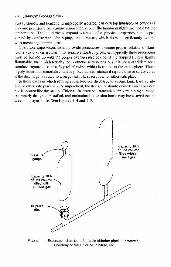
76 Chemical Process Safety
vinyl chloride, and benzene, if improperly isolated, can develop hundreds of pounds ofpressure per square inch (many atmospheres) with fluctuation in nighttime and daytimetemperatures. The liquid tries to expand as a result of its physical properties, but it is pre-vented by confinement, the piping, or the vessel, which do not significantly expandwith increasing temperatures.
Operations supervisors should provide procedures to ensure proper isolation of flam-mable, toxic, or environmentally sensitive fluids in pipelines. Typically these proceduresmust be backed up with the proper overpressure device. If the trapped fluid is highlyflammable, has a high toxicity, or is otherwise very noxious it is not a candidate for astandard rapture disc or safety relief valve, which is routed to the atmosphere. Thosehighly hazardous materials could be protected with standard rupture disc or safety valveif the discharge is routed to a surge tank, flare, scrubber, or other safe place.
In those cases in which routing a relief-device discharge to a surge tank, flare, scrub-ber, or other safe place is very impractical, the designers should consider an expansionbottle system like the one the Chlorine Institute recommends to prevent piping damage.A properly designed, installed, and maintained expansion bottle may have saved the icecream manager's life. (See Figures 4–4 and 4–5.)
Pressuregauge
Capacity 10%of line volume
filled withan inert gas
Rupturedisc
Capacity 20%of line volume
/ filled with aninert gas
FiGURE 4–4 Expansion chambers for liquid chlorine pipeline protection.Courtesy of the Chlorine Institute, Inc.
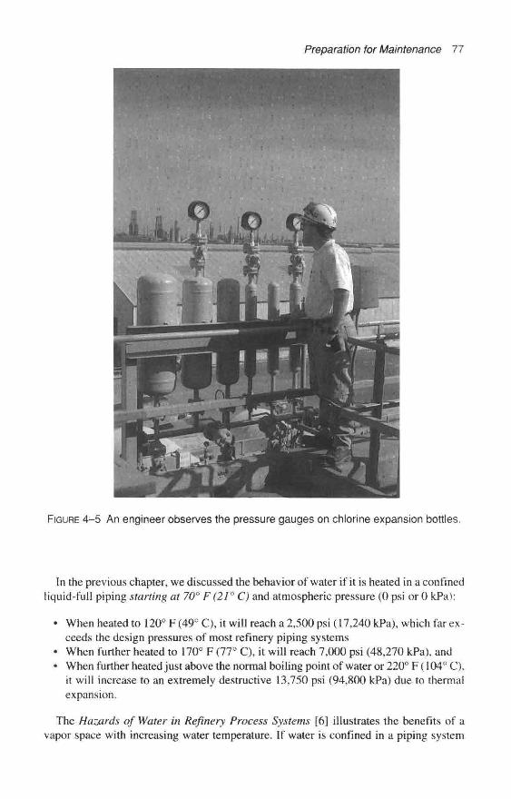
Preparation for Maintenance 77
FIGURE 4-5 An engineer observes the pressure gauges on chlorine expansion bottles.
In the previous chapter, we discussed the behavior of water if it is heated in a confinedliquid-full piping starting at 70° F (21° C) and atmospheric pressure (0 psi or 0 kPa):
* When heated to 120° F (49° C), it will reach a 2,500 psi (17,240 kPa), which far ex-ceeds the design pressures of most refinery piping systems
* When further heated to 170° F (77° C), it will reach 7,000 psi (48,270 kPa), and* When further heated just above the normal boiling point of water or 220° F (104° C),
it will increase to an extremely destructive 13,750 psi (94,800 kPa) due to thermalexpansion.
The Hazards of Water in Refinery Process Systems [6] illustrates the benefits of avapor space with increasing water temperature. If water is confined in a piping system

78 Chemical Process Safety
with a vapor space, and then heated, the pressure rises more slowly until it becomes toosmall due to compression or disappears due to the solubility of air in water. When a sim-ple water system piping has a vapor space of 11.5-percent air at 70° F (21 ° C) and at-mospheric pressure (0 psi or 0 kPa), if it is heated to 350° F (177° C), the pressure willrise to 285 psi (1,954 kPa) with only a 1.2-percent vapor space remaining. Pressuresshoot up in the next 20° F as the vapor space compresses to near 0 percent.
The benefits of vapor space are very dramatic. The examples of the water heated in aconfined system without vapor space exhibit dangerously high pressures—high enoughto rupture almost any equipment not protected with a pressure-relief device.
A Chemical Cleaning Operation Kills Sparrows,But Improves Procedures
The chemical and oil refining industries employ a variety of methods to clear andclean storage tanks, pressure vessels, and pipelines as a preparation for maintenance orthe actual maintenance itself. Depending on the job, water washing may not be suitableand the planners may use various acids and alkalis for this activity. There can be risksassociated with such reactive chemicals, as noted in the following paragraphs.
When a number of dead sparrows had accumulated around the polymerization unit, re-finery management realized it needed to develop more rigid policies governing chemicalcleaning of equipment. The refinery hired a chemical cleaning contractor to acid clean acaustic scrubbing system of the catalytic polymerization unit. Both parties seemingly didnot adequately consider possible unwanted chemical reactions. No one predicted that theacid would react to form hydrogen sulfide gas, which the unit unexpectedly released intothe atmosphere in a heavy concentration. No personnel were injured, but a number ofbirds were not that fortunate. [7] After the incident, the refinery readily understood itneeded to plan and supervise such chemical cleaning operations more closely. One su-pervisor each from the operations, maintenance, inspection, technical, and safety depart-ments composed a maintenance preparation and planning group. They concluded:
1. The planning group made the technical department responsible for preparingsketches of the equipment and deciding on the details. The technical departmentfocused on: locating the temporary connections, drafting a step-by-step procedurefor cleaning, recommending safe disposal of any gases (particularly H2S) and thecleaning fluid, specifying the personnel-protective equipment required, and simi-lar concerns.
2. The planning group should decide how to vent the system during the cleaning op-erations (e.g., to the flare, through a caustic wash, or directly into the atmosphere).
3. The planning group is responsible for ensuring that copies of sketches and anyother pertinent instructions would be issued to the contractor doing the work andto the operating, maintenance, and inspection departments.
4. The operating foreman is responsible for issuing all safe work permits. The area su-pervisor or the shift supervisor is responsible for checking the lineup. [7]
The approach of forming a team of specialists to evaluate a proposal to chemicallyclean refinery equipment is a concept that will be discussed in Chapter 10. This approachis excellent for developing Mechanical Integrity procedures of critical operations.

Preparation for Maintenance 79
Other Cleaning, Washing, Steaming,and Purging Operations
Cleaning, washing, steaming-out, and purging of equipment, vessels, and pipelines inpreparation for maintenance can create problems. Often equipment cleaning does not at-tract much attention and is frequently carried out by individuals with the least amount oftechnical training. A few problems that have been reported follow.
A 30,000-gallon (115 cubic meters) atmospheric tank in a Fine Chemical Plant inWest Virginia was being readied for a different batch. As part of the standard change-over in products, employees were assigned to completely clean the tank of any traces ofproduct. Steam cleaning was the usual process, but no one seemed to take into consid-eration the brutally cold weather that was nearing 0° F (–18° C). They steamed out theFine chemical lank for a considerable time and then shut the steam valve. Unexpectedly,the tank partially collapsed from the rapidly condensing steam, despite the fact thatsome nozzles were completely open.
A similar incident involving steam condensation was reported in the Hazards of Waterin Refinery Process Systems [6], where the caption on a photo of a badly damaged tankstates, "A vacuum vent and one open hatchway was not enough to prevent damagewhen steam condensed and pulled in the top two courses of this 35-ft. diameter by 21 ft.-high wash tank."
In another tank collapse incident, a tank containing a solution of ammonia and waterwas being emptied and cleaned. After employees emptied the tank of liquid ammonia,they added water to rinse the vessel. While the water was being added the sides of thetank were sucked in. The ammonia vapor remaining in the tank dissolved in the waterso rapidly that air could not enter through the vent to prevent the collapse. [81
Calculations were made. Engineers figured that a vent of about 30 inches (76 cm) indiameter would have prevented the destructive vacuum from collapsing the tank duringthe ammonia absorption incident. A giant-sized vent was impractical for this installation,hence they concluded that water should be added slowly through a restrictive orifice. [8]
Every plant has a story of good intentions that went sour for well-meaning plant em-ployees washing a pipeline or vessel of an acidic or reactive material. Improperly wash-ing a carbon steel vessel in strong (about 98 percent) sulfuric acid has left wall thicknessdamage. Underestimating the heat of solution or heat of reaction of water washing outother chemicals has resulted in clouds of toxic fumes.
A Tragedy When Preparing for Valve MaintenanceA catastrophic explosion and major fire occurred within a major refinery as operations
prepared a system for valve maintenance. This refinery stored a flashing flammable fluid(isobutane with a boiling point of 11° F or –12° C) in two spherical tanks. The spheresconnected to an alkylation unit via a 10-inch (25 cm) line. Operating line pressure wasabout 50 psig (345 kPa gauge) and one of the valves in this underground system was inan open pit. [9J
A refinery operator noticed bubbles in the water that covered the 10-inch (25 cm)valve in the pit. The employee proceeded to try to clear the underground pipeline byflushing the leaking line with a 110 psig (760 kPa gauge) water supply to Sphere No. 1.When the operator determined that water had flushed the flammables from the pipeline

80 Chemical Process Safety
and into the Sphere No. 1, he closed the valve to Sphere No. 1 and started to open theSphere No, 2 valve.
High water system pressure of nearly 110 psig (760 kPa gauge) against the 10-inchclosed valve to Sphere No. 1 forced the bonnet to fly off the weakened valve in the pit andcreated a geyser of water. The operator saw the geyser, sensed something was wrong, andmistakenly closed the valve to Sphere No. 2 and reopened the Sphere No. 1 valve, |9j
With the bonnet blown off, the resultant large opening in the piping system allowedan uncontrolled catastrophic release on this pre-dawn summer morning. An estimated500 barrels of isobutane escaped and the vapor dispersed over an area of 300 ft. by 800ft. before it ignited explosively. The resulting explosion and fire destroyed or heavilydamaged two alkylation units, a delayed coker unit, a thermal cracker, and a catalytichydroforming unit. Two spherical tanks failed and numerous cone roof tanks were in-volved, [10] The fire burned for two weeks. Investigators later determined that a leakysulfuric acid line was in the vicinity of the 10-inch valve in the pit. Acid had attacked thevalve bonnet bolts and weaken them. [9]
In 1967, it was believed this incident was the largest vapor cloud explosion reportedto date. A company spokesman presented details of this incident at the American Insti-tute of Chemical Engineers Loss Prevention Symposium. [11] The next four paragraphsare direct quotes from that technical paper:
The explosion occurred about 4:45 A.M. Residents of the area were awakened by afrightening roar to see smoke and flame filling the western horizon. With dawn, thedestruction was more apparent: three refining units were afire, tankage wasablaze, and columns of black smoke spiraled upward. . . .
The explosion had all the characteristics of a detonation. A plot of overpressuredestruction vs. distance statics fits exactly on known TNT detonation curves. Basedon the stoichiometric combustion, my calculations indicate that the explosion hadthe force of 10 to 12 tons of TNT.
After the fires were extinguished, we took our first hard look at the damage. Ourunits resembled ruins from the ravages of war. Two-story buildings had been re-duce to 4-ft. piles of rubble, towers leaned in all directions, pipe runs looked like ablackened mass of giant waste spaghetti. Pumps were melted and concrete supportsdestroyed. Glass breakage was massive, unbelievable. Small buildings werecrushed and shattered.
When the final results were tallied, we counted 7 deaths, 13 injuries, and an in-sured loss exceeding $35 million. About half of this loss was property damage, theremaining half in business interruption.
Using an inflation index of the property damage in 1995 dollars, the total property damage was $80.8 million. [10]
Afterthoughts on Piping Systems
Corrosion is a serious problem throughout the world, and you can often observe its af-fects on piping, valves, and vessels within chemical plants. Each plant must train its per-sonnel to observe serious corrosion and external chemical attack.
Often plant personnel do not appreciate piping as well as it should be. As many chem-ical plants grow older, more piping corrosion problems will occur. It is critical that pip-
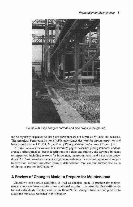
Preparation for Maintenance 81
FIGURE 4-6 Pipe hangers corrode and pipe drops to the ground,
ing be regularly inspected so that plant personnel are not surprised by leaks and releases.The American Petroleum Institute (API) understands the need for piping inspection andhas covered this in API 574, Inspection of Piping, Tubing, Valves and Fittings. [12]
API Recommended Practice 574, within 26 pages, describes piping standards and tol-erances, offers practical basic descriptions of valves and fittings, and devotes 16 pagesto inspection, including reasons for inspection, inspection tools, and inspection proce-dures. API 574 provides excellent insight into predicting the areas of piping most subjectto corrosion, erosion, and other forms of deterioration. You can find further discussionof piping inspection in Chapter 9.
A Review of Changes Made to Prepare for MaintenanceShutdown and startup activities, as well as changes made to prepare for mainte-
nance, can sometimes require some abnormal activity. It is essential that sufficientlytrained individuals develop and review these "little" changes from normal practice toavoid the mistakes recorded in this chapter.

82 Chemical Process Safety
In a paragraph entitled "Nonroutine Work Authorizations," the OSHA Process SafetyManagement Law recognizes that this "abnormal preparation" activity can create prob-lems. [13] In part the paragraph reads: "Nonroutine work which is conducted in processareas needs to be controlled in a consistent manner. The hazards identified involving thework that is to be accomplished must be communicated to those doing the work, but alsoto those operating personnel whose work could affect the safety of the process." (Thebalance of the paragraph discusses authorization notice or permit and the necessarycommunications to make this system work.) These communications include lock-out/tag-out procedures, line-break procedures, confined-space entry, and hot-work permits.
1. Kletz, Trevor A., Critical Aspects of Safety and Loss Prevention, London: Butterworth,1990, p. 212.
2. Institution of Chemical Engineers, "Over- and Under-Pressuring of Vessels—HazardWorkshop," Module 001, Rugby, England (available as a training kit with 34 35mm slides, book--lets, a teaching guide, etc.).
3. Institution of Chemical Engineers, Loss Prevention Bulletin: Articles and Case Historiesfrom Process Industries throughout the World, vol. 078. Rugby, U.K., Dec. 1987, pp. 26–27.
4. National Safety Council, Work, Injury and Illness Rates 1985, 1986, 1987, 1988, and 1989,Chicago, 1986–1989, p. 8.
5. Refrigerating Engineers and Technicians Association, "One Man's Death: An InvestigativeReport," The Technical Report 3, no. 2, July 1990.
6. Standard Oil Company (Indiana), Hazards of Water in Refinery Process Systems, Chicago,1960, pp. 4-6.
7. American Petroleum Institute, "Safety in Maintenance," Safety Digest of Lessons Learned,sec. 4, 1981, p. 49.
8. Kletz, Trevor A., private communication, Feb. 1981. See also What Went Wrong? CaseHistories of Process Plant Disasters, 3d ed. Houston: Gulf Publishing, 1994, pp. 96–97.
9. Vervalin, C. H., ed. Fire Protection Manual—For Hydrocarbon Processing Plants, 2d ed.Houston: Gulf Publishing, 1973, p. 90.
10. Mahoney, David, ed. Large Property Damage Losses in the Hydrocarbon-Chemical In-dustries—A Thirty-Year Review, 16th ed. New York: Marsh & McLennan Protection 1995, p. 23.
11. Goforth, C. P., "Functions of a Loss Control Program," Loss Prevention 4. New York:American Institute of Chemical Engineers, 1969, p. 1.
12. American Petroleum Institute, Inspection of Piping, Tubing, Valves and Fittings, Recom-mended Practice 574, 1st ed. Washington, D.C., June 1990.
13. OSHA, U.S. Department of Labor, Process Safety Management of Highly HazardousChemicals: Compliance Guidelines and Recommendations for Process Safety Management (Non-mandatory}, 29 C.F.R. Part 1910.119, Appendix C, Federal Register, Feb. 24, 1992, p. 6414.
References
Maintenance-Induced Accidentsand Process Piping Problems
Improper or insufficient maintenance can lead to serious personnel or process acci-dents. Occasionally, well-intended maintenance activities inadvertently introduce an un-wanted situation into a carefully engineered plant. A lack of a maintenance program withproper inspections and tests can also result in accidents. This chapter reviews both ofthese maintenance causes of accidents while emphasizing piping-related case histories.
Maintenance employees often work on equipment and piping that handles high vol-umes or high flow-rates of hazardous materials. Maintenance mechanics' jobs oftenconsist of opening up piping systems and vessels that previously contained hazardouschemicals and may still have an undetermined amount of hazardous chemical residues.It is logical to think these vital upkeep activities share a significant role in plant acci-dents. Trevor Kletz often stated during his Continuing Education lectures for the Amer-ican Institute of Chemical Engineers that, in his industrial experience, the preparation formaintenance and the actual maintenance activity accounted for more chemical plant ac-cidents than any other single cause.
In most plants, piping systems require plenty of maintenance, and piping changesoccur frequently. Typically there is piping replacement (due to corrosion or to providelarger diameter piping for more flow-rate), some rerouting, and other less glamorous ac-tivities to clear and clean piping. And then there is the periodic installation of blinds andthe replacement or repair of block valves, control valves, and leaking fittings.
A high percentage of the incidents covered in this chapter involve piping maintenanceproblems, and this chapter concludes with case histories of poor design and poor main-tenance of piping systems. It also addresses ruptures in piping systems that seemed to re-sult from shortcomings in inspection, testing, and quality control of piping materials.Several of the latest incidents have resulted in OSHA citations, so we will take a brieflook at the citation process.
U.S. regulators understood the importance of maintenance when the OccupationalSafety and Health Agency (OSHA) proposed OSHA Process Safety Management Regu-lation 1910.119. The regulation requires facilities that handle highly hazardous chemicalsto implement a 14-point process safety management program. Three of the 14 elements—"Hot Work Permits," "Mechanical Integrity" (see Chapter 9), and "Contractor Safety"—have a direct impact on maintenance programs of covered units.
83
CHAPTER 5
84 Chemical Process Safety
Planning and CommunicationTo be successful providing preventive maintenance or repair maintenance, effective
planning is necessary with approved procedures, proper materials, and qualified techni-cians. These elements are necessary when operations shut down a single piece of equip-ment or shut down an entire unit for a turnaround. Continuous good communications atthe job site are imperative.
One simple, vivid example of poor communication in maintenance occurred after theplant staff marked the location of an underground electrical bus with a series of flags onthe surface. No one discussed the job with the backhoe operator, so when he saw theflags, the hoe operator assumed that the flags indicated the location of the path to be dug.He severed the subsurface electrical cables and a large portion of the chemical plant fa-cility was blacked out. The report failed to mention the fate of the backhoe operator. [1]
Filter Cartridges Are Replaced and an Iron-in-ChlorineFire Develops
An astonished operations crew witnessed the body of a carbon steel filter spontaneouslyignite and burn just after maintenance installed a replacement set of fiberglass filter car-tridges. The filter, designed to remove any possible fine particles from a heated gaseouschlorine stream, was 18 inches (45 cm) in diameter and about 4-ft. (1.2 m) high. The car-tridges selected to replace the spent units were in the chemical plant's warehouse stockbut were originally specified for other chemical services within this Gulf Coast complex.These cartridges consisted of fiberglass filter media on tin-coated steel cores.
No doubt the chemical process operators watched in amazement as they started up thefilter system with the newly replaced cartridges and then observed rusty-colored smoke.Investigators theorized the tin spontaneously caught fire within the hot chlorine atmos-phere. Apparently, the cartridges burned with sufficient heat to initiate an iron-in-chlorine fire on the filter body. Operations promptly blocked the upstream chlorinevalves and the fire continued to burn until it quickly consumed the chlorine gas. The firedestroyed the steel shell of the filter and several inches of downstream piping, but no in-juries were reported.
Repairs to a Pipeline Result in Another Iron-in-Chlorine FireWhen a welder finished welding a short section of 2-inch (5 cm) piping in a rather
long insulated gaseous chlorine equalizing line, it was late on the day shift. The weld thatjoined the new section of piping to existing piping was about 6 inches (15 crn) from ad-jacent thermal insulation that encircled the original chlorine line.
The evening shift loader's first task was to return the repaired chlorine line to service.The loader quickly pressured the section of piping with 100 psig (690 kPa gauge) com-pressed air and determined the repairs were leak-free. He next opened a valve connectingthe 2-inch (5 cm) pipeline to 160 psig (1100 kPa gauge) compressed chlorine gas.
Within seconds, the iron caught fire and the escaping gases roared like a jet as abrownish-orange plume of ferric chloride drifted towards the fence line from the blazingpiping. The shift loader quickly isolated the piping system by closing the block valve hehad just opened. Once the oxidant was consumed, the fire self-extinguished. Eyewit-

Maintenance-Induced Accidents and Process Piping Problems 85
nesses said that sparking and fire resembled a traditional roman candle, shooting sparksof burning steel. Although the fire burnt out quickly, it was remembered for years.
Many of the supervisors and loaders were aware that if chlorine comes in contact withiron that has been heated above 483° F (250° C), a spontaneous iron-in-chlorine fire canoccur. But, the loader probably assumed the new weld on the repaired pipeline hadcooled to well below the auto-ignition temperature of iron in chlorine. The investigationdetermined that the fire did not originate at the new weld, but started under the adjacentinsulation, which trapped heat and did not allow the piping to cool quickly.
Repaired Reboiler Passes the Hydrotest and LaterCreates a Fire
Furnace coils heated a flowing combustible heat-transfer oil before the hot oil is dis-tributed and routed through the shells of four heat exchangers (reboilers) (see Figure 5–1).One of the four heat exchangers required considerable repairs and was shut down. Thesystem pump continued to circulate hot transfer oil at about 460° F (240° C) through theother three reboilers while repairs were underway on the faulty exchanger. [2]
The repaired reboiler was mounted in the normal vertical position when the employ-ees decided to hydrostatically test the unit at the conclusion of the repairs. The mechan-ical integrity of the reboiler could be assured by a simple hydrotest. After the hydrotestpressure held and no leaks were detected, employees drained the water used to hydrotestfrom the shell side. Unfortunately, the lower drain valve nozzle was not located on thevery bottom of the unit, and it allowed about 8 inches (21 cm) of water to be trapped.
From other reboilers
13 000gallonsurgetank90%full
-HX3—*—{X] To other reboilers
^<^ *
Furnace
8 inwaterleft inshell
<D _©
'5 6a. .a<D 0>
DC *- Drain valveon shell£<Hi
-03-
FIGURE 5–1 Residual, undetected water from a hydrotest explosively vaporizes andruptures a surge tank. Courtesy of Trevor A. Kietz.
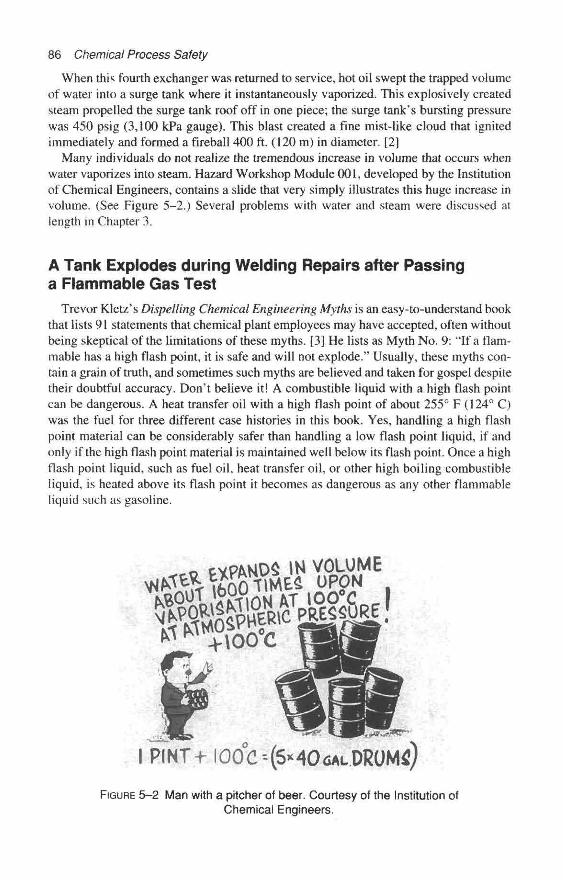
86 Chemical Process Safety
When this fourth exchanger was returned to service, hot oil swept the trapped volumeof water into a surge tank where it instantaneously vaporized. This explosively createdsteam propelled the surge tank roof off in one piece; the surge tank's bursting pressurewas 450 psig (3,100 kPa gauge). This blast created a fine mist-like cloud that ignitedimmediately and formed a fireball 400 ft. (120 m) in diameter. [2]
Many individuals do not realize the tremendous increase in volume that occurs whenwater vaporizes into steam. Hazard Workshop Module 001, developed by the Institutionof Chemical Engineers, contains a slide that very simply illustrates this huge increase involume. (See Figure 5–2.) Several problems with water and steam were discussed atlength in Chapter 3.
A Tank Explodes during Welding Repairs after Passinga Flammable Gas Test
Trevor Kletz's Dispelling Chemical Engineering Myths is an easy-to-understand bookthat lists 91 statements that chemical plant employees may have accepted, often withoutbeing skeptical of the limitations of these myths. [3] He lists as Myth No. 9: "If a flam-mable has a high flash point, it is safe and will not explode." Usually, these myths con-tain a grain of truth, and sometimes such myths are believed and taken for gospel despitetheir doubtful accuracy. Don't believe it! A combustible liquid with a high flash pointcan be dangerous. A heat transfer oil with a high flash point of about 255° F (124° C)was the fuel for three different case histories in this book. Yes, handling a high flashpoint material can be considerably safer than handling a low flash point liquid, if andonly if the high flash point material is maintained well below its flash point. Once a highflash point liquid, such as fuel oil, heat transfer oil, or other high boiling combustibleliquid, is heated above its flash point it becomes as dangerous as any other flammableliquid such as gasoline.
FIGURE 5-2 Man with a pitcher of beer. Courtesy of the Institution ofChemical Engineers.
Maintenance-Induced Accidents and Process Piping Problems 37
Additional hazardous conditions can occur with aerosols or fine mists of combustiblehigh flash point material. Mists of combustible liquids can readily explode. Mists canexplode, just as combustible dusts will explode, even if the fluids in the mists are at tem-peratures well below their flash point.
In Critical Aspects of Safety and Loss Prevention, Kletz defines the problems ofworking on tanks containing high flash point oils. His message introduces the next twoincidents. [4]
Many fires and explosions have occurred when welding has been carried out ontanks which have contained heavy oils (or materials which polymerize to formheavy oils). It is almost impossible to remove all traces by cleaning and the weld-ing vaporizes the oil and then ignites it. If welding has to be carried out on suchtanks they should be inerted with nitrogen or with fire fighting foam made with ni-trogen (hut not foam made with air). The volume to be inerted can be reduced byfilling the tank with water up to the level at which welding has to be carried out.
A Phenol Tank's Roof Lifts as Repairs Are Made
The roof of a small phenol storage tank required repairs for continued safe opera-tions. Supervisors wanted to complete the maintenance without the fuss and bother ofemptying and washing the vessel. This portion of the chemical plant had experienceda minor incident with hot phenol a few years before, so it was important for operationsto empty the tank as far as practical. The thoughtful job planners decided to shut off thesteam to the heating coil well in advance of the maintenance effort. The loss of steamallowed the heel of the tank to freeze. This combustible material has a melting point of106° F (41°C).
The welder was directed to weld a patch-plate on the roof of the low-pressure, verti-cal tank. Heat from the welder's torch vaporized and ignited some phenol which had ac-cumulated on the underside of the roof and a mild explosion occurred. The overpressuretore some of the roof seam. Fortunately, the alert welder saw evidence of an internal fireand ran to safety just before the explosion occurred. [3]
Another Country, Another Decade, Another Tank Explosion
One afternoon in June 1988, in an Ohio River Valley plant a similar incident occurred.Regrettably, three employees received relatively minor burns, abrasions, and lacerationsduring a fire and an overpressurization of a tank containing about a 3-ft. (1 m) level of acombustible liquid. At the time of the incident, a welder was repairing a moderate-sizedvessel—25-ft. (7.6 m) high and 20 ft. (6.1 m) in diameter.
Two days before the incident, the maintenance foreman, the shift foreman, operationsengineer, and two pipefitters discussed the job. The scope of the job included repairs tohandrails and walkways. Concerned supervision decided that burning and weldingwould be permitted on the structural steel that was located on top of the tank. However,the supervisor declared no burning and welding on the actual surface of the tank topwould be allowed.
The first day progressed with no problems, and it rained the next day, which pre-vented further work on the outdoor tank. On the third day, the job resumed with the same
88 Chemical Process Safety
two pipefitters and a welder joined the crew. Flammable gas testing of the area was per-formed on the exterior of the tank and the flammable gas probe was lowered a few feetinto the tank through an atmospheric vent. The meter showed no evidence of a flamma-ble mixture.
No one told the welder that burning and welding were previously prohibited on thesurface of the tank's top. Apparently the pipefitters did not immediately recall the con-versations that took place two days before. While the job was in progress, it seemedexpedient to weld a horizontal support to the top of the vessel for a section of walkway.The welder attempted to attach the post to the thin tank top when his weld "blewthrough" it.
Investigators speculated that when the welder's arc penetrated the surface of the tanktop, combustible organics (a benzene derivative) ignited. Most likely, combustible ma-terial had vaporized from liquid over a period of time, condensed and solidified on theunderside of the tank roof. Furthermore, in the opinion of the investigators, burning or-ganic droplets fell through the vapor space until it ignited a dense layer of flammablevapor liberated by the heat of the welding activity.
The fuel-to-air conditions must have been ideal because fire violently created com-bustion gases at a rate which quickly exceeded the tank's venting capability. In less thanfive seconds, as the top raptured, alert employees hurried off the tank. The last of thethree fleeing employees recalled being propelled into the other two escaping employeesahead of him when the tank top blew open.
Management promptly initiated an in-depth accident investigation. All the employeesinterviewed by the investigating team shared the impression that the organic was prac-tically not ignitable. Employees were familiar with handling this organic compoundwell below it's 148° F (65° C) flash point. Perhaps they believed in the myth "if a com-bustible liquid has a high flash point it is safe."
Catastrophic Failures of Storage Tanks as Reportedby the Environmental Protection Agency
In 1997, the U.S. Environmental Protection Agency started publishing a bulletin en-titled "Chemical Safety Alert." The intent of these bulletins is to increase awareness ofpossible hazards. One of the earlier published Alerts, entitled "Catastrophic Failure ofStorage Tanks," was issued in May 1997. [5] This "Alert" including the concepts of tankfailures of shell to bottom seam or side seam will be reviewed in detail in Chapter 7.However, to highlight recent problems created by maintenance efforts, three paragraphswere quoted from that document and are repeated here.
In a 1995 incident, during a welding operation on the outside of a tank, the com-bustible vapor inside two large, 30-ft. diameter by 30-ft. high, storage tanks ex-ploded and propelled the tanks upward—one landing more than 50 feet away. Theflammable liquid inside was instantly released and ignited, resulting in a massivefire, that caused five deaths and serious injuries. . . .
In a 1992 incident, while workers were welding the outside of a tank empty ofliquid, the residual vapor in the tank exploded and propelled the tank upward andinto an adjacent river. Three workers were killed and one was injured. . . .

Maintenance-Induced Accidents and Process Piping Problems 89
In a 1994 incident, during a grinding operation on a tank holding petroleum-based sludge, the tank was propelled upward, injuring 17 workers and spilling itscontents over a containment berm into a nearby river.
Hazard Awareness
Generation of combustible vapors is a hazard not only for the storage of pure flam-mable liquids but also for the storage of any sludge or mixture where a combustiblecomponent is present or can be produced by reaction. Sludge (slop tanks) and mixture(e.g., oil/water) tanks may be particularly vulnerable because they are sometimes opento the air; explosive atmospheres may form inside and outside the tank. Facilities maynot always recognize the hazard. In addition, even tanks appearing to be empty may posea hazard if they still contain combustible vapors.
In the cited cases, the potential for combustible vapors was not clearly recognized andmaterials were stored in tanks that were not equipped with flame arresters to prevent ex-ternal fire from reaching the vapor space inside the tank or vapor control devices to limitvapor emissions from the tank. [5]
FIGURE 5–3 A sketch of the piping arrangement being repaired below the sphere.Courtesy of the Institution of Chemical Engineers.
90 Chemical Process Safety
Repair Activity to a Piping Spool Results in a MassiveLeak from a Sphere
A petrochemical plant in Altona, Australia, was scheduled to replace a section of 3-inch (75 mm) piping below a sphere in February 1982. The externally corroded sectionof pipe was bolted in just below a single air-operated isolation valve. [6]
The work was considered normal maintenance and presented no special hazards. Em-ployees carried a prefabricated section of replacement piping to the sphere containinghundreds of tons of a flashing flammable liquid. The boiling point of this material was8° F (–13° C) and it was stored under several atmospheres of pressure. [61
This section of piping not only served as an outlet for the flashing flammable liquid, bulit also supported the valve actuator and was connected by a lever to the valve. Mechanicsremoved the brackets connecting the lever to the corroded section of piping and then thepiping was removed. The lever and the actuator, with a combined weight of about 45pounds (20 kg), hung down just below the sphere and were suspended from the valve.
The prefabricated piping spool was not exactly the right size, so it was being re-moved and returned to the workshop to make it useful. Before returning to the shop withthe ill-fitting spool, the fitter and two assistants decided to move the old pipe furtheraway. Somehow, the hanging actuator suddenly dragged the valve handle to the openposition.
For the next five hours, 670 tons (608,000 Kg) of vinyl chloride escaped from thesphere, which was under about 30 psig (2.4 bar) pressure. The discharging liquid jettedout, self-refrigerated, and froze the water that was being poured over the sphere (see Fig-ure 5–4). Engineers determined that liquid vinyl chloride escaped at about 3500 L/rnin(725 gal/min).
The breeze held steady from the south but the speeds varied from 8 to 14 knots (16 to26 km/hr). Employees searched for and shut down all nearby potential electrical ignitionsources. Fortunately, the petrochemical plant was able to avoid an ignition. This ordealof a massive uncontrolled leak lasted over five hours. An accidental ignition of thiscloud had the potential for a severe vapor cloud explosion and massive fire damage. [6]
It is ironic; the piping spool was being replaced to avoid the possibility of a leak andyet the proactive maintenance attempt resulted in the escape of 670 tons of a flashingflammable material.
The Phillips 66 Incident: Tragedy in Pasadena, TexasOn October 23, 1989, a massive amount of flammable gases (over 40 tons) (39,000
Kg) escaped in less than two minutes from the reactor loop which was operating underhigh pressure. This catastrophe occurred when maintenance was being performed onpiping systems immediately below the last block valve holding back a massive amountof flammables. The cloud exploded with the force of 2.4 tons of TNT and was the equiv-alent to an earthquake registering 3.5 on the Richter Scale. Two isobutane storage tanksexploded 10 to 15 minutes later and each explosion contributed to a chain reaction of ex-plosions. This tragic explosion and fire resulted in the deaths of 23 employees and thedestruction of nearly $750 million in property. This is the costliest single-owner prop-erty damage loss to occur in the petrochemical industry. Debris from this explosion wasfound about six miles from the plant. Structural beams were twisted like pretzels from

Maintenance-Induced Accidents and Process Piping Problems 91
FIGURE 5–4 The sphere as it empties to the ground. Courtesy of the Institution ofChemical Engineers, Hazards Workshop Module 006.
the heat of such an intense fire, and two polyethylene production plants covering about16 acres were destroyed, [7]
High-density polyethylene reactors are long tubular type reactors operated under ele-vated pressure and temperature. The tail vertical reactors were in excess of 150-ft(46 m) high and had settling legs that were 8 inches (20 cm) in diameter. The reactor wasoperating at about 600 psig (4, 100 kPa gauge) and near 225° F (106° C).
Ethylene is dissolved in isobutane. This ethylene reacts with itself to form polyethyl-ene particles that gradually settle out of solution and are collected in one of six settlinglegs. Particles pass through a main 8-inch (21 cm) block valve called a DEMCO® valveto collect in a chamber. The particles are periodically isolated from the reactor, thevolatiles are removed, and the polyethylene is routed to other equipment for further pro-cessing. (See Figure 5–7, which appeared in OSHA reports and is reproduced with thepermission of OSHA.)
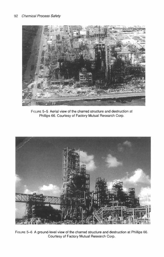
92 Chemical Process Safety
FIGURE 5–5 Aerial view of the charred structure and destruction atPhillips 66. Courtesy of Factory Mutual Research Corp.
FIGURE 5–6 A ground-level view of the charred structure and destruction at Phillips 66.Courtesy of Factory Mutual Research Corp.

Maintenance-Induced Accidents and Process Piping Problems 93
DEMCO valve
Vent (purge)valve
Reactorloop
Flushingisobutane
line
Ethyleneline
Producttake offvalve
FIGURE 5-7 Reactor piping settling leg arrangement.Courtesy of the U.S. Department of Labor, OSHA.
According to the OSHA investigation report, the reactor was undergoing a regularmaintenance procedure for the removal of a solidified polyethylene blockage on three ofthe six reactor settling legs. The procedure called for the isolation of the 8-inch valve andthe removal of the compressed air hoses used to operate the valve. [7]
The maintenance crew had partially disassembled the leg and managed to extract apolyethylene "log" from one section of the leg. However, part of the log remained
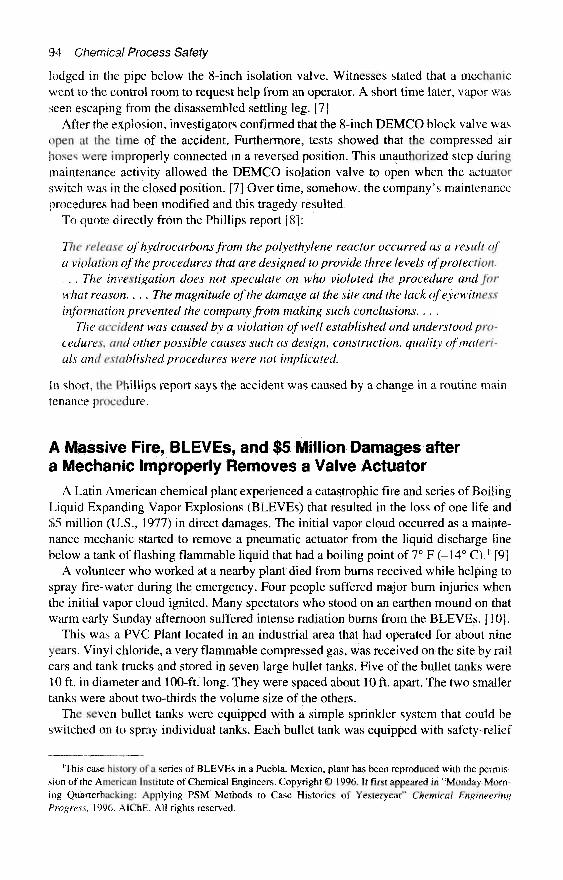
94 Chemical Process Safety
lodged in the pipe below the 8-inch isolation valve. Witnesses stated that a mechanicwent to the control room to request help from an operator. A short time later, vapor wasseen escaping from the disassembled settling leg. [7]
After the explosion, investigators confirmed that the 8-inch DEMCO block valve wasopen at the time of the accident. Furthermore, tests showed that the compressed airhoses were improperly connected in a reversed position. This unauthorized step duringmaintenance activity allowed the DEMCO isolation valve to open when the actuatorswitch was in the closed position. [7] Over time, somehow, the company's maintenanceprocedures had been modified and this tragedy resulted.
To quote directly from the Phillips report [8]:
The release of hydrocarbons from the polyethylene reactor occurred as a result ofa violation of the procedures that are designed to provide three levels of protection.. . . The investigation does not speculate on who violated the procedure and forwhat reason. . . . The magnitude of the damage at the site and the lack of eyewitnessinformation prevented the company from making such conclusions. . . .
The accident was caused by a violation of well established and understood pro-cedures, and other possible causes such as design, construction, quality of materi-als and established procedures were not implicated.
In short, the Phillips report says the accident was caused by a change in a routine main-tenance procedure.
A Massive Fire, BLEVEs, and $5 Million Damages aftera Mechanic Improperly Removes a Valve Actuator
A Latin American chemical plant experienced a catastrophic fire and series of BoilingLiquid Expanding Vapor Explosions (BLEVEs) that resulted in the loss of one life and$5 million (U.S., 1977) in direct damages. The initial vapor cloud occurred as a mainte-nance mechanic started to remove a pneumatic actuator from the liquid discharge linebelow a tank of flashing flammable liquid that had a boiling point of 7° F (–14° C).1 [9]
A volunteer who worked at a nearby plant died from burns received while helping tospray fire-water during the emergency. Four people suffered major burn injuries whenthe initial vapor cloud ignited. Many spectators who stood on an earthen mound on thatwarm early Sunday afternoon suffered intense radiation burns from the BLEVEs. [10].
This was a PVC Plant located in an industrial area that had operated for about nineyears. Vinyl chloride, a very flammable compressed gas, was received on the site by railcars and tank trucks and stored in seven large bullet tanks. Five of the bullet tanks were10 ft. in diameter and 100-ft. long. They were spaced about 10 ft. apart. The two smallertanks were about two-thirds the volume size of the others.
The seven bullet tanks were equipped with a simple sprinkler system that could beswitched on to spray individual tanks. Each bullet tank was equipped with safety-relief
'This case history of a series of BLEVEs in a Puebla, Mexico, plant has been reproduced with the permis-sion of the American Institute of Chemical Engineers. Copyright © 1996. It first appeared in "Monday Morn-ing Quarterbacking: Applying PSM Methods to Case Histories of Yesteryear" Chemical EngineeringProgress, 1996. AIChE. All rights reserved.
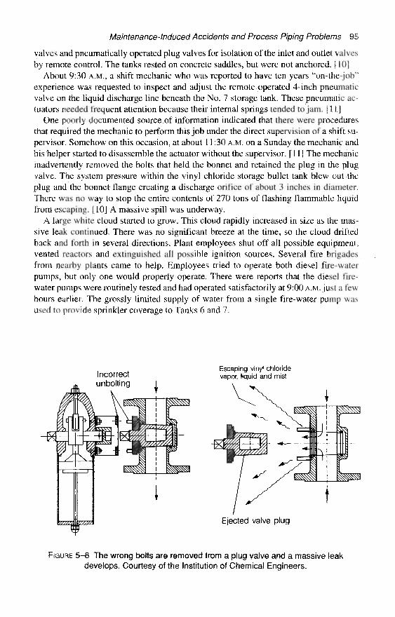
Maintenance-Induced Accidents and Process Piping Problems 95
valves and pneumatically operated plug valves for isolation of the inlet and outlet valvesby remote control. The tanks rested on concrete saddles, but were not anchored. [10]
About 9:30 A.M., a shift mechanic who was reported to have ten years "on-the-job"experience was requested to inspect and adjust the remote operated 4-inch pneumaticvalve on the liquid discharge line beneath the No. 7 storage tank. These pneumatic ac-tuators needed frequent attention because their internal springs tended to jam. [11]
One poorly documented source of information indicated that there were proceduresthat required the mechanic to perform this job under the direct supervision of a shift su-pervisor. Somehow on this occasion, at about 11:30 A.M. on a Sunday the mechanic andhis helper started to disassemble the actuator without the supervisor. [11] The mechanicinadvertently removed the bolts that held the bonnet and retained the plug in the plugvalve. The system pressure within the vinyl chloride storage bullet tank blew out theplug and the bonnet flange creating a discharge orifice of about 3 inches in diameter,There was no way to stop the entire contents of 270 tons of flashing flammable liquidfrom escaping. [10] A massive spill was underway.
A large white cloud started to grow. This cloud rapidly increased in size as the mas-sive leak continued. There was no significant breeze at the time, so the cloud driftedback and forth in several directions. Plant employees shut off all possible equipment,vented reactors and extinguished all possible ignition sources. Several fire brigadesfrom nearby plants came to help. Employees tried to operate both diesel fire-waterpumps, but only one would properly operate. There were reports that the diesel fire-water pumps were routinely tested and had operated satisfactorily at 9:00 A.M. just a fewhours earlier. The grossly limited supply of water from a single fire-water pump wasused to provide sprinkler coverage to Tanks 6 and 7.
Incorrectunbolting I
Escaping vinyl chloridevapor, liquid and mist
Ejected valve plug
FIGURE 5-8 The wrong bolts are removed from a plug valve and a massive leakdevelops. Courtesy of the Institution of Chemical Engineers.

96 Chemical Process Safety
Emergency control volunteers tried to control the release of flashing flammable liq-uid by directing a fire-water stream at the valve and allowing an ice plug to form. Re-sponders made three attempts to reduce the flow of flamrnables with a plug of ice. (NoteFigure 5-5 on a similar massive leak of vinyl chloride. It appeal's that a large ice forma-tion occurred at that incident.)
But each time ice formed and slowed the leak, the internal pressure within the tank in-creased and blew the plug out. By 1:00 P.M., the massive leak of 90 minutes' durationcreated a huge visible white vapor cloud estimated to be nearly 1,100-ft. (330 m) long,800-ft. (240 m) wide, and about 5-ft. (1.5 m) high. [11] Five minutes later the cloud ig-nited. The flame flashed back to the source, and a blowtorch-like flame shot beneath thetanks.
The bonnet opening of the disabled valve body below Tank No. 7 provided a steadystream of fuel to create a blowtorch-like flame aimed beneath Tank Nos. 5, 6, and 7,which threatened the equipment. Within a short length of time, safety-relief valves onthese tanks opened with a loud shrill sound to cope with the heat-induced rising pressurein the tanks.
Tank No. 5, which was not being fire-water sprayed because of limited fire-water sup-plies, catastrophically exploded with a large BLEVE fireball. One section of Tank No.5 rocketed over 1,500 ft. from its original location. This was followed by more explo-sions as first Tank No. 7 and then Tank No. 6 broke up into pieces. One section of TankNo. 7, which weighed 52 tons, also rocketed over 1,800 ft. [11]
FIGURE 5–9 BLEVE of a vinyl chloride storage tank.Courtesy of the Institution of Chemical Engineers.
Maintenance-Induced Accidents and Process Piping Problems 97
Tank No. 4 only partially separated and hit Tank No. 3 and knocked it off the foun-dations, which struck Tank No. 2 and then Tank No. 1. Tank No. 3 was being servicedand full of water. Tanks No. 1 and No. 2 caught fire and burned until the next day.
Total direct damages were about $5 million (1977 dollars). One emergency responderfrom a neighboring plant died as a result of burns and four individuals suffered majorburn injuries when the ignition of the cloud took place.
Based on the reports and the accompanying photos, there were apparent troubles withcrowd control and other emergency response considerations. It also appears that therewere equipment design shortcomings. Still, a top-notch viable mechanical integrity pro-gram would have eliminated or helped minimize the extent of the incident.
Afterthoughts on Massive Fire and BLEVEs in Latin American Plant
It is obvious that a good Process Safety Management (PSM) Program could have re-duced the probability and consequences of this tragedy. Today a U.S. company coveredby the PSM regulation would be asked:
* Is the risk too high to adjust the critical isolation valves while the bullet tank wasfull of a highly flammable liquid? (A Process Hazards Analysis might question thepractice.)
« Was there sufficient Process Safety Information on the valve and actuator arrange-ment?
« Was there an Operations Standard Operating Procedure for permitting this job?* Did written procedures exist detailing this job and its precautions?» Were any such procedures available?* Were maintenance mechanics trained in the procedures?* Were the fire-water pumps and associated controls part of an inspection and test
program?* Did the Emergency Response plan consider and address a potential release of this
magnitude?* Was crowd control part of the emergency response plan?
Misdirected Precautions on a Reactor System IsolationPlug Valve Results in a Vapor Cloud Explosion
At 6:30 P.M. one October 1980 evening, a U.S. chemical plant on the Delaware Riverwas partially destroyed after a safety precaution was mishandled. A 4-inch (10 cm) plugvalve was shut during a maintenance cleaning activity and the air actuator was to be re-moved. But, just as in the Puebla, Mexican Incident, the wrong bolts were removed. Re-ports indicate the valve arrangement was comparable to the situation shown in Figure5-8. [12]
Polypropylene was produced in three reaction trains on a location that employednearly 300 workers. A recycle cooling line on a Reactor in Train "A" plugged with prod-uct slurry. This was considered a regular occurrence. Standard procedures to address thisplugged line required mechanics to work under the direction of operators to rod-out the
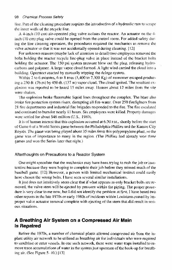
98 Chemical Process Safety
line. Part of the cleaning procedure requires the introduction of a hydraulic ram to scrapethe inner walls of the recycle line.
A 4-inch (10 cm) air-operated plug valve isolates the reactor. An actuator on the 4-inch (10 cm) plug valve could be opened from the control room. For added safety dur-ing the line cleaning operation, the procedures required the mechanics to remove thevalve actuator so that it was not accidentally opened during cleaning. [12]
For unknown reasons (maybe lack of attention to detail) two employees removed thebolts holding the reactor recycle line-plug valve in place instead of the bracket boltsholding the actuator. The 150 psi system pressure blew out the plug, releasing hydro-carbons and polymer. A large vapor cloud formed. A light wind carried the cloud into abuilding. Operators reacted by manually tripping the deluge system.
Within 2 to 6 minutes, 6 to 8 tons (5,400 to 7,300 Kg) of monomer escaped produc-ing a 250-ft. (76 m) by 450-ft. (137 m) vapor cloud. The cloud ignited. The resultant ex-plosion was reported to be heard 15 miles away. Houses about 12 miles from the sitewere shaken.
The explosion broke flammable liquid lines throughout the complex. The blast alsobroke fire protection system risers, disrupting all fire-water. Over 250 firefighters from21 fire departments and industrial fire brigades responded to the fire. The fire escalatedand continued to burn for nearly 11 hours. Six employees were killed. Property damageswere settled for about $46 million (U.S., 1980).
It is of human interest that this explosion occurred at 6:30 P.M., shortly before the startof Game 6 of a World Series game between the Philadelphia Phillies and the Kansas CityRoyals. The game was being played about 35 miles from this polypropylene plant, so thegame was of importance to many in the region. (The Phillies had already won threegames and won the Series later that night.)
Afterthoughts on Precautions to a Reactor System
One might speculate that the mechanics may have been trying to rush the job or inat-tentive because they were hoping to complete their job before they missed much of thebaseball game. [12] However, a person with limited mechanical instinct could easilyhave chosen the wrong bolts. I have seen several similar installations.
It just does not intuitively seem clear that if what appears as only bracket bolts are re-moved, the valve stem will be ejected by pressure within the piping. The proper proce-dure is very clear to me now, but I did not identify the problem at first. I have heard twoother reports in the late 1970s or early 1980s of incidents within Louisiana caused by im-proper valve actuator removal complete with ejecting of the stem that did result in seri-ous situations.
A Breathing Air System on a Compressed Air MainIs Repaired
Before the 1970s, a number of chemical plants allowed compressed air from the in-plant utility air network to be utilized as breathing air for individuals who were requiredto sandblast or enter vessels. In one such network, there were water traps installed to re-move trace accumulations of water in the system just upstream of the hook-up for breath-ing air. (See Figure 5–10.) [13]
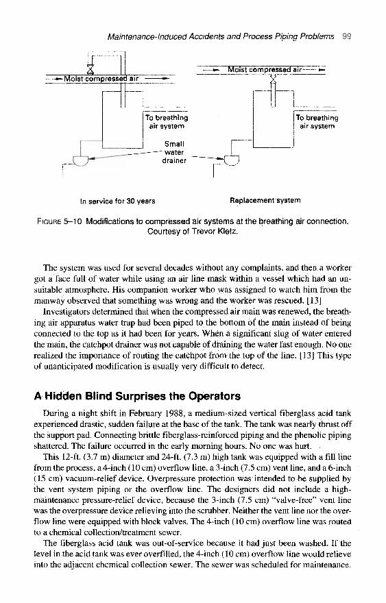
Maintenance-Induced Accidents and Process Piping Problems 99
To breathingair system
In service for 30 years Replacement system
FIGURE 5–10 Modifications to compressed air systems at the breathing air connection.Courtesy of Trevor Kletz.
The system was used for several decades without any complaints, and then a workergot a face full of water while using an air line mask within a vessel which had an un-suitable atmosphere. His companion worker who was assigned to watch him from themanway observed that something was wrong and the worker was rescued. [13]
Investigators determined that when the compressed air main was renewed, the breath-ing air apparatus water trap had been piped to the bottom of the main instead of beingconnected to the top as it had been for years. When a significant slug of water enteredthe main, the catchpot drainer was not capable of draining the water fast enough. No onerealized the importance of routing the catchpot from the top of the line. [13] This typeof unanticipated modification is usually very difficult to detect.
A Hidden Blind Surprises the Operators
During a night shift in February 1988, a medium-sized vertical fiberglass acid tankexperienced drastic, sudden failure at the base of the tank. The tank was nearly thrust offthe support pad. Connecting brittle fiberglass-reinforced piping and the phenolic pipingshattered. The failure occurred in the early morning hours. No one was hurt.
This 12-ft. (3.7 m) diameter and 24-ft. (7.3 m) high tank was equipped with a fill linefrom the process, a 4-inch (10 cm) overflow line, a 3-inch (7.5 cm) vent line, and a 6-inch(15 cm) vacuum-relief device. Overpressure protection was intended to be supplied bythe vent system piping or the overflow line. The designers did not include a high-maintenance pressure-relief device, because the 3-inch (7.5 cm) "valve-free" vent linewas the overpressure device relieving into the scrubber. Neither the vent line nor the over-flow line were equipped with block valves. The 4-inch (10 cm) overflow line was routedto a chemical collection/treatment sewer.
The fiberglass acid tank was out-of-service because it had just been washed. If thelevel in the acid tank was ever overfilled, the 4-inch (10 cm) overflow line would relieveinto the adjacent chemical collection sewer. The sewer was scheduled for maintenance.
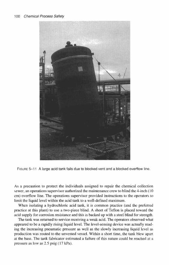
100 Chemical Process Safety
FIGURE 5–11 A large acid tank fails due to blocked vent and a blocked overflow line.
As a precaution to protect the individuals assigned to repair the chemical collectionsewer, an operations supervisor authorized the maintenance crew to blind the 4-inch (10cm) overflow line. The operations supervisor provided instructions to the operators tolimit the liquid level within the acid tank to a well-defined maximum.
When isolating a hydrochloric acid tank, it is common practice (and the preferredpractice at this plant) to use a two-piece blind. A sheet of Teflon is placed toward theacid supply for corrosion resistance and this is backed up with a steel blind for strength.
The tank was returned to service receiving a weak acid. The operators observed whatappeared to be a rapidly rising liquid level. The level-sensing device was actually read-ing the increasing pneumatic pressure as well as the slowly increasing liquid level asproduction was routed to the unvented vessel. Within a short time, the tank blew apartat the base. The tank fabricator estimated a failure of this nature could be reached at apressure as low as 2.5 psig (17 kPa).

Maintenance-Induced Accidents and Process Piping Problems 1 0 1
FIGURE 5-12 An aerial view of the tank failure.
Several probable causes were speculated and investigated. Since ambient temperature was just below freezing, it was very easy to conclude that water froze in the small water- quenching scrubber, sealing the vent. It took just a few minutes to reach that conclusion, but the culprit-a blind found “sort of hidden” in the 3-inch (7.5 cm) vent line flanges- was a major contributory cause.
With a newly installed precautionary blind in the overflow line, the hidden blind in the vent line, and no additional overpressure devices, the tank was destined to fail. As liq- uid was pumped into the vessel, the inerts had no place to go and the tank was pressur- ized to destruction. To the best of everyone’s knowledge and the evidence, this hard-to-detect blind may have been inserted over a year prior to the incident for a pre- vious internal inspection of the acid tank. Obviously the mechanic(s) who removed the other blinds a year or so before and on this occasion did not notice this one.

102 Chemical Process Safety
FIGURE 5-13 A close-up of the failed tank base.
Other Reported Incidents in Which Failure to Remove BlindsCreated Troubles
Designers specified a water jacket pressure rating on a small vessel in a soap plantwas for a pressure rating lower than the cooling water supply pressure. A simple pipingdesign helped to ensure that this 6-ft. (1.8 m) diameter and 6-ft. (1.8 m) high cylindricalvessel with a bottom dished head could not be overpressured during operation. Thecooling water discharge line was engineered without a discharge valve. [14]
It became necessary to hydrostatically test the vessel jacket so that it was properlyblinded and passed the test. But during the startup, as the inlet cooling water valve wasopened, the small flat top vessel collapsed. Repairs were expensive and the startup wasdelayed by several weeks because no one remembered to remove the blind on the"valve-free" water discharge line. [14]
Maintenance-Induced Accidents and Process Piping Problems 103
In another case, the scrubber that served a storage tank had been isolated to make re-pairs to the scrubber. Again by an oversight the blind isolating the vent scrubber from thetank was not removed when the scrubber repairs were completed. [14]
The fiberglass storage tank was overpressured as a transfer was being made into it. Analert operator noticed a remote level indicator seemed to be misbehaving. He wiselystopped the unloading operation and investigated only to find that two anchor bolts werepulled out. The pressure bowed the tank's flat bottom up by several inches. [14]
Afterthoughts on the Use of Blinds
Maintenance workers frequently use blinds to provide a measure of safety on manyassignments. The details of the blinding method are usually customized for each typejob. If a vessel or a system requires significant blinding, there should be a blinding listwhich is used as a checklist to install and remove them. When a Teflon blind is used witha steel blind, the Teflon sheet should be designed and cut with a protruding tab or "ear."
Some companies paint bright orange colors on the "ear" or handle of a blind to iden-tify such blinds more easily and quickly in a maze of piping. Other companies tie abrightly colored ribbon to the tab on the blind to provide additional visibility. Many com-panies rely on blind lists and some companies mistakenly just depend on memory.
Poor Judgment by Mechanics Allowed a Bad SteamLeak to Result in a Minor Explosion
In today's world, many U.S. chemical plants rely on specialty leak repair contractorsto stop steam and other utility fluid nuisance leaks. However, in the mid-1970s thesecontractors were not immediately available to many plant sites, so the plants had to cre-ate their own clamps or other containment systems if shutdowns were to be avoided.
It was late on a Friday afternoon when a maintenance crew consisting of a welder anda pipefitter was assigned to stop a bad steam leak on the bonnet gasket of a 3-inch (7.5cm) steam valve. A supervisor instructed the mechanics to fabricate a clamp that could betightened around the valve bonnet to silence the leak of 260 psig (1,800 kPa gauge)steam and condensate. [15]
The leak repair clamp was a good idea, but it was one of those jobs that was easiersaid than done. There was minimal supervision when the crew returned on Saturday andtook it upon themselves to build a steel box around the leaking valve.
The journeyman mechanics designed a temporary box that lacked most engineeringdesign considerations. With flat 1/4-inch (0.64 cm) steel plate they fabricated a box 3-ft. (0.9 rn) high, 2-ft. (0.6 m) wide, and a little more than 14 inches (0.36 m) deep. Thebox included a 2-inch (5 cm) vent pipe to relieve the steam as the box was encasing thevalve. Even the 150 psi-rated flange on the 2-inch (5 cm) piping was an unsuitable de-sign for the operating pressure temperature.
Upon completion of the box on Saturday, a self-assured and rather cavalier workmanclosed the valve on the relief line. The box started to swell. The employee quicklyopened the valve and told the shift supervisor that they needed to return to finish up thejob on Sunday.
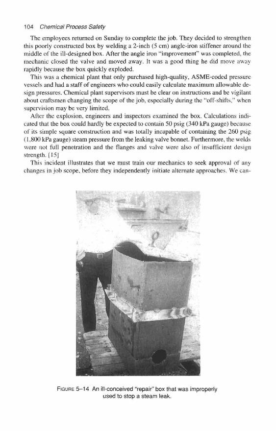
104 Chemical Process Safety
The employees returned on Sunday to complete the job, They decided to strengthenthis poorly constructed box by welding a 2-inch (5 cm) angle-iron stiffener around themiddle of the ill-designed box. After the angle iron "improvement" was completed, themechanic closed the valve and moved away. It was a good thing he did move awayrapidly because the box quickly exploded.
This was a chemical plant that only purchased high-quality, ASME-coded pressurevessels and had a staff of engineers who could easily calculate maximum allowable de-sign pressures. Chemical plant supervisors must be clear on instructions and be vigilantabout craftsmen changing the scope of the job, especially during the "off-shifts," whensupervision may be very limited.
After the explosion, engineers and inspectors examined the box. Calculations indi-cated that the box could hardly be expected to contain 50 psig (340 kPa gauge) becauseof its simple square construction and was totally incapable of containing the 260 psig(1,800 kPa gauge) steam pressure from the leaking valve bonnet. Furthermore, the weldswere not full penetration and the flanges and valve were also of insufficient designstrength. [15]
This incident illustrates that we must train our mechanics to seek approval of anychanges in job scope, before they independently initiate alternate approaches. We can-
FIGURE 5-14 An ill-conceived "repair" box that was improperlyused to stop a steam leak.
Maintenance-Induced Accidents and Process Piping Problems 105
not assume that because we employ qualified craftsmen and graduate engineers, theywill never carry out repairs with foolish or improper methods. Chemical plants must becontinually vigilant for unwise modifications.
The Flixborough Disaster and the Lessons We ShouldNever Forget
The largest single loss by fire or explosion ever experienced by the United Kingdomoccurred June 1, 1974, as a result of an unwise plant maintenance modification. A totalof 28 individuals lost their lives, 36 more employees experienced injuries, and 53 morenonemployees had recorded injuries. Estimated property damage was $63 million (U.S.,1976). [16]
Of the 28 who perished, 18 were found in the control room. The blast of the vaporcloud explosion shattered the control room windows and caused the roof to collapse.The initial explosion damaged so much equipment that numerous fires started and someburned for days. Even after ten days, the fires were hindering rescue activities. [17]
The plant was on low-lying land on the banks of the Trent River and surrounded byfields. The Flixborough plant produced caprolactam, a basic raw material for makingNylon 6. The process area consisted of six reactors in which heated and pressurized liq-uid cyclohexane was oxidized by introducing air and catalyst. The vertical reactors wereabout 12 ft. (3 m) in diameter and about 16-ft. (5.3 m) high. The reaction only convertedabout 6 percent of the cyclohexane, while 94 percent of the flammables were recircu-lated, resulting in large inventories relative to the production rates. [16]
The six reactors operated at about 8.8 kg/cm2 (125 psig) and at a temperature of about310° F (155° C). Cyclohexane has a normal boiling point of 178° F (81° C), so thereforeany leaks of 310° F material would instantly form a vapor cloud. Cylcohexane has aflammability range of 1.3 to 8 percent in air (a flammability range similar to gasoline)and a flash point of -1 ° F (0° C).
Each similar reactor rested about 14 inches (36 cm) lower than its predecessor. The cir-culating liquid gravity-flowed from one reactor to the next on a sort of staircase. The sixreactors were connected by short lengths of 28-inch (61 cm) diameter stainless steel pipesand stainless steel expansion joints. These pipes were only partially liquid-filled and theoff-gases flowed to equalize the pressure. [18]
A crack about 6-ft. (2 m) long was discovered on Reactor No. 5 and the plant wasshut down on March 27, 1974. Plant personnel decided to remove the reactor and toconstruct a bypass pipe to allow the plant to stay in operation using the remaining fivereactors. This bypass piping would route cyclohexane from Reactor No. 4 to ReactorNo. 6.
The plant mechanical engineer had previously left the company and there was no me-chanical engineer on the site. No one involved with this bypass piping project appearedto appreciate that connecting Reactor No. 4 with Reactor No. 6 was anything but aplumbing job. No 28-inch (61 cm) piping was available on site, but there was some 20-inch (51 cm) piping at hand. The 20-inch piping was fabricated with two miters and in-stalled between two 28-inch bellows (called "expansion joints" in the United States).Plant personnel supported the bypass piping by resting it on scaffolding normally con-structed for workmen working at elevated positions. [18]
106 Chemical Process Safety
The "Minutes of Proceedings of the Court of Inquiry into the Disaster which Occurredat Nypro (U.K.) Ltd. Flixborough" stated in part [18]:
No one appreciated that the pressurized assembly would be subject to a turningmovement imposing lateral (shear) forces on the bellows for which they are not de-signed. Nor did anyone appreciate that the hydraulic thrust on the bellows (some38 tons at working pressure) would tend to make the pipe buckle at the mitre joints.No calculations were done to ascertain whether the bellows or pipe would with-stand these strains; no reference was made to relevant British Standard or anyother accepted standard; no drawing of the pipe was made to the designer's guideissued by the manufacturers of the bellows; no drawing of the pipe was made,other than in chalk on the workshop floor; no pressure testing of the pipe or thecomplete assembly was made before it was fitted.
The report further commented on the poor support for the bypass piping.Nevertheless, the plant restarted on April 1, 1974, without any significant problems.
It operated successfully until late May. On May 29,1974, the plant was shut down to re-pair a leaking sight glass. The plant restarted with steam heating beginning about 4:00A.M. on June 1, 1974, and the tragic explosion occurred about 5:00 P.M. The pressurewave from the explosion and ensuing fire involved 433,000 gallons (1,640,000 L) offlammable liquids and damaged structures up to eight miles (13 km) away.
One of the main recommendations of the official inquiry was: "Any modificationshould be designed, constructed, tested, and maintained to the same standards as theoriginal plant.'"
Do Piping Systems Contribute to Major Accidents?Note the previous case histories in this chapter involving piping replacement, tempo-
rary piping, valve actuators being removed from piping, blinds left in piping, and relatedpiping activities. Piping systems in many plants are generally more likely to be ignoredthan other equipment such as furnaces, reactors, heat exchangers, other pressure vessels,and storage tanks. Piping between units within major chemical facilities can even haveareas where the responsibility of ownership is clouded. Yes, piping systems often con-tribute to releases and accidents.
The Institution of Chemical Engineers (U.K.) understands the problems that can occurin poorly designed, poorly operated, and poorly maintained piping systems, and offersan awareness training package. This excellent training package is entitled Module 012,"Safer Piping," and includes a group leader's guide, a videotape, and 105 color 35mmslides. [19]
The "Safer Piping" module instructs the viewers that piping systems typically repre-sent 30 percent of total plant capital costs and that property insurance statistics claim that40 percent of all major process plant losses are due to piping failures. This is worth re-peating: 40 percent of all major process plant losses are due to piping failures.
Piping systems may be relatively simple or complex and may convey utility servicesand chemical fluids that can be highly flammable, highly toxic, corrosive, erosive, orany combination of these properties. Piping systems within chemical plants handlinghazardous fluids must be designed, fabricated, tested, operated, and maintained consid-
Maintenance-Induced Accidents and Process Piping Problems 107
ering the materials of construction, routing, support, thermal expansion, overpressureprotection, and vibration. Piping designers should give additional consideration to smallthreaded piping, methods of pipe support, dead legs, overpressure due to trapped liquids,heat-up and expansion, external corrosion, and corrosion under insulation.
But, all of these obvious technical pipeline considerations are sometimes overlooked,and many of the most infamous incidents have involved poor practices in piping design,in operations, or in piping maintenance systems. The American Insurance Associationstates: "Piping hazards are often underrated as compared to pressure vessels although thehistory of failures does not warrant this. . . . Piping systems should be located in ser-viceable areas. They should be constructed in accordance with appropriate code re-quirements and inspected by appropriate means. ..." [20]
Specific Piping System Problems Reportedas Major Incidents
"Large Property Damage Losses in the Hydrocarbon-Chemical Industries —A ThirtyYear Review" is published periodically. M & M Protection Consultants compiles anddevelops excellent two- to five-paragraph summaries of major losses in industries allover the world. Nearly all of the losses involve fires and explosions. [21]
Thirteen of the twenty-seven major refinery incidents reported from 1980 to 1995 inthe Large Property Damage report were piping failures. Six of twenty-four major petro-chemical plant incidents were the result of tube or piping failures or improper mainte-nance procedures involving valves. An example of piping failures which resulted inmassive fires or explosions follows.
A Major Fire at a Louisiana Refinery Is Due to an Out-of-Spec Pipe Fitting
A major fire that resulted in $65 million in property damages occurred early in themorning (4:21 A.M.) on August 2,1993. The central unit of three delayed coker units wasthe origin of the fire. Each of the three units consisted of four 100-ft. metal coke drumsmounted about 40 ft. above grade. The sustained, intense fire caused other pipes in thearea to rupture, releasing more hydrocarbons. Over 95 fire brigade members battled thefierce fire for nearly three hours. [21] The fire killed three people.
One report stated the heavy crude oil processing unit was in normal operation and hadnot been undergoing repairs. A spokesman indicated the fire produced a "visible plume"of black smoke and a "bucketful" of debris was blown into the community. The com-pany offered to wash cars to remove any airborne soot from the fire. [22]
The refinery operators were in the process of switching feed from the "D" drum to the"C" drum when a 45-degree elbow in the feed line ruptured. Investigators later deter-mined that the 6-inch diameter elbow was made of carbon steel instead of the 5-percentchrome alloy steel required by specifications. It seems that this section of piping wasfabricated and installed in 1963. The mistake in piping fabrication was discovered 20years later. The extent of the fire damage was such that the central unit was down for aperiod approaching a year and the adjacent units were each down for a few weeks. [21 ]
According to a Baton Rouge newspaper, OSHA initially recommended a $221,500fine. One citation was $70,000 for a "willful" fine for not searching more aggressivelyfor the faulty pipe fitting. This was in addition to 31 "serious" violations. [23]
108 Chemical Process Safety
The newspaper stated, "A willful violation is one that the employer intentionally orknowingly commits according to an OSHA news release." [23] "The first deals with thelack of inspection and testing procedures for existing pipe." "The second part addressesthe frequency of further inspections once company officials discovered componentswere made of the wrong materials."
The refinery manager reportedly strongly disagreed with OSHA's characterizationsof the alleged violations as "willful" and planned to contest that and a number of otherclaims. [23] Typically, there are informal conferences and other opportunities to ap-peal between OSHA and the cited company before the final penalty is established. Ac-cording to the OSHA database, the initial penalty was $118,500 and was settled for$96,426. [24] I recognize that the newspaper reports of the penalty and the OSHAdatabase published penalties are very different. A very short insight on OSHA cita-tions follows.
OSHA CitationsIn the next few paragraphs, we will digress from the case histories of piping prob-
lems to get a glimpse of the OSHA Citation process. Thompson Publishing has an ex-cellent section on OSHA Enforcement. [25] Note the quotations from the firstparagraph of the overview: "OHSA's enforcement process is complex and often con-fusing to employers faced with compliance requirements. It has been criticized as beinginconsistent.... It is in the best interest of employers to understand the basics of the en-forcement process. .. ."
After an OSHA inspection of the workplace, the investigator(s) will review the evi-dence gathered via documents, interviews, and observations. If the OSHA inspector be-lieves there has been a violation of a standard, he can use a standard citation form thatidentifies the site inspected, the date, the type of violation, a description of the violation,the proposed penalty, and other requirements. The citation must be issued within the firstsix months after the alleged violation occurred.
Categories of OSHA Violations and Associated Fines
Several types of categories of violations are available to describe the degree of seri-ousness of the charge. Three of the more commonly seen classes of violations are: "will-ful," "serious," and "other-than-serious." A "willful violation" is defined as one committedby an employer with either an intentional disregard of, or plain indifference to the re-quirements of the regulation. To support a "willful violation," OSHA must generallydemonstrate that the employee knew the facts about the cited condition and knew theregulation required the situation to be corrected. OSHA's penalty policy requires that theinitial penalties for violations shall be between $25,000 and $70,000 based on a numberof factors.
A "serious violation" is defined as a violation where there is a substantial probabilitythat serious physical harm or death could result, and the employer knew or should haveknown of the condition. OSHA's typical range of proposed penalties for serious viola-tions is between $1,500 and $5,000. [25]
Maintenance-Induced Accidents and Process Piping Problems 109
Challenge an OSHA Citation?
Typically the OSHA Area Director approves and signs the citation that lists the viola-tions, the seriousness of such violations, and proposed penalty amounts. If the employeewants to discuss the citation and the alleged violations, he can request an informal con-ference to better understand the details. Should the employer choose to contest the cita-tion, he has 15 days from the date of issuance of the citation to provide a "notice ofcontest" letter to OSHA's Area Director. The receipt of the letter starts a process to re-view the case by the Occupational Safety and Health Review Commission.
Ian Sutton stated, "Some companies choose to challenge citations, even when the fineis small." He indicated that up to 80 percent of the citations that were challenged wererejected on the grounds that there were errors that invalidated the citation. He suggestsanother reason to contest a citation, which has a modest fine of say $5,000, is that in theunlikely event of a second citation, the second fine may be escalated to $50,000 as a re-peat violation. [26]
Different companies use different approaches. Sutton indicated some managers chooseto settle with the agency as quickly as possible. This approach minimizes the distractioncaused by a potential dispute and allows the use of those valuable talents and resourcesto get on with business and improve safety. [26]
Four Case Histories of Catastrophic Pipe FailuresHere is a broad picture and some details on four of the worst piping disasters.
Piping Rupture in a Los Angeles Refinery Results in a Vapor Cloud Explosion
A six-inch carbon steel elbow in a Los Angeles refinery raptured releasing a hydro-carbon/hydrogen mixture at 9:43 P.M. on October 8,1992. The vapor cloud ignited withinseconds. The explosion damaged nearby buildings and shattered windows several milesaway and was recorded as a "sonic boom" at the California Institute of Technology about20 miles away. [21]
One report stated that there were about 200 people staffing the plant at the time of theincident and 16 minor injuries caused primarily by flying debris. The fire departmentstated the blast was felt 40 miles away. [27]
The explosion and subsequent fires fueled from damaged processing equipment re-sulted in about $78.3 million in property damage. The fires started with the explosion at9:43 P.M. on October 8, 1992, and were finally extinguished at 2:00 A.M. on October 11,1992. [21]
OSHA conducted a lengthy and complex investigation with the California OSHA(Cal-OSHA). The federal OSHA proposed $147,000 in penalties. Cal-OSHA proposedseven citations (with $83,500 in penalties) centered on pipe maintenance—comprising$70,000 of the proposed penalties, but Cal-OSHA also cited emergency response. [27]The investigation revealed that there were no out-of-range or warning indications priorto the piping failure. [21]
One report stated that a thickness measurement a short distance away from the ruptureshowed the line was a nearly full design thickness. Investigators concluded the line fail-ure was the result of the thinning of the Schedule 120 carbon steel 90-degree elbow due
110 Chemical Process Safety
to long-term erosion/corrosion. [21] Another story stated the piping was originally ornominally 0.625 inches thick, but had worn down to 0.085 inches. [27] That representsan 86-percent wall loss.
The refinery was planning to participate in informal conferences with both agencies.[27] The latest available OSHA inspection database indicated the proposed penaltieswere in the neighborhood of $100,000. [28]
An Eight-Inch Pipeline Ruptures and an Explosion Occurs on December 24.1989
Record subfreezing weather may have contributed to the rupture of an 8-inch (20 cm)pipeline transferring ethane and propane that ruptured at 700 psig (4,800 kPa gauge) inBaton Rouge, Louisiana, in December 1989. A vapor cloud was formed, ignited, and thepowerful explosion broke windows 6 miles (10 km) away and was felt as far away as 15miles (24 km). The blast destroyed a number of pipelines and the resulting fire involvedtwo large diesel storage tanks holding about 3.6 million gallons (16 thousand cubic me-ters) of diesel fuel. Twelve smaller tanks containing a total of 880,000 gallons (4,000cubic meters) of lube oil were also involved in the fire. [21]
The initial explosion created a partial loss of electricity and steam damaged the 12-inch (30.5 cm) fire-water pipeline connected to the dock fire-water pumps. The remain-ing fire-water pumps and municipal fire trucks drafted from other sources including theriver. Over 200 fire brigade members and 13 pumpers participated in the fire-fighting ef-fort. About 48,000 gallons (220 cubic meters) of AFFF foam-type concentrate was usedduring the 14 hours of fire-fighting. Property damage estimates were $70 million (U.S.,1989). 121]
An Eight-Inch Elbow Ruptures from Internal Corrosion and a BlastResults in Worldwide Feedstock Disruptions
A major refinery in Norco, Louisiana, U.S., experienced an explosion on May 5,1988, resulting from a rupture of an elbow in process piping. Property damages were es-timated to be $300 million (U.S., 1988) which was the most costly refinery incident upto that time. (The Phillips Incident in Pasadena, Texas, just 17 months later in October1989, experienced property damages two-and-a-half times greater.) This Norco incidenthad enormous effects on worldwide feedstock supplies. [25]
Operations appeared normal at this 90,000 barrel per day refinery until an 8-inch (20cm) carbon steel elbow failed due to internal corrosion. An estimated 10 tons (9,000 Kg)of C 3 hydrocarbons escaped during the first 30 seconds between failure and ignition.The failed elbow was 50 ft. (15 m) in the air and the large vapor cloud was believed tohave been ignited by a nearby heater. [21]
The blast destroyed the cracking unit control room and the most severe damage wasin the 300-ft. (90 m) by 600-ft. (180 m) unit. According to analysis of bolt stretching onthe towers, the overpressure from the blast may have been as high as 10 psi. [25]
An Eight-Inch Line Ruptures in Mexico City and over 500 People Die
The rupture of an 8-inch (20 cm) LPG pipeline resulted in the worst petrochemical in-cident in the Western Hemisphere (in terms of casualties). This tragic incident occurredin November 1984 within a LPG terminal. The facility received hydrocarbons fromthree refineries in a suburb of Mexico City. The LPG was stored in six spheres of up to

Maintenance-Induced Accidents and Process Piping Problems 111
630,000 gallons (2.4 million L) each and 48 bullet tanks. A total inventory of about 3.8million gallons (14,400 cubic meters) was on-site at the time of the explosion and fire.Mahoney reported property damages of $19.9 million (U.S., 1984). [21]
The exact cause of piping failure was not identified; however, a gas cloud that cov-ered a large area ignited, resulting in a 1,200-ft. (360 m) fireball. This started a chain ofproblems which resulted in BLEVEs or ruptures of four spheres and 44 cylindricaltanks. Some tanks weighing up to 20 tons skyrocketed and landed 3,900 ft. (1,200 m)away. Reports indicated 542 people were killed in this catastrophe, 4,248 were injured,and about 10,000 were left homeless. Unofficial estimates of human suffering werehigher. [29,21]
Piping Problems ReviewImproper or insufficient maintenance can lead to serious personnel or process acci-
dents. A significant number of accidents don't involve complicated reactors, distillationcolumns, or large rotating equipment: just plain old piping.
After reviewing some of the world's worst incidents involving piping, it seems thatwe as an industry should continue to improve our mechanical integrity programs deal-ing with piping. Chapter 9 addresses Mechanical Integrity Programs.
References1. Lorenzo, D. K., A Manager's Guide to Reducing Human Errors—Improving Human Per-
formance in the Chemical Industry, Chemical Manufacturers Association, Washington, D.C., July1990, p. 17.
2. Kletz, Trevor A., What Went Wrong? Case Histories of Process Plant Disasters, 3d ed.Houston: Gulf Publishing Co., 1994, p. 217; plus a private communication with Trevor Kletz.
3. Kletz, Trevor A., Dispelling Chemical Engineering Myths, 3d ed. Washington, D.C.: Tay-lor & Francis, 1996, pp. 32-35.
4. Kletz, Trevor A., Critical Aspects of Safety and Loss Prevention. London: Butterworth,1990. pp. 160-61.
5. U.S. Environmental Protection Agency, "Catastrophic Failure of Storage Tanks." EPA550-F-97-002b, May 1997.
6. Institution of Chemical Engineers, "Preventing Emergencies in the Process Industries-Volume 1," Hazard Workshop Module 006, pp. 4.37-4.42 (available as a training kit with avideotape, sixty 35mm slides, a teaching guide, etc.).
7. OSHA, "Phillips 66 Company Houston Chemical Complex Explosion and Fire—Implica-tions for Safety and Health in the Petrochemical Industry," Occupational Safety and Health Ad-ministration, U.S. Dept. of Labor, Washington, D.C., April 1990.
8. Phillips Petroleum Company, "A Report on the Houston Chemical Complex Accident,"Phillips Petroleum Company, Bartlesville, OK, 1990.
9. Sanders, Roy and Wayne Spier, "Monday Morning Quarterbacking: Applying PSM Meth-ods to Case Histories of Yesteryear," Chemical Engineering Progress 15, no. 14, Winter 1996:pp. 192-93.
10. Lewis, D., "Puebla, Mexico—19 June 1977," Loss Prevention Bulletin—Articles and CaseHistories from Process Industries Throughout the World, vol. 100, published by the Institution ofChemical Engineers, August 1991, pp. 35-42.
11. Narrative of Primex Fire—A memo of unknown origin complete with a set of 35mm slidesof the fire that was dated December 1977 and supplied from a fire chief.

112 Chemical Process Safety
12. Perron, Michael, "Operator Error: Lessons Learned, Case Histories from Large Losses,"Spring National Meeting of the American Institute of Chemical Engineers, Paper 103-C, Orlando,Fla., March 1990.
13. Kletz, Trevor A., What Went Wrong? Case Histories of Process Plant Disasters, 3d ed.Houston: Gulf Publishing, 1994, pp. 46-47.
14. Griffin, M. L., "Maintaining Plant Safety through Effective Process Change Control," 23dAnnual Loss Prevention Symposium, AIChE, Houston, 1989.
15. Kletz, Trevor A., supra note 13, p. 24.16. Warner, Sir Fredrick, "The Flixborough Disaster," Chemical Engineering Progress 71, no.
9. Sept. 1975: pp. 77-84.17. Lees, Dr. Frank P., Loss Prevention in the Process Industries: Hazard Identification, As-
sessment and, Control, vol. 3, 2d ed. Oxford, U.K.: Butterworth-Heinemann, 1996, Appendix 2/7.18. "Anatomy of a Disaster," Fire Prevention No. I I0—The Journal of the Fire Protection As-
sociation, Aug. 1975, pp. 12-20.19. Institution of Chemical Engineers, "Safer Piping," Hazards Workshop, Module 012 (avail-
able as a training kit with a videotape, 105 35mm slides, a teaching guide, etc. by the IChemE).20. Hazards Survey of the Chemical and Allied Industries, Technical Survey No. 3, Engineer-
ing and Safety Service, American Insurance Association, New York, 1979, p. 65.21. Mahoney, David, Large Property Damage Losses in the Hydrocarbon-Chemical Indus-
tries—A Thirty Year Review, Sixteenth ed. New York: Marsh & McLennan, 1995.22. Chemical Process Safety Report 3, no. 11 .Washington, D.C.: Thompson Publishing Group,
May 1997, Sept. 1993.23. The Advocate, Feb. 3, 1994 (a Baton Rouge, Louisiana newspaper).24. Chemical Process Safety Report, Washington, D.C.: Thompson Publishing Group, May
1997, Tab 800, p. 315.25. Ibid., 3-10.26. Sutton, Ian S., Process Safety Management, 2d ed. Houston: Southwestern Books, 1997,
pp. 52-54.27. Chemical Process Safety Report 3, no. 7.28. Chemical Process Safety Report, Tab 800, p. 327.29. Kletz, Trevor A., What Went Wrong? Case Histories of Process Plant Disasters, 3d ed.
Houston: Gulf Publishing, 1994, pp. 138-43.
CHAPTER 6
One-Minute Modifications:Small, Quick Changes in a PlantCan Create Bad Memories
Chemical plant managers aspire to hire individuals who can think for themselves, an-alyze a complex problem, and solve it quickly. However, it is risky business if thesecompanies fail to properly educate all of their team members on the danger of unautho-rized changes. It is dangerous for companies to allow well-meaning employees to intro-duce quick alterations into their carefully engineered plant without some sort of formalreview. Some one-minute modifications discussed in this chapter include: simple errorsintroduced by lack of procedures, incomplete understanding of procedures, insufficienttraining, and failure to consult specifications. The quick fixes in the following examplesled to nightmares.
The purpose of this chapter is to raise awareness. Details to consider for a Manage-ment of Change Program suitable to satisfy OSHA's Process Safety Management (PSM)regulation follow in Chapter 10.
Explosion Occurs after an Analyzer Is RepairedSeveral decades ago, an instrument mechanic working for a large chemical complex
was assigned to repair an analyzer within a nitric acid plant. He had experience in otherparts of the complex, but did not regularly work in the acid plant. As part of the job, themechanic changed the fluid in a cylindrical glass tube called a "bubbler." This bubblerscrubbed certain entrained foreign materials and also served as a crude flow meter asthe nitrous acid and nitric acid gases flowed through this conditioning fluid and into theanalyzer.
The instrument mechanic replaced the fluid in the bubbler with glycerin. Unfortu-nately, the glycerin reacted with the gas, turned into nitroglycerin, and detonated. Theexplosion seriously and permanently injured the employee. This dangerous accident re-sulted from an undetected "one-minute" process change of less than a quart (1 L) offluid. It appears that a lack of proper training led to this accident.
113

114 Chemical Process Safety
Just a Little of the Wrong Lubricant
While attempting to free up a 2-inch (5 cm) plug valve in chlorine service, which wasbecoming difficult to use, a chemical process operator located a lubricant gun that wasmarked "for chlorine service." The operator checked the cartridge, and it was properlylabeled as the specified chlorine-compatible grease,
The operator connected the grease gun to the valve fitting and hand pumped in a smallamount of grease. Before the operator could disconnect the grease gun, a mild explosionoccurred. Evidence showed that someone had contaminated the gun with hydrocarbongrease. The rapid chlorination of the hydrocarbon grease created destructive pressureshigh enough to blow a 3/4-inch (2 cm) hole in the bottom of the plug cock body. Somechlorine escaped from the system via the damaged valve, but no one was injured.
The chemical process operator did everything correctly. However, someone else inthe organization apparently did not understand the dangers when he previously violatedgood practice and used the grease gun for hydrocarbon grease service.
When Cooling Methods Were Changed, a Tragedy OccurredTwo chemical process operators died as a result of making a small change in cooling
a reactor that not only provided an alternate approach for refrigeration, but also drasticallychanged the chemistry within the reactor. The tragic misfortune occurred several decadesago, in a U.S. dyestuff plant where batch reactions were carried out in aqueous solutionsof sodium hydrosulfide. Sodium hydrosulfide (sometimes called NaSH or sodium bisul-fide) is one of the active reagents that is stable as long as the solution pH is high.
Operators conducted the chemical reaction in an aqueous solution at about 32° F(0° C) to minimize side reactions and maintain product quality. The operating teamkeeps the reactor temperature controlled by adding an excess of crushed ice. As theexothermic reaction melted the ice, the operators replenished the crashed ice by addingmore into the system via the man way.
A large ice machine nearby provided the necessary ice for reactor cooling. On thistragic night, the ice ran out, and rising temperatures jeopardized the quality of a largebatch of dye. The concerned operators understood the need for additional cooling, andthey must have been pleased when they found a supply of dry ice and started adding itthrough the man way.
Unfortunately, by focusing on the potential cooling aspects, the operators did not un-derstand that dry ice in water reacts to become carbonic acid. NaSH, a reaction productof H2S and sodium hydroxide, is stable at high pH, but liberates toxic H2S when acidi-fied. As operators added pieces of dry ice, the pieces instantly created acidic pockets thatreacted with the sodium hyrosulfide, and immediately liberated poisonous hydrogensulfide gas. Events happened so quickly that the process operators were overcome by thetoxic fumes before they were able to add all the dry ice. They perished from acute hy-drogen sulfide inhalation—while trying to be helpful.
Instrument Air Backup Is DisconnectedA maintenance supervisor at another plant decided to temporarily use instrument air
as a source of breathing air. For the safety of the workers, he disconnected the automaticnitrogen backup system as a well-intended "one-minute modification."
One-Minute Modifications 115
The nitrogen backup system was not reconnected. Later, when the instrument aircompressor tripped, the auxiliary pneumatic power (nitrogen) was unavailable. Withoutthe instrument air backup-system capabilities, the process crashed down, and severalbatches were ruined. [1]
An Operator Modifies the Instrumentation to Handlean Aggravating Alarm
A chemical process operator taped down the "acknowledge" button on the instrumentcabinet to stop an incessant alarm after a level alarm switch had slipped. The alarmswitch slipped down its support into a sump and alarmed every few minutes as the sumppump cycled on and off. The "acknowledge" button, common to a number of alarms, de-activated the whole system. A critical high-temperature alarm was not sounded becauseof this modification. The operator failed to see the alarm light, and the situation eventu-ally led to a large toxic vapor release. [ 1 ]
A major fire erupted in a nonflammable solvents manufacturing unit in a U.S. GulfCoast chemical complex. A furnace tube in a natural-gas-fired heater ruptured due tooverheating. At least 1,800 gallons (6,800 L) of a combustible heat-transfer fluid spilledand burned intensely. Within about 25 minutes, the intense hot fire damaged four levelsof structure and associated process equipment. The plant on-site emergency squadquickly and properly responded. However, the price tag for short-lived incident was over$1.5 million in direct property damage and over $4 million in business interruption(U.S., 1979). Fortunately, there were no injuries. [2]
Five large 9-ft. (2.7 m) diameter gas phase reactors produce solvents. The process de-sign requires a startup furnace-heater to bring the gaseous streams to an elevated tem-perature to obtain the proper reaction. A large volume of high-boiling, combustible,heat-transfer fluid transports heat from the heater to the reactors. A single natural-gas-fired startup heater equipped with 6-inch (150 mm) diameter tubes is shared by all fivereactors.
Operators use the heater to heat each reactor to startup conditions, one at a time. Thereaction is exothermic, and once the reactor is up to full production the heater is shut-down and the operator isolates the reactor from that heater circulation loop. When an-other reactor is scheduled for startup, the operator aligns the valving, starts the circulationpump, ignites the heater burner, and brings the reactor up to temperature.
Investigators determined that during a hectic day of operations, the chemical processoperator erred. On this afternoon, he inadvertently tried to startup the heater with theburner firing and the heater tubes isolated from the circulating pump by closed blockedvalves. Shortly after firing the heater, the lead operator checked the flame pattern but ob-served nothing out of the ordinary.1 [3]
'The rest of this case history of a furnace fire is reproduced here almost verbatim as it appeared in "MondayMorning Quarterbacking: Applying PSM Methods to Case Histories of Yesteryear," Process Safety Progress,Winter 1996. The American Institute of Chemical Engineers gave permission to reprint it. All rights reserved.

116 Chemical Process Safety
FIGURE 6-1 Excellent response by the emergency squad to reinforcethe fixed fire-water deluge system.
Within 20 to 35 minutes after the heater was fired, a fire-water sprinkler system tripped.A heater flame failure alarm occurred a short time later. Witnesses stated flames were over50-ft. (15m) high in approximately five seconds after the tube ruptured. The fire damageswere the greatest on the third and fourth levels of the process unit as 10- to 12-mph windscarried flames and destructive heat into the unit. There was an excellent response by theemergency squad with eight hose lines reinforcing the fixed fire-water deluge systems.
This was a complex case, requiring a full and detailed investigation by members oftechnical, engineering, operations, and process safety groups. Investigators did numer-ous interviews and made detailed observations. Inspectors found a 6-inch (150 mm) longand 4-inch (100 mm) wide hole on a ballooned section of a heater tube. Normally thetube had a 6.6-inch (168 mm) outside diameter, but it had swollen to about 8.0 inches(200 mm) in diameter at a point about 2.5 ft. (0.75 m) above the heater floor.
The 15-year-old heater was designed to automatically shutdown and alarm in thecontrol room in response to high heat-transfer oil pressure, high tube-wall temperature,low-pressure fuel gas, or flame failure. As best as it could be determined after the firedamage, the original instrumentation system was still in place at the time of the fire.There were no records documenting that prooftesting and/or preventive maintenance ofthe instrumentation was achieved even though it was known that some periodic mainte-nance had been performed. At that time, there was no systematic program in place to en-sure periodic inspection, testing, and record-keeping of this critical instrumentation.
Instrument engineers provided a high tube-wall-temperature shutdown system to pro-tect the heater. The initial design and prevailing practices allowed the shutdown temper-ature setpoint to be adjusted by the operator without any formal approval or authorizationsystem. Perhaps the rather primitive (by today's standards) safety instrumented systemhad given troubles, been a nuisance, and become a victim of a one-minute modification.

One-Minute Modifications 117
FIGURE 6-2 Tube rupture in a fired heater.
FIGURE 6-3 Close up of the tube failure.
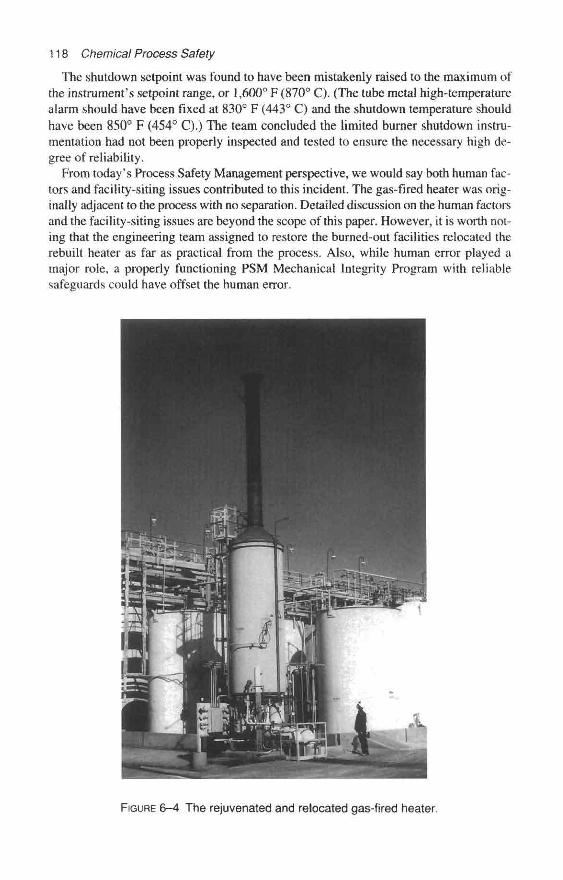
118 Chemical Process Safety
The shutdown setpoint was found to have been mistakenly raised to the maximum ofthe instrument's setpoint range, or 1,600° F (870° C). (The tube metal high-temperaturealarm should have been fixed at 830° F (443° C) and the shutdown temperature shouldhave been 850° F (454° C).) The team concluded the limited burner shutdown instru-mentation had not been properly inspected and tested to ensure the necessary high de-gree of reliability.
From today's Process Safety Management perspective, we would say both human fac-tors and facility-siting issues contributed to this incident. The gas-fired heater was orig-inally adjacent to the process with no separation. Detailed discussion on the human factorsand the facility-siting issues are beyond the scope of this paper. However, it is worth not-ing that the engineering team assigned to restore the burned-out facilities relocated therebuilt heater as far as practical from the process. Also, while human error played amajor role, a properly functioning PSM Mechanical Integrity Program with reliablesafeguards could have offset the human error.
FIGURE 6-4 The rejuvenated and relocated gas-fired heater.
One-Minute Modifications 119
Afterthoughts—What Would the OSHA's PSM Regulation Require?
In today's world, process safety engineers responsible for process areas covered bythe OSHA Process Safety Management standard would examine the facility for:
« Up-to-date operating procedures. Most of the chemical process operators had lessthan 18 months of service, and several sections of the unit did not have written op-erating procedures available.
* Critical process safeguards as alarms and trips. A Process Hazards Analysis mayhave questioned the lack of a loss of heat-transfer-fluid flow alarm and burner fir-ing shutdown for a flow loss condition.
• Some type of Management of Change evaluation. Such an evaluation should be per-formed if someone is considering an adjustment of alarm or shutdown setpoint.
* Tests and inspections. These would be conducted to ensure proper performance andproper setpoints of critical alarms and shutdown systems.
• Documentation. Written procedures for each inspection and test including trainingfor the mechanics.
The Wrong Gasket Material Creates Icicles in the SummerMolten caustic soda at about 700° F (370° C) sprayed and dripped for about 2-1/2
hours from elevated equipment in a well-maintained unit. The blistering hot causticsoda leak—discovered during the day shift—melted insulation on wiring and destroyedplastic electrical junction boxes and instrument control boxes. An estimated 15 tons(13,600 Kg) of material slowly leaked out of the concentrator. Caustic soda (about 98-percent strength) leaking from above formed icicles hanging from supporting structureand molten piles of material accumulated on the ground. It cost about $40,000 (U.S.!988) to clean up and recover from the damages. There were no injuries or environ-mental insults. (See Figures 6-5, 6-6, and 6-7.)
This situation was inadvertently created when someone installed a compressed as-bestos gasket (the nearly universal gasket for this chemical complex at that time) on athermocouple flange in the vapor space. Specifications dictated a metallic nickel gasket,but the compressed asbestos was installed in error.
The improper gasket may have been installed months or perhaps years before. Typi-cally this gasket is exposed to a high vacuum and caustic soda vapors. Unrelated prob-lems within the unit that day created a high liquid level in the vessel that exposed thegasket to atmospheric pressures and molten-liquid, 98-percent caustic soda.
A serious oil refinery fire resulted from the installation of the wrong gasket on a heatexchanger. The unit was operating normally, processing a very flammable naphtha forabout six weeks following an outage in which the exchangers were cleaned and tested. [4]
A spiral-wound metal asbestos gasket was required by specifications, but a compressedasbestos gasket was installed. The gasket failed causing a leak followed by a fire. Theheat from the initial fire caused an adjacent hydrogen exchanger flange to open. Vaporsflashed and impinged on an 18-inch (46 cm) hydrogen-oil line which then ruptured. Thispiping failure released oil and hydrogen under 185 psig (1275 kPa) pressure. [4] The fire
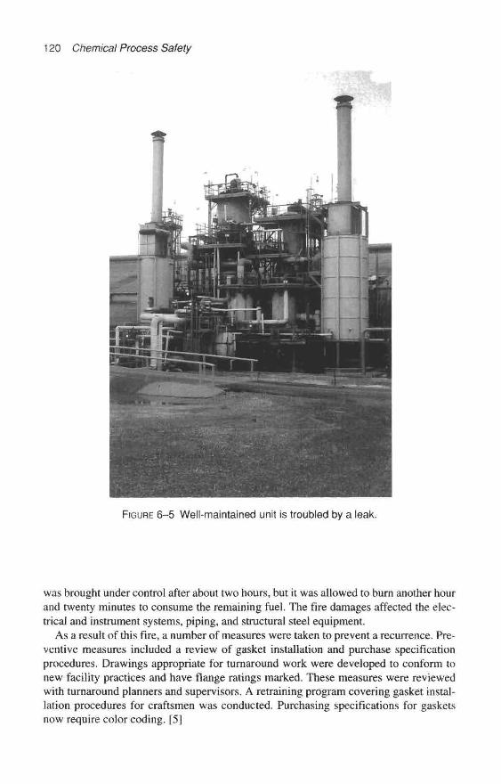
120 Chemical Process Safety
FIGURE 6-5 Well-maintained unit is troubled by a leak.
was brought under control after about two hours, but it was allowed to burn another hourand twenty minutes to consume the remaining fuel. The fire damages affected the elec-trical and instrument systems, piping, and structural steel equipment.
As a result of this fire, a number of measures were taken to prevent a recurrence. Pre-ventive measures included a review of gasket installation and purchase specificationprocedures. Drawings appropriate for turnaround work were developed to conform tonew facility practices and have flange ratings marked. These measures were reviewedwith turnaround planners and supervisors. A retraining program covering gasket instal-lation procedures for craftsmen was conducted. Purchasing specifications for gasketsnow require color coding. [5]

One-Minute Modifications 121
FIGURE 6-6 Molten caustic soda leaks from above due to an improper gasket.
FIGURE 6-7 Icicles are formed from leaking caustic soda that dripped from anevaporator flange.
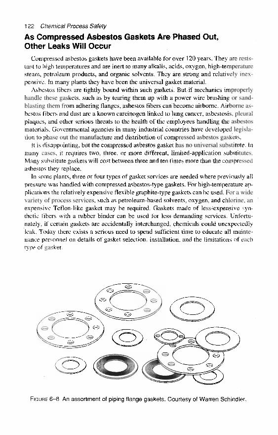
122 Chemical Process Safety
As Compressed Asbestos Gaskets Are Phased Out,Other Leaks Will Occur
Compressed asbestos gaskets have been available for over 120 years. They are resis-tant to high temperatures and are inert to many alkalis, acids, oxygen, high-temperaturesteam, petroleum products, and organic solvents. They are strong and relatively inex-pensive. In many plants they have been the universal gasket material.
Asbestos fibers are tightly bound within such gaskets. But if mechanics improperlyhandle these gaskets, such as by tearing them up with a power wire brushing or sand-blasting them from adhering flanges, asbestos fibers can become airborne. Airborne as-bestos fibers and dust are a known carcinogen linked to lung cancer, asbestosis, pleura!plaques, and other serious threats to the health of the employees handling the asbestosmaterials. Governmental agencies in many industrial countries have developed legisla-tion to phase out the manufacture and distribution of compressed asbestos gaskets.
It is disappointing, but the compressed asbestos gasket has no universal substitute. Inmany cases, it requires two, three, or more different, limited-application substitutes.Many substitute gaskets will cost between three and ten times more than the compressedasbestos they replace.
In some plants, three or four types of gasket services are needed where previously allpressure was handled with compressed asbestos-type gaskets. For high-temperature ap-plications the relatively expensive flexible graphite-type gaskets can be used. For a widevariety of process services, such as petroleum-based solvents, oxygen, and chlorine, anexpensive Teflon-like gasket may be required. Gaskets made of less-expensive syn-thetic fibers with a rubber binder can be used for less-demanding services. Unfortu-nately, if certain gaskets are accidentally interchanged, chemicals could unexpectedlyleak. Today there exists a serious need to spend sufficient time to educate all mainte-nance personnel on details of gasket selection, installation, and the limitations of eachtype of gasket,
FIGURE 6-8 An assortment of piping flange gaskets. Courtesy of Warren Schindler.

One-Minute Modifications 123
FIGURE 6-9 Choosing the proper piping gaskets with help fromeasy-to-understand gasket board.
Other Piping Gasket Substitution ProblemsA petroleum refinery was in the process of phasing out compressed asbestos gaskets
to conform to new U.S. laws. Asbestos gaskets had been used for years without any sig-nificant problems. During the conversion the company mistakenly assumed the non-asbestos substitute gasket would seal out the same fluids as the asbestos products if thegaskets were used within the manufacturer's temperature limitations.
Regrettably, a refinery worker was injured by sulfuric acid because a 4-inch (10 cm)piping substitute gasket failed. The acrylic fibers in the nonasbestos gasket material wereattacked by the acid. The asbestos fibers had resisted the chemical attack.
In a different chemical manufacturing company and at a different time, the introduc-tion of the wrong gasket into piping flanges extended a planned outage by an additionalweek due to an unplanned fire. A reactor was taken out of service for an outage and be-fore startup it was necessary to replace some 6-inch (15 cm) piping gaskets on the vessel.
The chemical plant stocked both a stainless steel spiral wound gasket with a flexiblegraphite filler and a similar spiral wound gasket with a micagraphite filler. The gasketslooked similar, but did have distinctive color-coding identification on the guide rings.The out-of-spec gasket was installed. As the reactor was being started up, flammable flu-ids leaked, then ignited. The resulting damage was severe enough to delay the startup bya week.
124 Chemical Process Safety
New Stud Bolts Fail Unexpectedly
Over 20 years ago, a thrifty purchasing agent for a large chemical complex was con-cerned about the high prices of stud bolts that were coated with a plastic-like finish to in-hibit rusting. He learned that cadmium-coated studs and nuts were available at moreeconomical prices.
Some cadmium-plated bolts and nuts were purchased and installed as a test in the plant.More bolts were purchased and eventually some of the cadmium-plated bolts were in-stalled on the outlet piping flanges of a cracking furnace. The high-temperature outletflanges on the furnace started to weep a bit. An experienced, intelligent pipefitter at-tempted to snug up a few bolts and the nuts crumbled. (The cause of the failure was laterdetermined to be due to corrosion phenomena called "liquid metal embrittlement.'*)
The alert mechanic informed the operations supervisors of the failures. Operationsshut down the furnace. Maintenance mechanics replaced the bolts with the properlyspecified, high-strength stud bolts prior to any serious releases.
If there are several grades of bolts, gaskets, tubing, and fittings available, and if in-terchanging these fairly low-cost items can result in leakage or loss of containment, thenonly the material that is suitable for all services should be stocked in the plant. A single,short-duration fire or hazardous material release in a chemical plant can easily wipe outmany years of savings realized by alternate lesser-quality bolts, gaskets, and fittings,
Hurricane Procedures Are Improperly Applied to a TankConservation Vent Lid
Hurricane winds and the accompanying intense, long-lasting showers frequentlythreaten U.S. Gulf Coast chemical plants. It is not unusual for an area to prepare for oneof these potentially dangerous stonn systems every few summers.
Some of the old-timers at this plant knew of myths or had perceptions that strongwinds associated with a hurricane could or would open top-mounted conservation vacuum/pressure lids on large atmospheric tanks. They believed strong winds would hold the lidsopen and torrential rains would enter the storage tanks contaminating a moisture-freeproduct. To protect certain low-moisture specification chemical products, a practice de-veloped to tether (or loosely tie down) the hinged vent lids for limited opening to allowmovement while reducing the chances of intrusion of rain. Apparently, the plant failedto train the individual who fully restrained a 24-inch (61 cm) lid before Hurricane Juanwas scheduled to hit land in 1985. [5]
Communication was poor in this instance. There was no reason to tie down this con-servation lid as this 100-ft (30 m) diameter tank was out of service, empty, and blindedon all process lines. Operations left the nitrogen-blanketing system in service with thenormal setting of about 0.5 oz/in2 gauge (22 Pa). The remote shipping tank remained inthat condition for several weeks.
A cold front passed through the area at the end of September. The nighttime temper-atures dropped to about 50° F (10° C) and the daytime temperatures rose to the high 80s(about 30° C). Assume that the nitrogen inerting system pressure was adjusted to 0.5oz/in2 gauge (22 Pa). Suppose the nitrogen in the tank cooled down to about 55° F(13° C) at the coolest part of the night. Now suppose the mid-day temperature within thetank reached 85° F (29.5° C). If the tank had a 0.5 oz/ingauge (22 Pa) at night then you

One-Minute Modifications 125
FIGURE 6-10 Hinged vent lid improperly tied to cope with anticipatedhigh winds and to prevent intrusion of rain.
FIGURE 6-11 Overpressure problems created by a one-minutemodification and changing weather.

126 Chemical Process Safety
FIGURE 6–12 Repairs in progress on a large tank.
could expect pressures of over 14 oz/in2 gauge (600 Pa) at mid-day in a leak-proof tanksystem. This 14 oz/in2 gauge pressure would have been nearly eight times the mechan-ical design pressure of the 100-ft. (30 m) diameter tank. [5]
The heat of the day warmed the gases and created damaging overpressure within thetank. Sun-heated, expanding gases damaged the cone roof and one portion of the upperadjacent side wall. Significant repairs were required including the replacement of sev-eral pieces of steel plate on the upper vertical wall and rewelding most of the seams onthe roof. Essential repairs to this tank cost nearly $56,000. (U.S., 1985) [5]
In specific, extraordinary situations it may be necessary to temporarily increase thesetpoint or bypass or deactivate some type of instrumentation or other equipment safe-guard. However, currently, this should only be done in an established manner, accordingto appropriate Management of Change procedures with proper approval. Furthermore,

One-Minute Modifications 127
any special defeat to a safeguard should be properly signaled for the operators and doc-umented in a special way. Operators and supervisors must regularly review any "out-of-cornpliance" log or alarm-point summary so that the defeated system can be properlyrestored at the earliest possible time.
Painters Create TroublesSandblasters and painters have occasionally produced troubles for chemical process-
ing by getting blasting sand or paint into moving parts of pump seals, safety-relief valves,or other equipment. Other problems include the predictable painting over of the sight
FIGURE 6–13 A threaded SRV valve reinstalled with a reduceddischarge piping arrangement.

128 Chemical Process Safety
glass windows or identifying tags. However, untrained or overzealous painters canalso create other problems when they paint over the fusible links of sprinkler heads orfire protective system pilot heads. An innocent-looking coat of paint quickly elevates thesprinkler head's melting temperature, and allows a fire's destructive temperatures to riseabove the specified detection level. Paint can hinder the release of the fire protection sys-tem signal air or hinder release of fire-water spray.
Pipefitters Can Create Troubles When ReinstallingRelief Valves
For totally unexplainable reasons, a mechanic reinstalled a small, threaded safetyrelief valve (SRV) using pipe fittings that reduced the discharge from 2-inch piping to1-1/2-inch piping. If this SRV were to relieve compressed air, then the back pressurewould cause it to rapidly slam shut. It would pop open again and quickly slam shutagain. Within a very short time the valve might self-destruct. (See Figure 6–13.)
There have been reports of unique and improper SRV discharge piping on threadedsafety valves. If the SRV discharge line runs horizontally and has a 90-degree ellmounted to provide a counterclockwise thrust, then SRVs have spun and unthreadedtheir way out of connecting nozzles.
Another Pipefitter's ErrorPipefitters have occasionally installed reverse buckling rupture discs upside down.
Depending on the rupture disc manufacturer's specifications, this usually means that thebursting pressure of the disc will be 50 percent higher than the manufacturer guaranteedas the relieving pressure. Such incidents must have happened at numerous plants andhave been whispered about, but seldom documented.
Process designer engineers often use rupture discs as the primary or secondary over-pressure devices on reactors, distillation columns, tanks, and piping. In many chemicalmanufacturing companies, rupture discs are installed upstream of SRVs, especially if thesystem contains corrosives, flammables, carcinogens, or toxic materials. The earlier de-signs of rupture discs allowed operation of the system up to 70 to 80 percent of the rup-ture disc rating by using a disc that was pre-bulged away from the pressure source.
Newer rupture disc designs, and especially "Reverse Buckling Types," allow opera-tion of pressures up to 90 percent of the rupture disc ratings resulting in fewer nuisance-premature failures and associated leakage. Reverse buckling discs are designed to beinstalled with the bulged surface projecting into the pressurized fluid. They are widelyused, but occasionally they are mistakenly installed upside down, which significantly in-creases the relieving pressure. To ensure the proper installation of rupture discs, theidentification tag must be visible when looking toward the pressurized system.
The simple error of installing a rupture disc upside down is easy to do in a minute ortwo and can jeopardize the integrity of the overpressure protection system. Rupture discmanufacturer's representatives are available to discuss proper handling with engineersand craftsman; such training can be very helpful.

One-Minute Modifications 129
FIGURE 6-14 Proper installations of a prebulged rupture disc and a reverse bucklingrupture disc. Courtesy of Jim C. Burns, Oklahoma Safety Equipment Company.
A Cooling Water System Is Safeguarded and an ExplosionOccurs Some Months Later
David Mansfield, in an article in the British Loss Prevention Bulletin, captures thefocus on the need for an effective Management of Change Policy in his introductoryparagraph: "Every once in a while an apparently subtle change to a process or methodof operation gives rise to a new or at least totally unexpected hazard." [6]
Management of a large research establishment was concerned that they should treattheir cooling water system, which was a part of their air conditioning system. The re-search organization wanted to prevent the dangers of the widely publicized incidents in-volving the legionella bacteria or Legionnaires Disease. Employees dosed the water inthe system with a suitable biocide. [6]
Some months after installing a biocide dosing system on the cooling water unit, oneof the dosing tanks overpressurized and ruptured. The explosion propelled the dosingliquids about 20 ft. (6 m) into the air. The unusually warm temperature of the tank wasa clue that some form of exothermic chemical reaction occurred. Samples analyzed ofthe liquids and gases in the vicinity revealed the presence of chlorine, bromine, and theiracid gases which were probably released during the explosion.
After the accident, the cooling water tests revealed 14-percent ethylene glycol (anti-freeze) in the system. Tests were conducted with the biocide and the ethylene glycol so-lution. Investigators learned that after a "dormant period" of several days, the temperatureof the mixture suddenly increased and the solution released bromine gas. Testing showedthat at elevated temperatures of about 140° F (60° C), the reaction occurred without thedelay.
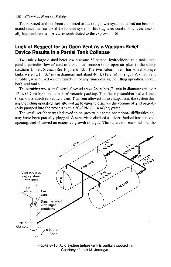
130 Chemical Process Safety
The raptured tank had been connected to a cooling tower system that had not been op-erated since the startup of the biocide system. This stagnated condition and the unusu-ally high ambient temperatures contributed to the explosion. [6]
Lack of Respect for an Open Vent as a Vacuum-ReliefDevice Results in a Partial Tank Collapse
Two fairly large dished head low-pressure 32-percent hydrochloric acid tanks sup-plied a periodic flow of acid to a chemical process in an open-air plant in the sunnysouthern United States. (See Figure 6-15.) The two rubber-lined, horizontal storagetanks were 12 ft. (3.7 m) in diameter and about 40 ft. (12.2 m) in length. A small ventscrubber, which used water absorption for any fumes during the filling operation, servedboth acid tanks.
The scrubber was a small vertical vessel about 28 inches (71 cm) in diameter and over12-ft. (3.7 m) high and contained ceramic packing. This flat-top scrubber had a 4-inch(6 cm) hole which served as a vent. This vent allowed air to escape from the system dur-ing the filling operation and allowed air to enter to displace the volume of acid periodi-cally pumped into the process with a 50-GPM (11.4 m3/hr) pump.
The small scrubber was believed to be presenting some operational difficulties andmay have been partially plugged. A supervisor climbed a ladder, looked into the ventopening, and observed an extensive growth of algae. The supervisor reasoned that the
Vent coveredwith a sheet
of plastic
28 in—diameter
4 invent
Small scrubberwith algaeproblems
6 in drainloop
FIGURE 6–15 Acid system before tank is partially sucked in.Courtesy of Jack M. Jarnagin.
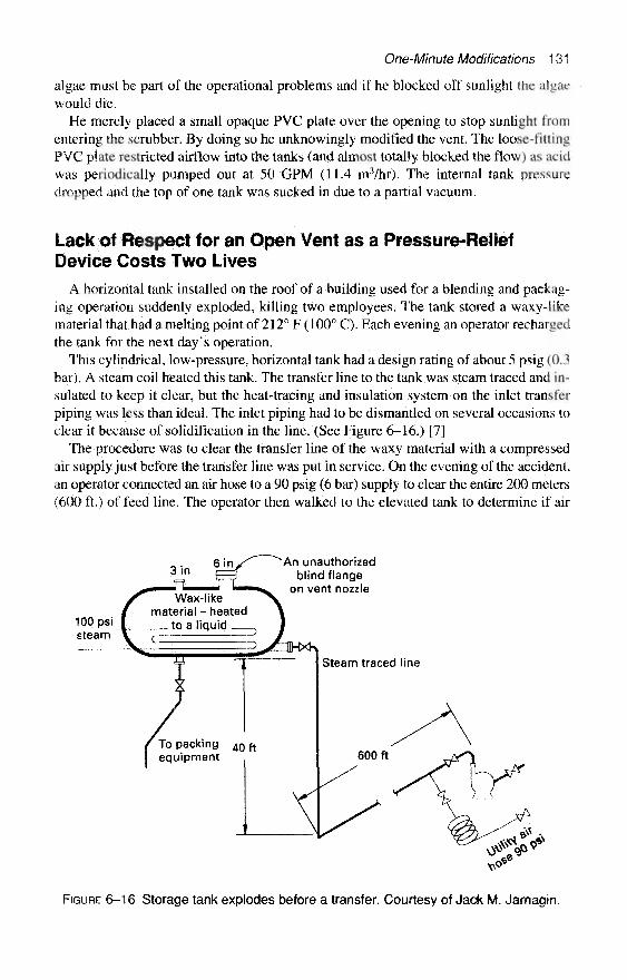
One-Minute Modifications 131
algae must be part of the operational problems and if he blocked off sunlight the algaewould die.
He merely placed a small opaque PVC plate over the opening to stop sunlight fromentering the scrubber. By doing so he unknowingly modified the vent. The loose-fittingPVC plate restricted airflow into the tanks (and almost totally blocked the flow) as acidwas periodically pumped out at 50 GPM (11.4 m3/hr). The internal tank pressuredropped and the top of one tank was sucked in due to a partial vacuum.
Lack of Respect for an Open Vent as a Pressure-ReliefDevice Costs Two Lives
A horizontal tank installed on the roof of a building used for a blending and packag-ing operation suddenly exploded, killing two employees. The tank stored a waxy-likematerial that had a melting point of 212° F (100° C). Each evening an operator rechargedthe tank for the next day's operation.
This cylindrical, low-pressure, horizontal tank had a design rating of about 5 psig (0.3bar). A steam coil heated this tank. The transfer line to the tank was steam traced and in-sulated to keep it clear, but the heat-tracing and insulation system on the inlet transferpiping was less than ideal. The inlet piping had to be dismantled on several occasions toclear it because of solidification in the line. (See Figure 6–16.) [7]
The procedure was to clear the transfer line of the waxy material with a compressedair supply just before the transfer line was put in service. On the evening of the accident,an operator connected an air hose to a 90 psig (6 bar) supply to clear the entire 200 meters(600 ft.) of feed line. The operator then walked to the elevated tank to determine if air
3 in
100 psisteam
Wax-likematerial - heated
to a liquid
An unauthorizedblind flange
on vent nozzle
Steam traced line
To packing 40 ftequipment
FIGURE 6–16 Storage tank explodes before a transfer. Courtesy of Jack M. Jarnagin.
132 Chemical Process Safety
could be heard rushing out of the tank vent. He heard nothing. The operator spoke to twomaintenance employees working near the end of the 20-m3 (700 ft3 or 5,300 gallon) tankand left the area to find his supervisor. Shortly after that, one end of the tank blew off,and the two maintenance mechanics plunged some 40 ft. (12 m) to their deaths. [7]
According to the engineering drawings, a 6-inch (150 mm) diameter open nozzlewas originally considered the tank vent. Over the seven years of operation, this 6-inchflange had been blinded and an unused 3-inch (75 mm) nozzle served as the vent. No oneknew when this "one-minute modification" had occurred. Experience elsewhere in thisplant with many similar products had established that a 3-inch vent hole could block solidwith this wax, but it was most likely that a 6-inch nozzle would not clog. [7] (See Fig-ure 6–16.)
Afterthoughts on Tank Vents via Open Nozzles
An open nozzle can be the primary relief device and should be treated with the samerespect as a safety relief valve. However, in the previous two incidents as well as thisone, open vents are not always treated with the same respect as SRVs. No competentprocess foreman or chemical process operator would dream of asking a fitter to replacea relief device with a smaller one without requesting that calculations be performed. [7]
An open vent that serves as a relief device should be registered for regular inspectionto be sure that it is not obstructed. It is also obvious that any open vent designed for over-pressure protection should not be designed so that it can be easily blinded. [7]
The Misuse of Hoses Can Quickly Create ProblemsHoses are essential within chemical plants. They are often necessary to purge vessels;
to wash vessels; and to load and unload trucks, rail cars, barges, and ships. Hoses helpto compensate for unavailable equipment, to prepare for maintenance, to safety-vent sys-tems, and similar tasks. When hoses are misused, many unpleasant things can occur—including some of the world's worst chemical plant accidents.
All plants have various utility fluids, such as well water, compressed air, low-pressuresteam, and nitrogen, and anyone who has opened a valve on a utility service expects theutility fluid to flow from the utility header and out the hose. However, if a utility hose isconnected to a higher pressure system and there aren't any check valves, undesirablechemicals can back into the utility system and exit in unexpected places.
Some of the Many Unpublished Errors Created with Hoses
Many stories have been repeated in control rooms and at inter-plant meetings where, dur-ing the 1960s and 1970s, flammables have backed into the nitrogen headers or wherecaustic soda, salt water, cooling-tower water, or other undesirable fluids have backed upinto the drinking water. One such 1960's incident involved a sandblaster using a hood re-ceiving breathing air from a plant compressed air network. This painter suddenly receiveda slug of ammonia-tainted air in his hood while working early one morning. The night be-fore this incident, the compressed air was being used to pressurize a large condenserwhich was about 4 ft. (1.2 m) in diameter and 30-ft. (9 m) long.
One-Minute Modifications 133
According to the ambiguous instructions written in the log for the operator, he shouldhave pressured up the ammonia condenser to compressed air system pressure. Next, heshould block off the air supply and discharge ammonia fumes into the atmosphere. Theoperator pressurized the ammonia-laden condenser to full air system pressure, but unfor-tunately did not block it off. Therefore at the beginning of the day when the arrivingmaintenance mechanics and operators put a high demand on the air system, the condenseracted as a surge tank. As the system pressure dropped, undesirable ammonia fumes trav-eled to the sandblaster's hood.
Another undocumented story concerns a dangerous quantity of hydrazine (a verytoxic vapor, corrosive to the skin and spontaneously igniting flammable liquid) backinginto a power plant's drinking water supply from a utility well water hose connected tothe boiler water treating system. This reportedly resulted in the hospitalization of a num-ber of power plant workers.
In another tragic incident, a piping contractor was completing a major modificationwithin a chemical plant. The role of this piping contractor was the fabrication and in-stallation of long runs of 24-inch (61 cm) diameter fiberglass headers. The contractorhad nearly completed the job and crawled through the piping for an inspection.
During this inspection the contractor recognized that additional fiberglass work wasrequired. These repairs would require grinding to properly finish one of the field-madejoints within this header. The contractor generally used a pneumatic grinder for thesetypes of repairs and this chemical plant was equipped with many compressed air utilitystations, which could be connected to nominal 3/4-inch (1.9 cm) hoses.
The unit was also engineered with several compressed nitrogen utility stations. Thenitrogen stations were equipped with different fittings (which were noninterchangeablewith compressed air) as a safeguard to prevent accidents. It seems that the contractorfailed to understand why a utility station had different fittings and modified what hethought was an "air" station to connect to a hose and a grinder.
Tragically, the repair job was many feet down the header, and the nitrogen-poweredgrinder exhausted into the confined space, asphyxiating the repairman. A well-intentioned,simple one-minute modification to piping by a small contractor cost the life of a coworker.
Some of the most tragic and well-remembered accidents also had a start with a mini-modification made with a hose connection. The Bhopal Tragedy, the Three Mile IslandIncident, and the Flixborough Disaster each was initiated by the improper use of hoses,
The Water Hose at the Flixborough Disaster
As discussed in the previous chapter, the explosion in the Nypro factory in Flixbor-ough, England, created a major impact on the entire chemical industry, and especiallythe European Chemical Industry. In short, this June 1, 1974, explosion was of warlikedimensions. The explosive energy was the equivalent to the force of 15 tons of TNT.Twenty-eight men perished at the plant and 36 other individuals suffered injuries. Outsidethe plant, 1,821 houses and 167 shops and factories suffered some degree of damage. [8]
Almost every discussion on the hazards of plant modifications uses this accident as anexample of the need to control plant modifications. The authors, almost without fail,center their attention on the 20-inch (500 mm) diameter piping that was improperly in-stalled to bypass the No. 5 Reactor which had developed a 6-ft. long crack. But the rea-son for the crack is usually just briefly mentioned.
134 Chemical Process Safety
Yes, a simple water hose or the temporary routing of cooling water to the stirrer glandof No. 5 Reactor was the precursory event of this tragedy. A hose routed a small streamof water to the gland to cool and quench a small cyclohexane leak. The cooling watercontained nitrates. Unfortunately nitrates encouraged stress corrosion cracking, whichcreated a crack on the No. 5 Reactor so that it had to be repaired. [8] Pouring water overequipment was once a common way of providing extra cooling, quenching, or absorp-sion of leaking material.
Hoses Used to Warm Equipment
Using a hose to pour water over certain equipment to warm the equipment or using ahose to route steam has also been successfully employed in many chemical plants. In aplant that required a small amount of chlorine gas from a ton cylinder, operators havepoured warm water over the vessel to slightly increase the chlorine vaporization rate.This has worked well for years.
However, there have been stories at inter-plant safety meetings that steam hoses cre-ated dangerous modifications. It seems that individuals, who were unfamiliar with one-ton chlorine cylinder design, placed steam hoses exhausting directly onto the portablecylinders to increase chlorine vaporization.
A chlorine cylinder design includes three fuse plugs (which melt at 165° F or 74° C)in each end. The heat from steam reportedly melted the plugs and the chlorine escapedthrough 3/8-inch (0.9 cm) diameter orifices. (See Chapter 3 for details.) (A tragedy alsooccurred when a steam hose was used on an ice cream refrigeration unit—see Chapter 4.)
Three Mile Island Incident Involved a Hose
At the Three Mile Island Nuclear Power Plant in Pennsylvania on March 28, 1979, ahose contributed to the front-page event. In short, a nuclear reactor overheated, a smallamount of radioactivity escaped, and the public confidence about the safety of nuclearpower was shattered. It is believed by the technical community that no one was likely tobe harmed by this release, but it led to a slowdown in the growth of nuclear power in theUnited States. [9]
Full details of this accident can be found in several major reports. This brief review isfocused on the utility hose and the one-minute modification aspects of the accident. Re-portedly the trouble started when one of the parallel paths used to treat the secondarywater system started plugging. When this resin polisher system, which is designed to re-move trace impurities, started to plug, an operator decided to clear the blockage with in-strument air. [9]
Clearing any system with instrument air as a pressure source is a bad idea. Otherpneumatic sources, such as utility air, plant air, or nitrogen, should be used instead. How-ever, the Three Mile Island instrument air was at a lower pressure than the water streamon the resin polisher system. Despite the presence of check valves, there was a reverseflow; water entered the instrument air system causing several instruments to fail, andthe turbine tripped. Through a series of other errors, the water covering of the radio-active core was uncovered, allowing an escape of a small amount of radioactivity. Dueto the widespread negative public reaction, the U.S. nuclear industry received a setback.If it were not for that improper hose connection or the erroneous one-minute modification,

One-Minute Modifications 135
it is unlikely that anyone outside of the Pennsylvania area would have heard of theThree Mile Island power station. [9]
The Bhopal Tragedy Was Initiated by Use of a Hose
The front-page and feature article of The Wall Street Journal in July 1988 explainedthe Union Carbide belief that a disenchanted worker initiated a one-minute plant modi-fication with a hose. The article [10] begins with these three paragraphs:
On a chilly winter night, a disgruntled worker at Union Carbide India Ltd. sneaksinto a deserted area of its Bhopal pesticide plant where storage tanks hold thou-sands of gallons of a toxic chemical.
He removes a pressure gauge on one tank, attaches a water hose to the openingand turns on the faucet. Two hours after he steals away, a calamity he never fore-saw begins unfolding. The tank rumbles. Vapors pass into a vent tower. A largecloud of poison gas drifts out into the night.
Such a chain of events, Union Carbide Corp. believes, explains the gas leak thatkilled 2,500 people and injured thousands more in Bhopal on Dec. 2 and 3, 1984.The company insists that sabotage—not sloppy corporate practices in the ThirdWorld—caused what has been called the worst industrial disaster in history.
Other news coverage or investigative reports do acknowledge the fact that the pres-ence of water in the system lead to runaway reactions. However, several other reportswere not able to identify the precise route for the entry of water.
One-Minute Modifications ReviewThe chemical industry has an excellent personal safety record because they approach
the majority of their activities with a great deal of discipline; but the general public haseven higher expectations of our industry. Significant process changes are being properlyreviewed at most chemical plant facilities. The industry must also be sure to addresschanges in the simple things—changes in lubricants, changes in gaskets, slight tamperingwith safety equipment, control of hose connections, and other day-to-day considerations.
Each plant must persistently train and create employee awareness of potential dangersfaced with even small changes that can be "easily" introduced into the plant. This mes-sage must be given not only to the engineers and supervisors, but also to the chemicalprocess operators and mechanics.
ReferencesThe majority of the material in this chapter was presented in a technical paper at the 25th An-
nual AIChE Loss Prevention Symposium in Pittsburgh, Pennsylvania, in August 1991. A paper en-titled "Mini Modification Miseries—Small Quick Changes in a Plant Can Create Bad Memories"was presented by Roy E. Sanders. About 75 percent of this chapter was published as an article en-titled "Small, Quick Changes Can Create Bad Memories" in Chemical Engineering Progress, May1992. The publisher, the AIChE, has given permission to freely use this material in this chapter.

136 Chemical Process Safety
1. Lorenzo, D. K., A Manager's Guide to Reducing Human Errors—Improving Human Per-formance in the Chemical Industry. Washington, D.C.: Chemical Manufacturers Association,July 1990, p. 16.
2. Sanders, Roy E., "Plant Modifications: Troubles and Treatment," Chemical EngineeringProgress, Feb. 1983, p. 76.
3. Sanders, R. E. and Wayne Spier, "Monday Morning Quarterbacking: Applying PSM Meth-ods to Case Histories of Yesteryear," Process Safety Progress 15, no. 4, Winter 1996, pp. 189–93.
4. Sanders, R. E., D. L. Haines, and J. H. Wood, "Stop Tank Abuse," Plant/OperationsProgress, Jan. 1990, p. 63.
5. American Petroleum Institute, "Safety in Unit Operations," Safety Digest of LessonsLearned, sec. 2. Washington, D.C., 1979, pp. 94–95.
6. Mansfield, D., "An Explosion in a Cooling Water System," Loss Prevention Bulletin 94,Aug. 1990, p. 25. Warwickshire, England: Institution of Chemical Engineers.
7. Kletz, Trevor A., Learning from Accidents in Industry. Guildford, U.K.: Butterworth Sci-entific, 1988, ch. 7.
8. Warner, Sir Frederick, "The Flixborough Disaster," Chemical Engineering Progress, Sept.1975, pp. 77–84.
9. Kletz, Trevor A., Learning from Accidents in Industry. Guildford, U.K.: Butterworth Sci-entific, 1988, ch. 11.
10. Hays, L. and Richard Koenig, "Dissecting Disaster," The Wall Street Journal, July 7,1988, p. 1.

CHAPTER 7
Failure to Use, Consult,or Understand Specifications
The value of up-to-date, practical specifications is well known to technical employeeswithin chemical plants. But at times, specifications are not properly maintained or per-sistently communicated to other members on the plant team, to equipment suppliers, orto construction crews. Many of the incidents covered in Chapters 2, 4, and 6 could alsobe repeated in this chapter. The incidents that follow occurred primarily because clear,concise specifications were either not readily available or because no one took the timeto consult these vital design or operating criteria.
Failure to Provide Operating Instructions Cost $100,000in Property Damages
Up-to-date standard operating procedures are now required by U.S. regulations for allchemical companies who handle significant quantities of highly hazardous chemicals.However, in the 1970s as chemical plants grew and grew, not all of them had up-to-dateprocedures to cover every unique situation.
An accidental fire interrupted the startup of a U.S. Gulf Coast plant during a cold win-ter morning. The plant experienced $100,000 (U.S. 1978) of property damages. All ittook to cause such extensive damage was less than 50 gallons (200 L) of combustibleheat transfer fluid.
Lack of operating instructions and lack of rigid operating discipline were major con-tributing elements in this accident. Quick, decisive, cooperative efforts between opera-tions and the emergency squad limited damages. Thankfully, there were no injuries.
Plans were underway to return a reactor to service. This gaseous phase reactor re-quires a startup temperature in excess of 500° F (260° C). A natural gas-fired heater pro-vides the heat energy to a circulating combustible heat transfer fluid and the heat transferfluid flows through the reactor tubes until startup temperature is reached.
The heat transfer piping system is not simple. There were three reactors and the heattransfer system was used for both heating and cooling the reactor. The circulating fluidheats the reactor to several hundred degrees Fahrenheit to start the reaction. Once thevery exothermic reaction is underway, the circulating heat fluid removes heat from thisreactor. (See Figure 7-1.)
137
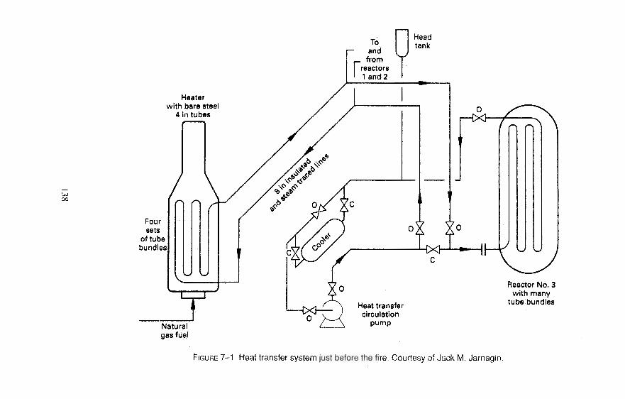
Headtank
Heaterwith bare steel
4 in tubes
Heat transfercirculation
pump
Foursets
of tubebundles
Reactor No. 3with many
tube bundles
FIGURE 7-1 Heat transfer system just before the fire, Courtesy of Jack M. Jarnagin.
Failure to Use, Consult, or Understand Specifications 139
The weather had been colder than usual at this outdoor Southern U.S. plant. Opera-tors were attempting to establish flow through the startup loop from the discharge of cir-culating pumps, through the gas-fired heater, through the reactor, and returning to thesuction of the circulating pumps. Despite their efforts, the operators could not establisha flow. (See Figure 7–1.)
The entire 8-inch (20 cm) piping system was insulated and steam traced except for theheater tubes within the heater. Operations assumed the heat transfer fluid froze in thefour heater tube passes. Each pass was a bare 4-inch (10 cm) diameter heater tube with5 bends and the equivalent of 72 ft. (22 m) of straight pipe. The foreman and the opera-tions team discussed the situation and decided to light and maintain a small fire on theburner to slowly thaw the material in the heater tubes. This method had been successfulfor a startup several weeks earlier.
About 8:30 A.M. the operator ignited the burner. He adjusted the fuel rate to producea flame between 12- and 24-inches (0.6 m) high. About 9:30 A.M., the operations foremanreturned to this busy control room and noticed that the natural gas flow to the heater wasnoticeably increased. Immediately, a team member cut the natural gas flow rate to aboutone-quarter of the existing flow.
Black smoke and fire from the heater stack were reported by a chemical process op-erator making his round at about 9:45 A.M. Nearby sprinkler systems activated, and theemergency squad was summoned. The emergency squad set up fire hose streams andbegan cooling down the heater structure. Within 15 minutes all external flames from theheater ceased, but black smoke continued to pour from the heater stack. A few minuteslater the fire flared up through the stack for about five minutes more.
The fire investigators could find no one, including the four operators, who wouldadmit to increasing the natural gas flow between 8:30 A.M. and 9:30 A.M. Regrettably,the flow recorder on the natural gas supply to the heater was not properly inking. There-fore none of the flow rates nor exact times of gas flow rate change could be establishedwith certainty.
It was easy to spot two failed tubes during an inspection of the heater after the fire.One of the 4-inch (10 cm) diameter tubes was swollen like a bubble with a split thatwas about 2.5-inches (6.4 cm) wide and 4.5-inches (11.4 cm) long. The other tube fail-ure was smaller. The failures were about 6 ft. (1.9 m) from the bottom bend of thetube.
What Did the Investigators Find?
The investigators concluded that the following items or conditions contributed to thecause of the fire.
• There were no written instructions for thawing out frozen tubes in the heater.• The operations crew was not fully aware of the hazards of lighting the main burner
before a flow through the heater was established.• The heater system was not engineered with the complement of flame management
and tube protection safeguards recommended by insurance guides.• The heater tubes had a carbon build-up inside the tubes which restricted flow to
some passes.• There was some external thinning of tubes in the higher heat flux zones.
140 Chemical Process Safety
Other Thoughts on FurnacesThe Institution of Chemical Engineers markets "Hazards Workshop 005," which is
entitled "Furnace Fires and Explosions." [1] One of the advertising leaflets for thisworkshop makes the following generalization:
Furnaces are comparatively simple items for a plant, and because they are unso-phisticated they tend to be imperfectly understood by operators and plant man-agers alike. Their tolerance to abuse is limited, and once abused their useful lifecan be drastically shortened. Worse still they may fail suddenly, since furnacetubes distort easily and then fracture. Such failure is often severe, with a conse-quential fire and/or explosion.
Low-Pressure Tank Fabrication SpecificationsWere Not Followed
Many vertical low-pressure storage tanks containing flammable or combustible liq-uids are designed with a weak weld seam on the wall-to-roof connection. This loss-prevention feature allows the roof to separate and peel back if an internal fire, an internalexplosion, or just a pneumatic overpressure situation occurs within the tank. If the roofrelieves or is blown off, the liquid is still contained within the walls if these tanks areproperly designed and fabricated. These conical roof tanks are often built to the Ameri-can Petroleum Institute's (API) Standard 650, "Welded Steel Storage Tanks."
There is one documented report that a welder had good intentions when he decidedthat the welding standard for the roof-to-wall seam was inadequate. This well-meaningwelder added a full strength weld to join the roof to the walls. [2] There were no reportedproblems on this tank, but the safety feature was rendered ineffective.
In another time and place, a lube oil tank experienced a dramatic failure of the wan-to-floor seam of an oil tank. A vertical lubricating oil storage tank, 19 ft. (6.1 m) in diameterand 24-ft. (7.4 m) high, failed catastrophically when it was accidentally overpressured withcompressed air injected into the tank. A stream of compressed air injected below the liq-uid level resulted in internal mixing within the tank. There were no injuries and no fire. [3]
Investigators found problems with the pressure-vacuum vent valve as well as con-cealed problems created by "nonspec" roof construction methods. The constructionmethod provided extra roof retaining strength. Although the roof-to-wall weld was cor-rectly finished, this safety feature's effectiveness was diminished due to some unex-plainable internal brackets that were not on the fabrication drawings. The wall-to-roofbrackets that strengthened the roof prohibited it from an easy separation. Instead of aweak roof tearing away with limited damages, the floor plate-to-wall seam ripped apart.Lubricating oil suddenly dumped all over the area. The bottom seam tear was so mas-sive that the lubricating oil instantly drained, creating a damaging vacuum on the tank.The side walls partially collapsed.
Explosion Relief for Low-Pressure TanksExplosion relief for vapor-air combustion within a closed-top, low-pressure tank can-
not be accomplished by customary tank conservation vents or other lightweight protec-tion. A well-written brief description of safety features of low-pressure tanks can be
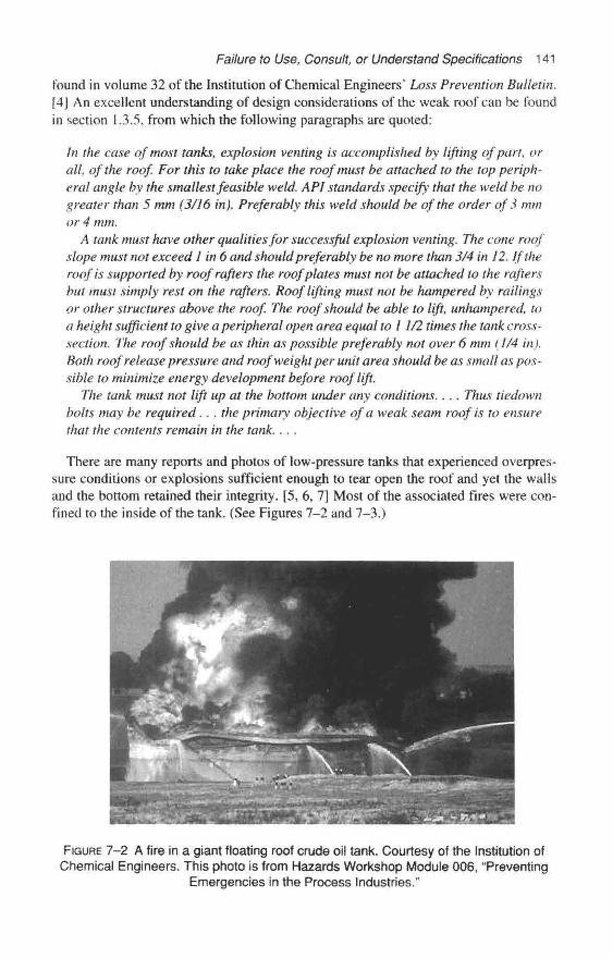
Failure to Use, Consult, or Understand Specifications 141
found in volume 32 of the Institution of Chemical Engineers' Loss Prevention Bulletin.[4] An excellent understanding of design considerations of the weak roof can be foundin section 1.3.5, from which the following paragraphs are quoted:
In the case of most tanks, explosion venting is accomplished by lifting of part, orall, of the roof. For this to take place the roof must be attached to the top periph-eral angle by the smallest feasible weld. API standards specify that the weld be nogreater than 5 mm (3/16 in). Preferably this weld should be of the order of 3 mmor 4 mm.
A tank must have other qualities for successful explosion venting. The cone roofslope must not exceed 1 in 6 and should preferably be no more than 3/4 in 12. If theroof is supported by roof rafters the roof plates must not be attached to the raftersbut must simply rest on the rafters. Roof lifting must not be hampered by railingsor other structures above the roof. The roof should be able to lift, unhampered, toa height sufficient to give a peripheral open area equal to I 1/2 times the tank cross-seel ion. The roof should be as thin as possible preferably not over 6 mm (1/4 in).Both roof release pressure and roof weight per unit area should be as small as pos-sible to minimize energy development before roof lift.
The tank must not lift up at the bottom under any conditions. . . . Thus tiedownbolts may be required. . . the primary objective of a weak seam roof is to ensurethat the contents remain in the tank. . . ,
There are many reports and photos of low-pressure tanks that experienced overpres-sure conditions or explosions sufficient enough to tear open the roof and yet the wallsand the bottom retained their integrity. [5, 6, 7] Most of the associated fires were con-fined to the inside of the tank. (See Figures 7-2 and 7-3.)
FIGURE 7-2 A fire in a giant floating roof crude oil tank. Courtesy of the Institution ofChemical Engineers. This photo is from Hazards Workshop Module 006, "Preventing
Emergencies in the Process Industries."

142 Chemical Process Safety
FIGURE 7-3 After the top opened, a fire burned but the liquid was still contained.Courtesy of the Institution of Chemical Engineers. This photo is from Hazards
Workshop Module 003, "Fires and Explosions."
Tinkering with Pressured Vessel Closure Bolts Ends witha Harmless Bang
In August 1992, within a U.S. chemical plant, a large mobile sandblasting potmounted on a four-wheel trailer sounded a harmless bang. The big pot experienced anunexpected failure of the 10-inch (25 cm) diameter quick-closure lid and a rapid de-pressurization. Damage was limited to the trivial loss of bolts and no one was injured.The vessel type is not a process vessel, nor is it covered by OSHA Process Safety Man-agement (PSM) regulations. However, the following cheap lesson offers an excellent ex-
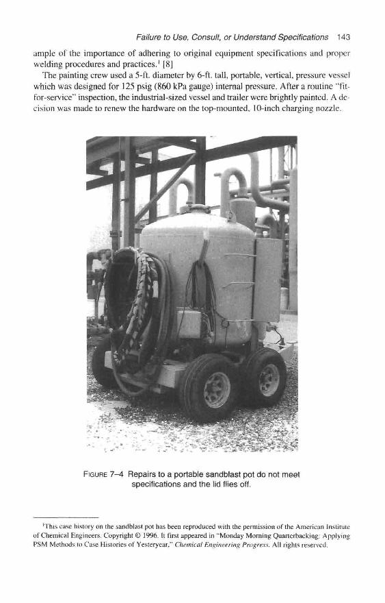
Failure to Use, Consult, or Understand Specifications 143
ample of the importance of adhering to original equipment specifications and properwelding procedures and practices.' [8]
The painting crew used a 5-ft. diameter by 6-ft. tall, portable, vertical, pressure vesselwhich was designed for 125 psig (860 kPa gauge) internal pressure. After a routine "fit-for-service" inspection, the industrial-sized vessel and trailer were brightly painted. A de-cision was made to renew the hardware on the top-mounted, 10-inch charging nozzle.
FIGURE 7-4 Repairs to a portable sandblast pot do not meetspecifications and the lid flies off.
'This case history on the sandblast pot has been reproduced with the permission of the American Instituteof Chemical Engineers. Copyright © 1996. It first appeared in "Monday Morning Quarterbacking: ApplyingPSM Methods to Case Histories of Yesteryear," Chemical Engineering Progress. All rights reserved.

144 Chemical Process Safety
Four eyebolts secured the quick-opening charging lid. The eyebolts had suffered ex-ternal corrosion, were thinning, and needed to be replaced. New eyebolts that fully metspecifications were ordered and received. A well-meaning but unenlightened individualdecided to expedite the job. He simply welded heat-treated B7 studs to the serviceable"eyes" instead of cutting the holding pins and replacing the entire set of eyebolts.
After the repairs, the painters started the portable air compressor. The pressure in thesand pot increased. Without warning, employees in the area heard a loud bang. Three ofthe four stud bolts (which were hardened and made brittle by the heat of the welding op-eration) snapped apart. The sand pot charging lid harmlessly flew open.
Fortunately, the lid was restrained by a short length of stout chain and did not rocketaway. A loud report and a swish was heard as the compressed air was harmlessly re-leased. If this unorthodox repair had been performed on a system containing a haz-ardous chemical, surely there would have been a lot more unwelcome problems. Goodmechanical integrity training and adherence to well-written repair procedures can helpprevent this type of predicament. (See Figures 7-4 and 7—5.)
Afterthoughts on a Cheap Lesson
You might ask, "What would the PSM regulation require?" A portable sandblast rigwould normally not be included in the covered process within a refinery or chemicalplant. But, a facility that had such PSM programs would probably have influence on themechanical integrity area that encourages strict adherence to welding procedures andemphasizes use of original manufacturers' methods and standards.
Piping Specifications Were Not Utilized
Piping system changes occur frequently within major chemical plants. This sectioncovers incidents involving piping changes in which piping specifications were notstrictly utilized.
A Small Piping Modification—for Testing the Line—Helped Createa Failure Point
Refinery employees observed a noticeable leak on a 1-inch (2.5 cm) connection abovea discharge header in a refinery. While carefully removing insulation around the leak tobetter observe the leak source, the mechanic aggravated the situation, and a threadednipple and valve blew off. A stream of hot oil slurry, 670° F (354° C), sprayed the areaand produced a dense cloud of heavy hydrocarbon mist. Oil sprayed over 90-ft. (27 m)high into the air and the mist covered an extensive area of the refinery. [9] Immediatelyafter the oil-mist cloud formed, operators initiated a shutdown of the unit, and the alertteam started the fire-water monitors. The hydrocarbon mist ignited about 10 minutesafter the threaded nipple blew off. Responders extinguished the blaze within about 90minutes. Luckily, only a portion of the total volume of escaping oil burned.
During a previous modification, a contractor installed the coupling and nipple forpipeline testing purposes. No refinery operating personnel were aware of this threadedconnection. Refinery piping specifications required the removal of any such nipple andback-welding of a threaded plug into the coupling before insulating the pipeline. [ 9]
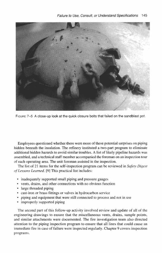
Failure to Use, Consult, or Understand Specifications 145
FIGURE 7-5 A close-up look at the quick closure bolts that failed on the sandblast pot
Employees questioned whether there were more of these potential surprises on pipinghidden beneath the insulation. The refinery instituted a two-part program to eliminateadditional hidden hazards to avoid similar troubles. A list of likely pipeline hazards wasassembled, and a technical staff member accompanied the foreman on an inspection tourof each operating area. The unit foreman assisted in the inspection.
The list of 21 items for the self-inspection program can be reviewed in Safety Digestof Lessons Learned. [9] This practical list includes:
• inadequately supported small piping and pressure gauges• vents, drains, and other connections with no obvious function• large threaded piping• cast-iron or brass fittings or valves in hydrocarbon service• piping and equipment that were still connected to process and not in use« improperly supported piping
The second part of this follow-up activity involved review and update of all of theengineering drawings to ensure that the miscellaneous vents, drains, sample points,and similar attachments were documented. The fire investigation team also directedattention to the piping inspection program to ensure that all lines that could cause animmediate fire in case of failure were inspected regularly. Chapter 9 covers inspectionprograms.

146 Chemical Process Safety
Correcting Piping Expansion Problems
A major food, detergent, and consumer products company had defined some pipingexpansion problems. The solution seemed obvious and several flexible elastomer ex-pansion joints were selected and installed to meet the process conditions within a soapmanufacturing plant. [10]
One of the expansion joints accidentally failed while being cleared with a steam sup-ply. Investigators determined the sponsors of this modification did not address the factthat sometimes process lines were blown clear with 150 psig (1,040 kPa gauge) steam.The robust piping system was compromised by an expansion joint that could not with-stand the heat. Fortunately, there were no injuries.
Failure to Follow Piping Specifications as Piping Supports Are Altered
The engineering team designed the reactor piping system to be able to handle the tem-perature extremes between pre-startup ambient temperature to operating conditions ofup to about 700° F (370° C). The piping had to be flexible and engineered with springsupports and expansion joints to minimize stress on equipment during the heat-up andcool-down. [ 1 1 ]
During the early years of operation the environment was hostile to most improperlypainted metals, and corrosion threats were everpresent. During the hectic pace of the1970s, the operations and maintenance team of the solvents' unit did not fully respect thenecessity of these spring hangers. As the spring hangers became impaired, plant main-tenance crews just removed the hangers and solidly supported the piping. [ 11 ]
This decision was a serious mistake. Many heat exchangers in this area were manu-factured of a very corrosion-resistant but brittle graphite material. Other problems inJanuary 1981 allowed a hot, vaporized, combustible heat transfer oil into the systemwhich normally only contained a nonflammable solvent and acidic gases. A graphitecondenser head fractured and a vapor cloud of combustible heat transfer fluid escaped,ignited, and resulted in an intense fire on an upper deck. There were no injuries, butproperty damages exceeded $500,000 (U.S., 1981).
The fire erupted late in the day shift. The incoming evening emergency squad quicklyresponded and assisted the day shift crew in supplying about 6,000 gpm (380 L/s) of firehose coverage in addition to fixed fire-water deluge systems. The fire was out in about25 minutes. (See Figures 7-6, 7-7, and 7-8.)
The small amount of maintenance required to remove the troublesome spring hang-ers was not considered a change, because the team did not understand the specifications.Trevor Kletz has often said, "People don't know what they don't know." Since peopledo not know (and cannot always remember) piping specifications, all specificationsmust be available and kept up-to-date.
Piping System Substitutions Damage a Six-Stage Centrifugal Compressor
A large six- stage dry chlorine centrifugal compressor was severely damaged duringa startup in 1990. Moisture entered this 9-ft. long piece of precision equipment andferric chloride corrosion products quickly formed which plugged up this machine,halting the production of over 600 tons per day of product.
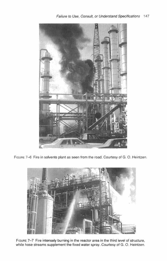
Failure to Use, Consult, or Understand Specifications 147
FIGURE 7-6 Fire in solvents plant as seen from the road. Courtesy of G. O. Heintzen.
FIGURE 7-7 Fire intensely burning in the reactor area in the third level of structure,while hose streams supplement the fixed water spray. Courtesy of G. O. Heintzen.

148 Chemical Process Safety
FIGURE 7-8 The emergency squad responding to a fire in the structure.Courtesy of G. O. Heintzen.
For a period of time just after startup, the upstream piping of this compressor operatedunder a vacuum. This upstream piping was equipped with a set of double block-and-bleed valves to a scrubber that circulated diluted caustic soda. During this unusualstartup configuration, moisture was sucked into the system and the wet chlorine com-pletely dissolved the stainless steel ball within the 3-inch (7.6 cm) quarter-turn valves,
The stainless valves were improper, but if they leaked slightly during normal opera-tion, dry chlorine would enter the scrubber and be harmlessly neutralized. However, dur-ing this startup with the piping under a vacuum, moisture from a slight leak managed tocombine with the dry chlorine and created an aggressive corrosive fluid.
The original project installed 3-inch (7.6 cm) Teflon-lined valve bodies and Teflon-lined plugs. Some of the supervisors seem to remember that the original valves were

Failure to Use, Consult, or Understand Specifications 149
very stiff to operate. It is believed that well-meaning individuals requested easier oper-ating valves, and no one worried about reviewing the plant specifications which were notalways up-to-date. Even if piping specifications were consulted, this 3-inch (7.6 cm)branch line on a 24-inch (61 cm) line was itself a plant modification that was not prop-erly authorized.
Substitute Piping Material Installed—Accelerated Corrosion/ErosionResults in a Large Fire
As was stated in Chapter 5, piping systems in many plants are generally more likelyto be ignored than other equipment such as furnaces, reactors, heat exchangers, and pres-sure vessels. The Institution of Chemical Engineers (U.K.) understands the problemsthat can occur in poorly designed, poorly operated, or poorly maintained systems. TheInstitution offers an awareness training package entitled, "Safer Piping," Module 012.This next example is a brief sketch of a very detailed piping failure and fire incident de-scribed in Module 012.
In August 1984, Coker 8-2 operated smoothly in a Canadian refinery until a piece ofpiping failed and a large fire broke out. The fire was so intense that it burned out of con-trol for two hours and took another two hours to extinguish it. Over 2,500 barrels of liq-uid hydrocarbon were lost during the fire. [12]
An 18-inch (450 mm) section of 6-inch (150 mm) diameter carbon steel fluid cokerpiping unexpectedly ruptured. The gross failure of this slurry recycle line allowed a highinitial release rate of hydrocarbons. A vapor cloud formed engulfing an area that in-cluded the light oil product pumps.
Ignition of the cloud occurred within a minute of the rupture. The rapid spread of thefire delayed containment and isolation. The unit suffered extensive physical damages,but no one was injured. [12] Much of the equipment at this Canadian refinery was se-verely damaged or destroyed. The damage estimate was over $76 million (U.S., 1984),[13]
Investigators determined that a carbon steel section of 6-inch (150 mm) line wasinstalled in an area in which specifications required corrosion-resistant 5-percentchromium—-1/2-percent molybdenum (generally called 5-chrorne) alloy piping. In aprocess plant like a fluid coker, the materials used are a mixture of carbon steel and othersteel alloys. Apparently, the welder and the maintenance crew, who previously repairedthis piping some time ago, were not aware of the piping specifications. Apparently, theydid not realize that if a material like carbon steel was installed in an area requiring 5-chrome alloy piping, erosion or corrosion could cause failure.
After this expensive incident, the company developed and implemented a safety man-agement system (which has elements of today's U.S. OSHA PSM Mechanical Integrityprogram) [ 12] to:
• provide positive material identification and to check the quality of all incoming ma-terial used for pressure containment systems in this process
• involve the plant inspection group to witness and recommend procedures in all re-pairs such as major piping replacements in safety critical containment systems.Their safety critical systems included high temperature, high pressure, and highlycorrosive applications.

150 Chemical Process Safety
provide ongoing training to ensure that plant personnel were aware of the need for the appropriate piping and equipment standards and specifications and understood how to find them.
Pump Repairs Potentially Endanger the Plant-But Are Corrected in Time to Prevent Newspaper Headlines Replacement Gaskets to Improve Personnel Safety Had the Potential to Downgrade Process Safety
Pumps typically require considerable maintenance, and modifications can be intro- duced accidentally. One type of misguided mini-modification (within a flammable liquids processing plant) was made in the name of employee industrial hygiene or safety. As a result of the U.S. regulations requiring the phaseout of asbestos gaskets, one employee decided to replace a number of asbestos pump bowl gaskets with low melting point Teflon-type nonasbestos gaskets. Some time later after several pumps had received the “fix,” a process safety professional advised that the replacement gasket compromised the “fire safe” design. Once this flaw in the substitution was identified, concerned main- tenance supervision quickly secured and installed gaskets meeting the fire safe design requirements.
Normal Maintenance on a Brine Pump
The impeller within a large sodium chloride brine pump in a closed loop system of a chlorine plant needed to be replaced. The job was not assigned to the regular mainte- nance crew, but was given to a crew who worked throughout a major chemical plant in areas that had a significant maintenance backlog. Pump specifications required that all wetted surfaces would be fabricated of titanium. However, the job was being manned with “outsiders” on an evening shift.
After the maintenance foreman searched for the appropriate titanium impeller and could not find one, he decided to improvise. The maintenance foreman located a stain- less steel impeller that was available for other pumps of the same size and manufacturer. He thought the stainless steel would be satisfactory, but would have a shorter life. The mechanics completed the job and the maintenance foreman went to eat an overtime sup- per at the plant cafeteria where he joined the operating foreman. The maintenance fore- man just happened to mention the problems he faced securing the specified impeller and his clever temporary approach to restore the pump.
After listening intently, the operating foreman explained that mere traces of chrome salts in the brine system could create an explosive situation within the electrolytic chlo- rine cells. Traces of chrome salts in the feed brine to the chlorine cells liberate hydrogen gas in the chlorine cell gas. Hydrogen in the chlorine cell gas has a very wide explosive range. Installation of stainless steel equipment in sodium chloride brine systems has dev- astated chlorine processing equipment within other similar chlorine manufacturing plants. The maintenance foreman had the improper pump impeller removed immediately before any problems occurred.
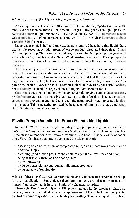
Failure to Use, Consult, or Understand Specifications 151
A Cast-iron Pump Bowl Is Installed in the Wrong Service
A flashing flammable chemical (that possesses flammability properties similar to bu-tane) had been manufactured in this new unit for just a few years. The liquid phase re-actor had a normal liquid inventory of 13,000 gallons (59,000 L). The vertical reactorwas about 9 ft. (2.74 m) in diameter and about 35-ft. (10.7 m) high and operated at about120 psig (826 kPa gauge).
Large water-cooled shell-and-tube exchangers removed heat from this liquid phaseexothermic reaction. A side stream of crude product circulated through a 12-inch(30 cm) piping loop. The system required large reactor circulating pumps designed witha 10-inch (25.4 cm) suction and an 8-inch (20.4 cm) discharge nozzle. These pumps con-tinuously operated to cool the crude product and to help mix the incoming gaseous rawmaterials.
After several years of operation, conditions warranted the replacement of a pumpbowl. The plant warehouse did not stock spare ductile iron pump bowls and none wereaccessible. A resourceful maintenance supervisor realized that there were a few otherlarge pumps within the plant and located one. Unfortunately, they chose a cast-ironpump bowl which is very desirable for certain sodium chloride (table salt) brine services,but it is totally unsuited for large volumes of highly flammable materials.
Cast iron is undesirable (and prohibited by certain flammable liquid codes) because abrittle fracture can lead to a massive leak. Some months after this mistake, the unit re-ceived a loss-prevention audit and as a result the pump bowls were replaced with duc-tile iron units. This same audit prompted the installation of remotely operated emergencyshut-off valves around these pumps.
Plastic Pumps Installed to Pump Flammable LiquidsIn the late 1980s pneumatically driven diaphragm pumps were gaining wide accep-
tance in handling acidic-contaminated water streams in a major chemical complex.These plastic pumps could be installed by sumps and handle a wide variety of condi-tions. Versatile plastic diaphragm pumps had the advantages of:
• operating on compressed air or compressed nitrogen and there was no need for anelectrical supply
• providing good suction pressure and could easily handle low-flow conditions.• being seal-less as there was no rotating shaft• being lightweight• being compact with no pump/motor alignment problems• being capable of running dry
With all of these benefits, it was easy for maintenance engineers to consider these pumpsfor many applications. Some plastic diaphragm pumps were mistakenly installed totransfer flammable liquids in several units of a chemical complex.
These Poly Tetrafloro-Ethylene (PTFE) pumps, along with the associated plastic ex-pansion joints, were installed because the sponsors were blinded by the advantages. Noone took the time to question their suitability for handling flammable liquids. The plastic
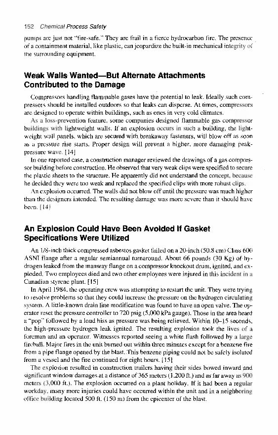
152 Chemical Process Safety
pumps are just not "fire-safe." They are frail in a tierce hydrocarbon fire. The presenceof a containment material, like plastic, can jeopardize the built-in mechanical integrity ofthe surrounding equipment.
Weak Walls Wanted—But Alternate AttachmentsContributed to the Damage
Compressors handling flammable gases have the potential to leak. Ideally such com-pressors should be installed outdoors so that leaks can disperse. At times, compressorsare designed to operate within buildings, such as ones in very cold climates.
As a loss-prevention feature, some companies designed flammable gas compressorbuildings with lightweight walls. If an explosion occurs in such a building, the light-weight wall panels, which are secured with breakaway fasteners, will blow off as soonas a pressure rise starts. Proper design will prevent a higher, more damaging peak-pressure wave. [14]
In one reported case, a construction manager reviewed the drawings of a gas compres-sor building before construction. He observed that very weak clips were specified to securethe plastic sheets to the structure. He apparently did not understand the concept, becausehe decided they were too weak and replaced the specified clips with more robust clips.
An explosion occurred. The walls did not blow off until the pressure was much higherthan the designers intended. The resulting damage was more severe than it should havebeen. [14]
An Explosion Could Have Been Avoided If GasketSpecifications Were Utilized
An 1/8-inch thick compressed asbestos gasket failed on a 20-inch (50.8 cm) Class 600ASNI flange after a regular semiannual turnaround. About 66 pounds (30 Kg) of hy-drogen leaked from the manway flange on a compressor knockout drum, ignited, and ex-ploded. Two employees died and two other employees were injured in this incident in aCanadian styrene plant. [15]
In April 1984, the operating crew was attempting to restart the unit. They were tryingto resolve problems so that they could increase the pressure on the hydrogen circulatingsystem. A little-known drain line modification was found to have an open valve. The op-erator reset the pressure controller to 720 psig (5,000 kPa gauge). Those in the area hearda "pop" followed by a loud hiss as pressure was being relieved. Within 10–15 seconds,the high-pressure hydrogen leak ignited. The resulting explosion took the lives of aforeman and an operator. Witnesses reported seeing a white flash followed by a largefireball. Major fires in the unit burned out within three minutes except for a benzene firefrom a pipe flange opened by the blast. This benzene piping could not be safely isolatedfrom a vessel and the fire continued for eight hours. [15]
The explosion resulted in construction trailers having their sides bowed inward andsignificant window damages at a distance of 365 meters (1,200 ft.) and as far away as 900meters (3,000 ft.). The explosion occurred on a plant holiday. If it had been a regularworkday, many more injuries could have occurred within the unit and in a neighboringoffice building located 500 ft. (150 m) from the epicenter of the blast.

Failure to Use, Consult, or Understand Specifications 153
Investigations revealed that the specified gasket for this installation was a spiralwound asbestos-filled gasket with a centering ring. However, the maintenance person-nel did not know the specifications, as they recalled that a compressed asbestos fiber(CAP) gasket had been used for 7 or 8 years.
Typically at this plant, substitution of a gasket is authorized only after calculations en-sure that the substitution is acceptable. No calculations or authorizations were found,The substitution of a CAP gasket was probably intended as a one-time substitute and itwas replaced in kind on each turnaround that followed. The 1/8-inch CAF gasket wastheoretically acceptable in this service, but conditions would have required a full pres-sure test to ensure that the 24 bolts had sealed the gasket properly. Unfortunately, therisk of the gasket disintegrating under a high-pressure leak was not considered.
Another unauthorized modification contributed to the severity of the explosion be-cause well-meaning individuals did not understand the design specifications of the com-pressor shed. The compressor shed was originally designed as a roof over the equipment.Later gables and a wall were added, perhaps for increased comfort during winter oper-ations and maintenance. This additional degree of confinement served to reduce the dispersion rate of the hydrogen and to contribute to the energy of the explosion. [ 151
Surprises within Packaged UnitsSometimes equipment that is rented or purchased as a packaged unit allows "out-of-
spec" components to enter a chemical plant. Air compressor systems, refrigeration units,and boiler systems are prime examples of units that, if improperly specified, may allowout-of-spec elements into a refinery or chemical plant.
In years past, caustic soda plants generally prohibited the use of any aluminum partson any processing equipment, motors, instruments, etc., because aluminum is aggres-sively attacked by any fumes or drips of caustic soda. However, during a major expan-sion in the late 1960s, refrigeration units were purchased that were equipped with SRVsmade with aluminum bodies. During this very active period of construction, the projectengineers were relatively new and failed to consider the materials aspect. Several yearslater the aluminum SRVs were tested and found to be corroded shut.
Another example of out-of-spec equipment is the use of filters on a unit. Many pack-aged units are equipped with filter cartridge bodies that have zero corrosion allowanceand are not as robust as other equipment purchased for the process.
Review
Anyone who reads this chapter should have a clearer understanding of the need forand the value of well-maintained and up-to-date specifications.
References1. Institution of Chemical Engineers, "Furnace Fires and Explosions," Hazards Workshop
Module 005, Rugby, U.K. (available as a training kit with 23 35mm slides, booklets, teachingguides, and related materials).

154 Chemical Process Safety
2. Kletz, Trevor A., Critical Aspects of Safety and Loss Prevention. London: Butterworth,1990, p. 183.
3. Institution of Chemical Engineers, Loss Prevention Bulletin: Articles and Case Historiesfrom Process Industries Throughout the World 32, 1981: pp. 13–14.
4. Ibid., pp. 2–5.5. Sanders, R. E., D. L. Haines, J. H. Wood, "Stop Tank Abuse," Plant/Operations Progress
9, no. 1, Jan. 1990: pp. 61–65.6. Institution of Chemical Engineers, "Fires and Explosions," Hazard Workshop Module 003
(available as a training kit with 45 35mm slides, booklets, teaching guides, and related material).7. Institution of Chemical Engineers, "Preventing Emergencies in the Process Industries,"
Hazard Workshop Module 006 (available as a training kit with 60 35mm slides, a videotape, book-lets, guides, and other related teaching materials).
8. Sanders, Roy and Wayne Spier, "Monday Morning Quarterbacking: Applying PSM Meth-ods to Case Histories of Yesteryear," Chemical Engineering Progress 15, no. 4, Winter 1996: pp.192-93.
9. American Petroleum Institute, Safety Digest of Lessons Learned, "Section 2: Safety in UnitOperations," Washington, D.C., 1979, pp. 45–46.
10. Griffin, M. L., "Maintaining Plant Safety through Effective Process Change Control," 23dAnnual Loss Prevention Symposium, Houston: AIChE, 1989.
11. Sanders, R. E., "Plant Modifications: Troubles and Treatment," Chemical EngineeringProgress, Feb. 1983: pp. 76-77.
12. Institution of Chemical Engineers, "Safer Piping—Awareness Training for the Process In-dustries." Hazards Workshop Module 012 (available as a training kit with 105 slides, a video,teaching guide, and related material).
13. Mahoney, David, Large Property Damage Losses in the Hydrocarbon-ChemicalIndustries—A Thirty Year Review, 16th ed. New York: Marsh & McLennan Protection Consul-tants, 1995.
14. Kletz, Trevor A., Critical Aspects of Safety and Loss Prevention. London: Butterworth,1990, pp. 122, 123, 183.
15. MacDiarmid, J. A. and G. J. T. North, "Lessons Learned from a Hydrogen Explosion in aProcess Unit," Plant/Operations Progress, April 1989: pp. 96-99.
CHAPTER 8
"Imagine If" Modifications andPractical Problem Solving
"Imagine If" Modifications—Let Us Not Overexaggeratethe Dangers as We Perform Safety Studies
Jeff L. Joseck, Trevor A. Kletz, and an unknown author on the Internet each commu-nicate a different clever story within the first part of this chapter.
Jeff is a talented staff engineer employed by a major chemical plant in West Virginia;he has a solid background in Loss Prevention. Jeff Joseck's article was written to sparkinterest and discussion of process safety in safety meetings. It is also very skillfullyworded to spark readers into thinking about acceptable risks and minimal risks.
Trevor Kletz is the most published Loss Prevention Engineer of all time with nineprocess safety books and over 100 technical articles. Professor Kletz's topics in thischapter assume that some of the modern synthetic materials we use daily have been avail-able since the dawn of time and that some ordinary materials are being examined in a sortof hazards review session. These are Kletz's most classic, clever illustrations of how wecan sometimes be overzealous and too narrow in our focus on a problem.
All three of these short articles show that it is easy to overexaggerate the dangers ofunfamiliar conditions and it is also easy for us to forget that humans have learned to livecomfortably with many of the hazards that surround us. The author thanks both of thesewriters for their permission to freely copy their work.
This first article was originally published in 1976 in the Imperial Chemical IndustriesLimited (ICI) Safety Newsletter. It later appeared in Critical Aspects of Safety and LossPrevention [1] in 1990. It assumes that water, in the pure form, has been unknown—there are no seas, no rivers, no lakes—and it has just been discovered.
New Fire-Fighting Agent Meets Opposition—"CouldKill Men as Well as Fires"
ICI has announced the discovery of a new fire-fighting agent to add to their exist-ing range. Know as WATER (Wonderful and Total Extinguishing Resource), itaugments, rather than replaces, existing agents such as dry powder and BCF (orHalon in the United States) which have been in use from time immemorial. It is
155
156 Chemical Process Safety
particularly suited for dealing with fires in buildings, timber yards and ware-houses. Though required in large quantities, it is fairly cheap to produce and it isintended that quantities of about a million gallons should be stored in urban areasand near other installations of high risk ready for immediate use. BCF (Halon)and dry powder are usually stored under pressure, but WATER will be stored inopen ponds and reservoirs and conveyed to the scene of the fire by hoses andportable pumps.
Id's new proposals are already encountering strong opposition from safety andenvironmental groups. Professor Connie Barrinner has pointed out that, if anyoneimmersed their head in a bucket of WATER, it would prove fatal in as little as 3minutes. Each of Id's proposed reservoirs will contain enough WATER to fill halfa million two-gallon buckets. Each bucket-full could be used a hundred times sothere is enough WATER in one reservoir to kill the entire population of the UnitedKingdom, Risk of this size, said Professor Barrinner, should not be allowed, what-ever the gain. If WATER were to get out of control the results of Flixborough orSeveso would pale into insignificance by comparison. What use was afire-fightingagent that could kill men as well as fires?
A Local Authority said that he would strongly oppose planning permission forconstruction of a WATER reservoir in this area unless the most stringent precau-tions were followed. Open ponds were certainly not acceptable. What would pre-vent people falling in them? What would prevent the contents from leaking out? Atthe very least the WATER would have to be contained in a steel pressure vessel sur-rounded by a leakproof concrete wall.
A spokesman from the Fire Brigades said he did not see the need for the newagent. Dry powder and BCF (Halon) could cope with most fires. The new agentwould bring with it risks, particularly to firemen, greater than any possible gain.Did we know what would happen to this new medium when it was exposed to in-tense heat? It had been reported that WATER was a constituent of beer. Did thismean that firemen would be intoxicated by the fumes?
The Friends of the World said that they had obtained a sample of WATER andfound it caused clothes to shrink. If it did this to cotton, what would it do to men?
In the House of Commons yesterday, the Home Secretary was asked if hewould prohibit the sale of this lethal new material. The Home Secretary repliedthat, as it was clearly a major hazard, Local Authorities would have to take ad-vice from the Health and Safety Executive before giving planning permission. Afull investigation was needed and the Major Hazards Group would be asked toreport.
WATER is being marketed in France under the name EAU (Element Anti-feuUniversel).
A Process Safety Management QuizJeff Joseck is a staff engineer with Union Carbide. He developed this clever quiz and
kindly offered it for publication. It stimulates the Process Safety Engineer or the LossPrevention Engineer to think about acceptable and minimal risks. A few minor changeswere made in Jeff's quiz to better fit the style of this chapter.
"Imagine If" Modifications and Practical Problem Solving 157
A Process Safety Management Problem Is Presented to the Committee
Consider the following operation from the aspect of process safety. There is an ur-gency to conduct this operation in the plant tomorrow.
Basically, it is a transfer of flammable liquid to a tank. The liquid will be 40° F to50° F with a flash point below -20° F. The fluid's electrical conductivity is low enoughto create static.
The tank does not have an inert blanket. The tank is vented to the air and there was nota flame arrester installed on the tank.
The inlet connection is above the liquid level throughout the transfer and it cannot beeasily altered.
The tank is steel, but does not have fixed grounding; grounding is expected to be madethrough the transfer line/hose connection.
The receiver tank's liquid level indicator will not be in service during the transfer. Aseparate, high-liquid level switch is interlocked to stop the transfer when the tank is full.The quantity transferred can be monitored from the distribution system, but it will notbe specified.
Granted, these are not the safest conditions to make this transfer. But given these cir-cumstances, do you think it would be an acceptable risk to proceed tomorrow?
Did the Process Safety Committee Reject This Proposal?
If the committee said "No," here is more information to consider:
• The high-level interlock has proven to be reliable. There are claims it is function-ally tested at least once a week.
« The tank already contains a heel of the same material.• The transfer quantity is small (greater than 100 pounds but less than 1,000 pounds),
so it's more like drum filling than a tank transfer.• This tank has been filled with this material hundreds of times in the past, without
incident.• The Plant Manager, a forceful practical engineer, knows of this operation and con-
dones it.
Was This Procedure Judged to Be an Unacceptable Risk?
If you said "Yes," what exceptions to these conditions do you take when filling yourcar at the service station? The "transfer" described is actually the filling of a vehicle'sgasoline tank at the plant's pump.
The primary reason to oppose the "filling of the car's gas tank" (as it was deceptively,but accurately, described) is simply because it violates the safe practices that have beenadopted as standard. The initial question—"Would it be an acceptable risk?"—cannot beanswered "yes" based solely on the information given. One would need either to under-stand the physics, design standards, and routine testing that make "fill-up's" safe, or torely on history, which indicates low probability of incident. Without this knowledge, onewould have to be conservative and say that gas tank fill-up, as described, is not an ac-ceptable, safe practice.

158 Chemical Process Safety
The Purpose of This Quiz
This quiz was not intended to remotely suggest that plants discontinue inerting tankscontaining flammable liquids. It was not to suggest that we reevaluate the safety pre-cautions in our procedures and design criteria; conversely, this exercise emphasizestheir importance.
Process Safety Professionals must be adamant in their responsibility to understandand control process hazards to the best of their abilities. However such process safety in-dividuals have a second responsibility to recognize the difference between acceptableand minimal risk. The difference is a matter of ethics and economics.
Gullible Individuals Worried about "Dangerous" ChemicalsDid any of you sign the petition? (This appeared in my e-mail in the Fall of 1997.I
would love to give the credit to "Brian" the creator of this witty survey and the newsmedia that reported the article, but I am at a loss as to how to find him or the author ofthis short piece.)
Brian, a freshman at Eagle Rock Junior High, won first prize at the Greater IdahoFalls Science Fair on April 26. He was attempting to show how conditioned we have be-come to the alarmists practicing junk science and spreading fear of everything in our en-vironment. In his project he urged people to sign a petition demanding strict control ortotal elimination of the chemical "dihydrogen monoxide." And for plenty of good rea-sons, since reportedly:
* it can cause excessive sweating and vomiting* it is a major component in acid rain* it can cause severe burns in its gaseous state8 it can kill you if accidentally inhaled» it contributes to erosion* it decreases effectiveness of automobile brakes» it has been found in tumors of terminal cancer patients
It was reported that Brian asked 50 people if they supported a ban of the chemical.Forty-three said "yes," six were undecided, and only one knew that the chemical waswater. The title of his prize-winning project was, "How Gullible Are We?" He feels theconclusion is obvious.
New Fiber Production Methods QuestionedThe clever article2 that follows was composed by Trevor Kletz and appeared in an ICI
Safety Newsletter in December 1978.
2Note: The British spelling of the words center, civilization, inquiry, fiber, and industrialization were leftin this short article to preserve the authenticity of a respectable British review.

"Imagine If" Modifications and Practical Problem Solving 159
New Fibre Runs into Trouble—"Land Use Excessive, Waste DisposalImpossible"
The proposals by ICI and other chemical companies to invest millions of pounds inthe production of a new fibre are already meeting widespread opposition. Whilenylon and polyester and the other fibres which have been in use since the dawn ofcivilisation are manufactured in conventional chemical plants, the new fibre,known as WOOL (Wildlife Origin Oily Ligament) will be grown on the backs of aspecially developed breed of Ovis musimon.
Opposition to the new fibre centres on the extensive areas of land required forits production. While a million pounds per year of nylon or polyester can be pro-duced in a fraction of an acre, the same quantity of WOOL will require at least25,000 acres of good land or a larger area of hill land. This land will no longer beavailable for growing crops or for recreation.
For once the National Farmers' Union and the Ramblers' Association havecombined to oppose a development and a public enquiry will be necessary. TheRSPCA has protested at the 'industrialisation' of animals and has asked what willhappen if they break loose from their enclosures. Although Ovis musimon is docile,all animal species, even man, produce occasional aggressive individuals. Mean-while the garment industry has pointed out the importance of quality control andhas questioned whether the necessary consistency can be obtained in a so-called"natural" product.
It is assumed that chemical plant process workers will operate the production fa-cilities as they will replace plants traditionally operated by them. Assuming thatoperators will not be expected to walk more than 200 yards from the control room,the control rooms will have to be spaced 400 yards apart that is, one per 33 acres.Over 750 control rooms will be required for a million-pounds-per-year operation.Building costs will therefore be much higher than on a conventional plant, and maywell make, the new process uneconomic, especially now that control rooms arebeing made stronger than in the past.
The greatest opposition to the new fibre is the result of the waste disposal prob-lems it will produce. Vast quantities of excreta will be deposited by the animals andwill presumably have to be collected and dumped. Have the risks to health beenfully considered? Will decomposition produce methane and a risk of explosions?
What will happen when the animals become too old for productive use? It hasbeen suggested that they might be used for human food and it is claimed that theyare quite palatable after roasting. To quote the Director of the Centre for the Studyof Strategic Perceptions, "The suggestion is nauseating. Five thousand years afterthe dawn of civilisation and 200 years after the industrial revolution, we are askedto eat the by-products of industrial production. "
Practical Problem Solving
When trying to find the "best" approach for reviewing modifications, do not hesitateto seek out the most practical approach, even if others around you are choosing more aca-demic and laborious procedures. For example, some engineers have labored for days

160 Chemical Process Safety
developing fault trees and estimating failure rates to determine if a flame managementsystem is an acceptable risk. Other more practical individuals reach for recommendationsfrom the National Fire Protection Association and from industrial insurance companiesfor acceptable approaches for flame management systems. Some practical references arelisted in Chapter 12.
In some other instances, engineers have counted flanges on long and complicated pip-ing networks to help estimate potential leak sources. Their time would have been betterspent getting an estimate on the maintenance mind-set so as to determine what programswere in progress to reduce leaks by the everpresent threats of external corrosion.
Mr. Alexander Calandra, who in 1968 was a member of the department of physics atWashington University in St. Louis, Missouri, told a story of a physics student in a class-room setting. The student was mischievous and practical, but he was in an academic sys-tem that did not appreciate his unique abilities.
The Physics Student and His Mischievous Methods
This anecdote was adapted from Alexander Calandra's article entitled "Angels on aPin" [2J, which was an excerpt from his 1969 book, The Teaching of Elementary Scienceand Mathematics. Mr. Calandra was asked by another instructor to help referee the dis-puted grading on an examination question. The physics teacher believed his student de-served a zero for his answer. The student argued he should receive a perfect grade, butthe student felt the school was not interested in practical approaches to problems. Pre-viously, the instructor and student agreed that an impartial arbiter should review the ex-amination question and they chose Mr. Calandra. The arbitrator went to his colleague'soffice and read the test.
The disputed exam question was: "How is it possible to determine the height of a talibuilding with the aid of a barometer?" The student's written response was:
Take the barometer and a long rope to the top of the building. Tie the rope to thebarometer, and lower the barometer to the sidewalk. Measure the length of therope that hung down the side of the building, and that is the building's height.
Mr. Calandra argued with his colleague that the student provided an answer that wascomplete and correct, therefore it seemed to the referee that the student was entitled tofull credit. The troubled instructor cautioned Mr. Calandra that if he gave the student ahigh mark for this answer, then the student was eligible for a high grade for the physicscourse. The instructor was concerned that a high physics grade should mean the studentperformed commendably in the principles of physics, but this answer and several otherslike this one did not confirm that ability.
Mr. Calandra recommended to both the instructor and the student that the student begiven another opportunity at answering the same question while in the instructor's of-fice. Mr. Calandra advised the student that the answer must show some skill in physicsand a complete answer must be written in six minutes.
At the end of four or five minutes the student still had a blank piece of paper. Mr. Ca-landra asked if the student wanted to give up. The student responded, "No! I am just try-ing to decide which of my answers is the 'best' one." The student quickly scribbled:
"Imagine If" Modifications and Practical Problem Solving 161
Take the barometer and a stopwatch to the top of the building and lean over the edgeof the roof. Drop the barometer and measure the duration of its fall with the stop-watch. Then using the formula S = 1/2 a t2 to calculate the height of the building. "
The arbiter showed the answer to his colleague and the student received almost fullcredit for this answer.
After the grade of the student was established, Mr, Calandra was curious enough toquestion the student about the other answers he was considering. The student replied:
There are many ways to determine the height of a building with a barometer. Forexample, on a sunny day you can stand the barometer up and measure the shadowof the barometer and measure the shadow of the building. Using simple propor-tions the height can be calculated.
The student continued:
There is a very basic measurement procedure that would work very well. Set thebarometer at the base of the stairs and draw a line at the top. Walk up the stairs andmark off the length of the barometer as you climb. Count the number of marks andmultiply by the length of the barometer and that is the height of the building.
A more sophisticated approach would be to tie the barometer to a string. Swingit as a pendulum. Calculate the value of "g " at the street and again at the top of thebuilding. From the difference between the two values of "g " the height of the build-ing, at least in principle, could be calculated.
The student smiled and stated that he knew the conventional atmospheric pressurecomparison answer, but that was neither the best practical answer nor the most accurateanswer. The student was asked: "What is the best approach?" The talented student mis-chievously replied:
The best and most accurate method to find out the height of the building is to takethe barometer to the building superintendent's door. Knock on the door and say,"Mr. Superintendent, I have this fine barometer to offer as a gift, if you will just tellme the exact height of the building." No answer can be better.
In our world we sometimes labor and struggle to determine a "best" answer, when asimple call to the building superintendent (the resource man) would quickly provide ac-curate information.
1. Kletz, Trevor A., Critical Aspects of Safety and Loss Prevention. London: Butterworth,1990, pp. 342–43.
2. Calandra, A. "Angels on a Pin," AIChE Journal 15 no. 2, 1969: p. 13 (excerpted from TheTeaching of Elementary Science and Mathematics, Ballwin, MO: ACCE Reporter, 1969).

This page intentionally left blank
CHAPTER 9
The Role of Mechanical Integrityin Chemical Process Safety
When handling significant quantities of highly hazardous chemicals, common sense andthe OSHA Process Safety Management standard require that there must be a formalmethod for effectively dealing with "mechanical integrity." Gaining a working under-standing of the requirements of the mechanical integrity element of the OSHA ProcessSafety standard has been troublesome to many companies. Compliance has been and con-tinues to be an exhausting challenge to some organizations.
The sections that follow offer a comprehensive view of mechanical integrity, com-plete with beneficial insights and practical details. Look forward to a chapter that:
• gives a working definition of mechanical integrity• provides key regulatory excerpts from the standard• highlights regulatory enforcement efforts and numerous OSHA citation statistics for
failure to comply with mechanical integrity regulations• offers an industry view of mechanical integrity and details on inspections and tests• defines vital hazard classifications of equipment• covers mechanical integrity programs for pumps and compressors, including vibra-
tion monitoring programs• covers mechanical integrity programs for piping, pressure vessels, storage tanks,
and process piping, including corrosion under insulation problems» covers mechanical integrity programs for safety critical instruments and safety re-
lief devices• provides numerous photos to illustrate various mechanical integrity activities• supplies a comprehensive listing of effective supplemental references if additional
resources seem desirable.
Mechanical Integrity in a Chemical PlantWhat does mechanical integrity mean in a chemical plant? One definition would be
using generally accepted and recognized good engineering practices to confidently contain
163

164 Chemical Process Safety
all the hazardous chemicals within the equipment and piping systems. This is achieved viastrong management support, written procedures, and practices:
• by designing to meet or exceed standards• by fabricating with proper materials, using proper construction and installation tech-
niques and confirming equipment suitability with tests• by ensuring that the equipment remains fit for service.
It is elementary that the equipment can only remain fit for service through effective,periodic inspection, testing, documentation, and restoration programs.
The Chemical Manufacturers' Association defines mechanical integrity as "the es-tablishment and implementation of written procedures to maintain the ongoing integrityof the process equipment." Mechanical integrity of process equipment is ensured througha documented program of procedures, training, inspections, and tests and throughpreventive/predictive maintenance based on good engineering practice, applicablecodes, standards, specifications, and manufacturers' recommendations.
A Regulatory View of Mechanical IntegrityThe term mechanical integrity became popular as a result of its use by the U.S. Oc-
cupational Safety and Health Administration (OSHA) in the 1992 standard on ProcessSafety Management of Highly Hazardous Chemicals. [1] The law, OSHA 1910.119,provides requirements for preventing or minimizing the consequences of catastrophicreleases of toxic, reactive, flammable, or other listed "highly hazardous" chemicals.The regulation requires inspection and testing of equipment using written proceduresand trained employees.
The federal standard regulates facilities that handle nearly 140 specifically listed, highlyhazardous chemicals (above a threshold quantity which is different for different sub-stances) and certain processes involving flammable liquids or gases in excess of 10,000pounds (4,540 Kg). While the law may not cover some highly toxic materials and flam-mables in quantities less than their threshold or 10,000 pounds for flammables, it does pre-sent a good benchmark for examining programs to ensure containment. The techniquesdiscussed in this chapter are not new, yet they are not universally used at this time.'
The Occupational Safety and Health Administration's Compliance Directive [3] iden-tifies the intent of a "Mechanical Integrity" program:
is to assure that equipment used to process, store or handle highly hazardouschemicals is designed, constructed, installed and maintained to minimize the riskof releases of such chemicals. This requires that a mechanical integrity program bein place to assure the continued integrity of process equipment. The elements of amechanical integrity program include the identification and categorization ofequipment and instrumentation, development of written maintenance procedures,
'Marcel Dekker, Inc., New York, kindly granted permission to use major selections from Chapter 12, en-titled "Mechanical Integrity" by Roy E. Sanders, of the Handbook of High Toxic Materials Handling and Man-agement (1995). [2]
The Role of Mechanical Ingegrity in Chemical Process Safety 165
training for process maintenance activities, inspection and testing, correction ofdeficiencies in equipment that are outside acceptable limits defined by the processsafety information, and development of a quality assurance program.
Mechanical Integrity Programs Must Be Tailoredto the Specific Site
An insightful Ian Sutton, in Process Safety Management, states, "The topic of me-chanical integrity is a very broad one. In spite of the fact that the title contains the word'mechanical,' it covers much more than mechanical engineering issues." The element re-quires input from a wide range of engineering, maintenance, process safety, and relia-bility disciplines. [4] Good mechanical integrity programs are usually very resourceintensive to develop and represent an ongoing expense to maintain. Although the lawhas been in effect for over six years, some organizations are still struggling to develop spe-cific mechanical integrity programs or are redeveloping their programs.
Mechanical integrity programs are "site specific." OSHA defines the requirements ofthis element of the Process Safety Management Law in about 350 words and yet, for mostcompanies, many years of engineering and maintenance work have been consumed try-ing to properly define and achieve the requirements. The procedures ought to be tailoredto the size of the facility, the management structure, the specific chemical processes, andthe specific equipment, as well as the engineering and maintenance resources. Some or-ganizations have in-house specialists such as certified safety relief valve (SRV) techni-cians, qualified metals inspectors, and experienced vibration technicians, and otherfacilities rely on the part-time services of contractors.
Mechanical Integrity in Design and InstallationThe term quality assurance appears in this section of the regulation. Quality assurance
specifically refers to new equipment. Mechanical integrity issues related to the initial de-sign of equipment, piping, and instrumentation design, as well as the construction andinstallation of equipment, is beyond the scope of this book and requires a library of ref-erences. If you need an overview look at design, consider reviewing the 1995 publica-tion Handbook of Highly Toxic Materials Handling and Management. [2] The handbookdevotes a chapter to design and operating considerations for process equipment. Thereis practical information on codes, corrosion basics, containment, inerting, as well as spe-cific information on various classes of equipment. The handbook also looks at designconsiderations for piping and instrumentation, providing good information on the basicscovering valves, gaskets, expansion joints, and design awareness concepts on instru-mentation. Finally, it addresses the storage of toxic materials and provides a compre-hensive look at the assessment of risk, "inherently safer" design, and other informationvital to a safe design.
In addition, the American Institute of Chemical Engineers publishes, Guidelines for SafeStorage and Handling of High Toxic Hazard Materials. [5] "Design of Storage and Pip-ing Systems," one of the chapters, provides information on vessel design, low-pressuretank guidelines, piping design, and other pertinent design considerations. It also presents

166 Chemical Process Safety
more than six pages of valuable references and 200 individual codes and standards—avaluable resource for new engineers. [5]
Equipment Covered by Mechanical IntegrityOSHA 1910.119 specifies that a mechanical integrity program must cover the fol-
lowing equipment:
* pressure vessels and storage tanks* piping systems including components such as valves* relief and vent systems and associated devices* controls including monitoring devices, sensors, alarms, and interlocks* pumps and compressors
The language of this element of the standard seems too stiff and vague—perhaps moreuseful to a courtroom lawyer than a practicing engineer working within a chemicalplant.
No doubt, the standard was intended to cover all components that handle highly haz-ardous materials. When the standard mentions pressure vessels and storage tanks, it nodoubt included much more. Surely the standard meant to include reactors, filters, fur-naces, boilers, other heat exchangers, surge bottles, knock-out pots, and other smallermiscellaneous containers common within the industry even if they were designed below15 psig (104 kPa gauge) or not as storage tanks. When piping is mentioned, it no doubtmeant the associated expansion joints, hoses, tubing, supports, and so forth. When thestandard mentions relief and vent systems, it no doubt meant ancillary equipment suchas scrubbers, flare stacks, incinerators, and similar equipment found on such headers.
Assuming that the original equipment design was acceptable, then the requirement forinspection, testing, and correction of the deficiencies is the heart of the mechanical in-tegrity standard. Any inspection and testing procedures used must follow the applicablemanufacturer's recommendations and/or the generally accepted good engineering prac-tices, guides, codes, as well as internal standards. The standard also specifies documen-tation of each inspection and test performed.
The Nonmandatory Appendix C provides compliance guidelines of the OSHA PSMstandard [1] that are much easier to understand than the standard itself (see page 6414in the Federal Register). Here is an extended quotation:
The first line of defense an employer has available is to operate and maintain theprocess as designed, and to keep the chemicals contained. This line of defense isbacked up by the next line of defense which is the controlled release of chemicalsthrough venting to scrubbers or flares, or to surge or overflow tanks which are de-signed to receive such chemicals, etc. These lines of defense are the primary lines ofdefense or means to prevent unwanted releases. The secondary lines of defensewould include fixed fire protection systems like sprinklers, water spray, or delugesystems, monitor guns, etc., dikes, designed drainage systems and other systemswhich would control or mitigate hazardous chemicals once an unwanted release oc-curs. These primary and secondary integrity lines of defense are what the mechan-ical integrity program needs to protect and strengthen these primary and secondarylines of defenses where appropriate.
The Role of Mechanical Ingegrity in Chemical Process Safety 167
The first step of an effective mechanical integrity program is to compile and cat-egorize a list of process equipment and instrumentation for inclusion in the pro-gram. This list would include pressure vessels, storage tanks, process piping, reliefand vent systems, fire protection system components, emergency shutdown systemsand alarms and interlocks and pumps. For the categorization of instrumentation andlisted, equipment the employer would prioritize which pieces of equipment requirecloser scrutiny than others. Meantime the failure of various instrumentation and.equipment parts would be known from the manufacturers' data or the employer'sexperience with the parts, which would then influence the inspection and testing f re -quency and associated procedures. Also, applicable codes and standards such as theNational Board Inspection Code, or those from the American Society for Testingand Material, American Petroleum Institute, National Fire Protection Association,American National Standards Institute, American Society of Mechanical Engineers,and other groups, provide information to help establish an effective testing and in-spection frequency, as well as appropriate methodologies,
Many of the detailed engineering aspects of mechanical integrity are covered by codesand standards generated by a wide variety of associations. Useful references not men-tioned in the OSHA excerpt above include those published by organizations such as theAmerican Institute of Chemical Engineers, the Chemical Manufacturers Association, theChlorine Institute, the Compressed Gas Association, and publications from variousproperty insurance associations.
The OSHA Law, a performance-oriented standard, allows employers to determinetesting criteria and to set criteria to judge the acceptance or failure of test results. If a testdetects a potentially hazardous condition, prompt corrective action is required.
Regulatory Enforcement of Mechanical Integrity
In 1995, OSHA issued more citations for mechanical integrity than for any other PSMelement, In 1996, the mechanical integrity was a close second to operating proceduresand just ahead of process hazards analysis. The May 1997 Chemical Process Safety Re-port [6] quoted Mr. John Miles, the Director of OSHA's Compliance Programs, as say-ing, "Operating procedures and mechanical integrity are two of the more important partsof the standard, and our people are looking for those violations."
The Chemical Process Safety Report reviewed the 1,296 citations issued under theOSHA Process Safety Management Standard in 1996. Oddly enough, chemical manu-facturing plants were not the usual target of the citations. The analysis showed more than75 percent of the companies cited for alleged PSM violations were NOT from the areas (orStandard Industrial Classifications Codes—SIC Codes) assigned to chemical producersor chemical users. Operating Procedures, Process Hazards Analysis, and the Mechani-cal Integrity elements of the standard had the highest number of citations in 1996.
The mechanical integrity element received 211 citations. Subsection j-2—"establish andimplement written procedures to maintain mechanical integrity of process equipment"—received the highest number (95) of citations followed by 39 citations in subsection j-4-i—"perform inspection and testing on process equipment within that element." Havingreadily available procedures is one of the main focal points for OSHA. Even if you aredoing the right things with regard to mechanical integrity, if you don't have a written

168 Chemical Process Safety
procedure, you can expect citations during an OSHA visit. Well-written procedures helpwith consistency as people move around in the organization.
An Industry View of Mechanical IntegrityMr. Ken Robertson, president of Exxon Chemical America, discussed "protective
programs" or "mechanical integrity" programs in a keynote address at the ChemicalManufacturers Association's Plant Inspection and Maintenance Forum in 1990. Indi-cating that public expectations are increasing, Mr. Robertson noted that there is less tol-erance for oil and chemical spills as well as tragic plant safety incidents. [7]
The Exxon president reviewed some of his company's process safety managementpractices relating to maintenance:
First, safety critical systems must be reliable. These systems control releases in theevent of accidents. It's necessary to have a critical analyzer, instrument and elec-trical system test program. This should consist of preventive maintenance and alarmand trip device testing for panel alarms, emergency isolation valves and other crit-ical components.
Also, procedures must be in place to control defeating safety critical systems.Before taking these systems out of service for any length of time, there must beproper authority, communication and detailed contingency planning.
Regular, comprehensive inspections to ensure the safe condition of site equip-ment is another important consideration. There must be clear lines of responsibil-ity for inspection and maintenance of crucial containment systems. A formal systemmust be in place for documenting recommendations and communicating themclearly and quickly to the appropriate managers in the organization.
We 're doing away with our traditional maintenance mindset of using heroicmeasures to fix something . . . our approach is to take ownership, to use predictivetools to get ahead of problems. . . .
In the past, some managers may have given mixed signals by praising actions takento keep production units onstream in the face of critical alarms being activated. All su-pervisors and managers must be careful not to praise actions that allow production tocontinue while in violation of recognized safe procedures.
Written Procedures and TrainingMechanical integrity procedures must be written in adequate detail to ensure that the
equipment receives prudent, appropriate, and periodically scheduled maintenance. Itwas noted above that OSHA issued a large number of citations for failure to have thewritten procedures.
The mechanical integrity procedures must also embody the safe work practices aswell as the detailed equipment procedures. Safe work practices include "Lock and Tag,""Confined Space Entry," "Welding, Burning and Open Flame," and similar essentialpersonnel safety procedures. Detailed equipment procedures include generic procedures,equipment specific procedures, and manufacturers' procedures.

The Role of Mechanical Ingegrity in Chemical Process Safety 169
Employees involved in maintaining the ongoing integrity of process equipment mustbe trained in an overview of the chemical process and its hazards. Employees also mustbe trained in the procedures applicable to the employees' job tasks, such as the safe workpractices discussed in the preceding paragraph.
Classification of Equipment by Hazard Potential
Chemical plant equipment—including tanks, pressure vessels, piping, rotating equip-ment, vent systems, and safety instrumentation—should be identified and categorizedaccording to different degrees of hazard potential. Classification systems could be sim-ple or very complex. A complex system could be a matrix of increasing severity ratingson one axis and the frequency of occurrence on the other axis. A simple identificationsystem could consist of three priorities such as:
Critical Consequences—Class 1. Containment equipment or the critical instrumentsserving that equipment whose failure would result in uncontrolled releases of dan-gerous materials, situations resulting in accidental fires or explosions, reportableenvironmental releases including closing of nearby highways or "shelter in place"for community members, personal injury, death, or major property or major pro-duction loss.
Tanks, pressure vessels, piping or rotating equipment containing highly haz-ardous or flammable chemicals are easily identified by experienced operations per-sonnel as "Class 1" equipment. These containment systems must be inspected insome effective manner on a priority basis.
Critical instruments assigned to "Class 1" include those necessary to avoid a fail-ure that may cause the perils listed above or instruments that fail to warn of upsetconditions that may result in perils. Testing of these instrument systems may bemandated by regulatory agencies, in-house technical safety review committees,HAZOP studies, or designated as critical by operations supervisors. All of theseshutdown systems and alarms must be prooftested in accordance with a properschedule. [8]
Serious Consequences—Class 2. Equipment or the critical instruments serving equip-ment whose failure could possibly cause, or fail to warn of upset conditions, un-controlled releases of dangerous materials, situations that could result in accidentalfires and explosions. Furthermore these failures could result in serious conditionsinvolving environmental releases, property or production losses, or other non-life-threatening situations. These particular pieces of equipment, the safety shutdownsystems and the alarms that serve this equipment are given a slightly lower prior-ity. However, they are also inspected, tested, or prooftested on a regular schedule,but may be allowed to have some leniency in compliance.
A Class 2 list might include equipment that typically does not contain highlyhazardous chemicals, but may under abnormal conditions contain such chemicals.It may also include utility systems such as cooling tower operations, compressed airor refrigeration systems whose failure could create significant upsets.
Normal Consequences—Class 3. All other containment equipment or instrumentationserving the operation whose failure could result in minor environmental releases,property or production losses, or injury to personnel or reduced economic life. It
170 Chemical Process Safety
may include less critical refrigeration systems, turbine overspeed trips, lubricationsystem alarms, and similar important, but not crucial, items.
These classifications should be considered when defining the level and frequency ofinspection and testing. There could also be some built-in tolerance or leniency for someoverdue "Class 2" and "Class 3" tests and inspections.
Mechanical Integrity Programs for Pumps/CompressorsWhen handling highly hazardous or flammable materials, it is obvious that the reliabil-
ity of critical rotating equipment, such as blowers, compressors, and pumps, is of extremeimportance. Rotating equipment with the highest consequence if a failure were to occur(Class 1 and Class 2 equipment) must have qualified personnel inspecting and testing inaccordance with written procedures. Mechanics may require specific skill training.
Rotating Equipment Invites Various Inspection Approaches
Inspections of rotating equipment could be accomplished by "Preventive MaintenancePrograms," which ensures that equipment and machine behavior follow some sort ofstatistical average based on weeks of operation or throughput in the process stream. Pre-ventive maintenance (PM) programs—the planned, periodic inspection of equipment—reduces the occurrence of unexpected problems. Preventive maintenance programs aremuch more efficient to conduct than the old-fashioned breakdown maintenance programsof previous years in which failures often occur at undesirable times, interfere with pro-duction, and may prove to be more costly to correct. [2]
PM programs require the equipment to be shut down at regular intervals and inspectedfor wear, cleanliness, and conformance to assembly and performance tolerances. PMprograms should detect small flaws before they grow into equipment problems which in-terfere with operation of the unit. The method can be satisfactory but can be expensiveif no flaws are detected. Despite having a good PM program, an abnormally prematurepart failure may not be detected before serious damage occurs. In addition, the PM in-spection process occasionally results in mistakes during the reassembly process. [2, 9]
Successful rotating equipment "Predictive Maintenance Programs" require several el-ements. Typical elements include an effective lubrication program with oil analysis todetect residual metal particles, thermography, machine monitoring instrumentation, re-pair specifications, repair history records, advanced training of mechanics, and the useof data management computers. [10]
Studies in the early 1980s reported predictive maintenance programs were more costeffective than the preventive maintenance programs. These studies showed that PM pro-grams cost about $ 11–$ 13 per horsepower of a machine, while a predictive maintenanceprogram cost $7—$8 per horsepower. [11]
Proactive and predictive maintenance programs were discussed in a Spring 1992 tele-phone survey of over 200 individuals from large industrial plants. Plant Services maga-zine published the results in a handbook in October 1992. [12] This survey establishedthat vibration analysis and oil analysis were the most frequently used predictive main-tenance monitoring techniques. Thermography was the third most popular approach.Ultrasonics and wear particle analysis (ferrography) were used regularly, although lessfrequently.
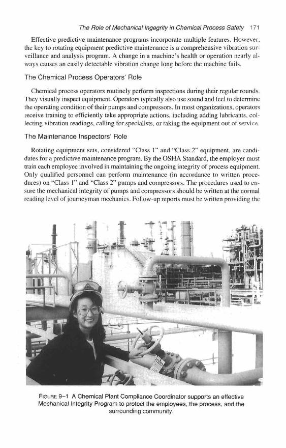
The Role of Mechanical Ingegrity in Chemical Process Safety 171
Effective predictive maintenance programs incorporate multiple features. However,the key to rotating equipment predictive maintenance is a comprehensive vibration sur-veillance and analysis program. A change in a machine's health or operation nearly al-ways causes an easily detectable vibration change long before the machine fails.
The Chemical Process Operators' Role
Chemical process operators routinely perform inspections during their regular rounds.They visually inspect equipment. Operators typically also use sound and feel to determinethe operating condition of their pumps and compressors. In most organizations, operatorsreceive training to efficiently take appropriate actions, including adding lubricants, col-lecting vibration readings, calling for specialists, or taking the equipment out of service.
The Maintenance Inspectors' Role
Rotating equipment sets, considered "Class 1" and "Class 2" equipment, are candi-dates for a predictive maintenance program. By the OSHA Standard, the employer musttrain each employee involved in maintaining the ongoing integrity of process equipment.Only qualified personnel can perform maintenance (in accordance to written proce-dures) on "Class 1" and "Class 2" pumps and compressors. The procedures used to en-sure the mechanical integrity of pumps and compressors should be written at the normalreading level of journeyman mechanics. Follow-up reports must be written providing the
FIGURE 9–1 A Chemical Plant Compliance Coordinator supports an effectiveMechanical Integrity Program to protect the employees, the process, and the
surrounding community.
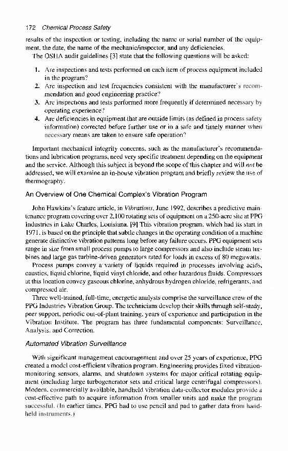
172 Chemical Process Safety
results of the inspection or testing, including the name or serial number of the equip-ment, the date, the name of the mechanic/inspector, and any deficiencies.
The OSHA audit guidelines [3] state that the following questions will be asked;
1. Are inspections and tests performed on each item of process equipment includedin the program?
2. Are inspection and test frequencies consistent with the manufacturer's recom-mendation and good engineering practice?
3. Are inspections and tests performed more frequently if determined necessary byoperating experience?
4. Are deficiencies in equipment that are outside limits (as defined in process safetyinformation) corrected before further use or in a safe and timely manner whennecessary means are taken to ensure safe operation?
Important mechanical integrity concerns, such as the manufacturer's recommenda-tions and lubrication programs, need very specific treatment depending on the equipmentand the service. Although this subject is beyond the scope of this chapter and will not beaddressed, we will examine an in-house vibration program and briefly review the use ofthermography.
An Overview of One Chemical Complex's Vibration Program
John Hawkins's feature article, in Vibrations, June 1992, describes a predictive main-tenance program covering over 2,100 rotating sets of equipment on a 250-acre site at PPGIndustries in Lake Charles, Louisiana. [9] This vibration program, which had its start in1971, is based on the principle that subtle changes in the operating condition of a machinegenerate distinctive vibration patterns long before any failure occurs. PPG equipment setsrange in size from small process pumps to large compressors and also include steam tur-bines and large gas turbine-driven generators rated for loads in excess of 80 megawatts.
Process pumps convey a variety of liquids required in processes involving acids,caustics, liquid chlorine, liquid vinyl chloride, and other hazardous fluids. Compressorsat this location convey gaseous chlorine, anhydrous hydrogen chloride, refrigerants, andcompressed air.
Three well-trained, full-time, energetic analysts comprise the surveillance crew of thePPG Industries Vibration Group. The technicians develop their skills through self-study,peer support, periodic out-of-plant training, years of experience and participation in theVibration Institute. The program has three fundamental components: Surveillance,Analysis, and Correction.
Automated Vibration Surveillance
With significant management encouragement and over 25 years of experience, PPGcreated a model cost-efficient vibration program. Engineering provides fixed vibration-monitoring sensors, alarms, and shutdown systems for major critical rotating equip-ment (including large turbogenerator sets and critical large centrifugal compressors).Modern, commercially available, handheld vibration data-collector modules provide acost-effective path to acquire information from smaller units and make the programsuccessful. (In earlier times, PPG had to use pencil and pad to gather data from hand-held instruments.)
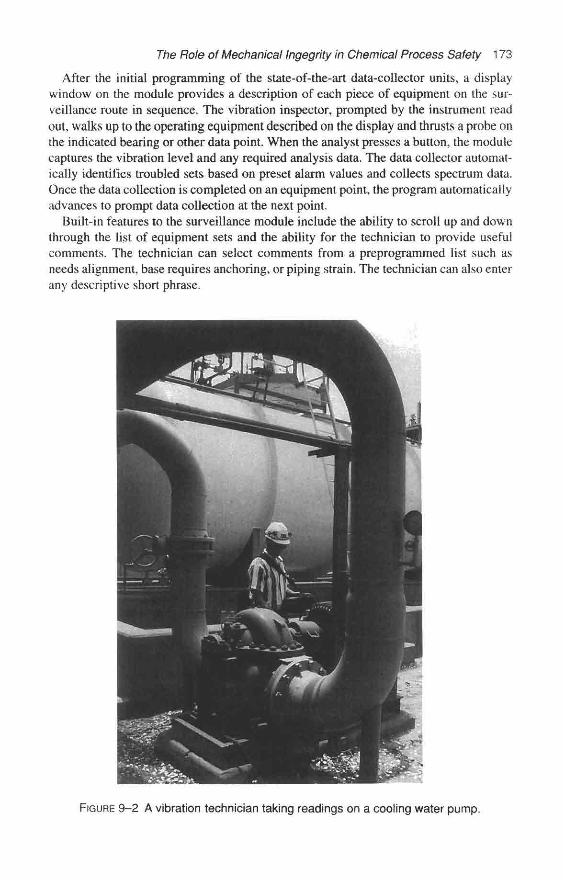
The Role of Mechanical Ingegrity in Chemical Process Safety 173
After the initial programming of the state-of-the-art data-collector units, a displaywindow on the module provides a description of each piece of equipment on the sur-veillance route in sequence. The vibration inspector, prompted by the instrument readout, walks up to the operating equipment described on the display and thrusts a probe onthe indicated bearing or other data point. When the analyst presses a button, the modulecaptures the vibration level and any required analysis data. The data collector automat-ically identifies troubled sets based on preset alarm values and collects spectrum data.Once the data collection is completed on an equipment point, the program automaticallyadvances to prompt data collection at the next point.
Built-in features to the surveillance module include the ability to scroll up and downthrough the list of equipment sets and the ability for the technician to provide usefulcomments. The technician can select comments from a preprogrammed list such asneeds alignment, base requires anchoring, or piping strain. The technician can also enterany descriptive short phrase.
FIGURE 9-2 A vibration technician taking readings on a cooling water pump.
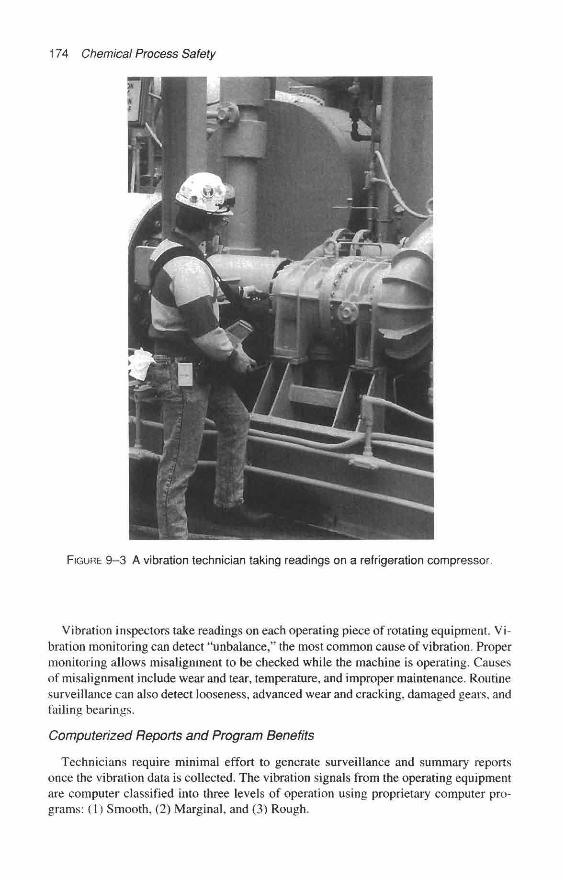
174 Chemical Process Safety
FIGURE 9-3 A vibration technician taking readings on a refrigeration compressor.
Vibration inspectors take readings on each operating piece of rotating equipment. Vi-bration monitoring can detect "unbalance," the most common cause of vibration. Propermonitoring allows misalignment to be checked while the machine is operating. Causesof misalignment include wear and tear, temperature, and improper maintenance. Routinesurveillance can also detect looseness, advanced wear and cracking, damaged gears, andfailing bearings.
Computerized Reports and Program Benefits
Technicians require minimal effort to generate surveillance and summary reportsonce the vibration data is collected. The vibration signals from the operating equipmentare computer classified into three levels of operation using proprietary computer pro-grams: (1) Smooth, (2) Marginal, and (3) Rough.

The Role of Mechanical Ingegrity in Chemical Process Safety 175
FIGURE 9–4 A close-up of a rotating machinery specialist with a vibration dataacquisition module.
The team generates two management reports. Vibration inspectors generate and dis-tribute detailed surveillance reports to the equipment owners and the area maintenancesupervisor so that corrective action can be planned. The inspectors also provide a sum-mary report for middle management.
The Vibration Inspectors at PPG-Lake Charles collect data on 27,000 data pointsfrom 2,100 equipment sets. The vast amount of data requires a Pentium computer witha 2-gigabyte hard disk to manage it. R. W. LeBlanc described the benefits of a proactivevibration program by citing a number of case histories (1985). His list of success stories[10] of a vibration surveillance and analysis includes:
• Postponing maintenance when it can be delayed safely. Certain costly steam turbine/generator units outages were scheduled every six years. With the data obtained
176 Chemical Process Safety
through vibration surveillance and analysis methods, the intervals between over-hauls were extended with the concurrence of the property insurance carrier.
« Focusing repair efforts to the source of the machine problems via vibration diag-noses so that repairs are effective and efficient. One service request for the vibrationtechnicians involved a 2QO-H.P. motor-driven, induced-draft fan. An area mainte-nance crew considered sending the large motor to a repair shop because they wereunable to get the system to operate smoothly. The vibration technician diagnosedthe problem as a simple imbalance in the fan, which was corrected easily with bal-ance weights.
9 Evading extensive damage and safety hazards by planning and scheduling machinerepairs as necessary, before complete failure.
* Verifying the quality of a machine overhaul. The vibration program can provide as-surances that the rotating equipment has been repaired correctly and that there areno residual problems.
• Identifying and communicating problems and solutions that are common through-out the plant complex.
Thermography Techniques for Rotatingand Stationary Equipment
During the 1960s, commercial thermography was very limited for plant operations.An instrument that weighed 85 pounds, required a 110-volt power supply, and wascooled by liquid nitrogen was the best equipment to produce a useful thermal picture.[13]
Significant technological advances made in infrared imaging systems over the pastdecades have made thermography a useful predictive maintenance tool. Nowadays,some infrared camcorder cameras weigh less than ten pounds. Quoting from a 1995Plant Services magazine article [14]:
The real power of thermography is that it allows us to quickly locate and monitorproblems, and present critical decision-making information in visual form makingit easy for management to understand. Infrared imaging systems, as they are gen-erally called, produce a picture . . . of the invisible thermal pattern of a componentor process. These thermal patterns, when understood, can be used to monitor op-erating conditions of equipment or processes.
All equipment, most processes, and most buildings have components at different tem-peratures that radiate invisible thermal or infrared energy. You can feel the heat in thenear vicinity of boilers, hot transformers, and hot motors. Thermography is a techniquefor producing pictures, called thermograms, from invisible infrared heat emissions.Good imaging systems in today's cameras can see temperature differences as small as1/2° F or less. Thermography is a noncontact means of quickly identifying electrical andmechanical components that are hotter than the expected normal temperature. [13, 14]
It is a unique experience to raise the sensitivity of the camera and see your fellow em-ployees on the screen with their temperature profiles. The instrument is so sensitive thateven a thermal handprint on the wall will remain visible a minute or so after the hand hasbeen removed.
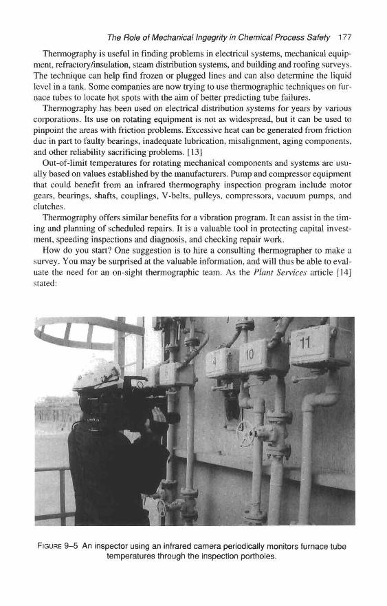
The Role of Mechanical Ingegrity in Chemical Process Safety 177
Therrnography is useful in finding problems in electrical systems, mechanical equip-ment, refractory/insulation, steam distribution systems, and building and roofing surveys.The technique can help find frozen or plugged lines and can also determine the liquidlevel in a tank. Some companies are now trying to use thermographic techniques on fur-nace tubes to locate hot spots with the aim of better predicting tube failures.
Thermography has been used on electrical distribution systems for years by variouscorporations. Its use on rotating equipment is not as widespread, but it can be used topinpoint the areas with friction problems. Excessive heat can be generated from frictiondue in part to faulty bearings, inadequate lubrication, misalignment, aging components,and other reliability sacrificing problems. [13]
Out-of-limit temperatures for rotating mechanical components and systems are usu-ally based on values established by the manufacturers. Pump and compressor equipmentthat could benefit from an infrared thermography inspection program include motorgears, bearings, shafts, couplings, V-belts, pulleys, compressors, vacuum pumps, andclutches.
Thermography offers similar benefits for a vibration program. It can assist in the tim-ing and planning of scheduled repairs. It is a valuable tool in protecting capital invest-ment, speeding inspections and diagnosis, and checking repair work.
How do you start? One suggestion is to hire a consulting thermographer to make asurvey. You may be surprised at the valuable information, and will thus be able to eval-uate the need for an on-sight thermographic team. As the Plant Services article j 14]stated:
FIGURE 9-5 An inspector using an infrared camera periodically monitors furnace tubetemperatures through the inspection portholes.
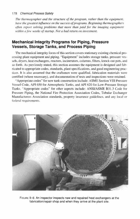
178 Chemical Process Safety
The thermographer and the structure of the program, rather than the equipment,have the greatest influence on the success of programs. Beginning thermographersoften report solving problems that more than paid for the imaging equipmentwithin a few weeks of startup. Not a bad return on investment.
Mechanical Integrity Programs for Piping, PressureVessels, Storage Tanks, and Process Piping
The mechanical integrity focus of this section covers stationary existing chemical pro-cessing plant equipment and piping. "Equipment" includes storage tanks, pressure ves-sels, dryers, heat exchangers, reactors, incinerators, columns, filters, knock-out pots, andso forth. As previously stated, this section assumes the equipment is designed and fab-ricated to appropriate codes, standards, plant specifications, and good engineering prac-tices. It is also assumed that the craftsmen were qualified, fabrication materials werecertified (where necessary), and documentation of tests and inspections were retained.
"Appropriate codes" for new tank construction include: ASME Section VIII PressureVessel Code, API 650 for Atmospheric Tanks, and API 620 for Low-Pressure StorageTanks. "Appropriate codes" for other aspects include: ANSI/ASME B31.3 Code forPressure Piping, the National Fire Protection Association Codes, Tubular ExchangerManufacturers Association standards, property insurance guidelines, and any local orfederal requirements.
FIGURE 9-6 An inspector inspects new and repaired heat exchangers at thefabrication/repair shop and when they arrive at the plant site.
The Role of Mechanical Ingegriiy in Chemical Process Safety 179
Corrosion under Insulation—A Legacy of Yesteryear
During the 1960s and 1970s, many plant designers were not concerned with the po-tential problems of corrosion under insulation. As a result, today's troublesome pittingor lamellar rusting of carbon steel, chloride stress corrosion cracking of austenitic stain-less steels, and other concealed metal loss can be found beneath insulation. This hiddenmetal loss may result in drips, spills, or ruptures, leading to environmental insults, re-leases of toxic materials, or conditions that allow significant quantities of flammables toescape and could result in fires or explosions.
Intruding water, ingress of acid vapors, and process spills are some of the menacesthat encourage corrosion problems on insulated equipment. Very few, if any, thermal in-sulation systems are completely waterproof, and the steel or alloy material covered byinsulation is intermittently wet and dry. Brackets that support insulated vessels or brack-ets on insulated vessels to support piping, ladders, or walkways can act as traps to col-lect water.
Engineers must take special care during the design stages and over the life of metal-lic equipment to reduce or eliminate the intrusion of water into the insulation by directopenings or by capillary action. The weather/vapor jacket covering the insulation pro-vides the primary barrier to rain, drips, and operator wash-down activities. This barriercan be destroyed by walking on piping, by poor maintenance, and by weathering.
In early designs, it was common to install thermal insulation over bare steel or over asingle coat of oil base primer. According to the National Association of Corrosion En-gineers (NACE) [15], the most serious corrosion problems seemed to be prevalent inplants with chloride-containing or sulfide-containing environments. These corrosionproblems were further aggravated in high rainfall, high humidity, and salt air locations.
NACE studies determined that the most severe corrosion problems occurred underthermal insulation at temperatures between 140° and 250° F (60° to 120° C) where thetemperatures were too low to quickly boil off any intruding water. At temperatures higherthan the boiling point of water, other corrosion problems can occur. The intruding watercan carry chlorides and other corrosive elements that can concentrate and result in stresscorrosion cracking. [15]
When serious corrosion was first noted, many engineers decided that better surfacepreparation and primer were needed. Inorganic zinc was then often selected and used toprime carbon steel, which was to be covered with thermal insulation. In the 1970s someU.S. Gulf Coast Corrosion Engineers noted that the presence of inorganic zinc seemedto accelerate corrosion.
A NACE task group reported in 1989 [15]:
• Inorganic zinc primers did not perform well under insulation, even if they were top-coated.
• Catalyzed epoxy coatings lacked sufficient high-temperature resistance to soakedinsulation for the long-term exposure.
• The best generic coatings for carbon steel that may be surrounded by wet insulationin the 140° to 250° F (60° to 120° C) range are the epoxy phenolic and the araine-cured coal tar epoxy formulations.
Chloride stress cracking corrosion was also a problem when austenitic stainless steelswere covered with thermal insulation. The NACE paper also discusses the protective

180 Chemical Process Safety
coatings for stainless steels and provides sandblasting and coating application guides forstainless and carbon steels.
To diminish the problems of corrosion under wet insulation within chemical plants,the design engineer, operator supervisor, and the maintenance foreman must focus oncertain practices, which include:
• Providing an appropriate coating system for all new installations.« Providing a periodic inspection of the piping or equipment in areas around poten-
tial points of moisture intrusion by removal of insulation.• Repairing mechanical damages to weather barriers and thermal insulation quickly.• Avoiding the use of zinc, cadmium, or zinc-rich coatings on austenitic stainless
steels. Even stainless systems operating at low temperatures can accidentally beheated by fire or welding repairs and can cause stress cracking.
• Becoming familiar with NACE Publication 6H189.
The degree and frequency of external inspection of equipment and piping under insu-lation is site specific. The API 570 Piping Inspection Code has added this note of caution:"The extent of a 'Corrosion Under Insulation Inspection' program may vary dependingon the local climate; warmer, marine locations may require a very active program,whereas cooler, drier, mid-continent locations may not need as extensive a program." [16]
Inspecting Pressure Vessels, Storage Tanks, and Piping
In some chemical plants, early inspection programs primarily addressed the corrosionand weld repairs of steels and alloys. However, inspections should also focus on theequipment's foundation, the connecting piping, exterior coatings, and insulation. Whensuch equipment is available, inspectors must also be capable of inspecting plastic (fiber-glass, ABS, PVC, Teflon-lined, etc.) vessels and piping. Specialty metal liners and Teflon,rubber, glass, or ceramic linings within reactors or tanks also need attention from qual-ified inspectors. The inspection function should be conducted and managed by person-nel who are independent of production, not unduly influenced by limited maintenancebudgets, and still have management's ear.
It is not the intent of this chapter to review in detail the types of inspection tools, tech-niques, and procedures. Recent American Petroleum Institute publications, available atmoderate costs, do an excellent job in that respect.
Inspection of Pressure Vessels and Storage TanksThe intent of the mechanical integrity section of the OSHA Process Safety Law is to
prevent or reduce catastrophic releases. [1] An equipment classification system is a re-quirement of the law. Earlier in the chapter, a simple system involving three classes wasdefined. Here are the highlights of that section specifically for pressure vessels and stor-age tanks.
Critical Consequences—Class 1. Containment equipment whose failure would resultin uncontrolled catastrophic releases of dangerous materials resulting in accidental
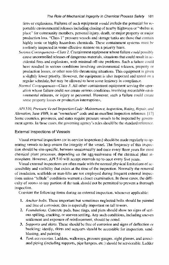
The Role of Mechanical Ingegrity in Chemical Process Safety 181
fires or explosions. Failures of such equipment would include the potential for rc-portable environmental releases including closing of nearby highways or "shelter inplace" for community members, personal injury, death, or major property or majorproduction loss. "Class 1" pressure vessels and storage tanks are those that containhighly toxic or highly hazardous chemicals. These containment systems must beroutinely inspected in some effective manner on a priority basis.
Serious Consequences—Class 2. Containment equipment whose failure could possiblycause uncontrolled releases of dangerous materials, situations that could result in ac-cidental fires and explosions, with minimal off-site problems. Such a failure couldhave resulted in serious conditions involving environmental releases, property orproduction losses, or other non-life-threatening situations. This equipment is givena slightly lower priority. However, the equipment is also inspected and tested on aregular schedule, but may be allowed to have some leniency in compliance.
Normal Consequences—Class 3. All other containment equipment serving the oper-ation whose failure could not create serious conditions involving recordable envi-ronmental releases, or injury to personnel. However, such a failure could createsome property losses or production interruptions.
API 510, Pressure Vessel Inspection Code: Maintenance, Inspection, Rating, Repair, andAlteration, June 1989, is an "owner/user" code and an excellent inspection reference. [17]Some countries, provinces, and states require pressure vessels to be inspected by govern-ment agents. In those cases, the governing agency's rules should be the standard reference.
External Inspections of Vessels
Visual external inspections (or in-service inspections) should be made regularly to op-erating vessels to help ensure the integrity of the vessel. The frequency of this inspec-tion should be site-specific, between semiannually and once every three years for mostchemical plant processes, depending on the aggressiveness of the chemical plant at-mosphere. However, API 510 will accept intervals up to once every five years.
Visual external inspections are often made with the normal physical limitations of ac-cessibility and visibility that exists at the time of the inspection. Normally the removalof insulation, scaffolds or man-lifts are not employed during frequent external inspec-tions unless "telltale" conditions warrant a closer examination. In those cases, the diffi-culty of access to any portion of the tank should not be permitted to prevent a thoroughinspection.
Consider the following items during an external inspection, whenever applicable:
1. Anchor bolts. These important but sometimes neglected bolts should be paintedand free of corrosion; this is especially important on tall towers.
2. Foundations. Concrete pads, base rings, and piers should show no signs of seri-ous spilling, cracking, or uneven settling. Any such conditions, including unevensettlement and exposure of reinforcement, should be noted.
3. Supports and skins. These should be free of corrosion and signs of deflection orbuckling; ideally, skirts and supports should be accessible for inspection, sand-blasting, and painting.
4. Tank accessories. Ladders, walkways, pressure gauges, sight glasses, and associ-ated piping (including supports, pipe hangers, etc.) should be serviceable. Ladder
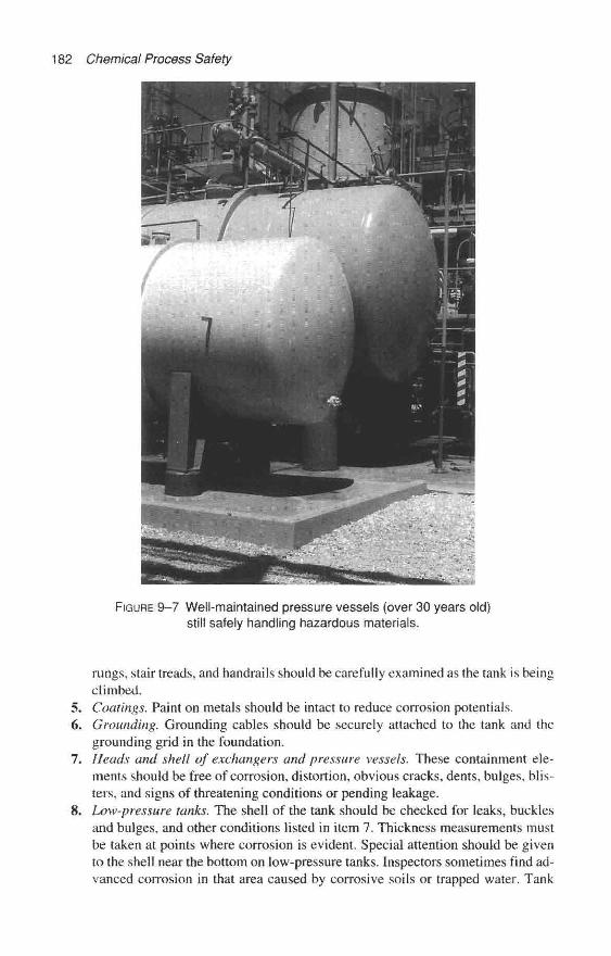
182 Chemical Process Safety
FIGURE 9-7 Well-maintained pressure vessels (over 30 years old)still safely handling hazardous materials.
rungs, stair treads, and handrails should be carefully examined as the tank is beingclimbed.
5. Coatings. Paint on metals should be intact to reduce corrosion potentials.6. Grounding. Grounding cables should be securely attached to the tank and the
grounding grid in the foundation.7. Heads and shell of exchangers and pressure vessels. These containment ele-
ments should be free of corrosion, distortion, obvious cracks, dents, bulges, blis-ters, and signs of threatening conditions or pending leakage.
8. Low-pressure tanks. The shell of the tank should be checked for leaks, bucklesand bulges, and other conditions listed in item 7. Thickness measurements mustbe taken at points where corrosion is evident. Special attention should be givento the shell near the bottom on low-pressure tanks. Inspectors sometimes find ad-vanced corrosion in that area caused by corrosive soils or trapped water. Tank

The Role of Mechanical Ingeghty in Chemical Process Safety 183
roofs also require detailed inspections. For safety's sake the inspector must exer-cise extra care to first establish that the roof will support his weight.
9. Fireproofing or insulation. Such barriers must be weather-sealed and intact toprevent collection and retention of moisture against metal surfaces that could cor-rode,
10. Nozzles, flanges, and valves. These components must be free of signs of corro-sion and leakage. All flange bolts should be installed and be of the correct diam-eter and length.
11. Relief devices/safety relief valves. Safety relief valves should be mounted in thevertical position. The ASME Code requires that the space between a combinationrupture disc mounted below an SRV must have a pressure gauge or other deviceto warn if the rupture disc is leaking.
In the event of detection, or suspicion of some form of corrosion or deterioration thatneeds further investigation, the inspector is encouraged to recommend more extensiveinspections or a different form of inspection.
Internal Inspections of Vessels
There is no good substitute for an internal inspection. Assuming the hazardous chem-ical residues can be easily removed, the internal inspection is easily accomplished andrelatively inexpensive. Internal inspections are essential to determine possible weaken-ing of the vessel or any conditions that may develop into unwanted leaks, because veryfew vessels experience uniform corrosion. Typically, internal inspections are estab-lished with frequencies between semiannually and once every ten years. The exact fre-quency is best determined by the corrosive nature of the chemical being processed orstored, including the effect of trace components and the history of this equipment.
Some companies are now using Risk-Based Inspections (RBI), especially for the costlypreparation efforts for internal inspections. RBI is a method that is gaining credibility andpopularity. Organizations calculate a proposed inspection frequency by considering theconsequences of failure (as described previously) and the likelihood of failure based onthe anticipated internal corrosion rates. The method employs a risk matrix.
An internal inspection provides a global view of the vessel. Visually "eyeballing" avessel can be much more revealing than any of the limited judgments based on thicknessreadings from the outside of the tank. Visual examination is usually the single most im-portant and universally accepted method used to ensure fitness of service of a vessel. Agood internal visual inspection should include examination of the shell and heads forcracks, blisters, bulges, operating deposits, corrosion products, erosive patterns, andother deterioration. In various aggressive chemical services, it is important to examinethe welded joint and the heat-affected zone for accelerated corrosion, cracks, and othermetal loss. Often the use of a bright flashlight placed parallel to the internal walls of avessel, shining away from the inspector, will help to visually identify metal loss or dis-tortion of the walls.
If the vessel is not insulated or does not have a liner, the wall thickness may be testedfrom either the outside or from within using a D-Meter. This tool can quickly and eas-ily measure the thickness of piping or a vessel wall. D-Meters are generally the inspec-tor's favorite tool. The name "D-Meter" is the technician's lingo for the simple handhelddigital ultrasonic thickness meter. Often corrosion patterns on vessels and equipment are

184 Chemical Process Safety
FIGURE 9-8 An operations foreman checks for blinding and samplesthe vessel's atmosphere before tank entry.
not uniform, so it is often best to check the thickness from the inside. Other inspectionmethods to ensure mechanical integrity of vessels may include magnetic-particle exami-nation for cracks at or near the metal surface, dye penetrate examination for disclosingcracks or pinholes that extend to the surface, radiographic examination, acoustic-emissiontesting, and pressure testing.
Pitfalls of Metal Ultrasonic Thickness Detectors
Many organizations rely heavily on the use of a D-Meter. D-Meter is a relatively in-expensive handheld digital display ultrasonic thickness gauge for determining the re-maining thickness of vessel walls and piping. Ultrasonic wall-thickness measurementsresemble radar or sonar in technique. A burst of ultrasound is emitted via a probe into amaterial and bounces off the rear wall. The time interval measured for this reflection toreturn is a measure of wall thickness.
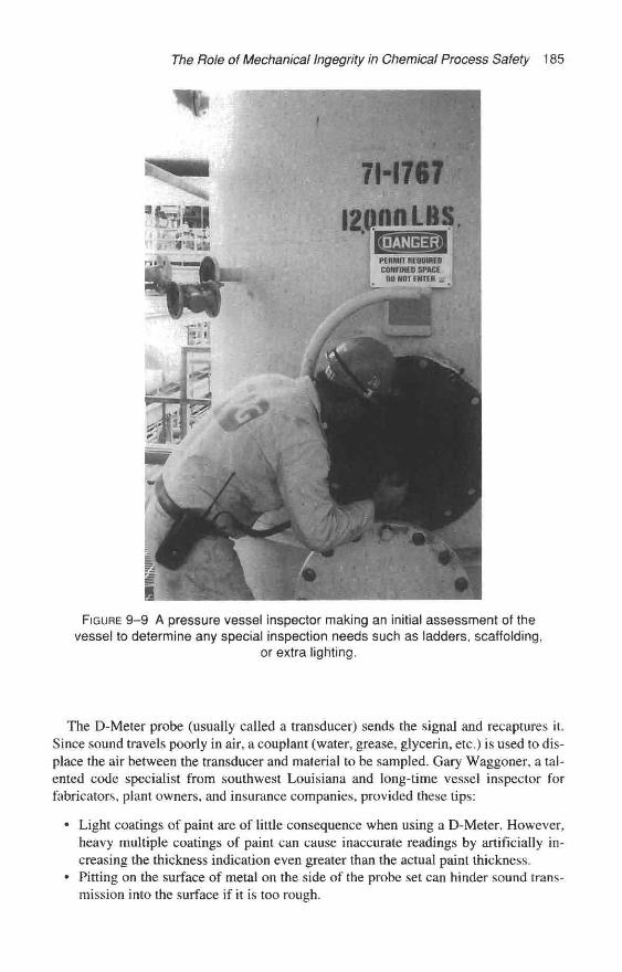
The Role of Mechanical Ingegrity in Chemical Process Safety 185
FIGURE 9-9 A pressure vessel inspector making an initial assessment of thevessel to determine any special inspection needs such as ladders, scaffolding,
or extra lighting.
The D-Meter probe (usually called a transducer) sends the signal and recaptures it.Since sound travels poorly in air, a couplant (water, grease, glycerin, etc.) is used to dis-place the air between the transducer and material to be sampled. Gary Waggoner, a tal-ented code specialist from southwest Louisiana and long-time vessel inspector forfabricators, plant owners, and insurance companies, provided these tips:
• Light coatings of paint are of little consequence when using a D-Meter. However,heavy multiple coatings of paint can cause inaccurate readings by artificially in-creasing the thickness indication even greater than the actual paint thickness.
* Pitting on the surface of metal on the side of the probe set can hinder sound trans-mission into the surface if it is too rough.
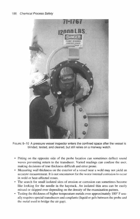
186 Chemical Process Safety
FIGURE 9-10 A pressure vessel inspector enters the confined space after the vesse! isblinded, tested, and cleared, but still relies on a manway watch.
Pitting on the opposite side of the probe location can sometimes deflect soundwaves preventing return to the transducer. Varied readings can confuse the user,making decisions of true thickness difficult and error prone.Measuring wall thickness on the exterior of a vessel near a weld may not yield anaccurate measurement. It is not uncommon for the worst internal corrosion to occurin weld or heat-affected zones.The search for small isolated sites of erosion or corrosion can sometimes becomelike looking for the needle in the haystack. An isolated thin area can be easilymissed or skipped over depending on the density of the examination pattern.Testing the thickness of higher temperature metals over approximately 180° F usu-ally requires special transducers and couplants (liquid or gels between the probe andthe metal used to bridge the air gap).
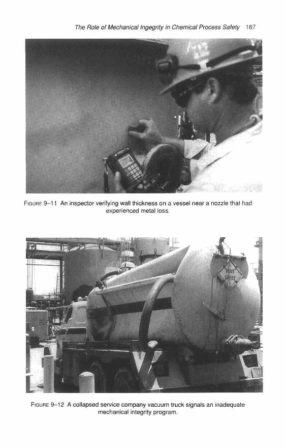
The Role of Mechanical Ingegrity in Chemical Process Safety 187
FIGURE 9–11 An inspector verifying wall thickness on a vessel near a nozzle that hadexperienced metal loss.
FIGURE 9–12 A collapsed service company vacuum truck signals an inadequatemechanical integrity program.
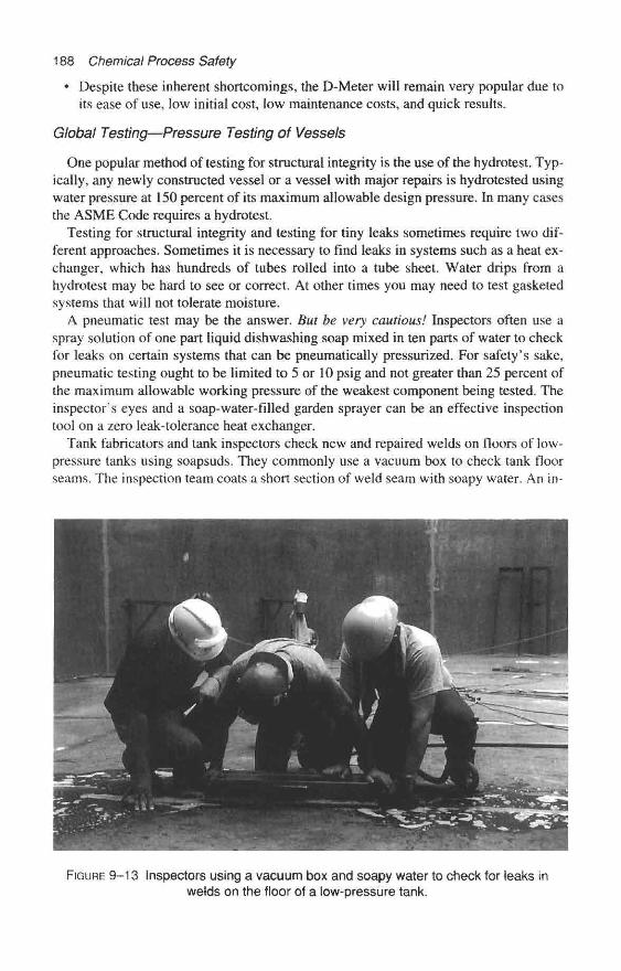
188 Chemical Process Safety
* Despite these inherent shortcomings, the D-Meter will remain very popular due toits ease of use, low initial cost, low maintenance costs, and quick results.
Global Testing—Pressure Testing of Vessels
One popular method of testing for structural integrity is the use of the hydrotest. Typ-ically, any newly constructed vessel or a vessel with major repairs is hydrotested usingwater pressure at 150 percent of its maximum allowable design pressure. In many casesthe ASME Code requires a hydrotest.
Testing for structural integrity and testing for tiny leaks sometimes require two dif-ferent approaches. Sometimes it is necessary to find leaks in systems such as a heat ex-changer, which has hundreds of tubes rolled into a tube sheet. Water drips from ahydrotest may be hard to see or correct. At other times you may need to test gasketedsystems that will not tolerate moisture.
A pneumatic test may be the answer. But be very cautious! Inspectors often use aspray solution of one part liquid dishwashing soap mixed in ten parts of water to checkfor leaks on certain systems that can be pneumatically pressurized. For safety's sake,pneumatic testing ought to be limited to 5 or 10 psig and not greater than 25 percent ofthe maximum allowable working pressure of the weakest component being tested. Theinspector's eyes and a soap-water-filled garden sprayer can be an effective inspectiontool on a zero leak-tolerance heat exchanger.
Tank fabricators and tank inspectors check new and repaired welds on floors of low-pressure tanks using soapsuds. They commonly use a vacuum box to check tank floorseams. The inspection team coats a short section of weld seam with soapy water. An in-
FIGURE 9–13 Inspectors using a vacuum box and soapy water to check for teaks inwelds on the floor of a low-pressure tank.

The Role of Mechanical Ingegrity in Chemical Process Safety 189
FIGURE 9–14 An inspector examines the condition of the tubes on a condenser.Waterside corrosion can occur if water treatment is insufficient.
spector places a custom-built rectangular box that has a clear window on the top of thesoapy weld seam. A specially designed air eductor, which uses compressed air, evacu-ates the box. If soap bubbles appear in the box, the inspector marks the defective weldfor repairs.
The inspection of low-pressure tanks is amply covered in API Standard 653 Tank In-spection, Repair, Alteration, and Reconstruction, January 1991. [18] This short, practi-cal booklet covers items such as inspector qualifications, concerns for tank bottomcorrosion, and related topics. Appendix C of API 653 offers a four-page checklist for in-spection of a tank while in service and seven pages of checklists for internal inspections.
One Chemical Plant's Pressure Vessel Management Program
The Freeport, Texas, Dow Chemical Plant shared details of their pressure vessel man-agement program several years ago. [19] The Dow Texas pressure vessel program hadevolved over 25 years and covered about 12,000 pressure vessels. No doubt with today'sPSM Mechanical Integrity element, Dow's program has far exceeded the excellent ef-forts discussed here.
Vessel Design Review and Registration
The Dow Chemical Texas Division Pressure Vessel Review Committee determines ifa vessel meets the requirements of the ASME Code and/or Dow's Engineering Specifi-cation, If a pressure vessel meets those requirements, Dow assigns a unique index num-ber. Such a pressure vessel is either fabricated in a commercial fabrication shop, is
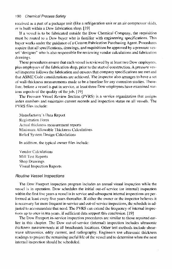
190 Chemical Process Safety
received as a part of a package unit (like a refrigeration unit or an air compressor skid),or is built within a Dow fabrication shop. [19]
If a vessel is to be fabricated outside the Dow Chemical Company, the requisitionmust be routed to a Dow buyer who is familiar with engineering specifications. Thisbuyer works under the guidance of a Custom Fabrication Purchasing Agent. Proceduresrequire that all specifications, drawings, and requisitions be approved by a pressure ves-sel "designer" who is also responsible for reviewing vendor calculations and fabricationdrawings.
These procedures ensure that each vessel is reviewed by at least two Dow employees,plus employees of the fabrication shop, prior to the start of construction. A pressure ves-sel inspector follows the fabrication and ensures that company specifications are met andthat ASME Code considerations are achieved. The inspector also arranges to have a setof wall-thickness measurements made to be a baseline for any corrosion studies. There-fore, before a vessel is put in service, at least three Dow employees have examined var-ious aspects of the quality of the job. [19]
The Pressure Vessel Review Section (PVRS) is a service organization that assignsindex numbers and maintains current records and inspection status on all vessels. ThePVRS files include:
Manufacturer's Data ReportRegistration FormActual thickness measurement reportsMinimum Allowable Thickness CalculationsRelief System Design Calculations
In addition, the typical owner files include:
Vendor CalculationsMill Test ReportsShop DrawingsVisual Inspection Reports
Routine Vessel Inspections
The Dow Freeport inspection program includes an annual visual inspection while thevessel is in operation. Dow schedules the initial out-of-service (or internal) inspectionwithin the first five years a vessel is in service and subsequent internal inspections are per-formed at least every five years thereafter. If either the owner or the inspector believes itis necessary for more frequent in-service and out-of-service inspections, the schedule is ad-justed to accommodate that need. The PVRS can extend the frequency of internal inspec-tions up to once in ten years, if sufficient data support this conclusion. [19]
The Dow Freeport in-service inspection procedures are similar to those reported ear-lier in this chapter. The Dow out-of-service (internal) inspection includes ultrasonicthickness measurements at all benchmark locations. Other test methods include shear-wave ultrasonics, eddy current, and radiography. Engineers use ultrasonic thicknessreadings to project the remaining useful life of the vessel and to determine when the nextinternal inspection should be scheduled.

The Role of Mechanical lngegrity in Chemical Process Safety 1 91
Repairs, Revisions, and Other Status Changes on Vessels
Under this system, Dow equipment owners are required to report a change of status when any of the following occur:
Rerating of the vessel Change in emergency relief requirements Change in service Return to service after being idle for a prolonged period Repair or modification to a pressure-containing part
If pressure-containing parts of a vessel corrode or erode to a thickness less than the minimum allowable, something must be done. The deficient parts must be reconditioned or the equipment will be assigned a lower pressure rating consistent with the new condi- tions. When a vessel is rerated, engineers review the relief system. [19] The Dow Chem- ical system for vessels, as reported a decade ago, seems to be a very practical method to meet today’s OSHA Mechanical Integrity requirements.
Inspection of Above-Ground Piping API 570 Piping Inspection Code: Inspection, Repair, Alteration and Rerating of In-
Service Piping Systems [ 161 was developed to establish requirements and guidelines for owners and users to maintain the safety and integrity of piping systems. Such important topics as frequency and extent of inspections, repairs, alterations, and rerating of piping systems are covered.
In Section 4 of API 570 the concept of Piping Service Classes is introduced. The clas- sification was developed to allow extra inspection efforts to be focused on piping sys- tems that may have the highest potential consequences, if failure or loss of containment should occur.
The API 570 categories are as follows:
Class 1 Piping Systems are services with the highest potential of an immediate emergency if a leak were to occur. Class 2 Piping Systems are an intermediate class and include the majority of unit process piping and some off-site piping. Class 3 Piping Systems are defined as flammable service systems that do not sig- nificantly vaporize from a release and are not located in high activity areas.
Using this “class” system, the API recommends a maximum inspection interval of be- tween three and ten years. See this valuable reference for details. [ 161
Some companies make piping service evaluations. These evaluations are used to cat- egorize piping systems and determine the initial piping inspection intervals and degree of inspections for critical piping systems. A team determines which inspection tasks are needed to lower the likelihood of failure occurrence. A matrix is established to deter- mine the type of inspection and the interval between inspections. This service evaluation is beyond the scope of this chapter.
The inspection of piping is very well covered in the practical American Petroleum In- stitute’s Recommended Practice 574, Inspection of Piping, Tubing, Valves, and Fittings.
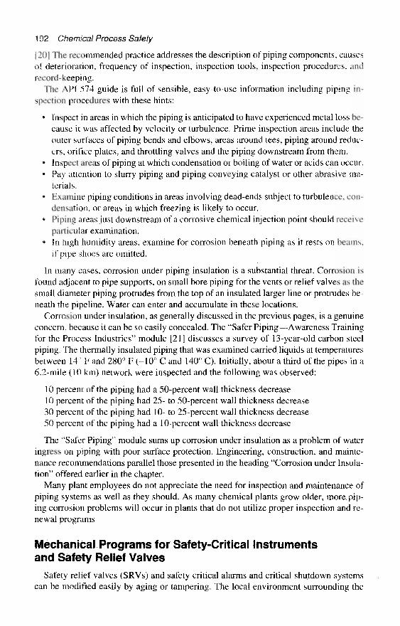
192 Chemical Process Safety
[ 20] The recommended practice addresses the description of piping components, causesof deterioration, frequency of inspection, inspection tools, inspection procedures, andrecord-keeping.
The API 574 guide is full of sensible, easy-to-use information including piping in-spection procedures with these hints:
• Inspect in areas in which the piping is anticipated to have experienced metal loss be-cause it was affected by velocity or turbulence. Prime inspection areas include theouter surfaces of piping bends and elbows, areas around tees, piping around reduc-ers, orifice plates, and throttling valves and the piping downstream from them.
• Inspect areas of piping at which condensation or boiling of water or acids can occur.• Pay attention to slurry piping and piping conveying catalyst or other abrasive ma-
terials.• Examine piping conditions in areas involving dead-ends subject to turbulence, con-
densation, or areas in which freezing is likely to occur,9 Piping areas just downstream of a corrosive chemical injection point should receive
particular examination.• In high humidity areas, examine for corrosion beneath piping as it rests on beams,
if pipe shoes are omitted.
In many cases, corrosion under piping insulation is a substantial threat. Corrosion isfound adjacent to pipe supports, on small bore piping for the vents or relief valves as thesmall diameter piping protrudes from the top of an insulated larger line or protrudes be-neath the pipeline. Water can enter and accumulate in these locations.
Corrosion under insulation, as generally discussed in the previous pages, is a genuineconcern, because it can be so easily concealed. The "Safer Piping—Awareness Trainingfor the Process Industries" module [21] discusses a survey of 13-year-old carbon steelpiping. The thermally insulated piping that was examined carried liquids at temperaturesbetween 14° F and 280° F (–10° C and 140° C). Initially, about a third of the pipes in a6.2-mile (10 km) network were inspected and the following was observed:
10 percent of the piping had a 50-percent wall thickness decrease10 percent of the piping had 25- to 50-percent wall thickness decrease30 percent of the piping had 10– to 25-percent wall thickness decrease50 percent of the piping had a 10-percent wall thickness decrease
The "Safer Piping" module sums up corrosion under insulation as a problem of wateringress on piping with poor surface protection. Engineering, construction, and mainte-nance recommendations parallel those presented in the heading "Corrosion under Insula-tion" offered earlier in the chapter.
Many plant employees do not appreciate the need for inspection and maintenance ofpiping systems as well as they should. As many chemical plants grow older, more pip-ing corrosion problems will occur in plants that do not utilize proper inspection and re-newal programs
Mechanical Programs for Safety-Critical Instrumentsand Safety Relief Valves
Safety relief valves (SRVs) and safety critical alarms and critical shutdown systemscan be modified easily by aging or tampering. The local environment surrounding the

The Role of Mechanical Ingeghty in Chemical Process Safety 193
device, including cycles of freezing and thawing, moisture, corrosive contact with equip-ment internals, localized corrosive emissions, general atmospheric corrosion, dirt, sand-blasting, painting, and tampering, can alter the ability of these process safeguards toproperly function.
McGraw-Hill Publications has granted special permission to use excerpts from my ar-ticle entitled "Don't Leave Plant Safety to Chance," Chemical Engineering 98, no, 2,February 1991. [8] Many paragraphs will be used verbatim in the rest of this section onSRVs without being shown as quotes or without further reference.
All of the effort expended in designing plant-safety systems is of little value unlessaccompanied by an adequate "prooftest" program and regular maintenance. These safetysystems—consisting of such components as SRVs, tank vents, critical alarms, and protec-tive isolation and shutdown devices—do not operate on a continuous basis. Rather, theyare only called into service periodically to warn of, or to prevent, conditions that could leadto plant accidents. [8]
After just a few years of neglect, many protective devices and preventive processloops could become ineffective. Unfortunately, these safety system failures may go un-detected until a crises occurs.
Determining the methods and frequencies of testing for critical instrument loops mustbe tailored to each plant's needs and resources. No matter how often testing is carriedout, the facility must be committed to checking all plant safety devices regularly. Test-ing programs must be impervious to all the other demands taxing a plant's resources, in-cluding key personnel changes. Periodic in-house audits should be conducted to ensurethat testing methods are effective.
The Critical Role of Safety Relief Valves
SRVs are critical elements to the overall process safety of a chemical plant. The de-cisive functions of these safeguards are described in Valve Magazine [22], which beginswith this attention-getting paragraph:
Perhaps no one valve plays as critical a role in the prevention of industrial accidentsas the pressure relief valve. This "silent sentinel" of industry, sometimes referred toas the "safety" or "safety relief" valve, is essential in helping us minimize industrialaccidents caused by the overpressurization of boilers and pressure vessels.
Relief valves serve the unique function of providing the last line of defense against thedangerous accumulation of excessive pressures within pressure vessels, tanks, and pip-ing. They are self-contained and self-operating when other warning and control systemsfail to provide the necessary protection.
The following observations were reported by Bruce Van Boskirk at an AIChE Meet-ing [23] in Southeast Texas:
Relief valves are very deceiving in appearance. Because they look like pipe fittings,they are often handled and stored in the same manner. This misconception can leadto significant abuse and damage. RELIEF DEVICES ARE DELICATE INSTRU-MENTS AND MUST BE TREATED AS SUCH.
It is reasonable to draw an analogy between a shotgun and a relief valve. Bothare made from high-quality materials. Both contain parts machined to extremelyclose tolerances. Both are expected to operate accurately and reliably when called

194 Chemical Process Safety
upon. Both are intended to provide many years of dependable service. AND BOTHCAN BE EASILY RUINED THROUGH ABUSE, MISUSE, AND NEGLECT
"In-House" Testing of Safety Relief Valves
Undetected corrosion, fouling of SRVs, or fouling in the inlet or outlet piping of theSRV can adversely affect the setpoint and the relieving flow-rate. Standby equipmentthat has been improperly specified, installed, or maintained is particularly susceptible toundetected corrosion and fouling.
One major chemical complex, PPG Industries in Lake Charles, Louisiana, relies onabout 2,200 individual safety relief valves and conservation (pressure/vacuum) vents foroverpressure protection. This large complex has a number of unique materials and cor-rosion challenges. On a typical day, huge quantities of saturated brine (NaCl) enter thecomplex, and several thousand tons of chlorine are produced. In the humidity of south-ern Louisiana, the salt, chlorine, co-product caustic soda, and hydrogen chloride gas cir-culating throughout the plant can attack process equipment. Other products, such asvinyl chloride monomer and chlorinated solvents, require unique elastomers for "O"-rings and gaskets.
PPG Lake Charles was one of the first chemical plants to openly discuss problems thatusers experience by improperly specifying and testing safety relief valves. Expertise onnew safety valves could be obtained from manufacturers; sizing methods were docu-mented by various designers and users, but no one published practical SRV testing andSRV corrosion problems.
Over the years, PPG Lake Charles has shared its findings with a number of organiza-tions. A series of technical papers [8,24,25] has documented the progress and problems.The late Warren H. Woolfolk, Inspector, became PPG's first SRV Test Program Coor-dinator in 1974. His prime responsibility was to ensure that SRVs were properly speci-fied, installed, tested, and that there was sufficient record-keeping. He gatheredinformation from SRV manufacturers, helped develop centralized record-keeping, andimproved engineering specifications.
Woolfolk became concerned over the adequacy of the SRV test facilities, which werecommonly used by many commercial SRV test and repair shops and most chemicalplants. The typical test stand consisted of a clamp-down table connected to a com-pressed air cylinder by 1/4-inch (0.6 cm) tubing. Woolfolk experimented with surge ac-cumulators for testing relief valves, using a substantial volume of air to mimic actualprocess conditions.
In 1983, after some years of testing SRVs with significant volumes of gas, Woolfolkpresented "Process Safety Relief Valve Testing" [24] to the Loss Prevention Symposiumof the American Institute of Chemical Engineers. The resulting published article gener-ated a lot of interest; he published an updated version for the Chemical ManufacturingAssociation in 1986. [25] However, a number of U.S. chemical plants were still usingthe primitive clamp-down table connected to a compressed air cylinder in the late 1980s.
Selection of Safety Relief Valve Testing Equipment
The American Society of Mechanical Engineers (ASME) understands the need for asufficient volume of gas to properly test a safety relief valve. Until the ASME providessome well-defined guides, a concerned chemical plant may wish to develop its own
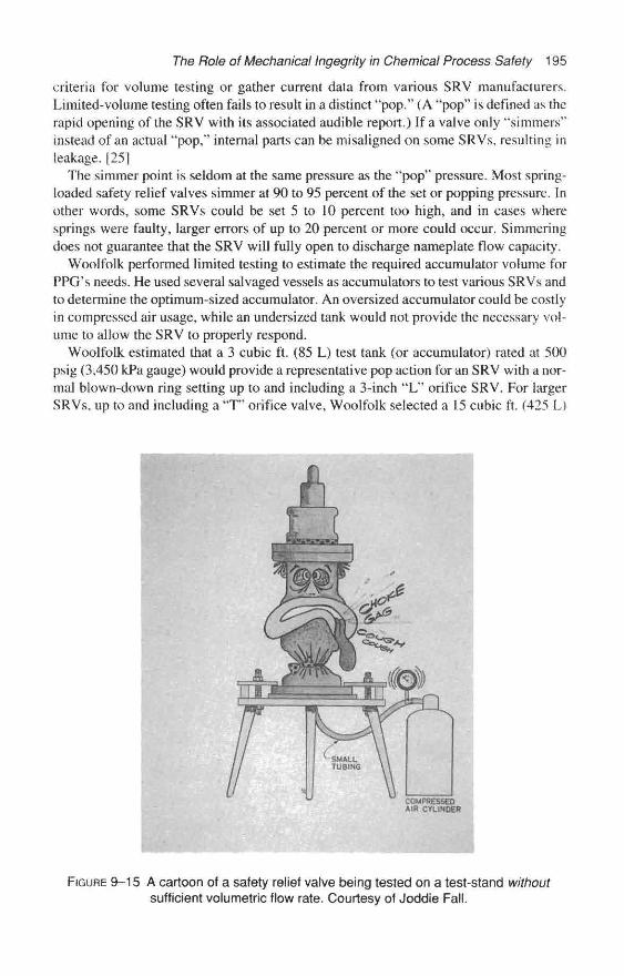
The Role of Mechanical Ingegrity in Chemical Process Safety 195
criteria for volume testing or gather current data from various SRV manufacturers.Limited-volume testing often fails to result in a distinct "pop." (A "pop" is defined as therapid opening of the SRV with its associated audible report.) If a valve only "simmers"instead of an actual "pop," internal parts can be misaligned on some SRVs, resulting inleakage, [25]
The simmer point is seldom at the same pressure as the "pop" pressure. Most spring-loaded safety relief valves simmer at 90 to 95 percent of the set or popping pressure. Inother words, some SRVs could be set 5 to 10 percent too high, and in cases wheresprings were faulty, larger errors of up to 20 percent or more could occur. Simmeringdoes not guarantee that the SRV will fully open to discharge nameplate flow capacity,
Woolfolk performed limited testing to estimate the required accumulator volume forPPG's needs. He used several salvaged vessels as accumulators to test various SRVs andto determine the optimum-sized accumulator. An oversized accumulator could be costlyin compressed air usage, while an undersized tank would not provide the necessary vol-ume to allow the SRV to properly respond.
Woolfolk estimated that a 3 cubic ft. (85 L) test tank (or accumulator) rated at 500psig (3,450 kPa gauge) would provide a representative pop action for an SRV with a nor-mal blown-down ring setting up to and including a 3-inch "L" orifice SRV. For largerSRVs, up to and including a "T" orifice valve, Woolfolk selected a 15 cubic ft. (425 L)
FIGURE 9–15 A cartoon of a safety relief valve being tested on a test-stand withoutsufficient volumetric flow rate. Courtesy of Joddie Fall.

196 Chemical Process Safety
test tank also rated at 500 psig (3,450 kPa gauge). He chose a 4.4 cubic ft. (125 L) tankwith a 3,000 psig (20,700 kPa) rating for this plant's higher pressure SRV testing. Healso selected a smaller tank—1/3 cubic ft. (9.4 L) rated at 5,000 psig (34,500 kPa)—thatcan be used to pneumatically or hydraulically test SRVs for some special cases. Later anadditional 6.5-cubic ft. (184 L) tank was engineered and installed for vacuum and low-pressure applications. Any plant considering installation of its own test facilities shouldcarefully study the specific needs of their unique situation for the number and size of theaccumulator tanks.
All test accumulators (pressure vessels) were mounted directly below the test table.These vessels were mounted vertically with 2:1 ellipsoidal heads on top and bottom. Thetop head has a well-rounded outlet nozzle sized equal to the SRV inlet to be tested. Totest smaller-orifice SRVs, ring-shaped adapter plates having an opening equal to theSRV inlet are used. This arrangement reduces the possibility of starving the flow to thevalve.
Mr. Woolfoik designed the accumulator depressurization piping to ensure that themomentum of the exiting air expelled any moisture, pipe scale, or other foreign mater-ial after each SRV test on each tank. The depressurization piping is connected to the lowpoint in the accumulator. [25]
PPG Industries learned firsthand that testing SRVs with a large volume test stand hadmany advantages. The larger pneumatic energy supply allowed a gradual pressure rise,easier reading on the test gauges and more "cushioned" reseating conditions. Finely lappednozzles and seats are better protected from slamming together during tests on larger vol-ume stands. The higher volume test equipment better simulates actual operational situa-tions, allows a measurable lift of the seats, and ensures that the moving parts are properlyaligned.
With a volume-pneumatic test, mechanics can detect defects in the parts due to incor-rect replacement parts, incorrect machining, corrosion, or weak springs. Each of these
FIGURE 9–16 An SRV test stand for dynamic testing.
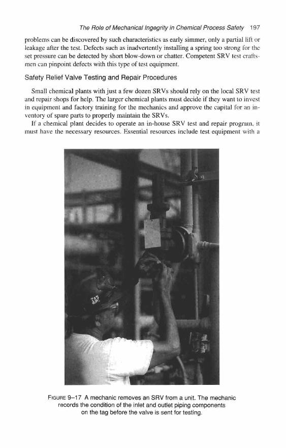
The Role of Mechanical Ingegrity in Chemical Process Safety 197
problems can be discovered by such characteristics as early simmer, only a partial lift orleakage after the test. Defects such as inadvertently installing a spring too strong for theset pressure can be detected by short blow-down or chatter. Competent SRV test crafts-men can pinpoint defects with this type of test equipment.
Safety Relief Valve Testing and Repair Procedures
Small chemical plants with just a few dozen SRVs should rely on the local SRV testand repair shops for help. The larger chemical plants must decide if they want to investin equipment and factory training for the mechanics and approve the capital for an in-ventory of spare parts to properly maintain the SRVs.
If a chemical plant decides to operate an in-house SRV test and repair program, itmust have the necessary resources. Essential resources include test equipment with a
FIGURE 9-17 A mechanic removes an SRV from a unit. The mechanicrecords the condition of the inlet and outlet piping components
on the tag before the valve is sent for testing.
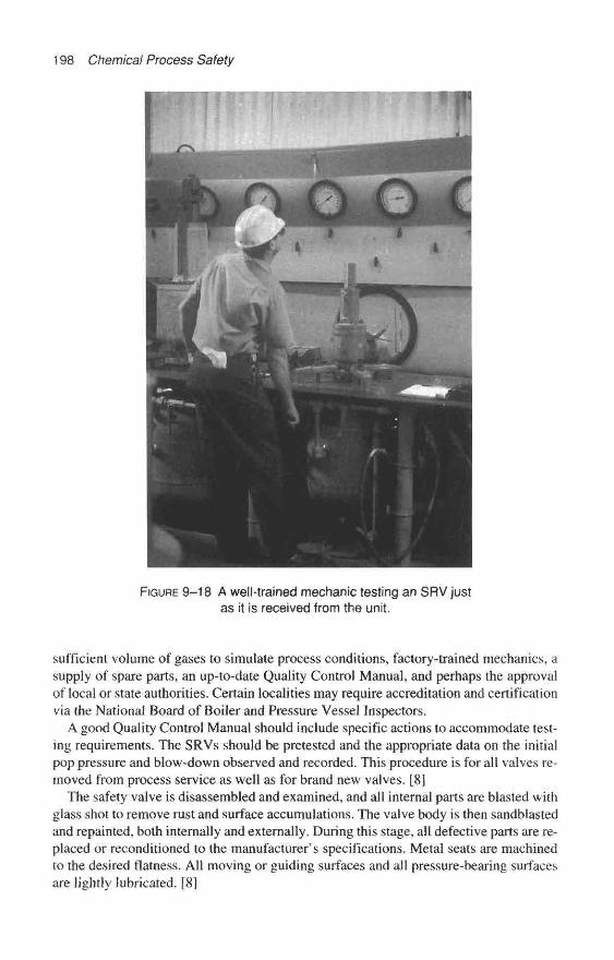
198 Chemical Process Safety
FIGURE 9–18 A well-trained mechanic testing an SRV justas it is received from the unit.
sufficient volume of gases to simulate process conditions, factory-trained mechanics, asupply of spare parts, an up-to-date Quality Control Manual, and perhaps the approvalof local or state authorities. Certain localities may require accreditation and certificationvia the National Board of Boiler and Pressure Vessel Inspectors.
A good Quality Control Manual should include specific actions to accommodate test-ing requirements. The SRVs should be pretested and the appropriate data on the initialpop pressure and blow-down observed and recorded. This procedure is for all valves re-moved from process service as well as for brand new valves. [8]
The safety valve is disassembled and examined, and all internal parts are blasted withglass shot to remove rust and surface accumulations. The valve body is then sandblastedand repainted, both internally and externally. During this stage, all defective parts are re-placed or reconditioned to the manufacturer's specifications. Metal seats are machinedto the desired flatness. All moving or guiding surfaces and all pressure-bearing surfacesare lightly lubricated. [8]

The Role of Mechanical Ingegrity in Chemical Process Safety 199
Once the valve is reassembled, the SRV is performance-tested and adjusted to the cor-rect set pressure, and the blow-down is set. All bellows-type and spring-loaded valvesexposed to back pressure are back-pressure tested to ensure the integrity of the bellowsand gaskets on the exhaust side of the SRV.
Tamperproof seals are added to discourage unauthorized or undetected field adjust-ments. Once testing is complete, a metal identification tag (of soft lead, which is easy toimprint, yet impervious to corrosion) is attached to the SRV. The tag records the loca-tion number, set pressure, and test date.
Safety relief valves must be kept clean during transit and storage so valve openingsare sealed with tape and cardboard. If lifting levers are present, they are tied down toprotect the SRV's seats en route to the user. The valve must be transported and stored inan upright position.
Mechanics document SRV test results and observations on a checklist. This informa-tion includes initial test pressure, and the condition of seats, stems, guides, springs, andinlet and outlet piping upon arrival at the plant. The appropriate second-level supervisorreceives these results and a copy is maintained in the central SRV records. [8]
How Often is Often Enough When Testing Safety Relief Valves?
PPG Lake Charles has established different test cycles for different process safetyequipment. Some are tested as frequently as every six months; some are tested as infre-quently as once every three years. SRVs operating in dirty, fouling, or highly corrosiveconditions may require more frequent testing to ensure reliable service.
FIGURE 9–19 A crane lifts a recently tested and reconditionedSRV to reinstall it on a reactor.
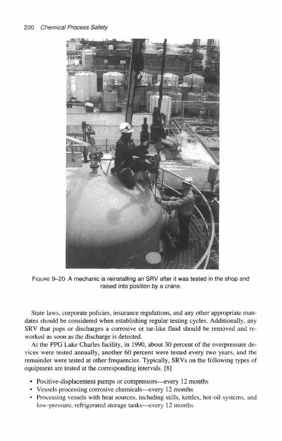
200 Chemical Process Safety
FIGURE 9-20 A mechanic is reinstalling an SRV after it was tested in the shop andraised into position by a crane.
State laws, corporate policies, insurance regulations, and any other appropriate man-dates should be considered when establishing regular testing cycles. Additionally, anySRV that pops or discharges a corrosive or tar-like fluid should be removed and re-worked as soon as the discharge is detected.
At the PPG Lake Charles facility, in 1990, about 30 percent of the overpressure de-vices were tested annually, another 60 percent were tested every two years, and theremainder were tested at other frequencies. Typically, SRVs on the following types ofequipment are tested at the corresponding intervals. [8]
• Positive-displacement pumps or compressors—every 12 months• Vessels processing corrosive chemicals—every 12 months• Processing vessels with heat sources, including stills, kettles, hot-oil systems, and
low-pressure, refrigerated storage tanks—every 12 months

The Role of Mechanical Ingegrity in Chemical Process Safety 201
* Boilers—ever}' 12 months (Louisiana law requires boiler SRVs to be tested, set, andsealed annually)
« Process steam headers—every 24 months• Storage vessels containing clean (nonplugging, noncorrosive) fluids—every 24
months• Instrument-air manifolds within dehumidified control rooms—every 36 months* Lubricating relief valves on enclosed systems, such as compressors, turbines and
generators—every 36 months
On a case-by-case basis, when documented tests over the years indicate excellent test-ing results, the interval between tests can be extended.
Keeping the Safety Relief Valve Records Straight
A simple, sequential numbering system to identify SRVs may be acceptable for asmall plant such as a batch-chemical processing facility with only a few dozen SRVs.However, for PPG's Lake Charles plant, a dual-numbering system is used to keep upwith 2,000 SRVs in service and several hundred additional SRVs in storage. The deviceskept in storage on-site are used as spares or can be cannibalized for parts. Spare safetyvalves for critical equipment must be available. [8]
In the dual-numbering system, one number refers to the valve design-type, and theother refers to its location and service. The first number identifying the equipment isunique to the SRV and is retired once the valve is taken out of service. Equipmentrecords include information on the orifice size, set pressure, manufacturer, model num-ber, serial number, and inlet and outlet flange sizes and ratings.
Test results are entered into the mainframe computer according to each device's iden-tification number. Employees have "read" access to the records at over 500 terminalsand personal computers throughout the complex.
The Importance of Proper Safety Relief Valve Identification
The importance of proper identification of the safety relief valve cannot be over-stated. Without a strict numbering system, the risk of incorrectly joining the wrong SRVto the right vessel after testing is too great to accept. For example, a 1-inch threadedvalve can have an effective orifice area from 0.06 to 0.314 square inches (a fivefold dif-ference), yet both could fit the same installation. Similarly, a 1-inch threaded-type SRVset at 100 psig (690 kPa) may look identical to another valve with the same descriptionbut set at 200 psig (1,380 kPa). Likewise, a 4-inch valve with 300 psi style flange couldbe equipped with either an "L" orifice (2.85 square inches) or a "P" orifice (6.38 squareinches). The "P" orifice is 2.24 times larger than the "L" orifice.
The location portion of the numbering system indicates the SRVs specific site. Siterecords include a description of the location, temperature, set pressure, product, and thepresence or absence of a rupture disc.
Communications to Equipment Owners and Management
A mainframe computer system has data on each SRV. Every other month, a computer-generated inspection schedule is sent to the second-level supervisor of each process unit.The report serves as a reminder of all SRV and conservation vent locations, recommended
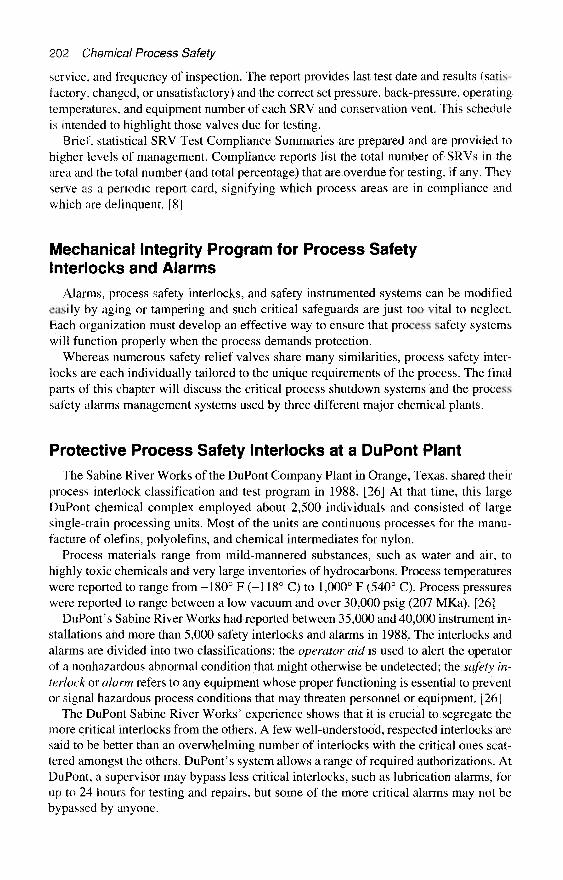
202 Chemical Process Safety
service, and frequency of inspection. The report provides last test date and results (satis-factory, changed, or unsatisfactory) and the correct set pressure, back-pressure, operatingtemperatures, and equipment number of each SRV and conservation vent. This scheduleis intended to highlight those valves due for testing.
Brief, statistical SRV Test Compliance Summaries are prepared and are provided tohigher levels of management. Compliance reports list the total number of SRVs in thearea and the total number (and total percentage) that are overdue for testing, if any. Theyserve as a periodic report card, signifying which process areas are in compliance andwhich are delinquent. [8]
Mechanical Integrity Program for Process SafetyInterlocks and Alarms
Alarms, process safety interlocks, and safety instrumented systems can be modifiedeasily by aging or tampering and such critical safeguards are just too vital to neglect.Each organization must develop an effective way to ensure that process safety systemswill function properly when the process demands protection.
Whereas numerous safety relief valves share many similarities, process safety inter-locks are each individually tailored to the unique requirements of the process. The finalparts of this chapter will discuss the critical process shutdown systems and the processsafety alarms management systems used by three different major chemical plants.
Protective Process Safety Interlocks at a DuPont PlantThe Sabine River Works of the DuPont Company Plant in Orange, Texas, shared their
process interlock classification and test program in 1988. [26] At that time, this largeDuPont chemical complex employed about 2,500 individuals and consisted of largesingle-train processing units. Most of the units are continuous processes for the manu-facture of olefins, polyolefins, and chemical intermediates for nylon.
Process materials range from mild-mannered substances, such as water and air, tohighly toxic chemicals and very large inventories of hydrocarbons. Process temperatureswere reported to range from -180° F (-118° C) to 1,000° F (540° C). Process pressureswere reported to range between a low vacuum and over 30,000 psig (207 MKa). [26]
DuPont's Sabine River Works had reported between 35,000 and 40,000 instrument in-stallations and more than 5,000 safety interlocks and alarms in 1988. The interlocks andalarms are divided into two classifications: the operator aid is used to alert the operatorof a nonhazardous abnormal condition that might otherwise be undetected; the safety in-terlock or alarm refers to any equipment whose proper functioning is essential to preventor signal hazardous process conditions that may threaten personnel or equipment. [26]
The DuPont Sabine River Works' experience shows that it is crucial to segregate themore critical interlocks from the others. A few well-understood, respected interlocks aresaid to be better than an overwhelming number of interlocks with the critical ones scat-tered amongst the others. DuPont's system allows a range of required authorizations. AtDuPont, a supervisor may bypass less critical interlocks, such as lubrication alarms, forup to 24 hours for testing and repairs, but some of the more critical alarms may not bebypassed by anyone.

The Role of Mechanical Ingegrity in Chemical Process Safety 203
Testing Safety Critical Process instruments at a DuPont Plant
Interlock testing is performed on a periodic basis, usually every 12 months, followingdetailed written test procedures. The test procedure for each safety interlock defines theactions, including the approval system and the mechanical work required to ensure reli-ability. These procedures cover the testing activity from the process measurement deviceto the final element, which is often a control valve. [26]
Due in part to the complexity of the instrument systems, there are two first-to-finaltesting methods. These methods are labeled "actual tests" and "simulated tests."
The "actual test" is performed by operating the process to the trip point, and ensuringthat the intermediate relays and instruments respond properly. The "simulated test" isused in circumstances in which the instruments are of a nature that create a forced shut-down or startup in a very hazardous process. The "simulated test" is also used if the in-strument schemes are so complicated that the interlocks cannot be checked on asingle-trip shutdown. [26]
The technical paper described the interlock testing program to consist of more thanmerely verifying that the interlock works. There is also inspection of the interlock equip-ment for deterioration. The "function test" on instrumentation is required following me-chanical work on one or more of the safety system elements. In short, all devices orsystems that have been disturbed enough to affect their normal function will be functiontested prior to being restored to service. [26]
Another Company—A Different Emphasis on SafetyCritical Instrument Systems
Gregory McMillan, formerly an engineering fellow in process control for the Mon-santo Chemical Company, approached the subject differently. His very entertainingpresentation—entitled "Can You Say 'Process Interlocks'?"—at the 1988 AIChE LossPrevention Symposium was written as a parody of a popular youngster's TV show. [27]
Monsanto felt there were some real benefits to separate the economic issues from thesafety issues and focus on the interlocks that really require special attention. Prior to thisseparation, human life was grouped with major property protection and formed a largeclass for which it was difficult to enforce stringent design and test requirements. [27]
In earlier times, costs associated with business interruption (which can exceed propertylosses) after an interlock failure were largely ignored and those interlocks were oftenplaced with the so-called "operational interlocks." McMillan's approach was a systemthat grouped the protection instrument loops into four classes. These are the classes anda rough idea of the number of affected loops:
100 Class I Community Protection (Safety) Loops1,000 Class II Employee Protection (Safety) Loops5,000 Class III Major Property and Production (Economic) Loops100,000 Class IV Minor Property and Production (Economic) Loops
McMillan reveals that alarms and interlocks can proliferate to the point where theydetract from the most critical loops. To be effective, a logical cause-and-effect approachto interlock classification is required. It must be determined which events are the directand distinct causes of hazardous events.
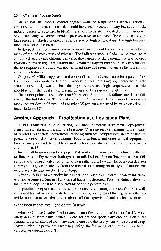
204 Chemical Process Safety
Mr. Fellow, the process control engineer—in the script of this satirical article—explains that in the past, interlocks would have been placed on many but not all of theindirect causes of a release. In McMillan's example, a steam-heated chlorine vaporizerwould have only two direct chemical process causes of a release. These direct causes arehigh pressure, which can open a relief device, or high temperature. The high tempera-ture can accelerate corrosion.
In the past, this company's process control design would have placed interlocks onmany of the indirect causes of releases. The indirect causes include a wide-open steamcontrol valve, a closed chlorine gas valve downstream of the vaporizer, or a wide openupstream nitrogen regulator. Unfortunately with the large number of interlocks with sim-ilar test requirements, there was not sufficient time and money to ensure the integrity ofall of the interlocks.
Gregory McMillan suggests that the most direct and distinct cause for a potential re-lease from this steam-heated chlorine vaporizer is high pressure; high temperature is thesecond most likely cause. Thus, the high-pressure and high-temperature interlocksshould receive the most severe classification and the most testing attention.
The author points out statistics that 80 percent of all interlock failures are due to fail-ures of the field device. Those statistics show 45 percent of the interlock failures aremeasurement device failures and the other 35 percent are caused by valve or valve ac-tuator failures. [27]
Another Approach—Prooftesting at a Louisiana Plant
At PPG Industries in Lake Charles, Louisiana, numerous instrument loops providecritical safety, alarm, and shutdown functions. These protective instruments are locatedon reactors, oil heaters, incinerators, cracking furnaces, compressors, steam-heated va-porizers, kettles, distillation columns, boilers, turbines, and other critical equipment.Process analyzers and flammable vapor detectors also enhance the overall process safetyenvironment. [8]
Instrument loops serving the equipment described previously can function in either anon-line or a standby manner; both types can fail. Failure of an on-line loop, such as fail-ure of a level control valve, becomes known rather quickly when the operation deviateseither gradually or drastically from the normal. Depending on the type of failure, thismay place a demand on the standby loop.
After all, failure of a standby instrument loop, such as an alarm or safety interlock,will not become evident until a potential hazard is detected. Potential defects develop-ing in these loops must be discovered by periodic prooftesting.
A prooftest program cannot be left to someone's memory. It must follow a well-structured format to accomplish the essential steps, regardless of the myriad of other ac-tivities and distractions that tend to absorb all the supervisors' and mechanics' time.
What instruments Are Considered Critical?
When PPG Lake Charles first initiated its prooftest program, efforts to classify whichsafety devices were truly "critical" were not defined specifically enough. Hence, theoriginal program allowed too many instruments into the test system which created a top-heavy burden. To prevent this from happening, the following information should be de-veloped for critical loops [8]:

The Role of Mechanical Ingegrity in Chemical Process Safety 205
FIGURE 9-21 Prooftesttng a flammable gas detector in a tank farm.
• A listing of critical alarms and safety interlocks essential to safe plant operationsmust be made.
• The criteria by which the truly "critical instrument" system can be characterized assuch, and distinguished from other important (but not critical) systems should bedocumented.
• The test procedure for complex interlocks should be developed with engineeringhelp and, for consistency and compliance with OSHA 1910.119, should be docu-mented in writing. Any proposed additions or deletions should be screened by athird-party group or committee. An appropriate authorization path should be inplace to assist in making changes in classified instrument alarms and shutdown setpoints.
• Test results must be recorded systematically, and must be easily accessible to allwho need them for analysis. Defective or worn components should be identified andrepaired immediately.
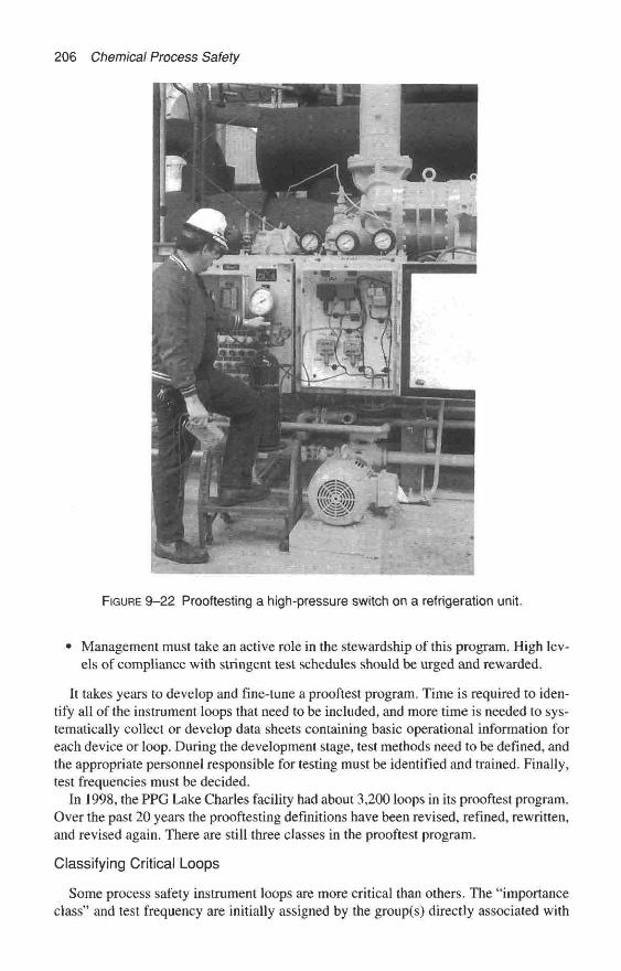
206 Chemical Process Safety
FIGURE 9-22 Prooftesting a high-pressure switch on a refrigeration unit.
Management must take an active role in the stewardship of this program. High lev- els of compliance with stringent test schedules should be urged and rewarded.
It takes years to develop and fine-tune a prooftest program. Time is required to iden- tify all of the instrument loops that need to be included, and more time is needed to sys- tematically collect or develop data sheets containing basic operational information for each device or loop. During the development stage, test methods need to be defined, and the appropriate personnel responsible for testing must be identified and trained. Finally, test frequencies must be decided.
In 1998, the PPG Lake Charles facility had about 3,200 loops in its prooftest program. Over the past 20 years the prooftesting definitions have been revised, refined, rewritten, and revised again. There are still three classes in the prooftest program.
Classifying Critical Loops
Some process safety instrument loops are more critical than others. The “importance class” and test frequency are initially assigned by the group(s) directly associated with

The Role of Mechanical Ingegrity in Chemical Process Safety 207
the origin and the reason for the required test. Input is received from a variety of in-plantdepartments such as: the Environmental Department, Process Hazard Analysis, LossPrevention Engineering, or Maintenance Engineering. However, additional guidanceoriginates from property insurance guidelines, in-plant technical safety committees, in-strument failure-rate data, prior operating experience, manufacturer recommendations,and good engineering judgment.
Class 1—Critical Consequence Instrument Loops
These are instrument loops that are necessary to avoid perilous situations. These crit-ical consequence instruments are those whose failure would either cause, or fail to in-form of, situations resulting in accidental fire, explosion, uncontrolled release ofdangerous materials, personal injury, or death. The OSHA Process Safety managementloops fall within this group.
The Safety Instrumented Systems (SIS) and critical alarms assigned a "Class I" in-clude those that have been mandated as such by state or federal agencies, an in-housetechnical safety review committee, .HAZOP studies, and specific alarms deemed criticalby operations supervisors. All of these Safety Instrumented Systems and alarms are ona regular prooftesting schedule.
In 1998, the PPG Lake Charles facility had about 1,325 "Class 1" critical consequenceinstrumentation loops that required prooftesting. These include alarms and trips on stor-age tanks containing flammable or toxic liquids, devices to control high temperature andhigh pressure on exothermic-reaction vessels, and control mechanisms for low-flow,high-temperature fluids on fired heaters. Other Class 1 instruments include alarms thatwarn of flame failure on fired heaters, high level and high pressure of toxic or flamma-ble storage tanks, and flammable vapor detectors for emergency valve isolation andsprinkler-system activation. All of the safeguards on the large diesel-driven fire-waterpumps, battery failure, low lubrication pressure, and high cooling water temperature arealso included. In 1997, there was a review to revisit all instrument loops in this classifi-cation, because it seems that a significant number of instrument loops were previouslyrated as too high in some units.
At PPG, Class 1 Prooftesting also covers 250 SIS loops in the PSM Safety Systems.An SIS is composed of sensors, logic solvers, and final control elements for the purposeof taking the process to a safe state when predetermined conditions are violated. SISs arenormally controlled by a PLC with the sole function of monitoring a process to ensureoperation is maintained within the safe operating envelope.
Class 2—Serious Consequence Instrument Loops
These serious consequences instrument loops are those instrument systems whosefailure could cause, or fail to inform of, serious conditions involving environmental re-leases, major property or production losses, or other non-life-threatening situations.These alarms are given a slightly lower priority but are also prooftested on a regularschedule. These prooftests may be required by many of the originators listed for Class 1Prooftests.
There are about 1,500 "Class 2" alarms at PPG Lake Charles. Examples includealarms or trip systems on refrigeration compressors (low freon pressure, high freon dis-charge pressure, high vibration), rectifiers, cooling towers (water level or high fan vi-bration), high- and low-operating liquid, pressure, or temperature levels or flow-rates
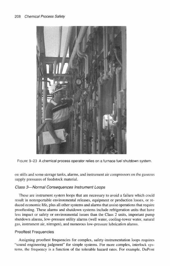
208 Chemical Process Safety
FIGURE 9-23 A chemical process operator relies on a furnace fuel shutdown system.
on stills and some storage tanks, alarms, and instrument air compressors on the gaseoussupply pressures of feedstock material.
Class 3—Normal Consequences Instrument Loops
These are instrument system loops that are necessary to avoid a failure which couldresult in nonreportable environmental releases, equipment or production losses, or re-duced economic life, plus all other systems and alarms that assist operations that requireproof testing. These alarms and shutdown systems include refrigeration units that haveless impact or safety or environmental issues than the Class 2 units, important pumpshutdown alarms, low-pressure utility alarms (well water, cooling-tower water, naturalgas, instrument air, nitrogen), and numerous low-pressure lubrication alarms.
Prooftest Frequencies
Assigning prooftest frequencies for complex, safety-instrumentation loops requires"sound engineering judgment" for simple systems. For more complex, interlock sys-tems, the frequency is a function of the tolerable hazard rates. For example, DuPont

The Role of Mechanical Ingegrity in Chemical Process Safety 209
FIGURE 9-24 A chemical process operator witnesses the testing of an "Emergencyisolation Valve" below a sphere of flammable product.
Sabine River Works (Orange, Texas) reported it had 35,000 instruments in service.Every safety interlock is tested on a periodic basis, usually every 12 months, followinga detailed written test procedure. Once a test frequency is established by DuPont for aparticular interlock, a significant review and multiple approvals are required to perma-nently remove the interlock or change its test frequency. [26]
Many of PPG's high-pressure and high-temperature alarms are tested every sixmonths. A significant number of the PPG Lake Charles Complex test frequencies havebeen developed using detailed reliability studies that consider the "hazard rate" (the ac-ceptable probability of a process accident) and the "demand rate" (the number of timesthe critical alarm or shutdown function is required in service). [8]
Several years ago, within PPG's chlorinated-hydrocarbon complex—which com-prises a major portion of the Lake Charles facility and produces eight different productlines—26 percent of the loops were on a one-year test frequency; 42 percent were on asix-month frequency; 15 percent were tested every four months; 11 percent every threemonths and the remaining 6 percent at various other frequencies from weekly to everytwo years.
Test-frequency changes to shorten or lengthen the test cycle at PPG are based on eval-uations of prooftest results, performance of the components in the loop, or changes inequipment or service. When the desired test pass rate (100-percent pass rate for Class 1loops) is not met, causes of failure are evaluated. If warranted, a corrective action (suchas a design change, test frequency change, or request for further study) is initiated.
A request to lengthen a test frequency may result from a long record of no failed testsand good maintenance records. The request is reviewed and documented by the Loss
210 Chemical Process Safety
Prevention Engineer. Any resulting changes are documented and retained for five yearsin the Loss Prevention Engineering "Prooftest Change" file.
Prooftest Methods at PPG
Many of PPG-Lake Charles control loops and shutdown systems are very compli-cated and it is difficult to prooftest the systems without interrupting production, unlesswell-planned methods are developed. In the mid-1990s, the importance class and theavailability was used to help specify one of the following four methods of prooftesting.
Method 1: Complete Loop Test
This method is the ideal dream test. For processes that allow complete loop prooftest-ing, the maintenance mechanics test all components in the loop by inputting a signal atthe primary field element or sensor and performing a three-point calibration check of therespective component. During the calibration span the prescribed set points are verified.The output is monitored through the Programmable Logic Controller (PLC) (or recorder,indicator, controller, enunciating devices, Distributed Control Systems, process com-puters) to the final trip or control element in the process. The trip function is included inthe test. All components in the loop are visually inspected for physical condition,
Method 2: Split Test
This is the more "normal" test situation. For processes where prooftesting the finaltrip or control element cannot be made available (such as testing a furnace shutdownsystem), the maintenance mechanics perform a prooftest as described previously (com-plete loop test) with the exception of testing the final trip or control element. All com-ponents in the loop including the final element are visually inspected for physicalcondition. Maintenance takes test credit for the portion of the loop prooftested.
In the case where the final element is not tested, Operations performs a functionalcheck of that loop's final trip element during the next routine startup or shutdown of theprocess unit. Operations then takes test credit for the final element prooftest, which islisted separately as their responsibility on the Prooftest Program.
Method 3: Trip Test
Operations are also assigned independent prooftests (in addition to the split test), whichare functional trips or visual checks of controls and emergency shutdown systems.
Method 4: Routinely Monitored Tests
Important Class 2 and 3 loops that are routinely monitored and have a backup indica-tion only require periodic verification of the listed criteria that follows:
• The loop does not have a PLC in the safety shutdown system.• The loop is routinely monitored (at least once per 24-hour period) and recorded by
Operations.« Performance and accuracy of the loop is verbally acknowledged between mainte-
nance and operations.• The loop's primary device has a backup indication with separate impulses sources.

The Role of Mechanical Ingegrity in Chemical Process Safety 211
* A satisfactory visual cross-check of the backup indication or recorder printout hasbeen made.
* Each component in the loop is physically inspected and found and/or left in goodcondition.
Administering the PPG Critical Instrument Prooftest Program
Six independent groups of technical personnel provide prooftesting services. Proof-testing is performed by electricians, critical-metering mechanics, refrigeration mechan-ics, analyzer-repair technicians, instrument-maintenance personnel, and chemical processoperators.
Once a loop has been prooftested, the results are entered into the mainframe com-puter, along with the date tested and the condition found. Many employees have "read"access to this data on many terminals throughout the complex, but only authorized per-sonnel have access to the actual database. Keeping track of other aspects of the system
FIGURE 9-25 An instrument mechanic prooftests a critical instrument panel.
212 Chemical Process Safety
is also done on a computer. For example, if a set point on a particular instrument needschanging, the request and approval (both approved by the second-level supervisor) aredone at the computer terminal. Loops that are no longer in service can be deleted by theauthorized personnel. New loops can be added by an individual designated by the tech-nical safety committee, who reviews all new and modified installations. Finally, monthlycompliance reports are issued to top plant management. Particularly critical to the suc-cess of the program is management's full support and commitment to compliance withprocess safety administration.
Additional Information on Mechanical IntegrityIn 1992, the Center for Chemical Process Safety (CCPS), a section of the American
Institute of Chemical Engineers, released a "how-to" book [28] which contains practi-cal appendices on inspection and test procedures. These appendices comprise the prac-tices at major chemical manufacturing facilities. Chapter 8 should be consulted forspecific information and actual plant programs.
Appendix 8-B of the CCPS book is entitled "Example of Test and inspection Equip-ment and Procedures." This appendix covers minimum testing and inspection require-ments of all classified equipment. "Classified" equipment is equipment identified inoperational safety standards and governmental regulations.
Appendix 8-C is called "Example of Field Inspection and Testing of Process SafetySystems." Appendix 8-E is named "Example of Criteria for Test and Inspection ofSafety" and in 17 pages, it covers safety relief valves, rupture disks, control loop/manualactuated emergency vent devices, and explosion vents. These AIChE guidelines shouldbe consulted if the reader desires more information while building or improving a me-chanical integrity program.
References1. OSHA, U.S. Department of Labor, Process Safety Management of Highly Hazardous
Chemicals: Explosives and Blasting Agents; Final Rule, 29 C.F.R. Part 1910.119, Feb. 24, 1992.2. Grossel, Stanley S. and Daniel A. Crowl, eds., Handbook of Highly Toxic Materials Han-
dling and Management. New York: Marcel Dekker, Inc., 1995.3. OSHA, U.S. Department of Labor, Process Safety Management of Highly Hazardous
Chemicals—Compliance Guidelines and Enforcement Procedures, 29 C.F.R. Part 1910.119,OSHA Instruction CPL 2- 2.45A, Sept. 28, 1992, pp. A-33-A-38.
4. Sutton, Ian, Process Safety Management. Houston: Southwestern Books, 1997, pp.243-65.
5. LeVine, Richard, Ph.D., and Arthur D. Little, Inc. Guidelines for Safe Storage and Han-dling of High Toxic Hazard Materials. New York: Center for Chemical Process Safety, AIChE,1988,ch. 4.
6. Chemical Process Safety Report 7, no. 7, May 1997, Washington, D.C.7. Chemical Manufacturers Association, "Responsible Care Is Template for Taking Effective
Action," CMA News 18, no. 9, Nov. 1990: pp. 11-12.8. Sanders, R. E. and J. H. Wood, "Don't Leave Plant Safety to Chance," McGraw-Hill's
Chemical Engineering, Feb. 1991: pp. 110—18.9. Hawkins, John A., "Improving Equipment Reliability through Vibration Analysis," Vi-
brations 8, no. 2, June 1992.
The Role of Mechanical Ingegrity in Chemical Process Safety 213
10. LeBlanc, Ronnie W., "Loss Prevention through Machinery Vibration Surveillance andAnalysis," Plant/Operation Progress 5, no. 3, July 1985: pp. 179-82.
11. Samdani, Gulam, G. Ondrey, and S. Moore, "Predictive Maintenance," Chemical Engi-neering 99, no. 11, Nov. 1992: pp. 30-33.
12. Boyles, Charles M., "The Plant Services Survey: What Does It Say," Plant Services 13, no.10, Oct. 1992: pp. 139-40.
13. "Improving Maintenance with Infrared," Maintenance Technology, Nov. 1989.14. Snell, John R, Jr., "The Power of Infrared Thermography: Seeing New Solutions to Old
Problems," Plant Services 16, no. 4, April 1995: pp. 79-82.15. NACE Publication 6H189, "A State-of-the~Art Report of Protective Coatings for Carbon
Steel and Austenitic Stainless Steel Surfaces under Thermal and Cementitious Fire Proofing"—ATechnical Report by the National Association of Corrosion Engineers Task Group 7-H-31 *, 1989.
16. American Petroleum Institute, Piping Inspection Code: Inspection, Repair, Alteration andRe rating of In-Service Piping Systems, API 570, 1st ed. Washington, D.C., June 1993.
17. American Petroleum Institute, Pressure Vessel Inspection Code: Maintenance, Inspection,Rating, Repair, and Alteration, API 510, 6th ed. Washington, D.C., June 1989.
18. American Petroleum Institute, Tank Inspection, Repair, Alteration, and Reconstruction,API 653, Isted. Washington, B.C., Jan. 1991.
19. Mueller, W. H., C. G. Arnold, and B. W. Ross, "Reducing Risks through a Pressure VesselManagement Program," a presentation for the AIChE Loss Prevention Symposium, New Orleans,La., April 1986.
20. American Petroleum Institute, Inspection of Piping, Tubing, Valves, and Fittings, API574, 1 st ed. Washington, D.C., June 1990.
21. "Safer Piping—Awareness Training for the Process Industries," Hazards Workshop Mod-ule 012 (available as a training kit with a video, slides, a teaching guide, etc.), AIChE, Warwick-shire, England, 1987.
22. Braun, Neil, "Silent Sentinels: Lessons on Pressure Relief Valve Performance," ValveMagazine, spring 1989: p. 28.
23. Van Boskirk, B. A., "Don't Let Your Plant Blow Up—An Overview of the Elements ofOverpressure Protection." Presented at the joint meeting of the Southeast Texas Section of theAIChE and the Sabine-Neches Section of the ACS, April 1986.
24. Sanders, R. E. and Woolfolk, W. H., "Process Safety Relief Valve Testing," Chemical En-gineering Progress, Mar. 1984, pp. 60-64.
25. Sanders, R. E. and Woolfolk, W. H., "Dynamic Testing and Maintenance of Safety ReliefValves," Chemical Engineering, Oct. 26, 1987, pp. 119-24.
26. Barclay, D. A., "Protecting Process Safety Interlocks," Chemical Engineering Progress,Feb. 1988, pp. 20-24.
27. McMillan, G. K., "Can You Say 'Process Interlocks"?" Tech Journal, May 1987.pp. 35-44.
28. Center for Chemical Process Safety of the AIChE, Plant Guidelines for Technical Man-agement of Chemical Process Safety, New York: AIChE. 1992, ch. 8.

This page intentionally left blank
CHAPTER 10
Effectively Managing Changewithin the Chemical Industry
Common sense and the OSHA Process Safety Management (PSM) standard requirea formal method to effectively deal with change in the chemical industry. The safety de-signed into the original process often occurs after a multidisciplined design team ago-nized for the optimum arrangement of process and layout. This process safety must notbe jeopardized by modification schemes of poor quality.
Here is an overall view of Management of Change (MOC) complete with beneficialinsights and details. This chapter:
• offers preliminary thoughts on Management of Change• stresses the development of a simple MOC system• provides pertinent OSHA MOC excerpts from the standard• proposes principles of an effective MOC system« defines vital MOC program terms• presents methods to create or improve an MOC system• proposes key steps for an MOC system for a medium or large facility• proposes alternate key steps for an MOC system for a smaller organization• discusses variances, exceptions and special cases of change• includes the acid test, Auditing the Management of Change Program• offers a comprehensive listing of effective supplemental references if additional
resources seem desirable
Two appendices to this chapter offer additional details.
Preliminary Thoughts on Managing ChangeEach location handling hazardous chemicals must develop, implement, and consis-
tently use an effective formal method to confidently deal with change. Many vivid ex-amples of flaws in managing change were described in previous chapters. Effectiveprocess safety equipment and procedures must not be jeopardized by cavalier workers orpoor-quality modification schemes.
215
216 Chemical Process Safety
No recipe or procedure can be devised that would be universally acceptable. Theexact approach used to scrutinize a proposed change must be site-specific and devel-oped for that location. There must be a sustained management commitment to the man-agement of change program since this may require a change in culture within manyorganizations.
Speaking of culture changes, Ian Sutton points out in Process Safety Managementthat a management of change system appears to contradict other current U.S. man-agement principles, such as employee empowerment. Empowerment concepts arethose in which management provides more opportunities for individuals to make de-cisions on their own authority. A management of change system by definition is an ap-proval and control system with requirements to work within a firmly establishedbureaucracy,[1]
Are Management of Change Systems LikeSnowflakes?
You could very easily conclude that nowadays, several years after the OSHA ProcessSafety Management standard, most companies have similar MOC systems. That is justnot true. Most MOC systems are different at each corporation, and somewhat differentat each location. Most MOC systems are like snowflakes, most are significantly differ-ent in details than the MOC system at the organization down the road.
To illustrate the point, at a three-hour meeting at McNeese State University's OSHASupport Group in Lake Charles, four major nationally recognized chemical plants andrefineries described the details of their MOC systems in November 1997. The four com-panies described major system differences and about five more attending companiesprovided information regarding their approaches. There were distinct differences in thereview and authorization process philosophy.
Some organizations required only one signature for authorization and others requiredup to five signatures. Some organizations had a one-page first-step risk analysis andsome had over 14 pages of checklists. Some systems classified the risk potential to de-termine the review steps. Some had a variable number of reviewers and signatures basedon the specific intention and impact of the change. When engineers discuss the detailsof their MOC systems at various forums across the nation, broad differences in reviewand authorization process philosophy can be heard.
Each chemical plant and refinery must adopt or develop a procedure tailored to fit thespecific hazards, the available technical resources, the culture of the organization, andany required governmental regulations. It must be practical and workable without unduedelays. Keep in mind that a modest MOC system that is regularly used and works ismuch better than an elaborate, sophisticated system with an impeccable paper trail thatis occasionally winked at, bypassed, or sometimes totally ignored.
Having an inadequate system or one that is ignored is worse than having no systemat all, because plant management can be lulled into thinking the employees are effec-tively managing change, when instead they are treading on danger. To ensure properperformance of MOC procedures, there must be periodic audits. [2]

Effectively Managing Change within the Chemical Industry 217
Essential elements of an effective management of change policy would include a pro-gram in which all employees:
« understand the definition of change and why it is necessary to examine proposedchanges
» recognize changes as they are proposed and seek independent review via establishedprocedures
• have access to qualified resource people—available individuals or committees—whocan assist in identifying all potentially negative consequences of a proposed change
• document the changes on drawings (process, electrical, instrumental, electrical areaclassification, and underground), revise operational procedures, change instrumenttesting methods, and revise training manuals, if necessary
• ensure that all recommendations offered to enhance process safety are studied andimplemented in a timely manner
• believe that the company's management firmly supports the program
A Reality Check Provided by Previous ChaptersFor a chemical manufacturing facility to survive in the dynamic industry, it must be
able to quickly adapt to changing conditions such as increasing production, reducing op-erating costs, improving employee safety, accommodating technical innovation, com-pensating for unavailable equipment, and/or reducing pollution potentials. Chemicalplants must also have a method to review temporary repairs, temporary connections, ordeviations from standard operations.
Chemical plant modifications, when properly engineered and implemented, avoid ac-tual and potential problems. Chapter 3 of this book demonstrates that a hidden practicalor technical flaw in a noble effort to correct a certain problem can blemish a designer'sreputation. It can also be dangerous. Gradual changes created by unauthorized alter-ations, deterioration, and other symptoms of aging can compromise the integrity of con-tainment and protective systems. The presence of these unwanted "modifications" canbe minimized by proactive inspection, safety instrument system testing, and the follow-up repairs. Those mechanical integrity concepts are covered in Chapter 9.
A hasty modification can result in an accident, as discussed in Chapter 6. To addressthe problems of "one-minute" modifications, chemical plant management must persis-tently encourage employee awareness and train their employees about the potential dan-gers that can be created by the quick, inexpensive substitutions. It is essential thatwell-maintained engineering and equipment specifications are readily available. Changeswhich might include improper substitutes (such as incompatible materials of construc-tion) or improper procedures should be reviewed by a third party. However, this is some-times easier said than done in the sometimes hectic pace of maintaining maintenance andproduction schedules.
Undesirable side effects may also be the result of modifications made in preparationfor maintenance and/or activities in the implementation of maintenance. Some of thesesituations, previously discussed in Chapter 4 and Chapter 5, require more effort than theisolated projects. A system to review work orders and the preparation for maintenance
218 Chemical Process Safety
requires continued diligence. Well-publicized, up-to-date mechanical and instrumentspecifications and written repair procedures, which include lists of blinds, will reducemany misunderstandings and incidents.
Keeping MOC Systems SimpleIt is crucial that companies refrain from making their management of change proce-
dures so restrictive or so bureaucratic that motivated individuals try to circumvent theprocedures. Mandatory requirements for a list of multiple autographs is not necessarily(by itself) helpful. Excessively complicated paperwork schemes and procedures that areperceived as ritualistic delay tactics must be avoided. Engineers, by training, have theability to create and understand unnecessarily complicated approval schemes. Some-times a simple system with a little flexibility can serve best.
Losing Tribal KnowledgeA persistent management trend today is the one toward being "leaner and meaner"
than the competition. A measurable excess in human resources is a luxury that is rarelyfound in today's chemical industry in developed countries. Management must constantlybe attuned to the problems of dilution of knowledge by movement of their human assets.
Trevor Kletz once said, "Organizations do not have good memories; only people havegood memories." Experienced employees can move due to promotions, changes in theorganizational structure, retirements, or acceptance of other employment opportunities.When these well-trained individuals (be they auxiliary chemical process operators, leadoperators, supervisors, or design engineers) are gone, all of that acquired experienceevaporates. Most personnel moves result in a loss of process safety knowledge. No oneshould be ashamed to seek help from another employee or from a committee to estab-lish the significance of the existing equipment, existing procedures, or system controlschemes before making a change.
Some Historical Approaches to Plant ChangesMany of the MOC practices developed by farsighted companies in the 1970s and
1980s are still valuable today. Several of the simple systems created by other companiesto review management of change may still be beneficial, especially to smaller organiza-tions. Appendix A to this chapter covers a historical look at some of the activities inEngland, Canada, and the United States that influenced the development of the U.S.OSHA Process Safety Management standard and the Management of Change element.
The U.S. OSHA Process Safety Management StandardAddresses "Management of Change"
The OSHA PSM standard should be reviewed to properly develop an MOC procedure.The PSM section addressing "Management of Change" is found in paragraph (/) ofOSHA 1910.119 [3] and states:
Effectively Managing Change within the Chemical Industry 219
(1) The employer shall establish and implement written procedures to managechanges [except for "replacements in kind"] to process chemicals, technology,equipment and procedures; and changes to facilities that affect a covered process,(2) The procedures shall assure that the following considerations are addressedprior to any change.
(i) The technical basis for the proposed change;(ii) Impact of change on safety and health;(in) Modifications to operating procedures;(iv) Necessary time period for the change; and(v) Authorization requirements for the proposed change.
(3) Employees involved in operating a process and maintenance and contract em-ployees whose job tasks will be affected by a change in the process shall be in-formed of, and trained in, the change prior to startup of the process or affected partof the process.(4) If a change covered by this paragraph results in a change to the process safetyinformation required by paragraph (d), the section shall be updated accordingly.(5) If a change covered by this paragraph results in a change to the operating pro-cedures or practices required by paragraph (f) of this section, such procedures orpractices shall be updated accordingly.'
The standard also defines "replacement in kind" as a replacement that satisfies the de-sign specification. Appendix C to OSHA 1910.119 is entitled "Compliance Guidelinesand Recommendations for Process Safety Management (Nonmandatory)." It serves as anonmandatory guideline to assist with complying to the standard. [3]
"Managing Change." To properly manage change to process chemicals, technol-ogy, equipment and facilities, one must define what is meant by change. In thisprocess safety management standard, change includes all modifications to equip-ment, procedures, raw materials and processing conditions other than "replace-ment in kind." These changes need to be properly managed by identifying andreviewing them prior to implementation of the change. For example, the operatingprocedures contain the operating parameters (pressure limits, temperature ranges,flow rates, etc.) and the importance of operating within these limits. While the op-erator must have the flexibility to maintain safe operation within the established pa-rameters, any operation outside of these parameters requires review and approvalby a written management of change procedure.
Management of change covers such as [sic] changes in process technology andchanges to equipment and instrumentation. Changes in process technology can re-sult from changes in production rates, raw materials, experimentation, equipmentunavailability, new equipment, new product development, change in catalyst andchanges in operating conditions to improve yield or quality. Equipment changes in-clude among others change in materials of construction, equipment specifications,piping pre-arrangements, experimental equipment, computer program revisions andchanges in alarms and interlocks. Employers need to establish means and methodsto detect both technical changes and mechanical changes.
'Note: Inclusion of the associated paragraphs (d) and (f) is beyond the intended scope of this book.

220 Chemical Process Safety
Temporary changes have caused a number of catastrophes over the years, andemployers need to establish ways to detect temporary changes as well as those thai:are permanent. It is important that a time limit for temporary changes be estab-lished and monitored since, without control these changes may tend to become per-manent. Temporary changes are subject to the management of change provisions.In addition, the management of change procedures are used to ensure that theequipment and procedures are returned to their original or designed conditions atthe end of the temporary change. Proper documentation and review of thesechanges is invaluable in assuring that the safety and health considerations arebeing incorporated into the operating procedures and the process.
Employers may wish to develop a form or clearance sheet to facilitate the pro-cessing of changes through the management of change procedures. A typicalchange form may include a description and the purpose of the change, the techni-cal basis for the change, safety and health considerations, documentation ofchanges for the operating procedures, maintenance procedures, inspection andtesting, P&IDs, electrical classification, training and communications, pre-startupinspection, duration if a temporary change, approvals and authorization. Wherethe impact of change is minor and well understood, a checklist reviewed by an au-thorized person with proper communication to others who are affected may be suf-ficient. However, for a more complex or significant design change, a hazardevaluation procedure with approvals by operations, maintenance, and safetydepartments may be appropriate. Changes in documents such as P&IDs, raw ma-terials, operating procedures, mechanical integrity programs, electrical classifi-cations, etc., need to be noted so that these revisions can be made permanent whenthe drawings and procedure manuals are updated. Copies of process changesneed to be kept in an accessible location to ensure that design changes are avail-able to operating personnel as well as to PHA team members when a PHA is beingdone or one is being updated.
The AIChE's Center for Chemical Process Safety developed a "how to" type of bookthat addresses most of the concerns of OSHA's proposed Process Safety Managementstandard and all of the concerns of Management of Change. This book is useful to thefrontline supervisor, the second-level supervisor, superintendent, and the manager of afacility that manufactures, handles, or stores hazardous chemicals. It is for the "on-site"organization that is developing the specific procedures of a MOC program.
Plant Guidelines for Technical Management of Chemical Process Safety (1992) [4]provides contributions from many participating chemical manufacturers. There are nu-merous checklists, decision trees, proposed forms, apparently provided by variouschemical plants that had an established MOC program. Nine very practical appendicesare provided in chapter 7, entitled "Management of Change." One of those approachesmay be very close to your needs.
The Chemical Manufacturers Association (CMA) contracted with JBF Associates,Inc., to develop A Manager's Guide to Implementing and Improving Management ofChange Systems. [2] This 100-page booklet, published in 1993, was not intended to bea cookbook, but rather a general guide to define the important features of MOC systems.
Effectively Managing Change within the Chemical Industry 221
Principles of an Effective Management of Change SystemThat Prevents Uncontrolled Change and Satisfies OSHA
It is easy for creative engineers to overengineer the design of a MOC system withmultiple pages of forms and autograph requirements from every engineering disciplineand every manager. Keep in mind that the focus is to prevent catastrophic accidents andto properly evaluate the concerns of safety and health and to accomplish this review ina timely manner.
The CMA's Executive Summary [2] covers these points:
• An effective plan must be documented in writing, readily available, and must be rel-atively simple to use.
• The plan must have wide-spread acceptance and commitment.• A new system or major changes to an existing system are best handled within a pilot
area to help debug a system.• There must be thoroughness in widespread training by providing initial education
and follow-up training for newcomers to the organization.• In order to satisfy the PSM Audit element and to get the best out of an MOC Sys-
tem, the MOC system must be periodically audited.• Management must show continuous commitment.• A number of major chemical organizations have combined their PSM Management
of Change element and their closely related PSM Pre-Startup Safety Review intothe same procedure for simplicity.
Beware of the limits of managing change with a procedure. Ian Sutton introduced aterm for two other types of changes that are very troublesome: "Covert Sudden" and"Covert Gradual." These are hidden changes that are made without anyone realizing achange is in progress. [1]
A sudden covert change could be "borrowing" a hose for a temporary chemical trans-fer and learning by its failure that it was unsuited for the service. Or it could be the useof the wrong gasket or the wrong lubricant or some of the other changes discussed inearlier chapters. Only continuous training can help in this situation. A gradual covertchange is one that equipment or safety systems corrode or otherwise deteriorate. Theprevious chapter on mechanical integrity addresses those types of change. [1]
An Overall Process Description to Create or Improvea Management of Change System
Here are a few ideas on the process to get a MOC system that will work. Remember thatthe MOC system will only work if each level in the organization's management visiblysupports and continuously reinforces the policies. Note the following six-step approach.
The initial step in the process must be to assign and design. In most organizationsMOC will affect a large multidisciplined group handling a spectrum of functions. Start byassigning a multidisciplined group to create or update the system. Evaluate the proposalsthat follow in this chapter. Better yet, "borrow" a procedure from a sister plant, evaluatethe plan's effectiveness in your plant and, if practical, reshape it to your plant's needs.
222 Chemical Process Safety
There may not be an available model MOC for your situation. The OSHA standard hasa number of requirements, but the procedure absolutely must be written and must em-phasize identification of change and a review process. Appendix C to OSHA 1910.119 ti-tled "Compliance Guidelines and Recommendations for Process Safety Management(Nonmandatory)" on pages 6414 and 6415 of the February 24, 1992 Federal Registershould be studied. If you are starting from ground zero, it may take time for the design-ers to reach consensus as the group attempts to design the system. Potential conflicts un-covered and resolved in the design stages save the team from troubles in the pilot effort.
The second step is to agree on an approach. This is easy to say. The plan must coverdefining roles and responsibilities. Also, there must be provisions for temporary repairs orinstallations, emergency changes, and variance policy. Also decide if it seems best to unitethe Management of Change and the Pre-startup Safety Review in the same procedure.
The third step is to the sell a pilot program. Communicate the proposed plan and sellthe idea so that a very limited pilot program can give the plan a true test.
Learn from the pain, and train is the fourth step. Incorporate any changes that mightbe required after piloting and train all individuals who will be affected by this activity.For optimum acceptance, this training program must be introduced to all affected em-ployees. Remember to train those on the fringe of direct operations such as environ-mental, shipping, and the like.
The fifth step is install and operate. Provide a review team to listen to any concernsor problems during the shake-down phase of implementation. It is sometimes difficult tokeep up with all of the signatures and the flow of approvals, the handling of the pre-startup requirements, and the training requirements. Many medium- to large-sized or-ganizations are implementing electronic MOC approval systems.
Just when you think everything is going very well, try an audit, the sixth step. Auditsare required by the PSM standard and the first audit can be an eye-opener. Check workorder logs and engineering projects logs to see if some types of activities are slipping bythe MOC procedure. Also emphasize complete authorizations prior to the introductionof highly hazardous chemicals into the area.
A quick summary of this section is shown in Table 10-1.
Clear Definitions Are Imperative
The nonmandatory section of the PSM standard under Management of Change statesthat organizations must define what is meant by change. Each organization needs defi-nitions that fit their circumstances. Note the definitions and examples that follow.
Definition of Replacement in Kind
A Replacement in Kind (RIK) is a replacement that does not vary from documentedplant specifications. A replacement of an instrument, electrical, piping, or other compo-nent with an identical part or an equivalent approved and specified by the applicable en-gineering standard. Some RIK examples include, but are not limited to:
* raising a reactor operating temperature within the safe operating envelope• changing from an Autumn turnaround to a Spring turnaround within the run-time
limit for the effective equipment in the unit [2]

Effectively Managing Change within the Chemical Industry 223
TABLE 10-1 Process to Develop or Improve a Management of Change System
Assign and Design
Agree on a Plan
Sell a Pilot Program
Train Everybody
Install and Operate
Initiate an Early Audit
Management must assign the creator(s) for a MOC program.Assigning a multidiscipline, multifunctional team is best for mostmedium to large companies. Use Appendix C to OSHA 1910.119titled "Compliance Guidelines and Recommendations for ProcessSafety Management" as a guide.
This is one of the more difficult tasks. Keep the plan as simple aspossible.
Encourage a small section of the facility to employ and evaluate thisnew MOC plan.
After an acceptable pilot run, propose to initiate the overall plan, buttrain first. Make sure everyone who can initiate, evaluate, or imple-ment a change understands the organization's commitment, the roleof the reviewers, and THE procedure.
Put the system into service, but listen for problems. Be prepared tomake some last-minute changes.
The MOC procedure relies on good communications and sometimesa number of the details are not clear. It is not unreasonable to makemore than one audit in the first couple of years.
• raising the maximum storage tank level within the safe operating envelope for thattank
• replacement of a vessel or piping with equipment of the same size, metallurgy, wallthickness, pressure rating, and design temperature
• replacement of gate valves with ball valves (within the plant valve specifications orwithin regular usage for that service) (Depending on the level of maturity of yourorganization, and your written program, this valve substitution and the two exam-ples that follow could require an MOC for this type of situation.)
« replacement of lubricants for pumps and valves that have been determined to be ofequal specifications approved by an experienced maintenance engineer
» replacement of heat exchanger tubes with a more corrosion-resistant material whichhas been approved by an experienced corrosion engineer
• promoting a properly qualified operator to a lead operator [2]» replacement of a previously installed compressed asbestos gasket with a substitute
gasket material that has been approved by engineering and written into the plantspecifications
A Change Requiring a Process Safety Risk Analysis
A change requiring a process safety risk analysis before implementing is any change(except "replacement in kind") of process chemicals, technology, equipment, and proce-dures. The risk analysis must ensure that the technical basis of the change and the impactof the change on safety and health are addressed. The analysis must also verify that anypotential hazard introduced is recognized, controlled and understood by those affected.

224 Chemical Process Safety
Definition of Process Safety Change
A Process Safety Change is any modification which is significant enough to requirea change in the Process Safety Information or Operating Procedures of the facilitiesbeing operated or changes to facilities that affect a covered process. Basically, it is anyprocess change other than a "replacement in kind."
Some examples of Process Safety Change include, but are not limited to:
• process equipment changes to alter production rates, or equipment change of service• facility changes made to significantly increase storage capacity of a hazardous
material• feedstock, equipment, inhibitors, catalyst, and other chemical changes, or proce-
dural changes made to increase production yield or increase product purity• alterations to protective equipment systems, such as changes to critical settings for
alarm, interlock, or shutdown systems; or changes involving safety relief or ventsystems
• changes made to compensate for unavailable or out-of-service process equipment,instruments, rotating equipment, or vessels, such as using jumpovers, hoses, andvacuum trucks, without established SOPs
• proposals to operate at significantly different pressures, temperatures, flow-rates,acidity, etc., which are considered outside the well-understood and documented"Safe Operating Envelope"
• proposals to improve personal safety, process safety, or for increased environmen-tal stewardship that deviate from standard practices
• plans to change materials of construction for major components and lesser com-ponents such as new gasket materials which are under experimental service con-ditions
• unique "one-time specialty maintenance" such as chemical cleaning, hot tapping,freezing water in pipelines to work downstream of the ice plug
• schemes for coping with temporary situations such as pipe clamps on leaking highhazard lines; operating with a heat exchanger out of service; changing deliverymethods, such as accepting a truck delivery when the normal method was by drumor pipeline
• restart of a unit after being idle for six months or more• decommissioning and demolition of parts of units• any change in the physical plant that could increase business interruption potential,
which may not have been identified above• any item that the second-level supervisor or the process safety engineer believes re-
quires additional examination• standard Operating Procedure changes (other than minor text changes).
The "Safe Operating Envelope" has been defined as the range of process parameters(such as temperature, pressure, flow, level, composition) that are critical to safe operation.The Safe Operating Envelope upper/lower limits are listed in the Safe Operating Enve-lope tables maintained under Process Safety Information. Operating beyond these limitswill cause a process upset. Key maximum and minimum limits are set based on manu-facturers' specifications, theoretical calculations, or operating experience.
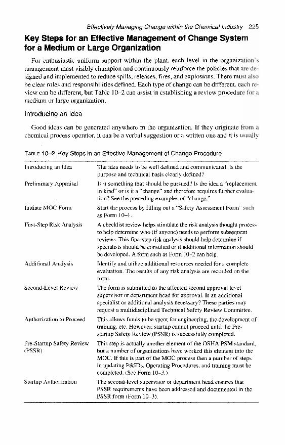
Effectively Managing Change within the Chemical Industry 225
Key Steps for an Effective Management of Change Systemfor a Medium or Large Organization
For enthusiastic uniform support within the plant, each level in the organization'smanagement must visibly champion and continuously reinforce the policies that are de-signed and implemented to reduce spills, releases, fires, and explosions. There must alsobe clear roles and responsibilities defined. Each type of change can be different, each re-view can be different, but Table 10-2 can assist in establishing a review procedure for amedium or large organization.
Introducing an Idea
Good ideas can be generated anywhere in the organization. If they originate from achemical process operator, it can be a verbal suggestion or a written one and it is usually
TABLE 10-2 Key Steps in an Effective Management of Change Procedure
Introducing an Idea
Preliminary Appraisal
Initiate MOC Form
First-Step Risk Analysis
Additional Analysis
Second-Level Review
Authorization to Proceed
Pre-Startup Safety Review(PSSR)
Startup Authorization
The idea needs to be well defined and communicated. Is thepurpose and technical basis clearly defined?
Is it something that should be pursued? Is the idea a "replacementin kind" or is it a "change" and therefore requires further evalua-tion? See the preceding examples of "change."
Start the process by filling out a "Safety Assessment Form" suchas Form 10-1.
A checklist review helps stimulate the risk analysis thought processto help determine who (if anyone) needs to perform subsequentreviews. This first-step risk analysis should help determine ifspecialists should be consulted or if additional information shouldbe developed. A form such as Form 10-2 can help.
Identify and utilize additional resources needed for a completeevaluation. The results of any risk analysis are recorded on theform.
The form is submitted to the affected second approval levelsupervisor or department head for approval. Is an additionalspecialist or additional analysis necessary? These parties mayrequest a multidisciplined Technical Safety Review Committee.
This allows funds to be spent for engineering, the development oftraining, etc. However, startup cannot proceed until the Pre-startup Safety Review (PSSR) is successfully completed.
This step is actually another element of the OSHA PSM standard,but a number of organizations have worked this element into theMOC. If this is part of the MOC process then a number of stepsin updating P&IDs, Operating Procedures, and training must becompleted. (See Form 10-3.)
The second-level supervisor or department head ensures thatPSSR requirements have been addressed and documented in thePSSR form (Form 10-3).

226 Chemical Process Safety
routed to the unit supervisor. Many maintenance improvement ideas are also routed to theunit operating supervisor. Process Engineering or Process Control ideas could travel dif-ferent paths. The idea and technical basis should be defined.
Preliminary Appraisal
Often the frontline operating supervisor performs the initial appraisal. This supervi-sor must consider whether the idea is of potentially significant value and fits in with allof the known constraints of budget, labor contract, engineering specifications, environ-mental permits, and the whole range of other concerns.
The supervisor must determine if it seems to be a true change or a "replacement inkind" as previously defined. In an ideal situation, the unit supervisor and the second-level supervisor (SLS) should discuss the proposed change prior to spending a lot oftime generating the MOC Form and starting the evaluation. It may be that the second-level supervisor has information that such changes have been unsuccessfully tried be-fore, or there is no money in the budget or similar roadblocks.
Initiate MOC Form
For changes proposed by employees (salaried or hourly, operations or maintenance)working within process units, a supervisor of the affected process unit initiates the MOCform. Typically, for changes that are inherent in capital projects, the engineer responsi-ble for the project will initiate the MOC form.
Naturally, some of the boilerplate information, such as requester's name, a good de-scription of the proposed change, any associated equipment numbers, a target date forcompletion, and other descriptors, must be filled in on the form. The reason (or the tech-nical basis) for the change must also be described. In addition, any supplementary doc-umentation that would be helpful for evaluation should be routed with the MOC form,
First-Step Risk Analysis
A checklist review helps stimulate the risk analysis thought process to help determinewho (if anyone) needs to perform subsequent reviews. This first-step risk analysisshould help determine if specialists should be consulted or if additional informationshould be developed. A form such as Form 10–2 can help.
The questions on Form 10-2 are less than two pages. From personal experience, 1have learned that many engineers designing an MOC system want to create long lists ofrisk analysis questions. Later PSM Auditors reviewing MOC will probably want to addeven more questions. Form 10-2 provides an optimum minimum of general questionsfor many plants which do not have combustible dusts or severe static electricity prob-lems. A chemical plant trying to develop a set of questions for a specific location shouldconsider the 45 pages of excellent questions in the Guidelines for Hazard EvaluationProcedures, Second Edition, with Worked Examples. [5]
Additional Analysis
Employees should understand the review process. Form 10–1 lists a whole set of re-sources that can be contacted to address concerns. Some plants and organizations willhave more and some could have less available technical resources.
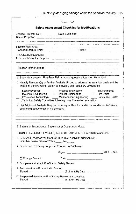
Effectively Managing Change within the Chemical Industry 227
Form 10–1
Safety Assessment Checklist for Modifications
Change Register No.: Date Submitted:Title of Proposal: ,
Specific Piant Area: _Proposed Startup Time: Rush?
REQUESTER to provide1. Description of the Proposal:
Reason for the Change:
2. Supervisor answer "First-Step Risk Analysis" questions found on Form 10–2.
3. Identify Resource(s) or Further Analysis Utilized to address the technical basis and theimpact of the change on safety, and health, and regulatory compliance.
Loss Prevention Process Engineering EnvironmentalMaterials Engineering Project Engineering Fire ChiefInformation Technology Maintenance Engineering Safety and HealthTechnical Safety Committee following Loss Prevention evaluation
4. List Additional Analysis Required or Analysis Results (additional conditions, limitations,supporting documentation if significant)
5. Submit to Second-Level Supervisor or Department Head.
SECONDTivirsUPERVISOR (SLS) or DEPARTMENT HEAD (DH) to address:
6. SLS or DH review/evaluate "First-Step Risk Analysis" question list.Is further review required? Yes No
7. Check one: fj Design Approved/Proceed with Change
Signed (SLS or DH)
n Change Denied Date _
8. Complete and attach Pre-Startup Safety Review.
9. Authorization to Proceed with Startup.Signed (SLS or DH) Date
10. Suspended items from Pre-Startup Review are complete.Signed (SLS or DH) Date
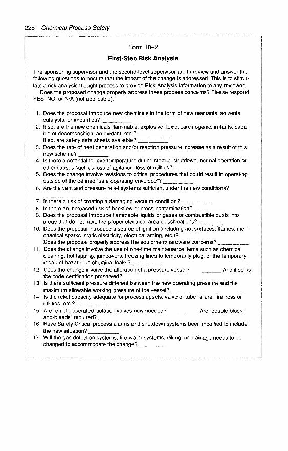
228 Chemical Process Safety
Form 10-2
First-Step Risk Analysis
The sponsoring supervisor and the second-level supervisor are to review and answer thefollowing questions to ensure that the impact of the change is addressed. This is to stimu-late a risk analysis thought process to provide Risk Analysis information to any reviewer.
Does the proposed change properly address these process concerns? Please respondYES, NO, or N/A (not applicable).
1. Does the proposal introduce new chemicals in the form of new reactants, solvents,catalysts, or impurities? _________
2. If so, are the new chemicals flammable, explosive, toxic, carcinogenic, irritants, capa-ble of decomposition, an oxidant, etc.?If so, are safety data sheets available?
3. Does the rate of heat generation and/or reaction pressure increase as a result of thisnew scheme?
4. Is there a potential for overtemperature during startup, shutdown, normal operation orother causes such as loss of agitation, loss of utilities?
5. Does the change involve revisions to critical procedures that could result in operatingoutside of the defined "safe operating envelope"?
6. Are the vent and pressure relief systems sufficient under the new conditions?
7. Is there a risk of creating a damaging vacuum condition? ________8. Is there an increased risk of backflow or cross-contamination?9. Does the proposal introduce flammable liquids or gases or combustible dusts into
areas that do not have the proper electrical area classifications?10. Does the proposal introduce a source of ignition (including hot surfaces, flames, me-
chanical sparks, static electricity, electrical arcing, etc.)?Does the proposal properly address the equipment/hardware concerns?
11. Does the change involve the use of one-time maintenance items such as chemicalcleaning, hot tapping, jumpovers, freezing lines to temporarily plug, or the temporaryrepair of hazardous chemical leaks?
12. Does the change involve the alteration of a pressure vessel? And if so, isthe code certification preserved? _________
13. Is there sufficient pressure different between the new operating pressure and themaximum allowable working pressure of the vessel?
14. Is the relief capacity adequate for process upsets, valve or tube failure, fire, loss ofutilities, etc.? _________
15. Are remote-operated isolation valves now needed? Are "double-block-and-bleeds" required?
16. Have Safety Critical process alarms and shutdown systems been modified to includethe new situation? _______
17. Will the gas detection systems, fire-water systems, diking, or drainage needs to bechanged to accommodate the change?

Effectively Managing Change within the Chemical Industry 229
Larger projects or complicated schemes often receive HAZOP Studies. But smallermore straightforward modifications may not require such an effort. If the type of pro-posed modification under consideration is not covered by plant specifications, codes ordesign and operating philosophy, or if unanswered questions are generated by an as-sessment form, then it is a candidate for further review and further approval levels,
Second-Level Review and Approval
The request is then submitted to the affected second-level supervisor (SLS) or de-partment head (DH) for review and further processing. The SLS or DH may reject therequested modification and file the form if he disagrees with the request or if he decidesthe proposal is not a change that impacts the concerns of process safety and health.
The SLS or DH reviews the risk analysis to ensure complete evaluation of the changeand identification of potential hazards. He uses the analysis results and documentation todetermine if further analysis indicates there is a need for consultation with specialists orto make a "Go/No Go" decision to proceed with making the change. He records whetherthe change is approved or denied by checking the appropriate box on line 7, signs anddates the form,
Authorization to Proceed
If the change is approved, startup cannot proceed until the Pre-Startup Review iscompleted (line 8) and the SLS or DH signs off on line 9. To proceed with the changeany affected documentation is updated, and the change is engineered and constructed.Any requirements identified for later completion are suspended as required. Peoplewhose job tasks will be affected by the change are informed and trained in the changeprior to startup of the process. Individuals who are off shift or absent are trained uponresumption of their job responsibilities.
Pre-Startup Safety Review
Prior to startup of new facilities or facilities that have undergone changes, a Pre-StartupSafety Review (PSSR) must be performed by a supervisor of the affected process unit. Ifthe supervisor is assured that construction and equipment are in accordance with designspecifications and that affected procedures, process safety information, and training areupdated, he completes the PSSR form (see Form 10–3). If any of the pre-startup require-ments have not been met satisfactorily, the supervisor sees to it that the deficiencies arecorrected and the Pre-Startup Safety Review is repeated. Certain items on the PSSR maybe completed after startup only if a suspended condition is generated for later follow-up.The supervisor forwards the MOC and PSSR forms and any attachments to the second-level supervisor or department head for approval to startup the change.
Startup Authorization
The second-level supervisor or department head ensures that PSSR requirements havebeen addressed and documented in the PSSR Form. He may elect to secure additionalapprovals. His authorization signature (line 9) grants approval to start up the new orchanged facilities. If any of the pre-startup requirements have not been met satisfacto-rily, he notifies the supervisor of the affected process unit to correct the deficiencies and

230 Chemical Process Safety
Form 10-3
Pre-Startup Safety Review Checklist
Does the proposal properly address the procedural, training and documentation require-ments as noted below? Please answer YES, NO, or N/A (not applicable).
1. Have the process, mechanical, and instrument drawings been updated, where required?
2. Have the new Material Safety Data Sheets been provided to Operations and Mainte-nance?
3. Have the startup, normal shutdown and emergency shutdown scenarios and proceduresbeen reviewed?
4. Have the schematic wiring, instrument/electrical troubleshooting and other electricaldrawings been updated?
5. Have the equipment files been updated to show the addition of pressure vessels, stor-age tanks, or revisions to them?
6. Have the sewer and underground drawings been updated, where required?
7. Have the alarm listings and safety critical prooftest procedures been developed?
8. Have all the other necessary maintenance testing and inspection procedures been| developed?

Effectively Managing Change within the Chemical Industry 231
repeat the Pre-Startup Safety Review. (Note: Authorization to proceed with the change,completion of the PSSR, and approval for startup may occur at the same time forchanges of a minor nature.)
Complete Suspended Items
Requirements may be identified that will need to be addressed before the Manage-ment of Change procedure is complete. The second-level supervisor or department headis responsible to ensure that suspended items within the PSSR are completed. Suspendeditems could include updating master drawings with the hand-corrected "as-built" mark-ups, completing the documentation to set up prooftests or vessel inspections, or otherimportant items that should not necessarily delay a startup.
Key Steps for an Effective Management of ChangeSystem for a Small Company
Employees in smaller companies must also be very familiar with the MOC reviewprocess. Management must visibly support and continuously reinforce the MOC pro-gram. A small company should at least have a system with a "Change Originator" and a"Change Authorizer." [2]
There needs to be provisions to deal with the "Key Steps in an Effective Managementof Change Procedure" as outlined in Table 10–2. The concepts of introducing the idea,providing a preliminary appraisal, and initiating an MOC Form need to be developed.Some useful ideas of simpler MOC systems proposed before the OSHA PSM standardare available in Appendix A to this chapter—"Some Historical Approaches to PlantChanges." In some Management of Change systems, Form 10–1 may be too cumber-some. A form similar to Form 10-4 might be more acceptable in a smaller operation.Form 10–4 should be used with additional review with something like Form 10–2, theFirst-Step Risk Analysis.
The more difficult task for a small organization is the risk analysis activities. The"Change Authorizer" should decide if the change is within specifications, or within theboundaries of "replacement in kind," basic good engineering judgment or normal vari-ances. A key to the success for this simple system is for both the change originator andthe change authorizer to recognize the limitations of their expertise and to seek techni-cally qualified assistance when appropriate.
Let's face it. The "Change Authorizer" should be a talented individual of authoritywith significant experiences and abilities. In a system that examines all proposed changeswithin a small chemical handling facility, it is anticipated that most changes will requireminimum investigative work. However, it would be wishful thinking if the "Change Au-thorizer" had an available resource to contact if he wanted reassurance.
In an ideal world, an easy-to-contact, responsive "modifications man" would beavailable for questions generated in Operations, Engineering, and Maintenance. This"modifications man" could be a Process Safety Engineer, Loss Prevention Engineer,or a mechanical or chemical engineer who has been trained in chemical process safety.Preferably, this individual would be an on-site plant employee, but he could be a com-pany regional engineer, a property insurance consultant, or a contractor. The "mod-ifications man" must understand basic loss-prevention principles of proper layout,

232 Chemical Process Safety
Form 10–4
A Safety Assessment Checklist for Modifications in a Small Company
Change Register No.: Date Submitted:Title of Proposal: __ . . __^_^
Name of the Change Requester:Specific Plant Area:Proposed Startup Time: Rush?Description of the Proposal:
Reason for the Change:
Circle those factors that may be changed by the proposal
Proposed Classification Maintenance ConsiderationsCapital Improvement Equipment InspectionEnvironmental Improvement Premodification
Periodically in ServiceProcess Change Trip and Alarm TestingAbnormal Operations Maintenance ProceduresEmergency Operations Specialty ContractorsA Short-Term Test Line FreezingTemporary Change Hot Tapping or StoppleMaterials Change Onstream Leak Repair
Preparation for Maintenance Engineering ConsiderationsVessel Replacement Instrument DrawingsVessel Alteration Process DrawingsProcess Control Changes Wiring Diagrams
Process Conditions Trip and Alarm ProceduresTemperature Plant LayoutPressure Pressure Relief DesignVacuum Flare and Vent SpecificationsFlOW Design TemperatureLevel Isolation for MaintenanceComposition Static ElectricityFlashpoint DrainageReactive ConditionsToxicityCorrosion Potentials
List Additional Analysis Required or Analysis Results (additional conditions, limitations,supporting documentation if significant)
Signature of the Change Authorizer
Date Authorized

Effectively Managing Change within the Chemical Industry 233
fundamentals of fire and explosion protection, overpressure protection, electrical areaclassification, property insurance guiding principles, and the like. It is unrealistic tohave such a well-trained individual who can think of all the right questions, so "A SafetyAssessment Checklist for Modifications" should be utilized. Form 10–4 was adaptedfrom Trevor Kletz's publications. [6J
If available, a "modifications man" should be asked to review certain modificationsthat unit supervisors feel need additional scrutiny. If the type of modification underconsideration is not covered by plant specifications, codes, or design and operating phi-losophy, or if unanswered questions are generated by an assessment form, then it is acandidate for further review and further approval levels.
Eight other examples of "Management of Change Policies," "Safety AssessmentChecklists," "Control of Change—Safety Management Practices," "Change of ProcessTechnology," etc., can be found in Plant Guidelines for Technical Management ofChemical Process Safety. [4]
Multidisciplined Committee Can Provide an In-DepthLook When Identifying Hazards
When there is concern during the "First-Step Risk Analysis" that the reviewers have anincomplete understanding, then help can often be achieved most effectively with a haz-ards identification procedure or a multidisciplined committee. Most medium-sized andlarge chemical and petrochemical corporations have or should implement flexible proce-dures for several layers of process safety reviews for capital projects as major modifica-tions, and expansions. There should be a procedure to alert or assign a "modificationsman" to examine the early stages of the proposed change. If the change is covered byspecifications or plant policy, or properly addressed by codes of practice, the review maystop at this point with or without a brief note depending on systems.
If a proposed change falls outside of plant specifications, codes of practice, or is rela-tively new technology, then a chemical process safety review team evaluation may be inorder. Different organizations provide various names to process safety review teams,such as: Safe Operations Committee, Hazards Review Committee, Technical SupportTeam, Facility and Operations Change Review Committee, or Chemical Process SafetyReview Team. Typically, this technical safety committee is chaired by mid-level super-vision. The committee can be lead by a Technical Manager, Engineering Superintendent,Manager of Process Safety, or others who are not directly affected by the budgetary con-straints or the startup deadlines.
Some successful chemical process safety review committees have a nucleus of two orthree individuals supporting the committee chair. A well-rounded process engineer fromengineering, an operations representative, and a Process Safety Coordinator are often keycentral players in such a committee. The committee should be rounded out with more in-dividuals who can make specific contributions, including process control engineers,chemists, mechanical engineers, unit supervisors, chemical process operators, environ-mental engineers, project engineers, fire protection engineers, reliability engineers, andsafety personnel. Progressive organizations include chemical process operators, shippingloaders, and other "hands-on" personnel if the occasion warrants their presence.
In certain cases, such as changes created by a significant expansion, it is better to havea small group of specialists first identify the potential hazards and seek out inherently

234 Chemical Process Safety
safer designs prior to any type of committee review. Brief descriptions of various ap-proaches to hazard identification are presented in Appendix B to this chapter.
The points of agreement of Chemical Process Safety Committee meetings should becaptured in meeting minutes. In some organizations a senior management team reviews theminutes and approves the conclusions. Once the minutes are accepted, the commitmentsmade by various participants should be recorded and the progress of each recommendationshould be periodically reviewed until such items are accomplished.
Periodic compliance questionnaires should be sent to the operating unit to review theprogress on those recommendations that were made to reduce risk, but were not requiredto be completed before startup. It is necessary to verify recommendations have beencompleted and this must be acknowledged in the records. Recommendations that werestudied further and later deemed impractical or capable of creating additional troublesmust not be allowed to remain in limbo. These items should be resubmitted to theprocess safety committee for reevaluation.
Variances, Exceptions, and Special Cases of ChangeAll deviations from normal plant policy requirements must follow a prescribed pro-
cedure. It must be approved by authorized individuals and properly documented prior toimplementation. In ideal situations, all variances are submitted in writing.
A Procedure to Address Taking Alarms, Instruments, or ShutdownSystems Out-of-Service
A "Safe Operating Procedure" developed to create a uniform method to ensure that ap-propriate steps are taken prior to bypassing or removing an alarm, instrument, or shutdownsystem from service is described in the section that follows. This procedure can provide aneffective way of communicating the status of an impaired instrument. The procedure hasbeen in use for over five years. It assumes that all instrumentation has been classified intothree safety critical systems. [7] (These classes have been defined in Chapter 9, but arerepeated here.)
Critical Consequences—Class 1. Safety Critical instruments whose failure would eithercause, or fail to inform of, situations resulting in accidental fire, explosion, uncontrolled re-lease of dangerous materials, reportable environmental releases, or major property or pro-duction losses. The safety critical instruments assigned a "Class 1" include those that havebeen mandated as such by regulating agencies, an in-house technical safety review com-mittee, reliability studies, specific shutdown systems, and specific alarms deemed criticalby operations supervisors.
Class 1 safety instrumentation loops include alarms and trips on storage tanks con-taining flammable or toxic liquids, devices to control high temperature and high pressureon exothermic-reaction vessels, and control mechanisms for low-flow, high-temperaturefluids on fired heaters. Other Class 1 instruments include alarms that warn of flame fail-ure on fired heaters, and vapor detectors for emergency valve isolation and sprinkler-system activation. All of these alarms, shutdown valves, and other critical instrumentsare regularly prooftested on a well-defined schedule.
Serious Consequences—Class 2. Safety Critical instruments whose failure could ei-ther cause, or fail to inform of, serious conditions involving environmental releases,
Effectively Managing Change within the Chemical Industry 235
property or production losses, or other non-life-threatening situations. These instrumentsare given a slightly lower priority, but are also prooftested on a regular schedule.
Class 2 Safety Critical instruments include alarms or trips on refrigeration systems,rectifiers, cooling towers, kettles, and stills. [7]
Normal Consequences—Class 3. Instrument systems that are used to alert the chem-ical process operator of a nonhazardous abnormal condition that might otherwise be un-detected. The failure to react to one of these alarms may create an off-specificationproduct such as a low-temperature alarm on certain distillation columns. These systemsare not included in the prooftest program.
1. If an instrument or instrument system malfunctions, the operator tries to correct theproblem. If an alarm, flow- or temperature-measuring instrument or shutdown systemmalfunctions, the operator's first response should be an attempt to restore it to service. Itmay be a plugged impulse line, inadvertent flow shut off to an analyzer, etc. If the In-strument System is a Class 1 or 2, immediately go to Step 2. If the alarm is a Class 3, theLead Operator (or Shift Foreman) should be consulted and follow established proceduresand his knowledge of the unit and the specifics of the situation to determine the tempo-rary steps required. At the minimum, a note in the maintenance logbook must be madeto initiate repairs. Stop Here for Class 3 Alarms.
2. If the instrument system is considered a Class 1 or Class 2 system, the Lead Oper-ator (or Shift Foreman) must be consulted and follow established procedures and hisknowledge of the unit and the specifics of the situation to determine the temporary stepsrequired. (Typically a Class 1 Shutdown System would have already tripped by this time.)The Lead Operator will decide if it is tolerable to take the instrument out of service. If itis safe to do so, the Lead Operator will complete an "out-of-service " tag and mount it onthe control panel. (This is a small brightly colored tag with adhesive on the back, like a"Post It" tag. It should be mounted on the control panel or other prominent place.)
At the minimum, the lead operator will make a note in the Operations Logbook andthe Maintenance Logbook. An orderly shutdown may be required, if so the Shift Super-visor should be consulted.
If the situation arises which requires an instrument to be out of service for a very shortperiod of time (e.g., an instrument mechanic is "freeing-up" a stuck shutdown valve withthe operator present, or temporarily pulling alarm cards to help identify "mysteryalarms," etc.), the lead operator should be informed and the operator gives his undividedattention to the problem, but an "out-of-service" tag may not be filled out.
The "Out-of-Service" tag is not a substitute for promptly performing maintenance. Thetag serves only to effectively communicate the status of instruments in need of repair.
3. The Lead Operator must take immediate action to restore the out-of-service in-strument. On a normal day shift, this will require contact with the supervisor who maydirect the efforts of a mechanic, or generate an "Emergency" work order. On the backshifts or holidays, this may mean having the Shift Supervisor summon the mechanic(s)from home.
4. When repairs are successfully completed and the safety critical instrument is re-stored, the Lead Operator will remove the "out-of-service" tag from the control board.He fills out the blank, which indicates the date when the instrument was restored, andtapes the small slip into the logbook.

236 Chemical Process Safety
5. A "Weekly Out-of-Service Tagging Checklist" will be completed by each unitevery Monday morning before the day shift arrives. This is a check of all the standardpanel alarm lights and a review of any work that remains to be accomplished. (Thispanel alarm light audit is not for the new technology of distributed control instrumenta-tion.) As a cross-check, a review of all the "out-of-service" tags of the previous weekwill be made. Each of the safety shutdown system valves that have been bypassed dur-ing the previous week will be inspected in the field to ensure that they are neither blockednor operating with the bypass open.
Safety Critical Instrument Setting Changes
Critical values of operating temperatures, pressures, and flows are often establishedprior to the startup of the unit. As experience is gained, it may be necessary to fine-tunethe alarm points and shutdown values. At a minimum, this should be approved by thesecond-level supervisor or unit manager.
If the shutdown system is complex, or there are reactive chemicals involved, it mayrequire additional help from individuals in research or the lab.
Delays to Safety Critical Instrument Tests and EquipmentInspection Frequencies
Occasionally, there may be business pressures or maintenance scheduling problemsthat would encourage the delay of prooftesting of safety critical alarms and shutdown sys-tems. Such situations can also delay vessel inspections and safety relief valve testing.Some type of variance procedure or review policy should be defined to handle this occa-sional need. Such a policy ought to require the review of all of the inspection and testrecords on the specific equipment involved as well as an approval of the superintendentof the area.
When Hazard Studies are performed on new plants and modifications, certain inspec-tion and test frequencies are defined. There should be a review process for changes. Ifequipment and instrumentation inspections reveal a pattern of failing to meet expectations,the testing or inspection should be increased and alternate equipment must be considered.
There must be an approval mechanism to reduce unnecessary inspection and testingif repeated testing shows ideal performance. Many test frequencies are initially self-imposed to be annual, which could be too frequent. Those type of changes should havean approval trail which includes the unit manager, or second-level supervisor, the criti-cal instrument testing supervisor, and a process safety representative.
Management of Change Approvals, Documentation,and Auditing
Approvals, Endorsements, and Documentation
A responsive modification review and approval system with competent reviewerscan gain acceptance quickly. If a modification approval system is unnecessarily cum-bersome, there can be tension between the sponsor and the reviewer or there can be at-tempts to circumvent any proposal.

Effectively Managing Change within the Chemical Industry 237
We all must realize that a modification control system, especially for the many littlebut vital changes, must not be so formal that an answer cannot be expected in a reason-ably short time. A multiple-layer system must be in place to deal with the entire rangeof proposals from the very simple change to the very complex.
Auditing the Management of Change Program
Common sense and the OSHA Chemical Process Safety Management Law requires anaudit of compliance to the Management of Change. Periodic review and documentationof a site's activities in managing aspects of personnel and process safety is often a part ofan organization's culture. A good audit can measure the "actual" versus "intended" ef-fectiveness of various programs.
Each organization must devise its own way to conduct an audit. Other readers maywish to consider details of "Audits and Corrective Actions" or Chapter 13 of Plant Guide-lines for Technical Management of Chemical Process Safety [4], which covers broad top-ics such as "Scope," "Staffing," "Frequency," "Reports," and "Internal and ExternalAuditors." It is not the intent of this book to cover that aspect of auditing.
Some Generic Management of Change Audit Questions
These are some commonsense audit questions for the Management of Change. Otherquestions can be found in Appendix 13 A of Plant Guidelines for Technical Managementof Chemical Process Safety. [4]
« Is there a formalized documented policy in place for the review and authorizationof changes in the hardware and the operating procedures in units that produce, use,handle, or store hazardous materials?
• Do all of the affected individuals including the engineers, supervisors, chemicalprocess operators, maintenance mechanics, purchasing employees, etc., understandthat there is a management of change policy?
• Is there a "modifications man" available who can provide expertise, has the time toreview changes, and can promptly answer process safety questions?
• Is the system to track and verify process safety recommendations working well andis it up-to-date?
• Is there a procedure to cope with and authorize "minor" temporary changes such asoperating without some critical alarms and a system to ensure that these "minor"temporary changes are restored?
• How is the Management of Change policy perceived by operators, supervisors, me-chanics, engineers, etc.?
• Have any recent incidents appeared to have been created by a change within theplant, either authorized or unauthorized?
Closing Thoughts on Management of Change PolicyThe material in this long chapter may not cover the needs of every chemical plant and
every petrochemical plant, but the ten or fifteen "Management of Change" procedures de-veloped by major corporations and reviewed by me did not seem to exactly fit the needsor culture of my own organization. Trevor Kletz has said many times that improper plant

238 Chemical Process Safety
modifications have been a major cause of chemical plant accidents. I have been workingin a process safety function for a quarter century and my experiences have been similar.It just seems appropriate to repeat the first three paragraphs of the second section of thischapter, as a fitting close.
There must be a formal method to deal with change in the chemical industry. Thesafety designed into the original process often occurs after a multidisciplined designteam agonized for the optimum arrangement of process and layout. This process safetymust not be jeopardized by poor-quality modification schemes.
No recipe or procedure can be devised to be universally acceptable. The exact ap-proach used to scrutinize a proposed change must be site-specific and developed for thatlocation. There must be a sustained management commitment to the management ofchange program since this may require a change in culture within many organizations.
Each chemical plant and refinery must adopt or develop a procedure tailored to fit thespecific hazards, the available technical resources, the culture of the organization, and re-quired governmental regulations. It must be practical and workable without undue delays.

Effectively Managing Change within the Chemical Industry 239
Appendix A
Some Historical Approaches to Plant ChangesMany of the management of change practices developed by farsighted companies in
the 1970s and 1980s are still valuable today. In April 1976, four chemical corporationsshared their progressive modification procedures at a Loss Prevention Symposium spon-sored by the American Institute of Chemical Engineers. Those technical papers were pub-lished in the AIChE's Loss Prevention, vol. 10.
In one paper, Peter Heron described the approach that BP Chemicals International,Ltd. London used at that time. He pointed out that all process and plant changes weresubjected to a regime of formal scrutiny and authorization. Minor alterations, such as theaddition of a valve, a change in materials of construction, or the switch in the type of me-chanical seal, were made at the discretion of the group manager, or the supervisory levelabove the unit supervisor. This individual must be satisfied that adequate considerationwas given so that there are not any undesired side effects. [8]
Major changes to existing units in BP Chemical, at the time the article was published,required consideration and formal authorization by personnel at the departmental man-agement level. A procedure that was used at one of the BP Chemicals Plant was includedin the article, and it included important items to be considered. Parts of two items on thelist of 14 items [8] are quoted here:
The proposal initiator and plant manager [the British "plant manager" is equiva-lent to the U.S. second-level supervisor or unit manager], plant engineer, chemicalengineer and instrument/electrical engineer, as appropriate, should together dis-cuss any proposed modification. They will prepare a set of notes and a sketch de-scribing the modification and submit these for approval to the relevant staff.
The plant manager will assess the effect of the proposals on all plant operations,including normal and routine operations, startup, shutdown and emergency actions.He must also check that hazardous conditions cannot arise due to mal-operation.
The plant engineer and/or instrument/electrical engineer will assess the effect ofthe modification on maintaining plant and equipment and will also ensure that theproposal meets:
• The original plant design standards were appropriate• The level of good engineering standards demanded on site
Peter Heron's article concludes with a statement that all of these procedures bring to-gether a multidisciplined team that ensures fewer problems in implementing, commis-sioning, and operating modified units. He further reflects that there is often a dilution ofexperience in management and these procedures assist in ensuring consideration of abroad spectrum of potential side effects. [8]
Trevor Kletz presented a number of very suitable examples of modifications thatwent sour in his article at that same symposium in 1976. After presenting several pagesof problems with modifications, Kletz stated [6]:
None of the accidents described here occurred because knowledge was lacking onmethods of prevention: they occurred because no one saw the hazards, nor askedthe right questions. To prevent similar accidents in the future, a three-pronged ap-proach is necessary.
240 Chemical Process Safety
There must he a rigid procedure for making sure that all modifications are au-thorized only by competent persons, who, before doing so, try to identify all possi-ble consequences of the modification then specify the change in detail.
There must be some sort of guide sheet or check list to help people identify theconsequences.
An instruction and aids are not enough. People will carry out the instructionsand use the aids only if they are convinced that they are necessary. A training pro-gram is essential.
Kletz's article also presented the 1976 procedures utilized by Imperial Chemicals In-dustries, Ltd. (ICI), Wilton, England. It stated that within the Petrochemicals Division ofICI, any modification, even if it is very inexpensive, or temporary, must be authorizedin writing by a competent manager (or, in the United States, a second-line supervisor)and an engineer. [6]
The ICI Procedures required the use of a "Safety Assessment" guide sheet, which dis-cussed overpressure protection equipment, electrical area classification, changes inalarms and trips, and other categories that might diminish the safety of the system (seeForm 10–4, which was developed from Trevor Kletz's article). The guide sheet also hadquestions on the relevant Codes of Practice and Specifications, questions on the materi-als of construction and fabrication standards, and any necessary changes in operatingconditions. This ICI "Safety Assessment" guide sheet, widely published first in 1976,seems to have withstood the test of time. It was published again in 1992, in a "how to"section of a current book of practical guidelines.
It would be unreasonable to think that both of these companies are still operating ex-actly as they did in the 1970s. Many chemical companies restructured and reduced thesize of their technical staffs in the mid-1980s, and many other organizations addedchemical process safety professionals. However, these approaches still seem very use-ful and workable.
How Are Chemical Plants Addressing Plant Modificationsduring the 1980s and Beyond?
In 1985, the Canadian Chemical Producers Association (CCPA) released a pamphletentitled, Essential Components of Safety Assessment Systems. This pamphlet was devel-oped to aid Canadian chemical producers determine the adequacy of their process safetyprograms. Modifications to a plant or process was one of the nine internal programs ex-amined by the CCPA. The guiding principles required a management program to for-mally examine and approve any significant changes in chemical components, processfacilities or process conditions whether temporary or permanent, prior to implementation.The procedure, as recommended by the Canadian Chemical Producers Association, ad-dressed 12 elements. It was intended that each element would be reviewed by qualifiedindividuals to assess if the proposed change could jeopardize the integrity of the system.The following considerations are based on the CCPA's publication and could be used asa simple evaluation form. [9]
This excellent, 44-page Canadian booklet [9] lists 58 references covering, but not lim-ited to: Emergency Planning, Process Hazards Reviews, Fault Tree Analysis, Evaluationof Toxic Vapor Cloud Hazards.

Effectively Managing Change within the Chemical Industry 241
KEY CONSIDERATIONS WHEN REVIEWINGMODIFICATIONS
(Adapted from the Canadian Chemical Producers Association.)
1. Does the change involve any different chemicals which could react with otherchemicals, including diluents, solvents, and additives already in the process?
2. Does the new proposal encourage the production of undesirable by-productseither through the primary reactions, through side reactions, or introduction ofimpurities with the new chemical component?
3. Does the rate of heat generation and/or the reaction pressure increase as a re-sult of the new scheme?
4. Does the proposed change encourage or require the operation of equipmentoutside of the approved operating or design limits of chemical processingequipment?
5. Does the proposal consider the compatibility of the new chemical componentand its impurities with materials of construction?
6. Has the occupational health and environmental impact of the change beenconsidered?
7. Has the design for modifying the process facilities or conditions been re-viewed by a qualified individual using effective techniques for analyzingprocess hazards, particularly when the modifications are being made in rushsituations or emergency conditions?
8. Has there been an on-site inspection by qualified personnel to ensure that thenew equipment is installed in accordance with specifications and drawings?
9. Have the operating instructions and engineering drawings been revised totake into account the modifications?
10. Have proper communications been made for the training of chemical processoperator, maintenance craftsman, and supervisors who may be affected by themodification?
11. Have proper revisions been made to the process control logic, instrumentationset points, and alarm points, especially for computer control systems, to prop-erly respond to the modification?
12. Have provisions been made to remove or completely isolate obsolete facili-ties in order to eliminate the chances for operator errors involving abandonedequipment?

242 Chemical Process Safety
The Center for Chemical Process Safety
The American Institute of Chemical Engineers (AIChE) has been involved in Chem-ical Process Safety and Loss Prevention for chemical and petrochemical plants fordecades. In early 1985, the AIChE established the Center for Chemical Process Safety(CCPS) to intensify development and dissemination of the latest scientific and engi-neering practices for prevention and mitigation of catastrophic incidents involving haz-ardous chemicals. The CCPS serves as a focus for developing literature and courses tocontinue to improve chemical process safety.
New Recommendations and New RegulationsIn December 1988, the Organization Resources Counselors, Inc. (ORC), in order to
assist the U.S. Occupational Safety and Health Administration (OSHA) prepared a re-port entitled "Recommendations for Process Hazards Management of Substances withCatastrophic Potential." [10] This document was drafted to help OSHA revise standardsfor handling hazardous materials.
The ORC is a Washington, D.C.-based private industry group with many representa-tives from the chemical industry. The ORC agreed to help because they were concernedabout another worldwide disaster that may cause the United States Congress to quicklydevelop legislation which may be ineffective. The ORC was also concerned about theproliferation of similar regulations at the state level and they felt a performance standardwas essential if the law was to be effective. [11]
The ORC indicated their report was capable of being a useful starting point in the de-velopment of a policy or program for dealing with chemical process hazards. The reportspecifically indicated that it was intended as a guideline or starting point only, and itshould be extensively reviewed and analyzed before being implemented.
The American Petroleum Institute developed Recommended Practice 750, Manage-ment of Process Hazards [12], and released it in January 1990. This sensible 16-pagedocument is based in part on the ORC report.
The Chlorine Institute developed and released Pamphlet 86, Recommendations toChlor-Alkali Manufacturing Facilities for the Prevention of Chlorine Releases [13], inOctober 1990. This 15-page pamphlet acknowledges that the ORC report "Recommen-dations for Process Hazards Management of Substances with Catastrophic Potential"was one of the primary documents used to develop it.
In 1992, the American Institute of Chemical Engineer's Center for Process Safety re-leased a book entitled, Plant Guidelines for Technical Management of Chemical ProcessSafety; there was a chapter dedicated to management of change. Six different approachesto management of change were offered as examples of workable systems. [4]
The ORC document emphasized the application of management control systems to fa-cilities processing highly hazardous chemicals. The ORC report helped form a new lawwithin the United States. The new standard, OSHA 1910.119, "Process Safety Manage-ment of Highly Hazardous Chemicals," is part of the U.S. Code of Federal Regulations andwas drafted in July 1990, and implemented on May 26, 1992.

Effectively Managing Change within the Chemical Industry 243
Appendix B
How Should Potential Hazards Be Identified and Evaluated?Frank Lees begins chapter 8 of Loss Prevention in the Process Industries, "Hazard
Identification and Safety Audit," [14] with the following paragraphs:
The identification of areas of vulnerability and of specific hazards is of fundamen-tal importance in loss prevention. Once these have identified, the battle is morethan half won.
Such identification is not a simple matter, however. In many ways it has becomemore difficult as the depth of technology has increased. Loss prevention tends in-creasingly to depend on the management system and it is not always easy to discoverthe weaknesses in this. The physical hazards also no longer lie on the surface, ac-cessible to simple visual inspection.
On the other hand, there is now available a whole battery of safety audit andhazard identification methods to solve these problems.
No single identification procedure can be considered the "best" for all companies orall situations. Large refineries and large single-train industrial chemical producers withlimited products and large technical staffs will by nature approach their reviews differ-ently than specialty batch operations for making limited campaigns of products whichare herbicides, insecticides, and other specialty chemicals.
Some considerations for choosing the type of evaluation would include:
• Potential "Worst Case" Consequences• Complexity of the Process or Facility• Experience Level of the Available Review Members• Time and Cost Requirements• Corporate Standards, State, and Local Requirements
Any and all reviews should take an orderly, systematic approach. Also it may be suf-ficient for a general qualitative review, except for some sophisticated portions of the pro-posed modification. The review team should be responsible for determining deficiencies,but not defining solutions. Lees [14] notes many selected references to help evaluateprocesses.
The AIChE's Guidelines for Hazard Evaluation Procedures, Second Edition [5], of-fers a wide variety of alternatives to review systems for hazards. These review proce-dures can be used to evaluate some plant modifications. No single identificationprocedure can be considered the "best" for all companies or all situations. Two basic cat-egories of evaluations are (1) adherence to good engineering practice and (2) predictivehazard evaluation.
Adherence to Good Engineering Practice
Adherence to good engineering practice means that the modification is reviewed andcompared to corporate or plant standards, state and local codes, insurance regulations, andsocietal codes. Many companies have developed excellent checklists or standards basedon years of experience with the manufacture, use, and handling of various chemicals.
244 Chemical Process Safety
Checklists, "What If Methods, and Multiple Discipline Reviews are often an excel-lent method to review a modification. These methods can ensure that design specifica-tions are adhered to, that previously recognized hazards are identified, and that P&IDsand operating procedures are updated. "What If' type studies have been used to somedegree for years. This type of questioning activity was often the method a junior processengineer would experience when presenting a proposal to a review team in previousyears. Not much has been written on this type of group brainstorming activity. However,the "Guidelines" [5] offer examples of a systematic approach. The method is suitable foran experienced staff reviewing a modification.
Checklists can be user friendly if properly prepared by experienced engineers. Suchchecklists can be very useful tools to assist less experienced engineers in considering sit-uations that Fault Trees Analysis may find if given enough time or that "What Ifs" mayoverlook.
A one-page, memory-jogging safety assessment checklist was made available byTrevor Kletz in 1976. [6] The checklist is still valid today. After a review of several"Management of Change" policies from several major companies, it appears that Kletz'schecklist or a similar checklist was used as a basis for a few companies' procedures.
Frank Lees [14] has cataloged and presented a number of checklists in "Hazard Iden-tification and Safety Audit." Lees states:
One of the most useful tools of hazard identification is the checklist. Like a standardor code of practice, a checklist is a means of passing on hard-won experience. It isimpossible to envisage high standards in hazard control unless this experience is ef-fectively utilized. The checklist is one of the main tools available to assist in this,
Checklists are only effective if they are used. There is often a tendency for them to beleft to gather dust on the shelves. This is perhaps part of the reason for the developmentof other techniques such as hazard and operability studies.
The Guidelines for Hazard Evaluation Procedures, Second Edition [5] also offers 45pages of sample questions in its appendix B. These questions cover process (i.e., flow-sheets and layout), equipment (reactors, heat exchangers, piping, and instrumentation),operations, maintenance, personnel safety, and other broad areas.
Other practical engineering information which can help evaluate modifications maybe obtained from individual organizations, such as the American Institute of ChemicalEngineers, the American Petroleum Institute, the Institution of Chemical Engineers(England), the National Fire Protection Association, etc. Chapter 12 lists a number ofsuch resources and the mailing addresses to obtain helpful information.
Predictive Hazard Evaluation Procedures
Predictive hazard evaluation procedures may be required when new and differentprocesses, designs, equipment, or procedures are being contemplated. The Dow Fire andExplosion Index provides a direct method to estimate the risks in a chemical process basedon flammability and reactivity characteristics of the chemicals, general process hazards (asexothermic reactions, indoor storage of flammable liquids, etc.) and special hazards (as op-eration above the flash point, operation above the auto-ignition point, quantity of flamma-ble liquid, etc.). Proper description of this index can be found in the 57-page Dow's Fireand Explosion Index, Hazard Classification Guide, 5th ed., AIChE, New York, 1981.

Effectively Managing Change within the Chemical Industry 245
The HAZOP Study is a very popular predictive method that was developed in theMond Division of Imperial Chemical Industries during the 1960s. A HAZOP (Hazardand Operability) study is an analysis method for identifying hazards and problems whichprevent efficient operation. Trevor Kletz was an early promoter of the HAZOP Methodand in one of his recent books [15], he states:
A Hazard and Operability study (HAZOP) is the preferred method, in the processindustries, of identifying hazards on new or existing plants.
, . . We need to identify hazards before accidents occur. Check lists have the dis-advantage that new hazards, not on the list, may be overlooked so we prefer themore open-ended HAZOP technique. It allows a team of people, familiar with thedesign, to let their minds go free and think of all the deviations that might occur butit is done in a systematic way in order to reduce the chance of missing something.
Note that HAZOP identifies operating problems as well as hazards.Although HAZOP has been used mainly in the oil and chemical industries it can
be applied to many other operations.The technique is applied to a line diagram, line-by-line. Using the guide word
"NONE" we ask if there could be no flow, or reverse flow, in the first line. If so,we ask if this would be hazardous or would prevent efficient operation. If it would,we ask what change in design or method of operation will prevent no flow, or re-verse flow (or protect against the consequences). Using the guides, "MORE OF"and "LESS OF" we ask if there could be more (or less) flow, pressure or tempera-ture in the line and if this would be hazardous, etc. Using the guide words "PARTOF" and "MORE THAN" we ask about the effects of changes in concentration orthe presence of additional substances or phases. The guide word "OTHER" re-minds us to apply our questioning to all states of operation, including startup, shut-down, catalyst regeneration and so on and we also ask if the equipment can he safelyprepared for maintenance. We then study the next line in the same way. All linesshould be studied including service lines and drains.
A HAZOP Study Team is best when it is a multidisciplinary group formed tobring a broader base of experience to the review. A HAZOP may not be suitable forthe small modification of a few extra valves or a new run of pipe, but it is desirablefor the medium-sized and larger modifications.
Robert Johnson presented a technical paper in April 1992 entitled "HAZOPS Today"[16] in which he stated, "The hazard and Operability studies (HAZOPS) method haslikely become, over a period of less than ten years, the most widely used hazard evalu-ation procedure in the process industries." Johnson also explained that HAZOPS is a rel-ative latecomer to the United States and it has attained a high degree of prominence inthe U.S. process industries. The method began in the United Kingdom and has nowspread throughout western Europe and North America. (See Figure 10-1.)
Another widely used predictive method is the use of Fault Tree Analysis. This is a "re-verse-thinking" method. The analyst assumes an accident or specific undesirableevent—the so-called "TOP Event." This could be the release of a toxic gas from a reac-tor safety relief valve.
The analyst must then define the various equipment failures and human failures thatcould lead up to that event. For the release of toxic gas from a reactor safety relief valve,
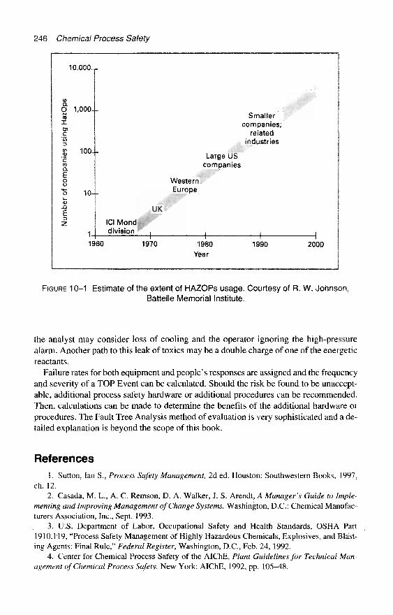
246 Chemical Process Safety
10,000-,
mQ.0 1,000.IMenXo>c"53
§ 100-"E03a.Eo
"o 10-
J3ErsZ
1
19
Smallercompanies;
relatedindustries
Large UScompanies
WesternEurope
UK
ICIMond*.division , ,
I I60 1970 1980 1990 2000
Year
FIGURE 10-1 Estimate of the extent of HAZOPs usage. Courtesy of R. W. Johnson,Battelle Memorial Institute.
the analyst may consider loss of cooling and the operator ignoring the high-pressurealarm. Another path to this leak of toxics may be a double charge of one of the energeticreactants.
Failure rates for both equipment and people's responses are assigned and the frequencyand severity of a TOP Event can be calculated. Should the risk be found to be unaccept-able, additional process safety hardware or additional procedures can be recommended.Then, calculations can be made to determine the benefits of the additional hardware orprocedures. The Fault Tree Analysis method of evaluation is very sophisticated and a de-tailed explanation is beyond the scope of this book.
References1. Sutton, Ian S., Process Safety Management, 2d ed. Houston: Southwestern Books, 1997,
ch. 12.2. Casada, M. L., A. C. Remson, D. A. Walker, J. S. Arendt, A Manager's Guide to Imple-
menting and Improving Management of Change Systems. Washington, D.C.: Chemical Manufac-turers Association, Inc., Sept. 1993.
3. U.S. Department of Labor, Occupational Safety and Health Standards, OSHA Part1910.119, "Process Safety Management of Highly Hazardous Chemicals, Explosives, and Blast-ing Agents: Final Rule," Federal Register, Washington, D.C., Feb. 24, 1992.
4. Center for Chemical Process Safety of the AIChE, Plant Guidelines for Technical Man-agement of Chemical Process Safety. New York: AIChE, 1992, pp. 105–48.
Effectively Managing Change within the Chemical Industry 247
5. Guidelines far Hazard Evaluation Procedures, Second Edition, with Worked Examples.Prepared by Battelle—Columbus Division, Center for Chemical Process Safety of the AIChE,New York, 1992.
6. Kletz, Trevor A., "A Three-Pronged Approach to Plant Modifications," Loss Prevention10, 1976: pp. 91–98. This material is also available as "Hazards of Plant Modifications—HazardWorkshop Module 002" (available as a training kit with slides, booklets, guides, etc., by the In-stitution of Chemical Engineers, Rugby, England).
7. Sanders, Roy E, and James H. Wood, "Don't Leave Plant Safety to Chance," Chemical En-gineering, Feb. 1991: pp. 110–18.
8. Heron, Peter M., "Accidents Caused by Plant Modifications," Loss Prevention 10, American Institute of Chemical Engineers, New York: pp. 72-78.
9. Canadian Chemical Producers Association, Essential Components of Safety AssessmentSystems, Ottawa, Ontario, 1985.
10. Organization Resources Counselors, Inc. (ORC), "Recommendations for Process HazardsManagement of Substances with Catastrophic Potential." Washington, D.C.: ORC, December1988.
11. Boyen, V. E., "A Compliance Strategy for Process Safety Regulations," presented at the1992 Loss Prevention Symposium of the American Institute of Chemical Engineers in New Or-leans, La., April 1992.
12. American Petroleum Institute, Management of Process Hazards—API RecommendedPractice 750, Washington, D.C., 1990.
13. Chlorine Institute, Recommendations to Chlor-Alkali Manufacturing Facilities for the Pre-vention of Chlorine Releases, Pamphlet 86, Edition 1. Washington, D.C.: Chlorine Institute, 1990.
14. Lees. F. P., Loss Prevention in the Process Industries vol. 1, ch, 8. London: Butterworth,1980.
15. Kletz, Trevor A., Critical Aspects of Safety and Loss Prevention. London. Butterworth,1990, pp. 155-57.
16. Johnson, R. W. and F. L. Leverenz, Jr., "HAZOPS Today," presented at the 1992 Loss Pre-vention Symposium of the American Institute of Chemical Engineers in New Orleans, La., April,1992.

This page intentionally left blank
CHAPTER 11
Investigating and Sharing Near-Misses and Unfortunate Accidents
No one rejoices when an incident occurs. An incident can bring embarrassment,equipment damage, interrupt production, create injury or worse. But often, an effectiveand timely incident investigation is an opportunity to acquire new insight. Within thespirit of continuous improvement, a system for investigating and sharing findings of sig-nificant incidents, near-misses, and truly perilous incidents can be a key for a better to-morrow. Common sense and the OSHA Process Safety Management (PSM) standarddictate that there must be a practical method to investigate process safety incidents.
World-class organizations have incident investigations described as "Near-Miss Re-porting" or "Significant Incident Reporting," which covers a range of abnormal inci-dents or injuries. They also have "Accident Investigations for OSHA RecordableCases," which involves an injury, and "Spill/Release Notification Guidelines" for envi-ronmental insults.
For decades, most chemical manufacturers have employed a hierarchy of reviews, in-vestigations, and reports for safety and environmental insults and incidents. It is obviousthat a Process Safety Incident Investigation is the "highest level" investigation that canincorporate other more limited investigations and reports.
This chapter provides an overall view of Incident Investigation with a focus on PSM-type incidents. Look forward to a chapter that:
« provides the OSHA-PSM standard for Incident Investigation• provides the OSHA Nonmandatory Appendix C Compliance Guidelines• discusses the cultural atmosphere surrounding incident reporting• presents the "layered" look at investigations« presents a view of Root Cause Analysis• offers a practical PSM Incident Investigation procedure• provides tips on interviewing for incident investigation
250 Chemical Process Safety
What Does the Regulation Say about IncidentInvestigations?
What does the Process Safety Management standard say? The regulation, 29 C.F.R,Part 1910.119, entitled "Process Safety Management of Highly Hazardous Chemicals,"has the following to say about Incident Investigations [1]:
The employer shall investigate each incident which resulted in, or could reasonablyhave resulted in a catastrophic release of a highly hazardous chemical in the work-place.
An incident investigation shall be initiated as promptly as possible, but not laterthan 48 hours following the incident.
An incident investigation team shall be established and consist of at least oneperson knowledgeable in the process involved, including a contract employee if theincident involved work of a contractor, and other persons with appropriate knowl-edge and experience to thoroughly investigate and analyze the incident.
A report shall be prepared at the conclusion of the investigation which includesat the minimum:
(i) Date of incident;(ii) Date investigation began;(iii) A description of the incident(iv) The factors that contributed to the incident, and,(v) Any recommendations resulting from the incident.The employer shall establish a system to promptly address and resolve the inci-
dent report findings and recommendations. Resolutions and corrective actionsshall be documented.
The report shall be reviewed with all affected personnel whose job tasks are rel-evant to the incident findings including contract employees where applicable.
Incident investigation reports shall be retained for five years.
The Nonmandatory OSHA Compliance Guidelines—Appendix C [2] expands on thedescription to say:
Incident investigation is the process of identifying the underlying causes of incidentsand implementing steps to prevent similar events from occurring. The intent of an in-cident investigation is for the employers to learn from past experiences and thusavoid repeating past mistakes. The incidents for which OSHA expects employers tobecome aware and to investigate are the types of events which result in or could rea-sonably have resulted in a catastrophic release. Some of the events are sometimesreferred to as "near-misses," meaning that a serious consequence did not occur, butcould have.
Employers need to develop in-house capability to investigate incidents that occurin their facilities. A team needs to be assembled by the employer and trained in thetechniques of investigation including how to conduct interviews of witness, neededdocumentation and report writing. A multi-disciplinary team is better able to gatherthe facts of the event and to analyze them and develop plausible scenarios as to whathappened, and why. Team members should be selected on the basis of their training.

Investigating and Sharing Near-Misses and Unfortunate Accidents 251
knowledge and ability to contribute to a team effort to fully investigate the incident.Employees in the process area where the incident occurred should be consulted, in-terviewed or made a member of the team. Their knowledge of the events form a sig-nificant set of facts about the incident which occurred. The report, its findings andrecommendations are to be shared with those who can benefit from the information.The cooperation of the employees is essential to an effective incident investigation.The focus of the investigation should be to obtain facts, and not to place blame. Theteam and the investigation process should clearly deal with all involved individualsin a fair, open and consistent manner.
Plant Cultures Can Affect InvestigationsThe last two sentences in the OSHA Compliance Guidelines are very telling. They ad-
dress plant culture and plant values. The organizational culture consists of social princi-ples, goals, beliefs, and standards of values that determine the acceptable behaviors of ateam. These cultural standards are frequently passed on to new members through warstories—rules and actions of veteran members of the group. [3] Long-existing culturescan influence PSM Incident Investigations.
Some cultural environments in the workplace can retard communications of unfavor-able situations. Few people want to be in the line of fire for a team searching for the"guilty." Management must be on-guard not to create an atmosphere in which people"cover up" potential process problems. Incidents cannot be investigated if they are notpromptly reported.
Ian Nimmo presented a paper at the Mary Kay O'Connor Process Safety Center's 1stSymposium in March 1998. The 1st Annual symposium was entitled "Beyond Regula-tory Compliance, Making Safety Second Nature." As part of that paper he covered theinfluence of organizational cultures on Incident Investigation. Ian Nimmo and his co-author, Peter Bullerner, have graciously granted special permission to quote from theirarticle, "Operator Training Strategy: Design the Work Environment for ContinuousLearning?" verbatim. [3]
Organizational cultures exist at many levels within an enterprise. For example, cul-tures exist at the level of a refinery with subcultures at the level of shift teams withina specific process unit of a refinery. The shift team cultures are the most influentialin teaching new employees the acceptable operational behaviors for a particularprocess unit. To the extent that a site management team treats all shift teams thesame, there will be some common cultural themes across the shift teams within a site,
Plant Cultures Can Be Influential in the Reporting an Incident andShaping an Incident Investigation
The response of the plant organization to incidents has impact on what the orga-nization learns from the incident. We identified and describe three kinds of reac-tions to incidents. Talk about how different cultures react to plant incidents. Thesespecific kinds of reactions are manifestations of different cultures that teach indi-viduals different things about how to operate the plant.
252 Chemical Process Safety
Finger Pointing
The investigation of incidents identifies specific individuals as those accountablefor the incident. Disciplinary actions are taken to teach people that this is unac-ceptable behavior. In extreme cases, individuals are fired for incompetence or neg-ligence in their duties. These organizations tend to report a small number ofincidents, and the incidents reported include significant observable events such asloss of life, major equipment damage, environmental release of contaminants, orsignificant loss of production.
In this type of environment, the shift team members cover for each other duringthe investigation when it is possible. Individuals avoid reporting near-misses or in-cidents if there is no observable results that capture the attention of managementor engineering. Often shift team members will establish the cause of the incident tobe an equipment process failure. This practice protects individuals from blame anddisciplinary actions. Individuals learn to tell others what are acceptable explana-tions for incidents. The organization outwardly believes people are doing the bestthey can and the people are infrequently the source of abnormal plant situations.Hence there is a tendency for ineffective practices to perpetuate and solutions tofocus on solving the wrong problems.
Fact Finding
The investigation of incidents identifies the specific root causes and contributingcauses for incidents. There is less emphasis on identifying the specific individualsresponsible. Disciplinary actions are rare but likely if there is a history of repeatedoccurrences. There is usually a greater amount of explanatory detail in the incidentreport. There is greater tendency in a fact finding organization to report a near-miss as well as minor incident events.
In this type of environment, the shift team members feel free to provide explana-tory information without fear of retaliatory actions. Individuals provide informa-tion if requested but usually do not initiate an investigation. It is expected thatmanagement will decide if an investigation is warranted. A major inhibitor to re-porting or initiating a report is fear of appearing stupid or incompetent to peers.In this culture, there is a willingness to admit that people are a frequent contribu-tor to the cause of abnormal situations. Consequently, practices can be effectivelyimproved following an incident. However, there is a tendency to only share the un-derstanding locally within the groups directly involved. Moreover, the informationin the reports is not used to enhance the operative knowledge across the organiza-tion or in the training of employees entering the organization following the event
Operations Improving
The investigation of incidents goes beyond event description and emphasizes oper-ations improvement. Individuals take initiative and pride in contributing to the im-provement of the operations. Peers reinforce sharing of incident information anddiscuss details collaboratively to improve their understanding of the process andappropriate operational activities.

Investigating and Sharing Near-Misses and Unfortunate Accidents 253
FIGURE 11–1 Proper reporting and investigation of "near-misses" andincidents can improve chemical plant safety and operations.
In this culture, the incident report database is perceived as containing importantinformation regarding the process behavior and effectiveness of the operation's prac-tices. There are many events reported annually. The analysis is used to focus site pro-ject efforts and shift team activities on factors most impacting effective operations.
More Guidelines on the Culture of Incident ReportingThe Guidelines for Investigating Chemical Process Incidents [4] has a section on near-
misses, included in that section is a discussion of the fragile balance between a man-ager's responsibility to promote and achieve near-miss reporting of incidents and theresponsibility to discipline inappropriate behavior. It is a matter of trust and openness.A single occasion of necessary discipline (if viewed as somewhat unfair) can erode

254 Chemical Process Safety
some confidence and create a hesitancy to report. Management must publicize commit-ment to investigating "near-misses" and to reduce the natural skepticism that can creepinto the attitudes of workers. This section emphasizes the importance of reporting near-misses with this direct quote [4] in a box.
What is not reported cannot be investigated.What is not investigated cannot be changed.What is not changed cannot be improved.
An OSHA Program Coordinator's ViewIn his opening comment at the Mary Kay O'Connor Process Safety Seminar, Michael
Marshall, OSHA's Program Coordinator of Process Safety Services stated [5]:
After a process incident at a facility, the company involved has an opportunity toturn a negative event into a positive learning experience. By utilizing informationobtained by the investigating team, the company can assess the effectiveness of itssafety programs and determine if and to what extent changes are needed in theirsafety program.
Marshall also suggests that world class organizations should not only address theprobable cause(s) and root cause(s) of the incident, but also benefit from the knowledgeof related potential scenarios. He suggests many organizations do not fully use newlyplowed-up bonus information. He reported [5]:
Conversely, information, related to potential scenarios which an investigation ad-dressed but later rejected because evidence could not support the scenario, is in al-most all cases not captured, reported, or as a result, used as input data from theincident investigation for program assessment purposes. The investigation processhas investigators evaluate many potential scenarios which are ultimately rejected.During the evaluation of these potential scenarios, the investigators many timeslearn information about deficiencies in company safety programs. However, the in-formation related to program deficiencies as they relate to potential scenarios isnot captured or reported.
If that is the case, it is unfortunate but not surprising.
Layers of Incident CausesTrevor Kletz often described accident investigation with the story of peeling an onion.
In the opening paragraph of Learning from Accidents in Industry, [6] Kletz states:
Accident Investigation is like peeling an onion or, if you prefer a more poeticmetaphor, the dance of the seven veils. Beneath one layer of causes and recommen-dations there are other, less superficial, layers. The outer layers deal with the imme-diate technical causes while the inner layers are concerned with ways of avoiding thehazards and with the underlying causes such as weaknesses in the management sys-tem. Very often only the outer layers are considered and thus we fail to use all of theinformation for which we have paid the high price of an accident. . . .
Investigating and Sharing Near-Misses and Unfortunate Accidents 255
In chapter 3 of his book [6], Kletz discusses a simple process safety incident from fivedifferent points of view. Each viewpoint is important and each is focused on a differenttarget. He concludes by saying, "accidents are rarely the fault of a single person but thatresponsibility is spread in varying degrees amongst many people." It is safe to spreadthat concept even farther to responsibilities in various departments.
A Furnace Tube Failure Case History Is Revisited
Let's apply the concept of shared responsibility to an incident found earlier in Chap-ter 6, "A Furnace Temperature Safeguard Is Altered"; the incident is supported by fourphotos.
The First View—Just Blame the Operator
It would be easy to say that this incident was just a result of "human error." But,Trevor Kletz says, "there is little we can do to prevent people from making mistakes, es-pecially those due to a moment's forgetfulness." We have to design the procedures, theequipment, and controls in the workplace differently.
If we search for culprits to blame using the finger-pointing method Ian Nimmo justdescribed, the investigation process is very simple. As Nimmo indicated, we identifyspecific individuals (in this case the chemical process operator) as accountable for the in-cident. It would be easy to say the operator failed to follow established procedures. Dis-ciplinary actions could result to teach people that this is unacceptable behavior. [3]
Using just the first-layer approach would be a waste of effort. Such injustice could cre-ate an atmosphere encouraging sincere individuals to be less likely to report all the facts.It is probable that we would not find out all the underlying contributors and hence be un-able to effectively prevent a repeat of an incident with a $5.5 million (U.S., 1979) price tag.
Jack Philley began his article, "Investigate Incidents with Multiple Root Causes," [8]as follows:
Incident reports often say, "The root cause of this accident was failure to follow es-tablished procedures. " There are two inherent fallacies in this statement. The firstis singling out one cause above all others as "THE" root cause. Identifying only onecause is usually oversimplistic and can result in seriously incomplete preventivemeasures. The concept of multiple root cause (MRC) is receiving increased recog-nition as a more effective model. The second fallacy is identifying "Failure to followestablished procedure" as a "root" cause. The underlying reasons for failing to fo l -low the procedure must be identified, evaluated and corrected. If the investigationstops prematurely (and thus fails to address these underlying causes), then preven-tive actions will likely be incomplete and thereby less effective.
Another View—Maintenance or Its Lack
During those years preceding the major fire, maintenance procedures and documen-tation were poor. There were no easy-to-fmd records documenting that prooftestingand/or preventive maintenance of the burner management system instrumentation. Plantpersonnel knew some instrument mechanics performed occasional maintenance. Inthose years, there was no systematic complex-wide program in place to ensure regularperiodic inspection, testing, and record-keeping of this critical instrumentation. As best

256 Chemical Process Safety
as it could be determined after the fire damage, the original instrumentation system wasstill in place at the time of the fire.
The shutdown set point was found to have been mistakenly raised to the maximum ofthe instrument's setpoint range or 1,600° F (870° C). (The tube-metal high-temperaturealarm should have been fixed at 830° F (443° C) and the shutdown temperature shouldhave been 850° F (454° C).) The investigating team concluded that the limited burnershutdown instrumentation had not been properly inspected and tested to ensure the nec-essary high degree of reliability. Perhaps the instrumentation was troublesome. If just atube metal high-temperature warning alarm would have sounded, the loss may have beenminimized.
insufficient Operational Support Information
Another present-day investigator could have attributed this incident in part to the lackof readily available process information. This incident occurred some time after a majorexpansion in that unit. Most of the chemical process operators had less than 18 monthsof service and several sections of the unit did not have written operating proceduresavailable. By today's Process Safety Management standards, such vital information asup-to-date standard operating procedures is mandatory. Also by today's standards, aManagement of Change procedure would be in place.
Another Layer—Engineering Design and Loss Prevention Reviews
By today's standards the instrument design was primitive. It is understood that the useof a Process Hazard Analysis was not consistently used in the mid-1970s. However,after this incident the instrumented safeguards were drastically improved.
Engineering apparently did not recognize the potential problems with the location ofthis fired heater during the last expansion. Today's property insurance guidelines requirea clear space between a fired heater and a high value chemical processing unit. In theearly 1980s, Industrial Risk Insurers recommended a minimum separation of 75 ft. (23 m).However, before the fire, this heater was just on the outside edge of the unit's mainprocess equipment structure.
Management's Role in Process Safety
In the 1960s and 1970s chemical plants were expanding in many areas. Many of thetechnical concepts of process safety were not highly developed nor fully publicized. Asa result, management did not provide a sustained focus on the potential process safetyproblems.
The body of technical knowledge on process safety was not extensive at that time. In1967, the first AIChE Loss Prevention Symposium was held in Houston, Texas. Overthe next decade there was more focus on Process Safety and the field grew. In today'satmosphere, world-class plants are highly focused on accident reduction and as a result,working within a chemical plant is one of the safer occupations.
Process Safety Incident Investigation TechniquesA number of professional and training organizations offer various incident investiga-
tion methods and techniques via books and courses. The AIChE's Guidelines for Inves-

Investigating and Sharing Near-Misses and Unfortunate Accidents 257
tigating Chemical Process Incidents dedicates a 55-page chapter to various investigationtechniques. The guidelines book mentions 18 different methods. [4]
The guidelines suggest that five of these methods are recognized as having suc-cessful application in the chemical process industries. These techniques have namessuch as: Accident Anatomy Method, Casual Tree Method, Fault Tree Analysis, Haz-ard and Operability Study, and Multiple-Cause, Systems-Oriented Incident Investiga-tion. Other investigation techniques, such as the TapRoot™ Incident InvestigationSystem, use human reliability or human performance methods. I guess most are ex-cellent. However, I had the enriching opportunity to participate in Apollo AssociatedServices' two-day course, "Root Cause Analysis—Effective Problem Solving and Be-yond." Apollo touts their method as simple, real, universal, and a creative methodology.It certainly seems to be simple to apply and appears effective. Their approach to acci-dent investigation [9] is to:
• First—Define the problem• Second—Create a cause-and-effect chart• Third—Identify effective solutions• Fourth—Implement the best solutions
Applying Root Cause Analysis
Apollo's approach on cause-and-effect is very simple. Their method suggests that theproblem be defined. As part of the problem definition a "Primary Effect" needs to befully defined. Questions they suggest need to be answered: "When did it happen?" and"Where did it happen?"
During Trevor Kletz's classes, he always wanted to know, "Why did it happen at theexact time that it did?" This question is not looking for the specific chronological time,but relates to a unique time when some significant manpower, process, or hardware con-ditions were different from normal. It could be a time when a new catalyst was used,when the vessel that had just been opened and contained an undetected heel of fumingsolids, or operating when the protective analyzer was out of service.
Another Apollo question is, "What is the significance of the problem?" Or stated dif-ferently: "Why am I working on the problem?" This method soft pedals the "Who?"question since it relates to Ian Nimmo's concept of the "Finger Pointing" investigation,discussed previously.
This "primary effect" might be a fire, a toxic release, an employee injury, or anythingelse worth investigating. The first question is "why?" The answer is a cause, but it isvery likely to be an effect. The second question is "why?" The answer is a cause, but itis very likely to be an effect and so on.
If you used the Apollo Method in the major furnace fire accident previously dis-cussed, the first question would be, "Why did the fired heater tube rupture?" The first an-swer might be, "Because the natural gas flame impinged on a tube of stagnant blocked-inliquid and the tube overheated." The second question might be, "Why was the liquid notflowing through the heater?" The second answer might be, "Because, the heater wasvalved in or blocked from the circulating pump." The third question might be, "Why wasthe heater blocked in?" One answer to the third question is, "Because the operator madean undetected error." The fourth question might be, "Why wasn't the operator warnedvia protective instruments about the process problem?"

258 Chemical Process Safety
When cause-and-effect are charted, the Apollo Method requires that evidence of eachcause be fully defined as it is stated. To support the second question you might docu-ment, "Investigators found the heat transfer pipeline block valves to the fired heaterclosed."
Some Chemical Manufacturers' Approachesto Incident Investigation
Some companies have their own investigation methods. We will briefly glance at afew elements from world-class organizations such as Rohrn and Haas and E. I. duPontde Nemours and Co. Both are well-recognized leaders in chemical plant safety.
Rohm and Haas Is Proud of Mac-Soy
Rohm and Haas uses "Multiple-Cause, Systems-Oriented Incident Investigation tech-niques (MCSOII), or "mac-soy." It is a direct adaptation of the Fault Tree Analysis logicand the Deming Principles of Systems and Quality. [10] The method was developed toimprove the overall quality of investigations, to increase the uniformity of investigationmade by various teams, and to improve the usefulness of the proposed corrective actions.
The quality of the "mac-soy" investigation is improved because the method: [10]
• challenges the investigating team to go beneath the surface to the underlying causes.• encourages the team to define as many causes as practical.• provides better investigation documentation.• allows information to be more easily used for training and information sharing. (In-
cidentally, Rohm and Haas has made significant contributions to the literature onchemical process incidents.)
Rohm and Haas is committed to using Event Trees for each incident. A technicalpaper, "More Bang for the Buck: Getting the Most from Accident Investigations," pro-vides a thumbnail sketch of their investigating process. [10]
[W]e now have a process for investigating accidents in which we construct anEvent Tree for each incident. The Tree is quite similar to a Fault Tree from theQuantitative Risk Analysis discipline, except that in the investigations we oftensacrifice some structural rigor to get the most results in a reasonable time. Basi-cally, the process uses a team to reconstruct the Event Tree. We try to include thosewho are most familiar with what actually happened, including the injured person(s)if any. We use the same basic method to investigate process failures, spills, injuries,or any other system failures. Emphasizing the system aspects of the failure re-moves much of the confrontational aspects of such proceedings, and facilitatesachieving comprehensive results. The event trees which are obtained contain muchinformation, communicate it in an easily understood from, are very useful in train-ing, and can easily be converted to fault trees if desired.
The top event of an event tree could be a release of a toxic gas from a relief valve. Theteam leader writes the top event on a flip chart. Each member of the multidisciplinedteam is to focus on that event. Each of the second-level events is defined and added tothe detailed tree by repeatedly asking, "Why did this event occur?" "Because the system
Investigating and Sharing Near-Misses and Unfortunate Accidents 259
pressure rose." The question "Why?" "Because the alarm was ignored during a busytime." This continues until the true system causes are identified, such as "the culture isto use shortcuts" or "not enough operators available for a difficult startup," [4]
Analysis of Key Factors
The DuPont Company has faith in a process called "the Analysis of Key Factors" forincident investigation. In early 1998, in a small article, entitled "Getting to the Root ofthe Problem—The Importance of Incident Investigation," appeared in DuPont's "Exec-utive Safety News." This article stresses the role of senior management in incident in-vestigation. The article states in part:
Senior management can and must, play a crucial role in this process. It is seniormanagement that establishes expectation levels and fosters a climate of trust andconfidence. It is also senior management that bears the responsibility for estab-lishing a clearly defined process for incident investigations.
The most common process used today is Analysis of Key Factors. According tothis process, all different speculative causes from a number of different elements(such as equipment, people, systems, processes, etc.) are examined for their possi-ble role in the incident.
Once the cause, or causes have been pinpointed, why and/or how they contributedto the incident must be determined. For example, if equipment is to blame, the nextquestion to answer is: Why weren 't we aware of this defect before the equipmentwas put in service. . . .
This method seems a little different than some of the others. But it still relies on the de-tective "why and how" questions.
What Is a Root Cause?The terms "root cause" or "multiple root causes" appear several times without a clear
definition. When Jack Philley teaches the "Investigating Process Safety Incidents"course for the AIChE, he offers several clear definitions. He describes a root cause as aprime reason, underlying cause, and most often associated with breakdowns or flaws inthe management systems. Furthermore, Philley's class notes point out definitions fromthe Department of Energy Guidelines in his handout, which states:
A root cause is a cause that would prevent recurrence of this and similar occur-rences. The root cause does not apply to this occurrence only, but has generic im-plications to a broad group of possible occurrences. . . . [TJhere may be a series ofcauses that can be identified, one leading to another. Each series should be pur-sued until the fundamental, correctable cause has been defined.
Some Thoughts on Process Safety incidentinvestigation Techniques
There seem to be similarities in the investigation methods. Each technique seems to usea different type of charting to help the team visualize the potential causes. Each methoduses special terms.

260 Chemical Process Safety
AIChE investigative guidelines plainly state that incident investigation is not an exactscience. It is a dynamic process that requires interpretation, judgment, flexibility, and pa-tience. It is not necessary to use a specific technique to be successful in finding the rootcauses. [4] By developing a flexible procedure, which includes a multidisciplined team,and planning for incident investigations prior to the need, the odds increase that the or-ganization will be successful in determining the root causes and proper corrective rec-ommendations.
Complying with the OSHA Element on Incident InvestigationRegardless of the method of investigation used for any incident, there are some
mandatory OSHA requirements. The OSHA Process Safety Management (PSM) stan-dard focuses on incidents that could reasonably have resulted or actually had resulted ina catastrophic release of highly hazardous chemicals. A major requirement is having aprocedure that the employer can quickly implement. Here are a few considerations foran incident investigation procedure that addresses the major points of the PSM standard.
Who Judges if the Incident Qualifies as an OSHA PSM "Near-Miss"or Incident?
Each incident is unique. One working definition of Process Safety Incidents is: inci-dents which—in the judgment of responsible, informed, in-plant administrators (such asthe shift superintendent or any second-level supervisor)—could reasonably have re-sulted or actually had resulted in a catastrophic release of highly hazardous chemicals.A catastrophic release for these purposes is a major uncontrolled emission, fire, or ex-plosion, involving one or more highly hazardous chemicals, which presents serious dan-ger to employees in the workplace.
Initiating the Investigation
An incident investigation shall be initiated as promptly as possible, but no later than48 hours following a catastrophic release of highly hazardous chemicals or one whichcould reasonably have resulted in a catastrophic release. Upon the recommendation ofthe shift superintendent or a second-level supervisor, the incident investigation will beinitiated by the affected plant manager or one of the superintendents.
In practice, especially with near-miss investigations, sometimes initial investigation ef-forts are started without the full team to meet the federal mandate of standard. There canbe scheduling problems. With today's mobile work force, technical specialists could beout of town, or key operating personnel are on revolving shifts, which could result in ashortage of the necessary expertise within the first 48 hours.
Investigation Team Members
The investigation shall begin no later than 48 hours following the incident. The af-fected plant manager or one of the superintendents assembles an investigation teamconsisting of:
• Chairman—Experienced, but uninvolved in the incident.• Person assigned within the area of the incident, who is knowledgeable about the
process.

Investigating and Sharing Near-Misses and Unfortunate Accidents 261
• Contractor employee, if appropriate.• Other persons with appropriate knowledge and experience in order to thoroughly in-
vestigate and analyze the incident. Examples could include, but not be limited to,"outside experts"—ones experienced in safety, environmental, and/or maintenance.
« One newer employee should be considered to help develop experience and conti-nuity.
« When practical, a chemical process operator should be considered.
If you help with the selection of the team members, be cautious in selecting "flawed"team members." Some of these imperfect individuals to avoid making team members are:
• Someone too close to the incident who might be too biased.» Someone who "knows" the causes of the incident, even before the team begins its
study.• An individual whose schedule is so crowded that it would be difficult for that per-
son to be available often enough to be helpful.
investigation Team Chairman's Duties
The Team Chairman's overall duties are to direct and manage the team in its investi-gation and ensure that the objectives and schedules are met. Specifically:
• Identify, control, and if necessary, modify the restricted access zone.• Establish and follow a procedure that quarantines the area and preserves evidence
until it can be evaluated.« Serve as principle spokesperson for the team and as the point of contact with other
organizations.• Organize teamwork: establish schedule, plans, and meetings; make clearly defined
work assignments for team members in accordance with individual skills, knowl-edge, capabilities and experience; set investigation priorities.
• Ensure that the investigation team reviews related investigation reports, such as in-surance reports or emergency responder reports.
• Determine root causes of the incident.• Ensure that the incident investigation report is reviewed with affected personnel
whose job tasks are relevant to the incident findings.• Ensure that the incident investigation findings are adequately addressed and closed.
Conducting the Investigation
If there are serious injuries, a fatality, or serious off-site effects, immediately double-check that someone has handled the required notifications to the appropriate local, state,and federal regulatory agencies. If there were serious injuries, a fatality, or serious off-site effects, the team leader should consider the need for services of the company attor-ney during the investigation.
The Investigation Team will clarify and confirm priorities on handling the followingitems:
• Secure the area in preparation for the investigation.» Participate in an initial orientation tour.• Provide for the initial photographic or videotape coverage of the directly affected
areas and the surrounding areas. Many times amateur photographers/investigators

262 Chemical Process Safety
concentrate on the worst damage, but fail to photograph the fringe of the undis-turbed surroundings. Also too many amateur photographers fail to have a size refer-ence in the picture, such as a pencil, a hand, a man or a truck to give an order of scale.Beware, some engineers are by nature skimpy on the use of film and fail to take suf-ficient photos.
• Plan for evidence identification, collection, and preservation. On evidence preser-vation, be aware that some neighboring units may want to clear explosion debrisfrom vital roadways and their unit. Some process instrument electronic records arenot retained beyond 6 hours or 24 hours, etc. and they must be secured.
• Plan for documentation.• Plan for interviews of operators, maintenance employees, and contractors involved
or knowledgeable of the incident (see Appendix A to this chapter).• Plan to interview other witnesses, including emergency responders and bystanders
(see Appendix A to this chapter).• Develop a timeline for the events leading up to the incident, when this type of in-
formation is appropriate.• Plan for coordination and communication with other functions.• Seek to obtain facts, not place blame.
The Incident Report
The incident report is designed to communicate the investigation results to a wide au-dience. The goal of the investigation is to prevent a similar incident. The AIChE's inci-dent investigation book [11] states:
An exceptional investigation report willfully explain the technical elements and is-sues associated with the incident. It will describe the management systems thatshould have prevented the event, and will detail the system root causes associatedwith human errors and other deficiencies involved in the incident.
Meeting OSHA Report Requirements
Naturally, while awaiting additional investigation or laboratory test results, it may benecessary for preliminary reports, status reports, and draft reports. However, the final in-cident investigation report must satisfy the requirements of the OSHA Process SafetyManagement standard. An OSHA PSM report shall, at a minimum, include:
• Date and time of the incident.• Date and time that the investigation began.« A list of the investigation team members including members' job titles.• A description of the incident including a detailed chronological sequence of events.• An Emergency Responder Report of the tactical operations if appropriate and useful.• The factors that contributed to the incident.• Recommendations resulting from the investigation.
Tips on the Style and Content of Incident Investigation Reports
The report must be written to the level of understanding of the operating teams. Itmust be clear and accurate and, when appropriate, it should receive a legal review. Hereare some practical details to consider when developing the report:
Investigating and Sharing Near-Misses and Unfortunate Accidents 263
• If preliminary draft copies of the incident are developed and released, make surethey are plainly and boldly identified "DRAFT COPY—SUBJECT TO CHANGE"on each page.
• An abstract or executive summary of one page or less is essential.• The narrative of the incident should have the appropriate answers to the traditional
journalistic questions of "What, When, Where, Why, and How."• Avoid needless jargon, unfamiliar acronyms, and vague abbreviations. If abbrevia-
tions and acronyms are necessary, be sure they are well defined.• Be sure that there is a sufficient amount of referenced evidence. This may be valu-
able if a somewhat similar incident occurs at a later date. Some items to consider in-clude: plot plans, process flow sheets, log sheets, material safety data sheets, photos,reports from the emergency brigade.
• Report on the multiple root causes including management system related causes.(Remember, Deming believes that most industry problems are system problems.)
Some individuals (perhaps "worry warts") who are concerned about potential OSHA au-dits or the legal discovery process may have other suggestions.
The team should be cautioned to minimize the use of "imperatives" within the rec-ommendations' section of the report. It is best not to say, "Install a high-pressure shut-down system." Instead the recommendation should say "Investigate high-pressureshutdown instrumentation." Often those individuals who gather and analyze evidence donot have the background for an optimum solution.
In addition, the team should be cautioned to minimize the use of "absolute modifiers,"such as "always," "never," and "everybody," within the recommendations' section of thereport. For example, "This system should be installed on "all" vent systems," could mean"all" vent systems in the damaged unit or "all" vent systems at that location or "all" ventsystems in the corporation.
The final report should be appropriate for the wide range of circumstances it serves,
Report Approval, Report Distribution, Sharing the Findings, Corrective ActionTracking, and Report Retention
Ordinarily the details of the incident investigation within the incident report are re-viewed by the appointing authority, middle management, or sometimes with a technicalsafety review committee before the report is issued.
The typical incident report will be maintained in the technical report system, unlessthe team chairman or legal council recommends that it is inappropriate for this incident.The original signed incident report is filed in the technical report system. Copies are sentto the affected plant manager, production superintendent, second-level supervisor,process safety manager, the investigation team chairman, and others as deemed appro-priate by the chairman.
Recommendations made during the investigation and published in the report must betracked until closure. Some recommendations require further study, approval for a cap-ital expenditure, or a turn-around to install.
The chairman of the investigation, as well as the second-level supervisor, will ensurethat the report is reviewed with affected personnel whose job tasks are relevant to the in-cident findings including contract employees where applicable.

264 Chemical Process Safety
The second-level supervisor of the affected process unit is responsible for addressingand documenting corrective actions and responses to the findings. The written responseis sent to the investigation team chairman with a copy to the process safety manager. Theresponse includes the finding, specific actions addressing closure, and the current status.Typically, "current status" is one of the following: Not started, In progress, or Complete.
The investigation team chairman reviews the responses and ensures their adequacy.When findings are reported as complete, the chairman accepts the findings as closed orreturns the response with comments. A copy of the chairman's comments is also sent tothe process safety manager. Responses are updated (usually quarterly) until all investi-gation findings are closed. The process safety manager is responsible for tracking the re-sponses to ensure adequate progress toward closure.
Incident investigation reports are retained for at least the legal minimum of five years,
ConclusionsIt would be difficult to compose a conclusion any better than part of Appendix C of
the Nonmandatory OSHA Compliance Guidelines [2], which says:
Employers need to develop in-house capability to investigate incidents that occurin their facilities. A team needs to be assembled by the employer and trained in thetechniques of investigation including how to conduct interviews of witnesses,needed documentation and report writing. A multi-disciplinary team is better ableto gather the facts of the event and to analyze them and develop plausible scenar-ios as to what happened, and why. Team members should be selected on the basisof their training, knowledge and ability to contribute to a team effort to fully in-vestigate the incident. Employees in the process area where the incident occurredshould be consulted, interviewed or made a member of the team. Their knowledgeof the events form a significant set of facts about the incident which occurred. Thereport, its findings and recommendations are to be shared with those who can ben-efit from the information.

Investigating and Sharing Near-Misses and Unfortunate Accidents 265
Appendix A—Interviewing Tips
General Concepts and PreplanningAn interview is one of the best ways to get valuable information. It should be well
planned. It should not be an effort to find fault or to place blame. The interviewer, whenpossible, should be listening much more than talking. This information is basic andfrom a variety of sources and experiences in interviewing.
The individual being interviewed could be intimidated very easily by the interviewer.When possible, chose an interviewer who has credibility with the individual to be inter-viewed. Choose a place for interviewing that is comfortable and private. If possible havethis person's supervisor explain a clear purpose for the interview and the approximateduration of the interview.
Do your homework and make sure you know the correct pronunciation of the inter-viewee's name and this person's role in the company, and/or the individual's relation-ship to the incident. Have a definite written interview outline or checklist, but also havean open mind.
Opening the InterviewA decent opening is crucial. Introduce yourself and explain the purpose and scope of
the interview.If the incident investigation policy allows, explain to the individual being interviewed
that he will not be quoted directly without his knowledge.Estimate the amount of time required for the interview and confirm that the person has
the time available.Explain that in order to be effective and remember details, you must take notes and
any writing or absence of writing does not mean there is anything to be concerned about.
Conducting the InterviewHere is the chance to get specific information.Design your questions into open-ended questions. Try to develop questions, such as
"Explain what you saw and heard just before the unit caught fire?" Such an open-endedquestion produces much more information than, "Did you hear an explosion just beforethe unit caught fire?"
Ask questions as if you are the student and the individual being interviewed is thelocal expert. "I am not sure that I understood, could you tell me more about the ... ?"
Follow up hunches or revealing statements like a detective.Concentrate on listening, but summarize what you heard to ensure understanding.If it seems the interviewee needs more time to think how to respond to a question ac-
curately, be silent.Ask for facts, opinions, and feelings, as well as solutions.
Closing the Interview and Documenting ItThere is an opportunity to close on a very pleasant note. Make sure you ask the key
question, "Is there anything else related to this incident I should be asking you, or thatyou think it is important to know?"
266 Chemical Process Safety
Review your notes while the person is still available, if appropriate.Thank them for their time, efforts, and factual responses.Ask them to call you if they think of anything else in the next few days.Write up the results of the interview including the interviewee's name, title, date, and
lime of the interview. If your minutes were poorly documented, then revise them.
References1. OSHA, U.S. Department of Labor, Process Safety Management of Highly Hazardous
Chemicals: Explosives and Blasting Agents: Final Rule, 29 C.F.R. Part 1910.119, Feb. 24, 1992,p. 6407,
2. Ibid., appendix C, p. 6415.3. Bullemer, Peter and Ian Nimmo, "Operator Training Strategy: Design the Work Environ-
ment for Continuous Learning," paper presented at the 1st Annual Symposium of the Mary KayO'Connor Process Safety Center, College Station, Texas. ("Beyond Regulatory Compliance:Making Safety Second Nature," March 1998. Available via Internet until March 1999 athttp://processafety.tamu.edu/Technical/anew.htm.)
4. Center for Chemical Process Safety, American Institute of Chemical Engineers, Guidelinesfor Investigating Chemical Process Incidents. New York: AIChE, 1992, pp. 1-88.
5. Marshal, Michael, "Using Incident Investigations as a Program Assessment Tool," paperpresented at the 1st Annual Symposium of the Mary Kay O'Connor Process Safety Center, Col-lege Station, Texas, March 1998. (Available via Internet until March 1999 at http://processsafety.tamu.edu/Technical/useof.htm.)
6. Kletz, Trevor A., Learning from Accidents in Industry. London: Butterworth. 1988,pp. 1–23.
7. Sanders, Roy E. and Wayne Spier, "Monday Morning Quarterbacking: Applying PSMMethods to Case Histories of Yesteryear," Process Safety Progress 15, no. 4, winter 1996, pp.189–93.
8. Philley, Jack, "Investigate Incidents with Multiple Root Causes," Hydrocarbon Processing,Sept. 1992, pp. 77–80.
9. Apollo Associated Services, Root Cause Analysis—Effective Problem Solving and Beyond.Friendswood. Texas, 1996.
10. Anderson, Stan and R. W. Skloss, "More Bang for the Buck: Getting the Most from Acci-dent Investigations," presented at the 25th Annual Loss Prevention Symposium, Pittsburgh, PA,1991.
11. Center for Chemical Process Safety, American Institute of Chemical Engineers, Guidelinesfor Investigating Chemical Process Incidents. New York: AIChE, 1992, p. 187.

CHAPTER 12
Sources of Helpful Informationfor Chemical Process Safety
At the end of each of the previous chapters there are pertinent references that cite theorigin of an idea or an incident. This final chapter is dedicated to providing a list ofbooks, booklets, technical articles, organizations, web site addresses, and other resourcesthat are essential to consider when developing or improving a Chemical Process SafetyProgram. Many of the references listed can supply, in turn, large numbers of additionalreferences.
The Best Seven Books on Chemical Process Safety—From a Process Engineer's Viewpoint
For individuals trying to learn more about Chemical Process Safety, a few good booksshould be strongly considered. The following books are all very useful, and it is hard tosay which is more important than another. A few personal comments follow the descrip-tion. Prices were added to give a relative idea of the cost.
Dr. Frank P. Lees, Loss Prevention in the Process Industries: Hazard Identification,Assessment and Control, 2d ed., ISBN 0-8169-1547-8. This is a three-volume set pub-lished by Butterworth-Heinemann, Oxford, U.K., 1996. Dr. Frank Lees's epic three-volume masterpiece is without a doubt the premier source of practical and statisticalprocess safety reference material. Within the 3,962 pages of valuable facts, nearly everyaspect of process safety is covered. Should you wish additional description of the book,try Butterworth-Heinemann's web site at www.butterworth.heinemann.co.uk/register/us/index.htm. Since this is a British text, there is little specific information on compli-ance with the OSHA Process Safety Management standard, A large index makes it easyto find specific subject material. List price $599, and worth every penny. I have seen dis-counted prices.
Plant Guidelines for Technical Management of Chemical Process Safety, ISBN 0-8169-0499-5, American Institute of Chemical Engineers, Center for Chemical Process Safety(AIChE/CCPS), New York, 1992. This practical, easy-to-use book, with a list price of$120, offers specific approaches to various process safety programs. The authors designed
267
268 Chemical Process Safety
this text for all levels of chemical process supervision, from the foreman to plant manage-ment. An entire chapter is devoted to the "management of change." This chapter providesdetailed policies, checklists, guidelines, and assessment sheets.
Management of Process Hazards—API Recommended Practice 750, American Pe-troleum Institute, Washington, D.C. It was first issued in 1990 and reaffirmed in May1995. It appears that OSHA's "Process Safety Management Law—1910.119" is basedon this well-worded pamphlet,
The objective of this 16-page publication (with a list price of $40) is to help prevent theoccurrence of, or minimize the consequences of, catastrophic releases. For more infor-mation try the American Petroleum Institute's web site at www.api.org/cat/SEC7c.htm.
Ian Sutton's Process Safety Management, ISBN 1-57502-528-1, Southwestern Books,1997. Southwestern Books (2437 Bay Area Blvd., Ste. 195, Houston, TX 77058, (281)488-7767), distributes Mr. Sutton's book. The e-mail address is [email protected].
Mr. Sutton developed this book to help readers meet the requirements of the OSHAProcess Safety Management standard and to help companies meet not only the letterof the law, but also the spirit. The text has a vitality and insight that is not found incommittee-written books. The cost is about $60.
Kletz, Trevor A., What Went Wrong? Case Histories of Process Plant Disasters, 3ded., ISBN 0-88415-027-5, Gulf Publishing, Houston, TX, 1994. (A fourth edition is dueout soon.) This is an easy-to-read book and the most popular selling process safety bookof all time. In a few chemical plants, it is required reading for new operations supervisors.
The book examines the causes and aftermath of numerous incidents, which providelearning opportunities for those involved with chemical plants and refineries. Look formore information on Gulf Publishing's web site at www.gulfpub.com/scitech.html.What Went Wrong? sells for $65.
Process Safety Booklets, 6th ed., 1984, AMOCO Oil Company Refining and Engi-neering. It seems this fundamental, matter-of-fact safety practices book is not availablevia the normal book sales route. You may contact Matt L. Smorch, AMOCO Oil Com-pany, 200 East Randolph Dr., Chicago, IL 60601, (312) 856-7232. It is a superior bookintended as a safety supplement to operator training courses, operating manuals, and op-erating procedures. The first edition of these booklets appeared over 40 years ago. Thetext is a real value at about $50.
The 1984 AMOCO Oil hardcover book is an accumulation of nine individual, previ-ously published booklets. The booklets are each chapters in the 1984 edition with titlesincluding: "The Hazards of Water," "The Hazards of Air," "Safe Furnace Firing," "SafeUps and Downs for Refinery Units," "The Hazards of Steam," and other fundamentalsneeded by operators, supervisors, and engineers.
Chemical Process Safety Report—News and Analysis on Regulation of ChemicalProcess Safety and Accident Prevention, Thompson Publishing, Washington D.C., (202)872-4000 or (800) 677-3789. The Chemical Process Safety Report is a comprehensivecompliance manual covering OSHA's PSM standard. The publisher updates this "how-to" manual on a monthly basis. The annual subscription includes a valuable indexed ret-

Sources of Helpful Information for Chemical Process Safety 269
erence manual, monthly updates and 12 monthly newsletters for $349. Sample news ar-ticles and the table of contents of the Chemical Process Safety Report are available attheir web site. For more information check it out at www.thompson.com/tpg/enviro/chern/chem.html.
General Chemical Process Safety BooksCountless new publications on process safety have been written in the past five or six
years. These new books have been written by independent, individual authors and vari-ous organizations such as the American Institute of Chemical Engineers' Center forChemical Process Safety. Very few individuals would have the time to read each newtext. Certainly I don't have the time or budget. (The books listed below were skimmedthrough, read, or studied and found useful, but there may even be some books better thanthose listed here.)
Many of the newer process safety titles are aimed at very specific subjects and offera great deal of detail. The books I suggest are more of a general nature or have a broaderimpact. These references appear in alphabetical order.
Casada, M. L., A. C. Remson, D. A. Walker, and J. S. Arendt, A Manager's Guide toImplementing and Improving Management of Change Systems, Chemical ManufacturersAssociation, Washington, D.C., 1993. The purpose of this well-written, 81-page bookletis to define the important features of management of change systems. It is intended for anaudience ranging from plant and corporate managers of process safety to workers whohave differing levels of knowledge about the principles of safely managing change.
Crowi, Daniel A., and Joseph F. Louvar, Chemical Process Safety: Fundamentalswith Applications, ISBN 0-13-129701-5, Prentice Hall, Englewood Cliffs, NJ, 1990.This is the first-widely used United States college textbook on Loss Prevention. Thetextbook has been selling well and is the basis for an AIChE Continuing EducationCourse. The price is about $85.
Dow's Fire and Explosion Index, Hazard Classification Guide, 7th ed.: A ChemicalEngineering Progress Technical Manual, AIChE, New York, 1994. This booklet pro-vides excellent, practical classification in 74 pages. This popular process safety best-seller, with a listed price of $45, is designed to help the user quantify the expecteddamage of potential fire and explosion incidents in realistic terms.
Grossel, Stanley, and Daniel A. Crowl, editors, Handbook of Highly Toxic MaterialsHandling and Management, ISBN 0-8247-8923-7, Marcel Dekker, Inc., New York,1995. The major objective of this book is to provide necessary technical information toindividuals who handle and process highly toxic materials so that they will do it safely,without impact on people and the environment. Twelve different specialists contributedto the 12 chapters. The publisher's listed price is $175.
Guidelines for Hazard Evaluation Procedures, 2nd ed., with Worked Examples,ISBN 0-8169-0491-X, AIChE—Center for Chemical Process Safety, New York, 1992.This document offers excellent overview coverage of evaluation procedures. Chapters

270 Chemical Process Safety
bear titles such as: Preparing for Hazards Evaluation Studies, Hazards IdentificationMethods and Results, and Selecting Hazard Evaluation Techniques. "SupplementalQuestions for Hazards Evaluation" in Appendix B is excellent. Appendix B containssome of the important questions that are not thought of when performing a HAZOPStudy. There are 45 pages of probing questions on the process, detailed questions onspecific classes of equipment, questions on operation and maintenance, and a wide va-riety of other hazard-searching review questions. List price $120.
Guidelines far Safe Storage and Handling of High Toxic Hazard Materials, ISBN0-8169-0400-6, Arthur D. Little, Inc. and Richard LeVine for AIChE/CCPS, New York,1988. This book focuses on good design, fabrication, erection, inspection, monitoring,maintenance, operation, and management practices for high toxic hazard materials. Oneexcellent feature is eight pages of helpful tables containing numerous standards, pam-phlets, and associations which can be contacted for their loss prevention resources.Some of the headings include: American Society of Mechanical Engineer (ASME)Codes, American Petroleum Institute (API) Publications, Selected American NationalStandards Institute (ANSI) Standards, Selected National Fire Protection Association(NFPA) Standards, and other resources.
Kletz, Trevor A., Critical Aspects of Safety and Loss Prevention, ISBN 0-408-04429-2, Butterworth, London and Boston, 1990. Critical Aspects is a collection ofnearly 400 thoughts and observations on safety and loss prevention. The topics aregenerally short and arranged in alphabetical order serving as sort of a "dictionary ofloss prevention."
Kletz, Trevor A., Dispelling Chemical Engineering Myths, 3rd ed., ISBN 1-56032-438-4, Taylor & Francis, Washington, D.C., 1996. This work makes important points inclever ways.
Kletz, Trevor A., Learning from Accidents in Industry, ISBN 0-408-02696-0, Butter-worth, London and Boston, 1988. The aim of this book is to show, by analyzing acci-dents that have occurred, how we can learn more and thus be better able to preventsimilar accidents from occurring. It is another of Trevor Kletz's easy-to-read informa-tive books.
Kletz, Trevor A., Plant Design for Safety—A User-Friendly Approach, ISBN1-56032-068-0, Taylor & Francis, Washington, D.C., 1991. Kletz's easy-to-read shortbook argues that additional safety can be achieved with safer substitute materials, lowerinventories, lower temperatures, and lower pressures. The list price is $55.
Loss Prevention, AIChE, New York, 1967 through 1981. These are the proceedingsof the annual Loss Prevention Symposium. Such proceedings were not published for1982 to 1989 symposia.
Proceedings of the 24th Annual Loss Prevention Symposium, AIChE, San Diego, CA,1990. These proceedings were issued annually up to and including the 1998 Proceedingsof 31st Annual Loss Prevention Symposium, AIChE, New Orleans, LA. The AIChE is cur-

Sources of Helpful Information for Chemical Process Safely 271
rently developing a project to electronically publish all of the safety and loss prevention pa-pers presented at the Annual Loss Prevention Symposia. Two CD-ROMs will include allthe papers presented since the first Loss Prevention Symposium in February 1967.
Process Safety Management (Control of Acute Hazards), Chemical ManufacturersAssociation (CMA), Washington, D.C., 1985. This booklet presents a number of ideason Hazard Identification, Hazard Assessment, and Hazard Control in just 47 pages.
Vervalin, Charles. H., Fire Protection Manual for Hydrocarbon Processing Plants,vol. 2, ISBN 087201-288-3, Gulf Publishing, Houston, TX, 1981. Currently sells for $99.
Zabetakis, M.G., Flammability Characteristics of Combustible Gases and Vapors,U.S. Bureau of Mines Bulletin 627, U.S. Department of the Interior, Washington, D.C.,1965. (This booklet is out of print and hard to obtain.)
Practical Information on Safety Critical Instruments andPressure Vessels, Tanks, and Piping
Application of Safety Instrumented Systems for the Process Industries, ISA-S84.01-1996, Instrument Society of America, ISBN 1-55617-590-6, Research Triangle Park,NC. The objective of this document is to define the requirements for Safety Instru-mented Systems (SIS) for the process industries. The SIS addressed includes electrical,electronic, and programmable electronic technology.
Barclay, D. A. "Protecting Process Safety Interlocks," Chemical EngineeringProgress, February 1988, pp. 20-24. This article gives insight into a maintenance andtesting program within a major plant with over 5,000 safety interlocks and alarms pro-tecting hazardous processes.
Grossel, Stanley and Daniel A. Crowl, eds., Handbook of Highly Toxic MaterialsHandling and Management, ISBN 0-8247-8923-7, Marcel Dekker, Inc., New York.Chapter 6 covers "Design Considerations for Piping and Instrumentation," chapter 7covers "Storage of Toxic Materials," and chapter 12, "Mechanical Integrity," is an ear-lier version of Chapter 9 in this text. The major objective of this handbook is to providenecessary technical information to individuals who handle and process highly toxic ma-terials so that they can do it safely, without impact on people and the environment.
American Petroleum Institute, Inspection of Piping, Tubing, Valves, and Fittings—Recommended Practice 574, 1st ed. Washington, D.C., 1990. Useful, needed, ready-to-use information can be found in this 26-page booklet based on the accumulatedknowledge and experience from the petroleum industry.
Pressure Vessel Inspection Code—Maintenance Inspection, Rating, Repair, and Al-teration, API—510, 6th ed., API, Washington, D.C., 1989. Another valuable guide,which should be in every significant chemical processing plant, is based on experiencesof participating member petroleum companies.
272 Chemical Process Safety
American Petroleum Institute, Sizing, Selection and Installation of Pressure RelievingDevices in Refineries, APIRP 520, Part I—Sizing and Selection, 5th ed., 1990 and PartII—Installation, 3d ed., Washington, D.C. This reference should be available to everychemical processing plant.
American Petroleum Institute, Tank Inspection, Repair, Alteration, and Reconstruc-tion, API—653,1st ed., Washington, D.C., 1991. Another very useful guide that is a ne-cessity in refineries and chemical plants.
Internet References
The Internet provides an enormous amount of information on any subject at your fin-gertips. This section addresses places to shop for books and web sites for governmentalinformation addressing process safety.
Government and Educational Web Sites
The U.S. Environmental Protection Agency maintains a web site for the ChemicalEmergency Preparedness and Prevention Office (CEPPO) at http://earthl.epa.gov:80/ceppo/.
EPA's CEPPO home page contains substantial information regarding accident pre-vention and risk management planning. Readily available information on right-to-know, emergency response, accident histories, and chemical information is easilyfound, EPA chemical fact sheets with hazard information on over 300 industrial chem-icals are provided.
The web site of the U.S. Department of Labor's Occupational Safety and Health Ad-ministration (OSHA) can be found at http://www.osha.gov/. This OSHA home pagecontains information of value to health professionals, links to publications, technicaldata, and advisory information. Some of the links are: What's New, Media Releases,Statistics and Data, and Frequently Asked Questions.
Ordering Reference Books via the Net
A recent issue of PC Magazine lists three book sellers who have set up shop in cyber-space. In the article "Let's Go Shopping," Toni F. Kistner judged the best 30 e-commercesites after visiting over 150 sites. [1]
PC Magazine listed Amazon.com, BarnesandNoble.com, and a third on-line bookseller that, with a few test cases, appears did not provide help for Process Safety books.
Both web sites were easy-to-use for an individual with limited surfing experience.These booksellers are reported to have a great selection. The layout, navigational fea-tures, and search functions are strikingly similar. Both locations offer books at or belowthe list prices of the publisher and if you are searching for bargains, it is worth your timeto check out their selection and prices.
These resources are listed in alphabetical order. Details about membership, certifica-tions, or specific services can be obtained via telephone calls or their Web site. Some of
Sources of Helpful Information for Chemical Process Safety 273
the information in this section was adapted from the article "Chemical Industry Associ-ations" in Chemical Processing magazine. [2]
American Chemical Society1155 16th St. N.WWashington, D.C. 20036Phone: (202) 872-4600Web site: www.acs.orgThis association has 149,000 members who are chemists, chemical engineers or who
work in related fields.
American Institute of Chemical Engineers3 Park Ave.New York, NY 10016Phone: (800) 242-4363Web site: www.aiche.org, www.ccps_aiche.orgThis group represents 55,000 members in industry, academia, and government. The
90-year-old organization provides leadership in the chemical engineering professionand offers several major meetings a year, publishes several specific journals, and more.Visit the AIChE's web site for a complete picture of current activities.
The AIChE's Center for Chemical Process Safety, (CCPS) has a wide variety ofprocess safety resources. The CCPS was established to focus on engineering and man-agement practices that will prevent or mitigate catastrophic process safety accidents, TheCCPS has a dynamic program of publications, seminars, training courses, and research.Some topics will be briefly covered here, but for the most up-to-date information visitthe web site.
CCPS has a project group called Safety and Chemical Engineering Education(SACHE). This group has developed a number of slide-lectures for the college class-room and for in-house industrial applications.
The American Institute of Chemical Engineers (AIChE) sponsors over a dozen "Con-tinuing Education Courses" which focus on process loss prevention. Each of thesecourses is usually offered two or three times a year. A partial list of these courses includeFundamentals of Chemical Process Safety, Fundamentals of Fire and Explosion HazardsEvaluation, Engineering Design for Process Safety Management, Hazard and Operabil-ity Studies for Process Safety and Risk Management, and Management of Change.
American Petroleum Institute1220 L. St., N.W.Washington, D.C. 20005Phone: (202) 682-8000Web site: www.api.comThe American Petroleum Institute (API) maintains cooperation between U.S. gov-
ernment and industry on all petroleum-related issues of U.S. concern. The API provides:Process Hazards and Process Safety Seminars, but they are best known to some of us fortheir valuable publications. The API generates easy-to-read and easy-to-understandtechnical standards of design and fire protection and equipment inspection guides which

274 Chemical Process Safety
are applicable in most plants. Specific information about their large number of standardscan be obtained from at their web site.
American National Standards Institute, Inc.11 W. 42d St., 13th FloorNew York, NY 10036Phone: (212) 642-4900Web site: www.ansi.orgThe American National Standards Institute is an approval body for voluntary stan-
dards effort.
American Society of Safety Engineers1800E. OaktonDesPlaines, IL60018Phone: (847) 699-2929The largest organization of safety engineers with more than 32,000 members and 139
local sections. Services include safety seminars, technical publications, and a monthlymagazine. [2]
American Society of Mechanical Engineers345 East 47th StreetNew York, NY 10017Phone:(212)705-7722Web site: www.asme.orgThe American Society of Mechanical Engineers (ASME) provides the Boiler and
Pressure Vessel codes which are widely accepted as the basis for construction of boilersand pressure vessels. This organization provides a wide range of other services and in-formation. Further information can be obtained from their web site.
The Canadian Chemical Producers Association350 Sparks St., Ste. 805Ottawa, Ontario K1R 7S8 CanadaPhone:(613)237-6215Web site: www.ccpa.caThis trade association represents the manufacturers of a broad range of petrochemi-
cals, inorganic chemicals, polymers, and specialty chemicals. The CCPA's membershipaccounts for 90 percent of the industrial chemicals manufactured in Canada.
Chemical Manufacturers Association1300 Wilson Blvd.Arlington, VA. 22209Phone: (202)887-1100Web site: www.cmahq.comThe Chemical Manufacturers Association (CMA) is a trade association of chemical
manufacturers, who collectively produce more than 90 percent of the basic industrialchemicals in the United States. The CMA offers a national chemical referral and infor-mation center as well as a number of management guides for risk assessment and

Sources of Helpful Information for Chemical Process Safety 275
process safety. The CMA is also the focal point for the industry's collective action onlegislative, regulatory, and legal matters.
Chlorine Institute2001 L St. N.W., Ste. 506Washington, D.C. 20036Phone: (202) 775-2790Web site: www.cl2.comThis trade association supports the chlor-alkali industry. It provides numerous technical
safety and engineering pamphlets and also focuses on regulatory and legislative matters.
Compressed Gas Association1725 Jefferson Davis Highway, Ste. 1004Arlington, VA 22202Phone: (703) 979-0900The Compressed Gas Association (CGA) is composed of members from firms that
produce and distribute compressed, liquefied, and cryogenic gases. The association de-velops and publishes recommendations to improve safety concerning the transportation,storing, and handling of gases. The CGA provides handbooks, technical publications,videotapes, and safety posters relating to safety.
The Institution of Chemical EngineersMark Smith, ManagerSafety, Health, and Environmental Department165-189 Railway TerraceRugby, CV21 3HQUnited KingdomPhone: +44 1788 578214Fax: +44 1788 560833The Institution of Chemical Engineers (IChemE) offers the "Loss Prevention
Bulletin—Articles and Case Histories from Process Industries Throughout the World."Contact Matthew Powell-Price, editor. This Bulletin is published every other monthand is available on a subscription basis.
The Institution of Chemical Engineers also offers a full range of training materials inthe form of Hazard Workshop Training Modules. These modules comprise case studies,including documented accidents, 35mm color slides, and notes for the discussion leader.Several of the modules are supplied with a video in the package. Currently, there areover 20 interactive training modules available for purchase. Some of the more popularmodules are: Hazards of Over- and Under-Pressuring Vessels, Hazards of Plant Modi-fications, Fires and Explosions, Human Error, Inherent Safety, and Safer Piping. Forworldwide distribution, contact Dr. Mark Smith as listed above.
For IChemE information in North and South America, contact:J. Charles FormanForman Associates Consulting and Technical Services77 Stanton RoadDarien, CT 06820

276 Chemical Process Safety
Phone:(203)655-4189Fax: (203) 655-0789
Instrument Society of AmericaP.O. Box 1227767Alexander DriveResearch Triangle Park, NC 27709Phone:(919)549-8411Web site: www.isa.orgThe ISA develops standards for instrumentation and control.
National Fire Protection AssociationBattery march ParkQuincy, MA 02269Phone:(617)770-3000The National Fire Protection Association (NFPA) has developed, published, and dis-
seminated a large number of practical standards to minimize the possibility and effectsof fires and explosions. The NFPA also produces reference books, test books, posters,and slide/audiotape programs on fire concerns. A list of a few of the more popular con-sensus standards related to fire and explosion would include: Flammable and Com-bustible Liquids Code; Hazardous Chemical Data; Liquefied Petroleum Gases: Storageand Handling; Explosion Venting; National Electric Code; and Fire Hazard Propertiesof Flammable Liquids, Gases, and Volatile Solids.
NACE International (National Association of Corrosion Engineers)P.O. Box 218340Houston, TX 77218Phone:(281)228-6200Web site: [email protected] is a good source of very practical information on corrosion. This group provides
technical information via books, publications, magazines, seminars, and symposia.
National Petroleum Refiners Association18991 St. N.W., Ste. 1000Washington, D.C. 20036Phone: (202) 457-0480Web site: www.npradc.orgThe NPRA is the oldest continuing oil industry association in the United States. The
organization gathers and distributes historical and technical information and statisticspertaining to the petroleum refining and petroleum manufacturing industries. [2]
Synthetic Organic Chemical Manufacturers Association1100 New York Ave. N.W., Ste. 1090Washington, D.C. 20005Phone:(202)414-4100This association provides its chemical manufacturer members updates and informa-
tion addressing rules and regulations. [2]
Sources of Helpful Information for Chemical Process Safety 277
Valve Manufacturers Association of America1050 17th St. N.W., Ste. 280Washington, D.C. 20036Phone:(202)331-8105Web site: www.industry.net.vmaThis organization supplies practical information about block valves, safety relief
valves, and control valves via their Valve Magazine and much more.
The 1991 CCPS/AIChE Directory of Chemical Process Safety Services, AIChE, NewYork, 1991, contains a compilation of more than 350 sources of chemical process safetyservices offered within the United States and Canada. The book contains the names andaddresses of companies offering consulting services, emergency services, testing assis-tance, and training schools.
1, Kistner, T. F., "Let's Go Shopping," PC Magazine 16, no. 20, New York, Nov. 18, 1997,pp. 124–41.
2. "Chemical Industry Associations," in 1997 Project Engineering Annual: Chemical Pro-cessing. Chicago: Putman, fall 1997, pp. 26–34.
References

This page intentionally left blank
Accident investigations. See IncidentInvestigations
Acids and water mixing, 57-58Aerosols, 87AFFF foam-type concentrate, 110AIChE. See American Institute of Chemical
EngineersAir system, compressed
as breathing air incident, 98-99nitrogen backup problems in, 40–41vessel blow-ups, 37-30
Alarm button tape-over incident, 115Alarms
procedure for taking out-of-service,234–236
prooftesting of, 204–212Alcohol fumes, 70American Chemical Society, 2, 273American Institute of Chemical Engineers, 21,
30, 34, 94, 115, 135, 141, 142, 193, 270address for, 273Center for Chemical Process Safety
(CCPS),212,242Chemical Plant Accidents course, xi, xiiidescription of, 273hazard evaluation and, 243, 244, 269-270investigation techniques guidelines by,
256–257, 259, 260, 262Loss Prevention Symposium of, 194, 203,
239, 256, 270–271management of change and, 220, 242mechanical integrity and, 165–166, 167Seminar on Tank Failures, 34
American National Standards Institute, 167,274
American Petroleum Institute, 81, 140, 167,272
address and description of, 273-274
hazard evaluation and, 244inspections and, 180, 181, 271Management of Process Hazards by, 242,
268Piping Inspection Code of, 180, 191, 192Pressure Vessel Inspection Code, 181, 271tank construction and, 178tank inspection and, 189, 272
American Society for Testing and Materials,167
American Society of Mechanical Engineers,50, 167, 189, 190
address for and description of, 274hydrotest and, 188safety relief valve testing and, 194–195tank construction and, 178
American Society of Safety Engineers, 274Ames, Bruce, 6Ammonia, 61
cylinders and steam, 59-60liquid, 75refrigerator system incident, 75-78tainted air, 132-133tank collapse and, 79
Amoco Oil Company Refining andEngineering, 49, 268
Analysis for management of change, 225,226, 228–229
Anchor bolts inspection, 181Anhydrous hydrogen chloride, 172Antifreeze, 129API. See American Petroleum InstituteApollo method for incident investigation,
257-258Appraisal, preliminary, 225, 226Asbestos, 6, 7, 119, 122, 123, 150, 152-153ASME. See American Society of Mechanical
EngineersAuditing management of change, 222, 236–237
279
Index
280 Index
BBellows. See Expansion jointBenzene fire, 152Bhopal Tragedy, 6,133, 135Biocide dosing system, 129Blinds, 83, 218
afterthoughts on usage of, 103removal failure incidents, 99-103
Boiler explosions, abridged history of, 50Boiling liquid expanding vapor explosions
(BLEVEs), 94–97, 111Books on chemical process safety
general, 269–271ordering online of, 272process engineer's viewpoint, 267-269
BP Chemicals International Ltd., 239Breathing air system on compressed air main
incident, 98-99Brine pump maintenance incident, 150Brine sludge dissolving system for
maintenance, preparing, 71-74British Health and Safety Executive, 16Bromine release, 129Bullemer, Peter, 251Bureau of Labor Statistics, 8, 9, 10
CCadmium-coated stud bolts, 124Calandra, Alexander, 160–161Calcium carbonate, 72, 74Calcium chloride, 57Canadian Chemical Producers Association
address and description of, 274on safety assessment, 240–241
Caprolactam, 105Carcinogenic materials, 122Carcinogenic chemical damage to our DNA, 6Cast iron
brittle fracture of, 151as pipeline hazard, 145pump bowl, 151
Catalytic polymerization unit cleaningincident, 78
Caustic sodaand aluminum, 153backup of, 132cleaning by, 57–58, 74–75dilution with water, 57–58, 74–75, 148icicles, 119, 121release of, 194
CCPA. See Canadian Chemical ProducersAssociation, on safety assessment
CCPS. See Center for Chemical ProcessSafety
Census of Fatal Occupational Injuries (CFOI).9, 10
Center for Chemical Process Safety, 242description of, 273guidelines, 212
Change, effectively managing, 215–247approvals for, 236-237audits of, 222, 236-237authorization for, 225, 229, 231Chemical Manufacturers Association and,
220, 221classification of change examples for, 221committee for hazards and, 233–234definition defining of, 222, 223diversity of, 216–217documentation of, 236–237elements of, 217evaluation, 119exceptions and, 234–236form for Management of Change, 225, 226,
227historical approaches to, 239-240introduction to, 215knowledge dilution and, 218medium or large company and, 225–231OSHA and, 218–221preliminary thoughts on, 215–216principles of, 221procedural steps for, 225-233process description for, 221–222, 223process safety/risk change and, 223-224recommendations and regulations for, new,
242replacement-in-kind (RIK) and, 222, 223review considerations for, 241review team for, 222risk analysis for, 225, 226, 228, 233simplicity when, 218small company and, 231–233special cases and, 234–236steps in, key, 225–233variances and, 234–236
Changes. See Change, effectively managing;Modifications
Chemical industrycredibility improvement in, 18
Index 281
dangers of working in, 15–18diversity of, 2history of, 2–4incident investigation approaches by,
258-259managing change effectively in, 215–247media and, 1-2mechanical integrity definition in, 163-164nonfatal accident rates, 17–18relative risks compared to, 14–15safety record of, 8, 9
Chemical Manufacturers Association, 167,194, 271
address and description of, 274–275management of change and, 220, 221mechanical integrity definition by, 164Plant Inspection and Maintenance Forum
of, 168risk manual, 7
Chemical manufacturing history beforeIndustrial Revolution, 2-3
Chemical process industries expansion, 4Chemical process operator's role, 171Chemical Process Safety Report, 167, 233, 268Chemical reaction with water, unforeseen,
57–58Chemical Safety and Hazard Investigation
Board, 18Chemical Safety Board, 18Chemicals, hazards of substitute, 44–45Chlorine, 3, 61, 172, 194. See also Iron-in-
chlorine firecentrifugal compressor incident, 147,
148-149cylinder and steam, 58-59, 134escape, 129, 134Institute, 76, 167, 242, 275lubricant incident, wrong, 114plant incident, 150release of, 129, 194, 204
Chromatographs, 41Clamp-down table, 194Classification of equipment by hazard
potential, 169-170Cleaning, 2. See also Maintenance
chemical, 78safety problems, 79
Clinton, President William Jefferson, 18CMA. See Chemical Manufacturers
Association
Coatings, inspection of, 182Coker drum, failure of, 61–64Coker piping rupture incident, 149–150Column collapse incident, stripper, 54–57Combustible materials, 86, 87, 89Comparative risks, 5Compressed air, breathing of, 98-99Compressed Gas Association (CGA), 167,
275Compressors, mechanical integrity programs
for, 170–176automated vibration surveillance and,
172–174chemical process operators' role and, 171maintenance and inspectors role for,
171-172reports and program benefits and,
computerized, 174–176rotating equipment and inspection
approaches and, 170–171vibration program example and, 172
Computerized reports and program benefits,174, 175-176
Cooling water system, explosion caused by,35–37, 129–130
Corrosionby chloride stress, 179ferric chloride, 148inorganic zinc and, 179insulation, 179–180, 192piping, 80–81, 192
Costliest damage loss in petrochemicalindustry, 90–94
Cultures in plant and investigations, 251–253Current Population Survey (CPS), 10Custom fabrication purchasing agent, 190Cyclohexane escape, 105, 134Cylinders
ammonia and steam, 59-60chlorine and steam, 58-59, 134
DDangerous jobs, 9-15
characteristics of, 12, 13-14how to identify, 9, 10–12, 13occupational rankings, 11, 13relative risk, 14–15
Death expectancy, accidental, 7, 11, 15, 16,17
DEMCO valve, 91, 94

282 Index
Design importance of chemical orpetrochemical plant, 4
Detectable versus undetectable risks, 5-6Digital ultrasonic thickness meter. See
D-meterDihydrogen monoxide, 158Diversity of chemical industry, 2D-meter, 183, 184–188DNA and carcinogen chemical damage, 6Dow Chemical Company, 6
Fire and Explosion Index, 244, 269inspection program, 189-191
Dowell III, Art M., 45, 46Drugs, development of, 3DuPont Company, 202, 209, 258
alarm/trip for, 202–203incident investigation approach by, 259
EEquipment and inspection approaches,
rotating, 170–171Equipment classification by hazard potential,
169–170Equipment covered by mechanical integrity
program, 166–167Eruptions. See Explosion(s)Ethane, 110Ethylene
glycol, 129polyethylene formation, 91tank, 43–44
Exothermic reaction vessels, 207, 244Expansion bottle, 61, 76, 77Expansion joint (bellows), 105, 106, 146,
199Explosion(s)
ammonia refrigeration incident, 75-78boiling liquid expanding vapor explosions
(BLEVEs), 94–97, 111caustic soda amount miscalculation and,
74–75isobutane storage tanks incident, 90–94low-pressure tank relief of, 140–141maintenance preparation on tank and,
74-75mists of combustible liquids and, 87nitroglycerin, 113phenol tank roof incident, 87pipe failure example incidents, 109–111relief, 140–141steam, 66–67, 103–105
vapor cloud, 80, 97-98, 105–106vent, information on, 141
External inspection, 181–183Exxon Chemical Americas, 168Eyebolts, 142
FFatal accident rates (FAR), 15–17Fatal accidents in workplace, 15Fatal activities in United Kingdom, 17Fatalities by occupation, 11, 15Fault Tree Analysis, 245, 246, 257, 258Ferric chloride corrosion, 148Ferrography, 170Fiber production methods questioned, new,
158-159Fiberglass, 4, 99, 103, 133, 180Filter cartridges replacement and fire, 84Filters, out-of-spec, 153Finger pointing and incident investigations,
252, 255, 257Fire, iron-in-chlorine, 84—85Fireproofmg, inspection of, 183Flammable materials, 86, 88Flanged joint, 61Flanges, inspection of, 104, 183Flash point explosion, 87-88Flixborough incident, 105-106, 133-134,
156Fluid catalytic cracking (FCC) unit incident,
64-66Foundation, inspection of, 181Frequencies, prooftest, 208, 209–210Furnace temperature safeguard altered
incident, 115–119Furnaces, abuse of, 140
GGas compressor and dirt, 46Gasket(s)
acrylic, 123asbestos, 119, 122, 123, 150, 152-153color coding of, 120, 123elastomers forgraphite, 122piping, 122, 123substitution problems, 122, 123, 150,
152–153Teflon, 122, 150testing, 199wrong, 119-121, 152-153
Index 283
Glycerin, nitroglycerin from, 113Government web sites, 272Grounding, inspection of, 182Gulf Coast chemical plants, 84, 115, 124, 137
HHainbly, Dr. Edmund, 16Hawkins, John, 172Hazard potential, classification of equipment
by,169–170Hazards. See also Risk assessment; Safety
combustible vapors as , 89evaluation, 243-246identification of, 233-234, 243-246plant startups and, 46reviews, 242, 243studies, 236
HAZOP (hazard and operability), 169, 207,229, 245, 246, 257
Heads, inspection of, 182Heating a liquid-full pipeline incident, 75-78Henderson, Dennis, 45, 46Heron, Peter, 239History of chemical industry, 2–4Hose(s)
Bhopal tragedy and, 135contamination in, 132-133Flixborough incident and, 133–134misuse of, 132–135Three-Mile Island incident and, 134–135uses for, 132utility fluids and, 132warming by, 134
Hurricane threat, 124—127Hydrazine contamination, 133Hydrocarbon-chemical industries, 107-108Hydrocarbon/hydrogen mixture vapor cloud,
109Hydrochloric acid, 3, 72, 100Hydrogen chloride corrosion, 150Hydrostatic pressure, 59Hydrostatic test, 59, 102Hydrotest incident, 50-54, 85-86
IIdea introduction, 225, 226"Imagine if modifications and problem
solving, 155–161Imperial Chemicals Industries (ICI) Ltd., 240,
245Impurities, 44-45
Incident investigation. See Investigatingincidents
Incident reportsapproval and distribution of, 263-264contents of, 250, 262, 263development tips for, 262-263style tips for, 262-253
Industrial chemical process, first large-scale, 3Information sources, 267-277Injuries and illnesses rankings by occupation,
13Inspection
D-meter and, 183external, 181–183frequency, 181, 183internal, 183–184items for, 145low-pressure tanks, 182-183mechanical integrity of pressure vessels and
storage tanks and, 180–191pipes, above-ground, 191–192pressure testing of vessels, 188–189pressure vessels and storage tanks, 180–191Risk-Based Inspections (RBI), 183rotating equipment and various approaches
of, 170–171self, 145storage tanks and pressure vessels, 180–191thickness detectors pitfalls and, metal
ultrasonic, 184, 185, 186–187vessel design review and registration,
189-191visual, 183
Inspector's role, 171–372vibration and, 173, 174
Institution of Chemical Engineersaddress and description of, 275awareness training, 71, 149on hazards, 26, 28, 44, 86, 140, 244information from, 26, 28on loss prevention, 141on piping systems, 106on tanks and tender nature of, 71
Instrument(s)critical, 204, 205-207malfunction handling, 235out-of-service, 234-236setting changes, 236
Instrument airbackup disconnected incident, 114–115blockage clearance by, 134–135

284 Index
Instrument Society of America, 271, 276Insulation
corrosion under, 179–180, 192inspection of, 183
Internal inspection, 183–184Internet references, 272Investigating incidents, 249-266
approach to, 257-259causes layers for, 254–256compliance with OSHA on, 260–263conclusions about, 264conducting, 261–262DuPont Company approach to, 259duties of team for, 261, 262fact finding and, 252Fault Tree Analysis and, 257, 258finger pointing and, 252focus of, 250incident reports, 262-264initiating, 260intent of, 250interviewing tips for, 265-266introduction to, 249MCSOII and, 258-259multiple root cause (MRC) and, 255near miss reporting and, 253-254, 260operations improving and, 252, 253OSHA on, 250–251OSHA report requirements, meeting, 262plant cultures and, 251–253PSM and, 250–251Rohm and Haas approach to, 258–259root cause analysis and, 257-258, 259team members for, 260–261techniques, 256-257, 259–260
Iron-in-chlorine fire, 84–85Lsobutane explosion, 79–80, 90–94
Johnson, Robert, 245Joseck, Jeff L., 155, 156
KKletz, Trevor A., xi, xiii, xiv, 146, 155, 158,
268, 270on accident investigation, 254–255, 257dangers exaggeration of, 9on detectable versus undetectable risks, 5-6Dispelling Chemical Engineering Myths, 86hazard workshop, 28
on HAZOP, 245on high flash point oils, 87on maintenance preparation, 69, 83on memory, 218on modifications and hazards, 44, 237-238.
239-240on moral versus immoral risks, 5on plant modifications, 44safety checklist, 232, 244on welding, 87
LeBlanc, R. W., 175Lees, Frank, 15, 16, 243, 244, 267Legionnaire's disease (legionella bacteria), 129Life expectancy loss by life-style, 7, 8Liquid metal embrittlement, 124Louisiana Loss Prevention Association, xiLow-pressure tank, inspection of, 182–183Low-pressure tank specification not followed
incident, 140LPG pipeline, 110–111Lubricant, wrong, 114
MMac-soy. See Multiple-cause, systems-
oriented incident investigationMagnesium carbonate, 72Maintenance, 4, 69–82
accidents induced by, 83–112brine sludge dissolving system for,
preparing, 71–74as cause for costliest petrochemical
industry damage, 94chemical cleaning, 78communication and, 83compressed air main incident, 98-99costs, 69explosion incidents, 74–78planning, 84predictive maintenance programs, 170, 171,
172preparation for, 69-82Preventive Maintenance Programs, 170problems when preparing for, 69, 217procedure, dangers of, 81storage tank incident and, 70–71tank explosion incident and, 74–75valve preparation tragedy and, 79–80vibration program and, 172

Index 285
Management of change. See also Change,effectively managing
auditing, 237evaluation, 119policy, 126, 129, 256systems, 216–217, 218
Mansfield, David, 129Marshall, Michael, 254McGraw-Hill publications, 193McMillan, Gregory, 203, 204MCSOII. See Multiple-cause, systems-
oriented incident investigationMechanical integrity role, 163–213
citations for, 167–168definition in chemical plant, 163–164design and installation, 165–166equipment covered by, 166-167first step in a program of, 167industry view of, 168inspection of pressure vessels, storage
tanks, and piping for, 180–192inspections and, 168, 180–192intent of program of, 164–165piping, pressure vessels, storage tanks, and
process piping programs for, 178–180process safety interlocks and, 202-203prooftesting, 204–212pumps/cornpressors programs for, 170–176regulatory enforcement of, 167–168regulatory view of, 164–165safety relief valves and, 192-202stationary equipment and piping programs
for, 178–180tailoring programs of, 165testing and, 168, 188–189written procedures and training and,
168–169Media and chemical industry benefits, 1–2Miles, John, 167Mist, combustible, 87Modifications, 113–136
considerations when reviewing, 241gaskets and, 119–123good intentions when made, 21hasty, 113, 217hoses and, 132–135hurricane procedures and, 124–127one minute types of, 113–136, 217painters and, 127–128piping incident, 144–145
problem solving and, practical, 155–161review considerations for, 241, 243-244safety assessment checklist for, 227, 232side effects of, 217stud-bolts failure and, 124tank vent incidents, 130–132temporary, 220
Molybdenum, 149Monomer produced vapor cloud, 98Monsanto Chemical Company, 6, 203Moral versus immoral risks, 5Multiple-cause, systems-oriented incident
investigation, 257, 258-259
NNACE. See National Association of Corrosion
EngineersNaphtha, 119National Association of Corrosion Engineers
address and description of, 276chlorides, 179corrosion under insulation, 179, 180publications, 180
National Board Inspection Code, 167National Board of Boiler and Pressure Vessel
Inspectors, 198National Fire Protection Association (NFPA),
159, 167, 178, 244, 276National Petroleum Refiners Association
(NPRA), 276National Safety Council, 5, 17Natural versus man-made risks, 6Near miss reporting, 249, 253-254, 260NFPA. See National Fire Protection
AssociationNimmo, Ian, 251, 255, 257Nitric acid gas, 113Nitrogen backup and compressed air systems,
40–41, 114–115, 133Nitroglycerin explosives, development of, 3,
113Nitroglycerin from glycerin, 113Nitro-methane, 44, 45Nonfatal accident rates in chemical plants,
17-18Nozzles, inspection of, 183
OO-rings, elastomers for, 194Occupational rankings for fatality and risk, 11

286 Index
Occupational rankings for injuries andillnesses, 13
Occupational Safety and HealthAdministration, xi, 65, 205
categories of fines by, 108challenging a citation from, 109change and, 215citation process of, 83, 108citations for mechanical integrity, 167-168compliance guidelines, 260–263enforcement process of, 108fatal accident rate (FAR) and, 16fourteen-point process safety management
program of, 83hazardous materials handling and, 242incident investigation compliance with,
260-263management of change (MOC) and,
218–221, 222, 231, 237mechanical integrity and, 163, 164–165,
166,191nonroutine work authorizations and, 82Phillips 66 incident and, 93-94Process Safety Law, 180–181PSM, xi, 49, 64, 115, 118, 143, 163,
166-167, 207, 215, 216, 218-220, 221PSM regulation, 83, 113, 119, 249,
250–251, 260question guidelines for inspectors by, 172violation and associated fines of, categories
of, 108web site of, 272
Oil explosion, 86, 87flash point of, 86, 87hydrogen fire, 119, 120vapor hazard, 87
One minute modifiers, 113–136, 217afterthoughts on, 135
Organization Resources Counselors Inc.(ORC), 242
Organizations, list of, 272-277OSHA. See Occupational Safety and Health
AdministrationOut-ot-service handling, 234–236Overpressirring, 4, 193, 194
Packaged units, hazards of, 153Painters create troubles, 127-128Painting large tanks, 71Pesticides, 6, 7
Petrochemical industry's costliest damageloss, 90-94
Phenol explosion, 87Philley, Jack, 255, 259Phillips 66 incident, 90–94Pipefitting, problems caused by, 128Pipeline, heating a liquid-full, 75–78Piping
accident contribution by, 106-107as cause of major incidents, 107–108corrosion of, 80–81, 83, 192dead legs, 107design failure, 109–110design of, 106expansion problems, 146failure incidents, 109–111flange gaskets and, 122inspection hints for, 192inspection of, 80, 145, 191-192liquid, heat, and, 60plant losses and, 106problems and maintenance-induced
accidents, 83–112routing, 83ruptures, 83, 109–111specifications ignored, 107-108, 143-150spool incident, 90substitutions incidents, 146, 148-150support, 146
Piping systems and corrosion, 80–83, 192Plant cultures and investigations, 251–253Plastic pump and flammable liquids, 151–152Plug valve bolts removal, 95, 97-98PM programs. See Preventive Maintenance
ProgramsPollution, first large-scale industrial, 3Poly tetrafloro-ethylene (PTFE) pumps. 151Polyethylene, 4
from ethylene, 91film, 71reactors, 91
Pop SRV testing, 195,198PPG industries, 172, 175, 194, 195, 196, 199,
200, 201, 204, 206, 207, 209prooftesting methods at, 210–212
Practical problem solving, 159-160Predictive maintenance programs, 170. 171,
172Pressure
build-up fluids, 66relief valve(s) for, 66, 99
Index 287
tanks and, 4vessel inspection, 180–191
Pressure-relief devices, 61, 193Pressure testing, 188–189Pressure vessel, inspection of, 180–191Pressure Vessel Review Section, 190Pressured vessel closure bolt ends incident,
142–143Pre-Startup Safety Review (PSSR), 222, 225,
229, 230Preventive Maintenance Programs, 170Problem solving, practical, 159-160Problem solving and modifications, practical,
1.55-161Process safety
change, 224incident investigation techniques and,
256-257managers role in, 256management quiz for, 156–158
Process Safety Management, xi, 49, 64, 115,118, 143, 163, 166–167, 207, 215, 216,218-220, 221. See also OccupationalSafety and Health Administration
incident investigation and, 249, 250-251,260, 262
program of, 97Programmable Logic Controller (PLC), 210Prooftesting, 193, 204-212, 235, 255
administering, 211–212classifying critical loops for, 206–207, 208delays, 236frequencies, 208, 209-210instruments for, 204, 205, 206methods for, 210–211
Propane, 110PSM. See Process Safety ManagementPump, hazards with, 150–152Pump tank incident, 72Pumps, mechanical integrity programs for,
170-176automated vibration surveillance and,
172-174chemical process operators' role and, 171maintenance and inspectors role for,
171-172reports and program benefits and,
computerized, 174–176rotating equipment and inspection
approaches and, 170–171vibration program example and, 172
Purged analyzer buildings, 42PVRS. See Pressure Vessel Review Section
Quality assurance, 165Quality Control Manual, 198
RReactor piping settling leg arrangement, 93Refrigerated tank, 43–44Refrigeration system incident, ammonia,
75-78Regulations, new, 242Regulatory view of mechanical integrity,
164–165Relative risk index chart, 14, 15Relief valve. See Safety relief valve(s)Replacement in kind (RIK), 222, 223Reports for incidents, 262-264
contents for, 250, 252near miss type of, 253-254, 260
Risk assessment, 4–7, 11. See also Dangerousjobs; Fatal accident rates (FAR); Safety
detectable versus undetectable, 5-6index of, 14managing change and, 225, 226, 228, 231moral versus immoral, 5natural versus man-made, 6process safety risk analysis, 223splashy and dreadful versus the ordinary,
4-5voluntary versus involuntary, 5
Risk ranking table, 7Robertson, Ken, 168Rohm and Haas incident investigation
approach, 258-259Root cause
analysis applying, 257-258definition of, 259
Rosenthal, Isodore, 9Ross, John F., 4–5Rotating equipment
inspection approaches for, 170–171thermography techniques for, 176–178
Rupture discinformation on, 128installation of, 128–129
SACHE. See Safety and ChemicalEngineering Education
288 Index
Safety. See also Risk assessmentalarms, 203assessment, 227, 240changes and, 223-224checklists, 227, 230, 232, 244chemical industry record of, 8,9classification of critical systems of,
234–235industry, 4interlocks, 202-204, 205investigations and, 254management, 149-150newsletter (ICI), 155-156, 158, 159prooftesting, 204–212review, 222, 225, 229, 230
Safety and Chemical Engineering Education,34
Safety Instrumented Systems (SIS), 207Safety relief valve(s)
appearance problem of, 193communication about, 201-202corrosion and fouling of, 194critical role of, 193-194discharge of, 128equipment for testing of, 194–197function of, 193identification, 199, 201information on, 199inspection of, 132, 183mechanical programs for, 192–193open nozzle as, 132records, 199, 201reinstalling problem, 128repair, 132, 197–199technicians for, 165, 194test cycles for, 199, 200–201testing, 153, 194–202,236
Sandblasting, problems caused by, 142-143,144, 145
Self-inspection program items, 145Shear wave ultrasonics, 190Shell, inspection of, 182Shutdown systems out-of-service, procedure
for taking, 234–236Siegel, Martin, 5"Significant Incident Reporting," 249Simmer SRV testing, 195Skirts, inspection of, 181Slurry piping, 144, 149Soda ash, 2, 3Sodium bisulfide, 114
Sodium carbonate. See Soda ashSodium chloride, 71, 72
brine pump, 150Sodium hydrosulfide (NaSH), 114Sources of information, 267-277Specifications, need for, 137-154"Spill/Release Notification Guidelines," 249Spring support, 147SRV. See Safety relief valve(s)Stabilizers, 44–45Standard Oil Company (Indiana), 49Startup of plant and hazardous risks, 46Steam hazards, 49-57. See also Water hazards
ammonia cylinder and, 59–60books and booklets about, 49-50chlorine cylinder and, 58-59cleaning using, cold weather, 79coker drum collapse incident, 61–64explosion(s), 35–37,66–67,94–97fluid catalytic cracking unit incident, 64–66history of, abridged, 50hydrotest incident, 50–54, 85–86leak to minor explosion incident, small,
103-105vapor explosion incidents, 94–97, 109–110
Steaming-out, safety problems, 79Storage tank(s)
damage to, 70–71failures of, catastrophic, 88-89inspection of, 180–191low pressure, 70, 71
Stossel, John, 6–7Stripper column collapse incident, 54—57Stud-bolt failure, 124Substitute chemicals, hazards of, 44—45Substitution of piping materials incidents,
147, 148–150Sulphuric acid leak, 79Superfund Sites, 7Supports, inspection of, 181Surge accumulators, 194Survey of Occupational Injuries and Illnesses
(SOU), 9Sutton, Ian, 165, 216, 221, 268Synthetic Organic Chemical Manufacturers
Association, 277
Tank(s). See also Storage tank(s)accessories, inspection of, 181, 182ethylene, 43-44

Index 289
impulse valve, 32, 33low-pressure, inspection of, 182-183low-pressure specification not followed
incident, 140mixture type of, 89overfilling of, 25–29painting preparation for, 71siphoning destroying example, 25-29sludge (slop) type of, 89steam condensation and collapse of, 79strength comparison to can of beans, 28vent modification incidents, 130–132vent stacks modification, 74vents versus open nozzles, 132
Tank truck collapse catastrophe example,21-25
Temperaturesafeguard altered incident, 115–119thermography and, 176-178
Thermography, 170, 172techniques for rotating and stationary
equipment, 176–178Three Mile Island incident, 133, 134–135TOP event, 245, 246Toscano, Guy, 9, 11, 13, 14, 15
UUltrasonic thickness measurement, 183,
184-188U.S. Code of Federal Regulations, 242U.S. Department of Labor, 10. See also
OSHAU.S. Environmental Protection Agency, 88,
272U.S. National Safety Council, 75U.S. Occupational Safety and Health Act of
1970, 17
VVacuum, damage(s) by, 21-29, 54–57Valve(s)
actuator removal incidents, 94–98blocked, incident involving, 64–66inspection of, 183maintenance of, 79-80overdesign of emergency relief devices for,
46safety relief, 23
Valve Manufacturers Association of America,277
Van Boskirk, Brace, 193Vapor explosions, 94–97, 140–141Vapor toxic release, 46Vaporization hazards, 58-59, 78, 134Vapors, combustible, 88-89Vent modification hazards of, 45, 130–132Vents versus open nozzles, 132Vessels, pressure testing of, 188–189Vibration surveillance
automated, 172–176thermography, 177
Vinyl chloride, escape of, 90, 94–97Volume-pneumatic test, 196, 197Voluntary versus involuntary risks, 5
WWaggoner, Gary, 185Walls, lightweight for safety, 152Washing, safety problems in, 79Water hazards, 49–67. See also Steam hazards
books and booklets about, 49-50caustic soda and, 57-58chemicals reacting with, strong, 57-58column collapse incident, 54–57contractibility of, 64corrosion under insulation and, 179drain line alteration, 35–37ethylene glycol incident, 129–130expansion of, 64explosions and, 66–67heating, in confined system, 60–61, 77–78history of, abridged, 50hose backups, 132hydrotest incident, 50–54"imagine if scenario, 155–156increase of confined type of, 60Legionnaires Disease (legionella bacteria),
129petroleum refining hazards and, 49
Web site references, 272Welding, ignition by, 84–85, 86–88"What if studies, 244Wiley, Dr. Ronald J., 34Woolfolk, Warren H., 194, 195, 196Workplace relative risks of fatal accidents,
15