CHAT SYSTEM FOR MOBILE TERMINALS AT A ... - MyScienceWork
26
Note: Within nine months from the publication of the mention of the grant of the European patent, any person may give notice to the European Patent Office of opposition to the European patent granted. Notice of opposition shall be filed in a written reasoned statement. It shall not be deemed to have been filed until the opposition fee has been paid. (Art. 99(1) European Patent Convention). Printed by Jouve, 75001 PARIS (FR) Europäisches Patentamt European Patent Office Office européen des brevets (19) EP 1 285 516 B1 & (11) EP 1 285 516 B1 (12) EUROPEAN PATENT SPECIFICATION (45) Date of publication and mention of the grant of the patent: 18.10.2006 Bulletin 2006/42 (21) Application number: 01932015.9 (22) Date of filing: 25.05.2001 (51) Int Cl.: H04L 29/06 (2006.01) (86) International application number: PCT/IB2001/000938 (87) International publication number: WO 2001/093529 (06.12.2001 Gazette 2001/49) (54) CHAT SYSTEM FOR MOBILE TERMINALS AT A SPECIFIC LOCATION Untehaltungssystem für Mobiltelefone an einem vorherbestimmten Aufenhaltsort
 SYSTEME DE CHAT POUR MOBILES SITUES DANS UNE ZONE PRECISE (84) Designated Contracting States: AT BE CH CY DE DK ES FI FR GB GR IE IT LI LU MC NL PT SE TR (30) Priority: 30.05.2000 US 580442 (43) Date of publication of application: 26.02.2003 Bulletin 2003/09 (73) Proprietor: Nokia Corporation 02150 Espoo (FI) (72) Inventor: KOPRA, Toni FIN-03250 Ojakkala (FI) (74) Representative: Becker Kurig Straus Patentanwälte Bavariastrasse 7 80336 München (DE) (56) References cited: WO-A-00/22860 WO-A-01/15450 WO-A-96/00950 US-A- 5 573 244 US-A- 5 828 839 US-A- 5 848 396 US-A- 5 949 326
-
Upload
khangminh22 -
Category
Documents
-
view
5 -
download
0
Transcript of CHAT SYSTEM FOR MOBILE TERMINALS AT A ... - MyScienceWork

Note: Within nine months from the publication of the mention of the grant of the European patent, any person may givenotice to the European Patent Office of opposition to the European patent granted. Notice of opposition shall be filed ina written reasoned statement. It shall not be deemed to have been filed until the opposition fee has been paid. (Art.99(1) European Patent Convention).
Printed by Jouve, 75001 PARIS (FR)
Europäisches Patentamt
European Patent Office
Office européen des brevets
(19)
EP
1 28
5 51
6B
1��&��� ��������
(11) EP 1 285 516 B1
(12) EUROPEAN PATENT SPECIFICATION
(45) Date of publication and mention of the grant of the patent: 18.10.2006 Bulletin 2006/42
(21) Application number: 01932015.9
(22) Date of filing: 25.05.2001
(51) Int Cl.:H04L 29/06 (2006.01)
(86) International application number: PCT/IB2001/000938
(87) International publication number: WO 2001/093529 (06.12.2001 Gazette 2001/49)
(54) CHAT SYSTEM FOR MOBILE TERMINALS AT A SPECIFIC LOCATION
Untehaltungssystem für Mobiltelefone an einem vorherbestimmten Aufenhaltsort

SYSTEME DE CHAT POUR MOBILES SITUES DANS UNE ZONE PRECISE
(84) Designated Contracting States: AT BE CH CY DE DK ES FI FR GB GR IE IT LI LU MC NL PT SE TR
(30) Priority: 30.05.2000 US 580442
(43) Date of publication of application: 26.02.2003 Bulletin 2003/09
(73) Proprietor: Nokia Corporation02150 Espoo (FI)
(72) Inventor: KOPRA, ToniFIN-03250 Ojakkala (FI)
(74) Representative: Becker Kurig StrausPatentanwälte Bavariastrasse 780336 München (DE)
(56) References cited: WO-A-00/22860 WO-A-01/15450WO-A-96/00950 US-A- 5 573 244US-A- 5 828 839 US-A- 5 848 396US-A- 5 949 326

EP 1 285 516 B1
2
5
10
15
20
25
30
35
40
45
50
55
Description
BACKGROUND ART
[0001] The present invention relates to the field of tel-ecommunications. More particularly, the present inven-tion relates to the use of mobile terminals capable of be-ing connected to a chat system at a specific location,e.g., a sports stadium.
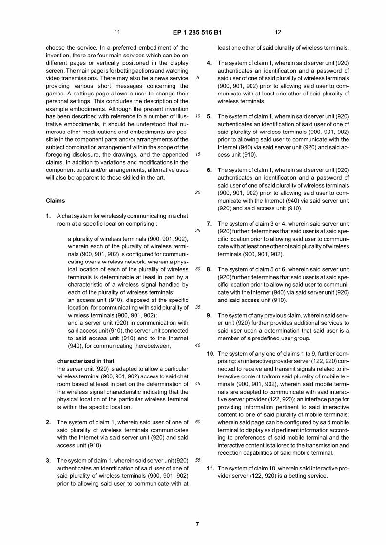
TECHNICAL FIELD
[0002] The Internet has opened up an entirely new ar-ea of communication between people. That is, newsgroups and chat rooms have become very popular onthe Internet since they allow people of similar intereststo communicate with each other quickly and easily withlittle or no cost.[0003] Group entertainment, that is, assembling agroup of people for the purpose of watching either a sport-ing event or other entertainment has always been popularthroughout recorded history as evidenced by the RomanColiseum and the Mayan ball courts.[0004] Several approaches relating to mobile accessto chatting systems and other interactive services suchas betting and gaming activities are known in the art.[0005] For example, US 5 949 326 discloses a pagingtechnology to provide a user with wireless access to theinternet and services such as a chat system through apager system.[0006] In US 5 828 839, a computer network chat sys-tem with a plurality of chat rooms is described, whereinthe topics of the chat rooms are currently broadcastedTV or radio programs. Users may be assigned to chatrooms depending on a indicated TV/radio channel and atime zone.[0007] WO 00/22860 describes a method and systemfor automatically informing a user of a wireless commu-nication terminal that another user is approaching his lo-cation.[0008] WO 96/00950 provides a remote gaming sys-tem to allow a user to bet or wager on a remote gamingfacility such as a casino, particularly without necessarilyestablishing on-line connection to the remote gaming fa-cility.[0009] Document WO 01/15450, which was filed bythe applicant on the priority date of this application, dis-closes a user interface for real-time interactive servicessuch as a betting service without a chat system or local-ized activities.[0010] What the present invention accomplishes is tointegrate a chat system, such as an Internet chat system,with users located at a specific location, a combinationwhich has never been previously contemplated.
DISCLOSURE OF INVENTION
[0011] Accordingly, an object of the present invention
is to provide a chat system which allows a group of userslocated at a specific location to enter a chat system usingtheir mobile terminals so as to communicate with otherusers located at the same location.
BRIEF DESCRIPTION OF DRAWINGS
[0012] The foregoing and a better understanding of thepresent invention will become apparent from the follow-ing detailed description of example embodiments andthe claims when read in connection with the accompa-nying drawings, all forming a part of the disclosure of thisinvention. While the foregoing and following written andillustrated disclosure focuses on disclosing example em-bodiments of the invention, it should be clearly under-stood that the same is by way of illustration and exampleonly and the invention is not limited thereto.[0013] The spirit and scope of the present inventionare limited only by the terms of the appended claims.[0014] The following represents brief descriptions ofthe drawings, wherein:
Fig. 1 illustrates an example of the architecture of anInternet system in which an embodiment of thepresent invention can be practiced.Figure 2 depicts a block diagram of digital servicesbeing delivered to a viewer.Figure 3 depicts a block diagram of the viewer= con-nectivity and interaction with the provided interactiveservices.Figure 4 depicts a block diagram of the betting pro-vider architecture.Figure 5 is a diagram depicting a possible interactivedisplay.Figure 6 depicts an integrated display with a live vid-eo feed and interactive content.Figure 7 depicts a betting login page which includesLogin and Password fields for logging on to the in-teractive service.Figure 8 depicts a main betting page supplied by thebetting server 120 to the user at logon.Figure 9 illustrates the system architecture of oneexample embodiment in accordance with thepresent invention.Fig. 10 is flowchart of the operation of one exampleembodiment in accordance with the present inven-tion.Fig. 11 illustrates the terminal functionality of oneexample embodiment in accordance with thepresent inventionFig. 12 is flowchart of another example embodimentin accordance with the present invention.Figure 13 depicts a flowchart of the interactive bet-ting process.Figure 14 depicts a block diagram of a direct recep-tion scenario.
1 2

EP 1 285 516 B1
3
5
10
15
20
25
30
35
40
45
50
55
BEST MODE(S) FOR CARRYING OUT THE INVEN-TION
[0015] Before beginning a detailed description of thesubject invention, mention of the following is in order.When appropriate, like reference numerals and charac-ters may be used to designate identical, corresponding,orsimilar components in differing drawing figures. Further-more, in the detailed description to follow, example sizes/models/values/ranges may be given, although thepresent invention is not limited thereto. still furthermore,well-known power connections and othercomponents may not be shown within the drawing figuresfor simplicity of illustration and discussion and so asnot obscure the invention.[0016] As noted above, the present invention is direct-ed to a chat system which enables a group of users hav-ing mobile terminals to communicate with each otherwhen located in the same general area, such as at asports stadium, for example.[0017] As illustrated in Fig. 9, a plurality of mobile wire-less terminals 900, 901 and 902, communicate with anaccess unit 910 connected to a server 920.[0018] The access unit 910 may be a LAN (local areanetwork) located in the stadium or any other locationwhere a group of users are expected to congregate. Theconnection from the chat enabling terminal to the server920 is via the access unit 910 wirelessly connected tothe units 900, 901 and 902. For this embodiment, theunits 900, 901 and 902 may be connected to the accessunit 910 via Bluetooth (a short range wireless transmis-sion system) or a WLAN (wireless local area network)arrangement.[0019] The chatting system allows the chatting to beeffected between all of the other terminals disposed with-in the same location. The chatting can be directed to aspecific terminal or terminals at the same location or toall of the terminals at the same location.[0020] The access unit 910 is connected via the server920 and a firewall 930 to the Internet 940. This allowseach terminal unit to connect to the Internet to utilize var-ious other services such as Internet searching or brows-ing, sending or receiving e-mail, or connecting with otherservices, such as betting services, in the case of a sport-ing event, for example.[0021] It is envisioned that the chatting service maynot necessarily be available in its complete form to allterminals located within the same location but rather thecomplete service would be available only to the terminalsof those users who have become "club members."[0022] As illustrated in Fig. 10, a user with a terminalwishing to use the full chat service would register to bea club member in step 1010 and would pay the appro-priate fees in step 1020. The registration could either beonline via a secure server using a credit card or by othermeans such as by telephone or regular mail.[0023] Upon paying the appropriate fees, the user
would receive a club membership in step 1030 whichwould include a member ID and password, for example.This could also be done via the Internet or by othermeans.[0024] When that user visits a location having the chatservice available, authentication is checked in step 1040using the members’ ID and password, for example.[0025] If it is determined that there is a match at thatlocation in step 1050, then the full spectrum of the chatservices are made available to the user in step 1060.[0026] On the other hand, if there is no match deter-mined in step 1050, then it may be possible to allow theuser who is not a club member to get a limited chat servicewhich would not include all of the services available to aclub member in step 1070.[0027] Fig. 11 illustrates the terminal functionality uti-lized in the chatting system in accordance with an exam-ple of the preferred embodiment.[0028] That is, block 100 illustrates what a user wouldsee on the user terminal’s display at the location of thechat system.[0029] If the user wishes to communicate with the chatLAN, the user answers affirmatively and the user’s dis-play would then show a screen similar to that illustratedin block 1110 of Fig. 3, for example.[0030] If the user chose the chat option, the display ofthe user’s terminal would appear as illustrated in block1130 of Fig. 11, for example.[0031] The user would then see the messages of otherusers’ at the same location and could create and sendhis or her own message in response to the chat messag-es on the display.[0032] Furthermore, the terminal of the user would alsohave the capability of forwarding the user’s message toa specific terminal or terminals rather than forwarding ageneralized message to all of the terminals at the samelocation.[0033] If on the other hand, the user did not wish tocommunicate with the chat LAN, the terminal of the userwould display a menu as shown in box 1120 of Fig. 11,for example, allowing the user to select alternate options,such as browsing on the Internet or sending an E-mailto another who is not at the same location as the user.[0034] The above-noted example of an embodimentof the present invention has utilized a wireless LAN. How-ever, a GPRS (general packet radio service)or 3G (thirdgeneration wireless technology) terminal may be usedalternatively as the chatting terminal. This requires theGPRS or 3G network to determine the required location.This may be determined, for example, from the informa-tion that the mobile network already has with regard tothe location of the terminal. It will be understood that otherpossible alternatives may used, like GPS. This can beintegrated to the phone.[0035] As illustrated in Fig. 12, if the user terminal is aGPRS or 3G terminal as noted in box 1200 and is visitinga location in which there is a chatting service as illustratedin box 1210, the location of the terminal as determined
3 4

EP 1 285 516 B1
4
5
10
15
20
25
30
35
40
45
50
55
by the mobile network is transferred from the mobile net-work to the local area network as noted in box 1220 anda determination is made as to whether there is a matchbetween the location of the terminal and the location ofthe chat service in box 1230.[0036] The location information can be gotten from thebase station in 3G when the serving RNC has the signalinformation.[0037] Upon a determination that the user wishes tocommunicate with the local chat service as illustrated inbox 1240, the user terminal is connected to the chat serv-ice as illustrated in box 1250 after the proper authentica-tion as noted above with regard to the wireless LAN em-bodiment of Fig. 10.[0038] The communication can be implemented eitherby the GPRS or 3G data from the user terminal beingtransmitted to the mobile network to the Internet and fi-nally to the chat LAN or by the user terminal directly tothe mobile network and then to the LAN or alternatively,the terminal of the user may include both a Bluetoothtransceiver or WLAN and a GPRS or 3G capability al-lowing it to communicate directly with the access unit 110.[0039] The chat system may be part of the service pro-vider’s system. The chat is activated when a user entersto a specific location e.g. stadium. The system includeschat information filtering. Every chat message sent by auser will be stored in database with keywords:
- user’s favorite team (system, already stored in usertable)
- user’s age (system, already stored in user table)- user’s sex (system, already stored in user table)- user’s hometown or postal code (system, already
stored in user table)- user’s day job (system, already stored in user table)- user’s credits or success in a betting system - there
can be different levels of difficulty (system, alreadystored in bet table)
- user’s bets (system, already stored in bet table)- tone of the message (set by the user, e.g. shouting,
whispering, complaining...)
[0040] The keywords will be partly set by the user andpartly by the system. With these keywords the contentprovider can create various chat channels or the userhimself can select the group he wants to communicatewith. Main idea is that the chat messages will be pushedto clients according to these keywords. The messagesnot matching with keywords are eliminated. This will re-duce the volume of broadcasted chat messages and in-creases the usability of this application.[0041] Other service nodes like interactive providerserver or betting provider server 920 can be connectedto application server 930.[0042] In the various disclosed embodiments, an inter-active application, betting, for example, is facilitated. Fig-ure 1 depicts a block diagram of the creation, reception,and response to interactive services in the presently pre-
ferred embodiment. A television signal 140 is received,compressed, and converted for streaming onto the Inter-net 110. Betting information is also created and streamedonto the Internet 110. A mobile betting client 153 candisplay the television program 120 and the betting infor-mation simultaneously and a viewer can interactively se-lect betting via the mobile betting client 153. Finally, themobile betting client 153 transmits information to the hostfacility 122 by connecting to a network 110 linked withthe host facility 122, for example, the Internet.[0043] Alternatively, a host facility 122 can integratedata to be supplied to the viewer into the vertical blankingintervals of the television signal 140 and broadcast (orstream) the integrated signal. A mobile betting client 153receives the broadcast integrated signal and separatesthe integrated signal into a television signal and the sup-plied dynamic or static data.[0044] Digital broadcast technology allows for servicesthat can present many-to-one, many-to-many, and one-to-one communication. DVB has defined delivery mediafor satellite services (DVB-S, direct-to-home viewing, ca-ble (DVB-C) run in several countries, and terrestrial, or"over the air", (DVB-T) planned for 17 countries. Use ofreturn channels enables digital receivers to provide a va-riety of services including Internet, television, and webcontent. Processing of the digital signal can be accom-plished on a desktop or laptop computer.[0045] Figure 2 depicts a block diagram of digital serv-ices being delivered to a viewer. The interfaces for themedia can include, for example, GSM, GSM+, UMTS,ISDN, PSTN, ATM, and others 202. The protocol andinterface enable a cluster of interconnected devices inthe home, each receiving and processing digital broad-cast services 204. A set top box (STB) or integrated re-ceiver-decoder (IRD), such as the d-box™ manufacturedby Nokia, Inc., 206 integrates the services for viewing ona television 208.[0046] The television receiver that incorporates the in-vention should include a plug-in PIP module. Most re-ceivers that incorporate PIP and other features also in-clude a microprocessor control which, via a suitable con-trol bus, periodically interrogates certain functionalblocks and modules in the television receiver chassis todetermine whether they are present and, if so, to controltheir operation. In the case of a PIP module, polling bythe microprocessor indicates whether the module ispresent in the receiver. If it is, the microprocessor arrang-es to switch the composite video signals (from the tunerand external sources) through the PIP processor andthen to the main video processor of the television receiv-er, in preference to the normal composite video pro-duced. Thus, the video processor of the television receiv-er has its inputs supplied from either the main chassis inthe event there is no PIP module or from the PIP process-ing module.[0047] A viewer watches a mobile betting client 153,for example, a digital television, which is able to act asan Internet browser. Commercial applications such as
5 6

EP 1 285 516 B1
5
5
10
15
20
25
30
35
40
45
50
55
Inet solution enable television/browser functionality. A di-al-up connection or other communications device, suchas a LAN connection, can provide Internet connectivity.Along with web browsing functions, the mobile bettingclient is equipped with streaming video and audio recep-tion and display and secure connection capabilities.[0048] Figure 3 depicts a block diagram of the con-nectivity of the viewer and interaction with the providedinteractive services. In the presently preferred embodi-ment, the mobile betting client 153 receives an integrateddigital broadcast signal (DVB-T). Reception of the signalcan be accomplished through various means. In the pres-ently preferred embodiment, the mobile betting client re-ceives the signal over a GSM, GSM++, POTS, UMTS,or other type of connection 152. The mobile connection152 is itself connected to a network such as an extranet,intranet, or the Internet 110. Mobile connection to thenetwork 116 may take place in a conventional mannerover a modem pool 151 with user dial-in and authentica-tion services 150.[0049] Figure 4 depicts a block diagram of the bettingprovider architecture. In the presently preferred embod-iment, the betting provider information is protected fromnetwork snooping by a security device such as a firewall121. At least one betting provider server 122 resides be-hind the firewall. Software running on the server tracksviewers (bettors) in various competitions.[0050] One task of the server 122 is to authenticateviewers. In the presently preferred embodiment, a userinformation (UI) database 430 is maintained. The UI da-tabase 430 stores usernames and associated pass-words, user account information, user preferences, andother user specific information. In addition to trackingviewers, the server 122 receives and accepts bets thathave been requested by the viewer to a betting server120 running on the network side of the firewall 121 andconnected to a network such as an extranet, intranet, orthe Internet 110. This betting server 120 acts as an in-terface between interactive services viewers on the net-work and the actual betting provider.[0051] The betting provider server 122 receives bettingcontent (questions to the user) and the odds of the par-ticular bets from a betting controller 440. The betting con-troller 440 is responsible for creating betting content, con-trolling the betting event, i.e., opening and closing of bet-ting, etc. Betting control software is used to enter andcalculate betting content and odds and send them to thebetting provider server 122. In the presently preferredembodiment, the betting provider server 122 stores thebetting content and odds in a database (BCO) 410. Thebetting controller 440, via betting control software tracks,the results of the betting question and reports the resultsto the betting provider server 122.[0052] The results of the bets are stored in a database(BR) 420. Once the results of a particular question areknown and stored by the betting provider server 122,software on the server calculates payments to the bettorson the particular question. In the presently preferred em-
bodiment, electronic accounts stored in the UI database430 are used for tracking betting wins and losses. Theresults of the event and sub-events (betting questions)are reported to the betting server 120. The mobile bettingclient 153 can then receive the results from the bettingserver 120.[0053] The connection between bets and chat line sys-tem is that the user can chat with other specific usersbetting the same bets. As well, there is additional quickbets for those who are at the stadium. The mobile bettingclient can join to the chatting services e.g. suggested bythe betting service. The clients coming to join to the chatmight have a common betting profile. The beting infor-mation is collected to the bett8ing server’s database. Thechat service may include e.g. the chat rooms for the bet-tors betting in certain games. The software enabling chat-ting service may be incorporated in the betting server.The client can see the chat rooms he/she is able to joinin his/her betting client. After connected to the chat theclient can see chatting and to join the chatting accord-ingly. The chatters can be selected also based on howthey have had success in betting etc.[0054] Video and audio streaming of an on-going com-petition on which viewers may bet is accomplished, inthe presently preferred embodiment, through use of alive video/audio streaming server (VAS) 130. The VASis connected to a network such as an extranet, intranet,or the Internet 110. A live broadcast 140 of a competitionis received through an RF receiver at the server. Theaudio and video components of the signal are separatedand digitized. The digitized audio is then compressedusing one of several digital compression schemes, forexample, H.728, H.729, or GSM. Likewise the digitizedvideo is compressed using a scheme such as MPEG,MVC, H.261, etc. The digitally compressed audio andvideo are packaged for network transfer e.g., TCP/IP,UDP. The packets are then broadcast to the network 110controlled by a streaming/multicasting controller.[0055] The mobile betting client 153 has PIP function-ality. This functionality allows the viewer to simultane-ously view two audio/video broadcasts in the display ofthe mobile betting client. The two broadcasts can be, forexample, the live-feed of a competition in one picture andinteractive betting possibilities in another.[0056] Figure 5 is a diagram depicting a possible in-teractive display. Directions at the top of the display 500inform the viewer of the status or title of the interactiveactivity, in this case, betting. For an application such asbetting, a dialog-type box 510 is used to inform the viewerof the current question on which bets can be placed. Inthe context of an auto race, a question such as "Who willturn the fastest 13th lap" may be presented. A pull-downmenu or radio button dialog box 520 may be presenteddepending on the type of question. In the above example,all of the drivers remaining in the race may be presentedin a pull-down menu. Dialog boxes specific to wagering:stakes 530; odds 540; and payout 550, may also be pre-sented. A statement of account 560 with a betting serv-
7 8

EP 1 285 516 B1
6
5
10
15
20
25
30
35
40
45
50
55
ices provider may also be presented. The account is dy-namic throughout the competition, registering winningsand debits as each occurs. A response dialog 570 in-forming the user of bets being received and the currentallowable wagers may also be provided. Such a responsewindow is also dynamically updated as available bets aremade or changed. In addition to the displays listed above,dialog boxes presenting last minute betting advice or in-formation can also be displayed. Such advice can in-clude, for example, up to the minute status of race par-ticipants not currently being shown on the broadcast orthe injury status of key players at an event. Figure 6depicts an integrated display with a live video feed andinteractive content.[0057] Figure 13 depicts a flowchart of the interactivebetting process. First, a mobile betting client wishing tointeractively bet connects to the betting provider (Step1302). Once connected, a secure network connection,using, for example, encryption or secure sockets, is es-tablished (Step 1304). Once a secure connection is es-tablished, an authentication process occurs, comparinguser name and password entered by the client to entriesin a database of user information (Step 1306). Once au-thenticated, the client can select the type of competitionto bet on, for example, auto racing, hockey, or football.(Step 1308). If live video and audio is available, the com-petition is displayed (Step 1310). The interactive bettingopportunities currently available for the chosen compe-tition are then displayed to the client (Step 1312). Thebetting opportunities are dynamic and will be continuous-ly updated. The client informs the betting provider of itsdesire to bet (Step 1314) and the stakes (Step 1316).The stakes can be variable amounts or limited to selec-tions presented in a choice menu. The betting selectionand the stakes are sent to the betting provider across thesecure connection (Step 1318). The betting provider ver-ifies the entries made by the client (Step 1320). Furtherchecks, including client payment history and credit re-ports can be included in this verification step (Step 1320).If any of the entries is invalid, a valid entry is requested(Step 1322). Entries can be invalid for several reasons,for example, incorrect selection, closing of the requestedbetting selection prior to the bet being received, or theclient’s inability to cover the stakes.[0058] If the entries are valid, the betting provider in-forms the client of that the particular wager has beenaccepted (Step 1324). Different bets open and close dur-ing the course of the competition. Once the bet has beenmade and accepted, the client may continue to view thecompetition, personally monitoring the outcome of itswager and making other bets on the same competition(Step 1326). The client may also choose a different com-petition to view and possibly bet on (Step 1328). If theclient does not wish to view or bet on any other compe-titions, the connection between the client and the bettingprovider is closed (Step 1330).[0059] At some point after the close of a particularwager, the participants are informed of the result and
appropriate adjustments to betting accounts are made.If the client is still connected to the betting provider whenthe results are known, the client can be informed of theresults. Otherwise, the client can be informed of the sta-tus of any outstanding wagers the next time a connectionto the betting provider is established.[0060] In an alternative embodiment, a live broadcast140 of a competition can be received directly by the mo-bile betting client 153. Figure 14 depicts a block diagramof a direct reception scenario. The mobile betting client153 can, of course, be at the viewer’s home or at anotherviewing location. The broadcast 140 is displayed in amonitor 1402. Additionally, an Internet browser can beconnected to the monitor 1402 or, alternatively, to a sep-arate display 804 in order to interface with the bettingserver 120 through a switching network 114 and an In-ternet service provider (ISP) 1406. The PIP property ofthe monitor can be used if the browser and the broadcast140 are shown in the same monitor.[0061] In another alternative embodiment, a DVB sig-nal with the live broadcast 140 and betting informationfrom the betting server 120 can be integrated into a digitalbroadcast.[0062] Figure 7 depicts a betting login page which in-cludes Login and Password fields for logging on to theinteractive service. The connection can be establishedover the Internet using a Virtual Private Network (VPN)tunnel and Secure Sockets Layer (SSL) connection.Once a secure connection is established, an authentica-tion process occurs in which the users enters his username and password in separate fields. If the incorrectuser name and password are entered, the login screenis again displayed. No assumption is made that the mo-bile betting client has a keyboard or a mouse. However,the user can edit text with a delete key and navigate witharrow keys or other cursor control in both the horizontaland vertical planes. In order to participate in the service,the user will need to register with the betting providerserver 122. New users will need to register. Registrationinformation includes information about the device the us-er is connecting with, the bandwidth of the connection,and the style sheet (or skin) the user prefers. New usergenerally are kept from participating in the service untilan active betting supervisor or administrator enables theuser logon.[0063] Logging on allows users of the service to makebets and watch both live and on-demand streamingbroadcasts. Figure 8 depicts a main betting page sup-plied by the betting server 120 to the user at logon. In-formation such as the current time, last use, and accountbalance information is displayed. Information such as thenumber of other users currently participating can also bedisplayed. Users can navigate from the main betting pageto other pages by navigating with the arrow or cursorcontrol keys.[0064] After the log-in process, the only chance to nav-igate is downward to reach "lower" folderleaves. There-after, the user can navigate up or down in the levels to
9 10
EP 1 285 516 B1
7
5
10
15
20
25
30
35
40
45
50
55
choose the service. In a preferred embodiment of theinvention, there are four main services which can be ondifferent pages or vertically positioned in the displayscreen. The main page is for betting actions and watchingvideo transmissions. There may also be a news serviceproviding various short messages concerning thegames. A settings page allows a user to change theirpersonal settings. This concludes the description of theexample embodiments. Although the present inventionhas been described with reference to a number of illus-trative embodiments, it should be understood that nu-merous other modifications and embodiments are pos-sible in the component parts and/or arrangements of thesubject combination arrangement within the scope of theforegoing disclosure, the drawings, and the appendedclaims. In addition to variations and modifications in thecomponent parts and/or arrangements, alternative useswill also be apparent to those skilled in the art.
Claims
1. A chat system for wirelessly communicating in a chatroom at a specific location comprising :
a plurality of wireless terminals (900, 901, 902),wherein each of the plurality of wireless termi-nals (900, 901, 902) is configured for communi-cating over a wireless network, wherein a phys-ical location of each of the plurality of wirelessterminals is determinable at least in part by acharacteristic of a wireless signal handled byeach of the plurality of wireless terminals;an access unit (910), disposed at the specificlocation, for communicating with said plurality ofwireless terminals (900, 901, 902);and a server unit (920) in communication withsaid access unit (910), the server unit connectedto said access unit (910) and to the Internet(940), for communicating therebetween,
characterized in thatthe server unit (920) is adapted to allow a particularwireless terminal (900, 901, 902) access to said chatroom based at least in part on the determination ofthe wireless signal characteristic indicating that thephysical location of the particular wireless terminalis within the specific location.
2. The system of claim 1, wherein said user of one ofsaid plurality of wireless terminals communicateswith the Internet via said server unit (920) and saidaccess unit (910).
3. The system of claim 1, wherein said server unit (920)authenticates an identification of said user of one ofsaid plurality of wireless terminals (900, 901, 902)prior to allowing said user to communicate with at
least one other of said plurality of wireless terminals.
4. The system of claim 1, wherein said server unit (920)authenticates an identification and a password ofsaid user of one of said plurality of wireless terminals(900, 901, 902) prior to allowing said user to com-municate with at least one other of said plurality ofwireless terminals.
5. The system of claim 1, wherein said server unit (920)authenticates an identification of said user of one ofsaid plurality of wireless terminals (900, 901, 902)prior to allowing said user to communicate with theInternet (940) via said server unit (920) and said ac-cess unit (910).
6. The system of claim 1, wherein said server unit (920)authenticates an identification and a password ofsaid user of one of said plurality of wireless terminals(900, 901, 902) prior to allowing said user to com-municate with the Internet (940) via said server unit(920) and said access unit (910).
7. The system of claim 3 or 4, wherein said server unit(920) further determines that said user is at said spe-cific location prior to allowing said user to communi-cate with at least one other of said plurality of wirelessterminals (900, 901, 902).
8. The system of claim 5 or 6, wherein said server unit(920) further determines that said user is at said spe-cific location prior to allowing said user to communi-cate with the Internet (940) via said server unit (920)and said access unit (910).
9. The system of any previous claim, wherein said serv-er unit (920) further provides additional services tosaid user upon a determination that said user is amember of a predefined user group.
10. The system of any one of claims 1 to 9, further com-prising: an interactive provider server (122, 920) con-nected to receive and transmit signals related to in-teractive content to/from said plurality of mobile ter-minals (900, 901, 902), wherein said mobile termi-nals are adapted to communicate with said interac-tive server provider (122, 920); an interface page forproviding information pertinent to said interactivecontent to one of said plurality of mobile terminals;wherein said page can be configured by said mobileterminal to display said pertinent information accord-ing to preferences of said mobile terminal and theinteractive content is tailored to the transmission andreception capabilities of said mobile terminal.
11. The system of claim 10, wherein said interactive pro-vider server (122, 920) is a betting service.
11 12

EP 1 285 516 B1
8
5
10
15
20
25
30
35
40
45
50
55
12. The system of any previous claim, wherein authori-zation for accessing a chat room by a mobile terminal(900, 901, 902) is given based on predetermined cri-teria.
13. The system of claim 12, wherein said predeterminedcriteria for accessing a chat room include a bettingsuccess parameter of a user of one of the pluralityof mobile terminals (900, 901, 902, 153).
14. The system of any previous claim , wherein everychat message sent by a user will be stored in a da-tabase (430) together with keywords related to saidchat user.
15. The system of claim 14, wherein allocation of a mo-bile terminal user to a chat room is determined onthe basis of said keywords in said database (430).
16. The system of claim 10, wherein said preferencesare stored by said interactive provider server (122,920).
17. A method of operating a chat system at a specificlocation comprising:
communicating with a plurality of wireless termi-nals with an access unit disposed at the specificlocation, wherein a physical location of each ofthe plurality of wireless terminals is determined(1220) at least in part by a characteristic of awireless signal handled by each of the pluralityof wireless terminals;connecting the access unit to the Internet via aserver unit for facilitating communication be-tween the access unit and the Internet;
characterized by the step ofenabling (1250) the chat room to be accessible by aparticular wireless terminal based at least in part onthe determination (1230) of the wireless signal char-acteristic indicating that the physical location of theparticular wireless terminal is within the specific lo-cation associated with the chat room.
18. The method of claim 17, further comprising the userof one of the plurality of wireless terminals commu-nicating with the Internet via the server unit and theaccess unit.
19. The method of claim 17 or 18, further comprising theserver unit authenticating (1040, 1050) an identifica-tion of the user of one of the plurality of wirelessterminals prior to allowing the user to communicatewith at least one other of the plurality of wireless ter-minals.
20. The method of any one of claims 17 to 19, further
comprising the server unit authenticating (1040,1050) an identification and a password of the userof one of the plurality of wireless terminals prior toallowing the user to communicate with at least oneother of the plurality of wireless terminals.
21. The method of any one of claims 17 to 20, furthercomprising the server unit authenticating (1040,1050) an identification of the user of one of the plu-rality of wireless terminals prior to allowing the userto communicate with the Internet via the server unitand the access unit.
22. The method of any one of claims 17 to 21, furthercomprising the server unit authenticating (1040,1050) an identification and a password of the userof one of the plurality of wireless terminals prior toallowing the user to communicate with the Internetvia the server unit and the access unit.
23. The method of claim 19 or 20, further comprising theserver unit determining (1230) that the user is at thespecific location prior to allowing the user to commu-nicate with at least one other of the plurality of wire-less terminals.
24. The method of claim 21 or 22, further comprising theserver unit determining (1230) that the user is at thespecific location prior to allowing the user to commu-nicate with the Internet via the server unit and theaccess unit.
25. The method of any one of claims 17 to 24, furthercomprising the server unit providing additional serv-ices (1060) to the user upon a determination that theuser is a member of a predefined user group.
Patentansprüche
1. Chatsystem zum drahtlosen Kommunizieren in ei-nem Chatroom an einem speziellen Ort, umfassend:
- mehrere drahtlose Endgeräte (900, 901, 902),wobei jedes der mehreren drahtlosen Endgerä-te (900, 901, 902) konfiguriert ist, um über eindrahtloses Netzwerk zu kommunizieren, wobeiein physikalischer Ort von jedem der mehrerendrahtlosen Endgeräte zumindest teilweisedurch ein Merkmal eines drahtlosen Signals be-stimmbar ist, das von jedem der mehreren draht-losen Endgeräte gehandhabt wird;- eine Zugriffseinheit (910), die an dem speziel-len Ort angeordnet ist, zum Kommunizieren mitden mehreren drahtlosen Endgeräten (900,901, 902); und eine Servereinheit (920) in Kom-munikation mit der Zugriffseinheit (910), wobeidie Servereinheit mit der Zugriffseinheit (910)
13 14

EP 1 285 516 B1
9
5
10
15
20
25
30
35
40
45
50
55
und dem Internet (940) verbunden ist, um zwi-schen ihnen zu kommunizieren,
dadurch gekennzeichnet, dass
- die Servereinheit (920) angepasst ist, einembestimmten drahtlosen Endgerät (900, 901,902) Zugriff zu dem Chatroom zu ermöglichen,zumindest teilweise auf Grundlage der Bestim-mung des drahtlosen Signalmerkmals, das an-zeigt, dass der physikalische Ort des bestimm-ten drahtlosen Endgeräts sich innerhalb desspeziellen Orts befindet.
2. System von Anspruch 1, wobei der Benutzer einesder mehreren drahtlosen Endgeräte über die Ser-vereinheit (920) und die Zugriffseinheit (910) mit demInternet kommuniziert.
3. System von Anspruch 1, wobei die Servereinheit(920) eine Identifikation des Benutzers von einemder mehreren drahtlosen Endgeräte (900, 901, 902)authentifiziert, bevor sie es dem Benutzer ermög-licht, mit mindestens einem weiteren der mehrerendrahtlosen Endgeräte zu kommunizieren.
4. System von Anspruch 1, wobei die Servereinheit(920) eine Identifikation und ein Passwort des Be-nutzers von einem der mehreren drahtlosen Endge-räte (900, 901, 902) authentifiziert, bevor sie es demBenutzer ermöglicht, mit mindestens einem weiterender mehreren drahtlosen Endgeräte zu kommunizie-ren.
5. System von Anspruch 1, wobei die Servereinheit(920) eine Identifikation des Benutzers von einemder mehreren drahtlosen Endgeräte (900, 901, 902)authentifiziert, bevor sie es dem Benutzer ermög-licht, mit dem Internet (940) über die Servereinheit(920) und die Zugriffseinheit (910) zu kommunizie-ren.
6. System von Anspruch 1, wobei die Servereinheit(920) eine Identifikation und ein Passwort des Be-nutzers von einem der mehreren drahtlosen Endge-räte (900, 901, 902) authentifiziert, bevor sie es demBenutzer ermöglicht, mit dem Internet (940) über dieServereinheit (920) und die Zugriffseinheit (910) zukommunizieren.
7. System von Anspruch 3 oder 4, wobei die Server-einheit (920) weiter bestimmt, dass der Benutzersich an dem speziellen Ort befindet, bevor sie esdem Benutzer ermöglicht, mit mindestens einemweiteren der mehreren drahtlosen Endgeräte (900,901, 902) zu kommunizieren.
8. System von Anspruch 5 oder 6, wobei die Server-
einheit (920) weiter bestimmt, dass der Benutzersich an dem speziellen Ort befindet, bevor sie esdem Benutzer ermöglicht, mit dem Internet (940)über die Servereinheit (920) und die Zugriffseinheit(910) zu kommunizieren.
9. System von einem der vorangegangenen Ansprü-che, wobei die Servereinheit (920) dem Benutzernach einer Bestimmung, dass der Benutzer ein Mit-glied einer vordefinierten Benutzergruppe ist, weiterzusätzliche Dienste bereitstellt.
10. System von einem der Ansprüche 1 bis 9, weiterumfassend:
- einen interaktiven Anbieterserver (122, 920),der verbunden ist, um Signale betreffend inter-aktiven Inhalt an/von den mehreren Mobilend-geräten (900, 901, 902) zu empfangen und zuübermitteln, wobei die Mobilendgeräte ange-passt sind, um mit dem interaktiven Anbieter-server (122, 920) zu kommunizieren;- eine Schnittstellenseite, um einem der mehre-ren Mobilendgeräte Informationen bereitzustel-len, die zu dem interaktiven Inhalt gehören; wo-bei die Seite durch das Mobilendgerät konfigu-riert sein kann, um die zugehörigen Informationgemäß den Präferenzen des Mobilendgerätsanzuzeigen und wobei der interaktive Inhalt aufdas Übermittlungs- und Empfangsfähigkeitendes Mobilendgeräts zugeschnitten ist.
11. System von Anspruch 10, wobei der interaktiven An-bieterserver (122, 920) ein Wettdienst ist.
12. System von einem der vorhergehenden Anspruch,wobei eine Autorisierung zum Zugreifen auf einenChatroom durch ein Mobilendgerät (900, 901, 902)auf Grundlage von vorbestimmten Kriterien gebenist.
13. System von Anspruch 12, wobei die vorbestimmtenKriterien zum Zugreifen auf einen Chatroom einenWetterfolgsparameter eines Benutzers eines dermehreren Mobilendgeräte (900, 901, 902, 153) ein-schließt.
14. System von einem vorhergehenden Anspruch, wo-bei jede Chatnachricht, die von einem Benutzer ge-sendet wird, in einer Datenbank (430) zusammenmit Schlüsselwörtern bezogen auf die Chatbenutzer,gespeichert wird.
15. System von Anspruch 14, wobei eine Zuordnung ei-nes Mobilendgerätbenutzers auf einen Chatroomauf der Grundlage der Schlüsselwörter in der Daten-bank (430) bestimmt ist.
15 16

EP 1 285 516 B1
10
5
10
15
20
25
30
35
40
45
50
55
16. System von Anspruch 10, wobei die Präferenzendurch den interaktiven Anbieterserver (122, 920) ge-speichert werden.
17. Verfahren zum Betreiben eines Chatsystems an ei-nem speziellen Ort, umfassend:
- Kommunizieren von mehreren drahtlosen End-geräten mit einer Zugriffseinheit, die an demspeziellen Ort angeordnet ist, wobei ein physi-kalischer Ort von jedem der mehreren drahtlo-sen Endgeräte zumindest teilweise durch einMerkmal eines drahtlosen Signals bestimmtwird (1220), das von jedem der mehreren draht-losen Endgeräte gehandhabt wird;- Verbinden der Zugriffseinheit mit dem Internetüber eine Servereinheit, um die Kommunikationzwischen der Zugriffseinheit und dem Internetzu erleichtern;
gekennzeichnet durch den Schritt
- Ermöglichen (1250), dass von einem bestimm-ten drahtlosen Endgerät auf den Chatroom zu-gegriffen werden kann, zumindest teilweise aufGrundlage der Bestimmung (1230) der drahtlo-sen Signaleigenschaft, die anzeigt, dass derphysikalische Ort eines bestimmten drahtlosenEndgeräts sich innerhalb des speziellen Orts,der mit dem Chatroom zugeordnet ist, befindet.
18. Verfahren nach Anspruch 17, weiter umfassend denBenutzer eines der mehreren drahtlosen Endgeräte,die mit dem Internet über die Servereinheit und dieZugriffseinheit kommunizieren.
19. Verfahren von Anspruch 17 oder 18, weiter umfas-send, dass die Servereinheit eine Identifikation desBenutzers von einem der mehreren drahtlosen End-geräte authentifiziert (1040, 1050), bevor sie es demBenutzer ermöglicht, mit mindestens einem weiterender mehreren drahtlosen Endgeräte zu kommunizie-ren.
20. Verfahren von einem der Ansprüche 17 bis 19, weiterumfassend, dass die Servereinheit eine Identifikati-on und ein Passwort des Benutzers von einem dermehreren drahtlosen Endgeräte authentifiziert(1040, 1050), bevor sie es dem Benutzer ermöglicht,mit mindestens einem weiteren der mehreren draht-losen Endgeräte zu kommunizieren.
21. Verfahren von einem der Ansprüche 17 bis 20, weiterumfassend, dass die Servereinheit eine Identifikati-on des Benutzers von einem der mehreren drahtlo-sen Endgeräte authentifiziert (1040, 1050), bevor siees dem Benutzer ermöglicht, mit dem Internet überdie Servereinheit und die Zugriffseinheit zu kommu-
nizieren.
22. Verfahren von einem der Ansprüche 17 bis 21, weiterumfassend, dass die Servereinheit eine Identifikati-on und ein Passwort des Benutzers von einem dermehreren drahtlosen Endgeräte authentifiziert(1040, 1050), bevor sie es dem Benutzer ermöglicht,mit dem Internet über die Servereinheit und die Zu-griffseinheit zu kommunizieren.
23. Verfahren von Anspruch 19 oder 20, weiter umfas-send, dass die Servereinheit bestimmt (1230), dassder Benutzer sich an einem speziellen Ort befindet,bevor sie es dem Benutzer ermöglicht, mit minde-stens einem weiteren der mehreren drahtlosen End-geräte zu kommunizieren.
24. Verfahren von Anspruch 21 oder 22, weiter umfas-send, dass die Servereinheit bestimmt (1230), dassder Benutzer sich an einem speziellen Ort befindet,bevor sie es dem Benutzer ermöglicht, mit dem In-ternet über die Servereinheit und die Zugriffseinheitzu kommunizieren.
25. Verfahren von einem der vorangegangenen Ansprü-che 17 bis 24, weiter umfassend, dass die Server-einheit nach einer Bestimmung, dass der Benutzerein Mitglied einer vordefinierten Benutzergruppe ist,dem Benutzer zusätzliche Dienste (1060) bereit-stellt.
Revendications
1. Système de discussion pour communiquer sans fildans une salle de discussion à une localisation spé-cifique comprenant :
une pluralité de terminaux sans fil (900, 901,902), dans lesquels chacun de la pluralité determinaux sans fil (900, 901, 902) est configurépour communiquer via un réseau sans fil, danslequel une localisation physique de chacun dela pluralité de terminaux sans fil est détermina-ble au moins en partie par une caractéristiqued’un signal sans fil géré par chacun de la pluralitéde terminaux sans fil ;une unité d’accès (910), située à la localisationspécifique, pour communiquer avec ladite plu-ralité de terminaux sans fil (900, 901, 902) ;et une unité de serveur (920) en communicationavec ladite unité d’accès (910), l’unité de ser-veur connectée à ladite unité d’accès (910) et àl’Internet (940), pour permettre la communica-tion entre les deux,
caractérisé en ce quel’unité de serveur (920) est adaptée pour permettre
17 18

EP 1 285 516 B1
11
5
10
15
20
25
30
35
40
45
50
55
à un terminal sans fil particulier (900, 901, 902) d’ac-céder à ladite salle de discussion sur la base aumoins en partie de la détermination de la caractéris-tique de signal sans fil indiquant que la localisationphysique du terminal sans fil particulier se situe à lalocalisation spécifique.
2. Système selon la revendication 1, dans lequel leditutilisateur de l’un de ladite pluralité de terminauxsans fil communique avec l’Internet via ladite unitéde serveur (920) et ladite unité d’accès (910).
3. Système selon la revendication 1, dans lequel laditeunité de serveur (920) authentifie une identificationdudit utilisateur de l’un de ladite pluralité de termi-naux sans fil (900, 901, 902) avant d’autoriser leditutilisateur à communiquer avec au moins un autrede ladite pluralité de terminaux sans fil.
4. Système selon la revendication 1, dans lequel laditeunité de serveur (920) authentifie une identificationet un mot de passe dudit utilisateur de l’un de laditepluralité de terminaux sans fil (900, 901, 902) avantd’autoriser ledit utilisateur à communiquer avec aumoins un autre de ladite pluralité de terminaux sansfil.
5. Système selon la revendication 1, dans lequel laditeunité de serveur (920) authentifie une identificationdudit utilisateur de l’un de ladite pluralité de termi-naux sans fil (900, 901, 902) avant d’autoriser leditutilisateur à communiquer avec l’Internet (940) vialadite unité de serveur (920) et ladite unité d’accès(910).
6. Système selon la revendication 1, dans lequel laditeunité de serveur (920) authentifie une identificationet un mot de passe dudit utilisateur de l’un de laditepluralité de terminaux sans fil (900, 901, 902) avantd’autoriser ledit utilisateur à communiquer avec l’In-ternet (940) via ladite unité de serveur (920) et laditeunité d’accès (910).
7. Système selon la revendication 3 ou 4, dans lequelladite unité de serveur (920) détermine en outre queledit utilisateur se trouve à ladite localisation spéci-fique avant d’autoriser ledit utilisateur à communi-quer avec au moins un autre de ladite pluralité determinaux sans fil (900, 901, 902).
8. Système selon la revendication 5 ou 6, dans lequelladite unité de serveur (920) détermine en outre queledit utilisateur se trouve à ladite localisation spéci-fique avant d’autoriser ledit utilisateur à communi-quer avec l’Internet (940) via ladite unité de serveur(920) et ladite unité d’accès (910).
9. Système selon l’une quelconque revendication pré-
cédente, dans lequel ladite unité de serveur (920)fournit en outre des services supplémentaires auditutilisateur lors d’une détermination que ledit utilisa-teur est un membre d’un groupe d’utilisateurs pré-défini.
10. Système selon l’une quelconque des revendications1 à 9, comprenant en outre : un serveur de fournis-seur d’accès interactif (122, 920) connecté pour re-cevoir et transmettre des signaux concernant uncontenu interactif à/depuis ladite pluralité de termi-naux mobiles (900, 901, 902), dans lequel lesditsterminaux mobiles sont adaptés pour communiqueravec ledit serveur de fournisseur d’accès interactif(122, 920) ; une page d’interface destinée à fournirdes informations pertinentes audit contenu interactifà l’un de ladite pluralité de terminaux mobiles ; danslequel ladite page peut être configurée par ledit ter-minal mobile pour afficher lesdites informations per-tinentes en fonction de préférences dudit terminalmobile et le contenu interactif est adapté aux capa-cités de transmission et réception dudit terminal mo-bile.
11. Système selon la revendication 10, dans lequel leditserveur de fournisseur d’accès interactif (122, 920)est un service de pari.
12. Système selon l’une quelconque revendication pré-cédente, dans lequel l’autorisation d’accès à une sal-le de conversation par un terminal mobile (900, 901,902) est donnée sur la base de critères prédétermi-nés.
13. Système selon la revendication 12, dans lequel les-dits critères prédéterminés pour accéder à une sallede conversation incluent un paramètre de réussitede pari d’un utilisateur de l’un de la pluralité de ter-minaux mobiles (900, 901, 902, 153).
14. Système selon l’une quelconque revendication pré-cédente, dans lequel chaque message de conver-sation envoyé par un utilisateur sera stocké dansune base de donnée (430) conjointement aux motsde passe relatifs audit utilisateur de conversation.
15. Système selon la revendication 14, dans lequel l’al-location d’un utilisateur de terminal mobile à une sal-le de conversation est déterminée sur la base desditsmots de passe dans ladite base de donnée (430).
16. Système selon la revendication 10, dans lequel les-dites préférences sont stockées par ledit serveur defournisseur d’accès interactif (122, 920).
17. Procédé de fonctionnement d’un système de con-versation à une localisation spécifique comprenant :
19 20

EP 1 285 516 B1
12
5
10
15
20
25
30
35
40
45
50
55
la communication avec une pluralité de termi-naux sans fil avec une unité d’accès agencée àla localisation spécifique, dans lequel une loca-lisation physique de chacun de la pluralité determinaux sans fil est déterminée (1220) aumoins en partie par une caractéristique d’un si-gnal sans fil géré par chacun de la pluralité determinaux sans fil ;la connexion de l’unité d’accès à l’Internet viaune unité de serveur pour faciliter la communi-cation entre l’unité d’accès et l’Internet ;
caractérisé par l’étape consistant àpermettre (1250) à la salle de discussion d’être ac-cessible par un terminal sans fil particulier sur la baseau moins en partie de la détermination (1230) de lacaractéristique de signal sans fil indiquant que la lo-calisation physique du terminal sans fil particulier sesitue à la localisation spécifique associée à la sallede discussion.
18. Procédé selon la revendication 17, comprenant enoutre l’utilisateur de l’un de la pluralité de terminauxsans fil communiquant avec l’Internet via l’unité deserveur et l’unité d’accès.
19. Procédé selon la revendication 17 ou 18, compre-nant en outre l’authentification par l’unité de serveur(1040, 1050) d’une identification de l’utilisateur del’un de la pluralité de terminaux sans fil avant l’auto-risation de l’utilisateur à communiquer avec au moinsun autre de la pluralité de terminaux sans fil.
20. Procédé selon l’une quelconque des revendications17 à 19, comprenant en outre l’authentification parl’unité de serveur (1040, 1050) d’une identificationet d’un mot de passe de l’utilisateur de l’un de lapluralité de terminaux sans fil avant l’autorisation del’utilisateur à communiquer avec au moins un autrede la pluralité de terminaux sans fil.
21. Procédé selon l’une quelconque des revendications17 à 19, comprenant en outre l’authentification parl’unité de serveur (1040, 1050) d’une identificationde l’utilisateur de l’un de la pluralité de terminauxsans fil avant l’autorisation de l’utilisateur à commu-niquer avec l’Internet via l’unité de serveur et l’unitéd’accès.
22. Procédé selon l’une quelconque des revendications17 à 21, comprenant en outre l’authentification parl’unité de serveur (1040, 1050) d’une identificationet d’un mot de passe de l’utilisateur de l’un de lapluralité de terminaux sans fil avant l’autorisation del’utilisateur à communiquer avec l’Internet via l’unitéde serveur et l’unité d’accès.
23. Procédé selon la revendication 19 ou 20, compre-
nant en outre la détermination par l’unité de serveur(1230) que l’utilisateur se trouve à la localisation spé-cifique avant l’autorisation de l’utilisateur à commu-niquer avec au moins un autre de la pluralité de ter-minaux sans fil.
24. Procédé selon la revendication 21 ou 22, compre-nant en outre la détermination par l’unité de serveur(1230) que l’utilisateur se trouve à la localisation spé-cifique avant l’autorisation de l’utilisateur à commu-niquer avec l’Internet via l’unité de serveur et l’unitéd’accès.
25. Procédé selon l’une quelconque des revendications17 à 24, comprenant en outre la fourniture par l’unitéde serveur de services supplémentaires (1060) àl’utilisateur lors d’une détermination que l’utilisateurest un membre d’un groupe d’utilisateurs prédéfini.
21 22

EP 1 285 516 B1
13

EP 1 285 516 B1
14

EP 1 285 516 B1
15

EP 1 285 516 B1
16

EP 1 285 516 B1
17

EP 1 285 516 B1
18

EP 1 285 516 B1
19

EP 1 285 516 B1
20

EP 1 285 516 B1
21

EP 1 285 516 B1
22

EP 1 285 516 B1
23

EP 1 285 516 B1
24

EP 1 285 516 B1
25
EP 1 285 516 B1
26