CHAPTER 2 - WIReDSpace
34
2-1 CHAPTER 2 EVALUATION OF THE INTERLOCKING DRY-STACK MASONRY SYSTEMS 2.1 Introduction In this chapter, 23 different existing dry-stack masonry systems are presented and discussed. The discussions are based on the available information from different sources. The systems discussed utilise concrete interlocking units and some utilise compressed soil- cement-interlocking units all of different types and shapes. Most of the systems are commercially available in many countries in America, Europe, Asia and Africa. 2.2 Hollow interlocking dry-stack masonry wall systems Hollow masonry wall interlocking systems are usually partially grouted after dry stacking and they function as hollow masonry walls only during construction period. During that time the load transfer mechanism is required to resist only wind load and other constructions loads. Because of the tolerance between the interlocking mechanism it follows that when no precompression forces are applied, there are unavoidable free translations and/ or rotations until the interlocking mechanism is developed. In addition there is no tensile resistance (or bonding) in the direction of block insertion. Thus in actual wall system the deflection under small load may be fairly large. When the deflections due to such free movements exceed a serviceability limit state, the resulting interlocking mechanism may have little structural meaning. Basically concrete dry-stack masonry systems are made of hollow interlocking masonry units. The units are made to allow placement of horizontal and vertical reinforcements including grouting. The cells are filled with grout to enhance axial load capacity, provide
-
Upload
khangminh22 -
Category
Documents
-
view
3 -
download
0
Transcript of CHAPTER 2 - WIReDSpace

2-1
CHAPTER 2
EVALUATION OF THE INTERLOCKING DRY-STACK MASONRY
SYSTEMS
2.1 Introduction
In this chapter, 23 different existing dry-stack masonry systems are presented and
discussed. The discussions are based on the available information from different
sources. The systems discussed utilise concrete interlocking units and some utilise
compressed soil- cement-interlocking units all of different types and shapes. Most
of the systems are commercially available in many countries in America, Europe,
Asia and Africa.
2.2 Hollow interlocking dry-stack masonry wall systems
Hollow masonry wall interlocking systems are usually partially grouted after dry
stacking and they function as hollow masonry walls only during construction
period. During that time the load transfer mechanism is required to resist only
wind load and other constructions loads. Because of the tolerance between the
interlocking mechanism it follows that when no precompression forces are
applied, there are unavoidable free translations and/ or rotations until the
interlocking mechanism is developed. In addition there is no tensile resistance (or
bonding) in the direction of block insertion. Thus in actual wall system the
deflection under small load may be fairly large. When the deflections due to such
free movements exceed a serviceability limit state, the resulting interlocking
mechanism may have little structural meaning. Basically concrete dry-stack
masonry systems are made of hollow interlocking masonry units. The units are
made to allow placement of horizontal and vertical reinforcements including
grouting. The cells are filled with grout to enhance axial load capacity, provide

2-2
out - of- plane resistance to transverse load and provide in plane shear resistance.
Interlocking hollow blocks reduce the use of shuttering.
2.3 Solid interlocking dry-stack masonry wall systems
Soil-cement dry-stack masonry systems are basically made of solid soil-cement
interlocking masonry units. Because of the low strength of the soil-cement units
the cavity where applicable should be kept minimum. Code BS 3921 defines a
solid masonry unit as a unit containing cavities not exceeding 25% of the gross
volume of the unit. The cavities are introduced to provide interlocking
mechanisms and allow for placement of reinforcements. Units can be
manufactured on site using local aggregates and soil saving the transportation
costs. Because cement is one of the expensive components in masonry
construction compressed soil-cement masonry units which utilise less cement is
increasingly popular particularly in the developing countries. The system is
considered to be low energy intensive and therefore environmentally benign as
no firing of the units is required.
2.4 General Advantages and Disadvantages of Interlocking Dry-stack
Masonry System
2.4.1 Advantages
1. System is more rationalized; It has simplicity of handling and
laying
2. Wall erection is faster
3. Alignment can be completed faster
4. Quality variation due to mortar joints is eliminated
5. Erection during cold winter is possible
6. Dependence of skilled labour is reduced.
7. Load of super structure can be immediately applied.

2-3
8. Ductility can be improved
9. Unlike mortared joint construction, use of smaller units does not
consume more material but does take more time.
10. Units can be manufactured on site using local aggregates and soil.
11. Demolition of dry-stack masonry is basically conducted by simply
unplugging the dry-stack masonry units allowing the re-use of the
units.
12. Least energy intensive and environmentally benign technology.
2.4.2 Disadvantages
1. Hollow system may be unstable to resist certain types of out of
plane loading during the construction; this can be overcome by
external bracing or grouting the hollow section at intervals.
2. Bond patterns are limited thus architecturally more restrictive.
Traditional aesthetic appeal may be compensated by troweled or
spray surface treatments.
3. Difficult to form curve walls with most interlocking systems (a few
systems include solution to this problem)
4. Initial seating deformation may decrease strength and stiffness of
hollow system.
5. Manufacturing and handling costs are marginally increased
(concrete bocks)
6. Use of hollow systems without partial grouting and surface
bonding is restricted.
7. More accessory units may be required.
8. Dimensional tolerance of the units
2.5 Evaluation Criteria for Dry-stack Masonry System
Criteria for evaluating interlocking dry-stack masonry system are discussed in this
section. Various interrelated factors, many of them not directly related to
2-4
structural performance, are considered in developing a good interlocking block
system. The importance of each factor will vary with the particular application
and the sophistication of other available competitive forms of construction,
including the more traditional masonry system. In this section, these factors are
grouped into several aspects and discussed.
2.5.1 Aesthetics
In conventional masonry the architectural appearance is achieved by application
of different types of mortar and joints treatment. Dry-stack masonry may limit this
traditional aesthetic appeal, although in some commercial available dry-stack
units this factor is incorporated by introducing specific finishing to the bed and
perpend edges of the units to give the required appearance such as pointing, etc. In
public eyes, still dry-stack masonry is perceived as being structurally unstable
regardless of its actual performance. Only testing and experience will help to
overcome such negative perceptions.
2.5.2 Social and political
Because of the dry stacking nature of the construction, the demand for skilled
labour is reduced providing job opportunities to wider range of people in the
community particularly in the developing countries where specialised skill is
scarce. Also the anticipated increased volume of construction will absorb more
masons needed to perform the special tasks. Therefore, the ill perception of job
loss may not hold particularly in the developing countries.

2-5
2.5.3 Nominal dimensions and tolerance
Like in conventional masonry, most of the commercially available dry-stack
interlocking units are being developed based on Modular Co-ordination Method to
enable components to be built in on site without modifications. The South African
Bureau of Standard (SABS) have adopted 100 mm (4 inch) module as the basic
module for horizontal and vertical dimensions in conventional masonry. So far the
same module has been adopted by the most of interlocking masonry developers.
In conventional masonry British Standards and SABS allow tolerance on work
sizes of up to ±10 mm. In dry-stacking research so far has suggested a tolerance of
±1.5 mm, which remains to be the greatest challenge to the manufactures
(VanderWerf, 1999).
2.6 Ancient dry-stack masonry in Africa
The occupants of the great Zimbabwe ruins lived in a clay huts with thatched
roofs but built substantial dry-stack masonry walls to form large enclosures to the
settlements, as shown in Figure 2.1 The dry-stack stone masonry walls vary in
height between 1 m and 12 m and also in thickness between 0.5m and 8m. Are
either free standing or retaining walls. The freestanding wall comprises two outer
leaves of regular coursed blocks separated by a core of irregularly stacked blocks.
No ties or mortar were provided to link the two faces. A dry-stack masonry lintel
is provided over openings.
a) Dry-stack fencing wall b) 11m high conical dry-stack tower
Figure 2.1 Zimbabwe Ruins
2-6
The dry-stack stone masonry walls vary in height between 1 m to 12 m and also in
thickness between 0.5m and 8m. Are either free standing or retaining walls. The
freestanding wall comprises two outer leaves of regular coursed blocks separated
by a core of irregularly stacked blocks. No ties or mortar was provided to link the
two faces. A dry-stack masonry lintel is provided over openings.
2.6.1 Structural problems in ancient walls.
A study of the structure of the great Zimbabwe civilization (Walker et al, 1991)
showed that the site was abandoned and left to deteriorate for about 300 years. It
suffered further damage from diggings by treasure hunters after it was found by
European explorers in the mid 19th century. Several researchers, including Walker
et al (1991), have studied structural damages encountered by the masonry wall.
The studies give an indication of typical weakness of dry-stack masonry as
follows-:
Toppling of masonry units - The masonry units depend on friction and the
interlocking mechanism between the rough surfaces for proper bonding.
The top units do not have the critical mass to develop adequate friction
and will therefore topple at a small disturbance.
Bulging of wall panels - Sections of the stone walls have bulged outwards
due to active pressure. The bulging generally occurs between the ground
level and mid-height. The friction between the units has been reduced by
the penetration of clay/silt materials at the interfaces thereby reducing the
resistance to bulging. A monitor of movement conducted by Walker et al
revealed a peak movement of 0.3mm per week.
Progressive collapse of wall panels
The stability of a wall panel depends
in part on the continuity of the system. Blocks at the edge of a collapsed
zone become unstable, which results in progressive collapse of the wall.
Splitting of the wall panel - Splitting within the units were particularly
observed at the joints between a re- built section and the original wall.
This may be caused by differential settlements.

2-7
2.7 Concrete Dry-stack Masonry systems
2.7.1 Introduction
Conventional masonry using mortar bonded joints have series of technological
and workmanship set backs, such as low construction speed, extra costs of the
bonding materials, difficulties in control workmanship in jointing, i.e; mortar
joints often fail to serve as air tight or water barriers against external environment
or differential deformations due to shrinkage. The search for more rapid and less
workmanship - dependent building procedures has led to the need to develop dry-
stack masonry units which can be laid without mortar. Hollow dry-stack concrete
masonry units, which allow placements of horizontal and vertical reinforcements
is likely to give solutions to the above problems, including reducing or
eliminating the use of shuttering and therefore reducing the total cost of the
project. In some building projects in conventional concrete masonry, shuttering
costs account for up 20% of the total cost of the project.
2.7.2 Azar dry-stack system -Canada
Azar Block is a mortarless concrete masonry wall system developed by Azar
Group International Inc. of Canada. The system is made of Azar interlocking
hollow blocks. The blocks have mechanical interlock in both bed joints and head
joints. The cells are filled with grout to enhance axial load capacity, provide out
of- plane resistance to transverse load and provide in plane shear resistance (see
Fig 2.2a).
The company report (Azar Block, 2000) indicates that out of plane interlock is
produced by three mechanisms. The first includes a key on the top of the web that
first fits into a recess on the bottom of the web of the block above it. Another
interlocking mechanism is created by two levels of bearing surface along each
face shell at the bed joint. The overlap creates interlock. The gap between the

2-8
outer parts of the face shell simulates mortar joints. These two interlocking
features ensure vertical alignment of blocks and resist out of plane displacement
along a vertical line. The third mechanism is the face shell interlocking of
adjacent blocks along the head joint using the shiplap geometry. Azar blocks are
designed to allow vertical and horizontal reinforcements including grouting. The
interlocking features assist with the alignment and levelling, and limit the
maximum construction tolerance. This dry-stack form of construction allows
floor and roof load to be applied immediately upon completion of walls and
construction continues without interruption. Figure 2.2b shows dry stacking Azar
blocks, and Table 2.1 shows some of the physical characteristics of the Azar
blocks.
(a) Azar Interlocking Blocks
b) Dry-stacking Azar blocks
Figure 2.2 Azar System (2000)
2-9
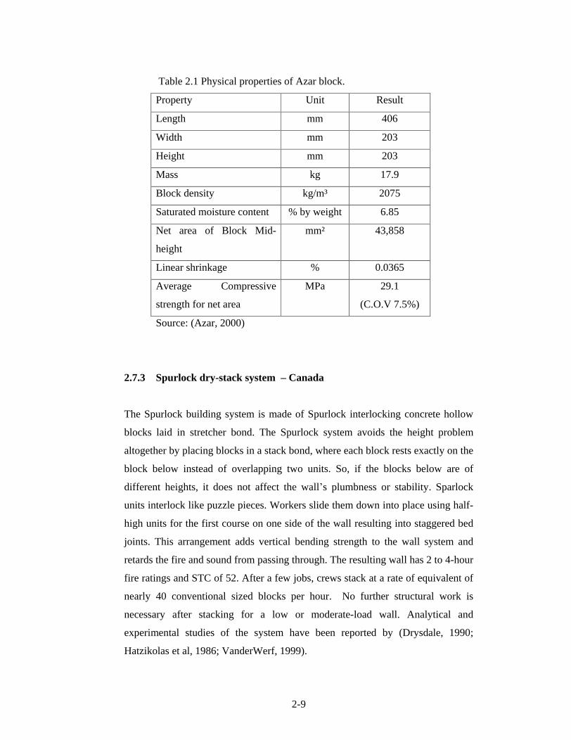
Table 2.1 Physical properties of Azar block.
Property Unit Result
Length mm 406
Width mm 203
Height mm 203
Mass kg 17.9
Block density kg/m³ 2075
Saturated moisture content % by weight 6.85
Net area of Block Mid-
height
mm² 43,858
Linear shrinkage % 0.0365
Average Compressive
strength for net area
MPa 29.1
(C.O.V 7.5%)
Source: (Azar, 2000)
2.7.3 Spurlock dry-stack system Canada
The Spurlock building system is made of Spurlock interlocking concrete hollow
blocks laid in stretcher bond. The Spurlock system avoids the height problem
altogether by placing blocks in a stack bond, where each block rests exactly on the
block below instead of overlapping two units. So, if the blocks below are of
different heights, it does not affect the wall s plumbness or stability. Sparlock
units interlock like puzzle pieces. Workers slide them down into place using half-
high units for the first course on one side of the wall resulting into staggered bed
joints. This arrangement adds vertical bending strength to the wall system and
retards the fire and sound from passing through. The resulting wall has 2 to 4-hour
fire ratings and STC of 52. After a few jobs, crews stack at a rate of equivalent of
nearly 40 conventional sized blocks per hour. No further structural work is
necessary after stacking for a low or moderate-load wall. Analytical and
experimental studies of the system have been reported by (Drysdale, 1990;
Hatzikolas et al, 1986; VanderWerf, 1999).

2-10
To date, the manufacturer has focused on the firewall market. This system has
enough strength and fire resistance without grout to be an interior, non load
bearing fire partition wall. There is no special provision for reinforcements in
either direction although it is possible to place vertical bars using a very high
slump grout. The blocks are produced in special moulds on standard block
equipment. Their unusual shape requires some extra thought cubing, but otherwise
no special steps are necessary. Figure 2.3 shows the type of Sparlock units
including a wall system. No design specifications available.
Figure 2.3 Spurlock dry-stack system (1986)
2.7.4 Haener dry-stack system USA
The Haener building system is made of Haener interlocking concrete blocks laid
in stretcher bond (see Fig. 2.4). The blocks are hollow with cavities to allow
vertical and horizontal reinforcements. The blocks consist of mechanical
interlocking features in the bed and head joints. According to WanderWerf
(1999), the Haener block system have been on the domestic market longer than
any other mortar less systems, largely attributed to the persistence and adaptability
of their inventor, Juan Haener. The blocks webs have raised lugs, formed with a
special contoured shoe during manufacture. The webs are offset from their
conventional locations so that the lugs align and lock each block into the correct
position during stacking. Some workers stack more than 100 blocks per hour.
Haener recently designed the Two-block Insulating system, which adds space in
each block to insert insulation. Haener blocks have sold well as a do-it
yourself product in Los Angeles area. It has achieved success for commercial

2-11
projects in other locations but it has no single dominant application. No design
specifications are available.
Figure 2.4 Block and stacking of the original Haener system
2.7.5 Linkblock dry stack system - South Africa
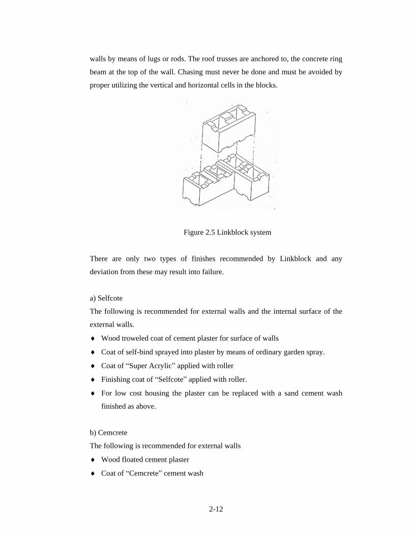
Linkblock dry-stack system is made of hollow interlocking concrete blocks laid in
stretcher bond. (see Fig.2.5) Linkblocks blocks are manufactured with
interlocking features A-shaped pattern visible on the face of the wall. The
blocks are made to accommodate vertical and horizontal reinforcements including
grouting. During construction, the foundation wall must be absolutely straight and
level, at predetermined depth below the floor level. The first course must be laid
in mortar. Where a stepped foundation is required, ensure that the height of the
steps is such that it corresponds with the coursing of the blocks (LinkBlock,1999).
External walls are done independently from internal walls using full blocks only.
No half block should be used in external walls. Concrete grout of 25 MPa is used
to fill the cavities, done at every 5 courses. Internal walls are tied to the external
2-12
walls by means of lugs or rods. The roof trusses are anchored to, the concrete ring
beam at the top of the wall. Chasing must never be done and must be avoided by
proper utilizing the vertical and horizontal cells in the blocks.
Figure 2.5 Linkblock system
There are only two types of finishes recommended by Linkblock and any
deviation from these may result into failure.
a) Selfcote
The following is recommended for external walls and the internal surface of the
external walls.
Wood troweled coat of cement plaster for surface of walls
Coat of self-bind sprayed into plaster by means of ordinary garden spray.
Coat of Super Acrylic applied with roller
Finishing coat of Selfcote applied with roller.
For low cost housing the plaster can be replaced with a sand cement wash
finished as above.
b) Cemcrete
The following is recommended for external walls
Wood floated cement plaster
Coat of Cemcrete cement wash

2-13
Final layer of texturite roughcast colored cement finish.
2.7.6 The Baker system
The Baker system is a interlocking block system developed in Australia by Baker
(Baker, 1972). It consists of interlocking head joints by means of dovetail lugs as
shown in Figure 2.6. The advantage of this system is that the courses can be
curved, a feature which is not readily achieved in other interlocking dry-stack
systems, where special units must be additionally produced if curved or offset
walls are required.
Figure 2.6 Baker System
2.7.7 The German KLB system
The KLB (Klimaleichtblock) system is a solid lightweight concrete dry-stack
block system developed in Germany. The blocks interlocks with a tongue and
groove interlocking mechanism on the head joint as shown in Figure 2.7
(Glitza, 1991)
Figure 2.7 KLB block (1990)

2-14
2.7.8 Sparfill system
A lightweight block (Figure 2.8.) made of polystyrene aggregate has been
developed in Canada and its structural performance when surface bonded, has
been reported by (Gazzola et al, 1989). The system, which is dry stacked and the
surface bonded with material containing glass fibers is marketed for low-rise
structures. The test results indicates that for the low rise construction, where
gravity loads are not high, the Sparfill block system can be readily designed to
resist lateral in-plane and out of plane forces .No reported test data is available.
Figure 2.8 Sparfill Block (1989)
2.7.9 The Sinustat system
The Sinustat System proposed by Hilmar Werner of Berlin and Oliver Collignon,
of London is a dry-stack system based on an open ended unit with a central cell
and two half cells (Oh, 1994). The widths of the basic units are 125 mm, 175 mm
and 200 mm and five basic units are needed for general construction. The
interlocking mechanism consists of lugs placed on the face shells as shown in
Figure 2.9a. The Sinustat system can be easily reinforced in the vertical and
horizontal direction with seat available for the ties as shown in Figure 2.9b
Figure 2.9 Sinustat System (1991)

2-15
2.7.10 The Whelan-Hatznikolas-Drexel (WHD)
A novel interlocking unit with a dove tailed end joint and using extruded mortar
material on the bed joints was introduced by Whelan in 1985. The geometry of
this unit is shown in Figure 2.10(a) and (b). This unit has a dovetailed lug at the
same head joints and although it can be reinforced in the vertical direction it
requires threading over the rebars during construction. Figure 2.10 (c) and (d)
shows the construction details of the system reported by Whelan, 1985.
Figure 2.10 Whelan Masonry System
2.7.11 Smart dry-stack system -Australia
Smart Masonry is a dry stacked concrete block system. The system consists of
hollow interlocking concrete blocks which are manufactured to controlled
dimensional tolerances and which incorporate detailing to permit the dry stacking
of the blocks (see Fig. 2.11). The block height is 200 mm and length 398.5 mm.
The top and bottom surfaces of the face shell incorporate a stepped profile. The
near vertical step is located at the mid
thickness of the face shell. When stacked
the outer half of the face shell of each block is in contact at the cursing height.
The back of the face shell of the lower block protrude upwards about 4mm to
engage the front lip of the upper block in a tongue and groove style of joint.
This ensures that the blocks are aligned vertically when stacked. The rear of the

2-16
face shell of the upper block is cut away by 20 mm so that an internal void, of
about 16 mm in height, is present in the back of the face shell. This void is filled
with grout when cores in the wall are grouted.
The wall is erected by bedding the first course on a leveling grout base. Half
height keys are inserted between blocks in the first course. Further courses are
erected with the plastic keys inserted in every vertical block joint (see Fig.2.11b)
Reinforcing bars are placed as the wall is constructed. The height the wall can be
erected prior to grouting is dependent upon the degree of restraint of return walls
and /or the extent of external bracing. The wall is grouted with Smart Masonry
Wall Grout, which is a special grade 32 MPa concrete grout, with a 250 slump
and 3 mm maximum aggregate size. The system was originally field tested in
South Africa and Sri Lanka, and subsequent developments of the system are now
being used in Australia (Anderson, 2001)
a) wall system b) inserting plastic key
Figure 2.11 Smart Masonry System (2000)
2.7.12 The modified H-Block system
Modified H-block unit shown in Figure 2.12 is a simple open ended block unit
with the tongue and groove interlock on both the bed and head joints developed
by Drexel University. It can be easily reinforced in the vertical and horizontal

2-17
direction. It has good resistance to water penetration due to the raised tongue and
groove bed joints (Oh, 1994).
Figure 2.12 Modified H-Block System
2.7.13 The Stepoc building system
The Stepoc building system is marketed in the United Kingdom by Forticrete
Architectural Masonry (Stepoc, 1989). It consists of single cell units with one end
interlocking block unit laid dry, which are then grouted in the interconnected
cavities thus bonding the block Figure 2.13 (a) shows the available blocks which
come in widths of 140 mm, 190 mm and 256 mm. No interlock mechanism exists
on the bed joints and a weak interlock for alignment is found on the head joints.
The Stepoc system can be easily reinforced in the vertical and horizontal
directions (Fig. 2.13b). It is suitable for construction of cavity, retaining or
foundation walls. The Stepoc system is laid in 1/3 running bond, which create an
internal configuration producing a cascade filling effect when the concrete is
poured as shown in Figure 2.13(b) and (c).

2-18
Figure 2.13 Stepoc System (1989)
2.7.14 Jordanian interlocking system
An interesting three-cell interlocking mortaless block has been used in Jordan for
low cost, low-rise housing. The basic stretcher unit has a raised lip around the
cells which provides horizontal interlock and open ends with tongue and groove
fit on the head joints as shown in Fig 2.14. The system is laid in stretcher bond
and allows the placements of vertical and horizontal reinforcements including
grouting as reported by (Bakeer, 1988).
Figure 2.14. Jordanian System (1988)

2-19
2.7.15 The Mecano system
A mortarless system, which can be dry-stacked then reinforced and grouted in the
vertical and horizontal directions, was developed in Peru by Gallegos in 1987.
(Gallegos, 1988). This system, known as Mecano system was developed for
earthquake resistance construction. The units are made of sand-lime mix and are
12 cm wide, have no interlocking geometry; rather continuity in the vertical and
horizontal directions is made through the grout cores (Fig.2.15). Since the block
cells are small a very fluid mix must be employed. The units shape creates two-
way modular cores which are 15 cm apart thus allowing of closely vertical
reinforcing. The horizontal reinforcement is placed during unit stacking and the
vertical reinforcement is placed after stacking. Testing on the compressive
strength of the units and prisms as well as diagonal tension tests has been
reported.
Figure 2.15 Mecano System (1988)
2.7.16 Barlock interlocking system
The Barlock was developed in the mid eighties by Barrett Industries of San
Antonio, Texas. The barlock system (Fig 2.16) uses the same dovetail lug
arrangement proposed by Whelan in1985 and has a smooth bed joint. The system
can be reinforced vertically or horizontally using a bond beam with knock out
webs (Barlock, 1992).

2-20
Figure 2.16 Barlock Interlocking System
2.7.17 Whelan interlocking masonry
A novel interlocking unit with a dove tailed joint and using extruded mortar
material on the bed joints was introduced by Whelan in 1985. The geometry of the
unit is shown in Figure 2.17. This unit has a dovetailed lug up the head joint,
although it can be reinforced in the vertical direction it require vertical threading
over the rebars during the construction (Whelan, 1985).
Figure 2.17 Whelan Interlocking system

2-21
2.7.18 McIBS, Inc. mortarlesss interlocking system
McIBS interlocking mortarless concrete block (McIBS, 1986) is two cell closed
end unit with a tongue and groove interlocking mechanism on the bed and head
joints. Figure 2.18a shows the various lightweight concrete units that can be
produced and Figure 2.18b shows the stacking and reinforcing arrangement. The
closed end unit has distinct disadvantages in earthquake resistance construction
because it must be threaded onto the vertical reinforcing bars. The control of the
block height is very critical for dimensional control and no details available on
how accurate the tongue and groove fit on the bed joints.
Figure 2.18 McIBS Masonry system (1980)
2.7.19 The Etherington building system
An Interlocking system developed in the late seventies and early eighties for low
cost housing in developing countries has been reported by Prof. Bruce Etherinton
of the university of Hawaii (Etherinton, 1983). The system has been used in
several large projects including 350 housing units in Manila and a 202 units
development in Bangkok. The main interlocking block types are shown in
Figure 2.19a. The basic block is closed ended two-cell unit with a raised lip
around each cell creating a horizontal interlock. Vertical interlock is achieved
through small cells placed in each web, which are continuous in the vertical

2-22
direction and are sealed with cement grout. It can accommodate vertical and
horizontal reinforcements see Figure 2.19b. According to the inventor, some of
the buildings using this system have survived for very strong earthquakes
Figure 2.19. Etherington System (1979)
2.7.20 The ACECOMS dry-stack system Thailand
Asia Center for Engineering Computations and Software (ACECOMS) of
Thailand is involved in the development of dry-stack masonry system.
ACECOMS system is made of hollow interlocking concrete blocks laid in
stretcher bond. The cavities in the blocks allow placement of vertical and
horizontal reinforcements and grouting.

2-23
ACECOMS Blocks (Fig.2.20) Specifications ACECOMS, 1998
Full block (300 mm long x150 mm wide x100 mm high)
Half block (150 mm long x150 mm wide x100 mm high)
U-Block
Half U-block
The two later types of bricks allow reinforcements to be laid horizontally (along
the full length of the wall) in the U cell on top of the blocks. Vertical cell allows
vertical reinforcements and grouting.
Figure 2.20 ACECOM Dry-stack blocks

2-24
2.8 Soil-Cement Dry-stack Masonry Systems
2.8.1 Introduction
Dry stacking using compressed soil-cement interlocking blocks is a recent
technology, which is increasingly becoming popular in the developing countries.
It has a potential for meeting the low cost housing needs for millions of people. A
cost comparison between compressed earth blocks and conventional concrete
blocks carried out by Killick (1998), indicates savings of about 20 % on the cost
of normal blocks. It utilizes the locally available materials, and therefore reduces
the transportation costs. Dry stacking increases the speed of construction and
reduces the need for skilled labour. Dry stacking using compressed soil-cement
consumes less cement; no firing of brick is required and therefore least energy
intensive and environmentally benign technology.
2.8.2 The Unique dry-stack building system - South Africa
Unique building system is made of soil-cement or concrete (UNIQUE, 2001). The
blocks consist of interlocking features in the bed and perpend joints including a
square cell, which allow for placements of vertical reinforcements and grouting to
increase wind and earthquake resistance. Unique block dimensions are-:
Full block 200 mm length x 200 mm width x 90 mm thick
Half block 200 mm length x100mm width x 90 mm thick
The block strength depends on the type of materials and the mix ratios used. The
average compressive strength range from 5 MPa for soil blocks to 21 MPa for
concrete blocks. The products are classified according to SABS 1215 as a solid
masonry unit. The code defines a solid masonry unit as a unit containing cavities
not exceeding 25% of the gross volume of the unit. The UB-200 with its 12%
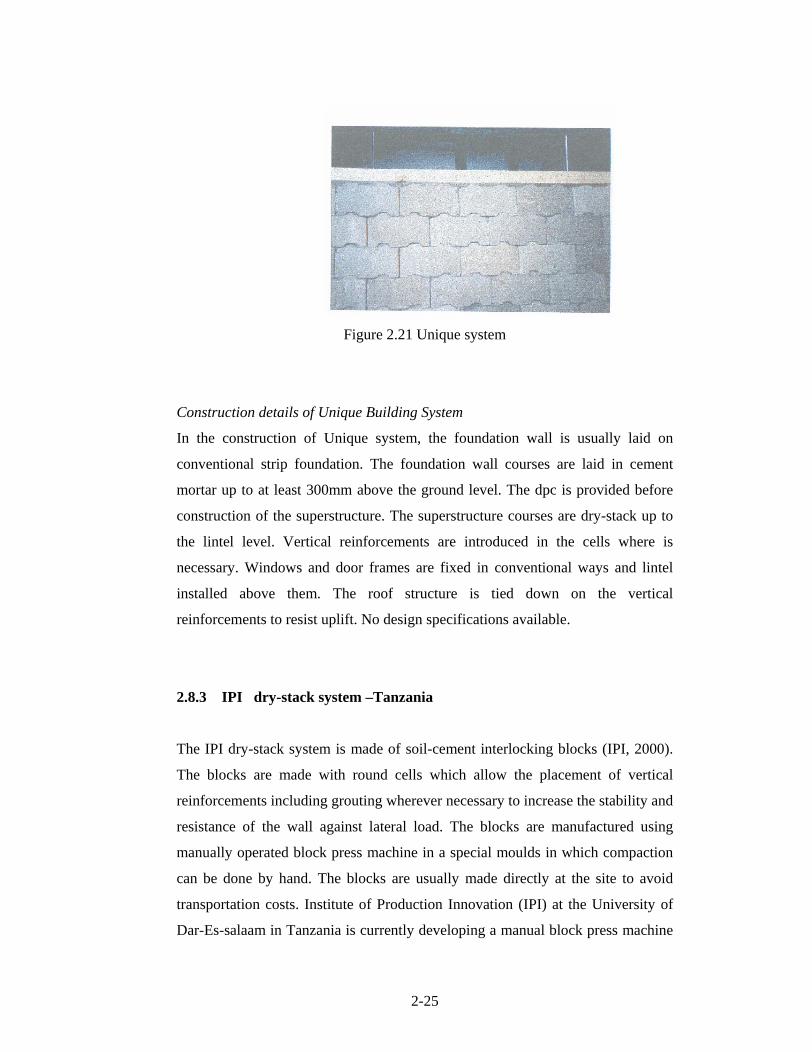
volume of air voids meets these criteria. Figure 2.21shows the Unique system.
2-25
Figure 2.21 Unique system
Construction details of Unique Building System
In the construction of Unique system, the foundation wall is usually laid on
conventional strip foundation. The foundation wall courses are laid in cement
mortar up to at least 300mm above the ground level. The dpc is provided before
construction of the superstructure. The superstructure courses are dry-stack up to
the lintel level. Vertical reinforcements are introduced in the cells where is
necessary. Windows and door frames are fixed in conventional ways and lintel
installed above them. The roof structure is tied down on the vertical
reinforcements to resist uplift. No design specifications available.
2.8.3 IPI dry-stack system Tanzania
The IPI dry-stack system is made of soil-cement interlocking blocks (IPI, 2000).
The blocks are made with round cells which allow the placement of vertical
reinforcements including grouting wherever necessary to increase the stability and
resistance of the wall against lateral load. The blocks are manufactured using
manually operated block press machine in a special moulds in which compaction
can be done by hand. The blocks are usually made directly at the site to avoid
transportation costs. Institute of Production Innovation (IPI) at the University of
Dar-Es-salaam in Tanzania is currently developing a manual block press machine
2-26
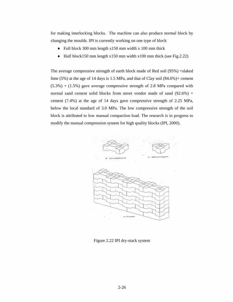
for making interlocking blocks. The machine can also produce normal block by
changing the moulds. IPI is currently working on one type of block
Full block 300 mm length x150 mm width x 100 mm thick
Half block150 mm length x150 mm width x100 mm thick (see Fig.2.22)
The average compressive strength of earth block made of Red soil (95%) +slaked
lime (5%) at the age of 14 days is 1.5 MPa, and that of Clay soil (84.6%)+ cement
(5.3%) + (1.5%) gave average compressive strength of 2.8 MPa compared with
normal sand cement solid blocks from street vendor made of sand (92.6%) +
cement (7.4%) at the age of 14 days gave compressive strength of 2.25 MPa,
below the local standard of 3.0 MPa. The low compressive strength of the soil
block is attributed to low manual compaction load. The research is in progress to
modify the manual compression system for high quality blocks (IPI, 2000).
Figure 2.22 IPI dry-stack system

2-27
2.8.4 Hydraform dry-stack building system South Africa
This research is based on the Hydraform dry-stack construction system using
Hydraform Interlocking blocks . The blocks are manufactured by compressing
a soil and cement mixture in a hydraulic block press - machine. The blocks
contain tongue &groove
type of interlocking features in the bed and head face.
Some units are designed to allow placements of reinforcements and grouting. The
blocks are found in two categories. Category one represents ordinary Hydraform
blocks for ordinary daily construction and the second category, Hydraform
Seismic blocks to be used where higher lateral strength is required i.e. earthquake
resistance.
Types of blocks are currently manufactured
i. 220 mm width x 115 mm height x 230-250 mm length for external walls
(weight 12 kg) see Fig. 2.23
Figure 2.23. Ordinary dry-stack block
ii) Ordinary block type II
115 mm width x 115 mm height x 230-250 mm length for internal non-
load bearing walls (weight 6 kg) see Fig. 2.24

2-28
Figure 2.24 Partition block
Figure 2.25 ordinary corner block
2.8.4.1 Construction details of Hydraform building system and use
limitations
In the construction with the Hydraform dry-stack system (Hydraform, 1988) the
foundation wall is built on a conventional cast in situ concrete strip or raft
foundation depending on the nature of the soil. The foundation wall is laid on
cement mortar preferably using higher strength blocks. In order to provide a level
surface to keep the wall aligned vertically and horizontally the starter course is
laid in ordinary sand cement mortar. Hydraform system normally utilises stretcher
bonding. (Figure 2.26a). The courses for the super structure are dry-stack, up to
the lintel level as shown in Figure 2.26b. The top three to four courses are also
laid in mortar to form a ring beam at the top. The roof is tied down to the ring
beam by galvanized wire to prevent up lift. Windows and door frames are
embedded in conventional ways and lintels installed above them. Plumbing and
electrical piping are chiselled into walls in the conventional ways. The external

2-29
walls may be plastered and painted, or other suitable type of finishing applied.
Internal walls are finished as prescribed by the client, but it is recommended to
plaster the internal walls to prevent rainwater penetration and improve thermal
and sound insulation. The wall cross-section detail is shown in Figure 2.26c
Figure 2.26(a) Dry-stacking Stretcher bond
Figure.2.26 (b) Dry-stacking the mid courses

2-30
Figure 2.26(c) Wall construction details
According to the South Africa National Building Regulations Agrement
Certificate (1996), the Hydraform building system is so far limited to erection of
single story buildings of the following category-:
Non-residential school buildings (A3)
Moderate and low risk commercial services buildings (B2) and
(B3)
Moderate and low risk industrial buildings (D2) and (D3)
Clinics and other institutional (residential) buildings (E3)
Small shops (F2)
Offices (G1)

2-31
Hostel, semi detached, row houses and detached houses (H2), (H3)
and (H4)
The system has also been used in the USA, India, Argentina Nigeria, Ethiopia,
Uganda, Tanzania and many other African countries to build hundreds of low cost
houses under government low cost housing schemes (Hydraform, 2000).
Appendix A shows some of the projects constructed using Hydraform system.
2.8.4.2 Manufacture of Hydraform Blocks
Hydraform compressed interlocking soil-cement blocks can be produced with a
sandy soil of 5-20% clay content and 5-25 % silt content. Blocks can even be
produced with higher clay and silt content, but you need to determine the
plasticity index to see if the soil is suitable for block production. Generally, soils
with low clay content and silt portions, below 10% will be difficult to handle
when coming out of machine. Soils with high clay and silt contents, above 35-
40%, will need to be blended with a sandy soil. The soil must be free of organic
material, must not contain harmful quantities of salts and should contain just
sufficient clay to bind the block so that they may be handled immediately after
manufacture without disintegrating. Generally the soil should comply with the
grading and plasticity requirements set out in the table below
Table 2.2 Basic requirements of Soil for CEB s production
% By mass passing the
0.075 mm sieve
(silt and clay fraction)
Soil
Range
Min. max
Plasticity
Index
(maximum)
Estimated block compressive
Strength
(After curing)
A 10% 35% 15 4 MPa (using soil range A)
B 10% 25% 10 7 MPa (using soil range B)
Source: Hydraform, 1988

2-32
Soil range A - should produce a block with a compressive strength of 4 MPa; Soil
range B - should produce block with a compressive strength of 7 MPa; Soils with
higher plasticity (over 15) are acceptable provided that the material has been pre -
treated with lime, laboratory testing will confirm the required dosage and
additional curing time required. Water must be clean and should not contain any
harmful quantities of acid, alkalis, salts, sugar or any other organic or chemical
material. Potable water will normally be satisfactory. The cement required will
normally be in the range of 4 to 7% by mass of the dry soil for 4 MPa blocks and
7 to 10% by mass for 7 MPa blocks. That will require a hydraulic press machine
of a compression load of between 8 to 13 MPa. For example a soil mix with 5%
cement content will produce blocks with average compressive strength of 4 to 5
MPa, while 10% cement content will give average strength of 7 to 8 MPa. In
production of 5% cement blocks, 23 bags of cement (standard size 50 kg) will
produce 1500 blocks, where in 10% cement, 45 bags will produce 1500 blocks.
Block production process involves breaking up lumps in freshly delivered or
excavated soil, sieving the soil (Fig. 2.27a), batching and adding cement, dry
mixing until uniform colour is achieved, adding water, wet mixing and loading the
mix into the machine (Fig. 2.27b). Hydraform blocks are produced using a mobile
diesel or electrical driven hydraulic block making machines normally vertically
extruded (Fig. 2.27c). Different geometry is achieved by simply changing the
moulds. The production capacity of the machine is 200 to 250 blocks per hour.
Seven trained Hydraform technicians produce ± 1600 blocks per day
(Hydraform, 2004).
a) sieving of soil b) block production

2-33
c) Hydraform mobile block making machine
Figure 2.27 Production of Hydraform interlocking blocks
Freshly produced blocks are stacked (not exceeding 6 blocks in height) and
covered immediately with plastic sheet to protect the blocks from weather. Curing
is commenced after 24 hrs by wetting the blocks daily for five to seven days and
keep them covered properly as shown Figure 2.28. Curing is very crucial in the
strength development of the blocks. On site production do not involve
transportation of the blocks. Blocks manufactured outside the site are delivered by
trucks in palettes as seen in Figure 2.29 (Hydraform, 2004).

2-34
Figure 2.28 Block curing
Figure 2.29 Delivering of the blocks in pallets