Chapter 16
119
17-1 Solutions Manual for Thermodynamics: An Engineering Approach Seventh Edition Yunus A. Cengel, Michael A. Boles McGraw-Hill, 2011 Chapter 17 COMPRESSIBLE FLOW PROPRIETARY AND CONFIDENTIAL This Manual is the proprietary property of The McGraw-Hill Companies, Inc. (“McGraw-Hill”) and protected by copyright and other state and federal laws. By opening and using this Manual the user agrees to the following restrictions, and if the recipient does not agree to these restrictions, the Manual should be promptly returned unopened to McGraw-Hill: This Manual is being provided only to authorized professors and instructors for use in preparing for the classes using the affiliated textbook. No other use or distribution of this Manual is permitted. This Manual may not be sold and may not be distributed to or used by any student or other third party. No part of this Manual may be reproduced, displayed or distributed in any form or by any means, electronic or otherwise, without the prior written permission of McGraw-Hill. PROPRIETARY MATERIAL preparation. If you are a student using this Manual, you are using it without permission. . © 2011 The McGraw-Hill Companies, Inc. Limited distribution permitted only to teachers and educators for course www.20file.org
-
Upload
khangminh22 -
Category
Documents
-
view
4 -
download
0
Transcript of Chapter 16
17-1
Solutions Manual for
Thermodynamics: An Engineering Approach Seventh Edition
Yunus A. Cengel, Michael A. Boles McGraw-Hill, 2011
Chapter 17 COMPRESSIBLE FLOW
PROPRIETARY AND CONFIDENTIAL
This Manual is the proprietary property of The McGraw-Hill Companies, Inc. (“McGraw-Hill”) and protected by copyright and other state and federal laws. By opening and using this Manual the user agrees to the following restrictions, and if the recipient does not agree to these restrictions, the Manual should be promptly returned unopened to McGraw-Hill: This Manual is being provided only to authorized professors and instructors for use in preparing for the classes using the affiliated textbook. No other use or distribution of this Manual is permitted. This Manual may not be sold and may not be distributed to or used by any student or other third party. No part of this Manual may be reproduced, displayed or distributed in any form or by any means, electronic or otherwise, without the prior written permission of McGraw-Hill.
PROPRIETARY MATERIALpreparation. If you are a student using this Manual, you are using it without permission.
. © 2011 The McGraw-Hill Companies, Inc. Limited distribution permitted only to teachers and educators for course
www.20file.org
17-2
Stagnation Properties
17-1C No, there is not significant error, because the velocities encountered in air-conditioning applications are very low, and thus the static and the stagnation temperatures are practically identical.
Discussion If the air stream were supersonic, however, the error would indeed be significant.
17-2C Stagnation enthalpy combines the ordinary enthalpy and the kinetic energy of a fluid, and offers convenience when analyzing high-speed flows. It differs from the ordinary enthalpy by the kinetic energy term.
Discussion Most of the time, we mean specific enthalpy, i.e., enthalpy per unit mass, when we use the term enthalpy.
17-3C Dynamic temperature is the temperature rise of a fluid during a stagnation process.
Discussion When a gas decelerates from high speed to zero speed at a stagnation point, the temperature of the gas rises.
17-4C The temperature of the air rises as it approaches the nose because of the stagnation process.
Discussion In the frame of reference moving with the aircraft, the air decelerates from high speed to zero at the nose (stagnation point), and this causes the air temperature to rise.
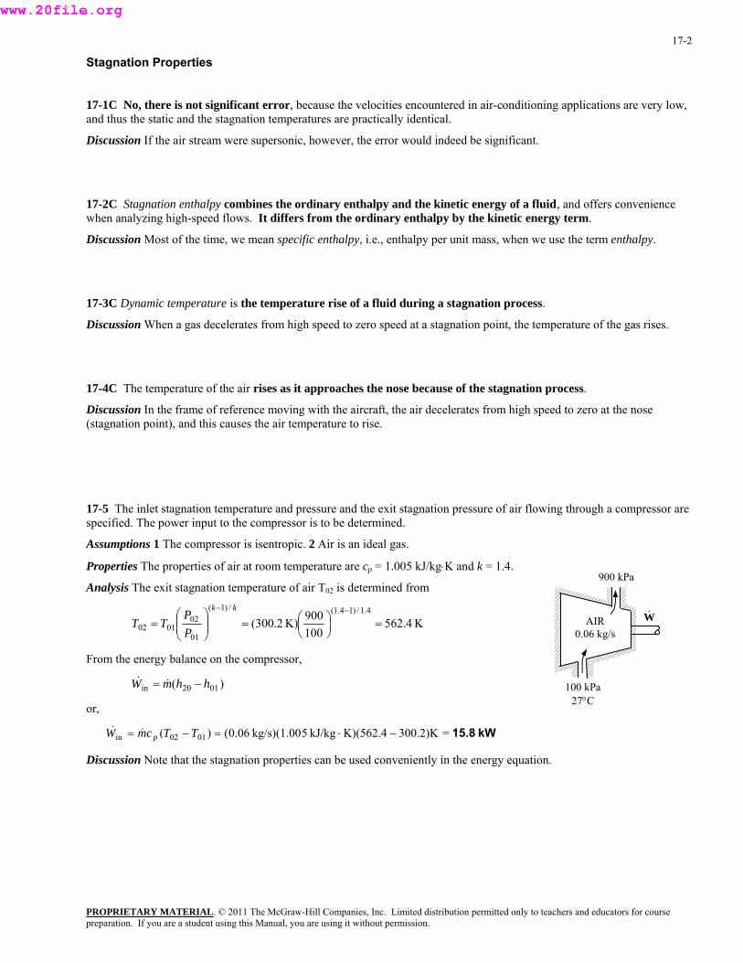
17-5 The inlet stagnation temperature and pressure and the exit stagnation pressure of air flowing through a compressor are specified. The power input to the compressor is to be determined.
Assumptions 1 The compressor is isentropic. 2 Air is an ideal gas.
100 kPa27°C
AIR 0.06 kg/s
900 kPa
&W
Properties The properties of air at room temperature are cp = 1.005 kJ/kg⋅K and k = 1.4.
Analysis The exit stagnation temperature of air T02 is determined from
K562.4100900K)2.300(
4.1/)14.1(/)1(
01
020102 =⎟
⎠⎞
⎜⎝⎛=⎟⎟
⎠
⎞⎜⎜⎝
⎛=
−− kk
PP
TT
From the energy balance on the compressor,
)( 0120in hhmW −= &&
or,
kW15.8=300.2)KK)(562.4kJ/kg5kg/s)(1.0006.0()( 0102in −⋅=−= TTcmW p&&
Discussion Note that the stagnation properties can be used conveniently in the energy equation.
PROPRIETARY MATERIALpreparation. If you are a student using this Manual, you are using it without permission.
. © 2011 The McGraw-Hill Companies, Inc. Limited distribution permitted only to teachers and educators for course
www.20file.org
17-3
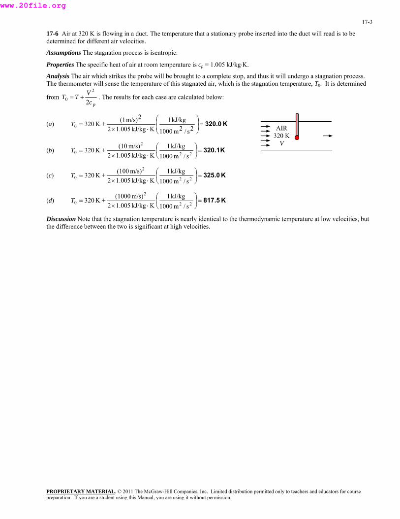
17-6 Air at 320 K is flowing in a duct. The temperature that a stationary probe inserted into the duct will read is to be determined for different air velocities.
Assumptions The stagnation process is isentropic.
Properties The specific heat of air at room temperature is cp = 1.005 kJ/kg⋅K.
Analysis The air which strikes the probe will be brought to a complete stop, and thus it will undergo a stagnation process. The thermometer will sense the temperature of this stagnated air, which is the stagnation temperature, T0. It is determined
from pc
VTT2
2
0 += . The results for each case are calculated below:
(a) K320.0⎟ =⎟⎠
⎞⎜⎜⎝
⎛
⋅×=
2s/2m1000
kJ/kg1KkJ/kg005.12
2m/s)(1+K3200T AIR 320 K
V (b) K320.1=⎟
⎠
⎞⎜⎝
⎛⋅×
= 22
2
0 s/m1000kJ/kg1
KkJ/kg005.12m/s)(10+K320T
(c) K325.0=⎟⎠⎞
⎜⎝⎛
⋅×= 22
2
0 s/m1000kJ/kg1
KkJ/kg005.12m/s)(100+K320T
(d) K817.5=⎟⎠
⎞⎜⎝
⎛⋅×
= 22
2
0 s/m1000kJ/kg1
KkJ/kg005.12m/s)(1000+K320T
Discussion Note that the stagnation temperature is nearly identical to the thermodynamic temperature at low velocities, but the difference between the two is significant at high velocities.
PROPRIETARY MATERIALpreparation. If you are a student using this Manual, you are using it without permission.
. © 2011 The McGraw-Hill Companies, Inc. Limited distribution permitted only to teachers and educators for course
www.20file.org
17-4
17-7 The states of different substances and their velocities are specified. The stagnation temperature and stagnation pressures are to be determined.
Assumptions 1 The stagnation process is isentropic. 2 Helium and nitrogen are ideal gases.
Analysis (a) Helium can be treated as an ideal gas with cp = 5.1926 kJ/kg·K and k = 1.667. Then the stagnation temperature and pressure of helium are determined from
C55.5°=⎟⎠
⎞⎜⎝
⎛°⋅×
+°=+=22
22
0s/m1000
kJ/kg1CkJ/kg1926.52
m/s)(240C50
2 pcVTT
MPa0.261=⎟⎠⎞
⎜⎝⎛=⎟⎟
⎠⎜
⎞⎜⎝
⎛=
−− )1667.1(/667.1)1(/0
0 K323.2K328.7MPa)25.0(
kk
TT
PP
(b) Nitrogen can be treated as an ideal gas with cp = 1.039 kJ/kg·K and k =1.400. Then the stagnation temperature and pressure of nitrogen are determined from
C93.3°=⎟⎠
⎞⎜⎝
⎛°⋅×
+°=+=22
22
0s/m1000
kJ/kg1CkJ/kg039.12
m/s)(300C50
2 pcVTT
MPa0.233=⎟⎠⎞
⎜⎝⎛=⎟⎟
⎠⎜
⎞⎜⎝
⎛=
−− )14.1/(4.1)1/(0
0 K323.2K366.5MPa)15.0(
kk
TT
PP
(c) Steam can be treated as an ideal gas with cp = 1.865 kJ/kg·K and k =1.329. Then the stagnation temperature and pressure of steam are determined from
K685C411.8 =°=⎟⎠
⎞⎜⎝
⎛°⋅×
+°=+=22
22
0s/m1000
kJ/kg1CkJ/kg865.12
m/s)(480C350
2 pcVTT
MPa0.147=⎟⎠⎞
⎜⎝⎛=⎟⎟
⎠⎜
⎞⎜⎝
⎛=
−− )1329.1/(329.1)1/(0
0 K623.2K685MPa)1.0(
kk
TT
PP
Discussion Note that the stagnation properties can be significantly different than thermodynamic properties.
17-8 The state of air and its velocity are specified. The stagnation temperature and stagnation pressure of air are to be determined.
Assumptions 1 The stagnation process is isentropic. 2 Air is an ideal gas.
Properties The properties of air at room temperature are cp = 1.005 kJ/kg⋅K and k = 1.4.
Analysis The stagnation temperature of air is determined from
K348≅=⎟⎠
⎞⎜⎝
⎛⋅×
+=+= K9.347/sm1000
kJ/kg1KkJ/kg005.12
m/s)470(K238
2 22
22
0pc
VTT
Other stagnation properties at the specified state are determined by considering an isentropic process between the specified state and the stagnation state,
kPa136≅=⎟⎠⎞
⎜⎝⎛=⎟⎟
⎠⎜
⎞⎜⎝
⎛=
−−
kPa9.135K238K347.9kPa)36(
)14.1/(4.1)1/(0
0
kk
TT
PP
Discussion Note that the stagnation properties can be significantly different than thermodynamic properties.
PROPRIETARY MATERIALpreparation. If you are a student using this Manual, you are using it without permission.
. © 2011 The McGraw-Hill Companies, Inc. Limited distribution permitted only to teachers and educators for course
www.20file.org
17-5
⎟
17-9E Steam flows through a device. The stagnation temperature and pressure of steam and its velocity are specified. The static pressure and temperature of the steam are to be determined.
Assumptions 1 The stagnation process is isentropic. 2 Steam is an ideal gas.
Properties Steam can be treated as an ideal gas with cp = 0.4455 Btu/lbm·R and k =1.329.
Analysis The static temperature and pressure of steam are determined from
F663.7°=⎟⎠
⎞⎜⎜⎝
⎛
°⋅×−°=−=
22
22
0s/ft25,037
Btu/lbm1FBtu/lbm4455.02
ft/s)(900F700
2 pcVTT
psia105.5=⎟⎠⎞
⎜⎝⎛=⎟⎟
⎠⎜
⎞⎜⎝
⎛=
−− )1329.1/(329.1)1/(
00 R1160
R1123.7psia)120(kk
TTPP
Discussion Note that the stagnation properties can be significantly different than thermodynamic properties.
17-10 Air flows through a device. The stagnation temperature and pressure of air and its velocity are specified. The static pressure and temperature of air are to be determined.
Assumptions 1 The stagnation process is isentropic. 2 Air is an ideal gas.
Properties The properties of air at an anticipated average temperature of 600 K are cp = 1.051 kJ/kg⋅K and k = 1.376.
Analysis The static temperature and pressure of air are determined from
K518.6=⎟⎠
⎞⎜⎝
⎛⋅×
−=−=22
22
0s/m1000
kJ/kg1KkJ/kg051.12
m/s)(5702.673
2 pcVTT
and
MPa0.23=⎟⎠⎞
⎜⎝⎛=⎟⎟
⎠
⎞⎜⎜⎝
⎛=
−− )1376.1/(376.1)1/(
02
2022 K673.2
K518.6MPa)6.0(kk
TT
PP
Discussion Note that the stagnation properties can be significantly different than thermodynamic properties.
PROPRIETARY MATERIALpreparation. If you are a student using this Manual, you are using it without permission.
. © 2011 The McGraw-Hill Companies, Inc. Limited distribution permitted only to teachers and educators for course
www.20file.org
PROPRIETARY MATERIAL. © 2011 The McGraw-Hill Companies, Inc. Limited distribution permitted only to teachers and educators for course preparation. If you are a student using this Manual, you are using it without permission.
17-6
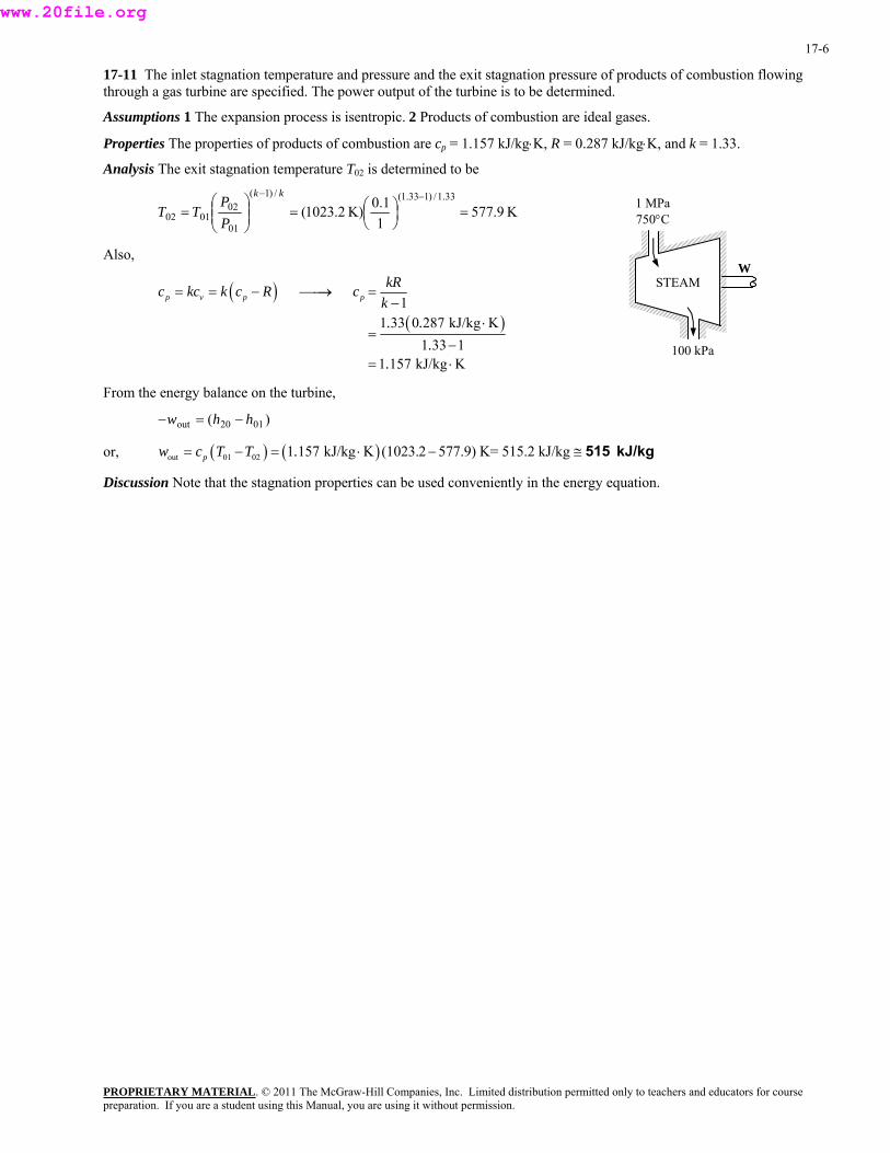
17-11 The inlet stagnation temperature and pressure and the exit stagnation pressure of products of combustion flowing through a gas turbine are specified. The power output of the turbine is to be determined.
Assumptions 1 The expansion process is isentropic. 2 Products of combustion are ideal gases.
Properties The properties of products of combustion are cp = 1.157 kJ/kg⋅K, R = 0.287 kJ/kg⋅K, and k = 1.33.
Analysis The exit stagnation temperature T02 is determined to be
K9.5771
0.1K)2.1023(33.1/)133.1(/)1(
01
020102 =⎟
⎠⎞
⎜⎝⎛=⎟⎟
⎠
⎞⎜⎜⎝
⎛=
−− kk
PP
TT 1 MPa 750°C
100 kPa
STEAM
Also, W
( )( )
11 33 0 287 kJ/kg K
1 33 11 157 kJ/kg K
p v p pkRc kc k c R c
k. .
..
= = − ⎯⎯→ =−
⋅=
−= ⋅
From the energy balance on the turbine,
)( 0120out hhw −=−
or, ( ) ( )out 01 02 1 157 kJ/kg K (1023.2 577.9) K= 515.2 kJ/kgpw c T T .= − = ⋅ − ≅ 515 kJ/kg
Discussion Note that the stagnation properties can be used conveniently in the energy equation.
www.20file.org
17-7
Speed of Sound and Mach Number
17-12C Sound is an infinitesimally small pressure wave. It is generated by a small disturbance in a medium. It travels by wave propagation. Sound waves cannot travel in a vacuum.
Discussion Electromagnetic waves, like light and radio waves, can travel in a vacuum, but sound cannot.
17-13C Yes, the propagation of sound waves is nearly isentropic. Because the amplitude of an ordinary sound wave is very small, and it does not cause any significant change in temperature and pressure.
Discussion No process is truly isentropic, but the increase of entropy due to sound propagation is negligibly small.
17-14C The sonic speed in a medium depends on the properties of the medium, and it changes as the properties of the medium change.
Discussion The most common example is the change in speed of sound due to temperature change.
17-15C Sound travels faster in warm (higher temperature) air since kRTc = .
Discussion On the microscopic scale, we can imagine the air molecules moving around at higher speed in warmer air, leading to higher propagation of disturbances.
17-16C Sound travels fastest in helium, since kRTc = and helium has the highest kR value. It is about 0.40 for air, 0.35 for argon, and 3.46 for helium.
Discussion We are assuming, of course, that these gases behave as ideal gases – a good approximation at room temperature.
17-17C Air at specified conditions will behave like an ideal gas, and the speed of sound in an ideal gas depends on temperature only. Therefore, the speed of sound is the same in both mediums.
Discussion If the temperature were different, however, the speed of sound would be different.
17-18C In general, no, because the Mach number also depends on the speed of sound in gas, which depends on the temperature of the gas. The Mach number remains constant only if the temperature and the velocity are constant.
Discussion It turns out that the speed of sound is not a strong function of pressure. In fact, it is not a function of pressure at all for an ideal gas.
PROPRIETARY MATERIALpreparation. If you are a student using this Manual, you are using it without permission.
. © 2011 The McGraw-Hill Companies, Inc. Limited distribution permitted only to teachers and educators for course
www.20file.org
17-8
17-19 The Mach number of an aircraft and the speed of sound in air are to be determined at two specified temperatures.
Assumptions Air is an ideal gas with constant specific heats at room temperature.
Properties The gas constant of air is R = 0.287 kJ/kg·K. Its specific heat ratio at room temperature is k = 1.4.
Analysis From the definitions of the speed of sound and the Mach number,
m/s347⎟ =⎟⎠
⎞⎜⎜⎝
⎛⋅==
kJ/kg1s/m1000K)K)(300kJ/kg287.0)(4.1(
22kRTc
and 0.692===m/s347m/s240Ma
cV
(b) At 1000 K,
m/s634⎟ =⎟⎠
⎞⎜⎜⎝
⎛⋅==
kJ/kg1s/m1000K)K)(1000kJ/kg287.0)(4.1(
22kRTc
and 0.379===m/s634m/s240Ma
cV
Discussion Note that a constant Mach number does not necessarily indicate constant speed. The Mach number of a rocket, for example, will be increasing even when it ascends at constant speed. Also, the specific heat ratio k changes with temperature, and the accuracy of the result at 1000 K can be improved by using the k value at that temperature (it would give k = 1.386, c = 619 m/s, and Ma = 0.388).
PROPRIETARY MATERIALpreparation. If you are a student using this Manual, you are using it without permission.
. © 2011 The McGraw-Hill Companies, Inc. Limited distribution permitted only to teachers and educators for course
www.20file.org
17-9
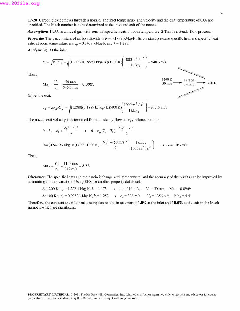
17-20 Carbon dioxide flows through a nozzle. The inlet temperature and velocity and the exit temperature of CO2 are specified. The Mach number is to be determined at the inlet and exit of the nozzle.
Assumptions 1 CO2 is an ideal gas with constant specific heats at room temperature. 2 This is a steady-flow process.
Properties The gas constant of carbon dioxide is R = 0.1889 kJ/kg·K. Its constant pressure specific heat and specific heat ratio at room temperature are cp = 0.8439 kJ/kg⋅K and k = 1.288.
Analysis (a) At the inlet
m/s3.540kJ/kg1
s/m1000K)K)(1200kJ/kg1889.0)(288.1(22
111 ⎟ =⎟⎠
⎞⎜⎜⎝
⎛⋅== RTkc
Thus, 1200 K 50 m/s
PROPRIETARY MATERIAL. © 2011 The McGraw-Hill Companies, Inc. Limited distribution permitted only to teachers and educators for course
400 K Carbon dioxide 0.0925===
m/s3.540m/s50Ma
1
11 c
V
(b) At the exit,
m/s 0.312kJ/kg1
s/m1000K)K)(400kJ/kg1889.0)(288.1(22
222 ⎟ =⎟⎠
⎞⎜⎜⎝
⎛⋅== RTkc
The nozzle exit velocity is determined from the steady-flow energy balance relation,
20
21
22
12VV
hh−
+−= → 2
)(02
12
212
VVTTc p
−+−=
m/s1163s/m1000
kJ/kg12
m/s)50(K)1200400(K)kJ/kg8439.0(0 222
222 =⎯→⎯⎟
⎠
⎞⎜⎝
⎛−+−⋅= V
V
Thus,
3.73===m/s312m/s1163Ma
2
22 c
V
Discussion The specific heats and their ratio k change with temperature, and the accuracy of the results can be improved by accounting for this variation. Using EES (or another property database):
At 1200 K: cp = 1.278 kJ/kg⋅K, k = 1.173 → c1 = 516 m/s, V1 = 50 m/s, Ma1 = 0.0969
At 400 K: cp = 0.9383 kJ/kg⋅K, k = 1.252 → c2 = 308 m/s, V2 = 1356 m/s, Ma2 = 4.41
Therefore, the constant specific heat assumption results in an error of 4.5% at the inlet and 15.5% at the exit in the Mach number, which are significant.
preparation. If you are a student using this Manual, you are using it without permission.
www.20file.org
17-10
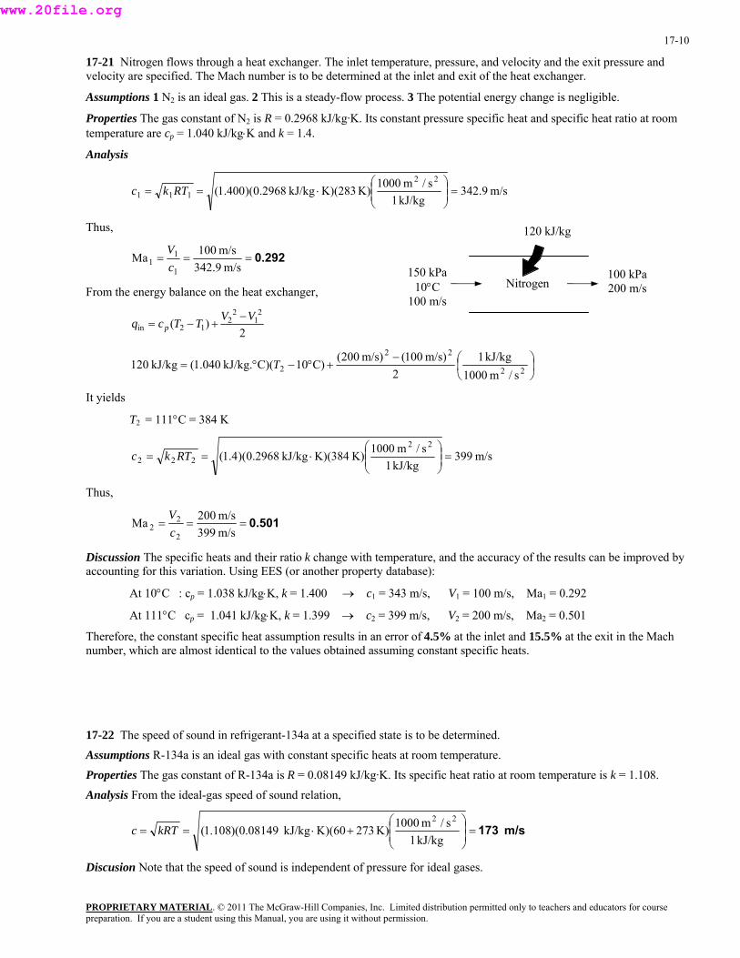
17-21 Nitrogen flows through a heat exchanger. The inlet temperature, pressure, and velocity and the exit pressure and velocity are specified. The Mach number is to be determined at the inlet and exit of the heat exchanger.
Assumptions 1 N2 is an ideal gas. 2 This is a steady-flow process. 3 The potential energy change is negligible.
Properties The gas constant of N2 is R = 0.2968 kJ/kg·K. Its constant pressure specific heat and specific heat ratio at room temperature are cp = 1.040 kJ/kg⋅K and k = 1.4.
Analysis
m/s9.342 kJ/kg1
s/m1000K)K)(283 kJ/kg2968.0)(400.1(22
111 ⎟ =⎟⎠
⎞⎜⎜⎝
⎛⋅== RTkc
Thus,
Nitrogen
120 kJ/kg
0.292===m/s9.342
m/s100Ma1
11 c
V
150 kPa 10°C
100 m/s
100 kPa 200 m/s From the energy balance on the heat exchanger,
2)(
21
22
12inVVTTcq p
−+−=
⎟⎠⎞
⎜⎝⎛−
+°−°= 22
22
2 s/m1000 kJ/kg1
2m/s)100(m/s)200(C)10C)( kJ/kg.040.1( kJ/kg120 T
It yields
T2 = 111°C = 384 K
m/s399 kJ/kg1
s/m1000K)K)(384 kJ/kg2968.0)(4.1(22
222 ⎟ =⎟⎠
⎞⎜⎜⎝
⎛⋅== RTkc
Thus,
0.501===m/s399m/s200Ma
2
22 c
V
Discussion The specific heats and their ratio k change with temperature, and the accuracy of the results can be improved by accounting for this variation. Using EES (or another property database):
At 10°C : cp = 1.038 kJ/kg⋅K, k = 1.400 → c1 = 343 m/s, V1 = 100 m/s, Ma1 = 0.292
At 111°C cp = 1.041 kJ/kg⋅K, k = 1.399 → c2 = 399 m/s, V2 = 200 m/s, Ma2 = 0.501
Therefore, the constant specific heat assumption results in an error of 4.5% at the inlet and 15.5% at the exit in the Mach number, which are almost identical to the values obtained assuming constant specific heats.
17-22 The speed of sound in refrigerant-134a at a specified state is to be determined. Assumptions R-134a is an ideal gas with constant specific heats at room temperature. Properties The gas constant of R-134a is R = 0.08149 kJ/kg·K. Its specific heat ratio at room temperature is k = 1.108. Analysis From the ideal-gas speed of sound relation,
m/s 173⎟ =⎟⎠
⎞⎜⎜⎝
⎛+⋅==
kJ/kg1s/m1000K)273K)(60kJ/kg 08149.0)(108.1(
22kRTc
Discusion Note that the speed of sound is independent of pressure for ideal gases.
PROPRIETARY MATERIALpreparation. If you are a student using this Manual, you are using it without permission.
. © 2011 The McGraw-Hill Companies, Inc. Limited distribution permitted only to teachers and educators for course
www.20file.org
17-11
17-23 The Mach number of a passenger plane for specified limiting operating conditions is to be determined.
Assumptions Air is an ideal gas with constant specific heats at room temperature.
Properties The gas constant of air is R = 0.287 kJ/kg·K. Its specific heat ratio at room temperature is k = 1.4.
Analysis From the speed of sound relation
m/s293 kJ/kg1
s/m1000K)273K)(-60 kJ/kg287.0)(4.1(22⎟ =⎟⎠
⎞⎜⎜⎝
⎛+⋅== kRTc
Thus, the Mach number corresponding to the maximum cruising speed of the plane is
0.897===m/s293
m/s)6.3/945(Ma max
cV
Discussion Note that this is a subsonic flight since Ma < 1. Also, using a k value at -60°C would give practically the same result.
17-24E Steam flows through a device at a specified state and velocity. The Mach number of steam is to be determined assuming ideal gas behavior.
Assumptions Steam is an ideal gas with constant specific heats.
Properties The gas constant of steam is R = 0.1102 Btu/lbm·R. Its specific heat ratio is given to be k = 1.3.
Analysis From the ideal-gas speed of sound relation,
ft/s2040Btu/lbm1
s/ft25,037R)R)(1160Btu/lbm1102.0)(3.1(22⎟ =⎟⎠
⎞⎜⎜⎝
⎛⋅== kRTc
Thus,
0.441===ft/s2040
ft/s900MacV
Discussion Using property data from steam tables and not assuming ideal gas behavior, it can be shown that the Mach number in steam at the specified state is 0.446, which is sufficiently close to the ideal-gas value of 0.441. Therefore, the ideal gas approximation is a reasonable one in this case.
PROPRIETARY MATERIALpreparation. If you are a student using this Manual, you are using it without permission.
. © 2011 The McGraw-Hill Companies, Inc. Limited distribution permitted only to teachers and educators for course
www.20file.org

17-12
17-25E Problem 17-24E is reconsidered. The variation of Mach number with temperature as the temperature changes between 350° and 700°F is to be investigated, and the results are to be plotted.
Analysis The EES Equations window is printed below, along with the tabulated and plotted results.
T=Temperature+460 R=0.1102 V=900 k=1.3 c=SQRT(k*R*T*25037) Ma=V/c
350 400 450 500 550 600 650 7000.44
0.45
0.46
0.47
0.48
0.49
0.5
0.51
0.52
0.53
Temperature, °F
Ma
Temperature, T, °F
Mach number Ma
350 375 400 425 450 475 500 525 550 575 600 625 650 675 700
0.528 0.520 0.512 0.505 0.498 0.491 0.485 0.479 0.473 0.467 0.462 0.456 0.451 0.446 0.441
Discussion Note that for a specified flow speed, the Mach number decreases with increasing temperature, as expected.
17-26 The expression for the speed of sound for an ideal gas is to be obtained using the isentropic process equation and the definition of the speed of sound.
Analysis The isentropic relation Pvk = A where A is a constant can also be expressed as
kk
Av
AP ρ=⎟⎠⎞
⎜⎝⎛=
1
Substituting it into the relation for the speed of sound,
kRTPkAkkAAPc kk
s
k
s
===⎟ =⎟⎠
⎞⎜⎜⎝
⎛=⎟⎟
⎠⎜
⎞⎜⎝
⎛= − )/(/)()( 12 ρρρρ
∂ρρ∂
∂ρ∂
since for an ideal gas P = ρRT or RT = P/ρ. Therefore, kRTc = , which is the desired relation.
Discussion Notice that pressure has dropped out; the speed of sound in an ideal gas is not a function of pressure.
PROPRIETARY MATERIALpreparation. If you are a student using this Manual, you are using it without permission.
. © 2011 The McGraw-Hill Companies, Inc. Limited distribution permitted only to teachers and educators for course
www.20file.org

17-13
17-27 The inlet state and the exit pressure of air are given for an isentropic expansion process. The ratio of the initial to the final speed of sound is to be determined.
Assumptions Air is an ideal gas with constant specific heats at room temperature.
Properties The properties of air are R = 0.287 kJ/kg·K and k = 1.4. The specific heat ratio k varies with temperature, but in our case this change is very small and can be disregarded.
Analysis The final temperature of air is determined from the isentropic relation of ideal gases,
K4.228MPa1.5MPa0.4K)2.333(
4.1/)14.1(/)1(
1
212 =⎟
⎠⎞
⎜⎝⎛=⎟⎟
⎠⎜
⎞⎜⎝
⎛=
−− kk
PP
TT
Treating k as a constant, the ratio of the initial to the final speed of sound can be expressed as
1.21=====4.2282.333Ratio
2
1
22
11
1
2
T
T
RTk
RTkcc
Discussion Note that the speed of sound is proportional to the square root of thermodynamic temperature.
17-28 The inlet state and the exit pressure of helium are given for an isentropic expansion process. The ratio of the initial to the final speed of sound is to be determined.
Assumptions Helium is an ideal gas with constant specific heats at room temperature.
Properties The properties of helium are R = 2.0769 kJ/kg·K and k = 1.667.
Analysis The final temperature of helium is determined from the isentropic relation of ideal gases,
K3.1961.50.4K)2.333(
667.1/)1667.1(/)1(
1
212 =⎟
⎠⎞
⎜⎝⎛=⎟⎟
⎠⎜
⎞⎜⎝
⎛=
−− kk
PP
TT
The ratio of the initial to the final speed of sound can be expressed as
1.30=====3.1962.333Ratio
2
1
22
11
1
2
T
T
RTk
RTkcc
Discussion Note that the speed of sound is proportional to the square root of thermodynamic temperature.
PROPRIETARY MATERIALpreparation. If you are a student using this Manual, you are using it without permission.
. © 2011 The McGraw-Hill Companies, Inc. Limited distribution permitted only to teachers and educators for course
www.20file.org
17-14
17-29E The inlet state and the exit pressure of air are given for an isentropic expansion process. The ratio of the initial to the final speed of sound is to be determined.
Assumptions Air is an ideal gas with constant specific heats at room temperature.
Properties The properties of air are R = 0.06855 Btu/lbm·R and k = 1.4. The specific heat ratio k varies with temperature, but in our case this change is very small and can be disregarded.
Analysis The final temperature of air is determined from the isentropic relation of ideal gases,
R9.48917060R)7.659(
4.1/)14.1(/)1(
1
212 =⎟
⎠⎞
⎜⎝⎛=⎟⎟
⎠⎜
⎞⎜⎝
⎛=
−− kk
PP
TT
Treating k as a constant, the ratio of the initial to the final speed of sound can be expressed as
1.16=====9.4897.659Ratio
2
1
22
11
1
2
TT
RTkRTk
cc
Discussion Note that the speed of sound is proportional to the square root of thermodynamic temperature.
PROPRIETARY MATERIALpreparation. If you are a student using this Manual, you are using it without permission.
. © 2011 The McGraw-Hill Companies, Inc. Limited distribution permitted only to teachers and educators for course
www.20file.org
17-15
One Dimensional Isentropic Flow
17-30C (a) The velocity increases. (b), (c), (d) The temperature, pressure, and density of the fluid decrease.
Discussion The velocity increase is opposite to what happens in supersonic flow.
17-31C (a) The velocity decreases. (b), (c), (d) The temperature, pressure, and density of the fluid increase.
Discussion The velocity decrease is opposite to what happens in supersonic flow.
17-32C (a) The exit velocity remains constant at sonic speed, (b) the mass flow rate through the nozzle decreases because of the reduced flow area.
Discussion Without a diverging portion of the nozzle, a converging nozzle is limited to sonic velocity at the exit.
17-33C (a) The velocity decreases. (b), (c), (d) The temperature, pressure, and density of the fluid increase.
Discussion The velocity decrease is opposite to what happens in subsonic flow.
17-34C (a) The velocity increases. (b), (c), (d) The temperature, pressure, and density of the fluid decrease.
Discussion The velocity increase is opposite to what happens in subsonic flow.
17-35C The pressures at the two throats are identical.
Discussion Since the gas has the same stagnation conditions, it also has the same sonic conditions at the throat.
17-36C No, it is not possible.
Discussion The only way to do it is to have first a converging nozzle, and then a diverging nozzle.
PROPRIETARY MATERIALpreparation. If you are a student using this Manual, you are using it without permission.
. © 2011 The McGraw-Hill Companies, Inc. Limited distribution permitted only to teachers and educators for course
www.20file.org
17-16
17-37 The Mach number of scramjet and the air temperature are given. The speed of the engine is to be determined.
Assumptions Air is an ideal gas with constant specific heats at room temperature.
Properties The gas constant of air is R = 0.287 kJ/kg·K. Its specific heat ratio at room temperature is k = 1.4.
Analysis The temperature is -20 + 273.15 = 253.15 K. The speed of sound is
2 21000 m / s(1.4)(0.287 kJ/kg K)(253.15 K) 318.93 m/s1 kJ/kg
c kRT⎛ ⎞
= = ⋅ =⎜ ⎟⎝ ⎠
and
3.6 km/hMa (318.93 m/s)(7) 8037 km/h1 m/s
V c ⎛ ⎞= = = ≅⎜ ⎟⎝ ⎠
8040 km/h
Discussion Note that extremely high speed can be achieved with scramjet engines. We cannot justify more than three significant digits in a problem like this.
17-38E The Mach number of scramjet and the air temperature are given. The speed of the engine is to be determined.
Assumptions Air is an ideal gas with constant specific heats at room temperature.
Properties The gas constant of air is R = 0.06855 Btu/lbm·R. Its specific heat ratio at room temperature is k = 1.4 .
Analysis The temperature is 0 + 459.67 = 459.67 R. The speed of sound is
2 225,037 ft / s(1.4)(0.06855 Btu/lbm R)(459.67 R) 1050.95 ft/s1 Btu/lbm
c kRT⎛ ⎞
= = ⋅ =⎜ ⎟⎝ ⎠
and
1 mi/hMa (1050.95 ft/s)(7) 5015.9 mi/h1.46667 ft/s
V c ⎛ ⎞= = = ≅⎜ ⎟⎝ ⎠
5020 mi/h
Discussion Note that extremely high speed can be achieved with scramjet engines. We cannot justify more than three significant digits in a problem like this.
PROPRIETARY MATERIALpreparation. If you are a student using this Manual, you are using it without permission.
. © 2011 The McGraw-Hill Companies, Inc. Limited distribution permitted only to teachers and educators for course
www.20file.org
17-17
17-39 The speed of an airplane and the air temperature are give. It is to be determined if the speed of this airplane is subsonic or supersonic.
Assumptions Air is an ideal gas with constant specific heats at room temperature.
Properties The gas constant of air is R = 0.287 kJ/kg·K. Its specific heat ratio at room temperature is k = 1.4.
Analysis The temperature is -50 + 273.15 = 223.15 K. The speed of sound is
2 21000 m / s 3.6 km/h(1.4)(0.287 kJ/kg K)(223.15 K) 1077.97 km/h1 kJ/kg 1 m/s
c kRT⎛ ⎞ ⎛ ⎞= = ⋅ =⎜ ⎟ ⎜ ⎟
⎝ ⎠⎝ ⎠
and
920 km/hMa 0.853461077.97 km/h
Vc
= = = ≅ 0.853
The speed of the airplane is subsonic since the Mach number is less than 1.
Discussion Subsonic airplanes stay sufficiently far from the Mach number of 1 to avoid the instabilities associated with transonic flights.
PROPRIETARY MATERIALpreparation. If you are a student using this Manual, you are using it without permission.
. © 2011 The McGraw-Hill Companies, Inc. Limited distribution permitted only to teachers and educators for course
www.20file.org
17-18
17-40 The critical temperature, pressure, and density of air and helium are to be determined at specified conditions.
Assumptions Air and Helium are ideal gases with constant specific heats at room temperature.
Properties The properties of air at room temperature are R = 0.287 kJ/kg·K, k = 1.4, and cp = 1.005 kJ/kg·K. The properties of helium at room temperature are R = 2.0769 kJ/kg·K, k = 1.667, and cp = 5.1926 kJ/kg·K.
Analysis (a) Before we calculate the critical temperature T*, pressure P*, and density ρ*, we need to determine the stagnation temperature T0, pressure P0, and density ρ0.
C1.131s/m1000
kJ/kg1C kJ/kg005.12
m/s)(250+1002
C100 22
22
0 °=⎟⎠⎞
⎜⎝⎛
°⋅×=+°=
pcVT
kPa7.264K373.2K404.3 kPa)200(
)14.1/(4.1)1/(0
0 =⎟⎠⎞
⎜⎝⎛=⎟
⎠⎞
⎜⎝⎛=
−−kk
TT
PP
33
0
00 kg/m281.2
K)K)(404.3/kgm kPa287.0( kPa7.264
=⋅⋅
==RTP
ρ
Thus,
K337=⎟⎠⎞
⎜⎝⎛=⎟
⎠⎞
⎜⎝⎛
+=
1+1.42K)3.404(
12* 0 k
TT
kPa140=⎟⎠⎞
⎜⎝⎛=⎟
⎠⎞
⎜⎝⎛
+=
−− )14.1/(4.1)1/(
0 1+1.42kPa)7.264(
12*
kk
kPP
3kg/m 1.45=⎟⎠⎞
⎜⎝⎛=⎟
⎠⎞
⎜⎝⎛
+=
−− )14.1/(13
)1/(1
0 1+1.42)kg/m281.2(
12*
k
kρρ
(b) For helium, C48.7s/m1000
kJ/kg1C kJ/kg1926.52
m/s)(300+40
2 22
22
0 °=⎟⎠⎞
⎜⎝⎛
°⋅×=+=
pcVTT
kPa2.214K313.2K321.9 kPa)200(
)1667.1/(667.1)1/(0
0 =⎟⎠⎞
⎜⎝⎛=⎟
⎠⎞
⎜⎝⎛=
−−kk
TT
PP
33
0
00 kg/m320.0
K)K)(321.9/kgm kPa0769.2( kPa2.214
=⋅⋅
==RTP
ρ
Thus,
K 241=⎟⎠⎞
⎜⎝⎛=⎟
⎠⎞
⎜⎝⎛
+=
1+1.6672K)9.321(
12* 0 k
TT
kPa 104.3=⎟⎠⎞
⎜⎝⎛=⎟
⎠⎞
⎜⎝⎛
+=
−− )1667.1/(667.1)1/(
0 1+1.6672kPa)2.214(
12*
kk
kPP
3kg/m 0.208=⎟⎠⎞
⎜⎝⎛=⎟
⎠⎞
⎜⎝⎛
+=
−− )1667.1/(13
)1/(1
0 1+1.6672)kg/m320.0(
12*
k
kρρ
Discussion These are the temperature, pressure, and density values that will occur at the throat when the flow past the throat is supersonic.
PROPRIETARY MATERIALpreparation. If you are a student using this Manual, you are using it without permission.
. © 2011 The McGraw-Hill Companies, Inc. Limited distribution permitted only to teachers and educators for course
www.20file.org
17-19
17-41 Quiescent carbon dioxide at a given state is accelerated isentropically to a specified Mach number. The temperature and pressure of the carbon dioxide after acceleration are to be determined.
Assumptions Carbon dioxide is an ideal gas with constant specific heats at room temperature.
Properties The specific heat ratio of the carbon dioxide at room temperature is k = 1.288.
Analysis The inlet temperature and pressure in this case is equivalent to the stagnation temperature and pressure since the inlet velocity of the carbon dioxide is said to be negligible. That is, T0 = Ti = 400 K and P0 = Pi = 1200 kPa. Then,
0 2 2
2 2(600 K) 570.43 K2 ( 1)Ma 2+(1.288-1)(0.6)
T Tk
⎛ ⎞ ⎛ ⎞= = =⎜ ⎟ ⎜ ⎟+ −⎝ ⎠ ⎝ ⎠
570 K≅
and /( 1) 1.288/(1.288 1)
00
570.43 K(1200 kPa) 957.23 K600 K
k kTP PT
− −⎛ ⎞ ⎛ ⎞= = = ≅⎜ ⎟ ⎜ ⎟⎝ ⎠⎝ ⎠
957 kPa
Discussion Note that both the pressure and temperature drop as the gas is accelerated as part of the internal energy of the gas is converted to kinetic energy.
17-42 Air enters a converging-diverging nozzle at specified conditions. The lowest pressure that can be obtained at the throat of the nozzle is to be determined.
Assumptions 1 Air is an ideal gas with constant specific heats at room temperature. 2 Flow through the nozzle is steady, one-dimensional, and isentropic.
Properties The specific heat ratio of air at room temperature is k = 1.4.
Analysis The lowest pressure that can be obtained at the throat is the critical pressure P*, which is determined from
kPa423=⎟⎠⎞
⎜⎝⎛=⎟
⎠⎞
⎜⎝⎛
+=
−− )14.1/(4.1)1/(
0 1+1.42kPa)800(
12*
kk
kPP
Discussion This is the pressure that occurs at the throat when the flow past the throat is supersonic.
PROPRIETARY MATERIALpreparation. If you are a student using this Manual, you are using it without permission.
. © 2011 The McGraw-Hill Companies, Inc. Limited distribution permitted only to teachers and educators for course
www.20file.org
17-20
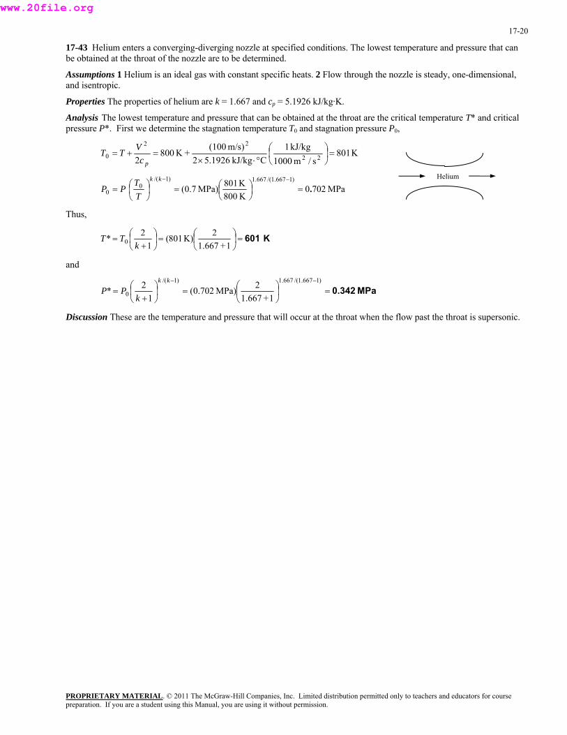
17-43 Helium enters a converging-diverging nozzle at specified conditions. The lowest temperature and pressure that can be obtained at the throat of the nozzle are to be determined.
Assumptions 1 Helium is an ideal gas with constant specific heats. 2 Flow through the nozzle is steady, one-dimensional, and isentropic.
Properties The properties of helium are k = 1.667 and cp = 5.1926 kJ/kg·K.
Analysis The lowest temperature and pressure that can be obtained at the throat are the critical temperature T* and critical pressure P*. First we determine the stagnation temperature T0 and stagnation pressure P0,
K801s/m1000
kJ/kg1C kJ/kg1926.52
m/s)(100+K800
2 22
22
0 =⎟⎠⎞
⎜⎝⎛
°⋅×=+=
pcVTT
Helium
MPa7020K800K801MPa)7.0(
)1667.1/(667.1)1/(0
0 .=⎟⎠⎞
⎜⎝⎛=⎟
⎠⎞
⎜⎝⎛=
−−kk
TT
PP
Thus,
K 601=⎟⎠⎞
⎜⎝⎛=⎟
⎠⎞
⎜⎝⎛
+=
1+1.6672K)801(
12* 0 k
TT
and
MPa0.342=⎟⎠⎞
⎜⎝⎛=⎟
⎠⎞
⎜⎝⎛
+=
−− )1667.1/(667.1)1/(
0 1+1.6672MPa)702.0(
12*
kk
kPP
Discussion These are the temperature and pressure that will occur at the throat when the flow past the throat is supersonic.
PROPRIETARY MATERIALpreparation. If you are a student using this Manual, you are using it without permission.
. © 2011 The McGraw-Hill Companies, Inc. Limited distribution permitted only to teachers and educators for course
www.20file.org
17-21
17-44 Air flows through a duct. The state of the air and its Mach number are specified. The velocity and the stagnation pressure, temperature, and density of the air are to be determined.
Assumptions Air is an ideal gas with constant specific heats at room temperature.
Properties The properties of air at room temperature are R = 0.287 kPa.m3/kg.K and k = 1.4.
Analysis The speed of sound in air at the specified conditions is
m/s387.2 kJ/kg1
s/m1000K)K)(373.2 kJ/kg287.0)(4.1(22⎟ =⎟⎠
⎞⎜⎜⎝
⎛⋅== kRTc
Thus, AIR m/s 310=m/s)2.387)(8.0(Ma =×= cV
Also,
33 kg/m867.1
K)K)(373.2/kgm kPa287.0( kPa200
=⋅⋅
==RTPρ
Then the stagnation properties are determined from
K 421⎟ =⎟⎠
⎞⎜⎜⎝
⎛+⎟ =⎟
⎠
⎞⎜⎜⎝
⎛ −+=
2.8)0)(1-.41(1K)2.373(
2Ma)1(1
22
0kTT
kPa 305=⎟⎠⎞
⎜⎝⎛=⎟⎟
⎠⎜
⎞⎜⎝
⎛=
−− )14.1/(4.1)1/(0
0 K373.2K421.0kPa)200(
kk
TT
PP
3kg/m 2.52=⎟⎠⎞
⎜⎝⎛=⎟⎟
⎠⎜
⎞⎜⎝
⎛=
−− )14.1/(13
)1/(10
0 K373.2K421.0)kg/m867.1(
k
TT
ρρ
Discussion Note that both the pressure and temperature drop as the gas is accelerated as part of the internal energy of the gas is converted to kinetic energy.
PROPRIETARY MATERIALpreparation. If you are a student using this Manual, you are using it without permission.
. © 2011 The McGraw-Hill Companies, Inc. Limited distribution permitted only to teachers and educators for course
www.20file.org
17-22
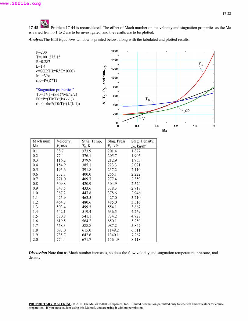
17-45 Problem 17-44 is reconsidered. The effect of Mach number on the velocity and stagnation properties as the Ma is varied from 0.1 to 2 are to be investigated, and the results are to be plotted.
Analysis The EES Equations window is printed below, along with the tabulated and plotted results.
P=200
0 0.4 0.8 1.2 1.6 20
200
400
600
800
1000
1200
1400
1600
Ma
V, T
0, P
0, a
nd 1
00•ρ
0
T0
P0
ρ0
V
T=100+273.15 R=0.287 k=1.4 c=SQRT(k*R*T*1000) Ma=V/c rho=P/(R*T)
"Stagnation properties" T0=T*(1+(k-1)*Ma^2/2) P0=P*(T0/T)^(k/(k-1)) rho0=rho*(T0/T)^(1/(k-1))
Mach num. Ma
Velocity, V, m/s
Stag. Temp, T0, K
Stag. Press, P0, kPa
Stag. Density, ρ0, kg/m3
0.1 0.2 0.3 0.4 0.5 0.6 0.7 0.8 0.9 1.0 1.1 1.2 1.3 1.4 1.5 1.6 1.7 1.8 1.9 2.0
38.7 77.4 116.2 154.9 193.6 232.3 271.0 309.8 348.5 387.2 425.9 464.7 503.4 542.1 580.8 619.5 658.3 697.0 735.7 774.4
373.9 376.1 379.9 385.1 391.8 400.0 409.7 420.9 433.6 447.8 463.5 480.6 499.3 519.4 541.1 564.2 588.8 615.0 642.6 671.7
201.4 205.7 212.9 223.3 237.2 255.1 277.4 304.9 338.3 378.6 427.0 485.0 554.1 636.5 734.2 850.1 987.2 1149.2 1340.1 1564.9
1.877 1.905 1.953 2.021 2.110 2.222 2.359 2.524 2.718 2.946 3.210 3.516 3.867 4.269 4.728 5.250 5.842 6.511 7.267 8.118
Discussion Note that as Mach number increases, so does the flow velocity and stagnation temperature, pressure, and density.
PROPRIETARY MATERIALpreparation. If you are a student using this Manual, you are using it without permission.
. © 2011 The McGraw-Hill Companies, Inc. Limited distribution permitted only to teachers and educators for course
www.20file.org
17-23
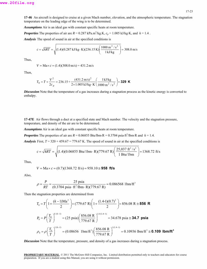
17-46 An aircraft is designed to cruise at a given Mach number, elevation, and the atmospheric temperature. The stagnation temperature on the leading edge of the wing is to be determined.
Assumptions Air is an ideal gas with constant specific heats at room temperature.
Properties The properties of air are R = 0.287 kPa.m3/kg.K, cp = 1.005 kJ/kg·K, and k = 1.4 .
Analysis The speed of sound in air at the specified conditions is
m/s308.0 kJ/kg1
s/m1000K)K)(236.15 kJ/kg287.0)(4.1(22⎟ =⎟⎠
⎞⎜⎜⎝
⎛⋅== kRTc
Thus,
m/s431.2=m/s)0.308)(4.1(Ma =×= cV
Then,
K 329=⎟⎠
⎞⎜⎝
⎛⋅×
=+=22
22
0s/m1000
kJ/kg1KkJ/kg005.12
m/s)(431.2+15.236
2 pcVTT
Discussion Note that the temperature of a gas increases during a stagnation process as the kinetic energy is converted to enthalpy.
17-47E Air flows through a duct at a specified state and Mach number. The velocity and the stagnation pressure, temperature, and density of the air are to be determined.
Assumptions Air is an ideal gas with constant specific heats at room temperature.
Properties The properties of air are R = 0.06855 Btu/lbm⋅R = 0.3704 psia⋅ft3/lbm⋅R and k = 1.4.
Analysis First, T = 320 + 459.67 = 779.67 K. The speed of sound in air at the specified conditions is
2 225,037 ft / s(1.4)(0.06855 Btu/1bm R)(779.67 R) 1368.72 ft/s1 Btu/1bm
c kRT⎛ ⎞
= = ⋅ =⎜ ⎟⎝ ⎠
Thus,
Ma (0.7)(1368.72 ft/s) 958.10V c= × = = ≅ 958 ft/s
Also,
33
25 psia 0.086568 1bm/ft(0.3704 psia ft /lbm R)(779.67 R)
PRT
ρ = = =⋅ ⋅
Then the stagnation properties are determined from 2 2
0( 1)Ma (1.4-1)(0.7)1 (779.67 R) 1 856.08 R
2 2kT T
⎛ ⎞ ⎛ ⎞−= + = + = ≅⎜ ⎟ ⎜ ⎟
⎝ ⎠ ⎝ ⎠856 R
/( 1) 1.4 /(1.4 1)0
0856.08 R(25 psia) 34.678 psia779.67 R
k kTP PT
− −⎛ ⎞ ⎛ ⎞= = = ≅⎜ ⎟⎜ ⎟ ⎝ ⎠⎝ ⎠
34.7 psia
1/( 1) 1/(1.4 1)3 30
0856.08 R(0.08656 1bm/ft ) 0.10936 lbm/ft779.67 R
kTT
ρ ρ− −
⎛ ⎞ ⎛ ⎞= = = ≅⎜ ⎟⎜ ⎟ ⎝ ⎠⎝ ⎠30.109 lbm/ft
Discussion Note that the temperature, pressure, and density of a gas increases during a stagnation process.
PROPRIETARY MATERIALpreparation. If you are a student using this Manual, you are using it without permission.
. © 2011 The McGraw-Hill Companies, Inc. Limited distribution permitted only to teachers and educators for course
www.20file.org
17-24
Isentropic Flow Through Nozzles
17-48C The fluid would accelerate even further instead of decelerating.
Discussion This is the opposite of what would happen in subsonic flow.
17-49C The fluid would accelerate even further, as desired.
Discussion This is the opposite of what would happen in subsonic flow.
17-50C (a) The exit velocity reaches the sonic speed, (b) the exit pressure equals the critical pressure, and (c) the mass flow rate reaches the maximum value.
Discussion In such a case, we say that the flow is choked.
17-51C (a) No effect on velocity. (b) No effect on pressure. (c) No effect on mass flow rate.
Discussion In this situation, the flow is already choked initially, so further lowering of the back pressure does not change anything upstream of the nozzle exit plane.
17-52C If the back pressure is low enough so that sonic conditions exist at the throats, the mass flow rates in the two nozzles would be identical. However, if the flow is not sonic at the throat, the mass flow rate through the nozzle with the diverging section would be greater, because it acts like a subsonic diffuser.
Discussion Once the flow is choked at the throat, whatever happens downstream is irrelevant to the flow upstream of the throat.
17-53C Maximum flow rate through a converging nozzle is achieved when Ma = 1 at the exit of a nozzle. For all other Ma values the mass flow rate decreases. Therefore, the mass flow rate would decrease if hypersonic velocities were achieved at the throat of a converging nozzle.
Discussion Note that this is not possible unless the flow upstream of the converging nozzle is already hypersonic.
17-54C Ma* is the local velocity non-dimensionalized with respect to the sonic speed at the throat, whereas Ma is the local velocity non-dimensionalized with respect to the local sonic speed.
Discussion The two are identical at the throat when the flow is choked.
17-55C (a) The velocity decreases, (b) the pressure increases, and (c) the mass flow rate remains the same.
Discussion Qualitatively, this is the same as what we are used to (in previous chapters) for incompressible flow.
PROPRIETARY MATERIALpreparation. If you are a student using this Manual, you are using it without permission.
. © 2011 The McGraw-Hill Companies, Inc. Limited distribution permitted only to teachers and educators for course
www.20file.org
17-25
17-56C No, if the flow in the throat is subsonic. If the velocity at the throat is subsonic, the diverging section would act like a diffuser and decelerate the flow. Yes, if the flow in the throat is already supersonic, the diverging section would accelerate the flow to even higher Mach number.
Discussion In duct flow, the latter situation is not possible unless a second converging-diverging portion of the duct is located upstream, and there is sufficient pressure difference to choke the flow in the upstream throat.
17-57 It is to be explained why the maximum flow rate per unit area for a given ideal gas depends only on P T0 0/ . Also
for an ideal gas, a relation is to be obtained for the constant a in = a& / *maxm A ( )00 / TP .
Properties The properties of the ideal gas considered are R = 0.287 kPa.m3/kg⋅K and k = 1.4.
Analysis The maximum flow rate is given by )1(2/)1(
00max 12/*
−+
⎟⎠⎞
⎜⎝⎛
+=
kk
kRTkPAm& or ( )
)1(2/)1(
00max 12//*/
−+
⎟⎠⎞
⎜⎝⎛
+=
kk
kRkTPAm&
For a given gas, k and R are fixed, and thus the mass flow rate depends on the parameter P T0 0/ . Thus, can be
expressed as
*/max Am&
( )00max /*/ TPaAm =& where
( 1) / 2( 1) 2.4 / 0.8
2 2
2 1.4 2/1 1.4 11000 m / s(0.287 kJ/kg.K)
1 kJ/kg
k k
a k Rk
+ −⎛ ⎞ ⎛ ⎞= = =⎜ ⎟ ⎜ ⎟+ +⎛ ⎞⎝ ⎠ ⎝ ⎠
⎜ ⎟⎝ ⎠
0.0404 (m/s) K
Discussion Note that when sonic conditions exist at a throat of known cross-sectional area, the mass flow rate is fixed by the stagnation conditions.
17-58 For an ideal gas, an expression is to be obtained for the ratio of the speed of sound where Ma = 1 to the speed of sound based on the stagnation temperature, c*/c0.
Analysis For an ideal gas the speed of sound is expressed as kRTc = . Thus,
1/ 2
0 00
* * *c kRT Tc TkRT
⎛ ⎞ ⎛ ⎞= = =⎜ ⎟ ⎜ ⎟⎝ ⎠⎝ ⎠
1/22+1k
Discussion Note that a speed of sound changes the flow as the temperature changes.
PROPRIETARY MATERIALpreparation. If you are a student using this Manual, you are using it without permission.
. © 2011 The McGraw-Hill Companies, Inc. Limited distribution permitted only to teachers and educators for course
www.20file.org
PROPRIETARY MATERIAL. © 2011 The McGraw-Hill Companies, Inc. Limited distribution permitted only to teachers and educators for course preparation. If you are a student using this Manual, you are using it without permission.
17-26
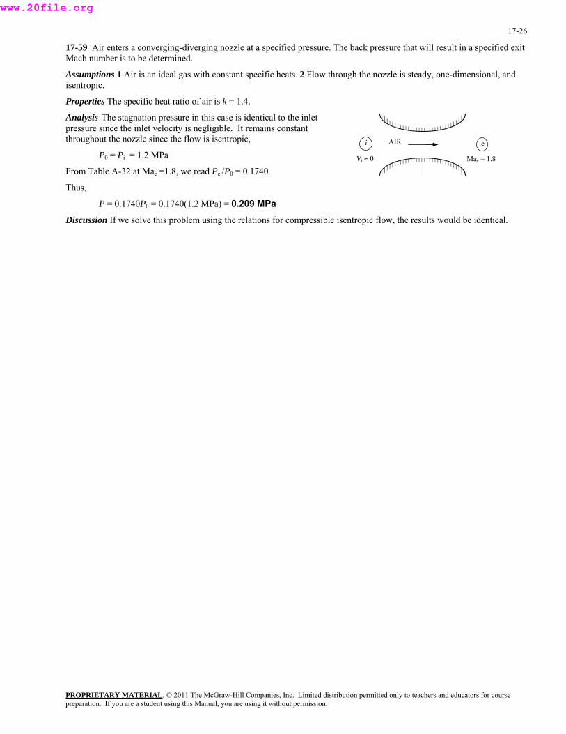
17-59 Air enters a converging-diverging nozzle at a specified pressure. The back pressure that will result in a specified exit Mach number is to be determined.
Assumptions 1 Air is an ideal gas with constant specific heats. 2 Flow through the nozzle is steady, one-dimensional, and isentropic.
Properties The specific heat ratio of air is k = 1.4.
Analysis The stagnation pressure in this case is identical to the inlet pressure since the inlet velocity is negligible. It remains constant throughout the nozzle since the flow is isentropic, AIR i e
P0 = Pi = 1.2 MPa Vi ≈ 0 Mae = 1.8
From Table A-32 at Mae =1.8, we read Pe /P0 = 0.1740.
Thus,
P = 0.1740P0 = 0.1740(1.2 MPa) = 0.209 MPa
Discussion If we solve this problem using the relations for compressible isentropic flow, the results would be identical.
www.20file.org
17-27
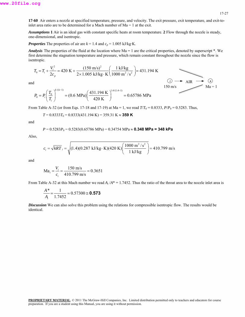
17-60 Air enters a nozzle at specified temperature, pressure, and velocity. The exit pressure, exit temperature, and exit-to-inlet area ratio are to be determined for a Mach number of Ma = 1 at the exit.
Assumptions 1 Air is an ideal gas with constant specific heats at room temperature. 2 Flow through the nozzle is steady, one-dimensional, and isentropic.
Properties The properties of air are k = 1.4 and cp = 1.005 kJ/kg·K.
Analysis The properties of the fluid at the location where Ma = 1 are the critical properties, denoted by superscript *. We first determine the stagnation temperature and pressure, which remain constant throughout the nozzle since the flow is isentropic.
2 2
0 2 2
(150 m/s) 1 kJ/kg420 K 431.194 K2 2 1.005 kJ/kg K 1000 m / s
ii
p
VT Tc
⎛ ⎞= + = + =⎜ ⎟× ⋅ ⎝ ⎠
150 m/s i AIR
Ma = 1 *and
/( 1) 1.4 /(1.4 1)
00
431.194 K(0.6 MPa) 0.65786 MPa420 K
k k
ii
TP PT
− −⎛ ⎞ ⎛ ⎞= = =⎜ ⎟ ⎜ ⎟⎝ ⎠⎝ ⎠
From Table A-32 (or from Eqs. 17-18 and 17-19) at Ma = 1, we read T/T0 = 0.8333, P/P0 = 0.5283. Thus,
T = 0.8333T0 = 0.8333(431.194 K) = 359.31 K ≈ 359 K
and
P = 0.5283P0 = 0.5283(0.65786 MPa) = 0.34754 MPa ≈ 0.348 MPa = 348 kPa
Also,
2 21000 m / s(1.4)(0.287 kJ/kg K)(420 K) 410.799 m/s1 kJ/kgiic kRT
⎛ ⎞= = ⋅ =⎜ ⎟
⎝ ⎠
and
150 m/sMa 0.3651410.799 m/s
ii
i
Vc
= = =
From Table A-32 at this Mach number we read Ai /A* = 1.7452. Thus the ratio of the throat area to the nozzle inlet area is
* 1 0.573001.7452i
AA
= = ≅ 0.573
Discussion We can also solve this problem using the relations for compressible isentropic flow. The results would be identical.
PROPRIETARY MATERIALpreparation. If you are a student using this Manual, you are using it without permission.
. © 2011 The McGraw-Hill Companies, Inc. Limited distribution permitted only to teachers and educators for course
www.20file.org

17-28
17-61 Air enters a nozzle at specified temperature and pressure with low velocity. The exit pressure, exit temperature, and exit-to-inlet area ratio are to be determined for a Mach number of Ma = 1 at the exit.
Assumptions 1 Air is an ideal gas. 2 Flow through the nozzle is steady, one-dimensional, and isentropic.
Properties The specific heat ratio of air is k = 1.4.
Vi ≈ 0 AIR
Analysis The properties of the fluid at the location where Ma = 1 are the critical properties, denoted by superscript *. The stagnation temperature and pressure in this case are identical to the inlet temperature and pressure since the inlet velocity is negligible. They remain constant throughout the nozzle since the flow is isentropic.
iMa = 1
*
T0 = Ti = 350 K and P0 = Pi = 0.2 MPa
From Table A-32 (or from Eqs. 17-18 and 17-19) at Ma =1, we read T/T0 =0.8333, P/P0 = 0.5283.
Thus,
T = 0.8333T0 = 0.8333(350 K) = 292 K
and
P = 0.5283P0 = 0.5283(0.2 MPa) = 0.106 MPa
The Mach number at the nozzle inlet is Ma = 0 since Vi ≅ 0. From Table A-32 at this Mach number we read Ai/A* = ∞.
Thus the ratio of the throat area to the nozzle inlet area is 0=∞
=1*
iAA .
Discussion If we solve this problem using the relations for compressible isentropic flow, the results would be identical.
PROPRIETARY MATERIALpreparation. If you are a student using this Manual, you are using it without permission.
. © 2011 The McGraw-Hill Companies, Inc. Limited distribution permitted only to teachers and educators for course
www.20file.org

17-29
17-62E Air enters a nozzle at specified temperature, pressure, and velocity. The exit pressure, exit temperature, and exit-to-inlet area ratio are to be determined for a Mach number of Ma = 1 at the exit.
Assumptions 1 Air is an ideal gas with constant specific heats at room temperature. 2 Flow through the nozzle is steady, one-dimensional, and isentropic.
Properties The properties of air are k = 1.4 and cp = 0.240 Btu/lbm·R (Table A-2Ea).
Analysis The properties of the fluid at the location where Ma =1 are the critical properties, denoted by superscript *. We first determine the stagnation temperature and pressure, which remain constant throughout the nozzle since the flow is isentropic.
R9.646s/ft25,037
Btu/1bm1RBtu/lbm240.02
ft/s)(450R630
2 22
22
0 ⎟ =⎟⎠
⎞⎜⎜⎝
⎛⋅×
+=+=p
i
cV
TT
i
PROPRIETARY MATERIAL. © 2011 The McGraw-Hill Companies, Inc. Limited distribution permitted only to teachers and educators for course
450 ft/s Ma = 1AIR *
psia9.32K630K646.9psia)30(
)14.1/(4.1)1/(0
0 =⎟⎠⎞
⎜⎝⎛=⎟⎟
⎠⎜
⎞⎜⎝
⎛=
−−kk
ii T
TPP
From Table A-32 (or from Eqs. 17-18 and 17-19) at Ma =1, we read T/T0 =0.8333, P/P0 = 0.5283.
Thus,
T = 0.8333T0 = 0.8333(646.9 R) = 539 R
and
P = 0.5283P0 = 0.5283(32.9 psia) = 17.4 psia
Also,
ft/s1230Btu/1bm1
s/ft25,037R)R)(630Btu/1bm06855.0)(4.1(22⎟ =⎟⎠
⎞⎜⎜⎝
⎛⋅== ii kRTc
and
3657.0ft/s1230ft/s450Ma ===
i
ii c
V
From Table A-32 at this Mach number we read Ai/A* = 1.7426. Thus the ratio of the throat area to the nozzle inlet area is
0.574==7426.11*
iAA
Discussion If we solve this problem using the relations for compressible isentropic flow, the results would be identical.
preparation. If you are a student using this Manual, you are using it without permission.
www.20file.org

17-30
17-63 For subsonic flow at the inlet, the variation of pressure, velocity, and Mach number along the length of the nozzle are to be sketched for an ideal gas under specified conditions.
Assumptions 1 The gas is an ideal gas. 2 Flow through the nozzle is steady, one-dimensional, and isentropic. 3 The flow is choked at the throat.
Analysis Using EES and CO2 as the gas, we calculate and plot flow area A, velocity V, and Mach number Ma as the pressure drops from a stagnation value of 1400 kPa to 200 kPa. Note that the curve for A is related to the shape of the nozzle, with horizontal axis serving as the centerline. The EES equation window and the plot are shown below.
Mai < 1
200 400 600 800 1000 1200 14000
1
2
P, kPa
A,
Ma,
V/5
00
A, m2
MaV/500, m/s
k=1.289 Cp=0.846 "kJ/kg.K" R=0.1889 "kJ/kg.K" P0=1400 "kPa"
T0=473 "K" m=3 "kg/s" rho_0=P0/(R*T0) rho=P/(R*T) rho_norm=rho/rho_0 "Normalized density" T=T0*(P/P0)^((k-1)/k) Tnorm=T/T0 "Normalized temperature" V=SQRT(2*Cp*(T0-T)*1000) V_norm=V/500 A=m/(rho*V)*500 C=SQRT(k*R*T*1000) Ma=V/C
Discussion We are assuming that the back pressure is sufficiently low that the flow is choked at the throat, and the flow downstream of the throat is supersonic without any shock waves. Mach number and velocity continue to rise right through the throat into the diverging portion of the nozzle, since the flow becomes supersonic.
PROPRIETARY MATERIALpreparation. If you are a student using this Manual, you are using it without permission.
. © 2011 The McGraw-Hill Companies, Inc. Limited distribution permitted only to teachers and educators for course
www.20file.org
17-31
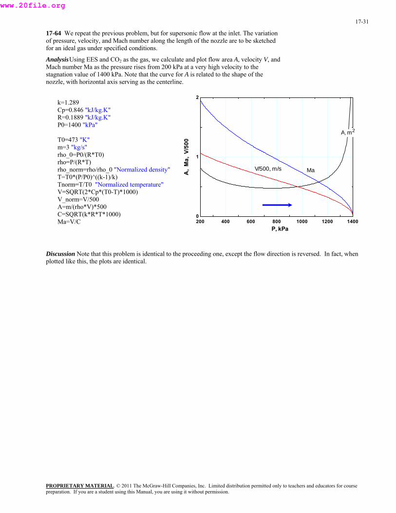
17-64 We repeat the previous problem, but for supersonic flow at the inlet. The variation of pressure, velocity, and Mach number along the length of the nozzle are to be sketched for an ideal gas under specified conditions.
Analysis Using EES and CO2 as the gas, we calculate and plot flow area A, velocity V, and Mach number Ma as the pressure rises from 200 kPa at a very high velocity to the stagnation value of 1400 kPa. Note that the curve for A is related to the shape of the nozzle, with horizontal axis serving as the centerline.
200 400 600 800 1000 1200 14000
1
2
P, kPa
A,
Ma,
V/5
00
A, m2
MaV/500, m/s
k=1.289 Cp=0.846 "kJ/kg.K" R=0.1889 "kJ/kg.K" P0=1400 "kPa"
T0=473 "K" m=3 "kg/s" rho_0=P0/(R*T0) rho=P/(R*T) rho_norm=rho/rho_0 "Normalized density" T=T0*(P/P0)^((k-1)/k) Tnorm=T/T0 "Normalized temperature" V=SQRT(2*Cp*(T0-T)*1000) V_norm=V/500 A=m/(rho*V)*500 C=SQRT(k*R*T*1000) Ma=V/C
Discussion Note that this problem is identical to the proceeding one, except the flow direction is reversed. In fact, when plotted like this, the plots are identical.
PROPRIETARY MATERIALpreparation. If you are a student using this Manual, you are using it without permission.
. © 2011 The McGraw-Hill Companies, Inc. Limited distribution permitted only to teachers and educators for course
www.20file.org
17-32
17-65 Nitrogen enters a converging-diverging nozzle at a given pressure. The critical velocity, pressure, temperature, and density in the nozzle are to be determined.
Assumptions 1 Nitrogen is an ideal gas. 2 Flow through the nozzle is steady, one-dimensional, and isentropic.
Properties The properties of nitrogen are k = 1.4 and R = 0.2968 kJ/kg·K.
Analysis The stagnation pressure in this case are identical to the inlet properties since the inlet velocity is negligible. They remain constant throughout the nozzle,
P0 = Pi = 700 kPa
T0 = Ti = 400 K i N2
Vi ≈ 0 3
30
00 kg/m896.5
K)K)(400/kgm kPa2968.0( kPa700
=⋅⋅
==RTP
ρ*
Critical properties are those at a location where the Mach number is Ma = 1. From Table A-32 at Ma =1, we read T/T0
=0.8333, P/P0 = 0.5283, and ρ/ρ0 = 0.6339.
Then the critical properties become
T* = 0.8333T0 = 0.8333(400 K) = 333 K
P* = 0.5283P0 = 0.5283(700 kPa) = 370 MPa
ρ* = 0.6339ρ0 = 0.6339(5.896 kg/m3) = 3.74 kg/m3
Also,
m/s372⎟ =⎟⎠
⎞⎜⎜⎝
⎛⋅===
kJ/kg1/sm1000K)K)(333kJ/kg2968.0)(4.1(***
22kRTcV
Discussion We can also solve this problem using the relations for compressible isentropic flow. The results would be identical.
17-66 An ideal gas is flowing through a nozzle. The flow area at a location where Ma = 2.4 is specified. The flow area where Ma = 1.2 is to be determined.
Assumptions Flow through the nozzle is steady, one-dimensional, and isentropic.
Properties The specific heat ratio is given to be k = 1.4.
Analysis The flow is assumed to be isentropic, and thus the stagnation and critical properties remain constant throughout the nozzle. The flow area at a location where Ma2 = 1.2 is determined using A /A* data from Table A-32 to be
22
111 cm98.14
4031.2cm36
4031.2*4031.2
*:4.2Ma ===⎯→⎯==
AA
AA
2cm15.4===⎯→⎯== )cm98.14)(0304.1(*)0304.1(0304.1*
:2.1Ma 22
22 AA
AA
Discussion We can also solve this problem using the relations for compressible isentropic flow. The results would be identical.
PROPRIETARY MATERIALpreparation. If you are a student using this Manual, you are using it without permission.
. © 2011 The McGraw-Hill Companies, Inc. Limited distribution permitted only to teachers and educators for course
www.20file.org
17-33
17-67 An ideal gas is flowing through a nozzle. The flow area at a location where Ma = 2.4 is specified. The flow area where Ma = 1.2 is to be determined.
Assumptions Flow through the nozzle is steady, one-dimensional, and isentropic.
Analysis The flow is assumed to be isentropic, and thus the stagnation and critical properties remain constant throughout the nozzle. The flow area at a location where Ma2 = 1.2 is determined using the A /A* relation,
)1(2/)1(2Ma
211
12
Ma1
*
−+
⎭⎬⎫
⎩⎨⎧
⎟⎠⎞
⎜⎝⎛ −+⎟
⎠⎞
⎜⎝⎛
+=
kkkkA
A
For k = 1.33 and Ma1 = 2.4:
570.22.42
133.11133.1
22.41
*
33.02/33.221 =⎭⎬⎫
⎩⎨⎧
⎟⎠⎞
⎜⎝⎛ −+⎟
⎠⎞
⎜⎝⎛
+=
×
AA
and
22
1 cm 01.14570.2cm36
570.2* ===
AA
For k = 1.33 and Ma2 = 1.2:
0316.11.22
133.11133.1
21.21
*
33.02/33.222 =⎭⎬⎫
⎩⎨⎧
⎟⎠⎞
⎜⎝⎛ −+⎟
⎠⎞
⎜⎝⎛
+=
×
AA
and 2cm 14.45=== )cm01.14)(0316.1(*)0316.1( 2
2 AA
Discussion Note that the compressible flow functions in Table A-32 are prepared for k = 1.4, and thus they cannot be used to solve this problem.
PROPRIETARY MATERIALpreparation. If you are a student using this Manual, you are using it without permission.
. © 2011 The McGraw-Hill Companies, Inc. Limited distribution permitted only to teachers and educators for course
www.20file.org
17-34
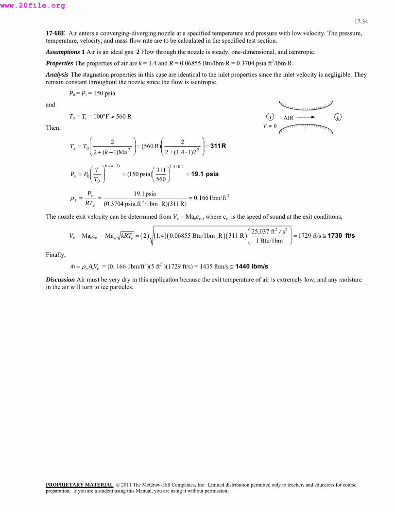
17-68E Air enters a converging-diverging nozzle at a specified temperature and pressure with low velocity. The pressure, temperature, velocity, and mass flow rate are to be calculated in the specified test section.
Assumptions 1 Air is an ideal gas. 2 Flow through the nozzle is steady, one-dimensional, and isentropic.
Properties The properties of air are k = 1.4 and R = 0.06855 Btu/lbm·R = 0.3704 psia·ft3/lbm·R.
Analysis The stagnation properties in this case are identical to the inlet properties since the inlet velocity is negligible. They remain constant throughout the nozzle since the flow is isentropic.
P0 = Pi = 150 psia
and
T0 = Ti = 100°F ≈ 560 R i eAIR Vi ≈ 0Then,
R311⎟ =⎟⎠
⎞⎜⎜⎝
⎛⎟ =⎟⎠
⎞⎜⎜⎝
⎛
−+=
2201)2-(1.4+2
2R)560(Ma)1(2
2k
TTe
psia 19.1=⎟⎠⎞
⎜⎝⎛=⎟⎟
⎠⎜
⎞⎜⎝
⎛=
− 4.0/4.1)1/(
00 560
311psia)150(kk
e TTPP
33
1bm/ft166.0R)R)(311/1bmpsia.ft3704.0(
psia1.19=
⋅==
e
ee RT
Pρ
The nozzle exit velocity can be determined from Ve = Maece , where ce is the speed of sound at the exit conditions,
Ve = Maece = ( ) ( )( )( )2 225,037 ft sMa 2 1 4 0 06855 Btu/1bm R 311 R 1729 ft/s
1 Btu/1bme e/kRT . .
⎛ ⎞= ⋅ =⎜ ⎟
⎝ ⎠1730 ft/s≅
Finally,
eee VAm ρ=& = (0. 166 1bm/ft3)(5 ft2 )(1729 ft/s) = 1435 lbm/s ≅ 1440 lbm/s
Discussion Air must be very dry in this application because the exit temperature of air is extremely low, and any moisture in the air will turn to ice particles.
PROPRIETARY MATERIALpreparation. If you are a student using this Manual, you are using it without permission.
. © 2011 The McGraw-Hill Companies, Inc. Limited distribution permitted only to teachers and educators for course
www.20file.org

17-35
17-69 Air enters a converging nozzle at a specified temperature and pressure with low velocity. The exit pressure, the exit velocity, and the mass flow rate versus the back pressure are to be calculated and plotted.
Assumptions 1 Air is an ideal gas with constant specific heats at room temperature. 2 Flow through the nozzle is steady, one-dimensional, and isentropic.
Properties The properties of air are k = 1.4, R = 0.287 kJ/kg·K, and cp = 1.005 kJ/kg·K.
Analysis The stagnation properties in this case are identical to the inlet properties since the inlet velocity is negligible. They remain constant throughout the nozzle since the flow is isentropic.,
P0 = Pi = 900 kPa
T0 = Ti = 400 K
The critical pressure is determined to be i eAIR Vi ≈ 0
kPa5.4751+1.4
2 kPa)900(1
2*4.0/4.1)1/(
0 =⎟⎠⎞
⎜⎝⎛=⎟
⎠⎞
⎜⎝⎛
+=
−kk
kPP
Then the pressure at the exit plane (throat) will be
Pe = Pb for Pb ≥ 475.5 kPa
Pe = P* = 475.5 kPa for Pb < 475.5 kPa (choked flow)
Thus the back pressure will not affect the flow when 100 < Pb < 475.5 kPa. For a specified exit pressure Pe, the temperature, the velocity and the mass flow rate can be determined from
Temperature 4.1/4.0
e/)1(
00 900
PK)400( ⎟
⎠⎞
⎜⎝⎛=⎟⎟
⎠⎜
⎞⎜⎝
⎛=
− kke
e PP
TT Pe
Velocity ⎟⎟⎠
⎞⎜⎜⎝
⎛⋅=−=
kJ/kg1/sm1000)T-K)(400 kJ/kg005.1(2)(2
22
e0 ep TTcV
Pb
Density e
e
e
ee TKkg
PRTP
)/m kPa287.0( 3 ⋅⋅==ρ
Ve
Mass flow rate )m001.0( 2eeeee VAVm ρρ ==& c
The results of the calculations are tabulated as
Pb
Pb, kPa Pe, kPa Te, K Ve, m/s ρe, kg/m3 &m, kg / s
900 900 400 0 7.840 0 800 800 386.8 162.9 7.206 1.174 700 700 372.3 236.0 6.551 1.546 600 600 356.2 296.7 5.869 1.741 500 500 338.2 352.4 5.151 1.815 475.5 475.5 333.3 366.2 4.971 1.820 400 475.5 333.3 366.2 4.971 1.820 300 475.5 333.3 366.2 4.971 1.820 200 475.5 333.3 366.2 4.971 1.820 100 475.5 333.3 366.2 4.971 1.820
Pb
kPa
& maxm
&m
900100 475.5
Discussion We see from the plots that once the flow is choked at a back pressure of 475.5 kPa, the mass flow rate remains constant regardless of how low the back pressure gets.
PROPRIETARY MATERIALpreparation. If you are a student using this Manual, you are using it without permission.
. © 2011 The McGraw-Hill Companies, Inc. Limited distribution permitted only to teachers and educators for course
www.20file.org
17-36
17-70 We are to reconsider the previous problem. Using EES (or other) software, we are to solve the problem for the inlet conditions of 0.8 MPa and 1200 K.
Analysis Air at 800 kPa, 1200 K enters a converging nozzle with a negligible velocity. The throat area of the nozzle is 10 cm2. Assuming isentropic flow, calculate and plot the exit pressure, the exit velocity, and the mass flow rate versus the back pressure Pb for 0.8>= Pb >=0.1 MPa.
Procedure ExitPress(P_back,P_crit : P_exit, Condition$) If (P_back>=P_crit) then P_exit:=P_back "Unchoked Flow Condition" Condition$:='unchoked' else P_exit:=P_crit "Choked Flow Condition" Condition$:='choked' Endif End
Gas$='Air' A_cm2=10 "Throat area, cm2" P_inlet =800"kPa" T_inlet= 1200"K" "P_back =422.7" "kPa"
A_exit = A_cm2*Convert(cm^2,m^2) C_p=specheat(Gas$,T=T_inlet) C_p-C_v=R k=C_p/C_v M=MOLARMASS(Gas$) "Molar mass of Gas$" R= 8.314/M "Gas constant for Gas$"
"Since the inlet velocity is negligible, the stagnation temperature = T_inlet; and, since the nozzle is isentropic, the stagnation pressure = P_inlet."
P_o=P_inlet "Stagnation pressure" T_o=T_inlet "Stagnation temperature" P_crit /P_o=(2/(k+1))^(k/(k-1)) "Critical pressure from Eq. 16-22" Call ExitPress(P_back,P_crit : P_exit, Condition$)
T_exit /T_o=(P_exit/P_o)^((k-1)/k) "Exit temperature for isentopic flow, K"
V_exit ^2/2=C_p*(T_o-T_exit)*1000 "Exit velocity, m/s"
Rho_exit=P_exit/(R*T_exit) "Exit density, kg/m3"
m_dot=Rho_exit*V_exit*A_exit "Nozzle mass flow rate, kg/s"
"If you wish to redo the plots, hide the diagram window and remove the { } from the first 4 variables just under the procedure. Next set the desired range of back pressure in the parametric table. Finally, solve the table (F3). "
The table of results and the corresponding plot are provided below.
PROPRIETARY MATERIALpreparation. If you are a student using this Manual, you are using it without permission.
. © 2011 The McGraw-Hill Companies, Inc. Limited distribution permitted only to teachers and educators for course
www.20file.org
17-37
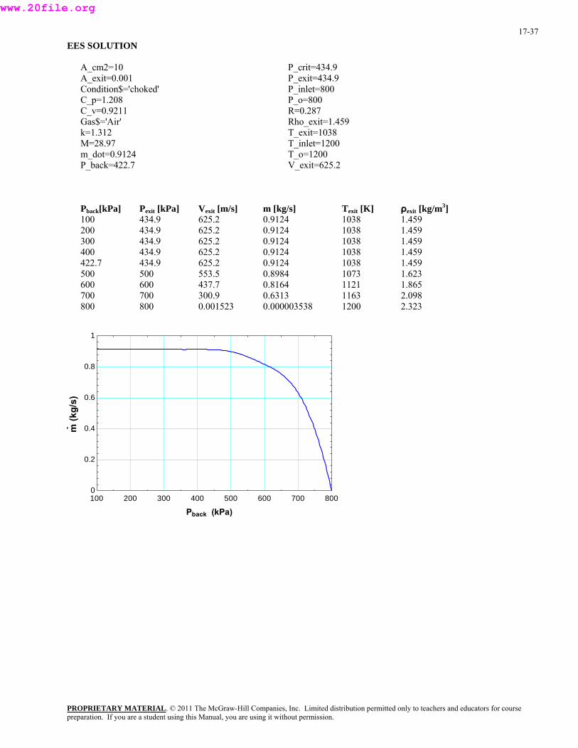
EES SOLUTION
A_cm2=10 A_exit=0.001 Condition$='choked' C_p=1.208 C_v=0.9211 Gas$='Air' k=1.312 M=28.97 m_dot=0.9124 P_back=422.7
P_crit=434.9 P_exit=434.9 P_inlet=800 P_o=800 R=0.287 Rho_exit=1.459 T_exit=1038 T_inlet=1200 T_o=1200 V_exit=625.2
Pback[kPa] Pexit [kPa] Vexit [m/s] m [kg/s] Texit [K] ρexit [kg/m3] 100 434.9 625.2 0.9124 1038 1.459 200 434.9 625.2 0.9124 1038 1.459 300 434.9 625.2 0.9124 1038 1.459 400 434.9 625.2 0.9124 1038 1.459 422.7 434.9 625.2 0.9124 1038 1.459 500 500 553.5 0.8984 1073 1.623 600 600 437.7 0.8164 1121 1.865 700 700 300.9 0.6313 1163 2.098 800 800 0.001523 0.000003538 1200 2.323
100 200 300 400 500 600 700 8000
0.2
0.4
0.6
0.8
1
Pback (kPa)
m (k
g/s)
PROPRIETARY MATERIALpreparation. If you are a student using this Manual, you are using it without permission.
. © 2011 The McGraw-Hill Companies, Inc. Limited distribution permitted only to teachers and educators for course
www.20file.org
17-38
100 200 300 400 500 600 700 800400
450
500
550
600
650
700
750
800
Pback (kPa)
P exi
t(k
Pa)
100 200 300 400 500 600 700 8000
100
200
300
400
500
600
700
V exi
t(m
/s)
Pback (kPa)
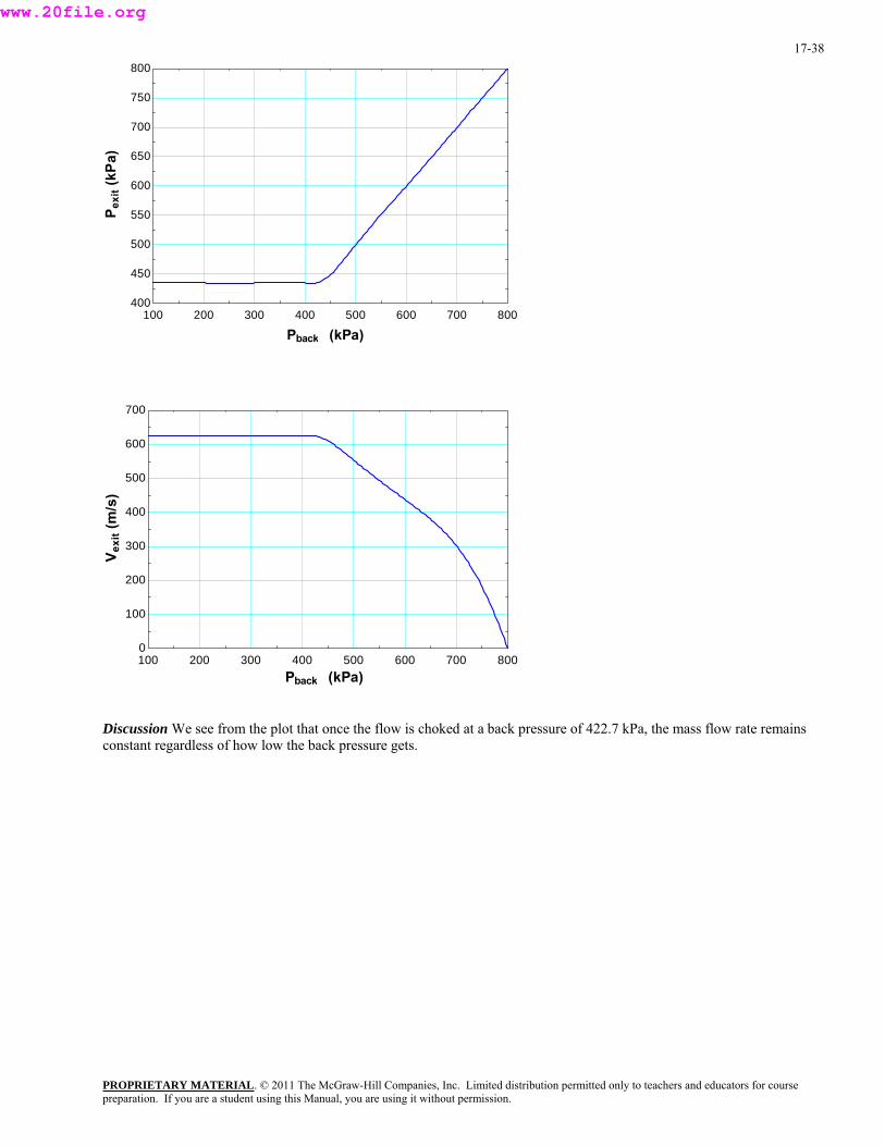
Discussion We see from the plot that once the flow is choked at a back pressure of 422.7 kPa, the mass flow rate remains constant regardless of how low the back pressure gets.
PROPRIETARY MATERIALpreparation. If you are a student using this Manual, you are using it without permission.
. © 2011 The McGraw-Hill Companies, Inc. Limited distribution permitted only to teachers and educators for course
www.20file.org
17-39
Shock Waves and Expansion Waves
17-71C No, because the flow must be supersonic before a shock wave can occur. The flow in the converging section of a nozzle is always subsonic.
Discussion A normal shock (if it is to occur) would occur in the supersonic (diverging) section of the nozzle.
17-72C The Fanno line represents the states that satisfy the conservation of mass and energy equations. The Rayleigh line represents the states that satisfy the conservation of mass and momentum equations. The intersections points of these lines represent the states that satisfy the conservation of mass, energy, and momentum equations.
Discussion T-s diagrams are quite helpful in understanding these kinds of flows.
17-73C No, the second law of thermodynamics requires the flow after the shock to be subsonic.
Discussion A normal shock wave always goes from supersonic to subsonic in the flow direction.
17-74C (a) velocity decreases, (b) static temperature increases, (c) stagnation temperature remains the same, (d) static pressure increases, and (e) stagnation pressure decreases.
Discussion In addition, the Mach number goes from supersonic (Ma > 1) to subsonic (Ma < 1).
17-75C Oblique shocks occur when a gas flowing at supersonic speeds strikes a flat or inclined surface. Normal shock waves are perpendicular to flow whereas inclined shock waves, as the name implies, are typically inclined relative to the flow direction. Also, normal shocks form a straight line whereas oblique shocks can be straight or curved, depending on the surface geometry.
Discussion In addition, while a normal shock must go from supersonic (Ma > 1) to subsonic (Ma < 1), the Mach number downstream of an oblique shock can be either supersonic or subsonic.
17-76C Yes, the upstream flow has to be supersonic for an oblique shock to occur. No, the flow downstream of an oblique shock can be subsonic, sonic, and even supersonic.
Discussion The latter is not true for normal shocks. For a normal shock, the flow must always go from supersonic (Ma > 1) to subsonic (Ma < 1).
17-77C Yes, the claim is correct. Conversely, normal shocks can be thought of as special oblique shocks in which the shock angle is β = π/2, or 90o.
Discussion The component of flow in the direction normal to the oblique shock acts exactly like a normal shock. We can think of the flow parallel to the oblique shock as “going along for the ride” – it does not affect anything.
PROPRIETARY MATERIALpreparation. If you are a student using this Manual, you are using it without permission.
. © 2011 The McGraw-Hill Companies, Inc. Limited distribution permitted only to teachers and educators for course
www.20file.org

17-40
17-78C When the wedge half-angle δ is greater than the maximum deflection angle θmax, the shock becomes curved and detaches from the nose of the wedge, forming what is called a detached oblique shock or a bow wave. The numerical value of the shock angle at the nose is β = 90o.
Discussion When δ is less than θmax, the oblique shock is attached to the nose.
17-79C When supersonic flow impinges on a blunt body like the rounded nose of an aircraft, the wedge half-angle δ at the nose is 90o, and an attached oblique shock cannot exist, regardless of Mach number. Therefore, a detached oblique shock must occur in front of all such blunt-nosed bodies, whether two-dimensional, axisymmetric, or fully three-dimensional.
Discussion Since δ = 90o at the nose, δ is always greater than θmax, regardless of Ma or the shape of the rest of the body.
17-80C The isentropic relations of ideal gases are not applicable for flows across (a) normal shock waves and (b) oblique shock waves, but they are applicable for flows across (c) Prandtl-Meyer expansion waves.
Discussion Flow across any kind of shock wave involves irreversible losses – hence, it cannot be isentropic.
PROPRIETARY MATERIALpreparation. If you are a student using this Manual, you are using it without permission.
. © 2011 The McGraw-Hill Companies, Inc. Limited distribution permitted only to teachers and educators for course
www.20file.org
17-41
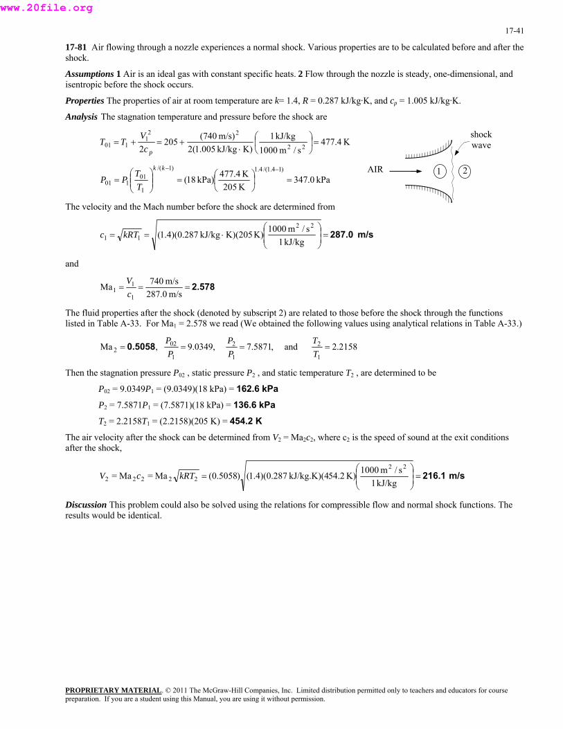
17-81 Air flowing through a nozzle experiences a normal shock. Various properties are to be calculated before and after the shock.
Assumptions 1 Air is an ideal gas with constant specific heats. 2 Flow through the nozzle is steady, one-dimensional, and isentropic before the shock occurs.
Properties The properties of air at room temperature are k= 1.4, R = 0.287 kJ/kg·K, and cp = 1.005 kJ/kg·K.
Analysis The stagnation temperature and pressure before the shock are
shock wave K4.477
s/m1000kJ/kg1
K)kJ/kg005.1(2m/s)(740205
2 22
221
101 =⎟⎠
⎞⎜⎝
⎛⋅
+=+=pc
VTT
PROPRIETARY MATERIAL. © 2011 The McGraw-Hill Companies, Inc. Limited distribution permitted only to teachers and educators for course
AIR 1 2kPa0.347
K205K477.4kPa)18(
)14.1/(4.1)1/(
1
01101 =⎟
⎠⎞
⎜⎝⎛=⎟⎟
⎠
⎞⎜⎜⎝
⎛=
−−kk
TT
PP
The velocity and the Mach number before the shock are determined from
m/s 287.0⎟ =⎟⎠
⎞⎜⎜⎝
⎛⋅==
kJ/kg1s/m1000K)K)(205kJ/kg287.0)(4.1(
22
11 kRTc
and
2.578===m/s287.0
m/s740Ma1
11 c
V
The fluid properties after the shock (denoted by subscript 2) are related to those before the shock through the functions listed in Table A-33. For Ma1 = 2.578 we read (We obtained the following values using analytical relations in Table A-33.)
2158.2 and ,5871.7 ,0349.9 ,Ma1
2
1
2
1
022 ====
TT
PP
PP0.5058
Then the stagnation pressure P02 , static pressure P2 , and static temperature T2 , are determined to be
P02 = 9.0349P1 = (9.0349)(18 kPa) = 162.6 kPa
P2 = 7.5871P1 = (7.5871)(18 kPa) = 136.6 kPa
T2 = 2.2158T1 = (2.2158)(205 K) = 454.2 K
The air velocity after the shock can be determined from V2 = Ma2c2, where c2 is the speed of sound at the exit conditions after the shock,
m/s 216.1⎟ =⎟⎠
⎞⎜⎜⎝
⎛=
kJ/kg1s/m1000K)54.2kJ/kg.K)(4287.0)(4.1()5058.0(Ma=Ma=
22
22222 kRTcV
Discussion This problem could also be solved using the relations for compressible flow and normal shock functions. The results would be identical.
preparation. If you are a student using this Manual, you are using it without permission.
www.20file.org
17-42
17-82 Air flowing through a nozzle experiences a normal shock. The entropy change of air across the normal shock wave is to be determined.
Assumptions 1 Air is an ideal gas with constant specific heats. 2 Flow through the nozzle is steady, one-dimensional, and isentropic before the shock occurs.
Properties The properties of air at room temperature are R = 0.287 kJ/kg·K and cp = 1.005 kJ/kg·K.
Analysis The entropy change across the shock is determined to be
KkJ/kg 0.2180 ⋅⋅−⋅=
−=−
=1)K)ln(7.587kJ/kg(0.2878)K)ln(2.215kJ/kg005.1(
lnln1
2
1
212 P
PR
TT
css p
Discussion A shock wave is a highly dissipative process, and the entropy generation is large during shock waves.
PROPRIETARY MATERIALpreparation. If you are a student using this Manual, you are using it without permission.
. © 2011 The McGraw-Hill Companies, Inc. Limited distribution permitted only to teachers and educators for course
www.20file.org

17-43
17-83 Air flowing through a converging-diverging nozzle experiences a normal shock at the exit. The effect of the shock wave on various properties is to be determined.
Assumptions 1 Air is an ideal gas with constant specific heats. 2 Flow through the nozzle is steady, one-dimensional, and isentropic before the shock occurs. 3 The shock wave occurs at the exit plane.
Properties The properties of air are k = 1.4 and R = 0.287 kJ/kg·K.
Analysis The inlet stagnation properties in this case are identical to the inlet properties since the inlet velocity is negligible. Then,
P01 = Pi = 1 MPa
1AIR
Shock wave
2
T01 = Ti = 300 K
Then, i
Vi ≈ 0 K4.139
1)2.4-(1.4+22K)300(
Ma)1(22
221
011 ⎟ =⎟⎠
⎞⎜⎜⎝
⎛⎟ =⎟⎠
⎞⎜⎜⎝
⎛
−+=
kTT
and
MPa06840.0300
139.4MPa)1(4.0/4.1)1/(
0
1011 =⎟
⎠⎞
⎜⎝⎛=⎟⎟
⎠⎜
⎞⎜⎝
⎛=
−kk
TT
PP
The fluid properties after the shock (denoted by subscript 2) are related to those before the shock through the functions listed in Table A-33. For Ma1 = 2.4 we read
02 2 22
01 1 1
Ma 0.5231 , 0.5401, 6.5533, and 2.0403P P TP P T
= ≅ = = =0.523
Then the stagnation pressure P02, static pressure P2, and static temperature T2, are determined to be
P02 = 0.5401P01 = (0.5401)(1.0 MPa) = 0.540 MPa = 540 kPa
P2 = 6.5533P1 = (6.5533)(0.06840 MPa) = 0.448 MPa = 448 kPa
T2 = 2.0403T1 = (2.0403)(139.4 K) = 284 K
The air velocity after the shock can be determined from V2 = Ma2c2, where c2 is the speed of sound at the exit conditions after the shock,
V2 = Ma2c2 = m/s 177⎟ =⎟⎠
⎞⎜⎜⎝
⎛⋅=
kJ/kg1s/m1000K)K)(284kJ/kg287.0)(4.1()5231.0(Ma
22
22 kRT
Discussion We can also solve this problem using the relations for normal shock functions. The results would be identical.
PROPRIETARY MATERIALpreparation. If you are a student using this Manual, you are using it without permission.
. © 2011 The McGraw-Hill Companies, Inc. Limited distribution permitted only to teachers and educators for course
www.20file.org

PROPRIETARY MATERIAL. © 2011 The McGraw-Hill Companies, Inc. Limited distribution permitted only to teachers and educators for course preparation. If you are a student using this Manual, you are using it without permission.
17-44
17-84 Air enters a converging-diverging nozzle at a specified state. The required back pressure that produces a normal shock at the exit plane is to be determined for the specified nozzle geometry.
Assumptions 1 Air is an ideal gas. 2 Flow through the nozzle is steady, one-dimensional, and isentropic before the shock occurs. 3 The shock wave occurs at the exit plane.
Analysis The inlet stagnation pressure in this case is identical to the inlet pressure since the inlet velocity is negligible. Since the flow before the shock to be isentropic,
shock wave
P01 = Pi = 2 MPa
Vi ≈ 0
AIR 1i 2
It is specified that A/A* =3.5. From Table A-32, Mach number and the pressure ratio which corresponds to this area ratio are the Ma1 =2.80 and P1/P01 = 0.0368. The pressure ratio across the shock for this Ma1value is, from Table A-33, P2/P1 = 8.98. Thus the back pressure, which is equal to the static pressure at the nozzle exit, must be Pb
P2 =8.98P1 = 8.98×0.0368P01 = 8.98×0.0368×(2 MPa) = 0.661 MPa
Discussion We can also solve this problem using the relations for compressible flow and normal shock functions. The results would be identical.
17-85 Air enters a converging-diverging nozzle at a specified state. The required back pressure that produces a normal shock at the exit plane is to be determined for the specified nozzle geometry.
Assumptions 1 Air is an ideal gas. 2 Flow through the nozzle is steady, one-dimensional, and isentropic before the shock occurs.
Analysis The inlet stagnation pressure in this case is identical to the inlet pressure since the inlet velocity is negligible. Since the flow before the shock to be isentropic,
P0x= Pi = 2 MPa shock wave It is specified that A/A* = 2. From Table A-32, the Mach number and
the pressure ratio which corresponds to this area ratio are the Ma1 =2.20 and P1/P01 = 0.0935. The pressure ratio across the shock for this M1 value is, from Table A-33, P2/P1 = 5.48. Thus the back pressure, which is equal to the static pressure at the nozzle exit, must be
Vi ≈ 0
AIR 1 i 2
Pb
P2 =5.48P1 = 5.48×0.0935P01 = 5.48×0.0935×(2 MPa) = 1.02 MPa
Discussion We can also solve this problem using the relations for compressible flow and normal shock functions. The results would be identical.
www.20file.org
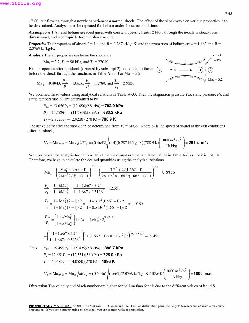
17-45
17-86 Air flowing through a nozzle experiences a normal shock. The effect of the shock wave on various properties is to be determined. Analysis is to be repeated for helium under the same conditions. Assumptions 1 Air and helium are ideal gases with constant specific heats. 2 Flow through the nozzle is steady, one-dimensional, and isentropic before the shock occurs. Properties The properties of air are k = 1.4 and R = 0.287 kJ/kg·K, and the properties of helium are k = 1.667 and R = 2.0769 kJ/kg·K. Analysis The air properties upstream the shock are shock
wave
PROPRIETARY MATERIAL. © 2011 The McGraw-Hill Companies, Inc. Limited distribution permitted only to teachers and educators for course
AIR 1i 2
Ma1 = 3.2, P1 = 58 kPa, and T1 = 270 K Fluid properties after the shock (denoted by subscript 2) are related to those before the shock through the functions in Table A-33. For Ma1 = 3.2,
Ma1 = 3.2 9220.2and,780.11,656.13,Ma
1
2
1
2
1
022 ====
TT
PP
PP
0.4643
We obtained these values using analytical relations in Table A-33. Then the stagnation pressure P02, static pressure P2, and static temperature T2, are determined to be
P02 = 13.656P1 = (13.656)(58 kPa) = 792.0 kPaP2 = 11.780P1 = (11.780)(58 kPa) = 683.2 kPa T2 = 2.9220T1 = (2.9220)(270 K) = 788.9 K
The air velocity after the shock can be determined from V2 = Ma2c2, where c2 is the speed of sound at the exit conditions after the shock,
m/s 261.4⎟ =⎟⎠
⎞⎜⎜⎝
⎛⋅=
kJ/kg1s/m1000K)K)(788.9kJ/kg287.0)(4.1()4643.0(Ma=Ma=
22
22222 kRTcV
We now repeat the analysis for helium. This time we cannot use the tabulated values in Table A-33 since k is not 1.4. Therefore, we have to calculate the desired quantities using the analytical relations,
0.5136⎟ =⎟⎠
⎞⎜⎜⎝
⎛
−−××
−+⎟ =⎟⎠
⎞⎜⎜⎝
⎛
−−
−+=
2/1
2
22/1
21
21
2 1)1667.1/(667.12.32)1667.1/(22.3
1)1/(Ma2)1/(2Ma
Makk
k
551.125136.0667.11
2.3667.11Ma1Ma1
2
2
22
21
1
2 =×+
×+=
+
+=
kk
PP
0580.42/)1667.1(5136.01
2/)1667.1(2.312/)1(Ma12/)1(Ma1
2
2
22
21
1
2 =−+
−+=
−+
−+=
kk
TT
( ) )1/(222
2
21
1
02 2/Ma)1(1Ma1Ma1 −
−⎟ +⎟⎠
⎞⎜⎜⎝
⎛
+
+=
kkk
kk
PP
( ) 495.152/5136.0)1667.1(15136.0667.11
2.3667.11 667.0/667.122
2=×−⎟ +⎟
⎠
⎞⎜⎜⎝
⎛
×+
×+=
Thus, P02 = 15.495P1 = (15.495)(58 kPa) = 898.7 kPaP2 = 12.551P1 = (12.551)(58 kPa) = 728.0 kPaT2 = 4.0580T1 = (4.0580)(270 K) = 1096 K
m/s 1000⎟ =⎟⎠
⎞⎜⎜⎝
⎛⋅===
kJ/kg1s/m1000K)K)(1096kJ/kg0769.2)(667.1()5136.0(MaMa
22
2222 ykRTcV
Discussion The velocity and Mach number are higher for helium than for air due to the different values of k and R.
preparation. If you are a student using this Manual, you are using it without permission.
www.20file.org

17-46
17-87 Air flowing through a nozzle experiences a normal shock. The entropy change of air across the normal shock wave is to be determined.
Assumptions 1 Air and helium are ideal gases with constant specific heats. 2 Flow through the nozzle is steady, one-dimensional, and isentropic before the shock occurs.
Properties The properties of air are R = 0.287 kJ/kg·K and cp = 1.005 kJ/kg·K, and the properties of helium are R = 2.0769 kJ/kg·K and cp = 5.1926 kJ/kg·K.
Analysis The entropy change across the shock is determined to be
KkJ/kg 0.370 ⋅⋅⋅=−=− =0)K)ln(11.78kJ/kg(0.287-0)K)ln(2.922kJ/kg005.1(lnln1
2
1
212 P
PR
TT
css p
For helium, the entropy change across the shock is determined to be
KkJ/kg2.02 ⋅⋅⋅=−=− =1)K)ln(12.55kJ/kg(2.0769-0)K)ln(4.058kJ/kg1926.5(lnln1
2
1
212 P
PR
TT
css p
Discussion Note that shock wave is a highly dissipative process, and the entropy generation is large during shock waves.
PROPRIETARY MATERIALpreparation. If you are a student using this Manual, you are using it without permission.
. © 2011 The McGraw-Hill Companies, Inc. Limited distribution permitted only to teachers and educators for course
www.20file.org
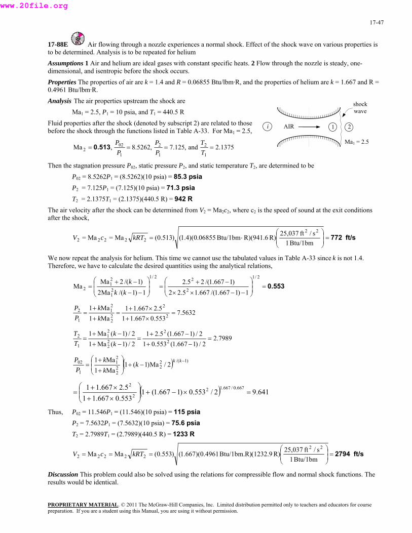
17-47
17-88E Air flowing through a nozzle experiences a normal shock. Effect of the shock wave on various properties is to be determined. Analysis is to be repeated for helium Assumptions 1 Air and helium are ideal gases with constant specific heats. 2 Flow through the nozzle is steady, one-dimensional, and isentropic before the shock occurs. Properties The properties of air are k = 1.4 and R = 0.06855 Btu/lbm·R, and the properties of helium are k = 1.667 and R = 0.4961 Btu/lbm·R. Analysis The air properties upstream the shock are shock
wave Ma1 = 2.5, P1 = 10 psia, and T1 = 440.5 R
PROPRIETARY MATERIAL. © 2011 The McGraw-Hill Companies, Inc. Limited distribution permitted only to teachers and educators for course
AIR 1i 2Fluid properties after the shock (denoted by subscript 2) are related to those before the shock through the functions listed in Table A-33. For Ma1 = 2.5,
Ma1 = 2.5 1375.2and,125.7,5262.8,Ma
1
2
1
2
1
022 ====
TT
PP
PP
0.513
Then the stagnation pressure P02, static pressure P2, and static temperature T2, are determined to be
P02 = 8.5262P1 = (8.5262)(10 psia) = 85.3 psiaP2 = 7.125P1 = (7.125)(10 psia) = 71.3 psia
T2 = 2.1375T1 = (2.1375)(440.5 R) = 942 R The air velocity after the shock can be determined from V2 = Ma2c2, where c2 is the speed of sound at the exit conditions after the shock,
ft/s 772⎟ =⎟⎠
⎞⎜⎜⎝
⎛⋅=
Btu/1bm1s/ft25,037R)R)(941.6Btu/1bm06855.0)(4.1()513.0(Ma=Ma=
22
22222 kRTcV
We now repeat the analysis for helium. This time we cannot use the tabulated values in Table A-33 since k is not 1.4. Therefore, we have to calculate the desired quantities using the analytical relations,
0.553⎟ =⎟⎠
⎞⎜⎜⎝
⎛
−−××
−+⎟ =⎟⎠
⎞⎜⎜⎝
⎛
−−
−+=
2/1
2
22/1
21
21
21)1667.1/(667.15.22
)1667.1/(25.21)1/(Ma2
)1/(2MaMa
kkk
5632.7553.0667.115.2667.11
Ma1Ma1
2
2
22
21
1
2 =×+×+
=+
+=
kk
PP
7989.22/)1667.1(553.01
2/)1667.1(5.212/)1(Ma12/)1(Ma1
2
2
22
21
1
2 =−+−+
=−+
−+=
kk
TT
( ) )1/(222
2
21
1
02 2/Ma)1(1Ma1Ma1 −
−⎟ +⎟⎠
⎞⎜⎜⎝
⎛
+
+=
kkkkk
PP
( ) 641.92/553.0)1667.1(1553.0667.11
5.2667.11 667.0/667.122
2
=×−⎟ +⎟⎠
⎞⎜⎜⎝
⎛
×+×+
=
Thus, P02 = 11.546P1 = (11.546)(10 psia) = 115 psiaP2 = 7.5632P1 = (7.5632)(10 psia) = 75.6 psiaT2 = 2.7989T1 = (2.7989)(440.5 R) = 1233 R
ft/s 2794⎟ =⎟⎠
⎞⎜⎜⎝
⎛===
Btu/1bm1s/ft25,037R)(1232.9Btu/1bm.R)4961.0)(667.1()553.0(MaMa
22
22222 kRTcV
Discussion This problem could also be solved using the relations for compressible flow and normal shock functions. The results would be identical.
preparation. If you are a student using this Manual, you are using it without permission.
www.20file.org
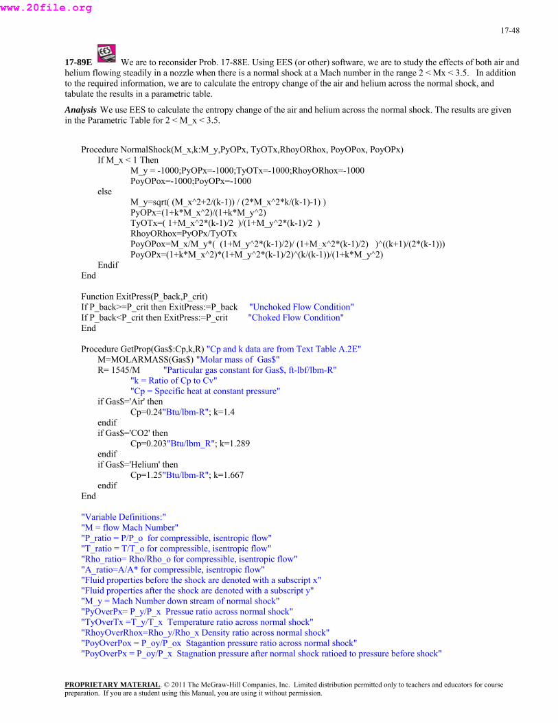
17-48
17-89E We are to reconsider Prob. 17-88E. Using EES (or other) software, we are to study the effects of both air and helium flowing steadily in a nozzle when there is a normal shock at a Mach number in the range 2 < Mx < 3.5. In addition to the required information, we are to calculate the entropy change of the air and helium across the normal shock, and tabulate the results in a parametric table.
Analysis We use EES to calculate the entropy change of the air and helium across the normal shock. The results are given in the Parametric Table for 2 < M_x < 3.5.
Procedure NormalShock(M_x,k:M_y,PyOPx, TyOTx,RhoyORhox, PoyOPox, PoyOPx) If M_x < 1 Then
M_y = -1000;PyOPx=-1000;TyOTx=-1000;RhoyORhox=-1000 PoyOPox=-1000;PoyOPx=-1000 else
M_y=sqrt( (M_x^2+2/(k-1)) / (2*M_x^2*k/(k-1)-1) ) PyOPx=(1+k*M_x^2)/(1+k*M_y^2)
TyOTx=( 1+M_x^2*(k-1)/2 )/(1+M_y^2*(k-1)/2 ) RhoyORhox=PyOPx/TyOTx
PoyOPox=M_x/M_y*( (1+M_y^2*(k-1)/2)/ (1+M_x^2*(k-1)/2) )^((k+1)/(2*(k-1))) PoyOPx=(1+k*M_x^2)*(1+M_y^2*(k-1)/2)^(k/(k-1))/(1+k*M_y^2) Endif End
Function ExitPress(P_back,P_crit) If P_back>=P_crit then ExitPress:=P_back "Unchoked Flow Condition" If P_back<P_crit then ExitPress:=P_crit "Choked Flow Condition" End
Procedure GetProp(Gas$:Cp,k,R) "Cp and k data are from Text Table A.2E" M=MOLARMASS(Gas$) "Molar mass of Gas$" R= 1545/M "Particular gas constant for Gas$, ft-lbf/lbm-R"
"k = Ratio of Cp to Cv" "Cp = Specific heat at constant pressure"
if Gas$='Air' then Cp=0.24"Btu/lbm-R"; k=1.4 endif
if Gas$='CO2' then Cp=0.203"Btu/lbm_R"; k=1.289 endif
if Gas$='Helium' then Cp=1.25"Btu/lbm-R"; k=1.667 endif End
"Variable Definitions:" "M = flow Mach Number" "P_ratio = P/P_o for compressible, isentropic flow" "T_ratio = T/T_o for compressible, isentropic flow" "Rho_ratio= Rho/Rho_o for compressible, isentropic flow" "A_ratio=A/A* for compressible, isentropic flow" "Fluid properties before the shock are denoted with a subscript x" "Fluid properties after the shock are denoted with a subscript y" "M_y = Mach Number down stream of normal shock" "PyOverPx= P_y/P_x Pressue ratio across normal shock" "TyOverTx =T_y/T_x Temperature ratio across normal shock" "RhoyOverRhox=Rho_y/Rho_x Density ratio across normal shock" "PoyOverPox = P_oy/P_ox Stagantion pressure ratio across normal shock" "PoyOverPx = P_oy/P_x Stagnation pressure after normal shock ratioed to pressure before shock"
PROPRIETARY MATERIALpreparation. If you are a student using this Manual, you are using it without permission.
. © 2011 The McGraw-Hill Companies, Inc. Limited distribution permitted only to teachers and educators for course
www.20file.org
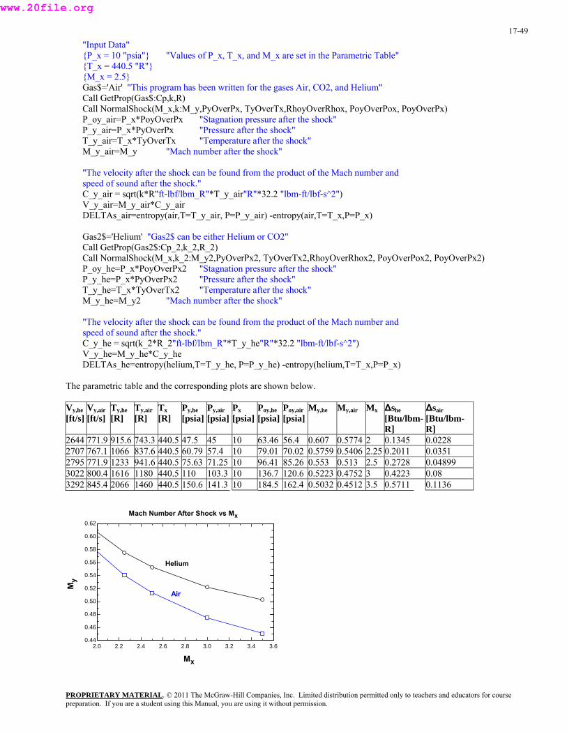
17-49
"Input Data" {P_x = 10 "psia"} "Values of P_x, T_x, and M_x are set in the Parametric Table" {T_x = 440.5 "R"} {M_x = 2.5} Gas$='Air' "This program has been written for the gases Air, CO2, and Helium" Call GetProp(Gas$:Cp,k,R) Call NormalShock(M_x,k:M_y,PyOverPx, TyOverTx,RhoyOverRhox, PoyOverPox, PoyOverPx) P_oy_air=P_x*PoyOverPx "Stagnation pressure after the shock" P_y_air=P_x*PyOverPx "Pressure after the shock" T_y_air=T_x*TyOverTx "Temperature after the shock" M_y_air=M_y "Mach number after the shock"
"The velocity after the shock can be found from the product of the Mach number and speed of sound after the shock." C_y_air = sqrt(k*R"ft-lbf/lbm_R"*T_y_air"R"*32.2 "lbm-ft/lbf-s^2") V_y_air=M_y_air*C_y_air DELTAs_air=entropy(air,T=T_y_air, P=P_y_air) -entropy(air,T=T_x,P=P_x)
Gas2$='Helium' "Gas2$ can be either Helium or CO2" Call GetProp(Gas2$:Cp_2,k_2,R_2) Call NormalShock(M_x,k_2:M_y2,PyOverPx2, TyOverTx2,RhoyOverRhox2, PoyOverPox2, PoyOverPx2) P_oy_he=P_x*PoyOverPx2 "Stagnation pressure after the shock" P_y_he=P_x*PyOverPx2 "Pressure after the shock" T_y_he=T_x*TyOverTx2 "Temperature after the shock" M_y_he=M_y2 "Mach number after the shock"
"The velocity after the shock can be found from the product of the Mach number and speed of sound after the shock." C_y_he = sqrt(k_2*R_2"ft-lbf/lbm_R"*T_y_he"R"*32.2 "lbm-ft/lbf-s^2") V_y_he=M_y_he*C_y_he DELTAs_he=entropy(helium,T=T_y_he, P=P_y_he) -entropy(helium,T=T_x,P=P_x)
The parametric table and the corresponding plots are shown below.
Vy,he [ft/s]
Vy,air [ft/s]
Ty,he [R]
Ty,air [R]
Tx [R]
Py,he [psia]
Py,air [psia]
Px [psia]
Poy,he [psia]
Poy,air [psia]
My,he My,air Mx ∆she[Btu/lbm-R]
∆sair[Btu/lbm-R]
2644 771.9 915.6 743.3 440.5 47.5 45 10 63.46 56.4 0.607 0.5774 2 0.1345 0.0228 2707 767.1 1066 837.6 440.5 60.79 57.4 10 79.01 70.02 0.5759 0.5406 2.25 0.2011 0.0351 2795 771.9 1233 941.6 440.5 75.63 71.25 10 96.41 85.26 0.553 0.513 2.5 0.2728 0.04899 3022 800.4 1616 1180 440.5 110 103.3 10 136.7 120.6 0.5223 0.4752 3 0.4223 0.08 3292 845.4 2066 1460 440.5 150.6 141.3 10 184.5 162.4 0.5032 0.4512 3.5 0.5711 0.1136
2.0 2.2 2.4 2.6 2.8 3.0 3.2 3.4 3.60.44
0.46
0.48
0.50
0.52
0.54
0.56
0.58
0.60
0.62
Mx
My
Helium
Air
Mach Number After Shock vs Mx
PROPRIETARY MATERIALpreparation. If you are a student using this Manual, you are using it without permission.
. © 2011 The McGraw-Hill Companies, Inc. Limited distribution permitted only to teachers and educators for course
www.20file.org
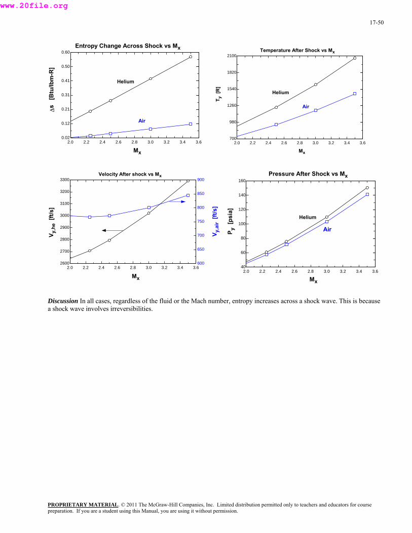
17-50
2.0 2.2 2.4 2.6 2.8 3.0 3.2 3.4 3.60.02
0.12
0.21
0.31
0.41
0.50
0.60
Mx
∆s
[B
tu/lb
m-R
]
Helium
Air
Entropy Change Across Shock vs Mx
2.0 2.2 2.4 2.6 2.8 3.0 3.2 3.4 3.6700
980
1260
1540
1820
2100
Mx
T y[R
]
Helium
Air
Temperature After Shock vs Mx
2.0 2.2 2.4 2.6 2.8 3.0 3.2 3.4 3.62600
2700
2800
2900
3000
3100
3200
3300
600
650
700
750
800
850
900
Mx
V y,h
e[ft
/s]
V y,a
ir[ft
/s]
Velocity After shock vs Mx
2.0 2.2 2.4 2.6 2.8 3.0 3.2 3.4 3.640
60
80
100
120
140
160
Mx
P y[p
sia]
Helium
Air
Pressure After Shock vs Mx
Discussion In all cases, regardless of the fluid or the Mach number, entropy increases across a shock wave. This is because a shock wave involves irreversibilities.
PROPRIETARY MATERIALpreparation. If you are a student using this Manual, you are using it without permission.
. © 2011 The McGraw-Hill Companies, Inc. Limited distribution permitted only to teachers and educators for course
www.20file.org

17-51
17-90 For an ideal gas flowing through a normal shock, a relation for V2/V1 in terms of k, Ma1, and Ma2 is to be developed.
Analysis The conservation of mass relation across the shock is 2211 VV ρρ = and it can be expressed as
⎟⎟⎠
⎜⎞
⎜⎝⎟⎛⎟⎠
⎜⎞
⎜⎝
⎛===
1
2
2
1
22
11
2
1
1
2
//
TT
PP
RTPRTP
VV
ρρ
From Eqs. 17-35 and 17-38,
⎟⎟⎠
⎞⎜⎜⎝
⎛
−+
−⎟ +⎟⎠
⎞⎜⎜⎝
⎛
+
+=
2/)1(Ma12/)1(Ma1
Ma1Ma1
22
21
21
22
1
2
kk
kk
VV
Discussion This is an important relation as it enables us to determine the velocity ratio across a normal shock when the Mach numbers before and after the shock are known.
17-91 The entropy change of air across the shock for upstream Mach numbers between 0.5 and 1.5 is to be determined and plotted.
Assumptions 1 Air is an ideal gas. 2 Flow through the nozzle is steady, one-dimensional, and isentropic before the shock occurs.
Properties The properties of air are k = 1.4, R = 0.287 kJ/kg·K, and cp = 1.005 kJ/kg·K.
Analysis The entropy change across the shock is determined to be
PROPRIETARY MATERIAL. © 2011 The McGraw-Hill Companies, Inc. Limited distribution permitted only to teachers and educators for course
1
2
1
212 lnln
PPR
TTcss p −=−
where
2/1
21
21
2 1)1/(Ma2)1/(2Ma
Ma ⎟⎟⎠
⎞⎜⎜⎝
⎛
−−
−+=
kkk
, 22
21
1
2
Ma1Ma1
kk
PP
+
+= , and
2/)1(Ma12/)1(Ma1
22
21
1
2
−+
−+=
kk
TT
The results of the calculations can be tabulated as
Ma1 Ma2 T2/T1 P2/P1 s2 - s1 0.5 2.6458 0.1250 0.4375 -1.853
s2 - sx
0
1 Ma
0.6 1.8778 0.2533 0.6287 -1.247 0.7 1.5031 0.4050 0.7563 -0.828 0.8 1.2731 0.5800 0.8519 -0.501 0.9 1.1154 0.7783 0.9305 -0.231 1.0 1.0000 1.0000 1.0000 0.0 1.1 0.9118 1.0649 1.2450 0.0003 1.2 0.8422 1.1280 1.5133 0.0021 1.3 0.7860 1.1909 1.8050 0.0061 1.4 0.7397 1.2547 2.1200 0.0124 1.5 0.7011 1.3202 2.4583 0.0210
Discussion The total entropy change is negative for upstream Mach numbers Ma1 less than unity. Therefore, normal shocks cannot occur when Ma1 < 1.
preparation. If you are a student using this Manual, you are using it without permission.
www.20file.org
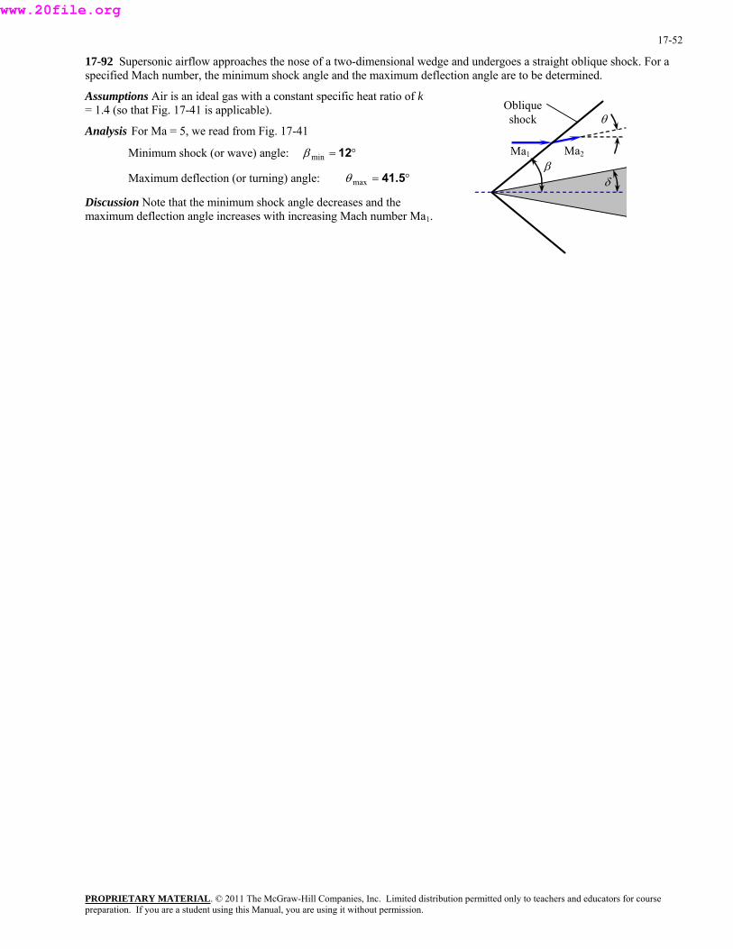
17-52
17-92 Supersonic airflow approaches the nose of a two-dimensional wedge and undergoes a straight oblique shock. For a specified Mach number, the minimum shock angle and the maximum deflection angle are to be determined.
Assumptions Air is an ideal gas with a constant specific heat ratio of k= 1.4 (so that Fig. 17-41 is applicable). Oblique
shock θ
βMa1 Ma2
δ
Analysis For Ma = 5, we read from Fig. 17-41
Minimum shock (or wave) angle: °= 12minβ
Maximum deflection (or turning) angle: °= 41.5maxθ
Discussion Note that the minimum shock angle decreases and the maximum deflection angle increases with increasing Mach number Ma1.
PROPRIETARY MATERIALpreparation. If you are a student using this Manual, you are using it without permission.
. © 2011 The McGraw-Hill Companies, Inc. Limited distribution permitted only to teachers and educators for course
www.20file.org

17-53
17-93E Air flowing at a specified supersonic Mach number is forced to undergo a compression turn (an oblique shock)., The Mach number, pressure, and temperature downstream of the oblique shock are to be determined.
Assumptions 1 The flow is steady. 2 The boundary layer on the wedge is very thin. 3 Air is an ideal gas with constant specific heats.
βweak
δ = 15o
Weak shock Ma1 Properties The specific heat ratio of air is k = 1.4.
Analysis On the basis of Assumption #2, we take the deflection angle as equal to the wedge half-angle, i.e., θ ≈ δ = 15o. Then the two values of oblique shock angle β are determined from
2)2cos(Ma
tan/)1sinMa(2tan 2
1
221
++
−=
βββ
θk
→ 2)2cos4.1(2
tan/)1sin2(215tan 2
22
++−
=°β
ββ
which is implicit in β. Therefore, we solve it by an iterative approach or with an equation solver such as EES. It gives βweak = 45.34o and βstrong = 79.83o. Then the upstream “normal” Mach number Ma1,n becomes
Weak shock: 423.134.45sin2sinMaMa 1n1, =°== β
PROPRIETARY MATERIAL. © 2011 The McGraw-Hill Companies, Inc. Limited distribution permitted only to teachers and educators for course
Strong shock: 969.183.79sin2sinMaMa 1n1, =°== β
Also, the downstream normal Mach numbers Ma2,n become
Weak shock: 7304.014.1)423.1)(4.1(2
2)423.1)(14.1(1Ma2
2Ma)1(Ma 2
2
2n1,
2n1,
n2, =+−
+−=
+−
+−=
kk
k
Ma1
δ = 15o
Strong shock βstrong
Strong shock: 5828.014.1)969.1)(4.1(2
2)969.1)(14.1(1Ma2
2Ma)1(Ma 2
2
2n1,
2n1,
n2, =+−
+−=
+−
+−=
kk
k
The downstream pressure and temperature for each case are determined to be
Weak shock: psia13.2=+
+−=
+
+−=
14.114.1)423.1)(4.1(2
) psia6(1
1Ma2 22n1,
12 kkk
PP
R609=+−+
=+
−+== 2
2
2n1,
2n1,
1
21
2
1
1
212 )423.1)(14.1(
)423.1)(14.1(2 psia6
psia2.13)R480(Ma)1(
Ma)1(2
k
kPP
TPP
TTρρ
Strong shock: psia 26.1=+
+−=
+
+−=
14.114.1)969.1)(4.1(2
) psia6(1
1Ma2 22n1,
12 kkk
PP
R798=+−+
=+
−+== 2
2
2n1,
2n1,
1
21
2
1
1
212 )969.1)(14.1(
)969.1)(14.1(2 psia6
psia1.26)R480(Ma)1(
Ma)1(2
k
kPP
TPP
TTρρ
The downstream Mach number is determined to be
Weak shock: 1.45=°−°
=−
=)1534.45sin(
7304.0)sin(
MaMa n2,
2 θβ
Strong shock: 0.644=°−°
=−
=)1583.79sin(
5828.0)sin(
MaMa n2,
2 θβ
Discussion Note that the change in Mach number, pressure, temperature across the strong shock are much greater than the changes across the weak shock, as expected. For both the weak and strong oblique shock cases, Ma1,n is supersonic and Ma2,n is subsonic. However, Ma2 is supersonic across the weak oblique shock, but subsonic across the strong oblique shock.
preparation. If you are a student using this Manual, you are using it without permission.
www.20file.org
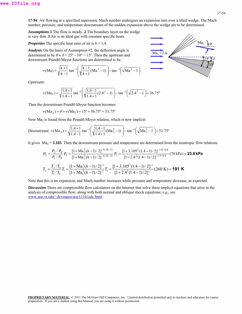
17-54
17-94 Air flowing at a specified supersonic Mach number undergoes an expansion turn over a tilted wedge. The Mach number, pressure, and temperature downstream of the sudden expansion above the wedge are to be determined.
Assumptions 1 The flow is steady. 2 The boundary layer on the wedge is very thin. 3 Air is an ideal gas with constant specific heats.
Ma1 =2.4
10°25°
Ma2
δ
θProperties The specific heat ratio of air is k = 1.4.
Analysis On the basis of Assumption #2, the deflection angle is determined to be θ ≈ δ = 25° - 10° = 15o. Then the upstream and downstream Prandtl-Meyer functions are determined to be
⎟⎠⎞⎜
⎝⎛ −⎟ −⎟
⎠
⎞⎜⎜⎝
⎛−
+−
−+
= −− 1Matan)1Ma(11tan
11)Ma( 2121
kk
kkν
Upstream:
°=⎟⎠⎞⎜
⎝⎛ −⎟ −⎟
⎠
⎞⎜⎜⎝
⎛−
+−
−+
= −− 75.3612.4tan)14.2(14.114.1tan
14.114.1)Ma( 2121
1ν
Then the downstream Prandtl-Meyer function becomes
°=°+°=+= 75.5175.3615)Ma()Ma( 12 νθν
Now Ma2 is found from the Prandtl-Meyer relation, which is now implicit:
Downstream: °=⎟⎠⎞⎜
⎝⎛ −⎟ −⎟
⎠
⎞⎜⎜⎝
⎛−
+−
−+
= −− 75.511Matan)1(Ma14.114.1tan
14.114.1)Ma( 2
212
21
2ν
It gives Ma2 = 3.105. Then the downstream pressure and temperature are determined from the isentropic flow relations
kPa23.8=−+−+
=−+
−+== −
−
−−
−−
) kPa70(]2/)14.1(4.21[]2/)14.1(105.31[
]2/)1(Ma1[]2/)1(Ma1[
//
4.0/4.12
4.0/4.12
1)1/(21
)1/(22
101
022 P
kk
PPPPP
P kk
kk
2 1 2 12 0 2
2 1 12 1 2 11 0 1
/ [1 Ma ( 1) / 2] [1 3.105 (1.4 1) / 2] (260 K)/ [1 Ma ( 1) / 2] [1 2.4 (1.4 1) / 2]
T T kT T TT T k
− −
− −
+ − + −= = = =
+ − + −191 K
Note that this is an expansion, and Mach number increases while pressure and temperature decrease, as expected.
Discussion There are compressible flow calculators on the Internet that solve these implicit equations that arise in the analysis of compressible flow, along with both normal and oblique shock equations; e.g., see www.aoe.vt.edu/~devenpor/aoe3114/calc.html .
PROPRIETARY MATERIALpreparation. If you are a student using this Manual, you are using it without permission.
. © 2011 The McGraw-Hill Companies, Inc. Limited distribution permitted only to teachers and educators for course
www.20file.org

17-55
17-95 Air flowing at a specified supersonic Mach number undergoes a compression turn (an oblique shock) over a tilted wedge. The Mach number, pressure, and temperature downstream of the shock below the wedge are to be determined.
Assumptions 1 The flow is steady. 2 The boundary layer on the wedge is very thin. 3 Air is an ideal gas with constant specific heats.
PROPRIETARY MATERIAL. © 2011 The McGraw-Hill Companies, Inc. Limited distribution permitted only to teachers and educators for course
Properties The specific heat ratio of air is k = 1.4.
Analysis On the basis of Assumption #2, the deflection angle is determined to be θ ≈ δ = 25° + 10° = 35o. Then the two values of oblique shock angle β are determined from
2)2cos(Matan/)1sinMa(2
tan 21
221
++
−=
βββ
θk
→ 2)2cos4.1(3.4
tan/)1sin4.3(212tan 2
22
++−
=°β
ββ
Ma1 = 5
10°
25°
Ma2
δ
θ
which is implicit in β. Therefore, we solve it by an iterative approach or with an equation solver such as EES. It gives βweak = 49.86o and βstrong = 77.66o. Then for the case of strong oblique shock, the upstream “normal” Mach number Ma1,nbecomes
884.466.77sin5sinMaMa 1n1, =°== β
Also, the downstream normal Mach numbers Ma2,n become
4169.014.1)884.4)(4.1(2
2)884.4)(14.1(1Ma2
2Ma)1(Ma 2
2
2n1,
2n1,
n2, =+−
+−=
+−
+−=
kk
k
The downstream pressure and temperature are determined to be
kPa1940=+
+−=
+
+−=
14.114.1)884.4)(4.1(2
)kPa70(1
1Ma2 22n1,
12 kkk
PP
K1450=+
−+=
+
−+==
2
2
2n1,
2n1,
1
21
2
1
1
212
)884.4)(14.1()884.4)(14.1(2
kPa70kPia1940)K260(
Ma)1(
Ma)1(2
k
kPP
TPP
TTρρ
The downstream Mach number is determined to be
0.615=°−°
=−
=)3566.77sin(
4169.0)sin(
MaMa n2,
2 θβ
Discussion Note that Ma1,n is supersonic and Ma2,n and Ma2 are subsonic. Also note the huge rise in temperature and pressure across the strong oblique shock, and the challenges they present for spacecraft during reentering the earth’s atmosphere.
preparation. If you are a student using this Manual, you are using it without permission.
www.20file.org
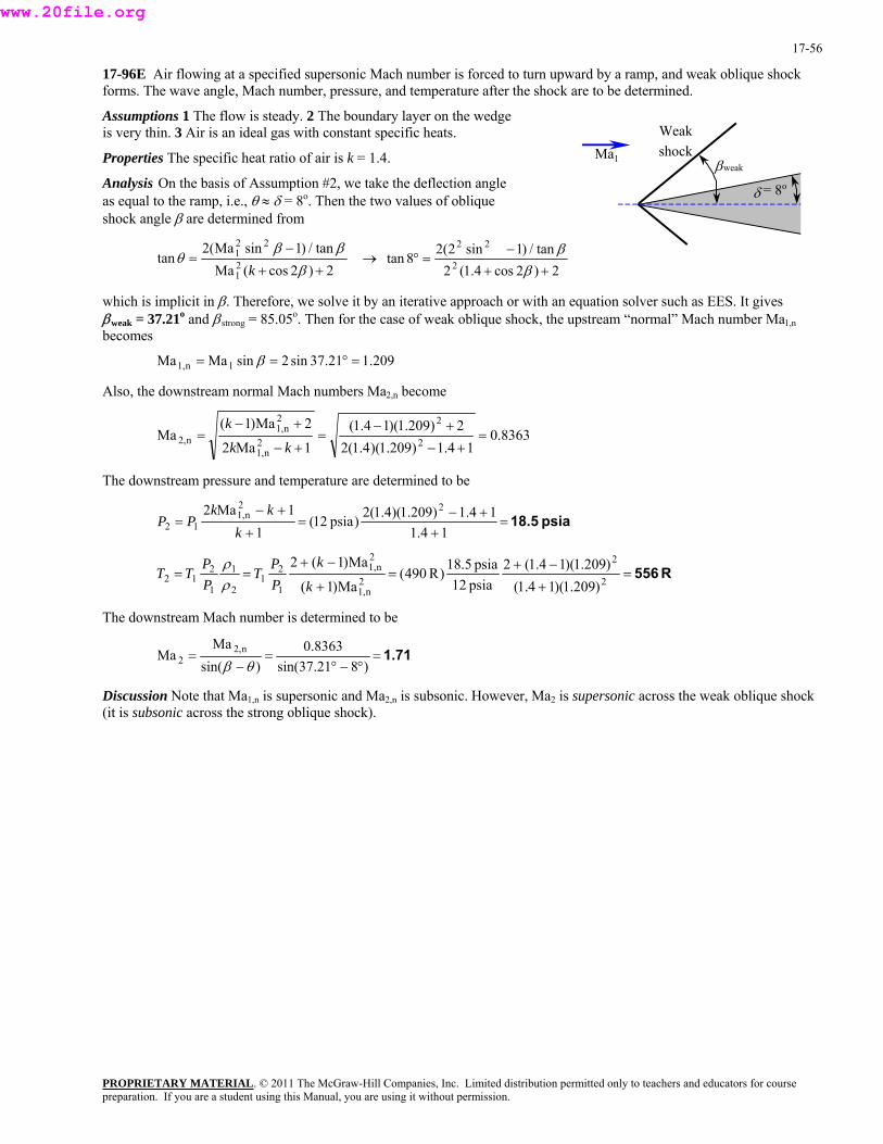
17-56
17-96E Air flowing at a specified supersonic Mach number is forced to turn upward by a ramp, and weak oblique shock forms. The wave angle, Mach number, pressure, and temperature after the shock are to be determined.
Assumptions 1 The flow is steady. 2 The boundary layer on the wedge is very thin. 3 Air is an ideal gas with constant specific heats.
PROPRIETARY MATERIAL. © 2011 The McGraw-Hill Companies, Inc. Limited distribution permitted only to teachers and educators for course
Properties The specific heat ratio of air is k = 1.4.
Analysis On the basis of Assumption #2, we take the deflection angle as equal to the ramp, i.e., θ ≈ δ = 8o. Then the two values of oblique shock angle β are determined from
2)2cos(Matan/)1sinMa(2
tan 21
221
++
−=
βββ
θk
→ 2)2cos4.1(2
tan/)1sin2(28tan 2
22
++−
=°β
ββ
βweak
δ = 8o
Weak shock Ma1
which is implicit in β. Therefore, we solve it by an iterative approach or with an equation solver such as EES. It gives βweak = 37.21o and βstrong = 85.05o. Then for the case of weak oblique shock, the upstream “normal” Mach number Ma1,nbecomes
209.121.37sin2sinMaMa 1n1, =°== β
Also, the downstream normal Mach numbers Ma2,n become
8363.014.1)209.1)(4.1(2
2)209.1)(14.1(1Ma2
2Ma)1(Ma 2
2
2n1,
2n1,
n2, =+−
+−=
+−
+−=
kk
k
The downstream pressure and temperature are determined to be
psia18.5=+
+−=
+
+−=
14.114.1)209.1)(4.1(2)psia12(
11Ma2 22
n1,12 k
kkPP
R556=+
−+=
+
−+== 2
2
2n1,
2n1,
1
21
2
1
1
212 )209.1)(14.1(
)209.1)(14.1(2psia12psia5.18)R490(
Ma)1(
Ma)1(2
k
kPP
TPP
TTρρ
The downstream Mach number is determined to be
= 1.71°−°
=−
=)821.37sin(
8363.0)sin(
MaMa n2,
2 θβ
Discussion Note that Ma1,n is supersonic and Ma2,n is subsonic. However, Ma2 is supersonic across the weak oblique shock (it is subsonic across the strong oblique shock).
preparation. If you are a student using this Manual, you are using it without permission.
www.20file.org

17-57
17-97 Air flowing at a specified supersonic Mach number undergoes an expansion turn. The Mach number, pressure, and temperature downstream of the sudden expansion along a wall are to be determined.
Assumptions 1 The flow is steady. 2 The boundary layer on the wedge is very thin. 3 Air is an ideal gas with constant specific heats.
Ma1 = 3.6
δ = 15o
Ma2
θProperties The specific heat ratio of air is k = 1.4.
Analysis On the basis of Assumption #2, we take the deflection angle as equal to the wedge half-angle, i.e., θ ≈ δ = 15o. Then the upstream and downstream Prandtl-Meyer functions are determined to be
⎟⎠⎞⎜
⎝⎛ −⎟ −⎟
⎠
⎞⎜⎜⎝
⎛−
+−
−+
= −− 1Matan)1Ma(11tan
11)Ma( 2121
kk
kkν
Upstream:
°=⎟⎠⎞⎜
⎝⎛ −⎟ −⎟
⎠
⎞⎜⎜⎝
⎛−
+−
−+
= −− 09.6013.6tan)13.6(14.114.1tan
14.114.1)Ma( 2121
1ν
Then the downstream Prandtl-Meyer function becomes
°=°+°=+= 09.7509.6015)Ma()Ma( 12 νθν
Ma2 is found from the Prandtl-Meyer relation, which is now implicit:
Downstream: °=⎟⎠⎞⎜
⎝⎛ −⎟ −⎟
⎠
⎞⎜⎜⎝
⎛−
+−
−+
= −− 09.751Matan)1Ma14.114.1tan
14.114.1)Ma( 2
212
21
2ν
Solution of this implicit equation gives Ma2 = 4.81. Then the downstream pressure and temperature are determined from the isentropic flow relations:
kPa8.31=−+−+
=−+
−+== −
−
−−
−−
) kPa40(]2/)14.1(6.31[]2/)14.1(81.41[
]2/)1(Ma1[]2/)1(Ma1[
//
4.0/4.12
4.0/4.12
1)1/(21
)1/(22
101
022 P
kk
PPPPP
P kk
kk
K179=−+−+
=−+
−+== −
−
−
−
)K280(]2/)14.1(6.31[]2/)14.1(81.41[
]2/)1(Ma1[]2/)1(Ma1[
//
12
12
1121
122
101
022 T
kk
TTTTT
T
Note that this is an expansion, and Mach number increases while pressure and temperature decrease, as expected.
Discussion There are compressible flow calculators on the Internet that solve these implicit equations that arise in the analysis of compressible flow, along with both normal and oblique shock equations; e.g., see www.aoe.vt.edu/~devenpor/aoe3114/calc.html .
PROPRIETARY MATERIALpreparation. If you are a student using this Manual, you are using it without permission.
. © 2011 The McGraw-Hill Companies, Inc. Limited distribution permitted only to teachers and educators for course
www.20file.org
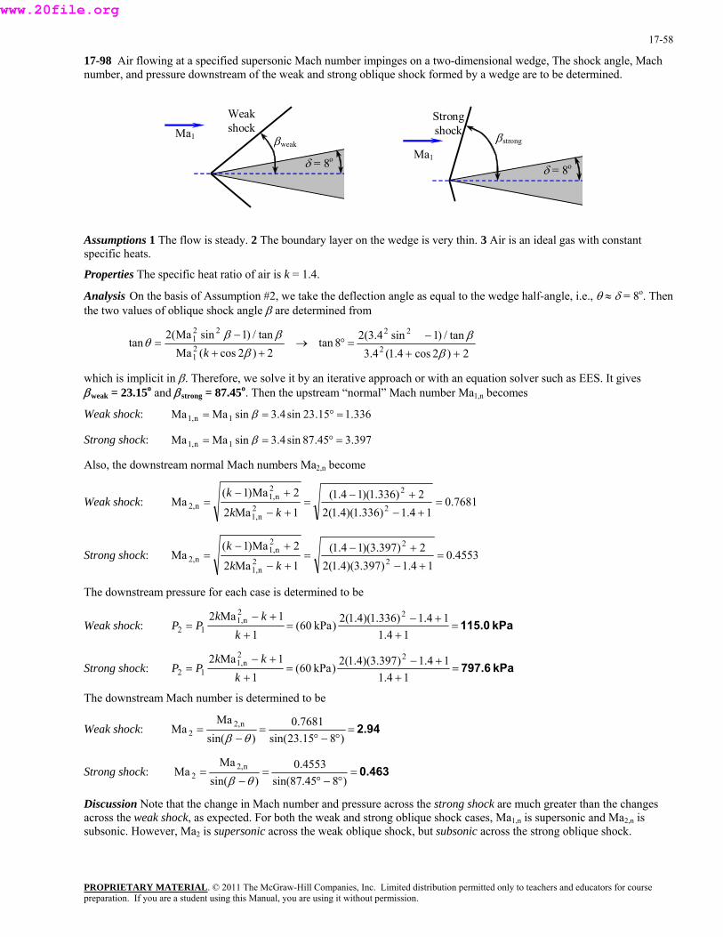
17-58
17-98 Air flowing at a specified supersonic Mach number impinges on a two-dimensional wedge, The shock angle, Mach number, and pressure downstream of the weak and strong oblique shock formed by a wedge are to be determined.
βweak
δ = 8o
Weak shock Ma1
Ma1
δ = 8o
Strong shock βstrong
Assumptions 1 The flow is steady. 2 The boundary layer on the wedge is very thin. 3 Air is an ideal gas with constant specific heats.
Properties The specific heat ratio of air is k = 1.4.
Analysis On the basis of Assumption #2, we take the deflection angle as equal to the wedge half-angle, i.e., θ ≈ δ = 8o. Then the two values of oblique shock angle β are determined from
2)2cos(Matan/)1sinMa(2
tan 21
221
++
−=
βββ
θk
→ 2)2cos4.1(3.4
tan/)1sin4.3(28tan 2
22
++
−=°
βββ
which is implicit in β. Therefore, we solve it by an iterative approach or with an equation solver such as EES. It gives βweak = 23.15o and βstrong = 87.45o. Then the upstream “normal” Mach number Ma1,n becomes
Weak shock: 336.115.23sin4.3sinMaMa 1n1, =°== β
Strong shock: 397.345.87sin4.3sinMaMa 1n1, =°== β
Also, the downstream normal Mach numbers Ma2,n become
Weak shock: 7681.014.1)336.1)(4.1(2
2)336.1)(14.1(1Ma2
2Ma)1(Ma 2
2
2n1,
2n1,
n2, =+−
+−=
+−
+−=
kk
k
Strong shock: 4553.014.1)397.3)(4.1(2
2)397.3)(14.1(1Ma2
2Ma)1(Ma 2
2
2n1,
2n1,
n2, =+−
+−=
+−
+−=
kk
k
The downstream pressure for each case is determined to be
Weak shock: kPa115.0=+
+−=
+
+−=
14.114.1)336.1)(4.1(2)kPa60(
11Ma2 22
n1,12 k
kkPP
Strong shock: kPa797.6=+
+−=
+
+−=
14.114.1)397.3)(4.1(2)kPa60(
11Ma2 22
n1,12 k
kkPP
The downstream Mach number is determined to be
Weak shock: 2.94=°−°
=−
=)815.23sin(
7681.0)sin(
MaMa n2,
2 θβ
Strong shock: 0.463=°−°
=−
=)845.87sin(
4553.0)sin(
MaMa n2,
2 θβ
Discussion Note that the change in Mach number and pressure across the strong shock are much greater than the changes across the weak shock, as expected. For both the weak and strong oblique shock cases, Ma1,n is supersonic and Ma2,n is subsonic. However, Ma2 is supersonic across the weak oblique shock, but subsonic across the strong oblique shock.
PROPRIETARY MATERIALpreparation. If you are a student using this Manual, you are using it without permission.
. © 2011 The McGraw-Hill Companies, Inc. Limited distribution permitted only to teachers and educators for course
www.20file.org
17-59
Duct Flow with Heat Transfer and Negligible Friction (Rayleigh Flow)
17-99C The characteristic aspect of Rayleigh flow is its involvement of heat transfer. The main assumptions associated with Rayleigh flow are: the flow is steady, one-dimensional, and frictionless through a constant-area duct, and the fluid is an ideal gas with constant specific heats.
Discussion Of course, there is no such thing as frictionless flow. It is better to say that frictional effects are negligible compared to the heating effects.
17-100C The points on the Rayleigh line represent the states that satisfy the conservation of mass, momentum, and energy equations as well as the property relations for a given state. Therefore, for a given inlet state, the fluid cannot exist at any downstream state outside the Rayleigh line on a T-s diagram.
Discussion The T-s diagram is quite useful, since any downstream state must lie on the Rayleigh line.
17-101C In Rayleigh flow, the effect of heat gain is to increase the entropy of the fluid, and the effect of heat loss is to decrease the entropy.
Discussion You should recall from thermodynamics that the entropy of a system can be lowered by removing heat.
17-102C In Rayleigh flow, the stagnation temperature T0 always increases with heat transfer to the fluid, but the temperature T decreases with heat transfer in the Mach number range of 0.845 < Ma < 1 for air. Therefore, the temperature in this case will decrease.
Discussion This at first seems counterintuitive, but if heat were not added, the temperature would drop even more if the air were accelerated isentropically from Ma = 0.92 to 0.95.
17-103C Heating the fluid increases the flow velocity in subsonic Rayleigh flow, but decreases the flow velocity in supersonic Rayleigh flow.
Discussion These results are not necessarily intuitive, but must be true in order to satisfy the conservation laws.
17-104C The flow is choked, and thus the flow at the duct exit remains sonic.
Discussion There is no mechanism for the flow to become supersonic in this case.
PROPRIETARY MATERIALpreparation. If you are a student using this Manual, you are using it without permission.
. © 2011 The McGraw-Hill Companies, Inc. Limited distribution permitted only to teachers and educators for course
www.20file.org
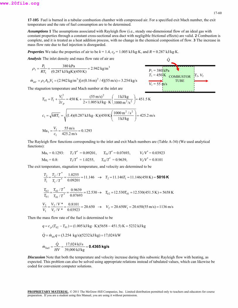
17-60
17-105 Fuel is burned in a tubular combustion chamber with compressed air. For a specified exit Mach number, the exit temperature and the rate of fuel consumption are to be determined.
Assumptions 1 The assumptions associated with Rayleigh flow (i.e., steady one-dimensional flow of an ideal gas with constant properties through a constant cross-sectional area duct with negligible frictional effects) are valid. 2 Combustion is complete, and it is treated as a heat addition process, with no change in the chemical composition of flow. 3 The increase in mass flow rate due to fuel injection is disregarded.
Properties We take the properties of air to be k = 1.4, cp = 1.005 kJ/kg⋅K, and R = 0.287 kJ/kg⋅K.
Analysis The inlet density and mass flow rate of air are
PROPRIETARY MATERIAL. © 2011 The McGraw-Hill Companies, Inc. Limited distribution permitted only to teachers and educators for course
3
1
11 kg/m942.2
K)0kJ/kgK)(45(0.287kPa380
===RTP
ρ
kg/s254.3m/s)55](4/m)(0.16)[kg/m942.2( 23111 === πρ VAm cair&
The stagnation temperature and Mach number at the inlet are
K5.451/sm1000
kJ/kg1KkJ/kg005.12
m/s)55(K4502 22
221
101 =⎟⎠
⎞⎜⎝
⎛⋅×
+=+=pc
VTT
Q&
COMBUSTOR TUBE
T2, V2 P1 = 380 kPa T1 = 450 K
V1 = 55 m/s
m/s2.425kJ/kg1
s/m1000K)K)(450kJ/kg287.0)(4.1(22
11 ⎟ =⎟⎠
⎞⎜⎜⎝
⎛⋅== kRTc
1293.0m/s2.425
m/s55Ma1
11 ===
cV
The Rayleigh flow functions corresponding to the inlet and exit Mach numbers are (Table A-34) (We used analytical functions):
Ma1 = 0.1293: T1/T* = 0.09201, T01/T* = 0.07693, V1/V* = 0.03923
Ma2 = 0.8: T2/T* = 1.0255, T02/T* = 0.9639, V2/V* = 0.8101
The exit temperature, stagnation temperature, and velocity are determined to be
146.1109201.00255.1
//
*1
*2
1
2 ===TTTT
TT
→ K5016=== )K450(146.11146.11 12 TT
530.1207693.09639.0
//
*01
*02
10
20 ===TTTT
TT
→ K5658)K5.451(530.12530.12 0120 === TT
650.2003923.08101.0
*/*/
1
2
1
2 ===VVVV
VV
→ m/s1136)m/s55(650.20650.20 12 === VV
Then the mass flow rate of the fuel is determined to be
kJ/kg5232K)5.4515658)(KkJ/kg1.005()( 0102 =−⋅=−= TTcq p
kW024,17)kJ/kg5232)(kg/s .2543(air === qmQ &&
kg/s0.4365===kJ/kg39,000kJ/s024,17
fuel HVQm&
&
Discussion Note that both the temperature and velocity increase during this subsonic Rayleigh flow with heating, as expected. This problem can also be solved using appropriate relations instead of tabulated values, which can likewise be coded for convenient computer solutions.
preparation. If you are a student using this Manual, you are using it without permission.
www.20file.org
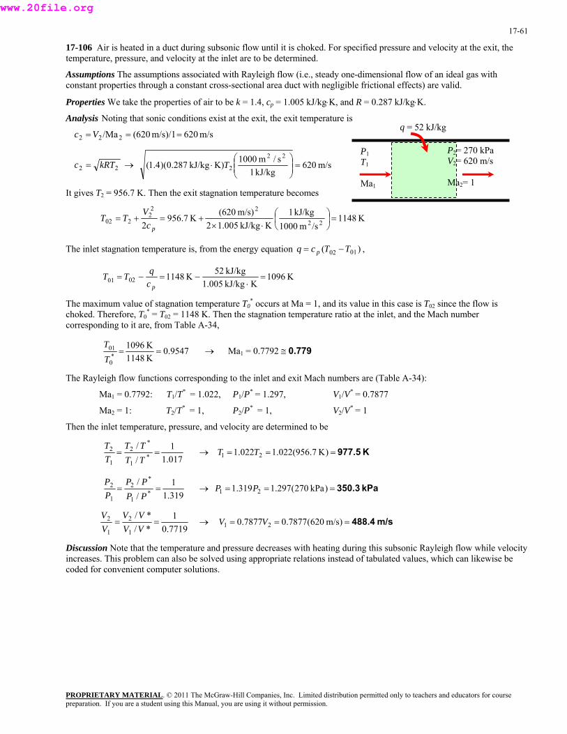
17-61
17-106 Air is heated in a duct during subsonic flow until it is choked. For specified pressure and velocity at the exit, the temperature, pressure, and velocity at the inlet are to be determined.
Assumptions The assumptions associated with Rayleigh flow (i.e., steady one-dimensional flow of an ideal gas with constant properties through a constant cross-sectional area duct with negligible frictional effects) are valid.
Properties We take the properties of air to be k = 1.4, cp = 1.005 kJ/kg⋅K, and R = 0.287 kJ/kg⋅K.
Analysis Noting that sonic conditions exist at the exit, the exit temperature is
PROPRIETARY MATERIAL. © 2011 The McGraw-Hill Companies, Inc. Limited distribution permitted only to teachers and educators for course
m/s620m/s)/1620(/Ma222 ===Vc
22 kRTc = → m/s620 kJ/kg1
s/m1000K) kJ/kg287.0)(4.1(22
2 ⎟ =⎟⎠
⎞⎜⎜⎝
⎛⋅ T
It gives T2 = 956.7 K. Then the exit stagnation temperature becomes
K1148/sm1000
kJ/kg1K kJ/kg005.12
m/s)620(K7.956
2 22
222
202 =⎟⎠⎞
⎜⎝⎛
⋅×+=+=
pcV
TT
P2= 270 kPa V2= 620 m/s
Ma2= 1
q = 52 kJ/kg
P1 T1
Ma1
The inlet stagnation temperature is, from the energy equation , )( 0102 TTcq p −=
K1096KkJ/kg1.005
kJ/kg52K11480201 =⋅
−=−=pc
qTT
The maximum value of stagnation temperature T0* occurs at Ma = 1, and its value in this case is T02 since the flow is
choked. Therefore, T0* = T02 = 1148 K. Then the stagnation temperature ratio at the inlet, and the Mach number
corresponding to it are, from Table A-34,
9547.0K1148K1096
*0
01 ==TT
→ Ma1 = 0.7792 ≅ 0.779
The Rayleigh flow functions corresponding to the inlet and exit Mach numbers are (Table A-34):
Ma1 = 0.7792: T1/T* = 1.022, P1/P* = 1.297, V1/V* = 0.7877
Ma2 = 1: T2/T* = 1, P2/P* = 1, V2/V* = 1
Then the inlet temperature, pressure, and velocity are determined to be
017.11
//
*1
*2
1
2 ==TTTT
TT
→ K977.5=== )K7.956(022.1022.1 21 TT
319.11
//
*1
*2
1
2 ==PPPP
PP
→ kPa350.3=== )kPa270(297.1319.1 21 PP
7719.01
*/*/
1
2
1
2 ==VVVV
VV
→ m/s488.4=== )m/s620(7877.07877.0 21 VV
Discussion Note that the temperature and pressure decreases with heating during this subsonic Rayleigh flow while velocity increases. This problem can also be solved using appropriate relations instead of tabulated values, which can likewise be coded for convenient computer solutions.
preparation. If you are a student using this Manual, you are using it without permission.
www.20file.org

17-62
17-107E Air flowing with a subsonic velocity in a round duct is accelerated by heating until the flow is choked at the exit. The rate of heat transfer and the pressure drop are to be determined.
Assumptions 1 The assumptions associated with Rayleigh flow (i.e., steady one-dimensional flow of an ideal gas with constant properties through a constant cross-sectional area duct with negligible frictional effects) are valid. 2 The flow is choked at the duct exit. 3 Mass flow rate remains constant.
Properties We take the properties of air to be k = 1.4, cp = 0.2400 Btu/lbm⋅R, and R = 0.06855 Btu/lbm⋅R = 0.3704 psia⋅ft3/lbm⋅R.
Q&
Ma2 = 1
T2 = 680 R
P1 = 30 psia T1 = 800 R
m = 5 lbm/s
Analysis The inlet density and velocity of air are
33
1
11 lbm/ft1012.0
R)R)(800/lbmft psia(0.3704 psia30
=⋅⋅
==RTP
ρ
ft/s9.565]4/ft)(4/12)[lbm/ft 1012.0(
lbm/s 523
111 ===
πρ c
air
Am
V&
The stagnation temperature and Mach number at the inlet are
R7.826/sft25,037
Btu/lbm1RBtu/lbm2400.02
ft/s)9.565(R800
2 22
221
101 ⎟ =⎟⎠
⎞⎜⎜⎝
⎛
⋅×+=+=
pcV
TT
ft/s1386Btu/lbm1
s/ft25,037R)R)(800Btu/lbm06855.0)(4.1(22
11 ⎟ =⎟⎠
⎞⎜⎜⎝
⎛⋅== kRTc
4082.0ft/s 1386ft/s9.565Ma
1
11 ===
cV
The Rayleigh flow functions corresponding to the inlet and exit Mach numbers are (Table A-34):
Ma1 = 0.4082: T1/T* = 0.6310, P1/P* = 1.946, T01/T0* = 0.5434
Ma2 = 1: T2/T* = 1, P2/P* = 1, T02/T0* = 1
Then the exit temperature, pressure, and stagnation temperature are determined to be
6310.01
//
*1
*2
1
2 ==TTTT
TT
→ 2 R12686310.0/)R800(6310.0/1T === T
946.11
//
*1
*2
1
2 ==PPPP
PP
→ 2 psia4.15946.1/) psia30(272.2/1 === PP
5434.01
//
*01
*02
10
20 ==TTTT
TT
→ 0 R 15215434.0/)R7.826(1743.0/012T === T
Then the rate of heat transfer and the pressure drop become
Btu/s 834=−⋅=−= R)7.8261521)(RBtu/lbm2400.0)(lbm/s5()( 0102air TTcmQ p&&
psia14.6=−=−=∆ 4.153021 PPP
Discussion Note that the entropy of air increases during this heating process, as expected.
PROPRIETARY MATERIALpreparation. If you are a student using this Manual, you are using it without permission.
. © 2011 The McGraw-Hill Companies, Inc. Limited distribution permitted only to teachers and educators for course
www.20file.org
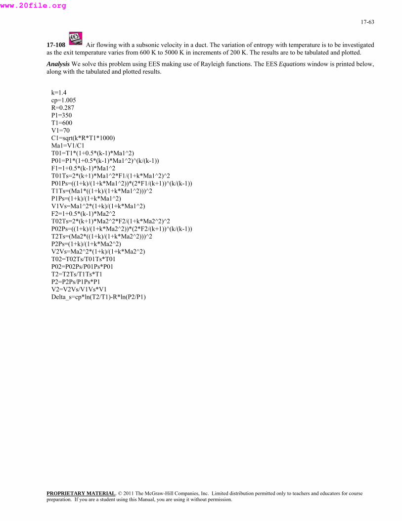
17-63
17-108 Air flowing with a subsonic velocity in a duct. The variation of entropy with temperature is to be investigated as the exit temperature varies from 600 K to 5000 K in increments of 200 K. The results are to be tabulated and plotted.
Analysis We solve this problem using EES making use of Rayleigh functions. The EES Equations window is printed below, along with the tabulated and plotted results.
k=1.4 cp=1.005 R=0.287 P1=350 T1=600 V1=70 C1=sqrt(k*R*T1*1000) Ma1=V1/C1 T01=T1*(1+0.5*(k-1)*Ma1^2) P01=P1*(1+0.5*(k-1)*Ma1^2)^(k/(k-1)) F1=1+0.5*(k-1)*Ma1^2 T01Ts=2*(k+1)*Ma1^2*F1/(1+k*Ma1^2)^2 P01Ps=((1+k)/(1+k*Ma1^2))*(2*F1/(k+1))^(k/(k-1)) T1Ts=(Ma1*((1+k)/(1+k*Ma1^2)))^2 P1Ps=(1+k)/(1+k*Ma1^2) V1Vs=Ma1^2*(1+k)/(1+k*Ma1^2) F2=1+0.5*(k-1)*Ma2^2 T02Ts=2*(k+1)*Ma2^2*F2/(1+k*Ma2^2)^2 P02Ps=((1+k)/(1+k*Ma2^2))*(2*F2/(k+1))^(k/(k-1)) T2Ts=(Ma2*((1+k)/(1+k*Ma2^2)))^2 P2Ps=(1+k)/(1+k*Ma2^2) V2Vs=Ma2^2*(1+k)/(1+k*Ma2^2) T02=T02Ts/T01Ts*T01 P02=P02Ps/P01Ps*P01 T2=T2Ts/T1Ts*T1 P2=P2Ps/P1Ps*P1 V2=V2Vs/V1Vs*V1 Delta_s=cp*ln(T2/T1)-R*ln(P2/P1)
PROPRIETARY MATERIALpreparation. If you are a student using this Manual, you are using it without permission.
. © 2011 The McGraw-Hill Companies, Inc. Limited distribution permitted only to teachers and educators for course
www.20file.org
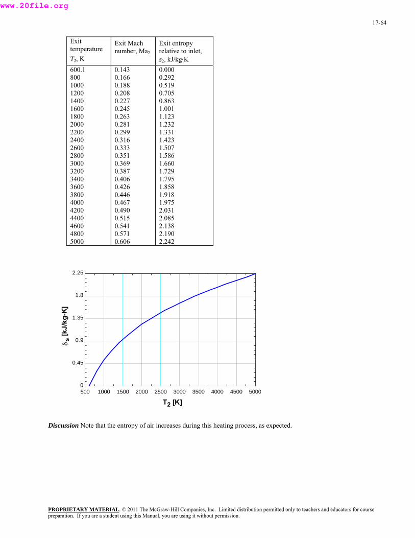
17-64
Exit temperature T2, K
Exit Mach number, Ma2
Exit entropy relative to inlet, s2, kJ/kg⋅K
600.1 800 1000 1200 1400 1600 1800 2000 2200 2400 2600 2800 3000 3200 3400 3600 3800 4000 4200 4400 4600 4800 5000
0.143 0.166 0.188 0.208 0.227 0.245 0.263 0.281 0.299 0.316 0.333 0.351 0.369 0.387 0.406 0.426 0.446 0.467 0.490 0.515 0.541 0.571 0.606
0.000 0.292 0.519 0.705 0.863 1.001 1.123 1.232 1.331 1.423 1.507 1.586 1.660 1.729 1.795 1.858 1.918 1.975 2.031 2.085 2.138 2.190 2.242
500 1000 1500 2000 2500 3000 3500 4000 4500 50000
0.45
0.9
1.35
1.8
2.25
T2 [K]
δ s[k
J/kg
-K]
Discussion Note that the entropy of air increases during this heating process, as expected.
PROPRIETARY MATERIALpreparation. If you are a student using this Manual, you are using it without permission.
. © 2011 The McGraw-Hill Companies, Inc. Limited distribution permitted only to teachers and educators for course
www.20file.org

17-65
17-109E Air flowing with a subsonic velocity in a square duct is accelerated by heating until the flow is choked at the exit. The rate of heat transfer and the entropy change are to be determined.
Assumptions 1 The assumptions associated with Rayleigh flow (i.e., steady one-dimensional flow of an ideal gas with constant properties through a constant cross-sectional area duct with negligible frictional effects) are valid. 2 The flow is choked at the duct exit. 3 Mass flow rate remains constant.
Properties We take the properties of air to be k = 1.4, cp = 0.2400 Btu/lbm⋅R, and R = 0.06855 Btu/lbm⋅R = 0.3704 psia⋅ft3/lbm⋅R.
Analysis The inlet density and mass flow rate of air are
33
1
11 lbm/ft3085.0
R)R)(700/lbmft psia(0.3704 psia80
=⋅⋅
==RTP
ρ
lbm/s06.20ft/s)260)(ft/1446)(6lbm/ft3085.0( 23111 =×== VAm cair& ρ
The stagnation temperature and Mach number at the inlet are
R6.705/sft25,037
Btu/lbm1RBtu/lbm2400.02
ft/s)260(R700
2 22
221
101 ⎟ =⎟⎠
⎞⎜⎜⎝
⎛⋅×
+=+=pc
VTT
ft/s1297Btu/lbm1
s/ft25,037R)R)(700Btu/lbm06855.0)(4.1(22
11 ⎟ =⎟⎠
⎞⎜⎜⎝
⎛⋅== kRTc
2005.0ft/s260Ma 11 ===
Vft/s12971c
The Ray ctio ding rs are (Table A-34):
Ma2 = 1 T2/T* = 1, P2/P* = 1, T02/T * = 1
Then the exit tem pressure, and stagnation temperature are be
leigh flow fun ns correspon to the inlet and exit Mach numbe
Ma1 = 0.2005: T1/T* = 0.2075, P1/P* = 2.272, T01/T0* = 0.1743
: 0
perature, determined to
2075.012
/ *2
TT2075
/
1
*
1==
TTTT
→ .0/)R700(2075.0/12 R3374=== TT
272.21
//
*1
*2
1==
PPPPP
→2
P psia2.35272.2/) psia80(272.2/12 === PP
1743.01
//
*01
*02
10
20 ==TTTT
TT
→ R40481743.0/)R6.705(1743.0/0120 === TT
Then the rate of heat transfer and entropy change become
900102air p 16,0=−⋅=−= R)6.7054048)(RBtu/lbm2400.0)(lbm/s06.20()( TTcmQ && Btu/s
RBtu/lbm0.434 ⋅=⋅−⋅=
−=∆
psia80psia2.35ln)RBtu/lbm06855.0(
R700R3374ln)RBtu/lbm2400.0(
lnln1
2
1
2
PP
RTT
cs p
Discussion Note that the entropy of air increases during this heating process, as expected.
Q&
Ma2 = 1P1 = 80 psia T1 = 700 R
V1 = 260 ft/s
PROPRIETARY MATERIALpreparation. If you are a student using this Manual, you are using it without permission.
. © 2011 The McGraw-Hill Companies, Inc. Limited distribution permitted only to teachers and educators for course
www.20file.org
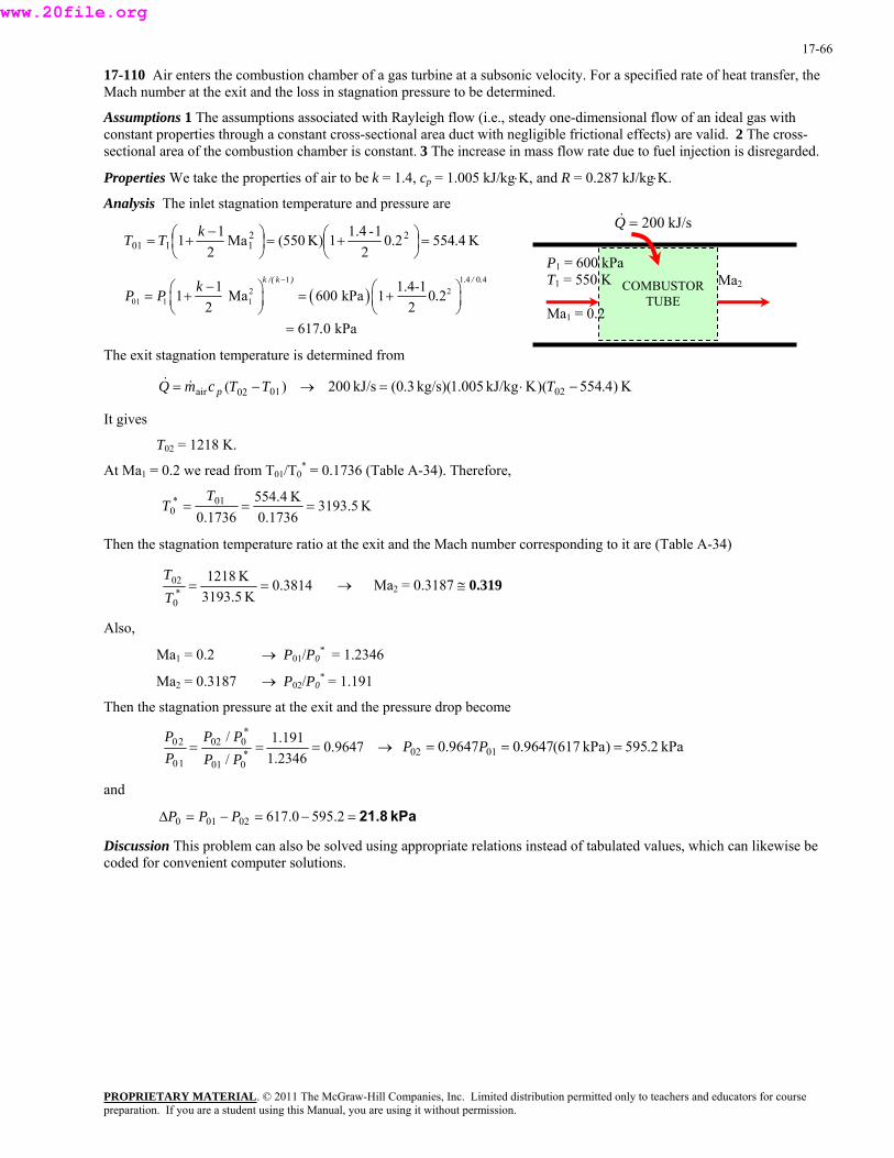
17-66
17-110 Air enters the combustion chamber of a gas turbine at a subsonic velocity. For a specified rate of heat transfer, the Mach number at the exit and the loss in stagnation pressure to be determined.
Assumptions 1 The assumptions associated with Rayleigh flow (i.e., steady one-dimensional flow of an ideal gas with constant properties through a constant cross-sectional area duct with negligible frictional effects) are valid. 2 The cross-sectional area of the combustion chamber is constant. 3 The increase in mass flow rate due to fuel injection is disregarded.
Properties We take the properties of air to be k = 1.4, cp = 1.005 kJ/kg⋅K, and R = 0.287 kJ/kg⋅K.
Analysis The inlet stagnation temperature and pressure are
K4.5542.02
1-1.41K)550(Ma2
11 221101 =⎟
⎠⎞
⎜⎝⎛ +=⎟
⎠⎞
⎜⎝⎛ −+=
kTT
PROPRIETARY MATERIAL. © 2011 The McGraw-Hill Companies, Inc. Limited distribution permitted only to teachers and educators for course
( )1 1 4 0 4
2201 1 1
1 1.4-11 Ma 600 kPa 1 0 22 2
k /( k ) . / .kP P .−−⎛ ⎞ ⎛ ⎞= + = +⎜ ⎟ ⎜ ⎟
⎝ ⎠ ⎝ ⎠
The exit st n temperature is determined from
→
617 0 kPa.=
agnatio
)( 0102air TTcmQ p −& = & K)4.554)(K kJ/kg005.1)( kg/s3.0( kJ/s200 02 −⋅= T
It gives
At Ma = 0 from T /T * = 0.1736 (Table A-34). Therefore,
T02 = 1218 K.
1 01 0.2 we read
K5.31931736.0
K4.55401* T1736.00 ===T
Then the stagnation temperature ratio at the exit and the Mach number corresponding to it are (Table A-34)
3814.0* 3190T Ma2K5.3
K121802 ==T
→ = 0.3187 ≅ 0.319
Also,
M .3187 → P02/P0* = 1.191
the stagnation pressure at the exit and the pressure drop become
Ma1 = 0.2 → P01/P0* = 1.2346
a2 = 0
Then
9647.02346.1/ *
00110===
PPP → kPa2.595) kPa617(9647.09647.0 0102
191.1/ *0022 PP0P
=== PP
and
kPa21.8=−=−=∆ 2.5950.61702010 PPP
Discussion This problem can also be solved using appropriate relations instead of tabulated values, which can likewise be coded for convenient computer solutions.
kJ/s200=Q&
COMBUSTOR TUBE
Ma2
P1 = 600 kPa T1 = 550 K
Ma1 = 0.2
preparation. If you are a student using this Manual, you are using it without permission.
www.20file.org

17-67
17-111 Air enters the combustion chamber of a gas turbine at a subsonic velocity. For a specified rate of heat transfer, the Mach number at the exit and the loss in stagnation pressure to be determined.
Assumptions 1 The assumptions associated with Rayleigh flow (i.e., steady one-dimensional flow of an ideal gas with constant properties through a constant cross-sectional area duct with negligible frictional effects) are valid. 2 The cross-sectional area of the combustion chamber is constant. 3 The increase in mass flow rate due to fuel injection is disregarded.
Properties We take the properties of air to be k = 1.4, cp = 1.005 kJ/kg⋅K, and R = 0.287 kJ/kg⋅K.
Analysis The inlet stagnation temperature and pressure are
PROPRIETARY MATERIAL. © 2011 The McGraw-Hill Companies, Inc. Limited distribution permitted only to teachers and educators for course
K4.5542.02
1-1.41K)550(Ma2
11 221101 =⎟
⎠⎞
⎜⎝⎛ +=⎟
⎠⎞
⎜⎝⎛ −+=
kTT
( )1 1 4 0 4
221 1.4-10 2
kPa
k /( k ) . / .k .−−⎛ ⎞ ⎛ ⎞
⎟⎠
The exit stagnation temperature is determined from
01T− →
01 1 11 Ma 600 kPa 12 2
P P= + = +⎜ ⎟ ⎜⎝ ⎠ ⎝
kJ/s300=Q&
COMBUSTOR TUBE
Ma2
P1 = 600 kPa T1 = 550 K
Ma1 = 0.2617 0.=
)( 02air TcmQ p& = & K)4.554)(K kJ/kg005.1)( kg/s3.0( kJ/s300 02 −⋅= T
It gives
T02 = 1549 K.
At Ma1 = 0.2 we read from T01/T0* = 0.1736 (Table A-34). Therefore,
K5.3193K4.55401* ===T
T1736.01736.00
Then the stagnation temperature ratio at the exit and the Mach number corresponding to it are (Table A-34)
4850.01502 ==T
→ MaK
K492 = 0.3753 ≅ 0.375
Ma1 = 0.2 → P01/P0* = 1.23
Ma2 = 0.3753 → P02/P0* = 1.167
the stagnation pressure at the exit and the pressure drop become
5.* 31930T
Also,
46
Then
9452.02346.1/ *
00110 PPP 0102167.1/ *
00220 ===PPP
→ kPa3.583) kPa617(9452.09452.0 === PP
Discussion This problem can also be solved using appropriate relations instead of tabulated values, which can likewise be coded for convenient computer solutions.
and
kPa33.7=−=−=∆ 3.5830.61702010 PPP
preparation. If you are a student using this Manual, you are using it without permission.
www.20file.org
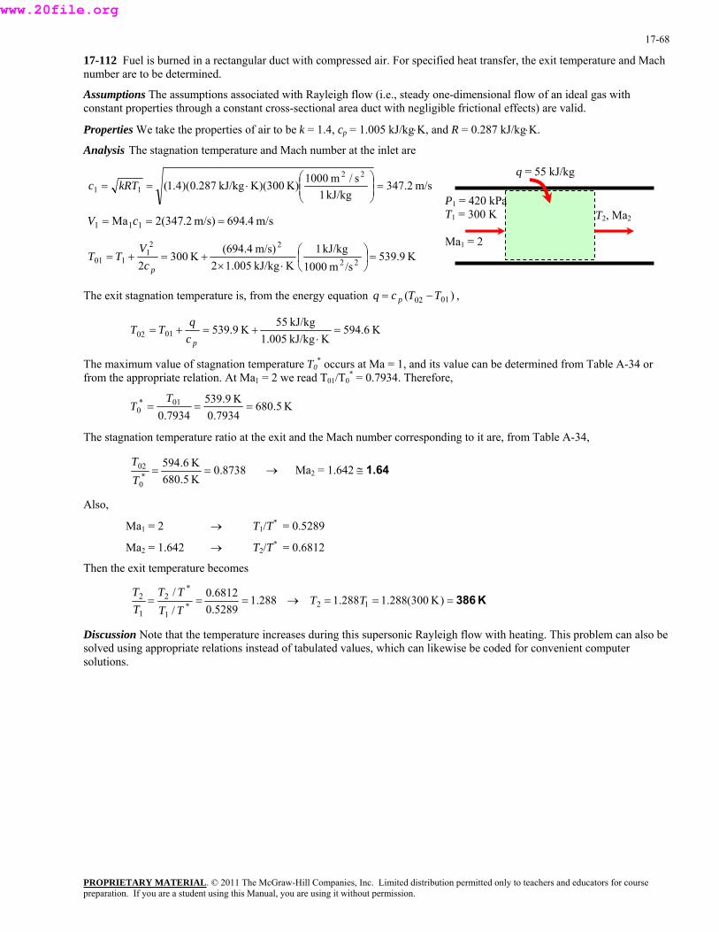
17-68
17-112 Fuel is burned in a rectangular duct with compressed air. For specified heat transfer, the exit temperature and Mach number are to be determined.
Assumptions The assumptions associated with Rayleigh flow (i.e., steady one-dimensional flow of an ideal gas with constant properties through a constant cross-sectional area duct with negligible frictional effects) are valid.
Properties We take the properties of air to be k = 1.4, cp = 1.005 kJ/kg⋅K, and R = 0.287 kJ/kg⋅K.
Analysis The stagnation temperature and Mach number at the inlet are
PROPRIETARY MATERIAL. © 2011 The McGraw-Hill Companies, Inc. Limited distribution permitted only to teachers and educators for course
m/s2.347 kJ/kg1
s/m1000K)K)(300 kJ/kg287.0)(4.1(22
11 ⎟ =⎟⎠
⎞⎜⎜⎝
⎛⋅== kRTc
q = 55 kJ/kg
m/s4.694m/s)2.347(2Ma 111 === cV
K9.539/sm1000
kJ/kg1m/s)4.694( 22 ⎞⎛VK kJ/kg005.12
K300 221
101 =⎟⎠
⎜⎝⋅×
+=+=pc
TT2
The exit stagnation temperature is, from the energy equation )( 0102 TTcq p −= ,
K6.594K kJ/kg1.005
kJ/kg55K539.90102 =
⋅+=+=
pcq
TT
The maximum value of stagnation temperature T0* occurs at Ma = 1, and its value can be determined from Table A-34 or
from the a e read T01/T0* = 0.7934. Therefore, ppropriate relation. At Ma1 = 2 w
K5.6807934.7934.0 0
K9.53901*0 ===
TT
The stag io at ch number corresponding to it are, from Table A-34, nation temperature rat the exit and the Ma
8738.0K6.594*
02 ==T
K5.6800T → Ma2 = 1.642 ≅ 1.64
Also,
emperature becomes
Ma1 = 2 → T1/T* = 0.5289
Ma2 = 1.642 → T2/T* = 0.6812
Then the exit t
288.15289.06812.0
//
*1
*2
1
2 ===TTTT
TT
→ K386=== )K300(288.1288.1 12 TT
Discussion Note that the temperature increases during this supersonic Rayleigh flow with heating. This problem can also be solved using appropriate relations instead of tabulated values, which can likewise be coded for convenient computer solutions.
P1 = 420 kT
Pa 00 K 1 = 3
M
T2, Ma2
a1 = 2
preparation. If you are a student using this Manual, you are using it without permission.
www.20file.org
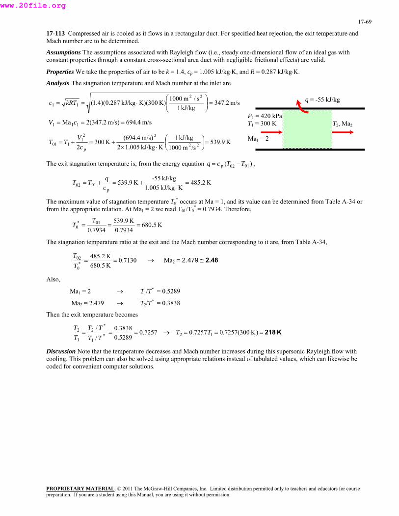
17-69
17-113 Compressed air is cooled as it flows in a rectangular duct. For specified heat rejection, the exit temperature and Mach number are to be determined.
Assumptions The assumptions associated with Rayleigh flow (i.e., steady one-dimensional flow of an ideal gas with constant properties through a constant cross-sectional area duct with negligible frictional effects) are valid.
Properties We take the properties of air to be k = 1.4, cp = 1.005 kJ/kg⋅K, and R = 0.287 kJ/kg⋅K.
Analysis The stagnation temperature and Mach number at the inlet are
m/s2.347 kJ/kg1
s/m1000K)K)(300 kJ/kg287.0)(4.1(22
11 ⎟ =⎟⎠
⎞⎜⎜⎝
⎛⋅== kRTc q = -55 kJ/kg
T2, Ma2
P1 = 420 kT
Pa 300 K
a = 2
1 =
M 1
1 m/s4.694m/s)2.347(2Ma 11 === cV
K9.539/sm1000
kJ/kg1K kJ/kg005.12
m/s)4.694(K300
2 22
221
101 =⎟⎠⎞
⎜⎝⎛
⋅×+=+=
pcV
TT
The exit stagnation temperature is, from the energy equation = )( 0102 TTcq p − ,
K2.485K kJ/kg1.005
kJ/kg-55K539.90102 =
⋅+=+=
p
The maximum value of stagnation temperature T0
cq
TT
e can be determined from Table A-34 or from the appropriate relation. At Ma1 = 2 we read T01/T0
* = 0.7934. Therefore, * occurs at Ma = 1, and its valu
K5.6807934.0
K9.5397934.0
01*0 ===
TT
The stagnation temperature ratio a rresponding to it are, from Table A-34, t the exit and the Mach number co
7130.0K5.680K2.485
*0
02 ==TT
→ Ma2 = 2.479 ≅ 2.48
Also,
1
Ma T2/T* = 0.3838
Then the exit te perature becomes
T /T* = 0.5289 Ma1 = 2 →
→2 = 2.479
m
7257.05289.03838.0
//
*1
*2
1
2 ===TTTT
TT
→ K218=== )K300(7257.07257.0 12 TT
Discussion Note that the temperature decreases and Mach number increases during this supersonic Rayleigh flow with cooling. This problem can also be solved using appropriate relations instead of tabulated values, which can likewise be coded for convenient computer solutions.
PROPRIETARY MATERIALpreparation. If you are a student using this Manual, you are using it without permission.
. © 2011 The McGraw-Hill Companies, Inc. Limited distribution permitted only to teachers and educators for course
www.20file.org

17-70
17-114 Argon flowing at subsonic velocity in a constant-diameter duct is accelerated by heating. The highest rate of heat transfer without reducing the mass flow rate is to be determined.
Assumptions 1 The assumptions associated with Rayleigh flow (i.e., steady one-dimensional flow of an ideal gas with constant properties through a constant cross-sectional area duct with negligible frictional effects) are valid. 2 Mass flow rate remains constant.
Properties We take the properties of argon to be k = 1.667, cp = 0.5203 kJ/kg⋅K, and R = 0.2081 kJ/kg⋅K.
Analysis Heat transfer stops when the flow is choked, and thus Ma2 = V2/c2 = 1. The inlet stagnation temperature is
K3.4052.022 1101 ⎟
⎠⎜⎝
⎟⎠
⎜⎝
The Rayleigh
1-1.6671K)400(Ma11 22 =⎞⎛ +=⎞⎛ −+=
kTT
flow functions corresponding to the inlet and exit Mach numbers
T02/T0* = 1 (since Ma2 = 1)
are
1900.0)2.0667.11(
]2.0)1667.1(2[2.0)1667.1()Ma1(
]Ma)1(2[Ma)1(22
22
221
21
21
*0T01 =
×+−++
=+
−++=
kkkT
Therefore,
PROPRIETARY MATERIAL. © 2011 The McGraw-Hill Companies, Inc. Limited distribution permitted only to teachers and educators for course
1900.01/ *
00220 ==TTT
→ K 21331900.0/)K3.405(1900.0/0102 === TT/ *
0011 TT0T
Then the rate of heat transfer becomes
kW 1080=−⋅=−= K)4002133)(KkJ/kg5203.0)(kg/s2.1()( 0102air TTcmQ p&&
Discussion It can also be shown that T2 = 1600 K, which is the highest thermodynamic temperature that can be attained under stated conditions. If more heat is transferred, the additional temperature rise will cause the mass flow rate to decrease. Also, in the solution of this problem, we cannot use the values of Table A-34 since they are based on k = 1.4.
Q&
Ma2 = 1P1 = 320 kPa T1 = 400 K
Ma1 = 0.2
preparation. If you are a student using this Manual, you are using it without permission.
www.20file.org
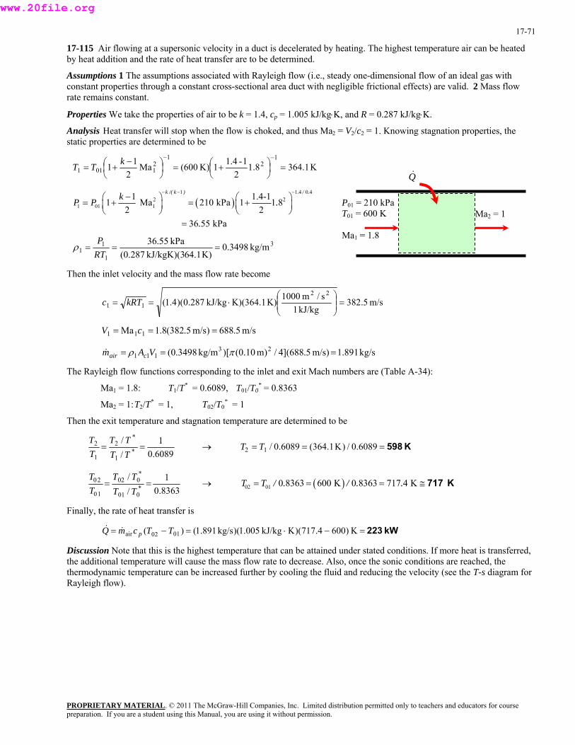
17-71
17-115 Air flowing at a supersonic velocity in a duct is decelerated by heating. The highest temperature air can be heated by heat addition and the rate of heat transfer are to be determined.
Assumptions 1 The assumptions associated with Rayleigh flow (i.e., steady one-dimensional flow of an ideal gas with constant properties through a constant cross-sectional area duct with negligible frictional effects) are valid. 2 Mass flow rate remains constant.
Properties We take the properties of air to be k = 1.4, cp = 1.005 kJ/kg⋅K, and R = 0.287 kJ/kg⋅K.
Analysis Heat transfer will stop when the flow is choked, and thus Ma2 = V2/c2 = 1. Knowing stagnation properties, the static properties are determined to be
K1.3648.12
1-1.41K)600(Ma2
111
21
21011 =⎟
⎠⎞
⎜⎝⎛ +=⎟
⎠⎞
⎜⎝⎛ −+=
−−kTT
( )1 1 4 0 4
2 21 01 1
1 1.4-11 Ma 210 kPa 1 1 82 2
36 55 kPa
k /( k ) . / .kP P .
.
− − −−⎛ ⎞ ⎛ ⎞= + = +⎜ ⎟ ⎜ ⎟⎝ ⎠ ⎝ ⎠
=
PROPRIETARY MATERIAL. © 2011 The McGraw-Hill Companies, Inc. Limited distribution permitted only to teachers and educators for course
311 kg/m3498.0 kPa55.36
===P
ρ1 K)64.1 kJ/kgK)(3(0.287RT
hen the inlet velocity and the mass flow rate beco e T m
m/s5.382 kJ/kg1
K)K)(364.1 kJ/kg287.0)(4.1(11 ⎟⎠
⎜⎝
kRTc s/m1000 22=⎟
⎞⎜⎛
⋅==
=
2 =
The Rayleigh flow functions corresponding to the inlet and exit Mach numbers are (Table A-34):
Ma1 = 1.8: T * = 89, T T0* = 0.8363
Ma2 = 1: T2/T* = 1, T02/T0* = 1
Then the exit temperature and stagn n temp ature are determined to be
m/s5.688)m/s5.382(Ma 111 == cV 8.1
891.1m/s)5.688](4/m)(0.10)[kg/m3498.0(111 VAm cair& 3== πρ kg/s
1/T 0.60 01/
atio er
6089.0/ *1
2
1
2 ==TTT
1/ *TTT→ K598=== 6089.0/)K1.364(6089.0/12 TT
8363.0/ *00110==
TTT→ 1/ *
00220 TTT ( )02 01 0 8363 600 K 0 8363 717 4 KT T / . / . .= = = ≅ 717 K
Finally, the rate of heat transfer is
= mQ && kW223=−⋅=− K)6004.717)(KkJ/kg1.005)(kg/s891.1()( 0102air TTc p
Discussion Note that this is the highest temperature that can be attained under stated conditions. If more heat is transferred, the additional temperature will cause the mass flow rate to decrease. Also, once the sonic conditions are reached, the thermodynamic temperature can be increased further by cooling the fluid and reducing the velocity (see the T-s diagram for Rayleigh flow).
Q&
Ma2 = 1P01 = 210 kPa T01 = 600 K
Ma1 = 1.8
preparation. If you are a student using this Manual, you are using it without permission.
www.20file.org

17-72
Steam Nozzles
17-116C The delay in the condensation of the steam is called supersaturation. It occurs in high-speed flows where there isn’t sufficient time for the necessary heat transfer and the formation of liquid droplets.
PROPRIETARY MATERIALpreparation. If you are a student using this Manual, you are using it without permission.
. © 2011 The McGraw-Hill Companies, Inc. Limited distribution permitted only to teachers and educators for course
www.20file.org
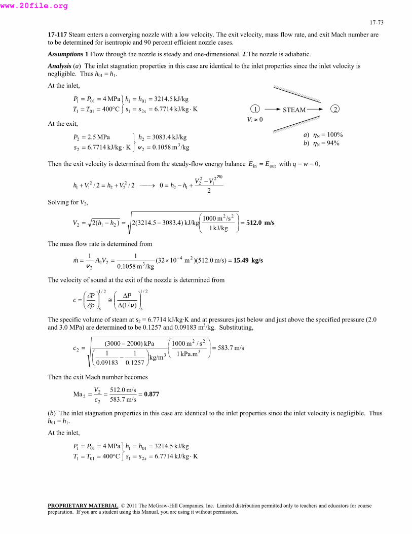
17-73
17-117 Steam enters a converging nozzle with a low velocity. The exit velocity, mass flow rate, and exit Mach number are to be determined for isentropic and 90 percent efficient nozzle cases.
Assumptions 1 Flow through the nozzle is steady and one-dimensional. 2 The nozzle is adiabatic.
Analysis (a) The inlet stagnation properties in this case are identical to the inlet properties since the inlet velocity is negligible. Thus h01 = h1.
At the inlet,
PROPRIETARY MATERIAL. © 2011 The McGraw-Hill Companies, Inc. Limited distribution permitted only to teachers and educators for course
Vi ≈ 0STEAM 21
a) ηN = 1b) η
00%94%
01
⋅====
⎭⎬⎫
°==
ssshh
TPP
At the exit,
MPa5.2 22 =⎫= hP
hen the exit velocity is determined from the steady-flow energy alance with q = w = 0,
N =
KkJ/kg7714.6kJ/kg5.3214
C400MPa4
21
011
01
1
1 ==T
/kgm1058.0KkJ/kg7714.6 3
22 =⎭⎬⋅= vs
kJ/kg4.3083
outin EE && =T b
20 2/2/
021
22
122
22VVhhVh −
+−=⎯→⎯+=211 Vh +
Solving for V2,
m/s 512.0⎟ =⎟⎠
⎞⎜⎜⎝
⎛−=−=
kJ/kg1/sm1000kJ/kg)4.30835.3214(2)(2
22
212 hhV
The mass flow rate is determined from
kg/s 15.49=×==& − m/s)0.512)(m1032(11 24VAm/kgm1058.
2 20 3
2v
The velocity of sound at the exit of the nozzle is determined from 2/12/1
)/1( ss
PPc ⎟⎟⎠
⎞⎜⎜⎝
⎛∆∆
≅⎟⎟⎠
⎜⎞
⎜⎝
⎛=
v∂ρ∂
The specific volume of steam at s2 = 6.and 3.0 MPa) are determined to be 0.1
7714 kJ/kg·K and at pressures just below and just above the specified pressure (2.0 257 and 0.09183 m3/kg. Substituting,
m/s7.583kPa.m1
s/m100011
kPa)20003000(32 =⎟
⎟⎞
⎜⎜⎛
⎞⎛−
=ckg/m
1257.009183.
22
3 ⎠⎝⎟⎠
⎜⎝
−
Then the exit Mach number becomes
0
0.877===m/s583.7m/s0.512Ma
2
22 c
V
(b) The inlet stagnation properties in this case are identical to the inlet properties since the inlet velocity is negligible. Thus h01 = h1.
At the inlet,
KkJ/kg7714.6kJ/kg5.3214
C400MPa4
21
011
011
011
⋅====
⎭⎬⎫
°====
ssshh
TTPP
preparation. If you are a student using this Manual, you are using it without permission.
www.20file.org
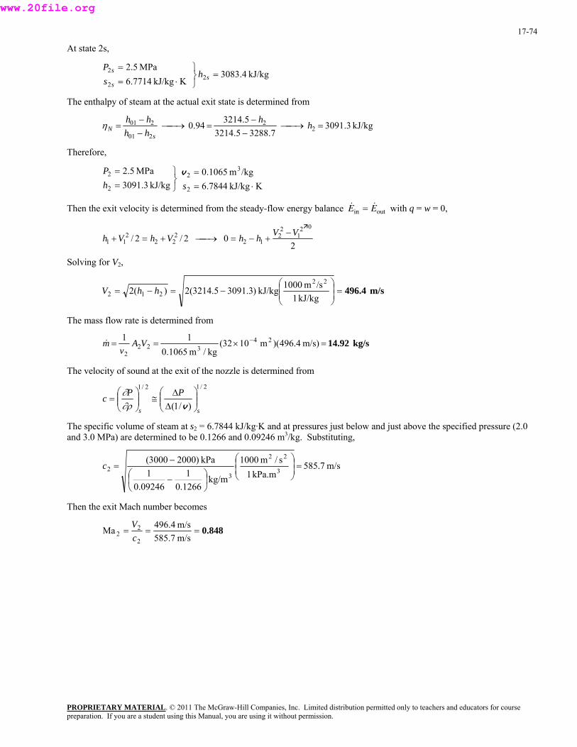
17-74
At state 2s,
PROPRIETARY MATERIAL. © 2011 The McGraw-Hill Companies, Inc. Limited distribution permitted only to teachers and educators for course
⎫=P
nthalpy of steam at the actual exit state is determined from
kJ/kg4.3083K kJ/kg7714.6 2
2=
⎭⎬⋅= s
sh
sMPa5.22s
The e
kJ/kg3.30917.32885.3214
5.321494.0 22
201
201 =⎯→⎯−−
=⎯→⎯−−
= hhhhhh
sNη
herefore,
kJ/kg3.3091 2 ⋅=⎭⎬= sh
locity is determined from the steady-flow energy balance with q = w = 0,
T
KkJ/kg7844.6/kgm1065.0MPa5.2 3
22 =⎫=P v
2
& &E Ein out=Then the exit ve
20 2/2/
021
22
122
222
11VVhhVhVh −
+−=⎯→⎯+=+
Solving for V2,
m/s 496.4⎟ =⎟⎠
⎞⎜⎜⎝
−=−=kJ/kg1
kJ/kg)3.30915.3214(2)(2 212 hhV⎛ /sm1000 22
he mass flow rate is determined froT m
kg/s 14.92=×== − m/s)4.496)(m1032(kg/m1065.
2 20 3
2VA
vm& 11 24
velocity of sound at the exit of the nozzle is determined from The 2/12/1
PPc ⎟⎟⎞
⎜⎜⎛ ∆
≅⎟⎟⎞
⎜⎜⎛
=∂
)/1( ss ⎠⎝ ∆⎠⎝ v∂ρ
volume of steam at s2 = 6.7844 kJ/kg·K and at pressures just below and just above the specified pressure (2.0 d 3.0 MPa) are determined to be 0.1266 and 0.09246 m3/kg. Substituting,
The specific an
m/s7.585kPa.m1
s/m1000
kg/m1266.01
09246.01
kPa)20003000(3
22
32 ⎟ =⎟
⎠
⎞⎜⎜⎝
⎛
⎟⎠⎞
⎜⎝⎛ −
−=c
Then the exit Mach number becomes
0.848===m/s585.7m/s4.496Ma
2
22 c
V
preparation. If you are a student using this Manual, you are using it without permission.
www.20file.org
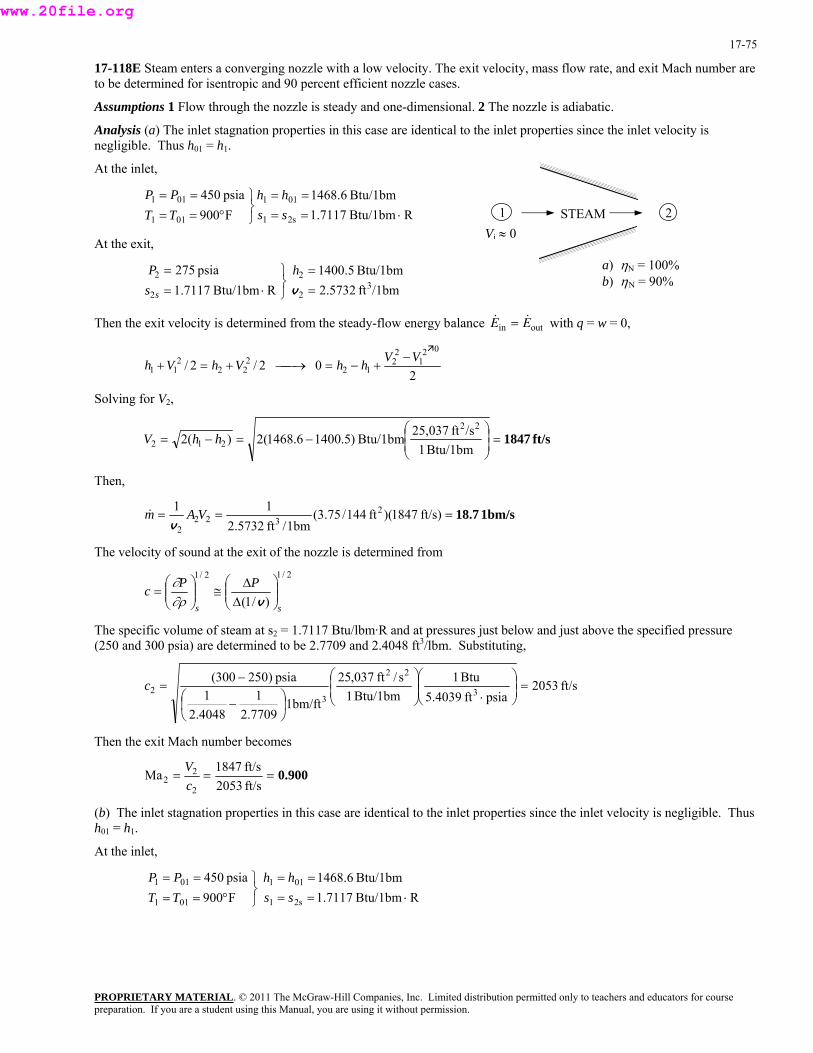
17-75
17-118E Steam enters a converging nozzle with a low velocity. The exit velocity, mass flow rate, and exit Mach number are to be determined for isentropic and 90 percent efficient nozzle cases.
Assumptions 1 Flow through the nozzle is steady and one-dimensional. 2 The nozzle is adiabatic.
Analysis (a) The inlet stagnation properties in this case are identical to the inlet properties since the inlet velocity is negligible. Thus h01 = h1.
At the inlet,
RBtu/1bm7117.1Btu/1bm6.1468
F900psia450
2s1
011
01
PROPRIETARY MATERIAL. © 2011 The McGraw-Hill Companies, Inc. Limited distribution permitted only to teachers and educators for course
Vi ≈ 0STEAM 21
a) ηN = 100% b) ηN = 90%
1 =T01
⋅====
⎭⎬⎫
°===
sshh
TPP
At the exit,
psia275 22 =⎫= hP
hen the exit velocity is determined from the steady-flow energy alance with q = w = 0,
1
/1bmft5732.2RBtu/1bm7117.1 322 =⎭
⎬⋅= vs s
Btu/1bm5.1400
& &E Ein out=T b
20 2/2/
021
22
122
222
11 Vh +VVhhVh −
+−=⎯→⎯+=
g for V2, Solvin
ft/s1847⎟ =⎟⎠
⎞⎜⎜⎝
⎛−=−=
Btu/1bm1/sft25,037Btu/1bm)5.14006.1468(2)(2
22
212 hhV
Then,
1bm/s18.7=== ft/s)1847)(ft144/75.3(1bm/ft5732.2 2 2 3
2v
The velocity of sound at the exit of the nozzle is determined from
11 2VAm&
2/12/1
)/1( ss
PPc ⎟⎟⎠
⎞⎜⎜⎝
⎛∆∆
≅⎟⎟⎠
⎜⎞
⎜⎝
⎛=
v∂ρ∂
The specific volume of steam at s2 = 1(250 and 300 psia) are determined to be
.7117 Btu/lbm·R and at pressures just below and just above the specified pressure 2.7709 and 2.4048 ft3/lbm. Substituting,
ft/s2053Btu1Btu/1bm1
s/ft037,2511
psia)250300(32 =⎟⎟
⎞⎜⎜⎛
⋅⎟⎟⎞
⎜⎜⎛
⎞⎛−
=cpsiaft5.40391bm/ft
7709.24048.
22
3 ⎠⎝⎠⎝⎟⎠
⎜⎝
−
Then the exit Mach number becomes
2
0.900===ft/s2053ft/s1847Ma
2
22 c
V
(b) The inlet stagnation properties in this case are identical to the inlet properties since the inlet velocity is negligible. Thus h01 = h1.
At the inlet,
RBtu/1bm7117.1Btu/1bm6.1468
F900psia450
2s1
011
011
011
⋅====
⎭⎬⎫
°====
sshh
TTPP
preparation. If you are a student using this Manual, you are using it without permission.
www.20file.org
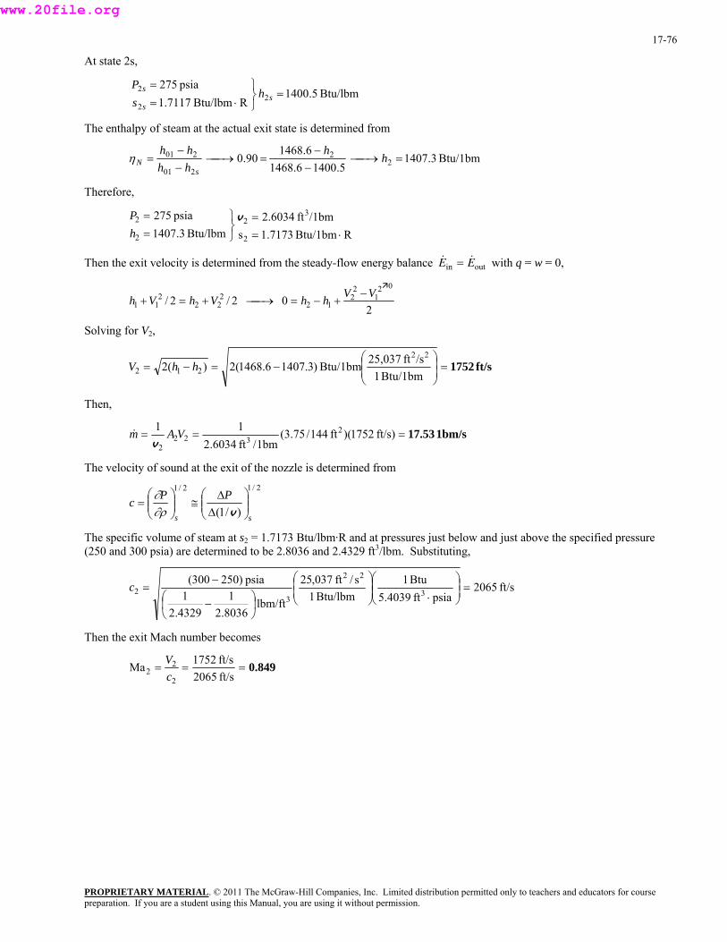
17-76
At state 2s,
PROPRIETARY MATERIAL. © 2011 The McGraw-Hill Companies, Inc. Limited distribution permitted only to teachers and educators for course
⎫=sP
nthalpy of steam at the actual exit state is determined from
Btu/lbm5.1400RBtu/lbm7117.1 2
2=
⎭⎬⋅= s
sh
spsia2752
The e
Btu/1bm3.14075.14006.1468
6.146890.0 2
2
201
201 =⎯→⎯−−
=⎯→⎯−−
= hh
hhhh
sNη
herefore,
Btu/lbm3.1407 2 ⋅=⎭⎬=h
locity is determined from the steady-flow energy balance with q = w = 0,
T
RBtu/1bm7173.1s/1bmft6034.2 psia275 3
22 =⎫= vP
2
& &E Ein out=Then the exit ve
20 2/2/
021
22
122
222
11VVhhVhVh −
+−=⎯→⎯+=+
V2, Solving for
ft/s1752⎟ =⎟⎠
⎞⎜⎜⎝
−=−=Btu/1
Btu/1bm)3.14076.1468(2)(2 212 hhV⎛
1bm/sft25,037 22
hen, T
1bm/s17.53=== ft/s)1752)(ft144/75.3(1bm/ft6034.2 2 2 3
2VAm
v&
11 2
velocity of sound at the exit of the nozzle is determined from The 2/12/1
PPc ⎟⎟⎞
⎜⎜⎛ ∆
≅⎟⎟⎞
⎜⎜⎛
=∂
)/1( ss ⎠⎝ ∆⎠⎝ v∂ρ
volume of steam at s2 = 1.7173 Btu/lbm·R and at pressures just below and just above the specified pressure (250 and 300 psia) are determined to be 2.8036 and 2.4329 ft3/lbm. Substituting, The specific
ft/s2065psiaft5.4039
Btu1Btu/lbm1
s/ft037,25
lbm/ft8036.21
4329.21
psia)250300(3
22
32 ⎟ =⎟
⎠
⎞⎜⎜⎝
⎛
⋅⎟⎟⎠
⎞⎜⎜⎝
⎛
⎟⎠⎞
⎜⎝⎛ −
−=c
Then the exit Mach number becomes
0.849===ft/s2065ft/s1752Ma
2
22 c
V
preparation. If you are a student using this Manual, you are using it without permission.
www.20file.org
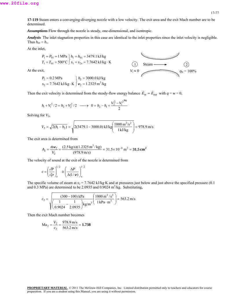
17-77
17-119 Steam enters a converging-diverging nozzle with a low velocity. The exit area and the exit Mach number are to be determined.
Assumptions Flow through the nozzle is steady, one-dimensional, and isentropic.
Analysis The inlet stagnation properties in this case are identical to the inlet properties since the inlet velocity is negligible. Thus h01 = h1.
At the inlet,
KkJ/kg7642.7kJ/kg1.3479
C500MPa1
2s1
011
01
PROPRIETARY MATERIAL. © 2011 The McGraw-Hill Companies, Inc. Limited distribution permitted only to teachers and educators for course
Vi ≈ 0 ηN = 100%
Steam 2 11 =T01
⋅====
⎭⎬⎫
°===
sshh
TPP
At the exit,
MPa2.0 22 =⎫= hP
hen the exit velocity is determined from the steady-flow energy alance with q = w = 0,
1
/kgm2325.1KkJ/kg7642.7 322 =⎭
⎬⋅= vskJ/kg0.3000
& &E Ein out=T b
20 2/2/
021
22
122
22VVhhVh −
+−=⎯→⎯+=211 Vh +
Solving for V2,
m/s9.978kJ/kg1
/sm1000kJ/kg)0.30001.3479(2)(222
212 ⎟ =⎟⎠
⎞⎜⎜⎝
⎛−=−= hhV
The exit area is determined from
2cm31.5=×=== − 243
22 m/s)(978.9V
The velocity of sound at the exit of the nozzle is determined from
2 m105.31)kg/m25kg/s)(1.235.2(mA v&
2/12/1
)/1( ss
PPc ⎟⎟⎠
⎞⎜⎜⎝
⎛∆∆
≅⎟⎟⎠
⎜⎞
⎜⎝
⎛=
v∂ρ∂
The specific volume of steam at s2 = 7and 0.3 MPa) are determined to be 2.0
.7642 kJ/kg·K and at pressures just below and just above the specified pressure (0.1 935 and 0.9024 m3/kg. Substituting,
m/s2.563mkPa1
s/m1000
kg/m0935.21
9024.01
kPa)100300(3
22
32 ⎟ =⎟
⎠
⎞⎜⎜⎝
⎛
⋅⎟⎠⎞
⎜⎝⎛ −
−=c
Then the exit Mach number becomes
1.738===m/s563.2m/s9.978Ma
2
22 c
V
preparation. If you are a student using this Manual, you are using it without permission.
www.20file.org

17-78
17-120 Steam enters a converging-diverging nozzle with a low velocity. The exit area and the exit Mach number are to be determined.
Assumptions Flow through the nozzle is steady and one-dimensional.
Analysis The inlet stagnation properties in this case are identical to the inlet properties since the inlet velocity is negligible. Thus h01 = h1.
At the inlet, KkJ/kg7642.7
kJ/kg1.3479C500
MPa1
2s1
011
011
011
⋅====
⎭⎬⎫
°====
sshh
TTPP
Steam1 2At state 2s, kJ/kg0.3000
KkJ/kg7642.7 22
=⎭⎬⋅= sh
sMPa2.02 ⎫=P
The enthalpy of steam at the actual exit state is determined from
Vi ≈ 0 ηN = 90%
kJ/kg9.30470.30001.3479
1.347990.0 2
2
201
201 =⎯→⎯−−
=⎯→⎯−−
= hh
hhhh
sNη
herefore,
kJ/kg9.3047 2 ⋅=⎭⎬= sh
is determined from the steady-flow energy balance with q = w = 0,
T
KkJ/kg7642.7/kgm2882.1MPa2.0 3
22 =⎫=P v
2
& &E Ein out=Then the exit velocity
20 2/2/
021
22
122
222
11VVhhVhVh −
+−=⎯→⎯+=+
Solving for V2,
m/s7.928kJ/kg1
kJ/kg)9.30471.3479(2)(2 212 ⎜⎜⎝
−=−= hhV /sm1000 22⎟ =⎟⎠
⎞⎛
he exit area is determined from T
PROPRIETARY MATERIAL. © 2011 The McGraw-Hill Companies, Inc. Limited distribution permitted only to teachers and educators for course
2cm34.7=×=== − 24
2
22 m107.34
m/s928.7VA
3 )/kgm82kg/s)(1.285.2(mv&
he velocity of sound at the exit of the nozzle is determined from T2/12/1
PPc ⎟⎞
⎜⎛ ∆
≅⎟⎞
⎜⎛
=∂
)/1( ss⎟⎠
⎜⎝ ∆
⎟⎠
⎜⎝ v∂ρ
The specific volume of steam at s2 = 7.7642 kJ/kg·K and at pressures just below and just above the specified pressure (0.1 and 0.3 MPa) are determined to be 2.1903 and 0.9425 m3/kg. Substituting,
m/s2.575mkPa1
s/m1000
kg/m1903.21
9425.01
kPa)100300(3
22
32 ⎟ =⎟
⎠
⎞⎜⎜⎝
⎛
⋅⎟⎠⎞
⎜⎝⎛ −
−=c
Then the exit Mach number becomes
1.61===m/s575.2m/s7.928Ma
2
22 c
V
preparation. If you are a student using this Manual, you are using it without permission.
www.20file.org
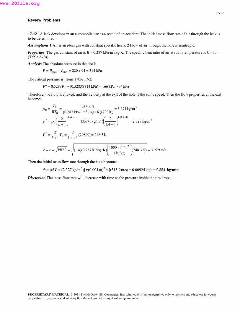
17-79
Review Problems
17-121 A leak develops in an automobile tire as a result of an accident. The initial mass flow rate of air through the leak is to be determined.
Assumptions 1 Air is an ideal gas with constant specific heats. 2 Flow of air through the hole is isentropic.
Properties The gas constant of air is R = 0.287 kPa⋅m3/kg⋅K. The specific heat ratio of air at room temperature is k = 1.4 (Table A-2a).
Analysis The absolute pressure in the tire is
kPa31494220atmgage =+=+= PPP
The critical pressure is, from Table 17-2,
kPa94>kPa166=kPa)314)(5283.0(5283.0* 0 == PP
Therefore, the flow is choked, and the velocity at the exit of the hole is the sonic speed. Then the flow properties at the exit becomes
PROPRIETARY MATERIAL. © 2011 The McGraw-Hill Companies, Inc. Limited distribution permitted only to teachers and educators for course
3)14.1/(1
3)1/(1
0*
33
0
00
kg/m327.214.1
2) kg/m671.3(1
2
kg/m671.3K)829)(Kkg/m kPa287.0(
kPa314
=⎟⎠⎞
⎜⎝⎛
+=⎟
⎠⎞
⎜⎝⎛
+=
=⋅⋅
==
−−k
k
RTP
ρ
ρ
ρ
K3.248K)(29814.1
22*
1 0 =+
=+
= Tk
T
m/s9.315K)3.248( kJ/kg1
s/m1000K) kJ/kg287.0)(4.1(22
* =⎟⎞
⎜⎛
⋅=== kRTcV ⎟⎠
⎜⎝
Then the initial mass flow rate through the hole becomes
Discussion The mass flow rate will decrease with time as the pressure inside the tire drops.
min/kg554.0=kg/s0.00924=m/s)/4](315.9m)(0.004)[kg/m327.2( 23 πρ == AVm&
preparation. If you are a student using this Manual, you are using it without permission.
www.20file.org
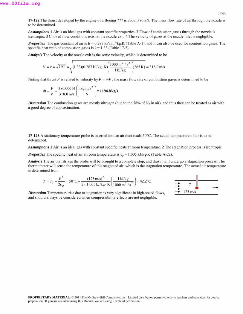
17-80
17-122 The thrust developed by the engine of a Boeing 777 is about 380 kN. The mass flow rate of air through the nozzle is to be determined.
Assumptions 1 Air is an ideal gas with constant specific properties. 2 Flow of combustion gases through the nozzle is isentropic. 3 Choked flow conditions exist at the nozzle exit. 4 The velocity of gases at the nozzle inlet is negligible.
Properties The gas constant of air is R = 0.287 kPa.m3/kg.K (Table A-1), and it can also be used for combustion gases. The specific heat ratio of combustion gases is k = 1.33 (Table 17-2).
Analysis The velocity at the nozzle exit is the sonic velocity, which is determined to be
m/s0.318K)265(kJ/kg1
kJ/k287.0)(33.1( =⎟⎟⎠
=== kRTcV s/m1000K)g22 ⎞
⎜⎜⎝
⎛⋅
F Noting that thrust is related to velocity by VmF & , the mass flow rate of combustion gases is determined to be =
s/kg1194.8=N1
kg1N000,380 ⎜⎛
==Fm&
.m/sm/s318.0
2⎟⎟⎠
⎞⎜⎝V
iscussion The combustion gases are mostly nitrogen (due to the 78% of N2 in air), and thus they can be treated as air with good degree of approximation.
perature of air is to be
Properties The specific heat of air at room temperature is cp = 1.005 kJ/kg⋅K (Table A-2a).
Analysis The air that strikes the probe will be brought to a complete stop, and thus it will undergo a stagnation process. The thermometer will sense the temperature of this stagnated air, which is the stagnation temperature. The actual air temperature
Da
17-123 A stationary temperature probe is inserted into an air duct reads 50°C. The actual temdetermined.
Assumptions 1 Air is an ideal gas with constant specific heats at room temperature. 2 The stagnation process is isentropic.
is determined from
T
125 m/s
C42.2°=⎟⎠
⎞⎛22 kJ/kg1m/s)(125V⎜⎝⋅×
−°=−= 220s/m1000KkJ/kg005.12
C502 pc
TT
Discussion Temperature rise due to stagnation is very significant in high-speed flows, and should always be considered when compressibility effects are not negligible.
PROPRIETARY MATERIALpreparation. If you are a student using this Manual, you are using it without permission.
. © 2011 The McGraw-Hill Companies, Inc. Limited distribution permitted only to teachers and educators for course
www.20file.org
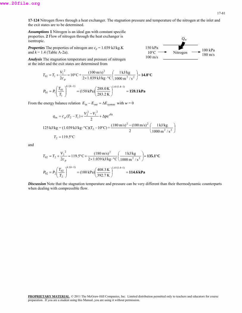
17-81
17-124 Nitrogen flows through a heat exchanger. The stagnation pressure and temperature of the nitrogen at the inlet and the exit states are to be determined.
Assumptions 1 Nitrogen is an ideal gas with constant specific properties. 2 Flow of nitrogen through the heat exchanger is isentropic.
150 kPa 10°C
100 m/sNitrogen
Qin
Properties The properties of nitrogen are cp = 1.039 kJ/kg.K and k = 1.4 (Table A-2a). 100 kPa
180 m/sAnalysis The stagnation temperature and pressure of nitrogen at the inlet and the exit states are determined from
C14.8°=⎟⎠
⎞⎜⎝
⎛°⋅×
°=+=22
221
101s/m1000
kJ/kg1CkJ/kg039.12
m/s)(100+C10
2 pcV
TT
kPa159.1=⎟⎠⎞
⎜⎝
=⎟⎟⎠
⎜⎜⎝
=1
101 283.kPa)1 0(
TPP ⎛⎞⎛ −− )14.1/(4.1)1/(
01
K2K288.05
kkT
From the energy balance relation E E Ein out system− = ∆ with w = 0
C119.5s/m1000
kJ/kg12
m/s)100(m/s)(180+C)10C)(kJ/kg(1.039=kJ/kg125
∆pe2
)(
2
22
22
2
02
12
212in
°=
⎟⎠
⎞⎜⎝
⎛−°−°⋅
+−
+−=
T
T
VVTTcq p
and
C135.1°=⎟⎠
⎞⎜⎝
⎛°⋅×
+°=+=22
222
202s/m1000
kJ/kg1CkJ/kg039.12
m/s)(180C5.1192 pcV
TT
kPa114.6=⎟⎠⎞
⎜⎝⎛=⎟
⎞⎜⎛
=−− )1/(
02kk
T⎟⎠
⎜⎝
)14.1/(4.1
2202 K392.7
K408.3kPa)100(T
PP
Discussion Note that the stagnation temperature and pressure can be very different than their thermodynamic counterparts when dealing with compressible flow.
PROPRIETARY MATERIALpreparation. If you are a student using this Manual, you are using it without permission.
. © 2011 The McGraw-Hill Companies, Inc. Limited distribution permitted only to teachers and educators for course
www.20file.org

17-82
17-125 An expression for the speed of sound based on van der Waals equation of state is to be derived. Using this relation, the speed of sound in carbon dioxide is to be determined and compared to that obtained by ideal gas behavior.
Properties The properties of CO2 are R = 0.1889 kJ/kg·K and k = 1.279 at T = 50°C = 323.2 K (Table A-2b).
Analysis Van der Waals equation of state can be expressed as
2vv b−aRTP −=
Differentiating,
32)( vv bT −⎠⎝ ∂2
vaRTP
+−=⎟⎞
⎜⎛ ∂
Noting that , the speed of sound relation becomes
Substituting,
2//1 vvv dd −=⎯→⎯= ρρ
vv bc
)( 22 −
−=
v
vv
akkRT
PkrPkc
TT
22
22 ⎟⎠⎞
⎜⎝⎛−=⎟
⎠⎞
⎜⎝⎛=
∂∂
∂∂
2 (M = 44 kg/kmol), the constant a and b can be expressed per unit mass as
he specif volume of CO2 is determined to be
Using the molar mass of CO
kg/m10705.9 34−× 26 /kgmkPa1882.0 ⋅=a and =b
T ic
kg/m3031.0kg/mkPa1882.02
/kgm0009705.0K)K)(323.2kg/mkPa(0.1889
=kPa200 32
26
3
3=→
⋅×−
−
⋅⋅v
vv
Substituting,
m/s277.5=
⎟⎟⎟⎟⎟⎠
⎞
⎜⎜⎜
−2236
)kg/m0097050.0(0.3031=c⎜⎜⎛
⋅−
⋅2/1
323
22
23
23
/kgmkPa1s/m1000
kg)/m3031.0()279.1)(kg/kPa.m1882.0(2
kJ/kg1s/m1000K)K)(323.2kJ/kg1889(1.279)(0.kg)/m(0.3031
⎝
If we treat CO2 as an ideal gas, the speed of sound becomes
m/s 279.4⎟ =⎟⎠
⎞⎜⎜⎝
⎛⋅==
kJ/kg1s/m1000K)K)(323.2kJ/kg1889.0)(279.1(
22kRTc
Discussion Note that the ideal gas relation is the simplest equation of state, and it is very accurate for most gases encountered in practice. At high pressures and/or low temperatures, however, the gases deviate from ideal gas behavior, and it becomes necessary to use more complicated equations of state.
PROPRIETARY MATERIALpreparation. If you are a student using this Manual, you are using it without permission.
. © 2011 The McGraw-Hill Companies, Inc. Limited distribution permitted only to teachers and educators for course
www.20file.org
17-83
17-126 The equivalent relation for the speed of sound is to be verified using thermodynamic relations.
Analysis The two relations are s
Pc ⎟⎟⎠
⎜⎞
⎜⎝
⎛=
∂ρ∂2 and
T
Pkc ⎟⎟⎠
⎜⎞
⎜⎝
⎛=
∂ρ∂2
From . Thus, 2//1 vvv ddrr −=⎯→⎯=
PROPRIETARY MATERIAL. © 2011 The McGraw-Hill Companies, Inc. Limited distribution permitted only to teachers and educators for course
sssssrc ⎟
⎠⎜⎝ ∂
=T
TPT
TPPP
⎟⎠⎞
⎜⎝⎛∂∂
⎟⎠⎞
⎜⎝⎛∂∂
−=⎟⎠⎞
⎜⎝⎛
∂∂
∂∂
−=⎟⎠⎞
⎜⎝⎛∂∂
−=⎞⎛ ∂v
vv
vv
v 222
rom the cyclic rule,
2
F
TPsTPs sP
Ts
TP
Ps
sT
TPsTP ⎟
⎠⎞
⎜⎝⎛∂∂
⎟⎠⎞
⎜⎝⎛∂∂
−=⎟⎠⎞
⎜⎝⎛∂∂
⎯→⎯−=⎟⎠⎞
⎜⎝⎛∂∂
⎟⎠⎞
⎜⎝⎛∂∂
⎟⎠⎞
⎜⎝⎛∂∂ 1:),,(
vv vvv
vv ⎟
⎠⎞
⎜⎝⎛∂∂
⎟⎠⎞
⎜⎝⎛∂∂
−=⎟⎠⎞
⎜⎝⎛∂∂
⎯→⎯−=⎟⎠⎞
⎜⎝⎛∂∂
⎟⎠⎞
⎜⎝⎛∂∂
⎟⎠⎞
⎜⎝⎛∂∂
sTsT
Ts
sTsT
TsTs1:),,(
Substituting,
TPTTPT ⎝⎠⎝ ∂ sP
sT
Ts
sTs
sPsc ⎟
⎠⎞
⎜⎝⎛∂∂
⎟⎠⎞
⎜⎝⎛∂∂
⎟⎠⎞
⎜⎝⎛∂∂
−=⎟⎠⎞
⎜⎝⎛∂∂
⎟⎠⎞
⎜⎝⎛∂∂
⎟⎠⎞
⎜⎛∂∂
⎟⎞
⎜⎛ ∂−=
vv
vv
v 22
Recall that
2
pc
v
v ⎟⎠
⎞⎜⎝⎛∂∂
=Ts
Tc
PT
s⎟⎠⎞
⎜⎝⎛∂∂
= and T
Substituting,
TTk
cTc ⎟
⎠⎜⎝ ∂
−=⎟⎠
⎟⎜⎝ ∂⎟⎠
⎜⎜⎝
p PPTc ⎞⎛ ∂⎞⎛ ∂⎞⎛⎟⎟⎞⎛ 22
eplacing by dρ,
2 ⎜⎠
⎜⎝
−=v
vv
vv
2/vvd−R
T
Pkc ⎟⎟⎠
⎜⎞
⎜⎝
⎛∂ρ∂
=2
Discussion Note that the differential thermodynamic property relations are very useful in the derivation of other property relations in differential form.
preparation. If you are a student using this Manual, you are using it without permission.
www.20file.org
17-84
17-127 For ideal gases undergoing isentropic flows, expressions for P/P*, T/T*, and ρ/ρ* as functions of k and Ma are to be obtained.
Analysis Equations 17-18 and 17-21 are given to be
2Ma)1(2 2
0 −+=
kTT
and
PROPRIETARY MATERIAL. © 2011 The McGraw-Hill Companies, Inc. Limited distribution permitted only to teachers and educators for course
10 +kT2
=T
Multiplying the two,
*
⎟⎠⎞
⎜⎝⎟⎛
+⎟⎠
⎜⎞
⎜⎝
⎟⎠
⎜⎝ 0TT
⎛ −+=⎟
⎞⎜⎛
12
2Ma)1(2* 2
0
kkTT
Simplifying and inverting,
2Ma)1(21
* −++
=kk
TT (1)
From )1/(
2
)1/(
Ma)1(21
*** ⎠⎝ PT
−−⎟⎟⎠
⎞⎜⎜⎝
⎛
−++
=⎯→⎯⎟⎞
⎜⎛=
kkkk
kkPT
P (2) P
From )1/(
2
)1/(
Ma)1(21
***
−−
⎟⎟⎠
⎞⎜⎜⎝
⎛
−++
=⎟ ⎯→⎯⎟⎠
⎞⎜⎜⎝
⎛=
kkkk
kk
ρρ
ρρ
ρρ (3)
Discussion Note that some very useful relations can be obtained by very simple manipulations.
preparation. If you are a student using this Manual, you are using it without permission.
www.20file.org

17-85
17-128 It is to be verified that for the steady flow of ideal gases dT0/T = dA/A + (1-Ma2) dV/V. The effect of heating and area changes on the velocity of an ideal gas in steady flow for subsonic flow and supersonic flow are to be explained.
Analysis We start with the relation )(2 0
2TTcV
p −= , (1)
Differentiating, )( 0 dTdTcdV p −= V (2)
We also have 0=++VdV
AdAd
ρρ (3)
0=+ dVVdPand (4)
n
ρ
dP
PROPRIETARY MATERIAL. © 2011 The McGraw-Hill Companies, Inc. Limited distribution permitted only to teachers and educators for course
Differentiating the ideal gas relatio P = ρRT, P T
= + =d dTρρ
0 (5)
TckkRTc p =−==From the speed of sound relation, ρ/kP (6) )1(2
0=++−VdV
AdA
TdT
PdP (7) Combining Eqs. (3) and (5),
VdVckP
dPdP−= =2/ρ
Combining Eqs. (4) and (6),
VdVk
VdV
cVkdVV
ck
PdP 2
2
2
2Ma−=−=−=or, (8)
bining Eqs. (2) and (6), Com
pcVdTdT −= 0 dV
VdVk
TdT
VdV
kcV
TdT
TdT
VdV
TcV
TdT
TdT
p
202
20
20 Ma)1(
)1/(−−=
−−==−=or, (9)
ningCombi Eqs. (7), (8), and (9),
0Ma)1(Ma)1( 202 −+−−−dk
dTdVk =++VdV
AdA
VV
TV
[ ]V
kkAT
1Ma)1(Ma 220 +−+−+=dVdATd
or,
Thus, VdV
AdA
TdT
)Ma1( 20 −+= (10)
Differentiating the steady-flow energy equation )( 01020102 TTchhq p −=−=
= 0dTcq pδ (11)
Eq. (11) relates the stagnation temperature change dT0 to the net heat transferred to the fluid. Eq. (10) relates the velocity changes to area changes dA, and the stagnation temperature change dT0 or the heat transferred.
(a) When Ma < 1 (subsonic flow), the fluid will accelerate if the duck converges (dA < 0) or the fluid is heated (dT0 > 0 or δq > 0). The fluid will decelerate if the duck converges (dA < 0) or the fluid is cooled (dT0 < 0 or δq < 0).
(b) When Ma > 1 (supersonic flow), the fluid will accelerate if the duck diverges (dA > 0) or the fluid is cooled (dT0 < 0 or δq < 0). The fluid will decelerate if the duck converges (dA < 0) or the fluid is heated (dT0 > 0 or δq > 0).
preparation. If you are a student using this Manual, you are using it without permission.
www.20file.org

17-86
17-129 A pitot tube measures the difference between the static and stagnation pressures for a subsonic airplane. The speed of the airplane and the flight Mach number are to be determined.
Assumptions 1 Air is an ideal gas with constant specific heat ratio. 2 The stagnation process is isentropic.
Properties The properties of air are R = 0.287 kJ/kg.K and k = 1.4 (Table A-2a).
Analysis The stagnation pressure of air at the specified conditions is
kPa8.50208.300 =+=∆+= PPP
Then, 4.0/4.121/2
0
2Ma)14.1(1
8.308.50
2Ma)1(1 ⎟
⎟⎠
⎞⎜⎜⎝
⎛ −+=⎟ ⎯→⎯⎟
⎠
⎞⎜⎜⎝
⎛ −+=
−kkk
PP
It yields
he speed of sound in air at the specified conditions is
Ma = 0.877
T
m/s5.310kJ/kg1
s/m1000K)K)(240kJ/kg287.0)(4.1(22⎟ =⎟⎠
⎞⎜⎜⎝
⎛⋅== kRTc
iscussion Note that the flow velocity can be measured in a simple and accurate way by simply measuring pressure.
m/s 272==×= m/s)5.310)(877.0(Ma cVThus,
D
17-130 The mass flow parameter &m RT s the Mach number fo1Ma0 ≤≤ is to be plotted.
/ ( )AP0 0 versu r k = 1.2, 1.4, and 1.6 in the range of
l The mass flow rate parameter ( & ) /m RT P A0 0Ana ysis can be expressed as
)1(2/)1(
2)1− Mk0 AP0
(2Ma
−+
⎟⎟⎠
⎞⎛=
kkRTm&
Thu
⎜2⎜⎝ +
k
s,
Ma k = 1.2 k = 1.4 k = 1.6 0.0 0 0 0 0.1 0.1089 0.1176 0.1257 0.2 0.2143 0.2311 0.2465 0.3 0.3128 0.3365 0.3582 0.4 0.4015 0.4306 0.4571 0.5 0.6 0.
0.4782 5411
0.5111 0.5763
0.5407 0.6077
0.7 0.5894 0.6257 0.6578
7106 1.0 0.6485 0.6847 0.7164
Discussion Note that the mass flow rate increases with increasing Mach number and specific heat ratio. It levels off at Ma = 1, and remains constant (choked flow).
0.4Ma
0.2
k = 1.61.41.2
0.8 0.6 1.0 0
0.30
0.45
0.15
0.75
0.60
0.8 0.6230 0.6595 0.6916 0.9 0.6424 0.6787 0.
PROPRIETARY MATERIALpreparation. If you are a student using this Manual, you are using it without permission.
. © 2011 The McGraw-Hill Companies, Inc. Limited distribution permitted only to teachers and educators for course
www.20file.org

17-87
17-131 Helium gas is accelerated in a nozzle. The pressure and temperature of helium at the location where Ma = 1 and the ratio of the flow area at this location to the inlet flow area are to be determined.
Assumptions 1 Helium is an ideal gas with constant specific heats. 2 Flow through the nozzle is steady, one-dimensional, and isentropic.
Properties The properties of helium are R = 2.0769 kJ/kg⋅K, cp = 5.1926 kJ/kg⋅K, and k = 1.667 (Table A-2a).
Analysis The properties of the fluid at the location where Ma = 1 are the critical properties, denoted by superscript *. We first determine the stagnation temperature and pressure, which remain constant throughout the nozzle since the flow is isentropic.
K4.501s/m1000
kJ/kg1KkJ/kg1926.52
m/s)(120K500
2 22
22
0 =⎟⎠
⎞⎜⎝
⎛⋅×
+=+=p
ii c
VTT
i
PROPRIETARY MATERIAL. © 2011 The McGraw-Hill Companies, Inc. Limited distribution permitted only to teachers and educators for course
120 m/s Ma = 1He *and
MPa806.0K500
MPa)8.0(0 =⎟⎠
⎜⎝
=⎟⎜ ⎟⎠
⎜⎝
=i
i TPP K501.4 )1667.1/(667.1)1/(
0 ⎞⎛⎞⎛ −−kkT
The Mach number at the nozzle exit is given to be Ma = 1. Therefore, the properties at the nozzle exit are the critical roperties determined from p
K376=⎟⎠⎞
⎜⎝⎛=⎟
⎠⎞
⎜⎝⎛
+=
1+1.6672K)4.501(
12* 0 k
TT
MPa0.393=⎟⎠⎞
⎜⎝⎛=⎟
⎠⎞
⎜⎝⎛
+=
−− 667.1/(667.1)1/(kk )1
0 1+1.6672MPa)806.0(
12*
kPP
The speed of sound and the Mach number at the nozzle inlet are
m/s1316 kJ/kg1
s/m1000K)K)(500k0769.2)(667.1(== ii kRTc J/kg22⎟ =⎟⎠
⎞⎜⎜⎝
⎛⋅
0912.0m/s1316
m/s120Ma ===i
ii c
V
The ratio of the entrance-to-throat area is
20621667.10912.0
.=⎦⎣ ⎠⎝⎠⎝ +
)0912.0(1667.1121
Ma1121
)667.02/(667.2
)]1(2/[)1(2
⎥⎤
⎢⎡
⎟⎞
⎜⎛ −+⎟
⎞⎜⎛=
⎥⎤
⎢⎡
⎟⎞
⎜⎛ −+⎟
⎞⎜⎛=
×
−+ kk
ii kA
Then the ratio of the throat area to the entrance area becomes
21Ma2
* ⎦⎣ ⎠⎝⎠⎝ +i kA
A
Ai
*
.= =
16 20
0.161
Discussion The compressible flow functions are essential tools when determining the proper shape of the compressible flow duct.
preparation. If you are a student using this Manual, you are using it without permission.
www.20file.org

17-88
17-132 Helium gas enters a nozzle with negligible velocity, and is accelerated in a nozzle. The pressure and temperature of helium at the location where Ma = 1 and the ratio of the flow area at this location to the inlet flow area are to be determined.
Assumptions 1 Helium is an ideal gas with constant specific heats. 2 Flow through the nozzle is steady, one-dimensional, and isentropic. 3 The entrance velocity is negligible.
Properties The properties of helium are R = 2.0769 kJ/kg⋅K, cp = 5.1926 kJ/kg⋅K, and k = 1.667 (Table A-2a).
Analysis We treat helium as an ideal gas with k = 1.667. The properties of the fluid at the location where Ma = 1 are the critical properties, denoted by superscript *.
The stagnation temperature and pressure in this case are identical to the inlet temperature and pressure since the inlet velocity is negligible. They remain constant throughout the nozzle since the flow is isentropic.
T0 = Ti = 500 K
P0 = Pi = 0.8 MPa
The Mach number at the nozzle exit is given to be Ma = 1. Therefore, the properties at the nozzle exit are the critical properties determined from i
PROPRIETARY MATERIAL. © 2011 The McGraw-Hill Companies, Inc. Limited distribution permitted only to teachers and educators for course
Vi ≈ 0 Ma = 1He *
K375=⎟⎠⎞
⎜⎝⎛=⎟
⎠⎞
⎜⎝⎛
+=
1+1.6672K)500(
12* 0 k
TT
MPa0.390=⎟⎠
⎜⎝
=⎟⎠
⎜⎝ +
= 0 1+1.667MPa)8.0(
1*
kPP ⎞⎛⎞⎛
−− )1667.1/(667.1)1/( 22 kk
The ratio of the nozzle inlet area to the throat area is determined from )]1(2/[)1(
2* 21Ma ⎥
⎦⎢⎣
⎟⎠
⎜⎝⎟⎠
⎜⎝ + i
i kAMa1121 −+
⎤⎡ ⎞⎛ −+⎞⎛=
kki kA
ut the M h number at the nozzle inlet is Ma = 0 since Vi ≅ 0. Thus the ratio of the throat area to the nozzle inlet area is B ac
0==1*A∞iA
The compressible flow functions are essential tools when determining the proper shape of the compressible flow duct. Discussion
preparation. If you are a student using this Manual, you are using it without permission.
www.20file.org
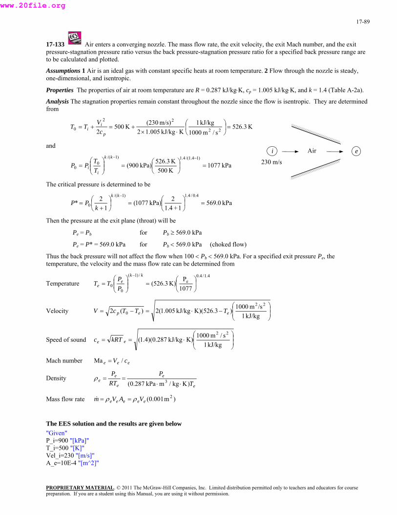
17-89
17-133 Air enters a converging nozzle. The mass flow rate, the exit velocity, the exit Mach number, and the exit pressure-stagnation pressure ratio versus the back pressure-stagnation pressure ratio for a specified back pressure range are to be calculated and plotted.
Assumptions 1 Air is an ideal gas with constant specific heats at room temperature. 2 Flow through the nozzle is steady, one-dimensional, and isentropic.
Properties The properties of air at room temperature are R = 0.287 kJ/kg⋅K, cp = 1.005 kJ/kg⋅K, and k = 1.4 (Table A-2a).
Analysis The stagnation properties remain constant throughout the nozzle since the flow is isentropic. They are determined from
K3.526s/m1000
kJ/kg1KkJ/kg005.12
m/s)(230K5002 22
22
0 =⎟⎠
⎞⎜⎝
⎛⋅×
+=+=p
ii c
VTT
and
PROPRIETARY MATERIAL. © 2011 The McGraw-Hill Companies, Inc. Limited distribution permitted only to teachers and educators for course
230 m/s
Air i e
kPa1077K500K526.3kPa)900(0 ⎜
⎝=⎟
⎠⎜⎝
=i
i TPP
)14.1/(4.1)1/(0 =⎟
⎠⎞⎛⎟
⎞⎜⎛ −−kk
T
The critical pressure is determined to be
kPa0.5691+1.4
kPa)1077(1
* 0 =⎟⎠
⎜⎝
=⎟⎠
⎜⎝ +
=k
PP 22 )1/(⎛⎞⎛
−kk 4.0/4.1⎞
Then the ne (throat) w
Pe = P* = 569.0 kPa for Pb < 569.0 kPa (choked flow)
pressure will not affect the flow when 100 < Pb < 9.0 kPa. For a specified exit pressure Pe, the temperature, the velocity and the mass flow rate can be determined from
Temperature
pressure at the exit pla ill be
Pe = Pb for Pb ≥ 569.0 kPa
Thus the back 56
4.1/4.0e
/)1(
00 1077
PK)3.526( ⎟
⎠
⎞⎜⎝
⎛=⎟⎟
⎠⎜
⎞⎜⎝
⎛=
− kke
e PP
TT
⎟⎟⎠
⎞⎜⎜⎝
⎛−⋅=−=Velocity
kJ/kg1/sm1000)K)(526.3kJ/kg005.1(2)(2
22
0 eep TTTcV
Speed of sound ⎟⎟⎠
⎞⎜⎜⎝
⎛⋅==
kJ/kg1s/m1000K)kJ/kg287.0)(4.1(
22
ee kRTc
ach number eee cV /Ma = M
Density e
ee PP==ρ
ee TRT )Kkg/m kPa287.0( 3 ⋅⋅
ρρ ==
he EES solution and the results are given below "Given" P_i=900 "[kPa]" T_i=500 "[K]" Vel_i=230 "[m/s]" A_e=10E-4 "[m^2]"
)m001.0( 2eeeee VAVm&Mass flow rate
T
preparation. If you are a student using this Manual, you are using it without permission.
www.20file.org
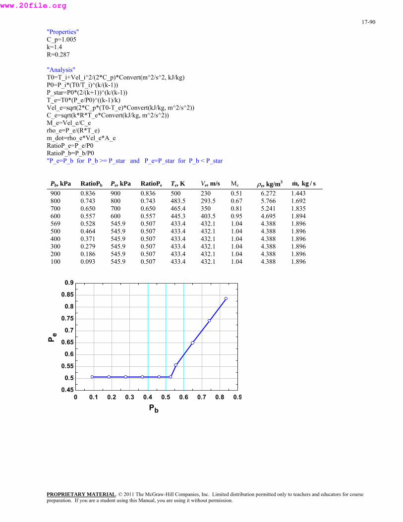
17-90
"Properties" C_p=1.005 k=1.4 R=0.287
"Analysis" T0=T_i+Vel_i^2/(2*C_p)*Convert(m^2/s^2, kJ/kg) P0=P_i*(T0/T_i)^(k/(k-1)) P_star=P0*(2/(k+1))^(k/(k-1)) T_e=T0*(P_e/P0)^((k-1)/k) Vel_e=sqrt(2*C_p*(T0-T_e)*Convert(kJ/kg, m^2/s^2)) C_e=sqrt(k*R*T_e*Convert(kJ/kg, m^2/s^2)) M_e=Vel_e/C_e rho_e=P_e/(R*T_e) m_dot=rho_e*Vel_e*A_e RatioP_e=P_e/P0 RatioP_b=P_b/P0 "P_e=P_b for P_b >= P_star and P_e=P_star for P_b < P_star
Pb, kPa RatioPb Pe, kPa RatioPe Te, K Ve, m/s Me ρe, kg/m3 &m, kg / s 900 800 700 600 569 500 400 300 200 100
0.836 0.743 0.650 0.557 0.528 0.464 0.371 0.279 0.186 0.093
900 800 700 600 545.9 545.9 545.9 545.9 545.9 545.9
0.836 0.743 0.650 0.557 0.507 0.507 0.507 0.507 0.507 0.507
500 483.5 465.4 445.3 433.4 433.4 433.4 433.4 433.4 433.4
230 293.5 350 403.5 432.1 432.1 432.1 432.1 432.1 432.1
0.51 0.67 0.81 0.95 1.04 1.04 1.04 1.04 1.04 1.04
6.272 5.766 5.241 4.695 4.388 4.388 4.388 4.388 4.388 4.388
1.443 1.692 1.835 1.894 1.896 1.896 1.896 1.896 1.896 1.896
0 0.1 0.2 0.3 0.4 0.5 0.6 0.7 0.8 0.90.45
0.5
0.55
0.6
0.65
0.7
0.75
0.8
0.85
0.9
Pb
P e
PROPRIETARY MATERIALpreparation. If you are a student using this Manual, you are using it without permission.
. © 2011 The McGraw-Hill Companies, Inc. Limited distribution permitted only to teachers and educators for course
www.20file.org

17-91
100 200 300 400 500 600 700 800 900
200
240
280
320
360
400
440
Pb
Vel e
100 200 300 400 500 600 700 800 9001.4
1.5
1.6
1.7
1.8
1.9
2
Pb
m [
kg/s
]
PROPRIETARY MATERIALpreparation. If you are a student using this Manual, you are using it without permission.
. © 2011 The McGraw-Hill Companies, Inc. Limited distribution permitted only to teachers and educators for course
www.20file.org
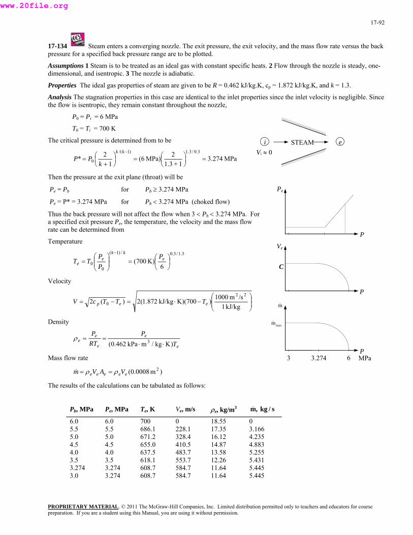
17-92
17-134 Steam enters a converging nozzle. The exit pressure, the exit velocity, and the mass flow rate versus the back pressure for a specified back pressure range are to be plotted.
Assumptions 1 Steam is to be treated as an ideal gas with constant specific heats. 2 Flow through the nozzle is steady, one-dimensional, and isentropic. 3 The nozzle is adiabatic.
Properties The ideal gas properties of steam are given to be R = 0.462 kJ/kg.K, cp = 1.872 kJ/kg.K, and k = 1.3.
Analysis The stagnation properties in this case are identical to the inlet properties since the inlet velocity is negligible. Since the flow is isentropic, they remain constant throughout the nozzle,
P0 = Pi = 6 MPa
T0 = Ti = 700 K
The critical pressure is determined from to be i eSTEAM Vi ≈ 0
MPa274.31+1.3
MPa)6(1
* 0 ⎟⎠
⎜⎝
=⎟⎠
⎜⎝ +
=k
PP 22 3.0/3.1)1/(=⎞⎛⎞⎛
−kk
b
e he temperature, the velocity and the mass flow rom
Temperature
Then the pressure at the exit plane (throat) will be
Pe = Pb for Pb ≥ 3.274 MPa
P
Pe
C
P
V
Pe = P* = 3.274 MPa for Pb < 3.274 MPa (choked flow)
Thus the back pressure will not affect the flow when 3 < P < 3.274 MPa. Fora specified exit pressure P , trate can be determined f
e3.1/3.0/)1(
00 6
K)700( ⎟⎠⎞
⎜⎝⎛=⎟⎟
⎠⎜
⎞⎜⎝
⎛=
−e
kke
eP
PP
TT
Velocity
⎟⎟⎠
⎞⎜⎜⎝
⎛−⋅=−=
kJ/kg1/sm1000)K)(700 kJ/kg872.1(2)(2
22
0 eep TTTcV
PROPRIETARY MATERIAL. © 2011 The McGraw-Hill Companies, Inc. Limited distribution permitted only to teachers and educators for course
& maxm
P
&m
3.274 3 6 MPa
Density
ee
ee
TP
RTP
)Kkg/m kPa462.0( 3 ⋅⋅==
ass flow rate
0.e A
The res f the calculations can bulated follows:
Pa Pa 3
eρ
M
)m008 20(eee Vρ=eVm ρ=&
ults o be ta as
Pb, M Pe, M Te, K Ve, m/s ρe, kg/m &m, kg / s
6.0 6.0 700 0 18.55 0 5.5 5.5 686.1 228.1 17.35 3.166 5.0 5.0 671.2 328.4 16.12 4.235 4.5 4.5 655.0 410.5 14.87 4.883 4.0 4.0 637.5 483.7 13.58 5.255 3.5 3.5 618.1 553.7 12.26 5.431 3.274 3.274 608.7 584.7 11.64 5.445 3.0 3.274 608.7 584.7 11.64 5.445
preparation. If you are a student using this Manual, you are using it without permission.
www.20file.org
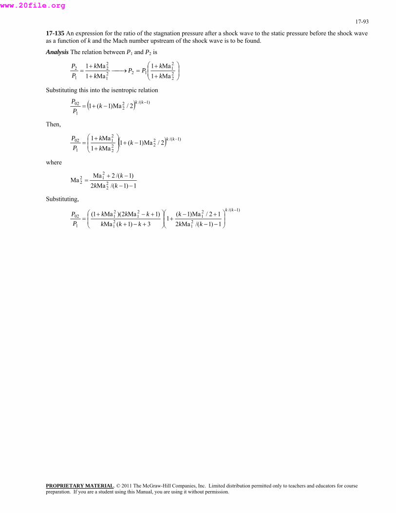
17-93
⎟
17-135 An expression for the ratio of the stagnation pressure after a shock wave to the static pressure before the shock wave as a function of k and the Mach number upstream of the shock wave is to be found.
Analysis The relation between P1 and P2 is
⎟⎠
⎞⎜⎜⎝ +
=⎯→⎯+
= 12211 1Ma1 k
PPkP
⎛ ++22
21
22
MaMa1Ma1 kkP
ubstituting this into the isentropic relation
2
S
( ) )1/(22
1
02 2/Ma)1(1 −−+=
kkkPP
Then,
( ) )1/(222
2
21
1
02 2/Ma)1(1Ma1Ma1 −
−⎟ +⎟⎠
⎞⎜⎜⎝
⎛
+
+=
kkk
kk
PP
where
1)1/(Ma2)1/(2Ma
Ma 22
212
2−−
−+=
kkk
Substituting, )1/(
21
21
21
21
21
1
02
1)1/(Ma212/Ma)1(
13)1(Ma
)1Ma2)(Ma1(−
⎟⎟⎠
⎞⎜⎜⎝
⎛
−−
+⎟ −+⎟
⎠
⎞⎜⎜⎝
⎛
+−+
+−+=
kk
kkk
kkkkkk
PP
PROPRIETARY MATERIALpreparation. If you are a student using this Manual, you are using it without permission.
. © 2011 The McGraw-Hill Companies, Inc. Limited distribution permitted only to teachers and educators for course
www.20file.org
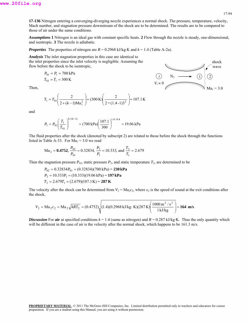
17-94
17-136 Nitrogen entering a converging-diverging nozzle experiences a normal shock. The pressure, temperature, velocity, Mach number, and stagnation pressure downstream of the shock are to be determined. The results are to be compared to those of air under the same conditions.
Assumptions 1 Nitrogen is an ideal gas with constant specific heats. 2 Flow through the nozzle is steady, one-dimensional, and isentropic. 3 The nozzle is adiabatic.
Properties The properties of nitrogen are R = 0.2968 kJ/kg⋅K and k = 1.4 (Table A-2a).
Analysis The inlet stagnation properties in this case are identical to the inlet properties since the inlet velocity is negligible. Assuming the flow before the shock to be isentropic,
shock wave
PROPRIETARY MATERIAL. © 2011 The McGraw-Hill Companies, Inc. Limited distribution permitted only to teachers and educators for course
N2 1i 2K300 kPa700
01
01
====
i
i
TTPP
Vi ≈ 0 Then, Ma1 = 3.0
K1.1071)3-(1.4+2
2K)300(Ma)1(2
222
1011 ⎟ =⎟
⎠
⎞⎜⎜⎝
⎛⎟ =⎟⎠
⎞⎜⎜⎝
⎛
−+=
kTT
and
kPa06.19300
kPa)700(01
1011 =⎟
⎠⎜⎝
=⎟⎟⎠
⎜⎜⎝
=T
PP 107.1 4.0/4.1)1/(⎞⎛⎞⎛
−kkT
he fluid properties after the shock (denoted by subscript 2) are related to those before the shock through the functions sted in T le A-33. For Ma = 3.0 we read
Tli ab 1
679.2and,333.10,32834.0,Ma1
2
1
2
01
022 ====
TPP0.4752
Then the stagnation pressure P02, static pressure P2, and static temperature T2, are determined to be
=K)1.107)(679.2(679.2 12
1
== TT
TPP
kPa197kPa230
= kPa)06.19)(333.10(333.10= kPa)700)(32834.0(32834.0
2
0102
====
PPPP
K287
The velocity after the shock can be determined from V2 = Ma2c2, where c2 is the speed of sound at the exit conditions after the shock,
m/s 164⎟ =⎟⎠
⎞⎜⎜⎝
⎛⋅===
kJ/kg1s/m1000K)K)(287kJ/kg2968.0)(4.1()4752.0(MaMa
22
22222 kRTcV
Discussion For air at specified conditions k = 1.4 (same as nitrogen) and R = 0.287 kJ/kg·K. Thus the only quantity which will be different in the case of air is the velocity after the normal shock, which happens to be 161.3 m/s.
preparation. If you are a student using this Manual, you are using it without permission.
www.20file.org
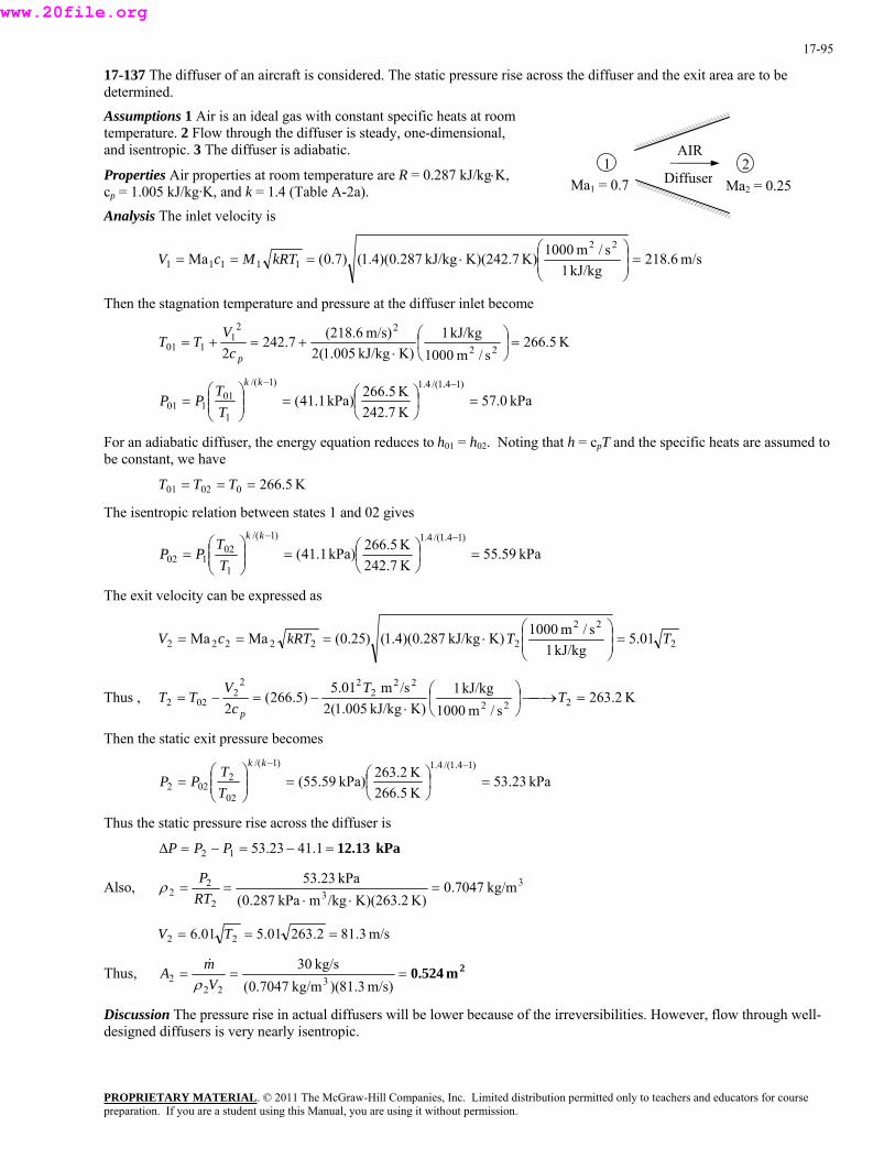
17-95
17-137 The diffuser of an aircraft is considered. The static pressure rise across the diffuser and the exit area are to be determined. Assumptions 1 Air is an ideal gas with constant specific heats at room temperature. 2 Flow through the diffuser is steady, one-dimensional, and isentropic. 3 The diffuser is adiabatic.
Ma2 = 0.25Diffuser2
AIR
Ma1 = 0.7 1
Properties Air properties at room temperature are R = 0.287 kJ/kg⋅K, cp = 1.005 kJ/kg·K, and k = 1.4 (Table A-2a). Analysis The inlet velocity is
m/s6.218kJ/kg1
s/m1000K)K)(242.7kJ/kg287.0)(4.1()7.0(Ma22
11111 ⎟ =⎟⎠
⎞⎜⎜⎝
⎛⋅=== kRTMcV
Then the stagnation temperature and pressure at the diffuser inlet become
K5.266s/m1000
kJ/kg1K)kJ/kg005.1(2
m/s)(218.67.2422 22
221
101 =⎟⎠
⎞⎜⎝
⎛⋅
+=+=pc
VTT
kPa0.7K
(41.1kPa)242.71
101 =⎟⎠
⎜⎝
=⎟⎟⎠
⎜⎜⎝
=T
PP 5K266.5 )14.1/(4.1)1/(01 ⎞⎛⎞⎛ −−kk
T
or an adiabatic diffuser, the energy equation reduces to h01 = h02. Noting that h = cpT and the specific heats are assumed to e constant, we have
he isentropic relation between states 1 and 02 gives
Fb
K5.266=== TTT 00201
T
kPa59.55K242.7K266.5kPa)1.41(
1
02102 =⎟⎟
⎠⎜⎜⎝
=T
PP)14.1/(4.1)1/(
=⎟⎠⎞
⎜⎝⎛⎞⎛ −−kk
T
xit velocity can be expressed as The e
2
22
222222 01.5kJ/kg1
s/m1000K)kJ/kg287.0)(4.1()25.0(MaMa TTkRTcV ⎟ =⎟⎠
⎞⎜⎜⎝
⎛⋅===
K2.263s/m1000
kJ/kg1K)
Thus , kJ/kg005.1(202 22 c p
/sm5.01)5.266( 222
222
222 =⎯→⎯⎟
⎠
⎞⎜⎝
⎛⋅
−=−= TTV
TT
Then the static exit pressure becomes
kPa23.53K266.5K263.2kPa)59.55(
)14.1/(4.1)1/(
02
2022 =⎟
⎠⎞
⎜⎝⎛=⎟⎟
⎠
⎞⎜⎜⎝
⎛=
−−kk
TT
PP
Thus th tae s tic pressure rise across the diffuser is
Also,
kPa 12.13=−=−=∆ 1.4123.5312 PPP
33
2
22 kg/m7047.0
K)K)(263.2/kgmkPa287.0(kPa53.23P
=⋅⋅
==RT
ρ
m/s3.812.26301.501.6 22 === TV
2m0.524===m/s)3.81)(kg/m7047.0(
kg/s303
222 V
mAρ&
Thus,
Discussion The pressure rise in actual diffusers will be lower because of the irreversibilities. However, flow through well-designed diffusers is very nearly isentropic.
PROPRIETARY MATERIALpreparation. If you are a student using this Manual, you are using it without permission.
. © 2011 The McGraw-Hill Companies, Inc. Limited distribution permitted only to teachers and educators for course
www.20file.org

17-96
17-138 Helium gas is accelerated in a nozzle isentropically. For a specified mass flow rate, the throat and exit areas of the nozzle are to be determined.
Assumptions 1 Helium is an ideal gas with constant specific heats. 2 Flow through the nozzle is steady, one-dimensional, and isentropic. 3 The nozzle is adiabatic.
Properties The properties of helium are R = 2.0769 kJ/kg.K, cp = 5.1926 kJ/kg.K, k = 1.667 (Table A-2a).
Analysis The inlet stagnation properties in this case are identical to the inlet properties since the inlet velocity is negligible,
T T
P P01 1
01 1
5001 0
= == =
K MPa.
PROPRIETARY MATERIAL. © 2011 The McGraw-Hill Companies, Inc. Limited distribution permitted only to teachers and educators for course
01 500= = K
he critical pressure and temperature are determined fro
* He The flow is assumed to be isentropic, thus the stagnation temperature and pressure remain constant throughout the nozzle, 1 2
Vi ≈ 0
P P02 01 1 0= = MPa.
T T02
T m
K0.3751+1.667
2K)500(1
2* 0 =⎟⎠⎞
⎜⎝⎛=⎟
⎠⎞
⎜⎝⎛
+=
kTT
MPa487.01+1.667
2MPa)0.1(1
2*)1667.1/(667.1)1/(
0 =⎟⎠⎞
⎜⎝⎛=⎟
⎠⎞
⎜⎝⎛
+=
−−kk
kPP
33 kg/m625.0
K)K)(375/kgm kPa0769.2(** ==
RTρ kPa487*
=⋅⋅
P
m/s4.1139 kJ/kg1
s/m1000K)K)(375 kJ/kg0769.2)(667.1(**22⎟ =⎟⎠⎝
⎞⎜⎜⎛
⋅=== kRTcV*
hus the throat area is T
2cm3.51=×=== − 243 m1051.3 kg/s25.0
**
*VmA
ρ&
m/s)4.1139)( kg/m625.0(
t the nozzle exit the pressure is P2 = 0.1 MPa. Then the other properties at the zzle exit are determined to be A no667.0/667.1
22
)1/(22
2
0 Ma2
1667.11MPa0.1MPa0.1Ma
211 ⎟
⎠⎞
⎜⎝⎛ −+=⎯→⎯⎟
⎠⎞
⎜⎝⎛ −+=
−kkkPP
ields Ma2 = 2.130, which is greater than 1. Therefore, the nozzle must be converging-diverging. It y
K0.19913.2)1667.1(2
2)K500(Ma)1(202 ⎜
⎜⎝ +
= TT 222
2
⎟ =⎟⎠
⎞⎜⎜⎝
⎛
×−+⎟ =⎟⎠
⎞⎛
−k
33
2
22 kg/m242.0
K)K)(199/kgm kPa0769.2(=
⋅⋅==
RTρ kPa100P
m/s0.1768 kJ/kg1
s/m1000K)K)(199 kJ/kg0769.2)(667.1()13.2(MaMa22
22222 ⎟ =⎟⎠
⎞⎜⎜⎝
⎛⋅=== kRTcV
Thus the exit area is
2cm5.84=×=== − 243
222 m1084.5
m/s)1768)( kg/m242.0( kg/s25.0
VmA
ρ&
Discussion Flow areas in actual nozzles would be somewhat larger to accommodate the irreversibilities.
preparation. If you are a student using this Manual, you are using it without permission.
www.20file.org

17-97
17-139E Helium gas is accelerated in a nozzle. For a specified mass flow rate, the throat and exit areas of the nozzle are to be determined for the cases of isentropic and 97% efficient nozzles.
Assumptions 1 Helium is an ideal gas with constant specific heats. 2 Flow through the nozzle is steady, one-dimensional, and isentropic. 3 The nozzle is adiabatic.
Properties The properties of helium are R = 0.4961 Btu/lbm·R = 2.6809 psia·ft3/lbm·R, cp = 1.25 Btu/lbm·R, and k = 1.667 (Table A-2Ea).
Analysis The inlet stagnation properties in this case are identical to the inlet properties since the inlet velocity is negligible,
T T
P P01 1
01 1
900150
= == =
R psia
PROPRIETARY MATERIAL. © 2011 The McGraw-Hill Companies, Inc. Limited distribution permitted only to teachers and educators for course
01 900= = R
he critical pressure and temperature are determined from
* He
The flow is assumed to be isentropic, thus the stagnation temperature and pressure remain constant throughout the nozzle, 1 2
02T TVi ≈ 0
P P02 01 150= = psia
T
R9.6741+1.667
2R)900(1
2* 0 =⎟⎠⎞
⎜⎝⎛=⎟
⎠⎞
⎜⎝⎛
+=
kTT
psia1.731+1.667
2 psia)150(1
2*)1667.1/(667.1)1/(
0 =⎟⎠⎞
⎜⎝⎛=⎟
⎠⎞
⎜⎝⎛
+=
−−kk
kPP
33 1bm/ft0404.0
R)R)(674.9/lbmft psia6809.2( psia1.73
*** =
⋅⋅==
RTPρ
ft/s3738Btu/1bm1
s/ft25,037R)R)(674.9Btu/lbm4961.0)(667.1(** =⎟⎟⎜⎜⋅=== kRTcV*22
⎠
⎞
⎝
⎛
and 2ft0.00132===1bm/s2.0
** 3*V
mAρ&
ft/s)3738)(1bm/ft0404.0(
t the nozzle exit the pressure is P2 = 15 psia. Then the other properties at the nozzle exit are determined to be A667.0/667.1
22
)1/(22
2
0 Ma2
1⎜⎝⎛ +=
pMa
21667.11
psia15 psia1501
⎟⎠⎞
⎜⎝⎛ −+=⎯→⎯⎟
⎠⎞− −kkkp
elds Ma2 = 2.130, which is greater than 1. Therefore, the nozzle must be converging-diverging. It yi
R1.35813.2)1667.1(2
2)R900(Ma)1(202 ⎜
⎜⎝ +
= TT 222
2
⎟ =⎟⎠
⎞⎜⎜⎝
⎛
×−+⎟ =⎟⎠
⎞⎛
−k
33
2
22 1bm/ft0156.0
R)R)(358.1/lbmft psia6809.2(=
⋅⋅==
RTρ
psia15P
ft/s5800Btu/1bm1
s/ft25,037R)R)(358.1Btu/lbm4961.0)(667.1()13.2(MaMa22
22222 ⎟ =⎟⎠
⎞⎜⎜⎝
⎛⋅=== kRTcV
Thus the exit area is
2ft0.00221===ft/s)5800)(lbm/ft0156.0(
lbm/s2.03
222 V
mAρ&
Discussion Flow areas in actual nozzles would be somewhat larger to accommodate the irreversibilities.
preparation. If you are a student using this Manual, you are using it without permission.
www.20file.org
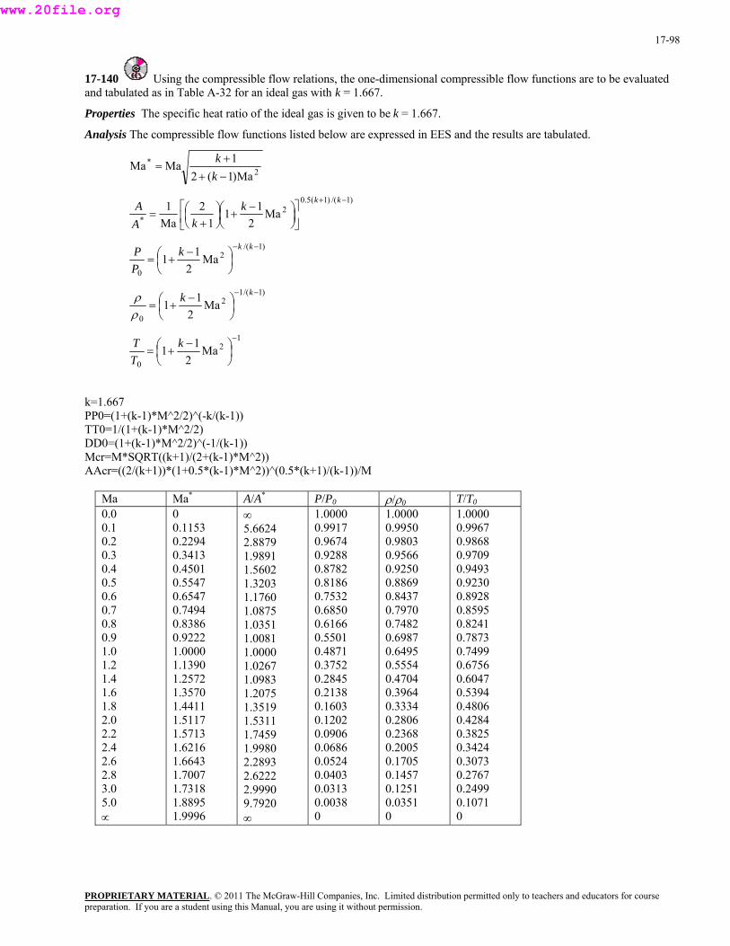
17-98
17-140 Using the compressible flow relations, the one-dimensional compressible flow functions are to be evaluated and tabulated as in Table A-32 for an ideal gas with k = 1.667.
Properties The specific heat ratio of the ideal gas is given to be k = 1.667.
Analysis The compressible flow functions listed below are expressed in EES and the results are tabulated.
2*
Ma)1(21MaMa
−++
=kk
)1/()1(5.02
* Ma2
111
2Ma1 −+
⎥⎦
⎤⎢⎣
⎡⎟⎠⎞
⎜⎝⎛ −+⎟
⎠⎞
⎜⎝⎛
+=
kkkkA
A
)1/(2
0Ma
211
−−
⎟⎠⎞
⎜⎝⎛ −+=
kkkPP
)1/(12
0Ma
211
−−
⎟⎠⎞
⎜⎝⎛ −+=
kkρρ
12a1 −
⎟⎞⎛ −kT
0 2 ⎠⎝TM1⎜ +=
kP
=1.667 P0 +(k-1)*M^2 (-k/(k-1))
TT 1+(k-1)*M /2) DD +(k-1)*M 1/(k-1Mc *SQRT((k )*AA (2/(k+1))* k-1)* .5*(k+ )/M
=(10=1/(
/2)^^2
0=(1 ^2/2)^(-+1)/(2+(k-1
)) r=M M^2)) cr=( (1+0.5*( M^2))^(0 1)/(k-1)
Ma Ma* A/A* P/P 0 ρ ρ/ 0 T/T0
0.0 0.1 0.2 0.3 0.4 0.5 0.6 0.7 0.8 0.9 1.0 1.2 1.4 1.6 1.8 2.0 2.2 2.4 2.6 2.8 3.0 5.0 ∝
1.6643 1.7007 1.7318 1.8895 1.9996
980 2.2893 2.6222 2.9990 9.7920 ∞
86 0.0524 0.0403 0.0313 0.0038 0
05 0.1705 0.1457 0.1251 0.0351 0
24 0.3073 0.2767 0.2499 0.1071 0
0 0.1153 0.2294 0.3413 0.4501 0.5547 0.6547 0.7494 0.8386 0.9222 1.0000 1.1390 1.2572 1.3570 1.4411 1.5117 1.5713 1.6216
∞ 5.6624 2.8879 1.9891 1.5602 1.3203 1.1760 1.0875 1.0351 1.0081 1.0000 1.0267 1.0983 1.2075 1.3519 1.5311 1.7459 1.9
1.0000 0.9917 0.9674 0.9288 0.8782 0.8186 0.7532 0.6850 0.6166 0.5501 0.4871 0.3752 0.2845 0.2138 0.1603 0.1202 0.0906 0.06
1.0000 0.9950 0.9803 0.9566 0.9250 0.8869 0.8437 0.7970 0.7482 0.6987 0.6495 0.5554 0.4704 0.3964 0.3334 0.2806 0.2368 0.20
1.0000 0.9967 0.9868 0.9709 0.9493 0.9230 0.8928 0.8595 0.8241 0.7873 0.7499 0.6756 0.6047 0.5394 0.4806 0.4284 0.3825 0.34
PROPRIETARY MATERIALpreparation. If you are a student using this Manual, you are using it without permission.
. © 2011 The McGraw-Hill Companies, Inc. Limited distribution permitted only to teachers and educators for course
www.20file.org

17-99
17-141 Using the normal shock relations, the normal shock functions are to be evaluated and tabulated as in Table A-33 for an ideal gas with k = 1.667.
Properties The specific heat ratio of the ideal gas is given to be k = 1.667.
Analysis The normal shock relations listed below are expressed in EES and the results are tabulated.
1Ma22Ma)1(
a 2
21
2+−
=k
M1 +− kk 1
1Ma2Ma1Ma1 2
122
21
1
2
++−
=+
+=
kkk
kk
PP
)1(Ma2)1(Ma2
2
212 −+
=k
21 −+ kT
T
2
121
21
12
12
1
2
Ma)1(2Ma)1(
//
VV
kk
TTPP
=−+
+==
ρρ
,
)1(21
21
22
2
1
01
02
2/)1(Ma12/)1(Ma1
MaMa −
+
⎥⎥⎦
⎤⎢⎢⎣
⎡
−+
−+=
kk
kk
PP
22
)1/(22
21
1
02
Ma1]2/)1(Ma1)[Ma1(
kkk
PP kk
+
−++=
−
x^2*k/(k-1)-1))
1)/2)/(1+My^2*(k-1)/2)
(k+1)/(k-1)) 0yPx=(1+k*Mx^2)*(1+My^2*(k-1)/2)^(k/(k-1))/(1+k*My^2)
/P01
k=1.667 My=SQRT((Mx^2+2/(k-1))/(2*MPyPx=(1+k*Mx^2)/(1+k*My^2) TyTx=(1+Mx^2*(k-RyRx=PyPx/TyTx P0yP0x=(Mx/My)*((1+My^2*(k-1)/2)/(1+Mx^2*(k-1)/2))^(0.5*P
Ma1 Ma2 P2/P1 ρ2/ρ1 T2/T1 P02 P02/P1
1.0 1.1 1.2 1.3 1.4 1.5 1.6 1.7 1.8 1.9 2.0 2.1 2.2 2.3 2.4 2.5 2.6 2.7 2.8 2.9 3.0 4.0 5.0∞ 0.4473
022 ∞ 3.9985
834 ∞
98 0
723 ∞
1.0000 0.9131 0.8462 0.7934 0.7508 0.7157 0.6864 0.6618 0.6407 0.6227 0.6070 0.5933 0.5814 0.5708 0.5614 0.5530 0.5455 0.5388 0.5327 0.5273 0.5223 0.4905 0.4753
1.0000 1.2625 1.5500 1.8626 2.2001 2.5626 2.9501 3.3627 3.8002 4.2627 4.7503 5.2628 5.8004 6.3629 6.9504 7.5630 8.2005 8.8631 9.5506 10.2632 11.0007 19.7514 31.0
1.0000 1.1496 1.2972 1.4413 1.5805 1.7141 1.8415 1.9624 2.0766 2.1842 2.2853 2.3802 2.4689 2.5520 2.6296 2.7021 2.7699 2.8332 2.8923 2.9476 2.9993 3.3674 3.5703
1.0000 1.0982 1.1949 1.2923 1.3920 1.4950 1.6020 1.7135 1.8300 1.9516 2.0786 2.2111 2.3493 2.4933 2.6432 2.7989 2.9606 3.1283 3.3021 3.4819 3.6678 5.8654 8.6
1 0.999 0.9933 0.9813 0.96260.938 0.9085 0.8752 0.8392 0.80160.763 0.7243 0.6861 0.6486 0.6124 0.5775 0.5442 0.5125 0.4824 0.4541 0.4274 0.2374 0.13
2.0530 2.3308 2.6473 2.9990 3.3838 3.8007 4.2488 4.7278 5.2371 5.7767 6.3462 6.9457 7.5749 8.2339 8.9225 9.6407 10.3885 11.1659 11.9728 12.8091 13.6750 23.9530 37.1
PROPRIETARY MATERIALpreparation. If you are a student using this Manual, you are using it without permission.
. © 2011 The McGraw-Hill Companies, Inc. Limited distribution permitted only to teachers and educators for course
www.20file.org

17-100
17-142 The critical temperature, pressure, and density of an equimolar mixture of oxygen and nitrogen for specified stagnation properties are to be determined.
Assumptions Both oxygen and nitrogen are ideal gases with constant specific heats at room temperature.
Properties The specific heat ratio and molar mass are k = 1.395 and M = 32 kg/kmol for oxygen, and k = 1.4 and M = 28 kg/kmol for nitrogen (Tables A-1 and A-2).
Analysis The gas constant of the mixture is
kg/kmol30285.0325.02222 NNOO =×+×=+= MyMyM m
KkJ/kg 0.2771kg/kmol30
KkJ/kmol8.314⋅=
⋅==
m
um M
RR
The specific heat ratio is 1.4 for nitrogen, and nearly 1.4 for oxygen. Therefore, the specific heat ratio of the mixture is also 1.4. Then the critical temperature, pressure, and density of the mixture become
K 500.0=⎟⎠⎞
⎜⎝⎛
+=⎟
⎠⎞
⎜⎝⎛
+=
11.42K)600(
12* 0 k
TT
kPa 158.5=⎟⎠⎞
⎜⎝⎛=⎟
⎠⎞
⎜⎝⎛
+=
−− )14.1/(4.1)1/(
0 1+1.42kPa)300(
12*
kk
kPP
PROPRIETARY MATERIAL. © 2011 The McGraw-Hill Companies, Inc. Limited distribution permitted only to teachers and educators for course
3kg/m 1.144===kPa5.158
*** 3RT
Pρ⋅⋅ K)K)(500/kgmkPa2771.0(
Discussion If the specific heat ratios k of the two gases were different, then we would need to determine the k of the mixture f o k = cp,m/cv,m where the specific heats of the mixture are determined from
) pc
r m
2222222222 N,NNO,OON,NO,O, /()/(mfmf mpmppmp MMycMMyccc +=+=
2222222222 N,NNO,OON,NO,O, )/()/(mfmf vvvvv cMMycMMyccc mmm +=+=
where mf is the mass fraction and y is the mole fraction. In this case it would give
kJ/kg.K9745.0039.1)30/285.0(918.0)30/325.0(, =××+××=c mp
kJ/kg.K6977.0743.0)30/285.0(658.0)30/325.0(, =××+××=mvc
and
k = 0.9745/0.6977 = 1.397
preparation. If you are a student using this Manual, you are using it without permission.
www.20file.org
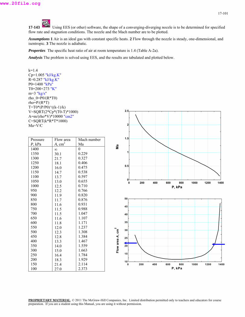
17-101
17-143 Using EES (or other) software, the shape of a converging-diverging nozzle is to be determined for specified flow rate and stagnation conditions. The nozzle and the Mach number are to be plotted.
Assumptions 1 Air is an ideal gas with constant specific heats. 2 Flow through the nozzle is steady, one-dimensional, and isentropic. 3 The nozzle is adiabatic.
Properties The specific heat ratio of air at room temperature is 1.4 (Table A-2a).
Analysis The problem is solved using EES, and the results are tabulated and plotted below.
k=1.4 Cp=1.005 "kJ/kg.K" R=0.287 "kJ/kg.K" P0=1400 "kPa" T0=200+273 "K" m=3 "kg/s" rho_0=P0/(R*T0) rho=P/(R*T) T=T0*(P/P0)^((k-1)/k) V=SQRT(2*Cp*(T0-T)*1000)
0 200 400 600 800 1000 1200 14000
0.5
1
1.5
2
2.5
P, kPa
Ma
A=m/(rho*V)*10000 "cm2" C=SQRT(k*R*T*1000) Ma=V/C
Pressure P, kPa
Flow area A, cm2
Mach number Ma
1400 1350 1300 1250 1200 1150 1100 1050 1000 950 900 850 800 750 700 650 600 550 500 450 400 350 300 250 200 150 100
∞ 30.1 21.7 18.1 16.0 14.7 13.7 13.0 12.5 12.2 11.9 11.7 11.6 11.5 11.5 11.6 11.8 12.0 12.3 12.8 13.3 14.0 15.0 16.4 18.3 21.4 27.0
0 0.229 0.327 0.406 0.475 0.538 0.597 0.655 0.710 0.766 0.820 0.876 0.931 0.988 1.047 1.107 1.171 1.237 1.308 1.384 1.467 1.559 1.663 1.784 1.929 2.114 2.373
0 200 400 600 800 1000 1200 140010
15
20
25
30
35
40
45
50
P, kPa
Flow
are
a A
, cm
2
PROPRIETARY MATERIALpreparation. If you are a student using this Manual, you are using it without permission.
. © 2011 The McGraw-Hill Companies, Inc. Limited distribution permitted only to teachers and educators for course
www.20file.org
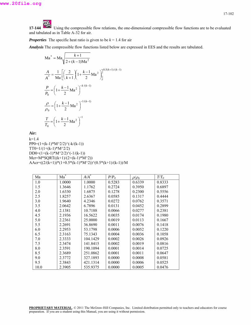
17-102
17-144 Using the compressible flow relations, the one-dimensional compressible flow functions are to be evaluated
Analysis The compressible flow functions listed below are expressed in EES and the results are tabulated.
and tabulated as in Table A-32 for air.
Properties The specific heat ratio is given to be k = 1.4 for air
2*
Ma)1(21MaMa
−++
=kk
)1/()1(5.02
* Ma2
111
2Ma1 −+
⎥⎦
⎤⎢⎣
⎡⎟⎠⎞
⎜⎝⎛ −+⎟
⎠⎞
⎜⎝⎛
+=
kkkkA
A
)1/(2
0Ma
211
−−
⎟⎠⎞
⎜⎝⎛ −+=
kkkPP
)1/(12
0Ma
211
−−
⎟⎠⎞
⎜⎝⎛ −+=
kkρρ
12a1 −
⎟⎞⎛ −kT
0M
21⎜⎝+=
T ⎠
P0=(1+(k-1)*M^2/2)^(-k/(k-1)) T0=1/(1+(k-1)*M^2/2)
DD +(k-1)*M )^(-1/(k-1Mc *SQRT((k k-1)*AA (2/(k+1))* -1)* .5*(k+
Air: k=1.4 PT
0=(1 ^2/2 )) r=M +1)/(2+( M^2)) cr=( (1+0.5*(k M^2))^(0 1)/(k-1))/M
Ma Ma* A/A* P/P0 ρ/ρ0 T/T0
1.0 1.5 2.0 2.5 3.0 3.5 4.0 4.5 5.0 5.5 6.0 6.5 7.0 7.5 8.0 8.5 9.0 9.5 10.0
2.3591 2.3689 2.3772 2.3843 2.3905
190.1094 251.0862 327.1893 421.1314 535.9375
0.0001 0.0001 0.0000 0.0000 0.0000
0.0014 0.0011 0.0008 0.0006 0.0005
0.0725 0.0647 0.0581 0.0525 0.0476
1.0000 1.3646 1.6330 1.8257 1.9640 2.0642 2.1381 2.1936 2.2361 2.2691 2.2953 2.3163 2.3333 2.3474
1.0000 1.1762 1.6875 2.6367 4.2346 6.7896 10.7188 16.5622 25.0000 36.8690 53.1798 75.1343 104.1429 141.8415
0.5283 0.2724 0.1278 0.0585 0.0272 0.0131 0.0066 0.0035 0.0019 0.0011 0.0006 0.0004 0.0002 0.0002
0.6339 0.3950 0.2300 0.1317 0.0762 0.0452 0.0277 0.0174 0.0113 0.0076 0.0052 0.0036 0.0026 0.0019
0.8333 0.6897 0.5556 0.4444 0.3571 0.2899 0.2381 0.1980 0.1667 0.1418 0.1220 0.1058 0.0926 0.0816
PROPRIETARY MATERIALpreparation. If you are a student using this Manual, you are using it without permission.
. © 2011 The McGraw-Hill Companies, Inc. Limited distribution permitted only to teachers and educators for course
www.20file.org
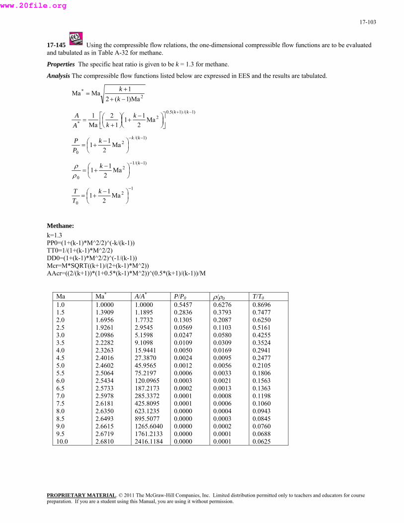
17-103
17-145 Using the compressible flow relations, the one-dimensional compressible flow functions are to be evaluated
Analysis The compressible flow functions listed below are expressed in EES and the results are tabulated.
and tabulated as in Table A-32 for methane.
Properties The specific heat ratio is given to be k = 1.3 for methane.
2*
Ma)1(21MaMa
−++
=kk
)1/()1(5.02
* Ma2
111
2Ma1 −+
⎥⎦
⎤⎢⎣
⎡⎟⎠⎞
⎜⎝⎛ −+⎟
⎠⎞
⎜⎝⎛
+=
kkkkA
A
)1/(2
0Ma
211
−−
⎟⎠⎞
⎜⎝⎛ −+=
kkkPP
)1/(12
0Ma
211
−−
⎟⎠⎞
⎜⎝⎛ −+=
kkρρ
12
PROPRIETARY MATERIAL. © 2011 The McGraw-Hill Companies, Inc. Limited distribution permitted only to teachers and educators for course
0 2 ⎠⎝TMa11
−
⎟⎞
⎜⎛ −+=
k
P0=(1+(k-1)*M^2/2)^(-k/(k-1)) T0=1/(1+(k-1)*M^2/2)
DD +(k-1)*M ^(-1/(k-1Mc *SQRT((k k-1)*AA (2/(k+1))* -1)* .5*(k+
T
Methane: k=1.3 PT
0=(1 ^2/2) )) r=M +1)/(2+( M^2)) cr=( (1+0.5*(k M^2))^(0 1)/(k-1))/M
Ma Ma* A/A* P/P0 ρ/ρ0 T/T0
1.0 1.5 2.0 2.5 3.0 3.5 4.0 4.5 5.0 5.5 6.0 6.5 7.0 7.5 8.0 8.5 9.0 9.5 10.0
2.6350 2.6493 2.6615 2.6719 2.6810
623.1235 895.5077 1265.6040 1761.2133 2416.1184
0.0000 0.0000 0.0000 0.0000 0.0000
0.0004 0.0003 0.0002 0.0001 0.0001
0.0943 0.0845 0.0760 0.0688 0.0625
1.0000 1.3909 1.6956 1.9261 2.0986 2.2282 2.3263 2.4016 2.4602 2.5064 2.5434 2.5733 2.5978 2.6181
1.0000 1.1895 1.7732 2.9545 5.1598 9.1098 15.9441 27.3870 45.9565 75.2197 120.0965 187.2173 285.3372 425.8095
0.5457 0.2836 0.1305 0.0569 0.0247 0.0109 0.0050 0.0024 0.0012 0.0006 0.0003 0.0002 0.0001 0.0001
0.6276 0.3793 0.2087 0.1103 0.0580 0.0309 0.0169 0.0095 0.0056 0.0033 0.0021 0.0013 0.0008 0.0006
0.8696 0.7477 0.6250 0.5161 0.4255 0.3524 0.2941 0.2477 0.2105 0.1806 0.1563 0.1363 0.1198 0.1060
preparation. If you are a student using this Manual, you are using it without permission.
www.20file.org
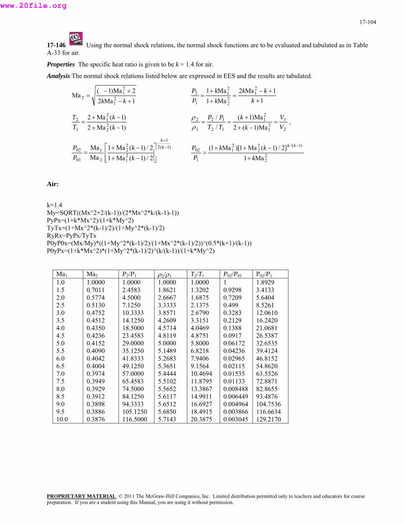
17-104
17-146 Using the normal shock relations, the normal shock functions are to be evaluated and tabulated as in Table
Analysis The normal shock relations listed below are expressed in EES and the results are tabulated.
A-33 for air.
Properties The specific heat ratio is given to be k = 1.4 for air.
1Ma22Ma)1(
Ma 21
21
2+−
+−=
kkk
1
1Ma2Ma1Ma1 2
122
21
1
2
++−
=+
+=
kkk
kk
PP
)1(Ma2)1(Ma2
22
21
1
2
−+
−+=
kk
TT
2
121
21
12
12
1
2
Ma)1(2Ma)1(
//
VV
kk
TTPP
=−+
+==
ρρ
,
)1(21
21
22
2
1
01
02
2/)1(Ma12/)1(Ma1
MaMa −
+
⎥⎥⎦
⎤⎢⎢⎣
⎡
−+
−+=
kk
kk
PP
22
)1/(22
21
1
02
Ma1]2/)1(Ma1)[Ma1(
kkk
PP kk
+
−++=
−
Air:
-1))
(k+1)/(k-1)) 0yPx=(1+k*Mx^2)*(1+My^2*(k-1)/2)^(k/(k-1))/(1+k*My^2)
k=1.4 My=SQRT((Mx^2+2/(k-1))/(2*Mx^2*k/(k-1)
/(1+k*My^2) PyPx=(1+k*Mx^2)TyTx=(1+Mx^2*(k-1)/2)/(1+My^2*(k-1)/2) RyRx=PyPx/TyTx
0yP0x=(Mx/My)*((1+My^2*(k-1)/2)/(1+Mx^2*(k-1)/2))^(0.5*PP
Ma1 Ma2 P /P2 1 ρ2/ρ1 T /T2 1 P02/P01 P /P02 1
1.0 1.5 2.0 2.5 3.0 3.5 4.0 4.5 5.0 5.5 6.0 6.5 7.0 7.5 8.0 8.5 9.0 9.5 10.0 0.3876 116.5000 5.7143 20.3875 0.003045 129.2170
1.0000 0.7011 0.5774 0.5130 0.4752 0.4512 0.4350 0.4236 0.4152 0.4090 0.4042 0.4004 0.3974 0.3949 0.3929 0.3912 0.3898 0.3886
1.0000 2.4583 4.5000 7.1250 10.3333 14.1250 18.5000 23.4583 29.0000 35.1250 41.8333 49.1250 57.0000 65.4583 74.5000 84.1250 94.3333 105.1250
1.0000 1.8621 2.6667 3.3333 3.8571 4.2609 4.5714 4.8119 5.0000 5.1489 5.2683 5.3651 5.4444 5.5102 5.5652 5.6117 5.6512 5.6850
1.0000 1.3202 1.6875 2.1375 2.6790 3.3151 4.0469 4.8751 5.8000 6.8218 7.9406 9.1564 10.4694 11.8795 13.3867 14.9911 16.6927 18.4915
1 0.92980.7209 0.499 0.3283 0.2129 0.1388 0.0917 0.06172 0.04236 0.02965 0.02115 0.01535 0.01133 0.008488 0.006449 0.004964 0.003866
1.8929 3.4133 5.6404 8.5261 12.0610 16.2420 21.0681 26.5387 32.6535 39.4124 46.8152 54.8620 63.5526 72.8871 82.8655 93.4876 104.7536 116.6634
PROPRIETARY MATERIALpreparation. If you are a student using this Manual, you are using it without permission.
. © 2011 The McGraw-Hill Companies, Inc. Limited distribution permitted only to teachers and educators for course
www.20file.org
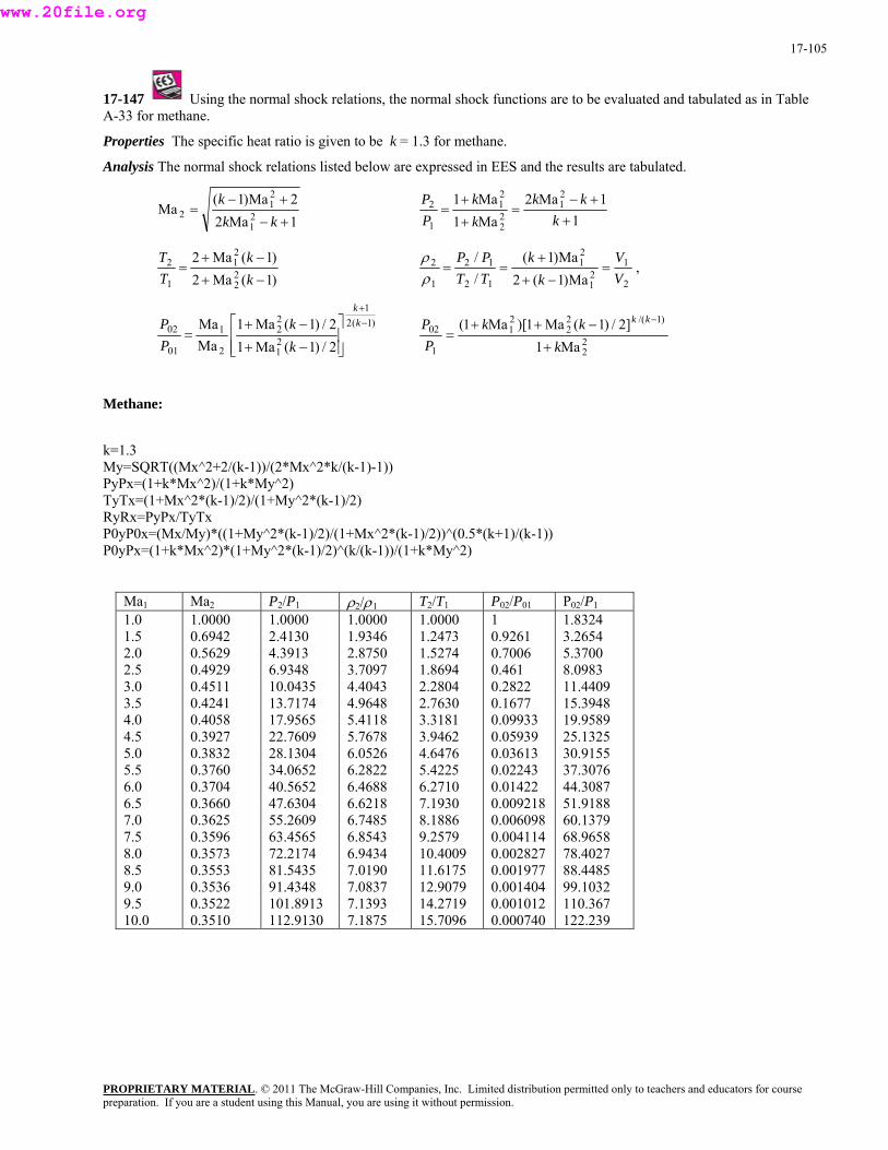
17-105
17-147 Using the normal shock relations, the normal shock functions are to be evaluated and tabulated as in Table A-33 for methane.
Properties The specific heat ratio is given to be k = 1.3 for methane.
Analysis The normal shock relations listed below are expressed in EES and the results are tabulated.
1Ma22Ma)1(
a21
2+−
=k
M 21 +− kk 1
1Ma2Ma1Ma1 2
122
21
1
2
++−
=+
+=
kkk
kk
PP
)1(Ma2)1(Ma2
2
212 −+
=k
21 −+ kT
T
2
121
21
12
12
1
2
Ma)1(2Ma)1(
//
VV
kk
TTPP
=−+
+==
ρρ
,
)1(21
21
22
2
1
01
02
2/)1(Ma12/)1(Ma1
MaMa −
+
⎥⎥⎦
⎤⎢⎢⎣
⎡
−+
−+=
kk
kk
PP
22
)1/(22
21
1
02
Ma1]2/)1(Ma1)[Ma1(
kkk
PP kk
+
−++=
−
ethane:
x^2*k/(k-1)-1))
1)/2)/(1+My^2*(k-1)/2)
(k+1)/(k-1)) 0yPx=(1+k*Mx^2)*(1+My^2*(k-1)/2)^(k/(k-1))/(1+k*My^2)
/P01
M
k=1.3 My=SQRT((Mx^2+2/(k-1))/(2*MPyPx=(1+k*Mx^2)/(1+k*My^2) TyTx=(1+Mx^2*(k-RyRx=PyPx/TyTx P0yP0x=(Mx/My)*((1+My^2*(k-1)/2)/(1+Mx^2*(k-1)/2))^(0.5*P
Ma1 Ma2 P2/P1 ρ2/ρ1 T2/T1 P02 P02/P1
1.0 1.5 2.0 2.5 3.0 3.5 4.0 4.5 5.0 5.5 6.0 6.5 7.0 7.5 8.0 8.5 9.0 9.5 10.0 0.3510 112.9130 7.1875 15.7096 0.000740 122.239
1.0000 0.6942 0.5629 0.4929 0.4511 0.4241 0.4058 0.3927 0.3832 0.3760 0.3704 0.3660 0.3625 0.3596 0.3573 0.3553 0.3536 0.3522
1.0000 2.4130 4.3913 6.9348 10.0435 13.7174 17.9565 22.7609 28.1304 34.0652 40.5652 47.6304 55.2609 63.4565 72.2174 81.5435 91.4348 101.8913
1.0000 1.9346 2.8750 3.7097 4.4043 4.9648 5.4118 5.7678 6.0526 6.2822 6.4688 6.6218 6.7485 6.8543 6.9434 7.0190 7.0837 7.1393
1.0000 1.2473 1.5274 1.8694 2.2804 2.7630 3.3181 3.9462 4.6476 5.4225 6.2710 7.1930 8.1886 9.2579 10.4009 11.6175 12.9079 14.2719
1 0.9261 0.70060.461 0.2822 0.1677 0.09933 0.05939 0.03613 0.02243 0.01422 0.009218 0.006098 0.004114 0.002827 0.001977 0.001404 0.001012
1.8324 3.2654 5.3700 8.0983 11.4409 15.3948 19.9589 25.1325 30.9155 37.3076 44.3087 51.9188 60.1379 68.9658 78.4027 88.4485 99.1032 110.367
PROPRIETARY MATERIALpreparation. If you are a student using this Manual, you are using it without permission.
. © 2011 The McGraw-Hill Companies, Inc. Limited distribution permitted only to teachers and educators for course
www.20file.org
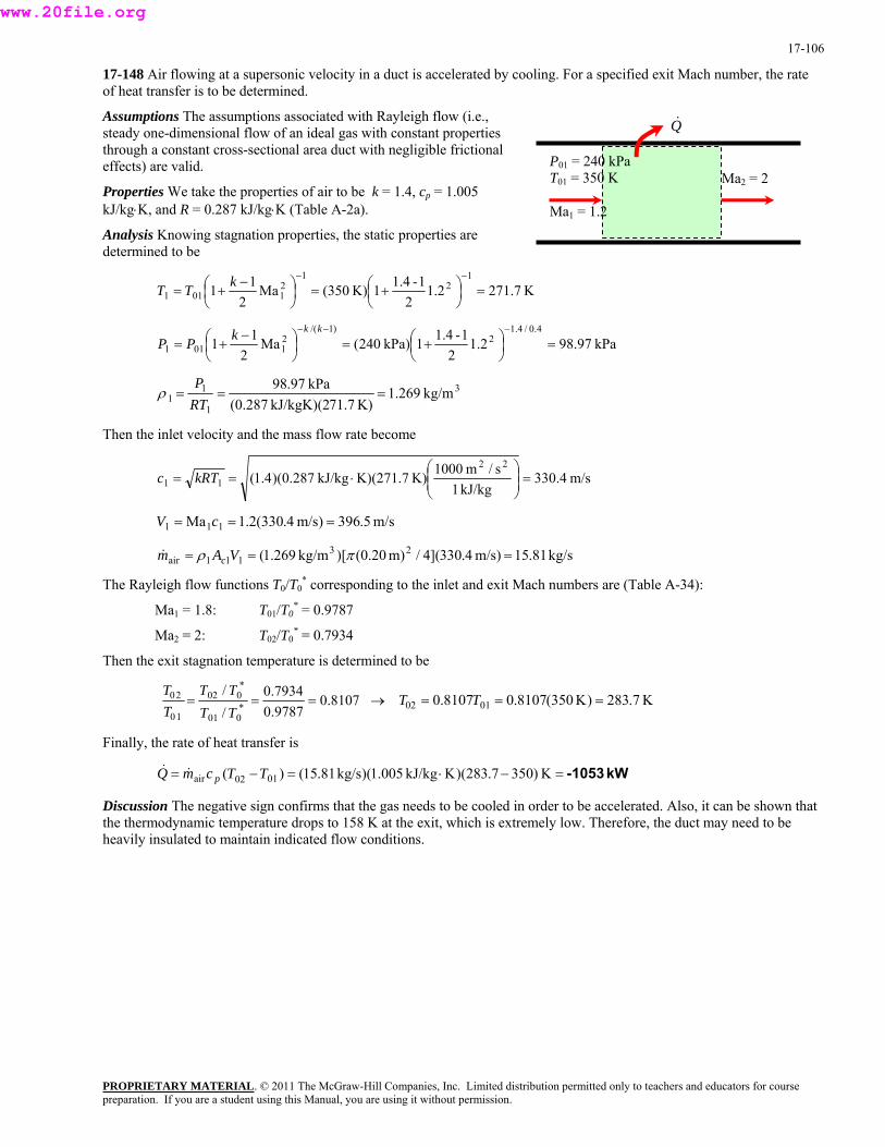
17-106
17-148 Air flowing at a supersonic velocity in a duct is accelerated by cooling. For a specified exit Mach number, the rate of heat transfer is to be determined.
Assumptions The assumptions associated with Rayleigh flow (i.e., steady one-dimensional flow of an ideal gas with constant properties through a constant cross-sectional area duct with negligible frictional effects) are valid.
Properties We take the properties of air to be k = 1.4, cp = 1.005 kJ/kg⋅K, and R = 0.287 kJ/kg⋅K (Table A-2a).
Analysis Knowing stagnation properties, the static properties are determined to be
K7.2712.12
1-1.41K)350(Ma2
111
21
21011 =⎟
⎠⎞
⎜⎝⎛ +=⎟
⎠⎞
⎜⎝⎛ −+=
−−kTT
kPa97.982.12
1-1.41 kPa)240(Ma2
114.0/4.1
2)1/(
21011 =⎟
⎠⎞
⎜⎝⎛ +=⎟
⎠⎞
⎜⎝⎛ −+=
−−− kkkPP
3
1
1 kg/m269.1 kPa97.98===
Pρ 1 K)71.7 kJ/kgK)(2(0.287RT
hen the inlet velocity and the mass flow rate become T
m/s4.330 kJ/kg1
s/m1000K)K)(271.7 kJ/kg287.0)(4.1(22
11 ⎟ =⎟⎠
⎞⎜⎜⎝
⎛⋅== kRTc
m/s5.396)m/s4.330(2.1Ma 111 === cV
(0.)[kg/m269.1( 31air = πρ Am c& kg/s81.15m/s)4.330](4/m)20 2
11 ==V
The Ray ctio ng to the inlet and exit Mach numbers are (Table A-34):
M T02/T0* = 0.7934
e is determined to be
leigh flow fun ns T0/T0* correspondi
Ma1 = 1.8: T01/T0* = 0.9787
a2 = 2:
Then the exit stagnation temperatur
PROPRIETARY MATERIAL. © 2011 The McGraw-Hill Companies, Inc. Limited distribution permitted only to teachers and educators for course
8107.09787.0/ *
00110===
TTT → K7.283)K350(8107.08107.0 0102
7934.0/ *00220 TTT
=== TT
Finally, the rate of heat transfer is
kW-1053=−⋅=−= K)3507.283)(K kJ/kg1.005)( kg/s81.15()( 0102air TTcmQ p&&
Discussion The negative sign confirms that the gas needs to be cooled in order to be accelerated. Also, it can be shown that the thermodynamic temperature drops to 158 K at the exit, which is extremely low. Therefore, the duct may need to be heavily insulated to maintain indicated flow conditions.
Q&
P01 = 240 kPa T01 = 350 K
Ma1 = 1.2
Ma2 = 2
preparation. If you are a student using this Manual, you are using it without permission.
www.20file.org

17-107
17-149 Air flowing at a subsonic velocity in a duct is accelerated by heating. The highest rate of heat transfer without affecting the inlet conditions is to be determined.
Assumptions 1 The assumptions associated with Rayleigh flow (i.e., steady one-dimensional flow of an ideal gas with constant properties through a constant cross-sectional area duct with negligible frictional effects) are valid. 2 Inlet conditions (and thus the mass flow rate) remain constant.
Properties We take the properties of air to be k = 1.4, cp = 1.005 kJ/kg⋅K, and R = 0.287 kJ/kg⋅K (Table A-2a).
PROPRIETARY MATERIAL. © 2011 The McGraw-Hill Companies, Inc. Limited distribution permitted only to teachers and educators for course
Analysis Heat transfer will stop when the flow is choked, and thus Ma2 = V2/c2 = 1. The inlet density and stagnation temperature are
3
1
11 kg/m259.4
K)0kJ/kgK)(45(0.287kPa550
===RTP
ρ
K1.4583.022 1101
⎝⎠⎝
1-1.41K)450(Ma11 22 =⎟⎠⎞
⎜⎛ +=⎟
⎞⎜⎛ −+=
kTT
Then the inlet velocity and the mass flow rate become
Q&
Ma2 = 1P1 = 550 kPa T1 = 450 K
Ma1 = 0.3
m/s2.425kJ/kg1
s/m1000K)K)(450kJ/kg287.0)(4.1(22
11 ⎟ =⎟⎠
⎞⎜⎜⎝
⎛⋅== kRTc
The Ray ding to the inlet and exit Mach numbers are
T nce Ma2 = 1)
m/s6.127)m/s2.425(3.0Ma 111 === cV
kg/s477.3m/s)6.127)(m0.08)(0.08kg/m259.4( 23111air =×== VAm cρ&
leigh flow functions correspon
02/T0* = 1 (si
3469.0)3.04.11(
]3.0)14.1(2[3.0)14.1()Ma1(
]Ma)1 2−(2[Ma)1(22
22
221
121
*0
01 =×+
−++=
+
++=
kkk
TT
Ther
efore,
3469.01
//
*00110
*00220 ==
TTTT
TT
→ K 7.13203469.0/)K1.458(3469.0/0102 === TT
Then the rate of heat transfer becomes
=−⋅=−= K)1.4587.1320)(KkJ/kg005.1)(kg/s477.3()( TTcmQ && kW30140102air p
Discussion It can also be shown that T2 = 1101 K, which is the highest thermodynamic temperature that can be attained under stated conditions. If more heat is transferred, the additional temperature rise will cause the mass flow rate to decrease. We can also solve this problem using the Rayleigh function values listed in Table A-34.
preparation. If you are a student using this Manual, you are using it without permission.
www.20file.org

17-108
17-150 Helium flowing at a subsonic velocity in a duct is accelerated by heating. The highest rate of heat transfer without affecting the inlet conditions is to be determined.
Assumptions 1 The assumptions associated with Rayleigh flow (i.e., steady one-dimensional flow of an ideal gas with constant properties through a constant cross-sectional area duct with negligible frictional effects) are valid. 2 Inlet conditions (and thus the mass flow rate) remain constant.
Properties We take the properties of helium to be k = 1.667, cp = 5.193 kJ/kg⋅K, and R = 2.077 kJ/kg⋅K (Table A-2a).
Q&
Ma2 = 1P1 = 550 kPa T1 = 450 K
Ma1 = 0.3
Analysis Heat transfer will stop when the flow is choked, and thus Ma2 = V2/c2 = 1. The inlet density and stagnation temperature are
3
1
11 kg/m5885.0
K)0kJ/kgK)(45(2.077kPa550
===RTP
ρ
K5.4633.02
1K)450(Ma2
1 1101 ⎜⎝
⎟⎠
⎜⎝
TT 1-1.6671 22 =⎟⎠⎞⎛ +=⎞⎛ −
+=k
hen the i et velocity and the mass flow rate become T nl
m/s1248kJ/kg1
s/m1000K)K)(450kJ/kg077.2)(667.1(22
11 ⎟ =⎟⎠
⎞⎜⎜⎝
⎛⋅== kRTc
The Rayleigh flow functions corresponding to the inlet and exit Mach numbers are
/T0* = 1 (since Ma2 = 1)
m/s5.374)m/s1248(3.0Ma === cV 111
kg/s410.1m/s)5.374)(m0.08)(0.08kg/m5885.0( 23111air =×== VAm cρ&
T02
3739.0)3.0667.11(
]3.0)1667.1(2[33.0)1667.1()Ma1( 22
1*
0 + kT]Ma)1(2[
22
2221
21 =
×+
++=
−+=
kT
Therefore,
Ma)1(01 −+k
3739.01
//
*001
*002
10
20 ==TTTT
TT
→ K 8.12393739.0/)K5.463(3739.0/0102 === TT
Then the rate of heat transfer becomes
Discussion It can also be shown that T2 = 930 K, which is the highest thermodynamic temperature that can be attained under stated conditions. If more heat is transferred, the additional temperature rise will cause the mass flow rate to decrease. Also, in the solution of this problem, we cannot use the values of Table A-34 since they are based on k = 1.4.
kW 5685=−⋅=−= K)5.4638.1239)(KkJ/kg193.5)(kg/s410.1()( 0102air TTcmQ p&&
PROPRIETARY MATERIALpreparation. If you are a student using this Manual, you are using it without permission.
. © 2011 The McGraw-Hill Companies, Inc. Limited distribution permitted only to teachers and educators for course
www.20file.org
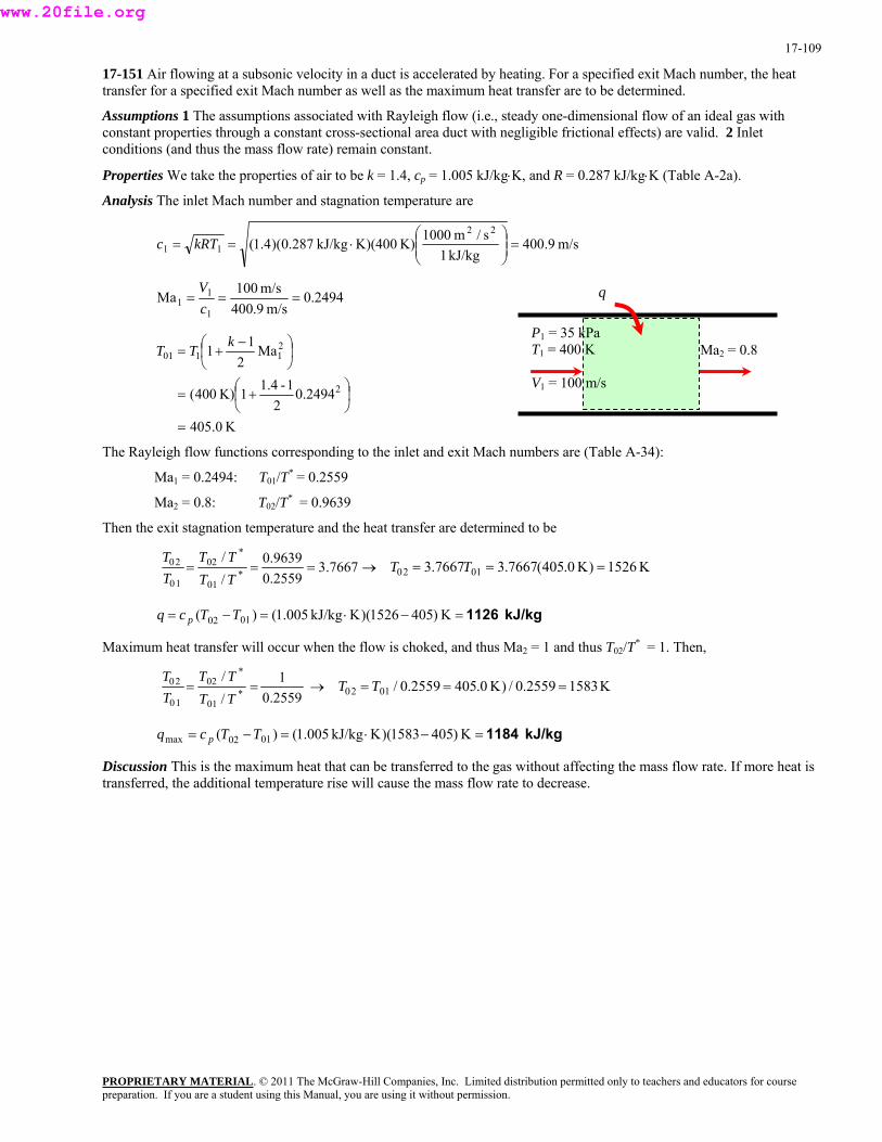
17-109
17-151 Air flowing at a subsonic velocity in a duct is accelerated by heating. For a specified exit Mach number, the heat transfer for a specified exit Mach number as well as the maximum heat transfer are to be determined.
Assumptions 1 The assumptions associated with Rayleigh flow (i.e., steady one-dimensional flow of an ideal gas with constant properties through a constant cross-sectional area duct with negligible frictional effects) are valid. 2 Inlet conditions (and thus the mass flow rate) remain constant.
Properties We take the properties of air to be k = 1.4, cp = 1.005 kJ/kg⋅K, and R = 0.287 kJ/kg⋅K (Table A-2a).
Analysis The inlet Mach number and stagnation temperature are
m/s9.400 kJ/kg1
s/m1000K)K)(400 kJ/kg287.0)(4.1(22
11 ⎟ =⎟⎠
⎞⎜⎜⎝
⎛⋅== kRTc
2494.0m/s9.400
m/s100Ma1
11 ===
cV
PROPRIETARY MATERIAL. © 2011 The McGraw-Hill Companies, Inc. Limited distribution permitted only to teachers and educators for course
K0.405=
2494.02
1-1.41K)400(
Ma2
11
2
21101
⎟⎠⎞
⎜⎝⎛ +=
⎟⎠⎞
⎜⎝⎛ −+=
kTT
The Ray e inlet and exit Mach numbers are (Table A-34):
Then the exit stagnation temperature and the heat transfer are determ to be
q
Ma2 = 0.8P1 = 35 kPa T1 = 400 K
V1 = 100 m/s
leigh flow functions corresponding to th
Ma1 = 0.2494: T01/T* = 0.2559
Ma2 = 0.8: T02/T* = 0.9639
ined
7667.32559.0/ *
0110 TTT 01209639.0/ *
022 ===TT
→0T K1526)K0.405(7667.37667.3 === TT
=−= K)4051526)(Kg1.00()( 0102 TTcq p
Maximum heat transfer will occur when the flow is choked, and thus Ma2 = 1 and thus T02/T* = 1. Then,
kJ/kg 1126=−⋅kJ/k5
2559.0/ *0110 TTT 0120
1/ *0220 ==
TTT→ K15832559.0/)K0.4052559.0/ === TT
Discussion This is the maximum heat that can be transferred to the gas without affecting the mass flow rate. If more heat is transferred, the additional temperature rise will cause the mass flow rate to decrease.
kJ/kg 1184=−⋅=−= K)4051583)(K kJ/kg1.005()( 0102max TTcq p
preparation. If you are a student using this Manual, you are using it without permission.
www.20file.org
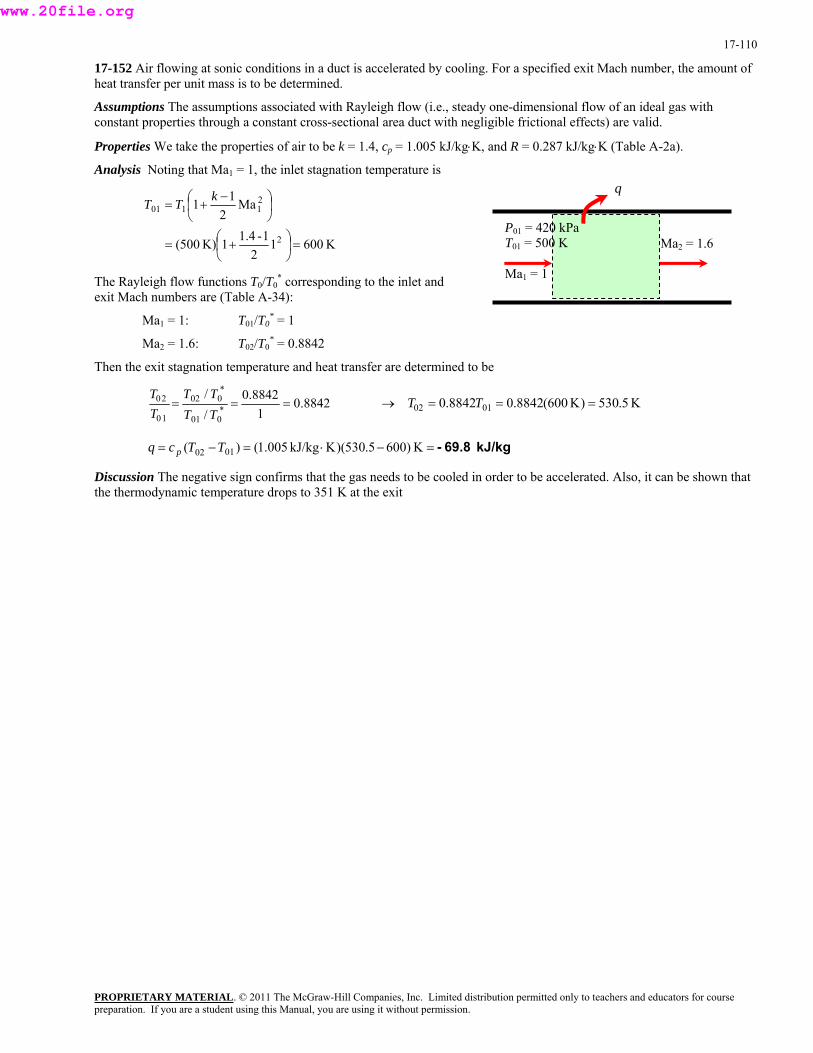
17-110
17-152 Air flowing at sonic conditions in a duct is accelerated by cooling. For a specified exit Mach number, the amount of heat transfer per unit mass is to be determined.
Assumptions The assumptions associated with Rayleigh flow (i.e., steady one-dimensional flow of an ideal gas with constant properties through a constant cross-sectional area duct with negligible frictional effects) are valid.
Properties We take the properties of air to be k = 1.4, cp = 1.005 kJ/kg⋅K, and R = 0.287 kJ/kg⋅K (Table A-2a).
Analysis Noting that Ma1 = 1, the inlet stagnation temperature is
K60012
500( =⎟⎠
=1-1.4
Ma2
1
2
1101
⎞⎛
⎟⎠
⎜⎝+= TT
1K)
1 2
⎜⎝+
⎞⎛ −k
The Ray io ding to the inlet and
Ma1 = 1: T01/T0* = 1
Ma2 = 1.6: T02/T0* = 0.8842
Then the exit stagnation temperature and heat transfer are determined to be
leigh flow funct ns T0/T0* correspon
exit Mach numbers are (Table A-34):
8842.01/ *
00110===
TTT → K5.530)K600(8842.08842.0 0102 =
8842.0/ *00220 TTT
== TT
kJ/kg 69.8-=−⋅=−= K)6005.530)(K kJ/kg1.005()( 0102 TTcq p
Discussion The negative sign confirms that the gas needs to be cooled in order to be accelerated. Also, it can be shown that the thermodynamic temperature drops to 351 K at the exit
q
P01 = 420 kPa T01 = 500 K
Ma1 = 1
Ma2 = 1.6
PROPRIETARY MATERIALpreparation. If you are a student using this Manual, you are using it without permission.
. © 2011 The McGraw-Hill Companies, Inc. Limited distribution permitted only to teachers and educators for course
www.20file.org

17-111
17-153 Saturated steam enters a converging-diverging nozzle with a low velocity. The throat area, exit velocity, mass flow rate, and exit Mach number are to be determined for isentropic and 90 percent efficient nozzle cases.
Assumptions 1 Flow through the nozzle is steady and one-dimensional. 2 The nozzle is adiabatic.
Analysis (a) The inlet stagnation properties in this case are identical to the inlet properties since the inlet velocity is negligible. Thus h10 = h1. At the inlet,
1 Steam 2tVi ≈ 0
a) ηN = 1b) η
00%92%
4
kJ/kg2603.5=1917.10.90+16.878)( MPa75.1@1
⋅N =1
5.987=0033.40.90+3844.2)( MPa75.1@11 ×=+=
PROPRIETARY MATERIAL. © 2011 The McGraw-Hill Companies, Inc. Limited distribution permitted only to teachers and educators for course
KkJ/kg
×=+= fgf hxhh
At the exit, P2 = 1.2 MPa and s2 = s2s = s1 = 5.9874 kJ/kg·K. Thus,
4
kJ/kg4.25374.19858759.033.798
8759.0)3058.4(2159.29874.5
3
22
2222
=×+=+=
=→+=→+=
fgf
fgf
hxhh
xxsxss
hen the e t velocity is determined from the steady-flow energy balance to be
fgf sxss
1431.0)001138.016326.0(8759.0001138.022 =−×+=+= fgf x vvv kg/m
T xi
20
22
21
22
12
22
2
2V11
VVhhVhh −+−=→+=+
Solving for V2,
m/s363.7⎟ =⎟⎠
⎞⎜⎜⎝
⎛−=−= 5.2603(2)(2 hhV
kJ/kg1s/m1000kg2537.4)kJ/
22
212
The mass flow rate is determined from
kg/s6.35=m/s)7.363)(m1025(kg/m14314.0
11 24322
2
−×== VAmv
&
The velocity of sound at the exit of the nozzle is determined from 2/12/1
)/1(P
rPc ⎟⎟
⎞⎜⎜⎛∆∆
≅⎟⎞
⎜⎛
v∂∂
The specific volume of steam at s2 = 5.9874 kJ/kg·K and at pressures just below and just above the specified pressure (1.1 nd 1.3 MPa) are determined to be 0.1547 nd 0.1333 m3/kg. Substituting,
=ss ⎠⎝⎠⎝
a a
( ) m/s9.438mkPa1
s/m100011
kPa1100130032 =⎟
⎟⎞
⎜⎜⎛
⋅⎞⎛−
=ckg/m
1547.01333.0
22
3 ⎠⎝⎟⎠
⎜⎝
−
ber becomes Then the exit Mach num
0.829===m/s9.438m/s7.363Ma
2
22 c
V
he steam saturated, and thus the critical pressure which occurs at the throat is taken to be T is
MPa008.175.1576.0576.0* 01 =×=×== PPPt
hen at the throat, T
KkJ/kg9874.5 andMPa008.1 1 ⋅=== ssP tt
hus, T
preparation. If you are a student using this Manual, you are using it without permission.
www.20file.org
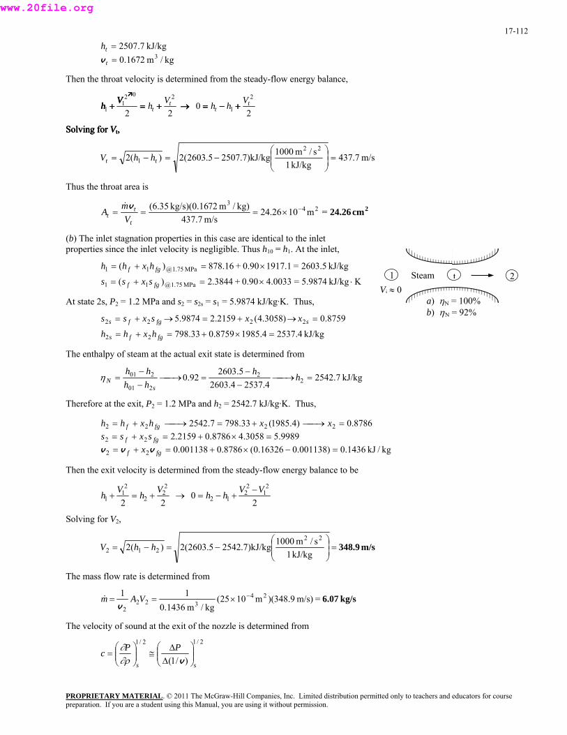
17-112
kg/m1672.0kJ/kg7.2507
3==
t
thv
Then the throat velocity is determined from the steady-flow energy balance,
20
22
2202
11 t
tt
tVhhVhVVVhhh +++−−−===→→→+++===1 +++
SSSooolllvvviiinnnggg fffooorrr VVVttt,,,
m/s7.437kJ/kg1
s/m1000.7)kJ/kg25075.2603(2)(222
1 ⎟ =⎟⎠
⎞⎜⎜⎝
⎛−=−= tt hhV
hus the throat area is T
2cm24.26=m1026.24kg)/m72kg/s)(0.1635.6( 243
−×=== tt
mA
v&
m/s437.7tV
) The inlet stagnation properties in this case are identical to the inlet velocity is negligible. Thus h10 = h1. At the inlet,
(bproperties since the inlet
Vi ≈ 0 Steam 21 t
a) ηN = 100%b) ηN = 92%
KkJ/kg5.9874=0033.40.90+3844.2)(MPa75.1@11
⋅×=+=
kJ/kg2603.5=1917.10.90+16.878)(
MPa75.1@11
×=+=
fgf
hxhh
1.2 MPa and s2 = s2s = s1 = 5.9874 kJ/kg·K. Thus,
fgf
sxss
At state 2s, P2 =
kJ/kg4.25374.19858759.033.798
8759.0)3058.4(2159.29874.5
22
2222
=×+=+=
=→+=→+=
fgfs
sfgfs
hxhh
xxsxss
The enthalpy of steam at the actual exit state is determined from
kJ/kg7.25424.25374.2603
5.260392.0 2
2
201
201 =⎯→⎯−−
=⎯→⎯−− hh
= hh
hh sη
2 2 ,
254
22
2222
=×+=+==⎯→⎯+=⎯→⎯+=
fgf
fgf
sxssxxhxhh
be
N
Therefore at the exit, P = 1.2 MPa and h = 2542.7 kJ/kg·K. Thus
9989.53058.48786.02159.28786.0)4.1985(33.7987.2
kg/kJ1436.0)001138.016326.0(8786.0001138.022 =−×+=+= fgf x vvv
velocity is determined from the steady-flow energy balance toThen the exit
20
222
21
1 hVhVh =→+=+2
12
212
22 VVh −+−
olving for V2, S
m/s348.9=⎟⎟⎞
⎜⎜⎛
−=−=s/m1000.7)kJ/kg25425.2603(2)(2
22
212 hhV⎠⎝ kJ/kg1
The mass flow rate is determined from
kg/s6.07=m/s)9.348)(m1025(11×== VAm&
kg/m1436.024
3222
−
v
The velocity of sound at the exit of the nozzle is determined from
PROPRIETARY MATERIAL. © 2011 The McGraw-Hill Companies, Inc. Limited distribution permitted only to teachers and educators for course
2/12/1PP ⎞⎛ ∆⎞⎛ ∂
)/1( ss
c ⎟⎟⎠
⎜⎜⎝ ∆
⎟ ≅⎟⎠
⎜⎜⎝
=v∂ρ
preparation. If you are a student using this Manual, you are using it without permission.
www.20file.org

17-113
PROPRIETARY MATERIAL. © 2011 The McGraw-Hill Companies, Inc. Limited distribution permitted only to teachers and educators for course
The specific volume of steam at s2 = 5.9989 kJ/kg·K and at pressures just below and just above the specified pressure (1.1 nd 1.3 MPa) are determined to be 0.1551 and 0.13 7 m3/kg. Substituting, a 3
( ) m/s7.439mkPa1
s/m1000
kg/m1551.01
1337.01
kPa110013003
22
32 ⎟ =⎟
⎠
⎞⎜⎜⎝
⎛
⋅⎟⎠⎞
⎜⎝⎛ −
−
Then the exit Mach number becomes
=c
0.793===m/s7.439m/s9.348Ma
2
22 c
V
The steam is saturated, and thus the critical pressure which occurs at the throat is taken to be
MPa008.175.1576.0576.0* 01 =×=×== PPPt
At state 2ts, Pts = 1.008 MPa and sts = s1 = 5.9874 kJ/kg·K. Thus, hts = 2507.7 kJ/kg.
The actual enthalpy of steam at the throat is
kJ/kg4.25157.25075.2603
5.260392.0
01
01 =⎯→⎯−−
=⎯→⎯−−
= tt
ts
tN h
hhhhh
η
kJ/kg.4.2515 and MPa008.12 == thPTherefore at the throat, Thus, vt = 0.1679 m3/kg.
Then the throat velocity is determined from the steady-flow energy balance,
20
22
2
1
2021
1t
tt
tVhhVhVh +−=→+=+
Solving for Vt,
m/s9.419kJ/kg1
s/m1000.4)kJ/kg25155.2603(2)(222
1 ⎟ =⎟⎠
⎞⎜⎜⎝
⎛−=−= tt hhV
Thus the throat area is
2cm24.30=m1030.24m/s419.9
kg)/m79kg/s)(0.1607.6( 243
−×===t
tt V
mA
v&
preparation. If you are a student using this Manual, you are using it without permission.
www.20file.org

17-114
Fundamentals of Engineering (FE) Exam Problems
17-154 An aircraft is cruising in still air at 5°C at a velocity of 400 m/s. The air temperature at the nose of the aircraft where stagnation occurs is
(a) 5°C (b) 25°C (c) 55°C (d) 80°C (e) 85°C
Answer (e) 85°C
Solution Solved by EES Software. Solutions can be verified by copying-and-pasting the following lines on a blank EES screen. (Similar problems and their solutions can be obtained easily by modifying numerical values).
k=1.4 Cp=1.005 "kJ/kg.K" T1=5 "C" Vel1= 400 "m/s" T1_stag=T1+Vel1^2/(2*Cp*1000) "Some Wrong Solutions with Common Mistakes:" W1_Tstag=T1 "Assuming temperature rise" W2_Tstag=Vel1^2/(2*Cp*1000) "Using just the dynamic temperature" W3_Tstag=T1+Vel1^2/(Cp*1000) "Not using the factor 2"
17-155 Air is flowing in a wind tunnel at 25°C, 80 kPa, and 250 m/s. The stagnation pressure at a probe inserted into the flow stream is
(a) 87 kPa (b) 93 kPa (c) 113 kPa (d) 119 kPa (e) 125 kPa
Answer (c) 113 kPa
Solution Solved by EES Software. Solutions can be verified by copying-and-pasting the following lines on a blank EES screen. (Similar problems and their solutions can be obtained easily by modifying numerical values).
k=1.4 Cp=1.005 "kJ/kg.K" T1=25 "K" P1=80 "kPa" Vel1= 250 "m/s" T1_stag=(T1+273)+Vel1^2/(2*Cp*1000) "C" T1_stag/(T1+273)=(P1_stag/P1)^((k-1)/k)
"Some Wrong Solutions with Common Mistakes:" T11_stag/T1=(W1_P1stag/P1)^((k-1)/k); T11_stag=T1+Vel1^2/(2*Cp*1000) "Using deg. C for temperatures" T12_stag/(T1+273)=(W2_P1stag/P1)^((k-1)/k); T12_stag=(T1+273)+Vel1^2/(Cp*1000) "Not using the factor 2" T13_stag/(T1+273)=(W3_P1stag/P1)^(k-1); T13_stag=(T1+273)+Vel1^2/(2*Cp*1000) "Using wrong isentropic relation"
PROPRIETARY MATERIALpreparation. If you are a student using this Manual, you are using it without permission.
. © 2011 The McGraw-Hill Companies, Inc. Limited distribution permitted only to teachers and educators for course
www.20file.org
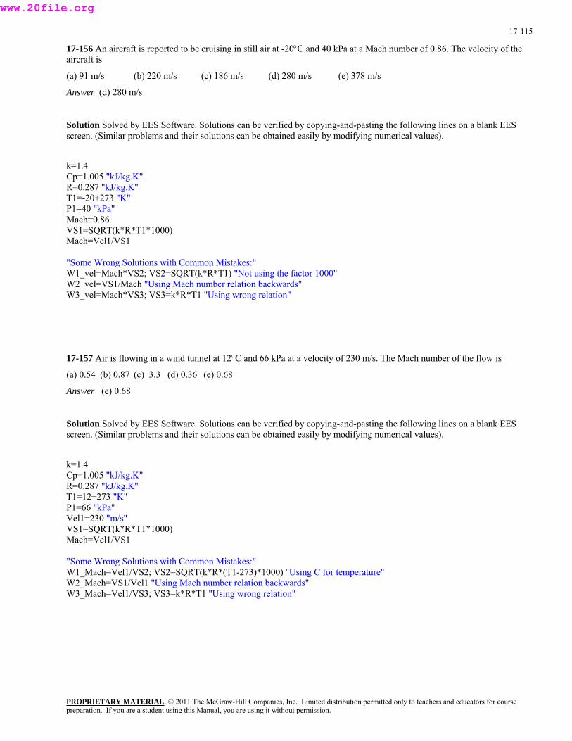
17-115
17-156 An aircraft is reported to be cruising in still air at -20°C and 40 kPa at a Mach number of 0.86. The velocity of the aircraft is
(a) 91 m/s (b) 220 m/s (c) 186 m/s (d) 280 m/s (e) 378 m/s
Answer (d) 280 m/s
Solution Solved by EES Software. Solutions can be verified by copying-and-pasting the following lines on a blank EES screen. (Similar problems and their solutions can be obtained easily by modifying numerical values).
k=1.4 Cp=1.005 "kJ/kg.K" R=0.287 "kJ/kg.K" T1=-20+273 "K" P1=40 "kPa" Mach=0.86 VS1=SQRT(k*R*T1*1000) Mach=Vel1/VS1
"Some Wrong Solutions with Common Mistakes:" W1_vel=Mach*VS2; VS2=SQRT(k*R*T1) "Not using the factor 1000" W2_vel=VS1/Mach "Using Mach number relation backwards" W3_vel=Mach*VS3; VS3=k*R*T1 "Using wrong relation"
17-157 Air is flowing in a wind tunnel at 12°C and 66 kPa at a velocity of 230 m/s. The Mach number of the flow is
(a) 0.54 (b) 0.87 (c) 3.3 (d) 0.36 (e) 0.68
Answer (e) 0.68
Solution Solved by EES Software. Solutions can be verified by copying-and-pasting the following lines on a blank EES screen. (Similar problems and their solutions can be obtained easily by modifying numerical values).
k=1.4 Cp=1.005 "kJ/kg.K" R=0.287 "kJ/kg.K" T1=12+273 "K" P1=66 "kPa" Vel1=230 "m/s" VS1=SQRT(k*R*T1*1000) Mach=Vel1/VS1
"Some Wrong Solutions with Common Mistakes:" W1_Mach=Vel1/VS2; VS2=SQRT(k*R*(T1-273)*1000) "Using C for temperature" W2_Mach=VS1/Vel1 "Using Mach number relation backwards" W3_Mach=Vel1/VS3; VS3=k*R*T1 "Using wrong relation"
PROPRIETARY MATERIALpreparation. If you are a student using this Manual, you are using it without permission.
. © 2011 The McGraw-Hill Companies, Inc. Limited distribution permitted only to teachers and educators for course
www.20file.org
17-116
17-158 Consider a converging nozzle with a low velocity at the inlet and sonic velocity at the exit plane. Now the nozzle exit diameter is reduced by half while the nozzle inlet temperature and pressure are maintained the same. The nozzle exit velocity will
(a) remain the same. (b) double. (c) quadruple. (d) go down by half. (e) go down to one-fourth.
Answer (a) remain the same.
17-159 Air is approaching a converging-diverging nozzle with a low velocity at 12°C and 200 kPa, and it leaves the nozzle at a supersonic velocity. The velocity of air at the throat of the nozzle is
(a) 338 m/s (b) 309 m/s (c) 280 m/s (d) 256 m/s (e) 95 m/s
Answer (b) 309 m/s
Solution Solved by EES Software. Solutions can be verified by copying-and-pasting the following lines on a blank EES screen. (Similar problems and their solutions can be obtained easily by modifying numerical values).
k=1.4 Cp=1.005 "kJ/kg.K" R=0.287 "kJ/kg.K" "Properties at the inlet" T1=12+273 "K" P1=200 "kPa" Vel1=0 "m/s" To=T1 "since velocity is zero" Po=P1 "Throat properties" T_throat=2*To/(k+1) P_throat=Po*(2/(k+1))^(k/(k-1)) "The velocity at the throat is the velocity of sound," V_throat=SQRT(k*R*T_throat*1000)
"Some Wrong Solutions with Common Mistakes:" W1_Vthroat=SQRT(k*R*T1*1000) "Using T1 for temperature" W2_Vthroat=SQRT(k*R*T2_throat*1000); T2_throat=2*(To-273)/(k+1) "Using C for temperature" W3_Vthroat=k*R*T_throat "Using wrong relation"
PROPRIETARY MATERIALpreparation. If you are a student using this Manual, you are using it without permission.
. © 2011 The McGraw-Hill Companies, Inc. Limited distribution permitted only to teachers and educators for course
www.20file.org
17-117
17-160 Argon gas is approaching a converging-diverging nozzle with a low velocity at 20°C and 120 kPa, and it leaves the nozzle at a supersonic velocity. If the cross-sectional area of the throat is 0.015 m2, the mass flow rate of argon through the nozzle is
(a) 0.41 kg/s (b) 3.4 kg/s (c) 5.3 kg/s (d) 17 kg/s (e) 22 kg/s
Answer (c) 5.3 kg/s
Solution Solved by EES Software. Solutions can be verified by copying-and-pasting the following lines on a blank EES screen. (Similar problems and their solutions can be obtained easily by modifying numerical values).
k=1.667 Cp=0.5203 "kJ/kg.K" R=0.2081 "kJ/kg.K" A=0.015 "m^2" "Properties at the inlet" T1=20+273 "K" P1=120 "kPa" Vel1=0 "m/s" To=T1 "since velocity is zero" Po=P1 "Throat properties" T_throat=2*To/(k+1) P_throat=Po*(2/(k+1))^(k/(k-1)) rho_throat=P_throat/(R*T_throat) "The velocity at the throat is the velocity of sound," V_throat=SQRT(k*R*T_throat*1000) m=rho_throat*A*V_throat
"Some Wrong Solutions with Common Mistakes:" W1_mass=rho_throat*A*V1_throat; V1_throat=SQRT(k*R*T1_throat*1000); T1_throat=2*(To-273)/(k+1) "Using C for temp" W2_mass=rho2_throat*A*V_throat; rho2_throat=P1/(R*T1) "Using density at inlet"
PROPRIETARY MATERIALpreparation. If you are a student using this Manual, you are using it without permission.
. © 2011 The McGraw-Hill Companies, Inc. Limited distribution permitted only to teachers and educators for course
www.20file.org
17-118
17-161 Carbon dioxide enters a converging-diverging nozzle at 60 m/s, 310°C, and 300 kPa, and it leaves the nozzle at a supersonic velocity. The velocity of carbon dioxide at the throat of the nozzle is
(a) 125 m/s (b) 225 m/s (c) 312 m/s (d) 353 m/s (e) 377 m/s
Answer (d) 353 m/s
Solution Solved by EES Software. Solutions can be verified by copying-and-pasting the following lines on a blank EES screen. (Similar problems and their solutions can be obtained easily by modifying numerical values).
k=1.289 Cp=0.846 "kJ/kg.K" R=0.1889 "kJ/kg.K" "Properties at the inlet" T1=310+273 "K" P1=300 "kPa" Vel1=60 "m/s" To=T1+Vel1^2/(2*Cp*1000) To/T1=(Po/P1)^((k-1)/k) "Throat properties" T_throat=2*To/(k+1) P_throat=Po*(2/(k+1))^(k/(k-1)) "The velocity at the throat is the velocity of sound," V_throat=SQRT(k*R*T_throat*1000)
"Some Wrong Solutions with Common Mistakes:" W1_Vthroat=SQRT(k*R*T1*1000) "Using T1 for temperature" W2_Vthroat=SQRT(k*R*T2_throat*1000); T2_throat=2*(T_throat-273)/(k+1) "Using C for temperature" W3_Vthroat=k*R*T_throat "Using wrong relation"
17-162 Consider gas flow through a converging-diverging nozzle. Of the five statements below, select the one that is incorrect:
(a) The fluid velocity at the throat can never exceed the speed of sound.
(b) If the fluid velocity at the throat is below the speed of sound, the diversion section will act like a diffuser.
(c) If the fluid enters the diverging section with a Mach number greater than one, the flow at the nozzle exit will be supersonic.
(d) There will be no flow through the nozzle if the back pressure equals the stagnation pressure.
(e) The fluid velocity decreases, the entropy increases, and stagnation enthalpy remains constant during flow through a normal shock.
Answer (c) If the fluid enters the diverging section with a Mach number greater than one, the flow at the nozzle exit will be supersonic.
PROPRIETARY MATERIALpreparation. If you are a student using this Manual, you are using it without permission.
. © 2011 The McGraw-Hill Companies, Inc. Limited distribution permitted only to teachers and educators for course
www.20file.org

17-119
17-163 Combustion gases with k = 1.33 enter a converging nozzle at stagnation temperature and pressure of 350°C and 400 kPa, and are discharged into the atmospheric air at 20°C and 100 kPa. The lowest pressure that will occur within the nozzle is
(a) 13 kPa (b) 100 kPa (c) 216 kPa (d) 290 kPa (e) 315 kPa
Answer (c) 216 kPa
Solution Solved by EES Software. Solutions can be verified by copying-and-pasting the following lines on a blank EES screen. (Similar problems and their solutions can be obtained easily by modifying numerical values).
k=1.33 Po=400 "kPa" "The critical pressure is" P_throat=Po*(2/(k+1))^(k/(k-1)) "The lowest pressure that will occur in the nozzle is the higher of the critical or atmospheric pressure."
"Some Wrong Solutions with Common Mistakes:" W2_Pthroat=Po*(1/(k+1))^(k/(k-1)) "Using wrong relation" W3_Pthroat=100 "Assuming atmospheric pressure"
17-164 ··· 17-166 Design and Essay Problems
PROPRIETARY MATERIALpreparation. If you are a student using this Manual, you are using it without permission.
. © 2011 The McGraw-Hill Companies, Inc. Limited distribution permitted only to teachers and educators for course
www.20file.org