CAREY - FOSTER'S BRIDGE - Magadh University
15
CAREY - FOSTER'S BRIDGE Dr. ANANT KUMAR SINHA ASSOCIATE PROFESSOR DEPTT. OF PHYSICS A.M. COLLEGE, GAYA
-
Upload
khangminh22 -
Category
Documents
-
view
1 -
download
0
Transcript of CAREY - FOSTER'S BRIDGE - Magadh University

CAREY - FOSTER'S BRIDGE
Dr. ANANT KUMAR SINHAASSOCIATE PROFESSORDEPTT. OF PHYSICSA.M. COLLEGE, GAYA

AimTo find low resistance by carey foster’s bridge after calibrating the bridge wire

Apparatus
• Carey FostersBridge
• Two equalresistance
• Fractional resistancebox
• Acell containingwires
• SensitiveGalvanometer
• Jockey andKey

Introduction
The Carey Foster’s bridge is an electrical circuit that can be used tomeasure very small resistances. It works on the same principle asWheatstone’s bridge, which consists of four resistances, P, Q,Rand S that are connected to each other as shown in the circuitdiagram in Figure 1. In this circuit, G is a galvanometer, E is a leadaccumulator, and K1 and K are the galvanometer key and thebattery key respectively. If the values of the resistances areadjusted so that no current flows through the galvanometer, then ifany three of the resistances P, Q, R and S are known, the fourth unknown resistance can be determined by using the relationship

You may be familiar with the post office box and the meter bridge, whichalso work on the same principle as Wheatstone’s bridge. In the meterbridge, two of the resistors, R and S, say, are replaced by a one meterlength of resistance wire, with uniform cross-sectional area fixed on ameter scale. Point D is an electrical contact that can be moved along thewire, thus varying the magnitudes of resistances R and S. The CareyFoster bridge is a modified form of the meter bridge in which the effectivelength of the wire is considerably increased by connecting a resistance inseries with each end of the wire. This increases the accuracy of the bridge.While performing this experiment, you will balance the Carey Fosterbridge by a null deflection method using a galvanometer. You will firstdetermine the resistance per unit length of the material used for the bridge wire, and will then determine the value of an unknown resistance.
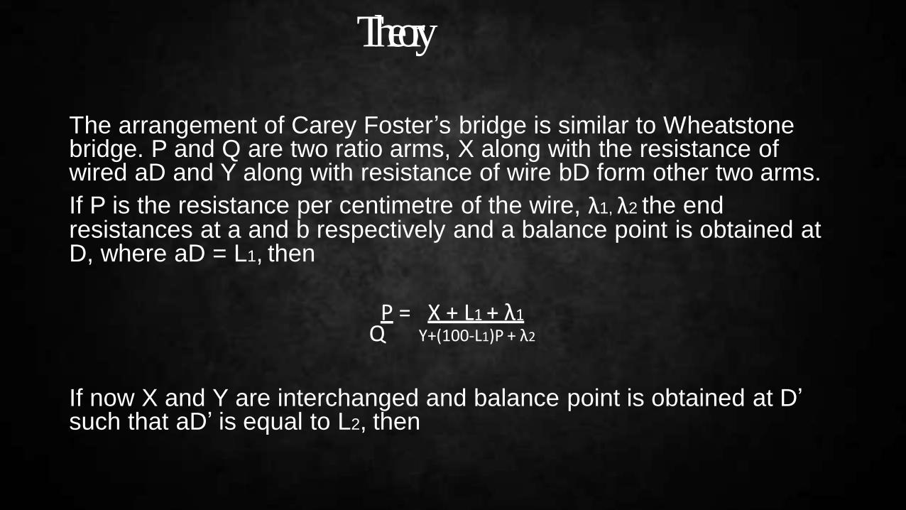
Theory
The arrangement of Carey Foster’s bridge is similar to Wheatstone bridge. P and Q are two ratio arms, X along with the resistance of wired aD and Y along with resistance of wire bD form other two arms.
If P is the resistance per centimetre of the wire, λ1, λ2 the end resistances at a and b respectively and a balance point is obtained at D, where aD = L1, then
P = X + L1 + λ1 Q Y+(100-L1)P + λ2
If now X and Y are interchanged and balance point is obtained at D’ such that aD’ is equal to L2, then

P = Y + L1 + λ1
Q Y+(100-L2)P + λ2
Y + (100-L1)P + λ2 = X + (100-L2)P + λ2
Y – X = (L1 - L2)PX = Y – (L1 - L2)P
Thus, the difference between the two resistances is equal to resistance of the bridge wire between the two balance points. Further the above relation is free from the end correction of the total length of the bridge wire.

CircuitConnections

Procedure
Connections:-
1)Draw diagram showing the scheme of connection. Mark the gaps 1, 2, 3, 4 on the bridge.
2)Clean the ends of the connecting wires and thick copper strips with a sand paper.
3)Connect two equal resistance P and Q in the inner gaps 2 and 3. If P and Q are two resistance boxes, take out 5 ohm plug from either and make all other plugs tight. Connect the thick copper strip X in the gap 1 and the fractional resistance box by means of thick copper rods in gap 4. Connect one terminal of the Galvanometer to the central terminal of the Galvanometer to the central terminal B and the other to a Jockey J. Connect the cell through a key K between the points A and C.

To test the connections:- Make the plugs of the fractional resistance boxtight by giving to each plug a slight twist. Put in the key K and Touch theJockey on the wire at the end a. Note the direction of deflection. Nowtouch the Jockey at the end b. If the direction of deflection is reserved the connections are correct.
To Find P, the resistance per centimetre of the wire: -1) Without taking out any plug from the fractional resistance box,
adjust the position of the Jockey to obtain a balance point and note thereading. Take out the key K. Interchange X and Y, put in the key K and obtain the balance point again. Note the reading.
The difference in the two positions give us the resistance of the loadwires connected to the fractional resistance box (Y) and the resistance ofthe plugs, brass blocks etc. This shift is known as the correction and mustbe subtracted from the shift obtained in the subsequent readings to get the correct shift. Let this be denoted by 𝛿L

Take out the key K and again interchange X and Y.
1) Take out 0.1 ohm plug from the fractional resistance box Y and after putting the key K obtain the balance point. Note the readings and interchange X and Y. Again obtain the balance point and note
2) Repeat the observation with the values of Y equal to 0.2, 0.3, 0.4 and 0.5 ohm etc.
Disconnect the copper strip and connect either the given low resistance in the form of a small piece of wire W soldered to two thick copper strips S1
and S2 or the two turns coil of the tangent galvanometer in its place by pieces of short thick copper wires. Keeping the resistance in the fractional resistance in the tangent galvanometer and the fractional resistance box and find the balance point again. Similarly repeat the observation by taking out 0.1, 0.2, 0.3, 0.4 and 0.5 ohm resistance from the fractional resistance box.

Observations
After studying the preparatory material, performing the experiments and working out the results, you should be able to :-
1. Describe a Carey Foster’s bridge circuit, and explain how it can be used tomeasure an unknown resistance.
1. Explain some of the advantages and limitations of a Carey Foster’s bridge for measuring resistance.
2. Distinguish between a Carey Foster’s bridge and a meter bridge.3. Use a Carey Foster’s bridge to determine the resistance per unit length of
the bridge wire and to determine the value of an unknown resistance.
1. Explain the meaning of the terms in the glossary, and use them appropriately.

Result
1.The resistance per unit length of the bridgewire
2.The value of the unknown lowresistance
P = ……Ωm-1.
Y= ………..Ω
Actual value (if known) =……….Ω
% error=……….

Sources ofError
• The ends of connecting wires, thick copper strips and leads for the resistance boxmay not be clean, so there may be an additional contact resistance at theconnections.
• The plugs of the fractional resistance box may be loose, again introducing undesirable contact resistance.
• The bridge wire may get heated up due to continuous passage of current for a long time. This will change its resistance.
• If the jockey is not pressed gently or if it is kept pressed on to the wire while beingshifted from one point to another, that may alter the cross sectional area of the wire and make it non uniform.


![Lawrie v Carey DCM and Anor [2016] NTSC 23 PARTIES](https://static.fdokumen.com/doc/165x107/632542fc051fac18490d2d4b/lawrie-v-carey-dcm-and-anor-2016-ntsc-23-parties.jpg)