Cap II Manual - Columbia Weather Systems
59
CAPRICORN II™ WEATHER STATION USER MANUAL Version 3.0 Cat. No. 81620 Columbia Weather Systems, Inc. 2240 NE Griffin Oaks Street, Suite 100 Hillsboro, OR 97124 Phone (503) 629-0887 - Fax (503) 629-0898 www.columbiaweather.com [email protected] All specifications subject to change without notice. Printed in U.S.A. © Copyright 1998 Columbia Weather Systems, Inc. All Rights Reserved. Proprietary Notice: Capricorn II is a trademark of Columbia Weather Systems, Inc. The information and drawings contained herein are the sole property of Columbia Weather Systems, Inc. Use of this publication is reserved exclusively for customers of Columbia Weather Systems and their personnel. Reproduction of this material is forbidden without the express written consent of Columbia Weather Systems, Inc.
-
Upload
khangminh22 -
Category
Documents
-
view
0 -
download
0
Transcript of Cap II Manual - Columbia Weather Systems

CAPRICORN II™ WEATHER STATION
USER MANUAL
Version 3.0
Cat. No. 81620
Columbia Weather Systems, Inc.2240 NE Griffin Oaks Street, Suite 100
Hillsboro, OR 97124 Phone (503) 629-0887 - Fax (503) 629-0898
All specifications subject to change without notice.
Printed in U.S.A.
© Copyright 1998 Columbia Weather Systems, Inc. All Rights Reserved.
Proprietary Notice: Capricorn II is a trademark of Columbia Weather Systems, Inc. The
information and drawings contained herein are the sole property of Columbia Weather
Systems, Inc. Use of this publication is reserved exclusively for customers of Columbia
Weather Systems and their personnel. Reproduction of this material is forbidden without the
express written consent of Columbia Weather Systems, Inc.

2 Capricorn II User Manual

Columbia Weather Systems, Inc. 3
WELCOME!Welcome to the Capricorn family of users and congratulations on your purchase ofthe Capricorn II Digital Weather Station.
Please be sure to fill in and return the Capricorn Product Registration Card locatedin the front of the manual. The Capricorn II has been in use since 1982, duringwhich time it has earned a reputation as a rugged, reliable product. It is a precisioninstrument, however, and requires proper installation and a certain amount of regu-lar maintenance.
The Capricorn II is quite easy to install and you may be tempted to skip the installa-tion procedure or other portions of this manual. We recommend that you resist thaturge. A thorough knowledge of these installation and calibration procedures willgreatly increase the usefulness and the accuracy of your instrument. In particular, aproper installation will help prevent problems with both operation and maintenance.
Please read this manual completely prior to installation.

4 Capricorn II User Manual
Columbia Weather Systems, Inc. 5
IMPORTANT NOTICE: SHIPPING DAMAGE
BEFORE YOU READ ANY FURTHER, please inspect all system componentsfor obvious shipping damage. The Capricorn II is a precision instrument and canbe damaged by rough handling. Your unit was packaged to minimize the possibilityof damage in transit. Therefore, we recommend that you save the specially de-signed shipping container for any future shipment of your Capricorn unit.
In the event your order arrives in damaged condition, it is important that the follow-ing steps be taken immediately. The title transfers automatically to you, the cus-tomer, once the material is entrusted to the transport company.
NOTE: DO NOT RETURN THE INSTRUMENT TO COLUMBIA WEATHER until thefollowing steps are completed. Failure to follow this request will jeopardize yourclaim.
1. Open the container and inspect the contents. Do not throw away the containeror any damaged parts. Try to keep items in the same condition as originallyreceived.
2. Notify the transport company immediately in writing, preferably by facsimileabout the shipping damage.
3. Wait for the transport company’s representative to inspect the shipment.
4. After inspection, request permission and a Return Materials Authorization(RMA) number from Columbia Weather for return of the damaged instrumentby calling (503) 629-0887.
5. Return approved items to the following address:
Columbia Weather Systems, Inc.2240 NE Griffin Oaks Street, Suite 100Hillsboro, OR 97124
6. After return permission is given and we receive the instrument, an estimate ofthe cost of repair will be sent to you for submittal to the transport company asa claim.

6 Capricorn II User Manual

Columbia Weather Systems, Inc. 7
Table of Contents
WELCOME! ............................................................................................................................ 3
IMPORTANT NOTICE: SHIPPING DAMAGE ........................................................................ 5
SECTION 1: INTRODUCTION ............................................................................................... 9A. The Capricorn II System............................................................................................... 9B. Specifications ............................................................................................................. 10
SECTION 2: PHYSICAL DESCRIPTION ............................................................................. 13A. Console....................................................................................................................... 13B. List of Parts............................................................................................................... .. 15
SECTION 3: INSTALLATION................................................................................................ 17A. Unpacking the Unit ..................................................................................................... 18B. Installing the Console ................................................................................................. 18C. Installing the Barometric Pressure Sensor................................................................. 20D. Installing the Temperature Sensors ........................................................................... 20E. Installing the Wind Sensors ........................................................................................ 22F. Lightning Earth Ground ............................................................................................... 27
SECTION 4: OPTIONAL SENSOR MOUNTING HARDWARE ........................................... 29A. Roof Mounting ............................................................................................................ 29B. Wall Mounting ............................................................................................................. 30
SECTION 5: CALIBRATION ................................................................................................. 33A. Calibrating the Temperature Sensors ......................................................................... 33B. Calibrating the Barometric Pressure Sensor .............................................................. 34C. Calibrating the Wind Sensors .................................................................................... 35
SECTION 6: OPERATION .................................................................................................... 37A. Temperature ............................................................................................................... 37B. Barometric Pressure ................................................................................................... 38C. Wind Speed ................................................................................................................ 39D. Wind Direction ............................................................................................................ 40E. Alarm Feature ............................................................................................................. 40F. Memory Feature .......................................................................................................... 43G. Memory Protection Feature ....................................................................................... 44
SECTION 7: MAINTENANCE ............................................................................................... 45A. Console Maintenance ................................................................................................. 45B. Barometric Pressure Sensor Maintenance ................................................................ 45C. Temperature Sensor Maintenance ............................................................................. 45D. Wind Sensor Maintenance ......................................................................................... 45
SECTION 8: TROUBLESHOOTING .................................................................................... 47A. Console Operation Problems ..................................................................................... 47B. Alarm Display Problems ............................................................................................. 47C. Temperature Display Problems .................................................................................. 48D. Barometric Pressure Display Problems ..................................................................... 48E. Wind Speed Display Problems ................................................................................... 49E. Wind Speed Display Problems (Continued) ............................................................... 50F. Wind Direction Display problems ................................................................................ 51G. Wind Sensor Tests ..................................................................................................... 52

8 Capricorn II User Manual
SECTION 9: REPLACEMENT PARTS ................................................................................. 55
SECTION 10: USER SUPPORT INFORMATION ................................................................ 57A. Limited Warranty ........................................................................................................ 57B. Return for Repair Procedure ...................................................................................... 58
ADDENDUM: WIND CHILL ALGORITHM ............................................................................ 59

Columbia Weather Systems, Inc. 9
SECTION 1: INTRODUCTION
A. THE CAPRICORN II SYSTEM
The Capricorn II weather station provides at-a-glance display of temperature read-ings at two locations (i.e., “Indoor” and “Outdoor”), wind chill temperature, baromet-ric pressure, wind speed and wind direction. Temperature may be displayed inFahrenheit or Celsius. Barometric pressure may be displayed in inches of mercury(in. Hg) or in millibars, at 0.01 in. Hg (1 millibar) resolution. Wind speed may bedisplayed in miles per hour (mph), kilometers per hour (km/h) or knots. Wind direc-tion is displayed on a 16 point compass.
User calibration is required for only wind direction and barometric pressure at thetime of installation. No other calibrations are required. The temperature sensorshave been factory calibrated.
A memory feature keeps track of the highest and lowest temperatures and baromet-ric pressures, and the highest wind speeds. A battery backup feature assures thatthese readings will not be forgotten if power is either interrupted or cut off entirely.An alarm feature provides an audible and visible alert when temperatures reachpredetermined highs or lows, or when the wind speed reaches limits set by the user.The alarm can be coupled with an external relay to control remote electrical devicessuch as pumps, motors and fans.
For those who need to record or transmit their weather data, the Capricorn IIRS232C Interface/Data Formatter option provides an easy connection to printers,terminals, computers and modems. This option may be added at any time, and canbe easily installed by the user.
For those who want greater flexibility in the management and manipulation of theirweather data, WeatherView 32TM software (for IBM and compatible personal com-puters) provides user-selectable data in a variety of formats. The flow of weatherdata can be customized to fit the needs of each user. It can be printed, stored orintegrated into other databases to provide local forecasts.

10 Capricorn II User Manual
B. SPECIFICATIONS
Temperature
Display: Either Fahrenheit or Celsius via a slide switch on the front panel for threeFunction Modes; indoor only, outdoor only, or four-second alternating.
Sample Rate: “Indoor” and “outdoor” temperatures are sampled for 0.5 secondsevery 1.5 seconds, followed by a comparison of two sequential readings. Ifthey differ, a third reading is taken. In all, eight 0.5-second samples are taken,averaged and output to the display. In the Operating Mode, the display isupdated every 12 seconds. The Calibrate Mode does not average, so thedisplay is updated every 1.5 seconds.
Display Resolution: 1o F or C; 0.2o F (0.1o C) Calibrate Mode.
Range: -67o to 140o F (-55o to 60o C).
Accuracy: +/- 1.0o F (0.5o C) or better from 20o to 105o F (-7o to 41o C); calibrated at32.0o F.
+/- 2.0o F (1.0o C) or better from -67o to 140o F (-55o to 60o C).
Chill Factor Temperature
Definition: The still-air temperature that would have the same cooling effect onexposed skin as a given combination of wind and temperature. Please refer toAddendum: Wind Chill Algorithm.
Display: Replaces normal temperature display via a front panel slide switch.
Range: -99o F to 91o F (-99o C to 33o C).
Barometric Pressure
Display: Either millibars or inches of mercury (in. Hg), via a slide-switch on the backpanel.
Sample Rate: One 0.5-second sample is taken every 1.5 seconds, followed by acomparison of two sequential readings. If they differ, a third reading is taken.In all, eight 0.5 second samples are taken, averaged and output to the display.In the Operate Mode the display is updated every 12 seconds. The CalibrateMode does not average, so the display is updated every 1.5 seconds.
Display Resolution: 0.01 in. Hg; 1 mbar.
Range: Sea Level Total Range
Inches of Mercury (In. Hg) 27 - 32 8.9 - 35.5
Millibars (mbar) 914 - 1084 300 - 1200
Accuracy: +/- 0.15% (or better) from 29 to 31 in. Hg (982 to 1050 mbar) at sea levelfor an ambient temperature of 64o to 82o F (18o to 28o C).
Altitude Correction: Altitude correction permits use within the range of -1000 ft. to25,000 ft. altitude.

Columbia Weather Systems, Inc. 11
Wind Speed
Display: Either knots, mph, or km/h via a slide switch on the front panel.
Sample Rate: Computed over a 0.5-second period and output to the display every0.5 second.
Electronic Display Resolution: 1 mph
Mechanical Threshold Speed: Responds to winds of 0.5 mph
Memory Mode: Two wind speed values are retained in memory for subsequentdisplay (see “Memory Feature” below)
Peak Wind Gust – highest 0.5-second reading since reset.
Highest Average Wind Speed – highest four-second average since reset.
Range: 0 to 125 mph/200 km/h /108 knots (sustained); higher gusts may be re-corded.
Accuracy: +/- 5% of reading (or better) from 20 to 125 mph; +/- 1 mph from 5 to 20mph.
Wind Direction
Display: 16 compass points indicated by LEDs
Sensor Range: 360 degrees
Alarm Feature
Functions: “Outdoor” temperature (rising or falling) and wind speed (rising).
Modes: Visual (“alarm” light), audible (2" internal speaker defeatable by a front panelswitch) and a relay contact closure.
Memory Feature
The following values may be displayed (and output via the Capricorn RS232CInterface Option) on command:
Highest outdoor temperature Lowest outdoor temperature
Highest barometric pressure Lowest barometric pressure
Peak wind gust Highest average wind speed (four-secondaverage)
Each value is displayed for four seconds and continues until the springloaded slideswitch is reset to either a) clear the memory or b) return to current condition display.
Alarm-Controlled Output Feature
The maximum control signal that may be switched by the Capricorn II’s contactclosure (see “Alarm Feature” above) is 12 volts DC, 100 milliamps.

12 Capricorn II User Manual
Input Voltage
115 volts AC +/- 10%, 50/60 Hz (Domestic)
230 volts AC +/- 10%, 50/60 Hz (Foreign)
9 volt DC, for Memory Backup
Console Dimensions
15.25" L x 7.5" W x 6.5" H (39 cm x 19 cm x 16.5 cm)
Weight
Net (console only) 17 lbs/7.7 kg
Shipping 20 lbs/10 kg

Columbia Weather Systems, Inc. 13
SECTION 2: PHYSICAL DESCRIPTION
A. CONSOLE
The Capricorn II Console is designed to display all it's weather parameters onindividual displays in a finely crafted wooden cabinet so that all readings can beseen at a glance.
Cabinet
The hardwood cabinet comes in light oak or dark walnut. Section 7: Maintenanceincludes instructions on how to keep the cabinet looking new.
Front Panel
Figure 1: Front Panel, Capricorn II Console
Note: The front panel is available with either English or Metric units of measureimprinted in the Alarm section (oF and mph vs. oC and km/h).
Indoor/OutdoorIndicator
Rising FallingIndicator Wind Speed Display
Wind DirectionCompass Rosette
BarometricPressure Display
TemperatureDisplay
oF/oC Temp Switch Alarm Switch
Alarm Temp SlideSwitch
Alarm Wind SpeedSlide Switch
MPH/Knots/KPHWind Speed Switch
Memory SwitchReal/Chill TempSwitch

14 Capricorn II User Manual
Back Panel
Inches/MbarsBarometric Pressure
Switch
Calibrate/OperateMode Switch
Wind Sensors CableConnectors
Temperature DisplaySwitch
Temperature AlarmSwitch
Indoor TemperatureSensor CableConnectors
Outdoor Tempera-ture Sensor Cable
Connectors
12V Relay Connector(Alarm Controlled
Output)
RS232C InterfaceConnector
9V BatteryConnector
0.5 or 0.25 AmpFuse
115 or 230V PowerConnector
Chassis GroundTerminal
Figure 2: Capricorn II, Back Panel

Columbia Weather Systems, Inc. 15
Figure 3: Wind Sensor Assembly
Figure 4: Hardware Assembly Kit
8
7
10
9
6
5
U-BOLTASSEMBLY
PLATED STEEL
SHEET METAL SCREWFOR CROSS-ARM SUPPORT,STAINLESS STEEL (QTY 2)
TOP SCREWFOR DIRECTION VANE,STAINLESS STEEL
TOP LOCK NUTFOR WIND SPEED SENSOR,STAINLESS STEEL
INTERNAL STAR WASHERFOR WIND DIRECTION SENSOR,STAINLESS STEEL
BLACK PLASTIC TIE-WRAPS (QTY 6)
B. LIST OF PARTS

16 Capricorn II User Manual
Refer to Figures 3 & 4 for key references. The following parts should be included inthe shipping carton:
Ref. Qty Description
- (1) User Manual
1 (1) Cross Arm Support
2 (1) Wind Cup Hub Assembly (with spare top lock nut)
3 (1) Wind Direction Vane (with spare top screw)
- (1) Console
- (2) 25-foot cables attached to temperature sensors for Indoor and Outdoor consoledisplays
4 (1) 3-foot cable coil with connector half molded to a wind direction sensor body (4a)(white, T-shaped, PVC fitting with two cables protruding) which in turn is con-nected by a single cable to a wind speed sensor body (4b) (white, T-shaped,PVC fitting).
- (1) 50-foot wind sensor cable coil with connector half.
- (1) Hardware Assembly Kit (see Fig. 4) consisting of:
5 (1) U-Bolt
5 (2) U-bolt nuts
5 (2) Locking washers
5 (2) U-bolt plates, one serrated, one rounded
6 (6) Black plastic tie wraps (UV-resistant)
7 (1) Top screw (for clamping the direction vane shaft to the vane holder)
8 (2) Stainless steel sheet metal screws (for mounting wind sensors to Cross
Arm Support)
9 (1) Internal locking star washer (for threaded shaft of wind direction sensor
10 (1) Top lock nut (to be placed on threaded shaft of wind speed sensor,
above wind cup assembly)
- (1) Console power cord
11 (1) Wind Sensor Cable Connector

Columbia Weather Systems, Inc. 17
SECTION 3: INSTALLATION
Tools Needed
#3 (med.) Phillips Screwdriver
#2 (small) Phillips Screwdriver
Power Drill and 3/8" or 1/2" Bit (1/2" bit needed to thread temperature and windsensor cables through same hole.)
3/8" or Adjustable Wrench
Wire Cutter
Compass
Pencil
Materials Needed (See also Section 4: Optional Sensor Mounting Hardware.)
Black PVC Electrical Tape
(2-4) Plastic Wall Bushings
Mast: Height above structure: Minimum 5 ft., recommended 10 ft. (Taller may bepreferred)
for Roof Mount
“Cold Patch” Roofing Tar
50' Guy Wire
Roof Anchor Mount
Guy Ring & Collar
(3-4) Eye Bolt Screws
for Wall Mount:
(2) 4" Wall Mount Bracket Assy.
(4) Bracket Mounting Screws
Optional Items:
9 Volt Battery (Memory Backup)
Surge Suppressor (highly recommended; see Cat. No. 8351 or 8350)

18 Capricorn II User Manual
A. UNPACKING THE UNIT
Unpack the Capricorn II console and verify that all parts are included. (See page 16for a complete parts list.)
Inspect all system components for obvious shipping damage. The Capricorn II is aprecision instrument and can be damaged by rough handling. (Refer to page 5 incase of damage.)
Save the shipping carton and packing material in case the unit needs to be returnedto the factory.
Note: If items are missing or if there is damage, see page 5. If the system does notoperate or calibrate properly, see Section 7: Maintenance and Section 8: Trouble-shooting, for further instructions.
B. INSTALLING THE CONSOLE
The Capricorn II will operate on 98 VAC to 130 VAC or 196 VAC to 250 VAC at 50 or60 Hz. Many international standard power outlets can be accommodated withavailable power cords that are compatible with the IEC 320 standard power recep-tacle on the rear of the console.
Before connecting the Capricorn II Plus to the power line, verify the line voltageselection by looking into the fuse compartment adjacent to the power connector. Thenominal value of the selected range is shown by etched markings on a small circuitboard (120 or 240). If the incorrect range is selected, open the fuse cover and firmlypull the circuit board out of the fuse compartment. Reinsert the board with thedesired line voltage range as indicated on the back panel. Close the fuse cover andinsert the power cord in the receptacle.
If a different male end of the supplied power cord needs to be attached rather thanthe male connector supplied; the installed should be aware that the GREEN conduc-tor is GROUND. Only use connectors which can be grounded.
Place the Capricorn II Console in a clean, dry location at room temperature, close toa grounded power outlet. Avoid areas subject to extreme or rapid changes in tem-perature, such as locations near furnace vents, heaters, stoves, televisions or otherheat generating appliances. Also avoid placing the console in the path of constantdirect sunlight to prevent bleaching of the wood cabinet. Do not plug the powercord in at this time.
With the uninstalled temperature and wind sensors just out of the shipping carton,connect all of the wires from the wind sensors (7) and the temperature probes (6total) to the back panel of the console. The "bare" wires from both temperaturesensors should be connected to the chassis ground terminal. For wind sensorswhich have the shielded cable option, the "bare" wire should be connected to thechassis ground terminal. To avoid confusion and simplify troubleshooting, hook upall wires at this time, even if you do not intend to use a particular display.
Plug the power cord into a convenient grounded outlet. (Foreign users may need to

Columbia Weather Systems, Inc. 19
remove the standard plug and replace it with one compatible with local require-ments.)
Note: It is strongly recommended that you protect your unit from power line spikes(caused by lightning or electrical discharge) by installing a good quality spike-surgesuppression device between the Capricorn II and the power source. This becomescritical if the installation occurs in areas which tend to experience frequent electricalstorms, such as the southeastern United States. More than 80% of repairs per-formed on Capricorn II units are caused by electrical storms.
Theoretically, there is no way to avoid the risk of damage entirely, but there hasnever been a reported case of electrical damage by power line transients to aCapricorn II console that was protected by a good quality spike-surge suppressor. Agood spike-surge suppression device is relatively inexpensive damage insuranceand may be purchased from finer computer and electronics outlets, or from thefactory. If ordering from Columbia Weather Systems, Inc., specify Cat. No. 8350 (sixoutlets) or 8351 (single outlet).
After waiting 30 seconds to give the microcomputer time to achieve normal operat-ing condition, check to see that all displays light properly. When power is first ap-plied, the display digits may not come on, or the values may be incorrect. This isnormal. If the display does not light up within 30 seconds unplug the unit, wait 15seconds and plug it in again. The Capricorn II should warm up at least one hour toachieve the specified sensor and display accuracies. The temperatures displayedshould be around room temperature.
Disconnect the temperature wires from the console back panel (in preparation forinstalling the temperature sensors). Do not disconnect the wind sensor wires at thistime.
After the computer has been operating for some time, the back panel will be warmto the touch. This is normal and is an indication that Capricorn II is operating cor-rectly. The instrument is designed so that heat will be released through the backpanel. Insure that sufficient air circulation is available all around the console.
Backup battery
Attach an alkaline 9-volt battery (user supplied) to the “Keep-Alive” battery clip onthe back panel to insure continuous memory protection. See the Memory ProtectionFeature section on page 43 for further details on this feature
Alarm Controlled Output
If Alarm Controlled Output is desired, a security-alarm contractor, a local electricianor an electrical supplier should be contacted to supply an external 12-volt (or less)relay. A qualified contractor should assist in connecting the relay to the controlsystem. (The alarm output relay contact is rated 100 mA maximum DC current, 12volts.) See Figure 5.

20 Capricorn II User Manual
Figure 5: Typical Wiring Diagram for Alarm Controlled Output
C. INSTALLING THE BAROMETRIC PRESSURE SENSOR
The barometric pressure sensor is located inside the console; no user installation isrequired. The sensor does need to be calibrated, however. Allow a one-hour warm-up period before carrying out the barometric pressure calibration steps listed inSection 5: Calibration.
D. INSTALLING THE TEMPERATURE SENSORS
Both temperature sensors are wound into 25 ft. coils. The indoor sensor is labeled“I” and the outdoor sensor is labeled ”O.”
If the temperature cable provided is not long enough, it may be extended by splicingon the extra length of 22 gauge, stranded, 2 conductor shielded cable with a grounddrain wire. When cutting and splicing, insure good contacts, proper color coding ofthe terminal leads, and a good seal. (A good solder splice and waterproof insulationare essential; merely twisting the respective wires together is not adequate.) Addi-tional cable (Cat. No. 81560) and a water tight splice kit (Cat. No. 81580) are avail-able from the factory. The maximum length of the cable (original cable plus splicedsection) should not exceed approximately 1500 ft. (457 m).
Relay SPST (normally open)
Power source
12 volt DC or less
(to energize external relay)
Motor Source voltageAC or DC for motor
Alarm controlled output relay(normally open)
Contanct rated at 12 VDC,100 mA maximum

Columbia Weather Systems, Inc. 21
As a general precaution, avoid placing or routing the temperature sensors or cablenear cables from other systems in order to decrease the possibility of picking updisruptive signals and of interfering with other systems. Also, avoid placing androuting sensors on or near metal gutters, metal windows, metal door frames, ordirectly on a metal tower. These items may attract an electrostatic discharge (possi-bly lightning) which could jump to the grounded cables and cause damage to thesensors and/or console.
Note: Sensors and cables mounted to properly earth grounded metal masts andtowers may receive some protection from electrostatic discharge.
Using insulated standoffs (user supplied, or see Section 4) when routing cable helpsavoid these problems.
Place the indoor sensor several feet away from the console or any other artificialheat source to insure accurate readings.
Note: Room temperatures typically vary 10° F or more between ceiling and floor.When installing the indoor sensor, place the sensor so that it will give the tempera-ture reading for the “level” in the room that is representative or of interest (typically,five feet above the floor). Route the cable back to the console.
Using a Phillips screwdriver, attach the 3 wires from the cable to the “Indoor Probe”terminal post screws labeled “red,” “black,” and “bare” on the back panel.
Mount the outdoor sensor. It may be located anywhere, but in order to obtain anaccurate wind chill reading, it must be located outdoors. It should be mounted in alocation shielded from direct or reflected sunlight. Mounting the sensor under roofeaves is appropriate in most applications. Avoid locations where ice and snow willaccumulate, or near heat radiating objects such as patios, sidewalks, reflectivesiding, attic vents, etc.
Note: If desired, radiation shields (reflector type or aspirated) that will house thetemperature sensor are available from various sources. Contact Columbia WeatherSystems for more information if interested.
Once the outdoor sensor has been placed, route the cable back to the console.
CAUTION - There may be electric wires in the wall. We recommend that youshut off the electricity in the room(s) where you are drilling.
For best results:
a. drill a 3/8" hole though the wall
b. insert small plastic wall bushings (user supplied, or see Section 4) on eitherside of the wall; and
c. thread the cable through the bushings. (It may be convenient to combine thisstep with routing of the wind sensor cable. See “Mounting the Wind SensorAssembly,” page 26.)
Using a Phillips screwdriver, attach the three wires from the end of the cable to the“Outdoor Probe” terminal post screws labeled “red,” “black,” and “bare” on the backpanel.

22 Capricorn II User Manual
E. INSTALLING THE WIND SENSORS
Assembling the Wind Speed Sensor
Figure 6: Wind Speed Sensor
Locate the wind speed sensor body. (It has one cable attached.)
Remove and discard the red vinyl shipping bumper from the threaded shaft. (Thepurpose of this shaft bumper is to protect the precision internal bearings from anydamage during shipment and pre-installation handling that might be caused byaccidental shock to the shaft.)
Place the wind cup/hub assembly on the threaded shaft of the wind speed sensor sothat the cup assembly rests on and mates to the inverted shaft nut which has beeninstalled at the factory.
Thread the lock nut (from the Hardware Kit) onto the shaft above the wind cupassembly.
While holding the wind cup/hub assembly with one hand, use a 3/8" wrench to screwthe lock nut down onto the cup assembly. DO NOT OVER TIGHTEN.
Spin the wind cup/hub assembly to make sure the wind speed display is functional.The number displayed on the front panel should be greater than zero.

Columbia Weather Systems, Inc. 23
Assembling the Wind Direction Sensor
Figure 7: Wind Direction Sensor
Remove and discard the red vinyl shipping bumper from the threaded directionshaft.
Place the internal star washer from the Hardware Kit onto the shaft of the winddirection sensor body so that the washer sits on the inverted nut. (Note: The winddirection sensor body has two cables attached to it.)
Place a 3/8" wrench on the inverted nut. Holding the direction vane assembly withone hand, firmly tighten the vane hub onto the nut.
Gently spin the wind direction vane to make sure the wind direction display is func-tional. The LEDs should light up in sequence around the rosette on the front panel.

24 Capricorn II User Manual
Attaching the Wind Sensors to the Cross Arm Support
Refer to Figure 3 as the individual wind sensors are assembled to the cross armsupport.
Set the wind speed and direction sensor bodies onto their respective ends of thecross arm support. Each sensor body is marked with either an "I” or “II” and shouldbe matched to the same mark on either end of the cross arm support.
Line up the marked hole in each sensor body with the correspondingly marked holes(1/8" diameter) at either end of the cross arm support.
Using a Phillips screwdriver, screw the stainless steel sheet metal screws from theHardware Kit through the predrilled holes and directly into the pilot holes in the crossarm support.
Assemble the U-bolt Assembly onto the Cross Arm Support. Refer to Figure 3 forthe proper order of assembly. Thread the two nuts onto the ends of the U-bolt armsso that the ends of the arms are flush with the outside faces of the nuts. (The nutswill be tightened later after the mast is inserted through the U-bolt assembly.)
Pre-Calibrating the Wind Direction Sensor
Figure 8: Marking the Wind Direction Sensor
With the wind sensor cable still connected to the console back panel, hold thesensor body vertical so the vane rotates in a horizontal plane. Then rotate the vaneand the rain cap on the wind direction assembly clockwise (when viewed fromabove); stop as soon as the NNE light on the front panel is illuminated. Mark theposition of the rain cap to the sensor body with a pencil by marking a vertical linethat extends from the rain cap down onto the sensor body.

Columbia Weather Systems, Inc. 25
Rotate the vane and rain cap counterclockwise; stop as soon as the NNW light isilluminated. Make a second pencil mark on the sensor body which is directly belowthe pencil mark on the rain cap (that was made in the previous step).
Divide the distance between the two marks on the sensor body, and mark that pointwith a pencil. This center mark indicates north in relation to the console display.
Rotate the rain cap so that its mark aligns with the middle mark on the sensor body.Secure the rain cap to the sensor body with a piece of tape so that the rain capcannot rotate around the sensor body.
Disconnect the wind sensor wires from the console back panel and prepare to takethe Wind Sensor Assembly to the roof for the final installation procedure.
Installing the Mast
The Capricorn II will measure wind speeds of up to 125 mph (200 km/h). However,unless the Wind Sensor Assembly is properly mounted to withstand such highwinds, this capability is useless. Please read these instructions carefully to insure asafe and reliable installation. Mounting the mast and the wind speed and directionsensors should be comparable in scope to installing a TV antenna.
There are three acceptable methods for mounting the mast to a roof or buildingstructure. Sloped roof mounting, flat roof mounting or wall mounting. See Section 4:Optional Sensor Mounting Hardware for more information.
Location
Do not attach the Wind Sensor Assembly to a chimney or a TV or radio transmittingmast or tower.
Select a mounting location that will allow the Wind Sensor Assembly cables to berouted away from TV antenna cables and other data cables to avoid interference.
Do not mount sensors close to power lines or telephone lines. For normal roofmounting, the recommended minimum distance from power or telephone lines is 25ft. (8 m). Use extreme caution when working close to power lines
Never route sensor cables in tall trees.
Mounting Method
Choose the appropriate mounting method for the installation and obtain the neces-sary mounting hardware. Refer to Section 4 for information on optional sensormounting hardware and accessories which are available from the factory.
If the mounting hardware is not obtained from the factory, be certain to use metalparts which are plated or galvanized to assure maximum longevity.
In marine locations (or other areas) which experience severe corrosion problems, awatertight, rubberized spray coating is recommended. This can be sprayed on allmetal parts from the cross arm support down (not the wind sensors) after the instal-lation is completed. Refer to Columbia Weather Systems Cat. No. 83500 as noted in

26 Capricorn II User Manual
Section 4.
Secure the mast to the roof, using guy wires with sufficient tensile strength. TheWall Mounting Method should utilize a mast of no more than 5 ft. maximum height,unless it can be secured with guy wires.
Routing Cable
Avoid routing the cable near metal windows, metal door frames, metal gutters, or ona metal tower.
Any mast or tower should always be properly earth grounded to minimize electricalstorm damage. The use of a properly grounded metal mast or tower, however, doesnot insure protection from electrostatic discharge. These items could becomeelectrically charged resulting in damage to the sensors and/or console. This coulddamage the system in the event of an electrical storm. Use insulated standoffs (usersupplied, see Section 4) when routing cable to help avoid this problem.
Mounting the Wind Sensor Assembly
Note: At this point, you will need to take the assembled and pre-calibrated WindSensor Assembly and tools (including wrench and compass) to the roof mountinglocation.
Attach the Wind Sensor Assembly to the mast. The mast should be inserted be-tween the rounded section of the U-bolt assembly and the serrated edge of the U-bolt clamp.
Tighten the two nuts on the U-bolt assembly so that the Wind Sensor Assembly islightly fastened to the mast. Final adjustment and tightening are described below.
With the direction vane/rain cap still secured with tape to the sensor body, rotate theentire cross arm support/sensor assembly around the mast until the pointer on thesecured direction vane is pointing toward true north. Use a compass to help alignthe pointer to the north. Once north has been located, tighten the cross arm supportU-clamp nuts securely with a wrench. Remove the tape from the rain cap/sensorbody. It should now rotate freely.
Use six plastic tie wraps to secure the cables to the cross arm support and mast.Use one tie wrap for the wind speed cable and one for the wind direction cables.The other four tie wraps can be placed on the mast. Be sure that one is used at themast base. Tighten the tie wraps securely and clip off any excess length with a wirecutter tool.
Route the cable back to the Capricorn II Console. If mounting on a roof, route thesensors through a vent or other opening into an attic or crawl space.
CAUTION - There may be electric wires in the wall. We recommend that youshut off the electricity in the room(s) where you are drilling.
For best results when routing the cable through the exterior wall adjacent to theconsole:

Columbia Weather Systems, Inc. 27
a. drill a 3/8" hole though the wall (1/2" if combined with the temperature sensorcable);
b. insert a pair of small plastic wall bushings (available as an option; see Section 4)on either side of the wall (or, insert a wall feed-through tube, also optionally avail-able); and
c. thread the cable through the bushings or tube.
Make sure that the exposed portion of the sensor cable that is beyond the mast willnot be blown about by the wind. Use insulated eye bolt standoffs or other fastenersif necessary. (See Section 4.)
Note: If the standard 50 ft. cable provided with the wind sensor assembly is notlong enough, it may be extended by splicing on an appropriate length of 22 gauge,stranded, seven conductor cable with the same color code. When cutting andsplicing, insure good contacts, proper color coding of the terminal leads, and a goodseal. (A good solder splice and water proof insulation are essential; merely twistingthe respective wires together is not adequate.) Additional cable (Cat. No. 81540)and a water tight splice kit (Cat. No. 81580) are available from the factory. Themaximum length of the cable (original cable plus spliced section) should not exceed1000 ft. (305 m).
Using a Phillips screwdriver, attach the seven colored wires from the end of the windsensor cable to the matching terminal post screws protruding from the back panel ofthe console below the label, “Wind Sensor Cable.” The screws are labeled to matchthe corresponding wire colors. See Figure 2.
F. LIGHTNING EARTH GROUND
Customers who desire to provide a lightning earth ground for the Capricorn II con-sole are encouraged to do so.
Drive a 5/8" x 8 foot solid copper ground into the earth. Use a suitable ground rodwire clamp and connect a #12 AWG. solid copper wire from the ground rod to thechassis ground terminal on the Capricorn II rear panel. A solderless crimp terminalis provided for this purpose on the back panel of the console.

28 Capricorn II User Manual

Columbia Weather Systems, Inc. 29
Figure 9: Sloped Roof Mounting Method / Figure 10: Flat Roof Mounting Method
Description Per Pkg Ref Catalog No
*Mast, 10 ft. (two 5 ft. sections) 1 1 88005
*Universal Mast Mount 1 2 88010
Lag Screw, Roof Mast Mount1 3 3 88020
1/4" x 4" (for shake roofs)
*Lag Screw, Roof Mast Mount1 4 3 88030
1/4" x 2 1/4" (for comp. roofs)
SECTION 4: OPTIONAL SENSOR MOUNTINGHARDWARE
A complete Wind Sensor Mounting Hardware Kit is available for roof mounting (Cat.No. 88002) or wall mounting (Cat. No. 88003).
A. ROOF MOUNTING
The roof mounting kit (Cat. No. 88002) is suitable for both a slanted and flat roofinstallation. The figure and table below illustrates and describes the individual parts.Items included in the kit are marked with an asterisk (*). Individual parts are alsoavailable.

30 Capricorn II User Manual
*Guy Ring and Collar 1 4 88040
*Cable Standoffs, Wood Screw1 4 5 88050
Cable Standoffs, Nail-In1 2 5 88060
(for masonry application)
Guy Wire Clamps, 1/8" 3 (not shown) 88070*Steel Guy Wire, Galvanized 50 ft. 6 88080
*Eye Bolt Wood Screws, 1/4" x 3" 4 7 88090
Turnbuckles, 6" open x 4" closed 2 (not shown) 88100
*Cable Nail Clips 20 8 88110
Wall Feed Through Tube1 1 10 88130
*Cable Feed Through Bushings1 4 10 88140
Watertight Rubberized Spray 17.75oz (not shown) 83500
1 Select one type
B. WALL MOUNTING
The figure and table below illustrates and describes the individual parts in the wallmounting kit (Cat. No. 88003). Items included in the kit are marked with an asterisk(*). Individual parts are also available.
Figure 11: Wall Mounting Method

Columbia Weather Systems, Inc. 31
Figure 12: Optional Sensor Mounting Hardware
Description Per Pkg Ref Catalog No.
*Mast, 10 ft. (two 5 ft. sections) 1 1 88005
*4" Wall Mount 2 9 88120
Lag Screw, 1/4" x 2 1/4" 4 3 88030
*Cable Nail Clips 20 8 88110
Wall Feed Through Tube1 1 10 88130
*Cable Feed Through Bushings1 4 10 88140
Watertight Rubberized Spray Coating 17.75oz (not shown) 83500
1 Select one type

32 Capricorn II User Manual

Columbia Weather Systems, Inc. 33
SECTION 5: CALIBRATION
Tools Needed:
Small Slotted Screwdriver
Insulated, Watertight Container
Materials Needed:
Crushed Ice
Water
A. CALIBRATING THE TEMPERATURE SENSORS
The Capricorn II temperature probes are carefully calibrated at the factory andshould not require any re-calibration for sometime. In any event, they should not becalibrated until the unit has had a sufficient warm-up time, at least one hour.
To re-calibrate, perform the following steps:
1. Move the Mode switch on the back panel of the console from “operate” to“calibrate.”
2. Move the Temperature Display switch on the back panel of the console to the“indoor” position.
3. Move the oF/oC switch on the front panel to oC.
4. Create an ice bath by mixing two cups of crushed ice in one cup of water. Usean insulated container for best results. A Thermos-type container is preferable.Allow the temperature throughout the ice bath to stabilize by waiting fiveminutes before proceeding.
5. Place the indoor temperature probe in the ice bath. Stir the ice bath with theprobe. Keeping the probe tip from touching the sides or bottom of the con-tainer, continue stirring during step 6.
6. Use a small flat head screwdriver to turn the “Calibration; indoor temp.” screwon the back panel of the console. Turn it clockwise to decrease the value ofthe display, counterclockwise to increase the value of the display. Adjust thescrew until the Temperature Display reads 0.0o C.
7. Move the Temperature Display switch on the back panel of the console from“indoor” to “outdoor” and repeat steps 5 and 6 with the outdoor temperatureprobe, adjusting the “Calibration; outdoor temp.” screw on the back panel ofthe console as necessary.
8. When finished with re-calibration, move the Mode switch back to the “operate”position.

34 Capricorn II User Manual
B. CALIBRATING THE BAROMETRIC PRESSURE SENSOR
The electronic transducer used to measure air pressure is sensitive to changes inelevation of as little as 10 ft. (3 m),* and the user will need to calibrate the baromet-ric pressure display for each installation to compensate for local conditions. Inaddition to elevation, several other factors affect the overall accuracy of the baro-metric pressure display when calibrated for local conditions. These include:
• The accuracy of the reference barometer (mercury column, aneroid, etc.) usedto calibrate the Capricorn II on-site.
• The accuracy with which the reading is taken from the reference barometerand how recently the reading was taken.
• The difference in the barometric pressure between the reference barometerlocation and the Capricorn II location.
• The variations in the immediate environment around the console due, forexample, to window fans, air conditioners, opening and closing of doors andwindows. Minor effects such as these can be reflected in the last digit of thedisplay.
• Subsequent relocation of the Capricorn II after calibration
• Stability of actual barometric pressure conditions during calibration. The besttime to perform the calibration is during stable and steady barometric pressureconditions.
*(10 feet in height equals 0.01 in. Hg; 3 meters in height equals approximately 0.33mbar).
With these considerations in mind, calibrate the barometric pressure display foreach installation by performing the following steps:
1. Allow a one-hour warmup period before performing a calibration.
2. Locate the nearest, most accurate barometric pressure at an elevation closestto the elevation of the Capricorn II site.
The most accurate calibration would involve a precise determination of theelevation of the Capricorn II installation by consulting the original building/siteconstruction plans (or, alternatively, by consulting a civil engineer), followed bydetermination of the actual barometric pressure at the site under stable condi-tions with an accurate mercury column or aneroid barometer.
However, since this usually involves more time and expense than most instal-lations require, there are other means of obtaining a reasonably precise baro-metric pressure reading for your installation. Call a nearby National WeatherService office, airport, radio station, or television station, etc., and ask for thebarometric pressure at that location. This will probably be an “adjusted-to-mean-sea-level” reading, as is usually reported by NWS offices. This is yourcalibrate value. Because of FAA requirements, an airport Flight Service Station(FSS) is usually best for this purpose. Be sure to ask when the last reading

Columbia Weather Systems, Inc. 35
was taken, and use the most current information you can obtain.
If you do not have a local barometric pressure reference (within 10 miles), butknow your elevation (mean sea level), you can use the factory calibration andcorrect for your elevation. Every ten feet of elevation is equal to approximately0.01 in. Hg, so divide your elevation in feet by ten and multiply by 0.01. This isthe correction factor to be subtracted (elevations above sea level) from thereading (using “Calibration; baro. fine” screw) if units are in in. Hg.
3. Move the Mode switch on the back panel of the console to the “calibrate”position.
4. Use a small flat head screwdriver to turn the “Calibration; baro. coarse” screwclockwise until lowest value is displayed. Then slowly turn the screw counter-clockwise until the display is near the calibrate value (see Step 2). Make thefinal adjustment by turning the “Calibration; baro. fine” screw until the displayreads the same as the calibrate value within the nearest hundredth of an inch(or nearest Millibar, as appropriate).
5. When finished with calibration, move the Mode switch back to the “operate”position. The first update of the display will occur within 12 seconds. It will takefrom one to two update readings to reach the correct average pressure read-ing.
C. CALIBRATING THE WIND SENSORS
The wind speed sensor contains no components that can be calibrated by the user.Refer to Section 7: Maintenance and Section 8: Troubleshooting if there appears tobe a problem. The wind direction sensor is calibrated during installation. Refer toSection 3: Installation.

36 Capricorn II User Manual
Columbia Weather Systems, Inc. 37
SECTION 6: OPERATION
A. TEMPERATURE
Actual temperature is displayed in the range -67o F to 140o F or -55o C to 60o C. TheCapricorn II continuously averages the temperature detected by the probes andupdates the display approximately every 12 seconds.
1. Indoor Display: For a continuous display of the indoor temperature move theTemperature Display switch on the back panel of the console to the “indoor”position.
2. Outdoor Display: For a continuous display of the outdoor temperature, movethe Temperature Display switch to the “outdoor” position.
3. Alternating Display: By moving the Temperature Display switch to the “auto”position, the display will alternate between the indoor and outdoor temperatureevery four seconds.
4. Sensor Indicator Display: Two LED lights to the right of the Temperaturedisplay on the front panel indicate which reading (“indoor” or “outdoor”) isbeing displayed.
5. Units of Measure: Temperature may be displayed in either units Fahrenheit (F)or Celsius (C), as determined by the position of the F/C switch below theTemperature display on the front panel.
6. Display Resolution: To display temperature with 0.2o F (0.1o C) resolution,move the Mode switch on the back panel to the “calibrate” position.
Note: When the unit is in the “calibrate” mode, the averaging will not be per-formed and the memory will not be updated with high/low temperature values.The temperature display may appear unstable as a result of the lack of averag-ing.
7. Wind Chill Display: The “wind chill” temperature is displayed when the Real/Chill switch on the front panel is in the “chill” position. It is a computed valuebased on the actual outdoor temperature and the average wind speed. (Pleaserefer to Addendum: Wind Chill Algorithm.) The microcomputer does not calcu-late the “wind chill” temperature when the outdoor temperature exceeds ap-proximately 91o F or 33o C. Above this point the temperature displayed will bethe same whether or not the switch is in the “real” or “chill” position. The lowesttemperature that can be displayed for the wind chill temperature in the Celsiusposition is 99o C (-146o F). In the Fahrenheit position, -99o F (-73o C) is thelowest temperature.

38 Capricorn II User Manual
B. BAROMETRIC PRESSURE
The barometric pressure measuring range is from at least 27.00 inches of mercury(Hg) to 32.00 inches in 0.01 increments. The range in Millibars is 914 to 1084 in 1mbar steps. The accuracy is 0.15% or better from 29 to 31 in. Hg (982 to 1050mbar) at an ambient temperature of between 64o and 82o F (18o and 28o C.)
Each digit in the Barometric Pressure display has varying levels of importance. Forexample, 29.96 in. Hg. would read:
Digit Number 1 2 3 4
Sample Reading 2 9 9 6
Digit 1 is significant, but relatively unchanging in the measurement of barometricpressure. This digit will display a reading of either 2 or 3. Digits 2 and 3 are the mostmeaningful in indicating weather activity. A change in either of these digits indicatesthat a “high” or a “low” pressure weather system may be passing through the areawith a resulting effect on local weather conditions. Digit 4 is more interesting thanimportant. It can change due to slight variations in pressure caused by the openingand closing of doors or windows, or the operation of fans and air conditioners.Frequent changes in the fourth digit are usually related to changes in the immediateenvironment. Slow changes are usually a true indicator of barometric pressurevariations.
Note that the rate and direction of change are normally more significant than theactual barometric pressure level itself.
During each measuring cycle, the Capricorn II will read the barometric pressureeight times, compute the average, and update the Barometric Pressure display. Thedisplay update will occur approximately every 12 seconds.
1. Inches of Hg Display: For a continuous display of barometric pressure ininches of mercury (in. Hg.) move the Pressure switch on the back panel of theconsole to the “inches” position.
2. Millibars Display: For a continuous display of barometric pressure in Millibars,move the Pressure switch on the back panel of the console to the “millibars”position.
3. Pressure Trend Indicators: Two LED lights to the right of the barometric pres-sure display indicate when the pressure is rising or falling.
If there has been no change over a three-hour period (i.e., the pressure conditionsare steady), neither light will be illuminated. The Capricorn II takes a sample ap-proximately every hour to see if there has been a significant change in barometricpressure from the reading taken three hours previously. If there has been a change

Columbia Weather Systems, Inc. 39
in the averaged barometric pressure of 0.06 in. Hg (2 mbar) or more over the lastthree hours, the Rising or Falling light will illuminate, as appropriate. During the firstthree hours of operation, the barometric pressure readings will be compared everyhour with the reading taken at the start.
Since the barometric pressure readings broadcast on radio and television arefrequently several hours old, it is likely that the Capricorn II will not agree with thebroadcast readings during changing weather conditions. Additionally, the CapricornII will differ from broadcast readings if it is not located in the immediate vicinity orelevation of the broadcast pressure site.
The United States Weather Service measures barometric pressure in Millibars andconverts the readings into inches of mercury (Hg). Use the following chart for con-version of values:
One inch Hg (mercury) = 33.8639 Millibars
One millimeter Hg = 1.3333 Millibar
One Millibar = 0.02953 inches Hg
One Millibar = 0.750 millimeter Hg
One atmosphere = 760 millimeters Hg
One atmosphere = 1013.3 Millibars
One atmosphere = 29.921 inches Hg
C. WIND SPEED
The Capricorn II measures wind speed by using a precision wind cup anemometerwhich turns an infrared optical chopper. The unique design of the wind speed sensorassembly virtually eliminates the effect of friction on the sensor hub. The mechanicalthreshold wind speed at which the anemometer starts to turn is 0.5 mph.
Measurable wind speeds range from 0 to 125 mph (0 to 200 km/h or 0 to 108 knots).Accuracy is +/- 5% (or better) of the wind (gust) speed reading. The displayed windspeed is the 0.5-second average. A measurement is taken and displayed every 0.5second.
The Capricorn II also records (but does not display) the average wind speed. Theaverage wind speed is determined by averaging wind gusts over a four-secondperiod. Average wind speed has three purposes. It is used to calculate the wind chillfactor. It is also used to trigger the wind speed alarm. Finally, the highest averagewind speed is also kept in memory and displayed during operation of the Memoryfunction.
The flashing LED light located in the bottom right-hand corner of the Wind Speeddisplay indicates that the microcomputer is active. A steady light indicates an “inac-tive” condition. If this occurs, unplug the power cord, wait 15 seconds and reconnectthe power cord.
Units of Measure – Move the MPH/Knots/KPH switch on the front panel of theconsole to display wind speed in either miles per hour, knots or kilometers per hour,

40 Capricorn II User Manual
respectively.
1 knot = 1.15078 mph
1 km/h = 0.62137 mph
D. WIND DIRECTION
Wind direction is displayed in a rosette of 16 LED compass points, 22.5o apart. If thewind direction sensor is installed as described in Section 3: Installation, the sensorshould be accurate to within +/- 11.25o (or better). The illuminated compass pointindicates the direction the wind is coming from. For example, when the unlabeledlight between “N” and “NE” is illuminated, the wind is blowing from (or “out of”) the“NNE.”
The Wind Direction display will always record the direction of the wind vane, evenwhen there is no detectable wind. As a result, when the wind speed display reads“0”, the compass point indicating the direction of the last detectable wind activity willremain illuminated.
E. ALARM FEATURE
The alarm feature allows the user to be warned of temperature and/or wind speedalarm conditions by providing visual, audible, and output contact closure response.Once set, the Capricorn II simultaneously evaluates both wind speed and outdoortemperature for alarm conditions.
Activating the Alarm
The purpose of the alarm feature is to draw the user’s attention to the alarm condi-tion. The purposes of the LEDs in the “Alarm” box on the front panel are 1) to pro-vide a visual indication of an alarm condition and 2) to indicate whether the alarmcondition relates to temperature or wind speed. A speaker mounted inside the backpanel provides an audible indication of an alarm condition, if desired.
To activate the alarm, move the Alarm switch on the front panel of the console fromthe “Off” position to either the “Silent” or ”Audible” position.
1. In the “Silent” mode, only the LED light(s) corresponding to the sensor that isset, either “Temperature” or “Speed” or both, will illuminate upon detection ofthe set condition. The LEDs will remain lit until the condition ceases or theAlarm switch is moved to the “Off” position.
2. In the “Audible” mode, in addition to the visible LED alarm, a speaker mountedinside the back panel will sound an audible alarm upon detection of a setcondition. The audible alarm may be disabled by moving the Alarm switch tothe “Off” position. Simply moving the switch to the “Silent” position will notdisable the audible alarm unless the alarm condition has ceased to exist (LEDis no longer lit).
3. A sudden power interruption (drop, loss or surge) may also cause the alarm toactivate. If this occurs, the audible alarm can be disabled by moving the alarm

Columbia Weather Systems, Inc. 41
switch to the “Off” position. (It is also possible that the system microprocessorhas not been properly reset. To insure proper reset, unplug and then replugthe console power cord from the wall receptacle.)
Setting The Temperature Alarm
Two temperature scales are available to set the temperature alarm. The scale onthe right is for setting the alarm to be activated when detecting temperatures belowthe freezing point of water, and the one on the left is for temperatures at or abovethe freezing point. The scale selector switch, below the Alarm switch and to the leftof the Temperature scales, is used to select the desired scale.
Note: Only the sensor attached to the outdoor temperature terminals on the backpanel will activate the alarm feature.
1. First, move the Alarm switch on the front panel of the console to the “Off”(reset) position to reset the feature.
2. After the temperature/wind alarm values are set, move the switch to either the“Silent” or “Audible” position, as desired, to set the alarm.
3. To set the alarm to activate when the temperature rises above a certain point,move the Temperature Alarm switch on the back panel of the console to “whenrising.”
4. To activate the alarm when the temperature drops below a certain point, movethe Temperature Alarm switch to “when falling.”
For example, if you wanted the alarm to activate when the outdoor tempera-ture falls to 32o F, you would:
a. move the Alarm switch on the front panel to the “Off” position;
b. move the Temperature scale selector switch to the up position;
c. move the Temperature slide switch to the bottom setting (32o F);
d. move the Temperature Alarm switch on the back panel to the “whenfalling” position; and
e. move the Alarm switch on the front panel to the “Silent” or “Audible”position, as desired.
5. To set alarm conditions equal to or greater than 32o F (0o C), move thescale selector switch to the up position. To set alarm conditions of lessthan 32o F (0o C), move the switch to the down position.
Setting the Wind Speed Alarrm
1. First, move the Alarm switch on the front panel of the console to the"Off"(reset) position to reset the feature.
2. Move the “Speed” slide switch on the front panel to the wind speed at which analarm is desired, to set the alarm.
3. Move the Alarm switch on the front panel to either the “Silent” or “Audible”

42 Capricorn II User Manual
position, as desired, to activate the alarm.
4. To be warned of a wind speed alarm condition independent of temperatureconditions, set the desired wind speed alarm as described above, move thetemperature scale switch (below the alarm switch) to the “down” position, movethe Temperature slide switch down to -30o F, and move the Temperature Alarmswitch on the back panel of the console to “when falling.” In this configurationthe temperature alarm will not activate unless the actual temperature reaches -30o F.
When the average wind speed (see pages 39) reaches or exceeds the alarm condi-tion, the LED light above the word “Speed” on the front panel will illuminate, thealarm will sound (if the Alarm switch is in the “Audible” position), and the AlarmControlled Output relay contact will close (12V/100mA maximum contact rating).
The scale reads in mph units of measure (km/h for optional foreign front panels), butthe alarm is designed to trigger at the actual wind speed regardless of the unit ofmeasure being displayed. Therefore, if the alarm is set at 10 mph the alarm willtrigger when the display reads 16 km/h (10 mph = 16 km/h) if the Wind Speedswitch is set on “KPH.”
Alarm Controlled Output
The Alarm Controlled Output terminal on the rear panel makes it possible to attach arelay device rated 12V (or less) to the Capricorn II so that independent electricalequipment such as external speakers, fans, heaters and pumps can be controlledby the alarm output.
When one or more alarm conditions are reached, a contact closure will be presentat the Alarm Controlled Output terminals until the alarm condition(s) cease(s), thetemperature and/or wind settings are changed, or the Alarm switch is moved to the“Off” position.
The Alarm Controlled Output contact has ratings of 12V and 100mA maximum. If

Columbia Weather Systems, Inc. 43
inductive loads are switched, appropriate capacitor and resistor contact protectionneeds to be added. Contact an electrical supply store for this.
Alarm Function Table
The following table shows the status of the alarm functions under different condi-tions.
F. MEMORY FEATURE
The Memory Feature permits immediate display of high and low outdoor tempera-ture, high and low barometric pressure, peak wind gust and high average windspeed.
Note: When the unit is in the “calibrate” mode, the averaging will not be performedand the memory will not be updated with high/low values.
1. Memory Display: To activate the Memory feature, move the Memory switch onthe front panel up to the “Display” position. The Capricorn II will then displayfor four seconds each the highest outdoor temperature, the highest barometricpressure reading, and the highest wind gust. Then the lowest outdoor tem-perature, the lowest barometric pressure reading, and the highest average
hctiwSsgnitteS
rotacidnIDELsthgiL
yalpsiDDELstigiD
rekaepSyaleR
tcatnoc
ffO ffO
syalpsiDrosnes
sasgnidaerlamron
ffOffoyaleRtcatnoC(
)nepo
tneliS
elihwnOnoitidnoc
ecnoffo,stsixenoitidnoc
tsixeotsesaec
syalpsiDrosnes
sasgnidaerlamron
ffO
desolCelihw)no(
noitidnoc,stsixe
ecnoneponoitidnocotsesaec
tsixe
elbiduA
elihwnOnoitidnoc
ecnoffo,stsixenoitidnoc
tsixeotsesaec
syalpsiDrosnes
sasgnidaerlamron
noenoTmralanehw
noitidnoc;stsixe
seunitnocmralAlitnu
hctiwsotdevom
"ffO"
desolCelihw)no(
noitidnocstsixe
ecnoneponoitidnocotsesaec
tsixe

44 Capricorn II User Manual
wind speed (four-second average) will be displayed for four seconds. A com-plete rotation of high and low memory values will take approximately eightseconds. Move the switch back to the “On” position to return the unit tonormal operation.
2. Memory Clear: To clear the Memory, move the Memory switch to the “Erase”position. The Capricorn II will immediately purge the previously stored high/lowreadings and begin storing new information.
3. Current Display: Move the switch to the “On” position to return the unit tonormal operation.
G. MEMORY PROTECTION FEATURE
In order to retain stored Memory values in the event of a power failure or interrup-tion, a 9-volt battery (user supplied) may be attached to the Capricorn II. With thebattery properly attached, Memory values will be retained in the event of a powerloss.
Attach a high quality, alkaline 9 volt battery to the "Memory Keep Alive Battery”terminals on the back panel. Be sure to match the positive and negative terminalswith the red (positive) and black (negative) wires of the supplied battery clip. If theyare reversed, memory will not be retained in the event of a power loss.
The Memory Protection feature only provides power to save the values stored in thememory in case of power failure or power interruption. The battery does not providepower for the instrument to continue operating during power failure.
The console will display erratic values when the 9V battery wears out and thememory is displayed.

Columbia Weather Systems, Inc. 45
SECTION 7: MAINTENANCEIn normal use, the Capricorn II should require very little maintenance, other thannormal care of the hardwood cabinet and a periodic check of the sensor calibration.In the event of any problems, follow the procedures contained in Section 8: Trouble‚shooting to determine whether the unit is defective. If it is and the unit needs to bereturned to the factory for repair, refer to the Return For Repair Procedure on page58 in Section 10: User Support Information.
A. CONSOLE MAINTENANCE
Keep your cabinet like new by wiping it occasionally with a good quality wood polishor wax. Sparingly spray a soft cloth, then wipe or rub on the cabinet. Avoid gettingwax or dusting products on the painted front and rear panels as these will stain thepanels. The console contains sensitive and dangerous electrical components andshould not be serviced by the user. If none of the displays light at all, check to see ifthe fuse on the back panel needs to be replaced. If it does, replace it with a 0.5 amp250V fast acting fuse. (0.25 amp 250V fast acting fuse for the 230V foreign voltageunit.) If the problem persists, or the digits all display “0”s or are otherwise erratic, theconsole (or any of the sensors) may be defective. Refer to Section 8: Troubleshoot-ing, and call the factory for service as required.
B. BAROMETRIC PRESSURE SENSOR MAINTENANCE
The barometric pressure sensor is located inside the cabinet and should not beserviced by the user. If the barometric pressure display does not light, displays “0” oris otherwise erratic, it may be defective. Refer to Section 8: Troubleshooting, andcall the factory for service as required.
C. TEMPERATURE SENSOR MAINTENANCE
Check the temperature sensor cables during installation and periodically thereafterto make sure they contain no cuts, kinks or other abnormalities, and that any splicesare properly connected and insulated. If either or both of the temperature displaysdo not light or are erratic, the console or either of the temperature sensors, or boththe console and the sensors may be defective. If the problem is evident only duringa display of one of the sensors, only one sensor may be defective. Indoor andoutdoor sensors can be interchanged to see if the problem “follows” the sensor inquestion. A new sensor, which can be installed in the field, may be all that is neces-sary. In any event, refer to Section 8: Troubleshooting, and call the factory forservice as required.
D. WIND SENSOR MAINTENANCE
Do not attempt to oil, grease or otherwise lubricate the wind sensors. The windspeed and direction bearings are permanently sealed and should not be tamperedwith. If it appears that the displayed wind speed values are substantially less thanexisting conditions, or that the wind direction display is sluggish in responding to

46 Capricorn II User Manual
changes in wind direction, it may be that the bearings need service. This can betested by spinning the sensors. They should spin freely. If they do not, call thefactory for service. All or part of the wind sensors may need to be replaced. Sincethe circuit is molded into the wind sensor housing, an electronic defect requiresreplacement of the sensor. The wind sensors are not designed for field repair.
In the event the wind speed or wind direction displays do not light, display “0” con-stantly regardless of wind conditions, or are erratic, either the console or the sen-sors (or both) may be defective. Refer to Section 8: Troubleshooting for recom-mended tests that will help locate the source of the problem.

Columbia Weather Systems, Inc. 47
SECTION 8: TROUBLESHOOTING
A. CONSOLE OPERATION PROBLEMS
motpmyS esuaCelbaborP noitcerroC
.sthgilfonoitanimullioN.rewopoN
.nideggulptontnemurtsnI;rO
021otnidrocrewopgulPro(ecruoszH06,CAV
rofzH05,CAV042.sledomelbacilppa
.nwolbesuF .esufecalperdnakcehC
.segnahcrevenyalpsiD tonsiretupmocorciMebotsdeendnagninnur
.teser
51tiaw,tinugulpnU.niaganigulp,sdnoces
dniwybtodgnihsalFsetacidniyalpsiddeepsrossecorporcimehttahtlliwgnihsalF.gninnursi
ehtnehwpotssirossecorporcim
.evitcani
.ylapsidelosnoccitarrE :nodenruttsujtinUsdeenrossecorporcim
etaluclacotemitegnahcdnasegareva
.yalpsid;rO
rofsdnoceslareveswollA.pu-mraw
edometarbilacnI othctiwsedomevoM.etarepo
yalpsidlenaptnorfcitarrE.yromemgnisseccanehw
siyrettabpukcabyromeMadnadeniardrowol
rewoprotuonworb.derruccoeruliaf
htiwyrettabV9ecalpeRehtesarednaenohserfa
.yromem
B. ALARM DISPLAY PROBLEMS
motpmyS esuaCelbaborP noitcerroC
thgilmralaerutarepmeTybffodenrutebtnonnoc
dnaelacsehtgnivom.sehctiwselggot
hctiwsmralaerutarepmeTsilenapkcabno
.denoitisopyltcerrocni
ehttesylreporPhctiwsmralaerutarepmet
eeS(.lenapkcabno.)noitarepO:6noitceS
48 Capricorn II User Manual
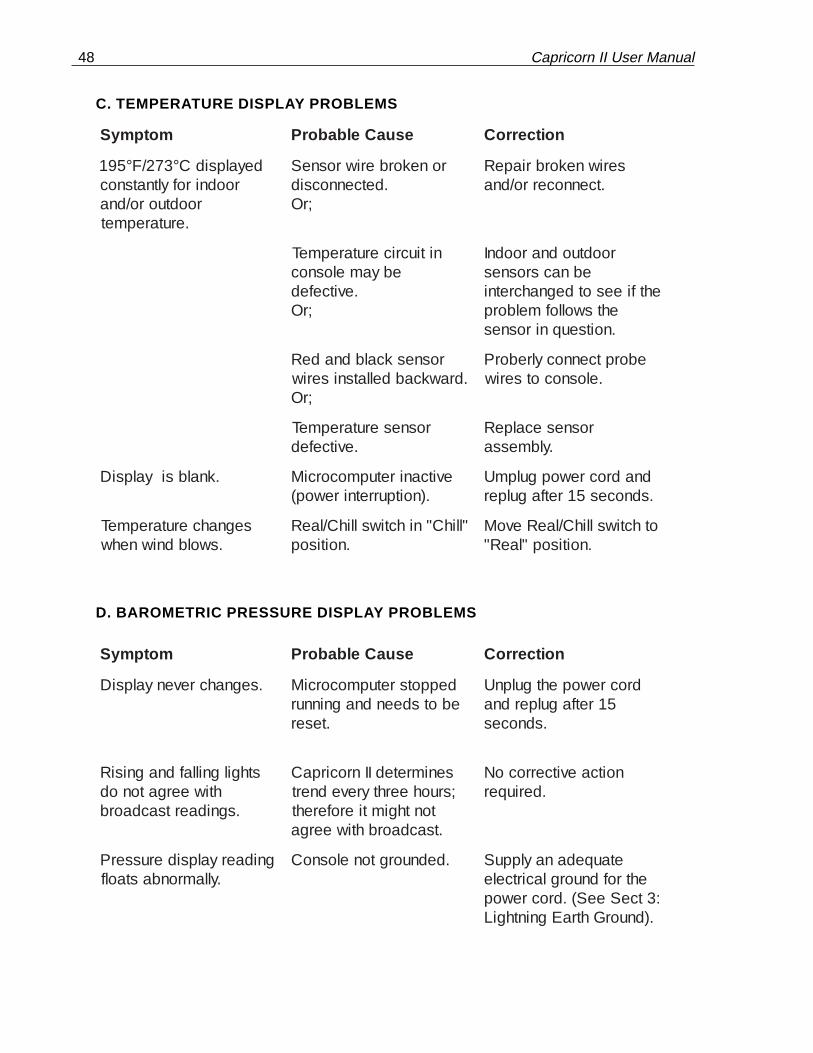
C. TEMPERATURE DISPLAY PROBLEMS
motpmyS esuaCelbaborP noitcerroC
deyalpsidC°372/F°591roodnirofyltnatsnoc
roodtuoro/dna.erutarepmet
ronekorberiwrosneS.detcennocsid
;rO
seriwnekorbriapeR.tcennocerro/dna
nitiucricerutarepmeTebyamelosnoc
.evitcefed;rO
roodtuodnaroodnIebnacsrosnes
ehtfieesotdegnahcretniehtswollofmelborp.noitseuqnirosnes
rosneskcalbdnadeR.drawkcabdellatsniseriw
;rO
eborptcennocylreborP.elosnocotseriw
rosneserutarepmeT.evitcefed
rosnesecalpeR.ylbmessa
.knalbsiyalpsiD evitcaniretupmocorciM.)noitpurretnirewop(
dnadrocrewopgulpmU.sdnoces51retfagulper
segnahcerutarepmeT.swolbdniwnehw
"llihC"nihctiwsllihC/laeR.noitisop
othctiwsllihC/laeRevoM.noitisop"laeR"
D. BAROMETRIC PRESSURE DISPLAY PROBLEMS
motpmyS esuaCelbaborP noitcerroC
.segnahcrevenyalpsiD deppotsretupmocorciMebotsdeendnagninnur
.teser
drocrewopehtgulpnU51retfagulperdna
.sdnoces
sthgilgnillafdnagnisiRhtiweergatonod
.sgnidaertsacdaorb
senimretedIInrocirpaC;sruoheerhtyrevednert
tonthgimtierofereht.tsacdaorbhtiweerga
noitcaevitcerrocoN.deriuqer
gnidaeryalpsiderusserP.yllamronbastaolf
.dednuorgtonelosnoC etauqedanaylppuSehtrofdnuorglacirtcele
:3tceSeeS(.drocrewop.)dnuorGhtraEgninthgiL

Columbia Weather Systems, Inc. 49
E. WIND SPEED DISPLAY PROBLEMS
motpmyS esuaCelbaborP noitcerroC
tubdniwtnerappaoN0nahtrehgihrebmun
nodehsalfyllanoisacco.yalpsideht
ecnerefretnilacirtcelEdniwehtaivpudekcip
.elbacrosnes
otlacitirctonsisihToT.noitarepoIInrocirpaC
sihtetanimileenimreted,ecneinevnocni
foecruosehtetuor-erdna,ecnerefretni
dedleihS(.elbacehtmorfelbaliavasielbac
lanoitponasayrotcafeht).noitulos
0wohsyalpsiDyltnatsnoc
.dniwoN,rO
.yrassecennoitcerrocoN
rotcennocelbacdniW.deggulpnu
,rO
.rotcennocdniwnigulP
ylreporptonrosneSdetacol
dniwehtnoitisopeReromotylbmessarosnes
rotinomyletarucca.sdniwgniliaverp
ylreporptonrosneS.elosnocotdetcennoc
seriwerabontahterusnEseriwtaht,gnihcuotera
detatsehtotdehcattaeraeraerehttaht,edocroloc,swercslanimretesoolon
eraseriwllatahtdna.lanimretaotdehcatta
.nekorbsielbacrosneS;rO
kcehC.evobaeeSfoortaelbacrosnes
kooL.ylbmessarosnesehtniskaerbrostucrofelbacehtriapeR.elbacrerutcafunamtlusnocro
rosneswenarofrosnesdniwroylbmessa.flahrotcennochtiwelbac

50 Capricorn II User Manual
E. WIND SPEED DISPLAY PROBLEMS (CONTINUED)
motpmyS esuaCelbaborP noitcerroC
morfnellafsahrosneS.tnuom
;rO
sitifirosnesllatsni-eResiwrehtO.degamadton
rorerutcafunamtlusnocrosneswenrofrelaed
.ylbmessa
ylbmessabuh/pucdniW.nekorbsimra
;rO
wenarofyrotcaftcatnoC.ylbmessabuh/pucdniw
.rosnesnoecI;rO
esutonoD.wahtotwollAwahtotecruosemalfa
.rosneseht
deppotsretupmocorciMebotsdeendnagninnur
teser
dnadrocrewopgulpnU.sdnoces51retfagulper
citarreroknalbsiyalpsiD srosnesro/dnaelosnoC.evitcefedera
;rO
debircsedtsetmrofreP.gniwollof
dnaylbmessaenaVehtnoeratesbuh/puc.seidobrosnesgnorw
ehtfonoitacolhctiwS.spucdnaenav

Columbia Weather Systems, Inc. 51
F. WIND DIRECTION DISPLAY PROBLEMS
motpmyS esuaCelbaborP noitcerroC
thgil)htron("N".ylsuounitnocdetanimulli
ylreporptonseriwrosneS.elosnocotdetcennoc
:rO
ontahtniatrecekaMeraseriwerabrodeyarf
eraseriwtaht,gnihcuotehtotgnidroccadehcattaeraerehttaht,edocrolocswercslanimretesoolon
eraseriwllatahtdna.lanimretaotdehcatta
debircsedtsetmrofeP.gniwollof
rotcennocelbacdniW.deggulpnu
elbacdniwnigulP.rotcennoc
thgiltonodsthgiLdetatorsisayllaitneuqes
.evobasaemaS .evobasaemaS
dniwtahtetacidnisthgiLgnitatorsinoitcerid
.ylsuounitnoc
tonsienavsdniW.decnalab
;rO
eeS(enavdniwecnalaB,)noitallatsnI:3noitceS
pucdeepssdniWnodetnuomsiylbmessa
.ydobrosnesnoitcerideht
ehtfonoitacolhctiwS.spucdniwdnaenav
citarresiyalpsiD ro(srosnesroelosnoC.evitcefedera)htob
ebircsedtsetmrofreP.woleb

52 Capricorn II User Manual
G. WIND SENSOR TESTS
In the event the wind speed or wind direction display does not light, displays "0"constantly regardless of wind conditions, or is inexplicably erratic, perform thefollowing tests as appropriate to help locate the source of the problem.
Tools required:
One small Phillips screwdriver
One 6" (15 cm) jumper wire, 22 gauge (approximately the same size as the indi-vidual wind sensor conductor wires)
Wind Speed Test:
1. Unplug the power supply cord from the Capricorn II.
2. Remove the seven wind sensor wires from their terminals at the back of theconsole.
3. Connect one end of the jumper wire to the wind sensor terminal marked "Red"on the back panel of the console.
4. Reconnect the power supply cord to the Capricorn II. If the dot is flashing inthe lower right corner of the wind speed display on the front panel, you areready to proceed with the individual tests for speed and direction.
5. With one end of the jumper wire connected to the "Red" terminal, rapidly tapthe loose end of the wire to the "White" terminal for several seconds. A windspeed display of any number (other than "0") should appear as the whiteterminal is being tapped. If that is the case, the console is functioning properly.Check the entire length of the cable for any cuts, kinks or other abnormalities.If there are none, or if problems persist after adjusting the cable, contact thefactory for service. Only the sensors need to be returned for repair. Unplug thewind sensors form the main cable. Do not send the cup/hub assembly or thewind vane as they may be damaged in shipping.
6. If no other numbers appear in the wind speed display, repeat the procedure toconfirm the results. If the result is the same, the console is defective (althoughit is possible that the wind sensor is also defective). The wind sensors are notdesigned for field repair. Contact the factory for service. Both the console andthe sensors need to be returned. Unplug the wind sensors from the maincable. Do not send the cup/hub assembly or the wind vane as they may bedamaged in shipping.
Wind Direction Test:
1. With one end of the jumper wire connected to the "Red" terminal, connect theother end to the "Blue" terminal; the NNW light should appear on the winddirection display. Proceed to touch the loose end of the jumper wire to theother terminals listed below and observe the wind direction display to confirm

Columbia Weather Systems, Inc. 53
that the appropriate direction light appears as its respective terminal istouched.
Terminal Direction
Blue NNWGreen SSEOrange ENEBrown NNE
2. If all the direction lights perform as indicated, the console is functioning prop-erly. Check the entire length of the cable for any cuts, kinks or other abnormali-ties. If there are none, or of problems persist after adjusting the cable, contactthe factory for service. Only the sensors need to be returned for repair. Unplugthe wind sensors from the main cable. Do not send the cup/hub assembly orthe wind vane as they may be damaged in shipping.
3. If any or all of the direction lights do not light up as indicated, repeat the proce-dure to confirm the results. If the result is the same, the console is defective(although it is possible that the wind sensor assembly is also defective). Thewind sensors are not designed for field repair. Contact the factory for service.Both the console and the sensors need to be returned for repair. Unplug thewind sensors from the main cable. Do not send the cup/hub assembly of thewind vane as they may be damaged in shipping.

54 Capricorn II User Manual

Columbia Weather Systems, Inc. 55
SECTION 9: REPLACEMENT PARTSRefer to Figure 13. Consult factory for price and availability.
Description Ref. Catalog No.
Complete Wind Sensor Assembly 1 81500
Partial Wind Sensor Assembly 2 81440Includes Speed and DirectionSensor bodies and connector only.
Wind Speed Cup/Hub Assembly, 3 81400with top nut.
Wind Direction Vane Assembly 4 81420with top screw.
Temperature Probe Assembly - 81520Includes one complete SensorAssembly (outdoor or indoor) with 25 ft. cable.
Hardware Assembly Kit 5 81480
User Manual - 81620
Cross-Arm Support 6 81460
Power Cord - 81610
Extra Length Temperature Sensor Cable - 81560for lengths over 25 ft.
50 ft. Wind Sensor Cable - 81538with connector half.
100 ft. Wind Sensor Cable - 81539
with connector half.
Extra Length Wind Sensor Cable - 81540for lengths over 100 ft.
Cable Splice Kit - 81580for user installation/repair of cable.
Sensor Cable Connector Option - 81585Allows quick disconnect of cablesfrom temperature sensors; watertight.Factory installed.

56 Capricorn II User Manual
Figure 13: Wind Sensor Assembly Parts

Columbia Weather Systems, Inc. 57
SECTION 10: USER SUPPORT INFORMATIONPlease fill out and return the Capricorn Product Registration Card immediately. If thecard is missing from the front of this manual, please call the Capricorn ServiceDepartment to obtain one.
Columbia Weather Systems, Inc. makes every attempt to ensure that the CapricornII Digital Weather Station is a product of superior quality and workmanship. Ourdocumentation is detailed to provide you with the maximum product support for theoperation of your instrument. Additionally, our Capricorn Service personnel areavailable to assist you from 8:00 a.m. to 4:30 p.m. PST.
This section consists of the following items:
1. Two-Year Limited Warranty: Please read this document carefully.
2. Return for Repair Procedure: This procedure is for your convenience in theevent you must return your Capricorn II for repair or replacement. Follow thepacking instructions carefully to protect your instrument in transit.
A. LIMITED WARRANTY
Columbia Weather Systems, Inc. (CWS), warrants the Capricorn II Digital WeatherStation to be free from defects in materials and/or workmanship when operated inaccordance with the manufacturer’s operating instructions, for two (2) years fromdate of purchase, subject to the provisions contained herein. CWS warranty shallextend to the original purchaser only and shall be limited to factory repair or replace-ment of defective parts.
EXCLUSIONS
Certain parts are not manufactured by Columbia (i.e., certain purchased options,etc.) and are therefore not covered by this warranty. These parts may be covered bywarranties issued by their respective manufacturers and although Columbia will notco-warrant these parts, Columbia will act as agent for the administration of any suchindependent warranties during the term of this warranty. This warranty does notcover normal maintenance, damage resulting from improper use or repair, or abuseby the operator. Damage caused by lightning or other electrical discharge, is specifi-cally excluded. This warranty extends only to repair or replacement, and shall in noevent extend to consequential damages. In the event of operator repair or replace-ment, this warranty shall cover neither the advisability of the repair undertaken, northe sufficiency of the repair itself.
THIS DOCUMENT REFLECTS THE ENTIRE AND EXCLUSIVE UNDERSTANDINGOF THE PARTIES, AND EXCEPT AS OTHERWISE PROVIDED HEREIN, ALLOTHER WARRANTIES, EXPRESS OR IMPLIED, PARTICULARLY THE WARRAN-TIES OF MERCHANT ABILITY AND/OR FITNESS FOR A PARTICULAR PUR-POSE ARE EXCLUDED.
This warranty gives you specific legal rights, and you may also have other rightswhich vary from state to state.

58 Capricorn II User Manual
B. RETURN FOR REPAIR PROCEDURE
1. In the event of defects or damage to your unit, first call the factory CapricornService Department Monday through Friday, 8:00 am to 4:30 pm PST, (503)690-2000 to determine the advisability of factory repair.
2. In the event factory service is required, return your Capricorn II as follows:
a. Packing
- wrap console in plastic bag first.
- pack in original shipping carton or a sturdy oversized carton.- use plenty of packing material.
b. Include
- a brief description of the problem with all known symptoms.- your phone number.
- your return street shipping address (UPS will not deliver to a P.O. box).
c. Shipping
- send freight prepaid (UPS recommended).- insurance is recommended. (The factory can provide the current replacementvalue of the item being shipped for insurance purposes.)
d. Send to:
Capricorn Service Dept.Columbia Weather Systems2240 NE Griffin Oaks Street, Suite 100Hillsboro, Oregon 97124
C.O.D. shipments will not be accepted.
3. If your unit is under warranty, after repair or replacement has been completed,it will be returned by a carrier and method chosen by Columbia WeatherSystems, Inc. to any destination within the continental U.S.A. If you desiresome other specific form of conveyance or if you are located beyond theseborders, then you must bear the additional cost of return shipment.
4. If your unit is not under warranty, we will call you with an estimate of thecharges. If approved, your repaired unit will be returned after all charges,including parts, labor and return shipping and handling, have been paid. If notapproved, your unit will be returned as is via UPS COD for the amount of theUPS COD freight charges.

Columbia Weather Systems, Inc. 59
ADDENDUM: WIND CHILL ALGORITHMTo compute the wind chill, first calculate the CORRECTION FACTOR (CF) from thefollowing table and formulas:
Using the wind speed in mph, calculate the wind speed index. (Range is 5 to 50mph.)
Index = 10 - Integer (Wind Speed/5)
Example: 37 mph/5 = 7 R2, where 7 = integer and 2 = remainder
Index Table #1 Table #2 Wind Speed (mph)
0 156 0 50
1 151 16 45
2 146 16 40
3 141 16 35
4 133 25 30
5 123 33 25
6 110 41 20
7 87 74 15
8 61 82 10
9 14 152 5
10 0 0 <5
CF = Table #1 + (Table #2 * 1/16 * Remainder (Wind Speed/5)
Then compute the WIND CHILL (WC), use the following formula:
IF temperature (in °C) - 33 (or in °F -91.4) is > 0;Then WC = (CF* (Temp. in °C - 33 (or Temp. in °F - 91.4))/256) + temperature
IF temperature (in °C) - 33 (or in °F -91.4) is < 0;Then WC = actual temperate (there is no wind chill)
Examples:
1. Given 25 mph and 20°C:Index = 10 - 25/5 = 5CF = 123 + (33 * 1/16 * 0) = 123WC = (123 * (20 - 33)/256) +20WC = -123 (0.05078) + 20 = 13.75° C
2. Given 27 mph and 68° F:Index = 10 - Integer(27/5) = 10 -5 = 5, Remainder = 2CF = 123 + (33 * 1/16 * 2) = 127.125WC = (127.125 * (68 - 91.4)/256) + 68 = 56.38° F