
by Jon R. Mancuso (Barney) Gibbons and INTRODUCTION
24
THE APPLICATION OF FLEXIBLE COUPLINGS FOR TURBOMACHINERY by Jon R. Mancuso Manager, Engineering Zurn Industries, Incorporated Erie, Pennsylvania C. B. (Barney) Gibbons Manager, Coupling Engineering Lucas Aerospace Power Transmission Corporation Utica, New York and Robert E. Munyon Vice President Engineering and Technology Kop-Flex, Incorporated Baltimore, Maryland ]on R. Mancuso has been working in various capacities at Zurn Industries, In- corporated, Mechanical Drives Division, for the past 5 years. Sta rting as a Re- search and Development Engineer, he moved to Staff Engineer, on to Manager of Project Engineering, a nd his present position of Manager of Engineering ( , years). He has been involved with many re- search and development projects relating to couplings. He is co-invent er ofZurn Industries' multiple con- voluted diaphragm coupling, "Ameriflex," "Ameriflex H " and Zurns' multiple convoluted link couplings. Mr. Mancuso graduate dfrom Gan no n University, with a B. S. in Mechanical Engineering, and has a M. S. in Engineering S ci- ence from Pennsylvania State University. He is chairing the ASME Committee on Couplings and Clutches. In addition, h e is a member of the AISE on the Mill Drive Committee, AGMA Cou pling Committee, and the API Committee on Couplings for Special Purpose Application s. C. B. (Baey) Gibbons is the Manager of Coupling Engineering for Lucas Aero- space wer nsmission Corporation, (formerly Bendix), in Utica, New York. He has been designing coulingsfor b oth airc and industrial applications for most of h is 32 year career. A graduate the University of Rochester and a licensed Professional Engineer in th e Stat e of w rk, he h as presented ser:eral papers on couplings to ASME, the Turbomachinery Symposium, and oth er organizations. He has oft en made techni- cal presentations on couplings and their interaction with rotat- ing machines at seminars spon sored by Bendix, Dresse r-Rand, Exxon, Mobil, the Vibration I nstitute, ASME, and others. 141 Robert E. Munyon, Vice President of Engineering and Tech nology for Kop- -Flex, Incorporated, is respon sible for di- recting t echnical operatio ns, including engine ering design, research, and prod- uct development. During h is urteen year tenure with Kop-Flex (fo rme rly the Power Transmission Division Kop pers Company, Incorporated), he has been in- strumental in the design of high p erform- ance gear and di aphragm couplings a nd in the development of t h e Kop-Flex@ high perf ormance disc cou- pling. He has coauthored an d present ed pap ers on various cou- pling to pics to ASME, the Thrbomachinery Symposium, and the Vibration Inst itute. Mr. Munyon received a B.S. degree in Mechanical Engineer- ing in 1975 from Rose-Hulman Institute of Technology a nd is a member a ASM and ASME. INTRODUCTION Flexible couplings are too often thought of as a piece of hardware rather than a vital parts of power transmission sys- tems. Virtually every user has a story about a piece of equipment with a coupling problem. Sometimes the coupling is the villain and just wi not petform as needed, but oſten the coupling is only reacting to a concealed problem and shoulders the blame for the real culprit. The basics of coupling design and operation will be presented. This presentation is intended to help the equipment user and OEM better understand the purpose of a coupling, how it accomplishes those tasks, how to best speci and utilize flexible couplings, and how to locate the r eal causes of coupling problems. Some of the issues discussed will be why use a flexible cou- pling, basic principles and terms, the differences between gear and flexible element couplings, selecting couplings for new ap- plications, retrofitting gear couplings \ith flexible element cou- plings, and API Standard 671. Operating considerations will also
-
Upload
khangminh22 -
Category
Documents
-
view
1 -
download
0
Transcript of by Jon R. Mancuso (Barney) Gibbons and INTRODUCTION

THE APPLICATION OF FLEXIBLE COUPLINGS FOR TURBOMACHINERY
by
Jon R. Mancuso
Manager, Engineering
Zurn Industries, Incorporated
Erie, Pennsylvania
C. B. (Barney) Gibbons
Manager, Coupling Engineering
Lucas Aerospace Power Transmission Corporation
Utica, New York
and
Robert E. Munyon
Vice President Engineering and Technology
Kop-Flex, Incorporated
Baltimore, Maryland
]on R. Mancuso has been working in various capacities at Zurn Industries, Incorporated, Mechanical Drives Division, for the past 21 years. Starting a s a Research a nd Development Engineer, he moved to Staff Engineer, on to Manager of Project Engineering, and h is present position of Manager of Engineering ( 12 years).
He has been involved with many research and development projects relating
to couplings. He is co-inventer o fZurn Industries' multiple convoluted diaphragm coupling, "Ameriflex," "Ameriflex HP," and Zurns' multiple convoluted link couplings.
Mr. Mancuso gra duated from Gannon University, with a B. S . in Mechanical Engineering, and has a M. S. in Engineering Science from Pennsylvania State University.
He is chairing the ASME Committee on Couplings and Clutches. In addition, he is a member of the AISE on the Mill Drive Committee, AGMA Coupling Committee, and the API Committee on Couplings for Special Purpose Applications.
C. B. (Barney) Gibbons is the Manager of Coupling Engineering for Lucas Aerospace Power Transmission Corporation, (formerly Bendix), in Utica, New York. He has been designing cou]Jlings for both aircraft and industrial applications for most of h is 32 yea r career. A graduate of the University of Rochester and a licen sed Professional Engineer in the State of New York, he has presented ser:eral papers on couplings to ASME, the Turbomachinery
Symposium, and oth er organizations. He has often made technical presentations on couplings and their interaction with rotating machines at semina rs spon sored by Bendix, Dresser-Rand, Exxon, Mobil, the Vibration Institute, ASME, and others.
141
Robert E. Munyon, Vice President of Engineering and Technolo gy for Kop
-Flex, Incorporated, i s responsible for directing technical operations, including engineering design , research, an d produ ct development. During h is fourteen year tenure with Kop-Flex (fo rmerly the Power Transmission Division of Koppers Company, Incorporated), he has been instrumental in the design of high p erformance gear and diaphragm couplings a nd
in the development of the Kop-Flex@ h igh performance disc coup ling. He h as coauthored and presented papers on various coupling topics to ASME, the Thrbomachinery Symposium, a nd the Vibration Institute.
Mr. Munyon received a B . S . degree in Mechanical Engineering in 1975 from Rose-Hulman Institute of Technology and is a member a ASM and ASME.
INTRODUCTION
Flexible couplings are too often thought of as a piece of hardware rather than a vital parts of power transmission systems. Virtually every user has a story about a piece of equipment with a coupling problem. Sometimes the coupling is the villain and just will not petform as needed, but often the coupling is only reacting to a concealed problem and shoulders the blame for the real culprit. The basics of coupling design and operation will be presented. This presentation is intended to help the equipment user and OEM better understand the purpose of a
coupling, how it accomplishes those tasks, how to best specify and utilize flexible couplings, and how to locate the r eal causes of coupling problems.
Some of the issues discussed will be why use a flexible coupling, basic principles and terms, the differences between gear and flexible element couplings, selecting couplings for new applications, retrofitting gear couplings \'l-ith flexible element couplings, and API Standard 671. Operating considerations will also

142 PROCEEDINGS OF THE EIGHTEENTH TURBO MACHINERY SYMPOSIUM
be addressed, such as the rotordynamic effects of couplings, dynamic balance, installation procedures, maintenance considerations, and windage effects.
WHY A FLEXIBLE COUPLING?
Ideally, process machines combine both the driving mechanism and the fluid handling mechanism in one device. The compressor in the modern refrigerator is just such an ideal machine. Unfortunately, though, most large sized fluid handling machines just aren't made that way.
Historically, some driving machine was connected to some load machine with flanges on each machine shaft and bolted together (Figure 1). Experience, in the form of a lot of broken shafts and wrecked machines, forced development of various kinds of flexible couplings to accommodate the reality that one cannot align and/or keep two machines sufficiently aligned. There are exceptions to this: most large steam turbo-generators and a few large gas turbine-generators utilize a "rigid" coupling which accommodates very little misalignment. This is accomplished by expending a lot of hard work matching the beat� ing and support systems for the two machines.
However, the majority of machines require flexible couplings to accommodate the misalignment. Generally, machines can be set up quite accurately, but there are many forces which push them out. Handling hot and cold fluids cause most of the movement in the vertical and axial directions (Figure 2). The vertical motions are the result of support structure growth and the axial motions are the result of the difference in case cs rotor growth, case growth only, or rotor growth only depending on the location of the thrust bearing. Horizontal (sideways) motions are usually caused by piping forces (Figure 3) or by differential solar heating (Figure 4). The piping forces can be caused by either temperature changes or by pressure changes.
-r::: Jl
Figure 1. Rigid Couplings.
The thermal growth of the machines can generally be calculated with sufficient accuracy from kno\vn thermal data and from available dimensions. Some typical machine axial displacements are shown in Figure 5.
During startup, the heavier housing takes approximately twice as much time to heat up as the lighter shaft. This causes a greater axial requirement during startup fot a machine such as D, ""ith the shaft expanding to position X until the casing expands to pull it back to position L .
A fact of life that machinery engineers must live with is that misalignment causes vibration. It isn't really the misalignment that causes the vibration, but the force (Figure 6) that a misaligned coupling puts on the machine that causes the machine to vibrate. All couplings subject to misalignment and torque
HOT COLD
-/1
Figure 2. Forces Due to Handling Fluids of Different Temperature.
...
Figure 3. Forces Due to Piping Expansion .
/ "
Figure 4. Distortion Due to Solar Heating .
/
/

TUTORIAL 1 ON COUPLINGS 143
apply reaction forces on the coupled machine s . Some types have greater reaction forces than others . Mechanically flexible couplings , such as the gear type , apply a bending moment on the machines that is a function of the transmitted torque . Flexible element couplings apply a bending moment that is a function of the amount of misalignment but is almost independent of the transmitted torque . The history of coupling development has been a progress ive search for coupling concepts that will not only survive long term operation under misaligned conditions but will also have the lease effect upon the machines . As the "power density," (the amount of power transmitted through a given size coupling) keeps increasing the required sophistication of the couplings has also increased to meet the demand .
NEGLIGIBLE AXIAL EXPANSION
B
l' SHAFT EXPANSION
X SHAFT BEARING 0 THRUST BEARING [;CASE SUPPORT
Figure 5. Types of Machine Axial Displacements.
Figure 6. Forces Due to Misalignment.
FUNCTIONS OF FLEXIBLE COUPLINGS
)(I )
Rotating equipment was first connected by means of rigid flanges . Experience indicated that this method did not accommodate the motions and excursions experienced by the equipment . Rigid couplings are used to connect equipment that experiences very small shaft excursions or with shafts made long and slender enough so that they can accept the forces and moments produced from the flexing flanges and shafts .
The two basic functions of a flexible coupling are (Figure 7) : • To transmit power. • To accommodate misalignment .
TRANS MIT POWER
Couplings are used primarily to transfer mechanical power from one machine to another so that useful work can be done . To the coupling, this po\\·er is in the form o f mechanical torque at some operating speed , or work per unit of time , so the coupling is being "tv.:isted" as it is spun at some high rpm . Torque
B
Figure 7. Functions of a Flexible Couplings.
is transferred into and out of the coupling at the equipment connection , usually by shaft fits (interference and keyed) o r flange fits (bolts) . Couplings normally have flange connection s of their own so that they can be installed and removed , plus they have "flexible membrane" to accommodate misalignment as described later. All components in the torque transmis s ion path through the coupling must be designed to withstand the operating torques of the machinery and all components mus t withstand the centrifugal forces of the operating speed .
The design o f the shaft hubs , flanges , bolts , and tube s are all relatively straight forward , but the torque requirements on the flexible elements is not . A gear coupling (Figure 8) uses a gear mesh as the "flexible" member. This mesh is similar to a spline (Figure 9) in that it has an inner "male" gear set that m eshes , or mates , with an outer "female" gear set to produce a s ingle gear mesh . Torque is transmitted from one coupling component to another through the gear mesh , by contact o f the gear teeth . Gear couplings can , therefore , transmit large values of torque , since the gear mesh can be designed for high contact load; i n fact , gear couplings can transmit more power per pound than any other type of flexible coupling .
Flexible element couplings use the same basic components as the gear coupling and the same basic design principles , except for the "flexible" member.
Figure 8. Typical Gear Coupling .
144 PROCEEDINGS OF THE EIGHTEENTH TURBO MACHINERY SYMPOSIUM
SLEEVE TOOTH
HUB TOOTH
� -� I Figure 9. Misalignment of a Crown Tooth Coupling.
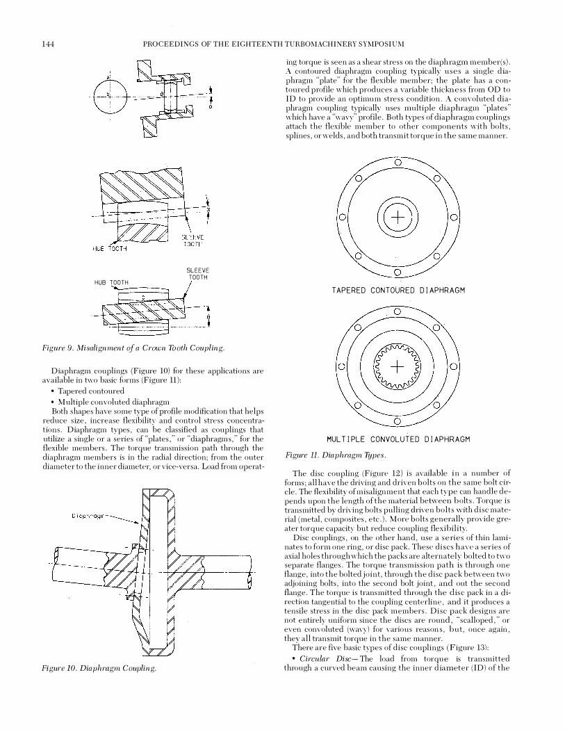
Diaphragm couplings (Figure 10) for these applications are available in two basic forms (Figure 11): • Tapered contoured • Multiple convoluted diaphragm
Both shapes have some type of profile modification that helps reduce s ize, increase flexibility and control stress concentrations . Diaphragm types, can be classified as couplings that utilize a single or a series of "plates , " or "diaphragms," for the flexible members. The torque transmission path through the diaphragm members is in the radial direction; from the outer diameter to the inner diameter, or vice-versa. Load from operat-
Figure 10. Diaphragm Coupling.
ing torque is seen as a shear stress on the diaph ragm member(s) . A contoured diaphragm coupling typically u se s a single diaphragm "plate" for the flexible member; the plate has a contoured profile which produces a variable thicknes s from OD to ID to provide an optimum stre s s condition . A convoluted diaphragm coupling typically uses multiple diaphragm "plates" which have a "wavy" profile . Both types of diaphragm couplings attach the flexible member to other components with bolts, splines, or welds, and both transmit torque in the same manner.
TAPERED CONTOURED DIAPHRAGM
MULTIPLE CONVOLUTED DIAPHRAGM
Figure 11. Diaphragm 1lJpes.
The disc coupling (Figure 12) is available in a number of forms ; all have the driving and driven bolts on the same bolt circle . The flexibility of misalignment that each type can handle depends upon the length of the material behveen bolts . Torque i s transmitted by driving bolts pulling driven bolt s with disc material (metal , composites, etc . ) . More bolts generally provide greater torque capacity bnt reduce coupling flexibil ity.
Disc couplings , on the other hand , use a s e ries of thin laminates to form one ring, or disc pack . These discs have a series of axial holes through which the packs are alternately bolted to two separate flanges . The torque transmiss ion path is through one flange, into the bolted joint , through the disc pack between two adjoining bolts, into the second bolt joint, and out the second flange . The torque is transmitted through the dis c pack in a direction tangential to the coupling centerline , and it produces a tensile stress in the disc pack members . Di sc pack designs are not entirely uniform since the discs are round, "scalloped," or even convoluted (wavy) for various reason s , but, once again, they all transmit torque in the same manner.
There are five basic types of disc couplings (Figure 13): • Circular Disc- The load from torque is transmitted through a curved beam causing the inner d iameter ( ID) of the

TUTORIAL l ON COUPLINGS 145
disc to be in tension and the outer diameter (OD) to be in compression. To avoid the line of action falling outside the disc material , more bolts than necessary can be required , reducing flexibility . • Hex Disc- M ore material i s left in the disc area where the largest bending stress occurs , which reduce tensile stresses at the bolt connections . • Scalloped Disc- By removing the least worked portion of the disc, it is designed to produce relatively uniform tensile stresses across the driving portion of the disc and reduce bending stresses at the anchor points due to misalignment. • Segmented Disc-This type typically has the same operating characteristics of the other disc type couplings , but with manufacturing advantages. • Multiple Convoluted Disc-This disc type refers to a series of thin separated convoluted s egmented links in a pack assembly. The least worked portion of the disc is eliminated and sep
. aration of the flexing area reduces fretting corrosion . The convolutions increase flexibility.
Figure 12. Disc Coupling .
MISALIGNMENT
There are three types of misalignment (Figure 14) a coupling is subject to by an equipment train , and which the coupling must accommodate; angular, offset , and axial . The oveiwhelming condition is some combination of all three of these at the same time . Angular misalignment is produced when the centerlines of the two equipment shafts the coupling connects are not parallel and they intersect at an angle . Offset misalignment, commonly called parallel offset , is when the two shaft centerlines are parallel and they do not intersect, they are "offset" by some distance . Axial misalignment is caused by changes in the axial position of the shafts which moves the shafts closer together or further apart . This is commonly caused by thermal growth of the machine casing and rotors as they change between ambient and operating temperature .
It is important to recognize that while the equipment places the coupling under combinations of these three types of misalignment, the coupling itself sees only angular and axial misalignment . The "flexible" portion of the coupling, be it a gear mesh or flexible elements , sees only angularly and axially, a "fully flexible" coupling , therefore , needs more than one flexible element to meet the offset misalignment criteria , and typical couplings utilize two playing elements . This way each element can deflect angularly and connect the two shafts that are offset misaligned .
As stated previously, gear couplings use gear meshes , which are "loose" splines . They are manufactured \Vith a certain
CIRCULAR DISC HEX DISC
SCALLOPED DISC SEGMENTED DISC
MULTIPLE CONVOLUTED DISC
Figure 13. Disc Types.
amount of backlash between mating male and female tee th , this clearance allows the male teeth to move relative t o the fe male teeth . The result being a gear mesh were the teeth can sl ide back and forth to accept axial misalignment and also where the teeth can tilt to allow the mesh to accept angular misalignment. A male tooth actually slides back and fi)lth on its mating female tooth under misalignment during each revolution of the coupling , which can be as high as 20,000 times per minute for a high performance coupling . The phy sical sliding that take s place between the gear tooth is the reason for the lubrication requirement, the oil (or grease) allows the teeth to slide freely back and forth and the oil carries away frictional heat generated in continuously lubricated couplings .
Flexible element couplings physically accomm odate mis alignment in different ways ; however, they all use the same basic principle , which is material flexure . They all utilize the inherent ability of a material to stretch and bend to some extent without breaking . Flexible element couplings, therefore , connect two parts of the coupling with specifically designed flexing m embers and allow the parts of the coupling to move relative to each other, while the flexing member stretches or bends to accept the relative motion . I t is important to recognize that the flexing member must be strong to transmit the high power required and yet must also be flexible enough to accept the deformation s fro m misalignment without breaking and without imposing o bj e ction able reaction forces on the equipment .
As s tated previously, contoured diaphragm couplings use a s ingle contoured "plate" for the flexing members: the plate is relatively thin and thus is called a diaphragm. Each diaphragm can be deformed much like an oil can lid (before the days of plastic), this deflection of the outer diameter relative to the inner diamete r is what occurs when the diaphragm is subject t o misalignment. Angular misalignment hvists the outer diameter, r elative

146 PROCEEDINGS OF THE EIGHTEENTH TURBO MACHINERY SYMPOSIUM
to the inner diameter, and produces a complex shape on the diaphragm where it must stretch one way at one point and then stretch the other way at 180 degrees . In between these points , the diaphragm is subject to a combination of stretching and h\isting . Axial misalignment attempts to "pull'" the ID and OD apart and , thus , attempts to s tretch the diaphragm , which results in a combination of elongation and bending of the diaphragm profile .
Convoluted diaphragms accommodate misalignment somewhat differently. They use multiple thin "plates" which are made to be wavy from OD to ID. They react similarly to the contoured diaphragm under misalignment except that they "unfold" the wavy profile of the plates instead of stretching the diaphragm .
Disc couplings are made of disc packs where the flexing member is alternately bolted to two flanges . The relative motion of the flanges is seen by the disc pack as relative movement between the flange connecting bolts . The part of the pack between two adjacent bolts is called a "link" and it acts much like a leaf spring where relative movement of the bolts produces stretching and bending of the link . Both angular and axial misalignment result in nearly identical deformation of the link , except that the angular misalignment bends the link back and forth as the coupling makes one complete revolution . The disc pack is typically made of many thin individual discs so that it has a low resistance to deflection , in some cases the links can be made with a convoluted or wavy profile to exhibit s imilar results as the convoluted diaphragm .
-I- -I-A -,
-I- I-B
c
Figure 14. Types of Misalignment. a) offset; b) angular; c) axial .
TYPES OF COUPLINGS
Couplings can be basically categorized as one of hvo types , the rigid coupling and the flexible coupling . Rigid couplings are usually used to connect equipment that experiences very small misalignments . S ince rigid couplings also produce the greatest
reaction on connected equipment, most applicatio n s require the use of flexible couplings . Flexible couplings are u sually categorized as one of four types (Figure 15) . • Mechanically flexible • Elastomeric • Flexible element • Miscellaneous
For the applications being compared , a mechanically flexible gear coupling or a flexible membrane coupling are most often considered because of torque , misalignment , speed , and environmental requirements . The gear coupling i s a type of mechanically flexible coupling and the disc and d iaphragm are types of flexible membrane coupling . These typ e s of couplings have unique characteristics that are suitable for the applications being considered .
The general operating principles of the four bas ic categories of couplings are as follows: • Mechanically flexible couplings: In general , these couplings obtain their flexibility from loose fitting parts and/or rolling or sliding of mating parts . Therefore , they usually require lubrication unles s one moving part is made of a material that supplies its own lubrication needs (e . g . , a nylon gear coupling) . Also included in this category are couplings that uses a combination of loose fitting parts and/or rolling or sliding, with some flexure of material . • Elastomeric couplings: In general , these couplings obtain their flexibility from stretching or compressing a resilient material (rubber, plastic, etc . ) Some sliding or rolling may take plac e , but i t i s usually minimal . • Flexible element couplings: In general , the flexibility of these couplings is obtained from the flexing of thin discs (me tallic , composite , etc . ) or diaphragms .
IndustriaL
MechanicaLL\:j FLexible
Elastomeric
FLexible ELement
MisceLLaneous
Figure 15. Types of Flexible Couplings.

TUTORIAL I ON COUPLINGS 147
• Miscellaneous couplings: These couplings obtain their flexibility from a combination of the mechanisms described above or through a unique mechanism .
CLASSIFICATION OF COUPLINGS
If coupling usage is divided into two categorie s , general pm� pose and high performance , it becomes easier to categorize the kinds of couplings available .
General Purpose Couplings
!\·lost liquid transfer pump s , material transfer mechanisms , mixer s , blowers , fans and the like run at moderate speed and can have very conservatively rated couplings . There are literally dozens of coupling types and varie ties competing for a place in this field .
The two common mechanical misalignment types are the grid (Figure 16) and the gear type (Figure 17) . The grid type has slots in each hub and a spring steel grid which connects them . This coupling must be grease lubricated and is limited to relatively low speed applications .
There are many different gear coupling types in service . They all use the principle of meshing an external gear in an internal gear with sufficient clearance in the teeth to permit some misalignment. Crowning of the external teeth allows some increase in misalignment without introducing excessive backlash . The main variation between gear couplings is how they are lubricated and what kind of seals are used . The original gear coupling, designed by Gustav Fast , has an end ring which provides a reservoir for oil . On some designs the oil supply can be replenished while either running or s topped . More recent designs (Figure 18) incorporate seals on the hub to retain lubricant . These couplings can b e made smaller and less expensive and can be either oil or grease lubricated .
Figu re 16 . Grid Type Coupling.
Flexing element coupling are available with both metallic and nonmetallic flexure s . The nonmetallic flexures use rubber, rubber like plastics such as polyurethane , and composite material . The four configurations (Figure 19) shown here are only a few of the ones available but are typical of the nonmetallic flexure couplings . The simplicity of the design and their easy maintenance makes these couplings very attractive for low power density applications .
· The most common flexible element coupling (Figure 20) is the
annular disc coupling . The flexure side transmits the torque from bolt hole to bolt hole through the annular segment . The number of discs can be increased to carry more torque or de-
Figure 17. Gear Coupling with Metallic Seals.
Figure 18 . Gear Coupling with 0-Ring Seals.
creased to improve flexibility. This type of coupling is available in a variety of configurations and from different manufacturers . The basic concept of the annular disc coupling does not restrict its use to low speed applications but many of the configurations use materials which are of inadequate strength to use at higher speeds .
Figure 19. Types of Nonmetallic Couplings.

148 PROCEEDINGS OF THE EIGHTEENTH TURBO MACHINERY SYMPOSIUM
Figure 20. Disc Type Coupling .
HIGH PERFORMANCE COUPLINGS
Two general categories of couplings have been developed to service the high performance industry ; gear types and flexible element types. These categories can also be labeled as "lubricated" and "non-lubricated" (or "dry") , since gear couplings require oil or grease lubrication and flexible element types require no lubrication , they therefore run "dry. " The gear coupling category has many subgroups to al!O\v for many different designs ; however, they are only variations on the same theme , which is the use of gear teeth in a spline type "mesh" to peiform the functions required. While gear couplings may differ in some design points , they all are identical in operating principal. Dry types however, have more diversity; there are two primary types used in the high pe1formance industry today : the diaphragm type and the disc type. Each has its own particular design features and operating characteristics.
GEAR COUPLINGS
Because of the gear coupling's dominance of the low to moderate power density application s , its design was adapted and modified during the 50s and 60s to carry more power at higher speeds. However, lubrication became (and still is) the major problem. Greases separated under the centrifugal force and seals leaked. Continuously lubricated designs (Figure 21), using the coupled machines bearing oil, avoided those problems and became the standard of the industry. These couplings were provided with the external teeth on the hub or with the external teeth on the spacer in the "marine" type (Figure 22). This type could be used with integral flanges on the machine shafts such as on ship propulsion turbines and gears . . . hence the name "marine" type. Reduced moment versions (Figure 23) were readily made available for those machines requiring them. Lubrication continued to be a problem because the coupling itself tends to act as a centrifugal filter. Any particles in the oil (especially oxidation products of the additives in the oil) would be trapped in the small passages of the tooth clearances or be caught in the built-in "dam" at the discharge side of the mesh.
This "sludging" became such a problem in the 1970s that many gear coupling designers removed the " dam" and/or required fine filtered oil (five micron) of sufficient flow to flush out the particles. This fix helps , but it doesn't eliminate the problem.
The most common mode of failure for a gear coupling is wear. It is one of the most common and simplest couplings used today. Due to the number of variables that can affect its successful operation , it is usually difficult to design and evaluate.
Figure 21. Continuously Lubricated Gear Couplings.
Figure 22. Marine Style Gear Coupling.
Figure 23. Reduced Moment Gear Coupling.
A gear coupling has its most significant effect not only on itself, but on system components from the forces and moments generated when it sl ides and/or misaligns. When a gear coupling accommodates the shaft float from thermal growth , hull deflection , shock , etc. , axial forces react back onto the thrust bearings and other equipment. When misaligned, a gear coupling will produce a bending moment that will load equipment s haft s , bearings , and other system components. Both the axial forces and bending moments are significantly affected b y the lubrication and the coefficient offriction between the mating gear teeth members.
Various coupling manufacturers use the following typical values from test data for the coefficient of friction :
Sealed lubricated gear couplings : 1-1. = 0. 05
Continuous lubricated gear couplings : 1-1. = 0. 075
Values of coefficient of friction higher than the above can b e experienced , although if they are present fo r any period o f tim e , the coupling i s n o longer flexible which would more than likely precipitate the failure of one of its own components or some component , of the coupling equipment. If a coupling i s mechanically locked due to sludge or wear, the forces could be increase d seven t o eight times those normally expected.
There is still much discussion of how large a value to use for a safety factor when designing a system or even a gear coupling. Due to the high reliability necessary for turbo machinery applications , the American Petroleum Institute specification s require thrust bearings to be designed for the maximum gear coupling thrust load with the conservative coefficient of friction of 1-1. = 0. 25 for continuous operating conditions.
FLEXIBLE ELEMENT COUPLING
Flexible element coupling use was limited through the 1940s to low torque , low speed applications where only l imited amounts of misalignment were required. In the late 1940s , the appearance of the s mall gas turbine produced the need for the thin contoured diaphragm , which saw usage in aircraft applications. The progress and acceptance of this coupling in industrial and marine applications was greatly hindered by the inability to accommodate high misalignment and large axial movem ents.
For many years , gear couplings have been used on steam turbines, gas turbines , compressors and pumps. \Vhen the horse power, speeds , and operating te111peratures increase d , many problems with gear couplings developed. The need for lower moments , forces , and noise characteristics has pushed the advanced deYelopment and usage of flexible membrane couplings in thousands of applications. Because of this developed techno!-

TUTORIAL 1 ON COUPLINGS 149
ogy, flexible element couplings have been successfully used since the mid 1970s for high performance gas turbine application s .
1\-tany manufacturers and users of rotating equipment have increased their list of coupling requirements to include the following: • No lubrication • Higher torque capability without an increase in coupling size • Accommodation of greater misalignments • Accommodation of greater axial motions • Suitable for high temperature operation • Adaptable to all types of connections: splines , taper shafts , flanges , etc . • Produce low moments and forces • Produce predictable moments and forces • Easily balanced • Operate for years without maintenance or problems • Produce low vibratory inputs into equipment
T he Contoured Diaphragm Coupling
The contoured diaphragm coupling hils as its flexible element a thin profiled diaphragm machined from a solid disk of heat treated vacuum melted alloy steel . This diaphragm is contoured so that it has a nearly uniform torsional shear stress throughout the profile , which is therefore thicker at the hub, or I D , and progress ively thinner at the rim , or 0 D. The purpose of contouring the profile is to keep the diaphragm as thin as possible consistent with the transmitted torque . This keeps the misalignment bending and axial bending stresses as low as possible for a given torque capacity (Figure 24) .
2 t, = k/r.
I I
ct.--Figure 24 . Contoured Diaphragm Shape .
The thickness o f a diaphragm can be changed t o permit a trade off between torque capacity and flexibility. A thicker diaphragm has greater torque capacity , but is not as flexible and vice versa. The reason for machining the diaphragm from a solid disk is to
provide smooth fillet junctions between the flexing p ortion and the rigid integral rims and hubs which connect to the res t of the coupling .
In most configurations , the diaphragm hub is electron beam welded to the spacer tube in a permanent connecti on . This minimizes the number of mechanical connections in the coupling (Figure 25) .
DIAPHRAGM
ELECTRON BEAM WELD
SPACER TUBE
{------Figure 25. Contoured Diaphragm Welded to Spacer Tube .
The most often used "marine s tyle" coupling configuration allows the mounting hub bore to vary considerably witho u t affecting the diaphragm diameter (Figure 26). Thus , the s ize of the coupling is be chosen to fitthe torque and misalignment requirements rather than be dictated by the connected machine shaft size .
Figure 26 . Marine Style Contoured Diaphragm Coupling.
A "piloted guard" version of the configuration incorporates diametral locating pilots which meet the API Standard 671 and enhance the balance repeatability of the coupling . This makes using the technique of only balancing the coupling components (for component interchangeability) more practical (Figure 27) .
For those special applications requiring a reduced moment coupling, the contoured diaphragm coupling is made with the diaphragms machined from forgings with integral mounting hubs (Figure 28) . This configuration shifts the flexible center closer to the machinery bearings to reduce the over hung moment from the weight by moving the coupling center of gravity (CG) towards the machine bearings .

150 PROCEEDINGS OF THE EIGHTEENTH TURBO MACHINERY SYMPOSIUM
Figure 27 . Piloted Contoured Diaphragm Coupling .
Figure 28 . Reduced Moment Contoured Diaphragm Cou pling .
Multiple Convoluted Diaphragm Coupling
The multiple convoluted diaphragm coupling was first introduced in 1971 . The first design introduced was a coupling with a large ratio (Figure 29) between OD and ID clamp diameters , to provide high misalignment capacity and low stiffness .
HP Series R Series
Figure 29. Diaphragm Pack Profile . a) HP series; b) R series.
The force applied at the ID by the clamp ring bolts is sufficient to cause the pack to act as one solid unit in the transmission of torque . The pack transmits torque to the splined adapter through a major diameter interference fit spline .
The second design introduced ( 1980) is constructed with a reduced ratio (see Figure 29) between O D and I D clamp di-
ameters in order to better accommodate the reduced momen t configuration . The pack a t the I D i s fused together \vith a full penetration electron beam weld which makes the ID spline area a solid unit . This increase s the shear diameter and , therefore , the torque capacity. Torque is transmitted from hub to pack by a fine pitch spline , while bending moments are resisted by a clamp nut . Thus , the welded portion of the pack i s not s ubjected to reversing stresses imposed by rotation and misalignment. Flexure takes place only in the convoluted area of the diaphragms which is not affected by the weld .
The heart of the multiple convoluted diaphragm coupling i s the stainless steel diaphragm pack. (Figure 30 ) The pack consists of several thin convoluted diaphragms, separated by inside diameter filler rings and segmented outside diameter fillers . These are sandwiched between thick end plates to give rigidity to the pack . The convolution and its unrolling act ion usually results in large axial capacity for these couplings . The multiple convoluted diaphragm pack has a linear stiffness axial s tiffnes s .
Figure 30. Multiple Convoluted Diaphragm Pack.
HP SERIES (HIGH PERFORMANCE) (Figure 31) Diaphragm profile permits large axial and angular deflection
with low stiffnes s . Diaphragm pack is tightly clampe d at the ID, causing it to act as a solid unit in the transmission of torque .
Figure 31. HP Series (h igh performance).
RM SERIES (REDUCED MOMENT) (Figure 32) A reduced ratio pack in a high performance, reduced moment
design coupling provides increased bore and torque capacity with low overhung moment . Diaphragm pack is fused together at the ID using a full penetration electron beam weld .

TUTORIAL 1 ON COUPLINGS 151
Pack Adapter
Hub
-,------,--- - -- -
Shippmg Scl Spacer Diaphragm
Pack
Figure 32. RM Series (reduced moment).
RR SERIES (REDUCED RATIO) (Figure 33) The reduced ratio pack from the rm series in a high perform
ance hp configuration produces a light , high torque capacity coupling .
Diaphragm Pack J
Spacer Bolts
l , Shipping Spacer Screw
Figure 33. RR Series (reduced ratio).
DISC COUPLINGS
Originally designed in the early 1900s , disc couplings have been adapted for the strenuous demands of modern high performance equipment and are frequently used for nonlubricated coupling applications . These types of couplings use disc packs that have a series of axial holes through which the pack is alternately bolted to two separate flanges ; torque is transmitted from one flange to the other between the bolts and through a tensile load on the discs . Flexibility is obtained from the deflection of the pack and varies with the length between adjacent bolts ; increasing the number of bolts raises the torque capacity and decreases the flexibility of the coupling; high performance designs generally use six or eight link designs for the proper balance between torque and misalignment capacity.
Most disc couplings use many thin discs to make one pack instead of one thick disc for increased flexibility and minimal reaction forces; the practical thickness of the individual disc ranges from 0 . 008 in to 0 . 025 in . High pe1formance couplings have discs made of corrosion resistant steel s , 300 series stainles s , PH stainless , or high strength nickel alloys . 1\Iany disc options are available including circular, hex, scalloped , and segmented discs for different stress and flexibility patterns; the most popular for high speed service are the hex and scalloped designs , since they possess the best service characteristics .
Four link discs are not used for high pe1formance couplings , due to the uneven speed fluctuations they produce (similar to U-joints) , six link designs are used for higher misalignments or high axial growth applications . Eight link discs provide higher torque capacity with flexibility to accommodate most installa-
tions , while ten links are used for high power requirem ents with minimal misalignment needs (Figure 34) .
Because the disc packs are made of many pmts , manufacturers provide pack subassemblies . Some disc packs are factory installed on the coupling , while others are supplied with pilot rings for installation in the field . One very important factor that influences coupling life is the proper tensioning of the disc pack fasteners . The fasteners can be installed in the field , but this requires accurate bolt torque equipment and procedure s . For these reasons , some coupling manufacturers install and torque the disc pack fasteners at their factory to assure the correct level of bolt tension .
6- LINK 8- LINK 10 - LINK
Figure 34. Disc/Link Shapes.
High pe1formance disc couplings have misalignment and axial growth capabilities equal to other "dry" types and are used on all categories of equipment , including gas turbine s with high thermal growth . They are available in a number of s tyles , the two predominant configurations are the reduced moment and the marine . The marine s tyle (Figures 35 and 36) derives i t s name from the marine style gear coupling and it s imply contains the flexible membrane on the center portion of the coupling . A rigid hub is mounted to the equipment shaft and the disc pack is attached to the center spacer where it can be completely removed and dropped out . The reduced moment style contains the flexible member on the hub mounted to the equipment shaft (Figure 37). This moves the disc pack , and therefore the effective coupling center of gravity, closer to the machine b earing which reduces the overhung moment of the coupling on the shaft .
Figure 35. Marine Style Disc Couplings.
COUPLING LIFE
Gear and flexible elements exhibit \\-idely divergent philosophies when determining operating life . Gear couplings

152 PROCEEDINGS OF THE EIGHTEENTH TURBO MACHINERY SYMPOSIU M
Figure 37. Reduced Moment Disc Coupling .
HUB TAPER BORE
are mechanically flexible and depend upon the relative sliding motion of the gear mesh to accommodate misalignment, thus their service life is dependent upon tooth condition more that anything else . If a gear coupling is properly lubricated and aligned, it will give years of trouble-free service ; examples of high performance gear couplings running in excess of twenty years are not uncommon . However, a gear coupling is definitely subject to wear from the sliding motion of the teeth and it is more common to have to replace a gear coupling after ten years service , some particularly difficult applications can even shorten the life to two years . Distress shows up in two typical ways ; the tooth contact faces become damaged, or the tooth tips are worn .
The faces of the teeth can be pitted as a result of poor lubrication or from high misalignment, a particular type of pitting damage is called "worm-tracking" and is a result of extremely high sliding velocity of the teeth combined V\ith marginal lubrication . Normal wear tends to slowlv erode the faces of the teeth until the hardened case of the nit�ided teeth is removed . The coefficient of friction at the teeth increases and the coupling becomes more resistant to motion under misalignment; the bending moment 011 the equipment shaft increases and the coupling resists sliding under axial misalignment . In extreme cases , the coupling is virtually "locked up" and will not freely slide to accommodate any misalignment . These conditions can usually be noticed with equipment vibration monitors , and typically manifest themselves as a strong 2 X operating speed signal , which correlates to the gear tooth sliding back and forth twice during each coupling revolution . Unfortunately, a good quantitative measure of tooth distress does not exist , but a sharp eye at inspection can discern tooth condition readily .
The coupling components must be maintained in some radial position during operation to ensure dynamic balance . If a part is allo\ved to shift radially, it will produce unbalance , which can
be extreme at the operating speed of most turbo machinery . For this reason , the gear meshes of a gear coupling are piloted; the tips of one set of teeth are tightly fitted to the roo t s of the mating set . Over time , the slight pilot clearance of the teeth can increase due to wear and the coupling unbalance can increase . Once again, this condition can usually be signaled with vibration monitors , which will be seen as a s lowly increasing 1 X operating speed s ignal related to unbalance . Often , the coupling unbalance can be "swamped" by rotor unbalance , so i t i s always a good idea to check the tooth clearance during maintenance turns .
FAILURE MODE FOR GEAR COUPLINGS
For gear couplings , the most common type of failure is due to tooth wear and distress . Tooth distress is most commonly caused by : • Inadequate lubrication (Figure 38) . • Improper tooth contact (Figure 39) . In this cas e , the coupling ran close to a torsional critical , and the cy clic load caused localized tooth distress only on those teeth loaded .
• Worm tracking-cold flow or welding occurs more frequently on continuous lubed couplings. This occurs near the end of the teeth when misalignment approaches the design limit of the crown , and the lubrication film breaks down and causes m etalto-metal contact . High, localized tooth loading or lubricant deterioration can cause this type offailure as describe d in improper tooth contact (Figure 40) . • Sludge buildup can cause failure of almost any system component such as shafts or bearings (Figure 41) . S ludge also will collect corrosive residue , which can corrode coupling parts and act as a source of crack initiations for a fatigue-propagated failure of a part .
Figure 38 . Gea r Tooth Failure (inadequate lubrication).
DESIGN PRINCIPALS FOR FLEXIBLE ELE:tviENT COUPLINGS
Flexible element couplings are not mechanically flexible like gear couplings , they operate through flexure of material , thus thev exhibit verv different behavior and their service life i s a
mu�h different phenomenon . First , they are designed to operate within the fatigue life of the flexing material . Therefore , they have an infinite life if operated within their rated capacitie s . All flexible element coupling designs have been subject to detailed stress analysis and the endurance limit of the coupling has been painstakingly determined by comprehensive test ing . Flexible

TUTORIAL 1 ON COUPLINGS 153
Figure 39. Gear Tooth Failure (improper tooth contact).
Figure 40. Gear Tooth Failure (warm tracking-coldjlowj.
element coupling manufacturers use this data to determine life margins , such as Goodman diagrams , and to establish safe operating limits of couplings. Although dry couplings have not been used as long as gear couplings in high performance applications , the results thus far have indicated that they will out live their gear counterparts by considerable margin . One important point to be aware of is that the fatigue life of a dry coupling is most influenced by the angular misalignment of the flexible member (which is angular and offset misalignment of the equip-
Figure 41. Sludged up Gea r Coupling.
ment) , s ince only this misalignment usually produces the alternating stress for fatigue . Flexible element couplings cannot be inspected to ascertain remaining life, s ince the flexible parts will not show any distress until they actually break in fatigue . H owever, most couplings contain some redundant features and the likelihood of fatigue failure is extremely remote .
Some of the stresses resulting from the flex element deflection are continuous during the entire period of operation, and thes e are termed "steady state . " On the other hand, some o f t h e s tresses not only vary, but go through complete reversals during each revolution . These are termed "alternating . "
Finally, the mean stre s s and the alternating stres s resulting from bending of the flex element can be plotted on a modified Goodman line for various misalignments and total coupling axial displacements . U sing a typical Goodman equation , the v alue of the design factor can be calculated . The results are shown in Figure 42 .
Figure 42. Goodman Diagram.

154 PROCEEDINGS OF THE EIGHTEENTH TURBO.tviACHINERY SYMPOSIUM
COUPLING EFFECT ON SYSTEM
Couplings affect their connected machines in three specific areas: • Misalignment moments , reaction forces and axial forces • Critical speeds • Unbalance
MOMENTS , REACTION, AND AXIAL FORCES MISALIGNMENT MOMENTS
The physical reaction to transmitting torque through a misalignment angle causes a reaction moment on the two connected machines . This moment varies directly with the torque and the angle and is about 0 . 2 percent of the torque in a typical installation . This moment is present with all couplings of any kind and acts in a plane at right angles to the plane containing the machine shaft and spacer centerlines .
lVIechanical alignment couplings , such as the gear and grid type , apply a bending moment on the machines that is a function of the transmitted torque . With gear couplings , this moment comes from the shift of the load contact on the teeth away from the center of the mesh . This off center loading will typically contribute a moment of about ten percent of the transmitted torque .
Additionally, gear coupling teeth must slide against friction when misaligned . The moment from this friction is proportional to torque and the coefficient offriction and typically is about five to ten percent of transmitted torque with good lubrication , and can easily reach 25 percent with marginal lubrication . The vectorial combination of these moments from a gear coupling is typically about 13 percent of the transmitted torque for a well lubricated coupling.
Flexible element couplings , such as the disc and diaphragm type , impose a bending moment on the machines that is proportional to misalignment but is independent of the transmitted torque . This bending moment varies with the bending stiffness of the coupling, which will differ with the type of flexible element used in the coupling. Typically, however, a flexible element coupling would impose a vectorially combined moment of two percent of the design torque on the connected machines .
REACTION FORCES
These moments must be reacted by the connected machines . The reaction forces are seen at the bearings , and will also tend to bow the machine shafts elastically. There are two sets of forces for each machine .
The larger of these reaction forces has a magnitude equal to the vectorial sum of the moments at each articulating point of a coupling divided by the distance between the articulating points . This radial force is the same on each of the connected machines and acts at each of the articulating points of the coupling .
The smaller of these reaction forces has a magnitude equal to the vectorial sum of the moments from the couplings at each end of a machine rotor, divided by the distance between the bearings . This force acts directly at the bearing.
These misalignment moments and reaction forces appear as steady state loads to the nonrotating observer. Howe\'er, they act as cyclic loads on the rotating shafts . If a shaft has any nonuniform flexural stiffness , such as from keyways for couplings or for turbine or compressor disks , these cyclic loads can directly cause vibration .
AXIAL FORCES
Gear couplings impose an axial force on the connected machines when the distance between the machines change s ,
such as from thermal growth . This force is directly proportional to the transmitted torque and the coefficient of friction and inversely proportional to the gear tooth pitch diameter.
F = TfL R
With good lubrication on moderately loaded gear couplings , this force (in pounds) is numerically about five percent of the transmitted torque (this assumes R = 1 in) . This force can easily climb to ten percent with marginal lubrication and 25 percent with "lockup . "
Flexible element couplings , such a s the d i sc and diaphragm type , impose an axial force on the connected machines whenever the coupling is stretched or compres sed from i t s free length . This force is proportional to the amount of deflection (stretch or compress ) and the flexural s tiffnes s of the type and size of flexible element coupling . The axial force i s independent of transmitted torque . This axial force is abou t 0 . 5 percent for a typical application .
If the axial motion of the machines is known o r is reasonably accurately predicted , the flexible element coupling can be ins talled with a predetermined prestretch (or precompression) , such that the deflection becomes near zero at the operating condition .
For newly designed machines , keeping the axial force low and predictable allows a smaller and lower drag thrus t bearing to be used . On existing machines , keeping the axial force low helps prevent excessive wear on the thrust bearing sand vibration from intermittent unloading of the thrust bearing .
COMPARISON BETWEEN GEAR COUPLINGS AND FLEXIBLE ELEMENT COUPLINGS
A comparison ofload and acces sory drive flexible element and gear couplings is listed in Figure 43 for a typical industrial gas turbine . Coupling diameter, weight , torque conditions , bending moment and axial force are listed .
COOTJNUOUS CON T I NU005 n],l,l CON T ! HUlXIS BEND iNG
0.0 . liE JGHf Ta/lOJE AXJ�l FtiRW: A T ANGUUR
IO'IENT A T CO!PL ING HPE {jl'l, ) OW.il COND I T I � TRAVEL
CONT I NUGUS 11 I SAL I GNHENT
CONT I NUOOS
( J !HtlSl ( J N . l C!Hi l T J O� CO:GREE$1
C!XiO I T I ONS ClBSl UN-LiiSl
GEAII AGC£5501H COUP L I NG (p o ,O.,Sl 1 2 . 75 190 1 8 , 000 "' ! . 25 1 , 900 GEAII ACct550RV CVIRL I NG Cp " . iSJ 1 2 . 75 1 50 1 8, 000 1 , 45il t . 25 4 ,81)0
D I APHRAGH ACC:::S50RY COIJPL I NG 1 1 . 75 liO I E , COO ± . 500 1 , 050 us 400
GEAR LOAD COOPL I NG Cp .0751 1 6 . 00 460 534,0CO 5, 610 us %, 300
Gt:AR LOAO COUPL I N{: (p < . Z\J l li . OO 450 534, �00 22.000 ± . 25 \ 4Q, if'_,()
D I APtlRACti LOAD COUPL ING 1 6 . 94 �· 534,000 uoo 4 , 05-J ' · " 5, 600
GEAR TYPt CGUPL I NG5 CAN EE !)tS I GNt.O f011 UNL IH I Ti:::O AW L CmC I T !E5
Figure 43. Comparison Gear Coupling to Flexible Element Couplings .
The forces and moments are calculated for hvo different coefficients of friction to demonstrate the impact of this \'ariation for gear couplings . The coefficient offriction will vary \\ith the tooth design , type and quantity oflube , the types of material and tooth finish . For a flexible element coupling , the moments and forces are predictable and are s imply related to the s tiffness of the metallic element . Although a gear coupling will typically haYe a smaller diameter and a lighter weight for very high axial travel requirement applications , the bending moment imposed by the gear coupling on the system is s till up to ten t imes higher than the equivalent diaphragm coupling . The axial force imposed by the gear coupling can be equivalent to the flexible element coupling dependent upon the coefficient offriction . Under peak tm� que conditions (five to ten) times the normal operating torque) , the axial force can be nine times greater for the gear coupling

TUTORIAL 1 ON COUPLINGS 155
and the bending moment 50 times greater than a comparable flexible element coupling .
Calculations based on the requirements of API specifications (coefficient of friction equals 0 . 25) are compared in Figure 30 . The impact of these moments and forces on system design is even more significant and can require larger shafts , bearings , thicker flanges , etc . , with the gear coupling .
CRITICAL SPEEDS
In addition to misalignment forces , couplings also interact with the machines by affecting their torsional and lateral critical speeds , and for flexible element couplings , by introducing an axial natural frequency. (This axial natural frequency is discussed after the section on balance . )
TORSIONAL CRITiCAL SPEED
The torsional critical speeds of a machine system are determined by the size of the inertial wheels in the machines and the torsional spring rate of the shafts and couplings connecting them (Figure 44 . )
Figure 44 . Machines ' Inertia and Coupling Stiffness.
The torsional spring rate of couplings selected for newly des igned machines often must be modified from "standard" in order to shift a torsional critical speed away from the operating speed range .
When replacing an existing coupling with a different type of coupling, it is generally necessary to have the new coupling match the torsional spring rate of the old coupling. This is more important with a multibody machinery train containing motors and gear which generate torsional excitation . I t is less important with simple two body turbine compressor trains which have little torsional excitation .
The torsional spring rate of most couplings can be modified by changing the diameter and/or length of the center spacer tubes (Figure 45) .
LATERA.L CRITICAL SPEED
The lateral critical speed of a machine can be affected by the weight and center of gravity location of the coupling.
The closer the operating speed of a machine is to its lateral critical speed , the more sensitive will be its vibration response to unbalance (Figure 46) . For "robust" machines with "rigid" shafts , operating well below their first lateral critical speed such as motors and low pressure pumps , see Figure 47 . This is not a significant problem . However, for less "robust" machines such as many steam turbines , most centrifugal compressors and many
Figure 45. Torsional Stiffness Modified by Cha nging S pacer Tube.
V I B RATI O N R ES P O N S E S E N S I T I V I TY
S P E E D
LAT E RA L
C R I T I CA L S P E E D
Figure 46. Subcritica l Vib ration Response vs Ope rating S peed.
gears the weight of a heavy coupling does affect the critical speed and reduce it sufficiently to encroach upon the operating speed range (Figure 47) .
In addition , machines with a long shaft overhang (Figure 48) , or an overhung wheel (Figure 49) , or a light weigh t , l ightly
Figure 47 . Machine With "Rigid" and "Not so Rigid" Shafts .
Figure 48 . Machine With Long Overhang.

156 PROCEEDINGS OF THE EIGHTEENTH TURBO MACHINERY SYMPOSIUM
Figure 49 . Machine With Overhung Wheel .
loaded gear pinion (Figure 50) , can be adversely affected by the weight of a heavy coupling .
Furthermore , many machines are designed with "flexible" shafts and are intended to operate at speeds above their first and below their second lateral critical speed (Figure 51) . Typical machines are compressors handling light molecular weight gases such as hydrogen or "syngas . "
Figure 50. Lightly Loaded Gea r Pinion.
Figure 51. Machine With "Flexible Shaft. "
These machines are generally quite sensitive to unbalance caused vibration and this sensitivity is aggravated by any decrease of the second lateral critical speed toward the operating range (Figure 52) . With these machines , not only the magnitude
V I B RATI O N LAT E RAL R E S P O N S E C R I T I CALS S E N S I T IVITY � 1ST 2 N D
O P E RAT I N G S P E ED RAN G E
S P E E D
, , , , : • • ' , I , , I I
I I I
I I \ \
' '
' �
Figure 52. S uper-Critical Vibration Response v s Operating Speed.
of the weight of the coupling, but the location of that weight affects the second critical (Figure 53) .
Here the "moment" (weight times distance to the node point , which is often at or near the bearing) is the property of the coupling which affects the second lateral critical .
Coupling manufacturers can provide special lightweight , reduced moment couplings for these machines . The se couplings reduce the "moment" by shifting the center of articulation closer to the machine (and i t s node) , thus shifting the point at which the weight of the spacer portion of the coupling appears to act upon the machine shaft .
W E I G H T T I M ES D I STAN C E
Figure 53. Coupling Weight to Node Point Distance .
UNBALANCE
For the reasons which have just been discu s sed , the unbalance of the coupling and machine rotor assembly may have serious effects on the vibration of the machinerv trai n . 'Machinerv manufacturers balance the rotors either withou t the couplings in place or with a part of the coupling and m aybe with a weight simulator plate in place . The latter technique i s he lpful in compensating for the weight effect of a coupling o n a "flexible" rotor (Figure 54) .
The coupling manufacturer balances the coupling to s imulate the machine shaft mounting . This is done by fixture s , mandrel s , or indicated parts (Figure 55) .
A major source of potential unbalance of the coupling/rotor assembly is sum of the mounting errors intrinsic in the difference between the mounting or locating of the coupling for balance correction at its factory and the mounting of the same coupling on the rotor.
FACTORY BALANCING
The first edition of the API S tandard 671 , " Special-Purpose Couplings for Refinery Services , " recognizes two different "schools" for factory balancing and one compromise between these "schools . "
COMPONENT BALANCE
One "school" champions the concept of balancing each of the components of the coupling independently as the only unbalance correction step . This technique depends upon the accu racy and fit o f the assembly locating features of these compo-

TUTORIAL 1 ON COUPLINGS 157
C O U P L I N G H U B
Figure 54 . Rotor With a Weight Simulator.
Figure 55. Coupling on Balancing Mandrel.
WEIGHT S I M U LATO R PLATE
nents to achieve a balanced assembly. (At least one coupling manufacturer marks the measured eccentricity "high spots , " so that the components can be assembled with alternating "high spots" so that the components can be assembled with alternating "high spots" 180 degrees out-of-phase to minimize the unbalance effect of concentricity errors ) .
Some advantages of this technique are : • The component can be interchanged without disturbing a matched assembly. • The components can be assembled without concern for aligning matchmarks . • The potential unbalance resulting from assembly concentricity errors inherent in the components is no worse that the potential unbalance resulting from the concentricity errors inherent in mounting the coupling on the machine rotor. • The fixtures form component balance correction can be less complex and introduce less unbalance error.
ASSEMBLY BALANCE
The other "school" champions the concept of balancing the complete coupling assembly. Each component is first balanced as a component and then assembled into the coupling which is then balanced as an assembly. This technique results in a matched assembly with any inaccuracies of the locating features neutralized .
Some advantages o f this technique are : • The potential unbalance resulting from assembly concentricity errors is corrected at the factory.
• The coupling is matchmarked and can be reas s embled after each disassembly in the same way it was factory balanced .
COl\fPONENT BALANCE AND ASSEMBLY CHECK BALANCE
This compromise between the two "schools" offers the advantage of interchangeability from the component balance technique with advantage of limiting the potential unbalance from assembly feature inaccuracies to a known quantity. This technique consists of doing the component balance correction followed by assembling the coupling on a mandrel or fixture and measuring the unbalance of the assembly. No unbalance correction is done to the assembly. Should the measured unbalance be too high , the component balance must be redone , and the assembly check redone .
Special Problems in Factory Balancing
When gear couplings are to be assembly balanced (or assembly checked) , the diameter over the t ips of the external teeth i s left oversized to provide a good pilot with the root of the internal teeth on the sleeve . After the balancing operation , this oversize condition is removed to provide the necessary clearance for operation . Thus , the assembly balanced condition cannot b e demonstnited after the coupling is delivered , nor can a gear coupling be as readily rebalanced in the field .
Mandrels: Historically, couplings have been mounted onto a rigid mandrel to align the coupling and provide two journals which are concentric to the coupling locating surfaces , i . e . , hub bores or flange pilots . However, for large or long couplings , the mandrel weight causes very significant errors . Additionally, on couplings with small diameter spacer tube s , the man d rels are too limber to adequately rigidize the coupling.
Mandrel-less balancing: Therefore , the technique of internally rigidizing a coupling (usually a flexible element type) was developed to enable rolling the coupling on journal diameters , which are part of the coupling or much less complex and lighter than a mandrel .
FIELD BALANCING
Trim balancing the coupling/rotor assembly in the machinery train onsite is the most complete way to remove unbalance from the coupling mounting errors . This can result in the lowes t operating vibration levels . It i s time consuming and sometimes very difficult to do on a large machine whose operation i s interdependent with other machines in the plant .
A word of caution on trim balancing machines in the field . B e sure that you are only correcting for coupling mounting errors - not masking a serious malfunction internal to one of the machines .
Special Problems in Field Balancing
Because gear couplings depend upon the self centering characteristics of the gear teeth for concentricity location , a gear coupling spacer can take a different position after each res tart . This random change i n location can result i n very inconsistent measured unbalance amount and angle .
AXIAL NATURAL FREQUENCY
In the introduction to the section on CRITICAL S PE E D S , i t was mentioned that flexible element couplings have an axial natural frequency which gear couplings do not have . This axial natural frequency (ANF) is treated as if it were a critical spe e d .
The ANF results from the physics o f s upporting a mass , (the weight of the spacer section of the coupling) , between two springs , (the coupling flexible elements) (Figure 56) .

158 PROCEEDINGS OF THE EIGHTEENTH TURBO MACHINERY SYMPOSIUM
Figure 56. Coupling S pace r Mass Between Two Springs.
A coupling will vibrate at its ANF only if it is excited by the connected machines . M erely rotating at the same RPM as the ANF will not cause a coupling to vibrate . Although one can make a coupling vibrate at its ANF on a laboratory vibration machine , it is not easy to excite it enough to get large amplitudes because of some non-linearity exist in most of the flexure stiffness's (some small and some very large) . Many flexible element couplings have been operating for years at speeds at or near to their ANF but no field problems with couplings on their connected machines have been traced to a coupling vibrating at its ANF.
The API Standard 671 requires that couplings be designed such that the ANF "shall not fall within ten percent of any of the following: • Any speed within the range from the minimum allowable speed to the maximum continuous speed . • Two times any speed within the above speed range . • Any other speed or exciting frequency specified by the purchaser. "
The purpose off01·bidding the ANF to two times an operating speed is to prevent vibration occurring on those machines which generate a 2 X axial excitation , for example , from a warped thrust runner. .
There are occasions when a coupling cannot be designed to place the ANF either wholly below or wholly above the forbidden speed ranges . In those cases where the ANF encroaches on part of the forbidden range , the coupling designer may be able to make use of the change in ANF with axial deflection or incorporate some type of damping of the coupling to have the encroachment only occur at a seldom used operating speed such as during a startup transient (Figure 57) .
AXIAL I D E F LECT I O N
t X
R U N N I N G S P E E D Figure 57. Deflected Axial Natural Frequency v s Speed.
SELECTION
Flexible couplings are a vital part of an equipment train . Unfortunately, many system designers treat them as if they were only another piece of hardware instead of an inherent component of the rotating equipment . The amount of care spent on selecting a coupling and determining hO\v it interacts with a system will go a long way toward minimizing possible problems . It i s continually surprising how costly equipment downtime could often have been eliminated by proper attention during the selection proces s .
In some cases , the selection process may take only a little time and is based on past experience; hO\vever, on sophisticated sys-
terns the proces s may require complex calculation s , computer modelling, and possibly even testing . A system d e signer or user ju s t cannot put any coupling into a train with the hope that i t will work; the coupling must be compatible with the train in all areas of performance . Couplings are called upon to transmit power and accommodate s tructural motion and thermal change of equipment therefore complete knowledge of the imposed loads and movements is required . In addition , the coupling interacts with the rotordynamics of the equipment s o a l l the pertinent effects of the coupling must be considered in the train analysi s . When this is shortchanged , coupling life can be reduced or a costly failure could occur.
There are three areas where a coupling s election could take place; at the user, at the drivetrain , OE M , and at the coupling manufacturer. And there are two general selection instances ; for a new train or for a retrofit of an existing train . Regardles s of the particular nuances of a selection , there are u sually four steps taken to assure proper selection of a coupling for c ritical or vital equipment . • The coupling selector reviews the initial requirements and selects the type of coupling that best suits the syste m . • The coupling selector supplies the coupling manufacturer(s) with all the pertinent information about the application , so that the coupling can be properly sized , designed , and manufactured to meet the requirements . • The coupling manufacturer supplies information to the coupling selector about the coupling characteristic s , s u ch as weight , torsional s tiffness , etc . , so that a "system" analysis can be don e . • The coupling selector reviews the res ults of the system analysis to assure compatibility and request s changes when necessary.
Naturally, this is not the process to use for a s imple motorpump application , but it is used for critical trains and often involves many iterative designs between the coupling selector and manufacturer to "tune" the characteristics of a coupling to fit a particular application .
NEW APPLICATION
The vast majority of new equipment is now being supplied from the O E M with flexible element couplings . When a new piece of equipment is being purchased , the train OE M does the majority of the coupling review. The user typically only designates acceptable coupling vendors , whether a gear or flexible element type is desired , and if API 671 or other specification s are required . However, this should not remove the user from the process ; he should review the selection to confirm that the design meets his particular operating and maintenance requirements . After all , he will have to "live" \Vith the coupling after installation .
The train OEM must forward the following information to the coupling manufacturer for proper selection : • Horsepower- normal , maximum continuou s , peak . • S peed- normal , max continuous , trip , sometimes torque , can b e supplied since it combines H P and speed , also , any unusual conditions , such as short circuits or surge s . • Connection to equipment - shaft or flange s ize , keyed or keyles s hydraulic . • Shaft sepa ration. • Angular and offset misalignment. • Axial displacements (pa rticularly for dry couplings). • Cou pling mass/elastic limitations -weight, CG location , torsional stiffnes s , axial force , etc . • Space or ent:elope limitations.

TUTORIAL l ON COUPLINGS 159
The coupling manufacturer suppliers the following data after , review of the requirements : • Coupling size and type (reduced moment, style , etc . ) • M ass-elastic data weight , C G , torsional stiffness , lateral critical speed, inertia (WR2) , axial force/deflection, angular moment , etc . • Dimensional data
The train analysis is then performed and refinement of the coupling design is done if problems exist (in extreme cases the coupling must be designed from scratch to meet rigid requirements) . The coupling manufacturer provides a general arrangement drawing and other documents , which contain the coupling design data for review by the user and 0 E M .
RETROFIT
There are two major differences from the above procedure if the coupling is a retrofit application ; 1) there is an existing coupling being replaced in the equipment train , 2) often a previous train analysis does not exist or the e quipment OE!\J is not involved in the train analysis . This situation most often comes about when the user is interested in replacing a gear couplings with a flexible element coupling to take advantage of the benefits of a dry coupling . The first major questions is - should the coupling be replaced at all? There are four compelling reasons not to change coupling designs : l . Satisfactory operation. The famous saying "if i t ain't broke , don't fix it" applies here . As long as the gear coupling is providing satisfactory service , there may not be a real need to change it; see reason 4 . 2 . Maintenance. Flexible element couplings require less continuous maintenance because they don't require lubrication ; however, they usually require a higher level of skill to properly install and they must be treated with care when working around the m . Gear couplings are less sensitive and accept more abuse . 3 . Restrictive machine. There may not b e enough space available to fit the flexible element coupling in or the train dynamics may require a coupling with limited characteristics . 4 . Economics. It is recommended that a train analysis be undertaken when changing from gear to flexible element couplings to make sure the rotordynamics are not adversely affected (if the coupling data cannot be matched) . The cost of this may far exceed the potential value of a flexible element coupling in service) .
If all these are acceptable , the flexible element coupling can provide some direct benefits , such as no lubrication , lower unbalance and operating force s , and long life . Now, what is the best way to ensure that the flexible element coupling can be best selected to fit the train? If the user returns to the equipment OE M , the process falls back to that of the new equipment selection and the OEM and the coupling manufacturer do most of the work (with input from the user on train operating experience) . Some users prefer to use inhouse experts or consultants to perform the train analysis , in which case the user will need to be very closely involved to provide data and to review the selection process . Both processes have merit and both have provided very successful retrofits ; the process follows this general procedure : • Attempt to match the gear coupling data with the new flexible element coupling. To check this , the coupling manufacturer will need the following information : · A drawing of the existing coupling being replaced , with weight , WR2, CGs , torsional stiffness , shaft separation and shaft connections (this should be double checked , sin<:e some "old" data is not accurate) . · A drawing of the existing guard and any space restrictions or inte1ferences around the coupling .
· An schematic overview of the complete train \Vith up-todate operating conditions (horsepower and speed) . · Historical data . Service of the present coupling , operating problems , maintenance adjustments or changes , e t c . Note that if the train has a history of vibration problems , a complete analysis is strongly recommended to make sure the change 'Aill not make the situation worse . • I f the old/new coupling mass-elastic match i s succe s sful , the coupling manufacturer can provide details of the new coupling for review. If unsuccessful, a train analysis will have to be done to make sure the new coupling characteristics are compatible with the equipment . In this case , a process similar to the n e\v equipment selection will need to take place , with the possible substitution of a rotordynamic consultant for the e quipment OE M , at the user's discretion .
I t i s extremely important that the new coupling physically fit in place of the old coupling . Too often an assumption has been made without verification and a new coupling cannot be installed during a shutdown (which can be very uncom fortable position for a few people) . This possibility can be reduced with these steps : • M easure the shafts exactly. Supply plug or ring gauges i f available (or a spare coupling i f in stock) . If there is any question of hub to shaft size or fits get them resolved . • Measure the shaft separation exactly. Dry couplings require accurate axial placement at installation and manufacturers provide shims to correct for reasonable differences , but gros s errors cannot be accepted . If the separation cannot be de termine d , prepare for all possibilities before the change , coupling m anufacturers can assist with this . • Determine the axial movement, which will b e thermal growth for most equipment . E quipment O E M s can normally provide this . • Survey and measure all areas around the coupling , including the guard . Physical interferences will have to b e resolved and windage checks will need to be done . Coupling m anufacturers have calculation examples available for determining heat generation and can help with evaluating windage effects .
One final requirement is to become familiar with the new coupling; ask the coupling manufacturer for complete l iterature , so that the design and operating features are unders t oo d . Get a copy of the installation instructions and review them with the maintenance crew, so that the procedure is clear and the prope r tools and precautions are made before installation ( instructions can be hard to read at three o 'clock in the morning , with a plant startup the next day) .
API STANDARD 671 SPECIAL PURPOSE COUPLINGS FOR RE FINERY SERVICES
This standard was written to specify the minimum requirements of special- purpose couplings for critical e quipment . These couplings are required to operate continuously for a minimum of three years on normally unspared equipment trains . As expected, the couplings used for this s e rvice are extremely high quality and are u sually designed specifically for each piece of equipment . The API 671 standard takes s ome of the guesswork out of specif)·ing a coupling by es tablishing design requirements and quality s tandards expected for the coupling manufacturer, and by providing a common base for communication and comparison . I t has gone a long way to unify coupling standards and clarify high performance coupling supply.
The First Edition of API 671 released in 1979 contained six major sections and four appendixes . A complete summary of the standard is much too long for this presentation so the m ajor sec-

160 PROCEEDINGS OF THE EIGHTEENTH TURBOMACHINERY SYMPOSIUM
tions are given with a relevant discussion of the major points of each as follo\vs .
Section 1) GENERAL Section 2 ) BASIC DESIGN Section 3 ) MATERIALS O F CONSTRUCTION Section 4) MANUFACTURING Q UALITY, INSPECTION
AND TESTING , AN D PREPAR-\.TION FOR SHIPMENT Section 5) G UARANTEE AND WARR-\.NTY Section 6) VE N DOR'S DATA Appendix A) COUPLING DATA SHEETS Appendix B) MATERIAL S PECIFICATIONS Appendix C) C O U PLING GUARDS Appendix D) RESILIENT COUPLINGS Appendix E) COUPLING TAPERS Appendix F) TAPER GAUGES A Second E dition of API 671 has been finalized f o r release in
late 1989; however, only preliminary information is nOV\' available . Important sections of API 671 that are subject to change will be generally presented where appropriate in the following discussion .
GENERAL
The basic framework of understanding for the specification , including the scope of application , conflicts and alternates , and definitions and references are presented in this section . An important statement made in this section is that coupling retrofits be referred to the equipment OEM for proper application . A second, in the form of a note , is often overlooked; a bullet (•) in the margin requires a decision by the coupling purchaser. Bulleted items are often important and are often overlooked , which requires another party to substitute their choice for that item .
BASIC DESIGN
The "service factors" to be used for selecting couplings are given in this section . Continuous torque capacity of the coupling must be 175 percent of specified , transient torque capacity must be 115 percent , and misalignment capacity must be 125 percent occurring simultaneously with 125 percent of axial displacement . This area of the specification has generated more discussion than all others combined, primarily due to the 1 . 75 service factor. The discussion of the service factor concerns the existence of equipment transient torque conditions where the coupling will see higher than normal operating torque . Equipment operators know that unusual events always occur and want a coupling that will provide the greatest safety margin when these events happen . Coupling manufacturers know that there are safety margins in the coupling design and they are reluctant to select a coupling that will be oversized for the application , which can also inhibit performance of the machine train .
The application of the 1 . 75 safety factor is at question , and the Second Edition of API 671 contains more detail about the use of the service factor and the substitution of lower factors where machine operation allows it (but no lower than 1 . 25) or where the mass-elastic requirements (weight , CG) of the coupling preclude its use .
Detailed requirements for bores and keyways are giYen, which is reinforced in the installation section of this presentation; the need for high quality hub to shaft connections is selfevident . Other detailed requirements are given with specifics for each coupling type .
Dynamic balancing is the major part of Section 2) , which describes the causes of unbalance and gives three recommended balance procedure s .
Component Balance Coupling components are individually balanced and supplied . This procedure allows maximum free-
dom for parts interchange , but it does not verify the assembled coupling balance .
Component Balance a nd Assembly Check Balance . Coupling components are individually balanced , then a s sembled into a complete coupling, for a check of the overall a s sembly balance . This procedure allows for part interchange and provides a check of the full assembly, but it does not correct for any minor unbalance of the assembly. • Component Balance and Assembly Balance . A final correction is made to the coupling as provided in Component Balance and Assembly Check Balance to eliminate any a s sembly u nbalance while the coupling is on the balance machine . This prohibits the direct interchange of components , s ince the entire coupling is "trimmed" as an assembly, but this procedure i s often used to provide minimal coupling unbalance for s e nsitive high speed rotors .
The First Edition of API 671 required the coupling purchaser to choose one of these three procedures , but the choice was often allotted to the coupling manufacturer. However, the balance choice in the Second Edition of API 671 automatically defaults to Component Balance a nd Assembly Check Balance. Component Balance a nd Assembly Balance is left to be specified at the purchaser's discretion . The balance tolerances are the same in both editions , except the Second E dition includes a limitation for minimum mass eccentricity of the coupling on the balance machine , which is 0 . 0005 in for assembly checks and 0 . 00005 in for correction tolerance (500 and 50 micro-inches , respectively) . The balance machine Sensitivity Check in the First E dition has been removed from the Second E dition and replaced with a procedure where the coupling is disas sembled after balance and reassembled on the balance m achine to check that the coupling assembly will maintain dynamic b alance when installed on equipment in the field .
Materials of Construction
This section describes the general requirements of identification and condition of materials used to make couplings .
Manufa cturing Quality, Inspection a nd Testing, and Preparation for Shipment
This section gives general machining quality requirements , inspections , certification , testing , and recording requirements . It also has shipment details and any special tools require d .
Guarantee a nd Warranty
Given as defective materials and workmanship for one year after the coupling is placed in service , but not exceeding eighteen months after shipment .
Ven dor's Data
This section describes all of the data required of the coupling manufacturer as listed on the coupling drawing, in a coupling data sheet, or provided as separate contract data .
Appendixes
The coupling data sheet is provided, to be comple:ed by both the coupling purchaser and manufacturer. Acceptable material s , guard requirements (see \VINDAGE) , bore tapers and taper gauges are given . A special section on res il ient couplings used for torsional damping is included since the se are unique coupling designs that have particular requirements which are not ahvays consistent with the previous specifications for high speed couplings .
INSTALLATION
The most important part of the installation of a coupling actually takes place prior to it , with a review of the installation proce-

TUTORIAL l ON COUPLINGS 1 6 1
dure ; this is particularly important when changing from a gear to dry coupling , since there are bound to be meaningful differences between the m . The coupling drawing, instruction sheets , tools , and parts should be ready or available . It's also a good idea to have contacts and phone numbers of the coupling manufacturer, just in case an opinion is needed or something unexpected occurs . There are numerous predicaments that come up during coupling installation , too many to m ention here , but there are four areas that encompass most problems : • Hub to shaft fits • Keys • Alignment • Axial spacing
Hub to Shaft Fits
The simplest high power hub to shaft connection is the straight shaft and bore with interference fit . However, this is typically only used on low speed motor/gear connections . It can be difficult to remove the hub for service , and there is a high likelihood of damage to the shaft smface or hub bore . Therefore , most high speed shafts use tapered connections , whether keyed or keyless design s . Some particular points to remember are :
Contact - the tapers should match to provide a good fit (Figure 58) , the shaft and hub contact should be checked with mechanic's blue; 70 percent minimum is acceptable for keyed connections , 85 percent minimum for keyles s connections . If the contact is les s , the shaft or hub bore should be remachined or lapped using special lapping gauge s . The hub should never be lapped on the shaft, since it will produce ridges which prevent proper draw for interference and stress raisers that could cause a shaft failure (Figure 59) . Some extremely qualified mechanics have fitted the hub and shaft without gauges ; but for every successful job there are many more tales of disaster.
Figu re 58. Result of 'lltper Mismatch .
In terfe ren ce - most shaft design standards result in interference of 0 . 0005 to 0 . 0010 in/in diameter for keyed hubs , and approximately 0 . 002 in/in for keyless hubs . Advancing the hub too much can overstress the hub , too little and the keys could be overstressed or the hub could spin on the shaft. Double check the interference and draw requirement.
Hub installation - t-.Iost keyed hubs are installed using heat to expand the hub; oil baths or ovens are always recommended instead of direct flame , (which can easily damage a hub when
Figure 59 . Conseq uence of Hub-On- S h aft Lapping .
used improperly) . The location of the hub on the shaft must be checked before and after the hub installation to check the draw. Most mechanics measure the "stand-off " of the hub face and the shaft to check this ; and they use shaft collars or shims to locate the heated hub on the shaft before it cools (Figure 60) .
Feeler gauges
a b
Figure 60 . Means to Measure Hub Advance .
Keyles s hydraulic installations are easier, s ince no heat i s necessary and the hub can he moved on the shaft to get the draw exact . They do require more care than keyed installations however, and the equipment manufacturers installation and removal instructions must be followed. Some users install keyles s hubs with heat to take advantage of the increase coefficient offriction of a "dry" connection , and use the hydraulics only to rem ove the hub s . And others remove the 0-ring grooves to increase the contact area, which works when care is taken to ensure precision contact and bore cleanliness . By the way, 0-rings are necessary if hydraulic installation is used, to seal the oil whe n there is no interference .
Keys
The most common machine/coupling attachment method i s the keyed shaft connection , and i t is also the one with the most problems . Keys must be made specifically for each hub and shaft , they must be high s trength alloy steel and they must be hand-fitted for proper size and balance . A few of the more important points are : · The key should he a snug fit side-to-side in the shaft keyway, and a sliding fit in the hub keyway. · The key should have a slight clearance top-to-bottom , between the key and the hub keyway. · The key edges should be chamfered to fit the radiused keyways . · S ingle keys should fill the voids ii1 the hub and shaft exactly for dynamic balance , with no excess material . · Double keys (at 180 degrees) should weigh e xactly the same amount for balance .
Failure to follow these recommendations can result in expensive damage (Figure 61) . Loose fits will allow the keys to "roll" or shear during peak torque conditions . A "tall" key or one without chamfered edges will interfere with the hub key,vay and could crack the hub . Couplings and shafts are balanced without keyway voids (or \Vith the keyway filled) so single keys must HU

162 PROCEEDINGS OF THE EIGHTEENTH TURBO MACHINERY SYMPOSIUM
Figure 61 . Problems with Key Misfits . a) tall key can crack h ub; b) result of sharp keys no chamfers; c) keys must be chamfered; d) results of loose key .
the voids completely, without extra material , to maintain correct balance .
Alignment
Flexible couplings accept misalignment during operation , but it exacts some toll . Couplings exert restoring forces on the shafts when misaligned and , even though the forces can be minimized, they can affect machine laterals and vibration . For
high performance gear couplings , misalignment can produce tooth wear or pitting; dry couplings can accept higher misalignments , but they too can fail when the misalignment exceeds recommendations . The best bet for equipment operators i s not to skimp on alignment , a good job pays dividends in m achine performance manv times over.
S ince the topic of alignment could fill an entire book, repe ating the detailed procedures here would be pointles s . The bes t advice from the coupling point of view is to minimize the amount of misalignment the coupling has to s�e for the longe s t coupling life and fewest problems .
Axial Spacing
Gear couplings can be classified as "loose fitting" splines and since the gears can sl ide back and forth axially, they are not particularly sensitive to axial spacing of the hubs (within physical limits ) . Flexible membrane couplings on the other hand are combinations of where axial spacing deflects the membranes and increases membrane s tresse s . Because of this , the axial movements of the machines must be known and the initial installation of the dry coupling must be done carefully, since i t requires accurate axial positioning .
Shaft separations and flange separations must be measured precisely. Coupling manufacturers provide shims to adjus t for the inevitable difference between the design shaft separation and the actual field separation , but the shims cannot correct a gross error.
Most flexible membrane couplings are designed to be "prestretched" at installation , which means they will be expanded axially a t installation . Machine shafts typically grow towards the coupling during thermal expansion and the cou p ling mus t absorb this movement . The couplings are pre stretche d , so that the membrane will be at a "neutral" position when the m achines reach their operating temperature . This places the coupling at the minimum stres s and axial force location for operation .
MISCELLANEOUS
Some general recommendations for coupling ins t allatio n are as follows : • Pay attention to serial numbers and match marks to get the right parts in the correct positions . • Install the bolts in the prescribed direction and use torque wrenches to tighten them to the recommended level . • Use only the coupling manufacturers bolts and nuts , d o not mix sets , and replace the fasteners at recommended intervals . • Handle flexible membranes carefully, do not s cratch flex elements . • Flexible membrane couplings sometimes need to be axially collapsed to install the spacer, do not overcollaps e the m e m branes , which could lead t o premature failure . • Read and follow all instructions . Contact the m anufacturer if there are any questions or problems .
WINDAGE
Continuously lubricated high performance gear couplings use o i l to lubricate the working gear mesh , but the oi l also has a secondary benefit that has gone largely unnoticed--it i s a tremendous heat sink. Because of this , heat generation is se ldom a problem with gear couplings . The fe\\· problems have typically been caused by the o i l not draining from the guard fas t enough , which "plugged" the drain line (Figure 62) . The entrapped oil was flung around the guard by the spinning coupling, producing heat and amazingly high guard temperatures . Although the introduction of flexible element couplings for turbomachinery has proven to

TUTORIAL l ON COUPLINGS 163
have tremendous benefits , one particular drawback has emerged from eliminating the lubricating oil : increased windage and higher guard temperatures . Therefore , when using flexible element couplings , coupling guards cannot be the simple oiltight enclosures used in the pas t , but must now be configured with aerodynamics in mind .
INI © il'l!! • HINJI!.I!!il' a I!!�IHJ�\\!1$'!1' IP' © Ifil il' $ $1Hl©I\!J/l.l!)) IHI©il' !mil! H INI -Il. HINII!! �� H�Il.ll.'li'
Figure 62 . Coupling Rotating in a Guard .
Flexible element couplings wi l l produce more air flow, more turbulence , �nd higher pressure differentials in guards than will gear couplings , simply because flexible element couplings are larger in diameter. The effect of these conditions is called windage . There are two primary components of coupling geometry that make up windage : the cylinder effect and the disc effect .
The cylinder effect is produced by a rotating tube in a stationary guard , where the air near the spinning tube has maximum velocity and the air near the spinning tube has maximum velocity and the air near the stationary guard has minimum velocity. The shear between the lavers of air at different velocities create friction , which generates
"heat .
The disc effect is produced by parts s imilar to rotating plates , which create air flow from the slower moving I D to the faster moving 0 D. This air circulation from smaller diameters to larger diameters , toward the guard , results in dynamic and static pressure differentials throughout the enclosure and around the coupling (Figure 63) . The disc effect is normally the larger windage producer and the cause of most problems . A third contributor is the turbulence produced by contoured or exposed smfaces ,
8r----l � 'if' /A 'il' D � !ii> IP.l [g � � l\D IP.l [l!! �
8 8 8
Figure 63 . Air Flow in Enclosu re .
EB 0 ;- � © l\D iii> IL D INI ®i
f--<-----,8'
which can be readily corrected in design and is a m inor contributor to the overall problem .
There are two basic areas of problems with windage which can often overlap : heat problems and pressure problem s . Heat i s generated in coupling enclosures by air friction and must b e dissipated . One way to do this is to close off, or "seal" the g uard and let the heat be carried away by radiation or convection; however, guards have been known to get hot enough to blister paint , so this could be a hazardous procedure . The alternative i s to allow the natural a i r circulation around the coupling to carry away heat . S ince air is a poor conductor, this option requires high flow and proper routing of air through the enclosure to produce good results . Specific guard design features are given in a paper presented in the Proceedings of the 14th Turbomachinery Symposium and will not be repeated here , except to reinforce a few inlet/outlet port requirements as follows : • There should be either two inlet ports and one outlet por t , or one inlet and two outlets , to produce axial air flow acro s s the enclosure . If single , inline ports are used , the air will make one loop around the coupling at one spot and be exhausted from the guard with negligible cooling . • The inlet port should be tangential to the coupling rotation (with rotation direction) and should end at a low pre s su re location to "pull" air into the enclosure . • The outlet port should be tangential to the couplin g rotation (against rotational direction) and should be at a high pre ssure lo cation to "push" air out of the enclosure . Not that it i s normally not a good idea to put outlets at the largest coupling diameter, since the extreme pressure and turbulence at that point will produce too much air flow. • Oil from seals should be kept separate from the air flow and drained as close to the seal as possible . If oi l is allowed in the airpath , it will mist or foam and could be prevented form draining by a pressure dam , which will produce an oi l "plug . " The shearing of the entrapped oil will generated extremely high en closure temperatures .
Pressure problems do not normally create high guard temperature s , but they can produce operating headaches . The mos t common pressure problem involves labyrinth seals where a flexible element coupling can "suck" the oil out of the seal (Figure 64) . This happens because the dry coupling is larger in diameter and the disc effect generates more airflow and higher pres sure differentials . The air at the seal (and shaft) is at a lower pre s sure and , therefore , the pressure differential across the s e al i s increased . A simple solution is available which involves installing a "baffle" plate in front of the seal (Figure 65) . This plate is bolted to the machine and sets up and alternate air flow path which , along with the specific plate clearance s , increases the pre s sure at the seal , thereby reducing the differential pressure acro s s the seal .
A / B = 1 / 1 0
Figu re 64 . Air Pressure and circulation .

164 PROCEEDINGS OF THE EIGHTEENTH TURBOMACHINERY SYMPOSIUM
� bl. IF IF U lil' l!. bl. 'U' llil
Figure 65 . Baffle Plate .
Other pressure effects are often related to the high pressure found at the guard directly over the largest coupling diameters . These diameters should be baffled to reduce air turbulence and the locations for vents or drains should be directed away from these areas since they would be highly pressurized . Windage calculations to estimate coupling and guard temperatures are available from coupling manufacturers; these are typically based on empirical data and assume some rational guard design has been used to minimize turbulence and provide reasonable air flow. The most logical approach to guard design is to first check the calculated temperature level to set attainable requirements , allow for practical air flow with proper porting , and sketch the coupling in the guard with pressure zones and air flow to expose any potentially troublesome areas .
BIBLIOGRAPHY
Boylan , W. , "Marine Application of Dental Couplings , " Society of Naval Architects and M arine Engineering ( 1966) .
Brown , R . N . , "API 671 - Couplings , \Vhat is the Impact on the User? , " Proceedings of the lOth Turbomachinery S ymposium , Turbomachinery Laboratory, D epartment of M e chanical En gineering, Texas A&M University, College Station , Texas ( 1981 ) .
Calistrat , M . M . , and Munyon , R . E . , "Des ign of C oupling E nclosure s , " Proceedings of the 14th Turbomachinery Symposium, Turbomachinery Laboratory, Department of �fechanical Engineering, Texas A&M Univer sity, C ollege Station , Texas ( 1985) .
Calistrat , M . M . , "Flexible Coupling Installation , " National Conference on Power Transmission ( 1981 ) .
Calistrat , M . M . , "Hydraulically Fitted Hub s , The ory and Practice , " Proceedings of the Ninth Turbomachinery Symposium, Turbomachinery Laboratory, D epartment of M echanical Engineering, Texas A&M University, College S tation , Texas ( 1980) .
Gibbons , C . B . , "The Use of Diaphragm Couplings in Turbomachinery, " Professional Development Seminar, S outh Texas Section , ASME (April 1983) .
Mancuso , J . R . , "Disc vs . Diaphragm Couplings , " Machine Design (July 24, 1986) .
M ancuso , J . R . , Retrofitting Gear Couplings with Diaphragm Couplings , " Hydrocarbon Processing (October 1988) .
Mancuso , J . R . , "Couplings and Joints : Des ign , S election and Applications , " Marcel Dekker, Incorporated ( 1986) .
Phillips , J . , Vowles , B . , and Johnson, C . M . , "The Design and Application of Flexible Metallic M embrane C ouplings , " International Conference on Flexible Couplings for High Powers and Speeds (June 1977) .
Richards , S . J , " Motor Vibration Analysis : Key to Effective Trouble Shooting , " Power (January 1988) .
Saunders , M . , "High-Performance Turbomachinery Couplings , A New Definition" ( 1980) .