
BVM PNP F-16 - Bob Violett Models
49
BVM-2022 BVM PNP F-16 1/5 Scale Length: 123.5”, Wing Span: 80” with Missile Rails For transportation convenience: Length without Pitot Tube, Nose Cone,& Nose Cone Formers attached 106” Weight: 46# Dry Fuel Capacity: 6.8L, Smoke Capacity: 2L ASSEMBLY AND OPERATING MANUAL Version 1.3 July 2022 Vne: Speed to Never Exceed= 175 MPH Use a Speed Limiting System Limit Engine Thrust to 49 lbs Equipped with HV Servos and should not be operated below 7.2 volts 3481 State Road 419 • Winter Springs, FL 32708 USA tel. 407-327-6333 • fax. 407-327-5020
-
Upload
khangminh22 -
Category
Documents
-
view
1 -
download
0
Transcript of BVM PNP F-16 - Bob Violett Models

BVM-2022
BVM PNP F-16 1/5 Scale
Length: 123.5”, Wing Span: 80” with Missile Rails
For transportation convenience: Length without Pitot Tube, Nose Cone,& Nose Cone Formers attached 106”
Weight: 46# Dry
Fuel Capacity: 6.8L, Smoke Capacity: 2L
ASSEMBLY AND OPERATING MANUAL
Version 1.3 July 2022
Vne: Speed to Never Exceed= 175 MPH
Use a Speed Limiting System
Limit Engine Thrust to 49 lbs
Equipped with HV Servos and should not be operated below 7.2 volts
3481 State Road 419 • Winter Springs, FL 32708 USA
tel. 407-327-6333 • fax. 407-327-5020

BVM ®2022 1 7/2022
Contents
INTRODUCTION .................................................................................................................. 4
DISCLAIMER ....................................................................................................................... 4
List of BVM Supplied Items .................................................................................................. 4
Recommended Accessories ................................................................................................. 5
Required Tools ..................................................................................................................... 6
List of Adhesives/Lubricants ................................................................................................. 6
Available Options ................................................................................................................. 6
Unpacking ............................................................................................................................ 7
Installing the Stabilators ....................................................................................................... 8
Installing the Vertical Fin ...................................................................................................... 8
Working on the Speed Brakes ............................................................................................ 10
Installing Tail Pipe Cone ..................................................................................................... 11
Lowering the Gear .............................................................................................................. 13
Installing Ventral Fins ......................................................................................................... 14
Hatch Preparation .............................................................................................................. 15
Canopy/Cockpit Access ..................................................................................................... 15
Canopy Servo Access ........................................................................................................ 17
Equipment Board Layout .................................................................................................... 18
Mounting the RX ................................................................................................................ 19
Mounting the Gyro .............................................................................................................. 20
Central Control Unit ............................................................................................................ 20
Fuel System ....................................................................................................................... 21
Installing Engine ................................................................................................................. 22
Install engine accessories .................................................................................................. 28
Mount RX and Turbine Batteries ....................................................................................... 30
Cockpit/Pilot ....................................................................................................................... 31

BVM ®2022 2 7/2022
Attaching Wing Tip Rails .................................................................................................... 32
Aileron linkage .................................................................................................................... 32
Installing Wings .................................................................................................................. 34
Lubing the brakes ............................................................................................................... 35
Smoke Pump ...................................................................................................................... 37
Operating air valves with power off .................................................................................... 37
Flush Mount Vent and Overflow System ............................................................................ 38
Center of Gravity ................................................................................................................ 39
Finishing Touches .............................................................................................................. 40
Static Wicks ........................................................................................................................ 40
Probes, Antennas, and Scoops ...................................................................................... 41
Wing Radar Antennas .................................................................................................... 42
Fin Light Probe ............................................................................................................... 42
Fin Cooling Scoop .......................................................................................................... 42
Upper Interrogator Antenna ............................................................................................ 43
Air Data Probe ................................................................................................................ 43
Glidesloop Antenna ........................................................................................................ 43
Control Surface Deflections and Expo Settings .................................................................. 44
Connecting RX wires .......................................................................................................... 45
DX18 and DX18QQ Transmitter File .................................................................................. 45
First Flight Profile ............................................................................................................... 46
Flight Time ...................................................................................................................... 46
Taxi Test/Engine Run Up ............................................................................................... 46
Takeoff ........................................................................................................................... 46
Trim ................................................................................................................................ 46
Practice Approaches ...................................................................................................... 46
Landing........................................................................................................................... 46

BVM ®2022 3 7/2022
RX Battery Consumption .................................................................................................... 46
Torque Drive Pocket Reinforcement Check ....................................................................... 47
Pilot’s Notes: ...................................................................................................................... 48

BVM ®2022 4 7/2022
INTRODUCTION
Thank you for purchasing the BVM 1/5 scale PNP F-16. This model represents the latest in manufacturing technology and completion for the R/C jet enthusiast. The factory has expertly crafted and thoroughly inspected all aspects of the model. The two fuselage halves have been joined by the factory. Only a small amount of work is required to complete the assembly of your F-16.
This manual contains instructions for safety, operation and maintenance. It is essential to read and follow all of the instructions and warnings in the manual.
Please read the entire manual to become familiar with the processes and procedures before you begin to assemble your aircraft.
DISCLAIMER
Bob Violett Models Inc. assumes no liability for the operation and use of these products. The owner and operator of these products should have the necessary experience and exercise common sense. Said owner and operator must have a valid Academy of Model Aeronautics license and a “Turbine Waiver” for operation in the U.S.A.
This is a sophisticated jet model aircraft. It must be operated with caution and common sense and requires some basic mechanical ability. Failure to operate this product in a safe and responsible manner could result in injury or damage to the product or other property.
Notice: Do not use with incompatible components or alter this product in any way outside of the instructions provided by BVM, Inc. The BVM F-16 has been designed and flight tested around 200-220N class engines. Damage to the aircraft may result from exceeding this thrust limitation (49 lbs).
List of BVM Supplied Items Assembly and Operating Manual Package
Jet Foam Canopy Support
.020 Polyply Battery Mounts
Static Wick Wire

BVM ®2022 5 7/2022
Recommended Accessories You may have some of these products in your shop, but if not, refer to this list.
200-220N engine of your choice.
BVM Hi-Flow U.A.T. (#TA-SR-1001)
BVM Hi-Flow Over Flow Tank (#TA-SR-1013)
Spektrum 12120 Power Safe Receiver (#VJ-SPMAR12120)
Spektrum X-Plus 8 Expansion Module (#VJ-SPMXP8000)
Spektrum Flight Log (#SPM9540)
(2) 7.4v Batteries 4500 mAh Magnum Ion (#VU-7456EXB-HC-EC3)
#2 x 3/16 Button Head SMS Package (BVM# 5625)
BVM “O Clips” (#PA-SR-0026)
BVM Velcro Package (#PA-SR-0081
Safety Wire (BVM# 2800)
Plastic Syringe (3 pack) (PA-SR-0072)
Bavarian Demon Aero Cortex Gyro (#V-DA-BD-Cortex)
Cortex USB PC Adapter (#V-DA-BD-PC Adapter)
(2)12” battery extension wire (#VJ-SPMEXEC312)
BVM Over Flow Tank (for Smoke System) (BVM# 6047)
Flush Mount Vent Fitting (#PS-SP-0301) (For Over Flow Tank)
Flush Mount Vent Plug (#PS-SP-0302) (For Over Flow Tank)
HD Y Harness (#VJ-JRPA135)
Male/Male Lead (#VJ-JRPA050)
Velcro Package
Safety Wire

BVM ®2022 6 7/2022
Required Tools
A combination of Metric and SAE hex socket and drivers along with a small standard and phillips head drivers will be necessary.
9/64” Long Ball Driver (PS-TO-0008)
List of Adhesives/Lubricants Available at BVMJets.com
BVM Aeropoxy # 9566
BVM Qt Poxy # PA-SR-0042
Zap-A-Goo # PT12
Pacer Z-42 # PT42
Super O-Lube BVM #5779
BVM Thin Lube for “O” Rings BVM# 1945
Axle Super Lube BVM #5784
Dry Lube BVM# 1947
Available Options Available at BVMJets.com
1/5th Pilot (15”) BVM# V-WB 1/5 Pilot
Behotec JB220 Turbine Installation parts & instructions package

BVM ®2022 7 7/2022
Unpacking
Carefully remove items from the box. Open each package and inspect for shipping damage. After reading this entire manual, get familiar with the major kit components.
Note: Damaged parts must be reported to BVM within 7 days of receiving your kit.
Become familiar with the work completed at the factory. It is important that you inspect and approve this work now.
The fuselage is shipped assembled. Using a stand, such as the BVM General Purpose Jet Foam Cradle (PA-SR-0080) will aid in the assembly of the F-16.
To prepare the model for engine installation and work on the aft fuse section, it is necessary to remove the forward crossover brace using a 2.5mm hex wrench and pliers.
The tailpipe must be removed.
Remove the (4) phillips screws from the tail pipe.
Remove the Tail pipe from the rear of the model. The exhaust nozzle assembly should not be attached.

BVM ®2022 8 7/2022
Installing the Stabilators
See Torque Pocket Reinforcement Check pg 46
As per the real F-16, the Stabilators are identical both left and right.
Each Stabilator is directly driven by a high torque brushless motor servo.
Slide the Stabilator tube into the receptacle while lining up the servo pin into its slot.
Place the Stabilator in its full “up” position, and line up the tube clamp with the SHCS facing downwards. Insert a 9/64 ball end hex driver through the small hole on the bottom of the fuselage, and tighten the SHCS on the tube clamp.
NOTE: Servo/Stab adjustments are set later in this manual using templates provided.
Repeat for the other side.
Installing the Vertical Fin
Set the Vertical Fin partially into the tube. Connect the LED light wire.
Note: This view is from the right side.

BVM ®2022 9 7/2022
Line up the LED connector, and then carefully push the Vertical Fin onto the fuselage until it is fully seated.
Tighten the (3) 9/64 SHCS on the left side of the fuselage to secure in place. (1) screw is on the forward tube clamp and (2) screws are on the rear tube clam.
Note: If it’s ever necessary to access the rudder servo, remove the aft fairing and servo screws.
Note that the servo is a HV-BLS-ARM-40 unit. (High Voltage Brushless Motor)

BVM ®2022 10 7/2022
Working on the Speed Brakes
NOTE: If you had to work on your Speed Brakes you can follow these steps
Open the Speed Brake to reveal the mounting bracket.
Place the Speed Brake over its location and route the airlines through the opening and into the fuse towards the bottom of the model.
Remove the (2) SHCS from the fuselage bracket, adjust the Speed Brake to the fuselage and mounting bracket and install the (2) SHCS.
Use a drop of Z-42 thread locker on each bolt.

BVM ®2022 11 7/2022
Route the air line along the former to the bottom of the fuse through the zip ties that are already in place.
Cut the excess air line leaving about 9” from the air 3 way block. This will allow removing the Speed Brakes without disconnecting the air lines.
Install the air lines onto the (2) 3way blocks, matching the corresponding colors. Make sure to use the small air line collars that are provided. Tuck the excess airline into the space near the Speed Brakes or secure with a heat resistant tape on the bottom of the fuse.
Installing Tail Pipe Cone

BVM ®2022 12 7/2022
Temporally place the Tail Pipe back into its position leaving about 2” extra out the rear.
Route the LED Light Ring lead through the fuse former.
With the Tail Cone LED light plug down, slide the Tail Cone onto the Tail Pipe
Finish routing the LED Light Ring through the Tail Cone former.
Line up the (4) bolts with the slots in the Tail Cone and twist lock into place.
Snug the bolts with a 2.5mm ball driver.
Secure the LED Light Ring lead wire to the former with a tie wrap.
See Page 19 for LED Afterburner Ring controller wiring.

BVM ®2022 13 7/2022
Slide the tail pipe aft to rest on the support ring, it is a snug fit.
Install the four tailpipe retaining wood screws
Lowering the Gear
Lower main landing gear by opening the gear doors and removing wire ties, the landing gear will push out and lock down. Confirm the locking cylinder is engaged.
Lower the nose landing gear by opening the gear door and gently pulling the nose gear down. Confirm the locking cylinder is engaged.

BVM ®2022 14 7/2022
Installing Ventral Fins
Apply BVM “Dry Lube” to the aluminum studs.
Note: The short side of the Ventral Fin bracket determines the outside of the Ventral Fin.
Gently install the Ventral Fins, a rocking motion may help. Use a small Phillips screw driver to install the screws.

BVM ®2022 15 7/2022
Hatch Preparation
Apply Aeropoxy around the Hatch Alignment pins and Hatch Latches for extra security.
Canopy/Cockpit Access
Removing the Canopy will allow easy access to the cockpit area while installing your components.
To release the Canopy manually, push on the spring loaded Retaining Rod in the Nose Cone area.
Use the BVM Canopy Jet Foam Support to hold the canopy in the up position when the power is off.

BVM ®2022 16 7/2022
Remove one of the canopy actuation arm cam screws using a 1.5mm hex wrench.
To release the Canopy, pull on the release spring loaded cable located under the forward engine hatch fuselage flange.
Pull the Canopy forward in an almost closed position.

BVM ®2022 17 7/2022
Canopy Servo Access
Removing the cover panel from the aft cockpit area gives access to the mid section of the fuse and the canopy actuating servo.
Remove the (2) phillips screws that hold the Rear Deck in place.
Remove the Rear Deck to access the servo.
Important Note:
Do not rely on the servo operated latching mechanism to fully hold the Canopy down and locked. Always manually push down on the front of the Canopy Hatch as it lowers to insure that the 2 locking pins are fully engaged.

BVM ®2022 18 7/2022
Equipment Board Layout
Below the Cockpit Deck
GYRO
RECEIVER
X-PLUS 8
DATA LOGGER
ECU
FUEL PUMP
SMOKE PUMP
GSU
FUEL ON/OFF VALVE
RECEIVER ON/OFF SWITCH
CENTRAL CONTROLLER
AIR VALVES
Air Fill Valve
Fuel Fill Line

BVM ®2022 19 7/2022
Mounting the RX
Use sticky back Velcro to mount the RX as shown. Mount Remote Receivers in various positions following the recommendations for your particular R/C system and range check accordingly.
Shown here are the four Spektrum remote receivers mounted in various locations with Velcro.
Note direction of antennas.
Under forward tray (L/R) Right side cockpit wall (F/R)
Right side former behind the canopy area (T/B) Left side behind the canopy area (45°)

BVM ®2022 20 7/2022
You can install the Receivers ON/OFF switch in a slot on the equipment board like the location shown here.
Notice the Air Fill Valve’s location.
Mounting the Gyro
Use the space aft of the Receiver to mount the Gyro of your choice. Make a Zap finish on the wood and use some adhesive backed Velcro to adhere the gyro in place. Follow the manufacture guidelines to connect to the receiver.
Make the first take-off and trim flight with the gyro “off”.
I Gyro is shown here. BVM uses the Demon Aero Cortex and adds an extra Velcro retaining strap.
Central Control Unit
Follow the instruction in the Central Control Unit Manual that was provided along with this manual.
The LED Afterburner Ring is controlled by the Central Control Unit.
Connect a Y Harness to your receiver and Throttle cable and then a Male to Male servo lead to the Y harness and RPM outlet on the Central Control Unit.

BVM ®2022 21 7/2022
Fuel System
The fuel system is factory installed. Please read the “PNP Fuel System Check” article supplied with your manual package.
The right Main Tank and BVM Hi-Flow U.A.T. shown.
Inspect the U.A.T. at this time to insure that there is clearance between the Main Wheel in the up position and the U.A.T. It may be necessary to shim the U.A.T. up about 1/4”.
The left Main Tank and Header Tank shown.
NOTE: The Header Tank shown in this photo was an early prototype. Your model’s Header Tank may look different.
The Fuel System Fill Line is located in the front compartment area below the Cockpit Deck.

BVM ®2022 22 7/2022
Installing Engine Your Choice- See next section for Behotec JB220 installation Notes: A no bypass system was used for installation of a K210G. A bypass system can be used as shown here.
Using a long bit, dill 1/16 holes through the Bypass and into the forward former on both sides to except #2x5/8” BHCS.
Using a long bit, dill 1/16 holes through the Bypass and into the aft former on both sides to except #2x5/8” BHCS.
Install the bypass using the #2x5/8” SHCS provided in your BVM package in the holes you drilled in steps 3 & 4.
Drill two 3/32” drain holes in the bottom of the bypass. Drill one near the tailpipe. Drill the other hole below the center of the turbine.

BVM ®2022 23 7/2022
Follow your turbine manufacture for their recommended position from the tail pipe.
For most engines, the aft end of the Inconel exhaust should be 1”-1.5” forward of the fwd end of the Stainless Steel inner pipe.
This shows a K210G installed without a bypass.
Sight down the Tail Pipe to ensure that the turbine is lined up properly, i.e. centered in the tailpipe. Use washers to shim if necessary.
Behotec JB220 installation This is typical of most Bypass installations.
Using a ruler held against both sides of the bell. Mark in the hatch flange, the location of the tailpipe bell. Do this on both sides for an accurate placement later.
Note: The plywood engine mount rails for
the Behotec are custom made at BVM; ask
for part # K9200M-RC001.
See following pages.
Remove the screws used to attach the tailpipe to the stock turbine rails. Slide the tailpipe aft just past the turbine rails.

BVM ®2022 24 7/2022
Using a long bit, dill 1/16 holes through the Bypass and into the forward former on both sides to except #2x5/8” BHCS.
Using a long bit, dill 1/16 holes through the Bypass and into the aft former on both sides to except #2x5/8” BHCS.
Mark an opening for the wires about 1.25”x.7” in front of the fwd former 2.25’ below the turbine rail. Make this clearance hole for electrical connections as necessary. Route the wires forward to the E.C.U.
Remove the front socket head cap screws using a 2.5mm hex wrench on both stock turbine rails.

BVM ®2022 25 7/2022
Remove the rear socket head tapered screws using a 2mm hex wrench on both stock turbine rails.
Remove the stock turbine rails along with the bottom of the bypass from the model.
Remove the bottom portion of the bypass from the stock turbine rails.
Cut out the hole for the wires in the bottom of the bypass that was marked earlier.
Install the bypass using the #2x5/8” SHCS provided in your BVM package in the holes you drilled in steps 3 & 4.

BVM ®2022 26 7/2022
Install the custom made BVM turbine rails using the existing screws from the stock turbine rails.
See page 4.
Align the tailpipe using the earlier method and your marks in the hatch flange. Also make sure it is centered between the turbine rails.
Pre drill 1/16” holes for the tail pipe using your long drill bit. Use (4) #2x5/8” SHCS provided in your BVM package to secure the tailpipe.
Drill two 3/32” drain holes in the bottom of the bypass. Drill one near the tailpipe. Drill the other hole below the center of the turbine. This is a fire preventive safety item in case of a “wet” start.

BVM ®2022 27 7/2022
Set up the brackets on the turbine per the manufacturer’s recommendations, and install in the F-16 using the hardware provided by the manufacture. Install the mounting screws, remove them and the engine to saturate the screw holes with thin CA to add security. Install everything back. The screws can now be securely tightened.
Cut a notch in the bypass top for the fuel lines to pass through. Also coat the back section with Heat Shield as shown.
Scuff the area with sandpaper, then apply 2-3 coats. Use a modeling heat gun to accelerate the drying time.
Route the fuel lines and cables to the engine from the front of the model.
Install the Bypass Cover.
Install the engine components per the manufacturer’s instructions under the cockpit compartment.

BVM ®2022 28 7/2022
Install engine accessories
Mount the ECU in the location shown. The ECU battery is mounted on the forward battery tray.
We mounted the hand held System Analyzer to the fuse using Velcro. This makes it convenient to use during engine start up.
Install the Fuel Pump next to the factory installed Smoke Pump in the space provided. Secure with a zip-tie.

BVM ®2022 29 7/2022
The Fuel system’s manual On/Off valve is located in the cockpit area.
The Fuel filter is located vertically to prevent entrapment of an air bubble, on the former aft of the cockpit.

BVM ®2022 30 7/2022
Mount RX and Turbine Batteries
Install the Nose Cone Former assembly using the (2) 2.5mm SHCS provided.
Mount .020 Poly Ply to the Nose Cone Formers with some 5/32 Button Head Panel Screws (BVM# 5625). Then apply adhesive backed Velcro to the Poly Ply.
Use sticky back Velcro and Velcro strap to mount the batteries as shown.
Use (2) 12” EC3 battery extensions
See page 4.
The F/G Nose Cone is retained by the Pitot Probe.

BVM ®2022 31 7/2022
Cockpit/Pilot
Secure the pilot to the seat using Zap-A-Goo, or Velcro.
A 1/5th scale Jet Pilot is used.
See http://shopbvmjets.com/zencart/index.php?main_page=index&cPath=25 for options.
A small amount of sanding may be necessary for the cockpit tub to fit perfectly in the recessed flange of the fuse opening.

BVM ®2022 32 7/2022
Attaching Wing Tip Rails
Determine the left and right rails by the rods. The rods are located on the bottom half of the rails. (View of the wing bottom)
Use a 2.5mm ball driver to snug the set screw on the bottom side of the wing.
Aileron linkage
Remove and inspect the linkage to insure sufficient threaded rod engagement. Mark its location prior to removal.

BVM ®2022 33 7/2022
Touch up the control linkage with an appropriate color. Use a paint like Model Masters that matches your jet’s finish.
Lubricate the moving parts with BVM Dry Lube.

BVM ®2022 34 7/2022
Installing Wings
Lubricate the wing tubes with Dry Lube to ease installing and removing the wings.
Connect Aileron servo plug and install a servo clip to secure.
Connect NAV light plug.
Insert wires into the wing while installing onto the fuselage.
The forward wing bolt hole may need to be slotted to about a half inch wide to accommodate the 9/64 hex drive while the main gear are in the down position. You may also push the Main Gear Door closed slightly. Remember to pull it back out before gear operation.
Tighten front and rear clamp bolts using a 9/64” hex driver.

BVM ®2022 35 7/2022
Lubing the brakes
Note: The main wheel brakes are activated by a simple on/off control or a pulsing action through the Central Controller if a slide lever is used on the transmitter.
Sufficient lubrication applied to the wheel drum and the brake “o” ring allows smooth, straight stops. After dozens of flights, the prototype model’s tires show little wear.
Remove the wheel by loosening the (2) set screws, using a 2.0mm hex driver.
Important: Do not lose the Nylon washers.
Apply a generous amount of Super O-Ring lube to the wheel drum surface.
Apply Super Lube BVM #5784 into the wheel bushings.

BVM ®2022 36 7/2022
The “O” Ring Brake hub will slide off the axle. Note the location of the thin white Teflon washer for reassembly. Sharpen one end of a wood mix stick as shown.
NOTE: Do not touch the “O” Ring or aluminum groove with any other kind of tool.
Apply air pressure to the nipple to push “O” Ring out then pinch with fingers while prying
the “O” Ring off the disc with the wood stick.
Massage Super O lube onto the entire O Ring.
Clean the Brake Hub and install the O Ring.

BVM ®2022 37 7/2022
Install the Brake Hub onto the wheel assembly and ensure it moves freely.
Reinstall the wheel. Use a drop of Z-42 on the threads of the set screws and secure them with the 2mm hex wrench.
Lubricate the moving parts on the landing gear using BVM Dry Lube.
Smoke Pump
A single connection to the receiver is all that is required for operation. The pump draws power from the receiver so a proper receiver with adequate power distribution is required. Our prototypes use the Spektrum SPM12120 Power Safe receiver. The speed of the pump is variable based on the travel adjustment on the radio. BVM uses a simple on/off switch to turn smoke on and off. The “on” travel adjustment is reduced to 65%. This allows a nice smoke trail without wasting smoke fluid.
The smoke pump is factory installed.
Operating air valves with power off The electronic valves can be operated manually by depressing the small orange buttons on the valves that corresponds to the action desired. Label the valves for easy reference.

BVM ®2022 38 7/2022
Flush Mount Vent and Overflow System
A flush mounted vent system is used on both the fuel and smoke systems. A magnetic vent plug with red “Remove Before Flight” tag and BVM Overflow/Taxi tank conversion fittings are provided. (Tank not included)
Note: The Smoke system vent is located on the starboard (right) side of the fuse, while the Fuel System vent is located on the port (left) side.
Install the fittings to your overflow/taxi tank. Use an overflow tank while fueling to prevent spillage and to ensure fuel tanks are full before flight.
Use BVM Overflow tank Part #BVM6047
Below, the overflow/taxi tank is connected. The vent plug is installed.

BVM ®2022 39 7/2022
Center of Gravity
Measure aft of the front/rear fuselage joint 8.5”. Drill a 1/16” hole in the fuselage skin 1/4” inboard from the wing root.
Install a #2 button head screw on each side. The root of the fuselage also has the GC location marked with a pen. This location is very forgiving; there is no need to move it forward. The second BVM demo plane is set slightly aft per pilot’s choice.
Balance the model fully assembled, empty fuel tanks, gear down, and a full UAT. With the correct CG, the model should balance level.

BVM ®2022 40 7/2022
Finishing Touches
Static Wicks
Static wicks can be added to enhance the scale appearance of your F-16. Use the supplied 20” Black plastic coated cable. The same procedure can be used to create static wicks for the stabilizers, wings, and rudder.
Open the pre-drilled holes using a 0.070” drill. Use a pin vice to control the drill bit. 1/4”-3/8” of insertion is required.
Insert the black plastic coated cable until it bottoms.
Measure .84” from the edge of the control surface. Mark the cable at this location.
BVM ®2022 41 7/2022
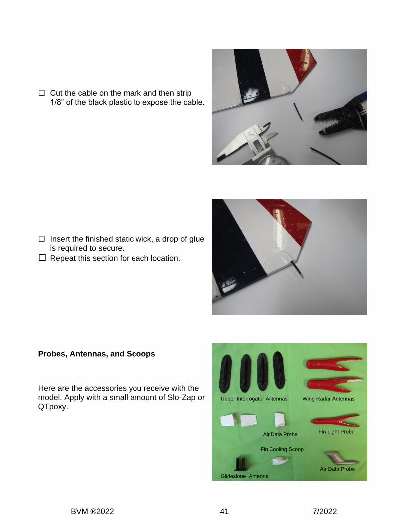
Cut the cable on the mark and then strip 1/8” of the black plastic to expose the cable.
Insert the finished static wick, a drop of glue is required to secure.
Repeat this section for each location.
Probes, Antennas, and Scoops
Here are the accessories you receive with the model. Apply with a small amount of Slo-Zap or QTpoxy.
Upper Interrogator Antennas
Fin Light Probe
Wing Radar Antennas
Fin Cooling Scoop
Air Data Probe
Glideslope Antenna
Air Data Probe

BVM ®2022 42 7/2022
Wing Radar Antennas
These are located 26.85” along the leading edge from the wing root.
Fin Light Probe
This is located between the panel lines on the upper part of the vertical fin.
Fin Cooling Scoop
Located below the rudder.

BVM ®2022 43 7/2022
Upper Interrogator Antenna
These are spaced evenly apart.
Air Data Probe
This has an indentation on the fuse below the Wing Strake on the starboard side.
Glidesloop Antenna
This is located just after the Nose Cone on the bottom of the fuse in the panel lined space.

BVM ®2022 44 7/2022
Control Surface Deflections and Expo Settings
Note: The BVM Demo plane is set up using the following Expo percentages. Positive values are used on Spektrum and JR radios, Futaba uses negative. Control High Rate Expo
Stabilator (measured at the L.E.)
Up 1.4” Down 1.6”
Up 17% Down 21%
Aileron (measured at the Root)
+/- ”1.8” 10% / 10%
Flaps- (Take-Off & Landing) (measured at the Root)
.4”
Rudder (measured at the Bot.)
+/- 1.25” 10% / 10%
Note: This model’s single flap setting was based on the full scale F-16. Anytime the gear was lowered or raised, the flaps went to a preset position.
Cut the templates from the last two pages of the manual. Use the heavy paper templates to setup control deflections. Align the “tick marks” to panel lines and dashed lines with model fuse line to locate the template onto the fuselage at the leading edge of the Stabilators, use tape to secure.
Aileron gauge
Rudder gauge
Stabilator gauge

BVM ®2022 45 7/2022
Connecting RX wires
The wires are labeled from the factory. If you are using the DX18, the program is available from BVM. Follow the chart below to connect the servos.
DX18 Connection Chart RX Port Throttle Aileron Elevator Rudder Gear Aux1
Surface Throttle Right Ail (Ail 2)
Right Elev (Elev 2)
Rudder Gear Seq.
Left Ail (Ail 1)
RX Port Aux2 Aux3 Aux4 Aux5 Aux6 Aux7
Surface Brakes Nose Steering
Left Elev (Elev 1)
Speed Brake
Lights Gyro
RX Port X-1 X-2 X-3 X-4 X-5 X-6
Surface Leave Open
Leave Open
Canopy Smoke
RX Port X-7 X-8
Surface
DX18 and DX18QQ Transmitter File
The BVM Demo models are setup on Spektrum DX18 transmitters. The file, if requested, has all the mixes, rates, expos, and settings done for you. Setting the sub trim and travel adjustment must be accomplished by the modeler for the specific aircraft.
Important!!! Check the directions of all flight controls before each flight. Switch/Lever/Trimmer Channel Output
Switch A Channel 5/Gear Landing Gear, Down is Down
Switch B X+1/Channel 11/Aux 6 Lights, Down is off, Up is on
Switch C Elevator Rates Up (0) is High
Switch D Flaperons, Ail and Aux 1 Up is Normal flight Mid is flaperon down w/ up elevator mix Down is “Taileron Mix”- for high-alpha
Button I Throttle Cut Throttle Cut
L. Trim Steering Trim/Aux 3 Down for Right Steering Trim Up for Left Steering Trim
Switch F Aileron Rates Up (0) is High
Switch G Rudder Rates Down/Away (0) is High
Switch H X-4/Smoke Down (0) Smoke off Up (1) Smoke on
Right Lever Aux 2/Brakes Up/Away – Brakes off Down/Pulled – Brakes on
Switch E Aux 5/Speed Brakes
Left Slider X-3/Canopy

BVM ®2022 46 7/2022
First Flight Profile Make the first flight with the gyro “off”. See also BVM article “Gyro Sense”. Flight Time The BVM demo model’s transmitter timer is set for 7 min. On the first flight, land a few minutes early to check fuel consumption. Adjust the flight timer accordingly.
Taxi Test/Engine Run Up A taxi test should include a radio range check with the engine running at various power levels. Check that the wheel brakes are adequate and the stopping action is without skidding or pulling left or right. Be sure to shake the aircraft and push fore and aft with the engine at half power, this will remove any trapped air bubbles in the fuel system. Check the fuel line to the engine for “no bubbles”.
Takeoff Begin the takeoff roll by slowly advancing the throttle. Maintain runway center while holding about 1/2 stick up elevator; the F-16 will rotate when it is ready. It there is a cross wind, hold a small amount of aileron into the wind, be prepared with opposite rudder. The aircraft does not need flaperons; we suggest making your first flights “clean wing”.
Trim Once in the air, find a medium cruise speed to set the trims. The aircraft should fly straight and level “hands off”. When the landing gear come down, a few clicks of up trim may be needed. This can be mixed in, or use flight modes to trim automatically.
Practice Approaches Save a few minutes at the end of your first flight to practice approaches and go arounds. It is beneficial to become familiar with the low speed handing of the aircraft.
Landing The landing is like most jets, “power on” during the approach. The F-16 does not stall easily, it is best to land nose high, touching on the main wheels first.
The majority of the first flight should be spent trimming and practicing for the first landing. Save the aerobatics and air show stuff for later flights.
RX Battery Consumption The average flight using the lights the entire flight consumes 500 mAh. We recommend two flights and recharge. Use this data to calculate how many flights you can achieve from your system. The use of the smoke pump will consume more mAh per flight. BVM recommends (2) 4500 mAh batteries.
BVM is synonymous with “Success Jets.” It is very important to us that you are successful with our products. This extensive manual reflects our sincerity. As always, your comments and suggestions on BVM products are appreciated.
BVM ®2022 47 7/2022
Torque Drive Pocket Reinforcement Check
Check the Rudder and Stabilator torque drive pockets.
One early kit had a Stab drive pocket improperly installed..
Because you cannot see inside these structures, this very simple procedure will assure that
the factory workers did not overlook another one.
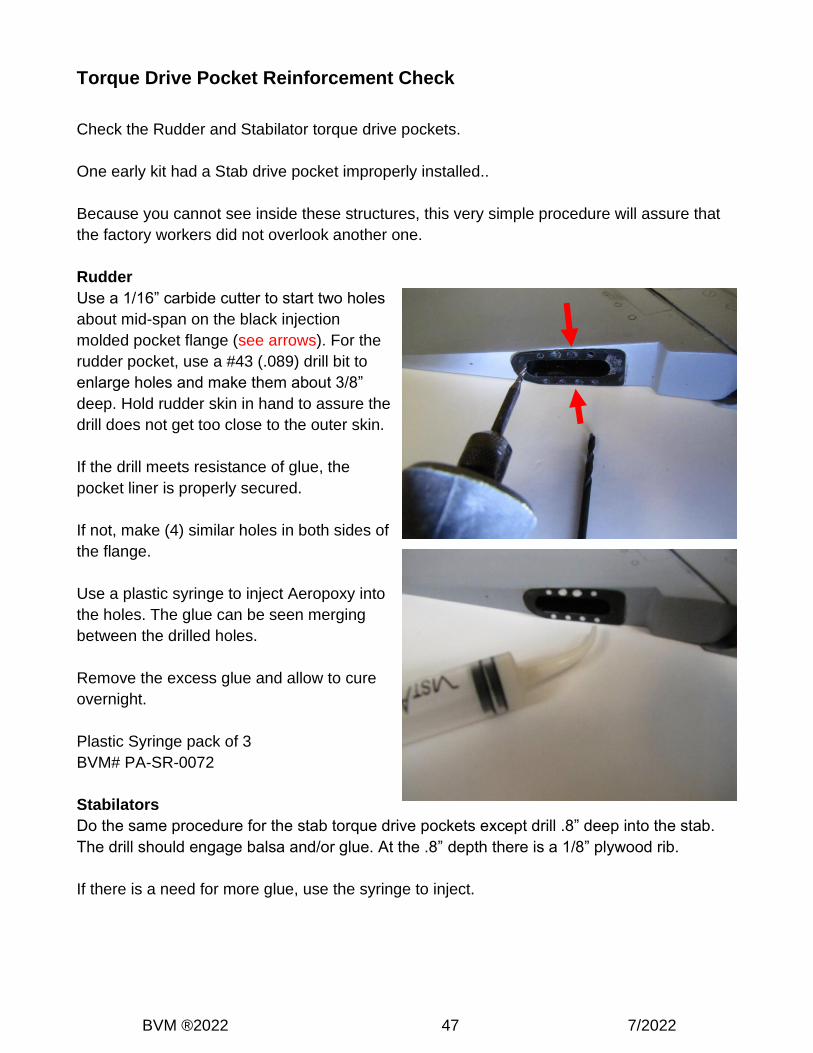
Rudder
Use a 1/16” carbide cutter to start two holes
about mid-span on the black injection
molded pocket flange (see arrows). For the
rudder pocket, use a #43 (.089) drill bit to
enlarge holes and make them about 3/8”
deep. Hold rudder skin in hand to assure the
drill does not get too close to the outer skin.
If the drill meets resistance of glue, the
pocket liner is properly secured.
If not, make (4) similar holes in both sides of
the flange.
Use a plastic syringe to inject Aeropoxy into
the holes. The glue can be seen merging
between the drilled holes.
Remove the excess glue and allow to cure
overnight.
Plastic Syringe pack of 3
BVM# PA-SR-0072
Stabilators
Do the same procedure for the stab torque drive pockets except drill .8” deep into the stab.
The drill should engage balsa and/or glue. At the .8” depth there is a 1/8” plywood rib.
If there is a need for more glue, use the syringe to inject.

BVM ®2022 48 7/2022
Pilot’s Notes: