


Building Data Centers with VXLAN BGP EVPN - HELLO DIGI
477
www.hellodigi.ir
-
Upload
khangminh22 -
Category
Documents
-
view
3 -
download
0
Transcript of Building Data Centers with VXLAN BGP EVPN - HELLO DIGI
www.hellodigi.ir

About This E-Book
EPUB is an open, industry-standard format for e-books. However, support for EPUBand its many features varies across reading devices and applications. Use your deviceor app settings to customize the presentation to your liking. Settings that you cancustomize often include font, font size, single or double column, landscape or portraitmode, and figures that you can click or tap to enlarge. For additional information aboutthe settings and features on your reading device or app, visit the device manufacturer’sWeb site.
Many titles include programming code or configuration examples. To optimize thepresentation of these elements, view the e-book in single-column, landscape mode andadjust the font size to the smallest setting. In addition to presenting code andconfigurations in the reflowable text format, we have included images of the code thatmimic the presentation found in the print book; therefore, where the reflowable formatmay compromise the presentation of the code listing, you will see a “Click here to viewcode image” link. Click the link to view the print-fidelity code image. To return to theprevious page viewed, click the Back button on your device or app.
www.hellodigi.ir
Building Data Centers with VXLANBGP EVPN
A Cisco NX-OS Perspective
Lukas Krattiger, CCIE No. 21921Shyam Kapadia
David Jansen, CCIE No. 5952
Cisco Press800 East 96th Street
Indianapolis, IN 46240
www.hellodigi.ir

Building Data Centers with VXLAN BGP EVPNA Cisco NX-OS PerspectiveLukas KrattigerShyam KapadiaDavid Jansen
Copyright© 2017 Cisco Systems, Inc.
Published by:Cisco Press800 East 96th StreetIndianapolis, IN 46240 USAAll rights reserved. No part of this book may be reproduced or transmitted in any formor by any means, electronic or mechanical, including photocopying, recording, or by anyinformation storage and retrieval system, without written permission from the publisher,except for the inclusion of brief quotations in a review.
Printed in the United States of America 1 2 3 4 5 6 7 8 9 0
First Printing April 2017Library of Congress Cataloging-in-Publication Number: 2017931984
ISBN-10: 1-58714-467-0
ISBN-13: 978-1-58714-467-7
Warning and DisclaimerThis book is designed to provide information about data center network design. Everyeffort has been made to make this book as complete and as accurate as possible, but nowarranty or fitness is implied.
The information is provided on an “as is” basis. The authors, Cisco Press, and CiscoSystems, Inc., shall have neither liability nor responsibility to any person or entity withrespect to any loss or damages arising from the information contained in this book orfrom the use of the discs or programs that may accompany it.
The opinions expressed in this book belong to the author and are not necessarily thoseof Cisco Systems, Inc.
Trademark AcknowledgmentsAll terms mentioned in this book that are known to be trademarks or service marks have
www.hellodigi.ir

been appropriately capitalized. Cisco Press or Cisco Systems, Inc., cannot attest to theaccuracy of this information. Use of a term in this book should not be regarded asaffecting the validity of any trademark or service mark.
Special SalesFor information about buying this title in bulk quantities, or for special salesopportunities (which may include electronic versions; custom cover designs; andcontent particular to your business, training goals, marketing focus, or brandinginterests), please contact our corporate sales department at [email protected] (800) 382-3419.For government sales inquiries, please contact [email protected].
For questions about sales outside the U.S., please contact [email protected].
Feedback InformationAt Cisco Press, our goal is to create in-depth technical books of the highest quality andvalue. Each book is crafted with care and precision, undergoing rigorous developmentthat involves the unique expertise of members of the professional technical community.Readers’ feedback is a natural continuation of this process. If you have any commentsregarding how we could improve the quality of this book or otherwise alter it to bettersuit your needs, you can contact by e-mail, at [email protected]. Please makesure to include the book title and ISBN in your message. We greatly appreciate yourassistance.
Editor-in-Chief: Mark Taub
Alliances Manager, Cisco Press: Ron Fligge
Product Line Manager: Brett Bartow
Executive Editor: Mary Beth Ray
Managing Editor: Sandra Schroeder
Development Editor: Christopher Cleveland
Project Editor: Mandie Frank
Copy Editor: Kitty Wilson
Technical Editors: Scott Morris, Jeff Tantsura
Editorial Assistant: Vanessa Evans
www.hellodigi.ir

Cover Designer: Okomon Haus
Composition: codeMantra
Indexer: Erika Millen
Proofreader: Abigail Manheim
Americas HeadquartersCisco Systems. Inc.San Jose, CA
Asia Pacific HeadquartersCisco Systems (USA) Pte. Ltd.Singapore
Europe HeadquartersCisco Systems International BVAmsterdam, The Netherlands Cisco has more than 200 offices worldwide. Addresses, phone numbers, and faxnumbers are listed on the Cisco Website at www.cisco.com/go/offices.
CCDE, CCENT, Cisco Eos, Cisco HealthPresence, the Cisco logo, Cisco Lumin,Cisco Nexus, Cisco StadiumVision, Cisco Telepresence, Cisco WebEx, DCE, andWelcome to the Human Network are trademarks; Changing the Way We Work, Live,Play, and Learn and Cisco Store are service marks; and Access Registrar, Aironet,AsyncOS, Bringing the Meeting To You, Catalyst, CCDA, CCDP, CCIE, CCIP, CCNA,CCNP, CCSP, CCVP, Cisco, the Cisco Certified Internetwork Expert logo, Cisco IOS,Cisco Press, Cisco Systems, Cisco Systems Capital, the Cisco Systems logo, CiscoUnity, Collaboration Without Limitation, EtherFast, EtherSwitch, Event Center, FastStep, Follow Me Browsing, FormShare, GigaDrive, HomeLink, Internet Quotient, IOS,iPhone, iQuick Study, IronPort, the IronPort logo, LightStream, Linksys, MediaTone,MeetingPlace, MeetingPlace Chime Sound, MGX, Networkers, Networking Academy,Network Registrar, PCNow, PIX, PowerPanels, ProConnect, ScriptShare, SenderBase,SMARTnet, Spectrum Expert, StackWise, The Fastest Way to Increase Your InternetQuotient, TransPath, WebEx, and the WebEx logo are registered trademarks of CiscoSystems, Inc. and/or its affiliates in the United States and certain other countries.
All other trademarks mentioned in this document or website are the property of theirrespective owners. The use of the word partner does not imply a partnershiprelationship between Cisco and any other company. (0812R)
www.hellodigi.ir

About the AuthorsLukas Krattiger, CCIE No. 21921 (Routing/Switching and Data Center), is principalengineer, Technical Marketing, with more than 15 years of experience in data center,Internet, and application networks. Within Cisco, he specializes in data centerswitching, overlay architectures, and solutions across platforms. Lukas is a double-CCIE (R&S and Data Center) with several other industry certifications and hasparticipated in various technology leadership and advisory groups. Prior to joiningCisco, Lukas was a senior network engineer with System Integrators and ServiceProviders, where he was responsible for data center and Internet networks. Sincejoining Cisco, he has covered various technologies within the data center as well asenterprise networks portfolio, and he has built foundational solutions for customers andpartners. He is from Switzerland and currently lives in California with his wife and onewonderful daughter. He can be found on Twitter at @ccie21921.
Shyam Kapadia is a principal engineer in the Data Center Group at Cisco Systems.With more than a decade of experience in the networking industry, Shyam holds morethan 30 patents and has coauthored the book Using TRILL, FabricPath, and VXLAN:Designing MSDC with Overlays. In his 10 years at Cisco, Shyam has worked on anumber of products, including the Catalyst and Nexus families of switches, with specialemphasis on end-to-end data center solutions, including automation and orchestration.He holds a Ph.D. and master’s degree from the University of Southern California in thefield of computer science. Over the past 15 years, Shyam has been the Program Chairfor the Southern California Linux Exposition (SCALE). He lives in California with hiswife, enjoys watching international movies, and is passionate about sports includingcricket, basketball, and football.David Jansen, CCIE No. 5952 (Routing/Switching), is a distinguished systems engineer(DSE) for Cisco, specializing in data center, campus, branch/WAN, and cloudarchitectures. He has 20 years of experience in the industry and has earned certificationsfrom Novell, VMware, Microsoft, TOGAF, and Cisco. His focus is working with globalenterprise customers to address their challenges with comprehensive end-to-end datacenter, enterprise, WAN/Internet, and cloud architectures. David has been with Ciscofor more than 19 years; for the last 4 years or so as a DSE, he has gained uniqueexperiences in building next generation data center solutions. David has a bachelor'sdegree in computer science engineering from the University of Michigan and a master'sdegree in adult education from Central Michigan University.
www.hellodigi.ir

About the Technical ReviewersScott Morris, the world traveling Über-Geek has four CCIE certifications (Routing &Switching, ISP/Dial, Security and Service Provider) as well as the coveted CCDE. Healso has several expert-level certifications from other major vendors, making him“multi-lingual” in the networking world.Working on large-scale network designs, troubleshooting, and some very interestingCyberSecurity projects, has kept Scott occupied. Outside of challenging work, Scott canbe found spending time with his family or finding new things to learn. Having more than30 years of experience in just about all aspects of the industry has provided both an in-depth and an entertaining approach to disseminating knowledge. Whether involved inlarge-scale designs, interesting implementations, or expert-level training, you can oftenfind Scott willing to share information.Jeff Tantsura has been in the networking space for 20+ years and hasauthored/contributed to many RFCs and patents. He is the chair of the IETF RoutingWorking Group, chartered to work on new network architectures and technologies,including protocol independent YANG models and working on YANG modeling as theworking group chair and contributor.Jeff is a coauthor of a recently published book, Navigating Network Complexity,talking, among other existing topics, about why networking has become so complex andthe urgent need for automation and programmable, model-driven networking.
www.hellodigi.ir

DedicationsFrom Lukas Krattiger:I want to dedicate this book to my family, especially my wife, Snjezi, and daughter,Nadalina. They have shown immense patience during nights, weekends, vacations, andother inconvenient times while this book project was being completed. I love you both!
From Shyam Kapadia:
I dedicate this book to my family, especially my wife, Rakhee, and my mother, for theirconstant love and support.
From David Jansen:
This book is dedicated to my loving wife, Jenise, and my three children, Kaitlyn,Joshua, and Jacob. You are the inspiration that gave me the determination to completethis project. To my three amazing children, you are learning the skills to be the best atwhat you do and to accomplish anything in life; keep up the great work. Thank you forall your love and support. I could not have completed yet another book without yourhelp, support, and understanding. I would also like to further dedicate this book to myparents, Michael and Dolores. You have given me the proper tools, guidance, attitude,drive, and education to allow me to do what I do. I’m likewise grateful to God, whogives endurance, encouragement, and motivation to complete such a large project likethis. In my last book dedication, I mentioned that I would not take on any additionalprojects like that one. As you can see, I had a hard time saying no when my good friendand colleague Lukas Krattiger convinced me to take on this project. Thank you, Lukas; itis always a pleasure, my friend. I truly enjoy working with you.
www.hellodigi.ir

AcknowledgmentsFrom Lukas Krattiger:First, I’d like to thank my coauthors, Shyam Kapadia and David Jansen. Shyam, thankyou for being such a great coworker and a true technical leader in our organization. Icould not imagine anyone better. It has been truly wonderful sharing ideas with you, andI look forward to addressing additional challenges and innovations with you in the nearfuture. David, thank you for stepping in to help tackle this project. You are anexceptional colleague, and it was a true pleasure working with you these manyengagements, especially the video series. Each of us has unique insights and gifts tocontribute, and both you and Shyam highlight the benefits the diversity in our communityprovides.
Likewise, I would like to send a special acknowledgment to the other team memberswith whom I am working. In particular, I would like to recognize Carl Solder as well asYousuf Khan for all the support and timely guidance. Special thanks to Victor Morenofor all the discussions and the groundbreaking work with overlays.I would also like to thank some individuals who are intimately involved with VXLANEVPN. In particular, Ali Sajassi, Samir Thoria, Dhananjaya Rao, Senthil Kenchiah (andteam), Neeraj Malhota, Rajesh Sharma, and Bala Ramaraj deserve special recognition.Similarly, all my engineering and marketing colleagues who support this innovativetechnology and have helped contribute to the completion of this book deserve specialrecognition.A special shout-out goes to all my friends in Switzerland, Europe, Australia, the UnitedStates, and the rest of the globe. Mentioning all of you here would create an additional11 chapters.Finally, writing this book provided me with the opportunity to get to know some newacquaintances. I would like to thank Doug Childress for his continuous edits andreviews on the manuscript, and I would also like to thank our technical editors, ScottMorris and Jeff Tantsura, for all the feedback they provided. Finally, I would like togive a special thanks to Cisco Press for all the support on this project.
From Shyam Kapadia:I would like to especially thank my coauthors, Lukas and David, for their collaborationand support. Lukas did the lion’s share in putting together this publication, and hedeserves substantial credit for that. It’s hard to imagine this book coming togetherwithout his tremendous contribution. Our collaboration over the past several years hasbeen extremely fruitful, and I look forward to additional joint innovations anddeliverables in the future. In addition, I would like to thank David, who has been a good
www.hellodigi.ir

role model for many individuals at Cisco, including me.I’d like to give a special acknowledgment to the engineering leadership team in the DataCenter group at Cisco for their constant support and encouragement in pursuing thisendeavor. This team includes Nilesh Shah, Ravi Amanaganti, Venkat Krishnamurthy,Dinesh Khurana, Naoshad Mehta, and Mahesh Chellappa.Like Lukas, I want to recognize individuals at Cisco involved in taking VXLAN BGPEVPN to the summit where it is today. I would also like to acknowledge thecontributions of the DCNM team for providing the management and controller aspects tothe programmable fabric solution with VXLAN BGP EVPN. I would like to also thankDoug Childress for helping review and edit the book chapters, and I offer a specialthanks to the reviewers and editors for their tremendous help and support in developingthis book. This is my second collaboration with Cisco Press, and the experience hasbeen even better than the first one.
From David Jansen:
This is my fourth book, and it has been a tremendous honor to work with the greatpeople at Cisco Press. There are so many people to thank, I’m not sure where to begin.First, I would like to thank my friends and coauthors, Lukas Krattiger and ShyamKapadia. Both of you are great friends as well as exceptional coworkers. I can’t think oftwo better people with whom to work or complete such a project. Cisco is one of themost amazing places I’ve ever worked, and people like you who are exceptionallyintelligent and an extreme pleasure to work with make it such a great place. I lookforward to working with you on other projects in the future and growing our friendshipfurther into as well.I would also like to acknowledge Chris Cleveland, with whom it is always a pleasureto work. His expertise, professionalism, and follow-up as a development editor areunsurpassed. I would like to specifically thank him for all his hard work and quickturnaround times in meeting the deadlines.To our technical editors, Jeff Tantsura and Scott Morris, I would like to offer a thankyou for your time, sharp eyes, and excellent comments/feedback provided during thisproject. It was a pleasure having you both as part of the team.I would like to also thank the heavy metal music world out there. It allowed me to stayfocused when burning the midnight oil. I would not have been able to complete thiswithout loud rock and roll music, air guitar, and air drums as well! So thank you.I want to thank my family for their support and understanding while I was working onthis project late at night. They were patient with me when my lack of rest may havemade me a little less than pleasant to be around. I know it is also hard to sleep whenDad is downstairs writing and fails to realize how the decibel level of the music isinterfering with the rest of the family’s ability to sleep.
www.hellodigi.ir
www.hellodigi.ir

Most importantly, I would like to thank God for giving me the ability to complete such atask with the required dedication and determination and for providing me the skills,knowledge, and health needed to be successful in such a demanding profession.
www.hellodigi.ir

Contents at a GlanceIntroduction
Chapter 1 Introduction to Programmable FabricChapter 2 VXLAN BGP EVPN BasicsChapter 3 VXLAN/EVPN Forwarding CharacteristicsChapter 4 The UnderlayChapter 5 MultitenancyChapter 6 Unicast ForwardingChapter 7 Multicast ForwardingChapter 8 External ConnectivityChapter 9 Multi-pod, Multifabric, and Data Center Interconnect (DCI)Chapter 10 Layer 4–7 Services IntegrationChapter 11 Introduction to Fabric ManagementAppendix A VXLAN BGP EVPN Implementation Options
Index
www.hellodigi.ir

ContentsIntroduction
Chapter 1 Introduction to Programmable FabricToday’s Data Center Challenges and RequirementsThe Data Center Fabric JourneyCisco Open Programmable Fabric
Fabric-Related TerminologyData Center Network Fabric Properties
Server or Endpoint Connectivity OptionsSummaryReferences
Chapter 2 VXLAN BGP EVPN BasicsOverlaysIntroduction to VXLAN
VXLAN Flood and Learn (F&L)Introduction to BGP EVPN with VXLAN
MP-BGP Features and Common PracticesIETF Standards and RFCsHost and Subnet Route DistributionHost Deletion and Move Events
SummaryReferences
Chapter 3 VXLAN/EVPN Forwarding CharacteristicsMultidestination Traffic
Leveraging Multicast Replication in the Underlying NetworkUsing Ingress Replication
VXLAN BGP EVPN EnhancementsARP Suppression
www.hellodigi.ir
Distributed IP Anycast GatewayIntegrated Route and Bridge (IRB)Endpoint MobilityVirtual PortChannel (vPC) in VXLAN BGP EVPNDHCP
SummaryReferences
Chapter 4 The UnderlayUnderlay Considerations
MTU ConsiderationsIP Addressing
IP Unicast RoutingOSPF as an UnderlayIS-IS as an UnderlayBGP as an UnderlayIP Unicast Routing Summary
Multidestination TrafficUnicast ModeMulticast ModePIM Any Source Multicast (ASM)BiDirectional PIM (PIM BiDir)
SummaryReferences
Chapter 5 MultitenancyBridge DomainsVLANs in VXLANLayer 2 Multitenancy: Mode of Operation
VLAN-Oriented ModeBD-Oriented Mode
www.hellodigi.ir

VRF in VXLAN BGP EVPNLayer 3 Multitenancy: Mode of OperationSummaryReferences
Chapter 6 Unicast ForwardingIntra-Subnet Unicast Forwarding (Bridging)Non-IP Forwarding (Bridging)Inter-Subnet Unicast Forwarding (Routing)
Routed Traffic to Silent EndpointsForwarding with Dual-Homed EndpointIPv6Summary
Chapter 7 Multicast ForwardingLayer 2 Multicast Forwarding
IGMP in VXLAN BGP EVPN NetworksLayer 2 Multicast Forwarding in vPCLayer 3 Multicast ForwardingSummaryReferences
Chapter 8 External ConnectivityExternal Connectivity Placement
External Layer 3 ConnectivityU-Shaped and Full-Mesh ModelsVRF Lite/Inter-AS Option ALISPMPLS Layer 3 VPN (L3VPN)External Layer 2 Connectivity
Classic Ethernet and vPCExtranet and Shared Services
www.hellodigi.ir

Local/Distributed VRF Route LeakingDownstream VNI Assignment
SummaryReference
Chapter 9 Multi-pod, Multifabric, and Data Center Interconnect (DCI)Contrasting OTV and VXLANMulti-pod
Interconnection at the Spine LayerInterconnection at the Leaf Layer
MultifabricInter-pod/Interfabric
Interfabric Option 1: Multi-podInterfabric Option 2: MultifabricInterfabric Option 3 (Multisite for Layer 3)Interfabric Option 4 (Multisite for Layer 2)
SummaryReferences
Chapter 10 Layer 4–7 Services IntegrationFirewalls in a VXLAN BGP EVPN Network
Routing ModeBridging ModeFirewall Redundancy with Static RoutingStatic Route Tracking at a Service LeafStatic Routing at a Remote LeafPhysical Connectivity
Inter-Tenant/Tenant-Edge FirewallServices-Edge DesignIntra-Tenant FirewallsMixing Intra-Tenant and Inter-Tenant Firewalls
www.hellodigi.ir

Application Delivery Controller (ADC) and Load Balancer in a VXLAN BGPEVPN Network
One-Armed Source-NATDirect VIP Subnet ApproachIndirect VIP Subnet ApproachReturn TrafficService Chaining: Firewall and Load Balancer
SummaryReferences
Chapter 11 Introduction to Fabric ManagementDay-0 Operations: Automatic Fabric Bring-Up
In-Band Versus Out-of-Band POAPOther Day-0 Considerations
Day-0.5 Operations: Incremental ChangesDay-1 Operations: Overlay Services ManagementVirtual Topology System (VTS)Nexus Fabric Manager (NFM)Data Center Network Manager (DCNM)
Compute IntegrationDay-2 Operations: Monitoring and Visibility
VXLAN OAM (NGOAM)SummaryReferences
Appendix A VXLAN BGP EVPN Implementation OptionsEVPN Layer 2 ServicesEVPN IP-VRF to IP-VRF ModelReferences
Index
www.hellodigi.ir

www.hellodigi.ir

IntroductionBuilding Data Centers with VXLAN BGP EVPN is intended to provide a solidunderstanding of how data center network fabrics with VXLAN BGP EVPN function. Itserves as both a technology compendium and a deployment guide.Cisco’s NX-OS-based data center switching portfolio provides a collection ofnetworking protocols and features that are foundational to building data center networksas traditional networks evolve into fabric-based architectures, like VXLAN with theBGP EVPN control plane.This book’s goal is to explain how to understand and deploy this technology, and itbegins with an introduction to the current data center challenges, before going into thetechnology building blocks and related semantics. It also provides an overview of theevolution of the data center fabric. The book takes a deep dive into the various fabricsemantics, including the underlay, multitenancy, control and data plane interaction,unicast and multicast forwarding flows, and external, data center interconnect, andservice appliance deployments.
Goals and MethodsThe goal of this book is to provide a resource for readers who want to get familiar withdata center overlay technologies, especially VXLAN with a control plane like BGPEVPN. This book describes a methodology that network architects and administratorscan use to plan, design, and implement scalable data centers. You do not have to be anetworking professional or data center administrator to benefit from this book. The bookis geared toward understanding the functionality of VXLAN with BGP EVPN in datacenter fabric deployments. Our hope is that all readers, from university students toprofessors to networking experts, will benefit from this book.
Who Should Read This Book?This book has been written with a broad audience in mind, while specifically targetingnetwork architects, engineers, and operators. Additional audiences who will benefitfrom reading this book include help desk analysts, network administrators, andcertification candidates. This book provides information on VXLAN with BGP EVPNfor today’s data centers.
For a network professional with in-depth understanding of various networking areas,this book serves as an authoritative guide, explaining detailed control and data planeconcepts, with VXLAN and BGP EVPN being the primary focus. Detailed packet flowsare presented, covering numerous functions, features, and deployments.Regardless of your level of expertise or role in the IT industry, this book offers
www.hellodigi.ir

significant benefits. It presents VXLAN and BGP EVPN concepts in a consumablemanner. It also describes design considerations for various fabric semantics andidentifies the key benefits of adopting this technology.
How This Book Is OrganizedAlthough this book slowly progresses conceptually from Chapter 1 to Chapter 11, youcould also read individual chapters that cover only the material of interest. The firstchapter provides a brief introduction to the evolution of data center networks, with anemphasis on the need for network overlays. Chapters 2 and 3 form the foundation forVXLAN BGP EVPN. The subsequent chapters describe underlying or adjacent buildingblocks to VXLAN BGP EVPN, with an emphasis on Layer 2 and Layer 3 services andthe associated multitenancy. Chapter 10 describes the integration of Layer 4–7 servicesinto a VXLAN network with BGP EVPN, while Chapter 11 concludes the book with anoverview of fabric management and operations.The chapter breakdown is as follows:
Chapter 1, “Introduction to Programmable Fabric.” This chapter provides abrief introduction to the Cisco VXLAN BGP EVPN fabric. It begins with adescription of the requirements of today’s data centers. It also gives an overview ofhow data centers evolved over the years, leading to a VXLAN BGP EVPN-basedspine–leaf fabric. This chapter introduces common fabric-based terminology anddescribes what makes the fabric extremely scalable, resilient, and elastic. Chapter 2, “VXLAN BGP EVPN Basics.” This chapter describes why overlayshave become a prime design choice for next-generation data centers, with a specialemphasis on VXLAN, which has become the de facto choice. The chapter describesthe need for a control plane–based solution for distribution of host reachabilitybetween various edge devices and provides a comprehensive introduction to BGPEVPN. It describes the important message formats in BGP EVPN for supportingnetwork virtualization overlays and presents representative use cases. Thesubsequent chapters build on this background and provide further details on theunderlay, multitenancy, and single-destination and multidestination data packetflows in a VXLAN BGP EVPN–based data center network. Chapter 3, “VXLAN/EVPN Forwarding Characteristics.” This chapter providesan in-depth discussion on the core forwarding capabilities offered by a VXLANBGP EVPN fabric. For carrying broadcast, unknown unicast, and multicast (BUM)traffic, this chapter describes both multicast and ingress replication. It alsodiscusses enhanced forwarding features that reduce flooding in the fabric onaccount of ARP and unknown unicast traffic. This chapter describes one of the keybenefits of a BGP EVPN fabric: the realization of a Distributed Anycast Gateway at
www.hellodigi.ir

the ToR or leaf layer. Chapter 4, “The Underlay.” This chapter describes the BGP EVPN VXLANfabric underlay that needs to be able to transport both single-destination andmultidestination overlay traffic. The primary objective of the underlay is to providereachability among the various switches in the fabric. This chapter presents IPaddress allocation options for the underlay, using both point-to-point IP numberedoptions and the rather attractive IP unnumbered option. It also discusses choices ofpopular IGP routing protocols, such as OSPF, IS-IS, and BGP for unicast routing.The chapter also describes the two primary choices for multidestination trafficreplication in the underlay: the unicast and multicast mode. Chapter 5, “Multitenancy.” This chapter describes how multitenancy has becomea prime feature for next-generation data centers and how it is realized in the datacenter network with VXLAN BGP EVPN. In addition to discussing multitenancywhen using VLANs or Bridge Domains (BDs) in VXLAN this chapter coversmodes of operation for both Layer 2 and Layer 3 multitenancy. Overall, this chapterprovides a basic introduction to the main aspects of multitenancy when using datacenter networks with VXLAN BGP EVPN. Chapter 6, “Unicast Forwarding.” This chapter provides a set of sample packetflows that indicate how bridging and routing operations occur in a VXLAN BGPEVPN network. Critical concepts related to IRB functionality, symmetric IRB, anddistributed anycast gateway are described in action for real-world traffic flows.This chapter pays special attention to scenarios with silent hosts as well as dual-homed hosts. Chapter 7, “Multicast Forwarding.” This chapter provides details aboutforwarding multicast data traffic in a VXLAN BGP EVPN network. It discussesvanilla Layer 2 multicast traffic forwarding over VXLAN, as well as topics relatedto its evolution with enhancements in IGMP snooping. It also presents specialconsiderations for dual-homed and orphan multicast endpoints behind a vPCdomain. Chapter 8, “External Connectivity.” This chapter presents external connectivityoptions with a VXLAN BGP EVPN fabric. After introducing the border leaf andborder spine variants, it provides details on options for external Layer 3connectivity using VRF Lite, LISP, and MPLS L3 VPN. It also details Layer 2external connectivity options, with an emphasis on vPC. Chapter 9, “Multi-pod, Multifabric, and Data Center Interconnect (DCI).” Thischapter describes various concepts related to multi-pod and multifabric optionswith VXLAN BGP EVPN deployments. It provides a brief primer on the salientdistinctions between OTV and VXLAN. Most practical deployments require some
www.hellodigi.ir

form of interconnection between different pods or fabrics. This chapter discussesvarious considerations that need to be taken into account when making a decision onwhen to use the multi-pod option versus the multifabric option. Chapter 10, “Layer 4–7 Services Integration.” This chapter provides details onhow Layer 4–7 services can be integrated into a VXLAN BGP EVPN network. Itcovers deployments with intra-tenant and inter-tenant firewalls, which can bedeployed in both transparent and routed modes. In addition, this chapter presents acommon deployment scenario with load balancers, with emphasis on the nuancesassociated with its integration into a VXLAN BGP EVPN network. The chapterconcludes with a common load balancer and firewall service chain deploymentexample. Chapter 11, “Introduction to Fabric Management.” This chapter introduces thebasic elements of fabric management, including POAP-based day-0 provisioning(using DCNM, NFM, and so on), incremental configuration using day-0.5configuration, overlay configuration using day-1 provisioning (using DCNM, VTS,and NFM), and day-2 provisioning, which involves provisions for continuousmonitoring, visibility, and troubleshooting capabilities in a VXLAN BGP EVPNfabric. It presents a brief primer on VXLAN OAM, which is an extremely efficienttool for debugging in overlay-based fabrics.
Command Syntax ConventionsThe conventions used to present command syntax in this book are the same conventionsused in the NX-OS Command Reference:
Boldface indicates commands and keywords that are entered literally, as shown. Inactual configuration examples and output (not general command syntax), boldfaceindicates commands that are manually input by the user (such as a show command). Italics indicate arguments for which you supply actual values. Vertical bars (|) separate alternative, mutually exclusive elements. Square brackets [ ] indicate optional elements. Braces { } indicate a required choice. Braces within brackets [{ }] indicate a required choice within an optional element.
www.hellodigi.ir

Chapter 1 Introduction to Programmable Fabric
In this chapter, the following topics will be covered:
Requirements of today’s data centers Evolution of data center technology from Spanning Tree Protocol (STP) to VXLANBGP EVPN Programmable fabric concepts
Data centers have evolved significantly over the past few years. This evolution hasoccurred rapidly and within a relatively short time period, bringing populartechnologies such as virtualization, the cloud (private, public, and hybrid), softwaredefined networking (SDN),1 and big data. For the mobile-first and cloud-native age,scale, agility, security, consolidation, and integration with compute/storageorchestrators are common data center requirements. In addition, visibility, automation,ease of management, operability, troubleshooting, and advanced analytics are alsoexpected to be part of today’s data center solutionsThe shift away from a device-by-device management toward a more service-centricsystem has already taken place. Open application programming interfaces (APIs) andstandards-based protocols that prevent single-vendor lock-in are prime criteria in mostcustomer requests for proposals (RFPs). The Cisco Virtual Extensible LAN (VXLAN)with BGP Ethernet VPN (EVPN)–based fabric presents a unified data center solutioncomposed of the data center Nexus family of switches2 running NX-OS coupled withcontrollers.
While this book focuses on NX-OS-based EVPN, the information presented is alsoapplicable for platforms running IOS-XE3 and IOS-XR4 operating systems. This chapterpresents some of the challenges and requirements that led to the evolution of the datacenter network fabric. It provides a brief primer on the architecture and commonly usedterms associated with the programmable fabric or Cisco’s VXLAN BGP EVPN– basedfabric.
Today’s Data Center Challenges and RequirementsIn the past, the desire for instant elasticity and agility was perhaps not as pervasive as itis today, considering the application expectations from data centers. It took days orweeks to deploy applications. But with the evolution of the data center—and the cloudin particular—deployment time today is expected to be minutes or even seconds.
Not only is the speed of deployment critical, but it is important to be able to scale-up as
www.hellodigi.ir

workload requirements expand. In addition, paying only for what is actively being usedhas become the norm. The requirements for high-availability access to applications andtheir associated data have become increasingly stringent. While the demand foravailability has been driven by the widespread globalization of enterprises acrosscontinents, applications have also become increasingly sophisticated.
In this new landscape, where all workloads and applications are being moved over tothe data centers, the traditional designs for data centers are no longer sufficient toaddress all the requirements. This is the case regardless of whether data centers exist incombination with a private cloud, public cloud, or hybrid cloud. Given the currentenvironment, some of the key demands of today’s data center deployments are asfollows:
Agility: Agility defines how long it takes for an application request to be fulfilled.An agile data center is one that is able to reduce this time to a minimum. Scalability: Scalability is of paramount importance, especially in cloud-based datacenters. A data center should be able to house thousands of tenants and severalthousand tenant networks. The 4096 (or 4K) network limitation imposed by the 12-bit VLAN field is not sufficient for supporting large multitenant data centers. Elasticity: A data center must be able to adapt to changing demands andrequirements. This might involve the addition of compute workloads, additionalstorage, additional network bandwidth, and so on. A data center must be able to addcapacity to address the increase in demand without affecting existing applicationworkloads. Availability: A data center must be able to be constantly operational (24/7, 365days a year). In addition, access to applications needs to be available from all typesof devices (such as tablets, smart phones, and smart watches), which advances thebring-your-own-device (BYOD) model to an entirely new level. For highavailability, disaster recovery (DR) requirements often specify that potentialbackup options are available that can take over whenever some kind of failureoccurs at the primary data center site. Low cost: The total cost of ownership (TCO) for a data center comprises both thecapital expenditure (CAPEX) and the operating expenditure (OPEX). While theCAPEX portion is amortized over time, the OPEX portion is a continuousexpenditure. As a result, OPEX is under close scrutiny from most CIOs/CFOs.Reducing OPEX for data centers is thus commonly a high-priority item. Openness: To prevent a tie-in with a single vendor, a push toward building datacenters with standards-based options exists from both hardware and softwarepoints of view. Most large-scale data centers have already moved to a white-box or
www.hellodigi.ir

branded white-box (Brite-box) model. Enterprise and service providers are alsodemanding open standards–based data center deployments. Security: Especially in multitenant data center deployments, a prime requirement isto impose effective security policies to ensure that traffic from a tenant iscompletely isolated from another tenant. Some of the other security-relatedrequirements include enforcement of application policies, prevention ofunauthorized access, detection of threats, isolation of infected devices, distributionof secure patches to affected devices, and consistent policy applications betweenthe private cloud and public cloud. Solution orientation: The days of a box-by-box deployment within a data centerhave passed. Today’s data centers demand a unified solution with various pieces inplace from a network point of view, and they also require close integration withcompute and storage orchestrators as well as service appliances (physical andvirtual). In addition, sophisticated automation in conjunction with an SDNcontroller is required in this highly competitive space. Ease of use: Even with a solution-oriented approach, continuous management,monitoring, and visibility into the day-to-day operations of a data center is highlydesirable. Ease of use has a direct impact on reducing the OPEX. Support for hybrid deployments: Both enterprises and service providers havealready adopted the cloud model to some extent. As a result, one of the keyrequirements of a data center is support for hybrid cloud deployments whereresources from the public cloud can be extended over to the private enterprise datacenter in an elastic manner. Such operations must be seamless from the point ofview of the applications. In other words, applications should be completelyunaware of whether they are hosted on premises or off premises. Power efficiency: A large portion of the operational cost of a data center isattributed to its electrical power requirements. The networking industry at large anddata center vendors in particular are cognizant of this requirement, and the incentiveto build progressively green data centers certainly exists.
The Data Center Fabric JourneyFigure 1-1 depicts the evolution of data center networks over the past several years.Spanning Tree Protocol (STP)–based networks served network requirements forseveral years. Virtual PortChannel (vPC)5 was introduced to address some of thedrawbacks of STP networks while also providing dual-homing abilities. Subsequently,overlay technologies such as FabricPath6 and TRILL7 came to the forefront, introducingrouted Layer 2 networks with a MAC-in-MAC overlay encapsulation. This evolved intoa MAC-in-IP overlay with the invention of VXLAN.8
www.hellodigi.ir

While Layer 2 networks evolved beyond the loop-free topologies with STP, the first-hop gateway functions for Layer 3 also became more sophisticated. The traditionalcentralized gateways hosted at the distribution or aggregation layers have transitioned todistributed gateway implementations. This has allowed for scaling out and removal ofchoke points. This section provides an overview of why and how this evolution hasoccurred.
www.hellodigi.ir

www.hellodigi.ir

Figure 1-1 Data Center Network JourneyBuilding a loop-free Layer 2 network that enables devices in the same broadcastdomain to communicate with each other, was the initial development that made localarea networks (LANs) extremely popular. Within a broadcast domain, forwarding isbased on a MAC address–based lookup. STP, which was standardized as IEEE802.1D,9 prescribed a methodology for creating a tree topology that is, by definition,loop free. By making this a plug-and-play function, STP-based networks with IEEE802.1Q10 support gained rapid adoption and are still being used today.
With many technologies, shortcomings become readily apparent when a technology orprotocol is designed for one specific environment but is then applied to anotherenvironment that has a completely different set of requirements. This has been the casewith STP-based networks. Various issues make the adoption of STP for a large datacenter network, difficult. Some of the major issues include the following:
Convergence issues: On a link failure or switch failure in STP-based networks,the tree needs to be recalculated. This can significantly impact traffic convergencetimes because topology change notifications result in clearing the MAC tables onthe switches. As a result, relearning of the state is required. This problem becomesamplified when the root node goes down and a new one needs to be elected. Whiletimers can be tweaked to reduce the effect of failures, the inherent problem persists.As link speeds go from 10G to 40G to 100G, even subsecond convergence timescan result in significant traffic drops. High convergence times are thus one of themain drawbacks of STP-based networks. Unused links: As mentioned earlier, STP builds a tree in order to ensure that theresultant network topology has no cycles or loops. One potential side effect of thisis that many of the links between the various switches, which are part of thetopology, are placed in a blocked state and rendered redundant. Consequently,network resources are not optimally utilized. Currently, having the ability toleverage all links and their corresponding bandwidth in order to attain optimal useof existing resources, is a desired goal. Suboptimal forwarding: Because the tree is rooted at a particular switch with STP,all traffic from that switch to any other switch in the topology will be forwardedalong a single path. Because traffic is always forwarded along this tree, a shorterpath between a pair of non-root switches, if it exists, will not be utilized.Consequently, traffic between those switches will be suboptimally forwarded, andthis is certainly a less-than-ideal situation. Lack of Equal-Cost MultiPath (ECMP) routing: Because only one path is activebetween a source switch and a destination switch in a traditional STP-based Layer
www.hellodigi.ir

2 network, ECMP options are absent. Layer 3 networks, on the other hand, providethe ability to leverage more than one equal-cost path between a pair of routers. Thisis extremely desirable and is one of the major reasons Layer 3 networks havegained popularity. Traffic storm issues: With a tree topology, traffic starting from a switch should notbe sent back to that switch; however, traffic may still loop endlessly within anetwork in certain failure states. Such an occurrence could potentially bring downthe entire network. This scenario has been termed a broadcast storm. Any kind ofnetwork storm can chew up unnecessary bandwidth within the network and shouldbe avoided at all costs. Because there is no Time to Live (TTL) field in a Layer 2header, once a storm is introduced, the traffic could flow endlessly. Layer 3networks have a fail-safe mechanism due to the presence of the TTL field and anassociated decrement at every routed hop. Once the TTL becomes 0, the packet isdropped. The lack of such a liveliness field in Layer 2 networks immensely limitsscalability, especially as the size of the network grows. Lack of dual-homing support: STP inherently does not allow a device or host tobe attached to more than one switch. When that is attempted, a loop is formed, andSTP essentially blocks one of the links. Consequently, from a redundancy or faulttolerance point of view, if that switch goes down, traffic to and from thedownstream device or host is black-holed until the tree is recalculated. Network scale: In the age of cloud computing, significant constraints can beintroduced as a result of having only a 4K network namespace, especially with theaddressing and numbering for tenant networks. Even a medium-sized data centerdeployment can host several tenants, each of which might have a set of networksthat summed together exceeds this limit. Unfortunately, due to the 12-bit identifierthat represents a VLAN or a broadcast domain in the IEEE 802.1Q or dot1q header,4K is quite limiting. When dot1q was introduced a few decades ago, perhaps theinventors thought that 4K would be a large enough namespace; however, significantadvances in networking technology resulted in this number being exceeded in arelatively short time period.
Technologies such as virtual PortChannel (vPC), Multichassis EtherChannel (MCEC)11
and virtual switching system (VSS)12 allow a downstream device (host or switch) toattach to a pair of switches. All these technologies fall under the umbrella of Multi-Chassis Link Aggregation (MC-LAG).13 With vPC, a pair of switches (called vPCpeers) is configured such that the rest of the network sees the pair as a single logicalswitch.
Figure 1-2 shows how a typical STP network can be made more efficient with vPC. Thedownstream device is attached to both vPC peers using a regular PortChannel or
www.hellodigi.ir

EtherChannel configuration. Both links are in an active state, thereby allowing active-active forwarding. Traffic from the downstream device may hash over to either peer andbe appropriately forwarded. Similarly, traffic to the downstream device may flowthrough either peer. Multidestination traffic to the downstream device is sent via onlyone of the peers, thereby avoiding duplication.
Figure 1-2 STP to vPC Improvement
Each vPC peer has a primary role and a secondary role. Information between the vPCpeers is synchronized over a control channel termed the vPC peer link. This informationincludes MAC, ARP, and neighbor-discovery (ND) information as well as variousconfiguration and consistency check parameters. Not only does vPC provide dual-homing from a Layer 2 perspective, but its active-active forwarding semantics alsoextend to first-hop redundancy protocols (FHRPs) like Hot-Standby Router Protocol(HSRP)14 and Virtual Router Redundancy Protocol (VRRP).15 This reflected asignificant improvement over traditional FHRP deployments with active-standbybehavior where only the active node was forwarding data traffic. With the presence ofvPC, both vPC peers forward data traffic simultaneously, while the active FHRP vPCpeer resolves ARP/ND requests from the control-plane perspective only. (For moreinformation on vPC, see the Cisco vPC design best practices guide.16)
While vPC addresses some limitations of STP, it remains limited to a pair of switches.A more generic multipath solution was desired, especially as the requirements ofbuilding an extremely large scalable Layer 2 domain developed. As the number ofendpoints within Layer 2 networks expanded, it became impractical for all switcheswithin a network to learn all endpoint MAC addresses.In addition, the plug-and-play behavior of Layer 2 networks was still desirable. As a
www.hellodigi.ir

result, overlay technologies such as FabricPath and TRILL were introduced. Overlaysin general provide a level of abstraction. With the separation of the host address spacefrom the topology address space, overlays allow both of these to scale independently.
Cisco FabricPath is a MAC-in-MAC encapsulation that eliminates the use of STP inLayer 2 networks. It uses Layer 2 Intermediate System to Intermediate System (IS-IS)with appropriate extensions to distribute the topology information among the switchesthat are part of the network. In this way, switches behave like routers, building switchreachability tables and inheriting all the advantages of Layer 3 strategies such as ECMP.In addition, no unused links exist in this scenario, while optimal forwarding betweenany pair of switches is promoted. One of the salient features of FabricPath is thesimplicity with respect to configuration and enablement. Only the global feature needsto be enabled, along with a couple of commands related to putting a VLAN and thenetwork-facing ports in a specific mode. The switch ID allocation, the enablement ofIS-IS, and the discovery of the switch topology happen under the hood.At the same time, the IS-IS protocol is employed to build appropriate multidestinationtrees, thereby allowing optimal forwarding of Broadcast, Unknown Unicast, Multicast(BUM) traffic. vPC was extended to vPC+17 for supporting dual-homed devices inFabricPath networks.
In FabricPath, every switch in the network has a unique switch identifier, or switch ID.Figure 1-3 provides a snapshot of the FabricPath header.
Figure 1-3 FabricPath Header
As shown in Figure 1-3, the outer MAC header encodes the destination and sourceswitch ID. In addition, a forwarding tag (FTAG field) is used for topologyidentification.
For multidestination traffic, the FTAG field identifies the tree along which BUM trafficmust be forwarded. In a FabricPath network, endpoints are attached to edge switches.Core switches interconnect various edge switches with each other. The edge switcheslearn about directly attached endpoints in a manner similar to traditional Layer 2
www.hellodigi.ir

network learning. When traffic is sent over the FabricPath network, however, the edgeswitches add a FabricPath header with its own source switch ID and an appropriatedestination switch ID. In that sense, MAC learning is still achieved via Flood and Learn(F&L) semantics, but in this situation, switches learn remote MAC addresses against theappropriate remote switch ID.
The core switches in the network only need to forward traffic based on the FabricPathheader. They are completely unaware of the endpoints. The core switches can thereforebe lean, and, in general, this helps the network scale.For improving the scale on the edge switches, Layer 2 conversational learning isenabled by default in a FabricPath network. With Layer 2 conversational learning,switches only learn about remote endpoints in active conversation.
While Layer 2 ECMP became available with FabricPath, the scale-out of first-hoprouting for endpoints (aka the default gateway) was also desired. With Anycast HSRP,18
a four-way active-active FHRP for FabricPath was introduced, allowing a morescalable approach than the classic centralized two-way active-active approach withvPC.
While FabricPath has been immensely popular and adopted by thousands of customers,it has faced skepticism because it is associated with a single vendor, Cisco, as well as alack of multivendor support. In addition, with IP being the de facto standard in thenetworking industry, a push for an IP-based overlay encapsulation occurred. As a result,VXLAN was introduced.VXLAN, a MAC-in-IP/UDP encapsulation, is currently the most popular overlayencapsulation in use. As an open standard, it has received widespread adoption fromnetworking vendors. Just like FabricPath, VXLAN addresses all the STP limitationspreviously described. However, in addition, with VXLAN, a 24-bit number identifies avirtual network segment, thereby allowing support for up to 16 million broadcastdomains as opposed to the traditional 4K limitation imposed by VLANs.
Because VXLAN runs over an IP network, the ECMP feature of Layer 3 networks isinnately available for use. In general, an overlay such as VXLAN running on top ofLayer 3 can use hierarchical addressing with IP and any transport. However, an overlaysuch as FabricPath that uses a MAC-in-MAC encapsulation requires a transparent Layer1 transport that cannot be addressed in a scalable manner because MAC addresses arerepresented by a flat address space. In essence, with VXLAN, data center networkshave moved from being transport dependent to any-transport (aka transport independent)with the use of IP. As a result, the previous flat MAC-based addressing scheme for theunderlay has moved to a hierarchical IP-based addressing scheme.
The edge switches in a VXLAN network are called edge devices, and they host thewww.hellodigi.ir

VXLAN Tunnel Endpoint (VTEP). The edge switches are responsible for encapsulationand decapsulation of the VXLAN header. The core switches that interconnect thevarious VTEPs are regular IP routers. Notably, these do not need to have anyspecialized hardware or software functionality. Also, the switches within a VXLANnetwork learn about each other using regular routing protocols such as OSPF, Layer 3IS-IS, and so on.
The VTEPs learn about their directly attached endpoints using regular Layer 2 learningsemantics. Remote endpoints are learned through a process known as VXLAN Floodand Learn (F&L). Toward the VXLAN core, VTEPs take the original Layer 2 framefrom an endpoint and add a VXLAN header. This header contains the outer source IPaddress (SIP) set to its own VTEP IP and an outer destination IP address (DIP) set to theVTEP IP below which the destination endpoint is attached.With VXLAN, the endpoint-to-VTEP binding is learned using F&L semantics. Typically,every network is identified with a unique Layer 2 virtual network identifier (L2 VNI)and associated with a multicast group. Multidestination traffic from a VTEP isforwarded toward the VXLAN core with the destination IP set to the multicast groupassociated with the corresponding Layer 2 network. In this way, remote VTEPs that arepart of the same Layer 2 network will receive that traffic because they are part of thesame multicast tree.
After decapsulation, VTEPs perform MAC learning of remote MAC addresses againstthe associated remote VTEPs (specifically L2 VNI, SMAC to VTEP SIP). As with anyother overlay, the core switches forward traffic based only on the outer header, in thiscase, the outer IP header and are unaware of the endpoint addresses. With non-multicastoptions for VXLAN F&L, the IP core network does not need to support IP multicast.
With the non-multicast option, the VTEPs need to support ingress or head-endreplication. Here, multiple replicas are generated and individually unicast to everymember remote VTEP for every multidestination frame. With VXLAN F&L, a similarapproach is performed for the first-hop gateway as with classic Ethernet. A two-wayactive-active FHRP in conjunction with vPC introduces a centralized gatewayapproach.Today, VXLAN is one of the few overlay protocols that can be used both as a networkoverlay and a host overlay. This means the VXLAN header can beencapsulated/decapsulated and processed not only at the VXLAN-capable networkswitches but also at the server hosts themselves. This allows for extremely flexibleimplementation options with seamless physical-to-virtual integration. In addition,proposals are already in place for the next overlay evolution, in the form of GenericProtocol Encapsulation (GPE) and Network Service Header (NSH). However,
www.hellodigi.ir

ratification of these options may take some time.19 For now, VXLAN remains the defacto overlay protocol for data center deployments.
Cisco Open Programmable FabricWith the introduction of VXLAN as a competent standards-based data center overlaysolution, learning within a VXLAN network was still based on F&L semantics. Years ofnetworking experience showed that flooding-based approaches eventually presentscalability challenges.
Regardless, flooding provided a mechanism to learn about endpoint, specifically remoteMAC to VTEP bindings so that subsequent traffic can be unicast. However, if this samemapping could be distributed to the various edge devices or VTEPs employing a controlprotocol, then the need for flooding could potentially be completely eliminated.
With extensions to the BGP EVPN address family, it is now possible to distributeendpoint (IP, MAC)-to-VTEP bindings within a VXLAN network. In this way, themoment an endpoint is learned locally at a VTEP, using BGP EVPN, this reachabilityinformation can be distributed to all the interested VTEPs. Any traffic to this endpointcan then be optimally forwarded from any other VTEP without the need for any floodtraffic.While elimination of flooding for Layer 2 traffic certainly helps scalability to a largeextent in a VXLAN network with BGP EVPN support, Layer 3 traffic can also beoptimally forwarded in these networks, using specific methodologies. Before discussingthese options, however, this chapter provides a brief primer regarding traditional Layer3 traffic forwarding in a data center network.
The classic three-tier topology has served the networking industry for a fairly long timeperiod (see Figure 1-4). Typically, endpoints or servers are attached to the access layer,which has Layer 2 support only with appropriate VLAN and switch port configurations.For inter-subnet communication, traffic from the endpoints is routed via the aggregationor distribution layer switches.
www.hellodigi.ir

Figure 1-4 Classic Three-Tier TopologyThe default gateway for the endpoints is hosted at the aggregation layer in the form ofLayer 3 SVIs or IRB interfaces. For redundancy, aggregation layer switches areconfigured with FHRPs such as HSRP or VRRP. Various aggregation layer switches arein turn interconnected via core layer switches. Appropriate Layer 3 protocols allowexchange of prefix information between aggregation and core layer switches.
With large-scale data center deployments, three-tier topologies have become scalebottlenecks. As the number of endpoints within a network expands, the number of IP-MAC bindings stored within the aggregation layer switches also increases,consequently requiring support for a large FIB table. In addition, the control planeoverhead in terms of ARP and ND refreshes that need to be handled by these switchesalso expands significantly. This issue, coupled with the number of Layer 3 interfacesand corresponding tenant VRFs that can be hosted at the aggregation layer switches,yields big problems.
With the agility and elasticity requirements, relocating any workload to areas whereresources are available, is desirable. With three-tier topologies, unnecessary“tromboning” of traffic through aggregation switches, which host the correspondingdefault gateways, offers the best-case scenario. In the worst-case scenario, theworkloads may only be brought up below servers that are behind the directly attachedaccess layer switches in a given aggregation POD.For 4K VLANs, the aggregation layer switches might suffer from huge scalability
www.hellodigi.ir
challenges. Therefore, with VXLAN in the picture, and its support for up to 16 millionvirtual networks, a traditional three-tier topology cannot survive such a burden. Theindustry at large recognized this limitation, and a strong push toward moving Layer 3 tothe access layer and away from a centralized Layer 3 gateway approach has occurred.
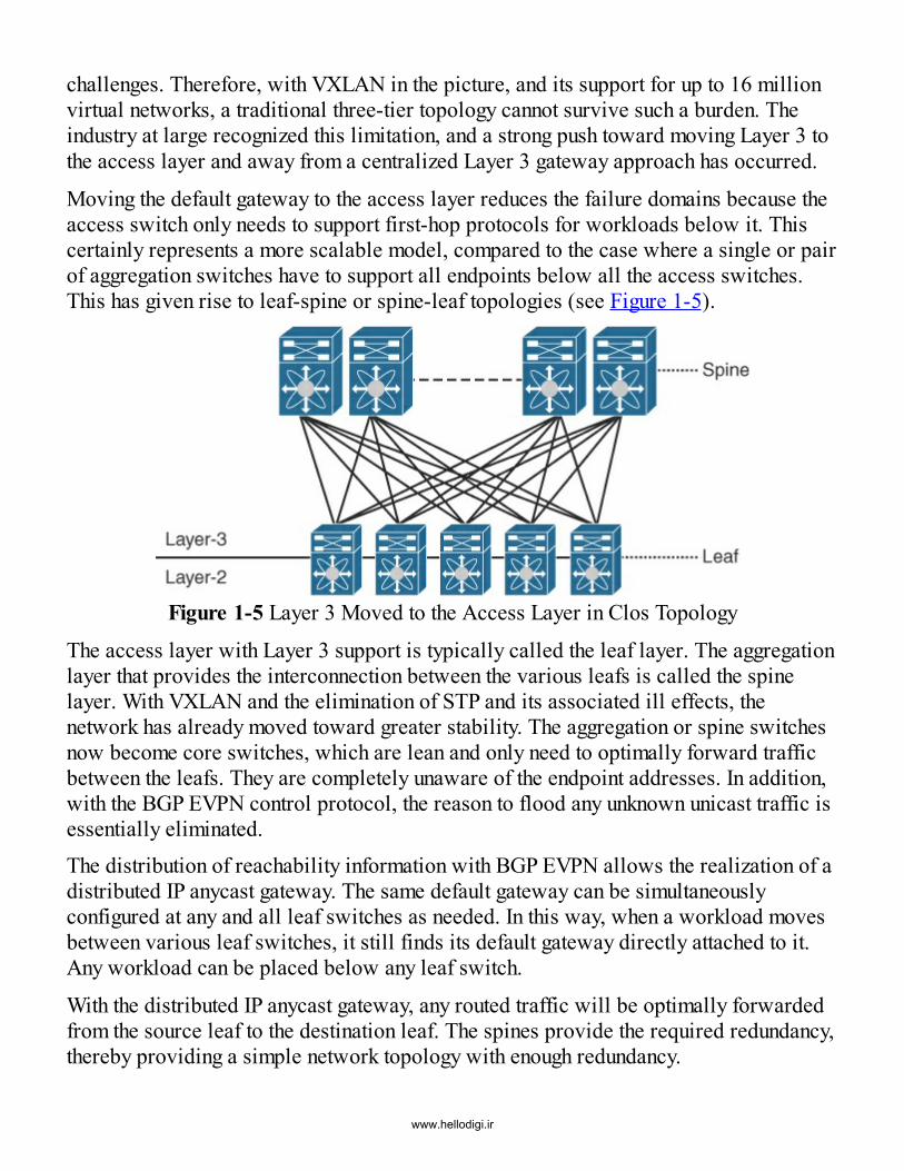
Moving the default gateway to the access layer reduces the failure domains because theaccess switch only needs to support first-hop protocols for workloads below it. Thiscertainly represents a more scalable model, compared to the case where a single or pairof aggregation switches have to support all endpoints below all the access switches.This has given rise to leaf-spine or spine-leaf topologies (see Figure 1-5).
Figure 1-5 Layer 3 Moved to the Access Layer in Clos Topology
The access layer with Layer 3 support is typically called the leaf layer. The aggregationlayer that provides the interconnection between the various leafs is called the spinelayer. With VXLAN and the elimination of STP and its associated ill effects, thenetwork has already moved toward greater stability. The aggregation or spine switchesnow become core switches, which are lean and only need to optimally forward trafficbetween the leafs. They are completely unaware of the endpoint addresses. In addition,with the BGP EVPN control protocol, the reason to flood any unknown unicast traffic isessentially eliminated.The distribution of reachability information with BGP EVPN allows the realization of adistributed IP anycast gateway. The same default gateway can be simultaneouslyconfigured at any and all leaf switches as needed. In this way, when a workload movesbetween various leaf switches, it still finds its default gateway directly attached to it.Any workload can be placed below any leaf switch.
With the distributed IP anycast gateway, any routed traffic will be optimally forwardedfrom the source leaf to the destination leaf. The spines provide the required redundancy,thereby providing a simple network topology with enough redundancy.
www.hellodigi.ir

The Cisco open programmable fabric employs this spine-leaf–based, multitier Clos20
topology that employs open, standards-based protocols, specifically VXLAN for thedata plane and BGP EVPN for the control plane. The fabric encompasses not only theoptimal forwarding semantics but also the automation and manageability framework thataccompanies the solution. In short, this involves (1) Day 0 bring-up of the fabric withthe devices set up in the appropriate designated roles and the corresponding startupconfiguration; (2) Day 1 operations of the fabric, which involves provisioning ofappropriate overlay configuration on the respective leaf switches based on activeworkloads; and (3) Day 2 operations of the fabric, which involves troubleshooting,manageability, and continuous monitoring of the fabric. This also includes integration ofthe fabric with various compute orchestrators as well as with Layer 4–7 serviceappliances.
Fabric-Related TerminologyFigure 1-6 shows some terminology that is used throughout this book. As mentionedearlier, the fabric is comprised of leaf switches hosting a VTEP. The leaf switches orleafs are also called edge or Network Virtualization Edge (NVE) devices. Physical andvirtual endpoints are connected to the leafs.
Figure 1-6 Data Center Fabric Terminology
www.hellodigi.ir

The downstream interface from the leaf toward the endpoints is typically a Layer 2 portover which dot1q tagged or untagged traffic is carried. One or more spine switchesprovide connectivity between the leafs. Each switch within the fabric is part of an IPnetwork that is termed the underlay (see Figure 1-7).
Figure 1-7 Fabric Underlay
All interleaf traffic is VXLAN encapsulated and sent over the overlay (see Figure 1-8).External reachability from the fabric occurs through special nodes called borders. Theborder functionality may either be hosted on a leaf (in which case it is termed a borderleaf) or hosted on a spine (in which case it is called a border spine).
www.hellodigi.ir

Figure 1-8 Fabric OverlayVXLAN encapsulated traffic coming from the leaf switches is typically decapsulated atthe VTEP on the border. Also, based on the configured Layer 2 or Layer 3 handoff,traffic is forwarded toward the external device. Sometimes the leaf to which serviceappliances are attached is termed a service leaf. Incidentally, different leaf roles arenotably logical and not physical. The same leaf switch could perform all three functions—regular, border, and service leaf.
For efficient BGP EVPN overlay connectivity, one or more route reflectors (RRs) arealso hosted within the fabric. Typically, RR functionality is configured on the spines orsuper spines. If IP multicast is employed for forwarding multidestination traffic,rendezvous points (RPs) also need to be hosted within the fabric. Typically, RPs arealso hosted on the spines or super spines.
Data Center Network Fabric PropertiesThe Clos-based fabric has several desirable properties that are especially appealing for
www.hellodigi.ir

data center networks. This relatively simple topology offers enhanced scalability,resiliency, and efficiency. With no oversubscription and with equal uplink and downlinkbandwidth at every leaf, the fabric offers high bisectional bandwidth that is especiallyappealing for data center applications.
With a two-tier Clos fabric, every leaf can reach every other leaf via a single hopthrough a selected spine. This provides deterministic latency for all traffic forwardedthrough the fabric. Adding an additional spine causes this number of equal-cost paths toincrease by one. The ECMP applies equally to both unicast and multicast traffic as wellas to both Layer 2 (bridged) and Layer 3 (routed) traffic with the distributed IP anycastgateway at the leaf layer.The fabric is extremely resilient to link and node failures, and therefore it provides ahigh level of redundancy. Losing a spine reduces the available fabric bandwidth, buttraffic continues to be forwarded in an optimal manner albeit at a reduced total rate.Similarly, on link failures, traffic is redirected to available paths, and the convergencetime is governed by how fast the underlay and overlay protocols converge.
Within a fabric, any and all subnets can be simultaneously configured on any and allleafs, providing a true “any workload anywhere” option from a network point of view.
The fabric has a desirable scale-out property by which more leafs can be added if moreservers, racks, or workloads are added. On the other hand, if the workloads requireadditional bandwidth, more spines can be added. And if higher bandwidth is requiredtoward the external world, more border nodes can be added. In this way, the fabric canbe extended as needed based on the demand.The fabric can also be designed so that tens to hundreds to thousands of 10G server-facing ports can be supported. With desired oversubscription configuration, the fabric ismalleable to support different kinds of workload environments with varying capacities.
Server or Endpoint Connectivity OptionsThe endpoints typically attached to a leaf may be bare-metal machines, virtualworkloads, storage devices or service appliances. The endpoints may be attached to theleafs either directly or via fabric extenders (FEX)21 or, in some cases, via bladeswitches. With the introduction of the Nexus 2K series of switches, FEX technologycame to the forefront, and since then, it has gained widespread acceptance in arelatively short period of time.
Logically, a FEX module can be treated as an external line card that is completelymanaged from the parent switch to which it is attached. All management andconfiguration of the FEX module is done from the parent switch. Traffic to and fromFEX-connected end hosts is switched and routed at the parent switch.
www.hellodigi.ir

With FEX, the end-of-row (EoR) or middle-of-row (MoR) topologies are prevalent,where the FEX typically serves as the top-of-rack (ToR) switch per rack and whereevery FEX connects to a MoR or EoR switch. MoR deployments have the advantage ofrequiring shorter cables for connectivity compared to EoR deployments.
With respect to a fabric, various FEX connectivity combinations are possible, as shownin Figure 1-9. These combinations depend on whether the server is dual attacheddirectly to the leaf or via the FEX. The FEX itself may even be dual attached to a pairof leaf switches configured as vPC peers.
Figure 1-9 Southbound FEX Connectivity Options
Probably the most common option is to have straight-through FEX with one on each vPCpeer while having a server dual attached to these FEXs via a PortChannel. This allowsfault tolerance in case of a link failure, FEX failure, or vPC peer failure. If even moreredundancy is required, enhanced vPC or EvPC deployments may be used, where boththe servers and the FEXs are dual attached.Blade chassis-based server deployments are extremely popular as well, providing theadvantages of packing more compute power in the same rack space, simplifyingmanagement, and reducing the amount of cabling required. Blade switches such as theCisco UCS Fabric Interconnect [FI] series of switches,22 can also be connectedsouthbound from the leafs. Figure 1-10 shows common southbound connectivity optionswith the UCS FI.
www.hellodigi.ir

Figure 1-10 Southbound UCS-FI Connectivity OptionsFor a complete data center solution, along with compute and network features, storagealso needs to be considered. The fabric is flexible enough to support both traditionalFibre Channel (FC)23–based storage and IP storage options. Cisco Nexus devicessupport the unified port option, where a port can be configured to carry either Ethernetor FC traffic.
Fibre Channel over Ethernet (FCoE)24 technology eliminates the need for having adedicated Ethernet link and a separate FC link. FCoE allows a converged southboundconnectivity option to the servers, where the same link can carry both Ethernet and FCtraffic. Upstream from the leafs, the traffic can be separated into Ethernet traffic that iscarried over the VXLAN core, and storage traffic that is carried over a separate storagenetwork.
With the popularity of IP storage and the rapid rise of hyperconvergence solutions, theneed for having a separate storage network has been completely eliminated. The CiscoHyperFlex25 solution provides an evolutionary approach for IP storage that is fullybackward compatible with current deployments and easily integrated with a VXLANBGP EVPN–based fabric. The fabric integrates well with both FC and IP storagedevices.This brief introduction to the VXLAN BGP EVPN–based fabric will allow accelerationto grasp the concepts discussed in subsequent chapters, which deal with the details ofvarious control and data plane nuances and how traffic is forwarded within and outsidethe fabric. The VXLAN BGP EVPN–based fabric is a giant step toward realization ofan extremely scalable network that is going to serve cloud-based data centerenvironments for the foreseeable future.
www.hellodigi.ir

SummaryThis chapter provides a brief introduction to the Cisco VXLAN BGP EVPN fabric. Thechapter begins with a description of the requirements of modern data centers.Subsequently, it gives an overview of how data centers evolved over the years leadingto a VXLAN BGP EVPN–based spine-leaf fabric. Common fabric-based terminologiesare introduced, along with a description on what makes the fabric extremely scalable,resilient, and elastic.
References1. Open Networking Foundation. Software-defined networking definition.
www.opennetworking.org/sdn-resources/sdn-definition.2. Cisco. Data center switches. www.cisco.com/c/en/us/products/switches/data-
center-switches/index.html.3. Cisco. Cisco IOS XE. www.cisco.com/c/en/us/products/ios-nx-os-software/ios-
xe/index.html.4. Cisco. Cisco IOS XR software. www.cisco.com/c/en/us/products/ios-nx-os-
software/ios-xr-software/index.html.5. Cisco. Design and configuration guide: Best practices for virtual PortChannels
(vPC) on Cisco Nexus 7000 series switches. 2016.www.cisco.com/c/dam/en/us/td/docs/switches/datacenter/sw/design/vpc_design/vpc_best_practices_design_guide.pdf
6. Cisco. Cisco’s FabricPath. www.cisco.com/c/en/us/solutions/data-center-virtualization/fabricpath/index.html.
7. Internet Engineering Task Force (IETF). Routing bridges (RBridges): Base protocolspecification. 2011. tools.ietf.org/html/rfc6325.
8. Mahalingam, M., et al. Virtual eXtensible local area network (VXLAN): Aframework for overlaying virtualized Layer 2 networks over Layer 3 networks.2014. tools.ietf.org/html/rfc7348.
9. IEEE Standards Association. 802.1D-2004—IEEE standard for local andmetropolitan area networks: Media access control (MAC) bridges. 2004.standards.ieee.org/findstds/standard/802.1D-2004.html.
10. IEEE Standards Association. 802.1Q-2003—IEEE standards for local andmetropolitan area networks: Virtual bridged local area networks. 2003.standards.ieee.org/findstds/standard/802.1Q-2003.html.
11. Cisco. Multichassis LACP. 2015. www.cisco.com/c/en/us/td/docs/ios-xml/ios/cether/configuration/15-s/ce-15-s-book/ce-multichass-lacp.html.
12. Cisco. Configuring virtual switching systems.
www.hellodigi.ir

www.cisco.com/c/en/us/td/docs/switches/lan/catalyst6500/ios/12-2SX/configuration/guide/book/vss.pdf.
13. IEEE Standards Association. 802.1AX-2008—IEEE standard for local andmetropolitan area networks: Link aggregation.standards.ieee.org/findstds/standard/802.1AX-2008.html.
14. Internet Engineering Task Force (IETF). Cisco hot standby router protocol (HSRP).1998. www.ietf.org/rfc/rfc2281.txt.
15. Internet Engineering Task Force (IETF). Virtual Router Redundancy Protocol(VRRP) version 3 for IPv4 and IPv6. 2014. tools.ietf.org/html/rfc5798.
16. Cisco. Design and configuration guide: Best practices for virtual PortChannels(vPC) on Cisco Nexus 7000 Series Switches. 2016.www.cisco.com/c/dam/en/us/td/docs/switches/datacenter/sw/design/vpc_design/vpc_best_practices_design_guide.pdf
17. Cisco. Cisco FabricPath best practice. 2016.www.cisco.com/c/dam/en/us/products/collateral/switches/nexus-7000-series-switches/white_paper_c07-728188.pdf.
18. Cisco. Configuring an anycast bundle. 2016.www.cisco.com/c/en/us/td/docs/switches/datacenter/sw/6_x/nx-os/fabricpath/configuration/guide/b-Cisco-Nexus-7000-Series-NX-OS-FP-Configuration-Guide-6x/b-Cisco-Nexus-7000-Series-NX-OS-FP-Configuration-Guide-6x_chapter_0100.html#task_BF30BB009250408E99FA8ED33D1FDB57.
19. Cisco. Encapsulation techniques: Generic network virtualization encapsulation,VXLAN generic protocol extension, and network service header. 2014.www.cisco.com/c/en/us/solutions/collateral/data-center-virtualization/application-centric-infrastructure/white-paper-c11-733127.html.
20. Clos, C. A study of non-blocking switching networks. Bell System TechnicalJournal, 32(2):406–424, 1953.
21. http://www.cisco.com/c/en/us/support/switches/nexus-2000-series-fabric-extenders/tsd-products-support-series-home.html
22. Cisco. Servers: Unified computing. www.cisco.com/c/en/us/products/servers-unified-computing/index.html.
23. Internet Engineering Task Force (IETF). Fibre Channel (FC) frame encapsulation.2003. tools.ietf.org/html/rfc3643.
24. Cisco. Fibre Channel over Ethernet (FCoE).www.cisco.com/c/en/us/solutions/data-center-virtualization/fibre-channel-over-ethernet-fcoe/index.html.
25. Cisco. Hyperconverged infrastructure.www.cisco.com/c/en/us/products/hyperconverged-infrastructure/index.html.
www.hellodigi.ir

Chapter 2 VXLAN BGP EVPN Basics
In this chapter, you will learn about the following:
VXLAN and its typical Flood and Learn (F&L) use case The evolution of a BGP EVPN control plane for VXLAN-based data centerenvironments Basic Route type messages employed with BGP EVPN for network virtualizationoverlays
The paradigm shift toward cloud has included the adoption of an increasing degree ofvirtualization, where an array of physical servers and I/O devices can host multiplevirtual servers that can all share the same logical network despite being in remotegeographic locales. As opposed to the traditional north–south direction of data trafficbetween clients and servers, virtualization has facilitated greater east–west data trafficwithin the data center. East–west traffic describes data communications betweenservers and/or various applications all contained within the data center. Because muchof the data required by the end user in a corporate network or on the Internet involvesmore complex data, certain preprocessing activities are required. As a means todemonstrate this preprocessing need, one example of east–west traffic involves accessfrom a web server (via an app server) to the database.Dynamic rendering of websites and/or business applications often uses a two- or three-tiered server architecture, where one tier must communicate with a second tier beforedelivering the requested data to the end user. When these tiers communicate with oneanother or need access to data storage or other data residing in the same data center, theterm east–west traffic is used because this represents a more horizontal path profile (seeFigure 2-1). Another example of east–west traffic is a user making a request to a socialnetworking site (such as www.facebook.com), which results in a rapid set of exchangesbetween the servers sitting on the data center backend and returning a web page that haslots of information about the user, his friends’ feeds, the associated advertisements thatmay match the user’s preferences, and so on.
www.hellodigi.ir

Figure 2-1 East–West Communication FlowTypically, groups of devices are isolated into a broadcast domain using virtual localarea networks (VLANs). A VLAN is assigned an IP subnet, and all the hosts within thatVLAN have unique IP addresses within that subnet. A VLAN based on the IEEE 802.1Qstandard is represented by a 12-bit tag.1 This limits the maximum number of VLANs to4096, thereby limiting the number of supported unique network identifiers or broadcastdomains. In an era of multitenant cloud deployments, 4K VLANs are not enough.Because a single tenant might require several network IDs (VLANs) for differentapplication tiers, saturation of these virtualized networks became a notable problem.
With virtualization, the number of end hosts, which now occupy virtual workloads orvirtual machines within a broadcast domain, has skyrocketed. Scalability issues areparamount as a result. A typical 48-port access layer switch traditionally had 48 serversattached to it. With virtualization, this number has increased 20- to 30-fold. In somecases, this increase is even greater due to the fact that containers are becoming popular.2As a result, a switch now needs to cater to this increased capacity by having largerhardware forwarding table resources; this is a MAC table explosion problem from adata plane point of view.3 In addition, the switches also have to service first-hopprotocols (for example, DHCP, ARP, ND, IGMP) for these workloads, which results inan increase in the control plane overhead.
The classical protocol for establishing a loop-free environment in a Layer 2 broadcastdomain has been the IEEE 802.1D Spanning Tree Protocol (STP) and the correspondingevolved revisions, Rapid Spanning Tree Protocol (RSTP; IEEE 802.1w) and MultipleSpanning Tree (MST; IEEE 802.1s).4 STP has served networking environments for over
www.hellodigi.ir

20 years. As discussed in Chapter 1, “Introduction to Programmable Fabric,” STP hasseveral drawbacks, such as increased convergence time on switch/link failures, non-optimal forwarding between switches since the packets traverse a tree, and no multipathor equal-cost multipath (ECMP) options (an attractive feature of Layer 3 networks). Theincrease in the host scale in a broadcast domain demands a better option than STP forsupporting large data center environments.
Because virtualization permits decoupling of an end host from a physical server,migration and mobility demands of data centers, allowing movement from one physicalserver to another, have resulted in higher bandwidth requirements of such networks.This fact is further supported by the change in network communications, which adopt an“any-to-any” model, where any host can communicate with any other host on thenetwork, logical or physical. In addition, agility, power efficiency, and ease ofmanageability are additional demands of data centers as utilization expands. Giventhese requirements, it is evident that traditional networking paradigms are insufficient.The rise in horizontal data center traffic requires solutions to address the broadcastdomain limitations exhibited by 12-bit VLANs. Overloading VLANs with differentmultiple IP subnets has not solved the problem because it does not provide the isolationrequired in multitenant environments. In addition, different tenants may have networkidentifiers with overlapping IP subnets. Thus any solution needs to somehow maintainLayer 2 bridging semantics while achieving better Layer 2 isolation of tenants with ahigher capacity for network IDs. In order to accommodate the needed flexibility,scalability, mobility, and agility that data centers now require, an extended virtualizednetwork solution was required. To fill this need, network virtualization overlays cameto the forefront.
OverlaysNetwork virtualization overlays have become the de facto solution to address theproblems just described related to data center expansion. Overlays provide a level ofindirection, which allows the abstraction of the existing network technologies andextends classic network capabilities. As stated by David Wheeler, “All problems incomputer science can be solved by another level of indirection, except of course for theproblem of too many indirections.”5 This fundamental computer science idea supportsthe concept of network virtualization overlays.The concept of overlays has been around in the networking world for quite a while.Chapter 1 describes the drawbacks of conventional networks that led to the evolution ofoverlays. As the name implies, an overlay is a static or dynamic tunnel that runs on topof a physical network infrastructure. In the 1990s, MPLS- and GRE-basedencapsulations started to gain popularity.6,7 Subsequently, other tunneling technologies,
www.hellodigi.ir

such as IPsec,8 6in4,9 and L2TPv3,10 also came to the forefront, but they were typicallyused at WAN edge devices. These tunnels were employed either for security purposes,for simplifying routing lookups, or in the case of 6in4 for example, for carryingpayloads over a transport network that was not capable of supporting the payload type.
With overlays, the original packet or frame is packaged or encapsulated at a sourceedge device with an outer header and dispatched toward an appropriate destinationedge device. The intermediate network devices all forward the packet based on theouter header and are not aware of the original payload. At the destination edge device,the overlay header is stripped off, and the packet is forwarded based on the innerpayload.Overlays have been used in data center environments only since 2008. That time framealso saw the rise of software defined networking (SDN) and the adoption of the cloud.Overlays in data center environments are referred to as network virtualization overlays.The name comes from the fact that most of the trends in data centers were revolutionizedby the rapid adoption of server virtualization. When considering network virtualizationoverlays, a few distinct characteristics need to be considered. A primary feature that allthese network virtualization overlays exhibit is related to the concept of location andidentity. Identity identifies an end host and could be its IP address, its MAC address,and so on. Location identifies the tunnel edge device that is responsible forencapsulating and decapsulating tunnel traffic for that end host. As mentioned earlier,the end hosts themselves could be virtual machines, bare-metal servers, containers, orany other workload. The outer header of the overlay references the source anddestination locations, and the inner header references the source and destination endhost identities.
The other notable feature pertains to the specific overlay service an overlay provides.This dictates the type of overlay as well as the associated header format. Overlayservices are routinely offered as either Layer 2 (bridging) or Layer 3 (routing) services;however, many modern overlays provide both Layer 2 and Layer 3 services. Theoriginal packet (Layer 3) or frame (Layer 2) can be encapsulated into another packet(Layer 3) or frame (Layer 2). This provides potentially four combinations, depending onwhether a packet/frame is carried in another packet/frame. If the outer header is a Layer2 frame, the overlay approach is referred to as frame encapsulation. Examples ofoverlays that employ frame encapsulation are TRILL,11 Cisco FabricPath,12 and SPB(IEEE 802.1Qaq).13 On the other hand, if the outer header is a Layer 3 packet, theoverlay is referred to as packet encapsulation. Examples of overlays that employ packetencapsulation are LISP, VXLAN, and NvGRE.14
With Overlay services defined along with the different data-plane encapsulations, amethod of transport to move the data across the physical network is required. This
www.hellodigi.ir

method of transport is typically an underlay transport network (or simply the underlay).In defining the underlay, we need to know the OSI layer where tunnel encapsulationoccurs. In some sense, the overlay header type dictates the type of transport network.For example, with VXLAN, the underlying transport network (underlay) would be aLayer 3 network, which would transport the VXLAN-encapsulated packets between thesource and destination tunnel edge devices. Thus, the underlay provides reachabilitybetween the various tunnel/overlay edge devices.
Usually reachability is distributed via an appropriate routing protocol. Discovery ofthese edge devices is a prerequisite to the operation of any overlay service. It should benoted that overlays incur a per-packet/frame overhead of n bytes, where n is the size ofthe overlay header along with the associated outer headers. The original payloadencapsulated into the overlay header is transported over the underlay; hence, theunderlay network must be provisioned with the appropriate maximum transmission unit(MTU) to ensure delivery of the overlay traffic.Next, the network virtualization overlay requires a mechanism to know which end hostsare behind which overlay edge device. This allows the tunnel edge devices to build thelocation-identity mapping database. The mapping information may be facilitated via acentral SDN controller (such as a Cisco APIC15 or an OpenDaylight controller16) or viaan overlay end host distribution protocol (such as BGP EVPN17 or OVSDB18) or via adata plane–based discovery scheme (such as Flood and Learn [F&L]). Using thisinformation for a destination end host lookup, the source edge device can push anoverlay header with the appropriate fields so that the packet/frame can be delivered tothe destination edge device and, subsequently, to the destination end host. Because endhosts typically belong to a certain tenant, it is imperative that the overlay header hassome notion of tenancy. By pushing the appropriate tenant context information in theoverlay header at the source device during encapsulation, the destination edge devicecan perform a per-tenant destination lookup post decapsulation, thereby ensuringisolation among tenant traffic. This is a primary requirement in multitenant data centerenvironments.
The data plane for overlays, in addition to providing unicast encapsulated transport ofLayer 2 or Layer 3 traffic, also needs to handle the transport of multidestination traffic.Multidestination traffic is typically referred to as “BUM,” which stands for “broadcast,unknown unicast, or multicast.” Handling these traffic types requires specialcapabilities to receive imposed multidestination packets from the overlay and thenreplicate and transport these packets accordingly in the underlay. The two most commonmethods that can accommodate this replication and transport in the underlay are IPmulticast and ingress replication (also called head-end replication or unicast mode).
Network virtualization overlays can be initiated either from physical servers or network
www.hellodigi.ir

switches, typically the top-of-rack (ToR) switches connected to the servers. Thephysical servers are typically virtualized so that they can host a virtual switch/routerthat has enhanced capability of encapsulating and decapsulating the overlay header. Thismodel requires the network switches to only provide connectivity between thevirtualized servers, which in turn permits transport of data between the virtual endhosts, using what are called host overlays.
For deployments where there is a mix of bare-metal and virtualized workloads, theToRs take care of pushing/popping the overlay headers for all kinds of workloadsbeneath them. These are termed network overlays. Both host overlays and networkoverlays are extremely popular and represent commonly deployed options foraddressing the scale challenges in multitenant data center environments. Each has prosand cons, but the best of both worlds can be realized by using hybrid overlayenvironments, where both host overlays and network overlays are supported, allowingfor optimized physical-to-virtual (P2V) communication (see Figure 2-2).
Figure 2-2 Host, Network, and Hybrid Overlays
With a basic understanding of essential features of overlay services, an overview of thecommonly used taxonomy for both the underlay and the overlay, is presented. Theunderlying transport network, or underlay, is typically composed of transit devices thatinterconnect the edge devices. Edge devices serve as boundary devices for the underlayand are connected to end hosts and to non-overlay-speaking devices such as physicaland virtual servers. Thus, edge devices connect LAN segments with the underlay.Within the edge devices resides the functionality for encapsulation and decapsulation ofoverlay data traffic and for building the whole overlay network. In VXLANterminology, this functionality on the edge device is termed a VTEP, which stands forVXLAN Tunnel Endpoint. Figure 2-3 illustrates the key terms and functions involved ina VXLAN underlay.
www.hellodigi.ir

Figure 2-3 Underlay TaxonomyWhile an edge device can host multiple VTEPs that may participate in differentunderlays, typically an edge device hosts a single VTEP. As a result, throughout thisbook we frequently use the terms VTEP and edge device interchangeably. Between theVTEPs, tunnel encapsulation is used to provide the overlay services. In regard toVXLAN, these services are distinctively identified with a virtual network identifier(VNI), which significantly expands the ability to accommodate a much larger scale ofbroadcast domains within the network. These aspects make VXLAN very attractive.Figure 2-4 illustrates the key terms and functions involved in a VXLAN overlay.
www.hellodigi.ir
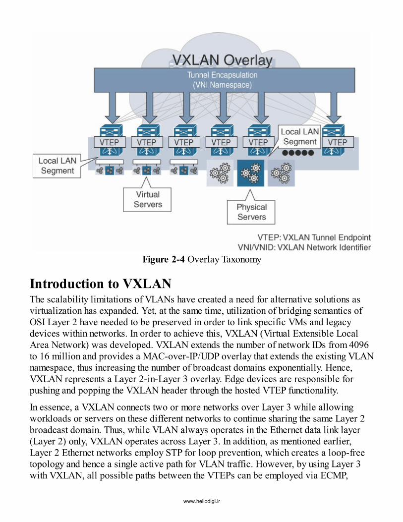
Figure 2-4 Overlay Taxonomy
Introduction to VXLANThe scalability limitations of VLANs have created a need for alternative solutions asvirtualization has expanded. Yet, at the same time, utilization of bridging semantics ofOSI Layer 2 have needed to be preserved in order to link specific VMs and legacydevices within networks. In order to achieve this, VXLAN (Virtual Extensible LocalArea Network) was developed. VXLAN extends the number of network IDs from 4096to 16 million and provides a MAC-over-IP/UDP overlay that extends the existing VLANnamespace, thus increasing the number of broadcast domains exponentially. Hence,VXLAN represents a Layer 2-in-Layer 3 overlay. Edge devices are responsible forpushing and popping the VXLAN header through the hosted VTEP functionality.
In essence, a VXLAN connects two or more networks over Layer 3 while allowingworkloads or servers on these different networks to continue sharing the same Layer 2broadcast domain. Thus, while VLAN always operates in the Ethernet data link layer(Layer 2) only, VXLAN operates across Layer 3. In addition, as mentioned earlier,Layer 2 Ethernet networks employ STP for loop prevention, which creates a loop-freetopology and hence a single active path for VLAN traffic. However, by using Layer 3with VXLAN, all possible paths between the VTEPs can be employed via ECMP,
www.hellodigi.ir

which also greatly increases utilization of the fabric. Even by using ECMP in theunderlay, a single distinct path between the VTEPs in the overlay is used while stillleveraging all available ECMP paths. And by using an IP core as part of its underlay,VXLAN has made it easier to debug and maintain data centers by leveraging existingnetwork expertise.
Inner aspects of the VXLAN header refer to Layer 2 components, while outer headersreflect the Layer 3 edge devices. Thus, the VXLAN header contains the original Layer 2Ethernet frame of a workload, which includes the inner MAC source address as well asthe inner MAC destination address, the original Ethernet payload, and the frame checksequence. In addition, the original inner 802.1Q header of the Layer 2 Ethernet frame isremoved and mapped to a VNI to complete the VXLAN header, as illustrated in Figure2-5.
Figure 2-5 VXLAN Frame Format
The VXLAN header is preceded by an outer UDP header, an outer IP header, and anouter Ethernet header. The destination port number of the outer UDP header is set to4789.19 The UDP source port number is generated based on the fields of the original orinner header. The source IP address in the outer IP header is set to that of the sourceVTEP, while the destination IP address is set to that of the destination VTEP. Thederivation of the outer Ethernet header is based on a routing lookup on the outer IPheader, using regular Layer 3 lookup semantics. In this way, VXLAN adds a 50-byteoverhead to the existing Ethernet frame or 54-byte overhead, if an optional IEEE802.1Q tag is added. Figure 2-6 illustrates the VXLAN frame format.
www.hellodigi.ir

Figure 2-6 VXLAN Frame Format DetailsTypically, in a Layer 3 network with ECMP, load balancing is achieved for forwardingtraffic by choosing one of several equal-cost paths based on the popular 5-tuple input.20
Typically, the 5-tuple comprises the source IP address, destination IP address, Layer 4(L4) protocol, source L4 port, and destination L4 port. With VXLAN, for all trafficdestined between workloads behind the same pair of source and destination VTEPs, allthe other fields in the outer headers other than the UDP source port are identical. Sincethe UDP source port varies based on the contents of the inner packet/frame, it providesthe necessary entropy to select different paths for different end host flows between thesame source and destination VTEP pair. Hence, the ability to appropriately generate theUDP source port values is an important feature that should be supported by VTEPs,regardless of whether they are implemented in a software or hardware form factor. Thisis a critical differentiator of VXLAN compared to other overlays.
With an IP underlay, any appropriate routing protocols such as OSPF,21 IS-IS,22 etc. canbe employed for all the VTEPs to establish connectivity to one another. The IP underlayneeds to provide a means to transport overlay single-destination and multidestinationtraffic. One way to transport multidestination traffic is using IP multicast in the underlay.In this case, the underlay employs Protocol Independent Multicast (PIM), which is afamily of multicast routing protocols for IP networks. Popular PIM options for IPmulticast include PIM Any Source Multicast (ASM), PIM Single Source Multicast(SSM), and Bidirectional PIM (BIDIR).23 Chapter 4, “The Underlay,” goes into furtherdetail on both unicast and multicast routing options for the IP underlay. A VXLAN VNI
www.hellodigi.ir

is mapped to an appropriate IP multicast group. This is done at configuration time, whenthe VNI is configured at a VTEP. As a result, the VTEP joins the correspondingmulticast tree established via PIM. In this way, all VTEPs that are members of the sameVNI are part of the same multicast group. Multidestination traffic originating from anend host that is part of a given VNI is transported to all other end hosts in that VNI overVXLAN where the outer destination IP address is set to the multicast group addressassociated with that VNI.
VXLAN Flood and Learn (F&L)Consider the sample network topology shown in Figure 2-7, which illustrates a typicalF&L-based communication in a VXLAN network.
Figure 2-7 VXLAN F&L
Host A (IP 192.168.1.101) below VTEP V1 (10.200.200.1) and Host B (IP192.168.1.102) below VTEP V3 (10.200.200.3) are part of the same VXLAN segmentwith VNI 30001. The network subnet associated with VNI 30001 is 192.168.1.0/24, and
www.hellodigi.ir

the associated multicast group is 239.1.1.2. When VNI 30001 is configured at V1 andV3, they both join the multicast group 239.1.1.2 as interested receivers. Assume thatHost A wants to communicate with Host B.As is usually the case, Host A will first try to resolve the IP-MAC binding associatedwith Host B, using Address Resolution Protocol (ARP). Host A sends out an ARPrequest with DMAC=FFFF.FFFF.FFFF and SMAC=00:00:30:00:11:01. VTEP V1receives this ARP request and performs a Layer 2 lookup based on [VNI=30001,DMAC=FFFF.FFFF.FFFF]. VTEP V1 determines that this is a multidestination framethat needs to be sent out to all members of VNI 30001. Consequently, it encapsulatesthis packet with a VXLAN header with VNI=30001, Source IP=10.200.200.1, andDestination IP=239.1.1.2.
The VXLAN-encapsulated packet is sent out toward the IP core. The packet isforwarded over the multicast tree and then reaches all interested receivers, includingV3. The VXLAN-encapsulated packet is decapsulated at V3 because it has[VNI=30001, Group=239.1.1.2] configured locally. Layer 2 learning results in the entry[VNI=30001, MAC=00:00:30:00:11:01->10.200.200.1] being learned at V3. A Layer 2lookup is performed at V3 based on [VNI=30001, DMAC=FFFF.FFFF.FFFF]. Becausethis is a broadcast packet, it is locally forwarded to all hosts below V3 that are part ofVNI 30001, including Host B. On receiving the ARP request, Host B sends out an ARPresponse with DMAC=00:00:30:00:11:01 and SMAC= 00:00:30:00:11:02. V3 receivesthis packet, and it performs local learning and a destination lookup based on[VNI=30001, DMAC=00:00:30:00:11:01]. This results in a Layer 2 table HIT, and thepacket is VXLAN encapsulated and sent toward V1.The salient fields of interest in this packet are VNI=30001, Source IP=10.200.200.3,and Destination IP=10.200.200.1. The encapsulated packet is delivered to V1 viaregular Layer 3 routing. V1 also performs Layer 2 learning and then the destinationlookup based on [VNI, DMAC] results in the ARP response packet from Host B beingdelivered to Host A. In this way, the host MAC information is appropriately populatedat both VTEPs, and Hosts A and B know about each other’s MAC-IP binding.Subsequent traffic between Hosts A and B is then unicast over VXLAN between V1 andV3, respectively.
Through this mechanism, the multidestination traffic is flooded over the VXLANbetween VTEPs to learn about the host MACs located behind the VTEPs so thatsubsequent traffic can be unicast. This is referred to as an F&L mechanism. Given this,communication within a VXLAN VNI follows regular Layer 2 forwarding semantics,just as is the case within a VLAN (see Figure 2-8). The main difference is that theVXLAN VNI domain spans Layer 3 networks over an IP underlay.
www.hellodigi.ir

Figure 2-8 VLAN-to-VNI MappingMultiple VNIs may share the same multicast group. This is because having 16 millionpotential VNI options and having a unique 1:1 mapping between a VNI and a multicastgroup requires an exorbitant number of software and hardware resources, making itimpractical for deployment. In fact, in most practical deployments, a maximum of 512 or1024 multicast groups are supported. This means that a VTEP may receive VXLAN-encapsulated multidestination traffic for a VNI that is not locally configured. Isolation atthe network level is still maintained, because every VXLAN network segment has aunique VNI, and the lookup key is always [VNI, DMAC]. One alternative to IP multicastfor handling multidestination traffic in a VXLAN environment is to use ingressreplication (IR), or head-end replication. With IR, every VTEP must be aware of otherVTEPs that have membership in a given VNI. The source VTEP generates n copies forevery multidestination frame, with each destined to other VTEPs that have membershipin the corresponding VNI. This places an additional burden on the VTEPs, but it has thebenefit of simplification since there is no need to run multicast in the IP underlay.
VXLAN is one of the few overlays that has been used both as a host overlay and as anetwork overlay. With the rise of SDN, VXLAN has been heavily used as a hostoverlay, with physical servers hosting software VTEPs that perform VXLANencapsulation and decapsulation for traffic between virtualized workloads. To establishcommunication between legacy workloads that do not support VXLAN, Layer 2
www.hellodigi.ir

VXLAN gateways come to the forefront, providing translation between legacy VLAN-based and virtualized VXLAN-based domains. Networking vendors started to supportVXLAN in their hardware switches, thereby providing options for use of VXLAN as anetwork overlay. This paved the way for a hybrid environment where both software andhardware VTEPs can be simultaneously supported in the same data center environment.
VXLAN provided a notable solution for the issues of poor scalability, the need forenhanced network mobility, and preserved network manageability. However, somedisadvantages with VXLAN have been identified. While VXLAN defined an extensibledata plane for virtual networks, a control plane was not specified in this regard.Consequently, the native F&L-based approach employed by VXLAN is far from idealsince the broadcast domain for a VXLAN now spans Layer 3 boundaries. In general,any flooding-based mechanism will have serious concerns, especially as the scaleincreases. As discussed in Chapter 1, VXLAN F&L suffers from the same disadvantagesas Ethernet F&L-based networks. Thus, while VXLAN offers significant advantages insome aspects related to the increasing data center demands, it fails to offer acomprehensive solution in total. The missing piece is a mechanism to learn about endhosts behind a VTEP without the need to flood traffic. This is accomplished using aBGP-based control protocol extension.
Introduction to BGP EVPN with VXLANUtilization of VXLAN clearly offers many advantages for multitenant data centersthrough advancing the number of network identifiers and through its Layer 3 overlayplatform. But while STP is avoided by incorporating the IP core for data transport,multicast protocols are still required to emulate flooding over a Layer 3 network whenseeking destination workloads before specific host-to-host identifiers are learned anddefined. Therefore, VXLANs traditionally have utilized F&L approaches whentransporting data over a network. All logical and legacy devices within the networkbehind the destination VTEP addresses receive data from the originating workload in aneffort to target the destination workload, and once received by its intended destinationaddress, specific MAC address information is provided back to the originatingworkload so that host learning occurs. Once learned, a direct host-to-host connection isestablished within the VXLAN network segment.
With this in mind, the use of Border Gate Protocol (BGP)24 and Ethernet VPN (EVPN)25
addresses some problems related to learning via flooding by minimizing the extent towhich this needs to occur. BGP is a longstanding, standardized protocol for NetworkLayer Reachability Information (NLRI) exchange to facilitate host-to-host reachabilitywithin the network. BGP has effectively demonstrated that it can scale at the Internetlevel. Being a hard-state protocol, one that initiates messaging only when there is a
www.hellodigi.ir

change of some sort in the network reachability information that it is advertising, BGPmessaging has been extended in various ways. In the context of network virtualizationoverlays, BGP provides a data directory of all MAC and IP addresses of devices(logical and otherwise) behind a VTEP within a VXLAN network segment. As a result,BGP permits a clear structure of standardized numbering and naming of VXLANdestinations, which eliminates the need to flood in order to learn addressinginformation. Multiprotocol BGP has similarly been well established in operating in IPnetworks with multitenancy support,26 and its use in combination with EVPN offers theneeded control plane aspects.
The EVPN extensions that are part of BGP (or Multiprotocol BGP [MP-BGP])27 addenough information within these standardized identifiers so data exchange may occurefficiently between workloads. EVPN transports information between source anddestination VTEPs within a VXLAN, using BGP/MP-BGP formatting to identifyreachability of specific IP and MAC address destinations behind a VTEP. Throughintegrated routing and switching,28 EVPN facilitates transport for both Layer 2 andLayer 3, using known workload addresses present within the VXLAN network. As aresult, the need for unnecessary flooding for learning can be notably reduced, and insome cases, it can be completely eliminated.In a nutshell, the EVPN address family allows the host MAC, IP, network, VRF, andVTEP information to be carried over MP-BGP. In this way, as long as a VTEP learnsabout a host behind it (via ARP/ND/DHCP etc.), BGP EVPN distributes and providesthis information to all other BGP EVPN–speaking VTEPs within the network. As longas the source VTEP continues to detect a host behind it, an EVPN update message is notsent out. As a result, other VTEPs need not “age out” any remote host reachabilityinformation. This prevents any kind of aging-related churn that may happen in typicalF&L scenarios, thereby greatly enhancing network scalability.
To expand on this concept a bit further, it is sometimes presumed that BGP-EVPNeliminates the need for flooding altogether, but this is not actually valid. VXLANoperates as the data plane of the network and transports data. Hence, for handling BUMtraffic over VXLAN, the sourcing VTEP is still required to send multidestination trafficto multiple VTEPs, either using IP multicast or ingress replication. While flooding dueto unknown unicast traffic can perhaps be eliminated (if there are no “silent” hosts, orhosts that have not yet been discovered and only respond when spoken to), broadcasttraffic due to ARP, DHCP, and other addressing protocols may still incur flooding.Examples of these include a web server, some firewalls, or some select serviceappliances. In the era of virtualization, the number of silent hosts has been reduced;however, these hosts have not been completely eliminated. Therefore, through the use ofthe EVPN control plane, the need for flooding is reduced, but EVPN does not remove
www.hellodigi.ir

the need for it entirely.
BGP EVPN differs from F&L in several ways. Both peer discovery and remote end hostlearning are handled in a completely different fashion because BGP EVPN distributesendpoint identifiers (MAC and optionally IP addresses) as well the endpoint-associatedIP prefix information behind a VTEP. Likewise, peer VTEP authentication is different,with the control plane containing the required information rather than waiting for unicastlearning responses. In addition, BGP EVPN narrows host route distribution through theuse of this control plane. As a result, ARP requests are suppressed within the VXLANnetwork, which markedly enhances the efficiency of the data transport. Given thesecharacteristics, the use of BGP EVPN with VXLAN offers an improved means by whichdata transport is facilitated and controlled so that the number of specific hosts beingidentified within a network can increase exponentially.
MP-BGP Features and Common PracticesThe VXLAN BGP-EVPN solution is based on MP-BGP, as described in RFC 4760.29
The main feature in MP-BGP is to allow a multiplex of address families and relatedNLRI into a single BGP peering session. As a result, MP-BGP also allows VPNservices across this single BGP peering session and provides embedded logic forseparating reachability information for the separate tenants. The terms tenant, VPN, andVRF are used interchangeably here.
MP-BGP address families are used to transport specific reachability information.Popular address families include VPNv4 and VPNv6, which are widely used forMultiprotocol Label Switching (MPLS) between different data center sites with Layer 3VPNs. Other VPN address families (for example, Multicast VPN [MVPN]) are used totransport reachability of multicast group information within MPLS or otherencapsulations in a multitenant environment. In case of VXLAN, the focus is on theaddress family L2VPN EVPN, which describes the method of transporting tenant-awareLayer 2 (MAC) and Layer 3 (IP) information across a single MP-BGP peering session.
In BGP, when using a single autonomous system (AS), the peering between BGPspeakers is called internal BGP (iBGP). iBGP is mainly used to exchange informationbetween all the speakers in a synchronous fashion across the entire AS. iBGP requiresfull-mesh peering as reachability information must be learned from an iBGP speaker andmust not be relayed to any other iBGP speaker. In order to change this behavior, iBGPcan utilize the function of a route reflector (RR). An RR is allowed to receive iBGPinformation and then “reflect” the information to any of its RR clients—that is, allknown iBGP neighbors. With iBGP and RR function, BGP peerings can be optimized sothe requirement of using a full-mesh BGP peering can be abandoned (see Figure 2-9).Likewise, this also permits the control plane to be scaled higher (that is, N sessions for
www.hellodigi.ir

N peers versus N(N–1)/2 or O(N2) sessions required with full-mesh connectivity).
Figure 2-9 iBGP with a Route Reflector
With external BGP (eBGP), peering between BGP speakers is achieved betweendifferent autonomous systems. This means, for example, that a BGP speaker in AS65500 can be peered with its neighbor BGP speaker, which resides in AS 65501 (seeFigure 2-10). In eBGP, the rules for route exchange are slightly different. Unlike withiBGP, which requires full-mesh peering without the use of an RR, BGP reachabilityinformation received from an eBGP speaker is always sent to all its neighbors. Inaddition, compared to iBGP, eBGP has implicit next-hop self-semantics so that everyroute originated by the eBGP speaker is advertised with itself as the next hop.
Figure 2-10 eBGP with no Route Reflector
MP-BGP is well known for its multitenancy and routing policy capabilities. In order todifferentiate between routes stored in the BGP tables, MP-BGP uses RouteDistinguishers (RDs). An RD is 8 bytes (64 bits) and composed of three fields. The first2 bytes are the Type field, which determines how the Value field will be interpreted.The remaining 6 bytes are the Value field, which can be filled according to three well-known formats.
www.hellodigi.ir

As illustrated in Figure 2-11, the first format is type 0, where a 2-byte autonomoussystem number plus a 4-byte individual number completes the Value field of the RD. Fortype 1 and type 2, the first portion of the Value field is similar in size (each 4 bytes), butthe content of this portion differs: It is the IP address in type 1 and the AS number intype 2. The latter portion of the Value field for both type 1 and type 2 formats is again a2-byte individual number field. As a common best practice for separation and pathefficiency, a good rule of thumb is to use a unique RD on a per-VRF, per-router basis soeach logical virtual router instance is individually identifiable.
Figure 2-11 Route Distinguisher Formats and Types
In addition to providing unique identifiers for multiple tenants, MP-BGP also uses routepolicies to prioritize routes in a particular logical instance. This is achieved via anattribute called a Route Target (RT). An RT attribute can be thought of as identifying aset of sites, though it would be more precise to think of it as identifying a set of VRFs.Associating a particular RT attribute with a route allows that route to be placed in theVRFs that are used for routing traffic that is received from the corresponding sites.
The RT’s notation is similar to that of the RD, but its function is rather different. Whileone is used to uniquely identify prefixes of entries in the BGP table, the other controlsthe import or export of these prefixes (see Figure 2-12). RTs essentially are tags placedon a route to identify routes, which may be preferentially important.By using RTs, routes can be identified and placed in different VRF tables. With thecontrol of an export RT, prefixes can be steered, at the ingress switch, to receive aspecial tag assigned in MP-BGP. Likewise, if the same RTs on the import side are beingused, all the routes marked at the export can then be imported preferentially as well.RTs are also 8 bytes long, but formatting can be rather freely used, apart from theprefix:suffix notation. Cisco provides automated derivation of RDs and RTs forsimplification.
www.hellodigi.ir

Figure 2-12 Route Target Concept
NoteAutomated derivation of RD uses the type 1 format with RID Loopback IP:internal MAC/IP VRF ID (RD: 10.10.10.1:3). For automatic derivation ofRT, the format is ASN: VNI (RT: 65501:50001).
Multiprotocol BGP contains many more features and functions. For the specifics of theVXLAN EVPN solution, the RD and RT fields are described to understand genericprefix advertisement. Further, extended community attributes are carried in MP-BGP toamend the existing prefixes with further information for forwarding. However, thisinformation is beyond the scope of this introduction to MP-BGP and its associatedcommon practices.
IETF Standards and RFCsVXLAN EVPN pertains to multiple Internet Engineering Task Force (IETF) Requestsfor Comments (RFCs) or drafts. The generic control plane for EVPN is described inRFC 7432. This RFC defines the general rules of engagement of the MP-BGP EVPNaddress family and its NLRI for the different data plane implementations. While specificdrafts exist to define the details for MPLS, for Provider Backbone Bridges (PBB), andfor the network virtualization overlay (NVO) implementations, our main focus involves
www.hellodigi.ir

the implementation of BGP EVPN for the NVO data plane with VXLAN (see Figure 2-13).
Figure 2-13 IETF RFC/Draft for Control and Data Plane
The relevant IETF draft describing the VXLAN implementation for EVPN is draft-ietf-bess-evpn-overlay. This draft is part of the BGP Enabled Services (BESS) workinggroup30 and defines functions like encapsulation markers, how to construct EVPNroutes, and how subnets are mapped to an EVPN virtual instance (EVI). Subsequentimplementation drafts are draft-ietf-bess-evpn-inter-subnet-forwarding and draft-ietf-bess-evpn-prefix-advertisement. Both of these additions describe how the IntegratedRouting and Bridging (IRB) and Layer 3 routing operation in EVPN are handled. Table2-1 lists the VXLAN BGP EVPN–related RFCs/drafts currently implemented on theCisco Nexus operating system (NX-OS).
Table 2-1 RFC/Draft Overview
www.hellodigi.ir

Important sections for Cisco’s NX-OS implementation of VXLAN EVPN are thesections on VLAN-based bundle services, symmetric IRB forwarding on NVEs for endhosts or subnets (that is, inter-subnet-forwarding, sections 5.1 and 5.2), andimplementation of IP-VRF-to-IP-VRF (that is, prefix advertisement, Section 5.4).
It should be noted that MP-BGP EVPN has different NLRI definitions as part of RFC7432. Likewise, MP-BGP EVPN Route types have different defining sections in RFC7432 for Route types 1 through 4 and also for Route type 5 in draft-ietf-bess-evpn-prefix-advertisement (see Table 2-2). Route type 1 (Ethernet auto-discovery [A-D]route) and Route type 4 (Ethernet segment route) are presently not used in Cisco’sEVPN implementation for VXLAN, but Route types 2, 3, and 5 are rather important.
Table 2-2 BGP EVPN Route types
Route type 2 defines the MAC/IP advertisement route and is responsible for thedistribution of MAC and IP address reachability information in BGP EVPN (see Figure2-14). Route type 2 has various fields that provide contexts for addressing information.Route type 2 has mandatory MAC Address and MAC Address Length fields. Likewise,one label has to be populated to define the Layer 2 VNI for the VXLAN data plane(MPLS label 1). This NLRI also allows for the optional fields, IP Address, and IPAddress Length. While normally the IP Address Length field is variable, the length isintended to be 32 for IPv4 and 128 for IPv6 for Route type 2, which contains IPaddressing information for a single endpoint or server.
www.hellodigi.ir

Figure 2-14 BGP EVPN Route type 2 NLRIWhen using Route type 2 for bridging information, additional community attributes canbe present, such as the encapsulation type (Encap 8: VXLAN), Route Target, or MACmobility sequence for endpoint mobility or duplicate host detection. Additionalattributes or communities are also present for the routing case where the Router MAC ofthe next hop will be incorporated as an extended community as well as a second VNI(Layer 3 VNI) and Route Target, for the Layer 3 operation. Note that with Route type 2,individual RTs and VNIs are present with one each for Layer 2 and Layer 3 information.In case of the absence of IP information in a Route type 2 message, the optional fields IPAddress and IP Address Length are “zeroed out,” and the Layer 3 VNI (MPLS Label 2)is omitted.
Route type 3 is called “inclusive multicast Ethernet tag route” and is typically used tocreate the distribution list for ingress replication (see Figure 2-15). This provides away to replicate multidestination traffic in a unicast way. Route type 3 is immediatelygenerated and sent to all ingress replication–participating VTEPs as soon as a VNI isconfigured at the VTEP and is operational. This is different from Route type 2, which isonly sent with MAC/IP information, once end hosts have been learned. In this way,every VTEP is aware of all the other remote VTEPs that need to be sent a copy of aBUM packet in a given VNI.
www.hellodigi.ir

Figure 2-15 BGP EVPN Route type 3 NLRINote that ingress replication is a functionality that not only has to be supported by theBGP EVPN control plane, but must also be supported by the data plane. In addition, thedata plane must be able to generate n copies for every multidestination packet, where nis the remote VTEPs that have membership in the associated VNI. Because this data-plane capability depends on the specific hardware ASIC that hosts the VTEP, in theabsence of ingress replication support, the only option for forwarding BUM traffic is IPmulticast. As a result, the myth that EVPN removes the requirement of multicast in theunderlay is nullified.
The third and last Route type to be discussed is Route type 5, the IP prefix route (seeFigure 2-16).
Figure 2-16 BGP EVPN Route type 5 NLRI
While EVPN was primarily built for transporting Layer 2 information and providingbetter efficiency in bridging operations, routing represents a generic demand in overlaynetworks for inter-subnet communication or communication across two Layer 2 VNIs.Route type 5 provides the capability of transporting IP prefix information within EVPNby allowing the transport of IPv4 and IPv6 prefixes with variable IP prefix length (0 to
www.hellodigi.ir
32 for IPv4 and 0 to 128 for IPv6). IP prefix routes on Route type 5 do not contain Layer2 MAC information within the NLRI, and therefore Route type 5 only incorporates theLayer 3 VNI needed for routing and integrated multitenancy. Furthermore, the extendedcommunities of Route type 5 carry the Route Target, the encapsulation type, and therouter MAC of the next-hop VTEP in the overlay. With a Route type 2, a MAC addressis used for route identification within a MAC VRF, while for a Route type 5, the IPprefix is used for route identification in an IP VRF. This allows a clean separation forthe BGP EVPN speakers, thereby preventing any MAC address–related processing forEVPN-advertised IP prefix routes (Route type 5).
Host and Subnet Route DistributionWith BGP EVPN, overlay end host and subnet reachability information is distributed insuch a way that it is decoupled from the underlay. While the underlay provides thetopology with reachability information from VTEP to VTEP, the overlay controlprotocol distributes end host information, like MAC addresses, IP addresses, or subnetprefixes with the associated location in the overlay. The VTEP is advertised as the nexthop in all BGP EVPN prefix advertisements. BGP EVPN exchanges this informationwith all participating VTEPs to achieve end-to-end reachability on the Layer 2 bridgingor Layer 3 routing layer. In addition to the reachability information itself, BGP EVPNalso provides the respective context to which the respective addresses belong and theresulting multitenancy. As BGP provides a resilient way to distribute the information,the individual edge devices, or VTEPs, are required to inject the local knowninformation of MAC, IP, and IP subnet into BGP for further distribution.
On detection of an end host connected to a VXLAN BGP EVPN–capable edge device orVTEP, the MAC information is learned on the local switch in a traditional way throughLayer 2 MAC learning (such as [VLAN, SMAC] entry points to the Incoming_port).Through the process of MAC learning, the relationship to the Layer 2 VLAN will beknown, and it maps to the Layer 2 VNI. Information about newly learned local MACaddresses is populated into the MP-BGP control protocol by filling the mandatorysection of the Route type 2 message. At this stage, a BGP update, containing an EVPNRoute type 2 NLRI, is created with the MAC address length (6 bytes), the MAC addressitself, the Layer 2 VNI (label 1), and the respective Route Distinguisher and RouteTarget, derived through the configuration on the edge device itself (see Figure 2-17).Furthermore, as BGP EVPNs for VXLAN are used, the encapsulation type 8 isincorporated to ensure that all neighboring devices understand that the data planeencapsulation being used is VXLAN.31 Because the message shown in Figure 2-17 wastriggered on a new MAC address learn event at the VTEP in the BGP EVPN–basednetwork, the MAC mobility extended community is unpopulated.32
www.hellodigi.ir

Figure 2-17 show bgp l2vpn evpn: Route type 2 (MAC Only)
NoteAs a verification, the EVPN NLRI is being checked with the bit count ofthe populated fields. This bit count results as a / notation next to therespective prefix. A MAC-only Route type 2 is represented with a /216prefix, while a MAC/IP Route type 2 is represented as a /272 prefix (thatis, an additional 32 bits for IPv4 address plus 24 bits for L3VNI). When anIPv6 address is carried in Route type 2, it is represented as a /368 prefix(that is, an additional 128 bits for IPv6 address plus 24 bits for L3VNI). ARoute type 5 EVPN route carrying an IPv4 prefix is represented by a /224prefix, while one carrying an IPv6 address is represented by a /416 prefix.
Once the edge device receives an ARP request from a directly attached end host, the IP-MAC binding of the end host is learned at that edge device. The ingress Layer 3interface on which the ARP request is received provides the associated contextinformation for that end host. The context implicitly maps to the tenant VRF associatedwith the Layer 3 interface and, hence, the end host. Recall that every tenant VRF isassociated with a unique Layer 3 VNI that is used for routing tenant traffic.
www.hellodigi.ir

While the description thus far refers to ARP, similar operations are performed withIPv6 end hosts using Neighbor Discovery Protocol (ND). With the parameters requiredto configure the VRF for BGP EVPN, the Route Distinguisher for this VRF is alsoderived, along with the respective Route Targets. At this stage, all the related Layer 3end host information can be populated into the Route type 2 NLRI in the BGP EVPNmessage. This includes the IP address length, the IP address, the Layer 3 VNI (label 2),and the Route Distinguisher and Route Target derived via the configuration. In addition,the Router MAC (RMAC) associated with the sourcing VTEP or edge device is alsoadded as an extended community. This provides the neighboring edge devices themapping information about the sourcing VTEP’s IP address (Layer 3) and the associatedMAC address (Layer 2).
The requirement of incorporating the RMAC in the BGP EVPN message comes from thefact that VXLAN is a MAC in IP/UDP encapsulation. By providing the inner MAC to bethe RMAC for routing purposes, the information used during encapsulationappropriately identifies the neighboring VTEP not only at the Layer 3 (next-hop IP)level but also at the Layer 2 (destination VTEP MAC) level. Next to the RMAC, theencapsulation type 8 (VXLAN) is also added to the extended community to ensure thatall neighboring VTEPs read this prefix as belonging to VXLAN. Additional fields in theBGP EVPN Route type 2 NLRI have to be considered. Figure 2-18 illustrates a sampleshow output for a typical Route type 2 entry with both MAC and IP fields populated.Because VLAN-based bundle services are employed, the Ethernet tag field in theMAC/IP advertisement (Route type 2) and inclusive multicast route (Route type 3)advertisement must be set to zero.33
www.hellodigi.ir
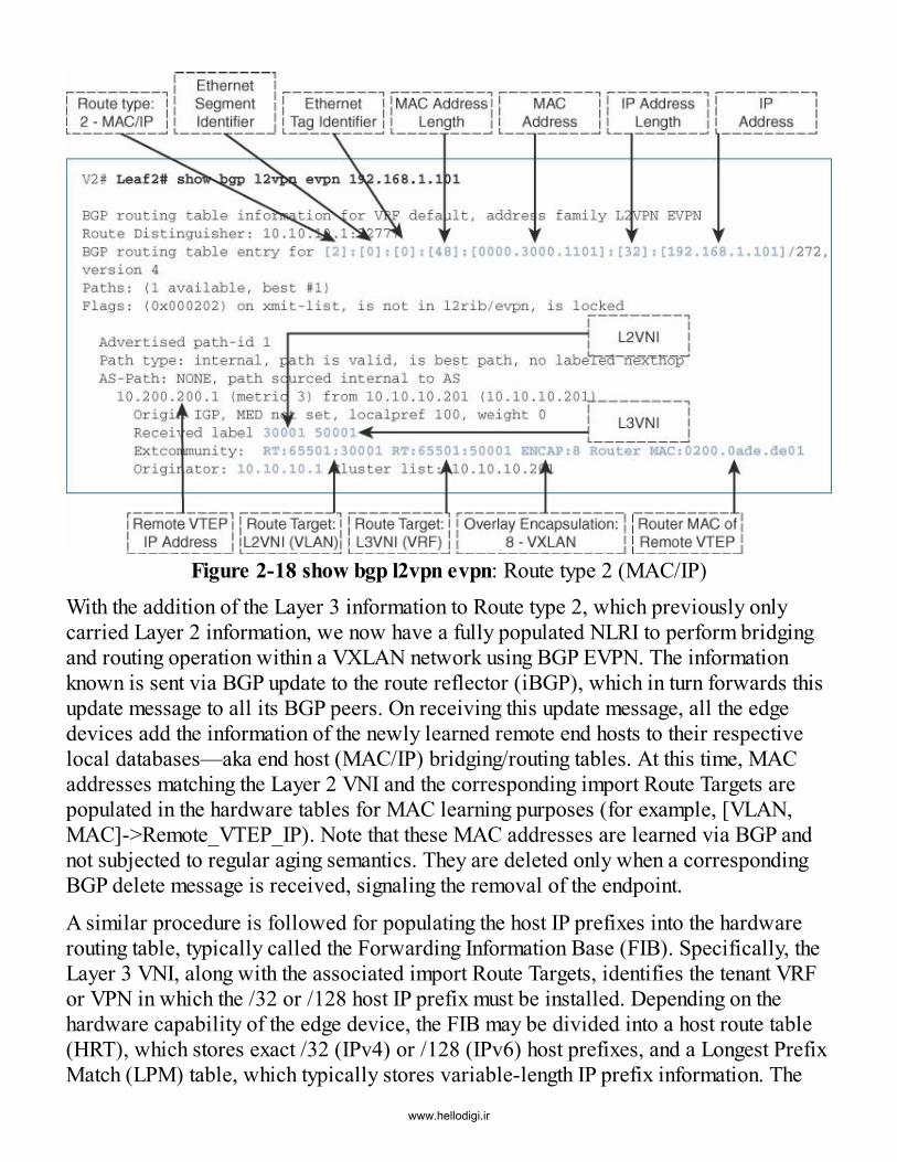
Figure 2-18 show bgp l2vpn evpn: Route type 2 (MAC/IP)With the addition of the Layer 3 information to Route type 2, which previously onlycarried Layer 2 information, we now have a fully populated NLRI to perform bridgingand routing operation within a VXLAN network using BGP EVPN. The informationknown is sent via BGP update to the route reflector (iBGP), which in turn forwards thisupdate message to all its BGP peers. On receiving this update message, all the edgedevices add the information of the newly learned remote end hosts to their respectivelocal databases—aka end host (MAC/IP) bridging/routing tables. At this time, MACaddresses matching the Layer 2 VNI and the corresponding import Route Targets arepopulated in the hardware tables for MAC learning purposes (for example, [VLAN,MAC]->Remote_VTEP_IP). Note that these MAC addresses are learned via BGP andnot subjected to regular aging semantics. They are deleted only when a correspondingBGP delete message is received, signaling the removal of the endpoint.
A similar procedure is followed for populating the host IP prefixes into the hardwarerouting table, typically called the Forwarding Information Base (FIB). Specifically, theLayer 3 VNI, along with the associated import Route Targets, identifies the tenant VRFor VPN in which the /32 or /128 host IP prefix must be installed. Depending on thehardware capability of the edge device, the FIB may be divided into a host route table(HRT), which stores exact /32 (IPv4) or /128 (IPv6) host prefixes, and a Longest PrefixMatch (LPM) table, which typically stores variable-length IP prefix information. The
www.hellodigi.ir

FIB entry, either from the HRT or LPM, points to an adjacency or next-hop entry. This ispopulated with the [BD, RMAC] entry, where BD is the hardware bridge domain thatmaps to the Layer 3 VNI and RMAC corresponds to the remote VTEP. Both of thesepieces of information are carried in the BGP-EVPN Route type 2/5 advertisement. Itshould be noted that the FIB HRT is typically implemented in hardware as a hash tablesince it only needs to support exact match semantics, while the FIB LPM is implementedas a true TCAM or algorithm TCAM, since it must support longest prefix matchsemantics. Because TCAMs are an expensive resource due to their larger powerrequirement, a relatively smaller LPM-based TCAM table is generally present in datacenter ToR ASICs with bigger HRT tables that can support a large number of endpointsor end hosts in massive-scale data center environments.
Only providing locally learned host routing information (with /32- or /128-based IPprefixes) via BGP EVPN is insufficient. Therefore, in addition to host bridging androuting capability, BGP EVPN also provides the classic semantics of IP prefix-basedrouting. IP prefixes are learned and redistributed by the sourcing edge devices into theBGP EVPN control protocol. To perform this operation, a specific EVPN NLRI formathas been introduced (Route type 5). With Route type 5 messages, an edge devicepopulates the IP prefix length with the IP prefix field corresponding to the route beingadvertised and the Layer 3 VNI associated with the VRF context to which the routebelongs (see Figure 2-19). Based on the configuration of the VRF itself, the RouteDistinguisher and Route Target associated with the route can be derived. Similar to theRoute type 2 message, the RMAC and encapsulation type (that is, VXLAN) are alsoincorporated as an extended community into the Route type 5 message.
www.hellodigi.ir

Figure 2-19 show bgp l2vpn evpn: Route type 5 (IP)Once a Route type 5 message is received by an edge device or a VTEP, the IP prefixroute carried in the update is imported into the routing tables only if the Layer 3 VNIand Route Target configured locally at the receiving VTEP matches the one carried inthe message. If this match exists, the IP route is installed into the FIB table, typically asan LPM entry. The corresponding adjacency or next-hop entry is populated in a similarmanner to the Route type 2 message.
There are two major use cases in which Route type 5 is utilized for carrying the IPprefix routing information in a VXLAN-based BGP EVPN network. The first involvesadvertising the IP subnet prefix information from every edge device performing first-hoprouting service. In the case of first-hop routing, also referred to as Integrated Routingand Bridging (IRB), the edge device performs the default gateway service with thedistributed IP anycast gateway (see Figure 2-20). As long as the gateway is configured,the IP subnet prefix is advertised via Route type 5. This helps in the discovery ofundiscovered, or “silent,” end hosts because the subnet prefix attracts routed traffic tothe edge device below which the undiscovered host resides. This edge device generatesan ARP request to discover the silent host, which in turn sends out an ARP response.After discovery, the IP-MAC binding of the end host is learned at the directly attachededge device (via ARP snooping) and advertised into BGP EVPN using Route type 2, asdescribed earlier. In case the IP subnet prefix route was not advertised from all edge
www.hellodigi.ir

devices hosting the distributed IP anycast gateway for that subnet, the traffic toward thatend host would be silently dropped instead of initiating the described host discoveryprocess.
Figure 2-20 Integrated Route and Bridge (IRB)
The second and probably more common use case for injection of IP prefix routes intothe BGP EVPN fabric involves external routing. Routes are learned via peeringestablished using eBGP (or other unicast routing protocols) and redistributed into theBGP EVPN address family using appropriate route map policies (see Figure 2-21). Aspart of this redistribution process, this information is advertised in the same routingcontext (VRF) in which it was learned. This means that using Inter-AS Option A34 withsubinterfaces is a viable way to keep multitenancy information even beyond the BGPEVPN network. An alternative solution for keeping this context awareness could beachieved by Locator/ID Separation Protocol (LISP)35 or an MPLS Layer 3 VPN. Nextto the integrated approach of receiving BGP EVPN information and advertising it to amultitenant-aware external network, LISP also provides the capability of FIB-spaceconservation (resource savings for host routes) for external sites and ingress routeoptimization with host granularity.36
www.hellodigi.ir

Figure 2-21 External Route Learning
Host Deletion and Move EventsSo far, end host detection has been covered in addition to the advertisement of Layer 2and Layer 3 reachability information about an end host into BGP EVPN. This sectioncovers handling of end host deletion and move events. The deletion of end hosts followsalmost the same process as learning a new end host, but in the opposite order. Once anend host gets detached from the VXLAN BGP EVPN–based network, on expiration ofthe ARP entry (the Cisco NX-OS default is 1500 seconds), Layer 3 information aboutthat end host is removed from BGP EVPN. This means the Route type 2 advertisementproviding the information for the end host’s MAC and IP is withdrawn after the timeoutof the related ARP entry.
Specifically, on expiration of the ARP entry, the NX-OS edge device performs a refreshoperation. It sends out an ARP request toward the end host to detect its presence. If itreceives an ARP response, the end host is deemed “alive,” and the ARP refresh timerfor that entry is reset to 1500 seconds. However, if no ARP response is received, theARP entry is deleted, and the end host is deemed “dead.” Then a Route type 2 deletionadvertisement is sent out to let all other edge devices know that the corresponding endhost is no longer reachable.
Even when the ARP entry is deleted, the MAC-only Route type 2 still resides in theBGP EVPN control plane until the MAC aging timer expires (the NX-OS default is1800 seconds), and the MAC information is removed. On this expiration event, theMAC-only Route type 2 advertisement is withdrawn from the BGP EVPN control
www.hellodigi.ir

protocol. Subsequently, when that end host reappears by sending some ARP or othertraffic, the information about the end host is relearned and advertised into the BGP-EVPN control plane. The EVPN prefixes are considered new and never seen before.Note that the ARP aging timer is slightly shorter than the MAC aging timer. As a bestpractice, the two timers should be configured in this way so that unnecessary unknownunicast flooding in the network is avoided. If the MAC aging timer is reduced, then it isimportant to also reduce the ARP aging timer.
Moving workloads is fairly common in today’s cloud-based data centers, especiallywith the presence of virtualization. It entails moving an end host so that the same MACand IP address can now be reached from a different edge device. From a network pointof view, the control protocol can treat this as a deletion of the end host from the oldedge device and a new learn event from the edge device to which the end host hasmoved. This process can be time-consuming, especially in case of “hot” move events,where the end host is still “on” when it is moved to permit the resumption of itsoperations at the new location as soon as the move is complete. A faster option isrequired that allows for just-in-time end host move signaling so that the network isaware of the new location of the end host, which allows for faster convergence.BGP EVPN has the logic for MAC mobility incorporated to cater to end host objects(like the same MAC and/or IP address) showing up behind two different locations(VTEPs) because of end host (aka VM) move operations. Initially, when a VM appears,the associated MAC and IP information is advertised by the VTEP that detected itspresence. When the VM is moved from one server to another, the hypervisor at thedestination server typically detects the VM move event. Once this detection iscompleted, the hypervisor sends out a broadcast Reverse ARP (RARP) message withthe MAC address of the moved VM. In some cases, the hypervisor/virtual switch maysend out a Gratuitous ARP (GARP) message signaling the move of both the IP and MACassociated with the moved VM. In either case, the VTEP connected to the destinationserver detects that the MAC and/or IP address that was originally remote has nowbecome local, that is, reachable via one of its server-facing interfaces.
Given this information, the VTEP connected to the destination server, generates a Routetype 2 BGP EVPN message similar to the one advertised during a new learn event. Butin addition to advertising the MAC address, Layer 2 VNI, and VTEP IP address as thenext-hop, the edge device also advertises an additional field in the form of a MACmobility extended community. The sequence number in the MAC Mobility field isincremented by one to provide a tiebreaker for what Route type 2 advertisement is themost up-to-date, and hence it is used for forwarding by all the remote edge devices orVTEPs. When this Route type 2 message is received by the old VTEP that initiallyadvertised the reachability of the VM, an additional validation step is performed toensure that the information learned from the new VTEP is not caused by a duplicate
www.hellodigi.ir

MAC/IP situation. A duplicate address situation occurs when two end hosts areinadvertently configured with the same address.
Figure 2-22 illustrates a sample show output for a typical Route type 2 entry with theMAC Mobility Sequence Number field populated after a host mobility event. Once thevalidation step passes the duplicate check, the old VTEP withdraws the non-best BGPEVPN Route type 2 message (the one with the lower mobility sequence number). TheBGP EVPN MAC mobility sequence numbering details are defined in RFC 7432,Section 7.7, which describes the handling of scenarios where the MAC mobilitysequence number may wrap around due to a large number of move events.
Figure 2-22 show bgp l2vpn evpn: Route type 2 (MAC/IP and Mobility SequenceNumber)
SummaryThis chapter describes why overlays have become a prime design choice for next-generation data centers. It places special emphasis on VXLAN, which has become thede facto choice. This chapter describes the need for a control plane–based solution fordistribution of host reachability between various edge devices and provides acomprehensive introduction to BGP EVPN. It describes the important message formatsin BGP EVPN for supporting network virtualization overlays, along with their
www.hellodigi.ir
representative use cases. The subsequent chapters build on this background, providingfurther details on the underlay, multitenancy, and single-destination and multidestinationdata packet flows in a VXLAN BGP EVPN–based data center topology.
References1. Institute of Electrical and Electronics Engineers (IEEE). 802.1q—VLANs. 2016.
www.ieee802.org/1/pages/802.1Q.html.2. Red Hat. Linux containers with docket format. 2016.
access.redhat.com/documentation/en-US/Red_Hat_Enterprise_Linux/7/html/7.0_Release_Notes/chap-Red_Hat_Enterprise_Linux-7.0_Release_Notes-Linux_Containers_with_Docker_Format.html.
3. Goransson, P., and C. Black. Software defined networks: A comprehensiveapproach (1st ed.). San Francisco, CA: Morgan Kaufmann Publishers Inc., 2014.
4. Institute of Electrical and Electronics Engineers (IEEE). IEEE 802.1. 2016.www.ieee802.org/1/.
5. Smith, K. Cython: The best of both worlds. Computing in Science & Engineering,13(2):31–39, 2011.
6. Cisco. Multiprotocol Label Switching (MPLS).www.cisco.com/c/en/us/products/ios-nx-os-software/multiprotocol-label-switching-mpls/index.html.
7. Cisco. GRE tunnel interface states and what impacts them. 2014.www.cisco.com/c/en/us/support/docs/ip/generic-routing-encapsulation-gre/118361-technote-gre-00.html.
8. Cisco. Cisco IOS IPsec. www.cisco.com/c/en/us/products/ios-nx-os-software/ios-ipsec/index.html.
9. Wilkins, S. IPv6 tunneling technology configurations. 2013.www.ciscopress.com/articles/article.asp?p=2104948.
10. Internet Engineering Task Force (IETF). Layer Two Tunneling Protocol—Version 3(L2TPv3). 2005. tools.ietf.org/html/rfc3931.
11. Internet Engineering Task Force (IETF). Routing bridges (RBridges): Base protocolspecification. 2011. tools.ietf.org/html/rfc6325.
12. Cisco. Cisco FabricPath. http://www.cisco.com/c/en/us/solutions/data-center-virtualization/fabricpath/index.html.
13. Institute of Electrical and Electronics Engineers (IEEE). 802.1aq—Shortest pathbridging. 2012. www.ieee802.org/1/pages/802.1aq.html.
www.hellodigi.ir

14. Internet Engineering Task Force (IETF). NVGRE: Network virtualization usinggeneric routing encapsulation. 2015. tools.ietf.org/html/rfc7637.
15. Cisco. Application policy infrastructure controller (APIC).www.cisco.com/c/en/us/products/cloud-systems-management/application-policy-infrastructure-controller-apic/index.html.
16. Open Daylight. www.opendaylight.org.17. Internet Engineering Task Force (IETF). BGP MPLS-based Ethernet VPN. 2015.
tools.ietf.org/html/rfc7432.18. Pfaff, B. The open vSwitch database management protocol. 2013.
tools.ietf.org/html/rfc7047.19. Internet Engineering Task Force (IETF). Virtual eXtensible local area network
(VXLAN): A framework for overlaying virtualized Layer 2 networks over Layer 3networks. 2014. tools.ietf.org/html/rfc7348.
20. Hogue, T. The dreaded 5-tuple. 2015. blogs.cisco.com/security/the-dreaded-5-tuple.21. Cisco. OSPF design guide. 2005. www.cisco.com/c/en/us/support/docs/ip/open-
shortest-path-first-ospf/7039-1.html#topic2.22. Cisco. Intermediate System-to-Intermediate System Protocol.
www.cisco.com/en/US/products/ps6599/products_white_paper09186a00800a3e6f.shtml23. Cisco. Configuring PIM.
www.cisco.com/c/en/us/td/docs/switches/datacenter/nexus3548/sw/multicast/602_A1_1/multicast_cli/pim.html24. Cisco. Border Gateway Protocol (BGP). www.cisco.com/c/en/us/products/ios-nx-
os-software/border-gateway-protocol-bgp/index.html.25. Cisco. Ethernet VPN (EVPN) and provider backbone bridging-EVPN: Next
generation solutions for MPLS-based Ethernet services.www.cisco.com/c/en/us/products/collateral/routers/asr-9000-series-aggregation-services-routers/whitepaper_c11-731864.html.
26. Network Working Group. BGP/MPLS IP virtual private networks (VPNs). 2006.tools.ietf.org/html/rfc4364.
27. Cisco. Multiprotocol BGP. http://www.cisco.com/c/en/us/td/docs/ios-xml/ios/mp_l3_vpns/configuration/15-mt/mp-l3-vpns-15-mt-book/mp-bgp-mpls-vpn.html.
28. Internet Engineering Task Force (IETF). Integrated routing and bridging in EVPN.2014. www.ietf.org/archive/id/draft-sajassi-l2vpn-evpn-inter-subnet-forwarding-05.txt.
29. IETF Network Working Group. Multiprotocol extensions for BGP-4. 2007.tools.ietf.org/html/rfc4760.
www.hellodigi.ir

30. BESS Working Group. Interconnect solution for EVPN overlay networks draft-ietf-bess-dci-evpn-overlay-01. 2016. tools.ietf.org/html/draft-ietf-bess-evpn-overlay-01.
31. L2VPN Work Group. A network virtualization overlay solution using EVPN draft-ietf-bess-evpn-overlay-02. 2015. tools.ietf.org/html/draft-ietf-bess-evpn-overlay-02#section-13.
32. Internet Engineering Task Force (IETF). BGP MPLS-based Ethernet VPN: MACmobility. 2015. tools.ietf.org/html/rfc7432#section-15.
33. L2VPN Work Group. A network virtualization overlay solution using EVPN draft-ietf-bess-evpn-overlay-02: Encapsulation options for EVPN overlays. 2015.tools.ietf.org/html/draft-ietf-bess-evpn-overlay-02#section-5.
34. Internet Engineering Task Force (IETF). BGP/MPLS IP virtual private networks.2006. tools.ietf.org/html/rfc4364#section-10.
35. Internet Engineering Task Force (IETF). The Locator/ID Separation Protocol(LISP). 2013. tools.ietf.org/html/rfc6830.
36. Cisco. Optimizing ingress routing with LISP across multiple VXLAN/EVPN sites:White paper. www.cisco.com/c/en/us/products/collateral/switches/nexus-7000-series-switches/white-paper-c11-734843.html.
www.hellodigi.ir

Chapter 3 VXLAN/EVPN Forwarding Characteristics
In this chapter, the following topics will be covered:
Enhanced BGP EVPN features such as ARP suppression, unknown unicastsuppression, and optimized IGMP snooping Distributed IP anycast gateway in the VXLAN EVPN fabric Anycast VTEP implementation with dual-homed deployments
VXLAN BGP EVPN has been extensively documented in various standardizedreferences, including IETF drafts1 and RFCs.2 While that information is useful forimplementing the protocol and related encapsulation, some characteristics regardingforwarding require additional attention and discussion. Unfortunately, a commonmisunderstanding is that VXLAN with BGP EVPN does not require any specialtreatment for multidestination traffic. This chapter describes how multidestinationreplication works using VXLAN with BGP EVPN for forwarding broadcast, unknownunicast, and multicast (BUM) traffic. In addition, methods to reduce BUM traffic arecovered. This chapter also includes a discussion on enhanced features such as earlyAddress Resolution Protocol (ARP) suppression, unknown unicast suppression, andoptimized Internet Group Management Protocol (IGMP) snooping in VXLAN BGPEVPN networks. While the functions and features of Cisco’s VXLAN BGP EVPNimplementation support reduction of BUM traffic, the use case of silent host detectionstill requires special handling, which is also discussed.In addition to discussing Layer 2 BUM traffic, this chapter talks about Layer 3 trafficforwarding in VXLAN BGP EVPN networks. VXLAN BGP EVPN provides Layer 2overlay services as well as Layer 3 services. For Layer 3 forwarding or routing, thepresence of a first-hop default gateway is necessary. The distributed IP anycast gatewayenhances the first-hop gateway function by distributing the endpoints’ default gatewayacross all available edge devices (or Virtual Tunnel Endpoints [VTEPs]). Thedistributed IP anycast gateway is implemented using the Integrated Routing and Bridging(IRB) functionality. This ensures that both bridged and routed traffic—to and fromendpoints—is always optimally forwarded within the network with predictable latency,based on the BGP EVPN advertised reachability information. Because of thisdistributed approach for the Layer 2/Layer 3 boundary, virtual machine mobility isseamlessly handled from the network point of view by employing special mobility-related functionality in BGP EVPN. The distributed anycast gateway ensures that the IP-to-MAC binding for the default gateway does not change, regardless of where an endhost resides or moves within the network. In addition, there is no hair-pinning of routedtraffic flows to/from the endpoint after a move event. Host route granularity in the BGP
www.hellodigi.ir

EVPN control plane protocol facilitates efficient routing to the VTEP behind which anendpoint resides—at all times.
Data centers require high availability throughout all layers and components. Similarly,the data center fabric must provide redundancy as well as dynamic route distribution.VXLAN BGP EVPN provides redundancy from multiple angles. The Layer 3 routedunderlay between the VXLAN edge devices or VTEPs provides resiliency as well asmultipathing. Connecting classic Ethernet endpoints via multichassis link aggregation orvirtual PortChannel (vPC) provides dual-homing functionality that ensures faulttolerance even in case of a VTEP failure. In addition, typically, Dynamic HostConfiguration Protocol (DHCP) services are required for dynamic allocation of IPaddresses to endpoints. In the context of DHCP handling, the semantics of centralizedgateways are slightly different from those of the distributed anycast gateway. In aVXLAN BGP EVPN fabric, the DHCP relay needs to be configured on each distributedanycast gateway point, and the DHCP server configuration must support DHCP Option82.3 This allows a seamless IP configuration service for the endpoints in the VXLANBGP EVPN fabric.The aforementioned standards are specific to the interworking of the data plane and thecontrol plane. Some components and functionalities are not inherently part of thestandards, and this chapter provides coverage for them. The scope of the discussion inthis chapter is specific to VXLAN BGP EVPN implementation on Cisco NX-OS-basedplatforms. Later chapters provide the necessary details, including detailed packet flows,for forwarding traffic in a VXLAN BGP EVPN network, along with the correspondingconfiguration requirements.
Multidestination TrafficThe VXLAN with BGP EVPN control plane has two different options for handling BUMor multidestination traffic. The first approach is to leverage multicast replication in theunderlay. The second approach is to use a multicast-less approach called ingressreplication, in which multiple unicast streams are used to forward multidestinationtraffic to the appropriate recipients. The following sections discuss these twoapproaches.
Leveraging Multicast Replication in the Underlying NetworkThe first approach to handling multidestination traffic requires the configuration of IPmulticast in the underlay and leverages a network-based replication mechanism. Withmulticast, a single copy of the BUM traffic is sent from the ingress/source VTEP towardthe underlay transport network. The network itself forwards this single copy along themulticast tree (that is, a shared tree or source tree) so that it reaches all
www.hellodigi.ir

egress/destination VTEPs participating in the given multicast group. As the single copytravels along the multicast tree, the copy is replicated at appropriate branch points onlyif receivers have joined the multicast group associated with the VNI. With thisapproach, a single-copy per-wire/link is kept within the network, thereby providing themost efficient way to forward BUM traffic.
A Layer 2 VNI is mapped to a multicast group. This mapping must be consistentlyconfigured on all VTEPs where this VNI is present, typically signifying the presence ofsome interested endpoint below that VTEP. Once it is configured, the VTEP sends out acorresponding multicast join expressing interest in the tree associated with thecorresponding multicast group. When mapping a Layer 2 VNI to a multicast group,various options are available in the mapping provision for the VNI and multicast group.The simplest approach is to employ a single multicast group and map all Layer 2 VNIsto that group. An obvious benefit of this mapping is the reduction of the multicast state inthe underlying network; however, it is also inefficient in the replication of BUM traffic.When a VTEP joins a given multicast group, it receives all traffic being forwarded tothat group. The VTEP does not do anything with traffic in which no interest exists (forexample, VNIs for which the VTEP is not responsible). In other words, it silently dropsthat traffic. The VTEP continues to receive this unnecessary traffic as an active receiverfor the overall group. Unfortunately, there is no suboption for a VNI to prune backmulticast traffic based on both group and VNI. Thus, in a scenario where all VTEPsparticipate in the same multicast group or groups, the scalability of the number ofmulticast outgoing interfaces (OIFs) needs to be considered.At one extreme, each Layer 2 VNI can be mapped to a unique multicast group. At theother extreme, all Layer 2 VNIs are mapped to the same multicast group. Clearly, theoptimal behavior lies somewhere in the middle. While theoretically there are 224 = 16million possible VNI values and more than enough multicast addresses (in the multicastaddress block 224.0.0.0–239.255.255.255), practical hardware and software factorslimit the number of multicast groups used in most practical deployments to a fewhundred. Setting up and maintaining multicast trees requires a fair amount of statemaintenance and protocol exchange (PIM, IGMP, and so on) in the underlay. To betterexplain this concept, this chapter presents a couple of simple multicast group usagescenarios for BUM traffic in a VXLAN network. Consider the BUM flows shown inFigure 3-1.
www.hellodigi.ir

Figure 3-1 Single Multicast Group for All VNIsThree edge devices participate as VTEPs in a given VXLAN-based network. TheseVTEPs are denoted V1 (10.200.200.1), V2 (10.200.200.2), and V3 (10.200.200.3). IPsubnet 192.168.1.0/24 is associated with Layer 2 VNI 30001, and subnet192.168.2.0/24 is associated with Layer 2 VNI 30002. In addition, VNIs 30001 and30002 share a common multicast group (239.1.1.1), but the VNIs are not spread acrossall three VTEPs. As is evident from Figure 3-1, VNI 30001 spans VTEPs V1 and V3,while VNI 30002 spans VTEPs V2 and V3. However, the shared multicast group causesall VTEPs to join the same shared multicast tree. In the figure, when Host A sends out abroadcast packet, VTEP V1 receives this packet and encapsulates it with a VXLANheader. Because the VTEP is able to recognize this as broadcast traffic (DMAC isFFFF.FFFF.FFFF), it employs a destination IP in the outer IP header as the multicastgroup address. As a result, the broadcast traffic is mapped to the respective VNI’smulticast group (239.1.1.1).
The broadcast packet is then forwarded to all VTEPs that have joined the multicast treefor the group 239.1.1.1. VTEP V2 receives the packet, but it silently drops it because ithas no interest in the given VNI 30001. Similarly, VTEP V3 receives the same packetthat is replicated through the multicast underlay. Because VNI 30001 is configured forVTEP V3, after decapsulation, the broadcast packet is sent out to all local Ethernetinterfaces participating in the VLAN mapped to VNI 30001. In this way, the broadcastpacket initiated from Host A reaches Host C.
www.hellodigi.ir

For VNI 30002, the operations are the same because the same multicast group(239.1.1.1) is used across all VTEPs. The BUM traffic is seen on all the VTEPs, but thetraffic is dropped if VNI 30002 is not locally configured at that VTEP. Otherwise, thetraffic is appropriately forwarded along all the Ethernet interfaces in the VLAN, whichis mapped to VNI 30002.
As it is clear from this example, unnecessary BUM traffic can be avoided by employinga different multicast group for VNIs 30001 and 30002. Traffic in VNI 30001 can bescoped to VTEPs V1 and V3, and traffic in VNI 30002 can be scoped to VTEPs V2 andV3. Figure 3-2 provides an example of such a topology to illustrate the concept of ascoped multicast group.
Figure 3-2 Scoped Multicast Group for VNI
As before, the three edge devices participating as VTEPs in a given VXLAN-basednetwork are denoted V1 (10.200.200.1), V2 (102.200.200.2), and V3 (10.200.200.3).The Layer 2 VNI 30001 is using the multicast group 239.1.1.1, while the VNI 30002 isusing a different multicast group, 239.1.1.2. The VNIs are spread across the variousVTEPs, with VNI 30001 on VTEPs V1 and V3 and VNI 30002 on VTEPs V2 and V3.The VTEPs are required to join only the multicast group and the related multicast treefor the locally configured VNIs. When Host A sends out a broadcast, VTEP V1 receives
www.hellodigi.ir
this broadcast packet and encapsulates it with an appropriate VXLAN header. Becausethe VTEP understands that this is a broadcast packet (DMAC is FFFF.FFFF.FFFF), ituses a destination IP address in the outer header with the multicast group addressmapped to the respective VNI (239.1.1.1). This packet is forwarded to VTEP V3 only,which previously joined the multicast tree for the Group 239.1.1.1, where VNI 30001 isconfigured. VTEP V2 does not receive the packet, as it does not belong to the multicastgroup because it is not configured with VNI 30001. VTEP V3 receives this packetbecause it belongs to the multicast group mapped to VNI 30001. It forwards it locally toall member ports that are part of the VLAN that is mapped to VNI 30001. In this way,the broadcast traffic is optimally replicated through the multicast network configured inthe underlay.The same operation occurs in relation to VNI 30002. VNI 30002 is mapped to adifferent multicast group (239.1.1.2), which is used between VTEPs V2 and V3. TheBUM traffic is seen only on the VTEPs participating in VNI 30002—specificallymulticast group 239.1.1.2. When broadcast traffic is sent from Host Z, the broadcast isreplicated only to VTEPs V2 and V3, resulting in the broadcast traffic being sent to HostY. VTEP V1 does not see this broadcast traffic as it does not belong to that multicastgroup. As a result, the number of multicast outgoing interfaces (OIFs) in the underlyingnetwork is reduced.
While using a multicast group per VNI seems to work fine in the simple example withthree VTEPs and two VNIs, in most practical deployments, a suitable mechanism isrequired to simplify the assignment of multicast groups to VNIs. There are two popularways of achieving this:
VNIs are randomly selected and assigned to multicast groups, thereby resulting insome implicit sharing. A multicast group is localized to a set of VTEPs, thereby ensuring that they sharethe same set of Layer 2 VNIs.
The second option to handling multidestination traffic may sound more efficient than thefirst, but in practice it may lack the desired flexibility because it limits workloadassignments to a set of servers below a set of VTEPs, which is clearly undesirable.
Using Ingress ReplicationWhile multicast configuration in the underlay is straightforward, not everyone isfamiliar with or willing to use it. Depending on the platform capabilities, a secondapproach for multidestination traffic is available: leveraging ingress or head-endreplication, which is a unicast approach. The terms ingress replication (IR) and head-end replication (HER) can be used interchangeably. IR/HER is a unicast-based mode
www.hellodigi.ir

where network-based replication is not employed. The ingress, or source, VTEP makesN–1 copies of every BUM packet and sends them as individual unicasts toward therespective N–1 VTEPs that have the associated VNI membership. With IR/HER, thereplication list is either statically configured or dynamically determined, leveraging theBGP EVPN control plane. Section 7.3 of RFC 7432 (https://tools.ietf.org/html/rfc7432)defines inclusive multicast Ethernet tag (IMET) routing, or Route type 3 (RT-3). Toachieve optimal efficiency with IR/HER, best practice is to use the dynamic distributionwith BGP EVPN. BGP EVPN provides a Route type 3 (inclusive multicast) option thatallows for building a dynamic replication list because IP addresses of every VTEP in agiven VNI would be advertised over BGP EVPN. The dynamic replication list has theegress/destination VTEPs that are participants in the same Layer 2 VNI.
Each VTEP advertises a specific route that includes the VNI as well as the next-hop IPaddress corresponding to its own address. As a result, a dynamic replication list isbuilt. The list is updated when configuration of a VNI at a VTEP occurs. Once thereplication list is built, the packet is multiplied at the VTEP whenever BUM trafficreaches the ingress/source VTEP. This results in individual copies being sent towardevery VTEP in a VNI across the network. Because network-integrated multicastreplication is not used, ingress replication is employed, generating additional networktraffic. Figure 3-3 illustrates sample BGP EVPN output with relevant fields highlighted,for a Route type 3 advertisement associated with a given VTEP.
Figure 3-3 Route type 3: Inclusive Multicastwww.hellodigi.ir

When comparing the multicast and unicast modes of operation for BUM traffic, the loadfor all the multidestination traffic replication needs to be considered. For example,consider a single Layer 2 VNI present on all 256 edge devices hosting a VTEP. Further,assume that a single VLAN exists on all 48 Ethernet interfaces of the edge deviceswhere BUM traffic replication is occurring. Each Ethernet interface of the local edgedevice receives 0.001% of the nominal interface speed of BUM traffic. For 10Ginterfaces, this generates 0.0048 Gbps (4.8 Mbps) of BUM traffic at the edge devicefrom the host-facing Ethernet interfaces. In multicast mode, the theoretical speed ofBUM traffic remains at this rate. In unicast mode, the replication depends on the amountof egress/destination activity on the VTEP. In the example of 255 neighboring VTEPs,this results in 255 × 0.0048 = ~1.2 Gbps of BUM traffic on the fabric. Even though theexample is theoretical, it clearly demonstrates the huge overhead that the unicast modeincurs as the amount of multidestination traffic in the network increases. The efficiencyof multicast mode in these cases cannot be understated.
It is important to note that when scoping a multicast group to VNIs, the same multicastgroup for a given Layer 2 VNI must be configured across the entire VXLAN-basedfabric. In addition, all VTEPs have to follow the same multidestination configurationmode for a given Layer 2 domain represented through the Layer 2 VNI. In other words,for a given Layer 2 VNI, all VTEPs have to follow the same unicast or multicastconfiguration mode. In addition, for the multicast mode, it is important to follow thesame multicast protocol (for example, PIM ASM,4 PIM BiDir5) for the correspondingmulticast group. Failure to adhere to these requirements results in broken forwarding ofmultidestination traffic.
VXLAN BGP EVPN EnhancementsThe following sections describe some of the feature enhancements that ride on top of theBGP EVPN control plane, further enhancing the forwarding of Layer 2 and Layer 3traffic in a VXLAN fabric.
ARP SuppressionAddress Resolution Protocol (ARP) is responsible for IPv4 address–to–MAC addressmapping in IP networks. ARP facilitates obtaining endpoint MAC address information,leveraging the IP address information sent out in an ARP broadcast request. Thebroadcast request is treated as multidestination traffic that is typically VXLANencapsulated and sent to every VTEP or edge device that is a member of thecorresponding Layer 2 VNI. The response to the ARP request is typically sent as aunicast packet to the requestor. ARP traffic is scoped within the bounds of the broadcastdomain represented by the Layer 2 VNI. Correspondingly, IPv6 networks rely on the
www.hellodigi.ir

Neighbor Discovery Protocol (ND) for IPv6 address–to–MAC address resolution. WithIPv6, this resolution is triggered via an initial neighbor solicitation (NS) that ismulticast through the Layer 2 broadcast domain. A neighbor advertisement (NA) sent inresponse from the destination completes the neighbor resolution.6
When an endpoint needs to resolve the default gateway, which is the exit point of thelocal IP subnet, it sends out an ARP request to the configured default gateway. The ARPoperation allows the local edge device or VTEP to populate IP/MAC mappings of thelocally attached endpoints. In addition to the MAC-to-IP table being populated on theedge device, all the MAC information is populated to the BGP EVPN control planeprotocol. In addition, for Layer 2, Layer 2 VNI, Route Distinguisher (RD), Route Target(RT), hosting VTEP, and associated IP information is populated, and for Layer 3, Layer3 VNI, RD, RT, hosting VTEP, and RMAC information is populated. Specifically, thisinformation is populated in a Route type 2 advertisement and distributed to all remoteVTEPs, which now have learned about that endpoint.Typically, all ARP broadcast requests sent out from an endpoint are subject to copy-to-router and forward behavior. The local edge device learns about an endpoint as long asthe endpoint sends out some type of ARP request—not necessarily an ARP request forthe resolution of the default gateway hosted on the local edge device.
Typically, when an endpoint wants to talk to another endpoint in the same subnet, itsends out an ARP request for determining the IP-to-MAC binding of the destinationendpoint. The ARP request is flooded to all the endpoints that are part of that Layer 2VNI. ARP snooping coupled with the BGP EVPN control plane information can helpavoid flooding for known endpoints. By using ARP snooping, all ARP requests from anendpoint are redirected to the locally attached edge device. The edge device thenextracts the destination IP address in the ARP payload and determines whether it is aknown endpoint. Specifically, a query is done against the known endpoint informationfrom the BGP EVPN control plane.
If the destination is known, the IP-to-MAC binding information is returned. The localedge device then performs an ARP proxy on behalf of the destination endpoint. In otherwords, it sends out a unicast ARP response toward the requestor with the resolvedMAC address of the known destination endpoint. In this way, all ARP requests to knownendpoints are terminated at the earliest possible point, which is the locally attachededge device or VTEP or leaf. This is known as ARP suppression. ARP suppression ispossible because all the information is known on all the VXLAN VTEPs.7
Note that ARP suppression is different from the Proxy ARP,8 in which the edge deviceor router may serve as a proxy on behalf of the destination endpoint, using its ownRouter MAC. ARP suppression reduces ARP broadcast traffic by leveraging the BGP
www.hellodigi.ir

EVPN control plane information. ARP suppression is enabled on a per-Layer 2 VNIbasis. In this way, for all known endpoints, ARP requests are sent only between theendpoint and the local edge device/VTEP. Figure 3-4 illustrates a scenario where ARPsuppression at VTEP V1 results in early ARP termination of a request for a host192.168.1.102 from a host 192.168.1.101 in Layer 2 VNI 30001. It is important to notethat the ARP suppression feature works based on the knob enabled under the Layer 2VNI, regardless of whether the default gateway is configured on the leafs.
Figure 3-4 ARP Suppression
When the destination endpoint is not known to the BGP EVPN control plane (that is, asilent or undiscovered endpoint), the ARP broadcast needs to be sent across theVXLAN network. Recall that ARP snooping intercepts the ARP broadcast request to thelocally attached edge device. Because the lookup for the destination endpoint results ina “miss,” the edge device re-injects the ARP broadcast request back into the networkwith appropriate source filtering to ensure that it does not return to the source port fromwhich the ARP request was originally received. The ARP broadcast leverages themultidestination traffic forwarding implementation of the VXLAN fabric.
When the queried endpoint responds to the ARP request, the endpoint generates an ARPresponse. The unicast ARP response is also subjected to ARP snooping behavior so thatit is sent to the remote edge device to which the destination is directly attached.Consequently, the IP/MAC binding of the destination endpoint is learned by the remoteVTEP, resulting in that information being populated into the BGP EVPN control plane.The remote edge device also sends out the ARP response to the original requestingendpoint, thereby completing the end-to-end ARP discovery process. The ARP response
www.hellodigi.ir

is sent via the data plane to ensure that there are no delays in the control plane updates.It is important to note that after the initial miss, all the subsequent ARP requests for thediscovered endpoint are handled with local ARP termination, as described earlier.
Figure 3-5 illustrates a scenario involving ARP termination or ARP suppression wherea miss occurs in the control plane. Host A and Host B belong to the same IP subnet,corresponding to the Layer 2 VNI 30001. Host A wants to communicate with Host B,but the respective MAC-to-IP mapping is not known in Host A’s ARP cache. Therefore,Host A sends an ARP request to determine the MAC-to-IP binding of Host B. The ARPrequest is snooped by VTEP V1. VTEP V1 uses the target IP address informationgleaned from the ARP request payload to look up information about Host B in the BGPEVPN control plane. Since Host B is not yet known in the network, the broadcast ARPrequest is encapsulated into VXLAN with the destination IP address of a multicast groupor a unicast destination IP address. The multicast group is leveraged when multicast isenabled in the underlay. Otherwise, using head-end replication, multiple unicast copiesare generated to each remote interested VTEP, as mentioned earlier.
Figure 3-5 ARP lookup miss with ARP Suppression
www.hellodigi.ir
The ARP broadcast sent to VTEP V2 and VTEP V3 is appropriately decapsulated, andthe inner broadcast payload is forwarded to all Ethernet ports that are members of VNI30001. In this way, the ARP request reaches Host B, and Host B answers with a unicastARP response back to Host A. Once the unicast ARP response hits VTEP V2, theinformation is snooped, and the control plane is then updated with Host B’s IP/MACaddress information. At the same time, the ARP response is encapsulated and forwardedacross the VXLAN network to VTEP V1. On receiving the ARP response, VTEP V1decapsulates the VXLAN header and forwards the decapsulated ARP response, basedon a Layer 2 lookup, in VNI 30001. Consequently, Host A receives the ARP responseand populates its local ARP cache. From this point forward, bidirectionalcommunication between Host A and Host B is enabled because all MAC and IP addressinformation of both hosts is known in the network.
The ARP request and response process between endpoints in a VXLAN BGP EVPNfabric is similar to that in classic Ethernet or any other Flood and Learn (F&L) network.However, the advantage of the control plane and ARP suppression is realized with theBGP EVPN information. A single ARP resolution of an endpoint triggers the controlplane to populate that endpoint information across the entire network, at all the VTEPs.Consequently, any subsequent ARP requests to any known endpoint are locallyanswered instead of being flooded across the entire network.Because ARP snooping proactively learns the endpoint information to populate thecontrol plane, it certainly helps in reducing unknown unicast traffic. ARP requests reallyneed to be flooded only for the initial period, when an endpoint has yet to bediscovered. However, there are other sources of unknown unicast traffic (for example,vanilla Layer 2 non-IP traffic or even regular Layer 2 IP traffic) that may suffer aDMAC lookup miss and the traffic being flooded all across the VXLAN network.
To completely disable any kind of flooding due to unknown unicast traffic toward theVXLAN network, a new feature called unknown unicast suppression has beenintroduced. This independent feature is enabled on a per-Layer 2 VNI basis. With thisknob enabled, when any Layer 2 traffic suffers a DMAC lookup miss, traffic is locallyflooded, but there is no flooding over VXLAN. Therefore, if no silent or unknown hostsare present, flooding can potentially be minimized in a BGP EVPN VXLAN network.
Next, we consider the third piece of BUM or multidestination traffic, which is calledmulticast traffic. Layer 2 multicast in a VXLAN network is treated as broadcast orunknown unicast traffic because the multicast traffic is flooded across the underlay.Layer 2 multicast flooding leverages the configured multidestination traffic-handlingmethod, whether it exists in unicast mode or multicast mode. Not all platforms candifferentiate between the different types of Layer 2 floods, such as multicast or unknownunicast. The IGMP snooping feature presents an optimal way of forwarding Layer 2
www.hellodigi.ir

multicast traffic if supported by the platform. The Cisco NX-OS default configurationresults in behavior that floods Layer 2 multicast traffic both locally and across theVTEP interfaces (see Figure 3-6). This means that all participating VTEPs with thesame VNI mapping and all endpoints in that Layer 2 VNI receive this Layer 2 multicasttraffic. The multidestination traffic is forwarded to every endpoint in the VNI,regardless of whether that endpoint is an interested receiver.
Figure 3-6 No IGMP Snooping in VLAN/VXLAN
With VXLAN, the option to implement IGMP snooping in the same way it isimplemented in traditional Ethernet-based networks. The main difference is that theVTEP interface selectively allows Layer 2 multicast forwarding for interested receiversthat are present behind a remote VTEP. If there are no interested receivers behindremote VTEPs, Layer 2 multicast traffic received from a source endpoint is not senttoward the VXLAN network. However, as long as there is at least one interestedreceiver behind some remote VTEP, Layer 2 multicast traffic is forwarded to all remoteVTEPs since they are all part of the same Layer 2 VNI. The VTEP interface is amulticast router port that participates in IGMP snooping, thereby allowing Layer 2multicast forwarding. This is dependent on the receipt of the IGMP “join” message froman endpoint for a given multicast group in a Layer 2 VNI.
The received IGMP join report is VXLAN encapsulated and transported to all remoteVTEPs that are members of the corresponding Layer 2 VNI. Note that the multicastgroup(s) employed for overlay multicast traffic between endpoints should not beconfused with the underlay multicast group that may be associated with the Layer 2 VNI.Recall that the latter is employed to provide the destination IP address in the outer IP
www.hellodigi.ir

header for forwarding multidestination traffic in the underlay when using multicastmode.
With IGMP snooping enabled for VXLAN VNIs, the ability to realize the true benefits ofmulticast occurs: Traffic is forwarded only to interested receiver endpoints (see Figure3-7). In other words, if no interested receivers exist for a given multicast group behind aVTEP in the same VNI, the Layer 2 multicast traffic is silently dropped and not flooded.After decapsulation at the remote VTEP, Layer 2 multicast traffic is forwarded based onthe local IGMP snooping state. IGMP join messages are used to selectively enable theforwarding of certain Layer 2 multicast traffic.
Figure 3-7 IGMP Snooping in VLAN/VXLAN
Depending on the platform software support, IGMP snooping for VXLAN-enabledVLANs may not be supported. IGMP snooping is a software feature that does not haveany dependencies on the underlying hardware. While this section provided a briefoverview, detailed IP multicast flows in a VXLAN BGP EVPN network are presentedin Chapter 7 “Multicast Forwarding”.
Distributed IP Anycast GatewayIn order for two endpoints in different IP subnets to communicate with each other, adefault gateway is required. Traditionally, the default gateway has been implementedcentrally at the data center aggregation layer, in a redundant configuration. For anendpoint to reach the centralized default gateway, it has to first traverse a Layer 2
www.hellodigi.ir

network. The Layer 2 network options include Ethernet, vPC, FabricPath, and even VXLAN F&L. Communication within the same IP subnet is typically bridged without any communication with the centralized default gateway. For routing communication between different IP networks/subnets, the centralized default gateway is reachable over the same Layer 2 network path.
Typically, the network is designed to be redundant as well as highly available.Likewise, the centralized gateway is highly available. First-hop redundancy protocols(FHRP) were designed to support the centralized default gateway with redundancy. Protocols such as HSRP,9 VRRP,10 and GLBP11 are examples of FHRPs. HSRP and VRRP have a single node responsible for responding to ARP requests as well as routing traffic to a different IP network/subnet. When the primary node fails, the FHRP changes the operational state on the backup node to master. A certain amount of time is needed to fail over from one node to another.FHRPs became more versatile when implemented with virtual PortChannels (vPCs), which allow both nodes to forward routing traffic and permit only the master node to respond to ARP requests. Combining vPC and FHRP significantly enhances resiliencyas well as convergence time in case of failures. Enabling ARP synchronization for the FHRP in vPC environments enables ARP synchronization between the vPC primary and the vPC secondary. FabricPath with anycast HSRP12 increases the number of active gateways from two to four nodes. The FHRP protocol exchange and operational state changes are still present with anycast HSRP. With FHRPs, the default gateway, implemented at the data center aggregation layer, provides a centralized default gateway as well as the Layer 2/Layer 3 network boundary.
The increasing importance of Layer 2 and Layer 3 operations, especially in a large data center fabric, has demanded additional resiliency in comparison to what has been provided by traditional FHRP protocols. Moving the Layer 2-Layer 3 network boundary to the fabric leaf/ToR switch or the access layer reduces the failure domain (see Figure 3-8). The scale-out approach of the distributed IP anycast gateway dramatically reduces the network and protocol state. The distributed IP anycast gateway implementation at each fabric leaf no longer requires each endpoint to traverse a large Layer 2 domain to reach the default gateway,
www.hellodigi.ir
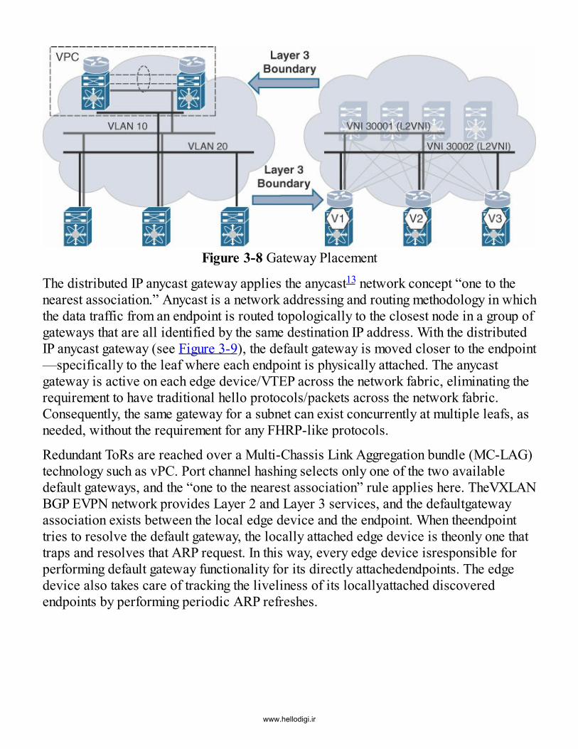
Figure 3-8 Gateway Placement
The distributed IP anycast gateway applies the anycast13 network concept “one to the nearest association.” Anycast is a network addressing and routing methodology in which the data traffic from an endpoint is routed topologically to the closest node in a group of gateways that are all identified by the same destination IP address. With the distributed IP anycast gateway (see Figure 3-9), the default gateway is moved closer to the endpoint —specifically to the leaf where each endpoint is physically attached. The anycast gateway is active on each edge device/VTEP across the network fabric, eliminating the requirement to have traditional hello protocols/packets across the network fabric. Consequently, the same gateway for a subnet can exist concurrently at multiple leafs, as needed, without the requirement for any FHRP-like protocols.
Redundant ToRs are reached over a Multi-Chassis Link Aggregation bundle (MC-LAG) technology such as vPC. Port channel hashing selects only one of the two available default gateways, and the “one to the nearest association” rule applies here. TheVXLAN BGP EVPN network provides Layer 2 and Layer 3 services, and the defaultgateway association exists between the local edge device and the endpoint. When theendpoint tries to resolve the default gateway, the locally attached edge device is theonly one that traps and resolves that ARP request. In this way, every edge device isresponsible for performing default gateway functionality for its directly attachedendpoints. The edge device also takes care of tracking the liveliness of its locallyattached discovered endpoints by performing periodic ARP refreshes.24.ir
www.hellodigi.ir
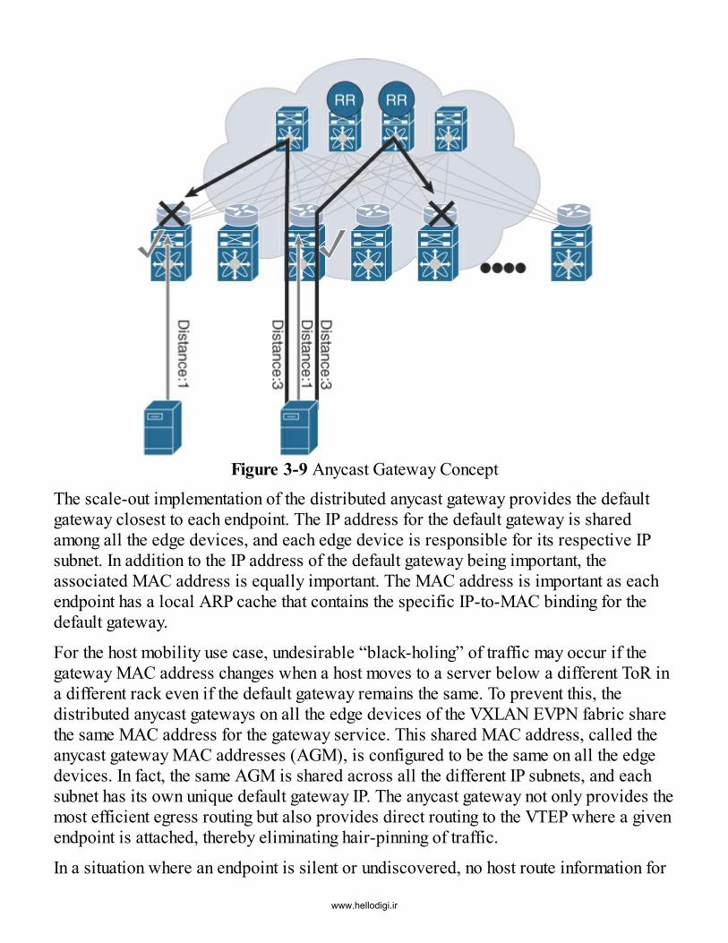
Figure 3-9 Anycast Gateway ConceptThe scale-out implementation of the distributed anycast gateway provides the defaultgateway closest to each endpoint. The IP address for the default gateway is sharedamong all the edge devices, and each edge device is responsible for its respective IPsubnet. In addition to the IP address of the default gateway being important, theassociated MAC address is equally important. The MAC address is important as eachendpoint has a local ARP cache that contains the specific IP-to-MAC binding for thedefault gateway.
For the host mobility use case, undesirable “black-holing” of traffic may occur if thegateway MAC address changes when a host moves to a server below a different ToR ina different rack even if the default gateway remains the same. To prevent this, thedistributed anycast gateways on all the edge devices of the VXLAN EVPN fabric sharethe same MAC address for the gateway service. This shared MAC address, called theanycast gateway MAC addresses (AGM), is configured to be the same on all the edgedevices. In fact, the same AGM is shared across all the different IP subnets, and eachsubnet has its own unique default gateway IP. The anycast gateway not only provides themost efficient egress routing but also provides direct routing to the VTEP where a givenendpoint is attached, thereby eliminating hair-pinning of traffic.
In a situation where an endpoint is silent or undiscovered, no host route information for
www.hellodigi.ir

that endpoint in known to the BGP EVPN control plane. Without the host routeinformation, the next-best route in the routing table should be used so that the packetsdestined to that endpoint are not dropped. Having each distributed IP anycast gatewayadvertise a subnet route from each VTEP where that subnet is locally instantiatedallows a “next-best” route to be available in the routing table. A remote VTEP, whichdoes not have that subnet instantiated locally, finds that the subnet prefix is reachableover multiple paths via ECMP. When traffic destined to an unknown/silent endpoint inthis subnet is received by this remote VTEP, traffic is forwarded to one of the chosenVTEPs that serve the destination subnet based on the calculated ECMP hash. Once thetraffic reaches that VTEP, the subnet prefix route is hit, which in turn points to a gleanadjacency. This triggers the VTEP to send out an ARP request to the local-connectedLayer 2 network, based on the destination subnet information. The ARP request is alsosent to the Layer 3 core encapsulated with the Layer 2 VXLAN VNI associated with thedestination subnet. As a result, the ARP request reaches the silent endpoint in thespecific subnet. The endpoint responds to the ARP request, which in turn gets consumedat the VTEP that is directly attached to that endpoint. This is because all VTEPs sharethe same anycast gateway MAC. As a result, the endpoint is discovered, and theendpoint information is distributed by this VTEP into the BGP EVPN control plane.
An alternative to the subnet route advertisement approach is to allow the default route(0.0.0.0/0) to achieve similar results with the disadvantage of centralizing thediscovery. However, a distributed approach based on subnet prefix routes scales muchbetter to discover the silent endpoints. Figure 3-10 illustrates the logical realization of adistributed IP anycast gateway in a VXLAN BGP EVPN fabric.
Figure 3-10 Subnet Prefix Advertisement for Distributed Anycast Gatewaywww.hellodigi.ir

With the distributed IP anycast gateway implementation, any VTEP can service anysubnet across the entire VXLAN BGP EVPN fabric. Integrated Routing and Bridging(IRB) from the VXLAN BGP EVPN construct provides the capability to efficientlyroute and bridge traffic. Regardless of the traffic patterns (east–west or north–south),the hair-pinning of traffic is completely eliminated. The BGP EVPN control planeknows the identity of an endpoint along with the next-hop (VTEP) information thatindicates its location. This leads to optimal forwarding in the network without requiringa large Layer 2 domain.
In summary, the AGM across all edge devices and subnets provides seamless hostmobility as no changes to the endpoint ARP cache need to occur. This allows for “hot”workload mobility across the entire VXLAN fabric. The distributed anycast gatewaymoves the Layer 3 gateway to the leafs, thereby providing reduced failure domains,simplified configuration, optimized routing, and transparent endpoint/workloadmobility.
Integrated Route and Bridge (IRB)VXLAN BGP EVPN follows two different semantics for IRB that are documented andpublished in the IETF’s draft-ietf-bess-evpn-inter-subnet-forwarding(https://tools.ietf.org/html/draft-ietf-bess-evpn-inter-subnet-forwarding).
Asymmetric IRB is the first of the documented first-hop routing operations. It follows abridge–route–bridge pattern within the local edge device or VTEP. As the nameimplies, when asymmetric IRB is employed for routing, traffic egressing toward aremote VTEP uses a different VNI than the return traffic from the remote VTEP.
As noted in Figure 3-11, Host A, connected to VTEP V1, wants to communicate to HostX, connected to VTEP V2. Because Host A and Host X belong to different subnets, theasymmetric IRB routing process is used. Post default gateway ARP resolution, Host Asends data traffic toward the default gateway in VLAN 10. From VLAN 10, a routingoperation is performed toward VLAN 20, which is mapped to VXLAN VNI 30002. Thedata traffic is encapsulated into VXLAN with VNI 30002. When the encapsulated trafficarrives on VTEP V2, it is decapsulated and then bridged over toward VLAN 20 becauseVLAN 20 is also mapped to VNI 30002 on VTEP V2.
www.hellodigi.ir
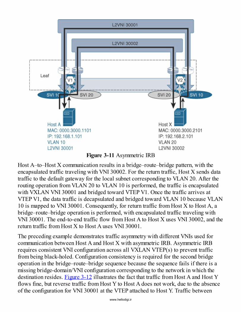
Figure 3-11 Asymmetric IRBHost A–to–Host X communication results in a bridge–route–bridge pattern, with theencapsulated traffic traveling with VNI 30002. For the return traffic, Host X sends datatraffic to the default gateway for the local subnet corresponding to VLAN 20. After therouting operation from VLAN 20 to VLAN 10 is performed, the traffic is encapsulatedwith VXLAN VNI 30001 and bridged toward VTEP V1. Once the traffic arrives atVTEP V1, the data traffic is decapsulated and bridged toward VLAN 10 because VLAN10 is mapped to VNI 30001. Consequently, for return traffic from Host X to Host A, abridge–route–bridge operation is performed, with encapsulated traffic traveling withVNI 30001. The end-to-end traffic flow from Host A to Host X uses VNI 30002, and thereturn traffic from Host X to Host A uses VNI 30001.
The preceding example demonstrates traffic asymmetry with different VNIs used forcommunication between Host A and Host X with asymmetric IRB. Asymmetric IRBrequires consistent VNI configuration across all VXLAN VTEP(s) to prevent trafficfrom being black-holed. Configuration consistency is required for the second bridgeoperation in the bridge–route–bridge sequence because the sequence fails if there is amissing bridge-domain/VNI configuration corresponding to the network in which thedestination resides. Figure 3-12 illustrates the fact that traffic from Host A and Host Yflows fine, but reverse traffic from Host Y to Host A does not work, due to the absenceof the configuration for VNI 30001 at the VTEP attached to Host Y. Traffic between
www.hellodigi.ir
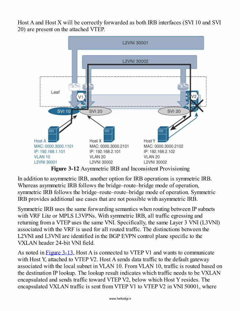
Host A and Host X will be correctly forwarded as both IRB interfaces (SVI 10 and SVI20) are present on the attached VTEP.
Figure 3-12 Asymmetric IRB and Inconsistent Provisioning
In addition to asymmetric IRB, another option for IRB operations is symmetric IRB.Whereas asymmetric IRB follows the bridge–route–bridge mode of operation,symmetric IRB follows the bridge–route–route–bridge mode of operation. SymmetricIRB provides additional use cases that are not possible with asymmetric IRB.
Symmetric IRB uses the same forwarding semantics when routing between IP subnetswith VRF Lite or MPLS L3VPNs. With symmetric IRB, all traffic egressing andreturning from a VTEP uses the same VNI. Specifically, the same Layer 3 VNI (L3VNI)associated with the VRF is used for all routed traffic. The distinctions between theL2VNI and L3VNI are identified in the BGP EVPN control plane specific to theVXLAN header 24-bit VNI field.As noted in Figure 3-13, Host A is connected to VTEP V1 and wants to communicatewith Host Y, attached to VTEP V2. Host A sends data traffic to the default gatewayassociated with the local subnet in VLAN 10. From VLAN 10, traffic is routed based onthe destination IP lookup. The lookup result indicates which traffic needs to be VXLANencapsulated and sends traffic toward VTEP V2, below which Host Y resides. Theencapsulated VXLAN traffic is sent from VTEP V1 to VTEP V2 in VNI 50001, where
www.hellodigi.ir

50001 is the Layer 3 VNI associated with the VRF in which Host A and Host Y reside.Once the encapsulated VXLAN traffic arrives at VTEP V2, the traffic is decapsulatedand routed within the VRF toward VLAN 20 where Host Y resides. In this way, fortraffic from Host A to Host Y, a bridge–route–route–bridge symmetric sequence isperformed. Note that the Layer 2 VNIs associated with the networks in which Host Aand Host Y reside are not used for the routing operation with the symmetric IRB option.
Figure 3-13 Symmetric IRB
For the return traffic from Host Y to Host A, the return flow is symmetric, using thesame VNI 50001 associated with the VRF. Host Y sends the return traffic to the defaultgateway associated with its local subnet in VLAN 20. VLAN 20 makes a routingdecision toward the VRF and VNI 50001, resulting in the VXLAN-encapsulated trafficbeing sent to VTEP V1. Once the encapsulated VXLAN traffic arrives at VTEP V1, thetraffic is decapsulated and routed toward the VRF and VLAN 10. The return traffic flowfrom Host Y to Host A follows the same bridge–route–route–bridge sequence,following the same VNI 50001. The traffic from Host A to Host Y and traffic from HostY to Host A leverage the same VRF VNI 50001, resulting in symmetric traffic flows. Infact, all routed traffic between hosts belonging to different networks within the sameVRF employs the same VRF VNI 50001.
Symmetric IRB does not have the requirement of maintaining a consistent configurationacross all the edge devices for all the VXLAN networks. In other words, scopedconfiguration can be implemented when it is not necessary to have all VNIs configured
www.hellodigi.ir

on all the edge devices or VTEPs (see Figure 3-14). However, for a given VRF, thesame Layer 3 VNI needs to be configured on all the VTEPs since the VRF enables thesequence of bridge–route–route–bridge operation. For communication between hostsbelonging to different VRFs, route leaking is required. For VRF route leaking, anexternal router or firewall is required to perform VRF-to-VRF communication. It shouldbe noted that support for VRF route leaking requires software support to normalize thecontrol protocol information with the data plane encapsulation. Next to local VRF routeleaking, downstream VNI assignment can provide this function for the extranet usecases. These options are discussed further in Chapter 8, “External Connectivity.”
Figure 3-14 Symmetric IRB and Inconsistent Provisioning
Both symmetric and asymmetric modes are documented in the IETF draft. The Ciscoimplementation with NX-OS follows the symmetric IRB mode. The symmetric IRBbridge–route–route–bridge sequence offers flexibility for large-scale multitenantdeployments. And the bridge–route–route–bridge sequence follows similar semantics toclassic routing across a transit segment. The transit routing segment with VXLAN BGPEVPN is reflected by the Layer 3 VNI associated with the VRF.
Endpoint MobilityBGP EVPN provides a mechanism to provide endpoint mobility within the fabric. When
www.hellodigi.ir
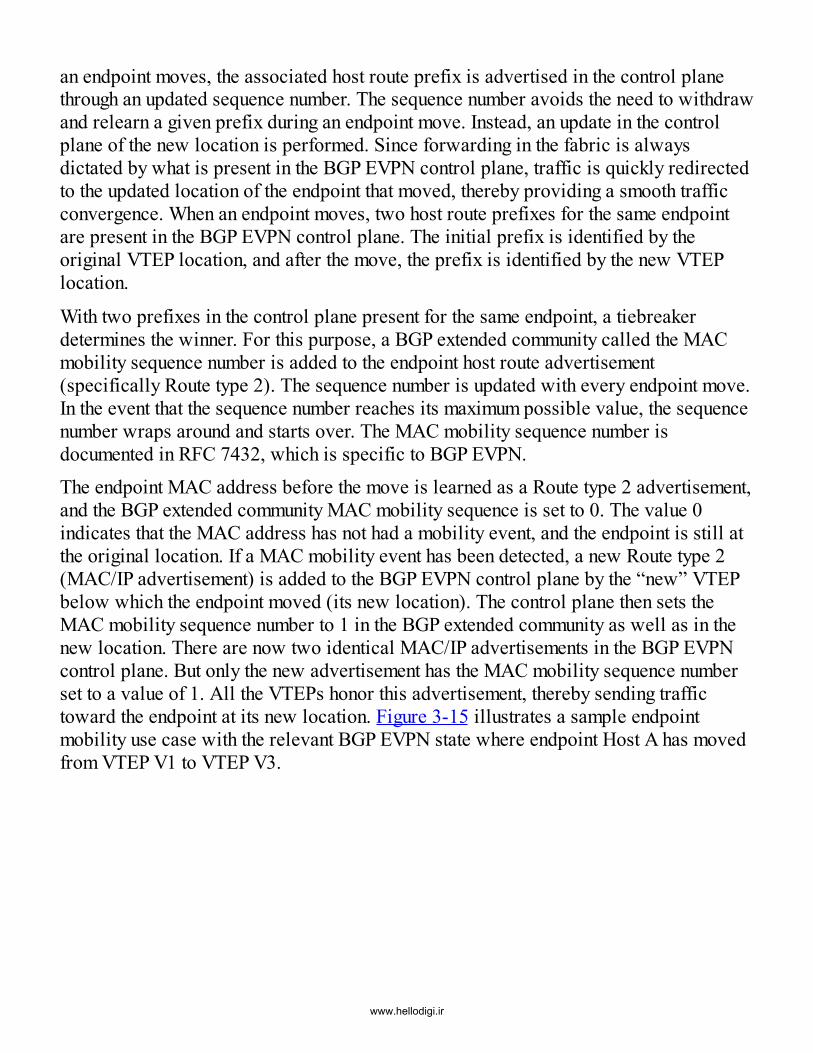
an endpoint moves, the associated host route prefix is advertised in the control planethrough an updated sequence number. The sequence number avoids the need to withdrawand relearn a given prefix during an endpoint move. Instead, an update in the controlplane of the new location is performed. Since forwarding in the fabric is alwaysdictated by what is present in the BGP EVPN control plane, traffic is quickly redirectedto the updated location of the endpoint that moved, thereby providing a smooth trafficconvergence. When an endpoint moves, two host route prefixes for the same endpointare present in the BGP EVPN control plane. The initial prefix is identified by theoriginal VTEP location, and after the move, the prefix is identified by the new VTEPlocation.
With two prefixes in the control plane present for the same endpoint, a tiebreakerdetermines the winner. For this purpose, a BGP extended community called the MACmobility sequence number is added to the endpoint host route advertisement(specifically Route type 2). The sequence number is updated with every endpoint move.In the event that the sequence number reaches its maximum possible value, the sequencenumber wraps around and starts over. The MAC mobility sequence number isdocumented in RFC 7432, which is specific to BGP EVPN.The endpoint MAC address before the move is learned as a Route type 2 advertisement,and the BGP extended community MAC mobility sequence is set to 0. The value 0indicates that the MAC address has not had a mobility event, and the endpoint is still atthe original location. If a MAC mobility event has been detected, a new Route type 2(MAC/IP advertisement) is added to the BGP EVPN control plane by the “new” VTEPbelow which the endpoint moved (its new location). The control plane then sets theMAC mobility sequence number to 1 in the BGP extended community as well as in thenew location. There are now two identical MAC/IP advertisements in the BGP EVPNcontrol plane. But only the new advertisement has the MAC mobility sequence numberset to a value of 1. All the VTEPs honor this advertisement, thereby sending traffictoward the endpoint at its new location. Figure 3-15 illustrates a sample endpointmobility use case with the relevant BGP EVPN state where endpoint Host A has movedfrom VTEP V1 to VTEP V3.
www.hellodigi.ir

Figure 3-15 Endpoint MobilityAn endpoint may move multiple times over the course of its lifetime within a fabric.Every time the endpoint moves, the VTEP that detects its new location increments thesequence number by 1 and then advertises the host prefix for that endpoint into the BGPEVPN control plane. Because the BGP EVPN information is synced across all theVTEPs, every VTEP is aware of whether an endpoint is coming up for the first time orwhether it is an endpoint move event based on the previous endpoint reachabilityinformation.
An endpoint may be powered off or become unreachable for a variety of reasons. If anendpoint has aged out of the ARP, MAC, and BGP tables, the extended community MACmobility sequence is 0 as well. If the same endpoint reappears (from the fabric’s andBGP EVPN’s point of view), this reappearance is treated as a new learn event. In otherwords, the BGP EVPN control plane is aware of the current active endpoints and theirrespective locations, but the control plane does not store any history of the previousincarnations of the endpoints.
Whether an endpoint actually moves (a hot move) or an endpoint dies and anotherendpoint assumes its identity (a cold move), from the BGP EVPN control plane’s point
www.hellodigi.ir
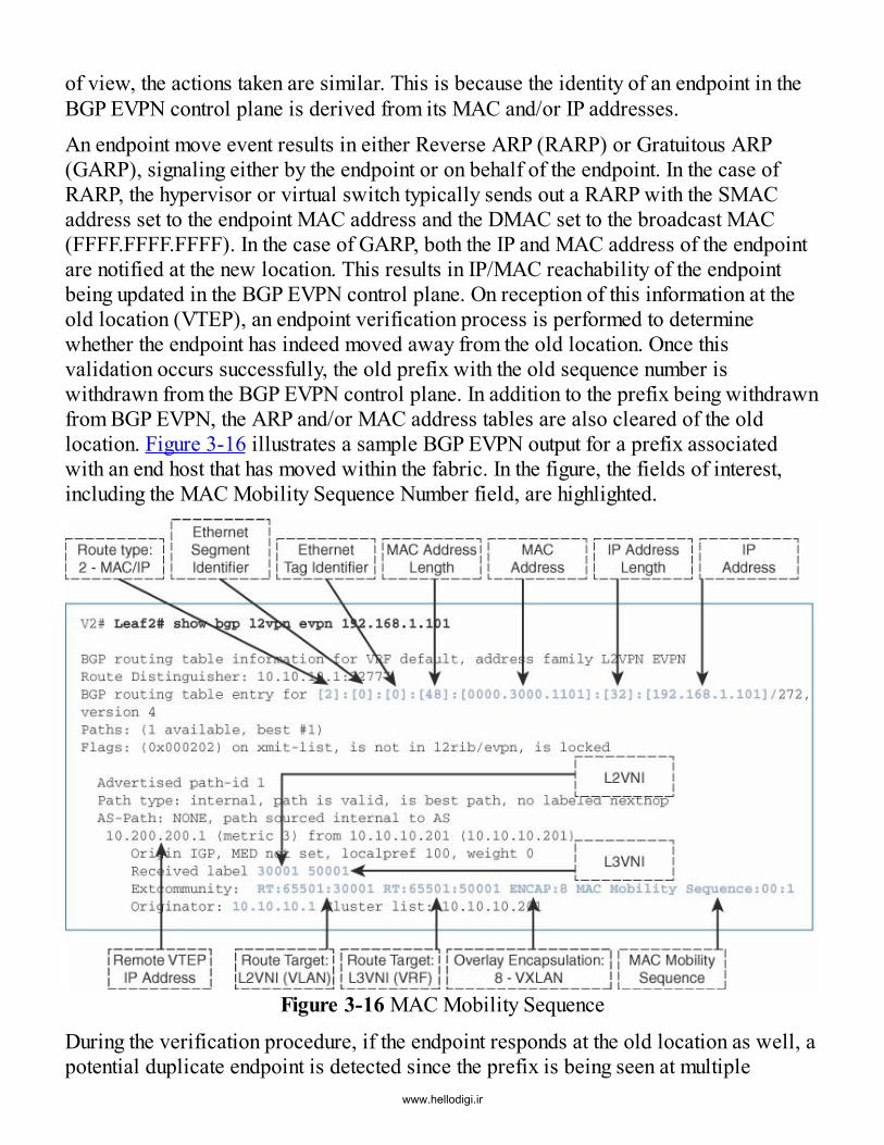
of view, the actions taken are similar. This is because the identity of an endpoint in theBGP EVPN control plane is derived from its MAC and/or IP addresses.An endpoint move event results in either Reverse ARP (RARP) or Gratuitous ARP(GARP), signaling either by the endpoint or on behalf of the endpoint. In the case ofRARP, the hypervisor or virtual switch typically sends out a RARP with the SMACaddress set to the endpoint MAC address and the DMAC set to the broadcast MAC(FFFF.FFFF.FFFF). In the case of GARP, both the IP and MAC address of the endpointare notified at the new location. This results in IP/MAC reachability of the endpointbeing updated in the BGP EVPN control plane. On reception of this information at theold location (VTEP), an endpoint verification process is performed to determinewhether the endpoint has indeed moved away from the old location. Once thisvalidation occurs successfully, the old prefix with the old sequence number iswithdrawn from the BGP EVPN control plane. In addition to the prefix being withdrawnfrom BGP EVPN, the ARP and/or MAC address tables are also cleared of the oldlocation. Figure 3-16 illustrates a sample BGP EVPN output for a prefix associatedwith an end host that has moved within the fabric. In the figure, the fields of interest,including the MAC Mobility Sequence Number field, are highlighted.
Figure 3-16 MAC Mobility Sequence
During the verification procedure, if the endpoint responds at the old location as well, apotential duplicate endpoint is detected since the prefix is being seen at multiple
www.hellodigi.ir

locations. The default detection value for duplicate endpoint detection is “5 moveswithin 180 seconds.” This means after the fifth move within the time frame of 180seconds, the VTEP starts a “30-second hold” timer before restarting the verification andcleanup process. After the fifth time (5 moves within 180 seconds), the VTEP freezesthe duplicate entry. With the Cisco NX-OS BGP EVPN implementation, these defaultdetection values can be modified via user configuration.
By using the MAC mobility sequence numbers carried with the Route type 2advertisement (MAC/IP advertisement), the BGP EVPN control plane can identify whena potential location change occurs for an endpoint. When a given prefix is determined tostill be reachable, the control plane actively verifies whether a given endpoint hasactually moved. The control plane provides a tremendous amount of value in not onlyverifying and cleaning up mobility events but also detecting duplicates within theVXLAN BGP EVPN network.
Virtual PortChannel (vPC) in VXLAN BGP EVPNThe bundling of multiple physical interfaces into a single logical interface between twochassis is referred to as a port channel, which is also known as a link aggregation group(LAG). Virtual PortChannel (vPC)14 is a technology that provides Layer 2 redundancyacross two or more physical chassis. Specifically, a single chassis is connected to twoother chassis that are configured as a vPC pair. The industry term for this is Multi-Chassis Link Aggregation Group (MC-LAG). Recall that while the underlying transportnetwork for VXLAN is built with a Layer 3 routing protocol leveraging ECMP, theendpoints still connect to the leafs or edge devices via classic Ethernet. It should benoted that the VXLAN BGP EVPN fabric does not mandate that endpoints must haveredundant connections to the fabric. However, in most practical deployments, highavailability is typically a requirement, and for that purpose, endpoints are connected tothe edge devices via port channels.
Several protocols exist to form port channels, including static-unconditionalconfigurations, protocols such as Port Aggregation Protocol (PAgP),15 and industrystandard protocols such as Link Aggregation Control Protocol (LACP).16
Port channels can be configured between a single endpoint and a single network switch.When ToR- or switch-level redundancy (as well as link-level redundancy) is arequirement, an MC-LAG is employed to provide the capability to connect an endpointto multiple network switches.vPCs allow interfaces of an endpoint to physically connect to two different networkswitches. From an endpoint perspective, they see a single network switch connected viaa single port channel with multiple links. The endpoint connected to the vPC domain can
www.hellodigi.ir

be a switch, a server, or any other networking device that supports the IEEE 802.3standard and port channels. vPC allows the creation of Layer 2 port channels that spantwo switches. vPCs consist of two vPC member switches connected by a peer link, withone being the primary and the other being the secondary. The system formed by thenetwork switches is referred to as a vPC domain (see Figure 3-17).
Figure 3-17 Classic Ethernet vPC Domain
The vPC primary and secondary members are initially configured as individual edgedevices or VTEPs for VXLAN integration. For northbound traffic, the routed interfacesare part of the underlay network to provide reachability to each individual VTEP. EachVTEP is represented by an individual primary IP address (PIP) per VTEP.
With this in mind, the vPC feature first needs to be enabled, followed by theconfiguration of the vPC domain between the two vPC member network switches. Next,the vPC peer link (PL) and vPC peer keepalive (PKL) need to be connected between thetwo nodes. The underlay network also needs to be configured on the vPC peer link forboth unicast and multicast (if multicast is used) underlay routing purposes.A single VTEP is configured to represent the vPC domain in the VXLAN BGP EVPN
www.hellodigi.ir

fabric. To achieve the single VTEP, an anycast VTEP is configured with a commonvirtual IP address (VIP) that is shared across both switches that form the vPC domain.The anycast IP address is used by all the endpoints behind the vPC domain and isrepresented by a single anycast VTEP for the vPC domain.
Figure 3-18 vPC with VXLAN BGP EVPN
A sample vPC domain is shown in Figure 3-18. VTEP V1 has IP address10.200.200.1/32, and VTEP V2 has IP address 10.200.200.2/32. These are individualphysical IP addresses (PIPs) on the NVE interface or the VTEP. A secondary IP addressis added to the two VTEPs, which represents the VIP or anycast IP address (specifically10.200.200.254/32). The secondary address depicts the location of any endpoint that isattached to the vPC pair. This address is the next hop advertised in the BGP EVPNcontrol plane advertisement, representing the location of all local endpoints below agiven vPC pair of switches.
The VIP is advertised from both vPC member switches so that both vPC members canreceive traffic directly from any locally attached endpoints. Remote VTEPs can reachthe VIP advertised by both the vPC member switches via ECMP over the underlay
www.hellodigi.ir

routed network. In this way, dual-attached endpoints can be reached as long as there isat least one path to any one of the vPC member switches or VTEPs.
In a vPC domain, both dual-attached endpoints and single-attached endpoints (typicallyreferred to as orphans) are advertised as being reachable via the VIP associated withthe anycast VTEP. Consequently, for orphan endpoints below a vPC member switch, abackup path is set up via the vPC peer link if the reachability to the spines is lost due touplink failures. Hence, an underlay routing adjacency across the vPC peer link isrecommended to address the failure scenarios.If multicast is enabled on the underlay for carrying multidestination traffic, multicastrouting (typically PIM) should also be enabled over the peer link. Of note, by default,the advertisement of an anycast VTEP VIP IP address as the next hop with BGP EVPNapplies to the MAC/IP advertisements of Route type 2 as well as the IP prefix routes ofRoute type 5. In this way, all remote VTEPs can always see all BGP EVPN routesbehind a vPC pair as being reachable via a single VTEP represented by the VIP. TheVTEP associated with the VIP on the VPC peers of a given VPC domain is sometimesreferred to as an anycast VTEP for that domain. If there are N leafs deployed in aVXLAN BGP EVPN fabric and all of them are configured as VPC peers, there are N/2peers present in the network, represented by the respective anycast VTEPs, one perVPC domain.
The term anycast VTEP should not be confused with the anycast gateway. Recall that theanycast gateway refers to the distributed IP anycast gateway for a given subnet that isshared by any and all leafs (including those configured as VPC peers) simultaneouslywith end host reachability information exchanged between the leafs via BGP EVPN.This is referred to as the gateway because end hosts within a subnet are configured withthe default router set to the corresponding anycast gateway IP. Consequently, from anend host point of view, the default gateway’s IP-to-MAC binding should remain thesame, regardless of where the end host resides within the fabric. With Cisco NX-OS, allthe anycast gateways also share the same globally configured anycast gateway MAC(AGM).
For a given vPC domain, since all ARPs, MACs, and ND entries are synced betweenthe two vPC member switches, both switches are effectively advertising reachability forthe same set of prefixes over BGP EVPN. A given vPC member switch thus ignores theBGP EVPN advertisements received from the adjacent vPC member switch since theyare part of the same vPC domain because these advertisements are identified by anappropriate site-of-origin extended community attribute that they carry. In this way, onlyone VTEP or VIP needs to be advertised over BGP EVPN for all endpoints per vPCdomain. For a VXLAN BGP EVPN network with N vPC pairs, each remote VTEPneeds to know about only N–1 VTEP IPs or VIPs. Even with the presence of only one
www.hellodigi.ir
VIP acting as the anycast VTEP within a given vPC domain, the MP-BGP RouteDistinguishers (RDs) are individual identifiers defined on a per-vPC member basis.However, in some scenarios, IP prefixes may only be advertised by one of the two vPCmember switches in a given vPC domain. For example, an individual loopback addressmay be configured under a VRF on each of the vPC member switches. In this case,because all reachability is advertised into BGP EVPN as being reachable via theanycast VTEP VIP, the traffic destined to a particular vPC member switch may reach itsadjacent peer. After decapsulation, the traffic gets black-holed because it will suffer arouting table lookup miss within that VRF.
When IP address information is only advertised by one of the two vPC memberswitches, such problems may arise. This is because the return traffic needs to reach thecorrect vPC member switch. Advertising everything from the vPC domain as beingreachable via the anycast VTEP IP address does not achieve this. This use case appliesto scenarios having southbound IP subnets, orphan-connected IP subnets, individualloopback IP addresses, and/or DHCP relays. With all these use cases, Layer 3 routingadjacency on a per-VRF basis is required to ensure a routing exchange between the vPCdomain members. This ensures that even if the packet reaches the incorrect vPC peer,after decapsulation the routing table lookup within the VRF does not suffer a lookupmiss.The configuration of this per-VRF routing adjacency between the vPC member switchesmay get a bit tedious. However, with BGP EVPN, an elegant solution to achieve similarbehavior involves the use of a feature called advertise-pip. This feature is globallyenabled on a per-switch basis. Recall that every vPC member switch has a unique PIPand a shared VIP address. With the advertise-pip feature enabled, all IP route prefixreachability is advertised from the individual vPC member switches using the PIP as thenext hop in Route type 5 messages. Endpoint reachability corresponding to the IP/MACaddresses via Route type 2 messages continues to use the anycast VTEP or VIP as thenext hop (see Figure 3-19). This allows per-switch routing advertisement to beindividually advertised, allowing the return traffic to reach the respective VTEP in thevPC domain. In this way, a vPC member switch that is part of a given vPC domain alsoknows about individual IP prefix reachability of its adjacent vPC peer via BGP EVPNRoute type 5 advertisements.
www.hellodigi.ir

Figure 3-19 Advertise PIP with vPCOne additional discussion point pertains to the Router MAC carried in the extendedcommunity attributes of the BGP EVPN Route type 2 and Route type 5 messages. Withadvertise-pip, every vPC switch advertises two VTEPs’ IP addresses (one PIP and oneVIP). The PIP uses the switch Router MAC, and the VIP uses a locally derived MACbased on the VIP itself. Both of the vPC member switches derive the same MACbecause they are each configured with the same shared VIP under the anycast VTEP.Because the Router MAC extended community is nontransitive, and the VIPs are uniquewithin a given VXLAN BGP EVPN fabric, using locally significant router MACs for theVIPs is not a concern.
In summary, by using the advertise-pip feature with VXLAN BGP EVPN, the next-hopIP address of a VTEP is conditionally handled, depending on whether a Route type 2(MAC/IP advertisement) or a Route type 5 (IP prefix route) is announced. AdvertisingPIP allows for efficient handling of vPC-attached endpoints as well as IP subnetsspecific to the use cases for Layer 2 and Layer 3 border connectivity or DHCP relays.Finally, it should be noted that some differences in the way vPC operates with thedifferent Nexus platforms might exist. For an exhaustive list of the configuration
www.hellodigi.ir

required with VPC in VXLAN BGP EVPN environment for Nexus 9000 platform,please refer to Cisco’s Example of VXLAN BGP EVPN (EBGP).17 And for Nexus 7000and Nexus 5600 platforms, please refer to Cisco’s Forwarding configurations for CiscoNexus 5600 and 7000 Series switches in the programmable fabric.18
DHCPDynamic Host Configuration Protocol (DHCP)19 is a commonly used protocol thatprovides IP address and other options for an endpoint. A DHCP server component isresponsible for delivering IP address assignments and managing the binding between anendpoint MAC address and the provided IP address. In addition to distributing the IPaddress (DHCP scope) itself, additional options such as default gateway, DNS server,and various others (DHCP options) can be assigned to the endpoint that serves as aDHCP client. The requester in the case of DHCP is the DHCP client, which sends adiscovery message to the DHCP server. The DHCP server then responds to thisdiscover request with an offer message. Once this initial exchange is complete, a DHCPrequest (from client to server) is followed by a DHCP acknowledgment, and thiscompletes the assignment of the IP address and subsequent information through theDHCP scope options. Figure 3-20 illustrates this DHCP process.
Figure 3-20 DHCP Process
Because the DHCP process relies on broadcasts to exchange information betweenDHCP client and DHCP server, the DHCP server needs to be in the same Layer 2network in which the DHCP client resides. This is one deployment method for DHCP. Inmost cases, multiple IP subnets exist, and routers are in the path between a DHCP clientand DHCP server. In this case, a DHCP relay agent is required. The DHCP relay agentis a DHCP protocol helper that snoops DHCP broadcasts and forwards these messages(specifically unicasts) to a specified DHCP server.
www.hellodigi.ir

The DHCP relay is typically configured on the default gateway facing the DHCP client.The DHCP relay agent can support many different use cases for automated IPaddressing, depending on whether the DHCP server resides in the same network, thesame VRF, or a different VRF compared to the DHCP client. Having a per-tenant or per-VRF DHCP server is common in certain service provider data centers where strictsegregation between tenants is a mandatory requirement. On the other hand, in enterpriseenvironments, having a centralized DHCP server in a shared-services VRF is notuncommon. Traffic crosses tenant (VRF) boundaries with the DHCP server and DHCPclient in a different VRF(s). In general, we can differentiate between three DHCP serverdeployment modes:
DHCP client and DHCP server within the same Layer 2 segment (VLAN/L2VNI)
No DHCP relay agent required DHCP discovery from DHCP client is broadcast in the local Layer 2 segment(VLAN/L2 VNI) As DHCP uses broadcasts, multidestination replication is required
DHCP client and DHCP server in different IP subnets but in the same tenant(VRF)
DHCP relay agent required DHCP discovery from DHCP client is snooped by the relay agent and directed tothe DHCP server
DHCP client and DHCP server are in different IP subnets and differenttenants (VRF)
DHCP relay agent required with VRF selection DHCP discovered from DHCP client is snooped by the relay agent and directedto the DHCP server into the VRF where the DHCP server resides
Two of the three DHCP server deployment modes relay data with a DHCP relay agent.20
The DHCP server infrastructure is a shared resource in a multitenant network, andmultitenancy support for DHCP services needs to be available. The same DHCP relayagent is responsible for handling the DHCP discovery message and DHCP requestmessage from the DHCP client to the DHCP server and the DHCP offer message andDHCP acknowledgment message from the DHCP server to the requesting DHCP client.
Typically, the DHCP relay agent is configured at the same place where the defaultgateway IP address is configured for a given subnet. The DHCP relay agent uses thedefault gateway IP address in the GiAddr field in the DHCP payload for all DHCP
www.hellodigi.ir

messages that are relayed to the DHCP server. The GiAddr field in the relayed DHCPmessage is used for subnet scope selection so that a free IP address is picked from thissubnet at the DHCP server and the respective DCHP options are assigned to the offerthat will be returned from the server to the relay agent. The GiAddr field indicates theaddress to which the DHCP server sends out the response (that is, the DHCP offer oracknowledgment).
Additional considerations need to be taken into account when implementing the DHCPrelay agent with the distributed IP anycast gateway in a VXLAN BGP EVPN fabric.This is because the same IP address is shared by all VTEPs that provide Layer 3service in the form of a default gateway for a given network. Likewise, the sameGiAddr field is consequently stamped in DHCP requests relayed by these VTEPs. As aresult, the DHCP response from the DHCP server may not reach the same VTEP that hadrelayed the initial request due to the presence of an anycast IP. In other words, theresponse may go to any one of the VTEPs servicing the anycast IP, which is clearlyundesirable (see Figure 3-21). If a unique IP address per VTEP exists, then that can beused in the GiAddr field, thereby ensuring that the server response is guaranteed tocome back to the right VTEP. This is achieved via specification of an ip dhcp relaysource-interface xxx command under the Layer 3 interface configured with the anycastgateway IP.
www.hellodigi.ir

Figure 3-21 GiAddr Problem with Distributed IP Anycast Gateway
In this way, the GiAddr field is modified to carry the IP address of the specified sourceinterface. Any given interface on the network switch can be used, as long as the IPaddress is unique within the network used for reaching the DHCP server. In addition, theIP address must be routable, so that the DHCP server must be able to respond to theindividual and unique DHCP relay IP address identified by the GiAddr field. Byaccomplishing this, the DHCP messages from the client to the server are ensured totravel back and forth through the same network switch or relay agent.It should be noted that typically the GiAddr field also plays a role in the IP subnet scopeselection from which a free IP address is allocated and returned to the DHCP client.Because the GiAddr field has been changed based on the source interface specification,it no longer represents the DHCP scope selection and respective IP address assignment.As a result, a different way to enable scope selection is required. DHCP option 82 (avendor-specific option) was designed to put in circuit-specific information, and hasbeen used in different deployments (see Figure 3-22). DHCP option 82 has twosuboptions that derive the required IP subnet for the IP address assignment, whichprovides a different approach for DHCP subnet scope selection.
Figure 3-22 DHCP Option 82With DHCP option 82 with the Circuit-ID suboption, the VLAN or VNI informationassociated with the network in which the client resides is added to the DHCP messages,which provide this information to the DHCP server. The DHCP server needs to supportthe functionality to select the right DHCP scope, based on the Circuit-ID suboption.DHCP servers that support the DHCP option 82 with the Circuit-ID suboption include
www.hellodigi.ir

Microsoft’s Windows 2012 DHCP server, ISC DHCP server (dhcpd), and Cisco PrimeNetwork Registrar (CPNR).
With the second option, which is the preferred option, the DHCP scope selection isperformed using the Link Selection suboption of DHCP option 82. Within the LinkSelection suboption, the original client subnet is carried, thereby allowing the correctDHCP scope selection. DHCP servers that support the Link Selection suboption includedhcpd, Infoblox’s DDI, and CPNR. For an exhaustive list of the DHCP relayconfiguration required in a VXLAN BGP EVPN network, refer to the vPC VTEP DHCPrelay configuration example at Cisco.com.21
With the use of the distributed anycast gateway in a VXLAN BGP EVPN fabric and itsmultitenant capability, centralized DHCP services simplify the ability to provide IPaddress assignments to endpoints. With a unique source IP address for relaying theDHCP message, and with DHCP option 82, the IP address assignment infrastructure canbe centrally provided even across the VRF or tenant boundary.
SummaryThis chapter provides an in-depth discussion of the core forwarding capabilities of aVXLAN BGP EVPN fabric. For carrying broadcast, unknown unicast, and multicast(BUM) traffic, the chapter examines both multicast and ingress replication, coupledwith the inclusive multicast Route type support with BGP EVPN. It also discussesenhanced forwarding features that allow for reducing ARP and unknown unicast trafficwithin the fabric. Perhaps the key benefit of a BGP EVPN fabric is the realization of adistributed anycast gateway at the ToR or leaf layer that allows for optimal forwardingof both Layer 2 and Layer 3 traffic within the fabric, using IRB semantics. Efficienthandling of endpoint mobility with BGP EVPN is also described, as well as how tohandle dual-attached endpoints with vPC-based deployments. Finally, the chapterconcludes with a description of how DHCP relay functionality can be implemented inenvironments with distributed IP anycast gateway.
References1. Internet Society. Internet-drafts (I-Ds). www.ietf.org/id-info/.2. Internet Society. Request for comments (RFC). www.ietf.org/rfc.html.3. Network Working Group. DHCP relay agent information option. 2001.
tools.ietf.org/html/rfc3046.4. Network Working Group. Protocol Independent Multicast–Sparse Mode (PIM-SM)
protocol specification (revised). 2006. tools.ietf.org/html/rfc4601.5. Network Working Group. Bidirectional Protocol Independent Multicast (BIDIR-
www.hellodigi.ir

PIM). 2007. tools.ietf.org/html/rfc5015.6. Network Working Group. Neighbor discovery for IP version 6 (IPv6). 2007.
tools.ietf.org/html/rfc4861.7. Rabadan, J., et al. Operational aspects of proxy-ARP/ND in EVPN networks. 2016.
www.ietf.org/id/draft-ietf-bess-evpn-proxy-arp-nd-01.txt.8. Cisco. Proxy ARP. 2008. www.cisco.com/c/en/us/support/docs/ip/dynamic-
address-allocation-resolution/13718-5.html.9. Network Working Group. Cisco’s Hot Standby Router Protocol (HSRP). 1998.
www.ietf.org/rfc/rfc2281.txt.10. Network Working Group. Virtual Router Redundancy Protocol (VRRP). 2004.
tools.ietf.org/html/rfc3768.11. Cisco. Cisco GLBP load balancing options. 1998.
www.cisco.com/c/en/us/products/collateral/ios-nx-os-software/ip-services/product_data_sheet0900aecd803a546c.html.
12. Cisco. Anycast HSRP. 2016.www.cisco.com/c/en/us/td/docs/switches/datacenter/sw/6_x/nx-os/fabricpath/configuration/guide/b-Cisco-Nexus-7000-Series-NX-OS-FP-Configuration-Guide-6x/b-Cisco-Nexus-7000-Series-NX-OS-FP-Configuration-Guide-6x_chapter_0100.html#concept_910E7F7E592D487F84C8EE81BC6FC14F.
13. Cisco. VXLAN network with MP-BGP EVPN control plane design guide. 2015.www.cisco.com/c/en/us/products/collateral/switches/nexus-9000-series-switches/guide-c07-734107.html#_Toc414541688.
14. Cisco. Cisco NX-OS software Virtual PortChannel: Fundamental concepts 5.0.2014. www.cisco.com/c/en/us/products/collateral/switches/nexus-5000-series-switches/design_guide_c07-625857.html.
15. Finn, N. Port Aggregation Protocol. 1998.www.ieee802.org/3/trunk_study/april98/finn_042898.pdf.
16. Network Working Group 802.1. 802.1AX-2008—IEEE standard for local andmetropolitan area networks—Link aggregation. 2008.standards.ieee.org/findstds/standard/802.1AX-2008.html.
17. Cisco. Example of VXLAN BGP EVPN (EBGP). 2016.www.cisco.com/c/en/us/td/docs/switches/datacenter/nexus9000/sw/7-x/vxlan/configuration/guide/b_Cisco_Nexus_9000_Series_NX-OS_VXLAN_Configuration_Guide_7x/b_Cisco_Nexus_9000_Series_NX-OS_VXLAN_Configuration_Guide_7x_chapter_0100.html#concept_53AC00F0DE6E40A79979F27990443953
18. Cisco. Forwarding configurations for Cisco Nexus 5600 and 7000 Series switchesin the programmable fabric. 2016.
www.hellodigi.ir

www.cisco.com/c/en/us/td/docs/switches/datacenter/pf/configuration/guide/b-pf-configuration/Forwarding-Configurations.html#concept_B54E8C5F82C14C7A9733639B1A560A01.
19. Network Working Group. Dynamic Host Configuration Protocol. 1997.www.ietf.org/rfc/rfc2131.txt.
20. Network Working Group. DHCP relay agent information option. 2001.tools.ietf.org/html/rfc3046.
21. Cisco. vPC VTEP DHCP relay configuration example. 2016.www.cisco.com/c/en/us/td/docs/switches/datacenter/nexus9000/sw/7-x/vxlan/configuration/guide/b_Cisco_Nexus_9000_Series_NX-OS_VXLAN_Configuration_Guide_7x/b_Cisco_Nexus_9000_Series_NX-OS_VXLAN_Configuration_Guide_7x_appendix_0110.html#id_16000.
www.hellodigi.ir

Chapter 4 The Underlay
In this chapter, the following topics will be covered:
The underlay associated with the BGP EVPN VXLAN fabric IP address allocation options and MTU considerations for the underlay Underlay unicast and multicast routing options
Network virtualization overlays, including Virtual Extensible LAN (VXLAN), require anetwork over which the overlay-encapsulated traffic can be transported. Severalconsiderations must be made in this regard. With VXLAN being a MAC in IP/UDPoverlay, the transport network needs to carry IP traffic from VXLAN Tunnel Endpoints(VTEPs) in an optimal manner. Recall that every overlay adds additional headers on topof the original packet/frame. The transport network, termed the underlay, needs toaccount for the additional bytes incurred by the overlay headers. In the case of VXLAN,typically, the transport network needs to be provisioned for an additional 50 bytes in themaximum transmission unit (MTU). Likewise, the transport network must match theresiliency and convergence requirements of the overlay as well. It is important toconsider scalability, resiliency, convergence, and capacity when considering data centerfabric designs. With overlay-based data center fabrics, the importance of the underlaycannot be understated. Typically, the overlay’s performance is only as good as theunderlay transport that carries it. Even for troubleshooting, debugging, and convergenceof the overlay traffic, the underlay is the critical piece.When designing and building the underlay for the fabric, IP address assignment is animportant aspect of this process. The IP address assignment is a prerequisite for anykind of routing protocol that provides reachability between the various devices in thefabric. Multiple options are available in assigning these IP addresses, including, amongothers, a traditional point-to-point (P2P) method or an address-saving option that usesan unnumbered IP addressing scheme. Likewise, it is important to be aware ofrequirements in addressing the interfaces of the VTEP (also called the NetworkVirtualization Edge [NVE] interface), the loopback interface over which themultiprotocol BGP session is established, and eventually the multicast rendezvouspoint, when using a multicast based underlay.
The underlay might be required to not only transport unicast traffic but also providemulticast routing in order to handle broadcast, unknown unicast, and multicast (BUM)traffic in the overlay. All these requirements need to be considered when designing andcreating the underlay network for a BGP EVPN VXLAN–based data center fabric.
www.hellodigi.ir

Underlay ConsiderationsWhen building the data center fabric, some upfront considerations regarding theunderlay take priority. The first involves defining the anticipated topology to be used forthe underlay. Today’s data centers have requirements for large amounts of north–south aswell as east–west traffic patterns, so the topology must be able to accommodate thesedifferent kinds of traffic streams and communication profiles.
North–south data traffic, as illustrated in Figure 4-1, is the traditional communicationprofile for moving data in and out of the data center. In essence, this profile is utilized ifa user in the campus or on the Internet wishes to access data from within a data center.Common examples of north–south traffic are traffic associated with classic webbrowsing or traffic related to email activities. In each of these cases, an end user has anapplication on a PC to access data hosted within a data center. This type of north–southtraffic is important to efficiently move data between data centers and toward the enduser.
Figure 4-1 North–South Traffic
East–west traffic, on the other hand, reflects a slightly different communication profilebecause this profile describes data communication between servers and/or variousapplications within the data center (see Figure 4-2). Typically, requests from an enduser in a corporate network or in the Internet involve complex preprocessing activitieson the underlying data. As a means to demonstrate this need for preprocessing, oneexample of east–west traffic involves access from a web server (via an app server) tothe database. Dynamic rendering of websites and/or business applications often uses a
www.hellodigi.ir

two- or three-tier server architecture, where one tier must communicate with one of theother tiers before delivering the requested data to the end user. When these tierscommunicate with one another or need access to data storage or other data residing inthe same data center, the term east–west traffic is used for this more lateral, orhorizontal, traffic profile.
Figure 4-2 East–West Traffic
In the early 1950s, when telephone switchboards were manually operated, Charles Closneeded to find a more efficient way to handle call transfers. The switchboards utilized atwo-stage network where calls would be transferred by using a single crossbar switch.Unfortunately, frequently calls were blocked because only one path existed, and ifanother transfer was occupying that path, transfers would fail. Faced with this dilemma,Clos established the best mathematical way for interconnecting two points from aningress call to an egress one by leveraging multistage fabrics. By having an ingressstage, a middle stage, and an egress stage, calls had multiple path opportunities to reachtheir transfer destinations. This additional stage created a crossbar matrix ofconnectivity, and because the resulting networks appeared like woven fibers, the termcrossbar switch was introduced.
Clos’s work and designs, which revolutionized telephone switchboards, also found itsway to network switch and data center fabric designs. Most network switches builttoday are based on Charles Clos’s mathematical equations from the 1950s. In a givenswitch, the front-facing Ethernet ports (first stage) are each interconnected via anetwork fabric (second stage). As a result of this topology, every front-facing Ethernet
www.hellodigi.ir

port must travel the same distance to every other front-facing Ethernet port (equidistant),thereby ensuring predictable and consistent latency.1 Figure 4-3 shows the internalarchitecture of a typical multistage modular network switch.
How does this apply to a data center network or a data center fabric? In applying theClos fabric concept from the network switch to data center fabric topology, a front-facing Ethernet port is replaced with a top-of-rack (ToR) switch, also known as a leaf.The leaf is responsible for providing connectivity to and from servers as well as makingforwarding decisions, based on bridging or routing lookups, within the data centerfabric. Hundreds of leafs potentially exist, and interconnections among them are needed.A leaf connects to a second stage in the data center fabric, which is composed of a set ofspine switches. Depending on the requirements for scale and bandwidth for the fabric,the number of spines can vary between 2 and 32, which is good enough for practicaldeployments.
Figure 4-3 Multistage Network Switch
Within the data center fabric, a spine is connected to every leaf, thereby providing Npaths from every leaf to every other leaf, where N is the number of spines (see Figure 4-4). The spines in turn may connect to another spine layer, termed the super-spine layer,thereby allowing construction of N-stage spine leaf fabrics. Because the spine itself is aconnectivity “backbone” in the overlay-based data center fabric, it has no visibility intothe user traffic itself because the overlay encapsulation occurs at the leaf. The spinesimply ensures that VTEP-to-VTEP communication is done efficiently between differentleafs by using the underlay IP network’s equal-cost multipath (ECMP) capabilityprovided by the routing protocol. In comparing this to Clos fabric topology concepts,multiple paths are available via the spines, with each offering the same distance andlatency between any two endpoints in the data center fabric.
www.hellodigi.ir
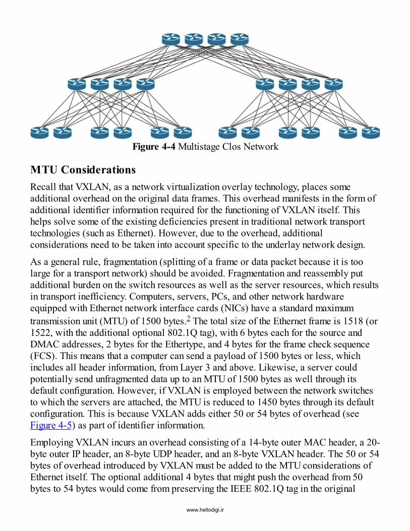
Figure 4-4 Multistage Clos Network
MTU ConsiderationsRecall that VXLAN, as a network virtualization overlay technology, places someadditional overhead on the original data frames. This overhead manifests in the form ofadditional identifier information required for the functioning of VXLAN itself. Thishelps solve some of the existing deficiencies present in traditional network transporttechnologies (such as Ethernet). However, due to the overhead, additionalconsiderations need to be taken into account specific to the underlay network design.
As a general rule, fragmentation (splitting of a frame or data packet because it is toolarge for a transport network) should be avoided. Fragmentation and reassembly putadditional burden on the switch resources as well as the server resources, which resultsin transport inefficiency. Computers, servers, PCs, and other network hardwareequipped with Ethernet network interface cards (NICs) have a standard maximumtransmission unit (MTU) of 1500 bytes.2 The total size of the Ethernet frame is 1518 (or1522, with the additional optional 802.1Q tag), with 6 bytes each for the source andDMAC addresses, 2 bytes for the Ethertype, and 4 bytes for the frame check sequence(FCS). This means that a computer can send a payload of 1500 bytes or less, whichincludes all header information, from Layer 3 and above. Likewise, a server couldpotentially send unfragmented data up to an MTU of 1500 bytes as well through itsdefault configuration. However, if VXLAN is employed between the network switchesto which the servers are attached, the MTU is reduced to 1450 bytes through its defaultconfiguration. This is because VXLAN adds either 50 or 54 bytes of overhead (seeFigure 4-5) as part of identifier information.
Employing VXLAN incurs an overhead consisting of a 14-byte outer MAC header, a 20-byte outer IP header, an 8-byte UDP header, and an 8-byte VXLAN header. The 50 or 54bytes of overhead introduced by VXLAN must be added to the MTU considerations ofEthernet itself. The optional additional 4 bytes that might push the overhead from 50bytes to 54 bytes would come from preserving the IEEE 802.1Q tag in the original
www.hellodigi.ir

Ethernet frame. In most instances, the 802.1Q tag is mapped to the VNI and stripped offbefore the VXLAN encapsulation is added to the original frame. However, certain usecases related to Q-in-Q3 or Q-in-VNI4 exist (for example, nested hypervisor, Layer 2tunneling, etc.), that would require the original IEEE 802.1Q tag to be preserved. In anycase, these additional bytes of the VXLAN overhead need to be considered as part ofthe underlay design.
Figure 4-5 VXLAN Frame Format, Including Byte Count (50/54 Byte Overhead forComparison)
In data center networks, efficiency is essential, and therefore, the MTU on the serverside is often increased to accommodate jumbo frames (data units that are larger than thetraditional 1500 bytes typical of Ethernet frames). Jumbo frames coming from the serverside can typically be up to a maximum of 9000 bytes, which most NICs and/or virtualswitches offer. With a need to now support MTUs of 9000 bytes from the server sidewhen using jumbo frames, and with the additional bytes from the VXLAN encapsulation,a value around 9050 or 9054 bytes needs to be allowed in order to avoid fragmentation.
Fortunately, most of the network switches from Cisco and other vendors provide amaximum MTU value of 9216 bytes, though some have to reduce this value by 20 to 30
www.hellodigi.ir

bytes to accommodate a network switch internal service header. Therefore, a jumboframe MTU of 9000 bytes from the server side can be accommodated by networkswitches without introducing fragmentation. This is not uncommon because the use oflarge transmission units is more efficient, and in a high-speed network, using themreduces the number of round trips required over the network. Because MTUconfiguration is performed at many locales, and because this can potentially affect theoverlay during subsequent reconfigurations, an initial consideration regarding the MTUsize of the network is critical. The jumbo frame MTU needs to be configuredconsistently across all points in the network, including the host-facing server interfaces.As an additional safeguard, certain network protocols check to assess whether aneighboring device is using the same MTU value before bringing up the routingadjacency with that neighbor. Thus, while the underlay for VXLAN can accommodatejumbo frame MTU size, specific design considerations remain important.
IP AddressingIP address allocation and assignment to the various network devices and/or relatedinterfaces (both physical and logical) is important when building a routed network forthe underlay. This section focuses on an IPv4-based underlay for a VXLAN-basednetwork. Note that the overlay supports IPv4 as well as IPv6 addresses. Each networkswitch participating in the underlay for the VXLAN network is uniquely identified by itsrouting protocol through a router ID, (RID), as demonstrated in Example 4-1.
Example 4-1 Output from OSPF Showing RIDClick here to view code image
LEAF11# show ip ospf
Routing Process UNDERLAY with ID 10.10.10.1 VRF default Routing Process Instance Number 1 Stateful High Availability enabled Graceful-restart is configured Grace period: 60 state: Inactive Last graceful restart exit status: None Supports only single TOS(TOS0) routes Supports opaque LSA Administrative distance 110 Reference Bandwidth is 40000 Mbps SPF throttling delay time of 200.000 msecs, SPF throttling hold time of 1000.000 msecs, SPF throttling maximum wait time of 5000.000 msecs LSA throttling start time of 0.000 msecs, LSA throttling hold interval of 5000.000 msecs, LSA throttling maximum wait time of 5000.000 msecs Minimum LSA arrival 1000.000 msec
www.hellodigi.ir

LSA group pacing timer 10 secs Maximum paths to destination 8 Number of external LSAs 0, checksum sum 0 Number of opaque AS LSAs 0, checksum sum 0 Number of areas is 1, 1 normal, 0 stub, 0 nssa Number of active areas is 1, 1 normal, 0 stub, 0 nssa Install discard route for summarized external routes. Install discard route for summarized internal routes. Area BACKBONE(0.0.0.0) Area has existed for 5w1d Interfaces in this area: 4 Active interfaces: 3 Passive interfaces: 0 Loopback interfaces: 2 No authentication available SPF calculation has run 86 times Last SPF ran for 0.000505s Area ranges are Number of LSAs: 7, checksum sum 0x25cd5
The RID is used in routing protocols to uniquely identify a given neighbor and/or anindex to the information received or sent to/from this neighbor in its database. With thisin mind, the RID should be always available and accessible, and therefore, it is a goodpractice to create a loopback interface with an IP address that matches the configuredRID. A loopback interface is a logical software interface in a network switch or routerthat is always up, as there are multiple physical paths to reach the loopback interface(s).Physical interfaces can be unavailable if a neighboring device interface shuts down ordisappears (for example, is unplugged). Example 4-2 shows an OSPF configuration thatincludes loopback interfaces for RID and VTEP.
Example 4-2 Example Configuration of a Loopback and OSPFClick here to view code image
LEAF11# show running-config ospf
feature ospf
router ospf UNDERLAY router-id 10.10.10.1
interface loopback0 ip address 10.200.200.1/32 ip router ospf UNDERLAY area 0.0.0.0
interface loopback1 ip address 10.10.10.1/32 ip router ospf UNDERLAY area 0.0.0.0
In addition to the RID, IP addresses are also assigned to the physical interfaces in order
www.hellodigi.ir

to build routing adjacencies. The best way to allocate these IP addresses on the physicalinterfaces is to establish them as P2P routed interfaces. In the situation shown in Figure4-6, only the two P2P interfaces each participate in the communication between thespine and leaf with VTEP V1 and the spine and leaf with VTEP V3.
Figure 4-6 Network with P2P Configuration
IP address subnetting for P2P-routed interfaces offers many ways of assigning netmaskor prefix size; however, there are two efficient methods. P2P subnets can use a prefixsize of /31 or a prefix size of /30. /30 is the most common prefix size for P2P IPnetworks. A typical /30 prefix provides one network ID address, two usable IPaddresses, and one broadcast ID address. While using this prefix size is an efficientway of assigning IP addresses to P2P networks, note that 50% of the addresses (thenetwork ID address and broadcast ID address) are unusable.
www.hellodigi.ir

Consider the math for a network with 4 spines and a 40-leaf underlay with a /30 prefix:
4 spines × 40 leafs = 160 P2P links= 160 links × 4 (/30)
= 40 leaf + 4 spines
= 640 IP addresses for P2P links= 44 IP addresses for loopback interfaces
= 684 IP addresses => /22 prefix (1024 IP addresses)
Alternatively, a more efficient option from an IP address assignment perspective wouldbe to use a /31 prefix length. The IP subnet of a /31 prefix consists of only two IPaddresses, both capable of being used in the P2P network. With the /30 prefix, theadditional two nonusable IP addresses (network ID and broadcast ID) are overloadeddue to usage with the two usable IP addresses. However, a /31 prefix provides only twousable IP addresses, without network ID and broadcast ID addresses, and thereforeoverloading does not occur. By using /31 prefixes instead of /30 prefixes in the underlaynetwork, all the IP addresses in the area of P2P networks are usable.Consider the match for a network with 4 spines and a 40-leaf underlay with a /31prefix:
4 spines × 40 leafs = 160 P2P links
= 160 links × 2 (/31) + 40 leafs + 4 spines= 320 IP addresses for P2P links + 44 IP addresses for loopback interfaces
= 364 IP addresses aggregate required => /23 prefix (512 IP addresses)
An alternative approach for P2P interface addressing is a technique called IPunnumbered, which has been available in the networking industry for decades.Essentially, this approach allows for IP processing on a P2P interface without assigningan individual IP address on a per-interface basis, which in turn conserves IP addressspace in the network. The IP unnumbered option allows reusing the loopback interfacecreated for the RID and “borrow” its IP address for all the physical interfaces. Example4-3 illustrates a typical IP unnumbered configuration
Example 4-3 IP Unnumbered Configuration ExampleClick here to view code image
interface loopback1 ip address 10.10.10.1/32
www.hellodigi.ir

ip router ospf UNDERLAY area 0.0.0.0 ip pim sparse-mode
interface Ethernet2/1 no switchport mtu 9216 ip unnnumbered loopback 1 ip ospf network point-to-point ip router ospf UNDERLAY area 0.0.0.0 ip pim sparse-mode no shutdown
By using this single IP address per network switch, the IP address space is notablysaved when compared to the /31 or /30 prefix approaches, and at the same time, theoverall address assignment process is simplified.
Consider the math for a network with 4 spines and a 40-leaf underlay with IPunnumbered configured:
4 spines + 40 leafs = 44 individual devices
= 44 IP addresses for loopback interfaces (IP unnumbered)
=> /26 prefix (64 IP addresses)IP unnumbered for Ethernet interfaces (see Figure 4-7) using the OSPF or IS-IS routingprotocols is available on most of the Cisco Nexus data center switches.
www.hellodigi.ir

Figure 4-7 Network with IP Unnumbered ConfiguredSo far, we have discussed interface addressing options for the underlay. However, oneadditional function is another essential aspect of the underlay in relation to the overlaynetwork. This involves the VTEP, or NVE, interface. The NVE interface has to deriveits IP address from a logical loopback interface, which is always available andaccessible much like the RID. The same loopback interface employed for RID can beused for the NVE. This approach avoids configuring additional IP addresses for eachNVE interface. However, from a network design perspective, separating pure underlayfunctions from overlay functions is desirable. In other words, common best practice isto create a separate loopback interface that is used by the NVE interface, asdemonstrated in Example 4-4.
Example 4-4 Configuration of a Separate Loopback for Routing and NVE
www.hellodigi.ir

Click here to view code image
! Loopback0 Interface Configuration (VXLAN VTEP)interface loopback0 ip address 10.200.200.1/32 ip router ospf UNDERLAY area 0.0.0.0 ip pim sparse-mode
! Loopback1 Interface Configuration (Routing Loopback for Underlay and BGPEVPN)interface loopback1 ip address 10.10.10.1/32 ip router ospf UNDERLAY area 0.0.0.0 ip pim sparse-mode
Note that the addresses associated with both interfaces, Loopback0 and Loopback1,need to be advertised by the underlay interior gateway protocol (IGP) for networkreachability. The separation of NVE loopback interface and underlay routing protocolshas operational benefits as well. With Cisco NX-OS offering graceful insertion andremoval features, a network switch can be isolated from the underlay routingperspective by shutting down the first loopback interface associated with the NVE orVTEP during maintenance or other disruptive operations. This allows troubleshooting ofthe underlay without necessarily having to turn off both overlay and underlayreachability at the same time. In addition, this also avoids unnecessary trafficdisruptions.
Apart from the interface IP assignment inherently necessary to connect the spine–leafnetwork, additional IP addressing requirements exist on the spine. Typically, a purespine allows connectivity between the VTEP hosting leafs and does not itself host anNVE interface—and therefore cannot provide VXLAN encapsulation/decapsulationfunctionality. In this case, a single loopback interface is sufficient on the spine, and it isemployed both for the RID associated with the underlay routing protocol andidentification of the BGP route reflector. However, the underlay needs to not onlysupport unicast reachability but also be able to transport multidestination traffic.
As mentioned earlier, IP multicast is commonly used in the underlay for this purpose.Support for multicast routing in the underlay, in turn, requires allocation andidentification of appropriate multicast rendezvous points (RPs). With a spine–leaftopology, spines are a desirable choice for hosting the RPs. Hence, the spines may needto have additional loopback interfaces that are employed by the RPs.Various methods exist for addressing RP redundancy. The focus in this discussion onlypertains to Anycast RP5 for PIM Anycast Source Multicast (PIM ASM),6 and PhantomRP7 for Bidirectional PIM (PIM BiDir).8 In order to address RP redundancy and loadbalancing with these operations, it is necessary to have some IP addresses available to
www.hellodigi.ir

accommodate these services. For PIM ASM, a single additional loopback interfaceused for Anycast RP addressing is sufficient, and therefore only one single IP address(/32 prefix) is required. For PIM BiDir and Phantom RP, more IP addresses are neededto provide redundancy and load balancing. Therefore, a dedicated subnet of aproportional size is required. Details regarding RP redundancy are provided later inthis chapter.
At this point, the need to understand IP addressing requirements for the underlay shouldbe apparent. In order to reduce the size of the routing tables, the creation of aggregateprefixes or aggregates can be considered in relation to these IP addresses. As a bestpractice, a single IP address aggregate or supernet would be ideal, depending on thenumber of P2P interfaces in the underlay and the corresponding addressing modeemployed. Using this approach, all the /30 or /31 IP subnet prefixes assigned to thevarious P2P interfaces can be summarized in the single aggregate (first). Likewise,different aggregates (second and third) can be used for the NVE loopback interfaces andthe RIDs, respectively, and they can be combined into a single aggregate if desired. Inthe presence of a Phantom RP, an additional aggregate is necessary. In summary, theaggregate options for the underlay are as follows (see Figure 4-8 for an example):
A single IP subnet for all P2P interface subnets A single IP subnet for all RIDs and NVE interfaces, using individual loopbacks(which can be split into separate IP aggregates if needed or desired) A single IP subnet for Phantom RP
Figure 4-8 A Simple Example Showing IP Address Pool Allocation for a TypicalUnderlay
IP Unicast RoutingUnicast routing can be achieved with various routing protocols as part of the underlay.Specifically, two types of IGPs have demonstrated efficient functional capabilitieswithin a multistage spine–leaf topology. These fall in the category of link-state anddistance-vector protocols. Link-state IGPs are based on Shortest Path First (SPF)9
algorithms and are suitable for spine–leaf networks. Spines provide multiple equal-costpaths between the leafs, and the SPF-based protocol considers all these links, as wellas the respective link speeds, to compute the single best path or multiple equal-cost bestpaths through the network. As mentioned earlier, equal-cost multipath (ECMP) is one of
www.hellodigi.ir

the biggest advantages an IP-based underlay network provides over the dominantSpanning Tree Protocol (STP) present in Ethernet-based networks (see Figure 4-9).
Figure 4-9 STP Versus ECMP
While BGP also has valuable merits as an underlay routing protocol, it is a path vectorprotocol (PVP)10 and only considers autonomous systems (AS) to calculate paths.However, an experienced network engineer can achieve outcomes with BGP that arecomparable to those that are possible with other SPF-based routing protocols.
OSPF as an UnderlayOpen Shortest Path First (OSPF) is a widely adopted IGP that has been employed inmany LAN, WAN, and data center core network environments.11 It is widely availablein an array of network components throughout the industry (routers, switches, serviceappliances, etc.), providing strong interoperability in alignment with its IETFbackground.12 The OSPF default interface type used for Ethernet interfaces is“broadcast,” which inherently results in a designated router (DR) and/or backupdesignated router (BDR) election, thus reducing control traffic comprising routingupdates. While this is appropriate for a multiaccess network such as a shared Ethernetsegment, it is unnecessary in a P2P network such as the underlay.
Changing the interface type to point-to-point avoids the DR/BDR election process and,therefore, reduces the time required to bring up the OSPF adjacency between the leafsand spines. In addition, with the point-to-point interface mode, there are no type 2 link-state advertisements (LSAs). Only type 1 LSAs are needed, thereby ensuring that the
www.hellodigi.ir

OSPF LSA database remains lean. It also reduces the time needed for the network toconverge after a topology change. Example 4-5 shows a typical OSPF configurationemployed in the underlay and the corresponding show output.
Example 4-5 OSPF Interface Configuration and StatusClick here to view code image
interface Ethernet2/1 no switchport mtu 9216 ip address 10.1.1.0/31 ip ospf network point-to-point ip router ospf UNDERLAY area 0.0.0.0 ip pim sparse-mode no shutdown LEAF11# show ip ospf interface Ethernet 2/1 Ethernet2/1 is up, line protocol is up IP address 10.1.1.0/31, Process ID UNDERLAY VRF default, area0.0.0.0 Enabled by interface configuration State P2P, Network type P2P, cost 1 Index 3, Transmit delay 1 sec 1 Neighbors, flooding to 1, adjacent with 1 Timer intervals: Hello 10, Dead 40, Wait 40, Retransmit 5 Hello timer due in 00:00:05 No authentication Number of opaque link LSAs: 0, checksum sum 0
A comprehensive understanding of how OSPF operates and the different state machinesand transitions related to network triggers would require multiple chapters; the goal ofthis chapter is to highlight some underlay specifics involved in using OSPF as the IGP.Some additional considerations with OSPF pertain to its behavior when SPFcalculations occur and the support of IPv4 as well as IPv6 routing. OSPF is built on IPprefixes, and any change in an IP prefix in an area triggers a full SPF calculationbecause the respective IP information is advertised in route and network LSAs for the IPprefix itself, as well as for the related topology information (in the same LSA). Thismeans that if an IP address on an interface changes, OSPF is required to send out arouter or network LSA, which in turn triggers the full SPF calculation on all routers inthe given OSPF area (that is, LSAs are flooded). While this does not necessarily presenta critical issue with today’s relatively high resources in network switches and routers, itis rather important to understand what happens during these events.
Another consideration pertains to IPv4 and IPv6 support with OSPF. While OSPFv2only supports IPv4, OSPFv3 is predominantly used for IPv6.13 In other words, any
www.hellodigi.ir

underlay that wants to use IPv6 requires OSPFv3, and this in turn requires dual-stackconfigurations and the addition of a second routing protocol.
Thus the key points regarding use of OSPF as an underlay IGP are as follows:
Use OSPF with the network type set to point-to-point. It is important to understand LSA types used by OSPF and caveats of LSA floods. It is important to understand requirements for OSPFv2 for IPv4 and OSPFv3 forIPv6.
IS-IS as an UnderlayIntermediate System to Intermediate System (IS-IS)14 is another link-state routingprotocol that also uses the SPF algorithm to calculate the shortest and loop-free pathsthrough a network. Unlike OSPF, IS-IS is an ISO standardized routing protocol(ISO/IEC 10589:2002), which the IETF republished as RFC 1195. IS-IS has not yetreached widespread popularity outside service provider networks. A potential reasonfor this may be that IS-IS does not operate on the IP layer but instead resides at Layer 2,forming adjacencies using a connectionless network service (CLNS). Because of this,IS-IS is independent of the IP addressing used to form respective routing peers, and itcan transport any kind of addressing (IPv4 as well as IPv6) over the same routingexchange. However, at the same time, IS-IS requires a different kind of addressingprotocol to uniquely identify an intermediate system (a router).
The IS-IS network entity title (IS-IS-NET) is a network-layer address (network serviceaccess point [NSAP] address) for CLNS, which identifies a router in a given IS-ISrouted network. Three NSAP formats are available in a given router’s NET. Example 4-6 shows a sample IS-IS configuration on a Cisco Nexus switch.
Example 4-6 IS-IS Configuration on a Cisco Nexus SwitchClick here to view code image
feature isis
router isis UNDERLAY net 49.0001.0100.1001.0001.00
interface Ethernet2/1 no switchport mtu 9216 ip address 10.1.1.0/31 ip router isis UNDERLAY medium p2p ip pim sparse-mode
www.hellodigi.ir

no shutdown
In IS-IS, IP information is carried in a type-length-value (TLV) of a link-state packet(LSP). Because IP prefixes are always considered external, at the end of a shortest pathtree calculation in this configuration, running a full SPF is not required when an IPnetwork change occurs. The IS-IS router (node) information, which is necessary for SPFcalculation, is individually advertised in IS neighbor or IS reachability TLVs. Thisapproach separates topology from IP information, allowing partial route calculation. Asa result, IS-IS is much less intensive in handling IP routing changes because the topologyis unaffected. As in OSPF DR/BDR elections, IS-IS uses a designated intermediatesystem (DIS) election process. There are significant differences in the details of theelection process for multiaccess media between IS-IS and OSPF, but those details arebeyond the scope of this chapter.
The key points for IS-IS are as follows:
IS-IS is based on CLNS and utilizes NSAP addressing. IS-IS uses IP-independent routing protocols. The topology remains independent from IP route prefixes.
BGP as an UnderlayBorder Gateway Protocol (BGP) is a path vector routing protocol that exchangesrouting and reachability information among various autonomous systems (AS). BGPfunctions well in making routing decisions based on paths, network policies, and/orrulesets configured by a network engineer. Thus, it requires greater design andconfiguration time in a spine–leaf underlay compared to SPF-based routing protocols.While BGP is great for enforcing policies in a network, it was not specificallydeveloped for fast convergence or link-path calculations. Nevertheless, use casesexist,15 mostly because of operational requirements, where BGP used as an underlayrouting protocol provides notable advantages. Note that BGP, as a hard-state protocol,sends out updates only when there is a change in network reachability. Hence, it doesnot incur the periodic update overhead that link-state protocols like OSPF have in termsof periodic hellos, redundant routing topology updates, etc.
While the initial incarnation of BGP communicated reachability between different AS,now named external BGP (eBGP), the protocol was enhanced to support communicationbetween different peers that are part of the same AS, thereby giving rise to internal BGP(iBGP). iBGP is a popular choice for carrying overlay EVPN reachability information.This is the case when using OSPF or IS-IS for the underlay. However, if eBGP is usedfor the underlay, and EVPN reachability information must be exchanged for the overlay,
www.hellodigi.ir

some additional considerations come into the picture. Specifically, with a single BGPinstance per network switch, when using eBGP in the underlay, the overlay also needs tobe configured in eBGP.
With eBGP, the next-hop attribute is always set, which means the neighbor of a routebecomes the next hop. In the spine–leaf topology, this would be inappropriate, as thespine would generally not host a VTEP interface and would thereby lack the capabilityto encapsulate/decapsulate VXLAN traffic. The EVPN advertisement sent out by a leaf,with regard to its locally attached hosts or prefixes, needs to be relayed by the spine toother leafs without a change in the next-hop attribute, which thereby allows VXLANtunnels to be established end-to-end from leaf to leaf. This is achieved by setting aspecific configuration in eBGP where the next-hop attribute is set to unchanged.Changing the next hop behavior is related to the overlay portion of the configuration(L2VPN EVPN), as demonstrated in Example 4-7.
Example 4-7 eBGP: next-hop unchangedClick here to view code image
route-map NH-UNCHANGED permit 10 set ip next-hop unchanged
router bgp 65501 address-family l2vpn evpn nexthop route-map NH-UNCHANGEDneighbor 10.1.1.1 remote-as 65500 address-family l2vpn evpn send-community both route-map NH-UNCHANGED out
As eBGP is used for the underlay as well as for the overlay, a separate BGP peering forthe EVPN address family (that is, overlay) is recommended. The underlay eBGPpeering is physical interface to physical interface, while the overlay BGP peering isloopback interface to loopback interface (eBGP multihop).In addition to this distinction for underlay routing and overlay reachability peering witheBGP, all EVPN information must be reflected to all leafs. In iBGP, the route reflector(RR) provides this functionality, but in eBGP, the role of a route reflector is notnecessary. Because an eBGP neighbor only reflects EVPN routes that also have a localinstance created, the retain Route-Target all knob must be enabled to make the eBGPneighbor act like a route reflector for the EVPN address family. This is not specific toEVPN but is also the case with MPLS VPN or similar MP-BGP VPN approaches.Getting an eBGP neighbor to act like a route reflector for VPN address families isrelated to the overlay portion of the configuration (L2VPN EVPN), as shown in
www.hellodigi.ir
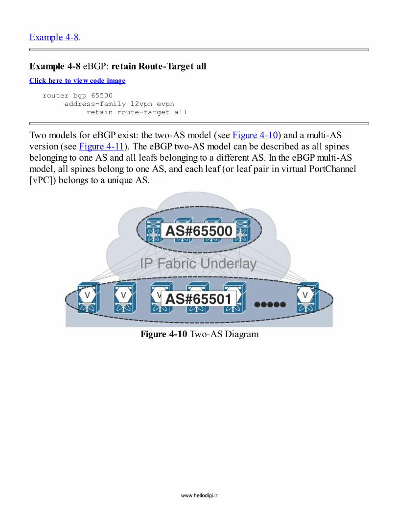
Example 4-8.
Example 4-8 eBGP: retain Route-Target allClick here to view code image
router bgp 65500 address-family l2vpn evpn retain route-target all
Two models for eBGP exist: the two-AS model (see Figure 4-10) and a multi-ASversion (see Figure 4-11). The eBGP two-AS model can be described as all spinesbelonging to one AS and all leafs belonging to a different AS. In the eBGP multi-ASmodel, all spines belong to one AS, and each leaf (or leaf pair in virtual PortChannel[vPC]) belongs to a unique AS.
Figure 4-10 Two-AS Diagram
www.hellodigi.ir

Figure 4-11 Multi-AS DiagramThe multi-AS scenario is comparable to the Internet concept where every node in anadministrative domain has a unique AS. The configured IP addresses on the physicalLayer 3 interfaces that connect the P2P links between the leafs and spines are used forBGP peering. For example, in the case of a four-spine topology, the leaf has to createfour different BGP peerings sourced from the four physical interface IP addresses, witha destination of the physical interface IP address of the respective spines. Logical IPinterfaces (loopbacks) need to be announced or redistributed by BGP in order toachieve reachability for VTEPs, RPs, and so on.
In the two-AS model, as mentioned earlier, all leafs share one AS, while the spinesshare another AS. Much as in the multi-AS approach, the BGP peering is established ona per-interface basis, using the IP addresses configured on the point-to-point links.However, in the two-AS mode, some adjustments are needed due to the AS pathviolation that occurs when the source AS is the same as the destination AS. Fortunately,the Cisco implementation provides all the necessary “hooks and knobs” to make thetwo-AS approach work with the appropriate configuration. In the case demonstrated inExample 4-9, the peer-AS check on the spine must be disabled (using the configurationdisable-peer-as-check) while receiving eBGP updates from a remote router in the sameAS as the leaf is permitted (using the configuration allowas-in, as demonstrated inExample 4-10).
Example 4-9 Two-AS Only: disable-peer-as-check (Spine Only)Click here to view code image
router bgp 65500router-id 10.10.10.201
www.hellodigi.ir

neighbor 10.1.1.0 remote-as 65501 address-family ipv4 unicast send-community both disable-peer-as-check address-family l2vpn evpn send-community both disable-peer-as-check
Example 4-10 Two-AS Only: allowas-in (Leaf Only)Click here to view code image
router bgp 65501 router-id 10.10.10.1neighbor 10.1.1.1 remote-as 65500 address-family ipv4 unicast allowas-in address-family l2vpn evpn send-community both allowas-in
In summary, the key points for eBGP as an underlay option are as follows:
Two different models exist for BGP: two-AS and multi-AS. Some BGP peering configuration work is required. It has implications for the overlay control protocol.
IP Unicast Routing SummaryAs we have seen, the choice of the underlay protocol can have significant implicationson the functioning of the overlay control protocol. By using the same protocol for theunderlay and overlay, a clear separation of these two domains can become blurred.Therefore, whenever designing an overlay network, it is a good practice toindependently build a transport network, as has been done with MPLS networks fordecades. This separation of underlay and overlay control protocol provides a very leanrouting domain for the transport network that consists of only loopback and P2Pinterfaces. At the same time, MAC and IP reachability for the overlay exist in a differentprotocol—BGP. This provides a blueprint for a network that is highly scalable due tothe separation of the topology address space from the end host reachability addressspace. It is also noteworthy that IGPs, based on link-state and SPF heuristics, areoptimal for an ECMP network, even when a data center fabric involves a few hundredrouters. The main advantage of using BGP for both underlay and overlay is having onlyone routing protocol. However, it requires additional configurations at the leaf andspine switches.
www.hellodigi.ir
In summary, for a BGP EVPN VXLAN fabric, it is advisable to verify the convergencerequirements for the desired overlay service. The underlay convergence should betested independently of the overlay convergence to make a final decision on which IGPto use for the underlay. It pays to implement a layered approach to measure expectationsand assess where results may vary from what is anticipated. Ideally, underlayconstruction should be done from bottom to top, and individual steps should build onone another. When building network overlays, one of the important guiding principles isto build the underlay, test it thoroughly, and then continue on to build the overlay.
Multidestination TrafficMultidestination traffic comprises traffic types such as broadcast, unknown unicast, andmulticast (BUM). The underlay must provide a way to carry BUM traffic between theedge devices. VXLAN has two different ways of handling BUM traffic:
Unicast mode, known as ingress replication, or head-end replication, is one way tocreate a multicast-independent underlay. Multicast mode that employs IP multicast in the underlay is the other option.
The choice of the mode and the associated pros and cons need to be considered whendesigning and creating the underlay network for a BGP EVPN VXLAN–based datacenter fabric.
Unicast ModeIn unicast mode, the data packets are replicated by the ingress VTEP and sent to therespective neighboring VTEPs that are part of the same VNI (see Figure 4-12). Becausethe ingress VTEP has to address all the neighboring VTEPs, it inherently knows aboutthem and has the burden of replicating and sending the BUM traffic to these VTEPs. Inother words, if N VTEPs have membership in a given VNI, for every multidestinationpacket in that VNI, a VTEP has to generate N–1 copies of the packet. Each copy isVXLAN encapsulated, with the outer DIP set to that of the destination VTEP to which itmust be delivered. From the underlay’s as well as the destination VTEP’s point of view,this packet is simply treated as a regular VXLAN-encapsulated unicast packet.
In the figure, Host A (192.168.1.101) attached to VTEP V1 sends out an ARP request toresolve the IP-to-MAC binding associated with Host B (192.168.1.102) attached toVTEP V2. Both the hosts belong to the same IP subnet 192.168.1.0/24 associated withVNI 30001. To handle this BUM packet, the figure indicates how VTEP V1 sends outtwo unicast packets containing this ARP request payload, one destined to VTEP V2 andother one destined to VTEP V3. The important fields of interest in the packet flow arehighlighted in the figure.
www.hellodigi.ir

Figure 4-12 Unicast Mode (aka Ingress Replication)There are two configuration options for unicast mode. The first option is static where alist of interested VTEPs is configured at each VTEP. The other option is to configure thelist dynamically, using a control protocol, in this case BGP EVPN, to distribute theinterest information within the network. Static configuration reduces scalability becauseany new VTEP or VNI added to the network requires reconfiguration at each of theneighboring VTEPs (see Example 4-11).
Example 4-11 Static Ingress Replication ConfigurationClick here to view code image
interface NVE 1source-interface loopback1member vni 30001 ingress-replication protocol static peer-ip n.n.n.n
BGP EVPN supports unicast mode. For example, in Example 4-12, the BGP EVPNcontrol protocol is leveraged with Route type 3 (inclusive multicast) messages to
www.hellodigi.ir

distribute VTEP and VNI membership information. This does not mean that BGP EVPNis doing the job of ingress replication, but instead it simply distributes the VTEP andVNI membership information over the control protocol. Replication of data traffic is adata plane operation performed by the VTEP. As a result, the ingress or head-endreplication operation must be supported by the forwarding functionality that isembedded at the VTEPs.
Example 4-12 Ingress Replication Configuration with EVPNClick here to view code image
interface NVE 1source-interface loopback1member vni 30001 ingress-replication protocol bgp
Whether the static or dynamic option is employed with the unicast mode, the data planeoperation that requires generation of N copies at a VTEP for every multidestinationpacket remains the same. With the support of the BGP EVPN control protocol, thediscovery of VTEP neighbors is significantly more dynamic. For a given VNI, thereceiving VTEP or interested VTEP advertises interest over EVPN, thereby dynamicallyadding itself to the replication list of a transmitting VTEP. In contrast, with static mode,for a given VNI, as long as the list of peer VTEPs is configured at the sending VTEP, thesending VTEP continues sending a copy to each member in the configured list,regardless of the receiving VTEP’s level of known interest. One way to configure staticmode is to configure all VTEPs as neighbors so that every time a new VNI isconfigured, the VTEP list does not have to be manipulated or changed. Only addition orremoval of a VTEP results in a change in the VTEP list.
With the disadvantages of the static configuration option, it becomes intuitive thatunicast mode for BUM traffic replication in VXLAN is more efficient when using theBGP EVPN control protocol. At the same time, however, it is still less efficient thanmulticast mode because multicast mode does not require transport of multiple copies ofa single packet from the ingress VTEP. Instead, efficient IP multicast on the underlaytakes care of transporting the multidestination traffic to the interested VTEPs withoutputting any additional burden on the VTEPs. Regardless, unicast mode has the advantageof not requiring any additional protocols (such as PIM) or, for that matter, any multicastexpertise in maintaining the underlay. In other words, no additional configuration isrequired in the underlay in order to use unicast mode as long as the network switchhosting the VTEP is capable of supporting the respective unicast mode.
Multicast Mode
www.hellodigi.ir

When using the multicast mode for transporting multidestination traffic over VXLAN,the multicast routing configured at the VTEP and in the spine–leaf network should be asresilient as that used for unicast routing.
Figure 4-13 Multicast Mode
With multicast mode, first the capability of the network switch participating in theunderlay comprising the spines and leafs (typically hosting the VTEPs) themselves mustbe known. This is important because not every type of network switch supports everymode of multicast replication. With Cisco switches, two modes of multicast-enabledunderlay are employed. One involves PIM Any Source Multicast (PIM ASM; RFC7761), sometimes referred to as PIM Sparse Mode (PIM SM). The other mode involvesBidirectional PIM (PIM BiDir; RFC 5015).16 Depending on the network switchhardware’s capability, one or the other would be chosen.
A VXLAN network identified by a Layer 2 VNI or 24-bit identifier is a Layer 2segment. Any BUM traffic that originated within this network must be sent to all nodesthat have membership in this VNI. Typically, the Layer 2 VNI is associated with amulticast group, and the same [VNI, multicast group] configuration is employed on allswitches that are part of the same VXLAN network. Even with this symmetricconfiguration, it is imperative that all the switches be configured to support the samePIM multicast mode. For example, in a VXLAN network with four leafs and two spines,
www.hellodigi.ir

if two leafs support only PIM ASM and the other two leafs support only PIM BiDir,multidestination BUM traffic within a VNI cannot be guaranteed to be forwardedappropriately. This is because PIM ASM and BiDir operate in very different ways.Needless to say, in a similar manner, in a VXLAN network, if some leafs supportunicast mode and other leafs support multicast mode, the same Layer 2 VNI cannot bestretched among them.
Figure 4-13 depicts how using the multicast underlay, the original ARP request fromHost A attached to VTEP V1 will be delivered to all VTEPs that have VNI 30001locally configured. Since VNI 30001 is mapped to multicast group 239.1.1.1, theoriginal ARP request payload is encapsulated with a VXLAN header with VNI 30001with the outer Destination IP set to 239.1.1.1. The multicast tree in the underlay willensure that the packet will be delivered to both VTEPs V2 and V3. Again, as before, theimportant fields are highlighted in the packet flow depicted in Figure 4-13.In summary, a common multidestination traffic replication mode is required among theVTEPs sharing the same Layer 2 VNI. Specifically, even if all VTEPs support multicastmode, they need to support the same PIM mode (either ASM or BiDir). Given that aLayer 2 VNI has a consistent replication mode in multicast mode, either multiple Layer2 VNIs can share a single multicast group (see Figure 4-14), or a single Layer 2 VNIcan occupy a single multicast group (see Figure 4-15). A Layer 2 VNI can be freelyassigned to a multicast group as long as the requirement for consistent assignment acrossall VTEPs is respected and as long as they operate within the scale of the respectivehardware platform.
www.hellodigi.ir

Figure 4-14 Single Multicast Group VNI Assignment
www.hellodigi.ir
www.hellodigi.ir

Figure 4-15 Scoped Multicast Group VNI AssignmentWith multicast mode, because the underlay needs to support multicast routing, there is aninherent dependency on PIM. In multicast networks with PIM ASM or PIM BiDir, arendezvous point (RP) is required. As mentioned earlier for underlay considerations,the spine serves as a prime location to host the RP because any traffic going between theleafs passes through the spine. The shared multicast tree is rooted at the RP on the spine,and a source tree is formed as needed, which then gets rooted at the respective leafVTEPs.
PIM Any Source Multicast (ASM)
In PIM ASM, source trees (S,G) are created at the VTEP. Because every VTEP is ableto send and receive multicast traffic for a given multicast group, each VTEP is both asource and a receiver. Therefore, multiple source trees can be created, with one sourcedat every VTEP participating in a given multicast group. The RP for these various sourcetrees is located at the spine layer. Because multiple spines are available, a significantdegree of resiliency and load balancing is available to be exploited.
With PIM ASM, Anycast RP is a means to accommodate an RP being spread across allthe available spines while still appearing as a single RP (see Figure 4-16). Anycast RPis available in two different modes: one that uses Multicast Source Discovery Protocol(MSDP)17 and another that integrates Anycast RP into PIM (see RFC 4610). Because
www.hellodigi.ir

MSDP requires the handling of two protocols (MSDP and PIM), the focus here is onPIM Anycast RP, but this does not, of course, mean that the Anycast RP approach withMSDP is invalid.
Figure 4-16 Anycast RP ConceptualWith PIM Anycast RP, a common Anycast RP address is selected, and this address isrequired to be the same across all spines. Among the spines acting as an Anycast RP,PIM Anycast RP peering is configured to allow exchange of state information. Going toback to the four-spine network, Example 4-13 provides a sample Anycast RPconfiguration from Spine#1.
Example 4-13 PIM Anycast RP ConfigurationClick here to view code image
! Anycast-RP Configuration on Spine#1ip pim rp-address 10.254.254.254ip pim anycast-rp 10.254.254.254 10.254.254.1 (Spine#1 IP)ip pim anycast-rp 10.254.254.254 10.254.254.2 (Spine#2 IP)ip pim anycast-rp 10.254.254.254 10.254.254.3 (Spine#3 IP)ip pim anycast-rp 10.254.254.254 10.254.254.4 (Spine#4 IP)
! Loopback Interface Configuration (RP) on Spine#1interface loopback 200ip address 10.254.254.1/32ip pim sparse-mode
! Loopback Interface Configuration (Anycast RP) on Spine#1interface loopback 254ip address 10.254.254.254/32ip pim sparse-mode
www.hellodigi.ir

Despite configuring the PIM Anycast RP on the spines with protocol peering toexchange all the necessary information and to act as an Anycast RP, further dynamicassignments in regard to multicast RPs are not necessary. Because all the RPs in thespine are acting as one single RP and are clustered for redundancy and load balancing,dynamic RP assignment on the leaf can be avoided. This said, the configuration on theleaf for Anycast RP is quite simplified, as it would be for a single RP. An important stepentails verifying that multicast peering on the P2P links is enabled and that the RP isdefined either globally or on a per-multicast group basis. Once this is accomplished, themulticast network setup for replicating BUM traffic in the VXLAN is established. Thus,the amount of configuration needed for PIM ASM is rather lean except for the additionalloopback interface needed in creating the PIM Anycast RP. Example 4-14 provides asample configuration with a view from any possible leaf.
Example 4-14 Using Anycast RPClick here to view code image
ip pim rp-address 10.254.254.254
BiDirectional PIM (PIM BiDir)
PIM BiDir offers a different way of providing multidestination traffic replication inmulticast mode. PIM BiDir is quite different from PIM ASM, despite the fact that theinterface configurations for the P2P links are exactly the same. As illustrated in Figure4-17, with PIM BiDir, shared trees or, more specifically, bidirectional shared trees(*,G) are created. These shared trees (*,G) are rooted at the RP, which serves as arouting vector. PIM BiDir is optimized for a many-to-many communication profile. Asingle bidirectional tree is created, with all the common sources and receivers of agiven multicast group as part of that tree. The respective multicast traffic is centered onthe RP, which again is optimally placed on the spine. As before, the VTEPs on the leafsact as sources and receivers for BUM traffic.
www.hellodigi.ir

Figure 4-17 PIM BiDir: Single Tree (*,G)The main difference with PIM BiDir is the creation of only a shared-tree (*,G) on a per-multicast group basis instead of creation of a source tree (S,G) per VTEP per multicastgroup, as is the case with PIM ASM. In PIM BiDir, the RP does not have an actualprotocol function. Instead, it acts as a routing vector, to which all the multidestinationtraffic converges. The same shared tree is used for forwarding the traffic from thesource up toward the RP and then down from the RP toward the receivers. Appropriatenodes called designated forwarders are elected; they are responsible for forwardingtraffic up the shared tree. In addition, the RP has less operational work with regard totracking the state of individual multicast groups and their respective trees.
To achieve redundancy in a similar way to Anycast RP in PIM ASM, PIM BiDir usesPhantom RP.18 In this case, the RP is configured as an IP address that is not actuallyassigned to any particular spine (thus the name Phantom RP). The preferred method forproviding PIM BiDir RP redundancy is to use logical loopback interfaces with differentprefix lengths. This method relies on the unicast routing longest prefix match routelookups to guarantee a consistent path to the RP. The RP address remains a phantomaddress (one not associated with any physical entity), but it is still necessary to ensurethat a route to the RP exists. Loopback interfaces in the primary and secondary routers(spines in this case) are used, and they have different netmask lengths. By advertisingdifferent netmasks for the RP route, the primary and secondary routers can bedistinguished. Based on a unicast routing longest prefix match lookup result, the primaryrouter is always preferred over the secondary router.
www.hellodigi.ir
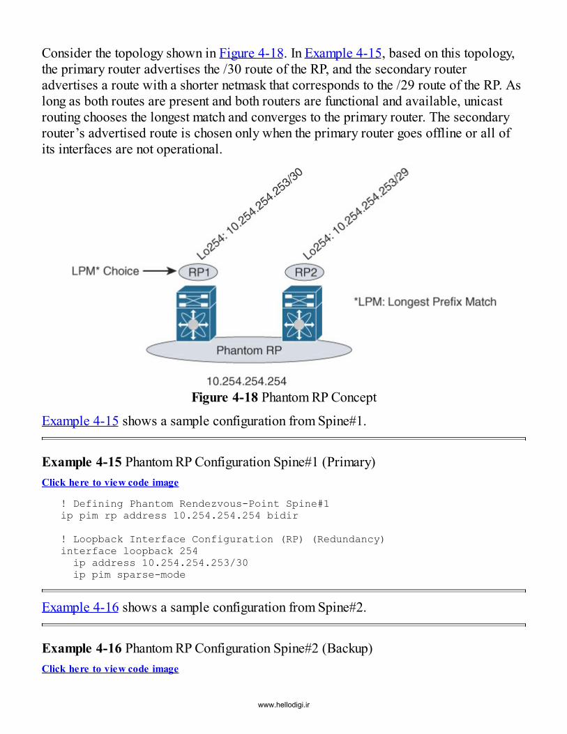
Consider the topology shown in Figure 4-18. In Example 4-15, based on this topology,the primary router advertises the /30 route of the RP, and the secondary routeradvertises a route with a shorter netmask that corresponds to the /29 route of the RP. Aslong as both routes are present and both routers are functional and available, unicastrouting chooses the longest match and converges to the primary router. The secondaryrouter’s advertised route is chosen only when the primary router goes offline or all ofits interfaces are not operational.
Figure 4-18 Phantom RP Concept
Example 4-15 shows a sample configuration from Spine#1.
Example 4-15 Phantom RP Configuration Spine#1 (Primary)Click here to view code image
! Defining Phantom Rendezvous-Point Spine#1ip pim rp address 10.254.254.254 bidir
! Loopback Interface Configuration (RP) (Redundancy)interface loopback 254ip address 10.254.254.253/30ip pim sparse-mode
Example 4-16 shows a sample configuration from Spine#2.
Example 4-16 Phantom RP Configuration Spine#2 (Backup)Click here to view code image
www.hellodigi.ir

! Defining Phantom Rendezvous-Point Spine#2ip pim rp address 10.254.254.254 bidir
! Loopback Interface Configuration (RP) (Redundancy)interface loopback 254ip address 10.254.254.253/29ip pim sparse-mode
As mentioned earlier, the Phantom RP simply uses an IP address belonging to aparticular subnet (10.254.254.254), but it is not associated with any physical or logicalinterface on any of the spines. This ensures that the RP address can be reached as longas one of the spines is connected to that subnet and that subnet is operational. Theavailability of the RP thus relies on the redundancy of the IP routing layer.
Example 4-17 shows a sample configuration with a view from any possible leaf.
Example 4-17 Using Phantom RPClick here to view code image
ip pim rp address 10.254.254.254 bidir
In a situation where Phantom RP is used for redundancy only, the configuration on theleaf for the Phantom RP is quite simple: It is the same as it would be for a single RP. Aswith PIM ASM, multicast peering on the P2P links needs to be enabled, and the RPneeds to be either globally configured across all multicast groups or configured on aper-multicast group basis. The keyword bidir must be specified at the end of the RPaddress configuration to indicate that the RP and corresponding groups are going to usePIM BiDir. In cases where Phantom RP is also to be used for load balancing, multiplePhantom RPs can be created, with one for each multicast group slice.As described earlier, the longest prefix match defines the active spine, which is thePhantom RP for all multicast groups. If load balancing is also desired, the multicastgroup range can be split into any number of slices (usually powers of 2), such as two orfour. When multicast groups are split into two ranges, active Phantom RPs must becreated on different spines. For example, if four active Phantom RPs are anticipated, themulticast groups need to be split into four ranges, with each RP becoming the active onefor the respective multicast group slice. In order to create two or four Phantom RPs, thesame number of loopback interfaces, with appropriate prefix lengths, need to beassigned to a given RP candidate (such as a spine) to achieve the load balancingobjective (see Figure 4-19).
www.hellodigi.ir

Figure 4-19 Phantom RP with Load BalancingExample 4-18 shows a sample configuration from Spine#1, which hosts the active RPfor the multicast group range 239.239.0.0/24. Spine#1 is the active Phantom RP for10.254.254.254, as per the longest prefix match result provided by the unicast routinglookup.
Example 4-18 Phantom RP Configuration with Load Balancing of Spine#1Click here to view code image
! Defining Phantom Rendezvous-Point Spine#1ip pim rp address 10.254.254.254 bidir group 239.239.0.0/24ip pim rp address 10.254.253.254 bidir group 239.239.1.0/24
! Loopback Interface Configuration (RP) (Redundancy)interface loopback 254ip address 10.254.254.253/30ip pim sparse-mode
! Loopback Interface Configuration (RP) (Redundancy)interface loopback 253ip address 10.254.253.253/29ip pim sparse-mode
Example 4-19 shows a sample configuration from Spine#2, which is active for themulticast group range 239.239.1.0/24. As is the case in Example 4-18, here Spine#2 isthe active Phantom RP for 10.254.253.254, as per the longest prefix match resultprovided by the unicast routing lookup.
www.hellodigi.ir

Example 4-19 Phantom RP Configuration with Load Balancing of Spine#2Click here to view code image
! Defining Phantom Rendezvous-Point Spine#2ip pim rp address 10.254.254.254 bidir group 239.239.0.0/24ip pim rp address 10.254.253.254 bidir group 239.239.1.0/24
! Loopback Interface Configuration (RP) (Redundancy)interface loopback 254ip address 10.254.254.253/29ip pim sparse-mode
! Loopback Interface Configuration (RP) (Redundancy)interface loopback 253ip address 10.254.253.253/30ip pim sparse-mode
The leaf itself has a split multicast group configuration, where one Phantom RP isdefined for a specific multicast group range, and the other multicast group range isassigned to a different Phantom RP. While this sounds a little complex, in essence onlyclassic routing semantics are being used regarding the longest prefix match and therespective best path to a given node. To reiterate, the Phantom RP is a nondefined IPaddress and requires a subnet route to ensure that the longest prefix match is followed.
Example 4-20 shows a sample configuration from any possible leaf.
Example 4-20 Using Phantom RPClick here to view code image
ip pim rp address 10.254.254.254 bidir group 239.239.0.0/24ip pim rp address 10.254.253.254 bidir group 239.239.1.0/24
In the preceding examples, the longest prefix match points to the active Phantom RP onSpine#1 for all multicast groups in the range 239.239.0.0/24. Likewise, Spine#2 is usedas the active Phantom RP for multicast groups in the range 239.239.1.0/24. In a typicalsituation involving two RPs, load balancing would be achieved based on multicastgroup assignment to the Layer 2 VNI. If Spine#1 fails, the residing longest prefix routecontinues to point toward Spine#2, and resiliency is achieved. Therefore, all thefailover and load balancing occurs within the unicast routing level (including thefunction of the Phantom RP itself), with only a minor portion being attributed to themulticast routing level.
In summary, depending on properties desirable for an underlay, multiple choices are
www.hellodigi.ir
www.hellodigi.ir

available to transport multidestination traffic or BUM traffic in an effective manner.While multicast is the most optimal method for multidestination traffic replication,ingress replication with its unicast mode also presents a viable alternative—albeit withits set of caveats. As a VXLAN network grows, specifically with increasing scale ofleafs or VTEPs, the BUM replication must also achieve greater scale. The multicastmode offers the most efficient way of achieving this. If the “performance impact”related to the creation of multiple copies of a single packet of BUM traffic for multipleVTEPs is not an issue, ingress replication can fulfill the job subject to an identifiedscale limit. However, with the requirement to support tenant multicast traffic over theVXLAN overlay becoming more and more critical, a multicast-in-multicastencapsulation will likely be the preferred option over the unicast mode.
SummaryThis chapter describes the BGP EVPN VXLAN fabric underlay that needs to be able totransport both single-destination and multidestination overlay traffic. The underlayneeds to provide a set of functionalities and exhibit certain characteristics. The primaryobjective of the underlay is to provide reachability among the various switches in thefabric. This chapter presents the IP address allocation options for the underlay, usingboth P2P IP numbered options and the rather attractive IP unnumbered options. Thischapter also describes choices of popular IGP routing protocols for unicast routingpurposes, such as OSPF, IS-IS, and BGP, along with the salient considerations for eachchoice. Two primary choices for multidestination traffic replication in the underlay arediscussed, namely unicast and multicast modes. While the unicast mode hinges on thehardware VTEP’s capability to perform multiple replications, the multicast mode (witheither PIM ASM or BiDir) is an attractive option that is likely to become more popularas the requirements for tenant overlay multicast become more stringent.
References1. Clos, C. A study of non-blocking switching networks. Bell System Technical
Journal, 32(2):406–424, 1953.2. Network Working Group. RFC894: A standard for the transmission of IP datagrams
over Ethernet networks. 1984. tools.ietf.org/html/rfc894.3. Jeffree, T. 802.1ad—Provider bridges. 2005.
www.ieee802.org/1/pages/802.1ad.html.4. Cisco. Configuring VXLAN: Configuring Q-in-VNI. Cisco Nexus 9000 Series NX-
OS VXLAN Configuration Guide, Release 7.x.www.cisco.com/c/en/us/td/docs/switches/datacenter/nexus9000/sw/7-x/vxlan/configuration/guide/b_Cisco_Nexus_9000_Series_NX-
www.hellodigi.ir

OS_VXLAN_Configuration_Guide_7x/b_Cisco_Nexus_9000_Series_NX-OS_VXLAN_Configuration_Guide_7x_chapter_011.html#task_ED949950FCF0481D9A5E389BAD1FA59B
5. Network Working Group. RFC4610: Anycast-RP using Protocol IndependentMulticast (PIM). 2006. tools.ietf.org/html/rfc4610.
6. Network Working Group. RFC4601: Protocol Independent Multicast—Sparse Mode(PIM-SM): Protocol specification. 2006. tools.ietf.org/html/rfc4601.
7. Cisco. Rendezvous point engineering. 2009.www.cisco.com/c/en/us/products/collateral/ios-nx-os-software/ip-multicast/whitepaper_c11-508498.html.
8. Network Working Group. RFC5015: BiDirectional Protocol Independent Multicast(BIDIR-PIM). 2007. tools.ietf.org/html/rfc5015.
9. Dijkstra, E. W. A note on two problems in connexion with graphs. 1959. www-m3.ma.tum.de/foswiki/pub/MN0506/WebHome/dijkstra.pdf.
10. Rexford, J. Distance-vector and path-vector routing. 2008.www.cs.princeton.edu/courses/archive/spr08/cos461/slides/14DistVector.ppt.
11. Cisco. Advance OSPF deployment. 2004.www.cisco.com/c/dam/en/us/products/collateral/ios-nx-os-software/open-shortest-path-first-ospf/prod_presentation0900aecd80310f6d.pdf.
12. Moy, J. IETF RFC2328—OSPF Version 2. 1998. www.ietf.org/rfc/rfc2328.txt.13. Internet Engineering Task Force. RFC5838: Support of address families in OSPFv3.
2010. tools.ietf.org/html/rfc5838.14. ISO/IEC. Information technology—Telecommunications and information exchange
between systems—Intermediate System to Intermediate System intra-domain routinginformation exchange protocol for use in conjunction with the protocol for providingthe connectionless-mode network service (ISO 8473). 2002.www.iso.org/iso/iso_catalogue/catalogue_tc/catalogue_detail.htm?csnumber=30932.
15. Lapukhov, P., A. Premji, and J. Mitchell. RFC7938: Use of BGP for routing in large-scale data centers. 2016. tools.ietf.org/html/rfc7938.
16. Network Working Group. RFC5015: BiDirectional Protocol Independent Multicast(BIDIR-PIM). 2007. tools.ietf.org/html/rfc5015.
17. Fenner, B., and D. Meyer. IETF RFC3618—Multicast Source Discovery Protocol(MSDP). 2003. tools.ietf.org/html/rfc3618.
18. Cisco Rendezvous point engineering. 2009.www.cisco.com/c/en/us/products/collateral/ios-nx-os-software/ip-multicast/whitepaper_c11-508498.html.
www.hellodigi.ir

www.hellodigi.ir

Chapter 5 Multitenancy
In this chapter, the following topics will be covered:
Multitenancy concepts VLAN-oriented versus bridge domain (BD)–oriented modes of operation formultitenancy Layer 2 and Layer 3 multitenancy in VXLAN BGP EVPN networks
Multitenancy is a mode of operation in which multiple independent logical instances(tenants) operate in a shared environment. Each of the logical instances provides aservice either at Layer 2 or Layer 3 or both Layer 2 and Layer 3 (the most commondeployment scenario. When using multitenancy, the aim is to allow control plane anddata plane separation to maintain proper isolation and to prevent unintended cross-communication between tenants. In traditional networks, isolation at Layer 2 is typicallyachieved using virtual local area networks (VLAN), while isolation at Layer 3 isachieved using virtual routing and forwarding (VRF). In modern cloud-based datacenters with overlays, these concepts must be extended to provide similar segregation,while also ensuring that service-level agreements (SLA) are honored.Multitenancy use cases are present in both enterprise and service providerenvironments. While service providers transport traffic between customer sites or fromcustomer sites to the Internet, large enterprises typically also have similar requirements.For example, in a large enterprise, due to its hierarchy and organizational structure,every department or business unit needs to be treated as a separate entity, or “customer.”In both service provider and enterprise environments, traffic belonging to differententities may be carried over a common infrastructure. In these environments,multitenancy allows transport of traffic with overlapping address space, ensuringseparation by Layer 2 and/or Layer 3 multitenancy function.
With network overlays, where the overlay encapsulation and decapsulation are handledat the network edge switches, the separation provided by multitenancy is realized by theASIC capability located in the hardware of the individual network switches, inconjunction with the software driving that functionality. Certain features related toquality of service (QoS) are typically provided by the hardware because they areapplied to traffic flowing at line rate. Other features, such as route leaking acrosstenants/VRFs, are controlled by software, based on the control plane injection of routingprefixes and appropriate route maps.
Note that both the hardware and software resources on the network switches are sharedacross various logical instances, and hence these require careful planning and
www.hellodigi.ir

consideration during network design. While the network hardware and softwarecapability might provide the option of supporting thousands of Layer 2 and Layer 3multitenant services, the network interface transporting this segregated traffic mightprovide only a limited set of buffers and queues to provide SLA enforcement such asQoS.
In order to provide efficient multitenancy and avoid duplication of requiredinfrastructure services, shared services are a common requirement. Examples of sharedservices include DHCP, DNS, and others that need to be equally accessible by alltenants without allowing any leakage of information among tenants. Additionalenforcement points, such as firewalls, can be employed at the edge of such centralizedor shared services to accept and inspect cross-communication between tenants. Variousdesign options are available for providing such centralized services, starting from thosethat provide simple route “leaking” between tenants to those having multitier fusionrouters and firewalls.1
Recall that the VXLAN header has a 24-bit identifier called the virtual networkidentifier (VNI). The VXLAN encapsulation uses this single field to uniquely identifyLayer 2 or Layer 3 services. VXLAN with BGP EVPN provides Layer 2 as well asLayer 3 multitenancy, and depending on the type of service under consideration,different terms for the respective VNIs are used. Whenever using a Layer 2 service,which typically means communication within the same subnet or same broadcastdomain, the term Layer 2 VNI (L2VNI) is used. Whenever using a Layer 3 service like aVRF, the term Layer 3 VNI (L3VNI) or VRF VNI is used. The separation of Layer 2 andLayer 3 VNIs is solely service dependent and does not attempt to describe a differentfield in the VXLAN encapsulation itself.
The use cases for multitenancy are very broad, as are the corresponding implementationchoices. In order to describe the various available design choices, this chapter providesa basic introduction to multitenancy, with a primary focus on the details of multitenancyservices provided by VXLAN BGP EVPN. Likewise, this chapter discusses basic Layer2 and Layer 3 multitenant services and how they are concurrently realized within thedata plane and control plane. Advanced use cases involving integration with servicesappliances such as firewalls, are described in Chapter 10, “Layer 4-7 ServicesIntegration.”
Bridge DomainsA bridge domain is a multitenancy service operating at Layer 2 across multiple networktechnologies. In other words, a bridge domain is a broadcast domain that represents thescope of the Layer 2 network. Using a VLAN is the most common way of providingLayer 2 multitenancy for classic Ethernet deployments with the IEEE 802.1Q (dot1q)
www.hellodigi.ir

header. VXLAN uses a VNI in the header to achieve the same outcome. A bridgedomain thus provides a way of stretching a Layer 2 service across multipleencapsulations, or network technologies across Layer 2.
The VLAN namespace provided by the IEEE 802.1Q header is 12 bits and yields 4096VLANs in a classic Ethernet domain. The VXLAN namespace provides a 24-bitnamespace, yielding 16 million segments of VNIs. In this regard, two differentnamespaces and encapsulations exist, so a mechanism is needed to allow mapping fromthe VLAN namespace to the VNI namespace and vice versa. This mapping is configuredat the edge device, or VTEP, and “stitched” using a bridge domain (see Figure 5-1).Specifically, when the VTEP has a hardware form factor (for example, on a ToRswitch), the VLAN and VNI representing the same Layer 2 network are mapped to thesame hardware bridge domain. Similarly, when the VTEP has a software form factor(for example, on a virtual switch), the VLAN and VNI for the same Layer 2 network aremapped to the same software bridge domain.
Figure 5-1 Hardware Bridge Domain
In summary, in the context of VXLAN, the bridge domain consists of three components:
The classic Ethernet domain with the VLAN namespace The VXLAN domain with the VNI namespace The network switch with the hardware/software bridge domain resources
VXLAN yields a much larger namespace, suitable for cloud-scale environments, and the802.1Q VLAN namespace may not be sufficient for typical deployment use cases inenterprise or service provider environments. The bridge domain concept, in comparingdifferent namespaces and encapsulations, is not specific to VXLAN. It applies equallyto other overlay encapsulations such as NVGRE, etc.
VLANs in VXLANMost servers or endpoints in a network are connected using classic Ethernet interfacesas described in IEEE 802.1Q.2 IEEE 802.1Q allows segmentation at Layer 2 and
www.hellodigi.ir

supports multiple VLANs on top of the physical wire. The IEEE 802.1Q (dot1q)standard employs a 12-bit addressing VID field, a 3-bit CoS field, and a 16-bit tagprotocol identifier (TPID). While the VID or VLAN identifier is commonly known, theTPID typically carries the value 0x8100 that serves as the Ethertype identifying thedot1q header.
Multiple dot1q tags can be configured back-to-back by using double-tagging (IEEE802.1ad or q-in-q).3 When implementing the double-tag 802.1Q header, outer VLANscan be transported in inner VLANs. In order to achieve this, the second TPID used hasto identify a second dot1q header and the additional inner VLAN space identifier. Theuse of q-in-q is common in metro-Ethernet transport cases where the inner VLAN spaceis assigned to the customer (C-TAG), while the outer VLAN ID is used for the serviceprovider (S-TAG) and has Ethertype 0x88A8. Next to the VLAN ID, the 802.1Q headeralso carries information for QoS in the Class of Service (CoS) field, which is furtherdocumented in the IEEE 802.1p standard.4
In a classic Ethernet environment, the VLAN’s namespace is globally significant. For agiven Layer 2 network, starting from the first switch to the last switch, a single VLAN isused end-to-end as shown in Figure 5-2. This makes the VLAN ID the global identifierin an Ethernet-based network and subsequently provides the 4K VLAN boundary.
Figure 5-2 VLAN End-to-EndWith VXLAN, the VLAN becomes locally significant while the global identifier
www.hellodigi.ir

becomes the VXLAN VNI. All endpoints communicating with each other at Layer 2receive the same L2 VNI (L2VNI) tag when traversing the network switches where theVTEPs reside. As mentioned earlier, endpoints still utilize Ethernet technology toconnect to the network switch, which provides a mechanism for mapping a VLANidentifier to a VNI. For example, this would occur with a single VXLAN edge deviceconnected to an endpoint. The local segment to which the server is connected uses aVLAN ID to identify the unique Layer 2 domain where the endpoint resides. The VLANsegment exists from the endpoint all the way to the network switch or edge device and isthe local identifier. In most cases, the VLAN becomes a per-switch identifier. Onentering the network switch, a translation is performed from the VLAN identifier to theVXLAN VNI (L2VNI), as shown in Figure 5-3. By virtue of having more bits availablein the VXLAN VNI than with the dot1q tag, there can be meaningful overlap in choosingthe overall numbering scheme for the design.
Figure 5-3 VLAN-to-VXLAN Mapping in an Edge Device
On a given edge device, this mapping is achieved by configuring the VLAN to therespective VXLAN VNI (vn-segment) in a 1:1 relationship, as shown here:
vlan 10vn-segment 30001
vlan 20vn-segment 30002
This demonstrates the mapping of a VLAN from the IEEE 802.1Q-defined namespace toan IETF RFC7348-based VXLAN VNI namespace on the ingress edge device.In this way, the VLAN is the local identifier, and the VNI becomes the global identifier.The VLAN is now significant to that edge device only. In this way, different VLANs ondifferent edge devices can map to the same VNI, as shown in Figure 5-4. Mapping fromVLAN to VNI, and eventually back to VLAN, can now be used in a flexible fashion, aslong as the VNI is used as the global unique identifier. Example 5-1 provides a samplelisting of the configuration on three edge devices for VNIs 30001 and 30002. Forconsistent mapping, the same source and destination VLAN are mapped to a commonVNI (L2VNI). However, some use cases require different source VLANs anddestination VLANs.
www.hellodigi.ir

Figure 5-4 Different-VLAN-to-Same-VNI Mapping
Example 5-1 Sample Layer 2 VNI Configuration on Different Edge DevicesClick here to view code image
Edge-Device #1vlan 10vn-segment 30001
vlan 20vn-segment 30002
Edge-Device #2vlan 100vn-segment 30001
vlan 200vn-segment 30002
Edge-Device #3vlan 1000vn-segment 30001
vlan 2000vn-segment 30002
The ability to have switch-local or switch-scoped VLANs permits the scaling of theVLAN namespace across the fabric with VXLAN. It is important to note that the VLANnamespace on a switch is still limited to 4096 VLANs. Moving the VLAN identifier
www.hellodigi.ir

from a per switch basis to a per switch, per port basis, provides a tremendous increasein flexibility. Per-port VLAN uses the VLAN ID arriving on the wire that is stored in thedot1q header. The edge device immediately maps this wire VLAN to an encapsulation-independent identifier without creating this VLAN on the switch. The hardwareresources allocated from the network switch provide the stitching capability from thewire VLAN to the respective hardware bridge domain with an encapsulation-independent identifier, which maps the wire VLAN to a VNI. The mapping of a VLANidentifier on a per-port basis thus allows for more flexible use cases compared to theper-switch use cases.
Figure 5-5 Per-Port VLAN-to-Same VNI MappingPer-port VLAN significance provides the ability to use the full VLAN namespace on aper-port basis and map each (port, VLAN) combination to a unique VXLAN VNI. Thisallows for an overlapping VLAN use case where same VLANs are mapped to differentVXLAN VNIs as long as they belong to different physical switch ports/interfaces.Figure 5-5 depicts a scenario where on a given edge device, the same wire VLAN 10on two different ports (Ethernet 1/8 and Ethernet 1/9) maps to VNIs 30001 and 30002respectively. Example 5-2 demonstrates the configuration on the edge device thatachieves this typical VLAN translation use case.
www.hellodigi.ir

Example 5-2 Sample Layer 2 VNI Configuration with per-Port VLAN SignificanceClick here to view code image
vlan 3501 vn-segment 30001vlan 3502 vn-segment 30002 interface Ethernet 1/8 switchport mode trunk switchport vlan mapping enable switchport vlan mapping 10 3501interface Ethernet 1/9 switchport mode trunk switchport vlan mapping enable switchport vlan mapping 10 3502
Different CLI implementations exist for creating the hardware bridge domain, dependingon the hardware and software platforms. Generally, two modes of operation areavailable: the VLAN mapping approach and the bridge domain mapping approach. Byusing the VXLAN VNI as the global identifier, the scaling of the VLAN namespacebecomes possible and the flexibility of the Layer 2 multitenancy construct increases.Depending on the network switch platform and software support, a VLAN can bemapped on a per-switch basis or on a per-port basis to a respective VNI. In either case,the mapping from a hardware resource (either VLAN or bridge domain) maintains a 1:1relationship.
In order to advertise the L2VNI within the BGP-based EVPN address family,configuration of the MAC-based EVPN instance is required, as shown in Example 5-3.The EVPN Layer 2 instance consists of multiprotocol BGP-related requirements toensure uniqueness and BGP route policy support. In order to uniquely identify the EVPNinstance (EVI) within MP-BGP, the instance consists of a VNI (L2VNI) and a RouteDistinguisher. In order to support MP-BGP route policies, appropriate Route Targetsare defined to ensure that prefixes for the instances are being imported. The valueschosen for the EVI are unique for the given instance because they are unique to theL2VNI. The Route Distinguisher is also unique for the Layer 2 EVI, on a per-edgedevice basis, while the L2VNI and Route Targets have a common value across all theedge devices sharing the same Layer 2 service.
Example 5-3 Sample Configuration to Advertise Layer 2 VNI Routes into BGP EVPNClick here to view code image
evpn
www.hellodigi.ir

vni 30001 l2 rd auto route-target import auto route-target export auto vni 30002 l2 rd auto route-target import auto route-target export auto
With the Cisco implementation of BGP-EVPN, the Route Distinguisher (RD) and routetarget (RT) values are derived automatically. The RD is generated from the router IDand the internal Layer 2 instance ID as demonstrated in Example 5-4. The RT is derivedfrom the autonomous system number (ASN) of BGP and the Layer 2 VNI (L2VNI). Notethat if eBGP is employed for the underlay, the RTs need to be manually configuredbecause the ASN may be different for different edge devices.
Example 5-4 Sample Output for Route Distinguisher per Layer 2 VNI with AutomatedDerivationClick here to view code image
LEAF1# show bgp l2vpn evpn vni-id 30001 | include "Route Distinguisher"
Route Distinguisher: 10.10.10.1:32777 (L2VNI 30001)
NoteAutomated derivation of the RD uses the type 1 format with RID LoopbackIP: internal MAC/IP VRF ID (RD: 10.10.10.1:32777). The internal MACVRF ID is derived from the VLAN ID (mapped to the L2VNI) plus 32767.For automatic derivation of RTs, the format is ASN: VNI (RT:65501:30001).
Layer 2 Multitenancy: Mode of OperationThe previous section discussed the significance of VLANs in the context of VXLAN.Likewise, it introduced the concepts of VLANs being the local identifiers and VNIsbeing the global identifiers. To elaborate on this further, Layer 2 multitenancy inVXLAN allows two modes of operation (see Figure 5-6):
VLAN-oriented mode Bridge domain (BD)-oriented mode
While these two modes are conceptually close, the implementation and thewww.hellodigi.ir

corresponding command-line configuration interface are quite different.
Figure 5-6 Modes of Operation
VLAN-Oriented ModeThe VLAN-oriented mode of operation can be described as traditional because theVLAN is the construct that makes the VNI mapping possible. The completeconfiguration on the edge device also follows VLAN semantics. This includes creatingthe VLAN and using the switch virtual interface (SVI) for potential Layer 3 services.When operating in the per-switch VLAN mode, the VLAN hosts the respective VNI. Theswitch then performs the mapping from Ethernet to VXLAN, based on the specifiedconfiguration. This case represents a bridge domain spanning from the local Ethernetsegment with the VLAN addressing (and the hardware resource within the edge devicerepresented in the VLAN) to the VNI once encapsulation takes place. Figure 5-7 showsthe concept of how VLAN, VNI, and switch internal resources are logically used toprovide an end-to-end Layer 2 service. The VLAN-oriented mode has been describedearlier in this chapter with the VLAN to VNI mapping configured as shown here:
vlan 10 vn-segment 30001
www.hellodigi.ir

Figure 5-7 Bridge Domain Span in the per-Switch VLAN Mode of OperationIn the VLAN-oriented mode, as the name implies, there is a restriction of a maximumpossible 4K VLAN-to-VNI mappings on a per-switch basis. Typically, the VLANmapped to the VNI is also the same one that is received over the local Ethernet port.However, a translation option is also possible, where the wire VLAN is mapped toanother translated VLAN that in turn maps to a VNI, as described in the previoussection.
BD-Oriented ModeIn the BD-oriented mode of operation, the VLAN resides on the local Ethernet segment,the addressing remains the same, and the encapsulation is specifically determined. Withclassic Ethernet and VLANs, the encapsulation of dot1q is used to identify the wireVLAN. In contrast, on the global VXLAN segment side (VNI), the encapsulationprovides specific naming via the VNI. In this specific construct, an encapsulationprofile allows the mapping of a dot1q-based VLAN to a VXLAN-based VNI:
encapsulation profile vni from10to30001 dot1q 10 vni 30001
With this approach of using encapsulation mapping profiles, the edge device becomescompletely agnostic to tagging, encapsulation numbering, and encapsulation naming usedon the wire. Instead, the encapsulation profiles define the mapping from a VLAN to aVNI. It is important to ensure that the correct hardware resources are available to
www.hellodigi.ir

accomplish this and that the encapsulation profile is assigned to the appropriatephysical interface. The appropriate interface exists where the local Ethernet segment isattached. In the BD-oriented mode, hardware resources are allocated as a bridgedomain. In this way, there is no longer the restriction of a maximum of 4K VNImappings on a per-switch basis. Instead, in theory, the number of VNIs is restricted tothe size of the hardware bridge domain table on the switch, which is typically 16K to32K. The BD-oriented mode does not have a VLAN-oriented configuration context,even with the existence of Layer 3 service instances. In this situation, the Layer 3service instances configuration is moved from an SVI to a bridge domain interface(BDI) configuration.
To summarize, the BD-oriented mode has two implementation differences from theVLAN-oriented mode:
A bridge domain is used instead of a VLAN. A bridge domain implements a BDI instead of an SVI.
It is now time to apply the BD concept as it relates to traffic flows. The traffic from aVLAN on the wire reaching an edge device is mapped to a hardware bridge domain atthe edge device and assigned a VNI encapsulated toward the VXLAN core. In order toclassify the bridge domain to be used for VXLAN encapsulation, the configuration mustassign membership of a VNI to the respective bridge domain. As in all the previousmodes described, the VNI-to-bridge-domain mapping still maintains a 1:1 relationship,as shown here:
vni 30001bridge-domain 5673 member vni 30001
Once the bridge domain and VNI have been paired, the last task is to configure theinterfaces facing the local LAN segment to their respective encapsulation profiles. Inorder to achieve this, a virtual services instance (VSI) is created for each interface, andthe appropriate encapsulation profile is referenced:
interface Ethernet 1/8 no switchport service instance 1 vni encapsulation profile from10to30001 default
The encapsulation profile provides a tremendous amount of flexibility as well asindependence from the wire encapsulation while achieving per-port VLAN significance.In the preceding configuration example, there is no relationship between the VLANidentifier, the VNI, or the hardware bridge domain configuration. The identifier can berandomly mapped as long as the encapsulation-specific numbering matches theanticipated addressing. The use of a VSI or an Ethernet flow point (EFP) is a common
www.hellodigi.ir
service provider platform approach that allows multi-encapsulation gateways.5
In summary, whenever Layer 2 multitenancy is to be achieved using the various modesof operations, the destination VNI to which the service is mapped is always a Layer 2VNI.
VRF in VXLAN BGP EVPNVirtual routing and forwarding (VRF) is a network switch construct that createslogically separated router instances on top of a single physical device. With VRF, therouting space can be separated in a given physical network while providing pathisolation. In addition, if desired, VRF can control communication between thesedifferent instances if required. VRF is defined locally on a switch/router; however,technologies exist that can extend local VRF instances across multiple devices. The firstmethod, called VRF Lite, is a common approach used to map a VRF to a VLANidentifier.6 However, scalability and configuration complexity often become challengingwhen using the VRF Lite approach. With VRF Lite (or Inter-AS Option A), each VRFhas its own routing instance and a dedicated routing interface. The configuration must bealigned to the peering/adjacent device.
Example 5-5 shows a typical VRF Lite configuration snippet for two routers that have aVRF instance extended via a Layer 3 subinterface.
Example 5-5 VRF Lite Configuration ExampleClick here to view code image
Router #1vrf context VRF-B
interface eth1/10.1002 encapsulation dot1q 1002 vrf member VRF-B ip address 10.2.2.1/24 ip router ospf 100 area 0router ospf 100 vrf VRF-B Router #2vrf context VRF-B
interface eth1/10.1002 encapsulation dot1q 1002 vrf member VRF-B ip address 10.2.2.2/24 ip router ospf 100 area 0
www.hellodigi.ir

router ospf 100 vrf VRF-B
Typically, an appropriate IGP is also enabled on these subinterfaces in order toexchange route prefixes between the two peering routers.7 In Example 5-5, the value1002 represents the tagged VLAN that will be employed for routing traffic belonging toVRF-B between two routers.
Over the years, VRF Lite has been widely used and deployed; however, as mentionedearlier, for every VRF instance, a dedicated interface is required and a separate peeringsession between the two involved entities must be present. An appropriate routingprotocol is configured over this peering session. In this way, there is a Layer 3 peeringsession established on a per-VRF instance basis that allows a Layer 3 handoff forstretching a VRF instance across multiple data center pods or sites. In contrast,Multiprotocol Label Switching (MPLS) Layer 3 VPNs offer a scalable solution forLayer 3 multitenancy.8 Despite the fact that MPLS has Layer 3 multitenancy, flexibility,and scale, the use of MPLS remains rather limited in data centers because data centerswitches have traditionally not supported MPLS. This pertains to support involving boththe control plane as well as the data plane.Layer 3 VPNs with MPLS are commonly deployed at the data center edge for Layer 3Data Center Interconnect (DCI) use cases. Another consideration, sometimes forgotten,is the scope of Layer 3 multitenancy. VRF Lite and MPLS L3VPN look at routinginformation from the perspective of an IP subnet. This means a given IP subnet stayslocal to a given provider edge (PE). A pair of PEs can then provide first-hopredundancy to the connected IP subnet. While the model of centralized routing applies tothe traditional data center, with the changing needs and evolution, a more efficientapproach is required for first-hop routing due to changing needs and evolution. This canbe accomplished with distributed subnets and integrated multitenancy at Layer 2 andLayer 3 with VXLAN BGP EVPN.
Centralized gateways for first-hop routing decisions can be moved to edge devices(ToR switches) with embedded Integrated Routing and Bridging (IRB) functionality. Thesame gateway can exist simultaneously at multiple edge devices, giving rise todistributed anycast gateway functionality at the edge devices. With the distributedgateway, the first-hop routing scope goes from IP subnet- to IP host-based routing.Furthermore, because the Layer 3 service is now provided at the edge device, Layer 3multitenancy can be introduced at this level. VRFs can therefore be defined or createdfor different tenants at the edge device.
MP-BGP EVPN with VXLAN is likewise able to provide enhanced scale functionalityfor Layer 3 multitenancy compared to that provided by MPLS L3VPNs. Recall that the
www.hellodigi.ir

control plane protocol used by EVPN is based on multiprotocol BGP. The MP-BGPcapability assigns a unique Route Distinguisher to each prefix, and transports thisinformation across a single BGP peering session. In addition, appropriate route policiesare enforced using import and export of appropriate Route Targets assigned to a givenprefix in the BGP control plane. Once a BGP peer receives a Route Target, it verifieswhether the Route Target matches its import policy of a given VRF. If there is a match,the route is installed and then used for forwarding.
In MPLS, the L3VPN label is responsible for separating tenant traffic belonging todifferent VRFs in the data plane. In this situation, the VNI associated with a VRF (Layer3 VNI [L3VNI]) and carried in the VXLAN header is used to achieve similar results.Notably, the VXLAN header carries only one VNI field. This is the same field thattypically carries the L2VNI for achieving Layer 2 multitenancy use cases. With Layer 3scenarios that involve routing operations, the information carried during Layer 2services becomes obsolete because source IP information is sufficient to identify theorigin. Thus, for Layer 3 routed traffic, the VNI in the VXLAN header is stamped withthe VRF VNI.In summary, Layer 3 multitenancy in VXLAN BGP EVPN uses the power ofmultiprotocol BGP to exchange the respective information. In addition to the BGPcontrol plane, it works with an IP/UDP-based encapsulation, VXLAN, and the VNInamespace. In addition, with the increased granularity provided with IRB, efficienthost-based routing can be achieved with no hair-pinning of traffic between nodes in thesame VXLAN-based fabric.
Layer 3 Multitenancy: Mode of OperationThe previous section focused on comparing Layer 3 multitenancy in VXLAN with BGPEVPN and MPLS L3VPNs. Layer 3 VNI (L3VNI) was introduced as the identifier forthe VRF in the routing context. Layer 3 multitenancy in VXLAN has a single mode ofoperation, and some small differences exist when comparing the VLAN- or BD-orientedswitch CLIs. Despite this, the overall concept remains the same.The VRF configuration in VXLAN-based Layer 3 multitenancy deployment consists ofthe name of the VRF and the respective VNI (L3VNI). All traffic routed within the VRFin a BGP EVPN VXLAN network is always encapsulated with the L3VNI. This is howrouted traffic is differentiated from the same subnet, or bridged traffic where the L2VNIis carried in the VXLAN header. While the L3VNI identifies the VRF uniquely acrossthe VXLAN-based network fabric, the name assigned to the VRF itself remains locallysignificant. However, it is common practice to follow a consistent naming conventionfor the L3VNI because doing so facilitates network operations and troubleshooting.
As mentioned earlier, in order to make sure a prefix from a given edge device iswww.hellodigi.ir

uniquely identified, each VRF has its unique Route Distinguisher (RD). In addition tothe Route Distinguisher, the VRF also contains routing policy values, specifically theRoute Targets (RTs). In the extranet case example, the Route Targets are imported andexported by all edge devices that are members of the same VRF. Example 5-6 shows atypical configuration for a VRF on an edge device in a VXLAN BGP EVPN network.
Example 5-6 Basic VRF Configuration in a VXLAN BGP EVPN NetworkClick here to view code image
vrf context VRF-A vni 50001 rd auto address-family ipv4 unicast route-target both auto route-target both auto evpn address-family ipv6 unicast route-target both auto route-target both auto evpn
Much as in the Layer 2 EVPN instance, the VRF construct consists of a RouteDistinguisher; this RD is automatically derived from the BGP router ID and the internalVRF identifier (decimal number), provided in Example 5-7. The Route Targets are alsoautomatically derived in the same manner as described in the case involving Layer 2VNI. Using the BGP ASN together with the L3VNI enables the RT value to be unique fora given VRF. However, the RT value remains the same across all the edge devices in thesame VRF.
Example 5-7 Sample Output for Route Distinguisher per Layer 3 VNI with AutomatedDerivationClick here to view code image
LEAF1# show vrfVRF-Name VRF-ID State ReasonVRF-A 3 Up --default 1 Up --management 2 Up --
LEAF11# show bgp l2vpn evpn vni-id 50001 | include "Route Distinguisher"
Route Distinguisher: 10.10.10.1:3 (L3VNI 50001)
www.hellodigi.ir

NoteAutomated derivation of the RD uses the type 1 format with RID LoopbackIP: internal MAC/IP VRF ID (RD: 10.10.10.1:3). For automatic derivationof Route Targets, the format is ASN: VNI (RT: 65501:50001).
It is critical to remember that the value of the L2VNI and L3VNI cannot overlap whenthe Layer 2 or Layer 3 instance is being configured. Specifically, the VNI configurationused for a Layer 2 instance should never be the same as the one used for a Layer 3instance. This same restriction also applies to the RT configuration. In regard to theRoute Distinguisher, it is highly recommended as a best practice to keep the layerconfiguration segregation as well, but in this case, it is not absolutely mandatory.
For the sake of completeness, it should be noted that RTs cannot be auto-generated insome cases when external BGP (eBGP) is used for the underlay. Specifically, with theeBGP underlay, the autonomous system number may vary on different edge devices.Consequently, the eBGP use case requires manual configuration of the Route Targets,and they must match between the respective edge devices. This is the only situationwhere manual configuration of Route Targets is required.
In terms of configuration requirements for realizing Layer 3 multitenancy in a VXLANBGP EVPN network, the VRF context configuration needs to be completed first.Subsequently, the BGP EVPN configuration for the VRF must be enabled. To make theL3VNI associated with the VRF fully active, the following must be present:
The L3VNI needs to be associated with the VTEP (NVE) interface. A core-facing VLAN or bridge domain must be associated with the L3VNI. A corresponding Layer 3 interface (SVI or BDI) must be created. This L3 interface must be associated with the VRF.
Associating the VRF L3VNI context with the VTEP allows it to be available toVXLAN. Example 5-8 outlines the critical steps required to configure Layer 3multitenancy for VXLAN.
Example 5-8 Sample BGP EVPN-Related VRF Configuration for Layer 3 MultitenancyClick here to view code image
router bgp 65501 vrf VRF-A address-family ipv4 unicast advertise l2vpn evpn
www.hellodigi.ir

interface nve1 member vni 50001 associate-vrf
VXLAN as an encapsulation requires MAC addresses to be populated in the inner MACheader. This allows the mapping of a Layer 2 bridge domain or a VLAN associated witha Layer 3 VRF. This VLAN or bridge domain model provides the necessary hardwareresource for creating the Layer 3 services across the VXLAN encapsulation. Example5-9 demonstrates a Layer 3 service on top of a Layer 2 encapsulation.
Example 5-9 VRF-Related VLAN and Bridge Domain Configuration for Layer 3MultitenancyClick here to view code image
VLAN Oriented Command Line Interface# VLAN for VRFvlan 2501 vn-segment 50001
# Layer-3 Interface for VRFinterface Vlan2501 no shutdown mtu 9216 vrf member VRF-A ip forward
Bridge-Domain Oriented Command Line Interface# Bridge-Domain for VRFvni 50001bridge-domain 2501 member vni 50001
# Layer-3 Interface for VRFinterface bdi2501 no shutdown mtu 9216 vrf member VRF-A ip forward
The VLAN or bridge domain in this case creates the hardware resource in the edgedevice. The Layer 3 interface provides the semantics of a routing hop, and the VRFmembership assigns it uniquely to the VRF. Configuring the MTU ensures that all routedtraffic is forwarded, including jumbo frames. Note that there may be some platform-specific commands and nuances for which the appropriate platform release notes andconfiguration guides must be referenced.
Summarywww.hellodigi.ir
This chapter describes how multitenancy has become a prime feature for next-generation data centers and how it is accomplished in VXLAN with BGP EVPN. Inaddition to discussing multitenancy when using VLANs and VXLAN, this chaptercovers modes of operation for both Layer 2 and Layer 3 multitenancy. Likewise, itdescribes the importance of bridge domains in regard to multitenancy in a VXLAN withBGP EVPN network, as well as concepts related to VRF. This chapter thus provides abasic introduction to the main aspects of multitenancy using VXLAN with BGP EVPN.
References1. Cisco. Network virtualization: Services edge design guide. 2008.
www.cisco.com/c/en/us/td/docs/solutions/Enterprise/Network_Virtualization/ServEdge.html2. Institute of Electrical and Electronics Engineers. 802.1Q virtual LANs. 2014.
www.ieee802.org/1/pages/802.1Q.html.3. Institute of Electrical and Electronics Engineers. 802.1ad provider bridges.” 2009.
www.ieee802.org/1/pages/802.1ad.html.4. Institute of Electrical and Electronics Engineers. 802.1D—1998—IEEE standard for
local area network MAC (media access control) bridges.standards.ieee.org/findstds/standard/802.1D-1998.html.
5. Cisco. Cisco CPT configuration guide CTC and documentation release 9.3 andCisco IOS release 15.1(01)SA. 2014.www.cisco.com/c/en/us/td/docs/optical/cpt/r9_3/configuration/guide/cpt93_configuration/cpt93_configuration_chapter_0100.html
6. Network Working Group. RFC4364: Multi-AS backbones. 2006.tools.ietf.org/html/rfc4364#section-10.
7. Cisco. Cisco Nexus 7000 series NX-OS interfaces configuration guide, release 5.x:Subinterfaces. 2015.www.cisco.com/c/en/us/td/docs/switches/datacenter/sw/5_x/nx-os/interfaces/configuration/guide/if_cli/if_layer3int.html#48044.
8. Network Working Group. RFC4364. 2006. tools.ietf.org/html/rfc4364.
www.hellodigi.ir

Chapter 6 Unicast Forwarding
In this chapter, the following topics will be covered:
Detailed packet flows for bridging in VXLAN BGP EVPN networks with andwithout early ARP termination Detailed packet flows for routing in VXLAN BGP EVPN networks with distributedIP anycast gateway and symmetric Integrated Routing and Bridging Handling silent endpoints, dual-homed endpoints, and IPv6 endpoints
This chapter explains the specifics of traffic forwarding across a VXLAN BGP EVPN–based network. It provides a brief description on how unicast forwarding worksconceptually in bridging and routing scenarios in a VXLAN BGP EVPN network. Thischapter describes how the Layer 2 service in the VXLAN overlay is provided by theLayer 2 Gateway (L2GW); the uses of the BGP EVPN control protocol; and how trafficfollows the VLANs and respective Layer 2 virtual network identifier (L2VNI) acrossthe entire bridge domain. It also covers various routing scenarios where the Layer 3service is provided by the VXLAN Layer 3 Gateway (L3GW), including the use of thedistributed IP anycast gateway. Various scenarios are examined involving local routingon the edge device as well as how forwarding is performed with symmetric IntegratedRouting and Bridging (IRB) to reach a remote endpoint across the VXLAN overlay.Some specific use cases with non-consistent (scoped) configuration demonstrate howsilent endpoints are made reachable within the network. In summarizing these bridgingand routing cases, this chapter takes a closer look at dual-homed endpoints and howforwarding takes place in virtual PortChannel (vPC) scenarios. The chapter concludeswith a look at IPv6 specifics.
Intra-Subnet Unicast Forwarding (Bridging)In overlays, a common requirement for the VXLAN data plane encapsulation is toprovide a basic Layer 2 service (Layer 2 Gateway or L2GW service). In order toprovide this service more efficiently, BGP EVPN control plane–assisted endpointlearning can reduce unnecessary broadcasts that result from ARP processing andunknown unicast traffic.Typically, bridged traffic is scoped by a VLAN. Learning is based on the SMACaddress carried in the packet, and forwarding is based on the DMAC address. WithVXLAN, the same semantics apply, but the VLAN is locally significant and scoped to aVTEP only. Consequently, all learning and forwarding is scoped by the Layer 2 VNI(L2VNI) that globally identifies a given Layer 2 network and the broadcast domain itrepresents. Bridged traffic is transported over VXLAN with the L2VNI, which is
www.hellodigi.ir
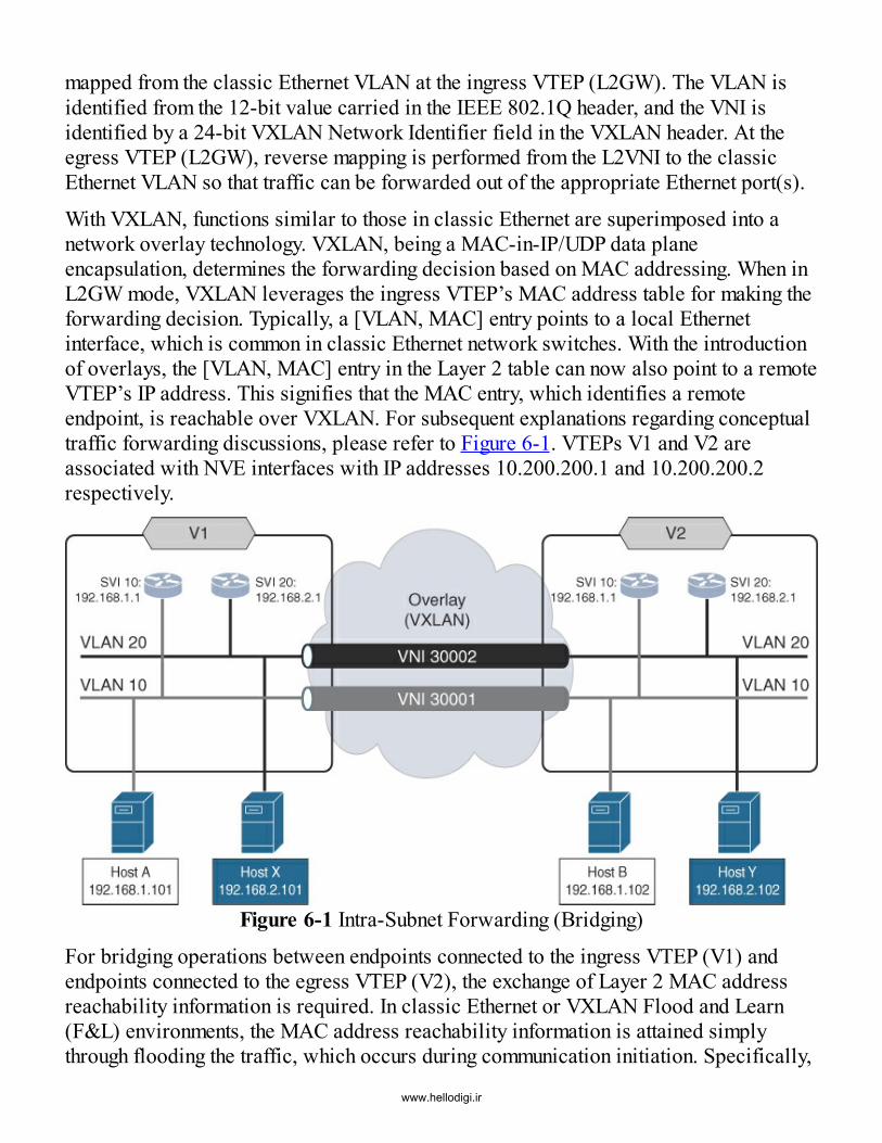
mapped from the classic Ethernet VLAN at the ingress VTEP (L2GW). The VLAN isidentified from the 12-bit value carried in the IEEE 802.1Q header, and the VNI isidentified by a 24-bit VXLAN Network Identifier field in the VXLAN header. At theegress VTEP (L2GW), reverse mapping is performed from the L2VNI to the classicEthernet VLAN so that traffic can be forwarded out of the appropriate Ethernet port(s).
With VXLAN, functions similar to those in classic Ethernet are superimposed into anetwork overlay technology. VXLAN, being a MAC-in-IP/UDP data planeencapsulation, determines the forwarding decision based on MAC addressing. When inL2GW mode, VXLAN leverages the ingress VTEP’s MAC address table for making theforwarding decision. Typically, a [VLAN, MAC] entry points to a local Ethernetinterface, which is common in classic Ethernet network switches. With the introductionof overlays, the [VLAN, MAC] entry in the Layer 2 table can now also point to a remoteVTEP’s IP address. This signifies that the MAC entry, which identifies a remoteendpoint, is reachable over VXLAN. For subsequent explanations regarding conceptualtraffic forwarding discussions, please refer to Figure 6-1. VTEPs V1 and V2 areassociated with NVE interfaces with IP addresses 10.200.200.1 and 10.200.200.2respectively.
Figure 6-1 Intra-Subnet Forwarding (Bridging)
For bridging operations between endpoints connected to the ingress VTEP (V1) andendpoints connected to the egress VTEP (V2), the exchange of Layer 2 MAC addressreachability information is required. In classic Ethernet or VXLAN Flood and Learn(F&L) environments, the MAC address reachability information is attained simplythrough flooding the traffic, which occurs during communication initiation. Specifically,
www.hellodigi.ir

the flooding ensures that all endpoints in the Layer 2 network receive thecommunication, and this results in Layer 2 learning on the forward path of traffic.Likewise, reverse traffic triggers learning on the return path. With the BGP EVPNcontrol protocol, the locally connected endpoints are learned from a MAC addressperspective on the ingress and egress VTEPs. This information is proactivelydistributed during BGP updates to all neighboring VTEPs. For the scenario shown inFigure 6-1, the BGP EVPN control protocol would carry the information outlined inTable 6-1:
Table 6-1 BGP EVPN Control Protocol Populated Information (After ARPDiscovery)
The information in Table 6-1 is expected to be present in the BGP EVPN control planeand then installed and used in the VTEP’s hardware tables. Cisco NX-OS providesvarious ways to verify that this information is present. Network administrators typicallycheck BGP tables to determine whether a given prefix is received (see Example 6-1);however, this action only validates reception of this information from a BGP databasepoint of view. It does not validate that the reachability information is installed as a validforwarding entry in the hardware tables.
Example 6-1 show bgp l2vpn evpn vni-id 30001 Output (at VTEP V1)Click here to view code image
V1# show bgp l2vpn evpn vni-id 30001BGP routing table information for VRF default, address family L2VPN EVPNBGP table version is 43, local router ID is 10.10.10.1Status: s-suppressed, x-deleted, S-stale, d-dampened, h-history, *-valid,>-bestPath type: i-internal, e-external, c-confed, l-local, a-aggregate, r-redist, I-injectedOrigin codes: i - IGP, e - EGP, ? - incomplete, | - multipath, & - backup
Network Next Hop Metric LocPrf Weight PathRoute Distinguisher: 10.10.10.1:32777 (L2VNI 30001)*>i[2]:[0]:[0]:[48]:[0000.3000.1102]:[0]:[0.0.0.0]/216 10.200.200.2
www.hellodigi.ir

100 0 i
*>l[2]:[0]:[0]:[48]:[0000.3000.1101]:[0]:[0.0.0.0]/216 10.200.200.1 100 32768 i
Because MP-BGP is used with EVPN, if the respective Route Target information doesnot match the import statement, forwarding does not occur because the entry residesonly in BGP. This said, for Layer 2 operations, it is a good practice to verify that theMAC address or MAC/IP prefix (Route type 2) has been received. However, verifyingthe installation of the prefix is split in two parts. The first part is new and relies on thefact that Layer 2 information is being learned through BGP for forwarding decisions.This information is installed in an EVPN instance, which is also called a MAC VRF.
Once the Layer 2 “routing” table has been verified with the appropriate MAC prefixes,as shown in Example 6-2, the next step is to ensure that similar entries should be presentin the MAC address table at the VTEP itself, as shown in Example 6-3.
Example 6-2 show l2route evpn mac all Output at VTEP V1Click here to view code image
V1# show l2route evpn mac allTopology Mac Address Prod Next Hop (s)----------- -------------- ------ ---------------10 0000.3000.1102 BGP 10.200.200.210 0000.3000.1101 Local Eth1/5
Example 6-3 show mac address-table vlan 10 Output at VTEP V1Click here to view code image
V1# show mac address-table vlan 10Legend: * - primary entry, G - Gateway MAC, (R) - Routed MAC, O - OverlayMAC age - seconds since last seen,+ - primary entry using vPC Peer-Link,(T) - True, (F) - False VLAN MAC Address Type age Secure NTFY Ports--------+-----------------+--------+---------+------+----+-----------* 10 0000.3000.1102 dynamic 0 F F nve1(10.200.200.2)* 10 0000.3000.1101 dynamic 0 F F Eth1/5
We are focusing on a Layer 2 bridging operation at this time, but the control protocolcan be populated with the IP address information in other ways. If at any point an ARPexchange occurs between endpoints connected to the edge devices with the ARP
www.hellodigi.ir

suppression feature explicitly enabled for the L2VNI, the ARP snooping performed onVTEPs V1 and V2 populates the control protocol with this information. Potentially, ifVRFs are configured, and first-hop gateways (distributed anycast gateways) are present,the population of the L3VNI would also have taken place.
Next, we walk through a sample use case shown in Figure 6-2, where endpoint Host A(192.168.1.101), which is connected to VTEP V1, wants to communicate with endpointHost B (192.168.1.102), which is connected to VTEP V2. Both endpoints belong to thesame VNI, 30001, and they can represent either virtual or physical hosts. Because HostB belongs to the same IP subnet as Host A, Host A tries to resolve the IP-to-MACmapping of Host B by first looking up its local ARP cache. If this process results in amiss, Host A initiates an ARP request. The broadcast ARP request is forwarded inVLAN 10, and the request enters the ingress VTEP V1. The MAC address of Host A islearned at VTEP V1 via regular MAC learning, and this information is populated overBGP EVPN to the VTEPs V2 and V3, respectively.
Figure 6-2 ARP Request, Host A to Host B
With ARP suppression disabled for VNI 30001 at VTEP V1, the ARP request fromendpoint Host A is handled as broadcast, unknown unicast, and multicast (BUM) traffic,encapsulated with Layer 2 VNI 30001, and then forwarded as a multidestination packet.The multidestination traffic can be replicated with multicast or with ingress replication
www.hellodigi.ir

to all VTEPs joining the same multidestination tree. This occurs by using either amulticast group or the ingress replication distribution list. All the viable egress VTEPsreceive the respective broadcast and decapsulate and forward the ARP request towardtheir local Ethernet interfaces participating in VNI 30001. Specifically, at VTEP V2,VNI 30001 is mapped to a local VLAN (namely 10), and subsequently traffic is sent outof the appropriate member classic Ethernet ports encapsulated with the dot1q tag 10.When Host B receives the ARP request, it responds with an ARP reply (unicast), asshown in Figure 6-3.
Figure 6-3 ARP Reply, Host B to Host AThis response results in regular MAC learning of Host B at VTEP V2, and the BGPEVPN control protocol is populated with Host B’s source information. Using the priorreachability information about Host A populated at VTEP V2 over BGP-EVPN, theunicast ARP reply, encapsulated with VNI 30001, is forwarded to VTEP V1. Afterdecapsulation at VTEP V1, the ARP reply is forwarded to Host A. In this way, the ARPcache of both Host A and Host B has been appropriately populated, and they can startsending data traffic to one another using regular bridging semantics.
www.hellodigi.ir

Optionally, if ARP suppression is enabled on VNI 30001, the initial ARP request fromHost A for Host B received at VTEP V1 is subjected to ARP snooping. Consequently, inaddition to the MAC address, the IP address of Host A is also populated in the BGPEVPN control plane via Route type 2 messages (see Example 6-4).
Example 6-4 show bgp l2vpn evpn vni-id 30001 Output at VTEP V1Click here to view code image
V1# show bgp l2vpn evpn vni-id 30001BGP routing table information for VRF default, address family L2VPN EVPNBGP table version is 43, local router ID is 10.10.10.1Status: s-suppressed, x-deleted, S-stale, d-dampened, h-history, *-valid,>-bestPath type: i-internal, e-external, c-confed, l-local, a-aggregate, r-redist, I-injectedOrigin codes: i - IGP, e - EGP, ? - incomplete, | - multipath, & - backup
Network NextHop Metric LocPrf Weight PathRoute Distinguisher: 10.10.10.1:32777 (L2VNI 30001)*>i[2]:[0]:[0]:[48]:[0000.3000.1102]:[0]:[0.0.0.0]/216 10.200.200.2 100 0 i
*>i[2]:[0]:[0]:[48]:[0000.3000.1102]:[32]:[192.168.1.102]/272 10.200.200.2 100 0 i
*>l[2]:[0]:[0]:[48]:[0000.3000.1101]:[0]:[0.0.0.0]/216 10.200.200.1 100 32768 i
*>l[2]:[0]:[0]:[48]:[0000.3000.1101]:[32]:[192.168.1.101]/272 10.200.200.1 100 32768 i
In addition, if Host B is known to the BGP EVPN control plane by MAC and IP, then aunicast ARP response is generated locally by VTEP V1 and returned to endpoint HostA. This results in early ARP termination. The ARP response is generated in the sameway that Host B would originate it, with VTEP V1 acting as an ARP proxy for Host B.Because the broadcast ARP request never reached Host B, only Host A’s ARP cache ispopulated with information about Host B, but not the other way around. When datatraffic is sent from Host A to Host B, Host B tries to resolve the IP-to-MAC binding forHost A by sending out an ARP request. VTEP V2 then serves as an ARP proxy, therebyappropriately populating the ARP cache of Host B as well.
www.hellodigi.ir

Figure 6-4 depicts the packet flow for data traffic between Host A and Host B oncetheir ARP caches have been appropriately populated. Host A generates data traffic witha SMAC of 0000.3000.1101 and source IP of 192.168.1.101. The destinationinformation is set to that of Host B, which is MAC 0000.3000.11102 and IP192.168.1.102, respectively. Once the packet is received at VTEP V1, a destinationlookup is performed, based on VLAN 10 mapped VNI 30001 and 0000.3000.1102. Thisyields the destination VTEP (V2), behind which Host B resides. Subsequently, VXLANencapsulation is performed with VNI 30001, and the packet is transported to therespective egress VTEP V2. Intuitively, this communication is very similar to theregular bridging operation that occurs in regular LAN environments, where the MACtable lookup drives the result.
Figure 6-4 Host A to Host B Forwarding (Bridging)
In the specific case involving endpoint Host B, the lookup results in a hit based on theprior endpoint discovery and associated control plane population. Table 6-2 shows thedetails of the respective outer IP, UDP, and VXLAN header fields, as well as the innerMAC and IP header fields for Host-A-to-Host-B data traffic sent from VTEP V1 toVTEP V2.
www.hellodigi.ir

Table 6-2 Encapsulated Packet, Including All Headers (as per Table 6-1)Once the packet is received at the egress VTEP V2 the packet is decapsulated, andappropriate local mapping is performed from VNI 30001 to VLAN 10, based on thetranslation table lookup result. The subsequent Layer 2 lookup results in a “hit,” basedon endpoint Host B’s MAC address (specifically [10, 0000.3000.1102]). As a result,the frame is sent toward the Ethernet interface where Host B is connected. In this way,the end-to-end unicast forwarding bridging flow in VNI 30001 is complete. This flowtravels from Host A in VLAN 10 behind VTEP V1 to Host B in VLAN 10 behind VTEPV2. VLAN 10 at VTEP V1 and VLAN 10 at VTEP V2 are thus stitched together via aLayer 2 service in VXLAN, identified with the VNI 30001.
Non-IP Forwarding (Bridging)The previous intra-subnet unicast forwarding case assumes that every endpoint has an IPaddress assigned to it. Forwarding is still based on the MAC address lookups,classifying the case as a bridging scenario. However, use cases exist where non-IPcommunication takes place between endpoints (see Figure 6-5), either coordinated by aprotocol or an application using an appropriate protocol. Examples include clusterreplication and legacy applications. When such non-IP protocols are used, endpointsmay be completely devoid of an IP stack. When using non-IP forwarding, the sameL2GW functionality is used when providing bridging functionality, as is the case whenIP addresses are present.
www.hellodigi.ir

Figure 6-5 Intra-Subnet Non-IP Forwarding (Bridging)In non-IP environments, different Layer 2 to Layer 3 address resolution protocols maybe employed, such as the AppleTalk Address Resolution Protocol (AARP). BecauseBGP EVPN supports only the Layer 3 protocols of IPv4 and IPv6 when IP addressing isabsent, BGP EVPN relies on only the MAC information in the control plane to make theforwarding decisions. For the topology depicted in Figure 6-5, the MAC-layerinformation is populated and distributed within the given VXLAN-enabled networkthrough the BGP EVPN control protocol, as illustrated in Table 6-3.
Table 6-3 BGP EVPN Control Protocol Populated Information (Non-IP)All the information related to the MAC layer is present. For example, the location of agiven MAC address identified by the VTEP and the associated Layer 2 VNI where theMAC address resides is included. Because forwarding is based only on the Layer 2information, the presence of IP addresses or Layer 3 VNIs (L3VNIs) is completelyabsent. If one of the endpoints begins using IP-based communication, then as soon as theARP exchange occurs, the IP information also begins appearing in the BGP EVPN
www.hellodigi.ir

control plane, as described in the scenario discussed in the earlier section “Intra-SubnetUnicast Forwarding (Bridging)” of this chapter.
Figure 6-6 describes a sample packet flow for non-IP communication between Host Aand Host B. Endpoint Host A generates data traffic with the SMAC address0000.3000.1101. Host A resides in VLAN 10. The destination information is set to theinformation associated with endpoint Host B, which is 0000.3000.1102. The higher-layer addressing information is unknown to the VXLAN BGP EVPN network. Once thepacket is received at VTEP V1, a destination lookup is performed [30001,0000.3000.1102]. Based on the information populated via the BGP EVPN controlprotocol, the lookup result yields the next-hop VTEP (V2) associated with thedestination (Host B) as well as the VNI (30001) to be employed for encapsulation.VXLAN encapsulation is then performed, and the packet is sent toward VTEP V2 withthe VXLAN VNI 30001.
Figure 6-6 Host A to Host B Forwarding (Non-IP)
Table 6-4 shows the details of the outer IP, UDP, and VXLAN header fields, as well asthe inner MAC fields.
www.hellodigi.ir

Table 6-4 Encapsulated Packet, Including All Headers (non-IP)From the control protocol perspective, the forwarded packet is considered non-IP (inneror original frame). Everything beyond the inner MAC headers represented in Table 6-4appears as non-addressing information and is abbreviated with “Payload.”
Once the packet is received at the egress VTEP V2, the packet is decapsulated, and alookup of the forwarding tables occurs. VNI 30001 is mapped to the local VLAN 10,and the Layer 2 lookup is performed as well based on the key [VLAN=10,0000.3000.1102]. If the lookup results in a hit, the frame is sent toward the Ethernetinterface to which Host B is attached. In case of a miss, the frame is flooded out of thelocal ports having membership in VLAN 10. Consequently, if Host B is behind VTEPV2, it receives the frame. Reverse traffic from Host B to Host A follows a similar flow.
At this stage, the unicast non-IP forwarding from endpoint Host A in VLAN 10 behindVTEP V1 to endpoint Host B in VLAN 10 behind VTEP V2 has been completed. Again,VLAN 10 on VTEP V1 and VLAN 10 on VTEP V2 are stitched together via a Layer 2service over VXLAN, identified with VNI 30001.
Inter-Subnet Unicast Forwarding (Routing)Thus far, the bridging packet flows have been discussed in regard to a Layer 2 overlayservice using VXLAN as the encapsulation and Layer 2 Gateway (L2GW) as the VTEPfunction. When considering Layer 3 overlay services provided by VXLAN and therespective Layer 3 Gateway (L3GW) function of the VTEP, a good understanding ofhow the Layer 2 or bridging operation itself works is crucial. With VXLAN being aMAC-in-IP/UDP header (regardless of Layer 2 or Layer 3 service), the inner payloadmust have a MAC header. In moving one OSI layer higher to cover Layer 3 operation, itis worthwhile to emphasize this important detail again. Understanding how theencapsulation and forwarding is performed when providing Layer 3 service withVXLAN is essential.
For a BGP EVPN VXLAN network, the function of symmetric Integrated Routing andBridging (IRB) is used to forward data traffic. With this approach, routed traffic usesthe Layer 3 VNI (L3VNI) associated with the VRF within which the routing operationoccurs. Every VRF has a unique L3VNI. In a given BGP EVPN VXLAN fabric, thesame VRF-to-L3VNI mapping must be present on every edge device or VTEP wherethat VRF is configured. When multiple VTEPs share the same L3VNI in a given
www.hellodigi.ir

VXLAN-based network, this is referred to as a routing domain. The 24-bit VNI used foraddressing a VRF or the individual routing domain is the same field in the VXLANheader that is used for carrying the L2VNI for forwarding bridged traffic.The reason for supporting the coexistence of two different values for a service whileonly employing a single encapsulation field is related to what happens after a routingoperation occurs. With bridging, the MAC addresses have to be end-to-end visible. Butin routing, the MAC information changes after the routing operation is completed.Consequently, after routing, the incoming or ingress MAC and VLAN informationbecomes irrelevant because the Layer 3 IP and VRF information is used for makingforwarding decisions. This remains true until the egress VTEP is reached, where alookup corresponding to [VRF, Destination IP] yields the final DMAC and egressinterface on which the packet must be sent. In essence, this procedure for forwardingrouted traffic over VXLAN is very similar to routing operations in non-VXLANenvironments.
In the subsequent explanations concerning conceptual traffic forwarding, refer toFigure6-7, which shows four endpoints (Host A, Host B, Host X, Host Y) residing in VRF Aassociated with L3VNI 50001. As in prior examples, VNI 30001 is associated with IPsubnet 192.168.1.0/24, on which endpoints Host A and Host B reside, and VNI 30002 isassociated with IP subnet 192.168.2.0/24, on which endpoints Host X and Host Yreside.
Figure 6-7 Inter-Subnet Forwarding (Routing)
www.hellodigi.ir

For routing operations between endpoints connected to the ingress VTEP V1 andendpoints connected to the egress VTEP V2, the exchange of Layer 3 addressing, IPaddresses, and associated IP subnets, has to occur first. With the BGP EVPN controlprotocol, the information learned about the local endpoints at an ingress VTEP isdistributed across BGP updates to all neighboring VTEPs. Specifically, the IP/MACinformation about the endpoints is distributed using BGP route type 2 messages.Likewise, the subnet prefix information is distributed using BGP route type 5 messages.For the scenario shown in Figure 6-7, the BGP EVPN control protocol would show theinformation depicted in Table 6-5.
This information is installed and used in the respective VTEPs’ hardware tables if theRoute Targets match. When this information is advertised over BGP and received from aVTEP, the portion of information seen as part of the BGP outputs differs from theinstalled information. As a result, the relationship to the VRF can be achieved only overthe VNI detour.
Table 6-5 BGP EVPN Control Protocol Populated Information (After ARP)
This explanation is not specific to BGP EVPN. It also applies to other MP-BGP VPN–based approaches, such as MVPN or VPNv4/v6 (MPLS L3VPN). Because mostnetwork administrators first check the BGP tables to validate whether a given prefix isreceived, this explanation is needed. MAC routes, IP host routes, and prefix routes areall being carried in BGP EVPN messages. Given that the MAC routes are applicable forMAC VRF identified by the L2VNI, and the IP routes are applicable for the IP VRFidentified by the L3VNI, the command show bgp l2vpn evpn vni-id XXXXX has beenintroduced to show these routes. The command show bgp ip unicast vrf VRF-NAMEprovides the IP prefix information for a given IP VRF.While it is good practice to verify what BGP prefixes are received for a given IP VRF,
www.hellodigi.ir

it is even more important to verify that the given prefixes are installed, and valid forforwarding. Specifically, the chain of verification at reception should be (a) whetherroutes have been received and installed in the BGP routing information base (BRIB);(b) whether routes have been installed in the unicast RIB; and (c) whether routes havebeen installed in the hardware forwarding information base (FIB) tables with thecorrect adjacency, or next-hop information. Example 6-5 illustrates how the BGP EVPNLayer 2 and Layer 3 information is stored at VTEP V1 with the VNI associated with vrfVRF-A (50001).
Example 6-5 show bgp l2vpn evpn vni-id 50001 Output at VTEP V1Click here to view code image
V1# show bgp l2vpn evpn vni-id 50001BGP routing table information for VRF default, address family L2VPN EVPNBGP table version is 43, local router ID is 10.10.10.1Status: s-suppressed, x-deleted, S-stale, d-dampened, h-history, *-valid,>-bestPath type: i-internal, e-external, c-confed, l-local, a-aggregate, r-redist, I-injectedOrigin codes: i - IGP, e - EGP, ? - incomplete, | - multipath, & - backup
Network Next Hop Metric LocPrf WeightPathRoute Distinguisher: 10.10.10.1:3 (L3VNI 50001)*>i[2]:[0]:[0]:[48]:[0000.3000.1102]:[32]:[192.168.1.102]/272 10.200.200.2 100 0 i*>i[2]:[0]:[0]:[48]:[0000.3000.2102]:[32]:[192.168.2.102]/272 10.200.200.2 100 0 i* i[5]:[0]:[0]:[24]:[192.168.1.0]:[0.0.0.0]/224 10.200.200.2 0 100 0 ?*>l 10.200.200.1 0 100 32768?* i[5]:[0]:[0]:[24]:[192.168.2.0]:[0.0.0.0]/224 10.200.200.2 0 100 0 ?*>l 10.200.200.1 0 100 32768 ?
www.hellodigi.ir

NoteAs part of the verification, the EVPN NLRI is being checked with the bitcount of the populated fields. This bit count results as a / notation next tothe prefix. A MAC-only route type 2 is represented with a /216 prefix,while a MAC/IP route type 2 is represented as a /272 prefix (additionalbits account for 32 bits for IPv4 address plus 24 bits for L3VNI). When anIPv6 address is carried in route type 2, it is represented as a /368 prefix(additional bits account for 128 bits for IPv6 address plus 24 bits forL3VNI). A route type 5 EVPN route carrying an IPv4 prefix is representedby a /224 prefix, and one carrying an IPv6 address is represented by a /416prefix.
Because MP-BGP is used with EVPN, the IP prefix entry would reside in the BGP RIBonly if the respective Route Target information did not match the route import statementunder a VRF. As a result, it would never be used for forwarding. It is therefore goodpractice to verify that the MAC/IP prefix (route type 2) and IP subnet prefix (route type5) have been received for Layer 3 operations. The information retrieved is divided intohost routes (/32 for IPv4 or /128 for IPv6) and IP prefix routes. All this information islearned through BGP EVPN and installed in the respective IP VRF, assuming theappropriate Route Targets have been imported. Example 6-6 shows all the IP routes forvrf VRF-A that are installed in the unicast RIB of VTEP V1. This includes both thelocally learned and instantiated routes and the routes received via BGP EVPN fromremote VTEPs.
Example 6-6 show ip route vrf VRF-A Output at VTEP V1Click here to view code image
V1 show ip route vrf VRF-AIP Route Table for VRF "VRF-A"'*' denotes best ucast next-hop'**' denotes best mcast next-hop'[x/y]' denotes [preference/metric]'%<string>' in via output denotes VRF <string>
192.168.1.0/24, ubest/mbest: 1/0, attached *via 192.168.1.1, Vlan10, [0/0], 00:16:15, direct, tag 12345192.168.1.1/32, ubest/mbest: 1/0, attached *via 192.168.1.1, Vlan10, [0/0], 00:16:15, local, tag 12345192.168.1.101/32, ubest/mbest: 1/0, attached *via 192.168.1.101, Vlan10, [190/0], 00:12:24, hmm192.168.1.102/32, ubest/mbest: 1/0 *via 10.200.200.2%default, [200/0], 00:12:57, bgp-65501, internal, tag65501 (evpn) segid: 50001 tunnelid: 0xa64640c encap: VXLAN
www.hellodigi.ir

192.168.2.0/24, ubest/mbest: 1/0, attached *via 192.168.2.1, Vlan20, [0/0], 00:14:24, direct, tag 12345192.168.2.1/32, ubest/mbest: 1/0, attached *via 192.168.2.1, Vlan20, [0/0], 00:14:24, local, tag 12345192.168.2.101/32, ubest/mbest: 1/0, attached *via 192.168.2.101, Vlan20, [190/0], 00:12:24, hmm192.168.2.102/32, ubest/mbest: 1/0 *via 10.200.200.2%default, [200/0], 00:11:47, bgp-65501, internal, tag65501 (evpn) segid: 50001 tunnelid: 0xa64640d encap: VXLAN
Typically, the IP/MAC binding of locally attached endpoints at a VTEP is learned viaARP. As a result, appropriate ARP entries are added to the ARP table, and, in turn,corresponding host routes (/32) are added to the unicast RIB. These host routes aresubsequently advertised to remote VTEPs over BGP EVPN using route type 2 messages.In that sense, validating the ARP tables for a given VRF is a good starting point.Example 6-7 shows the host entries in the ARP table for vrf VRF-A at VTEP V1.
Example 6-7 show ip arp vrf VRF-A Output at VTEP V1Click here to view code image
V1 show ip arp vrf VRF-AFlags: * - Adjacencies learnt on non-active FHRP router + - Adjacencies synced via CFSoE # - Adjacencies Throttled for Glean D - Static Adjacencies attached to down interface
IP ARP Table for context VRF-ATotal number of entries: 2Address Age MAC Address Interface192.168.1.101 00:11:36 0000.3000.1101 Vlan10192.168.2.101 00:11:16 0000.3000.1102 Vlan20
The separation of locally learned information for Layer 3 with ARP, along with theremotely learned Layer 3 information through a routing protocol, is similar to howthings operate in traditional routed networks. However, in traditional networks, only thesubnet routes are advertised for reachability via an appropriate routing protocol. Incontrast, the difference here is the presence of host routes, which are traditionallylearned but automatically redistributed into the BGP tables in the appropriate VRFcontext. With this approach, efficient routing is possible to any endpoint in the sameVRF in the VXLAN BGP EVPN network even when the IP subnet is distributed acrossmultiple VTEPs or leafs. Efficient routing occurs because the endpoint’s locationinformation is known, as is the VTEP behind which the endpoint resides. With thedistributed IP anycast gateway, not only can routing occur at the ingress VTEP, butrouting can also be performed efficiently to the correct egress VTEP.
www.hellodigi.ir

The output in the previous IP- and ARP-related examples assumes that an endpoint has been learned at its directly attached VTEP. This learning occurs by way of the interception of an ARP request from the endpoint. For inter-subnet communications, the endpoint needs to resolve its default gateway, and hence it needs to send out an ARP request. While this is true for an endpoint initiating the inter-subnet communication, in some scenarios, endpoints may be “silent.” In other words, these endpoints are not the initiators but are instead responders to communications. Other scenarios where silent hosts could exist could also include the misalignment of a MAC/ARP timer and an unknown behavior of a given endpoint’s IP stack. Scenarios involving both non-silent and silent endpoints are covered in this section. And for completeness, the initial ARP resolution process that occurs when non-silent hosts try to resolve their default gateway is discussed as well.
Figure 6-8 shows a scenario where endpoint Host A in VLAN 10 is attached below VTEP V1. Either during endpoint Host A’s initialization of its IP stack or whenever it tries to communicate with another endpoint in a different IP subnet, Host A tries to resolve the IP-to-MAC mapping for its default gateway from its local ARP cache. If this process results in a miss, Host A initiates an ARP request for the IP address of its default gateway, which is also the distributed IP anycast gateway configured on VTEPV1. The broadcast ARP request is forwarded in VLAN 10 and enters VTEP V1. At VTEP V1, the ARP request is then evaluated through ARP snooping, and the retrieved source information is populated in the BGP EVPN control protocol. Host A’s MAC 0000.3000.1101 and IP 192.168.1.101 then becomes known as behind VTEP V1,
www.hellodigi.ir

Figure 6-8 ARP Request, Host A to Distributed IP Anycast GatewayAt the same time, VTEP V1, which is responsible for the queried IP address, responds. The ARP reply sent from the distributed IP anycast gateway is sourced from VTEP V1, and it uses the anycast gateway MAC address (AGM) in the response to endpoint Host A. Once this information is received, Host A updates its ARP cache with the AGM(2020.0000.00AA in this example) mapped to the default gateway IP entry(192.168.1.1). Now, endpoint Host A is ready to communicate with other endpoints in different subnets. With the distributed anycast gateway, the Layer 3 boundary is at the VTEP, which naturally acts as the first-hop gateway for all the directly attached endpoints.
Two major forwarding semantics exist in VXLAN BGP EVPN, along with their respective use of IRB functions. The first relates to the local routing operation that occurs if the source and destination endpoints reside in different subnets in the same VRF and below the same edge device or VTEP. The second relates to forwarding routed traffic to an endpoint behind a remote VTEP, where similar processing occurs, but appropriate VXLAN encapsulation is now required between VTEPs.
In the local routing scenario shown in Figure 6-9, Host A (192.168.1.101)communicates with Host X (192.168.2.101), and both hosts are attached to the same VTEP (V1). Host A generates data traffic with the SMAC address 0000.3000.1101 andتک نت24
www.hellodigi.ir

source IP address 192.168.1.101. Because the default gateway has already beenresolved, the DMAC is set to 2020.0000.00AA. Host A resides in subnet192.168.1.0/24, which is part of vrf VRF-A, and this subnet is within VLAN 10. Thedestination information is set to the information of endpoint Host X, which has thedestination IP address 192.168.2.101 in the same VRF. Once the packet is received atVTEP V1, a destination lookup is performed for IP 192.168.2.101 in vrf VRF-A, whichyields the next hop.
Figure 6-9 Inter-Subnet Forwarding (Local Routing)In the case of local routing, the next hop is a layer-3 interface in a different VLAN(VLAN 20). The packet is transported to the respective egress VLAN at VTEP V1.Because Host X has already been learned at VTEP V1 based on the prior ARPprocessing, the longest prefix match entry (the host route 192.168.2.101/32) is hit.Subsequently, the appropriate MAC header rewrites are performed on the packet andthe packet is delivered to Host X. Therefore, for local routing, VXLAN encapsulation isnot needed. Table 6-6 shows the details of the header fields that are part of the localrouting operation.
Table 6-6 Host A Sourced Packet, Including All HeadersOnce the packet is received at endpoint Host X in a different VLAN and IP subnet, Host
www.hellodigi.ir

X can respond to Host A in a similar manner, thereby completing bidirectional unicastcommunication through local routing at VTEP V1.
When routing to a destination endpoint behind a remote VTEP, the initial steps for ARPresolution and for reaching the default gateway are identical to that described with localrouting. But the routing performed between two different VTEPs needs to be discussedfurther. In this instance, as shown in Figure 6-10, the source, Host A, is connected to theingress VTEP V1, while the destination, Host Y, is connected to the egress VTEP V2 ina different IP subnet.
Figure 6-10 Host-A-to-Host-Y Forwarding (Routing)
Host A generates data traffic with the SMAC address 0000.3000.1101, the source IPaddress 192.168.1.101, the DMAC address 2020.0000.00AA, and the destination IPaddress 192.168.2.102. When the packet is received at VTEP V1, a destination lookupis performed for IP 192.168.2.102 in vrf VRF-A, which results in the next-hopdestination VTEP and the VNI to be used for encapsulation. Because the remote hostroute 192.168.2.102/32 has been learned at VTEP V2, populated over BGP EVPN toVTEP V1, and installed in the hardware FIB tables, the lookup results in a hit. Thelookup result yields VTEP V2, L3VNI=50001, corresponding to vrf VRF-A, as well asthe appropriate MAC header rewrite information.Because VXLAN requires an inner MAC header, the source and next-hop MAC addressof the involved routers in the overlay have to be present. On the ingress VTEP side,
www.hellodigi.ir

where VTEP V1 encapsulates the packets, the source Router MAC (RMAC) is knownbecause it is owned by VTEP V1. The remote VTEP’s RMAC information is encoded inthe BGP EVPN NLRI as an extended community. Consequently, whenever a routinglookup is performed at the ingress VTEP for a remote destination IP (host or subnet), thedestination RMAC is derived from the BGP EVPN information. Note that intuitively theregular Layer 2/Layer 3 lookup semantics apply here. Because this is a routed case, aLayer 3 lookup is performed, and the lookup result drives the rewrite that must beapplied to the packet before it is forwarded out the appropriate egress interface.
Table 6-7 depicts the details of the VXLAN-encapsulated packet sent from VTEP V1 toVTEP V2, including the salient inner and outer header fields. In the table,0200.0ade.de01 and 0200.0ade.de02 correspond to the RMACs associated with VTEPV1 and VTEP V2, respectively.
Table 6-7 Encapsulated Packet, Including All Headers
The VXLAN-encapsulated packet is forwarded using regular Layer 3 lookup as ittraverses different routers along the path until it reaches the egress VTEP. Once thepacket is received at the VTEP V2, the packet is decapsulated, and the forwardingtables that are responsible for the VNI 50001 mapped vrf VRF-A are consulted.Because endpoint Host Y is known at VTEP V2, the routing lookup results in a lookuphit for 192.168.2.102/32, and the frame is appropriately rewritten and sent toward theEthernet interface where Host Y is connected. In this way, with symmetric IRB, abridge–route–route–bridge sequence is performed. In this situation, the packet fromHost A is first bridged toward VTEP V1 and then routed on VTEP V1 toward VTEP V2.At VTEP V2, the packet is routed again and subsequently bridged toward Host Y.At this point, the unicast forwarding from Host A within VLAN 10 behind VTEP V1 toHost Y within VLAN 20 behind VTEP V2 is complete. The subnet (as part of VLAN 10)and the subnet (as part of VLAN 20) are connected together via a Layer 3 service inVXLAN identified with VNI 50001, representing a transit segment between VTEP V1and VTEP V2.
Routed Traffic to Silent EndpointsSo far the hosts or endpoints have “announced” their presence to their directly attachedVTEP via ARP, thereby ensuring efficient routing to these endpoints. This includes bothlocal and remote hosts. These endpoints are different from the silent endpoints
www.hellodigi.ir

introduced earlier, whose presence is not known to the network. In that situation, thesilent endpoints are not known at the ingress VTEP or at any of the egress VTEPs.
The Layer 3 forwarding approach with BGP EVPN handles silent endpoints efficientlyas well. Sending traffic toward the silent endpoint results in their discovery.Subsequently the endpoint is known to the network and treated like any other knownendpoint. Two scenarios for handling silent hosts or silent endpoints in a VXLAN BGPEVPN network are now discussed.For the scenario depicted in Figure 6-11, the BGP EVPN control protocol shows theinformation in Table 6-8, where endpoint Host Y is a silent host. Specifically, Host Y’sIP address is not known because it has yet to be discovered.
Figure 6-11 Silent Host Y with L2VNI Present (Router Bridge)
www.hellodigi.ir

Table 6-8 BGP EVPN Control Protocol, VTEP V2 Silent HostAssume that Host A wants to communicate with Host Y. As before, Host A generatesdata traffic with the SMAC address 0000.3000.1101, the source IP address192.168.1.101, the DMAC address 2020.0000.00AA, and the destination IP address192.168.2.102. This occurs because the default gateway has already been resolved.Once the packet is received at VTEP V1, a destination lookup is performed for IP192.168.2.102 in vrf VRF-A. This yields the destination VTEP and the associated VNI(50001 associated with vrf VRF-A) to be employed for VXLAN encapsulation. Giventhat Host Y is a silent endpoint, the Layer 3 lookup hits the longest prefix match entry. Inthis case, the prefix corresponding to the subnet 192.168.2.0/24 in which host Y resides,will be the hit.
Because the destination IP subnet is locally known, the direct or connected route ischosen (lowest administrative distance). This subnet prefix entry points to a gleanadjacency, and this in turn triggers the generation of an ARP request in the bridgedomain associated with VNI 30002. Appropriate BUM forwarding on the underlayensures that this broadcast ARP request reaches all the other VTEPs participating inVNI 30002. Assume that VNI 30002 is associated with multicast group 239.1.1.1. Table6-9 shows the details of the header fields involved in this operation.
Table 6-9 Encapsulated Packet, Including All Headers
Consequently, Host Y also receives the ARP request. Given that the ARP request issourced from VTEP V1, which hosts the distributed anycast gateway, Host Y respondswith a directed ARP reply to the default gateway. The distributed anycast gateway is
www.hellodigi.ir

also hosted on VTEP V2, which captures the ARP response. Based on the ARPresponse, VTEP V2 learns about the IP-to-MAC binding associated with Host Y. In turn,VTEP V2 advertises this information over the BGP EVPN control protocol. As a result,VTEP V1 learns about the 192.168.2.102/32 address associated with Host Y.Subsequently, traffic is routed over to VTEP V2 and eventually forwarded to Host Yover VLAN 20, which is mapped to VNI 30002.
As with symmetric IRB, routed traffic from VTEP V1 to VTEP V2 is sent out withVXLAN VNI 50001, which is the L3VNI associated with vrf VRF-A. Reverse trafficfrom Host Y to Host A is also routed from VTEP V2 to VTEP V1, using the sameVXLAN VNI 50001, thus providing symmetry. Consequently, with symmetric IRB,VXLAN-routed traffic in either direction uses the same VNI, which is the VNIassociated with the VRF.At this stage, the unicast forwarding scenario is complete, with silent host detectionfrom endpoint Host A (in VLAN 10 behind VTEP V1) to endpoint Host Y (in VLAN 20connected to VTEP V2). Once the silent host, Host Y is detected, and subsequentforwarding takes place across VNI 50001 (L3VNI). For the scenario shown in Figure 6-12, the BGP EVPN control protocol shows the information in Table 6-10 after silenthost discovery.
Figure 6-12 Silent Host Y with L2VNI Present (Routing)
www.hellodigi.ir

Table 6-10 BGP EVPN Control ProtocolThe previous scenario discusses silent host detection where the bridge domain of thedestination endpoint is local to the ingress VTEP. Because this is not always the case,silent host detection has to also work in cases where no Layer 2 extension is present. Insuch a situation, the destination IP subnet prefix is chosen to forward data traffic towardthe destination endpoint. Subsequently, one of the VTEPs hosting the destination subnetis chosen as the candidate to discover the silent endpoint via ARP.
For the scenario depicted in Figure 6-13, the BGP EVPN control protocol has theinformation shown in Table 6-11.
Figure 6-13 Silent Host Y (Routing Only)
www.hellodigi.ir

Table 6-11 BGP EVPN Control Protocol information at VTEP V1As in prior examples, here Host A with IP 192.168.1.101 wants to communicate withHost Y with IP 192.168.2.102. After ARP resolution of the default gateway, Host Agenerates data traffic with the SMAC address 0000.3000.1101, the source IP address192.168.1.101, the DMAC address 2020.0000.00AA, and the destination IP address192.168.2.102. Once the packet is received at VTEP V1, a destination lookup isperformed for IP 192.168.2.102 in vrf VRF-A, which results in a hit for the subnetprefix 192.168.2.0/24. Because this subnet prefix is advertised by VTEP V2, traffic isVXLAN-encapsulated with the VRF-A VNI 50001 and sent toward VTEP V2 using thesymmetric IRB function at VTEP V1. Once again, the inner SMAC is rewritten with theinformation of VTEP V1, and the inner DMAC is rewritten to the RMAC associatedwith VTEP V2, which was advertised over BGP EVPN using the Router-mac extendedcommunity. Table 6-12 shows the details of the outer IP, UDP, and VXLAN headerfields, as well as the inner MAC and IP header fields for this operation.
Table 6-12 Encapsulated Packet, Including All HeadersWhen the traffic reaches VTEP V2, it is decapsulated, and the subsequent destination IPlookup in vrf VRF-A, which is mapped from VNI 50001, results in the 192.168.2.0/24subnet prefix entry being hit. Because Host Y is silent, its /32 route has not yet beendiscovered at VTEP V2. The glean adjacency associated with the local subnet192.168.2.0/24 is hit, and, in turn, VTEP V2 injects an ARP request in VLAN 20,associated with this subnet. The broadcast ARP request flooded in VNI 30002 mappedfrom VLAN 20, also reaches Host Y. The ARP response from Host Y is then directed tothe default gateway (specifically the distributed anycast gateway), which is hosted onVTEP V2.
As in earlier examples, Host Y is discovered, its address information is injected intothe BGP EVPN control plane, and distributed to all remote VTEPs, including VTEP V1.In this way, subsequent data traffic is forwarded from Host A to Host Y via routing from
www.hellodigi.ir

VTEP V1 to VTEP V2, using the symmetric IRB bridge–route–route–bridge operation.For the scenario shown in Figure 6-13, the BGP EVPN control protocol shows theinformation in Table 6-13 after silent host discovery:
Table 6-13 BGP EVPN Control Protocol information After Silent Host Discovery ofHost Y
Note that the announcement of the IP subnet route of a given L3GW instance (SVI orBDI) has to be performed manually via an appropriate configuration. Chapter 2,“VXLAN BGP EVPN Basics,” explains this approach and the merits of thisredistribution. Example 6-8 shows a simple configuration with this in mind.
Example 6-8 show run vrf VRF-A Output (at VTEP V1)Click here to view code image
interface Vlan10 vrf member VRF-A ip address 192.168.1.1/24 tag 12345 fabric forwarding mode anycast-gateway
route-map FABRIC-RMAP-REDIST-SUBNET permit 10 match tag 12345
router bgp 65501 vrf X address-family ipv4 unicast advertise l2vpn evpn redistribute direct route-map FABRIC-RMAP-REDIST-SUBNET
Forwarding with Dual-Homed EndpointVirtual PortChannel (vPC) is a technology used in forwarding traffic to dual-homedendpoints attached to a pair of switches. From a VXLAN perspective, the vPC domainrepresents a common VTEP within the VXLAN network and is referred to as the anycastVTEP. This section explains vPC-based forwarding and its use with VXLAN BGPEVPN and the distributed IP anycast gateway. By default, the location of every endpointconnected to a vPC domain is represented by the corresponding anycast VTEP IP
www.hellodigi.ir

address.
For the scenario depicted in Figure 6-14, VTEP V1 and VTEP V2 form a vPC domainrepresented with the anycast VTEP (VIP) with the IP address 10.200.200.12. Once HostA intends to send traffic toward Host B, port channel hashing decides whether Host Ashould choose VTEP V1 or VTEP V2 as an ingress VTEP for VXLAN encapsulationand forwarding. Once the hashing decision has been made between the endpoint and theVTEPs for transporting the traffic across the port channel, the same semantics describedin previous sections related to intra-subnet (bridging) or inter-subnet (routing)forwarding are used. Figure 6-14 shows the end-to-end bridging scenario from a dual-attached endpoint (Host A) to a single attached endpoint (Host B). Whether the trafficingresses VTEP V1 or VTEP V2, the outer source IP address is always set to that of theanycast VTEP, in this case, 10.200.200.12. This holds true for both routed and bridgedtraffic sent out from the vPC domain toward the VXLAN network.
Figure 6-14 Endpoint Behind Ingress Anycast VTEP (vPC)
In the opposite direction, where traffic is directed to an endpoint connected to a vPCdomain (represented by the anycast VTEP in VXLAN), additional details should betaken into consideration. For the scenario depicted in Figure 6-15, traffic from Host Btoward Host A is VXLAN encapsulated and sent out with the outer destination IPaddress set to the anycast VTEP IP address 10.200.200.12. Both VTEP V1 and VTEPV2 are part of the same vPC domain and are configured with this anycast VTEP.Consequently, they both advertise reachability of 10.200.200.12 over the IP underlay.
www.hellodigi.ir

Figure 6-15 Endpoint Behind Egress Anycast VTEP (vPC)Traffic directed toward 10.200.200.12 is forwarded either toward VTEP V1 or VTEPV2 by the underlay, based on equal-cost multipath (ECMP). Depending on the hashingused in the underlying transport network, an egress VTEP hidden behind the anycast VIP,is chosen. In this way, traffic reaches either VTEP V1 or VTEP V2. Likewise, the samesemantics are used for intra-subnet (bridging) or inter-subnet (routing) forwarding, asdescribed in the previous sections. Figure 6-15 shows the end-to-end bridging scenariofrom a non-VPC attached endpoint (Host B) to a vPC-attached endpoint (Host A). Onlyone of the two VTEPs, V1 or V2 will receive the traffic, decapsulate it and forward ittoward Host A over the port channel.
With vPC-enabled edge devices, orphan endpoints are still present. An orphan endpoint,by definition, is connected to only one of the two vPC member switches that are part ofthe vPC domain. For an orphan endpoint, traffic destined to that endpoint might need totravel the vPC peer link because the endpoint information is always announced overBGP EVPN with the anycast VTEP being the next hop. This is also true for dual-homedendpoints that may become singly attached due to link/port failures.
Figure 6-16 shows an orphan endpoint Host A that is only attached to VTEP V1. Asbefore, VTEP V1 and VTEP V2 form a vPC domain with the same anycast VTEP VIPadvertised from the vPC domain. When traffic is ingressing from a remote VTEP and is
www.hellodigi.ir

destined to Host A, there is a chance that traffic directed toward VIP will be sent toVTEP V2, based on the ECMP hashing in the underlay network. After VXLANdecapsulation at VTEP V2, traffic is bridged across the vPC peer link toward VTEP V1.Subsequently, VTEP V1 forwards it on the orphan port where Host A is attached.
Figure 6-16 Orphan EndpointsFor routed traffic received at VTEP V2 that is destined for Host A, the routing lookupand rewrite occur on VTEP V2. Subsequently, the rewritten packet is bridged towardVTEP V1 over the vPC peer link. In the opposite direction, for traffic from Host Atraveling toward any remote endpoint, VTEP V1 is used for both bridging and routingdecisions. This is because Host A is connected only to this specific VTEP.
For a local bridging operation within a vPC domain in a VXLAN BGP EVPN networkcontaining orphan endpoints, forwarding occurs in a manner similar to what happenswith a traditional vPC deployment. Figure 6-17 shows a scenario with two orphanhosts, Host A and Host B, connected to VTEPs V1 and V2 respectively. Since Host Aand Host B belong to the same L2VNI 30001, traffic from Host A is received at VTEPV1 and forwarded across the vPC peer link toward VTEP V2. Once traffic reaches
www.hellodigi.ir

VTEP V2, the traffic is forwarded toward the orphan port where Host B is attached. Ingeneral, this operation does not involve any VXLAN encapsulation, but certain platformlimitations may still require traffic to be VXLAN-encapsulated across the vPC peerlink.
Figure 6-17 vPC with two Orphan EndpointsNotably, all bridged and routed traffic within a vPC domain is announced with a nexthop as the anycast VTEP associated with that domain. When routing through a vPCdomain, the egress VTEP receiving the traffic needs to have the routing information inorder to make further decisions. If the traffic reaches VTEP V1, but further egressrouting has to happen from VTEP V2, a routing exchange must occur between VTEP V1and VTEP V2. This can be achieved between vPC peers through either full-meshexternal routing connectivity or VRF Lite across the vPC peer link. Regarding VRF Liteacross the vPC peer link, a dedicated interface is required for establishing the routingadjacency. This restriction can be lifted by advertising routing information (route type5) with the individual IP address of the VTEPs rather than the anycast VTEP IP.
www.hellodigi.ir

IPv6VXLAN-based overlays using the BGP EVPN control protocol support IPv4- as well asIPv6-based Layer 2 and Layer 3 services. The distributed IP anycast gateway hosted atthe VTEPs can act as a first-hop gateway for either IPv4 or IPv6, as well as in dual-stack mode. Just as with IPv4, all the VTEPs can share the same distributed anycastgateway IPv6 address with global addressing for a given IPv6 subnet. The anycastgateway MAC (AGM) is shared between IPv4 and IPv6. The overlay services are fullysupported with both IPv4 and IPv6 addressing; however, the underlying transportnetwork is presently only available with IPv4 addressing. Underlay transport based onIPv6 addressing will be supported in the future.
Figure 6-18 shows a sample topology where two IPv6 endpoints are attached todifferent VTEPs in a VXLAN BGP EVPN fabric. For endpoint detection, move, anddeletion events with IPv6 endpoints, Neighbor Discovery Protocol (ND) is used insteadof ARP. The locally learned IPv6 entries at a VTEP are subsequently advertised overthe BGP EVPN control plane, using the same MP-BGP channel. In this way, thelocations of all known IPv6 endpoints are learned everywhere in the BGP EVPNnetwork.
www.hellodigi.ir

Figure 6-18 IPv6 Endpoints in a BGP EVPN VXLAN Network
With IPv6, the BGP EVPN NLRI is populated in a similar way as with IPv4 (see Figure6-19). The differences are obvious, given that IPv6 addresses are 128 bits compared to32 bits for IPv4. The show commands use hex notation for IPv6 addresses, but the restof the BGP EVPN NLRI and extended community fields are equally applicable to IPv6and IPv4. Recall that an appropriate routing protocol is responsible for populating theVTEP-to-VTEP reachability in the underlay. MP-BGP as the overlay reachabilityprotocol employs the VTEP IP addresses as next-hop information associated with theBGP EVPN route advertisements. While the end host information can be MAC, IPv4,and/or IPv6 and only associates with the overlay, the next hop always follows theunderlay. Consequently, even in the case of IPv6-based communication in the overlaynetwork, the next hop is still a VTEP with an IPv4 address, as shown in Figure 6-19.
Figure 6-19 Sample BGP EVPN Advertisement with IPv6 Endpoints
SummaryThis chapter provides a set of sample packet flows that indicate how bridging androuting operations occur in a VXLAN BGP EVPN network. Critical concepts related toIRB functionality, symmetric IRB, and distributed IP anycast gateway that are introducedin earlier chapters are described here in action for real-world traffic flows. This
www.hellodigi.ir

chapter pays special attention to scenarios with silent hosts as well as to dual-homedendpoints.
www.hellodigi.ir

Chapter 7 Multicast Forwarding
In this chapter, the following topics will be covered:
How Intra-Subnet multicast traffic is forwarded in a VXLAN BGP EVPN network Optimized multicast forwarding over VXLAN with IGMP snooping enhancements Intra-Subnet multicast forwarding to dual-homed and orphan endpoints
This chapter discusses multicast forwarding in a VXLAN BGP EVPN–based network.Previous chapters discuss multidestination traffic for the overlay and underlay. Thischapter focuses on the handling of multicast traffic in the overlay. It also explains Intra-Subnet Multicast forwarding, including specific enhancements to IGMP snooping foroptimized forwarding. This chapter also covers single-homed Intra-Subnet Multicastforwarding, followed by dual-homed deployments in virtual PortChannel (vPC)environments. Finally, this chapter briefly discusses Inter-Subnet Multicast forwardingor Routed Multicast in a VXLAN BGP EVPN overlay. Note that Layer 2 Multicast andIntra-Subnet Multicast are used interchangeably and Layer 3 Multicast and Inter-SubnetMulticast or Routed Multicast are also used interchangeably in the chapter.
Layer 2 Multicast ForwardingVXLAN, as a MAC-in-IP/UDP data plane encapsulation, does not have any particulardependence on multicast; however, in order to forward overlay multidestination traffic(typically referred to as broadcast, unknown unicast, and multicast [BUM]), somemechanism is needed in the underlay transport. For this reason, the underlying transportnetwork employs either the unicast mode of ingress/head-end replication or IP multicast.While both methods work well, they both also have advantages and disadvantages. Notethat Layer 2 multicast refers to multicast traffic between a multicast source andreceivers within the same broadcast domain or VXLAN VNI in this case. Ideally, Layer2 multicast traffic should be sent from the source to only the interested receivers.
Unicast mode works well in environments with a small amount of multidestinationtraffic (for example, that associated with ARP, ND, DHCP, and so on) and with a smallnumber of Virtual Tunnel Endpoints (VTEPs). Unicast mode works well for smalldeployments in most cases because a VTEP has to create multiple replicas formultidestination traffic, one for each neighboring VTEP. Multicast in the underlay is abetter fit, however, when multicast applications are present and when a higher-bandwidth demand for BUM traffic is anticipated for the overlay. Clearly, withmulticast traffic in the overlay, a definite advantage exists in employing multicast in theunderlay. When the scale increases, using multicast is the preferred method of handling
www.hellodigi.ir

multidestination traffic in the underlay (see Figure 7-1).
Figure 7-1 Multicast-in-Multicast
When the unicast mode is used for handling multidestination traffic, the VTEPs require amechanism to know which other VTEPs are interested in receiving the multidestinationtraffic. As discussed in the previous chapters, this is facilitated via a BGP EVPN routetype 3 message that advertises VTEP membership interest in the Layer 2 VXLAN VNI(L2VNI). With multicast mode, the native IP multicast mechanism in the underlay isenough to create a multicast tree with the interested VTEPs because an L2VNI ismapped to a specific multicast group. This configuration is done symmetrically at all theVTEPs where that L2VNI is instantiated. Consequently, with a multicast-enabledunderlay, no requirement exists for exchange of any BGP EVPN messages to signal the(L2VNI, VTEP) membership. From this point onward, unless otherwise mentioned, it isassumed that multicast is employed in the underlay.
When a multicast packet from an endpoint connected to a VTEP is to be transportedover VXLAN, specific outer header fields need to reflect the change from unicast tomulticast forwarding. The change in the fields triggers the correct forwarding behaviorin the underlay. With multicast, the outer DMAC as well as the outer destination IP is setto a multicast address. For Layer 2 multicast traffic, the multicast address is set to bethat of the Layer 2 VXLAN VNI’s mapped IP multicast group. The multicast outerDMAC uses the well-known multicast group MAC address derived from the outer IP
www.hellodigi.ir

destination multicast address. The multicast group information in the original payload(received from the endpoint) is placed in the inner MAC and IP header and becomesinvisible to the underlay (see Figure 7-2).
Figure 7-2 Multicast-in-VXLAN
In order to provide overlay multicast service, the same semantics as with classicEthernet apply. In other words, Layer 2 multicast forwarding is dependent on the bridgedomain’s capability to forward multicast traffic. In a VXLAN network, multicast trafficstarts from the classic Ethernet VLAN namespace and moves toward the VXLAN VNInamespace.
With the advent of VXLAN as a standard network virtualization overlay, most initialimplementations supported Layer 2 multicast in VXLAN without IGMP snooping. Inother words, IGMP snooping is disabled for VLANs that are extended over VXLAN;however, this is not specific to the VXLAN VNI. IGMP snooping is also disabled forthe VLAN(s) where the endpoints are attached. As a result, Layer 2 multicast traffic inVXLAN is treated the same way as broadcast and unknown unicast traffic. In otherwords, Layer 2 multicast traffic is flooded across the network to wherever that Layer 2VNI extends.The local bridge domain is represented by a VLAN without IGMP snooping. Also, thecorresponding VTEP on which the Layer 2 VNI is enabled is unconditionally part of thesame flood tree as that associated with the multicast group. This common flood treeresults in traffic being sent to all other VTEP(s) that are part of the same L2VNI ormulticast group.
www.hellodigi.ir

By consuming additional resources from the classic Ethernet segments, as well as fromthe VXLAN portion of the network, inefficiency exists because Layer 2 multicast trafficis seen everywhere; however, despite this inefficiency, the requirement to forwardLayer 2 multicast within a VXLAN VNI is satisfied. With this forwarding approach,even endpoints that are not interested in a specific multicast stream, receive the traffic.This behavior is not specific to VXLAN Flood and Learn (F&L) environments but isalso present in VXLAN BGP EVPN networks.
Because one of the primary goals of BGP EVPN was to provide efficient unicastforwarding and flooding reduction, forwarding Layer 2 multicast traffic in an efficientmanner became necessary. As a result, enhancements to IGMP snooping for VXLANwere required. Before detailing these enhancements, we provide a look at howmulticast without IGMP snooping works in a VXLAN BGP EVPN network.
IGMP in VXLAN BGP EVPN NetworksFigure 7-3 shows a sample network with three VTEPs, each configured with VNI30001, that is mapped to multicast group 239.1.1.1.
www.hellodigi.ir

Figure 7-3 Layer 2 Multicast: Overlay/Underlay MappingConsequently, the three VTEPs V1, V2, V3 join the corresponding multicast tree in theunderlay. The steps labeled 1, 2, 3, in the figure highlight the salient packet fields as themulticast traffic is forwarded from the source attached to VTEP V1 to receiversattached to VTEPs V2 and V3 respectively. Here, we specifically concentrate on howmulticast traffic is forwarded between VTEPs V1 and V2, in the example topologydepicted in Figure 7-4. Multicast Source A provides a multicast stream destined to thegroup 224.1.1.1. Endpoints in the same bridge domain (10) as Source A unconditionallyreceive the multicast stream, regardless of their interest. This occurs because IGMPsnooping is disabled in that bridge domain. Because bridge domain 10 is extendedacross VXLAN VNI 30001, packets that are sent to the multicast group 224.1.1.1 arealso encapsulated across the VXLAN fabric. This occurs because all the VTEPs that aremembers of the L2VNI 30001 are configured with the same mapping between L2VNI tounderlay multicast group 239.1.1.1. The same behavior that is seen in the local VLANsegment (BD 10) for traffic destined to multicast group 224.1.1.1 is also seen by all
www.hellodigi.ir

remote bridge domains that are mapped to the VXLAN VNI 30001. This occurs even ifno interested receivers are present for the multicast traffic.
Figure 7-4 Layer 2 Multicast (No IGMP)
Having IGMP snooping enabled for both local and remote LAN segments (andcoexisting with VXLAN) optimizes multicast traffic forwarding. As a result, endpointsthat are not interested in the multicast traffic or that failed to send an IGMP join messagefor a particular multicast stream do not get the traffic. IGMP snooping enhancements onthe Cisco Nexus platforms allow differentiation of the logical VTEP interface on a per-VNI basis. With “standard” IGMP snooping enabled, the VTEP interface isunconditionally added as an outgoing interface (OIF) for multicast traffic. In otherwords, even if no interested receiver(s) behind a remote LAN segment are present, thetraffic is still forwarded across the VXLAN network and then dropped. This is true forall edge devices that have a VTEP responsible for a given L2VNI.
With IGMP snooping enabled in the local and remote LAN segments, the data providedby multicast Source A with group of 224.1.1.1 is seen only if the endpoint-connectedinterface is added based on IGMP signaling (see Figure 7-5). Endpoints in the samebridge domain (10) as Source A receive the multicast stream only if the interestedreceiver signals that interest through IGMP reports (IGMP join). As before, packets thatare sent to the multicast group 224.1.1.1 are also forwarded across the VXLAN fabricbecause bridge domain 10 is extended across VXLAN with VNI 30001.
www.hellodigi.ir

Figure 7-5 Layer 2 Multicast with IGMP Snooping (Classic Ethernet Only)To reiterate, VTEP V1 is unconditionally added to the multicast outgoing interface listfor group 224.1.1.1 for VNI 30001 even if there are no interested receivers behind theremote VTEPs (in this case VTEP V2). The behavior seen at the local LAN segment(BD 10) at VTEP V1 for multicast group 224.1.1.1 is also seen by all remote VTEPsparticipating in VXLAN VNI 30001. This occurs because only endpoint-connectedinterfaces on which IGMP join reports are received, get the multicast stream destined to224.1.1.1.
Even with the enhancements of IGMP snooping enabled on the classic Ethernet segmentside, traffic is still flooded unconditionally across the VXLAN network as long asremote VTEPs have membership in a given VNI. Additional enhancements have beenadded to control the addition of the VTEP interfaces on a per-VNI basis. Theseenhancements prevent the unnecessary flooding of multicast data traffic across theVXLAN fabric. Notably, IGMP member reports are still flooded as control packetsacross the VXLAN network. This flooding triggers the addition of the VTEP interface tothe outgoing interface list for Layer 2 multicast traffic forwarding.
With IGMP snooping-enabled LAN segments, the conditional addition of the VTEPinterface to the multicast outgoing interface list for a given VNI and overlay multicastgroup is achieved via the configuration ip igmp snooping disable-nve-static-router-port under the bridge domain. As shown in Figure 7-6, multicast data traffic fromsource A to group 224.1.1.1 is not sent over VXLAN to VTEP V2 because no interestedreceivers behind VTEP V2 exist. As in the previous example, VNI 30001 extends
www.hellodigi.ir

across both VTEPs V1 and V2. Multicast traffic is forwarded only to interestedreceivers behind VTEP V1 based on IGMP join reports (specifically receiver B).
Figure 7-6 Layer 2 Multicast with IGMP Snooping Enhancements for VXLAN withno remote interested receivers
If receiver D behind VTEP V2, which is part of VNI 30001 (see Figure 7-7), sends outan IGMP join message for multicast group 224.1.1.1, the IGMP join message is receivedby VTEP V2 and forwarded to VTEP V1 over the overlay. This triggers the addition ofVTEP V1 to the multicast outgoing interface list for VNI 30001 and the multicast group224.1.1.1. The control for forwarding traffic in multicast group 224.1.1.1 occurs at theingress VTEP V1, which is closest to the source. In this way, every remote VTEPserving VNI 30001 receives the multicast traffic once a receiver on any remote VTEPhas sent an IGMP join message across the VXLAN fabric. This behavior occurs becauseof the mapping between the Layer 2 VNI (L2VNI) and the underlay multicast group. Thesame behavior occurs even if ingress replication is used for forwarding multidestinationtraffic in the underlay.
www.hellodigi.ir

Figure 7-7 Layer 2 Multicast with IGMP Snooping Enhancements for VXLAN withat least one remote interested receiver
As in classic Ethernet IGMP snooping, only interested receivers see the multicast datatraffic, even if the VTEP receives it. Multicast copies are forwarded toward theendpoint-connected interfaces only if an interested receiver is present because ofstandard IGMP snooping behavior.
Note:IGMP snooping enhancements for VXLAN are available on Cisco Nexus7000/7700 switches with the F3 linecard module starting with NX-OSversion 7.2.1 These enhancements are also supported on Cisco Nexus 9000switches starting with NX-OS version 7.0(3)I5(1).2 In the future, otherCisco Nexus platforms will inherit similar functions. Please consult theCisco NX-OS software release notes for the current status.
Layer 2 Multicast Forwarding in vPCWith the introduction of vPC with VXLAN and the anycast VTEP concept, there’s aneed to elect roles for encapsulation and descapsulation in a vPC domain. If the electionis not maintained correctly, multicast traffic is duplicated and has a negative impact onthe network.With vPC, one of the two peers that are part of the vPC domain is elected as the
www.hellodigi.ir

designated forwarder (DF) or encapper/decapper. The DF is responsible for VXLANencapsulation and forwarding of the encapsulated traffic over the underlay. Asdescribed previously for multidestination traffic, the outer destination IP address is setto that of the multicast group associated with the corresponding L2VNI. Typically, theDF and encapsulating node also combine the decapsulating node function for the vPCdomain (see Figure 7-8), although this is not mandatory. For example, with Cisco Nexus9000 switches, the decapsulating node is elected to be the one of the two vPC peers thatoffers the least cost to the rendezvous point (RP). When the cost for each vPC peer isthe same, the vPC primary node is elected as the decapsulating node.
Figure 7-8 vPC Designated Forwarder
In the DF election process in a vPC domain, both vPC members send a PIM joinmessage (null registration) toward the RP, as shown in Figure 7-9. The PIM joinmessage is sourced from the anycast VTEP IP address shared by both vPC membernodes (secondary IP address on the VTEP). The RP responds with a PIM join message,which is forwarded toward the anycast VTEP IP address. Only one PIM join message issent by the RP, and the respective PIM join message is hashed toward one of the twovPC peers participating in the vPC domain.
The vPC peer that has the (S,G) entry toward the RP becomes the DF; the source (S) isthe anycast VTEP IP address, and the group (G) is the multicast group assigned to theVNI. In practical deployments with BGP VXLAN EVPN fabrics that have PIM ASMemployed in the underlay, anycast RP is employed both for redundancy and loadbalancing. The DF election procedure previously described remains the same because
www.hellodigi.ir

both vPC peers source a PIM join message toward the anycast RP. This, in turn, goes toone of the RPs.
Figure 7-9 vPC Designated Forwarder Election
The next example involves a scenario where a Layer 2 multicast stream is sent from aremote source to a dual-homed receiver behind a vPC domain and is destined to group224.1.1.1 (see Figure 7-10). Specifically, VTEP V3 sees Layer 2 multicast traffic fromthe directly attached multicast source (SRC). If IGMP snooping is enabled, and theVTEP is not unconditionally forwarding multicast traffic with the ip igmp snoopingdisable-nve-static-router-port command, multicast traffic is seen only between thesource (SRC) and the edge device (V3).
Once the dual-homed receiver (RCVR) behind anycast VTEP VX becomes interested inmulticast group 224.1.1.1, an IGMP join message is sent. The IGMP join message isflooded across the VXLAN network and reaches VTEP V3. Consequently, VTEP V3 inVNI 30001 is added to the outgoing interface list for the Layer 2 multicast entryassociated with group 224.1.1.1.The multicast receiver (RCVR) is within the vPC domain and is represented by theanycast VTEP IP address. Multicast data traffic destined to group 224.1.1.1 reaches theDF (assuming that it is the decapsulation node as well) in the vPC domain. After
www.hellodigi.ir

decapsulation, the Layer 2 multicast traffic is forwarded toward the receiver (RCVR)on the locally attached classic Ethernet interface. Notably, the regular PIM operation oftransitioning from a (*,G) to a (S,G) tree stills occur. The details regarding thistransition are not described in detail and follow the well known transition from (*, G) to(S,G). Figure 7-10 shows the packet fields of interest for the multicast traffic flowforwarded from multicast SRC attached to VTEP V3 to the dual-homed receiver RCVRattached to anycast VTEP VX, over VXLAN in VNI 30001.
Figure 7-10 Layer 2 Multicast with vPC
Not all endpoints in a vPC domain are dual attached, that is, attached to both of the vPCpeers. Some endpoints may be attached to only one of the two vPC peers, and these aretypically called orphan endpoints or orphans. Even when multicast receivers areattached to orphan ports or become singly attached (when one vPC leg goes down),multicast traffic must be forwarded appropriately to these receivers. Because only oneof the two vPC peers in a vPC domain is responsible for decapsulation, traffic mayneed to traverse the vPC peer link in order to reach an orphan endpoint attached to theadjacent peer after decapsulation.
Figure 7-11 illustrates how Layer 2 multicast traffic is sent and received from an orphanendpoint behind a vPC domain. As before, VTEPs V1 and V2 form a vPC pair whereVTEP V1 is elected to be the DF responsible for both encapsulation and decapsulationof multicast traffic for the given vPC domain. The orphan endpoint sends multicast (orany BUM traffic) within its local LAN segment. The edge device, vPC member node
www.hellodigi.ir

V2, receives the traffic and evaluates the forwarding decision. Because V2 is not the DFfor the vPC domain, the multicast traffic is forwarded across the vPC peer link to VTEPV1. Once the multicast traffic is received at VTEP V1 (DF), the data traffic isencapsulated and forwarded toward the VXLAN network. This procedure remains thesame if the underlay transport for forwarding multidestination traffic uses eithermulticast or ingress replication.
Figure 7-11 vPC Layer 2 Multicast with an Orphan EndpointThe same behavior occurs in the reverse direction when a remote VTEP (not shown inFigure 7-11) wants to send multicast traffic toward the orphan endpoint connected toVTEP V2. Because VTEP V1 is responsible for decapsulating the VXLAN-encapsulatedmultidestination traffic for the vPC domain, decapsulated traffic is sent to the orphanendpoint across the vPC peer link connected to VTEP V2. Because VTEP V2 is not theDF, traffic is not sent toward the VXLAN core but forwarded only toward the classicEthernet interfaces attached to orphan endpoints.
All the explanation thus far has assumed that PIM ASM is employed in the VXLANunderlay when using multicast for forwarding multidestination traffic. Whileconceptually only one of the two nodes should be responsible for encapsulation anddecapsulation with vPC to avoid duplication, the exact mechanism employed may varyslightly when PIM BiDir is employed in the underlay. The main difference with PIM
www.hellodigi.ir

BiDir is the presence of (*,G) entries instead of (S,G) entries for forwardingmultidestination traffic in the underlay.
Layer 3 Multicast ForwardingWhen providing Layer 3 multicast services in the overlay, also known as routedmulticast, extending a bridge domain over VXLAN is insufficient. A control planeprotocol is required to advertise information of multicast sources and receivers existingin different IP subnets thereby facilitating appropriate forwarding of routed IP multicasttraffic. In F&L deployments, VXLAN VNIs provide similar Layer 2 semantics asclassic Ethernet VLANs. For forwarding routed multicast traffic in VXLAN F&Lenvironments, per-tenant PIM peering is established, much as unicast routing is usedwith VRF Lite. However, this per-tenant multicast peering is extremely inefficient inregard to the configuration as well as the state that must be maintained.This section discusses the integrated approach for Layer 3 overlay multicast with regardto VXLAN BGP EVPN. While the Layer 3 overlay multicast forwarding feature (tenant-routed multicast) is due to be released on Cisco Nexus switches in the middle of 2017,the goal here is to provide guidance for current solutions as well as look at how it willbe integrated in upcoming releases. Several IETF draft proposals exist for handlingLayer 3 multicast traffic in VXLAN BGP EVPN networks,3 and one of the proposalswill eventually emerge as the de facto standard.
When tenant-routed multicast support is required, VXLAN BGP EVPN provides acentralized design that leverages external PIM routers attached to the VXLAN network(see Figure 7-12). The VXLAN header is removed before the multicast traffic isforwarded toward the external PIM routers. This approach allows the Layer 2 multicastin a given bridge domain to be extended from the local classic Ethernet VLAN segment,across the VXLAN VNI segment, and to the externally attached PIM routers. Theexternal PIM routers are required to participate in the multicast bridge domain.
www.hellodigi.ir

Figure 7-12 Layer 3 Multicast (Centralized)In order to provide multicast routing between the bridge domain and the respective IPsubnets, a PIM router must be enabled in all the bridge domains that require multicastrouting. The IP address on the PIM-enabled interface on the external PIM router doesnot need to be that of the default gateway of the associated IP subnet. This allows theVXLAN BGP EVPN fabric to continue provide the support for the distributed IP anycastgateway.
Only the multicast-designated router port is presented through the external router withthe IP PIM interface. The external PIM routers can peer with other multicast routers, asis the case currently with traditional networks where multicast routing is enabled.Notably, in order to be able to pass multicast reverse path forwarding (RPF), theexternal PIM routers need to know about source IP addresses associated with themulticast sources. Appropriate route peering from the VXLAN EVPN fabric to theexternal PIM routers can advertise all the source information. At the PIM routers, thesource address will be found in the RIB, and the outgoing interface is determined. If theoutgoing interface found in the RIB is the same as the interface the multicast packet wasreceived on, the packet passes the RPF check. Multicast packets that fail the RPF checkare dropped because the incoming interface is not on the shortest path back to thesource. This behavior on the PIM routers is the same as what exists in traditionalnetworks today.
www.hellodigi.ir

With this centralized approach, dedicated external PIM routers are required forsupporting Layer 3 IP multicast services in the VXLAN overlay network. Enhancementsto integrate the external router into a pair of edge devices or VTEPs native to theVXLAN network are present.
In the future, a more distributed multicast forwarding approach will be available asstandards and implementations evolve. These standards are determining the functionalattributes required, such as a fully distributed multicast router at the distributed IPanycast gateway, as well as the associated integration required with the BGP EVPNcontrol protocol (see Figure 7-13).
Figure 7-13 Distributed Layer 3 Multicast (Tenant-Routed Multicast)
Additional enhancements that will require only a single copy of the multicast traffic inthe VXLAN core with multistage replication are also under consideration. Finally,structured handoff approaches to external networks with PIM, LISP, and/or MVPN areadditional options being considered with such a design. With the availability of a trueLayer 3 multicast approach where each edge device with distributed anycast gatewaywill become a multicast router, the requirement for Layer 2 multicast can be reduced orcompletely eliminated.
SummaryThis chapter provides details of forwarding multicast data traffic in a VXLAN BGPEVPN network. It discusses vanilla Layer 2 multicast traffic forwarding over VXLANas well as its evolution, with enhancements in IGMP snooping. Special considerationsare also presented for dual-homed and orphan multicast endpoints behind a vPC
www.hellodigi.ir

domain. The chapter concludes with a discussion of the current and future support ofoverlay Layer 3 multicast traffic in VXLAN BGP EVPN networks.
References1. Nexus 7000 reference
http://www.cisco.com/c/en/us/td/docs/switches/datacenter/sw/7_x/nx-os/release/notes/72_nx-os_release_note.html.
2. Nexus 9000 referencehttp://www.cisco.com/c/en/us/td/docs/switches/datacenter/nexus9000/sw/7-x/release/notes/70351_nxos_rn.html.
3. Internet Engineering Task Force (IETF). IGMP and MLD proxy for EVPN. 2015.tools.ietf.org/html/draft-sajassi-bess-evpn-igmp-mld-proxy.
www.hellodigi.ir
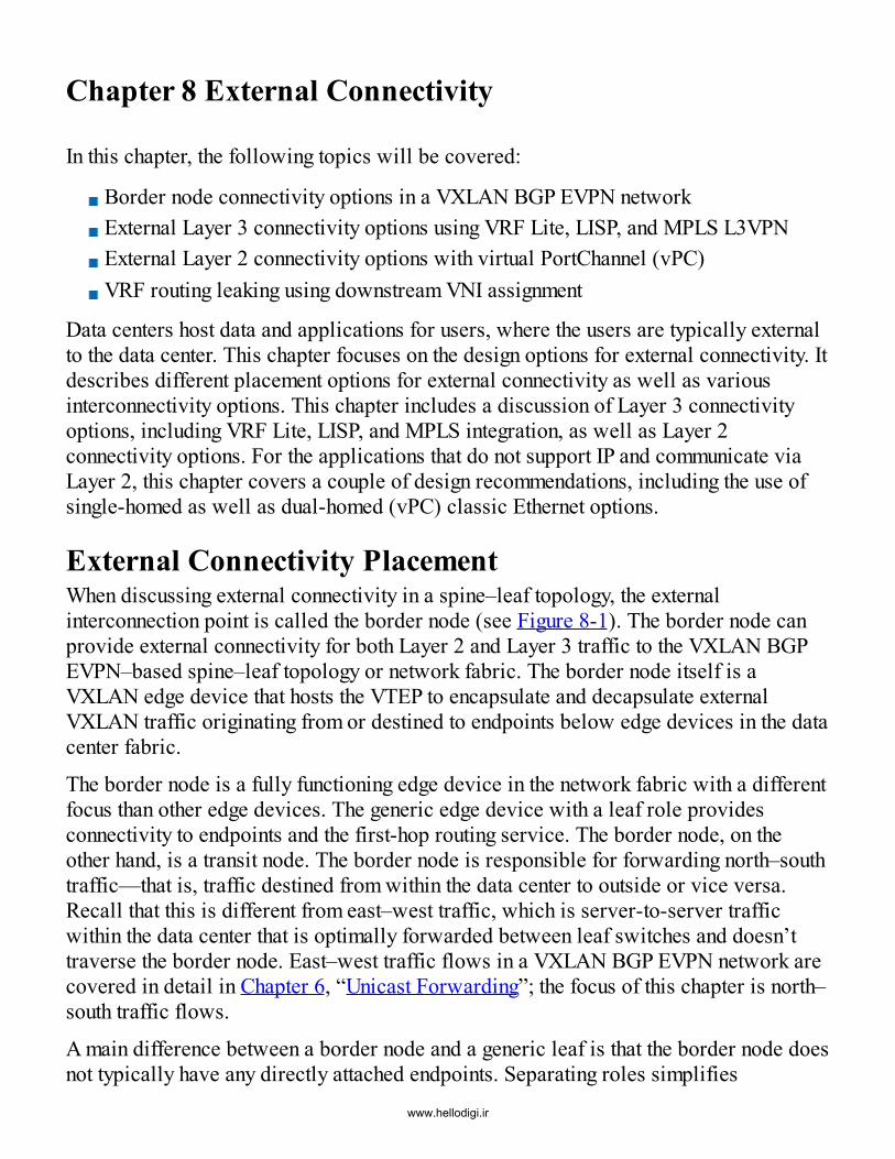
Chapter 8 External Connectivity
In this chapter, the following topics will be covered:
Border node connectivity options in a VXLAN BGP EVPN network External Layer 3 connectivity options using VRF Lite, LISP, and MPLS L3VPN External Layer 2 connectivity options with virtual PortChannel (vPC) VRF routing leaking using downstream VNI assignment
Data centers host data and applications for users, where the users are typically externalto the data center. This chapter focuses on the design options for external connectivity. Itdescribes different placement options for external connectivity as well as variousinterconnectivity options. This chapter includes a discussion of Layer 3 connectivityoptions, including VRF Lite, LISP, and MPLS integration, as well as Layer 2connectivity options. For the applications that do not support IP and communicate viaLayer 2, this chapter covers a couple of design recommendations, including the use ofsingle-homed as well as dual-homed (vPC) classic Ethernet options.
External Connectivity PlacementWhen discussing external connectivity in a spine–leaf topology, the externalinterconnection point is called the border node (see Figure 8-1). The border node canprovide external connectivity for both Layer 2 and Layer 3 traffic to the VXLAN BGPEVPN–based spine–leaf topology or network fabric. The border node itself is aVXLAN edge device that hosts the VTEP to encapsulate and decapsulate externalVXLAN traffic originating from or destined to endpoints below edge devices in the datacenter fabric.
The border node is a fully functioning edge device in the network fabric with a differentfocus than other edge devices. The generic edge device with a leaf role providesconnectivity to endpoints and the first-hop routing service. The border node, on theother hand, is a transit node. The border node is responsible for forwarding north–southtraffic—that is, traffic destined from within the data center to outside or vice versa.Recall that this is different from east–west traffic, which is server-to-server trafficwithin the data center that is optimally forwarded between leaf switches and doesn’ttraverse the border node. East–west traffic flows in a VXLAN BGP EVPN network arecovered in detail in Chapter 6, “Unicast Forwarding”; the focus of this chapter is north–south traffic flows.
A main difference between a border node and a generic leaf is that the border node doesnot typically have any directly attached endpoints. Separating roles simplifies
www.hellodigi.ir

operations, thereby preventing overload of too many functions on a set of special-purpose edge devices, namely the border nodes.
Figure 8-1 The Border Node
In order to make the decision on the proper border node placement, it is important tounderstand the placement options available in a spine–leaf topology. The two optionsavailable are the border spine and the border leaf (see Figure 8-2). Severalconsiderations are critical in selecting the right border node location for the servicesrequired in a VXLAN BGP EVPN–based network fabric.
Figure 8-2 Border Node Placement
Placing the border node at the spine provides efficiency with respect to the north–south
www.hellodigi.ir

traffic flows (see Figure 8-3). With the border node placed at the spine, all traffic fromthe endpoints attached to the leaf is one hop away when destined to reach the externalnetworks outside the fabric. Note that this is different from the typical east–west trafficflows, which go from leaf (source) to spine to leaf (destination). The placement of theborder node at the spine is common for situations when most of the traffic flows in thedata center fabric are north–south.
Figure 8-3 Border node at Spine or Border Spine
Whenever the spine and border node placement is combined, the transport for bothnorth–south and east–west traffic is combined as well. In addition to the traffic flows,the border spine becomes a VXLAN edge device configured as a VTEP thatencapsulates and decapsulates VXLAN traffic for north–south flows. Recall that for
www.hellodigi.ir

east–west flows, the spine continues to provide underlay functionality by routing trafficbetween the edge devices based on the outer IP header.
Having a VTEP configured on the border spine is not an issue. The VTEP is specificallycalled out as capacity planning needs must be considered to accommodate all the north–south and east–west traffic flows. A major benefit of the spine–leaf architecture andfunction separation is the allowance for a scale-out approach where additional spinescan be added to provide more bandwidth and resiliency.Scaling the spine with the border node also requires increasing the external connectivityinterfaces and adjacencies to provide the ability to have consistent reachabilityinformation for all available network paths. For the applications requiring Layer 2external connectivity, additional considerations need to be taken into account with theborder spine, specifically when more than two spines are required because the spinesneed to be deployed in pairs, with Layer 2 redundancy.
The pair deployment recommendation is to allow for Layer 2 multihoming with vPC.Instead of creating multiple vPC pairs at the spine layer for Layer 2 connectivity, onespine pair could be configured for Layer 2 external connectivity, which would yielduniform reachability for Layer 2 traffic. Alternatively, external Layer 2 connectivitycould be built redundantly in pairs (dual homing with vPC).
Additional services can also be enabled on the border spines. The spine typically hoststhe BGP route reflector (RR) as well as the multicast rendezvous point (RP). Theseadditional functions need to be considered for the border spine. In summary, the borderspine provides external connectivity, VTEP support, RR support, RP support, and thebaseline functionality to transport east–west and north–south traffic for the fabric.The next option, as illustrated in Figure 8-4, is to have the border node functionality at aspecial leaf called the border leaf. The border leaf decouples north–south and east–west traffic flows. In the previous border spine placement, the border spine served as atransit node for leaf-to-leaf traffic (east–west) and for the external connectivity (north–south). With border node functionality placement at the border leaf, the role of the spinechanges because it no longer performs any encapsulation or decapsulation for VXLANtraffic. In fact, a VTEP is not required on the spines in this scenario. The border leafhosts a VTEP and is responsible for the encapsulation/decapsulation of traffic thatprovides external connectivity. In other words, the border leaf is responsible for allnorth–south traffic. This option reduces the requirement for capacity planning for theborder leaf from an intra-DC perspective. Capacity planning is required only for thenorth–south traffic flows. An additional hop for north–south traffic with a border leafdeployment may be considered less than desirable. However, a clean separation is amajor advantage of this deployment, and uniform reachability from the entire fabric isanother benefit.
www.hellodigi.ir

Figure 8-4 Border node at Leaf or Border LeafFor applications that require Layer 2 connectivity and dual-homing with vPC, the sameconsiderations as discussed in the case of the border spine are important. The reducedamount of functionality on the border leaf compared to the border spine simplifies thedesign and reflects a key difference. At worst, using the border leaf design has the sameeffect as scaling out the border spine design. However, the border leaf is less likely tohost the BGP RR or multicast RP because this would be inefficient in a spine–leaftopology, where the spine is clearly a much better option for the RR and RP placement.
In summary, the border leaf topology provides specific functions such as externalconnectivity, and VTEP support for north–south traffic flows for a fabric at a singlelocation.
www.hellodigi.ir

External Layer 3 ConnectivityWith placement of external connectivity at the border spine or border leaf, theconnection of the VXLAN BGP EVPN fabric to the external network can be considered.External networks could involve the Internet, WAN, branch, other data centers, or thecampus network. All these external networks require a common set of protocols forcommunication.The following sections look at popular Layer 3 handoff options from a VXLAN BGPEVPN fabric. Note that a handoff causes the VXLAN encapsulation to be terminated atthe border node, and then an appropriate translation occurs to carry the traffic externallywhile still retaining the context of the unique VRF or tenant that originated that traffic.Various handoff options are possible, including VRF Lite, LISP, and MPLS L3VPN.Before diving into the handoff options, a brief introduction of the different physicalconnectivity choices between the border and the external network will be discussed.
U-Shaped and Full-Mesh ModelsThis section describes the primary options for physically wiring the border nodes to theexternal networks. Regardless of the external connectivity placement—at the border leafor border spine—two major wiring or connectivity models are available for redundantborder nodes. The most common and recommended model is the full-mesh connectivitymodel. In this approach, each of the border nodes is connected to each of the edgerouters (see Figure 8-5). For example, with two border nodes and two edge routers,four links are used to build a highly resilient external connectivity deployment. Whenusing a full-mesh connectivity model, links between the border nodes are not required.The full-mesh connectivity model provides any-to-any connectivity, and thus theexchange of the routing information is synchronized.
www.hellodigi.ir

Figure 8-5 Full-Mesh Border NodesFrom a routing perspective, full-mesh connectivity appears a bit messy, but this modelis the easiest and most resilient option. Notably, the full-mesh model does not requireany additional synchronization between the border nodes. Likewise, a big advantage ofthe full-mesh model is that black-holing of traffic is impossible in the event of a singlelink failure. Only when all the links on one border node are lost, is 50% of the trafficpotentially black-holed.
An alternative to the full-mesh model for connecting the border nodes to the edgerouters is the U-shaped model (see Figure 8-6). This is a more resilient evolution of thestraight-through model. The straight-through model is commonly seen when a singleborder node is connected to one edge router, and it is a nonredundant way of connectingthe fabric to external networks. It is therefore generally not recommended.
www.hellodigi.ir

Figure 8-6 U-Shaped Border NodesWith the U-shaped model, two border nodes and two edge devices are connected usingthe straight-through connectivity model. If a single link or node fails, 50% of the trafficwill potentially be black-holed. To prevent this black-holing of traffic, a cross-linkbetween the border nodes is required and recommended. The route peering session isestablished between the border nodes over this cross-link, which provides a redirectionpath in case the straight-through uplink between border node and edge router fails. Thecross-link provides an additional network traffic path, without the need for a full-meshwiring model. The cross-link makes the straight-through connection between bordernodes and edge routers look like a “U”—hence the name U-shaped model. Conditionaladvertisement is not needed in the U-shaped model. Traffic from inside the VXLANBGP EVPN fabric can still reach both border nodes and can then be forwarded outsidethe fabric either directly or via the additional cross-link for external connectivity.
The full-mesh and U-shaped models both provide the necessary resiliency for externalconnectivity. While the full-mesh model provides extensive redundancy in most failurescenarios, the U-shaped provides just enough redundancy to avoid traffic black-holingin basic situations. Both models are widely adopted and deployed in the field. Insummary, the full-mesh connectivity model is superior and the most optimal traffic-forwarding model in the event of failure scenarios.
www.hellodigi.ir

VRF Lite/Inter-AS Option AThe BGP EVPN control plane integrates Layer 3 multitenancy. MP-BGP has capabilitiesto transport information for multiple virtual routing and forwarding (VRF) instancesacross the VXLAN network on a single BGP session. Different options are available tocarry VRF or VPN information from VPN-based address family (L2VPN EVPN)networks to non-EVPN networks. The simplest option is to use VRF Lite or Inter-ASOption A.1
With VRF Lite, the border node has all VRF instances and sends the associated Layer 3prefix information from the EVPN network into individual VRF-specific routing tablestoward the edge router. The routing information can be exchanged with the externalrouter via an appropriate routing protocol (control plane).
In addition to static route support on a per-VRF basis, dynamic routing protocols alsohave per-VRF isolation. This results in a routing protocol on a per-VRF basis. Therouting protocol has its own routing instance and address family support, and it can beused to create individual route peering sessions to the external router. While this is thesimplest of the Inter-AS options, it is also the least scalable as it requires a Layer 3interface and a peering session on a per-VRF basis.Several routing protocol options are available. Because the fabric already implementsBGP, reusing the same routing protocol (eBGP) provides benefits, such as the presenceof embedded advertisements that do not require any explicit protocol redistribution.BGP provides clear separation of autonomous systems, and this enables a structuredhandoff between the VXLAN BGP EVPN fabric and the external routing domain, be itWAN, campus, or other external networks. BGP also provides an option to configure anextensive set of routing policies that can manipulate received or announced networkreachability information. A network administrator therefore has the option to createcustom routing policies suited to particular domains. Enforcement of the routing policiescan be configured on a per-neighbor basis since each neighbor will be associated with aspecific autonomous system number (ASN).
While BGP is certainly a good choice for external connectivity, other dynamic routingprotocols, such as OSPF, EIGRP, IS-IS, and simple static routing work as well. Becausenone of these protocols have a direct interaction with the intra-fabric overlay controlprotocol (BGP), redistribution must be configured in order to have the proper IP prefixinformation exchange.
Each dynamic routing protocol has individual needs and requirements for howreachability information is redistributed from the external world into the VXLAN BGPEVPN–based network and vice versa. For example, when redistributing IP prefixinformation between IGPs (that is, OSPF to EIGRP), the process of redistribution is
www.hellodigi.ir

very different when compared with the redistribution from iBGP to other IGPs. Becauseall iBGP routes are tagged as internal routes by default, they are not advertised to IGPs.
Redistributing all iBGP IP prefix information into IS-IS, OSPF, or EIGRP requiresadditional configuration. Specific to NX-OS, a route map is required to match the iBGPinternal routes. Example 8-1 demonstrates how iBGP routes can be redistributed into anIGP such as OSPF. Note that this only redistributes routes originated in BGP; routesredistributed into BGP from another routing protocol are not in turn redistributed.
Example 8-1 Advertise iBGP Routes to OSPFClick here to view code image
route-map RM_iBGP_ALLOW permit 10 match route-type internal
router ospf EXTERNAL vrf VRF-A redistribute bgp 65001 route-map RM_iBGP_ALLOW
When iBGP IP prefixes are advertised into the external network via an appropriaterouting protocol, additional considerations apply with regard to summarizing the entireinternal IP prefix space. Coverage of host routes (/32 or /128) needs to be available forthe external network either by summary routes and specific routes, summary routes only,or an overarching supernet summary route. In addition to BGP, IGP routing protocolsalso have filtering capabilities. Appropriate route filtering options should beconsidered when external connectivity is required.In addition to having the routing protocols to exchange the VRF information withexternal networks, and thus having the ability to provide control plane separation, thedata plane also needs to keep the different VRF data traffic separated and isolated whenleaving the border node. When using a single physical link between the border node andthe external router, per-VRF segregation can be achieved using IEEE 802.1Q tags, witha unique tag allocated per VRF, as shown in Figure 8-7. Recall that with a 12-bit VLANfield, a maximum of 4K tags can be allocated on a per-physical interface basis.Leveraging individual VLAN tags for the individual VRFs ensures that separationoccurs not only at the control plane level but also at the data plane level. This providesthe capability to transport VRF-specific traffic that is isolated from the other traffic.
www.hellodigi.ir

Figure 8-7 VRF LiteTwo methods are available for implementing VRF Lite between the border node and theexternal router. The first method is to configure Layer 3 VLAN interfaces (switch virtualinterfaces [SVI]), and the second method is to configure subinterfaces on the physicalrouted interface.
The first method requires the physical interface to be configured as an IEEE 802.1Q(dot1q) trunk port. The SVI initiates the routing protocol peering on a per-VRF basis,and it also serves as the next hop for routing. Configuring a dot1q trunk between theborder node and the external router allows the use of Layer 2 transport for Layer 3routing and forwarding. This approach does not allow any Layer 2 control planeinformation exchange to occur between the two network domains of the border node andthe external router.
The second option involves implementation of subinterfaces on the physical interface(no switchport) between the border node and the external router. Subinterfaces onlyrequire dot1q tagging for marking the traffic belonging to a specific VRF. Layer 2capabilities are automatically disabled on the physical interface. The subinterface isused for the routing protocol peering as well as next-hop reachability. The subinterfacehas a direct interface-to-IP relationship, which results in additional signaling when theinterface is brought down, thereby bringing down the routing protocol peering sessionand resulting in traffic converging onto an alternate path. In the SVI-based approach, the
www.hellodigi.ir

physical interface down detection needs to ensure that the SVI goes down as well,thereby bringing down the associated routing protocol peering session.
The subinterface signaling detection is a simple approach that implements BidirectionalForwarding Detection (BFD). BFD also enhances the failover detection of routingprotocols that are enabled on the corresponding routed interface (subinterface in thiscase). If a requirement for external Layer 2 connectivity exists (for example, for DataCenter Interconnect [DCI]) or for Layer 4 to 7 services, the connectivity can becombined with the VRF Lite/subinterface approach by using dedicated interfaces for theLayer 2 connectivity. The additional interfaces would operate in Layer 2–only mode andwould be configured as a dot1q trunk port. For Layer 2 redundancy, it is recommendedto use vPC. Example 8-2 demonstrates VRF Lite with BGP using subinterfaces.
Example 8-2 VRF Lite with BGP Using Subinterfaces on the Border NodeClick here to view code image
# Subinterface Configurationinterface Ethernet1/10 no switchportinterface Ethernet1/10.1002 mtu 9216 encapsulation dot1q 1002 vrf member VRF-B ip address 10.2.2.1/30 no shutdown
# eBGP Configurationrouter bgp 65501 vrf VRF-B address-family ipv4 unicast advertise l2vpn evpn aggregate-address 192.168.0.0/16 summary-only neighbor 10.2.2.2 remote-as 65599 update-source Ethernet1/10.1002 address-family ipv4 unicast
Customers often ask for best-practice recommendations for VRF Lite–based externalconnectivity. The use of subinterfaces is recommended for Layer 3 connectivity androute peering, as shown in Example 8-2.For the routing protocol, eBGP between the border node and external router is therecommended option. If a Layer 2 external connectivity requirement is present,implementing vPC for Layer 2 connectivity, multihoming, and high availability isrecommended. Operationally and technically, pros and cons exist with the VRF-Liteoption, depending on the environment as well as the trade-offs related to greenfield
www.hellodigi.ir

designs versus brownfield integration.
LISPSimilarly to VRF Lite, Locator/ID Separation Protocol (LISP) provides externalconnectivity, extending Layer 3 multitenancy from the VXLAN fabric to the rest of theenterprise. While VRF Lite and LISP both provide multitenancy, LISP exchangesreachability information and transports the multitenant traffic in a different way. TheLISP data plane encapsulation is agnostic to the underlying network transport andtherefore provides simplified operations over traditional Layer 2 requirements (forexample, Ethernet, FabricPath) and label-switching technologies (such as MPLS).
In addition, the LISP architecture implements a pull-based approach to exchangereachability information, whereas traditional routing protocols use a push-based model.Before going into the details regarding LISP integration with the VXLAN BGP EVPNfabric, this section provides a brief introduction to LISP, with an emphasis on thedifferent features of LISP that make it inherently scalable.
LISP is a next-generation routing architecture. It is based on a topology-independentaddressing mechanism and an on-demand (pull-based) lookup approach for forwardingdecisions. LISP also provides its own reachability protocol, based on a mappingdatabase. In addition, LISP has its own data plane encapsulation. The LISP data planeencapsulation is very similar to the VXLAN data plane format (see Figure 8-8). Themain difference between the LISP and VXLAN headers is that VXLAN is a MAC-in-IP/UDP encapsulation, while LISP is an IP-in-IP/UDP encapsulation.
Figure 8-8 VXLAN/LISP Encapsulation
To provide the details on how LISP achieves the separation of location (locator) andendpoints (ID), a comparison to traditional routing protocols is a good first step; seeFigure 8-9.
www.hellodigi.ir
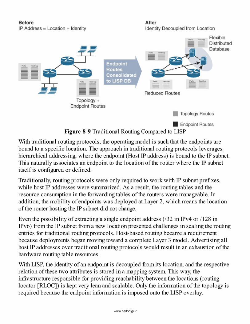
Figure 8-9 Traditional Routing Compared to LISPWith traditional routing protocols, the operating model is such that the endpoints arebound to a specific location. The approach in traditional routing protocols leverageshierarchical addressing, where the endpoint (Host IP address) is bound to the IP subnet.This naturally associates an endpoint to the location of the router where the IP subnetitself is configured or defined.
Traditionally, routing protocols were only required to work with IP subnet prefixes,while host IP addresses were summarized. As a result, the routing tables and theresource consumption in the forwarding tables of the routers were manageable. Inaddition, the mobility of endpoints was deployed at Layer 2, which means the locationof the router hosting the IP subnet did not change.
Even the possibility of extracting a single endpoint address (/32 in IPv4 or /128 inIPv6) from the IP subnet from a new location presented challenges in scaling the routingentries for traditional routing protocols. Host-based routing became a requirementbecause deployments began moving toward a complete Layer 3 model. Advertising allhost IP addresses over traditional routing protocols would result in an exhaustion of thehardware routing table resources.With LISP, the identity of an endpoint is decoupled from its location, and the respectiverelation of these two attributes is stored in a mapping system. This way, theinfrastructure responsible for providing reachability between the locations (routinglocator [RLOC]) is kept very lean and scalable. Only the information of the topology isrequired because the endpoint information is imposed onto the LISP overlay.
www.hellodigi.ir

Traditional routing protocols are optimized to provide the endpoint location within theRLOC space or topology. With the endpoint address information moved onto theoverlay, any requirement for RLOC space to know this information is eliminated. As aresult, a level of abstraction is achieved. With this abstraction, the ingress LISP tunnelrouter (iTR) queries the LISP mapping server that holds the respective information ofthe endpoints (identity) and their respective RLOCs (location). Based on the lookupresult, the iTR adds the LISP header with the respective destination ID and RLOC.
Unaware of the endpoint information, the rest of the infrastructure simply forwards theLISP-encapsulated packet toward the destination RLOC. The packet is subsequentlydecapsulated and sent toward the destination endpoint. The same process happens onthe egress tunnel router (eTR) for the return traffic.The inherent pull-based or on-demand model of LISP has some advantages over thepush-based model used by traditional routing protocols (see Figure 8-10).
Figure 8-10 Routing Push and Pull ModelsWith traditional routing protocols, whenever information is learned on a router for agiven routing domain, the respective information is immediately sent to all other routersparticipating in that routing domain. Even if interest in a given route at that time is notpresent, the routers still receive this information, process it, and install it in thehardware tables if local policy specifies a permit action. This consumes CPU andmemory resources for routing path computation, storage space in the routing informationbase (RIB), and costly ternary content addressable memory (TCAM) as well asforwarding information base (FIB) resources.
The large table state in both the RIB and FIB has direct implications on scalability and
www.hellodigi.ir

convergence times. LISP introduces a different behavior that is more graceful tocomputation and resource usage/consumption. When a new IP subnet or endpoint islearned, the directly associated LISP tunnel router populates this information to the LISPmapping system. Only the router responsible for the origin of the information and theLISP mapper are involved.
If communication between two endpoints is initiated, as mentioned earlier, only thesource of the communication (the iTR) consults the LISP mapper to download therequired routing information on demand. The lookup provides the location of the egresstunnel router (eTR), which contains the RLOC’s IP address.Only the iTR and eTR are involved in the routing operation. Route demand (pull) andpath computation operations only happen between the iTR and eTR. As a result, CPUand memory consumption only occurs on the communicating nodes. In addition, theresource consumption in TCAM and FIB is localized to the participating nodes,resulting in more efficient use of hardware resources in the overall view of the routingdomain.
To summarize, the IP addresses in the routing tables with LISP only have the locationinformation (RLOC), and the identities (EID) stored in the mapping system. In case ofendpoint mobility, the identity is mapped to a new location in the LISP overlay only. Theidentity and location are only known in the LISP mapping system and by the ingress andegress LISP tunnel routers participating in the conversation (forwarding).
LISP provides many capabilities, benefits, and options for network overlay approaches,including mobility, scalability, security, and support options for DCI. As a result, LISPprovides significant advantages compared to other overlay approaches.Looking specifically at the mobility use case, LISP provides IP prefix address familyportability for both IPv4 and IPv6. Its on-demand (or pull approach) providesscalability so that the IP prefix portability can be specific to each endpoint. Thecombined LISP mobility and scalability features provide endpoint mobility, and onlyconsume hardware resources for conversations that are required (on demand).
The security part of LISP is encompassed in a tenant ID (instance ID) for segmentation.This provides end-to-end Layer 3 multitenancy. The three elements of LISP (mobility,scalability, and security) enable data center interconnect use cases that support high-scale IP mobility in a secure way. When an endpoint (ID) is moved between datacenters, the tenant isolation needs to remain intact, and traffic should be optimallyforwarded to the proper destination (location) to which the endpoint (ID) has moved.The decoupling of the location and endpoint address spaces in LISP allows for ingressrouting optimization, which is an inherent advantage for DCI use cases.
LISP is integrated with the VXLAN EVPN fabric, thereby providing the capability towww.hellodigi.ir

exchange all the reachability information from the BGP EVPN control protocol into theLISP-based mapping database. With LISP integration, the border node provides themulti-encapsulation gateway function. A set of border nodes is implemented to routefrom a VXLAN BGP EVPN infrastructure to a LISP transport network.
In the integrated external connectivity approach, the border node also becomes the LISPtunnel router (xTR), as shown in Figure 8-11. This allows the combination of twodifferent encapsulation and control plane protocols with a “single-box” solution insteadof having a “two-box” solution approach, as in the VRF Lite use case.
Figure 8-11 LISP Border Node
In addition to the single-box solution, LISP offers several advantages for externalconnectivity. One advantage involves the manner with which LISP installs reachabilityinformation into a network node (on-demand, or pull). With LISP, the need orrequirement to hide the endpoints’ IP information (/32 in IPv4 or /128 in IPv6) no longerexists. LISP also provides on-demand, or pull, semantics to accommodate the scale ofthe endpoint reachability information. This results in using fewer resources for all theparticipating network nodes.Another advantage with LISP is that all the endpoint reachability information isregistered with the LISP database. This allows for optimal ingress path selectionwithout consuming expensive network hardware resources. Example 8-3 provides asnippet of a relevant LISP configuration on a border node in a VXLAN BGP EVPNfabric.
www.hellodigi.ir

Example 8-3 LISP Extension from VXLAN BGP EVPNClick here to view code image
# LISP Configurationfeature lisp
ip lisp itr-etrip lisp itr map-resolverip lisp etr map-server 10.8.12.9 key MY_MS_KEY
# VRF Configurationvrf context VRF-A list instance-id 10 ip lisp locator-vrf default lisp dynamic-eid MY_LISP_SUBNETS database-mapping 192.168.0.0/16 10.8.2.46 priority 1 weight 50 register-route-notification tag 65501
# BGP Configurationrouter bgp 65501 vrf VRF-A address-family ipv4 unicast advertise l2vpn evpn
MPLS Layer 3 VPN (L3VPN)Similarly to both VRF Lite and LISP, Multiprotocol Label Switching Layer 3 VirtualPrivate Network (MPLS L3VPN) provides external connectivity by keeping intact theLayer 3 multitenancy in the VXLAN EVPN network. Reachability information isexchanged in MPLS L3VPNs much the way it is in BGP EVPN—based on multiprotocolBGP.
MPLS L3VPN uses label switching in the data plane to separate the tenants on the wireusing a VPN label in addition to a per-hop label. The difference between the VXLANand MPLS implementations involves the use of the respective Network LayerReachability Information (NLRI), which is specific to the different address families.VXLAN EVPN uses the L2VPN EVPN address family, while MPLS L3VPN leveragesthe VPNv4 address family for IPv4 and the VPNv6 address family for IPv6.VXLAN BGP EVPN–to–MPLS L3VPN internetworking enables an integrated approachto exchanging Layer 3 reachability information between the EVPN address family andthe VPNv4/VPNv6 address family. This approach leverages the location of the bordernode to provide the multi-encapsulation gateway function. The MPLS L3VPN bordernodes route from a VXLAN BGP EVPN infrastructure to a MPLS L3VPN–basedtransport network.
With this integrated external connectivity approach, the VXLAN BGP EVPN border
www.hellodigi.ir
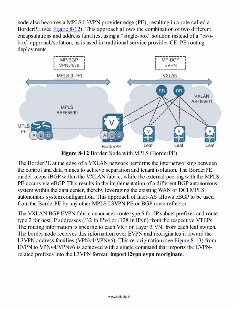
node also becomes a MPLS L3VPN provider edge (PE), resulting in a role called aBorderPE (see Figure 8-12). This approach allows the combination of two differentencapsulations and address families, using a “single-box” solution instead of a “two-box” approach/solution, as is used in traditional service provider CE–PE routingdeployments.
Figure 8-12 Border Node with MPLS (BorderPE)
The BorderPE at the edge of a VXLAN network performs the internetworking betweenthe control and data planes to achieve separation and tenant isolation. The BorderPEmodel keeps iBGP within the VXLAN fabric, while the external peering with the MPLSPE occurs via eBGP. This results in the implementation of a different BGP autonomoussystem within the data center, thereby leveraging the existing WAN or DCI MPLSautonomous system configuration. This approach of Inter-AS allows eBGP to be usedfrom the BorderPE by any other MPLS L3VPN PE or BGP route reflector.
The VXLAN BGP EVPN fabric announces route type 5 for IP subnet prefixes and routetype 2 for host IP addresses (/32 in IPv4 or /128 in IPv6) from the respective VTEPs.The routing information is specific to each VRF or Layer 3 VNI from each leaf switch.The border node receives this information over EVPN and reoriginates it toward theL3VPN address families (VPNv4/VPNv6). This re-origination (see Figure 8-13) fromEVPN to VPNv4/VPNv6 is achieved with a single command that imports the EVPN-related prefixes into the L3VPN format: import l2vpn evpn reoriginate.
www.hellodigi.ir

Figure 8-13 BorderPE ReoriginateA similar approach exists in the reverse direction, where the VPNvx-related prefixesare re-originated into the EVPN address family (import vpn unicast reoriginate). Inaddition to the reoriginate-related BGP address family configuration, additional RouteTargets need to be added to the extended VRFs to match those configured on the MPLSL3VPN side.
Aligning the Route Target information is straightforward, using appropriate import andexport statements from the MPLS L3VPN autonomous system and using the EVPNautonomous system to drive label imposition. This is comparable to traditionalimplementations, where MPLS labels are driven through the MP-BGP control plane. Inexactly the same way, the BorderPE performs integrations through control planelearning and the respective data plane actions. Example 8-4 provides a sampleconfiguration of the relevant sections of a typical BorderPE node in a VXLAN BGPEVPN network.
Example 8-4 MPLS Extension from VXLAN BGP EVPNClick here to view code image
# VRF Configurationvrf context VRF-A vni 50001 rd auto address-family ipv4 unicast route-target both 65599:50001
www.hellodigi.ir

route-target both auto route-target both auto evpn # BGP Configurationrouter bgp 65501 neighbor 10.2.2.2 remote-as 65599 update-source loopback254 address-family vpnv4 unicast import l2vpn evpn reoriginate neighbor 10.10.10.201 remote-as 65501 address-family l2vpn evpn import vpn unicast reoriginate vrf VRF-A address-family ipv4 unicast advertise l2vpn evpn
# Interface Configurationinterface ethernet 1/10 ip address 10.2.2.1/30 mpls ip
By announcing the host and subnet prefix information from EVPN toward L3VPN, it isalways a best practice to summarize and/or filter unnecessary routing information. In thecase of EVPN, this involves announcing the IP subnet routes and suppressing the hostroutes (/32 in IPv4 or /128 in IPv6).
Even with the end host route information being suppressed, silent host detection issupported in the EVPN network. External traffic reaching the border node hits theappropriate IP subnet route entry and is forwarded over ECMP to one of the leafs thatserve that IP subnet. At that leaf, the subnet prefix route is also hit, but the result is aglean adjacency. An ARP/ND-triggered detection of the silent endpoint from this leafoccurs so that the endpoint is detected behind its directly attached leaf. Once this silenthost is detected, the host route is advertised over EVPN to the border node, which candirectly send traffic to the corresponding egress VTEP.With the reorigination of the control protocol information and the related data planeactions, BorderPE provides an integrated MPLS L3VPN approach to a VXLAN BGPEVPN network. Simplified multitenancy transport can be achieved across a label switchtransport for WAN connectivity or DCI.
External Layer 2 ConnectivityExternal connectivity is commonly achieved at Layer 3, and it has been the main focusso far in this chapter. Nevertheless, if certain bridging communication is required,structured communication at Layer 2 also becomes necessary. Common use cases thatrequire Layer 2 connectivity between two data centers include non-IP communicationand special application needs.
www.hellodigi.ir

One of the most commonly seen requirements for external Layer 2 connectivity isrelated to endpoint mobility use cases. These use cases require specific signaling formove operations through the transport of Reverse ARP (RARP) messages. RARPinherently requires Layer 2 connectivity; RARP is a non-IP packet with Ethertype0x8035.
Additional use cases arise when a spanning-tree-based classic Ethernet network needsto be integrated into a VXLAN BGP EVPN network. For these use cases, certainconsiderations need to be discussed for proper interconnectivity, integration,multihoming, and loop avoidance. It is also important to note that in a VXLAN BGPEVPN fabric, Layer 4 through 7 services (such as firewall, IDS/IPS, and loadbalancers) often require certain Layer 2 connectivity with classic Ethernet. Thesescenarios are described in greater detail in other chapters.For all the cases mentioned, single-attached classic Ethernet connectivity is notdesirable due to the lack of redundancy and fault tolerance. Consequently, for Layer 2connectivity, dual-homing or multihoming technology needs to be implemented. WithVXLAN BGP EVPN, dual-homing options are available with virtual PortChannel (vPC)and with the extension of the EVPN control protocol for multihoming support. Thislatter option occurs without the tight pairing of two network switches and also achievesmore than dual homing. While vPC support with EVPN is available on all the Nexusplatforms, checking the respective platform release notes to assess which platformshave EVPN multihoming support, is recommended.
Layer 2 connectivity at the border node (see Figure 8-14) is similar to the “two-box”approach with VRF Lite. The border node provides Layer 2 dual homing ormultihoming toward the VXLAN BGP EVPN network as well as Layer 2 classicEthernet services. The classic Ethernet services leverage IEEE 802.1Q capability usedby any external connected service such as Layer 2 DCI, legacy spanning-tree-basednetworks, or Layer 4 through 7 services.
www.hellodigi.ir
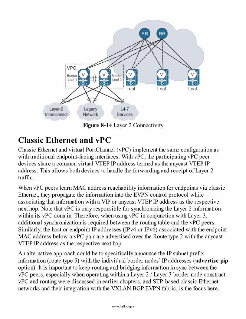
Figure 8-14 Layer 2 Connectivity
Classic Ethernet and vPCClassic Ethernet and virtual PortChannel (vPC) implement the same configuration aswith traditional endpoint-facing interfaces. With vPC, the participating vPC peerdevices share a common virtual VTEP IP address termed as the anycast VTEP IPaddress. This allows both devices to handle the forwarding and receipt of Layer 2traffic.
When vPC peers learn MAC address reachability information for endpoints via classicEthernet, they propagate the information into the EVPN control protocol whileassociating that information with a VIP or anycast VTEP IP address as the respectivenext hop. Note that vPC is only responsible for synchronizing the Layer 2 informationwithin its vPC domain. Therefore, when using vPC in conjunction with Layer 3,additional synchronization is required between the routing table and the vPC peers.Similarly, the host or endpoint IP addresses (IPv4 or IPv6) associated with the endpointMAC address below a vPC pair are advertised over the Route type 2 with the anycastVTEP IP address as the respective next hop.An alternative approach could be to specifically announce the IP subnet prefixinformation (route type 5) with the individual border nodes’ IP addresses (advertise pipoption). It is important to keep routing and bridging information in sync between thevPC peers, especially when operating within a Layer 2 / Layer 3 border node construct.vPC and routing were discussed in earlier chapters, and STP-based classic Ethernetnetworks and their integration with the VXLAN BGP EVPN fabric, is the focus here.
www.hellodigi.ir

VXLAN does not natively integrate with STP, and this results in a VXLAN-enabledbridge domain (VLAN/L2VNI) that is always in forwarding state. Because BPDUs arenot transported over the point-to-multipoint VXLAN network, the southbound classicEthernet connectivity is required to be loop-free.
If a classic Ethernet switch is connected downstream to two different VTEPs, theVLANs toward them are put in forwarding state. Since the BPDU exchange is not sentover the VXLAN encapsulation, the downstream classic Ethernet network is unaware ofa redundant link, which results in a classic Layer 2 loop (see Figure 8-15).
Figure 8-15 Layer 2 Loop
There are ways to block ports from a dual-connected classic Ethernet network towardsVXLAN. However, the best practice for multihoming an STP-based classic Ethernetnetwork to VXLAN is to implement vPC (see Figure 8-16).
www.hellodigi.ir

Figure 8-16 VXLAN with VPC and Classic EthernetInterconnecting classic Ethernet–based networks and VXLAN-based networks whileleveraging vPC enables the implementation of a logical loop-free topology. This canalso be achieved leveraging EVPN multihoming.
In addition to the specific connectivity requirements for VXLAN, protecting the networkboundary is also important and a recommended practice. Traditional Layer 2 tools suchas BPDU guard, root guard, or storm control provide protection at any classic Ethernetedge port. These tools allow for a clean and protected demarcation, which preventsundesirable failure propagation. As a result, desired network stability is ensured.
Extranet and Shared ServicesIn many cases, there is a requirement to deploy services that are shared by differenttenants aka VRFs. Examples include services such as DHCP and DNS. The sharedservices may be deployed or attached to certain leafs within a fabric in a “shared” VRF.Consequently, there may be a need to allow communication between the tenant VRF andthe shared VRF. This is achieved via route leaking, as described in this section. Thesame mechanism is also employed for deploying extranet services.
www.hellodigi.ir

Local/Distributed VRF Route LeakingVirtual routing and forwarding (VRF) provides the ability to have multiple virtualrouting and forwarding instances in a single network router/switch. Typically, each VRFis associated with a unique VPN identifier. VRF route leaking allows leaking of prefixinformation between multiple VRF instances within the same network router (see Figure8-17).
Figure 8-17 VRF Route Leaking
With this approach, there is no requirement to interconnect the leaked VRFs via anexternal routing instance using a loopback cable. Use cases specific to VRF routeleaking are common for the Internet access VRF, the shared services VRF, and thecentralized services VRF.In general, VRF route leaking is a native function of MP-BGP, together with the VRFsand related Route Targets, as shown in Example 8-5.
Example 8-5 VRF Route-Leaking ConceptClick here to view code image
# VRF Configuration at Ingress VTEP (V1)vrf context VRF-A vni 50001 rd auto address-family ipv4 unicast route-target both auto route-target both auto evpn
www.hellodigi.ir
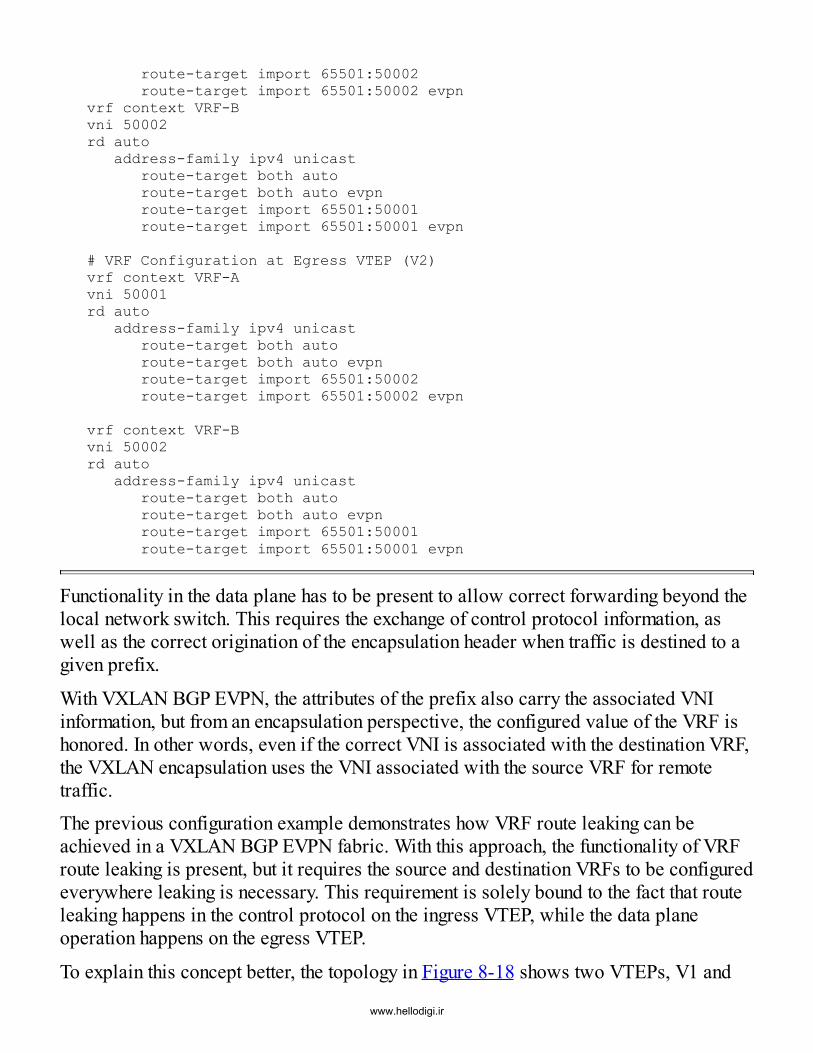
route-target import 65501:50002 route-target import 65501:50002 evpn vrf context VRF-Bvni 50002rd auto address-family ipv4 unicast route-target both auto route-target both auto evpn route-target import 65501:50001 route-target import 65501:50001 evpn
# VRF Configuration at Egress VTEP (V2)vrf context VRF-Avni 50001rd auto address-family ipv4 unicast route-target both auto route-target both auto evpn route-target import 65501:50002 route-target import 65501:50002 evpn
vrf context VRF-Bvni 50002rd auto address-family ipv4 unicast route-target both auto route-target both auto evpn route-target import 65501:50001 route-target import 65501:50001 evpn
Functionality in the data plane has to be present to allow correct forwarding beyond thelocal network switch. This requires the exchange of control protocol information, aswell as the correct origination of the encapsulation header when traffic is destined to agiven prefix.
With VXLAN BGP EVPN, the attributes of the prefix also carry the associated VNIinformation, but from an encapsulation perspective, the configured value of the VRF ishonored. In other words, even if the correct VNI is associated with the destination VRF,the VXLAN encapsulation uses the VNI associated with the source VRF for remotetraffic.The previous configuration example demonstrates how VRF route leaking can beachieved in a VXLAN BGP EVPN fabric. With this approach, the functionality of VRFroute leaking is present, but it requires the source and destination VRFs to be configuredeverywhere leaking is necessary. This requirement is solely bound to the fact that routeleaking happens in the control protocol on the ingress VTEP, while the data planeoperation happens on the egress VTEP.
To explain this concept better, the topology in Figure 8-18 shows two VTEPs, V1 and
www.hellodigi.ir

V2, both having VRF-A and VRF-B locally configured on them. This exampledemonstrates VRF route leaking between two endpoints in different VRFs.
Figure 8-18 VRF Route Leaking: Flow shows 192.168.1.101 (VRF-A) to192.168.2.102 (VRF-B)
The endpoint with IP 192.168.1.101 (VRF-A) connected to VTEP V1 wants tocommunicate with the endpoint with IP 192.168.2.102 (VRF-B) connected to VTEP V2.On ingress VTEP V1, the IP address 192.168.2.102 is seen in VRF-A as the informationis leaked between the VRFs by the respective Route Target import configuration. From aforwarding perspective, remote traffic destined to 192.168.2.102 is encapsulated oningress VTEP V1 with VNI 50001 toward the egress VTEP V2. Once traffic arrives onVTEP V2, VNI 50001 is evaluated in VRF-A, and a lookup for 192.168.2.102 results inthe traffic being locally leaked over to VRF-B. In turn, this traffic is sent to thedestination endpoint.
It is important to understand that the encapsulation occurs with the VNI of the VRFwhere the source endpoint is connected. Therefore, the source VRF and VNI must beconfigured in the destination system. Consequently, this mechanism is termedlocal/distributed VRF route leaking.Because route leaking is configured locally, on all participating ingress VTEPs, the dataplane leaking always happens locally on the egress VTEP. With this route leaking
www.hellodigi.ir

approach, the related forwarding results have a certain asymmetry, depending on theforwarding direction.
In the opposite direction (see Figure 8-19), the endpoint with IP 192.168.2.102 in VRF-B can reach endpoint 192.168.1.101 in VRF-A. On ingress VTEP V2, the IP address192.168.1.101 is seen in VRF-B because the information is leaked between the VRFsby the appropriate Route Target import configuration. This time, traffic destined to192.168.1.101 from VTEP V2 to VTEP V1 is encapsulated with VNI 50002, which isthe VNI associated with VRF-B. As before, traffic is leaked over to VRF-A at theegress VTEP V1 and finally sent to the destination.
Figure 8-19 VRF Route Leaking: Flow shows 192.168.2.102 (VRF-B) to192.168.1.101 (VRF-A)
This route leaking approach requires additional configuration, and it impacts scalabilityby forcing consistent configuration on all the VTEPs where either of the leaking VRFs ispresent. Traffic is always sent toward the remote VTEP with the VRF VNI associatedwith the source VRF even though the traffic is destined to an endpoint in the destinationVRF. This asymmetric behavior has similar disadvantages as prescribed for asymmetricIRB as described in Chapter 3, “VXLAN/EVPN Forwarding Characteristics.”Alternative approaches, such as downstream VNI, are available for more scalablecross-VRF communication that uses the control protocol to drive the VNI used withinthe data plane encapsulation.
www.hellodigi.ir

Downstream VNI AssignmentFor traditional VRF route leaking, the downstream VNI assignment scheme uses asimilar approach to that used by MPLS L3VPN. In this instance, the upstream device(egress node) dictates the label to be used for the VPN to the ingress node. In VXLAN,a slightly different approach is used since the label (aka VNI in the case of VXLAN) isnot dynamically assigned but is statically configured.With downstream VNI assignment for a given VRF, in addition to the locally assignedVNI (configured L3VNI), a VTEP can use different VNI assignments but still achievecommunication. This is similar to a generic route leaking case. With downstream VNI,specifically, the egress VTEP advertises its local VRF VNI in the MP-BGP EVPN routeupdate. This VNI information is part of the EVPN NLRI and present in Route type 2 andRoute type 5 messages.
Upon reception of a route update on the ingress VTEP, BGP pushes the route update intothe hardware tables with the VNI advertised from the egress VTEP. As a result, theegress VTEP dictates the VNI to be used by the ingress VTEP with downstream VNIassignment via the control protocol. Clearly, to support this function, both the egress andingress VTEPs should support this functionality because a per-VNI per-VTEPassociation has to be stored within the forwarding information base (FIB).
This instantiation and storing of information is needed because the right VNI has to bechosen to reach the prefix advertised by the egress VTEP during the encapsulationprocess at the ingress VTEP. Downstream VNI assignment offers various optimizationsto reduce the VNI range and corresponding peer VTEPs. With this approach,downstream VNI is less configuration-intensive.For the same topology employed for the VRF route leaking use case between VRF-Aand VRF-B, the downstream VNI assignment scheme operation can now be considered,as shown in Figure 8-20. As before, the endpoint with IP 192.168.1.101 in VRF-Awants to reach endpoint with IP 192.168.2.102 in VRF-B. On ingress VTEP V1, the IPaddress 192.168.2.102 is seen with the VNI of VRF-B (50002), as advertised fromVTEP V2 via MP-BGP EVPN.
www.hellodigi.ir

Figure 8-20 Downstream VNI AssignmentFrom a forwarding perspective, traffic is encapsulated on ingress VTEP V1 with VNI50002 toward egress VTEP V2. On reception at VTEP V2, VNI 50002 is evaluated inVRF-B, and traffic is ultimately forwarded to endpoint 192.168.2.102 in VRF-B.
It is important to understand that the VNI to be used for encapsulation is determined bythe destination VTEP and, in turn, the destination endpoint. This means that VTEP V2announces the VNI downstream to VTEP V1 for the ensuing encapsulation operation.This is where this scheme, downstream VNI assignment, gets its name.
While downstream VNI assignment can operate within a large-scale VXLAN BGPEVPN fabric, the amount of per-VTEP, per-VNI information required may explode ifevery VTEP starts using a different VNI for every VRF. This can result in additionalrequirements for operations personnel as well as for the hardware table scale, and itmay become a significant problem. Reasonable use of this feature in the use case ofcommon Internet VRF or the centralized shared services use case is thereforerecommended, thereby leveraging the resulting simplification most effectively.
SummaryThis chapter presents external connectivity options with a VXLAN BGP EVPN fabric.After introducing the border leaf and border spine options, this chapter provides details
www.hellodigi.ir

on the options for external Layer 3 connectivity using VRF Lite, LISP, and MPLSL3VPN. This chapter also covers Layer 2 external connectivity options, with anemphasis on vPC. Finally, this chapter discusses how VRF route leaking can beimplemented in the fabric using local leaking. The use of downstream VNI assignmentfor VRF route leaking scenarios provides a more elegant solution.
Reference1. Internet Engineering Task Force (IETF). BGP/MPLS IP virtual private networks
(VPNs)—Multi-AS backbones. 2006. tools.ietf.org/html/rfc4364#page-32.
www.hellodigi.ir

Chapter 9 Multi-pod, Multifabric, and Data CenterInterconnect (DCI)
In this chapter, the following topics will be covered:
OTV and VXLAN technologies Multi-pod and multifabric options with VXLAN BGP EVPN deployments Interconnection options that can be deployed between multiple VXLAN BGP EVPNfabrics
Data centers are expected to function 24 hours a day, 365 days a year. With such a highdemand for availability, a disaster recovery plan is almost always in place. Dependingon the size of the organization, data center deployments may be spread across multiplegeographic sites. In some cases, multiple data center pods are deployed at the same site.Data center fabrics are often constructed in multiple rooms, halls, or sites, andinterconnectivity is mandatory. This chapter focuses on interconnecting multiple pods,or fabrics (sites), to one another. It leverages many concepts described in earlierchapters.This chapter describes various considerations involving the deployment of VXLANEVPN in multi-pod and multisite environments. Overlay Transport Virtualization (OTV)is often discussed for providing Layer 2 DCI functionality and is commonly mentionedin the same sentence with VXLAN. Therefore, this chapter discusses Layer 2 DCI andthe difference between OTV and VXLAN. It also dives into various options for DCI andfor splitting VXLAN BGP EVPN networks in multiple-pods, or fabrics. Experience hasshown that a single large fabric is difficult to operate and maintain. As discussed at theend of this chapter, approaches to scale a network by separating administrative andoperational boundaries are congruent with interconnecting data centers.
Contrasting OTV and VXLANIs it possible to use VXLAN with EVPN instead of OTV for DCI? Answering thisquestion requires exploration of the world of Data Center Interconnect (DCI) toevaluate architectural considerations and potential solutions. If VXLAN is onlyconsidered as an encapsulation with EVPN as a control protocol, and if thiscombination is acknowledged as a DCI solution, it would be unfair and limited inconsidering OTV and its functionality. In an effort to limit the discussion of Ethernet orlabel-switched DCI solutions such as Wavelength-Division Multiplexing (WDM)1,2 orVirtual Private LAN Service (VPLS),3,4 this section focuses on comparing twotransport-agnostic IP-based solutions, namely OTV and VXLAN.
www.hellodigi.ir

OTV employs a control protocol for peer auto-discovery and for the exchange of unicastand multicast reachability information. In addition, OTV provides a data plane thattransports data traffic from one site to another site or to multiple sites.5 OTV uses IS-IS6
as a control protocol; it uses the generic extensions to IS-IS to transport Layer 2information.7 In addition, specific IS-IS protocol extensions have been added for OTV.8
On the data plane side, OTV was first produced with a combination of GRE9 andEoMPLS10 in order to provide the desired functionality with existing hardware. Thiswas in contrast to the documented data plane encapsulation stated in the IETF’s OTVdraft. The second version of OTV more accurately followed the IETF draft. Incomparing the OTV data plane encapsulation and the VXLAN frame format, significantsimilarities exist, with notable differences in the specific fields and their associatednomenclature (see Figure 9-1). This has resulted in some speculation about thesimilarities between these two different data plane encapsulations. However, significantdifferences exist, and this section explains why the question between OTV versusVXLAN arises.
Figure 9-1 OTV and VXLAN (Frame Format)
Initially, VXLAN was primarily proposed as a MAC-in-IP/UDP data planeencapsulation, with an associated Flood and Learn (F&L) learning mechanism. This isthe first difference between VXLAN and OTV: OTV provides an integrated controlprotocol for exchanging peer and Layer 2 address information in order to avoid F&L.Once OTV has been configured with its approximately 5–10 commands, all thenecessary control protocol and data plane functions are enabled. With VXLAN controlprotocols, namely BGP EVPN, a similar functionality is available, but EVPN itself isnot integrated in a true sense. VXLAN and BGP EVPN have to be separately configured,
www.hellodigi.ir

and VXLAN must be instructed to use that control protocol. Having described thespecifics of the OTV data plane encapsulation and its control protocol, solutiondifferences can now be discussed between those provided by OTV and by VXLAN (or,more specifically, VXLAN with BGP EVPN).
Because the service to be provided relies on resiliency, redundancy for DCI isimportant. Various ways to provide all-active paths in Layer 3 exist—for example, withequal-cost multipath (ECMP). When moving to Layer 2, however, the number of optionsto accomplish this becomes limited. OTV provides redundancy via multihoming basedon a designated forwarder (authoritative edge device [AED]) election on a per-VLANbasis. Enabling OTV multihoming functionality does not require any specificconfiguration other than defining the devices that share the same site. Also, OTV doesnot require any method of multihoming, as is the case with virtual PortChannel (vPC).In contrast, VXLAN does not provide any integrated multihoming; however, with theaddition of vPC, Layer 2 redundancy for VXLAN and classic Ethernet traffic isavailable for edge devices. Whether using VXLAN or VXLAN EVPN, vPC is anavailable multihoming solution in which VTEPs can be paired to ensure Layer 2redundancy. Endpoints can be dually attached to a pair of VTEPs that are part of a vPCdomain.
EVPN multihoming capabilities will soon become available and will allow the use ofnative multihoming for Layer 2 redundancy. With the control protocol–related approach,no additional technology, such as vPC or Multi-Chassis Link Aggregation Group (MC-LAG), is required, and more than two devices can provide Layer 2 redundancy in anintegrated way. When EVPN multihoming for VXLAN becomes available, in thisspecific area, the difference between OTV and VXLAN EVPN will become negligible.
When extending networks at the level of Layer 2, loops are perhaps the most seriousthreat that can undermine the entire network. To prevent possible situations such as abackdoor link introducing a loop, the OTV site VLAN continuously probes for potentialOTV edge devices (EDs) on the classic Ethernet side. If another OTV ED is detected,the site identifier is compared. If these are found to be different, the overlay extension isdisabled. All this is done to ensure that no Layer 2 loops occur through the OTV overlayor through the backdoor link (see Figure 9-2).
www.hellodigi.ir
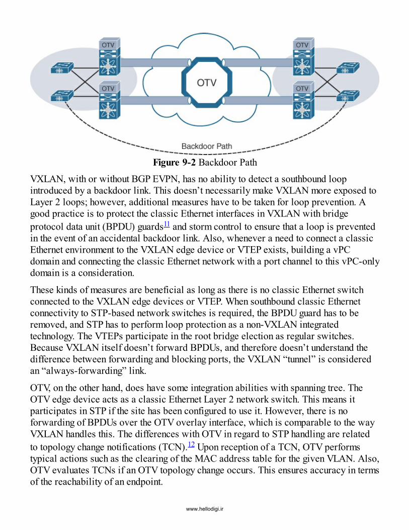
Figure 9-2 Backdoor PathVXLAN, with or without BGP EVPN, has no ability to detect a southbound loopintroduced by a backdoor link. This doesn’t necessarily make VXLAN more exposed toLayer 2 loops; however, additional measures have to be taken for loop prevention. Agood practice is to protect the classic Ethernet interfaces in VXLAN with bridgeprotocol data unit (BPDU) guards11 and storm control to ensure that a loop is preventedin the event of an accidental backdoor link. Also, whenever a need to connect a classicEthernet environment to the VXLAN edge device or VTEP exists, building a vPCdomain and connecting the classic Ethernet network with a port channel to this vPC-onlydomain is a consideration.
These kinds of measures are beneficial as long as there is no classic Ethernet switchconnected to the VXLAN edge devices or VTEP. When southbound classic Ethernetconnectivity to STP-based network switches is required, the BPDU guard has to beremoved, and STP has to perform loop protection as a non-VXLAN integratedtechnology. The VTEPs participate in the root bridge election as regular switches.Because VXLAN itself doesn’t forward BPDUs, and therefore doesn’t understand thedifference between forwarding and blocking ports, the VXLAN “tunnel” is consideredan “always-forwarding” link.
OTV, on the other hand, does have some integration abilities with spanning tree. TheOTV edge device acts as a classic Ethernet Layer 2 network switch. This means itparticipates in STP if the site has been configured to use it. However, there is noforwarding of BPDUs over the OTV overlay interface, which is comparable to the wayVXLAN handles this. The differences with OTV in regard to STP handling are relatedto topology change notifications (TCN).12 Upon reception of a TCN, OTV performstypical actions such as the clearing of the MAC address table for the given VLAN. Also,OTV evaluates TCNs if an OTV topology change occurs. This ensures accuracy in termsof the reachability of an endpoint.
www.hellodigi.ir

With OTV, the STP root continues to reside at the location where it was placed beforethe integration of OTV. If deemed beneficial, the spanning tree root can be moved to theOTV edge device; however, it is important to understand that spanning tree domains arekept localized on an OTV site. The same considerations apply when using VXLAN tointerconnect classic Ethernet sites.
Multidestination traffic can be handled with OTV and with VXLAN with BGP EVPN.When interconnecting data centers or network fabrics, fault containment is mandatorymost of the time. This can be achieved by reducing or eliminating unnecessary networktraffic in the overlay. An optimal way of accomplishing this is with ARP suppression,which reduces unnecessary ARP broadcast traffic over the network. Such ARPbroadcasts can be answered locally once seen as broadcasts. This functionality isavailable with VXLAN BGP EVPN as well as with OTV.Unknown unicast is another kind of network traffic that is a legacy from the classicEthernet times. The need for unknown unicast flooding may be required in cases ofsilent host detection on Layer 2 or during some endpoint failover scenarios. In modernnetworks, attempts to prevent such traffic are desirable because that traffic canintroduce network storms. OTV implicitly does not forward any unknown unicast traffic.If a DMAC address is not known, the traffic is simply dropped. In the event that aspecific MAC address should be allowed to generate unknown unicast flooding, theMAC address can explicitly be allowed to perform this function on a per-VLAN basis.
VXLAN with BGP EVPN prevents unknown unicast traffic. As is the case with activecontrol protocol learning, an unknown MAC should not exist. However, VXLAN doesnot stop unknown unicast forwarding by default. Some implementations of VXLAN withEVPN have a feature by which unknown unicast forwarding can be disabled on a per-Layer 2 VNI basis. But once disabled, options to selectively enable the flooding for asingle MAC do not exist. However, the need for unknown unicast forwarding isinfrequently required.
When multicast forwarding is necessary in the same Layer 2 domain, the interactionwith IGMP messages and IGMP snooping allows the forwarding of multicast in the mostoptimal way. The OTV edge device receives and evaluates these IGMP reports tooptimally forward multicast traffic across the overlay. For multicast forwarding, OTVuses data groups that are based on PIM source-specific multicast (SSM)13 learning andforwarding semantics. With PIM SSM, the source for a group is always known, andoverlay multicast traffic can be forwarded in the most efficient way.OTV also has the ability to separate the data groups used for multicast traffic from theones used for broadcast traffic. This can allow further fine-tuning for the traffic and islike having a “rate-limiter” for broadcast traffic only. In VXLAN, all broadcast,
www.hellodigi.ir

unknown unicast, and multicast (BUM) traffic is handled in the same way and isforwarded by the multicast group or ingress replication method assigned to the Layer 2VNI. The capability to specifically differentiate between the different BUM traffic typesis not implicitly available. Nevertheless, optimization of multicast in the sameVLAN/L2VNI can be achieved through the availability of IGMP snooping. Chapter 7,“Multicast Forwarding,” elaborates on the mechanics of IGMP when used together withVXLAN. In summary, OTV provides active control protocol and data plane integrationfor multicast traffic, while VXLAN only partly offers such granularity.
Table 9-1 highlights the differences between OTV and VXLAN discussed in thissection. The applicability of VXLAN with BGP EVPN evolves as the control protocoland the related optimizations evolve. Also, VXLAN was notably built as an extension toLANs, with the primary focus of having it not be an extension over WANs. Previously,VXLAN was just another encapsulation that imposed F&L on top of a Layer 3 networkand required multicast. However, VXLAN now, with BGP EVPN, has applicability fordeployment of large-scale networks that traverse multiple data center sites.
www.hellodigi.ir

www.hellodigi.ir

Table 9-1 VXLAN and OTV FunctionsIn terms of data center networks, active peer discovery and learning of Layer 2 andLayer 3 information over BGP EVPN provides the capability to scale well beyond thecapacity of F&L networks. In the near future, VXLAN with BGP EVPN will prove itscapability for being a full-featured DCI solution, through enhancements related tomultihoming, fault containment, and loop protection. Likewise, the additional gains inefficiency using multicast forwarding will support this claim as well, once VXLANwith BGP EVPN is maturely developed.
After comparing OTV with VXLAN EVPN, the following sections will discuss designconsiderations for the inter-pod connectivity and DCI.
Multi-podOverlay networks inspire “flat” network designs. This might be a good approach forscaling out the network and removing unnecessary layers. However, with respect tooperational simplicity, the practices involving hierarchical network design also apply tooverlay networks deployed on top of spine–leaf topologies. Spine–leaf topologies areintroduced in Chapter 1, “Introduction to Programmable Fabric,” but there are manymore variations to this approach than are discussed in that chapter. Significantflexibility exists that goes beyond a single tier of spine and leaf, in the ability to scaleout horizontally.
The leaf layer provides endpoint connectivity, and additional southbound tiers probablydo not exist other than virtual switches, FEX (Fabric Extender/Nexus 2000),14 CiscoUCS FI (Unified Computing System Fabric Interconnect),15 or switches in a blade-server enclosure. This does not mean that the connection of network service functions(for example, firewall, load-balancer, router, other service appliances) is not a feasibleoption. However, the connection of additional southbound switch tiers for endpointconnectivity and cascaded access is not considered in this discussion.
In general, connection of a full-fledged Layer 2 network below the leafs requiresspecial considerations for STP, such as root placement, TCN handling, and loopprevention. This is a very common problem, especially because overlay technologiessuch as VXLAN do not transport BPDUs or TCNs today.With the leaf being responsible for hosting the VTEP, the traditional spine is a simpleIP/UDP traffic forwarder (see Figure 9-3). In that sense, the spines are unaware of theendpoint addresses, and their forwarding tables only need to scale in the order of thenumber of leafs and not in the order of the number of endpoints. By scaling out the spinein the same stage, in addition to increasing its bandwidth and resiliency, advantageslisted earlier related to scale and operational simplicity still apply.
www.hellodigi.ir

The optimal number of spines is defined by the available uplink interfaces on the leafs,at least when the symmetrical connectivity of the spine–leaf topology is assumed. Forexample, in a topology where a leaf has 6 × 40G interfaces, the optimal number ofspines would be between 4 and 6. This takes into consideration vPC-based deploymentswhere some 40G links may be employed for the vPC peer link.
Figure 9-3 Two-Tier Spine–Leaf Topology
It is not always possible to provide the needed interface density for a spine layer at thebeginning of a buildout. Initially, a standard two-tier spine–leaf topology that typicallycontains two spines and N leafs may be used. As the demands of the data center grow,more leafs and spines may be required. At some point, a new pod is added, with anadditional set of spines serving at the same tier level as the initially deployed one. Thenew pod includes a new set of leafs as well.
Because some leafs connect to some spines and other leafs connect to other spines, it isimportant that these different pods are interconnected. A multi-pod design is simplifiedby introducing a super-spine layer (see Figure 9-4). All the spines at Tier 1 connect toall the super-spines. This way, instead of a two-tier spine–leaf topology, the fabricbecomes an n-stage topology, where n represents the number of spine levels. The valueof n can be increased as much as required to accommodate the network design. For mostpractical deployments, having one super-spine layer is usually sufficient.
www.hellodigi.ir

Figure 9-4 Multi-podThe MP-BGP EVPN control protocol needs to be part of the design considerations in ann-stage fabric. The exchange of reachability information across all the available stagesis required even if only the VTEPs need this information for making forwardingdecisions. The spines or super-spines are used as BGP route reflectors (RRs) fordistributing this reachability information in an efficient way (see Figure 9-5). Inaddition to the placement of BGP RRs, the overall design also needs to consider theappropriate placement of rendezvous points (RPs) if multicast is being used forforwarding BUM traffic.
www.hellodigi.ir

Figure 9-5 BGP Route Reflector PlacementIn relation to the use of multicast and RPs in an n-stage or multistage fabric, anotheradvantage also exists, involving scaling the output interfaces (OIFs) for multicast. Oncethe OIF limit is reached for the number of leafs in a given pod, an upstream super-spinecan help increase that scale by extending the multicast tree to other spines (see Figure 9-6). This can subsequently increase the scale of the OIF limit for the fabric.
www.hellodigi.ir

Figure 9-6 Multicast OIF ScalingWith a simple multi-pod topology as shown in Figure 9-6, a spine can serve up to 256OIFs and can represent as many as 256 leafs, which would allow a single multicast treebetween the 256 leafs and the spine acting as the RP. To further increase the scale, thepod would need to be split before the maximum OIF scale could be reached at the spinelayer. Assuming that this split is created upon reaching 255 leafs, the spine is allowed tohave 255 southbound OIFs toward the leafs and one northbound OIF toward the super-spine. At that point, if the super-spine also allowed scaling to 256 OIFs, 256 spinescould be served by a single set of super-spines.
With this type of multi-pod design having 256 spines multiplied by 255 leafs,theoretically the number of leafs would expand to 65K from an OIF perspective. Whilethis demonstrates how OIFs can be scaled to higher numbers by using an n-stage spine–leaf topology, the overall scale in terms of the number of VTEPs and prefixes (MACand IP) also needs to be considered.
In the case of a multi-pod design where any-to-any reachability is required across allthe leafs across all the VNIs, the maximum scale is defined by the least common
www.hellodigi.ir

denominator. By using a fabric approach, and by employing the notion of movingintelligence to the leaf layer with a scale-out property, it might not be necessary to haveall VNIs configured everywhere. If this is the case, configurations can be constructedonly where needed at the leaf layer, and the scale potentially achieved is far beyondwhat current Layer 2 networks can provide. With this approach, the theoretical maximalnumber of 65K leafs may seem attractive. However, it is impractical, especially withthe operational complexity associated with deploying, managing, and maintaining such alarge network.
When having such multitier or multistage spine layers, the placement of the RP is alsoimportant. To achieve some independence between the different pods, the use of a singlePIM Anycast RP per pod is a reasonable approach. Because multiple pods exist, andBUM traffic needs to flow between these pods when Layer 2 VNIs are extended,additional considerations need to be taken into account for interconnecting the differentpods.One way to expand the PIM Anycast RP approach across each of the different pods is touse the same RP address and provide a full-mesh neighbor relationship. Configuring theanycast IP address on the spine ensures that multicast traffic that always uses theshortest path to reach the RP, stays within the pod. In a pod where pod-local RPs mustbe used, different sets of PIM Anycast RPs along with Multicast Source DiscoveryProtocol (MSDP)16 can be used to ensure that the multicast source and receiver groupinformation is exchanged between the pods (see Figure 9-7). In this way, theindependence of the pods is increased from a multicast perspective.
www.hellodigi.ir

Figure 9-7 PIM Anycast RPs per Pod with MSDP Between PodsThe use of multicast forwarding for BUM traffic is a potentially superior alternative tothe use of ingress replication. This may be especially true as the amount of BUM trafficgrows. When multicast is employed for forwarding BUM traffic, an efficient singlepacket per link for a given BUM packet would result because the traffic is forwardedalong the multicast tree. When using ingress replication, this is notably different becauseBUM traffic alone can result in a significant amount of traffic in the multi-podenvironment.
With ingress replication, a single BUM packet is replicated to each of the peer VTEPsthat host the same Layer 2 VNI. Therefore, with 256 VTEPs in a VXLAN domain, aVTEP has to replicate a single packet 255 times. With 64-byte packets, the uplink fromthe VTEP where the packet originates sees the transport of 255 × 64 = 16,320 bytes, orabout 16KB.
If a couple of southbound interfaces from this VTEP toward locally attached endpointswere considered instead of a single packet, the negative impact of ingress replication ina worst-case scenario could easily be appreciated. Consider one VTEP with 20 active
www.hellodigi.ir

endpoints, with each of them creating 1Kb/s (kilobit per second) of BUM traffic. Thiswould result in 20Kb/s ingressing the VTEP. Assuming once again that the number ofremote VTEPs are 255, this would result in 5100Kb/s (255 × 20Kb/s), or 637.5KB/s.
Because the feasibility of only one VTEP having active endpoints sending BUM trafficis not likely, other endpoints below other VTEPs are also producers as well asconsumers of BUM traffic. As a result, the amount of traffic in the network for handlingBUM packets when using ingress replication can grow from megabits per second togigabits per second. Therefore, at the design phase, it is important to consider the typeand volume of application traffic that will be transported over the multi-pod topology.This consideration facilitates making the correct decisions regarding the underlaytechnology employed for forwarding BUM traffic.Finally, in a VXLAN BGP EVPN fabric, not all leafs are expected to provide the sameLayer 2 and/or Layer 3 service for all tenants. In other words, sets of leafs may bedivided into clusters, also called mobility domains. Leafs within a mobility domain areconfigured with the same set of Layer 2 and Layer 3 VNIs (see Figure 9-8). As a result,a cluster with common spines may be converted into a pod that resides in a room or hallin a single physical data center location.
Some use cases also exist where pods are separated across a few close-quarter datacenters that are providing limited separation for a high-availability set. This use casewould apply to some metro data center approaches where failure propagation is not aprimary concern because a disaster recovery site is always available.
Figure 9-8 Leaf Cluster (Mobility Domain)
www.hellodigi.ir

As previously described, one of the main advantages of a VXLAN BGP EVPN networkcompared to traditional networks related to the overlay is the distributed IP anycastgateway. With the default gateway being spread across all the available leafs or VTEPs,any concerns regarding the impact on first-hop gateway decisions becomes limited tothe endpoints connected to a particular leaf. In this way, operational tasks become muchsimpler because a pair of critical switches holding the majority of the network functionsno longer exists as is the case with the aggregation or distribution-layer switches in atraditional three-tier (access/aggregation/core) topology.
Because the distributed anycast gateway is available at the leaf layer in every pod,special localization configuration is not required. This is not the case for FHRPprotocols in traditional deployments. Also, with the distributed anycast gateway,optimal one-hop forwarding between endpoints on any VTEP in any pod in a multi-podfabric deployment is possible.With all these different design options, the existence of multiple pods has severaloperational benefits. Having multiple pods minimizes the impact of one pod on otherpods. For example, if some maintenance needs to be performed on one of the podswhile all other pods continue to carry production traffic, the maintenance at the one podmight impact the overlay connectivity toward that pod, but all the other pods wouldcontinue to operate independently, without any impact. This is substantially differentfrom what happens in a large expanded two-tier spine–leaf topology (see Figure 9-9),where the underlay change on one leaf could impact the entire underlay routing domainand, in turn, may impact the overlay as well.
Figure 9-9 Multi-pod Versus Two-Tier Spine–Leaf TopologyThe underlay routing design in multi-pod environments requires special considerationsas well. The underlay routing has to be able to exchange reachability information for theVTEP, BGP RR, multicast RP, and other addresses used for building and maintaining the
www.hellodigi.ir

pods. Since full visibility of the VTEP addresses (/32 in IPv4 or /128 in IPv6) isrequired, and no summary should be used, the routing domain could benefit fromseparation. When using an interior gateway protocol (IGP) in a multi-pod environment,area separation for the different pods should be considered. While this provides acertain separation into what LSAs are sent between pods (for example, with OSPF), thecomplete underlay routing can be affected if the link-state database is compromisedwith faulty information (such as a duplicate router ID).
There are other ways to achieve separation in multi-pod deployments, such as using stubareas and only injecting the default route between the pods. However, this approach hasa significant impact on the convergence of the overlay control protocol because theVTEPs are no longer individually visible. If a VTEP fails in a remote area, the defaultroute toward the exit of the area still exists. Therefore, traffic may potentially black-hole until the dead timer removes the prefix from the control protocol. In such a case,the benefits of simplicity versus complexity must be weighed.It is possible to achieve strong separation between the pods by using BGP tointerconnect the pods from an underlay perspective. But with this approach,implications involving the overlay control protocol exist because the underlay andoverlay control protocols merge (using BGP).
Today, multi-pod designs provide the option of hierarchical network design in theunderlay and potentially in the overlay control plane. As a result, a single data planedomain remains. In other words, the VXLAN tunnels always begin and terminate at theleafs, regardless of whether the traffic is being forwarded between endpoints in thesame pod or across pods. This means the same consistent configuration of Layer 2 andLayer 3 services is required across all pods. This approach also allows virtual machinemobility across multiple pods in a multi-pod environment.
Overlay control plane separation in the different pods can be achieved by usingdifferent BGP autonomous system (AS) numbers in each pod. However, the separationonly involves the handling functions within the control protocol provided by the BGPEVPN feature set. As a result, the prefix scale per MAC and IP becomes a globalconsideration in the entire multi-pod environment. As previously noted, intelligentnetwork design can allow the scale requirements at the individual leafs to be somewhatamortized by not requiring every Layer 2 and Layer 3 VNI to be configured everywhere.In considering a multi-pod design, a residing point remains in regard to the availablephysical connectivity. Because many existing infrastructure cablings were designed toaccommodate the classic hierarchical three-tier topologies, additional factors must beconsidered with spine–leaf and n-tier spine–leaf fabrics. In cases where sufficientcabling for symmetrical connectivity is available, the single-tier spine–leaf approachmay be sufficient. Once an n-tier deployment is required, the super-spine helps
www.hellodigi.ir
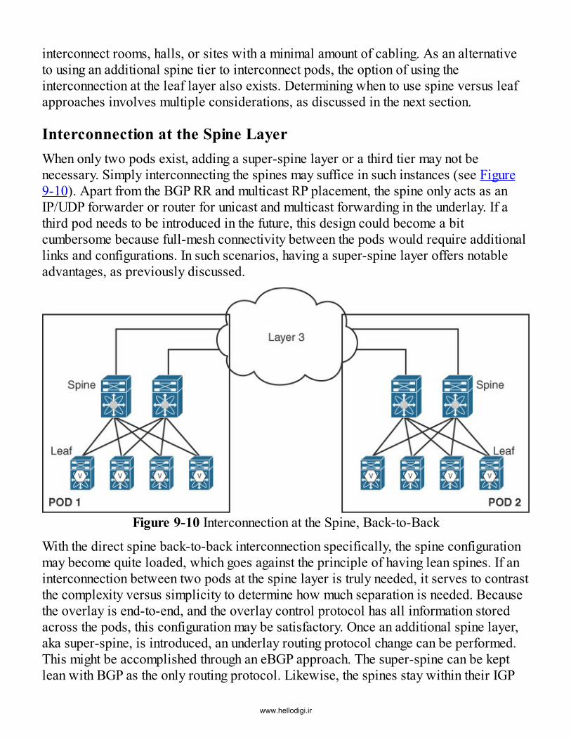
interconnect rooms, halls, or sites with a minimal amount of cabling. As an alternativeto using an additional spine tier to interconnect pods, the option of using theinterconnection at the leaf layer also exists. Determining when to use spine versus leafapproaches involves multiple considerations, as discussed in the next section.
Interconnection at the Spine LayerWhen only two pods exist, adding a super-spine layer or a third tier may not benecessary. Simply interconnecting the spines may suffice in such instances (see Figure9-10). Apart from the BGP RR and multicast RP placement, the spine only acts as anIP/UDP forwarder or router for unicast and multicast forwarding in the underlay. If athird pod needs to be introduced in the future, this design could become a bitcumbersome because full-mesh connectivity between the pods would require additionallinks and configurations. In such scenarios, having a super-spine layer offers notableadvantages, as previously discussed.
Figure 9-10 Interconnection at the Spine, Back-to-Back
With the direct spine back-to-back interconnection specifically, the spine configurationmay become quite loaded, which goes against the principle of having lean spines. If aninterconnection between two pods at the spine layer is truly needed, it serves to contrastthe complexity versus simplicity to determine how much separation is needed. Becausethe overlay is end-to-end, and the overlay control protocol has all information storedacross the pods, this configuration may be satisfactory. Once an additional spine layer,aka super-spine, is introduced, an underlay routing protocol change can be performed.This might be accomplished through an eBGP approach. The super-spine can be keptlean with BGP as the only routing protocol. Likewise, the spines stay within their IGP
www.hellodigi.ir

domain with redistribution of the information into BGP for inter-pod exchange.
Interconnection at the Leaf LayerMuch like using the back-to-back interconnection at the spine layer, employing aninterconnection at the leaf layer is also a feasible way to connect pods (see Figure 9-11). It is possible to add another layer south of the leaf. However, multiple podsinterconnected at the leaf layer might appear a bit cumbersome in a data center. Theinterconnection at the leaf layer is advantageous when a degree of geographicseparation is needed and when the same nodes are used for multi-pod and externalconnectivity.
Figure 9-11 Interconnection at the Leaf, Back-to-Back
The same options available for interconnecting multiple pods at the spine layer are alsoavailable at the leaf layer. The main difference between these interconnectionapproaches resides in the available connectivity between pods. In addition, considerthat the leaf might also act as a VTEP and become burdened with a heavy load offunctionality. For example, if the interconnecting leaf is a default gateway for a givennetwork, part of a vPC domain, and also provides Layer 2 interconnectivity, a fairamount of complexity, from an operational perspective, occurs. Because these leafsneed to be highly available to ensure cross-pod connectivity, reducing complexity maybe preferred, and an approach allowing the interconnection point to be as lean aspossible may be ideal when dealing with multi-pod deployments.
MultifabricWhile multi-pod deployments follow the concept of multiple control protocol domainsin the underlay as well as in the overlay, a single data plane that extends end to endacross all the pods exists. Therefore, a multi-pod environment is considered a single
www.hellodigi.ir

fabric. In a multifabric deployment, complete segregation at the control plane leveltypically occurs, as does segregation at the data plane level. In other words, a singleVXLAN BGP EVPN fabric can consist of its own underlay, its own overlay controlprotocol, and related data plane encapsulation.
The advantage of such a multifabric design not only involves the option of having trueseparation of the traffic but also benefits from an administrative domain perspective. Inregard to the administrative domain, benefits relate to the BGP autonomous system aswell as the numbering of VNIs, multicast groups, and other components that arecompletely independent between different fabrics. This means an individual fabric canuse any numbering model desired without being dependent on any of the other fabricsnumbering models. In addition, with respect to BUM traffic forwarding, one fabric canuse multicast and another fabric can use ingress replication. The capability to have thisdegree of independence is not possible in multi-pod environments.Because things are truly localized within a fabric, traffic egressing needs to beterminated at the border of the fabric. Specifically, the VXLAN encapsulation needs tobe terminated, and an appropriate Layer 2 or Layer 3 handoff needs to occur. Thisprovides the option of interconnecting multiple fabrics where VNIs can beindependently stitched together via a different technology (for example, by using OTVwith VLANs). This separation or normalization allows the introduction of demarcationsand the option of an enforcement point at the border of the fabric.
In summary, the main difference in multi-pod versus multifabric deployments (seeFigure 9-12) lies solely in the structuring and the applicability of hierarchical networkdesign principles. Key aspects of this discussion therefore focus on the notion ofbuilding multiple data center networks and achieving the necessary separation betweenthem.
www.hellodigi.ir

Figure 9-12 Multi-pod and MultifabricIn the past, Layer 2 DCI was a hot topic of discussion because virtual machine mobilityrequired the stretch of Layer 2 networks between data centers. As the stretching of suchnetworks across multiple data centers raised concerns about failure propagation,solutions such as OTV came to the forefront. OTV-like solutions offered the desiredfeature set to address the requirements. With the spine–leaf fabric evolution in the datacenter, however, the need for Layer 2 DCI remains a primary requirement.
There is a common misconception that virtual machine mobility can now be achievedvia Layer 3 networks. This would imply that Layer 2 DCI may not be required. Butwhile the transport network over which the VMs are moved can be routed or Layer 3,the specific network segment on which the endpoint or virtual machine resides stillrequires a Layer 2 extension. This is because the virtual machine typically retains its IP
www.hellodigi.ir

and MAC addresses after a VM move. Consequently, a Layer 2 or bridge servicebetween data centers is required.
Note that using approaches such as those prescribed by LISP, where routing is employedfor within-subnet communications, it may be possible to get away from the Layer 2 DCIrequirement; however, such deployments are not common.With a Layer 2 stretch, the clean separation of multiple fabrics must be ensured.Separating the data plane from the source fabric and the destination fabric with atechnology in between allows protection in case of a “storm” in one fabric. This is acritical requirement. This separation helps avoid propagation of any unnecessary trafficto the other fabric in case of faults. This failure containment is one of the many featuresa DCI solution must provide.
Interconnecting data centers requires a Layer 2 extension, and in many deployments, aLayer 3 extension is needed as well. The extension of such a Layer 3 service needs tohave simple availability for routing between subnets, and it also requires optimizationso that traffic is always forwarded to the right fabric without hair-pinning. Architecturesthat use functionality such as LISP provide the option of integration with VXLAN BGPEVPN fabrics, thereby allowing efficient steering of the ingress traffic to the right datacenter (see Figure 9-13). The same can be achieved by advertising host routes outsidethe data center fabric (/32 in IPv4 or /128 in IPv6). However, this approach is muchless scalable compared to approaches that introduce indirection at the control protocollevel. The advantages of LISP in regard to external connectivity are discussed in otherchapters.
www.hellodigi.ir

Figure 9-13 Multifabric and Ingress Traffic OptimizationIn summary, there are many ways to construct multiple fabrics and interconnect them. Itis important to understand the difference between a multi-pod design and the use ofmultiple individual fabrics. While multi-pod designs provide a hierarchical structurefor individual pods, the multifabric approach adds an additional level of hierarchy tothe multi-pod design for true data center separation.
Inter-pod/InterfabricOften it is suggested that separation of the underlay and overlay control protocolsbetween pods is sufficient network segregation for failure containment. Unfortunately,this is one of the most significant misconceptions in the world of overlay networking.While structuring has some scale and operational advantages, a broadcast storm in theoverlay can be propagated throughout the whole multi-pod network if the Layer 2service is expanded across all pods. One approach to address such failure propagationis to use multicast storm control in the underlay. However, this approach also affects thetransport of legitimate BUM traffic. Because it is very difficult to limit these kinds of“storms” once they exist in the overlay, it is critical to have enforcement pointsavailable in the network. With multi-pod networks, the VXLAN encapsulation is end-to-end between different pods. Therefore, enforcement points between the pods are notpresent. This is where multifabric designs offer an advantage, thereby limiting failure
www.hellodigi.ir

propagation.
Currently, the enforcement point for filtering traffic is only available through thetermination of the VXLAN encapsulation at the border of the fabric. Afterdecapsulation, traffic is carried across classic Ethernet over the DCI domain and thenre-encapsulated at the ingress of the remote fabric.When the need for a classic Ethernet segment between decapsulation and encapsulationbecomes obsolete, more scalable multi-pods can be constructed with better segregationfeatures to prevent failure propagation (also known as multisite). Currently, the onlyway to achieve such separation of individual fabrics is through DCI solutions such asOTV (see Figure 9-14). The following sections discuss different interconnectivityoptions available for multifabric or multi-pod deployments.
Figure 9-14 OTV Hand-off through Ethernet.
Interfabric Option 1: Multi-podInterfabric Option 1 basically follows the model of a multi-pod design (see Figure 9-15). It is listed here for the sake of completeness.
www.hellodigi.ir

Figure 9-15 Interfabric Option 1 (Multi-pod)As with multi-pod designs, independent overlay control protocol domains within eachfabric exist, but a single data plane is present end-to-end. All the MAC/IP prefixes aredistributed to all the participating VTEPs, and the same mechanism for BUM replicationmust be employed in all the fabrics. Interfabric Option 1 is more of a multi-pod designand not a real interfabric connectivity option per se. Nevertheless, this option may besufficient for certain implementations to have such an end-to-end approach. However, itis important to clearly understand the disadvantages, such as failure propagation and
www.hellodigi.ir

separation of the individual pods. Interfabric Option 1 should not be expected to be theprimary solution for interconnecting fabrics together in the context of DCI.
Interfabric Option 2: MultifabricInterfabric Option 2 follows the model of classic DCI by employing classic Ethernet atthe border of the fabric. The DCI network between the fabrics is cleanly separated fromthe fabrics themselves. This is basically the multifabric approach described earlier inthis chapter.In this interconnectivity model, independent overlay control protocol domains as wellas individual overlay data planes are present in the different fabrics (see Figure 9-16).By having these two overlay control protocol domains interconnected, the exchange ofall reachability information happens non-uniformly. This means that all prefix (MACand IP) information is not spread across all the participating VTEPs. Therefore, a muchbetter scale results with this option than with interfabric Option 1.
www.hellodigi.ir

Figure 9-16 Interfabric Option 2 (Multifabric)Because neither the reachability information nor the data plane is extended end-to-end,the option of having an enforcement point is achieved, allowing clean separationbetween the different fabrics. By having separation from an overlay perspective, the
www.hellodigi.ir
underlay can also be completely separated. As a result, the need for a VTEP from onefabric to connect to the VTEP in the other fabric does not occur. End-to-end reachabilitybetween endpoints in the two fabrics is achieved via the DCI domain between thefabrics.
This also means that the underlay-related information, such as the VTEP information andthe multicast tree, does not need to exist end-to-end and can be constrained within afabric. As a result, one fabric could use multicast for BUM traffic handling, while theother fabric uses ingress replication. Also, the DCI domain in the middle cancompletely and independently replicate BUM traffic, depending on its capability.The handoff from a fabric toward the DCI domain is achieved by terminating theVXLAN encapsulation at the border of that fabric and by employing classic Ethernet totransport the necessary information to the DCI domain. The use of VRF Lite17 and IEEE802.1Q trunks provides the ability to normalize the VXLAN-related information andtransport the data within the respective segmentation context (Layer 2 or Layer 3) acrossthe DCI domain. With VRF Lite, an eBGP session per VRF is typically established tocarry the IP prefix information from the fabric to the DCI domain from a control planepoint of view. Similarly, for every Layer 2 VNI or Layer 2 network that needs to beextended between the fabrics, a VLAN is employed between the fabric and the DCIdomain for Layer 2 purposes. Once traffic reaches the remote fabric, the forwardingdecision is evaluated based on data plane contents. Subsequently, the traffic isencapsulated over VXLAN toward the remote leaf below which the destinationendpoint is attached in that fabric.
At the point where the handoff from VXLAN to classic Ethernet occurs, enforcementpoints such as QoS, rate limiters, and other storm control functions can be applied. Withall these features, it is possible to separate unnecessary traffic and stop failures frompropagating to the remote fabric. Also, with the use of OTV in the DCI domain, datatraffic can be efficiently transported between the fabrics. This helps leverage theadditional benefits that OTV provides as a DCI solution.
Interfabric Option 2 provides much better separation between fabrics than Option 1, butit requires the termination of the VXLAN encapsulation at the fabric border, followedby normalization using classic Ethernet constructs. This approach might become apotential scale bottleneck because the use of VLAN IDs on the wire for segmentationseparation at the VRF or network level occurs with this normalization. Because theVLAN IDs are used only on the Ethernet interface toward the DCI domain, the numberof VLANs can potentially be scaled through the per-port VLAN significance feature.This requires additional configuration and alignment between the fabric border and theDCI nodes. This could become operationally complex. However, automation for theclassic Ethernet normalization with IEEE 802.1Q trunks and VRF Lite can significantly
www.hellodigi.ir
ease this operational burden.
Interfabric Option 3 (Multisite for Layer 3)Interfabric Option 3 (see Figure 9-17) involves integrated DCI handoff for Layer 3services. This scalable interconnectivity approach for handling interfabric routed trafficinvolves segmentation-related functions that lack the drawbacks of the VRF Liteapproach (interfabric Option 2). Option 3 basically employs the same multifabricconcept described earlier but with an option that allows reorigination of Layer 3 routinginformation. For interfabric Option 3, only the integrated Layer 3 interconnections areconsidered; the Layer 2 components are discussed in interfabric Option 4.
www.hellodigi.ir

Figure 9-17 Interfabric Option 3 (Multisite for Layer 3)All the considerations related to the overlay and underlay described with Option 2
www.hellodigi.ir

apply to Option 3 as well. The handoff from one fabric toward the DCI domain isachieved by terminating the VXLAN encapsulation at the border of one fabric andthrough an integrated reorigination approach for Layer 3 routing to transport thenecessary information across the DCI domain. The integrated handoff approach usingLISP18 or MPLS Layer 3 VPN (L3VPN)19 is employed in this situation. In addition tothe approaches mentioned earlier in this chapter, a VXLAN BGP EVPN integratedmultisite solution is planned.20
With MPLS L3VPN, a VRF is identified by a VPN label. Recall that a Layer 3 VNIidentifies a VRF in the VXLAN header. Using MP-BGP with the L3VPN address family,the EVPN prefix routes are reoriginated as VPNv4/v6 routes, and advertised by theborder node toward the DCI domain. From a data plane point of view, the VXLANheader is removed, and the border node stamps a VPNv4 label and a MPLS label forinterfabric Layer 3 traffic. This permits the forwarding of the packet over the MPLScore toward the remote fabric.A similar approach is used with LISP, where the VXLAN header is removed and anappropriate LISP header identifying the VRF is stamped by the border node. Theintegrated handoff approach provides the ability to normalize the VXLAN-relatedinformation and transport the data in the respective segmentation context (Layer 2 orLayer 3) across the DCI domain. When the MPLS- or LISP-encapsulated traffic reachesthe remote fabric, the reverse operation is performed at the border node. In other words,the LISP/MPLS header is stripped off, and traffic is again VXLAN-encapsulated, basedon the Layer 3 lookup, and dispatched toward the destination VTEP in that fabric.Where Layer 2 connectivity to remote fabrics is needed, interfabric Option 2 can alsobe incorporated.
For routed traffic, Layer 2 enforcement points are not needed; however, protectionagainst routing loops may still be needed. This may be the case in instances where routeleaking is employed for enabling inter-VRF communication either directly at the bordernode or by way of a fusion router.21
Interfabric Option 3 retains all the advantages of Option 2, and this option also providesa simplified and scalable multitenant Layer 3 DCI alternative. Using a separate dataplane to encapsulate Layer 3 traffic and using a control protocol for informationexchange allows true segregation without normalization to classic Ethernet.
Interfabric Option 4 (Multisite for Layer 2)Interfabric Option 4 follows a similar model as option 3, with an integrated DCIhandoff. While Option 3 covers Layer 3 services, Option 4 provides a similar approachfor Layer 2 services (see Figure 9-18). This integrated interconnectivity approach for
www.hellodigi.ir

Layer 2 extensions enables a scalable approach for a bridging service by keeping thesegmentation-related information intact.
www.hellodigi.ir

Figure 9-18 Interfabric Option 4 (Multisite for Layer 2)
www.hellodigi.ir

All the considerations related to the overlay and underlay described for Option 2 applyhere as well. The handoff from one fabric toward the DCI domain is achieved byterminating the VXLAN encapsulation at the border of one fabric. Likewise, anintegrated reorigination approach for Layer 2 bridging to transport the necessaryinformation across the DCI domain is also present. Whereas IEEE 802.1Q trunks areemployed for this approach with Option 2, an integrated handoff approach to OTV (orEVPN in the future) is prescribed with Option 4.
A Layer 2 network is represented by a specific Layer 2 VNI in one fabric. With a VNI-to-VNI stitching feature, VXLAN-encapsulated bridged traffic is mapped from one VNIto another VNI and sent toward the DCI domain. Similarly, the Layer 2 VXLAN trafficcan be terminated at the border node and directly encapsulated with the OTV header.The integrated handoff approach provides the ability to normalize the VXLAN-relatedinformation and transport the data in the respective segmentation context (Layer 2 orLayer 3) across the DCI domain. When the traffic reaches the remote fabric, the reverseoperation is performed so that the Layer 2 DCI header is removed, and the bridgedtraffic is encapsulated into VXLAN and sent toward the destination VTEP. The Layer 2DCI handoff point at the border node allows enforcement actions such as stoppingunknown unicast, applying appropriate QoS, enforcing rate-limiting, or other stormcontrol functions. localizing the failures to a given fabric, thereby preventing them frombeing propagated to a remote fabric.Interfabric Option 4 provides a much better separation than Option 1, and it providesgreater simplification for multitenant Layer 2 deployments as compared to Option 2.The use of a separate data plane to encapsulate Layer 2 traffic, and the use of a controlprotocol for information exchange allows true separation without normalization toclassic Ethernet. In combination with interfabric Option 3, Layer 3 and Layer 2extensions can be provided in an integrated, scalable, and secure way compared to withOptions 1 and 2. The combination of interfabric Option 3 and Option 4 will be providedin a VXLAN with BGP EVPN-integrated multisite solution that will become availablein 2017.22
SummaryThis chapter describes various concepts related to multi-pod and multifabric optionswith VXLAN BGP EVPN deployments. It provides a brief primer on the salientdistinctions between OTV and VXLAN. Most practical deployments require some formof interconnection between different pods, or fabrics. This chapter discusses variousconsiderations involved in making a decision on when to use the multi-pod option andwhen to use the multifabric option. These include underlay protocols, overlay protocols,the placement of route reflectors, the placement of rendezvous points, vPC
www.hellodigi.ir

considerations, and others. The chapter concludes with an exhaustive list ofinterconnection options that can be employed between multiple VXLAN BGP EVPNfabrics.
References1. International Telecommunication Union. G.694.2: Spectral grids for WDM
applications: CWDM wavelength grid. 2003. www.itu.int/rec/T-REC-G.694.2-200312-I.
2. International Telecommunication Union. G.694.1: Spectral grids for WDMapplications: DWDM frequency grid. 2012. www.itu.int/rec/T-REC-G.694.1/en.
3. IETF Network Working Group. Virtual Private LAN Service (VPLS) using LabelDistribution Protocol (LDP) signaling. 2007. www.ietf.org/rfc/rfc4762.txt.
4. IETF Network Working Group. Virtual Private LAN Service (VPLS) using BGP forauto-discovery and signaling. 2007. www.ietf.org/rfc/rfc4761.txt.
5. IETF Network Working Group. Overlay transport virtualization draft-hasmit-otv-04.2013. tools.ietf.org/html/draft-hasmit-otv-04.
6. IETF Network Working Group. OSI IS-IS intra-domain routing protocol. 1990.tools.ietf.org/html/rfc1142.
7. IETF. Extensions to IS-IS for Layer 2 systems. 2011. tools.ietf.org/html/rfc6165.8. IETF Network Working Group. IS-IS extensions to support OTV draft-drao-isis-otv-
00. 2011. tools.ietf.org/html/draft-drao-isis-otv-00.9. IETF Network Working Group. Generic Routing Encapsulation (GRE). 2000.
tools.ietf.org/html/rfc2784.10. IETF Network Working Group. Encapsulation methods for transport of Ethernet
over MPLS networks. 2006. tools.ietf.org/html/rfc4448.11. Cisco. Configuring spanning tree protocol. 2007.
www.cisco.com/c/en/us/td/docs/wireless/access_point/1300/12-2_15_JA/configuration/guide/o13span.html.
12. Cisco. Understanding Spanning-Tree Protocol topography changes. 2016.www.cisco.com/c/en/us/support/docs/lan-switching/spanning-tree-protocol/12013-17.html.
13. IETF Network Working Group. Source specific multicast for IP. 2006.tools.ietf.org/html/rfc4607.
14. Cisco. Cisco Nexus 2000 series fabric extenders.www.cisco.com/c/en/us/products/switches/nexus-2000-series-fabric-extenders/index.html.
www.hellodigi.ir

15. Cisco. Cisco UCS 6300 series fabric interconnects.www.cisco.com/c/en/us/products/servers-unified-computing/ucs-6300-series-fabric-interconnects/index.html.
16. IETF Network Working Group. Multicast Source Discovery Protocol (MSDP).2003. tools.ietf.org/html/rfc3618.
17. IETF Network Working Group. How PEs learn routes from CEs. 2006.tools.ietf.org/html/rfc4364#section-7.
18. Cisco. Optimizing ingress routing with LISP across multiple VXLAN/EVPN sites.2015. www.cisco.com/c/en/us/products/collateral/switches/nexus-7000-series-switches/white-paper-c11-734843.html.
19. Cisco. Configure the Cisco fabric border provider edge feature for VXLAN EVPNfabric. 2016. www.cisco.com/c/dam/en/us/products/collateral/switches/nexus-7000-series-switches/white-paper-c11-737109.pdf.
20. IETF Network Working Group. Multi-site EVPN-based VXLAN using bordergateways. 2016. tools.ietf.org/html/draft-sharma-multi-site-evpn.
21. Cisco. Network virtualization—Services edge design guide. 2008.www.cisco.com/c/en/us/td/docs/solutions/Enterprise/Network_Virtualization/ServEdge.html
22. IETF Network Working Group. Multi-site EVPN based VXLAN using bordergateways. 2016. tools.ietf.org/html/draft-sharma-multi-site-evpn.
www.hellodigi.ir

Chapter 10 Layer 4–7 Services Integration
In this chapter, the following topics will be covered:
Layer 4–7 services deployment in a VXLAN BGP EVPN network Intra-tenant and inter-tenant firewall deployment in transparent and routed modes Load balancer deployment in single-arm routed mode A sample service-chaining deployment with a firewall and a load balancer
This chapter discusses the integration of Layer 4–7 services into a VXLAN BGPEVPN–based network and highlights how such a setup works with the distributed IPanycast gateway. The chapter covers the process of securing the tenant edge and howtraffic leaves a given VPN or IP VRF serviced by EVPN and traverses the tenant-edgeservice node. Tenant-edge services designs are reviewed, which are often used to makeinter-tenant communication possible. The chapter also looks at some scenarios for intra-tenant traffic where endpoints in different IP subnets in a given VRF need to beprotected from one other. This chapter also examines how policy-based routing (PBR)is used in this environment, in conjunction with Layer 4–7 services.
Other popular Layer 4–7 services are also covered, such as application deliverycontrollers (ADCs) and load balancers. This includes a combination of a load balancerand firewall deployment together in a service chaining example. Additional services areavailable in the Layer 4–7 space other than firewall and ADCs, and this chapterprovides the groundwork necessary to derive many other deployment use cases.Overall, this chapter covers how to successfully integrate different Layer 4–7 servicesin a VXLAN BGP EVPN network.
Firewalls in a VXLAN BGP EVPN NetworkThe most popular service appliance in use in networks today is the firewall. Whenorganizations require some kind of security or segregation between different networks,the deployment of one or more firewalls invariably satisfies this requirement. Mostnetwork switches or routers today can satisfy firewall rules based on Layer 3–4 headersvia regular security access control lists (ACLs); however, when visibility is requiredinto the application payload, and when security rules need to be set based on that, adedicated appliance (either virtual or physical) is typically required.
Modern firewalls allow quite a bit of flexibility in enforcing policies and inspectingtraffic. While several different types of firewalls can be deployed, depending on thespecialized functionality they offer, they all have some basic functionality by which aninside network can be protected from an outside network (see Figure 10-1).
www.hellodigi.ir

Figure 10-1 FirewallA firewall typically has at least two interfaces: an “IN” interface directed interiorly,toward the network for which it provides protection, and an “OUT” interface directedtoward the untrusted or unprotected network. These interfaces may be logical orphysical in nature. Firewalls may be deployed within a network in either Layer 3 orrouted mode, or in Layer 2 or bridged mode (also sometimes called transparent mode).The following sections discuss these deployment modes in greater detail, with emphasison nuances associated with their deployment in a VXLAN BGP EVPN network.
Routing ModeIn routing mode, a firewall protects routed or inter-subnet traffic. Currently, a firewallcan be deployed as a router, and forwarding decisions can be performed based on IProuting. The simplest option when operating in routed mode is to have the firewall actas the default gateway for the endpoints. The firewall performs all inter-subnetoperations, while the network behind the interfaces provides only Layer 2, or bridging,functionality (see Figure 10-2).
Figure 10-2 Firewall as a Default Gateway
Figure 10-2 shows three networks, depicted as Layer 2 VNIs 30001, 30002, and 30003.
www.hellodigi.ir

These networks map to subnets 192.168.1.0/24, 192.168.2.0/24, and 192.168.3.0/24,respectively. The firewall is configured with the default gateway IP address for thesenetworks (specifically 192.168.1.1, 192.168.2.1, and 192.168.3.1). In many enterprisenetworks, PCIE compliance demands that all inter-subnet traffic must go through afirewall to provide strict control on which endpoint can talk to another endpoint.
Traffic to and from the endpoints flows through the firewall because it serves as thedefault gateway; however, the firewall is also able to perform forwarding decisionsbased on static or dynamic routing, just like a regular router. In static routing, the IPsubnet protected by the firewall (and its location behind the firewall’s IN interface) isdefined statically through its configuration at the upstream router. On the firewall itself,a default route configured (0/0) typically exists that points to the next-hop routerreachable via the OUT interface.With dynamic routing, routing protocols come into the picture, and routing adjacenciesare established between the firewall and other routers/switches in the network. Newnetworks can be added and protected by the firewall without requiring any additionalnetwork configuration. Depending on the firewall vendor and software versions,various IGP protocols or even BGP may be supported for dynamic routing. These areoften supplemented with Bidirectional Forwarding Detection (BFD)1 to help with fastfailure detection and fast convergence.
With dynamic routing, routing adjacencies are established between the network and thefirewall, thereby allowing the firewall to advertise all subnets being protected to thenetwork. Similarly, from the network side, either a default route or more specificexternal routes may be advertised to the firewall. This approach allows greaterflexibility in learning the respective network location with regard to an IP subnet’slocation.
All higher-level functions of the firewall, such as network address translation (NAT),2packet inspection, and application inspection, should be configured as usual. Even if theforwarding rules on the firewall are properly configured to allow the transport ofpackets, the additional functions of the firewall might still prevent traffic from beingforwarded. With this approach, security integrity can still be kept intact, while theforwarding decisions are based on dynamically learned information. This allowssegregation of duty from network and security perspectives.Additional aspects of routing mode need to be considered when the firewall operates inhigh-availability mode for both dynamic and static routing. Depending on the firewallvendor appliance and the associated software version, routing tables may not besynchronized between the active and standby instances. In these cases, especially withdynamic routing, the standby device does not learn any of the routes learned through
www.hellodigi.ir

dynamic routing, nor does it establish a routing adjacency.
In case of a failover event, the standby firewall becomes active and is required to firstestablish routing adjacency with the network. Then the routing information should belearned. Only then the standby firewall is ready to handle traffic forwarding. In thisinstance, despite the simplicity of learning new networks, dynamic routing with afirewall becomes less feasible because the reconvergence after a failure or failoverevent could take several seconds.
Bridging ModeFirewalls have the option to operate in a bridging, or transparent, mode. In this mode, afirewall does not learn IP routes or carry any static or dynamic routing information.Instead, the firewall acts as a security enforcement point from a forwarding perspective,representing a “bump on the wire.” The biggest advantage of deploying a firewall intransparent mode is that no changes are required to the network configuration withrespect to IP addressing.
Depending on where the firewall is located, there are different ways to force trafficthrough the inspection or enforcement device. One option is to place the firewall in thetransparent mode between the endpoints and the default gateway. Here, the defaultgateway resides in a different bridge domain (or typically VLAN) from the endpoints,and the firewall transparently stitches these two bridge domains together.
Figure 10-3 shows a typical transparent firewall deployment where the two legs of thefirewall are associated with VLAN 10 and VLAN 100 respectively. In this case, everyendpoint for external communication must pass firewall inspection in order to reach thedefault gateway. Similarly, all traffic toward the protected endpoints must also beinspected by the firewall. In this particular deployment option, the MAC address tableof the firewall dictates the forwarding decision, just as a typical network switch wouldnormally operate. The endpoints are separated from the default gateway through thefirewall. As a result, multiple bridge domains or VLANs have to be used for each IPsubnet to force the traffic through the firewall. This approach is therefore often referredto as VLAN stitching.
www.hellodigi.ir

Figure 10-3 Transparent Firewall with VLAN/L2 VNI Stitching
In cases where more scalable solutions are required, and a services edge design isanticipated, a routing sandwich can be created. The transparent firewall is placedbetween two routers (logical or physical), and the two routers form routing adjacenciesthrough the transparent firewall and exchange all necessary routing information for theprotected and unprotected networks.In order to create this routing or VRF sandwich, each router must advertise anindividual, unique MAC address over the peering interface. Otherwise, the firewallwill not be able to forward traffic correctly since the source and DMAC would be thesame. This would naturally create some network issues. The reason for mentioning thisis that many smaller switching platforms commonly work with a single MAC addressshared across all routed interfaces (physical and logical). This would make itimpractical to deploy such a transparent firewall using a router sandwich approach.
Firewall Redundancy with Static RoutingWhen a firewall is deployed as a high-availability pair (HA pair) in routed mode, someconsiderations regarding the attachment of the HA pair to the VXLAN BGP EVPNnetwork are noteworthy. If both firewall instances are attached to the same leaf or leafpair with vPC, special considerations for a failover case are not necessary. From arouting and forwarding perspective, the VTEP IP address serving the firewalls does notchange on an HA event.
If the firewalls are attached to different leafs or leaf pairs (with or without vPC), theVTEP IP address for reaching the firewall changes on an HA event. In these cases, onlythe VTEP hosting the active firewall instance should be considered for forwarding, andthe most efficient path toward this VTEP should be selected.To elaborate further on the redundancy designs with firewalls, the firewall IP address isassumed to persist as the active firewall node. Typically, the standby firewall node isdormant and continuously monitors the health of the active firewall node. It can takeover in case of a failure to ensure minimal disruption. Therefore, in such a network,only the VTEP attached to the active firewall node should advertise reachability for thefirewall into the BGP EVPN network.
When using a static route on a given VTEP attached to the active firewall (which pointsto the local connected firewall as the next hop), the static route becomes active. This isbecause the next-hop IP address for the static route is the firewall, and the firewall IPaddress is locally resolved through ARP. In the Cisco BGP EVPN implementation onNexus switches, this information is populated into the local routing table through acomponent called the host mobility manager (HMM).
www.hellodigi.ir

So far, the static route configured where the active firewall is connected worksperfectly, and no special considerations have to be made. But this changes once firewallhigh availability is present. In this scenario, the firewall HA pair is assumed to bedistributed, and the standby firewall is located behind a different leaf or pair of leafs(with vPC) from the current active firewall (see Figure 10-4). This assumption is madeso that comprehensive background information can be provided for the configuration ofa routing entry at a given location in the network.
Most of these considerations are required when firewalls are distributed. But in today’sworld of virtual services appliances and scale-out extensions, it is best to consider anypossible design and failure option to meet the requirements.
Figure 10-4 Firewall Failover with Static Routing (Steady State)
With the standby firewall located behind a different VTEP on an HA event, the physicallocation associated with the active firewall changes. Even with the location change, thepreviously configured static route at the location of the former active firewall stillremains active. As a result, it steers traffic toward the firewall, to the old VTEPlocation. This is because the next hop (aka the firewall’s IP address) for the static routeis still present in the routing table or RIB.On the HA event, the new VTEP learns the firewall’s IP address through ARP, createsan IP address entry in the local routing table, and then distributes it as an IP prefix viaBGP EVPN. All remote VTEPs, including the VTEP attached to the formerly active
www.hellodigi.ir

firewall, receive this information and install/update that entry in the RIB. Consequently,having this entry present allows the former VTEP to still keep the static route active.
In the best-case scenario, roughly 50% of the traffic directed to the firewall issuboptimally forwarded. In the worst-case scenario, this traffic is black-holed, resultingin traffic impairment caused by a redundancy event.In Figure 10-4, the firewall with the cluster IP address 10.2.2.2 is connected to VTEPV1. Behind the firewall, a protected subnet has prefix 192.168.1.0/24. The firewall’s IPaddress is learned locally on VTEP V1 through ARP resolution and propagated into therouting table via HMM. On VTEP V1, the static IP route is configured such that192.168.1.0/24 is reachable via 10.2.2.2. In order to make this route available to thewhole VXLAN BGP EVPN network, this static route is redistributed to all VTEPs in thenetwork.
In this steady state, when an endpoint in a different network (VLAN 20) intends to reachan endpoint in the protected IP subnet 192.168.1.0/24 (VLAN 10), it follows theredistributed route toward VTEP V1. Subsequently, it then follows through the activefirewall and eventually reaches the protected IP subnet.
Say that an event occurs that requires the active firewall to fail over to the standbyfirewall located behind VTEP V4 (see Figure 10-5). With this event, the cluster IPaddress of the firewall, 10.2.2.2, has moved from VTEP V1 to VTEP V4. The firewall’sIP address is now learned locally on VTEP V4 through ARP resolution and propagatedinto the routing table via the HMM.As the cluster IP address is distributed through BGP EVPN from VTEP V4, VTEP V1still has a valid next hop for the static route. In this failover state, when an endpoint in adifferent network intends to reach an endpoint in the protected IP subnet 192.168.1.0/24,the traffic follows the redistributed route toward VTEP V1. It then follows to VTEP V4and finally through the firewall to reach the protected IP subnet.
www.hellodigi.ir
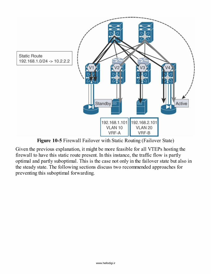
Figure 10-5 Firewall Failover with Static Routing (Failover State)Given the previous explanation, it might be more feasible for all VTEPs hosting thefirewall to have this static route present. In this instance, the traffic flow is partlyoptimal and partly suboptimal. This is the case not only in the failover state but also inthe steady state. The following sections discuss two recommended approaches forpreventing this suboptimal forwarding.
www.hellodigi.ir

Static Route Tracking at a Service LeafWhenever an endpoint, a firewall, or any other device is attached to a leaf hosting thedistributed IP anycast gateway in a VXLAN BGP EVPN network, the IP address islearned via ARP through the HMM in the local routing table and subsequentlydistributed into BGP EVPN. In this approach, a route-tracking condition is added to thisparticular route when adding the static route for the protected IP subnet behind thefirewall.
The static route configured on the service leaf (leaf attached to the firewall) is allowedto become active only if the route is being learned through the HMM. This prevents theconfigured static route from remaining active if the next hop is learned through anythingother than HMM. Alternatively, if the next hop for the route is learned through BGP, thestatic route becomes inactive. As a result, the static route is only active on the VTEPwhere the active firewall is present.
The following special configuration is required on the leaf where the firewalls areattached so that the firewall’s cluster IP can be tracked (10.2.2.2 in this case) andlearned via HMM only:
track 5 ip route 10.2.2.2/32 reachability hmmip route 192.168.1.0/24 10.2.2.2 track 5
Static Routing at a Remote LeafAn alternative approach to configuring route tracking by HMM is to employ static routeresolution at the remote leafs. In other words, a static route can be configured at all theremote leafs having endpoints that need to reach the protected subnet behind thefirewall. This occurs as follows:
ip route 192.168.1.0/24 10.2.2.2
This is simply a regular static route configuration for a remote route. Notably, thisrequires remote leafs to support recursive route resolution when the next hop is behind aremote VTEP. The active firewall’s IP address is learned at the service leaf andadvertised over BGP EVPN unconditionally to all remote leafs, just like any otherendpoint. When an HA event occurs, and the standby firewall takes over, it typicallysends out a Gratuitous Address Resolution Protocol (GARP) or ARP request toannounce its “takeover” to the network. The leaf attached to the standby firewall learnsthe firewall’s IP address as a local entry. After a rapid EVPN sequence number–assisted mobility convergence event, traffic is directed to the VTEP attached to the newactive firewall. In this way, the HA event for the firewall is treated just like any otherendpoint move event from the BGP EVPN network’s point of view.
Physical Connectivitywww.hellodigi.ir

There are many ways to connect a firewall to a leaf or pair of leafs. Options vary from asingle attached interface to using a local port channel to using a virtual PortChannel(vPC). The cases for using a single interface or a port channel attached to a single VTEPare not really different. Options for both Layer 2 and Layer 3 connectivity are available,and no special implications for routing protocols are present.
In case of static routing, the use of a Layer 2 interface or port channel is most commonlychosen when using a switch virtual interface (SVI) on the VTEP side, while the firewallprovides its option of a logical interface. Between the VTEP and the firewall, VLANIDs are used to separate the different logical firewall interfaces, if this approach is incompliance with the deployment. Alternatively, if a stronger separation than VLANs isrequired, separate physical or port channel interfaces can be used. However, this mayrequire the use of VLANs within the separate interfaces in order to address the logicalinterfaces within the VTEP or firewall.In cases where a firewall is connected to only one leaf, the redundancy is achieved bythe firewall’s high-availability capability. Here, it is assumed that one VTEP serves afirewall of the HA pair, while a different independent VTEP serves the respective HApartner. In these specific instances, the firewall provides the device redundancy, whilethe network takes care of providing the path redundancy.
From an operational perspective, this is the simplest way to deploy firewalls intonetworks because there is no “fate sharing” between the responsible network switches.Firewall redundancy is provided by two firewalls, network redundancy is provided bytwo network switches, and link redundancy is provided by two interfaces in a local portchannel.
For deployments requiring further redundancy, vPC can provide some additionalnetwork options. vPC enables the use of dynamic routing protocols, but the choice hereneeds to be evaluated carefully. Support for dynamic routing protocols over vPC isavailable on some hardware platforms and software releases, but even with this feature,certain constraints exist. Whenever the use of vPC is required, it is important to consultthe appropriate release notes and configuration guides for applicability.When vPC is required for redundancy, consider attaching each firewall to individualvPC domains and the associated switch pairs. This implementation provides commonfate sharing in a vPC domain; it is recommended to keep additional network redundancyrequirements intact. Both firewalls in the HA pair can also be connected to a single vPCdomain, but the operational tasks of a vPC domain have to be included in the overallredundancy consideration.
In discussing the deployment models, mode, and connectivity, it is important to considerthe location of the firewall or firewall HA pair. Once the location is defined in the
www.hellodigi.ir
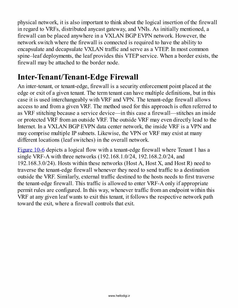
physical network, it is also important to think about the logical insertion of the firewallin regard to VRFs, distributed anycast gateway, and VNIs. As initially mentioned, afirewall can be placed anywhere in a VXLAN BGP EVPN network. However, thenetwork switch where the firewall is connected is required to have the ability toencapsulate and decapsulate VXLAN traffic and serve as a VTEP. In most commonspine–leaf deployments, the leaf provides this VTEP service. When a border exists, thefirewall may be attached to the border node.
Inter-Tenant/Tenant-Edge FirewallAn inter-tenant, or tenant-edge, firewall is a security enforcement point placed at theedge or exit of a given tenant. The term tenant can have multiple definitions, but in thiscase it is used interchangeably with VRF and VPN. The tenant-edge firewall allowsaccess to and from a given VRF. The method used for this approach is often referred toas VRF stitching because a service device—in this case a firewall—stitches an insideor protected VRF from an outside VRF. The outside VRF may even directly lead to theInternet. In a VXLAN BGP EVPN data center network, the inside VRF is a VPN andmay comprise multiple IP subnets. Likewise, the VPN or VRF may exist at manydifferent locations (leaf switches) in the overall network.
Figure 10-6 depicts a logical flow with a tenant-edge firewall where Tenant 1 has asingle VRF-A with three networks (192.168.1.0/24, 192.168.2.0/24, and192.168.3.0/24). Hosts within these networks (Host A, Host X, and Host R) need totraverse the tenant-edge firewall whenever they need to send traffic to a destinationoutside the VRF. Similarly, external traffic destined to the hosts needs to first traversethe tenant-edge firewall. This traffic is allowed to enter VRF-A only if appropriatepermit rules are configured. In this way, whenever traffic from an endpoint within thisVRF at any given leaf wants to exit this tenant, it follows the respective network pathtoward the exit, where a firewall controls that exit.
www.hellodigi.ir

Figure 10-6 Inter-tenant FirewallJust as the endpoints can be located anywhere within the VXLAN BGP EVPN fabric,the firewall can also be located behind any leaf. The best practices for deploymentplace the tenant-edge firewall at the service leaf or border leaf. In the case of the borderleaf, the given tenant-edge firewall is generally in control of external access. Oncetraffic has entered the tenant, VRF, or VPN, the tenant-edge firewall does not enforceany further control. This means that data traffic between various IP subnets in the giventenant is not enforced through the tenant-edge firewall.
Once traffic is allowed to enter the VRF, based on the configured policy rules, it is freeto communicate within the boundaries of the VRF. In summary, the tenant-edge firewallis the gatekeeper for traffic entering or leaving a given tenant, VRF, or VPN construct.
Figure 10-7 shows a tenant-edge firewall HA pair connected to the border in a VXLANBGP EVPN fabric. The connectivity of the firewall to the border can happenindividually as well as in association with a vPC domain. The leaf attached to endpoint192.168.1.101 has subnet 192.168.1.0/24 in VRF-A locally configured. Similarly, theleaf attached to endpoint 192.168.2.102 has subnet 192.168.2.0/24 in VRF-B locallyinstantiated. The networks in VRF-A and VRF-B need to be protected. VRF-C is the
www.hellodigi.ir

unprotected network where the Internet or WAN is connected. VRF-A, VRF-B, andVRF-C are instantiated on the border to which the tenant-edge firewall is attached.
Figure 10-7 Deployment of Tenant-Edge Firewall at Border Leaf
If an external client wants to connect to the endpoint 192.168.1.101, the traffic from theclient needs to enter the VXLAN BGP EVPN network through the external router andreach the border leaf in the unprotected VRF-C. Based on routing information in VRF-C, the traffic is directed toward the firewall HA pair (specifically the active firewallnode) and inspected.
The active firewall applies the appropriate security policies to the traffic, and if thetraffic is permitted, the firewall makes a forwarding decision based on the routing table,determining the appropriate interface through which the traffic should exit in order toreach the border leaf protected by VRF-A. Once in VRF-A on the border leaf, the trafficis VXLAN encapsulated and sent toward the leaf hosting endpoint 192.168.1.101 in themost efficient way. Recall that because this is routed traffic, the VXLAN VNI carried inthe header corresponds to the Layer 3 VNI associated with VRF-A.If endpoint 192.168.1.101 wants to connect to the WAN/Internet, the traffic from theendpoint flows toward its default gateway, which is the distributed IP anycast gatewayon the connected leaf. Once the leaf is reached, a routing lookup is performed that hitsthe default route leading to the exit point (the tenant edge) of VRF-A. The default route
www.hellodigi.ir

in VRF-A is advertised by the border leaf. Based on the routing table lookup, the trafficis encapsulated in VXLAN with the VNI associated with VRF-A and sent toward theborder leaf.
At the border leaf, the default route to exit the VXLAN BGP EVPN network is set topoint toward the firewall HA pair. After the firewall is reached, its local routing tableis consulted, and traffic is forwarded toward the appropriate next hop. In this case, thelookup hits the default-route match, which points to the border leaf in VRF-C. Once inVRF-C, external routing provides the exit by a learned default route, and in followingthis path, traffic reaches the external world, the WAN, or the Internet.Some variations exist in the connection between the tenant-edge firewall and theunprotected network VRF-C on the external router. One option is to provide a Layer 2network where the firewall can directly build Layer 3 adjacency with the external router(see Figure 10-8). This option sounds rather simple but might raise some complexityissues if multiple routers and multiple firewalls are present.
Figure 10-8 Logical Diagram for Tenant-Edge Firewall Connectivity (BridgeUnprotected)
Alternatively, the VXLAN BGP EVPN network can become the routing neighbor to theexternal router or routers as well as to the firewalls. In this case, the routers andfirewall build local routing adjacency to the leaf where they are connected (see Figure10-9). All this information is then redistributed into the BGP EVPN control protocol.With this approach, it is important to understand that the routing adjacency can occurwith either a physical or logical interface.
www.hellodigi.ir

Figure 10-9 Logical Diagram for Tenant-Edge Firewall Connectivity (RoutedUnprotected)
In the case of a logical interface or an SVI, the interface should not be a distributed IPanycast gateway. There are many reasons for this. First, such an interface would resultin the existence of multiple overlapping router IDs because every leaf would have thesame IP for respective peering. Furthermore, a logical interface is not required becausea physical interface can provide additional advantages in terms of convergence.Likewise, a logical interface might need additional protocols such as BFD (ifavailable).
When the firewall is deployed in the bridged or transparent mode, the exchange of IPinformation must be achieved between the logical router instances of the protected(VRF-A/VRF-B) and the unprotected networks (VRF-C), as shown in Figure 10-10. Asa result, a logical or physical interface on the protected network side of the firewallmust be present for each network as one side of the routing adjacency. Also, anadditional logical or physical interface is needed on the unprotected side of thefirewall. As discussed previously in describing firewall deployment in bridged mode, itis imperative that interfaces have individual MAC addresses. The firewall creates itsbridging table based on these addresses, and if the MAC addresses are all the same, thefirewall sees no need to forward anything.
www.hellodigi.ir

Figure 10-10 Logical Diagram for Tenant-Edge Firewall Connectivity (BridgedFirewall)
In this model, the firewall only acts as a security enforcement and potential addresstranslation point. All forwarding is in a pure bridged mode on the firewall, while thelogical routers or VRFs ensure that traffic from a given protected network can flow tothe unprotected side and vice versa.
Services-Edge DesignVarious white papers, design guides, and books cover services-edge design.3,4 Withnetwork virtualization, such deployments are simpler because the multitenancyconstructs are already reflected. With VXLAN BGP EVPN, the construct of VRFs orVPNs is inherently available, which simplifies the transport of segmentation through thenetwork.
When normalization to the firewall or other service tiers becomes necessary, traditionalapproaches are considered, such as those described in connection with externalconnectivity. Data center networks using VXLAN BGP EVPN enable multitenancy andallow integration with various services-edge deployment designs.
Intra-Tenant FirewallsAn intra-tenant or east-west firewall is a security enforcement point placed betweennetworks in a given tenant or VRF. The terms network, VLAN, and IP subnet are usedinterchangeably in this section. An intra-tenant firewall allows access control between
www.hellodigi.ir

networks. In regard to a VXLAN BGP EVPN data center fabric, the network is a Layer2 VNI, and it refers to a single IP subnet within this fabric at any location (that is, leaf).
Whenever an endpoint at any given leaf in the network wants to reach an endpoint in adifferent network, traffic follows the network path toward the exit, which is controlledby a firewall. Just as endpoints can exist at any location in the VXLAN fabric, thefirewall can also be located behind any and every possible leaf. However, firewalls aremost commonly attached to a set of service leafs or border leafs.As noted in the discussion regarding tenant-edge firewalls, once traffic has entered thetenant, VRF, or VPN, the tenant-edge firewall does not enforce any further control. Thisenforcement is the responsibility of the intra-tenant, or east–west, firewall. In otherwords, control of data traffic between various IP subnets within a given tenant isenforced through the intra-tenant firewall.
The east–west firewall inspects the communications and enforces the configured policyset for east–west communication when the endpoints in one network want tocommunicate with endpoints in a different network. Figure 10-11 shows a sample intra-tenant firewall deployment where three VLANs in Tenant 1 are protected by an east–west firewall. Specifically, the three VLANs (VLAN 10, VLAN 20, and VLAN 30) mapto three unique Layer 2 VNIs (VNI 30001, VNI 30002, and VNI 30003), eachassociated with a different subnet (192.168.1.0/24, 192.168.2.0/24, and192.168.3.0/24). The policies configured at the firewall ensure that traffic betweenhosts in different subnets is denied.
www.hellodigi.ir

Figure 10-11 Intra-Tenant/East–West Firewall
An intra-tenant firewall can be deployed in a VXLAN BGP EVPN network in differentways. One option is to integrate the firewall in routed mode and provide the defaultgateway for the networks on the firewall. This implementation method requires that theVXLAN network only operate in Layer 2 mode, while the distributed IP anycastgateway and VRFs are not configured. In this case, the endpoints communicate via aVXLAN Layer 2 VNI toward the default gateway configured on the firewall, and allfirst-hop routing is performed at the firewall, as shown in Figure 10-12. In the figure,VLAN 10 maps to VNI 30001, which in turn terminates on the firewall in the protectedleg where the default gateway for that subnet resides. Similarly, VLAN 20 maps to VNI30002. The unprotected leg of the firewall maps to VNI 30003, over which appropriateroute prefixes are exchanged to allow for reachability from an endpoint in the protectedsubnet to an endpoint in any other subnet and vice versa. In this scenario, the intra-tenantfirewall is deployed in routed mode.The Cisco implementation of VXLAN BGP EVPN provides the option to operate thenetwork in Layer 2–only mode. The control protocol is only leveraged for MAC prefixdistribution and for ARP suppression. In this case, the east–west firewall provides acentralized default gateway-like functionality, which is seen in many classic non-fabricapproaches.
Figure 10-12 Intra-Tenant/East–West Firewall as the Default GatewayWhen deploying the firewall in transparent mode, a slightly different option becomesavailable, as shown in Figure 10-13. VLANs 10, 20, and 30 are all part of the
www.hellodigi.ir

192.168.1.0/24 subnet. Endpoints in VLAN 10 and 20 need to be protected by thefirewall. In this situation, the distributed IP anycast gateway of the VXLAN BGP EVPNnetwork can still be leveraged, in conjunction with a Layer 2 approach. The firewall isconnected to a VTEP that serves the distributed IP anycast gateway for a given network.The network represented by VLAN 30 in the figure is available in the whole VXLANBGP EVPN fabric and represents the unprotected side. Endpoints can be connected tothis network in VLAN 30, but traffic toward these endpoints from other networks isdirectly routed without any enforcement via the transparent firewall.
The connectivity between the VTEP hosting the distributed IP anycast gateway and thefirewall is a classic Ethernet trunk, which feeds the unprotected network and the defaultgateway toward the firewall. The firewall operates in transparent mode and enforcesthe respective security policies for all passing traffic.Because the firewall is like a bump in the wire, the protected side is represented with adifferent VLAN ID from the unprotected side. Specifically, as shown in Figure 10-13,VLANs 10 and 20 represent the protected side. The protected VLANs are fed back tothe VTEP and get mapped to Layer 2 VNIs, making these protected networks availablethroughout the VXLAN BGP EVPN network. With this approach, the distributed IPanycast gateway can be better leveraged. Note that all endpoints in VLANs 10, 20, and30 share the same default gateway IP because they are part of the same subnet,192.168.1.0/24. However, the default gateway IP is only provisioned in VLAN 30 thatmaps to VNI 30003.
The advantage of this transparent firewall deployment is that protected and unprotectedbridge domains can be used throughout the VXLAN BGP EVPN network. This allowsflexibility and also enables the firewall, the distributed IP anycast gateway, and Layer 2and Layer 3 VNIs to coexist, which is not possible when a firewall is deployed inrouted mode as a default gateway. Also, this implementation allows simple integrationwith vPC because Layer 3 operations toward the firewall are not especially needed.
www.hellodigi.ir

Figure 10-13 Intra-Tenant/East–West Firewall - Transparent ModeWhen using the VXLAN BGP EVPN network to provide Layer 2 and Layer 3 functionwith the distributed IP anycast gateway, additional considerations are needed,particularly if the firewall is to be part of the routing path.
For example, when an endpoint (192.168.1.101) wants to connect to an endpoint(192.168.2.101) in a different subnet, the traffic must be inspected by the east–westfirewall. In a VXLAN BGP EVPN network, where a distributed IP anycast gateway isbeing used, the firewall participates in routing and also in the network itself. This meansthe firewall announces the IP subnets intended to be protected by it. Because these IPsubnet prefix routes are less specific than host routes (/32 in case of IPv4), the routesannounced by the firewall might not be considered. When inter-subnet traffic from theendpoint 192.168.1.101 reaches its distributed IP anycast gateway, it performs a lookupfor the destination endpoint, 192.168.2.101. Because both IP subnets belong to the sameVRF, an LPM lookup match hits the 192.168.2.101/32 host route. This results in the nexthop being the egress VTEP, which is the VTEP where the destination endpoint resides.
Consequently, the IP subnet route advertised by the firewall is ignored. Therefore, therequirement of inspecting the traffic between the two endpoints is not fulfilled. Aspreviously described, not only does the distributed IP anycast gateway provide the first-hop routing functionality for an endpoint, it is also responsible for advertising theendpoint location from a MAC and IP perspective. With this approach, shortest-path
www.hellodigi.ir

routing is achieved in the overlay directly from the ingress VTEP to the egress VTEP.
When inspection through a firewall is required, the previously described approach mustbe overridden. As explained, the advertisement of an IP subnet does not help in thiscase. If the firewall announces host routes, the best possible outcome would be adestination lookup that yields an ECMP path with the next hop being the firewall and theegress VTEP. However, this would still not satisfy the requirement that all inter-subnettraffic must be inspected via the intra-tenant firewall.Because classic destination-based routing is insufficient in the case of east–westfirewalls with networks in the same VRF, different approaches have to be selected. Oneoption would be to set one network to Layer 2–only mode and use the firewall as thedefault gateway for that network. In this way, the use of the distributed IP anycastgateway would be removed for that network, but it would still be available for use bythe other network. Nevertheless, this approach would be quite restrictive if more thanjust two networks were present and if firewall enforcement were required. In thissituation, only one single network would be able to use the distributed IP anycastgateway, while all the others would use the firewall as a default gateway. Because theuse of the distributed IP anycast gateway offers a significant advantage in the VXLANBGP EVPN network, using it together with east–west traffic enforcement is desirablewhen the protected and unprotected networks reside in the same VRF.
With policy-based routing (PBR), routing decisions can be overridden based ondifferent classification match criteria. Specifically, PBR classified traffic can bedirected and forwarded recursively to a specific firewall (see Figure 10-14). Thismeans that if traffic from IP subnet 192.168.1.0/24 wants to reach IP subnet192.168.2.0/24, traffic is classified and directed to a firewall. This firewall can be onthe same VTEP where the PBR rule is configured or somewhere else in the VXLANBGP EVPN network.
www.hellodigi.ir

Figure 10-14 Intra-Tenant/East–West Firewall—Policy-Based RoutingThe PBR match result can point to a next hop, which requires recursive lookups and isreachable over VXLAN. This is possible as long as the next hop is known andreachable. Because it is assumed that traffic from endpoint 192.168.1.101 to192.168.2.101 must be sent to the firewall and return traffic must also go through thefirewall, the PBR rule must also be configured on the VTEP serving endpoint192.168.2.101. Now if every endpoint within the 192.168.1.0/24 subnet needs to beprotected while communicating with endpoints in the 192.168.2.0/24 subnet, the PBRrule must be installed on all VTEPs servicing either of these subnets. With the presenceof the distributed IP anycast gateway, and endpoints spread across the fabric, this couldpotentially mean PBR rules being configured on all leafs under the IRB interfacesassociated with the subnets. The PBR rule sets could quickly become unwieldy if thenumber of subnets in the VRF that need protection also goes up. The complexity inmanaging these rules and the corresponding maintenance may make the use of PBRimpractical if the number of networks within a VRF becomes even a handful. Inaddition, the ACL table scale for installing the PBR rules becomes a concern.
With the PBR-based approach, IP subnet traffic for endpoint-to-endpoint protection canbe enforced, and this traffic can bypass the firewall during certain communications forperformance reasons. While Network Services Header (NSH),5 Segment Routing (SR),6and LISP7 are presently valid standards related to services redirection, the ability toinfluence and control traffic forwarding with PBR in a VXLAN BGP EVPN network ona hop-by-hop basis also exists. The following section looks at a combination ofVXLAN with the technologies previously mentioned so simplification of existing traffic
www.hellodigi.ir

direction rules for VXLAN BGP EVPN networks can be achieved.
Mixing Intra-Tenant and Inter-Tenant FirewallsData center networks are not uniform, and therefore the requirement for east–west aswell as north–south security policy enforcement has to be accommodatedsimultaneously. The previous sections explain in detail approaches used for firewallinsertion in a VXLAN BGP EVPN network. These approaches are not mutuallyexclusive as long as operations are in the same mode (routed or transparent).A firewall can operate at a tenant edge with routing protocols configured, and adifferent interface can act as the default gateway for an intra-tenant segment. Thequestion arises, however, whether it is permissible to mix the slightly different modesand positions in the network on a given firewall. Often, organizations require theseparation of the different stages in a network layer by layer. To support theseseparation requirements, modern firewalls allow virtualization and the creation ofmultiple contexts with dedicated or shared interfaces. This helps achieve a more logicalseparation than is provided by VLANs or VRFs.
Regardless of whether one or multiple firewalls are used to build an infrastructure, theplacement, function, and integration approach should be flexible enough toaccommodate the required deployment permutations.
Figure 10-15 depicts a sample deployment with both inter-tenant and intra-tenantfirewalls for VRF-A. The logical topology also depicts a service leaf to which thefirewalls are attached, and a regular leaf(s) to which various endpoints may be attached.The intra-tenant networks 192.168.1.0/24 and 192.168.2.0/24 are part of the same VRF(VRF-A) connected to the same VTEP (Leaf 1), as shown in Figure 10-15.
Figure 10-15 Inter-Tenant and Intra-Tenant Firewalls
Because the east–west firewall becomes the default gateway for these networks, theywww.hellodigi.ir

are extended as Layer 2 only across the VXLAN BGP EVPN fabric toward the serviceleaf. On the service leaf, IEEE 802.1Q trunks are used to extend the Layer 2 VNI viaVLANs toward the firewall. On the firewall, logical interfaces (similar to SVIs)provide the Layer 3 first-hop function (default gateway) to the endpoints in intra-tenantnetworks namely, 192.168.1.101 and 192.168.2.101.
Layer 3 point-to-point peering is set up between the east–west firewall and the serviceleaf over which the 192.168.1.0/24 and 192.168.2.0/24 subnet prefixes are advertisedfrom the firewall to the service leaf. This enables them to be redistributed into the BGPEVPN network. The third network 192.168.3.0/24 uses the distributed IP anycastgateway of the fabric and is therefore routed immediately to the leaf for different IPsubnet forwarding. This is accomplished by using the Layer 3 VNI associated with theVRF (VRF-A).If an endpoint in 192.168.1.101 wants to reach an endpoint in 192.168.2.101, traffic isforwarded via Layer 2 across the VXLAN BGP EVPN network. At the service leaf, thetraffic is decapsulated and mapped from the Layer 2 VNI to a VLAN, where it isforwarded to the east–west firewall. The firewall performs security policy enforcementand first-hop routing toward the network where the destination endpoint resides(192.168.2.101).
Leaving the firewall, the traffic is IEEE 802.1Q tagged on egress, depending on thedestination determined by the firewall. The service leaf maps the traffic, and adds aVXLAN header according to the configured VLAN–to–Layer 2 VNI mapping. Theencapsulated traffic is then forwarded toward the leaf where the destination endpoint192.168.2.101 resides.
The VXLAN BGP EVPN fabric thus operates in Layer 2–only mode. In other words, adistributed IP anycast gateway is not configured for the two networks (192.168.1.0/24and 192.168.2.0/24) within the fabric. Instead, the default gateway resides on the east–west firewall.For communication from an endpoint in the network 192.168.1.101 or 192.168.2.101toward an endpoint in the network 192.168.3.101, the flow begins in a similar fashion.Traffic is forwarded via Layer 2 across the VXLAN BGP EVPN network. At theservice leaf, the traffic is decapsulated and mapped from the Layer 2 VNI to a VLAN,where it is forwarded to the firewall. The firewall then performs security policyenforcement and first-hop routing toward the network where the destination endpointresides (192.168.3.101).
Leaving the firewall, the traffic is routed based on the firewall’s routing tables. Theegress interface is determined based on the destination identified by the firewall. Theservice leaf takes the routed traffic, performs a lookup, and encapsulates traffic
www.hellodigi.ir

according to the locally configured VRF-to-Layer-3 VNI mapping. The Layer 3 lookupin the VRF (VRF-A) also provides the next hop behind which the endpoint192.168.3.101 resides.
The VXLAN BGP EVPN fabric operates in Layer 3 mode, which means the distributedIP anycast gateway is configured for the network 192.168.3.0/24 on the leaf. The defaultgateway sits on the leaf for all endpoints in the network 192.168.3.0/24. Forcommunication from the endpoint 192.168.3.101 toward any other network in the sameVRF, the distributed IP anycast gateway on the leaf is employed.
As shown in Figure 10-15, a separate tenant-edge firewall is connected in the sameVRF where the endpoints reside, in order to provide external connectivity. A staticdefault route 0/0 may be configured in the tenant VRF on the service leaf pointing to thetenant-edge firewall. In turn, the default route is distributed within the BGP EVPNfabric so that all traffic that needs to leave the VRF is directed toward the service leafand then to the tenant-edge firewall, where the appropriate policies may be applied.As an alternative, the east–west firewall can be connected to the tenant-edge firewall toperform external connectivity in a two-staged approach. Many valid alternativeapproaches also apply in this case, but some common cases are discussed in thefollowing section to provide an overview on the subject.
Application Delivery Controller (ADC) and LoadBalancer in a VXLAN BGP EVPN NetworkThus far, this chapter has provided a lot of information regarding the use of firewalls asLayer 4–7 service nodes. Other than firewalls, the most commonly deployed serviceappliances are load balancers. Load balancing is often seen as a service provided bymultiple real servers, but a load balancer also allows the distribution of load based onspecific criteria.This section does not provide details of the mechanics of load balancers, but it isimportant to realize that these are stateful8 devices, just as firewalls are. Statefulimplies that data traffic, which creates sessions on the load balancer, must flow throughthe same Layer 4–7 device in both forward and reverse directions. This ensures that theserver applications behind the load balancer can be addressed from a requestperspective, and it also ensures that the return traffic stays valid within thiscommunication. This is similar to the behavior of a firewall, where traffic must not onlybe validated but also allowed.
The same considerations described for firewall placement and connectivity also applyfor the load balancer service appliances. Specifically, the classic integration
www.hellodigi.ir

approaches with VLAN or VRF stitching apply in exactly the same way. In contrast tothe approaches already covered, the following sections focus on some of the differentconnectivity models a load balancer allows (for example, the one-armed source-NATapproach).
NoteIn one load balancing approach, called Direct Server Return (DSR), thereverse traffic from the servers sitting behind the load balancer is sentdirectly back to the client, without traversing the load balancer. Thismethod is generally not the preferred deployment mode with loadbalancers and hence is not discussed here.
One-Armed Source-NATIn the one-armed source-NAT mode, the load balancer is connected with a single link orport channel to the leaf. A single port channel can include the use of vPC to achieveconnectivity redundancy across a pair of leafs. With a load balancer deployment, client-side and server-side parts typically exist. The client side represents requests for aservice, which maps to a virtual IP (VIP) address configured on the load balancer. TheVIP may be allocated from the same subnet associated with a directly attached interfaceof the load balancer. Alternatively, it may be allocated from a completely separatesubnet.
The server side comprises the set of server IP addresses that provide the serviceadvertised by the VIP. This section describes both the client side and the server side.
Direct VIP Subnet ApproachFigure 10-16 shows a sample VXLAN BGP EVPN deployment with a service leafattached to a load balancer. The load balancer is configured with VIP(192.168.200.200) being part of the subnet (192.168.200.0/24) and associated with theload balancer’s physical interface (192.168.200.254). This is called the direct VIPsubnet approach. The default gateway for the subnet is configured on the directlyattached leaf (192.168.200.1). The servers serving the VIP are in subnet192.168.1.0/24; 192.168.1.101 is the IP address of one such server attached to the leafwith VTEP V3. The client endpoint is attached outside the VXLAN BGP EVPN fabricbehind the border node hosting VTEP V1.
www.hellodigi.ir
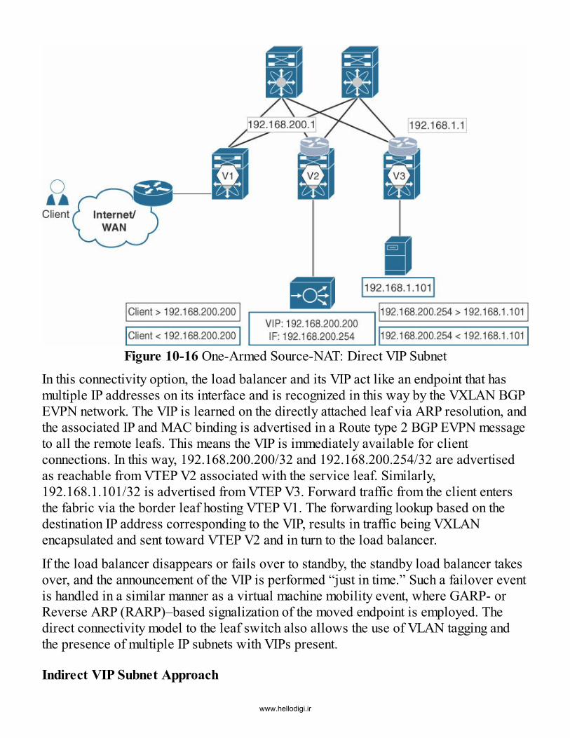
Figure 10-16 One-Armed Source-NAT: Direct VIP SubnetIn this connectivity option, the load balancer and its VIP act like an endpoint that hasmultiple IP addresses on its interface and is recognized in this way by the VXLAN BGPEVPN network. The VIP is learned on the directly attached leaf via ARP resolution, andthe associated IP and MAC binding is advertised in a Route type 2 BGP EVPN messageto all the remote leafs. This means the VIP is immediately available for clientconnections. In this way, 192.168.200.200/32 and 192.168.200.254/32 are advertisedas reachable from VTEP V2 associated with the service leaf. Similarly,192.168.1.101/32 is advertised from VTEP V3. Forward traffic from the client entersthe fabric via the border leaf hosting VTEP V1. The forwarding lookup based on thedestination IP address corresponding to the VIP, results in traffic being VXLANencapsulated and sent toward VTEP V2 and in turn to the load balancer.
If the load balancer disappears or fails over to standby, the standby load balancer takesover, and the announcement of the VIP is performed “just in time.” Such a failover eventis handled in a similar manner as a virtual machine mobility event, where GARP- orReverse ARP (RARP)–based signalization of the moved endpoint is employed. Thedirect connectivity model to the leaf switch also allows the use of VLAN tagging andthe presence of multiple IP subnets with VIPs present.
Indirect VIP Subnet Approach
www.hellodigi.ir

As an alternative to having the VIP subnet being the same as the one on which the loadbalancer interface resides, a dedicated IP subnet(s) for the VIP space can also bedefined, as shown in Figure 10-17. This is termed the indirect VIP subnet approach. Inthis case, the VIPs are behind the physical interface of the load balancer, and routing isrequired to reach the corresponding IP subnet (10.10.10.0/24).
Figure 10-17 One-Armed Source-NAT: Indirect IP Subnet
Unlike with the direct VIP subnet approach, the specific IP address for the VIP is notlearned via ARP resolution. Instead, the VIP-associated IP subnet (10.10.10.0/24) iseither configured statically or advertised using a dynamic routing protocol at the leaf. Inturn, it is then redistributed into BGP EVPN as a Route type 5 prefix so that it is knownthroughout the network. In case of a failover event, the VIP subnet is still reachable viathe active load balancer.
Just as in the firewall case previously described with static routes, the same options areavailable to ensure that VIP-directed traffic is always forwarded to the leaf attached tothe active load balancer. These options include static route configuration on the leafswhere the endpoints are connected (except for the service leaf, where the load balanceris attached), and also static route configuration on the service leaf with HMM trackingenabled.In both the direct and indirect VIP subnet approaches, the VIP is advertised only if the
www.hellodigi.ir

load balancer is available. This can help when a multiple-load-balancer cluster or HApair is available. The VIP used depends on the routing metric; this approach can helphandle either failure or load distribution scenarios.
Return Traffic
Thus far, the client-side details have been described with traffic following the regularforwarding path from the client to the VIP advertised by the load balancer. The serverside is less spectacular, since the major requirement involves a request from the clientvia the load balancer that is forwarded to the chosen destination server. The loadbalancer must have a valid forwarding path toward the server endpoints participating inthe server farm for the load balancer service.Typically, load balancers monitor the health of each of these servers and the servicesthey are hosting, so that requests are only forwarded to healthy servers. Also, because aload balancer is a stateful device, the return traffic from the servers must go through aload balancer before going back to the client. This is specifically important because theload balancer does not alter the client IP address under normal circumstances. As aresult, the servers participating in the server farm try to use the best path toward therequesting client IP.
Because the load balancer is not located in the physical path between the client andserver, source-NAT is employed. For all requests from the client reaching the loadbalancer, the source IP address is modified to one that is owned by the load balancer.The destination IP address then directs traffic to the selected server endpoint. In thisway, with the source-NAT feature, the individual client IP addresses are hidden behinda set of IP addresses owned by the load balancer. This way, return traffic from theservers within the server farm is always sent to the load balancer, and, in turn, the loadbalancer sends the traffic back to the client based on its stateful NAT tables.
One disadvantage of this deployment scenario is that the original client IP address ishidden behind the load balancers’ source-NAT pool. As a result, servers in the serverfarm see only the load balancers’ information. This can have some implications indeployments where certain compliance regulations are in place. Nevertheless, clientcredentials are often transported in the application-layer payload, and this can helpbypass the requirement of providing them redundantly in the network layer.Figure 10-18 shows a sample load balancer deployment with the direct subnet VIPoption and source-NAT feature. As before, the client wants to reach an application orservice hosted on the server endpoint (192.168.1.101). This server endpoint is servicedby a VIP (192.168.200.200) configured on the load balancer with interface IP192.168.200.254. The request from the client travels through the VXLAN BGP EVPNnetwork to reach the VIP (client > 192.168.200.200). The VIP is advertised into the
www.hellodigi.ir

network via either static or dynamic routing options. Recall that the VIP is advertised tothe remote VTEPs using a Route type 2 advertisement since it is learned on the serviceleaf as a regular ARP entry. Because the client and load balancer reside in the sameVRF, the request is transported over VXLAN with the VNI set to the Layer 3 VNIassociated with the corresponding VRF.
Figure 10-18 Source-NAT
Once the request has reached the load balancer, a session is created, and the destinationserver endpoint is selected based on the server farm, the load balancing algorithm, andother decision criteria configured on the load balancer. The client-side request isterminated, and a new server-side request is initiated toward the selected serverendpoint (192.168.1.101) with the source IP address of the load balancer(192.168.200.254). Because the load balancer and the server endpoint reside indifferent subnets, the new server-side request from the load balancer reaches theservice leaf where it is routed over VXLAN to VTEP V3. The VNI will be set to the L3VNI associated with the VRF in which the load balancer and server resides. Afterdecapsulation at VTEP V3, the request will undergo a routing lookup and finally beforwarded to 192.168.1.101. After processing, the response from the server is directedto the load balancer’s source-NAT IP address (192.168.1.101 > 192.168.200.254).Again, given this is inter-subnet communication, the response will be routed over to theservice leaf and delivered to the load balancer.
www.hellodigi.ir

The server-side response is terminated on the load balancer, and a new client-sideresponse is initiated toward the client. The VIP address is used as the source IP address,and the client IP address is used as the destination address for the response(192.168.200.200 > client). The response is routed over the VXLAN network to VTEPV1, where the client is attached. In this example, the VIP and the IP address for thesource-NAT pool are different. Depending on the load balancer vendor and softwareversion, the IP address for VIP and source-NAT pool may be different or may be thesame.
Service Chaining: Firewall and Load BalancerService chaining is an extensive topic involving the chaining of multiple Layer 4–7services so that data traffic can be inspected for security purpose and so that loadbalancing can occur for traffic distribution. Individual integration of the VXLAN BGPEVPN fabric with firewalls and load balancers has been discussed thus far. Building onthe integration story, additional deployment scenarios will be covered by adding aservice-chain to include firewall as well as a load-balancer.From a placement perspective, some additional considerations are warranted as the twotypes of services are traversed sequentially. One involves the unnecessary passing ofswitches and respective encapsulation/decapsulation passes, and the second relates toflooding the VXLAN BGP EVPN network with “transit” segments.
Consider a deployment scenario in which the firewall is attached at the border leaf, andthe load balancer is attached at a service leaf in the fabric. Depending on the source ofthe traffic generated from within the fabric, traffic first reaches the border node, isdecapsulated, is sent through the firewall, and then is once again encapsulated.Subsequently, the traffic is sent to the service leaf, is decapsulated again, then sent to theload balancer, then encapsulated again, and finally reaches the endpoint on a differentleaf in the server farm.
While this scenario can be easily supported with a VXLAN BGP EVPN fabric, trafficflows should traverse service chains as local as possible to avoid the need foradditional forwarding hops through the switches. In addition, the VXLAN BGP EVPNnetwork need not be aware of the transit segments between the firewall and the loadbalancer. Only the leaf that participates in the service chain needs the transit informationfor forwarding and failover purposes.In an optimal deployment, a client request from outside first enters the VXLAN BGPEVPN fabric through the border leaf. Before allowing traffic to reach the protected IPsubnet, the traffic is inspected by a tenant-edge firewall, which is typically attached tothe border leaf. From there, traffic is sent to the load balancer attached to the borderleaf. Alternatively, the traffic can enter the VXLAN BGP EVPN fabric pre-inspected
www.hellodigi.ir

and reach the service leaf where the east–west firewall and the load balancer areattached. In both cases, the traffic is encapsulated only once to pass through the servicechain (firewall and load balancer) in order to reach the endpoint on any given leaf in theVXLAN BGP EVPN fabric.
Additional stages can be easily integrated into the service chain if required. Forexample, if a requirement for a firewall sandwich exists with a load balancer andIDS/IPS (intrusion detection system/intrusion prevention system9) in between, this canbe integrated into the service chain. Service chains can therefore begin in a very simplemanner and develop into very sophisticated sets of service steps before reaching thefinal endpoint.With the different ways of integrating firewalls and load balancers, two main use casesneed to be covered. One involves the firewall and load balancer being physically inpath. This means a client request has to first flow through the firewall before beingallowed to access the load balancer. The other involves the firewall and load balancernot being physically in path but instead having the load balancer deployed in a single-armed mode. In the latter situation, the firewall and load balancer can be deployed ineither routed or transparent mode. The main difference between these choices involvesthe use of Layer 2 or Layer 3 segments for the respective transit segments. Figure 10-19shows a sample logical topology with an in-path firewall and load balancer servicechain deployment.
Figure 10-19 Routed Service ChainDeploying a service chain in routed mode, the transit segment between the unprotectedrouter, the firewall, the load balancer, and the protected router are IP subnets in the
www.hellodigi.ir

same switch or vPC domain. In order to ensure that the transit segment between theprotected and unprotected VRF is not leaked and that traffic is forced from firewall toload balancer, a dedicated VRF is created in between.
The segment before the firewall is the unprotected network (VRF-Outside), whichoperates in Layer 3 mode toward the firewall. At the point where the unprotected VRFsegment toward the firewall is presented, a Layer 3 interface for routing exchange ispresent. At this point, the routing configuration can be either static or dynamic. Thiseases the announcement of the IP subnets in the protected VRF (VRF-A). As a result, asimilar interconnection point exists in the secured or protected portion of the servicechain. Between the firewall and load balancer, the routing information for forwarding ispassed along, and in order to provide isolation, a service leaf local VRF (VRF-Transit)is employed.Traffic initiated from the client enters the VXLAN BGP EVPN network through theborder leaf. The traffic is then destined to the VIP configured on the load balancer,which is advertised through the firewall into VRF-Outside. The routing lookup on theborder leaf forwards the traffic, encapsulated with the Layer 3 VNI of VRF-Outsidetoward the service leaf where the firewall is attached. At the service leaf, the egressinterface is determined based on a local routing lookup, and traffic is sent into thefirewall through its OUT or unprotected interface.
At that stage, the firewall performs its inspection duties, and upon a permit result, trafficis forwarded toward the interface over which the VIP can be reached. The loadbalancer VIP is known via routing (static or dynamic) between the load balancer and thefirewall. Once traffic reaches the load balancer, the application-layer function isperformed, and the destination server endpoint is determined from the configured serverfarm.
Based on routing lookup, the egress interface is determined, and the traffic is forwardedtoward the protected VRF (VRF-A). In this way, traffic enters the service leaf on aningress interface associated with VRF-A. The destination lookup in VRF-A toward theendpoint in either in network 192.168.1.0/24 or 192.168.2.0/24 yields the leaf behindwhich the former resides. Traffic is appropriately VXLAN-encapsulated with the Layer3 VNI associated with VRF-A and sent toward the destination leaf. In turn, it is thendecapsulated and sent toward the destination. The reverse traffic from the destination tothe client follows a similar path but in the opposite direction.In the service chaining example described so far, the option to deploy the load balancerin the one-armed source-NAT mode exists instead of deploying the load balancer intwo-armed mode. In this situation, it is not necessary to create a transit VRF betweenthe load balancer and the firewall since the load balancer is positioned virtually in pathby using source-NAT. The service chain scenario with a tenant-edge firewall and a one-
www.hellodigi.ir

armed load balancer is discussed next.
Figure 10-20 shows a logical topology with a firewall and one-armed load balancerservice chain in routed mode. The source-NAT feature is enabled on the load balancer.The single arm or leg of the load balancer resides in the protected VRF (VRF-A). Inaddition, the IN, or protected leg of the firewall resides in a segment or subnet that ispart of VRF-A. The OUT leg of the firewall resides in a subnet in the unprotected VRF,namely VRF-Outside, and the corresponding segment operates in Layer 3 mode.
Figure 10-20 Routed and One-Armed Source-NAT Service Chain
At the point where the unprotected VRF segment toward the firewall is presented, aLayer 3 interface for routing exchange is present with either a static or dynamic routingconfiguration. The protected network (VRF-A) also has a dedicated interface towardthe firewall to facilitate routing exchange of the protected network into the unprotectednetwork. This eases the announcement of all protected IP subnets toward the client. TheVIP network for the load balancer participates in the VXLAN BGP EVPN fabric in asimilar way to the endpoint networks within the protected VRF-A.Because the load balancer is in one-armed source-NAT deployment mode, the trafficfrom the endpoints in network VLAN A or B always returns to the originator, whether itis the client directly or the load balancer. With this deployment mode, only load-balanced traffic is required to flow bidirectionally through the load balancer. Othertraffic, however, can bypass the load balancer. This advantage allows scaling of theload balancer with more services because only a portion of the traffic is transportedthrough it. This is not the case when the load balancer is physically in path. In such asituation, all traffic has to be forwarded by the load balancer, and this can impact the
www.hellodigi.ir
overall scale. Recall that with source-NAT, an inherent disadvantage exists because theoriginal client IP address is hidden behind the load balancer source-NAT pool whenclient requests are sent to the servers in the server farm. However, as mentioned before,client credentials are often transported in the application layer, circumventing thisproblem to a large extent.
Next, the flow of traffic from the client to the server endpoints is described for thetopology shown in Figure 10-20. As before, traffic initiated from the client enters theVXLAN BGP EVPN network through the border leaf. The destination IP address is theVIP, which has been configured and advertised by the load balancer (via the serviceleaf) and by the firewall into the unprotected VRF-Outside. Traffic is thus VXLAN-encapsulated with the Layer 3 VNI associated with VRF-Outside, and sent toward theservice leaf to which the firewall is attached.At the service leaf after decapsulation, the routing lookup sends the traffic toward thefirewall, ingressing via its OUT interface. After inspection, traffic is then sent out of thefirewall over its IN interface, which is the VIP-reaching interface. In this way, trafficingresses the service leaf in the protected VRF-A, goes through a regular routing lookupbased on the VIP, and is sent toward the load balancer.
Once traffic hits the load balancer, the application-layer function is performed, and anappropriate destination server endpoint is determined. Based on routing lookup, theegress interface is decided, and the traffic is again forwarded toward the protectedVRF-A after it has had a new source IP address applied via NAT. On the service leaf inthe protected VRF, a further lookup is done for the destination endpoint in eithernetwork 192.168.1.0/24 or 192.168.2.0/24. Traffic is appropriately VXLAN-encapsulated with the Layer 3 VNI associated with VRF-A and sent toward the leafwhere the destination endpoint is attached. Finally, after decapsulation at the destinationleaf, traffic is sent out toward the server endpoint.
The return traffic from the endpoint is sent to the load balancer source-NAT pool–selected IP address. In this way, only load balanced return traffic is sent to the loadbalancer before it traverses the tenant-edge firewall and returns to the client, therebyensuring stateful behavior.The two deployment approaches with service chains presented in this section indicatehow they can be integrated into a VXLAN BGP EVPN network. Various permutationsand combinations exist, but this section provides a good idea of how the deployment ofchoice can be derived by extension.
In conclusion, the tenant-edge service insertion with VXLAN BGP EVPN networks hasa similar implementation as in traditional networks. For intra-tenant firewalldeployment, there are some changes because of the presence of the distributed IP
www.hellodigi.ir

anycast gateway in the fabric. For load balancer deployments, the injection of the VIP asa host route and automatic handling of that advertisement even in case of a move orfailure scenario provides for a simple, elegant, and optimized deployment in the fabric.
SummaryThis chapter provides details on how Layer 4–7 services can be integrated into aVXLAN BGP EVPN network. Deployments with intra-tenant and inter-tenant firewallsare covered as these services can be deployed in both transparent and routed modes.The chapter also describes a common deployment scenario with a load balancer.Finally, the chapter presents two commonly deployed service-chaining scenariosinvolving a firewall and a load balancer. While this chapter certainly does not providean exhaustive list of all possible service deployments in a VXLAN BGP EVPN fabric,it presents adequate details to potentially allow any desired deployment to be realized.
References1. Internet Engineering Task Force (IETF). Bidirectional Forwarding Detection (BFD).
2010. tools.ietf.org/html/rfc5880.2. Cisco. Network address translation (NAT) FAQ. 2014.
www.cisco.com/c/en/us/support/docs/ip/network-address-translation-nat/26704-nat-faq-00.html.
3. Cisco. Network virtualization—Services edge design guide. 2009.www.ciscopress.com/store/network-virtualization-9781587052484.
4. Cisco. Network virtualization. Indianapolis, IN: Cisco Press, 2006.5. Internet Engineering Task Force (IETF). Network service header. 2016.
www.ietf.org/id/draft-ietf-sfc-nsh-09.txt.6. Internet Engineering Task Force (IETF). Segment router. http://www.segment-
routing.net/7. Internet Engineering Task Force (IETF). The Locator/ID Separation Protocol (LISP).
2013. tools.ietf.org/html/rfc6830.8. Wikipedia. Stateful devices. 2016. en.wikipedia.org/wiki/Stateful_firewall.9. Wikipedia. Intrusion detection system. 2016.
en.wikipedia.org/wiki/Intrusion_detection_system.
www.hellodigi.ir

Chapter 11 Introduction to Fabric Management
In this chapter, the following topics will be covered:
Day-0 operations that involve touchless device provisioning of the VXLAN BGPEVPN fabric using POAP Day-1 operations that involve Layer 2 and Layer 3 overlay service provisioning inthe fabric based on active endpoints Day-2 operations for continuous monitoring and visibility in the fabric VXLAN OAM and troubleshooting for overlay-based fabrics
Operating the fabric in a VXLAN BGP EVPN–based network requires more than justcontrol plane and data plane forwarding. In the world of automation, orchestration, andcontrollers, simply having the network operationalized is no longer sufficient. Instead,the elements of the switches, routers, and endpoints need to be managed and set upaccording to business and security requirements. To complement the content presentedin the other chapters so far, in this chapter, a brief overview will be provided on themanagement, orchestration, and automation aspects of the data center fabric. Figure 11-1depicts the typical elements involved in a fabric management framework.
Figure 11-1 Fabric Management Framework
The first step involves setting up the individual network components and building thefabric. The build-out of the fabric is referred to as day-0 operations. This includes amodel of the network configuration for the initial setup as well as the cabling plan
www.hellodigi.ir

layout of the fabric. Zero-touch provisioning options such as Power On AutoProvisioning (POAP)1 can help achieve these tasks autonomously.
Once the initial cabling of the fabric has been completed for Layer 1 connectivitybetween the spines and leafs, additional configurations for each network and each tenantare required. This is referred to as day-1 operations of the fabric. The overlay servicesinstantiate the necessary configurations on the fabric devices to ensure that the fabric isready to carry traffic to and from the endpoints when they are brought into theirrespective network/tenant. Day-1 configuration can be done via the CLI at one extremeor can be completely automated with close integration with compute orchestrators, atthe other extreme.Certain use cases add an incremental step between the day-0 initial setup and the day-1operations. In such situations, the endpoints (servers, firewalls, and so on) are addedand connected for the first time. An order of operation for specific automation tasksexists. For example, it is important to understand that endpoint interfaces (trunk oraccess) need to be configured before the network (VLAN, VRF, SVI, etc.). The order ofoperation is thus important for specific interface configuration management; it isreferred to as day-0.5 operations.
Once the network is set up and the endpoints are connected, the overlay provides thenecessary multitenant communication capabilities. At this point in the life cycle, thefocus turns to operation: monitoring, visibility, and troubleshooting. Day-2 operationsfor the life cycle management of the data center network with VXLAN BGP EVPNprovide insight into current functioning of the data center fabric.
While having visibility of the overlay is important, having visibility into the underlay—including performance and element management—is also important. The ability tocorrelate events in the underlay to services in the overlay provides a holistic view ofthe data center fabric. This entails health and inventory management of every individualhardware device that is part of the network.Troubleshooting spans the entire life cycle of the data center fabric. It begins with day-0provisioning operations and extends through the life cycle until the last networkcomponent has been decommissioned. In addition to preliminary troubleshooting,comprehensive sets of dedicated references are also available for troubleshooting aVXLAN BGP EVPN network as an entire entity.2
This chapter briefly describes details of each of the elements of the fabric managementframework: day-0, day-0.5, day-1, and day-2 operations.
Day-0 Operations: Automatic Fabric Bring-Up
www.hellodigi.ir

Zero-touch provisioning allows the automation of the fabric “bring-up” to enable day-0configuration. This is an easy and automated way to unbox, cable, and power on theswitching infrastructure that results in a consistently configured data center network.
NX-OS has a feature called Power On Auto Provisioning (POAP),3 which enables theday-0 operational model. POAP allows for unattended switching configuration, and italso achieves consistent configuration and software deployment across the entire datacenter fabric.Before unpacking, cabling, and powering up the switching infrastructure, somepreparation tasks must be completed for the infrastructure to receive the configuration.For example, the devices need to be assigned roles in the DC fabric, depending on theirintended functionality (such as leaf, spine, or border). This allows them to beappropriately wired and configured.
Cisco’s POAP leverages DHCP and specific DHCP options to tell the switch where theboot-up instructions are to be received. The boot-up instruction set can be transportedvia various protocols, such as Hypertext Transfer Protocol (HTTP)4 or Trivial FileTransfer Protocol (TFTP). The choice of the protocol used is defined in the DHCPoptions.
The boot-up instructions are transported in a Tcl5 or Python6 script that tells the switchexactly which steps to perform during the POAP process. It is recommended to onlyhave the boot-up script hosted on the TFTP server. The actual network configuration,which is more sensitive, is recommended to leverage secure protocols such as SecureCopy (SCP) or Secure File Transfer Protocol (SFTP)7 to transfer the entireconfiguration to the appropriate network switch during the POAP process.The Python/Tcl script instructs the device to implement SCP or SFTP transfers.Likewise, it also has precise instructions to retrieve configurations specific to thebooting switch identified by the serial number and/or MAC address associated with thatswitch. Note that other switch identification parameters can also be incorporated intothe Python/Tcl script for use during the POAP process.
The infrastructure required for the POAP process includes a DHCP server, aTFTP/HTTP server for the Python/Tcl script download, and a SCP/SFTP server for thedevice configuration file and software image, if desired. Several options exist forproducts that provide POAP server functionality. Some recommendations include thefollowing:
Leverage Cisco’s Data Center Network Manager (DCNM),8 which can alsoperform the tasks needed for all Cisco NX-OS–based hardware switches Leverage Cisco’s Nexus Fabric Manager (NFM)9 for relevant Nexus switching
www.hellodigi.ir

platforms Leverage Cisco’s project Ignite at the open source github repository10
In-Band Versus Out-of-Band POAP
POAP is a simple process and can be implemented using two different methods:
Out-of-band POAP In-band POAP
The out-of-band method is the most common method for implementation, and uses the“Management0” (mgmt0) interface of the network switch for the POAP process. Withthe out-of-band method (see Figure 11-2), the network switch boots up without anyconfiguration. The mgmt0 interface requests an IP address, leveraging DHCP. TheDHCP server, which is either embedded separately or resides in a POAP service’sengine, responds with an IP address as well as the specific DHCP scope options neededto retrieve the Python or Tcl script via TFTP or HTTP.
Figure 11-2 Out-of-Band POAP
The network switch retrieves the specific NX-OS image as well as the specificconfiguration mapped to its identity (such as the serial number or MAC address). Thesteps are defined within the script, and the ability to detect reboot requests duringconfiguration playback is also supported.
Cisco provides predefined Python scripts with these tasks via the NX-OS imagedownload, for example, with DCNM. Once all the tasks defined in the script have beensuccessfully completed, the network switch boots into operation with the respectiveconfiguration. In the event that NX-OS licensing is required for enabling specificconfigurations or feature sets, software license installation can be achieved through thePOAP process with appropriate modifications to the script.
www.hellodigi.ir

The in-band method for POAP (see Figure 11-3), on the other hand, leverages switchinterfaces, which are also known as “front panel ports,” as opposed to the mgmt0interface. DHCP requests are sent out on all front-panel ports. Once a DHCP responseis received, the Integrated Routing and Bridging (IRB) interface, or switch virtualinterface (SVI) associated with VLAN 1, is assigned the DHCP-offered IP address.Note that SVI 1 is always present on all Nexus switches. Subsequently, SVI 1 is therouted interface on which all the POAP steps are executed, including download andexecution of the appropriate Python-/Tcl-based POAP script, which in turn triggersappropriate system image download, startup configuration download, optional licensedownload and installation, and so on. In a sense, SVI 1 is comparable to the mgmt0interface used for POAP with the out-of-band method.
Figure 11-3 In-Band POAP
The choice of out-of-band versus in-band POAP requires careful consideration. Withthe out-of-band option, POAP services such as DHCP, TFTP, and SCP need to bereachable from the mgmt0 interface of every switch. The services could be Layer 2 orLayer 3 adjacent. If the management network is implemented as a flat Layer 2 domain,the services are all part of the same broadcast domain or VLAN. There may be scaleissues if the number of switches goes up; consequently, sufficient bandwidth must beprovisioned in the management network to accommodate these scenarios. A morescalable option is to have the services be reachable via routing. If the DHCP server isLayer 3 adjacent, a DHCP relay needs to be configured to allow the DHCP packets fromthe switch to reach the DHCP server and vice versa.
As with the out-of-band option, with the in-band option, the POAP services should be
www.hellodigi.ir
reachable via the front-panel interfaces. For a VXLAN BGP EVPN fabric, a seedswitch (or a pair, for redundancy) provides this reachability. Once the seed switch(typically a leaf) comes up via POAP, the next switch to come up is one of the spines.Recall that because the underlay is a routed network, all interfaces between the leafsand spines are configured as routed ports. DHCP requests coming in from a new spineare blocked at the neighboring uplink interfaces of the seed switch (aka leaf). Toovercome this limitation, a DHCP relay needs to be configured on the leaf interfacestoward the new spine switch being added to the fabric. The same holds true for any newleaf coming up where DHCP relay needs to be configured on appropriate spineinterfaces.
Today, the mgmt0 interface on most Nexus switches is a 1G port, while the front-panelports can be 10G, 25G, 40G, and 100G. Clearly, with the in-band option using the front-panel interface, there is plenty of bandwidth available for expansion, which is one of itsmajor advantages. However, with the in-band option, the leaf and spine switches needto come up in a certain order during the bootstrap phase. On the other hand, with the out-of-band option, because every switch has independent reachability to the POAPservices, there is no order dependency in terms of which switches need to come upbefore others.
Other Day-0 ConsiderationsIn addition to the POAP process itself, and the dependencies of the SCP, TFTP, andPython/Tcl script requirements, the ability to generate the respective startupconfiguration for the network switches is the next essential piece. Previously, theconfigurations were generated by hand or by a creative scripting method. The use of anintegrated template approach that is present in DCNM can improve, simplify, and scaleconfigurations significantly. It allows templates to be defined in a flexible andcustomizable fashion, with the desired parameterization and use of commonprogramming constructs such as iterative loops and IF-ELSE statements. In this way,the same template can be applied to multiple devices for efficient use and maintenance.
Tools such as Ignite, NFM, and DCNM provide the capability to set the management IPaddress on a network switch as well as the capability to generate full featureconfiguration for VXLAN BGP EVPN. NFM has an embedded capability to push thenecessary configuration down to the network switches as a turnkey solution. This allowsminimal attention to be given to the day-0 configuration.
DCNM behaves slightly differently from Ignite and NFM. The POAP definitions are notonly defined for VXLAN BGP EVPN networks, but the DCNM templates are flexibleenough to handle all kind of configurations through POAP. Within the template, sectionsand fields can be defined for all configurations through a GUI-based framework. DCNM
www.hellodigi.ir

can be used to provision multiple devices at once by entering multiple serial numbersand IP address pools. Much like NFM, DCNM provides a fabric setup wizard to createthe VXLAN BGP EVPN fabric in a workflow.
While an overlap may appear to be present between Cisco NFM and DCNM, some keydifferences are important to mention. NFM assigns an IP address to the switch from thebeginning and keeps the same IP address through the entire life cycle of the switch. Incontrast, DCNM uses a temporary IP address for the switch for the POAP processinitially, and subsequently, it replaces that IP address with the one defined in theconfiguration after POAP. This may not appear to be a major difference, but the scope ofthe hardware platforms supported with NFM is somewhat limited. (Refer to the latestrelease notes for current information.) It is also important to mention that DCNMsupports the POAP setup of any Cisco Nexus hardware platform with extensivetemplates for VXLAN, Cisco FabricPath, and classic Ethernet. DCNM also hasadditional templates to support virtual PortChannel (vPC), Fibre Channel/Fibre Channelover Ethernet (FC/FCoE), and Overlay Transport Virtualization (OTV) deployments.Loading the NX-OS image along with the configuration for the device(s) includingfeature sets and licensing during the POAP process, promotes consistent output to theconsole for real-time troubleshooting. The information sent to the console is alsocollected in a log file and stored on the network switches’ local storage (bootflash).
Building the in-band or out-of-band network is a one-time task that may not appear to bean attractive investment for an automation setup. It might seem as though the overallpreparation work, investment, and modeling of the network is too time intensive.However, there are significant benefits to setting this up correctly, such as savingoperational expenses for troubleshooting and preventing inconsistent configuration. Thisis especially beneficial during device return merchandise authorization (RMA).
When managing the configuration manually across multiple devices, a high percentageof errors can occur, resulting in mismatched configuration across the data centerinfrastructure. To prevent manual and inconsistent device configuration, the template-based approach with day-0 automation allows for consistency across the data center.For the hardware failure use case, the stored day-0 configurations can be quicklyreapplied to the new device(s).Once the new switch is unboxed, cabled, and powered on, the specific configurationrelated to the device role and identity is applied without requiring manual configuration.Day-0 automation provides tremendous value for unattended network device setup. As aresult, the operational process is simplified for the life cycle of the data centerinfrastructure.
www.hellodigi.ir

Day-0.5 Operations: Incremental ChangesAfter the day-0 automation, incremental changes may be required for new requirementsor for the addition of other servers or compute nodes over time. These day-0.5operations could be specific to the configuration of additional virtual port channels forhost-facing interfaces. While all these configuration additions can be placed in thePOAP configuration, this information is not available during day-0 bring-up of thenetwork switch in most practical scenarios. Therefore, requirements for day-0.5operations are quite common. Depending on the tools, software, and operational modelused, the interface configuration might be embedded directly in the day-1 process whenthe overlay services are configured.With a Clos-based spine–leaf fabric, an important step is validation of the connectivitybetween the various switches. The cable plan that serves as a blueprint for whichinterface on which switch should be connected to which interface on which otherswitch, requires validation so that the actual connectivity matches the intended design.This can be done in a brute-force manner, with the CDP or LLDP outputs on everyswitch cross-checked against the cable plan. This is not a one-time process and requirescontinuous monitoring as connectivity may be inadvertently changed, or misconnectionsmay occur during the lifetime of a fabric. The idea is to have an assurance model wherethe actual device connectivity is continuously monitored and matched against anintended blueprint, with appropriate notifications and alerts being pushed out wheninconsistencies are detected.
Typically, a graph-based network topological visualization can greatly aid in thisprocess. Cisco Nexus switches have a cable-management feature11 that can be usedindependently or in conjunction with DCNM to greatly ease the connectivity validationburden. The idea is that a network administrator can come up with a “golden”connectivity cable plan that is then imported on the switches. Each switch independentlyvalidates its current physical connections against that specified in the golden plan, and ifthere are discrepancies or inconsistencies, appropriate actions can be taken, such asbringing down a port. (Please check the release notes for updates on which Nexusplatforms support this feature.)
Day-1 Operations: Overlay Services ManagementThe VXLAN BGP EVPN overlay requires additional configuration steps to beconsidered. In addition to the traditional VLAN configuration, VXLAN VNIs needs tobe configured so the bridge domain can be extended across the VXLAN overlay.Additional services that need to be configured specific to the BGP EVPN control planeinclude distributed IP anycast gateway, VRFs, Layer 3 VNIs, and Layer 3 SVIs.
www.hellodigi.ir

Generic services also need to be configured for the VXLAN BGP EVPN, such as NVEinterfaces (VTEP), multicast groups, EVPN instances (EVI), and the associated BGPconfiguration. Several configuration components need to be aligned for the VXLANEVPN fabric. Aligning all of the Layer 2 and Layer 3 configurations requires overlayservices management to achieve consistent, correct, and efficient configuration.
In addition to the entire configuration itself, the management and operation of thedifferent namespaces (VLANs, VNIs, and IP subnets) are critical to ensuring reusabilityof local resources while ensuring that global resources do not overlap. All theparticipating entities such as the VXLAN VTEPs participating in the overlay, need to bevisible and managed to complete the overlay services management.The ability to discover all the devices participating as VXLAN VTEPs is a criticalrequirement for importing all the capabilities into the overlay services management.discovery and configuration not only apply to the VXLAN BGP EVPN network butextend to the external connectivity and the Data Center Interconnect (DCI) components.
Discovery includes learning different device roles and functions to gain completeknowledge of all available resources. Such a discovery allows better visibility of theoverlay topology and also a comprehensive understanding of the physical components.The end-to-end discovery, visibility, and operation are important to call out since theboundaries between network and compute operations typically serve as an impedimentto providing the necessary visibility. The overlay services management and controllersrequire the ability to understand the physical and logical infrastructure in conjunctionwith virtual machine managers and virtual switch VTEPs.
Proving end-to-end visibility and monitoring of the underlay and overlay allowsresources to be placed, configured, and provisioned on specific underutilized segments.The placement of these resources can be triggered on notifications received fromcompute managers of endpoints such as virtual machines or containers via a northboundAPI. Manual configuration triggered by the administrator via an appropriate GUI orsome scripts or even CLIs is also an option.The most common use case involves the agility to provision the network at the sametime an endpoint is attached. The requirement to automate the overlay provisioningservice gives the operations teams a couple of options:
Push model Pull model
A push model pushes a configuration snippet (configlet) to the appropriate networkdevices. The configuration push sends individual CLI commands. When using deletionvia CLI, simply adding no in front of every command in the configlet that created the
www.hellodigi.ir

initial configuration works in certain situations, but subcommands below a parentcommand or other subcommands require some intelligent handling.
When the push approach is not desired, Cisco permits a second method, a pull model. Ina pull model, the network device (or, in a VXLAN BGP EVPN fabric, the VTEP) isresponsible for downloading the required configuration. The switch or VTEP uses atrigger to detect an endpoint and in turn sends a query to fetch the relevant configurationrequired for that endpoint. The download or pull request is serviced on the overlayservices manager, where the desired configuration is stored in the configurationrepository.The push model needs to know exactly where to send the configuration. One advantageof this model is that minimal requirements on the network switch are present; however,from a scalability point of view, the push model is inherently centralized and may not bedesirable because it has to manage every network switch individually. For a largenetwork, this may become a performance bottleneck; however, the push model, beinginherently centralized, has the advantage of a single point of configuration push and easytracking.
With the pull model, more requirements for the network switch exist, but the location isnot important because the network device is the source of the requests when triggered.This results in not having a real-time topology, but instead having a dependency on theconfiguration repository. With the pull model, the load is distributed among all the leafswitches so that they manage the endpoints below them. This provides a more scalableoption. The individual switches manage both configuration provisioning and cleanupservices in a distributed manner.
While so far the discussion on overlay provisioning has considered CLI as the primaryoption, a more modern approach that leverages API calls can be used to perform thesame task. It is crucial to add overlay configuration for specific Layer 2 or Layer 3services, and it is equally critical to provide deletion and modification options.Compared to the CLI option, API calls are more efficient and flexible.
Virtual Topology System (VTS)The Cisco Virtual Topology System (VTS)12 is a service-oriented tool that focusesexclusively on provisioning the overlay services. VTS uses a push model leveragingNX-API.13 With the efforts in the IETF for EVPN service models such as Layer 2 VPN:L2SM and Layer 3 VPN: L3SM,14 Cisco will continue to expand the capabilities ofNX-API and orient it from the CLI15 to the model-driven NX-API REST.16 VTS’s tightcompute integration—for example, with OpenStack and VMware vCenter—allows forendpoint location awareness to enable the provisioning of Layer 2 or Layer 3 overlay
www.hellodigi.ir

services on the relevant switches, including the relevant VXLAN BGP EVPNconfiguration.
In addition to the VXLAN VTEP provisioning on Cisco Nexus switches, VTS alsoprovides the software Virtual Topology Forwarder (VTF).17 The VTF resides on thecompute servers and functions as a virtual VTEP, performing host-based VXLANoverlays. The VTF is provisioned by the VTS, using appropriateRESTCONF/NETCONF interfaces and is supported in hypervisor environments such asVMware ESXi and KVM. VTS has an integrated controller for VTF functionality thatallows seamless integration of physical and virtual VTEPs. In addition to physical andvirtual overlay automation, VTS also provides external connectivity (DCI) and Layer 4–7 services stitching automation. VTS relies on a tool like DCNM to enable provisioningand automation of the underlay network.VTS is also able to integrate with the model-based Cisco Network ServicesOrchestrator (NSO), which is powered by Tail-f Systems.18 VTS includes managementfor Cisco Nexus 9000, Cisco Nexus 5600, and Cisco Nexus 7000/7700. In addition, theCisco ASR 9000 series routers can be provisioned from the VTS for the externalconnectivity use case.19
Nexus Fabric Manager (NFM)The Cisco Nexus Fabric Manager (NFM)20 provides a turnkey solution for deployingVXLAN BGP EVPN networks. NFM’s integrated approach enables a simple point-and-click interface for creating Layer 2 and Layer 3 overlay services for the VXLAN BGPEVPN network. NFM has a fabric-aware control engine that understands currentconfigurations. This feature allows NFM to react to potential misconfigurations enteredthrough the CLI.NFM not only provides overlay services management but also provides the initial setupof the fabric with Auto Fabric Provisioning (AFP). At the present time, NFMexclusively manages and configures the Nexus 9000 series of switches. For specifichardware platform support, consult the NFM software release information.21
Data Center Network Manager (DCNM)Much like NFM, DCNM provides underlay and overlay management, while VTS onlyprovides overlay services management. Cisco DCNM was initially built to be a datacenter element manager, but it has been significantly enhanced to provide overlayservices management as well automated instantiation of the underlay. In addition to theEthernet and IP capabilities, DCNM also manages storage area networks (SANs).DCNM leverages POAP services to provide a turnkey, automated underlay network.
www.hellodigi.ir

The DCNM-integrated services such as DHCP, TFTP, and SCP are complemented witha template-driven workflow to enable provisioning of the VXLAN BGP EVPN network.The templates required for automated network deployment are included with the DCNMimage. Additional templates can also be downloaded from cisco.com.
DCNM provides integrated template and profile deployment capabilities that allow theconfiglets to be pushed to Cisco NX-OS-based network switches. The network switchescan also use the same configuration repository used for storing the push-based configletsto pull the configuration. As a result, DCNM supports both the push-based and pull-based models for overlay services management. With the extensibility of using CLIconfiguration-based templates and profiles, any configuration can be applied to anetwork switch managed through DCNM.With regard to VXLAN BGP EVPN networks in particular, external connectivity iscritical for making applications and data center resources accessible. As discussed forVTS, Cisco DCNM also integrates the border leaf and external routers with VRF Lite,MPLS L3VPN (BorderPE), and LISP. All the configurations are driven through CLI-liketemplate and profiles. Layer 4–7 services can also be easily integrated and automatedwith DCNM. Likewise, DCNM supports and manages all Cisco NX-OS-basedswitches, including the Cisco MDS SAN platforms.22
In addition to the commercial products provided by Cisco, open source tools areavailable for configuration of overlay services. IT automation tools such as Puppet,Chef, and Ansible provide a framework to create a manifests to deploy VXLAN BGPEVPN networks. While many of the open source automation tools provide options forVXLAN Flood and Learn, Ansible23 and Puppet24 provide a VXLAN BGP EVPNoption for Cisco NX-OS. While these are the current options available, extension ofChef and other IT automation tools are expected in the future. For automation integratedto the CLI shell within the Cisco NX-OS-based network switches, Python25 can also beused to automate the configuration of VXLAN BGP EVPN.
Compute IntegrationCompute integration for network automation can be implemented in multiple ways. Forthe use case in which a controller takes ownership and triggers a specific configurationto the network switches, the integration is performed in a top-down manner. In otherwords, the orchestration layer uses APIs or registered callbacks to drive configurationrequests to the overlay services manager. These triggers are based on the endpointscoming up or going down to the respective compute nodes.Using the existing topology mapping between the compute nodes and the networkswitches, decisions on where and what needs to be instantiated can be performed.
www.hellodigi.ir
Either the northbound orchestrator provides specific instructions on endpoint placementor a horizontal integration between the compute manager and overlay services managerneeds to exist.
With OpenStack26 and Cisco UCS Director (UCSD),27 such an approach is performed inthe absence of an overlay services manager. Therefore, the capabilities are limited toonly the information that OpenStack or UCSD can tell the network. By exposing theoverlay services and allowing OpenStack or UCSD to drive the intent through anoverlay services manager, a more flexible configuration can be achieved in the networklayer. OpenStack/UCSD28 combined with DCNM provides these benefits.With the resource management available, the intent-based request can be completed andextended, and this in turn provides comprehensive network deployments in a VXLANBGP EVPN network. While OpenStack or UCSD have been mentioned as examples,many orchestration options are capable of driving network-related requests via an API.These other options also support the top-down approach to overlay service instantiation(see Figure 11-4).
www.hellodigi.ir

Figure 11-4 Top-Down Overlay Service InstantiationAlternative approaches involve the integration of the network switch with the computemanager. In this model, the network switch is combined with the virtual machinemanager (VMM) to allow an exchange of information. Based on specific actionsoccurring in the virtual machine layer, the associated information is directly sent to thenetwork switches registered with the VMM.
A network switch decides if the message is relevant, based on whether the message isrelated to a virtual machine below a compute node that is directly attached to thatswitch. If the message is relevant, the network switch acts on it, triggering theappropriate configuration for that virtual machine. With Cisco’s VM Tracker29 feature,communication between the VMM (specifically VMware vcenter) and the networkswitch can be achieved. In turn, the provisioning/deprovisioning of the appropriatenetwork configuration is enabled.
www.hellodigi.ir

The integration of VM Tracker with the overlay services manager30 enables extensiveconfiguration that starts with basic Layer 2 configuration and extends all the way tocomplete VXLAN BGP EVPN configuration and Layer 3 services. The VM Trackerintegration uses a pull-based model for overlay configuration provisioning, with DCNMas the overlay services controller (see Figure 11-5).
Figure 11-5 Bottom-Up Overlay Service Instantiation
Day-2 Operations: Monitoring and VisibilityThe VXLAN BGP EVPN fabric is composed of two key elements:
VXLAN data plane encapsulation BGP-based EVPN control protocol
Because many components are involved in the overall solution, it is important tounderstand where specific information is derived and how that information can bevalidated. Network operators typically verify BGP functionality first because this is animportant verification step in showing relevant reachability information.Monitoring and retrieving the correct information for visibility are important for alltroubleshooting exercises. This section focuses on the operational aspects on howinformation can be retrieved from a VXLAN BGP EVPN network. It also includes
www.hellodigi.ir

troubleshooting approaches.
VXLAN BGP EVPN provides Layer 2 and Layer 3 services in the overlay network.Verification of the learning of Layer 2 MAC address information and Layer 3 IP addressinformation is a great place to start. This process also verifies whether certainendpoints are being learned locally.When verifying the classic Ethernet side, initially the local MAC address table isverified to ensure that it has learned the endpoint(s). This initial procedure verifies themapping between the endpoint, the connected interface, and the associated VLAN, asdemonstrated in Example 11-1.
Example 11-1 MAC Table Output at LeafClick here to view code image
L11# show mac address-tableLegend: * - primary entry, G - Gateway MAC, (R) - Routed MAC, O - overlayMAC age - seconds since last seen,+ - primary entry using vPC Peer-Link, (T) - True, (F) - False VLAN MAC Address Type age Secure NTFY Ports---------+-----------------+--------+---------+------+----+------------------* 100 0011.0100.0001 dynamic 0 F F Eth2/1
Example 11-1 verifies that the MAC address 0011.0100.0001 is learnt on interfaceEthernet 2/1 on VLAN 100. When this happens, local MAC learning on the networkswitch is verified. The same MAC address is advertised to BGP EVPN, into theappropriate MAC-VRF or EVPN instance (EVI) by the Layer 2 Routing InformationBase (L2RIB) component on the switch. This can be validated by using the showl2route evpn mac all command, as demonstrated in Example 11-2.
Example 11-2 MAC Entries Advertised Over BGP-EVPN at LeafClick here to view code image
L11# show l2route evpn mac allTopology Mac Address Prod Next Hop (s) ----------- -------------- ------ ---------------100 0011.0100.0001 Local Eth2/1
The output in Example 11-2 shows the presence of the locally learned MAC address intopology 100, where topology 100 maps to the VLAN ID. Based on the information
www.hellodigi.ir

present, it is not possible to derive the Layer 2 VNI from the given outputs. Verifying theVLAN to the segment mapping retrieves the respective L2VNI used for topology 100and EVI 100, as demonstrated in Example 11-3.
Example 11-3 VLAN to Layer 2 VNI Mapping at LeafClick here to view code image
L11# show vlan id 100 vn-segment
VLAN Segment-id---- -----------100 30000
The MAC is verified in the local address table as well as in the L2RIB table. Now it ispossible to verify and determine whether the respective MAC address has been sent tothe BGP EVPN address family for further advertisement, as shown in Example 11-4.
Example 11-4 BGP EVPN Route type 2 Entries at LeafClick here to view code image
L11# show bgp l2vpn evpn vni-id 30000BGP routing table information for VRF default, address family L2VPN EVPNBGP table version is 1670, local router ID is 10.100.100.11Status: s-suppressed, x-deleted, S-stale, d-dampened, h-history, *-valid,>-bestPath type: i-internal, e-external, c-confed, l-local, a-aggregate, r-redist, I-injectedOrigin codes: i - IGP, e - EGP, ? - incomplete, | - multipath, & - backup network Next Hop Metric LocPrf Weight Path
Route Distinguisher: 10.100.100.11:32867 (L2VNI 30000)*>l[2]:[0]:[0]:[48]:[0011.0100.0001]:[0]:[0.0.0.0]/216 10.200.200.11 100 32768i*>l[2]:[0]:[0]:[48]:[0011.0100.0001]:[32]:[192.168.100.200]/272 10.200.200.11 100 32768i
Based on the BGP output for the Layer 2 VNI 30000, the MAC address previouslyobserved in the local MAC address and L2RIB table has been advertised to BGP. Theoutput includes two route type 2 entries, with one containing the MAC address and theother containing the MAC address and the IP address. In order to verify that the local
www.hellodigi.ir

advertisement matches the configured attributes and to assess whether the appropriateprefix is received on the remote site, the show bgp command with the relevant MACaddress is executed on the local and remote leafs. Example 11-5 depicts the output fromthe show bgp l2vpn evpn command on a local leaf, and Example 11-6 depicts the outputfrom the show bgp l2vpn evpn command on a remote leaf.
Example 11-5 Details of a Particular BGP EVPN Route type 2 Advertisement at a LeafClick here to view code image
L11# show bgp l2vpn evpn 0011.0100.0001BGP routing table information for VRF default, address family L2VPN EVPNRoute Distinguisher: 10.100.100.11:32867 (L2VNI 30000)BGP routing table entry for [2]:[0]:[0]:[48]:[0011.0100.0001]:[0]:[0.0.0.0]/216, version 1540Paths: (1 available, best #1)Flags: (0x00010a) on xmit-list, is not in l2rib/evpn
Advertised path-id 1 Path type: local, path is valid, is best path, no labeled nexthop AS-Path: NONE, path locally originated 10.200.200.11 (metric 0) from 0.0.0.0 (10.100.100.11) Origin IGP, MED not set, localpref 100, weight 32768 Received label 30000 Extcommunity: RT:65501:30000
Path-id 1 advertised to peers: 10.100.100.201 10.100.100.202BGP routing table entry for [2]:[0]:[0]:[48]:[0011.0100.0001]:[32]:[192.168.100.200]/272, version 1550Paths: (1 available, best #1)Flags: (0x00010a) on xmit-list, is not in l2rib/evpn
Advertised path-id 1 Path type: local, path is valid, is best path, no labeled nexthop AS-Path: NONE, path locally originated 10.200.200.11 (metric 0) from 0.0.0.0 (10.100.100.11) Origin IGP, MED not set, localpref 100, weight 32768 Received label 30000 50000 Extcommunity: RT:65501:30000 RT:65501:50000
Path-id 1 advertised to peers: 10.100.100.201 10.100.100.202
Example 11-6 Details of a Particular BGP EVPN Route type 2 Advertisement at aRemote LeafClick here to view code image
www.hellodigi.ir

L12# show bgp l2vpn evpn 0011.0100.0001BGP routing table information for VRF default, address family L2VPN EVPNRoute Distinguisher: 10.100.100.11:32867BGP routing table entry for [2]:[0]:[0]:[48]:[0011.0100.0001]:[0]:[0.0.0.0]/216, version 1538Paths: (2 available, best #2)Flags: (0x000202) on xmit-list, is not in l2rib/evpn, is not in HW, , islocked Advertised path-id 1 Path type: internal, path is valid, is best path, no labeled nexthop AS-Path: NONE, path sourced internal to AS 10.200.200.11 (metric 3) from 10.100.100.201 (10.100.100.201) Origin IGP, MED not set, localpref 100, weight 0 Received label 30000 Extcommunity: RT:65501:30000 ENCAP:8 Originator: 10.100.100.11 Cluster list: 10.100.100.201
Example 11-6 verifies that the MAC address learned on the local leaf has reached theremote leaf via the BGP EVPN control protocol exchange. As was the case with theinitial leaf, verification that the MAC address is correctly downloaded and installedfrom the MAC-VRF or EVI (EVPN instance), should be performed. Example 11-7shows output from show l2route evpn mac on a remote leaf.
Example 11-7 MAC Entries Received Over BGP EVPN at a Remote LeafClick here to view code image
L12# show l2route evpn mac allTopology Mac Address Prod Next Hop (s) ----------- -------------- ------ ---------------100 0011.0100.0001 BGP 10.200.200.11
Example 11-7 verifies that MAC address 0011.0100.0001 has been learned by BGP andinstalled into L2RIB for further processing. The output verifies that the MAC addresshas a next hop assigned, and it reflects the IP address of the VTEP where the MAC waslearned.
Example 11-8 shows output from show mac address-table.
Example 11-8 MAC Table Output at a Remote LeafClick here to view code image
L12# show mac address-tableLegend: * - primary entry, G - Gateway MAC, (R) - Routed MAC, O - overlayMAC age - seconds since last seen,+ - primary entry using vPC Peer-Link,
www.hellodigi.ir

(T) - True, (F) - False VLAN MAC Address Type age Secure NTFY Ports---------+-----------------+--------+---------+------+----+------------------* 100 0011.0100.0001 dynamic 0 F F nve1(10.200.200.11)
Example 11-7 verifies that the MAC address has been learned via the BGP EVPNcontrol protocol and that it has been imported into the MAC-VRF. Finally, the MACaddress table on the remote leaf must be inspected to confirm that 0011.0100.0001 isindeed installed in the MAC table as shown in Example 11-8. From that point on, datatraffic can be expected from the remote leaf to this MAC address and that it can beforwarded via VXLAN encapsulation. With the integrated Layer 2 and Layer 3 services,Layer 2 and Layer 3 learning and information exchange must also be verified.Continuing with the same flow, it is also important to verify the ARP information hasbeen learned on the local leaf as well. Example 11-9 shows output from show ip arpvrf.
Example 11-9 ARP Table Output at a LeafClick here to view code image
L11# show ip arp vrf Org1:Part1
Flags: * - Adjacencies learnt on non-active FHRP router + - Adjacencies synced via CFSoE # - Adjacencies Throttled for Glean D - Static Adjacencies attached to down interface
IP ARP Table for context Org1:Part1Total number of entries: 1Address Age MAC Address Interface192.168.100.200 00:13:58 0011.0100.0001 Vlan100
The output derived from the ARP table shows that the MAC address previously tracked(0011.0100.0001) is associated with the IP address 192.168.100.200. A correspondingentry is installed in the Adjacency Manager (AM). This ARP and AM entry creationnotification is also passed along to the Host Mobility Manager (HMM) component,which is responsible for installing the host route in the unicast RIB. Example 11-10shows output from show forwarding vrf.
Example 11-10 Adjacency Output for an ARP EntryClick here to view code image
L11# show forwarding vrf Org1:Part1 adjacency
www.hellodigi.ir
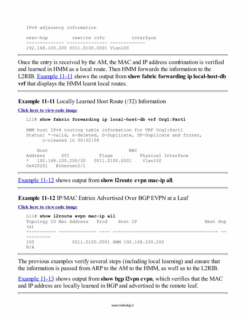
IPv4 adjacency information
next-hop rewrite info interface-------------- --------------- -------------192.168.100.200 0011.0100.0001 Vlan100
Once the entry is received by the AM, the MAC and IP address combination is verifiedand learned in HMM as a local route. Then HMM forwards the information to theL2RIB. Example 11-11 shows the output from show fabric forwarding ip local-host-dbvrf that displays the HMM learnt local routes.
Example 11-11 Locally Learned Host Route (/32) InformationClick here to view code image
L11# show fabric forwarding ip local-host-db vrf Org1:Part1
HMM host IPv4 routing table information for VRF Org1:Part1Status: *-valid, x-deleted, D-Duplicate, DF-Duplicate and frozen, c-cleaned in 00:02:58
Host MACAddress SVI Flags Physical Interface* 192.168.100.200/32 0011.0100.0001 Vlan100 0x420201 Ethernet2/1
Example 11-12 shows output from show l2route evpn mac-ip all.
Example 11-12 IP/MAC Entries Advertised Over BGP EVPN at a LeafClick here to view code image
L11# show l2route evpn mac-ip allTopology ID Mac Address Prod Host IP Next Hop(s)----------- -------------- ---- --------------------------------------- -----------100 0011.0100.0001 HMM 192.168.100.200 N/A
The previous examples verify several steps (including local learning) and ensure thatthe information is passed from ARP to the AM to the HMM, as well as to the L2RIB.
Example 11-13 shows output from show bgp l2vpn evpn, which verifies that the MACand IP address are locally learned in BGP and advertised to the remote leaf.
www.hellodigi.ir

Example 11-13 Details of a Particular BGP EVPN Route type 2 Advertisement withBoth IP and MAC at a LeafClick here to view code image
L11# show bgp l2vpn evpn 192.168.100.200BGP routing table information for VRF default, address family L2VPN EVPNRoute Distinguisher: 10.100.100.11:32867 (L3VNI 50000)BGP routing table entry for [2]:[0]:[0]:[48]:[0011.0100.0001]:[32]:[192.168.100.200]/272, version 1550Paths: (1 available, best #1)Flags: (0x00010a) on xmit-list, is not in l2rib/evpn
Advertised path-id 1 Path type: local, path is valid, is best path, no labeled nexthop AS-Path: NONE, path locally originated 10.200.200.11 (metric 0) from 0.0.0.0 (10.100.100.11) Origin IGP, MED not set, localpref 100, weight 32768 Received label 30000 50000 Extcommunity: RT:65501:30000 RT:65501:50000
Path-id 1 advertised to peers: 10.100.100.201 10.100.100.202
Example 11-14 shows output from show bgp l2vpn evpn on a remote leaf.
Example 11-14 Details of a Particular BGP EVPN Route type 2 Advertisement withBoth IP and MAC at a Remote LeafClick here to view code image
L12# show bgp l2vpn evpn 192.168.100.200BGP routing table information for VRF default, address family L2VPN EVPNRoute Distinguisher: 10.100.100.11:32867BGP routing table entry for [2]:[0]:[0]:[48]:[0011.0100.0001]:[32]:[192.168.100.200]/272, version 1554Paths: (2 available, best #2)Flags: (0x000202) on xmit-list, is not in l2rib/evpn, is not in HW, , islocked
Advertised path-id 1 Path type: internal, path is valid, is best path, no labeled nexthop AS-Path: NONE, path sourced internal to AS 10.200.200.11 (metric 3) from 10.100.100.201 (10.100.100.201) Origin IGP, MED not set, localpref 100, weight 0 Received label 30000 50000 Extcommunity: RT:65501:30000 RT:65501:50000 ENCAP:8 RouterMAC:f8c2.8887.88f5 Originator: 10.100.100.11 Cluster list: 10.100.100.201
The BGP output helps verify that the MAC and IP addresses are correctly imported and
www.hellodigi.ir

installed from the MAC-VRF and IP-VRF, respectively. With the corresponding BGPEVPN Route type message, two labels are advertised and received. The label 30000 isattached to the Layer 2 VNI, and the Layer 3 VNI is represented with the label 50000.
Example 11-15 shows output from show l2route evpn mac-ip on a remote leaf.
Example 11-15 IP/MAC Entries Received Over BGP EVPN at a Remote LeafClick here to view code image
L12# show l2route evpn mac-ip allTopology ID Mac Address Prod HostIP Next Hop (s) ----------- -------------- ---- --------------------------------------- -------100 0011.0100.0001 BGP 192.168.100.200 10.200.200.11
Example 11-16 shows output from show ip route vrf on a remote leaf.
Example 11-16 Output of IP Routing Table for Received IPv4 /32 Route Installed inRIBClick here to view code image
L12# show ip route vrf Org1:Part1 192.168.100.200IP Route Table for VRF "Org1:Part1"'*' denotes best ucast next-hop'**' denotes best mcast next-hop'[x/y]' denotes [preference/metric]'%<string>' in via output denotes VRF <string>
192.168.100.200/32, ubest/mbest: 1/0 *via 10.200.200.11%default, [200/0], 6w1d, bgp-65501, internal, tag65501 (evpn) segid: 50000 tunnelid: 0xac8c80b encap: VXLAN
At the remote leaf, the MAC and IP addresses are learned via the BGP EVPN controlprotocol, and they are imported into the respective MAC- and IP-VRFs. In particular,the import is controlled by the appropriate Route Targets import semantics, as is usuallythe case with BGP route prefixes.Finally, the IP address is installed in the IP routing table in the respective VRF. At thispoint, it should be possible to send both routed and bridged traffic to the endpoint(represented with MAC address 0011.0100.0001 and IP address 192.168.100.200)from anywhere in the VXLAN BGP EVPN fabric.
Example 11-17 shows the output from show nve internal bgp rnh database, whichwww.hellodigi.ir
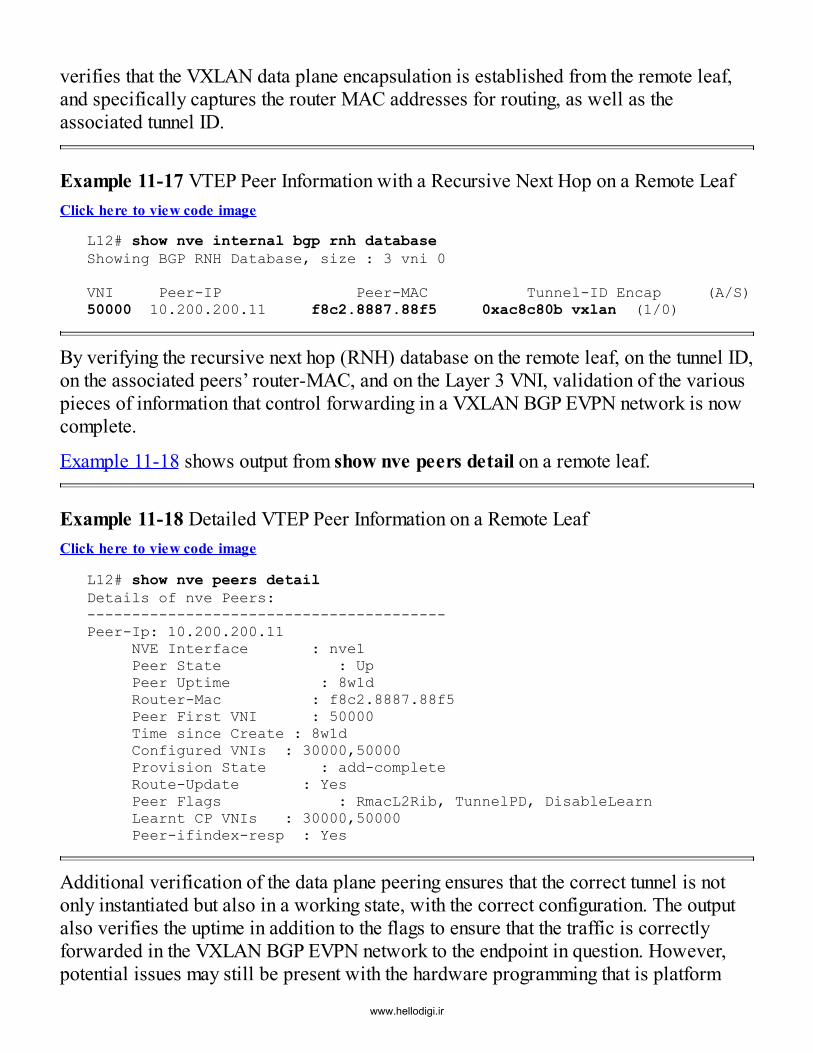
verifies that the VXLAN data plane encapsulation is established from the remote leaf,and specifically captures the router MAC addresses for routing, as well as theassociated tunnel ID.
Example 11-17 VTEP Peer Information with a Recursive Next Hop on a Remote LeafClick here to view code image
L12# show nve internal bgp rnh databaseShowing BGP RNH Database, size : 3 vni 0
VNI Peer-IP Peer-MAC Tunnel-ID Encap (A/S)50000 10.200.200.11 f8c2.8887.88f5 0xac8c80b vxlan (1/0)
By verifying the recursive next hop (RNH) database on the remote leaf, on the tunnel ID,on the associated peers’ router-MAC, and on the Layer 3 VNI, validation of the variouspieces of information that control forwarding in a VXLAN BGP EVPN network is nowcomplete.
Example 11-18 shows output from show nve peers detail on a remote leaf.
Example 11-18 Detailed VTEP Peer Information on a Remote LeafClick here to view code image
L12# show nve peers detailDetails of nve Peers:----------------------------------------Peer-Ip: 10.200.200.11 NVE Interface : nve1 Peer State : Up Peer Uptime : 8w1d Router-Mac : f8c2.8887.88f5 Peer First VNI : 50000 Time since Create : 8w1d Configured VNIs : 30000,50000 Provision State : add-complete Route-Update : Yes Peer Flags : RmacL2Rib, TunnelPD, DisableLearn Learnt CP VNIs : 30000,50000 Peer-ifindex-resp : Yes
Additional verification of the data plane peering ensures that the correct tunnel is notonly instantiated but also in a working state, with the correct configuration. The outputalso verifies the uptime in addition to the flags to ensure that the traffic is correctlyforwarded in the VXLAN BGP EVPN network to the endpoint in question. However,potential issues may still be present with the hardware programming that is platform
www.hellodigi.ir

specific. To determine how this can be validated, please refer to the relevant Nexusswitch–specific guides.
This section shows how to verify that the VXLAN BGP EVPN setup and configurationthrough relevant outputs and explanations. Likewise, it shows how to verify that MACand IP learning in the data center fabric is occurring correctly. The preliminarytroubleshooting steps in this section demonstrate a sequence of events to betterunderstand the flow of information and what configuration settings can be derived fromvarious outputs. As a result, several insights are provided beyond the basic examinationof the BGP output previously discussed in Chapter 2, “VXLAN BGP EVPN Basics.”
VXLAN OAM (NGOAM)The growing deployment of overlay networks in the data center has placed a great dealof focus on the operations, management, and life cycle of multiple stacks. Historically,troubleshooting and management involved some Layer 2 and Layer 3 basics, along withthe specifics of certain routing protocols used in the network. Overlays bring anadditional layer of virtual wires along with the associated protocols. These additionallayers add a level of indirection and abstraction from the underlying network as well asadditional complexity.
Abstraction provides a simple and efficient way of providing services withoutconsidering intermediate devices. However, when it comes to service degradation orperformance drops, a physical infrastructure that contains multiple paths is challenging.For example, when an operator is trying to determine the specific path an application istaking from one endpoint to another in the data center fabric, there is no simple tool forproviding this visibility. In other words, it is not easy to determine the path withoutinvesting a fair amount of time and energy.
In a VXLAN network, entropy is achieved by changing the UDP source port number sothat traffic between the same pair of VTEPs is spread across all available paths. Theintermediate nodes use an appropriate hashing algorithm, based on the outer packetheader fields of the VXLAN-encapsulated packet. The hashing algorithm used on theingress VTEP may be different from that used at the intermediate nodes. This results inchallenges for specific troubleshooting efforts related to path selection from the ingressVTEP to the egress VTEP.
VXLAN Operations, Administration, and Management (OAM)31 is part of Cisco’s Next-Generation OAM (NGOAM) framework for a Connectivity Fault Management (CFM)approach. NGOAM provides a simple and comprehensive solution to address theseproblems. VXLAN OAM and Cisco’s NGOAM are both evolutions of Ethernet OAM,known as IEEE 802.1ag.32 In addition to generating synthetic traffic to probe all
www.hellodigi.ir

available paths between ingress and egress VTEPs, OAM also provides an easyapproach for determining the outer UDP source port number used by VXLAN for aspecific application traffic flow.
Example 11-19 shows output from ping nve.
Example 11-19 Sample Output from the ping nve CommandClick here to view code image
L37# ping nve ip unknown vrf Org1:Part1 payload ip 192.168.166.51192.168.165.51 port 5644 25 proto 6 payload-end vni 50000 verbose
Codes: '!' - success, 'Q' - request not sent, '.' - timeout,'D' - Destination Unreachable, 'X' - unknown return code,'m' - malformed request(parameter problem),'c' - Corrupted Data/Test
Sender handle: 410! sport 52677 size 56,Reply from 192.168.166.51,time = 1 ms! sport 52677 size 56,Reply from 192.168.166.51,time = 1 ms! sport 52677 size 56,Reply from 192.168.166.51,time = 1 ms! sport 52677 size 56,Reply from 192.168.166.51,time = 1 ms! sport 52677 size 56,Reply from 192.168.166.51,time = 1 ms
Success rate is 100 percent (5/5), round-trip min/avg/max = 1/1/1 msTotal time elapsed 42 ms
The command ping nve sends ICMP probes, simulating traffic in the VXLAN overlay. InExample 11-19, the destination endpoint has the IP address 192.168.166.51 within VRFOrg:Part1. It should be noted that the source and destination IPs are in different subnets,resulting in a routing decision where the Layer 3 VNI that is assigned to the VRF(50000) is used in the VXLAN header.
ping nve has the ability to calculate the UDP source port used for the VXLANencapsulation, which achieves entropy for ECMP in the underlay network. The UDPsource port is generated based on the inner payload; in this example, the value is 52677.This example uses an inner payload with TCP (protocol 6), destination port 25signifying an SMTP application (25/TCP), and source port 5644 for the e-mailconnections. The result shows the acknowledgment and the reachability of the endpoint,using the outer UDP source port (52677) for VXLAN encapsulation. Instead ofunderstanding all the algorithms or searching for the used paths, a single probe canprovide the feedback and acknowledgment of the reachability of the destinationendpoint or application.
In the event that one path is experiencing performance degradation, the probe canwww.hellodigi.ir

determine and detect this erroneous path by returning potential packet loss similarly totraditional ICMP ping or traceroute tools. The presence of an application or payloadprofile yields the exact path the application is using and plots the effective physical pathtaken.
Example 11-20 shows output from traceroute nve.
Example 11-20 Sample Output from the traceroute nve CommandClick here to view code image
L37# traceroute nve ip unknown vrf Org1:Part1 payload ip 192.168.166.51192.168.165.51 port 5644 25 proto 6 payload-end vni 50000 verbose
Codes: '!' - success, 'Q' - request not sent, '.' - timeout,'D' - Destination Unreachable, 'X' - unknown return code,'m' - malformed request(parameter problem),'c' - Corrupted Data/Test
Traceroute Request to peer ip 10.1.1.140 source ip 10.1.1.37Sender handle: 412 1 !Reply from 10.1.1.38,time = 1 ms 2 !Reply from 10.1.1.140,time = 1 ms 3 !Reply from 192.168.166.51,time = 1 ms
The command traceroute nve issues a VXLAN traceroute and sends ICMP probe-simulating traffic in the overlay with incrementing TTL. Of note, TTL is copied from theinner header to the outer header to ensure that the intermediate routers will handle theVXLAN-encapsulated packets like regular IP traceroute packets.In Example 11-20, the destination endpoint has IP address 192.168.166.51 within VRFOrg:Part1. The source and destination IPs are in different subnets, which results in arouting operation using the Layer 3 VNI assigned to the VRF (50000). The output fromthe traceroute nve command provides the exact path that certain data traffic uses in theunderlay routed network. Specifically, the IP of each intermediate node along the path islisted, as with the regular IP traceroute command.
With ECMP, traffic selects one of several equal-cost paths. traceroute nve simplifiesthe path-finding and troubleshooting exercise. The path generated is based on theprotocol payload, thereby emulating a packet sent by the application or endpoint inquestion. As before, the example uses TCP (protocol 6) with destination port 25,emulating an SMTP application with the source port set to 5644 for the e-mailconnections.
The output provides an understanding of the exact path being used in the underlaynetwork, which enables the ability to pinpoint the exact spine that the data traffic is
www.hellodigi.ir

taking to the e-mail server. In addition, the destination VTEP has been set to “unknown,”so the output of traceroute nve also provides the IP address of the VTEP (10.1.1.140)attached to the destination endpoint.
One additional tool within VXLAN OAM that is extremely helpful is the “tissa”-basedpathtrace described in the draft-tissa-nvo3-oam-fm IETF draft.33 This OAM toolprovides the ability to list the exact underlay path that specific applications are taking,and it also derives the respective destination VTEP information and lists the ingress andegress interfaces at each of the intermediate hops (including the egress VTEP). Inaddition, it provides metadata information such as the interface load, interface state, andinterface error counters of all the listed interfaces.
Example 11-21 shows output from pathtrace nve with interface statistics.
Example 11-21 Sample Output from the pathtrace nve CommandClick here to view code image
L37# pathtrace nve ip unknown vrf Org1:Part1 payload ip 192.168.166.51 192.168.165.51 port 5644 25 proto 6 payload-end vni 50000 verbose req-stats
Path trace Request to peer ip 10.1.1.140 source ip 10.1.1.37Sender handle: 416
Hop Code ReplyIP IngressI/f EgressI/f State=============================================== 1 !Reply from 10.1.1.38, Eth1/23 Eth2/2 UP / UP Input Stats:PktRate:999 ByteRate:558873Load:3 Bytes:2101901590781unicast:3758851978 mcast:1487057bcast:13 discards:0errors:0 unknown:0bandwidth:171798691880000000 Output Stats:PktRate:999 ByteRate:558873load:3 bytes:2101901590781unicast:3758851978 mcast:1487057bcast:13 discards:0errors:0bandwidth:171798691880000000 2 !Reply from 10.1.1.140, Eth2/3 Unknown UP / DOWN Input Stats:PktRate:0 ByteRate:860Load:0 Bytes:5057292548unicast: 194899 mcast:1175038bcast:13 discards:0errors:0 unknown:0bandwidth:171798691880000000
www.hellodigi.ir

The command pathtrace nve issues a VXLAN path trace and uses special OAM probe-simulating traffic in the overlay. The same sample payload as that used for ping andtraceroute is used here, with the destination endpoint corresponding to an SMTPapplication located at the endpoint with IP address 192.168.166.51 within VRFOrg:Part1.The output clearly lists the intermediate hops, the ingress and egress interfaces, and theassociated load, statistics, and bandwidth. This results in an understanding of the exactpath being used in the underlay network. It also provides the ability to pinpoint the exactspine that the data traffic is taking to the e-mail server, as well as the exact path/linkbeing taken.
VXLAN OAM is implemented as NGOAM in the NX-OS platforms. This functionalityis provided through both the CLI and the API, via NX-API. NGOAM not only executesthe various probes across a programmatic interface but also provides the ability toretrieve statistical information from the VTEP. Both synchronous and asynchronousoptions are available.
With the preferred asynchronous option, a session handle is returned as anacknowledgment that the OAM probe execution request has been received. When theOAM probe execution is complete, the result is stored in the OAM database at thesourcing VTEP so that it can be retrieved at a later date since it is indexed via thesession handle. In this way, the session handle enables retrieval of the current andhistorical statistics from the VTEP local OAM database via a programmatic API or CLI.Additional enhancements in VXLAN OAM include the introduction of periodic probesand notifications to proactively manage the overlay network, along with the physicalunderlay. In order to make the collected path information and statistics meaningful,VXLAN OAM has been integrated with VXLAN management systems such as DCNM.
SummaryThis chapter introduces the basic elements of fabric management, including POAP-based day-0 provisioning (using DCNM, NFM, Ignite, and so on), incrementalconfiguration using day-0.5 configuration, overlay configuration using day-1provisioning (using DCNM, VTS, and NFM), and day-2 provisioning, includingproviding continuous monitoring, visibility, and troubleshooting capabilities in aVXLAN BGP EVPN fabric. This chapter also provides a brief primer on VXLANOAM, which is an extremely efficient tool for debugging overlay-based fabrics.
References
www.hellodigi.ir
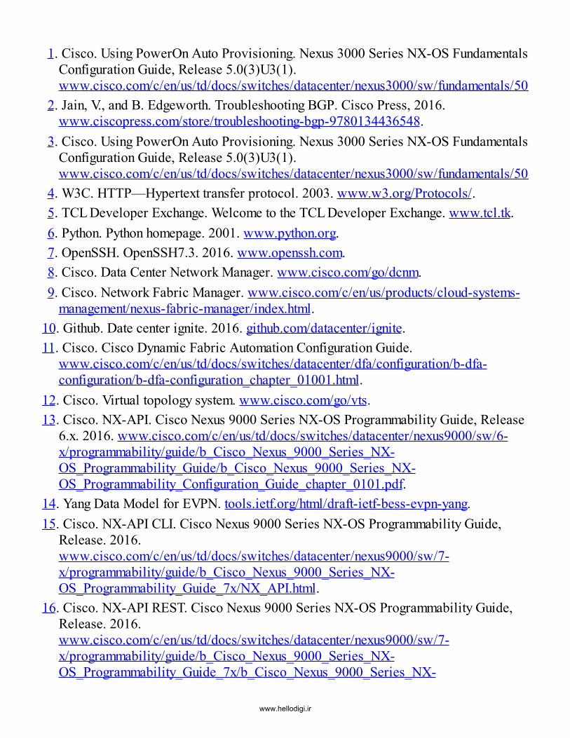
1. Cisco. Using PowerOn Auto Provisioning. Nexus 3000 Series NX-OS FundamentalsConfiguration Guide, Release 5.0(3)U3(1).www.cisco.com/c/en/us/td/docs/switches/datacenter/nexus3000/sw/fundamentals/503_U3_1/b_Nexus_3000_Fundamentals_Guide_Release_503_U3_1/using_power_on_auto_provisioning.pdf
2. Jain, V., and B. Edgeworth. Troubleshooting BGP. Cisco Press, 2016.www.ciscopress.com/store/troubleshooting-bgp-9780134436548.
3. Cisco. Using PowerOn Auto Provisioning. Nexus 3000 Series NX-OS FundamentalsConfiguration Guide, Release 5.0(3)U3(1).www.cisco.com/c/en/us/td/docs/switches/datacenter/nexus3000/sw/fundamentals/503_U3_1/b_Nexus_3000_Fundamentals_Guide_Release_503_U3_1/using_power_on_auto_provisioning.pdf
4. W3C. HTTP—Hypertext transfer protocol. 2003. www.w3.org/Protocols/.5. TCL Developer Exchange. Welcome to the TCL Developer Exchange. www.tcl.tk.6. Python. Python homepage. 2001. www.python.org.7. OpenSSH. OpenSSH7.3. 2016. www.openssh.com.8. Cisco. Data Center Network Manager. www.cisco.com/go/dcnm.9. Cisco. Network Fabric Manager. www.cisco.com/c/en/us/products/cloud-systems-
management/nexus-fabric-manager/index.html.10. Github. Date center ignite. 2016. github.com/datacenter/ignite.11. Cisco. Cisco Dynamic Fabric Automation Configuration Guide.
www.cisco.com/c/en/us/td/docs/switches/datacenter/dfa/configuration/b-dfa-configuration/b-dfa-configuration_chapter_01001.html.
12. Cisco. Virtual topology system. www.cisco.com/go/vts.13. Cisco. NX-API. Cisco Nexus 9000 Series NX-OS Programmability Guide, Release
6.x. 2016. www.cisco.com/c/en/us/td/docs/switches/datacenter/nexus9000/sw/6-x/programmability/guide/b_Cisco_Nexus_9000_Series_NX-OS_Programmability_Guide/b_Cisco_Nexus_9000_Series_NX-OS_Programmability_Configuration_Guide_chapter_0101.pdf.
14. Yang Data Model for EVPN. tools.ietf.org/html/draft-ietf-bess-evpn-yang.15. Cisco. NX-API CLI. Cisco Nexus 9000 Series NX-OS Programmability Guide,
Release. 2016.www.cisco.com/c/en/us/td/docs/switches/datacenter/nexus9000/sw/7-x/programmability/guide/b_Cisco_Nexus_9000_Series_NX-OS_Programmability_Guide_7x/NX_API.html.
16. Cisco. NX-API REST. Cisco Nexus 9000 Series NX-OS Programmability Guide,Release. 2016.www.cisco.com/c/en/us/td/docs/switches/datacenter/nexus9000/sw/7-x/programmability/guide/b_Cisco_Nexus_9000_Series_NX-OS_Programmability_Guide_7x/b_Cisco_Nexus_9000_Series_NX-
www.hellodigi.ir

OS_Programmability_Guide_7x_chapter_010001.html.17. Cisco. Virtual topology system data sheet.
www.cisco.com/c/en/us/products/collateral/cloud-systems-management/virtual-topology-system/datasheet-c78-734877.html.
18. Cisco. Tail-f. 2015. www.tail-f.com.19. Cisco. Virtual topology system data sheet, Table 2. 2016.
www.cisco.com/c/en/us/products/collateral/cloud-systems-management/virtual-topology-system/datasheet-c78-734877.html.
20. Cisco. Nexus Fabric Manager. www.cisco.com/c/en/us/products/cloud-systems-management/nexus-fabric-manager/index.html.
21. Cisco. Nexus Fabric Manager data sheet, Table 2. 2016.www.cisco.com/c/en/us/products/collateral/cloud-systems-management/nexus-fabric-manager/datasheet-c78-736499.html.
22. Cisco. Data Center Network Manager 10 data sheet. 2016.www.cisco.com/c/en/us/products/collateral/cloud-systems-management/prime-data-center-network-manager/datasheet-c78-736613.html.
23. Github. Data center Ansible NXOS. 2016. github.com/datacenter/Ansible-NXOS/tree/master/Ansible-NXOS/VxLAN-BGP-EVPN.
24. Puppetforge. Puppetlabs/Ciscopuppet. 2016.forge.puppet.com/puppetlabs/ciscopuppet#type-cisco_evpn_vni.
25. Cisco. Python scripting. 2016. www.cisco.com/c/en/us/products/collateral/cloud-systems-management/aci-fabric-controller/white-paper-c11-729385.html#_Toc459078278.
26. OpenStack. OpenStack homepage. 2016. www.openstack.org.27. Cisco. Cisco UCS Director. www.cisco.com/c/en/us/products/servers-unified-
computing/ucs-director/index.html.28. Github. Nexus fabric OpenStack integration. 2016.
github.com/CiscoSystems/fabric_enabler.29. Cisco. Cisco Nexus 9000 Series NX-OS Virtual Machine Tracker Configuration
Guide, Release 7.x. 2016.www.cisco.com/c/en/us/td/docs/switches/datacenter/nexus9000/sw/7-x/vm_tracker/configuration/guide/b_Cisco_Nexus_9000_Series_NX-OS_Virtual_Machine_Tracker_Configuration_Guide_7x/b_Cisco_Nexus_9000_Series_NX-OS_Virtual_Machine_Tracker_Configuration_Guide_7x_chapter_010.html.
30. Cisco. Virtual machine tracker auto-configuration. 2016.www.cisco.com/c/en/us/td/docs/switches/datacenter/pf/configuration/guide/b-pf-configuration/Introducing-Cisco-Programmable-Fabric-Management-Operations-
www.hellodigi.ir

and-Provisioning.html?bookSearch=true#concept_ED66F638F46A4CA0BCA431E141345D15.
31. Cisco. VXLAN OAM. 2016.www.cisco.com/c/en/us/td/docs/switches/datacenter/pf/configuration/guide/b-pf-configuration/Introducing-Cisco-Programmable-Fabric-Management-Operations-and-Provisioning.html?bookSearch=true#concept_2359393ACD0E4159B0E3DFCE99C00BD0.
32. IEEE. 802.1ag—Connectivity fault management.www.ieee802.org/1/pages/802.1ag.html.
33. NV03 Working Group. NVO3 fault management draft-tissa-nvo3-oam-fm-03.txt.2016. tools.ietf.org/html/draft-tissa-nvo3-oam-fm-03.
www.hellodigi.ir

Appendix A VXLAN BGP EVPN Implementation Options
This book encompasses details on building data center fabrics with open standards,specifically VXLAN, BGP, and EVPN. Although the primary focus is specific to theCisco NX-OS implementation, the book also explains the fundamentals associated withthe base technologies of VXLAN, BGP, and EVPN. Nevertheless, with open standards,the associated documented definitions in IETF contain some prescribed implementationoptions and additional functionality that will be briefly discussed here.
This appendix goes over some specific EVPN implementation options that arementioned as part of RFC 7432 BGP MPLS-Based Ethernet VPN1, the EVPN Overlaydraft-ietf-bess-evpn-overlay2 draft, and the EVPN Prefix Advertisement draft-ietf-bess-evpn-prefix-advertisement3 draft. The option for EVPN inter-subnet forwardingspecified in draft-ietf-bess-evpn-inter-subnet-forwarding4 that relates to symmetric andasymmetric Integrated Route and Bridge (IRB) options is excluded as it has beencovered in detail in Chapter 3, “VXLAN/EVPN Forwarding Characteristics,” under theIRB discussion.
EVPN Layer 2 ServicesEVPN defines different VLAN Layer 2 Services, as mentioned in RFC7432 Section 6.There are two options mentioned in Section 5.1.2 in draft-ietf-bess-evpn-overlay, whichapply to the VXLAN-related implementation. The first option, implemented by Cisco, iscalled VLAN-based bundle service interface. The second option is called VLAN-awarebundle service interface.
In the VLAN-based option, a single bridge domain is mapped to a single EVPN VirtualInstance (EVI). The EVI provides the Route Distinguisher (RD) and controls the importand export of the associated prefixes via Route Targets (RT) into the MAC-VRF and inturn into the bridge domain (see Figure A-1). When using the VLAN-based approach,the EVI corresponds to a single MAC-VRF in the control plane and a single VNI in thedata plane, resulting in a 1:1 mapping of EVI, MAC-VRF, and bridge domain (VNI).The disadvantage of the VLAN-based implementation is the configuration requirementof one EVI per bridge domain. This becomes an advantage for import/export granularityon a per bridge domain basis. Example 5-3 in Chapter 5, “Multitenancy,” provides aconfiguration example for the Cisco VLAN-based implementation.
www.hellodigi.ir

Figure A-1 VLAN-based Bundle ServicesIn the case of the VLAN-aware bundle service interface, multiple bridge domains canbe mapped to a single EVI. The VLAN-aware implementation allows a single RD andRT set to be shared across multiple bridge domains that belong to the same EVI. Thisresults in a 1:N mapping for the EVI to MAC-VRF to bridge domain (see Figure A-2);resulting in the VNI in the data plane being sufficient to identify the correspondingbridge domain. The VLAN-aware implementation reduces the configurationrequirements for EVIs. The disadvantage of the VLAN-aware implementation is that itdoes not allow the granularity of prefix import/export on a per bridge domain basis.
Figure A-2 VLAN-aware Bundle ServicesThe big difference between the VLAN-based and the VLAN-aware implementation isthe use of the Ethernet Tag ID field in the control plane. The VLAN-based option
www.hellodigi.ir

requires this field to be zero (0). The VLAN-aware option specifies the Ethernet Tag IDmust carry the identification of the respective bridge domain (VNI). The difference inEthernet Tag ID usage is described in RFC7432 section 6.1: VLAN-Based ServiceInterface and 6.3: VLAN-Aware Service Interface. It is important to understand that bothoptions are valid and conform to RFC 7432 but are not per se interoperable.
EVPN IP-VRF to IP-VRF ModelIn some cases, IP prefix routes may be advertised for subnets and IPs behind an IRB.This use case is referred to as the “IP-VRF to IP-VRF” model. As part of the EVPNprefix-advertisement draft, draft-ietf-bess-evpn-prefix-advertisement, there are threeimplementation options for the IP-VRF to IP-VRF model. The draft provides tworequired components and one optional component. For draft conformity, it is necessaryto follow one of the two required component models. The main focus here is on the tworequired models; the optional model will be touched upon briefly towards the end.Section 5.4 in draft-ietf-bess-evpn-prefix-advertisement describes the three models,which will be briefly introduced in this section.
The first model is called the interface-less model where the Route type 5 route containsthe necessary information for an IP Prefix advertisement. The Cisco NX-OSimplementation uses the interface-less model. Within the IP Prefix advertisement, all theIP routing information is included-such as the IP subnet, IP subnet length, and the nexthop. In addition, the IP-VRF context is preserved in form of the Layer 3 VNI present inthe Network Layer Reachability Information (NLRI). The interface-less model alsoincludes the Router MAC of the next hop as part of the BGP extended community. WithVXLAN being a MAC in IP/UDP encapsulation, the data plane encapsulation requirespopulation of the inner source and DMAC addresses. Although the local router MAC isknown and used as the inner-source MAC, the DMAC address needs to be populatedbased on the lookup of the destination prefix. The Router MAC extended communitywill provide this necessary information, as shown in Figure A-3. Note that with theinterface-less model, the Gateway IP (GW IP) field is always populated to 0. Example5-9 in Chapter 5 provides a configuration example for Cisco’s interface-lessimplementation.
www.hellodigi.ir

Figure A-3 IP-VRF Interface-less ModelThe second model is called interface-full, which has two sub-modes:
Core-facing IRB Unnumbered Core-facing IRB
In both cases of the interface-full model, in addition to the Route type 5 prefixadvertisement, a Route type 2 advertisement is also generated. With the interface-fullcore-facing IRB option, the Router MAC extended community is not part of the Routetype 5 advertisement. Instead, the Gateway IP (GW IP) field is populated to be that ofthe core-facing IRB associated with the VTEP. In addition, the VNI field in the Routetype 5 advertisement is set to 0. To complete the information required for the VXLANencapsulation, a Route type 2 advertisement is generated, as shown in Figure A-4. TheRoute type 2 advertisement provides the IP, as well as MAC information for the next-hop core-facing IRB interface that in turn is used for the population of the VXLANheader. In addition, the VNI field corresponding to the tenant or IP-VRF is also carriedin the Route type 2 advertisement.
www.hellodigi.ir

Figure A-4 IP-VRF Interface-full Model with Core-facing IRBIn the optional interface-full model of unnumbered core-facing IRB (see Figure A-5),the Router MAC extended community is sent as part of the Route type 5 advertisement ina similar way as the interface-less model. However, the VNI field in the advertisementremains 0, as does the GW IP address field. The associated Route type 2 advertisementis keyed by the Router MAC address associated with the next-hop core-facing IRBinterface and also carries the VNI associated with the tenant or IP-VRF. In this way,when traffic is destined to the Route type 5 advertised prefix, there is a recursivelookup performed to verify the next-hop router MAC information, and it is employed topopulate the corresponding VXLAN header.
www.hellodigi.ir

Figure A-5 IP-VRF Interface-full Model with Unnumbered Core-facing IRBThe difference between the interface-less and the interface-full model is mainly thepresence or absence of an additional Route type 2 advertisement. The interface-lessoption expects the Router MAC in the Route type 5 advertisement and will not leveragethe Route type 2 information advertised by an interface-full core-facing IRB model.Similarly, an interface-full option would expect the additional Route type 2advertisement. In both cases, the VXLAN data plane encapsulation would have theinformation necessary for populating the inner DMAC address.
In summary, the different IP-VRF to IP-VRF models are described in the EVPN prefixadvertisement draft, draft-ietf-bess-evpn-prefix-advertisement in section 5.4. It isimportant to understand what is required for each model so that they conform to theIETF draft; the different models are not per-se interoperable.
References1. BGP MPLS-Based Ethernet VPN. IETF Website, 2015. Retrieved from
https://tools.ietf.org/html/rfc7432.2. A Network Virtualization Overlay Solution using EVPN. IETF Website, 2016.
Retrieved from https://tools.ietf.org/html/draft-ietf-bess-evpn-overlay.3. IP Prefix Advertisement in EVPN. IETF Website, 2016. Retrieved from
https://tools.ietf.org/html/draft-ietf-bess-evpn-prefix-advertisement.4. Integrated Routing and Bridging in EVPN. IETF Website, 2015. Retrieved from
https://tools.ietf.org/html/draft-ietf-bess-evpn-inter-subnet-forwarding.
www.hellodigi.ir

www.hellodigi.ir

Index
AAARP (AppleTalk Address Resolution Protocol), 147ADCs (application delivery controllers), 262Address Resolution Protocol. See ARP (Address Resolution Protocol)addressing (IP)
address pool allocation, 99IP multicast, 98–99IP prefix route, 40IP unicast, 99–100, 103–107IP unnumbered, 96–97IPv6 endpoints, 167–169NVE (Network Virtualization Edge) loopback interface, 97–98P2P (point-to-point) configuration, 94–96PIP (primary IP address), 77RID (router ID), 93–94VIP (virtual IP address), 77
Adjacency Manager (AM), 290adjacency output (ARP), 290advertise-pip, 80–81advertising iBGP (internal BGP) routes, 193AFP (Auto Fabric Provisioning), 282agility, need for, 2AGM (anycast gateway MAC), 67, 79, 167allocating IP address pool, 99allowas-in, 106AM (Adjacency Manager), 290Ansible, 283Any Source Multicast (ASM), 29, 112–114anycast gateway MAC (AGM), 67, 79, 167Anycast HSRP, 8anycast VTEP, 79, 164–167APIs (application programming interfaces), 1AppleTalk Address Resolution Protocol (AARP), 147
www.hellodigi.ir

application delivery controllers (ADCs), 262application programming interfaces (APIs), 1ARP (Address Resolution Protocol), 30
suppression, 60–65tables
adjacency output for ARP entry, 290output at leaf, 289–290
ASM (Any Source Multicast), 29, 112–114ASN (autonomous system number), 129, 192asymmetric IRB (Integrated Routing and Bridging), 69–71Auto Fabric Provisioning (AFP), 282automatic fabric bring-up, 275–276AS (autonomous system), 34
ASN (autonomous system number), 129, 192multi-AS model, 104–105two-AS model, 104–106
availability, need for, 2
Bbackdoor links, 215–216balancing load. See load balancersin-band POAP (Power On Auto Provisioning), 276–278BDI (bridge domain interface) configuration, 131BD-oriented mode mode (multitenancy), 131–132BFD (Bidirectional Forwarding Detection), 194–195BGP EVPN (Border Gate Protocol Ethernet VPN)
BGP as underlay, 103–106eBGP (external BGP), 35, 192
multi-AS model, 104–105next-hop unchanged, 103–104retain route-target all, 104two-AS model, 104–106
forwardingARP (Address Resolution Protocol) suppression, 60–65DHCP (Dynamic Host Configuration Protocol), 81–84distributed IP anycast gateway, 65–69
www.hellodigi.ir

endpoint mobility, 73–76IRB (Integrated Routing and Bridging), 69–73vPC (virtual PortChannel), 76–81
host and subnet route distribution, 40–46host deletion and move events, 46–48iBGP (internal BGP), 34, 193IETF standards
Ethernet auto-discovery (AD) route, 38Ethernet segment route, 38inclusive multicast Ethernet tag route, 39IP prefix route, 40MAC/IP advertisement route, 38–39RFC/draft overview, 37–38
MP-BGP (Multiprotocol BGP), 34–37overview of, 32–34route types, 38
BGP routing information base (BRIB), 151BiDir (BiDirectional PIM), 29, 114–119Bidirectional Forwarding Detection (BFD), 194–195BiDirectional PIM (BiDir), 29, 114–119blade switches, 16Border Gate Protocol. See BGP EVPN (Border Gate Protocol Ethernet VPN)border leaves, 14, 188–189, 227, 248border nodes
BorderPE, 201full-mesh, 190–192LISP (Locator/ID Separation Protocol), 199placement of, 185–189U-shaped, 190–192
border spine, 14, 186–188, 227BorderPE, 201BRIB (BGP routing information base), 151bridge domain interface (BDI) configuration, 131bridge domains, 123bridging. See also routing
firewall bridging mode, 244–245
www.hellodigi.ir

Intra-Subnet Unicast forwarding, 139–146IRB (Integrated Routing and Bridging), 69–73non-IP forwarding, 147–149
bridging mode (firewall), 244–245BUM (broadcast, unknown unicast, and multicast) traffic. See also multicast forwarding
forwardingARP (Address Resolution Protocol) suppression, 60–65DHCP (Dynamic Host Configuration Protocol), 81–84distributed IP anycast gateway, 65–69endpoint mobility, 73–76ingress replication (IR), 58–59IRB (Integrated Routing and Bridging), 69–73multicast replication in underlay, 55–58vPC (virtual PortChannel), 76–81
ingress replication (IR), 58–59multicast mode
overview of, 109–112PIM ASM (Any Source Multicast), 112–114PIM BiDir (BiDirectional PIM), 114–119VNIs (virtual network identifiers), 111–112
multicast replication in underlay, 55–58overview of, 107unicast mode, 107–109
CCFM (Connectivity Fault Management), 295challenges of data centers, 2–3Cisco FabricPath, 7–9Cisco Network Services Orchestrator (NSO), 282Cisco open programmable fabric, 10–12Cisco UCS Director (UCSD), 284Cisco UCS Fabric Interconnect switches, 16Cisco Virtual Extensible LAN. See VXLAN (Virtual Extensible Local Area Network)Class of Service (CoS) field, 124classic Ethernet segments, 26classic Ethernet vPC domain, 76–77
www.hellodigi.ir

Clos, Charles, 89Clos network, 90–91commands
import l2vpn evpn reoriginate, 201import vpn unicast reoriginate, 202ip dhcp relay source-interface, 83ip igmp snooping disable-nve-static-router-port, 176, 179pathtrace nve, 297–298ping nve, 295show bgp ip unicast vrf, 151show bgp l2vpn evpn, 287–289, 291–292show bgp l2vpn evpn vni-id, 141, 144–145, 151–152, 287show fabric forwarding ip local-host-db vrf, 290–291show forwarding vrf, 290show ip arp vrf, 154, 289–290show ip route vrf, 153, 292–293show l2route evpn mac, 289show l2route evpn mac all, 142, 286show l2route evpn mac-ip, 292show l2route evpn mac-ip all, 291show mac address table, 289show mac address-table, 286show mac address-table vlan 10, 142show nve internal bgp rnh database, 293show nve peers detail, 294show run vrf, 163show vlan id, 287traceroute nve, 296–297
compute integration, 283–285configuration
BGP EVPN (Border Gate Protocol Ethernet VPN), 103–106IR (ingress replication), 107–109IS-IS (Intermediate System to Intermediate System), 102–103Layer 3 multitenancy, 135–137LISP (Locator/ID Separation Protocol), 200OSPF (Open Shortest Path First), 100–102
www.hellodigi.ir

P2P (point-to-point), 94–96Phantom RP, 114–119PIM (Protocol Independent Multicast)
PIM ASM (Any Source Multicast), 112–114PIM BiDir (BiDirectional PIM), 114–119
switch startup configuration, 278–279VNIs (virtual network identifiers), 125–128VRF Lite, 132–134
connectivityendpoint options, 15–17firewalls, 249–250Layer 2
classic Ethernet and vPC, 204–206overview of, 203–204
Layer 3, 189–190full-mesh models, 190–192LISP (Locator/ID Separation Protocol), 195–200MPLS Layer 3 VPN (L3VPN), 200–203U-shaped models, 190–192VRF Lite/InterAS Option A, 192–195
placement of, 185route leaking
downstream VNI assignment, 210–212local/distributed VRF route leaking, 207–210
server options, 15–17Connectivity Fault Management (CFM), 295convergence (STP), 5CoS (Class of Service) field, 124
Ddata center challenges, 2–3Data Center Interconnect (DCI), 194–195, 213–214, 280Data Center Network Manager (DCNM), 278–279, 283data center requirements, 2–3day-0 operations
automatic fabric bring-up, 275–276
www.hellodigi.ir
POAP (Power On Auto Provisioning), 275–278switch startup configuration, 278–279
day-0.5 operations, 279–280day-1 operations
compute integration, 283–285DCNM (Data Center Network Manager), 283NFM (Nexus Fabric Manager), 282overview of, 280–282VTS (Virtual Topology System), 282
day-2 operationsmonitoring and visibility, 285–294
adjacency output for ARP entry, 290ARP table output at leaf, 289–290BGP EVPN Route type 2 advertisement, 291–292BGP EVPN Route type 2 advertisement at leaf, 287–289BGP EVPN Route type 2 entries at leaf, 287IP/MAC entries advertised at leaf, 291IP/MAC entries received at remote leaf, 292locally learned host route information, 290–291MAC entries advertised at leaf, 286MAC entries received at remote leaf, 289MAC table output at leaf, 286MAC table output at remote leaf, 289output of IP routing table, 292–293VLAN to Layer 2 VNI mapping at Leaf, 287VTEP peer information, 293–294
NGOAM (Next-Generation OAM), 294–298DCI (Data Center Interconnect), 194–195, 213–214, 280DCNM (Data Center Network Manager), 278–279, 283deletion of end hosts, 46–48design of multi-pod deployments
mobility domains, 224multicast OIF (output interface) scaling, 221–222PIM Anycast RP approach, 223route reflector placement, 221topology, 225–226
www.hellodigi.ir
designated forwarders (vPC), 115, 178–179designated intermediate system (DIS), 102–103destination IP address (DIP), 9DHCP (Dynamic Host Configuration Protocol), 81–84
GiAddr field, 82–83option 82, 83–84process, 81–82
DIP (destination IP address), 9Direct Server Return (DSR), 262direct VIP subnet approach, 263–264DIS (designated intermediate system), 102–103disable-peer-as-check, 105–106distributed gateways, 3, 65–69distributed VRF route leaking
downstream VNI assignment, 210–212overview of, 207–210
domainsbridge domains, 123mobility domains, 224routing domains, 149vPC (virtual PortChannel), 76–77
downstream VNI assignment, 210–212draft-ietf-bess-evpn-inter-subnet-forwarding, 69DSR (Direct Server Return), 262dual-homing, 6
dual-homed endpoints, 164–167dual-homed forwarding, 178–180
Dynamic Host Configuration Protocol. See DHCP (Dynamic Host ConfigurationProtocol)
Eease of use, need for, 3east-west firewalls, 254–259east-west traffic, 21–23, 89eBGP (external BGP), 35, 192
multi-AS model, 104–105
www.hellodigi.ir

next-hop unchanged, 103–104retain route-target all, 104two-AS model, 104–106
ECMP (Equal-Cost MultiPath) routing, 5, 90edge devices, 9, 13. See also VTEPs (VXLAN Tunnel Endpoints)egress tunnel router (eTR), 197elasticity, need for, 2encapsulation
frame encapsulation, 24LISP (Locator/ID Separation Protocol), 196packet encapsulation, 24, 158
end hosts. See hostsend-of-row (EoR) topology, 15endpoint mobility, 73–76endpoints. See also VTEPs (VXLAN Tunnel Endpoints)
connectivity options, 15–17dual-homed endpoints, 158–163IPv6 endpoints, 167–169orphan endpoints, 78, 166, 180–181silent endpoints, routed traffic to, 158–163
end-to-end VLANs, 124EoR (end-of-row) topology, 15Equal-Cost MultiPath (ECMP) routing, 5, 90Ethernet
auto-discovery (AD) route, 38classic Ethernet and vPC, 76–77, 204–206Ethernet VPN. See BGP EVPN (Border Gate Protocol Ethernet VPN)multifabric deployments, 231
Interfabric Option 1, 232Interfabric Option 2, 233–234Interfabric Option 3, 235–236Interfabric Option 4, 236–238
segment route, 38eTR (egress tunnel router), 197EVI (EVPN instance), 128evolution of data center networks, 3–4
www.hellodigi.ir

EVPN instance (EVI), 128external BGP (eBGP), 35, 192external connectivity
Layer 2classic Ethernet and vPC, 204–206overview of, 203–204
Layer 3, 189–190full-mesh models, 190–192LISP (Locator/ID Separation Protocol), 195–200MPLS Layer 3 VPN (L3VPN), 200–203U-shaped models, 190–192VRF Lite/InterAS Option A, 192–195
placement of, 185route leaking
downstream VNI assignment, 210–212local/distributed VRF route leaking, 207–210
extranet, shared services and. See route leaking
FF&L (Flood and Learn), 8–9, 30–32fabric evolution, 3–4, 10fabric extenders (FEX), 15fabric management
day-0 operationsautomatic fabric bring-up, 275–276POAP (Power On Auto Provisioning), 275–278switch startup configuration, 278–279
day-0.5 operations, 279–280day-1 operations
compute integration, 283–285DCNM (Data Center Network Manager), 283NFM (Nexus Fabric Manager), 282overview of, 280–282VTS (Virtual Topology System), 282
day-2 operationsmonitoring and visibility, 285–294
www.hellodigi.ir

NGOAM (Next-Generation OAM), 294–298fabric properties, 14–15fabric-related terminology, 13–14framework, 273–274overview of, 273–275
fabric properties, 14–15FabricPath, 3, 7–9fabric-related terminology, 13–14FC (Fibre Channel), 16FCoE (Fibre Channel over Ethernet), 16FEX (fabric extenders), 15FHRPs (first-hop redundancy protocols), 7, 65–66FIB (forwarding information base), 151, 198, 211Fibre Channel (FC), 16Fibre Channel over Ethernet (FCoE), 16firewalls
bridging mode, 244–245firewall redundancy with static routing, 245–248inter-tenant firewalls
deployment, 250–254mixing with intra-tenant firewalls, 260–262
intra-tenant firewallsdeployment, 254–259mixing with inter-tenant firewalls, 260–262
overview of, 242physical connectivity, 249–250routing mode, 242–244service chaining, 267–271services-edge design, 254
first-hop redundancy protocols (FHRPs), 7, 65–66five-tuple input, 29Flood and Learn. See F&L (Flood and Learn)forwarding, 139
ARP (Address Resolution Protocol) suppression, 60–65DHCP (Dynamic Host Configuration Protocol), 81–84distributed IP anycast gateway, 65–69
www.hellodigi.ir

endpoint mobility, 73–76IGMP (Internet Group Management Protocol) snooping, 63–65IRB (Integrated Routing and Bridging), 69–73multicast forwarding
advantages of, 172IGMP snooping enhancements for VXLAN, 174–178Inter-Subnet Multicast forwarding, 182–184multicast in VXLAN, 171–174overview of, 54RPs (rendezvous points), 188in vPC, 178–181
multidestination trafficingress replication (IR), 58–59multicast replication in underlay, 55–58overview of, 54
overview of, 53–54STP (Spanning Tree Protocol), 5unicast forwarding
dual-homed endpoints, 164–167Inter-Subnet Unicast forwarding, 149–158Intra-Subnet Unicast forwarding, 139–146IPv6 endpoints, 167–169non-IP forwarding, 147–149overview of, 139routed traffic to silent endpoints, 158–163
forwarding information base (FIB), 151, 198, 211forwarding tag (FTAG) field, 8frames
encapsulation, 24format of, 28–29
framework, fabric management, 273–274FTAG (forwarding tag) field, 8full-mesh border nodes, 190–192
GGARP (Gratuitous ARP), 47, 75, 248
www.hellodigi.ir

gateways. See also ARP (Address Resolution Protocol)definition of, 79distributed, 3, 65–69
Generic Protocol Encapsulation (GPE), 10GiAddr field (DHCP), 82–83GPE (Generic Protocol Encapsulation), 10Gratuitous ARP (GARP), 47, 75, 248
HHA (high-availability) pairs, 245HER (head-end replication), 32, 58–59, 107–109high-availability (HA) pairs, 245HMM (host mobility manager), 245–246, 290host mobility manager (HMM), 245–246, 290hosts
deletion of, 46–48HMM (host mobility manager), 245–246, 290host A to host B forwarding, 145–146, 148host A to host Y forwarding, 157host and subnet route distribution, 40–46moving, 46–48
HSRP (Hot-Standby Router Protocol), 7HTTP (Hypertext Transfer Protocol), 275hybrid deployments, support for, 3Hypertext Transfer Protocol (HTTP), 275
IiBGP (internal BGP), 34, 193identity, overlay, 24IEEE 802.1D, 5, 22IEEE 802.1Q, 5, 22, 124IEEE 802.1s, 22IEEE 802.1w, 22IETF (Internet Engineering Task Force) standards
draft-ietf-bess-evpn-inter-subnet-forwarding, 69Ethernet auto-discovery (AD) route, 38
www.hellodigi.ir

Ethernet segment route, 38inclusive multicast Ethernet tag route, 39IP prefix route, 40MAC/IP advertisement route, 38–39RFC/draft overview, 37–38
IGMP (Internet Group Management Protocol) snooping, 63–65, 174–178Ignite, 278IGP (interior gateway protocol), 98import l2vpn evpn reoriginate command, 201import vpn unicast reoriginate command, 202inclusive multicast Ethernet tag route, 39incremental changes, fabric management and, 279–280indirect VIP subnet approach, 264–265ingress LISP tunnel router (iTR), 197ingress replication (IR), 32, 58–59, 107–109Integrated Routing and Bridging (IRB), 45, 69–73, 133–134, 149integrating Layer 4–7 services. See Layer 4–7 services integrationInterAS Option A, 192–195interconnection
at leaf layer, 227at spine layer, 227
Interfabric Option 1, 232Interfabric Option 2, 233–234Interfabric Option 3, 235–236Interfabric Option 4, 236–238interior gateway protocol (IGP), 98Intermediate System to Intermediate System (IS-IS), 7–8, 102–103internal BGP (iBGP), 34, 193Internet Engineering Task Force. See IETF (Internet Engineering Task Force) standardsInternet Group Management Protocol. See IGMP (Internet Group Management Protocol)snoopinginter-pod/interfabric
Ethernet handoff, 231Interfabric Option 1, 232Interfabric Option 2, 233–234Interfabric Option 3, 235–236
www.hellodigi.ir

Interfabric Option 4, 236–238Inter-Subnet Multicast forwarding, 182–184Inter-Subnet Unicast forwarding, 149–158inter-tenant firewalls
deployment, 250–254mixing with intra-tenant firewalls, 260–262
Intra-Subnet Multicast forwardingadvantages of, 172IGMP snooping enhancements for VXLAN, 174–178multicast in VXLAN, 171–174in vPC, 178–181
Intra-Subnet Unicast forwarding, 139–146intra-tenant firewalls
deployment, 254–259mixing with inter-tenant firewalls, 260–262
IOS-XE, 1IOS-XR, 1IP addressing
address pool allocation, 99IP multicast, 98–99IP prefix route, 40IP unicast, 99–100, 103–107IP unnumbered, 96–97IPv6 endpoints, 167–169NVE (Network Virtualization Edge) loopback interface, 97–98P2P (point-to-point) configuration, 94–96PIP (primary IP address), 77RID (router ID), 93–94VIP (virtual IP address), 77
ip dhcp relay source-interface command, 83ip igmp snooping disable-nve-static-router-port command, 176, 179IR (ingress replication), 32, 58–59, 107–109IRB (Integrated Routing and Bridging), 45, 69–73, 133–134, 149IS-IS (Intermediate System to Intermediate System), 7–8, 102–103iTR (ingress LISP tunnel router), 197
www.hellodigi.ir

J-K-LL2GW (Layer 2 Gateway), 139–140L2VNI (Layer 2 VNI), 122, 140L3GW (Layer 3 Gateway), 149L3VNI (Layer 3 VNI), 122, 149LACP (Link Aggregation Control Protocol), 76LAGs (link aggregation groups), 76Layer 2
external connectivityclassic Ethernet and vPC, 204–206overview of, 203–204
forwardingARP (Address Resolution Protocol) suppression, 60–65DHCP (Dynamic Host Configuration Protocol), 81–84distributed IP anycast gateway, 65–69endpoint mobility, 73–76ingress replication (IR), 58–59IRB (Integrated Routing and Bridging), 69–73multicast replication in underlay, 55–58vPC (virtual PortChannel), 76–81
L2GW (Layer 2 Gateway), 139–140L2VNI (Layer 2 VNI), 122, 140multicast forwarding
advantages of, 172IGMP snooping enhancements for VXLAN, 174–178multicast in VXLAN, 171–174in vPC, 178–181
multisite for, 236–238multitenancy
BD-oriented mode, 131–132VLAN-oriented mode, 130
unicast forwardingdual-homed endpoints, 164–167Inter-Subnet Unicast forwarding, 149–158Intra-Subnet Unicast forwarding, 139–146
www.hellodigi.ir

IPv6 endpoints, 167–169non-IP forwarding, 147–149routed traffic to silent endpoints, 158–163
Layer 2 Gateway (L2GW), 139–140Layer 2 VNI (L2VNI), 140Layer 3
external connectivityfull-mesh models, 190–192LISP (Locator/ID Separation Protocol), 195–200MPLS Layer 3 VPN (L3VPN), 200–203overview of, 189–190U-shaped models, 190–192VRF Lite/InterAS Option A, 192–195
forwardingARP (Address Resolution Protocol) suppression, 60–65DHCP (Dynamic Host Configuration Protocol), 81–84distributed IP anycast gateway, 65–69endpoint mobility, 73–76IRB (Integrated Routing and Bridging), 69–73vPC (virtual PortChannel), 76–81
L3GW (Layer 3 Gateway), 149L3VNI (Layer 3 VNI), 122, 149multicast forwarding, 182–184multisite for, 235–236multitenancy, 134–137
Layer 3 Gateway (L3GW), 149Layer 3 VNI (L3VNI), 149Layer 4–7 services integration
firewallsbridging mode, 244–245firewall redundancy with static routing, 245–248inter-tenant firewalls, 250–254, 260–262intra-tenant firewalls, 254–262overview of, 242physical connectivity, 249–250routing mode, 242–244
www.hellodigi.ir

service chaining, 267–271services-edge design, 254
load balancersDSR (Direct Server Return), 262one-armed source-NAT, 262–266overview of, 262service chaining, 267–271stateful nature of, 262
leaf switches, 13leaking. See route leakingleaves. See border leavesLink Aggregation Control Protocol (LACP), 76link aggregation groups (LAGs), 76links (STP), 5link-state advertisements (LSAs), 100LISP (Locator/ID Separation Protocol), 45–46, 195–200, 259load balancers
DSR (Direct Server Return), 262one-armed source-NAT
direct VIP subnet approach, 263–264indirect VIP subnet approach, 264–265overview of, 262–263return traffic, 265–266
overview of, 29, 116–118, 262service chaining, 267–271stateful nature of, 262
local/distributed VRF route leakingdownstream VNI assignment, 210–212overview of, 207–210
locally learned host route information, 290–291location, overlay, 24Locator/ID Separation Protocol (LISP), 45–46, 195–200, 259loopback interface (NVE), 97–98LSAs (link-state advertisements), 100
Mwww.hellodigi.ir

MAC Mobility Sequence Number field, 48MAC tables
IP/MAC entriesadvertised at leaf, 291received at remote leaf, 292
MAC entries advertised at leaf, 286output at leaf, 286output at remote leaf, 289
MAC/IP advertisement route, 38–39management. See fabric managementmapping
VLAN-to-VNI, 31–32different VLAN to same VNI, 125–126per-port VLAN to same VNI, 127–128sample configuration, 128–129
VLAN-to-VXLAN, 125maximum transmission unit (MTU), 24, 91–93MCEC (Multichassis EtherChannel), 6MC-LAG (Multi-Chassis Link Aggregation), 6, 66–67, 76, 215middle-of-row (MoR) topology, 15misses, ARP suppression and, 62mobility
endpoint mobility, 73–76mobility domains, 224
models of border nodesfull-mesh, 190–192U-shaped, 190–192
modes of operationfirewalls
bridging mode, 244–245routing mode, 242–244
Layer 2 multitenancyBD-oriented mode, 131–132VLAN-oriented, 130
Layer 3 multitenancy, 134–137monitoring and visibility, 285–294
www.hellodigi.ir

adjacency output for ARP entry, 290ARP table output at leaf, 289–290BGP EVPN Route type 2 advertisement, 291–292BGP EVPN Route type 2 advertisement at leaf, 287–289BGP EVPN Route type 2 entries at leaf, 287IP/MAC entries advertised at leaf, 291IP/MAC entries received at remote leaf, 292locally learned host route information, 290–291MAC entries advertised at leaf, 286MAC entries received at remote leaf, 289MAC table output at leaf, 286MAC table output at remote leaf, 289output of IP routing table, 292–293VLAN to Layer 2 VNI mapping at Leaf, 287VTEP peer information, 293–294
MoR (middle-of-row) topology, 15moving end hosts, 46–48MP-BGP (Multiprotocol BGP), 34–37MPLS (Multiprotocol Label Switching), 34MPLS Layer 3 VPN (L3VPN), 200–203MSDP (Multicast Source Discovery Protocol), 223MST (Multiple Spanning Tree), 22MTU (maximum transmission unit), 24, 91–93multi-AS model (eBGP), 104–105multicast forwarding
Layer 2advantages of, 172IGMP snooping enhancements for VXLAN, 174–178multicast in VXLAN, 171–174in vPC, 178–181
Layer 3, 182–184overview of, 54RPs (rendezvous points), 188
multicast IP, 98–99multicast mode
overview of, 109–112
www.hellodigi.ir

PIM ASM (Any Source Multicast), 112–114PIM BiDir (BiDirectional PIM), 114–119VNIs (virtual network identifiers), 111–112
multicast OIF (output interface) scaling, 221–222multicast replication in underlay, 55–58Multicast Source Discovery Protocol (MSDP), 223multicast traffic, 63Multicast VPN (MVPN), 34Multichassis EtherChannel (MCEC), 6Multi-Chassis Link Aggregation (MC-LAG), 6, 66–67, 76, 215multidestination traffic. See also multicast forwarding
ingress replication (IR), 58–59multicast mode
overview of, 109–112PIM ASM (Any Source Multicast), 112–114PIM BiDir (BiDirectional PIM), 114–119VNIs (virtual network identifiers), 111–112
multicast replication in underlay, 55–58overview of, 107unicast mode, 107–109
multifabric deploymentscompared to multi-pod deployments, 228–231inter-pod/interfabric
Ethernet handoff, 231Interfabric Option 1, 232Interfabric Option 2, 233–234Interfabric Option 3, 235–236Interfabric Option 4, 236–238
OTV (Overlay Transport Virtualization), 213–219overview of, 213
Multiple Spanning Tree (MST), 22multi-pod deployments. See also multifabric deployments
compared to multifabric deployments, 228–231design
mobility domains, 224multicast OIF (output interface) scaling, 221–222
www.hellodigi.ir

PIM Anycast RP approach, 223route reflector placement, 221topology, 225–226
OTV (Overlay Transport Virtualization), 213–219overview of, 213topology, 219–226
interconnection at leaf layer, 227interconnection at spine layer, 227
Multiprotocol BGP. See MP-BGP (Multiprotocol BGP)Multiprotocol Label Switching Layer 3 Virtual Private Network (MPLS L3VPN),200–203Multiprotocol Label Switching (MPLS), 34multisite, 231
for Layer 2, 236–238for Layer 3, 235–236
multistage network switches, 90multitenancy
bridge domains, 123Layer 2 multitenancy
BD-oriented mode, 131–132VLAN-oriented mode, 130
Layer 3 multitenancy, 134–137overview of, 121–122VLANs (virtual local area networks)
end-to-end, 124VLAN-to-VNI mapping, 125–129VLAN-to-VXLAN mapping, 125
VRF Lite, 132–134multitier Clos topology, 12MVPN (Multicast VPN), 34
NNA (neighbor advertisement), 60NAT (network address translation), one-armed source-NAT, 42
direct VIP subnet approach, 263–264indirect VIP subnet approach, 264–265
www.hellodigi.ir

overview of, 262–263return traffic, 265–266
ND (Neighbor Discovery Protocol), 60, 168neighbor advertisement (NA), 60Neighbor Discovery Protocol (ND), 42, 60, 168neighbor solicitation (NS), 60network forwarding. See forwardingnetwork interface cards (NICs), 91Network Layer Reachability Information (NLRI), 33network scale, 6network service access point (NSAP), 102Network Services Header (NSH), 10, 259Network Services Orchestrator (NSO), 282Network Virtualization Edge. See NVE (Network Virtualization Edge)network virtualization overlay (NVO), 23–27networks, storage area (SANs), 283Next-Generation OAM (NGOAM), 294–298next-hop, RNH (recursive next hop), 293next-hop unchanged, 103–104Nexus Fabric Manager (NFM), 278–279, 282NGOAM (Next-Generation OAM), 294–298NICs (network interface cards), 91NLRI (Network Layer Reachability Information), 33non-IP forwarding, 147–149north-south traffic, 88NS (neighbor solicitation), 60NSAP (network service access point), 102NSH (Network Service Header), 10, 259NSO (Network Services Orchestrator), 282NVE (Network Virtualization Edge)
devices, 13loopback interface, 97–98
NVO (network virtualization overlay), 23–27
OOAM (Operations, Administration, and Management), 295
www.hellodigi.ir

OIFs (outgoing interfaces), 55–58, 175OIFs (output interfaces), 221one-armed source-NAT
direct VIP subnet approach, 263–264indirect VIP subnet approach, 264–265overview of, 262–263return traffic, 265–266
open programmable fabric, 10–12Open Shortest Path First (OSPF), 100–102openness, need for, 2–3OpenStack, 284operations
day-0automatic fabric bring-up, 275–276POAP (Power On Auto Provisioning), 275–278switch startup configuration, 278–279
day-0.5, 279–280day-1
compute integration, 283–285DCNM (Data Center Network Manager), 283NFM (Nexus Fabric Manager), 282overview of, 280–282VTS (Virtual Topology System), 282
day-2monitoring and visibility, 285–294NGOAM (Next-Generation OAM), 294–298
Operations, Administration, and Management (OAM), 295orphan endpoints, 78, 166, 180–181OSPF (Open Shortest Path First), 100–102OTV (Overlay Transport Virtualization), 213–219outgoing interfaces (OIFs), 55–58, 175out-of-band POAP (Power On Auto Provisioning), 276–278output interfaces (OIFs), 221overlay services management
compute integration, 283–285DCNM (Data Center Network Manager), 283
www.hellodigi.ir

NFM (Nexus Fabric Manager), 282overview of, 280–282VTS (Virtual Topology System), 282
Overlay Transport Virtualization. See OTV (Overlay Transport Virtualization)overlays, 23–27. See also overlay services management
PP2P (point-to-point) configuration, 94–96packet encapsulation, 24, 158PAgP (Port Aggregation Protocol), 76pathtrace nve command, 297–298PBB (Provider Backbone Bridges), 37PBR (policy-based routing), 258–259PE (provider edge), 201peer keepalive (PKL), 77peer links (PLs), 77peers (vPC), 6–7Phantom RP, 99, 114–119PIM (Protocol Independent Multicast), 29
PIM ASM (Any Source Multicast), 112–114PIM BiDir (BiDirectional PIM), 114–119
ping nve command, 295PIP (primary IP address), 77, 80–81PKL (peer keepalive), 77placement
of external connectivity, 185–189of RRs (route reflectors), 221
PLs (peer links), 77POAP (Power On Auto Provisioning), 275–278point-to-point (P2P) configuration, 94–96policy-based routing (PBR), 258–259Port Aggregation Protocol (PAgP), 76power efficiency, need for, 3Power On Auto Provisioning (POAP), 275–278prefix: suffix notation, 36primary IP address (PIP), 77, 80–81
www.hellodigi.ir

properties of network fabric, 14–15Protocol Independent Multicast. See PIM (Protocol Independent Multicast)Protocol Independent Multicast (PIM), 29Provider Backbone Bridges (PBB), 37provider edge (PE), 201pull model, 281Puppet, 283push model, 281Python, 283
Q-RRapid Spanning Tree Protocol (RSTP), 22RARP (Reverse ARP), 47, 75, 203RDs (Route Distinguishers), 35–36, 60, 129, 135recursive next hop (RNH), 293redundancy (firewall), 245–248relay (DHCP), 82remote leaves, static route tracking at, 248rendezvous points (RPs), 14, 178, 188
in multistage fabric, 221Phantom RP, 114–119
replicationIR (ingress replication), 32, 58–59, 107–109multicast replication in underlay, 55–58
Requests for Comments. See RFC (Requests for Comments)requirements of data centers, 2–3retain route-target all, 104return merchandise authorization (RMA), 279return traffic, 265–266Reverse ARP (RARP), 47, 75, 203reverse path forwarding (RPF), 183RFC (Requests for Comments)
Ethernet auto-discovery (AD) route, 38Ethernet segment route, 38inclusive multicast Ethernet tag route, 39IP prefix route, 40
www.hellodigi.ir

MAC/IP advertisement route, 38–39RFC/draft overview, 37–38
RIB (routing information base), 198RID (router ID), 93–94RLOC (routing locator), 197RMA (return merchandise authorization), 279RMAC (Router MAC), 42RNH (recursive next hop), 293Route Distinguishers (RDs), 35–36, 60, 129, 135route leaking
across tenants/VRFs, 122downstream VNI assignment, 210–212local/distributed VRF route leaking, 207–210
route reflectors (RRs), 14, 34, 188, 221Route Targets (RTs), 36, 60, 129, 135routed multicast, 182–184routed traffic to silent endpoints, 158–163router ID (RID), 93–94Router MAC (RMAC), 42routing. See also bridging; forwarding
dual-homed endpoints, 164–167ECMP (Equal-Cost MultiPath) routing, 5firewall redundancy with, 245–248firewall routing mode, 242–244host and subnet route distribution, 40–46Inter-Subnet Unicast forwarding, 149–158IPv6 endpoints, 167–169PBR (policy-based routing), 258–259RDs (Route Distinguishers), 35–36, 60, 129, 135RIB (routing information base), 198RLOC (routing locator), 197route leaking
downstream VNI assignment, 210–212local/distributed VRF route leaking, 207–210
route typesEthernet auto-discovery (AD) route, 38
www.hellodigi.ir
inclusive multicast Ethernet tag route, 39IP prefix route, 40MAC/IP advertisement route, 38–39
routed traffic to silent endpoints, 158–163routing domains, 149
routing domains, 149routing information base (RIB), 198routing locator (RLOC), 197routing mode (firewall), 242–244RPF (reverse path forwarding), 183RPs (rendezvous points), 14, 178, 188
in multistage fabric, 221Phantom RP, 114–119
RRs (route reflectors), 14, 34, 188, 221RSTP (Rapid Spanning Tree Protocol), 22RTs (Route Targets), 36, 60, 129, 135
SSANs (storage area networks), 283scalability
multicast OIF (output interface) scaling, 221–222need for, 2
scoped multicast group, 111–112SCP (Secure Copy), 275SDN (software defined networking), 24Secure Copy (SCP), 275Secure File Transfer Protocol (SFTP), 275security
firewallsbridging mode, 244–245firewall redundancy with static routing, 245–248inter-tenant firewalls, 250–254, 260–262intra-tenant firewalls, 254–262overview of, 242physical connectivity, 249–250routing mode, 242–244
www.hellodigi.ir

service chaining, 267–271services-edge design, 254
need for, 3SCP (Secure Copy), 275SFTP (Secure File Transfer Protocol), 275
Segment Routing (SR), 259server connectivity options, 15–17service chaining, 267–271service leaves, static route tracking at, 248service-level agreements (SLAs), 121services-edge design, 254SFTP (Secure File Transfer Protocol), 275shared services, extranet and. See route leakingshow bgp ip unicast vrf command, 151show bgp l2vpn evpn command, 287–289, 291–292show bgp l2vpn evpn vni-id command, 141, 144–145, 151–152, 287show fabric forwarding ip local-host-db vrf command, 290–291show forwarding vrf command, 290show ip arp vrf command, 289–290show ip arp vrf commands, 154show ip route vrf command, 153, 292–293show l2route evpn mac all command, 142, 286show l2route evpn mac command, 289show l2route evpn mac-ip all command, 291show l2route evpn mac-ip command, 292show mac address table command, 289show mac address-table command, 286show mac address-table vlan 10 command, 142show nve internal bgp rnh database command, 293show nve peers detail command, 294show run vrf command, 163show vlan id command, 287silent endpoints, routed traffic to, 158–163single multicast group, 111Single Source Multicast (SSM), 29SIP (source IP address), 9
www.hellodigi.ir

SLAs (service-level agreements), 121snooping (IGMP), 63–65, 174–178software defined networking (SDN), 24solution orientation, need for, 3source IP address (SIP), 9source-specific multicast (SSM), 217Spanning Tree Protocol (STP), 3–6, 22spine-leaf topology, 12
border leaves, 14, 188–189, 227, 248border nodes
BorderPE, 201full-mesh, 190–192LISP (Locator/ID Separation Protocol), 199placement of, 185–189U-shaped, 190–192
border spine, 186–188multi-pod deployments, 219–226
interconnection at leaf layer, 227interconnection at spine layer, 227
service leaves, static route tracking at, 248two-tier spine-leaf topology, 219–220
SR (Segment Routing), 259SSM (Single Source Multicast), 29SSM (source-specific multicast), 217startup configuration (switches), 278–279stateful devices, 262static ingress replication, 108static routing, firewall redundancy with, 245–248stitching, 244, 250storage area networks (SANs), 283STP (Spanning Tree Protocol), 3–6, 22subnets
direct VIP subnet approach, 263–264host and subnet route distribution, 40–46indirect VIP subnet approach, 264–265
suppression (ARP), 60–65
www.hellodigi.ir

SVIs (switch virtual interface), 130, 194, 249switches
blade switches, 16multistage network switches, 90startup configuration, 278–279SVIs (switch virtual interface), 130, 194, 249ToR (top-of-rack) switches, 25, 90
symmetric IRB (Integrated Routing and Bridging), 71–73
Ttables. See MAC tablestag protocol identifiers (TPIDs), 124TCAM (ternary content addressable memory), 198TCN (topology change notifications), 216tenant-edge firewalls
deployment, 250–254mixing with intra-tenant firewalls, 260–262
tenant-routed multicast, 182–184tenants, 34
definition of, 250inter-tenant firewalls
deployment, 250–254mixing with intra-tenant firewalls, 260–262
intra-tenant firewallsdeployment, 254–262mixing with inter-tenant firewalls, 260–262
multitenancybridge domains, 123Layer 2 multitenancy, 130–132Layer 3 multitenancy, 134–137overview of, 121–122VLANs (virtual local area networks), 124–129VRF Lite, 132–134
route leaking across, 122, 207–210tenant-edge firewalls
deployment, 250–254
www.hellodigi.ir

mixing with intra-tenant firewalls, 260–262tenant-routed multicast, 182–184
ternary content addressable memory (TCAM), 198TFTP (Trivial File Transfer Protocol), 275three-tier topology, 10–11Time to Live (TTL) field, 6TLV (type-length-value), 102–103top-of-rack (ToR) switches, 25, 90topology
EoR (end-of-row) topology, 15MoR (middle-of-row) topology, 15multi-pod deployments, 219–226
interconnection at leaf layer, 227interconnection at spine layer, 227
spine-leaf topology, 12border leaves, 188–189border node models, 190–192border node placement, 185–189border notes as LISP tunnel routers, 199border spine, 186–188two-tier spine-leaf topology, 219–220
three-tier topology, 10–11topology change notifications (TCN), 216ToR (top-of-rack) switches, 25, 90TPIDs (tag protocol identifiers), 124traceroute nve command, 296–297traffic forwarding. See forwardingtraffic patterns. See also BUM (broadcast, unknown unicast, and multicast) traffic
east-west traffic, 89north-south traffic, 88
traffic storms, 6TRILL, 3Trivial File Transfer Protocol (TFTP), 275TTL (Time to Live) field, 6two-AS model (eBGP), 104–106two-tier spine-leaf topology, 219–220
www.hellodigi.ir

type-length-value (TLV), 102–103
UUCSD (UCS Director), 284unchanged next-hop attribute, 103–104underlay, 24
BGP (Border Gateway Protocol), 103–106east-west traffic, 89IP addressing
address pool allocation, 99IP multicast, 98–99IP unicast, 99–100, 106–107IP unnumbered, 96–97NVE (Network Virtualization Edge) loopback interface, 97–98P2P (point-to-point) configuration, 94–96RID (router ID), 93–94
IS-IS (Intermediate System to Intermediate System), 102–103MTU (maximum transmission unit), 91–93multicast mode
overview of, 109–112PIM ASM (Any Source Multicast), 112–114PIM BiDir (BiDirectional PIM), 114–119VNIs (virtual network identifiers), 111–112
multicast replication in, 55–58multidestination traffic
multicast mode, 109–119overview of, 107unicast mode, 107–109
north-south traffic, 88OSPF (Open Shortest Path First), 100–102overview of, 87–88topology, 88–91unicast mode, 107–109
underlay transport network. See underlayunicast forwarding
dual-homed endpoints, 164–167
www.hellodigi.ir

Inter-Subnet Unicast forwarding, 149–158Intra-Subnet Unicast forwarding, 139–146IPv6 endpoints, 167–169non-IP forwarding, 147–149overview of, 139routed traffic to silent endpoints, 158–163
unicast IP, 99–100, 106–107unicast mode, 107–109unknown unicast suppression, 63unknown unicast traffic, 216–217unnumbered IP, 96–97U-shaped border nodes, 190–192
VVIP (virtual IP address), 77Virtual Extensible LAN. See VXLAN (Virtual Extensible Local Area Network)virtual IP address (VIP), 77virtual local area networks. See VLANs (virtual local area networks)virtual machine manager (VMM), 285virtual network identifiers. See VNIs (virtual network identifiers)virtual PortChannel. See vPC (virtual PortChannel)Virtual Private LAN Service (VPLS), 213–214virtual private networks. See VPNs (virtual private networks)Virtual Router Redundancy Protocol (VRRP), 7virtual routing and forwarding. See VRF (virtual routing and forwarding)virtual switching system (VSS), 6Virtual Topology Forwarder (VTF), 282Virtual Topology System (VTS), 282virtualization, OTV (Overlay Transport Virtualization), 21–27, 213–219visibility, monitoring, 285–294
adjacency output for ARP entry, 290ARP table output at leaf, 289–290BGP EVPN Route type 2 advertisement, 291–292BGP EVPN Route type 2 advertisement at leaf, 287–289BGP EVPN Route type 2 entries at leaf, 287IP/MAC entries advertised at leaf, 291
www.hellodigi.ir

IP/MAC entries received at remote leaf, 292locally learned host route information, 290–291MAC entries advertised at leaf, 286MAC entries received at remote leaf, 289MAC table output at leaf, 286MAC table output at remote leaf, 289output of IP routing table, 292–293VLAN to Layer 2 VNI mapping at Leaf, 287VTEP peer information, 293–294
VLAN-oriented mode (multitenancy), 130VLANs (virtual local area networks), 22, 121. See also VXLAN (Virtual ExtensibleLocal Area Network)
end-to-end, 124VLAN stitching, 244VLAN to Layer 2 VNI mapping at Leaf, 287VLAN-oriented mode (multitenancy), 130VLAN-to-VNI mapping, 31–32
different VLAN to same VNI, 125–126per-port VLAN to same VNI, 127–128sample configuration, 128–129
VLAN-to-VXLAN mapping, 125VMM (virtual machine manager), 285VNIs (virtual network identifiers), 27
assignment, 111–112downstream VNI assignment, 210–212L2VNI (Layer 2 VNI), 122, 140L3VNI (Layer 3 VNI), 122, 149scoped multicast group, 56–57, 111single multicast group, 55–56, 111–112VLAN-to-VNI mapping, 31–32
different VLAN to same VNI, 125–126per-port VLAN to same VNI, 127–128sample configuration, 128–129
VRF VNI, 122vPC (virtual PortChannel), 3, 6–7, 76–81
advertise-pip, 80–81
www.hellodigi.ir

anycast VTEP, 79classic Ethernet and, 76–77, 204–206designated forwarders, 115domains, 76–77multicast forwarding in, 178–181peer keepalive (PKL), 77peer links (PLs), 77unicast forwarding, 164–167
VPLS (Virtual Private LAN Service), 213–214VPNs (virtual private networks)
MPLS Layer 3 VPN (L3VPN), 200–203overview of, 34
VRF (virtual routing and forwarding), 34, 121Layer 3 multitenancy configuration, 135–137route leaking across, 122, 207–210VRF Lite
configuration, 132–134external connectivity, 192–195
VRF stitching, 250VRF VNI, 122VRF-A, 268VRF-Outside, 268VRF-Transit, 268
VRF Liteconfiguration, 132–134external connectivity, 192–195
VRF-A, 268VRF-Outside, 268VRF-Transit, 268VRRP (Virtual Router Redundancy Protocol), 7VSS (virtual switching system), 6VTEPs (VXLAN Tunnel Endpoints). See also fabric management; Layer 4–7 servicesintegration; VXLAN (Virtual Extensible Local Area Network)
anycast VTEP, 79, 164–167, 205ARP (Address Resolution Protocol) suppression, 60–65bridge domains, 123
www.hellodigi.ir

definition of, 26DHCP (Dynamic Host Configuration Protocol), 81–84distributed IP anycast gateway, 65–69endpoint mobility, 73–76external connectivity
classic Ethernet and vPC, 204–206downstream VNI assignment, 210–212placement, 185–189route leaking, 207–210
IGMP (Internet Group Management Protocol) snooping, 63–65IR (ingress replication), 58–59, 107–109IRB (Integrated Routing and Bridging), 69–73multicast forwarding
advantages of, 172IGMP snooping enhancements for VXLAN, 174–178Inter-Subnet Multicast forwarding, 182–184multicast in VXLAN, 171–174overview of, 54RPs (rendezvous points), 188in vPC, 178–181
multidestination trafficingress replication (IR), 58–59multicast replication in underlay, 55–58overview of, 54
multi-pod deployments, 219–226, 232–234overview of, 9STP (Spanning Tree Protocol), 5unicast forwarding
dual-homed endpoints, 164–167Inter-Subnet Unicast forwarding, 149–158Intra-Subnet Unicast forwarding, 139–146IPv6 endpoints, 167–169non-IP forwarding, 147–149overview of, 139routed traffic to silent endpoints, 158–163
VLAN-to-VXLAN mapping, 125
www.hellodigi.ir

VTF (Virtual Topology Forwarder), 282VTS (Virtual Topology System), 282VXLAN (Virtual Extensible Local Area Network). See also VTEPs (VXLAN TunnelEndpoints)
BGP EVPN with, 32–34compared to OTV, 213–219development of, 3F&L (Flood and Learn), 30–32frame format, 28–29IETF standards
Ethernet auto-discovery (AD) route, 38Ethernet segment route, 38inclusive multicast Ethernet tag route, 39IP prefix route, 40MAC/IP advertisement route, 38–39RFC/draft overview, 37–38
MTU (maximum transmission unit), 91–93multicast forwarding
IGMP snooping enhancements for VXLAN, 174–178Layer 2 multicast, 171–174Layer 3 multicast, 182–184in vPC, 178–181
overview of, 9–10, 27–29VLAN-to-VNI mapping, 31–32VLAN-to-VXLAN mapping, 125
W-X-Y-ZWDM (Wavelength-Division Multiplexing), 213–214Wheeler, David, 23
www.hellodigi.ir
Code Snippets
Many titles include programming code or configuration examples. To optimize thepresentation of these elements, view the eBook in single-column, landscape mode andadjust the font size to the smallest setting. In addition to presenting code andconfigurations in the reflowable text format, we have included images of the code thatmimic the presentation found in the print book; therefore, where the reflowable formatmay compromise the presentation of the code listing, you will see a “Click here to viewcode image” link. Click the link to view the print-fidelity code image. To return to theprevious page viewed, click the Back button on your device or app.
www.hellodigi.ir

www.hellodigi.ir

www.hellodigi.ir

www.hellodigi.ir

www.hellodigi.ir

www.hellodigi.ir

www.hellodigi.ir

www.hellodigi.ir

www.hellodigi.ir

www.hellodigi.ir

www.hellodigi.ir

www.hellodigi.ir
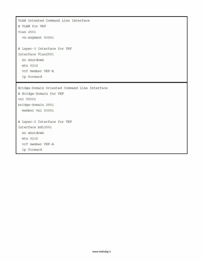
www.hellodigi.ir

www.hellodigi.ir

www.hellodigi.ir

www.hellodigi.ir

www.hellodigi.ir
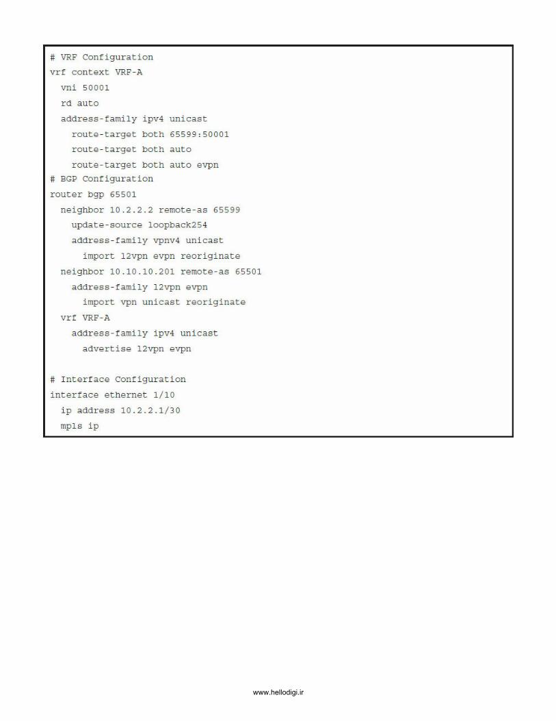
www.hellodigi.ir

www.hellodigi.ir

www.hellodigi.ir

www.hellodigi.ir

www.hellodigi.ir

www.hellodigi.ir

www.hellodigi.ir

www.hellodigi.ir

www.hellodigi.ir