Bruce Auld David Gershon Berry James William Birch Jill Hargreaves Joseph Jacobs John Ivor Pulsford...
133
Ali Fatemi - University of Toledo All Rights Reserved Chapter 6-LEFM & Crack Growth Approach 1 FUNDAMENTALS OF LEFM AND APPLICATIONS TO FATIGUE CRACK GROWTH
Transcript of Bruce Auld David Gershon Berry James William Birch Jill Hargreaves Joseph Jacobs John Ivor Pulsford...
Ali Fatemi - University of Toledo All Rights Reserved Chapter 6-LEFM & Crack Growth Approach 1
FUNDAMENTALS OF LEFM
AND APPLICATIONS TO
FATIGUE CRACK GROWTH

Ali Fatemi - University of Toledo All Rights Reserved Chapter 6-LEFM & Crack Growth Approach 2
FUNDAMENTALS OF LEFM & APPLICATIONS
TO FATIGUE CRACK GROWTH
• Overview
• LEFM Concepts
• Crack Tip Plasticity
• Fracture Toughness
• Fatigue Crack Growth
• Mean Stress Effects on FCG
• Cyclic Plastic Zone, LEFM Limitations, EPFM
• Crack Closure
• Small Cracks

Ali Fatemi - University of Toledo All Rights Reserved Chapter 6-LEFM & Crack Growth Approach 3
OVERVIEW

Ali Fatemi - University of Toledo All Rights Reserved Chapter 6-LEFM & Crack Growth Approach 4
FUNDAMENTALS OF LEFM & APPLICATIONS TO
FATIGUE CRACK GROWTH, FCG (OVERVIEW)
• The presence of a crack can significantly reduce the life of a component or structure.
• To make life estimations for fatigue crack growth and damage tolerant design, the following information are often needed:
– The stress intensity factor, K.
– The fracture toughness, Kc.
– The applicable fatigue crack growth rate expression.
– The initial crack size, ai (ao).
– The final or critical crack size, af (ac).
Ali Fatemi - University of Toledo All Rights Reserved Chapter 6-LEFM & Crack Growth Approach 5
FUNDAMENTALS OF LEFM &
APPLICATIONS TO FCG, OVERVIEW
• Damage tolerant and fatigue crack growth analysis
design assume a discontinuity, flaw, or crack exists.
• Cracks can form
– due to fatigue,
– as a consequence of manufacturing processes (i.e. deep
machining marks or voids in welds),
– and metallurgical discontinuities (i.e. inclusions).

Ali Fatemi - University of Toledo All Rights Reserved Chapter 6-LEFM & Crack Growth Approach 6
FUNDAMENTALS OF LEFM &
APPLICATIONS TO FCG, OVERVIEW
Ntotal = Nnucleation + Ngrowth
S-N
or LEFM
e-N
Nnucleation may be 0 or almost the entire life
Ngrowth may be very small or almost the entire life

Ali Fatemi - University of Toledo All Rights Reserved Chapter 6-LEFM & Crack Growth Approach 7
FUNDAMENTALS OF LEFM &
APPLICATIONS TO FCG, OVERVIEW
• Use of fracture mechanics in fatigue crack growth and damage tolerant design requires knowledge of “pre-existing” cracks, either assumed or found using nondestructive flaw detection techniques (reviewed in Chapter 2).
• Fracture mechanics has been used heavily in the aerospace, nuclear, and ship industries with a recent extension to the ground vehicle industry.

Ali Fatemi - University of Toledo All Rights Reserved Chapter 6-LEFM & Crack Growth Approach 8
FUNDAMENTALS OF LEFM &
APPLICATIONS TO FCG, OVERVIEW
• This chapter
– Provides an introduction to the important aspects of
linear elastic fracture mechanics (LEFM),
– Shows how LEFM is used to describe and predict fatigue
crack growth and final fracture.
– Does not contain the mathematics used to develop the
theory (See textbooks on fracture mechanics 1-4), but
does provide the background fracture mechanics
concepts needed for fatigue design.

Ali Fatemi - University of Toledo All Rights Reserved Chapter 6-LEFM & Crack Growth Approach 9
LEFM & APPLICATIONS TO FCG,
OVERVIEW
Stress Concentration Effect of Flaws and the need for Fracture
Mechanics.
• Consider a plate with an elliptical hole.
• Based on Mechanics of Materials approach for stress concentrations:
sA = Kt s = (1 + 2 a/b) s
• For circular hole, a = b, Kt = 3
• As a>>b (i.e. crack), sA goes to infinity (even for small s).
• Therefore a different approach is needed (Fracture Mechanics)
b
a
A
s
s

Ali Fatemi - University of Toledo All Rights Reserved Chapter 6-LEFM & Crack Growth Approach 10
LEFM & APPLICATIONS TO FCG
(LEFM CONCEPTS)
• Fracture mechanics is used to evaluate the strength of a
structure or component in the presence of a crack or flaw.
• LEFM is used for material conditions which are
predominantly linear elastic during the fatigue process.
• For crack growth or fracture conditions that violate this basic
assumption, elastic-plastic fracture mechanics (EPFM)
approaches are used to describe the fatigue and fracture
process.

Ali Fatemi - University of Toledo All Rights Reserved Chapter 6-LEFM & Crack Growth Approach 11
LEFM & APPLICATIONS TO FCG
(LEFM CONCEPTS)
Three modes in which a crack can extend:

Ali Fatemi - University of Toledo All Rights Reserved Chapter 6-LEFM & Crack Growth Approach 12
MODE I
• Mode I is the crack opening mode
• It is the most common mode, particularly in fatigue, becausecracks tend to grow on the plane of maximum tensile stress.
Ali Fatemi - University of Toledo All Rights Reserved Chapter 6-LEFM & Crack Growth Approach 13
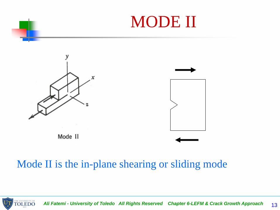
MODE II
Mode II is the in-plane shearing or sliding mode
Ali Fatemi - University of Toledo All Rights Reserved Chapter 6-LEFM & Crack Growth Approach 14
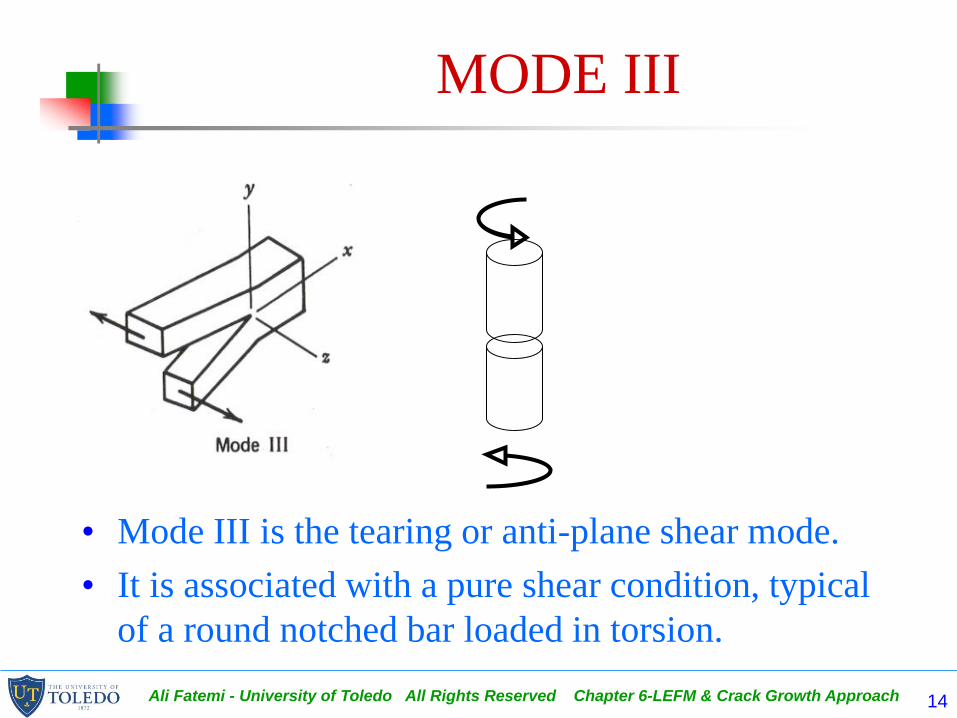
MODE III
• Mode III is the tearing or anti-plane shear mode.
• It is associated with a pure shear condition, typical
of a round notched bar loaded in torsion.

Ali Fatemi - University of Toledo All Rights Reserved Chapter 6-LEFM & Crack Growth Approach 15
LEFM & APPLICATIONS TO FCG
(LEFM CONCEPTS)
• Combinations of these
crack extension modes
can also occur.
– An example of mixed
mode I-II crack extension
is a crack on an inclined
plane.
– If b = 90, pure Mode I

Ali Fatemi - University of Toledo All Rights Reserved Chapter 6-LEFM & Crack Growth Approach 16
LEFM & APPLICATIONS TO FCG
(LEFM CONCEPTS)
• Mode I crack extension will only be covered
because:
– It most commonly occurs, and
– Other mode cracks (II and III) in combination with mode I
cracks often turn into mode I cracks.
• K used without a mode subscript I, II, or III normally
refers to mode I.

Ali Fatemi - University of Toledo All Rights Reserved Chapter 6-LEFM & Crack Growth Approach 17
LEFM CONCEPTS
Stress Intensity Factor K
• Based on energy balance of a cracked body for ideally brittle behavior(i.e. glass) Griffith showed that:
S √a = constant where S = P /A
• This product is related to the energy release rate, G.

Ali Fatemi - University of Toledo All Rights Reserved Chapter 6-LEFM & Crack Growth Approach 18
LEFM CONCEPTS
Stress Intensity Factor K
S1√a1 = S2√a2
2a2
S2
S2
2a1
S1
S1

Ali Fatemi - University of Toledo All Rights Reserved Chapter 6-LEFM & Crack Growth Approach 19
LEFM CONCEPTS
Stress Intensity Factor K
• Irwin applied Griffith’s theory to metals with small plastic
deformation at the crack tip and used the stress intensity
factor K to quantify the crack tip driving force.
• Using Griffith’s energy approach, Irwin showed:
For plane stress: For plane strain:
E
KG
2
)1(
2
2
E
KG

Ali Fatemi - University of Toledo All Rights Reserved Chapter 6-LEFM & Crack Growth Approach 20
LEFM CONCEPTS
Stress Intensity Factor K
• Consider a through thickness sharp crack in a linear elastic isotropic body subjected to Mode I loading.
• Consider an arbitrary point in the vicinity of the crack tip.
• Stresses at this point can be obtained from linear elasticity theory.
a

Ali Fatemi - University of Toledo All Rights Reserved Chapter 6-LEFM & Crack Growth Approach 21
LEFM CONCEPTS
Stress Intensity Factor K
• Consider the arbitrary point in the vicinity of the crack tip with coordinates r and .
• Using the mathematical theory of linear elasticity and the stress function in complex form, the stress field at any point near the crack tip can be described, as given in Fig. 6.2.
• Note that the normal and shear stresses in the z direction are zero for plane stress, while the normal stress in the z direction is not zero for plane strain.

Ali Fatemi - University of Toledo All Rights Reserved Chapter 6-LEFM & Crack Growth Approach 22
LEFM CONCEPTS
Stress Intensity Factor K
• Stresses in the vicinity of the crack tip are dependent on r, , and K.
• The magnitudes of these stresses at a given point are entirely dependent on K.
– K is called a stress field parameter, or stress intensity factor.
– K is not to be confused with the elastic stress concentration factor Kt.
– The stress intensity factor, K, is the fundamental parameter of LEFM.
– K depends on the:
• Loading mode
• Crack shape and component, specimen, or structure configuration.

Ali Fatemi - University of Toledo All Rights Reserved Chapter 6-LEFM & Crack Growth Approach 23
LEFM CONCEPTS
Stress Intensity Factor K
The elastic stress distribution in the
y direction for = 0 is shown.
• As r approaches zero, the stress at the crack tip approaches infinity, thus a singularity exists at r = 0.
• Since infinite stresses cannot exist, the elastic solution must be modified to account for some crack tip plasticity.
• If, the plastic zone radius, ry, at the crack tip is small relative to local geometry, little or no modification to the stress intensity factor, K, is needed.
• Thus an important restriction to the use of LEFM is that the plastic zone size at the crack tip must be small.
• Crack tip plasticity and LEFM limitations are discussed in section 6.2.

Ali Fatemi - University of Toledo All Rights Reserved Chapter 6-LEFM & Crack Growth Approach 24
LEFM CONCEPTS
Stress Intensity Factor K
• Values of K for various loadings and configurations can be calculated using:
– The theory of elasticity involving
• Analytical calculations
• Computational calculations (i.e. FEA)
– Experimental methods (i.e. photo-elasticity)
• When the crack is small compared to other dimensions of the component, the crack is viewed as being contained within an infinite body. The reference value of K is for a 2-D center crack of length 2a in an infinite sheet subjected to a uniform tensile stress S.
Ali Fatemi - University of Toledo All Rights Reserved Chapter 6-LEFM & Crack Growth Approach 25
LEFM CONCEPTS
Stress Intensity Factor K
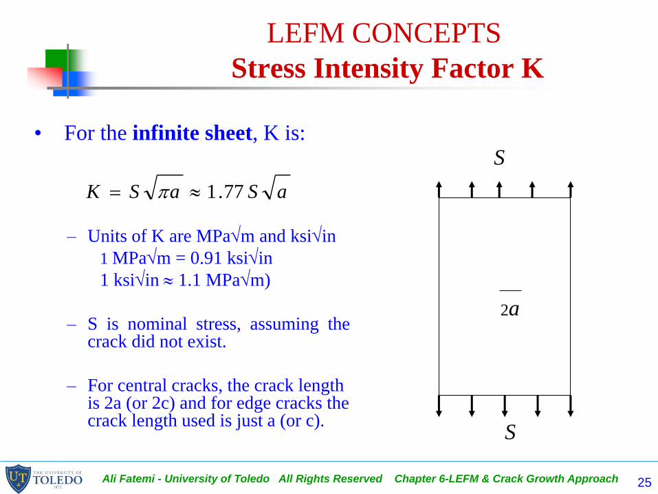
• For the infinite sheet, K is:
– Units of K are MPam and ksiin
1 MPam = 0.91 ksiin
1 ksiin 1.1 MPam)
– S is nominal stress, assuming thecrack did not exist.
– For central cracks, the crack length is 2a (or 2c) and for edge cracks the crack length used is just a (or c).
aSaSK 77.1
2a
S
S

Ali Fatemi - University of Toledo All Rights Reserved Chapter 6-LEFM & Crack Growth Approach 26
LEFM CONCEPTS
Stress Intensity Factor K
• For other crack geometries, configurations, and1oadings:
or or
Where:
, f(a/w), and Y are dimensionless geometry parameters,
w is a width dimension.
aSK
w
afaS YaS

Ali Fatemi - University of Toledo All Rights Reserved Chapter 6-LEFM & Crack Growth Approach 27
LEFM CONCEPTS
Stress Intensity Factor K
• Opening mode I stress intensity expressions for
several common configurations of thickness B are
given in the form of:
– Dimensionless curves in Fig. 6.3.
– Mathematical expressions in Table 6.1.

Ali Fatemi - University of Toledo All Rights Reserved Chapter 6-LEFM & Crack Growth Approach 28
Stress Intensity Factor K
Center Cracked Plate in Tension
)/sec( wa
• As a/w0, K approaches an infinite body solution.
• The term shown for a center cracked plate in tension is used for finite width solutions.

Ali Fatemi - University of Toledo All Rights Reserved Chapter 6-LEFM & Crack Growth Approach 29
Stress Intensity Factor K
Single Edge Cracked Plate in Tension
Ali Fatemi - University of Toledo All Rights Reserved Chapter 6-LEFM & Crack Growth Approach 30
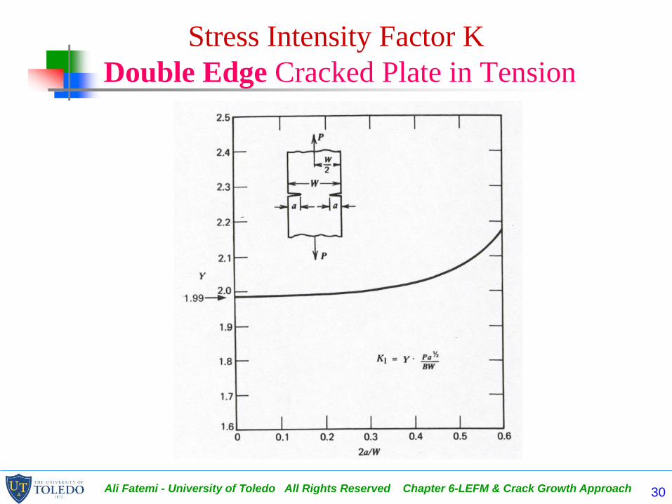
Stress Intensity Factor K
Double Edge Cracked Plate in Tension

Ali Fatemi - University of Toledo All Rights Reserved Chapter 6-LEFM & Crack Growth Approach 31
• Note that Y, and therefore, K increase much faster with a/w for the single edge crack plate, as compared with the double edge crack plate.
• For the single or double edge crack in a semi-infinite plate (a/w 0)
where 1.12 is the free edge correction.
a2Sa1.12SK

Ali Fatemi - University of Toledo All Rights Reserved Chapter 6-LEFM & Crack Growth Approach 32
Stress Intensity Factor K
Single Edge Cracked Plate in Bending

Ali Fatemi - University of Toledo All Rights Reserved Chapter 6-LEFM & Crack Growth Approach 33

Ali Fatemi - University of Toledo All Rights Reserved Chapter 6-LEFM & Crack Growth Approach 34
LEFM CONCEPTS
Stress Intensity Factor K
• Additional stress intensity factor expressions for all three modes, KI, KII, and KIII can be found in handbooks of stress intensity factors.
– H. Tada, P. C. Paris, and G. R. Irwin, The Stress Analysis of Cracks
Handbook, 2nd edition, Paris Productions Inc., St. Louis, Mo, 1985.
– G. C. Sih, Handbook of Stress Intensity Factors, Institute of Fracture
and Solid Mechanics, Lehigh University, Bethleham, PA, 1973.
– D.P. Rooke and D. J. Cartwright, Compendium of Stress Intensity
Factors, Her Majesty's Stationery Office, London, 1976.
• t and B are often used interchangeably for thickness.

Ali Fatemi - University of Toledo All Rights Reserved Chapter 6-LEFM & Crack Growth Approach 35
LEFM CONCEPTS
Stress Intensity Factor K
• Elliptical-shaped cracks
approximate many cracks
found in engineering
components & structures.
• The general reference
specimen is the embedded
elliptical crack in an
infinite body subjected to
uniform tension S
perpendicular to the crack
plane:
4/1
2
2
2cossin
bb
c
aaSK

Ali Fatemi - University of Toledo All Rights Reserved Chapter 6-LEFM & Crack Growth Approach 36
• b is the angle shown, 2a is the minor axis, and 2c is the major axis.
• Values of are given in Fig. 6.4h. K varies along the elliptical crack tip.
• K varies along the elliptical crack tip.– The maximum value of K exists at
the minor axis and the minimum is at the major axis (b = 90).
– Therefore the embedded elliptical crack subjected to uniform tension tends to grow to a circle
dc
a2/1
2
2
22/
0
sin11

Ali Fatemi - University of Toledo All Rights Reserved Chapter 6-LEFM & Crack Growth Approach 37
LEFM CONCEPTS
Stress Intensity Factor K
• For the circular embedded crackin an infinite solid, with a/c = 1 and = /2:
aSa
SaSK 13.122

Ali Fatemi - University of Toledo All Rights Reserved Chapter 6-LEFM & Crack Growth Approach 38
LEFM CONCEPTS
Stress Intensity Factor K
• A general expression for mode I semi-elliptical surface crack in afinite thickness plate is
where Mf is a front face correction factor and Mb is a back facecorrection factor. Mf and Mb are functions of b.
4/1
2
2
2cossin
bb
c
aMM
aSK
bf

Ali Fatemi - University of Toledo All Rights Reserved Chapter 6-LEFM & Crack Growth Approach 39
LEFM CONCEPTS
Stress Intensity Factor K
• For a semi-elliptical surface crack in a plate of
thickness t, K at the deepest point is:
– Where 1.12 is the free edge correction
– is the finite thickness correction factor.
• For the quarter-circular corner crack (a/c = 1) in an
infinite solid with two free edges, K is:
)2/sec(12.1
taaS
K
a/2t)sec(
)aS
aSK 41.1
12.12

Ali Fatemi - University of Toledo All Rights Reserved Chapter 6-LEFM & Crack Growth Approach 40
LEFM CONCEPTS
Stress Intensity Factor K
• Superposition for Combined Mode I Loading.
– The principle of superposition can be used to determine stress intensity factor solutions for combined loadings.
– For example, for an eccentrically loaded member that experiences both axial and a bending loading, the resultant stress intensity solution is
KI = KI(axial) + KI(bending)
• Noted that:
– as the geometry factor , for axial and bending are different.
– Also, K values of different modes, i.e. I, II, and III, cannot be added together.
= +
aSSKbendingaxialI
)(

Ali Fatemi - University of Toledo All Rights Reserved Chapter 6-LEFM & Crack Growth Approach 41
EXAMPLE PROBLEM

Ali Fatemi - University of Toledo All Rights Reserved Chapter 6-LEFM & Crack Growth Approach 42
CRACK TIP PLASTICITY

Ali Fatemi - University of Toledo All Rights Reserved Chapter 6-LEFM & Crack Growth Approach 43
CRACK TIP PLASTICITY
• A distance ry ahead of the
crack tip ( = 0) can be
determined that identifies the
plastic zone boundary:
– By using the stress field
equation for sy and
– Substituting the yield strength,
Sy, for sy, and ry for r.
Sy = K / (√2ry)
ry = 1/2 (K/Sy)2
Ali Fatemi - University of Toledo All Rights Reserved Chapter 6-LEFM & Crack Growth Approach 44
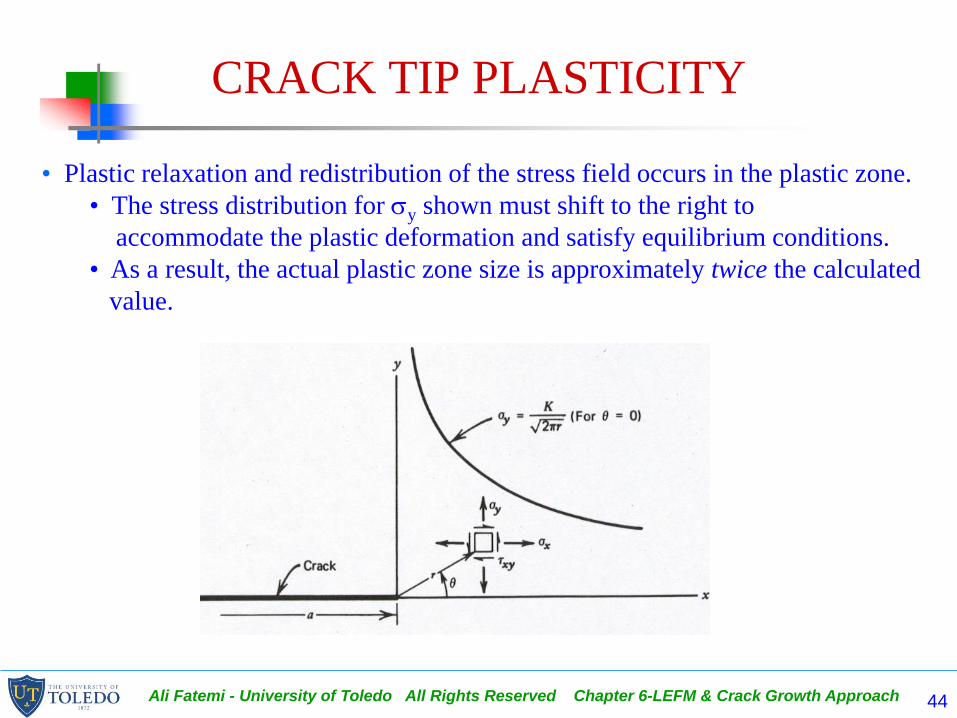
CRACK TIP PLASTICITY
• Plastic relaxation and redistribution of the stress field occurs in the plastic zone.
• The stress distribution for sy shown must shift to the right to
accommodate the plastic deformation and satisfy equilibrium conditions.
• As a result, the actual plastic zone size is approximately twice the calculated
value.

Ali Fatemi - University of Toledo All Rights Reserved Chapter 6-LEFM & Crack Growth Approach 45
CRACK TIP PLASTICITY
• Using the stress field equations in Fig. 6.2 and the von Mises or maximum shear stress yield criteria, plastic zone shape can be determined.
• The resultant plastic zone shape for mode I using the von Mises criterion is shown.
• For plane stress conditions (where sz = 0) a much larger plastic zone exists compared to plane strain condition, where the tensile stress component, sz, restricts plastic flow.
Ali Fatemi - University of Toledo All Rights Reserved Chapter 6-LEFM & Crack Growth Approach 46
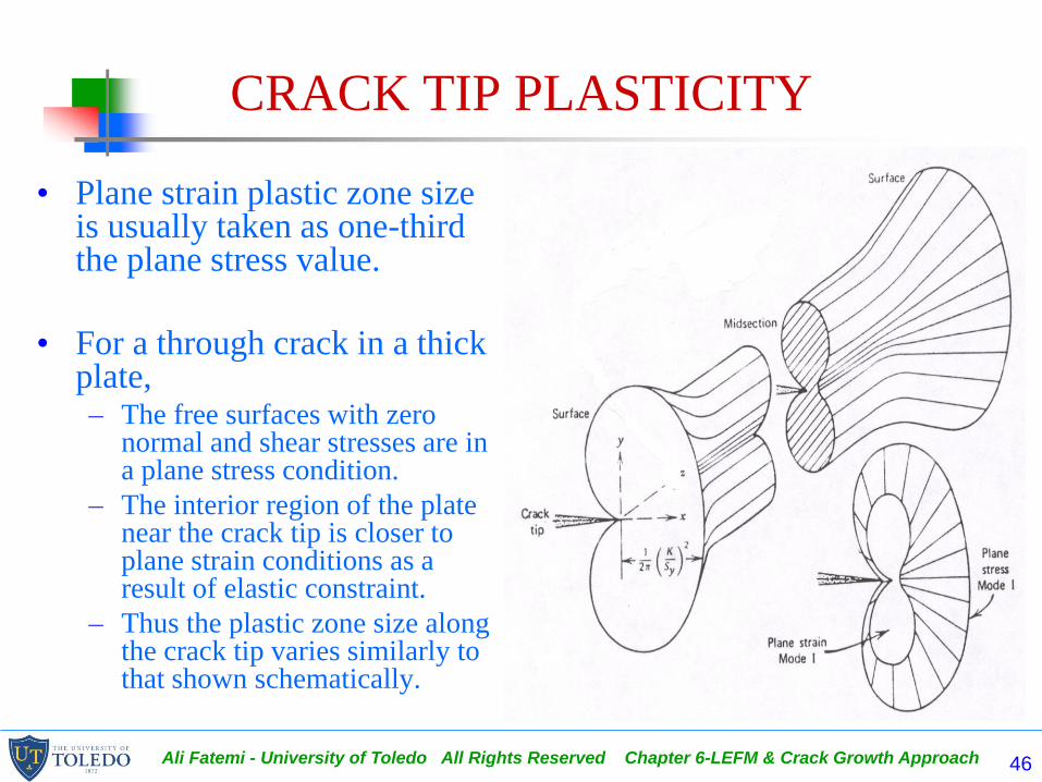
CRACK TIP PLASTICITY
• Plane strain plastic zone size is usually taken as one-third the plane stress value.
• For a through crack in a thick plate,– The free surfaces with zero
normal and shear stresses are in a plane stress condition.
– The interior region of the plate near the crack tip is closer to plane strain conditions as a result of elastic constraint.
– Thus the plastic zone size along the crack tip varies similarly to that shown schematically.

Ali Fatemi - University of Toledo All Rights Reserved Chapter 6-LEFM & Crack Growth Approach 47
CRACK TIP PLASTICITY
• Under monotonic loading, the plastic zone size, 2ry, at the crack tip, in the plane of the crack, is:
For plane stress
For plane strain
• The criteria for deciding between plane stress and plane strain are discussed in Section 6.3.
• The value ry is often called the plastic zone radius.
22
1
2
122
yy
yS
K
S
Kr
2
3
12
y
yS
Kr

Ali Fatemi - University of Toledo All Rights Reserved Chapter 6-LEFM & Crack Growth Approach 48
CRACK TIP PLASTICITY
• An important restriction to the use of LEFM is that plastic zone size at the crack tip must be small relative to the crack length as well as the geometrical dimensions of the specimen or part.
– A definite limiting condition for LEFM is that net (nominal) stresses in the crack plane must be less than 0.8Sy (80% of yield strength).
– Under monotonic loading ry (1/8)a.
– Other restrictions include ry 1/8 of t and (w-a) where t is the thickness and (w-a) is the uncracked ligament along the plane of the crack.
• Otherwise, a plasticity correction is required for the stress intensity factor, K, or elastic-plastic fracture mechanics may be needed (Section 6.9).

Ali Fatemi - University of Toledo All Rights Reserved Chapter 6-LEFM & Crack Growth Approach 49
CRACK TIP PLASTICITY
– Under monotonic loading ry (1/8)a.
– Other restrictions include ry 1/8 of t and (w-a) where t is the thickness and (w-a) is the uncracked ligament along the plane of the crack.

Ali Fatemi - University of Toledo All Rights Reserved Chapter 6-LEFM & Crack Growth Approach 50
FRACTURE TOUGHNESS

Ali Fatemi - University of Toledo All Rights Reserved Chapter 6-LEFM & Crack Growth Approach 51
FRACTURE TOUGHNESS - Kc, KIc
• Critical values of K refer to the condition when a crack extends in a rapid (unstable) manner.
Sc is the applied nominal stress at crack instability..
ac is the crack length at instability.
Kc is called fracture toughness and depends on the material, temperature, strain rate, environment, and thickness.
• This equation provides a quantitative design parameter to prevent fracture involving applied stress, material selection, and crack size.
w
afaSK
c
ccc
Ali Fatemi - University of Toledo All Rights Reserved Chapter 6-LEFM & Crack Growth Approach 52
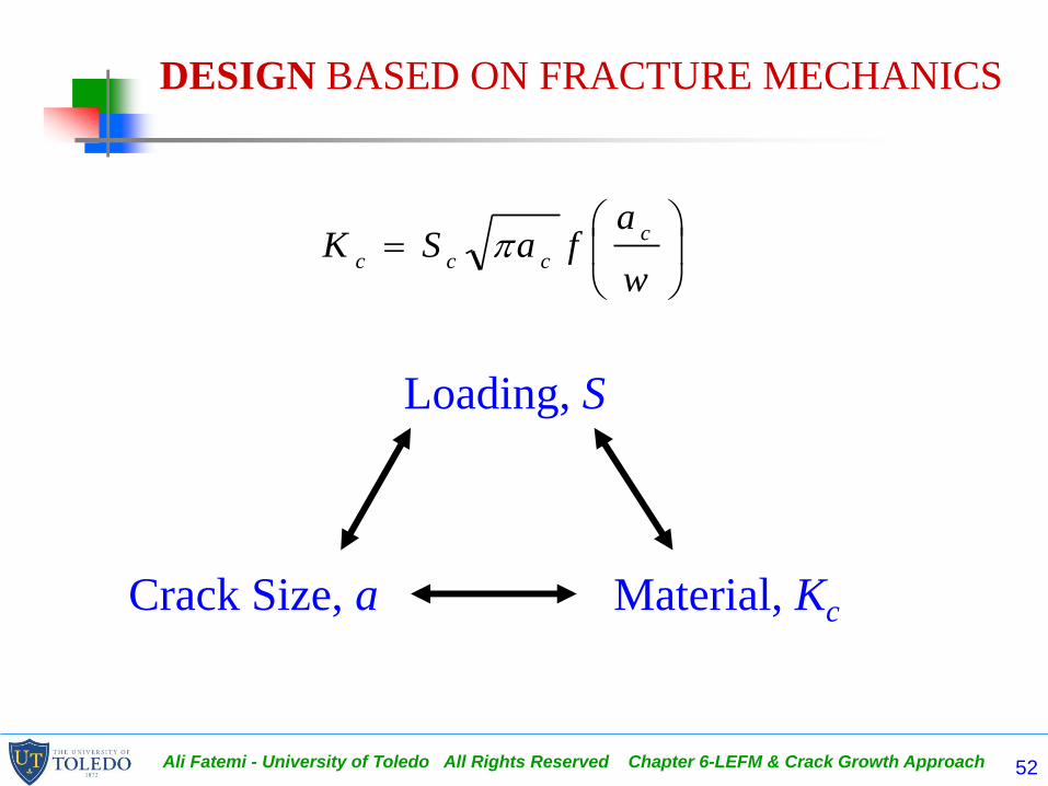
DESIGN BASED ON FRACTURE MECHANICS
Loading, S
Crack Size, a Material, Kc
w
afaSK
c
ccc

Ali Fatemi - University of Toledo All Rights Reserved Chapter 6-LEFM & Crack Growth Approach 53
FRACTURE TOUGHNESS - Kc, KIc
• The general relationship between fracture toughness, Kc, and thickness is shown.
– Thin parts have a high value of Kc
accompanied by appreciable “shear lips" or slant fracture.
– As the thickness is increased, the percentage of "shear lips" or slant fracture decreases, as does Kc. This type of fracture appearance is called mixed-mode implying both slant and flat fracture.
– For thick parts, the entire fracture surface is flat and Kc approaches an asymptotic minimum value, called the "plane strain fracture toughness" KIc.
– Plastic zone sizes at fracture are much larger in thin parts as compared to thick parts.

Ali Fatemi - University of Toledo All Rights Reserved Chapter 6-LEFM & Crack Growth Approach 54
FRACTURE TOUGHNESS - Kc, KIc
• Plane strain fracture toughness KIc is considered a truematerial property because it is independent of thickness.
• In order for a plane strain fracture toughness value to beconsidered valid, it is required that:
• Approximate thickness required for steels and aluminumsto obtain valid KIc values are given in Table 6.2.
• Low strength, ductile materials are subject to plane strainfracture only if they are very thick.
2
5.2
y
Ic
S
Ktanda

Ali Fatemi - University of Toledo All Rights Reserved Chapter 6-LEFM & Crack Growth Approach 55
FRACTURE TOUGHNESS - Kc, KIc
TABLE 6.2 Approximate Thickness Required for Valid KIC Tests
Steel Aluminum
Sy, MPa (ksi) Sy, MPa (ksi) Thickness, mm (in.)
690 (100) 275 (40) >76 (3)
1030 (150) 345 (50) 76 (3)
1380 (200) 448 (65) 45 (1-3/4)
1720 (250) 550 (80) 19 (3/4)
2070 (300) 620 (90) 6 (1/4)

Ali Fatemi - University of Toledo All Rights Reserved Chapter 6-LEFM & Crack Growth Approach 56
FRACTURE TOUGHNESS - Kc, KIc
• A higher yield or ultimate strength generally produces a decrease in KIc,and thus a greater susceptibility for catastrophic fracture!

Ali Fatemi - University of Toledo All Rights Reserved Chapter 6-LEFM & Crack Growth Approach 57
Some representative KIc values are given in Table A.3.

Ali Fatemi - University of Toledo All Rights Reserved Chapter 6-LEFM & Crack Growth Approach 58
FRACTURE TOUGHNESS - Kc, KIc
• Low impurity materials provide better fracture toughness.
• KIc
can be very sensitive to metallurgical conditions such as grain orientation, chemistry, and microstructure.
• Fracture toughness Kc
of metals is also dependent on temperature, strain rate, and corrosive environment.

Ali Fatemi - University of Toledo All Rights Reserved Chapter 6-LEFM & Crack Growth Approach 59
FRACTURE TOUGHNESS - Kc, KIc
• Typical results for a low alloy nuclear pressure vessel steel.– As the temperature decreases,
Kc usually decreases, while the yield strength increases.
– Thus, even though unnotched or uncracked tensile strength increases with decreasing temperature, the flaw or crack resistance can be drastically reduced.
• Increased strain rate tends to lower fracture toughness, and hence, greater crack sensitivity, similar to that of decreasing the temperature.

Ali Fatemi - University of Toledo All Rights Reserved Chapter 6-LEFM & Crack Growth Approach 60
FRACTURE TOUGHNESS - Kc, KIc
• General schematic of how changes in fracture toughness influence the relationship between allowable nominal stress and allowable crack size.
– The allowable stress in the presence of a given crack size is directly proportional to the fracture toughness.
– the allowable crack size for a given stress is proportional to the square of the fracture toughness.
– Thus increasing KIc has a much larger influence on allowable crack size than on allowable stress.
• 0.8Sy is the upper bound limit of allowable stress in LEFM approach.

Ali Fatemi - University of Toledo All Rights Reserved Chapter 6-LEFM & Crack Growth Approach 61
FRACTURE TOUGHNESS - Kc, KIc
• ASTM Standard E399 contains a detailed description of the specimen geometry, experimental procedure, and data collection and & techniques used to determine valid KIc values.
• When a specimen or component has a thickness less than that required for plane strain conditions, it will experience either mixed-mode or plane stress conditions depending on thickness.
• Under plane strain conditions, once a critical stress is reached, unstable crack growth occurs.
• Under plane stress conditions where the plastic zone size is greater, the crack may first extend by slow stable crack growth prior to unstable fracture.
• ASTM Standard E561 [24] provides a recommended practice for plane stress fracture toughness testing.

Ali Fatemi - University of Toledo All Rights Reserved Chapter 6-LEFM & Crack Growth Approach 62
FRACTURE TOUGHNESS - Kc, KIc
• In design situations, the stress state may be plane
stress, where Kc for the particular thickness is
required but is often not available.
– KIc is often used over Kc because of availability as well
as KIc being a more conservative value.
– However, use of KIc rather than Kc may be inefficient
and costly in some situations.
– Use of KIc or Kc is dependent on the application and the
safety critical aspects of the component or structure.

Ali Fatemi - University of Toledo All Rights Reserved Chapter 6-LEFM & Crack Growth Approach 63
EXAMPLE PROBLEM

Ali Fatemi - University of Toledo All Rights Reserved Chapter 6-LEFM & Crack Growth Approach 64
FATIGUE CRACK GROWTH
da/dN - K
• In many structural components subjected to cyclic loading, sub-critical crack growth often occurs due to fatigue until a critical crack size is reached causing fracture.

Ali Fatemi - University of Toledo All Rights Reserved Chapter 6-LEFM & Crack Growth Approach 65
FATIGUE CRACK GROWTH, da/dN-K
• Three a-N curves for three identical test specimens (with the same initial crack length, ao) subjected to different repeated stress levels are shown.
• At higher stresses the crack growth rates (slopes of the curves) are higher and the fatigue life is shorter.
• The crack lengths at fracture are shorter at the higher stress levels.
• Therefore, for the given initial crack size, the life to fracture depends on the magnitude of the applied stress and the final fracture resistance of the material (which dictates final crack length).

Ali Fatemi - University of Toledo All Rights Reserved Chapter 6-LEFM & Crack Growth Approach 66
FATIGUE CRACK GROWTH, da/dN-K
• By applying LEFM concepts to a-N data
we can obtain crack growth rate, da/dN,
versus the applied stress intensity factor
range, K.
• The fatigue crack growth rate, da/dN, is
simply the slope of the a vs. N curve at a
given crack length or given number of
cycles as identified by da/dN (a/N).
• The corresponding applied stress
intensity factor range, K, is calculated
knowing the crack length, a, applied
stress range, S, and the stress intensity
factor solution, K, for the part in
question.

Ali Fatemi - University of Toledo All Rights Reserved Chapter 6-LEFM & Crack Growth Approach 67
FATIGUE CRACK GROWTH, da/dN-K
• K is defined as:
Since the stress intensity factor is undefined in compression,
Kmin is taken as zero if Smin is compression.
• As K primarily depends on S, a, and geometry
(for example ), many models of the following form
have been proposed and developed
aSaSSaSaSKKKKI
)(minmaxminmaxminmax
)(),,( KfaSfdN
da
Ali Fatemi - University of Toledo All Rights Reserved Chapter 6-LEFM & Crack Growth Approach 68
FATIGUE CRACK GROWTH, da/dN-K
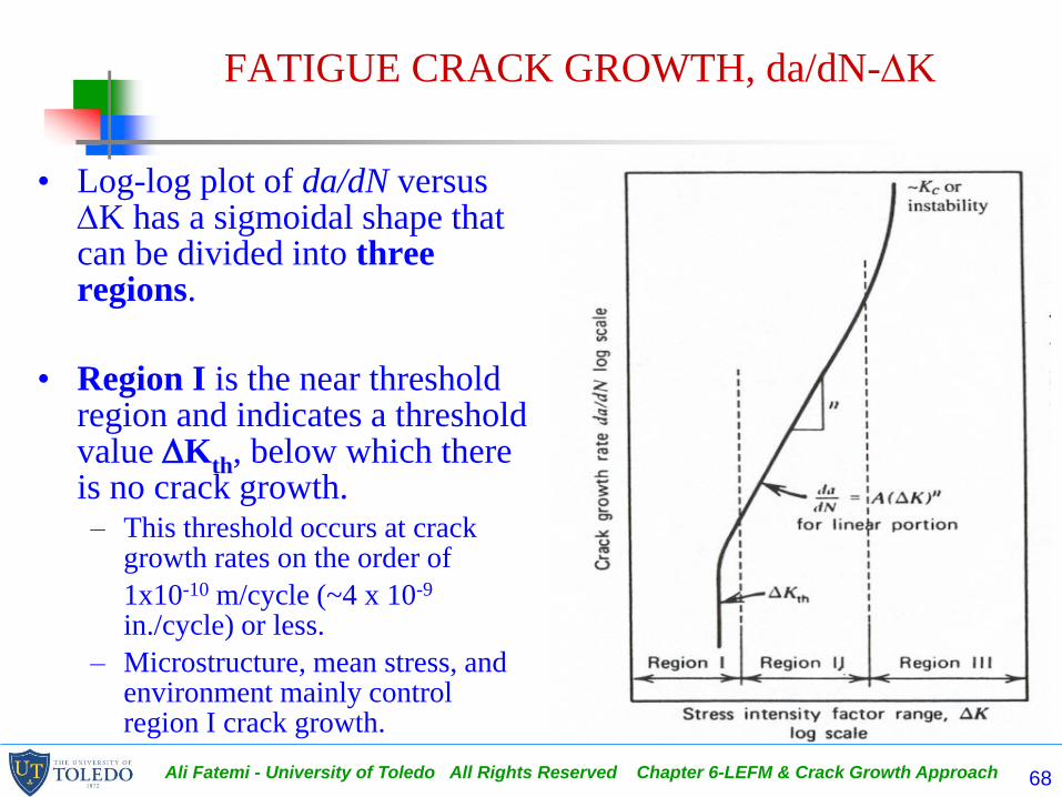
• Log-log plot of da/dN versus K has a sigmoidal shape that can be divided into three regions.
• Region I is the near threshold region and indicates a threshold value Kth, below which there is no crack growth.– This threshold occurs at crack
growth rates on the order of
1x10⁻¹⁰ m/cycle (~4 x 10⁻⁹
in./cycle) or less.
– Microstructure, mean stress, and environment mainly control region I crack growth.
Ali Fatemi - University of Toledo All Rights Reserved Chapter 6-LEFM & Crack Growth Approach 69
FATIGUE CRACK GROWTH, da/dN-K
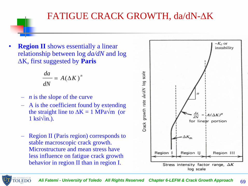
• Region II shows essentially a linear relationship between log da/dN and log K, first suggested by Paris
– n is the slope of the curve
– A is the coefficient found by extending the straight line to K = 1 MPam (or 1 ksiin.).
– Region II (Paris region) corresponds to stable macroscopic crack growth. Microstructure and mean stress have less influence on fatigue crack growth behavior in region II than in region I.
nKA
dN
da)(

Ali Fatemi - University of Toledo All Rights Reserved Chapter 6-LEFM & Crack Growth Approach 70
FATIGUE CRACK GROWTH, da/dN-K
• In region III
– the fatigue crack growth
rates are very high as they
approach instability
– little fatigue crack growth
life is involved.
– this region is controlled
primarily by fracture
toughness Kc or KIc.

Ali Fatemi - University of Toledo All Rights Reserved Chapter 6-LEFM & Crack Growth Approach 71
FATIGUE CRACK GROWTH, da/dN-K
• For a given material the fatigue crack growth behavior shown in Fig. 6.12 is essentially the same for different specimens or components.
• This allows fatigue crack growth rate versus K data obtained under constant amplitude conditions with simple specimen configurations to be used in design situations.
S and a K da/dN Nf
• In many cases, integration of Paris by extrapolating to both regions I and III may be satisfactory as it often gives conservative fatigue crack growth life values.

Ali Fatemi - University of Toledo All Rights Reserved Chapter 6-LEFM & Crack Growth Approach 72
FATIGUE CRACK GROWTH, da/dN-K
• Standard test methods are available for performing constant amplitude fatigue crack growth tests (ASTM Standard E647).
– Common test specimens are shown, although other types may be used.
– A typical fatigue crack growth experiment is performed under constant amplitude cyclic loading with R = constant
– Generally a fatigue precrack is formed at a sharp machined notch at a relatively low K level to provide a sharp crack tip.
– Extension of the growing crack is documented in terms of crack length and number of cycles until failure occurs.
– Crack growth is usually measured with optical, compliance, ultrasonic, eddy current, electrical potential, or acoustic emission techniques.

Ali Fatemi - University of Toledo All Rights Reserved Chapter 6-LEFM & Crack Growth Approach 73

Ali Fatemi - University of Toledo All Rights Reserved Chapter 6-LEFM & Crack Growth Approach 74
FATIGUE CRACK GROWTH, da/dN-K
– Data reduction techniques, as recommended in ASTM Standard E647, include asecant or incremental polynomial methods to smoothen a-N curve.
– These data are then reduced to generate da/dN vs. K data.
– Fatigue crack growth rates that correspond to near threshold conditions, ~10-10
m/cycle, are very slow (i.e. it takes about 14 hours of continuous testing at 50 Hzfrequency to grow a crack 0.25 mm at this crack growth rate).
– Details of the recommended load shedding procedure for threshold tests are summarized in ASTM Standard E647.

Ali Fatemi - University of Toledo All Rights Reserved Chapter 6-LEFM & Crack Growth Approach 75
da/dN-K for R = 0
• Conventional S-N or e-N fatigue behaviors are usually withreference to the fully reversed stress or strain conditions (R = -1).
• Fatigue crack growth data, however, are usually referenced to thepulsating tension condition with R = 0 or approximately zero,since during compression loading the crack is closed and henceno stress intensity factor, K, can exist.
• Many mathematical equations depicting fatigue crack growthrates above threshold levels have been formulated. The Parisequation (for region II) is the most popular equation for R = 0loading.

Ali Fatemi - University of Toledo All Rights Reserved Chapter 6-LEFM & Crack Growth Approach 76
da/dN-K for R = 0
• Barsom has evaluated Paris equation (for region II) for a wide variety of steels varying in yield strength from 250 to 2070 MPa (36 to 300 ksi).
– He shows that the scatter band for a given K, with many ferritic-pearlitic steels, varies by a factor of about 2 (shown in Fig. 6.14a).

Ali Fatemi - University of Toledo All Rights Reserved Chapter 6-LEFM & Crack Growth Approach 77
da/dN-K for R = 0
• He also found a similar scatter band width for martensitic steels.
• He suggested that conservative values of the upper boundaries of these scatter bands could be used in design situations if actual data could not be obtained.

Ali Fatemi - University of Toledo All Rights Reserved Chapter 6-LEFM & Crack Growth Approach 78
da/dN-K for R = 0
• An approximate schematic sigmoidal shaped scatter band for steels with Barsom's scatter bands superimposed is shown, which also includes austenitic stainless steels.

Ali Fatemi - University of Toledo All Rights Reserved Chapter 6-LEFM & Crack Growth Approach 79
da/dN-K for R = 0
• Typical values of n and A for some metals are given in Table 6.3.
• In general, the crack growth rate exponent n is higher for materials that behave in a more brittle manner.

Ali Fatemi - University of Toledo All Rights Reserved Chapter 6-LEFM & Crack Growth Approach 80
da/dN-K for R = 0
• Frequency, wave shape, and thickness effects on constant amplitude fatigue crack growth rates are secondary compared to environmental effects such as corrosion and temperature.
• The thickness influence can be greatest in region III because of the inverse relationship between fracture toughness and thickness.
– A high fracture toughness is desirable because of the longer final crack size at fracture.
– This allows easier and less frequent inspection and, therefore, safer components or structures.

Ali Fatemi - University of Toledo All Rights Reserved Chapter 6-LEFM & Crack Growth Approach 81
Threshold stress intensity factor ranges, Kth, for
selected engineering alloys.

Ali Fatemi - University of Toledo All Rights Reserved Chapter 6-LEFM & Crack Growth Approach 82
da/dN-K for R = 0
– These values are usually less than 10 MPam for steels and less than 4 MPam for aluminum alloys.
– Values of Kth are substantially less than KIc values
– The threshold stress intensity factor, Kth, has often been considered analogous to the fatigue limit, Sf, since an applied stress intensity factor range below Kth does not cause fatigue crack growth.
– Use of Kth in design may be appropriate for conditions involving high frequency or high cycle applications such as turbine blades, or for metals with very high da/dN-K slopes.

Ali Fatemi - University of Toledo All Rights Reserved Chapter 6-LEFM & Crack Growth Approach 83
da/dN-K for R = 0
• Figure 6.16 shows the
use of Kth as a design
parameter for no crack
growth using a single-
edge cracked infinitely
wide plate subjected to
R = 0 loading as shown.

Ali Fatemi - University of Toledo All Rights Reserved Chapter 6-LEFM & Crack Growth Approach 84
Crack Growth Life Integration
The last part of this equation is not correct if significantly changes with a between the limits ai and af.
aSK
nnnnnaSAaSAKA
dN
da
2/)()()()(
f f
i
f
i
N a
a
a
a nnnnnnnfa
da
SAaSA
dadNN
0 2/2/2/)()(
1
)()(
f
i
a
a nnnna
da
SA2/2/
)()(
1

Ali Fatemi - University of Toledo All Rights Reserved Chapter 6-LEFM & Crack Growth Approach 85
Crack Growth Life Integration
where
For cases where is a function of a, integration is usually necessary using either standard numerical techniques or computer programs.
2
max
1
S
Ka
c
f
nnn
n
i
n
f
fSAn
aaN
2/
1)2/(1)2/(
)()()12/(

Ali Fatemi - University of Toledo All Rights Reserved Chapter 6-LEFM & Crack Growth Approach 86
EXAMPLE PROBLEM

Ali Fatemi - University of Toledo All Rights Reserved Chapter 6-LEFM & Crack Growth Approach 87
MEAN STRESS EFFECTS
• The general influence of mean stress on FCG behavior is shown schematically.
– The stress ratio R = Kmin/Kmax= Smin/Smax is used as the principal parameter.
– Most mean stress effects on crack growth have been obtained for only positive stress ratio, that is, R0.
– Increasing the R ratio (which means increasing the mean stress) has a tendency to increase the crack growth rates in all portions of the sigmoidal curve.
– The increase in region II, however, may be small.
– In region III, where fracture toughness Kc or KIc controls, substantial differences in crack growth rates occur for different R ratios.
• The effect of R on fatigue crack growth is very material dependent.

Ali Fatemi - University of Toledo All Rights Reserved Chapter 6-LEFM & Crack Growth Approach 88
MEAN STRESS EFFECTS
• A commonly used equation depicting mean stress effects inregions II and III is the Forman equation:
– A' and n' are empirical material fatigue crack growth rate constants and Kc
is fracture toughness for the material and thickness.
– The Forman equation is a modification of the Paris equation to incorporatemean stress and region III fatigue crack growth behavior.
– As Kmax approaches Kc, the denominator approaches zero, thus the crackgrowth rate, da/dN, gets very large. This describes region III crack growth.
))(1(
)('
)1(
)('
max
''
KKR
KA
KKR
KA
dN
da
c
n
c
n

Ali Fatemi - University of Toledo All Rights Reserved Chapter 6-LEFM & Crack Growth Approach 89
MEAN STRESS EFFECTS
• Another common empirical relationship used to describe
mean stress effects with R0 is the Walker relationship
– where A and n are the Paris coefficient and slope for R=0 and l is a material constant.
– The stress ratio, R, does not affect the slope, n.
– Values of l for various metals range from 0.3 to nearly 1 with a typical value around 0.5. Lower values of l indicate a stronger influence of R on fatigue crack growth behavior.
n
n
n
KAR
KA
dN
da)("
)1(
)(
)1(
l

Ali Fatemi - University of Toledo All Rights Reserved Chapter 6-LEFM & Crack Growth Approach 90
MEAN STRESS EFFECTS
• Effect of mean stress on Kth can be substantial (see Fig. 6.17 & Table A.4).
• Incert tab and fig
Ali Fatemi - University of Toledo All Rights Reserved Chapter 6-LEFM & Crack Growth Approach 91
MEAN STRESS EFFECTS
– A form similar to the Walker equation can be used to describe the effect of R ratio on threshold:
where g is an empirical constant.
– The effect of negative R ratios, which includes compression in the cycle on wrought and cast steels, cast irons, and aluminum alloys in regions II and III indicate crack growth rates based on K values (which neglect compressive nominal stresses) are similar to R = 0 results.
g
1
)0()0()1( RKK
RthRth

Ali Fatemi - University of Toledo All Rights Reserved Chapter 6-LEFM & Crack Growth Approach 92
EXAMPLE PROBLEM

Ali Fatemi - University of Toledo All Rights Reserved Chapter 6-LEFM & Crack Growth Approach 93
CYCLIC PLASTIC ZONE
• The monotonic plastic zone size and stress distribution developed due to the maximum load applied in the loading cycle, point A, is shown in Fig. 6.18(b).
• As the maximum load is reduced during the loading cycle to the minimum load, point B, it causes the development of the cyclic plastic zone size, 2ry', and corresponding stress distribution, shown in Fig. 6.18(c).

Ali Fatemi - University of Toledo All Rights Reserved Chapter 6-LEFM & Crack Growth Approach 94
CYCLIC PLASTIC ZONE
• For the assumed elastic-perfectly plastic behavior, the maximum stress developed in Fig. 6.18(b) is Sy. The maximum stress change developed during unloading can be as large as 2Sy.
• Fig. 6.18(c) shows the summation of the inelastic loading stress distribution plus the elastic unloading stress distribution.
• The stresses within the cyclic plastic zone, 2ry', are compressive, while outside the cyclic plastic zone the compressive stress decreases and then becomes tensile.

Ali Fatemi - University of Toledo All Rights Reserved Chapter 6-LEFM & Crack Growth Approach 95
CYCLIC PLASTIC ZONE
• A key point to recognize is that the sign of the inelastic stress distribution associated with the cyclic plastic zone size is opposite to the sign of the applied stress during loading.
• Thus, if a region yields in tension during loading, as shown in Fig. 6.18(b), after unloading a portion of that region is in compression, as shown in Fig. 6.18(c).

Ali Fatemi - University of Toledo All Rights Reserved Chapter 6-LEFM & Crack Growth Approach 96
CYCLIC PLASTIC ZONE
• The size of the cyclic plastic zone where yielding occurs can be
approximated by using 2Sy for Sy and K for K in the
monotonic plastic zone equation for plane stress condition:
where 2ry' is the cyclic plastic zone size under plane stress
conditions for R0.
• For R = 0, where Kmax = K, the size of the plastic zone is only
one quarter that of which existed at the peak tensile load.
22
'
4
1
2
12
yy
yS
K
S
Kr
2
12
y
yS
Kr

Ali Fatemi - University of Toledo All Rights Reserved Chapter 6-LEFM & Crack Growth Approach 97
CYCLIC PLASTIC ZONE
• The cyclic plastic zone for plane strain conditions is one third
as large as the corresponding cyclic plastic zone for plane stress:
• If the material cyclic hardens or softens, Sy should be replaced
with the cyclic yield strength, Sy'.
22
'
12
1
23
12
yy
yS
K
S
Kr

Ali Fatemi - University of Toledo All Rights Reserved Chapter 6-LEFM & Crack Growth Approach 98
CYCLIC PLASTIC ZONE
• Excessive plasticity, where the plastic zone size or applied stress are a large fraction of the crack size or the yield strength respectively, violates the basic assumptions of LEFM, whether due to monotonic or cyclic loading.
• Because the cyclic plastic zone is usually much smaller than the monotonic plastic zone size, LEFM can often be applied to fatigue crack growth situations with good success even for materials that exhibit large plasticity or for region III crack growth where the magnitude of plasticity is greatest.
• In region III of crack growth, usually a very small fraction of the total fatigue life is involved, thus accuracy is not as important.
• Because ry' is always less than ry for fatigue loading, limitations of LEFM associated with ry for monotonic loading can often be extended to ry' as associated with fatigue crack growth.
• Excessive plasticity effects used in fatigue crack growth are addressed in Section 6.9.
Ali Fatemi - University of Toledo All Rights Reserved Chapter 6-LEFM & Crack Growth Approach 99
CRACK CLOSURE
• Crack closure was first quantified and its importance made known by Elber in 1970 who showed that a fatigue crack closed even with a tensile load still applied (Figure 6.19).
• Based on his experimental results he argued that a reduction in the crack tip driving force occurred as a result of residual tensile deformation left in the wake of a fatigue crack tip.
• The residual tensile deformation caused the crack faces to close prematurely prior to the minimum load being reached.
• Since Elber’s work, extensive research on crack closure has been performed and documented.
• Many fatigue crack growth effects have been explained, at least in part by closure concepts, however, many details of the mechanisms of crack closure are still only partly understood.

Ali Fatemi - University of Toledo All Rights Reserved Chapter 6-LEFM & Crack Growth Approach 100
CRACK CLOSURE
• At Kop the crack opens on the loading portion of the cycle.
• At Kcl the crack closes on the unloading portion of the cycle.
• The opening stress intensity factor, Kop, is typically greater than the minimum stress intensity factor, Kmin.
K = Kmax– Kmin But Keff = Kmax - Kop

Ali Fatemi - University of Toledo All Rights Reserved Chapter 6-LEFM & Crack Growth Approach 101
CRACK CLOSURE
• The effective crack tip driving force, Keff, is less than the nominal crack tip driving force, K.
• The damaging portion of the loading cycle is restricted to the opening portion of the stress intensity range, Keff.

Ali Fatemi - University of Toledo All Rights Reserved Chapter 6-LEFM & Crack Growth Approach 102
CRACK CLOSURE
• One parameter used to define the measurement of closure is the closure ratio:
• For loading conditions were there is little or no closure, U approaches one.
• For loading conditions that show extensive crack closure, U is small.
• At high stress ratio (e.g. for R > 0.5) crack growth generally displays limited crack closure, while at low stress ratio crack growth tends to exhibit higher levels of crack closure.
)1(
)/1(max
R
KK
K
KU
opeff

Ali Fatemi - University of Toledo All Rights Reserved Chapter 6-LEFM & Crack Growth Approach 103
CRACK CLOSURE
• The effect of crack closure on region I behavior is probably of greatest interest as:
– It is this region where much of the crack growth life is expended,
– In this region crack closure is most significant,
– Region I crack growth is influenced by many variables, including stress ratio, environment, and microstructure, which have a direct influence on the effect of crack closure.
• The practical significance of crack closure is related to the growth, retardation, or arrest of fatigue cracks under in-service load histories. The effect of crack closure on variable amplitude loading is presented in Chapter 9.

Ali Fatemi - University of Toledo All Rights Reserved Chapter 6-LEFM & Crack Growth Approach 104
CRACK CLOSURE
• Since Elber’s pioneering work, additional crack
closure mechanisms have been identified.
• The most extensively studied forms of closure include:
– plasticity-induced closure
– oxide-induced closure
– roughness-induced closure
• Elber’s work fundamentally described what is now
referred to as plasticity-induced closure.

Ali Fatemi - University of Toledo All Rights Reserved Chapter 6-LEFM & Crack Growth Approach 105
CRACK CLOSURE
• Plasticity-induced closure is most prevalent in metals at
low stress ratios under plane stress conditions, although it
can still be significant for plane strain.
• This form of closure arises from the presence of the
compressive plastic zone.
• Based on plasticity-induced closure arguments, Keff has
been shown to reasonably correlate fatigue crack growth
curves for various stress ratios into a single narrow scatter
band.

Ali Fatemi - University of Toledo All Rights Reserved Chapter 6-LEFM & Crack Growth Approach 106
CRACK CLOSURE
• Oxide formation by way of various aggressive
environments can affect crack closure levels in a
number of ways:
– The oxide can form as either a uniform layer on the crack
faces or can form as rough bulky deposits.
– At low stress ratio and near-threshold levels there is a
greater propensity for repeated crack face contact to occur.
– At low stress intensity levels there is a continual breaking
and reforming of the oxide layer along the crack faces.
– At high stress ratio where crack closure is less prevalent,
oxide debris and build-up are not as significant.

Ali Fatemi - University of Toledo All Rights Reserved Chapter 6-LEFM & Crack Growth Approach 107
CRACK CLOSURE
• Crack deflection due to microstructural contributions can have a large effect on threshold behavior.
• This form of crack closure is generally referred to as roughness-induced closure.
• An increase in surface roughness encourages crack deflection, resulting in premature crack face contact leading to higher crack opening levels.
• Materials with very small grain size show no crack closure, even at low stress ratio. This leads to low threshold values and no stress ratio dependence.
• For coarser grained materials, more serrated and faceted morphology is generally observed that lead to higher opening loads.
• In regions II and III, where crack opening displacements are higher, roughness-induced closure has much less effect.

Ali Fatemi - University of Toledo All Rights Reserved Chapter 6-LEFM & Crack Growth Approach 108
CRACK CLOSURE
• Various forms of closure can operate synergistically.
• Methods to measure crack closure range from simple to complex and include:
– Direct observation (using various microscopes, interferometry, lasers, or other detection devices).
– Indirect observation (such as striation counting and spacing, crack growth rate changes, and high stress ratio tests to evaluate crack growth observations).
– Compliance measurements:• They indicate a variation in the load-displacement response
• They involve techniques that use clip gages, strain gages, electrical potential, ultrasound, and eddy current.
• Compliance methods are generally the simplest and most often used.

Ali Fatemi - University of Toledo All Rights Reserved Chapter 6-LEFM & Crack Growth Approach 109
SMALL FATIGUE CRACKS
AND
LEFM LIMITATIONS

Ali Fatemi - University of Toledo All Rights Reserved Chapter 6-LEFM & Crack Growth Approach 110
SMALL FATIGUE CRACKS AND
LEFM LIMITATIONS
• In many design situations, LEFM analyses allow a direct comparison of fatigue crack growth behavior between engineering components or structures and laboratory specimens using the stress intensity factor range, K.
• This holds true for conditions where LEFM is applicable, primarily based on small scale crack tip yielding.
• This is controlled primarily by
– plastic zone size to crack length ratio and
– the magnitude of the operating stress.
• LEFM assumptions are violated when operating stress levels are too high resulting in excessive plasticity or when cracks are small in comparison to
either the plastic zone or microstructural dimensions.

Ali Fatemi - University of Toledo All Rights Reserved Chapter 6-LEFM & Crack Growth Approach 111
SMALL FATIGUE CRACKS & LEFM LIMITATIONS
• This figure provides a schematic comparison between stress range, S, and crack length, a, on a log-log scale as first presented by Kitagawa and Takahashi.
• The sloped straight line labeled A-A, which defines the long crack threshold, represents the stress-crack length combination below which a crack should not grow using LEFM.
• At high stress range levels, extending beyond that shown, LEFM assumptions are violated due to excessive plasticity.
• The horizontal line labeled B-B identifies the fatigue limit or fatigue strength range, below which fatigue life is very long.

Ali Fatemi - University of Toledo All Rights Reserved Chapter 6-LEFM & Crack Growth Approach 112
SMALL FATIGUE CRACKS AND LEFM LIMITATIONS
• Experimental work has been shown to
deviate from these two lines between
certain small crack lengths, labeled a1
and a2 and follow the “solid curve”
which merges the threshold and
fatigue limit lines.
• For the solid curve segment labeled
C-C, a1 defines the smallest crack
length capable of lowering the fatigue
limit and a2 defines the crack size at
which small crack effects end.

Ali Fatemi - University of Toledo All Rights Reserved Chapter 6-LEFM & Crack Growth Approach 113
SMALL FATIGUE CRACKS AND LEFM LIMITATIONS
• Thus, the experimentally determined
threshold stress range, Sth, shown for
an arbitrary crack length (ath) is less
than the stress range predicted from
either the fatigue limit (labeled point 1)
or the long crack threshold (labeled
point 2).
• This holds true up to a crack length of
a2.
• This behavior leads to cracks growing
below the long crack threshold and the
fatigue limit and can lead to non-
conservative life predictions based on
LEFM and/or fatigue limit analysis

Ali Fatemi - University of Toledo All Rights Reserved Chapter 6-LEFM & Crack Growth Approach 114
SMALL FATIGUE CRACKS AND LEFM LIMITATIONS
• One simple method to approximate the
crack length for which small crack
growth behavior could pose a concern
for a material can be obtained by
setting the equations for the threshold
line and fatigue limit line equal to each
other and solving for the crack length.
• In the equation shown, asmall
approximates small crack growth
behavior and Sf is the fatigue limit
range, i.e. twice the fatigue limit, Sf.

Ali Fatemi - University of Toledo All Rights Reserved Chapter 6-LEFM & Crack Growth Approach 115
SMALL FATIGUE CRACKS AND
LEFM LIMITATIONS
• Based on the general classification of small fatigue cracks as defined in ASTM Standard E647, cracks are defined as being small as follows:
– Microstructurally small if their length is comparable to the scale of some microstructural dimension, for example the grain size.
– Physically small if their length is typically between 0.1 and 1 or 2 mm (0.004 to 0.04 or 0.08 in.),
– Mechanically small if their length is small compared to the scale of local plasticity, for example a crack growing from a notch exhibiting local plasticity. Mechanically small cracks, typically those growing from notches, are discussed in Chapter 7.

Ali Fatemi - University of Toledo All Rights Reserved Chapter 6-LEFM & Crack Growth Approach 116
SMALL FATIGUE CRACKS AND
LEFM LIMITATIONS
• Fatigue crack growth rates of small cracks can be significantly higher than the corresponding growth rates of long cracks for the same nominal stress intensity factor range K.
• Also, small cracks grow at values of K that are below the long crack threshold stress intensity factor range, Kth. This in effect shifts the region I “small” crack growth curve to the left of the sigmoidal fatigue crack growth curve, as shown schematically for both microstructurally and physically small cracks.
Ali Fatemi - University of Toledo All Rights Reserved Chapter 6-LEFM & Crack Growth Approach 117
SMALL FATIGUE CRACKS AND LEFM
LIMITATIONS
• In general, most of the fatigue life of a crack occurs when the crack is
small.
• Current design philosophy using LEFM analysis for long cracks usually
provides accurate fatigue life estimates for crack sizes that are typically
greater than about 1 mm (0.04”)
• Life predictions based on da/dN vs. K curve, when extended to small
crack behavior may lead to non-conservative estimates.
• This is of very importance for safety critical components, such as gas
turbine engine discs and blades, where fatigue life is typically dominated
by microstructurally and/or physically small crack growth and critical
crack sizes can be very small because of high stress levels.
Ali Fatemi - University of Toledo All Rights Reserved Chapter 6-LEFM & Crack Growth Approach 118
SMALL FATIGUE CRACKS AND
LEFM LIMITATIONS
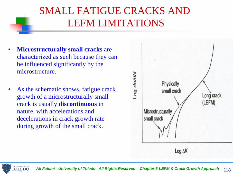
• Microstructurally small cracks are
characterized as such because they can
be influenced significantly by the
microstructure.
• As the schematic shows, fatigue crack
growth of a microstructurally small
crack is usually discontinuous in
nature, with accelerations and
decelerations in crack growth rate
during growth of the small crack.
Ali Fatemi - University of Toledo All Rights Reserved Chapter 6-LEFM & Crack Growth Approach 119
SMALL FATIGUE CRACKS AND
LEFM LIMITATIONS
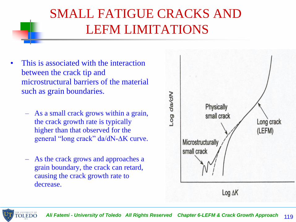
• This is associated with the interaction
between the crack tip and
microstructural barriers of the material
such as grain boundaries.
– As a small crack grows within a grain,
the crack growth rate is typically
higher than that observed for the
general “long crack” da/dN-K curve.
– As the crack grows and approaches a
grain boundary, the crack can retard,
causing the crack growth rate to
decrease.

Ali Fatemi - University of Toledo All Rights Reserved Chapter 6-LEFM & Crack Growth Approach 120
SMALL FATIGUE CRACKS AND
LEFM LIMITATIONS
• Once the small crack grows to a size that is several times larger than the grain size, typically around ten grain sizes, the microscopically small crack curve generally merges with the physically small and then long crack curve as shown.
• The growth of microstructurally small cracks typically violates the basis of continuum mechanics and LEFM. The use of probabilistic and statistical methods, and/or damage mechanics, appears to be potential solutions for better characterizing the fatigue crack growth of microstructurally small cracks.

Ali Fatemi - University of Toledo All Rights Reserved Chapter 6-LEFM & Crack Growth Approach 121
• Physically small cracks, typically
less than about 1 or 2 mm, are such
that in many cases they do not
necessarily violate LEFM limitations
based on stress level or near-tip
plastic zone size, yet still propagate at
rates faster than long cracks subjected
to the same nominal crack tip driving
force.
• The general fatigue crack growth
behavior of physically small cracks is
shown in the schematic of Fig. 6.21
and in Fig. 6.22.

Ali Fatemi - University of Toledo All Rights Reserved Chapter 6-LEFM & Crack Growth Approach 122
SMALL FATIGUE CRACKS AND
LEFM LIMITATIONS
• Crack growth behavior of physically small cracks is similar to the general long crack region I fatigue crack growth behavior except the growth rates are higher and Kth is lower.
• Crack closure can contribute significantly to the effective K level. The anomalous behavior of physically small cracks is associated with the lack of premature contact between the crack faces behind the crack tip as it advances, opposite of that typically observed at low stress ratio for long crack behavior.
• The crack growth behavior of physically small cracks is similar to the behavior of long cracks at higher stress ratio.
• In regions II and III, the crack growth rate increases rapidly thus a physically small crack operating in regions II or III becomes a “long crack” very quickly.

Ali Fatemi - University of Toledo All Rights Reserved Chapter 6-LEFM & Crack Growth Approach 123
SMALL FATIGUE CRACKS AND
LEFM LIMITATIONS
• A simple approximation for this type of small crack growth behavior is extrapolation of the Paris equation to region I type growth.
• Although not an accurate fit to most long crack growth data in region I, extrapolation of the Paris equation may provide better life predictions by taking into account much of the non-conservative behavior associated with small crack growth.
• However, one must be careful when performing this operation, as extrapolation could result in either conservative or non-conservative behavior depending on the physically small crack behavior observed.
Ali Fatemi - University of Toledo All Rights Reserved Chapter 6-LEFM & Crack Growth Approach 124
SMALL FATIGUE CRACKS AND
LEFM LIMITATIONS
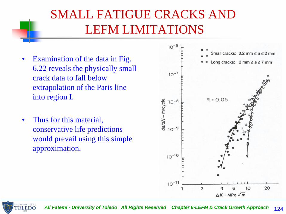
• Examination of the data in Fig.
6.22 reveals the physically small
crack data to fall below
extrapolation of the Paris line
into region I.
• Thus for this material,
conservative life predictions
would prevail using this simple
approximation.
Ali Fatemi - University of Toledo All Rights Reserved Chapter 6-LEFM & Crack Growth Approach 125
PLASTICITY EXTENSION OF LEFM
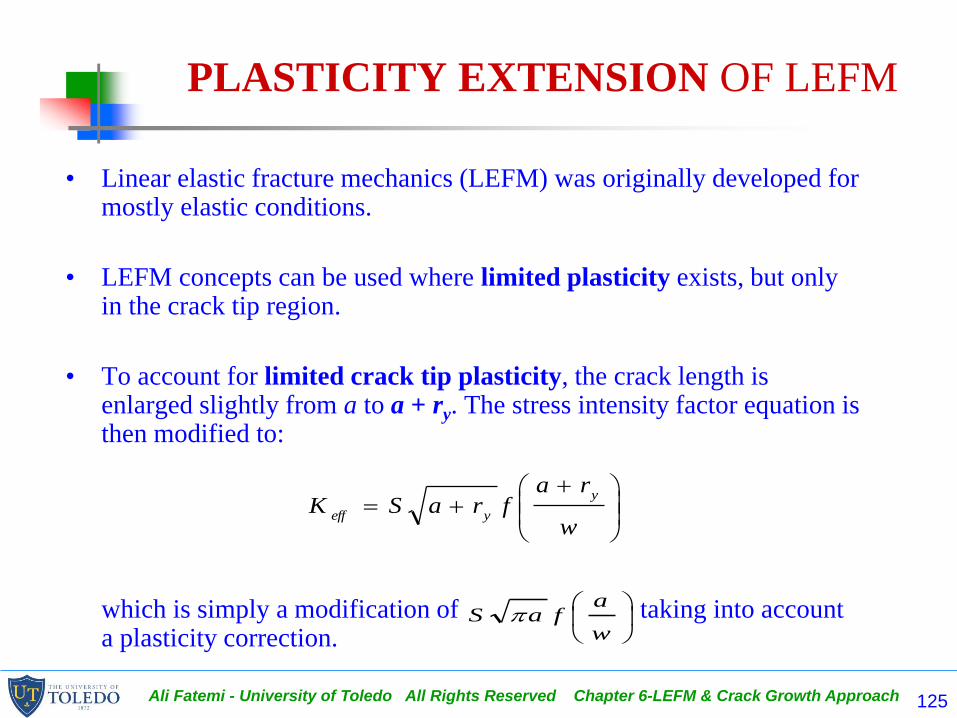
• Linear elastic fracture mechanics (LEFM) was originally developed for mostly elastic conditions.
• LEFM concepts can be used where limited plasticity exists, but only in the crack tip region.
• To account for limited crack tip plasticity, the crack length is enlarged slightly from a to a + ry. The stress intensity factor equation is then modified to:
which is simply a modification of taking into account a plasticity correction.
w
rafraSK
y
yeff
w
afaS

Ali Fatemi - University of Toledo All Rights Reserved Chapter 6-LEFM & Crack Growth Approach 126
PLASTICITY EXTENSION OF LEFM
• Keff defined here is not the same as Keff defined regarding crack closure.
• Since calculation of ry requires the value of Keff, a trial and error
procedure is often necessary to obtain Keff, unless f [(a + ry)/w] does not
change significantly for the new crack length (a + ry).
• The plastic zone correction is typically small when S<<Sy, but increases
appreciably when the applied stress, S, exceeds approximately 0.8Sy.
• Therefore, conditions that exhibit appreciable plasticity, i.e. when a
plasticity correction of about 20% is calculated, violate the basic
assumptions of LEFM. This is typical for metals with low strength and high
ductility at fracture and may occur with fatigue. Thus, the evolution of
elastic-plastic fracture mechanics (EPFM).
Ali Fatemi - University of Toledo All Rights Reserved Chapter 6-LEFM & Crack Growth Approach 127
ELASTIC-PLASTIC FRACTURE MECHANICS
• The parameter used in EPFM is the J-integral.
• The crack opening displacement (COD) approach, introduced prior to the introduction of the J-integral, is another technique used to characterize fracture and fatigue crack growth for conditions with excessive plasticity.
• Consideration of elastic-plastic fracture and nonlinear behavior is prominent in the nuclear power industry, specifically for pressure vessels and piping.
– Metals used to fabricate these structures are usually steels with high ductility toughness, where fracture or FCG is accompanied by extensive plastic deformation.
– Similar to the extensive use of K in the aerospace industry, because of the catastrophic consequences of failure in the nuclear power industry, much research has focused on the development of nonlinear (elastic-plastic) fracture mechanics methods to assess fracture risks in nuclear power plant structures and components.
• Elastic-plastic fracture concepts also are used in elevated temperature applications, offshore petrochemical rigs, structures, and components, as well as applications to safety critical components and structures in other industries.
Ali Fatemi - University of Toledo All Rights Reserved Chapter 6-LEFM & Crack Growth Approach 128
SUMMARY
• Development of LEFM provides an understanding of the reduced strength of
components in the presence of flaws or cracks.
• The stress intensity factor, K, is the governing parameter in LEFM and is a
function of applied stress, crack length, and geometry.
• For various crack geometries and configurations K takes on the form of one of the following:
OR
• Determination of fracture toughness, Kc or KIc, of metals provides a quantitative design criteria to prevent failure of cracked components.
YaS
w
afaS

Ali Fatemi - University of Toledo All Rights Reserved Chapter 6-LEFM & Crack Growth Approach 129
SUMMARY
• Limitations on the use of LEFM due to plasticity have been established that
– restrict the net (nominal) stress to less than approximately 80% of the yield strength, and
– the plastic zone size be small relative to the crack length and local geometry.
• LEFM applications to fatigue crack growth and damage tolerant design have allowed life estimations and predictions to be made.
• The total life is more sensitive to initial crack size than fracture toughness, which illustrates the importance of minimizing initial crack or discontinuity size.

Ali Fatemi - University of Toledo All Rights Reserved Chapter 6-LEFM & Crack Growth Approach 130
SUMMARY
• Empirical relationships describing fatigue crack growth developed by
Paris, Forman, Walker, and others, are used to perform fatigue life
calculations.
• Region II fatigue crack growth essentially shows a linear relationship
between log da/dN and log K which corresponds to the equation:
• Resulting in:
nnnnaSAKA
dN
da
2/)()()(
f
i
f a
a nnnn
N
fa
da
SAdNN
2/2/0 )()(
1
Ali Fatemi - University of Toledo All Rights Reserved Chapter 6-LEFM & Crack Growth Approach 131
SUMMARY
• The threshold stress intensity range, Kth, defines a lower
limit of crack growth rate, typically around 10-10 m/cycle
below which cracks are assumed to be non-propagating.
• Concepts such as the J-integral and EPFM, crack closure,
and small crack growth have provided a great deal of
stimulus to the engineering community during the past 25
years and more. Despite these, LEFM is still applicable to
many fatigue situations.

Ali Fatemi - University of Toledo All Rights Reserved Chapter 6-LEFM & Crack Growth Approach 132
DOS AND DON'TS IN DESIGN
• Do recognize that the presence of cracks or crack-like manufacturing and metallurgical discontinuities can significantly reduce the strength of a component or structure.
• LEFM can aid both qualitatively and quantitatively in estimating static strength as well as fatigue crack growth life and final fracture.
• Do consider that fracture toughness depends much more on metallurgical discontinuities and impurities than does ultimate or yield strength. Low impurity alloys have better fracture toughness.
• Don't expect doubling thickness or doubling ultimate strength of a component to double the fracture load. Cracks can exist and fracture toughness may drop appreciably with both thickness and ultimate strength increases.
• Do recognize the importance of distinguishing between plane stress and plane strain in fracture mechanics analysis as fracture toughness, crack tip plasticity, and LEFM limitations can be significantly different for the two conditions.

Ali Fatemi - University of Toledo All Rights Reserved Chapter 6-LEFM & Crack Growth Approach 133
DOS AND DON'TS IN DESIGN
• Don't neglect the importance of nondestructive flaw or crack inspection for both initial and periodic inspection periods.
• Do note that most fatigue crack growth usually occurs in mode I even under mixed-mode conditions, and hence the opening mode stress intensity factor range KI is often the predominant controlling factor in FCG.
• Do investigate the possibility of using LEFM principles in fatigue crack growth life predictions even in low strength materials; crack tip plasticity can be small even in low strength materials under fatigue conditions. If plasticity is large, EPFM may be required.
• Do consider the possibility of inspection before fracture. High fracture toughness materials may not provide appreciable increases in fatigue crack growth life, but they do permit longer cracks before fracture, which makes inspection and detection of cracks more reliable.