Brocade Fabric OS FICON Administration Guide, 7.4.x
110
Supporting Fabric OS 7.4.0 Supporting Fabric OS 7.4.1 ADMINISTRATION GUIDE Brocade Fabric OS FICON Administration Guide, 7.4.x 53-1003517-06 14 October 2016
-
Upload
khangminh22 -
Category
Documents
-
view
0 -
download
0
Transcript of Brocade Fabric OS FICON Administration Guide, 7.4.x

Supporting Fabric OS 7.4.0Supporting Fabric OS 7.4.1
ADMINISTRATION GUIDE
Brocade Fabric OS FICONAdministration Guide, 7.4.x
53-1003517-0614 October 2016

© 2016, Brocade Communications Systems, Inc. All Rights Reserved.
Brocade, the B-wing symbol, and MyBrocade are registered trademarks of Brocade Communications Systems, Inc., in the United States and in othercountries. Other brands, product names, or service names mentioned of Brocade Communications Systems, Inc. are listed at www.brocade.com/en/legal/brocade-Legal-intellectual-property/brocade-legal-trademarks.html. Other marks may belong to third parties.
Notice: This document is for informational purposes only and does not set forth any warranty, expressed or implied, concerning any equipment,equipment feature, or service offered or to be offered by Brocade. Brocade reserves the right to make changes to this document at any time, withoutnotice, and assumes no responsibility for its use. This informational document describes features that may not be currently available. Contact a Brocadesales office for information on feature and product availability. Export of technical data contained in this document may require an export license from theUnited States government.
The authors and Brocade Communications Systems, Inc. assume no liability or responsibility to any person or entity with respect to the accuracy of thisdocument or any loss, cost, liability, or damages arising from the information contained herein or the computer programs that accompany it.
The product described by this document may contain open source software covered by the GNU General Public License or other open source licenseagreements. To find out which open source software is included in Brocade products, view the licensing terms applicable to the open source software, andobtain a copy of the programming source code, please visit http://www.brocade.com/support/oscd.
Brocade Fabric OS FICON Administration Guide, 7.4.x2 53-1003517-06

ContentsPreface...................................................................................................................................................................................................................................7
Document conventions............................................................................................................................................................................................................................7Notes, cautions, and warnings.....................................................................................................................................................................................................7Text formatting conventions......................................................................................................................................................................................................... 7Command syntax conventions....................................................................................................................................................................................................8Text formatting conventions......................................................................................................................................................................................................... 8Command syntax conventions....................................................................................................................................................................................................8Notes, cautions, and warnings.....................................................................................................................................................................................................9
Brocade resources.....................................................................................................................................................................................................................................9Contacting Brocade Technical Support......................................................................................................................................................................................... 10
Brocade customers.......................................................................................................................................................................................................................10Brocade OEM customers.......................................................................................................................................................................................................... 10
Document feedback.............................................................................................................................................................................................................................. 10
About This Document..................................................................................................................................................................................................... 11Supported hardware and software...................................................................................................................................................................................................11Additional FICON resources.............................................................................................................................................................................................................. 11What's new in this document............................................................................................................................................................................................................. 11
Changes made for this release ............................................................................................................................................................................................... 11Changes made for this release (53-1003517-02).......................................................................................................................................................12Changes made for this release (53-1003517-03).......................................................................................................................................................12Changes made for this release (53-1003517-04).......................................................................................................................................................12Changes made for this release (53-1003517-05).......................................................................................................................................................12Changes made for this release (53-1003517-06).......................................................................................................................................................12
Introducing FICON...........................................................................................................................................................................................................13FICON overview......................................................................................................................................................................................................................................13
Fabric OS support for FICON..................................................................................................................................................................................................13Latency guideline...........................................................................................................................................................................................................................14
FICON concepts......................................................................................................................................................................................................................................14FICON configurations...........................................................................................................................................................................................................................16
Switched point-to-point..............................................................................................................................................................................................................16Cascaded FICON.......................................................................................................................................................................................................................... 17
Access control in FICON..................................................................................................................................................................................................................... 25Cascaded zoning........................................................................................................................................................................................................................... 26Error reporting.................................................................................................................................................................................................................................28Secure access control.................................................................................................................................................................................................................. 28
FICON commands.................................................................................................................................................................................................................................29Link and FC addressing....................................................................................................................................................................................................................... 31
Domain ID.........................................................................................................................................................................................................................................32Port area............................................................................................................................................................................................................................................ 32ALPA...................................................................................................................................................................................................................................................32
Administering FICON Fabrics........................................................................................................................................................................................33User security considerations.............................................................................................................................................................................................................. 33Meeting high-integrity fabric requirements..................................................................................................................................................................................33
Enabling the insistent domain ID............................................................................................................................................................................................ 34Creating and activating the SCC policy................................................................................................................................................................................ 34
Brocade Fabric OS FICON Administration Guide, 7.4.x53-1003517-06 3

Enabling the fabric-wide consistency policy...................................................................................................................................................................... 35Enabling High-Integrity Fabric mode....................................................................................................................................................................................35Using other security commands............................................................................................................................................................................................. 35
Preparing a switch for FICON............................................................................................................................................................................................................36Cascaded FICON and two-byte addressing considerations.......................................................................................................................................36
Configuring switched point-to-point FICON...............................................................................................................................................................................36Configuring cascaded FICON........................................................................................................................................................................................................... 42FICON and FICON CUP in Virtual Fabrics..................................................................................................................................................................................43Addressing modes................................................................................................................................................................................................................................. 44
Mode 1 (zero-based addressing)............................................................................................................................................................................................44FICON and blade support for addressing modes........................................................................................................................................................... 44Port swap limitations.................................................................................................................................................................................................................... 44
Disabling and enabling ports - persistent states........................................................................................................................................................................45Clearing the FICON management database...............................................................................................................................................................................45Automating CS_CTL mapping..........................................................................................................................................................................................................46FICON best practices............................................................................................................................................................................................................................47Latency guideline.................................................................................................................................................................................................................................... 48
Configuring FICON CUP................................................................................................................................................................................................ 49Control Unit Port overview.................................................................................................................................................................................................................. 49
FICON CUP restrictions............................................................................................................................................................................................................. 51CUP configuration recommendations.................................................................................................................................................................................. 51FICON CUP zoning and PDCM considerations.............................................................................................................................................................. 52
Port and switch naming standards for FMS mode...................................................................................................................................................................52FICON CUP Fabric OS commands......................................................................................................................................................................................52
Configuring FICON CUP.....................................................................................................................................................................................................................53Disabling ports 0xFE and 0xFF..............................................................................................................................................................................................53Configuring FICON CUP in Virtual Fabrics........................................................................................................................................................................54
Determining physical port assignment .........................................................................................................................................................................................54FMS mode and FICON CUP............................................................................................................................................................................................................ 54
Fabric OS command limitations and considerations......................................................................................................................................................55Displaying FMS mode.................................................................................................................................................................................................................55Enabling FMS mode.................................................................................................................................................................................................................... 55Disabling FMS mode...................................................................................................................................................................................................................56FMS mode and FICON 0xFE or 0xFF ports....................................................................................................................................................................56Upgrade considerations..............................................................................................................................................................................................................56Port swap limitations.................................................................................................................................................................................................................... 57
Mode register bit settings.................................................................................................................................................................................................................... 57FICON file access facility........................................................................................................................................................................................................... 58Considerations for setting mode register bits....................................................................................................................................................................60Setting the mode register bits.................................................................................................................................................................................................. 60
Setting the MIHPTO value..................................................................................................................................................................................................................60Persistently enabling and disabling ports for CUP................................................................................................................................................................... 60
Administering FICON Extension Services.................................................................................................................................................................. 63Platforms supporting FICON extension over IP........................................................................................................................................................................63FICON emulation overview................................................................................................................................................................................................................ 63
IBM z/OS Global Mirror emulation........................................................................................................................................................................................64Tape emulation............................................................................................................................................................................................................................... 65Printer emulation............................................................................................................................................................................................................................67Teradata emulation........................................................................................................................................................................................................................68
Brocade Fabric OS FICON Administration Guide, 7.4.x4 53-1003517-06

FCIP configuration requirements for FICON extension......................................................................................................................................................... 68Configuration requirements for switches and directors...........................................................................................................................................................68
High-integrity fabric requirements for cascaded configurations................................................................................................................................69FICON emulation requirement for a determinate path..................................................................................................................................................69
Configuring FICON emulation...........................................................................................................................................................................................................70Configuration examples.............................................................................................................................................................................................................. 70Displaying FICON emulation configuration values......................................................................................................................................................... 71
Modifying FICON emulation..............................................................................................................................................................................................................71Displaying FICON emulation performance statistics...............................................................................................................................................................71
FICON emulation monitoring...................................................................................................................................................................................................71Options for displaying statistics...............................................................................................................................................................................................73
Maintaining and Troubleshooting FICON................................................................................................................................................................... 75Firmware management in a FICON environment.....................................................................................................................................................................75
Upgrade and downgrade considerations.............................................................................................................................................................................75Firmware download disruption.................................................................................................................................................................................................75Non-disruptive firmware upload and download................................................................................................................................................................76
Configuration restoration in a FICON environment..................................................................................................................................................................76Traffic Isolation Zoning..........................................................................................................................................................................................................................77
Determining ports for the TI Zone..........................................................................................................................................................................................77Enhanced TI Zoning..................................................................................................................................................................................................................... 78
Monitoring and Alerting Policy Suite.............................................................................................................................................................................................. 83Port fencing............................................................................................................................................................................................................................................... 83
Defining port fencing....................................................................................................................................................................................................................83Settings for FICON environments..........................................................................................................................................................................................83
FICON information.................................................................................................................................................................................................................................84Link incidents...................................................................................................................................................................................................................................84Registered listeners.......................................................................................................................................................................................................................84Node identification data.............................................................................................................................................................................................................. 85FRU error reporting...................................................................................................................................................................................................................... 85
Swapping port area IDs........................................................................................................................................................................................................................ 86Important notes.............................................................................................................................................................................................................................. 87
Blade swapping........................................................................................................................................................................................................................................87Common FICON issues...................................................................................................................................................................................................................... 87Troubleshooting FICON.......................................................................................................................................................................................................................90
General information to gather for all cases......................................................................................................................................................................... 90Switched point-to-point topology checklist........................................................................................................................................................................91Cascaded topology checklist....................................................................................................................................................................................................91Gathering additional information.............................................................................................................................................................................................91CUP diagnostics............................................................................................................................................................................................................................ 92
Troubleshooting FICON CUP............................................................................................................................................................................................................92Troubleshooting NPIV...........................................................................................................................................................................................................................92
Platforms Supporting FICON........................................................................................................................................................................................ 93Introduction................................................................................................................................................................................................................................................93Supported platforms with end-of-support announcements................................................................................................................................................ 93Currently supported platforms...........................................................................................................................................................................................................94Supported Brocade blades.................................................................................................................................................................................................................94
Basic Switch Configuration............................................................................................................................................................................................ 97
Address Binding Examples..........................................................................................................................................................................................101
Brocade Fabric OS FICON Administration Guide, 7.4.x53-1003517-06 5

Sequential address binding..............................................................................................................................................................................................................101Example scripts for binding ports (Mode 1)....................................................................................................................................................................102
Unbinding multiple ports.................................................................................................................................................................................................................. 105
Configuration Information Record............................................................................................................................................................................. 107
EBCDIC Code Page.......................................................................................................................................................................................................109
Brocade Fabric OS FICON Administration Guide, 7.4.x6 53-1003517-06
Preface• Document conventions...................................................................................................................................................................................... 7• Brocade resources............................................................................................................................................................................................... 9• Contacting Brocade Technical Support....................................................................................................................................................10• Document feedback.........................................................................................................................................................................................10
Document conventionsThe document conventions describe text formatting conventions, command syntax conventions, and important notice formats used inBrocade technical documentation.
Notes, cautions, and warningsNotes, cautions, and warning statements may be used in this document. They are listed in the order of increasing severity of potential
hazards.
NOTEA Note provides a tip, guidance, or advice, emphasizes important information, or provides a reference to related information.
ATTENTIONAn Attention statement indicates a stronger note, for example, to alert you when traffic might be interrupted or the device mightreboot.
CAUTIONA Caution statement alerts you to situations that can be potentially hazardous to you or cause damage to hardware,firmware, software, or data.
DANGERA Danger statement indicates conditions or situations that can be potentially lethal or extremely hazardous to you. Safetylabels are also attached directly to products to warn of these conditions or situations.
Text formatting conventionsText formatting conventions such as boldface, italic, or Courier font may be used to highlight specific words or phrases.
Format Description
bold text Identifies command names.
Identifies keywords and operands.
Identifies the names of GUI elements.
Identifies text to enter in the GUI.
italic text Identifies emphasis.
Identifies variables.
Identifies document titles.
Courier font Identifies CLI output.
Identifies command syntax examples.
Brocade Fabric OS FICON Administration Guide, 7.4.x53-1003517-06 7

Command syntax conventionsBold and italic text identify command syntax components. Delimiters and operators define groupings of parameters and their logicalrelationships.
Convention Description
bold text Identifies command names, keywords, and command options.
italic text Identifies a variable.
value In Fibre Channel products, a fixed value provided as input to a command option is printed in plain text, forexample, --show WWN.
[ ] Syntax components displayed within square brackets are optional.
Default responses to system prompts are enclosed in square brackets.
{ x | y | z } A choice of required parameters is enclosed in curly brackets separated by vertical bars. You must selectone of the options.
In Fibre Channel products, square brackets may be used instead for this purpose.
x | y A vertical bar separates mutually exclusive elements.
< > Nonprinting characters, for example, passwords, are enclosed in angle brackets.
... Repeat the previous element, for example, member[member...].
\ Indicates a “soft” line break in command examples. If a backslash separates two lines of a commandinput, enter the entire command at the prompt without the backslash.
Text formatting conventionsText formatting conventions such as boldface, italic, or Courier font may be used in the flow of the text to highlight specific words orphrases.
Format Description
bold text Identifies command names
Identifies keywords and operands
Identifies the names of user-manipulated GUI elements
Identifies text to enter at the GUI
italic text Identifies emphasis
Identifies variables
Identifies document titles
Courier font Identifies CLI output
Identifies command syntax examples
Command syntax conventionsBold and italic text identify command syntax components. Delimiters and operators define groupings of parameters and their logicalrelationships.
Convention Description
bold text Identifies command names, keywords, and command options.
italic text Identifies a variable.
value In Fibre Channel products, a fixed value provided as input to a command option is printed in plain text, forexample, --show WWN.
Document conventions
Brocade Fabric OS FICON Administration Guide, 7.4.x8 53-1003517-06

Convention Description
[ ] Syntax components displayed within square brackets are optional.
Default responses to system prompts are enclosed in square brackets.
{ x | y | z } A choice of required parameters is enclosed in curly brackets separated by vertical bars. You must selectone of the options.
In Fibre Channel products, square brackets may be used instead for this purpose.
x | y A vertical bar separates mutually exclusive elements.
< > Nonprinting characters, for example, passwords, are enclosed in angle brackets.
... Repeat the previous element, for example, member[member...].
\ Indicates a “soft” line break in command examples. If a backslash separates two lines of a commandinput, enter the entire command at the prompt without the backslash.
Notes, cautions, and warningsNotes, cautions, and warning statements may be used in this document. They are listed in the order of increasing severity of potentialhazards.
NOTEA Note provides a tip, guidance, or advice, emphasizes important information, or provides a reference to related information.
ATTENTIONAn Attention statement indicates a stronger note, for example, to alert you when traffic might be interrupted or the device mightreboot.
CAUTIONA Caution statement alerts you to situations that can be potentially hazardous to you or cause damage to hardware,firmware, software, or data.
DANGERA Danger statement indicates conditions or situations that can be potentially lethal or extremely hazardous to you. Safetylabels are also attached directly to products to warn of these conditions or situations.
Brocade resourcesVisit the Brocade website to locate related documentation for your product and additional Brocade resources.
White papers, data sheets, and the most recent versions of Brocade software and hardware manuals are available at www.brocade.com.Product documentation for all supported releases is available to registered users at MyBrocade.Click the Support tab and select Document Library to access documentation on MyBrocade or www.brocade.com You can locatedocumentation by product or by operating system.
Release notes are bundled with software downloads on MyBrocade. Links to software downloads are available on the MyBrocade landingpage and in the Document Library.
Brocade resources
Brocade Fabric OS FICON Administration Guide, 7.4.x53-1003517-06 9

Contacting Brocade Technical SupportAs a Brocade customer, you can contact Brocade Technical Support 24x7 online, by telephone, or by e-mail. Brocade OEM customersshould contact their OEM/solution provider.
Brocade customersFor product support information and the latest information on contacting the Technical Assistance Center, go to www.brocade.com andselect Support.
If you have purchased Brocade product support directly from Brocade, use one of the following methods to contact the BrocadeTechnical Assistance Center 24x7.
Online Telephone E-mail
Preferred method of contact for non-urgentissues:
• Case management through the MyBrocade portal.
• Quick Access links to KnowledgeBase, Community, Document Library,Software Downloads and Licensingtools
Required for Sev 1-Critical and Sev 2-Highissues:
• Continental US: 1-800-752-8061
• Europe, Middle East, Africa, and AsiaPacific: +800-AT FIBREE (+800 2834 27 33)
• Toll-free numbers are available inmany countries.
• For areas unable to access a toll-freenumber: +1-408-333-6061
Please include:
• Problem summary
• Serial number
• Installation details
• Environment description
Brocade OEM customersIf you have purchased Brocade product support from a Brocade OEM/solution provider, contact your OEM/solution provider for all ofyour product support needs.
• OEM/solution providers are trained and certified by Brocade to support Brocade® products.
• Brocade provides backline support for issues that cannot be resolved by the OEM/solution provider.
• Brocade Supplemental Support augments your existing OEM support contract, providing direct access to Brocade expertise.For more information, contact Brocade or your OEM.
• For questions regarding service levels and response times, contact your OEM/solution provider.
Document feedbackQuality is our first concern at Brocade, and we have made every effort to ensure the accuracy and completeness of this document.However, if you find an error or an omission, or you think that a topic needs further development, we want to hear from you. You canprovide feedback in two ways:
• Through the online feedback form in the HTML documents posted on www.brocade.com
• By sending your feedback to [email protected]
Provide the publication title, part number, and as much detail as possible, including the topic heading and page number if applicable, aswell as your suggestions for improvement.
Contacting Brocade Technical Support
Brocade Fabric OS FICON Administration Guide, 7.4.x10 53-1003517-06

About This Document• Supported hardware and software..............................................................................................................................................................11• Additional FICON resources.........................................................................................................................................................................11• What's new in this document........................................................................................................................................................................11
Supported hardware and softwareAlthough many different software and hardware configurations are tested and supported by Brocade Communications Systems, Inc. forFabric OS v7.4.0 documenting all possible configurations and scenarios is beyond the scope of this document.
For a complete list of platforms supported by FICON and Fabric OS v7.4.0, refer to Platforms supporting FICON on page 93Platforms supporting FICON.
In cases where procedures or parts of procedures do not apply to all Brocade hardware platforms, this guide identifies which platformsare supported.
Additional FICON resourcesIn addition to Brocade product resources listed under "Brocade Resources" in this Preface, a dedicated page for mainframe resources islocated at Mainframe and FICON Solutions.
What's new in this documentThis document includes new and modified information for the Fabric OS 7.4.0 release.
Changes made for this releaseThe following information was added or changed in this document, in addition to other changes made for accuracy and clarity:
• Throughout the document, updated reference to third-party products.
• Updated the information in FICON Overview to current IBM versions.
• Updated the information in Configuring switched point-to-point FICON on page 36 to allow both PBR and DBR whenFICON Emulation features are enabled.
• Updated the information and added a note about HIF requirements in Meeting high-integrity fabric requirements on page 33.
• Updated the information in Configuration restoration in a FICON environment on page 76 for changes to configurationupload and configuration download.
• In the chapter Administering FICON Fabrics on page 33, removed the section FCR and FICON cascading that exists in priorreleases of the document
• Added information in IBM z/OS Global Mirror emulation on page 64 recommending use of DBR rather than PBR incascaded FICON configurations.
• Updated the supported platform list in Enhanced TI Zoning on page 78.
• Updated the information in Port fencing on page 83 to recommend alternatives to port fencing.
• Updated the list of supported platforms and releases in Currently supported platforms on page 94.
Brocade Fabric OS FICON Administration Guide, 7.4.x53-1003517-06 11

Changes made for this release (53-1003517-02)Minor changes have been made to the document to enhance presentation of the graphics and illustrations.
Changes made for this release (53-1003517-03)Minor corrections have been made to the document to correct typographical errors.
Changes made for this release (53-1003517-04)The following information was changed in this document:
• Information about Mode 0 and Mode 2 addressing modes was removed from Addressing modes on page 44. Mode 1 (zero-based) addressing is the recommended mode for FICON configurations.
• Examples for Mode 2 addressing were removed from Address Binding Examples on page 101.
• Information about supported platforms in Fabric OS 7.4.0 was updated in Currently supported platforms on page 94.
Changes made for this release (53-1003517-05)The following information was changed in this document:
• Information about supported platforms in Fabric OS 7.4.0 and Fabric OS 7.4.1 was updated in Currently supported platformson page 94.
Changes made for this release (53-1003517-06)The following information was added or changed in this document:
• A note was added to the following areas in the document to advise the importance of enabling FMS mode before configuringport names.
– Port and switch naming standards for FMS mode on page 52– FMS mode and FICON CUP on page 54– Enabling FMS mode on page 55
What's new in this document
Brocade Fabric OS FICON Administration Guide, 7.4.x12 53-1003517-06

Introducing FICON• FICON overview.................................................................................................................................................................................................13• FICON concepts................................................................................................................................................................................................ 14• FICON configurations......................................................................................................................................................................................16• Access control in FICON................................................................................................................................................................................25• FICON commands........................................................................................................................................................................................... 29• Link and FC addressing..................................................................................................................................................................................31
FICON overviewIBM Fibre Connection (FICON®) is an industry-standard, high-speed input/output (I/O) interface for mainframe connections to storagedevices. This guide discusses support offered by Fabric OS in intermix mode operations, in which FICON and Fibre Channel technologywork together.
For specific information about intermix mode and other aspects of FICON, refer to the IBM Redbook, FICON® Implementation Guide(SG24-6497-03), and IBM z System Connectivity Handbook (G24-5444-15).
NOTEIn this guide, the term switch is used to refer to a Brocade switch, Backbone, backbone platform, or director unless otherwisenoted.
Fabric OS support for FICONThe following Fabric OS standard features support FICON fabrics:
• Blade swapping
Allows you to swap a blade of the same type so that you can replace a field-replaceable unit (FRU) with minimal trafficdisruption. This feature is available for both FICON and open system environments. Blade swapping resolves situations in whichthe hardware has failed and the channel configurations cannot be changed quickly. In addition, a blade swap minimizes andeliminates the need to make changes to the I/O sysgen in the hardware configuration definition (HCD). Blade swapping hasminimal or no impact on other switch features.
• Routing policies
IBM z Systems FICON did not support exchange-based routing as of the publication date of this document, but does supportport-based and device- based routing. For details on these policies, refer to the "Routing Traffic" chapter in the Fabric OSAdministrator's Guide.
• FICON MIB module
Addresses link incident data for FICON hosts and devices connected to a switch. The FICON MIB module supplements otherManagement Information Bases (MIBs) used to manage switches and should be used in conjunction with those other MIBs.
• Insistent Domain ID (IDID)
Disables the dynamic domain ID feature and only allows the switch to use a pre-set domain ID. All switches in a fabric musthave a unique domain ID. An insistent domain ID is required with 2-byte addressing. IDID is the recommended best practice forsingle byte addressing.
• Link incident detection, registration, and reporting
Provides administrative and diagnostic information.
Brocade Fabric OS FICON Administration Guide, 7.4.x53-1003517-06 13

• Swap port area IDs (PIDs) of physical ports
Redirects resources from a failed port to a healthy port without changing the mainframe hardware configuration definition (HCD)settings. This feature, also called "port swapping," is available for both FICON and open system environments. Swapping PIDson ports resolves situations in which the hardware has failed and the channel configurations cannot be changed quickly. Portswapping has minimal or no impact on other switch features.
• Switch connection control (SCC) policy
Includes fabric security methods that prevent unauthorized switches from joining a fabric. SCC policy configured in strict modeis required for cascaded FICON configurations and whenever 2-byte addressing is used.
• Traffic Isolation (TI) Zones and Enhanced TI Zones
TI Zones are used to direct traffic across links through a specified path. Enhanced TI Zones allow you to have ports in more thanone TI Zone and to program domain controller routes to destination domains for F-class traffic, ensuring fabric stability.
NOTEFor more detail on these features and configuration procedures, refer to the Fabric OS Administrator'sGuide.
Brocade management tools provide further support:
• Brocade Network Advisor
Brocade Network Advisor is an optional software program that can be used to manage a fabric that supports FICON and FibreChannel Protocol (FCP) devices and traffic. This is the recommended GUI management tool for FICON environments on B-series enterprise-class switches. For more information on Brocade Network Advisor, refer to the manual appropriate for yourversion requirements:
– Brocade Network Advisor SAN + IP User Manual– Brocade Network Advisor SAN User Manual
• Web Tools
Web Tools is an embedded GUI-management tool that can be used to manage a Brocade switch or director that supportsFICON and Fibre Channel Protocol (FCP) devices and traffic. For more information on Web Tools, refer to the Web ToolsAdministrator's Guide.
Latency guidelineThe maximum supported distance for a FICON channel is 300 Km (1.5 msec of delay). Synchronous remote data replication for DASDis generally limited to 100 Km (0.5 msec of delay). Asynchronous remote data replication for DASD, and remote tape reads/writesrequire that the Brocade Advanced Accelerator for FICON feature be used with FCIP. The Advanced Accelerator for FICON featureemulates control unit response to the channel to improve the performance over distances greater than locally attached distances.
FICON conceptsThe following figure shows how the traffic in a switched point-to-point configuration flows in a FICON environment. The logical path ofthe traffic is defined as frames moving from the channel to the switch to the control unit. FICON traffic moves from a logical partition(LPAR) and through the channel, through a Fibre Channel link to the switch through the control unit, and ends at the device. This is alsocalled a channel path, which is a single interface between a central processor and one or more control units along which signals and datacan be sent to perform I/O requests. The channel path uses the logical path to traverse the Fibre Channel fabric. The channel path isdefined using an ID, called the channel path ID (CHPID). This information is stored in the Input/Output Definition File (IODF) and may bedynamically configured. The IODF is typically built using the hardware configuration definition (HCD).
FICON concepts
Brocade Fabric OS FICON Administration Guide, 7.4.x14 53-1003517-06

FIGURE 1 FICON traffic
The traffic on the channel path communicates using channel command words (CCW) for Command Mode FICON, and transport controlwords (TCW) for z High Performance FICON (zHPF) channel programs. In a FICON environment, buffer credits are used at the FibreChannel Protocol (FCP) level for flow control between optically adjacent ports, while information unit (IU) pacing is the flow controlmechanism used by the channel. There are times when there are no more buffer credits to pass back to the other end of the link and aframe pacing delay occurs. Frame pacing delay is the number of intervals of 2.5 microseconds that a frame had to wait to be transmitteddue to a lack of available buffer credits. Frame pacing delay information is reported via the z/OS Resource Measurement Facility (RMF),specifically in the FICON Director Activity Report (RMF 74-7).
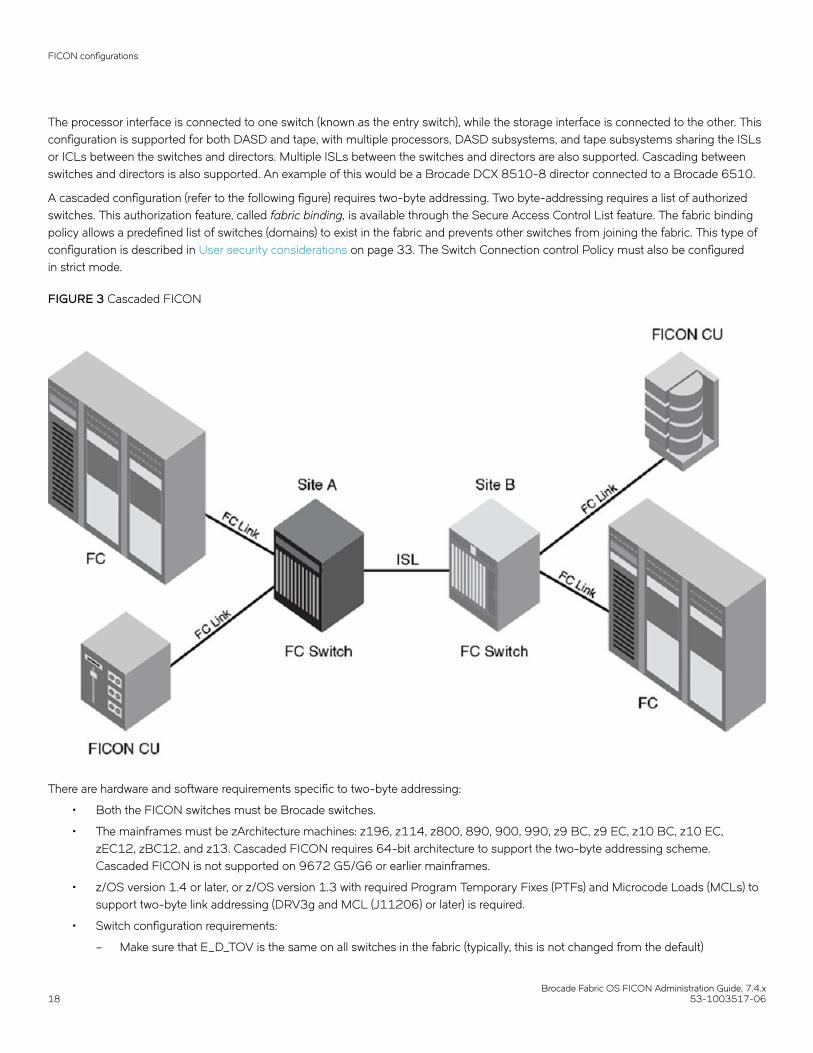
FICON introduces the following concepts:
• FICON Control Unit Port (CUP)
The internal port in a switch that assumes an Fibre Channel (FC) address such that it is the FC domain ID (DID) used to directFICON traffic to the FICON Management Server (FMS).
• FICON Manager
Host communication includes control functions such as blocking and unblocking ports, as well as monitoring and error-reporting functions.
• Hardware configuration definition (HCD)
HCD is an IBM interactive interface application that allows you to define the hardware configuration for both the processorchannel subsystem and the operating system running on the processor.
• Information unit
A unit of FICON data consisting of from one to four Fibre Channel frames.
• Link Incident Record Registration (LIRR)
The LIRR Extended Link Service (ELS) requests that the recipient add the requesting port to its list of ports that are to receive aRegistered Link Incident Report (RLIR).
• Node
A node is an endpoint that contains information. It can be a computer (host), a device controller, or a peripheral device, such as aDASD array or tape drive. A node has a unique 64-bit identifier known as the Node_Name. The Node_Name is typically usedfor management purposes.
FICON concepts
Brocade Fabric OS FICON Administration Guide, 7.4.x53-1003517-06 15

• Prohibit Dynamic Connectivity Mask (PDCM) and connectivity attributes
PDCM controls whether communication between a pair of ports in the switch is prohibited. Connectivity attributes controlwhether all the communication is blocked for a port.
• Read Record Set (RRS)
RRS is an IBM Channel-initiated CCW command. The Brocade Advanced Accelerator for FICON License allows the emulationof command chains that include this CCW command. The command is used in IBM z/OS Global Mirror configurations to readupdates from a volume in an active mirroring session.
• Registered Link Incident Report (RLIR)
RLIR ELS provides a way for a node port to send an incident record to another node port.
• Request Node Identification Data (RNID)
RNID ELS acquires the associated node’s identification data, which provides configuration discovery and management purposeinformation.
• Resource Measurement Facility (RMF)
Performance monitoring component of z/OS that gathers transaction data from the environment and generates performancereports. All Level II reports, which include port statistics, require the FICON Control Unit Port (CUP) and FICON ManagementServer (FMS), the FICON director included in the IOSysGen as a 2032 Control Unit, and the appropriate parmlib settingsconfigured to enable the RMF 74-7 record generation and statistics collected.
• Systems Operations (SysOps)
SysOps provides the ability to monitor and control all subsystems in a sysplex from any system in the sysplex. This includescontrolled startup, controlled shutdown, and automated recovery of software resources.
• Sysplex
In IBM mainframe computers, a Systems Complex, commonly called a sysplex, allows multiple processors to be joined into asingle unit, sharing the same sysplex name and Couple Data Sets.
• IPL file
The initial program load (IPL) File, located in nonvolatile storage, contains the current, active configuration settings for theFICON director. If functions to initialize data on the Director during a POR event. When the "Active=Saved" FICON CUP moderegister bit setting is on, any active configuration in switch memory is automatically saved to the IPL file.
FICON configurationsThere are two types of FICON configurations that are supported using Brocade Fabric OS: switched point-to-point and cascadedtopologies.
Switched point-to-pointA single-switch configuration is called switched point-to-point allows the channel to use single-byte addressing.
FICON configurations
Brocade Fabric OS FICON Administration Guide, 7.4.x16 53-1003517-06

FIGURE 2 Switched point-to-point FICON
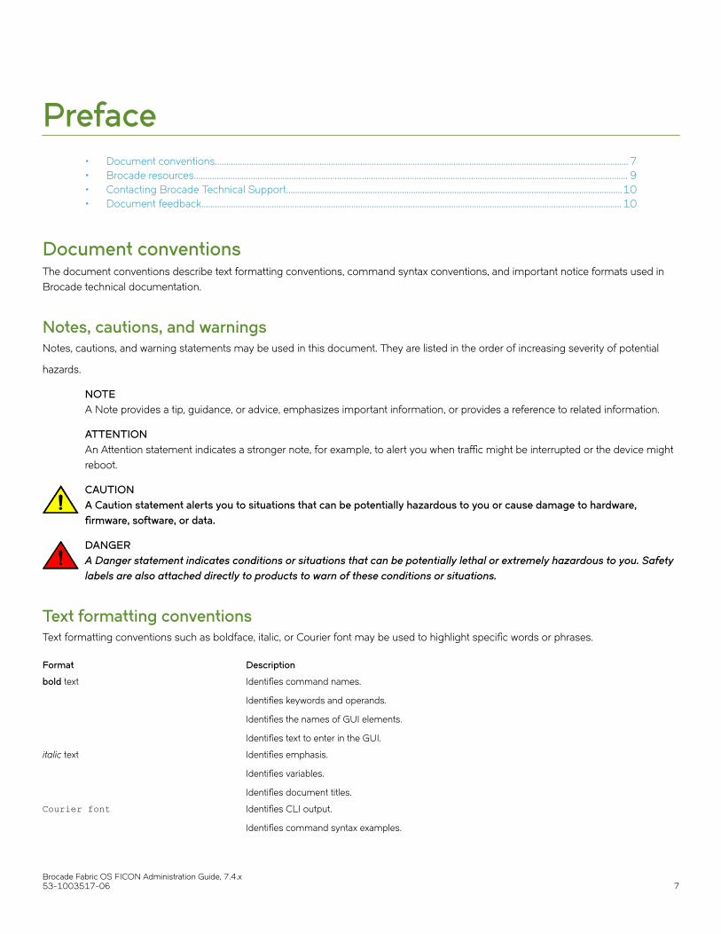
Cascaded FICONCascaded FICON refers to an implementation of FICON that uses one or more FICON channel paths in which the domain ID of theentry switch is different than the domain ID of the switch where the control unit is attached. Therefore, cascading requires a two-byte linkaddress. Anytime a two-byte link address is defined on a channel, all link addresses associated with that channel must be two-byte linkaddresses.
Switches may be interconnected using the following links:
• Traditional Inter-Switch Links (ISLs)
• Inter-Chassis Links (ICLs)
• Fibre Channel over Internet Protocol (FCIP)
FICON configurations
Brocade Fabric OS FICON Administration Guide, 7.4.x53-1003517-06 17
The processor interface is connected to one switch (known as the entry switch), while the storage interface is connected to the other. Thisconfiguration is supported for both DASD and tape, with multiple processors, DASD subsystems, and tape subsystems sharing the ISLsor ICLs between the switches and directors. Multiple ISLs between the switches and directors are also supported. Cascading betweenswitches and directors is also supported. An example of this would be a Brocade DCX 8510-8 director connected to a Brocade 6510.
A cascaded configuration (refer to the following figure) requires two-byte addressing. Two byte-addressing requires a list of authorizedswitches. This authorization feature, called fabric binding, is available through the Secure Access Control List feature. The fabric bindingpolicy allows a predefined list of switches (domains) to exist in the fabric and prevents other switches from joining the fabric. This type ofconfiguration is described in User security considerations on page 33. The Switch Connection control Policy must also be configuredin strict mode.
FIGURE 3 Cascaded FICON
There are hardware and software requirements specific to two-byte addressing:
• Both the FICON switches must be Brocade switches.
• The mainframes must be zArchitecture machines: z196, z114, z800, 890, 900, 990, z9 BC, z9 EC, z10 BC, z10 EC,zEC12, zBC12, and z13. Cascaded FICON requires 64-bit architecture to support the two-byte addressing scheme.Cascaded FICON is not supported on 9672 G5/G6 or earlier mainframes.
• z/OS version 1.4 or later, or z/OS version 1.3 with required Program Temporary Fixes (PTFs) and Microcode Loads (MCLs) tosupport two-byte link addressing (DRV3g and MCL (J11206) or later) is required.
• Switch configuration requirements:
– Make sure that E_D_TOV is the same on all switches in the fabric (typically, this is not changed from the default)
FICON configurations
Brocade Fabric OS FICON Administration Guide, 7.4.x18 53-1003517-06

– Make sure that R_A_TOV is the same on all switches in the fabric (typically, this is not changed from the default)– Configure insistent Domain ID (IDID)– Configure fabric binding (strict SCC policy)
Qualified FICON cascaded configurationsNot all fibre channel fabrics are qualified for FICON. Cascaded FICON configurations are limited to well-controlled paths. Only thechannel paths illustrated in this section are supported for FICON. The resulting fabric scenario after ISL failures must not result in anunsupported configuration. When physical cabling is not practical to enforce these configurations, zoning or Traffic Isolation zoning (TIzoning) with failover disabled may be used to ensure unsupported fabrics cannot be formed. Note that these restrictions apply to logicalswitches and not the chassis.
The following figures show two cascaded configurations. These configurations require Channel A to be configured for two-byteaddressing and require IDID and fabric binding. It is recommended that there be only two domains in a path from a FICON Channelinterface to a FICON Control Unit interface. There are exceptions to the two-domain rule in extended fabric configurations. Refer to Extended fabric configurations on page 20 for examples.
FIGURE 4 Cascaded configuration, two switches
The following figure illustrates multiple switches cascaded off of switch 21. As long as there is only one hop from channel to control unit,the configuration is supported.
FIGURE 5 Cascaded configuration, core-edge architecture
FICON configurations
Brocade Fabric OS FICON Administration Guide, 7.4.x53-1003517-06 19

Extended fabric configurationsSwitches in cascaded configurations may be connected through interchassis links (ICLs), interswitch links (ISLs), and FCIP. Connectionusing FCIP is through Fibre Channel extension devices, such as 7800 switches, 7840 switches, and FX8-24 blades. Following areexample configurations.
For more information on long distance and extended fabrics, refer to the Fabric OS Administrator's Guide. For more information onextension products, including FCIP and IP Extension, refer to the Fabric OS Extension Administrator's Guide.
The following figure illustrates a multi-hop ICL triangle configuration that uses ICLs. Note that three switches are connected through ICLsonly.
FIGURE 6 Multi-hop ICL triangle
The following figure illustrates a multi-hop configuration that uses ICLs and ISLs. This configuration is supported with or without switches4 or 1. All switches must be all generation (Gen) 4 or all Gen 5. You cannot mix Gen 4 and Gen 4 on ICL connections.
FICON configurations
Brocade Fabric OS FICON Administration Guide, 7.4.x20 53-1003517-06

FIGURE 7 Multi-hop configuration with ICLs
The following figure illustrates a multi-hop configuration that uses ICLs and FCIP. The two 7800 switches are for ISL extension onlyusing FCIP. Channel or control unit connections are not permitted. These switches may be replaced with an FX8-24 blade installed indirectors. This configuration can be supported with or without switches 4 or 1. All switches must be Gen 4 or Gen 5. You cannot mix Gen4 and Gen 5 switches with ICLs.
FICON configurations
Brocade Fabric OS FICON Administration Guide, 7.4.x53-1003517-06 21

FIGURE 8 Multi-hop with ICLS and FCIP
The following figure illustrates a configuration that uses FCIP between 7800 switches that are used as routers only, for ISL extension. Inthis configuration topology, direct FICON channel or control unit connections into the 7800 FC Ports are not supported. The 7800switches may be replaced with FX8-24 blades installed in directors.
FICON configurations
Brocade Fabric OS FICON Administration Guide, 7.4.x22 53-1003517-06

FIGURE 9 FCIP with 7800 switches as routers only
The following figure illustrates a configuration that uses cascaded FCIP with four 7800 switches. The 7800 switches at site 1 are usedfor ISL extension only. Channel or control unit connections are not permitted. The 7800 switches at site 2 are only for network, channel,and control unit connections. The 7800 switches on either site may be replaced with the FX8-24 blades installed in directors.
FICON configurations
Brocade Fabric OS FICON Administration Guide, 7.4.x53-1003517-06 23

FIGURE 10 Cascaded configuration using FCIP and 7800 switches
The following figure illustrates a cascaded configuration that uses FCIP and 7800 switches as edge switches. At site 1, the 7800switches are used for ISL extension only. Channel or control unit connections are not permitted. At site 2, only channel, and control unitconnections are permitted on the 7800 switches. The 7800 switches at either site may be replaced with the FX8-24 blades installed indirectors.
FICON configurations
Brocade Fabric OS FICON Administration Guide, 7.4.x24 53-1003517-06

FIGURE 11 Cascaded configuration using FCIP and 7800 edge switches
Access control in FICONZoning is used to control access in a FICON environment. A zone consists of a group of ports or WWNs. Connectivity is permitted onlybetween connections to the switch that are in the same zone. There are three types of zoning: WWN, port, and domain index zoning. Azone configuration includes at least one zone. In open systems environments and in more complex FICON deployments, the zoneconfiguration contains multiple zones. Although domain index zoning is supported, WWN zoning for Quality of Service (QoS) isrecommended in environments where N_Port ID Virtualization (NPIV) is deployed. For more information on how to implement QoSdomain index zoning in your fabric, refer to the "QoS zones" section of the Fabric OS Administrator's Guide for details.
When zoning changes occur, Registered State Change Notification (RSCN) messages are sent out throughout the zone. RSCNs are partof the low-level Fibre Channel Protocol that alerts channels and devices to changes in the fabric. As a best practice, Brocaderecommends use of one zone for all FICON connectivity.
Access control in FICON
Brocade Fabric OS FICON Administration Guide, 7.4.x53-1003517-06 25

NOTESession-based zoning enforcement is not recommended on a FICON switch. For more information on session-based zoningenforcement, refer to the Fabric OS Administrator's Guide.
Cascaded zoningThe figure below illustrates multiple sites sharing the same disaster-recovery site. Each switch or Director at a remote site, labeledDirector 1 and Director 3, can pass traffic to Director 2, but no traffic is permitted between Zone A and Zone B.
FIGURE 12 Simple cascaded zoning
The figure below illustrates the multiple zoning concepts that can be used to restrict traffic. Any host channel at the Backup Site(connected to Director 11 or Director 12) can connect to the backup tape contained within the same zone. Notice that no more than asingle hop is ever allowed and only Channel Path Identifiers (CHPIDs) 79 and 7A on the Primary Site can connect to the backup tape.Furthermore, CHPIDs 79 and 7A can only connect to the backup tape at the Backup Site.
NOTEZoning does not replace the need to set up the connectivity from the host to storage control units in the HCD or Input/OutputConfiguration Program (IOCP). For more information on zoning, refer to the Fabric OS Administrator's Guide.
Access control in FICON
Brocade Fabric OS FICON Administration Guide, 7.4.x26 53-1003517-06

FIGURE 13 Complex cascaded zoning
Zone A (Blue): Any CHPID connected to Director 1, except CHPID 79, can get to any control unit connected to Director 1. The zoneincludes all ports in Director 1 except ports 4, 5, and 6.
Zone B (Orange): Any CHPID connected to Director 2, except CHPID 7A, can get to any control unit connected to Director 2. The zoneincludes all ports in Director 2 except ports 4, 5, and 6.
Zone C (Green): Any CHPID connected to Director 11 can get to any control unit connected to Director 11. The zone includes all ports inDirector 11 except ports 5 and 6. Adding ports 5 and 6 to the zone, so that all ports in the switch or Director are in the same zone, wouldnot affect permitted connectivity and may be a more practical alternative.
Zone D (Yellow): Any CHPID connected to Director 12 can get to any control unit connected to Director 12. The zone includes all portsin Director 12 except ports 5 and 6, which are used for ISLs.
Red Zone E: CHPID 79 can talk only to the remote tape connected to ports 7 and 8 on Director 11. The zone includes port 4 of Director1 and ports 7 and 8 of Director 11. Either ISL can be used.
Access control in FICON
Brocade Fabric OS FICON Administration Guide, 7.4.x53-1003517-06 27

Purple Zone F: CHPID 7A can talk only to the remote tape connected to ports 7 and 8 on Director 12. The zone includes port 4 ofDirector 2 and ports 7 and 8 of Director 12. Either ISL can be used.
Error reportingNon-implicit link incidents (such as Fabric OS recognized or bit error rate threshold exceeded) and implicit link incidents (such as FRUfailure) are reported to registered listeners on the local switch. The RMF 74-7 record (FICON Director Activity Report, which is the sameRMF record containing the average frame pacing delay information) reports port errors, which in turn are also reported back to themainframe host management consoles.
Secure access controlBinding is a method used to prevent devices from attaching to the switch or director. Secure Access Control Lists (ACLs) provides thefollowing fabric, switch, and port binding features:
• Fabric binding is a security method for restricting switches within a multiple-switch fabric. Brocade recommends using fabricbinding for cascaded FICON. SCC ACLs with strict fabric-wide consistency are required for FICON fabric binding.
• Switch binding is a security method for restricting devices that connect to a particular switch or director. If the device is anotherswitch, this is handled by the SCC policy. If the device is a host or storage device, the device connection control (DCC) policybinds those devices to a particular switch. Policies range from completely restrictive to reasonably flexible, based uponcustomer needs. SCC ACLs with strict fabric-wide consistency are necessary for FICON switch binding.
• Port binding is a security method for restricting host or storage devices that connect to particular switch ports. The DCC policyalso binds device ports to switch ports. Policies range from completely restrictive to reasonably flexible, based on customerneeds.
The figure below demonstrates the three types of binding you can use depending on the security requirements of your fabric.
Access control in FICON
Brocade Fabric OS FICON Administration Guide, 7.4.x28 53-1003517-06

FIGURE 14 Types of binding for access control
FICON commandsNOTEThe Fabric OS CLI supports only a subset of the Brocade management features for FICON fabrics. The full set of FICON CUPadministrative procedures is available using the Brocade Network Advisor and Web Tools software features. You can also use anSNMP agent and the FICON Management Information Base (MIB).
FICON commands
Brocade Fabric OS FICON Administration Guide, 7.4.x53-1003517-06 29

The table below summarizes the Fabric OS CLI commands that can be used for managing FICON fabrics. For detailed information onthese commands, refer to the Fabric OS Command Reference.
TABLE 1 Fabric OS commands related to FICON
Command Description
Standard Fabric OS commands
bladeSwap Swaps the area numbers for matching port pairs of two blades.
configure Changes a variety of switch configuration settings, including setting thedomain ID and the insistent mode.
configUpload Backs up the current FOS feature and switch configuration, includingFMS or FICON-specific configuration such as IPL file, activeconfiguration, mode register, and host data.
firmwareShow Displays the current version of the firmware.
licenseAdd Adds a license to the switch. The license key is case-sensitive and mustbe entered exactly.
licenseRemove Removes a license from the switch. Note that FMS mode must bedisabled before removing the FICON license.
licenseShow Displays current license keys, along with a list of licensed productsenabled by these keys.
licenseSlotCfg Enables and displays slot-based licenses for a switch chassis. Note thatfor a switch without blades, such as the 7840 Extension Switch, slot 0 isused as the slot-based license target. For blades, slot numbers arebased on the switch chassis numbering scheme. A license key with thespecified capacity must be installed with the licenseAdd commandbefore you can enable a feature on a specified slot with this command.
portAddress Binds the 16-bit address to the lower two bytes of a port 24-bit FibreChannel address. Also unbinds the currently bound address for thespecified port.
portSwap Swaps ports. Note that the portswap --restore command restoresswapped ports to an unswapped state.
portSwapDisable Disables the portSwap feature. The portSwap command cannot be usedafter this feature is disabled. The disabled state is persistent acrossreboots and power cycles. Enabling or disabling the portSwap featuredoes not affect previously performed portSwap operations.
portSwapEnable Enables the portSwap feature.
portSwapShow Displays information about swapped ports.
supportShowCfgEnable ficon Turns on logging of FICON information on the switch.
Commands specific to FICON
ficonClear rlir Removes all RLIR records from the local RLIR database.
ficonClear rnid Removes all outdated RNID records from the local RNID database.
ficonCfg --set LIRR portnumber Sets the current LIRR device port number persistently.
ficonCfg --reset LIRR portnumber Clears the currently configured LIRR port number.
ficonHelp Displays a list of FICON support commands.
ficonCupSet fmsmode enable | disable |reset Enables, disables, or resets FICON Management Server (FMS) mode.
CAUTIONUse the ficonCupSet fmsmode reset option only underdirection from technical support personnel. Indiscriminateuse can disrupt CCW processing and create errors at thehost.
ficonCupSet modereg bitname 0 | 1 Sets FICON-CUP mode register bits.
FICON commands
Brocade Fabric OS FICON Administration Guide, 7.4.x30 53-1003517-06

TABLE 1 Fabric OS commands related to FICON (continued)
Command Description
ficonCupSet MIHPTO seconds Sets missing interrupt handler primary timeout (MIHPTO) values.
ficonCupSet CRP PID CHID Sets the current reporting path (CRP).
ficonCupShow DD_LOG Displays the log information associated with the last diagnosticcommand processed by the CUP.
ficonCupShow diag_info Displays the diagnostic interval setting and related statistic samplinginformation for diagnostic information collected by the CUP.
ficonCupShow fmsmode Displays the current FMS mode setting.
ficonCupShow hlthchk_log Displays health check logs for the logical switch.
ficonCupShow modereg bitname Displays FICON-CUP mode register bits.
ficonCupShow MIHPTO Displays MIHPTO values.
ficonCupShow LP Displays the CUP logical path and error-reporting path information.
ficonShow lirr fabric Displays registered listeners for link incidents for the local switch or forthe fabric, if specified.
ficonShow rlir fabric While all FICON channels register as "conditional" recipients of registeredlink incident reports (RLIRs) and are added to the switch LIRR database,only one channel per switch is selected to forward reports to the host.The command output displays all channels which have registered andindicates which node on each switch is selected to generate reports tothe host.
ficonShow rnid fabric Displays node identification data for all devices registered with the localswitch or all devices registered with all switches defined in the fabric, ifspecified.
ficonShow rnid port Displays node identification data for a specified port.
ficonShow rnid table Displays the local node identification database in tabular format.
ficonShow switchrnid fabric Displays node identification data for the local switch or for the fabric, ifspecified.
For limitations and considerations for using Fabric OS commands with FMS mode enabled, refer to Fabric OS command limitations andconsiderations on page 55.
Link and FC addressingTo understand the addressing mode requirements and restrictions for FICON, it is important to understand the relationship between thelink address and the FC address. Understanding this relationship is also valuable for troubleshooting paths.
The following figure represents components of link and FC addresses that are explained in this section.
Link and FC addressing
Brocade Fabric OS FICON Administration Guide, 7.4.x53-1003517-06 31

FIGURE 15 Link and FC address components
Domain IDAlthough you enter the domain ID in decimal format when configuring a switch, it is represented in hexadecimal formal in the FCaddress.
For single-byte addressing, the domain area returned from the switch where the channel logs in is used for the FC address. Therefore,the channel and control unit must be in the same logical switch. With two-byte link addressing, the most significant byte of the linkaddress is used for the domain area of the FC address. Once two-byte link addressing is defined for a channel, all link addressing for thatchannel must use two-byte link addressing.
Port areaThe port area address is the single-byte link address or the least significant byte of a two-byte link address. The link address is entered inthe HCD in hexadecimal format and is represented in hexadecimal in the FC address.
ALPAThe Arbitrated Loop Physical Address (ALPA) was originally used in fibre channel for loop devices. Currently, the ALPA is used forN_Port ID Virtualization (NPIV), which allows multiple WWNs to log in to the same switch port. The ALPA determines the logical entity towhich frames belong. This is how virtual servers using Linux on IBM z Systems or z/VM can share the same channel. Because the DCXand DCX 8510-8 directors can have up to 512 ports, the upper two bits of the ALPA are used in certain addressing modes.
FICON does not use the ALPA byte. However, the ALPA is a required byte in the FC address. The channel completes the FC address fora control unit link address by acquiring the ALPA that the switch returned to the channel when the channel logged in. This is why theALPA must be the same for both the channel port and the control unit port. This is also the reason why 10-bit addressing mode cannotbe used for FICON (refer to Addressing modes on page 44).
Link and FC addressing
Brocade Fabric OS FICON Administration Guide, 7.4.x32 53-1003517-06

Administering FICON Fabrics• User security considerations.........................................................................................................................................................................33• Meeting high-integrity fabric requirements.............................................................................................................................................33• Preparing a switch for FICON...................................................................................................................................................................... 36• Configuring switched point-to-point FICON......................................................................................................................................... 36• Configuring cascaded FICON......................................................................................................................................................................42• FICON and FICON CUP in Virtual Fabrics............................................................................................................................................ 43• Addressing modes............................................................................................................................................................................................44• Disabling and enabling ports - persistent states.................................................................................................................................. 45• Clearing the FICON management database..........................................................................................................................................45• Automating CS_CTL mapping.....................................................................................................................................................................46• FICON best practices...................................................................................................................................................................................... 47• Latency guideline...............................................................................................................................................................................................48
User security considerationsTo administer FICON, you must have one of the following roles associated with your login name on the switch:
• Admin
• Operator
• SwitchAdmin
• FabricAdmin
The User and BasicSwitchAdmin roles are view-only. The ZoneAdmin and SecurityAdmin roles have no access.
In an Admin Domain-aware fabric, if you use the FICON commands (ficonShow, ficonClear, ficonCupShow, and ficonCupSet) for anyAdmin Domain other than AD0 and AD255, the current switch must be a member of that Admin Domain. The output is not filteredbased on the Admin Domain. In Virtual Fabrics, these commands apply to the current logical or specified switch only.
Meeting high-integrity fabric requirementsIn a cascaded switch configuration, FICON channels use an Extended Link Service Query Security Attributes (ELS QSA) function todetermine whether they are connected to a high-integrity fabric. Each switch in a high integrity fabric must have the following attributesconfigured:
• An insistent domain ID (IDID)
• A valid SCC policy, configured and activated
• A fabric-wide consistency policy greater than or equal to switch connection control - strict mode (SCC:S)
NOTEYou enable the fabric-wide consistency policy on the fabric once the switch joins the fabric.
NOTEIf FMS mode is enabled before upgrading from any earlier release to v7.3.0 or later, including v7.4.0, the IDID,SCC_Policy, and SCC:S are validated. If any of the validations fail, the firmware upgrade will fail. When validation issuccessful, HIF mode will automatically enable when the firmware installs.
If a FICON channel tries to connect to a fabric switch without these features configured, the channel segments from the fabric.
Brocade Fabric OS FICON Administration Guide, 7.4.x53-1003517-06 33

With HIF mode not configured, new channel bring-up is not possible in v7.3.0 or later firmware. The absence of HIF mode configurationwill fail all the security attributes in QSA even though they are actually present. Therefore, you must perform HIF mode configurationwhen upgrading from v7.3.0 or later firmware.
Once these features are configured, you must enable the switch in High-Integrity Fabric (HIF) mode using the Fabric OS configurecommand. This verifies the required features are set and locks the configuration to ensure connection with the FICON channel. Once theHIF mode is set, you cannot change the IDID, fabric-wide consistency policy, and SCC policy without disabling HIF mode.
Following are considerations for using HIF mode:
• Once at 7.3.0 or later firmware you must enable HIF mode to enable FMS mode.
• Before a Fabric OS downgrade, you must disable HIF mode. Note that this operation is not recommended for FICON andshould only be used when downgrading firmware. You will receive a warning to this effect if FMS mode is enabled. If HIF isdisabled, any new channel initialization would fail as the Query Security Attribute (QSA) reply from the switch to the channel willfail. The existing channel will continue to operate.
• Before a Fabric OS firmware upgrade, be sure the switch has appropriate IDID, fabric-wide consistency policy, SCC policysettings enabled.
• FICON users should verify that HIF is enabled following the upgrade to v7.3.0 or later.
The following instructions are provided in this section to configure a switch as part of a high-integrity fabric:
• Enabling insistent domain ID on page 34
• Creating and activating the SCC policy on page 34
• Enabling the fabric-wide consistency policy on page 35
• Enabling High-Integrity Fabric mode on page 35
Enabling the insistent domain IDTo enable the insistent domain ID, complete the following steps for each switch in the fabric.
1. Connect to the switch and log in using an account assigned to the admin role.
2. Enter the configure command and step through the interactive prompts.
a) At the "Fabric parameters" prompt, type y.
b) At the "Insistent Domain ID Mode" prompt, type y.
Creating and activating the SCC policyCreating a switch connection control (SCC) policy defines switches allowed in the fabric.
To configure and activate an SCC policy, use the following steps.
1. Connect to the switch and log in.
2. Perform one of the following steps:
• Enter the secpolicycreate command to add all switches in the fabric, if they are connected.
secpolicycreate "SCC_POLICY","*"
• Enter the secpolicyadd command to add one or more members to an existing policy. The following command is anexample of adding a member using device WWNs.
secpolicyadd "SCC_POLICY","wwn1;wwn2"
Meeting high-integrity fabric requirements
Brocade Fabric OS FICON Administration Guide, 7.4.x34 53-1003517-06

3. Enter the secpolicyactivate command to activate the currently defined SCC policy.This activates the policy set on the local switch or all switches in the fabric, depending on the configured fabric-wide consistencypolicy.
Enabling the fabric-wide consistency policyEnable the fabric-wide consistency policy after all the switches have joined the merged fabric. If there are fabric-wide data distribution(FDD) conflicts on any of the ISLs, disable the fabric-wide consistency policy on each switch in the fabric.
Once the fabric has merged successfully (use fabricShow to verify), enter the following command.
fddcfg --fabwideset "SCC:S"
Following are considerations for enabling the fabric-wide security policy:
• SCC:S enforces strict mode, which is required for FICON.
Enabling High-Integrity Fabric modeSetting High-Integrity Fabric (HIF) mode on a switch verifies that the switch meets high-integrity fabric requirements through thechannel's Extended Link Services Exchange Query Security Attributes (ELS QSA) function.
For a list of high-integrity fabric requirements for switches, refer to Meeting high-integrity fabric requirements on page 33. Setting HIFmode locks the IDID, fabric-wide consistency policy, and SCC policy settings to ensure that the fabric is of high integrity so that it canconnect with the FICON channel. You cannot change these settings without disabling HIF mode.
NOTEHIF mode must be enabled to enable FMS mode.
To enable HIF mode, use the following steps.
1. Connect to the switch and log in using an account assigned to the admin role.
2. Enter the configure command and step through the interactive prompts.
a) At the "Fabric parameters" prompt, type y.
b) At the "High Integrity Fabric Mode" prompt, type y.
If HIF configuration requirements have not been met, an error message describes what you must configure for the command to succeed.For example, the following message states that an IDID, SCC policy or fabric-wide consistency policy have not been configured for theswitch. Perform additional configuration if required, then enable HIF mode.
Error: Unable to set HIF Mode. No valid IDID settings, SCC policy and/or Fabric wide(SCC:S) configuration
Using other security commandsThe following commands are some other security-related commands that you might find useful.
Disabling the fabric-wide consistency policyTo disable the fabric-wide consistency policy, enter the fddcfg --fabwideset command.
Displaying the fabric-wide consistency policyTo display fabric-wide consistency policy information, enter the fddcfg --showall command.
Meeting high-integrity fabric requirements
Brocade Fabric OS FICON Administration Guide, 7.4.x53-1003517-06 35

Displaying the current security policyTo display the current security policy, enter the secpolicyshow command.
Deleting the SCC_POLICYEnter the secpolicydelete "SCC_POLICY" command if you get messages that the E_Port is in a security violation state.
Recovering the E_PortEnter the following commands for each switch if the E_Port is down:
secpolicyactivateportenable n
NOTEFor more detailed information on commands and command output referenced in this section, refer to the Fabric OS CommandReference.
Preparing a switch for FICONUse the following steps to verify and prepare a switch for use in a switched point-to-point FICON environment. A single-switchconfiguration does not require insistent domain IDs (IDIDs) or fabric binding, provided that connected channels are configured for single-byte addressing. However, you should configure an IDID to ensure that domain IDs are maintained.
1. Connect to the switch and log in using an account assigned to the admin role.
2. Verify the management IP addresses have been set up.
3. Verify the switches can be seen by your management tool.
4. Verify the switches have the correct version of Fabric OS.
5. Add feature keys, if applicable.
6. Enter the configUpload command to save a baseline of the switch configuration.
Cascaded FICON and two-byte addressing considerationsThe following are considerations when installing a switch in a FICON environment where two-byte addressing is used. Two-byteaddressing is always used in cascaded environments but may be used in single-switch fabrics as well. Making changes to your switch ordirector may require scheduled downtime.
• All fabric operating parameters, such as timeout values, must be the same. If you have not made any changes outside thescope of this document, there is nothing additional to consider regarding these parameters.
• The domain IDs of all switches must be unique and insistent.
• Although not required, it will be easier to configure the security policies if the zoning matches. Ensuring proper zoningconfiguration, ISL connections, and that switches and directors have merged into a fabric will also make the process of settingthe security attributes much easier.
Configuring switched point-to-point FICONThis section provides detailed steps and commands to configure a switch for point-to-point FICON operation. The following stepsassume that you have used your hardware reference manual to perform the initial setup of the switch and have performed all the stepsfrom Preparing a switch for FICON on page 36.
Preparing a switch for FICON
Brocade Fabric OS FICON Administration Guide, 7.4.x36 53-1003517-06

For basic steps and commands in a checklist format to quickly configure a switch for fabric and possible FICON operation, refer to theBasic Switch Configuration chapter, then return to this chapter for detailed FICON configuration procedures.
Use the worksheet in the Configuration Information Record appendix to record your configuration information.
Refer to FICON commands on page 29 for a list of FICON-related Fabric OS commands.
CAUTIONConfiguring the switch for FICON is a disruptive process. The switch must be disabled to configure switchparameters.
1. Connect to the switch and log in using an account assigned to the admin role.
2. Enter the switchDisable command. You will need to disable the switch to access all the switch parameters.
3. Configure the switch and chassis name, if applicable.
4. Set the routing policy by entering the aptPolicy command.
Port-based routing (PBR) and device-based routing (DBR) are qualified for IBM z Systems; however, reference your systemqualification letter for current support information. The recommended policy is DBR (aptPolicy 2).
If FICON Emulation features (IBM z/OS Global Mirror or Tape Pipelining) are enabled on an FCIP Tunnel in the switch, eitherPBR (aptPolicy 1) or DBR (aptPolicy 2) should be set in the switch.
5. Configure Dynamic Load Sharing.
The recommended best practice is to enable Dynamic Load Sharing (DLS); however, DLS is only supported when Lossless isenabled.
• To enable Lossless with DLS, use the dlsSet --enable -lossless command.
• If Lossless will not be used, use the dlsReset command.
NOTEIf Lossless DLS is not enabled, the routing policy must be port-based routing (aptPolicy 1).
6. Set In-Order Delivery using the iodSet command.
Configuring switched point-to-point FICON
Brocade Fabric OS FICON Administration Guide, 7.4.x53-1003517-06 37

7. Configure the switch parameters using the configure command and enter the responses shown in the table below whenprompted. (Items in italics are top-level parameters.)
TABLE 2 FICON switch parameters
Parameter Response Comment
Fabric parameter Yes Prompts for the fabric parameters.
Domain The domain ID is the switch address. Therecommended best practice is to set theswitch address and domain ID to be thesame. The domain ID is entered in decimal,so a switch address of hexadecimal 0x22would have a domain ID of decimal 34.
R_A_TOV 10000 Do not change. The Resource AllocationTimeOut Value (R_A_TOV) is entered inmilliseconds. This works with the variableE_D_TOV to determine switch actions whenpresented with an error condition.
Allocated circuit resources with detectederrors are not released until the time valuehas expired. If the condition is resolved priorto the timeout, the internal timeout clockresets and waits for the next error condition.
E_D_TOV 2000 The Error Detect TimeOut Value (E_D_TOV)is a timeout value entered in milliseconds.This timer is used to flag a potential errorcondition when an expected response is notreceived within the set time limit. If the timefor an expected response exceeds the setvalue, then an error condition occurs. Leavethis value at 2 seconds (2000) unlessconnected to extension equipment. In somecases, when connecting to extensionequipment, such as the Brocade 7800, itmust be set to 5 seconds (5000). This fieldshould only be changed after consulting aBrocade Certified Fabric Professional.
WAN_TOV 0 Wide-Area Network TimeOut Value(WAN_TOV) is set in milliseconds. This is themaximum frame timeout value for a WAN, ifany, interconnecting the Fibre Channelislands.
MAX HOPS 7 This parameter should not be confused withthe one- hop FICON cascading limitation.There are configurations that are more thanone hop because more than two domain IDsare used in the path that fit within the IBMsupport limitation of "one hop." Also, Linuxon IBM z Systems using FCP channels is notrestricted to "one hop".
Data field size 2112 Do not change. Specifies the largest possiblevalue, in bytes, for the size of a type 1 (data)frame. The switch advertises this value toother switches in the fabric duringconstruction of the fabric and to otherdevices when they connect to the fabric.Setting this value smaller than 2112 mayresult in decreased performance.
Configuring switched point-to-point FICON
Brocade Fabric OS FICON Administration Guide, 7.4.x38 53-1003517-06

TABLE 2 FICON switch parameters (continued)
Parameter Response Comment
Sequence level switching 0 Do not change. When set to 1, frames of thesame sequence from a particular source aretransmitted together as a group. When set to0, frames are interleaved among multiplesequences when transmitted. Under normalconditions, sequence-level switching shouldbe disabled for better performance.
Disable device probing 1 The recommended best practice is to disabledevice probing. When disable device probingis set to 1, devices that do not register withthe Name Server will not be present in theName Server database.
Suppress Class F traffic 0 Do not change. By default, the switch cansend Class F frames. When this option isturned on (set to 1), Class F traffic isconverted to Class 2 traffic before beingtransmitted to support remote fabrics thatinvolve ATM gateways.
Per-frame route priority 0 Do not change. In addition to the virtualchannels used in frame routing priority, whenthis value is set to 1, support is also availablefor per-frame-based prioritization.
Long-distance fabric 0 Do not change. The recommended bestpractice is to configure individual ports forlong distance when cascading at extendeddistances.
Insistent Domain ID Mode Yes The recommended best practice is to set thedomain ID to be insistent. Setting theinsistent domain ID is required for two-byteaddressing.
High Integrity Fabric Mode No Before setting HIF mode, the followingattributes must be configured:
• An insistent domain ID (IDID
• A Fabric Wide Consistency Policy =>SCC:S (Strict mode)
• A valid SCC_Policy (configured andactivated)
Setting HIF mode locks the IDID, fabric wideconsistency policy, and SCC policy settingsto ensure that the fabric is of high integrity sothat it can connect with the FICON channel.You cannot change these settings withoutdisabling HIF mode.
Virtual Channel parameters No Do not change. The switch allows fine-tuningof a specific application through virtualchannel parameters. The default virtualchannel settings have already beenoptimized for switch performance. Changingthese values can improve switchperformance, but can also degradeperformance.
F_Port login parameters No With Fabric OS v6.1.0 and later, it is notnecessary to make any changes to F_Port
Configuring switched point-to-point FICON
Brocade Fabric OS FICON Administration Guide, 7.4.x53-1003517-06 39

TABLE 2 FICON switch parameters (continued)
Parameter Response Comment
login parameters. The only other reason toanswer yes (y) to this prompt is if NPIV isbeing used and there is a need to change thedefault number of NPIV logins.
Maximum logins per switch Change this only if NPIV is being used andthe number of fabric logins will exceed thedefault or there is a need to limit the numberof logins.
Maximum logins per port Change this only if NPIV is being used andthe number of port logins will exceed thedefault or there is a need to limit the numberof logins.
Maximum logins per second For Fabric OS v6.1.0b and later - Do notchange. Leave at default.
Login stage interval Do not change. Specifies the stage interval inthe staged F_Port login, in milliseconds.
Zoning operation parameters No Do not change. Disables and enablesNodeName Zone Checking.
RSCN transmission mode No Configures end-device RSCN TransmissionMode values such as:
• RSCN only contains single PID
• RSCN contains multiple PIDs (Default)
• Fabric addresses RSCN
Arbitrated Loop parameters No Parameters include Send FAN frames,Enable CLOSE on OPEN received, andAlways send RSCN. Refer to the configurecommand in the Fabric OS CommandReference for more information.
System services No Enables or disables the read link status (RLS)probing performed by the FCP daemon.
Portlog events enable No Determines whether various types of portevents are logged.
SSL attributes No Enables or disables Secure Socket Layerattributes.
RPCD attributes No Enables or disables Remote Procedure CallDaemon (RPCD) attributes.
cfgload attributes No Configures configuration upload anddownload parameters. Refer to theconfigureChassis command in the FabricOS Command Reference for moreinformation.
Web Tools attributes No Modifies Webtools attributes such asenabling the Basic User Enabled PerformLicense, Checking and Warning, Allow FabricEvent Collection, and Login Session Timeout.
8. Enter the switchEnable command to set the switch online.
9. Enter the trackChangesSet command to enable or disable the track-changes feature and to configure the SNMP-TRAP mode.
10. Enter the fabricPrincipal command on the switch you want to be the principal switch.
In cascaded fabrics, only one switch should be the principal. In core-edge designs, the director class switch should be theprincipal.
Configuring switched point-to-point FICON
Brocade Fabric OS FICON Administration Guide, 7.4.x40 53-1003517-06

11. Enter the portCfgSpeed command to configure port speeds.
By default, all ports are configured to auto-negotiate. Normally, the only time the port configuration is changed is whenconnecting to 1 Gbps ports. Some Dense Wavelength Division Multiplexing (DWDM) ports are known not to auto-negotiatewell.
NOTE8 Gbps ports will not auto-negotiate to 1 Gbps and cannot be configured for 1 Gbps. 16 Gbps ports will not auto-negotiate to 2 Gbps or 1 Gbps.
12. Enter the portCfgLongDistance command for ports with fiber connections exceeding 10 km.
For ports with fiber connections exceeding 10 km, configuring the port for long distance mode increases the number of buffer-to-buffer (BB) credits available on that port. If you have any Extended Fabrics links, enable VC translation link initialization tostabilize them. Refer to the Fabric OS Administrator's Guide for details on this option of the portCfgLongDistance command.
13. Configure the fill word on Gen4 (8 Gbps capable) switches using the portCfgFillWord command. The following example showsthe command with mode 3 and passive operands set:
portcfgfillword slot/port, 3 passive
NOTEThis command is only supported on Gen4 (8 Gbps capable) switch products. It is not supported on Gen2 (4 Gbpscapable) switches and is automatic in Gen5 (16 Gbps capable) switches. Refer to your switch vendor for appropriate fillword settings, such as mode. For more information on the portCfgFillWord command, refer to the Fabric OSCommand Reference.
14. Enter the defZone --noaccess command to disable the default zone.
15. Configure zoning for your fabric.
Follow standard FICON zoning practices published by IBM. For more information on zoning, refer to the administrator’s guidefor your management tool.
16. Enter the statsClear command to clear port statistics.
17. Enter the switchShow command to verify that the switch and devices are online.
18. Enter the ficonShow rnid command to verify that the FICON devices are registered with the switch. Enter this command only iffabric binding is enabled; otherwise, channels will be attached as invalid. The ficonShow rnid port command displays RNIDinformation for a port.
19. Enter the ficonShow lirr command to verify that the FICON host channels are registered to listen for link incidents. Enter thiscommand only if fabric binding is enabled; otherwise, channels will be attached as invalid.
20. Enter the configUpload command to save your configuration.
NOTEThis command backs up the current FOS feature and switch configuration, including FMS or FICON-specificconfiguration such as IPL file, active configuration, mode register, and host data.
21. Enter the command appropriate for your environment:
• If you do not have access to an FTP server, use a Telnet session that can log console output and enter the supportShowcommand to save a FICON baseline.
• If you have access to an FTP server, enter the supportSave command to save the FICON baseline of your switch.
Configuring switched point-to-point FICON
Brocade Fabric OS FICON Administration Guide, 7.4.x53-1003517-06 41

22. Take the appropriate action based on your configuration:
• If you have a cascaded configuration, continue configuring your switches using the instructions in Configuring cascadedFICON on page 42.
• If you have and plan to use a CUP license, continue configuring your switches using the instructions in Configuring FICONCUP on page 53.
• If you have a switched point-to-point configuration, you have completed the switch configuration.
Configuring cascaded FICONIn addition to performing the steps listed in Configuring switched point-to-point FICON on page 36, you also must perform the followingsteps to configure cascaded FICON.
CAUTIONConfiguring the switch for FICON is a disruptive process. The switch must be disabled to configure switch parameters. Thisprocedure must be followed prior to channels joining the fabric.
1. Perform the following actions for each switch:
a) Enable the IDID mode using the Fabric OS configure command. For details on enabling the IDID mode, refer to Enablingthe insistent domain ID on page 34.
b) Set the domain ID. It is highly recommended that the switch ID used in hardware configuration definition (HCD) and Input/Output Configuration Program (IOCP) be the same as the switch address in hexadecimal. All switches ship from the factorywith a default domain ID of 1. The best practice is to use something other than 1 so that a new switch can be added to thefabric without changing the domain ID.
2. Use the secPolicyCreate command to configure the SCC policies on all switches to limit connectivity to only the switches in theselected fabric.
switch:admin> secPolicyCreate SCC_POLICY, member;...;member
In the command syntax, member indicates a switch that is permitted to join the fabric. Specify switches by WWN, domain ID, orswitch name. Enter an asterisk (*) to indicate all the switches in the fabric. To create a policy that includes all the switches in thefabric, enter the following command:
switch:admin> secPolicyCreate SCC_POLICY "*"
3. Save or activate the new policy by entering either the secPolicySave or the secPolicyActivate command. If neither of thesecommands is entered, the changes are lost when the session is logged out.
4. Enter the fddCfg command to enable the ACL fabric-wide consistency policy and enforce a strict SCC policy.
switch:admin> fddcfg --fabwideset "SCC:S"
5. Enable High-Integrity Fabric mode using the Fabric OS configure command. For details on enabling HIF mode, refer to Enabling High-Integrity Fabric mode on page 35.
Setting HIF mode locks the IDID, fabric-wide consistency policy, and SCC policy settings to ensure that the fabric is of highintegrity to connect with the FICON channel. You cannot change these settings without disabling HIF mode.
6. Connect and enable channel and control unit (CU) devices. The Query Security Attributes (QSA) response to the channelindicates that the fabric binding and IDID are enabled.
Configuring cascaded FICON
Brocade Fabric OS FICON Administration Guide, 7.4.x42 53-1003517-06

FICON and FICON CUP in Virtual FabricsFor FICON CUP, FICON Management Server (FMS) mode is enabled on the logical switch and not the chassis. For example, in a VirtualFabrics environment on the Brocade 6510 switch and the Brocade DCX Directors, enable CUP on each logical switch.
You can configure up to four CUP switches as logical switches in a Virtual Fabrics-enabled platform in FMS mode. Completeinstructions for creating a logical switch using Fabric OS commands are in the Fabric OS Administrator's Guide. Instructions for forcreating a logical switch using Brocade Network Advisor are in the Brocade Network Advisor User Manual. Once a logical switch isconfigured, CUP must be installed on the switch per the instructions under Configuring FICON CUP on page 53.
The table below specifies the maximum number of logical switches and maximum number of logical switches with FMS mode enabledfor supported Brocade FICON switches and directors.
TABLE 3 Maximum logical switches for FICON switches and directors
Switch or director Maximum number of logical switches Maximum number of logical switches with FMS(CUP) enabled
DCX 8510-8 8 4
DCX 8 4
DCX-4S 8 4
7840 4 (does not support base switch) 2
7800 4 (does not support base switch) 4 1
6510 4 (3 if using a base switch) 4
5300 4 2
When creating a logical switch, consider the following for FICON:
• Set the addressing mode to 1 (zero-based) or 2 (port-based) for FICON CUP. Setting these modes may be required forspecific hardware configurations; refer to the following examples:
– For 48-port blades in an 8-slot chassis, FICON is supported only on a logical switch with mode 1 addressing configured.This must be in a logical switch other than the default switch.
– For 48-port blades in an 4-slot chassis, FICON is supported on a logical switch defined for mode 1 or mode 2addressing. This must be in a logical switch other than the default switch.
For more information on addressing modes, refer to Addressing modes on page 44.
• You can use the Fabric OS configure command to allow XISL use.
An extended interswitch link (XISL) is an interswitch link (ISL) that connects the logical switch to a base switch and carries trafficfor multiple logical fabrics. The XISL is a logical switch feature, not a link feature. It is shared by multiple logical switches and canbe used for multiple Fabric IDs (FIDs). Creating an XISL is disruptive because it provides a core routing function for the switch.For more information on creating XISLs and restrictions, refer to the configure command in the Fabric OS CommandReference.
When using XISLs, the effective routing policy for all logical switches configured to allow XISL use is that of the base switchregardless of how the routing policy is defined. The best practice is to set the routing policy in all logical switches that allow XISLuse to have the same routing policy as the base switch to avoid confusion about the routing policy used. A base switch can onlybe used for XISLs. Therefore, the switch cannot be managed through a CUP port and cannot report statistics for RMF.
Port-based routing (PBR) and device-based routing (DBR) are qualified for IBM z Systems; however, refer to your systemqualification letter for current support information. The recommended policy is DBR or aptPolicy 2.
• If addresses 0xFE or 0xFF have been assigned to physical ports, those ports must be disabled before FMS can be enabled.
FICON and FICON CUP in Virtual Fabrics
Brocade Fabric OS FICON Administration Guide, 7.4.x53-1003517-06 43

• Each logical switch has its own configuration data, such as the following:
– Initial Program Load (IPL) file.– Configuration data elements, such as Prohibit Dynamic Connectivty Mask (PDCM), Port Information Block (PIB), port
address names, mode register, and key counter.– CUP configuration files.
• Ports moved into a logical switch will have persistent states based on the Active=Saved (ASM) bit setting and other factors.Refer to Disabling and enabling ports - persistent states on page 45 for more information.
Addressing modesThe following 256-area addressing modes provide extended functionality in dynamically created partitions:
• Mode 0: 10-bit addressing. For more information about 10-bit addressing, refer to the Brocade Fabric OS AdministrationGuide.
• Mode 1: zero-based addressing. Zero-based addressing is the recommended method when configuring FICON support.
• Mode 2: port-based addressing. For more information about port-based addressing, refer to the Brocade Fabric OSAdministration Guide.
Mode 1 (zero-based addressing)Mode 1 is the recommended mode for FICON. With zero-based addressing, unique area assignments begin at zero regardless of wherethe port is physically located. This allows FICON users to make use of high port count blades with port indexes greater than 256.
Zero-based addressing assigns areas when the ports are added to the logical switch, beginning at area 0x00. When a port is assigned toa logical switch, the next free PID starting from 0x00 is assigned. This mode allows FICON customers to make use of the upper ports ofa 48-port or 64-port blade.
The arbitrated loop physical address (ALPA) is always 0x00. Therefore, Mode 1 addressing limits the maximum switch size to 256 ports.Mode 1 does not use any of the ALPA bits and may be preferred for native FCP with zVM to allow up to 256 (255 practical) NPIVlogins.
NOTEAlthough port addresses are assigned when moved to a logical switch, the address is not bound to the port. To ensure that thelink address for a control unit attached to a port does not change, the portAddress command must be used to bind the addressto the port even if you are not changing the port address assignments. Refer to Sequential address binding on page 101 for alist of commands that will bind ports on DCX or DCX 8510-8 Directors fully populated with 32-port blades.
FICON and blade support for addressing modesNote the following considerations about FICON and blade support on logical switches in DCX and DCX 8510 systems:
• On default logical switches (and non-Virtual Fabrics switches), FICON is not supported if addressing Mode 1 is enabled.
• Addressing Mode 1 is not supported if FICON CUP is enabled on the default logical switch.
• On default logical switches with an addressing mode other than Mode 1, any 48-port and 64-port blades are disabled.
Port swap limitationsFor limitations for port swapping on logical switches and when FMS mode is enabled, refer to Port swap limitations on page 57.
Addressing modes
Brocade Fabric OS FICON Administration Guide, 7.4.x44 53-1003517-06

Disabling and enabling ports - persistent statesYou cannot issue the portCfgPersistentDisable command if FMS mode is enabled. When FMS mode is enabled, persistently enabled ordisabled configuration states are saved in the CUP's IPL file. When FMS mode is enabled and Active=Saved Mode (ASM) is ON, theuser can achieve persistent port configuration states by using the portDisable and portEnable command. IBM CUP documentationrefers to these persistent configuration states as blocked and unblocked.
The persistent configuration state depends on the following factors:
• If ASM is set to one (1) and you change the port's enabled state to block, unblock, enable, or disable in the CUP ActiveConfiguration, then that setting will update the IPL file and will be in a persistent configuration state.
• If ASM is set to zero (0) and you change the port's enabled state to block, unblock, enable, or disable in the CUP ActiveConfiguration, then that setting will not update the IPL file and will not be in a persistent configuration state.
The following tables compare the achievement of port persistent enable and disable states with interactions between the ASM Modesetting, IPL state. and use of the portdisable or portenable command.
Initial IPL state Blocked Blocked Unblocked Unblocked
User action portenable command pordisable command portenable command pordisable command
Physical state of port Enabled Disabled Enabled Disabled
Port state in IPL file Unblocked Blocked Unblocked Blocked
PortCfgShow commanddisplay for persistent state
OFF ON OFF ON
Initial IPL state Blocked Blocked Unblocked Unblocked
User action portenable command pordisable command portenable command pordisable command
Physical state of port Enabled Disabled Enabled Disabled
Port state in IPL file Blocked Blocked Unblocked Unblocked
PortCfgShow commanddisplay for persistent state
OFF OFF OFF OFF
Following are summaries of important points in the tables:
• The only time "Persistent Disable ON" should display with the PortCfgShow command is when you disable a port and ASM isset to ON.
• The only time the IPL file changes is when ASM is set to ON.
• When FMS mode is enabled, persistence is controlled by the interaction of ASM mode and the IPL file.
Clearing the FICON management databasePerform the following steps to clear RLIR and RNID records from the FICON management database.
1. Connect to the switch and log in as admin.
2. Enter ficonClear rlir to remove all the RLIR records from the local RLIR database.
3. Enter ficonClear rnid to remove all the RNID records marked "not current" from the local RNID database.
Clearing the FICON management database
Brocade Fabric OS FICON Administration Guide, 7.4.x53-1003517-06 45

Automating CS_CTL mappingThe CS_CTL-based frame prioritization feature allows you to prioritize the frames between a host and Control Unit (CU) as having high,medium, or low priority, depending on the value of the CS_CTL field in the FC frame header. High, medium, and low priority frames areallocated to different virtual channels (VCs). High priority frames receive more VCs than medium priority frames, which receive more VCsthan low priority frames. The virtual channels are allocated according to the CS_CTL value.
IBM introduced a new feature, SAN Fabric I/O Priority with the IBM z13. SAN Fabric I/O Priority integrates the IBM z/OS WorkloadManager (WLM) I/O prioritization with the FICON SAN fabric QoS functionality. The Brocade CS_CTL based frame prioritizationfunctionality should be run in auto mode for use with the SAN Fabric I/O priority feature. QoS zoning is not supported in FICONenvironments.
NOTECheck with your host and storage manufacturer to determine if they support Fibre Channel CS_CTL prioritization on theirdevices.
The Fabric OS Administrator's Guide provides additional information on this feature and steps to enable CS_CTL-based frameprioritization on your switch using the portCfgQos command.
The configureChassis command allows you to set chassis-level configuration parameters, such as cfgload, custom, system, and FabricOS attributes, to be used by ASIC drivers. The following procedure uses the Fabric OS attribute, CS_CTL QoS Mode, to change CS_CTLvalues mapped to VCs for priority levels from default to auto mode. While default mode maps CS_CTL values 1-8 (low), 9-16(medium), and 17-24 (high) to specific VCs, auto mode maps CS_CTL values 1 (low), 2 (medium), and 3 (high) to VCs based on theASIC supported by your platform. For DCX 8510-4, DCX 8510-8, and 6510 models, a single CS_CTL value is mapped to multipleVCs.
To enable auto mode for CS_CTL to VC mapping on a FICON switch, use the following steps.
NOTEThis process is disruptive as you must reboot the chassis to reset the configuration in the ASIC. You cannot enable CS_CTLmapping on individual ports until this is done. If auto mode is selected, you must select auto mode for each chassis in thefabric. Not doing so will mean different virtual channels (VCs) will be used across the fabric with undesirable results.
1. Connect to the switch and log in to an account that has admin permissions.
2. Launch the configureChassis command.
3. Select no when prompted to modify cfgload attributes, custom attributes, and system attributes, then select yes to modifyFabric OS attributes.
root> configurechassisConfigure... cfgload attributes (yes, y, no, n): [no] Custom attributes (yes, y, no, n): [no] system attributes (yes, y, no, n): [no] fos attributes (yes, y, no, n): [no] y
4. Select 1 (auto mode) when prompted to configure CS_CTL QoS mode.
CSCTL QoS Mode (0 = default; 1 = auto mode): (0..1) [0] 1
5. Reboot the switch or chassis.
Automating CS_CTL mapping
Brocade Fabric OS FICON Administration Guide, 7.4.x46 53-1003517-06

6. To verify if auto mode or default mode is set for the chassis, enter the configShow --all command.
root> configshow -all | grep fos.csctlModefos.csctlMode:1
• If auto mode is set, the following should display in the command output:
fos.csctlMode:1
• If default mode is set, the following should display in the command output:
fos.csctlMode:0
To return to default mode, follow the preceding steps, but select 0 (default mode) for CS_CTL QoS mode when modifying fosattributes through the configureChassis command.
NOTEThe configureChassis command does not provide options to enable the CS_CTL QoS mode on individual ports in thechassis. Once you set the mode on the chassis, you must enable individual ports to use this mode with theportCfgQos command. For details on the configureChassis and portCfgQos commands, refer to the Fabric OSCommand Reference for details.
FICON best practicesUse the following best practices for configuring FICON on Brocade switches and directors:
• Configuring Domain ID
Give all switches a unique domain ID and always set the IDs to "insistent."
• Switch ID
Make the Switch ID in the IOCP or HCD the same as the hexadecimal equivalent of the domain ID. Although not required, thiswill make it easier to correlate switches to the IOCP. For example, if the domain ID is 32 (0x20), the Switch ID should be 20.
• Firmware
– Use only qualified firmware for FICON.– All versions of firmware for switches that Brocade Network Advisor will be managing should be in the Brocade Network
Advisor repository.– All switches in a fabric should be at the same code level.– When upgrading code more than two levels, plan the upgrades so that no switch in the fabric is more than one release
apart.– Always check the version of firmware on a switch before putting the switch into production.– If a firmware upgrade is required on a new switch installation, upgrade the firmware before making any configuration
changes.
• CHPID and control unit placement
Place CHPID and control unit connections on the same port card when possible to minimize the impact of a card failure. Thisalso allows for maximum use of Brocade local switching to minimize latency and optimize performance. Consult your BrocadeSE for more specifics on maximizing the benefits of local switching with your specific configuration. This should be done inconjunction with your IOCDS planning.
• Default switch
Leave the default switch FID at 128.
• Logical switches
FICON best practices
Brocade Fabric OS FICON Administration Guide, 7.4.x53-1003517-06 47

Always use a logical switch other than the default switch for FICON and do not disable Virtual Fabrics.
• Cascading
When cascading switches, connect ISLs so that a fabric forms before configuring switches for FICON. Merging switches ordirectors into the fabric after configuring FICON is possible, but allowing the fabrics to form before applying the FICON settingssimplifies the configuration process.
• Addressing mode
Always use Mode 1 addressing. You can bind ports to specific addresses and ensure Mode 1 or Mode 2 addressing using theportAddress --bind command. Use the Fabric OS scripts in Sequential address binding on page 101 to help simplifyconfiguration.
• Port fencing
Set the port fencing parameters with the following values:
– C3 Discard Frames - 2 per minute– Invalid Words - 25 per minute– Invalid CRCs - 3 per minute– Link Reset - 2 per minute– Protocol Error - 2 per minute– State Change - 7 per minute
• WWN-based persistent port area IDs (PIDs)
Do not enable WWN-based persistent PIDs for FICON environments.
Latency guidelineThe maximum supported distance for a FICON channel is 300 Km (1.5 msec of delay). Synchronous remote data replication for DASDis generally limited to 100 Km (0.5 msec of delay). Asynchronous remote data replication for DASD, and remote tape reads/writesrequire that the Brocade Advanced Accelerator for FICON feature be used with FCIP. The Advanced Accelerator for FICON featureemulates control unit response to the channel to improve the performance over distances greater than locally attached distances.
Latency guideline
Brocade Fabric OS FICON Administration Guide, 7.4.x48 53-1003517-06

Configuring FICON CUP• Control Unit Port overview.............................................................................................................................................................................49• Port and switch naming standards for FMS mode............................................................................................................................. 52• Configuring FICON CUP............................................................................................................................................................................... 53• Determining physical port assignment ....................................................................................................................................................54• FMS mode and FICON CUP.......................................................................................................................................................................54• Mode register bit settings...............................................................................................................................................................................57• Setting the MIHPTO value.............................................................................................................................................................................60• Persistently enabling and disabling ports for CUP..............................................................................................................................60
Control Unit Port overviewThe Control Unit Port (CUP) provides an in-band management interface defined by IBM that defines the channel command words(CCWs) that the FICON host can use for managing the switch. The protocol used is the IBM version of the ANSI FC-SB4 single-bytecommand code specification, which defines the protocol used for transporting CCWs to the switch, and for the switch to direct data andstatus back. The CUP is an optional licensed feature.
The CUP provides an interface for host in-band management and collection of FICON switch performance metrics using the ResourceMeasurement Facility (RMF) 74-7 record, more commonly known as the FICON Director Activity Report. Host-based managementprograms manage the FICON switches by sending commands to the switch control unit defined in the I/O Configuration Data Set(IOCDS) and hardware configuration definition (HCD). A FICON switch that supports CUP can be controlled by one or more host-basedmanagement programs or switch consoles. Control of the FICON switches can be shared between these options. CUP commands, orCCWs, monitor and control FICON switch functions. CUP commands are oriented towards management of a single switch, even thoughthe use of CUP in a cascaded FICON environment is fully supported.
NOTEThe CUP port address will always be xxFExx. Port addresses xxFE and xxFF are unavailable to assign to physical ports whenFMS is enabled. For more information, refer to Disabling ports 0xFE and 0xFF on page 53.
FICON Management Server mode (FMS mode) must be enabled on the switch to enable CUP management features. For moreinformation, refer to FMS mode and FICON CUP on page 54.
Brocade Fabric OS FICON Administration Guide, 7.4.x53-1003517-06 49
FIGURE 16 FICON CUP
The figure above is a simplified representation of a FICON environment and how CUP fits into that environment. FICON switches withFMS enabled use port address "FE" as the embedded internal port for host connectivity to the CUP, and port address "FF" is reserved.Therefore, addresses "FE" and "FF" cannot be used for assignment to physical ports when FMS is enabled. For more information, referto Disabling ports 0xFE and 0xFF on page 53.
In a FICON environment, only one RMF logical partition (LPAR) should be configured to poll the CUP for port statistical counter data tominimize contention for the CUP device. Host contention for access to the CUP can lead to missing interrupts, potentially causing thehost to box the device. It is a best practice to have more than one CHPID defined as a path to the CUP to ensure redundancy for host-to-CUP connectivity.
Control Unit Port overview
Brocade Fabric OS FICON Administration Guide, 7.4.x50 53-1003517-06
FICON CUP restrictionsThe following restrictions apply to Brocade FICON switches having at least 256 ports when FMS mode is enabled and when hostapplications are used for in-band monitoring and management of the switch:
• FICON Management Server mode (FMS mode) must be enabled on the switch to enable CUP management features. Whenthis mode is enabled, Fabric OS prevents configuration requests from out-of-band management interfaces from interfering withhost in-band configuration requests by serializing access to switch parameters.
ATTENTIONOnce FMS mode is enabled, you cannot bind addresses 0xFE or 0xFF to any ports using either the portAddress orwwnAddress commands.
• The switch is advertised to the mainframe by the CUP as having a specific number of ports, which is based on the hardwareplatform. The maximum supported switch size is 256 ports.
• The FE and FF addresses are not components of the Allow/Prohibit Matrixes (as they are called in Brocade Network Advisorand Web Tools), because the Prohibit Dynamic Connectivity Masks (PDCMs) for the ports associated with FE and FF aredefined architecturally and cannot be modified by the user.
• The port address name for the internal FE port can be read by the host, and corresponds to the switch name that is set for theswitch. The switch name can be modified by the host, with the limitation that the host can write Extended Binary Coded DecimalInterchange Code (EBCDIC) characters that cannot be converted directly to ASCII for display in the GUI or CLI managementinterfaces. Such characters will be converted to dots (...) for these displays.
• Addresses FE and FF are not available for external connections. Before enabling FMS mode, you must manually disablephysical ports associated with FE and FF if there is an active device connected to these ports. If there is an active deviceconnected to either of these ports, Fabric OS will not enable FMS mode until either the port is disabled or the device is takenoffline (logs out of the switch). If there is no active device connected, these ports will automatically disable when FMS enables.Because the ports associated with FE and FF are not available after enabling FMS mode, you should first move any fiberconnected to either of them to another free port. For more information, refer to Disabling ports 0xFE and 0xFF on page 53.
CUP configuration recommendationsThe following are recommendations for setting up FICON CUP:
• Device Type: 2032
Use device type 2032 as the CUP "UNIT" type for the CNTLUNIT and IODEVICE statements in the IOCDS or HCD. AlthoughIBM has developed new machine types for switches, all Brocade FICON directors and switches regardless of model ormanufacture should be configured as 2032.
• Paths
Define at least two CHPIDs as paths to the CUP in the IOCDS Control Unit statement for the switch to ensure redundancy forhost connectivity.
• RMF 74-7 statistics gathering
So as not to overwhelm the CUP, the recommended best practice in a sysplex environment is to disable FICON switch statistics(RMF polling) on all but one host system that has in-band access to the CUP. If no FICON statement is specified, the systemwill gather switch statistics by default so FICON switch statistics should be disabled on all but the system intended to gatherstatistics.
• Missing Interrupt Handler (MIH)
Set the MIHPTO to three minutes (180 seconds).
Control Unit Port overview
Brocade Fabric OS FICON Administration Guide, 7.4.x53-1003517-06 51

NOTEAlthough 180 seconds should be the default value set on the switch when FMS mode is enabled, this value may notbe set when older versions of Fabric OS are upgraded. This value must be set on the host system as well.
FICON CUP zoning and PDCM considerationsThe FICON PDCMs control whether or not communication between a pair of ports in the switch is prohibited or allowed. PDCMs are aper-port construct. Each port on the switch has its own PDCM that defines whether communication is allowed between that particularport and each of the other ports in the switch, including itself. The Allow/Prohibit Matrix presents a matrix that allows you to set and clearthe PDCMs for all external ports. If there are any differences between restrictions set up with Brocade Advanced Zoning and PDCMs, themost restrictive rules are automatically applied.
FMS mode must be enabled for the Allow/Prohibit Matrix to be operational, and there must be an active zoning configuration.Domain,Index (D,I) zoning is recommended for FICON, but is not specifically required. Hard-port or hard WWN zoning enforcement isrequired however. PDCMs will not be enforced on ports with session-based enforcement.
If Brocade Advanced Zoning is in use, refer to the Fabric OS Administrator's Guide for more information on configuration.
Port and switch naming standards for FMS modeThe FICON management server and the FICON programming interface employ 8-bit EBCDIC characters in port address names andswitch names. Fabric OS employs 7-bit characters. Therefore, when FMS mode is enabled, all characters greater than 0x40 and notequal to 0xFF; refer to the EBCDIC Code Page section) are allowed in port address names, and it is possible for a channel to set a namewith nonprintable characters. If a name contains nonprintable characters, those characters are displayed as dots (...). The followingcharacters are also displayed as dots: semicolon (;), comma (,), equal sign (=), and at sign (@).
The port name for the CUP must be unique within the chassis.
IMPORTANTChange to FSM mode first and then configure port names. If you configure port names before changing to FMS mode, you willnot see the port names when you do enable FMS mode.
FICON CUP Fabric OS commandsThe table below summarizes the Fabric OS CLI commands that can be used for managing FICON fabrics. For detailed information onthese commands, refer to the Fabric OS Command Reference.
TABLE 6 Fabric OS commands related to FICON CUP
Command Description
ficonCupSet fmsmode Sets FICON Management Server mode on or off for the switch.
ficonCupSet crp Sets the current reporting path (CRP).
ficonCupSet MIHPTO Sets the Missing Interrupt Handler Primary Timeout value.
ficonCupSet modereg Sets the mode register bits for the switch.
ficonCupShow lp Displays the host logical path information for the CUP.
ficonCupShow fmsmode Displays the FICON Management Server enabled or disabled state for theswitch.
ficonCupShow modereg Displays the mode register bit settings for the switch.
Port and switch naming standards for FMS mode
Brocade Fabric OS FICON Administration Guide, 7.4.x52 53-1003517-06
Configuring FICON CUPTo set up FICON CUP, use the following procedure.
1. Connect to the switch and log in using an account assigned to the admin role.
2. Verify that the switch or director has been set up according to the instructions in Configuring switched point-to-point FICON onpage 36 and, if in a cascaded topology, Configuring cascaded FICON on page 42.
3. For switches with at least 256 ports installed, use the portDisable command to disable ports 0xFE and 0xFF. Refer to Disabling ports 0xFE and 0xFF on page 53 for more information.
4. Enter the ficonCupShow fmsmodefmsmode command to verify if FMS mode is disabled.
5. Take the appropriate action based on whether FMS mode is enabled or disabled:
• If FMS mode is disabled, proceed to step 6.
• If FMS mode is enabled, disable it using the ficonCupSet fmsmode disable command.
ATTENTIONIf FMS mode is already enabled, disabling it may be disruptive to operations because ports that were previouslyprohibited from communicating will be allowed to do so because prohibits are no longer enforced.You must disableFMS mode to continue setting up CUP.
6. Install a CUP license on the switch. For more information on installing a license, refer to the Fabric OS Administrator's Guide.
7. Be sure that the switch meets requirements for a high-integrity fabric, and then enable High-Integrity Fabric (HIF) mode usingthe configure command. For details, refer to Meeting high-integrity fabric requirements on page 33.
NOTEYou must enable HIF mode to enable FMS mode.
8. Enter the ficonCupSet modereg command to set the mode register bits. Refer to Mode register bit settings on page 57 formore information.
9. Verify with the systems programmer that the CUP ports, and the switches and directors, are defined properly in their IOCDS.
FICON ports are defined as part of the sysgen process. The z/OS systems programmer can verify if the CUP ports are definedproperly.
Disabling ports 0xFE and 0xFFAddresses 0xFE and 0xFF are not available for external connections, so they must be disabled to configure FICON CUP. Note that inlogical switches or in cases where port address binding or port swapping has occurred, addresses 0xFE and 0xFF are not necessarilytied to specific physical ports, such as 254 and 255. After FMS mode has been successfully enabled, these two ports remain disabledand cannot be used either as an F_Port or an E_Port. Because these ports are not available after enabling FMS mode, you should firstmove any cable connected to either of them to another free port.
You must manually disable ports associated with 0xFE and 0xFF to enable FMS mode only if there is an active device connected tothese ports. Otherwise, if physical ports have been assigned these addresses by default prior to enabling FMS mode, they will beautomatically disabled when FMS mode is enabled.
On a Brocade DCX and DCX-4S Directors, when Virtual Fabrics is not enabled or addressing Mode 1 is not used, you must disablephysical ports associated with addresses 0xFE and 0xFF (if ports were assigned by default) before enabling FMS mode. Note thatphysical ports associated with 0xFE and 0xFF may be different in logical switches using Mode 1 addressing. Disable these addressesmanually if there is an active device attached. If an active device is not attached to the ports, they will be disabled automatically when youenable FMS mode.
You can only disable ports if there is a card present in the slot.
Configuring FICON CUP
Brocade Fabric OS FICON Administration Guide, 7.4.x53-1003517-06 53

If FMS mode is enabled in a logical switch with Mode 2 addressing, the physical ports with addresses 0xFE and 0xFF are essentiallywasted and may be used better elsewhere. This is the same for a switch with Mode 1 addressing where all available addresses are used,and thus no addresses are available for binding to these ports. On logical switches with Mode 1 addressing, such ports may bereclaimed for external connections by binding a new address to the port, if unused addresses are available.
Ports that are disabled for having addresses "FE or "FF" when FMS mode is enabled are not eligible for port swapping.
Configuring FICON CUP in Virtual FabricsFor details on FICON and FICON CUP in Virtual Fabrics, refer to FICON and FICON CUP in Virtual Fabrics on page 43.
Determining physical port assignmentThe following steps help you locate the physical port from CUP_PortAddress.
1. Connect to the switch and log in using an account assigned to the admin role.
2. Set the context to the appropriate logical switch.
3. Enter the switchShow command.
4. Look for the PID in the Address column.
5. Read across to the Slot and Port columns to find the physical port number.
For more information and example output from the switchShow command, refer to the Fabric OS Command Reference.
FMS mode and FICON CUPEnabling FICON Management Server (FMS) mode in a Fabric OS environment allows the switch to behave within the context of theFICON architecture and creates a FICON director. The FMS mode setting can be changed whether the switch is disabled or enabled. IfFMS mode is changed while the switch is enabled, a device reset is performed for the control device and an RSCN is generated with PID0xDDFE00, where 0xDD is the domain ID of the switch.
IMPORTANTChange to FSM mode first and then configure port names. If you configure port names before changing to FMS mode, you willnot see the port names when you do enable FMS mode.
The following are required on the switch to enable FMS mode:
• For Fabric OS 7.0 and later, a FICON CUP license.
• For Fabric OS 7.3 and later, High-Integrity Fabric (HIF) mode must also be enabled.
Changing FMS mode from disabled to enabled triggers the following events:
• Access to switch configuration parameters is serialized.
• The active CUP configuration data, including the following, is initialized according to the IPL file:
– Port and switch names– Port "Block" and "Unblock" values– PDCM values
• Brocade Advanced Zoning, if used, continues to be enforced. If there are any differences between the port-to-port connectivityrestrictions defined by Brocade Advanced Zoning and those defined by PDCMs, the most restrictive rules are automaticallyapplied.
• RSCNs are sent to devices if PDCM changes result in changes to connectivity between a set of ports that are zoned together.
Determining physical port assignment
Brocade Fabric OS FICON Administration Guide, 7.4.x54 53-1003517-06
• An RSCN for the CUP is generated to all mainframe FICON and FCP channels in the fabric.
Changing FMS mode from enabled to disabled triggers the following events:
• A device reset is performed on the control device.
• Prohibits are no longer enforced.
• RSCNs may be generated to some devices if PDCM removal results in changes to connectivity between a set of ports that arezoned together.
• If a given port was set to "Block" or "Unblock," that port remains disabled or enabled.
• The switch interface for host in-band management is no longer enabled.
• An RSCN for the CUP is generated to all mainframe FICON and FCP channels in the fabric.
NOTEFMS mode cannot be enabled in a Virtual Fabrics environment when a logical switch is using Mode 0 addressing.
Fabric OS command limitations and considerationsThis section describes limitations and considerations for using Fabric OS commands with FMS mode enabled. For a list of Fabric OScommands related to FICON, refer to FICON commands on page 29.
• The following Fabric OS commands return a "switch busy" response if they are issued when the host-based managementapplication is performing a write operation. This prevents interference from out-of-band management applications when a host-based management program is being used to administer the switch.
– bladeEnable– portName– portShow– portSwap– switchCfgPersistentDisable– switchDisable– switchEnable– switchName– switchShow– portDisable– portEnable
• You cannot use the portCfgPersistentEnable and portCfgPersistentDisable commands to persistently enable and disableports. Refer to Persistently enabling and disabling ports for CUP on page 60 for instructions.
• Specifying a range of ports for the portName command will fail except for the first port in the range. FMS mode does notpermit multiple ports with the same name.
Displaying FMS modeUse the ficonCupShow fmsmode command to display the enabled or disabled state of FMS mode for the switch.
Enabling FMS modeBefore enabling FMS mode, you must enable attributes for high-integrity fabrics and HIF mode. For more information, refer to Meetinghigh-integrity fabric requirements on page 33.
FMS mode and FICON CUP
Brocade Fabric OS FICON Administration Guide, 7.4.x53-1003517-06 55

IMPORTANTChange to FSM mode first and then configure port names. If you configure port names before changing to FMS mode, you willnot see the port names when you do enable FMS mode.
1. Connect to the switch and log in using an account assigned to the admin role.
2. Enter ficonCupSet fmsmode enable.
3. Enter the ficonCupShow fmsmode command to verify that FMS mode is enabled.
Disabling FMS modePerform the following steps to disable FMS mode.
1. Connect to the switch and log in using an account assigned to the admin role.
2. Enter ficonCupSet fmsmode disable.
3. Enter the ficonCupShow fmsmode command to verify that FMS mode is disabled.
FMS mode and FICON 0xFE or 0xFF ports0xFE and 0xFF addresses are assigned to the CUP and cannot be associated with any physical port with FMS mode enabled. Therefore,note the following when using FMS mode:
• You must manually disable ports associated with 0xFE and 0xFF using the portDisable command before you can enable FMSmode, but only if there is an active device connected to these ports. Otherwise, these ports will disable automatically when FMSis enabled. Refer to Disabling ports 0xFE and 0xFF on page 53 for more information.
• Enabling FMS mode disables all ports with 0xFE and 0xFF addresses.
• If you enable FMS mode, you will get port-disable messages for physical ports with 0xFE or 0xFF FICON addresses.
• You cannot enable FMS mode when physical ports have 0xFE or 0xFF FICON addresses with live devices connected.
• Port swapping and blade swapping cannot be performed on ports where FMS mode is enabled and ports have either 0xFF or0xFE FICON addresses.
Upgrade considerationsTake the CUP offline before performing a firmware upgrade or downgrade operation. The upgrade can disrupt host communication withthe CUP, especially for active RMF sessions.
For Fabric OS 7.0 and later, a FICON CUP license is required to enable FMS mode. Consider the following when using FMS mode andupgrading from Fabric OS v6.4.0 to v7.0 or later:
• If using Fabric OS v6.4.0 and FMS mode is enabled, but a FICON CUP license was never installed:
– You can manage the port connectivity configuration through management applications such as Brocade Network Advisorand Web Tools.
– The In-band Management feature is not enabled.– After a nondisruptive upgrade from Fabric OS v6.4.0 to v7.0.0 or later:
› You can manage the port connectivity configuration using management applications such as Brocade NetworkAdvisor and Web Tools. The FICON CUP mode register is accessible through Web Tools.
› To enable In-band Management, you must install a FICON CUP license and disable and then re-enable FMS mode.
• If using Fabric OS v6.4 and FMS mode is enabled, but a FICON CUP license was installed and then removed:
– You can manage the port connectivity configuration through management applications such as Brocade Network Advisorand Web Tools. The FICON CUP mode register is accessible through Web Tools.
FMS mode and FICON CUP
Brocade Fabric OS FICON Administration Guide, 7.4.x56 53-1003517-06

– Inband Management is enabled, providing you do not disable FMS mode, disable and then re-enable the switch, or power-cycle the switch.
• After a nondisruptive upgrade from Fabric OS v6.4.0 to v7.0.0 or later, the following events occur:
NOTEThe following only occur on platforms released prior to Fabric OS v7.0.0.
– You can manage port connectivity using the Allow/Prohibit Matrix in Brocade Network Advisor and Web Tools. Note thatthese applications are not available unless you install a FICON CUP license. The mode register is accessible via Web Toolsand the Fabric OS commands.
– In-band Management is enabled, provided you do not disable FMS mode, disable and then enable the switch, or power-cycle the switch.
– If you disable FMS, a FICON CUP license is required to re-enable the feature.
• Upgrading with FMS mode enabled from Fabric OS v7.2.1 or prior to v7.3.0 or later requires that the following attributes beconfigured. If FMS mode is enabled on the switch and these are not configured, the upgrade will fail. Refer to AdministeringFICON Fabrics on page 33 for configuration information.
– An insistent domain ID (IDID)– A valid SCC_Policy (configured and activated)– A Fabric Wide Consistency Policy => SCC:S (Strict mode)
NOTEYou enable the Fabric Wide Consistency Policy on the fabric once the switch joins the fabric.
– HIF mode enabled.
Port swap limitationsThe following limitations apply to swapping ports or blades using CLI commands or Brocade Network Advisor options. Note that someof these constraints apply to logical switches in general, and are not necessarily limited to switches enabled for FMS mode.
• A port can be swapped with only one other port at a time.
• Ports cannot be swapped if one of the ports has a value of 0xFE or 0xFF in the Fibre Channel Port ID (FC ID) field.
• The logical switch addressing mode cannot be changed if the logical switch contains swapped ports.
• Logical switch configuration (LSCFG) operations cannot operate on swapped ports.
• You cannot swap ports that are in two different logical switches.
• Swapped ports cannot be moved out of a logical switch.
• The portaddress - -bind command is not allowed on swapped ports.
• The wwnaddress - -bind command is not recommended on swapped ports.
Mode register bit settingsA mode register controls the behavior of the switch with respect to CUP itself, and with respect to the behavior of other managementinterfaces. The FICON CUP mode register bits are described in the table below.
ACP Alternate control prohibited. Because the Fabric OS CLI, Web Tools, andBrocade Network Advisor are considered to be switch consoles, this bithas no effect on their operations. Attempts to set CUP parameters throughSNMP are denied when this bit is set on. The default setting is 1 (on).
Mode register bit settings
Brocade Fabric OS FICON Administration Guide, 7.4.x53-1003517-06 57

ASM Active=Saved mode. When this bit is set on, all CUP configurationparameters are persistent, meaning that they will be saved in nonvolatilestorage in the IPL file that is applied upon a cold reboot or a power cycle.The default setting is 1 (on).
DCAM Switch clock alert mode. When this bit is set on, a warning is issued whenthe date, tsClockServer, or tsTimeZone commands are entered to set thetime and date on the switch. The default setting is 0 (off).
HCP Host control prohibited. When this bit is set on, the host is not allowed toset CUP parameters. The default setting is 0 (off).
POSC Programmed offline state control. If the bit is set (=1), the command fromthe host sets the switch offline. If the bit is off (=0), the command from thehost is rejected and the switch does not go offline. The default setting is 1(on).
UAM User alert mode. When this bit is set on, a warning is issued when anaction is attempted that will write CUP parameters on the switch; forexample, changing the block/unblock state of a port, the portname, or aPDCM by means of the out of band interfaces. This bit can only bemodified in-band by the host. The default setting is 0 (off).
When the POSC bit=1, the FICON host is allowed to set the switch offline. The bit is set to 1 by default. If you do not want to allow thehost to have permission to set the switch offline, the bit should be turned off. The state of this bit cannot be changed by the FICON host;it can only be changed through the command line.
The ficonCupShow modereg command displays the mode register bit settings for the switch. A display of 0 indicates that the moderegister bit is set to off; 1 indicates that the bit is set to on. To display the mode register bit HCP for the switch, enter the command asshown in the following example:
switch:admin> ficoncupshow modereg HCP
For more information on this command and an example of command output, refer to the Fabric OS Command Reference.
FICON file access facilityThe FICON file access facility (FAF) stores configuration files. This includes the initial program load (IPL) and other configuration files.Fabric OS saves the IPL and all other configuration files on the switch. The FAF supports a maximum of 16 configuration files, includingthe IPL file.
You can upload the configuration files saved on the switch to a management workstation using the configUpload command.
For more information on the configUpload process, refer to the configuration file backup section in the Fabric OS Administrator's Guide.
Configuration files uploadedWhen you execute the configUpload command, all the files saved in the file access facility are uploaded to a management workstation.There is a section in the uploaded configuration file labeled [FICU SAVED FILES] where the files are stored in an encoded format.
Configuration files downloaded with Active=Saved mode enabledWhen the Active=Saved mode register bit is set to on, the contents of existing files saved on the switch, also present in the FICON_CUPsection of the configuration file, are overwritten.
The files in the [FICU SAVED FILES] section of the configuration file, which are not currently on the switch, are saved on the switch.
The IPL file is not replaced because Active=Saved mode is enabled. A warning message is displayed in the event log to warn users thatthe IPL will not be overwritten.
Mode register bit settings
Brocade Fabric OS FICON Administration Guide, 7.4.x58 53-1003517-06

Configuration files downloaded with Active=Saved mode disabledThe contents of existing files saved on the switch, which are also present in the [FICU SAVED FILES] section, are overwritten.
When the Active=Saved mode register bit is set to off, the contents of existing files saved on the switch, also present in the [FICU SAVEDFILES] section of the configuration file, are overwritten.
The IPL is replaced because Active=Saved mode is disabled.
Sample IOCP configuration fileThe channel subsystem controls communication between a configured channel, the control unit, and the device. The I/O ConfigurationData Set (IOCDS) defines the channels, control units, and devices to the designated logical partitions (LPARs) within the server; this isgenerated using the Input/Output Configuration Program (IOCP). The IOCP statements are typically built using the hardwareconfiguration definition (HCD). The interactive dialog is used to generate the Input/Output Definition File (IODF), invoke the IOCP, andsubsequently build the production IOCDS.
Each FICON switch in a fabric must have a unique domain ID and a unique switch ID. The switch ID used in the IOCP definitions can beany value between x00 to xFF. The domain ID range for switches is hex x01 to xEF or decimal 1 to 239. When defining the switch IDs inthe IOCP definitions, ensure that you use values within the FICON switch’s range.
The switch ID must be assigned by the user and must be unique within the scope of the definitions (IOCP and HCD).
The domain ID is assigned by the manufacturer and can be customized to a different value. It must be unique within the fabric.
Brocade recommends that the switch ID (IOCP or HCD) be set to the same value as the domain ID of the FICON switch, which isdefined to the switch at installation time. This simplifies the configuration and reduces confusion by having a common designation acrossall definitions.
For more information on switch numbering, refer to the IBM Redbook FICON® Planning and Implementation Guide (SG24-6497-03).
In the following sample IOCP configuration file, the UNIT value for FICON CUP definitions is 2032 for any FICON switch regardless ofvendor or platform. All Brocade switches require UNIT=2032 for the CUP definition. All domain IDs are specified in hex values in theIOCP (and not in decimal values).
*------------------------------------------------------------------ * Brocade Domain_ID=0x3c0000*------------------------------------------------------------------ CNTLUNIT CUNUMBR=0D8,UNITADD=00,UNIT=2032, PATH=(50,51), LINK=(60FE,60FE) IODEVICE ADDRESS=(0D8,1),CUNUMBR=0D8,UNIT=2032,STADET=Y,UNITADD=00 *--------------------------------------------------------------- CNTLUNIT CUNUMBR=0D9,UNITADD=00,UNIT=2032, PATH=(8A,8B), LINK=(22FE,22FE) IODEVICE ADDRESS=(0D9,1),CUNUMBR=0D9,UNIT=2032,STADET=Y,UNITADD=00 *------------------------------------------------------------------ * Brocade Domain_ID=0x190000*------------------------------------------------------------------ * CNTLUNIT CUNUMBR=0DB,UNITADD=00,UNIT=2032, PATH=(5A,5B), LINK=(25FE,25FE) IODEVICE ADDRESS=(0DB,1),CUNUMBR=0DB,UNIT=2032,STADET=Y,UNITADD=00 * *------------------------------------------------------------------
Mode register bit settings
Brocade Fabric OS FICON Administration Guide, 7.4.x53-1003517-06 59

Considerations for setting mode register bitsConsider the following when changing mode register bits:
• The UAM bit can only be set by host programming.
• All mode register bits except UAM are saved across power cycles; the UAM bit is reset to 0 following a power-on.
• Mode register bits can be changed when the switch is offline or online. If the ACP or HCP bits are changed when the switch isonline, they will take effect any time between the completion of the current command and the end of the CCW command chain(or the next alternate manager operation).
Setting the mode register bitsPerform the following steps to set mode register bits:
1. Connect to the switch and log in using an account assigned to the admin role.
2. Enter the ficonCupSet modereg command to set the FICON CUP mode register bits for the local switch.
Example of setting the mode register bit HCP to off
switch:admin> ficoncupset modereg HCP 0
Example of setting the mode register bit ACP to on
switch:admin> ficoncupset modereg ACP 1
Setting the MIHPTO valueThe missing interrupt handler primary timeout (MIHPTO) value determines how long the channel will wait before timing out an expectedresponse from the CUP. This value is part of the data returned to the host when it reads the configuration data, but the host is under noobligation to adhere to this value. The actual value that the host will use before detecting a timeout can be set by the system programmer(overriding the value returned by the switch).
Use the ficonCupSet MIHPTO command to increase, decrease, or display the MIHPTO value that the CUP returns to the host whenconfiguration data is read. Changing the MIHPTO value requires that the CUP control device be varied offline from the host, as the hostwill not automatically be notified when the value is changed. The host will normally read the new value using the Read Configuration Datacommand when the CUP is varied back online.
The MIHPTO setting will persist across switch reboots, power on reset (POR), and failovers. Setting this value to the upper end of thetime range will allow the CUP more time to process requests during intervals of peak usage, without causing the host to detect timeouts.It is recommended that the value be set to 180 seconds (default).
Complete the following steps to set the MIHPTO value.
1. Connect to the switch and log in using an account assigned to the admin role.
2. Enter the ficonCupSet MIHPTO command and set the value from 15 through 600.
Persistently enabling and disabling ports for CUPWhen FMS mode is enabled, you cannot use the portCfgPersistentEnable and portCfgPersistentDisable commands to persistentlyenable and disable ports. Instead, use the following procedure.
1. Connect to the switch and log in using an account assigned to the admin role.
2. Enter the ficonCupShow modereg command to display the mode register bit settings.
Setting the MIHPTO value
Brocade Fabric OS FICON Administration Guide, 7.4.x60 53-1003517-06

3. Verify that the ASM bit is set on (1).
4. If the ASM bit is set off (0), enter the ficonCupSet modereg asm 1 command to set the bit to on.
For more information on this command and an example of command output, refer to the Fabric OS Command Reference.
5. Use the portEnable and portDisable commands to enable and disable ports as necessary.
The ports remain enabled or disabled after a switch reboot.
switch:admin> portenable 1/1
Refer to Disabling and enabling ports - persistent states on page 45 for more information on enabling and disabling ports and persistentstates.
Persistently enabling and disabling ports for CUP
Brocade Fabric OS FICON Administration Guide, 7.4.x53-1003517-06 61

Brocade Fabric OS FICON Administration Guide, 7.4.x62 53-1003517-06

Administering FICON Extension Services• Platforms supporting FICON extension over IP...................................................................................................................................63• FICON emulation overview...........................................................................................................................................................................63• FCIP configuration requirements for FICON extension....................................................................................................................68• Configuration requirements for switches and directors..................................................................................................................... 68• Configuring FICON emulation..................................................................................................................................................................... 70• Modifying FICON emulation........................................................................................................................................................................ 71• Displaying FICON emulation performance statistics......................................................................................................................... 71
Platforms supporting FICON extension over IPFICON extension over IP is supported between Brocade 7800 Extension Switches and FX8-24 blades. FICON on Brocade 7840Extension Switches is supported, but these switches can only connect to Brocade 7840 switches.
• The Brocade 7800 switch has 16 Fibre Channel ports and six physical GbE ports.
• The FX8-24 blade has 12 Fibre Channel ports, ten 1 GbE ports, and two 10 GbE ports.
• The Brocade 7840 switch has 24 physical Fibre Channel ports, two 40 GbE ports, and 16 1/10 GbE ports.
FICON emulation overviewFICON emulation supports FICON traffic over IP WANs using FCIP as the underlying protocol. FICON emulation can be extended tosupport performance enhancements for specific applications through use of the following licensed features:
• IBM z/OS Global Mirror emulation (formerly eXtended Remote Copy or XRC)
• FICON tape emulation (tape read and write pipelining)
Brocade extension products use the following licenses:
• Advanced Accelerator for FICON (FTR_AFA)
Allows interoperability for the following features and products:
– Prizm FICON to ESCON converter and ESBT Bus/Tag Interface Module for Prizm from Optica Technologies, Inc. Theseproducts allow emulation and extended distance support for bus and tag tapes and printers, such as 3203, 3211, 3800,3900, 4248, and intelligent printer data stream (IPDS) models.
– Write and read tape pipelining– Teradata emulation– IBM z/OS Global Mirror emulation
This license contains the following options:
– Capacity 1– Consumed 1– Configured Blade Slots 1
This is a slot-based license for extension switches and blades.
• Advanced Extension (FTR_AE)
Required for multiple-circuit tunnels, FCIP Trunking, Adaptive Rate Limiting, and other FCIP features. Advanced Extension isnot required for FICON Acceleration features, but multiple circuits could be used in a FICON emulation environment. This is aslot-based license for extension switches and blades.
Brocade Fabric OS FICON Administration Guide, 7.4.x53-1003517-06 63

This license contains the following options:
– Capacity 1– Consumed 1– Configured Blade Slots 1
ATTENTIONUse the licenseShow command to verify the licenses are installed on the hardware at both ends of the FCIP tunnel. For slot-based licenses, use the licenseSlotCfg --show command to display all slot-based licenses in a chassis.
For more information on licensing, such as licensing required per product, refer to the Fabric OS Software Licensing Guide.
IBM z/OS Global Mirror emulationThe IBM z/OS Global Mirror emulation (formerly eXtended Remote Copy or XRC) application is a direct-attached storage device (DASD)application that implements asynchronous disk mirroring, as supported by the disk hardware architecture and a host software componentcalled the System Data Mover (SDM). Within this application, a specific application channel program invokes a well-constrained type ofchannel program called a Read Record Set (RRS) channel program. This channel program is used to read only updates to disk volumes(record sets) after they have been brought into synchronization with the aim of writing only record updates to a mirrored volume. The RRSchannel program accesses primary volumes from a remote host for the purpose of reading these record sets (updates) supported byIBM z/OS Global Mirror emulation. The emulation feature thus allows the primary volume to be located at a distance from its mirroredsecondary without encountering performance degradation associated with IU pacing.
FIGURE 17 IBM z/OS Global Mirror emulation
FICON emulation overview
Brocade Fabric OS FICON Administration Guide, 7.4.x64 53-1003517-06

The figure above shows how the primary volume and the secondary mirrored volume may be geographically distant across an IP WAN.Updates to the primary disk volumes are completed by the production applications and then staged in a control unit cache to be read bySDM. SDM then writes the updates to the secondary volumes. The latency introduced by greater distance creates delays in anticipatedresponses to certain commands. The FICON IU pacing mechanism may interpret delays as an indication of a large data transfer thatcould monopolize a shared resource and react by throttling the I/O. IBM z/OS Global Mirror emulation provides local responses toremote hosts, eliminating distance-related delays. You can use the Brocade 7800 switch, Brocade 7840 switch, or an FX8-24 bladewith FICON emulation.
For information on configuring IBM z/OS Global Mirror emulation, refer to Configuring FICON emulation on page 70. For informationon displaying IBM z/OS Global Mirror emulation status and statistics, refer to Displaying FICON emulation performance statistics onpage 71.
For z/OS Global Mirror implementations with cascaded FICON, it is recommended that device based routing (DBR) be used for therouting policy on the ISLs instead of PBR.
Tape emulationTape emulation (also called tape pipelining) refers to the concept of maintaining a series of I/O operations across a host-WAN-deviceenvironment and should not be confused with the normal FICON streaming of CCWs and data in a single command chain. Normally,tape access methods can be expected to read data sequentially until they reach the end-of-file delimiters (tape marks) or to write datasequentially until either the data set is closed or an end-of-tape condition occurs (multi-volume file). The emulation design strategyattempts to optimize performance for sequential reads and writes, while accommodating any other nonconforming conditions in a lowerperformance non-emulating frame shuttle. Because write operations can be expected to comprise the larger percentage of I/Ooperations for tape devices (for archival purposes), they are addressed first.
For information on configuring tape emulation, refer to Configuring FICON emulation on page 70. For information on displaying tapeemulation status and statistics, refer to Displaying FICON emulation performance statistics on page 71.
Tape Write PipeliningFICON Tape Write Pipelining improves performance for a variety of applications when writing to tape over extended distances. FICONTape Write Pipelining locally acknowledges write data records, enabling the host to generate more records while previous records are intransit across the IP WAN. If an exception status is received from the device, the writing of data and emulation is terminated.
FICON emulation overview
Brocade Fabric OS FICON Administration Guide, 7.4.x53-1003517-06 65

FIGURE 18 Tape Write Pipelining
Tape Read PipeliningFICON Tape Read Pipelining improves performance for certain applications when reading from FICON tape over extended distances.FICON Tape Read Pipelining reads data on the tape directly from the tape device. Reading of the tape continues until a threshold isreached. The buffered data is forwarded to the host in response to requests from the host. When the host sends the status accept frameindicating that the data was delivered, the read processing on the device side credits the pipeline and requests more data from the tape. Ifan exception status is received from the device, the reading of data and emulation is terminated.
FICON emulation overview
Brocade Fabric OS FICON Administration Guide, 7.4.x66 53-1003517-06

FIGURE 19 Tape Read Pipelining
FICON and ESCON conversion supportBrocade extension switches and blades can operate with the Prizm FICON to ESCON converter and ESBT Bus/Tag Interface Modulefor Prizm from Optica Technologies, Inc. This allows FICON tape emulation when connecting to ESCON and to bus and tag devicesincluding 3480, 3490, and 3590 controllers. Discovery of these devices is automatic when FICON emulation is enabled on an FCIPtunnel.
Printer emulationBrocade extension switches and blades can operate with a Prizm FICON to ESCON converter and an ESBT Bus/Tag Interface Modulefor Prizm from Optica Technologies, Inc. This allows FICON printer emulation when connecting to printers such as the 1043, 3203,3211, 3800, 4245, 4248, 6262, Xerox Printer Access Facility (XPAF), and Intelligent Printer Data Stream (IPDS) models. Discovery ofthese devices is automatic when FICON emulation is enabled on an FCIP tunnel.
For printer emulation, basic write streams are emulated to help resolve link latency resulting from channel programming and associatedFICON protocols. Because most supported printers will be connected through the Prizm FICON to ESCON converter or ESBT Bus/TagInterface Module, resolving latency on the WAN is not required. The bottleneck will be the remote channel connection where it is moreimportant to have outstanding commands queued. Basic read commands known to be part of the write command chain, typically thosethat read printer page counters, will be handled locally without waiting for the actual read data from the device.
FICON emulation overview
Brocade Fabric OS FICON Administration Guide, 7.4.x53-1003517-06 67

This emulation provides the following benefits:
• Optimized performance for FICON printers over distance when printers are extended through an FCIP tunnel with FICONemulation.
• Intermediate ending status as appropriate to prevent FlCON channel protocol timeout (PTOV) expirations.
• Acceptance of device status as required to prevent FICON control unit PTOV expirations.
• Prevention of "clutching" during print jobs.
For information on configuring printer emulation, refer to Configuring FICON emulation on page 70. For information on displayingprinter emulation status and statistics, refer to Displaying FICON emulation performance statistics on page 71.
Teradata emulationTeradata emulation reduces latency on links to Teradata Warehouse systems caused by WAN propagation delays and bandwidthrestrictions. It accomplishes this by processing selected FICON commands for associated control, data, and status responses. FICONTeradata emulation is only supported between FICON channels and FICON Teradata controllers.
For write commands, control and status frames are generated for the host side of the WAN in order to pipeline write commands over thesame or multiple exchanges. Such pipelined write commands and their data are queued at the device side of the WAN for asynchronoustransfer to the device.
For read operations received by the device side of the WAN, a number of anticipatory read commands are autonomously generated andtransferred to the device. The data and status associated with such commands are sent to the host side of the WAN and queued inanticipation of host-generated read commands.
FICON emulation for Teradata sequences over an FCIP tunnel is controlled by using FICON emulation feature flags in the PortCfgfciptunnel command associated with the FCIP tunnel.
For information on configuring Teradata emulation or tape emulation, refer to Configuring FICON emulation on page 70. Forinformation on displaying Teradata emulation status and statistics, refer to Displaying FICON emulation performance statistics on page71.
FCIP configuration requirements for FICON extensionFICON extension uses FCIP for transport. FCIP interfaces and tunnels used for FICON extension must be defined prior to configuringFICON emulation. Ports should remain persistently disabled until after FICON emulation is configured. Refer to the Fabric OS ExtensionAdministrator's Guide for information about configuring FCIP interfaces, tunnels, and circuits.
Configuration requirements for switches and directorsConsider these configuration issues when an extension switch or blade is connected to a switch or director in a FICON configuration:
• If you are creating a cascaded configuration (connecting two switches or directors with different domain IDs), be aware of IBMrequirements for high integrity fabrics.
• In configurations with ISLs, ensure that ISL paths are properly configured to meet FICON emulation requirements for adeterminate path for FICON commands and responses.
• FICON networks with FCIP emulating and non-emulating tunnels do not support Dynamic Path Selection (aptpolicy 3)configurations.
• When running FICON emulation features over an FCIP tunnel, it is highly recommended that both switches providing the FCIPtunnel use the same Fabric OS release level.
FCIP configuration requirements for FICON extension
Brocade Fabric OS FICON Administration Guide, 7.4.x68 53-1003517-06

High-integrity fabric requirements for cascaded configurationsYou can use extended FICON connections between or through Brocade extension switches or blades to create a cascaded FICONswitched configuration. The fabric must be set up to provide a secure, or high integrity, fabric to enable this configuration to operate in anIBM environment. Refer to Meeting high-integrity fabric requirements on page 33 for an explanation of these requirements.
FICON emulation requirement for a determinate pathFICON emulation processing creates FICON commands and responses on extended CHPIDs, and intercepts all exchanges between achannel and a CU. For FICON emulation processing to function correctly, all the exchanges between a channel and a CU must take asingle tunnel path.
There are two ways to ensure a determinate path for FICON commands and responses:
• Define only one FCIP tunnel between sites.
• When multiple FICON emulation FCIP tunnels are required between a pair of chassis, define a new logical switch pair (onelogical switch in each chassis) for each tunnel. The logical switches and the FCIP tunnel in those logical switches will provide adeterminant path for all FICON sequences between the host and device ports in that logical switch pair.
• When it is not possible to create logical switches, use Traffic Isolation Zones (TI Zones) to define the host and device ports thattraverse each required FCIP tunnel.
FCIP tunnel between sitesBrocade extension switches and blades use FCIP trunking features to overcome the limitation of one Ethernet interface, one IP address,and one FCIP tunnel. In Fabric OS v6.3 and later, an FCIP tunnel is created with multiple FCIP circuits over different IP interfaces toprovide WAN load balancing and failover recovery in the event of a limited WAN outage. This provides a highly redundant WANconfiguration for all FICON or FCP emulation technologies with Fabric OS. The figure below shows that a tunnel can have up to fourcircuits per GbE port.
FIGURE 20 FCIP tunnel and circuits
Configuration requirements for switches and directors
Brocade Fabric OS FICON Administration Guide, 7.4.x53-1003517-06 69

Configuring FICON emulationBefore you configure FICON emulation, you need to understand the available options, and whether those options are to be implementedin your installation. If FICON emulation is new to you, refer to FICON emulation overview on page 63.
ATTENTIONMake sure both ends of the tunnel match before bringing it up or the tunnel will not form.
1. Verify that the following ports are opened in the IP network for FCIP:
• TCP 3225--FC Class F frames
• TCP 3226--FC Class 2 and 3 frames
• TCP 3227--Brocade proprietary IP path performance utility (ipPerf)
• IP protocol 6--Transmission Control Protocol
• IP protocol 108--IP Payload Compression Protocol (IPComp)
2. Verify that the firmware is Fabric OS v6.1.0e or later using the firmwareShow command.
3. Verify the correct licenses are installed using the licenseShow command. You can verify all slot-based licenses in a chassisusing the licenseSlotCfg --show command.
4. Verify the switches have been set up according to the instructions in Configuring switched point-to-point FICON on page 36and Configuring cascaded FICON on page 42.
5. Configure the FCIP tunnel according to the Fabric OS Extension Administrator's Guide.
6. Enable compression on the FCIP tunnel.
7. Configure FICON emulation on the tunnel that is solution-specific. Refer to Configuration examples on page 70.
8. If you have more than one tunnel being configured, take the following actions:
• If there is more then one tunnel to the same destination and their tunnel commit rates are different, configure the link costvalues the same.
• Configure TI Zones ensuring that if there are multiple E_Ports of different link costs, from one switch to another switchwithin TI Zones, configure the link cost values to be the same.
Configuration examplesYou can configure FICON emulation with such features as Teradata read, Teradata write, printer emulation, tape write pipelining, tape readpipelining, TIN/TIR, device level ACK, and IBM z/OS Global Mirror (formerly XRC) emulation enabled.
Following are examples for enabling IBM z/OS Global Mirror, Teradata emulation, tape read and write pipelining, and printer emulation.
portcfg fciptunnel 23 modify --ficon-xrc 1 portcfg fciptunnel 23 modify --ficon-tera-read 1 1 --ficon-tera-write 1 portcfg fciptunnel 23 modify --ficon-tape-write 1 --ficon-tape-read 1 portcfg fciptunnel 23 modify --ficon-print 1
Note that the preceding commands assume that an FCIP tunnel was a enabled for FICON operation by using the -F or --ficon option.Following are two examples:
• To create a empty tunnel as a FICON FCIP tunnel, use the following command:
portcfg fciptunnel 1/17 create -F -c 1
• To modify a tunnel to be FICON enabled and with hardware compression enabled, use the following command:
portcfg fciptunnel 1/17 modify -c 1 -F 1
Configuring FICON emulation
Brocade Fabric OS FICON Administration Guide, 7.4.x70 53-1003517-06

Displaying FICON emulation configuration valuesFor Brocade extension switches or blades, use the portShow fciptunnel command to display FICON configuration values. Commandoutput shows which emulation features are enabled or disabled and displays related emulation parameters for each tunnel.
For more information, refer to Displaying FICON emulation performance statistics on page 71.
Modifying FICON emulationFICON emulation can be enabled on a per-FCIP tunnel basis. For Brocade extension switches and blades, use the portCfg fciptunnelcommand to make modifications to the FICON emulation feature.
For details on command usage, refer to the Fabric OS Command Reference.
ATTENTIONYou must bring the FCIP tunnel down in order to make changes. The following process is disruptive to all traffic on thetunnel.
1. Connect to the switches at both ends of the FCIP tunnel and log in using an account assigned to the admin role.
2. Disable the FCIP tunnel at both ends where FICON emulation is enabled.
3. Use the portCfg fciptunnel modify command for the Brocade extension switches and blades.
4. Make matching FICON emulation changes to both ends of the tunnel.
5. Enable the FCIP tunnel.
Displaying FICON emulation performance statisticsYou can use the portShow command to view performance statistics and monitor the behavior of FICON emulation. You do not need todisable any FICON emulation feature to display statistics.
1. Connect to the switch and log in using an account assigned to the admin role.
2. Use the portShow xtun command to display the statistics for the Brocade extension switches and blades.
Refer to FICON emulation monitoring on page 71, Options for displaying statistics on page 73, and the Fabric OSCommand Reference for information on command formats that you can use to display various FICON statistics.
FICON emulation monitoringUse the -emul option for the portShow xtun command to display FICON emulation statistics. The syntax for this command is portshowxtun [slot/]ve_port -ficon -emul.
The -emul option displays statistics and status for printer, Teradata, tape, and IBM z/OS Global Mirror emulation.
IBM z/OS Global Mirror emulation (formerly eXtended Remote Copy or XRC) and tape statistics are presented differently in outputformats for the -emul option. The following elements are common to both tape and IBM z/OS Global Mirror emulation outputs (refer to Emulation statistics examples on page 72 for an illustration of actual tape and XRC emulation statistics output).
FDCB Ptr A pointer to the FICON Device Control Block. Support personnel may use this pointer.Path The device path, in the format VE-HD-HP-DD-DP-LP-CU-DV: where
• VE is the internal VE_Port number.
• HD is the hex value for the Host Domain (the entry domain for this host port into the fabric).
• HP is the hex value for the Host Port (the entry port of this host connection into the fabric).
Displaying FICON emulation performance statistics
Brocade Fabric OS FICON Administration Guide, 7.4.x53-1003517-06 71
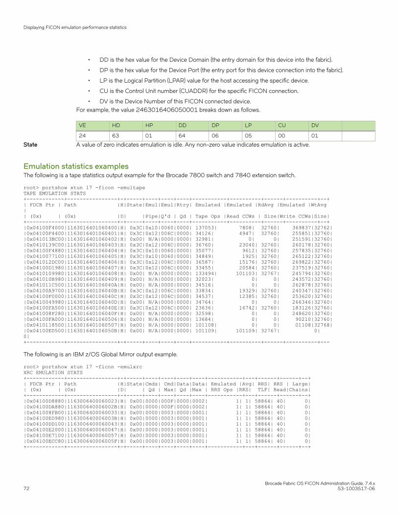
• DD is the hex value for the Device Domain (the entry domain for this device into the fabric).
• DP is the hex value for the Device Port (the entry port for this device connection into the fabric).
• LP is the Logical Partition (LPAR) value for the host accessing the specific device.
• CU is the Control Unit number (CUADDR) for the specific FICON connection.
• DV is the Device Number of this FICON connected device.For example, the value 2463016406050001 breaks down as follows.
VE HD HP DD DP LP CU DV
24 63 01 64 06 05 00 01
State A value of zero indicates emulation is idle. Any non-zero value indicates emulation is active.
Emulation statistics examplesThe following is a tape statistics output example for the Brocade 7800 switch and 7840 extension switch.
root> portshow xtun 17 -ficon -emultapeTAPE EMULATION STATS+------------+----------------+-+-----+----+----+----+-----------+----------+------+----------+--+| FDCB Ptr | Path |H|State|Emul|Emul|Rtry| Emulated |Emulated |RdAvg |Emulated |WtAvg|| (0x) | (0x) |D| |Pipe|Q'd | Qd | Tape Ops |Read CCWs | Size|Write CCWs|Size|+------------+----------------+-+-----+----+----+----+-----------+----------+------+----------+--+|0x04100F4000|1163016401060400|H| 0x3C|0x10|0060|0000| 137053| 7808| 32760| 369837|32762||0x04100F4400|1163016401060401|H| 0x3C|0x12|006C|0000| 34126| 4947| 32760| 255851|32760||0x041013BC00|1163016401060402|H| 0x00| N/A|0000|0000| 32981| 0| 0| 251591|32760||0x0410139C00|1163016401060403|H| 0x3C|0x12|006C|0000| 36760| 23040| 32760| 260178|32760||0x04100F4880|1163016401060404|H| 0x3C|0x10|0060|0000| 35077| 9612| 32760| 257835|32760||0x0410077100|1163016401060405|H| 0x3C|0x10|0060|0000| 34849| 1925| 32760| 265122|32760||0x041012DC00|1163016401060406|H| 0x3C|0x12|006C|0000| 36587| 15176| 32760| 269822|32760||0x04100D1980|1163016401060407|H| 0x3C|0x12|006C|0000| 33455| 20584| 32760| 237519|32760||0x0410109980|1163016401060408|H| 0x00| N/A|0000|0000| 133494| 101103| 32767| 245794|32760||0x041010B980|1163016401060409|H| 0x00| N/A|0000|0000| 32023| 0| 0| 243572|32760||0x041011C500|116301640106040A|H| 0x00| N/A|0000|0000| 34516| 0| 0| 262878|32760||0x04100A9700|116301640106040B|H| 0x3C|0x12|006C|0000| 33834| 19329| 32760| 240347|32760||0x04100F0000|116301640106040C|H| 0x3C|0x12|006C|0000| 34537| 12385| 32760| 253620|32760||0x0410049980|116301640106040D|H| 0x00| N/A|0000|0000| 34764| 0| 0| 266346|32760||0x04100FA500|116301640106040E|H| 0x3C|0x12|006C|0000| 23636| 16742| 32760| 183126|32760||0x041008F280|116301640106040F|H| 0x00| N/A|0000|0000| 32598| 0| 0| 248620|32760||0x04100FA000|1163016401060506|H| 0x00| N/A|0000|0000| 13684| 0| 0| 90210|32760||0x0410118500|1163016401060507|H| 0x00| N/A|0000|0000| 101108| 0| 0| 01108|32768||0x04100ED500|116301640106050B|H| 0x00| N/A|0000|0000| 101109| 101109| 32767| 0|0|+------------+----------------+-+-----+----+----+----+-----------+----------+------+----------+---
The following is an IBM z/OS Global Mirror output example.
root> portshow xtun 17 -ficon -emulxrcXRC EMULATION STATS+------------+----------------+-+-----+----+----+----+----+-----------+---+------+------+--+| FDCB Ptr | Path |H|State|Cmds| Cmd|Data|Data| Emulated |Avg| RRS| RRS | Large|| (0x) | (0x) |D| | Qd | Max| Qd |Max | RRS Ops |RRS| TLF| Read|Chains|+------------+----------------+-+-----+----+----+----+----+-----------+---+------+------+--+|0x04100D8880|1163006400060023|H| 0x00|0000|000F|0000|0002| 1| 1| 58864| 40| 0||0x04100DA880|116300640006002B|H| 0x00|0000|000F|0000|0002| 1| 1| 58864| 40| 0||0x041008FB00|1163006400060033|H| 0x00|0000|0003|0000|0001| 1| 1| 58864| 40| 0||0x04100ED980|116300640006003B|H| 0x00|0000|0003|0000|0001| 1| 1| 58864| 40| 0||0x04100DD100|1163006400060043|H| 0x00|0000|0003|0000|0001| 1| 1| 58864| 40| 0||0x04100E2000|1163006400060047|H| 0x00|0000|0003|0000|0001| 1| 1| 58864| 40| 0||0x04100E7100|1163006400060057|H| 0x00|0000|0003|0000|0001| 1| 1| 58864| 40| 0||0x04100ECC80|116300640006005F|H| 0x00|0000|0003|0000|0001| 1| 1| 58864| 40| 0|+------------+----------------+-+-----+----+----+----+----+-----------+---+------+------+--+
Displaying FICON emulation performance statistics
Brocade Fabric OS FICON Administration Guide, 7.4.x72 53-1003517-06

Options for displaying statisticsUse the portshow xtun [slot/]ve_port -ficon -stats command to display status, performance statistics, and other statistics for tape,Teradata, IBM z/OS Global Mirror, and printer emulation on Brocade extension switches and blades. Refer to the table below for adescription of command formats to achieve various outputs.
TABLE 8 FICON emulation statistics commands
Command Output display
portshow xtun slot/ve_port ve_port -ficon -emul Statistics and status for printer, Teradata, tape, and IBM z/OSGlobal Mirror (XRC) emulation.
portshow xtun slot/ve_port -ficon -emulxrc FICON IBM z/OS Global Mirror emulation statistics and status.
portshow xtun slot/ve_port -ficon -emultape FICON tape emulation statistics and status.
portshow xtun slot/ve_port -ficon -emulprint FICON printer emulation statistics and status.
portshow xtun slot/ve_port -ficon -emultera FICON Teradata emulation statistics and status.
portshow xtun slot/ve_port -ficon -stats General statistics, including those for Teradata, XRC, tapeemulation, and FICON idle status acceptance.
portshow xtun slot/ve_port -ficon -fdcb control block Teradata, tape, IBM z/OS Global Mirror, or printer emulationstatistics, including the device extension of the FDCB for aspecified Device Control Block.
portshow xtun ve_port ficon -teraperf Teradata performance statistics.
portshow xtun ve_port -ficon -tapeperf FICON tape pipelining performance statistics.
portshow xtun ve_port -ficon -xrcperf IBM z/OS Global Mirror performance statistics.
portshow xtun ve_port -ficon -printperf Printer emulation processing statistics.
Refer to the portShow command section of the Fabric OS Command Reference for more information on these commands.
Displaying FICON emulation performance statistics
Brocade Fabric OS FICON Administration Guide, 7.4.x53-1003517-06 73

Brocade Fabric OS FICON Administration Guide, 7.4.x74 53-1003517-06

Maintaining and Troubleshooting FICON• Firmware management in a FICON environment............................................................................................................................... 75• Configuration restoration in a FICON environment.............................................................................................................................76• Traffic Isolation Zoning.................................................................................................................................................................................... 77• Monitoring and Alerting Policy Suite.........................................................................................................................................................83• Port fencing..........................................................................................................................................................................................................83• FICON information........................................................................................................................................................................................... 84• Swapping port area IDs...................................................................................................................................................................................86• Blade swapping.................................................................................................................................................................................................. 87• Common FICON issues.................................................................................................................................................................................87• Troubleshooting FICON..................................................................................................................................................................................90• Troubleshooting FICON CUP...................................................................................................................................................................... 92• Troubleshooting NPIV..................................................................................................................................................................................... 92
Firmware management in a FICON environmentYou can use either the CLI or Brocade Network Advisor to upgrade or downgrade your Fabric OS. Registered users can log in on theBrocade website at http://www.brocade.com and follow the links for downloads to access firmware.
Firmware is downloaded in a .gz or .zip file. Brocade Network Advisor contains built-in intelligence that unbundles the necessary files,making it unnecessary to unbundle a package. With Web Tools or the CLI, it is necessary to decompress or extract the files from thepackage first.
For more information, refer to the firmware download process overview in the Fabric OS Administrator's Guide.
Upgrade and downgrade considerationsConsider the following when upgrading and downgrading firmware:
• Concurrent upgrades are generally supported from one major release level to the next, for example, Fabric OS v7.0.0 to v7.3.0.As a precaution, always read the appropriate section in the Brocade Fabric OS Release Notes before upgrading or downgradingfirmware.
• Firmware may need to be upgraded in multiple steps. Consult the Release Notes for details.
• When downgrading firmware, turn off and disable all features not supported in the final release.
For more information on the firmware download process and considerations for FICON CUP environments, refer to the firmwaredownload process overview section of the Fabric OS Administrator's Guide.
Firmware download disruptionDownloading new firmware is not a disruptive process except for the following cases:
• During the firmware download process, a failover to the backup processor occurs. Any outstanding CUP commands are lostwhich results in a timeout. To avoid this, CUP should be varied offline before starting a firmware download. The CUP may bevaried back online after a successful firmware download.
• All firmware downloads cause an I/O disruption when the new code is activated on the Brocade 7800 switch and FX8-24blade. However, the Brocade 7840 switch supports the FCIP Hot Code Load (HCL) feature which allows firmware downloadswithout I/O disruption.
Brocade Fabric OS FICON Administration Guide, 7.4.x53-1003517-06 75

Non-disruptive firmware upload and downloadAll systems maintain a primary and a secondary partition of nonvolatile storage areas. The following overview of the firmware downloadprocess illustrates the use of the two partitions:
1. The firmware is downloaded to the secondary partition.
2. The current secondary and primary partitions are swapped.
3. The CP then reboots. In dual-CP systems (Brocade DCX and DCX 8510 FICON directors), the backup CP is rebooted with thenew firmware and the HA failover is automatically invoked.
4. Once rebooted, the primary code image is copied to the secondary.
Considerations for fixed-port switchesUnlike director-class products, fixed-port switches have only one control processor (CP) so they behave differently during Fabric OS hotcode upgrades. This can impact FICON operations if best practices are not followed.
During the code upload process, there is a period of time when the CP is busy rebooting the operating system and re-initializing FabricOS, and CP is not available to respond to CPU-targeted queries or frames. For dual-CP products, this "busy" time is a couple of seconds(the time it takes for mastership to change), and is non-disruptive. For single-CP fixed-port switches, however, the "busy" period can lasta minute or two. During this time, data traffic continues to flow uninterrupted, unless a response from the CP is required. If a responsefrom the CP is required, for path and device validation for instance, Interface Control Checks (IFCCs) are possible. Any IFCCs should berecovered automatically by the IBM z Systems host, with no required user action.
This does not mean that switches are not appropriate for FICON. Fully certified FICON switch deployments will continue to be sold andsupported. It is important to follow the best practices of performing the firmware upgrade during scheduled maintenance windows whentraffic is minimized, IFCCs can be tolerated, and the CUP is turned off.
Configuration restoration in a FICON environmentThe following table describes the behavior of the configUpload and configDownload commands and IPL file function when the ASM bitis set on or off. In general, if the switch is operating in a FICON CUP environment and the ASM (Active=Saved) bit is set on, then theswitch ignores the IPL file downloaded when you restore a configuration.
TABLE 9 Backup and restore in a FICON CUP environment
ASM bit Command Description
on or off configUpload All the files saved in the file access facilityare uploaded to the managementworkstation. A section in the uploadedconfiguration file labeled FICON_CUP is inan encoded format.
on configDownload Files saved on the switch that are alsopresent in the FICON_CUP section of theconfiguration file are overwritten.
Files in the FICON section of theconfiguration file that are not currentlypresent on the switch are saved.
off configDownload Files saved on the switch that are alsopresent in the FICON_CUP section of theconfiguration file are overwritten.
Files in the FICON section of theconfiguration file that are not currentlypresent on the switch are saved.
Configuration restoration in a FICON environment
Brocade Fabric OS FICON Administration Guide, 7.4.x76 53-1003517-06

TABLE 9 Backup and restore in a FICON CUP environment (continued)
ASM bit Command Description
The IPL file is replaced. The ActiveConfiguration is re-established with valuesthat may be different from what is in IPLfile.
Traffic Isolation ZoningTraffic Isolation (TI) Zoning allows you to specify dedicated data paths to control traffic flowing from a specific set of source ports(N_Ports). TI Zoning has the following benefits:
• Separates direct attached storage device (DASD) and tape traffic.
• Selects traffic for diverse ISL routes (typical of dual fiber networks).
• In conjunction with long-distance channel extension equipment (FICON Acceleration), guarantees bandwidth for certainmission-critical data.
Creating logical switches is preferred over creating TI Zones for FICON emulation configurations. Logical switches can be created easilyand they naturally separate disk and tape traffic to different tunnels and network bandwidth.
Fabric OS v6.2.0 or later is required for TI Zoning in a FICON fabric. For more information on TI Zoning, refer to the Fabric OSAdministrator's Guide.
NOTESession-based zoning enforcement is not recommended on a FICON switch. For more information on session-based zoningenforcement, refer to the Fabric OS Administrator’s Guide.
Determining ports for the TI ZoneTo determine source ports and paths for specific devices, use the MVS display command. The following example displays paths todevice 1002 and where the device is connected:
D M=DEV(1002)
Response is:
DEVICE 1002 STATUS=OFFLINE CHP AC AD AE AF ENTRY LINK ADDRESS .. 6715 6808 6679 DEST LINK ADDRESS 66FE 66FE 66FE 66FE \ //CUP has link address = DDFE, where DD= domain ID of switch// PATH ONLINE Y Y Y Y CHP PHYSICALLY ONLINE Y Y Y Y PATH OPERATIONAL Y Y Y Y MANAGED N N N N CU NUMBER 1002 1002 1002 1002 MAXIMUM MANAGED CHPID(S) ALLOWED: 0 DESTINATION CU LOGICAL ADDRESS = 00 SCP CU ND = SLKWRM.DCX.BRD.CA.4FT00X39C19A.0001 SCP TOKEN NED = SLKWRM.DCX.BRD.CA.4FT00X39C19A.0000 SCP DEVICE NED = SLKWRM.DCX.BRD.CA.4FT00X39C19A.0000
Traffic Isolation Zoning
Brocade Fabric OS FICON Administration Guide, 7.4.x53-1003517-06 77

Enhanced TI ZoningEnhanced Traffic Isolation Zones allow you to specify a preferred and exclusive path through a cascaded fabric for a particular flow bydefining a set of devices or ports to appear in more than one Enhanced TI Zone. A preferred path is one that has failover enabled and anexclusive path has failover disabled . An exclusive path in the following topologies is beneficial as it limits the number of hops betweenswitches:
• Triangular
• System Data Mover
• Emulation
Enhanced TI Zoning for the three previously listed topologies is available only on the following platforms running Fabric OS v6.4.0 orlater:
• Brocade 5100
• Brocade 5300
• Brocade 7800
• Brocade 7840
• Brocade 6510
• Brocade DCX 8510-4
• Brocade DCX 8510-8
• Brocade DCX
• Brocade DCX-4S
Triangular topologyThe triangular topology shown in the figure below is a common FICON deployment for managing data center recovery functions. In thistopology, a switch is located in each of three sites and connected to the other two forming a triangle. In most environments, the purposeof this configuration is to give the host application the ability to connect to storage media at the other two sites, which allows it to recoverfrom an outage at either site. Meanwhile, the storage systems constantly synchronize between the two storage sites.
Traffic Isolation Zoning
Brocade Fabric OS FICON Administration Guide, 7.4.x78 53-1003517-06

FIGURE 21 Typical triangular setup
During normal operation, the routes from any device on one switch are a one-hop path to either of the other two switches. However, if thepath between any pair of switches fails, then a two-hop path is available. Multi-hop paths are not certified for FICON configurations.
To get around the multiple-hop issue, use Enhanced TI Zoning to prohibit the connection between E_Ports on the switches. For thissetup you must define a device in two zones with failover disabled. The figure below shows that the setup allows a source device to reachtwo separate destinations over exclusive, one-hop paths, while preventing the source device from taking the two-hop path in the event ofa failure.
Traffic Isolation Zoning
Brocade Fabric OS FICON Administration Guide, 7.4.x53-1003517-06 79
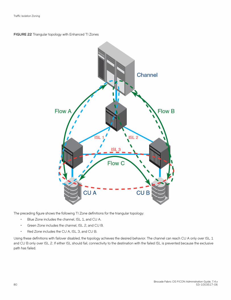
FIGURE 22 Triangular topology with Enhanced TI Zones
The preceding figure shows the following TI Zone definitions for the triangular topology:
• Blue Zone includes the channel, ISL 1, and CU A.
• Green Zone includes the channel, ISL 2, and CU B.
• Red Zone includes the CU A, ISL 3, and CU B.
Using these definitions with failover disabled, the topology achieves the desired behavior. The channel can reach CU A only over ISL 1and CU B only over ISL 2. If either ISL should fail, connectivity to the destination with the failed ISL is prevented because the exclusivepath has failed.
Traffic Isolation Zoning
Brocade Fabric OS FICON Administration Guide, 7.4.x80 53-1003517-06
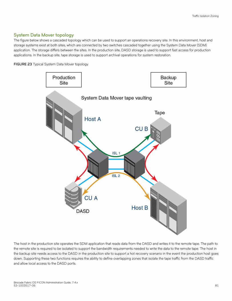
System Data Mover topologyThe figure below shows a cascaded topology which can be used to support an operations recovery site. In this environment, host andstorage systems exist at both sites, which are connected by two switches cascaded together using the System Data Mover (SDM)application. The storage differs between the sites. In the production site, DASD storage is used to support fast access for productionapplications. In the backup site, tape storage is used to support archival operations for system restoration.
FIGURE 23 Typical System Data Mover topology
The host in the production site operates the SDM application that reads data from the DASD and writes it to the remote tape. The path tothe remote site is required to be isolated to support the bandwidth requirements needed to write the data to the remote tape. The host inthe backup site needs access to the DASD in the production site to support a hot recovery scenario in the event the production host goesdown. Supporting these two functions requires the ability to define overlapping zones that isolate the tape traffic from the DASD trafficand allow local access to the DASD ports.
Traffic Isolation Zoning
Brocade Fabric OS FICON Administration Guide, 7.4.x53-1003517-06 81

FIGURE 24 System Data Mover topology using Enhanced TI Zones
The figure above shows the following Enhanced TI Zone definitions for the System Data Mover topology:
• Green Zone includes Host A, ISL 1, and CU B.
• Orange Zone includes CU A, ISL 2, and Host B.
• Red Zone includes Host A and CU A.
• Blue Zone includes Host B and CU B.
Using these definitions with failover disabled achieves the desired behavior. The production channels can access the local DASD and usean exclusive path to write data to the remote tape. The remote channels can access the remote tape and use an exclusive path to writedata to the production DASD. In both cases, the production tape traffic is excluded from intruding on the backup DASD traffic and viceversa.
Traffic Isolation Zoning
Brocade Fabric OS FICON Administration Guide, 7.4.x82 53-1003517-06

Monitoring and Alerting Policy SuiteThe Monitoring and Alerting Policy Suite (MAPS) is an optional storage area network (SAN) health monitor supported on all switchesrunning Fabric OS 7.2.0. MAPS allows you to enable each switch to constantly monitor itself for potential faults and automatically alertsyou to problems before they become costly failures.
MAPS tracks a variety of SAN fabric metrics and events. Monitoring fabric-wide events, ports, and environmental parameters enablesearly fault detection and isolation as well as performance measurements.
MAPS provides the following set of predefined monitoring policies that allow you to immediately use MAPS on activation:
• dflt_conservative_policy
• dflt_moderate_policy
• dflt_aggressive_policy
It is recommended that all IBM z Systems customers enable MAPS after upgrading to Fabric OS version supporting MAPS and use thedefault aggressive policy (dflt_aggressive_policy). This policy contains rules with very strict thresholds. For details on enabling MAPS andmonitoring policies, refer to the Monitoring and Alerting Policy Suite Administrator's Guide.
Port fencingOccasionally, bad optics and cables can cause errors to occur at such a rapid rate that error processing and RSCN transmission andprocessing results in fabric performance problems. Port fencing allows you to limit the number of errors a port can receive by forcing aport offline when certain error thresholds are met.
The port fencing feature is configured through Fabric Watch. For more information on configuring port fencing, refer to the Fabric WatchAdministrator's Guide.
It is recommended that the port decommissioning/recommissioning feature be used to the maximum extent possible in place of portfencing.
Defining port fencingThe following overview defines port fencing.
1. (Optional) Clear all alarms.
2. Define threshold levels.
3. Define alarm action.
4. Activate alarming.
NOTEEstablish a Telnet session with a tool such as PuTTy that allows the columns to be increased. This is because some ofthe displays use more than the standard 80 columns that programs such as HyperTerminal support. Therecommended number of columns is 120.
Settings for FICON environmentsFor typical FICON environments, port fencing is usually only set for CRC errors and Invalid Words. The default of 1,000 errors perminute is a little high for CRC errors and Invalid Words. A more common setting is 50 errors per minute. This is high enough to ignoreoccasional errors and transient errors due to recabling but low enough to stop problematic optics from causing fabric issues.
Port fencing
Brocade Fabric OS FICON Administration Guide, 7.4.x53-1003517-06 83

By default, the alarms are set to fence the port, log an alert, send an e-mail message, and set an SNMP trap. In most FICONenvironments, only fencing the port and logging the alert are desired.
The following are the default thresholds:
• Low - 0
• High - 1,000 errors per minute
FICON informationYou can display link incidents, registered listeners, node identification data, and FRU failures, as described in the following sections.
Link incidentsThe Registered Link Incident Report (RLIR) ELS contains the link incident information sent to a listener N_Port.
To display link incidents, connect to the switch, log in as user, and enter one of the following commands:
• For the local switch: ficonShow rlir
• For all switches defined in the fabric: ficonShow rlirrlir fabric
Identifying portsThe ficonShow rlir command displays, among other information, a tag field for the switch port. You can use this tag to identify the porton which a FICON link incident occurred. The tag field is a concatenation of the switch domain ID and port number, in hexadecimalformat. The following example shows the top portion of command output which shows a link incident for the switch port at domain ID120, port 93 (785d in hex):
switch:admin> ficonshow rlir { {Fmt Type PID Port Incident Count TS Format Time Stamp 0x18 F 785d00 93 1 Time server Thu Apr 22 09:13:32 2004 Port Status: Link not operational Link Failure Type: Loss of signal or synchronizationRegistered Port WWN Registered Node WWN Flag Node Parameters 50:05:07:64:01:40:16:03 50:05:07:64:00:c1:69:ca 0x10 0x200115(output truncated)
For complete examples of output from this command, refer to the ficonShow command section of the Fabric OS Command Reference.
Registered listenersTo display registered listeners for link incidents, connect to the switch, log in as user, and enter one of the following commands:
• For the local switch: ficonShow lirr
• For all switches defined in the fabric: ficonShow lirr fabric
For an example of local Link Incident Record Registration (LIRR) database output, refer to the ficonShow command section of the FabricOS Command Reference.
When you configure an LIRR entry and it is current, it is marked with -C. If the Management Server marks an entry as current based onorder, it is marked with -C. If the Management Server marks an entry as secondary, it is marked with -S. Following is an example ofoutput with the -C and -S flags.
Switch Port WWN Listener Type20:2d:00:60:69:80:1e:4e Conditional-C20:0d:00:60:69:80:1e:4f Conditional-S
FICON information
Brocade Fabric OS FICON Administration Guide, 7.4.x84 53-1003517-06

If the LIRR is configured, then the a valid port number displays as shown in the following example.
Current LIRR device port number: 27 (0x1b)
If the LIRR is not configured, the following displays:
Current LIRR device port number is not configured.
Node identification dataTo display node identification data, connect to the switch, log in as user, and enter one of the following commands:
• For the local switch: ficonShow switchrnid
• For all switches defined in the fabric: ficonShow switchrnid fabric
• For all devices registered with the local switch: ficonShow rnid
• For all devices registered with all switches defined in the fabric: ficonShow rnid
FRU error reportingField Replaceable Unit (FRU) error information, such as FRU failures and fan and power supply removals and insertions, are stored inerror reports as sense data. All FRUs in a chassis have an assigned number that is included in this data. Each CUP instance retains adatabase of ten FRU error reports. All error reports are sent to host LPARs that have appropriate Current Reporting Paths establishedwith the CUP.
Error reports are added to the database as they occur, and then they are removed when sent. If the database fills up, new reports arediscarded and not delivered.
Error dataThe following examples show error data available from the host. The number identifying the failed Brocade FRU (refer to FRU numberson page 86) is derived from a single bit from byte 29 as the high order bit and four bits from byte 30 or 31 as the low order bits (referto the data in bold in the second lines of the following examples). The FRU numbers are decoded for display as the FRU names, whichdisplay in the third lines of the following examples.
IOS000I 1065,AB,EQC,**,8200,,,*MASTER*, 200 1000A00000000046700010000000000000000000000000000000000000008000 *IRD000E 1065,002032-001 LEVEL=1 FRU(S)=SLOT8 IOS000I 1065,AB,EQC,**,8200,,,*MASTER*, 286 1000A00000000046700000000000000000000000000000000000000000088000 *IRD000E 1065,002032-001 LEVEL=0 FRU(S)=FAN1 IOS000I 1065,AB,EQC,**,8200,,,*MASTER*, 461 1000A00000000046700000000000000000000000000000000000000000084000 *IRD000E 1065,002032-001 LEVEL=0 FRU(S)=PWR4 IOS000I 1065,AB,EQC,**,8200,,,*MASTER*, 496 1000A00000000046700000000000000000000000000000000000000000089000 *IRD000E 1065,002032-001 LEVEL=0 FRU(S)=FAN2 IOS000I 1065,AB,EQC,**,8200,,,*MASTER*, 502 1000A00000000046700000000000000000000000000000000000000000081000 *IRD000E 1065,002032-001 LEVEL=0 FRU(S)=PWR1 IOS000I 1065,AB,EQC,**,8200,,,*MASTER*, 568 1000A0000000004670000000000000000000000000000000000000000008F000 *IRD000E 1065,002032-001 LEVEL=0 FRU(S)=WWN-CRD IOS000I 1065,AB,EQC,**,8200,,,*MASTER*, 662 1000A0000000004670001000000000000000000000000000000000000000A000
FICON information
Brocade Fabric OS FICON Administration Guide, 7.4.x53-1003517-06 85

*IRD000E 1065,002032-001 LEVEL=1 FRU(S)=SLOT10 IOS000I 1061,A8,EQC,**,8200,,,*MASTER*, 697 1000A00000000046700010000000000000000000000000000000000000007000 *IRD000E 1061,002032-001 LEVEL=1 FRU(S)=SLOT7
FRU numbersThe following Brocade FRU numbers are provided for error reports and associated FRU names that display in error reports. Note that theFRU number does not display in the error reports, but its associated FRU name does display.
• 1 = SLOT1
• 2 = SLOT2
• 3 = SLOT3
• 4 = SLOT4
• 5 = SLOT5
• 6 = SLOT6
• 7 = SLOT7
• 8 = SLOT8
• 9 = SLOT9
• 10 = SLOT10
• 11 = SLOT11
• 12 = SLOT12
• 17 = PWR1
• 18 = PWR2
• 19 = PWR3
• 20 = PWR4
• 24 = FAN1
• 25 = FAN2
• 26 = FAN3
• 30 = CHASSIS
• 31 = WWN-CRD
Swapping port area IDsIf a port malfunctions, or if you want to connect to different devices without having to rewire your infrastructure, you can move a port’straffic to another port (swap port area ID ) without changing the I/O Configuration Data Set (IOCDS) on the mainframe computer.
To swap port area IDs, refer to the "Swapping port area IDs" procedure in the Fabric OS Administrator's Guide.
For more detail on the following commands that you will use to swap port area IDs, refer to the Fabric OS Command Reference Manual:
• portSwapEnable
• portDisable
• portSwap
• portSwapShow
Swapping port area IDs
Brocade Fabric OS FICON Administration Guide, 7.4.x86 53-1003517-06
• PortSwapDisable
Important notesConsider the following when swapping port area IDs:
• Ports that have been swapped cannot be moved to another logical switch.
• Ports with area 0xFE or 0xFF addresses cannot be swapped when FMS mode is enabled.
• You can use the portSwapShow command to display information about swapped ports in a switch.
• You can use the portSwap command to disable the port swapping feature. You cannot use the portSwap command after thisfeature is disabled. The enabled state of the port swapping feature is persistent across reboots and power cycles. Enabling anddisabling the port swapping feature does not affect previously executed port swapping operations.
Blade swappingBlade swapping allows you to swap one blade with another of the same type; in this way, you can perform a FRU replacement withminimal traffic disruption. The entire operation is accomplished when the bladeSwap command runs on Fabric OS. Fabric OS thenvalidates each command before actually implementing the command on the platform. If an error is encountered, the blade swap quitswithout disrupting traffic flowing through the blades. If an unforeseen error does occur during the running of the bladeSwap command,an entry will be made into the RASlog and all ports that have been swapped as part of the blade swap operation will be swapped back.On successful completion of the command, the source and destination blades are left in a disabled state, allowing you to complete thecable move.
Blade swapping is based on port swapping and has the same restrictions:
• Shared area ports cannot be swapped.
• Faulty blades cannot be swapped.
• Ports or blades with area OxFE or OxFF addresses cannot be swapped when FMS mode is enabled.
• Ports that are part of a trunk group cannot be swapped.
• GbE ports cannot be swapped.
• Swapping ports between different logical switches is not supported. The ports on the source and destination blades must be inthe same logical switch.
• Undetermined board types cannot be swapped. For example, a blade swap will fail if the blade type cannot be identified.
• Blade swapping is not supported when swapping to a different model of blade or a different port count. For example, youcannot swap an FC8-32 blade with an FC8-48 port blade.
• Blade swapping is not supported on application blades.
• Blade swapping is supported on the FX8-24 blade, but only the 12 Fibre Channel ports will swap. The GbE and VE_ Ports willnot be swapped.
For procedures and more information on blade swapping, refer to the Fabric OS Administrator's Guide.
Common FICON issuesAny information you need to verify that FICON has been set up correctly can be found in the Administering FICON Fabrics or theConfiguring FICON CUP chapters.
Common FICON issues
Brocade Fabric OS FICON Administration Guide, 7.4.x53-1003517-06 87

Symptom Probable cause and recommended action
Cascading: No path - Entry Link is ".." message This typically occurs when one or more of the required high integrityfeatures for cascading have not been met. Check the following:
• Review each step in Configuring switched point-to-point FICONon page 36 and Configuring cascaded FICON on page 42 andvalidate that all features are configured properly.
• Validate that CUP is online for each FICON director or switch inthe fabric with the data center’s system programmer.
Path to a device does not come online. No connection to device.
Make sure binding or zoning does not prevent the connection. Validate thefollowing with the data center's system programmer:
• Correct switch addresses (not switch IDs) are used in linkstatements. Remember that the switch address is the domain IDconverted to hex and may have an offset.
• The switch ID, used in the CHPID statements, was defined withthe correct switch address.
• All addressing (link statements) uses two-byte addressing onthe channel if two-byte addressing has been previously used onthat channel. This is necessary even when the specified path isnot cascaded.
Packets are being dropped between two FICON units. Distance between devices is impacting data.
When planning cable needs, the following criteria must be considered:
• Distance considerations
• Fiber Optic Sub Assembly (FOSA) type (SW or LW)
• Cable specifications (SM or MM)
• Patch Panel Connections between FOSA ports (link loss .3-5dB per)
• Maximum allowable link budget (dB) loss
For cabling, the most important factor of a Fibre Channel link is theselection of the Fibre Optic Sub Assembly (FOSA) and matching cabletype, to support the required distance. Both ends of the optical link musthave the matching FOSA (SFP) types.
Channel path with two-byte addressing does not come online. The fabric may not be configured properly, cable connections are notcorrect, or cable is wrong type.
Find out what CHPID the operator is attempting to bring online. In FICONenvironments, only the egress ports are defined in the IOCDS. The CHPIDnumber of the channel appears in the node list, but only if the channelpath has logged in. If the channel path will not come online, it may nothave completed a Fibre Channel fabric login. If this is the case, you willhave to rely on customer documentation to determine the switch port towhich the channel is connected.
Next, find out what type of error message the operator is getting. An IOSerror message is reported when there is an error external to the host; anIEE error message indicates something is wrong internal to the host.
Fabric Not Configured Properly
• Make sure that the insistent domain ID is set and the domainIDs are unique for all switches in the fabric.
• Make sure that the same binding method is used on all switchesin the fabric.
• Scroll through the node list and make sure there are no invalidattachments.
• Make sure that the re-routing delay is turned off.
Common FICON issues
Brocade Fabric OS FICON Administration Guide, 7.4.x88 53-1003517-06

Symptom Probable cause and recommended action
Cabling
Validate that cables are connected where intended.
When using multimode fiber, make sure that all fiber is either all 50u or all62.5u. A common mistake is to mix 50u and 62.5u fiber cables, whichcauses errors at patch panels.
Example of a Boxed Channel
In the following example, the CHPIDs with two-byte addressing did notcome online. In response, the CHPID was configured offline and thenreconfigured back online.
MVS console commands and responses (lines beginning with "IEE" areresponses and all other lines are entries).
CF CHP(60),OFFLINE IEE503I CHP(60),OFFLINE IEE712I CONFIG PROCESSING COMPLETE CF CHP(60),ONLINE IEE754I NOT ALL PATHS BROUGHT ONLINE WITH CHP(60) IEE502I CHP(60),ONLINE IEE712I CONFIG PROCESSING COMPLETE
The following line displays the status of the CHPID with the "D M ="command. All other lines are responses.
D M=CHP(60) IEE174I 03.29.45 DISPLAY M 021 CHPID 60: TYPE=1D, DESC=FICON INCOMPLETE, ONLINE DEVICE STATUS FOR CHANNEL PATH 60 0 1 2 3 4 5 6 7 8 9 A B C D E F 006 . $@ . . . . . . . . . . . . . . SWITCH DEVICE NUMBER = NONE ATTACHED ND = NOT KNOWN PHYSICAL CHANNEL ID = 01F0 ************************ SYMBOL EXPLANATIONS ************************+ ONLINE @ PATH NOT VALIDATED - OFFLINE . DOES NOT EXIST * PHYSICALLY ONLINE $ PATH NOT OPERATIONAL
The responses "NOT ALL PATHS BROUGHT ONLINE" after attemptingto configure the CHPID online and "FICON INCOMPLETE" in the displayexample indicate that the channel did not come online. You can determinethis because the IEE error types are shown and combined with thevalidation that there was no attempt to do a basic FLOGI (no lightdisplayed on the port view (LED) and no Fibre Channel frames werereceived).
The Control Unit Port cannot access the switch. Domain or port ID has changed on CHPID link.
A two-byte CHPID link is defined using a domain and port ID that mustremain consistent. Any change in the physical link, such as a change in adomain or port ID, will prevent storage control unit access.
Use the configure command to verify and set the insistent domain ID(IDID) parameter.
FICON:admin> configure
For more information and examples of using this command to set theIDID parameter, refer to the Configure command in the Fabric OSCommand Reference.
Unable to "vary online" FICON CUP port on the switch . FICON CUP port cannot go online.
Common FICON issues
Brocade Fabric OS FICON Administration Guide, 7.4.x53-1003517-06 89

Symptom Probable cause and recommended action
Use the haFailover command on the FICON director. This the only knownfix as there is no known firmware solution.
Troubleshooting FICONThis section provides information-gathering and troubleshooting techniques necessary to fix your problem.
General information to gather for all casesThe following information must be gathered for all FICON environments:
• The output from the standard support commands (portLogDump, supportSave, and supportShow) the Fabric Manager EventLog or Brocade Network Advisor logs.
By default, the FICON group in the supportShow output is disabled. To enable the capture of FICON data in the supportShowoutput, enter the supportShowCfgEnable ficon command. After you get confirmation that the configuration has been updated,ouput from the following will be collected and display for the supportShow command:
– ficonCupShow fmsmode– ficonCupShow modereg– ficonDbg dump rnid– ficonDbg log– ficonShow lirr– ficonShow rlir– ficonShow rnid– ficonShow switchrnid– ficuCmd dump -A
• The type of mainframe involved including the make, model, and driver levels in use.
• The type of storage array installed. Many arrays emulate a certain type of IBM array and the make, model, and firmware of thearray in use must be provided.
• Other detailed information for protocol-specific problems:
– Port data structures, displayed using the ptDataShow command.– Port registers, displayed using the ptRegShow command.
The following actions must be performed to troubleshoot all FICON environments:
• Use the configUpload command to gather configuration files. Provide the IOCDS mainframe file.
This will define how all mainframe ports are configured.
• Verify that Dynamic Load Sharing (DLS) has been disabled with the dlsReset command.
If DLS is enabled, traffic on existing ISL ports may be affected when one or more new ISLs is added between the same twoswitches. Specifically, adding the new ISL may result in dropped frames as routes are adjusted to take advantage of thebandwidth provided. By disabling DLS, you ensure that there will be no dropped frames. In thesupportShow output, search forroute.stickyRoutes and check for a value of 1 or enter the dlsShow command.
• Verify that IOD is enabled using the iodSet command to ensure in-order delivery.
In the output from the supportShow or supportSave, search for route.delayReroute and check for a value of 1 as this indicatesthat the feature is turned on. Alternately, you can enter the iodShow command.
Troubleshooting FICON
Brocade Fabric OS FICON Administration Guide, 7.4.x90 53-1003517-06

Switched point-to-point topology checklistVerify the following in your FICON environment to ensure proper functionality of the feature:
• Fabric OS v6.1.0 or later release is installed on Brocade switch or director.
• Appropriate management tool is being used, such as EFCM v9.6x, DCFM, or Brocade Network Advisor.
• All required licenses are enabled for your FICON configuration.
• Switch or director does not have a special mode setting turned on for FICON.
• Brocade Advanced features software package (Trunking, Fabric Watch, Extended Fabric) license is activated.
NOTEThere is no requirement to have a secure fabric in a switched point-to-point topology.
Cascaded topology checklistVerify the following in your FICON environment to ensure proper functionality of the feature:
• Fabric OS v6.1.0 or later is installed Brocade switch or director.
• Appropriate management tool is used, such as EFCM v9.6x, DCFM, or Brocade Network Advisor.
• All required licenses are activated to enable your FICON configuration?
• The switch or director does not have a special mode setting enabled for FICON.
In addition to device-based routing, lossless, and in-order frame delivery (IOD), the dynamic load-sharing feature is enabled.
• If you have a fabric for intermix mode of operations, separate zones for FICON and FCP devices are configured.
• A maximum of one hop exists for both FCP and FICON devices (mainframe channel device connectivity rule).
• The insistent domain ID flag is set to keep the domain ID of a fabric switch persistent.
• The CHPID link path is defined using the two-byte address format.
• The FICON channel connectivity to the storage CU port does not exceed one hop.
• Proper security policies are enabled. Refer to Configuring cascaded FICON on page 42.
• The Switch Connection Control (SCC) security policy is active.
• Brocade Advanced features software package (Trunking, Fabric Watch, Extended fabric) license is activated.
Gathering additional informationCollect information for your support provider as mentioned in the Fabric OS Troubleshooting and Diagnostics Guide. In addtion, gatherthe following FICON-specific information.
• Did the problem occur during an initial install or has was everything functioning prior to the problem?
• What was changed immediately before the problem occurred.
• Is the switch properly configured for a FICON environment.
Refer to the most recent version of the Fabric OS Release Notes for notes on FICON setup and configuration.
• Is this a switched point-to-point or cascaded environment.
• Is the FICON group enabled for supportShow.
Enter the supportShow command and verify that FICON is enabled under "supportshow groups enabled". If it is not enabled,use supportShowCfgEnable ficon command.
Troubleshooting FICON
Brocade Fabric OS FICON Administration Guide, 7.4.x53-1003517-06 91

CUP diagnosticsFICON CUP supports the IBM Health Checker for zOS to diagnose problems. Refer to the IBM Redbooks website at www.redbooks.ibm.com for details on using the IBM Health Checker for z/OS.
Troubleshooting FICON CUPIn addition to the information you collect for your support provider mentioned in Troubleshooting FICON on page 90, also gather thefollowing information which is specific to FICON CUP:
• Verify the FICON CUP license is installed.
• Check the state of the CUP by running the ficonCupShow fmsmode command. If it is disabled, enter the ficonCupSetfmsmode enable command to enable it. If the CUP is on a director, enter the haFailover command to ensure both CPs are setcorrectly.
• Verify that the switch is using Fabric OS v6.1.0 or later.
• Ensure no device is plugged into port 254 on the Brocade FICON director.
• Verify with the systems programmer that the CUP ports are defined properly.
FICON ports are defined as part of the sysgen process. The z/OS systems programmer can verify if the CUP ports are definedproperly.
• Verify that ports 254 and 255 display Disabled (FMS Mode) by entering the switchShow command. If not, enter theportDisable command on the appropriate models for the related ports:
– On a Brocade 48000, disable 10/30 and 10/31.– On a Brocade DCX Backbone, disable 12/30 and 12/31.
Troubleshooting NPIVGather all information as listed in General information to gather for all cases on page 90 and Gathering additional information on page91.
Be sure that NPIV licenses are installed if using Fabric OS v5.0.x. There is no license requirement for Fabric OS v5.1.0 and later.
Troubleshooting FICON CUP
Brocade Fabric OS FICON Administration Guide, 7.4.x92 53-1003517-06

Platforms Supporting FICON• Introduction.......................................................................................................................................................................................................... 93• Supported platforms with end-of-support announcements...........................................................................................................93• Currently supported platforms..................................................................................................................................................................... 94• Supported Brocade blades............................................................................................................................................................................94
IntroductionThis appendix provides the following support details:
• Brocade products with end-of-support announcements supported for FICON for different IBM systems and drivers (Supportedplatforms with end-of-support announcements on page 93).
• Brocade products currently supported for FICON for different IBM systems and drivers (Currently supported platforms on page94).
• Brocade blades supported for FICON in various Brocade Switch and Data Center Backbone products (Supported Brocadeblades on page 94).
Due to the nature of environments in which the mainframes are used, product qualification for FICON is more rigorous than with otherproducts. As a result, not all product combinations and versions of Fabric OS are qualified for FICON.
Supported platforms with end-of-support announcementsAll Brocade products in the table below have end-of-support announcements. However, end-of-support dates vary for each product,and your service provider may have end-of-support dates that differ from Brocade dates. Contact your service provider for details.
Firmware listed in the following table is the final version supported and the recommended target path.
TABLE 10 Supported platforms with end-of-support announcements
Brocade 4900
Fabric OS
Brocade 5000
Fabric OS
Brocade 6140
Fabric OS
Brocade i10K
Fabric OS
Brocade 7500
Fabric OS
Brocade 48000
Fabric OS
Brocade 5100
Fabric OS
z900 & z800Driver 3GF
v6.2.0e v6.2.0e v9.9.9 v9.9.8 v6.4.2a v6.4.2a v7.0.0d
z990 & z890Driver 55K
v6.2.0e v6.2.0e v9.9.9 v9.9.8 v6.4.2a v6.4.2a v7.0.0d
z9 EC & z9 BCDriver 67L
v6.2.0e v6.2.0e v9.9.9 v9.9.8 v6.4.2a v6.4.2a v7.0.0d
z10 EC & z10BC Driver 76D& 79F
v6.2.0e v6.2.0e v9.9.9 v9.9.8 v6.4.2a v6.4.2a v7.0.0d
z10 BC Driver76D
v6.2.0e v6.2.0e v9.9.9 v9.9.8 v6.4.2a v6.4.2a v7.0.0d
z196 Driver86E or 93G
Not supported Not supported v9.9.9 v9.9.8 v6.4.2a v6.4.2a v7.0.0d
z114 Driver93G
Not supported Not supported v9.9.9 v9.9.8 v6.4.2a v6.4.2a v7.0.0d
EC12 at driver12K
Not supported Not supported Not supported Not supported v6.4.2a v6.4.2a v7.0.0d
Brocade Fabric OS FICON Administration Guide, 7.4.x53-1003517-06 93

Currently supported platformsThe table below lists Brocade products currently supported for Fabric OS 7.4 for various IBM systems and drivers.
TABLE 11 Currently supported platforms
Brocade 7800,7840
Fabric OS
Brocade DCX-4S
Fabric OS
Brocade DCX
Fabric OS
Brocade DCX8510-4
Fabric OS
Brocade DCX8510-8
Fabric OS
Brocade 6510
Fabric OS
z196 Driver 86Eor 93G
7.4.0a
7.4.1b
7.4.0a
7.4.1b
7.4.0a
7.4.1b
7.4.0a
7.4.1b
7.4.0a
7.4.1b
7.4.0a
7.4.1b
z114 Driver 93G 7.4.0a
7.4.1b
7.4.0a
7.4.1b
7.4.0a
7.4.1b
7.4.0a
7.4.1b
7.4.0a
7.4.1b
7.4.0a
7.4.1b
EC12 and BC12at driver 12K
7.4.0a
7.4.1b
7.4.0a
7.4.1b
7.4.0a
7.4.1b
7.4.0a
7.4.1b
7.4.0a
7.4.1b
7.4.0a
7.4.1b
z13
z13s
7.4.0a
7.4.1b
7.4.0a
7.4.1b
7.4.0a
7.4.1b
7.4.0a
7.4.1b
7.4.0a
7.4.1b
7.4.0a
7.4.1b
IBM LinuxONEplatforms
LinuxOneEmperor
LinuxOneRockhopper
7.4.1b 7.4.1b 7.4.1b 7.4.1b 7.4.1b 7.4.1b
Supported Brocade bladesThe table below lists Brocade blades supported for FICON in various Brocade Switch and Data Center Backbone products.
TABLE 12 Currently supported blades in Brocade Switch and Data Center Backbone products
FC4-16
FC4-32
FX8-241
FC8-16
FC8-32
FC8-48
FC8-64
FC16-32
FC16-48
FC16-64
CR16-8 CR16-4
FC10-6
DCX8510-8
No No Yes No No No Yes2 Yes Yes Yes2 Yes No No
DCX8510-4
No No Yes No No No Yes 2 Yes Yes3 Yes2 No Yes No
DCX No No Yes Yes Yes Yes 3 Yes 2 No No No No No Yes4
DCX-4S
No No Yes Yes Yes Yes Yes 2 No No No No No Yes4
48000 Yes Yes Yes No No No No No No No No No No
1. The Ethernet ports of an FX8-24 extension blade can operate with another FX8-24 or Brocade 7800 switch. The maximumnumber of FX8-24 blades supported in a chassis is four. An FX8-24 can operate with an FX8-24E; however, IPsec andcompression is only supported on one 10GbE port on the FX8-24.
2. The 64-port card is not supported for FICON but may be in the same chassis used for FICON. It must be in a logical switchthat does not have any FICON traffic.
Currently supported platforms
Brocade Fabric OS FICON Administration Guide, 7.4.x94 53-1003517-06

3. For the 48-port card in an 8-slot chassis, FICON is supported in a logical switch configured for zero-based addressing mode.For this card in a DCX-4S Backbone, FICON is supported only on a logical switch defined for port-based addressing (mode 2).
4. FC10-6 10 Gbps port blade for ISL connections.
Supported Brocade blades
Brocade Fabric OS FICON Administration Guide, 7.4.x53-1003517-06 95

Brocade Fabric OS FICON Administration Guide, 7.4.x96 53-1003517-06

Basic Switch ConfigurationThis appendix provides basic steps and commands to quickly configure a switch for fabric and possible FICON and cascaded FICONoperation.
For detailed concepts, procedures, and additional Fabric OS command options to configure a switch for point-to-point and cascadedFICON operation, refer to Administering FICON Fabrics.
The following tables are included in this appendix:
• The Switch configuration example and commands table provides the basic steps and commands in a checklist format toquickly configure a switch for fabric and possible FICON operation.
• The Cascading (2-byte addressing) example and commands table provides additional steps and commands for FICONcascading (two-byte addressing).
TABLE 13 Switch configuration example and commands
Feature Relevant Commands
Upgrade code (if necessary). firmwaredownload
firmwareshow
Feature keys (add licenses). licenseadd
licenseshow
Create all logical switches and add all intended ports to each logical switch. lscfg
Set switch offline. switchdisable
Repeat the following procedure to configure switch parameters for eachlogical switch.
1. Enter the configure command. You will be asked severalquestions. Only answer questions listed in the RelevantCommands column. Use defaults for other settings unlessinstructed by a Brocade Certified Architect for FICON. Note thatthe BB_Credit setting here should not be changed. BB_Creditswill be set elsewhere in this checklist.
2. Change fabric parameter settings by answering Yes . Afteranswering Yes , you will be asked several questions. Changeonly the following parameters. Leave all other parameters at thedefault unless instructed by a Brocade Certified Architect forFICON. After completing all of the Fabric Parameter settings,answer No for all other parameters.
• Domain
• Allow XISL Use
When applicable.
• Enable a 256 Area Limit
– 0 - Not supported for FICON.– 1 - Zero-based addressing. Recommended for FICON.– 2 - Port-based addressing. Not supported for 48-port
cards in 8-port slot chassis.
• Disable Device Probing
Set to 1.
• Insistent Domain ID Mode
Answer Yes.
configure
To set the routing policy to 1: aptpolicy 1
Brocade Fabric OS FICON Administration Guide, 7.4.x53-1003517-06 97

TABLE 13 Switch configuration example and commands (continued)
Feature Relevant Commands
Set Interop mode
0 - No other interop mode is supported for FICON.
interopmode 0
Device Based Routing.
Set to 2.
To set the routing policy to 2: aptpolicy 2
To display the routing policy: aptpolicy
Set in-order delivery with lossless DLS enabled. iodset --enable -losslessDLS
Enable dynamic load sharing only if lossless DLS is set. dlsset
Set switch name. switchname
Set chassis name. chassisname
Set switch online. switchenable
Set the principal switch. This can only be one switch in the fabric. In mixedM-Type and B-Type fabrics, the M-Type must be the principal switch.
fabricprincipal 1
If you are enabling FMS (CUP), disable all ports assigned address 0xFEand 0xFF.
portdisable
Enable FMS if FICON CUP will be used.
NOTEHigh-integrity fabric requirements must be met and HIF modeenabled to enable FMS mode.
ficoncupset fmsmode enable
ficoncupshow fmsmode
Set the default zone for no access. defZone --noaccess
cfgsave
defZone --show
Configure zones. This is much easier with Brocade Network Advisor orWeb Tools. Typically, scripts are used when using Fabric OS commands.
cfgclear
cfgcreate
cfgdelete
cfgdisable
cfgenable
cfgremove
cfgsave
cfgshow
Clear all port statistics and trace information. supportsave -R
errclear
statsclear
portlogclear
diagclearerror -all
tracedump -c
slotstatsclear
errclear
ficonclear rlir
Turn on FICON logging. supportshowcfgenable ficon
Set port fencing. Setting port fencing parameters is much easier withBrocade Network Advisor.
To clear alarms:
Brocade Fabric OS FICON Administration Guide, 7.4.x98 53-1003517-06

TABLE 13 Switch configuration example and commands (continued)
Feature Relevant Commands
fwalarmsfilterset 0
To define alarms:
fwconfigure
Respond to menu driven prompts accordingly.
To enable the defined alarms:
fwalarmsfilterset 1
Parameters in the table below are only required when two-byte link addressing is used in the IOCP. Normally, these parameters are notset when single-byte addressing is used.
TABLE 14 Cascading (two-byte addressing) example and commands
Feature Parameter
Add members to the SCC Policy. secPolicyCreate "SCC_POLICY", "wwn;wwn; ..."
Or, to add all switches already in the fabric, use an "*" for each WWN:
secPolicyCreate "SCC_POLICY", "*"
Save the policy. secpolicysave
Activate the policy. secpolicyactivate
Enable the ACL Fabric-Wide Consistency Policy and enforce a strict SCCpolicy.
fddcfg --fabwideset "SCC:S;"
Brocade Fabric OS FICON Administration Guide, 7.4.x53-1003517-06 99

Brocade Fabric OS FICON Administration Guide, 7.4.x100 53-1003517-06

Address Binding Examples• Sequential address binding........................................................................................................................................................................ 101• Unbinding multiple ports.............................................................................................................................................................................105
Sequential address bindingThis section provides an example that will allow all ports on all blades installed in a Brocade DCX or DCX 8510 FICON director to usesequential, zero-based, Mode 1 addresses. The following figure illustrates ports with sequential addresses.
FIGURE 25 Sequential addresses
Before binding an address with the portAddress --bind command, disable the port with the portDisable command. To change thebound address, you must first unbind the addresses. Refer to Unbinding multiple ports on page 105 for an easy method to unbindmultiple ports at once.
For more information on port addressing modes, refer to Addressing modes on page 44.
Brocade Fabric OS FICON Administration Guide, 7.4.x53-1003517-06 101

Example scripts for binding ports (Mode 1)The following example scripts containing the portAddress --bind command bind all ports on the DCX Backbone to sequential, zerobased (Mode 1) addresses. You can copy and paste these scripts directly into a Telnet Fabric OS command line session. If a port doesnot exist, an error message will be reported, but this has no effect.
date# Slot 1portaddress --bind 1/0 0000portaddress --bind 1/1 0100portaddress --bind 1/2 0200portaddress --bind 1/3 0300portaddress --bind 1/4 0400portaddress --bind 1/5 0500portaddress --bind 1/6 0600portaddress --bind 1/7 0700portaddress --bind 1/8 0800portaddress --bind 1/9 0900portaddress --bind 1/10 0A00portaddress --bind 1/11 0B00portaddress --bind 1/12 0C00portaddress --bind 1/13 0D00portaddress --bind 1/14 0E00portaddress --bind 1/15 0F00portaddress --bind 1/16 1000portaddress --bind 1/17 1100portaddress --bind 1/18 1200portaddress --bind 1/19 1300portaddress --bind 1/20 1400portaddress --bind 1/21 1500portaddress --bind 1/22 1600portaddress --bind 1/23 1700portaddress --bind 1/24 1800portaddress --bind 1/25 1900portaddress --bind 1/26 1A00portaddress --bind 1/27 1B00portaddress --bind 1/28 1C00portaddress --bind 1/29 1D00portaddress --bind 1/30 1E00portaddress --bind 1/31 1F00# Slot 2portaddress --bind 2/0 2000portaddress --bind 2/1 2100portaddress --bind 2/2 2200portaddress --bind 2/3 2300portaddress --bind 2/4 2400portaddress --bind 2/5 2500portaddress --bind 2/6 2600portaddress --bind 2/7 2700portaddress --bind 2/8 2800portaddress --bind 2/9 2900portaddress --bind 2/10 2A00portaddress --bind 2/11 2B00portaddress --bind 2/12 2C00portaddress --bind 2/13 2D00portaddress --bind 2/14 2E00portaddress --bind 2/15 2F00portaddress --bind 2/16 3000portaddress --bind 2/17 3100portaddress --bind 2/18 3200portaddress --bind 2/19 3300portaddress --bind 2/20 3400portaddress --bind 2/21 3500portaddress --bind 2/22 3600portaddress --bind 2/23 3700portaddress --bind 2/24 3800portaddress --bind 2/25 3900portaddress --bind 2/26 3A00portaddress --bind 2/27 3B00portaddress --bind 2/28 3C00
Sequential address binding
Brocade Fabric OS FICON Administration Guide, 7.4.x102 53-1003517-06

portaddress --bind 2/29 3D00portaddress --bind 2/30 3E00portaddress --bind 2/31 3F00# Slot 3portaddress --bind 3/0 4000portaddress --bind 3/1 4100portaddress --bind 3/2 4200portaddress --bind 3/3 4300portaddress --bind 3/4 4400portaddress --bind 3/5 4500portaddress --bind 3/6 4600portaddress --bind 3/7 4700portaddress --bind 3/8 4800portaddress --bind 3/9 4900portaddress --bind 3/10 4A00portaddress --bind 3/11 4B00portaddress --bind 3/12 4C00portaddress --bind 3/13 4D00portaddress --bind 3/14 4E00portaddress --bind 3/15 4F00portaddress --bind 3/16 5000portaddress --bind 3/17 5100portaddress --bind 3/18 5200portaddress --bind 3/19 5300portaddress --bind 3/20 5400portaddress --bind 3/21 5500portaddress --bind 3/22 5600portaddress --bind 3/23 5700portaddress --bind 3/24 5800portaddress --bind 3/25 5900portaddress --bind 3/26 5A00portaddress --bind 3/27 5B00portaddress --bind 3/28 5C00portaddress --bind 3/29 5D00portaddress --bind 3/30 5E00portaddress --bind 3/31 5F00# Slot 4portaddress --bind 4/0 6000portaddress --bind 4/1 6100portaddress --bind 4/2 6200portaddress --bind 4/3 6300portaddress --bind 4/4 6400portaddress --bind 4/5 6500portaddress --bind 4/6 6600portaddress --bind 4/7 6700portaddress --bind 4/8 6800portaddress --bind 4/9 6900portaddress --bind 4/10 6A00portaddress --bind 4/11 6B00portaddress --bind 4/12 6C00portaddress --bind 4/13 6D00portaddress --bind 4/14 6E00portaddress --bind 4/15 6F00portaddress --bind 4/16 7000portaddress --bind 4/17 7100portaddress --bind 4/18 7200portaddress --bind 4/19 7300portaddress --bind 4/20 7400portaddress --bind 4/21 7500portaddress --bind 4/22 7600portaddress --bind 4/23 7700portaddress --bind 4/24 7800portaddress --bind 4/25 7900portaddress --bind 4/26 7A00portaddress --bind 4/27 7B00portaddress --bind 4/28 7C00portaddress --bind 4/29 7D00portaddress --bind 4/30 7E00portaddress --bind 4/31 7F00# Slot 9portaddress --bind 9/0 8000portaddress --bind 9/1 8100
Sequential address binding
Brocade Fabric OS FICON Administration Guide, 7.4.x53-1003517-06 103

portaddress --bind 9/2 8200portaddress --bind 9/3 8300portaddress --bind 9/4 8400portaddress --bind 9/5 8500portaddress --bind 9/6 8600portaddress --bind 9/7 8700portaddress --bind 9/8 8800portaddress --bind 9/9 8900portaddress --bind 9/10 8A00portaddress --bind 9/11 8B00portaddress --bind 9/12 8C00portaddress --bind 9/13 8D00portaddress --bind 9/14 8E00portaddress --bind 9/15 8F00portaddress --bind 9/16 9000portaddress --bind 9/17 9100portaddress --bind 9/18 9200portaddress --bind 9/19 9300portaddress --bind 9/20 9400portaddress --bind 9/21 9500portaddress --bind 9/22 9600portaddress --bind 9/23 9700portaddress --bind 9/24 9800portaddress --bind 9/25 9900portaddress --bind 9/26 9A00portaddress --bind 9/27 9B00portaddress --bind 9/28 9C00portaddress --bind 9/29 9D00portaddress --bind 9/30 9E00portaddress --bind 9/31 9F00# Slot 10portaddress --bind 10/0 A000portaddress --bind 10/1 A100portaddress --bind 10/2 A200portaddress --bind 10/3 A300portaddress --bind 10/4 A400portaddress --bind 10/5 A500portaddress --bind 10/6 A600portaddress --bind 10/7 A700portaddress --bind 10/8 A800portaddress --bind 10/9 A900portaddress --bind 10/10 AA00portaddress --bind 10/11 AB00portaddress --bind 10/12 AC00portaddress --bind 10/13 AD00portaddress --bind 10/14 AE00portaddress --bind 10/15 AF00portaddress --bind 10/16 B000portaddress --bind 10/17 B100portaddress --bind 10/18 B200portaddress --bind 10/19 B300portaddress --bind 10/20 B400portaddress --bind 10/21 B500portaddress --bind 10/22 B600portaddress --bind 10/23 B700portaddress --bind 10/24 B800portaddress --bind 10/25 B900portaddress --bind 10/26 BA00portaddress --bind 10/27 BB00portaddress --bind 10/28 BC00portaddress --bind 10/29 BD00portaddress --bind 10/30 BE00portaddress --bind 10/31 BF00# Slot 11portaddress --bind 11/0 C000portaddress --bind 11/1 C100portaddress --bind 11/2 C200portaddress --bind 11/3 C300portaddress --bind 11/4 C400portaddress --bind 11/5 C500portaddress --bind 11/6 C600portaddress --bind 11/7 C700
Sequential address binding
Brocade Fabric OS FICON Administration Guide, 7.4.x104 53-1003517-06

portaddress --bind 11/8 C800portaddress --bind 11/9 C900portaddress --bind 11/10 CA00portaddress --bind 11/11 CB00portaddress --bind 11/12 CC00portaddress --bind 11/13 CD00portaddress --bind 11/14 CE00portaddress --bind 11/15 CF00portaddress --bind 11/16 D000portaddress --bind 11/17 D100portaddress --bind 11/18 D200portaddress --bind 11/19 D300portaddress --bind 11/20 D400portaddress --bind 11/21 D500portaddress --bind 11/22 D600portaddress --bind 11/23 D700portaddress --bind 11/24 D800portaddress --bind 11/25 D900portaddress --bind 11/26 DA00portaddress --bind 11/27 DB00portaddress --bind 11/28 DC00portaddress --bind 11/29 DD00portaddress --bind 11/30 DE00portaddress --bind 11/31 DF00# Slot 12portaddress --bind 12/0 E000portaddress --bind 12/1 E100portaddress --bind 12/2 E200portaddress --bind 12/3 E300portaddress --bind 12/4 E400portaddress --bind 12/5 E500portaddress --bind 12/6 E600portaddress --bind 12/7 E700portaddress --bind 12/8 E800portaddress --bind 12/9 E900portaddress --bind 12/10 EA00portaddress --bind 12/11 EB00portaddress --bind 12/12 EC00portaddress --bind 12/13 ED00portaddress --bind 12/14 EE00portaddress --bind 12/15 EF00portaddress --bind 12/16 F000portaddress --bind 12/17 F100portaddress --bind 12/18 F200portaddress --bind 12/19 F300portaddress --bind 12/20 F400portaddress --bind 12/21 F500portaddress --bind 12/22 F600portaddress --bind 12/23 F700portaddress --bind 12/24 F800portaddress --bind 12/25 F900portaddress --bind 12/26 FA00portaddress --bind 12/27 FB00portaddress --bind 12/28 FC00portaddress --bind 12/29 FD00portaddress --bind 12/30 FE00portaddress --bind 12/31 FF00
Unbinding multiple portsThe following example scripts containing the portAddress --unbind command unbind all addresses on an 8-slot chassis that is fullypopulated with 32-port cards. You can copy and paste these scripts directly into a Telnet Fabric OS command line session. If a port doesnot exist, an error message will be reported, but this has no effect.
for ((i=0;i<32;i++)); do (echo 1/$i;portaddress --unbind 1/$i); donefor ((i=0;i<32;i++)); do (echo 2/$i;portaddress --unbind 2/$i); donefor ((i=0;i<32;i++)); do (echo 3/$i;portaddress --unbind 3/$i); donefor ((i=0;i<32;i++)); do (echo 4/$i;portaddress --unbind 4/$i); done
Unbinding multiple ports
Brocade Fabric OS FICON Administration Guide, 7.4.x53-1003517-06 105

for ((i=0;i<32;i++)); do (echo 9/$i;portaddress --unbind 9/$i); donefor ((i=0;i<32;i++)); do (echo 10/$i;portaddress -unbind 10/$i); donefor ((i=0;i<32;i++)); do (echo 11/$i;portaddress --unbind 11/$i); donefor ((i=0;i<32;i++)); do (echo 12/$i;portaddress --unbind 12/$i); done
Unbinding multiple ports
Brocade Fabric OS FICON Administration Guide, 7.4.x106 53-1003517-06
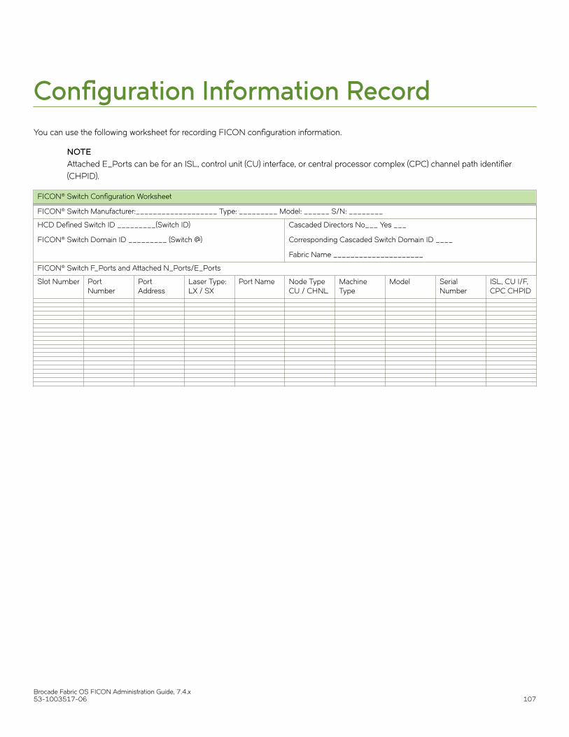
Configuration Information RecordYou can use the following worksheet for recording FICON configuration information.
NOTEAttached E_Ports can be for an ISL, control unit (CU) interface, or central processor complex (CPC) channel path identifier(CHPID).
FICON® Switch Configuration Worksheet
FICON® Switch Manufacturer:___________________ Type: _________ Model: ______ S/N: ________
HCD Defined Switch ID _________(Switch ID)
FICON® Switch Domain ID _________ (Switch @)
Cascaded Directors No___ Yes ___
Corresponding Cascaded Switch Domain ID ____
Fabric Name _____________________
FICON® Switch F_Ports and Attached N_Ports/E_Ports
Slot Number PortNumber
PortAddress
Laser Type:LX / SX
Port Name Node TypeCU / CHNL
MachineType
Model SerialNumber
ISL, CU I/F,CPC CHPID
Brocade Fabric OS FICON Administration Guide, 7.4.x53-1003517-06 107

Brocade Fabric OS FICON Administration Guide, 7.4.x108 53-1003517-06

EBCDIC Code PageExtended Binary Coded Decimal Interchange Code (EBCDIC) is an 8-bit character encoding (code page) used on IBM mainframeoperating systems such as z/OS and S/390. Code page 37 is an EBCDIC code page with full Latin-1 character set.
Brocade Fabric OS FICON Administration Guide, 7.4.x53-1003517-06 109

Brocade Fabric OS FICON Administration Guide, 7.4.x110 53-1003517-06