
Broadband Radio Access Network Channel Identification and Downlink MC-CDMA Equalization
22
International Journal of Energy, Information and Communications Vol.5, Issue 2 (2014), pp.13-34 http://dx.doi.org/10.14257/ijeic.2014.5.2.02 ISSN: 2093-9655 IJEIC Copyright ⓒ 2014 SERSC Broadband Radio Access Network Channel Identification and Downlink MC-CDMA Equalization M. Zidane 1 , S. Safi 2 , M. Sabri 1 , A. Boumezzough 3 and M. Frikel 4 1 Department of Physics, Faculty of Sciences and technology, Sultan Moulay Slimane University, Beni Mellal, Morocco 2 Department of Mathematics and Informatics, Polydisciplinary Faculty, Sultan Moulay Slimane University, Beni Mellal, Morocco 3 Department of Physics, Polydisciplinary Faculty, Sultan Moulay Slimane University, Beni Mellal, Morocco 4 GREYC laboratory, ENSICAEN School, Caen University, France [email protected] Abstract In this paper we propose a new algorithm based on third order cumulants, for MultiCarrier Code Division Multiple Access (MC-CDMA) system equalization. In order to test its efficiency, we have compared with the (CUM-AZ) algorithm proposed in the literature, for that we considered five practical frequency-selective fading channels, called Broadband Radio Access Network (BRAN A, BRAN B, BRAN C, BRAN D, and BRAN E), normalized for (MC-CDMA) system, excited by non-Gaussian sequences. In the part of (MC-CDMA), we use the zero forcing (ZF) and the minimum mean square error (MMSE) equalizers techniques after the channel identification to correct the channel’s distortion. The simulation results, in noisy environment and for different signal to noise ratio (SNR), are presented to illustrate the performance of the proposed algorithm. Keywords: Blind identification, equalization, higher order cumulants, MC-CDMA system 1. Introduction During recent years, finite impulse response system identifcation based on Higher Order Cumulants (HOC) of system output, has increasingly been emphasized [1, 2, 3]. In the literature we have important results, established that blind identification of finite impulse response (FIR) single-input single-output (SISO) communication channels is possible only from the output second order statistics of the observed sequences [1]. But these approaches are sufficient only to identify Gaussian processes with minimal phase [2-4]. Moreover, the system to be identified has no minimum phase, excited by non Gaussian distribution input, and is contaminated by a Gaussian noise [2, 3] where the autocorrelation function (second order statistics) does not allow identifying the system correctly [2-4]. To overcome these problems, another approach was proposed by several authors [5-9, 11, 12, 13].This approach allow the resolution of the insoluble problems using the second order statistics. In this paper, we will consider the problem of the identification of the Broadband Radio Access Network Channel such as BRAN A, B, C, D and E, normalized by the European Telecommunications Standards Institute (ETSI) [14] and [15], and downlink MC-CDMA Equalization. The principle of MC-CDMA transmits a data symbol of a user simultaneously on several narrowband sub-channels. These sub-channels are multiplied by the chips of the
-
Upload
universitesms -
Category
Documents
-
view
0 -
download
0
Transcript of Broadband Radio Access Network Channel Identification and Downlink MC-CDMA Equalization

International Journal of Energy, Information and Communications
Vol.5, Issue 2 (2014), pp.13-34
http://dx.doi.org/10.14257/ijeic.2014.5.2.02
ISSN: 2093-9655 IJEIC
Copyright ⓒ 2014 SERSC
Broadband Radio Access Network Channel Identification and
Downlink MC-CDMA Equalization
M. Zidane1, S. Safi
2, M. Sabri
1, A. Boumezzough
3 and M. Frikel
4
1Department of Physics, Faculty of Sciences and technology, Sultan Moulay Slimane
University, Beni Mellal, Morocco 2 Department of Mathematics and Informatics, Polydisciplinary Faculty, Sultan
Moulay Slimane University, Beni Mellal, Morocco 3 Department of Physics, Polydisciplinary Faculty, Sultan Moulay Slimane
University, Beni Mellal, Morocco 4 GREYC laboratory, ENSICAEN School, Caen University, France
Abstract
In this paper we propose a new algorithm based on third order cumulants, for
MultiCarrier Code Division Multiple Access (MC-CDMA) system equalization. In order to
test its efficiency, we have compared with the (CUM-AZ) algorithm proposed in the literature,
for that we considered five practical frequency-selective fading channels, called Broadband
Radio Access Network (BRAN A, BRAN B, BRAN C, BRAN D, and BRAN E), normalized for
(MC-CDMA) system, excited by non-Gaussian sequences. In the part of (MC-CDMA), we use
the zero forcing (ZF) and the minimum mean square error (MMSE) equalizers techniques
after the channel identification to correct the channel’s distortion. The simulation results, in
noisy environment and for different signal to noise ratio (SNR), are presented to illustrate the
performance of the proposed algorithm.
Keywords: Blind identification, equalization, higher order cumulants, MC-CDMA system
1. Introduction
During recent years, finite impulse response system identifcation based on Higher Order
Cumulants (HOC) of system output, has increasingly been emphasized [1, 2, 3]. In the
literature we have important results, established that blind identification of finite impulse
response (FIR) single-input single-output (SISO) communication channels is possible only
from the output second order statistics of the observed sequences [1]. But these approaches
are sufficient only to identify Gaussian processes with minimal phase [2-4]. Moreover, the
system to be identified has no minimum phase, excited by non Gaussian distribution input,
and is contaminated by a Gaussian noise [2, 3] where the autocorrelation function (second
order statistics) does not allow identifying the system correctly [2-4]. To overcome these
problems, another approach was proposed by several authors [5-9, 11, 12, 13].This approach
allow the resolution of the insoluble problems using the second order statistics.
In this paper, we will consider the problem of the identification of the Broadband Radio
Access Network Channel such as BRAN A, B, C, D and E, normalized by the European
Telecommunications Standards Institute (ETSI) [14] and [15], and downlink MC-CDMA
Equalization. The principle of MC-CDMA transmits a data symbol of a user simultaneously
on several narrowband sub-channels. These sub-channels are multiplied by the chips of the

International Journal of Energy, Information and Communications
Vol.5, Issue 2 (2014)
14 Copyright ⓒ 2014 SERSC
user-specific spreading code, Multi-carrier modulation is realized by using the low complex
OFDM operation. In most wireless environments, there are many obstacles in the channels,
such as buildings, mountains and walls between the transmitter and the receiver. Reflections
from these obstacles cause many different propagation paths. The problem encountered in
communication is the synchronization between the transmitter and the receiver, due to the
echoes and reflection between the transmitter and the receiver. Synchronization errors cause
loss of orthogonality among sub-carriers and considerably degrade the performance especially
when large number of subcarriers presents [19].
In this contribution, we propose an algorithm based, only, on third order cumulants. In
order to test its efficiency, we have compared with the Antari, et al., algorithm [6, 17]. The
simulation results show that the bit error rate (BER) performances of the downlink MC-
CDMA systems, using proposed algorithm (Algo3ZS) is more accurate compared with the
results obtained with the Antari, et al., (CUM_AZ) algorithm.
2. Problem Statement
The Broadband Radio Access Network channel output is modeled as the output of a FIR
system that is excited by an unobservable input and is corrupted at its output by an
additive white Gaussian noise (Figure 1).
Figure 1. Channel model
The completely blind channel identification problem is to estimate based only on
the received signal and without any knowledge of the energy of the transmitted
data nor the energy of noise.
The output time series is described by
Noise free case:
∑
With noise: (2)
The principal assumptions made on the model can be presented as follows: The input
sequence, , is independent and identically distributed (i.i.d) zero mean, and non-
Gaussian. The system is causal truncated, i.e. for and , where
. The system order q is known. The measurement noise sequence is
assumed zero mean, Gaussian and independent of with unknown variance.
3. Proposed Algorithm: Algo3ZS
The mth order cumulants of the can be expressed as a function of impulse response
coefficients as follows [5-7, 16, 17]:

International Journal of Energy, Information and Communications
Vol.5, Issue 2 (2014)
Copyright ⓒ 2014 SERSC 15
∑
where represents the order cumulants of the excitation signal at origin.
If , Eq. (3) yield to
∑
The same, if , Eq. (3) becomes
∑
The Fourier transforms of the 2nd
and 3rd
order cumulants are given respectively by the
following equations:
{ } ∑ ∑
{ }
If we suppose that , Eq. (6) reduces:
Then, from Eqs. (7) and (8) we obtain the following equation
with
The inverse Fourier transform of Eq. (9) demonstrates that the 3rd
order cumulants, the
second order statistics (autocorrelation function) and the impulse response channel parameters
are combined by the following equation:
∑ ∑
If we use the ACF property of the stationary process such as only for
and vanishes elsewhere.
If we suppose that the Eq. (10) reduces:
∑
International Journal of Energy, Information and Communications
Vol.5, Issue 2 (2014)
16 Copyright ⓒ 2014 SERSC
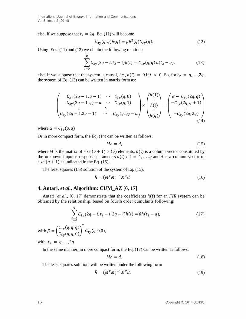
else, if we suppose that , Eq. (11) will become
(12)
Using Eqs. (11) and (12) we obtain the following relation :
∑
else, if we suppose that the system is causal, i.e., if . So, for the system of Eq. (13) can be written in matrix form as:
(
)
(
)
(
)
(14)
where
Or in more compact form, the Eq. (14) can be written as follows:
(15)
where is the matrix of size elements, is a column vector constituted by
the unknown impulse response parameters and is a column vector of
size as indicated in the Eq. (15).
The least squares (LS) solution of the system of Eq. (15):
(16)
4. Antari, et al., Algorithm: CUM_AZ [6, 17]
Antari, et al., [6, 17] demonstrate that the coefficients for an FIR system can be
obtained by the relationship, based on fourth order cumulants following:
∑
(
)
with
In the same manner, in more compact form, the Eq. (17) can be written as follows:
(18)
The least squares solution, will be written under the following form
. (19)

International Journal of Energy, Information and Communications
Vol.5, Issue 2 (2014)
Copyright ⓒ 2014 SERSC 17
5. Equalization of MC-CDMA system
The multicarrier code division multiple access (MC-CDMA) system is based on the
combination of code division multiple access (CDMA) and orthogonal frequency division
multiplexing (OFDM) which is potentially robust to channel frequency selectivity.
5.1. M C-CDMA Transmitter
In the MC-CDMA modulator the complex symbol of each user is, first,
multiplied by each chip of spreading code, and then applied to the modulator of
multicarriers. The MC-CDMA emitted signal is given by
√
∑
where
⁄ , is the user number and is the number of subcarriers, and
we consider .
We suppose that the channel is time invariant and it’s impulse response is
characterized by paths of magnitudes and phases . So the impulse response is
given by
∑
( )
5.2. MC-CDMA Receiver
The downlink received MC-CDMA signal at the input receiver is given by the
following equation [5]:
√
∑ ∑ ∑ {
(
⁄ )( )
}
where is an additive white Gaussian noise.
The equalization goal, is to obtain a good estimation of the symbol . At the
reception, we demodulate the signal according the subcarriers, and then we multiply
the received sequence by the code of the user. Figure 2 explains the single user-
detection principle.
Figure 2. Principle of the single user-detection
After the equalization and the spreading operation, the estimation of the emitted
user symbol , of the user can be written by the following equation

International Journal of Energy, Information and Communications
Vol.5, Issue 2 (2014)
18 Copyright ⓒ 2014 SERSC
∑ ∑ ( ) ∑
⏟
∑ ∑
⏟
∑
⏟
where the term I, II and III of Eq. (23) are, respectively, the signal of the considered user, a
signals of the others users (multiple access interferences) and the noise pondered by the
equalization coeffcient and by spreading code of the chip.
5.3. Equalization for MC-CDMA
5.3.1 Zero forcing (ZF)
The principle of the ZF, is to completely cancel the distortions brought by the channel. The
gain factor of the ZF equalizer, is given by the equation:
| |
By that manner, each symbol is multiplied by a unit magnitude. So, the estimated received
symbol, of symbol of the user is described by:
∑
⏟
∑ ∑
⏟
∑
⏟
If we suppose that the spreading code are orthogonal, i.e.,
∑
Eq. (25) will become
∑
∑
5.3.2Minimum Mean Square Error (MMSE)
The MMSE techniques minimize the mean square error for each subcarrier between the
transmitted signal and the output detection
[| | ] [| | ]
International Journal of Energy, Information and Communications
Vol.5, Issue 2 (2014)
Copyright ⓒ 2014 SERSC 19
The minimization of the function [| | ], gives us the optimal equalizer coefficient, under the
minimization of the mean square error criterion, of each subcarrier as :
| |
where [| |
]
[| | ].
∑
| |
| |
⏟
∑ ∑
| |
| |
⏟
∑
| |
⏟
The same, if we suppose that the spreading code are orthogonal, Eq. (30) will reduces:
∑
| |
| |
∑
| |
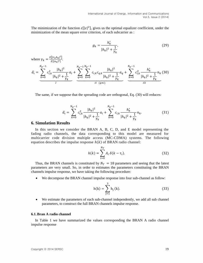
6. Simulation Results
In this section we consider the BRAN A, B, C, D, and E model representing the
fading radio channels, the data corresponding to this model are measured for
multicarrier code division multiple access (MC-CDMA) systems. The following
equation describes the impulse response of BRAN radio channel:
∑
Thus, the BRAN channels is constituted by parameters and seeing that the latest
parameters are very small. So, in order to estimates the parameters constituting the BRAN
channels impulse response, we have taking the following procedure:
We decompose the BRAN channel impulse response into four sub-channel as follow:
∑
We estimate the parameters of each sub-channel independently, we add all sub channel
parameters, to construct the full BRAN channels impulse response.
6.1. Bran A radio channel
In Table 1 we have summarized the values corresponding the BRAN A radio channel
impulse response

International Journal of Energy, Information and Communications
Vol.5, Issue 2 (2014)
20 Copyright ⓒ 2014 SERSC
Table 1. Delay and magnitudes of 18 targets of BRAN A channel
[ ] [ ] [ ] [ ]
In time domain we have represented the BRAN A channel impulse response parameters
using proposed algorithm (Algo3ZS), compared with the results obtained with the Antari, et
al., (CUM_AZ) algorithm (Figure 3).
Figure 3. Estimated of the BRAN A channel impulse response, for an SNR = 16 dB and a data length N=4800
From the Figure 3 we ca can conclude that the estimated BRAN A channel impulse
response are very closed to the true ones, than those obtained by the Antari, et al.,
(CUM_AZ) principally for high data length (N = 4800), and for In the following figure (Figure 4) we have represented the estimated magnitude and phase
of the impulse response BRAN A using all target, for an data length N = 4800 and SNR=20
dB, obtained using proposed algorithm (Algo3ZS), compared with the (CUM_AZ) algorithm.
0 50 100 150 200 250 300 350 400-0.2
0
0.2
0.4
0.6
0.8
1
1.2
Time in (ns)
Sam
ple
s o
f th
e m
agnitude im
puls
e r
esponse
True(BRAN A)
Estimated using Algo3ZS
Estimated using CUM-AZ

International Journal of Energy, Information and Communications
Vol.5, Issue 2 (2014)
Copyright ⓒ 2014 SERSC 21
Figure 4. Estimated of the BRAN A channel impulse response using all target, for an SNR = 20 dB and a data length N=4800
From the Figure 4, we remark that the magnitude and phase estimations using proposed
algorithm (Algo3ZS), have the same allure comparatively to the true ones, than those
obtained by the Antari, et al., (CUM_AZ) algorithm, we have a difference between the
estimated and the measured ones.
6.2. Bran B radio channel
In Table 2 we have represented the values corresponding to the BRAN B radio channel
impulse response.
Table 2. delay and magnitudes of 18 targets of bran B channel
[ ] [ ] [ ] [ ]
In time domain we have represented the BRAN B channel impulse response parameters
using proposed algorithm (Algo3ZS), compared with the results obtained with the Antari, et
al., (CUM_AZ) algorithm (Figure 5).
0 0.2 0.4 0.6 0.8 1 1.2 1.4 1.6 1.8 2-200
-100
0
100
200
Normalized Frequency ( rad/sample)
Phase (
degre
es)
0 0.2 0.4 0.6 0.8 1 1.2 1.4 1.6 1.8 2-40
-20
0
20
Normalized Frequency ( rad/sample)
Magnitude (
dB
)
Measured Bran A
Estimated using Algo3ZS
Estimated using CUM-AZ

International Journal of Energy, Information and Communications
Vol.5, Issue 2 (2014)
22 Copyright ⓒ 2014 SERSC
Figure 5. Estimated of the BRAN B channel impulse response, for an SNR = 16 dB and a data length N=4800
From Figure 5, we can conclude that the proposed algorithm (Algo3ZS) give us a good
estimation for all parameters of BRAN B radio channel impulse response, compared with the
results obtained by the (CUM_AZ) algorithm.
In the following figure (Figure 6) we have represented the estimated magnitude and phase
of the impulse response BRAN B using all target, for an data length N = 4800 and SNR=20
dB, obtained using proposed algorithm (Algo3ZS), compared with the (CUM_AZ) algorithm.
Figure 6. Estimated of the BRAN B channel impulse response using all target, for an SNR = 20 dB and a data length N=4800
0 100 200 300 400 500 600 700 8000
0.2
0.4
0.6
0.8
1
1.2
1.4
Time in (ns)
Sam
ple
s o
f th
e m
agnitude im
puls
e r
esponse
True(BRAN B)
Estimated using Algo3ZS
Estimated using CUM-AZ
0 0.2 0.4 0.6 0.8 1 1.2 1.4 1.6 1.8 2-200
-100
0
100
200
Normalized Frequency ( rad/sample)
Phase (
degre
es)
0 0.2 0.4 0.6 0.8 1 1.2 1.4 1.6 1.8 2-30
-20
-10
0
10
20
Normalized Frequency ( rad/sample)
Magnitude (
dB
)
Measured Bran B
Estimated using Algo3ZS
Estimated using CUM-AZ

International Journal of Energy, Information and Communications
Vol.5, Issue 2 (2014)
Copyright ⓒ 2014 SERSC 23
From the Figure 6 we observe that the estimated magnitude and phase, using proposed
algorithm (Algo3ZS) are the same allure and we have not more difference between the
estimated and the true ones, than those obtained by the (CUM_AZ) algorithm we remark a
difference between the estimated and the measured ones.
6.3. Bran C radio channel
In Table 3 we have represented the values corresponding to the BRAN C radio channel
impulse response
Table 3. Delay and magnitudes of 18 targets of bran C channel
[ ] [ ] [ ] [ ]
In time domain we have represented the BRAN C channel impulse response parameters
using proposed algorithm (Algo3ZS), compared with the results obtained with the Antari, et
al., (CUM_AZ) algorithm (Figure 7).
Figure 7. Estimated of the BRAN C channel impulse response, for an SNR = 16 dB and a data length N=4800
From the figure (Figure 7) we have approximately the same allure of the estimated and the
true ones, using proposed algorithm (Algo3ZS), compared with the results obtained with the
(CUM_AZ) algorithm we remark a difference between the estimated and the measured ones.
0 200 400 600 800 1000 12000
0.2
0.4
0.6
0.8
1
1.2
1.4
Time in (ns)
Sam
ple
s o
f th
e m
agnitude im
puls
e r
esponse
True(BRAN C)
Estimated using Algo3ZS
Estimated using CUM-AZ
International Journal of Energy, Information and Communications
Vol.5, Issue 2 (2014)
24 Copyright ⓒ 2014 SERSC
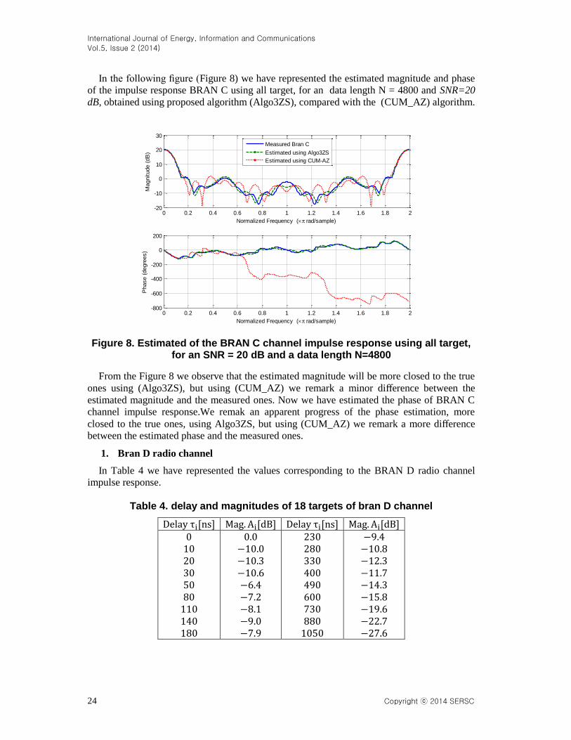
In the following figure (Figure 8) we have represented the estimated magnitude and phase
of the impulse response BRAN C using all target, for an data length N = 4800 and SNR=20
dB, obtained using proposed algorithm (Algo3ZS), compared with the (CUM_AZ) algorithm.
Figure 8. Estimated of the BRAN C channel impulse response using all target, for an SNR = 20 dB and a data length N=4800
From the Figure 8 we observe that the estimated magnitude will be more closed to the true
ones using (Algo3ZS), but using (CUM_AZ) we remark a minor difference between the
estimated magnitude and the measured ones. Now we have estimated the phase of BRAN C
channel impulse response.We remak an apparent progress of the phase estimation, more
closed to the true ones, using Algo3ZS, but using (CUM_AZ) we remark a more difference
between the estimated phase and the measured ones.
1. Bran D radio channel
In Table 4 we have represented the values corresponding to the BRAN D radio channel
impulse response.
Table 4. delay and magnitudes of 18 targets of bran D channel
[ ] [ ] [ ] [ ]
0 0.2 0.4 0.6 0.8 1 1.2 1.4 1.6 1.8 2-800
-600
-400
-200
0
200
Normalized Frequency ( rad/sample)
Phase (
degre
es)
0 0.2 0.4 0.6 0.8 1 1.2 1.4 1.6 1.8 2-20
-10
0
10
20
30
Normalized Frequency ( rad/sample)
Magnitude (
dB
)
Measured Bran C
Estimated using Algo3ZS
Estimated using CUM-AZ

International Journal of Energy, Information and Communications
Vol.5, Issue 2 (2014)
Copyright ⓒ 2014 SERSC 25
In time domain we have represented the BRAN D channel impulse response parameters
using proposed algorithm (Algo3ZS), compared with the results obtained with the Antari, et
al., (CUM_AZ) algorithm (Figure 9).
Figure 9. Estimated of the BRAN D channel impulse response, for an SNR = 16 dB and a data length N=4800
From Figure 9, we can conclude that the algorithm (Algo3ZS) give us a good estimation
for all parameters of BRAN D radio channel impulse response, than those obtained by the
(CUM_AZ) algorithm.
In the following figure (figure 10) we have represented the estimated magnitude and phase
of the impulse response BRAN D using all target, for an data length N = 4800 and SNR=16
dB, obtained using proposed algorithm (Algo3ZS), compared with the (CUM_AZ) algorithm.
Figure 10. Estimated of the BRAN D channel impulse response using all target, for an SNR = 16 dB and a data length N=4800
0 200 400 600 800 1000 1200-0.2
0
0.2
0.4
0.6
0.8
1
1.2
Time in (ns)
Sam
ple
s o
f th
e m
agnitude im
puls
e r
esponse
True(BRAN D)
Estimated using Algo3ZS
Estimated using CUM-AZ
0 0.2 0.4 0.6 0.8 1 1.2 1.4 1.6 1.8 2-100
-50
0
50
100
Normalized Frequency ( rad/sample)
Phase (
degre
es)
0 0.2 0.4 0.6 0.8 1 1.2 1.4 1.6 1.8 2-20
-10
0
10
20
Normalized Frequency ( rad/sample)
Magnitude (
dB
)
Measured Bran D
Estimated using Algo3ZS
Estimated using CUM-AZ

International Journal of Energy, Information and Communications
Vol.5, Issue 2 (2014)
26 Copyright ⓒ 2014 SERSC
From the Figure 10 we observe that the estimated magnitude and phase will be more closed
to the true ones using (Algo3ZS), but using (CUM_AZ) we remark more difference between
the estimated (magnitude and phase) and the measured ones.
2. Bran E radio channel
In Table 5 we have represented the values corresponding to the BRAN E radio channel
impulse response.
Table 5. delay and magnitudes of 18 targets of bran E channel
[ ] [ ] [ ] [ ]
In time domain we have represented the BRAN E channel impulse response parameters
using proposed algorithm (Algo3ZS), compared with the results obtained with the Antari et al
(CUM_AZ) algorithm (Figure 11).
Figure 11. Estimated of the BRAN E channel impulse response, for an SNR = 16 dB and a data length N=4800
0 200 400 600 800 1000 1200 1400 1600 18000
0.2
0.4
0.6
0.8
1
1.2
1.4
Time in (ns)
Sam
ple
s o
f th
e m
agnitude im
puls
e r
esponse
True(BRAN E)
Estimated using Algo3ZS
Estimated using CUM-AZ
International Journal of Energy, Information and Communications
Vol.5, Issue 2 (2014)
Copyright ⓒ 2014 SERSC 27
From the Figure 11, we remark that the estimated using proposed algorithm (Algo3ZS),
have the same allure comparatively to the true ones, than those obtained by (CUM_AZ)
algorithm, we have a minor difference between the estimated and the measured ones.
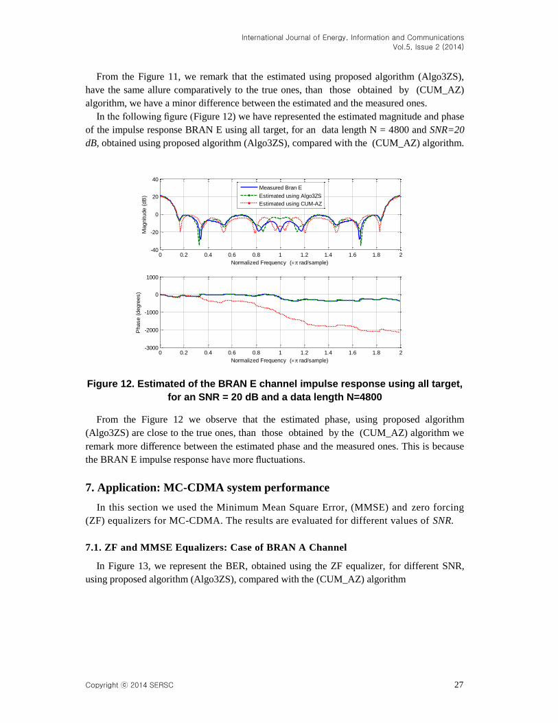
In the following figure (Figure 12) we have represented the estimated magnitude and phase
of the impulse response BRAN E using all target, for an data length N = 4800 and SNR=20
dB, obtained using proposed algorithm (Algo3ZS), compared with the (CUM_AZ) algorithm.
Figure 12. Estimated of the BRAN E channel impulse response using all target,
for an SNR = 20 dB and a data length N=4800
From the Figure 12 we observe that the estimated phase, using proposed algorithm
(Algo3ZS) are close to the true ones, than those obtained by the (CUM_AZ) algorithm we
remark more difference between the estimated phase and the measured ones. This is because
the BRAN E impulse response have more fluctuations.
7. Application: MC-CDMA system performance
In this section we used the Minimum Mean Square Error, (MMSE) and zero forcing
(ZF) equalizers for MC-CDMA. The results are evaluated for different values of SNR.
7.1. ZF and MMSE Equalizers: Case of BRAN A Channel
In Figure 13, we represent the BER, obtained using the ZF equalizer, for different SNR,
using proposed algorithm (Algo3ZS), compared with the (CUM_AZ) algorithm
0 0.2 0.4 0.6 0.8 1 1.2 1.4 1.6 1.8 2-3000
-2000
-1000
0
1000
Normalized Frequency ( rad/sample)
Phase (
degre
es)
0 0.2 0.4 0.6 0.8 1 1.2 1.4 1.6 1.8 2-40
-20
0
20
40
Normalized Frequency ( rad/sample)
Magnitude (
dB
)
Measured Bran E
Estimated using Algo3ZS
Estimated using CUM-AZ

International Journal of Energy, Information and Communications
Vol.5, Issue 2 (2014)
28 Copyright ⓒ 2014 SERSC
Figure 13. BER of the estimated and measured BRAN A channel using the ZF equalizer
Figure 14 represents the BER, obtained using MMSE equalizer, for different SNR, using
proposed algorithm (Algo3ZS), compared with the (CUM_AZ) algorithm.
Figure 14. BER of the estimated and measured BRAN A channel using the MMSE equalizer
The BER simulation for different SNR, demonstrates that the estimated values by the
(Algo3ZS) algorithm are more close to the measured value than those estimated by
(CUM_AZ) algorithm for ZF and MMSE equalization. From the Figure 13 and 14, we
conclude that: if the SNR=24 dB we have 1 bit error occurred when we receive 103 bit using
(CUM_AZ), but using (Algo3ZS) we obtain only one bit error for 104 bit received.
4 6 8 10 12 14 16 18 20 22 2410
-5
10-4
10-3
10-2
10-1
100
SNR (dB)
BE
R
BIT ERROR RATE FOR MC-CDMA (DOWNLINK): BRAN A - Zero Forcing
ZF: True channel (BRAN A)
ZF: Blind channel estimation using Algo3ZS
ZF: Blind channel estimation using CUM-AZ
4 6 8 10 12 14 16 18 20 22 2410
-5
10-4
10-3
10-2
10-1
100
SNR (dB)
BE
R
BIT ERROR RATE FOR MC-CDMA (DOWNLINK): BRAN A - MMSE
MMSE: True channel (BRAN A)
MMSE: Blind channel estimation using Algo3ZS
MMSE: Blind channel estimation using CUM-AZ

International Journal of Energy, Information and Communications
Vol.5, Issue 2 (2014)
Copyright ⓒ 2014 SERSC 29
7.2. ZF and MMSE Equalizers: Case of BRAN B Channel
In Figure 15, we represent the BER for different SNR, obtained using proposed algorithm
(Algo3ZS), compared with the (CUM_AZ) algorithm, but the equalization is performed using
the ZF equalizer.
Figure 15. BER of the estimated and measured BRAN B channel using the ZF equalizer
From the Figure 15, we observe that the blind ZF equalization give us approximately the
same results obtained by the measured BRAN B values using Algo3ZS, than those obtained
by (CUM_AZ) algorithm, we have a difference between the estimated and the measured ones.
Using the MMSE equalizer we represents, Figure 16, the BER for different SNR, obtained
using proposed algorithm (Algo3ZS), compared with the (CUM_AZ) algorithm.
Figure 16. BER of the estimated and measured BRAN B channel using the MMSE equalizer
4 6 8 10 12 14 16 18 20 22 2410
-4
10-3
10-2
10-1
100
SNR (dB)
BE
R
BIT ERROR RATE FOR MC-CDMA (DOWNLINK): BRAN B - Zero Forcing
ZF: True channel (BRAN B)
ZF: Blind channel estimation using Algo3ZS
ZF: Blind channel estimation using CUM-AZ
4 6 8 10 12 14 16 18 20 22 2410
-5
10-4
10-3
10-2
10-1
100
SNR (dB)
BE
R
BIT ERROR RATE FOR MC-CDMA (DOWNLINK): BRAN B - MMSE
MMSE: True channel (BRAN B)
MMSE: Blind channel estimation using Algo3ZS
MMSE: Blind channel estimation using CUM-AZ
International Journal of Energy, Information and Communications
Vol.5, Issue 2 (2014)
30 Copyright ⓒ 2014 SERSC
From the Figure 16, we remark that the MMSE equalization using proposed algorithm
(Algo3ZS), have the same allure comparatively to the true ones, than those obtained by
(CUM_AZ) algorithm, thus, if the SNR=24 dB, we observe that 1 bit error occurred when we
receive, approximately, 103 bit with the (CUM_AZ), but using (Algo3ZS) we obtain only one
bit error for 104 bit received.
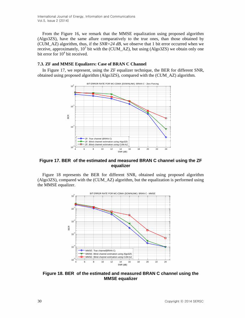
7.3. ZF and MMSE Equalizers: Case of BRAN C Channel
In Figure 17, we represent, using the ZF equalizer technique, the BER for different SNR,
obtained using proposed algorithm (Algo3ZS), compared with the (CUM_AZ) algorithm.
Figure 17. BER of the estimated and measured BRAN C channel using the ZF equalizer
Figure 18 represents the BER for different SNR, obtained using proposed algorithm
(Algo3ZS), compared with the (CUM_AZ) algorithm, but the equalization is performed using
the MMSE equalizer.
Figure 18. BER of the estimated and measured BRAN C channel using the MMSE equalizer
4 6 8 10 12 14 16 18 20 22 2410
-3
10-2
10-1
100
SNR (dB)
BE
R
BIT ERROR RATE FOR MC-CDMA (DOWNLINK): BRAN C - Zero Forcing
ZF: True channel (BRAN C)
ZF: Blind channel estimation using Algo3ZS
ZF: Blind channel estimation using CUM-AZ
4 6 8 10 12 14 16 18 20 22 2410
-5
10-4
10-3
10-2
10-1
100
SNR (dB)
BE
R
BIT ERROR RATE FOR MC-CDMA (DOWNLINK): BRAN C - MMSE
MMSE: True channel(BRAN C)
MMSE: Blind channel estimation using Algo3ZS
MMSE: Blind channel estimation using CUM-AZ

International Journal of Energy, Information and Communications
Vol.5, Issue 2 (2014)
Copyright ⓒ 2014 SERSC 31
From Figure 18, we conclude that: if the SNR values are superior to 24 dB we have a BER
than 10-4
with the (CUM_AZ), but using the (Algo3ZS) we have only the BER than 10−5
,
principally if we use the MMSE equalizer.
7.4. ZF and MMSE Equalizers: Case of BRAN D Channel
In Figure 19, we represent the BER for different SNR, obtained using proposed algorithm
(Algo3ZS), compared with the (CUM_AZ) algorithm, but the equalization is performed using
the ZF equalizer.
Figure 19. BER of the estimated and measured BRAN D channel using the ZF
equalizer
Figure 19 demonstrates that the proposed algorithm (Algo3ZS) more accurate than those
Antari et al (CUM_AZ), So, if the SNR=20 dB, we observe that 1 bit error occurred when we
receive 102 bit with the (CUM_AZ), but using (Algo3ZS) we obtain only one bit error for 10
3
bit received.
Figure 20 represents the BER for different SNR, obtained using proposed algorithm
(Algo3ZS), compared with the (CUM_AZ) algorithm, but the equalization exploiting the
MMSE equalizer.
4 6 8 10 12 14 16 18 2010
-4
10-3
10-2
10-1
100
SNR (dB)
BE
R
BIT ERROR RATE FOR MC-CDMA (DOWNLINK): BRAN D - Zero Forcing
ZF: True channel (BRAN D)
ZF: Blind channel estimation using Algo3ZS
ZF: Blind channel estimation using CUM-AZ

International Journal of Energy, Information and Communications
Vol.5, Issue 2 (2014)
32 Copyright ⓒ 2014 SERSC
Figure 20. BER of the estimated and measured BRAN D channel using the MMSE equalizer
Figure 20 demonstrates clearly that the estimated values by the first algorithm (Algo3ZS)
are more close to the measured value than those estimated by second algorithm (CUM_AZ),
thus, if the SNR=20 dB, we observe that 1 bit error occurred when we receive 103 bit with the
(CUM_AZ), but using (Algo3ZS) we obtain only one bit error for 104 bit received.
7.5. ZF and MMSE Equalizers: Case of BRAN E Channel
In Figure 21, we represent the BER for different SNR, obtained using proposed algorithm
(Algo3ZS), compared with the (CUM_AZ) algorithm, but the equalization is performed using
the ZF equalizer.
Figure 21. BER of the estimated and measured BRAN E channel using the ZF equalizer
4 6 8 10 12 14 16 18 2010
-5
10-4
10-3
10-2
10-1
100
SNR (dB)
BE
R
BIT ERROR RATE FOR MC-CDMA (DOWNLINK): BRAN D - MMSE
MMSE: True channel(BRAN D)
MMSE: Blind channel estimation using Algo3ZS
MMSE: Blind channel estimation using CUM-AZ
4 6 8 10 12 14 16 18 20 22 2410
-3
10-2
10-1
100
SNR (dB)
BE
R
BIT ERROR RATE FOR MC-CDMA (DOWNLINK): BRAN E - Zero Forcing
ZF: True channel (BRAN E)
ZF: Blind channel estimation using Algo3ZS
ZF: Blind channel estimation using CUM-AZ

International Journal of Energy, Information and Communications
Vol.5, Issue 2 (2014)
Copyright ⓒ 2014 SERSC 33
Figure 22 represents the BER for different SNR, obtained using proposed algorithm
(Algo3ZS), compared with the (CUM_AZ) algorithm, but the equalization is performed using
the MMSE equalizer.
Figure 22. BER of the estimated and measured BRAN E channel using the MMSE equalizer
From the figure 22 we can conclude that the BER obtained using (Algo3ZS) gives a very
good results like these obtained by (CUM_AZ). If the we have a BER less
than using (Algo3ZS), but using the (CUM_AZ) we have only the BER less than .
In conclusion, for all channels the MMSE equalizer best than the ZF technique.
8. Conclusion
In this paper we have proposed an new algorithm (Algo3ZS) based on third order
cumulants, compared with the Antari et al algorithm (CUM_AZ), to identify the
parameters of the impulse response of the frequency selective channel such as the
experimental channels, BRAN A, BRAN B, BRAN C, BRAN D, and BRAN E,
normalized for MC-CDMA systems. The simulation results show the efficiency of the
proposed algorithm (Algo3ZS) than those obtained using (CUM_AZ), mainly if the
input data are sufficient. The magnitude and phase of the impulse response is estimated
with an acceptable precision in noisy environment principally if we use the first
algorithm (Algo3ZS). In part of five experimental channels for MC-CDMA systems
application, we have obtained very important results on bit error rate using the proposed
algorithm (Algo3ZS), than those obtained by (CUM_AZ) algorithm.
References
[1] G. B. Giannakis and A. Delopoulos, “cumulant based autocorrelation estimates of non-gaussian linear
processes”, Signal Processing, Elsevier, vol. 47, (1995), pp. 1-17.
[2] J. M. Mendel, “tutorial on higher order statistics in signal processing and system theory: theoretical results
and some applications”, Procceeding of the IEEE, vol. 79, (1991), pp. 278-305.
4 6 8 10 12 14 16 18 20 22 2410
-5
10-4
10-3
10-2
10-1
100
SNR (dB)
BE
R
BIT ERROR RATE FOR MC-CDMA (DOWNLINK): BRAN E - MMSE
MMSE: True channel (BRAN E)
MMSE: Blind channel estimation using Algo3ZS
MMSE: Blind channel estimation using CUM-AZ

International Journal of Energy, Information and Communications
Vol.5, Issue 2 (2014)
34 Copyright ⓒ 2014 SERSC
[3] C. L. Nikias and A. P. Petropulu, “higher order spectra analysis”, PTR Prentice Hall, Englewood Cliffs, New
Jersey, vol. 07632, (1993).
[4] S. Safi and A. Zeroual, “blind parametric identification of non-gaussian FIR systems using higher order
cumulants”, International Journal of Systems Science, vol. 35, (2004), pp. 855-867.
[5] M. Zidane, S. Safi, M. Sabri and A. Boumezzough, “Impulse Response Identification of Minimum and Non
Minimum Phase Channels”, 4th Workshop on Codes, Cryptography and Communication Systems
(WCCCS’13), (2013) November 07-08, Meknes, Morocco.
[6] J. Antari, R. Iqdour and A. Zeroual, “Forecasting the wind speed process using higher order statistics and
fuzzy systems”, Revue des Energies Renouvelables, vol. 9, (2006), pp. 237-251.
[7] S. Safi, M. Frikel, M. M’Saad and A. Zeroual, “Blind Impulse Response Identification of frequency Radio
Channels: Application to Bran A Channel”, Int. J. Sig. Proces., vol. 4, (2007), pp. 201-206.
[8] M. Zidane, S. Safi, M. Sabri and A. Boumezzough, “Blind Identification of Minimum Phase Channels Based
On Higher Order Cumulants”, International Conference on Intelligent Information and Network Technology
(IC2INT’13), (2013) November 13-14, Settat, Morocco.
[9] M. Bakrim and D. Aboutajdine, “Cumulant-based identification of non gaussian moving average signals”,
Traitement du Signal, vol. 16, (1999), pp. 175-186.
[10] J. Antari, A. El Khadimi, D. Mammas and A. Zeroual, “Developed Algorithm for Supervising Identification
of Non Linear Systems using Higher Order Statistics: Modeling Internet Traffic”, International Journal of
Future Generation Communication and Networking, vol. 5, (2012).
[11] J. Antari, A. Zeroual and S. Safi, “Stochastic analysis and parametric identification of moving average (MA)
non Gaussian signal using cumulants”, International Journal of Physical and Chemical News, vol. 34, (2007),
pp. 27-32.
[12] S. Safi and A. Zeroual, “Blind identification in noisy environment of nonminimum phase finite impulse
response (FIR) system using higher order statistics”, vol. 43, (2003), pp. 671-681.
[13] K. Abderrahim, R. B. Abdennour, G. favier, M. Ksouri and F. Msahli, “New results on FIR system
identification using cumulants”, APII-JESA, vol. 35, (2001), pp. 601-622.
[14] ETSI, “Broadband Radio Access Networks (BRAN); High Performance Radio Logical Area Network
(HIPERLAN) Type 2; Requirements and architectures for wireless broadband access”, Janvier, (1999).
[15] ETSI, “Broadband Radio Access Networks (BRAN); HIPERLAN Type 2; Physical Layer”, Decembre,
(2001). [16] S. Safi, “Identification aveugle des canaux à phase non minimale en utilisant les statistiques d’ordre
supérieur: application aux réseaux mobiles”, Thèse d’Habilité, Cadi Ayyad University, Marrakesh, Morocco,
(2008). [17] J. Antari, “analyse et identification aveugle des Systèmes non linéaire en utilisant les statistiques d’ordre,
supérieur : application à la modélisation du trafic dans les réseaux internet”, Thèse de Doctorat, Cadi Ayyad
University, Marrakesh, Morocco, (2008).
[18] S. Safi and A. Zeroual, “Blind non-minimum phase channel identification using 3rd and 4th order cumulants”,
Int. J. Sig. Proces., vol. 4, (2007), pp. 158-168.
[19] M. Frikel, B. Targui, M. M’Saad and F. Hamon, “Bit error rate analysis of the controlled equalization for
MC-CDMA”, in IEEE ICSPC’07 Conf., Dubai, United Arab Emirates, (2007).