
botswana standard bos 41-2:2001 - Punto Focal
56
BOTSWANA STANDARD BOS 41-2:2001 13 A plugs, socket-outlets, adaptors and connection units Part 2: Switched and unswitched socket-outlets – Specification BOS 41-2: 2001 BOTSWANA BUREAU OF STANDARDS
-
Upload
khangminh22 -
Category
Documents
-
view
2 -
download
0
Transcript of botswana standard bos 41-2:2001 - Punto Focal

BOTSWANA STANDARD BOS 41-2:2001
13 A plugs, socket-outlets, adaptors and connection units
Part 2: Switched and unswitched socket-outlets – Specification
BO
S 4
1-2:
200
1
BOTSWANA BUREAU OF STANDARDS


BOS 41 – 2: 2001
i
Contents Page Foreword……………………………………..………………………………………………………………………………iv
1 Scope………………………………………………………………………………………………………………...1
2 References…………………………………………………………………………………………………………..1
3 Definitions……………………………………………………………………………………………………………2
4 Conditions of use…………………………………………………………………………………………………...4
5 General ………………………………………………………………………………………………………………4
6 General conditions of type testing………………………………………………………………………………...4
6.1 Type tests………………………………………………………………………………………………………...4
6.2 Inspections and tests of one classification………………………...………………………………………….5
6.3 Gauges…………………………………………………………………………………………………………...5
7 Classification………………………………………………………………………………………………………..5
8 Marking and labelling………………………………………………………………………………………………6
8.1 Marking…………………………………………………………………………………………………..……….6
8.2 Labelling……………………………………………………………….…………………………………………7
9 Creepage distances, clearances and distances through insulation…………………………………………..8
9.1 Minimum clearance through air and creepage distance………………………….…………………………8
9.2 Minimum distance through insulation…………………..……………………………………………………..8
10 Accessibility of live parts…………………………………………………………………………………………...9
11 Provision of earthing……………………………………..…………………………………………………………9
12 Terminals and terminations………………………………………………………………………………………10
12.1 Clamping and securing………………………………………………………………………………………..10
12.2 Terminals for rewirable socket outlets……………………………………………………………………….10
12.3 Terminations for non-rewirable portable sockets…………..……………………………………………….11
12.4 Connection of flexible cords…………………………………………….…………………………………….11
12.5 Line and neutral terminals…………………………………………………………………………………….11
12.6 Earthing terminals………………………………………………...……………………………………………11
12.7 The use of pillar terminals…………………………………………………….………………………………11
12.8 Terminal screws…………………………………………..……………………………………………………11
12.9 Location of terminals in rewirable portable sockets-outlets………...……………………………………..12
13 Construction of socket outlets….………………………………………………………………………………..12
13.1 Disposition of sockets………………………………………………………………..………………………..12
13.2 The line and neutral socket contacts in socket-outlets………………………….…………………………12
13.3 Insertion of a plug into socket-outlet……………………...………………………………………………….12
13.4 Socket contacts…………………………………………………….…………………………………………..13
13.5 Line and neutral sockets contacts…………………...……………………………………………………….13
13.6 Earth socket contacts………………...………………………………………………………………………..13

BOS 41 – 2: 2001
ii
13.7 The construction of the socket-outlet…………………...……………………………………………………14
13.8 Withdrawal of the plug…………………………………………………….…………………………………..14
13.9 Apertures for the reception of the line……………………………………………………………………….14
13.10 Actuating member of a switch…………………………………………..…………………………………….15
13.11 Multiple socket-outlets…………………………………………………………………………………………15
13.12 Fuse link fitted to a socket-outlet…………………………………………..…………………………………15
13.13 Conductive component parts of socket-outlets……………………………..……...……………………….15
13.14 Flush socket-outlets used for enclosures……………………………………………………………………16
13.15 Fixed surface-mounted socket-outlets……………………………………….………………………………16
13.16 Flush socket-outlet plates……………………….…………………………………………………………….16
13.17 Base and cover of non-rewirable portable socket-outlets……….……………………..………………….16
13.18 Portable socket-outlets………………………………………………………………………………………..17
13.19 Prevention of loose strands…………………………………….……………………………………………..17
14 Resistance to ageing and to humidity………………………………………………………………...………...17
14.1 Resistance to ageing……….………………………………………………………………………..………..17
14.2 Resistance to humidity………………………………………………………………….……………………..18
15 Insulation resistance and electric strength……………………………………………………………………..18
15.1 General………………………………………………………………………………………………………….18
15.2 Non-rewirable socket-outlets……………………..…………………………………………………………..19
16 Temperature rise…………………………………………………………………………….……………………19
16.1 Temperature of socket-outlets……………………………………………………………..…………………19
16.2 Surface-mounted fixed socket-outlets……………………………………………………………………….20
16.3 Temperature rise test……………………………….…………………………………………………………21
17 Breaking capacity of socket-outlets……………………………………………………………………………..22
17.1 Adequacy……………………………………………………………………………………………………….22
17.2 Test for breaking current in socket outlet……………………………………………………………………22
17.3 Test for breaking current in a switch.…………………….………………………...………………………..22
17.4 Test for breaking current in a fuse……………………………………….…………………………………..22
18 Normal operation of socket-outlets……………………………………………………………………………...23
18.1 General………………………………………………………………………………………………………….23
18.2 Test for mechanical and electrical stresses……………………………..………………………………….23
18.3 Switched socket-outlets..…………………………………………………………….………………………..23
19 Connection of flexible cords and cord anchorages...………………………………………………………….23
19.1 Entry and clamping of 3-core flexible cords………………………….……………………………………..23
19.2 Compliance of flexible cords and cords anchorage…………………….………………………………….24
19.3 Cord anchorages..………………………….………………………………………………………………….24
19.4 Screws………………………………………………………..…………………………………………………25
19.5 Flexible cords…………………………………….…………………………....……………………………….25
19.6 Protection of flexible cords against bending…………………………….…………………………………..25

BOS 41 – 2: 2001
iii
19.7 Cord entry to rewirable portable socket-outlets…………………………………………………………….25
20 Mechanical strength………………………………………………………………………………………………26
20.1 General………………………………………………………………………………………………………….26
20.2 Solid link of stainless steel……………………………………………...…………………………………….26
20.3 Impact test……………………………………………….……………………………………………………..26
20.4 Rewirable single and twin portable socket-outlets…………...…………………………………………….27
20.5 Rewirable socket-outlets with more than two outlets………………………….…..……………………….27
21 Screws, current-carrying parts and connections………………………………………………………………28
21.1 Screwed connections……………………………………………………………………………….…………28
21.2 Thread-cutting and/or thread-forming screws……………………...……………………………………….28
21.3 Current-carrying parts and earthing earth contacts………..…………………………...………………….29
22 Resistance to heat………………………………………………………………………………………………...29
22.1 Socket-outlets………………………………………………………………….……………………………….29
22.2 Complete socket-outlets and separate ancillary components………..…………...………………………29
22.3 Portable socket-outlets………………………………………………………………………………………..29
22.4 Parts of insulating material……………………………………………………………………………………30
23 Resistance to abnormal heat, fire and tracking………………………………………………………………..30
23.1 General……………………………………………………………………….…………………………………30
23.2 Glow-wire test……………………………………………………………………………..……………………31
Figures
1 Test pin…………………………………………………………………………………………….……………….32
2a Apparatus for mechanical strength test on resilient covers…………………………………………………..33
2b Hardwood block for Figure 2a…………………………………………………………………………………...34
3 Disposition of socket-contacts…………………….……………………………………………………………..35
4 GO gauge for socket-outlet…………………………..…………………………………………………………..36
5 Contact test gauge……………………………………………………..…………………………………………37
6 Test apparatus and circuit use with contact and non-contact gauges………………...…………………….38
7 Non-contact test gauges……………………………………………………………..…………………………..39
8 Turning moment gauge……………………………………………………………….………………………….40
9 Withdrawal pull gauges for effectiveness of contact……………………………….………………………….41
10 Apparatus for flexing test…………………………………………………………………………………………42
11 Solid link for test on fuse clips…………………………………………………………...………………………43
12 Tumbling barrel……………………………………………………………………………………………………44
13 Pendulum impact test……………………………………….……………………………..…………………45-46
14 Arrangement for mechanical strength test for portable socket-outlets………………………………………47
15 Apparatus for pressure test………..…………………………………………………………………………….48
16 Ball pressure test…………………………………………………………………...……………………………..49

BOS 41 – 2: 2001
iv
Foreword
This Botswana Standard was approved by the Standards Council on 01-06-11.
The Botswana Bureau of Standards (BOBS) was established under the Standards Act No. 16 of 1995 with a primary responsibility of preparing Botswana Standards.
During the preparation of this Botswana Standard assistance was derived from the British Standard BS 1363: 1995: 13 A plugs, socket-outlets, adaptors and connection units: Part 2: Specification for switched and unswitched socket-outlets.
This Part of Botswana Standard is the second in a series that applies to rewirable and non-rewirable 13 A fused plugs, switched and unswitched socket-outlets, adaptor and 13 A fused connection units (switched and unswitched)1).
During the preparation of this Botswana Standard the following member organizations were directly represented in the Technical Committee EED2: Electrical Installation and Accessories:
Ministry of Works, Transport and Communications Mr I Malapa (Chairman) Department of Electrical and Mechanical Services
Botswana Bureau of Standards Mr T Kavei (Technical Secretary)
Association of Consulting Engineers of Botswana ARUP Botswana Ms J Portman
Association of Electrical and Mechanical Contractors of Botswana Benmas (Pty) Ltd Mr J Bennett
Association of Electrical and Mechanical Contractors of Botswana Kentz Botswana Mr M Campbell
Botswana Power Corporation Mr E Cairns
Botswana Power Corporation Mr B Sebego
Botswana Telecommunications Corporation Mr L Mojaphoko
Debswana Diamond Company (Pty) Ltd Mr K Sinyinza
Electrical Distributors Mr A R Ameer
Ministry of Education Mr A Foudraine Department of Vocational Education and Training
Ministry of Local Government Mr C Chongo Francistown City Council
M & P Cables and Electrical (Pty) Ltd Mr J D Oxley
Omega Electrical (Pty) Ltd Mr N Desai
Sharps Electrical (Pty) Ltd Mr C J Leddy
University of Botswana, Mr E T Rakgati Electrical Engineering Department
Published by: Botswana Bureau of Standards Private Bag BO 48 Gaborone, Botswana Telephone 267 564044 Fax: 267 564042 Email: [email protected]
ICS 29.120.30
© Botswana Bureau of Standards, 2001
1) In preparation

BOS 41 – 2: 2001
13 A plugs, socket-outlets, adaptors and connection units ―
Part 2: Switched and unswitched socket-outlets – Specification
1 Scope
This Part of BOS 41 specifies requirements for 13 A switched and unswitched shuttered socket-outlets for household, commercial and light industrial purposes, with particular reference to safety in normal use. The socket-outlets are suitable for connection of portable appliances, sound-vision equipment, luminaries, etc. in a.c. circuits only, operating at voltages not exceeding 250 V r.m.s at 50 Hz using plugs in accordance with Part 1 of BOS 41.
Requirements are specified for 13 A shuttered socket-outlets in single or multiple arrangements, with or without associated controlling switches, for flush mounting in suitable boxes, e.g., complying with BS 4662, or for surface or panel mounting or for portable use. Fixed socket-outlets are intended for use with cables complying with BS 6004: 1991 or BS 6007: 1991 having copper conductors.
Portable socket-outlets are intended for use with flexible cords, complying with BS 6500: 1994. Socket-outlets containing devices other than fuse links, switches and indicator lamps are outside the scope of this Part of BOS 41.
NOTE 1 In order to maintain safety and interchangeability with plugs and socket-outlets it is necessary that these products comply with the requirements of Clauses 10 and Clause13 of this Part of BOS 41, however their body outline need not be limited at a distance of 6.35 mm from the plug engagement face.
NOTE 2 Requirements for electromagnetic compatibility are not given for the following reasons:
A switched or unswitched socket-outlet does not emit intolerable electromagnetic interference since significant electromagnetic disturbances are only generated during insertion and withdrawal, which are not continuous.
A switched or unswitched socket-outlet is mechanical by nature of construction. The product is therefore immune from electromagnetic interference.
2 References
The following standards contain provisions, which through reference to this text constitute provisions of this standard. All standards are subject to revision, and since any reference to a standard is deemed to be a reference to the latest edition of that standard, parties to agreements based on this standard are encouraged to take steps to ensure the use of the most recent editions of the standards indicated below. Information on currently valid National and International Standards can be obtained from the Botswana Bureau of Standards.
BS 219:1977, Specification for soft solders.
BS 1210:1963, Specifications for wood screws.
BS 1362:1973, Specification for general purpose fuse links for domestic and similar purposes (primarily for use in plugs).
BOS 41-1:2001, 13 A plugs, sockets, adaptors and connection units, Part 1, Specification for rewirable and non-rewirable 13 A fused plugs.
BOS 41-3:2001 13, A plugs, sockets, adaptors and connection units, Part 3, Specification for adaptors.
BS 1363:Part 4, Specification for 13 A fused connection units: switched and unswitched.
BS 3042:1992, Test probes to verify protection by enclosures.
BS 4662:1970, Specification for boxes for the enclosure of electrical accessories.
1

BOS 41 – 2: 2001
BS 5901:1980, Method of test for determining the comparative and the proof tracking indices of solid insulating materials under moist conditions.
BS 6004:1991, Specification for PVC-insulated cables (non-armoured) for electric power and lighting.
BS 6007:1991, Specification for rubber-insulated cables for electric power and lighting.
BS 6458, Fire hazard testing for electrotechnical products.
BS 6458: Part 2, Methods of test.
BS 6458: Section 2.1:1984, Glow-wire test.
BS 6500: 1994, Specification for insulated flexible cords and cables.
3 Definitions
For the purposes of this Part of BOS 41 the following definitions shall apply:
NOTE Where the terms voltage and current are used, they imply r.m.s. values, unless otherwise stated.
3.1 socket-outlet: an accessory having a set of three socket-contacts designed to engage with the pins of a corresponding plug having means for the electrical connection of appropriate cables or flexible cords.
3.2 fixed socket-outlet: a socket-outlet which with its associated enclosure is intended for use mounted in or on a fixed surface.
3.3 surface-mounted socket-outlet: a socket-outlet, which is intended to be mounted on a wall or other flat surface without the need for recessing.
3.4 flush-mounted socket-outlet: a socket-outlet, which is intended to be mounted in a box which is recessed into a wall or other flat surface. The socket-outlet plate and the socket-outlet base are regarded as forming a complete unit, and the socket-outlet plate is mounted with its back either flush with a wall or other flat-surface structure, or flush with the front of a socket-outlet box or enclosure.
3.5 panel-mounted socket-outlet: a socket-outlet intended for incorporation into equipment panels or electrical trunking and which depends upon such incorporation for its enclosure.
3.6 portable socket-outlet: a socket-outlet intended to be connected to, or integral with, a flexible cord, and which can easily be moved from one place to another while connected to the supply.
3.7 rewirable portable socket-outlet: a portable socket-outlet so constructed that a flexible cord can be fitted or replaced using general-purpose tools.
3.8 non-rewirable portable socket-outlet: a portable socket-outlet so constructed that it forms a complete unit with the flexible cord after connection and assembly by the manufacturer of the portable socket-outlet.
NOTE See also 13.18
3.9 moulded-on portable socket-outlet: a non-rewirable portable socket-outlet, the manufacture of which is completed by insulating material moulded around pre-assembled component parts and the terminations of the flexible cord.
3.10 fused socket-outlet: a socket-outlet having provision for a replaceable cartridge fuse link.
3.11 switched socket-outlet : a socket-outlet with an associated switch to disconnect the supply to the line socket contact or to both line and neutral socket contacts.
3.12 multiple socket-outlet: a combination of two or more socket-outlets.
2

BOS 41 – 2: 2001
3.13 socket-outlet base: the part of the socket-outlet which carries the contacts.
NOTE It may be integral with the socket-outlet plate.
3.14 socket-outlet plate: the external plate which covers the base and contact assembly of a socket-outlet and through which the pins of the plug are inserted.
3.15 socket-outlet box: a box suitable for mounting one or more socket-outlets.
3.16 shutter: a movable device arranged to shield the current-carrying socket-outlet contacts automatically when a corresponding plug is removed.
3.17 actuating member: that part which is moved, e.g. pulled, pushed or turned by the user, to operate the switch mechanism.
3.18 indicator lamp (pilot lamp): a lamp which illuminates to indicate that the socket-outlet contacts are energized.
3.19 terminal: a means by which the user can make an electrical connection between the appropriate cable or flexible cord and the conducting parts of the socket-outlet without the use of special tools.
3.20 screw-type terminal: a terminal in which the connection is made directly by means of screws or nuts of any kind or indirectly through an intermediate metal part such as a washer, clamping plate or anti spread device on which the screw bears directly.
NOTE The following are examples of screw-type terminals.
a) A pillar terminal is a terminal in which the conductor is inserted into a hole or cavity, where it is clamped under the shank of the screw or screws.
b) A screw terminal is a terminal in which the conductor is clamped under the head of the screw.
c) A stud terminal is a terminal in which the conductor is clamped under a nut.
3.21 termination: a means by which an electrical connection can be made between the appropriate flexible cord and the conducting part of the socket-outlet using special purpose tools, e.g. soldering, welding, crimping.
3.22 fuse carrier: a movable or removable part designed to carry, retain, cover and/or remove the fuse link.
3.23 type test: a test or series of tests made on a type test sample, for the purpose of checking compliance of the design of a given product with the requirements of the relevant standard.
3.24 type test sample: a sample consisting of one or more similar units or specimens submitted by the manufacturer or responsible vendor for the purpose of a type test.
3.25 accessible external surfaces of a socket-outlet: all surfaces which can be touched by test probe B of BS 3042: 1992 when the socket-outlet is installed as in use.
3.26 live parts: current-carrying parts and those metal parts in contact with them during normal use.
3.27 fine wire thermocouple: a thermocouple having wires not exceeding 0.3 mm in diameter.
3.28 calibrated link: a calibrated heat source for use in place of a fuse link during temperature rise tests.
3.29 resilient material: a material having the inherent capability of regaining or substantially regaining its original form when deforming loads are removed.
3

BOS 41 – 2: 2001
4 Conditions of use
Socket-outlets shall be suitable for use under the following conditions:
a) an ambient temperature in the range –5 °C to +40 °C, the average value over 24 h not exceeding 25 °C;
NOTE Under normal conditions of use, the available cooling air is subject to natural atmospheric variations of temperature and hence the peak temperature occurs only occasionally during the hot season, and on those days when it does occur it does not persist for lengthy periods.
b) a situation not subject to exposure to direct radiation from the sun or other source of heat likely to raise temperatures above the limits specified in a);
c) an altitude not exceeding 2000 m above sea level;
d) an atmosphere not subject to abnormal pollution by smoke, chemical fumes, rain, spray, prolonged periods of high humidity or other abnormal conditions.
5 General
Socket-outlets shall be so designed and constructed that in normal use their performance is reliable and without danger to the user or to the surroundings. Such socket-outlets shall be capable of meeting all the relevant requirements and tests specified in this Part of BOS 41.
Unless otherwise stated, reference to a plug within this Part of BOS 41 shall mean a plug in accordance with BOS 41-1.
6 General conditions for type testing
6.1 Type tests
All tests shall be type tests.
Unless otherwise specified in this Part of BOS 41 the socket-outlets shall be tested as delivered by the manufacturer or responsible vendor and under normal conditions of use, at an ambient temperature of 20 °C ± 5 °C, after being conditioned at normal laboratory temperature and humidity levels for at least 4 days.
Unless otherwise stated by the manufacturer, flush-mounted socket-outlets shall be tested when mounted on a corresponding insulated box complying with BS 4662: 1970, the fixing screws being tightened with a torque of 0.6 N.m ± 10 %.
Other types shall be mounted according to the manufacturer’s instructions.
The socket-outlets used for the tests shall be representative of normal production items in respect of all details which may affect the test results.
Non-rewirable socket-outlets shall be supplied with an appropriate flexible cord which shall be at least 1 m long.
Socket-outlets shall be deemed to comply if no specimen fails the complete series of tests given in Table 1.
If one specimen fails in the complete series of tests given in Table 1, then socket-outlets of that type shall be deemed to have failed to comply with this Part of BOS 41, unless the socket-outlets shall be shown to be not representative of normal production or design, in which case a further type test sample shall be submitted to the test or tests in that particular group. If there is no failure in this re-test then socket-outlets of that type test shall be deemed to comply with this Part of BOS 41.
4

BOS 41 – 2: 2001
If more specimens fail in the complete series of tests given in Table 1, then socket-outlets of that type shall be deemed to have failed to comply with this Part of BOS 41. For type testing, all tests have been included in the test schedule and shall be performed in the specified order.
NOTE 1 References to carrying out specific tests in various clauses are not intended to indicate a sequence of testing different to that in the schedule and should not be conducted as separate additional tests.
NOTE 2 Where reference to BS 6500: 1994 is made equivalent flexible cords to the latest version of that standard may be used.
Table 1 – Schedule of test
Sequence no. Samples Test Clause number 1 3 Inspection, measurement, gauging and
manipulation 6, 7, 8, 10.1, 12.1, 10.2, 10.4, 11.1, 13.1, 13.2, 13.3, 13.9, 13.10, 13.12, 13.14, 13.15, 13.16, 13.17, 13.18, 13.20, 19.2, 19.3, 19.4, 19.6, 21, 9
2 3 6, 10.3, 21.3 (11.2, 11.3 only), 19.1, 14.2, 13.13, (10.1.1 only), 13.4.1a), 13.4.1b), 13.5, 13.6
3 3 6, 13.13, (20.1.2 only), 17, 13.11, 16, 19.5, 21.3
4 3 6, 14.1, 15, 18.1.2, (10.1, 16, 13.19, 15, 13.4.1a), 11.2, 13.6, 13.7, 13.8)
5 3
General
6, 14.2, 18.1.3, 20 6 3 6, 22 7 3 6, 23.2 8 3
Material
6, 23.3, 21.3 NOTE The order of tests given in sequence no.1 is preferred but not mandatory except where required within the text of the appropriate clause.
6.2 Inspections and tests of one classification
All inspections and tests, of any one classification (see Clause 7), shall be carried out as specified in the clauses listed in Table 1 on the number of specimens in the sample column and in the order given.
6.3 Gauges
Gauges in accordance with Figures 4, 5, 7 and 9 shall be considered to comply with the dimensional requirements if the results of the measured values are within the specified dimensions and the uncertainty of measurement at not less than 95 % confidence level does not exceed ± 0.005 mm.
7 Classification
Socket-outlets shall be classified as follows:
―single or multiple;
―switched or unswitchwed;
―fused or unfused;
―fixed or portable;
5

BOS 41 – 2: 2001
―(if fixed) flush or surface or panel-mounting;
―(if portable) rewirable or non-rewirable;
―with or without indicator lamp.
8 Marking and labelling
8.1 Marking
Socket-outlets shall be legibly and durably marked with the following information, which shall not be placed on screws, removable washers or other easily removable parts, or upon parts intended for separate sale:
a) either the name, trade mark or identification mark of the manufacturer or responsible vendor, which may be duplicated on a removable fuse carrier;
b) the number of this Botswana Standard1)
c) for portable socket-outlets the number of this Botswana Standard shall be followed by ‘/A’;
d) on rewirable socket-outlets the terminals intended for the connection of the various conductors shall be identified by the symbols given in 8.2.4;
e) for fused socket-outlets, the words ‘FUSE’ or ‘FUSED’ or the symbol (given in 8.2.4) on the engagement surface of a socket-outlet;
f) fixed fused multiple socket-outlets shall be marked on the engagement surface with the maximum rated current of 13 A (e.g. MAX. 13 A);
g) all socket-outlets shall be marked with the following:
1) rated current;
2) rated volts;
3) nature of supply.
Portable socket-outlets shall be marked on the accessible external surface. In the case of a non-rewirable portable socket-outlet, the rated current shall be the maximum current appropriate to the attached flexible cord as given in Table 2.
Compliance shall be checked by inspection and by rubbing the marking for approximately 15 s with a cloth soaked in water, and again for approximately 15 s with a cloth soaked in an aliphatic solvent hexane with a content of aromatics of maximum 0.1 % by volume, a Kauri-butanol value of 29, an initial boiling point of approximately 69 °C, and relative density of approximately 0.68. The marking shall remain legible. Markings produced by an engraving or moulding process shall be deemed to comply without test.
1) Marking with the number of this Botswana Standard on or in relation to a product represents a manufacturer’s declaration of conformity, i.e. a claim by or on behalf of the manufacturer that the product meets the requirements of the standard. The accuracy of the claim is solely the claimant’s responsibility. Such a declaration is not to be confused with third party certification of conformity.
6

BOS 41 – 2: 2001
8.2 Labelling
8.2.1 Portable fused socket outlets
Portable fused socket-outlets shall be supplied with a removable tag, label or instructions indicating the rating of the fuse link fitted, e.g. ‘Fitted with ‘X’ ampere fuse’ (where ‘X’ denotes the rating of the fuse link).
Compliance shall be checked by inspection.
8.2.2 Portable socket outlets with a flexible cord
Portable socket-outlets fitted with a flexible cord shall be supplied with a label or instruction indicating the colour coding of the cores of the flexible cord.
Wires in the mains lead shall be coloured in accordance with the following code:
Green/yellow Earth (if any) Blue Neutral Brown Live
Compliance shall be checked by inspection.
Table 2 – Current, fuse rating and load for flexing and cord grip tests related to size of flexible co rd
Cord grip tests Flex cord nominal cross-sectional area mm2
Rated current A
Test current ± 0.4 A A
Fuse rating A
Load for flexing test + 2 %, - 0 % kg
Load + 2 %, - 0 % kg
Torque* N.m
0.5 0.75 1
1.25 1.5
3 6 10 13 13
3.5 7 11 14 14
3
13 13 13 13
1 1 2 2 2
3 3 3 6 6
0.15 0.20 0.25 0.30 0.35
*The recording of a measured value of torque in accordance with this table is considered to comply with this Part of Botswana standard on condition that the uncertainty of measurement at not less than 95 % confidence level does not exceed ± 10 %.
8.2.3 Rewirable portable socket outlets
Rewirable portable socket-outlets shall be provided with adequate instructions for the safe connection of the appropriate 3-core flexible cord, including clear instructions for the removal of insulation from the conductors.
Compliance shall be checked by inspection.
8.2.4 Use of symbols
If symbols are used they shall be as follows:
amperes A volts V *alternating current ~ line L neutral N
*earth (preferred) or
7

BOS 41 – 2: 2001
*fuse
NOTE 1 BS 6217 gives details of symbols marked *.
NOTE 2 For the marking of the rated current and rated voltage of the socket-outlet, figures may be used alone, the figures for the current rating being placed before or above that of the rated voltage and separated by a line. If a symbol for nature of the supply is used, it shall be placed next to the marking for rated current and rated voltage. Examples are as follows:
13 A 250 V ~ or 13/250 ~ or 13 A 250 V a.c. or 13/250 a.c.
9 Creepage distances, clearances and distances thro ugh insulation
9.1 Minimum clearance through air and creepage dist ance
When the socket-outlet is correctly assembled, installed and wired with the appropriate cable and/or flexible cord, as specified in 16.1.1, the minimum clearance through air and the minimum creepage distance shall be 2.5 mm as follows:
a) between live parts of opposite polarity (the value of 2.5 mm is reduced to 1 mm for the distance between the lead wires in the pinch of a neon lamp with external resistor);
b) between live parts and any other metal parts;
c) between live parts and the accessible external surface of the socket-outlet;
d) between component parts in the fused line circuit which are separated by the removal of the fuse link;
e) between the edge of any line or neutral socket contact aperture and a metallic front plate.
The minimum clearance between switch contacts in the open position for switched socket-outlets shall be 1.2 mm.
Compliance shall be checked by inspection and measurement. Movable parts shall be placed in the most unfavourable position. Nuts and screws with non-circular heads shall have been tightened in the most unfavourable position. In rewirable socket-outlets the clearances shall be measured when fitted with the maximum size of conductors.
NOTE The contribution to the creepage distance of any groove less than 1 mm wide is limited to its width; any air gap less than 1 mm is ignored in computing the total clearance.
9.2 Minimum distance through insulation
Socket-outlets shall have a minimum distance through insulation between live parts and the accessible external surface, of either:
a) 2 mm through solid insulation; or
b) 3 mm comprising at least 1 mm through solid insulation plus an additional distance through air.
NOTE The requirements of this subclause do not apply to any flexible cord connected to the socket-outlet.
Compliance shall be checked by inspection, measurement and where the solid insulation is less than 2 mm by the following test:
―test probe 11 of BS 3042: 1992 is applied to the surface with a force of 3002 N. This shall not cause the
distance through air to reduce below 1 mm whilst under pressure and, after removal of the 30 N force, the
8
BOS 41 – 2: 2001
measurement shall be approximately equal to the original air gap, with a permissible negative deviation of 10 %.
10 Accessibility of live parts
Socket-outlets shall be so designed that when they are mounted and wired as in normal use, live parts are not accessible.
Compliance shall be checked by the application of test pin shown in Figure 1 perpendicular to the accessible
external surface of the socket-outlet with a force of 50
-1 N. It shall not be possible to touch live parts.
Socket-outlets shall be designed and constructed so as to protect the user against accidental contact with live parts during insertion or withdrawal of plugs.
Compliance shall be proved by satisfying the dimensional and gauging requirements of this Part of BOS 41
Resilient accessible external surfaces of socket-outlets shall be so designed and constructed that when assembled and wired as in normal use, there is no risk that, as a result of undue pressure, live parts could penetrate the accessible external surfaces or become so disposed as to reduce creepage and clearances below those given in Clause 9.
Compliance shall be checked by the following test (an example of a suitable test apparatus is shown in Figure 2):
a) the design of the apparatus shall be such that a steady force of 2400
-10 N can be applied to those places where the possibility of a failure exists, the force being applied through a metal test pressure block as shown in Figure 2;
b) each sample shall be subjected to the force at each chosen place in turn. During each application of force, a
test voltage of 2 000 V ± 60 V 50 Hz of substantially sinusoidal waveform is applied for 60+5
0 s between all live parts bonded together and the earthed test pressure block;
c) during the test no flashover or breakdown shall occur;
d) after the test it shall not be possible to touch live parts with test probe 11 of BS 3042: 1992 applied with a
force of 30-
0
2 N;
e) it shall not be possible to introduce a conducting device through the earthing socket aperture(s) of a socket-outlet in such a manner that there is risk of making contact with any live conductor, with or without insulation.
Compliance shall be checked by introducing a rigid metal pin, 1– 000 5 mm diameter × 60 mm ± 1 mm long, through
the earthing socket aperture or apertures of a socket-outlet mounted and wired within an appropriate enclosure,
applying a force of 5-
0
1 N, with the conductors in the most unfavourable positions.
11 Provision for earthing
Socket-outlets shall be so constructed that, when inserting the plug, the earth connection is made before the current-carrying pins of the plug become live. When withdrawing the plug, the current-carrying parts shall separate before the earth contact is broken.
Compliance shall be checked by inspection and electrical test.
All accessible metal parts of socket-outlets shall be in effective electrical contact with the earthing socket contact, except that metal parts on, or screws in or through, non-conducting material, and separated by such material from current-carrying parts in such a way that in normal use they cannot become live, need not be in effective electrical contact with the earthing socket contact.
9

BOS 41 – 2: 2001
NOTE Metal parts having an accessible surface coating of lacquer or enamel are accessible metal parts within the meaning of this requirement.
Compliance shall be checked by inspection and the following:
a) for metal parts insulated from live parts, by the test described in 15.1.3;
b) for metal parts connected to an earthing terminal by the following test. A current of 25 A ± 0.75 A, derived
from an a.c. source having a no-load voltage not exceeding 12 V, is passed for 60+5
0 s between the earthing terminal and an earthing plug pin inserted in the earthing socket contact.
The resistance between the earthing terminal and any other nominated part shall not exceed 0.05 Ω.
If means are provided for electrically bonding the mounting box to the earthing circuit of the socket-outlet by means of the fixing screws the connection between the screws and earthing terminal shall be of low resistance.
Compliance shall be checked by the test described in Clause 11 applied between the socket-outlet earthing terminals and any fixing screw in electrical contact with the earthing circuit. For the purpose of this test the socket-outlet shall be attached to its appropriate mounting box, the fixing screws being tightened to a value of two-thirds those given in Table 3.
Table 3 – Torque values for screws and nuts
Torque Declared diameter of screw thread mm
For metal screws (see note 1) N.m
For other metal screws and nuts N.m
For screws of insulating material N.m
Up to and including 2.8 Over 2.8, up to and including 3 Over 3, up to and including 3.2 Over 3.2, up to and including 3.6 Over 3.6, up to and including 4.1 Over 4.1, up to and including 4.7 Over 4.7, up to and including 5.3 Over 5.3, up to and including 6
0.2 0.25 0.3 0.4 0.7 0.8 0.8 -
0.4 0.5 0.6 0.8 1.2 1.8 2.0 2.5
0.4 0.5 0.6 0.6 0.6 0.9 1.0 1.25
NOTE 1 This column applies to metal screws without heads if the screw when tightened does not protrude from the hole, and to other metal screws which cannot be tightened by means of a screwdriver with a blade wider than the diameter of the screw.
NOTE 2 The recording of a measured value given in this table is considered to comply with this Part of Botswana standard on condition that the uncertainty of measurement at not less than 95 % confidence level does not exceed ± 10 %.
12 Terminals and terminations
12.1 Clamping and securing
Terminals and terminations shall provide for effective clamping and securing of conductors connected to them, so that efficient electrical connection is made.
Compliance shall be checked in accordance with 12.2 to 12.9.
12.2 Terminals for rewirable socket-outlets
Rewirable socket-outlets shall be provided with terminals as defined in 3.20.
Compliance shall be checked by inspection.
10

BOS 41 – 2: 2001
12.3 Terminations for non-rewirable portable socket s
Non-rewirable portable socket-outlets shall be provided with soldered, welded, crimped or similar terminations; for all these methods of termination, not more than one strand of a 0.5 mm2 or two strands of other sized conductors shall be fractured during connection.
Screwed and ‘snap-on’ terminals shall not be used. Crimped connections shall not be made on to pre-soldered flexible cords unless the soldered area is entirely outside the crimp.
Compliance shall be checked by inspection and measurement.
12.4 Connection of flexible cords
Terminals in rewirable portable socket-outlets shall permit the connection, without special preparation, of flexible cords having nominal conductor cross-sectional areas of 0.5 mm2 to 1.5 mm2.
Compliance shall be checked by inspection and fitting the appropriate conductors.
12.5 Line and neutral terminals
Line and neutral terminals in fixed socket-outlets shall permit the connection, without special preparation, of one, two or three 2.5 mm2 solid or stranded or of one or two 4 mm2 stranded conductors.
Compliance shall be checked by inspection and by fitting the appropriate conductors.
12.6 Earthing terminals
Earthing terminals in fixed socket-outlets shall permit the connection, without special preparation, of one, two or three 1.5 mm2 or 2.5 mm2 solid or stranded or of one or two 4 mm2 stranded conductors.
Compliance shall be checked by inspection and fitting the appropriate conductors.
12.7 The use of pillar terminals
Where pillar terminals are used, they shall have clamping screws of sufficient length to extend to the far side of the conductor hole. The end of the screw shall be slightly rounded so as to minimize damage to the conductors. The sizes of the conductor hole and the clamping screw shall be such that the clearance between the sides of the major diameter of the clamping screw and the conductor hole does not exceed 0.4 mm when intended for the connection of flexible cords and 0.6 mm when intended solely for the connection of fixed wiring.
Compliance shall be checked by inspection and measurement.
12.8 Terminal screws
Terminal screws shall have a declared outside diameter of not less than 3 mm or be not smaller than 6 B.A.
Thread cutting and/or thread forming screws shall not be used.
Compliance shall be checked by inspection and measurement.
12.9 Location of terminals in rewirable portable socket- outlets
In rewirable portable socket-outlets terminals shall be so located or shielded that should a stray strand of a flexible conductor escape when the conductors are fitted, there is negligible risk of accidental connection between live parts and accessible external surfaces, or of a stray strand bypassing the fuse link if any.
Compliance shall be checked by inspection, and by the following test.
11

BOS 41 – 2: 2001
A length of insulation in accordance with the manufacturer’s instructions is removed from the end of a flexible conductor having a nominal cross-sectional area of 1.5 mm2. One free strand of the flexible conductor is left free and the other strands are fully inserted into and clamped in the terminal. The stray strand is bent, without tearing the insulation back, in every possible direction, but without making sharp bends round barriers unless a bend is reproduced by the replacement of the cover.
The free strand of a flexible conductor connected to a live terminal, shall not:
a) touch any metal part, so as to by-pass the fuse link;
b) touch any metal part which is accessible or is connected to an accessible metal part;
c) reduce creepage distance and clearance to accessible surfaces to less than 1.3 mm.
The free strand of a flexible conductor connected to an earthing terminal shall not touch any live parts.
13 Construction of socket-outlets
13.1 Disposition of sockets
The disposition of the socket contacts shall be as shown in Figure 3.
There shall be no projection on the engagement surface of the socket-outlet such as would prevent the full insertion of a plug. The spacing of the socket contacts shall correspond with that of plug pins as specified in part 1 of BOS 41.
Compliance shall be checked by inspection and the use of the gauges shown in Figure 4.
If raised marking is used it shall not project more than 0.5 mm from the engagement face and shall allow compliance with 13.2.
13.2 The line and neutral socket-contacts in socket -outlets
The line and neutral socket contacts in socket-outlets shall be positioned so as to make satisfactory contact with the corresponding pins of a plug in all positions that the contacts may occupy when the plug is correctly and fully inserted.
Compliance shall be checked by inspection and the use of the gauge shown in Figure 5 and the circuit shown in Figure 6. Both indicator lamps shall light.
13.3 Insertion of a plug into socket-outlet
On insertion of a plug into socket-outlet, the travel of the end of either current-carrying pin from the front face of the socket-outlet to the first point of contact with the appropriate socket contact, in any position the socket contacts may occupy, shall not be less than 9.6 mm.
Compliance shall be checked by inspection and the use of a gauge shown in Figure 7 and the circuit shown in Figure 6. Neither indicator shall light.
13.4 Socket contacts
Socket contacts shall be self-adjusting as to contact making and each socket contact shall be such as to make and maintain, in normal use, effective electrical and mechanical contact with a corresponding plug pin. The means for producing the contact pressure shall be associated with each socket contact independently and shall not be dependent on insulating material. Each socket contact shall be reliably connected to the fixed parts of its terminal or termination.
12
BOS 41 – 2: 2001
Compliance shall be checked by the following tests and Clause 16:
a) the voltage drop between any individual line or neutral socket contact and the corresponding plug pin is measured between the terminal connecting strap at a point immediately adjacent to the socket contact and the corresponding plug pin. The voltage drop shall not exceed 25 mV at 13 A ± 0.4 A;
b) the withdrawal pull of a gauge as shown in Figure 9b) from any individual line or neutral socket contact is checked ensuring that neither the shutter mechanism, nor the material of the cover or base moulding, have any effect on the results of the test. The socket contact shall retain the gauge for not less than 30 s when the socket-outlet is held horizontally with the gauge hanging vertically downwards.
13.5 Line and neutral socket contacts
Line and neutral socket contacts shall withstand the stresses imposed upon them by the use of socket-outlet adaptors and the like.
Compliance shall be checked by the following test. The socket-outlet is mounted with the engagement face in the vertical plane and with the major axis of the line and neutral pins horizontal. The end E of the gauge shown in Figure 8 is inserted into the line socket aperture as
far as the pin D and a mass of 750 g ± 5 g is suspended from pin C for 30+5
0 s. The socket-outlet is rotated
through 180° approximately about an axis perpendicular to the engagement face and the load applied to pin C for a further 30
+50 s. The test is repeated with the gauge inserted in the neutral socket aperture.
After the test the socket contact shall retain the weight gauge shown in Figure 9b) for not less than 30 s when the socket-outlet engagement face is held horizontally, with the gauge hanging vertically downwards.
13.6 Earth socket contacts
Earth socket contacts shall withstand the stresses imposed upon them by the attempted incorrect insertion of plugs.
Compliance shall be checked by the following test.
The socket-outlet is mounted with the engagement face in the vertical plane and with the major axis of the earth pin aperture horizontal. The end A of the gauge shown in Figure 8 is inserted into the earth socket aperture as far as the pin B, and a mass of 750 g ± 5 g is suspended from pin D for 30
+50 s the socket-outlet is rotated
through 180° approximately about an axis perpendicular to the engagement face and the load applied to pin D
for a further 30+5
0 s.
After the test the earth socket contact shall retain the weight gauge shown in Figure 9a) for not less than 30 s when the socket-outlet engagement face is held horizontally with the gauge hanging vertically downwards.
13.7 The construction of the socket-outlet
The construction of the socket-outlet shall be such that when a plug is withdrawn from it, the current-carrying socket contacts are automatically screened by shutters. One socket aperture shutter shall not be capable of closing independently of the other aperture shutter. The shutters shall be operated either by the insertion of the earthing pin or by the simultaneous insertion of any two or more pins of the plug, provided that the gauge (see Figure 9b)) inserted into any current-carrying socket aperture shall not open the shutter.
Compliance shall be checked by inspection, by the test described in 18.2, and by the application of the gauge
shown in Figure 9b). The gauge and the test pin, shown in Figure 1, are applied to the shutter using a force of 50
1 N applied perpendicular to the engagement face of the socket-outlet.
It shall not be possible to touch current-carrying parts.
13

BOS 41 – 2: 2001
13.8 Withdrawal of the plug
The construction of socket-outlets shall be such as to allow for easy withdrawal of the plug.
Compliance shall be checked by the following test:
a) a plug is inserted into and withdrawn from the socket-outlet 10 times with the socket-outlet mounted as in normal use;
b) the plug is then inserted into the socket-outlet and a force is gradually exerted in a direction parallel to the axis of the pins;
d) it shall not be possible to reach a pull of 36 N without the plug coming out of the socket-outlet.
NOTE Care should be taken to remove any grease from the plug pins and socket contacts prior to the tests.
13.9 Apertures for the reception of the line
Apertures for the reception of the line and the neutral plug pins shall not exceed 7.2 mm × 4.8 mm and for the earthing plug pin 8.8 mm × 4.8 mm.
NOTE Aperture may be shaped at their front edges to facilitate insertion of appropriate plug pins.
The holes for the line and the neutral plug pins in metal plates shall have sufficient insulating material around them to ensure compliance with Clause 9.
Earth socket contacts may be flush with the front face of covers or cover plates but shall not depend for their effectiveness on insulating material of the cover. In such a case the aperture shall be measured between the contact faces at the maximum separation.
Compliance shall be checked by inspection and measurement.
No part of the aperture intended for the reception of the line or neutral pin shall be less than 9.5 mm from the periphery of the engagement face of a socket-outlet except that when a shutter is operated by the simultaneous insertion of the current-carrying pins this dimension shall be increased to not less than 18 mm from the lower edge of the socket-outlet.
NOTE The 9.5 mm and 18 mm dimensions may include a peripheral edge radius of not more than 1 mm.
Compliance shall be checked by inspection and measurement.
13.10 Actuating member of a switch
The actuating member of a switch shall not remain at rest in the off position whilst the switch contacts remain closed.
The actuating mechanism shall be so constructed that when operated the switch can remain only in a position giving adequate contact or adequate separation of the contacts.
Switches shall be so constructed that undue arcing cannot occur when the switch is operated slowly. The switch in any switched socket-outlet shall disconnect at least the supply to the line socket contact.
Double pole switches shall make or break each pole with one movement of the actuator.
Compliance shall be checked by inspection and the following test.
14

BOS 41 – 2: 2001
Following the test described in Clause 17, the circuit is broken a further 10 times, each time moving the actuating member by hand over a period of approximately 2 s in a manner such as to attempt to stop the moving contact in an intermediate position causing arcing. The actuating member shall be released after approximately 2 s and any arcing shall cease.
13.11 Multiple socket-outlets
Multiple socket-outlets shall be capable of simultaneous use of all socket-outlets. Compliance shall be checked by inspection and by fitting gauges as shown in Figure 4 in adjacent socket-outlets of a multiple socket-outlet.
13.12 Fuse link fitted to a socket-outlet
If a fuse link is fitted to a socket-outlet it shall comply with BS 1362: 1973 and shall be mounted in suitable contacts between line terminal or terminations and the corresponding socket contact or contacts or the switch.
The design shall be such that the fuse link cannot be displaced accidentally during use or be left in incorrect contact when the fuse cover of fuse carrier is replaced and secured in position.
It shall be possible to remove and replace the fuse link whilst passing current without dismantling the socket-outlet and no live parts shall become accessible during its removal or replacement.
The contact for a fuse link connected to the line terminal, or to a switch, shall be formed in one piece with a fixed part of that terminal or the switch, or connected to them in such a way that efficient electrical connection is made that cannot work loose in normal use. The other contact for the fuse link shall be similarly connected to the corresponding socket contact or contacts.
Compliance shall be checked by inspection and by the application of the standard test probe B of BS 3042: 1992 and the test pin shown in Figure 1 applied in accordance with Clause 10. Fuse link clips in socket-outlets shall be checked for mechanical strength by the insertion and withdrawal test described in 20.2.
Current making and breaking of fuse links shall be checked by the test described in 17.3 after which the temperature-rise test described in Clause 16 shall be carried out.
13.13 Conductive component parts of socket-outlets
Conductive component parts of socket-outlets shall be so located and separated that, in normal use, they cannot be displaced so as to affect adversely the safety or proper operation of the socket-outlet.
Compliance shall be checked by inspection and manipulation.
13.14 Flush socket-outlets used for enclosures
For flush socket-outlets intended to be used in enclosures complying with BS 4662: 1970 the size of the base or bases shall be such that the clearance for the purpose of wiring between the base or bases and the inside walls of the box or enclosure is not less than 6 mm and such that the clearance between the overall depth of the base or bases and the bottom of a 35.0 mm deep box or enclosure is not less than 14 mm, when the box or enclosure and the socket-outlet are in the relative positions they will occupy in use, except that encroachments on these clearances shall only be acceptable if there is no interference with at least one conduit or cable entry on each face of the box or enclosure.
There shall be no live metal protruding from or flush with the socket-outlet base. Any exposed live metal part shall be recessed to give the necessary clearance distance from any earthed metal which may come into contact with the base.
NOTE If the terminals are arranged for front wiring after fixing the base then the 14 mm clearance need not apply.
15

BOS 41 – 2: 2001
For socket-outlets for use in other enclosures, the clearance between the socket-outlet and the appropriate box or enclosure shall provide adequate wiring space according to the method of entry of all the necessary cables.
Where it is intended that the fixed wiring conductors pass through holes in the base of the socket-outlet to the terminals, each hole shall be large enough to accept satisfactorily three 2.5 mm2 cable cores with their insulation, the sheath, if any, having been removed.
Compliance shall be checked by inspection and measurement.
13.15 Fixed surface-mounted socket-outlets
Fixed surface-mounted socket-outlets shall be provided with means to ensure proper seating on a flat surface and with fixing holes which will accept No. 6 wood screws complying with BS 1210: 1963.
Flush mounted socket plates intended for mounting on boxes in accordance with BS 4662: 1970 shall have provision for two M3.5 fixing screws at centres of 60.3 mm ± 0.2 mm on the horizontal or vertical centre-lines for 1-gang socket-outlets or 120.6 mm ± 0.3 mm on the longitudinal centre-line for 2-gang socket-outlets.
The size and disposition of fixing holes shall be such as to allow satisfactory attachment to boxes having centres manufactured to a ± 0.8 mm tolerance.
Compliance shall be checked by inspection and measurement.
13.16 Flush socket-outlet plates
Flush socket-outlet plates either of insulating material or metal, or a combination of both, shall be 82.5 mm × 82.5 mm minimum for single socket-outlets and 82.5 mm × 142.5 mm minimum for multiple socket-outlets.
Compliance shall be checked by inspection and measurement.
13.17 Base and cover of non-rewirable portable sock et-outlets
The base and cover of non-rewirable portable socket-outlets shall be permanently attached to each other, such that the flexible cord cannot be separated without making the portable socket-outlet permanently useless, and the portable socket-outlet cannot be opened by hand or by using a general purpose tool, for example a screwdriver used as such. A portable socket-outlet is considered to be permanently useless when for reassembling the portable socket-outlet parts or materials other than the original have to be used.
The base and cover of rewirable portable socket-outlets shall be firmly secured to each other, such that they cannot be detached from each other without the aid of a tool.
Compliance shall be checked by inspection.
13.18 Portable socket-outlets
Portable socket-outlets shall be so designed and constructed that they cannot be deformed to allow access to live parts or to allow separated metal parts to be brought into contact with each other.
Compliance shall be checked by inspection and by the use of test probe 11 of BS 3042: 1992 applied with a
force of 300
-2 N immediately after the appropriate temperature-rise test described in Clause 16.
13.19 Prevention of loose strands
For non-rewirable portable socket-outlets means shall be provided to prevent loose strands of a conductor connected to current-carrying parts from reducing the minimum insulation thickness requirements between such parts and all accessible external surfaces of the socket-outlet.
16
BOS 41 – 2: 2001
Compliance shall be checked by inspection and the test described in 15.2.
14 Resistance to ageing and to humidity
14.1 Resistance to ageing
Socket-outlets shall be resistant to ageing.
Compliance shall be checked by the following test:
a) socket-outlets are subjected to a test in a heating cabinet with an atmosphere having the composition and pressure of the ambient air and ventilated by natural circulation;
b) the temperature in the cabinet is maintained at 70 °C ± 5 °C;
c) the specimens are kept in the cabinet for a minimum of 7 days;
NOTE 1 The use of an electrically heated cabinet is recommended;
NOTE 2 Natural circulation may be provided by holes in the walls of the cabinet.
d) after the treatment, the specimens are removed from the cabinet and kept at normal room temperature and relative humidity for at least 4 h;
e) the samples shall show no crack visible with normal or corrected vision without additional magnification, nor shall the material have become sticky or greasy, this being judged as follows.
)With the forefinger wrapped in a dry piece of rough cloth the sample is pressed with a force of between 4.9 N and 5.0 N.
The force is obtained in the following way:
―The sample is placed on one of the pans of a balance and the other pan is loaded with a mass equal to the mass of the sample plus 500 g.
―Equilibrium is then restored by pressing the sample with the forefinger wrapped in a dry piece of rough cloth.
―No traces of the cloth shall remain on the sample and the material of the sample shall not stick to the cloth.
―After the test the samples shall show no damage which would lead to non-compliance with this Part of BOS 41 standard.
14.2 Resistance to humidity
Socket-outlets shall be proof against humid conditions which may occur in normal use.
Compliance shall be checked by the following humidity treatment followed within 20 min by the measurement of the insulation resistance and by the electric strength test specified in Clause 15:
a) rewirable portable socket-outlets are fitted with 1 000 mm ± 50 mm of 3-core 1.25 mm2 PVC cord as specified in Table 16 of BS 6500: 1994. Non-rewirable portable socket-outlets are tested with 1 000 mm ± 50 mm of the flexible cord with which they are supplied. Fixed socket-outlets are tested as delivered;
b) vitrified ceramic material, which after 24 h immersion in water has not increased in mass by more than 0.5 % after all the moisture has been removed from its surface, shall not be subjected to further tests, providing the resistance to water of the material does not depend on glaze or varnish.
17

BOS 41 – 2: 2001
c) to suit the ambient conditions at the time of test, a convenient temperature, T (in °C), between 20 °C and 30 °C, is chosen as a reference temperature. The sample is brought to a temperature of between T and T + 4 °C and is then placed in a humidity cabinet containing air with a relative humidity maintained between 85 % and 95 %. The temperature of the air where the samples are placed shall be maintained within ± 2 °C of the chosen value T.
The sample is kept in the cabinet for 48+1
0 h.
NOTE 1 In most cases samples may be brought to the chosen reference temperature by keeping them at this temperature for at least 4 h before the humidity treatment.
NOTE 2 A relative humidity of between 85 % and 95 % can be obtained by placing in the humidity cabinet a saturated solution of potassium nitrate (KNO3) or sodium sulfate (Na2SO4) in water having a sufficiently large contact surface with the air.
In order to achieve the specified conditions within the cabinet it is necessary to ensure constant circulation of the air within the cabinet and, in general, to use a cabinet which is thermally insulated.
The tests described in Clause 14 shall be made in the humidity cabinet or immediately after removal of the specimen from the cabinet in a room where the specified temperature is maintained. Inspection shall not reveal any damage to the sample which would impair its use or safety within the requirements of this Part of BOS 41.
15 Insulation resistance and electric strength
15.1 Insulation resistance and electric strength
The insulation resistance and electric strength of socket-outlets shall be adequate.
15.1.1 Compliance
Compliance shall be checked by the tests described in 15.1.2 and 15.1.3.
15.1.2 Insulation resistance
The insulation resistance is measured using a d.c. voltage of 500+250
0 V the measurement being made for 60+50 s
after application of the voltage. The insulation resistance is measured consecutively between:
a) line and neutral terminals/terminations;
b) line and neutral terminals/terminations connected together and:
1) a metal foil in contact with the entire accessible external surface;
2) the earthing terminal/termination;
3) any metal part of a cord anchorage.
c) each switched pole terminal of a switched socket and corresponding socket-outlet contact, with the switch contacts open.
15.1.3 Minimum insulation resistance
The insulation resistance shall be not less than the following:
a) 5 MΩ between parts of opposite polarity;
18

BOS 41 – 2: 2001
b) 5 MΩ between parts of opposite polarity connected together, and other parts insulated there from, including earthed metal;
c) 2 MΩ across contacts with the switch open (where applicable).
One pole of neon indicators and others with similar characteristics shall be disconnected before making this test.
Where terminals/terminations are not directly accessible, e.g. in non-rewirable portable socket-outlets, these tests shall be made using accessible parts, e.g. socket-outlets contacts, known to be connected to the terminations.
15.1.4 Substantially sinusoidal waveform
A 50 Hz voltage of substantially sinusoidal waveform is applied as described in 15.1.2. Initially, not more than 1 000 V is applied, the voltage then being raised to 2 000 V ± 60 V. The high voltage
source used shall be such that when the output is adjusted to 2 000 V ± 60 V for 60+5
0 s and is then short circuited, the output current is not less than 200 mA. Any over-current protection shall not operate at a current less than 100 mA. During the test no flashover or breakdown shall occur.
Glow discharges without drop in voltage shall be ignored.
One pole of neon indicators and others with similar characteristics shall be disconnected before making this test.
15.2 Non-rewirable socket-outlets
Non-rewirable socket-outlets shall withstand a high voltage test, for which the test voltage shall be alternating, (50 Hz to 60 Hz) applied between all current-carrying parts connected together and a conducting electrode in contact with the entire outer accessible surface. This test shall be carried out at 6 000 V ± 100 V for a period between 3 s and 5 s.
During the test no breakdown or flashover shall occur.
Glow discharges without drop in voltage shall be ignored.
16 Temperature rise
16.1 Temperature of socket outlets
Socket-outlets and their surroundings shall not attain excessive temperatures in normal use.
Compliance shall be checked by the tests described in 16.2, and 16.3 for fixed socket-outlets and portable socket-outlets respectively. The tests shall be carried out at rated voltage +10 %, -20 %. For these tests, where conductors are connected to terminals, the terminals screws shall be tightened with a torque equal to two-thirds of the values given in Table 3.
During the tests temperature rises are measured at the terminals or terminations and where overheating might result in a hazard and the values measured shall not exceed the values given in Table 4. Temperature rises are determined by means of fine wire thermocouples so chosen and positioned that they have minimum effect on the temperature of the part under test. The thermocouples are attached by means of a mixture of equal parts of resin adhesive and zinc oxide, by soldering, or by other equally effective means.
NOTE If soldering is used, it is essential that care is taken to ensure that the heat from the soldering process does not affect the performance of the socket-outlet and that no electrical connections are bridged by the solder.
If, in order to fix thermocouples, a non-rewirable portable socket-outlet is dissected to give access to the appropriate positions, the removed parts shall be replaced and if necessary shall be cemented in place such that no additional air spaces are created.
19
BOS 41 – 2: 2001
Table 4 – Permitted temperature rises
Measurement point Temperature rise K
Terminals or terminations (fixed socket-outlets only) Terminals or terminations (portable socket-outlets only) Accessible external surface
47 52 52
NOTE The recording of a measured value up to and including the specified maximum permissible limit for temperature rise is considered to comply with the requirements of the standard on condition that the uncertainty of measurement at not less than 95 % confidence level does not exceed ± 2 °C.
16.2 Surface-mounted fixed socket-outlets
Surface-mounted fixed socket-outlets are mounted as in use with their accompanying mounting block or backplate fixed to a vertical plywood board having a nominal thickness of 24 mm and having a surface extending at least 150 mm in each direction beyond the extremity of the socket-outlet.
Flush-mounted socket-outlets having one or two sets of socket contacts and designed for use with flush-mounted socket-outlet boxes as shown in either Figure 1b) or Figure 2b) of BS 4662: 1970 are mounted on a test fixture designed to simulate normal conditions of use, comprising such a metal box having a nominal internal depth of 35 mm, which is fixed into a block of wood, so that the front edges of the metal box are between 2.5 mm to 5 mm below the front surface of the block. The size of the block shall be such that there is a minimum of 25 mm of wood surrounding the box on all four sides and the back. The socket-outlet is then mounted by means of its fixing screws so that the rear of the plate is flush with the surface of the block.
Other types of fixed socket-outlets are mounted according to the manufacturer’s instructions or, in the absence of such instructions, in the position of normal use considered to give the most onerous conditions.
The line, neutral and earth terminals of a single socket-outlet are connected to an incoming and outgoing 2.5 mm2 2-core and earth PVC insulated and sheathed cable as given in Table 5a of BS 6004: 1991.
A twin unfused socket-outlet is connected with an incoming cable as described above but with no outgoing cable.
A multiple unfused socket-outlet having more than two sets of socket contacts is connected to an incoming 4 mm2 2-core and earth PVC insulated and sheathed cable as given in Table 5a of BS 6004: 1991. There shall be no outgoing cable.
A fused socket-outlet having more than one set of socket contacts is connected to an incoming and outgoing 2.5 mm2 2-core and earthed PVC insulated and sheathed cable as given in Table 5a of BS 6004: 1991.
The incoming cable shall enter on the horizontal axis on one side of the enclosure and, where specified, the outgoing cable shall leave on the horizontal axis on the opposite side of the enclosure. Where possible, the cables shall enter and leave the enclosure through the standard knockouts provided and these, if required, shall be fitted with suitable grommets. The points of entry and exit shall be sealed to prevent circulation of the air.
For surface-mounted socket-outlets the length of each of the cables within the enclosure shall be 75 mm ± 5 mm and for flush socket-outlets the length of each cable shall be 150 mm ± 5 mm. In each case the outer sheath shall be removed from the cores to within 20 mm of the point of entry of the cable to the box or enclosure.
The fuse link, if any, incorporated in a multiple fused socket-outlet is replaced by a calibrated link, constructed and calibrated in accordance with Annex A.
Socket-outlets under test shall be subjected to electrical loading as given in Table 5. Where a plug is specified it shall be a special test plug, constructed and calibrated whilst carrying a load in accordance with Annex B. During
20

BOS 41 – 2: 2001
the test the resistor of the test plug shall be connected to a d.c. source of supply equivalent to the ‘calibration voltage’.
Table 5 – Loading of socket-outlets for temperature -rise test
Numbers of outlets Plugs with connected loads ±±±± 0.4 A
Balance of load ±±±± 0.4 A A
Total load on supply cable (nominal) A
1 2 >1 (fused) >2 (unfused)
1 × 14 A 1 × 14 A + 1 × 6 A 1 × 14 A 2 × 14 A
6 - 6 -
20 20 20 28
NOTE The tolerance values for current take account of an uncertainty of measurement of not greater than ± 1.5 % at a confidence level of not less than 95 %.
In the case of socket-outlets having more than one outlet, the disposition of the plugs shall be so arranged as to give the most onerous test conditions with regard to the position of terminals and fuses.
In the case of fused socket-outlets in which the number of outlets is greater than two, the test is then repeated, the total test current being divided equally between each of the test plugs, one inserted in to each set of socket contacts in the socket-outlet.
The socket-outlet is subjected to the loading given in Table 5 for a minimum continuous period of 4 h or longer until stability is reached with a minimum duration of 8 h, stability being taken as less than 1 K rise within 1 h.
16.3 Temperature rise test
Rewirable portable socket-outlets are tested with 1000 mm ± 50 mm of 1.25 mm2 3-core PVC flexible cord as given in Table 16 of BS 6500: 1994, non-rewirable portable socket-outlets are tested with 1 000 mm ± 50 mm of the flexible cord supplied with them.
The fuse link, if any, incorporated in the portable socket-outlet is replaced by a calibrated link, constructed and calibrated in accordance with Annex A.
The portable socket-outlet is placed in its intended position of normal use on a horizontal plywood board having a nominal thickness of 24 mm and having a surface extending at least 150 mm in each direction beyond the extremities of the socket-outlet.
A test current approximate to the flexible cord fitted as given in Table 2 is passed through the portable socket-outlet by means of a special test plug constructed and calibrated in accordance with Annex B. In the case of a multiple portable socket-outlet the plug shall be placed in the set of socket contacts considered to give the most onerous conditions.
The socket-outlet is operated as described for a minimum continuous period of 4 h or longer until stability is reached with a minimum duration of 8 h, stability being taken as less than 1 K rise within 1 h.
In the case of a multiple portable socket-outlet, the test is then repeated, the total test current being divided equally between each of the test plugs, one inserted in to each set of socket contacts in the socket-outlet.
17 Breaking capacity of socket-outlets
17.1 Adequacy
The breaking capacity of socket contacts, switches, and fuse contacts incorporated in socket-outlets, shall be adequate.
21

BOS 41 – 2: 2001
Compliance shall be checked by the tests described in 17.1, 17.2 and 17.3 as applicable, which shall be completed with the socket-outlets connected and mounted as in normal use.
17.2 Test for breaking current in socket outlet
The socket contacts shall make and break a current of 1.25 times rated current ± 0.4 A (i.e. (1.25 × 13) ± 0.4 A) in a substantially non-inductive a.c. circuit at 250 V ± 5 V, 10 times in succession at intervals of approximately 30 s, a plug being withdrawn from the socket-outlet at a speed of approximately 150 mm/s immediately after insertion. For the purpose of the test the fuse link may be replaced by a link of negligible impedance.
After the test, the socket-outlet shall be capable of satisfying the subsequent tests detailed in Table 1 for the appropriate test sample.
17.3 Test for breaking current in a switch
The switch shall make and break a current of 1.25 times rated current ± 0.4 A (i.e. (1.25 × 13) ± 0.4 A) in a substantially non-inductive a.c. circuit at 275 V ± 5 V, 10 times in succession at intervals of approximately 30 s.
After the test, the socket-outlet shall be capable of satisfying the subsequent tests detailed in Table 1 for the appropriate test sample.
17.4 Test for breaking current in a fuse
The fuse contacts shall make and break a current by insertion and removal of a fuse in a substantially non-inductive a.c. circuit at 275 V ± 5 V, 10 times in succession at intervals of approximately 30 s, the values of the current being 1.25 times rated current ± 0.4 A (i.e. (1.25 × 13) ± 0.4 A) for fuses in single socket-outlets and 1.6 times rated current ± 0.4 A for fuses in multiple socket-outlets. Standard 13 A fuse links in accordance with BS 1362: 1973 are used for this test, and may be replaced if necessary during the test. For the test, all metal parts not in contact with line contacts shall be connected to the earth pole of the test circuit.
After the test, the socket-outlet shall be capable of satisfying the subsequent tests detailed in Table 1 for the appropriate test sample.
18 Normal operation of socket-outlets
18.1 General
Socket-outlets shall withstand without excessive wear or other harmful effects, the electrical and mechanical stresses occurring in use.
Compliance shall be checked by the tests described in 18.2 and 18.3.
18.2 Test for mechanical and electrical stresses
The combination of plugs having solid pins and the socket-outlet under test shall make and break their rated current ± 0.4 A at 250 V ± 10 V a.c. 15 000 times (30 000 movements) in a substantially non-inductive circuit. Each plug is inserted into and withdrawn from the socket-outlet under test at a rate of approximately six insertions and six withdrawals per minute, the speed of travel of the plug being approximately 150 mm/s. The periods during which the plug is inserted and withdrawn are approximately equal. The plug pins are renewed after each 5 000 insertions and withdrawals. For the purpose of this test no lubrication is applied to the plug or socket under test.
After the test the shutter shall be operating satisfactorily, the socket contacts safely shielded and the socket-outlet shall be in accordance with Clauses 10 16, 15, 13.4.1a), 11.2, 13.6, 13.7 and 13.8. The permitted value of voltage drop described in 13.4.1a) is increased to not greater than 13.4.1a) 40 mV.
22
BOS 41 – 2: 2001
18.3 Switched socket-outlets
In switched socket-outlets the voltage drop across each switched pole, measured at points immediately adjacent to the switch, shall not exceed 60 mV at rated current.
The switch shall then make and break a current of 13 A ± 0.4 A at 250 V ± 10 V 15 000 times (30 000 movements) in a substantially non-inductive a.c. circuit at a rate of approximately six complete cycles per minute at regular intervals. The periods during which the switch is ‘on’ and ‘off’ shall be approximately equal. The means used for operating the switch shall be such as to move the actuating member at a speed of approximately 300 mm/s both in making and breaking the circuit and shall be so positioned that the normal action of the mechanism is not interfered with in any way.
At the end of the test, the switch shall be capable of making and breaking the rated current of 13 A ± 0.4 A at 250 V ± 10 V and the voltage drop across each switched pole, measured as above, shall not exceed 75 mV.
The switch shall also be in accordance with Clause 15, the test voltages of 15.1.3 being reduced by 25 %.
19 Connection of flexible cords and cord anchorage
19.1 Entry and Clamping of 3-core flexible cords
Provision shall be made for the entry and effective clamping without bending of 3-core flexible cords for rewirable portable socket-outlets, as given in Tables 4, 5, 6, 9, 14, 15 and 16 of BS 6500: 1994, having nominal conductor cross-sectional areas not exceeding 1.5 mm2.
For non-rewirable portable socket-outlets provision shall be made for the entry and adequate retention of the 3-core flexible cord with which the socket-outlet is supplied.
The cord anchorage shall be such that the conductors are relieved from strain, including twisting, where they are connected to the terminals or terminations.
The cord anchorage shall contain the sheath. Cord anchorages shall either be of insulating material or if of metal shall be provided with an insulating lining fixed to the metal parts.
Methods such as tying the flexible cord into a knot or tying the ends with string or the like shall not be used.
19.2 Compliance of flexible cords and cord anchorag e
Compliance shall be checked by inspection and by the following tests:
a) rewirable portable socket-outlets are fitted with a 3-core flexible cord having a nominal cross-sectional area of 0.5 mm2 as given in Table 15 of BS 6500: 1994. The conductors are introduced into the terminals and the terminal screws tightened just sufficiently to prevent the conductors easily changing their positions. The cord anchorage is used in the normal way, the clamping screws, if any, being tightened to a torque of two-thirds of that given in Table 3. The assembly is then left untouched for a minimum of 24 h;
b) after this preparation, it shall not be possible to push the flexible cord into the portable socket-outlet to such an extent as to impair safety or so that the cord anchorage is loosened;
c) the flexible cord is then subjected 25 times to the pull given in Table 2. The pulls are applied without jerks in
the most unfavourable position momentarily. Immediately afterwards, the flexible cord is subjected for 60 +5
0 s to the appropriate torque shown in Table 2, as near as practicable to the cord entry;
d) these tests are then repeated but with the portable socket-outlet fitted with a 3-core flexible cord having a nominal conductor cross-sectional area of 1.5 mm2 as given in Table 16 of BS 6500: 1994.
23

BOS 41 – 2: 2001
e) for non-rewirable portable socket-outlets the test is carried out with the cord with which it is supplied, using the appropriate load and torque as given in Table 2. The conductors of the flexible cord are severed at the point of termination prior to the test;
f) during this test the insulation of the flexible cord shall not be damaged.
g) a voltage of 3 750 V ± 75 V is applied for 60+5
0 s between the conductors. Breakdown or flashover is considered to indicate damage to the flexible cord;
h) after the tests given in a) and b) the flexible cord shall not have been displaced by more than 2 mm.
For the measurement of longitudinal displacement a mark is made on the cord whilst it is subjected to the pull at a distance of approximately 20 mm from the anchorage before starting the test. After the test the displacement of the mark on the flexible cord in relation to the cord anchorage is measured whilst the cord is again subjected to the pull.
19.3 Cord anchorages
Cord anchorages in rewirable portable socket-outlets shall anchor the cord securely to the socket-outlet. The design shall ensure the following:
a) the cord anchorage cannot be released from the outside without the use of a tool;
b) it shall not be possible to touch cord anchorage screws, if any, with test probe B of BS 3042: 1992 when the socket-outlet is energized;
c) the cord is not clamped by a metal part bearing directly on the flexible cord;
d) at least one part of the anchorage is securely fixed to the socket-outlet;
e) clamping the cord does not require the use of a special purpose tool;
f) the cover may be correctly fitted without damage when the portable socket-outlet is wired with the largest specified flexible cord and all screws are tightened to the torque specified in Table 3.
Compliance shall be checked by inspection and test.
19.4 Screws
Screws which are used when clamping the flexible cord shall not serve to fix any other components unless the portable socket-outlet is rendered manifestly incomplete if the component is omitted or is replaced in an incorrect position, or the component intended to be fixed cannot be removed without further use of a tool.
Compliance shall be checked by inspection.
19.5 Flexible cords
Non-rewirable portable socket-outlets shall be fitted with 3-core flexible cords complying with BS 6500: 1994. Connections shall be as given in Table 6.
Compliance shall be checked by inspection and a continuity test.
24

BOS 41 – 2: 2001
Table – 6 Connection of flexible cords
Termination Conductor insulation colour: 3-core
Earthing Live Neutral
Green/yellow Brown Blue
19.6 Protection of flexible cords against bending
Non-rewirable portable socket-outlets shall be so designed that the flexible cord is not subjected to excessive bending where it enters the portable socket-outlet.
Compliance shall be checked by the following test using an apparatus similar to that shown in Figure 10. The portable socket-outlet is fixed to the oscillating member of the apparatus so that when this is vertical the axis of the flexible cord at the point of entry is vertical and passes through the axis of oscillation.
The flexible cord is loaded with a weight as given in Table 2.
The distance between the point of entry to the portable socket-outlet and the axis of oscillation is adjusted so that the weight makes the minimum lateral movement as the oscillating member moves. A current appropriate to the flexible cord fitted, as given in Table 2, is passed through the line and neutral conductors, the voltage between them being 250 V ± 10 V a.c. The earthing conductor shall be connected at one end to the neutral conductor. The oscillating member is moved backwards and forwards through an angle of 45° ± 3° on either side
of the vertical, the number of flexings being 10 000 at a rate of 60-
0
10 flexings per minute. After 5 000 flexings, socket-outlets are turned through 90° ± 5° about the cord entry centreline.
NOTE A flexing is one movement through 90°, either backwards or forwards.
During the test there shall be no interruptions of the current passing through the conductors and no short-circuit between them.
After the test the sample shall show no damage except that breakage of no more than 10 % of the total number of conductor strands in any core is ignored provided they have not pierced the insulation.
19.7 Cord entry to rewirable portable socket-outlet s
The cord entry to rewirable portable socket-outlets shall be so shaped as to prevent damage to the cord.
Compliance shall be checked by inspection.
20 Mechanical strength
20.1 General
Socket-outlets shall have adequate mechanical strength and be so constructed as to withstand such handling as may be expected in normal use.
Compliance shall be checked by the tests described in 20.2, 20.3, 20.4, and 20.5 as appropriate.
Any decorative cover, cover plates or parts thereof, not providing protection against electric shock, shall be removed prior to testing.
20.2 Solid link of stainless steel
A solid link of stainless steel as shown in Figure 11 is inserted and withdrawn from the fuse clips of a fused socket-outlet 20 times in succession in a normal manner, not in misuse conditions, at a rate not exceeding 10
25
BOS 41 – 2: 2001
per minute. A standard fuse link complying with BS 1362: 1973 is then fitted and the appropriate mechanical strength test completed.
20.3 Impact test
Fixed socket-outlets are tested with the impact test apparatus shown in Figure 13 a). The pendulum consists of a steel tube with an external diameter of 9 mm nominal and a wall thickness of 0.5 mm nominal suspended in such a way that it swings only in vertical plane. A hammer is rigidly fixed to the lower end.
The striking element has a hemispherical face made of polyamide having a Rockwell hardness of HR 100 ± 5, or hornbeam, and a radius of 10 mm ± 0.5 mm (see Figure 13b). The design of the apparatus is such that a force of between 1.9 N and 2 N has to be applied to the face of the hammer to maintain the pendulum in a horizontal position.
The socket-outlet is mounted on a sheet of plywood approximately 8 mm thick and 175 mm square, secured at its top and bottom edges to a mounting support.
The mounting support (see Figure 13c)), having a mass of 10 kg ± 1 kg, is mounted on a rigid bracket by means of pivots. The bracket is mounted on a frame which is fixed to a solid wall. The design of the mounting assembly shall be such that:
a) the specimen can be so placed that the point of impact lies in the vertical plane through the axis of the pendulum pivot;
b) the specimen can be moved horizontally and turned about an axis perpendicular to the surface of the plywood;
c) the plywood can be turned about a vertical axis.
The socket-outlet is mounted on the plywood as in normal use.
Flush socket-outlets and their boxes (if any) are placed in a block of hardwood which is itself fixed to the sheet of plywood.
The wood used shall have the direction of the wood fibres perpendicular to the direction of impact.
To simulate the condition of normal use the rear of the plate is flush with the surface of the block. The front edge of the box is between 2.5 mm and 5 mm behind the face of the block.
The socket-outlet is placed so that the point of impact lies in the vertical plane through the axis of the pivot of the
pendulum. For all tests the hammer falls from a height of 150-
0
5 mm measured vertically between the point of impact on the specimen and the face of the hammer at the point of release. Ten blows are applied to points evenly distributed over the socket-outlet. Any lens incorporated in a socket-outlet receives one blow of the hammer at a point approximately at its centre. One of the ten blows of the hammer is applied to the actuating member, if any.
After the test the socket-outlet shall still be in accordance with Clauses 9, 10 and 15. After the test on a lens, the lens may be cracked and/or dislodged but it shall not be possible to touch live parts using the test pin shown in Figure 1 applied with a maximum force of 5 N, applied in accordance with 10.
Damage to the finish, small dents which do not reduce creepage distances and clearances below the values specified in Clause 9 and small chips that do not adversely affect the protection against electric shock or moisture shall be ignored.
Cracks not visible with normal or corrected vision without additional magnification, and surface cracks in fibre-reinforced mouldings and the like shall be ignored.
26

BOS 41 – 2: 2001
20.4 Rewirable single and twin portable socket-outl ets
Rewirable single and twin portable socket-outlets are fitted with 3-core PVC 1.25 mm2 flexible cord as given in Table 16 of BS 6500: 1994, the terminals and cover screws being tightened with the torque in Table 3. Non-rewirable single and twin portable socket-outlets are tested as delivered.
The flexible cords attached to socket-outlets are cut to a length of 150 mm ± 5 mm measured from the nearest edge of the socket-outlet, precoiled flexible cords being extended before measurement.
They are tested in the tumbling barrel shown in Figure 12. The barrel is turned at a rate of approximately 5 r/min, (approximately 10 falls per minute).
Only one socket-outlet is tested at a time. The number of drops is 5 000.
After the test portable socket-outlet shall show no external damage which might affect the safety and no components shall have become detached.
Compliance shall be checked by inspection and the test described in 13.4b) and Clauses 15 and 16.
Small chips and dents which do not adversely affect the protection against electric shock shall be ignored.
For the repeat test in accordance with Clause 16, the attached flexible cord is retained without disturbing the terminal connections, but the conductor insulation and sheath are removed only as far as is necessary for the attachment of a 1 000 mm ± 50 mm length of flexible cord of the same type as that already attached to the socket-outlet, the connection being made by means of a connector having a current rating appropriate to that of the flexible cord.
20.5 Rewirable socket-outlets with more than two ou tlets
Rewirable socket-outlets with more than two outlets are fitted with 3-core 1.25 mm2 flexible cord as given in Table 16 of BS 6500: 1994.
Non-rewirable accessories are tested as delivered.
The free end of the flexible cord which is approximately 2 250 mm long is fixed to a wall at a height of
400-
0
10 mm above the floor, as shown in Figure 14. The specimen is held so that the cable is approximately horizontal and then it is allowed to fall on to a concrete floor eight times, the flexible cord being rotated through approximately 45° at its fixing each time.
After the test, the socket-outlet shall show no external damage which might affect the safety, no components shall have become detached and the portable socket-outlet shall satisfy the tests described in 13.4b) and Clauses 15 and 16. For the repeat test in accordance with Clause 16 the attached flexible cord is reduced to 1 000 mm ± 50 mm without disturbing the terminal connections.
Small chips and dents which do not adversely affect the protection against electric shock are ignored.
21 Screws, current-carrying parts and connections
21.1 Screwed connections
Screwed connections, electrical and otherwise, shall withstand the mechanical stresses occurring in normal use. Screws directly transmitting electrical contact pressure shall screw into metal. Screws shall not be of metal which is soft and liable to creep.
Screws shall not be of insulating material if their replacement by a metal screw would affect the safety or performance requirements of the socket-outlet.
27

BOS 41 – 2: 2001
Contact pressure in electrical connections within the socket-outlet and between the socket-outlet and the cable or flexible cord connected to it shall not be transmitted through insulating material other than ceramic, pure mica or other material with characteristics no less suitable, unless there is sufficient resiliency in the metallic parts to compensate for any possible shrinkage or yielding of the insulating material.
NOTE The suitability of the material is considered in respect of the stability of the dimensions under all conditions of normal use especially in view of shrinking, ageing or cold flow of the insulating part.
Compliance shall be checked by inspection and, for screws and nuts which are intended to be tightened during installation, or use, or during replacement of the fuse link by the following test.
The screw is tightened and loosened as follows:
―10 times for screws in engagement with a thread of insulating material, the screw being completely removed and replaced each time;
―5 times for nuts and other screws.
When testing terminal screws and nuts a 1.5 mm2 flexible conductor is placed in the terminal in the case of portable socket-outlets, and a 2.5 mm2 solid conductor is placed in the terminal in the case of fixed socket-outlets. The conductor is moved each time the screw is loosened. The test is made by means of a suitable test screwdriver, applying a torque as given in Table 3.
During the test no damage impairing the further use of the screwed connection shall occur.
NOTE It is essential that the shape of the blade of the test screwdriver suits the head of the screw being tested and that the screw is not tightened in jerks.
21.2 Thread-cutting and/or thread-forming screws
Thread-cutting and/or thread-forming screws shall not be used for the making of current-carrying or earth continuity connections.
NOTE Thread-forming screws may be used to provide earthing continuity, provided that it is not necessary to disturb the connection in normal use and at least two screws are used for each connection.
Screws, which make a mechanical connection between different parts of the socket-outlet shall be locked against loosening, if the connection carries current.
Rivets used for current-carrying or earth continuity connections shall be locked against loosening, if these connections are subject to torsion in normal use, which is likely to loosen the connection.
Compliance shall be checked by inspection and by manual test.
NOTE 1 Spring washers and the like may provide satisfactory locking.
NOTE 2 For rivets a non-circular shank or an appropriate notch may be sufficient.
21.3 Current-carrying parts and earthing earth cont acts
Current-carrying parts and earthing earth contacts shall be of brass, copper, phosphor-bronze or other metal at least equivalent with regard to its conductivity, resistance to abrasion and resistance to corrosion.
NOTE This requirement does not apply to screws, nuts, washers, clamping plates and similar parts of terminals, nor to parts of socket-outlets used for earth continuity purposes other than the earthing contacts.
Compliance shall be checked by inspection and by the relevant tests described in Clauses 11 and 16.
28
BOS 41 – 2: 2001
22 Resistance to heat
22.1 Socket-outlet
Socket-outlets shall be resistant to heat.
Compliance shall be checked by the test described in 22.1 or 22.2.
Parts made from rubber or ceramics in fixed socket-outlets shall not be subjected to these tests.
22.2 Complete socket-outlets and separate ancillary components
For complete socket-outlets and for separate ancillary components specimens are kept for 60+5
0 min in a heating
cabinet maintained at the following temperature:
a) 70 °C ± 5 °C for portable socket-outlets, mounting boxes, separate covers and separate cover plates;
b) 100 °C ± 5 °C for all other socket-outlets.
During the test they shall not undergo any change impairing their further use and the sealing compound shall not flow to such an extent that live parts are exposed.
NOTE A slight displacement of the sealing compound should be disregarded.
After the test the socket-outlet shall still comply with Clause 10 and 15.1.3, and it shall not be possible to touch
live parts with test probe 11 of BS 3042: 1992 applied with a force of 300
- 2 N.
22.3 Portable socket-outlets
Portable socket-outlets with external parts of resilient material, e.g. thermoplastics, rubber, are subjected to a pressure test by means of an apparatus similar to that shown in Figure 15, the test being made in a heating cabinet at a temperature of 70 °C ± 5° C.
The socket-outlet is clamped between the jaws in such a way that these press against it in the area where it is gripped in normal use, the centerline of the jaws coinciding as nearly as possible with the centre of this area.
The force applied through and including the effect of the jaws is 200
-1 N.
After 60+5
0 min the jaws are removed and the socket-outlets shall satisfy the tests described in 15.1b)1) and 15.2 and shall accept the gauges of Figure 4.
22.4 Parts of insulating material
Parts of insulating material shall be sufficiently resistant to heat having particular regard for their location and function in the complete socket-outlet.
Compliance shall be checked as follows:
a) parts of ceramic material are deemed to comply without testing;
b) external parts of socket-outlets tested according to 22.2, are deemed to comply without further testing;
c) all other parts of insulating material shall be subjected to the ball pressure test using the apparatus shown in Figure 16.
29

BOS 41 – 2: 2001
The test shall be made in a heating cabinet maintained as given below for the particular part. For parts of insulating material necessary to retain current-carrying parts in position and the material forming the front surface of socket-outlets, within a zone of 2 mm around line and neutral pin entry holes, the test temperature shall be:
―for fixed socket-outlets: 125 °C ± 5 °C;
―for portable socket-outlets: 75 °C ± 5 °C.
For parts of insulating material not necessary to retain current-carrying parts in position, even though they may be in contact with them, the test temperature shall be 75 °C ± 5 °C for fixed and portable socket-outlets.
The surface of the part to be tested is placed in the horizontal position and the apparatus shown in Figure 16 is
placed on this surface such that a force of 20 0
-1 N is applied.
The underside of the part being tested is supported to withstand the test force and to minimize the risk of distortion.
The test load and the supporting means are placed within the heated cabinet for a sufficient time to ensure they have attained the stabilized testing temperature before the test commences.
The part to be tested is placed in the heating cabinet, for a period of at least 10 min, before the test load is applied.
After 60+10 min, the ball is removed from the specimen, which is then cooled down, by immersion for at least 10 s
in water at approximately room temperature. The diameter of the impression caused by the ball is measured and shall not exceed 2 mm.
23 Resistance to abnormal heat, fire and tracking
23.1 General
Socket-outlets shall be proof against abnormal heat, fire and tracking.
Compliance shall be checked by the tests described in 22.2 and 22.3. The tests shall not be made on parts of ceramic material or metal.
23.2 Glow-wire test
The test is performed according to Clauses 5 to 11 of BS 6458: Section 2.1: 1984 and at the test temperature given in Table 7.
Table 7 – Application of glow-wire test
Temperature of glow wire Part Portable socket-outlets °C
Fixed socket-outlets °C
Parts necessary to retain live parts in position Parts not necessary to retain live parts in position (although they may be in contact with live parts)
750 ± 10 650 ± 10
850 ± 10 650 ± 10
NOTE 1 If the test specified is required to be made at more than one place on the same specimen, it is essential that care is taken to ensure that any deterioration caused by previous tests does not affect the result of the test to be made.
30

BOS 41 – 2: 2001
NOTE 2 Small parts unlikely to be subjected to abnormal heat and whose failure to pass these tests would not materially affect the safety of the socket-outlet are not subjected to this glow-wire test.
The glow-wire test is applied to ensure that an electrically heated test wire under defined test conditions does not cause ignition of insulating part osr to ensure that a part of insulating material, which might be ignited by the heated test wire under defined conditions, has a limited time to burn without spreading fire by flame or burning parts or droplets falling down from the tested part onto a pinewood board covered with tissue paper.
The test specimen shall be either a complete socket-outlet or, if the test cannot be made on a complete socket-outlet, a suitable part may be cut from one for the purpose of the test. 31

BOS 41 – 2: 2001
All dimensions are in millimetres.
Figure 1 – Test pin (see clause 10)
32

BOS 41 – 2: 2001
All dimensions are in millimetres.
NOTE This drawing is not intended to govern design except as regards the dimensions and specific requirements shown.
Figure 2a – Apparatus for mechanical strength test on resilient covers (see clause 10)
33

BOS 41 – 2: 2001
All dimensions are in millimetres.
NOTE Holes are not used for testing sockets.
Figure 2b – Hardwood block for figure 2a (see clause 10)
Figure 15 – Turning moment gauge (see clause 13)
34

BOS 41 – 2: 2001
NOTE The diagram shows the disposition of the socket contacts as viewed from the front of a socket-outlet.
Figure 3 – Disposition of socket contacts (see clause 13)
35

BOS 41 – 2: 2001
All linear dimensions are in millimetres.
NOTE 1 All sharp edges of the shaped portion of all the pins of the socket-outlet gauge are slightly rounded.
NOTE 2 The surfaces of the gauge in which the pins are mounted are flat to within 0.025 mm.
Figure 4 – GO gauge for socket-outlet (see clause 13)
36

BOS 41 – 2: 2001
All linear dimensions are in millimetres.
NOTE 1 All sharp edges of the chamfered portion and ends of the gauge pins are slightly rounded.
NOTE 2 Insulated ends of pins may require suitable protection against wear.
Figure 5 – Contact test gauge (see clause 13)
37
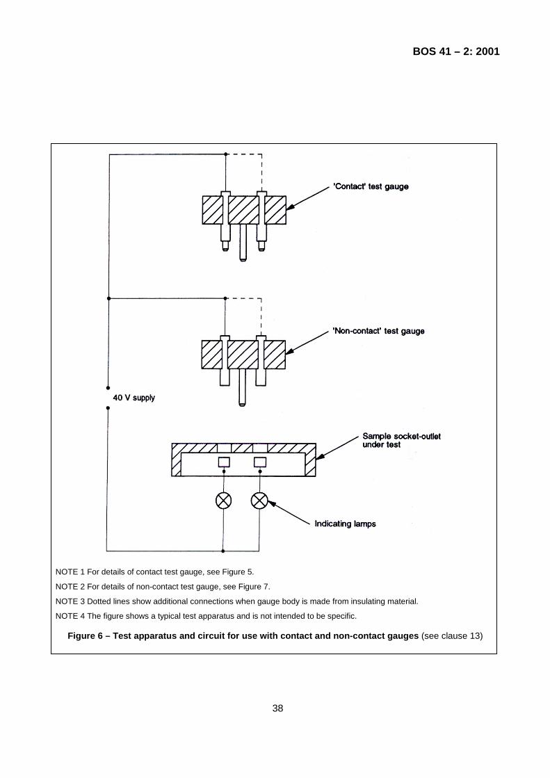
BOS 41 – 2: 2001
NOTE 1 For details of contact test gauge, see Figure 5.
NOTE 2 For details of non-contact test gauge, see Figure 7.
NOTE 3 Dotted lines show additional connections when gauge body is made from insulating material.
NOTE 4 The figure shows a typical test apparatus and is not intended to be specific.
Figure 6 – Test apparatus and circuit for use with contact and non-contact gauges (see clause 13)
38

BOS 41 – 2: 2001
All linear dimensions are in millimetres.
NOTE All sharp edges of the chamfered portion and ends of the gauge pins are slightly rounded.
Figure 7 – Non-contact test gauge (see clause 13)
39

BOS 41 – 2: 2001
All linear dimensions are in millimetres.
NOTE The material is of steel.
Figure 8 – Turning moment gauge (see clause 13)
40

BOS 41 – 2: 2001
b) Gauge for line and neutral current-carrying socket contacts.
All linear dimensions are in millimetres.
Figure 9 - Withdrawal pull gauges for effectiveness of contact (see clause 13)
41

BOS 41 – 2: 2001
Linear dimension is in millimetres.
NOTE This drawing is not intended to govern design except as regards the dimensions and specific requirements shown.
Figure 10 – Apparatus for flexing test (see clause 19)
42

BOS 41 – 2: 2001
All dimensions are in millimetres.
NOTE Finish: polished and sharp corners removed.
Figure 11 – Solid link for test on fuse clips (see clause 20)
43

BOS 41 – 2: 2001
All dimensions are in millimetres.
*9 mm nominal plywood having impact face of birch, 1.4 mm nominal thickness and of 5 ply construction.
NOTE 1 This drawing is not intended to govern design except as regards the dimensions and specific requirements shown.
NOTE 2 All dimensions subject to tolerance of ± 3.0 except for material thickness.
Figure 12 – Tumbling barrel (see clause 20)

BOS 41 – 2: 2001
b) Constructional details of striking elements
All linear dimensions are in millimetres. NOTE This drawing is not intended to govern design except as regards the dimensions and specific requirements shown.
Figure 13 – Pendulum impact test (see clause 20)
44
45

BOS 41 – 2: 2001
c) Constructional details of mounting support for test specimens.
All linear dimensions are in millimetres. NOTE This drawing is not intended to govern design except as regards the dimensions and specific requirements shown.
Figure 13 – (Concluded)
46

BOS 41 – 2: 2001
All dimensions are in millimetres.
NOTE This drawing is not intended to govern design except as regards the dimensions and specific requirements shown.
Figure 14 – Arrangements for mechanical strength te st for portable socket-outlets (see clause 20)
47

BOS 41 – 2: 2001
All linear dimensions are in millimetres. NOTE This drawing is not intended to govern design except as regards the dimensions and specific requirements shown.
Figure 15 – Apparatus for pressure test (see clause 22) 48

BOS 41 – 2: 2001
Dimension is in millimetres.
NOTE This drawing is not intended to govern design except as regards the dimensions and specific requirements shown.
Figure 16 – Ball pressure test (see clause 22)
49

BOS 41 – 2: 2001