bOOK OF ABSTRACTS - 13th Multinational Congress on ...
774
0 BOOK OF ABSTRACTS
-
Upload
khangminh22 -
Category
Documents
-
view
1 -
download
0
Transcript of bOOK OF ABSTRACTS - 13th Multinational Congress on ...

13th Multinational Congress on Microscopy
September 24-29, 2017 in Rovinj, Croatia
BOOK OF ABSTRACTS
Editors
Andreja Gajović, Igor Weber, Goran Kovačević, Vida Čadež
Suzana Šegota and Ana Vidoš
Publishers
Ruđer Bošković Institute and Croatian Microscopy Society

13th Multinational Congress on Microscopy: BOOK OF
ABSTRACTS
September 24-29, 2017 in Rovinj, Croatia
Editors: Andreja Gajović, Igor Weber, Goran Kovačević, Vida
Čadež, Suzana Šegota and Ana Vidoš
Publishers: Ruđer Bošković Institute and Croatian Microscopy
Society
Zagreb 2017
ISBN 978-953-7941-19-2

Committees
CONFERENCE CHAIRS
Andreja Gajović, Division of Materials Physics, Ruđer Bošković Institute and Croatian
Microscopy Society
Igor Weber, Division of Molecular Biology, Ruđer Bošković Institute and Croatian Microscopy
Society
INTERNATIONAL ORGANIZING COMMITTEE
Gerd Leitinger, Institute of Cell Biology, Graz, Austria
Michael Stöger-Pollach, Technische Universität Wien, Austria
Jana Nebesarova, Institute of Parasitology, České Budejovice, Czechia
Sašo Šturm, Jožef Stefan Institute, Ljubljana, Slovenia
Rok Kostanjšek, University of Ljubljana, Slovenia
Katalin Solymosi, Eötvös Loránd University, Budapest, Hungary
Mihály Pósfai, University of Pannonia, Egyetem, Hungary
Falcieri Elisabetta, Università degli Studi di Urbino, Italy
Roberto Balboni, National Research Council, Rome, Italy
Dusan Chorvat, International Laser Centre, Bratislava, Slovakia
Serap Arbak, Acibadem University, Istanbul, Turkey
Mehmet Ali Gülgün, Sabanci University, Istanbul, Turkey
Nataša Nestorović, University of Belgrade, Serbia
Dragan Rajnović, University of Novi Sad, Serbia
Andreja Gajović, Ruđer Bošković Institute, Zagreb, Croatia
Igor Weber, Ruđer Bošković Institute, Zagreb, Croatia

LOCAL ORGANIZING COMMITTEE
Vida Čadež, Ruđer Bošković Institute, Zagreb, Croatia
Goran Kovačević, Department of Biology, Faculty of Science, University of Zagreb, Zagreb,
Croatia
Suzana Šegota, Ruđer Bošković Institute, Zagreb, Croatia
Marko Kralj, Institute of Physics, Zagreb, Croatia
Petra Peharec, Department of Biology, Faculty of Science, Zagreb, Croatia
Vesna Babić-Ivančić, Ruđer Bošković Institute, Zagreb, Croatia
Ognjen Milat, Institute of Physics, Zagreb, Croatia
Ana Vidoš, Marketing and Events Coordinator, Ruđer Bošković Institute, Zagreb, Croatia
The Multinational Congress on Microscopy 2017 has been designated an EMS Extension
meeting by the European Microscopy Society.

13th Multinational Congress on Microscopy
September 24-29, 2017 in Rovinj, Croatia
CONTENTS
KEYNOTE LECTURE .............................................................................................................
From Micrometer to Sub-Angstroem Resolution – the Development of the Electron
Microscope ............................................................................................................................. I
EMS SPONSORED PLENARY LECTURES ...........................................................................
Operando and multimodal studies of speciation and activity of Pt catalysts during the
hydrogenation of ethylene ..................................................................................................... II
Coherent diffraction imaging in transmission electron microscopy for atomic resolution
quantitative studies of the matter ........................................................................................... V
PLENARY LECTURES ...........................................................................................................
HRTEM and HRSTEM Investigations of oxide thermoelectric materials ............................. VIII
Developments in cryo-electron tomography for in situ structural biology ............................... XI
Electron tomography and multi-dimensional electron microscopy ....................................... XIII
Nanoparticle interactions with human biological barriers ..................................................... XV
Optical and electrical approaches in astrocyte physiology ................................................. XVII
INSTRUMENTATION ..............................................................................................................
I1: Tomography, 3D Imaging and Image Processing, Phase-Related Techniques
(including holography, vortex beams, Bessel beams etc.) .............................................
INVITED LECTURES I1: ............................................................................................. 1
Tayloring the phase of electron probes for selective EELS experiments ................................ 1
Holography with low-energy electrons: a tool for single molecule structural biology .............. 4

ORAL PRESENTATIONS I1: ....................................................................................... 6
Surface plasmon tomography ................................................................................................ 6
Electron phase modulation with topologically patterned electrostatic mirrors ........................10
Electron Vortices in Solids: From Crystalline to Amorphous Materials ..................................12
Measuring band gaps of semiconductors by off-axis EELS with Bessel aperture .................14
POSTER PRESENTATIONS I1: ................................................................................ 16
Electron tomography in the Scanning Electron Microscope for the investigation of biological
and inorganic samples ..........................................................................................................16
Project „Pattern“ – an online tool for spatial analysis of immunolabeling in electron
microscopy. ..........................................................................................................................20
Selective imaging of the Cu-sublattice in the complex Cu2-xSe crystal structure ..................23
Toward direct electron microscopy of nanomaterials in living systems .................................26
A micro computed tomography quantitative study of tumor microvasculature changes after
PhotoBioModulation therapy.................................................................................................27
Optical Vortex Scanning Microscope - Imaging Procedures .................................................30
I2. In situ and Environmental Microscopy (including cryo-microscopy, heating, low-
vacuum etc.) ..................................................................................................................
INVITED LECTURES I2: ........................................................................................... 33
Vizualizing Catalysts in Action ..............................................................................................33
In situ observation of nucleation processes in solution by TEM ............................................36
ORAL PRESENTATIONS I2: ..................................................................................... 38
A combined in-operando approach for low-energy scanning transmission electron
microscopy and grazing incident small angle X-ray scattering ..............................................38
Temperature Dependent Dynamics and Structure of Atomic Clusters in 3D by High Speed
STEM ...................................................................................................................................41
In situ electrochemical deposition of Fe in a liquid TEM cell .................................................45
In situ tracking the structural and chemical evolution of nanostructured materials ................47
POSTER PRESENTATIONS I2: ................................................................................ 49

Thermal vs. beam induced dynamics in the TEM: in situ experiments and simulation ..........49
Precipitation mechanism and kinetics in the Al-Mn-Be-Cu alloy ............................................52
Structural dynamics of copper and platinum substrates during redox reactions studied by in
situ SEM ...............................................................................................................................54
In situ experiments in the ESEM – What can they tell us about the microstructure and
behavior of polymeric microfiltration membranes? ................................................................56
Nanoworld of acrobatic crystals – thermosalient effect (example of Scopolamine bromide) .62
In vivo study of diatom assemblages using low temperature method for ESEM ...................64
I3. Correlative Microscopy and other Imaging Modalities (including AFM, STM etc.) ....
INVITED LECTURES I3: ........................................................................................... 67
Microscopic and spectroscopic characterization of epitaxial graphene and transition metal
dichalcogenides ....................................................................................................................67
Simultaneous STM/AFM imaging of oxide surfaces ..............................................................69
Nanoscale thermal microscopy and spectroscopy of dissipation in quantum systems ..........70
ORAL PRESENTATIONS I3: ..................................................................................... 71
Correlative multiscale tomography for additive manufacturing of biomedical components ....71
Plasma FIB and microCT for Multi-scale 3D Pore Information in Battery Cathode Material ..75
POSTER PRESENTATIONS I3: ................................................................................ 76
Scanning tunneling microscopy and spectroscopy of thin films of strontium ruthenates ........76
Preservation of the moss Physcomitrella patens for electron and light microscopy in
correlation with element analysis ..........................................................................................78
Localization of nanodiamonds inside cancer cells using cathodoluminescence imaging in the
cryo-SEM .............................................................................................................................80
Ex vivo microangioCT and light microscopy: new correlative approach for the vasculature-
focused studies ....................................................................................................................83
True tapping mode Scanning Near-Field Optical Microscopy with bent glass fiber-made
probes ..................................................................................................................................86
I4. Light and Electron Optics, Super-Resolution Microscopy .........................................

INVITED LECTURES I4: ........................................................................................... 87
Reinke's crystal: the mystery still remains ............................................................................87
Stimulated emission depletion (STED) nanoscopy of astrocytic vesicles ..............................90
ORAL PRESENTATIONS I4: ..................................................................................... 93
Gaussian probes and highly efficient diffractive phase masks: new achievements in
holographic electron beam shaping ......................................................................................93
Sprague-Dawley rat (Rattus norvegicus) and European sea bass (Dicentrarchus labrax) as
models for pathology of third stage Anisakis spp. larvae ......................................................96
POSTER PRESENTATIONS I4: ................................................................................ 98
Colored micrographs significantly outperform grayscale ones in modern machine learning:
Insights from a systematical analysis of lithium-ion battery micrographs using convolutional
neural networks ....................................................................................................................98
I5. Specimen Preparation Techniques ...........................................................................
INVITED LECTURES I5: ......................................................................................... 101
Effects of different sample preparation techniques of W-based composite for plasma-facing
materials on electron microscopy characterization ............................................................. 101
Overcoming the sample preparation hurdle for cryo-electron tomography .......................... 104
ORAL PRESENTATIONS I5: ................................................................................... 106
Automatized freeze substitution under agitation: opportunities for studies of intracellular
mesostructures ................................................................................................................... 106
A modified method to avoid loss of calcium mineral constituents during preparation of
mineralized tissues for light and electron microscopy ......................................................... 109
Formaldehyde-induced membrane blebbing during fixation - a major risk for loosing cellular
proteins. ............................................................................................................................. 111
Advancement of broad and focused low energy ion milling procedures for the optimization of
high resolution TEM samples ............................................................................................. 112
POSTER PRESENTATIONS I5: .............................................................................. 114
Improving scanning capacitance microscopy by specimen preparation .............................. 114

Immunogold labelling of allergens at fine dust filter particles for SEM investigations .......... 117
Short freeze substitution under agitation: brevity is the soul of wit ...................................... 119
I6. Advances in Instrumentation and Techniques (including aberration correction, low
voltage SEM & TEM etc.) ..............................................................................................
INVITED LECTURES I6: ......................................................................................... 121
Universal pressure scanning electron microscopy (UPSEM) - electron microscopy up to
atmospheric pressure ......................................................................................................... 121
Towards atomic-scale studies of nucleation and growth of matter by in situ (scanning)
transmission electron microscopy ....................................................................................... 124
ORAL PRESENTATIONS I6: ................................................................................... 126
Measuring the orbital angular momentum spectrum of an electron beam ........................... 126
EELS experiments influenced by the CMR effect ............................................................... 129
Superfast scintillators for SEM electron detectors ............................................................... 131
A Micro-combinatorial method for an efficient TEM study of binary films ............................ 134
POSTER PRESENTATIONS I6: .............................................................................. 136
Novel high vacuum heating for in situ experiments in FIB/SEM systems ............................ 136
STEM modes in SEM – simulations and experiments ......................................................... 139
New approaches for reducing charging effects– TESCAN S8000....................................... 141
Application of compressive sensing to multi-energy serial block-face SEM ........................ 143
I7. Electron Spectroscopy, Diffraction and Analytical Microscopy .................................
INVITED LECTURES I7: ......................................................................................... 145
Application of Concentric Electron Probe (CEP) method for accurate quantitative chemical
analysis of interfaces on a sub-nanometer scale ................................................................ 145
PICO – application of chromatic aberration correction in materials science ........................ 147
ORAL PRESENTATIONS I7: ................................................................................... 149

Electron diffraction rietveld analysis of nanocrystals ensemble ........................................... 149
How sample holder geometries influence the quantification of X-ray spectra ...................... 152
Examination of strain evolution during micropillar compression with HR-EBSD .................. 155
Spectroscopic investigation of the electronic structure phase diagram of yttria-stabilized
zirconia in an electron microscope...................................................................................... 157
POSTER PRESENTATIONS I7: .............................................................................. 160
Atomic-level strain response of amorphous TiAl thin film under tension measured by selected
area electron diffraction ...................................................................................................... 160
Electron beam induced radiation explored by CL and EELS ............................................... 164
Thickness and orientation dependence of the average HAADF STEM normalized intensity: a
comparison with Monte Carlo and Multislice simulations. ................................................... 166
LIFE SCIENCES .....................................................................................................................
L1. Live Cell Imaging and Intracellular Dynamics ..........................................................
INVITED LECTURES L1: ........................................................................................ 169
Imaging neurotransmitter receptor dynamics in the brain at the nanoscale ......................... 169
Dynamics of the Golgi apparatus during dis- and reorganizations, visualized by 3D-electron
tomography ........................................................................................................................ 171
ORAL PRESENTATIONS L1: .................................................................................. 174
Ras proteins regulate actin assembly at endocytic structures via Diaphanous-related formin
G ........................................................................................................................................ 174
Effect of intracytoplasmic morphologically selected sperm injection (IMSI) imaging system on
intracytoplasmic sperm injection outcomes ......................................................................... 178
Imaging via multimode optical fiber: calibration by internal reference ................................. 180
Biosensor based real-time single cell monitoring using microfluidics that generate spatial and
temporal dynamic stimulation ............................................................................................. 182
POSTER PRESENTATIONS L1: ............................................................................. 185
The role of exercise in tenocyte activation at myotendinous junction level .......................... 185
Cell damage induced by asbestos-like fibers ...................................................................... 187

Ex vivo investigation of hemoglobin distribution in erythrocytes using two photon excitation
microscopy: insight from an animal erythrocyte .................................................................. 190
CLEM and FIB for studing organisation of Golgi apparatus in urothelium ........................... 193
Custodiol versus blood cardioplegia; comparision of myocardial tissue effects in adult cardiac
surgery ............................................................................................................................... 196
NDPK A and NDPK B – subcellular dynamics and interactions .......................................... 199
Novel colchicine-BODIPY conjugates for phototherapy ...................................................... 200
Nucleoside-diphosphate kinase Nme6 in humans and sponges ......................................... 202
Injection molded microfluidic device for providing dynamic stimuli ...................................... 204
L2. High-Resolution Microscopy in Biological Sciences ................................................
INVITED LECTURES L2: ........................................................................................ 207
Combining light sheet microscopy and optical projection tomography to visualize protein
dynamics ............................................................................................................................ 207
In vitro handling of oocyte for fertility preservation. Recent ultrastructural acquisitions ....... 215
ORAL PRESENTATIONS L2: .................................................................................. 216
Ultrastructural analysis of umbilical cord derived MSCs at undifferentiated stage and during
osteogenic and adipogenic differentiation ........................................................................... 216
Microscopic evaluation of the enamel surface after debonding procedures: an ex-vivo study
using scanning electron microscopy (SEM) ........................................................................ 218
Super resolution, multiphoton and light sheet microscopy for evaluation of two-dimensional
and three-dimensional implantation models ........................................................................ 220
High resolution visualisation of iron deposits in the human brain in health and disease ...... 223
POSTER PRESENTATIONS L2: ............................................................................. 225
Melatonin ameliorates mitochondrial status in leptin-deficient mice heart ........................... 225
Reconstructing the auditory region of Palorchestes azael using micro computed tomography
........................................................................................................................................... 228
Microscopy Centre: Electron Microscopy Core Facility ....................................................... 231
Selenium induces accumulation of lipid droplets in antral follicles of porcine ovaries .......... 233
Hypothyroidism remodels mitochondrial population in rat brown adipocytes: ultrastructural &
stereological study .............................................................................................................. 235
Insulin-induced appearance of bi-hormonal (glucagon+insulin+) cells in rat pancreatic islets:
immunofluorescnet and immunogold studies ...................................................................... 237

L3. Structure and Imaging of Biomolecule .....................................................................
INVITED LECTURES L3: ........................................................................................ 239
Varying label density to probe membrane protein nanoclusters in STORM/PALM .............. 239
Imaging therapeutic efficacy of toxin releasing stem cells in recurrent brain tumor ............. 241
ORAL PRESENTATIONS L3: .................................................................................. 243
Ultrastructural examination of the effects of piezoelectric and strontium methods on oocyte
activation ............................................................................................................................ 243
Healing effect of p-coumaric acid on ethanol induced gastric damage ................................ 246
Marine sponge alkaloid and its chemical derivatives as potential anticancer drugs ............ 248
Comparison of the expression and localization of FoxO3 in normal term and gestational
diabetic placentas ............................................................................................................... 250
POSTER PRESENTATIONS L3: ............................................................................. 252
Modular architecture of Photosystem I-Light Harvesting antenna complex from
eustigmatophyte alga, Nannochloropsis oceanica .............................................................. 252
Putative effect of exercise on liver in high-fat diet-fed rats .................................................. 254
Isolation of the chondrocytes and chondroprogenitor/stem cell from human articular cartilage,
comparison of the chondrogenic capacity of these two cell lines ........................................ 256
The investigation of potential protective effects of tetrandrine against reproductive damage
induced by Aroclor 1254 in male rats .................................................................................. 258
Investigation of the protective effects of tetrandrine in Aroclor1254 exposed liver tissue .... 261
The role of luzindole in the antiinflammatory effect of melatonin in the kidney of the rats with
type 2 diabetes mellitus ...................................................................................................... 263
Assembly of interleukin-2 and -15 receptors during trafficking ............................................ 265
L4. Nanobiology and Nanomedicine ..............................................................................
INVITED LECTURES L4: ........................................................................................ 266
Opportunities and challenges of cancer treatment by SPIONs ........................................... 266
The nano world: strategy for life style improvement ............................................................ 268
ORAL PRESENTATIONS L4: .................................................................................. 270
Nanoparticles as drug delivery system in skeletal muscle disorders: in vitro studies of PLGA
nanoparticles as carriers for pentamidine for the treatment of myotonic dystrophy type 1 .. 270

Atomic Resolution Microscopy-EELS/EDS in combination with ultrastructural localization of
amphiboles in epithelial cell models: a chance to foresee the biological effect of nano/micro-
minerals? ............................................................................................................................ 273
Bacterial growth in the presence of laser produced silver nanoparticles ............................. 276
Role of NSCLC exosomes in osteoclast differentiation ....................................................... 277
POSTER PRESENTATIONS L4: ............................................................................. 279
In vivo and in vitro biodistribution of solid lipid nanoparticles .............................................. 279
Biodistribution of different nanocarriers in murine mioblasts ............................................... 282
Ultrastructural changes in tobacco cells induced by differently coated silver nanoparticles. 285
Nanostructured titanium scaffolds as a biocompatible material for bone regeneration ........ 289
Platelet lysate as a serum replacement for skin cell culture on biomimetic PCL nanofibers 291
Toxicological effects of three differently shaped carbon nanomaterials in Daphnia magna: a
morphological approach ..................................................................................................... 293
L5. Microscopy in Microbiology, Plant and Environmental Sciences .............................
INVITED LECTURES L5: ........................................................................................ 295
Autophagy and heavy metal induced stress in green algae ................................................ 295
Apoplasmic barriers – sensitive stress-responding structures in plants .............................. 297
ORAL PRESENTATIONS L5: .................................................................................. 298
Study of the asbestos bodies and chemical-physical modification of mineral fibres in rat
histological tissues using scanning electron microscopy, and high resolution transmission
electron microscopy ........................................................................................................... 298
FIB-SEM- and TEM-tomography reveal stress induced fusion of mitochondria in different
plant cells ........................................................................................................................... 300
Glandular trichomes and essential oil characteristics of in vitro propagated Micromeria
croatica (Pers.) Schott (Lamiaceae) ................................................................................... 302
Small-angle neutron scattering provides novel and dynamic insight into thylakoid structure
and transmission electron microscopic artefacts ................................................................. 304
POSTER PRESENTATIONS L5: ............................................................................. 307
Peculiar tubuloreticular membrane organization in plastids with secretory function ............ 307

Ecotoxicological effects of sodium metasilicate on green (Hydra viridissima Pallas, 1766) and
brown (Hydra oligactis Pallas, 1766) hydra ......................................................................... 309
The effect of quercetin on brown hydras, endosymbiotic and free-living algae ................... 311
The effect of naringenin on hydra – alga symbiosis ............................................................ 312
Monitoring lipid production in yeast using SEM and Raman spectroscopy.......................... 313
Analysis of pyretrins in extract of Tanacetum cinerariifolium using Raman spectroscopy ... 316
Isolated endosymbiotic algae at test: the point of no return? .............................................. 319
The development of Norway spruce somatic embryos visualized with different microscopic
tools ................................................................................................................................... 320
L6. Neuroscience and Histopathology ...........................................................................
INVITED LECTURES L6: ........................................................................................ 323
Fast 3D imaging of neuronal coding in spine, dendritic, and neuronal assemblies in the visual
cortex of behaving animals ................................................................................................. 323
Proximal association of P/Q-type voltage-gated calcium channels and the vesicle fusion sites
at cerebellar excitatory synapses ....................................................................................... 325
ORAL PRESENTATIONS L6: .................................................................................. 326
The Investigation of STAT3 protein expression changes in rat kidney injury model induced by
puromycin aminonucleoside application ............................................................................. 326
Ultrastructural characterization of chordoma cells .............................................................. 328
Central exogenous apelin-13 and restraint stress stimulates hypothalamic cholecystokinin via
APJ receptor ...................................................................................................................... 330
Placental pathology associated with pesticides exposure in female tea garden workers .... 332
POSTER PRESENTATIONS L6: ............................................................................. 335
A histological analysis of glycogen content in hepatocytes of trefoil factor family 2 and trefoil
factor family 3 knock-out mice ............................................................................................ 335
Growth plate and trabecular bone histomorphometry in wild-type and TFF3 knock-out mice
........................................................................................................................................... 336
Mast cells of the human foetal testis ................................................................................... 338
Effect of resveratrol and metformin on ovarian reserve and ultrastructure in PCOS ........... 340
Reconstructing a looming sensitive pathway in locusts using serial block-face SEM (SBEM)
........................................................................................................................................... 343

Zika virus interaction with astrocytes .................................................................................. 345
Morphometrical evaluation of histopathological alterations in freshwater snail Holandriana
holandrii exposed to phenol ................................................................................................ 347
Spatial organization of peptidergic axon terminals and myoepithelial cells in salivary glands
of tick Ixodes ricinus ........................................................................................................... 348
Histological evaluation of granular dystrophy ...................................................................... 350
Therapeutic effect of thymoquinone on amyloid beta-induced neurotoxicity in rats ............. 352
Beta-Site APP Cleaving Enzyme 1 regulation depends on VDR or PDIA3 ......................... 354
Comparison of different cryopreservation protocols for human umbilical cord as source of
mesenchymal stem cells .................................................................................................... 355
The acetamipride, a neonicotinoid insecticide, inhibits cell proliferation and induces apoptosis
on rat testis ......................................................................................................................... 357
Effects of combined treatment of bisphosphonate and melatonin on stomach tissue in rats
with ovariectomy ................................................................................................................. 358
The effects of Trastuzumab and Paclitaxel for metastatic 4T1, MDA-MB231 and MCF-7
breast cancer cell lines ....................................................................................................... 360
GABA immunogold labeling in the substansia nigra pars reticulata of kindled genetic absence
epilepsy rats ....................................................................................................................... 363
L7. Multidisciplinary Approaches in Natural and Biomedical Sciences ..........................
INVITED LECTURES L7: ........................................................................................ 364
Worms under the microscope: how TEM and transcriptomics give us a holistic picture ...... 364
Imaging techniques in connective tissue diseases .............................................................. 367
ORAL PRESENTATIONS L7: .................................................................................. 370
Overwintering-dependent changes in the epithelial cells of Malpighian tubules in the cave
crickets Troglophilus cavicola and T. neglectus (Rhaphidophoridae, Ensifera) ................... 370
Characterization of melanosomes involved in production of non-iridescent structural colors in
bird plumage (Aves) and their detection in fossil record ...................................................... 373
Tunneling membrane nanotubes as communication tool between urinary bladder cancer and
normal urothelial cells: Insights from combination of microscopic techniques ..................... 376
Cytotoxic and apoptotic activity of Prunus spinosa extract on human cancer cells ............. 378
POSTER PRESENTATIONS L7: ............................................................................. 380
A method for measuring area and surface-related parameters on microphotographs by using
free and open-source image processing software .............................................................. 380
Adipogenic effect of mild ozonisation on human adipose-derived adult stem cells .............. 382

New study on metformin action against testicular injury: prostate cancer, diabetes and
diabetes-cancer connection ................................................................................................ 385
The effect of oral administration of shea butter on liver damage caused by
lipopolysaccharide-induced sepsis in rats ........................................................................... 387
Effects of UVB radiation and norflurazon on green and brown hydra .................................. 389
Ultrastructural analysis of in vitro matured granulosa cell under treatment with the fungicide
Mancozeb ........................................................................................................................... 390
Evaluation of tumorogenic proteins in stanozolol treated rat kidney .................................... 392
Spatiotemporal expression pattern of the neuronal markers in the developing human spinal
cord .................................................................................................................................... 396
The effects of pentoxifylline and caffeic acid phenethyl ester in the treatment of D-
galactosamine-induced renal injury in rats .......................................................................... 399
Serial passaging effects the carcinogenicity, semness and speroid formation of HEPG2 cells,
a hepatocellular carcinoma cell line .................................................................................... 401
Collagen scaffold for human mesenchymal stem cells osteogenesis induction ................... 403
Cell-free scaffolds functionalized with bioactive compounds for treatment of bone defects . 405
Daidzein does not fully reverse changes of pituitary castration cells in rat:
immunohistochemical and stereological study .................................................................... 407
The preparation of biological objects for 3D scanning electron microscopy ........................ 409
Ozone treatment induces antioxidant stress response through Keap1/Nrf2 dependent
pathway .............................................................................................................................. 412
Hypothyroidism induces maturation arrest of spermatogenesis in adult rat ......................... 415
Microscopy in urolithiasis research ..................................................................................... 417
The effects of dipeptidyl peptidase-4 inhibitor treatment on liver regeneration in STZ-diabetic
rats ..................................................................................................................................... 419
Harmful effects of dimethyl sulphoxide on WM-266-4 melanoma cell line ........................... 421
Comparison of fiber fabrication techniques in tissue engineering ....................................... 424
Regulation of pancreatic beta cell regeneration by nicotinamide in neonatal streptozotocin
diabetic rats ........................................................................................................................ 425
Evaluation of INSL3 in diabetic testicular tissue by admministered JNK inhibition .............. 427
Effect of royal jelly on apoptosis, proliferation and immunoreactivity of INSL3 in rat diabetic
testes tissue ....................................................................................................................... 429
Fluorescent conjugates of natural products with anticancer potential for imaging and
phototherapy applications ................................................................................................... 431
Postmortem evaluation of wound healing after Descemet membrane endothelial keratoplasty
(DMEK) .............................................................................................................................. 433
The use of microscope in school biology teaching .............................................................. 435

Protective effects of curcumin against methotrexate-induced nephrotoxicity in rats: role of
nuclear factor-kappa B pathway ......................................................................................... 437
MATERIALS ..................................................................................................................
M1: Thin Films, Coatings, Surfaces and Interfaces .......................................................
INVITED LECTURES M1: ....................................................................................... 434
Void formation during solid state dewetting of thin Al films on single crystalline (0001)
oriented Al2O3substrates .................................................................................................... 434
Epitaxial strain in oxide thin films and heterostructures....................................................... 437
ORAL PRESENTATIONS M1: ................................................................................. 439
In situ observation of electron beam induced nanocrystallization of an ultra thin tungsten foil
........................................................................................................................................... 439
Automatic analysis of [110] tilt grain boundaries in III-V zinc-blende semiconductors from
aberration-corrected HAADF-STEM images ....................................................................... 442
Sub-nanometer microanalysis on hematite photoanodes with localized Sn dopants to
enhance photocatalytic water splitting ................................................................................ 445
In situ TEM study of micro/nanoscaled amorphous or nanocrystalline freestanding films
under stress ....................................................................................................................... 448
POSTER PRESENTATIONS M1: ............................................................................ 451
Microscale characterisation of the next-generation of Nb3Sn superconducting thin films for
radio frequency cavity applications ..................................................................................... 451
EM analysis to improve the response of tungsten trioxide as gas sensor: SEM, EBSD and
TEM analyses versus sensors response. ........................................................................... 454
Mechanical properties of magnetron sputtered W-B-C coatings ......................................... 457
Microstructural characterization of TaAlN coatings ............................................................. 460
Comparison of measuring methods for determination of thickness of the multilayer tin/ticn
pacvd coating deposited on cold work tool steel x153crmov12 ........................................... 462
TEM investigation of magnetron sputtered TiC, TiC/Ti, Ti(C) thin films ............................... 463
Barium titanate thin films deposition by spray pyrolysis ...................................................... 466
Electron microscopy of Ti/Ni multilayers prepared by magnetron sputtering ....................... 468

TEM study of basal-plane inversion boundaries in Sn‐Doped ZnO ..................................... 471
Measuring buried interface roughness by electron tomography .......................................... 474
Fabrication and characterization of PMN-PT based high-frequency linear ultrasound array
........................................................................................................................................... 477
Zinc oxide for photovoltaic applications .............................................................................. 478
Study of crystallization process in gexs1-x glasses by microscopic techniques .................. 481
M2. Polymers, Organic and Soft Materials ....................................................................
INVITED LECTURES M2: ....................................................................................... 483
Supramolecular assembly/reassembly processes at surfaces and interfaces ..................... 483
Studying surface-assisted collagen fibrillogenesis by timelapse AFM ................................. 484
Use of AFM for mechanical mapping of nanostructured surfaces ....................................... 486
ORAL PRESENTATIONS M2: ................................................................................. 488
Experimental observation, theoretical modelling and quantification of nanoparticle-induced
polymer crystallization using in situ microscopy .................................................................. 488
Influence of Bismuth oxide nanoparticles on mechanical properties of epoxy resin ............ 491
Polymer fracture – Analysis by 3D reconstructions of the fracture region ........................... 493
Comparison of EDX and EELS sensibility for resolving the morphology of organic solar cells
........................................................................................................................................... 496
POSTER PRESENTATIONS M2: ............................................................................ 498
Laser-scanning confocal fluorescence microscopy using elliptically polarized cylindrical
vector excitation beam: the visualization of arbitrarily oriented single quantum emitters on
planar surfaces ................................................................................................................... 498
M3. Materials in Geology, Mineralogy and Archaeology, Ceramics and Composites ....
INVITED LECTURES M3: ....................................................................................... 500
Oriented rutile exsolutions from ilmenite under controlled oxidation conditions: electron
microscopy study ................................................................................................................ 500
The applications and contexts of microscopy applied to historic building materials ............. 503

ORAL PRESENTATIONS M3: ................................................................................. 505
Formation pathways of alumina particles in supersaturated vapour under micro gravity
conditions ........................................................................................................................... 505
Soil contamination of human dental calculus determined by Energy-dispersive X-ray
spectroscopy ...................................................................................................................... 508
Low thermal treatment optimisation of sol-gel derived composite-coating for multi-purpose
functionality and protection of all-metals ............................................................................. 511
Enhanced photocatalytic properties of the reduced TiO2 nanotubes arrays decorated with Ag
nanoparticles ...................................................................................................................... 513
POSTER PRESENTATIONS M3: ............................................................................ 516
Structural characterization and luminescence properties of Y2MoO6 powders doped with
various rare earth elements (Eu3+, Sm3+, Yb3+/Er3+) ............................................................ 516
Defects in orthorhombic (Mo,V)Ox mixed oxide – from local to extended ........................... 518
Microstructural characteristics of staurolite from mica schist of the Drava depression
basement (Croatia) ............................................................................................................. 520
Scanning electron microscopy – original painting or not? Analysis of the 18th century portrait
color layers ......................................................................................................................... 522
A look into the past: a Focused Ion Beam study of the ultrastructure of fossil plant cuticles
........................................................................................................................................... 524
EBSD study of twins in SnO2-cassiterite ............................................................................. 527
Three-dimensional microstructural evolution during sintering of Ni-SDC cermets for SOFC
anode reconstructed by FIB-SEM nanotomography ........................................................... 529
Occurrence of clinozoisite-epidote minerals in the metamorphic suite and granitic intrusions
of the Dunje area, South Macedonia .................................................................................. 532
The mineralogy and texture of shales from palaeozoic baltic basin (Northern Poland) - data
from SEM/EDS analysis ..................................................................................................... 534
M4. Metals, Alloys and Intermetallics ............................................................................
INVITED LECTURES M4: ....................................................................................... 536
TEM analysis of core-shell and hollow nanospheres .......................................................... 536
FIB/SEM in metallography .................................................................................................. 538
ORAL PRESENTATIONS M4: ................................................................................. 541

Using organic additives to form the defect structure of electrodeposited nanocrystalline Ni 541
Structure determination of a new phase Ni8Ti5 by PEDT .................................................... 543
Observation of the structural transformation of multinary nanoparticles by in situ transmission
electron microscopy ........................................................................................................... 545
The role of Mo on formation and stability of the ordered omega phase in multi-phase TiAl
alloys: experimental and theoretical aspects ...................................................................... 547
POSTER PRESENTATIONS M4: ............................................................................ 549
Microstructure development in as cast Al-Mg-Li alloy ......................................................... 549
Influence of neutron irradiation on the microstructure and magnetic properties of Nb3Sn
superconductors ................................................................................................................. 551
Electron microscopy analysis of flash-annealed CuZr based bulk metallic glass ................ 553
Systematic study of structural changes in the vicinity of indentation marks with HR-EBSD 556
Investigation of domains in Pr2NiO4+delta by transmission electron microscopy .................... 557
Microstructure of rapidly solidified aluminium powder alloys compacted by Spark Plasma
Sintering ............................................................................................................................. 559
On-line monitoring of steel microsturcture changes within tensile testing ........................... 561
Study on the kinetics of the intermediary phase formation in Ni-Al system ......................... 562
Microstructure evolution of AlFe7Mn4 alloy during its preparation by powder metallurgy .... 563
Influence of low temperature on the microstructure and fracture mode of unalloyed ADI
material .............................................................................................................................. 564
Deformation and fracture of copper and silicon during indentation. acoustic emission
measurements.................................................................................................................... 567
Novel stem-edx analysis of radiation-induced precipitates in a self-ion irradiated cold-worked
316 austenitic stainless steel used for pwr baffle-bolts ....................................................... 568
M5. Nanostructures and Materials for Nanotechnology .................................................
INVITED LECTURES M5: ....................................................................................... 571
Multi-Scale observation of red-ox dynamics by in situ scanning and transmission electron
microscopy ......................................................................................................................... 571
Multipurpose cantilever sensors ......................................................................................... 573
ORAL PRESENTATIONS M5: ................................................................................. 575
PtCu3 fuel cell catalyst nanoparticles studied from growth to degradation using transmission
electron microscopy ........................................................................................................... 575

Advanced electron microscopy characterization of silver nanowires for transparent electrode
applications ........................................................................................................................ 577
Manganese oxide based materials as insertion cathodes for Mg-ion batteries ................... 580
Transmission Kikuchi diffraction in SEM; application in various materials system ............... 582
POSTER PRESENTATIONS M5: ............................................................................ 583
Structural characterization of carbon-supported bimetallic aucu nanoparticles derived from
metal vapors ....................................................................................................................... 583
Microscopic study on carbon fibre surface modification for tuning the plasma treatment
parameters ......................................................................................................................... 585
Babinet principle for plasmonic antennas: complementarity and differences ...................... 587
Electron beam effect on the mechanical properties of alumina and silica coated metal
nanowires. .......................................................................................................................... 590
The comparative XRD and SEM analysis of electrochemically produced silver nanostructures
........................................................................................................................................... 592
Role of hydrogen in creating morphology of nanostructured NiCo alloy powder particles ... 595
Synthesis of magnetic α-Fe2O3 -carbon allotropes nanocomposites ................................... 598
Analytical electron microscopy of submicrocrystalline skutterudite with addition of metallic
borides ............................................................................................................................... 600
The role of oxygen non stoichiometry in the CO oxidation activity of BaFeO3- ................... 603
Micro and nanosized 4H-SrMnO3: structural and physical properties.................................. 604
EELS simulations of IrOx catalysts for water splitting ......................................................... 605
EM investigation of DC jet plasma grown Cu-oxide nanowires for amine detection ............ 607
Assemblies of Sub-10 nm nanoparticles - imaged by SEM in impeding conditions ............. 610
Colloidal synthesis of metastable AuCuS phase nanocrystals and in situ TEM heating study
of their transformation......................................................................................................... 613
Imaging zeolite NaA ........................................................................................................... 615
In situ characterization of M@Co3O4 (M = NiFe2O4, ZnFe2O4) core-shell nanoparticles for the
Fischer-Trospch Synthesis ................................................................................................. 616
Examination of 2D crystals in a low voltage SEM/STEM .................................................... 618
Structure, morphology and kinetic analysis of Gd2Ti2O7 nanopowders ............................... 621
Characterization of Nd3+-doped TiO2 nanopowders synthesized by hydrolytic sol-gel method:
structural, morphological and optical properties .................................................................. 623
TiO2 modified by Sm and catechol for photovoltaic use ...................................................... 626

M6. Semiconductor Materials and Devices....................................................................
INVITED LECTURES M6: ....................................................................................... 627
Advanced STEM-EELS characterisation of semiconductor materials beyond the nanoscale
........................................................................................................................................... 627
Atomic-scale characterisation of accumulated charged defects at domain walls in BiFeO3 . 630
ORAL PRESENTATION M6: ................................................................................... 633
Structural analysis of InAs/InP nanowires at atomic scale .................................................. 633
Ferromagnetic manganese germanide thin films characterization by correlation of scanning
electron microscopy, transmission electron microscopy and laser assisted atom probe
tomography ........................................................................................................................ 636
Microscopy of nitride layers with integrated graphene ........................................................ 639
Influence of microstructure of Ag16.7Sb30Te53.3 bulk thermoelectrics on their performance... 642
POSTER PRESENTATIONS M6: ............................................................................ 645
In situ formation of crystallographically-oriented semiconductor nanowire arrays via selective
vaporization for high-performance optoelectronic applications ............................................ 645
TEM study of the as-deposited and annealed Ga2O3 films grown by vapor phase epitaxy .. 648
STEM study of NiSi2/Si interface at inclusion boundaries ................................................... 650
Structural investigation of nanocrystalline ZnO:Al thin films deposited by PLD in RF excited
oxygen atmosphere ............................................................................................................ 652
Structural study of Mg- and Ga-doped ZnO thin films grown by atomic layer deposition ..... 654
TEM study of heterostructures of AlN on epitaxial graphene .............................................. 657
Effects of Li+ co-doping on Eu3+ activated TiO2 anatase nanoparticles ............................... 659
Quantitative analysis of internal interfaces - structural and quantitative analysis via high
resolution STEM ................................................................................................................. 660
Atomically resolved structure of luminescent ZnkIn2O3+k ..................................................... 662
Wide bandgap AlGaN semiconductors: doping and polarity” .............................................. 664
M7. Biomaterials and Biosensors ..................................................................................
INVITED LECTURES M7: ....................................................................................... 665

Biomolecules and living cells monitored by label-free optical waveguide sensors ............... 665
ORAL PRESENTATIONS M7: ................................................................................. 667
Biologically templated synthesis of magnetic filaments ....................................................... 667
The role of chitin in the biomineralization of mollusks and its integration in a PVP-CMC
hydrogel scaffolds as a bone tissue reparation biomaterial ................................................. 670
Surface characterization of porous calcium phosphate architectures and their effect on cell
colonization and metabolic activity...................................................................................... 672
Microscopic analysis of micro-patterning of calcium phosphate bioceramics promoting bone
cells adhesion and proliferation .......................................................................................... 674
Bio-inspired design: beyond materials and structures ......................................................... 676
Atomic force microscopy in conjunction with super-resolution optical microscopy and optical
tweezers ............................................................................................................................. 677
POSTER PRESENTATIONS M7: ............................................................................ 679
Fractographic analysis of biomedical Ti-based alloys with acicular microstructures ............ 679
Structural investigation of waste biomass-derived carbon for bioelectrocatalytic applications
........................................................................................................................................... 681
Electron and neutron diffraction based PDF analysis of bioactive glasses .......................... 683
Novel method of drug delivery system ................................................................................ 685
Microstructure of plasma sprayed bioactive coatings .......................................................... 688
AUTHOR INDEX: .................................................................................................... 702

KEYNOTE LECTURE

I
From Micrometer to Sub-Angstroem Resolution – the Development
of the Electron Microscope
Herald Rose (1)
(1) Ulm University, Albert-Einstein-Allee 11, 89081 Ulm, Germany
Electron microscopy is based on the fundamental discoveries made in 1924 by Louis de
Broglie who postulated that a wave is attributed to each elementary particle and in 1926 by
Hans Busch who showed that the magnetic field of a solenoid acts on electrons in the same
way as a glass lens on the light rays. It had been these two fundamental discoveries which
initiated Ernst Ruska to realize an electron microscope in 1931. Unfortunately, round electron
lenses suffer from large unavoidable aberrations which limit the resolution of any electron
microscope to about 100 wavelengths, as shown by Otto Scherzer in 1936. Fortunately, he
found an ingenious way in 1947 to enable aberration correction by employing non-rotationally
symmetric elements. However, all subsequent experiments to improve the resolution by means
of various correctors failed because the resolution was limited by mechanical and electrical
instabilities rather than by the defects of the electron lenses. Owing to these facts experiments
on aberration were abandoned in the mid 1980th after a group of experts in the US had
concluded that the successful realization of aberration correction was “unthinkable”. As a
result, funding on aberration correction was stopped worldwide. Experimental work on
aberration correction was resumed in 1992 within the context of the “Volkswagen Project”
aimed to improve the resolution limit of a 200 kV transmission electron microscope (TEM) by
eliminating the spherical aberration and the coma of the objective lens by means of a novel
highly symmetric aplanatic hexapole corrector. In addition, an effective alignment procedure
was developed which enables a precise and fast elimination of the spherical aberration and of
all resolution-limiting parasitic aberrations originating from mechanical inaccuracies, magnetic
in homogeneities, and misalignment. By means of these measures the resolution limit of a
commercial 200kV TEM was reduced from 2.1Å (100λ) to 1.4Å in 1997. In the meantime this
limit has been lowered further to about 0.5Å in the frame of the US TEAM project. In April
2016, the SALVE Project ended with spectacular success. Within the frame of this project,
which aimed to obtain atomic resolution of radiation-sensitive objects at low voltages, the
resolution limit has been reduced to 15λ giving sub-Å resolution down to 40kV. First promising
results will be presented

EMS SPONSORED
PLENARY LECTURES

Operando and multimodal studies of speciation and activity of Pt
catalysts during the hydrogenation of ethylene
Eric A. Stach (1,2*), Yuanyuan Li (3), Deyu Liu (5) Shen Zhao (2,5) Jing Liu (3) Yao-Min Liu
(5), Dmitri N. Zakharov (2), Qiyuan Wu (4), Alexander Orlov (4), Andrew A. Gewirth (5) Ralph
G. Nuzzo (5), Anatoly I. Frenkel (3,4)
1) Department of Materials Science and Engineering, University of Pennsylvania,
Philadelphia, PA 19104 *[email protected]
2) Center for Functional Nanomaterials, Brookhaven National Laboratory, Upton, NY 11973
3) Department of Chemistry, Brookhaven National Laboratory, Upton, NY 11793
4) Department of Materials Science and Chemical Engineering, Stony Brook University,
Stony Brook, NY 11794
5) Department of Chemistry, University of Illinois, Urbana, IL 61801
The creation of fuels and large volume chemicals (such as olefins) from crude oil feedstocks
involves the hydrogenation of unsaturated hydrocarbons. These processes involve numerous
catalytic reforming and hydrogenation/dehydrogenation processes, and are generally
mediated by supported metal nanoparticle catalysts. These catalysts are generally chosen for
their high activity, long term stability and the ease with which they can be regenerated and
recovered. However, despite the extensive use of these materials, there are many questions
that remain about how specific attributes of the structure and composition of the catalysts are
affected by the gases with which they interact. Furthermore, it is critically important to
understand how these structural changes affect selectivity, as well as how deactivation occurs
because of the conversion process. In this work, we will describe how we use a multi-modal,
operando experimental approach to understand the subtle changes that occur to both the
atomic structure and the chemical state of palladium nanoparticle catalysts supported on SiO2
during the hydrogenation of ethylene. The core of this approach is the use of a closed-cell
microreactor (1) that allows sequential experimental investigation via scanning transmission
electron microscopy (STEM), x-ray absorption spectroscopy (XAS) and microbeam infrared
spectroscopy (µ-IR), and gas-chromotography/mass spectroscopy (GC-MS), with all
measurements being made in the same operando reaction conditions (2,3). We will describe
how this approach allows us to directly correlate the measurements in a robust fashion, leading
to novel insights regarding several aspects of ethylene conversion. In specific, we will describe

how the specifics of reactive gas composition lead to interconversion of both hydride and
carbide phases of the Pd clusters, which processes affect the stability of the particles against
coarsening, the reversibility of structural and compositional transformations and the role that
surface oligomers that form under hydrogen limited reactant conditions, leading to
deactivation.
Acknowledgements:
The authors gratefully acknowledge support for this by the US Department of Energy, Office of
Basic Energy Sciences under Grant No. DE-FG02-03ER15476. The development of the micro-
cell was supported, in part, by an LDRD grant at Brookhaven National Laboratory. We
acknowledge the facilities support provided at the Centre for Functional Nanomaterials, the
National Synchrotron Light Source at the Brookhaven National Laboratory (US Department of
Energy, Office of Basic Energy Sciences, Contract No. DE-SC0012704) and the Synchrotron
Catalysis Consortium (US Department of Energy, Office of Basic Energy Sciences, Grant No.
DE-SC0012335).
References:
1. Li, Y., D. Zakharov, S. Zhao, R. Tappero, U. Jung, A. Elsen, Ph Baumann, Ralph G. Nuzzo,
E. A. Stach, and A. I. Frenkel. “Complex structural dynamics of nanocatalysts revealed in
Operando conditions by correlated imaging and spectroscopy probes”, Nature Comm. 6, 7583,
2015.
2. Zhao, S., Li, Y., Stavitski, E., Tappero, R., Crowley, S., Castaldi, M.J., Zakharov, D.N.,
Nuzzo, R.G., Frenkel, A.I. and Stach, E.A., “Operando Characterization of Catalysts through
use of a Portable Microreactor”, ChemCatChem, 7(22), pp.3683-3691, 2015
3. Zhao, S., Y. Li, D. Liu, J. Liu, Y.-M. Liu, D.N. Zakharov, Q. Wu, A. Orlov, A.A. Gewirth, E.A.
Stach, R.G. Nuzzo, A.I. Frenkel, in review.

Figure 1. Schematic of the portable microreactor utilized for operando and multimodal studies
which shows both the the probes that we have demonstrated and the information that we can
obtain from each technqiues.

Coherent diffraction imaging in transmission electron microscopy
for atomic resolution quantitative studies of the matter
Elvio Carlino (1), Liberato De Caro (2), Francisco Scattarella (3), Alessandro Colombo (4),
Davide E. Galli (1)
1) Istituto di Microelettronica e Microsistemi, Consiglio Nazionale delle Ricerche (CNR-IMM) -
Sezione di Lecce - Campus Universitario - Via per Monteroni, 73100 Lecce – Italy
2) Istituto di Cristallografia, Consiglio Nazionale delle Ricerche (IC -CNR), via Amendola 122/O
Bari, 70125 Italy
3) Istituto Officina dei Materiali, Consiglio Nazionale delle Ricerche (IOM-TASC-CNR), Strada
Statale 14 km 163.5, 34149 Trieste, Italy
4) Università degli Studi di Milano, via Giovanni Celoria 16, 20133 Milano, Italy
Keywords: TEM, Coherent diffraction imaging, quantitative atomic resolution, data reduction,
phase retrieval algorithms
Coherent electron diffraction imaging (EDI) in the transmission electron microscope (TEM) is
a method to image the sample atomic structure at a resolution not limited by the aberrations
of the electron lenses1. The method can be applied to isolated nano-objects or to extended
objects; in the latter case by using an approach named keyhole electron diffraction imaging
(KEDI)2, which is obtained by confining properly the illumination function on a nanosized area
of an extended specimen. Possible future applications of EDI/KEDI are foreseen in the field of
femtosecond and 3D imaging. EDI is theoretically based on the sampling theorem of Shannon
and requires the acquisition of the diffraction pattern at least at the Nyquist’s frequency1. The
phase of the scattered waves is recovered by using iterative Fast Fourier Transform (FFT)
algorithms that relates information available from the standard HRTEM to that available from
the measured intensities in the diffraction experiment2. The electron diffractions for EDI
requires an extensive data reduction before the application of phasing algorithms and the
presence of eventual diffraction intensity artifacts, due to the experimental limitation related to
the equipment and to the detector, complicate the application of EDI. In addition, the presence
of strong dynamical effects in the electron diffractions can produce results not reliable2
requiring the use of extremely thin TEM samples. Another subtle point is the phasing process,
which is particularly demanding in the case of electron diffraction experiments. This is due to

the complex nature of the electron diffracted waves and to the size of the area to be
reconstructed, which is very close to the size illuminated by the electron probe3. Here we show
the results of our recent research in: -The treatment of the intensity artifacts in the experimental
diffraction pattern;-The handling of the dynamical intensities as always present in the diffraction
pattern of any standard good quality TEM specimen; -The developing of new phasing methods
based on genetic algorithms capable of reconstructing the phase of the scattered waves
starting from random phases and from an HRTEM image with a resolution four times worst
with respect to the resolution achieved in the phase reconstructed image. In figure 1 an
example of KEDI experiments on a specimen of SrTiO3 in [001] zone axis is shown. The
retrieved function is a structural image of the SrTiO3 seen in the [001] zone axis and the
intensity of the projected potential is in agreement with calculations within accuracy, in the
worst case, of 14%. The methods developed for the quantification of EDI/KEDI experiments
are not only methods to improve the resolution of TEM imaging experiments, but represent a
set of tools to maximize the information that can be extracted from coupled HRTEM and
electron diffraction experiments enabling high accuracy and spatial resolution in the
quantitative study of the properties of the matter.
Figure 1. Results of phase reconstructed experimental KEDI data: (a) modulus of the retrieved
scattering function extracted from the relevant experimental HRTEM image; (b) KEDI HRTEM
image of SrTiO3 in [100] zone axis; (c) simulation of the SrTiO3 projected potential in [100]
zone axis and (d) experimental projected potentials extracted from the phased map

References:
1. L. De Caro et al., Nature Nanotech., 5, (2010) 360–365.
2. L. De Caro et al., Acta Cryst. A, 68, (2012) 687–702.
3. A. Colombo et al., Sci. Rep., 7 (2017) 42236–42248

PLENARY LECTURES

VIII
HRTEM and HRSTEM Investigations of oxide thermoelectric
materials
Miran Čeh (1), Sašo Šturm (2), Boštjan Jančar (3), Aleksander Rečnik (2), Nina Daneu (2),
Goran Dražić (4), Marja Jerič (2), Mateja Košir (2), Matej Presečnik (2), Slavko Bernik (2),
Cleva Ow-Yang (5), Mehmet A. Gülgün (5), Johannes de Boor (6)
1) Nanostructured Materials, Jožef Stefan Institute, Ljubljana, Slovenia, Center for Electron
Microscopy, Jožef Stefan Institute, Jamova cesta 39, 1000 Ljubljana, Slovenia
2) Nanostructured Materials, Jožef Stefan Institute, Jamova cesta 39, 1000 Ljubljana, Slovenia
3) Advanced Materials, Jožef Stefan Institute, Jamova cesta 39, 1000 Ljubljana, Slovenia
4) National Institute of Chemistry, Hajdrihova ulica 19, 1000 Ljubljana, Slovenia
5) Sabanci University, Orta Mahalle, Üniversite Caddesi No:27 Tuzla, 34956 İstanbul, Turkey
6) German Aerospace Center, Cologne, Germany
Keywords: thermoelectrics, planar faults, modulated structures, HR (S)TEM
It is known that thermoelectric (TE) properties (i.e. figure of merit, ZT) of oxide-based TE
materials can be improved by introducing planar faults and/or modulated structures into the
matrix material which reduce thermal conductivity via enhanced phonon scattering. In order to
tailor TE properties of materials, it is prerequisite to assess structural and chemical information
of such nanostructures on atomic scale. In our work we used high-resolution electron
microscopy techniques (HRTEM, HRSTEM) accompanied with spectroscopic techniques
(EELS and EDS) to characterize the following planar faults and modulated structures in oxide
based thermoelectric materials: Ruddlesden-Popper (RP) type planar faults (1) in CaO-doped
Sr(Ti,Nb)O3- (STNO), inversion boundaries (IB’s) (2) in ZnOk(In2O3/Al2O3) and modulated
structures in Ca3Co4O9-NaxCoO2+x system (3). All results were obtained in a Jeol 2010F and
in Jeol ARM-200CF with Cs probe corrector. TEM BF imaging of CaO-doped STNO showed
regions with ordered RP faults and regions with a network of random RP planar faults. HAADF
analysis of the perovskite matrix additionally showed that the Nb content on the Ti sites largely
varied from app. X=0.05 to X=0.35 for the STNO compositions with 10 mol% of added CaO.
Furthermore, the concentration of Ca at the RP faults was always higher as compared to the
STNO matrix (Fig. 1). This was attributed to preferential incorporation of smaller Ca ions into
the rock-salt-type structure of the RP faults. Within In2O3-doped ZnO grains pure In monolayers

IX
parallel to the {0001 ZnO lattice planes were readily observed by the HAADF. These basal
inversion boundaries (b-IB) separate domains with different orientation. On the other hand, the
pyramidal IB’s (p-IB) were much easier observed with ADF due to additional strain contrast
caused by In incorporation in these IB’s. When some fraction of In2O3 was replaced by Al2O3,
the EDS spatial difference showed that Al is incorporated into the b-IB’s as well as into p-IB’s
(Fig. 2a,b,c,d). The ADF of the Ca3Co4O9-NaxCoO2+x layered cobaltate system revealed
coherent intergrowth of two structural types within individual grains. The intergrowths are
comprised of the NaxCoO2-type where the CoO2 layers are separated by a layer of Na+ ions
and the Ca3Co4O9-type in which the CoO2 layers are separated by three-layer rock-salt-type
structure consisting of one CoO and two CaO layers. The two structural types are intergrown
through the octahedral CoO2 layer (Fig. 2e,f,g). STEM further revealed that Ca incorporates
between the CoO2 layers of NaxCoO2 structural part of the grain, thus increasing complexity of
interlayer space. Employing EELS we found that differences in local interlayer structure do not
affect the oxidation state of Co within the CoO2 octahedral layers. Finally, TE measurements
of above investigated materials confirmed that the presence of planar faults and/or modulated
structures increased the ZT value.
Figure 1. (a) HRTEM of RP faults in CaO-doped STNO. The inset marks four perovskite unit
cells in between two RP faults. (b,c,d) HAADF STEM images RP faults that run along {001}
perovskite planes. (e) Region of EDS analysis and spatial difference spectrum.

X
Figure 2. (a) HAADF STEM image of In-rich basal IB's. (b) ADF imaging revealing the
pyramidal IB's. (c) Ordered IB's corresponding to (ZnO)5.In2O3 phase. (d) Region of EDS
analysis and spatial difference spectrum. (e) Intergrowth of Ca3Co4O9-NaxCoO2+x layered
cobaltates. (f) NaxCoO2+x structure and (g) Ca3Co4O9 structure.
References:
1. S.N. Ruddlesden, P. Popper, Acta Crystallogr. 11 (1958) 54-55.
2. A. Rečnik et al., J. of the European Ceram. Soc. 27(4) (2007) 1999-2008.
3. D. Vengust et al., Chem. Mater. 25 (2013) 4791-4797.

XI
Developments in cryo-electron tomography for in situ structural
biology
Juergen M. Plitzko
Max Planck Institute of Biochemistry, Department of Molecular Structural Biology
82152 Martinsried, Germany
To chart the landscape of cellular territories at the molecular level, to directly observe
molecules and macromolecular machines and to investigate their location, their
neighbourhood, and their interaction partners, within the cellular context, thus in situ was and
still is the grand vision of cellular tomography. Recent developments and breakthroughs in
instrumentation encompassing novel direct electron detectors, phase plates, and micro-
machining/preparation methods and their combined use for cryo-electron tomography (cryo-
ET) are clearly the basis towards realising this vision. The word tomography derives from the
old Greek tomos (τόμος) - to ‘slice’ or ‘section’, and graphō (γράφω), to ‘write’. The ‘write’ part,
thus the efficient detection of electrons accelerated to 300 keV, had been a real challenge for
the past several decades. Most of the signal was lost on its way through the detector or just
too scattered. Images from the “cameras of yesteryear” can be literally described as a look
through frosted windows, when compared to the latest detector generation. Detecting electrons
directly did enhance the vision enormously by a more than three-fold increase in signal transfer
and the ability to discriminate every incoming electron. However, the ‘slice’ aspect is equally
as important as the ‘write’ part. Electrons do not like a lot of material to interact with and the
attainable resolution in cryo-ET is directly related to the sample thickness. Therefore, thin
samples are mandatory for any high-resolution tomographic study. ‘Slicing’ in the 21st century,
to obtain electron transparent lamellas, can be done gently and in a targeted fashion with the
focused-ion-beam instrument. Originally designed for the quality control of silicon wafers and
for troubleshooting erroneous wiring of their circuits, it was first explored for frozen-hydrated
samples 10 years ago: A fine focused beam of ions ablating material of a cryo-specimen to
make it transparent enough for cryo-ET, while at the same time keeping it frozen hydrated.
That pilot study was the start of further exploration of this methodology for in situ structural
biology. Perhaps it is too early to say that cryo-focused ion beam milling (cryo-FIB) is now the
method of choice for obtaining 150-300 nm thin slices from a wide variety of cell types ranging
from larger bacteria to neuronal primary cultures. However, the method is certainly gaining

XII
momentum and in combination with direct detection and phase-plate assisted tomography, we
are now able to explore the ‘wonders’ of the inner space of cells at molecular detail. But one
has to be aware, only a tiny fraction of the cell’s volume is covered in such a ‘slice’. For a given
mammalian cell, a FIB-ed lamella contains less than 0.1% of the whole cellular volume.
Therefore, it is necessary to find ways of navigating and localising specific features and
structures within this ‘huge’ (at least ‘huge’ from the electron microscopists point of view)
cellular volume. This fact necessitates the introduction of correlative light and electron
microscopy (CLEM) and at best in all three dimensions to guide the FIB milling and thus to
allow us to capture unique and transient structures within these lamellas. Ongoing
developments hold promise for targeting specific cellular structures, even within tissues and
multicellular organisms. The fidelity with which macromolecules can now be visually identified
in cryo-electron tomograms of FIB-ed lamellae is dependent on several factors. Foremost is
assuredly the thickness of the sample, since resolution scales with the thickness, but the
degree of molecular crowding has to be considered as well, since crowding can vary greatly
from one cell type to another (e.g. yeast is denser than algae) and between different regions
within a single cell (e.g. the nucleoplasm is denser than the cytoplasm). Together, a sample’s
thickness and crowding will ultimately determine the level of detail that can be resolved by
cryo-ET. This lecture will present recent work in the field of cryo-electron tomography and in
situ structural biology and highlights technological developments, limitations and their
opportunities. Furthermore, it will give a prospective towards obtaining structural insights from
an in situ context, possibly at atomic resolution.

XIII
Electron tomography and multi-dimensional electron microscopy
Paul A. Midgley
Department of Materials Science and Metallurgy, University of Cambridge, 27 Charles Babbage Road, Cambridge, CB3 0FS, UK.
Since its introduction into materials science, STEM-based electron tomography has become
an almost-routine method to examine the 3D structure of materials at the nanometre level.
There have been significant advances in terms of optimal acquisition strategies (e.g. sub-
sampling and in-painting) and reconstruction algorithms. The adoption of SIRT and more
recently compressed sensing methods has led to greatly improved reconstruction fidelity by
incorporating known (prior) information or comparable fidelity using greatly reduced data sets.
Recently, with the introduction of more efficient spectrometers and cameras, and with a vast
increase in computer power, analytical electron microscopy / tomography has yielded new
quantitative nanoscale information about the crystallography, composition, chemistry and
electric, magnetic and optical properties through the acquisition of ‘multi-dimensional’ data
sets. This has been accomplished by combining different modes of electron microscopy,
exploring real and reciprocal space, energy and time. I will discuss how this is best
implemented, reviewing the state-of-the-art in multi-dimensional microscopy and look forward
to how these techniques might be developed further for automated data collection and
analysis.

XIV
Figure 1. Left: Orthoslices from a reconstructed cobalt phthalocyanine (CoPc)/ZnO nanowire
showing comparable fidelity after random sub-sampling (reduction of dose by a factor of 10)
from Z. Saghi et al (2015) Adv. Str. Chem. Imaging 1:7. Right: Colour composite figure
indicating five surface plasmon modes on a silver nanoparticle, 100nm in size; from O. Nicoletti
et al., Nature 502 (2013) 80.

XV
Nanoparticle interactions with human biological barriers
Eva Roblegg (1)
1) University of Graz, Institute of Pharmaceutical Sciences, Pharmaceutical technology and
Biopharmacy
Keywords: drug delivery, nano-carrier, biological barrier, oral cavity, saliva
Due to scientific advances of the past decade the number of potent drug candidates in
development has increased dramatically. However, new “designer-made” drug molecules are
becoming increasingly complex, and as a consequence they are less soluble in aqueous
media. Moreover, biological candidates, such as proteins and antibodies are prone to
enzymatic degradation and are expected to be inactivated, when exposed to the harsh human
physiological conditions. As a consequence, these substances are mainly administered via the
parenteral route, which is associated with pain and anxiety, leading to poor patient compliance.
To overcome these hurdles, innovative drug delivery systems, which are administered via
alternative non-invasive uptake routes such as the mucosal tissues in the oral cavity are an
interesting approach in this emerging field. Thereby, the use of nano carriers that embed,
protect and transport a drug candidate to the site of action is being intensively researched.
However, the rational design of such systems is still challenging, because of lack of
understanding of the biological processes governing the main barriers that nanoparticles (NP)
encounter during administration. This includes absorption of biomolecules on NP surfaces (i.e.,
formation of a biocorona), colloidal stability and mobility in saliva, cellular uptake mechanisms,
interference with cellular components, and possible adverse effects considering distinct NP
properties with respect to size and surface charge. To fill this knowledge gap, we studied the
architecture, more specifically the pore size distribution of the human salivary network by the
use of freeze fracture TEM. The fluid´s rheology inside of the pores was examined with optical
tweezers and the agglomeration tendency, the protein binding capacity and the mobility of
differently sized and surface-tuned NPs was investigated by dynamic light scattering and
particle tracking analysis. Uptake studies and interference with cell organelles were performed
with standardized in-vitro models and visualized by SEM (1). We showed that the salivary
network facilitates the access of NPs to the underlying oral mucosa in general. However, the
physico-chemical properties of the NPs were found to critically affect the impact of saliva on

XVI
colloidal stability and mobility: Compared with non-functionalized NPs, the mobility of positively
and negatively charged NPs was significantly impaired in saliva, preventing diffusion through
the salivary barrier and uptake into the oral epithelium. Moreover, NP immobilization was
correlated with increased binding of mucoglycoproteins and agglomeration. Particle size
critically affected cellular uptake. Compared to 25 and 50 nm NPs, 200 nm particles showed a
higher uptake rate and penetrated into deeper regions of the epithelium. We found that this
size-dependent uptake is attributed to the specialized structure of the epithelial surface
membrane, which is covered with ridge-like–folds, also referred as microplicae. Thereby,
uptake is driven by thermodynamic driving forces and interparticle repulsion, which are both
reduced for smaller NP sizes (2). To sum up, the tuning of NP properties enables control of the
rates of NPs elemination through swallowing versus NP cell entry in the oral cavity. These
fundamental insights are expected not only to improve the rational design of therapeutic NPs
for intraoral administration but also to enable the objective evaluation of the risks associated
with engineered NPs taken up unintentionally through the mouth.
References:
1. Teubl et al., Eur J Pharm Biopharm. 84(2) (2013) 86-93.
2. Teubl et al., Small.9(3) (2013) 457-66.

XVII
Optical and electrical approaches in astrocyte physiology
Marko Kreft (1,2,3), Maja Potokar (1,2), Matjaž Stenovec (1,2), Marko Muhič (1), Tina Pangršič (1), Mateja Prebil (1), Jernej Jorgačevski (1,2), Nina Vardjan (1,2), Helena
Chowdhury (1,2), Robert Zorec (1,2)
1) Laboratory of Neuroendocrinology-Molecular Cell Physiology, Institute of Pathophysiology,
Faculty of Medicine, University of Ljubljana, Zaloska 4, 1000 Ljubljana, Slovenia
2) Celica Biomedical Center, Tehnološki park 24, 1000 Ljubljana, Slovenia
3) Department of Biology, Biotechnical Faculty, University of Ljubljana, Večna pot 111, 1000
Ljubljana, Slovenia
Astrocytes are increasingly viewed as crucial cells in supporting and integrating the brain
function. An important process of communication between astrocytes and neurons is
exocytotic release of gliotransmitters from astrocitic membrane-bound vesicles into the
extracellular space. Patch-clamp membrane capacitance measurements were used to monitor
changes in membrane area of a single astrocyte while the photolysis of caged calcium
compounds by a UV flash was used to elicit steps in [Ca2+]i to determine the exocytotic
properties of astrocytes. Experiments show that astrocytes exhibit Ca2+-dependent increases
in membrane capacitance. Prior to fusing with the plasma membrane, membrane-bound
vesicles are transported through the cytoplasm. Their trafficking and the consequent release
of their content may be changed in altered physiological conditions, therefore affecting the
physiological status of neurons. The results show that the delivery of vesicles to the plasma
membrane for membrane merger involves an interaction with the cytoskeleton, in particular
microtubules, actin and intermediary filaments. Astrocytes also play a significant role in the
brain energy metabolism. Their anatomical position between blood vessels and neurons
makes them an interface for effective glucose uptake from blood. Astrocytes contain glycogen,
an energy buffer, which can bridge local short term energy requirements in the brain. Glycogen
levels reflect a dynamic equilibrium between glycogen synthesis and glycogenolysis. Many
factors that include hormones and neuropeptides, such as insulin likely modulate glycogen
stores in astrocytes, but detailed mechanisms at the cellular level are sparse. We used a
glucose nanosensor based on Förster resonance energy transfer to monitor cytosolic glucose
concentration with high temporal resolution and a cytochemical approach to determine
glycogen stores in single cells. Following the adrenaline or noradrenaline stimulation the
availability of cytosolic glucose is increased promptly after stimulation. Insulin boosts the
process of glycogen formation. This indicates, that astrocytic cytosolic glucose metabolism
responds to neuronal activity in the time-domain of tens of seconds.

XVIII
INSTRUMENTATION

I1: Tomography, 3D Imaging and Image
Processing, Phase-Related Techniques
(including holography, vortex beams,
Bessel beams etc.)

1
INVITED LECTURES I1:
Tayloring the phase of electron probes for selective EELS
experiments
Johan Verbeeck (1), Giulio Guzzinati (1), Armand Béché (1), Hugo Lourenço-Martins (2),
Jerome Martin (3), Mathieu Kociak (4)
1) University of Antwerp, G.U.433, 2020 Antwerpen, Belgium
2) Université Paris-Sud 11, Orsay Département de Physique
3) Laboratoire de Nanotechnologie et d'Instrumentation Optique, Institut Charles Delaunay -
UMR CNRS 6279, Université de Technologie de Troyes, 12 rue Marie Curie - CS 42060 -
10004 Troyes Cedex - France
4) Laboratoire de Physique des Solides, Université Paris Sud, Bât 510, 91405 Orsay, France
Keywords: EELS, adaptive optics, plasmon, inelastic scattering, phase plate
Electronic spectroscopies are important in the study of localised surface plasmon resonances
(SPRs) of metallic nanostructures, allowing to detect and image the strong spatial variations
in the electrical field of the induced resonances of a single nanostructure. These techniques
do however present some drawbacks when compared to their optical counterparts. While
optical spectroscopies can make use of polarisation to directionally probe the response of a
nanoparticle, an electronic beam can’t discriminate between energy-degenerate eigenmodes
and is also blind to optical activity and dichroism. New developments (e.g. PINEM) have
reduced this gap, without however eliminating the root of the problem: electron spectroscopies
probe the intensity of the plasmon’s field, but are blind to the dynamics of that field. Here we
show how the electrical potential of a SPR inelastically couples to the in-plane phase
modulation of the electron beam. We exploit this in a radically new approach based on the idea
of controlling, through beam shaping methods (1), the wave function of the electronic probe.
By fitting the probe to the plasmonic modes under investigation, it becomes possible to
measure previously inaccessible properties. We theoretically describe this coupling, then
design an experimental setup allowing to selectively detect localised plasmonic excitations that
possess the same symmetry as the electron probe (2). Finally, we experimentally test this by

2
selectively detecting the dipolar mode of a nanorod with a two-lobed probe, which we
successfully generate in a TEM by applying state of the art phase manipulation techniques.
The above demonstrates the power of phase manipulation techniques and the topic will be
cast in the broader perspective of generic phase manipulation and its potential for
breakthrough advances in instrumentation and capabilities in the TEM.
Acknowledgements:
G.G. acknowledges funding from FWO project 42/FA070100/6088 ”Nieuwe eigenschappen in
complexe oxides” and ERC starting grant 278510 VORTEX.
References:
1. G. Guzzinati et al., Ultramicroscopy 151 (2015) 85.
2. G. Guzzinati et al., Nature Communications 8 (2017) 14999.
Figure 1. A schematic representation of the interaction described. A modified electron beam
(a) interacts with the potential of a plasmon resonance (b). This interaction results in partial
inelastic exit wave, whose form depends on both the incident beam, and plasmon potential (c).
This information is then carried to the detection plane where a selection becomes possible (d).

3
Figure 2. A modified electron beam with a 2-lobed profile (a) is used to selectively detect
dipolar modes. Plasmonic nanorods (b) which show clear dipolar and quadrupolar modes (c)
are probed with the modified beam (a) and a normal one, in the position marked with a red
cross (b). The modes are individually detected as shown in (d), also compared with simulations
(dashed line).

4
Holography with low-energy electrons: a tool for single molecule
structural biology
Hans-Werner Fink (1)
1) University of Zurich, Winterthurerstr. 190, CH-8057 Zuerich, Switzerland
Keywords: Imaging single proteins, electron holography
While a remarkable amount of structural detail about proteins has been assembled from
crystallography experiments, a strong desire to obtain such data from just a single molecule
experiment is emerging. So far, none of all known and established mapping techniques using
sufficient short wave-length radiation, be it X-rays or high energy electrons, allow looking at
just one single biological molecule without destroying it shortly after the initiation of the
observation process. Due to this unavoidable radiation damage problem, structural information
can so far only be obtained by averaging over a large number of molecules. In contrast to this,
coherent low energy electrons with deBroglie wavelengths in the Ångstrom regime allow
imaging individual bio-molecules without detectable damage. The challenges to create a well-
defined ensemble of low-energy electrons, capable of directly displaying interference effects
without the need of electron lenses, will be discussed. Applications in view of imaging including
holography and coherent diffraction with low-energy electrons will also be illustrated. Recent
findings, obtained in collaboration between the Max-Planck Institute in Stuttgart and the
University of Zurich, demonstrate that structural biology of single proteins has become possible
by combining protein mass-spectrometry with low-energy electron holography (1).
References:
1. Jean-Nicolas Longchamp, Stephan Rauschenbach, Sabine Abb, Conrad Escher, Tatiana
Latychevskaia, Klaus Kern, Hans-Werner Fink, PNAS (2017), vol. 114, no. 7

5
Figure 1. Top: Schematic setup for holography with low-energy electrons, featuring the
coherent electron point source (EPS), free-standing graphene as sample holder (SH) and a
multi-channel plate (MCP) for recording the holograms. Bottom: Two images of individual BSA
proteins anchored on free-standing graphene. The scale bars correspond to 5nm.

6
ORAL PRESENTATIONS I1:
Surface plasmon tomography
Georg Haberfehlner (1), Anton Hörl (2), Franz P. Schmidt (3), Andreas Trügler (2), Ulrich
Hohenester (2), Gerald Kothleitner (4)
1) Graz Centre for Electron Microscopy, Steyrergasse 17, 8010 Graz, Austria
2) Institute of Physics, University of Graz, Universitätsplatz 5, 8010 Graz, Austria
3) Institute for Electron Microscopy and Nanoanalysis, Graz University of Technology,
Steyrergasse 17, 8010 Graz, Austria & Institute of Physics, University of Graz,
Universitätsplatz 5, 8010 Graz, Austria
4) Institute for Electron Microscopy and Nanoanalysis, Graz University of Technology,
Steyrergasse 17, 8010 Graz, Austria
Keywords: Surface plasmons, Electron tomography, Electron energy-loss spectroscopy,
Photonic local density of states
Plasmonic modes in metal nanostructures induce field localization, strong coupling effects and
high sensor sensitivity, properties that can be expressed by the photonic local density of states
(LDOS). Coupling of metallic nanoparticles is recognized as a method for maximizing the
photonic LDOS in the gap region between separate nanoparticles, but until recently no tool
was available for the direct 3D nanoscale measurement of the photonic LDOS. However, to
exploit the full potential of plasmonics, full 3D characterization and simulation taking into
account the imperfections of real structures become mandatory. Here we present tomography-
based approaches to understanding complex plasmonic nanoparticles created by electron
beam lithography and to access local near-fields around nanoparticles and in gap regions. In
our first approach the precise 3D geometry of a particle dimer fabricated by means of electron
beam lithography was reconstructed through electron tomography. This full 3D morphological
information was used as an input for simulations of energy-loss spectra and plasmon
resonance maps (Figure 1). Here excellent agreement between measured EELS data and
theory was found, bringing the comparison between EELS imaging and simulations to a

7
quantitative and correlative level (2). In our second approach we directly reconstruct particle
plasmon fields from a tomographic tilt series of EELS spectrum images. While first approaches
and demonstrations of plasmon field tomography were limited to very small particles – small
enough to neglect retardation – we lift this limitation with our approach making plasmon field
tomography generally applicable to nanoparticles of all sizes. Formulation EELS tomography
as an inverse problem allows reconstructing the complete dyadic Green tensor for plasmonic
particles, from which the photonic LDOS can be calculated. Using this approach, we are able
to reconstruct the full 3D LDOS for different metallic nanoparticle geometries (Figure 2) and
reveal the strong near-fields in the gap regions of nanoparticle dimers, both in lateral and
vertical arrangements. This work overcomes the need for geometrical assumptions or
symmetry restrictions of the sample in simulations and generalizes plasmon field tomography
to particles of all sizes, paving the way for detailed investigations of realistic and complex
plasmonic nanostructures.
Acknowledgements:
We thank Gernot Schaffernak, Andreas Hohenau and Joachim Krenn for access to and
support with electron beam lithography and helpful discussion. This research has received
funding from the European Union within the 7th Framework Program [FP7/2007-2013] under
Grant Agreement no. 312483 (ESTEEM2). We acknowledge support by the Austrian Science
Fund FWF under project P27299-N27, the SFB F49 NextLite, and NAWI Graz.
References:
1. G. Haberfehlner et al., Nano Lett. 15: 7726–7730 (2015)
2. A. Hörl, G. Haberfehlner et al., Nat. Commun., accepted (2017)

8
Figure 1. Tomographically reconstructed morphology of coupled nanocuboids and simulated
and experimental EELS spectra and plasmon resonance maps. Simulations are based on the
reconstructed 3D model of the nanocuboids. Colored locations in the inset indicate regions
from which the spectra were extracted (1).

9
Figure 2. Photonic local density of states (LDOS) for a (a) dipolar and (b) quadrupolar mode
on a silver nanocuboid and (c) bonding plasmon mode on coupled silver nanodisks
reconstructed from tilt series of EELS spectrum images. The orientation of the markers
indicates the direction along which the LDOS is maximal, the color represents the magnitude
of the LDOS (2).

10
Electron phase modulation with topologically patterned
electrostatic mirrors
Maurice A.R. Krielaart (1), Pieter Kruit (1), Navid Abedzadeh (2), Chung-Soo Kim (2),
Richard G. Hobbs (2), Karl K. Berggren (2)
1) Department of Imaging Physics, Delft University of Technology, Lorentzweg 1, 2628CJ
Delft, The Netherlands
2) Department of Electrical Engineering and Computer Science, Massachusetts Institute of
Technology, 77 Massachusetts Ave., Cambridge, MA 02139
Keywords: Electron beam shaping, Phase manipulation, Electron mirror
Electron beam shaping involves the controlled manipulation of either amplitude or phase of the
electron wave. A variety of methodologies exist for this purpose. For instance, Zernike phase
plates are used for phase contrast microscopy (1) and other holographic reconstructed phase
plates allow the creation of electron vortex beams (2). All these methods work in a transmission
mode and although proven methods, these techniques do share common practical difficulties,
being sensitive to local thickness variations, charging effects and inelastic scattering events
(3). To circumvent these issues, we suggest a topologically patterned electrostatic mirror that
is used to manipulate the relative phase of the incident electron wave. An electron mirror avoids
the above-mentioned practical complications, as the electron reflects in front of the physical
mirror structure, thus avoiding charging, surface roughness and undesired scattering effects.
Using focused ion beam lithography, a grating-like structure is created with pitch and amplitude
of (sub)micrometre order. This grating mirror is used in a proof of principle experiment (figure
1) where it is expected that phase modulation due to the mirror pattern will induce diffraction
in the reflected beam. When this reflected beam is used to image a holey carbon sample
(positioned inside the specimen chamber of a conventional SEM) the diffraction is expected to
produce fringes near the edges of the holes inside the sample. The analysis of the grating
effect is based initially on applying the WKB approximation along the electron trajectories in
front of the mirror. Next, a more rigorous description of the pattern effect is obtained by solving
the time-independent Schrodinger equation in the region just before the reflection point, where

11
the equipotential landscape is sinusoidal. These studies support the expectation that a
patterned electrostatic mirror can be used as a diffractive element for electron microscopy.
Future applications of patterned electrostatic mirrors include use as coherent beam splitter in
the scheme of a quantum electron microscope (3) or correcting for chromatic and spherical
aberrations.
References:
1. F. Zernike, Physica, 9 (1942), p. 686.
2. J. Verbeeck, H. Tian and P. Schattschneider, Nature 467 (2010).
3. P. Kruit, R.G. Hobbs, C-S. Kim, Y. Yang, V.R. Manfrinato, J. Hammer, S. Thomas, P. Weber,
B. Klopfer, C. Kohstall, T. Juffmann, M.A. Kasevich, P. Hommelhoff, K.K. Berggren,
Ultramicroscopy 164 (2016).
Figure 1. Image formation principle of the grating mirror. On hole-locations, the beam is
collimated to the mirror plane below. The reflected (black) and diffracted (red, green) beams
are focused back onto the sample, creating fringes around the edges.

12
Electron Vortices in Solids: From Crystalline to Amorphous
Materials
Stefan Löffler (1), Stefan Sack (2), Thomas Schachinger (2)
1) Universitäre Service-Einrichtung für Transmissionselektronenmikroskopie (USTEM) Vienna
University of Technology / E052, Wiedner Hauptstraße 8-10 / 052, A-1040 Wien, Austria
2) Vienna University of Technology, Wiedner Hauptstrasse 8 -10,1040 Wien, Austria
Keywords: vortices, propagation, orbital angular momentum, multislice
Electron vortex beams (EVBs) are fundamental solutions to the free-space Schrödinger
equation in cylindrical coordinates. Their peculiar properties, such as their orbital angular
momentum (OAM) and the associated magnetic moment, make them a very interesting novel
tool for nanoanalysis. Actual and predicted applications include nanomanipulation, energy-loss
magnetic chiral dichroism (EMCD) measurements, and spectroscopy with ultimate energy
resolution. Here, we investigate how vortices behave in a non-isotropic environment such as
inside a crystalline or amorphous sample. The breaking of the rotational symmetry leads to
superpositions of and scattering between different vortex orders, thus leading to a broadening
of the OAM distribution. In some cases, such as nanomanipulation, the associated exchange
of OAM between the beam and the sample is vital. In other cases, such as EMCD, this is an
artifact that can severely distort the outcome of measurements or even prohibit their analysis.
To elucidate the influence of elastic scattering, we use the theoretical framework of the
multislice formalism. With it, dynamic scattering effects can be described in a general manner
and can also be compared to numerical simulations. For crystalline materials, it is well-known
that depending on the experimental geometry, the average OAM can oscillate drastically
throughout the sample, but can also be protected by channeling along atomic columns (1). In
amorphous materials, we find that the average OAM remains approximately unaffected over a
significant thickness range (see Figure 1). Here, an incident m=1 beam was used. Of more
practical relevance than the average OAM is the intensity of the m=1 component itself. This is
found to decrease due to scattering to other vortex orders, but the m=1 component still remains
dominant for a large range of thicknesses. It is noteworthy that the specific behavior depends

13
on both the atomic weight of the scatterer and the size of the EVB. These results are also
combined with inelastic simulations to calculate the (defocus-dependent) EMCD effect when
using EVBs. Vortex-EMCD has the unique benefit over classical EMCD that the sample does
not need to act as a beam splitter. Therefore, vortex-EMCD is directly applicable to amorphous
materials. Hence, it is clear that understanding the scattering behavior of EVBs is not only
required for analyzing experimental data, but also paves the way for the development and
efficient use of novel, emerging techniques for nanoanalysis.
Acknowledgements:
The authors acknowledge financial support by the FWF (J3732-N27, I543-N20)
References:
1. S. Löffler et al., Acta. Cryst. A 68 (2012) 443.
Figure 1. Thickness dependence of the average OAM (top) and the intensities of individual
vortex components (middle), together with the intensity histogram at 100 nm (bottom) as
simulated for amorphous Si with an incident m=1 EVB with 20 mrad convergence semi-angle.

14
Measuring band gaps of semiconductors by off-axis EELS with
Bessel aperture
Svetlana Korneychuk (1), Giulio Guzzinati (1), Rajesh Ramaneti (2), Paulius Pobedinskas
(2), Joff Derluyn (3), Ken Haenen (2), Johan Verbeeck (1)
1) Electron Microscopy for Material Science (EMAT), University of Antwerp, 2020 Antwerp,
Belgium
2) Institute for Materials Research (IMO), Hasselt University, 3590 Diepenbeek, Belgium,
IMOMEC, IMEC vzw, 3590, Diepenbeek, Belgium
3) EpiGaN NV, 3500, Hasselt, Belgium
Keywords: band gaps, bessel beams
The possibility to locally measure band gaps of materials in TEM appeared with the invention
of the monocromator for electron energy loss spectroscopy (EELS). Despite this the technique
hasn’t become conventional for band gap measurements due to unwanted losses such as
Cherenkov radiation emission which has an impact on low loss spectra and complicates the
retrieval of the band gap signal1. Nevertheless, several approaches to measure the band gap
were demonstrated 2,3. among which decreasing the acceleration voltage of the microscope
and avoiding the retardation losses by off-axis acquisition. Based on previous experience in
band gap measurement with EELS we attempt to improve this method in order to make it more
feasible and accessible. In this work we demonstrate the off-axis acquisition technique
highlighting its application for STEM mode. This method originates from the assumption that
all undesirable losses take place in a certain narrow range of angles and can be avoided by
measuring off-axis. Its effectiveness can be shown by simulations using the Kröger formula
which allows to calculate the energy losses of fast electrons in thin foils with retardation starting
from the dielectric properties. We minimize the impact of undesirable losses by selecting the
retardation-free part of the outcoming signal using an annular (Bessel) aperture. The obtained
band gap values are in good agreement with the conventional optical measurements, with a
much improved spatial resolution.

15
Acknowledgements:
S.K. and J.V. acknowledge funding from the “Geconcentreerde Onderzoekacties” (GOA)
project “Solarpaint” of the University of Antwerp. P.P. acknowledges Postdoctoral Fellowship
of the Research Foundation Flanders (FWO).
References:
1. Erni R., Ultramicroscopy 160 (2016) 80-83.
2. Stöger-Pollach M. et al., Ultramicroscopy 173 (2017) 24–30.
3. Zhang L. et al., Phys. Rev. B 77 (2008), 195119.
Figure 1. (a) ADF-STEM image of semiconductor heterostructure including diamond layer and
(b) low loss EELS spectra demonstrating band gap onsets for every layer. (c) Simulation of
low loss electron scattering for diamond at 60 kV for Bessel aperture and STEM mode based
on Kröger formula.

16
POSTER PRESENTATIONS I1:
Electron tomography in the Scanning Electron Microscope for the
investigation of biological and inorganic samples
Maurizio Donarelli (1), Matteo Ferroni (2), Vittorio Morandi (3), A. Migliori (3), Luca Ortolani
(3), Luca Masini (3), ChandraKanth Reddy Chandraiahgari (4), Giovanni De Bellis (4), Maria
Sabrina Sarto (4)
1) Department of Information Engineering, University of Brescia, Via Branze 38, 25123 Brescia
(Italy)
2) Department of Information Engineering, University of Brescia, Via Branze 38, 25123 Brescia
(Italy) & CNR-Microelectronic and Microsystems Institute, Via Gobetti 101, 40129 Bologna
(Italy)
3) CNR-Microelectronic and Microsystems Institute, Via Gobetti 101, 40129 Bologna (Italy)
4) Department of Astronautics, Electrical and Energetics Engineering, Sapienza University of
Rome, via Eudossiana 18, Rome 00184 (Italy) & Research Center for Nanotechnology Applied
to Engineering of Sapienza (CNIS), SNNLab, Sapienza University of Rome, Piazzale Aldo
Moro 5, 00185 Rome (Italy)
Keywords: STEM, tomography, compressed sensing
The recent advances in the fabrication of hybrid nanostructures for application in micro and
nanoelectronics and the need to explore biological samples call for a three dimensional
investigation of the constituents and their spatial disposition at nanometric resolution. For the
purpose, Scanning-Transmission imaging in the SEM (STEM) is a already established
implementation of the SEM platform, and when implemented with a rotating sample holder, it
offers the capability of a tomographic reconstruction of the sample. In this paper, we report on
the application of SEM tomography to a graphene-nanorods hybrid system and to a biological
sample of dermal tissue. Graphene flakes have been fabricated by solvo-thermal exfoliation
method and ZnO nanorods (NR) have been grown in-situ by aqueous hydrothermal method

17
(1). A graphene-NR hybrid system can be fabricated by dispersing the NR through the
graphene flakes or promoting the nucleation of NR directly over graphene.
Samples, transparent to the electron beam, are prepared on a standard TEM grid and are
mounted on a rotating sample holder. The in-house designed and fabricated detector, formed
by four annular and concentric sections, is mounted on a separate support. The activation of
specific sectors of the detector enables to obtain bright field (BF) or dark field (DF) images.
The STEM signal, collected by the detector, is based on the intensity of the forward scattered
electrons and the mass-thickness contrast should vary monotically when the sample is rotated
in order to obtain images at different tilt angles. This requirement is fundamental for the
tomographic reconstruction of the specimen from the STEM projection images taken at
different tilt angles (2). A DF STEM image of the graphene ZnO hybrid system is reported in
Figure 1, left. The brightest areas are related to the ZnO nanorods, which are heavier than the
surrounding graphene flake, which is the bright area. The beam acceleration voltage was 27
KV. The DF projection images series has been recorded by tilting the sample between -60°
and +50°, at 2° steps. After the alignment of the projection images with a cross correlation
algorithm, the 56 projection images series has been reconstructed. The tomogram has been
obtained by a standard retroprojection and followed by iterative refining. The resulting
tomogram is reported in Figure 1, right. The aim of the 3D reconstruction is to achieve a
tomogram without artifacts, allowing a quantitative description of the investigated sample.
However, some ET limitations due to the geometry of the experimental setup, like a restricted
angular range (“missing wedge”), hinder the achievement of this goal. Furthermore, in
particular for biological samples, the electron beam exposure can damage the sample itself,
so a limited number of projections can be recorded without damaging the specimen. Here we
report the use of compressed sensing (CS) for the reconstruction of a human dermal tissue
(3). The experimental setup is basically the same reported for the graphene-NR hybrid
structure investigation. The sample has been tilted in order to obtain a series of projection
images in DF STEM mode. The projection images have been aligned and nine of them are
reported in Figure 2, top (the tilt angle is reported in each panel). The collagen bundle, which
is the region of interest for the reconstruction, is reconstructed and refined by CS, and reported
in Figure 2, bottom. The CS-reconstruction compares positively with the one obtained by
ordered-subset simultaneous algebraic technique (OS-ART), implemented in popular
reconstruction softwares (TomoJ). The OS-ART based reconstructions are strictly related with
the number of projection images, with a loss of resolution with a decreasing number of
projections. On the other hand, the CS refinement allows to reconstruct a tomogram from a

18
relatively low number of projections, without a significant loss of information. Therefore, it is a
promising approach for the reconstruction of tomograms, limiting the artifacts due to the
missing wedge and the low number of projection images. Furthermore, the CS reconstruction
approach opens the possibility to perform ET on beam-sensitive samples and to reduce the
acquisition times.
In conclusion, ET in SEM platform is a viable technique to perform 3D analysis and
investigation of material science and biological samples. CS approach enables to reconstruct
the specimens using a low number of projection images, limiting the artifacts due to the
geometry of the ET setup, and reducing the acquisition times.
References:
1. C. R. Chandraiahgari et al., RSC Adv. 86 (2016) p. 83217.
2. M. Ferroni et al., J. Phys.: Conf. Ser. 644 (2015) 012012.
3. M. Ferroni et al., Scientific Reports 6 (2016) p. 33354.
Figure 1. Left: STEM image of the graphene-NR in dark-field condition. Right: The
reconstructed tomogram.

19
Figure 2: Top: DF STEM images of the collagene bundle. Bottom: CS based reconstruction of
the sample.

20
Project „Pattern“ – an online tool for spatial analysis of
immunolabeling in electron microscopy.
Dominik Pinkas (1), Vlada Philimonenko (1), Jiří Janáček (2), J. Novák (3), Marcel Jiřina (4),
Pavel Hozák (4)
1) Institute of Molecular Genetics ASCR v.v.i., Microscopy Center, Electron Microscopy Core
Facility, Vídeňská 1083, 142 20 Prague 4, Czech Republic
2) Institute of Molecular Genetics ASCR v.v.i., Department of Biology of the Cell Nucleus,
Vídeňská 1083, 142 20 Prague 4, Czech Republic
3) Institute of Physiology ASCR v.v.i., Department of Biomathematics, Vídeňská 1083
142 20, Prague, Czech Republic
4) Czech Technical University in Prague, Faculty of Information technology, Department of
Theoretical Computer Science, Prague, Czech Republic
Keywords: transmission electron microscopy, image analysis, immunolabeling, colocalization
In biological research, the term „colocalization“ is usually used in the context of fluorescence
microscopy. However, the character of analyzed data such as signal leakage from different
channels, signal originating from other focal planes and low resolution as well as subjective
thresholding may lead to erroneous conclusions. On the other hand, immunolabeling in
electron microscopy can be used to detect structures and molecules with much higher
precision than even novel super-resolution techniques while sharing common principles with
fluorescence immunolabeling. So far, the evaluation of such images was often subject to
similar woes, lacking unbiased quantitative approach despite higher resolution provided by
EM. We are developing an easy-to-use online tool for semi-automatic multi-stage analysis of
immunolabeling on EM images spanning particle detection and classification, mathematical
and statistical evaluation and visualization of results that builds on previous work of A. A.
Philimonenko et al. (1) and C. Schofer et al. (2). Multiple types of common simultaneous
labelling should be recognizable automatically, while custom particles of irregular shapes
would have to be localized semi-manually. Spatial relations will be analyzable in 2-dimensional
and 3-dimensional microscopic data and along linear structures such as membranes and

21
filaments. Clustering and colocalization of particles will be evaluated by pair correlation (Figure
1) and pair cross-correlation functions with results presented both numerically and graphically.
Labelled structures will be visualized via mapping (Figure 2) and their spatial relations to other
structures or particles will be further evaluated as shown by V. V. Philimonenko et al. (3).
Statistical significance of detected patterns will be calculated and presented to the user without
the need for deep insight into statistical analysis. This online tool will be provided by the
Institute Molecular Genetics of Czech Academy of Science to the broad scientific community
in open access mode within the Czech-BioImaging research infrastructure. The tool will
emphasize understandability of the interface and results and will provide detailed explanations
of all steps values and options. The platform will be modular and can be expanded with more
capabilities in the future.
Acknowledgements:
This project is supported by MEYS CR (LM2015062), OPVVV
(CZ.02.1.01/0.0/16_013/0001775), IMG grant (RVO: 68378050) and TACR (TE01020118)
grants.
References:
1. Philimonenko, A. A., Janáček J. and Hozák P. "Statistical evaluation of colocalization
patterns in immunogold labeling experiments." Journal of structural biology 132.3 (2000): 201-
210.
2. Schöfer, C., Janáček, J., Weipoltshammer, K., Pourani, J., & Hozák, P. (2004). Mapping of
cellular compartments based on ultrastructural immunogold labeling. Journal of structural
biology, 147(2), 128-135.
3. Philimonenko, V. V., Philimonenko, A. A., Šloufová, I., Hrubý, M., Novotný, F., Halbhuber,
Z., ... & Hozák, P. (2014). Simultaneous detection of multiple targets for ultrastructural
immunocytochemistry. Histochemistry and cell biology, 141(3), 229-239.

22
Figure 1. Pair corelation function representing clustering of DNA polymerase α. For distances
in which the function value exceeds 1, density of particles is higher than that of random
distribution. A. A. Philimonenko et al. (1).
Figure 2 Example of graphic representation of mapping of five different immunolabeled
antigens. Scale bar 1 µm. V. V. Philimonenko et al. (3).

23
Selective imaging of the Cu-sublattice in the complex Cu2-xSe
crystal structure
Ognjen Milat (1), Nazif Demoli (1)
1) Institute of Physics, Bijenicka 46, HR1000 Zagreb, Croatia
Keywords: electron diffraction, selective imaging
Imaging of crystal structure in high resolution electron microscopy (HREM) depends not only
on observation parameters such as aperture, defocus, objective lens aberration, or the energy
loss spectral window, but also on the crystal thickness and even more, on its crystallographic
orientation. By computer control in variation of each of these parameters and image acquisition
and processing, a new approaches to digital holographic electron microscopy can be
envisaged. In the case of composite crystals such as the Cu2-xSe with two or more
subsystems(1), these substructures can be selectively imaged and resolved by observing the
projected structure of the same area of crystal along a number of crystallographic
orientation(2). This method was termed “oblique zone imaging”(2) and applied here for the
selective imaging of an exotic, and still disputed(3) arrangement of the Cu-atoms and vacancies
in the Cu2-x-layers of complex structure of the monoclinic room temperature (RT) Cu2-xSe
phase(1,3). Regardless of its simple chemical formula, the RT-Cu2-xSe phase exhibits complex
ordering in a kind of layered structure (1). This ordering mainly takes place within the Cu2-x-
layers via phase transition during cooling from the high temperature (HT) superionic phase
(1,3). Namely, the superionic mobility in the HT-Cu2-xSe phase is supported by a disordered,
“liquid-like sublattice” of Cu-cations within a rigid Se-sublattice usually termed “imobile cage”.
At room temperature, the Se atom arrangement retains the symmetry of the slightly distorted
HT-Cu2-xSe phase; a form of face centred cubic lattice slightly elongated along one of the [111]
diagonal axis (1,3). This is revealed in electron diffraction patterns (EDPs), as well as in the
HREM imaging, as represented in Figure1. In the basic sections of the reciprocal space, the
weak superlattice spots are present together with the sublattice ones as it is shown for the
EDPs in left panels of Figure 1(a,b). Along the “oblique” zone (with at least two indices different,
and non equal zero), as in Figure 1(c), the separated superlattice weak spots fill one or more

24
additional rows between the basic spot rows. Such an “oblique” reciprocal section contains
one or more rows of exclusively superlattice spots corresponding to resolvable spacing, while
the rows of basic sublattice spots are at such a large reciprocal distance that the corresponding
sublattice spacing is below the point resolution of the microscope, Figure 1(c). Along such an
oblique zone the image reveals mainly the structural features due to the superlattice; the partial
structure of the basic sublattice is unresolved in the background. This method is shown to be
especially applicable to the HREM study of RT-Cu2-xSe lamellar structures built on Se-layers
and Cu1-x-layers in which the superlattice formation is due to Se-lattice elongation along one
of the layer stacking directions accompanied by alternating displacements of subset of Cu-
atoms (1,3). In such a case, imaging along principal zone axis, (perpendicular to the [111]c
layer stacking direction), as in Figure 1(a,b), is heavily affected by the arrangement of bright
and dark dots representing the average structure; a slight brightness variation, which becomes
more prominent in thicker area reveals mainly the geometry of superlattice nodes in which the
structural details have to be resolved by image simulation. In the other hand, imaging along
the “oblique” zone axis, Figure1(c), reveals the main feature selectively of the RT-Cu2-xSe
superstructure: the displacement of the Cu-atoms out of each Cu1-x-layers along the [111]c and
the perpendicular <202>c directions of the basic cubic lattice (1,3). Structure information
obtained here by “oblique zone imaging” of the RT-Cu2-xSe composite crystal will be further
approached in terms and methodology of electron tomography and digital holographic
microscopy (4).Electron diffraction patterns of RT-Cu2-xSe along three crystallographic
directions are presented in Figure 1. (left panels), with the corresponding structure projection
images (right panels). Zone axis are labelled in the fcc notation of the Se-sublattice. Rows of
spots which contain basic reflections are marked with arrows, while the arrowheads at the top
indicate reciprocal rows that consist exclusively of the superlattice spots. Both types of spots
are present in (a), as they are revealed in the right panel; no superlattice spots out of basic
rows in (b) indicate the same lateral periodicity of both subsystems, while only the superlattice
spots which are observed out of the central rows in (c), and consequently only the Cu-atoms
with lateral spacing 0.23 nm is selectively imaged in the right panel; the Se-sublattice
periodicity (0.08 nm) is out of the resolution range.
Acknowledgements:
This study is partially supported by Croatian Science Foundation (project: IP-2014-09-7515).

25
References:
1. Z. Vucic, O. Milat, V. Horvatic and Z. Ogorelec, Phys. Rev. B24 (1981), 5397.
2. S. Amelinckx, O. Milat and G. Van Tendeloo, Ultramicroscopy 51 (1993), 90.
3. S.L. White, P. Banerjee, P.K. Jain, Nature Com. (2017) 8:14514.
4. P.A. Midgley, R.E. Dunin-Borkowski, Nature Materials 8, 271 - 280 (2009).
Figure 1. Electron diffraction patterns of RT-Cu2-xSe along three crystallographic directions
(left panels) with the corresponding structure projection images (right panels). Zone axis are
labelled in the fcc notation of the Se-sublattice.

26
Toward direct electron microscopy of nanomaterials in living
systems
Domagoj Belić (1), Oihane Fragueiro (1), Dina Salah (2), Martin Volk (1), Mathias Brust (1)
1) University of Liverpool, Liverpool L69 3BX, United Kingdom
2) Ain Shams University, Khalifa El-Maamon St, 11566 Cairo, Egypt
Keywords: ESEM, Wet STEM, live cell imaging, gold nanorod
We use environmental scanning (transmission) electron microscopy in Wet STEM and ESEM
mode to directly visualize the uptake of PEG-COOH or TAT-peptide functionalized Au
nanorods into whole, as-cultured, fully hydrated mammalian stem cells, without any additional
chemical or physical (pre)treatment. By carefully setting the experimental conditions within the
environmental electron microscope, we examine nanorod-containing cells in near-native state,
down to resolution of individual nanorods. We outline the pros and cons of these direct
methods for straightforward imaging of nanomaterials in soft hydrated biological matrices,
comparing them with the standard fixation-staining-sectioning protocol and more advanced
cryo-EM and liquid-cell TEM approaches.
Figure 1. Wet STEM (a,b) and ESEM (c,d) images of uptake of TAT-peptide functionalized Au
nanorods into a fully hydrated, as-cultured mammalian stem cell grown directly on a TEM grid
(for Wet STEM) or glass slide (for ESEM).

27
A micro computed tomography quantitative study of tumor
microvasculature changes after PhotoBioModulation therapy
Davide Porrelli (1), Simone Vodret (2), Katia Rupel (1), Luisa Zupin (1), Giulia Ottaviani (1),
Jacopo Dus (1), Matteo Biasotto (1), Gianluca Turco (1), Serena Zacchigna (2)
1) Department of Medicine, Surgery and Health Sciences, University of Trieste, Trieste, Italy
2) Cardiovascular Biology Laboratory, International Centre for Genetic Engineering and
Biotechnology (ICGEB), Trieste, Italy
Keywords: micro-computed tomography, tumor vascularization, PhotoBioModulation, cancer
therapy,
We exploited micro computed tomography (μ-CT) to assess the effect of PhotoBioModulation
(PBM) on the vascular network of tumors. Tumor tissues usually present altered
vascularization, with a vessel diameter distribution different from normal tissues and vast
necrotic regions. These abnormal vessels importantly limit an efficient delivery of
chemotherapeutic drugs to cancer cells and vessel normalization is emerging as a novel,
promising strategy to improve drug penetration into tumors and thus the efficacy of
chemotherapy in various solid cancers (1). PBM is a form of light therapy that utilizes non-
ionizing forms of light sources, including lasers, LEDs, and broadband light, in the visible and
near infrared spectrum to impact on clinically relevant biological processes, including wound
healing, bone remodeling and repair, pain control and the immune system (2). We have
recently shown that PBM can be exploited to inhibit tumor progression and that this anti-cancer
effect is associated to the appearance of more mature and regular tumor vessels, as assessed
by histological analysis (3). Here, we wish to obtain further and more comprehensive insights
on the structural modifications induced by PBM on experimental tumors in mice. Tumors were
induced in C57BL/6 mice by dorsal sub-cutaneous injection of melanoma cell line (B16F10)
and half of the mice were irradiated by the most effective PBM protocols able to inhibit tumor
growth (3). Tumor-bearing mice were perfused with Microfil, a silicone injection compound
used to fill and opacify microvascular spaces, thus providing x-ray contrast to the vascular
network. From every animal, we harvested both the tumor mass and the kidneys, used as an
intra-animal controls for μ-CT image acquisition. Images were used for three-dimensional

28
reconstruction and analysis using two different software, Amira and ImageJ, which allowed to
define the border of the samples and to quantify the extent of both the vascular and avascular
regions using the maximal sphere algorithm. This analysis provides a quantitative assessment
of tissue vascularization, vessel diameter distribution and the volume of avascularized areas.
We confirmed that the vascularization of tumor samples is very different from the one of normal
tissues, exhibiting a broader distribution of vessel diameter and larger avascular spaces. Our
preliminary data show that PBM is able to normalize the tumor vasculature, resulting in vessel
diameter distribution more similar to healthy tissue and in a reduction of avascular, necrotic
areas. These data support the feasibility of a μ-CT-based imaging approach to evaluate the
structure of tumor-associated vascular networks and to evaluate the efficacy of anti-angiogenic
therapies in animal models of cancer. In addition, the same approach could be used to evaluate
the efficacy of pro-angiogenic therapies in inducing the formation of new blood vessels in
ischemic tissues.
References:
1. R.K. Jain et al. 307 (2005) 5706-58.
2. V. Kathuria et al., Laser Ther. 24 (2015) 3-215.
3. G. Ottaviani et al., EBioMedicine 11 (2016) 165.

29
Figure 1. 3D rendering of the reconstruction of a kidney tomography. The microvasculature
and the complete perfusion of the kidney by the Microfil, can be appreciated.
Figure 2. 3D rendering of the reconstruction of a tumor tomography. The tumor has not been
treated with PBM therapy. Vast avascularized regions can be appreciated.

30
Optical Vortex Scanning Microscope - Imaging Procedures
Agnieszka Popiołek-Masajada (1), Jan Masajada (1)
1) Department of Optics and Photonics, Wroclaw University of Science and Technology,
Wybrzeże Wyspiańskiego 27, 50370 Wrocław, Poland
Keywords: optical vortex, phase singularity, microscope
The optical vortex scanning microscope (OVSM) uses the focused vortex beam to scan a
sample. The schematic view of our system is presented in Figure1: the laser beam (Gaussian
beam) passes through the spiral phase plate (vortex lens) and is focused on the sample plane,
where it interacts with the investigated object. The vortex lens introduces an optical vortex into
the incoming laser beam. The sample plane is imaged into the CCD camera. The
interferometer’s reference arm enables detection of the interference fringes, from which the
internal structure of the object beam can be recovered. The recorded interferograms are
preceded using the carrier frequency technique which was described in paper (1). In this way
the phase and amplitude distribution of the recorded image was reconstructed. The important
part of the OVSM metrology procedures is the internal scanning method (ISM). ISM (2) is
realized by moving the vortex lens perpendicularly to the direction of the incident laser beam.
In this method the sample needs to be scanned just by an optical vortex, while the entire
focused beam stays in a place. The intriguing properties of the ISM were discussed in the
papers (2,3,4). It supports the precise method for finding the optimal position of the object
plane. In the papers (5,6) the analytical model of the OVSM basic optical system was
presented (Figure 1). The model was calculated with the Fresnel diffraction integral in scalar
approximation. The model supported the first working image recovery procedures. In Figure
(2) the image of the phase square reconstructed with the OVSM is shown. The ISM method
can be also used for object characterization. In this presentation the following aspects of the
OVSM will be discussed: The general idea of the imaging with a focused vortex beam; -
Currently available topography reconstruction methods and its limitations. The exemplary
images will be also shown; - possible applications both current and in the near features; -The
most important problems to be solved for the OVSM development.

31
References:
1. J. Masajada, I. Augustyniak and A. Popiołek-Masajada, “Optical vortex dynamics induced
by vortex lens shift – optical system error analysis,” J. Opt. 15, 044031 (2013).
2. I. Augustyniak, A. Popiołek-Masajada, J. Masajada, and S. Drobczyński, “New scanning
technique for the optical vortex microscope,” Appl. Opt. 51(10), C117-C124 (2012). 3. A.
Popiołek-Masajada, B. Sokolenko, I. Augustyniak, J. Masajada, A. Kohoroshun, and M. Bacia,”
Optical vortex scanning in an aperture limited system,” Opt. Lasers in Eng. 55(), 105-112
(2014).
4. J. Masajada, I. Augustyniak and A. Popiołek-Masajada, “Optical vortex dynamics induced
by vortex lens shift – optical system error analysis,” J. Opt. 15, 044031 (2013).
5. Ł. Plociniczak, A. Popiołek-Masajada, M. Szatkowski, and D. Wojnowski, “Transformation
of the vortex beam in the optical vortex scanning microscope,” Opt. Las. Technol. 81, 127-136
(2016)
6. Ł. Plociniczak, A. Popiołek-Masajada, J. Masajada, and M. Szatkowski, “Analytical model
of the optical vortex microscope,” Appl. Opt. 55(12), B20-B27 (2016).
Figure 1. Optical scheme of the OVSM.

32
Figure 2. The figures
are rescaled by system magnification (160x).

33
I2. In situ and Environmental
Microscopy (including cryo-
microscopy, heating, low-vacuum
etc.)

33
INVITED LECTURES I2:
Vizualizing Catalysts in Action
Christian D. Damsgaard (1)
1) Center for Electron Nanoscopy, Technical University of Denmark, DK-2800 Kgs. Lyngby,
Denmark and Department of Physics, Technical University of Denmark, DK-2800 Kgs. Lyngby,
Denmark
Keywords: Catalysis, Environmental TEM, in situ characterization, methanol synthesis, soot
oxidation
The rate of catalyzed chemical reactions is in general very dependent on the actual state and
geometry of the catalysts surface. This state and geometry are very often dependent on the
actual chemical environment the solid-state catalyst is exposed to. Electron microscopy in
general and transmission electron microscopy (TEM) in particular gives unmatched detailed
insight of the local chemical and structural state of the nanostructured catalysts. Adding the
possibility of controlling the gaseous atmosphere around the studied sample at elevated
temperature gives a unique way of watching catalysts in action. This work includes examples
of how the Environmental TEM (ETEM) complements characterization of catalysts during
catalyst formation and under reaction conditions. Ga-Pd alloys have recently been investigated
for several catalytic reactions including hydrogenation of acetylene, steam reforming of
methanol and methanol synthesis from CO2/H2(1). In this example, the focus is on the
characterization of the GaPd2 nanoparticles during catalyst formation, methanol synthesis and
rapid ageing. ETEM investigations (electron diffraction patterns and images) show that
nanoparticle size and dispersion are defined upon calcination with no significant changes
observed after reduction and methanol synthesis. The Pd2Ga phase is formed during
reduction and the catalyst does not change phase during methanol synthesis and rapid ageing
experiments. Figure 1 shows an ETEM image of a GaPd2 NP along the [100] zone axis
acquired at 550C in 120 Pa H2. These observations are supported by complimentary

34
characterization methods such as in situ XRD, In situ EXAFS, IL-TEM, and STEM-EDX. Soot
particles in the exhaust from diesel vehicles are likely to cause lung cancer and to affect the
climate both locally and globally. Soot particles are therefore typically removed from exhaust
gases by filtration through a ceramic filter. However, increased fuel consumption due to filter
regeneration demands development of soot oxidation catalysts that can lower the regeneration
temperature. The heterogeneously catalyzed soot oxidation is a gas/solid/solid interaction;
hence, the contact between soot and catalyst is very important for the catalytic activity. In this
example, soot oxidation by a silver catalyst is monitored in situ in the ETEM by ramping the
temperature in 300 Pa oxygen at identical rates as used in complementary temperature
programmed oxidation experiments (2). Small Ag particles are observed to be highly mobile at
an oxidation temperature of approx. 350˚C. The Ag particles travel throughout the soot partly
oxidizing the carbon structures. A full oxidation of the soot is observed when the temperature
reaches 700˚C. Snapshots of the in situ temperature programmed soot oxidation are shown in
Figure 2. In conclusion, this work shows examples of how the ETEM is used in combination
with other techniques to elucidate, study, and relate performance and local structure of
catalysts.
References:
1. E. M. Fiordaliso, I. Sharafutdinov, H. W. P. Carvalho, J.-D. Grunwaldt, T. W. Hansen, I.
Chorkendorff, J. B. Wagner, C. Damsgaard, ACS Catal. 5(2015), 5827–5836.
2. D. Gardini, J. M. Christensen, C. D. Damsgaard, A. D. Jensen, J. B. Wagner, Appl. Catal. B
Environ. 183(2016), 28–36.

35
Figure 1. ETEM image of GaPd2 NP acquired at 550°C in 120 Pa H2(1).
Figure 2. BF-TEM micrographs of in situ soot oxidation by a silver catalyst in the ETEM in tight
contact condition. P(O2)=300 Pa(2).

36
In situ observation of nucleation processes in solution by TEM
Yuki Kimura (1)
1) Hokkaido University, Hokkaido University, Kita 8, Nishi 5, Kita-ku, Sapporo, Hokkaido,
060-0808 Japan
Keywords: Nucleation, nanoparticles, liquid cell, in situ observation, protein
How atoms or molecules (called growth units) coagulate, arrange and stabilize into a crystal
from their mother phase (solution or vapor)? In the classical view, this crystallization process
is simple; single growth unit attaches to a n-mer to be a (n+1)-mer, which process progresses
sequentially from a formation of dimer by attachment of two growth units. This process,
however, is not in one-way at the beginning of crystallization; growth unit detaches and comes
back into a mother phase because of energetic disadvantage for creation of new surface.
Increasing the surface energy makes a potential barrier and inhibits a nucleation, which is
formation of a seed of its final crystal. Some amount of a driving force
(supersaturation/supercoiling) is demanded for nucleation. If a seed of a crystal successfully
overcome a potential barrier, the seed, called critical nucleus, grows continuously to its crystal
in one-way. The size of the critical nucleus is determined depending on the strength of the
driving force. Despite the simple picture, we cannot explain an actual nucleation process even
in a considerably most simple case. For instance, it has been well known that nucleation rates
obtained by classical nucleation theory are several orders of different from that obtained by
experiments and by molecular dynamics simulation. The large difference implies existence of
unknown nucleation pathways. To explain the actual nucleation process, several advanced
nucleation pathways have been proposed; nucleation via metastable phase, which is able to
nucleate at first and then transformed into a final stable crystal by dissolution and precipitation
or solid-solid phase transition; nucleation of a crystal inside a pre-nucleated amorphous or
dense-liquid particle; and aggregation of precursor particles. The non-classical pathway for
nucleation is a hot topic in a field of crystal growth in recent years. Development of an
innovative tool for transmission electron microscope (TEM), liquid cell, allows us to observe a
nanoscale phenomenon in a water solution, and gives us a chance to find a direct evidence of

37
a nucleation pathway. The liquid cell also enables to observe hydrated organic materials under
TEM (Figure 1). Here, we will report our resent results using a lysozyme protein (1), which
has a very large size (~3 nm) and, therefore, has been used extensively for the study of
crystallization. Nucleation rates of the lysozyme crystal in an experiment are also difficult to
explain using a nucleation model and are ten orders smaller than that of theoretical estimation
based on thermodynamics (2). Although two step nucleation process via dense liquid phase
has been proposed as the nucleation mechanism (2), this process only works in limited
experimental condition. Based on a direct observation of the nucleation phenomena in solution
using a TEM, we approach to the actual pathway for nucleation of lysozyme and will tackle to
the universality of the mechanisms.
References:
1. T. Yamazaki, Y. Kimura, et al., Proceedings of the National Academy of Sciences of the
United States of America 114 (2017) 2154-2159.
2. P. G. Vekilov, Crystal Growth & Design, 10 (2010) 5007–5019.
Figure 1. Typical TEM image of a lysozyme protein crystal observed in a water solution using
a liquid cell with a spacer of 500 nm in thick. The TEM of Hitachi H-8100 with a tungsten
filament was operated with an accelerating voltage of 200 keV.

38
ORAL PRESENTATIONS I2:
A combined in-operando approach for low-energy scanning
transmission electron microscopy and grazing incident small angle
X-ray scattering
Simone Dal Zilio (1), Marc Salleras (2), Lluis Balcells (3), Jaume Esteve (2), Allison P. Young
(4), Chia-Kuang Tsung (4), Paolo Scardi (5), Benedetta Marmiroli (6), Heintz Amenitsch (6),
Regina Ciancio (1)
1) CNR-IOM TASC, Area Science Park, Basovizza S.S. 14 Km 163.5, 34149 Trieste, Italy.
2) IMB-CNM (CSIC), Campus UAB, E-08193 Bellaterra, Spain
3) ICMAB-CSIC, Campus UAB, E-08193 Bellaterra, Spain
4) Boston College, Merkert Chemistry Center, Department of Chemistry, 2609 Beacon St.,
Chestnut Hill, Massachusetts 02467, USA
5) University of Trento, Department of Civil, Environmental & Mechanical Engineering, via
Mesiano 77, Trento 38123, Italy
6) Institute of Inorganic Chemistry, Graz University of Technology, Stremayrgasse 9/IV, Graz,
Austria and Austrian SAXS Beamline at ELETTRA,
Keywords: stem, in operando, saxs, multifunctional microreactor
The study of dynamic gas-solid interactions by probing the evolution of electronic, structural,
and chemical properties of nanostructured materials under reaction conditions is a crucial
issue to determine their structure-functionality relationships. A relevant example is represented
by hetereogeneous catalysts whose properties change dramatically with respect to the
environment. The common agreement is the need of different lengh scales information and, to
this aim, the smart comobination of multiple acquisistion techniques. Much of effort has been
made lately in designing new instruments and adapting existing ones to investigate catalysts
under operando conditions. Another approach has been the use of micro- or nanoreactors that
separate the high-pressure volume from the (ultra)high vacuum part via ultrathin walls of an

39
inert material. Very recently, microreactor cells have been developed to integrate the
capabilities of ensemble-averaging synchrotron techniques with local probe ones as TEM to
analyze the same catalytic process with different instruments (1,2). Despite the great power of
this method, the extremely small probing size of TEMs restricts the application of a combined
approach to a limited set of micro-focused synchrotron techniques. We propose here the
development of a novel multifunctional microreactor for operando low voltage Scanning TEM
in a SEM compatible with a broad range of synchrotron techniques. Low voltage STEM/SEM
has indeed a series of advantages connected, in the first place, to the use of reduced electron
energy (not more than 30kV). In addition, the high flexibility of the SEM chamber allows
designing larger microreactors which can be adapted to many synchrotron techniques. The
microreactor (sketch in Figure1) is a sealed chamber consisting of two facing SiN semi-
transparent windows allowing transmission of both electrons and X-rays. It allows operation at
atmospheric pressure, in presence of reactive gases and at elevated temperatures. The device
is designed to be compatible with Grazing Incident Small Angle X-ray Scattering (GISAXS)
and Wide-Angle X-ray Scattering (GIWAXS) where extended beam footprint (about 1x10 mm2)
and small penetration of the beam are involved due to the grazing incidence geometry. The
entire fabrication protocol has been designed to ensure optimal electron transparency for
STEM imaging and to preserve the mechanical resistance of the membranes for GISAXS
experiments. We successfully demonstrated the feasibility of our approach by studying the
stability, shape and size evolution of PVP-capped Pd nanocrystals under oxidation/reaction
conditions. Information on size, morphology of the nanocrystals obtained at the nanoscale by
STEM (Figure2a and 2b) have been coupled with that concerning their collective behaviour
over extended areas such as size, aggregation and cristalline structure by GISAXS/GIWAXS
(Figure2c and 3d), all in one portable microreactor and under identical reaction conditions.
References:
1. J.F. Creemer et al. Ultramicroscopy (2008), 108, 993– 998.
2. Shen Zhao et al.Chem. Cat. Chem. (2015), 7, 3683 – 3691.

40
Figure 1. Sketch of the proposed reactor: (left) the holder, designed for STEM and SAXS
measures, hosts the cell where the nanoparticles are inserted. Detail (right) of the SiN nitride
windows chip with micrometric thinned windows.
Figure 2. SAXS Intensity- scattering vector curves related to experimental cycle d in Figure5.
For clarity, only few curves are reported: the initial one, the one after the end of the heating
ramp under oxygen flow, and the one at the end of cooling ramp done in Oxygen rich
atmosphere. (b) WAXS data for the same curves

41
Temperature Dependent Dynamics and Structure of Atomic
Clusters in 3D by High Speed STEM
Trond Henninen (1), Marta D. Rossell (2), Rolf Erni (2)
1) EmpaElectron Microscopy Center, Empa, Swiss Federal Laboratories for Materials Science
and Technology, CH-8600 Dübendorf, Switzerland
2) Electron Microscopy Center, Empa, Swiss Federal Laboratories for Materials Science and
Technology, CH-8600 Dübendorf, Switzerland
Keywords: STEM, atomic cluster, in situ heating, 3D, high speed dynamics
The formation of solid matter is typically modelled by classical nucleation theory, assuming the
solid forms a spherical nucleus. However, during the initial phase at sub-nm, non-spherical
atomic clusters form with atomic structures deviating from bulk crystal. Thus understanding the
dynamics of this regime requires considering individual atoms. Understanding this initial cluster
formation, enables improved control of nanomaterial fabrication and potentially the creation of
new materials. The aim of this work is to study the atomic dynamics of cluster formation, from
single atoms of Pt combining to form clusters. Aberration corrected scanning transmission
electron microscopy (STEM) has the resolution to directly image this system. However, STEM
images are 2D projections, and 3D reconstruction must be done to recover the 3D geometry
of the clusters. Using HAADF-STEM, the contrast is linearly proportional to the number of
atoms stacked in a column (up to 10 atoms). This enables 3D reconstruction of these clusters
through atom counting. The atomic dynamics of the clusters are affected by the e-beam, as
have been studied for clusters of Ge and Si (1,2). However, to study cluster formation in situ,
the effect of the e-beam should be minimized. By using a heating stage, the effect of the e-
beam is evaluated, so instead thermal effects can dominate the system. Samples were made
by sputtering Pt onto Protochips Fusion thermal chips, giving homogeneous coverage of single
atoms of Pt and small clusters up to ~2 nm. STEM was done using a probe corrected FEI Titan
Themis at 300 and 80 kV. Heating experiments were performed using a Protochips Fusion
heating holder, from room temperature up to 500°C. Image series were recorded at ca 15, 35
and 75 fps. 3D reconstruction was done by atom counting, using Matlab code based on

42
StatSTEM (3). reliminary data shows the clusters at room temperature appeared amorphous
below 2 nm in size, while quasi-molten crystalline above 2 nm. The amorphous clusters
disassociated to single atoms over minutes due to the high energy e-beam, while the crystalline
particles were more resistive, enduring imaging for more than an hour. Heating promotes
crystallinity and clustering. At above 300°C single atoms were observed to combine, forming
metastable (for minutes) amorphous clusters ranging from less than 10 atoms up to ~1 nm (ca
50 atoms). 1 nm clusters were also observed to turn quasi-molten at 350°C, with crystalline
structures distinctly changing in every few 10s of frames. In contrast, amorphous clusters
showed significant changes in structure for every frame. Atomic scale Ostwald ripening was
observed when clusters came into contact, but also due to individual atoms crossing a gap
between particles of up to a few nanometers (fig 1a). 3D reconstruction of particles and clusters
showed that clusters form a flatter structure than the more spherical crystalline particles (Figure
2).
Acknowledgements:
We acknowledge funding from the European Research Council (ERC) under EU’s Horizon
2020 program (grant agreement No. 681312).
References:
1. S. Bals, et al., Nat. Commun. 3:897, (2012).
2. J. Lee, et al., Nat. Commun. 4:1650, (2013).
3. A. De Backer et al., Ultramicroscopy 171, (2016).

43
Figure 1. (a) Three clusters at 350°C. Marked atoms were moving from cluster 1 to 2. (b)
Crystalline structure of cluster 3. (c) Structure of cluster 3 2.36 s later.

44
Figure 2. 3D reconstruction with atomic columns from 1 to 9 atoms, overlaid a noise-filtered
HAADF-STEM image of a nanoparticle and three clusters.

45
In situ electrochemical deposition of Fe in a liquid TEM cell
Ulrike Wolff (1), Bojan Ambrožič (2), Janez Zavašnik (2), Kristina Žužek Rožman (2),
Kornelius Nielsch (1), Sašo Šturm (2)
1) Leibniz Institute for Solid State and Materials Research Dresden, Helmholtzstraße 20,
01069 Dresden
2) Jožef Stefan Institute, Jamova cesta 39, 1000 Ljubljana, Slovenia
Keywords: electrodeposition, in situ, TEM
Materials science applications benefit from both the spatial resolution available with liquid cell
electron microscopy and its temporal resolution, which allows reaction kinetics and
mechanisms to be probed. Electrochemical processes provide an excellent example, with
observations possible in a liquid cell that is filled with an electrolyte and also contains the three
electrodes (1). Nucleation and growth of Ni (2), catalytic reactions, nanoparticle self-assembly
at liquid interfaces (3) are just a few examples of the wide range of possibilities to use the liquid
transmission electron microscopy (TEM) cell. We demonstrate the first stages of in situ
electrochemical Fe deposition in a liquid TEM cell. The experiments were performed in a JEM-
2100 (JEOL Ltd., Tokyo, Japan) microscope operating at 200 kV combined with the energy
dispersive X-ray spectroscopy (EDXS). We used a Poseidon 510 TEM (Protochips Inc.,
Raleigh, NC, USA) holder combined with a Gamry Reference 600 potentiostat (Gamry
Instruments, Warminster, PA, USA) for applying the electrochemical conditions
(chronoamperometry). The microfluidic electrochemical cell consists of two chips with 50 nm
amorphous silicon nitride windows where the smaller one has a spacer height of 50 nm, thus
controlling the total thickness of the liquid layer between the two windows. The upper larger
chip contains the glassy carbon working electrode and the Pt reference and counter electrodes.
As electrolyte a Fe sulphate containing solution with a pH of 2 was used. Applying a potential
of -1.2 V vs. Pt shows the electrodeposition of first, an amorphous Fe layer (diffraction pattern,
Figure 1a) and b)), which then crystallizes to Fe-oxide (Figure 2a) and b)). The nucleation
occurs instantaneously in dependence on the applied potential. The resulting deposition is
discontinuous. During the time of electrodeposition the electron beam was blocked to minimize

46
the influence of the beam on the water radiolysis and radical chemistry. EELS measurements
will clarify the nature of the amorphous and crystalline layers. Furthermore, growth mechanism
will be determined.
Acknowledgements:
Fruitful discussion with K. Duschek and K. Leistner is gratefully acknowledged.
References:
1. N. De Jonge, F.M. Ross, Nature Nanotechnology 6, 695 (2011)
2. X. Chen, K.W. Noh, J.G. Wen, S.J. Dillon, Acta Materialia 60, 192 (2012)
3. L.L. Dai, R. Sharma, C.Y. Wu, Langmuir 21, 2641 (2005).
Figure 1. (a) + (b): TEM image and corresponding diffraction pattern of electrodeposited Fe
after applying a potential of -1.2V/Pt.
Figure 2. (a) + (b): Crystallization of Fe-oxide by longer deposition times (TEM image and
corresponding diffraction pattern).

47
In situ tracking the structural and chemical evolution of
nanostructured materials
Zaoli Zhang (1), Jinming Guo (1), Reinhard Pippan (1)
1) Erich Schmid institute of Materials Science, Austrian Academy of Sciences, Jahnstrasse 12
8700 Leoben, Austria
Keywords: in situ heating, nanostructured materials, EELS, STEM
Bulk nanostructured materials show extremely high strength compared to bulk materials, and
have received unprecedented attention in material research also due to its potential
applications in industry. Severe plastic deformation is an emerging and quite efficient route to
generate nanocrystalline materials out of normally immiscible systems. However, the main
issue on nanostructured materials is its thermal stability. In this contribution, the thermal
stability of nanostructured materials will be explored at a very high-spatial resolution using
modern spherical transmission electron microscopy (TEM) via simultaneous in situ imaging
and spectroscopy analysis. CuCr (CuFe) nanostructured alloy was utilized for in situ monitoring
the structural evolution and chemical composition changes simultaneously. A coarse-grained
Cu-Cr composite material (43wt % Cr, 57wt % Cu, and corresponding to 48 at % Cr and 52
at% Cu, respectively) was deformed by high pressure torsion (HPT) at room temperature. The
initial microstructure of the composite consists of a Cu matrix with Cr particles (volume fraction
of about 50%, mean diameter of about 50 µm) produced by PLANSEE (Reutte, Austria). Disks
with a diameter of ~8 mm and a thickness (t) of ~0.8 mm were HPT deformed for different
numbers of turns n under a constant pressure of 6.25 GPa with a rotation speed of 0.2
rotations/minute. HPT disks which were deformed for 25 turns (equal strains = 400) were used
for in situ annealing in TEM at 25°C, 212°C and 414°C after preparing TEM specimens from
the edge of the disk, where the highest strain has occurred. A JEOL 2100F field emission
microscope (200kV) equipped with an image-side Cs-corrector which possesses a 1.2 Å
resolutions at 200 kV was used. The aberration coefficients were set to be sufficient small, i.e.
CS ~ - 15.0 μm. The HRTEM images were taken under a condition of slightly over-focus. The
evolution of the structural and chemical composition in the nanostructured materials with

48
temperature was tracked in real-time. It demonstrates that the nanostructured materials are
not only subjected to a structural change but also to obvious chemical composition fluctuations
upon annealing. The destabilization process in the nanostructured materials starts at a quite
low temperature. Real-time imaging and composition determination reveal the concentration
changes with temperature, and allows further analyzing the dynamic behavior in
nanocrystalline materials in details, i.e. deducing the instantaneous diffusion coefficients and
excess vacancy concentration generated by severely deformation. The experiments
demonstrated a direct approach to measure the excess vacancy concentration via measuring
elemental profiles, except visualizing the morphology evolution. Essentially, the study
uncovers the interplay between the thermal stability and chemical decomposition process of
bulk nanostructured materials in real-time.

49
POSTER PRESENTATIONS I2:
Thermal vs. beam induced dynamics in the TEM: in situ
experiments and simulation
Daniel Knez (1), Maximilian Lasserus (2), Martin Schnedlitz (2), Evelin Fisslthaler (1),
Wolfgang Ernst (2), Ferdinand Hofer (1)
1) Institute for Electron Microscopy and Nanoanalysis, Graz University of Technology & Centre
for Electron Microscopy, Steyrergasse 17, 8010 Graz, Austria
2) Institute for Experimental Physics, Graz University of Technology, Petersgasse 16, 8010
Graz, Austria
Keywords: electron beam damage simulations, in situ, atom dynamics, metallic clusters,
interfaces
Knowledge about thermodynamic properties of metallic clusters, surfaces and interfaces is of
paramount importance for a variety of applications, such as barrier layers in semiconductor
devices, metallurgy or heterogeneous catalysis. Therefore, we perform in situ heating
experiments via STEM, using clusters and metal/metal/semiconductor layer stacks. In
principle, state-of-the-art STEM allows to gain elemental information on the atomic scale.
However, the high electron energies and current densities that typically occur in such
instruments often cause beam induced dynamic processes. This is true especially for systems
with a high amount of low-coordinated and weakly bound atoms, such as clusters, surfaces
and interfaces (1). For STEM experiments, we use a probe corrected FEI Titan3 60-300
microscope. This microscope is equipped with a Super-X detector (EDXS) and a Gatan
Quantum energy filter for EELS. In situ heating experiments are performed with a
DENSsolutions Wildfire D6 holder, equipped with a heatable MEMS device. The nanoparticles
used for our investigations were synthesized within superfluid helium nanodroplets, under
ultra-high vacuum (UHV) conditions (2). This approach provides exceptional advantages over
conventional methods, like sequential addition of a wide range of materials without the use of
ligands and stabilizers. Thus, nanoparticles can be synthesised with any composition and

50
different structures (3), with extremely high purity. Figure 1a shows results of a heating
experiment with a Cu/Ru/SiO2/Si layer stack. The Ru layer acts as a barrier to prevent Cu
atoms to diffuse into the Si crystal. At a temperature of about 500°C the Ru barrier layer breaks
and Cu particles can be observed diffusing randomly through crystalline Si, forming copper
silicide on their paths. Figure 1b gives an example of a NiAu core-shell cluster supported by
amorphous carbon. The cluster changes its morphology at elevated temperature and
eventually forms an alloyed cluster. Observing this process live via STEM HAADF time-lapse
series enables us to draw conclusions about diffusivity of Ni and Au on the nanoscale. The
separation of beam induced sample changes from purely thermally driven processes is often
challenging during in situ experiments. Hence, it is necessary to gain a deeper understanding
of the observed processes, which we achieve by comparing experimental data with a
theoretical description of beam-induced dynamics in metallic systems using molecular
dynamics and Monte Carlo algorithms. We show that high purity metallic clusters are an ideal
demo system to study such phenomena, in experiment and simulation. Figure 1c demonstrates
electron beam induced sputtering on the example of an Ag cluster, which rapidly loses atoms
under electron beam irradiation. We compare experimental STEM HAADF time-lapse series
with corresponding simulation results obtained with our code.
Acknowledgements:
We kindly acknowledge financial support by the Federal Ministry of Science, Research and
Economy with the project “Infrastrukturförderung 2015”, by the Austrian Research Promotion
Agency (FFG) in the project 850220/859238.
References:
1. Egerton, R. F. Microsc Microanal 19 (2013) 479–486
2. A. Volk et al. J. Chem. Phys. 138 (2013) 214312
3. P. Thaler et al. Phys. Rev. B 90 (2014)

51
Figure 1. (a) Cu/Ru/SiO2/Si layer stack before and after heating to 500°C. (b) Alloying of NiAu
core-shell clusters during heating. (c) Electron beam (300 keV) induced sputtering of an Ag
cluster: Experimental STEM HAADF image series compared with molecular dynamics
simulations.

52
Precipitation mechanism and kinetics in the Al-Mn-Be-Cu alloy
Franc Zupanič (1), Tonica Bončina (1)
1) University of Maribor, Faculty of Mechanical Engineering, Smetanova ulica 17, 2000 Maribor
Slovenia
Keywords: precipitation, Al-alloy, transmission electron microscopy, quasicrystal
The quasicrystal-strengthened Al-alloys have been attaining an increased attention because
they can possess excellent combinations of strength and ductility (1). In some alloys, In Al-Mn-
Be-Cu alloys the strength can be heightened by an appropriate heat treatment, even for 50 %
in comparison with the as-cast state (2). In the rapidly solidified alloys, the strongest effect can
be achieved by heat treatment because of extremely high precipitate density. Recently, in situ
transmission electron microscopy (TEM) study have become an important tool for elucidating
the mechanisms and kinetics of phase transformations. This method was also used for the
study of precipitation kinetics and mechanisms within an Al-Mn-Be-Cu quasicrystal
strengthened alloy at 300 °C (3). The FIB lamellas were examined using high-resolution TEM
(HRTEM), energy-filtered TEM (EFTEM), scanning TEM (STEM), and energy-dispersive X-ray
spectroscopy (EDXS) in FEI Titan 80-300. The initial condition of the alloy was an as-cast state
after cooling by a moderate cooling rate. At 300 °C, icosahedral quasicrystalline precipitates
formed within the Al-rich solid solution. On the other hand, the formation of Al2Cu and T-phase
was heterogeneous on the phases formed during solidification. In the presentation, several
aspects regarding the nucleation and growth of different precipitates will be explained.
Acknowledgements:
This work was partly financed by the research programme P2—0120 (Slovenian Research
Agency – ARRS). We appreciate the support of the European Research Infrastructure
EUMINAfab, funded under the FP7 specific programme Capacities, Grant Agreement Number
226460), and its partner Karlsruhe Institute of Technology, especially to Dr. Di Wang for the
excellent work on TEM.

53
References:
1. A. Inoue, H. Kimura, Current Opinion in Solid State and Materials Science 2, 305 (1997).
2. F. Zupanic, G. Lojen, L. Barba, T. Boncina, Mater. Charact. 70, 48 (2012).
3. T. Boncina, F. Zupanic, Archives of Metallurgy and Materials, 62 (2017) 5-9.
Figure 1. In situ treatment at 300°C for 60 and 150min. (a) TEM bright-field image, (b) EFTEM
distributions of Cu, and (c) EFTEM distributions of Mn.

54
Structural dynamics of copper and platinum substrates during
redox reactions studied by in situ SEM
Jing Cao (1), Mark Greiner (1), Adnan Hammud (1), Marc Willinger (1), Robert Schlögl (2)
1) Fritz-Haber-Institut der Max-Planck-Gesellschaft, Fritz-Haber-Institut der Max-Planck-
Gesellschaft, Faradayweg 4-6, 14195 Berlin, Germany
2) Fritz Haber Institute of the Max Planck Society, Department of Inorganic Chemistry,
Faradayweg 4-6, 14195 Berlin, Germany
Many efforts have been made in order to investigate catalyst under relevant working
conditions. Indeed, the action of a chemical potential has to be considered when describing
the state of a catalyst and recent studies have demonstrated that the catalyst surface evolves
dynamically under reaction conditions (1,2). In order to complement in situ spectroscopic tools,
such as near-ambient X-ray photoelectron spectroscopy (NAP-XPS), with visual information
about the active surface structure, we have implemented in situ scanning electron microscopy
(SEM) for the observation of dynamic processes at the µm to nm scale (3). By coupling in situ
SEM with mass spectroscopy measurements we are able to relate structural dynamics at the
surface of metal catalysts to changes in the gas phase composition. Under specific conditions,
oscillatory behavior of the catalyzed chemical reactions was observed for the case of
polycrystalline nickel, copper and platinum foils. Our on-going investigation of redox dynamics
on the Cu surface has revealed several interesting phenomena. We find that three distinct
phases coexist under hydrogen oxidation conditions, and over time the surface oscillates
between these three phases, as shown in Figure 1. In situ NEXAFS (Figure 2) was performed
on such samples in dynamic redox conditions. These measurements allowed to identify the
coexisting phases as metallic copper and Cu2O (as evident from the position of the Cu L3-
edge), and has also revealed that an O-terminated Cu species is present (as evident from the
O K-edge shoulder at ca. 530 eV) (4). Overall, it will be outlined how the implementation of
complementary in situ SEM and NAP-XPS techniques can enrich our understanding of the
dynamic behavior of active catalyst and how it complements spatially integrated spectroscopic
data that is recorded under similar conditions.

55
References:
1. T. Lunkenbein et al., Angew. Chem. Int. Ed. 2015, 127, 15, 4627-4631.
2. S. Piccinin et al., Phys. Rev. Lett. 2010, 104, 035503.
3. Z. J. Wang et al., ACS Nano., 2015, 9, 1506-1519.
4. M. T. Greiner et al., Phys. Chem. Chem. Phys., 2015, 17, 25073.
Figure 1. In situ ESEM images of a Cu surface during redox dynamics in H2 + O2 at 700°C.
The regions shown in (a), (b) and (c) are of the same area, but at different time (t*, t*+506s,
t*+724s).
Figure 2. (a) Cu L3-edge and (b) O K-edge of Cu foil measured in situ in a mixture of H2 and
O2 at 700°C.

56
In situ experiments in the ESEM – What can they tell us about the
microstructure and behavior of polymeric microfiltration
membranes?
Manfred Nachtnebel (1), Peter Poelt (2)
1) Graz Centre for Electron microscopy, Steyrerg. 17, 8010 Graz
2) Institute of Electron Microscopy and Nanoanalysis, NAWI Graz, Graz University of
Technology, Steyrerg. 17, 8010 Graz
Keywords: microfiltration membranes, ESEM, in situ, 3D reconstruction
Asymmetrically layered flat sheet microfiltration membranes, consisting of a blend of
polyethersulfone (PES) and polyvinylpyrrolidone (PVP), are widely used for wastewater
purification. Apart from the microstructure of the membranes especially the content and
distribution of PVP, which serves to increase the hydrophilicity of the membranes, are crucial
parameters for their performance. Such membranes must be regularly cleaned and disinfected
for long term usage to recover the loss of effectiveness caused by fouling. Typical cleaning
agents used for this purpose are, amongst others, sodium hypochlorite (NaClO) and sodium
hydroxide (NaOH). But the cleaning process itself can also cause membrane degradation. In
the environmental scanning electron microscope (ESEM Quanta 600 FEG, FEI, Eindhoven,
NL) the wetting and drying of cooled membranes can be carried out and the progress at the
surfaces can be observed. Simultaneously the temperature changes at the surfaces of the
membranes can be recorded. The correlation of both provides information about the
microstructure of the membranes as well as the interaction of the membrane material with
water (1, 2). Changes in the hydrophilicity of a membrane will cause a change both in the time
necessary for the drying of the membranes and in the temperature characteristics (see Figure
1). Contrary to conventional test methods used for membrane characterization, these changes
tell us to which layer the membrane degradation can be mainly attributed. Extensive
investigations proved that all chemicals used for membrane cleaning also cause membrane
damage. The main mechanism seems to be a loss of hydrophilicity directly at the membrane
surface due to a decrease in the PVP concentration (2). The separation layer, which is the

57
main filtration layer, is less affected. This was corroborated by spatially resolved transmission
IR-spectroscopy. A change in the membrane structure could not be observed. The temperature
characteristics mentioned above provide only qualitative information about the membrane
structure, but do not give quantitative values about the pore size, the pore length, the
connectivity and other parameters. To get these parameters, a 3D reconstruction of the
membrane structure is necessary. An ultramicrotome (3View® (Gatan, Pleasanton, CA)
mounted in the specimen chamber of an ESEM was used for serial sectioning and imaging.
Sectioning was possible at room temperature and without the need for staining, because the
sulphur concentration in PES is high enough to provide sufficient contrast in the backscattered
electron images. But whereas parameters like connectivity cannot be measured directly and
thus confirm the calculations, this is possible for other even more important values like the
trans-membrane flux (see Figure 2). Systematic modifications in the reconstructed models and
recalculations of the relevant parameters might help in the design of new and more efficient
membranes.
References:
1. H. Reingruber et al., J. Membr. Sci. 399-400 (2012) 86-94.
2. M. Nachtnebel et al., J. Membr. Sci 503 (2016) 81-89.
3. H. Reingruber et al., J. Membr. Sci 372 (2011) 66-74.

58
Figure 1. Temperature profiles of a flat sheet microfiltration membrane recorded at both
surfaces after treatment with different doses of NaClO. The time axis was shifted and set to
zero at the time the drying of the membrane was completed.
Figure 2. Calculation of the trans-membrane flux and the volume porosity for the membrane
DuraPES®450 from a 3D reconstruction and comparison of the results with measured values
and manufacturer data.

59
In situ EBSD Investigations of Al-Mg-Si-Alloy during heating
Stefan Mitsche (1), Jakob Grasserbau (1), Peter Pölt (1)
1) Institute of Electron Microscopy, NAWI Graz, Graz University of Technology, Steyrergasse
17, 8010 Graz, Austria
Keywords: in situ EBSD, Al-Mg-Si, recrystallization, texture
Heat-treatable aluminium alloys like the Al-Mg-Si alloy are of high interest in the automotive
industry due to a combination of good formability, corrosion resistance, satisfactory strength
and of course their light weight in comparison to steel. The texture of the Al sheets induced by
the rolling process influences both the drawability of the Al alloys and the roping effect (1, 2).
In order to minimize the roping effect a better understanding of the texture evolution during the
heat treatment is essential. In situ EBSD analysis is a powerful technique to evaluate the
change of the texture caused by a heat treatment. Our investigations were performed on rolled
samples of Al-Mg-Si alloys. Due to the stored deformation energy caused by the rolling process
static recrystallization can occur. With in situ EBSD measurements it is possible to determine
the starting and the end point of the recrystallization in dependence on the temperature and
holding time. Additionally, it is possible to establish a direct correlation between the texture of
the deformed state and that of the recrystallized state of the sample. For the in situ EBSD
investigations of the rolled Al-Si-Mg sheets a Zeiss Ultra 55 field emission scanning electron
microscope equipped with a Kammrath&Weiss heating stage and the OIM System from EDAX
was used. An inverse pole figure map is a colour coded map, where the colour is directly
correlated to the orientation of the grains. Figure 1 shows the IPF maps of a rolled sample at
200°C (a) and at exactly the same area at 300°C (b). It is obvious that at a temperature of
200°C the sample is still fully deformed and there are no indications for recrystallization or
recovery. However, after increasing the temperature to 300°C a fully recrystallized sample was
obtained, as can be seen in Fig 1b. Comparing the orientations of both IPF maps it seems that
the recrystallized grains show just those orientations which were already present at the
deformed state of the sample. Additionally, the grain boundaries of the recrystallized grains
seem to be distributed randomly, not connected to those of the deformed grains. This

60
recrystallization behaviour is completely different to that of e.g. the dynamic recrystallization of
nickel base alloys (3). The correlation between the orientations of the deformed and
recrystallized grains is confirmed by the inverse pole figures in Figure 2. The sample at 200°C
(Figure 2a) shows a smeared distribution due to the high deformation of the grains but only in
some preferred directions. The IPF of the recrystallized sample (Figure 2b) shows only clear
points of the different grains, but it is obvious that these grains have only orientations in the
same region were a smeared distribution of the orientation is present for the deformed sample.
As a consequence, it can be concluded that the recrystallized grains show a “memory effect”
concerning the orientation of the deformed grains.
References:
1. O. Engler et al., Materials Science and Engineering A336 (2002), 249–262.
2. J.J. Sidor et al., Acta Materialia 59 (2011), 5735–5748.
3. S. Mitsche et al., Journal of Microscopy 227 (3), 267-274.

61
Figure 1. Inverse pole figure maps of a rolled Al-Si-Mg sample recorded at (a) 200°C and at
the same area at b) 300°C.
Figure 2. Inverse pole figure of a rolled Al-Si-Mg sample recorded at (a) 200°C and at the
same position at (b) 300°C.

62
Nanoworld of acrobatic crystals – thermosalient effect (example of
Scopolamine bromide)
Teodoro Klaser (1), Željko Skoko (1)
1) Department of Physics, Faculty of Science, University of Zagreb, Bijenička c. 32, HR-10000
Zagreb, Croatia
Keywords: Thermosalient effect, Scopolamine bromide, Phase transition
Imagine the surprise on one’s face when, during the microscopic evaluation of the crystals’
habits, these crystals start to literally jump and fly on the stage providing a vivid example of
thermosalient effect. Thermosalient materials are the ones that during heating/cooling undergo
an energetic phase transition which is so sudden and abrupt that the crystals are ballistically
projected to heights of several hundred times larger than their own dimensions. Apart from
providing visually extremely attractive phenomenon, these materials have a tremendous
technological potential as the future self-actuation device (nanoswitches, thermal sensors,
artificial muscles, etc.)1. Several exciting experimental studies on the origin of the
thermosalient effect were published resulting in an astonishing wealth of information about the
effect, but still we are far from the full understanding of the peculiarities and all the interplays
and forces that govern this phenomenon. Here we present a systematic experimental study of
the thermosalient effect in Scopolamine methyl bromide. As in most of the thermosalient
systems, immense negative thermal expansion seems to be the most likely candidate for the
driving force behind this phenomenon. This study presents combination of optical and electron
microscopy, together with the x-ray diffraction measurements. Optical microscopy provides a
direct insight into this visually extremely attractive phenomenon which is a manifestation of the
macroscopic transformation of thermal energy into mechanical work. This analysis gives us a
wealth of information about mechanical behaviour of thermosalient crystals – the macroscopic
change of the crystal habit during the transformation, their trajectory, initial velocity and the
dependence of the jumping height on the heating rate. On the other side, high resolution
transmission electron microscopy gives us an insight into the fine details of the crystal structure
and the stress field which is responsible for the thermosalient effect. These two microscopic

63
techniques, coupled with the in situ non-ambient x-ray powder diffraction measurements,
enable us to fully elucidate the thermosalient phenomenon in this system.
References:
1. Skoko, Ž. et al., J. Am. Chem. Soc., 2010, 132 (40), pp 14191–14202
Figure 1. Change of the crystal’s microscopic dimension during the thermosalient phase
transition.

64
In vivo study of diatom assemblages using low temperature method
for ESEM
Eva Tihlarikova (1), Vilem Neděla (1), Markéta Fránková (2)
1) Environmental Electron Microscopy Group, Institute of Scientific Instruments of the CAS,
Brno, Czech Republic
2) Laboratory of Paleoecology, Institute of Botany of the CAS, Brno, Czech Republic
Keywords: ESEM, diatom, morphology, LTM
Diatoms are the most species-rich algal group represented by 12 000 described species and
are recognized as powerful bio indicators and used for water quality monitoring (1). Diatom
taxonomy is predominantly based on the morphology of ornate silicified cell wall called frustule
composed of two overlapping parts (thecae). This frustule displays intricate patterns and
designs unique to each species. For these studies conventional scanning electron microscopy
(SEM) was and still is widely used. This method requires cleaning of diatom frustules in strong
acids and peroxides followed by conductive coating. This aggressive procedure removes
protoplast and damages delicate structures. Environmental scanning electron microscopy
(ESEM) brings advantages of observation of fresh diatom material that are presence of whole
intact diatom cells, not only empty diatom frustules, extracellular mucilaginous diatom secrets
(e.g. pads, stalks, tubes) and whole diatom assemblages directly in situ together with other
algal assemblages (e.g. cyanobacteria or green algae). However, in diatom research, ESEM
is used mainly for elimination of conductive coating and observation of these organisms in their
native wet state adhered directly on the host plant is not yet common (2). The ESEM
observation of native aquatic samples is usually affected with radiation damage that can be
lovered by the use of special methods like the Low Temperature Method (LTM) for the ESEM
(3). Using the LTM for ESEM, we observed epiphytic diatom assemblages on a stem epidermis
of common reed (Phragmites australis). Samples were observed on the FEI Peltier stage.
Epidermis was cut to 4 – 8 mm2 segments and placed into a drop of 2 µl of water, to obtain
better thermal contact between the sample and the Peltier stage. The observation conditions
were adjusted according to (3): the air pressure was 250 Pa, sample temperature -20°C. All

65
experiments were performed on FEI ESEM QUANTA 650FEG and carried out under constant
operating conditions (the beam energy 20 kV, probe current 35 pA, working distance 8.5 mm).
Figures 1 A, B show a frustule of a common benthic species Achnanthidium minutissimum
able to attach to the surface with a gelatinous stalk that is ornamented with lines of pores called
striae that are radially oriented around pseudoraphe. Figure 1 C shows three individuals of the
heteropolar genus Gomphonema attaching to the substrate with a mucilaginous stalk. Figure
1 D shows a common planktic centric diatom Puncticulata balatonis with well visible radial
striae in distal part of the valve face and fultoportulae in proximal part of the valve face. The
work shows high applicable potential of the LTM ESEM to observe aquatic plants and algae
under conditions of reduced gas pressure and low relative humidity with higher resolution
necessary for traditional diatom taxonomy as well as capability to observe susceptible
structures like mucilaginous stalks that are destroyed during the preparation for SEM.
Acknowledgements:
This study was supported by the research grant of the Ministry of Education, Youth and Sports
in frame of the research program COST CZ, grant nr. LD 14045, by the Institute of Botany CAS
as a long-term research development project no. RVO 67985939 and the NPUI LO1417 and
LO1212 together with the European Commission (ALISI No. CZ.1.05/2.1.00/01.0017).
References:
1. F. Rimet, Hydrobiologia 683 (2012), 1-24.
2. J John et al, Diatom Res. 7(2) (1992), 403-407.
3. V. Neděla et al, Microsc. Res. Tech. 78 (2015), 13-21.

66
Figure 1. Fresh diatoms attached to the surface of reed. (A) Benthic pennate diatom
Achnanthidium minutissimum, (B) detail of its valve end. (C) Gomphonema attached to the
surface with a gelatinous stalk, (D) Planktic centric diatom Puncticulata balatonis.

67
I3. Correlative Microscopy and other
Imaging Modalities (including AFM,
STM etc.)

67
INVITED LECTURES I3:
Microscopic and spectroscopic characterization of epitaxial
graphene and transition metal dichalcogenides
Marko Kralj (1)
1) Institute of Physics, Bijenička cesta 46, 10000, Zagreb, Croatia
Keywords: graphene, transition metal dichalcogenides, scanning tunneling microscopy, low
energy electron microscopy, spectroscopy
The ability to control structure and uniformity of novel two-dimensional (2D) materials is greatly
related to various promising applications arising from their electronic properties or mechanical
strength. While linear bands in semimetallic graphene lead to record mobility, mono- and few-
layer transition metal dichalcogenides (TMDs) attract increasing attention due to their intrinsic
semiconducting and optoelectronic properties and corresponding advantages over graphene.
In order to demonstrate possibilities of atomic-scale control of 2D materials, first a highlighted
epitaxial system, graphene on iridium, has been characterized. It exhibits intrinsic properties
matching that of a freestanding graphene but with added superperiodic potential (1). We use
scanning tunneling microscopy (STM), low energy electron microscopy (LEEM) and electron
spectroscopy to study a mechanism and effects of insertion/intercalation of atomic layers
between graphene and iridium. Along with a pronounced charge transfer effects, a
quasiparticle scattering of doped graphene is directly visualized in low-temperature STM,
marking a pseudospin character of electrons in graphene (2). In the second part, we show how
optical visibility of mono- and few-layer TMD samples on SiO2 covered silicon wafers at
elevated temperatures was exploited to construct chemical vapor deposition system with
optical access for real time microscopy that enables observation of TMDs during growth. This
provides us a significant level of control of the growth process. After synthesis, the quality of
grown MoS2 and WS2 samples is checked by the characterization of optical response,
transport and in particular STM characterization of atomic-scale defects and their typical
concentrations (3).

68
References:
1. I. Pletikosić, et al., Phys. Rev. Lett. 102 (2009) 056808.
2. M. Petrović, et al., Nat. Commun. 4 (2013) 2772, U.A. Schroeder et al., 2D Materials 4
(2017) 015013, D. Dombrowski, et al., Phys. Rev. Lett. 118 (2017) 116401.
3. D. Čapeta, et al., in preparation, I. Delač Marion, et al., in preparation.

69
Simultaneous STM/AFM imaging of oxide surfaces
Martin Setvin (1)
1) Institut für Angewandte Physik der Technische Universität Wien, 1040 Wien, Austria
Keywords: AFM, STM, oxides, TiO2
Recent development in the field of noncontact atomic force microscopy (nc-AFM) has
opened many new possibilities like submolecular resolution of organic molecules (1),
measuring and switching the charge state of adsorbed species (2), or atomically-resolved
chemical identification of surface atoms (3). The invention of the q-Plus sensor made the
technique easy-to-implement into existing devices and thus accessible to a broad community
of scientists. We focus on the possibilities and challenges of the combined q-Plus STM/AFM
approach on oxide surfaces. Examples will be presented on surfaces of TiO2 (rutile and
anatase), In2O3, Fe2O3 hematite, and others. While traditional STM approach shows mainly
electronic states localized at the cation sites, AFM offers the possibility of imaging the oxygen
sublattice with superior resolution, thus provides complementary information to STM. Imaging
of clean and hydroxylated oxide surfaces will be discussed, with emphasis of fundamental tip-
surface interactions responsible for formation of the image contrast. AFM can provide
information beyond simple imaging of surface atoms: It allows for instance the possibility of
injecting or removing single electrons from adsorbed species. We use an example of O2
adsorbed on anatase TiO2 (101) surface to illustrating its impact on surface chemistry. Neutral
O2 is an inert species, while a negatively (O2)- radical readily enters chemical reactions. We
can switch between these two states at will, and directly image the resulting chemical change
in the molecule.
References:
1. L. Gross, Nat. Chem. 3 (2011), 273.
2. L. Gross et al., Science 324 (2009), 1428.
3. Y. Sugimoto et al., Nature 446 (2007), 64.

70
Nanoscale thermal microscopy and spectroscopy of dissipation in
quantum systems
Eli Zeldov
1) Department of Condensed Matter Physics, Weizmann Institute of Science, Rehovot
76100, Israel
Energy dissipation is a fundamental process governing the dynamics of physical systems. In
condensed matter physics, in particular, scattering mechanisms, loss of quantum information,
or breakdown of topological protection are deeply rooted in the intricate details of how and
where the dissipation occurs. Despite its vital importance, direct imaging and microscopy of
dissipation in quantum systems is currently impossible because the existing thermal imaging
methods lack the necessary sensitivity and are unsuitable for low temperature operation. We
developed a scanning nanoSQUID with sub 50 nm diameter that resides at the apex of a sharp
pipette (1) that can act simultaneously as nanomagnetometer with single spin sensitivity and
as nanothermometer providing cryogenic thermal imaging with four orders of magnitude
improved thermal sensitivity of below 1 µK/Hz1/2 (2). The non-contact non-invasive
thermometry allows thermal imaging of minute energy dissipation down to the fundamental
Landauer limit of 40 fW for continuous readout of a single qubit at 1 GHz at 4.2 K. In addition,
by varying the potential between the SQUID-on-tip and the sample a nanoscale spectroscopic
analysis of the dissipation process can be attained. These advances enable observation of
changes in dissipation due to single electron charging of individual quantum dots in carbon
nanotubes. Our thermal imaging study of hBN encapsulated graphene reveals a fascinating
dissipation mechanism due to resonant localized states providing the first visualization of
inelastic electron scattering from individual atomic defects, opening the door to direct imaging
and spectroscopy of dissipation processes in quantum matter.
References:
1. Vasyukov et al., Nature Nanotech. 8, 639 (2013).
2. D. Halbertal, J. Cuppens, M. Ben Shalom, L. Embon, N. Shadmi, Y. Anahory, H. R. Naren,
J. Sarkar, A. Uri, Y. Ronen, Y. Myasoedov, L. S. Levitov, E. Joselevich, A. K. Geim, and E.
Zeldov, Nature 539, 407 (2016).

71
ORAL PRESENTATIONS I3:
Correlative multiscale tomography for additive manufacturing of
biomedical components
Bartomiej Winiarski (1,2), Grzegorz Pyka (1), Dirk Laeveren (3) and Philip J. Withers
(2)
1) Thermo Fisher Scientific (FEI Czech Republic s.r.o.), Vlastimila Pecha 12, Brno 627 00,
Czech Republic
2) Henry Moseley X-ray Imaging Facility, School of Materials, University of Manchester, M13
9PL, U.K.
3) Thermo Fisher Scientific - Achtseweg Noord 5, Bldg 5651 GG, Eindhoven, The Netherlands
Correlative tomography (1) is a concept/workflow of spatial registration in two and three
dimensions (2D and 3D) of many imaging modalities - light microscopy (LM), electron/ion
microscopy (EM, IM), X-Ray tomography, 2D/3D EBSD (2), EDS, Raman, etc.) - that allows
various types of information, and at different lenghscale (Figure 1A), to be collected for the
same region of interest (ROI). In soft tissue biology, a 2D correlation of EM and LM s an
invaluable tool to study the interactions of viruses with cells, and the ultrastructural changes
induced in host cells by virus infection (3). While biological materials are generally
characterized as having complex 3D hierarchical microstructures (4) giving rise to interesting
combinations of anisotropic mechanical properties that, in many cases, surpass those of
manmade materials. A better understanding of these hierarchical structures and engineering
of biomedical materials and structures requires a multiscale correlative imaging approach,
which brings together 3D multimodal information at each length scale (1) often aided with
temporal (4D) imaging (5). Biocompatible titanium and its alloys are widely used in orthopaedic
surgery for the replacement and stabilization of damaged bone tissue because of the high
specific strength, low stiffness and high corrosion and fatigue resistance. Porous metal
implants/scaffolds, additively manufactured (AM) by electron beam melting or selective laser
melting (SLM), having an interconnected pore structure are of particular interest due to their
potential ability to facilitate tissue ingrowth deep within the porous network and therefore
present the possibility for reducing the stiffness mismatch between the load-bearing metal

72
implant and bone (6). Biomedical engineering uses computer-aided design models (CAD) and
finite-element analysis (FEA) together with AM methods to design and reproduce scaffolds
with controlled topology, porosity, pore shape and size, interconnectivity and mechanical
properties. Nevertheless, AM processing conditions e.g. laser power, laser scanning speed,
etc., and material impurities may have a significant impact on the scaffold morphology and
mechanical performance leading to large deviations from the designed parameters (7). Thus
in order to precisely tailor the morphology and mechanical performance of implants, the
information about actual geometry and microstructural defects needs to be feed back to the
CAD/FEA model. In this contribution we sketch the designing-manufacturing-testing feedback
loop that uses correlative multiscale tomography workflow as an essential component for
additive manufacturing of biomedical components. In this interactive design process by
understanding the surface roughness we can optimize the biocompatibility and by helping
optimize ALM process we can improve the mechanical properties. As a practical example, we
study at different length scale and imaging modalities, morphology and microstructural features
and imperfections of Ti-6Al-4V cellular orthopaedic scaffold produced by SLM from a CAD
model. We use FEI HeliScanTM micro X-Ray Computed Tomography system and HeliosTM
Plasma FIB – SEM (PFIB-SEM) microscope to facilitate the correlative multiscale tomography
workflow and close the designing-manufacturing-testing feedback loop (Figure 1B). The loop
consists three major blocks: I) design and numerical modeling (for simple structures this can
be abandoned as indicated by procedure step ‘g’ in Figure 1B); II) AM manufacturing and
mechanical testing (for not load-bearing structures this can be abandoned as indicated by
procedure step ‘h’ in Figure 1B); III) correlative multiscale tomography workflow. Here, a PFIB-
SEM not only can facilitate number of 2D, 3D imaging modalities (EBSD, EDS, SEM see inset
in Figure 2i) and residual stress mapping with micro-hole drilling (see inset in Figure 2h), but
also is able to excise sub-millimeter size samples (Figure 2d and 2g) for further study and ROI
correlation at smaller scale using micro XCT (as indicated by procedure step ‘i’ in Figure 1B),
PFIB-SEM 3D imaging modalities, TEM or other techniques. The workflow and feedback loop
is flexible and allows for: (a) smart information handling, e.g. feedback can be passed to
different procedure steps (feedback loops ‘3’ and ‘7’ from XCT, and ‘4’ and ‘8’ from PFIB-SEM);
(b) perform various procedure steps, e.g. temporal study (the procedure step ‘d’ and feedback
loop ‘11’) with the feedback to CAD/FEA procedure step (loop ‘3’); (c) redesign material
microstructure and surface topography (procedure ’h’ and/or ‘c,d’ and loop ‘7’). We
demonstrated the feasibility of FEI HeliScanTM micro X-Ray CT system and HeliosTM Plasma
FIB – SEM microscope combo as an ideal research instruments for correlative multiscale
tomography analyses of biomedical materials and structures. PFIB system allowed for site-

73
specific preparation and lift-out of massive sub-milometer blocks of material required for further
3D high resolution study. Presented designing-manufacturing-testing feedback loop has a
potential for application in other bottom-up manufacturing methods.
References:
1. Burnett TL, McDonald, SA, Gholinia A, et al. Scientific Reports 4(2014): 4711.
2. Burnett TL, Kelley R, Winiarski, B, at al. Ultramicroscopy 161(2016): p. 119-129.
3. Bykov YS, at al. FEBS Letters, 590/13(2016): 1877-1895.
4. Fratzl P, Weinkamer R. Prog. Mater. Sci. 52(2007): 1263.
5. Bradley RS, and Withers PJ. MRS Bulletin 41(2016): 549.
6. Ryan G, at al. Biomaterials 27 (2006):2651–2670.
7. Taniguchi S, at al. Acta Biomaterialia 30 (2016) 345–356.

74

75
Plasma FIB and microCT for Multi-scale 3D pore information in
battery cathode material
Daniel Phifer (1), Herman Lemmens (1)
1) Thermo Fisher Scientific - Achtseweg Noord 5, Bldg 5651 GG, Eindhoven, The Netherlands
Keywords: plasma FIB, microCT, battery cathode, multi-scale
Many materials have features crossing several length scales which make it difficult to select
the correct technique to fully characterize structure as it relates to properties and function. In
developing instrumentation to image samples for 3D modeling, it would be interesting to know
how well the overlap of the information can be and if there is a gap in available techniques that
enables a “blind spot” at some length scale. As an example, the microstructure of battery
electrodes has a significant impact on the transport properties and is hence key to understand
ionic and electronic transport. This presentation is to investigate the relationship to the length
scales in Ga and Xe based DualBeam (FIB-SEM) systems and compare this to data from
microCT techniques employing helical scanning technology for energy storage materials. The
3D analysis of the composite electrode is typically a combination of microCT imaging and FIB-
SEM imaging; where the microCT provides the representative volume and the FIB-SEM
provides stochastical input to the fine structure in the microCT volume. In this way the lack of
resolution of the microCT is offset by the higher resolution of the FIB-SEM; which itself has too
small Field of View to be representative. In this paper we show how the Field of View limitation
can be overcome by using a PlasmaFIB instead of a Ga-based FIBSEM system. The
PlasmaFIB has much higher material removal rates and allows larger volumes to be imaged.
Representative volumes of a Lithium ion battery anode and a Solix Oxide Fuel Cell are shown.
Segmentation of the pore space is demonstrated to come to a pore network model from which
transport properties over a representative volume can be calculated. Segmentation of the pore
space is demonstrated to come to a pore network model from which transport properties over
a representative volume can be calculated with a high degree of confidence.

76
POSTER PRESENTATIONS I3:
Scanning tunneling microscopy and spectroscopy of thin films of
strontium ruthenates
Marion van Midden (1), Tjaša Parkelj (2), Jernej Mravlje (3), Rok Žitko (3), Matjaž Spreitzer
(2), Erik Zupanič (1)
1) Condensed Matter Physics Department, Jožef Stefan Institute, Jamova 39, Ljubljana,
Slovenia
2) Advanced Materials Department, Jožef Stefan Institute, Jamova 39, Ljubljana, Slovenia
3) Department of Theoretical Physics, Jožef Stefan Institute, Jamova 39, Ljubljana, Slovenia
Keywords: STM, STS, transition metal oxides, Ruthenates, strongly correlated materials
Due to strong coupling of charge, spin, lattice, and orbital degrees of freedom 4d- and 5d-
transitional metal oxides exhibit a range of distinct electronic and magnetic properties. In the
case of perovskite type transitional metal oxides these materials are also extremely sensitive
to perturbations and can therefore be tuned via nonthermal parameters such as doping,
pressure, and magnetic fields (1). We studied thin films of the Ruddlesden-Popper series of
Strontium-Ruthenates Srn+1RunO3n+1, which range from a spin-triplet superconductor (n = 1,
Sr2RuO4), via a material with an electronic liquid-crystalline phase (n = 2, Sr3Ru2O7) to the
itinerant ferromagnet (n = 1, SrRuO3) in bulk samples. The films were grown on different
substrates using Pulsed Laser Deposition (PLD) (2). The pressure in the PLD vacuum system
is below 10-9 mbar, which enables growth with a relatively small concentration of impurities.
Controlling the substrate and film thickness, the electronic properties and strain in the material
can be tuned, allowing us to explore a wide variety of phases. Growth was controlled in situ
using Reflected High-Energy Electron Diffraction (RHEED). Using an ultra-high vacuum (UHV)
suitcase the samples were transported to an UHV system equipped with Low-Energy Electron
Diffraction and a Joule-Thompson Scanning Tunneling Microscope. Topography and
spectroscopy measurements were perfomed on clean surfaces and in the vicinity of different
defects. The obtained local density of states and information about the band structure obtained

77
from quasiparticle interference were compared with Angle Resolved Photoemission
Spectroscopy measurements, focusing on discrepancies such as the zero bias anomaly.
References:
1. G. Cao and L. DeLong, Frontiers of 4d- and 5d- transitional metal oxides. 1st ed. New
Jersey: World Scientific Publishing, 2013. (2) G. Koster et al, Structure, physical properties,
and applications of SrRuO3 thin films Rev. Mod. Phys. 84, 253, (2012).
Figure 1. The unit cells of the Ruddlesden-Popper phase of (n = 1) SrRuO3, (n = 1) Sr2RuO4,
and (n = 2) Sr3Ru2O7.

78
Preservation of the moss Physcomitrella patens for electron and
light microscopy in correlation with element analysis
Margret Eckhard (1)
1) Core Facility Cell Imaging and Ultrastructure Research, Unversity of Vienna,
Universitätsring 1, 1010 Vienna, Austria
This study aims to establish a protocol for the best preservation method for electron energy
loss spectroscopy (EELS). EELS is used to detect and quantify the amount of the heavy metal
zinc in moss cells of Physcomitrella patens. This model organism is easy to cultivate and
tolerant to heavy metals (1) but the preparation is very challenging due to its cell wall that is
forming a really tight barrier. Therefore, a combination of various methods from light and
electron microscopy is necessary to achieve this goal. At the electron microscopy level, I
compare preparation protocols for chemical fixation and cryofixation using the Leica HPM 100
and the Leica AFS 2 with a new agitation module for accelerated freeze substitution (2). High-
pressure freezing combined with rapid freeze substitution achieved the best preparation results
so far. Chemical fixation protocols were tested light microscopically since they resulted in
diverse reactions of gametophore and the protonema cells. An essential outcome is the precise
adjustment of the chosen buffer.
References:
1. Sassmann, S. et al., Environmental and experimental botany 118 (2015) 12-20
2. Goldammer. H., et al., Protist, 167/4(2016) 369- 376

79
Figure 1. Physcomitrella patens. A: overview of gametophyte; B: gametophore leaf, cryofixed
and freeze substituted. Gametophore (G), protonemata (P), vacuole (V), chloroplast (CL),
starch (S), cytoplasm (C), cell wall (CW).

80
Localization of nanodiamonds inside cancer cells using
cathodoluminescence imaging in the cryo-SEM
Nadezda Vaskovicova (1), Radim Skoupy (1), Kamila Hrubanova (1), Pavel Kulich (2),
Jaroslav Turanek (2), Vladislav Krzyžánek (1)
1) Institute of Scientific Instruments, The Czech Academy of Sciences, v. v. i., Ústav
přístrojové techniky AV ČR, v. v. i., Královopolská 147, 612 64 Brno, Czech Republic
2) Department of Chemistry and Toxicology, Veterinary Research Institute, v. v. i., Brno,
Czech Republic, Hudcova 296/70, 621 00 Brno, Czech Republic
Keywords: cryo-SEM, cathodoluminescence, nanodiamonds, cancer cells, THP1 cells
Synthetic nanodiamonds, usually prepared with a method based on detonation, are carbon
minerals with the size ranging between 5 and 200 nm. The detonation method is performed by
an oxygen-deficient explosive mixture of TNT/RDX (trinitrotoluene / hexogene) that is allowed
to detonate in a closed chamber. Nanodiamonds are neither biologically resorbable, nor
degradable; however, certain biocompatible drugs may be present on their surface, functioning
as cancer markers or a drug delivery system (1). The effect of cathodoluminescence (CL)
present on nanodiamonds can be visualized with the use of an electron microscope (Figure
1). Consequently, they can be thoroughly localized within the cells (2) (Figure 2). In the course
of our experiment, the Dulbeccoa’s modified EAGles medium low glucose (Sigma Aldrich) was
used to wash and store the nanodiamonds in, for they were needed to wash quickly in the PBS
buffer before the application itself. THP1 cells were cultivated with nanodiamonds for 24 hours
and frozen with a high pressure freezing method (HPF EM ICE, Leica Microsystems).
Eventually, all the samples were fractured in the ACE600 device (Leica microsystems), and
transferred to the SEM Magellan 400 (FEI) (high vacuum and low temperature necessary),
using the shuttle VCT100 (Leica microsystems). Detection system MonoCL4 (Gatan) was used
for the cathodoluminescence analysis. After the experiment had ended, all the samples were
transferred to the ACE600 device again, where they were completely freeze-dried.
Concentrated either in the ice bulk, or the multilayers (or both), individual cancer cells are
visible and distinguishable in the cryo-SEM. It is problematic to localize the nanodiamonds
clusters in the cryo-SEM directly, since there are phenomena such as irregular arrangement

81
of organelles, ice crystals, rests of cytoplasm and sample charging effects (Figure 2A). The
cells can be visualized on the sample surface with the Cryo-SEM-CL imaging. The electron
energy determines a generated CL signal of nanodiamonds from the deeper layers of
specimen bulk (Figure 2B). “Bright spots” visible in the images of the cells are presumably the
individual diamonds. If the sample is freeze dried, it is possible to investigate certain parts of
the cells at higher magnification, and thus demonstrate the “bright spots” are in fact
nanodiamonds clumps. The individual nanodiamonds of small sizes are rather difficult to
observe due to cytoplasm rests. Groups of various-sized nanodiamonds can be imaged in a
SEM, hence it is possible to determine their proportions required to finding the best
nanodiamonds fraction for the drug delivery system. The Cryo-CL technique is a sufficient
imaging method for nanodiamonds drug delivery system theory verification, and by combining
both cryo-SEM and cryo-CL images, investigation of marked cancer cells or tissues can be
performed.
Acknowledgements:
This study was supported by the Czech Science Foundation GA17 15451S and
GBP503/12/G147, the Ministry of Education, Youth and Sports (LO1212 and
CZ.02.1.01/0.0/0.0/15_003/0000495). We would like to thank A. Nowak (Leica Microsystems)
for providing the HPF EM ICE.
References:
1. C.D. Gupta et al., Front Biosci (Schol Ed) 9 (2017), 62 70.
2. S. Nagarajan et al.: Nanoscale 8 (2016), 11588 11594.

82
Figure 1. Nanodiamonds (size 100 nm) imaged with the use of (a) SE, (b) CL.
Figure 2. (a) Cryo-SEM-SE image, (b) Cryo-SEM-CL image of freeze-fractures that emerged
within the cells. Nanodiamonds clusters marked with red arrows.

83
Ex vivo microangioCT and light microscopy: new correlative
approach for the vasculature-focused studies
Ruslan Hlushchuk (1), David Haberthür (1), Laura Schaad (1), Roberto Gianni-Barrera (2),
Andrea Banfi (2), Valentin Djonov (1)
1) Institute of Anatomy, University of Bern, Switzerland, Postfach 922, Baltzerstrasse 2, CH-
3000 Bern 9
2) Department of Biomedicine, University Hospital Basel, Hebelstrasse 20, 4031 Basel,
Switzerland
Keywords: microangioCT, microvasculature, light microscopy, correlative imaging, computed
tomography
The cardiovascular diseases are the globally leading cause of death. Billions of cardiovascular
patients would benefit from the effective angiomodulating treatments. The murine hind limb is
a widely used model to study pro-angiogenic treatment strategies. Traditionally, the
vasculature is evaluated based on histological sections, which lacks essential 3D information.
A detailed vascular visualization and adequate quantification is essential for the proper
assessment of novel angiomodulating strategies. To develop an ex vivo microangioCT-based
imaging approach for the 3D visualization of the entire vasculature down to the capillary level
and rapid estimation of the vascular volume and vessel size distribution. Moreover, it should
be suitable for the successive correlative morphological analysis using light or transmission
electron microscopy. A correlative imaging approach comprising two microCT scanning
modalities followed by histology was introduced. After the perfusion with µAngiofil®, a novel
polymerizing contrast agent, low- and high-resolution scans (Skyscan 1272; voxel side length:
2.58-0.66µm) of the entire vasculature were acquired. In a second step, samples were
dehydrated and rescanned to delineate the muscle fiber architecture. Based on the microCT
data, sites of interest were defined and samples further processed for correlative morphology
(Figure 2). The solidified µAngiofil® remained in the vasculature and its autofluorescence
allowed co-registering the histological sections with the corresponding microCT-stacks. The
perfusion efficiency of µAngiofil® was validated based on lectin-stained histological sections:
98±0.5% of the total blood vessels were µAngiofil®-positive, whereas 93±2.6% were lectin-

84
positive. By applying this approach, we analyzed the angiogenesis induced by cell-based
delivery of a controlled VEGF dose. VEGF increased vascular density by 426% predominantly
by increasing the proportion of medium-sized vessels (20-40 μm). The introduced correlative
and quantitative imaging approach is highly reproducible and allows a detailed 3D
characterization of the vasculature and muscle tissue. Combined with histology, a broad range
of complementary structural information can be generated.
Figure 1. Microangio-CT of the vasculature of the sceletal muscle. Panel a: overview of the
500µm-thick slice of the murine soleus muscle. Panel b and c represent a subvolume of the
volume in a: the capillaries with their connections and tortuosity are clearly and inambigously
visualized (arrows, panel b). In panel c the perimysium as well as borders of the single muscle
fiber cells can be easily recognized (dashed line).

85
Figure 2. Correlative imaging approach to visualize the vasculature and fiber arrangement by
microCT and histology. A Workflow. B, C Contrast-enhanced vasculature of plantaris muscle
in 2D (B) and 3D (C). Voxel side length: 0.99 µm. C, D Muscle fibers of the same muscle in 2D
(C) and 3D (D). Voxel side length: 1.39 µm. F Corresponding histological cross-section
(Masson trichrome). G Estimated shrinkage between the different steps.
Acknowledgements:
The contrast agent has been developed in collaboration with FUMEDICA AG (Muri,
Switzerland). The project was supported by the Swiss Federal Government (Grant Nr:14055.1
PFIW-IW).
References:
1. Schaad L, Hlushchuk R, Barré S, Gianni-Barrera R, Haberthür D, Banfi A, Djonov V.
Correlative Imaging of the Murine Hind Limb Vasculature and Muscle Tissue by MicroCT and
Light Microscopy. Scientific Reports.7:41842. (2017).

86
True tapping mode Scanning Near-Field Optical Microscopy with
bent glass fiber-made probes
Anton Smirnov (1), Valeriy. M. Yasinskii (2), Dmitry. S. Filimonenko (2), Ekaterina Rostova
(3), Giovanni Dietler (3), Serguei. K. Sekatskii (3)
1) Laboratoire de Physique de la Matière Vivante, Ecole Polytechnique Fédérale de
Lausanne, BSP 410 (Cubotron UNIL), Rte de la Sorge, CH-1015 Lausanne, Switzerland
2) Institute of Physics, National Academy of Sciences of Belarus, Nezavisimosti ave 68,
220072 Minsk, Belarus
3) Laboratoire de Physique de la Matière Vivante, IPHYS, BSP-408, Ecole Polytechnique
Fédérale de Lausanne, BSP 408 (Cubotron UNIL), Rte de la Sorge, CH-1015 Lausanne,
Switzerland
Keywords: SNOM, tapping mode SNOM, bent fibers
Nowadays, sharpened glass fiber – made probes attached to a quartz tuning fork (TF) and
exploiting the shear force–based feedback is by far the most popular in the field of Scanning
Near-field Optical Microscopy. It was often discussed that the use of tapping mode feedback
could be preferable and that such an approach can be realized e.g. using bent fiber probes.
Here we report the following results in this direction. Detailed analysis of the vibration mode
shows that an extreme caution is needed if one wants to realize truly tapping mode of the
probe dithering: in case of using the 2nd resonance mode this occurs only for probes having a
rather small (ca. 0.3 mm) bending radius and similarly small length of the part of the probe
after the bend; otherwise, the shear force character of the dithering persists. Probes having
these characteristics were prepared by irradiation of a tapered etched glass fiber with a CW
CO2 laser resulted in their bending due to the effects caused by anisotropic heating. These
probes were attached to the TF in double resonance conditions (TF working frequency
coincides with that of the dithering of the free-standing part of the probe beam) which enables
to achieve very large quality factor (4000 – 6000) of the TF + probe system. We also argue
that to achieve a truly tapping character of dithering, short, not exceeding 3 mm, lengths of a
free-standing part of bent fiber probe beam should be used also in the case of a usual probe
gluing onto TF with non-resonant excitation.

448
I4. Light and Electron Optics, Super-
Resolution Microscopy

87
INVITED LECTURES I4:
Reinke's crystal: the mystery still remains
Davor Ježek (1)
1) University of Zagreb, School of Medicine, Šalata 3, 10 000 Zagreb
Keywords: biocrystals, testis, crystal of Reinke, stereology, confocal microscopy
In humans, Reinke's crystals are found in Leydig cells but their nature and function are poorly
understood. The aim of our study was to investigate the properties of Reinke's crystals in man
with the normal morphology of the testis (control group) and infertile patients diagnosed with
cryptorchidism. 20 biopsies from infertile patients and six biopsies from men with regular
spermatogenesis (20-30 years.) were used. Sections of the testis tissue were stained with
haematoxylin and eosin and a modified Masson's method. Specimens were observed by bright
field, confocal and transmission electron microscopy (TEM). The number of Reinke's crystals
in investigated groups was determined applying stereological methods. In both groups,
Reinke's crystals were noted within the cytoplasm and nuclei of Leydig cells. Some "free"
crystals were found within the interstitial space, outside Leydig cells. Confocal microscopy
proved to be very useful in the assessment of the shape and 3D reconstruction of the crystal.
TEM analysis confirmed a hexagonal form of the crystal, while crystallographic data on
sections of 70-300 nm thickness provided a better insight into the organization of the crystal
lattice. Stereological analysis revealed a significant increase in the number of crystals in
cryptorchid testes when compared with controls. Increased number of crystals in cryptorchid
specimens leads to the assumption that the prolonged exposure to higher (abdominal)
temperature might stimulate enzymes involved in the synthesis of the proteins of the crystal.
However, the exact molecular nature of the crystal lattice remains in both normal and
cryptorchid testis obscure.

88
Acknowledgements:
This reasearch was supported by Ministry of Science, Research and Education, bilateral
Croatian-Austrian grant.
References:
Kozina V, et al., Histochem. Cell Biol. 135 (2011) 215-28.
Figure 1. 3-D reconstruction of crystals of Reinke based on series of confocal microscopy
images.

89
Figure 2. Abundant crystals of Reinke in a cryptorchid testis specimen.

90
Stimulated emission depletion (STED) nanoscopy of astrocytic
vesicles
Jernej Jorgačevski (1), Marko Kreft (2), Robert Zorec (1)
1) Faculty of Medicine, University of Ljubljana, Vrazov trg 2, 1000 Ljubljana, Slovena
2) Biotechnical Faculty, University of Ljubljana, Jamnikarjeva ulica 101, 1000 Ljubljana,
Slovenia
Keywords: STED, SIM, superresolution microscopy, astrocytes, vesicles
Fluorescence microscopy is one of the most powerful tools in the biological investigation of
subcellular structures and dynamic processes, since it allows us measurements in live samples
in real time. In the past decades far field fluorescence microscopy techniques have undergone
extraordinary developments. The invention of super-resolution techniques has enabled
fluorescence nanoscopy to achieve resolution well below the diffraction limit (~200 nm in the
focal plane and ~600 nm along the optic axis). The first of the three general types of
fluorescence-based super-resolution microscopies invented was stimulated emission
depletion (STED) microscopy (1) (the other two types are structured illumination microscopy
(SIM) and single-molecule switching (SMS)). In the first part of my presentation I will explain
the basic concept of STED microscopy and present a two-color STED microscope, developed
in the collaboration with colleagues from Laser Laboratorium Goettingen (Germany). In the
second part of my talk I will illustrate the potential of STED microscopy on biological samples.
Astrocytes are a sub-type of glial cells in the central nervous system that are now understood
to play an active role in brain signaling. The intercellular communication of astrocytes with
neurons and other non-neuronal cells involves the exchange of molecules by exocytotic and
endocytotic processes. Studying the synaptic-like vesicles with diffraction-limited microscopies
has proved to be challenging, since the diameters of these organelles are in the range of 30–
50 nm (2). Here, I will compare astrocytic vesicle diameters, as measured by a diffraction-
limited confocal microscopy and super-resolution microscopies STED and SIM (Figures 1 and
2).

91
Acknowledgements:
This work was supported by the Research Agency of Slovenia (Grant Numbers P3 0310, J3
4051, J3 4146, J3 7605 and J3 3632) together with CipKeBip.
References:
1. S.W. Hell et al. Opt. Lett., 19 (1994) 780–782.
2. A. Guček et al. Cell Mol. Life Sci., 73 (2016) 3719–3731.
Figure 1. SIM images of vesicles containing peptides ANP and BDNF and amino acids D-
serine and glutamate (immunostained with antibody against V-GLUT1). Histograms show
distributions of vesicle diameters (in nm).

92
Figure 2. Confocal and STED images of vesicles containing peptides ANP and BDNF and
amino acids D-serine and glutamate (immunostained with antibody against V-GLUT1).
Histograms show distributions of STED-acquired vesicle diameters (in nm).

93
ORAL PRESENTATIONS I4:
Gaussian probes and highly efficient diffractive phase masks: new
achievements in holographic electron beam shaping
Federico Venturi (1), Amir H. Tavabi (2), Gian Carlo Gazzadi (3), Roberto Balboni (4), Robert
W. Boyd (5), Rafal E. Dunin-Borkowski (2), Ebrahim Karimi (6), Vincenzo Grillo (7), Stefano
Frabboni (1)
1) (a) Dipartimento FIM Università di Modena e Reggio Emilia, Via G Campi 213/a, I-41125
Modena, Italy (b) CNR-Istituto Nanoscienze, Centro S3, Via G Campi 213/a, I-41125
Modena, Italy
2) Ernst Ruska-Centre for Microscopy and Spectroscopy with Electrons, Forschungszentrum
Jülich, Jülich 52425, Germany
3) CNR-Istituto Nanoscienze, Centro S3, Via G Campi 213/a, I-41125 Modena, Italy
4) CNR-IMM Bologna, Via P. Gobetti 101, 40129 Bologna, Italy
5) (a) University of Ottawa, 25 Templeton St., Ottawa, Ontario, K1N 6N5 Canada (b) Institute
of Optics, University of Rochester, Rochester, New York, 14627, USA
6) (a) Department of Physics, University of Ottawa, 25 Templeton St., Ottawa, Ontario, K1N
6N5 Canada (b) Department of Physics, Institute for Advanced Studies in Basic Sciences,
45137-66731 Zanjan, Iran
7) (a) CNR-Istituto Nanoscienze, Centro S3, Via G Campi 213/a, I-41125 Modena, Italy (b)
CNR-IMEM Parco Area delle Scienze 37/A, I-43124 Parma, Italy
Keywords: Vortex beams, electron beam shaping, electron holography, Gaussian beams,
astigmatic mode transformations
Since the introduction of holographic phase masks for the generation of electron vortex beams
in 2011 (1), the field of holographic electron beam shaping has begun a constant and fruitful
growth, as many different applications were proposed and implemented. In particular, phase
holograms i.e. those that affect the beam’s phase but are non-absorptive, open many
interesting perspectives since they allow for 100% efficient diffraction gratings in the case of

94
blazed profiles, and a full control over the beam’s transmitted amplitude and phase using a
suitable encoding procedure (2). In this work, we fabricated phase holograms with focused ion
beam on Si3N4 membranes following well-established procedures explained in (3). The
holograms, when observed in a transmission electron microscope (TEM) in low-angle
diffraction mode, generate the encoded wavefunction in the first diffraction order. We here
show some newly generated probes and their characteristics. By carefully tuning the blazing
peak-to-trough height difference, we fabricated a phase hologram encoding an L=1 vortex
beam (Figure1a-b) with diffraction efficiency (Itransm/I1st) of about 70% at the first diffraction order
(Figure1c). Although theoretically it would be possible to reach 100% efficiency, there are many
factors that worsen this value. For instance, inelastic scattering contributes to a diffuse intensity
background, and fabrication defects like non-ideal peak sharpness and uneven blazing angle
contribute to spread the intensity in all orders. Nonetheless, the efficiency value reached is still
enough for the hologram to be employed in practical applications e.g. electromagnetic chiral
dichroism experiments. By encoding both amplitude and phase of a wavefunction on a single
hologram, we could produce different Gaussian probes, both low- and high-order. As an
instance, we could generate a Gaussian beam (Figure2a) with flat phase wavefront. This flat
phase wavefront is the main characteristic that differentiates holographically generated
Gaussian beams from the usual ones obtained in a TEM by condensing the beam. Among
high-order Gaussian beams, we could generate Laguerre-Gauss (LGpl) beams, controlling
both the radial p and azimuthal l indexes. This allowed for the generation of an LG010 beam
that is shape-invariant upon propagation (Figure2b), as peculiar of LG beams. Furthermore,
by using TEM stigmator lenses in order to resemble a cylindrical lens, we could operate a
mode transformation from LGpl to Hermite-Gauss (HGm
n) beams, with index relation: n=p;
m=p+l. In particular, we transformed an LG010 beam into an HG10
0 beam (Figure2c). In this
way, it is also possible to visually infer the orbital angular momentum (OAM) content of the
former LG beam that, since n=0 and m=10, corresponds to l=10 i.e. an OAM value of 10ħ.
Acknowledgements:
S.F. and F.V. thank the University of Modena and Reggio Emilia for the grant FAR-2015-
Project Title: Computer Generated Holograms for the realization and analysis of structured
electron waves. F.V. thanks CNR for the grant STM-2016.

95
References:
1. J. Verbeeck, H. Tian, and P. Schattschneider, Nature 467, 301 (2010)
2. E. Bolduc, N. Bent, E. Santamato, E. Karimi, and R. W. Boyd, Optics Letters 38, 18 (2013)
3. V. Grillo, G. C. Gazzadi, E. Karimi, E. Mafakheri, R. W. Boyd, and S. Frabboni, Appl. Phys.
Lett. 104, 043109 (2014)
Figure 1. Highly efficient blazed phase mask. (a) Energy filtered TEM thickness map, (b) height
profile in mean free paths from the blue area in (a), and (c) low-angle diffraction obtained from
the phase mask showing high intensity at first diffraction order.
Figure 2. (a) Gaussian beam experimental intensity and radially integrated intensity profile,
(b) LG(0,10) beam propagation shape invariance through focus over a range of 3 Rayleigh
ranges, and (c) astigmatic mode transformation from LG(0,10) to HG(10,0) beam.

96
Sprague-Dawley rat (Rattus norvegicus) and European sea bass
(Dicentrarchus labrax) as models for pathology of third stage
Anisakis spp. larvae
Jerko Hrabar (1), Ivana Bočina (2), Ivana Bušelić (1), Anamarija Vrbatović (1), Željka
Trumbić (1), Ivona Mladineo (1)
1) Institute of Oceanography and Fisheries, Šetalište Ivana Meštrovića 63, 21000, Split,
Croatia
2) University of Split, Faculty of Science, Livanjska ul. 5, 21000, Split, Croatia
Consumption of raw or undercooked sea food infected with live third stage larvae (L3) of the
nematode Anisakis spp. can lead to a zoonotic disease termed anisakiasis or anisakidosis.
Although symptoms can vary greatly, in severe cases of disease perforation of gastric or
intestinal wall, due to migration of the larva, occurs. Histopathologic changes in such cases
typically exhibit severe eosinophilia and formation of eosinophilic granulomas as hallmarks of
gastro-intestinal anisakiasis in humans. The aim of this study was to compare two host models
experimentally infected with Anisakis larvae, namely Sprague-Dawley rat (Rattus norvegicus)
as a model for human infection, and European sea bass (Dicentrarchus labrax) as a model
paratenic host. Rats (n=15) and European sea bass (n=24) were each experimentally infected
with 10 live third stage Anisakis larvae by oro-gastric intubation. At predefined time points,
animals were euthanized with an overdose of anaesthetic, dissected and inspected for
migrating larvae. Tissues with embedded migrating larva and lesions caused by its migration
were sampled and routinely processed for classical histopathological analysis and
transmission electron microscopy (TEM). In rats, larvae were mostly found penetrating gastric
wall. Only rarely, larval migration through other tissues, i.e. intestinal wall, abdominal
musculature or subcutaneous fat tissue, occurred. Histopathological analysis showed deep
ulcerations of glandular epithelium in gastro-intestinal wall accompanied by tissue necrosis at
the site of larval penetration. In lamina propria mucosae severe haemorrhages with extensive
neutrophil and eosinophil infiltration were present. Affected muscles were infiltrated with
neutrophils and eosinophils, some of which showed degranulation as revealed by TEM.
Moreover, necrosis and structural disintegration of muscle fibres was observed. In European
sea bass, Anisakis larvae were found penetrating either gastric or intestinal wall in a few

97
animals only, indicating successful expulsion of parasites by host’s peristaltic. Larval migration
through gastro-intestinal wall caused ulcerations and necrosis of glandular epithelium. Lamina
propria mucosae was moderately infiltrated with mast cells that tended to accumulate around
larvae themselves. Due to acute infection only, wounds caused by larva migrans healed rapidly
and without proliferation of connective tissue. These findings demonstrate that rats, identical
to humans as both being accidental and naïve hosts, exhibit strong innate immune response
to an unknown pathogen, such as Anisakis. In contrast, fish as an evolutionary long-lasting
paratenic host shows considerably milder immune response to Anisakis parasite together with
rapid wound healing processes.
Figure 1. Semithin section of Anisakis spp. third stage larva (L3) migrating through abdominal
musculature. Larval migration caused structural reorganization and necrosis of muscle fibres
at the site of penetration, together with concentration of polymorphonuclear leukocytes around
the larva. Extensive heamorrhage with polymorphonuclear leukocytes infiltration can be seen
in perimysial connective tissue. 1% toluidine blue, 100x

98
POSTER PRESENTATIONS I4:
Colored micrographs significantly outperform grayscale ones in
modern machine learning: Insights from a systematical analysis of
lithium-ion battery micrographs using convolutional neural
networks
Hermann Baumgartl (1), Ricardo Buettner (1), Timo Bernthaler (1), Ingo J. Timm (2),
Andreas Jansche (1), Gerhard Schneider (1)
1) Aalen University, Beethovenstraße 1, 73430 Aalen, Germany
2) Trier University, Universitätsring 15, 54296 Trier, Germany
Keywords: machine learning, convolutional neural networks, colored micrographs,
information content
While digital microscopy image analysis self-evidently shifted from grayscale to colored images
years ago (1), it is still an open question if the information content of more efficient grayscale
images is sufficient for powerful modern machine learning approaches. This question is an
important one for practitioners since one-layer grayscale images can be stored and computed
much more efficiently compared to multi-layer colored images. In addition – since a broad
range of modern machine learning algorithms were built on the information content paradigm
(such as Shannon’s entropy in C5.0 or the Gini coefficient in Random Forests) – it is also very
interesting from a theoretical point of view to know if colored images contain more relevant
information content in comparison to grayscale images. To contribute to this question we
systematically analyzed a series of greyscale versus colored material images from quality
assessments of lithium-ion batteries. In this poster we report promising results from the Deep
Convolutional Networks test series. Deep Convolutional Networks belong to the leading edge
machine learning approaches that are working very well in image classification tasks [2, 3]. As
a result, we found a significant increase in the classification accuracy of lithium-ion battery
anode and cathode material quality, by using colored micrographs instead of monochrome
ones. We showed that Convolutional Neural Networks are able to extract valuable information

99
from RGB channels, when compared to grayscale micrographs. We used a two layer
Convolutional Neural Network architecture, trained to classify micrographs into “OK” and “Not-
OK” classes (Figure 1). For training and testing purposes, we used 122 colored 128 times 128
pixel micrographs captured by a ZEISS Axio Imager.Z2 Vario microscope. We converted the
colored images into grayscales using the ITU-R 601-2 luma transformation. In more detail:
When using RGB colored micrographs, we found a 50% improvement of the area-under-the-
curve measurement and a 14.2% increase in accuracy (Figure 2). Both values indicate a
substantial gain in the information content of colored images.

100
Figure 1. Examples of colored and non-colored micrographs from quality assessments

101
Figure 2. Performance indicators of trained convolutional network
References:
1. K.R. Castleman, Biol. Bull. 1994 (1998) 100-107.
2. N. Jones, Nature 505 (2014) 146-148. 3. Y. LeCun et al., Nature 521 (2015) 436-444.

448
I5. Specimen Preparation
Techniques

101
INVITED LECTURES I5:
Effects of different sample preparation techniques of W-based
composite for plasma-facing materials on electron microscopy
characterization
Andreja Šestan (1), Matej Kocen (2), Janez Zavašnik (3), Petra Jenuš (4), Saša Novák (4),
Miran Čeh (5)
1) Centre for electron microscopy and microanalysis, Jožef Stefan Institute, 1000 Ljubljana,
Slovenija, Jožef Stefan Institute International Postgraduate School, 1000 Ljubljana, Slovenija
2) Department for nanostructured materials, Jožef Stefan Institute, 1000 Ljubljana, Slovenija,
3) Centre for electron microscopy and microanalysis, Jožef Stefan Institute, 1000 Ljubljana,
Slovenija
4) Department for nanostructured materials, Jožef Stefan Institute, 1000 Ljubljana, Slovenija
5) Department for nanostructured materials, Jožef Stefan Institute, 1000 Ljubljana, Slovenija,
Centre for electron microscopy and microanalysis, Jožef Stefan Institute, 1000 Ljubljana,
Slovenija
Keywords: composites, sample preparation, electron microscopy, fusion
Sample preparation is the first and also the key step in every electron microscopy investigation
which can potentially influence the correctness of the interpretation of obtained results due to
possible present artefacts in the specimens resulting from the sample preparation procedures.
Therefore, the key question is how to avoid, minimize or at least how to recognize the possible
sample structural and chemical modifications due to different sample preparation techniques
and how to take them into account when evaluating and interpreting the results. In present
work we discuss and explain different sample preparation techniques that enable
microstructural characterization of W2C and WO2 particle-reinforced W-matrix using various
SEM and TEM analytical techniques. A combination of hard and brittle metal combined with
ceramic-like particles, which is the case in our investigated material, is one of the most

102
demanding combinations for SEM and TEM sample preparation in the field of material science,
since each of the components is subject to specific modifications during sample preparation
(grinding, polishing, dimpling, ion-milling, etc). For example, for the most basic phase
differentiation methods in SEM, i.e. BSE imaging, EBSD and EDS, we need flat samples with
clean surfaces (1). Already due to the different etching rate of metal-ceramic composites,
based on refractory metal matrix and refractory particles, sample preparation can be very
challenging and demands careful planning of subsequent mechanical and ion polishing,
combined with (non)selective chemical etching (2). W-based composites can be potentially
used as plasma-facing materials in the fusion reactor. However, to further assess its suitability,
systematic irradiation studies with deuterium, tritium, He-ions and neutrons need to be
performed. Only then it can be justly evaluated whether these composites are suitable
materials for fusion application (3). This is why the proper understanding of the pre-irradiation
surface and near-surface structural modifications, caused by different sample preparation
techniques, is of vital importance to properly distinguish between the changes developed
during irradiation and preparation of the samples. The following preparations procedures were
used for the preparation of W-based composites specimens for electron microscopy
observations: Focused-ion beam (FIB), mechanical polishing and ion-milling. Our results for
W-xW2C composite (Figure 1) showed that FIB readily revealed the existence of a surface
deformation layer with a thickness of approximately 2.5 µm, which is always present in
mechanically prepared samples. The deformation layer was successfully removed by
additional polishing with a mixture of OPS and H2O2. However, the final polishing using OPS
and H2O2 can also etch away some of the oxide phases of interest in the matrix composites
(Fig 2a). In the case of this, ion-milling procedure is preferential since also the existence of
oxide phases could be retained (Figure 2b).
Acknowledgements:
This work has been carried out within the framework of the EUROfusion Consortium and has
received funding from the European Union’s Horizon 2020 research and innovation
programme under grant agreement number 633053. The view is and opinions expressed
herein do not necessarily reflect those of the European Commission.

103
References:
1. S.M., Mukhopadhyay, Sample Preparation for Microscopic and Spectroscopic
Characterization of Solid Surfaces and Films, in Sample Preparation Techniques in Analytical
Chemistry. 2003, John Wiley & Sons, Inc. p. 377-411.
2. E. Lassner, W.-D. Schubert, Tungsten-Properties, Chemistry, Technology of the Element,
Alloys, and Chemical Compounds. 1999, Springer US, p.54.
3. G. Pintsuk, Reference Module in Materials Science and Materials Engineering,
Comprehensive Nuclear Materials, ed. R. J. M. Konings, Elsevier: Oxford. p. 551-581 (2012).
Figure 1. (a) Cross-section cut of W-xW2C sample using FIB (Ga+ ions) revealing the region
with mechanically induced deformation app. 2.5 µm thick. (b) BSE image of W-xW2C after
mechanical polishing. (c) Sample from (b) additionally polished with a mixture of OPS and
H2O2 for 30 min.
Figure 2. (a) BEI image of W-xWO2 after mechanical polishing and additional final polishing
with a mixture of OPS and H2O2 for 15 min. (b) BEI image of W-xWO2 after mechanical
polishing and additional Ar+ ion-milling.

104
Overcoming the sample preparation hurdle for cryo-electron
tomography
Miroslava Schaffer (1), Benjamin D. Engel (1), Stefan Pfeffer (1), Sahradha Albert (1),
Stephan Kleindiek (2), Julia Mahamid (1), Philipp Stawski (1), Tim Laugks (1), Wolfgang
Baumeister (1), Jürgen M. Plitzko (1)
1) Max Planck Institute of Biochemistry, Department of Molecular Structural Biology, Am
Klopferspitz 18, 82152 Martinsried, Germany
2) Kleindiek Nanotechnik GmbH, Markwiesenstraße 55, 72770 Reutlingen, Germany
Keywords: Cryo-FIB, Cryo-ET
Sample preparation by cryo-focused ion beam (cryo-FIB) milling has been shown to be a key
technique in advancing the capabilities of structural biology to investigate structures at high
resolution directly within the native cellular environment [1-3]. The preparation of electron-
transparent lamellas from vitreous frozen specimens enables the acquisition of previously
inaccessible information by cryo-electron tomography (CET). These in situ studies of biological
systems often reveal the molecular structures of specific conformational or assembly states,
which are then mapped back into the cellular volume to gain a better understanding of
biological processes. Recent developments in TEM imaging such as direct detection cameras
and Volta phase plates help to further extend the possibilities of CET, but can only harness
their full potential once the sample preparation workflow has been optimized to reproducibly
yield thin, homogenous, fully vitrified and sufficiently conductive specimens. We can now
routinely achieve this goal for plunge-frozen cells prepared directly on TEM grids. However,
this standard preparation technique is not suitable for thicker specimens, such as large
eukaryotic cells or tissue samples, which cannot be vitrified by plunge-freezing. We therefore
have developed a new, complementary cryo-FIB preparation technique in which the volume of
interest is completely extracted from frozen bulk material utilizing a novel cryo-gripper tool. The
cryo-FIB lift-out routine has no strict sample size limitation and is thus applicable to high-
pressure frozen specimens, which could also be first trimmed in a cryo-ultramicrotome to
specific volumes of interest that were targeted by correlative light-microscopy. In this
presentation, we will discuss the key aspects of both complementary cryo-FIB preparation

105
techniques and showcase recent in situ studies of membrane-bound macromolecules, such
as photosynthetic complexes and ribosomes.
References:
(1) Schaffer et al., J Struct Biol. (2017) 197(2):73-82.
(2) Engel et al., eLife (2015) 4:e04889.
(3) Mahamid et al., Science (2016) 351(6276):969-72.

106
ORAL PRESENTATIONS I5:
Automatized freeze substitution under agitation: opportunities for
studies of intracellular mesostructures
Siegfried Reipert (1), Elena Hollergschwandtner (1), Daniela Gruber (1), Helmuth
Goldammer (1), Margret Eckhard (2), Josef Neumüller (3), Ulrich Kaindl (3), Michael Stöger-
Pollach (4), Thomas Schwaha (5)
1) Core Facility Cell Imaging and Ultrastructure Research, University of Vienna,
Universitätsring 1, 1010 Vienna, Austria
2) Core Facility Cell Imaging and Ultrastructure Research, Unversity of Vienna,
Universitätsring 1, 1010 Vienna, Austria
3) Center of Anatomy and Cell Biology, Department for Cell and Developmental
BiologyMedical University of Vienna, Waehringer Strasse 13, 1090 Vienna, Austria
4) University Service Center for TEM (USTEM), Vienna University of Technology, Wiedner
Hauptstraße 8-10 / 052, A-1040 Vienna, Austria
5) Department of Integrative Zoology, University of Vienna, Universitätsring 1, 1010 Vienna
Keywords: cellular inclusions, mesocrystals, confocal reflection microscopy, rapid freeze
substitution, transmission electron microscopy
Cryopreparation based on high-pressure freezing and freeze substitution has been proven as
superior for sample preservation if compared with chemical fixation and processing of cells
and tissues at ambient temperature. Here, we address its potential for studies of paracrystalline
cellular inclusions, with specific reference to our findings of novel intracellular mesostructures.
Recently we applied our agitation module for accelerated automatized freeze substitution in a
commercial freeze substitution unit to cryoimmobilized animal- and plant tissues for
transmission electron microscopy (TEM). Besides other advantages, the initial tests indicated
the usefulness of this technique for preservation of paracrystals in algal microbodies and
polysaccharides in form of starch (1). We also generated data from oocytes of brine shrimp
demonstrating that particular small, organelle-bound nanocrystals are preserved by this

107
method. Here we provide a clear example how high-pressure freezing in combination with
rapid freeze substitution can prevent disintegration of crystal-like inclusions that are part of
mesoscopic superstructures. If applied to epidermal cells of brine shrimp Artemia franciscana,
we found novel, flake-like entities with electron-opaque and electron-lucent stripes (Figure 1a)
in abundance both in the cytoplasm and nucleoplasm of these cells. Under conditions of
chemical fixation and processing at room temperature the zebra-striped ´flakes´ disintegrated
into individual crystal-like rhomboids (Figure 1b). These rhomboids resemble previous
observations made in different context in other species, which have been interpreted as
proteinaceous paracrystals. Confocal laser scanning microscopy of native tissues correlated
with our data based on cryopreparation. Moreover, it revealed optical activity of the
superstructured flakes and the full extent of their distribution in the tissue (Figure 1c). Electron
tomography provided a 3D-impression of individual superstructures flakes and their edged
interface with the cytoplasm, but selected area electron diffraction could not verify the status
of crystallinity. We conclude that A. franciscana possess epidermal cells with crystal-like
superstructured inclusions that resemble mesocrystals. Mesocrystals are known to self-
assemble from inorganic crystalline components and biopolymers (2). However, energy
dispersive X-ray spectroscopy detected no raise of inorganic elements potentially involved in
crystallization, but an increase of nitrogen inside the inclusions. Accordingly, in the formation
of mesostructures in Artemia tissue proteinaceous precursors seem to play the part of the
inorganic ones. Our hypothesis is supported by TEM observations likely to be related to the
process of self-assembly. Artemia, therefore, could serve as an excellent model for
interdisciplinary studying of mesostructure formation in vivo. If correct, mesocrystals are more
widespread and diverse than currently thought. Cryofixation in combination with rapid freeze
substitution could possible bring more structures like those reported here to our attention,
because of better preservation of both proteins and (poly) carbohydrates. The interest in this
topic is explained by the fact that mesocrystals are subject of intense studies by biophysicist
and material scientist because of their extraordinary physical properties (2).
Acknowledgements:
The FS agitation module is protected under Austrian patent number AT515423 and PCT
applicationWO2015154118. We are grateful to Prof. G. van Stappen (Laboratory of
Aquaculture & Artemia Reference Center, University of Gent) for providing Artemia cysts and
to D. Abed-Navandi from the Haus des Meeres aquarium Vienna, for providing algae.

108
References:
1. H. Goldammer,et al., Protist 167 (2016), p. 369.
2. L. Bergström et al., Acc Chem Res 48 (2015), 1391.
3. This project is supported by the Austria Wirtschaftsservice (P1404894).
Figure 1. Mesostructured cellular inclusions in an epidermal cell layer of A. franciscana.
Transmission electron microscopy: (a) Sample high-pressure frozen and rapidly freeze
substituted. Note ´flakes´ with ´zebra striped´ patterns surrounded by cytoplasm filled with
numerous glycogen rosettes (white asterisks). (b) Sample chemically fixed and processed at
room temperature showing particular strong washing out of biological material (black
asterisks). Confocal laser scanning microscopy: (c) Sample, not chemically fixed, displaying
flake-like entities with striations resembling observations in the TEM. Bars in a and b, 1 µm.
Bar in c, 5 µm.

109
A modified method to avoid loss of calcium mineral constituents
during preparation of mineralized tissues for light and electron
microscopy
Nada Žnidaršič (1), Polona Mrak (1), Jasna Štrus (1)
1) University of Ljubljana, Biotechnical Faculty, Department of Biology, Večna pot 111,
Ljubljana, Slovenia
Keywords: calcification, dry sectioning, cuticle
Mineralized tissues are complex organic-inorganic hybrid materials produced by organisms
and consist of minerals embedded in a hierarchically organized network of organic
macromolecules. Crystalline and amorphous mineral forms are frequently present in close
proximity and form defined functional regions of the tissue. Imaging of the mineralized
biological tissues is demanding due to specific requirements for the preservation and
visualization of chemically different constituents and due to sectioning difficulties. Preparation
of biological samples for light and electron microscopy typically involves exposure of the tissue
to aqueous solutions, that was reported to adversely affect the detection and analyses of early
calcification in cell cultures (Studer et al., 2011). Calcification is an integrative part of the
crustacean cuticle differentiation during development, in addition to organic matrix formation
(Mrak et al., 2014). Thus, evaluation of the preparation procedures for calcified biological
samples is an important issue in these studies. Here we report on comparative imaging of
aldehyde fixed / resin embedded and methanol fixed / resin embedded crustacean cuticle
samples, including the comparison of wet sectioning versus dry sectioning. Alizarin red S
histochemical staining for calcified tissue localization was applied on semithin sections. A
positive histochemical reaction was evident in the external part of the cuticle in the sections of
aldehyde fixed samples, while the inner part of the cuticle was not stained. The whole
transverse profile of the cuticle, comprising exo- and endocuticle, was stained only in certain
sections of methanol fixed samples. As it is known that exocuticle in adult animals contains
calcite, whereas the mineral phase in the inner cuticle layers (endocuticle) is amorphous (Hild
et al., 2008), we consider that amorphous forms of calcium minerals were preserved and

110
stained in the thicker sections of methanol fixed cuticle. Therefore, methanol fixed samples
were prepared for transmission electron microscopy imaging. Evaluation of the postembryonic
cuticle ultrathin sections in TEM supports the view that wet sectioning resulted in the loss of
mineral constituents, as abundant electron dense material was evidenced within the cuticular
matrix in the dry ultrathin sections, corresponding in position to electron lucent regions in the
wet ultrathin sections of the same sample. In conclusion, special precautions are necessary to
avoid exposure of the samples to aqueous solutions in the studies of biomineralized tissues.
Methanol fixation and dry-ultrathin sectioning was an advantageous additional approach in our
studies of calcified cuticle architecture. This aspect is especially relevant when amorphous
calcium mineral forms are likely present in the tissues, e.g. in imaging the de novo calcification
of the matrix during embryonic / postembryonic development as well as in imaging calcified
matrix renewal and repair.
References:
1. D. Studer et al., Cells Tissues Organs 194 (2011) 138-145.
2. P. Mrak et al., Arthropod Structure & Development 43 (2014) 423-439.
3. S. Hild et al., Journal of Structural Biology 163 (2008) 100-108.

111
Formaldehyde-induced membrane blebbing during fixation - a
major risk for loosing cellular proteins.
Lukas Pastorek (1), Margrita Sobol (1), Tomas Venit (1), Pavel Hozák (2)
1) Institute of Molecular Genetics ASCR v.v.i., Department of Biology of the Cell Nucleus,
Vídeňská 1083, 142 20, Prague 4, Czech Republic
2) Institute of Molecular Genetics ASCR v.v.i., Department of Biology of the Cell Nucleus &
Microscopy Centre, Vídeňská 1083, 142 20, Prague 4, Czech Republic
Keywords: cell fixation, membrane blebbing, fixation artifacts, microscopy, histochemistry
The crucial step of the biological samples preparation is the fixation procedure. The
effectiveness of the fixation process is assessed by the preservation of the cellular constituents
and the suitability for further treatments (e.g. immunolabelling). Curiously, the detailed
mechanisms of the cell fixation remain unclear. We focused on studying the fixation-induced
cell blebbing and searching the methods to minimize this effect. Using different microscopy
techniques, we quantitatively estimated the loss of cytoplasmic content during the blebs
rupture. With time-lapse experiments, we found the crucial points in the blebs formation and
rupture. Based on this, we tested a wide range of fixation mixtures applied during different time
intervals to minimize the effect of blebbing. Taking into consideration various quantitative
parameters, we determined the most optimal procedures to fix the cells. Finally, we discussed
the possible mechanisms of the fixation-induced blebs formation and a requirement to choose
the most appropriate fixation protocol for further experiments.
Acknowledgements:
We would like to thank for the financial support GACR (GA16-03346S, and GA15-
08738S), TACR (TE01020118), HFSP (RGP0017/2013), project „BIOCEV – Biotechnology
and Biomedicine Centre of the Academy of Sciences and Charles University“
(CZ.1.05/1.1.00/02.0109) from the European Regional Development Fund, IMG
(RVO:68378050). The microscopy data presented in this paper were produced at the
Microscopy Centre (Electron Microscopy Core Facilities), IMG ASCR, Prague, Czech
Republic, supported by MEYS (LM2015062 Czech-BioImaging).

112
Advancement of broad and focused low energy ion milling
procedures for the optimization of high resolution TEM samples
Martina Dienstleder (1), Evelin Fisslthaler (1), Christian Gspan (1), Gerald Kothleitner (2)
1) Graz Centre of Electron Microscopy, Steyrergasse 17, 8010 Graz, Austria
2) Institute for Electron Microscopy and Nanoanalysis, Graz University of Technology,
Steyrergasse 17, 8010 Graz, Austria
Keywords: sample preparation, low voltage ion milling, transmission electron microscopy
Specimen preparation is the key to obtain representative insights into morphology, structure,
chemistry and functionality of materials in a transmission electron microscope. Artefact
generation during the sample preparation [1-2] is one of the limiting factors in order to perform
high resolution transmission electron microscopy analysis. Mechanically or ion-induced
artefacts are part of the preparation and should be kept as small as possible in order to be able
to examine the samples in an as original state as possible. However, to exploit the full potential
of high-end TEM instrumentation towards the sub-atomic scale, classical approaches and
routine preparation protocols are no longer sufficient. The way to thin and consequently clean
the samples as a post preparation step with low energy argon ions is a suitable way to remove
some artefacts completely or reduce other artefacts to a minimum. We will present a couple of
material science samples - both mechanically and PIPS™ or FIB prepared - which are cleaned
and thinned in such a way and will show the assets and drawbacks of this post treatment with
low voltage argon ions. Furthermore, a study to verify the NanoMill® equipment in terms of
milling homogeneity as well as geometrical influences of the FIB prepared samples on the
sample quality is presented with the intention to illustrate options to enhance this cleaning
procedure.

113
References:
1. J. Ayache, et.al. “Sample preparation handbook for transmission electron microscopy” (Vol.
2), (2010)
2. L. Reimer „Elektronenmikroskopische Untersuchungs- und Präparationsmethoden“ (1967)
3. „We kindly acknowledge financial support by the Austrian Research Promotion Agency
(FFG) (project 850220/859238).”
Figure 1. (a) FIB image of conventionally prepared TiO2 sample; (b) STEM DF image of twin
boundary in a; (c) comparison of implantation of Ga by EDX measurements before and after
low voltage argon ion thinning; (d) STEM DF image after low voltage argon ion thinning.

114
POSTER PRESENTATIONS I5:
Improving scanning capacitance microscopy by specimen
preparation
Mao Nan Chang (1), Jhih Yang Chen (2), Chun Hsien Liu (1), Yung Han Chuang (1), Tsung
Yu Chan (2), Chia Yi Wu (1), Yao Jen Lee (3)
1) Department of Physics, National Chung Hsing University, Taichung, 402, Taiwan
2) Institute of Nanoscience, National Chung Hsing University, Taichung, 402, Taiwan
3) National Nano Device Laboratories, NARL, Hsinchu, 300, Taiwan
Keywords: SCM, silicide, microwave, annealing, modulation
In scanning capacitance microscopy (SCM), contact electrodes including moving electrode,
i.e., conductive probe, and back electrode, i.e., Ohmic contact at specimen, are essential
components during imaging carrier concentrations.(1) It is well known that silver glue is a
typically-used back electrode for SCM specimens. From conductive point of view, silver glue
is hard to form good Ohmic contact with silicon, leading to a low modulation efficiency (ME) in
SCM measurements. Since the ME value is a key indicator of the image contrast and signal to
noise ratio, high ME values not only imply the SCM images with high signal intensity and high
image contrast, but also guarantee the use of low modulation voltage. Low modulation voltage
reduces the stray field effect and hence enhances the spatial resolution of SCM images. (2)
The ME stability is also an important factor influencing quantitative analysis of SCM. A direct
approach to high ME is reducing the contact impedance of SCM specimens. Therefore, it is
necessary to improve the specimen preparation for SCM applications. In this work, we
employed silver silicide to form the back electrode for the cross-sectional samples. Patterned
n+ regions were formed on an n-type silicon substrate for demonstrating SCM image contrast.
The silicidation processes were performed by microwave annealing for 80 seconds, which is a
low thermal budget process. A PtSi conductive probe was used for acquiring the junction
images. With ultraviolet treatment, a stable specimen surface was obtained. During the SCM

115
measurements, the modulation voltage is less than 300 mV. Experimental results revealed that
using silver silicide as the back electrode we obtained 47.1%-63.1% improvements in the ME
for n-type samples, as shown in figure 1(a). For p-type samples, we obtained more than 3
times of ME improvement. Using silver silicide electrode, the relative standard deviation (RSD)
of the measured ME can be as low as 0.84% for n-type samples. For the specimen electrodes
using silver glue, the RSD value was up to 8.07%. For p-type samples, the best RSD values
for using silver silicide and silver glue electrodes are 4.41% and 46.09%, respectively. With
the improved ME, figure 2 evidently shows that the silver silicide electrode provides a contrast
improvement in the n+ region. In addition to the SCM image quality, the scanning capacitance
spectroscopy benefitting by reducing contact impedance will also be discussed in this work.
References:
1. M.N. Chang et al., Appl. Phys. Lett. 84 (2004) 4705.
2. M.N. Chang et al., Appl. Phys. Lett. 101 (2012) 083503.
Figure 1. (a) and (b) respectively show the ME values for n- and p-type samples contacting
with silver silicide and silver glue electrodes.

116
Figure 2. (a) and (b) show the SCM images by using silicide and silver glue electrodes,
respectively. The sectional analysis reveals that clear non-monotonic behavior is obtained by
using the silver silicide electrode.

117
Immunogold labelling of allergens at fine dust filter particles for
SEM investigations
Manfred Nachtnebel (1), Tobias Achtsnit (1), Johannes Mertl (2), Gabi Ettenberger (2),
Johannes Rattenberger (1)
1) Graz Centre for Electron Microscopy, Steyrergasse 17, 8010 Graz, Austria
2) OFI Technologie & Innovation GmbH, Brehmstraße 14a, 1110 Vienna, Austria
Keywords: SEM, immunogold electron microscopy, allergens, pollen, fine dust filter
In the last decades the number of people with allergies against at least one of the major
allergens like birch, grass, ragweed pollen or domestic cat steady increases (1).There are
various investigation methods available with which new insights were gained regarding the
allergy potential, the concentration or position of specific allergens at various sample types. A
more sophisticated method is immunogold electron microscopy, which enables to locate
specific proteins who are responsible for an allergic reaction. Because of their high spatial
accuracy and the used small gold particle size (approximately 10 – 40 nm), this method is
typically applied for transmission electron microscope (TEM) investigation (2). The
investigations presented were performed to obtain information about the presence of specific
allergens at particles deposited at fine dust filters. Because of the sample size they have to be
examined in a scanning electron microscope (SEM). Unfortunately, several examinations have
shown that typical TEM labelling protocols are not directly transferable for SEM investigations.
Therefore the immunogold labelling protocol had to be adopted to enable labelling at the
samples under investigation. The main task was to achieve a high signal (gold particle
concentration) at position where the allergen is present while the labelling of the background
is sufficient low to enable a distinct differentiation. A protocol was found by an iterative sample
preparation process, initially for the detection of the grass pollen allergen Phl p5. Here, among
others, the appropriate primary antibody concentration had to be found. Monoclonal antibodies
were used because of their highly specific binding to one protein. Additionally a fixation and
blocking step were applied, to fix the proteins at its initial position on the one hand and to
suppress a labelling of the background on the other hand. Subsequently, the protocol was

118
successfully tested at cryo-milled grass (as positive control) and birch (as negative control)
pollen, see Img. 1. An initial test directly at the filter material had shown that the hygroscopic
forces make it hardly possible to get rid of the unwanted background without losing the signal.
A better result was gained by using carbon tape as substrate. Thus the particles have to be
extracted from the filter material, by e.g. soaking them into the buffer solution and subsequently
evaporate the solution at the carbon tape. For further improvement of the overall method, a
better extraction method, which extracts a higher amount of particles, has to be found. Also
further allergens should be labelled, but the developed protocol should easily be adaptable for
other allergens by only changing the used primary antibody.
Acknowledgements:
The authors thank the Austrian Research Promotion Agency FFG (project 856321) for funding.
References:
1. N. Ghouri et al., J. R. Soc. Med 101 (2008) 466–472.9
2. T. M. Mayhew et al., Ann. o. Anat. – Anat. Anz. 191 (2009) 153-170.2
Figure 1. BSE images of immunogold labelling protocol test for the used Phl p5 antibody on
cryo-milled grass pollen at a) (positive control) and same performed for birch pollen at b)
(negative control). Bright white spots (used 20nm gold particles) marks allergy protein position.

119
Short freeze substitution under agitation: brevity is the soul of wit
Siegfried Reipert (1), Helmuth Goldammer (1)
1) Cell Imaging and Ultrastructure Research (CIUS), University of Vienna, 1090 Vienna,
Austria
Keywords: rapid freeze substitution, agitation module, sample preparation, transmission
electron microscopy
Freeze substitution (FS) is a well-established method for low-temperature dehydration and-
fixation of instantly cryoimmobilized cells and tissues. It results in less extraction of biological
material and, in consequence, improved sample preservation. Until recently FS had the
reputation of being notoriously slow. In 2011, McDonald and Webb published a
groundbreaking paper (1) demonstrating that sample agitation is essential to speed up the
substitution process from days to a couple of hours. As a proof of concept they realized the
agitation of their samples in a dry ice-filled bucket that was placed on a laboratory shaker. We
found a straightforward way how to combine agitation of the samples in the substitution
medium with the advantages of automatized FS (AFS), such as flexibility in programming,
reproducibility and safety. We developed an agitation module for straightforward refitting in
commercial FS units without interference with the electronics and construction of the AFS itself
(2). In our initial publication we demonstrated the performance of a hand-made prototype for
the AFS2 (LEICA Microsystems) on example of plunge- and high pressure frozen algae (3).
Subsequently, we established the cost-effective ´on demand´ manufacturing of agitation
modules based on 3D-printing. Besides testing in our own lab, we provided such agitation
modules to other EM labs in Europe. Encouraged by positive feedback, we organized the
manufacturing of agitations modules by a small start-up company, Cryomodultech e.U. (holder:
H. Goldammer). The company offers agitation modules for both the AFS2 and its predecessor,
AFS (1) (LEICA Microsystems), and it is prepared to find similar solutions for further FS units
that are currently in use.

120
Acknowledgements:
This project is supported by the Austria Wirtschaftsservice (P1404894).
References:
1. KL McDonald KL, RI Webb.J. Microsc.243 (2011) 227-33.
2. Austrian patent number AT515423 and PCT applicationWO2015154118.
3. H Goldammer et al., Protist 167(2016) 369-76.
4. Reipert et al. 13th Multinational Congress on Microscopy, Sept. 2017, Rovinj, Croatia.
Figure 1. (A) Agitation module. The rotor, driven by a motor (1), runs between a Plexiglas lid
(2) and the lid of the cryochamber (3). The agitation inside the chamber is induced by magnets
(4). (B) Intracellular mesostructures preserved by FS under agitation (4).

448
I6. Advances in Instrumentation and
Techniques (including aberration
correction, low voltage SEM & TEM
etc.)

121
INVITED LECTURES I6:
Universal pressure scanning electron microscopy (UPSEM) -
electron microscopy up to atmospheric pressure
Johannes Rattenberger (1), Harald Fitzek (2), Tobias Achtsnit (1), Hartmuth Schroettner (3)
1) Graz Centre for Electron Microscopy (ZFE), Steyrergasse 17, 8010 Graz, Austria
2) Institute of Electron Microscopy and Nanoanalysis (FELMI), Graz University of
Technology, Steyrergasse 17, 8010 Graz, Austria
3) Graz Centre for Electron Microscopy (ZFE)
4) Institute of Electron Microscopy and Nanoanalysis (FELMI) Graz University of Technology,
Steyrergasse 17, 8010 Graz, Austria
Keywords: ESEM, Low Vacuum SEM, high pressure applications, wetting experiments
The imaging gas inside a Low Vacuum (up to a few hundred Pascal chamber pressure) or
Environmental Scanning Electron Microscope (ESEM) (up to a few thousand Pascal chamber
pressure) suppresses negative charging and prevents outgassing of the sample. With such a
system electrically insulating, biological and even liquid samples as well as wetting
experiments can be performed (1). The negative side effect of the imaging gas is the poor
image quality. Electron scattering processes and an insufficient secondary electron detection
system decrease the signal to noise ratio with increasing chamber pressure. As a result these
experiments must be done at lowest possible pressure, high electron energies, long dwell
times and large electron beam currents. However, recent publications on high pressure
capabilities of state of the art microscopes have shown that they are working far away from
physical limits and that there is plenty of room for improvements (2). The key to high image
quality at high pressures is to reduce primary beam scattering as far as possible while
maintaining ideal operation conditions for the secondary electron detector (3). In the FEI
Quanta series ESEMs the gaseous environment in the sample chamber is separated by two
Pressure Limiting Apertures (PLA) and a differential pumping system from the high vacuum

122
inside the electron column. Nevertheless, a lot of gas streams through the PLA upwards and
a significant amount of electrons are lost for imaging before the beam is entering the sample
chamber. Based on the insights of Monte Carlo and finite element simulations a new aperture
holder was designed that significantly reduces primary beam scattering and increases image
quality. In most of the state of the art ESEMs the secondary electron detector is a flat positively
biased electrode positioned sideways or directly at the end of the pole piece. Secondary
electrons are attracted and accelerated by the electric field of the detector and on their way
through the gas collision ionization amplifies the signal. With increasing pressure the
amplification efficiency decreases because secondary electrons do not gain enough energy
between collisions to ionize the gas. However, nearby a needle detector with very small tip
radius (R < 10 µm) the electric field is strong enough for amplification even at very high
chamber pressure and by positioning the needle on the sample table it operates at ideal
conditions regardless of pressure and working distance. A by-product of this design is that the
conventional position of the backscatter electron detector (BSE) at the end of the column is no
longer blocked by the SE detector. With this optimized high pressure design the limits of
conventional ESEM technology can be crossed. Imaging at higher chamber pressures up to
one atmosphere (see figure 1), investigations of living organisms (see figure 2) and much more
are possible.
References:
1. Danilatos, G.D, Adv. Electron El. Phys. Vol. 71 (1988) 109-250
2. Danilatos G., Rattenberger J., Dracopoulos V., J. Microsc. Vol. 242 (2011) 166-180
3. Fitzek H., Schroettner H., Hofer F., Rattenberger J., J. Microsc. (2016) 85–91

123
Figure 1. Copper wire (@ atmospheric pressure)
Figure 2. Images of a living mite

124
Towards atomic-scale studies of nucleation and growth of matter by
in situ (scanning) transmission electron microscopy
Rolf Erni (1), Yucheng Zhang (1), Trond Henninen (1), Debora Keller (1)
1) Electron Microscopy Center, Empa – Swiss Federal Laboratories for Materials Science
and Technology, 8600 Dübendorf, Switzerland
Keywords: fast STEM, atom dynamics, clusters, liquid cell
Solid matter is formed by the agglomeration of individual atoms, molecules or ions. This
nucleation step triggers the subsequent growth process which eventually defines the
macroscopic crystal, its morphology and properties. Proper understanding of both, the
nucleation and the growth process, can provide crucial information on how the formation of
solids can be controlled and modified, such that even thermodynamically unfavorable atomic
structures could be synthesized with physical properties tailored to fulfill given tasks. Recently
implemented in situ transmission electron microscopy methods have enabled to study such
processes, even in environments which are close the ones used for (nano-)materials
syntheses. We employ two approaches to study the onset and growth of crystalline matter
formation. In the first approach we gently deposit individual Pt atoms on carbon membranes
and study at high spatial and temporal resolutions how the atoms start to agglomerate and
form clusters. The high temporal resolution, we achieve with an unconventional STEM
approach, enables the study of atoms and cluster in almost real time, and at low electron
doses. It is found that Pt atoms at room temperature stay largely unconnected and that only
after a thermal excitation to above 300°C the atoms start to build rather stable cluster
configurations which, however, deviate from the expected bulk structure. In the second
approach, we employ the electron beam to induce reduction reactions of Ag- and Au-ions in
liquid cell. It is found that the electron dose can be adjusted to favor either a facetted or a
cauliflower-type of nano-particle morphology. Similar findings can be found in literature (see,
e.g. (1)). Moreover, in the case of Pb-ions we observe that the growth mode is largely
independent from the electron dose, but that when beam exposure is stopped, a change of
particle morphology occurs “in the dark”. A key factor to understand these experiments is the

125
electron dose which essentially triggers nucleation and growth. Radiation chemistry is of
outmost importance for such reactions in liquid cells. However, it is shown that at enhanced
dose rates, which might be necessary for atomic-scale observations in liquid cells, a full
understanding of the reaction process also needs to consider a substantial thermal effect,
which is particularly due to elastic electron-atom interactions (2).
Acknowledgements:
This research is supported by the European Research Council (ERC) under EU’s Horizon 2020
program (grant agreement No. 681312).
References:
1. T. J. Woehl et al., ACS Nano 6 (2012) 8599.

126
ORAL PRESENTATIONS I6:
Measuring the orbital angular momentum spectrum of an electron
beam
Vincenzo Grillo (1), Amir H. Tavabi (2), Federico Venturi (3), Hugo Larocque (4), Roberto
Balboni (5), Gian Carlo Gazzadi (6), Stefano Frabboni (7), Peng-Han Lu (2), Erfan Mafakheri
(8), Frédéric Bouchard (4), Rafal E. Dunin-Borkowski (2), Robert W. Boyd (9), Martin P. J.
Lavery (10), Miles J. Padgett (10), Ebrahim Karimi (11)
1) (a) CNR-Istituto Nanoscienze, Centro S3, Via G Campi 213/a, I-41125 Modena, Italy (b)
CNR-IMEM Parco Area delle Scienze 37/A, I-43124 Parma, Italy
2) Ernst Ruska-Centre for Microscopy and Spectroscopy with Electrons, Forschungszentrum
Jülich, Jülich 52425, Germany
3) (a) Dipartimento FIM Università di Modena e Reggio Emilia, Via G Campi 213/a, I-41125
Modena, Italy (b) CNR-Istituto Nanoscienze, Centro S3, Via G Campi 213/a, I-41125
Modena, Italy
4) Department of Physics, University of Ottawa, 25 Templeton St., Ottawa, Ontario, K1N 6N5
Canada
5) CNR-IMM Bologna, Via P. Gobetti 101, 40129 Bologna, Italy
6) CNR-Istituto Nanoscienze, Centro S3, Via G Campi 213/a, I-41125 Modena, Italy
7) (a) Dipartimento FIM Universita di Modena e Reggio Emilia, Via G Campi 213/a, I-41125
Modena, Italy (b) CNR-Istituto Nanoscienze, Centro S3, Via G Campi 213/a, I-41125
Modena, Italy
8) Dipartimento FIM Università di Modena e Reggio Emilia, Via G Campi 213/a, I-41125
Modena, Italy
9) (a) University of Ottawa, 25 Templeton St., Ottawa, Ontario, K1N 6N5 Canada (b) Institute
of Optics, University of Rochester, Rochester, New York, 14627, USA
10) School of Physics and Astronomy, Glasgow University, Glasgow, G12 8QQ, Scotland,
UK
11) (a) Department of Physics, University of Ottawa, 25 Templeton St., Ottawa, Ontario, K1N
6N5 Canada (b) Department of Physics, Institute for Advanced Studies in Basic Sciences,
45137-66731 Zanjan, Iran

127
Keywords: Orbital angular momentum, electron beam shaping, electron holography, OAM
states sorting device, magnetic measurement
We here propose, design, and demonstrate the performance of a device capable of measuring
the azimuthal wavefunction of an electron beam, i.e. its orbital angular momentum (OAM)
content. Our device consists of two phase masks fabricated by focused ion beam (FIB) (1),
shown in Figure1a, that are placed inside a transmission electron microscope (TEM) and used
to analyse the beam. The two phase masks, also referred to as holograms, are named “Sorter”
and “Corrector” and are positioned in sample and selected area diffraction aperture position
respectively, as reported in Figure1b. The device analyses an arbitrary electron beam as
follows: the first hologram (Sorter) performs a conformal mapping from log-polar to Cartesian
coordinates, unwrapping the azimuthal phase variations due to OAM into intensity variations
along one Cartesian coordinate. The second hologram (Corrector) corrects the phase
distortions introduced by the Sorter, and is placed in its reciprocal plane. The result of this
process is a spatial representation of the azimuthal phase components of the initial beam.
There, the different positions along one Cartesian direction correspond to different OAM
values, and the beam intensity at each position, integrated along the orthogonal direction,
corresponds to the relative magnitude of the various |c|2 coefficients of the decomposition in
the OAM basis. We employed this device to sort pure and superposition OAM states of
electrons that were generated by binary phase masks, ranging within OAM values of -10 and
10 as illustrated in Figure2a-d. This set of measurements served as a calibrating procedure
for the device, setting up a correspondence between various spatial positions and different
OAM values. This implementation, though similar to its light optical counterpart (2), can also
unveil further information of materials by harnessing the interactions that are distinctive of
electrically charged particles. In particular, we employed the device for the analysis of the OAM
spectrum of electrons affected by a micron-scale cobalt magnetic dipole as in Figure2e. A
magnetic dipole introduces a phase term proportional to its magnetic moment according to the
equation 𝑔(𝑟,𝜑)=𝑒𝑥𝑝[𝑖𝜒(𝑟)𝑠𝑖𝑛𝜑] where 𝜒(𝑟)=(𝑒𝜇0𝑀)/(ℎ𝑟). With the sorting device, it has been
possible to acquire the OAM spectrum and to recover the magnetic moment of this cobalt
dipole, obtaining a good agreement with the estimated value. It is worth noticing that the result
is obtained directly in the OAM space. Further developments of our device could aim to
overcome the absorption due to the holograms, for instance by using structured electrostatic
fields (3), and the use for atomic scale measurements or with scanning-TEM.

128
Acknowledgements:
V.G. acknowledges the support of the Alexander von Humboldt Foundation. We thank P.
Pingue and F. Carillo for the access to the lithography facility of CNR. Nest in Pisa (Italy). S.F.
and F.V. thanks the University of Modena and Reggio Emilia for the grant FAR-2015-Project
Title: Computer Generated Holograms for the realization and analysis of structured electron
waves. The research leading to these results has received funding from the European
Research Council under the European Union's Seventh Framework Programme (FP7/2007-
2013)/ ERC grant agreement number 320832. E.K. and A.S. acknowledges the support of the
Canada Research Chairs (CRC) and Canada Foundation for Innovations (CFI) Programs.
References:
1. V. Grillo et al., Appl. Phys. Lett. 104, 043109 (2014).
2. G. C. Berkhout et al., Phys. Rev. Lett. 105, 153601 (2010).
3. B. J. McMorran et al., New J. Phys. 19 023053 (2017).
Figure 1. Experimental scheme of the OAM measuring device. (a) Sketch of the three phase
masks, generator, sorter and corrector, and their effect on the beam; and (b) ray diagram and
mask positioning inside the TEM.
Figure 2. Generator masks and respective spectra measured with the sorter device of L=1 (a),
L=±4 (b), L=±5 (c), L=10 (d) OAM, and cobalt dipole (e). The solid line in (e) refers to the
theoretically calculated spectrum.

129
EELS experiments influenced by the CMR effect
Wolfgang Wallisch (1), Michael Stöger-Pollach (1), Stefan Löffler (1), Edvinas Navickas (1)
1) University Service Center for Transmission Electron Microscopy, Technische Universität
Wien, Wiedner Hauptstraße 8-10, 1040 Wien, Austria
Keywords: CMR, VEELS, EMCD, band gap, low loss
For a wide range of applications, double perovskites are promising candidates due to their
structural, physical and electronic properties. The La2CoMnO6 (LCM) composition exhibits a
huge negative magnetoresistance (1), which is known as colossal magnetoresistance (CMR).
The CMR effect is an interesting consequence of a metal-insulator transition, which describes
the change of the resistance in the presence of a magnetic field. Transmission electron
microscopes (TEMs) equipped with energy filters are powerful tools and their main advantage
for probing band gaps is the high spatial resolution. It is primarily limited by the inelastic
delocalization and the excitation of Čerenkov light (2). In the low energy part of the electron
energy loss spectrometry (EELS) spectrum the optical properties and band gaps can be
investigated by a technique called valence EELS (VEELS). An additional advantage of TEM is
the opportunity to detect energy loss magnetic chiral dichroism (EMCD) with high spatial
resolution and chemical sensitivity (3). In this study, the influence of the CMR effect on the
EELS signal is shown. The change of the band structure in the low losses caused by the CMR
effect and the magnetic behaviour of the material are measured. Different LCM thin film layers
are investigated to ensure the reproducibility of our evaluation. The experimental results are
confirmed by density functional theory (DFT) calculations. The preparation of the LCM thin
films are done by pulsed laser deposition. The LCM layers are epitaxially grown on different
substrates, SrTiO3 and LaAlO3. The cross section specimens for the TEM analysis are
prepared by focused ion beam milling and the analytical TEM investigations are performed by
using two TECNAI TEMs. In order to study the influence of the CMR effect, the magnetic field
and the temperature are varied. The EMCD experiments are performed in the classical scheme
to achieve a three-beam diffraction geometry. By considering the theoretical aspects, the
experimental results are supported by DFT calculations using the WIEN2k code. In Figure 1A

130
the 40 keV and the 200 keV spectra are shown at a temperature of 85 K and a difference in
the energy loss range of 1.5 eV to 4 eV is observed. An intensity variation caused by the CMR
effect is detected by 40 keV VEELS spectra at different temperatures (Figure 1B). The
chemical sensitivity of EMCD is shown in Figure 2. The EMCD effect can be observed at the
Co L-edge (779 eV) in the 85 K experiment, whereas the same edge at room temperature (RT)
exhibits no EMCD effect. The consequences of the CMR effect on the band gap are detected
by observing the LCM oxide.
Acknowledgements:
The authors kindly acknowledge financial support by the Austrian Science Fund (FWF, F4501-
N16 and F4509-N16).
References:
1. Mahato, R. N., et. al. (2010) Journal of Applied Physics, 107, 09D714.
2. Stöger-Pollach, M. (2010) Micron, 41, 577-584. (3) Ennen, I., et. al. (2012) Journal of
Magnetism and Magnetic Materials, 324, 2723-2726.
Figure 1. A) Unprocessed VEELS spectra recorded at 85 K using 40 keV and 200 keV. B)
VEELS spectrum recorded at RT and 85 K using 40 keV. The insertion shows the difference
between both spectra.

131
Superfast scintillators for SEM electron detectors
Petr Schauer (1), Ondřej Lalinský (1), Miroslav Kučera (2), Zuzana Lučeničová (2)
1) Institute of Scientific Instruments of the CAS, Královopolská 147, 612 64 Brno, Czech
Republic
2) Charles University, Faculty of Mathematics and Physics, 121 16 Prague, Czech Republic
Keywords: Electron detector, Scintillator, Multicomponent garnet film, Liquid phase epitaxy,
Cathodoluminescence
Scanning electron microscopes (SEM) require a high-quality electron detector. Such an
electron detector must primarily be very fast to process a large number of imaging data in real
time. For example, for the acquisition of a high-quality image in a scanning electron microscope
(SEM) in real time, it is usually required to process each pixel in less than 100 ns without a
loss of contrast (1). If the mentioned electron detectors are to be formed by scintillation
detection systems, they must be equipped with very fast scintillators having a short decay time
(decay to 1/e value, where e is the base of natural logarithms) and low afterglow even at a
microsecond time range after an excitation cut-off. The scintillator with the long decay time
causes an image blur and the scintillator with the high afterglow reduces image contrast in the
SEM. In the scintillation electron detectors, Czochralski grown single-crystal scintillators such
as YAG:Ce and YAP:Ce, whose cathodoluminescence (CL) properties have been thoroughly
studied, are commonly used. A disadvantage of most of these single-crystal scintillators is their
excessive scintillation decay time (even longer than 100 ns for the YAG:Ce) and especially
their relatively high afterglow (even about 1 % at 1 µs after the excitation). Thus, new materials
and new growth technology resulting in faster decay and substantially reduced afterglow were
sought. To obtain new superfast scintillators the liquid phase epitaxy (LPE) technique has been
used for the growth of various multicomponent garnets. Two of these multicomponent single
crystalline epitaxial garnet films were selected and their CL properties are presented in this
paper. (1) LuGAGG:Ce, i.e. (LuGd)3(GaAl)5O12:Ce film and (2) LuGAGG:Ce,Mg, i.e. Mg2+ co-
activated (LuGd)3(GaAl)5O12:Ce film were prepared, measured and studied. The YAG:Ce and
YAP:Ce single crystals were used as reference specimens. CL decay characteristics of all

132
mentioned scintillators, measured using the CL apparatus (2), are shown in Figure 1. CL
emission spectra including CL intensities of the mentioned scintillators, together with PMT
sensitivities, are shown in Figure 2. An important result is that the new multicomponent garnet
films have the afterglow 1 to 2 orders lower than the standard single-crystal scintillators. The
decay time as low as 28 ns and the afterglow of only 0.02 % at 1 μs after the excitation
predetermines the LuGAGG:Ce,Mg film scintillators for extremely fast electron detectors in
SEMs where a somewhat reduced intensity can be expendable. If the scintillator efficiency is
to be preferred, the LuGAGG:Ce film with the same efficiency as YAG:Ce and still the excellent
decay time of 61 ns and the afterglow of only 0.10 % at 1 μs after the excitation is a better
choice. Regarding the scintillator‐PMT matching, for the both film scintillators a photocathode
S20 with a cheap glass window can be used, which is a great advantage compared to the
YAP:Ce single crystals.
Acknowledgements:
This research was supported by the CSF (project, GA16-05631S and GA16-15569S), MEYS
CR (project LO1212), and EC and MEYS CR (project CZ.1.05/2.1.00/01.0017).
References:
1. J. Bok, P. Schauer, Scanning, 36 (2014), 384-393.
2. P. Schauer, Nucl. Instrum. Methods B, 269 (2011), 2572-2577.
3. J. Bok, P. Schauer, Rev. Sci. Instrum., 82 (2011), 113109.

133
Figure 1. Cathodoluminescence decay characteristics of the LuGAGG:Ce and
LuGAGG:Ce,Mg epitaxial film scintillators as well as of the YAG:Ce and YAP:Ce reference
single crystal scintillators.

134
A Micro-combinatorial method for an efficient TEM study of binary
films
György Sáfrán (1), Ildikó Cora (1), Zsolt Fogarassy (1), János Szívós (1), Miklós Fried (1),
Peter Petrik (1), Tivadar Lohner (1), Miklós Serényin (1)
1) Centre for Energy Research, Intsitute for Technical Physics and Materials Science,
H.A.S., Konkoly Thege M. út 29-33, H-1121 Budapest, Hungary
Keywords: micro combinatorial TEM, gradient films, all in one TEM grid
Phases of thin films may remarkably differ from those of bulk. Unlike to the comprehensive
data files of Equilibrium Binary Phase Diagrams available for bulk, phase maps of thin binary
layers are unrevealed, or incomplete! This is, mainly, due to the numerous metastable and
instable phases feasible in thin films and the sophisticated techniques required for the analysis.
For the systematic study of phases of such thin layers a micro-combinatorial method together
with a device was developed and patented (1). It enables the deposition of a gradient sample
onto a single TEM grid that is variable in its preparation parameters e.g. composition,
background pressure, substrate temperature, amount of additives, etc. The main point is the
deposition of binary samples with constantly evolving composition so that the transition region
from 0 to 100% of one component i.e 100% to 0% of the other component is spread along a
track of 1.5x1mm2 in a single TEM grid (Figure 1). The actual composition at the area of interest
can be measured by EDS (Figure2) or EELS, while the corresponding morphology and phases
are studied by TEM and HRTEM imaging and electron diffraction methods, respectively. The
method can be applied also for characterization of the samples by means of further analytical
techniques e.g. Nanoindentation, AES and Ellipsometry. The effectivness is demonstrated by
various (MnAl, SiGe) thin combinatorial samples. Obviously, the study of all possible phases
of a binary system within a single TEM specimen is extremely efficient compared to the
traditional “sample by sample” preparation and investigation. The remarkable save in the
number of experiments, time and costs required for the investigations facilitates, remarkably,
the search of binary phases and a reveal of composition-related properties of thin films.

135
References:
Hung. Patent No. P 15 00500 (2015).
Figure 1. Mn-Al micro-combinatorial sample DC sputter-deposited on a TEM grid with a track
of 1.5mm x 1mm for TEM characterization of all compositions in the 0-100% concentration
range.
Figure 2. Concentration vs position curve of a Mn-Al micro-combinatorial sample measured in
a TEM by EDS.

136
POSTER PRESENTATIONS I6:
Novel high vacuum heating for in situ experiments in FIB/SEM
systems
Min Wu (1), Libor Novák (1), Petr Wandrol (1), Miroslav Kolíbal (2), Tomáš Vystavěl (1)
1) Thermo Fisher Scientific (FEI Czech Republic s.r.o.), Vlastimila Pecha 12, Brno 627 00,
Czech Republic
2) CEITEC BUT, Brno University of Technology, Brno, Czech Republic, Antonínská 548/1,
601 90 Brno, Czech Republic
Keywords: novel in situ heating, EDS/EBSD, high vacuum, FIB/SEM
In situ heating experiments inside microscope chambers bear significant importance in
investigating real-time dynamic behaviours of materials at elevated temperatures such as
recrystallization, grain growth, and phase transformation. We present two new versatile in situ
heating modules for FIB/SEM systems. These modules operate under high vacuum
environment which brings significant advantages, such as achieving of optimal experiment
cleanness, ultra-high SEM imaging and provide adaptable geometry for EBSD and EDS
detection. A high vacuum heating stage designed for millimeter-sized samples can provide a
heating rate up to 50°C per minute for temperatures up to 1000°C. The heating stage is
fabricated using materials with negligible outgassing therefore can provide a high vacuum
environment with chamber pressure in the order of 10-5 Pa. In situ SE/BSE imaging as well as
EBSD and EDS signal collection can be obtained using standard detectors combined with
dedicated heat shields. However, the EDS and EBSD acquisition is influenced by infrared
radiation interference at temperatures above 600°C. This background can be reduced to
minimum by employing a µHeater device. A novel µHeater based on microelectromechanical
systems (MEMS) technology can achieve temperatures up to 1200°C at very high
heating/cooling rates in the order of 104 degrees per second (1). This miniaturized heating chip
is able to support nano-scale to sub-millimeter-sized samples (samples with dimensions in
tens of µm are typically used). In situ observation of samples placed on the µHeater chip during

137
heating can be obtained using all types of detectors (2) including STEM, EBSD and EDS. The
localised heating and small thermal mass capacity result in high uniformity of the heating area,
high stability even during operations above 1000°C, site specification and minor sample
displacement and drift stablilization, without introducing thermal radiation interference at
elevated temperatures(1). Extraordinary image resolution can be attained at temperatures as
high as 1200°C using the µHeater (see Figure1). In situ EDS maps collection above 1000°C
has been achieved with standard EDS detector during heating of magnetite and hematite
nanoparticles mixture, as shown in Figure2(a). Larger bulk-like samples with typical
dimensions in the order of 102 µm can be first fabricated by FIB milling of the bulk, then in situ
lifted out, welded on the µHeater chip and optionally the sample surface can be cleaned with
low energy ions to enhance surface quality for diffraction studies. In Figure2(b) we present a
sequential EBSD mapping of the grain evolution of a slightly deformed Ti6Al4V sample during
in situ annealing at 1100°C on the micro-heating device in FEI DualBeam Helios G4 work
station equipped with standard EBSD detector.
Acknowledgements:
The authors acknowledge funding from the Technology Agency of the Czech Republic,
TE01020118.
References:
1. L. Mele et al., Microscopy Research and Technique 79 (2016), p.239.
2. L. Novák, J. Stárek, T. Vystavěl, L. Mele, Microsc. Microanal. 22 (Suppl. S3) (2016), p. 184.
Figure1. SEM images of SBA15 nanoparticles on µHeater device at room temperature and at
1200°C. The horizontal field of view is 690nm.

138
Figure 2. (a). Mixture of magnetite and hematite nanoparticles heated at 1030°C. Secondary
electron image, backscattered electron image and EDS maps of iron and oxygen acquired
simultaneously. The horizontal field of view is 8.1µm; (b). Sequence of 12 in situ EBSD IPFZ
images of deformed Ti6Al4V alloys heated at 1100°C using the µHeater. The images were
taken in 5 minutes intervals. The horizontal field of view is 20µm.

139
STEM modes in SEM – simulations and experiments
Ivo Konvalina (1), Aleš Paták (1), Filip Mika (1), Ilona Müllerová (1)
1) Institute of Scientific Instruments of the CAS, Královopolská 147, 612 64 Brno, Czech
Republic
Keywords: STEM detector, trajectory simulations, cathode lens, collection efficiency
The semiconductor STEM detector in the Magellan 400 FEG SEM microscope (www.fei.com)
is used to detect transmitted electrons (TE) and allows observing samples in four imaging
modes (1). Two modes of objective lens, namely HR (high resolution) and UHR (ultra high
resolution), differ by their resolution and by the presence or absence of a magnetic field around
the sample. If the deceleration mode is chosen, cathode lens (CL) field is added, and two
further microscope modes can be obtained. The aim of this work is to study the trajectories of
the TEs in each mode with regard to their angular and energy distribution. The HR and HR +
CL mode is without magnetic field around the sample, for that reason the electrons retain their
angular information. In addition, the electrostatic field between the sample and the STEM
detector collimates the electrons towards the optical axis. We can detect TEs emitted at a large
polar angles with respect to the optical axis. On the other hand, for UHR and UHR + CL modes,
the sample is placed in a strong magnetic field. The electrons under the influence of the
magnetic field have spiral trajectories and can cross the optical axis plane several times during
their path to the detector, thus angular information is not simply interpretable. The Figure
shows the highly oriented pyrolytic graphite (HOPG) displayed in all four microscope modes.
In order for the images to be comparable, the energy of the electrons incident on the sample
is always 4 keV, we observe the same sample field of view and we do not change the setting
of the detection parameters (contrast, brightness, etc.). In cathode lens mode, we have more
signal in the final image. In the right part of the micrograph there is an illustration of trajectories
of transmitted electrons with energy of 4 keV and 400 eV. TEs are emitted from the center of
the sample, the polar angle varies from 0° to 90° in 10° increments. From the simulated
trajectories we can determine acceptance diagrams of the STEM detector. We use EOD
program (2) for magnetic and electrostatic field calculations and raytracing. If we consider the

140
measured transmissivity (TM) of the sample in each mode, we see how it affects the final image.
For HR and HR + CL the measured transmissivity is 7.5% and 43.3% respectively. For UHR
and UHR + CL it is 13.8% and 28.2% respectively. The significant increase of the transmissivity
in the modes with CL is due to the change in the intensity of the maximum image intensity;
which is proportional to the beam current going through the hole in the sample. The simulation
results show that for UHR and UHR + CL, the collection efficiency (CE) is 100%. CE of
elastically transmitted electrons is for HR and HR + CL mode 52% and 61%, respectively.
References:
1. F. Mika et al., Microscopy and Microanalysis 21 (2015) 66-71.
2. J. Zlámal et al., Nucl. Instr. Meth. Phys. Res. A 645 (2011) 278-282.
3. The work is supported by the TA CR (TE01020118).
Figure 1. STEM images of HOPG taken by the STEM detector in four modes (EL – landing
energy, EP – primary beam energy, TM – measured transmissivity). Trajectories of elastically
TEs (ETE = 4 keV) and nonelastically TEs (ETE = 400 eV) are enclosed.

141
New approaches for reducing charging effects– TESCAN S8000
Michal Petrov (1), Samuel Záchej (1), Petr Sytař (1), Rostislav Váňa (1)
1) TESCAN Brno, s.r.o., Libušina tř. 1, Brno, Czech Republic
Keywords: charging artefacts, insulating samples, low energy
Sample charging is the cause of the most common artefacts that reduce image quality in
scanning electron microscopy (SEM). This is especially true for non-conductive samples.
Approaches used to suppress these artefacts are often time consuming or entail a trade off
with respect to resolution. With TESCAN’s new microscope – TESCAN S8000, comprising the
innovative BrightBeamTM column, charging artefacts are suppressed by the design. This newly
integrated technology is based on an electrostatic-magnetic lens, which filters away secondary
electrons (SE) bearing the charging information from charge-free topographical back-scattered
electrons (BSE). The resulting images are formed only from the topographic BSE signal, which
does not include charging artifacts and is highly surface sensitive – see figure 1. Moreover,
BrightBeamTM technology is built for operation at low energies, which also help to prevent
charging of the sample. The low accelerating voltage also allows contrast variation and
enhances surface detail sensitivity [1, 2]. Mitigation of charging artefacts on TESCAN S8000
is exceptionally effective and very easy to perform because it is a standard SEM operation in
High Vacuum. Here we show how selecting the detected signal is important for imaging non-
conductive biological samples. Apart from other biological and ceramic samples we took
micrographs from different parts of a moth. In figure 1 a moth wing is displayed and the
comparison of different signals is presented. Both images were taken simultaneously and
charge mitigation with the preservation of topography is evident. The sample was imaged at
1kV in High Vacuum and without any coating. This is a clear demonstration of how TESCAN
S8000 uses low-kV electron microscopy effectively for the high-efficiency SEM analyses of
biological tissues, minerals, ceramics, composites, plastics and other non-conductive
materials.

142
References:
I. Müllerová at al., Adv Imag Electron Phys 128 (2003), 128: 309–443. D.C. Joy at al., Micron
(1996), 27.3: 247-263.
Figure 1: The comparison of micrographs of uncoated moth wing imaged by means of
topographic BSEs (left) and SE signal (right).

143
Application of compressive sensing to multi-energy serial block-
face SEM
Pavel Potocek (1), Milos Hovorka (2), Faysal Boughorbel (1), Tomas Janocko (2)
1) Thermo Fisher Scientific - Achtseweg Noord 5, Bldg 5651 GG, Eindhoven, The Netherlands
2) Thermo Fisher Scientific (FEI Czech Republic s.r.o.), Vlastimila Pecha 12, Brno 627 00,
Czech Republic
Keywords: serial block-face scanning electron microscopy, virtual slicing, compressive
sensing, radiation sensitivity, volume imaging
Serial Block-Face Scanning Electron Microscopy (SBEM) combines an in situ ultramicrotomy
with electron microscopy to acquire large volumes of resin embedded specimens with a high
resolution. Its potential has been recognized for tissue and cell biology, or in the observation
of polymers, membranes, and metals. The technique relies on alternating the cutting of the
specimen’s surface, using a diamond knife, and electron signal detection to create a 3D image
of a given specimen volume. A recent refinement of SBEM is using so-called virtual slicing,
which is based on backscatter imaging at different electron beam energies, and enables the
extension of z-resolution beyond physical cutting limits (1). In SBEM, the data acquisition step
can be a time consuming process, depending on sample properties and the detection system.
The cutting process and the reproducibly-achievable minimum slice thickness are, among
other factors, constrained by the electron dose delivered by the primary electron beam. It is
beneficial to further increase the data throughput, by decreasing the acquisition time, and also
to reduce the electron dose to preserve the specimen integrity. One possible way is based on
sparse data acquisition and processing strategies (2). We focused on the exploration of
compressive sensing (CS) algorithms combined with appropriate sparse scanning schemes to
improve the performance of the SBEM workflow. The full-frame image of the sample surface
has been replaced by a sparse measurement matrix, obtained with an optimized scan strategy.
The final image is reconstructed according to the CS principles. We present results from our
comparison between standard full-frame acquisition and the CS approach to multi-energy
SBEM. CS image quality and specimen radiation sensitivity have been investigated on stained
mouse brain specimen embedded in resin.

144
Acknowledgements:
We would like to thank to TA CR, project TE01020118 for funding.
References:
1. Hovorka M. et al., The 16th European Microscopy Congress, Lyon, France.
2. Boughorbel F. et al., Microscopy and Microanalysis 2017, St. Louis, USA.
Figure 1. Comparison of standard full frame data acquisition and compressive sensing
approach. (A) Large volume acquired with a sparsity of 20%; (B) CS reconstruction; (C) the
full frame scanned volume of the same region. Data size: 100 µm x 100 µm x 80 µm.
Figure 2. Radiation damage vs. cutting quality in overdosed condition. The images show
height maps for the cut thickness of different regions of the same cut acquired by (A) full frame
and (B) compressive sensing. The less variation the better cutting quality.

448
I7. Electron Spectroscopy,
Diffraction and Analytical
Microscopy

145
INVITED LECTURES I7:
Application of Concentric Electron Probe (CEP) method for
accurate quantitative chemical analysis of interfaces on a sub-
nanometer scale
Aleksander Rečnik (1), Thomas Walther (2) and Nina Daneu (1)
1) Jožef Stefan Institute, Jamova cesta 39, 1000 Ljubljana, Slovenia
2) Department for Nanostructured Materials, Jožef Stefan Institute, 1000 Ljubljana, Slovenia
3) Electronic and Electrical Engineering, University of Sheffield, Sheffield, United Kingdom
Keywords: TEM, quantitative analysis, 2D structures, quantum walls, interface chemistry
Understanding chemical and physical properties of interfaces in crystalline materials has
always been the key issue in materials science. Due to the extremely low dimensionality of
interfaces measuring their exact chemical composition remains to be a substantial analytical
challenge. Together with phase and Z-contrast imaging at atomic resolution spectroscopic
methods, i.e. energy-dispersive X-ray spectroscopy (EDS) or electron energy-loss
spectroscopy (EELS), provide a valuable complementary information on the interface
chemistry. One of the main drawbacks in quantification of EDS and EELS spectra is associated
with determining the exact volume of analysis in transmission geometry. In most instances the
fraction of analyzed interface within the volume of analysis is thus not precisely known leading
to the erroneous interpretation of interface structure. Most common techniques for analyzing
the interface composition are line profiling and spatial difference techniques. While the first is
based on acquiring several spectra across the interface, spatial difference method relies on
normalized difference between the spectrum acquired on the interface and the one recorded
in bulk crystal close to that interface. Both techniques suffer from inaccurate estimation of the
volume of analysis due to local thickness variations. To improve the accuracy and precision of
quantitative analysis, we developed a new technique for measurement of chemical
composition of interfaces at the atomic scale (1,2). The method is based on acquiring several
EDS or/and EELS spectra with parallel electron probes placed directly on the analyzed
interface. In order to eliminate the effect of sample thickness the probe is maintained concentric
for all measurements, i.e. concentric electron probe (CEP) method. Using several examples

146
we will demonstrate that CEP method is approximately 102-times more precise and 10-times
more accurate than spatial difference technique, allowing determination of down to ± 0.1
atoms/nm2, depending on the type of the solute element that is measured in the interface plane.
Because of its high precision we could extend the use of this method not only to accurately
measure the amount of the trace element on the interface but also to determine complex solute
distribution profiles in the interfacial region. Here we demonstrate implementation of CEP
method on special interfaces such as twin, antiphase and inversion boundaries in sphalerite
(ZnS), pyrite (FeS2), spinel (MgAl2O4), bixbyite (Mn,Fe)2O3, zincite (ZnO) and rutile (TiO2).
References
1. Rečnik A, Daneu N, Walther T, Mader W: Structure and chemistry of basal-plane inversion
boundaries in Sb2O3-doped ZnO. J Am Ceram Soc 84 (2001) 2657-68.
2. Walther T, Daneu N, Rečnik A: A new method to measure small amounts of solute atoms
on planar defects and its application to IBs in ZnO. Interface Science 12 (2004) 267-75.
3. Rečnik A, Zavašnik J, Jin L, Čobić A, Daneu N: On the origin of ‘iron-cross’ twins of pyrite
from Mt. Katarina, Slovenia. Mineralogical Magazine 80 (2016) 937-948.
Figure 1. Application of CEP/EDS method on twin boundaries in pyrite (3). (a) TEM image of
two types of twin boundaries in pyrite: type-A in {110} planes, and type-B in {100} planes. (b)
Symmetric and asymmetric twin boundaries produced by linear combination of type-A and
type-B twin boundaries. (c) EDS analysis of the twin boundaries. Only type-A twin boundaries
are enriched with Cu, whereas type-B boundaries are pure. (d) Quantitative concentric electron
probe EDS analysis (CEP/EDS) of type-A twin boundary; illustrated in.

147
PICO – application of chromatic aberration correction in materials
science
Joachim Mayer (1,2), Juri Barthel (2), Lothar Houben (2), Maryam Beigmohamadi (1,2), Rafal
E. Dunin-Borkowski (2) and Knut Urban (2)
1) Central Facility for Electron Microscopy, RWTH Aachen University, 52074 Aachen,
Germany
2) Ernst Ruska-Centre for Microscopy and Spectroscopy with Electrons, Research Centre
Juelich, 52425 Juelich, Germany
The invention of aberration correctors has revolutionized the development of TEM and STEM
instrumentation. Only shortly after the development and installation of the first TEM with a
corrector for the spherical aberration, commercial instruments with aberration correctors are
now offered by all major manufacturers. In order to provide a platform for these novel
developments and based on the experience with the first aberration corrected TEM, Research
Centre Juelich and RWTH Aachen University have jointly founded the Ernst Ruska-Centre for
Microscopy and Spectroscopy with Electrons (ER-C). At the Ernst Ruska-Centre we have
recently installed the FEI Titan 60-300 PICO. PICO is a fourth-generation transmission electron
microscope capable of obtaining high-resolution transmission electron microscopy images
approaching 50 pm resolution in the CC- and CS-corrected mode at 300 keV. It is currently one
of only two microscopes in the world capable of chromatic aberration correction (1,2). In the
present contribution we will report on the initial results obtained with the PICO instrument
(Figure 1a). In the PICO instrument, HRTEM images can be obtained with simultaneous
correction of the spherical and the chromatic aberration. Furthermore, a spherical aberration
corrector also exists in the illumination system for Cs-corrected STEM imaging. The blurring
caused by the chromatic aberration Cc is proportional to the aperture angle θ, the energy
spread ΔE and inversely proportional to the primary electron energy E. The benefits of
chromatic aberration corrected imaging are thus particularly large for HRTEM imaging at low
accelerating voltages and for energy filtered (EFTEM) imaging with large energy window width.
In the present contribution we will focus on these two applications and will present results from
our recent work (3), Figure 1b.

148
References:
1. H. Rose, Philos.Trans.R.Soc.A: Math.Phys.Eng.Sci. 367(2009)3809–3823.
2. M. Haider, P.Hartel, H.Müller, S.Uhlemann, J.Zach, Microsc.Microanal. 16(2010)393–408.
3. K. Urban, J. Mayer, J. Jinschek, M. J. Neish, N. R. Lugg, and L. J. Allen, PRL 110, 185507
(2013)
Figure 1. The PICO instrument and an EFTEM map of the Si distribution in a multi-quantum-
well solar cell.

149
ORAL PRESENTATIONS I7:
Electron diffraction rietveld analysis of nanocrystals ensemble
Andrea Serafini (1), Francesca Tana (1), Luca Lutterotti (2), Silvia Gross (3), Luigi De Nardo
(1), Stefano Gialanella (2)
1) Politecnico di Milano, Piazza Leonardo da Vinci, 32, 20133 Milano - Italy
2) University of Trento, via Calepina, 14 - I-38122 Trento, Italy
3) ICMATE-CNR, Università degli Studi di Padova
Keywords: Electron diffraction, Rietveld method, nanograins, size-strains, quantitative
analysis
Transmission Electron Microscopy (TEM) is one of the most effective experimental technique
for the analysis of nanostructured systems. TEM is commonly employed for the investigation
of nanoparticles, allowing to characterize grain size and other microstructural features down to
sub-nanometric scale. For this purpose, diffraction contrast imaging, based on bright field (BF)
and dark field (DF) images, is particularly useful. However, if a strong overlap of the diffracted
components does exist there might be some limitation. In particular, diffraction contrast may
fail in the presence of agglomerated aggregates of nanoparticles, and multiphase
nanocrystalline systems. An alternative method is proposed herewith, and relies on the
attainment of the microstructural information directly from the Selected Area Electron
Diffraction (SAED) patterns, following a procedure adopted with other diffraction methods, like
XRD and neutron diffraction, using a full-pattern fitting approach (1,2), based on the Rietveld
method. To test advantages, limitation and possible developments of the proposed approach
two cases of study are presented herewith: 1) a two-phase nanostructured system composed
by zinc sulfide (ZnS) and zinc oxide (ZnO) shown by Figure 1; 2) nanocrystalline powders of
zirconia (ZrO2) exhibiting the co-presence of the monoclinic and tetragonal polymorphs as
shown in Figure 2. Both systems represent appropriate test samples for the proposed
approach, since both exhibit homogenous electron diffraction rings without any graininess,
which is a basic requirement to obtain reliable results. The conversion from two-dimensional
to one-dimensional pattern, the correction of the electron diffraction pattern misalignment and
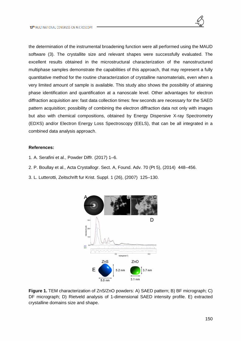
150
the determination of the instrumental broadening function were all performed using the MAUD
software (3). The crystallite size and relevant shapes were successfully evaluated. The
excellent results obtained in the microstructural characterization of the nanostructured
multiphase samples demonstrate the capabilities of this approach, that may represent a fully
quantitative method for the routine characterization of crystalline nanomaterials, even when a
very limited amount of sample is available. This study also shows the possibility of attaining
phase identification and quantification at a nanoscale level. Other advantages for electron
diffraction acquisition are: fast data collection times: few seconds are necessary for the SAED
pattern acquisition; possibility of combining the electron diffraction data not only with images
but also with chemical compositions, obtained by Energy Dispersive X-ray Spectrometry
(EDXS) and/or Electron Energy Loss Spectroscopy (EELS), that can be all integrated in a
combined data analysis approach.
References:
1. A. Serafini et al., Powder Diffr. (2017) 1–6.
2. P. Boullay et al., Acta Crystallogr. Sect. A, Found. Adv. 70 (Pt 5), (2014) 448–456.
3. L. Lutterotti, Zeitschrift fur Krist. Suppl. 1 (26), (2007) 125–130.
Figure 1. TEM characterization of ZnS/ZnO powders: A) SAED pattern; B) BF micrograph; C)
DF micrograph; D) Rietveld analysis of 1-dimensional SAED intensity profile. E) extracted
crystalline domains size and shape.

151
Figure 2. TEM characterization of ZrO2 powders: A) SAED pattern; B) BF micrograph; C)
Rietveld analysis of 1-dimensional SAED intensity profile. Dot line: experimental profile; red
line: calculated profile; D) extracted crystalline domains size and shape.

152
How sample holder geometries influence the quantification of X-ray
spectra
Judith Lammer (1), Johanna Kraxner (1), Georg Haberfehlner (1), Gerald Kothleitner (2),
Werner Grogger (2)
1) Graz Centre for Electron Microscopy, Steyrergasse 17, 8010 Graz, Austria.
2) Institute of Electron Microscopy and Nanoanalysis, Graz University of Technology,
Steyrergasse 17, 8010 Graz, Austria
Keywords: EDX quantification, analytical STEM, Super-X, detector position, shadowing
Large area sensors and multi-detector systems have substantially improved X-ray
spectrometry in (scanning) transmission electron microscopes in the last decade. Thanks to
this increase in collection efficiency, even signals from single atoms have become detectable.
Nevertheless, correct compositional analysis remains challenging and requires reliable
parameters for ionization cross sections, the amount of absorption or for the shadowing effects
from the sample holder [1, 2]. In this work, we focus on shadowing and show how different
sample holders influence the quantification using a ChemiSTEM system (Super-X) on an FEI
60-300 Titan³ microscope. We compare the results of two FEI low background double tilt high
visibility holders (an old and a new design, shown in Figure 1) and tomography holders. In
order to do this, we determined the detector positions in the microscope chamber in terms of
elevation angle and distance (3). For this purpose, we measured the X-ray intensities on each
detector as a function of specimen tilt angle α and compared them to simulations, where we
varied the detector positions such that deviations to the experimental data were minimal. For
the simulations we generated realistic geometric models of the TEM holders by X-ray
computed tomography (CT) and calculated shadow images for different detector positions in
the 3D modelling program CINEMA 4D (by MAXON Computer GmbH). The sample used was
an Au-Pd thin film deposited on a silicon nitride membrane grid. We noted that shadowing also
depends on the X-ray energy (see Figure 2). Even at zero degree tilt, the detector illumination
for the total of all four detectors did not always reach 100%, especially when it came to low X-
ray energies. This is caused by the Beryllium specimen carrier inside the holder, which appears

153
fully transparent for high enough X-ray energies (e.g. Au-L), but partially blocks low-energy X-
rays. Therefore, the amount of shadowing depends not only on tilt angles and specimen
positions, but also on the X-ray energy, which can introduce significant errors upon
quantification of both low- and high-energy X-ray lines. This method provides a means to
determine accurately the positions of different X-ray detectors in a multi-detector system. The
knowledge about the geometric arrangement of sample, sample holder and EDX detectors is
paramount for a better understanding of the EDX system setup but also enables a post-
experiment correction to quantitative results.
Acknowledgements:
We greatly acknowledge the help of Dr. Bernd Oberdorfer, Austrian Foundry Research Institute
(ÖGI), Leoben, Austria for performing the X-ray tomography experiments. The authors also
want to thank the Austrian Research Promotion Agency FFG (project 850220) for funding.
References:
1. T. J. A. Slater et al., Ultramicroscopy 162 (2016), 61–73.
2. W. Xu et al., Ultramicroscopy 164 (2016), 51–61.
3. J. Kraxner et al., Ultramicroscopy 172 (2017), 30–39.

154
Figure 1. FEI low background double tilt high visibility holders: The old holder (top) and the
newly designed holder (bottom) differ from each other in the shape of the beryllium and brass
part (highlighted in red).
Figure 2.: Relative intensity values measured with detector Q4: The shift between the data
points of a low-energy line (Au-M @ 2.12 keV) and a high-energy line (Au-L @ 9.71 keV) is
caused by absorption within the Be specimen carrier.

155
Examination of strain evolution during micropillar compression
with HR-EBSD
Szilvia Kalácska (1), Zoltán Dankházi (1), Dávid Ugi (1), Péter Dusán Ispánovity (1), István
Groma (1)
1) Eötvös Loránd University (ELTE, Department of Materials Science, Pázmány Péter sétány
1/a., Budapest, Hungary
Keywords: micropillar compression, strain evolution, HR-EBSD
The understanding of the mechanisms occurring during plastic deformation of crystalline
materials is in the focus of materials science research. In the last decade one of the remarkable
results of plasticity was that plastic deformation of crystals becomes dramatically different
when the sample size is reduced to the micron or submicron scale, compared to the behavior
of bulk materials (1). This difference decisively influences today’s industrial sectors with focus
on miniaturization, as the size reduction effect is no longer negligible. Therefore the plastic
behavior at the micrometer scale (in case of micropillars) is the main focus of the presented
work. The aim of our research was to develop a focused ion beam (FIB) milling method to be
able to produce micropillars in large numbers, which are also suitable for electron
backscattered diffraction (EBSD) measurements. After the preparation phase of the copper
single crystal sample, micropillars were formed on the surface, and then they were compressed
to various deformation levels with a nanoindentation stage developed by the researchers at
the Department of Materials Science, ELTE. After compression the pillars were cut in half with
FIB and the resulting new surface was measured with high resolution EBSD (HR-EBSD). The
HR-EBSD technique is capable of mapping the strain field in the deformed sample caused by
the dislocations (2), therefore we can examine the strains’ magnitude and distribution evolving
in the material after plastic deformation. The micropillars made by the FIB preparation
(Figure1.) were successfully compressed and measured by EBSD. The high resolution EBSD
maps show interesting features when the different components of the strain tensor elements
are plotted, and this presentation aims to introduce these findings. The experiments were
conducted on differently oriented samples as well. The comparison of the results lead us to the

156
possibility to map and reconstruct strain states in 3 dimensions, which is a fairly new approach
in the experimental research of microdeformations.
References:
1. C. A. Volkert and E. T. Lilleodden, Phil. Mag. 86 (2006) 5567. 2. Sz. Kalácska et al. Appl.
Phys. Lett. 110 (2017), 091912.
Figure 1. Secunder electron image of micropillars milled with focused ion beam (4 identical,
each of them is 6 um x 6 um x 18 um), after compression with a nanoindentation tip.

157
Spectroscopic investigation of the electronic structure phase
diagram of yttria-stabilized zirconia in an electron microscope
Thomas Götsch (1), Erminald Bertel (1), Alexander Menzel (1), Michael Stöger-Pollach (2),
Simon Penner (1)
1) Institute of Physical Chemistry, University of Innsbruck, A-6020 Innsbruck, Austria
2) University Service Center for Transmission Electron Microscopy, Vienna University of
Technology, A-1040 Vienna, Austria
Keywords: YSZ, electronic structure, EELS, Cerenkov radiation, crystallography
Yttria-stabilized zirconia (YSZ) is one of the most frequently used ionic conductors since the
substitution of Zr4+ by Y3+ ions results in the formation of oxygen vacancies. These vacancies
lead to a significant O2- ion conductivity at elevated temperatures. Therefore, YSZ is employed
as an electrolyte in devices like solid oxide fuel cells or chemical sensors. In this work, we
investigate the influence of the Y2O3 concentration in the complex oxide on the crystallographic
as well as the electronic properties. For this, we employed our self-built direct current ion beam
sputter gun,(1) and deposited thin films with a nominal thickness of 25 nm for four different
compositions, ranging from 3 mol% to 40 mol% Y2O3. These specimens were investigated
using transmission electron microscopy as well as photoelectron spectroscopy to gain
complementary information about their electronic structures. Usually, differentiating the
tetragonal and cubic polymorphs of zirconium dioxide species is impossible with diffraction
methods (both crystal structures yield the same diffraction patterns). The crystal class
determination is nevertheless achievable by calculation of the unit cell height (i.e. the lattice
parameter c), since this parameter is equivalent for both crystal structures (because the (002)
spots in the diffraction patterns are identical). If this lattice parameter is subsequently plotted
as a function of the yttria content, a distinct stagnation between 8 and 20 mol% Y2O3 can be
observed (see Figure 1a). However, due to the significantly increased amount of Y3+, which is
the larger ion when compared to Zr4+, the unit cell volume has to increase, which can only be
explained by a phase transformation from tetragonal to cubic (i.e. a growth in the lateral
dimensions). In later experiments, the phase transition could even be narrowed down to lie

158
between 8 mol% and 9.3 mol% Y2O3.(2) The same trend as a function of the yttrium oxide
content is also observed for other parameters such as the direct band gaps, displayed in Figure
1b. These have been obtained by Valence EELS (VEELS),(3) for which the acceleration
voltage is lowered to prevent Čerenkov losses from occluding the onset of the interband
transitions, which corresponds to the band gap. Figure 1b reveals that the behavior of the band
gaps is a mirrored version of that of the lattice parameter: when the yttria-concentration
increases and the unit cell becomes larger, the band bap decreases, whereas it features a
significant rise at the phase transition. A combination of core-loss EELS and UPS also gives
rise to information about the O-vacancy related defect states within the band gap. Furthermore,
it is shown that, using a cathodoluminescence spectrometer, the absorption of the emitted
Čerenkov radiation inside the TEM can be used as a precise tool for the determination of the
distance between the occupied and the unoccupied defect states (Čerenkov emission
spectroscopy), as shown in Figure 2.
References:
1. T. Götsch et al., AIP Adv. 6 (2016) 025119.
2. T. Götsch et al., Appl. Surf. Sci. 402 (2017) 1–11.
3. M. Stöger-Pollach et al., Micron 37 (2006), 396–402.

159
Figure 1. a) The unit cell height as a function of the yttria content reveals the phase
transformation between the tetragonal and cubic polymorphs. b) The band gaps show the
same behavior as the unit cell heights with a discontinuity at the phase transition.
Figure 2. a) Cerenkov emission spectra, as measured using a cathodoluminescence
spectrometer inside the TEM. b) The absorption edges yield information regarding the distance
between the occupied and the unoccupied states within the band gap.

160
POSTER PRESENTATIONS I7:
Atomic-level strain response of amorphous TiAl thin film under
tension measured by selected area electron diffraction
Christian Ebner (1), Rohit Sarkar (2), Jagannathan Rajagopalan (2), Christian Rentenberger
(1)
1) University of Vienna, Physics of Nanostructured Materials, Boltzmanngasse 5, 1090
Vienna, Austria
2) Arizona State University, Department of Materials Science and Engineering, School for
Engineering of Matter Transport and Energy, Tempe 85287, USA
Keywords: in situ, selected area diffraction, metallic glasses, strain mapping
Metallic glasses are a new class of materials with very distinct properties such as high yield
stresses and large elastic limits. These properties make them promising materials for structural
applications (1). Understanding the mechanisms of elastic and plastic deformation and
modelling these on an atomic level is a challenge because of the lack of periodicity in these
materials. This challenge needs to be tackled to fully take advantage of the materials
properties. Especially, the local stress strain state and time dependent response in form of
elastic, anelastic, viscoelastic and plastic deformations are of interest. In this study, in situ
tensile tests with MEMS base thin films are performed (cf. Fig 1(a)). We present a selected
area electron diffraction (SAED) based technique allowing the determination of the local atomic
level elastic strain. The 2D strain tensor is contained within the experimental SAED patterns in
form of elliptical distortions of the diffuse diffraction halo of amorphous alloys (cf. Fig 1(b)).
Changes in the nearest neighbor distance distribution on an atomic level result in shifts of the
radial intensity maxima positions. By accurately tracking these shifts from sector-wise
calculated line profiles, the strain can be obtained in a semi-automated manner (2). This
method is finally used to measure the following mechanical phenomena within the elastic
regime of an amorphous TiAl thin film: (a) the elastic stress - strain response, allowing to
calculate the Young’s modulus and the Poisson’s ratio, (b) uncopling the anelastic from the

161
elastic strain and (c) the viscoelastic strain response at fixed external stress over time. In situ
tensile tests are performed using a Phillips CM200 TEM operating at 80 - 200kV. First, the
principal strain e1 (parallel) and e2 (perpendicular to the loading direction) as a function of the
external stress σ are measured for several stress levels with small increments. The Young’s
modulus is calculated from the slope of the stress -strain curve, the Poisson’s number from the
ratio of the obtained principal strains e2/e1. Anelastic contributions are decoupled by comparing
the strain from the diffraction data with the external strain measured via strain gauges on the
MEMS device. Also, the strain distribution at a high, fixed external stress is mapped over a
larger specimen area (cf. Figure 2(a)). Finally, the specimens time response to loading and
unloading to different levels of external stress (denoted as states 0 – 4 in Figure 2(b)) is
measured. After each stress change a time series of SAED patterns with 2s resolution is
acquired. Patterns are recorded for times up to 1h. The changes in principal strain Δe1 with
respect to the first pattern of the time series are shown in Figure 2(b). Fitting of these changes
with a relaxation time model function gives a good fit only if two different relaxation times are
used.
Acknowledgements:
C. E. and C. R. acknowledge financial support by the Austrian Science Fund FWF: [I1309]. R.
S. and J. R. acknowledge funding from the National Science Foundation (NSF) grants CMMI
1400505 and DMR 1454109.
References:
1. A.L. Greer. Materials Today, 12 (2009) 1-2, 14-22.
2. C. Ebner et al., Ultramicroscopy, 165 (2016) 51-58.
162
Figure 1. (a) Low magnification image of the amorphous TiAl thin film with the gauges to
measure external stress and strain. (b) Color-coded difference image of a highly strained DP
and its 90 degree rotated pattern.

163
Figure 2. (a) Principle strain mapping at fixed stress over the width of the specimen shows
variation caused by slight thickness fluctuations. (b) Time dependent strain evolutions and their
fits according to a relaxation model.

164
Electron beam induced radiation explored by CL and EELS
Michael Stöger-Pollach (1), Lukáš Kachtik (2), Bernhard Miesenberger (3), Philipp Retzl (3)
1) University Service Center for Transmission Electron Microscopy, Technische Universität
Wien, Wiedner Hauptstraße 8-10, 1040 Wien, Austria
2) Brno university of technology, Antonínská 548/1, 601 90 Brno, Czech Republic
3) University Service Center for Transmission Electron Microscopy, Technische Universität
Wien, Wiedner Hauptstraße 8-10, 1040 Wien, Austria
Keywords: EELS, CL, Cerenkov radiation, transition radiation
When the electron beam passes through the specimen in a transmission electron microscope
(TEM), several photon emission mechanisms are activated. The most common are the
excitation if X-rays being detected within energy or wave length dispersive X-ray spectroscopy
(EDX or WDX) and the excitation of IR-VIS-UV light detected by cathodoluminescence. The
latter is generated if a valence electron was excited into the conduction band and recombines
with its hole in the valence band or of a radiative surface mode of a non-periodic nanostructure
is excited. Additionally Cerenkov radiation and transition radiation are generated by the swift
electron. The emission probability per incoming electron for transition radiation (TR) is
measured by employing electron energy losses spectrometry (EELS) and
cathodoluminescence (CL) in a transmission electron microscope (TEM) using beam energies
varying from 20 – 200 keV. We further demonstrate that TR is excited only at the sample
surfaces, because the emitted intensity and the respective energy loss are independent of the
sample thickness. As specimen we use an aluminium single crystal, because TR is known to
be strongest on metals. For studying Cerenkov radiation we record CL spectra of a crystalline
MgO specimen. Due to its low refractive index the Cerenkov limit can be determined to be
approximately 90 keV (1). CL spectra were recorded using a GATAN VULCAN system,
corrected for the spectrometer response and integrated over the whole visible range. Using
EELS we explored the angular behaviour of the transition radiation losses (TRLs) and verified
the emission probability by observing the corresponding inelastic contributions in the EELS
spectrum. Summing up it is the first time that within a TEM transition radiation of aluminium

165
was studied by means of EELS and CL. We proved experimentally that the angular dispersion
of the TRLs is within the light cone, that TR is emitted from the surfaces only, and we
determined the photon emission probability with respect to the beam energy. Due to the fact,
that the probability for the emission of TR is very low, even for aluminium, it is even smaller in
the case of semiconductors, where low loss EELS is used for determining the local dielectric
behaviour.
References:
1. M. Stöger-Pollach, Micron 39 (2008) 1092-1110.
Figure 1. Left: VEELS spectrum of a 7.5 nm thin Al foil and the ZLP recorded in vacuum. Right:
Comparison of the AR-VEELS experiment and the simulation being convolved with the spectral
and angular resolution of the experiment.

166
Thickness and orientation dependence of the average HAADF STEM
normalized intensity: a comparison with Monte Carlo and Multislice
simulations.
Andrea Parisini (1), Stefano Frabboni (2), Gian Carlo Gazzadi (3), Aldo Armigliato (1),
Rodolfo Rosa (1)
1) CNR-IMM, Sezione di Bologna, via P. Gobetti 101, 40129 Bologna, Italy
2) Dipartimento di Fisica, Università di Modena e Reggio Emilia, via G. Campi 213/A, 41100
Modena, Italy
3) CNR-Istituto di Nanoscienze-S3, via G. Campi 213/A, 41100 Modena, Italy
Keywords: STEM, HAADF, quantitative intensity measurement, QSTEM, Monte Carlo
simulation
In the last years, much attention has been paid to the quantitative measurement of the HAADF
STEM intensity wherefrom thickness and/or sample composition values may be obtained. The
use of averaged values of this quantity allowing a useful filtering of unwanted signals, led to
the determination of doping profiles in ultra shallow junctions in Si at subnanometer resolution
(1). In general, there are still some open issues concerning the origin of the contrast in HAADF
STEM images that mainly regard the dependence of the intensity on sample thickness and
orientation. One of these issue concerns the suggestion (2) that for thin specimen, out of an
axial sample orientation, elastic scattering is enhanced at the expense of thermal diffuse
scattering. In this work, we focus on two main problems: i) we test this suggestion by seeking
its maximum thickness limit and ii) we investigate the precise sample orientation conditions
leading to maximize the Z-contrast contribution. The former problem is studied by a comparison
of the experimentally determined average normalized intensity depth profiles with those
obtained by Monte Carlo simulations. In MC simulations, scattering events are completely
independent so that elastic scattering is temperature independent. Moreover, as in these
simulations each single electron trajectory is followed, the HAADF detector response may be
easily introduced. The second problem is faced by a comparison with Multislice simulations in
which full account of sample orientation and thermal diffuse scattering is taken (3). We do this

167
on a wedged FIB lamella consisting of crystalline 4H-SiC and amorphous SiO2 having average
Z values that differ by no more than 7%. In Figure 1, a head-on SEM view of the lamella, the
relative orientation of sample and electron beam, the HAADF detector response and finally an
edge-on STEM image of the sample, are reported. In Figure 2, our main results are
summarized. In the case of SiO2 (Figure 2 b), irrespective of the given orientation conditions
the different experimental depth profiles superpose in agreement with MC simulations, this
contrast with the crystalline 4H-SiC (Figure 2 a) where the experimental profiles appear to
slightly depend on the sample orientation. This dependence is investigated by Multislice
simulations in different planar channeling sample orientations (Figure 2 c) revealing the
presence of secondary intensity maxima. Thus, even out of axial channeling condition the
precise sample orientation has to be taken into account when using the average intensity in
quantitative works. Finally, in Figure 2 d we show that just outside planar channeling conditions
the average intensity mass thickness profiles of the two material almost coincide. The residual
difference is in keeping with the expected difference in Z-contrast contribution, this small
average Z difference is thus revealed. Applications to the composition profiles determination
in C-O-Si ternary films by X-ray EDS are in progress.
References:
1. A. Parisini et al., Appl. Phys. Lett. 92 (2008) 261907.
2. J. Liu and J. M. Cowley, Ultramicroscopy 37 (1991) 50.
3. C. T. Koch, Ph.D. Thesis, Arizona State University, (2002).

168
Figure 1. (a) Head-on SEM view of the wedged FIB lamella; (b, c) relative orientation of sample
and electron beam; (d) HAADF detector response and image (inset); (e) edge-on STEM image
of the sample with segments marking line profile directions.
Figure 2. (a,b) Experimental averaged normalized intensity depth profiles and MC simulations;
(c) Multislice relative intensities vs tilt angle, extrapolated data from experimental fits are also
reported; (d) experimental intensity mass thickness profiles.

LIFE SCIENCES

163
L1. Live Cell Imaging and
Intracellular Dynamics

169
INVITED LECTURES L1:
Imaging neurotransmitter receptor dynamics in the brain at the
nanoscale
Juan A. Varela (1), Laurent Groc (2)
1) University of Cambridge, Department of Chemistry, Lensfield Road, Cambridge, CB2 1EW, United Kingdom
2) Interdisciplinary Institute for Neuroscience, Centre Broca Nouvelle-Aquitaine, CNRS 5297,
University of Bordeaux, 146 rue Léo Saignat, 33076 Bordeaux Cedex, France
Keywords: single-molecule tracking, neurotransmitter receptors, brain extracellular space,
quantum dots, carbon nanotubes
Single-molecule detection and tracking techniques have become powerful tools to study the
dynamics of biological events, surpassing the molecular ensemble averages obtained with
conventional microscopy. These techniques have significantly contributed to developments in
the field of neuroscience, as the synapse is organized at the nanoscale. Furthermore, the
extracellular space of the brain (which occupies ~20% of its volume) is also structured at the
nanoscale, and until now, its high-resolution characterisation has been restricted to electron
microscopy imaging. While organic fluorophores can be used for single-molecule imaging in
cultured cells, thick tissue experiments require much brighter probes. In high background noise
environments such as the brain, nanoparticles offer great potential for high-resolution imaging
due to their brightness and small size. It is critically important to be able to develop and adapt
imaging techniques in such a way that they can be used to unravel molecular information with
minimal bias from the sample preparation. I will present our recent work where for the first time
we succeeded tracking single-molecules in rodent acute brain slices (1). I will also discuss how
single-molecule diffusion studies compare across different brain preparations (2). I will
describe as well how we can use carbon nanotubes to study the extracellular space of the
brain at the nanoscale (3).

170
References:
1. Varela JA, JP Dupuis, L Etchepare, A Espana, L Cognet, and L Groc. 2016. Targeting
neurotransmitter receptors with nanoparticles in vivo allows single-molecule tracking in acute
brain slices. Nature Communications, 7: 10947 (2016).
2. Varela JA*, JS Ferreira*, JP Dupuis*, P Durand, D Bouchet, and L Groc. Single nanoparticle
tracking of N-methyl-D-aspartate receptors in cultured and intact brain tissue. Neurophotonics,
3: 41808 (2016).
3. Godin AG*, JA Varela*, Z Gao*, N Danné, JP Dupuis, B Lounis, L Groc, and L Cognet. 2017.
Single-nanotube tracking reveals the nanoscale organization of the extracellular space in the
live brain. Nature Nanotechnology, 12, 238–243 (2017).
Figure 1. Single-molecule tracking techniques have been developed and used in cultured
systems in neuroscience for the past 10 years. I will show how we can adapt techniques to
target single molecules in vivo and image in acute brain slices.

171
Dynamics of the Golgi apparatus during dis- and reorganizations,
visualized by 3D-electron tomography
Margit Pavelka (1)
1) Center for Anatomy and Cell Biology, Medical University of Vienna, Schwarzspanierstraße
17, 1090 Vienna, Austria
Keywords: Golgi apparatus, endocytosis, intracellular dynamics, 2-deoxy-D-glucose
The Golgi apparatus rapidly reorganizes its subcompartments in response to intra- and
extracellular influences. A dynamic crossroads is formed consisting of stacks of flat cisternae
in a polarized organization that is traversed by flows of membranes and contents in diverse
directions, including anterograde traffic in the biosynthetic systems, retrograde traffic in
endocytic pathways and flow via multiple recycling routes (1, 2). This high flexibly of the Golgi
apparatus is assumed to be crucial for fulfilling its tasks in the cellular transport systems. In the
first part of my talk, I will show our results on the dynamics of the Golgi apparatus connected
with endocytic flow after internalization of peroxidase-labelled wheat germ agglutinin (WGA);
the second part of the talk focuses on the Golgi stack dis- and reorganizations in response to
metabolic stress induced by treatment with the glucose-analogue 2-deoxy-D-glucose (2DG),
which reversibly lowers the cellular ATP-levels. All results shown here are obtained from
experiments with human HepG2 hepatoblastoma cells either fixed chemically or cryo-
immobilized by high pressure-freezing; WGA was visualized by oxidation of diaminobenzidine;
the 3D-analyses were performed with the aid of electron tomography using a Tecnai-20
electron microscope (FEI Company) at 200 kV. The figure shows a summary of characteristic
changes of the Golgi stack structure in connection with WGA-endocytosis and induced by
treatment with 2DG and after its removal. The route to and into the Golgi apparatus is one of
the main endocytosis pathways of WGA and is a complex process connected with extensive
membrane dynamics. Initial accumulations of vesicular endocytic compartments at the trans-
Golgi side after 5-10 min of endocytosis are followed by new formations of extended endocytic
trans-Golgi networks after 10-30 min, which again decrease concomitantly with uptake of WGA
into cisternae of the stacks after 30-60 min. By using 2DG, successive steps of Golgi stack

172
dis- and reorganizations can be followed. The 3D-analyses show that intra-stack networks
occur within 10 min after onset of 2DG-treatment, which coincides with a rapid drop-down of
the cellular ATP-levels. With ongoing treatment, regularly organized Golgi stacks disappear
and are replaced by tubulo-reticular Golgi bodies. The early occurring bodies are rather loosely
arranged; at later times, compact glomerular Golgi bodies with densely packed membranes
dominate. After removal of 2DG, the cellular ATP again increases coinciding with a re-
formation of regular stacks of cisternae. Initial mini-stacks are built in close spatial relationship
to glomerular parts of densely packed Golgi bodies. Both the results of the endocytosis studies
and the 2DG-experiments show the high flexibility and dynamics of the Golgi stack
architectures in response to changed cellular functions and altered environmental conditions.
Acknowledgements:
I would like to express my cordial thanks to all my colleagues and co-workers, in particular to
Adolf Ellinger, Josef Neumüller, Carmen Ranftler, Monika Vetterlein, Claudia Meisslitzer-
Ruppitsch, Beatrix Mallinger, Regina Wegscheider, Ivanna Fedorenko, Ulrich Kaindl, Thomas
Nardelli and Peter Auinger.
References:
1. F. Perez and D.J. Stephens Eds. Methods in Cell Biology Vol 118, Methods for analysis of
Golgi complex function. Elsevier Academic Press Inc. San Diego (2013).
2. C. Ranftler et al. Histochem. Cell Biol. 147 (2017) 415-438.

173
Figure 1. Summary of the Golgi stack reorganizations in human HepG2 hepatoblastoma cells
in connection with endocytosis of wheat germ agglutinin and in response to treatment with the
non-metabolizable glucose-analogue 2-deoxy-D-glucose and after removal of the agent.

174
ORAL PRESENTATIONS L1:
Ras proteins regulate actin assembly at endocytic structures via
Diaphanous-related formin G
Alexander Junemann (1), Vedrana Filić (2), Moritz Winterhoff (1), Benjamin Nordholz (1),
Christof Litschko (1), Helena Schwellenbach (1), Till Stephan (1), Igor Weber (2), Jan Faix
(1)
1) Institute for Biophysical Chemistry, Hannover Medical School, OE 4350,Carl-Neuberg-Str.
1, D-30625 Hannover, Germany
2) Division of Molecular Biology, Ruđer Bošković Institute, Bijenička cesta 54, HR-10000
Zagreb, Croatia
Keywords: formin, Arp2/3 complex, macropinocytosis, phagocytosis, Ras
Formins and Arp2/3 complex are major actin assembly factors in eukaryotic cells. While Arp2/3
complex induces branching of the existing filaments, thus creating a dense actin meshwork at
the cell's leading edge, formins promote nucleation and elongation of linear actin filaments,
mostly in filopodia, stress fibers and cytokinetic rings (1). Formins are defined by the presence
of a highly conserved C-terminal formin homology 2 (FH2) domain preceded by an FH1
domain, which are necessary and sufficient to nucleate actin polymerisation and elongate
filaments (2). Diaphanous-related formins (DRFs) constitute a conserved subfamily in which
core FH1 and FH2 domains are flanked by regulatory domains: a GTPase binding domain
(GBD), a Diaphanous-inhibitory domain (DID) and a dimerization domain (DD) at the N
terminus, and a C-terminal Diaphanous-autoregulatory domain (DAD). DRFs are autoinhibited
through interaction between DID and DAD and binding of a Rho GTPase to GBD releases this
inhibition. We have characterized formin G (ForG) from the professional phagocyte
Dictyostelium discoideum as a Diaphanous-related formin that fully conforms to the canonical
domain organization of DRFs, and described its role in large-scale endocytosis (3).
Biochemical assays identified ForG as a rather week actin nucleator that efficiently elongates
actin filaments. Live cell imaging demonstrated that ForG was enriched at the plasma

175
membrane during the formation and maturation of macropinocytic cups. Analysis of
phagocytosis also revealed localization to nascent phagocytic cups and ForG remained
associated with the membrane over the entire course of engulfment and internalization of yeast
particle (Figure 1). Real-time assays of the nutrient uptake showed markedly decreased fluid-
phase uptake of TRITC-dextran and phagocytosis of TRITC-labeled yeast particles in forG null
cells compared with control cells. Interestingly, yeast-two-hybrid (Y2H) assay failed to identify
any interaction of ForG with Rho family GTPases, although DRFs have been previously shown
to act exclusively as effectors of Rho GTPases (1). Strikingly, another Y2H screen and
bimolecular fluorescence complementation (BiFC) in vivo identified specifically activated forms
of RasB and RasG, but not their dominant negative variants, as ForG interactors (Figure 2).
The role of RasG in macropinocytosis has already been well established. To assess the role
of RasB in this process, we have created rasB null cells and tested their nutrient uptake. The
uptake of large particles was substantially impaired in rasB deficient cells, while pinocytosis
rates were only slightly diminished. Taken together, these data demonstrate the significance
of ForG for actin assembly in endocytic structures, with RasB being mainly responsible for its
regulation during phagocytosis of large particles, and RasG being the main regulator of ForG
in macropinocytosis.
Acknowledgements:
This work was supported by Deutsche Forschungsgemeinschaft Grants FA 330/6-2 and FA
330/10-1 (to J.F.). V.F. was supported by the FP7-REGPOT-2012-2013-1 Grant Agreement
316289–InnoMol.
References:
1. Pollard TD, Annu. Rev. Biophys. Biomol. Struct. 2007, 36:451–477.
2. Faix J and Grosse R, Dev. Cell 2006, 10:693–706.
3. Junemann A et al., Proc. Natl. Acad. Sci. U. S. A. 2016, 113:E7464–E7473.

176
Figure 1. ForG localizes to endocytic structures during macropinocytosis (upper panel) and
phagocytosis (lower panel). Time is given in seconds. (Junemann et al., 2016)

177
Figure 2. ForG interacts with active Ras in vivo. (Left panel) Scheme of the BiFC strategy. VC
and VN, Venus C-terminal and N-terminal fragment. (Right panel) ForG interacted with active
or WT forms of RasB and RasG. (Junemann et al., 2016)

178
Effect of intracytoplasmic morphologically selected sperm injection
(IMSI) imaging system on intracytoplasmic sperm injection
outcomes
Seda Karabulut (1), İlknur Keskin (2), Ö. Aksünger (3)
1) Medipol University, International School of Medicine, Department of Histology and
Embryology, REMER, İstanbul, Turkey
2) Medipol University, School of Medicine, Department of Histology and Embryology,
REMER, İstanbul, Turkey
3) Memorial Antalya Hospital IVF Unit, Antalya, Turkey
Keywords: sperm, ICSI, IMSI
Introduction: Intracytoplasmic sperm injection is an assisted reproductive technique used for
treating infertility in male and female origin. In male factor infertility ICSI is used in cases of
poor sperm quality (oligo/astheno/teratozoospermia) and morphology of spermatozoa used for
injection is directly related to fertilization and pregnancy rates. ICSI is performed by selecting
motile spermatozoa with normal morphology and motility under a magnification of ×400 which
is hard to distinguish morphologically healty sperm. But, subtle morphological defects of the
sperm cell are also related to low fertilization rates and poor clinical outcome. A new method,
the intracytoplasmic morphologically selected sperm injection (IMSI) is introduced for choosing
ultrastructurally normal motile sperm using high-power differential interference contrast optics.
This high magnification (X 10,160) allowed the identification of spermatozoa and its organelles
in a detailed manner. The aim of the present study is to evaluate the efficacy of IMSI in infertile
patients undergoing ICSI. Material method: A total of 49 cycles performed between January
2016 and June 2016 at Memorial Antalya Hospital IVF Unit (Antalya, Turkey) were included in
the study where IMSI is used in 21cycles and not used in 28 cycles. The patients were
randomly selected for IMSI procedure. Cycles that testicular sperm is used were not included
in the study. The causes for infertility among the patients were similar in the IMSI and no-IMSI
groups. The motile sperm with normal ultrastructural feature were selected by using using high-
power differential interference contrast optics (MSOME) and used in IMSI procedure. The ICSI

179
outcome parameters (fertilization, embryo quality and pregnancy rates) were compared
between two groups in which IMSI is used or not. Results: Although the age of the women and
mature oocyte numbers were similar in the IMSI and the no-IMSI group (34.7 and 34.8 resp.)
(p>0.05), the fertilization rates were significantly higher in the IMSI group (70% and 59% resp.)
(p<0.05). The mean number of embryos transferred were similar (1.4) in both groups but top
quality embryo rate of transferred embryos were significantly higher in the IMSI group (81%
and 71,5% resp.) (p<0.05). The pregnancy rates were higher in the IMSI group although the
difference were not significant (60% and 53% resp.). Conclusion: In conclusion, the IMSI
procedure not only significantly improves fertilization and embryo quality but also presents a
tendency to increase pregnancy rates as compared with the no-IMSI group in a non-selected
group of patients representing the effect of sperm ultrastructural consequences on the
outcome of ICSI parameters. These data justify the clinical application of IMSI during infertility
treatment. More studies, in which variables are controlled and with more cycles are needed to
verify the data.
References:
1. Palermo G, Joris H, Devroey P, Van Steirteghem AC. Pregnancies after intracytoplasmic
injection of single spermatozoon into an oocyte. Lancet. (1992)340: 17–18.
2. De Vos A, Van de Velde H, Joris H, Verheyen G, Devroey P, Van Steirteghem A. Influence
of individual sperm morphology on fertilization, embryo morphology, and pregnancy outcome
of intracytoplasmic sperm injection. Fertil Steril. (2003)79:42–48. 3.
3. Bartoov B, Berkovitz A, Eltes F, Kogosowski A, Menezo Y, Barak Y. Real-time fine
morphology of motile human sperm cells is associated with IVF-ICSI outcome. J Androl.
(2002)23:1–8. 4.

180
Imaging via multimode optical fiber: calibration by internal
reference
Petr Jákl (1), Johanna Traegaardh (1), Jan Ježek (1), Martin Šiler (1), Pavel Zemánek (1),
Tomáš Čižmár (2)
1) Institute of Scientific Instruments of the CAS, v. v. i., Královopolská 147, 61264 Brno,
Czech Republic
2) Ewing Building, School of Engineering, Physics & Mathematics, University of Dundee,
Dundee, DD1 4HN, Scotland, UK
Keywords: multimode optical fiber, imaging, beam shaping
Various biomedical problems suffer from a lack of a fast and reliable imaging technique that
enables in vivo imaging deep in the tissue. The issue that obscures deep tissue imaging is the
random light scattering. Several imaging techniques deal with these problems from different
angels, such as optical coherence tomography, light sheet microscopy or structured light
illumination. In the clinical studies rigid or flexible endoscopes are often used for imaging deep
in the bodies of animals or in human patients. The flexible endoscopes are formed by a bundle
of hundreds single mode optical fibers closely packed in a matrix. Each optical fiber then serves
as a "pixel" of the output image. However, the endoscopes are rather bulky devices that cannot
be further miniaturized because of evanescent light leaking between optical fibers. This causes
cross-talks that ultimately scramble the whole image. On the contrary to single mode optical
fibers multimode fibers (MMF) could in principle transfer the whole image at once. Until recently
it was considered that imaging by the optical fiber is not possible due to the randomization of
transferred light, see Figure 1a. However, it was shown (1) that by properly designing input
light pattern the very well defined focal point might be created and placed in 3D in different
positions with respect to the MMF facet, see Figure 1b. In principle, such point can be scanned
and used for imaging in the tissue anywhere the optical fiber is placed. Further on, even the
light sheet, Bessel beams, optical vortices might be created using the same approach (2). In
order to achieve such imaging properties of the MMF has to be well known in an advance.
These are described by the transmission matrix (TM) that relates the input and output light
structure. The elements of TM have to be found by the calibration procedure that employs

181
interference of the light propagating through the MMF with a reference beam. It was even
shown that the TM can be diagonalized, i.e. there exist propagation invariant modes that image
the input fiber facet to the output one and, further, that the the transmission matrix changes
due to the fiber deformations might be analytically predicted (3). The above mentioned studies
used a complex optical setup that employed an external reference arm. In this contribution we
show that this complexity is unnecessary and that the transmission matrix can be obtained
using light transmitted by the MMF fiber only.
Acknowledgements:
This work was supported by EC (CZ.02.1.01/0.0/0.0/15_003/0000476), Scottish Universities
Physics Alliance (SUPA – PaLS initiative) and its infrastructure by the MEYS Czech Republic
(LO1212), CAS (RVO:68081731) and EC (CZ.1.05/2.1.00/01.0017).
References:
1. T Cizmar & K Dholakia, Nature Communications 3 1027 (2012).
2. M Ploeschner et al., Scientific Reports 5 (2015).
3. M Ploeschner et al., Nature Photonics 9(8) 529-535 (2015).
Figure 1. (a) Light passing through the MMF creates a speckled patten upon leaving the output
fiber facet. (b) Properly designed and shaped (by spatial light modulator) input light creates a
single focused spot close to the output fiber facet.

182
Biosensor based real-time single cell monitoring using
microfluidics that generate spatial and temporal dynamic
stimulation
Jiyoung Song (1), Hyunryul Ryu (2), Minhwan Chung (1), Youngtaek Kim (1), Sungsik Lee
(3), Olivier Pertz (4), Noo Li Jeon (1)
1) Department of Mechanical and Aerospace Engineering, Seoul National University, Korea
2) Institute of advanced machinery and design, MIT, Boston, USA
3) Department of biochemistry, ETH Zurich, Switzerland
4) Department of biomedicine, University of Bern, Switzerland
Keywords: biosensor, microfluidics, dynamic stimulation, real time imaging, single cell
analysis
Recent trends in dynamic response at single cell level have led to a number of new techniques
to study cell biology. Above all, recent advances in time-lapse imaging techniques and
fluorescent marker has made real-time cell monitoring wide-spread. Microfluidic devices with
time-lapse imaging techniques allow us to study cellular response under the dynamic
stimulation at a cellular level. Despite the number of publications that explore the generation
of dynamic stimulation, the proposed microfluidic devices are limited in simultaneous variables.
Thus, the main feature of our microfluidic device is its capability of generating various multiple
profiles of diffusible chemicals such as GFs, hormones, and drugs in a single device without
any modifications. Moreover, a computer controlled pressure pump allows us to generate
multiple profiles in sequence. Consequently, we can generate pulsatile stimulation at a desired
concentration, with persistent ramp up and down in concentration, and dynamic manipulation
of baseline, slope, and direction of the gradient. In contrast, EKAR2G1 is a versatile biosensor
to monitor ERK kinetics. By combining our microfluidic device and EKAR2G1 transfected
HEK293 B5 cells, we can successfully monitor ERK kinetics under spatial and temporal
dynamic stimulations. In particular, ramp-down profiles in concentration is unable to perform
in conventional petri-dish based approach. In this aspect, we hope our microfluidic device will
become an essential toolkit to elucidate unidentified regions in cell biology.

183
Acknowledgements:
This research was supported by the International Research & Development Program of the
National Research Foundation of Korea (NRF) funded by the Ministry of Education, Science
and Technology(MEST) of Korea (Grant No.NRF-2015K1A3A1A14021299) .
References:
1. Fritz, R. D., Letzelter, M., Reimann, A., Martin, K., Fusco, L., Ritsma, L., . . . van Rheenen,
Sci. Signal. 6(2013) rs12.
2. Ryu, H., Chung, M., Dobrzyński, M., Fey, D., Blum, Y., Lee, S. S., . . . Pertz, O. Molecular
systems biology 11 (2015) 838.
Figure 1. Microfluidic platform to generate spatial and temporal dynamic stimulations. (A)
schematic of entire system. (B) pulsatile stimulation. (C) ramp-like changes in concentration.
(D) combination of ramp-like stimulation and pulsatile stimulation at various concentrations.
(E) dynamically changing gradient in baseline, slope, and direction.

184
Figure 2. Monitoring of ERK kinetics under the dynamic stimulation. HEK 293 B5 cells were
transfected with EKAR2G1 biosensor for monitoring of ERK activation. The cells were exposed
to various profiles of EGF stimulations. (A) Sustained (B) single pulse (C) double pulse with
different concentrations (D) ramp-like stimulation.

185
POSTER PRESENTATIONS L1:
The role of exercise in tenocyte activation at myotendinous junction
level
Debora Burini (1), Pietro Gobbi (1), Elisabetta Falcieri (1), Davide Curzi (1)
1) Department of Biomolecular Sciences, University of Urbino Carlo Bo, Via Aurelio Saffi, 2,
61029 Urbino, Italy
Keywords: myotendinous junction, tenocyte, exercise, muscle atrophy, muscle strength
Myotendinous junction (MTJ) is the anatomical interface between muscle and tendon, with the
key role to transfer the contractile strength (Figure 1A). The plasticity of MTJ has been
demonstrated in different physiological conditions. In particular, in previous works we revealed
the MTJ ability to reduce or to increase its complexity and the contact surface between tissues,
in relationship to muscle atrophy and exercise protocols, respectively (1, 2). The molecular
mechanisms and the different stages of these morpho-functional adaptations are still unknown,
but, by means of transmission electron microscopy (TEM) observations, an interesting high
presence of tenocytes close to the MTJ has been revealed (Figure 1B). At high magnification,
these tenocytes display an increased amount of rough endoplasmic reticulum in the exercised
group, compared to sedentary one (Figure 1C-D). The exercise ability to increase tenocytes
rough endoplasmic reticulum amount has already been demonstrated and correlated to the
production of collagen fibers and extracellular matrix components (3). Morphological
observations of tenocyte behavior close to MTJ reveal their activation following a resistive
exercise protocol, suggesting a key role of the cells in the modulation of MTJ morphology and
plasticity.
References:
1. Curzi D. et al., Eur. J. Histochem. (2013) 57:247-54.

186
2. Curzi D. et al., Histol. Histopathol. (2014), 30:465-72.
3. Salamanna F. et al., Connect. Tissue Res. (2014), 56:35-43.
Figure 1. MTJ semithin section (A) and MTJ after TEM observation (B-D). Bars: (A-D)=1 μm;
insert (C-D)=0,2 μm.

187
Cell damage induced by asbestos-like fibers
Michela Battistelli (1), Sara Salucci (1), Michele Mattioli (2), Michela Cangiotti (2), Matteo
Giordani (2), Maria Francesca Ottaviani (2), Elisabetta Falcieri (1)
1) Department of Biomolecular Sciences, Urbino University, Via Aurelio Saffi, 2, 61029
Urbino, Italy
2) Department of Pure and Applied Sciences, Urbino University, Via Aurelio Saffi, 2, 61029
Urbino, Italy
Keywords: asbestos-like fibers, U937 human cell line, transmission electron microscopy,
toxicity, mineral fibers
The presence, in nature, of asbestos-like fibers, highly toxic and potentially cancerogenic for
human healthy, is well known (1). Inhalation of the fibrous form of some zeolites, has been
shown to cause effects similar to those observed with mineral fibers classified as ‘‘asbestos,’’
including malignant mesothelioma, a disease typically associated with occupational and
environmental exposures to asbestos (2). In this work different fibers of zeolite erionite (termed
MD8 and GF1, demonstrated carcinogenic), offretite (termed BV12, suspected carcinogenic)
and scolecite (termed SC1, poorly carcinogenic) were investigated (3), with particular regard
to their possible interactions with U937 cell, a human hemopoietic cell line. Chemical and
morpho-functional analyses have been carried out, both to characterize fiber structure and cell
response. Cells showed the ability to internalize all the minerals, as observed after TEM
analyses. With zeolite and erionite exposure time increasing, a diffuse cell damage with
features of apoptotic and necrotic death could be evidenced (4). All fibers are able to induce a
cell shape change which appears, at reverted microscope, more evident when increasing the
exposure time (data not shown). The ultrastructural analyses reveal the capacity of cells to
internalize these compounds (Figure 1). Erionite (A, B, C) and offretite (D) fibers enter the
cells, even if their size is large. All fibers, showing an electron-dense aspect, can be detected
both in the cytoplasm () and in the nucleus () (A, B, C, D). All zeolites induce a diffuse
cytoplasmic vacuolization (A, inset). A significant damage can be revealed after 24h of fiber
administration, with an initial, potentially apoptotic, chromatin margination and nuclear pore
translocation (*) (C and C, inset). Features of necrotic cell death, in particular after erionite

188
incubation and that with offretite (D), which appear those with greatest toxicity, are also
present. Scolecite fibers, according to literature data (3), present poor interactions with the
model membranes (E, F, G). Trypan Blue assay shows that all zeolites reduce cell viability, in
particular after 24h of incubation (data not shown). These findings suggest that all asbestiform-
like fibers enter U937 human cells and that, with a certain variability, they can be considered
potentially toxic for cell culture in vitro.
References:
1. Mattioli et al. (2016) J Hazard Mater. 306:140-8.
2. Van Gosen et al. (2013) Environ Geochem Health. 35(4):419-30.
3. Cangiotti et al. (2017) J Toxicol Environ Health A. Feb 22:1-17.
4. Salucci et al. (2014) Int J Mol Sci. 17;15(4):6625-40.

189
Figure 1. Unstained TEM sections of erionite (termed MD8 and GF1, demonstrated
carcinogenic) (A), (B), (C), offretite (termed BV12, suspected carcinogenic) (D) and scolecite
fibers (termed SC1, poorly carcinogenic) (E), (F), (G), internalized by U937 cell line. (B), (C),
(E), Bar 1 µm; (A), (D), Bar 2 µm; (F). Bar 200 nm.

190
Ex vivo investigation of hemoglobin distribution in erythrocytes
using two photon excitation microscopy: insight from an animal
erythrocyte
Ana Z. Stančić (1), Ivana T. Drvenica (1), Svetlana Jovanić (2), Katarina Bukara (3), Vesna
Lj. Ilić (4), Mihajlo D. Rabasović (5), Dejan V. Pantelić (1), Brana M. Jelenković (3), Branko
M. Bugarski (3), Aleksandar J. Krmpot (3)
1) Institute for Medical Research, University of Belgrade, Dr Subotića 4, 11 129 Belgrade,
Serbia
2) Department of Chemical Engineering, Faculty of Technology and Metallurgy, University of
Belgrade, Karnegijeva 4, 11 000 Belgrade, Serbia
3) Institute of Physics Belgrade, University of Belgrade, Pregrevica 118, 11 080 Belgrade,
Serbia
4) Department of Chemical Engineering, Faculty of Technology and Metallurgy, University of
Belgrade, Karnegijeva 4, 11 000 Belgrade, Serbia
5) Department Pharmaceutics, University of Antwerp, Universiteitsplein 1, 2610 Antwerp,
Belgium
Keywords: erythrocytes, two photon excitation microscopy
Introduction: Nonlinear laser scanning microscopy (NLSM) with its three modalities, two-
photon excited fluorescence (TPEF), second and third harmonic generation (SHG/THG) is
advanced optical technique mostly used in biomedicine for label free imaging (1). Hemoglobin,
the main intracellular component of erythrocytes, emits strong Soret fluorescence with the
peak at 438 nm upon two-photon excitation by femtosecond pulses in red and near infrared
region (600-750 nm) (2, 3). Such optical properties of hemoglobin opened the possibility to use
TPEF microscopy as a tool for label-free imaging of erythrocytes, even in vivo (4). Objective:
Despite wide applicability of erythrocytes in diagnostic tests, and distribution of hemoglobin
within erythrocytes as a marker of their functional status under physiological or pathological
conditions [5], data on spatial distribution of hemoglobin at the single cell level are scarce.
Materials & methods: Based on findings reported by Zheng and co-workers (2) we have utilized
TPEF microscopy to map the spatial distribution of hemoglobin in porcine erythrocytes ex vivo.

191
Porcine erythrocytes were used as extremely susceptible cells to stress and thus represent a
good model system to study influence of stress factors (heat, humidity, malnutrition,
infections…) on erythrocyte morphology and hemoglobin distribution. The custom made
experimental set up for NLSM utilized the train of the femtosecond pulses from Ti:Sapphire
laser (Coherent, Mira 900-F) at 730nm. The repetition rate was 76MHz, and pulse duration
was 160fs. Results: Two different morphological types of porcine erythrocytes, normocytes
and echinocytes, are collected during mild autumn or extremely hot summer respectively
(Figure 1a and 1c). Besides, erythrocytes having intermediate morphology i.e. having some
characteristics of both abovementioned morphological extremes were also found (Figure 1b).
Pseudo coloring in figures corresponds to the TPEF signal intensity and no further processing
of image was performed. The results demonstrate that the resolution of the TPEF microscopy
is good enough for the analysis of erythrocytes at single cell level. The distribution of
hemoglobin in erythrocytes followed the cells’ shape, where erythrocytes with altered
morphology (Figure 1b and 1c) demonstrated significant accumulation of hemoglobin in cells’
protrusions. Conclusion: Changes in erythrocytes morphology and hemoglobin distribution
may influence erythrocytes’ oxygen transport function. Erythrocytes monitoring might be of
significance in analysis of their functional status in physiological condition, as well in numerous
hematological and non-hematological disorders accompanied with erythrocyte morphology
changes. Result of this studyeven though obtainedon animal cell model only, confirmed strong
potential of TPEF for such application in human and veterinary medicine and basic biomedical
research.
References:
1. Masters, B. R .& So, P. T. C. (2008) “Handbook of Biomedical Nonlinear Optical
Microscopy”, Oxford University Press.
2. W. Zheng, et al., “Two-photon excited hemoglobin fluorescence,” Biomed Opt Express 2:
71-79. (2010) [doi:10.1364/BOE.2.000071].
3. G. O. Clay, C. B. Chaffer, and D. Kleinfeld, “Large two-photon absorptivity of hemoglobin in
the infrared range of 780-880 nm,” J ChemPhys. 126:025102. (2007)
[doi:http://dx.doi.org/10.1063/1.2404678].
4. D. Li, et al., “Time-resolved detection enables standard two-photon fluorescence microscopy
for

192
Figure 1. Representative raw TPEF image of (a) porcine erythrocytes with “normal” biconcave,
(b) intermediate and (c) echinocytic morphology.TPEF signal is presented in pseudocolor.

193
CLEM and FIB for studing organisation of Golgi apparatus in
urothelium
Samo Hudoklin (1), Tanja Korpar (1), Caroline Kizilyaprak (2), Bruno Humbel (2), Rok Romih
(1)
1) Institute of Cell Biology, Faculty of Medicine, Vrazov trg 2,1000 Ljubljana, Slovenia
2) Electron Microscopy Facility, Faculty of Biology and Medicine, University of Lausanne,
1015 Lausanne, Switzerland
Keywords: urothelium, Golgi apparatus, GRASP55
Correlative light and electron microscopy (CLEM) and 3D reconstructions using dual beam
microscopes with focused ion beam (FIB) can provide new insights into the structure-function
of cell organelles. In differentiated superficial urothelial (umbrella) cells, Golgi apparatus (GA)
plays a central role in the biogenesis of urothelial plaques, which are transported to the apical
cell surface where they provide functional blood-urine permeability barrier of the urinary
bladder (1). We used CLEM and FIB methods to correlate large-scale GA distribution in
umbrella cells with its ultrastructure and spatial organization in order to get new insights into
the function of GA in the urothelium. For CLEM, urinary bladders of 6-8 weeks old male C57B6
mice were fixed with 4% FA in 0.1M phosphate buffer, pre-incubated in 5% goat serum + 0.1%
saponin in PBS and immunolabelled with anti-GORASP55 rabbit polyclonal antibody
(Proteintech). GORASP55 antibody labels Golgi reassembly stacking protein of 55 kDa
(GRASP55), which is medial- to trans-GA cisternae associated membrane protein involved in
the stacking of GA cisternae and required for the GA ribbon formation (2, 3). Samples were
then incubated with FluoroNanogold goat anti-rabbit IgG antibodies conjugated with
AlexaFluor488 and 1.4 nm colloidal gold (Nanoprobes). For light microscopy, urothelial sheets
were mounted in Vectashield with DAPI and observed from the apical surface with
AxioImager.Z1 microsocope with ApoTome upgrade (Zeiss). For TEM, samples were silver
enhanced, post fixed with 0.1% OsO4, dehydrated and embedded in Epon. Ultrathin sections
were observed with Philips CM100 TEM. For FIB, samples were cryo-fixed with CPC device
(Leica), freeze-substituted in AFS (Leica) with 2 % OsO4 in acetone, and embedded in Epon.

194
Epon block was trimmed with ultra-microtome UC6 (Leica) and FIB-sectioned with dual beam
Helios NanoLab 650 microsocope (FEI). GRASP55 immunostaining showed continuous
network distributed throughout the cytoplasm of umbrella cells (Figure 1). This is in-line with
studies proposing that GA is involved in the formation of urothelial plaques, in their polarised
sorting and transport toward the apical plasma membrane of umbrella cells (4). Gold particles
were located between GA cisternae, confirming GRASP55 role in GA stacking in urothelial
cells. Three-dimensional reconstruction of the GA in serial sections produced by FIB (Figure
2), further demonstrated lateral connections between individual GA stacks, which might form
functionally connected GA network in the cell. In conclusion, we have successfully applied
CLEM and FIB microscopy methods to reveal unique GA complexity in higly differentiated
urothelial umbrella cells. Correlated results support the idea of special role of GA in the
urothelial barrier function.
References:
1. S. Hudoklin et al., PLoS One 7 (2012) e32935.
2. C. Rabouille et al., Front. Cell Dev. Biol. 4 (2016) 1.
3. J. Shorter et al., EMBO J. 18 (1999) 4949-60.
4. S. Hudoklin et al., Cell Tissue Res. 336 (2009) 453-63.

195
Figure 1. Distribution of GRASP55 in mouse urothelium. In the intermediate cells, GRASP55
(green fluorescence) is located in the perinuclear region (asterisk), while in the superficial cells,
it is distributed throughout the cytoplasm (arrows). Ni – nucleus of intermediate cell, Ns –
nucleus of superficial cell. Bar: 10 µm.
Figure 2. Serial section of mouse urothelium made by FIB. On individual FIB section (no. 856
out of 1056 sections is shown) multiple GA stacks (arrows) are seen in the umbrella cell.
Simple GA stacks (asterisks) are seen in intermediate urothelial cells. Bar: 1 µm.

196
Custodiol versus blood cardioplegia; comparision of myocardial
tissue effects in adult cardiac surgery
Ünal Aydın (1), Onur Şen (1), Ersin Kadiroğullaarı (1), Süheyla Gonca (2), Ünal Uslu (3),
Alev Cumbul (4), Burak Orhan (1), Korhan Erkanlı (1)
1) Department of Cardiovascular Surgery, İstanbul Mehmet Akif Ersoy Thoracic and
Cardiovascular Surgery Training Hospital, Istanbul, Turkey
2) Department of Histology and Embryology, Kocaeli University Faculty of Medicine, Kocaeli,
Turkey
3) Private Practise, İstanbul, Turkey
4) Department of Histology and Embryology, Yeditepe University Faculty of Medicine,
Istanbul, Turkey
Aim: Cardioplegic arrest is one of the most common myocardial protection strategies. During
heart surgeries worldwide, substantially as a method of providing cardiac arrest ‘Blood
cardioplegia’ is used. In some centers in long-awaited procedures, cardiac arrest is achieved
using ‘Custodiol’ solution. In our study, during aortic clambing between Blood cardioplegia and
Custodiol groups of patients, we plan to investigate whether there is a difference in cell level
of the two methods determined by immunohistochemistry. Material and Methods: Ethics
committee approval was received for this study. Our study carried out at Mehmet Akif Ersoy
Thoracic and Cardiovascular Surgery Training Rsearch Hospital consisted of 24 cases of
patients. The study was planned as two groups (Group I: Custodiol (C), Group II: Blood
cardioplegia (BC) and each group contained 12 cases. Deoggraphic datas and risk factors
were analyzed and both groups were similar to each others. Cardioplegia was performed via
antegrad in both groups and complete cardiac arrest was achieved. Before declamping atrial
tissue sample was taken and kept in formalin until histopathological evaluation.
Immunohistochemistry was performed (Formalin/PFA-fixed paraffin embedded sections) using
an avidin-biotin-peroxidase method. (Zymed, San Francisco, CA). Paraffin embedded sections
of 5-μm thickness were stained using a modified terminal deoxynucleotidyl transferase dUTP
nick end labeling (TUNEL) technique. The muscle cells from these sections were examined
under a Leica DM 4000B microscope with Stereo Investigator version 11.0-image analysis

197
program. Result: According to immunohistochemistry, in the Blood cardioplegia group,
moderate Bcl-2 staining (+++) was seen. In Custodiol group, severe Bcl-2 staining (++++) was
seen. Apoptosis positive cells significantly attenuated Blood cardioplegia group as compared
to Custodiol group (Figure 1). Conclusion: In this study, anti-apoptotic Bcl-2 molecule was well
better preserved in the atrial tissue with the Custodiol group and Blood cardioplegia group, and
especially important increased in Custodiol group. Because of the protective myocardial effect
of Custodiol solution may result from anti-apoptotic response of tissue via Bcl-2 molecule. Our
data suggest that Custodiol may interfere with the apoptotic mechanisms, which are involved
in Blood cardioplegia induced cell death. The results of the available evidence suggest that
single dose Custodiol solution well-preserved myocardial protection when compared to
conventional cardioplegia. Large randomized trials are required to determine the efficacy of
Custodiol for both myocardial protection in cardiac surgery and myocardial preservation in
cardiac transplant.
References:
1. Misao J, Hayakawa Y, Ohno M, Kato S, Fujiwara T, Fujiwara H. Expression of bcl-2 protein,
an inhibitor of apoptosis, and Bax, an accelerator of apoptosis, in ventricular myocytes of
human hearts with myocardial infarction. Circulation. 1996 Oct 1;94(7):1506-12.
2. Viana FF, Shi WY, Hayward PA, Larobina ME, Liskaser F, Matalanis G. Custodiol versus
blood cardioplegia in complex cardiac operations: an Australian experience. Eur J
Cardiothorac Surg. 2013 Mar;43(3):526-31.
3. Karakoyun B, Uslu U, Ercan F, Aydın MS, Yüksel M, Öğünç AV, et al. The effect of
phosphodiesterase-5 inhibition by sildenafil citrate on inflammation and apoptosis in rat
experimental colitis. Life Sci 2011; 89: 402-7.

198
Figure 1. Bcl-2 immunoexpression in the atrial section of Custodiol group is showed (A1).
Strong Bcl-2 immunoreactivity is presented in myocardiocyte (++++). Bcl-2 immunostaining in
the atrial section of Control (Blood Cardioplegia) group is showed (B1). Moderate Bcl-2
immunoreactivitiy is presented in myocardiocytes (+++). Scale bars represent 200 μm and 150
μm respectively (A1-B1). TUNEL positive cells were increased in Blood Cardioplegia group.
Photomicrographs demonstrate TUNEL staining of sections taken from myocardium (A2-B2).
Groups: A1; Custodiol treated, A2; Control (Blood Cardioplegia), B1; Control (Blood
Cardioplegia), B2; Custodiol treated. Apoptotic cardiac muscle cell (TUNEL positive cell) is
demonstrated with arrowhead in A2. Scale bar represents 50 μm (A2-B2).

199
NDPK A and NDPK B – subcellular dynamics and interactions
Martina Radić (1), Marko Šoštar (2), Helena Ćetković (2), Igor Weber (2), Neda Slade (1),
Maja Herak Bosnar (1)
1) Ruđer Bošković Institute, Division of Molecular Medicine, Bijenička cesta 54, HR-10000
Zagreb, Croatia
2) Ruđer Bošković Institute, Division of Molecular Biology, Bijenička cesta 54, HR-10000
Zagreb, Croatia
Keywords: NDPK A, NDPK B, live cell imaging, FRET/FLIM technique
The Nme gene/protein family was named after the first member identified, Nm23-H1/Nme1,
which is responsible for metastasis suppression in many tumor types. The Nme1/NDPKA and
Nme2/NDPKB are two units of a well-known enzyme nucleoside-diphosphate kinase (NDPK),
which transfers the terminal phosphate form (d)NTPs to (d)NDPs and is, therefore, responsible
for the maintenance of the cellular nucleotide pool. Besides this housekeeping role, the
Nme/NDPK A and B proteins have been assigned several additional biochemical functions
such as the His-protein kinase and the scaffold function. There has also been evidence that
they may function as transcriptional factors and as exonucleases. The two subunits can
assemble into enzymatically active hexamers in all possible combinations (A6, A5B…..B6).
Our hypothesis is that the isoenzyme assembly, with potentially distinct roles of the two
subunits, differs between specific cellular physiological processes and locations. To be able to
determine the potential diverse functions of the A and B subunits, as well as their spatially
specific assembly, we subcloned their cDNAs into pEGFP and pmCherry fluorescent reporter
vectors, and transfected human tumor cells in culture. By using live cell imaging techniques,
we monitored their cellular dynamics with and without induction of DNA damage. Further, we
investigated localization of the interaction between subunits by FRET/FLIM technique. Our
preliminary results suggest that the assembly of heterohexamers is generally favorable
compared to homohexamers. Additional experiments are needed to determine possible spatial
specificity of these interactions.

200
Novel colchicine-BODIPY conjugates for phototherapy
Vladimíra Pavlíčková (1), Silvie Rimpelová (1), Michal Jurášek (2), Ivana Křížová (3), Pavel
B. Drašar (2), Tomáš Ruml (1)
1) Department of Biochemistry and Microbiology, University of Chemistry and Technology
Prague, Technická 3, 166 28, Prague 6, Czech Republic
2) Department of Chemistry of Natural Compounds, University of Chemistry and Technology
Prague, Technická 3, 166 28, Prague 6, Czech Republic
3) Department of Biotechnology, University of Chemistry and Technology Prague, Technická
3, 166 28, Prague 6, Czech Republic
Keywords: colchicine, BODIPY, phototherapy
Colchicine is a plant alkaloid well-known as an inhibitor of microtubule polymerization by
binding to tubulin. Destabilization of microtubules leads to cell cycle arrest in the G2/M phase
followed by apoptosis. A broader use of colchicine in the clinical practice has been limited by
its high systemic toxicity. However, recent findings have opened new possibilities for colchicine
application at very low concentrations, e.g. in cancer treatment. Photosensitizers based on
BODIPY, especially iodo-BODIPYs, have been lately proven to be very potent for
photodynamic therapy (PDT). PDT is one of the approaches for treatment of cancer as well as
other severe diseases. PDT principle is based on an application of a photosensitive compound
(PS) which is activated by light in presence of molecular oxygen. Then, PSs generate toxic,
highly reactive O2 species, which results in cell death. In this work, we have designed,
synthesized and assessed biological properties of novel colchicine-BODIPY and colchicine-
iodo-BODIPY conjugates aimed at PDT applications. We found that these conjugates localized
efficiently in living cells of four human cell lines after 3 h. The intracellular localization was
verified using live-cell fluorescence microscopy and cell organelle-specific fluorescent markers
(MitoTracker, ER-Tracker, LysoTracker). The conjugates localized in the endoplasmic
reticulum of MCF-7 and PC-3 cells. Further, we determined cyto- and phototoxicity of the
conjugates as well as of pure colchicine and pure BODIPY/iodo-BODIPY in a panel of human
cell lines. Either of the conjugates did not exhibit significant toxicity (without illumination) in

201
cancer cell lines LNCaP, PC-3, U-2 OS, HeLa, MiaPaCa-2, and MCF-7 up to 1 µM
concentration. A iodo-BODIPY conjugate was very potent in terms of phototoxicity upon
illumination with the light of 450–800 nm (the light dose of 4 J·cm2). Cancer cell treatment with
this conjugate resulted in a 50% decrease in cell proliferation already at 5 nM concentration
for HeLa cells and 10 nM for U-2 OS and PC-3 cells. Next, we will examine further biological
properties of the conjugates, since we are convinced that they are very promising for
application in photodynamic therapy and could be an effective tool for multimodal therapy,
which utilizes two active compounds with a different mechanism of action.
Acknowledgements:
Support from Specific university research (MSMT No 20-SVV/2017) and by JIGA 2017 UCT
grant.

202
Nucleoside-diphosphate kinase Nme6 in humans and sponges
Helena Ćetković (1), Martina Radić (1), Lucija Ačkar (1), Maja Herak Bosnar (1)
1) Ruđer Bošković Institute, Bijenička cesta 54, HR-10000 Zagreb, Croatia
Keywords: Nme6, Nm23-H6, NDPK
Nucleoside-diphosphate kinases (Nme/Nm23/NDPK) constitute a family of evolutionary
conserved enzymes involved in many crucial biological processes. Despite of intensive studies
in the last two decades, their biochemical functions have not yet been fully elucidated. The
family consists of ten members divided in two groups. Group I, which encompasses Nme1-
Nme4, has been extensively studied, especially Nme1 in the context of metastasis formation
and Nme2 which appears to be involved in cardiac diseases. The Group I members in humans
are generally highly homologous among themselves and in comparison to their orthologues in
other Metazoans. They all possess the NDP kinase activity in their hexameric form. The Group
II members display a lower level of mutual homology and apparently do not possess the NDP
kinase activity. Their multimeric structure has not yet been revealed. The Group II members
emerged very early in the evolutionary history, especially the Nme5, Nme6 and Nme7 and,
therefore, considered to be involved in crucial biological processes. Building upon our previous
work on the human and sponge Nme family proteins, the aim of this study is resolving the
structure, as well as biochemical and biological functions of the human Nme6 and its changes
during evolution. For this purpose we have been analyzing in parallel the human and the
sponge nme6 homologs. Sponges are regarded to be living fossils, and it is widely accepted
that their genome and proteome structure did not change much in the last 500 million years.
Therefore, they have probably preserved the genome and proteome structure of the common
ancestor of all Metazoans. Subcellular localization studies using confocal scanning microscopy
reviled that the human Nme6 colocalizes mainly with mitochondria, while the sponge variant
colocalizes with early, late and recycling endosomes of human tumor cells although it has a
putative mitochondrial signaling sequence. The sponge Nme6 protein does not possess the
NDPK activity. Bioinformatical analyses of the intron and promoter regions also reviled
significant differences between the two nme6 homologs. Our results suggest that nme6

203
gene/protein changed significantly during evolution probably along with its biochemical and
biological function. This, however, needs to be confirmed by future experiments.
Acknowledgements:
This work has been supported in part by Croatian Science Foundation under the project IP-
2016-06-4021.

204
Injection molded microfluidic device for providing dynamic stimuli
Youngtaek Kim (1), Jiyoung Song (1), Youngguen Lee (1), Noo Li Jeon (2)
1) 1 Department of Mechanical and Aerospace Engineering, Seoul National University,
Korea
2) 1 Department of Mechanical and Aerospace Engineering, Seoul National University,
Korea 2 Institute of advanced machinery and design, Seoul National University, Korea
Keywords: microfluidic, single cell analysis, injection molding, live cell imaging, dynamic
stimulation
As time-lapse imaging techniques has been evolved, as research for the response of cells by
dynamic stimuli has been emerged. It can overturn the results of previous studies that are
derived from static stimuli and obtain heterogeneous results for cells, not average value. The
research is enabled by microfluidic devices, and generally. polydimethylsiloxane (PDMS) have
been used to replicate the micro channel from the silicon master. However, the manufacturing
process using PDMS is time-consuming, expensive and complicate to fabricate. In order to
overcome limitations, we proposed a plastic microfluidic device through injection molding. By
increasing width, height and gap between channels and simplifying a shape, we manufacture
an injection molded device. Using fluorescein isothiocyanate (FITC) and phosphate buffer
saline (PBS), we verified that the device was activated when diverse stimuli were provided.
We also observed the extracellular signal-regulated kinase(ERK) response of pc12 cell for
pulsatile stimulation.
References:
1. Fritz, R. D., Letzelter, M., Reimann, A., Martin, K., Fusco, L., Ritsma, L., . . . van Rheenen,
J. (2013). A versatile toolkit to produce sensitive FRET biosensors to visualize signaling in time
and space. Sci. Signal., 6(285), rs12-rs12.
2. Ryu, H., Chung, M., Dobrzyński, M., Fey, D., Blum, Y., Lee, S. S., . . . Pertz, O. (2015).
Frequency modulation of ERK activation dynamics rewires cell fate. Molecular systems
biology, 11(11), 838.

205
3) Levine, J. H., Lin, Y., & Elowitz, M. B. (2013). Functional roles of pulsing in genetic circuits.
Science, 342(6163), 1193-1200.
Figure 1. Device design.
Figure 2. Left) Using PBS Solution and FITC-dextran, we verified that device can be applied
for generating ramping and pulsatile stimulation profiles. Pneumatic pressure pump was used
to control fluid flow. Right) Starvation medium and starvation medium containing growth factor
(100ng/ml EGF) were provided to pc12 cell as pulsatile stimulation for 20 minutes and 3
minutes each. Persistent ERK response was showed as GF was applied to pulse-type.

448
L2. High-Resolution Microscopy in
Biological Sciences

207
INVITED LECTURES L2:
Combining light sheet microscopy and optical projection
tomography to visualize protein dynamics
Matthias Rieckher (1), Athanasios Zacharopoulos (2), Stylianos Psycharakis (2), Udo Birk
(3), Nektarios Tavernarakis (4), Jorge Ripoll (5), Giannis Zacharakis (2)
1) Cologne Cluster of Excellence in Cellular Stress Responses in Aging-Associated Diseases
(CECAD) Institute for Genome Stability in Ageing and Disease, 50931 Cologne, Germany
2) Foundation for Research and Technology-Hellas Institute of Electronic Structure and
Laser, 71110 Heraklion, Greece
3) Institute of Molecular Biology GmbH, 55128 Mainz, Germany
4) University of Crete Department of Basic Sciences, Herklion, Greece, and Foundation for
Research and Technology-Hellas Institute of Molecular Biology and Biotechnology, N.
Plastira, 70013 Heraklion, Greece
5) Universidad Carlos III de Madrid Department of Bioengineering and Aerospace
Engineering, Dr. Esquerdo 46, 28007 Madrid, Spain
Keywords: Light Sheet Microscopy, Optical Projection Tomography, FRAP, C. elegans
ageing, 3D tumor spheroids
3 dimensional (3D) visualization of the localization and distribution of proteins within cells and
whole animals is an essential tool to decipher the molecular mechanisms that underlie
biological phenomena, such as development, tissue integrity and organismal ageing. The two
novel imaging technologies Light Sheet Microscopy (LSM) and Optical Projection Tomography
(OPT) have emerged as exceptionally suitable for rapid in vivo imaging of a wide range and
size of specimen from the mesoscopic to the sub-micron scale. We present a customized
system that combines LSM and OPT for rapid 3D imaging: The LSM is designed for high
penetration depth, causes low photo-toxicity and allows for rapid image acquisition when using
fluorescently labeled specimens, enabling extended time-lapse in vivo experiments. OPT
removes the requirement for optical sectioning of specimens, which is required in conventional

208
confocal microscopy, and acquires high resolution fluorescence, as well as absorption imaging
of whole samples. We use the SPIM and OPT modalities to image biomarkers of ageing, which
are fluorescently tagged proteins that correlate with organismal lifespan, at different time points
of ageing Caenorhabditis elegans individuals. To directly quantify the dynamics of de novo
protein synthesis and protein distribution we implement fluorescent recovery after
photobleaching (FRAP) into our imaging system. In a parallel project, we determine the growth
dynamics of 3D spheroid tumor models in a longitudinal study. OPT and SPIM data are
combined to merge absorption-derived anatomic information with images of fluorescently
labelled proteins. We establish novel reconstruction algorithms to improve the reconstruction
speed and the resolution of 3D images. Our versatile setup achieves recording of highly robust
datasets when imaging dynamic developmental processes and animal ageing in vivo. Further,
it permits monitoring of spatio-temporal gene expression and anatomical alterations with
single-cell resolution and is easily modified to image a wide range of biological systems.
Figure 1. Various 3D images obtained with our combined LSM and OPT modalities. (a, b) 3D
visualizations via OPT of anterior body anatomy of C. elegans. Three transversal and five
coronal sections are shown in (a) and (b), respectively. The 3D view of absorption-derived data
and fluorescent information allows detailed visualization and analysis protein localization,
down to single cell. (c, d) Two-dimensional, single slices in transversal and coronal planes,
respectively, are shown (indicated by white arrows in (a) and (b) respectively). Size bar
indicates 50 µm. (e) LSM imaging of protein dynamics in a longitudinal ageing study in 3 single
C. elegans individuals grown at 25°C at day 1, 3 and 5. The animals co-express two
fluorescently tagged biomarkers of ageing. Size bars are 100 µm. (f) LSM-derived 3D
visualization of a growing tumor spheroid with fluorescence-labelled cells.

215
In vitro handling of oocyte for fertility preservation. Recent
ultrastructural acquisitions
Guido Macchiarelli (1), Giuseppe Familiari (2), Stefania A. Nottola (2)
1) University of L'Aquila, Via Giovanni di Vincenzo, 16/B, 67100 L'Aquila, Italy
2) La Sapienza, University of Rome, Piazzale Aldo Moro 5, 00185, Rome, Italy
Keywords: oocyte, ART, ultrastructure, human
Assisted reproduction technology (ART) success depends on the oocyte quality. In vitro
handling of female gamete, and ART procedure itself, may alter the morphodynamics of oocyte
organelles during maturation and thus may prejudice oocyte competence for fertilization.
Electron microscopy significantly supports phase contrast microscopy, clinical, epidemiological
and bimolecular data, for validation of ART procedures, such as in vitro fertilization,
cryopreservation and in vitro maturation (Nottola et al 2007; Bianchi et al 2014; Coticchio et al
2016). In this study, we analyzed the ultrastructural features of the oocyte subjected to ART
procedures, in order to understand whether in vitro handling of human oocytes might impair
morphological integrity. The ultimate goal is providing a contribution to the realization of less
aggressive protocols that may improve ART viability. We analyzed donated human oocytes,
obtained during ART cycles after the informed consent of the patients. Our study demonstrated
the presence of significant changes, occurring as the consequence of the application of certain
ART protocols such as in vitro maturation and cryopreservation. In particular, ART derived
oocytes showed vacuoles, alteration in the distribution of cortical granules, hardening of the
zona pellucida and changes of mitochondria-vesicle complexes. These changes deserves of
special consideration because may be related to ART failures and impairment of early embryo
development, as well.
References:
1. Nottola SA et al. Hum Reprod. (2007) 22:1123-33.
2. Bianchi V et al. Reprod Biol Endocrinol. (2014) 12:110.
3. Coticchio G et al. Mol Human Rep (2016) 22: 110-118.

216
ORAL PRESENTATIONS L2:
Ultrastructural analysis of umbilical cord derived MSCs at
undifferentiated stage and during osteogenic and adipogenic
differentiation
Serbay Ozkan (1), Basak Işildar (1), Mahmut Öncül (2), Zafer Baslar (3), Semih Kaleli (2),
Meral Koyutürk (1)
1) Department of Histology and Embryology, Cerrahpasa Medical Faculty, Istanbul
University, Turkey
2) Department of Obstetrics and Gynecology, Cerrahpasa Medical Faculty, Istanbul
University, Turkey
3) Division of Hematology, Department of Internal Medicine, Cerrahpasa Medical Faculty,
Istanbul University, Turkey
Keywords: Mesencymal Stem Cells, Umbilical Cord, differentiation, Transmission Electron
Microscopy
Mesenchymal stem cells (MSCs) are considered as an important tool for regenerative
medicine and experimental treatment. MSCs are defined as multipotent stem-like cells which
are able to differentiate into the cells derived from three germ layers. At this point, unveiling
the ultrastructural changes during the differentiation might help to understand the nature of the
process and to develop novel therapeutic approaches. In this research, firstly, isolation and
characterization of MSCs from sub-amniotic (SAA), intervascular (IVA) and perivascular areas
(PVA) of umbilical cord (UC) by utilizing two different methods -enzymatic and tissue explant-
were performed to determine the most favorable region of UC, and technique. Consequently,
it was aimed to examine the ultrastructural morphologies of the MSCs at undifferentiated status
and during osteogenic and adipogenic differentiations. MSCs were isolated from different
regions of human UCs (hUC) by enzymatic and tissue explant method. Characterization of the
hUC-MSCs groups were done on the bases of morphologic, immunologic and growth kinetic
analyses. Osteogenic and adipogenic differentiation were assessed by alkaline phosphatase

217
and osmium tetroxide black staining, respectively. In addition, ultrastructural morphologies of
the MSCs at the end of the 1st and 3rd week of differentiation were also evaluated by
transmission electron microscopy. Microscopic analysis showed that the hUC-MSCs generally
have active fibroblast like (stellate) cell morphologies with euchromatic nucleus, distinct
nucleolus, dilated rough endoplasmic reticulum, autophagic vesicles, filopodia and microvilli-
like projections. Among the groups, there was no clear difference in growth kinetics and
morphologies. Flow cytometric analysis showed that CD44 and CD90 MSC markers were
highly expressed, while CD34 and CD45 hematopoietic stem cells markers were expressed at
low degree. Because our preliminary results showed that there was no conspicuous superiority
among the hUC-MSCs groups, for further differentiation analysis, MSCs were isolated from
whole UC which was preferred for requiring less time and effort with respect to regional
approach by applying tissue explant method which was favored for its less probability of
damaging the cell membrane compared to the enzymatic one. At the 1st and 3rd week of
osteogenic and adipogenic differentiation, ultrastructural analysis showed an increase in
autolysosome/autophagosome ratio in comparison with the undifferentiated status. Increase
in mitochondrial content was also detected at the 1st week of adipogenic differentiation.
Consequently, ultrastructural changes including increased mitochondria number and
autolysosome/autophagosome ratio during the adipogenic and osteogenic differentiation could
be attributed to the switch in energy metabolism of the MSCs.

218
Microscopic evaluation of the enamel surface after debonding
procedures: an ex-vivo study using scanning electron microscopy
(SEM)
Sara Bernardi (1), Maria Adelaide Continenza (1), Guido Macchiarelli (1)
1) Department of Life, Health and Environmental Sciences, University of L'Aquila, Italy
Keywords: dental debonding, Scanning Electron Microscopy (SEM), enamel surface
The orthodontic bracket placement on the dental surface includes the modification of the
enamel tissue to improve the adhesive bonding between the composite resin and the bracket-
itself. The final stage of the orthodontic therapy, after the bracket removal, is the debonding
procedure. Debonding procedure can be defined as the complete residual adhesive removal.
This stage should lead to a complete polished enamel in order to prevent the plaque
accumulation and future enamel injures. Aim of this study is to evaluate and compare on two
groups of extracted teeth by use of Scanning Electron Microscopy (SEM) the enamel surface
after the bracket removal and the enamel polishing with four different techniques. The teeth
were extracted at the Dental Clinic of University of L’Aquila for periodontal reasons and
donated for research with the patients consent. On one teeth group (group A) the enamel
polishing techniques was performed with the aid of a magnifying loop. On the other group
(group B) the polishing was performed with naked eyes. The four techniques used included
the use of (1) Multiblade burr/soft-polisher tip Komet, 2) Multiblade burr/Blade, (3) Disks Sof-
lex and (4) enhance/pogo. The teeth were stored in PBS solution and prepared according the
protocol of D’Attilio et al.1 (Angle Orthodonics 2005). The images were analyzed by the Image
J software and qualitative and quantitative considerations referring to Adhesive Index Residual
and Enamel Damage Index were made. From the qualitative and quantitative images analyses
the most conservative technique resulted to be the tungsten carbide bur followed by the final
polishing using the soft-polisher tip for composites. In group A, the percentage of the residual
adhesive resulted 8% and the damages on the enamel surface showed to be 7%. In group B
the percentage of the residual adhesive resulted 35% and the damages on the enamel surface
showed to be 15%. From the above considerations, it can be concluded the use of a

219
magnification system aids in significant way during the debonding procedures for the enamel
surfaces’ preservation.
References:
1. M. D'Attilio et al., Angle Orthod. 3 (2005) 410-5.
Figure 1. Representative Scanning Electron Microscopy photographs of the 1A sample.
Figure 2. Representative Scanning Electron Microscopy photographs of the 1B sample.

220
Super resolution, multiphoton and light sheet microscopy for
evaluation of two-dimensional and three-dimensional implantation
models
Sercin Karahuseyinoglu (1,6), Gizem Nur Sahin (2), Kubra Sari (3), Nida Karahan (3), Ali
Cihan Taskin (4), Ahmet Kocabay (4), Deniz Yucel (5)
1) Department of Histology & Embryology, Koc University School of Medicine, Rumelifeneri
Kampusu, Maden Mah, 34450, Sariyer/Istanbul, Turkey
2) Cellular and Molecular Medicine PhD rpogram, Graduate School of Health Sciences,
Rumelifeneri Kampusu, Maden Mah, 34450, Sariyer/Istanbul, Turkey
3) Reproductive Biology MS program, Graduate School of Health Sciences, Rumelifeneri
Kampusu, Maden Mah, 34450, Sariyer/Istanbul, Turkey
4) Animal Facility Center, Koc University College of Sciences Rumelifeneri Kampusu, Maden
Mah, 34450, Sariyer/Istanbul, Turkey
5) Department of Histology & Embryology, Acibadem University School of Medicine,
Kayısdagi Cad,No:32, 34752, Atasehir/ Istanbul, Turkey
6) Koc University Research Center for Translational Medicine- KUTTAM , Rumelifeneri
Kampusu, Maden Mah, 34450, Sariyer/Istanbul, Turkey
Keywords: implantation, culture, 2D, 3D, STED, DLS
Introduction & objectives: Implantation is a very complex biological event that involves the
crosstalk between endometrium and blastocyst (1). Implantation failure is a common event that
can be as frequent as 40-60% even with assisted reproductive technologies (2). Since the
event takes place in a well-organized 3D environment, the in vitro mimicking of implantation
process is very difficult to organize. The aim of this study involves construction of 2D and 3D
culture models and compare the effects of the composed model via use of high-end
microscopes as using light sheet, STED and multiphoton technology. Materials and methods:
(A) Isolation of epithelial and stromal cells of mouse. The mouse uterus was divided into small
pieces and enzymatic lysis was performed. Epithelial cells and stromal cells were cultured
separately (Figure 1); (B) Infection of epithelial and stromal cells. Epithelial cells were marked

221
green with GFP virus. Stroma cells were marked red by FMC virus; (C) Preparation of the
polymeric carriers (foams and films). A P(L-D,L)LA (70:30) solution in 1,4-dioxane was
prepared by mixing for 24 hours. Polymeric carriers were coated by collagen before use.
Polymeric carriers were imaged under a SEM (Zeiss); (D) Formation of 2D and 3D endometrial
co-culture. i) Epithelial and stromal cells were mixed and 2-dimensional co-culture was formed
on the films; ii) The 3D foam was covered with epithelial and stromal cells; iii) 3D co-cultures
by use of jelly extracellular matrix (Matrigel). Blastocysts were placed on 2D and 3D co-cultures
and cultured for 48 and 72 hours; (E) Evaluation of implantation parameters.
Immunofluorescence staining was performed for LIF(leukemia inhibitory factor), MMP9 (matrix
metalloproteinase), E-cadherin and progesterone receptors were measured as implantation
parameters (Figure 2). Samples were observed under conventional confocal microscope
(Zeiss and Leica) as well as a digital lightsheet set-up (Leica DLS) and multiphoton equipped
confocal microsope to evaluate the depth of penetration. Surface modifications were revealed
by a super-resolution set-up equipped with STED technology (Leica STED 3x). Samples for
prepared in matrigel for DLS and sectioned for STED (3). Results: The parameters were
designated as functional parameters (LIF, progesterone receptors) and invasion parameters
(E-cadherin, MMP9). The results implicated that, three dimensional cultures with matrigel and
foam were more effective in terms of both functional and invasive parameters to support
implantation related mechanisms. Conclusion: It was concluded that 3D cultures can be used
for implantation experiments.
Acknowledgements:
This research is supprted by KU Seed Fund 00023. The authors gratefully acknowledge use
of the services and facilities of the Koç University Research Center for Translational Medicine
(KUTTAM), equally funded by the Republic of Turkey Ministry of Development Research
Infrastructure Support Program. Findings, opinions or points of view expressed on this article
do not necessarily represent the official position or policies of the Ministry of Development.
References:
1. Wang et al. Roadmap to embryo implantation: clues from mouse models. Nat. Rev. Genet.
(2006)7(3), 185–199.
2. Timeva et al. Recurrent Implantation Failure: The Role of the Endometrium. J Reprod Infertil.
(2014)15(4):173-183.

222
3. Fendl et al. STED Imaging in Drosophila Brain Slices.Methods Mol Biol. (2017) 1563:143-
150.
Figure 1. The visualization of a 4AA blastocyst. The sample is stained for LIF at hour 72.
Blastocysts are 3D structures, so mounting was designed to be higher not to compress the
blastocyst. Red arrowheads: trophoectodermal cells, asterisk: inner cell mass. Bar=20 μm.
Figure 2. 3D co-cultture with Foam. Blastocyst is in interaction with foam in the inner area (A,
foam side). Foam has pores (red arrowheads) of different size (B), (C). The foam is coated
with collagen (black arrowheads).

223
High resolution visualisation of iron deposits in the human brain in
health and disease
Mariella Sele (1), Christoph Birkl (2), Stefan Ropele (2), Johannes Haybäck (3), Walter
Gössler (4), Gerd Leitinger (1)
1) Medical University of Graz, Institute of Cell Biology, Histology and Embryology,
Harrachgasse 21, 8010 Graz, Austria
2) Medical University of Graz, Division of General Neurology, Auenbruggerplatz 22, 8036
Graz, Austria
3) Medical University of Graz, Institute of Pathology, Auenbruggerplatz 25, 8036 Graz,
Austria
4) University of Graz, Institute of Chemistry, Universitätsplatz 1, 8010 Graz, Austria
Keywords: iron, ferritin, human brain, HPF, EFTEM
Iron is an important element in the human body not only as part of haemoglobin in erythrocytes
but also in the neuronal tissue. It is known to be involved in the synthesis and degeneration of
neurotransmitters like dopamine (1), and in the syntheses of myelin sheaths. During aging,
from birth until the fourth decade of life, in various areas of the brain iron starts to accumulate
(2). However, iron overload may induce oxidative stress to the nerve cell and also make it more
susceptible to toxins and inflammatory processes (1). Iron has also been associated with many
inflammatory and neurodegenerative diseases like Alzheimer’s disease (AD) or multiple
sclerosis (3, 4). Chelators for metals have been suggested for treatment of iron overload, but
detailed studies about the iron accumulation and its subcellular distribution are necessary
before realising such novel treatment ideas (5). Most of the iron in the human and mammalian
brain (6, 7) was found in oligodendrocytes but it was also found in neurons and microglia.
Because little is known about the mechanism of iron accumulation in the human brain we aim
to elucidate the distribution of the stored iron in brain samples of deceased humans. With a
comprehensive approach we aim to combine findings from quantitative magnetic resonance
imaging, mass spectrometry, analytical electron microscopy, and immunochemical tests of
samples taken from six different areas of the brain. Due to ethical and logistical reasons, there

224
is a considerable time delay from the time of death until the sample can be fixed, especially in
comparison to freshly fixed animal brain samples. The autolytic processes partially dismantle
the ultrastructure, hence an effective fixation of the samples, especially of the myelin sheaths
is very important. As Cryo fixation has been shown to give a truer representation of the
neuronal ultrastructure, especially of glial cells (8), we are using high pressure freezing (HPF),
followed by freeze substitution and resin embedding, to conserve the ultrastructure as well as
possible. We use electron microscope with energy filtered transmission electron microscopy
(EFTEM) and Energy-dispersive X-ray spectroscopy (EDX) to localise iron in the brain.
Preliminary results confirm that the cellular and subcellular distribution of iron differs between
areas with high and low iron content in human brain samples. The basal ganglia which consist
of the globus pallidus (205 ± 32 ppm Iron) and the putamen (153 ± 29 ppm Iron) is the brain
area in which the most iron was found (9). In these areas were are able to show clusters of
iron-loaded particles within oligodendrocytes. The particle size corresponds to the size of the
cores of brain ferritin, confirming the notion that ferritin is the main iron storage protein in brain
cells.
Acknowledgements:
We kindly acknowledge financial support by the Austrian Science Fund (FWF):[P-29370B27].
References:
1. Zecca L., et al. Nature Reviews Neuroscience 5 (2004) 863-873.
2. Hallgren, B. & Sourander P. Journal of Neurochemistry 3 (1958) 41-51.
3. Smith, M., Harris P., Pauly, S., Sayre, L., & Perry G. PANS 94 (1997) 9866-9868.
4. Khalil, M., Teunissen, C. & Langkammer, C. Mult. Scler. Int. 6 (2011).
5. Bush, A. I. Neuriobiol. Aging 12 (2002) 1031-1038.
6. Connor J, & Menzies S Journal of the Neurological Sciences 134 (1999) 33-44.
7. Merugo, R., et al. Arch. Histol. Cytol., 71 (2008) 205-222.
8. Korogod N., Petersen C. and Knott G. (2015) eLife.
9. Langkammer C., et al. Radiology 257 (2010) 455-462.

225
POSTER PRESENTATIONS L2:
Melatonin ameliorates mitochondrial status in leptin-deficient mice
heart
Alessandra Stacchiotti (1), Gaia Favero (1), Lorena Giugno (1), Igor Golic (2), Marija Aleksic
(2), Aleksandra Korac (2), Rita Rezzani (1)
1) Anatomy and Physiopathology Division, Department of Clinical and Experimental
Sciences, University of Brescia, Viale Europa 11, 25123, Brescia, Italy
2) Center for Electron Microscopy, Faculty of Biology, University of Belgrade, Studentski trg
16, 11000 Belgrade, Serbia
Keywords: leptin-deficient mice, melatonin, heart, mitochondria, TEM
Question: Leptin-deficient obese mice (ob/ob) developing hyperphagy, abnormal body weight
and diabetes represent an interesting translational model to study obesity in vivo (1). Melatonin
(N-acetyl-5-methoxytryptamine), the pleiotropic product of the pineal gland with strong
antioxidant properties, has been successfully tested against the metabolic syndrome and
diabetes (2). We previously demonstrated a beneficial role of melatonin against renal and
hepatic mitochondria alterations (3). So considering that cardiomyocytes are particularly rich
in mitochondria and that data on melatonin in ob/ob mice are still lacking, we performed the
present microscopic study to focus on ultrastructural feature and distribution of mitochondria
in heart of ob/ob mice fed a regular rodent chow but supplemented or not with melatonin in
drinking water at 100 mg/kg/day for 8 weeks. Methods: We described and measured diameter
and distribution of subsarcolemmal and intermyofibrillar mitochondria in different groups.
Moreover, by Alizarin red staining we observed calcium deposition and, by immunostaining,
localized mitochondrial markers like mitofusin 2 and autophagic and oxidative markers like
p62/SQSTM1 (sequestosome 1) and 4HNE (4-hydroxynonenal). Results: No statistically
significant differences were detected in C57BL6 mice (lean) receiving or not melatonin, so we
referred to these last as lean group. By contrast, in ob/ob mice a dramatic change in
mitochondria cristae and size (mainly as mega-mitochondria) were described in both

226
subsarcolemmal and intermyofibrillar sites (Figure 1a). Melatonin supply partially restores
cristae organization and mitochondria-sarcoplasmic reticulum association (Figure 1b). Hypoxic
status and altered calcium signal associated to leptin-deficiency were attenuated by melatonin
supplementation in the diet. Mitofusin 2 expression almost disappeared in ob/ob mice but lipid
peroxidation and abnormal autophagic flux were greatly sustained as indicated by strong
4HNE and p62 reactions. In contrast, after dietary melatonin integration, mitofusin 2, a crucial
regulator of sarcoplasmic reticulum/mitochondria coupling in the heart, is overexpressed,
associated to sustained autophagic flux (Figure 2). Finally, melatonin hampers mitochondrial
membrane oxidation and accelerated autophagy as documented by reduced 4HNE and
p62/SQSTM1 signals. Conclusions: Taken together our results suggest that in this animal
model, melatonin may act as useful adjuvant treatment in obesity, particularly able to sustain
cardiac mitochondrial membranes health, clearly visualized by transmission electron
microscopy and corroborated by light microscopy. However further biochemical and functional
analysis are required to validate the therapeutic role of melatonin in the obese heart.
References:
1. Wang B et al., Curr Diabetes Rev 10 (2014) 131-145.
2. Paradies S et al., J Pineal Res 48 (2010) 297-310.
3. Stacchiotti A et al., Formatex Microscopy Book Series 7 (2017) 208-215.

227
Figure 1. TEM showing mitochondria in leptin-deficient heart mice drinking or not melatonin
(MEL) at 100 mg/kg/day for 8 weeks. (A) Leptin-deficient obese (ob/ob) mice, (B) ob/ob plus
melatonin. Original magnification: 13000x.
Figure 2. Quantitation of mitofusin 2 immunostaining and Alizarin Red calcium deposition in
the heart. Significantly reduced in ob/ob and restored after MEL supply (* p≤ 0.05 significant
vs lean/lean plus MEL/ob/ob plus MEL; + p≤ 0.05 vs ob/ob mice).

228
Reconstructing the auditory region of Palorchestes azael using
micro computed tomography
Eva Papp (1), Alannah Pearson (1), Michael Curry (2), Julien Louys (1), Gilbert Price (3),
Ken Aplin (1), Stephen Wroe (2)
1) The Australian National University, Australia
2) University of New England, Australia
3) The University of Queensland, Australia
Keywords: Palorchestes azael, micro CT, auditory region, Lake George NSW, extinct
megafauna
Palorchestes azael (Owen, 1873) was an enigmatic, large palorchestid which has been
variably reconstructed as a giant kangaroo, marsupial “tapir” and more recently as a unique
browsing quadruped with a prehensile lip. P. azael was the last surviving member of
Palorchestidae and became extinct in the late Pleistocene; well preserved fossils of this
marsupial family are rare. The discovery of a fragmented partial Palorchestes skull in a
limestone crevice near Lake George in South East NSW, Australia, provided a first ever
opportunity to reconstruct high resolution 3D models of the auditory region. Due to the process
of fossilisation, mineralised soil content adhering to the bone surface made reconstruction a
challenging task. Using Micro Computed Tomography (µCT), we were able to reveal the fine-
detail of the inner auditory region by digitally separating the rock matrix from the bone. We
scanned the fossil using a GE Phoenix v|tome|x X-ray micro-computed tomography scanner,
and reconstructed the volume using datos|x and VGStudio Max. Segmentation and 3D model
generation was performed using ImageJ and Materialize Mimics.
Acknowledgements:
Funding from the Australian Research Council LP120200626 grant is acknowledged.

229
References:
1. John A. Cunningham, Imran A. Rahman, Stephan Lautenschlager, Emily J. Rayfield, Philip
C.J. Donoghue (2014): Virtual Paleontology. Trends in Ecology and Evolution Vol. 29. No 6.
2. B.S. Mackness, (2008). Reconstructing Palorchestes (Marsupialia: Palorchestidae) - from
Giant Kangaroo to Marsupial ‘Tapir’. Proceedings of the Linnean Society of New South Wales
130, 21-36.
3. Xijun Ni, John J. Flynn, and André R. Wyss (2012): Imaging the inner ear in fossil mammals:
High-resolution CT scanning and 3-D virtual reconstructions. Palaeontologia Electronica Vol.
15, Issue 2;18A, 10p; palaeo-electronica.org/content/2012-issue-2-articles/251-mammal-
inner-ear.
Figure 1. A segment of the micro-CT scan with two of the semicircular canals, a partial area
of the cochlea and the tympanic cavity leading toward the external auditory meatus.

230
Figure 2. Palorchestes azael. Artwork by Peter Trusler 2016. Reproduced with permission
from the artist.

231
Microscopy Centre: Electron Microscopy Core Facility
Vlada Philimonenko (1, 2), Zuzana Lubovská (1), Dominik Pinkas (1), Pavel Hozák (1, 2)
1) Institute of Molecular Genetics ASCR v.v.i., Microscopy Center, Electron Microscopy Core
Facility, Prague, Czech Republic
2) Institute of Molecular Genetics ASCR v.v.i., Department of Biology of the Cell Nucleus,
Prague, Czech Republic
Keywords: transmission electron microscopy, sample preparation, core facility, open access,
Czech-BioImaging, Euro-BioImaging
The Electron Microscopy Core Facility provides expertise and cutting edge equipment for a
broad range of biological sample preparation and ultrastructural imaging techniques. The core
facility deals with various biological samples: human and animal cell cultures, plant and animal
tissues, worms, microorganisms, lipid micelles. The sample preparation techniques include
routine chemical fixation and resin embedding, cryofixation using high-pressure freezing
technique, freeze-substitution, plunge-freezing, cryosectioning, and immunolabeling, including
simultaneous detection of multiple targets by our self-developed methods. High-pressure
freezing machine, two automatic freeze-substitution machines, cryo-ultramicrotomes, Vitrobot
for automated plunge-freezing, as well as additional wet lab equipment are available. The core
facility is equipped with two transmission electron microscopes (TEM) – a standard instrument
for routine observation and an advanced 200 kV instrument providing the possibility of high-
resolution TEM, 3D electron tomography, cryo-electron microscopy and electron energy-loss
(EELS) analysis. The team has a long expertise in the development and optimization of sample
preparation techniques for electron microscopy. We have optimized the cryofixation of cultured
cells and sample processing after cryofixation, developed a completely new system for
simultaneous immunolabeling of five molecular targets, a special technique for combination of
3D pre-embedding immunolabeling and 2D on-section immunolabeling to provide more
possibilities for spatial analysis of biological processes. We have also implemented quick
freezing freeze-fracture replica immunolabeling to the study of inner nuclear structure and
developed algorithms for statistical evaluation of immunogold labeling. Currently, we also
collaborate with the companies developing instrumentation for electron microscopy to

232
contribute in development of sample preparation for various modes of microscopic analysis.
We collaborate with visiting scientists from the Czech Republic, Austria, Croatia, France,
Japan, and Switzerland. The projects deal with a broad range of biological objects and
questions, e.g. mechanisms of bacterial infection, nanoparticles uptake by mammalian cells,
mechanisms of apoptosis induction and involvement of mitochondria, cell adhesion structures,
study of lipid micelles structure, mechanism of heavy metals uptake by plant and human cells,
study of mitochondrial structures in protists. The Electron Microscopy Core Facility associated
to the IMG Microscopy Centre is part of the IMG Czech-BioImaging node and Prague Euro-
BioImaging node. We provide open access to our technologies and expertise.
Acknowledgements:
The core facility is supported by MEYS CR (LM2015062), OPVVV
(CZ.02.1.01/0.0/16_013/0001775), IMG grant (RVO: 68378050).
Figure 1. Sample preparation lab of the core facility.

233
Selenium induces accumulation of lipid droplets in antral follicles of
porcine ovaries
Jelena Danilovic Lukovic (1), Anita Lazarevic (2), Maja Bogdanovic (2), Desislava Abadjieva
(3), Milena Atanasova (3), Gennadiy Boryaev (4), Elena Kistanova (3), Aleksandra Korac (2)
1) State University of Novi Pazar, Department of Biomedical Sciences, Vuka Karadžića bb,
36300 Novi Pazar, Serbia
2) University of Belgrade, Center for Electron Microscopy, Faculty of Biology, Studentski trg
16, 11000 Belgrade, Serbia
3) Institute of Biology and Immunology of Reproduction, Bulgarian Academy of Sciences, 73
Tzarigradsko shose, 1113 Sofia, Bulgaria
4) Penza State Agricultural Academy, Ботаническая 30, Penza, 440026, Russia
Keywords: porcine oocyte, antral follicles, ultrastructure, lipid droplets
The selenium (Se) is an essential microelement included in diet for reproductive swine female.
It is known that Se has an important role in antioxidative defense and maintenance of ovarian
tissue in pathological conditions (1) though the information how it could be involved in healthy
reproduction of female is limited. The present work is aimed to study the effect of injective
application of organic compound selenopyran on ultrastructure of antral follicles of the
porcine’s ovary. The experiment was conducted with 18 gilts of Danube white breed, ages
between 120 - 228 days, divided into two groups each consisting of 9 animals. The animals
received equal basal diets without selenium additives (Se content was 15 mg per kg of forage).
The experimental gilts (Se-treated) were injected intramuscularly with oil solution of
selenopyran (9-phenyl-symmetrical octahydroselenoxanthene) once per month (0.1 mg Se/kg
live weight). After euthanasia of animals, tissue from one ovary of each animal was fixed in 4%
glutaraldehyde, post-fixed in 1% osmium tetroxide, routinely dehydrated and embedded in
Durcupan. Semi-thin sections were stained with Toluidine blue and used to select areas of
interest. Ultra-thin sections of selected areas were mounted on copper grids and examined on
a Philips CM12 transmission electron microscope. This preliminary study indicates the
presence of numerous lipid droplets (LD) (2), as roundish dark structures with electron-lucent

234
streaks, uniformly distributed and densely packed in the antral follicles oocyte’s cytoplasm in
the ovaries of Se-treated group (Figure1). These structures, containing the dark precipitate
which was not detected in cytoplasm or other organelles, were placed in the close vicinity of
mitochondria and numerous vacuoles. In contrast, these structures in control group appeared
quite different, electron-lucent, various in size and randomly distributed in cytoplasm. These
results indicate that Se-treatment induce the heterogeneity in size, distribution and lipid
composition of LD in the antral follicle oocytes. In the light of the impact of Se-treatment on the
serum lipid content (3), our ongoing research should further clarify the impact of potential lipid
profile alteration in ovaries on process of oogenesis and folliculogenesis.
References:
1. M. Jamilian et al., Clin. Enocrinol. 82 (2015) 885-891.
2. R. C. Silva et al., Theriogenology. 76 (2011) 1647-1657.
3. J. T. da Rocha et al., J. Pharm. Pharmacol. 63 (2011) 663-669.
Figure 1. Ultrastructure of control and Se-treated porcine antral follicle oocyte’s. Notice the
great amount of lipid droplets in the cytoplasm of the Se-treated group. Magnification x3000,
inset x13000x.

235
Hypothyroidism remodels mitochondrial population in rat brown
adipocytes: ultrastructural & stereological study
Marija Aleksic (1), Igor Golic (1), Milica Markelic (1), Aleksandra Jankovic (2), Sava Masovic
(2), Bato Korac (2), Aleksandra Korac (1)
1) Center for Electron Microscopy, University of Belgrade-Faculty of Biology, Studentski trg
16, 11000 Belgrade, Republic of Serbia
2) University of Belgrade-Institute for Biological Research „Sinisa Stankovic“, Bulevar
Despota Stefana 142, 11060 Belgrade, Republic of Serbia
Keywords: thyroid hormones, mitochondria, brown adipocytes
Uncoupling oxidative phosphorylation in the mitochondria of brown adipose tissue (BAT) is a
basis of non-shivering thermogenesis. This is accomplished via uncoupling protein-1 (UCP1),
which renders the inner membrane of the mitochondria permeable to protons (1). Thyroid
hormones (TH) plays an important role in modulating this process trought both, direct and
indirect effect. It is well known that UCP1 transcription is positive regulated by thyroid response
element (TRE) (2). Also, they regulate mitochondrial gene expression by increasing steady
state mitochondrial mRNA levels, respiration, enzyme activity and protein synthesis and by
increasing mitochondrial metabolism via TH receptor α2 (TRα2) (3). The aim of this study was
to analyze ultrastructural alterations of brown adipocytes mitochondria induced by
hypothyroidism using antithyroid drug methimazole. Two month old male Wistar rats were fed
with standard pelleted food ad libitum. The rats were divided into four groups. Three groups
were treated with 0.04% methimazole (MMI) in drinking water for 7, 15, 21 days respectively;
untreated animals in the fourth group served as a control. The interscapular portion of BAT
was isolated and fixed in glutaraldehyde in phosphate buffer, postfixed in osmium tetroxide,
routinely dehydrated and embedded in araldite. Ultrathin sections were mounted on copper
grids and examined on CM12 transmission electron microscope. Semithin sections were
routinely stained by toluidine blue, and observed using a Leica DMLB microscope. Our results
showed that, in comparison to control, induced hypothyroidism led to an increase in relative
mitochondrial number, especially in the group treated with MMI for 15 days. Compared to the
control, the mean mitochondrial diameter was increased in the group treated with MMI for 7

236
days, and then decreased with treatment duration. Also, the amount of damaged mitochondria
(Figure 1), along with a lysosomes numbers was increased during the treatment. Hence, our
results suggest that the lack of thyroid hormones can cause a mitochondrial dysfunction and
consequently disruption of energy homeostasis in rat brown adipocytes.
Acknowledgements:
This work was supported by Serbian Ministry of Education, Science and Technological
Development, Grant #173055.
References:
1. A Lombardi et al., Plos. One. 10(2) (2015) e0116498.
2. A Vaitkus et al., Int. J. Mol. Sci. 16(7) (2015) 16158-16175.
3. D Bassett et al., Mol. Cell. Endocrinol. 213(1) (2003) 1-11.
Figure 1. Ultrastructure of brown adipocyte. Methimazole-induced hypothyroidism damages
mitochondria during the treatment, and increases the number of lysosomes. Magnification
6300x, insets 10000x.
237
Insulin-induced appearance of bi-hormonal (glucagon+insulin+)
cells in rat pancreatic islets: immunofluorescnet and immunogold
studies
Mila Pajevic (1), Marija Aleksic (2), Igor Golic (2), Milica Markelic (2), Aleksandra Jankovic
(3), Vesna Otasevic (3), Ana Stančić (3), Bato Korac (3), Aleksandra Korac (2)
1) Clinical Center of Serbia, Department of Histopathology Belgrade, Belgrade, Serbia
2) Center for Electron Microscopy, University of Belgrade-Faculty of Biology, Belgrade,
Serbia
3) University of Belgrade-Institute for Biological Research „Sinisa Stankovic“, 142 Bulevar
despota Stefana, Belgrade, Serbia
Keywords: pancreatic islets, insulin, glucagon
Newly discovered cellular endocrine plasticity among cells of Langerhans islet may provide the
way of their regeneration and treatment of diabetes. Also at the same time it may contribute to
islet pathogenesis in diabetes by decreasing beta cell mass and increasing numbers of alpha
cells, thereby promoting both hypoinsulinaemia and glucagon excess. Although co-expression
of insulin and glucagon in islet cells is documented in vivo and ex vivo, so far there are no data
regarding endocrine plasticity of rat pancreatic islet cells after sustained insulin secretion
induced by insulin treatment. The aim of this study was to analyze the effect of insulin treatment
on insulin and glucagon polypeptideco-expression in the pancreatic islets, using
immunofluorescent and immunogold methods. Two month old male Wistar rats were fed with
standard pelleted food ad libitum. The rats were divided into six groups. Four groups were
treated with a low (0.4 IU/kg) or high (4 IU/kg) dose of insulin (Mixtard® 30, NovoNordisk,
Denmark) intraperitoneally once a day, for one (acute) or three days (chronic). The last two
groups served as a control and received a 0.9% saline intraperitoneal injection (1 ml/kg) for
one or three days. The pancreas was isolated and routinely processed for paraffin or araldite
embedding. We used immunofluorescent and immunogold staining with primary antibodies
against insulin and glucagon to observe their localization in islet cells. In the group treated with
chronic high-dose of insulin we observed the co-presence and specific localization of insulin

238
and glucagon granules in the same islet cell. These bi-hormonal cells (glucagon+ insulin+) are
localized at the periphery of the islets, on the boundary between the α- and β-cells.The insulin
granules are localized closer to islets core, while glucagon granules to α-cells. Our results
suggest that chronic high-dose insulin treatment leads to co-expression of both hormones,
gucagon and insulin in the same cell, with polarity in their localization. The question of possible
β- to α-cells transdifferentiation in this conditions was raised.
Acknowledgements:
This study was supported by Serbian Ministry of Education, Science and Technological
Development, grant #173055.

448
L3. Structure and Imaging of
Biomolecule

239
INVITED LECTURES L3:
Varying label density to probe membrane protein nanoclusters in
STORM/PALM
Florian Baumgart (1), Andreas Arnold (1), Gerhard J. Schütz (1)
1) TU Wien, Karlsplatz 13, A-1040, Vienna, Austria
Keywords: superresolution microscopy, plasma membrane, single molecule biophysics,
immunological synapse
Superresolution microscopy has facilitated the investigation of cellular structures at length
scales far below the optical diffraction limit. When applied to the plasma membrane, the
presence of a variety of protein nanoclusters was revealed, which lead to speculations whether
nanoclustering was a general feature of plasma membrane proteins. Particularly in T
lymphocytes, clustering of signaling proteins has been proposed to represent a fundamental
mechanism for cell activation. Recently, however, doubts were raised whether imaging
artifacts inherent to PALM/STORM might have influenced or even caused the observation of
some of those protein clusters. To approach these concerns, we developed a method to
robustly discriminate clustered from random distributions of molecules detected with single
molecule localization microscopy-based techniques like PALM and STORM (1).The approach
is based on deliberate variations of the labeling density of the samples and quantitative cluster
analysis. Our method circumvents the problem of clustering artifacts generated by the blinking
statistics of the fluorophores used. It can be readily applied to PALM and STORM experiments
where either overexpressed proteins are present over a broad range of expression levels or
antibody concentrations are titrated to achieve different degrees of labeling. In my talk I will
present the application of this technique to a variety of proteins expressed at the T cell plasma
membrane.

240
Acknowledgements:
This research was supported by the Austrian Science Fund (FWF) and by the Austrian
Research Promotion Agency (FFG).
References:
1. F. Baumgart et al., Nat. Meth. 13 (2016) 661-664 2.

241
Imaging therapeutic efficacy of toxin releasing stem cells in
recurrent brain tumor
Nihal Karakas (1)
1) İstanbul Medipol University, School of Medicine, Department of Medical Biology,
Regenerative and Restorative Medicine Research Center (REMER), Kavacık Mah. Ekinciler
Cad. No.19 Kavacık Kavşağı-Beykoz 34810 İstanbul, Turkey
Keywords: bioluminescence imaging, stem cells, targeted toxin, brain tumor
Glioblastoma multiform (GBM), is the most common, agressive and malignant form of brain
tumors in adults. Current treatment implementations for GBM include surgical debulking with
adjuvant chemotherapy and radiotherapy. Nevertheless, these treatment methods remain
insufficient due to the recurrence of tumor, cytotoxicity on healthy brain tissue and blood-brain
barrier characteristics. Stem cells have been shown as they have the ability to migrate primary
tumor sites and microinvasive tumor deposits in mice bearing brain tumors. Therefore, a new
GBM treatment approach has been developed including stem cells as delivery vehicles of
therapeutic proteins migrating towards tumor foci. Among therapeutic proteins, targeted toxins
are one of the most promising candidates for the treatment of many cancers including GBM.
On the other hand, Phase-III clinical trials with targeted toxins were failed due to short half life,
systemic toxicity and insufficient tissue penetration. There is therefore an urgent need to safely
and continuously deliver targeted toxins to overcome side effects and maximize therapeutic
efficacy. In this study, two cytotoxins involving Pseudomonas Exotoxin (PE) and targeting
either epidermal growth factor receptor (ENb-PE) or interleukin-13 receptor alpha-2 (IL13-PE)
were engineered using lentiviral vectors to treat recurrent GBMs by stem cell delivery of
targeted toxins. Our results showed that human neural stem cells (hNSC) secreting targeted
toxins have significant therapeutic effect on both GBM cell lines and patient derived GBM cells
via inhibition of protein synthesis as a result of toxin action. Protein synthesis kinetics and
regression in GBM tumor mass upon therapeutic stem cell delivery was monitored by
bioluminescence imaging tools that is based on luciferase signal records. Thus, therapeutic

242
stem cells increased long-term survival of mice. In conclusion, our findings serve pre-clinical
data for the use of stem cells secreting targeted toxins to further adopt them into clinical
applications of GBM treatment.
References:
1. Stuckey D.W. et al, Stem Cells. (2015) 33(2):589-600.

243
ORAL PRESENTATIONS L3:
Ultrastructural examination of the effects of piezoelectric and
strontium methods on oocyte activation
Sıla Özlem Öztürk (1), Tuğba Kotil (2), Evrim Ünsal (1), Canan Hürdağ (1)
1) Istanbul Science University, Medicine Faculty, Department of Histology and Embriyology,
Gayrettepe, İstanbul, Turkey
2) İstanbul University, İstanbul Faculty of Medicine, Department of Histology and
Embriyology, Çapa, İstanbul, Turkey
Keywords: oocyte activation, strontium, piezo electric, ultrastructure
Oocyte activation is a process characterized by ultrastructural changes occurs in ooplasma
like changes in organelle distrubution, exocytosis of cortical granules, disappearances of some
organelle distribution patterns. Activation triggered with temporary increase of intracellular Ca+2
concentrations. If this doesn’t occur, activation process arrests and causes infertility (1). Some
methods are identified to increase intracellular Ca+2 concentrations in women who have
activation problems. Strontium simulates the calcium oscillation and fertilization. It stimulates
calcium oscillation from intracellular-storage and causes oocyte activation (2). In piezoelectric
methods, an electric shock given to cell with ‘electro cell manipulator’ equipment after
microinjection and consequently oocyte activation occurs (3). The aim of our study is to
compare ultrastructure of the oocytes the group of treated with strontium and piezoelectric
methods and non-treated oocyte control group with transmission electron microscope. Oocytes
were obtained from the patients between the ages of 22-55 with the approval form. The waste
oocytes were taken from the center after ICSI without fertilization from the Gen-Art Tube Baby,
Women's Health and Reproductive Biotechnology Center. In all groups failure of fertilization
were evident with intact cortical granules, large smooth endoplasmic reticulum (SER) vesicles
and SER aggregates of tubules were seen in the ooplasm with lack of cytoplasmic halo. In the
control group mitochondria with clear cristae and all other organelles showed intact
morphology (Figure 1a-b). In the piezoelectric group, dilated SER cisternae were detected in

244
the cortical area, ruptures in the SER membranes and lamellary accumulations were seen in
the SER vesicles. Mitochondria degeneration with cristae loss and intense matrix were
detected. Autophagic vacuoles with ctoplasmic remnants were seen in the ooplasma (Figure
1c-e). Dilated SER aggregates of tubules and SER cisternia with lamellary bodies were
distributed through the ooplasm. Degenerated mitochondria with loss of cristae and vacuole
formation were detected. Some mitochondria showed intense matrix. Phagophore formation
and autophagic vacuoles were also detected in the oocytes of Strontium group (Figure 1f-h).
Cytoplasmic halo occurs after oocyte activation via movement of organelles from cortex to
center of the oocyte. Large SER vesicles and SER aggregates of tubules were dissapeared
after activation (1). In our findings these changes were not detected in all groups as an
evidence of oocyte activation failure. Also degenerative changes like loss of mitochondria
cristae, dilated SER vesicles, ruptured SER membranes, lamellary body formations and
autophagic vacuoles were seen in the oocytes of piezoelectric and strontium groups. These
findings suggested that clinical use of these methods must be evaluated in this regard, and
further studies are required to address the issue.
References:
1. M. El Shafie et al., New York: The Parthenon Publishing Group (2000).
2. R.Tomashov-Matar et al., Reproduction (2005) 130 467-474.
3. V. Baltacı et al., Fertility and Sterility (2010) 94 900-904.

245
Figure 1. (a-b) Control, (c-e) Piezo, (f-h) Strontium groups. (a) cortical granules (arrows), large
SERv(LV); (b) SER aggregates; (c) dilated SER vesicles (DV); (d) multilamellary bodies (MLB);
(e) autophagic vacuoles (arrows); (f) dilated tubules (T); (g) MLB (arrows) and loss of cristae
(dashed arrows); (h) phagophore (arrows).

246
Healing effect of p-coumaric acid on ethanol induced gastric
damage
Meltem Kolgazi (1), Edanur Arsoy (2), Gulsen Oztosun (2), Muge Yalcin (2), Simge Oral (2),
Neslisah Z. Unan (2), Sumeyye Cilingir (1), Merve Açıkel Elmas (3), Nilsu Atay (3), Serap
Arbak (3)
1) Acibadem University, School of Medicine, Department of Physiology, Istanbul, Turkey
2) Acibadem University, School of Medicine, Second Year Medical Student, Istanbul, Turkey
3) Acibadem University, School of Medicine, Department of Histology and Embryology,
Istanbul, Turkey
Keywords: ulcer, p-coumaric acid, anti-oxidant,rat
Introduction: P-coumaric acid is a phenolic acid that is found in a variety of edible plants,
vinegar, wine, and barley grain. Recently, antioxidant, anti-cancer, antimicrobial, antivirus an
anti-inflammatory effect of p-coumaric acid has been reported. Peptic ulcer formation depends
on the impairments in the mucosal defensive system. Ethanol solubilizes the protective mucus
and increases the concentration of hydrochloric acid and pepsin, causing the damage in the
membrane and lead to ulceration. Aim: In this study we aim to investigate the anti-ulcer effects
of p-coumaric acid in ethanol induced ulcer model. Methods: Following 24-h starvation,
Sprague-Dawley rats (300-400g) were divided into 4 groups. Rats were given 75% ethanol
(ulcer group) or saline (control group and p-coumaric acid group) by oral gavage. One hour
before ethanol administration, rats were treated with either tween-80 (ulcer and control groups)
or p-coumaric acid (250 mg/kg suspended in tween-80) (p-coumaric acid group and ulcer p-
coumaric acid groups) per oral. One hour after ulcer induction, all rats were euthanized and
their stomach samples were collected for macroscopic examination, microscopic scoring and
biochemical analysis. Stomach samples were analyzed for tissue-associated myeloperoxidase
(MPO) activity as the indicator of neutrophil infiltration, malondialdehyde (MDA) which is the
end-product of lipid peroxidation and endogen anti-oxidant glutathione (GSH) levels. Tissue
samples were also examined microscopically under light microscopy. For histopathological
evaluation, paraffin sections were stained with haematoxylin & eosin and scored according to

247
epithelial desquamation, mucosal hemorrhage, glandular damage and eosinophilic infiltration.
ANOVA test were used for statistical analysis. Values of p<0.05 was regarded as significant.
Results: Ulcer induction increased macroscopic (p<0.001) and microscopic damage scores
(p<0.001), gastric MDA levels (p<0.001) and MPO (p<0.01) activity with concomitant
decreases in gastric GSH (p<0.05) content. On the other hand, p-coumaric acid treatment
reduced microscopic (p<0.001) and macroscopic damage scores (p<0.05), MDA levels
(p<0.01) and MPO activity (p<0.01), while gastric GSH and were replenished (p<0.05). In ulcer
group, there was severe damage of surface epithelium and glandular epithelium with
hemorrhagic regions and desquamatic cells. Coumaric acid group had slight degeneration of
gastric epithelium and moderate inflammatory cell infiltration, while ulcer p-coumaric acid
group the treatment group had minor damage at surface epithelium and gastric glands.
Conclusion: It is concluded that p-coumaric acid ameliorates the inflammation in a rat model
of ethanol-induced ulcer as confirmed by macroscopic and microscopic examination, along
with biochemical assays.

248
Marine sponge alkaloid and its chemical derivatives as potential
anticancer drugs
Sara Salucci (1), Sabrina Burattini (1), Francesca Buontempo (2), Ester Orsini (2), Lucia
Furiassi (1), Michele Mari (1), Simone Lucarini (1), Alberto Maria Martelli (2), Elisabetta
Falcieri (1)
1) Department of Biomolecular Sciences, Carlo Bo Urbino University, Ca' le Suore 2 street ,
61029, Urbino, Italy
2) Department of Biomedical and Neuromotor Sciences, University of Bologna, Irnerio 48
street, 40126 Bologna, Italy
Keywords: U937, apoptosis, mitochondria alterations, TUNEL, Bcl-2 protein involvement
Apoptosis, the most well-characterized form of cell death, has critical roles in development and
diseases, including cancer. It can be triggered by a variety of physiological and pathological
stimuli and it is routed through two main pathways, the extrinsic and the intrinsic one (1).
Marine organisms such as corals, sponges and tunicates produce active molecules which
could represent a valid starting point for new drug development processes. The aim of this
study is to highlight the action of new molecules, potential apoptotic inducers, extracted from
marine sponge. Among the various structural classes, the attention has been focused on
marine bisindole alkaloids which have shown significant cytotoxicity, antineoplastic and
antimicrobical activity in different cell models (2). Here, for the first time, the effect of 2,2-di(6-
bromo-3-indolyl) ethylamine and its chemical derivatives have been evaluated in a U937
tumor cell line (3). Ultrastructural (TEM) and confocal (CLMS) observations reveal apoptotic
death in treated-samples, absent in control cells, which present preserved nuclei, negative
TUNEL staining and viable mitochondria (Figure 1a, b, f). Chromatin condensation,
micronuclei (Figure 1c) and in situ DNA cleavage (Figure 1d, e), can be detected. Moreover,
mitochondrial alterations, characterized by cardiolipin peroxidation (Figure 1g) and loss of
mitochondrial membrane potential, appear. Western blotting analyses show that 2,2-di(6-
bromo-3-indolyl) ethylamine induce cell death following the caspase dependent pathways and
involving the pro-apoptotic Bcl-2 proteins (Figure 1h). These findings display the potential role
of sponge alkaloids as anticancer drugs in U937 cells in vitro. Their action is able to modulate

249
Bcl-2 protein, enhancing pro-apoptotic factor expression in detriment to cell survival proteins
and for this aspect, they represent promising candidates for cancer therapies.
References:
1. S. Salucci et al., Eur. J. Histochem. 59 (2015) 2539.
2. S. Mantenuto et al., Eur. J. Org. Chem. 19 (2016) 3193–3199.
3. S. Salucci et al., Int. J. Med. Food 2017 in press.
Figure 1. U937 control (a, b, f) and treated (c, d, e, g) cells after TEM observations (a, c) and
after TUNEL reaction (b, d, e) or NAO staining (f, g) at CLSM. Western blotting of sponge
alkaloid at different concentrations can be observed (h). Bars: 1µm for a and c; 2 µm for d;
5µm for b, e-g.

250
Comparison of the expression and localization of FoxO3 in normal
term and gestational diabetic placentas
Leyla Sati (1), Nilay Kuscu (1), Gizem Gamze Tas (1), Bikem Soygur (1), Ciler Celik-Ozenci
(1)
1) Department of Histology and Embryology, Akdeniz University School of Medicine, Antalya,
Turkey
Keywords: human placenta, gestational diabetes, FoxO3, immunohistochemistry, western
blot
Forkhead box O (FoxO) proteins are a family of signaling molecules that act as nuclear
transcription factors that mediate key functions in diverse pathways including cell metabolism,
proliferation, differentiation, oxidative stress and cell survival in mammals (1). As a result,
genetic mutations in FoxO genes or altered expression of FoxO proteins are associated with
diseases such as diabetes. However, the regulation and interaction of these molecules in
human are not well known. It was previously shown that FoxO1 involves in the establishment
of maternal-fetal circulatory interaction and morphogenesis of normal and pathological
placentas including preeclampsia and fetal growth restriction (2). In addition, the presence of
FoxO3 and FoxO4 is implicated in normal human placenta suggesting both proteins might
contribute to apoptosis and/or cell cycle regulation associated with fetal membrane rupture (3).
In line with previous studies, we wonder whether the expression and localization of FoxO3
alters in gestational diabetic placentas that increased oxidative stress is seen in pregnancies
in association with increased trophoblast apoptosis and deportation and altered placental
vascular reactivity. Therefore, in the present study we aimed to investigate the localization and
expression of FoxO3 in normal term and gestational diabetic placentas. Immunohistochemistry
and Western Blot methods were performed to localize and determine FoxO3 protein in normal
term (n=4) and gestational diabetic placentas (n=5). FoxO3 immunoreaction was observed in
stromal cells and some endothelial cells in normal term placentas (Figure 1a, c). There was
also weak nuclear FoxO3 immunostaining in some trophoblastic cells. In diabetic placentas,
FoxO3 localization was similar with normal placentas; however, stronger nuclear FoxO3
immunoreaction was noted in diabetic samples compared to normal term placentas (Figure

251
1b, d). No staining was present in the negative controls for FoxO3 in all placenta samples.
Western Blot analysis showed an increased expression in diabetic placentas compared to
normal term placentas. Since it is known that activation of FoxO impairs glucose metabolism,
it is important to investigate the expression of these proteins in placentas of gestational
diabetes mellitus women. Here, we demonstrate that the expression of FOXO3 alters in human
gestational placenta at protein level. However, further functional studies are needed to make
a precise conclusion whether this protein is crucial in the placental pathogenesis of gestational
diabetes mellitus.
References:
1. Ho, K.K. et al., Oncogene. 27 (2008) 2300-11.
2. Ferdous, A. et al., Proc Natl Acad Sci U S A. 108 (2011) 16307-12.
3. Lappas, M. et al., Placenta. 31 (2010) 1043-50.
Figure 1. The immunolocalization of FoxO3 in normal term and diabetic placentas. FoxO3
immunostaining was observed predominantly in stromal cells (arrows) and also the
endothelium of some vessels (V) both in normal term (a, c) and diabetic placentas (b, d).

252
POSTER PRESENTATIONS L3:
Modular architecture of Photosystem I-Light Harvesting antenna
complex from eustigmatophyte alga, Nannochloropsis oceanica
Zdenko Gardian (1), David Bina (1), Radek Litvin (1)
1) Faculty of Science, University of South Bohemia, Branisovska 1760, 370 05 Ceske
Budejovice, Czech Republic, Biology Centre CAS, Branisovska 31, 370 05 Ceske
Budejovice, Czech Republic
Keywords: photosynthetic supercomplexes, heterokonta algae
Stramenopile (Heterokonta) algae are a diverse group of eukaryotes with different
photosynthetic supercomplexes from those of green algae and land plants. Their chloroplasts
are of secondary endosymbiotic origin, originating likely from an engulfed red alga.
Nannochloropsis oceanica (Eustigmatophyta, Stramenopila) utilizes light-harvesting
complexes of multiple classes: Lhcr-type proteins (related to red algae LHCI), Lhcv (VCP)
proteins (violaxanthin-containing Lhcs related to Lhcf/FCP proteins of diatoms), Lhcx proteins
(related to Lhcx/LhcSR of diatoms and green algae), and Lhc proteins related to Red-CLH of
Chromera velia. The integral-membrane Lhcr-type light-harvesting antenna was found in
association with Photosystem I (Litvin et al., 2016). The precise arrangement of stramenopile
PSI antenna is not known, but it can be assumed to have similar architecture as red algae −
one or more sickle-shaped arrays attached to monomeric PSI core (Gardian et al., 2007). In
this work we studied Photosystem I particles from N. oceanica by biochemical and electron
microscopy methods, to reveal association of light harvesting system to Photosystem I. N.
oceanica is shown to be a useful model for studying of stramenopile Photosystem I.
Acknowledgements:
The work was supported from European Regional Development Fund-Project "Mechanisms
and dynamics of macromolecular complexes: from single molecules to cells" (No.
CZ.02.1.01/0.0/0.0/15_003/0000441).

253
References:
1. R. Litvin et al., Photosynth Res, 130 (2016) 137-150.
2. Z. Gardian et al., Biochem Biophys Acta, 1767 (2007) 725–731.

254
Putative effect of exercise on liver in high-fat diet-fed rats
Merve Açıkel Elmas (1), Nilsu Atay (1), Özlem Bingöl Özakpınar (2), Meltem Kolgazi (3),
Göksel Şener (4), Feriha Ercan (5), Serap Arbak (1)
1) Acıbadem University School of Medicine, Department of Histology and Embryology,
Kerem Aydınlar kampüsü Kayısdagı Cad. İcerenkoy Atasehir İstanbul, 34752 Turkey
2) Marmara University Faculty of Pharmacy, Department of Biochemistry, Hastaneler cad.
Haydarpasa İstanbul, 34567 Turkey
3) Acıbadem University School of Medicine, Department of Physiology, Kerem Aydınlar
Kampüsü kayısdagı Cad. İcerenkoy Atasehir İstanbul, 34752 Turkey
4) Marmara University Faculty of Pharmacy, Department of Pharmacology, Basibuyuk
Maltepe 34587 İstanbul, Turkey
5) Marmara University School of Medicine, Department of Histology and Embryology,
Basibuyuk Maltepeİstanbul, 34587 Turkey
Keywords: liver, microscopy, high-fat diet, exercise
Introduction: World Health Organization (WHO) is defined the obesity as hyperplasia and
hypertrophy of adipose tissue that presents a risk to health. Obesity is increasing in western
countries and which is the one of major epidemic problems in these countries. In particular,
the increase in the consumption of high fat content is one of the most important factors for the
spread of obesity in these countries. Obesity, diabetes and metabolic syndrome are important
risk factors that cause the pathogenesis of non-alcohol-related liver disease, cirrhosis and
hepatocellular carcinoma. Material and methods: Sprague Dawley male rats fed either
standard chow (STD group; 6% fat) or high fat diet (HFD group; 45% fat) for 18 weeks and
half of these animals were trained by daily swimming sessions (1h per day, 5 days/week) the
last 6 weeks (STD+EXC group and HFD+EXC group respectively). After 18 weeks, the animals
were sacrified under anesthesia, then blood and liver tissue were collected and prepared for
light, transmission electron microscopical (TEM) and biochemical evaluations. Paraffin
sections were stained with Haematoxylin–Eosin (H&E) and Masson’s trichrome for light
microscopical examination. All sections were evaluated for histopathological scoring to

255
determine the liver damage. Hepatic degeneration, sinusoidal dilatation, vasocongestion and
leukocyte infiltration were scored using a scale ranging from 0 to 3 (0: none, 1: mild, 2:
moderate, and 3: severe) for each criterion. The total score was 12. For biochemical
examinations, malondialdehyde (MDA), glutathione (GSH) levels were measured. All data
were analyzed statistically. Results: Normal morphology of liver tissue was observed in STD
and STD+EXC group. Light and transmission electron microscopical evaluation of the STD
revealed a regular liver parenchyme with intact hepatocytes and sinusoids. STD+EXC and
HFD+EXC groups presented slight hepatocyte degeneration. Severe sinusoidal congestion
and hemorrhage, degenerated hepatocytes with perinuclear vacuolization and leukocytic
infiltration in portal triads were observed in HFD group. Biochemical results were consistent
with the histopathological results. Conclusion: This study revealed that swimming training for
6 weeks could only a slight reducing effect on the hepatic parenchymal damage caused by
HFD. Effect of daily swimming sessions could be considered as a source of stress and
therefore would not be able to sufficiently reverse the hepatic damage due to high fat diet.
References:
1. Evangelista, F.S., et al., Physical training improves body weight and energy balance but
does not protect against hepatic steatosis in obese mice. Int J Clin Exp Med, 2015. 8(7): p.
10911-9.
2. Schultz, A., et al., Swimming training beneficial effects in a mice model of nonalcoholic fatty
liver disease. Exp Toxicol Pathol, 2012. 64(4): p. 273-82.
3. Sener, G., et al., Estrogen protects the liver and intestines against sepsis-induced injury in
rats. J Surg Res, 2005. 128(1): p. 70-8.

256
Isolation of the chondrocytes and chondroprogenitor/stem cell from
human articular cartilage, comparison of the chondrogenic capacity
of these two cell lines
O. Ozbey (1), N. Acar (1), F. Tepekoy Ozcelik (1), A. M. Ozenci (1), S. Koksoy (1), I. Ustunel
(1)
1) Akdeniz University, Antalya, Turkey
Keywords: CD90, Stro-1, CD105, CD166, Human Articular Cartilage
Articular cartilage has a very limited capacity for self repair. Recent studies have shown that
articular cartilage contains a population of progenitor cells. We aimed to isolate and culture the
chondrocytes and progenitor/stem cells from adult human femoral distal articular cartilage, and
investigate the expression of stem cell markers and differentiation capacities. In our study,
chondrocytes were isolated from adult human articular cartilage biopsies with
pronase/collagenase digestion. Full-depth chondrocytes were cultured in different culture
plates and single cell suspension were seeded on the fibronectin coated petri dishes for
isolation of colony cells. Following seeding of chondrocytes, colony cells were selected and
seeded on a different culture dish. Briefly, the parameters of this study were; determining the
expression of stem cell markers such as CD90, STRO-1, CD105, C166 with flow cytometry
and immunofluorescence techniques, induction of chondrocytes and colony cell lines to
chondrogenesis, adipogenesis and osteogenesis. Our findings can be summarized as;
expression levels were similar between chondrocyte and colony culture cell lines. Our
immunofluorescence studies showed that, expressions of all markers were observed in two
cell lines, and expression intensity of colony culture cell line was higher than chondrocyte
culture cell line after a long-term culture period. On cell differentiation assay results, while
chondrocyte culture cell lines were more efficient in the process of chondrogenesis, colony
cells were effective in the process of adipogenesis and osteogenesis. In conclusion, according
to the results of this study we can say that, there are progenitor/stem cells within the adult
articular cartilage which are capable of mesenchymal stem cells (MSC) properties. Moreover,
following the long-term culture period, chondrocytes may gain similar features with colony
cells.

257
References:
1. C.W. Archer et al., Birth Defects Res C Embryo Today (2003) 69(2): p. 144-55.
2. G.P. Dowthwaite et al., J Cell Sci. (2004) 29;117(Pt 6):889-97.

258
The investigation of potential protective effects of tetrandrine
against reproductive damage induced by Aroclor 1254 in male rats
Feride Karahan Özdemir (1), Aslı Taşlıdere (2), İlkay Teyyareci Özdemir (1), Fatma Nur
Karakuş (1), Osman Çiftçi (3)
1) İstanbul University, İstanbul Faculty of Medicine, Histology and Embryology Department,
Turkey
2) İnönü University, Medical Faculty, Histology and Embryology Department, Turkey
3) İnönü University, Medical Faculty, Pharmacology Department, Turkey
Keywords: Aroclor1254, testis, tetrandrine, rat, TEM
AR1254 which is one of the polychlorinatedbiphenyl compounds have immune system
suppressive, endocrine disruptive, neurotoxic, carcinogenic and teratogenic effects.
Tetrandrine (TET), a bisbenzylisoquinoline alkaloid, has anti-inflammatory, anti-cancer,
immunosuppressive and cytoprotective effects. This study was planned to investigate of
potential protective effects of TET againts reproductive damage induced by AR1254 in male
rats. In our study 28 Sprauge-Dawley rats were used. Rat were randomized into 4 groups:
Group 1: Control (corn oil; 1 ml/kg/day orally) Group 2: Ar1254 (2 mg/kg/day intraperitoneally)
Group 3: AR1254+TET (2 mg/kg/day intraperitoneally and 30 mg/kg/day orally) Group 4:TET
(30 mg/kg/day orally). At the end of the study testis tissue samples were taken from rats. These
samples investigated under light and electron microscopy. For light microscopic examination
the samples were processed by routine tissue techniques and embedded in paraffin.
Tissue samples were cut in 5-μm-thick sections , mounted on slides, stained with
Hematoxylin-Eosin (H-E) and examined under a Leica DFC280 light microscope by Leica Qwin
and Image Analysis System. For electron microscopic examination the tissue were fixed in
glutaraldehyde and postfixed in osmium tetroxide, and embedded in araldite. Sections with a
thicknes of 60 nm were taken from the blocks with ultramicrotome (Leica EM UC7) and were
examined with TEM (JEOL, JEM-1011) by contrasting with uranyl acetate and lead citrate. In
control and TET groups, testis showed a normal histological appearance with TEM and H&E
procedure. In AR1254 group, testis tissue showed some histological alterations such as:

259
Sertoli cells and leydig cells with vesiculated cytoplasm, and much smaller nuclei, Leydig cells
showing nuclear shape abnormalities and cytoplasmic disorganization, degeneration and
congestion in tunica albuginea layer, congestion, oedema and vacuolisation in interstitial area,
reduction in germ line cells in seminiferous tubules, squamotion in lumen, arrested
spermatocytes in different stages of division were observed. These fındings were significantly
decreased in AR1254+TET group. In biochemical analysis, AR1254 lead to a significant
increase in TBARS levels and significant decrease in GSH, SOD, GPxand CAT levels in testis
tissue compared with other groups. Besides, in the AR1254+TET group there was an
attenuated increased in TBARS levels and an increase in GSH, SOD, GPx and CAT activities.
As a result of TET have protective effects againts the reproductive damage which created with
AR1254.
References:
1. A. A. et al. , Basic Clin Pharmacol Toxicol 2010 Jun; 106, 6: 479-89.
2. Z. J. et al. , J Ethnopharmacol 2014, 151: 729-32.
Figure 1. Vacualization (arrows) is observed in AR 1254 treated rat testis tissue. (h-e; X40)

260
Figure 2. Decreased vacualization (arrows) is observed in AR 1254 + TET treated rat testis
tissue. (h-e; X40)

261
Investigation of the protective effects of tetrandrine in Aroclor1254
exposed liver tissue
Feride Karahan Özdemir (1), İlkay Teyyareci Özdemir (1), A. Erdoğan (1), Asli Taşlıdere (2),
Osman Çiftçi (3)
1) İstanbul University, İstanbul Faculty of Medicine, Histology and Embryology Department,
Turkey
2) İnönü University, Medical Faculty, Histology and Embryology Department, Turkey
3) İnönü University, Medical Faculty, Pharmacology Department, Turkey
Keywords: Aroclor1254, tetrandrine, liver, electron microscopy
Aroclor1254 (AR1254) which is one of the polychlorinated biphenyl compounds have immune
system suppressive, neurotoxic, endocrine disruptive, carcinogenic and teratogenic effects.
Tetrandrine (TET), a bisbenzylisoquinoline alkaloid, has anti-inflammatory, anti-carcinogenic,
immunosuppressive and cytoprotective effects. In this study we aimed to investigate
the protective effects of TET against AR1254-induced hepatotoxicity in rats. 28 Sprague-
Dawley rats were randomized to 4 groups and treated for 30 days: Group I vehicle (corn oil; 1
mL/kg/day orally); Group II TET (30 mg/kg/day orally); Group III AR1254 (2 mg/kg/day
intraperitoneally); Group IV TET+AR1254 (TET (30 mg/kg/day orally) and AR1254 (2
mg/kg/day intraperitoneally)). At the end of the study, livers were excised and investigated by
light microscopy and transmission electron microscopy (TEM). For light microscopic
examination, liver samples were fixed with formaldehyde and embedded in paraffin. 5µm thick
sections of tissues were cut, stained with Hematoxylin-Eosin (H-E) and examined under light
microscope (Olympus BX61). To examinate with TEM, samples were fixed with gluteraldehyde
and embedded in epon. 60 nm thick sections of tissues were cut and examined with TEM
(JEOL, JEM-1011). In control group, livers showed normal histological appearance with
normal hepatic acinar architecture. In TET group, there was no evidence of hepatic
abnormality. In AR1254 group, livers showed a visible increase of lymphocyte infiltration at the
portal tracts as compared to that of controls. In addition, AR1254-exposed tissue showed
sinusoidal dilation in portal tract and degenerated architectural structure. In AR1254+TET

262
group, these findings were significantly decreased and normal histological pattern was
observed. These findings support that TET exhibits hepatoprotective effect in AR1254–
induced hepatotoxicity.
References:
1. S.K. et al., Cell Biochem. Funct. (2005) 167-172.25.
2. J.Z. et al., J. Ethnopharmacol. (2014) 729-732.151.
3. S.S. et al., J. Biochem. Mol. Toxicol. (2012) 522-532.26.

263
The role of luzindole in the antiinflammatory effect of melatonin in
the kidney of the rats with type 2 diabetes mellitus
Hande Yapislar (1), Ebru Haciosmanoglu (2), Turkan Sarioglu (3)
1) Acibadem University Faculty of Medicine Physiolgy Department, Istanbul, Turkey
2) Istanbul Bilim University Faculty of Medicine Physiology Department, Istanbul, Turkey
3) Istanbul University Faculty of Medicine Histology and Embryology Department, Capa,
Istanbul, Turkey
Keywords: Type 2 diabetes, melatonin, inflammation
Diabetes is a chronic, metabolic disease with serious complications. The diagnosed diabetes
cases are mostly consist of Type 2 diabetes mellitus. Inflammation is one of the main causes
of complications observed in Type 2 diabetes mellitus as nephropathy, retinopathy and
neuropathy. Inflammation that occurs by different pathways and mechanisms causes a
progress in diabetic microvascular complications. Melatonin is a hormone released from pineal
gland with circadian rhythm which has antoxidant effects. Melatonin is also related to
inflammation. In this study, we investigated the effect of melatonin by suppressing MT2
receptor in diabetes mellitus due to its anti-inflammatory effects. 2,5 months old Sprague
Dawley male rats were used for this experiment. Type 2 diabetes was induced with
nicotinamide (NA 100mg/kg) and streptozotocin (STZ 50 mg/kg). We had 4 experimental
groups consisted of 10 rats each; control group, type 2 diabetes mellitus group, type 2 diabetes
mellitus group treated with Melatonin (500 µg/day) and type 2 diabetes mellitus gruop treated
with Luzindole (0.25 g/kg) and Melatonin. Xylazine (10mg/kg) and Ketamine 100 mg/kg) were
used for anaesthetics. After kidneys were taken, rats were decapitated. We studied
inflammation markers, IL-1beta, TNF-alpha, IL-6 and NFkB protein levels with
immunohistochemistry in the kidney with immunohistochemistry. Images were analyzed with
Image J Programme. All inflammation marker levels were found to be increased significantly
in type 2 diabetes group than the control group (p<0.05). Our data showed that inflammation
markers of melatonin treated groups decreased significantly when compared to type 2 diabetes
group (p<0.05) in kidney. However, when we applied luzindole, we found that the anti-

264
inflammatory effect of melatonin was reduced (p<0.05). Type 2 diabetes has microvascular
complications and inflammation is being blamed for these complications. Kidney are one of the
tissues most affected of the disease due to their roles in the body. We observed that melatonin
decreased inflammation in kidney of diabetic rats and melatonin has been shown to mediate
its antiinflammatory effect through MT2 receptors. Melatonin might be an important agent to
prevent microvascular complications by decreasing inflammation in type 2 diabetes mellitus.
References:
1. Peschke E, Frese T, Chankiewitz E, Peschke D, Preiss U, Schneyer U, et al. Diabetic Goto
Kakizaki rats as well as type 2 diabetic patients show a decreased diurnal serum melatonin
level and an increased pancreatic melatonin-receptor status. J Pineal Res. 2006
Mar;40(2):135-43.
2. Domingueti CP, Dusse LM, Carvalho Md, de Sousa LP, Gomes KB, Fernandes AP.
Diabetes mellitus: The linkage between oxidative stress, inflammation, hypercoagulability and
vascular complications. J Diabetes Complications. 2016 May-Jun;30(4):738-45.
3. Donath MY. Multiple benefits of targeting inflammation in the treatment of type 2 diabetes.
Diabetologia. 2016 Apr;59(4):679-82.

265
Assembly of interleukin-2 and -15 receptors during trafficking
Julianna Volkó (1), Ádám Kenesei (1), Péter Várnai (2), Felix Bestvater (3), Thomas A.
Waldmann (4), Katalin Tóth (3), György Vámosi (1)
1) Department of Biophysics and Cell Biology, University of Debrecen, Egyetem tér 1, H-
4032 Debrecen, Hungary
2) Department of Physiology, Semmelweis University, Tűzoltó utca 37-47, H-1094 Budapest,
Hungary
3) German Cancer Research Center, Im Neuenheimer Feld 580, 69120 Heidelberg,
Germany
4) Lymphoid Malignancies Branch, Center for Cancer Research, National Cancer Institute,
Building 10, Room 4N115, Bethesda, MD 20892-1374, USA
Keywords: Interleukin receptors, FRET, ER, Golgi
Interleukin-2 and -15 are important cytokines in the activation and death of T and NK cells.
Their membrane receptors exist in the membrane of immune cells as heterodimers or -trimers
of their cytokine-specific alpha and shared beta and gamma-c subunits having different ligand
binding affinities. Assembly of the subunits has already been characterized at the cell surface,
but their formation inside the cell after their synthesis remains to be clarified. Our aim was to
investigate the associations of subunits in the ER and Golgi. We created plasmids expressing
the different receptor chains tagged with EGFP (as FRET donor) or mCherry (as FRET
acceptor). After co-transfecting cells with the receptor chains, their association was
characterized by intensity based FRET using confocal microscopy. TagBFP-tagged ER and
Golgi markers were used to localize these organelles; FRET data were analyzed in an
organelle specific manner. IL-2/15 receptor subunits showed positive FRET efficiency during
their trafficking. Our data suggest that the receptor subunits start to assemble prior to reaching
the cell membrane, already in the ER. Our data may also imply that in T cells producing IL-2,
signaling might take place inside the cell before receptor chains are expressed in the plasma
membrane. These results may have clinical importance by helping to understand the inefficacy
of interleukin-2 receptor-targeted antibody therapies in certain lymphomas.

266
Acknowledgements:
This work was supported by grants from the Hungarian Scientific Research Fund K103965 and
the German Academic Exchange Service and the Tempus Public Foundation Hungary
(#73163) and EFIS-IL Fellowship.

L4. Nanobiology and Nanomedicine

266
INVITED LECTURES L4:
Opportunities and challenges of cancer treatment by SPIONs
Rok Romih (1)
1) Institute of Cell Biology, Faculty of Medicine, Vrazov trg 2, 1000 Ljubljana, Slovenia
Keywords: nanoparticles, SPION, cancer, magnetofection, transmission electron microscopy
Advances in nanoparticle synthesis and functionalization have opened numerous possibilities
in the field of nanomedicine. Nanoparticles are used in both therapeutic and diagnostic
applications in the clinic, especially in cancer management. In order to improve current cancer
treatment strategies, nanoparticles must be optimized to deliver the right therapeutic to the
right target and to achieve its localised release and action. The huge benefit of such approach
is minimization of systemic toxicity and detrimental side effects. To target cancer cells in the
body, nanoparticles must overcome various obstacles, such as phagocytosis by macrophages
due to opsonisation, endothelial and epithelial barriers as well as cell barriers (plasma
membrane, the membrane of endosomes, cytosol and nuclear envelope). Nanoparticles that
may fulfil all these requirements are superparamagnetic iron oxide nanoparticles (SPIONs).
SPIONs greatest advantage is that they can be guided to the target cells by applying external
magnetic field, yet they do not retain residual magnetism in the absence of the magnetic field.
Furthermore, different coatings and functionalization can modify their physicochemical
properties, biocompatibility, cellular uptake and intracellular trafficking. In addition, conjugation
with therapeutic nucleic acids, such as DNAs, RNAs or siRNAs, makes SPIONs suitable for
magnetofection mediated gene therapy. We synthesised SPIONs of different sizes (8 – 14 nm)
and coatings (polyacrylic acid (PAA) or silica). Positive and negative surface charge of silica
coated SPIONs was obtained by functionalization with amino and carboxyl groups,
respectively. PAA coated SPIONs were further functionalised with polyethylenimine (PEI) for
binding of nucleic acids. We used plasmid DNA containing reporter gene encoding GFP,
plasmid DNA encoding Interleukin 12 (IL-12) and short hairpin RNA against Melanoma Cell
Adhesion Molecule (MCAM). We explored the effects of surface charge, functionalization and

267
external magnetic field on distribution, targeting, cellular uptake and intracellular trafficking of
our custom synthesised SPIONs. These effects were determined in vitro on normal urothelial
cells (PU), MDCK cells, mesothelial cells (MeT-5A), fibroblasts (L929), melanoma cells (B16F1
and SK-MEL-28) and in vivo on two tumour mouse models (B16F10 melanoma, TS/A
mammary adenocarcinoma). In my talk, I will present the results of our study and discuss the
opportunities and challenges of using magnetofection to target cancer cells by intratumorally
injected SPIONs. I will focus on the contribution of transmission electron microscopy in
investigation, understanding and improvement of cancer management by using SPIONs.

268
The nano world: strategy for life style improvement
Stefania Meschini (1), Maria Condello (1), Evelin Pellegrini (1), Marina Scarpa (2)
1) National Center for Drug Research and Evaluation, Italian National Institute of Health,
Rome, Italy
2) Nanoscience Laboratory, Department of Physics, University of Trento, Povo-Trento, Italy
Keywords: nanomaterials, drug delivery, TEM, cytotoxicity, quantitative analysis
Nanoparticles (NPs) are defined as particles designed and produced to have at least one
dimension lower than 100 nm. They have physico-chemical characteristics that are not found
in their bulk counterparts and for this reason are used for biological, medical, environmental
and industrial applications. The nanomaterials are in the composition of cosmetics, dental
cements, electrodes for solar cells, pigments for paints, gas sensors and, not least in the field
of environmental remediation, demilitarization of chemical and biological warfare agents and
photocatalytic decontamination. Important developments of nanotechnologies in medical
diagnostic and photodynamic therapy, food and packaging fields require the benefit-risk
assessment. Nanoparticles have also shown to be a great promise in the development of
efficient drug delivery systems to reach specific sites such as organs, tissues and cells.
Especially in the early diagnosis, for the opportunity of high-resolution imaging in the hard-to-
find diseases, such as early-stage malignant cancer and very rare circulating tumor cells.
Decreasing particle size, the surface area to volume ratio increases, so small particles can
become more responsive to the biological activity. This is matter of concern for the use of
nanomaterials in biomedicine and in this regard electronic microscopy analysis provides a
platform to evaluate toxicity and interaction of nanostructures with biological systems. At
present nanomaterials with different size, shape, chemical composition and surface functional
groups are currently produced. Here we show some representative examples. Figure1a is the
SEM image of titanate nanotubes that were prepared by the hydrothermal method modified to
increase the affinity of this nanomaterial for water (1). The unusual characteristic of this
nanomaterial is the reduced length, the high solubility in aqueous environment and the high
capacity of exchange small cations, such as sodium ion. These properties suggest that this

269
nanomaterial has a good biocompatibility and could be useful for biomedical applications, in
particular for drug delivery. Figure1b shows the effect of Titaniun dioxide nanoparticles on
human epithelial colorectal adenocarcinoma cells (Caco-2). Cell retraction, rounding and
microvilli modifications underline cytotoxicity due to the treatment. In Figure 1c is clearly visible
the toxicological effect of multwall carbon nanotubes (mwCNTs) -OH groups functionalized, on
mouse fibroblast cells line (Balb/T3) after 72h of treatment (2). Carcinogenic potential and
direct interactions with cell nucleous were observed. Same cells (Balb/T3) treated with gold
nanoparticles (AuNPs) for 72h show the nanostructure internalization confined mainly in lipid
vescicular bodies (Figure 1d) (3). For these reasons, information about the safety, or the
potential hazards or benefits of nanostrutured materials using are of high impact in the society.
References:
1. Zennaro L , Scarpa M. et al., ChemPhysChem 14 (2013) 2786 – 2792.
2. Gioria S., Meschini S. et al. Toxicology Letters, 228 (2014) 111-126.
3. Ponti J., Meschini S. et al. Nanotoxicology, 7 (2013) 231-233.
Figure 1. (a) TEM image of Titanate nanotube; (b) SEM image of cells treated withTiO2 NPs
(40microng / cm-2 for 72h); (c) TEM image of mwCNTs on Balb/T3 cells (10 microng/ml for
72h); (d) TEM image of AuNPs on Balb/T3 cells (300microM for 72h).

270
ORAL PRESENTATIONS L4:
Nanoparticles as drug delivery system in skeletal muscle disorders:
in vitro studies of PLGA nanoparticles as carriers for pentamidine
for the treatment of myotonic dystrophy type 1
Valeria Guglielmi (1), Flavia Carton (1), Barbara Stella (2), Silvia Arpicco (2), Gloria Berlier
(3), Alessandro Marengo (2), Federico Boschi (4), Rosanna Cardani (5), Laura V. Renna (6),
Giovanni Meola (6), Manuela Malatesta (1)
1) Department of Neurosciences, Biomedicine and Movement Sciences, Section of Anatomy
and Histology, University of Verona, Italy
2) Department of Drug Science and Technology, University of Turin, Italy
3) Department of Chemistry and NIS Research Centre, University of Turin, Italy
4) Department of Computer Science, University of Verona
5) Laboratory of Muscle Histopathology and Molecular Biology, IRCCS Policlinico San
Donato, Milan, Italy
6) Department of Neurology, IRCCS Policlinico San Donato, Milan, Italy
Keywords: myotonic dystrophy, poly(lactic-co-glycolic acid) (PLGA) NPs, pentamidine,
nanomedicine, primary human myoblasts
In the recent years, there has been a growing interest in the biomedical applications of
nanoparticles (NPs) as drug carriers to control the delivery of therapeutics at the site of action
as well as to decrease systemic toxicity. Myotonic dystrophy type 1 (DM1) is a multisystemic
disorder that affects 1:8000 individuals worldwide being the most common muscular dystrophy
in adults. The genetic basis of DM1 is the expansion of a CTG triplet repeat in the 3' UTR
region of the Dystrophia Myotonica Protein Kinase (DMPK) gene. The expanded CTG repeats
are transcribed into toxic RNA that accumulate as foci in cell nuclei where retain specific
splicing factors such as muscleblind-like protein 1 (MBNL1) leading to the alteration of a subset
of developmentally regulated splicing events. Currently, no disease-modifying therapies are

271
available for DM1 patients. Pentamidine is a FDA-approved compound known to mitigate the
pathological hallmarks of DM1 but so far it has had limited therapeutic application due to its
high toxicity. In this study, we investigated different types of NPs to identify suitable
nanocarriers for pentamidine for the treatment of DM1. Poly(lactic-co-glycolic acid) (PLGA)
NPs, mesoporous silica (MSN) NPs and liposomes have been tested on primary human
myoblasts obtained from skeletal muscle of healthy subjects to preliminarily evaluate their
biocompatibility and biosafety. Treatment with MSN NPs and liposomes resulted in a slight but
statistically significant reduction in cell viability at high concentrations and long incubation
times. PLGA NPs did not negatively affect myoblasts viability at any of the tested doses and
duration of treatment. Based on these results we decided to focus on PLGA NPs. Confocal
microscopy imaging of Nile red-labeled PLGA NPs revealed that they are rapidly taken up by
most of the myoblasts and persist in the cytoplasm up to 72h where they partially co-localize
with fluorescent labeled cell membrane-derived vesicles, suggesting that they enter the cell
through the endocytic pathway. Ultrastructural analysis revealed that PLGA NPs are
internalized, probably via endocytosis, but they quickly escape endosomes, thus occurring free
in the cytoplasm. They re-enter the lytic pathway and, after 72h, many degraded NPs occur
within residual bodies. PLGA NPs neither enter the nucleus nor come in close contact with
other cellular organelles. We demonstrated that treatment with pentamidine-loaded PLGA NPs
results in a statistically significant higher cell viability as compared to cell treated with the free
molecule, suggesting that the delivery of pentamidine through PLGA NPs reduces the toxicity
of the drug. We are currently using primary human myoblasts obtained from diagnostic muscle
biopsies of patients with DM1 as in vitro model of the disease to evaluate the ability of
pentamidine-loaded PLGA NPs to reduce specific pathological features of DM1 i.e.
intranuclear toxic RNA foci and splicing abnormalities.
References:
1. Meola G, Cardani R. Biochim Biophys Acta. 2015. Apr;1852(4):594-606.
2. Warf MB et al. Proc Natl Acad Sci U S A. 2009 Nov 3;106(44):18551-6.
3. Danhier F et al. J Control Release. 2012 Jul 20;161(2):505-22.

272
Figure 1. (A) Confocal micrograph: PLGA NPs (red) are internalized into myoblasts. Bar: 50
µm. (B-D) TEM micrographs: PLGA NPs (arrowheads) occur inside endosomes or free in the
cytoplasm; residual bodies containing NP remnants (arrows). Bars: 100 nm.
Figure 2. Effect of free PTM and PTM-loaded PLGA NPs on myoblasts viability after 24h (A)
and 48h (B) of incubation: NP-mediated drug delivery induces a significant decrease of PTM
cytotoxicity. * p<0.05; ** p<0.01; ***p<0.001; ****p<0.0001; *****p<0.0001.

273
Atomic Resolution Microscopy-EELS/EDS in combination with
ultrastructural localization of amphiboles in epithelial cell models:
a chance to foresee the biological effect of nano/micro-minerals?
Ruggero Vigliaturo (1), Maja Jamnik (2), Simon Caserman (2), Magda Tušek Žnidarič (3),
Marjetka Podobnik (2), Goran Dražić (1)
1) Department for Materials Chemistry, National Institute of Chemistry, Hajdrihova 19, 1000
Ljubljana, Slovenia
2) Department for Molecular Biology and Nanobiotechnology, National Institute of Chemistry,
Hajdrihova 19, 1000 Ljubljana, Slovenia
3) Department of Biotechnology and System Biology, National Institute of Biology, Večna pot
111, 1000 Ljubljana, SlovenijaLjubljana, Slovenia
Keywords: asbestos, medical mineralogy, HRTEM, lung cancer, mesothelioma
The aim of this project is to investigate which transmission electron microscopy (TEM)
techniques can give a contribution in revealing unclear aspects of the interaction of dangerous
and potentially harmful nano/micro-minerals in contact with cells (1). Several natural fibers
have the reputation to trigger malignant lung diseases resulting from inhalation (2), this
“reverse nanotoxicology” approach may enlighten and allow to foresee the effect of these
harmful materials. Our experiment needs a “tunable” amphibole’s structure to be studied in
order to evidence those characteristics that can have a role in the disruption of biological
equilibrium of model cells that comes after generation of reactive oxygen species (ROS). It has
thus been selected a mineral series that belongs to the amphibole family with a simple and
representative structure with general formula: □ (Mg, Fe2+, Mn2+, Li)7Si8O22(OH,F,Cl)2 (Li < 1.00
apfu). This system allows to select a natural mineral with low content of iron and rich in
magnesium that shows a bladed morphology (cummingtonite), a second phase that has higher
iron content and similar morphology (grunerite) and the asbestiform correspondent (amosite).
On the other side, we tested the interaction with several model cell lines that represent the
typical population within the human lungs encountered by the inhaled mineral particles or
fibers. All the cell lines were tested for viability, ROS generation and investigated through visual
light microscopy and confocal microscopy in order to have a solid analytical feedback to be

274
compared with the transformation on the mineral characterized by different transmission
electron microscopy techniques. The evolution and transformation of minerals at an atomic
and nanometric scale are poorly studied and the chance to characterize these transformations
will bring to foresee and to better comprehend the carcinogenic mechanism at the very
beginning, providing the pharmaceutical industry and biologists with newly expanded margins
of intervention. With the application of atomic resolution TEM, dual range electron energy loss
spectroscopy (Dual range EELS) and energy-dispersive spectroscopy mapping (EDS
mapping) we evidenced the iron fate during the interaction of the mineral with the biological
environment drawing a comprehensive scheme of the subsequent ROS cascade within the
target cells. Our findings suggest that, just with the observation of the transformed mineral
features, could be possible to understand if it has or not been engulfed by the cells which is a
fundamental aspect in tracking the carcinogenic response of the human body. Another
important aspect in the role of the mineral within a cell is its ultrastructural localization, being
this reaction “distance dependent” it is important to understand where in the cell the mineral
can get and how this influence is effectiveness in harm the natural ROS equilibrium and the
different biological compartment.
Acknowledgements:
This research is supported by a Rotary Global Grant (GG1640842).
References:
1. Vigliaturo et al. 2nd European Mineralogical Conference (2016), Rimini, Italy.
2. Pollastri et al. Chemosphere 164 (2016) 547-557.

275
Figure 1. I and II show STEM-BF and MAADF of an asbestos fiber interacted with epithelial
cells, nanoparticles are well visible at the surface. EELS spectra (III) of a newly formed iron
particle and chemical mapping (IV): Fe (green), Si (Red), O (Blue).

276
Bacterial growth in the presence of laser produced silver
nanoparticles
Lucija Krce (1), Matilda Šprung (1), Ana Maravić (1), Nikša Krstulović (2), Ivica Aviani (3)
1) Faculty of Science, University of Split, Ruđera Boškovića 33, HR-21000 Split, Croatia
2) Institute of Physics, Bijenička cesta 46, HR-10000 Zagreb, Croatia
3) Faculty of Science, University of Split, Ruđera Boškovića 33, HR-21000 Split, Croatia and
Institute of Physics, Bijenička cesta 46, HR-10000 Zagreb, Croatia
Keywords: silver nanoparticles, antimicrobial activity, modeling bacterial growth, AFM
microscopy
There are numerous reports of antimicrobial activity of the silver nanoparticles (AgNPs)
produced by different methods (1-2), but the laser ablation in liquid has been proven to be the
most convenient technique for the production of nanoparticles free of chemical byproducts.
Here we present the study of AgNPs and the influence these nanoparticles have on the
bacteria and their growth kinetics. AgNPs were produced by laser ablation in water and
characterized by different experimental methods. Their antibacterial activity was observed by
different microscopic techniques. In the present literature, there are only few reports on
attempts to model the bacterial growth in the presence of nanoparticles. The reported model
(3) is just a modification of the empirical Gompertz model. To explain the obtained growth
curves of treated and untreated bacterial cells, we have designed the novel microscopic model
described by three differential equations. Our model gives a good description of the
experimentally obtained data.
References:
1. I. Sondi and B. Salopek-Sondi, J. Colloid Interface Sci. 275 (2004) 177-182.
2. G. A. Martinez-Castanon et al., J Nanopart Res 10 (2008) 1343–1348.
3. T. Chatterjee, et al., Biochim. Biophys. Acta 1850 (2014) 299–306.

277
Role of NSCLC exosomes in osteoclast differentiation
Simona Taverna (1), Maria Antonietta Di Bella (1), Marzia Pucci (1), Marco Giallombardo (1),
Christian Rolfo (2), Riccardo Alessandro (1)
1) Dept. of Biopathology and Biomedical Methodology (DIBIMED), Biology and Genetic
section, University of Palermo, Via Divisi, 83- 90133 Palermo, Italy
2) Phase I-Early Clinical Trials Unit, Oncology Dept, Antwerp University Hospital (UZA) and
Center for Oncological research (CORE) Antwerp University, Antwerp, Belgium
Keywords: exosomes, NSCLC, osteoclasts, AREG
Bone metastases represent a frequent cause of morbidity and mortality in patients suffering
many types of cancer including breast, kidney, and lung. Non-small cell lung cancer (NSCLC)
is one of the most commonly diagnosed neoplasia. About 70% of NSCLC patients develop
bone metastasis during the course of disease or at diagnosis. NSCLC frequently induces
osteolytic metastases associated to bone lesions or destruction. NSCLC cells induce the
release of factors that alter the regulatory networks existing between osteoblast and
osteoclasts, modifying the normal balance of the receptor activator of NF-kB ligand (RANKL)
and osteoprotegerin (OPG). RANKL is essential during the differentiation stage from the pre-
osteoclast to active osteoclast. RANKL activity is counteracted by OPG that blocks the bind of
this latter to its receptor RANK, thus preventing the RANK/RANKL signaling. RANK/ RANKL
system can be modulated by epidermal growth factor receptor (EGFR) expressed in the pre-
osteoclasts. In NSCLC cells EGFR is overexpressed (1), the total effect is an of RANKL
upregulation with a induction of osteoclast formation (2). EGFR binds several ligands among
which AREG, a molecule overexpressed in several cancers such as colon, breast, and lung.
Particularly, high level of AREG has been reported in exosomes released by cancer cells
resulting in an increase of the invasiveness. Exosomes, released from cells under both
physiological and pathological conditions, have recently been recognized as mediators in the
cell-to-cell communication processes as they contain a variety of cargo such as mRNA,
microRNA, DNA, and proteins (3). They seem to have a key role in the crosstalk in the tumor
microenvironments promoting tumor growth and metastatic dissemination of a primary tumor.
Our data report about the effects of NSCLC exosomes in the induction of pre-osteoclast

278
differentiation to mature osteoclast, focusing on the role of AREG in the EGFR pathway
activation and bone metastasis induction. The treatment of murine monocyte cells RAW246.7
with NSCLC exosomes enriched in AREG, modulates the typical phenotype of mature
osteoclasts via EGFR pathway that in turn causes an upregulation of RANKL. Exosomes
released in CRL-2868 cells conditioned media and in plasma of NSCLC patients, were isolated
and morphologically and biochemically characterized. The effect of these exosomes on the
RAW246.7 cell was also evidenced by morphological observations. Findings here reported
show that RAW246.7 added of exosomes from NSCLC cell line CRL-2868, mature towards
the osteoclastic lineage within 7 days from the treatment, resulting in multinucleated cells of
various size and configuration. A better understanding of exosomes function can improve the
therapeutic strategy to inhibit the attraction between lung cells and bone. In order to take
advantage of exosomes as vehicles for delivering therapeutic reagent or drugs in the treatment
of malignancies with bone osteolytic lesions.
Acknowledgements:
This research was supported by italian Association of Cancer Research and University of
Palermo, FFR.
References:
1. Chan, B. A. et al. Transl Lung Cancer Res 4, 36-54, 2015.
2. Taverna, S. et al. Oncotarget 7, 28748-28760, 2016.
3. Zhu, J. et al. J Biol Chem 282, 26656-26664, 2007.

279
POSTER PRESENTATIONS L4:
In vivo and in vitro biodistribution of solid lipid nanoparticles
Silvia Mannucci (1), Federico Boschi (2), Elisabetta Esposito (3), Rita Cortesi (3), Claudio
Nastruzzi (3), Manuela Malatesta (1), Laura Calderan (1)
1) Department of Neurolsciences, Biomedicine and Movement Sciences, University of
Verona, 37134 Verona, Italy
2) Department of Computer Sciences, University of Verona, 37134 Verona, Italy
3) Department of Life Sciences and Biotechnology, University of Ferrara, I-44121 Ferrara,
Italy
Keywords: solid lipid nanoparticles, transmission electron microscopy, in vitro internalization,
in vivo and ex vivo biodistribution
Solid lipid nanoparticles (SLN) are a versatile tool with a high potential of applications. They
are constituted by biocompatible and biodegradable matrix with well-established safety
profiles. Their matrix can improve the stability and bioavailability of labile molecules, assuring
restrained release profile. Moreover, due to the physicochemical properties of lipids (i.e. the
low melting temperature), SLN can be easily obtained by direct emulsification of the molten
lipids and subsequent recrystallization, thus avoiding the use of potentially toxic solvents that
are commonly required for the preparation of polymeric nanoparticles (1). SLN used for this
study were produced by a protocol based on emulsification of the molten lipids in water by melt
and ultra-sonication method (2), and were functionalized with polysorbate 80 (SLN-P80) for in
vivo administration. In fact, it has been reported that this surfactant extend the nanoparticle
circulation time in the blood, avoiding opsonization with the complement activation and uptake
by the reticulo-endothelial system. The influence of nanoparticle composition and
functionalization was investigated on morphology, dimension and inner structure by mean of
cryogenic transmission electron microscopy (cryo-TEM), X-ray diffraction measurements,
photon correlation spectroscopy (PCS) and sedimentation field flow fractionation (SdFFF) (2).

280
SLN-P80 were labeled with cardiogreen fluorophore to allow their visualization in living
organisms, and the in vivo biodistribution was evaluated with Fluorescent Luminescent
Imaging (FLI) after intraperitoneal (i.p.) administration in a mice model. After the in vivo
acquisition, mice were perfused and the excised organs (liver, kidney, spleen, brain, lung) were
acquired to confirm SLN-P80 accumulation in specific districts (3). Organ tissues were also
analyzed at light microscopy (LM) to evaluate SLN-P80 localization. After 4 h from systemic
administration, SLN-P80 specifically accumulated in liver (Figure 1a). LM revealed that no
histological alteration is induced by SLN-P80 administration; however, a marked increase in
lipid content (red oil staining) was found in hepatocytes, especially close to the centrilobular
venula (Figure 1b, c). To clarify this phenomenon, we investigated in vitro the uptake and
intracellular fate of SLN-P80 in a murine cell line. 3T3 cells were incubated with SLN-P80 for
1, 4 and 24h, and then processed for both LM (red oil staining) and transmission electron
microscopy (TEM). SLN-P80 administration induced accumulation of lipid droplets already
after 1 h (Figure 2a, b). At TEM scarce SLN-P80 were observed inside the cells: they occurred
free in the cytoplasm, often in close proximity to lipid droplets showing a peripheral electron
dense material (Figure 2c). This suggests that SLN-P80 enter the cells by fusion with the
plasma membrane, undergo rapid degradation and their components migrate, probably due to
chemical affinity, into the lipid deposits.
References:
1. Wolfgang et al. Advanced Drug Delivery Reviews 64 (2012) 83–101.
2. Esposito E et al. Pharm Res. 2008; 25: 1521-1530.
3. Elisabetta et al. J Nanomed Nanotechnol 2015, 6:1, 1-9.

281
Figure 1. FLI : liver explanted from a mouse 4h after perfusion with SLN-P80 (a). LM: control
(b) and SLN-P80-treated (c) liver; note the large amounts of lipid droplets (red oil) in c. Bar,
100 µm.
Figure 2. LM: 3T3 cells incubated with SLN-P80 for 1h (b) contain more lipid droplets (red oil)
than controls (a). Bars, 20 µm. TEM: SLN-P80 (arrows) occur near to lipid droplets (L)
containing electron dense material (thin arrows). Bar, 200 nm.

282
Biodistribution of different nanocarriers in murine mioblasts
Federica Vurro (1), Manuela Costanzo (1), B. Cisterna (1), F. Boschi (2), Alessandro
Marengo (3), Silvia Arpicco (3), B. Stella (3), Gloria Berlier (4), Laura Calderan (1), Manuela
Malatesta (1)
1) Dept. of Neurosciences, Biomedicine and Movement Sciences, University of Verona, Str.
Le Grazie, 8, 37134, Verona, Italy
2) Dept. of Computer Science University of Verona, Strada le Grazie 15 - 37134 Verona, Italy
3) Dept. of Drug Science and Technology, Via P. Giuria, 9 - 10125, Torino, Italy
4) Dept. of Chemistry, University of Torino, Via P. Giuria, 7 - 10125 Torino, Italy
Keywords: nanoparticles, murine mioblasts, biodistribution, confocal microscopy,
transmission electron microscopy
The targeting of drugs or imaging agents to organs, tissues and cells is a main difficulty in the
treatment or the diagnosis of different disorders. Nanomaterials are potentially able to solve
this problem: thanks to their physico-chemical features, nanocarriers may be efficient tools for
drug delivery to the target sites. A wide variety of molecules can be encapsulated in
nanoparticles (NPs) and, from a pharmacokinetic point of view, their association has prominent
effects, such as delayed drug absorption, metabolism and clearance, restricted drug
biodistribution, and the possibility to administer reduced drug amounts (1). Due to this potential,
a broad range of drug delivery systems is being designed. In this work we focused on
liposomes, mesoporous silica NPs (MSN), and two different formulations of Poly Lactic-co-
Glycolic Acid (PLGA) NPs (50% lactic acid and 50% glycolic acid [PLGA 50:50], and 75%
lactic acid and 25% glycolic acid [PLGA 75:25]). These nanocarriers were labelled with either
fluorescein (liposomes and MSN) or Nile red (PLGA NPs) to make them detectable at
fluorescence microscopy. Liposomes, PLGA NPs and MSN were tested on the murine
myoblast cell line C2C12 as an in vitro cell system. C2C12 cell proliferation and death were
evaluated 2h, 24h and 48h after treatment with NPs at different concentrations (Figure 1); the
non-toxic ones were used for further investigations. Cell proliferation was also estimated by
the BrdU assay 24h and 48h after NPs exposure. Fluorescence and transmission electron

283
microscopy (TEM) allowed visualising the uptake and intracellular fate of the different NPs, as
well as the damages the cellular organelles had possibly undergone. All the NPs were rapidly
and efficiently internalised by C2C12 myoblasts (Figure 2). Liposomes enter the cells probably
by fusion with the plasma membrane (no overlapping with PKH26, a red fluorescent dye for
plasma membrane, was found) and undergo a rapid degradation in the cytosol. PLGA NPs
enter the cells via endocytosis as demonstrated by both the cell membrane staining with the
green fluorescent dye PKH67 and TEM observation; they are then rapidly degraded by
lysosome action. MSN are internalised as small clusters via endocytosis and then follow the
lytic pathway. All the NPs exhibited good biocompatibility, since no cell damage was found in
C2C12 myoblasts up to 24h incubation. Liposomes, polymeric NPs and MSN had been already
tested in HeLa cells (2), with similar but not identical results. In particular, myoblasts showed
lower internalisation and degradation efficiency compared to epithelial cells. This confirms and
strengthens the notion that the effects induced by NPs may vary depending on the cell type
and metabolic rate (3), and this important information should cautiously be taken into account
when testing nanocarriers for medical use.
References:
1. F. Re Nanomedicine: Nanotechnology, Biology and Medicine 8 (2012): S51-S58.
2. M. Costanzo et al., Eur. J. Histochem. 60 (2016) 2640.
3. J.S. Chang et al., Environ Sci Technol 41 (2007) 2064-2068.

284
Figure 1. Cell proliferation at different times after treatment with liposomes, MSN, and PLGA
NPs. Asterisks indicate statistically significant differences (Mann Whitney test, p<0.05).
Figure 2. Confocal microscopy: C2C12 myoblasts after 2h incubation with liposomes (a), MSN
(b) and PLGA NPs (c). Cytoplasm counterstaining with trypan blue (a, b); DNA staining with
Hoechst 33342 (a-c). Bar, 20 µm.

285
Ultrastructural changes in tobacco cells induced by differently
coated silver nanoparticles
Petra Peharec Štefanić (1), Petra Cvjetko (1), Ilse Letofsky-Papst (2), Ivana Vinković Vrček
(3), Biljana Balen (1)
1) Division of Molecular Biology, Department of Biology, Faculty of Science, University of
Zagreb, Horvatovac 102a, HR-10000 Zagreb, Croatia
2) Institute of Electron Microscopy and Nanoanalysis (FELMI), Graz University of
Technology, Graz Centre for Electron Microscopy (ZFE), Austrian Cooperative Research
(ACR), Steyrergasse 17, 8010 Graz, Austria
3) Institute for Medical Research and Occupational Health, Ksaverska cesta 2, HR-10000
Zagreb, Croatia
Keywords: silver nanoparticles, tobacco, transmission electron microscopy, ultrastructure,
localization
Nanoparticles (NPs) research is currently an area of intense scientific surveys due to a variety
of their potential applications. However, the characteristics making NPs attractive for their
exploitation in new products have led to concerns that they may pose a risk for environment
and human health. Silver NPs (AgNPs) are of particular interest because of their well-known
antibacterial and antifungal properties. Therefore, they can be found in various consumer
products. Since plants play a significant role in accumulation and biodistribution of many
environmentally released substances, they could be influenced by AgNPs, serving as a
potential pathway for AgNP-transport and bioaccumulation into food chains1,2,3. The aim of the
study is to reveal effects of differently coated laboratory-synthesized AgNPs: slightly negatively
charged AgNP-PVP, strong negatively charged AgNP-citrate and strong positively charged
AgNP-CTAB as well as of silver nitrate (AgNO3) on tobacco cell ultrastructure. Two months-
old plants grown in vitro on a solid MS medium were exposed to 100 µM AgNPs of each type
and to 100 µM AgNO3 in ½ strength MS medium for 7 days. For localization of AgNPs in plant
cells and ultrastructural analyses, small pieces of tobacco leaf and root were fixed with 1%
glutaraldehyde in 50 mM cacodylate buffer (pH 7.2) for 1 h at +4 °C, washed twice and post-
fixed with 1% osmium tetroxide in the same buffer for 1 h at +4 °C followed by 10 min wash in

286
ice-cold water. After dehydration in a graded series of ethanol, the tissue was embedded in
Spurr´s resin. Semi-thin sections of fixed material were stained with mixture of 2% toluidine
blue and 2% borax and examined using light microscope. Ultrathin sections were stained with
2% uranyl acetate and 2% lead citrate and examined using the FEI Morgagni 268D electron
microscope for ultrastructural study and the monochromated TF20 (FEI Tecnai G2) TEM for
confirmation of AgNPs localization in the tobacco cells. Ultrastructural studies revealed
changes in root meristematic cells and leaf chloroplasts in both AgNPs- and AgNO3-treated
plants. The root meristematic cells became highly vacuolated and due to large vacuoles only
nuclei were observed. AgNPs were localized in the root cells and in the intermembrane space.
In the leaf cells, the chloroplasts of AgNP-citrate treated plants were swollen and ruptured with
no difference in thylakoid system formation compared to control. Leaves of AgNP-PVP treated
plants were characterized with thinner and longer chloroplasts with stacked thylakoids
compared to control. In AgNP-CTAB treated plants, chloroplasts were well developed with
higher content of plastoglobules compared to control. Big chloroplasts with well-developed
thylakoid system were characteristic for leaves of AgNO3 treated plants. The obtained results
show the impact of AgNPs and silver ions on the ultrastructure of root meristematic cells and
leaf chloroplasts, which is also dependent on the applied coating.
Acknowledgements:
This research was supported by the Croatian Science Foundation [grant number IP-2014-09-
6488] and TEM analyses have received funding from the European Union Seventh Framework
Programme under Grant Agreement 312483 - ESTEEM2 (Integrated Infrastructure Initiative–
I3).
References:
1. Rico, C. M. et al. J. Agric. Food Chem 59 (2011) 3485-3498.
2. Vannini, C. et al. J. Plant Physiol. 171(13) (2014) 1142-1148.
3. Qian, H. et al. J. Environ. Sci. (China) 25(9) (2013) 1947-1955.

287
Figure 1. Chloroplast and root cell ultrastructure of control (A, B), AgNP-citrate (C, D), AgNP-
PVP (E, F), AgNP-CTAB (G, H) and AgNO3 (I, J) treated plants, GT-grana thylakoids, ST-
stroma thylakoids, PG-plastoglobules, N-nucleus, V-vacuole.

288
Figure 2. TEM images of differently coated silver nanoparticles (A, D, G) and their localization
in tobacco root cells of AgNP-citrate (B), AgNP-PVP (E) and AgNP-CTAB (H) treated plants;
bright field image (C, F, I) and energy-dispersive X-ray spectrum (J).

289
Nanostructured titanium scaffolds as a biocompatible material for
bone regeneration
Barbora Kodedova (1,2), Eva Filová (2), Vera Lukášová (1,2,3), Veronika Blahnova (1,3,4),
Jaroslav Fojt (5), Ludek Joska (5)
1) Institute of Experimental Medicine of the Czech Academy of Sciences, Videnska 1083,
14220, Prague, Czech Republic
2) Charles University in Prague, Faculty of Science, Albertov 2038/6, 128 00, Prague, Czech
Republic
3) University Centre for Energy Efficient Buildings of Technical University in Prague, Trinecka
1024, 273 43, Bustehrad, Czech Republic
4) Second Faculty of Medicine, Charles University in Prague, V Uvalu 84,150 06, Prague,
Czech Republic
5) University of Chemistry and Technology, Technicka 5, 166 28, Prague, Czech Republic
Keywords: biocompatibility, nanostructure, osteosarcoma cell, titanium
Titanium is widely used in bone regenerative medicine, moreover there have been problems
with implants healing. Titanium surface structure is possible to modify in nanoscale using
anodic oxidation. Changed nano topography could help cell adhesion and implants
biocompatibility. The aim of our study was to evaluate impact of the nanostructures on the
titanium surface on the cell differentiation or viability. Non-modified commercially pure titanium
(cpTi) and tree types of nanostructured cpTi scaffolds were tested in vitro using osteosarcoma
cell line SaoS2. Nanostructures were fabricate using anodic oxidation on 10, 15 or 20 V. Cells
were cultivated for 14 days in standard media with addition of ascorbate-2phospate. Cell
adhesion were quantitatively and qualitatively verified by immunohistochemical staining using
vinculin and talin monoclonal antibody. Proliferation and metabolic activity were evaluated
using PicoGreen Assay and MTS test. Additionally, expression of collagen-I and osteocalcin
was measured by qRT-PCR and visualised by immunohistochemical staining. We did not
observe any difference in cell proliferation among nanostructured or control samples.
Nevertheless, metabolic activity was significantly higher after 10 days of culture on
nanostructured cpTi (10V,20V). In comparison to control titanium expression of osteocalcin

290
and collage-I increased on the nanostructured cpTi samples, while the highest synthesis of
them were noticed on sample 20V. Nanostructured cpTi supported differentiation of the SaoS2,
also influenced adhesion of the cells and vinculin distribution. Therefore, the nanostructured
titanium scaffolds, mainly 20V, support SaoS2 cell proliferation and osteogenic differentiation.
Thus should serve as a suitable material in bone regeneration.
Acknowledgements:
This project was supported by the Czech Science Foundation No. 16-14758S.

291
Platelet lysate as a serum replacement for skin cell culture on
biomimetic PCL nanofibers
Věra Sovková (1,2,3), Karolína Vocetková (1,2,3), Michala Rampichová (1,3), Andrea
Míčková (1,3), Matej Buzgo (3), Věra Lukášová (1,3,4), Eva Filová (1,5), Alois Nečas (6),
Evžen Amler (1,2)
1) Laboratory of Tissue Engineering, Institute of Experimental Medicine, Czech Academy of
Sciences, Videnska 1083, 142 20 Prague 4, Czech Republic
2) Institute of Biophysics, 2nd Faculty of Medicine, Charles University, V Uvalu 84, 150 06
Prague 5, Czech Republic
3) University Centre of Energy Efficient Buildings, Czech Technical University in Prague,
Trinecka 1024, 273 43 Bustehrad, Czech Republic
4) Faculty of Sciences, Charles University, Albertov 2038/6, 128 00 Prague 2, Czech
Republic
5) Faculty of Biomedical Engineering, Czech Technical University in Prague, Namesti Sitna
3105, 272 01 Kladno, Czech Republic
6) University of Veterinary and Pharmacuetical Sciences Brno, Palackeho trida 1946/1, 612
42 Brno, Czech Republic
Keywords: platelet lysate, nanofibers, dermal cells
Platelets are a popular source of native growth factors for tissue engineering applications. The
aim of the study was to verify the use of platelet lysate as a fetal bovine serum (FBS)
replacement for skin cell culture. The cytokine content of the platelet lysate was characterized
using the BioPlex system. The cells (fibroblasts, melanocytes, keratinocytes) were cultured on
PCL nanofibrous scaffolds to mimic their natural microenvironment. The cytokine content of
the platelet lysate was determined, and to the cells a medium containing platelet lysate or
platelet lysate in combination with FBS was added. The results showed that 7% (v/v) platelet
lysate was sufficient to supplement 10% (v/v) FBS in the culture of fibroblasts and
keratinocytes. The combination of platelet lysate and FBS had a rather inhibitory effect on
fibroblasts, in contrary to keratinocytes, where the effect was synergic. Platelet lysate did not
sufficiently promote proliferation in melanocytes, however the combination of FBS and platelet

292
lysate yielded a better outcome and resulted in bipolar morphology of the cultured
melanocytes. The data indicated, that platelet lysate improved cell proliferation and metabolic
activity, and may be used as an additive to the cell culture media.
Acknowledgements:
The study was supported by the Grant Agency of Charles University (Grants Nos. 424213,
1246314, 1262414, 1228214), the Ministry of Education, Youth and Sports of the Czech
Republic within National Sustainability Programme I: projects No. LO1605, LO1508, LO1309,
Operational Program – Prague Competitiveness CZ.2.16/3.1.00/21528 and The Internal Grant
Agency of the Ministry of Health of the Czech Republic (MZ-VES projects nos. 15-33094A and
16-29680A).

293
Toxicological effects of three differently shaped carbon
nanomaterials in Daphnia magna: a morphological approach
Renato Bacchetta (1), Paolo Tremolada (1), Irene Valenti (1), Mariangela Longhi (3), Daniela
Maggioni (3), Miriam Ascagni (2), Nadia Santo (2)
1) Dipartimento di Scienze e Politiche Ambientali, Università degli Studi di Milano, Via G.
Celoria, 26, I-20133 Milan, Italy
2) Dipartimento di Bioscienze, Università degli Studi di Milano, Via G. Celoria, 26, I-20133
Milan, Italy
3) Dipartimento di Chimica, Università degli Studi di Milano, Via C. Golgi, 19, I-20133 Milan,
Italy
Keywords: carbon nanomaterials, the shape effect in NP toxicity, acute toxicity, electron
microscopy, Daphnia magna
Carbon nanomaterials (CNM) are among the most used and promising materials in
Nanotechnology, but their environmental compatibility still needs to be evaluated. In this work,
we have compared the acute toxicity of three differently shaped CNM (carbon nanopowder,
CNP, carbon nanocubes, CNC, and carbon nanotubes, CNT) on the crustacean Daphnia
magna, to investigate possible concentration-dependent effects and morphological alterations
up to an ultrastructural level. The selected concentrations were 1, 2, 5, 10, 20 and 50 mg/L
and the morphological approach involved Light, Scanning and Electron Microscopy. CNM were
widely characterized. Size distribution and particle morphology were analyzed by TEM,
particles composition by SEM/EDS, hydrodynamic diameter and z-potentials by DLS, and
PAHs by gas-chromatography and mass-spectrometry (GC-MS-MS). Acute toxicity, measured
in terms of immobilization/mortality of individuals, resulted >50mg/L for all the CNM, with the
following toxicity order CNC≥CNP>CNT. Despite their low general toxicity, the CNPs and the
CNCs presented time- and concentration-dependent toxicity, reaching the maximum of 35%
immobilisation in 50 mg/L CNP group and 20% lethality in 50 mg/L CNC group. Differently from
CNPs and CNCs, CNTs did not present any significant immobilisation or lethality effects at
these concentrations. Stereoscopical observations on exposed daphnids showed an
accumulation concentration dependent of CMN inside the digestive system and within the

294
thoracic appendages, used to filter food particles from water. The CNP and the CNC treated
specimens appeared to be the most affected by NPs, their guts being completely full of black
masses, while daphnids exposed to the CNTs presented a lower intensity of the NPs inside
their guts and within the appendages. SEM observations highlighted the accumulation inside
the intestinal lumen, suggesting a mechanical damage due to the pressure and the abrasion
by particles on the epithelium. Ultrastuctural analyses were performed mainly focusing onto
two possible entry sites: the midgut region, specifically involved in absorption, and gills,
associated to thoracic appendages. Histological sections showed integrity of the gut
epithelium, except in 50 mg/L CNC treated animals. At TEM analyses they evidenced the most
severe effects at both individual (immobilisation and mortality) and cellular levels (thinning of
the digestive layer, dissolution of the brush border, detachment of paracellular and basement
membranes, appearance of large multi-lamellar body and autophagic vacuoles). All these
phenomena, observed also without an evident NP internalisation, led us to hypothesize that
the toxicity was primarily caused by mechanical damage to enterocytes, with a sequence of
“pressure” of the ingested-CNM-mass coming from the gut lumen, “abrasion” against the
peritrofic membrane first and the microvilli later, and finally cellular degeneration.

448
L5. Microscopy in Microbiology,
Plant and Environmental Sciences

295
INVITED LECTURES L5:
Autophagy and heavy metal induced stress in green algae
Alessio Papini (1), Cristina Gonnelli (1), Corrado Tani (1), Pietro Di Falco (1), Giovanna
Wolswijk (1), Giovanni Maretti (1), Raffaello Ballini (1)
(1) Dept. Biology, University of Florence, via Micheli 1-3, Firenze, 50121 Italy
Keywords: autophagy, green algae, heavy metals, stress, ultrastructure
Various genera and species of unicellular green algae proved to be resistant, at different level
of effectiveness to heavy metals pollution (Kumar et al. 2015). For instance, species of genera
Chlorella (Kumar et al. 2015), Dichtiosphaerium (Pereira et al. 2015) and Micrasterias (Lütz-
Meindl 2016) showed different level of resistence depending on the strain and populations.
The presence of heavy metals in water can be faced by these organisms in very different ways,
with respect to the metal involved and to the strategy carried out by the cell itself. Some cells
may arrest the metals at the wall level, by excluding the entrance into the cytoplasm, other
may concentrate and precipitate the metal in a vacuole. Besides these methods, some cells
appear to increase their turn over by increasing autophagic activity in order to replace organels
that get damaged by the heavy metal toxicity. Some preliminary results in Dictiosphaerium
may even suggest that some members of the populations accumulate faster the heavy metals
than the others, eventually dieing subtracting part of the metal from the medium. If confirmed,
this activity would represent a Programmed Cell Death case resembling the sacrifice of some
cells in multicellular organisms in order to accomplish a specific task of general interest for the
entire organisms. Such cases are quite rare or of difficult interpretation in unicellular organisms.
The strategy with which such unicellular (or colonial) genera of green algae are able to resist
to heavy metals in the environments is object of interest (see, for instance), since the method
to reduce the biological effects may provide strains capable of production of industrial products
even in polluted cultures and/or suggest methods to remove the heavy metals from polluted

296
water (phytoremediation). A survey of the ultrastructural morphology of effects of heavy metal-
induced stress on cell organelles in unicellular green algae is presented.
References:
1. Lütz-Meindl U. (2016) Micrasterias as a Model System in Plant Cell Biology. Front. Plant
Sci. 7:999.
2. Pereira M, Bartolomé CM, Sánchez-Fortún S (2014) Photosynthetic activity and protein
overexpression found in Cr (III)-tolerant cells of the green algae Dictyosphaerium
chlorelloides. Chemosphere, 108: 274–280.
3. Kumar KS, Dahms HU, Won EJ, Lee JS, Shina K-H (2015) Microalgae–A promising tool for
heavy metal remediation. Ecotoxicology and environmental safety 113: 329-352.

297
Apoplasmic barriers – sensitive stress-responding structures in
plants
Michal Martinka (1), Milan Soukup (1), Monika Bathóová (1), Eliška Mašírová (2), Alexander
Lux (1)
1) Department of Plant Physiology, Faculty of Natural Sciences, Comenius University in
Bratislava, Mlynska dolina, Ilkovicova 6, 842 15 Bratislava, Slovak Republic
2) Plant Science and Biodiversity Center, Institute of Botany, Dubravska cesta 9, 845 23
Bratislava, Slovak Republic
Keywords: fungi, plant roots, silica phytoliths, suberin lamellae
Apoplasmic barriers are structures mostly based on cell-wall modifications controlling the
movement of solvents and solutes via apoplasmic space in plant body. Many plant species
need to control the movement of these substances in their cortical tissues – mostly in
endodermis and exodermis. We investigated the formation of apoplasmic barriers in the roots
of monocotyledonous plants by bright field, fluorescence, scanning and transmission electron
microscopy. The cell wall modifications can occur in these tissues in the form of specifically
localized deposits of lignin and suberin either in primary or secondary cell walls. Their
deposition is under spatiotemporal control and it is ontogenetically-dependent. However, their
earlier development can be induced under specific conditions like the stressful environment,
e.g. water deficiency or the presence of bioavailable toxic elements or even the presence of
biotic stressors. The formation of apoplasmic barriers in plants can be influenced also by the
presence of beneficial silicon (Si) in their substrate. The degree of influence depends on the
concentration of phyto-available form of Si, the ability of plant to take up and to distribute Si,
and the shape and thickness of final silica deposits. The simultaneous presence of Si and
apoplasmic barriers can increase the fitness and viability of plants exposed either to the
excessive concentrations of essential elements or to the presence of toxic non-essential
elements like cadmium or phytopathogenic fungi.
Acknowledgements:
This work was financially supported by Slovak Grant Agency VEGA 1/0755/16.

298
ORAL PRESENTATIONS L5:
Study of the asbestos bodies and chemical-physical modification of
mineral fibres in rat histological tissues using scanning electron
microscopy, and high resolution transmission electron microscopy
Nicola Bursi Gandolfi (1), A. F. Gualtieri (1), K. Pollok (2), Ruggero Vigliaturo (3)
1) Department of Chemical and Geological Sciences, University of Modena and Reggio
Emilia, Via Università 4, 41121 Modena, Italy
2) Friedrich-Schiller-Universität Jena, Fürstengraben 1, 07737 Jena Germany
3) National Institute of Chemistry, Hajdrihova 19, 1000 Ljubljana, Slovenija
Keywords: SEM-FEG, HR-TEM, asbestos bodies, asbestos, in vivo study
Mineral fibres like chrysotile, fibrous amphiboles and erionite are among the most feared
minerals worldwide because they may provoke fatal lung diseases, such as mesothelioma,
through inhalation. The close relationship between inhaled fibres and respiratory diseases
have been demonstrated by many scientific works (1) but the mechanisms of cyto- and geno-
toxicity are not completely understood. In fact, it is difficult to draw a conclusive model to
explain the biochemical activity of these fibres because a number of parameters act a
synergetic role, such as fibre size, crystal habit, morphology, presence of iron and
biopersistence (2). Since 2011, a long term Italian Research Project of National Interest (PRIN)
entitled “Interazione fra minerali e biosfera: conseguenze per l'ambiente e la salute umana” is
focused on mineral fibres, with the aim to develop a general model capable to classify each
mineral fibre based on its toxicity potential. The attempt to understand the complex biochemical
mechanisms between the mineral fibres and the organic matter requires a systematic
mineralogical-crystallographic study of the fibres. Hence, eight mineral fibres samples have
been selected for the study based on their socio-economic and industrial importance: three
chrysotile of different origin (Canada; Balangero and Val Malenco, Italy), four amphibole
asbestos species (amosite, anthophyllite, crocidolite and tremolite) and the fibrous zeolite

299
erionite (from Jersey, Nevada, USA). The systematic characterization has been combined with
in vitro and in vivo tests to assess their toxicity potential. The selected mineral fibres are exactly
the same used for a 3 years long in vivo testing performed on Sprague–Dawley rats by the
Ramazzini Cancer Research Institute of Bologne. The microscopic observation of the fibres
and asbestos bodies within the organic tissues, were performed using a FEI Nova NanoSEM
450 FEG-SEM (3) located at C.I.G.S. of University of Modena. Each mineral fibre observed in
the histological section of rats could be clearly distinguished due to X-EDS analysis. Parts of
histological tissue were dissolved, and the mineral fibres recovered were subsequently
analysed with a FEI TECNAI G2 200kv TEM located at The Friedrich Schiller University of
Jena, and with a JEOL ARM 200F TEM located at National Institute of Chemistry of Ljubljana.
The combination of both scanning and high resolution transmission electron microscopy,
allowed to study in detail the structural and morpho-chemical changes that occurred in the
three mineral fibres that remains in contact with the organic medium for different residence
time. On all fibrous samples, dissolution experiments with simulated lung fluid (SLF) solutions
are concluding to test in vitro their bio-durability. Scanning electron microscopy were used to
assess the advancement of the dissolution reaction. The outcome of this study will be
described in this contribution.
References:
1. Davis, J.M.G. (1989): Mineral fibre carcinogenesis: experimental data relating to the importance of fiber types, size, deposition, dissolution and migration. In “Non-occupational exposure to mineral fibres”, J. Bignon, J. Peto, R. Saracci, eds., IARC Scientific Publication, Lyon, 90, 33–45.
2. Donaldson, K., Murphy, F. A., Duffin, R., & Poland, C. A. (2010). Asbestos, carbon
nanotubes and the pleural mesothelium: a review of the hypothesis regarding the role of long
fibre retention in the parietal pleura, inflammation and mesothelioma. Part. Fibre Toxicol., 7, 1.
3. Bursi Gandolfi, N., Gualtieri, A. F., Pollastri, S., Tibaldi, E., Belpoggi, F., (2016): Assessment
of asbestos body formation by high resolution FEG–SEM after exposure of Sprague–Dawley
rats to chrysotile, crocidolite, or erionite. J. Haz. Mat., 306, 95-104.

300
FIB-SEM- and TEM-tomography reveal stress induced fusion of
mitochondria in different plant cells
Philip Steiner (1), Manja Luckner (2), Gerhard Wanner (2), Ursula Lütz-Meindl (1)
1) University of Salzburg, Cell Biology and Plant Physiology Department, Hellbrunnerstraße
34, A-5020 Salzburg, Austria
2) Ludwig-Maximilians-University Munich, Faculty of Biology, Ultrastructural Research,
Großhadernerstr. 2-4, D-82152 Planegg-Martinsried, Germany
Keywords: mitochondria, Micrasterias, FIB/SEM-tomography, TEM-tomography, salt stress
Sub-structural alterations of organelles frequently accompany stress induced physiological and
molecular reactions in plant and animal cells. In higher plants and algae, structural stress
hallmarks have been reported for example in organelles like chloroplasts or dictyosomes (1).
In mitochondria, which are main targets of different stressors and react by either rapid increase
or decrease in respiration, ultrastructural changes have been reported as consequence of
environmental impact or disease both in plant and animal cells (2,3). Alzheimer’s disease for
example causes alterations of the inner and outer membrane of mitochondria in transgene
mouse brain (3). In many cases advanced electron microscopic techniques, such as electron
tomography, have substantially contributed to our understanding of structure related
subcellular stress reactions in recent years. In the present study we investigate structural
effects of mitochondria in the unicellular freshwater alga Micrasterias after exposure to
potassium chloride (KCl) by means of FIB/SEM and TEM tomography. The model system
Micrasterias denticulata is perfectly suited for such investigations as the cells are large and
correspondingly contain large, well defined organelles. Moreover, the alga is closely related to
higher land plants, which allows drawing conclusions on evolutionary aspects of stress
reactions. Whereas mitochondria in untreated control Micrasterias cells are single, spherical
or slightly elongated organelles, 3-D reconstructions from FIB-SEM series of KCl exposed cells
show that they fuse to 3-dimensional aggregates during stress. These mitochondrial clusters
all distributed all over the cell during ionic stress. Our reconstructions from TEM tomography
series show that the membranous connections, by which the clusters are formed, are

301
established by protuberance of the outer mitochondrial membrane (Figure1). As the
mitochondrial respiration potential of KCl stressed cells remained almost the same as in
controls (2) and as the sub-structural alterations of mitochondria were reversible during
recovery from stress, we assume that mitochondrial aggregation is important for maintaining
respiration as essential cellular function during stress. We obtained similar effects in
mitochondria in the aquatic higher plant Lemna sp. after KCl exposure which we studied for
comparison. Together with reports on similar structural mitochondrial changes in the literature,
this seems to suggest that mitochondrial cluster formation represents an ubiquitous stress
avoidance reaction at least in plant cells.
References:
1. U. Lütz-Meindl et al., J. Microsc. 263 (2015) 129-141.
2. M. J. Affenzeller et al., J. Exp. Bot. 5 (2009) 854-855.
3. K. J. Choi et al., J. Biosci. 39 (2014) 97–105.
Figure 1. Protuberance of the outer mitochondrial membrane induced by 150 mM KCl in
Micrasterias denticulata. (a) Reconstruction from TEM tomography series, protrusion in
transparent purple. (b) Corresponding TEM micrograph.

302
Glandular trichomes and essential oil characteristics of in vitro
propagated Micromeria croatica (Pers.) Schott (Lamiaceae)
Svetlana Tošić (1), Dragana Stojičić (1), Violeta Slavkovska (2), Bojan Zlatković (1), Snežana
Budimir (3), Branka Uzelac (3)
1) Department of Biology and Ecology, Faculty of Sciences and Mathematics, University of
Niš, Višegradska 33, 18000 Niš, Serbia
2) Department of Botany, Faculty of Pharmacy, University of Belgrade, Vojvode Stepe 450,
11000 Belgrade, Serbia
3) Institute for Biological Research “Siniša Stanković”, University of Belgrade, Bulevar
despota Stefana 142, 11060 Belgrade, Serbia
Keywords: capitate trichomes, micropropagation, peltate trichomes, phytochemical analysis
Morphology and structure of Micromeria croatica glandular trichomes in relation to the
secretory process were characterized using scanning electron microscopy (SEM) and light
microscopy, and their secretion was histochemically analyzed. SEM and histochemical
analysis revealed that leaf indumentum of in vitro grown M. croatica consisted of non-glandular
and glandular trichomes (Figure 1a). The main types of glandular trichomes observed in M.
croatica leaves were peltate and capitate (Figure 1b-d). Peltate trichomes consisted of a broad
basal cell embedded in the epidermis, a single-celled stalk, and a large round multicellular
head (Figure 1e, h). Two types of capitate trichomes, differing in size and structure, could be
distinguished. Type I capitate trichomes were positioned at an angle to the leaf surface and
composed of one basal epidermal cell, short cutinized stalk and unicellular ellipsoidal head
(Figure 1f). Type II capitate trichomes comprised of one basal cell, unicellular stalk and one
apical secretory cell (Figure 1g). Apical cell of mature type II capitate trichomes had well
developed round subcuticular space (Figure 1d). Plant extracts secreted from glandular
trichomes are a valuable source of biologically active compounds. Phytochemical analysis
identified up to 37 compounds in the essential oils (EOs) of wild-growing and micropropagated
plants, and revealed differences in both content and the composition of the EOs obtained from
different samples. EOs from both native plant material and in vitro cultivated plants showed
very high percentages of total monoterpenoids, dominated by oxygenated monoterpenes.

303
Borneol was the main essential oil component detected in wild-growing plants (25.28%) and
micropropagated plants grown on plant growth regulator-free medium (20.30%).
Micropropagated plants cultivated in the presence of 0.3 µM kinetin had the highest yield of
the EO, with geranial (33.53%) and cis-p-mentha-1(7),8-dien-ol (23.69%) being the main EO
components. The percentage of total sesquiterpenoids in micropropagated plant material was
considerably lower than in wild-growing plants. Sesquiterpene hydrocarbons accounted for the
majority of detected sesquiterpenoids and were dominated by alpha-cadinene and beta-
vetivenene. Some of the volatiles were found only in plant material obtained by
micropropagation but not in wild-growing plants. Differences in both content and the
composition of the essential oils obtained from different samples indicated that in vitro culture
conditions and plant growth regulators significantly influence the essential oils properties.
Acknowledgements:
This research was financially supported by the Ministry of Education, Science and
Technological Development of the Republic of Serbia, Grant № 173015, 173021 and 173030.
Figure 1. SEM and light micrographs of in vitro leaf trichomes of M. croatica. (a) Abaxial
surface of leaf lamina. (b) Upper view of peltate trichome. Capitate trichome type I (c, f) and
type II (d, g). (e,h) Longitudinal sections of immature peltate trichome.

304
Small-angle neutron scattering provides novel and dynamic insight
into thylakoid structure and transmission electron microscopic
artefacts
Renáta Ünnep (1), Ottó Zsiros (2), Gergely Nagy (3), Győző Garab (2), Katalin Solymosi (4)
1) Department of Neutron Spectroscopy, Institute for Solid State Physics and Optics, Wigner
RCP of the H.A.S., Budapest, Hungary
2) Institute of Plant Biology, Biological Research Centre, Hungarian Academy of Sciences,
Szeged, Hungary
3) Laboratory for Neutron Scattering and Imaging, Paul Scherrer Institute, Villigen,
Switzerland
4) Department of Plant Anatomy, ELTE Eötvös Loránd University, Budapest, Hungary
Keywords: glutaraldehyde, grana, NaCl, osmotic stress/adjustment, swelling
Photosynthesis is one of the most important metabolic processes for life on Earth. The capture
of sunlight happens in pigment-protein complexes located in the thylakoid membrane network
present in the chloroplast stroma. In land plants, these membranes consist of solitary
membrane sacs (stroma thylakoids) and regular thylakoid stacks (grana). Ultrastructural
details of plastid structure emerged by the use of transmission electron microscopy (TEM) and
suitable sample preparation protocols. Similarly, biochemical methods were developed to
isolate chloroplasts and thylakoid membranes and to preserve them in a ’quasi’ in vivo state
by using osmoprotectants. Isolation procedures and TEM are routinely used to monitor
alterations in plastid function and structure under various stress conditions (e.g. salt and
osmotic stress). Small-angle neutron scattering (SANS) is a non-destructive method providing
information on key structural parameters of multilamellar membrane systems on the
mesoscopic scale (1-100 nm) and an insight into their dynamic features. Our aim was to
compare SANS and TEM data of chloroplast thylakoids and to identify the strengths and
weaknesses of both techniques and sample preparation protocols. SANS is a technique
yielding statistically and spatially averaged data on repeat distances (RDs) of granum thylakoid
membranes contained in macroscopic sample volumes without fixation, dehydration and

305
staining. Although it is possible to measure intact leaves by SANS, D2O infiltration is preferably
applied to improve the contrast. Our TEM analyses showed that infiltration may induce swelling
of granum end membranes in some species, indicating that SANS sample preparation may
need further optimization. On the other hand, the periodicity of grana on TEM micrographs
strongly depended on their orientation as revealed by our Fast Fourier Transformation
analyses of TEM micrographs. This shows that grana are mechanically compressed during
ultrathin sectioning of resin-embedded leaves or cells. Therefore, conventional TEM, while
contains a wealth of information on the ultrastructure, per se is not suitable to monitor small
(<few nm) alterations in the membrane system. We have also shown that the addition of
sorbitol – generally used for osmotic adjustment during thylakoid and chloroplast isolation –
results in slight swelling of grana, while NaCl retained better the in vivo RDs. This raises further
questions about potential isolation and TEM artefacts – because salt/osmotic stress is often
associated with thylakoid swelling, while osmoprotectants like sorbitol are thought to prevent
it. SANS also clearly showed that the addition of glutaraldehyde (a conventional TEM fixative)
or mannitol (used for high pressure freezing during cryo-fixation) induced a decrease in the
granum thylakoid RD. It can thus be concluded that simultaneous use of TEM and SANS may
complement each other and provide a good basis for the development of sample preparation
protocols.
Acknowledgements:
This research was supported by the Bolyai János Research Scholarship (K.S.) and by the
Hungarian Scientific Research Fund, OTKA 112688 (G.G.).

306
Figure 1. Transmission electron micrographs of pea leaves with or without D2O infiltration
(upper panel). Lower panel: Transmission electron micrographs and SANS profiles of
thylakoids in intact tobacco leaves, or after isolation with sorbitol or NaCl.

307
POSTER PRESENTATIONS L5:
Peculiar tubuloreticular membrane organization in plastids with
secretory function
Anna Skribanek (1), Adrienn Dobi (2), Pál Vági (2), Katalin Solymosi (2)
1) ELTE Eötvös Loránd University, Savaria University Center, Department of Biology,
Egyetem tér 1–3, 1053 Budapest, Hungary
2) ELTE Eötvös Loránd University, Department of Plant Anatomy, Múzeum krt. 6-8, 1088
Budapest, Hungary
Keywords: Lamiaceae-type peltate glandular hairs, prolamellar bodies, tubular complexes
Several economically important plant species belong to the Lamiaceae family. Their
importance is mostly related to the secretory activity of their glandular hairs which produce
essential oils and other pharmaceutically active compounds. Several precursors or compounds
of the essential oils are synthesized by the secretory plastids of these glandular trichomes.
During secretion, the ultrastructure of the plastids is altered in the different cells of the glandular
hairs. For instance, prolamellar body (PLB)-like cubic phase membrane structures appear in
the stalk cells of the peltate hairs during the secretory stage of development, but similar
structures can be observed in secretory plastids of other taxa as well. The highly regular PLBs
are typically observed in plastids of dark-grown or low-light grown angiosperm plants impaired
in chlorophyll biosynthesis, and are rapidly transformed into chloroplast thylakoids upon high
light (1). It should be noted that heterotrophic cells (yeast cells, rat liver cells, tumor cells,
amoeba cells) may also contain cubic phase (endoplasmic reticulum) membranes termed
tubular complexes, the formation of which is often associated to virus infection or oxidative
stress (2). However, it is unclear whether (i) the peculiar inner membrane organization of
secretory plastids is structurally more similar to PLBs of dark-grown plants or to the tubular
complexes of animal or other cells, and (ii) whether the formation of the cubic phase
membranes in secretory plastids is in any ways related to the absence of light or is independent
from it, and in the letter case which physiological processes may be related to it. Using

308
transmission electron microscopy, we studied plastid differentiation in the different cells of
capitate and peltate hairs of species belonging to the Lamiaceae family (e.g. Mentha crispa
and Mentha piperita) and have shown that - besides few similarities like the sporadic presence
of irregular PLB-like structures - plastid structure shows some differences between the
species. Using scanning electron microscopy we have shown that dark growth influenced the
development of glandular hairs: less peltate hairs developed on the leaves of dark-grown
plants than on those of light-grown ones of the same age, and the diameter of the peltate hairs
(head cells) was also reduced in the dark. In the absence of light, plastid differentiation of the
secretory tissues was slightly altered. For instance, small and assembling PLB-like
membranes appeared in the head cells of the peltate hairs of few species. However, neither
the structure nor the size of the PLB-like structures was altered by the absence of light in the
stalk cells of the peltate hairs. Our data indicate that these PLB-like membranes are structurally
and developmentally not similar to the PLBs of etioplasts, and are probably formed by a
special, relatively high lipid/protein/water ratio within the plastids.
References:
1. K. Solymosi, B. Schoefs, Photosynth. Res. 105 (2010) 143–166.
2. Z.A. Almsherqui et al., J. Cell. Biol. 173 (2006) 839-844.

309
Ecotoxicological effects of sodium metasilicate on green (Hydra
viridissima Pallas, 1766) and brown (Hydra oligactis Pallas, 1766)
hydra
Ana Šimičev (1), Goran Kovačević (2), Romana Gračan (2)
1) Ilica 280b, HR-10000 Zagreb, Croatia
2) Faculty of Science, University of Zagreb, Department of Biology, Rooseveltov trg 6, HR-
10000 Zagreb, Croatia
Keywords: soluble silicates, toxicology, endosymbiosis, freshwater ecosystems
Hydra is a freshwater invertebrate from the phylum Cnidaria. Due to its widespread distribution,
easy cultivation and morphological, behavioural and reproductive traits which are simple to
measure, it represents a popular model organism in scientific research. Considering the fact
that species of hydra differ in their morphology and physiology, it is possible they have different
responses to stressors in the environment. Unlike all other species of hydra, green hydra
harbours endosymbiotic algae in its gastrodermal myoepithelial cells. The aim of this research
was to determine and compare the effects of sodium metasilicate on green and brown hydra.
Sodium metasilicate belongs to the group of synthetic chemicals defined as soluble silicates
and was chosen for the experiment because of its widespread use in many human activities
such as production of detergents and soaps, cosmetic industry and production of paper.
Hydras were treated with four concentrations of sodium metasilicate (0.05 g/L, 0.365 g/L, 0.38
g/L, 0.39 g/L). Morphological, behavioural and reproductive changes on hydras were observed
during the following three days using a light microscope. For analysis of cyto-histological
changes, standard preparations were made. The results showed that sublethal concentrations
of sodium metasilicate caused migration, reduced reactivity to mechanical stimuli, changes in
body contraction and damage of tentacles. The observed changes were more pronounced in
brown hydra. Higher concentrations caused disintegration of cellular layers. In addition, sodium
metasilicate caused changes in distribution of algae inside the body of green hydra. Green
hydra showed better adaptability to unfavourable environmental conditions. Higher

310
concentrations of sodium metasilicate could pose a direct influence on viability of populations
of green and brown hydra in nature.
Figure 1. Asexual reproduction in green hydra (Hydra viridissima Pallas, 1766).
Figure 2. Asexual reproduction in brown hydra (Hydra oligactis Pallas, 1766).
References:
1. Campbell R. D. (1990) Transmission of symbiotic algae through sexual reproduction in
Hydra: movement of algae into the oocyte. J. Tissue Cell 22, 137-147.
2. Kovačević G., Matulić A. (2013) Effects of Quercetin on the Green Hydra (Hydra viridissima
Pallas). Int. J. Biol. 5, 57-63.
3. Kovačević G., Gregorović G., Matijević A., Kalafatić M. (2015) Toxic effects of iron on green
and brown hydra. Curr. Sci. 110, 502-504.

311
The effect of quercetin on brown hydras, endosymbiotic and free-
living algae
Monika Karin (1), Valerija Vujčić (2), Damir Sirovina (2), Goran Kovačević (2)
1) High school “dr. Mate Ujevića” Brune Bušića 59, HR-21260 Imotski, Croatia
2) Faculty of Science, University of Zagreb, Department of Biology, Rooseveltov trg 6, HR-
10000 Zagreb, Croatia
Keywords: brown hydra, endosymbiotic alga, free-living alga, quercetin
Quercetin is the most significant flavonoid which is an antioxidant, but sometimes it also
performs a prooxidative effect. Brown hydra (Hydra oligactis Pallas, 1766) is a freshwater
animal belonging to the phylum Cnidaria. It was treated with quercetin (0,2, 0,25, 0,3 gL−1) and
compared to the control, as well as endosymbiotic algae isolated from green hydra
Desmodesmus subspicatus (Chlorophyceae) (Chodat) Hegewald and Schmidt, Mychonastes
homosphaera (Chlorophyceae) (Skuja) Kalina and Punčochářová and free-living related alga
Chlorella vulgaris Beij. [K&H, 1992], strain SAG 211-11b. Morphological changes were
observed by using a stereo microscope and included migration in the experimental dish,
reactions to mechanical stimuli, secretion of mucus from hydra body and mortality. Cytological
and histological changes were observed using light microscopy. At higher concentrations of
toxicant quercetin caused damages of ectoderm and gastroderm of brown hydra and growth
inhibition of endosymbiotic algae. Free-living alga treated with quercetin showed higher
viability compared to the isolated endosymbiotic algae.

312
The effect of naringenin on hydra – alga symbiosis
Valentina Bartol (1), Goran Kovačević (2), Damir Sirovina (2), Valerija Vujčić (2)
1) 6th primary school Varaždin, Dimitrija Demetra 13, HR-42 000 Varaždin, Croatia
2) Faculty of Science, University of Zagreb, Department of Biology, Roosveltov trg 6, HR–
10000 Zagreb, Croatia
Keywords: naringenin, hydras, algae, structural changes, microscopy
Flavonoids are plant pigments found in fruit, vegetables, tea, flowers and wine. Naringenin is
a flavonoid that belongs to the group of flavanones and its effect was monitored on hyda – alga
symbiosis. As test organisms used were: Hydra viridissima Pallas, 1766 and Hydra oligactis
Pallas, 1766, endosymbiotic algae isolated from the hydra host Mychonastes homosphaera
(Skuja) Kalina and Punčochářová, Desmodesmus subspicatus (Chodat) Hegewald and
Schmidt and related free – living species Chlorella vulgaris Beij. Morphological and cyto –
hystological analysis was made using concentrations of 0,2 gL−1, 0,25gL−1 and 0,3 gL−1 of
naringenin. It was determined that the middle concentration does not favor growth of the
organisms. Mortality, budding, mucus secretion, migration and contractions of hydra as well
as viability of algal cells were monitored by stereo microscopy and changes in structural cell
organization were observed by light microscopy.
313
Monitoring lipid production in yeast using SEM and Raman
spectroscopy
Kamila Hrubanova (1), Vladislav Krzyžánek (1), Ota Samek (1), Martin Šiler (1), Pavel
Zemánek (1), Andrea Haronikova (2), Ivana Marova (2)
1) Institute of Scientific Instruments of the CAS, v.v.i., Královopolská 147, 612 64 Brno,
Czech Republic
2) Faculty of Chemistry, Materials Research Centre, Purkyňova 118, Brno University of
Technology, Purkyňova 118, 612 00 Brno, Czech Republic
Keywords: yeast, lipid bodies, SEM, Raman spectroscopy
The main goal of our project is the development of specialized instrumentation and
methodology to monitor metabolic states of microorganisms in order to optimize cultivation
process for biotechnological applications. Here the attention is given to the oil-producing yeast
strain Metschnikowia pulcherrima. The influence of different cultivation parameters (such as
the effects of temperature regime and medium composition) on cells can be monitored. In our
investigations on yeast cells scanning electron microscopy (SEM) and Raman spectroscopy
techniques were used. Here, SEM uses electron beam to gain information about morphology
of cells which reflects cells response on the different cultivation conditions. Consequently,
Raman spectroscopy (1) was used for the determination of lipids/oil present in the biomass.
Thus, our study targets some factors which could lead to efficient industrial production of oil in
selected biotechnological production. The yeast strains (Metschnikowia) were cultivated in
medium containing different ratios of C/N (glycerol/yeast extract and/or ammonium sulphate)
during a time period of two weeks. On the different days of cultivation, the cells were collected
by centrifugation (2000 rpm, 1 min.) and analysed. SEM - the samples of yeast were cultivated
as mentioned above and observed by cryo scanning electron microscopy (cryo-SEM). Cells
were imaged using a cryo-SEM. For freezing the propane-jet technique was used (JFD030;
Bal-Tec, Balzers). After freezing, the samples were mounted onto a double fracture cryo-stage
under liquid nitrogen and transferred under inert gas in a cryo-high vacuum shuttle VCT100
(Leica microsystems, Vienna) to a pre-cooled freeze-fracture device ACE600 (Leica
microsystems, Vienna) at –140 °C. The samples were then fractured and sublimated at –95

314
°C for 2 minutes to remove deposited residual water condensation and ice crystals. Finally,
they were transferred under high vacuum and low temperature using the shuttle VCT100 to a
pre-cooled (–120 °C) cryo-SEM Magellan 400/L (FEI) for the imaging with 1 keV electron beam
and beam current 6.3 pA without any metal coating. Raman spectroscopy - cells were analyzed
using a Renishaw Invia system (Renishaw inVia Raman Spectrometer, Renishaw plc., Wotton
under Edge, UK), with a 785 nm single-mode diode laser as the excitation source on Raman
grade CaF substrate (Crystran Ltd., UK). Our experimental results are presented in Figure 1
(SEM) and Figure 2 (Raman spectroscopy). The spectral map (Figure 2) nicely visually
monitors (qualitatively) changes in unsaturated oil within the cells at the different collection
dates with maximum of unsaturation at the last two days of collections. Based on our results
presented here, further systematic studies are required in order to fully monitor mechanisms
of lipid accumulation in yeast cells. Such studies are currently under way in our laboratories,
exploiting combination of SEM and Raman spectroscopy approaches.
Acknowledgements:
This work was supported by the Czech Science Foundation (GA15-20645S), the infrastructure
by the Ministry of Education, Youth and Sports of the Czech Republic (LO1212) and the
European Commission (ALISI ED0017/01/01). KH acknowledges the support of FEI/CSMS
scholarship.
References:
1. O. Samek et al, Sensors 10 (2010), p. 8635-8651.

315
Figure 1. (a) SEM image of Metschnikowia andauensis; lipid bodies are clearly visible due to
the optimisation of cultivations parameters (sample was collected on day 13).
Figure 2. Spectral map plotted using Raman intensities of 1656 cm -1 line for monitoring of
unsaturated oil. Measurements of oil unsaturation were performed for 14 collection dates
(days) in Metschnikowia andauensis.

316
Analysis of pyretrins in extract of Tanacetum cinerariifolium using
Raman spectroscopy
Ilinka Pećinar (1), Filip Varga (2), Martina Grdiša (2), Ivan Šoštarić (1), Zlatko Šatović (2),
Zora Dajić Stevanović (1)
1) University of Belgrade, Faculty of Agriculture, Nemanjina 6, 11080 Belgrade-Zemun,
Serbia
2) Department of Seed Science and Technology, Faculty of Agriculture, University of Zagreb,
Svetošimunska cesta 25, HR-10000 Zagreb, Croatia
Keywords: Dalmatian pyrethrum, Raman spectroscopy, pyrethrin I, II, cinerin I, II jasmolin I, II
Dalmatian pyrethrum (Tanacetum cinerariifolium /Trev./ Schultz Bip (Asteraceae), the species
native for East Adriatic coast, is known as the main source of pyrethrin, which is mixture of six
active compounds (pyrethrin I and II, cinerin I and II and jasmolin I and II), acting as natural
insecticide. Quality of the natural pyrethrin is expresed as pyrethrin I/pyrethrin II ratio (Grdiša
et al., 2014). The aim of this paper was to describe possibilities of using Raman spectroscopy,
as fast and sensitive method in screening and differentiation of six pyrethrin components of
the extract of T. cinerariifolium inflorescence. The plant material was collected from ten
indigenous populations in Croatia. Ultrasound assisted extraction (UAE) was used for
extraction of pyrethrins from samples of dried flowers of Dalmatian pyrethrum. Isolation and
purification of six compounds from pyrethrine active substance was performed using liquid
chromatography (HPLC-UV/VIS-DAD). Raman spectroscopy of the extracts and pyrethrins
was performed in the range 500–1800 cm-1 with XploRA Raman spectrometer (Horiba Jobin
Yvon). Raman scattering was excited by a frequency-doubled Nd/YAG laser at a wavelength
of 532 nm (maximum output power 20-25mW), equipped with a 600 lines mm-1 grating. Spectra
were analysed using Origine Pro 8.6 software (OrigineLab, USA). Figure 1 represents Raman
spectra in the spectral region from 500-1800 cm-1 of extracts of T. cinerariifolium (Figure 1.1-
10), as well as pyrethrines (Figure 2.1-6) which were used as standard chemicals. Due to the
high percentage of pyrethrines in the drug extracts, the Raman spectra (Figure 1) actually
represent the profile characteristic for this compound. This was evidenced through high
similarity of obtained Raman spectra of the extracts and the isolated (standard) pyrethrines

317
(Figures 1 and 2). The region between 600 and 1710 cm-1 of Raman spectra exhibited
significant structural information, and therefore informative in distinguishing the variances
among extracts originating from different populations (Figure 1). High intensity bands at 1634
and 1437cm-1 can be attributed to the six individual pyrethrins, as well as bands at 1703 cm-1
(Figure 1.1-10). In addition, the prominent bands at 1646, 1273 and 956 cm-1 cm-1 indicated
the presence of jasmolin and cinerin I (Figure 2b, c), the band at 1259 and 1295 cm-1 indicates
the presence of pyretrin I (Figure 2a), 1414 cm-1 cinerin I, II, (Figure 2c, f). These preliminary
results showed that Raman spectroscopy can be used as a screening method for the pyrethrins
in extracts but should be combined with HPLC for more precise determination of quality and
quantity of extracts.
References:
1. M, Grdiša et al., PLoS ONE 9(8) (2014) e105265.
Figure 1. Raman spectra in the spectral region from 500-1800 cm-1 of extracts of T.
cinerariifolium (ten indigenous populations in Croatia, 1-10).

318
Figure 2. Raman spectra of pyrethrine standards in the region from 500-1800 cm-1 (a) pyretrin
I, (b) jasmolin I, (c), cinerin I (d) pyretrin II (e), jasmolin II, (f) cinerin II.

319
Isolated endosymbiotic algae at test: the point of no return?
Goran Kovačević (1), Martina Ivšić (1)
1) Faculty of Science, University of Zagreb, Department of Biology, Rooseveltov trg 6, HR-
10000 Zagreb, Croatia
Keywords: endosymbiotic algae, green hydra, Chlorella test, morphometry, iron
It is well known that evolutionary changes in organisms are not limited to the vertical exchange
of genes: a transfer of new genetic characteristics from one species to another is possible as
a horizontal gene transfer. Symbiosis, denoting close and often long-term interaction between
at least two species, is possibly the best way to achieve such a horizontal gene transfer. The
aim of this work was to research advantages or disadvantages of releasing from the hydra-
alga symbiotic relationship using Chlorella test with iron. The test was performed on
endosymbiotic algae Desmodesmus subspicatus (Chodat) Hegewald and Mychonastes
homosphaera (Skuja) Kalina and Punčochářová (Chlorella zagrebiensis group Kovac. and
Jelen.) isolated from green hydra host (Hydra viridissima Pallas, 1766) and on related free-
living species Chlorella kessleri Fott and Novák. [K&H, 1992] strain LARG/1and C. vulgaris
Beij. [K&H, 1992] strain SAG 211 - 11b. The results were observed macroscopically and
microscopically in relation to various parameters. Isolated endosymbiotic algae showed a
higher sensitivity to iron than the free-living relatives. Increasing concentration of iron led to
deformations of cells and cell formations. Among others, empty cells, disturbed divisions and
reduced intensity of green color in both isolated species were observed. Isolated species were
less able to defend against the toxicity of iron possibly due to a transfer of some of their genetic
material to the genome of their Hydra host. Mutualistic symbiotic lifestyle gives a greater
chance of survival in the unfavorable (micro-)environment, but after having lost that advantage
the symbiotic partners could become more vulnerable. Mutualistic symbiotic lifestyle gives a
greater chance of survival in the unfavorable (micro-)environment, but after having lost that
advantage the symbiotic partners could become more vulnerable.
References:
1. Kovačević G., Jelenčić B., Kalafatić M., Ljubešić N. (2008) Chlorella test. Periodicum
biologorum 4: 373-374.

320
The development of Norway spruce somatic embryos visualized
with different microscopic tools
Kateřina Eliášová (1), Vilém Neděla (2), Jiří Runštuk (2), Zuzana Vondráková (1)
1) Institute of Experimental Botany CAS, Rozvojová 263, Praha 6 - Lysolaje, 165 02, Czech
Republic
2) Institute of Scientific Instruments CAS, Královopolská 147, Brno, 612 64, Czech Republic
Keywords: environmental scanning electron microscopy, confocal laser scanning microscopy,
Picea abies L. Karst., somatic embryogenesis
Somatic embryogenesis represents useful system for the study of the process of
embryogenesis as well as the convenient system for clonal propagation of conifers. It consists
in induction of embryogenic culture from somatic cells and the development of early somatic
embryos, their maturation, desiccation and emblings development. The detailed
characterization of all developmental steps is a prerequisite for optimal regulation of this
process. For observation of the structural changes during development of Norway spruce
somatic embryos we use light, confocal laser-scanning (CLSM) and environmental scanning
electron microscopy (ESEM). Early somatic embryos of Picea abies L. Karst. are composed of
densely cytoplasmic small meristematic cells and highly vacuolated elongated suspensor cells.
During the process of maturation, embryo proper forms from meristematic cells while
suspensor cells undergo degradation in the course of programmed cell death. Embryo proper
elongates and polarizes. The basic embryonal structures are gradually established – apical
and root meristems on the opposite embryonal poles, protoderm on the embryo surface and
the root cap covering the root pole. Mature somatic embryo is completed when the ring of
cotyledons is formed around apical meristem above the elongated hypocotyl and radicle.
Usage of non-commercial AQUASEM ESEM enables to study the development of surface cell
layers that are necessary for protection of inner embryonal tissues against both abiotic and
biotic stresses as UV radiation, drought or extreme temperatures and attack of pathogens. We
followed the development of protoderm (from tile pattern on the top of the meristematic head
of the cylindrical embryo to the elongated protoderm cells of cotyledonary embryo) and root

321
cap on the surface of somatic embryos during maturation, changes in the arrangement of
suspensor cells and establishment of morphological embryonal structures – cotyledons,
hypocotyl and radicle. Native samples were observed without chemical fixation and coating
under low vacuum conditions (air pressure 520-560 Pa) at a temperature -1°C. Under these
conditions we could observe also extracellular matrix covering meristematic heads and/or
suspensor cells that have been already shown in somatic embryogenic cultures of conifers
(Hřib et al, 2015; Neděla et al, 2016). Histochemically (by staining with Alcian Blue and
Toluidine Blue) we proved that this extracellular matrix has, at least partially, mucilaginous
character. ESEM observation of Norway spruce somatic embryo structure was compared with
the results of viability assay which was done using a double staining with fluorescein diacetate
(FDA) and propidium iodide (PI). Fluorescence of these substances in living (green
fluorescence of FDA) or dead cells (red fluorescence of PI) was visualized using CLSM. This
method permitted us to determine not only the viability of cells but also the arrangement of
whole embryo.
Acknowledgements:
This work was supported by Ministry of Education, Youth and Sports, project no. LTC17030.
References:
J. Hřib et al., Open Life Sciences 10 (2015) 285-290 V. Neděla et al., Micron 84 (2016) 67-71.

322
Figure 1. Cotyledons of mature somatic embryo of Norway spruce visualized with ESEM under
conditions of low vacuum and temperature -1°C.
Figure 2. Meristematic head of Norway spruce somatic embryo visualized with ESEM under
conditions of low vacuum and temperature -1°C; note the extracellular matrix covering
meristematic cells.

448
L6. Neuroscience and
Histopathology

323
INVITED LECTURES L6:
Fast 3D imaging of neuronal coding in spine, dendritic, and
neuronal assemblies in the visual cortex of behaving animals
Gergely Szalay (1*), Linda Judák(1*), Gergely Katona (1,3*), Pál Maák (4), Katalin Ócsai (3),
Máté Veress (4), Zoltán Szadai (1,2), Tamás Tompa (1,2), Balázs Chiovini (1,2), Balázs
Rózsa (1,2)
1) Laboratory of 3D functional network and dendritic imaging, Institute of Experimental
Medicine Hungarian Academy of Sciences, Budapest-1083, Hungary
2) The Faculty of Information Technology, Pázmány Péter Catholic University, Budapest-
1083, Hungary.
3) MTA-PPKE ITK-NAP B – 2p measurement technology group, The Faculty of Information
Technology, Pázmány Péter Catholic University, Budapest-1083, Hungary.
4) Department of Atomic Physics, Budapest University of Technology and Economics,
Budapest-1111, Hungary.*
Keywords: two photon microscopy, neuronal imaging, behaving animals
Our long-term aim is to assess the feasibility of creating an “artificial sense” and, thereby, a
possible sensory (visual) prosthetic. While working towards this goal, we will have to address
the question of how neural assembly activity relates to subjective perceptions. Finding and
understanding these functional assemblies will make it possible to reactivate them in a precise,
biologically relevant manner to elicit similar cortical activation as visual stimulation. Recent
publications suggest that cortical connectivity can be mapped by two-photon microscopy.
Threedimensional (3D) random-access point scanning can simultaneously read out neural
activity on both the somatic and dendritic scales which is required to map coding assemblies
in the visual cortex. This method can increase measurement speed and signal-to-noise ratio
(SNR) by several orders of magnitude, but suffers from one main disadvantage: fluorescence
information is lost during brain movement. Therefore we developed a novel 3D microscope
technique for highthroughput assembly mapping in behaving animals. The novel 3D DRIFT

324
acousto-optical scanning microscopy can extend each scanning point to small 3D lines or
surface or volume elements, preserving fluorescence information for motion correction. The
method effectively eliminates in vivo motion artifacts, allowing fast 3D measurement of over
150 dendritic spines with 3D lines, over 100 somata with squares and cubes, or multiple spiny
dendritic segments with surface and volume elements in behaving animals. Finally, a four-fold
improvement in total excitation efficiency resulted in about 500 µm × 500 µm × 650 µm,
scanning volume with GECIs. Using the new microscope we mapped activity of large neuronal
assemblies associated with different visual stimulation.

325
Proximal association of P/Q-type voltage-gated calcium channels and the vesicle fusion sites at cerebellar excitatory synapses
Walter A. Kaufmann (1), Harumi Harada (1), Pradeep Bhandari (1), Ryuichi Shigemoto (1,2)
1) Institute of Science and Technology-Austria, Am Campus 1, 3400 Klosterneuburg, Austria
2) Division of Cerebral Structure, National Institute for Physiological Sciences, Myodaiji, Okazaki 444-8787, Japan
Keywords: voltage-gated calcium channel, synaptic vesicle, immunolabeling, freeze-fracture replica, electron tomography
In neuron synapse, voltage-gated calcium channels in the pre-synaptic active zone trigger
vesicle fusion and transmitter release with distinct coupling distance to calcium sensors on
vesicles. Still, no direct measurement of spatial distance between calcium channels and
vesicle fusion sites has been made. In this study, we investigated ultrastructural localization of
P/Q-type voltage-gated calcium channels (Cav2.1) and their distance to docked vesicles and
fusion pores in the active zone of cerebellar excitatory synapses, particularly climbing fiber
(CF) and parallel fiber (PF) to Purkinje cell synapses. These show striking differences in
release probability deduced from paired-pulse ratios. To this end, freeze-fracture replica
immunolabeling (FRIL) was applied for Cav2.1 localization at high spatial resolution. Electron
tomography of pre-embedding samples was used for concurrent analysis of Cav2.1 distribution
and spatial relationship between Cav2.1 and docked vesicles respectively fusion pores. In
FRIL, immunogold labeling for Cav2.1 was non-homogeneously distributed in the active zone
of both PF and CF synapses forming nanoclusters. Average number of particles in clusters as
well as whole active zone compartment was similar in these synapses, and a positive
correlation between particle number and active zone area was found. Electron tomography of
pre-embedding samples revealed comparable results with similar channel densities in PF and
CF synapses although at lower detection efficiency. Yet <30 nm distances of Cav2.1 to docked
vesicles and fusion pores were detected in both synapse types. The overall number of docked
and fused vesicles appeared the same. These results indicate similar number and distribution
pattern of P/Q-type voltage-gated calcium channels in PF and CF to Purkinje cell synapses
and comparable coupling distances. Further morphological parameters are going to be
dissected as the ratio of docked and fused vesicles closer than 30 nm from calcium channel
clusters, which could explain the physiological difference between these synapse types.

326
ORAL PRESENTATIONS L6:
The Investigation of STAT3 protein expression changes in rat
kidney injury model induced by puromycin aminonucleoside
application
Halil İbrahim Saygı (1), Zeynep Banu Güngör (2), Fatma Kalay (2), İsmail Seçkin (1)
1) İstanbul University, Cerrahpaşa Medical Faculty, Histology and Embryology
Department; Kocamustafapaşa – Fatih/İst., Turkey
2) İstanbul University, Cerrahpaşa Medical Faculty, Biochemistry
Department; Kocamustafapaşa – Fatih/İst., Turkey
Keywords: kidney glomerulus, nephrosis, proteinuria, immunohistochemistry, STAT3
Glomerular damages could lead to glomerular losses and ultimately to end stage renal
diseases (ESRD). Recent studies showed that JAK/STAT pathway plays role in these
damages. The fact that STAT3 could be activated both by extracellular (e.g. growth factors)
and intracellular (e.g. oxidative stress) stimulants make STAT3 very important for glomerulus
pathology. One of the animal models that depicts glomerular damage is Puromycin
Aminonucleoside Nephrosis (PAN) model which is thought to be mediated by oxidative stress.
In this study, glomerular STAT3 expression changes are aimed to be analyzed in PAN model.
Along with a control group, three PAN groups which were sacrificed on different days are
formed by the i.p. injection of Puromycin Aminonucleoside for 5 consecutive days. Throughout
the experiment, 24 hour urines are collected on specific days and level of urinary proteins was
monitored. At the end of the experiments, tissue specimens were stained with pSTAT and
tSTAT antibodies. Moreover they also examined ultrastructurally in electron microscope and
stained with Periodic Acid Schiff (PAS) Hemaluan for light microscope. The proteinuria levels
did not increase in 5th day of all groups but showed a dramatic increase on 15th day of 15th
and 20th day groups. In 25th day group, urinary protein levels decreased and become close
to Control group on 25th day. Ultrastructural findings showed glomerular damages such as

327
significant decrease in SlitPore (SP) number, a significant gradual increase in GBM thickness,
podocyte hypertrophy and formation of PAGs on 5th and 15th days; besides significant
increase in mesangial matrix. pSTAT and tSTAT immunoreactivities significantly scaled up in
this groups but tSTAT immunoreactivity showed its first dramatic increase on 15th days
whereas pSTAT on 5th day. These changes come close to Control group levels in 25th day of
25th day group which showed a recovery. Regarding all the groups, it was thought that the
increases in the pSTAT and tSTAT immunoreactivity levels correlated with the proteinuria and
degenerations of the glomerular structure.

328
Ultrastructural characterization of chordoma cells
Dagmar Kolb (1), Elisabeth Pritz (2), Bibiane Steinecker-Frohnwieser (3), Birgit Lohberger
(4), Alexander Deutsch (5), Thomas Kroneis (6), Amin El-Heliebi (3), Gottfried Dohr (3),
Katharina Meditz (3), Karin Wagner (7), Harald Köfeler (7), Gerd Leitinger (7), Andreas
Leithner (8), Bernadette Lieg-Atzwanger (5), Dagmar Zweytick (9), Rinner Beate (10)
1) Center for Medical Research, Medical University of Graz, Graz, Austria
2) Institute of Cell Biology, Histology & Embryology, Medical University of Graz, Graz, Austria
3) Institute of Cell Biology, Histology & Embryology, Medical University of Graz, Graz, Austria
4) Ludwig Boltzmann Institute for Rehabilitation of Internal Diseases, Ludwig Boltzmann
Cluster for Rheumatology, Balneology and Rehabilitation, Saalfelden, Austria
5) Department of Orthopaedic Surgery, Medical University of Graz, Graz, Austria
6) Division of Hematology, Department of Internal Medicine, Medical University of Graz,
Graz, Austria
7) Center for Medical Research, Medical University of Graz, Graz, Austria
8) Institute of Cell Biology, Histology & Embryology, Medical University of Graz, Graz, Austria
9) Institute of Pathology, Medical University of Graz, Graz, Austria
10) Biophysics Division, Institute of Molecular Biosciences, University of Graz, Graz, Austria
Keywords: chordoma, tumor, high pressure freezing, electron tomography, therapeutic
approaches
Chordomas are rare bone tumors, largely resistant to chemotherapy. The most impressive
about chordomas is their unique phenotype in tumor tissue and especially in cell culture. These
tumors are morphologically composed of heterogeneous cells, ranging from smaller non-
vacuolated spindly-shaped cells to large cells with prominent vacuoles (1). A detailed
ultrastructural investigation of the vacuoles represents an important step towards an improved
understanding of their tumor biology. The most efficient way to obtain information on cell
interactions, as close as possible to the native state, when using electron microscopy is by
combining high pressure freezing (HPF) with electron tomography. The combination of both

329
techniques enables us to visualize the dynamic process of the cell. These ultrastructural
analyses offer valuable information on the biological behavior of chordomas. Furthermore, we
show the mitochondria – associated ER complex (MAM complex), a prominante ultrastructural
feature in chordoma cells. Within the MAM-complex, rough ER surrounds the mitochondria
and is linked to it via proteinaceous tethers. Measurements in 2D on mitochondrial profiles of
MUG-Chor1 cells showed that 64.8% of the mitochondrial surface appeared to be completely
surrounded with ER. In contrast in U2OS cells none of these profiles were fully covered by ER.
The main function of the MAM complex is to enable the transfer of lipids and calcium between
the two organelles (2), (3). Our aim was to find a new perspective on the biology of chordoma
that would open up the field for completely new therapeutic approaches with regard to lipids
and Ca2+ pathways to finally overcome thus far untreatable chordoma tumors.
References:
1. Erlandson RA et al., Cancer Res 28 (1968) 2115–2125.
2. Csordas G et al., J Cell Biol 174 (2006) 915–921.
3. Rizzuto R et al., Science 280 (1998) 1763–1766.

330
Central exogenous apelin-13 and restraint stress stimulates
hypothalamic cholecystokinin via APJ receptor
Gokhan Akkoyunlu (1), Mehmet Bulbul (2), Osman Sinen (2), Melahat Gök (2)
1) Akdeniz University, Faculty of Medicine, Department of Histology and Embryology,
Antalya, Turkey
2) Akdeniz University, Faculty of Medicine, Department of Physiology, Antalya, Turkey
Keywords: APJ receptor, apelin, cholecystokinin, paraventricular nucleus, acute restraint
stress
Background: Apelin was identified as the endogenous ligand of the G protein-coupled receptor
APJ. Apelinergic system is expressed in gastrointestinal (GI) tissues, furthermore, peripherally
administered apelin has been shown to increase cholecystokinin (CCK) in plasma and
duodenal mucosal cells. Besides the GI tract, both apelin and APJ receptor are widely
expressed in numerous brain regions including hypothalamic paraventricular nucleus (PVN)
which is also known to harbor CCK-producing cells. In rats, acute restraint stress (ARS) was
shown to stimulate the apelin-producing cells in PVN. Although APJ receptors are present in
PVN, it is not clear whether ARS-evoked or centrally administered apelin induces hypothalamic
CCK release. Methods: In male Wistar rats, artificial cerebrospinal fluid (aCSF) or apelin-13
(30 nmol/100 nL) was injected through a microinjection cannula stereotaxically implanted into
PVN. In a separate group, vehicle or APJ receptor antagonist F13A (30 nmol/100 nL) was pre-
administered in rats subsequently underwent ARS. Rats were euthanized and brains were
dissected. Double labeled immunofluorescence was used for detection of APJ and CCK-
positive cells in PVN sections. Results: APJ receptor expression was shown in the neurons of
parvocellular and magnocellular regions of PVN. While there were individual labeled APJ or
CCK positive cells there were also APJ and CCK double labeled cells present. CCK-positive
cell number was increased after apelin-13 administration (Figure 1). The increased pattern is
more pronounced with ARS administration (Figure 2). This ARS dependent increase is
suppressed after F13A preadministration. Conclusions: Taken together, central apelin appears

331
to mediate hypothalamic CCK release through APJ receptor. APJ antagonism might be a novel
approach for treatment of stress-related disorders.
References:
1. M. Bülbül et al., Neuropeptides. 2017 Jun;63:91-97.
Figure 1. APJ and CCK double stainings in PVN after aCSF (A-D) and Apelin-13 (E-H)
administrations.
Figure 2. APJ and CCK double stainings in PVN after ARS (A-D) and F13A+ARS (E-H)
treatment.

332
Placental pathology associated with pesticides exposure in female
tea garden workers
Shashi N. Kumar (1)*, Banajit Bastia, S. Raisuddin (1), Usha Agrawal*, D Borgohain (2), A.
K. Jain* (1)
1) *National Institute of Pathology (ICMR), Safdarjung Hospital Campus, New Delhi, India
1Department of Medical Elementology and Toxicology, Jamia Hamdard, New Delhi, India
2) Assam Medical College, Dibrugarh, Assam, India
Keywords: pesticides, placenta, pathology
The objective of this study was to investigate the pathological changes in placenta from women
who were working in tea garden and exposed to pesticides during pregnancy. Sixty term
placentas were observed; 30 women working in tea garden, who were at risk of exposure to
pesticides during pregnancy, and rest 30 women were living in house, not exposed to
pesticides. Placental tissues were analyzed for the quantifications of pesticides by GC/MS.
Placental tissues were examined with the microscopes for pathological
studies. Pesticides levels were significantly high in placenta of female tea garden workers than
those from non female tea garden worker. Placentas of female tea garden workers exposed
to pesticides indicated deposition of fibrinoid in villous stroma. Syncytiotrophoblastic lining was
more degenerated and a number of syncytial knots found to be increased. In most of the cases
of tea garden workers, placenta showed the dynamic changes in syncytialtrophoblasts of
nuclei such as increased heterochromatin content and nuclear aggregation (Figs. 1&2). There
was increased collagen in the villus stroma and shrunken endothelium in fetal
capillaries. Deleterious effect of pesticides on placental barrier of tea garden workers could
result in Impairment of placental barrier and restriction of nutrient supply from mother to fetus,
finally this could cause the Low birth Weight (LBW). Therefore, it can be concluded that
exposure to pesticides during pregnancy is likely to be detrimental to the growth and injure of
the fetus in proportion to the level of pesticide exposure.

333
References:
1. Levario-Carrillo M, Olave ME, Corral DC, Alderete JG, Gagioti SM, Bevilacqua E. Placental
morphology of rats prenatally exposed to methyl parathion. Exp Toxicol Pathol. 2004
Jul;55(6):489-96.
2. Levario-Carrillo M, Feria-Velasco A, De Celis R, Ramos-Martínez E, Córdova-Fierro L, Solís
FJ. Parathion, a cholinesterase-inhibiting plaguicide induces changes in tertiary villi of placenta
of women exposed: a scanningelectron microscopy study. Gynecol Obstet Invest.
2001;52(4):269-75.
Figure 1. TThe placental villi exposed to pesticides shows syncytiotrophoblast (ST) with
regular finger-like microvilli (MV). Syncytial nuclei are swollen and displayed karyolysis with
severe loss of the euchromatin. Vacuolation of the syncytiotrophoblast and dilated
endoplasmic reticulum (ER).

334
Figure 2. Chromatin condensations are pronounced and the nuclear profiles are frequently
small, round and clustered.

335
POSTER PRESENTATIONS L6:
A histological analysis of glycogen content in hepatocytes of trefoil
factor family 2 and trefoil factor family 3 knock-out mice
Edi Rođak (1), Kristina Ivić (2), Tatjana Belovari (1), Ivana Lovrić (1), Nikola Bijelić (1), Mirela
Baus Lončar (3)
1) Department of Histology and Embryology, Faculty of Medicine, University of Osijek, J.
Huttlera 4, HR-31000 Osijek, Croatia
2) Clinical Hospital Centre Osijek, J. Huttlera 4, HR-31000 Osijek, Croatia
3) Department of Molecular Medicine, Institute Ruđer Bošković, Bijenička cesta 54, HR-
10000 Zagreb, Croatia
Keywords: Tff, liver, histology, glycogen
Trefoil factor family (Tff) peptide 2 and Tff peptide 3 are small peptides mostly present in the
gastrointestinal mucosa and related to mucosal protection and restitution. Tff3 is included in
hepatic glucose metabolism, and both Tff2 and Tff3 peptide stimulate beta-cell proliferation in
the pancreatic islets. Tff2 and Tff3 deficient mice including appropriate wild type mice of mixed
background (Sv129/C57Bl6) (N=6 per genotype) were kept on standard diet until 6 month old.
Glycogen distribution was monitored in PAS stained formalin fixed and paraffin embedded
tissue sections (6 µm). Areas of strongest glycogen staining were chosen for analysis and
glycogen-positive cells were counted within regions of 100 cells. Using an arbitrary semi-
quantitative scale, the signal was classified as weak (0-35 positive cells), medium (36-70
positive cells) and strong (71 or more positive cells). Tff3 deficient mice had the strongest
accumulation of glycogen that was statistically increased compared to wild-type mice (p=0.005,
Mann-Whitney U test). Liver glycogen distribution in Tff2 deficient mice was heterogeneous
and overall signal did not differ statistically from that of wild-type mice (p=0.5). Our results
support the notion that Tff3 peptide is included in the hepatic glucose and glycogen
metabolism. Further, metabolism-oriented studies are needed to elucidate the exact metabolic
role of Tff3 peptide.
References:
1. Y. Xue et al., Plos One 8 (2013) e75240.

336
Growth plate and trabecular bone histomorphometry in wild-type
and TFF3 knock-out mice
Ivana Lovrić (1), Dunja Stolnik (2), Nikola Bijelić (1), Tatjana Belovari (1), Mirela Baus Lončar
(3)
1) Department of Histology and Embryology, Faculty of Medicine, University of Osijek,
J.Huttlera 4, HR-31000 Osijek, Croatia
2) Clinical Hospital Centre Osijek, J. Huttlera 4, HR-31000 Osijek, Croatia
3) Department of Molecular Medicine, Institute Ruđer Bošković, Bijenička cesta 54, HR-
10000 Zagreb, Croatia
Keywords: TFF3, trabecular bone, primary ossification center, growth plate,
histomorphometry
TFF3 peptide is present during intrauterine endochondral ossification in mice. Lack of TFF3
peptide in TFF3 knock-out mice affects histomorphometric parameters describing cancellous
bone quality in secondary ossification centers of mouse tibiae, impairing bone formation. The
aim of this study was to quantitatively analyze several parameters describing the growth plate
and primary ossification centers in tibiae of one month old wild type and TFF3 knock-out mice.
For the analysis of primary ossification centers, tibiae of one month old 5 wild type mice and 5
TFF3 knock-out mice were used. Three representative slides were used from each bone,
hemalaun-eosine stained and analyzed. Digital photographs of bones were processed by open
source computer programs Gimp and FIJI. Histomorphometric parameters describing growth
plate were analyzed after staining with Masson’s trichrome stain. Growth plate photographs
were analysed by QuickPHOTO Pro software. Statistical software Statistica was used to
perform Mann-Whitney U test. Morphological analysis of the TFF3 knock-out mice bone
showed significantly smaller trabecular number (Tb.N.) and significantly larger trabecular
separation (Tb.Sp.), compared to the wild type mice. Trabecular bone volume (BV/TV),
trabecular bone surface (BS/TV) and trabecular thickness showed no significant difference
between wild type and knock out mice. No significant histomorphological differences between
wild-type mice and TFF3 knockout mice were found in epiphyseal plate thickness, in the

337
thickness of different zones of endochondral ossification, and in the chondrocyte density.
There are several histomorphological differences in bone structure between the wild type and
the TFF3 knock-out mice. TFF3 probably has an effect on the formation and quality of the
cancellous bone in the primary ossification centers. Further research might explain the extent
of TFF3 influence on bone development and the function of epiphyseal plate.

338
Mast cells of the human foetal testis
Viviana Kozina (1), Trpimir Goluža (2), Marina Kos (3), Davor Ježek (1)
1) University of Zagreb, School of Medicine, Department of Histology and Embryology, HR-
10000 Zagreb, Croatia
2) University of Zagreb, School of Medicine, Clinical Hospital Centre „Zagreb“, Department
for Gynaecology & Obstetrics, HR-10000 Zagreb, Croatia
3) University of Zagreb, School of Medicine, Clinical Hospital Centre „Sisters of Mercy“,
"Ljudevit Jurak" Clinical Department of Pathology, HR-10000 Zagreb, Croatia
Keywords: human foetal testis, mast cells, sex cords
Data about the mast cells of human foetal testis are lacking in the literature. The aim of this
study is to gain knowledge about the presence of mast cells within the testis during foetal
period and how their number is changing with the gestational age. Our hypothesis was that the
number of this cells in foetal testis is increasing with the volume of testis ie size of the sex
cords and intersititial volume. Specific aims were to visualize the presence of mast cells using
histological and immunohistological methods and quantify their number during the intrauterine
development of the whole testis. The material was obtained during the routine
paedopathological autopsy of 39 spontaneously aborted/stillborn foetuses between 15 and 36
gestational weeks. Qualitative and quantitative analysis was performed. During gestational
weeks 15-29, mast cells were exclusively located within the tunica albuginea. After 30th
gestational week, besides the tunica albuginea, mast cells populated the loose connective
tissue of the tunica vasculosa and the connective tissue of septa/interstitium within the
parenchyma. The total number of mast cells increased over the investigated period.
Quantitative stereological analysis showed that the development of mast cells coincided with
the increase of the volumes of the testis. In contrast to increase of the volume and number of
mast cells, diameter of the sex cords remains similar. The development of mast cells in the
foetal testis is probably regulated by paracrine factors secreted by cells of the interstitium and
sex cords.

339
References:
1. Sharpe RM., Clin Endocrinol Med (1986) 185-207.
2. Young JC et al.,Semin Cell Dev Biol.(2015) 94-1030.
3. Raz E., Curr Opin Cell Biol (2004) 169-73.
Figure 1.
visible within the connective tissue of tunica albuginea (M – mesothelium; TV – tunica
- sex cords). IHC (mast cell tryptase Ab+DAB) counterstained with hemalaun, x
400, scale bar = 50 µm.

340
Effect of resveratrol and metformin on ovarian reserve and
ultrastructure in PCOS
Selenay Furat Rencber (1), Sema Kurnaz Ozbek (1), Ceyla Eraldemir (2), Zehra Sezer (3),
Tugba Kum (2), Sureyya Ceylan (1), Elif Guzel Meydanli (3)
1) Kocaeli University Faculty of Medicine, Department of Histology and Embryology, Kocaeli,
41380, TURKEY
2) Kocaeli University Faculty of Medicine, Department of Biochemistry, Kocaeli,
41380, TURKEY
3) Istanbul University Cerrahpasa Faculty of Medicine, Department of Histology and
Embryology, Istanbul, 34091, TURKEY
Keywords: PCOS, Resveratrol, Metformin, oxidative stress, inflammation
Polycystic ovary syndrome (PCOS) is a reproductive hormonal abnormality and a metabolic
disorder (1). It’s frequently associated with insulin resistance (IR), hyperandrogenism, chronic
inflammation, and oxidative stress (OS) (2). Resveratrol is a natural polyphenol and may have
beneficial effects, including antioxidant, anti-inflammatory and antiapoptotic actions. Metformin
is an antihyperglycemic drug widely used for the treatment of type 2 diabetes and can cause
reductions in body weight, restore ovulation and increase the rate of pregnancy (3). The aim of
this study is to examine the histological, ultrastructural and biochemical effects of Resveratrol
and Metformin in PCOS treatment. 63 female Wistar albino rats were initially divided into
control (n=9) and experimental (PCOS) groups (n=54). After DHEA administration, PCOS
group (n=54) were randomly divided into 6 groups (n=9) as follows. Group 1 (PCOS; no
treatment), Group 2 (Resveratrol; 20 mg/kg), Group 3 (Ethanol; resveratrol solvent), Group 4
(Metformin; 300 mg/kg), Group 5 (Salin; metformin solvent) and Group 6
(Metformin+Resveratrol). The daily treatments of both groups lasted for up to 28 days. Estrous
cyclicity was monitored by vaginal smears. At the end of the treatment, body and ovary weights
were measured. Right and left ovaries were processed for electron and light microscopic
examination, respectively. Apoptosis was evaluated by TUNEL assay. Serum FSH, LH and
Testosterone levels were analysed with bio-otoanalyzer, while plazma and tissue AMH and

341
TNF-ɑ were determined by ELISA. Serum MDA levels were also measured. Metformin and
combined treatment groups reduced the body and organ weights compared to PCOS group
(p<0.05). Serum LH levels were significantly higher in PCOS group compared to control groups
(p<0,001). Because of the excess androgen accumulation, serum testosterone levels were
significantly higher in PCOS group, but Resveratrol treatment group reduced this hormone
levels (p<0,001). Plasma and tissue TNF-α level, as an inflammation marker, were significantly
higher in PCOS group than in control group (p<0,05) where the same levels were significantly
decreased in the all treatment groups when compared to the PCOS group (p<0,05). Ovarian
sections of the control group exhibited all types of follicles at different stages of maturation
whereas PCOS group displayed increased number of secondary, cystic and atretic follicles
(p<0,05). Increased number of atretic follicles in PCOS group were supported by TUNEL assay
findings. In control group, healthy follicles were observed by electron microscopy. In PCOS
group apoptotic granulosa cells and hyperplasic theca cells were seen. But all treatment
groups ameliorates these findings nearly same as in control group. Resveratrol and metformin
improve ovarian follicular cell architecture, hormone profile, oxydative stress, inflammation,
and weight gain so might be a good candidate for PCOS treatment.
References:
1. A.E. Joham et al., J. Women’s Health. 4 (2015) 299 - 307.
2. M. Murri et al., J. Human Reproduction Update. 3 (2013) 268 - 288.
3. G. Ladson et al., J. Fertility & Sterility. 3 (2011) 1059 - 1066.

342
Figure 1. Histologic examination of ovaries in control, PCOS and treatment groups. (A),
Control; (B), Group1; (C), Group 2; (D), Group 3; (E), Group 4; (F), Group 6. Note that cystic
follicles were seen in Group 1 and 2 (H&E, 4X).
Figure 2. Electron microscopic examination of follicular cells of ovaries in control, PCOS and
treatment groups. (A), Control; (B), Group1; (C), Group 2; (D), Group 3; (E), Group 4; (F),
Group 6.

343
Reconstructing a looming sensitive pathway in locusts using serial
block-face SEM (SBEM)
Stefan Wernitznig (1), Armin Zankel (2), Claire Rind (3), Susanne Summerauer (1), Manuela
Nikolić (1), Mariella Sele (1), Peter Pölt (2), Gerd Leitinger (1)
1) Institute of Cell Biology, Histology and Embryology, Medical University of Graz,
Harrachgasse 21, 8010 Graz, Austria
2) Institute for Electron Microscopy and Nanoanalysis, NAWI Graz, Graz University of
Technology, Steyrergasse 17, 8010 Graz, Austria
3) Newcastle University, Institute of Neuroscience, Framlington Place, NE2 4HH Newcastle
upon Tyne, UK
Keywords: locust, vision, LGMD, SBEM, 3D-reconstruction
The response of animals to different visual stimuli can be investigated behaviourally and
physiologically. But to get a real idea of how the detected stimuli are computed in specific
neuronal circuits, it is inevitable to investigate the circuits at the ultra-structure level, as only
this can provide the exact wiring diagram of the circuit. Therefore describing the structure of
neuronal circuits of sensory systems in different organisms throughout the animal kingdom,
showing their similarities and variations, is essential to understanding the main principles of
stimulus. A special visual pathway in orthopterans such as Locusta migratoria detects objects
on collision course. This collision sensing pathway and especially its key player, the lobula
giant movement detector (LGMD), have been thoroughly studied over the last decades1–2. Yet,
the exact computation within the circuit is not yet fully understood and the anatomy and
connectivity patterns of the afferent neurons presynaptic to the LGMD are still unknown. These
afferent neurons connect the second optic ganglion, the medulla, to the LGMD in the third optic
ganglion, the lobula complex, and are called trans-medullary afferent (TmA) neurons3. For this
study on the LGMD and TmA neurons serial block-face SEM (SBEM) was used to trace TmA
neurons from their output synapse at the LGMD back to the medulla. We used 4th instar locusts
instead of adults to minimise the distance to cover with serial sections. SBEM produces a
series of electron micrographs with high resolution that enables us to identify the synapses

344
and document their location along a 3D reconstruction of the LGMD and TmA neurons. Our
findings so far are: first, looking at the connectivity of a 40 µm long LGMD reconstruction we
identified over 1100 input synapses at the LGMD. Compared to adult animals with 100%
reciprocal synapses, we found 34% for the 4th instar. No clustering of synapses was observed
but more synapses (424) were found at the side branches of the LGMD than at the larger
branches. Also the vast majority of synapses were located at the LGMD side facing posterior.
Second, in two samples, single TmA neurons were traced from the lobula, where they connect
with the LGMD, to the medulla, covering a distance of over 300 µm each. Both TmA neurons
differ considerable in their morphology and also terminate in different layers of the medulla.
Both TmA neurons receive input in the medulla but also form output synapses with other cells;
indicating a more complex wiring than initially thought. We also looked at the input neurons of
the TmA neuron in the medulla by reconstructing those cells as far as possible. In some cases
we can document that these input neurons accompanied the TmA neuron over long distances
(40-100 µm), exhibiting several synapses with the TmA neuron along this distance.
Acknowledgements:
The authors gratefully acknowledge the contributions by Elisabeth Bock, Elisabeth Pritz,
Gertrud Havlicek and Claudia Mayrhofer. The study was supported by Grant Sponsor: Styrian
Provincial Government “das Land Steiermark”, HTI:SMApp Programme 2012.
References:
1. Rind, F. C. A J., Exp. Biol. 149 (1990) 1–19.
2. Jones, P. W. & Gabbiani, F., Curr. Biol. 20 (2010) 2052–2057.
3. Rind, F. C. et al., Sci. Rep. 6 (2016) 35525.

345
Zika virus interaction with astrocytes
Tomas Bily (1,2), Marie Vancova (1,2), Martin Palus (1,2,3), Daniel Ruzek (1,2,3), Jana Nebesarova (1,2,4)
1) Institute of Parasitology, Biology Centre of the Czech Academy of Sciences, Branisovska 31, CZ-37005, Ceske Budejovice, Czech Republic
2) Faculty of Science, University of South Bohemia, Branisovska 1760, CZ-37005, Ceske Budejovice, Czech Republic
3) Department of Virology, Veterinary Research Institute, Hudcova 70, CZ-62100 Brno, Czech Republic
4) Faculty of Science, Charles University in Prague, Vinicna 7, CZ-12843, Praha, Czech Republic
Keywords: Zika, electron tomography, astrocytes
Zika virus (ZIKV) causes an illness known as Zika fever or Zika virus disease. ZIKV is a
positive-sense RNA virus. It is a member of Flavivirus genus within the Flaviviridae family.
ZIKV is transmitted primarily by mosquitoes; however, sexual ZIKV transmission, transmission
from mother to child, and transmission through blood transfusion were also reported.
Analogously to other flaviviruses (Tick borne encephalitis virus, Denge virus and West Nile
virus), ZIKV infects neural cells, where it causes a reorganisation of rough endoplasmic
reticulum (rER) into replication factories. We demonstrate extensive remodelling of rER
membranes into replication sites in astrocytes infected with ZIKV by means of the transmission
electron tomography (ET). We observe a replication sites derived from rER that is highly
convoluted. ZIKV-induced replication vesicles are 85.8 ± 8.3 nm (n = 70) in diameter and ZIKV
particles are 50.6 ± 1.9 nm (n = 6) in diameter. Infected cells contain numerous neurosecretory
vesicles broadly varied in diameter from 38.1 nm to 89.4 nm present in the cytoplasm.
Astrocytes were infected with ZIKV for 24 hours. The samples were prepared for ET by using
high-pressure freezing and freeze substitution method. Dual axis electron tomography
montage 2×2 was done over a tilt from range -60 to 60 degree with 1 degree step (JEOL 2100F
equipped with high tilt stage and Gatan camera Orius SC 1000) by means of Serial EM
software. Tomogram was aligned, reconstructed and 3D models were generated by manually
masking the area of interest using IMOD software package.

346
Acknowledgements:
The TACR (TE01020118), MEYS Czech Republic (Czech BioImaging LM2015062 and
CZ.02.1.01/0.0/0.0/16_013/0001775) supported this work.

347
Morphometrical evaluation of histopathological alterations in
freshwater snail Holandriana holandrii exposed to phenol
Maria Špoljar (1), Jasna Lajtner (1), Romana Gračan (1), Martina Ivšić (1), Blaženka Banjad
Ostojić (2), Ana Miletić (3), Goran Kovačević (1)
1) Faculty of Science, University of Zagreb, Department of Biology, Rooseveltov trg 6, HR-
10000 Zagreb, Croatia
2) Institut IGH, d.d., Water and Environmental Engineering Department, J. Rakuše 1, HR-
10000 Zagreb, Croatia
3) Croatian Agency for the Environment and Nature, Radnička cesta 80/7, HR-10000
Zagreb, Croatia
Keywords: hepatopancreas, gills, freshwater molluscs
Morphometrical observations of histopathological changes induced by phenol intoxication were
performed and analysed on the freshwater snail Holandriana holandrii. We exposed animals
to sodium pentachlorophenate (Na-PCP; 0.56, 1.0 mg/L) through the period of acute toxicity,
and compared them with the control samples. Morphometrical analysis of target organs were
performed on routine paraffine sections using light microscope with a digital camera AxioCam
ERc 5s and software Zen 2 Lite (Carl Zeiss Microscopy GmbH, Germany). Measurement was
conducted on tubular area, tubular lumen area and vacuoles of digestive tubules and
epithelium and lamellar width of the gills. We recorded and compared remarkable
histopathological alterations in animals treated with toxicant through the time and between
different concentrations, which included shedding and swelling of tubular cells and
disorganization of tubules in digestive glands, while lamellar spaces in the gills were distended.
Histomorphometry was confirmed as a powerful tool in the quantitative measurements of
ecotoxicological impact of xenobiotics upon freshwater organisms.
References:
1. J. Lajtner et al. Period. Biol. 105 (2003) 157-162.
2. D. Žnidaršić et al. Environ. Toxicol. Phar. 13 (2003) 161-174.

348
Spatial organization of peptidergic axon terminals and
myoepithelial cells in salivary glands of tick Ixodes ricinus
Marie Vancova (1,2), Ladislac Šimo (3), Tomas Bily (1,2), Jana Nebesarova (1,4)
1) Institute of Parasitology, Biology Centre CAS, Branišovská 31, České Budějovice, Czech
Republic
2) Faculty of Science, University of South Bohemia, Branišovská 31, České Budějovice,
Czech Republic
3) French National Institute of Agricultural Research, UMR-BIPAR INRA-ANSES-ENVA,
Maisons-Alfort, France
4) Faculty of Science, Charles University, Viničná 7, Prague, Czech Republic
Keywords: tick, salivary glands, neurotransmitters, myoepithelial cells
European tick Ixodes ricinus is a medicaly important vector of variety of causative disease
agents including Borrelia burgdorferi causing Lyme borreliosis or tick-borne encephalitis virus.
During tick feeding, salivary glands produce a variety of pharmacologically active compounds
which significantly compormise the host immune system and thus represent a great route for
tick-born pathogens transmission. Recently, it has been shown that activities of salivary glands
are controlled by nerves, arrising from tick central nervous system, releasing various
peptidergic neurotransmitters such as myoinhibitory peptide (MIP), SIFamide, orcokinin and
pigment dispersing hormone (PDF) (1). In presented study, we described for the first time three
dimensional morphology of axonal projections, reaching individual acini (alveoly) in the tick
salivary gland. Particularly, we focused on the peptidergic axon terminals and their
associations with the neighbouring myoepithelial cells that control the contraction of the acini
or regulate the activity of acinar valve. Neuropeptides were localized using immunogold
labeling on thawed cryosections. We found that myoepithelial cells with their numerous and
highly branched protrusions were preferentially stained with hafnium chloride added during the
freeze substitution process. This staining facilitated the three dimensional reconstruction of
these cells in larger volume by transmission electron microscopy.

349
Acknowledgements:
This work was supported by the Technology Agency of the CR (TE01020118), MEYS CR
(Czech BioImaging LM2015062 and CZ.02.1.01/0.0/0.0/16_013/0001775).
References:
1. Simo et al., J. Comp. Neurol. 522 (2014) 2038–2052.

350
Histological evaluation of granular dystrophy
Ismail Seçkin (1), Osman Şevki Arslan (2), Başak Işildar (1), Cezmi Doġan (2), Gülşah
Tezcan (2), Ümit Yaşar Güleser (2)
1) Cerrahpasa Faculty of Medicine, Department of Histology and Embryology, 34098
Cerrahpaşa-Fatih/İstanbul, Turkey
2) Cerrahpasa Faculty of Medicine, Department of Ophthalmology, 34098 Cerrahpaşa-
Fatih/İstanbul, Turkey
Keywords: Granular corneal dystrophy, histology, cornea
Granular corneal dystrophy (GCD) is an autosomal-dominant, bilateral, stromal corneal
disorder caused by human transforming growth factor b-induced (TGFBI) gene mutations.
Histopathologically, it affects the central and peripheral cornea and eosinophilic material
(hyaline) deposition is detected in all the layers of the stroma. Initially the deposits are in the
anterior stroma. As the disease progresses, the deep layers of the cornea are also affected
The corneal stroma between the deposits is clear (1). In this study, we aimed to light
microscopic evaluation of the corneal buttons of 3 patients with granular dystrophy. For light
microscopic evaluation, a portion of corneal buttons were embedded into the paraffin blocks
after fixation and dehidration steps. Paraffin blocks were cut as 5 μ sections and stained with
hematoxylen & eosin. The sections were analyzed and photographed by Olympus: BX61.
Semi-quantitative scoring was performed in terms of hyaline deposition, epithelial damage,
inflamation and edema. As a result of light microscopic examination, hyaline accumulation was
observed in different quantities and locations in the substantia propria cornea (SPC) in every
3 cases. In the case 2 deposits accumulated under the epithelium, while in the cases 1 and 3
hyaline deposits were seen in deep parts of the SPC. The knowledge that the density of hyaline
deposits increased and proceeded to the deep parts of the CMB as the disease progressed
led us to think that the most severe case was the case 2 (1). While epithelial damage was
observed at advanced level in all 3 cases, inflammation and edema were seen at different
levels. These data for semi-quantitative scoring are given in Table 1. As in many other corneal
dystrophies, the formation mechanisms of granular corneal dystrophy is not fully understood
yet. In this context, histologic examination can give an insight about the formation mechanisms

351
of dystrophies. For example; according to Underhaug et al. the mutations of the TGFBI may
cause in reduction of the proteolytic susceptibility of the mutated (Transforming growth factor-
beta-induced protein) TGFBIp leading to the abnormal accumulations of the TGFBIp in GCD
(2). In conclusion, histopathological evaluation with a systematic approach is important
because of the information that can be given about both the diagnosis and the causes of
dystrophies.
References:
1. Yagi-Yaguchi, Y., Yamaguchi, T., Okuyama Y., Satake Y., Tsubota, K., Shimazaki J. (2016).
Corneal Higher Order Aberrations in Granular, Lattice and Macular Corneal Dystrophies. PLoS
One, 11(8):e0161075.
2. Lin, ZN., Chen, J., Cui, HP. (2016). Characteristics of corneal dystrophies: a review from
clinical, histological and genetic perspectives. Int J Ophthalmol. 9(6):904-13.
Figure 1. The data of semi-quantitative scoring.

352
Therapeutic effect of thymoquinone on amyloid beta-induced
neurotoxicity in rats
Birsen Elibol (1), Tuğçe Aydogan (1), Merve Beker (1), Sule Terzioglu-Usak (1), Ulkan Kilic
(2)
1) Bezmialem Vakif University, Bezmialem Vakif University, Faculty of Medicine, Department
of Medical Biology, 34093, Istanbul, Turkey
2) Istanbul Medipol University, Faculty of Medicine, Department of Medical Biology, 34810,
Istanbul, Turkey
Keywords: Thymoquinone, Alzheimer’s Disease, immunofluorescence, light microscopy
Alzheimer’s disease, characterized by synaptic deficiency, neuronal damage and loss in the
brain is the most common neurodegenerative disease in aged population. Due to only
symptomatic recovery for treatment of Alzheimer’s disease with existing molecules, the
investigations of new neuroprotective substances gain importance. One of these candidate
molecules is Tymoquinone (TQ), an aromatic hydrocarbon found in Nigella Sativa. The aim of
the present study was to examine the therapeutic effects of TQ in the hippocampus of rats
which have infused with amyloid beta peptide. An infusion canula linked to a micro-osmotic
pump including aggregated amyloid beta was placed into the hippocampus of 6 month-old rats.
During 15 days, TQ at a dosage of 20 mg/kg/day were intubated intragastrically. At the 16th
day, the rats were decapitated and their brains were removed for histological analysis. The rat
brain sections were analysed by staining with cresyl-violet for surviving neurons, anti-amyloid
beta antibody for amyloid beta toxicity, Fluora Jade for degenerating neurons and Congo red
for accumulation of amyloid plaques. According to present results, TQ was effective in the
clearance of amyloid beta plaques which was visualized by anti-amyloid beta antibody
fluorescently (p<0.05). On the other hand, when we perfomed congo red staining to confirm
these results, we observed a significant increase in the accumulation of amyloid beta plaques
in the amyloid beta infused animals when compared sham animals. However, TQ treatment
cannot decrease this fibril deposition, significantly. In addition, the neuronal loss in the CA1
region of hippocampus, but not in the DG region of hippocampus, was ameliorated by TQ.
Lastly, the number of degenerating neurons also changed by supplementation this

353
neuroprotective substance. In conclusion TQ is effective in the clearance of amyloid beta
plaques to increase the survival rate of neurons. TQ may be a candidate molecule in the
treatment of Alzheimer’s disease due to its capacity to recover AD-related neuropathology and
to increase the cell survival.
Acknowledgements:
This study is supported by Bezmialem Vakif University Scientific Research Council with grant
numbers 12.2014/2 and 9.2015/26.

354
Beta-Site APP Cleaving Enzyme 1 regulation depends on VDR or
PDIA3
Erdinç Dursun (1), Selma Yılmazer (1), İrem L. Atasoy (1), Merve Alaylıoğlu (1), Esin Candaş
(1), Duygu Gezen-Ak1 (1)
1) University of Istanbul, Cerrahpasa Faculty of Medicine, Department of Medical Biology,
Fatih, 34096, Istanbul, Turkey
Background: Vitamin D regulates more than 1000 genes via its nuclear receptor, vitamin D
receptor (VDR). Recent studies suggested that vitamin D has another receptor called
PDIA3/1,25-MARRS which is localized in the plasma membrane. The studies demonstrated
that it might regulate oxidative stress, intracellular calcium homeostasis, immune response and
neurotrophic factor synthesis. Given that vitamin D might be an important molecule in
neurodegeneration by regulating the expressions of various proteins. The present study
investigated the expression levels of Beta-Site APP Cleaving Enzyme 1 (BACE1) in order to
explain whether or not vitamin D has a role in cellular mechanisms that are directly involved in
amyloid beta production which is a hallmark of AD pathogenesis. Methods: VDR silencing,
PDIA3/1,25-MARRS silencing, VDR and PDIA3/1,25-MARRS double silencing by siRNAs
were performed in primary cortical cultures in order to establish cellular model of vitamin D
pathway disruption. Silencing efficiency was determined by immunofluorescence labelling of
VDR and PDIA3/1,25-MARRS proteins. BACE1 mRNA and protein expression levels were
analyzed with qRT-PCR and western blotting. Results: Our results indicated that BACE1
mRNA and protein expressions were significantly induced in response to VDR or PDIA3/1,25-
MARRS or double silencing. Conclusion: Consequently, we have determined that vitamin D
has an effect on regulating the expressions of key enzyme that have role in amyloid beta
production. The results of the present study supply a clue for understanding the molecular
mechanisms of Alzheimer’s disease and neurodegeneration via vitamin D perspective.

355
Comparison of different cryopreservation protocols for human
umbilical cord as source of mesenchymal stem cells
Başak Işildar (1), Serbay Özkan (1), Mahmut Öncül (2), Zafer Başlar (3), Semih Kaleli (2),
Mustafa Taşyürekli (1), Meral Koyutürk (1)
1) Cerrahpasa Faculty of Medicine, Department of Histology and Embryology, 34098
Cerrahpaşa-Fatih/İstanbul, Turkey
2) Cerrahpasa Faculty of Medicine, Department of Gynaecology and Obstetrics, 34098
Cerrahpaşa-Fatih/İstanbul, Turkey
3) Cerrahpasa Faculty of Medicine, Department of Internal Medicine, 34098 Cerrahpaşa-
Fatih/ İstanbul, Turkey
Keywords: Mesenchymal stem cells, umbilical cord, cryopreservation
Mesenchymal stem cells (MSCs) are self-renewal, multipotent cells which have great
therapeutic potential and low immunogenicity. They have the ability to differentiate into multiple
cell lines. These are plastic adherent cells which show fibroblastic morphology. They show
high rates of expression for CD44, CD90, CD105 and negative or low rates expressions for
CD34, CD45 (1). MSCs can be isolated from bone marrow, adipose tissue, amniotic membrane
and dental pulp. Recently, the researchers have been searching for alternative sources. In this
context, they have seen that umbilical cord is an advantageous source for MSCs. Because it
does not include invasive procedures during acquisition, it has fewer risks of contamination
and fewer bioethics issues (2). In clinics, successful cryopreservation of umbilical cord tissue
as autologous stem cell source is important for usage when the necessity arises. It constitutes
one of the major objectives of the present stem cell research. In this study, two different
cryoprotectants using 10% dimethyl sulfoxide (DMSO) + 0.2 M sucrose and 10% 1,2
propanediol (PrOH) + 0.2 M sucrose, was prepared and used in cryopreservation. The cells
which isolated from the cryopreserved tissues are compared with untreated tissue cells in
terms of: morphology, immunophenotypes, growth kinetics, adipogenic and osteogenic
differentiation and ultrastructural features. Isolation was performed by tissue explant method.
Based on the research results, no significant morphological difference observed between

356
mesenchymal stem cells isolated from cryopreserved tissues and untreated tissues. The
isolated cells resulted in high rates of expression for the positive markers of MSCs, CD44 and
CD90, and low rates of expression for the negative markers for MSCs, CD34 and CD45.
Ultrastructural examination showed that: filopodium and microvillus-like projections, a large
quantity of round/elongated mitochondria, enlarged rough endoplasmic reticulum cisternae,
endocytotic and autophagic vesicles and abundance of vacuolization when the number of
passages increased. Differentiation was observed in all groups. In the growth kinetics analysis;
the cells of DMSO group showed similar results in proliferation with untreated tissues however,
the cells of PrOH group showed decline. In conclusion, when two different cryopreservation
groups are compared, no significant differences observed except for the proliferation rates.
Therefore, clarification of their superiority in clinical applications should be supported with
further researches.
References:
1. Bourin, P., Gadelorge, M., Peyrafitte, JA., Cappellesso, SF., Gomez, M., Rage C., Sensebe
L. (2008). Mesenchymal progenitor cells: Tissue origin, isolation and culture. Transfusion
Medicine and Hemotherapy, 35, 160-167.
2. Han, YF., Tao, R., Sun, TJ., Chai, JK., Xu G., Liu J. (2013). Optimization of human umbilical
cord mesenchymal stem cell isolation and culture methods. Cytotechnology, s10616-012-
9528-0.

357
The acetamipride, a neonicotinoid insecticide, inhibits cell proliferation and induces apoptosis on rat testis
Yağmur Emre Arican (1), Damla Kayali (2), Feriha Ercan (2), Gül Özhan (1)
1) Istanbul University, Faculty of Pharmacy, Department of Pharmaceutical Toxicology, İstanbul, Turkey
2) Marmara University, Faculty of Medicine, Department of Histology and Embryology, İstanbul, Turkey
Keywords: Acetamipride, cell proliferation, apoptosis, testis
Introduction: The fact about industrialization and advanced technology is that they have
cumulative harmful effects on human health and environment while making the life easy, fast
and modern. Recently it was reporeted that, many xenobiotics has developmental,
reproductive and endocrin system-related toxic effects. Organophosphate and carbamate
pesticides were replaced with neonicotinoids, which have sun-light resistance and higher
toxicity to pests than mammals. Acetamipride is one of the most preffered and widely used
neonicotinoids, act as a selective agonist on acetylcholine receptor. There are some
information about effects of acetamipride on male reproductive system in both agriculture
laborers and food consumers, however, its antiproliferative and apoptotic effects have not been
clarified exactly yet. The aim of the study investigate effects of acetamipride on spermatogenic
cell proliferation and cell death in rat testis. Material and methods: Male Sprague-Dawley rats
were used in this study. Acetamipride solved in methylselulose were applied to the animals
orally, in 12.5, 25 ve 35 mg/kg bw doses for 90 days. In control rats only methylselulose were
applied to the animals. Under ether anesthesia testes removed from the animals and prepared
for histological observation. Sperm parameters and testis morphology were evaluatated via
the routin light microscopy. Spermatogenic cell proliferation was evaluated by PCNA
immunohistochemistry and apoptotic cells were evaluated by TUNEL methods. Data were
analyzed statistically. Results: The percentage of normal spermatozoa, cell proliferation were
decreased, the number of atrophic seminiferous tubules and apoptotic cells were increased in
a 35 mg/kg bw dose acetamipride administration comparing to the control rats. Discussion:
According to our histopathological results oral administration of acetamipride at 35mg/kg bw
dose causes testis damage by decreasing spermatogenic cell line via the induction of
apoptotic cell death.

358
Effects of combined treatment of bisphosphonate and melatonin on
stomach tissue in rats with ovariectomy
Esra Bihter Gürler (1), Özlem Tuğçe Kaya (2), Dilek Özbeyli (1), Feriha Ercan (2), Berrak Ç.
Yeğen (1)
1) Department of Physiology, Marmara University, School of Medicine, Istanbul, Turkey
2) Department of Histology and Embryology, Marmara University, School of Medicine,
Istanbul, Turkey
Keywords: melatonin, alendronate, ovariectomy, osteoporosis
Introduction: Osteoporosis is a postmenopausal disorder characterized by a higher risk of
fractures, while the medications aimed to treat osteoporosis, such as bisphosphonates, are
known to induce gastric inflammation. In the present study, we aimed to determine the impact
of melatonin on the gastric side-effects of bisphosphonates in rats with surgical menopause.
Materials and Methods: Sprague Dawley rats (n=56) underwent bilateral ovariectomy (OVX),
while control group had sham-surgery (n=8). After the recovery for 4 weeks, OVX rats were
treated with saline, alendronate (ALD, 70 um/kg/day, subcutaneously), melatonin (MEL, 25
mg/kg/day, orally), MEL+ALD, MEL+ melatonin receptor antagonist luzindole (LZD, 10
um/kg/day, intraperitoneally) or ALD+MEL+LZD for the following 8 weeks. At the end of 12th
week, rats were euthanized. Gastric tissue samples were fixed with 10% neutral formalin and
proccessed for routine paraffine embedding for histopathological evaluation. Additional
stomach tissue samples were obtained for the measurement myeloperoxidase (MPO) activity,
levels of malondialdehyde (MDA) and glutathione (GSH). Statistical analysis was performed
using Kruskal-Wallis and ANOVA tests. Results: Compared to control group, in saline- and
ALD-treated OVX groups MPO and MDA levels were significantly increased (p<0.05), while
there was a significant decrease in LZD- and LZD+ALD-treated OVX groups (p<0.05-0.001).
In ALD-, MEL+ALD-treated OVX and MEL+LUZ+ALD-groups, significant decreases in GSH
were observed with respect to saline-treated OVX group. In ALD-treated OVX group, the
significant increase in histopathologically determined injury score (p<0.05) was abolished by
the addition of MEL, but injury was further enhanced in MEL+ALD+LUZ-treated OVX group.

359
Conclusion: It is observed that melatonin treatment reduced alendronate-induced gastric
inflammation. Our results suggest that the choice of combined MEL and ALD therapy should
be evaluated in the further clinical studies.

360
The effects of Trastuzumab and Paclitaxel for metastatic 4T1, MDA-
MB231 and MCF-7 breast cancer cell lines
Sevinc Inan (1), Fatma Firat (2), Ibrahim Tuglu (2)
1) Izmir University of Economics, Faculty of Medicine, Turkey
2) Manisa Celal Bayar University, Faculty of Medicine, Turkey
Keywords: Trastuzumab, Paclitaxel, breast cancer cell lines, AKT, ERK
Human epidermal growth factor receptor 2 (HER2) is a transmembrane tyrosine kinase
receptor and its signaling stimulates cell proliferation, differentiation and survival. HER2
overexpression is detected in 20–25% of human breast cancers. Trastuzumab (Tmab), a
monoclonal antibody is specific to the extracellular domain of HER2. Paclitaxel (PTX) is also
among the most active agents in the treatment of metastatic breast cancer, with response rates
ranging from 30 to 60% when used as a single agent. The serine/threonine kinase AKT plays
a critical role in regulating various cellular functions including growth, proliferation, survival,
transcription, protein synthesis and angiogenesis. The AKT signaling cascade is activated by
receptor tyrosine kinases, integrins, B - T cell receptors and cytokine receptors. Apoptotic
peptidase activating factor (APAF) encodes a cytoplasmic protein that initiates apoptosis. It
mediates the cytochrome c-dependent autocatalytic activation of pro-Caspase-9, leading to
the activation of Caspase-3 and apoptosis. In this study, the aim was to investigate the
combined treatment of Trastuzumab (Tmab) and Paclitaxel (PTX) for metastatic 4T1, MDA-
MB231 and MCF-7 breast cancer cell lines and to understand the mechanisms underlying the
anti-tumor effects of Trastuzumab. 4T1, MDA-MB-231 and MCF-7 cells were cultured in RPMI-
1640 medium containing 10% FBS, 1% L-Glutamine, 1% penicillin-streptomycin. Tmab (10
μg/ml), PTX (5 μg/ml), Tmab+PTX (combined) and no treatment (control) groups were formed.
After 36 hours from treatment, the cells were counted and fixed for indirect
immunohistochemical staining. Anti-AKT, anti-ERK, anti-COX-2, anti-VEGF, anti-BCL-2 and
anti-APAF primary antibodies were applied. Immunohistochemical evaluation was scored as
mild, moderate and strong and very strong, according to the intensity of staining. Statistical

361
evaluation was done by using the ANOVA test. Immunopositivity for all primary antibodies were
observed in the cytoplasm of all cancer cells. We observed many prominent apoptotic bodies
besides the spindle shaped cells in the combined treatment group. It was observed that there
were increased immunoreactivities of AKT, ERK, COX-2, VEGF and BCL-2 in the control
groups of 4T1 and MDA-MB231 cells compared to MCF-7 cells. After combined treatment, all
of the immunoreactivies were observed as mild to moderate (p<0.05). While weak APAF
immunoreactivity was detected in the cytoplasm of 4T1 and MDA-MB231 in control groups,
the immunorectivity was strong in the combined groups (p<0.05). In many biological and
clinical aspects of breast tumorigenesis; AKT, ERK, COX-2 and VEGF signals appear to
include tumor initiation and progression, metastasis, resistance to chemotherapy and
angiogenesis. The results of this study showed that these pathways represent attractive
therapeutic targets in breast cancers. In addition, combination of Trastuzumab and Paclitaxel
has synergistic effects in metastatic 4T1 and MDA-MB 231 breast cancers.
References:
1. Zhou L, Xu S, et al., Oncotarget. (2017) May 17.
2.Tezuka K, Takashima T., Mol Clin Oncol. (2017) Apr 6(4):534.
3.Toi M, Shao Z., Breast Cancer Res. (2017) Apr 11;19(1):47.

362
Figure 1. Microphotograph of ERK immunoreactivity from 4T1 cells in control group.
Figure 2. Microphotograph of ERK immunoreactivity from 4T1 cells in Tmab+PTX group.

363
GABA immunogold labeling in the substansia nigra pars reticulata
of kindled genetic absence epilepsy rats
Zehra Nur Turgan (1), Ozlem Tuğçe Kaya (2), Tugba Karamahmutoglu (1), Medine Gülcebi
Idrizoglu (1), Cansu Kandemir (2), Dilek Akakın (2), Serap Sirvanci (2), Filiz Onat (1)
1) Department of Pharmacology and Clinical Pharmacology, Marmara University, School of
Medicine, Basibuyuk Mah. Maltepe Basibuyuk Yolu Sok. No: 9/1 34854, Maltepe-Istanbul,
Turkey
2) Department of Histology and Embryology, Marmara University, School of Medicine,
Basibuyuk Mah. Maltepe Basibuyuk Yolu Sok. No: 9/1 34854, Maltepe-Istanbul, Turkey
Keywords: GAERS, kindling, substansia nigra, GABA, immunogold method
Genetic Absence Epilepsy Rats from Strasbourg (GAERS) is a well-known animal model of
absence epilepsy and they are resistant to kindling stimulations. The aim of the present study
was to examine whether there was a difference in gamma-aminobutyric acid (GABA) levels in
the posterior part of substantia nigra pars reticulata (SNR) between GAERS and Wistar rats
receiving kindling stimulations.Animals in the kindling group either received only 6
stimulations in the basolateral amygdala region or they were kindled and had grade 5 seizures.
Rats were decapitated one hour after the last stimulation. SNR regions were obtained under a
stereomicroscope after intracardiac perfusion fixation and vibratome sectioning. GABA
immunoreactivity was detected by using ultrastructural postembedding immunogold method.
Labeled sections were observed and photographed by JEOL 1200 EXII transmission electron
microscope and analyzed quantitatively by Image J program. Quantitative analysis showed
that GABA density in fully kindled GAERS group increased significantly compared to that of
GAERS group which received only 6 stimulations and therefore did not have grade 5 seizures.
GABA density in fully kindled Wistar group showed a tendency to increase compared to that
of Wistar group receiving 6 stimulations, however, the results did not reach statistical
significance. We concluded that SNR may be an important region in modulating resistance of
GAERS to kindling stimulations.
Acknowledgements:
This study was supported by The Scientific and Technological Research Council of Turkey
(TUBITAK, project number 111S209).

L7. Multidisciplinary Approaches in
Natural and Biomedical Sciences

364
INVITED LECTURES L7:
Worms under the microscope: how TEM and transcriptomics give
us a holistic picture
Ivona Mladineo (1)
1) Institute of Oceanography & Fisheries, Institute of Oceanography and Fisheries, POB 500,
HR-21000 Split, Croatia
Keywords: marine helminths, host-parasite interaction, transcriptomics
The immense biodiversity of marine habitats and organisms of the visible size-scale, is nothing
compared to the micro word of marine parasites and the myriad of their devious ways of
interacting with the hosts. From simple and sacculous exogenous crustaceans with direct life
cycle attached to the gills of 200 kg-large tuna swimming 70 km/h and larval hibernating
nematodes secluded in the visceral cavity of a sardine dangerous for men, to the gonochoristic
digeneans that stay firmly locked their whole adult life embedded in pairs in a tissue cysts,
molecular communication between parasite and host remains the most fascinating key to
understand their long-lasting evolution. Despite their diversity however, helminths elicit
consistent immune responses characterised by hypereosinophilia, considerable plasma cell
IgE production, mucous mastocytosis, and goblet cells hyperplasia, accompanied by the
production of the cytokines interleukin-4 (IL-4), IL-5, IL-9, IL-10, IL-13, collectively known as T-
helper 2 (Th2) immune response (Anthony et al. 2007; Moreau & Chauvin 2010).
Interconnected with Th2 response, pro-inflammatory Th1 response is characterised by
production of IL-2, IFN-γ, lymphotoxin (LT-α), TNF-α and other chemokines that stimulate
phagocytosis, the oxidative burst, intracellular killing of microbes and antigen presentation to
T cells. Collateral damage of activated immune response and the mechanical impact of the
parasite reflects mostly on epithelial and connective host tissues, therefore its healing potential
is important indicator of parasite pathogenicity. For example, while digeneans in tuna gills
induced down-regulation of metabolic and signalling groups functionally associated with
endocrine, digestive and nervous host system, and an immunity-related pathway consisting of
complement and coagulation cascades bideractionally perturbed, anisakid nematodes show
versatility in respect to the type of the organism they infect; in fish as a paratenic hosts they

365
induce fast tissue remodelling after migration, and in rat as a model of accidental host, they
induce extreme inflammatory reaction. The possibility of complimenting in situ visualisation of
the parasite by SEM, TEM and confocal microscopy, with analysis of target genes expressions,
microarray and RNA sequencing, enables a deeper understanding of intricate patterns of host-
parasite convivence, but still opens more questions than offers clear answers. Herein are
presented some of the most interesting and novel cases of marine host-parasite systems
where microscopy and transcriptomics helped in building up a more holistic picture.
Acknowledgements:
This research was supported by Croatian Science Fundation HRZZ, project Angel (Anisakis
spp: Genomic Epidemiology, grant number 5576).
References:
1. R.M. Anthony et al., Nature Rev. Immunol. 7 (2007) 975–987.
2. E. Moreau, A. Chauvin J. Biomed. Biotechnol. (2010) Article ID 428593.
Figure 1. Dermis of the tissue-embedded digenean Didymosulcus katsuwonicola showing
exchange of vesicles from the surrounding host's connective tissue.

366
Figure 2. Unidentified structure in the intestine of nematode Anisakis pegreffii non-specifically
binding DAPI (in blue). In green: positive staining of actin by Alexa fluor phallioidin 488; in red:
positive staining of the cuticle by anti-ß tubulin Cy3.

367
Imaging techniques in connective tissue diseases
Daniela Quaglino (1), D. Taverna (2), F. Boraldi (1)
1) Department of Life sciences, University of Modena and Reggio Emilia, Modena, Italy
2) Department of Chemistry and Chemical Technologies, University of Calabria, Arcavacata
di Rende, Italy
Keywords: connective tissue, disease, ultrastructure, imaging mass spectrometry
Almost all organs and tissues of the human body contain some form of connective tissue,
namely skin, vessels, lungs, ligaments, tendons, bone, cartilage. Light and electron microscopy
have shown that extracellular matrices are organized in many different morphological
arrangements also depending on the type of cells and the function of the tissue. In the last
decades, histopathological investigations allowed to discover a growing number of ECM
components which increased from the originally recognized “collagen, elastin and
mucopolysaccharides” to more than 28 different collagen types, a large number of
proteoglycans and an increasing number of glycoproteins, including elastin and elastic fibre-
related molecules. Approximately 300 molecules have been already recognized, thus forming
the core-matrisome. However, there are many more constituents within the ECM, as those
resulting from alternative splicings of primary transcripts, cell-membrane receptors mediating
cell–matrix interactions and signalling pathways, as well as bioactive fragments that are
released from extracellular proteins by limited proteolysis. These matricryptins, having their
own biological activities, can regulate numerous physiological and pathological processes such
as angiogenesis, wound healing, fibrosis, diabetes and cancer. These findings suggest that
the “core-matrisome” and the “matrisome-associated proteins” are key players in connective
tissue homeostasis and failure, thus representing new and important diagnostic and
therapeutic targets. Since decades, different microscopical techniques (from light to
transmission electron microscopy, from histochemistry to immuno-electronmicroscopy) have
been applied mainly for diagnostic purposes and for the detailed description of changes
occurring on cells and on matrix components. More recently, the development of new structural
approaches allowed to improve the knowledge of connective tissue biology and to disclosenew

368
pathways in the pathogenesis of genetic diseases (collagenopathies, mucopolysaccharidoses,
elastinopathies) and of more widespread acquired disorders, partly related to the aging
process (i.e. localized or systemic fibrosis, emphysema, rheumatologic diseases,
osteoporosis, vascular complications). Furthermore, additional evidence highlighted the
importance of matrix components as fundamental regulators of the interactions between
cancer cells and stroma. To better dissect the molecular complexity of the matrix network,
classical histomorphological methods have been supplemented by new approaches as matrix
assisted laser desorption ionization imaging mass spectrometry (MALDI IMS) allowing direct
mass spectrometric analysis of tissue sections. Since tissue homogenization is not required,
the relative abundance and spatial distribution of proteins, peptides, lipids, metabolites and
xenobiotics can be visualized throughout a tissue section and correlated with histology.
Moreover, a wide range of proteins can be analysed from affected an unaffected areas within
the same tissue specimen, thus avoiding differences due to individual variability. Therefore,
the application of IMS represent a promising approach complementary to standard
morphological techniques and can be advantageously expanded to the clinic, paving the way
for the selection of new molecules to be validated as pathogenic or as potential
pharmacological target.

369
Figure 1. Dermal tissue visualized by light microscopy (A), transmission electron microscopy
(B) and Imaging mass spectrometry (C).

370
ORAL PRESENTATIONS L7:
Overwintering-dependent changes in the epithelial cells of
Malpighian tubules in the cave crickets Troglophilus cavicola and T.
neglectus (Rhaphidophoridae, Ensifera)
Saška Lipovšek (1,2,3), Tone Novák (2), Franc Janžekovič (2), Barbara Dariš (1),
Magdalena Rost-Roszkowska (4), Szymon Gorgoń (4), Karolina Kamińska (4), Gerd
Leitinger (5)
1) Faculty of Medicine, University of Maribor, Taborska ulica 8, 2000 Maribor, Slovenia
2) Department of Biology, Faculty of Natural Sciences and Mathematics, University of
Maribor, Koroška cesta 160, 2000 Maribor, Slovenia
3) Faculty of Chemistry and Chemical Engineering, Smetanova ulica 17, University of
Maribor, 2000 Maribor, Slovenia
4) Department of Animal Histology and Embryology, Faculty of Biology and Environmental
Protection, University of Silesia, Bankowa 9, Katowice 40-007, Poland
5) Institute of Cell Biology, Histology and Embryology, Medical University of Graz,
Harrachgasse 21, 8010 Graz, Austria
Keywords: cave crickets, epithelial cells, Malpighian tubules, overwintering, ultrastructure
In insects, dormancy is the most usual state of temporarily reduced metabolic activity during
unfavorable conditions. This natural starvation period represents stressful conditions for the
cave crickets Troglophilus cavicola and T. neglectus during their overwintering in hypogean
habitats. They are among the most numerous invertebrates overwintering in central European
caves (1). The larvae of T.cavicola hatch in spring and live in epigean habitats until the autumn.
Younger larvae enter hypogean habitats and overwinter there. After overwintering, they live
outside until the next autumn when they move, as older larvae, for the second time to
overwinter in caves. They reach their maturity in caves, mate, lay eggs outside in March, and
die by June. Troglophilus neglectus larvae enter caves two weeks later and leave them two
weeks earlier. Older T. neglectus larvae mature, mate and lay eggs in July. During

371
overwintering, cave crickets do not feed and are therefore convenient for studying the
influences of stress conditions caused by natural starvation. The Malpighian tubules (MTs) are
the most important excretory and osmoregulatory organs in insects. They transport organic
solutes, break down and remove toxic substances, and maintain ionic balance (2). During
overwintering, cave crickets do not feed. Changes in the epithelial cells of the MTs are best
representative for understanding the Troglophilus natural starvation period, because the MTs
show the final products of the cell homeostasis processes during their non-nourishing
overwintering. In this study, in both species and sexes, ultrastructural characteristics of the
MTs were studied using the transmission electron microscopy in three time frames: the
beginning, the midle and the end of owerwintering (3). In both species, the general structure
of the epithelial cells of the MTs was comparable during overwintering (Figs. 1, 2), while some
specific differences appeared in cell characteristics (Figs. 3, 4). During overwintering, spherites
were gradually exploited and autophagic structures (phagophores, autophagosomes,
autolysosomes and residual bodies) more numerous. The abundance of the autophagosomes
increased toward the end of overwintering as shown by both TEM and immunofluorescence
microscopy. In both species, the autophagic processes seemed to be more intense in females,
as they showed higher rates of cells containing autophagic structures than males.
References:
1.T. Novák et al., Acta Carsolog. 42 (2013), 301−309.
2. K. W. Beyenbach et al., Annu. Rev. Entomol. 55 (2010), 351–374.
3. S. Lipovšek et al., PLOS ONE (2016), https://doi.org/10.1371/journal.pone.0158598.

372
Figure 1. Ultrathin cross-sections of the Malpighian tubules in T.cavicola at the beginning of
overwintering. Magnification: 3000x.
Figure 2. Ultrathin cross-sections of the Malpighian tubules in T.cavicola at the beginning of
overwintering. Magnification: 7000x.

373
Characterization of melanosomes involved in production of non-
iridescent structural colors in bird plumage (Aves) and their
detection in fossil record
Frane Babarovic (1), Jakob Vinther (2)
1) University of Zagreb, Faculty of Science, Department of Biology, Rooseveltov trg 6, HR-
10000 Zagreb, Croatia
2) School of Biological Sciences, University of Bristol, Life Sciences Building, 24 Tyndall
Avenue, Bristol BS8 1TQ, UK; School of Earth Sciences, University of Bristol, Wills Memorial
Building, Queens Road, Bristol BS8 1RJ, UK
Keywords: melanosome fossilization, feather nanostructure, molecular paleontology
The colors in the bird’s feather are pigmentary or structural. Pigmentary colors are produced
solely by absorption and reflection of light on the molecule of the pigment. Structural colors are
produced by the light scattering from nanometer scale arrangements of the molecules that form
the feather and are classified as iridescent and non-iridescent colors structural (NISC).
Nanostructures that produces NISC is the matrix made of β-keratin and air, below which is a
layer of melanosomes that absorbs non-coherently scattered light from the layer above.
Despite the fact that a spongy layer is responsible for color production in NISC, a layer of
melanosomes placed underneath color-producing structures has been observed. These
melanosomes are not directly involved in color production as they absorb incoherently
scattered light relative to the coherently scattered light produced by the overlying spongy layer.
Without them, i.e. in amelanotic birds, the NISC is found to be washed out. The melanosomes
preserve on the surface of the fossil in the shape of elongated or circular granules. The shape
of melanosomes is connected to the color of feathers they are involved in the production.
Therefore, due to the shape of melanosomes, it is possible to reconstruct the coloration of an
extinct organisms. The shape of the melanosomes in the NISC and their detection in the fossil
record has not yet been researched. The melanosomes from recent feathers are isolated, their
images were taken with scanning electron microscope, and their shape is determined. One-
way ANOVA and Tukey's post hoc test of their width and length were used to compare them
to other color categories. Results indicate a significant overlap with melanosomes from gray

374
color, being very large and wide. A sample of unknown melanosomes from the surface of the
fossil Eocoracias brachyptera from Messel pit in Germany was scanned with Scanning electron
microscopy and compared with the other melanosomes categories. (Figure 1.) Reconstruction
of the fossils combined with ancestral state reconstruction showed that bird was blue. The
importance of self-assembly processes is highlighted during the development of feather. Size
and shape of melanosomes are known to affect their movement through keratin matrix and
their final location within the feather. To assess the localization of melanosomes within gray
feathers and compare it with feathers expressing non-iridescent structural color, the
Transmission electron microscopy images of feathers colored with mentioned colors were
taken. (Figure 2.) With transmission electron microscopy images of feather cross-sections, the
importance of the size of the NISC melanosomes was explained from the aspect of the
development of the feather.
Acknowledgements:
This research was supported by ERASMUS+ Internship program.
References:
1. J Vinther, BioEssays (2015) 37 (6), 643-656.
2. MD Shawkey, GE Hill, Journal of Experimental Biology (2006) 209 (7), 1245-1250.
3. R. Maia et al., J R Soc Interface. (2012) 9(69): 734–743.

375
Figure 1. Images of melanosomes taken with scanning electron microscope: (a) melanosomes
isolated from fresh feathers, scale bar: 1 μm; (b) melanosomes isolated from fossil sample,
scale bar: 2 μm.
Figure 2. Transmission electron microscopy images of feather nanostructure: (a) Rupicola
peruvianus grey feather, (b) Acryllium vultarinum NISC feather. Scale bar for both images is 5
μm.

376
Tunneling membrane nanotubes as communication tool between
urinary bladder cancer and normal urothelial cells: Insights from
combination of microscopic techniques
Mateja Erdani Kreft (1), Nataša Resnik (1), Samo Hudoklin (1), Daša Zupančič (1), Tanja
Višnjar (1), Diana Baraga (1), Tim Prezelj (1), Polona Glažar (1), Irenej Kolšek (1), Adolf
Ellinger (2), Roman Polishchuk (3), Erik Manders (4), Peter Veranič (1)
1) University of Ljubljana, Faculty of Medicine, Institute of Cell Biology, Ljubljana, Slovenia
2) Medical University of Vienna, Centre for Anatomy and Cell Biology, Department of Cell
Biology and Ultrastructure Research, Vienna, Austria
3) Telethon Institute of Genetics and Medicine (TIGEM), Pozzuoli (NA), Italy
4) University of Amsterdam, Swammerdam Institute for Life Sciences, The Netherlands
Keywords: tunneling membrane nanotubes, urinary bladder cancer, super-resolution
microscopy, electron microscopy, immunolabeling
Tunneling membrane nanotubes (TnTs) are open-ended channels that mediate intercellular
exchange of various components between connected cells (1), and thus represent a novel type
of cell-to-cell communication. It is suggested that in animal tissues TnTs are the tools for
discrete communication pathways. TnTs balance diverse stress factors caused by pathological
changes or fluctuating physiological and environmental conditions, such as oxidative stress or
nutrient shortage (2). They are increasingly recognized as central players in a multitude of
cellular mechanisms and diseases. However, the possible role of TnTs in urinary bladder
cancerogenesis has not been elucidated yet. In our study, we aimed to analyze TnTs between
cancer and normal urothelial cells by combining immunofluorescence and super-resolution
microscopy, transmission and scanning electron microscopy as well as electron tomography.
In addition, we customized a triple labelling of major TnT's cytoskeleton components- actin
filaments, intermediate filaments, and microtubules. We showed that TnTs of normal and
cancer urothelial cells distinguish in dimensions as well as in the arrangement of cytoskeletal
elements and their representative motor proteins. Furthermore, results from co-cultures studies
revealed that cells which are in the minority form TnTs toward cells in the majority, which

377
supports our hypothesis that TnTs are important for the urothelial cell-to-cell communication in
stressful conditions. Moreover, this could mimic the situation in human urinary bladder when
cancer cells start to communicate with the normal cells to provoke a tumor growth. To sum up,
our findings provide new descriptions of TnT’s morphological, molecular, ultrastructural, and
physiological characteristics, which are prerequisite for use of TnTs as therapeutic targets in
translational medicine.
Acknowledgements:
This research was supported by Slovenian Research Agency (J3-7494).
References:
1. Rustom A. et al. Science (2004), 303, 1007–1010.
2. Rustom A. Open Biol (2016), 6, pii: 160057.

378
Cytotoxic and apoptotic activity of Prunus spinosa extract on
human cancer cells
Maria Condello (1), E. Pellegrini (1), G. Occhionero (2), S. Delfine (3), F. Mastrodonato (2),
Stefania Meschini (1)
1) National Center for Drug Research and Evaluation, Italian National Institute of Health,
Viale Regina Elena, 299, 00161, Rome, Italy
2) Italian Society of Biointegrated Medicine, Variante Esterna, 86091, Bagnoli del Trigno
(Isernia), Italy
3) Department of Agriculture, Environment and Food Science, University of Molise, Via
Francesco De Sanctis, 1, 86100,Campobasso, Italy
Keywords: tumor cells, cytotoxic effect, dietary supplement, morphological alterations
The use of a natural diet supplements to improve chemotherapeutic efficacy and to reduce the
side effects of anti-cancer therapy is one of the objectives of the international research. In our
studies we investigated the effect of the extract of drupes picked from Prunus spinosa Trigno
ecotype (PsT®) used in combination with a special blend of aminoacids, vitamins and mineral
salts (NAC, Nutraceutical Activator Complex) on human cancer cells (colorectal, uterine
cervical, breast and bronchoalveolar carcinoma). MTT and cloning efficacy assays shown that
PsT® plus NAC reduced cell vitality; in particular, PsT®
10 plus NAC was the most efficacy
combination on all human cancer cell lines. After changing the NAC vehicle with phosphate
saline buffer or physiological solution the treatments resulted ineffective, showing the efficacy
of PsT® plus NAC treatment. The cytotoxic effect of PsT®
plus NAC on colon carcinoma cells
(HCT116) has been confirmed by optical (Figure 1) and scanning (Figure 2) microscopic
observations, that show evident morphological modifications. Analysis of mitochondrial
membrane potential by flow cytometry showed an increase of depolarized mitochondria,
proving that this organelle is a target of the combined cytotoxicity. Cell cycle data showed sub
G1 peak appearance after treatment, indicating apoptotic cell death induction. Moreover,
normal cell (as human fibroblasts and rat intestinal cells) vitality are not altered by PsT® plus

379
CAN treatment. These data further support the idea that PsT® may be used in combination
with antineoplastic drugs to enhance their effectiveness and decrease side effects.
Figure 1. Optical observations of untreated HCT116 cells (a), treated with PsT® 2 mg/ml plus
NAC (b), PsT® 4 mg/ml plus NAC (c) or PsT® 10 mg/ml plus NAC (d).

380
POSTER PRESENTATIONS L7:
A method for measuring area and surface-related parameters on
microphotographs by using free and open-source image
processing software
Nikola Bijelić (1), Dunja Stolnik (2), Edi Rođak (1), Ivana Lovrić (1), Tatjana Belovari (1)
1) Department of Histology and Embryology, Faculty of Medicine, University of Osijek, J.
Huttlera 4, HR-31000 Osijek, Croatia
2) Clinical Hospital Centre Osijek, J. Huttlera 4, HR-31000 Osijek, Croatia
Keywords: histomorphometry, microscopy, software, methods
There are different ways of obtaining area and surface-related parameters for describing the
micromorphology of different tissues, including cancellous bone. Histomorphometry and micro
computed tomography can be too costly for small laboratories and institutions, especially when
proprietary software or expensive equipment is needed. Free and open-source software
alternatives are available today. Some of these can be used for histomorphometry. Here we
demonstrate how all image processing and morphometry can be done on freely available
software. This method was inspired by the paper by Egan et al. (1), however, we further
replaced all of the proprietary and expensive software by using free and open-source
alternatives. For measurements of the cancellous bone, images were first processed using
open-source and free imaging software GIMP (GNU Image Manipulation Program) and
measurements were performed by using FIJI software (FIJI is Just ImageJ), a distribution of
ImageJ open-source image processing software (2, 3). The measured parameters were: bone
area (B.Ar), trabecular tissue total area (T.Ar) and trabecular bone perimeter (B.Pm). Using
several mathematical formulas, we calculated the following parameters describing cancellous
bone histomorphometry: trabecular bone volume (BV/TV, in %), trabecular bone surface
(BS/TV, in /mm), trabecular thickness (Tb.Th, in mm), trabecular number (Tb.N, in/mm) and
trabecular separation (Tb.Sp, in mm). These parameters are important in studies of bone
development and quality. There are many benefits of using freely available and open-source

381
software for scientific research, especially the low cost, worldwide availability and
transparency, and this work supports that notion.
References:
1. K. P. Egan et al. Histopathology 61 (2012) 1168–1173.
2. J. Schindelin et al. Nat Methods 9 (2012) 676–682.
3. J. Schindelin et al. Mol Reprod Dev 82 (2015) 518–529.

382
Adipogenic effect of mild ozonisation on human adipose-derived
adult stem cells
Manuela Costanzo (1), F. Carton (1), G. Conti (1), E. Solani (1), G. Tabaracci (2), V. Covi (2),
Manuela Malatesta (1)
1) Dept. of Neurosciences, Biomedicine and Movement Sciences, University of Verona,
Strada Le Grazie 8, 37134, Verona, Italy
2) Poliambulatorio San Rocco, Via Monsignor G. V. Moreni 95, 25018 Montichiari (BS), Italy
Keywords: ozone, stem cells, adipose tissue, light microscopy, transmission electron
microscopy
Oxygen-ozone (O2-O3) therapy is a modestly invasive procedure based on the regeneration
capabilities of low ozone concentrations, and used in medicine as an alternative/adjuvant
treatment for different diseases (1). In this work, we investigated the effects of mild ozonisation
on human adipose-derived adult stem (hADAS) cells. hADAS are mesenchymal stem cells
present in the stromal-vascular fraction of fat tissue, and able to differentiate in vitro into meso-
, ecto- and endodermal cell lineages (2). For the present study, the cells were grown in a
medium with adipogenic factors (IBMX, dexamethasone, rositigliazone, insulin) to obtain
differentiation into the adipoblastic lineage. Adipose tissue is largely used in regenerative
medicine and tissue engineering and we aimed at exploring the potential of low O3
concentrations in stimulating hADAS cell differentiation. Based on our previous ozonisation
protocols (3), hADAS cells were seeded on glass coverslips and exposed to O2-O3 gas
mixtures (5 and 10 µg O3/ml O2) using an OZO2 FUTURA apparatus (Alnitec); cells exposed
to pure O2 or air served as controls. Cells were treated at early (6 days), intermediate (16 days)
and late (20 days) differentiation steps and the effects of O3 were evaluated 2 and 24 hours
after gas exposure. Trypan blue test excluded increased cell mortality following treatment. After
gas exposure, cells were fixed with aldehydes and then processed for either light or
transmission electron microscopy. For brightfield microscopy, cells were stained with Red oil
(to visualize lipid droplets) and hematoxylin (Figure 1a). Quantitative evaluation of the cellular
lipid content was performed by measuring cells and lipid droplets area (Image J, NIH).

383
Statistical comparisons (one-way Anova test) revealed that exposure to 10 µg O3 significantly
increased lipid content after 24 hours at all the differentiation steps considered, whereas 5 µg
O3 exerted a limited effect (Figure 1b). To elucidate the role of the milieu in the adipogenic
effect of O3, cells were grown in a medium devoid of adipogenic factors and treated as
described above. Under these conditions, no adipogenic effect was observed. Ultrastructural
analysis was carried out in OsO4-fixed Epon-embedded samples. Notably, no alteration of cell
organelles was found in any samples at any treatment times. In all hADAS cells mitochondria
were numerous, rough and smooth endoplasmic reticulum were well developed, Golgi complex
showed many cisternae and vesicles, while lipid droplets and glycogen progressively increased
during differentiation. It is likely that the lipogenic effect observed in hADAS cells is related to
the mild oxidative stress caused by low O3 concentrations. In fact, it is known that an
appropriate level of reactive oxygen species is required to stimulate adipogenesis. Our results
open interesting perspectives for the application of mild ozonisation to promote differentiation
of hADAS and, more generally, stem cells.
Acknowledgements:
This research was supported by University of Verona, Italy (Joint Projects 2015)
References:
1. A.M. Elvis and J.S. Ekta, J. Nat. Sci. Biol. Med. 2 (2011) 66-70.
2. W.K. Ong and S. Sugii, Int. J. Biochem. Cell Biol. 45 (2013) 1083-1086.
3. M. Costanzo et al., Eur. J. Histochem. 59 (2015) 2515.

384
Figure 1. Brightfield microscopy, control (a) and 10 µg O3-treated (b) hADAS cells (16
differentiation days). (c,d) Mean values±SD of variables at 2h (blue) and 24h (red) post-
treatment. Symbols indicate values significantly different from control.
Figure 2. Transmission electron microscopy, 10 µg O3-treated hADAS cells at 16 (a) and 20
(b) differentiation days. Note the increased amount of lipid and glycogen at the late
differentiation step. G, glycogen; L, lipid droplet, N, nucleus.

385
New study on metformin action against testicular injury: prostate
cancer, diabetes and diabetes-cancer connection
Pinar Koroglu (1), Omur Karabulut-Bulan (1), Ismet Burcu Turkyilmaz (2), Ilknur Bugan (1),
Refiye Yanardag (2)
1) Istanbul University, Faculty of Science, Department of Biology 34134-Vezneciler, Istanbul,
Turkey
2) Istanbul University, Faculty of Engineering, Department of Chemistry 34320-Avcılar,
Istanbul, Turkey
Keywords: STZ, MAT-Lylu, testes, metformin, oxidative stress.
The prostate cancer is the most common second cancer followed by lung cancer in men (1).
Diabetes is a heterogeneous metabolic disease characterized by increase of blood glucose
level. The most common consequence of diabetes is generation of reactive oxygen species
which can cause oxidative stess and beta cell failure. Diabetes and cancer directly affect male
fertility (2, 3). Cancer that is a growing disease with diabetes is a major health concern (4).
Metformin is the first choice drug for diabetes treatment and an oral glucose lowering agent
(5). Besides, the studies related to reduce the risk of cancer of the metformin have recently
drawn attention (6). Aim of this study is to evaluate the role of metformin on testicular injury in
prostate cancer, diabetes and prostate cancer+diabetes model via histopathological,
immunohistochemical and biochemical methods. In this study, male Copenhagen rats were
divided into six groups. 1. Control group: 0.9 % physiological saline was received during 14
days, 2. Diabetic group: 65 mg/kg a single dose of streptozotocin (STZ) was applied with the
intraperitoneal injection, 3. Cancer group: 2x10⁴ Mat-LyLu cells were inoculated
subcutaneously, 4. Diabetic+cancer group: 2x10⁴ Mat-LyLu cells were received after injection
of 65 mg/kg STZ, 5. Diabetic+cancer+metformin group: metformin was received 250 mg/kg by
gavage during experimental period, following injection of STZ and inocculation of Mat-LyLu
cells, 6. Cancer+metformin group: metformin was received 250 mg/kg during experimental
period, following inocculation of Mat-LyLu cells. The experiment was terminated on the 14th
day following MAT-LyLu cell injection. Testes tissues were taken and stained with hematoxylin
and eosin. Histopathological damage in the seminiferous tubules was evaluated as: normal,

386
regressive, degenerative and atrophic (7). Apoptotic cells in testes tissue were detected with
terminal deoxynucleotidyl transferase dUTP nick end labeling (TUNEL) reaction. Oxidative
stress parameters were determined spectrophotometrically such as catalase, superoxide
dismutase, glutathione-S-transferase in testicular tissue specimens. In addition to biochemical
methods, serum glutathione, malondialdehyde and prostate specific antigen levels were
determined by applying Enzyme Linked Immuno Sorbent Assay (ELISA) method. Our results
suggest that metformin treatment in cancer and diabetes+cancer group reduced the testicular
damage on testes tissue significantly. It was declared that metformin played a role in alleviating
the inflammatory responses, which was beneficial in protecting the testes from ischemia-
reperfusion injury (5). In conclusion, we can say that metformin has an ameliorative effect on
the testes in prostate cancer and diabetes model histopathologically, immunohistochemically
and biochemically.
References:
1. Chung SD, Kao LT, Lin HC, Xirasagar S, Huang CC, Lee HC, Patients receiving androgen
deprivation therapy for prostate cancer have an increased risk of depressive disorder, PLoS
One (2017).
2, 12(3), 0173266- 0173274. 2. Afifi M, Almaghrabi OA, Kadasa NM, Ameliorative effect of zinc
oxide nanoparticles on antioxidants and sperm characteristics in streptozotocin-induced
diabetic rat testes, Biomed Res Int (2015) 153573-153579.
3.Skakkebaek NE, Rajpert-De Meyts E, Buck Louis GM, Toppari J, Andersson AM, Eisenberg
ML, Jensen TK, Jørgensen N, Swan SH, Sapra KJ, Ziebe S, Priskorn L, Juul A, Male
reproductive disorders and fertility trends: influences of environment and genetic susceptibility,
Physiol Rev (2016)96(1), 55-97.
4. Giovannucci E, Harlan DM, Archer MC, Diabetes and cancer: a consensus report, Diabetes
Care (2010) 33, 1674–1685.
5. Asghari A, Akbari G, Meghdadi A, Mortazavi P, Protective effect of metformin on testicular
ischemia/reperfusion injury in rats, Acta Cir Bras (2016) 31(6), 411-416.
6. Tao Z, Peng G, Yinan Z, Hui X, Xiao Y, Shan X, Xinyang W, Dalin H, Xunbo J, The
antidiabetic drug metformin inhibits the proliferation of bladder cancer cells in vitro and in vivo,
Int J Mol Sci (2013) 14, 24603-24618.
7. Hess RA, Linder RE, Strader LF, Perreault SD, Acute effects and long term sequelae of 1,3-
dinitrobenzene on male reproduction in the rat ıı. quantitative and qualitative histopathology of
the testis, J Androl (1988) 9, 327- 342.

387
The effect of oral administration of shea butter on liver damage
caused by lipopolysaccharide-induced sepsis in rats
Nihan Bayindir (1), Mukaddes Esrefoglu (1), Cilem Ercan (2), Fahri Akbas (2), Elif Kilic (3)
1) Bezmialem Vakif University Medical Faculty, Dept. of Histology and Embryology, Istanbul,
Turkey
2) Bezmialem Vakif University Medical Faculty, Dept. of Medical Biology, Istanbul, Turkey
3) Bezmialem Vakif University Medical Faculty, Dept. of Medical Biochemistry, Istanbul,
Turkey
Keywords: lipopolysaccharide, liver, shea butter
Lipopolysaccharides (LPSs) induce production/release of biochemical mediators and triggers
inflammatory cascades, which may result from organ failure and death. During the course of
sepsis, the liver plays a crucial role both as an origin of inflammatory mediators as well as a
target for these molecules. Shea butter, a natural fat derived from shea tree (Vitellaria
paradoxa), has antiinflammatory and antioxidant effects. Based on the previous knowledge of
low toxicity and anti-inflammatory effect of shea butter, we hypothesized that it should be
protective on liver damage caused by LPS. 40 female (4 mount of age) Spraque Dawley rats
were divided into the four groups: -Control group (C, n=10), -LPS groups (24LPS, 7LPS, and
7SLPS): Rats received single dose of 6 mg/kg i.p. LPS, dissolved in PBS. In 24 LPS group, at
the end of 24th hour, in 7LPS and 7SLPS group at the end of 7th day, livers were removed. In
7SLPS group 1 ml shea butter was administered orally for 7 days following LPS injection. Prior
to sacrification, blood samples were obtained from heart. Liver damage was scored by
considering sinusoidal dilatation, infiltration, vacuolization, lobular degeneration and necrosis.
Each data was scored with a maximum total score of 15. Total oxidant status (TOS) and total
antioxidant capacity (TAC) were measured in liver tissue and IL-6, TNF-α, AST, ALT levels in
serum by appropriate biochemical methods. Samples from the control group revealed normal
histology (Figs. 1A-B). In 24LPS and 7LPS group inflammation, sinusoidal dilatation,
vacuolization, lobular degeneration and necrosis were observed (Figs. 1C-F). Hepatic damage

388
scores of 24LPS and 7LPS groups were higher than that of the control (p < 0.0001, p < 0.05;
respectively). In 7SLPS group histopathological changes were similar to those of 7LPS group.
The hepatic TOS level of 24LPS group was higher than that of 7LPS group. TOS level of
7SLPS was similar to that of 7LPS group. The highest hepatic TAS level was detected in 7LPS
group. TAS level of 24LPS group was higher than that of the control group. Tissue TAS level
was decreased in 7SLPS group versus 7LPS group. The highest serum AST (p<0,01 vs
control) and ALT levels were detected in 24LPS group. AST and ALT levels of both 7LPS
(p<0,01) and 7SLPS were lower than those of 24LPS group. No significant differences were
detected between therapy groups. The highest level of IL-6 was detected in 7LPS group (p <
0.01 vs control). In 7SLPS group IL-6 level was decreased vs 7LPS group (p < 0.05). TNF-α
level of 7LPS group was higher than those of the control (p < 0.001), 24LPS (p< 0. 0001) and
7SLPS group. TNF-α was lower in 7SLPS level than 7LPS group. That dose of oral shea butter
supplementation seems not to be effective in reducing sepsis induced liver injury. We suggest
administering higher doses for demonstrating its antioxidant/anti-inflammatory effects in LPS-
induced sepsis model.
Figure 1. Liver samples of the groups. (A-B) Control; (C-D) 24LPS; (E-F) 7LPS; (G-H) 7SLPS
(yellow arrow: necrosis; red arrow: edema; asterisk: lobular degeneration; black arrow:
vacuolization). H-E technique.

389
Effects of UVB radiation and norflurazon on green and brown hydra
Goran Kovačević (1), Petra Korać (2), Katarina Caput Mihalić (2), Ana Matijević (3)
1) Faculty of Science, University of Zagreb, Division of Biology, Department of Zoology,
Rooseveltov trg 6, HR-10000 Zagreb, Croatia
2) Faculty of Science, University of Zagreb, Division of Biology, Department of Molecular
Biology, Horvatovac 102a, HR-10000 Zagreb, Croatia
3) University Hospital Centre Zagreb, Department of Laboratory Diagnostics, Division of
Cytogenetics, Kišpatićeva 12, HR-10000 Zagreb, Croatia
Keywords: Hydra, UVB radiation, norfluorazon, budding, sexual reproduction
The aim of this study was to determine whether exposure to UVB radiation and herbicide
norfluorazon had a mutagenic effect on freshwater invertebrate hydra. The experiment was
performed in 60 ml volume glass dishes filled with 50 ml of aquarium water for control group
and in 60 ml volume glass dishes filled with 50 ml of norfluorazon in concentrations of 2x10⁻⁶
or 2x10⁻⁷ mol/L. Specimens of green and brown hydra were parallely exposed to UVB radiation
wavelength 254 nm. The second part of the experiment was performed in the same way except
there was no radiation. In brown hydra, the most visible was the damage to the tentacles, while
in green hydra were observed tentacle-like growths on the body of hydra. In some individuals
of the experimental animals, there was no visible damage to buds while in others the buds had
the form of a damaged polyp. Budding was observed in both species, while sexual reproduction
was noticed mainly in samples of green hydra treated with herbicide as well in the control
samples. Mortality was low in green hydra samples and radiation proved to be the cause of
greater damage than exposure to herbicide. Histology slides of brown hydra showed surface
cellular/tissue formations that require further investigation.

390
Ultrastructural analysis of in vitro matured granulosa cell under
treatment with the fungicide Mancozeb
Manuel Belli (1), Orlando Donfrancesco (2), Maria Grazia Palmerini (1), Selenia Miglietta (2),
Stefania Annarita Nottola (2), Sandra Cecconi (1), Serena Bianchi (1), Sevastiani Antonouli
(1), Giuseppe Familiari (2), Guido Macchiarelli (1)
1) Dept. of Life, Health and Environmental Sciences, University of L'Aquila, Piazzale
Salvatore Tommasi 1, 67100 Coppito, L’Aquila, Italy
2) Dept. of Anatomy, Histology, Forensic Medicine and Orthopaedics, Laboratory of Electron
Microscopy “Pietro M. Motta”, University La Sapienza, Via Alfonso Borelli 50, 00161 Rome,
Italy
Keywords: Mancozeb, granulosa cells, transmission electron microscopy, scanning electron
microscopy, ultrastructure
Mancozeb is an ethylene bis-dithiocarbamate broadly used as fungicide. Reproductive toxicity
has been demonstrated in vivo and in vitro in mouse oocytes, by the alteration of spindle
morphology and impairment of the ability to fertilize (1). Mancozeb induced a premalignant
status in mouse granulosa cells (GCs) cultured in vitro, indicated by decreased p53 expression
and tenuous oxidative stress (2). By using this in vitro model of reproductive toxicity, made of
parietal GCs from mouse antral follicles cultured with increasing concentration of Mancozeb,
we aimed to ascertain the in vitro cellular toxicity by means of transmission (TEM) and scanning
electron microscopies (SEM). Presence and extent of ultrastructural alterations induced in vitro
by Mancozeb on GCs were not yet studied. GCs were obtained by puncturing antral follicles
of PMSG-treated prepubertal CD1 female mice and cultured in vitro in
DMEM+5%FBS+pen/step without (control) or with increasing concentration of Mancozeb
(0.001-to-1 µg/ml) (1) for 36 hrs, 37°C and 5% CO2. At the end of the culture period, cells were
aspirated, washed in PBS, centrifuged at 1200 rpm for 5 minutes and immediately fixed in
2.5% glutaraldehyde/PBS. Pellets were maintained at +4° C for 2-5 days, until processing.
GCs were then subjected to standard preparative for TEM and SEM observations (3). Results
showed a dose-dependent toxicity of Mancozeb on mouse GCs. Ultrastructural data showed
intercellular junction alterations, irregular nuclear membrane and chromatin marginalization at

391
lower concentrations; chromatin condensation, membrane blebbing and cytoplasmic
vacuolization at higher concentrations. In conclusion, Mancozeb induced a dose-dependent
toxic action against GCs in vitro, with ultrastructural signs of cell degeneration probably due to
the toxic breakdown product ethylenethiourea. These alterations could be a major cause of
reduced/delayed/missed oocyte maturation observed in cases of infertility associated with
exposure to pesticides.
References:
1. Rossi G. et al., Mancozeb adversely affects meiotic spindle organization and fertilization in
mouse oocytes Reproductive Toxicology. 22 (2006) 51–55.
2. Iorio R. et al., Mancozeb affects mitochondrial activity, redox status and ATP production in
mouse granulosa cells. Toxicol In vitro. 30 (2015) 438-45.
3. Nottola SA. et al., Ultrastructure of isolated mouse ovarian follicles cultured in vitro. Reprod
Biol Endocrinol. 9 (2011) 3.

392
Evaluation of tumorogenic proteins in stanozolol treated rat kidney
Tuğba Kotil (1), Çiğdem Sevim (2), Mehtap Kara (3), Eren Özçağlı (3), Buket Alpertunga (3)
1) İstanbul University, İstanbul Faculty of Medicine, Department of Histology and
Embryology, Çapa, İstanbul, Turkey
2) Atatürk University, Faculty of Veterinary Seciences, Department of Pharmaceutical
Toxicology, Erzurum, Turkey
3) Department of Pharmaceutical Toxicology, Faculty of Pharmacy, Istanbul University,
İstanbul, Turkey
Keywords: anabolic androgenic steroids, stanozolol, kidney, PTEN, PI3K-AKT pathway
Stanozolol, is an anabolic androgenic steroid (AAS) that has widespread usage in
bodybuilding, sports and athletics by teenagers and athletes. AAS are synthetic derivatives of
testosterone hormone. It was known that AAS caused harmful effects on various systems such
as endocrine, cardiovascular, urogenital (1). Some studies reported association between
carcinoma and AAS usage (2). Potential effects of stanozolol in kidney functions have not been
well defined. In this study we investigated expression of tumor supressor protein PTEN and
mRNA levels of PI3K and Akt in kidney treated by stanozolol. We used 34 adult male Spraque
Dawley rats. Animals were divided into 5 groups as I-control (n=5), II-solvent control (n=5), III-
stanozolol (n=8), IV-solvent control exercise (n=8), V-stanozolol exercise (n=8). Subcutaneous
injection of stanozolol (5mg/kg) were applied for 28 days. During the experiments, 20 min/day,
5 days/week swimming exercises were performed by the animals of exercise groups. After 28
days, animals were sacrificed under ether anesthesia and kidneys fixed with 10% buffered
formalin. Expression of PTEN were evaluated by immunohistochemistry. The staining intensity
were scored as an overall intensity score with 3 levels (+ = weak staining; ++ = moderate
staining; and +++ = strong staining). Also relative PTEN, PKI3 and AKT mRNA expressions
analysed via RT-PCR. In control, solvent control exercise group strong (+++) PTEN reactivity
were detected in cell of the tubules. In steroid group tubule cells have weak (+) PTEN
immunoreactivity but showed moderate (++) reactivity in Stanozolol exercise group (Figure 1).
mRNA expression of PTEN showed significant decrease, PI3K and Akt mRNA expression

393
were significantly increased in stanozolol group versus control and the other groups (p<0.001).
PTEN expression showed increase, PI3K and Akt expression showed decrease with exercise
treatment (p<0.05) (Graph1). PTEN is a well known tumor supressor gene and showed its
effects via inhibition the phosphoinositide 3-kinase (PI3K)- AKT pathway (3). In our study
stanozolol treatment caused decrease in PTEN expression level in cells of tubules. PI3K and
AKT mRNA expression were also increased in stanozolol group depending on reduced
expression of PTEN. Our findings suggested that AAS usage may trigger telomerase activity
and kidney tumour generation through PTEN and associated PI3K and AKT pathway.
References:
1. M.S.M. Barbalho et al., International Journal of Sports Science (2015) 5-171-179.
2. C. M. Souza et al., Human and Experimental Toxicology (2017) 36-302-310.
3. N. Chalhoub et a., Annu Rev Pathol. (2009) 4-127–150.

394
Figure 1. PTEN immunoreactivity, (a) Control group, (b) solvent control group, (c) stanozolol
group, (d) solvent control exercise group, (e) stanozolol exercise group. G: Glomerulus, T:
tubules.

395
Figure 2. Compares the PTEN, PKI3and Akt expressions between groups. *** p<0.001,
* p<0.05.

396
Spatiotemporal expression pattern of the neuronal markers in the
developing human spinal cord
Ivana Restović (1), Ivana Bočina (2), Darko Kero (3), Katarina Vukojević (3), Natalija Filipović
(3), Mirna Saraga-Babić (3)
1) Faculty of Philosophy, University of Split, Teslina 12, HR-21000 Split, Croatia
2) Faculty of Science, University of Split, Ruđera Boškovića 33, HR-21000 Split, Croatia
3) Laboratory for Early Human Development, Department of Anatomy, Histology and
Embryology, School of Medicine, University of Split, Šoltanska 2, HR-21000 Split, Croatia
Keywords: human spinal cord development, calretinin, NF200, CGRP, VR1
We have investigated the spatiotemporal appearances of the different neuronal markers in the
different parts of the developing human spinal cord (SC) in 12 human conceptuses
(developmental weeks, DW 5–10) by immunohistochemical and immunofluorescence
methods. In the developing SC a dorsoventral (DV) organization can be seen. CV neural wall
is consists of three layers, marginal, intermediate and ventricular one. Between roof (placed
dorsally) and floor plate (placed ventrally), an abundant of neuroblasts showing a DV
organization were found, pointing to anatomically segregated motor and sensory spinal
neurons. Dorsal area of the SC is sensory area, while motor neurons and proprioceptors are
found in the ventral part. The motoneurons are the first cells that occur, followed by
interneurons and finally sensory and autonomic neurons. Intermediate and large neurons are
predominantly mechanoreceptors and proprioceptors and could be identified by neurofilament
NF200. Small-diameter unmyelinated nociceptive peptidergic neurons can be recognized by
expression of neuronal marker calcitonin gene-related peptide (CGRP). The vanilloid receptor
(VR1) is expressed by primary afferent nociceptor neurons which are peptidergic small
diameter type cells, while calretinin has important role in somatosensory and proprioceptive
pathways. In the 5th-6th DW, calretinin first appears in the marginal layer of the developing
SC, dorsally, while in the 7th-8th DW it was found in the intermediate layer. In the 9th-10th
DW, calretinin was found also in the ventral part. During the 5th-6th DW, NF200 positive cells
were found in the intermediate layer ventrally and in the cells lining the marginal layer, while in

397
the 7th-8th DW NF200 showed moderate expression in the ventricular layer also ventrally, as
well as in the intermediate layer dorsally. Co-localisation with DAPI was found only in the
ventricular layer. In the 9th-10th DW, NF200 positive cells were predominantly distributed in
the marginal layer. CGRP was highly expressed in the intermediate and ventricular layer, as
well as in lining cells of the marginal layer during the 5th-6th DW. By the end of the 7th-8th
DW, strong expression of the CGRP was seen in the cells lining the central canal, while in the
9th-10th DW it was predominantly expressed in the intermediate layer and strongly co-
localised with DAPI dorsally. During the 5th-6th DW, VR1 positive expression was found in the
intermediate layer as well in the cells lining the marginal one, while in the 7th-8th DW it was
evenly distributed in both, intermediate and ventricular layer. In the 9th-10th DW, strong
expression of VR1 was found in intermediate layer and in the cells lining the central canal, also
showing strong co-localisation with DAPI within all three layers. Spatial and temporal
expression pattern of these neuronal markers with their possible changes during the
embryogenesis provide important information for normal spinal cord development.
References:
1. T.M. Jessell, Nat. Rev. Genet. 1 (2000) 20-29.
2. M. Goulding et al., Curr. Opin. Neurobiol. 12 (2002) 508-515.
3. K.W. Dunn, et al. Am J Physiol Cell Physiol. 300 (2011) 723-742.

398
Figure 1. Section through the developing spinal cord of the human embryo at the 5th-10th DW.
Investigated neuronal marker positive cells (arrows) in the ventricular (V), intermediate (I),
marginal (M) layer and central canal (C). (a1-3) calretinin; (b1-3) NF200; (c1-3) CGRP; (d1-3)
VR1. Immunostaining to calretinin, NF200, CGRP and VR1. Magnification 10x, scale bar 100
µm.

399
The effects of pentoxifylline and caffeic acid phenethyl ester in the
treatment of D-galactosamine-induced renal injury in rats
Elif Taslidere (1), Mukaddes Esrefoglu (1), Nigar Vardi (2), Merve Gökşin Karaaslan (3)
1) Department of Histology and Embryology, Faculty of Medicine, Bezmialem Vakif
University, İstanbul, Turkey
2) Department of Histology and Embryology, Faculty of Medicine, Inonu University,
Malatya,Turkey
3) Department of Chemistry, Faculty of Science, Inonu University, Malatya, Turkey
Keywords: D-GalN, CAPE, PTX , kidney
D-Galactosamine (D-GalN), which is an established experimental toxin, primarily causes liver
injury by the generation of free radicals and depletion of UTP nucleotides (1). D-GalN
intoxication also induces renal dysfunction thus, renal failure is often associated with the end-
stage of the liver damage (2). We have investigated both curative effects of pentoxifylline (PTX)
and caffeic acid phenethyl ester (CAPE) in this study. The animals were randomly divided into
six groups each consisting of seven rats. Control, D-GAL group: Rats received single i.p.
injection of D-GAL (500 mg/kg body weight) dissolved in 0.9% saline on day 0, and at the end
of 21st day, they were killed. D-GAL + PTX group: rats received single i.p. injection of D-GAL
on day 0 and were treated with PTX dissolved in 0.9% saline at a dose of 50 mg/kg/day for 20
days. D-GAL +CAPE group: rats received single i.p. injection of D-GAL on day 0 and they were
treated with CAPE dissolved in 4% ethanol at a dose of 10 mmol/kg body weight for 20 days,
CAPE group (10 mmol/kg) and PTX group (50 mg/kg/day). At the end of the experiment, rats
were killed by ketamine anesthesia and kidneys were removed. Samples were used for
histopathological examination and evaluation of oxidative stress parameters by biochemical
methods. Kidney tissue was fixed in 10% formalin and was embedded in paraffin. Tissue
sections were cut at 5mm, mounted on slides, stained with hematoxylin– eosin for
histopathological examination. In histological evaluations, the kidneys of the control, CAPE and
PTX groups showed normal histologic features. However in the GAL group, extensive cortical
damage was observed. The affected glomeruli showed shrinkage. Furthermore, interstitial

400
hemorrhage and inflamatuar cell infiltration were seen in the GAL group. In biochemical
analysis, there was an increase in MDA level, while a decrease was observed in GSH activity
in group treated to GAL compared to control group (p<0.05). On the other hand, there was no
statistically significant change in mean GPx activity in GAL group when compared with the
other groups (p>0.05). However, it was seen that, in the group treated to GAL, histological
and biochemical injuries in the kidney were recovered by administration of PTX and CAPE
(p<0.05). In this study showed that ameliorative effects of PTX and CAPE on GAL induced
renal injury.
References:
1. Kmiec Z et al., Acta Biochim Pol (2000) 47:349–353.
2. Javle P. Et al., Gut (1998) 43:272–279.

401
Serial passaging effects the carcinogenicity, semness and speroid
formation of HEPG2 cells, a hepatocellular carcinoma cell line
Olgu Enis Tok (1), R. G. Aktas (2)
1) Bezmialem Vakif University, School of Medicine, Department of Histology and
Embryology, Istanbul, Turkey
2) Maltepe University, School of Medicine, Department of Histology and Embryology and
Cancer and Stem Cell Research Center, Istanbul, Turkey
Keywords: HepG2, liver cancer stem cell, tumorsphere, OV6, AFP
Introduction: Hepatocellular carcinoma (HCC) is, worldwide, the fifth most common cancers.
The liver cancer stem cells (CSCs) have been reported in multiple subtypes of HCC (1).
Expressions of some stem cell markers have also been shown in HepG2 cells, a HCC cell line
(2). Serial in vivo passaging is known to increase the stemness of CSCs (3). Additionaly, it has
been shown that CSCs have tendency to aggregate and form spheres known as tumorspheres.
We designed this study to examine the relationship between the passage numbers (7th and
14th passages) of HepG2 cells and the formation of spheroids, the carcinogenicity and the
stemness. We examined the expression of (i) OV6, as a marker for liver stem/progenitor cell,
(ii) alpha fetoprotein (AFP), as an early biomarker for the diagnosis of HCC, (iii) proliferation
cell nuclear antigen (PCNA) positivity, as a proliferation marker, and (iv) TUNEL positivity, as
an apoptotic index. Materials and methods: HepG2 cells were cultured between 7th and 14th
passages. The cells from 7th and 14th passages were fixed in 4% paraformaldehyde and
labeled with OV6, AFP or PCNA, as primary antibodies. Dylight 488 conjugated secondary
antibody and Histostain-plus kit were used as secondary antibodies. The number of PCNA and
TUNEL positive-stained HepG2 cells were calculated in 10 different fields of each section at
200X magnification. To evaluate the interaction between the staining pattern and the size of
spheroids; the spheroids were classified into two groups : The ones containing less than 10
cells (10<) and more than 10 cells (10>). The intensity of OV6 and AFP positive cells and
tumorspheres were examined under laser scanning confocal microscope (Carl Zeiss, LSM
780). The data was statistically evaluated. Results: (i) The staining density with OV6 was

402
significantly higher in 14th passage than 7th passage (p<0,0001). Additionally, statistical
difference was detected when compared the size of spheroids (spheroids containing less than
10 cells (10<) (p<0,0001) and more than 10 cells (10>) (p<0,001) and the passage number (
7th and 14th passages). There was no significant change at the Ov6 staining intensity when
compared the small and big spheroids in 14th passage. The intensity of OV6+ spheres in 14th
passage group was higher than the 7th passage. (ii)The intensity of AFP was significantly
higher (p<0,0001) in 14th passage when compared with the 7th passage. Statistical difference
was also detected during the comparison of the size of spheroids and the passage number
(p<0,0001). The intensity of AFP+ spheres in 14th passage was higher than 7th passage. (iii)
Proliferation index was significantly higher (p<0,01) in 14th passage than 7th passage. PCNA
negative cells were generally seen as single cell in culture. They were rarely observed in
spheroids in microscopic analysis. (iv) No significant difference was found between groups for
apoptotic index. TUNEL + cells were rarely observed in spheroids. Conclusions: The results of
the study support the hypothesis that the stemness, carcinogenity, proliferation capacity and
spheroid formation of HepG2 cells increase as the passage number increase. The increase at
proliferation capacity is compatible with the changes at carcinogenity and stemness. Apopitotic
index has not been effected and is considered as low, as found in many cancer types. This
can be used as a useful model for the studies related with liver cancer stem cells and
carcinogenic features of hepatocellular carcinoma.
References:
1. S.O. Min et al., Cancer Cell Int (2015) 15:95.
2 Z. Zhu et al., Int J Cancer 2010;126(9):2067–78.
3. J.E. Visvader et al., Nat Rev Cancer 2008; 8: 755–768.

403
Collagen scaffold for human mesenchymal stem cells osteogenesis
induction
Veronika Blahnova (1), Eva Filová (1), Veronika Svachova (2), Martin Trunec (2), Lucy
Vojtova (3), Evzen Amler (4)
1) 2. Faculty of Medicine of Charles University, V Úvalu 84, 150 06 Praha 5, Institute of
experimental medicine of Czech Academy of Sciences, Vídeňská 1083, Praha 4, Chech
Republic
2) CEITEC (Central European Institute of Technology), Purkyňova 648/125, 621 00 Brno-
Medlánky, Chech Republic
3) CEITEC(Central European Institute of Technology), Purkyňova 648/125, 621 00 Brno-
Medlánky, SCITEG , a.s., U vodárny 2965/2, 616 00 Brno – Královo Pole, Chech Republic
4) Institute of experimental medicine of Czech Academy of Sciences, UCEEB (University
Centre for Energy Efficient Buildings), Třinecká 1024, 273 43 Buštěhrad, Chech Republic
Keywords: osteogenesis, collagen, scaffold, hMSCs
Bone fractures and other bone defects caused by an accident or other pathology are one of
the most frequently bad healing wounds. Sometimes the size of defect is so called critical.
Such a defect has poor ability of regeneration and also a bad prognosis of its function
restoration.(1) Implantation of noncellular biocompatible foamed scaffold made of collagen
type I and other inorganic substances which naturally occur in bone extracellular matrix could
work as a promising alternative therapy of this kind of injuries. We were testing scaffolds with
different pore size and made of collagen type I, tricalcium phosphate and calcium phosphate.
Porous scaffolds were prepared by lyophilization from the material Lyopor (Sciteg, a.s.).
Morphology of each scaffold was determined by scanning electron microscopy. For cellular
viability evaluation we used MTS assay based on reduction of substrate by mitochondrial
enzymes. We also used rt-PCR to relatively quantify expression of osteogenic transcription
factor RunX2 and extracellular protein collagen type I. For staining of another protein
osteocalcin the immunohistochemical staining was used. Samples were observed using
confocal microscopy. During 21 days lasting cultivation we showed, that no of tested scaffolds
had cytotoxic effect on the human mesenchymal stem cells. Scaffold made of collagen and

404
calcined hydroxyapatite seemed to be the most suitable for ColI and RunX2 mRNA expression
stimulation. Proliferation of the cells was also supported for the whole period of cultivation,
which means the scaffold provided sufficient mechanical support to the cells. Weak osteocalcin
synthesis was observed in some experimental groups. There is therefore need to evaluate
samples cultivated longer than 21 days, in order to the cells are confluent for a longer time. In
general we can assume that more significant influence on osteogenic differentiation and
proliferation of hMSCs had the material of certain scaffold compared to its size of pores.
Acknowledgements:
This research was supported by Ministry of health of the Czech Republic, project no. VES 16-
28637A and Ministry of youth education and sports of the Czech Republic, projects no. RP
NPU I:LO1309 and LQ1601.
References:
1. Schmitz JP, Hollinger JO, Clin. Orthop. Relat. Res. (1986) (205):299-308.

405
Cell-free scaffolds functionalized with bioactive compounds for
treatment of bone defects
Vera Lukášová (1), Michala Rampichová (2), Matej Buzgo (1), Veronika Blahnova (2), Eva
Filová (2), Evzen Amler (1)
1) Laboratory of Tissue Engineering, Institute of Experimental Medicine, Academy of
Sciences of the Czech Republic, Videnska 1083, 142 20 Prague 4, Czech Republic
2) University Center for Energy Efficient Buildings, Czech Technical University in Prague,
Trinecka 1024, 273 43, Bustehrad, Czech Republic
Keywords: scaffold, osteogenic supplements, osteogenic differentitation, Saos2 cells
A cell-free scaffold for use in bone tissue engineering should serve as a suitable scaffold for
cells migrating into the side of the defect and as well should promote cell adhesion. At the
same time, scaffold serves as a drug delivery system. The advantage of this system is the
gradual release of bioactive substances from the scaffold. The present study focusses on
comparison of polycaprolactone (PCL) scaffolds functionalized with enclosed osteogenic
supplements (OS), namely β-glycerolphosphate (β-GP), ascorbate-2-phosphate (asc) and
dexamethasone (dex), at various concentrations. OS are substances commonly used for
induction of osteogenic differentiation in vitro (1). Results showed that PCL scaffolds with
enclosed OS statistically promoted metabolic activity, proliferation and differentiation of
cultured Saos2 cells compared to control groups. PCL scaffolds with enclosed OS at different
concentrations were prepared by the method of centrifugal spinning and designated SM1,
SM2, SM5 and SM10 (according to increasing concentrations of OS used in the process of
centrifugal spinning). The scaffolds were seeded with Saos2 cells and cultured for 21 days in
growth medium without OS (SM1, SM2, SM5, SM10). Control groups were seeded on non-
modified PCL scaffolds and incubated either in growth medium (CGM) or in medium
supplemented with OS (COM). The metabolic activity of cells was determined using the MTS
assay, cell proliferation was measured by the PicoGreen assay, adhesion and proliferation was
further monitored by confocal microscopy and scanning electron microscopy and cell
differentiation was verified by q-PCR. SM1-10 groups, with enclosed OS, promoted cell
proliferation statistically more during first two weeks compared to control groups. On day 21,

406
the lowest cell growth was detected on the COM group. Highest metabolic activities were
detected on the SM1-10 groups. Expression of collagen I, a marker of osteogenic
differentiation, had an increasing tendency along with the increasing concentration of enclosed
OS with the peak reached on the SM5 group. Release of OS enclosed in the PCL scaffold had
a positive effect on increased metabolic activity and cell proliferation compared to control
groups (CGM and COM). In addition, scaffolds with enclosed OS promoted the expression of
collagen I and thus the osteogenic differentiation of Saos2 cells. The results indicate that PCL
scaffolds with enclosed OS exhibited suitable biocompatible properties and promoted
osteogenic differentiation of Saos2 cells. SM5 is the most suitable scaffold for further testing.
Acknowledgements:
This study has been supported by the Ministry of Education, Youth, and Sports of the Czech
Republic (Research Program NPU I:LO1309) and the Czech Science Foundation (Grant No.
15-15697S).
References:
1. Coelho MJ, Fernandes MH. Human bone cell cultures in biocompatibility testing. Part II:
effect of ascorbic acid, β-glycerophosphate and dexamethasone on osteoblastic differentiation.
Biomaterials. 2000;21(11):1095-102.

407
Daidzein does not fully reverse changes of pituitary castration cells
in rat: immunohistochemical and stereological study
Nestorović Nataša (1), Svetlana Trifunović (1), Milica Manojlović-Stojanoski (1), Ivana Jarić
(1), Nataša Ristić (1), Branko Filipović (1), Branka Šošić-Jurjević (1), Verica Milošević (1)
1) University of Belgrade, Institute for Biological Research "Siniša Stanković“, 142 Despot
Stephan Blvd, 11000 Belgrade, Serbia.
Keywords: daidzein, soy, castration cells, unbiased stereology
Daidzein is a soybeans-derived isoflavone that has structural and functional similarity to 17
beta-estradiol. It competes with endogenous estrogens for binding to estrogen receptors with
preferential binding affinity for estrogen receptor beta over alpha (1). The aim of this study was
to examine the potential of daidzein to recover castration cells after long-term orchidectomy
(Orx) of adult rats, by quantifying changes in their morphology and intracellular hormone
content. To that end we have used design-based stereology that still remains one of the pillars
of quantitative biomedical research. Estradiol-dipropionate treatment was used as a positive
control. Two weeks post orchidectomy (Orx), adult male rats subcutaneously received 30 mg
of daidzein or 0.625 mg of estradiol-dipropionate per kg b.w. for three weeks. Control sham-
operated (So) and Orx rats were injected with the solvent. Changes in the volume of pituitary
pars distalis, the volumes of individual follicle-stimulating hormone (FSH) and luteinizing
hormone (LH) immunoreactive cells, their volume and numerical densities, and number per
pars distalis were determined. The FSH and LH intracellular content was estimated by relative
intensity of fluorescence. Orchidectomy caused hyperstimulation and hyperplasia of
gonadotropes and formation of castration cells that are characterized by prominent vacuolation
of cytoplasm. All examined stereological parameters and relative intensity of fluorescence were
increased comparing to So controls. After estradiol treatment, gonadotropic cells were smaller
in size, polyhedral in shape with homogenous cytoplasm. Volume of gonadotropic cells, their
volume and numerical density, as well as intracellular hormone contents, significantly
decreased comparing to Orx controls. The parameters that did not return to the level of So
controls and in contrast increased, are number of gonadotropic cells and volume of pars
distalis. Castration cells in the pituitaries of daidzein-treated rats appeared smaller comparing

408
to those of Orx males, but vacuolation of cytoplasm was still apparent. Significant decrease of
volume of FSH- and LH-labeled cells by 15.4% and 14.4%, respectively, was observed.
Additionally, intracellular FSH and LH contents decreased by 50.1% and 41.9%, respectively.
Comparing to the values of Orx controls, the number of FSH- and LH-immunoreactive cells per
pituitary pars distalis increased by 37.7% and 72.1%, respectively, upon daidzein treatment.
The volume density of gonadotropes and the volume of pars distalis remained unchanged. The
results of this study suggest that daidzein had an estradiol-like effect by reversing some of
examined parameters. However, having in mind that volume and numerical densities of
gonadotropic cells remained unchanged or increased, respectively, it can be concluded that
dadzein does not have potential to fully recover castration cells in the model of adult Orx rats.
References:
1. C. R. Cederroth et al., Mol. Cell. Endocrinol. 355 (2012) 192-200.
Figure 1. Immunohistochemicaly stained LH cells in the pituitaries of sham-operated (a),
orchidectomized (b) estradiol- (c) and daidzein-treated orchidectomized rats. Arrows –
vacuolated cytoplasm in the pituitary of orchidectomized rat. Bar- 20 micrometers.

409
The preparation of biological objects for 3D scanning electron
microscopy
Jana Nebesarova (1), Marie Vancova (1), Petra Masarova (1), Jiri Vanecek (1)
1) Biology Centre of CAS, Branisovska 31, 370 05 Ceske Budejovice, Czech Republic
Keywords: SBFSEM, specimen preparation of biological objects, charging, trimming
procedure
Serial block face scanning electron microscopy (SBFSEM) is one of current methods which
can be used for a 3D reconstruction of large tissue volumes. A small ultramicrotome is placed
directly in the SEM chamber and used for cutting of ultrathin sections from the specimen. The
new revealed surface of the specimen block is then imaged by detection of backscattered
electrons. The sequence of block cutting and sample imaging is repeated and can acquire a
thousands of images with perfect alignment in an automated way. Biological sample
preparation for this method is based on a procedure that is similar to that used for transmission
electron microscopy, starting by aldehyde fixation, staining with heavy metals and embedding
in epoxy resins. The improved protocols designed to enhance the signal for backscattered
electron imaging were suggested by Denk and Horstman (2004) or Deerinck et al. (2010). They
include an increased number of staining steps like ferrocyanide reduced osmium tetroxide post
fixation followed by thiocarbohydrazide-osmium liganding and subsequent uranyl acetate and
lead aspartate en bloc staining. Regardless of the increased presence of heavy metals, we
can observe sometimes heavy charging of the revealed epoxy block surface with an embedded
biological sample during the exposition to primary electrons. The aim of this study was to test
embedding and trimming parameters and their influence on the charging effect. We measured
the electric conductivity and the hardness of different variants of epoxy resins, compared the
influence of different trimming tools on the smoothness of the resin block sides and exposed
face from which the ultrathin sections were cut (Figure1). We tested the way how to stick
optimally the trimmed block to a pin and also we tried the choice of other staining procedure.

410
Acknowledgements:
We thank to Helmut Gnaegi (Diatome) for help with trimming of blocks. This study was
supported by the Technology Agency of the Czech Republic (TE01020118).
References:
1. W. Denk, H. Horstmann, S, PLoS Biol. 2 (2004), 1900–1909
2. T.J. Deerinck, E. A. Bushong, V. Lev-Ram, X.Shu, R.Y.Tsien, M.H. Ellisman, Microsc.
Microanal., 16 (2010) Suppl.2.
Figure 1. The comparison of blocks with brain tissue in epoxy resin (EMbed 812, hard, EMS)
trimmed for SBFSEM using a glass knife (left) and a diamond trimming tool 90° (Diatome)
(right). The ultrastructure of the surface of side walls exhibits huge differences, which can
influence charging during the observation in SEM.

411
Figure 2. SEM observations of untreated HCT116 cells (a), treated with PsT® 2 mg/ml plus
NAC (b), PsT® 4 mg/ml plus NAC (c) or 5-fluorouracil 300 micronMolar, as positive control (d).

412
Ozone treatment induces antioxidant stress response through
Keap1/Nrf2 dependent pathway
Alice Nodari (1), M. Galiè (1), F. Boschi (2), V. Covi (3), G. Tabaracci (3), Manuela Malatesta
(1), Manuela Costanzo (1)
1) Dept of Neurosciences, Biomedicine and Movement Sciences, University of Verona, Italy
2) Dept of Computer Science, University of Verona, Italy
3) Poliambulatorio San Rocco, Montichiari (BS), Italy
Keywords: ozone therapy, Nrf2, Keap1, ARE, oxidative stress
Recently ozone therapy has been applied successfully as adjuvant therapy in the treatment of
several disorders such as rheumatoid arthrıtis, heart and vascular disease, asthma
emphysema and multiple sclerosis (1). Positive effects of ozone therapy have been
hypothesized to rely on the capability of mild acute oxidative stress to induce antioxidant
response. Nevertheless, molecular mechanisms behind those beneficial effects remain
unclear. Some evidence suggests that mild oxidative stress induced by ozone treatments leads
to activation of the transcription factor Nrf2 (nuclear factor erythroid-derived-like2) (2). Nrf2
regulates the expression of genes under the control of antioxidant response element (ARE)
enhancer. These genes include drug metabolizing enzymes, such as glutathione s-
transferases (GSTs) and NAD(P)H-quinone Oxidoreductase 1 (NQO1), and antioxidant genes,
such as heme oxygenase-1 (OH-1), the subunit of γ-glutamylcysteine synthetase (γ-GCS) and
thioredoxin. Under basal conditions, Nrf2 is sequestered in the cytoplasm by its specific
inhibitor Keap1 (Kelch-like ECH associated protein), which promotes Nrf2 ubiquitination and
proteasomal degradation within a few minutes after its transcription. Under specific stimuli,
Nrf2 dissociates from Keap1 and is preserved from degradation. Then, Nrf2 translocates into
the nucleus, heterodimerizes with Maf proteins and trans-activates ARE-mediated genes. The
current study was designed to investigate whether ozone therapy might induce ARE activation
via Nrf2-dependent mechanisms. First, we established a HeLa cell line engineered to express
NanoLuc Luciferase under the control of ARE promoter. We show that the treatment with
different concentrations of ozone increased ARE-driven expression of NanoLuc in a dose-

413
dependent manner (Figure 1a). Ultrastructural immunocytochemistry showed Nrf2 to be
associated to perichromatin fibrils, which are sites of active transcription (Figure 1b). Hela cells
were transiently transfected with Nrf2-GFP and/or Keap1-dsRed fusion proteins to enable
microscopy visualization of Nfr2 and Keap1 subcellular localization (Figure 2a). As expected,
in untreated cells Nrf2-GFP disappeared when co-transfected with Keap1-dsRed. In contrast,
ozone treatment induced persistence of Nrf2-GFP fluorescence and its massive nuclear
translocation, suggesting that ozone might prevent Keap1-mediated Nrf2 degradation. In line
with this conclusion we found an increased amount of Nrf2 protein compared to controls over
30 minutes after ozone treatment (Figure 2b), likely due to an increased Nrf2 stability. Finally,
Keap1 transient overexpression partially reverted ARE-Luc activation in ozone treated cells
(Figure 2c), thus providing further evidence that ozone treatment is able to induce an
antioxidant stress response through a Keap1/Nrf2-dependent pathway.
Acknowledgements:
This research was supported by University of Verona, Italy (Joint Projects 2015).
References:
1. I. Zanardi et al., Curr. Med. Chem. 23 (2016) 304-314.
2. A. Pecorelli et al., Toxicol. Appl. Pharmacol. 267 (2013) 30-40.
Figure 1. (a) Ozone activates ARE-driven genes expression in a dose-dependent manner.
ARE/NLuc was co-transfected and normalized to PGK-driven firefly Luciferase (fLuc). (b)
Immunoelectron microscopy: Nrf2 occurs in perichromatin fibrils (arrows).

414
Figure 2. (a) Nuclear translocation of Nrf2 after ozone treatment. (b) Increase of Nrf2 protein
due to ozone treatment. (c) Keap-1 suppresses ozone-induced activation of ARE-driven genes.
ARE/NLuc was co-transfected and normalized to PGK-driven fLuc.

415
Hypothyroidism induces maturation arrest of spermatogenesis in
adult rat
Isidora Protic (1), Igor Golic (2), Marija Aleksic (2), Vesna Otasevic (3), Aleksandra Korac (2)
1) Department of Reproductive Assistive Technology, Clinic for Gynecology and Obstetrics, Clinical Center of Serbia, Belgrade, Serbia 2) Center for Electron Microscopy, University of Belgrade – Faculty of Biology, Belgrade, Serbia 3) Institute for Biological Research “Sinisa Stankovic”, University of Belgrade, Belgrade, Serbia
Keywords: rat testis, hypothyroidism, spermatogenesis
Thyroid hormones are important for regulation of development, differentiation and metabolism
in various mammalian tissues. The thyroid hormones effects on male reproductive system
mainly related to proliferation and differentiation of Sertoli and Leydig cells during
spermatogenesis. Induced chronic hypothyroidism in rats, from birth to adulthood, may be
associated with delayed maturation of the testis, impaired spermatogenesis, germ cells
degeneration, and reduced seminiferous tubule diameter. The goal of this study was to
investigate the effect of induced hypothyroidism on the Leydig, Sertoli and spermatogenic cell
number in seminiferous tubules. Two months old male Wistar rats were divided into two groups
and treated for 21 days.Control group received tap drinking water while in hypothyroid group,
methimazole was added to drinking water. At the end of experiment, testicles were isolated
and fixed in 4% buffered formaldehyde and later routinely dehydrated and embedded in
paraffin. 5 µm sections were stained with hematoxylin and observed on Leica DMLB
microscope equipped with Leica DFC295 camera. Acquired micrographs were analyzed for
total number of Leydig cells, Sertoli cells, spermatogonia, spermatocytes and spermatides per
tubule using ImageJ software. The results showed significant decrease in Leydig cell number,
while Sertoli cell and spermatogonia number was increased. Number of spermatids and
spermatocytes per tubule was not affected. It can be concluded that methimazole-induced
hypothyroidism lowers Leydig cells amount in adult rat testicle along with and increases of the
pool of spermatogonia and supporting Sertoli cells leading to maturation arrest of
spermatogenesis.

416
Acknowledgements:
This work was supported by Serbian Ministry of Education, Science and Technological
Development, Grant #173054.

417
Microscopy in urolithiasis research
Vesna Babić-Ivančić (1,3*), Maja Dutour Sikirić (1), Anamarija Stanković (2), Silvija Šafranko
(2)
1) Ruđer Bošković Institute, Bijenička cesta 54, HR-10000 Zagreb, Croatia
2) Department of Chemistry, J. J. Strossmayer University of Osijek, HR-31000 Osijek,
Croatia
3) 3 Faculty of Medicine, J. J. Strossmayer University of Osijek, HR-31000 Osijek, Croatia
Retired in 01. 01. 2014
Keywords: urolithiasis, microscopy, crystals, calcium oxalate
The crystallization is process of the formation a crystalline phase from a parent phase, e.g.
solution. The normal (bone, teeth, shells) and pathological mineralized tissues (stones, caries,
gouty arthritis, arteriosclerosis) are biominerals in human body and animals. The formation of
biominerals, is the formation of sparingly soluble salts from body fluids (blood, serum, urine)
within an organic macromolecular matrix. Processes involved in pathological mineralization
are of special interest due to the great medical and social problems that they cause.
Urolithiasis, a form of pathologic biomineralization, is a disease which causes the formation of
urinary stones in different parts of kidney or bladder (1). The kidney stones formation under
biological conditions can be triggered by various metabolic disorders such as: hipercalciuria,
hypocitraturia, hiperoxaluria and the change in the urine acidity. The mechanisms and the
conditions under which they crystallize are still not completely clarified. In this work, the
crystallization from supersaturated solution in model system, calcium oxalates, calcium
phosphates, magnesium phosphates, uric acid and/or salts of the uric acid, also in artificial
urine were reported. The reactant solutions were mixed under controlled hydrodynamic and
thermodynamic conditions; pH, ionic strength, temperature. The influence of aditives,
macromolecules on crystal growth morphology and on the composition of the crystallizing
phase were determined. The crystalluria from real urine system as one indicator the formation

418
of calculi were compared with the morphology and composition of crystals which crystalized in
model systems. The changes in the composition and morphology of precipitated salts were
observed by means of PXRD, light microscopy (Figure 1.), TEM, SEM, IR and TGA.
References:
1. B. Hess, R.L.R., J. Kavanagh, S.R. Khan, D.J. Kok, A.L. Rodgers, H.G Tiselius, Eur. Urol.
40 (2001) 220-230.
Figure 1. Light microscopy images of calcium oxalate precipitated at differents initial
conditions.

419
The effects of dipeptidyl peptidase-4 inhibitor treatment on liver
regeneration in STZ-diabetic rats
Melek Ozturk (1), Fatma Kaya Dagistanli (1), Gamze Argun Kurum (1), A. Seda Akdemir (1),
Merve Anapali (1), Gamze Tanriverdi (2)
1) Istanbul University, Cerrahpasa Faculty of Medicine, Medical Biology Department, Turkey
2) Istanbul University, Cerrahpasa Faculty of Medicine, Histology and Embryology
Department, Turkey
Keywords: Liver regeneration, Oval cells, neonatal STZ-diabetes, DPP-4 inhibitor
Diabetes mellitus is a severe metabolic disorder. Type-2 diabetes is one of the main causes of
diabetic liver diseases. The development of the chronic liver diseases and glucose intolerance
are related with dipeptidyl peptidase-4 (DPP-4). Vildagliptin (VG), a DPP-4 inhibitor, regulates
insulin secretion and plasma glucose levels. Hepatic oval (Ov) cells as precursors both
hepatocytes and bile duct cells are involved the liver regeneration. Streptozotocin (STZ),
pancreatic beta cell toxin, induces hyperglycemia and Diabetes Mellitus (1-3). In this study, we
aimed to examine the effects of long term VG treatment on liver regeneration in neonatal STZ-
diabetic (nSTZ) rats after diabetic liver injury. In this study four groups using Wistar albino rats
were performed; (1) control, (2) diabetic (n2STZ) (STZ;100mg/kg, i.p. injected second day after
birth), (3) VG-treated diabetic (n2STZ+VG) (VG; 60mg/kg/day, oral during 28 days), and (4)
only VG (VG; 60mg/kg/day, oral during 28 days). Body weights and blood glucose levels of all
groups were measured. The liver paraffin-embedded tissue sections were stained with
hematoxylin and eosin, Masson trichrome and PAS stain, also they were stained
immunohistochemically with Ov-6 (for hepatic precursor cells) and PCNA (for proliferation
index) antibodies by using the streptavidin-biotin peroxidase technique. All values were
analyzed with statistical methods. Blood glucose levels significantly increased in n2STZ groups
compared to the other groups. In diabetic group there was lymphocytic infiltration and
increased collagen fibers, and also cytoplasmic vacuolization, depleted glycogen and binuclear
morphology in most hepatocytes. Oval cells were located predominantly in the periportal region
and fibrosis septa on the n2STZ groups. Ov-6 is a marker for newly formed hepatocytes. Ov-

420
6 staining was seen intensively in the n2STZ+ VG group. Ov-6 immunopositive cell were mainly
located in bile ductal cells and peripheral areas of the bile ducts and spreading into the
parenchymal areas. Also Ov-6 some hepatocyte like cells which are located far from the portal
regions were Ov-6 immunopositive. Additionally, the PCNA index was significantly increased
in the n2STZ+ VG and VG groups (p<0.001) versus the nSTZ group. Our results indicate that
long term VG treatment for diabetic liver injury reduces hyperglycemia, contributes to the
improvement of liver histology, enhances liver regeneration which is associated with oval cell
expansion, increases hepatocytes proliferation in neonatal STZ diabetic rats. DPP-4 inhibition
may be a novel therapeutic approach in the therapy of diabetic liver injury for inducing the
regenerative stem cells.
References:
1.K.G. Tolman et al., Diabetes Care. 30 (2007) 734–43.
2.C.K. Chakraborti. J Pharmacol. 40 (2008) 10–14.
3- 4. Y. Wan et al., J. Cell. Mol. Med. 20 (2016). 195-203

421
Harmful effects of dimethyl sulphoxide on WM-266-4 melanoma cell
line
Barbara Dariš (1), Polonca Ferk (2), Željko Knez (3), Saška Lipovšek (1)
1) Department of Cell Biology, Faculty of Medicine, University of Maribor, Taborska 8, SI-
2000 Maribor, Slovenia
2) Department of Pharmacology, Faculty of Medicine, University of Maribor, Taborska 8, SI-
2000 maribor, Slovenia
3) Faculty of Chemistry and Chemical Engineering, University of Maribor, Smetanova 17, SI-
2000 Maribor, Slovenia
Keywords: WM-266-4, dimethyl sulphoxide, phase-contrast microscopy, MTT
WM-266-4 is a metastatic human melanoma cell line with small flat mesenchymal morphology.
The key applications of this cell line include various biological assays, drug testing and genetic
studies (1). Dimethyl sulphoxide (DMSO), an amphipatic solvent soluble in both water and
organic substances, is often used to dissolve hydrophobic substances in biomedical research.
However, DMSO was reported to interact with the metabolism and membrane of cells, resulting
in cell damage (2, 3). Nevertheless, little si known about the effect of different DMSO
concentration on WM-266-4 cells. To address this question, WM 266-4 cells (ATCC®, USA)
were treated with 0.1-5% DMSO concentrations for 24h. Changes in cell morphology and
proliferation activity were examinated. The cells were seeded in 96-well culture plates and
exposed to selected DMSO concentrations for 24h. MTT Colorimetric Cell Viability Kit IV
(PromoKine, Germany) was performed to determine proliferation activity of the cells.
Morphological analysis was carried out by phase-contrast microscopy, using an inverted
microscope (DMI6000B, Leica). Images were taken with Leica camera DFC365 FX at 100x
magnification. Significant harmful effects on cells proliferation activity were observed at 0.9%
DMSO concentration. After exposure to DMSO, morphological changes of WM-266-4 were
observed; cells became round in shape. Less than 25% of cells changed their morphology at
0.1-0.6% DMSO concentrations, 25-50% at 0.7-1.1% DMSO and 50-75% at 1.2-5% DMSO
concentrations. Although evident harmful effects of DMSO on WM-266-4 cell line were shown,

422
DMSO is indispensable solvent in biological assays. However, the solvent should be used at
the lowest possible concentration.
References:
1. Dokmeci, D., Testicular torsion, oxidative stress and the role of antioxidant therapy. Folia
medica, 2005. 48(3-4): p. 16-21.
2. Al-Maghrebi, M., E.O. Kehinde, and J.T. Anim, Long term testicular ischemia–reperfusion
injury-induced apoptosis: Involvement of survivin down-regulation. Biochemical and
biophysical research communications, 2010. 395(3): p. 342-347.
3. Karaguzel, E., M. Kadihasanoglu, and O. Kutlu, Mechanisms of testicular torsion and
potential protective agents. Nature Reviews Urology, 2014. 11(7): p. 391-399
1. J. Barretina et al., Nature 483 (7391) (2012) 603-607.
2. J. Hebling et al., Dental Materials 31 (2015) 399-405.
3. W. Qi et al., Hearing Research 236 (2008) 52-60.
Figure 1. Typical morphological appearance of WM-266-4 cell line (magnification 100X).

423
Figure 2. 25-50% of morphologically changed WM-266-4 cells after 24h of exposure to DMSO
(magnification 100X).

424
Comparison of fiber fabrication techniques in tissue engineering
Karolina Vocetková (1), Vera Sovková (1), Matej Buzgo (2), Michala Rampichová (2), Andrea
Míčková (2), Vera Lukášová (1), Evzen Amler (2)
1) Istitute of Experimental Medicine CAS, v.v.i., Videnska 1083, 140 00 Prague 4, Czech
Republic
2) University Centre of Energy Efficient Buildings CTU, Trinecka 1024, 273 43 Bustehrad,
Czech Republic
Keywords: nanofiber, electrospinning, forcespining, skin, SEM
Nano- and microfibrous scaffolds represent a significant area in the field of tissue engineering
and regenerative medicine. Depending on the technique employed, fibrous scaffolds of varying
structural and functional properties can be fabricated. The aim of the study was to prepare
polycaprolactone fibers of core/shell character with encapsulated platelet lyophilizate, using
electrospinning and centrifugal spinning (Forcespinning). The prepared scaffolds were
characterized using scanning electron microscopy and seeded with keratinocytes and
fibroblasts. Metabolic activity was tested on day 1, 7, 10, 14 and 17, as well as cell proliferation.
Additionally, the cells were stained and visualized using confocal microscopy. The acquired
data showed similar loading efficiency of electrospun and forcespun fibers. Additionally, the
differing morphology of the scaffolds influenced the cellular behavior. Keratinocytes strongly
preferred the 2D structure of the electrospun scaffolds, whereas fibroblasts showed
preferential initial adhesion to the rather 3D structure of the forcespun scaffolds.
Simultaneously, the proliferation of fibroblasts exhibited rather dose-dependent increase with
increasing platelet lyophilizate concentration. The data suggest suitability of the fibrous
scaffolds for tissue engineering applications.
Acknowledgements:
This study was supported by Czech Science Foundation Grant No. 15-15697S, University
Center for Energy Efficient Buildings (UCEEB) and research project NPU I:L01508.

425
Regulation of pancreatic beta cell regeneration by nicotinamide in
neonatal streptozotocin diabetic rats
Fatma Kaya Dagistanli (1), Melek Ozturk (1)
1) Istanbul University, Cerrahpasa Faculty of Medicine, Medical Biology Department, Turkey
Keywords: Nicotinamid, neonatal rat, STZ-diabetes, beta cell, regeneration
Streptozotocin (STZ), as an diabetogenic agents, induces DNA strand breaks in pancreatic
beta-cell through the formation of free radicals. The breaks induce DNA repair involving the
activation of poly (ADP-ribose) polymerase. Nicotinamide (NA), a PARP inhibitor, is a
biochemical precursor of nicotinamide adenine dinucleotide that protects beta cells from
several toxic agents. Our aim was to observe the effect of Nicotinamide on beta-cell apoptosis
and regeneration in newborn diabetic rats. In this study 3 groups, each containing 7 neonatal
Wistar albino rats, were established. The first group was the control group. The second and
third groups were injected i.p with 100 mg/kg streptozotocin on the second day after birth.
Second group was not given any treatment (n2-STZ). The third group received, 500 mg/kg/day
NA for 5 days (n2-STZ+NA) by starting from third day. The pancreatic tissue sections were
immunostained with insulin, glucagon, somatostatin, pdx-1, ngn3, notch1, jagged1, active
caspase-3 and PARP antibodies and also double immunostained with insulin and PCNA
antibodies. In situ hybridization carried out with insulin probe. TUNEL assay was used for
detection of DNA degradation in apoptotic cells. Body weight and blood glucose levels of the
animals in all groups were measured. All values were analyzed with statistical methods. The
increase of the blood glucose levels in n2-STZ+NA group were significantly decreased by NA
treatment(p<0.01). The number of insulin/PCNA double-positive cells significantly increased in
the n2-STZ+NA group compared with the other groups(p<0.001). n2-STZ group had lower
number of insulin and pdx-1 positive cells compared to NA treated diabetic group in islet.The
immunopositive insulin, pdx1 and ngn3 cells were located in small cell clusters or scattered in
exocrine tissue and close to ducts in n2-STZ+NA. The ngn3 expression was not in any islet.
There was significant difference between the numbers of notch1 and jagged1 immunopositive
cells when the n2-STZ+NA group were compared with the other groups. PARP1, active
caspase-3(p<0,001) and TUNEL (p<0,001) positive cells increased in n2-STZ group compared
to other groups. In conclusion, we showed that NA treatment inhibits apoptosis via PARP1

426
inhibition, and stimulates duct epithelium or acinar cell differentiation into the beta cell via up
regulation of ngn3 and pdx1, and down regulation of notch1.

427
Evaluation of INSL3 in diabetic testicular tissue by admministered
JNK inhibition
Onur Ersoy (1), Gulnur Kizilay (1), Sinasi Bayram (1), Yeliz Bozdemir Donmez (2)
1) Trakya University, School of Medicine, Department of Histology and Embryology, 22030
Edirne, Turkey
2) Trakya University, Technology Research and Development Application Research Center,
22030 Edirne, Turkey
Keywords: Diabetes mellitus, testis, SP600125, INSL3
Diabetes mellitus is an important metabolic disease that threatens public health. Diabetic male
infertility is a remarkable research topic in recent years. Insulin-like 3 (INSL3) is an important
marker of Leydig cell function. c-Jun N-terminal kinases (JNKs), belong to the family mitogen-
activated protein kinases, is regulate cell functions including proliferation, gene expression,
differentiation, mitosis, cell survival and apoptosis. We aimed to clarify the importance of INSL3
expression of diabetic testis tissue in inhibition of JNK (SP600125). This experimental study
was approved by the Ethics Committee of Trakya University. Eighteen Sprague-Dawley male
rats, weighing 250–350 g, were divided randomly into three groups; I. group; control animals,
received only vehicle; n=6, II. group; Diabetes mellitus (DM), single dose 60 mg/kg
streptozotocin (STZ) i.p.,15 days; n=6, III. group; 60 mg/kg STZ + 15mg/kg SP600125, 15
days; n=6. After 4 weeks of the experiment, rats were sacrificed and testis tissue samples were
collected. Then, fixation each tissue sample was routinely processed then embedded in
paraffin. INSL3 were evaluated by using immunohistochemistry to examine Leydig cell function
in the diabetic testis tissues. All data were analyzed using SPSS 20.0 for Windows software.
Multiple comparisons were made among the different groups using Mann Whitney U test. P
value less than 0.05 was accepted as statistically significant. INSL3 immunpositive cells count
was significantly decreased in second and third groups compared with first group (P=0.004,
P=0.006 respectively). On the other hand; INSL3 immunpositive cells count was significantly
increased in third group compared with second group (P=0.004). We suggested that inhibition
of JNK may be effective in protecting Leydig cell functions.

428
References:
1. A. Bener et al., Int. Urol. Nephrol. 4 (2009) 41-777.84.
2. F. Ermetici et al., Eur. J. Endocrinol. 6 (2009) 161-853.9.
3. C. Li et al., Gene. 2 (2016) 577-275.80.
Figure 1. INSL3 immunoreactivity of the Leydig cells (→) in the interstitial area is observed.
INSL3 and hematoxylin backround staining.

429
Effect of royal jelly on apoptosis, proliferation and immunoreactivity
of INSL3 in rat diabetic testes tissue
Sirin Yavas (1), Gulnur Kizilay (2), Onur Ersoy (3), Sinasi Bayram (3)
1) Trakya University, School of Medicine, Department of Histology and Embryology, 22030
Edirne, Turkey
2) Trakya University, School of Medicine, Department of Histology and Embryology, 22030
Edirne, Turkey
3) Trakya University, Department of Histology and Embryology, 22030 Edirne, Turkey
Keywords: Diabetes mellitus, testis, INSL3, PCNA, TUNEL, apoptosis
Subfertility or infertility in diabetic male has become a major problem recently. One of the most
important histopathological changes in the diabetic testicular tissue are apoptosis. We aimed
to contribute the identification of new treatment protocols based on the possible therapeutic
effect of royal jelly using insulin-like factor 3 (INSL3) for leydig cell function, proliferating cell
nuclear antigen (PCNA) for proliferation and terminal deoxynucleotidyl transferase (tdt)-
mediated dutp nick end labeling (TUNEL) for apoptosis in diabetic testicular tissue. Twenty
Wistar albino male rats under stable laboratory conditions were divided into three groups. The
groups were designated as the control group (n=6), the diabetic group (n=8) was administered
a single dose 50 mg/kg of streptozotocin and royal jelly group (n=6) given 400 mg/kg/day royal
jelly after a single dose of 50 mg/kg streptozotocin. Testicular weight (P=0.044), testis length
(P=0.026) and seminiferous tubule diameter (P<0.001) were significantly higher in royal jelly
group compared to the diabetic group. While PCNA immunreactivity (P<0.001) were
significantly increased, apoptotic tubule indices (P<0.001) and apoptotic cell indices (P<0.001)
were significantly decreased in the royal jelly group compared to the diabetic group. The
number of INSL3 immunopositive cells (P=0.026) was significantly increased in royal jelly
groups compared to the diabetic group. As a result, we believe that the protective effect of
royal jelly may be effective in preventing male infertility caused by diabetes.

430
References:
1. Y.B. Donmez et al., Acta. Cir. Bras. 29 (2014) 644-50.10.
2. S. Bayram et al., Biotech. Histochem. 91 (2016) 204-11.3.
3. T. Karaca et al., Turk. J. Med. Sci. 45 (2015) 27-32.
Figure 1. TUNEL, PCNA, INSL3 positive cells (→) is observed.

431
Fluorescent conjugates of natural products with anticancer
potential for imaging and phototherapy applications
Silvie Rimpelová (1), Michal Jurášek (2), Vladimíra Pavlíčková (1), Lucie Peterková (1), Eva
Kmoníčková (3), Pavel B. Drašar (2), Tomáš Ruml (1)
1) Department of Biochemistry and Microbiology, University of Chemistry and Technology
Prague, Technicka 3, 166 28 Prague 6, Czech Republic
2) Department of Chemistry of Natural Compounds, University of Chemistry and Technology
Prague, Technicka 3, 166 28 Prague 6, Czech Republic
3) Institute of Experimental Medicine, Czech Academy of Sciences CR, v.v.i., Vídeňská
1958/9, 140 21 Praha 4, Czech Republic
Keywords: BODIPY dyes, iodo-BODIPY, fluorescence real-time imaging, photodynamic
therapy of cancer, sesquiterpene lactone trilobolide
Medicinal plants have proven their value as a source of molecules with high therapeutic
potential, and nowadays, they still represent an important pool for identification of novel drug
leads. Natural products or their structural relatives comprise of ca. 50% of drugs used for
cancer therapy. Since optical imaging, a rapidly developing field of research, has proven to be
a valid tool for non-invasive monitoring of disease progression and determining the effects of
a drug at a particular target, more advanced, multimodal agents, are being developed. They
have the capabilities of both imaging and curing of a disease using the same drug for both.
This perspective is of a tremendous importance especially for human burdens such as cancer,
since it is one of the high-risk deathful diseases, the mortality of which has been still increasing,
thus early detection and more efficient treatment are crucial. On this basis, we have developed
four series of multimodal agents based on a natural plant product sesquiterpene lactone
trilobolide, which is a structural analogue to thapsigargin, which is currently in clinical trials for
solid tumor treatment. Trilobolide, an inhibitor of sarco/endoplasmic reticular Ca2+ ATPase, has
anticancer, pro-apoptotic and immunomodulatory properties. Using click chemistry, trilobolide
was conjugated to newly developed fluorescent BODIPY, (1, 2) iodo-BODIPY, porphyrin, (3)
and purpurin 18 derivatives, the last three of which are applicable as multimodal agents in
photodynamic therapy (PDT). PDT relies on photoactivation of a photosensitive compound

432
(PS), which generates toxic, highly reactive O2 species resulting in cell death. The
antiproliferative effect of the trilobolide conjugates was confirmed in various cancer cells line
models and the selectivity was compared to primary human fibroblasts. Further biological
properties were examined by live-cell fluorescence microscopy, which revealed localization in
endoplasmic reticulum (ER). The impact on physiology of mitochondria and ER was studied
as well as whole genome gene expression analysis. We are convinced that these newly
developed fluorescently labeled trilobolide conjugates could serve as multimodal agents in
cancer therapy.
Acknowledgements:
This research was supported by Czech Science Foundation (GAČR) 14-04329S and from
Specific university research (MSMT No 20-SVV/2017) by JIGA 2017 UCT grant.
References:
1. M. Jurášek et al., J. Med. Chem. 57 (2014) 7947-7954.
2. L. Škorpilová et al., Beilstein J. Org. Chem. 13 (2017) 1316-1324.
3. P. Tomanová et al. Steroids 97 (2015) 8-12.

433
Postmortem evaluation of wound healing after Descemet membrane
endothelial keratoplasty (DMEK)
Daniele Spinozzi (1), Thomas M. Müller (1), Itay Lavy (1), Robert M. Verdijk (2), Marieke
Bruinsma (1), Jack Parker (1), Perry S. Binder (3), Gerrit R.J. Melles (1)
1) NIIOS, Rotterdam, The Netherlands: Netherlands Institute for Innovative Ocular Surgery,
Rotterdam, The Netherlands
2) Erasmus MC, Rotterdam, The Netherlands: Department of Pathology, Section Ophthalmic
Pathology, Erasmus MC University Medical Center, Rotterdam, The Netherlands
3) Gavin Herbert Eye Institute, Irvine, CA, USA: Gavin Herbert Eye Institute, University of
California, Irvine, Irvine, California, USA
Keywords: DMEK, postmortem tissue, histopathology, cornea, keratoplasty
Introduction: Main postoperative complications after Descemet membrane endothelial
keratoplasty (DMEK) include incomplete graft adherence, folds and DM-remnants.
Histopathology of postmortem DMEK-eyes may elucidate wound healing processes after
DMEK. Objectives: To describe the histologic features of postmortem eyes after Descemet
membrane endothelial keratoplasty (DMEK) and their potential clinical implications. Methods:
Eleven postmortem corneas of eight patients, who underwent DMEK surgery for Fuchs
endothelial dystrophy with an average postoperative time of 4 ± 1.9 years were procured after
death and processed for light microscopy evaluation. Results: Nine eyes showed a ‘normal’
anatomy in the corneal center. One eye had an anatomically 'normal' periphery, ten showed
peripheral abnormalities: in nine, the DMEK-graft overlapped with the host edge of the
descemetorhexis; one eye showed a acellular scarring overlying a portion of the DMEK-graft
that was detached followed by spontaneously adherence; three eyes showed graft folds with
scar-tissue anteriorly; in two eyes (same patient), the anterior banded layer of the host DM was
still in-situ across the cornea (both required re-bubbling); and two eyes showed host DM-
remnants within the corneo-limbal tunnel incision that may have interfered with wound healing.
Conclusions: Incomplete host DM removal may relate to postoperative DMEK graft detachment
and wound instability. Graft detachments may re-attach with interface scarring. Re-bubbling

434
procedures may be performed within 4-6 weeks, before scarring of detached graft portions
occurs.
Acknowledgements:
Financial Disclosure: Dr. Melles and Dr. Parker are consultants for DORC International
BV/Dutch Ophthalmic USA, and Dr. Melles is a consultant for SurgiCube International. The
other authors have no conflict of interest to disclose.

435
The use of microscope in school biology teaching
Mirko Ruščić (1), Antonio Vidović (2), Goran Kovačević (3), Damir Sirovina (3)
1) Department of Biology, Faculty of Science Split, University of Split, HR-21000 Split,
Croatia
2) High School Hvar, Island of Hvar, Croatia
3) Department of Biology, Faculty of Science Zagreb, University of Zagreb, Rooseveltov trg
6, HR-10000 Zagreb, Croatia
Keywords: teachers, microscopes, practical work, active learning, microscopy
During the last decade, the Republic of Croatia has been developing a modern educational
system focused on a synergy of educational, pedagogic and functional competences in primary
and secondary school students and university students. Teaching natural sciences must
necessarily include active learning and research, with constant presence of critical thinking. It
is essential to teach the students how to observe, generalise, conclude and think, as they are
not acquiring mere knowledge, but also the cognitive strategies. Teachers should master the
techniques of creating the efficient combinations of teaching methods, in order to guide
students to clear and complete concepts which are the basis of quality knowledge. Teaching
biology and life sciences in primary and secondary schools involves a lot of material that is not
visible to the naked eye and which is valuable for the students’ direct insights and discoveries.
As these are of key importance for the students’ understanding of cell structure, organelle,
microorganisms and similar, is it essential to bring this micro-world closer to students and to
use microscopes. As a teaching method, microscopy is primarily defined as a visual method,
used as a demonstration method and method for practical work. It includes using a microscope
as a teaching aid and sample slides as teaching tool. The survey was conducted in 73 primary
schools and 30 high schools, mostly with grammar school programme. The results showed
that 94% of schools in Split/Dalmatia County have at least one microscope, with monocular
light microscopes of primary importance for biology classes. Most common types of
microscopes used in teaching are monocular light microscopes (80%), followed by binocular
optical microscopes (16%), digital microscopes (3%) and stereomicroscopes (1%). Animal

436
tissues and plant structure cross-sections are being primarily used in demonstrations, while in
conducting a practical work, sample slides most commonly contained plant, protozoan and
reproductive cells. In the survey 61% of participants answered to use a microscope only
occasionally, whereas 39% of participants often. Average grade awarded to the level of
satisfaction with using microscopy in teaching was 3.73. The high number of schools showed
to be equipped with microscopes, 97 out of the total number of schools. Only 6 schools did not
show to have access to any technical equipment for microscopy. Teachers are sometimes
forced to be less engaged in microscopy since, for inexperienced teachers, it represents too
much time and effort to create and organise a practical work, with no guarantee that the time
and effort will be worthwhile. As main reasons for not using a microscope, the participants
stated that this is due to lack of microscopes (53%) and demanding biology and life science
syllabus (30%). But, it is evident that among 103 participants in the survey there were no
teachers who openly avoid working with a microscope.

437
Protective effects of curcumin against methotrexate-induced
nephrotoxicity in rats: role of nuclear factor-kappa B pathway
Yesim Uz (1), Duygu Uzun (1), Ozlem Delen (1), Leyla Kilinc (2)
1) Department of Histology and Embryology, Trakya University School of Medicine, Edirne,
Turkey
2) Department of Histology and Embryology, Akdeniz University School of Medicine, Antalya,
Turkey
Keywords: curcumin, methotrexate, nephrotoxicity, nuclear factor-kappa B
Background: Methotrexate (MTX) is a chemotherapeutic agent which is commonly used to
treat malignant tumours and inflammatory diseases. However, its clinical use is limited by its
nephrotoxicity. One of the most prominent toxicities caused by MTX chemotherapy is
nephrotoxicity. Objective: The aim of the present study was to investigate the protective effects
of curcumin (CMN) against methotrexate-induced nephrotoxicity in rats. Materials and
methods: Eighteen adult Wistar albino male rats were equally divided randomly into three
groups of six rats each. The control (C) group rats were administered dimethyl sulfoxide
(DMSO) intragastrically for 14 days. The rats in the second (MTX) group were administered
only a single dose of MTX intraperitoneally (20 mg/kg) on the eleventh day of the experiment.
CMN (100 mg/kg/day, dissolved in DMSO) was administered to the third group (MTX+CMN)
intragastrically for 14 days and a single dose of MTX (20 mg/kg) was injected intraperitoneally
on the eleventh day of the experiment. All rats were sacrificed 24 hours after the last dose of
CMN and their kidneys were removed. After routine tissue processing, sections were stained
with hematoxylin-eosin and Sirius red for histological examination, or with anti-nuclear factor-
kappa B (NF-kB) antibody for immunohistochemical assay. Additionally, blood samples were
collected for serum urea and creatinine determination. The data were analyzed statistically.
Results: Kidneys of control group animals showed normal histological structure of the glomeruli
and renal tubules. However, the kidneys of animals injected with MTX revealed severe
histological damage such as tubular dilatation, tubular cell swelling, edema, capsular dilatation,
inflammatory cell infiltration, medullary congestion, tubular and glomerular degeneration. In

438
addition, immunoreactivity of NF-kB was significantly increased in the MTX group compared
with the control group. MTX group also showed significantly higher serum urea and creatinine
level compared with the control group. Treatment with CMN exhibited significant decreased in
levels of serum urea and creatinine as well as histological damage. Furthermore, CMN
markedly reduced immunoreactivity of MTX-induced NF-kB. Conclusion: Treatment with CMN
may have protective effects against MTX-induced nephrotoxicity, in part, through inhibition of
the NF-kB signaling pathway.
References:
1. M. Bozkurt et al., Clin Invest Med. 37 (2014) E19-25.
2. I. Asvadi et al., Eur Rev Med Pharmacol Sci. 15 (2011) 1003-9.

439
MATERIALS

440
M1: Thin Films, Coatings, Surfaces
and Interfaces

434
INVITED LECTURES M1:
Void formation during solid state dewetting of thin Al films on
single crystalline (0001) oriented Al2O3substrates
Stefan Hieke (1), Gerhard Dehm (1), Christina Scheu (1)
1) Max-Planck-Institut für Eisenforschung GmbH, Max-Planck-Straße 1, 40237
Düsseldorf, Germany
Keywords: Al- Al2O3 Interface, Dewetting, Voids, STEM, EELS
Al thin films on Al2O3 substrates find application in microelectronics, where they are used as
connection lines. However, during operation elevated temperature can occur which might lead
to a break-up of the thin film into islands. To develop strategies against this failure, the
phenomena of solid state dewetting has to be understood in detail. In our work we used a
model tetracrystalline Al thin film grown by molecular beam epitaxy on (0001) oriented, single
crystalline sapphire substrates and studied the occurring processes during annealing at 600°C,
which is slightly lower than the melting point of Al (660°C). The initial film microstructure
consisted of two growth variants which are both twinned. The majority of the grains possessed
a heteroepitaxial orientation relationship (OR) with the close-packed planes and directions
parallel to each other: ± [-110] (111) Al || [10-10] (0001) α-Al2O3 (OR I a/b). The minor fraction
showed OR II a/b: ± [-211] (111) Al || [10-10] (0001). The film is homogenously covered by a
thin, amorphous oxide scale which prevents surface diffusion, such that only interface and
grain boundary diffusion can occur. During annealing of the thin film two competing processes
were activated. First, texture evolution took place. Grains possessing OR II grew faster than
those of OR I and finally dominated as determined by electron back scatter diffraction (EBSD)
experiments in the scanning electron microscope (SEM) (Figure 1a). Second, the film locally
retracted and facetted voids occurred. The EBSD analysis revealed that high energy grain
boundaries and defects were the initial starting points of dewetting. The region of the facetted
voids was analysed in depth using Cs corrected scanning transmission electron microscopy

435
(STEM) performed on a FEI Titan Themis 60-300 X-FEG S/TEM instrument operated at 300
kV. The Titan Themis is equipped with a probe Cs-corrector and a monochromator. Energy-
dispersive X-ray spectroscopy (EDS) and electron energy loss spectroscopy (EELS)
experiments were done in STEM mode using the attached FEI Super-X windowless EDS
system and the post column Gatan GIF Quantum ERS spectrometer. Site-specific cross-
sections of Al- void regions were prepared by focused ion beam sectioning using a FEI Helios
Nanolab 600 or 600i dual beam SEM/FIB. Two different types of voids were observed. Some
of the voids showed a hexagonal shape which can be explained by the inverse Wulff-shape of
Al crystals (Figure 1b). High angle annular dark field (HAADF) STEM images revealed that the
side walls of the retracting film are partly facetted and that the retracted Al is uniformly
redistributed to the surrounding of the void. This is different to the second type of voids which
possess an irregular shape (not shown). Pinning of the retracting film leads here to the
formation of a rim. Epitaxial ridges were sometimes additionally observed for this void type.
The interface between the Al film and the substrate remains atomically abrupt, independent of
the OR, as exemplary shown in Figure 1c. Both types of voids are covered by a thin oxide
membrane which continues as oxide scale on the remaining Al film as discovered by EDS
mappings (Figure 1d). The original amorphous surface oxide layer has transformed during
annealing to γ-Al2O3 which is confirmed by high resolution HAADF STEM images as well as
by EELS (Figure 2). The energy loss near structure features of the continuous oxide film
covering the remaining metallic Al as well as the void are different to those of metallic Al and
α-Al2O3 and are in close agreement to the ones observed in γ-Al2O3.

436
Figure 1. (a) EBSD orientation map showing a facetted void adjacent to grains possessing OR
I and OR II. Grain growth and void formation occurred after annealing at 600°C. HAADF image
of (b) the film - void – substrate region and (c) film – substrate interface. (d) Al and O EDS map
of the region corresponding to (b).
Figure 2. (a) Surface oxide (γ-Al2O3) on top of the Al film after annealing at 600°C. (b) shows
the EELS data acquired in the surface oxide, the metallic film and the substrate.

437
Epitaxial strain in oxide thin films and heterostructures
Neven Biškup (1), Maria Varela (1), Juan Salafranca (1), Das Saikat (2), Benjamin P. P.
Mallet (2), Virat Mehta (3)
1) Universidad Complutense de Madrid, Avda. de Séneca, 2 Ciudad Universitaria, 28040
Madrid, Spain
2) University of Fribourg, Department of Physics and Fribourg Centre for Nanomaterials, Chemin
du Musée 3, CH-1700 Fribourg, Switzerland
3) University of California Berkeley, Berkeley, CA, USA
Keywords: atomic resolution electron microscopy and spectroscopy
Epitaxial strain can change both the structure and the chemical composition of a thin film,
resulting in modified, and sometimes even opposite properties when compared to the bulk
material. Complex oxides, known for their richness of physical properties (superconductivity,
magnetism, ferroelectricity…) are the particularly interesting system to be explored when
confined to nanometer dimension. In order to study the material on atomic scale, the atomic
resolution microscopy is a necessary tool. The scanning transmission electron microscopy
combined with electron energy loss spectroscopy can help us understand the unexpected
properties in oxide thin films and heterostructures. We will show how local defects and/or
superstructures are able to determine the property of the material. Few examples will be shown
including ferroelectrics, ferromagnets and heterostructures of ferromagnetic/superconducting
thin films.

438
Figure 1. Atomic resolution EELS of PLCMO/YBCO interfaces.

439
ORAL PRESENTATIONS M1:
In situ observation of electron beam induced nanocrystallization of
an ultra thin tungsten foil
Stefan Noisternig (1), Clemens Mangler (1), Christian Ebner (1), Willem Tichelaar (2),
Christian Rentenberger (1), Hans-Peter Karnthaler (1)
1) University of Vienna, Physics of Nanostructured Materials, 1090 Vienna, Austria
2) CEOS-GmbH, 69126 Heidelberg, Germany
Keywords: amorphous ultra thin tungsten foil, STEM, beam induced crystallization, surface
diffusion
An amorphous ultra thin W foil with a thickness of 2 nm was made by physical vapor deposition
of electron beam heated pure W. As support for the W foil an amorphous ultra thin (3 nm)
carbon foil was used as supplied by QUANTIFOIL. The beam induced crystallization of the
amorphous W foil was carried out in an UltraSTEM 100 Nion instrument operating at a vacuum
of about 10-10 Pa within the whole instrument. The very stable imaging conditions regarding
thermal drift allowed us to image the same specimen area for a long period of time. The data
were acquired in form of video files from continuously recordings up to 30 minutes. An
acceleration voltage of 60 kV was used. Special care was taken to avoid contamination: The
specimen and the holder were heated at 140 °C for several hours in an ultrahigh vacuum and
transferred to the microscope. In addition, the method of ''beam shower'' was used to suppress
the contamination of the observed area. Beam shower stands for gathering the contaminants
present at the sample surface at an area far off the area of interest by long-time exposure with
the electron beam. The experimental results show that during the observation the amorphous
structure of W converts to a partially nanocrystalline one (cf. Figure 1.a and Figure 1.b). The
time to form the crystalline structure depends on the radiation dose of the electron beam. The
radiation dose is controlled by the size of the area selected for the observation using fixed
parameters (high voltage, beam current, probe size and acquisition time per pixel). The crystal
phase structures are analyzed by Fast Fourier Transformation (FFT) of High Angle Annular

440
Dark Field (HAADF) images and Medium Angle Annular Dark Field (MAADF) images
calculated from selected nanocrystals as shown in Figure 2.a and Figure 2.b. The small pixel
counts of the selected nanocrystalline sub areas in the images lead to FFT with low resolution.
Therefore, the signal in the FFT is improved by a drift correction for the continuously acquired
HAADF and MAADF images followed by the averaging of images which show the same
crystalline structures. The FFT analysis reveals that WC0.82 and W3C0.375 nanocrystals formed
during the radiation of the amorphous W foil under the electron beam. During the continuous
acquisitions a movement of bright dots is observed in the HAADF images. We interpret this
phenomenon as a surface diffusion of W atoms. The additional W atoms at the sample surface
would be visible in HAADF images because of the ultra thin (2 nm) W foil and the dominant Z-
contrast of W compared to carbon. We conclude that the electron beam activates surface
diffusion at an energy well below the knock-on energy (above 1 MeV for crystalline W). Mean
square displacements of bright dots are measured at amorphous areas and at crystalline
areas. The calculated diffusion parameters are then compared to literature values as obtained
by other methods (1).
Acknowledgements:
We kindly acknowledge financial support by the Austrian Science Fund (FWF): [I1309].
References:
1. Gert Ehrlich and F. G. Hudda, J CHEM PHYS 44 (1966) 1039-1049.

441
Figure 1. STEM HAADF images of a 16x16 mm² amorphous W area at the start of the image
acquisition (Figure 1.a) and after about 10 minutes acquisition time (Figure 1.b).
Figure 2. FFT of two different areas in a HAADF image which correspond to a WC0.82
nanocrystal (Figure 2.a) and a W3C0.375 nanocrystal (Figure 2.b). The orientations of the
nanocrystals and reciprocal lattice vectors are indicated in the FFT.

442
Automatic analysis of [110] tilt grain boundaries in III-V zinc-blende
semiconductors from aberration-corrected HAADF-STEM images
Roksolana Kozak (1), Fiodar Kurdzesau (2), Ivan Prieto (1), Yadira Arroyo-Rojas Dasilva (3),
Oliver Skibitzki (1), Thomas Schroeder (4), Hans von Känel (4), Rolf Erni (5), Marta D.
Rossell (1)
1) Electron Microscopy Center, Empa - Swiss Federal Laboratories for Materials Science &
Technology, Überlandstrasse 129, CH-8600 Dübendorf, Switzerland
2) MAS “Medical Physics”, ETH Zürich, Gloriastrasse 35, CH-8092 Zürich, Switzerland
3) Laboratory for Solid State Physics, Otto-Stern-Weg 1, ETH Zürich, CH-8093 Zürich,
Switzerland
4) IHP, Im Technologiepark 25, 15236 Frankfurt (Oder), Germany
5) Institute of Physics, Brandenburgische Technische Universitaet, Konrad-Zuse Strasse 1,
03046 Cottbus, Germany
Keywords: grain/twin boundary, semiconductor, scanning transmission electron microscopy,
image processing
Grain boundaries (GBs) are 2D crystal defects frequently observed in semiconductors (1).
Their presence within the material is generally believed to degrade the optical and electrical
properties of the devices made therefrom. However, control of the type, orientation, and
frequency of occurrence/distribution of GBs in the synthesized structure can greatly enhance
the devices’ intrinsic performances (2). Therefore, it is crucial to be able to identify and
characterize the local GB structures at the atomic scale in a precise way. Here we present an
in-house developed automatic analysis approach and the corresponding processing tool that
can be used to recognize [110] tilt grain boundaries in GaAs nanoparticles, which crystallize in
the ZnS-type structure (space group F-43m, Pearson symbol cF8) from high-resolution high-
angle annular dark-field scanning transmission electron microscopy (HAADF-STEM) images
(Figure 1a). Its main processing steps are the following: peak search and refinement, extraction
of the misorientation angles and transformation matrices for different twins within the analyzed
image by considering the closest atomic (dumbbell) peaks as a single vector following the

443
polarity given by the direction from the lighter Ga to the heavier As atoms, and finding the
common plane(s) by 3D modelling of all possible intersections of the corresponding reciprocal
lattices. The structural unit (SU) model (Figure 1b) (3) has also been applied to characterize
GB structures and used to validate the data obtained by the developed algorithm. The
summary of the results for the symmetric Ʃ9{221} GB illustrating the performance of the
developed script are presented in Figure 1c,d. The developed script can be used to analyze
[110] tilt GBs in any fcc-based zinc blende material with any degree of complication as long as
the dumbbell atomic columns in the HAADF-STEM image are clearly resolved (4).
Acknowledgements:
This work was supported by the Swiss National Science Foundation under Grant
200021L_153558; and by the Deutsche Forschungsgemeinschaft (DFG) under Grant SCHR
1123/10-1 in the framework of the DACH project.
References:
1. D.B. Holt, B.G. Yacobi, Extended Defects in Semiconductors: Electronic Properties, De-vice
Effects and Structures, Cambridge University Press, Cambridge (2007).
2. R. Raghunathan et al., Nano Lett. 14 (2014) 4943-4950.
3. J. Thibault et al., J. Mater. Sci. Eng. A 164 (1993) 93-100.

444
Figure 1. (a) High-resolution HAADF-STEM image presenting a symmetric Ʃ9{221} (marked
in blue) and Ʃ3{111} (green lines) GBs between twins I, II, and III with overlaid SU analysis.
(b) Models of known SUs used for the description of the [110] tilt GBs in zinc blende-type semi-
conductors (3). (c) Lattice rotation map (in degrees) obtained from the image in panel (a) by
using the automatic processing algorithm with the twins colored according to their orientation.
(d) Simulation of the incoherent Ʃ9{221} GB.

445
Sub-nanometer microanalysis on hematite photoanodes with
localized Sn dopants to enhance photocatalytic water splitting
Siyuan Zhang (1), Alexander G. Hufnagel (2), Hamid R. Hajiyani (3), Tong Li (1), Baptiste
Gault (1), Dina Fattakhova-Rohlfing (2), Thomas Bein (2), Rossitza Pentcheva (3), Christina
Scheu (1)
1) Max-Planck-Institut für Eisenforschung GmbH, Max-Planck-Straße 1, 40237 Düsseldorf,
Germany
2) University of Munich (LMU), Geschwister-Scholl-Platz 1, 80539 München, Germany
3) Universität Duisburg-Essen, Forsthausweg 2, 47057 Duisburg, Germany
Keywords: hematite, photoelectrochemical water splitting, aberration-corrected scanning
transmission electron microscopy, electron energy loss spectroscopy, atom probe tomography
Photoelectrochemical water splitting is a promising technology for H2 fuel production. Hematite
(α-Fe2O3) is a popular materials for the photoanode, owing to its good absorption of solar
energy and earth abundance. On the flip side, the low carrier mobility of hematite needs to be
overcome, and various strategies including doping (1) and nanostructuring (2) have been
investigated. Our study combines the two strategies to demonstrate an optimized performance
by doping Sn into different volumes of ultrathin (< 20 nm) hematite photoanodes fabricated by
atomic layer deposition (ALD) shown in Figure 1a. In order to correlate the
photoelectrochemical performance of the thin films with their microstructure and chemistry, we
characterized them by scanning transmission electron microscopy (STEM), electron energy
loss spectroscopy (EELS), and atom probe tomography (APT). A probe-corrected FEI Titan
Themis microscope was operated at 300 kV and a convergence angle of 24 mrad. EELS
spectrum imaging was collected using a Gatan Quantum ERS energy filter operated in the
image-coupled mode and using a collection angle of 35 mrad. The APT experiments were
conducted on a CAMECA LEAP 5000 XS instrument with a ~80% detection efficiency. Data
was acquired in laser pulsing mode at a specimen temperature of 50 K, with a target
evaporation rate of 5 ions per 1000 pulses. Although ALD growth allows control of the depth
of doping with monolayer precision, a key question is whether Sn atoms diffuse into the
nominally undoped volumes upon subsequent calcination to crystallize the hematite films. As
shown in Figure 1b, STEM images of the hematite thin film demonstrate a good control of the
ALD doping profile to even a monolayer at the surface. Moreover, the coverage of Sn depends
on the crystallographic orientation of hematite. We also performed first principles calculations
that show a lower overpotential for the water oxidation reaction on the hematite surface with

446
Sn dopants (3). Microanalysis from energy dispersive X-ray spectroscopy shows a background
level of Sn even in the undoped hematite films due to nonlocal contribution from the
neighboring SnO2 substrate. However, the local measurement approaches, EELS and APT,
confirm there is negligible Sn diffusion into the undoped volumes. Moreover, there is more
signal from the Sn-M4,5 edge at grain boundaries (Figure 2a). This is further confirmed by APT
(Figure 2b). Segregation of Sn at grain boundaries has an adverse effect on the crystallinity of
hematite and is harmful to the charge transport. By imaging and microanalysis at the atomic
scale, we are able to examine the local distribution of Sn dopants on the surface, within
different volumes, and their segregation at grain boundaries in the hematite photoanodes,
thereby explaining the physical mechanisms of their different activity in photocatalytic water
splitting.
Acknowledgements:
This research is funded by German Science Foundation (DFG) under the priority programme
SPP 1613.
References:
1. K.D. Malviya, et al., J. Mater. Chem. A 4 (2016) 3091.
2. H.K. Dunn, et al., Phys. Chem. Chem. Phys. 16 (2014) 24610.
Figure 1. (a) STEM images of ultrathin hematite photoanodes on the FTO substrate; (b) Sn
atoms observed at the hematite surface (scale bar is 5 nm).

447
Figure 2. Segregation of Sn at grain boundaries (highlighted by red arrows) as characterized
by (a) EELS spectrum imaging of Sn-M4,5 edge and (b) 3D APT reconstruction of Sn atoms
(scale bars are 10 nm).

448
In situ TEM study of micro/nanoscaled amorphous or
nanocrystalline freestanding films under stress
Rohit Sarkar (1), Christian Ebner (2), Jagannathan Rajagopalan (1), Christian Rentenberger
(2)
1) Department of Materials Science and Engineering, School for Engineering of Matter,
Transport and Energy, Arizona State University, Tempe, AZ 85287 , USA
2) Physics of Nanostructured Materials, Faculty of Physics, University of Vienna,
Boltzmanngasse 5, 1090 Wien, Austria
Keywords: electron diffraction, nanocrystalline, amorphous, in situ TEM
Basic understanding of the mechanical properties of amorphous or nanocrystalline materials
is essential for their future potential application. Consequently, various established
measurements as well as new developed methods have been used to deepen the knowledge
of the deformation behaviour and processes of such materials. In the present work we
investigated amorphous or nanocrystalline freestanding thin films using transmission electron
microscopic (TEM) methods to study their elastic and plastic behaviour under tensile stress
condition. Freestanding microscaled amorphous TiAl and nanocrystalline Al thin films were
produced on MEMS devices using DC magnetron sputtering. The MEMS based tensile devices
have built-in force and displacement sensing gauges to measure macroscopic stress and
strain during in situ tensile deformation (cf. Figure 1a). The in situ TEM study was performed
with a Philips CM200 microscope operating at 80-200kV and a Philips straining holder. Bright-
field and diffraction images were acquired with a Gatan OriusTM SC600 at different stress states
of the film. Figure 1b shows the stress-strain curves of a nanocrystalline Al sample taken under
different imaging conditions. The black curve (first cycle) corresponds to the stress-strain
values measured at the gauges without irradiating the samples whereas the red, green and
blue curves show the behaviour during imaging using 80, 120 and 200kV, respectively. The
analysis of the curves in combination with bright-field imaging of dislocations at different stress
states (cf. Figure 1c) indicates a clear electron beam-induced stress relaxation caused by
enhanced activation of dislocations (1). The effect is more pronounced at lower accelerating
voltages and leads to local sample necking at the irradiated area. Nevertheless, in situ TEM
can be used to correlate the stress-strain curve with the grain size dependent activity of

449
dislocations and to understand the deviation from linearity during unloading (Bauschinger
effect). Figure 2a shows the diffraction image of sputter deposited TiAl. The broad intense ring
is characteristic for an amorphous structure. Under stress the circular ring becomes elliptic as
illustrated schematically in Figure 2a. By measuring the position of the intensity maxima (as a
function of the azimuthal angle -level strain can be
calculated (cf. Figure 2b). The method, evaluation and calculation using our Digital
MicrographTM script are described in (2). By plotting principal atomic-level elastic strains as a
function of stress mechanical properties (Young’s modulus, Poisson’s ratio) of the thin film can
be calculated. The comparison with macroscopic data reveals the presence of anelasticity of
the TiAl thin film. In addition, strain maps or time-dependent strain evolution under stress can
be obtained by this method [see C. Ebner, this conference].
Acknowledgements:
C.E. and C.R. acknowledge financial support by the Austrian Science Fund (FWF): [I1309].
References:
1. R. Sarkar, C. Rentenberger, J. Rajagopalan, Scientific Reports 5 (2015) 16345.
2. C. Ebner et al., Ultramicroscopy 165 (2016) 51-58.
Figure 1. Nanocrystalline Al. (a) Freestanding thin film and stress-strain gauges prepared on
a MEMS device. (b) Stress strain-curves measured under different illumination conditions. (c)
Bright-field image, sudden contrast changes indicate dislocation activity.

450
Figure 2. Amorphous TiAl. (a) Diffraction pattern becomes distorted under stress as illustrated
by the ellipse (shear direction SD, scattering vector q). (b) Atomic-level elastic strain: maxima
and minima correspond to the principal elastic strains parallel and perpendicular to the
straining direction, respectively.

451
POSTER PRESENTATIONS M1:
Microscale characterisation of the next-generation of Nb3Sn
superconducting thin films for radio frequency cavity applications
Alexander J. G. Lunt (1), Katsiaryna Ilyina (1), Guillaume J Rosaz (1), Josep Busom-
Descarrega (1), Marco Bonura (2), Carmine Senatore (2), Enrico Salvati (3), Alexander M
Korsunsky (3), Walter Venturini-Delsolaro (1), Floriane Leaux (1), Mauro Taborelli (1)
1) CERN, CH-1211 Geneva 23, Switzerland
2) Université de Genève, 1205 Geneva, Switzerland
3) University of Oxford, Oxford OX1 2JD, UK
Keywords: Thin films, superconducting radio frequency cavities, residual stress, direct current
magnetron sputtering, focused ion beam milling
In recent decades, substantial improvements to the efficiency and magnetic field strength of
Superconducting Radio Frequency (SRF) cavities have been achieved through the use of
niobium thin films (1). These films are applied to copper cavities to reduce both the
manufacturing cost and the likelihood of thermal quenching when compared to conventional
bulk niobium designs. For this reason SRF cavities can be operated at higher working
temperatures, thereby reducing operating costs. Despite these benefits, a new class of
materials with a higher critical temperature than pure niobium is required to significantly
improve SRF cavity performance. The low surface resistance of A15 phase materials such as
Nb3Sn makes these intermetallics especially suitable for this application. Direct current
magnetron sputtering is a promising deposition method for generating the fully dense Nb3Sn
films required, however the influence of coating pressure, coating temperature, and annealing
parameters on the superconducting properties are still unknown. Insight into the influence of
these parameters on the microstructure and characteristics of the film is therefore required in
order to optimise film manufacture. Following preliminary testing, six Nb3Sn films were
produced using different temperature profiles and coating pressures. After performing critical
temperature testing on each of the samples, Focused Ion Beam (FIB) milling was used to

452
produce cross sections and scanning electron microscopy was performed to image the film
topology and microstructure. Energy dispersive X-ray spectroscopy was also used to gain
insight into the nanoscale elemental distribution in lamellae extracted from the films. One of
the most critical parameters in the reliability of thin films is the magnitude of residual stress
which is induced during manufacture, as well as its variation as a function of distance from the
film surface. In the case of superconducting films, residual stress magnitude also has an
important influence on the critical temperature (2). In order to obtain estimates for residual
stress, the ring-core FIB milling and Digital Image Correlation (DIC) approach has been applied
to quantify the average in-plane stress in each film at the microscale (3). Insights into the
nanoscale residual stress variation with depth has also been obtained using the newly
developed multi-ring-core approach. Cross validation of these results was performed using
lab-based X-ray diffraction. The results of this analysis indicate that the film microstructure,
elemental distribution, residual stress state and critical temperature are sensitive to coating
parameters. These insights will be used to optimise film manufacture in order to produce more
efficient coatings for the next-generation of SRF cavities. Such improvements will allow these
cavities to operate at higher temperatures and with the increased currents required to
accelerate particles faster and more efficiently.
References:
1. W. M. Roach et al., Physical Review Special Topics-Accelerators and Beams. 15-6 (2012)
062002.
2. P. Phelan and M. Ghasemi Nejhad, Transactions - American Society of Mechanical
Engineers, Journal of Electronic Packaging. 116-4 (1994) 249-257.
3. A. J. G. Lunt et al., Journal of Strain Analysis for Engineering Design. 50-7 (2015) 426-444.

453
Figure 1. Study overview outlining characterization techniques applied to the thin film. (a)
Focused ion beam cross sectional milling. (b) Energy dispersive X-ray spectroscopy mapping.
(c) Critical temperature testing. (d) Scanning electron microscopy.
Figure 2. Residual stress analysis of Nb3Sn films. (a) Stress induced film failure. (b) Influence
of residual stress on critical temperature. (c) X-ray diffraction. (d) Average and depth resolved
residual stress: the ring-core FIB milling and DIC approach (3).

454
EM analysis to improve the response of tungsten trioxide as gas
sensor: SEM, EBSD and TEM analyses versus sensors response.
Alessio Impagnatiello (1), Andrea P.C. Campos (2), Loic Patout (1), Christian Dominici
(2), Tomas Fiorido (1), M. Marc Bendahan (1), Kalifa Aguir (1), Claude Alfonso (1),
Ahmed Charaï (1)
1) Aix-Marseille Université, CNRS, Université de Toulon, IM2NP - Campus de St Jérôme,
13397 Marseille cedex 20, France
2) Aix-Marseille Université, CP2M - Campus de St Jérôme, 13397 Marseille cedex 20,
France
Keywords: tungsten trioxide, films, nanostructured materials, gas sensors
Tungsten trioxide (WO3) films over oxidized silicon wafer are investigated as sensor for gases
(1, 2). An intensive electron microscopy study at different scales is performed in order to
determine at different scales the relationship between the microstructure and physical
properties. Sensors become more and more present in our daily life because of the increasing
demand of the society for more environmental and security requirements. There is research
focusing on reducing their size and power consumption in order to create an advanced device
for health monitoring wearable as a watch. Our sensors consist of a WO3 film deposited by
reactive RF magnetron sputtering on an oxidized silicon wafer with Pt contacts. In order to
optimize the sensitivity, several sensors have been prepared and annealed under different
conditions. We carried investigations over the samples coupling different complementary
microscopy techniques at different scales (SEM, EDS, EBSB, TEM, microdiffraction …) using
a Zeiss Gemini500 SEM and a FEI Tecnai 200kV. The efficiency of the sensor is evaluated by
its response to 100ppm of ozone, it is defined as the ratio between the electrical resistances
under ozone and air. Our results show clearly that the response depends strongly on the
conditions of the deposition (sputtering power and pressure, thickness, ratio Ar/O2) and
annealing. The differences are important enough to consider a thorough study of the fine
structure of these sensitive materials. A view of the best sample (called a, 93,81% of response)
at 15 kV with only secondary electron (HE-SE2) detector reveals the topographical presence

455
of particular cross-shaped sub-grains (Figure 1a). EBSD analysis (Figure 1b-c) matched as α-
WO3 tetragonal (a = 0.525, c = 0.391 nm (3)) the crystal structure of sample a relating these
sub-grains as α-WO3 tetragonal oriented along the [001] direction. In order to confirm this
crystal structure and check the existence of any minor phase, TEM foil of sample a has been
prepared by mechanical and chemical etching. Micro-diffraction patterns, compared with
simulated data, further demonstrate the presence of α-WO3 tetragonal as P4/nmm. The degree
of crystallization influences the response of the film. Figure 2 shows the microstructure of
another sample (b) with has equal sputtering conditions of a but lower response (15,67%).
Sample b has a lower degree of crystallization, after a lower temperature annealing, and cross-
shaped sub-grains are only partly present. These cross-shaped α-WO3 tetragonal subgrains
improves the response of the sensor, probably by increasing the specific surface area of the
sensor allowing more gas to be absorbed. Further experimental and simulation studies are
underway to investigate the role of these crosses in the large resistance variation and why they
improve the properties of the gas sensor.
References:
1. J. Kukkola, J. Mäklin and N. Halonen, Sensor Actuat B-Chem 153 (2011) 293.
2. H. Long, W. Zeng, H. Zhang, J Mater Sci: Mater Electron 26 (2015) 4698.
3. K. K. Zhu et al, Chem Phys Lett 377 (2003) 317.
Figure 1. (a) SEM image of the microstructure of sample a characterized by cross shaped
subgrains, using a high efficiency secondary electron (HE-SE2) detector at 15 keV. (b) EBSD
map of a cross shaped subgrains, from the spot c the measured Kikuchi lines are shown in (c)
revealing an orientation close to the [001] direction.

456
Figure 2. SEM image of the microstructure of sample b partially crystalline, using a high
efficiency secondary electron (HE-SE2) detector at 15 keV.

457
Mechanical properties of magnetron sputtered W-B-C coatings
Vilma Bursikova (1), Jiri Bursik (2), Lukas Zabransky (1), Saeed Mirzaei (1), Mustafa Alishahi
(1), Pavel Souček (1), Petr Vasina (1), Ivo Kubena (2)
1) Department of Physical Electronics, Faculty of Science, Masaryk University, Kotlářská 2,
61137 Brno, Czech Republic
2) Institute of Physics of Materials, Academy of Sciences of the Czech Republic, Žižkova 22,
61662 Brno, Czech Republic
Keywords: W-B-C coatings, magnetron sputtering, nanoindentation, AFM, FIB, SEM
Recently, W-B-C thin films appeared among competitive candidates for protective films due to
their high hardness, low friction, high melting point and excellent chemical stability (1,2). In this
work nanostructured W-B-C coatings were prepared using a custom built sputtering system
with four magnetron sputtering heads in balanced magnetic field configuration on single
crystalline silicon, high speed steel and tungsten carbide substrates. The coatings were
prepared using sputtering of three targets: B4C, C and W. The B4C and W targets were DC
driven and the carbon target was DC driven or connected to a bipolar pulsed generator working
at frequencies up to 350 kHz. The thickness of prepared films was in the range from 1200 to
2000 nm. The mechanical properties of the prepared coatings were studied by means of
instrumented nanoindentation technique performed on Hysitron TI950 Triboindenter equipped
with a Berkovich indenter. Several testing modes were used in the range of indentation loads
from 0.1 to 11 mN, namely quasistatic nanoindentation test, quasistatic nanoindentation with
several unloading segments and nanodynamic mechanical analysis (nanoDMA) in the range
from 0.1 to 300 Hz. In order to study the fracture resistance of the film as well as the
film/substrate system in the load range from 10 to 1000 mN the Fisherscope H100 indentation
tester equipped with a Berkovich indenter was used. The scratch resistance of the films was
studied using Revetest (Anton Paar) scratch tester equipped with a Rockwell diamond tip
(Radius = 200 µm) in linear progressive mode with loading rate of 15 N/min. Thin lamellas
were prepared from central part of the indentation print as well as from the nondeformed part
of the coating using focused ion beam technique in a scanning electron microscope LYRA 3
XMU FEG/SEM×FIB by Tescan. The details of microstructure for both parts of the coatings

458
were studied using transmission electron microscopes JEOL 2100F and Philips CM12 STEM.
The microstructure of the prepared coatings was studied also using X-ray diffraction analysis
performed on Rigaku Smartlab X-ray diffractometer with a fixed angle of incidence. The grazing
incidence configuration was used. The surface morphology and roughness were analyzed by
an atomic force microscope Ntegra Prima NT-MDT in a semi-contact mode. Figure 1 shows
an example of SEM image of an indentation print made with load of 1N in W-B-C film. The C/W
ratio of the film was 0.68. This film exhibited high hardness of (27±2) GPa and elastic modulus
of (340±5) GPa. On the right hand part of Figure 1 the preparation of thin lamella at the central
part of indentation print is illustrated. The 3D AFM image in Figure 2 illustrates the surface
structure of the W-B-C film.
Acknowledgements:
The Czech Science Foundation is acknowledged for the financial support of this work (Project
15-17875S).
References:
1. H. Bolvardi, J. Emmerlich, M. to Baben, D. Music, J. von Appen, R. Dronskowski, J.M.
Schneider, J. Phys. – Condens. Mat. 25 (2013), 045501 6pp.
2. Y.M. Liu, Z.L. Pei, J. Gongb, C. Sun, Surface and Coatings Technology 291 (2016) 276–
285.
Figure 1. SEM image of an indentation print made with load of 1N in W-B-C film (on the left).
Preparation of thin lamella at the central part of indentation print (on the right).

459
Figure 2. 3D AFM image of the W-B-C film surface.

460
Microstructural characterization of TaAlN coatings
Mária Čaplovičová (1), Marian Veselý (1), Mário Kotlár (1), Viliam Vretenár (1), Ľubomír
Vančo (1), Peter Vogrinčič (1), Milan Mikula (2), Tomáš Roch (2), Leonid Satrapinsky (2)
1) STU Centre for Nanodiagnostics, University Science Park Bratislava Centre, Slovak
University of Technology, Vazovova 5, 81243 Bratislava, Slovakia
2) Department of Experimental Physics, Faculty of Mathematics, Physics and Informatics,
Comenius University, Mlynska Dolina F2, 84248 Bratislava, Slovakia
Keywords: TaAlN hard coatings, HRTEM, STEM
Ta-Al-N coatings were grown on mirror-polished Al2O3 plates (sapphire) at 450°C by means of
relative unbalanced magnetron sputtering. As-deposited Ta0.55Al0.45N coatings with
thickness 4 µm were annealed in vacuum at temperatures of 900°C, 1000°C, 1100°C, 1200°C,
and 1300°C for 3min using a heating rate of 30°Cmin_1 and self-limiting cooling rates.
Microstructural characterization of Ta-Al-N coatings annealed in vacuum at temperatures of
900°C, 1000°C, and 1200°C for 3 min was performed using JEM ARM 200cF transmission
electron microscope(TEM) by cTEM, high resolution (HR) TEM, selected area electron
diffraction (SAED), scanning transmission STEM, and energy dispersive spectroscopy (EDS)
techniques. Columnar crystals grown in <001> direction of cubic NaCl-type (B1) TaAlN solid
solution created the microstructure of the TaAlN coating after annealing at 900°C.
Ta0.55Al0.45N coatings retain a columnar grain character also during annealing at 1000°C
and 1200°C. STEMHAADF investigations of as-deposited and annealed (at 900°C) coatings
revealed the presence of a phase of lower density at column boundaries, appearing as dark
lines separating the individual columns. Line scan of STEM-EDS analyses identified relatively
high Al content along with Ta very low content in these 2–3 nm thick regions consisting of very
tiny nanograins. HRTEM and relevant FFT pattern confirmed that nanocrystals formed at
columnar grain boundaries are of wurtzite AlN phase. Therefore, it is supposed that blurred
ring in the SAED pattern belonging to wurtzite AlN corresponds to the AlN-rich boundary phase
imaged by HAADF and BF STEM. Annealing at 1000°C also promoted the segregation and
growth of wurtzite AlN-rich inclusions at column boundaries. Moreover, redistribution of atoms
to create coherent cubic TaN- and AlN-rich nanometer-size domains inside the grains was

461
registered. Formation of coherent cubic TaN- and AlN-rich nanometer-size domains, occurring
during the initial stage of thermally induced phase separation within cubic NaCl-type (B1)
TaAlN solid solutions, yields a monotonic increase in hardness from 29 GPa (as deposited
coatings) up to a maximum of 35 GPa (17%) reached after annealing at 1000°C. Further
thermal treatment at T>1000°C leads to the transformation of metastable cubic domains into
stable hexagonal TaN and AlN phases, thus resulting in hardness reductions.
Acknowledgements: This presentation was created with the support of the Ministry of Education, Science, Research
and Sport of the Slovak Republic within the Research and Development Operational
Programme for the project “University Science Park of STU Bratislava”, ITMS 26240220084,
co-funded by the European Regional Development Fund.

462
Comparison of measuring methods for determination of thickness
of the multilayer tin/ticn pacvd coating deposited on cold work tool
steel x153crmov12
Darko Landek (1), Suzana Jakovljević (1), Saša Kovačić (1)
1) Faculty of Mechanical Engineering and Naval Architecture, Ivana Lučića Street No.1,
10000 Zagreb, Croatia
Keywords: DC PACVD, TiN/TiCN coating, coating thickness, callotest, SEM, EDS, GDOES
The paper investigates methods for the thickness measurements of the direct current plasma
assisted chemical vapor deposition TiN/TiCN coating applied to substrate of hardened and
tempered tool steel for cold work grade X153CrMoV12. The developed coating is composed
from a TiN sublayer and TiN/TiCN gradient layer with the final TiCN layer. The base coating
properties have been characterized by examination of the surface roughness, chemical
composition and thickness. The thickness of the sublayer and gradient layer of the same
TiN/TiCN coating was determined by the four methods: the ball grinding test (callotest), the
scanning electron microscopy (SEM), the electron dispersive spectroscopy (EDS) and by the
quantitative depth profile analysis using glow discharge optical emission spectroscopy
(GDOES). Results of measurements were statistically analysed in aim to evaluate the
accuracy and reliability of tested methods.

463
TEM investigation of magnetron sputtered TiC, TiC/Ti, Ti(C) thin
films
Zsolt Fogarassy (1), Nikolett Oláh (1), Ildikó Cora (1), Horváth Zsolt Endre (1), Tamás
Csanádi (2), Katalin Balázsi (1)
1) Thin Film Physics Department, Institute for Technical Physics and Materials Science,
Centre for Energy Research, Hungarian Academy of Sciences, KFKI Campus 1121
Budapest, Hungary
2) Institute for Materials Research, Slovak Academy of Sciences, Watsonova 47, 040 01
Košice, Slovak Republic
Keywords: TiC, Sputtering, TEM, Hardness, Nanocomposite
The c-TiC is considered as a promising hard coating material. TiC thin layers are usually
produced by magnetron sputtering forming a two-phase layer, in which crystalline c-TiC nano-
particles are separated from each other by a 0.5-2 nm thick amorphous carbide matrix (1). The
research of these layers is mostly focused on the composition range of around 40 at.% Ti
content since the hardness as the function of the Ti content shows maximum at this value. In
this work, the c-TiC/h-Ti transition has been investigated, which has been less studied in the
literature or was analyzed only by X-ray diffraction (XRD) (2). Our Ti-C layers were prepared
by magnetron sputtering at room temperature in ultrahigh vacuum chamber (3x10⁻⁸ mbar) with
varying Ti content from 58 to 95 at.% in the different samples. The composition of each layer
was set by the sputtering power. 300 nm thick amorphous SiOx layers on Si single crystal
wafers were used as substrate. Transmission electron microscopic (TEM) investigations were
performed on cross sectional samples thinned by Ar+ ion beam. Shift of the lattice parameters
depending on Ti content was determined by XRD in the different samples. The mechanical
properties of the samples were studied by nanoindentation. Columnar grains were formed in
the deposited layers as it is illustrated on bright-field TEM image (see Figure 1). Diameter of
the columns increases with the thickness of the growing layers, this broadening is faster in the
layers with higher Ti content. According to both TEM (Fig 2.a) and XRD (Fig 2.b) studies, two
phases are present in the samples: c-TiC was formed in layers with Ti-content from 58 to 86

464
at.%, while in the samples with 86 at.% Ti content the h-Ti is also present. The c-TiC
disappears at 90 at.% Ti-content or above, where only h-Ti crystallizes.
With the increase of titanium content, (111) texture of the c-TiC phase dominates, as it can be
observed from the cross-sectional selected area electron diffraction (SAED) patterns showed
in Figure 2.a. In the sample containing 86 at.% titanium, the c-TIC (111) and the h-Ti (001)
peaks in the XRD pattern (Fig 2.b) are overlapping resulting a widely broadened peak. Based
on this peak broadening at 2,43 Ȧ and the very weak but clearly visible h-Ti (100) peak at 2,57
Ȧ, the co-existence of the two phases can be supposed. The presence of the two structures
was cleared with the HRTEM studies. In the presentation, the structural changes of the Ti-C
layers as the function of Ti content will be shown and based on this, the evolution of mechanical
properties will be interpreted. Besides, HRTEM studies confirming phase-separation of h-Ti
and c-TiC in the sample containing 86 at.% titanium are going to be presented.
References:
1. N. Oláh, Zs. Fogarassy, A. Sulyok, J. Szívós, T. Csanádi, K. Balázsi, Ceramics International
42 (2016) 12215–12220.
2. A. Sato, N. Kikuchi, H. Nanto, A. Kinbara E. Kusano, Surface and Coatings Technology 120-
121 (1999) 378-382.
Figure 1. Cross-sectional bright-field TEM image from the c-TiC sample with 58 at.% Ti
content.

465
Figure 2. On the left the SAED patterns are shown from the TiC layers containing different
amount of Ti. Arrows indicate the direction perpendicular to the surface of the substrate. On
the right the XRD patterns of the grown layers.

466
Barium titanate thin films deposition by spray pyrolysis
Krunoslav Juraić (1), Marco Deluca (2), Robert Wimmer-Teubenbacher (2)
1) Ruđer Bošković Institute, Bijenička cesta 54, 10000 Zagreb, Croatia
2) Materials Center Leoben Forschung GmbH, Roseggerstraße 12, A-8700 Leoben, Austria
Keywords: barium titanate, thin films, spray pyrolysis
Barium titanate (BaTiO3) is emerging as a promising material due to the merits of high dielectric
constant, low leakage current and excellent piezoelectric, large electro-optic coefficients and
ferroelectric properties. Like in other electronic ceramic materials, the electrical properties of
BaTiO3 are closely linked to its microstructural features, such as porosity and grain size. For
optimal properties, it is desirable to have a homogeneous microstructure. In principle, BaTiO3
ceramics with a dense structure and fine grains have very good dielectric properties. The
BaTiO3 thin films with perovskite structure are of particular interest for electronic device
applications due to their useful ferroelectric properties. Perovskite-type BaTiO3 was recently
tested as a pure phase porous film electrode in dye-sensitized solar cells (DSSC) and as a
TiO2/BaTiO3 composite electrode and showed better efficiency than a solar cell with the pure
TiO2 electrode. BaTiO3 is an n-type semiconductor, and its band-gap is equal or more than
that of TiO2. Thus, DSSC using these perovskite-type semiconductors may exhibit higher VOC
than DSSC using TiO2, although the band tuning among electrode, dye and electrolyte is
necessary. There are various chemical methods for BaTiO3 preparation co-precipitation,
alkoxide hydrolysis, metal-organic processing and hydrothermal treatment. In the form of thin
films BaTiO3 were also deposited by RF magnetron sputtering, laser ablation, metal-organic
chemical vapor deposition (MOCVD), sol–gel processing and spray pyrolysis. Among the listed
deposition techniques, the spray pyrolysis method is widely used to grow complex, multi-
layered thin films because of its ability to preserve the target stoichiometry to prepare thin films
by layer-by-layer growth. In comparison with other deposition techniques, spray pyrolysis has
several advantages, such as high purity, excellent control of chemical uniformity and
stoichiometry in multi-component systems. The other advantage of the spray pyrolysis method
is that it can be adapted easily for the production of large-area thin films. In this work, we will

467
present results of structural analysis of BaTiO3 thin films by spray pyrolysis. Deposition
parameters were optimized to get a very thin homogeneous BaTiO3 layer. Precursor solution
based on barium acetate [(CH3COO)2Ba] and titanium tetraisopropoxide [C12H28O4Ti] were
used for spray pyrolysis experiments. Structural properties of obtained layer were examined
by XRD, Raman spectroscopy and Scanning Electron Microscopy.
Acknowledgements:
This work has been supported in part by Croatian Science Foundation under the project IP-
2014-09-9419 and STSM TO-BE COST action.
References:
[Li2014] 1 Y. Li, C. Wang, Z. Yao, H.-K. Kim, and N.-Y. Kim, Nanoscale Research Letters 9,
530 (2014).
[Kumbhar2015] S.S. Kumbhar, M.A. Mahadik, P.K. Chougule, V.S. Mohite, Y.M. Hunge, K.Y.
Rajpure, A.V. Moholkar, and C.H. Bhosale, Materials Science-Poland 33, (2015).
[Okamoto2014] Y. Okamoto and Y. Suzuki, Journal of the Ceramic Society of Japan 122, 728
(2014).

468
Electron microscopy of Ti/Ni multilayers prepared by magnetron
sputtering
Jiri Buršík (1), Vilma Buršíková (2), Pavel Souček (2), Petr Vašina (2)
1) Institute of Physics of Materials, Czech Academy of Sciences, Žižkova 22, CZ-61662
Brno, Czech Republic
2) Department of Physical Electronics, Faculty of Science, Masaryk University, Kotlářská 2,
CZ-61137 Brno, Czech Republic
Keywords: multilayer, magnetron sputtering, microstructure, indentation
Nanostructured materials such as nanocomposite thin films, multilayers and nanolaminates
are of great scientific and industrial interest. They have often been proven to be superior to
conventional protective coatings due to their increased fracture toughness, improved sliding
wear resistance and mainly due to the possibility of controlling their toughness and hardness
independently (1). Most of the applications require materials which are resistant to
deformation, structural changes and failure. However, the nanolayered or nanostructured films
may also be designed to exhibit controlled reversible structure changes, which may be
prospective for many applications, including information storage, optical communication
devices, sensors and actuators, micro-fluidic instruments for drug delivery, and smart
tribological surfaces for friction and wear control. One of the main advantages of the magnetron
sputtering technique often used for preparation of well-defined coatings is a wide variability of
properties of deposited films in dependence on the deposition conditions. One of the most
often used diagnostic methods to characterize the local mechanical properties of thin films is
based on indentation techniques (2). In the last few decades, an exceeding progress has been
achieved due to advances in instrumentation both (i) in the field of micro- and nanoindentation
characterization of thin films and (ii) in the subsequent techniques of microstructural study by
analytical scanning and transmission electron microscopy (SEM and TEM), namely thanks to
routine implementation of focussed ion beam (FIB) in SEM for sample preparation and various
sorts of in situ testing in both SEM and TEM. In this work we used indentation techniques, SEM
with FIB and TEM to study Ti/Ni multilayers deposited on Si substrates. Layered coatings with

469
alteration of Ni and Ti layers were prepared with different bilayer thickness (here either 2×10
nm or 2×50 nm) and the total coating thickness of 0.40.5 µm. A DC (direct current) magnetron
sputtering without sample heating was used with Ti and Ni targets, power on each target was
350 W, the deposition pressure was 0.3 Pa, the growth rate was 0.75 nm/s and 1.52 nm/s for
Ti and Ni layers, respectively. Figure 1 shows a lamella prepared from 5×(50 nm Ti + 50 nm
Ni) multilayer indented with a large load of 1N. Massive pile-ups are shown in the inset and
wrinkling of layers is observed in Figure 1 under the white protective Pt layer deposited across
the indentation print. The cracks developed in course of lamella preparation as a way to relieve
internal stresses. An overview of multilayer 20×(10 nm Ti + 10 nm Ni) is shown on Figure 2.
Polycrystalline layers with well-defined planar interfaces are visible near the substrate, with
increasing number of layers the planarity subsequently degrades. Mechanical properties
obtained from nanoindentation experiments will be discussed in relation to microstructural
observations.
Acknowledgements:
The research is supported by the Czech Science Foundation (Project 15-17875S).
References:
1. Nanostructured Materials, G. Wilde (Ed.), Elsevier, 2009.
2. Nanoindentation, A.C. Fischer-Cripps, Springer, 2011.

470
Figure 1. SEM image, cross section of indentation print.
Figure 2. TEM micrograph of a thin lamellar section prepared by FIB.

471
TEM study of basal-plane inversion boundaries in Sn‐Doped ZnO
Vesna Ribic (1), Aleksander Rečnik (2), Goran Drazić (3), Matej Komelj (2), Anton Kokalj (2),
Mateja Podlogar (2), Nina Daneu (2), Tina Radosevic (2), Danijela Lukovic-Golic (1), Zorica
Brankovic (1), Slavko Bernik (2), Goran Brankovic (1)
1) Institute for Multidisciplinary Research, University of Belgrade, Kneza Višeslava 1, 11030,
Belgrade, Serbia
2) Jožef Stefan Institute, Jamova cesta 39, 1000 Ljubljana, Slovenia
3) National Institute of Chemistry, Hajdrihova ulica 19, 1000 Ljubljana, Slovenia
Keywords: ZnO, SnO2, domain walls, HRTEM, HAADF-STEM
Various dopants are known to produce inversion boundaries (IBs) in ZnO, causing polarity
inversion across the interface. These are found either in basal or pyramidal planes and can be
of head-to-head or tail-to-tail configuration with respect to the orientation of the polar c-axis.
The dopants, known to produce IBs in ZnO are: In2O3, Fe2O3, Mn2O3, Ga2O3, SiO2, SnO2, TiO2
and Sb2O3. While some of IBs have been studied in detail, many IB structures remain
unresolved. In our study we investigated structure and chemistry of basal plane inversion
boundaries in SnO2-doped ZnO. The formation of IBs in this system was first reported by
Daneu et al. (2000)1 and using high-resolution transmission electron microscopy the same
group attempted to solve structure and chemistry of Sn-rich IBs.2 Implementing an innovative
analytical approach based on acquiring multiple EDS spectra with concentric electron probes
they showed that Sn4+ ions do not occupy the full IB layer, but rather one half of the layer. This
suggested an average oxidation state of III+ for the cations comprising the IB plane. Based on
electron micro-diffraction and HRTEM study Daneu et al.1,2 reported that Sn-rich IBs are head-
to-head oriented with interfacial cations located in trigonal prismatic sites, however, the exact
atomic arrangement of Sn along IB has not been determined. To identify the translation state
and atomic arrangement on Sn-rich IBs in ZnO we performed quantitative HRTEM and
HAADF-STEM analysis of SnO2-doped ZnO/Bi2O3 ceramics. IBs in ZnO grains were observed
for two low-index orientations, [100] and [120], to obtain a 3D information on the translation
state of the IB plane. The coordination site of interfacial cations was shown to be octahedral.

472
Translation obtained from images is compared with three different, so far known, types of the
head-to-head IB translations with octahedral coordination of cations at IB-plane: (i) IB with
observed with Mn doping. For Sn-doped ZnO translations turned out to
- and Fe-doped ZnO. Based on
experimental observations of local atomic arrangement, HRTEM and HAADF-STEM image
simulations were performed for two different in-plane distributions of Sn and Zn atoms, to better
understand experimental image contrast on IBs. The generated models will be further used for
ab-initio calculations aimed at determining the electronic structure of IBs. This study was
realized within the frame of Serbian-Slovenian bilateral collaboration scheme under the project
'Zero- to Three-Dimensional Nanostructures for Application in Optics, Electronics and
Energetics'.
Acknowledgements:
This research was supported by Serbian - Slovenian bilateral project, “Zero- to Three-
Dimensional Nanostructures for Application in Optics, Electronics and Energetics”.
References:
1. N. Daneu et al., Microsc. Microanal. (2003) 286–287.9 (S3)
2. N. Daneu et al., J. Am. Ceram. Soc. (2000) 3165–3171.83 (12)

473
Figure 1. Experimental HAADF-STEM and HRTEM images of Sn-rich IB in ZnO shown in two
projections with hypothetical atomic arrangements realizing 1:1 distribution of Sn and Zn atoms
at the IB plane. HAADF-STEM image simulations show the image contrast at the IB plane for
the two IB modulations.

474
Measuring buried interface roughness by electron tomography
Georg Haberfehlner (1), Evelin Fisslthaler (1), Wolfgang Jäger (2), Gerald Kothleitner (3)
1) Graz Centre for Electron Microscopy, Steyrergasse 17, 8010 Graz, Austria
2) Institute for Materials Science, University of Kiel, Kaiserstr. 2, 24143 Kiel, Germany
3) Institute of Electron Microscopy and Nanoanalysis, Graz University of Technology,
Steyrergasse 17, 8010 Graz, Austria
Keywords: electron tomography, interface roughness, HAADF STEM
The roughness of surfaces and interfaces between different materials at a sub-nanometer
scale is an important factor for the functionality of many materials and devices, examples are
semiconductor devices or X-ray mirrors. On a local scale, atomic force microscopy (AFM) is
usually the method of choice for measuring surface roughness, but AFM is unable to access
buried interfaces. For imaging buried interfaces the transmission electron microscope (TEM)
is an useful tool, but interface roughness is masked by the projection nature of TEM images.
Electron tomography can overcome this limitation by reconstructing a 3D image of a sample
for a tilt series of projections, most frequently acquired using high-angles annular dark field
(HAADF) scanning TEM (STEM) (1). Thereby, electron tomography shows promises for
measuring roughness of buried interfaces. Quantitative measurement of surface roughness by
electron tomography is challenging though. Many factors can introduce uncertainties and
distortions, such as tilt series alignment, choice of reconstruction algorithm and criterion for
interface detection. In this work, we investigate buried interfaces in two materials systems by
electron tomography. First, we analyse the interface between SiC and SiO2, which is a system
of utmost importance in the gate stack of SiC power field-effect transistors (Figure 1) and
second, we investigate an X-ray mirror consisting of alternating layers of Mo and B4C with
nominal layer thicknesses varying between 1 and 2 nm (Figure 2). On these materials, we will
highlight the potential and challenges of measuring roughness through electron tomography,
and show routes to quantitative measurements and error estimation.

475
Acknowledgements:
We kindly acknowledge financial support by the Austrian Research Promotion Agency (FFG)
(project 850220/859238)” and by the European Union within the 7th Framework Program
(FP7/2007-2013) under Grant Agreement no. 312483 (ESTEEM2). We thank Infin Austria for
proving SiC/SiO2 samples, and U. Heidorn, F. Hertlein, J. Wiesmann from Incoated GmbH,
Geesthacht, Germany for multilayer samples.
References:
1. P. Ercius et al., Adv. Mater. 27 (2015) 5638–5663.

476
Figure 1. Tomography on SiC/SiO2 interface. (a) Single HAADF STEM projection from the tilt
series. (b) One slice though the reconstruction (c) Surface reconstruction of the interface
between SiC and SiO2. Periodic steps of ~6 atomic layers are well visible in the reconstruction.
Figure 2. Tomography of a layer system of alternating Mo and B4C layers. (a) Single HAADF
STEM projection, (b) Slice through the reconstruction. (c) Surface reconstruction of a single
interface from the stack.

477
Fabrication and characterization of PMN-PT based high-frequency
linear ultrasound array
Anton Kabaši (1), Andrijana Ćurković (1), Tonći Čakarić (1), Barbara Malić (2), Mirjam
Budimir (3), Ante Bilušić (1)
1) University of Split, Faculty of Science, Ruđera Boškovića 33, Split, Croatia
2) Jožef Stefan Institute, Jamova cesta 39, 1000 Ljubljana, Slovenia
3) Institute for Nuclear Technology – INETEC, Dolenica 28, 10250 Zagreb, Croatia
Keywords: piezoelectric thick films, phased array
We present our initial-phase research with a final goal of development of high-frequency
phase-synchronized microarray of ultrasound probes with possible application in
ophthalmological diagnostics. Following facts led to the research idea: - a human eye that has
been blurred and impermeable to light due to trauma (eg bleeding or disease), is still
transparent for ultrasonic waves; - due to small spatial size of microstructures in the eye
especially in the front (forehead eyelid, cornea, occipital lens), high-frequency ultrasound
devices with central frequency of several tens of MHz have to be used; - classical diagnostic
ophthalmic probes use only one piezoelectric element – it is the consequence of the
technological limitations of producing micron-scale multi-element probes, although qualitative
advantage of millimetre-scale multi-element ultrasound probes over a single-element ones has
been proven in industry for decades; - recent technological achievements in the field of
piezoelectric thick films (1) have opened up the possibility of producing a phase-harmonized
series of independent ultrasonic high-frequency resonators. We will present results of
structural and electrical characterization of 30-micrometer thick films of lead magnesium
niobate-lead titanate (PMN-PT) produced by sol-gel technique and of their performance as
phased-array ultrasound microprobes. Implementation of the research is enabled by the
capacities built by the project “Strengthening the Capacities for Application and Technology
Transfer of Microelectromehanical Systems at the University of Split” (MEMSplit, RC.2.2.08-
0052) financed by the European Research and Development Fund.
References:
1. B.P Zhu et al., Ceramics International 39 (2013) 8709–8714.

478
Zinc oxide for photovoltaic applications
Ivana Panžić (1), Jelena Macan (2), Krunoslav Juraić (1), Krešimir Salamon (3), Andreja
Gajović (1)
1) Ruđer Bošković Institute, Bijenička 54, 10000 Zagreb, Croatia
2) Faculty of Chemical Engineering and Technology, University of Zagreb, Marulićev trg 19,
10000 Zagreb, Croatia
3) Institute of Physics, Bijenička cesta 46, 10000, Zagreb
Keywords: zinc oxide, aluminium doped, sol-gel, SEM, GIXRD
Zinc oxide as a wide bandgap II-IV semiconductor is a promising material for many device
applications such as solar cells, thin film transistors, chemical and biological sensors. For the
application of ZnO as a transparent conducting electrode in solar cells it is important to develop
low resistivity films with high transparency in the visible region and high stability against heat.
ZnO films have a lot of advantages over widely used indium tin oxide film such as low cost,
non-toxicity and high stability in atmosphere with good electrical and optical properties. The
influence of preparation procedure and morphology on the electrical properties of the ZnO thin
films modified by doping with aluminium were studied. The ZnO and Al doped ZnO (AZO) films
were prepared on glass substrates by the sol-gel spin coating method using zinc acetate
dihydrate-isopropanol-monoethanolamine sol doped with 1, 2, or 3 at % of Al with respect to
Zn. The sol was aged for 24, 48, 72 h and 7 days before the spin coating process. The films
were deposited 5,10,15, 20, 25,30 times, with heating for 5 minutes on 150 °C between the
layers. When the desired number of layers was deposited, the films were annealed at different
temperatures and different heating rates to investigate the influence of the annealing process
on the morphological, structural and electrical properties. The morphological, structural,
electrical and optical properties of post annealed films were investigated. For the
morphological and structural characterization scanning electron microscopy (SEM)
techniques, grazing incidence X-ray diffraction (XRD), Raman spectroscopy and FTIR were
used. For the optical characterization UV/VIS spectroscopy measurements of transmittance
and absorbance were performed.

479
AZO transparent conductive films with low resistivity and excellent transparency in the visible
range were prepared by the sol-gel method. The fabricated films are believed to have great
potential in the solar cell applications instead of the commonly used ITO and FTO substrates.
Moreover, it was observed that the post annealing temperature and rate of heating influence
morphology of the AZO (Figure 1 and Figure 2). Therefore, the sol-gel procedure combined
with post-annealing treatment could be also used as the new method for preparation of electron
transport layers in solar cells.
Acknowledgements:
This work has been fully supported by Croatian Science Foundation under the project IP-2014-
09-9419
References:
1. Y.S.Kim and W.P.Tai, Applied Surface Science, 253 (2007) 4911-4916 2. X.Zhao et al., Thin
Solid Films, 605 (2015) 208-214 3.K. E. Lee et al., Current Applied Physics, 9 (2009) 683-687.
Figure 1. AZO thin film, annealed at 500°C, heating rate 50°C per minute.

480
Figure 2. AZO thin film, annealed at 400°C, heating rate 2°C per minute.

481
Study of crystallization process in gexs1-x glasses by microscopic
techniques
Veronika Podzemná (1), Luděk Hromádko (1)
1) University of Pardubice, Center of Materials and Nanotechnologies, nám. Čs. legií 565,
530 02 Pardubice
Keywords: Chalcogenide glasses, Germanium disulfide, Optical microscopy, Scanning
electron microscopy
Germanium chalcogenide glasses show several remarkable features. These properties as
high refractive index and wide transmission region of light from visible to IR are widely utilized
for example in manufacturing optical waveguides of high transparency in the infrared window,
as host materials of rare earth ions for photonic applications and others (1-2). Usually the
investigation of these materials is focused on indirect monitoring of property changes. Optical
and scanning electron microscopy are very useful techniques for direct observation of
crystallization process. The crystal growth of GeS2 in Ge-S based glasses was studied. The
crystal growth rate as a slope of crystal diameter time dependence is linearly increasing,
suggesting interface controlled growth. Kinetics parameters as activation energy of crystal
growth, growth mechanism and growth rate maximum versus temperature estimated from
measured crystal diameter data will be discussed in this contribution.
Acknowledgements:
This work was supported by the grants P106/11/1152, LM2015082 and
CZ.1.05/4.1.00/11.0251 from the Czech Ministry of Education, Youth and Sports of the
Czech Republic.

482
References:
1. S.R. Elliott, Chalcogenide glasses, in: Materials Science and Technology,Wiley-VCH
Verlag GmbH & Co. KGaA,Weinheim (2006)
2. V. Krasteva, D. Machewirth, G.H. Sigel Jr., J Non-Cryst Solids, 304 (1997) 213-214
Figure 1. Show of the crystal in Ge32S68 undercooled melt.

448
M2. Polymers, Organic and Soft
Materials

483
INVITED LECTURES M2:
Supramolecular assembly/reassembly processes at surfaces and
interfaces
Artur Ciesielski (1)
1) Universitede Strasbourg, CNRS, ISIS, 8 allee Gaspard Monge, 67000 Strasbourg, France
Among the many significant advances within the field of supramolecular chemistry over the
past decades, the development of the so-called ‘‘dynamers’’ features a direct relevance to
materials science. Defined as ‘‘combinatorial dynamic polymers’’, dynamers are constitutional
dynamic systems and materials resulting from the application of the principles of
supramolecular chemistry to polymer science. Like supramolecular materials in general,
dynamers are reversible dynamic multifunctional architectures, capable of modifying their
constitution by exchanging, recombining, incorporating components. They may exhibit a
variety of novel properties and behave as adaptive materials. In this talk I will focus on the
design of responsive switchable monolayers, i.e. monolayers capable to undergo significant
changes in their physical or chemical properties as a result of external stimuli. Moreover, I will
discuss the dynamic covalent chemistry approaches for tuning the chemical composition and
the structure of the monolayers. Scanning tunneling microscopy studies provide direct
evidence with a sub-nanometer resolution, on the formation and dynamic response of these
self-assembled systems featuring controlled geometries and properties. (1-3)
References:
1. A. Ciesielski et al., Nanoscale 3 (2011) 1397–1410.
2. A. Ciesielski et al., Angew. Chem. Int. Ed. 49 (2010) 1963–1966.
3. A. Ciesielski et al., Nat. Chem. 6 (2014) 1017–1023.

484
Studying surface-assisted collagen fibrillogenesis by timelapse
AFM
Franz M. Clemens (1)
1) Karlsruher Institut für Technologie (KIT), DFG-Center for Functional Nanostructures,
Wolfgang-Gaede-Str. 1a, 76131 Karlsruhe, Germany
Fibrillar collagens, such as collagen type I, belong to the most abundant extracellular matrix
proteins, but the collagen self-assembly process is still incompletely understood. Visualising
the dynamic self-assembly process of collagen I on the molecular scale requires imaging
techniques offering high spatiotemporal resolution. High-speed scanning atomic force
microscopy (AFM) provides the means to study the assembly kinetics of fibrillar collagen type
I nanomatrices on mica surfaces under near-physiological conditions. Furthermore, by
modifying the buffer composition and pH value, the kinetics of collagen fibrillogenesis can be
adjusted for optimal analysis by fast AFM scanning.
Depending on the particular tissue function, collagen fibril architecture and spacing in vivo is
further modified by additional regulatory proteins. For instance, lumican and decorin, two
members of the small leucine-rich repeat proteoglycan (SLRP) family, are important regulators
of collagen I fibril spacing in cornea, which is important for the transparency of this tissue. Both
proteoglycans consist of a core protein and a glycosaminoglycan (GAG) chain, but quantitative
information regarding the precise role of the protein and GAG moieties in regulating collagen
structure is still limited. AFM imaging of aligned collagen I nanofibrils can be used to investigate
the role of lumican and decorin on collagen I fibril structure with high resolution. When co-
assembled with collagen I, recombinant lumican or decorin proteins lacking the GAG chains
decreased collagen fibril width to values below <100 nm and increased interfibrillar spacing in
a dose-dependent manner. GAG-containing decorin also increased interfibrillar spacing,
decreased fibril width and ultimately inhibited fibrillogenesis, but these effects required lower
concentrations compared to recombinant decorin, indicating that the decorin core protein alone
cannot compensate for the full regulatory and structural contribution of the GAG chain during
collagen I fibrillogenesis. Using a 2D autocorrelation approach to compare the effects of
recombinant and glycosylated decorin on collagen ultrastructure provided a quantitative
measure for the observed structural differences. AFM analysis of ordered fibrillar collagen

485
arrays in combination with quantitative autocorrelation image analysis thus provides a useful
tool for investigating SLRP-dependent nanoscale effects on collagen fibril structure.
References:
1. D.R. Stamov, E. Stock, C.M. Franz, T. Jähnke, H. Haschke, Imaging collagen type I
fibrillogenesis with high spatiotemporal resolution, Ultramicroscopy. 149 (2015)
2. D.R. Stamov, A. Müller, Y. Wegrowski, S. Brezillon, C.M. Franz, Quantitative analysis of
type I collagen fibril regulation by lumican and decorin using AFM, J. Struct. Biol. 183 (2013).
3. D.A. Cisneros, C. Hung, C.M. Franz, D.J. Muller, Observing growth steps of collagen self-
assembly by time-lapse high-resolution atomic force microscopy, J. Struct. Biol. 154 (2006)
4. T. Gudzenko, C.M. Franz, Studying early stages of fibronectin fibrillogenesis in living cells
by atomic force microscopy, Mol. Biol. Cell. 26 (2015)

486
Use of AFM for mechanical mapping of nanostructured surfaces
Jan Pribyl (1)
1) CEITEC MU, Masaryk University, Kamenice 5, CZ-62500 Brno, Czech Republic
Keywords: Nanoindentation, BioAFM, mica silanization, hydrogels
Atomic force microscopy (AFM) is not only a high-resolution imaging technique but also a
sensitive tool able to study mechanical properties of samples (nanostructures, biomolecules,
cells). Moreover, such measurements can be performed in laboratory atmosphere (with dry
samples) but also under near physiological conditions – i.e. in buffered solutions and elevated
temperature (mostly 37 oC). Micromechanical transducers (cantilevers) are often used to map
surface stiffness distribution, adhesion forces and viscoelastic parameters of variety of different
surfaces – starting from solid surfaces such as nanostructured surfaces (electrodes, pillars,
nanotubes), through the analysis of single molecules and their complexes, the range of sample
may finish with the less stiff samples such as hydrogels and living cells. Use of AFM
microscopy and spectroscopy will be illustrated on various research projects solved in our
laboratory. Synthesis and characterization of new siloxane derivate 1-(3-aminopropyl)silatrane
(APS) for binding of DNA molecules to mica surface will be shown. Procedure employing APS
derivative brings experimental simplicity combined with lower background roughness of the
sample prepared for AFM imaging. APS compound exhibits higher stability in comparison to
other silanization compounds. Bioinspired hydrogels are promising materials having many
possible applications, materials based on crosslinked serum and structural proteins were
investigated. Use of such soft matrix in specific culturing of fibroblasts and effect of the stiffness
of supporting material on mechanobiological properties of cells will be shown.
Acknowledgements:
This work was supported by the Ministry of Education, Youth and Sports of the Czech Republic
under the projects CEITEC 2020 (LQ1601) and FNUSA-ICRC (LQ1603), as well as grant
MSM0021622430, and Grant Agency of the Czech Republic (Grant No. P302/12/G157).

487
References:
1. G. Nardone et al., Nature Communications, vol. 8, p. ncomms15321, May 2017. 2. M. Pesl
et al., Biosensors and Bioelectronics, vol. 85, pp. 751–757, Nov. 2016. 3. V. Horňáková, et al.,
Monatsh Chem, vol. 147, no. 5, pp. 865–871, May 2016.
Figure 1. Mechanical properties of bioinspired (A, B) and synthetic (C, D) gels investigated in
the region of 10x10 µm2. Different ratio of crosslinked compounds (either proteins – A, B, or
acrylamide – C, D) leads to different stiffness of the surface: 285.4, 169.1, 27.4 and 5.2 kPa
for gels A, B, C, and D.

488
ORAL PRESENTATIONS M2:
Experimental observation, theoretical modelling and quantification
of nanoparticle-induced polymer crystallization using in situ
microscopy
Miroslav Šlouf (1), Sabina Krejcikova (1), Helena Vlkova (1), Antonin Sikora (2), Alexander
Zhigunov (1)
1) Institute of Macromolecular Chemistry AS CR, v.v.i., Heyrovského nám. 2, CZ-162 06,
Praha 6, Czech Republic,
2) Univerzita Tomáše Bati ve Zlíně, Fakulta technologická, Vavrečkova 275, 760 01 Zlín,
Czech Republic
Keywords: semicrystalline polymers, nucleated crystallization, nanoparticles, in situ
microscopy
Semicrystalline polymers belong among the most important polymer materials. The four most
common thermoplastics dominating the market (polyethylene (PE), polypropylene (PP),
polyvinylchloride (PVC) and polystyrene (PS)) together represent >80% by volume of world
plastics consumption and three of them (PE, PP, and PVC) exhibit semicrystalline character,
which strongly impacts on their mechanical performance. The properties of semicrystalline
polymers can be further modified by various inorganic additives, which work as nucleating
agents (i.e. agents influencing the rate and/or overall extent of the crystallization). In this work,
we describe our recently-developed microscopic technique, named sandwich method (1), for
direct quantitative comparison of nucleating activity of various nucleating agents in
semicrystalline polymers. The samples for sandwich method consist of two thin polymer films
(thickness ~100 micrometers) with a thin, homogeneous layer of nucleating agent (thickness
< 1 micrometer) between them. The cross-section of the sandwich, containing the central
nucleating agent layer, is observed in polarized light microscope (PLM) during crystallization
(Figure 1). Control samples without nucleating agent show random growth of the spherulites,
while the samples with the central nucleating agent layer display spherulites and/or crystalline

489
aggregates growing from the central line. The overall crystallization kinetics is closely
connected with the nucleating agent activity. The intensity of the polarized light is detected with
a digital camera, automatically converted to a qualitative signal and the whole set of
micrographs is evaluated in terms of Avrami theory (1, 2). Moreover, the crystallization process
in sandwich composites can be modeled, simulated and verified using our program package
SCRYST (Figure 2). The output parameters from sandwich method and/or SCRYST, such as
Avrami coefficients and crystallization half-times, are used for quantitative evaluation and
comparison of nucleating activity of the investigated particles. The sandwich method was
recently employed in comparison of the nucleating activity in polyoxymethylene composites
with gold nanoparticles (POM/Au), TiO2-based nanotubes (POM/TiX), talc microparticles
(POM/mTalc) and calcium carbonate nanoparticles (POM/nChalk) (1). Moreover, we
successfully applied the sandwich method for elucidation and description of somewhat unusual
crystallization kinetics in polypropylene and polycaprolactone nanocomposites with TiO2
micro- and nanoparticles (PP/TiX and PCL/TiX) (2). The results evidenced that the sandwich
method is a reliable and reproducible tool for evaluation of nucleating activity of nanoparticles
in the microscale. Due to the small size of the sandwich nanocomposites and negligible
amounts of the nucleating agents needed, the sandwich method is suitable for evaluation of
expensive or difficult-to-prepare polymers and/or nanoparticles.
Acknowledgements:
This research was supported by Czech Science Foundation (project 17-05007S), TA CR
(project TE01020118), and MSMT CR (project POLYMAT LO1507).
References:
1. M. Slouf et al., Front. Mater. 2:23 (2015) doi: 10.3389/fmats.2015.00023.
2. T. Vackova et al., Polym. Bull. 74 (2017) 445–464.

490
Figure 1. Principle of the sandwich method: (a, b) preparation of the sandwich
nanocomposites; (c) evaluation of the results – each PLM micrograph corresponds to one
experimental point in crystallization plot, which is interpreted in terms of Avrami theory.
Figure 2. Example of the sandwich method results: (a) experimental PLM micrographs for
polyoxymethylene sandwich composites and (b) theoretical simulation of the results using
program SCRYST.

491
Influence of Bismuth oxide nanoparticles on mechanical properties
of epoxy resin
Ivana Ropuš (1), Tatjana Haramina (2), Pravin Jagdale (3), Alberto Tagliaferro (3)
1) Energoatest zaštita d.o.o., 10020 Zagreb, Croatia
2) Faculty of Mechanical Engineering and Naval Architecture, Department for Materials,
10002 Zagreb, Croatia
3) Department of applied science and technology (DISAT), Politecnico di Torino, 10129
Torino, Italy
Keywords: nanocomposites, epoxy resin, bismuth oxide, mechanical properties
Bismuth oxide (Bi2O3) has very interesting optical and electrical properties (1-2). It is worth
then to have a look also at the impact they can have on mechanical properties of composites.
In order to investigate mechanical properties of epoxy based composites containing Bi2O3 as
a filler two composites with 1 wt % and 3 wt % of Bi2O3 powder were prepared. Dispersion of
the filler in the epoxy matrix was achieved by means of a 3 roll mill calender method. Field
Emission Scanning Electron Microscopy (FESEM) was used to analyze nanocomposite cryo-
fractured surface morphology in order to investigate powder dispersion. Mechanical properties
are tested by means of Vickers microhardness test, three points bending flexural test and
dynamic mechanical analysis (DMA). Microhardnesses of the nanocomposites do not change
sensibly with respect to the neat epoxy resin. While microhardness of 1 wt % Bi2O3 composite
is lower than the neat epoxy resin, the microhardness of the nanocomposite with 3 wt % Bi2O3
increased with respect to that of the neat epoxy resin. Flexural modulus and strength of both
nanocomposites decreased compared to those of the neat epoxy resin. Inclusion of bismuth
oxide nanoparticles in the epoxy resin matrices reduced the flexural properties more than 20
%. The effect was more pronounced for the nanocomposite with 1 wt % of filler. Dynamic
mechanical analysis (DMA) was performed with tensile stress applied. It shows that 1 wt % of
filler has greater impact on properties of the matrix as glass to rubber transition where material
turns from stiff to ductile takes place at higher temperatures. However the storage modulus of
nanocomposites with 1 wt % of Bi2O3 decreases both in glass and rubber conditions compared

492
to those of the neat epoxy resin and of the nanocomposite with 3 wt % of filler. The damping
factor tan δ of the two later materials shows two peaks in the near glass transition region. For
the nanocomposite with less nanoparticles the peak at lower temperatures vanishes and the
intensity of the peak at higher temperatures increases leading to the conclusion that the
polymer structure is more homogeneous. All results lead to the conclusion that for the analyzed
systems fewer nanoparticles have higher impact on the material’s behavior.
References:
1. Y. Astuti et al., IOP Conf. Series: Mater. Sci. and Engine. 107 (2016) 012006.
2. P. Jagdale et al., App. Surfa. Sci. 303 (2014) 250–254.
Figure 1. FESEM analysis of neat epoxy resin as well as nanocomposites containing 1 wt%
and 3 wt% of filler respectively. (A) Neat epoxy resin. (B) Nanocomposite E/Bi2O3 1 % and (C)
Nanocomposite E/Bi2O3 3 %.

493
Polymer fracture – Analysis by 3D reconstructions of the fracture
region
Manfred Nachtnebel (1), Claudia Mayrhofer (2), Armin Zankel (2), Peter Poelt (1)
1) Institute of Electron Microscopy and Nanoanalysis, NAWI Graz, Graz University of
Technology, Steyrerg. 17, 8010 Graz
2) Graz Centre for Electron Microscopy, Steyrerg. 17, 8010 Graz
Keywords: polymer fracture, 3D reconstruction, SBEM, ESEM, in situ
As Thermoplastics are a widely used material in nearly every field of application, they are also
subjected to various physical tests. By far the majority of these investigations are based,
however, upon parameters and characteristics resulting from mechanical tests, e.g. stress–
strain diagrams from tensile tests. Additional information can be gained from micrographs
recorded from the fracture surfaces by light and electron microscopy. But all these experiments
and results provide only limited insight into what is happening in the material during the tests
at a microscopic length scale. Performing such experiments in a microscope and observing
with high magnification what is happening at the crack tip or at the surface of the specimen
might be one possibility to overcome this obstacle (1). Additionally the combination of
mechanical tests with other methods like acoustic emission analysis can help to elucidate
some of the micromechanical processes (2). But even this does not give information about the
structures forming in the bulk of the specimen during the tests. To this aim, the tensile tests
were stopped at a predefined force below the yield of the respective material. Subsequently,
the specimens were removed from the stage and sectioned by in situ ultramicrotomy. Since
vital parameters like area of the fracture face or its texture and roughness can help to assess
the energy necessary for the formation of the cracks and to gain knowledge about the fracture
behaviour at the microscale, 3D reconstructions of the fracture region are imperative. Isotactic
polypropylene (iPP) samples modified with either ethylene propylene rubber (EPR) or linear
low-density polyethylene (LLDPE) particles of different sizes were subjected to a tensile test,
with the test stopped at predefined forces of around 25% or 50 % yield. After removal of the
sample from the tensile stage, part of the fracture region was extracted and stained in RuO4 to

494
make the different phases visible. Thereafter automated slicing and imaging of the fracture
region was performed by use of the in situ ultramicrotome 3View® (Gatan, Pleasanton, CA)
mounted in an environmental scanning electron microscope Quanta FEG 600 (FEI, Eindhoven,
NL). Finally, the resulting stack of images was used for 3D reconstructions. They revealed a
different cracking behaviour of the EPR blend compared to that of the LLDPE blend. Figure 1
shows that in the EPR modified iPP widespread cracks were formed inside the matrix. In case
of the LLDPE blend the creation of voids, concentrated in a small region perpendicular to the
applied force, could be observed (see Figure 2). The size of the cracks or voids was dependent
on the maximum applied force. Overall, this technique can be an outstanding method for the
investigation of the crack formation at the early stage of the fracture process.
References:
1. P. Poelt et al., Polymer 51 (2010) 3203–3212.
2. M. Schoßig et al., Compos. Sci. Technol. 71 (2011) 257–265.
Figure 1. EPR modified iPP – 3D reconstruction of EPR particles (green) and cracks (red)
after the carrying out of a tensile test that was stopped at a force of 50 % yield.

495
Figure 2. Extraction of the developed voids (red) inside the LLDPE particle (green) modified
iPP sample after stopping the tensile test at 50 % yield.

496
Comparison of EDX and EELS sensibility for resolving the
morphology of organic solar cells
Mona Sedighi (2), Pavel Potapov (3), Markus Löffler (1), Petr Formanek (2)
1) Dresden Center for Nano analysis, Technical University of Dresden, 01062 Dresden
Germany
2) Leibniz-Institut für Polymerforschung Dresden e.V., Hohe Str. 6, 01069 Dresden, Germany
3) GLOBALFOUNDRIES Dresden Module 1, CCA, Wilschdorfer Landstrasse 101, 01109
Dresden, Germany
Keywords: Organic solar Cell, Morphology, EELS on organic materials, EDX on organic
materials
The performance of small molecule organic solar cells strongly depends on the morphology of
the blend of donors and acceptors forming the bulk heterojunction. Therefore, resolving the
morphology of the blend and visualizing the donor-acceptor phase separation is crucial.
Obtaining insights into the morphology of the blend requires high spatial resolution and a
contrast mechanism to discriminate two phases with similar average atomic number.
Conventional transmission electron microscopy (TEM) usually cannot reveal the morphology
and special techniques have to be used. Here we present electron energy loss spectroscopy
(EELS) and energy dispersive X-ray spectroscopy (EDX) study of the phase separation in
oligothiophene:C60 blends by mapping the local distribution of elements.The specimen is a
FIB lamella of pure layers of C60 and dicyanovinyl-dimethyl-pentathiophene (C30H20N4S5) as
well as blends, interleaved with buffer layers, as shown in the Figure 1. Such a specimen
design enables calibrating contrast differences as a function of composition. We compare the
detection limits and signal to noise ratio of the two techniques under identical conditions, to
obtain reliable 2D sulfur, nitrogen, oxygen and carbon maps with minimum radiation damage.

497
Figure 1. TEM bright field image of the stacks: pure layers of C60 (acceptor) and dicyanovinyl-
dimethyl-pentathiophene (donor) as well as blends and buffer interlayers

498
POSTER PRESENTATIONS M2:
Laser-scanning confocal fluorescence microscopy using elliptically
polarized cylindrical vector excitation beam: the visualization of
arbitrarily oriented single quantum emitters on planar surfaces
Stepan Boichenko (1)
1) Irkutsk Branch of Institute of Laser Physics of Siberian Branch of Russian Academy of
Sciences, 13, Ac. Lavrentieva ave., Novosibirsk, Russia, 630090
Keywords: single molecule visualization, arbitrarily oriented dipole, fluorescence microscopy,
cylindrical vector beams, surface enhanced fluorescence
We have demonstrated previously that the task of visualization of arbitrarily oriented single
quantum emitters (SQEs) (like single molecules, single quantum dots, single color centers)
can be solved efficiently by means of laser-scanning confocal fluorescence microscopy
(LSCFM) using an elliptically polarized cylindrical vector excitation beam (EPCVB) for SQEs
located in a homogeneous medium and inside a special planar optical antenna providing 99%
fluorescence collection efficiency (1). In the present work, we theoretically explore the task of
visualization of arbitrarily oriented SQEs located on different planar surfaces by means of
EPCVB-based LSCFM. SQEs of two types are considered: linear dipole and 2D dipole (a
couple of two incoherent mutually orthogonal dipoles). The efficiency of arbitrarily oriented
SQE visualization is described using the approach of comparing the dimmest and the brightest
orientations (1). The simulations are performed for the following experiment configurations:
SQEs are located on a glass cover slide in air (confifuration I); SQEs are located in air on the
top of a polymer film over thin metal film as was suggested by Stefani et al. (2) (configuration
II); SQEs are located in a polymer film on the top of layered metal-dielectric structure proposed
by Uddin et al. (3) (configuration III). It was demonstrated in (2) and (3) that the layered media
of configurations II and III enhance the fluorescence emission pattern of a SQE due to the
surface plasmon coupled emission; it makes them attractive for fluorescence microscopy. The
results of our present simulations are collected in the table. Here qi is SQEs' intrinsic quantum

499
yield, is the degree of independence of SQEs' image intensity maxima on SQEs' orientations
( = 0 indicates strong undesirable orientational dependence, = 1 indicates no dependence),
ηz and ηpl are the collection efficiencies of SQEs perpendicular and parallel to the sample
plane, respectively. The data show that the -parameter amounts up to about 0.9 when the
difference between ηz and ηpl is sufficiently small. So, arbitrarily oriented SQEs of some types
located on air/glass interface and on the top of the structure of configuration III can be efficiently
visualized by means of EPCVB-based LSCFM. For the structure of configuration II this task
can be solved, but less efficiently as in this case emitters with transition dipole moments
(TDMs) parallel to the sample plane are significantly less observable than emitters with normal
TDMs.
References:
1. S. Boichenko & K. König, J. Opt. Soc. Am. B 32 (2015) 601-605.
2. F.D. Stefani et al., Phys. Rev. Lett. 94 (2005) 023005.
3. S.Z. Uddin et al., J. of Appl. Phys. 119 (2016) 204701.
qi
Linear dipole 2D dipole
ηz ηpl ηz ηpl
conf. I
≈ 0 1.75 qi 0.99 qi 0.87 1.98 qi 2.74 qi 0.73
0.5 0.56 0.45 0.90 0.45 0.51 0.87
1 0.76 0.71 0.89 0.71 0.74 0.97
conf. II
≈ 0 2.69 qi 0.28 qi 0.35 0.54 qi 2.97 qi 0.19
0.5 0.36 0.10 0.59 0.10 0.28 0.38
1 0.38 0.16 0.70 0.16 0.34 0.49
conf. III
≈ 0 1.40 qi 0.46 qi 0.77 0.92 qi 1.86 qi 0.54
0.5 0.21 0.13 0.92 0.13 0.18 0.76
1 0.25 0.18 0.90 0.18 0.23 0.85

448
M3. Materials in Geology,
Mineralogy and Archaeology,
Ceramics and Composites

500
INVITED LECTURES M3:
Oriented rutile exsolutions from ilmenite under controlled oxidation
conditions: electron microscopy study
Nina Daneu (1), Nadežda Stanković (2), Masahiro Kawasaki (3), Goran Dražić (4),
Aleksander Rečnik (1)
1) Department for Nanostructured Materials, Jožef Stefan Institute, Jamova cesta 39,
Ljubljana, Slovenia
2) Department of Materials Sciences, Institute of Nuclear Sciences Vinča, Mike Petrovića
Alasa 12-14, 11001 Belgrade, Serbia
3) JEOL USA Inc., 11 Dearborn Rd, Peabody, MA 01960, USA
4) National Institute for Chemistry, Hajdrihova 019, Ljubljana, Slovenia
Keywords: Keywords: topotaxial recrystallization, diffusion processes, HRTEM, HAADF-
STEM
Oxidation of ilmenite is a typical example of a topotaxial recrystallization reaction, where the
starting phase, ilmenite (FeTiO3, divalent iron), is transformed to structurally related products,
rutile (TiO2) and hematite (Fe2O3, trivalent iron). Such oriented transformation is possible
because of the common hexagonally packed (hcp) oxygen sublattice of the starting phase and
the products; however, due to the slight tetragonal deformation of the rutile's oxygen sublattice
(2.78°), two main orientation relationships (OR) between rutile and ilmenite/hematite can
develop: in OR-1, the [001] axis of the exsoluted rutile is parallel to the [210] of ilm/hem and in
OR-2, the [101] axis of rutile is parallel to the [210] direction of the ilm/hem matrix.1 We have
studied two types of rutile-hematite intergrowths that formed under different oxidation
conditions and resulted in the formation of two different ORs between exsoluted rutile lamellae
and the matrix phase. During oxidation of a primary ilmenite single crystal at 800°C in air,
oxidation of Fe2+ to Fe3+ on the surface triggers fast lattice diffusion processes within the
ilmenite lattice that progress rapidly from the surface towards the interior.2 Out-diffusion of Fe2+

501
triggers rearrangement of the cations within ilmenite and fast exsolution of rutile lamellae
according to the OR-1 (Figure 1a). In this case, the rutile lamellae follow six (three unique)
directions within the matrix ilmenite, intersecting at 60° or 120°, which are non-crystallographic
angles for the rutile-rutile contacts (Figure 1a). The diffusion processes during this process
were investigated by HAADF-STEM and EELS. The analyses of the rutile lamellae in two
perpendicular directions revealed that they contain exsolutions of secondary ilmenite and
hematite, indicating that the rutile lamellae serve as fast diffusion paths (chimneys) for out-
diffusion of Fe2+ and at the same time in-diffusion of Fe3+ form the surface. In natural rutile-
hematite intergrowths from Mwinilunga in Zambia1 we observe the OR-2 between rutile
lamellae and hematite matrix (Figure 2b). Due to the small deviation of the rutiles' c-axes from
the [210] direction of hematite, the rutile lamellae exsolute in twelve (six unique) directions and
these may intersect at different rutile-rutile angles: non-crystallographic contacts at 60°and
120°, low-angle boundaries at 174.44° and 5.56° and also two-types of crystallographic
contacts or (101) and (301) twin boundaries at 114.44°and 54.44°. Detailed HRTEM and
HAADF-STEM analyses of the rutile-rutile contacts, rutile-hematite interfaces and ilmenite
precipitates within the hematite matrix along two perpendicular zone axes revealed that these
samples formed from initial hemo-ilmenite crystals during very slow cooling process in low-
oxygen environment and these condition enabled the development of the best-matching
interfaces between rutile and hematite.
Acknowledgements:
The authors acknowledge financial support of the Slovenian Research Agency (project J1-
6742).
References:
1. A. Rečnik et al., Contrib. Mineral. Petrol. 169 (2015) 19/1-22.
2. N. Stanković et al., J. Mater. Sci. 51 (2016) 958-968.

502
Figure 1. Rutile lamellae in (a) ilmenite heated at 800°in air and (b) natural samples from
Mwinilunga, have different OR with the matrix (hematite/ilmenite) due to different oxidation
kinetics (fast-slow). Dashed red lines denote c-axes of rutiles.

503
The applications and contexts of microscopy applied to historic
building materials
John Hughes (1)
1) University of the West of Scotland, B121, Richardson Building, Paisley Campus
Keywords: microscopy, cultural heritage, geomaterials
The analysis of historic construction materials encompasses all forms of materials that have
been used in the past for building, including the naturally occurring and those processed and
manufactured in human activities. This contribution focusses on the reasons, methods and
effects of the analysis of what are generally referred to as Geomaterials, i.e. mostly hard,
mineral-based composite materials, for example stone, mortar, concrete and ceramics.
Analysis of the microstructure of these materials as they occur in historic buildings and in
archaeological remains is carried out for various reasons. These include baseline condition
diagnosis, to identify the products (and therefore the mechanisms) of decay and
characterisation to support the choice of material replacement, and how long term behaviours
(e.g. durability) are linked to texture and composition. In archaeology there is a need to
understand the materials used historically, not only to aid conservation, but to imply social,
economic, technological and environmental processes, choices and impacts of past human
activities. The methods used are mostly standard light microscopy and electron microscopy
but also in a smaller number of studies high resolution transmission electron methods and
also, increasingly, three-dimensional tomographic methods such as u-CT. These approaches
are applied as static characterisation but also to allow the observation of dynamic processes,
both compositional and mechanical, within materials. The contexts for investigations are
archaeological, art-historical, conservation and restoration related, and often purely scientific.
A significant application is the evaluation of damage, from long term processes of weathering
(now influenced by climate change), pollution and acute processes (conflict, fire, climate and
seismic disasters). The application of scientific characterisation methods has an impact on the
framing of cultural heritage value, which are themselves constrained by the value system that
operates across cultural heritage. International charters and western conservation philosophy

504
privilege the material, and necessitate the application of science to understanding and framing
the contexts for conservation. However, the appearance of science in heritage work has also
led to the performance of science for its own sake. This moves some to suggest that there is
a disconnect between ‘endoscience’ (sense of Munoz-Vinas 2011) and its practical use.
Anecdotal, and some semi-quantitative evidence of communication problems between
scientists applying microscopy and other stakeholders suggests a need for changes to
management of material characterisation in heritage projects.
References:
1. Munoz Vinas, S. (2005) “Contemporary Theory of Conservation”, Routledge, 2011 edition.

505
ORAL PRESENTATIONS M3:
Formation pathways of alumina particles in supersaturated vapour
under micro gravity conditions
Shinnosuke Ishizuka (1), Tomoya Yamazaki (1), Yuki Kimura (1), Sašo Šturm (2)
1) Institute of Low Temperature Science,Hokkaido University, Kita-19, Nishi-8, Kita-ku,
Sapporo 060-0819, Japan
2) Department of Nanostructured Materials, Jožef Stefan Institute, Jamova cesta 39,
Ljubljana, Slovenia
Keywords: microgravity, nucleation, alumina
Understanding the homogeneous nucleation processes of the first inorganic compounds in the
astrophysical environments is vital for understanding the early formation of astronomical dust
around dying stars. Due to its highest sublimation temperature among all the major rock-
forming minerals, alumina is naturally expected to emerge as the first condensate in the cooling
outflows of oxygen rich giants and supergiants (1). In this study homogeneous nucleation and
early growth of alumina nanoparticles close to astrophysical conditions was mimicked by
thermal evaporation from Al source in the presence of high-purity background gas of Ar (3-38
× 103 Pa) and O2 (2 × 10³ Pa), under the 20 seconds of microgravity condition (~10-1 G), which
was achieved during the parabolic flight of the airplane. The resulted alumina particles were
studied by means of analytical electron microscopy. Figure 1a shows typical sphere-shaped
morphology of alumina dust. Nanoparticles were found to be either perfectly round or they
exhibit partial faceting. Atomic-resolution HAADF-STEM images acquired from the individual
alumina spheres confirmed the crystalline nature of faceted particles, as shown from the
corresponding FFT (Figure 1b). On the other hand, perfectly round particles did not reveal any
periodic arrangements (Figure 1c), suggesting that these particles could not exceed the
nucleation barrier for crystallization, thus remaining in the amorphous state. In order to
unequivocally confirm the crystalline nature of alumina particles an electron energy-loss near

506
edge structure (ELNES) analysis was applied by using the so-called fingerprint method, where
the fine structure of the experimental Al-L2,3 ionization edge is compared with the ELNES
ionization edges acquired from the well-defined reference materials. Figure 1d shows the
resultant ELNES of two representative alumina particles combined with spectra from reference
amorphous and crystalline alumina (2), confirming that the perfectly round particles are indeed
in the amorphous state. The O/Al ratio of 3.75 calculated from the corresponding EELS
spectra acquired from the amorphous particles indicates significantly higher oxygen
concentration when compared with their crystalline counterparts (1.5). These results
confirmed that at least two structurally distinct alumina particle classes can coexist throughout
the condensation and solidification process. It is plausible that during the rapid solidification a
part of oxygen was not able to completely escape from the molten particle, thus remained
trapped inside the heavily distorted structure of amorphous alumina. Consequent
crystallization, which proceeds by the continuous breaking and rearrangement of AlOx
(x=4,5,6) clusters enable further release of oxygen, thus lowering the total O/Al ratio. These
results could be a motivation for analysing crystalline structure and O/Al ratio of cosmic alumina
particles and will give us a better understanding of its formation process.
Acknowledgements:
The Slovenian Research Agency is greatly acknowledged for its financial support.
References:
1. E. E. Salpeter, Formation and Destruction of Dust Grains. Annual Review of Astronomy and
Astrophysics, 15, 267-293, 1977
2. D. Bouchet, C. Colliex. Experimental study of ELNES at grain boundaries in alumina:
intergranular radiation damage effects on Al-L 23 and OK edges. Ultramicroscopy, 96(2), 139-
152, 2003.

507
Figure 1. (a) Alumina dust produced from supersaturated vapour under microgravity
conditions, revealing (b) faceted, crystalline and (c) spherical, amorphous nanoparticles, (d)
with the corresponding experimental ELNES combined with spectra obtained from reference
material.

508
Soil contamination of human dental calculus determined by Energy-
dispersive X-ray spectroscopy
Radim Skoupý (1), Dana Fialová (2), Michaela Dörnhöferová (3), Vladislav Krzyžánek (1),
Eva Drozdová (2)
1) Department of Electron Microscopy, Institute of Scientific Instruments of the CAS,
Královopolská 147, 612 64 Brno, Czech Republic
2) Department of Experimental Biology, Faculty of Science, Masaryk University, Kamenice 5,
625 00 Brno, Czech Republic
3) Department of Anthropology, Faculty of Natural Sciences, Comenius University, Ilkovičova
6, 842 15 Bratislava 4, Slovak Republic
Keywords: soil contamination, human dental calculus, EDX-SEM, element composition,
anthropology
Dental calculus (tartar, or calcified dental plaque) is caused by precipitation of minerals from
saliva and gingival crevicular fluid in plaque. It is found in all known human populations.
Scanning electron microscopy (SEM) gives a lot of information about human diet, oral bacterial
flora and the habits of our ancestors. Energy dispersive X-ray spectroscopy (EDX) brings
information about the inorganic elemental composition of the calculus. The main elements in
dental calculus are calcium, phosphorus, magnesium, fluoride and carbon dioxide. Other
special elements are supposed to come from other sources. A study performed by Charlier
(Charlier et al. 2010) confirmed various individual elemental compositions of dental calculus
from the Etruscan-Celtic necropolis. In this study, we want to distinguish soil contamination
from elements which come from calculus (which are special for the individual). We continue in
our previous study (Fialova et. al. 2016) to recognize elements from external environment
which can affect the results of authentic composition of dental calculus. A sample of dental
calculus came from a 20-29 year old female from the burial site Kopčany Kačenáreň (from the
9th-10th century, Slovak Republic). For the SEM-EDX analysis, a SEM Magellan 400 (FEI)
equipped with an ED APOLLO X Silicon Drift Detector (EDAX) was used. All measurements
were taken at an acceleration voltage of 30 kV. Samples were investigated without the use of
any surface modifications. The EDX analyses were performed at three places: 1) the side of

509
calculus which adhered to the tooth (Fig 1a), 2) the outside of the calculus with soil residuals
(Fig 1b) and 3) soil (found in a grave) (Fig 1c). As can be seen in spectra and in results in Fig
2, we estimated presence of several elements which are usually not a compound of calculus
– silicon, aluminium, manganese and iron. The example of an typical present element is
calcium. Our results show the possibility to locate the origins of investigated elements and their
permeability, through dental calculus. Si and Al came from the soil and dental calculus was not
permeable for these elements, Mn and Ca came from dental calculus because there is only an
insufficient amount of it or none in the soil. Fe, however, is more complicated. We assume that
the iron is present in the soil and in the calculus as well (because the lowest amount of Fe was
outside). As can be seen, the EDX-SEM analysis is a powerful method for a non-destructive
estimation of a dental calculus elemental composition. For the elimination of environment
contamination we suggest to measure the elemental spectra from three different places – from
calculus inside/outside and from the surrounding medium.
Acknowledgements:
This research was supported by the Czech Science Foundation GA17-15451S and the Ministry
of Education, Youth and Sports (LO1212). The research infrastructure was funded by Ministry
of Education, Youth and Sports of the Czech Republic and European Commission
(CZ.1.05/2.1.00/01.0017).
References:
1. P. Charlier et al., Leg. Med. 12(4) (2010) 1344-6223.
2. D. Fialova et al., Microsc. Microanal. 22(3) (2016) 1431-9276.

510
Figure 1. A SEM image and an EDX spectrum of dental calculus inside (a), outside (b) and in
soil (c). Black arrows show elements of interest and red arrows show missing peaks.
Figure 2. The amount of elements at three different places (white – no element detected, green
– the lowest, yellow – middle and red – the highest).

511
Low thermal treatment optimisation of sol-gel derived composite-
coating for multi-purpose functionality and protection of all-metals
Vilko Mandić (1), Arnaud Tricoteux (1), Christelle Nivot (1)
1) UVHC-LMCPA, Pôle universitaire de Maubeuge Boulevard Charles de Gaulle, 59600
Maubeuge, France
Keywords: Ceramic coatings, Composite, Anticorrosive, Tribological, Sol-gel
Development of protective coatings for the metal surfaces has been continuous demand in
wide industrial area and therefore was continuously scientifically researched. Inorganic as well
as hybrid organic-inorganic coatings were found to be very favourable solutions. Recently
achieved multifunctional layers shown it is possible to exhibit simultaneously both anticorrosion
and tribological efficiency. However, discrepancies arise upon consideration of: (a) the up-
scale to high area, (b) the price of deposition techniques, (c) the overall stability and (d) the
requirements for thermal treatment, all of which prevents real technological applicability. This
investigation aims to surpass these discrepancies and yield multifunctional (hard,
anticorrosive, tribo-effective) multi-layer coatings (2 or more layers) on behalf of advanced sol-
gel-based (cheap, simple) procedure with lower-temperature treatment (applicable, easy
scale-up). First of all we withhold from one-pot synthesis and thereof maximise distinctive
properties in each of the layers. Sol-gel method was utilised to tailor different but compatible
layers. This investigation aims to evaluate the feasibility of a crystalline coating, which was
rarely done. As a (metal-contacted) protection-layer, i.e. corrosion barrier (both from
environment and chemicals), dense, crystalline (anatase) and thin (50-100nm) was
considered. This layer was shown to have low porosity and SS surface, closed pores and good
mechanical properties. Next layer was the container-type layer; it was shown to be thicker
(300-500nm), consisting of amorphous TiO2, porous (open mezzo-pores with uniform pore
distribution and size 10-50nm) capable of accepting infiltration with another liquid anti-
corrosive agent (benzotriazole). This layer show great anti-corrosive behaviour with
reasonable mechanical properties. The final layer consists of core-shell particles which
somewhat penetrate the pores of the 2nd layer thus closing them (and close the infiltrated anti-

512
corrosive liquid) and forming additional top layer. The tribo-active core-material was enclosed
in outer hybrid shell for stability finally offering reasonable mechanical properties. Materials
were extensively characterised using thermal, structural, microstructural and functional
methods. Overall, the 3-layer-coating (<1µm) processed below 350°C shows physical, anti-
corrosive efficiency and tribo-activity with good mechanical properties.
Acknowledgements:
The support of the INTERREG project TRANSPORT is gratefully acknowledged.

513
Enhanced photocatalytic properties of the reduced TiO2 nanotubes
arrays decorated with Ag nanoparticles
Milivoj Plodinec (1), Ivana Grcić (2), Xing Huang (3), Adnan Hammud (3), Danail Ivanov (3),
Andreja Gajović (4), Marc-Georg Willinger (5)
1) Fritz-Haber-Institute der Max-Planck-Gesellschaft, Faradayweg 4-6, D-14195 Berlin,
Germany/Ruđer Bošković Institute, Bijenička 54, HR-10000 Zagreb, Croatia
2) University of Zagreb, Faculty of Chemical Engineering and Technology, Marulićev trg 19,
HR-10000 Zagreb
3) Fritz-Haber-Institute der Max-Planck-Gesellschaft, Faradayweg 4-6, D-14195 Berlin,
Germany
4) Ruđer Bošković Institute, Bijenička 54, HR-10000 Zagreb, Croatia
5) Fritz-Haber-Institute der Max-Planck-Gesellschaft, Faradayweg 4-6, D-14195 Berlin,
Germany/Department of Colloid Chemistry, Max Planck Institute of Colloids and Interfaces,
Am Mühlenberg 1, 14476 Potsdam, Germany
Keywords: hydrogenated TiO2 nanotube arrays, Ag decoration, visible light, surface disorder
Since the black TiO2 nanostructures show advanced performances in photocatalysis and water
splitting reactions, we prepared novel form of black TiO2-based photocatalyst for waste water
purification. The photocatalytic efficiency were studied on the real contaminant from the
pharmaceutical company, salicylic acid, listed as a pollutant in precipitation, surface waters
and as a constituent of humic material in the fresh waters. The novel photocatalyst was formed
by the hydrogenation of TiO2 nanotube arrays additionally decorated with Ag nanoparticles.
Prepared nanotubes arrays synthesized by this procedure are strongly attached on Ti foils. In
this way, after catalytic reaction there is no nanoparticles released in purified waste water as
in the case of powder catalysts. The results about the influence of nanotube array decoration
with silver nanoparticles and susbequently annealed in a hydrogen atmosphere on the
photocatalytic activity, using visible and solar simulated radiation, will be presented. TiO2
nanotube arrays were synthesized by simple, routine, anodization process and decorated by
silver nanoparticles using photo-reduction process. Structure and morphology were studied

514
using Raman spectroscopy, scanning and transmission electron microscopy techniques.
Optical characteristic will be investigated by UV-vis spectroscopy and photocatalytic activity in
flow cell reactor. HAADF STEM images of cross-section performed on the TiO2 NT’s@Ag
sample, that TiO2 nanotubes have outer diameter (87±10) nm with nanotube wall thickness 14
nm.and length of around 2100 nm. The silver nanoaprticles in average 6 nm and they are
uniformly distributed on the nanotubes wall through whole length (Figure 1a and 1b). The
preliminary results show the best photocatalytic performances for TiO2 nanotube arrays
decorated with Ag nanoparticles and subsequently annealed in the hydrogen atmosphere
(Figure 2a and 2b). The enhancement in the photocatalytic efficiency, particularly under visible
light irradiation, can explained by synergetic effects of surface plasmon resonance effect of Ag
and creation amorphous layer with Ti3+ and oxygen vacancies states at nanotubes surfaces.
The evidence of the presence Ti3+ in the samples reduced by the annealing in the hydrogen
atmosphere were studied by EELS spectroscopy in details. From all the sample were prepared
TEM lamella’s by focus ion beam with the aim to study the surface disorder at nanotubes wall
and to confirm the presence of Ti3+ by the EELS profile through the nanotubes wall thickness
(Figure 1e-1g). The findings are well supported by the complex kinetic model which allowed a
separate study of contribution from salicylic acid photolysis, photocatalysis in UVB, UVA and
visible part of applied simulated solar irradiation on overall degradation rate. The synergistic
effects were quantified through the factor of synergy, fSyn. The obtained results in this research
are promising for large-scale application of these photocatalysts and the development of more
efficient photocatalytic reactors, due to novel design that allows easy usage of prepared
material.

515
Figure 1. (a) and (b) HAADF image of the TiO2 NT’s@Ag, (c) and (d) HRTEM micrographs of
TiO2 NT’s reduced in Ar/H2 atmosphere at 500 °C, e) – g) HAADF image of EELS line profile
of the TiO2 NT’s reduced in Ar/H2 atmosphere at 500 °C, (f) Ti L2,3 edge of reduced TiO2
NT’s, g) O k-edge of reduced TiO2 NT’s.
Figure 2. Kinetics of photolysis and photocatalytic degradation of SA under full-spectrum solar
irradiation (a) and visible irradiation (photolysis was negligible) (b) using TiO2 NT’s, TiO2
NT’s@Ag and TiO2 NT’s@Ag-HA as photocatalysts (C0, SA = 0.2 mmol dm-3, pH 4).

516
POSTER PRESENTATIONS M3:
Structural characterization and luminescence properties of Y2MoO6
powders doped with various rare earth elements (Eu3+, Sm3+,
Yb3+/Er3+)
Nadežda Stanković (1), Marko Nikolić (2), Branislav Jelenković (2), Nina Daneu (3), Branko
Matović (1)
1) Vinča Institute of Nuclear Science, Material Science Laboratory, Mike Petrovića 12,
Belgrade, Serbia
2) Institute of Physics Belgrade, University of Belgrade, Studentski trg 1, Belgrade, Serbia
3) Jožef Stefan Institute, Department for Nanostructured Materials, Jamova cesta 39,
Ljubljana, Slovenia
Keywords: Structural characterization, Phosphors, Y2MoO6, Luminescence
Phosphors are emitting radiation known as luminescence when exposed to ultraviolet
radiation, X-rays, electron beam, friction or other forms of excitation. They have incorporated
activator in the form of rear earth elements (REE) at a proper position in the host lattice. The
rear earth ions have a deep-lying 4f shell which is not entirely filled and its electrons are
screened by the electrons from the outer shells giving rise to a number of discrete energy
levels that leads to their various possible applications depending on the emitting wavelength
(1). One of the phosphors extensively studied is Y2MoO6 doped with various REE. In this study,
we report an experimental investigation of Y2MoO6 powders doped with 5at%Eu3+, 2at%Sm3+,
and 2.5at%Yb3+/0.5at%Er3+ prepared by means of the self-propagating method and then
annealed at different temperatures (600-1400 °C) for 4h. The synthesized powders were
examined by X-ray diffraction (XRD), scanning electron microscopy (SEM), transmission
electron microscopy (TEM) and luminescence emission and excitation spectra. All samples
were single phase Y2MoO6 with very low crystallinity at 600 °C, which was confirmed both by
XRD and broad emission band in PLE spectra. Already at 800 °C, samples showed ordering
of the structure and increase in luminescence intensity and the appearance of narrow emission

517
lines and sharper peaks in diffraction diagram. Increasing the annealing temperature leads to
the ordering of MoO5 and YO8:REE units and reducing the defects number. Rietveld refinement
showed that rear earth elements take the positions of the yttrium atoms in non-centrosymmetric
position in the lattice causing the luminescence due to charge transfer (CT) from MO6 groups
to REE. In the excitation spectrum of Y2MoO6 doped with Eu3+ broad absorption line in the
region from 324 nm to 425 nm The Y2MoO6 doped with Sm3+ has central emission band at
around 652 nm, and Yb3+/Er3+ has double emitting luminescence at around 655 and 546 nm.
Since Y2MoO6 doped with Eu3+ and Sm3+ emits radiation in red part of the spectra, it can be
used as red phosphors in LEDs, while Yb3+/Er3+ can be used in lasers and devices for optical
communications because of the infrared-to-visible light conversion.
References:
1. Blasse, G. Handbook on the Phys. and Chem. of Rare Earths, (1979). 237-274.

518
Defects in orthorhombic (Mo,V)Ox mixed oxide – from local to
extended
Liudmyla Masliuk (1), Marc Heggen (2), Annette Trunschke (1), Klaus Hermann (1), Marc G.
Willinger (1), Robert Schlögl (3), Thomas Lunkenbein (1)
1) Department of Inorganic Chemistry, Fritz-Haber-Institut der Max-Planck-Gesellschaft,
Faradayweg 4, Berlin, Germany
2) Ernst-Ruska Centre, Forschungszentrum Jülich GmbH, Jülich, Germany
3) Department of Colloid Chemistry, Max Planck Institute of Colloids and Interfaces, Golm,
Germany
4) Department of Heterogeneous Reactions, Max Planck Institute for Chemical Energy
Conversion, Mülheim a.d. Ruhr, Germany
Keywords: transmission electron microscopy, intergrowth, motifs, tiling, heterogeneous
catalysis
Molybdenum-vanadium mixed oxides are promising catalysts for the partial oxidation of light
alkanes. 1 Their activity and selectivity are influenced by a delicate interplay between the real
bulk and surface structures. While the dominant ideal crystallographic phases of these
catalysts have been investigated in great detail, 2 our work focuses on a local description of
the real structure, which includes bulk and surface defects. Corresponding studies are scarce
3 since common averaging techniques, such as X-ray photoelectron spectroscopy (XPS) or X-
ray diffraction (XRD) cannot provide insight into the details of local perturbations or distortions.
We have applied high resolution transmission electron microscopy (TEM) for atomic-scale
investigations of the catalyst surface and a tiling concept for simple and fast identification of
local structure details. We have found in total 19 different structures, which can be classified
as local and extended defects. The local defects are split further into five linear and two
triangular motifs that involve two and three pentagonal structural building blocks, respectively.
The extended defects are classified according to their internal motifs and tiling details as well
as to the local environment. This classification allows further to investigate the local
composition of a given defect and to determine relative local strain highlighting the presence

519
of inclination or disinclination. Our detailed structure analysis can offer a key for predicting the
catalyst activity and stability of the molybdenum-vanadium based mixed oxides.
References:
1. Chieregato, A.; López Nieto, J. M.; Cavani, F. Coordination Chemistry Reviews 2015, 3,
301–302.
2. S. Ishikawa, W. Ueda, Catalysis Science & Technology 2016, 6, 617-629.
3. Lunkenbein, T.; Girgsdies, F.; Wernbacher, A.; Noack, J.; Auffermann, G.; Yasuhara, A.;
Klein-Hoffmann, A.; Ueda, W.; Eichelbaum, M.; Trunschke, A.; Schlogl, R.; Willinger, M. G.,
Angew. Chem., Int. Ed. 2015, 54 (23), 6828-6831.
Figure 1. HAADF-STEM image of orthorhombic (Mo,V)Ox mixed oxide viewed along [001]
illustrating an extended defect (yellow polygon) surrounded by the orthorhombic bulk (black
tiling). Circles indicate the linear shared motif, green triangle – triangular motif.

520
Microstructural characteristics of staurolite from mica schist of the
Drava depression basement (Croatia)
Mario Matošević (1), Sanja Šuica (1)
1) INA – Oil Industry, Exploration & Production, Exploration Sector, Rock & Fluid Analysis
Department
Keywords: staurolite, mica schist, dynamic metamorphism, Tisia, Drava Depression
Staurolite, with the chemical formula (Fe,Mg,Zn)2Al9Si4O22(OH)2, is a nesosillicate mineral
formed during regional metamorphism in the amphibolite facies (medium grade
metamorphism), usually as a porphyroblast. Atypical staurolite has been found in the garnet-
staurolite-muscovite-biotite schist of the SW part of the Pannonian Basin System's crystalline
basement, in the exploration wells of the Grubišno Polje field, located in the Drava Depression,
Croatia. The analyzed rock can be correlated with biotite-muscovite gneisses of the Ravna
Gora progressive-metamorphic series (Raffaelli, 1965), a part of the Papuk complex (Jamičić,
1983, 1988) or Hercynian progressive-metamorphic complex of the Slavonian mountains
(Pamić & Lanphere, 1991). This is in accordance with Pamić (1999), who claims that the rocks
of the surrounding area of Grubišno Polje are connected to the crystalline complex of the
Slavonian mountains. Based on modern regional-geological concepts, the Slavonian
mountains, along with the area of Grubišno Polje, are a part of the Tisia microplate (e.g.
Schmid et al., 2008 and references therein). The rock is characterized by augen structure with
mylonitic foliation. The peak metamorphic assemblage includes quartz, biotite, muscovite,
staurolite, garnet, K-feldspar and plagioclase. Accessory minerals are apatite and zircon, while
tourmaline, carbonate, hematite and chlorite represent retrograde mineral phases. Foliation is
defined by the arrangement of quartz and phyllosilicates into distinct elongated and lenticular
domains (Q and P domains). Garnet and rare feldspars occur as porphyroclasts, while
staurolite appears as an aggregate of finer clasts with sericite-muscovite in intergranular
space. The staurolite in the garnet-staurolite-muscovite-biotite schist has been confirmed
optically, by using polarizing microscope Olympus BX51, as well as chemically and
mineralogically, by the scanning electron microscope (SEM) JEOL JSM-6510 LV with Energy-

521
dispersive X-ray spectrometry (EDS). The staurolite grains are mainly prismatic, elongated
along the c axis, with rarely developed twins. Individual grains and fragments (50-400 µm) are
formed as a result of cleavage along the b axis, along with irregular fracturing. They typically
display pleochroism, from colorless to pale yellow. The porphyroblastic schist was developed
during regional metamorphism in the amphibolite facies from pelitic protolith enriched with iron
and potassium. Later episode of dynamic metamorphism resulted in recrystallization and the
occurence of retrograde assemblage. Anastomosing of quartz and phillosilicate domains
around staurolite aggregates indicates that the staurolite initially represented porphyroblast as
well. The shear stress led to the segmentation and a fracturing of staurolite porhyroblasts,
rotation and recrystallization of newly-formed grains and crystallization of sericite-muscovite in
fractures between staurolite grains.
References:
1. Jamičić, D. (1988): Strukturni sklop Slavonskih planina (sjeverni Psunj, Papuk, Krndija). –
Neobjavljena Disertacija, Rudarsko-geološko naftni fakultet Sveučilišta u Zagrebu, Zagreb,
152 p.
2. Pamić, J. (1999): Kristalina podloga južnih dijelova Panonskog bazena – temeljena na
površinskim i bušotinskim podacima. – Nafta, 50 (9) 291-310.
3. Raffaelli, P. (1965): Metamorfizam paleozojskih pelitskih škriljavaca u području Ravne gore.
Geološki vjesnik, 18 (1), 61-111

522
Scanning electron microscopy – original painting or not? Analysis
of the 18th century portrait color layers
Snezana Vucetic (1), John Milan van der Bergh (1), Bojan Miljevic (1), Helena Hirsenberger
(2), Jonjaua Ranogajec (1)
1) University of Novi Sad, Faculty of Technology, Bulevar cara Lazara 1, 21000 Novi Sad,
Serbia
2) University of Novi Sad, Faculty of Technical Science, Trg Dositeja Obradovića 6, 21101
Novi Sad, Serbia
Keywords: multilayered portrait, SEM, EDS, morphology, painting technique
Scanning Electron Microscopy with Energy Dispersive Spectrometry (SEM-EDS) and
Polarized Light Microscopy (PM) are commonly used for the characterization of pigments and
supportive layers of the historic paintings. Recently the team of the Laboratory for historic
materials of the Faculty of Technology was involved in investigation project on 18th century
portrait of count Andras Hadik de Futak (work by an author named Jager or Fager from 1764),
led by the Provincial Institute for Protection of Cultural Monuments, Petrovaradin, Serbia.
During the investigative work on the 18th century portrait a combination of analytical techniques
were applied. Five cross sections were selected from damaged parts of the painting in order
to mitigate further damage done to the painting. The SEM and PM techniques, and other as
XRF and FTIR, showed that all the samples were multilayered and that in fact there were two
paintings – original (inner) portrait not visible to the naked eye, and the visible (outer) portrait.
Morphologically different layers observed using PM and SEM proved to have characteristic
chemical composition, as determined by EDS technique. The analysis of one of the samples
unequivocally confirmed the presence of the original inner portrait. The EDS analysis of the
cross section identified four different layers. The first (innermost) layer is a red bole support,
the second layer contained lead white paint, the next layer was again red bole and, finally, the
last layer was the actual visible paint layer. This kind of repeated pairs of support and paint
layer (so called “double sample”) was confirmed in another sample by using only SEM and PM
techniques which clearly showed morphological differences between present layers. The
combination of microscopy techniques (SEM and PM) that provide information about samples

523
structure, and spectroscopy technique (EDS) which analyses chemical composition of the
samples gives invaluable insight in historic materials and remains the first step in conservation
and protection of cultural heritage artefacts.
Figure 1. SEM-EDS of the painting layers cross section.

524
A look into the past: a Focused Ion Beam study of the ultrastructure
of fossil plant cuticles
Alessandro Benedetti (1), Jose B Diez (2), Luis M Sender (3), Ignacio Escapa (4), Roberto
Cuneo (4)
1) CACTI, Universidade de Vigo, Rúa Fonte das Abelleiras, s/n, 36310 Vigo, Pontevedra,
Spain
2) Dept Xeociencias Mariñas, Universidade de Vigo, Marcosende, 36310 Vigo, Pontevedra,
Spain
3) Dept Ciencias de La Tierra, Universidad de Zaragoza, Pedro Cerbuna 12, 50009
Zaragoza, Spain
4) Museo Paleont Egidio Feruglio, Trelew, Argentina, and CONICET, Av. Fontana 140, 9100
Trelew, Chubut, Argentina
Keywords: FIB, fossil plants, palaeobotany, ultrastructure
Historically, paleobotany has been severely hindered by the complexity of mechanical slicing
and SEM/TEM imaging of fossil material (1). A few years ago, we applied the Focused Ion
Beam (FIB) technique to the cross-sectioning and imaging of Cretaceous fossil both spores
and pollen grains from several taxonomic species (2), with a spatial resolution unmatched by
any conventional technique. Here, we present a study of the inner ultrastructure of fossil plant
cuticles of conifers from the Early Jurassic of the Argentinian Patagonia. As every material
respond in a different way to the ion beam, we could not directly apply the methodology
previously developed. Therefore, we carried out a detailed study to determine the best
experimental conditions. In particular, we found out that the use of water vapour-enhanced
milling (SCE, Selective Carbon Etching), which would normally speed up the milling process
in organic materials, result in the formation of large columnar structures inside the trench. X-
ray analysis revealed them to be mostly composed of Ga, which rules out redeposition of milled
material as an explanation. Results show (Figs. 1) the presence of cavities and a diversity of
nanometer sized structures placed inside them, which had never been seen in the fossil plant
record. However, our elemental analysis indicate that great care has to be taken when
interpreting the results, as we observed some gallium redeposition on the cavity walls, mostly
on the surface of the trench exposed to the milling action of the ion beam; no gallium was
found, on the other hand, inside the cavities. These artifacts, which partially alter the local
morphology, can be effectively reduced by employing a lower ion acceleration voltage for the
final cleaning, which imply a much lower milling rate. Elemental analysis also provided us with

525
a valuable insight on the internal composition of cavities (Figs. 2 and inset), indicating the
presence of elements which may be related to the original atmospheric composition. This
insight into the ultrastructure features of fossil plant cuticles provides new data with further
applications in taxonomy, climatic and environmental studies concerning both to extinct and
extant plants.
References:
1. J. R. Rowley et al, Rev. of Palaeobot. and Palynology 132 (2004) 237 2. U. Villanueva-
Amadoz et al, Grana 51 (2012) 1.
Figure 1. Cavity inside a fossil cuticle.

526
Figure 2. Detail of the same cavity showing ultrastructures; the spectrum from the region
framed in white is shown in the inset.

527
EBSD study of twins in SnO2-cassiterite
Zoran Samardžija (1), Sara Tominc (1), Nina Daneu (1), Aleksander Rečnik (1)
1) Jožef Stefan Institute, Department for Nanostructured Materials, Jamova cesta 39,
Ljubljana, Slovenia
Keywords: EBSD, cassiterite, twins
Crystallographic orientations of the tin dioxide (SnO2, cassiterite) grains in sintered
polycrystalline bulk ceramic material were studied using electron backscatter diffraction
(EBSD) technique (Oxford Instruments EBSD system equipped with a Nordlys detector and a
HKL CHANNEL 5 software) installed in a FEG-SEM (JEOL JSM-7600F). The SnO2 sample
was prepared for FEGSEM/EBSD analysis by metallographic polishing route with final
-
free, smooth sample surface. The EBSD analyses were performed at SEM operating
conditions of 20-kV accelerating voltage, 5-nA beam current, working distance of 18 mm and
the specimen tilt of 70 °. The SnO2 material was sufficiently conductive and no charging was
observed under applied analytical conditions. The EBSD patterns were acquired at 50 ms dwell
time per point and indexed using the unit cell parameters of tetragonal cassiterite (SnO2) ICSD
39173. EBSD orientation map was acquired within a rectangular frame of 42 μm x 35 μm with
a step of 0.7 μm between the points which gave the total number of 3231 analyzed points. A
high indexing efficiency of 93 % was achieved. Non-indexed (7 %) points occurred mainly
because of grain boundary effects where local topography, i.e. the curvature of grain edges
and gaps between the grains make the pattern acquisition and indexing not possible. All the
patterns were indexed with high confidence using 10 characteristic Kikuchi bands with an
average mean angular deviation of 0.4 o. The acquired data were subsequently processed to
obtain information about crystallographic orientation of SnO2 crystallites/grains located in the
EBSD maps. The inverse pole figure diagram revealed random spatial distribution of the
crystallographic orientations of the SnO2 grains in the ceramic microstructure. Further analysis
of local misorientations across the grain boundaries between neighbouring grains showed the
presence of numerous twins with characteristic misorientation angle of 67.8 degrees which is

528
direct confirmation of the elbow twins in cassiterite (Figure 1). The misorientation angle
distribution histogram given in Figure 2 has distinct maximum at an angle of 67.8 degrees
which is due to the increased number of elbow-type cassiterite twins corresponding to 101
type twin boundary.
Figure 1. Backscattered electron micrograph (a) and corresponding EBSD orientation map (b)
of SnO2 grains with marked twin boundaries in white.
Figure 2. Distribution histogram of the misorientation angles across the 147 correlated grain
boundaries (found in the area displayed in Figure 1) shows distinct increase of twin boundaries
with 67.8 degrees misorientation which corresponds to elbow-

529
Three-dimensional microstructural evolution during sintering of Ni-
SDC cermets for SOFC anode reconstructed by FIB-SEM
nanotomography
Gregor Kapun (1), Marjan Marinšek (2), Tina Skalar (2), Endre Majorovits (3), Franci Merzel
(1), Sašo Šturm (4), Miran Gaberšček (1)
1) National Institute of Chemistry, Hajdrihova ulica 19, 1000 Ljubljana, Slovenia
2) University of Ljubljana, Faculty of Chemistry and Chemical Technology, Ljubljana,
Slovenia Večna pot 113, 1000 Ljubljana, Slovenia
3) Carl Zeiss Microscopy GmbH, ZEISS Gruppe, Carl-Zeiss-Strasse 22, 73447 Oberkochen
4) Jožef Stefan Institute, Jamova cesta 39, 1000 Ljubljana, Slovenia
Keywords: SOFC, Ni-SDC cermet, 3D microstructure, FIB-SEM tomography
A solid oxide fuel cells (SOFC) are one of the most promising energy conversion systems
because they can directly convert chemical energy of various fuels into electrical energy with
high conversion efficiency in an environmentally friendly manner. To overcome all challenges
regarding manufacturing costs and materials long term stability current research efforts are
aimed at the development of SOFCs with high power densities operating at temperatures
below 700 °C. In contemporary SOFC devices, conventional ion conducting ceramic material,
have been typically replaced with samarium-doped ceria (SDC), with superb ionic
conductivities, which can be used as an anode when combined with Ni in Ni-SDC cermet. The
electro-catalytic activity of cermet anodes towards fuel oxidation is directly related to the length
of a triple-phase boundary (TPB) where the fuel, electronic (Ni), and ionic (SDC) conductor
meet. High density TPB cermet microstructure is achieved when fine Ni and ion conducting
ceramic are mixed. However, in porous cermet fabrication process, sintering of nanometer
scale ceramic and metallic powders is one of the most important step to achieve efficient and
reliable electrodes. Therefore, in attempt to find an optimal sintering procedure during Ni-SDC
anode preparation, it is crucial to establish quantitative relationship between primary
microstructural parameters, that can be adjusted during material processing, with the higher
order topological features that control the electrochemical performance of the electrode. In

530
such a cermet composite critical topological features such as connectivity, TPB density and
the tortuosity of transport pathways in the pores can only be established based on detailed 3D
microstructural information. In this work we present a quantitative characterization of Ni-SDC
cermets sintered at 1400°C, 1300°C and 1200°C using FIB-SEM nanotomography. The
samples were serial sectioned using a fully automated slicing procedure with advanced drift
correction algorithms and auto focusing routine to obtain a series of 2D images with 5 nm slice
thickness. Experimental milling and imaging parameters have been optimized in order to obtain
a high quality 3D dataset with phase contrast information. Individual phases were identified
from analytical images and further segmented using a 3D watershed algorithm. After phase
separation, the entire probed volume was reconstructed and 3D quantification algorithms were
established. Volume fractions and porosity as well as feature sizes, specific surface areas of
individual phases were calculated directly from 3D reconstructed volume. Segmented 3D data
cube was used for TPB density calculations and grain connectivity analysis. Quantitative three-
dimensional microstructural data related with Ni-SDC cermet microstructure evolution will be
used for determination of optimal sintering temperature and optimization of thermal treatment
process during Ni-SDC anode material preparation.
References:
1. D.A.Medvedev, J.G. Lyagaeva, E.V. Gorbova, A.K. Demin, P. Tsjakaras, Progress in
Materials Science, 2016, 75, 38–79
2. G. Brus, H. Iwai, A. Sciazko, M. Saito, H. Yoshida, Journal of Power Sources, 2015, 288,
199-205.
3. K.P. Mingard, H.G. Jones & M.G. Gee, Journal of Microscopy, 2014, 253, 93–108.

531
Figure 1. Three-dimensional reconstructions of Ni-SDC cermets sintered at: (a) 1400 °C, (b)
1300°C and (c) 1200°C.

532
Occurrence of clinozoisite-epidote minerals in the metamorphic
suite and granitic intrusions of the Dunje area, South Macedonia
Nenad Tomašić (1), Sabina Strmić Palinkaš (2), Andrea Čobić (1), Blažo Boev (3), Ivan Boev
(3), Vladimir Bermanec (1)
1) University of Zagreb, Faculty of Science, Department of Geology, Division of Mineralogy
and Petrology, Horvatovac 95, HR-10 000 Zagreb, Croatia
2) UiT The Arctic University of Norway, P.O. 6050 Langnes, NO-9037, Tromsø, Norway
3) University “Goce Delčev”- Štip, Faculty of Natural and Technical Sciences, Blvd.Krste
Misirkov, 10-A, P.O.Box 210. 2000 Stip Republic of Macedonia
Keywords: clinozoisite-epidote mineral series, metamorphic suite South Macedonia,
polarizing light microscopy, SEM-EDS
Epidote group minerals occur in various geological settings reflecting local lithology and
geological history. From petrogenetic point of view these minerals are quite unspecific because
of wide temperature and pressure stability fields (Franz & Liebscher, 2004).The Dunje area is
situated in the Pelagonian Massif of southern Macedonia comprising a Precambrian
metamorphic suite composed of gneisses, amphibolites and schists. Granitic intrusions and
concomitant pegmatitic veins in the metamorphic host rocks are quite common (Temovski,
2016). The studied area is located 3 km in SSW direction from village of Dunje. Occurrence of
the clinozoisite-epidote series minerals in the granitic intrusions and host gneisses in contact
with pegmatite veins is investigated in this study. The studied granitic rocks outcrop roughly
100 m in NNE direction from the investigated gneiss-pegmatite contact. Plane-polarized light
microscopy (Zeiss, Axiolab) and scanning electron microscopy (SEM) with EDS system
(Bruker, Quantax 70) were used to study micro-features of the rock samples with special
interest into the co-existence of clinozoisite-epidote minerals and Ti-rich phases, which both
seem to be quite abundant in the investigated rock suite. The host gneiss is coarsely foliated
and composed of clinozoisite-epidote, amphibole, quartz, plagioclase, titanite and sparse but
large grains of opaque minerals. The intruding granite is composed of quartz, orthoclase with
occasional perthitic lamellae, biotite, small elongated or irregular grains of clinozoisite-epidote,

533
titanite, and sparse garnet. The occurrence of clinozoisite and epidote in both host gneiss and
granite represents a mineral chemistry change at small scale, and even in polarizing light
epidote and clinozoisite are readily distinguished by a clear distinction in interference color.
Both minerals appear mutually in a very close contact (Figure 1A and 1B; Ep – epidote, Czo
– clinozoisite, Amp – amphibole, Ttn – titanite, Pl – plagioclase). SEM-EDS analysis (Figure
1C and 1D) indicates an inhomogeneous distribution of iron throughout the clinozoisite-epidote
grains, thus giving rise to a simultaneous occurrence of both phases. Amphibole is of Mg-Fe
series containing some Ca (intergrowths?), and a frequent occurrence of titanite indicates a
significant availability of titanium in both metamorphic suite and granite. Besides, in the host
gneiss rutile grains are also identified. A detailed micro-chemical characterization of the
mineral phases in the rocks of the studied metamorphic suite is in progress especially focusing
to a possible relationship between occurrence of clinozoisite-epidote minerals in host rocks
and granitic/pegmatitic intrusions.
References:
1. G. Franz et al.,Phys. Reviews in Mineralogy and Geochemistry (2004), 56, 1-82
2. M. Temovski, Evol. of Karst in Lower Part of Crna Reka Riv. Bas. (2016) Springer p. 265
Figure 1. Plane-polarized light images (with crossed polars) of gneiss close to a pegmatite
contact (A) and of granite (B). BSE (C) and mapping (D) images of the gneiss showing
clinozoisite-epidote in contact with other major phases.

534
The mineralogy and texture of shales from palaeozoic baltic basin
(Northern Poland) - data from SEM/EDS analysis
Arkadiusz Gąsiński (1),
1) Institute of Geochemistry, Mineralogy and Petrology, Faculty of Geology, University of
Warsaw, Poland
Keywords: shale, hyper-mapping, preferred orientation
The mineral composition of fine grained rocks is one of the main factor that influence the
geomechanical properties of shales. Thus the proportion of different minerals and texture
features of grains are of primary importance for planning the hydraulic fracturing. The thin
sections made from drill cores of Ordovician and Silurian rocks from the Palaeozoic Baltic
Basin in northern Poland were the objects of the research. These rocks represent a wide range
of siliceous and argillaceous rocks. Due to very small grains, the optical microscopy is not
adequate to get all necessary data. Much better results is obtained with scanning electron
microscopy, especially in BSE mode. However it is still not enough, due to similar gray values
for different minerals (e.g. chlorite and calcite). The BSE imaging and the elemental hyper-
mappings were performed using Sigma VP (Zeiss) scanning electron microscope equipped
with two Bruker's XFlash 6/10 EDS detectors and Esprit 1.9 software. The mappings were
performed on the relatively large area of thin sections, some scans were done using low
vacuum mode. About 500 to 1000 of BSE pictures and hyper-maps were taken from each of
thin sections. The stitching of images and mappings was done using plug-in written by
Preibisch et al. (2009) and an automatic macro wrtitten in ImageJ macro-language. The
analysis of elemental x-ray hyper-mappings were performed in order to visual qualification of
each pixel to chemical phases. All samples show a rather complex mineralogical composition
with illite, micas, quartz, calcite, dolomite and chlorites as major minerals. It was possible to
detect microzones that contain higher amount of brittle minerals and therefore should be
especially prone to cracking.
Anisotropy in clay-rich sedimentary rocks is receiving increasing importance. This feature is
very useful for the prospecting for hydrocarbon deposits and for hydraulic fracturing.
Anisotropy of diffusion has become relevant for environmental contaminants, including nuclear

535
waste. In both cases, the orientation of component minerals is a critical ingredient. In this study
I also show the orientation of different mineral components in shales with image analysis
methods that allow me to characterize the shape of grains and its preferred orientation with
respect to their elongation quantitatively. It is clear that not only clay minerals but also brittle
minerals (quartz, carbonates, feldspars) contribute to anisotropy of shales.
Acknowledgements:
The research was supported by ShaleMech project, funded by the Polish National Centre for
Research and Development (NCBiR), grant no. BG2/SHALEMECH/14.
References:
1. S. Preibisch et al., Bioinformatics 25 (2009), 1463-1465.

448
M4. Metals, Alloys and
Intermetallics

536
INVITED LECTURES M4:
TEM analysis of core-shell and hollow nanospheres
Sašo Šturm (1), Kristina Žužek Rožman (1), Boštjan Markoli (2), Evangelia Sarantopoulou
(3), Cefalas Alciviadis-Constantinos (3), Kollia Zoe (3), Spomenka Kobe (1)
1) Department for Nanostructured Materials, Jozef Stefan Institute, 1000 Ljubljana, Slovenia
2) Department of Materials and Metallurgy, Faculty of Natural Sciences and Engineering,
University of Ljubljana, 1000 Ljubljana, Slovenia
3) National Hellenic Research Foundation, 11635 Athens, Greece
Keywords: nanotechnology, TEM/HRTEM, pulsed-laser, nanoparticles
Some predict, that nanotechnology is likely to have a profound impact on our economy and
society in the early 21st century, comparable to that of semiconductor technology, information
technology, or cellular and molecular biology. Science and technology research on the nano-
level promises breakthroughs in areas such as materials and manufacturing, nanoelectronics,
medicine and healthcare, energy, biotechnology, information technology, and national security.
Nanotechnology is any technology on a nanoscale that actually has applications in real world.
This technology literally encompasses the production and application of physical, chemical,
and biological systems at scales ranging from individual atoms or molecules to submicron
dimensions, as well as the integration of the resulting nanostructures into larger systems. We
have focused our attention on analysis of core-shell and nano-spheres produced via pulsed
laser ablation-PLA, in three different systems, i.e. Al-O, Sm-Fe(Ta)-N, and Co–Pt. These are
very promising system in areas of magnetism, and catalysis, with the possibility to fine tune
the physical properties by adjusting both the composition and the morphology of nanoparticles.
By means of various techniques of transmission electron microscopy we aimed to characterize
both structure and composition of synthesised nanoparticles as well as to determine the
nitrogen pressure inside the individual voids in the case of hollow nanospheres. Experimental
data were used for the reconstruction of the formation mechanism of nanospheres, and

537
suggestions were made towards the general formation mechanism for gas-filled nanospheres
in other metallic systems.
References:
1. Bhushan B 2010 Springer Handbook of Nanotechnology (Springer-Verlag Berlin Heidelberg).
2. Šturm S., Žužek Rožman K., Markoli B., Sarantopoulou E., Kollia Z., Cefalas A. C. and Kobe S. Nanotechnology (2010) 21 485603.
3. Šturm S, Rožman K Ž, Markoli B, Antonakakis B E, Sarantopoulou E, Kollia Z, Cefalas A C, Kobe S. Acta Materialia (2013) 61 7924.

538
FIB/SEM in metallography
Tonica Bončina (1), Franc Zupanič (1)
1) University of Maribor, Faculty of Mechanical Engineering, Smetanova ulica 17, 2000
Maribor, Slovenia
Keywords: Metals, Metallography, Focused Ion Beam (FIB), Scanning Electron Microscopy
(SEM)
Metallography is a science dealing with the analysis and determination of the microstructure
constituents in metals, alloys and other materials. It comprises a number of research methods,
techniques and practices of sample preparation. Recently, the Focused Ion Beam (with the
liquid metal Ga source) combined with Scanning Electron Microscopy has been increasingly
used for the characterization in metallography, mainly as a complementary method to other
metallographic techniques. Dual-beam microscopes are additionally equipped with different
detectors (ET, BSD ICE…) to acquire ions and various types of electrons. The dual-beam
system allows not only the imaging with electrons and ions but also the processing of the
sample at precisely selected places on the surface. By using FIB, one can reveal the
microstructure with physical etching by ions without any metallographic preparation. By making
cross-section the microstructure under the surface is revealed, and after the serial cutting of
the slices, a 3D-reconstruction of the microstructure can be obtained. Interactions of ions with
the matter can produce different types of contrast: topographic, phase and channelling
(Figure1 and 2). The ion beam can produce images with enhanced crystallographic orientation
contrast using secondary electrons (SE) generated from the ions (channelling). The ion beam
induced secondary electron yield strongly depends on the crystallographic orientation of the
specimen. In crystalline materials, ions can penetrate several times deeper along directions
with low Miller indices as in other directions or amorphous targets. FIB/SEM method allows a
unique preparation of samples for HRTEM (thickness below 50 nm) and Atom Probe
Tomography (APT), where materials are shaped into sharp needles (tip radius 50100 nm).
Dual-beam FIB microscopes equipped with EDS and EBSD can provide information about
subsurface chemistry and crystallographic orientation. In the presentation, we will present

539
several cases of use FIB/SEM methods in metallography, advantages and disadvantages of
the method.
References:
1. Giannuzzi, L. A., Stev ie, F. A. (2005): Introduction to Focused Ion Beams; Instrumentation,
Theory, Techniquesand Practice. Springer-Science + Business Media LLC.
2. Lojen G., Bončina T., Zupanič F. Materiali in tehnologije, 46 (2012), 329-333.
3. Zupanič F., Bončina T., Pipić D., Henč-Bartolič Višnja. Journal of alloys and compounds,
465 (2008), 197-204.
Figure 1. Ion induced secondary-electron image of an in situ FIB prepared cross-section of the
alloy Al-Mn-Be. Strong phase contrast revealed Be4AlMn phase that contained a light element
Be.

540
Figure 2. Ion induced secondary-electron image of an in situ FIB prepared cross-section
through the deepest point of a crater formed after 10 pulses in pure copper. Note equiaxed
grains beneath the crater, with straight grain and twin boundaries (topological and channelling
contrast).

541
ORAL PRESENTATIONS M4:
Using organic additives to form the defect structure of
electrodeposited nanocrystalline Ni
Tamás Kolonits (1), Péter Jenei (2), Péter László (3), Imre Bakonyi (3), Jenő Gubicza (2),
Zsolt Czigány (1)
1) Institute of Technical Physics and Materials Science, Centre for Energy Research,
Hungarian Academy of Sciences, Konkoly Thege M. út 29-33, H-1121 Budapest, Hungary
2) Eötvös Loránd University Faculty of Natural Sciences, Department of Materials Physics,
117 Budapest, Pázmány Péter sétány 1/a, Hungary
3) Institute for Solid State Physics and Optics, Wigner Research Centre for Physics,
Hungarian Academy of Sciences, Konkoly-Thege Miklós út 29-33, 1121 Budapest, Hungary
Keywords: electrodeposition, crystal defects, nanocrystalline, X-ray diffraction, TEM
The effect of various organic additives on the defect structure of electrodeposited Ni films was
investigated by X-ray diffraction (XRD) line profile analysis (eCMWP model) and transmission
electron microscopy (TEM). The main task of the project is the synthesis of chemically
homogenous nickel layers with various nanostructure i.e. carefully controlled crystal and defect
structure and texture. These various layers are able to be basics of some current fundamental
research and industrial applications. The aim of the present lecture is a sub-topic of the main
task: namely, to investigate the effect of the additives on the grain structure and defect
(dislocation and twin) density which influence the macroscopic properties and application of
the layers. The electrodeposited layers were deposited at room temperature with low current
density (6.25 mA/cm2) onto various substrates (Al2O3, Cu, Si). The basic electrolyte mainly
contained nickel sulphate (NiSO4·7 H2O) and boric acid (H3BO3). Formic acid, saccharin and
trisodium citrate were used as orgainc additives. Using complementary features of XRD and
TEM, a detailed grain size, defect density and phase analysis was carried out to determine the
microstructure. In addition to the detailed mapping of the various microstructures, we
underlined the importance of understanding how the refinement of the particle size, the

542
formation of the texture, the formation of dislocations and twin boundaries were induced by the
different types of electrolytic solutions, their additives and contaminants. To support these
arguments, we also made a composition analysis with EDS. Based on our measurements, the
incorporated metallic (e.g. Na) and non-metallic components (such as S) are responsible for
the refinement of the particle size which components are clearly incorporated form the organic
additive or by its effect. Similarly, the built-in sulfur is responsible for the development of twin
boundaries (and thus for a significantly increased dislocation density).
Figure 1. grain size distribution and the corresponding TEM/SAED patterns of samples
deposited with no organic additive, trisodium citrate additive and saccharin additive.

543
Structure determination of a new phase Ni8Ti5 by PEDT
Mariana Klementova (1), Miroslav Karlik (2), Pavel Novák (3), Lukas Palatinus (1)
1) Institute of Physics, Na Slovance 1999/2, 182 00 Prague 8, Czech Republic
2) Czech Technical University, Faculty of Nuclear Sciences and Physical Engineering,
Department of Materials, Trojanova 13, Praha 2, 120 01Prague, Czech Republic
3) University of Chemistry and Technology, Prague, Department of Metals and Corrosion
Engineering, Technická 5, 166 28 Prague 6 – Dejvice, Czech Republic
Keywords: electron diffraction tomography, dynamical refinement, shape-memory alloys
NiTi alloys with approximately equimolar composition are well known functional materials
exhibiting shape memory effect and pseudoelasticity, which make them attractive for various
applications in robotics and automotive, aerospace and biomedical industries. The new phase
Ni8Ti5 was studied in the Ni-48 at.%Ti alloy prepared from elemental powders by self-
propagating hightemperature synthesis and subsequent annealing at 1000 °C for 12 h,
followed by slow cooling to room temperature. The phase forms micrometer-sized precipitates
within NiTi matrix. It was also observed in the alloy of the same composition prepared by
conventional vacuum induction melting from bulk Ni and Ti metals. So its existence is not
related only to the powder metallurgy preparation route. For the structure determination of the
unknown phase, thin foils prepared by mechanical thinning and ion milling using Gatan PIPS
were studied by Transmission Electron Microscopy (TEM) performed on a Philips CM 120
(LaB6, 120 kV) equipped with a NanoMEGAS precession unit DigiStar. The diffraction data
were collected by means of precession electron diffraction tomography (PEDT). Data were
recorded from several precipitates/crystals. Each crystal was sequentially tilted by the step of
1 deg. From -55 to +55 deg. (depending on the crystal position on the grid the tilt range was
slightly different for every crystal), and at every tilt step a precession diffraction pattern was
acquired using a precession angle of 1 or 1.5 deg. The data processing was carried out in the
PETS software (1). Structure solution and refinement were performed in the computing system
Jana2006 (2). The structure was solved by the charge flipping algorithm using the program
Superflip (3). The structure of Ni8Ti5 was solved and refined from precession electron diffraction

544
tomography data using dynamical refinement approach. It has trigonal symmetry R-3m (a =
12.24(5) Å, c = 15.33(5) Å) with a structure related to the structure of Ni4Ti3. The greatest
challenge of the structure determination was the assignment of atomic types due to the
proximity of scattering powers of Ti and Ni. Several approaches to determination of atom type
distribution over atomic positions were used; (1) analysis of the Wyckoff position multiplicities,
(2) refinement of displacement parameters, and (3) geometrical analysis of the structure and
comparison with known structures. These approaches consistently pointed to one distribution,
which was confirmed by a significant improvement of the refinement figures of merit.
References:
1. L. Palatinus, PETS - Program for Analysis of Electron Diffraction Data, Institute of Physics
of the AS CR, Prague, 2011. http://pets.fzu.cz/.
2. V. Petricek, M. Dusek, L. Palatinus, Crystallographic computing system JANA2006: general
features, Z. Krist. 229-5 (2014) 345e352.
3. L. Palatinus, G. Chapuis, SUPERFLIP - a computer program for the solution of crystal
structures by charge flipping in arbitrary dimensions, J. Appl. Cryst. 40 (2007) 786e790.
4. The research was conducted using instruments of the ASTRA lab established within the
Operation program Prague Competitiveness - project CZ.2.16/3.1.00/24510.
Figure 1. Bright-field TEM image with electron diffraction pattern, and resulting atomic
structure of Ni8Ti5 viewed along [001].

545
Observation of the structural transformation of multinary
nanoparticles by in situ transmission electron microscopy
Alba Garzón-Manjón (1), Gesa Zahn (2), Christina Kuchshaus (2), Alfred Ludwig (2),
Christina Scheu (1)
1) Max-Planck-Institut für Eisenforschung GmbH, Max-Planck-Straße 1, 40237 Düsseldorf,
Germany
2) Ruhr-Universität Bochum, Werkstoffe der Mikrotechnik, Universitätsstr.150, D-44801
Bochum, Germany
Keywords: Nanoparticles, Multinary-Alloy, Sputtering, HRTEM, EDS
Combinatorial sputtering was used to synthetize alloy nanoparticles (NPs), of interest for
different applications ranging from catalysis and energy to medicine, cosmetics, among other.
Ionic liquids1 (salts with a melting point <100°C) are used as liquid substrates, due to their low
vapor pressure they are able to provide outstanding possibilities as media for the sputter
synthesis of NPs. The ionic liquid itself can act as an electronic as well as a steric stabilizer
preventing particle growth and particle aggregation leading to the formation of extremely small
sizes with a strong effect on the morphology of the formed NPs. In addition, this methodology
can demonstrate a high efficiency to produce the desired NPs. Our research is based on the
preparation and in-depth atomic-scale characterization of noble-metal based NPs systems,
such as binary, ternary and multinary alloys. The main focus is set on the investigation of these
multinary alloy NPs by using various microscopy techniques, such as high-resolution
(scanning) transmission electron microscopy ((S)TEM), energy dispersive X-ray spectroscopy
(EDS) and electron energy loss spectroscopy (EELS). With these techniques the final size,
shape, microstructure, chemical composition and electronic properties are studied. Some of
the fabricated multinary NPs appear amorphous after the synthesis as can be seen in the high
resolution TEM image and the corresponding Fast Fourier Transformation (FFT) (figure 1).
During illumination with a 200 kV electron beam structural changes occur. Up to 40 min the NP
remain in the amorphous state. Above 40 min the illumination of the NP leads to a structural
transformation to a crystalline state as visible in the lattice fringes observed in the HRTEM

546
image and the corresponding reflection in the FFT (figure 2). Similar observation have been
reported by Uematsu et al. for Au NPs2. Further in situ studies will be performed to study
Ostwald ripending on the atomic scale and to investigate how the different diffusion constants
of the various atomic species will affect the growth.
Acknowledgements:
This work was funded by German Science Foundation (DFG) via the project SCHE 634/21-1.
References:
1. König, D. et al. Adv. Funct. Mater. 24, 2049–2056 (2014).
2. Uematsu, T. et al. J. Am. Chem. Soc. 136, 13789-13797 (2014).
Figure 1. Time sequence of high resolution TEM images of multinary nanoparticles during the
observation with a 200 keV electron beam.

547
The role of Mo on formation and stability of the ordered omega
phase in multi-phase TiAl alloys: experimental and theoretical
aspects
Boryana Rashkova (1), Thomas Klein (1), David Holec (1), Helmut Clemens (1), Svea Mayer
(1)
1) Department of Physical Metallurgy and Materials Testing, Montanuniversität Leoben,
Roseggerstr. 12, 8700 Leoben, Austria
Keywords: intermetallic TiAl alloys, HRTEM. APT, ab initio calculation
Advanced intermetallic TiAl alloys are designed for high temperature application as lightweight
materials which can withstand temperatures up to 750°C, while maintaining attractive
functional and structural properties. Particularly, the so-called TNM alloy has been recently
implemented as a structural material in the aerospace and automotive industry. TNM alloys,
exhibiting a nominal composition of Ti-43.5Al-4Nb-1Mo-0.1B (in at.%), are multi-phase -
solidifying -TiAl-based alloys, where the microstructure is determined by the manufacturing
process as well as subsequent heat treatments. At room temperature, the TNM alloy consists
predominantly of γ-TiAl, α2-Ti3Al and βo-TiAl phases, which are present in different
morphologies. The alloying with Mo leads to a formation of additional phases such as the o-
Ti4Al3Nb phase (1, 2 and Refs. Therein). In this work we present detailed investigations on the
effect of Mo on the formation mechanism and evolution of the o-phase. The microstructure of
the constituent phases in differently heat-treated specimens was examined by conventional
and high resolution transmission electron microscopy (HRTEM). The chemical composition of
o and o was determined by means of energy dispersive X-ray spectroscopy, whereas the
local elemental composition of the phases was quantified by atom probe tomography (APT).
In particular, the impact of Mo on the growth of the o-grains within the o-matrix was
investigated. Additionally, the thermodynamic stability of the o and o phases by Mo was
calculated by ab initio simulations using the Vienna Ab initio Simulation Package. The
experimental results reveal that the o-phase nucleates in the o-matrix without significant
diffusional alloying element redistribution (Figure 1a), while the subsequent growth is controlled

548
by the diffusion of Mo, i.e. its rejection from the o-phase and its subsequent accumulation in
the o-phase (Figs.1b-c). Detailed HRTEM studies show the fine o precipitates within the o-
matrix after a heat treatment (Figure 2a) and a dislocation-free segment of the atomically
abrupt and coherent o/o interface after the creep test (Figure 2b). Ab initio calculations of the
energies of formation confirm the experimentally observed phenomena: a strong
destabilization of the o-phase after incorporation of Mo, while the o-phase is stabilized by
Mo. More details about the experimental conditions and the obtained results are given in the
original full-length papers, i.e. (1, 2).
References:
1. M. Schloffer et al., Acta Materialia 64 (2014) 241-252.
2. T. Klein et al., Intermetallics 85 (2017) 26-33.
Figure 1. TEM images with selected area diffraction analysis and APT reconstructions of
regions containing the beta and omega phase in differently heat-treated TNM specimens (2).
Figure 2. HRTEM images showing the omega precipitates within the beta phase: (a) after
furnace cooling and (b) after creep testing (1).

549
POSTER PRESENTATIONS M4:
Microstructure development in as cast Al-Mg-Li alloy
Franjo Kozina (1), Zdenka Zovko Brodarac (1), Mitja Petrič (2)
1) University of Zagreb, Faculty of Metallurgy, Aleja narodnih heroja 3, 44000 Sisak, Croatia
2) University of Ljubljana, Faculty of Natural Sciences and Engineering, Aškerčevacesta 12,
1000 Ljubljana, Slovenia
Keywords: Al-Mg-Li alloy, lithium, magnesium, phase precipitation, microstructure
Since the beginning of economical crisis, weight reduction and temperature stability, as well
as high strength and stiffness, have become the key driving forces for new material
development and utilization in aerospace and space industry. One of the more promising
materials to be utilized is aluminium-magnesium-lithium alloy due to combination of high
strength and light weight as well as the god weldability, and corrosion resistance. While, every
1% of lithium added to aluminium increases elastic modulus roughly for 3 GPa and decreases
density by approximately 80 kg/m3, the exact influence of magnesium on the phase
precipitation and strengthening of Aluminium-Magnesium-Lithium ternary system is not fully
understood. The aim of this investigation is to identify the Mg influence on microstructure
development of Aluminium-Magnesium-Lithium alloy in as cast condition. The results of
preliminary metallographic testing conducted on Al-2,5wt.%Mg-0,72wt.%Li produced under
laboratory conditions have shown existence of two different secondary phases, T(Al2LIMg) and
Al3Mg2 in αal. While optical microscopy shows existence of phases precipitated in interdendritic
areas and grain boundaries, electron microscopy allows for them to be localised based on
differences in magnesium and aluminium content. Ultimately, T has been identified to
precipitate in interdendritic areas, whilst Al3Mg2 will precipitate at drain boundaries of last
solidifying areas.

550
References:
1. S. Betsofen et al., Quantitative Phase Analysis of Al-Mg-Li and Al-Cu-Li Alloys, Aluminium
Alloys 2014, 794-796 (2014) 915-920
2. A. Deschamps et al., Experimental and modelling assessment of precipitation kinetics in an
Al-Li-Mg alloy, Acta Materialia 60(5) (2012) 1917-1928.
3. N. Prasad et al., Aluminium–Lithium Alloys, Aerospace Materials and Material Technologies
2017
Figure 1. Dendritic cell growth and orientation, 100 X.
Figure 2. SEI showing phase precipitation at interdendritic areas as well as grain boundaries
represented as interfaces between differently oriented dendrites.

551
Influence of neutron irradiation on the microstructure and magnetic
properties of Nb3Sn superconductors
Stephan Pfeiffer (1), Johannes Bernardi (1), Michael Stöger-Pollach (1), Thomas
Baumgartner (1), Michael Eisterer (1), Johannes Hecher (1), Amalia Ballarino (2), Luca
Bottura (2), Christian Scheuerlein (2)
1) TU Wien, Wiedner Hauptstrasse 8-10/057B, A-1040 Wien, Austria
2) CERN, CH-1211 Geneva 23, Switzerland
Keywords: superconductivity, magnets, Nb3Sn, neutron irradiation
An increase of the high field critical currents in commercial Nb3Sn wires by about 50 % is
required for the design of Future Circular Collider (FCC) superconducting magnets. Creating
additional flux pinning centers by means of fast neutron irradiation that induces defects in the
crystal structure is one promising approach for reaching this target. In this study, the underlying
mechanisms are investigated through combined microstructural and magnetic analyses. This
knowledge is a requirement for manufacturing such high-performance superconductors in an
industrial process. The nuclear research reactor of TU Wien was used to irradiate various
Nb3Sn wires produced by different manufacturing techniques as well as transmission electron
microscopy (TEM) specimens. Micro- and nanostructural examinations of grain geometry,
grain boundary morphology, compositional gradients, local texture and defect structure were
performed before and after irradiation by transmission electron microscopic methods such as
high-resolution TEM (HRTEM), energy-dispersive X-ray spectroscopy (EDX), electron energy
loss spectroscopy (EELS) and selected area diffraction. The results thereof are correlated with
measurements of the superconducting properties, in particular scanning Hall probe
experiments and SQUID magnetometry to determine the global critical current as well as the
local critical current density within the superconducting subelements. The established
correlation contributes to a better understanding of the influence of irradiation damage and the
resulting microstructure on local superconducting properties and ultimately on the macroscopic
performance of the superconductor.

552
Figure 1. High-resolution TEM image of a neutron impact site.
Figure 2. Remanent field Hall scan of the cross section of a Nb3Sn wire at 4 K.

553
Electron microscopy analysis of flash-annealed CuZr based bulk
metallic glass
Christoffer Müller (1), Christoph Gammer (2), Konrad Kosiba (3), Simon Pauly (3), Christian
Rentenberger (1)
1) Physics of Nanostructured Materials, Faculty of Physics, University of Vienna,
Universitätsring 1, 1010 Vienna, Austria
2) Erich Schmid Institute of Materials Science, Österreichische Akademie der
Wissenschaften, Erich Schmid Institute of Materials Science, Jahnstrasse 12, 8700 Leoben,
Austria
3) Institute for Complex Materials, IFW Dresden, Helmholtzstraße 20, 01069 Dresden,
Germany
Keywords: fluctuation electron microscopy, amorphous structure, bulk metallic glass, flash-
annealing
Bulk metallic glasses (BMGs) are amorphous materials showing attractive mechanical
properties due to their unique atomic structures. Despite the lack of long-range order, still
topological and chemical short-range and medium-range order are expected to occur. Although
being amongst the strongest engineering materials known, they exhibit a disappointingly low
plastic deformability. To circumvent this limited ductility the concept of heterogeneous
microstructure by the formation of composites has recently been used (1). One way to achieve
such a structure is thermal treatment of the BMG. This work deals with flash-annealed CuZr
based BMGs. During the flash-annealing process the atomic structure of the Cu44Zr44Al8Hf2Co2
BMG is modified by rapid heating to different target temperatures above glass transition
temperature (712 K) and the subsequent cooling in a water bath. The samples were heated to
817 K, 898 K and 916 K with a mean rate of 67 K/s. Using back-scattered electrons the SEM
observation of the sample heated to 916 K reveals both an amorphous and a crystalline part
each taking up about half of the sample with spherical crystallites of different size in between.
The diffraction pattern (DP) of the crystallites contains superlattice reflections indicating the
presence of the B2 ordered structure. This is interesting as in crystalline CuZr based materials,
devitrified from the amorphous structure, Cu10Zr7 and CuZr2 structures are expected to occur.

554
In order to analyse and compare the structures of the fully amorphous samples flash-annealed
to 817 K and 898 K as well as the amorphous part of the sample heated to 916 K, variable
resolution dark field (DF) fluctuation electron microscopy (FEM) was applied. Fluctuations of
DF image intensity (cf. Figure 1a) reveal structural ordering at the medium range. Acquiring a
series of DF images at different vectors k and azimuthal angles φ provides the mean intensity
and normalized variance as a function of k. Figure 1b illustrates the mean intensity and
variance curves of the differently treated samples for a given spatial resolution defined by the
aperture size. It is interesting to compare the profile of the normalized variance to the 4 most
intense peaks in the X-ray spectrum of B2 structured CuZr, as they show remarkable
similarities. By changing the aperture size and thus varying the spatial resolution the correlation
length (a length scale for medium-range order) can be derived from the pair persistence model
(3). Figure 2 compares the correlation lengths of the flash annealed amorphous samples to the
as-cast state showing an increase in medium-range order with increasing target temperatures.
In a nutshell, depending on the target temperature flash-annealing of CuZr based BMGs
facilitates an increase of the medium-range order length scale in the amorphous phase or the
formation of B2 ordered crystalline structure.
References:
1. J. Eckert, J. Das, S. Pauly, C. Duhamel, Journal of Materials Research 22, 285 (2007).
2. C. Gammer, C. Mangler, C. Rentenberger, H. P. Karnthaler, Scr Mater 63, 312 (2010).
3. J.M. Gibson, M.M.J. Treacy, P.M. Voyles, Ultramicroscopy 83, 169 (2000). We kindly
acknowledge financial support by the Austrian Science Fund (FWF): [I1309, J3397].

555
Figure 1. (a) Tilted DF image showing intensity variations due to local structural correlations.
(b) Intensity and variance curves, each derived from a series containing 320 DF images, and
the 4 most intense peaks of the X-ray spectrum of B2 ordered CuZr.
Figure 2. Comparison of the correlation lengths of the flash-annealed amorphous samples to
the as-cast state showing an increase in medium-range order with increasing target
temperatures.

556
Systematic study of structural changes in the vicinity of indentation
marks with HR-EBSD
Zoltán Dankházi (1), Szilvia Kalácska (1), Péter Dusán Ispánovity (1), István Groma (1)
1) Eötvös Loránd University (ELTE) Department of Materials Science, H-1117, Pázmány
Péter sétány 1/a., Budapest, Hungary
Keywords: indentation, HR-EBSD, 3D reconstruction, FIB
In crystalline materials a deeper understanding of the effects of external deformation is
essential to develop new materials. The mechanical properties are highly influenced by the
lattice defects (mainly dislocations) and their dynamics in the crystal structure, since the
dislocation movement is most often responsible for the plastic deformation. The primary task
of the research is to gain more experimental knowledge on the dislocations forming in the
metals’ crystal structure as a result of external deformation. During these experiments an
indentation head was pressed into the sample to a depth of a few micrometers. After the
removal of the head high resolution electron backscatter diffraction (HR-EBSD) measurements
were carried out in the vicinity of mark, from which we are expecting a better understanding of
the whole deformation process. It is also important to investigate the depth distribution of stain
values. In order to achieve this we have removed thin layers of the matter along the cross-
section of an indentation mark using focused ion beam (FIB). On each of newly formed surface
a HR-EBSD measurement could be done. Combining the images of these slices a 3
dimensional map is forming. The method (so called “slice and view”) is a novel approach in
HR-EBSD measurements, which will be also introduced during the presentation.

557
Investigation of domains in Pr2NiO4+delta by transmission electron
microscopy
Christian Gspan (1), Edith Bucher (2), Andreas Egger (2), Nina Schrödl (2), Christian Berger
(2), Martina Dienstleder (1), Stefan Mitsche (3), Werner Sitte (2), Werner Grogger (3)
1) Graz Centre for Electron Microscopy, Steyrergasse 17/III, 8010 Graz, Austria
2) Chair of Physical Chemistry, Montanuniversitaet Leoben, Franz-Josef-Straße 18, 8700
Leoben, Austria
3) Institute of Electron Microscopy and Nanoanalysis, Graz University of Technology,
Steyrergasse 17/III, 8010 Graz, Austria
Keywords: LACBED, domains, phase transition
Praseodymium nickelate is a very promising candidate for high temperature solid oxide fuel
cell cathodes. However, the synthesis of the pure material is not straightforward and therefore
the characterization of the microstructure in a transmission electron microscope (TEM) is
essential for the correlation with the materials properties. The crystal structure and the physical
properties of Pr2NiO4+delta are well known (1) and also two structural phase transitions. The
high-temperature phase transition from the orthorhombic to the tetragonal crystal system
occurs in the temperature range between 650 and 700 K, depending on the oxygen partial
pressure. This phase transition can be observed by electron diffraction in the TEM. In this study
we will show the formation of domains and how they change at temperatures in the range of
this phase transition. TEM investigations reveal the existence of different types of domains,
especially micro twin domains along certain crystallographic directions (Figure 1). The domains
are clearly visible in some regions of the crystal while in other regions there are no domains
present. In order to understand the crystallographic nature of the domains and their
boundaries, electron diffraction measurements were performed in combination with high
resolution images. In particular, large angle convergent beam electron diffraction (LACBED)
patterns show a clear difference between areas with and without domains (Figure 2). In
addition, Kikuchi lines corresponding to certain lattice planes may provide an even deeper
insight into the structural changes. In order to obtain a better understanding of the formation

558
mechanism of the domains, TEM measurements were performed at elevated temperatures.
The appearance and the shape of these domains change with the temperature and strongly
depend on the heating/cooling rate.
Acknowledgements:
Financial support by the Klima- und Energiefonds within the program "Energieforschung
(e!MISSION)" is gratefully acknowledged.
References:
1. E. Niwa, et al., Thermochimica Acta 575 (2014) 129-134.
2. This research was supported by the Austrian Research Promotion Agency FFG (No.
853538).
Figure 1. Annular dark field image of a Pr2NiO4+delta crystal in [0 0 1] orientation.

559
Microstructure of rapidly solidified aluminium powder alloys
compacted by Spark Plasma Sintering
Anna Knaislová (1), Alena Michalcová (1), Ivo Marek (1)
1) Department of Metals and Corrosion Engineering, University of Chemistry and Technology
in Prague, Technická 5, Prague 6, 166 28, Czech Republic
Keywords: Microstructure, Rapid solidification, Aluminium alloys, Spark Plasma Sintering
Aluminium alloys are used in the manufacturing of highly stressed components for aerospace
and automotive industry. Their main advantages are low density and relatively high strength.
Conventional cast aluminium alloys are characterised by good mechanical properties, but their
main disadvantage is low thermal stability, which significantly limits their use to only low
temperature (up to 200 °C). Dispersed aluminium alloys, formed by aluminium and one or more
transition metals (eg. Ni, Fe, Zr, Ti), are used for temperature range around 400 °C today.
Rapidly decrease of strength at higher temperature (above 200 °C) is result of relatively high
diffusion coefficients of alloying elements in Al matrix. Alloying elements suppress
recrystallization of material. However, proportion of transition metals in alloy is considerably
limited by creation of hard and brittle intermetallic phases, which decrease plasticity, ductility
and strength of material. Aluminium alloys with new metastable nonequilibrium phases
(amorphous, quasicrystalline and crystalline), fine-grained structures and fine- and uniformly-
distributed intermetallic phases can be prepared by rapid solidification method, which enable
increasing of transition metals concentration above their limits of solubility. Several
technologies of rapid solidification exist: melt atomization by pressure medium, surface melting
by laser or electron beam, or melt spinning. High cooling rates suppress crystallization and
support formations of amorphous alloys, but are achieved only in small bulk of melt. After rapid
solidification, obtained powders are consolidated by hot extrusion (400 - 600 °C). Tensile
strength is increased by consolidation (up to 1000 MPa), also elongation and thermal stability.
In this work, microstructure of AlFeCrSiTi alloy prepared gas atomization will be characterized.
Rapidly solidified powder was sifted into different granulometric fractions (under 63 µm, 63 -
125 µm, above 125 µm). Powder contains two types of particles: type 1 contains almost

560
spherical intermetallic phase, evenly distributed in solid aluminium matrix and dominates in
fraction under 63 µm. Type 2 is formed by irregularly oblong intermetallic phase and
predominates in the coarse fraction. Quasicrystalline decagonall phases were also found in
the powder alloy. Rapidly solidified powders were then consolidated by Spark Plasma Sintering
method and influence of temperature on microstructure of compacted material was described
(1, 2, 3).
Acknowledgements:
This research was supported by Czech Science Foundation, project No. GJ17-25618Y.
References:
1. B. Bártová et al., Journal of Alloys and Compounds 387 (2005) 193–200
2. A. Michalcová et al., Micron 45 (2013) 55–58
3. D. Vojtěch et al., Journal of Alloys and Compounds 475 (2009) 151–156

561
On-line monitoring of steel microsturcture changes within tensile
testing
Martin Bystriansky (1), Ludmila Kucerova (1), Jan Prochazka (1)
1) University of West bohemia, Regional Technological Institute, Univerzitní 8, Pilsen, Czech
Republic
Keywords: tensile testing, In situ testing, steel microstructure
Scanning electron microscope (SEM) equipped with in situ tensile testing stage was used for
experiments aimed at both crack development and microstructure changes during tensile
testing of steel specimen. Mostly TRIP (transformation induced plasticity) steels were used.
Imaging using secondary electrons detection or by electron backscattered diffraction was
applied. The microstructure affects the mechanical properties of the material and influences
the results mechanical testing. Equally the microstructure of the material can be affected as
mechanical testing is proceeded.
Acknowledgements:
The present contribution has been prepared under project LO1502 ‘Development of the
Regional Technological Institute‘under the auspices of the National Sustainability Programme
I of the Ministry of Education of the Czech Republic aimed to support research, experimental
development and innovation.
References:
1. J. Prochazka et al., IOP Conference Series: Materials Science and Engineering 179 (2016)
2. L. Kucerova, M. Bystriansky, Journal of Achievements of Materials and Manufacturing
Engineering (2016)

562
Study on the kinetics of the intermediary phase formation in Ni-Al
system
Andrea Školáková (1), Pavel Novák (1)
1) Department of Metals and Corrosion Engineering, University of Chemistry and
Technology, A, Technická 5, 166 28, Prague 6 - Dejvice, Czech Republic
Keywords: kinetics, microstructure, Ni-Al alloys
NiAl alloys are perspective materials for gas turbine applications due to their high melting
temperature, low density, high thermal conductivity and oxidation resistance up to 1300 °C.
This alloy belongs to the group of new generation materials which could replace nickel-base
superalloys. The problem lies in theirs low ductility and toughness. Moreover, this alloy has
been produced by induction melting under argon atmosphere which influences microstructure
negatively. For this reason, reactive sintering is very promising and easy method for preparing
intermetallic phases only from powders. Intermetallic phases form during this process and on
the basis of observation of their formation, kinetics could be estimated. In this work, kinetics of
the formation of intermetallic compounds in the Ni-Al system was studied. Kinetics was
determined by an experimental model consisting of bulk nickel submerged into molten
aluminium. Layers of intermetallics form on the interface between nickel and aluminium and
grow gradually. Based on the thickness of layers depending on the process duration, the
controlling process of the formation of intermetallics could be determined.
Ackowledgements:
The research was supported by Czech Science Foundation, project No. P108/12/G043

563
Microstructure evolution of AlFe7Mn4 alloy during its preparation
by powder metallurgy
Alena. Michalcová (1), Ivo Marek (1), Anna Knaislová (1)
1) Department of Metals and Corrosion Engineering, University of Chemistry and Technology
in Prague, Technická 5, Prague 6, 166 28, Czech Republic
Keywords: Microstructure, Rapid solidification, Aluminium alloys, Spark Plasma Sintering
Rapidly solidified Al-TM (TM = Transition metal) alloys are well known for their ability to form
metastable phases such as quasicrystals (1). These phases often decompose at elevated
temperatures, which is accompanied by change of morphology of the intermetalic particles (2).
The aim of our research is to prove if this effect can give to the material so-called “self-healing“
properties. The main question is if the phase transformation is able to close initial cracks in
material. The crucial point to study this phenomenon is to prepared material with high amount
of quasicrystals. Rapidly solidified alloy usually have the form of powders or thin ribbons.
Powder metallurgy processes that are used for subsequent consolidation require thermal
exposure of material. It can lead to decomposition of quasicrystals during the compaction
process. Because of this, the SPS process was chosen while it needs only several minutes for
compaction of the material. Ribbons of AlFe7Mn4 alloy were compacted by SPS process in
three ways: 1) ordered perpendicularly to the uniaxial pressing while SPS process, 2) randomly
ordered 3) after short milling in ball mill. Microstructure of compact materials were studied by
light, scanning electron and transmission electron microscopy.
References:
1. A. Michalcová et al., Micron 45 (2013) 55–58
2. M. Galano et al. Acta Materialia 57; (2009) 5107 –5119

564
Influence of low temperature on the microstructure and fracture
mode of unalloyed ADI material
Dragan Rajnovic (1), Olivera Eric Cekic (2), Leposava Sidjanin (1), Sebastian Balos (1),
Danka Labus Zlatanovic (1), Miroslav Dramićanin (1), Petar Janjatovic (1)
1) University of Novi Sad, Faculty of Technical Sciences, Trg D. Obradovica 6, 21000 Novi
Sad, Serbia
2) University of Belgrade, Faculty of Mechanical Engineering, Innovation Centre, Kraljice
Marije 16, 11000 Belgrade, Serbia
Keywords: ADI material, low temperatures, microstructure, hot tinting
Austempered Ductile Iron (ADI) is an advanced engineering material produced from ductile
iron by austempering heat treatment. Through this process, a unique microstructure of
ausferrite - a mixture of ausferritic ferrite (AF) and carbon enriched retained austenite (RA), is
obtained. Due to the microstructure obtained, the ADI have a wide range of mechanical
properties: a remarkable combination of high strength, ductility, and toughness, combined with
good wear and fatigue resistance. The ADI materials are used increasingly in many wear
resistant and critical components of machinery that work in all weather conditions. However,
at low temperatures retained austenite might transform to a mixture of ferrite and carbides
(bainite) or to martensite, resulting in loss of ductility (1, 2). In this paper microstructure and
fracture mode at low temperatures of unalloyed austempered ductile iron have been studied.
Two different ADI materials were produced by austenitization at 900°C for 2h followed by
austempering at 300°C (ADI-300) or 400°C (ADI-400) for 1h. To study microstructure and
fracture mode at low temperatures the Charpy impact tests in range of -196 to +24°C were
used. The microstructure has been examined by a “Leitz-Orthoplan” light microscope using a
special heat tinting procedure (3) which produces the following colors: purple (the higher the
carbon content, the darker the purple color) - reacted, carbon enriched RA; light blue -
metastable austenite (MA); beige - AF; white to cream - carbides; and light to dark blue -
martensite (M). The fracture mode was studied by the scanning electron microscope JEOL
JSM 6460LV, at 20kV. The ADI microstructure, after heat tinting, is presented in Figure 1ab

565
and 2ab. The ADI-300 and ADI-400 microstructure was fully ausferritic consisting of a mixture
of ausferritic ferrite and retained austenite, with 16 and 31.4% of RA, respectively (Fig 1a and
2a). However, the carbon content in RA, which influences stability of austenite has an opposite
trend. The ADI-300 with lower RA is more stable due to carbon content of 2.08%C, while the
ADI-400 with higher RA and 1.64%C is less stable. After the ADI-300 is cooled to -196°C, the
stable, high carbon enriched RA content decreases to 10.6%, while the light blue color area of
low carbon enriched MA increases, Figure 1b. Moreover, finely dispersed carbides appear, as
carbon content decreases to 1.61%C. In the case of the ADI-400, after cooling, the less stable
RA transforms into MA, bainite (B) and lenticular martensite (M), Figure 2b. Namely, the RA
decreases to 16.7% and carbon content to 1.5%C. In addition, the microstructure
transformation influence the change of fracture mode from ductile (ADI-400) or quasi-cleavage
(ADI-300) to fully brittle (Figure 1cd and Figure 2cd). Finally, to conclude, after cooling the
stable retained austenite becomes thermally unstable and trough diffusionless decomposition
transform to MA, bainite or even martensite, hence causing brittleness of ADI.
Acknowledgements:
This research was supported by The Ministry of Education, Science and Technological
Development of the Republic of Serbia through the Project TR34015.
References:
1. L. Sidjanin et al., Mater Sci Tech-Lond, 26 (5) (2010) 567-71;
2. D. Rajnovic et al., J. Microsc. – Oxford, 232 (2008) 605-10;
3. B.V. Kovacs, Modern Casting, 41 (1987) 34-5;

566
Figure 1. The ADI 300: a,b) Microstructure revealed by heat tinting (LM); c,d) Fracture mode
(SEM).
Figure 2. The ADI 400: a,b) Microstructure revealed by heat tinting (LM); c,d) Fracture mode
(SEM).

567
Deformation and fracture of copper and silicon during indentation.
acoustic emission measurements.
Vladislav Perfilyev (1), Alexey Moshkovich (1), Igor Lapsker (1), Lev Rapoport (1)
1) Holon Institute of Technology, Golomb St 52, Holon, 5810201, Israel
Keywords: Indentation, Acoustic emission, Plastic deformation
The acoustic emission (AE) signals during different phases in indentation (loading, dwell, and
unloading times) of ductile Cu and brittle Si were studied. The effect of load and time of loading
on the AE parameters were studied. The waveforms and dominant frequency ranges were
analyzed. In order to clarify the effect of friction during indentation on the AE signals, the
indentation was performed through lubricant film. It was shown that the main AE signals were
observed just in the loading phase in indentation of Cu. The low-amplitude wide band noise-
like high-frequency-range AE signals, observed during indentation of Cu, can be associated
with breakaway and jump in the motion of dislocations. Much larger duration of the AE signals
in indentation of Cu indicates a substantially larger dislocation glide in annealed Cu in
comparison with limited deformation in Si. The waveform during the indentation of brittle Si
presents strong burst-type AE signals. Indentation of Si is accompanied by high-energy and
low frequency AE signals characterizing development of the dominant damage and limiting
level of plastic deformation. Indentation through the lubricant film leads to the formation of flaky
cleavage and swelling around the impression.

568
Novel stem-edx analysis of radiation-induced precipitates in a self-
ion irradiated cold-worked 316 austenitic stainless steel used for
pwr baffle-bolts
Jan Michalička (1), Zhijie Jiao (2), Gary Was (2)
1) Brno University of Technology, CEITEC Nano Research Infrastructure, Purkynova 123,
Brno, 612 00, Czech Republic
2) University of Michigan, Department of Nuclear Engineering and Radiological Sciences,
1921 Cooley Bld., Ann Arbor, MI 48109 USA
Keywords: Radiation-induced damage, self-ion irradiation, austenitic stainless steels, PWR,
STEM-EDX
High neutron irradiation doses exceeding 100 dpa (displacement per atom) are estimated for
reactor vessel internal components such as baffle-bolts (1), when the pressurized water reactor
(PWR) life extension beyond 60 years will take place. At doses above 100 dpa, there are no
literature data of the general radiation-induced microstructure of a cold-worked 316 austenitic
stainless steel (CW 316SS). Furthermore, the information about radiation-induced precipitates
evolution is still limited even from intermediate doses and mechanisms of their evolution is still
not well understood. The missing experience about the radiation damage at the high doses
and temperatures can be achieved with use of self-ion experimental irradiations. In comparison
with neutrons, the self-ion irradiations with high dose rates on the order of 10-3 dpa/s shorten
the irradiation times of 100 dpa from decades to days, these experiments are low cost and do
not produce activated samples. Therefore, 5 MeV Ni++ and Fe++ ion irradiations were
performed to investigate radiation-induced precipitates evolution in a cold-worked 316
austenitic stainless steel at high doses and temperatures. The irradiation conditions were 23
dpa at 380°C, 130 dpa at 380°C, 23 dpa at 500°C, and 15 dpa at 600°C. Complementary
techniques, TEM selected electron diffraction (SAED), TEM dark-field imaging, STEM energy
dispersive X-ray (EDX) spectroscopy mapping and atom probe tomography (APT) determined
crystallography, morphology and chemical composition of fine radiation-induced precipitates
in nano-scale. The precipitates were predominantly in form of the Ni3Si rich ´ phase at all
irradiation conditions. The EDX analysis further determined Ni-Si-Mo-P and Ni-Si-Mn rich

569
precipitates after irradiation at 380°C and 600°C, respectively. The precipitates were found
close to saturated state between 23 and 130 dpa at 380°C irradiation conditions. A different
effect of higher irradiation temperatures was found between 500°C and 600°C. In case of the
irradiation to 23 dpa at 500°C, the average size of precipitates was similar to irradiations at
380°C, but the density was lower. However, the precipitates revealed substantially larger size
and very low density following the irradiation to 15 dpa at 600°C. The original dislocation
network introduced by cold-working was found by STEM-EDX and APT as dominant sink for
intra-granular solute radiation-induced segregation (RIS) and possibly took place as primary
nucleation site of radiation-induced precipitates at irradiation temperatures 380°C and 500°C.
At the temperature 600°C, the RIS at dislocation network almost vanished and the main
nucleation sites became twin boundaries as more energetically favorable intra-granular sinks.
An example of the fine/scale precipitates studied by all TEM techniques is shown in Figure 1.
Acknowledgements:
The research could be performed thanks to support of facilities provided by the Michigan Ion
Beam Laboratory and the Electron Microbeam Analysis Laboratory at University of Michigan,
the CEITEC Nano Research Infrastructure at Brno University of Technology (MEYS CR (ID
LM2015041)), the Tescan Orsay Holding in Brno (MIT CR (4.2 PT03/586)), and the Institute
of Materials of Czech Academy of Science in Brno (MEYS CR (No. LM2015069)). Financial
support was provided by DOE under contract DE-FG07-07ID14894.
References:
1. S.J. Zinkle, G.S. Was, Acta Materialia, 61 (2013) 735–758.

570
Figure 1. Radiation-induced precipitates of Ni3Si gamma´ phase in CW 316SS irradiated to
130 dpa at 380°C. The SAED, TEM-DF image (a,b) and STEM-EDX maps (c-f) are from the
same area. Chemical composition of one precipitate (ppt) is shown in a line profile (g.

448
M5. Nanostructures and Materials
for Nanotechnology

571
INVITED LECTURES M5:
Multi-Scale observation of red-ox dynamics by in situ scanning and
transmission electron microscopy
Marc Willinger (1), Ramzi Farra (1), Jing Cao (1), Zhu-Jun Wang (1), Elena Willinger (1), Xing
Huang (1)
1) Department of Inorganic Chemistry, Fritz Haber Institute of the Max Planck Society,
Faradayweg 4, 14195 Berlin, Germany
Keywords: in situ SEM/TEM, catalyst dynamics
In order to observe working catalysts in their active state, we have recently implemented
commercially available sample holders for in situ studies under controlled atmosphere and
temperature inside a transmission electron microscope. Since we need to relate local
processes that occur on the nanometre scale with collective processes that involve fast
movement of large numbers of atoms, we have furthermore adapted an environmental
scanning electron microscope (ESEM) for the investigation of catalytically active surfaces (1).
Using these two instruments, we are now able to cover a pressure range from 10-4 to 103 mbar
and a spatial resolution ranging from the mm to the sub-nm scale. Both setups are equipped
with mass spectrometers (MS) for analysis of the gas-phase composition and detection of
catalytic conversion. I will present structural dynamics that are observed during oscillatory red-
ox reactions on different metal catalysts (see Figure s 1 and 2).The ability to directly image the
active catalyst and associated morphological changes at high spatial resolution enables us to
refine the interpretation of spatially averaged spectroscopic data that was obtained under
otherwise similar reaction conditions, for example, during near-ambient-pressure in situ XPS
measurements (2). It will be shown that the ability of observing the adaption of an active surface
to changes in the chemical potential of the surrounding gas phase in real-time potentially offers
new and direct ways of optimizing catalysts and applied reaction conditions.

572
References:
1. Z.-J. Wang et al., Nature Communications 7, Article number: 13256 (2016).
2. M. T. Greiner et al., Phys.Chem.Chem.Phys. 17 (2015), p. 25073
Figure 1. In situ ESEM observations of thermo-kinetic oscillations during hydrogen oxidation
on a Ni foil. The surface shows rich dynamics and periodic changes from an oxide (bright) to a
metallic state (dark).
Figure 2. Corresponding in situ TEM observations showing a Ni particle oscillating between
metallic (a and c) and oxide state (b) during hydrogen oxidation at 700 °C.

573
Multipurpose cantilever sensors
Vuk V. Radmilović (1), Thomas Duden (2), Velimir R. Radmilović (3)
1) University of Belgrade, Innovation Center of the Faculty of Technology and Metallurgy,
Karnegijeva 4, 11120, Belgrade, Serbia
2) Ernest Rusca-Centre and Peter Grünberg Institute, Forschungszentrum Jülich, Wilhelm-
Johnen-Straße, 52428 Jülich, Germany
3) Serbian Academy of Sciences and Arts, Knez Mihailova 35, 11000, Belgrade, Serbia
Keywords: Cantilever Sensors, Transmission electron microscopy (TEM), atomic force
microscopy (AFM), Fabry–Perot interferometry, Energy dispersive spectroscopy (EDS)
Transmission electron microscopy (TEM), atomic force microscopy (AFM) and fiber optic
interferometry (optical feedback) in the focused ion dual beam DB225 instrument (DB-FIB),
which possesses field emission electron gun scanning electron microscopy (SEM-FEG)
capabilities for imaging, have been used to characterize multipurpose cantilever sensors
fabricated using aluminum-32 at.% molybdenum (Al-32at.%Mo) metallic thin films. High
resolution TEM demonstrates the presence of nanocrystallites with a body-centered cubic
(BCC) crystal structure, densely dispersed throughout the amorphous matrix. The presence of
an oxide layer was observed, which coats the surface of the film as well as the space between
the grain columns, with a maximum thickness of 3 nm. Local stoichiometry of the columns and
boundaries were captured by jump ratio EFTEM images for the molybdenum M4,5-edge and
the oxygen K-edge. Elastic properties of freestanding single-clamped cantilever sensors were
obtained using resonant frequency (RF) measurements in the dual beam FIB system where
the optical fiber tip was modified in situ, in order to obtain a clean and optically transparent face
without breaking vacuum. High sensitivity to specimen vibrations is achieved by the
combination of optical Fabry–Pérot interferometry and narrow band RF detection. The Al-
32at.%Mo cantilever sensor performance is limited by energy dissipation caused by the
surface oxide and internal friction (1).

574
Acknowledgements:
VVR and VRR acknowledge support from the Ministry of Education, Science and
Technological Development of the Republic of Serbia, under the projects III45019 and 172054,
respectively. VRR acknowledges support from Serbian Academy of Sciences and Arts, under
the project F-141.

575
ORAL PRESENTATIONS M5:
PtCu3 fuel cell catalyst nanoparticles studied from growth to
degradation using transmission electron microscopy
Francisco Ruiz-Zepeda (1), Matija Gatalo (1), Primož Jovanović (2), Nejc Hodnik (3), Marijan
Bele (1), Miran Gaberšček (1)
1) Department of Material Chemistry, National Institute of Chemistry, Hajdrihova Ulica 19,
1000 Ljubljana, Slovenia
2) Department of Analytical Chemistry, National Institute of Chemistry, Hajdrihova Ulica 19,
1000 Ljubljana, Slovenia
3) Department of Catalysis and Reactor Engineering, National Institute of Chemistry,
Hajdrihova Ulica 19, 1000 Ljubljana, Slovenia
Keywords: Nanostructure, TEM, Nanoparticles, Pt-based electrocatalyst,
Currently, big efforts are being made to search for a cathode catalyst to increase the kinetics
of the slow oxygen reduction reaction (ORR) in proton exchange membrane fuel cells (PEM-
FC) (1). Some of the catalytic materials are typically comprise of Pt based alloys, usually with
high activity but that rapidly drops due to the harsh electrochemical environment and
detrimental effects occurring in fuel cells (2). Bimetallic core-shell or skin type structures have
been reported to possess high activity, and are the subject of an active field of study (3). The
catalytic properties of metal nanoparticles depend on size, shape and crystal structure, and
several approaches have addressed the material composition as well to find an affordable,
active and stable catalyst. In the present work, we study the growth and later the effects of
activation of a gram-scale PtCu3 catalyst. This study is divided in two parts. First we observed
the formation process of electrocatalyst nanoparticles PtCu3 on HSAC by annealing precursors
on in situ heating TEM. The composite, obtained from a partial galvanic displacement of copper
on carbon support with a platinum precursor salt, is then further annealed in order to obtain
PtCu3 nanoparticles (Figure 1). This view provided insight and feedback into the annealing part
of the synthesis. Afterwards, we studied ex situ the nanoparticles at different stages (Figure

576
2): right after annealing, subsequent electrochemical activation (200 cycles) and further
degradation (10 000 cycles). The morphology and composition of the nanoparticles is imaged
and analyzed in order to understand the catalytic activity and stability of the catalyst.
References:
1. M. Shao et al., Chem. Rev. 116 (2016) 3594−3657. 2. I. Katsounaros et al., Angew. Chem.,
Int. Ed. 53 (2014) 102-121. 3. Y.-J. Wang et al., Chem. Rev. 115 (2015) 3433−3467.
Figure 1. STEM-HAADF images of in situ heating experiment. Left, CuPt nanoparticles at room
temperature. In the right, CuPt nanoparticles after annealing at 500 °C.
Figure 2. STEM-HAADF images of representative Cu3Pt nanoparticles at three different
stages: left, after annealing, center, electrochemical activation (200 cycles) and right, further
degradation (10 000 cycles).

577
Advanced electron microscopy characterization of silver nanowires
for transparent electrode applications
Vuk V. Radmilović (1), Peter Ercius (2), Colin Ophus (2), Erdmann Spiecker (3), Velimir R.
Radmilović (4)
1) Innovation Center, University of Belgrade, Faculty of Technology and Metallurgy,
Karnegijeva 4, 11120 Belgrade, Serbia
2) National Center for Electron Microscopy, Molecular Foundry, Lawrence Berkeley National
Laboratory, Berkeley, CA 94720, USA
3) Center for Nanoanalysis and Electron Microscopy, Friedrich-Alexander University
Erlangen-Nürnberg, Cauerstrasse 6, 91058 Erlangen, Germany
4) Serbian Academy of Sciences and Arts, Knez Mihailova 35, 11000 Belgrade, Serbia
Keywords: Silver Nanowires (AgNWs), Aluminum-Doped Zinc Oxide (AZO), Nanoweld
formation, Solid-State Wetting, Nanowire Sintering
For their ease and cost-effectiveness of synthesis and processing, silver nanowires (AgNWs)
have been extensively studied as a transparent electrode alternative to conventional solutions
like indium tin oxide (ITO) for the application in optoelectronic devices like solar cells. In this
study, AgNWs were synthesized by a simple polyol reduction process. The main focus of this
research was elucidating the solid-state wetting and welding mechanisms that occur during
annealing of AgNWs before a layer of aluminum doped zinc oxide (AZO) is deposited on them,
for the enhancement of properties essential for an electrode in a solar cell (1). Microstructural
characterization using scanning electron microscopy (SEM) and scanning transmission
electron microscopy (STEM) revealed that solid-state wetting and subsequent welding
occurred only between nanowires whose contact geometry is characterized by an enormous
difference in radii of curvature. Results also indicated that, during annealing, the AgNW in
contact through a smaller radius of curvature dissolves, Ag atoms diffuse and are incorporated
in a welded zone between the AgNWs whose crystallographic orientation is inherent from the
AgNW in contact through a large radius of curvature. Wetting angle between two welded
AgNWs was measured to be below 4.8°, indicating almost complete wetting (Figure 1).

578
Tomography, based on 3D reconstruction of STEM imaging, was employed to better
understand the morphology of the welded zone and geometric relationship between the
AgNWs (Figure 2). Electron diffraction orientation and strain mapping were performed in order
to elucidate possible strain fluctuation across the AgNWs. Crystal lattice distortion, directly
measured by atomic column displacements in drift corrected cross-sectional atomic resolution
STEM images of an AgNW, prepared by focused ion beam (FIB), demonstrated non-uniform
distribution of strain in five twin segments of the AgNW. It has been demonstrated that welding
of AgNWs significantly reduces electrical resistivity while preserving high optical transparency,
properties essential for transparent electrodes utilized in solar cells (2).
References:
(1) M. Göbelt et al., Nano Energy 16 (2015) 196-206.
Acknowledgements:
This research was supported by the Ministry of Education, Science and Technological
Development of the Republic of Serbia, contract No. III45019. The aid of M. Göbelt and prof.
dr Christiansen is gratefully acknowledged.

579
Figure 1. High resolution ADF STEM cross-sectional image of welded zone between two
AgNWs.
Figure 2. 3D volume rendering of welded AgNWs.

580
Manganese oxide based materials as insertion cathodes for Mg-ion
batteries
Elena Tchernychova (1), Ana Robba (1), Anna Randon-Vitanova (2), Miran Gaberšček (1),
Robert Dominko (1)
1) National Institute of Chemistry, Hajdrihova ulica 19, 1000 Ljubljana, Slovenia
2) Honda Europe R&D, Carl-Legien-Straße 30, 63073 Offenbach am Main, Germany
Keywords: Mg-ion batteries, EELS, EDX, spinel, birnessite
One of the strategies to increase the energy density of a battery in comparison to the current
Li-ion technology is to apply a multivalent intercalation cathode material pared with metal
electrode. Among the promising candidates, Mg with its 2 valence electrons possesses high
volumetric specific capacity of 3833 mAh cm-3, absence of the dendrite growth, safe handling
in an ambient atmosphere and large availability throughout the planet has gained increased
attention. Chevrel phase Mo6S6, layered V2O5, graphitic fluoride, etc. showed the initial promise
for multivalent intercalation. However, the limited mobility of Mg ions and possible concurrent
insertion of water and/or protons lowers the cycling stability of these host materials. Therefore,
we have chosen the manganese oxide variants, which were shown to exhibit higher voltages
than the Chevrel phases. The MgMn2O4 spinel and (MgxNay)Mn2O4 birnessite phases were
investigated in this study. The crystal structures of the former and the latter materials employ
different mechanisms for keeping the stability upon cycling and allow for Mg de/insertion. The
aim of the study was to investigate the Mg insertion mechanisms in both materials by
correlating the cyclic voltammetry (CV) results with the structural and compositional changes
of these cathode materials assessed by S/TEM at the atomic level upon increasing number of
cycles in magnesium nitrite aqueous electrolyte. The STEM-EDX of birnessite confirmed a
partial exchange of Na over Mg with the Mg occupying fully the smaller particles and only the
outer shells of the larger particles, with Na still present in the inner cores. Same behaviour was
observed in the spinel material, where the small particles had a higher Mg content than the
large particles (above 200 nm). Both materials in charged state, i.e. demagnesiated, exhibited
etched microstructure, where the initially single-crystalline particle structure had changed into

581
the patchwork of small regions with variously orientated crystallites, which was observed by
HAADF and ABF imaging. Evaluation of the ELNES data in line profiles of the crystallites
aggregates showed changes of the Mn valence towards Mn2+ and Mn3+, indicating the
presence of Mn3O4 spinel phase in both materials. Upon galvanostatic magnesiation (battery
discharge) both spinel and birnessite phases resembled their initial crystalline structures,
however, leaving voids and defects behind with damage being more prominent in the
birnessite. The degradation of both materials through the permanent change of the crystal
structure led to the battery failure.
Acknowledgements:
The authors gratefully acknowledge the financial support of Honda Initiation Grant Europe and
the Ministry of Education, Science and Sport of the Republic of Slovenia through the Research
program P2-0393.
Figure 1. STEM-BF images of the spinel and birnessite. On the insets, the atomic structure,
its evolution upon cycling, example of cyclic voltammetry curve for spinel, and EELS spectra
of Mg-L and O-K edges showing changes in electronic structure are shown.

582
Transmission Kikuchi diffraction in SEM; application in various
materials system
Hossein Alimadadi (1), Alice Bastos Fanta (1), Andrew Burrows (1)
1) Technical University of Denmark, Center for Electron Nanoscopy, Fysikvej 307, DK 2800
Lyngby, Denmark
Keywords: Transmission Kikuchi Diffraction, Orientation Microscopy, SEM
Electron Backscatter Diffraction (EBSD) is a well stablished technique and routinely applied for
obtaining automated microstructure related crystallographic information in a scanning electron
microscope (SEM). However, the spatial resolution of the technique is a limiting factor for
investigating nano-scale crystals. To overcome this shortcoming, it has been proposed to study
electron transparent specimens positioned perpendicular to the standard EBSD sample
position (1). This new technique has been termed “transmission electron forescatter diffraction
(t-EFSD)” or “transmission Kikuchi diffraction in the SEM (SEM-TKD)” and is emerging as a
very promising technique to characterize materials in the nano-scale. Of particular interest, a
recent development has shown the effective resolution of the technique is comparable with the
available orientation microscopy techniques in the transmission electron microscope (2). In this
presentation the application of TKD on material systems that are beyond the resolution limit of
conventional EBSD, such as nanowires, nanoplasmonic disc are shown. Additionally, the
benefits and challenges of utilizing the SEM-TKD to characterize fine microstructural features
in metallic materials such as functionally graded electrodeposits, heavily deformed material
and hierarchical structure in the steels are outlined. The importance of sample thickness in
standard TEM sample preparation and focused ion beam lift out technique is addressed. And
finally, very recent in situ TKD annealing experiments carried out in our lab and the potentials
that is opened up using such experimental set-up is discussed.
References:
1. R.Geiss, et. al. Microscopy and Microanalysis 17 (2011) 386–387.
2. P. W. Trimby, Ultramicroscopy 120 (2012) 16–24.

583
POSTER PRESENTATIONS M5:
Structural characterization of carbon-supported bimetallic aucu
nanoparticles derived from metal vapors
Marcello Marelii (1), Andrea Jouve (2), Alberto Villa (2), Laura Prati (2), Vladimiro Dal Santo
(1), Antonella Balerna (3), Claudio Evangelisti (1)
1) The Institute of Molecular Science and Technologies (ISTM-CNR), Via C.Golgi 19, 20133
Milano, Italy
2) Department of Chemistry, Università degli Studi di Milano, via C.Golgi 19, 20133 Milano,
Italy - Istituto di Scienze e Tecnologie Molecolari (ISTM-CNR), Via C.Golgi 19, 20133 Milano,
Italy
3) Laboratori Nazionali di Frascati, INFN, Frascati, E. Fermi 40, Roma, Italy
Keywords: AuCu Bimetallic, Metal Vapor Synthesis, HRTEM, XAFS, Catalysis
Bimetallic nanoparticles have caught great interest in catalysis over the past decade. The
electronic or structural modifications of the active sites arising from interactions among metals
at the nanoscale can result in a material with enhanced catalytic properties. Recently, bimetallic
catalysts composed of Au and Cu have been widely studied in heterogeneous catalysis; the
addition of Cu is an attractive way to promote activity and selectivity of Au-based catalysts in
different catalytic reactions (1,2). We report here the synthesis of AuCu bimetallic nanoparticles
by the simultaneous co-condensation of Au and Cu vapors with acetone, according to the
solvated metal atom (SMA) technique (Figure 1) (3). The AuCu nanoparticles where then
supported on carbon by direct impregnation. Samples containing three different metal ratios
(i.e. Au:Cu 1:10; 4:1 and 17:1), as well as the corresponding monometallic systems, were
prepared. The fine structure and the analytical local composition of the unsupported AuCu
nanoparticles were investigated by corrected TEM and STEM analysis combined with energy
filtered maps and EDX measurements. The structural features of the corresponding carbon-
supported systems having a total metal loading (Au+Cu) of 1 wt.% were then characterized by
HRTEM and X-ray absorption fine structure (XAFS) spectroscopy. Interestingly, nor

584
nanoparticles aggregation nor structural modifications occurred during the deposition step. The
catalytic performances of the 1%wt AuCu/C catalysts with different Au:Cu ratio were evaluated
in both oxidation and hydrogenation of glycerol, highlighting the different role of Cu in modifying
the activity/selectivity with respect to the monometallic counterparts.
Acknowledgements:
Authors kindly acknowledge the ESTEEM2 European Network and Project iZEB from
ACCORDO QUADRO REGIONE LOMBARDIA - CNR
References:
1. C.L.Bracey P. R. Ellis, G.J. Hutchings Chem. Soc. Rev. 38 (2009) 2231-2243.
2. L. Delannoy, G. Thrimurthulu, P.S. Reddy, et Alt. Phys. Chem. Chem Phys. 16 (2014)
26514-26527
3. C. Evangelisti, et Alt. ChemPhysChem (2017), in press, doi:10.1002/cphc.201700215.
Figure 1. On the left side, schematic of SMA synthesis and catalyst preparation. On the right
side, representative HRTEM micrograph.

585
Microscopic study on carbon fibre surface modification for tuning
the plasma treatment parameters
Pravin Jagdale (1), Aamer Abbas Khan (1), Dimitrios Dragatogiannis (2), Stavros Anagnou
(2), Mauro Raimondo (1), Kostas Mpalias (2), Zhenxue Zhang (3), Iryna Husarova (4),
Yevheniia Tishchenko (4), Pietro Mandracci (1), Hanshan Dong (3), Alberto Tagliaferro (1),
Costas Charitidis (2)
1) Department of applied science and technology (DISAT), Politecnico di Torino, Torino-Italy-
10129
2) RNanolab, National Technical University of Athens, School of Chemical Engineering,
Athens-Greece-15780
3) Department of Metallurgy, and Materials, University of Birmingham, Edgbaston,
Birmingham-UK-B15 2TT
4) Yuzhnoye State Design Office, Dnipro, Ukraine
Keywords: FESEM,Carbon fibre,surface, plasma, EDS
Globalization and infrastructural growth on the planet are in growing stage. The rising
awareness about benefits of carbon fibre over metals is encouraging carbon fibre use in
various applications. Carbon fibre reinforced plastics are lightweight and have excellent
mechanical properties. Carbon fibre surface, however, is chemically inert and leading to the
potential problem of inadequate adhesion and hence weaker composite than the expected
one. It indicates the better bonding between the matrix and the reinforcement materials must
be acquired. Therefore, it becomes important to study the structural change on carbon fibre
before and after surface modification. There are many known techniques to study this structural
modification. This study is presenting the microscopic analysis on carbon surface modification.
Microscopic analysis is one of the fastest way to extract the structural information. It helps to
tune the online process parameters at commercial scale. Field emission scanning electron
microscope coupled with Energy-dispersive X-ray spectroscopy was employed to study the
carbon surface modification. The analysis technique was mainly focused on topographical and
elemental information at higher magnifications, with a virtually unlimited depth of field. In-house
made and commercial carbon fibres are considered for this comparative study. Commercial
Toray carbon fibres are used as a standard source of carbon fibre. Carbon fibres were coated

586
with chromium layer (5 nm) to avoid charging effect from the bombardment of the secondary
electrons. Field emission scanning electron microscope confirms the physical modification on
carbon fibre surface. Energy-dispersive X-ray spectroscopy collects the elemental information
on the carbon fibre surface. The information extracted in this study is important in assistance
the tuning of the process parameters for plasma treatment.
Acknowledgements:
This work has received funding from EU FP7 Project “Functionalized Innovative Carbon Fibres
Developed from Novel Precursors with Cost Efficiency and Tailored Properties”
(FIBRALSPEC) under Grant Agreement No. 604248.

587
Babinet principle for plasmonic antennas: complementarity and
differences
Michal Horák (1), Vlastmil Křápek (2), Martin Hrtoň (1), Ondřej Metelka (3), Tomáš Šamořil
(2), Michael Stöger-Pollach (4), Aleš Paták (5), Tomáš Šikola (2)
1) CEITEC—Central European Institute of Technology, Brno University of Technology,
Technická 3058/10, 616 00 Brno, Czech Republic
2) CEITEC—Central European Institute of Technology, Brno University of Technology,
Technická 3058/10, 616 00 Brno, Czech Republic
3) Institute of Physical Engineering, Brno University of Technology, Brno, Czech Republic
4) University Service Center for Transmission Electron Microscopy, Vienna University of
Technology, Vienna, Austria
5) Institute of Scientific Instruments, The Czech Academy of Sciences, Brno, Czech Republic
Keywords: Babinet principle, complementarity, plasmonic antennas, cathodoluminescence,
EELS
Plasmonics deals mainly with surface plasmon polaritons (SPP), which are collective
oscillations of free electrons at metal-dielectric interfaces connected with the local
electromagnetic field. When SPP are spatially restricted to a metallic nanoparticle, we talk
about localized surface plasmons (LSP). LSP resonances can be characterized with an
excellent spectral and spatial resolution by electron energy loss spectroscopy (EELS) and
cathodoluminescence. Both techniques utilize an electron beam that interacts with the metallic
nanoparticle and excites the LSP resonances. EELS measures the energy transferred from
electrons to the LSP and cathodoluminescence deals with the light which the LSP emit during
their decay. Babinet principle, originating in the wave theory of light and analysis of diffraction,
relates the optical response of apertures in thin films and their complementary particle
analogues. According to the Babinet principle, LSP in complementary particles and apertures
have identical resonance energies and their near fields are closely linked: the electric field
distribution of a specific in-plane polarization for an aperture corresponds to the magnetic field
distribution of a perpendicular polarization for a particle1. On the other hand, additional

588
differences can be related to different fabrication processes and experimental techniques
involved in the characterization of real structures. To assess the theoretically predicted Babinet
complementarity, we have studied a set of gold disc-shaped plasmonic antennas with various
diameters, both particles and apertures. The plasmonic antennas were fabricated by focused-
ion-beam lithography of a thin gold layer on a silicon nitride membrane. LSP resonances were
characterized by both the cathodoluminescence and EELS. Babinet complementarity was
confirmed for main plasmon properties such as the LSP resonance energy, but differences
were found, for example, for the excitation efficiency. Figure 1 shows measured
cathodoluminescence spectra followed by the plasmon dispersion relation: The energy of LSP
resonance is plotted as a function of inverted antenna diameter (i.e. effective wave number).
The excitation electron beam was focused on the edge of the structure to maximize the
excitation efficiency. Note the generally stronger response of the apertures. In the lower row,
dark-field micrographs of a gold disc and an aperture (a hole in the thin gold layer) with the
diameter of 100 nm followed by electron energy loss intensity maps at the energy loss range
of measured LSP resonances by EELS are shown (yellow color corresponds to the maximal
intensity).
Acknowledgements:
This research has been supported by Czech Science Foundation (17-25799S), CEITEC Nano
RI (MEYS CR, LM2015041), and Brno University of Technology (FSI/STI-J-17-4623).
References:
1. M. Hentschel et al., Nano Lett. 13 (2013) 4428–4433.

589
Figure 1. Cathodoluminescence spectra of gold disc antennas and apertures (a) and
dispersion relation of the LSP resonance (b). Dark field micrographs of 100 nm gold disc (c)
and aperture (e) with intensity maps (d,f) of the LSP resonance measured by EELS.

590
Electron beam effect on the mechanical properties of alumina and
silica coated metal nanowires.
Mikk Vahtrus (1), Boris Polyakov (2), Magnus Mets (1), Mikk Antsov (1), Sven Oras (1), Aivar
Tarre (1), Jaan Aarik (1), Rünno Lõhmus (1), Sergei Vlassov (1)
1) Institute of Physics, University of Tartu, W. Ostwaldi 1, 50412, Tartu, Estonia
2) Institute of Solid State Physics, University of Latvia, Kengaraga 8, LV-1063, Riga, Latvia
Keywords: Core/shell nanowires, mechanical properties, electron beam
Metallic (e.g. Au and Ag) nanowires (NWs) are promising materials for nanoscale systems due
to their excellent electrical and thermal conductivity, perfect structure and ease of synthesis.
Properties of these NWs can be further enhanced by coating them with a thin layer of another
material resulting in formation of a 1D core/shell type heterostructure. In the present work,
effect of the oxide coating on the mechanical properties of metallic NWs were studied for SiO2
(1) and Al2O3 coatings. Ag NWs were coated by SiO2 using sol-gel method, atomic layer
deposition (ALD) was employed to cover Ag and Au NWs with Al2O3. Morphology and structure
of the uncoated and the coated NWs were characterized by a high resolution scanning electron
microscopy (HR-SEM) and a transmission electron microscopy (TEM). The mechanical
characterization of the NWs was mainly carried out by an in situ HR-SEM cantilevered beam
bending scheme. The NWs were deposited on TEM grids and the half-suspended NWs were
bent in-plane using an atomic force microscope tip attached to a micromanipulator. Ag/SiO2
core/shell NWs demonstrated high fracture resistance and withstood severe deformation
without visible fracture. More importantly, the bending test revealed a novel electron beam (e-
beam) induced shape restoration effect. The NWs were bent close to the plastic yield point of
the core and the external force was removed, the NWs first rabidly and then slowly (within
several minutes) restored to their initial straight profile (Fig 1a-d). When the e-beam was
switched off, the shape restoration ceased and the NW profile was “frozen”. As soon as the
beam was switched on again, the shape restoration resumed. Similar behavior was shown for
Al2O3 coated Au and Ag NWs. The bending experiments on the uncoated NWs revealed that
the NWs behave purely elastically at moderate deformations. Furthermore, the bending test in

591
AFM revealed brittle nature for SiO2 and Al2O3 shells. Dynamics of the shape restoration under
e-beam resembled the behavior of viscoelastic materials (Fig 1e). Overall response of the
core/shell system to bending deformation is determent by an interplay between the elasticity
of the core and the e-beam induced viscosity of the shell. Observed phenomena can be
explained by the nonthermal e-beam induced structural relaxation in elastically deformed oxide
via creation and increased mobility of defects. The viscosity of the shells was estimated
quantitatively by finite element method simulations by fitting experimental data. The
viscoelastic behavior and ability to “freeze” arbitrary profiles of the core-shell NWs under e-
beam irradiation demonstrated in the present study can be considered as a new approach to
manipulation of nanostructures and their properties.
References:
1. S. Vlassov et al., Nano Lett. 14 (2014) 5201-5205.
Figure 1. Bending and gradual shape restoration of Ag/SiO2 core/shell NW (a-d).
Corresponding plot of the normalized restoration angle versus time (e).

592
The comparative XRD and SEM analysis of electrochemically
produced silver nanostructures
Nebojša D. Nikolić (1), Ljiljana Avramović (2), Miroslav M. Pavlović (1), Vesna M. Maksimović
(3), Marina Vuković (4), Jasmina S. Stevanović (1), Mile Bugarin (2)
1) ICTM-Department of Electrochemistry, University of Belgrade, Njegoševa 12, Belgrade,
Serbia
2) Mining and Metallurgy Institute, Zeleni bulevar 35, Bor, Serbia
3) Vinča Institute of Nuclear Sciences, University of Belgrade, P.O.Box 522, 11000 Belgrade,
Serbia
4) Institute for Multidisciplinary Research, University of Belgrade, Kneza Višeslava 1a,
Belgrade, Serbia
Keywords: electrodeposition, silver, powder particles, SEM, XRD
Electrodeposition technique is very suitable way to obtain nanostructures of the desired shapes
and dimensions. It is attained by the choice of regimes and parameters of electrolysis, such as
the type and composition of electrolyte, temperature of electrolysis, the type of working
electrode, the time of electrolysis, the addition of additives, application of periodically changing
regimes of electrolysis, etc. (1). Thanking its unique electrical, chemical and optical
characteristics, silver nanostructures found wide applications in electronics, optics, catalysis,
sensors, etc (2). In this study, we produce silver nanostructures via electrochemical route from
the two various types of electrolytes: basic (nitrate) and complex (ammonium) ones. Ag
particles were produced by the potentiostatic regime of electrolysis at the room temperature
using Pt as the working electrode. Electrodepositions were performed at overpotentials which
corresponded to the plateaus of the limiting diffusion current density, i.e. at 90 mV (for the
nitrate electrolyte) and 625 mV (for the ammonium electrolyte). Morphologies of the obtained
particles were characterized by the technique of scanning electron microscopy (SEM), while
the preferred orientation of the particles was evaluated by X-ray diffraction (XRD) analysis by
calculation of the „Texture Coefficient“, TC(hkl) and the „Relative Texture Coefficient“,
RTC(hkl) (3). The needle-like dendrites, as that shown in Figure 1a, were formed from the

593
nitrate electrolyte at 90 mV. The X-ray diffraction (XRD) analysis of the needle-like dendrites
(Figure 2) showed their strong (111) preferred orientation. On the other hand, very branchy 3D
(three dimensional) pine-like dendrites (Figure 1b) were formed by electrodeposition at 625
mV from the ammonium electrolyte. Analysis of the pine-like dendrites showed that they are
constructed from corncob-like forms with spherical grains as the basic element. The X-ray
diffraction analysis of the pine-like dendrites (Figure 2) showed the considerably smaller
degree of Ag crystallites oriented in the (111) plane indicating almost random orientation of
crystallites in these particles. The strong difference in morphology of the obtained particles is
explained by different affiliation of Ag electrodeposition processes from these two electrolytes.
Namely, Ag electrodeposition from the nitrate electrolyte belongs to the fast electrochemical
processes (the high exchange current density values), and then, Ag is classified into the group
of the normal metal (1). On the other hand, when Ag is electrodeposited from the ammonium
electrolyte, then Ag is classified into the group of the intermediate metals which the basic
characteristics are considerably lower exchange current density values than the normal metals.
Simultaneously, the different preferred orientation of the obtained particles can be ascribed to
different growth rate on these crystal faces caused by different surface energy values.
References:
1. K.I. Popov et al., Springer: New York, USA, 2016; pp. 1–368.
2. L. Fu et al., Chem. Pap. 68 (2014) 1283–1297.
3 L.Ph. Berube et al., J. Electrochem. Soc. 136 (1989) 2314–2315.

594
Figure 1. (a) The needle-like dendrite electrodeposited at an overpotential of 90 mV from 0.10
M AgNO3 in 2.0 M NaNO3, and (b) The pine-like dendrites electrodeposited at an overpotential
of 625 mV from 0.10 M AgNO3 in 0.50 M (NH4)2SO4 with the addition of NH3 in excess to
dissolve silver sulfate precipitate.

595
Role of hydrogen in creating morphology of nanostructured NiCo
alloy powder particles
Vesna M. Maksimović (1), Vladan B. Kusigerski (1), Milovan M. Stoiljković (1), Jelena R.
Maletaškić (1), Nebojša D. Nikolić (2)
1) Vinča, Institute of Nuclear Sciences, University of Belgrade, P.O. Box 522, Belgrade,
Serbia
2) ICTM-Department of Electrochemistry, University of Belgrade, Njegoševa 12, Belgrade,
Serbia
Keywords: Electrodeposition, Ni-Co powder particles, morphology, magnetic parameters
Electrodeposition processes in the hydrogen co-deposition range are very promising ways to
obtain metals in the desired form at the micro and nano scale which are suitable for applications
in various technologies (1). Electrodeposition of alloys is more difficult to study in compare to
pure metals, due to the co-deposition of at least two metals, and the various possible
crystallographic structures arising from the phase diagram. Electrodeposition of the binary Ni-
Co system has been studied comprehensively, mainly because of its importance in the field of
soft magnetism. However, another reason is that the deposition of Ni-Co alloys demonstrates
the phenomenon of anomalous co-deposition. Based on the binary Ni-Co phase diagram,
nickel and cobalt build series of solid solutions in the whole range of concentrations. The aim
of this work has been to study the role of hydrogen in creating of the final morphology of binary
NiCo powder particles deposited from electrolytes with different Ni2+/Co2+ ions ratios (Ni2+/Co2+
= 4; 1.5; 0.67 and 0.25) and their magnetic properties, phase and chemical composition. The
morphology, phase and chemical composition of these powders were investigated using XRD,
SEM, and AES analysis. Magnetic measurements were performed at room temperature using
a commercial SQUID-based magnetometer. Depending on Ni2+/Co2+ ratio, the three main types
of surface morphology were observed: dendrites, the coral-like and spongy-like particles. With
increasing the Ni2+/Co2+ ratio morphology of powder particles changed from dendrites to the
spongy-like particles. At the first sight, it is clear that the shape of observed particles is
determined by hydrogen evolution as a parallel reaction to alloy electrodeposition, with a
tendency of increasing quantity of evolved hydrogen with the increasing Ni2+/Co2+ ratio.

596
Hydrogen generated during an electrodeposition process causes a stirring of the electrolyte in
the near-electrode layer, leading to a decrease in the thickness of the diffusion layer, an
increase in the limiting diffusion current density and a decrease in the degree of diffusion
control of the electrodeposition process. The increase of Ni2+/Co2+ ratio caused a complete
inhibition of dendritic growth. For example, the particles deposited from electrolytes with
Ni2+/Co2+ = 1.5 shown in Figs. 1a-c have the open structure which is a result of hydrogen
evolution reaction, and these small holes are consequence of detached hydrogen bubbles.
These particles can be denoted as coral-like, and it is noteworthy that this type of particle has
been observed in this investigation for the first time. The XRD patterns of Ni/Co powder
particles with the characteristic peaks of nickel-
cobalt phase ( ) are shown in Figure 2a and magnetic parameters obtained from M(H) curves
recorded at room temperature are given in Figure 2b where MS and HC denote saturation
magnetization and coercive field, respectively.
Acknowledgements:
This work was financially supported by the Ministry of Education, Science and Technology
Development of the Republic of Serbia through the Project No. III-45012
References:
1. K.I. Popov et al., Springer, New York, (2016).
Figure 1. Morphology of NiCo powder particles obtained at a current density of 100 mA cm-2
with the Ni2+/Co2+ = 1.5: (a) the agglomerates constructing coral-like structure, and (b, c) the
holes formed at the top of coral-like particle.

597
Figure 2. (a) XRD patterns and (b) magnetic parameters of Ni/Co powder particles deposited
from electrolytes with different Ni2+/Co2+ ions ratios (Ni2+/Co2+ = 4; 1.5; 0.67 and 0.25).

598
Synthesis of magnetic α-Fe2O3 -carbon allotropes nanocomposites
Paloma Almodovar (1), Carlos Díaz-Guerra Viejo (1), Julio Ramirez-Castellanos (1), Javier
Piqueras (1), Jose M. González-Calbet (1)
1) Complutense University of Madrid, Av. Séneca, 2, 28040 Madrid, Spain
Keywords: α-FeO, carbon allotropes, nanocomposites
Transition metal oxide composites based on carbon allotropes have received much recent
attention, owing to their potential applications in diverse fields. For example, these composites
stand out in many promising applications such as energy conversion devices, water
purification, sensors or catalysts (1-3). In the particular case of iron oxides, most of the studies
have been about magnetite (Fe3O4) based composites, as promising anode material for
rechargeable lithium-ion batteries (LIBs), owning to its high specific capacity. For example, in
the last few years the charge-discharge cycles of Fe3O4/graphene nanocomposites have been
evaluated (4), as well as in Fe3O4/graphite nanocomposites (5). In contrast, the study of
hematite (α-Fe2O3) in this kind of composites, and the reduction to graphene oxide based
composited for water purification (6) and as anode material for lithium batteries (7). Hematite
is an abundant, low cost, and nontoxic material and is therefore a promising candidate for the
study of such applications and in other fields. α-Fe2O3 nanoparticles and the respective
composites with graphene, graphene oxide (GO) and graphite, were obtained by means of a
sol-gel method. The structure and composition of the materials were studied in detail by X-ray
diffraction (XRD), micro-Raman spectroscopy and high-resolution transmission electron
microscopy (HRTEM). They reveal the formation of the hematite nanoparticles, with a high
crystallinity and an average particle size of 4nm, as well as, a homogeneous distribution on the
graphene/GO/graphite sheets. It was also confirmed by compositional maps realized by energy
dispersive X-ray microanalysis (EDX) by using aa scanning electron microscope (SEM). A
super paramagnetic behavior with strong interactions between the hematite particles was
observed, in all cases. Memory effect in the thermal variation of ZFC magnetization (8) allowed
us to confirm this behavior and affirm, for the first time, the presence of hematite nanoparticles
with a super spin-glass behavior.

599
References:
1. Zhong-Shua Wu et al., Nano Energ. 1, 107 (2012).
2. T.S. Sreeprasad et al., J. Hazard. Mater. 186, 921 (2011).
3. Yun Xu et al., J. Phys. Chem. Lett. 3, 309 (2012).
4. Xiaodan Huang et al., J. Alloy. Comp. 514, 76 (2012).
5. Weidong Zhang et al., J. Power Sources 223, 119 (2013).
6. Rajendra C. Pawar et al., Int. J. Hydrogen Energ. 40, 767 (2015).
7 . Xianjun Zhu et al., ACS Nano 5, 3333 (2011).
8. M Sasaki et al., Phys. Rev. B 71, 104405 (2005)

600
Analytical electron microscopy of submicrocrystalline skutterudite
with addition of metallic borides
Jiří Buršík (1), Gerda Rogl (2), Peter Franz Rogl (2)
1) Institute of Physics of Materials, Czech Academy of Sciences, Žižkova 22, CZ-61662
Brno, Czech Republic
2) Institute of Materials Chemistry and Research, University of Vienna, Währingerstr. 42, A-
1090 Wien, Austria
Keywords: skutterudite, boride, thermoelectrics, microstructure
Skutterudites are known as excellent thermoelectric (TE) materials and have already achieved
good efficiencies for the conversion of heat to electricity. They can be produced easily and fast
from relatively cheap starting materials, they can be used in a wide temperature range and
besides an excellent TE quality they also show a long-term stability. Researchers try to further
enhance the figure of merit, ZT. For maximum TE efficiency not only a high maximum ZT at a
certain temperature is compulsory, but also high ZT values over the entire temperature range
are involved. TE properties can be enhanced e.g. by doping, (multi)filling, by dispersing
nanoparticles or by nanostructuring. In the recent works of Vienna group (1,2) various additives
were tested with the aim of shortening phonon free path and thus reducing thermal conductivity
without changing electrical resistivity and Seebeck coefficient. It was shown that small
additions of metallic borides to (Mm,Sm)yCo4Sb12 skutterudite enhanced the maximum ZT from
1.2 to 1.3 and increased the thermal-electrical conversion efficiency in the whole temperature
range from 300 to 823 K. At the same time the boride additives enhanced the hardness, elastic
moduli and fracture resistance. In this work we studied the microstructure of composite material
prepared by mixing of industrial n-type (Mm,Sm)yCo4Sb12 skutterudite with 1 wt.% Ta0.8Zr0.2B
(Mm stands for the Mischmetal, a rare earth alloy, which typical composition includes
approximately 50% Ce and 25% La, with small amounts of Nd, Pr and other trace rare earths).
After sieving the skutterudite and boride powders and blending them manually, they were high
energy ball milled and then uniaxially hot pressed. In order to prevent oxidation all work with
powders was performed in a glove box. The processing resulted in well compacted material

601
with fine equiaxial polyhedral grains (200–400 nm, see Figure 1). Thin cross sectional lamellas
were prepared using a focused ion beam (FIB) in a scanning electron microscope (SEM).
Analytical transmission electron microscopy (TEM) was used on lamellas to study details of
microstructure (see Figure 2). It turns out that grain boundaries are decorated by particles
(20–50 nm) of Sm-rich phase. Another type of smaller precipitates (sized down to several nm)
is homogeneously distributed in the grain interiors. These observations explain enhanced
phonon scattering of the tested material.
Acknowledgements:
The research was supported by the Czech Science Foundation (Project 17-12844S).
References:
1. G. Rogl and P. Rogl, Curr. Opin. Green Sus. Chem. 4 (2017) 50–57.
2. G. Rogl, A. Grytsiv, F. Failamani et al., J. Alloys Compd. 695 (2017) 682–696.
Figure 1. SEM of fracture surface, signal of secondary electrons.

602
Figure 2. TEM micrograph of a thin lamellar section prepared by FIB.

603
The role of oxygen non stoichiometry in the CO oxidation activity of
BaFeO3-
Marina Parras (1), Aúrea Varela (1), Jose M. González-Calbet (1), María J. Hernando (1), R.
Cortés (1), Achraf el Hadri (1), Eloy del Río (2), Juan C. Hernández (2), Juan J. Delgado (2),
Jose J. Calvino (2), Javier García-García (1)
1) Universidad Complutense Madrid, Av. Séneca, 2, 28040 Madrid, Spain
2) Universidad de Cádiz, C/ Ancha, nº 16, 11001 Cádiz, Spain
Keywords: BaFeO3 nano-particles microstructural study catalytic behavior
The substitution of so-called critical elements, among which Noble Metals (NM) and some Rare
Earths (RE) are included, has become a question of major concern to reach the goal of
sustainable development. In the particular context of Heterogeneous Catalysis, the substitution
of NM by Transition, mostly 3d, Metals, is an issue that has already received attention. In
connection with this target, ABO3 perovskite related oxides have been essayed as catalysts in
a number of reactions, most of them redox processes. Lanthanide based Fe, Mn and Co
perovskites, LnBO3 (Ln=lanthanide, B=Fe, Co, Mn), have been extensively studied systems,
particularly as catalysts in the CO oxidation reaction. Substitution of La by an alkaline earth
element (Sr2+ being the most widely studied case) has been reported to significantly modify the
catalytic activity of LnBO3 perovskites, the modification depending on the B element, the
amount of the alkaline addition and, of course, the particular reaction. Total substitution of La
by Ba fits perfectly with the actual demands to replace critical RE. LnFeO3 (Ln=La, Sm, Nd).
BaFeO3- (0.2 < <0.4) depicts a 6H perovskite hexagonal structural type with Fe both in III
and IV oxidation states and oxygen nonstoichiometry accommodated by random distribution
of anionic vacancies. The perovskite with the highest oxygen content, BaFeO2.78, proved to be
more active than its lanthanide-based counterparts, LnFeO3 (Ln=La, Sm, Nd). Removal of the
lattice oxygen detected in both TPO and TPR diagrams at around 500 K, and which leads to
the complete reduction of Fe4+ to Fe3+, i.e. to a BeFeO2.50 perovskite, decreases significantly
the catalytic activity, especially in the low temperature range. The analysis of thermo-
gravimetric experiments performed under oxygen and of TPR studies run under CO clearly
support the involvement of oxygen lattice in the CO oxidation on these Ba-Fe perovskites, even
at the lowest temperatures. Atomically-resolved images and chemical maps obtained using
different Aberration-Corrected Scanning Transmission Electron Microscopy techniques, have
provided a clear picture of the accommodation of oxygen- non-stoichiometry in these materials.
Besides, the temperature dependence of the redox process has been followed by in situ X-ray
and selected area electron diffraction. From the whole results obtained it has been possible to
propose the role of the oxygen deficiency responsible for the CO oxidation activity of BaFeO3-
.

604
Micro and nanosized 4H-SrMnO3: structural and physical properties
Aúrea Varela (1), Marina Parras (1), Jose M. González-Calbet (1), Almudena Torres-Pardo
(1), Irma N. González-Jiménez (1), María del Mar García-Hernández (2), Alicia de Andrés
(2), E. Clement (2)
1) Universidad Complutense Madrid, Av. Séneca, 2, 28040 Madrid, Spain
2) Instituto de Ciencia de Materiales, CSIC, Campus de Cantoblanco, Calle Sor Juana Inés
de la Cruz, 3, 28049 Madrid, Spain
Keywords: SrMnO3 nanoparticles, Microstructural study, thermocromic behaviour
The great progress of technology during the last decade requires the continuous stabilization
of new compounds at the nanometer scale for the development of advanced devices. Mn
perovskite related mixed nano-oxides constitute a promising set of materials in the field of
nanoscience and nanotechnology as a result in part of the high oxidation state’s number in
which Mn can be stabilized providing a structural variety and a wide range of electrical and
magnetic properties. In this work, we report the synthesis as well as the structural
characterization of 4H-SrMnO3 particles obtained by two synthetic routes: i) from the thermal
decomposition at low temperatures of the heterometallic precursor [SrMn(edta)(H2O)5]·3/2H2O
ii) and an hydrothermal method from metallic salts in KOH medium. Only the former method
leads to SrMn-oxide particles with nanometric size (average particle size 70 nm). Local
structural information, provided by atomically-resolved electron microscopy techniques, shows
that SrMnO3 nanoparticles exhibit the structural features corresponding to a 4H phase,
although structural disorder due to edge-dislocations is observed. On the contrary,
hydrothermal method gives rise to faceted microcrystals which morphology depends on the
nature of the metallic precursor. The influence of particle sized in the thermocromic properties
of 4H- SrMnO3 have been explored by means of different diffractometric (X-Ray, Neutron and
Electron Diffraction) and spectroscopic (Raman) techniques, working in the temperature range
between 40 and 450 K. From these results we have shown the existence of a phase transition
from a hexagonal (hchc)-4H (P63/mmc) to an orthorhombic (C2221) phase at temperature close
to 340 K in the bulk sample. This structural change would involve a slight tilting of the corner-
sharing octahedra. When temperature decreases, non-trivial structural distortions take place
at temperatures close to 280 and 170 K. Finally, at 120 K the maximal orthorhombic distortion
seems to be achieved. These structural changes promote the modification of the electronic
structure of this oxide originating the observed color change from black to violet. These
structural features are not clearly apparent when decreasing particle size down to the
nanoscale and, in this case, only a very small orthorhombic distortion is detected below 170 K.
A decrease in the orthorhombic distortion degree may be the reason why a color change is not
observed in nano particles of 4H-SrMnO3.

605
EELS simulations of IrOx catalysts for water splitting
Walid Hetaba (1), Elena Willinger (1), Marc-Georg Willinger (2), Robert Schlögl (2)
1) Max-Planck-Institute for Chemical Energy Conversion, Stiftstraße 34-36, 45470 Mülheim an
der Ruhr, Germany
2) Fritz Haber Institute of the Max Planck Society, Faradayweg 4, 14195 Berlin, Germany
Keywords: EELS, ELNES, DFT, IrOx, Catalyst
Iridium oxides and hydroxides are promising catalysts for water splitting due to their high
stability and activity. (1) In order to gain greater insight into their functionality and (electronic)
structure, a number of microscopical and analytical techniques were applied to iridium oxide
and potassium iridium oxide as well as IrOx-hydroxides. (2) Previous work suggests that the
amorphous IrOx-hydroxides can consist of IrO2-rutile and K0.25IrO2-hollandite structural motifs.
With the purpose to improve understanding of the electronic structure, EELS analysis was
performed. In this work, DFT based simulations of the O-K edge ELNES for different iridium
oxides were performed, analysed and compared to experimental spectra. We used the FP-
LAPW code WIEN2k and the TELNES subroutine (3) to carry out the calculations for different
materials: rutile-structured IrO2, several hollandite structures and a todorokite-like structure.
The simulated hollandite structures contain Li, Na and K, respectively and show different
octahedral distortions. The results were analysed with respect to the contribution of the
different oxygen atoms to the total spectrum. Figure 1 shows the total O-K edge ELNES of the
calculated structures. The relative intensities of the first and second peak differ for the
investigated materials. Furthermore, the intensity maxima are shifted to different energy
losses. However, the ELNES of the three hollandite structures are rather similar. In Figure 2,
the symmetry-projected Ir d-DOS and O p-DOS of rutile-structured IrO2 is shown. From these
plots the different contributions to the EELS signal as well as the bonding between the atoms
in the structure can be analysed. The same analysis was performed for the other calculated
structures. In addition, for these structures the contributions of atoms of the same element but
at different crystallographic positions was investigated. Comparison of the calculated and
experimental spectra (not shown) leads to a good agreement. Furthermore, the simulations
confirm the results of experimental EELS measurements and pair distribution function analysis
of previous work (2). This suggests that the amorphous IrOx-hydroxide synthesized at FHI is
best described by hollandite structural motifs. Additionally, the calculated spectra allow to
distinguish the contributions of each atom at different crystallographic positions to the total
spectrum. Furthermore, the bonding between the atoms in the structures can be investigated.
This improves the understanding of the structure-property relationship of these highly
promising catalyst materials.

606
References:
Massue et al., ChemSusChem, DOI: 10.1002/cssc.201601817 Willinger et al., in preparation
Blaha et al., WIEN2k, TU Wien (2001), ISBN 3-9501031-1-2
Figure 1. Oxygen K-edge ELNES calculation for different iridium oxide structures.
Figure 2. Symmetry-projected Ir d-DOS and O p-DOS of rutile-structured IrO2.

607
EM investigation of DC jet plasma grown Cu-oxide nanowires for
amine detection
Janez Zavašnik (1), Harinarayanan Puliyalil (2), Johannes Gruenwald (3), Gregor Filipič (4)
1) CEMM, Jožef Stefan Institute, Jamova 39, 1000 Ljubljana, Slovenia
2) Department of catalysis and chemical reaction engineering, National institute of Chemistry,
Hajdrihova 19, Ljubljana 1000, Slovenia
3) Independent researcher, Nová 167, 252 42 Zlatniky-Hodkovice, Czech Republic
4) Jožef Stefan Institute, Jamova 39, 1000 Ljubljana, Slovenia
Keywords: Cu-oxide nanowires, DC jet plasma, electron microscopy, amine detection
Copper oxide nanowires (NWs) can be synthesised in many ways: thermal oxidation,
hydrothermal methods, electrospinning, etc. (1) However, not many can grow NWs directly on
a temperature sensitive and non-conductive substrate. In this work we present NWs that have
been deposited on polymer substrates by means of atmospheric non-thermal DC Ar plasma
with a sacrificial electrode as copper source (2). Plasma induced growth of nanostructures at
atmospheric pressure offers a promising alternative as there is no vacuum systems involved,
resulting in lower costs, and faster process time (3). Copper oxide nanostructures have already
found many applications: for supercapacitors (4), optoelectronic devices (5) and photo-
electrochemical applications (6). As they have antimicrobial properties there is growing interest
for their use in medical and food applications (7) and to their sensor response also in bio- and
gas sensors (8,9) .Thus, the proper identification and characterisation of such obtained
nanostructures is of major importance for their practical use. Copper-oxide nanostructures that
were synthesized by Atmospheric Pressure Plasma Source (APPS) were tested for amine
detection at elevated temperatures (373 K) and investigated by various electron microscopy
(EM) techniques before and after amine exposure: chemistry and morphology were
investigated by scanning electron microscopy (SEM), while their structure and phase
composition were investigated by transmission electron microscopy (TEM) techniques. Two
sets of samples, before and after the amine treatment, were observed under SEM and then

608
directly transferred to TEM without any further alterations to commercially available Ni-
supported amorphous carbon grids and investigated using analytical beryllium double-tilt
holder. SEM and CTEM observations revealed up to 1 µm sharp Cu-oxide monocrystals
growing atom bulk polycrystalline Cu matrix. Phase composition was determined in TEM by
selected area electron diffraction (SAED) as Cu2O – cuprite. Phase composition of
nanostructures after amine treatment was preserved, while the surface of cuprite monocrystals
was additionally covered by up to 20 nm thick amorphous C-N-O layer. Since the sensor would
be exposed to higher temperature for longer times their structure was observed at elevated
temperatures by in situ TEM heating experiment. Initial Cu2O crystals undergo rapid
transformation to pure Cu monocrystals at 373 K. Further temperature increase only speed-up
the growth of Cu, eventually resulting in large, bulky, heavily twinned Cu monocrystals. The
result is somehow unexpected since even just the melting point of copper oxide is much higher
(1505 K) that the heating experiment.
References:
1. G. Filipič et al. Nanotechnology 23 (2012): 194001001-194001016
2. J. Gruenwald et al. Plasma Process. Polym 13 (2016): 766–774
3. J. Gruenwald et al. Plasma Process. Polym. 13 (2016) 946–954
4. B. Vidyadharan et al. J. Alloys Compd. 633 (2015) 22–30
5. V. Binh Nam et al. Nanomaterials 6 (2016) 47-63
6. L. Chen et al. J. Mater. Chem. 20 (2010) 6962–6967
7. Y. Abboud et al. Appl. Nanosci. 4 (2014) 571–576
8. Y. Zhang et al. Sens. Actuators A 191 (2014) 86–93 (9) O. Lupan et al. Phys. Status Solidi
RRL 10 3 (2016) 260–266

609
Figure 1. Cu-oxide nanostructures before and after amine treatment; while general size and
elongated shape of the individual crystal is preserved, their morphology is changed.
Figure 2. In situ heating experiment of Cu-oxide nanostructures, starting at room temperature.
SAED patterns confirmed that initial Cu2O (cuprite) transforms to pure Cu at 200 °C.

610
Assemblies of Sub-10 nm nanoparticles - imaged by SEM in
impeding conditions
Kristina Kučanda (1), Rafal Klajn (1)
1) Weizmann Institute of Science, Herzl St 234, Rehovot, 76100, Israel
Keywords: scanning electron microscopy (SEM), nanoparticles, nanostructures, self-
assembly, crystallization
Self-assembly of nanoscale components is a widely studied bottom-up approach to formation
of nano- and microdevices and structured materials. The structure and function of the resulting
assemblies are governed by interactions between the nanoscale and molecular ingredients,
and in some cases can be tuned by stimuli such as magnetic field (Ref. 1) or light (Ref. 2).
Among the research topics of our group are chemical, solution-based synthesis of small
inorganic nanoparticles (mainly noble metal or metal oxide nanoparticles with diameters
around 10 nm or less) covered with a monolayer of organic ligands; and their self-assembly,
especially reversible, responsive to multiple stimuli. That research has provided fundamental
insights about concepts such as interplay of interactions, symmetry breaking (Ref. 1), and
chemical reactivity in nanoconfined environments (Ref. 2), as well as applications for catalysis
(Ref. 2) and magnetic transport. In order to see our assemblies, besides transmission electron
microscopy and optical microscopy, we have developed expertise in scanning electron
microscopy at sub-10 nm resolution. We routinely image supracrystalline and disordered
assemblies in which nanoparticles of diameters 5–10 nm are clearly observed, including within
strongly magnetic wires hundreds of micrometers long (Figure 1) or nearly equal volume of
organic (carbonaceous) material (Figure 2). The assemblies of gold and magnetite
nanoparticles as shown in the figures in this abstract were obtained by precipitation via non-
solvent vapor diffusion crystallization method (Ref. 3). The long magnetite assemblies (wires)
formed in permanent magnetic field ("neodymium magnet"). SEM samples were prepared by
drop-casting on a silicon wafer, blotting with a paper tissue, and washing with methanol. The
micrographs were acquired with SEM Ultra 55 FEG (Zeiss), at 8 kV, aperture 30 μm and
working distance 2–4 mm, with in-lens detector. To our knowledge we are the first to report 3D

611
supracrystalline assemblies of quasi-spherical magnetite nanoparticles, and the dependence
of the shape (crystal habit) and crystalline order of gold and magnetite nanoparticle assemblies
on simple, small-molecule, commercially available chemicals.
Acknowledgements:
This research was supported by the European Research Council. KK thanks Dr. Ifat Kaplan-
Ashiri for the basic training and allowing 24/7 access to the SEM, and Michał Sawczyk for help
with finding optimal imaging settings.
References:
1. G. Singh et al., Science 345 (2014) 1149-1153.
2. H. Zhao et al., Nature Nanotech. 11 (2016) 82-88.
3. D. Haubold et al., Adv. Funct. Mater. 26 (2016) 4890-4895.
Figure 1. Wire-like assemblies of magnetite nanoparticles (average diameter 9 nm).

612
Figure 2. Octahedral assembly of gold nanoparticles (average diameter 6 nm) with a large
amount of triphenylphosphine.

613
Colloidal synthesis of metastable AuCuS phase nanocrystals and in
situ TEM heating study of their transformation
Muhammad Imran (1), Liberato Manna (1), Rosaria Brescia (1)
1) Istituto Italiano di Tecnologia, via Morego 30, 16163 Genova, Italy
Keywords: Colloidal synthesis, in situ heating TEM, metastable phases, Cu2S
In this contribution the authors report on a novel, metastable ternary phase, with composition
AuCuS, resulting from a colloidal synthesis protocol. Au+ ions from solution diffuse into
stoichiometric Cu2S (high chalcocite) disk-shaped nanocrystals obtained by formerly reported
procedures (Figure 1a) (1). Inward diffusion of Au+ ions is accompanied by outward migration
of an equal number of Cu+ ions, resulting in a sort of cation exchange reaction (2). Independent
of the Au concentration in solution, the resulting particles are preferentially Janus-type
structures, with the novel phase domain and the remaining Cu2S one separated by sharp
interfaces (Figure 1b). Only in few cases, the nanocrystals evolve entirely into the ternary
phase, in which case the energetically favored structure is composed by multiple domains. In
addition, the thermal stability of the AuCuS phase has been examined by in situ heating TEM
experiments, during which outwards diffusion of Au and metallic Au domain formation was
observed at about 150°C. This is due to the high diffusivity of Au through the Cu2S template
structure, eventually leading to Au-decorated Cu2-xS nanocrystals (Figure 1c). The initial
ternary phase, the mechanisms leading to it starting from the parent high chalcocite phase and
its thermal stability will be discussed in detail in this contribution.
Acknowledgements:
We acknowledge funding from the European Union under grant agreement n. 614897 (ERC
Grant TRANS-NANO).

614
References:
1. F. Wang et al., J. Am. Chem. Soc. 137 (2015) 12006−12012.
2. D. H. Son et al., Science 306 (2004) 1009-1012.
Figure 1. (a) HRTEM image of a pristine Cu2S (high chalcocite) nanodisk. (b) HAADF-STEM
image of AuCuS-Cu2S Janus-type nanoparticles. (c) Outcome of in situ heating-up of the
heterostructures up to 150°C, with formation of few Au-decorated Cu2-xS nanodisks.

615
Imaging zeolite NaA
Gerardo Algara-Siller (1), Thomas Lunkenbein (1), Robert Schlögl (1), Marc G. Willinger (1)
1) Fritz Haber Institute of the Max Planck Society, Faradayweg 4, 14195 Berlin, Germany
Keywords: HRTEM, Zeolite A
Zeolites have been studied thoroughly using different TEM techniques, but until now the
mechanisms for radiation damage in zeolites are not fully understood due to the complexity of
their structure. Some works have given a general indication on the origin of the radiation
damage. From these works, it can be derived that the main factors for the stability of a zeolite
under the electron beam are: Si/Al ratio i.e. the lower the ratio the more sensitive to electron
irradiation; the type of the cations; and the water content. In this work we present the synthesis
and TEM characterisation of zeolite NaA (LTA framework). This type of zeolite has a Si/Al ratio
of 1 and exhibits sodium cations in the channels. Zeolite NaA was synthesized based on the
synthetic protocol of Wenqing et al.(1) In order to know the sample purity we characterised the
sample, previous to TEM, by XRD and XRF. The results show that the sample is NaA zeolite
with a 1.10(5) Si/Al ratio. HRTEM characterisation was performed in an aberration-corrected
TITAN 80-300. We found that using electron dose rates up to 10^3 e/nm^2 s the atomic
structure of such material can be obtained over a timespan that is necessary for imaging. In
addition, we did not observe any significant influence of the electron energy (80 keV, 200 keV
and 300 keV) used for characterization. The latter result suggests that by using an electron
energy above 80 keV, the damage due to electronic excitations (e.g. radiolysis) and knock-on
are simultaneously taking place. These results are in agreement with previous findings
reported by Urgulu et al. Although the structure of zeolite could be obtained, invariable damage
occurred during recording, however, at a slow rate. In conclusion, these results are one step
forward for the understanding of radiation damage mechanisms in molecular sieves, and a
step towards imaging the cation positions.
References:
1. Wenqing et al., Proceedings of the 7th International Zeolite Conference, Elsevier (1986)

616
In situ characterization of M@Co3O4 (M = NiFe2O4, ZnFe2O4) core-
shell nanoparticles for the Fischer-Trospch Synthesis
Ezra J. Olivier (1), Alisa Govender (2), Werner Barnard (2), Roy P. Forbes (3), Eric Van
Steen (4), Johannes H. Neethling (1)
1) Center for HRTEM, Nelson Mandela University, Nelson Mandela University, University
Way, Summerstrand, Port Elizabeth, 6001 South Africa
2) Group technology R & T Analytics, Sasol South Africa, , PO Box 1, Sasolburg 1947, South
Africa
3) School of Chemistry, University of the Witwatersrand, 1 Jan Smuts Avenue, Braamfontein
2000, Johannesburg, South Africa
4) Catalysis Research Unit, Department of Chemical Engineering, University of Cape Town,
Private Bag X3, Rondebosch, 7701 Cape Town
Keywords: In situ, TEM, Catalyst
Recently Co3O4 based catalysts have found application in a variety of catalytic reactions. This
is due to the relatively high catalytic activity of Co. Some important processes include oxidation
reactions for environmental applications1 as well as hydrogenation reactions (after reduction)2,
such as the Fischer-Tropsch synthesis3. Unfortunately, the use of cobalt leads to a significant
increase in the cost of these catalysts. Consequently, routes to synthesize a lower cost catalyst
containing cobalt oxide as the active material are constantly being sought. One such option is
the design of a core-shell catalyst, in which the shell of cobalt oxide is combined with a core of
a less expensive material. Calderone and co-workers3 proposed that a cheap, simple scalable
method is needed to produce a particular cobalt shell thickness for a certain crystallite size
whilst maintaining an overall cost saving and achieving a high performance material. In this
present work, the characteristics of NiFe2O4@Co3O4 and ZnFe2O4@Co3O4 core-shell
nanoparticles, before and after reduction, was studied and compared to Co3O4 using various
techniques. Additionally, the influence of a reducing environment at particular temperatures,
on the make-up of each core-shell nanoparticle system was studied using in situ TEM.
Moreover, these core-shell nanoparticles were tested for its performance in the Fischer-

617
Tropsch Synthesis. Importantly, correlations between the characterization results and catalytic
performance were made. Whilst the observed catalytic behaviour of core-shell nanoparticles
may be explained by the adsorption properties of the active metal, the observed characteristics
will be largely dependent on the structure of the active phase surface after activation. The
atomic level structure of nanoparticles, particularly those comprised of multiple metals, may
evolve into different surface arrangements when exposed to a reactive environment such as
hydrogen and increasing temperature. Although the nanoparticle can undergo a re-structuring
due to various factors, the primary purpose of the atomic movement is to reduce the surface
free energy of the nanoparticle. As a result, the reduction process done on the core-shell
nanoparticles prepared in this work could induce changes to the atomic ordering and/or surface
composition of the nanoparticle. This means that establishing the structure of these
nanoparticles, particularly after activation, is essential to understand the relationship between
the surface structure of the material and the mechanisms at play during the reaction
Figure 1. HAADF-STEM images of NiFe2O4@Co3O4 obtained (a) ex-situ and during the in
situ TEM reduction at (b) 230 °C, one atm, one hour hold time; (c) 230 °C, one atm, two hour
hold time and (d) 280 °C, one atm, one hour hold time.
References:
1. Choudhary, T.V., Banerjee, S. and Choudhary, V.R. (2002) Appl. Catal. A: Gen. 234, 259.
2. Sewell, G.S., O’Connor, C.T. and van Steen, E. (1995) Appl. Catal. A: Gen. 125, 97. 3.
Chalderone, V.R. et al. (2013) Angew. Chem. Int. Ed. 52, 4397.

618
Examination of 2D crystals in a low voltage SEM/STEM
Eliška Mikmeková (1), Luděk Frank (2), Josef Polčák (3), Aleš Paták (1), Michael Lejeune (4)
1) Institute of Scientific Instruments of the CAS, v.v.i., Královopolská 147, Brno 612 64,
Czech Republic
2) Institute of Scientific Instruments of the CAS, v.v.i., Královopolská 147, Brno 612 64,
Czech Republic
3) CEITEC—Central European Institute of Technology, Brno University of Technology,
Technická 3058/10, 616 00 Brno, Czech Republic
4) Laboratoire de Physique de la Matière Condensée, Universite Picardie Jules Verne, 33
rue Saint Leu, 80028 Amiens, France
Keywords: Low voltage SEM/STEM, 2D crystals, contamination
Development of new types of materials such as 2D crystals (graphene, MoS2, WS2, h-BN, etc.)
requires emergence of new surface-sensitive techniques for their characterization. As regards
the “surface” sensitivity, the (ultra) low energy electron microscopy can become a very powerful
tool for true examination of these atom-thick materials, capable of confirming physical
phenomena predicted to occur on their surfaces. Modern commercial scanning electron
microscopes enable imaging and analyses by low energy electrons even at very high
magnification. In the case of the SEM, resolution even below 1 nm can be achieved at low
landing energy of electrons (1). Since specimen contamination increases with increasing
electron dose and decreasing landing energy, specimen cleanness is a critical factor in
obtaining meaningful data. A range of various specimen cleaning methods can be applied to
selected samples. Typical cleaning methods, such as solvent rinsing, heating, bombarding with
ions and plasma etching have their limitations. Electron-induced in situ cleaning procedure can
be gentle, experimentally convenient and very effective for wide range of specimens. Even a
small amount of hydrocarbon contamination can severely impact on the results obtained with
low energy electrons, as illustrated in Figure 1A. During the scanning of surfaces by electrons,
the image usually darkens because of a carbonaceous layer gradually deposited on the top
from adsorbed hydrocarbon precursors (2). This effect can be described as the electron

619
stimulated deposition. The surface diffusion of hydrocarbon molecules around the irradiated
area serves as a source of additional precursors, responsible for even darker frame of the
contaminated field of view. On the other hand, the effect of electron stimulated desorption
occurs at the same time, especially at low energies, so fundamental question arises what
process, deposition or desorption, will dominate – see Figure 1B. Examination of phenomena
taking place on surfaces bombarded with very slow electrons may open the door to the
performance of many surface studies outside an ultrahigh vacuum. Our unique equipment
enabling measurement of both the transmissivity and reflectivity of 2D crystals for electrons of
arbitrary energy, presented in Figure 2 – WS2 crystals prepared by CVD.
Acknowledgements:
The work was financially supported from the Technology Agency of the Czech Republic:
Competence center Electron microscopy, no: TE01020118. 1. D. Phifer, L. Tuma, T. Vystavel,
P. Wandrol, R. J. Young, Microscopy Today (July 2009) 2. R. F. Egerton, P. Li, M. Malac,
Micron 35 (2004), 399-409.
Figure 1. (A) Tin balls observed with 5000 eV, 500 eV, 250 eV, 100 eV, 50 eV and 1 eV
electrons; (B) Low voltage STEM observation at 100 eV of graphene after irradiation by
electrons causing deposition at 5 keV and desorption at 500 eV.

620
Figure 2. Low voltage STEM and SEM observation of CVD prepared WS2 crystals.

621
Structure, morphology and kinetic analysis of Gd2Ti2O7
nanopowders
Milena Marinović-Cincović (1), Bojan Janković (2), Bojana Milićević (1), Slavica J. Porobić
(1), Miroslav D. Dramićanin (1)
1) Institute of Nuclear Sciences “Vinča”, University of Belgrade, P.O.Box 522, 11000
Belgrade, Serbia
2) Faculty of Physical Chemistry, University of Belgrade, Studentski trg 12-16, P.O.Box 137,
11001 Belgrade, Serbia
Keywords: Gd2Ti2O7 nanopowders, Pechini method, kinetic analysis, structure and
morphology
Particularly for nanosized materials, grain size is important factor that affects their structural
stability and crystallization properties. The SEM and TEM analysis were conducted to
investigate morphology of gadolinium pyrochlore-phase dititanate nanopowders (Gd2Ti2O7),
prepared by a Pechini method. The results from these measurements show that increasing the
heat-treatment temperature resulted in rapid transformation of the porous sponge-like structure
into a dense structure composed of regular polyhedron-like nanocrystals, which were uniformly
dispersed and weekly aggregated and the average particle size is in the range of 20–50 nm.
Structural and crystallization properties of Gd2Ti2O7 nanopowders were studied using X-ray
diffraction analysis and differential thermal analysis, respectively. The average values of
activation energy in the case of non-isothermal crystallization process of powder precursors
sample was estimated by various isoconversional (“model-free”) methods, including the
Ozawa, Kissinger-Akahira-Sunose and Friedman. Based on the results of DTA analysis and
calculated values of Avrami exponent determined through Ozawa and Matusita-Sakka method
it was concluded that the crystallization may be characterized as heterogeneous, where the
major portion of nucleation started from the surface. In addition, utilizing the Matusita-Sakka
equation and the value of Ea (calculated from isoconversional methods), the calculated
parameter m is close to 1. These values suggest a three-dimensional crystal growth with
polyhedron-like morphology. The presented results of the morphology for the final product were

622
in good agreement with kinetic analysis, in the case of crystallization process under considered
experimental conditions.
Acknowledgements:
This work has been completed and presented at MCM2017 thanks to the on-going Serbia-
Croatia bilateral project (2016-2017) ”Radiolytic degradation of some drugs in dilute aqueous
solution”. B.Mihaljević and M.Marinović-Cincović thank the Ministry of Science and Education
of the Republic of Croatia and the Ministry of Education, Science and Technological
Development of the Republic of Serbia for their financial support of this bilateral project.

623
Characterization of Nd3+-doped TiO2 nanopowders synthesized by
hydrolytic sol-gel method: structural, morphological and optical
properties
Bojana Milićević (1), Radenka Krsmanović Whiffen (1), Vesna Đorđević (1), Andreja Gajović
(2), Barbora Bartova (3), Damien Bregiroux (4), Miroslav D. Dramićanin (1)
1) Vinča Institute of Nuclear Sciences,University of Belgrade, P.O.Box 522, 11000 Belgrade,
Serbia
2) Ruđer Bošković Institute, Bijenička cesta 54, 10000 Zagreb, Croatia
3) École Polytechnique Fédérale de Lausanne EPFL, CH-1015 Lausanne, Switzerland
4) Université Pierre et Marie Curie, Tour 44-54, 4 place Jussieu - 75252 Paris cedex 05,
France
Keywords: TiO2, rare earth doped anatase, application in photovoltaic cells
Titanium dioxide and nanostructures based on TiO2 have for many years attracted the attention
of the scientific community, primarily due to their superior photocatalytic activity, chemical
stability, low cost and nontoxicity. However, the practical application of TiO2 as a photocatalyst
is limited as TiO2 is active only for UV radiation due to its wide band gap and so less than 5%
of sunlight can be used for photoexcitation. Numerous studies have attempted to modify the
optical properties of TiO2 mainly by doping it with other elements or by sensitization with various
inorganic or organic compounds (1-3). In our project we are searching options to modify. the
optical properties of TiO2 by adjusting its nanostructure and activating both its surface and
volume. The properties are optimized primarily for use in photovoltaic devices, but are also
applicable to other optoelectronic devices, sensors and photocatalysts. For these applications
the ability of the prepared material to absorb light in the widest possible range of the solar
spectrum is crucial. In order to increase the efficiency of the absorption of solar radiation and
the stability of the material we created an anatase nanopowder of appropriate geometry and
changed the chemical structure of TiO2 by adding atoms of the rare earth metal neodymium.
The next step will be to perform the surface modification of TiO2 with different ligands such as
salicylic acid and create thin films from the obtained nanostructures. Anatase TiO2

624
nanocrystalline powders were synthesized by a highly practical hydrolytic sol-gel method. The
effect of Nd3+ doping was studied by X-ray powder diffraction, transmission electron
microscopy, Raman, UV-vis and PL spectroscopy. The introduction of 1 at.% Nd3+ ions into the
TiO2 matrix was reflected in the reduction of the crystallite size from 14.9 nm to 6.8 nm, and an
increase in the specific surface area from 9.7 m2/g to an astounding 101.5 m2/g. In this study,
an X-ray EDS system (Esprit/Quantax Bruker) in STEM mode in a FEI Tecnai Osiris
microscope (200 kV X-FEG field emission gun, X-ray detector Super-X with 4 × 30
mm2 windowless SDD diodes and a 0.9 sr collection angle) was used. The results from these
measurements show that there was no precipitation or enrichment present; all the elements
(Ti, O and Nd) were equally distributed. The elemental concentrations in atomic % (within a
95% confidence level) confirmed the presence of 0.98 at.% of introduced neodymium. Diffuse-
reflectance spectral analysis revealed a large number of absorption bands in the spectral
region of 450–950 nm, originating from the dopant Nd3+ ions. A radiative emission was
observed in a near-IR region, and the emission bands were assigned to the following Nd3+ f-f
transitions: 4F3/2 → 4I9/2 (916 nm), 4F3/2 → 4I11/2 (1095 nm) and 4F3/2 → 4I13/2 (1385 nm).
Figure 1. Bright field image, HAADF image and elemental maps of Ti, O and Nd taken from
Nd-doped TiO2 sample.

625
Acknowledgements:
This work has been completed and presented at MCM2017 thanks to the on-going Serbia-
Croatia bilateral project (2016-2017) ”Preparation and characterization of thin films from
modified TiO2 nanostructures for application in photovoltaic cells”. A. Gajević and R.
Krsmanović Whiffen thank the Ministry of Science and Education of the Republic of Croatia
and the Ministry of Education, Science and Technological Development of the Republic of
Serbia for their financial support of this bilateral project.
References:
1. M. Grätzel, Accounts Of Chemical Research 42 (2009) 1788¬-1798.
2. H. Wang et al.,Thin Solid Films 558 (2014) 1–19.
3. M. Plodinec et al., Journal of Alloys and Compounds 591 (2014) 147–155.

626
TiO2 modified by Sm and catechol for photovoltaic use
Wiebke Frandsen (1), Marc-Georg Willinger (1), Bojana Milićević (1), Miroslav D. Dramićanin
(2), Ivana Panžić (3), Milivoj Plodinec (1,3), Andreja Gajović (3)
1) Fritz Haber Institute of Max Planck Society, Faradayweg 4, 14195 Berlin, Germany
2) Vinča Institute of Nuclear Sciences, University of Belgrade, P.O.Box 522, 11000 Belgrade,
Serbia
3) Rudjer Boskovic Institute, Bijenička 54, 10000 Zagreb, Croatia
Nanostructured titanium dioxide is known as a material with excellent physical and chemical
properties, such as high specific surface area, high photo-activity and environmental stability
as well as low cost synthesis. TiO2 exists in three different crystalline phases: anatase, rutile
and brookite, but it was found that anatase (Eg ~ 3.2 eV) is more photo-active than other
modifications. It has gathered much research for its application in solar energy, primarily as
electron transporting layer in perovskite and dye sensitized solar cells. Furthermore, numerous
studies were done with the aim to furthered improve optical properties of TiO2 e.g. by doping
with other elements and by modification with different organic and inorganic substances. In this
work we studied the influence of doping with samarium and furthered modification with organic
catechol to improve TiO2 morphology, structure, optical properties and photovoltaic
performance. TiO2 samples doped with samarium were prepared by sol-gel syntheses, while
further modification by catechol was obtained by immersing overnight in solution of different
concentration. The structure and morphology of nanostructured TiO2 doped with Sm and
modified by catechol was studied using FEG-TEM Philips CM200-F. HAADF-DF and BF were
used with the aim to study doping of the TiO2 and were performed using JEOL-ARM300. The
thin layers of porous doped and modified TiO2 for photovoltaic application are prepared by
sintering of the materials applied at the conducting glass substrates by blade casting. The
morphology of the obtained layers was studied by HR-SEM Hitachi. Electron microscopy
results were related to Raman spectroscopy measurements, while the optical properties are
studied by UV-vis spectroscopy. The dye sensitized solar cells solar cells were prepared using
different types of doped and modified TiO2 as electron conductive layers. TEM measurements
of doped as well as doped and additionally modified TiO2 samples indicated crystallite sizes
smaller than 10 nm and strong agglomeration of the particles (Figure 1), which influenced

627
preparation of the thin layers. HAADF-DF measurements show successful doping of the TiO2
nanoparticles by Sm that are inbuilt substitutionary in the crystal lattice of TiO2 (Figure 2). The
Raman spectroscopy measurements clearly indicated anatase structure of TiO2, but also
bands characteristic for luminescence due to the Sm in crystal lattice were observed. The solar
cell performances will be discussed in the view of structure and crystallite sizes of the starting
TiO2 powder with different doping and modification as well as in the view of the morphology of
the obtained electron conducting layers.
Acknowledgements:
This work has been supported in part by Croatian Science Foundation under the project IP-
2014-09-9419, by Croatian-Germany bilateral project and by Croatian-Serbian bilateral project.
Figure 1. TEM images of (a) TiO2 samples doped with samarium, (b) TiO2 samples doped
with samarium and further modified by catechol. Scale bars are 10 nm.

628
Figure 2. HAADF-DF of TiO2 doped with samarium.

448
M6. Semiconductor Materials and
Devices

627
INVITED LECTURES M6:
Advanced STEM-EELS characterisation of semiconductor materials
beyond the nanoscale
Giuseppe Nicotra (1), Ioannis Deretzis (1), Quentin Ramasse (2), Fiorenza Patrick (1),
Filippo Giannazzo (1), Enzo Rotunno (3), Paolo Longo (4), Maria Caporali (5), Maurizio
Perruzini (5), Laura Lazzarini (3), Giancarlo Salviati (3), Antonio Politano (6), Corrado
Bongiorno (1), Fabrizio Roccaforte (1), Antonino La Magna (1), Corrado Spinella (1)
1) IMM-CNR Institute, Zona industriale Strada VIII, 5, 95121 Catania, Italy
2) SuperSTEM Laboratory, STFC Daresbury Campus, Daresbury WA4 4AD, United
Kingdom
3) IMEM-CNR Institute, Parco Area delle Scienze 37/A, 43124 Parma, Italy
4) Gatan Inc., 5794 W. Las Positas Blvd., Pleasanton, CA 94588, USA
5) CNR-ICCOM, Via Madonna del Piano 10, 50019 Sesto Fiorentino, Italy.
6) Dipartimento di Fisica, Universit a della Calabria, via ponte Bucci, cubo 31/C, 87036
Rende (CS), Italy
Keywords: STEM, HAADF, EELS, semiconductors, 2D materials
Nowadays Cs-corrected scanning transmission electron microscopes (STEM) have reached
such a high performances and versatility to allow simultaneous acquisition of both structural
and chemical informations at atomic scale. Direct atomic resolution images may be acquired
by STEM-HAADF configuration and the electron properties may be probed simultaneously by
EELS or EDS spectroscopy. EELS spectroscopy combined with ColdFEG electron source
equipped microscopes gives information comparable with that of a synchrotron light source
with the plus of much higher spatial resolution. An extensive study of semiconductor materials,
performed through the "sub-Ångstrom microscope lab" located at CNR-IMM laboratories in
Catania, will be presented by coupling high spatial and high energy resolution. A series of
recents results, such us the study of few layers of exfoliated MoS2 for application in the field

628
of opto- and microelectronics will be presented. Among the 2D materials, the Phosphorene is
particularly important and a study, both in plan and cross view, together with its electronic
properties will reported. Combined STEM and EELS datasets acquired at the interfaces of
systems made by Graphene based specimens growth on different kind of substrates, together
with system made by SiO2 grown on SiC, for application in the field of power semiconductor
devices, will be also presented together with density functional theory (DFT) simulations,
obtained by using WIEN2K and FEFF, for the interpretation of experimental EELS data.
Acknowledgements:
This work was performed at Beyondnano CNR-IMM, which is supported by the Italian Ministry
of Education and Research (MIUR) under project Beyond-Nano (PON a3_00363).
References:
1. Rotunno et. al., Nat Commun et al 2016; 7: 13044.
2. G Nicotra et. al., Physical Review B, Volume: 91 Issue: 15 Pages: 155411 3. G Nicotra et.
al., ACS nano, Volume: 7 Issue: 4 Pages: 3045-3052 g on si-sic .
Figure 1. Atomic resolution STEM-HAADF image of few layers of MoS2 flakes.

629
Figure 2. Atomic resolution STEM HAADF image of AB stacked Black Phosphorus in cross
view.

630
Atomic-scale characterisation of accumulated charged defects at
domain walls in BiFeO3
Goran Dražić (1), Andreja Benčan (2), Hana Uršič (2), Boštjan Jančar (2), Gašper Tavčar (2),
Maja Makarovič (2), Julian Walker (2), Barbara Malič (2), Naonori Sakamoto (3), Dragan
Damjanović (4), Tadej Rojac (2)
1) National Institute of Chemistry, Hajdrihova ulica 19, 1001 Ljubljana, Slovenia
2) Jožef Stefan Institute, Jamova cesta 39, 1000 Ljubljana, Slovenia,
3) Shizuoka University, 3-5-1 Johoku, Naka-ku, Hamamatsu City, Japan
4) Swiss Federal Institute of Technology – EPFL, CH-1015 Lausanne, Switzerland
Keywords: BiFeO3, ferroelectrics, domain walls, STEM, EELS
Multiferroic bismuth ferrite (BiFeO3) with Neel and Curie temperatures well above room
temperature is a promising material for high-temperature piezoelectric devices. A serious
drawback is its high electrical conductivity, which has been recently found to be localized at
domain walls (DW) (1, 2). Origin of this local conductivity was theoretically explained with the
accumulation of charged defects at domain walls, but no experimental evidence of these
defects has been yet obtained. Recently, we have reported that in contrast to the usually
assumed oxygen vacancies, the dominant defects in BiFeO3 are bismuth vacancies along with
compensating electron holes, associated with the presence of Fe4+ (3). We proposed that in
addition to electrostatic forces, the lattice strain at DWs may also drive the defects towards the
DW region (Figure 1). In this work two analytical techniques (electron-energy loss
spectroscopy, and quantitative high-angle annular dark-field, imaging) which lead to the
identification of iron (IV) ions and bismuth vacancies, accumulated at the domain walls will be
explained and discussed. We will further show the results of the domain wall dynamics studied
by ex-situ poling experiments. It will be demonstrated that the local domain-wall conductivity
can be tailored by material processing. The structure of domain walls in the BFO ceramics
was analyzed by atomically resolved Cs-probe corrected JEM-ARM 200CF STEM microscope,
operated at 200 kV. Atomic column positions were determined using 2D Gaussian fit and
normalized Bi-column intensities were measured from background subtracted HAADF images.

631
A systematic lowering of the intensity of Bi columns at the domain wall was observed. Using
quantitative analysis we found that all types of domain walls (71°, 109°and 180°) exhibit around
20% lowering of the column intensity. To correlate the Bi column intensities with the amount
of Bi vacancies we performed HAADF image simulations with QSTEM code. Calculations
were done on a R3c BiFeO3 structural model (ICSD #97591) in which the concentration of Bi
vacancies was varied in selected columns. By comparing the results obtained from simulated
images with those obtained experimentally we estimated a concentration of 30% of Bi
vacancies at DWs. These vacancies are likely compensated with the presence of Fe4+
determined from EELS analysis (Figure 2) (3). Experimental details, estimations of errors of
the various techniques used during this study, ex-situ poling experiments and the influence of
the preparation conditions on the presence and concentration of Bi vacancies and Fe4+ ions
will be explained and discussed.
Acknowledgements:
This work was financed by the Slovenian Research Agency (programmes P2-0105 and P2-
0393; projects J2-5483 and J2-6754).
References:
1. J. Seidel et al., Nature Materials 8 (2009), p. 229.
2. T. Rojac, et al., Adv. Funct. Mater. 25 (2015), p. 2099.
3. T. Rojac, et al., Nature Materials (2017), 16, p. 322.

632
Figure 1. HAADF-STEM image of (a) 109° DW with indicated DW region (red box) and Fe
displacements (see arrows in the insets). (b) vector map of Fe displacements from the center
of the Bi sublattice (arrows) superimposed on the c/a lattice-strain map.
Figure 2. (a) HAADF-STEM image of a 109° DW indicating on and off DW areas where EELS
spectra were collected. (b) EELS spectra from indicated areas showing different O K – Fe L3
onset energy difference.

633
ORAL PRESENTATION M6:
Structural analysis of InAs/InP nanowires at atomic scale
Antonietta Taurino (1), Massimo Catalano (1), Antonio Della Torre (1), Rosaria Rinaldi (2),
Stefano Roddaro (3), Francesco Rossella (3), Lucia Sorba (3), Daniele Ercolani (3), Stefano
Masiero (4)
1) Institute for Microelectronics and Microsystems IMM-CNR, via Monteroni 73100 Lecce,
Italy
2) Dipartimento di Matematica e Fisica ‘Ennio de Giorgi’, Università del Salento, I-73100
Lecce, Italy
3) NEST, Scuola Normale Superiore e Istituto Nanoscienze-CNR, Pisa, Italy
4) Dipartimento di Chimica "Giacomo Ciamician", Università di Bologna, Via S.Giacomo 11,
Bologna, Italy
Keywords: nanowires, InAs/InP heterostructure, Au-catalyst epitaxy, polytypism
Self-assembled semiconductor nanowires (NWs) are nanostructured materials very promising
for application in nanoelectronics. Homogeneous, as well as radially or axially heterostructured
nanosystems can be obtained by different growth methods and can be used as a whole in the
pristine assembly, or as single nanostructures isolated on substrates for the realization of
nanodevices (1). In this work, InAs/InP heterostructured NWs have been grown by Au-catalyst
epitaxy; the heterostructure nominally consists of a 2 μm long InAs NW containing two 5 nm-
thick InP barriers, separated by a 20 nm long InAs island. These nanostructures have been
recently used to fabricate highly-confined single-electron transistors (SETs) (2). The evolution
of the crystalline structure of InAs NWs may be affected by polytypism, i.e. by the occurrence
of hexagonal Wurtzite and cubic Zinc-Blende structure in the same NW (3). Polytypism is
naturally observed in NWs grown in the preferential 111 B direction and is favoured by the
fact that the cubic and hexagonal structures exhibit the same crystalline arrangement in the
(111) and (001) planes, respectively. Zinc blende (111) differs from wurtzite (001) only by virtue
of the stacking sequence of atomic layers, being ABCABC for zinc blende and ABAB for wurtzite.

634
Polytypism strongly affects transport phenomena occurring in NW-based electronic devices.
Thus considerable effort is made in order to understand and finally control polytypism in
NWs.Here InAs/InP NWs, preserving the same crystalline arrangement along the whole growth
axis, were obtained by a chemical beam epitaxy. Growth was performed at 420°C using
trimethylindium, tertiarybutylarsine and tributylphosphine as precursors. No growth interruption
but a switch of the group V precursors was used at the heterointerface. Scanning Transmission
Electron Microscopy (STEM) investigations were carried out by using a JEM-ARM200F
instrument, operating at 200 kV, with a resolution of 78 pm. Figure 1 reports the high angle
annular dark field (HAADF) STEM images of InAs/InP NWs: the low magnification image (a)
shows few isolated NWs (the bright contrast particle on the tip is the catalyst) and the high
resolution image (b) evidences the sequence of the InAs and InP semiconductor materials and
the relevant interfaces. The stacking sequence of the atomic layers is compatible with the
wurtzite structure, as evidenced by the high resolution image (c), obtained from the InAs
region, and showing the In-As dumbbell in the 010 zone axis orientation. Stacking faults are
observed only at the InAs/InP interface, where the transition from the ABAB to the ABCABC
sequence is evident but confined to few atomic MLs. Analytical investigations were carried out
in order to study the chemical sharpness of the interfaces and to obtain information about the
functionalization of the NW surface with metallo-porphyrin molecules, for possible applications
in molecular nanoelectronics.
References:
1. M.S. Gudiksen et al., Nature 415 (2012) 617-620.
2. L. Romeo, et al., Nano Lett. 12 (2012) 4490−4494.
3. D. Kriegner et al., Nano Lett. 11 (2011) 1483–1489.

635
Figure 1. (a) low mag HAADF image of a group of NWRs and the relevant high resolution
STEM images (b, c, d) showing the InAs/InP heterostructure (b) and the InAs region (c). In (d),
the hexagonal stacking sequence of atomic layers is highlighted.

636
Ferromagnetic manganese germanide thin films characterization by
correlation of scanning electron microscopy, transmission electron
microscopy and laser assisted atom probe tomography
Hannes Zschiesche (1), Elie Assaf (1), Andrea Campos (2), Marion Descoins (1), Martiane
Cabié (2), Thomas Neisius (2), Maxime Bertoglio (1), Christian Dominici (2), Khalid
Hoummada (1), Sylvain Bertaina (1), Alain Portavoce (1), Ahmed Charaï (1), Dominique
Mangelinck (1), Claude Alfonso (1)
1) IM2NP - CNRS, Aix-Marseille University, Faculté des Sciences de Saint-Jérôme, F-13397
Marseille, France
2) CP2M, Aix-Marseille University, Faculté des Sciences de Saint-Jérôme, F-13397
Marseille, France
Keywords: Manganese Germanide thin films; Structure and composition; Electron
microscopy; Atom probe tomography; Ferromagnetism/energy harvesting
Manganese Germanides are of interest for their magnetic properties. In particular Mn5Ge3 is
ferromagnetic with a Curie temperature close to room temperature (TC=297 K (1)). Such thin
films are thus promising for applications as spintronic devices. However, in order to reach spin
current injections at temperatures higher than room temperature, tuning of the Curie
temperature is crucial. A precise engineering of the Curie temperature requires an even better
understanding of the mechanisms involved during the formation of these thin films. Therefore,
to get complementary characterization about the structure and the composition at the atomic
scale, a correlative investigation using SEM (Zeiss GeminiSEM 500), TEM (FEI Titan 80 Cs-
corrected) and atom probe tomography (APT, LEAP 3000XHR) was performed on Mn-Ge thin
films. There are different possibilities to effect a change of the magnetic properties of a thin
film. For example, it was recently proposed that a significant increase of the Curie temperature
in Mn5Ge3 thin films can be performed by adding C into Mn5Ge3 (1). Additionally, molecular
beam epitaxy allows to grow Mn5Ge3 in epitaxy on Ge(111) substrate with high purity and a
Mn5Ge3/Ge interface with a very good crystallinity and no defects (1). In this work, Mn5Ge3 thin
films were grown on SiO2 using magnetron sputtering at room temperature followed by an
annealing in a furnace at 400°C. Successive or simultaneous deposition was done in order to

637
compare two kinds of reaction: reactive diffusion (RD) and non-diffusive reaction (NDR),
respectively. An increase of the Curie temperature of NDR has been found (2) (Figure 1) while
the RD exhibit similar magnetic properties as MBE-grown monocrystalline Mn5Ge3 thin films
(1,2). SEM and TEM EDS show that films are not homogeneous with grains whose
stoichiometry is compatible with the one of Mn5Ge3 and others with higher concentration of Ge.
To achieve a better precision on composition, APT analysis has been performed and points
out significant differences: In the RD films, the composition is in the expected stoichiometry of
Mn5Ge3 (3) with slightly less Ge (~ 0.4 at. %) and a small amount of C. In contrast, in the NDR
films the concentration of Ge is unexpectedly lower (~ 5.3 at. %) than the range of stoichiometry
for Mn5Ge3 (3). Instead, an important concentration of O, a higher C concentration and a low
concentration of N were found. TEM cross-section images show the NDR films are
polycrystalline with a thickness of about 45 nm (Figure 2b). In addition, a non-expected
multilayer-type contrast is visible with a period of about 6 nm. The APT analysis exhibits similar
layers containing Manganese oxides (Figure 2c) which can be correlated to the contrast in
TEM. Furthermore, to check the influence of a single crystal substrate, Mn5Ge3 was grown on
Ge(111) under same conditions.
References:
1. M. Petit et al., Thin Solid Films 589 (2015) 10.1016/j.tsf.2015.05.068.
2. E. Assaf et al., Appl. Phys. Lett. 110 (2017) 10.1063/1.4976576.
3. A.B.Gokhale et al. Bulletin of Alloy Phase Diagrams 11, 5 (1990) 10.1007/BF0302929.
Acknowledgements:
This work was supported by the French government through the program “Investissement
d’Avenir A*MIDEX” (Project APODISE, No. ANR-11-IDEX-0001-02) managed by the National
Agency for Research (ANR).

638
Figure 1. Evolution of the magnetization for rising temperature with a magnetic field of 0.01 T
applied in-plane: The Curie temperature of Mn5Ge3 RD is ~300K, for Mn5Ge3 NDR the Curie
temperature is ~385 K. From (2).
Figure 2. (a) Exemplary 3d-APT reconstruction of a NDR Mn5Ge3 tip; (b) Bright-field TEM
image of NDR Mn5Ge3 film grown on SiO2. A multilayer-type contrast inside the film is visible;
(c) Slice of APT reconstruction of (a) exhibits the presence of layers of Mn2O.

639
Microscopy of nitride layers with integrated graphene
Bella Pécz (1), Andras Kovács (2), Martial Duchamp (2), Anelia Kakanakova (3), Rositza
Yakimova (3)
1) Institute for Technical Physics and Materials Science, Centre for Energy Research,
Hungarian Academy of Sciences, Konkoly-Thege 29-33, Budapest, Hungary
2) Ernst Ruska-Centre for Microscopy and Spectroscopy with Electrons and Peter Grünberg
Institute, Forschungszentrum Jülich, 52425 Jülich, Germany
3) Department of Physics, Chemistry and Biology, Linköping University, S-581 83 Linköping,
Sweden
Keywords: GaN, graphene
Due to its excellent physical properties graphene has been the subject of several scientific
papers in the last years. The integration of graphene into GaN devices is also a hot topic.
Graphene contacts to III-nitride devices are studied in several laboratories and even new
device concepts like hot electron transistor were published (1). Graphene was also integrated
into GaN power devices in order to decrease the self-heating in an efficient way. On the other
hand there are experiments in order to form 2D layers of nitrides with intercalation growth
between SiC and graphene.The present work focuses on the microscopy of nitride layers
grown on patterned graphene/SiC, which is a promising heat management solution in high
pwer GaN transistors. The nitride layers were grown on patterned graphene/6H-SiC by
Metalorganic Chemical Vapour Deposition (MOCVD). The growth is similar to the well-known
Epitaxial Lateral Overgrowth method in which the graphene buried stripes are overgrown
laterally from the window regions, where AlN could grow on bare SiC with epitaxy. An AlN
buffer layer was first deposited on patterned graphene/6H-SiC surface followed by a deposition
of ~ 300 nm thick Al0.2Ga0.8N and ~ 1.5 µm thick GaN layer (2). The top surface of the layer is
flat. The AlN buffer deposited onto the graphene stripe was grown in a 3D way (Figure 1a). A
peculiar detail of this study is the appearance of the AlN/GaN superlattices, which were formed
in a self-organised way over the buffer layer. Instead the ternary AlGaN we have superlattice
(Figure 1.b and c) in which the thickness of the AlN/GaN is determined by the available

640
elements from the Al0.2Ga0.8N which we wanted to grow. The control sample (without graphene)
showed a much more flat AlN buffer and a ternary Al0.2Ga0.8N on that without any phase
separation. EDX mapping and also superlattice reflections show however, clearly the complete
phase separation in the case the nitride layers are grown on graphene. We suppose, that some
excess carbon induced the phase separation. Figure 2 shows the edge of graphene and how
that was overgrown laterally by AlN. The high resolution image in Figure 2 shows three layers
of graphene. Below them the last SiC layer shows a brighter contrast, this is known as buffer
layer for the graphene. EELS spectroscopy gave further details on the graphene layers with a
layer by layer resolution. The HAADF image in Figure 2.c is shown with the Si and Al maps.
The results show that we can grow high quality GaN layer over graphene/SiC, which can serve
as templates for high power GaN devices.
Acknowledgements:
Authors thank the support of the Hungarian National Scientific Foundation (OTKA) through
Grant No. NN118914 (GRIFONE FLAG-ERA).
References:
1. F. Gianazzo et al., Phys. Status Solidi A, 1-16 (2016) DOI 10.1002/pssa.201600460.
2. A. Kovács et al., Advanced Materials Interfaces, published online: 22 DEC 2014 | DOI:
10.1002/admi.201400230, Vol. 2, Iss. 2, January 21 201597.

641
Figure 1. (a) Cross section of the interface region with AlN buffer, AlN/GaN superlattices and
GaN layer, (b) EDXS map of Al in the region marked by dashed box in Figure 1a. (c) diffraction
pattern taken in the superlattice region.
Figure 2. (a) graphene overgrown by AlN together with the atomic arrangements (b) high
resolution HAADF STEM image (c) HAADF image with Si and Al maps.

642
Influence of microstructure of Ag16.7Sb30Te53.3 bulk thermoelectrics
on their performance
Lamya Abdellaoui (1), Siyuan Zhang (2), Oana Cojocaru-Mirédin (3), Yaron Amouyal (4),
Dierk Raabe (2), Christina Scheu (5)
1) Phd Student in Max-Planck Institut für Eisenforschung GmbH, Max-Planck Straße 1,
40237 Düsseldorf, Germany
2) Max-Planck Institut für Eisenforschung GmbH, Max-Planck Straße 1, 40237 Düsseldorf,
Germany
3) University of RWTH Aachen, I. Institute of Physics, Sommerfeldstraße 14, 52056 Aachen,
Germany.
4) Department of Materials Science and Engineering, Technion-Israel Institute of
Technology, Haifa, 3200003, Israel.
5) Christina Scheu, Max-Planck-Straße 1, 40237 Düsseldorf, Germany
Keywords: Thermoelectric materials, Silver-antimony-telluride compounds, Thermal
conductivity, Electron microscopy, Microstructure evolution.
The challenge of waste heat recovery ranging from transportation vehicles to oil refineries and
multiple industrial infrastructures motivates research on thermoelectric materials (TE). TE
compounds can directly convert heat into electricity through the Seebeck effect. The
conversion efficiency is determined by the dimensionless figure of merit, ZT, which depends
on the thermal and electrical conductivity, the Seebeck coefficient and the temperature.
Attempts to optimize ZT require reducing lattice thermal conductivity, while maintaining
relatively high values of electrical conductivity. In our study, we synthesized and characterized
the ternary Ag–Sb–Te system which is a subsystem of the very promising quaternary
compounds Pb-Ag-Sb-Te (LAST) and (AgSbTe2)1-x(GeTe)x (TAGS), alloys which can be
achieved via doping of AgSbTe2. The samples having the nominal composition of
Ag16.7Sb30Te53.3 were investigated after quenching and subsequent heat treatments for 8h and
192h at 380°C by several probing methods such as electron backscatter diffraction (EBSD),
scanning electron microscopy (SEM), Cs-probe corrected scanning transmission electron

643
microscopy (STEM), focused ion beam (FIB) sectioning, energy dispersive X-ray spectroscopy
(EDS) and atom probe tomography (APT). This allowed us to obtain information on chemistry
and crystal structure of the various microstructural features, which form during the heat
treatment, and which are important for the TE performance.For example, the sample annealed
at 380 °C for 8h exhibits a relatively good TE performance with ZT=0.5 at 300°C. This is related
to the various microstructural features such as the large precipitates (3µm width) observed
with EBSD which are shown in Figure 1 (a). The large precipitates contain 1 to 8% Ag and
assume Sb2Te3 crystal structure. We prepared a site specific TEM lamella by FIB of the
interface region between the metastable lamellar Sb-Te rich precipitates and the cubic matrix,
Figure 1 (c). High angle annular dark field STEM images of this region confirmed the 5 atomic
layer stacking sequence typical for the Sb2Te3 crystal structure and revealed an abrupt
interface (Figure 1 d-f). EDX conducted in the STEM showed that we have up to 10% Ag
embedded in the Sb2Te3 precipitates and no enrichment of any of the elements at the interface,
which is in accord to the APT results. We find correlation between the measured thermal and
electrical conductivities and the applied heat treatments, we attribute these findings to the
delicate interplay between formation of precipitates and the corresponding gradual decay in
the degree of quenched-in solute supersaturation. Thus, in our opinion, these structural and
chemical informations are essential for understanding the mechanisms acting on the efficiency
improvement and thus to further design better TE materials.
References:
1. Oana Cojocaru-Miredin, Lamya Abdellaoui, Michael Nagli,Siyuan Zhang,Yuan Yu,Christina
Scheu, Dierk Raabe, Matthias Wuttig, and Yaron Amouyal, "Role of Nanostructuring and
Microstructuring in Silver Antimony Telluride Compounds for Thermoelectric Applications".
ACS Appl. Mater. Interfaces.2017.

644
Figure 1. (a) SEM image and corresponding elemental maps showing the presences of large
precipitates, (b) image of the area investigated by STEM, (c) overview of the region between
the matrix and precipitate,(d)HAADF image of the (Ag,Sb)2Te3 precipitate/AgSbTe2 matrix
interface. Atomic structure of (b) (Ag,Sb)2Te3 precipitate and (c) AgSbTe2 matrix.

645
POSTER PRESENTATIONS M6:
In situ formation of crystallographically-oriented semiconductor
nanowire arrays via selective vaporization for high-performance
optoelectronic applications
Xing Huang (1), Yongqiang Yu (2), Travis Jones (1), Hua Fan (1), Lei Wang (3), Jing Xia (3),
Zhujun Wang (1), Lidong Shao (4), Xiangmin Meng (3), Marc Willinger (4)
1) Fritz-Haber Institute of Max-Planck Society, Faradayweg 4-6, 14195, Berlin, Germany
2) Hefei University of Technology, Hefei, 230009, P. R. China
3) Technical Institute of Physics and Chemistry, Chinese Academy of Sciences, 100190,
Beijing, P. R. China
4) Shanghai University of Electric power, No.2588 Changyang Road, Yangpu District,
200090 Shanghai, P. R. China
Keywords: Semiconducting nanowire arrays, wurtzite, selective vaporization, in situ
observation, photodetectors
Mass production of high-quality semiconductor nanowire arrays (SNAs) with precisely
controlled orientation and structure is essential for their application in nanoelectronics and
optoelectronics. Herein, we report a facile and efficient method for large-scale fabrication of
[0001]-oriented CdS and CdSe SNAs via direct heating of their bulk components in a H2/Ar
atmosphere. In situ environmental SEM experiments clearly demonstrate that the SNAs form
through selective vaporization with respect to the crystallography of wurtzite crystals. Together
with DFT calculations we propose that the selective vaporization relies on the low symmetry
of the wurtzite structure with large differences between surface energies of low-index planes.
Further, we demonstrate that the approach can be extended to zinc-blende type structures
through a cation exchange process. Specifically, we show that wurtzite-structured ZnS
nanowire arrays are achieved by heating powder mixture of wurtzite CdS and zinc-blende ZnS.
In this process, the CdS crystal serves as a WZ structural template for the formation of
nanowire arrays. Finally, the high-quality of the SNAs is demonstrated by fabrication of

646
photodetector. The device presents excellent performances, including large on/off ratio (~107),
high detectivity (~1.86×10¹³ Jones), high linear dynamic range (~140 dB), and fast photo-
response speed. We believe that our method represents a transformative new fabrication
platform for large-scale fabrication of orientated SNAs with novel functionalities.
References:
1. X. Huang, Y. Q. Yu, T. Jones, H. Fan; L. Wang, J. Xia, Z. J. Wang, L. D. Shao, X. M. Meng,
M. G. Willinger, Adv. Mater. 28 (2016) 7603-7612.
Figure 1. (a) Schematic drawing of in situ formation of semiconducting nanowire arrays; (b-d)
SEM images of formed CdS nanowire arrays; (e) HRTEM image and corresponding SAED
pattern of a CdS nanowire.

647
Figure 2. A series of SEM images recorded during real-time observation of formation of CdS
nanowire arrays upon heating.

648
TEM study of the as-deposited and annealed Ga2O3 films grown by
vapor phase epitaxy
Ildikó Cora (1), Francesco Mezzadri (2), Francesco Boschi (3), Matteo Bosi (4), Maria
Čaplovičová (5), Gianluca Calestani (2), István Dódony (6), Béla Pécz (1), Roberto Fornari
(3)
1) Institute for Technical Physics and Materials Science, Centre for Energy Research,
Hungarian Academy of Sciences, Konkoly Thege M. út 29-33, H-1121 Budapest, Hungary
2) Department of Chemistry, University of Parma, via Università, 12 - I 43121 Parma, Italy
3) Dept. of Mathematical, Physical and Computer Sciences, University of Parma and IMEM-
CNR, Parco Area delle Scienze 7/A, 43124 Parma, Italy
4) IMEM-CNR Institute, Parco Area delle Scienze 37/A, 43124 Parma, Italy
5) Slovak University of Technology, Vazovova 5, 812 43 Bratislava 1, Slovak Republic
6) Department of Mineralogy, Eötvös Loránd University, Pázmány Péter sétány 1/a, 1117
Budapest, Hungary
Keywords: epitaxial Ga2O3, HRTEM, ED, XRD, MOVPE
Ga2O3 is a wide bandgap semiconducting oxide (~4.7 eV), promising for UV optoelectronics
and power electronics. Several Ga2O3 layers were grown onto (001) surface of α-Al2O3 by
vapor phase epitaxy at 650 °C and 100 mbar for 15 min. and some of them were annealed up
to 1000 °C for different time (2 and 6 hours). The as-deposited layers and two annealed
samples were studied by high resolution transmission electron microscopy and X-ray
diffraction. Previous XRD studies on the as-deposited film carried out by some of the authors
(1) showed that these films are single crystal epitaxial layers and exhibit hexagonal P63mc
space group symmetry, characterized by partial occupation of the Ga sites. Such a phase is
normally referred to as ε phase, -with disordered Ga atoms in the structure in the current
literature. In the present work, detailed TEM studies allowed to investigate the real structure of
this phase at the nanoscale (2). It was found that the Ga distribution is not random, but it
exhibits a short-range order, giving rise to 5-10 nm large (110)-twinned domains. Each domain
actually has an orthorhombic structure with Pna21 space group symmetry, called κ-Ga2O3
(following the nomenclature previously used for the similar Al2O3 polymorph). Parallel XRD
analysis carried out on thicker samples (9-10 µm) confirmed the same results, and refined

649
structural parameters are provided. The crystal structure of these Ga2O3 layers consists of an
ABAC oxygen close-packed stacking, where Ga atoms in between occupy octahedral and
tetrahedral sites forming two types of polyhedral layers parallel to (001). The edge-sharing
octahedra and the corner-sharing tetrahedra form zig-zag ribbons along the [100] direction.
Anti-phase boundaries are common inside the domains. The polar character of the structure
is confirmed, in agreement with the characteristics of the Pna21 space group and our previous
observations. Phase conversion to β-Ga2O3 starts at about 700 °C. The duration of the thermal
treatment at 1000 °C strongly influenced the crystallinity of the samples: while for a 2 hour
annealing the sample was found to be polycrystalline and strongly textured, the sample
annealed for 10 hours was almost single crystalline. The crystallographic relationships
between the substrate and the annealed layer corresponding to the two treatments were also
determined by TEM.
References:
1. F. Mezzadri, G. Calestani, F. Boschi, D. Delmonte, M. Bosi and R. Fornari, Inorg. Chem. 55
(2016) 12079
2. I. Cora, F. Mezzadri, F. Boschi, M. Bosi, M. Čaplovičová, G. Calestani, I. Dódony, B. Pécz,
and R. Fornari, Cryst. Eng. Comm. 19 (2017) 1509–1516.
Figure 1. TEM images of the cross section and the plan view TEM specimens of the as-
deposited layers with the corresponding crystal structure of κ-Ga2O3. The structure is textured
consisting of 5-10 nm large (110)-twinned orthorhombic domains.

650
STEM study of NiSi2/Si interface at inclusion boundaries
György Z. Radnóczi (1), Daniel Knez (2), Ferdinand Hofer (2), Nikolaos Frangis (3), Nikolaos
Vouroutzis (3), John Stoemenos (3), Béla Pécz (1)
1) Centre for Energy Research, Institute for Technical Physics and Material Science,
Hungarian Academy of Sciences, MTA EK MFA, Konkoly-Thege M. u. 29-33, 1121
Budapest, Hungary
2) Institute for Electron Microscopy and Nanoanalysis and Graz Centre for Electron
Microscopy, TU Graz, Steyrergasse 17, 8010 Graz, Austria
3) Department of Physics, Aristotle University of Thessaloniki, GR-54124 Thessaloniki,
Greece
Keywords: interface, NiSi2, MILC, STEM
Crystalline Si whiskers obtained by Ni induced lateral crystallization of amorphous Si at low
temperature (413°C for 11days + 420°C for 11days) were characterized by STEM with special
regard to tetrahedral NiSi2 inclusions found in the whiskers earlier. A detailed investigation of
the NiSi2/Si interface at the boundary of tetrahedral inclusions was carried out to determine the
atomic configuration at the interface. High resolution high angle annular dark field (HAADF)
images were recorded on inclusions accurately aligned to the <110> zone axis of the face
centred cubic lattice. Nickel containing atomic columns were located based on comparison of
the scattering intensity maxima corresponding to the atomic columns. The results were then
compared to geometrical models of tetrahedrons with various interface configurations and
image simulation results. The Ia type interface was identified which is characterized by 7-fold
coordination of the Ni atoms at the interface. The orientation of the inclusions is uniform within
one whisker despite the geometrical constrains allowing two equivalent orientations inside the
Si crystal. A whisker grown in the [111] direction exhibits only tetrahedral inclusions with one
vertex pointing in the direction of growth whereas the tetrahedrons having a different
orientation would point to the opposite direction. The formation process is selective for the two
different orientations due to different relations of the inclusions to the whisker lead edge during
growth.

651
References:
This research was financially supported in the frame of a Hungarian-Greek bilateral scientific
collaboration (Project Codes TET-10-1-2011-0570 for Hungary and HUN92 for Greece) and
also by OTKA K108869. The research leading to these results has received funding from the
European Union Seventh Framework Programme under Grant Agreement No. 312483
ESTEEM2 (Integrated Infrastructure Initiative–I3).
Figure 1. STEM HAADF images of NiSi2 tetrahedrons in a Si whisker showing uniform
orientation (left) and lattice resolution image with the line profile measured (middle) to
determine the atomic configuration of the structure (right).

652
Structural investigation of nanocrystalline ZnO:Al thin films
deposited by PLD in RF excited oxygen atmosphere
Daniel Meljanac (1), Krunoslav Juraić (1), Davor Gracin (1), Milivoj Plodinec (1), Nikša
Krstulović (2), Krešimir Salamon (2), Hrvoje Skenderović (2), Iva Šrut Rakić (2), Sigrid
Bernstorff (3)
1) Ruđer Bošković Institute, Bijenička 54, 10000 Zagreb, Croatia
2) Institute of Physics, Bijenička 46, 10000 Zagreb, Croatia
3) Elettra-Sincrotrone Trieste, SS 14, Km 163.5, I-34049Basovizza (TS), Italy
Nanocrystalline Al-doped ZnO thin films were deposited in vacuum and in oxygen atmosphere
with and without RF excitation by pulsed laser deposition (PLD). The gas pressures during
deposition were varied between 10 and 70 Pa in order to investigate the influence on structural
properties and point defect dynamics. The surface structures were monitored by atomic force
microscopy (AFM) and field-emission-gun scanning electron microscope (FEG-SEM), while
the obtained nanostructural changes were analyzed by x-ray scattering at grazing incidence
angles. The imaged surfaces, obtained from AFM, are not homogenous and flat, but show a
granular structure. The surface roughness mostly follows the trend, where the roughness
increases with the oxygen pressure, and also by applying RF excitation. Grazing incidence
small angle x-ray scattering (GISAXS) and grazing incidence x-ray diffraction (GIXRD) showed
also the trend, that the roughness of film surfaces increases with increasing gas pressure, and
the density decreases due to the formation of nanovoids. The nanocrystals sizes estimated
from GIXRD were around 20 nm, while the sizes of the nanovoids increased from 1 to 2 nm
with the oxygen pressure. Furthermore, as seen from the SEM micrographs, various larger
particles are present on the surface, possibly as a consequence of droplet formation in the
laser plume. The samples deposited under vacuum condition and at lower pressures, contain
on the surface nanostructures with cylindrical shape, hollow at lower pressures, while solid at
higher pressures. At 70Pa, the cylindrical shapes turned to spherical. The addition of excited
oxygen particles from a RF plasma improves the structural ordering by lowering the defect
level, which is evident from GISAXS and photoluminescence (PL) measurements. The PL
consisted of 3 well defined peaks, UV emission that corresponds to a band-to-band transition,

653
blue emission that appeared due to Zn vacancies, VZn, and red emission that is probably due
to oxygen interstitials, Oi. For all pressures the RF excitation lowered the defect level related
to blue emission and resulted in a narrower UV luminescence peak, indicating better structural
ordering. The red emission peak is only seen using a RF excited oxygen atmosphere at 70Pa.
The observed influence of the pressure and RF excitation on the films properties is a
consequence of two main effects: the variation of the energy transfer from the laser plume to
the growing film due to a different collision rate in the gaseous phase and changes of the
growth chemistry due to various concentrations of active oxygen species.
Acknowledgements:
This work has been fully supported by Croatian Science Foundation under the project IP-2014-
09-9419.
References:
1. D. Meljanac et al., J. Vac. Sci. Technol. A 34 (2016) 021514.
2. This work has been supported in part by the Croatian Science Foundation under the projects
IP-2014-09-9419 and IP-11-2013-2753.

654
Structural study of Mg- and Ga-doped ZnO thin films grown by
atomic layer deposition
Ildikó Cora (1), Zsófia Baji (1), Zoltán Szabó (1), Aleksander Rečnik (2), Zsolt Fogarassy (1),
Csaba Dücső (1), Béla Pécz (3), Zsolt Endre Horváth (1)
1) Institute of Technical Physics and Materials Science, Centre for Energy Research,
Hungarian Academy of Sciences, Konkoly Thege M. út 29-33, H-1121 Budapest, Hungary
2) Jožef Stefan Institute, Department for Nanostructured Materials K7, Jamova cesta 39,
1000 Slovenia
3) Institute of Technical Physics and Materials Science, Centre for Energy Research,
Hungarian Academy of Sciences, Konkoly Thege M. út 29-33, H-1121 Budapest, HUNGARY
Keywords: SAED, HRTEM, ALD, GZO, MZO
ZnO is a transparent conductive oxide and it is widely used in photovoltaics, thin film transistors
and light emitting devices. The highly n-type doped zinc oxide is one of the most promising
replacements of In-doped Sn-oxide (ITO), due to its excellent transparency in the visible range
and similar electrical conductivity (1-2). Mg and Ga-doped ZnO (MZO and GZO) thin films are
observed to possess advantageous features such as a tunable, wide and direct band gap,
large exciton binding energy, and low growth temperature (3). For example, Mg doping can
increase and enlarge the band gap and the absorption coefficient. Mg and Ga doped layers
were deposited by atomic layer deposition with different dopant element concentrations (1, 10
and 100 at% Mg and 3 at.% Ga). Samples were grown at different ambient temperatures
(250°C and 300°C) and some of them were further ex-situ annealed at 500, 700 and 800°C.
We used 4 different substrates: (001) sapphire, (001) GaN, (110) Si and (001) diamond.
Samples were studied by XRD, transmission electron microscopy (SAED, HRTEM), UV-VIS
spectroscopy and their band gaps were calculated. The electronic structure of the films was
examined with Hall measurements. Dopant induced defects in the ZnO crystal structure were
studied in detail. In the case of the pure MgO layer the crystal growth started at the interface
with epitaxy, however, due to the large misfit between the substrate and the MgO dislocations
and stacking faults are common parallel to (100). After 10-20 nm random orientation was

655
formed (Figure ). In the doped samples (1% and 10 %) Mg always appears form of cubic MgO
buffer layers at the interface with ZnO growing epitaxially onto them: (001)GaN, (001)Al2O3
and (110)Si are || to (111) MgO. In the samples doped with Ga grown at low temperature
(250°C) the layer is polycrystalline but strongly textured. While in the samples grown at an
elevated temperature (300°C), the film is single crystalline showing strong mosaicity. In the
samples which were grown at lower temperature (110)-type dislocations dominates while in
samples grown at 300°C defects parallel to (001) are typical (stacking faults, polarity changing
inversion boundaries). Further annealing of the doped layer increases the crystal quality and
the layer is almost single crystalline with low defect density. All films are highly transparent
with sharp absorption edges. The incorporation of the Ga atoms into the films can be seen
from the shift of their absorption edges toward the blue regime due to the Burstein-Moss effect.
The band-gaps were also calculated, and the addition of the dopant atoms increases the gap
of the ZnO materials. The Hall measurements also supported this result.
Acknowledgements:
The research was funded by the National Research, Development and Innovation Fund
(NKFIA) via the TÉT_16-1-2016-0025 project and by ARRS, Slovenia (project no. BI-HU/17-18-
003 ). Zs. Baji thanks to the support of the Hungarian National Science Fund OTKA (Grant No.
PD 116579).
References:
1. Z.H. Li et al., Appl. Surf. Sci., 314 (2014) 97.
2. Z.G. Ju et al., Appl. Phys. Lett. 93 (2008) 173505.
3. S. Choopun et al., Appl. Phys. Lett. 80 (2002) 1529.

656
Figure 1. Bright field image, high resolution TEM image and SAED pattern of MgO film grown
by ALD onto GaN (001). Lower part of the film grows epitaxially onto the GaN substrate, while
the upper part of the layer is polycrystalline with strong texture.

657
TEM study of heterostructures of AlN on epitaxial graphene
Ildikó Cora (1), Anelia Kakanakova-Georgieva (2), Béla Pécz (1), Rositsa Yakimova (2),
Filippo Giannazzo (3)
1) Institute for Technical Physics and Materials Science, Centre for Energy Research,
Hungarian Academy of Sciences, P.O.Box 49, H-1525 Budapest, Hungary
2) Department of Physics Chemistry and Biology (IFM), Linköping University, Sweden
3) CNR-IMM, Strada VIII, 5, Zona Industriale, 95123 Catania, Italy
Keywords: TEM, AlN, MOCVD
A widespread interest is currently emerging in integrating group III nitrides with epitaxial
graphene (1) with applications in, e.g., high frequency electronics and flexible electronics. The
heteroepitaxy of mostly wurtzite (wz) GaN (2) but also wz-AlN on epitaxial graphene (2) has
been approached by some research groups. Here, we employ conventional transmission
electron microscopy (SAED and HRTEM) to understand the microstructure of epitaxial layers
of AlN grown directly on epitaxial graphene. The epitaxial graphene was obtained by thermal
desorption of Si from SiC. The epitaxial graphene is of predominantly one or two monolayers,
whereby a buffer layer exists at the interface with the SiC substrate. The MOCVD of AlN was
performed at various temperatures, 1100-1410 oC, which are typical for the growth of epitaxial
layers of AlN of high-crystal quality on SiC substrates (3). In some of the growth runs ammonia
precursor was introduced at the end of the temperature ramping step and ahead of the
introduction of the precursor trimethylaluminum, giving opportunity to explore the impact of the
high-temperature ammonia surface treatment of epitaxial graphene and subsequent AlN
deposition. With the present TEM study we could demonstrate how the deposition temperature
influences the the stability of the graphene and quality of the AlN layers. At 1410°C the top
surface of the SiC substrate shows stacking disorder, and the AlN grows epitaxially onto it,
while the graphene layer diminishes. Voids between the SiC and the AlN are common if the
substrate is pre-treated by H2/NH3. At 1240°C the AlN grows onto SiC with epitaxial orientation.
The AlN crystals grow in islands and at their coalescence threading dislocations are common.
Graphene diminishes again. At 1100°C graphene is still stable, but the layer is polycrystalline.

658
Acknowledgements:
Support for this work by the FLAG-ERA JTC 2015 project GRIFONE is acknowledged.
References:
1. F. Gianazzo et al., Phys. Status Solidi A 214 (2017) 1600460.
2. Z.Y. Al Balushi et al., Surf. Sci. 634 (2015) 81.
3. D. Nilsson et al., J. Phys. D: Appl. Phys. 49 (2016) 175108.
Figure 1. HRTEM and FFT images show that AlN grows onto the substrate epitaxially at
1410°C and voids between them are common. Geometric phase maps calculated by the two
reflections show that the layer is inhomogeneous and it grows in 3D.

659
Effects of Li+ co-doping on Eu3+ activated TiO2 anatase
nanoparticles
Vesna Đorđević (1), Bojana Milićević (1), Jelena Papan (1), Goran Dražić (2), Miroslav D.
Dramićanin (1)
1) Vinča Institute of Nuclear Sciences,University of Belgrade, P.O.Box 522, 11000 Belgrade,
Serbia
2) Laboratory for Materials Chemistry, National Institute of Chemistry, Hajdrihova 19, 1000
Ljubljana
Keywords: TiO2 anatase, nanoparticles, europium, doping
Anatase TiO2 nanocrystalline powders were synthesized by hydrolytic sol-gel method. In order
to achieve photoluminescent nanoparticles, the powders were doped with trivalent europium
ions. Introducing of 3 at.% of Eu3+ ions in the TiO2 matrix significantly disturbs the structure by
lowering crystallite size from 11 nm to 4 nm, while forming substantial amount of amorphous
phase. The doped samples were co-doped with Li+ ions in the concentrations from 0 up to
12at.%. The effect of Li+ co-dopant was studied by X-ray powder diffraction (XRD),
transmission electron microscopy (TEM), and photoluminescence emission and lifetime
spectroscopy. XRD patters showed that the samples of TiO2:Eu,Li crystallize as pure TiO2
anatase in addition of 3at.% Eu3+ and addition of Li+ ions up to 9at.%. Addition of Li+ co-dopant
partially compensated the disturbance between Eu3+ and Ti4+ ions, ordering the structure and
improving the crystallinity. With the increase of the of the Li+ ions content reduction of unit cell
volume was observed, mainly due reduction of the c unit cell parameter. Also, with the increase
of Li+ content the enhancement of the Eu3+ emission intensity and the increase of the lifetime
of 5D0 excited state was observed, leading to the increase of the internal quantum efficiency of
Eu3+ emission of 37.5%.

660
Quantitative analysis of internal interfaces - structural and
quantitative analysis via high resolution STEM
Evelin Fisslthaler (1), Christian Gspan (1), Georg Haberfehlner (1), Werner Grogger (2)
1) Graz Centre for Electron Microscopy, Steyrergasse 17, 8010 Graz
2) Institute of Electron Microscopy and Nanoanalysis, Graz University of Technology,
Steyrergasse 17, 8010 Graz
Keywords: HR STEM, ELNES, EELS, quantitative analysis
The scope of the research project “Quantitative analysis of internal interfaces” is the high
resolution analysis of internal interfaces in multilayer materials for electronic devices via
aberration corrected STEM combined with HR EELS and EDX. For this purpose, a variety of
different approaches for both data acquisition and data analysis is consequently refined to
provide reliable and reproducible datasets with high accuracy in both spatial and energetic
resolution as well as in terms of quantitative reliability. Concomitantly, TEM sample preparation
methods were sufficiently enhanced and modified to provide specimens with adequate quality.
One of the key topics of the project is the detection and analysis of interfacial layers with few-
or even sub-monolayer dimension in silicon based materials. The transition area between Si
and SiO2 is of major interest, since the properties as well as the extent of this region can be
crucial for device performance. Therefore, the ELNES signals of both silicon and oxygen are
traced with high spatial and energetic resolution to yield detailed information about the
chemical composition of the few atomic layers that form the interface between the two
materials. In order to obtain the contributions of individual silicon oxidation states from the
ELNES signal, various signal optimization and fit procedures are used. In dependence of the
material system that is examined, these measurements are combined with low level EELS
measurements for the detection of trace elements that are adsorbed at or close to the interface
between the semiconductor and the oxide, and that affect the device characteristics –
presumably via their influence on the nature of the transition area. These procedures are then
applied for several silicon based material systems to determine the exact composition of the

661
transition region in order to advance material fabrication procedures for silicon based electronic
devices.
Acknowledgements:
We kindly acknowledge financial support by the Austrian Research Promotion Agency (FFG)
(project 850220/859238).
References:
1. Oh et al., PhysRevB 63 (2001) 205310 2. Batson, Nature 366 (1993) 727
Figure 1. Schematic of transition area between Si and SiO2 (a) (1), HR-EELS of SiL-edge
during transition (b) (2), HR STEM HAADF images of the interface Si/SiO2 (optimized for spatial
resolution (c), and for both spatial and energetic resolution (d)).
Figure 2. ELNES signal of SiL-edge for Si (red), SiO2 (blue) and residual signal in transition
area showing a peak in the area characteristic for the Si2+ state (a), line profile of the signals
across the transition area (b).

662
Atomically resolved structure of luminescent ZnkIn2O3+k
Javier García-Fernández (1), Almudena Torres-Pardo (1), Julio Ramirez-Castellanos (1), A.
Cremades (1), Javier Piqueras (1), Jose M. González-Calbet (1)
1) Universidad Complutense de Madrid, Av. Complutense, s/n, 28040 Madrid, Spain
Keywords: ZnkIn2O3+k, electron microscopy, luminescence
Indium zinc oxides (IZOs) have attracted the interest due to their physical properties and high
chemical stability. These materials constitute a large field of research due to its applications
as transparent electrodes in transistors, flat panel displays, solar cells, sensors and
photocatalysis properties. In this work, several terms of the homologous series ZnkIn2O3+k with
3≤k≤13 materials were prepared by the ceramic method. The microstructure of the materials
has been elucidated by means of X-ray Diffraction (XRD), high-resolution transmission
electron microscopy (HRTEM and STEM) and Raman spectroscopy. Additionally,
luminescence properties were measured by cathodoluminescence in a scanning electron
microscope. The structure can described based on a hexagonal symmetry, with R-3m space
group for those terms with odd k, and P63/mmc for k even, although overlap of the diffraction
maxima occurs for higher members of the series. HRTEM images show these materials are
formed by the ordered intergrowth of layers of InO2- octahedral sharing edges with InZnkOk+1
+
blocks stacked perpendicularly to the c-axis of the crystal, where zinc and indium occupy
tetrahedral and trigonal bipyramid sites. The existence of extended defects such as twins,
dislocations and disordered intergrowths were also observed (Figure 1). (S)TEM in High Angle
Annular Dark Field (HAADF) and Annular Bright Field (ABF) modes show the indium and zinc
distribution along [1-10] and [010] zones axes. The characteristic modulation of this
homologous series (a zigzag pattern) is also visualized. Cathodoluminescence (CL)
measurements show the existence of a main emission band centered at 1.75 eV (Figure 2),
associated to Zn vacancies. The variation of the intensity and width of the band depends on
the chemical composition of the material. These results suggest that physical properties can
be tailored for technological applications depending on the material composition.

663
Figure 1. HRTEM image showing the presence of structural defects.
Figure 2. Cathodoluminescence (CL) measurements.

664
Wide bandgap AlGaN semiconductors: doping and polarity”
Lucia Spasevski (1), Robert Martin (1), Paul Edwards (1), Gunnar Kusch (1), Pietro Pampili
(2), Vitaly Zubialevich (2), Peter Parbrook (2), Dinh Van Duc (3)
1) Department of Physics, SUPA, University of Strathclyde, 107 Rottenrow, Glasgow G4
0NG, UK
2) Tyndall National Institute, University College Cork, Lee Maltings, Dyke Parade, Cork,
Ireland
3) The University of Sheffield, Western Bank, Sheffield S10 2TN, UK
Keywords: Wide bandgap, semiconductors, WDX, hyperspectral CL, SEM
Two sets of wide bandgap AlxGa1-xN:Si samples with AlN content ranging from 60% up to 85%,
grown in a polar and semipolar direction were examined in this study. The samples were
produced at the Tyndall Institute by metalorganic vapour phase epitaxy. Different scanning
electron microscope techniques were employed to investigate the doping, and the impact of
polarity. Wavelength dispersive X-ray spectroscopy (WDX) and cathodoluminescence (CL)
hyperspectral imaging are used to correlate the composition and optical properties. Changes
introduced by the Si doping will be considered and challenges for doping of high AlN-content
AlGaN will be discussed.

448
M7. Biomaterials and Biosensors

665
INVITED LECTURES M7:
Biomolecules and living cells monitored by label-free optical
waveguide sensors
Robert Horvath (1)
1) MTA EK MFA Nanobiosensorics Lab, Konkoly Thege Miklós út 29-33, H-1121 Budapest,
Hungary
Keywords: label-free, optical biosensor, waveguide, biomolecules, living cells
The present talk highlights the most recent optical waveguide based biosensors to monitor
biomolecules and living cells. Our group is developing and applying such sensors for highly
sensitive analyzis of surface processes in real time, without the need for any labels. These
biosensors offer the possibility to monitor the binding of small molecules, the adhesion kinetics of
cells, and molecular movement inside living cells; highly relevant for the development of biomedical
surfaces and drug discovery. Label-free biosensors are especially promising candidates to
measure the kinetics of surface processes. From the kinetic measurement of protein adsorption we
are able to measure nanoscale parameters of biomolecules, like the footprint of adsorbed species,
in aqueous solution, in an in situ manner. Optical waveguide employing more modes are also
applicable to measure molecular scale ordering in the adsorbed layer, using optical anisotropy
analyzis. When living cells are monitored, multimode reverse symmetry waveguides can be
employed to optically slice the living cells and measure refractive index variations in cellular
sublayers. Moreover, the most advanced waveguide configurations have a high lateral resolution
to resolve the label-free signals of living cells making them ideal to combine them with singe cell
manipulation techniques, such as computer controlled micropipette or FluidFM.
Acknowledgments:
This work was supported by the Lendület Program of the Hungarian Academy of Sciences and
by the ERC_HU Project of NKFIH.

666
References:
1. www.nanobiosensorics.com
2. https://www.researchgate.net/profile/Robert_Horvath5/publications

667
ORAL PRESENTATIONS M7:
Biologically templated synthesis of magnetic filaments
Éva Bereczk-Tompa (1), Ferenc Vonderviszt (2), Balázs Tóth (2), Barnabás Horváth (3),
István Szalai (3), Mihály Pósfai (1)
1) Department of Earth and Environmental Sciences, University of Pannonia, Egyetem u.
10., Veszprém, Hungary
2) Bio-Nanosystems Laboratory, Research Institute of Biomolecular and Chemical
Engineering, University of Pannonia, Veszprém, Hungary
3) Institute of Physics and Mechatronics, University of Pannonia, Veszprém, Hungary
Keywords: flagellin, magnetite, bio-nanotechnology, magnetic nanofibers
We aimed at creating one-dimensional biological templates that either trigger the nucleation of
magnetite (a magnetic iron oxide, Fe3O4) from solution or bind magnetite nanoparticles from
their aqueous suspension, with oth processes leading to the formation of filamentous magnetic
nanostructures (Figure 1). Bacterial flagellar filaments are built of thousands of copies of the
flagellin protein. The central domain (D3) of flagellin is displayed and periodically repeated on
the surface of the flagellum, and can be replaced by protein fragments having specific
functionalities. We engineered mutant bacteria with flagellin in which D3 was substituted with
the functional parts of two proteins known from the magnetosome membrane of magnetotactic
bacteria. These proteins (Mms6 and MamI) are thought to play important roles in the
biomineralization of magnetite within the cells of the bacteria. In addition, we created four
mutants by using oligopeptides that were known to either bind iron ions from solution, or to
have strong affinity to adhere to magnetite particles. All six mutant bacteria were able to grow
flagella (Figure 2a). The mutant flagella were then used as scaffolds onto which premade
magnetite nanoparticles were attached. From the six different mutants the filaments displaying
the MamI fragment proved to be bound most strongly to magnetite (Figure 2b), as shown by
a magnetic selection procedure. In contrast, the mutants carrying the functional part of Mms6
and the two iron-binding sequences did not attach to magnetite nanoparticles at all. On the

668
other hand, all six mutant filaments were able to nucleate magnetite on their surfaces, when
they were incubated in a solution containing iron ions. Both experimental approaches resulted
in filamentous structures covered by randomly oriented magnetite nanoparticles (Figure 2c).
The magnetic filaments can be aligned in an external magnetic field, resulting in a twofold
increase in viscosity relative to the control sample. The produced magnetic nanofibers can be
potentially used in various applications in the future, including magnetic nanoparticle imaging
and for the preparation of new soft intelligent materials.
Acknowledgments:
This research was supported by grants ERA-CHEMISTRY NN117642 and BIONANO_GINOP-
2.3.2-15-2016-00017.
Figure 1. Graphic illustration of the concept of our study. Flagellar filaments (a) are made of
flagellin (b), the D3 domain of which is replaced by specific motifs (c); bacteria with mutant
flagella (d) are used in two ways (e) to make magnetic filaments (f).

669
Figure 2. (a) Cells of genetically engineered bacteria with long flagella; (b) cells with mutant
flagella, partly covered by magnetite nanoparticles; (c) magnetic, filamentous structure, formed
by the attachment of magnetite particles to mutant flagella.

670
The role of chitin in the biomineralization of mollusks and its
integration in a PVP-CMC hydrogel scaffolds as a bone tissue
reparation biomaterial
Vida Čadež (1), Maja Dutour Sikirić (1), Suzana Šegota (1), Darija Domazet Jurašin (1),
Galja Pletikapić (1), Srečo D. Škapin (2), Ivan Sondi (3), Nabanita Saha (4), Petr Saha (4)
1) Ruđer Bošković Institute, Bijenička cesta 54, 10000 Zagreb, Croatia
2) Jožef Stefan Institute, Jamova cesta 39, 1000 Ljubljana, Slovenia
3) Faculty of Mining, Geology and Petroleum Engineering, Pierottijeva 6, 10000 Zagreb,
Croatia
4) Centre of Polymer Systems, University Institute, Tomas Bata University in Zlin, tř. Tomáše
Bati 5678, 760 01 Zlín, Czechia
Keywords: biomaterials, bone tissue engineering, hydrogels, biomineralization, chitin
Functionalized hydrogels have a great potential as biomaterials for bone tissue reparation.
They can be used as matrices for bone tissue ingrowth, as therapeutics (by increasing disk
hydrations) or/and as drug delivery systems. The challenge is to develop hydrogel scaffolds
that are highly porous, but strong enough to withstand diverse mechanical strains, while
mimicking the natural extracellular matrix (ECM) structure. Integration of ECM as a part of a
biomaterial provides simple and efficient way to obtain scaffolds with enhanced framework
structure. In this sense, marine organisms attract special attention as ECM sources (1). Their
extracellular organic matrix is rich with diverse proteins and chitinous fibers. Potential of chitin
is already known in the biomimetics (1,2), but most research is conducted on the chitin isolated
from arthropods, i.e. on α-chitin. In comparison, β-chitin is more suitable to serve as a
biomaterial since it has better water retention possibilities, but it is also more difficult to extract
from highly mineralized mollusk shells (3). Therefore, the incorporation feasibility of chitin, a
bioactive, antibacterial and biodegradable material (1,2), was examined in order to test its
ability to enhance properties of the perspective mineralized PVP-CMC hydrogel scaffold (4,5).
Chitin based PVP-CMC hydrogels were prepared and characterized both as non-mineralized
and mineralized form of hydrogel scaffolds. Both α-chitin (commercially bought) and β-chitin

671
(isolated from the Sepia officinalis cuttlebone) were individually tested. Structure – function
relationships of organic matrix and hydrogel scaffold structures were examined from
morphological and structural perspective with the use of Fourier transmission spectroscopy
(FTIR), atomic force microscopy (AFM), field emission scanning electron microscopy (FESEM)
and rheometry. It was observed that at 1% strain all hydrogel scaffolds have linear trend, with
highly pronounced elastic properties in comparison to viscous ones. Incorporation of β-chitin
increased storage modulus of all mineralized samples, making it interesting biomaterial for
further research on its utilization as a scaffold for bone tissue reparation.
Acknowledgements:
This research was partially supported by the Croatian Science Foundation under the projects
2504 (NanoMin) and 5055 (Bio-Mat-Form) and Ministry of Education, Youth and Sports of the
Czech Republic, Program NPU I (LO1504). The work was performed according to the work
plan of COST Action MP1301, New Generation Biomimetic and Customized Implants for Bone
Engineering “NEWGEN”. The first author is thankful to COST Action MP1301 for providing
financial support of 5th call of STSM 2016.
References:
1. Čadež et al. JCIS 508 (2017) 95-104.
2. R. Jayakumar, et al., Int. J. Mol. Sci. 12 (2011) 1876–1887.
3. I. Younes, M. Rinaudo., Mar. Drugs 13 (2015) 1133–1174.
4. R. Shah et al., Int. J. Polym. Mater. Polym. Biomater. 65 (2016) 619–628.
5. Čadež et al. AIP Conf. Proc. 1843 (2017), 050009/1-050009/7.
Figure 1. AFM and FESEM images of biomaterials: (a) AFM image of β-chitin isolated from
the Sepia officinalis cuttlebone with cross section of β-chitin fibers, marked as blue and grey
lines, (b) FESEM of biomineralized hydrogel scaffold, fibers marked with yellow arrows.

672
Surface characterization of porous calcium phosphate architectures
and their effect on cell colonization and metabolic activity
Jean - Christophe Hornez (1), Shaan Chamary (1), Edwige Meurice (1), Dominique
Hautcoeur (2), Anne Leriche (1), Maria H. Fernandes (3), Fernando Jorge Mendes Monteiro
(4), Andreja Gajović (5), Franck Bouchart (1)
1) Laboratoire des Matériaux Céramiques et Procédés Associés - Université de
Valenciennes, 59313 Valenciennes Cedex 9, France
2) Belgian Ceramic Research Center, Avenue Gouverneur Cornez 4, B-7000 Mons, Belgium
3) Faculdade de Medicina Dentara da Universidade do Porto, Rua Dr. Manuel Pereira da
Silva, 4200-393 Porto, Portugal
4) Instituto de Engenharia Biomédica, Rua Alfredo Allen, 208, 4200-135 Porto, Portugal
5) Ruder Boskovic Institute, Bijenička 54, 10000 Zagreb, Croatia
Keywords: Bioceramic, calcium phosphates, bone substitute
Bioceramics, such as calcium phosphates, have been used for decades in orthopedic and
dental reconstruction protocols of bone defects. The quality of the bone substitute integration
relies on many parameters. For instance, pore size, shape, volume and the presence of
interconnections are key factors in osteogenesis. By developing new processing techniques,
these parameters can be controlled in order to generate novel architectures and properties.
The latter will influence cell invasion and activity. This study sets out to explore the links
between cell invasion (Osteoblasts (MG63) and Human Mesenchymal Stem Cells (HMSC))
and the porous architecture of a bone substitutes made out of β Tricalcium Phosphate (β-
TCP). Three processing methods were chosen for their ability to generate interesting porous
network. Freeze casting or ice templating generates structure exhibiting interconnected and
oriented elliptical tubular pores. This peculiar morphology could guide and enhance
vascularization thus improving cell invasion. Comparison will be made with other structures
achieved by techniques such as slip casting (Slurry impregnation of an organic scaffold) and
stereolithography. Samples were used as cell culture supports. Colonization, cell morphology,
extracellular matrix production, mineralization and surface topography were observed through
electron, optical and confocal microscopy whereas metabolic activity, vitality were assessed

673
through MTT and Resazurin assays and trough Raman spectroscopy phase composition was
assessed. Phosphatase alkaline activity was also measured. The preliminary results that came
from the MG63 cultures showed that β-TCP’s bioactivity was not altered by the shaping
processes. We were also able to select the optimal fabrication parameters for ice templating.
The HMSC revealed ice templating obtained samples’ osteogenic potential. Even if they
exhibited low density population compared to samples fabricated by slip casting or
stereolithography, ALP activity was significantly higher. Furthermore, cell colonization and
migration into the porous network was better compared to the other types of sample. Slip
casting and stereolithography yielded good cell culture supports but the latter poorly influenced
HMSC’s differentiation. It seems that the porous network generated by ice templating
enhances and improves differentiation process of the osteoblastic lineage in vitro.
Figure 1. SEM images of (A) slip casting, (B) stereolithography and (C) ice templating

674
Microscopic analysis of micro-patterning of calcium phosphate
bioceramics promoting bone cells adhesion and proliferation
Marie Lasgorceix (1) Cédric Ott (1) Laurent Boilet (1) Stéphane Hocquet (1) Anne Leriche (2)
Maria Helena Fernandes (3) Fernando Jorge Mendes Monteiro (4) Véronique Lardot (1) Francis Cambier (1)
1) Belgian Ceramic Research Centre, member of EMRA, Avenue Gouverneur Cornez, 4, B-7000 Mons, Belgium
2) LMCPA-UVHC, Pôle Universitaire de Maubeuge, Boulevard Charles de Gaulle, 59600 Maubeuge, France
3) Faculdade de Medicina Dentária, Rua Dr. Manuel Pereira da Silva, 4200-393 Porto, Portugal
4) Laboratorio de Biomateriais, INEB - Instituto de Engenharia Biomedica, Rua do Campo Alegre 823, 4150-180, Porto, Portugal
Keywords: CaP ceramics; laser patterning; physico-chemical surface characterization;
biological assessmen
The bioactivity of synthetic bone implants is highly impacted by their surface topography,
especially by the presence of micro-patterns likely to influence cell behaviour. In this study,
laser machining technology was employed in order to produce controlled regular micro-
patterns on dense calcium phosphate surfaces, without any contamination. Beta tricalcium
phosphate substrates with perfectly controlled micro-patterning and without any secondary
phase were obtained by controlling the process parameters (laser power, scanning speed,
pulse frequency). An accurate optimization of the process parameters allowed obtaining
micropatterns with several complex designs. The microstructural characteristics were
investigated by means of 3D confocal microscopy and 3D rugosimeter. Surface analyses are
completed with the phase identification performed by X-Ray Diffraction and micro-Raman
spectroscopy. The effect of the process parameters on the patterning are highlighted in this
work. The influence of surface micro-patterning on osteoblast cells behaviour was determined
by in vitro assays. In particular, an elongation of the cells shape was observed along linear
grooves, whereas cells appeared more spread on smooth surfaces with same chemical
composition. These results show that linear patterning should promote cell migration. The
effects of the micro-patterning design and particularly the presence of angular shapes, on stem
cell adhesion, proliferation and differentiation are currently being evaluated.

675
Acknowledgements:
The authors are grateful to the Walloon Region for financial support, within the “BEWARE”
program (convention n°1510392) co-funded by Wallonia and European Union (FP7 – Marie
Curie Actions). All the authors also thank the JECS Trust Action "Frontiers of Research" for
the financial support facilitating the collaborative work between laboratories.
Figure 1. Beta-TCP substrate textured by femtosecond laser - profile analysis with 3D
rugosimeter.
Figure 2. MG63 cells adhesion on Beta-TCP substrates linearly textured by femtosecond laser - day 1 after seeding.

676
Bio-inspired design: beyond materials and structures
Dusan Chorvat (1), Alzbeta Marcek Chorvatova (2)
1) International Laser Centre, Ilkovicova 3, 841 04 Bratislava 4, Slovakia
2) University of Ss. Cyril and Methodius, Faculty of Natural Sciences, Námestie J. Herdu 2
917 01Trnava, Slovakia
Keywords: functional, design, cells, sensors
Despite significant advancements in understanding cell biology, we still lack a clear insight into
precise mechanisms that are responsible for the cell functionality. It is becoming increasingly
apparent that this information does not reside neither in the genome, nor in individual proteins,
as no real biological functionality is expressed at these levels (1). Deeper knowledge of
principles guiding living cell function, based on recent advances of optical and electron
microscopy methods, can be translated into the conceptual progress in design of emerging
sensing and manipulation devices. In our contribution we present a new approach for creation
of bio-inspired devices, that will be based not only on structural analogies to organic materials,
but rather on knowledge derived from understanding of functional principles that control the
behaviour of the living cells. From our viewpoint, new designs should be based on
understanding of the non-linear integrative physiological behavior of the complex molecular
interactions in their natural environment and precise spatio-temporal topology. Such approach
emphasize investigation of cell structure and its communication system from the "engineering"
perspective. In our case we are referring to our previous work (2,3), describing living cells as
an analog to biological “quantum resonators”, paving the new road for conceptually new class
of biosensors.
References:
1. Noble D, The music of life. Biology beyond the genome, Oxford University Press (2006).
2. Chorvat D. Jr. and Chorvatova A., BioSystems 92/1 (2008): 49-60.
3. Chorvatova A. Chorvat D., Jr., Chapter 2: 25-44, Cardiac Pacemakers - Biological Aspects,
Clinical Applications and Possible Complication, Mart Min (Ed.), InTech (2011).

677
Atomic force microscopy in conjunction with super-resolution optical microscopy and optical tweezers
Jan Vavra (1), Philipp Rauch (1), Heiko Haschke (1), Torsten Jähnke (1)
1) JPK Instruments AG, Colditzstr. 34-36, Haus 13, Eingang B,12099 Berlin, Germany
Keywords: optical tweezers, atomic force microscope, STED, QI, OT-AFM
The latest NanoWizard family developments extend the seamless integration of atomic force
microscopy (AFM) into advanced super-resolution STED microscopy and even optical
tweezers making it an indispensable tool for high-resolution studies under native conditions.
Here, we introduce the novel “Easy-to-Use” software module for the latest “Quantitative
Imaging” (QI™) mode in the JPK NanoWizard® 4 in order to simultaneously acquire
topographic, nano-mechanical, and adhesive sample properties with only a few clicks from
setting up to having images acquired. This is achieved by setting most parameters
automatically which makes it convenient to use and allows non-expert users to acquire data of
highest standards. With automated batch processes even more complex data, such as, contact
point images, Young´s moduli images, or even recognition events can be achieved. Here, we
present data showing the major-minor groove of DNA resolved in buffer environment. Further
research towards automated AFM has been put into the feature “Experiment Control” which
gives the opportunity to control all main parameters of the AFM remotely conveniently on any
device, such as, a tablet, PC or mobile phone without interfering with the setup. With recent
tip-scanning AFM developments we extended our capability of performing fully simultaneous
measurements with AFM and STED on a living cell – to our knowledge the first time with a fully
commercial system. We will show AFM QI elastic moduli data of individual living skin fibroblast
cells and actin super-resolution STED images of the same cell acquired in one experiment. In
addition, we will present data on the stimulation of individual SiR-labelled microtubules in live
skin fibroblasts observed simultaneously with STED microscopy. Thus, conclusions can be
drawn on the mechanics of microtubules in live cells. The novel OT-AFM Combi-System pairs
the exceptional surface force measurement and imaging capabilities of AFM with the ability of
optical tweezers to apply and measure smallest forces in the femto-newton range in 3D. We
will present AFM adhesion experiments between dendritic cells (DC) and conventional T-cells

678
(Tconv) while regulatory T-cells (Treg) are attached to and removed from the DC with optical
tweezers to test its influence on the binding strength. It is found that Treg attachments reduce
DC-Tconv interactions. After the Treg is removed, the adhesion level is almost restored (Yan
Shi et al – submitted).

679
POSTER PRESENTATIONS M7:
Fractographic analysis of biomedical Ti-based alloys with acicular
microstructures
Ivana Cvijović-Alagić (1), Zorica Cvijović (2), Nenad Gubeljak (3), Marko Rakin (2)
1) Institute of Nuclear Sciences „Vinča“, University of Belgrade, Mike Petrovića Alasa 12-14,
11001 Belgrade, Serbia
2) Faculty of Technology and Metallurgy, University of Belgrade, Karnegijeva 4, 11120
Belgrade, Serbia
3) Faculty of Mechanical Engineering, University of Maribor, Smetanova 17, Maribor,
Slovenia
Keywords: Biomedical Ti-based alloys, thermo-mechanical processing, fracture resistance,
SEM observation, fractographic analysis
The mechanical biocompatibility is essential for biomedical Ti-based alloys used for orthopedic
implants. Therefore, many studies are focused on decreasing the elastic modulus closely
associated with the microstructural features. Recently, it is established that acicular
microstructure, such as fully martensitic microstructure, results in a significant enhancement
of the biomechanical compatibility. The obtained improvement depends on alloy chemical
composition and geometrical parameters of acicular phase. Thus, a newly developed Ti-13Nb-
13Zr (mass %) alloy has lower elastic modulus than standard Ti-6Al-4V (mass %) alloy in the
same microstructural condition. On the other hand, a martensitic microstructure shows inferior
fracture properties. The crack nucleation and propagation resistance of these implant materials
is possible to optimize by the proper martensitic characteristics. A most critical parameter can
be determined by the fracture surface morphology evaluation. In this study, the relationship
between acicular microstructure, induced by different processing conditions, attaining the
required biomechanical compatibility and fracture mode of Ti-13Nb-13Zr and Ti-6Al-4V ELI
(extra-low impurity) alloys was established. Two microstructures with different untransformed
β phase amount and martensite plates aspect ratio were developed by water quenching after

680
solution treatment above the β transus temperature. The scanning electron microscopy (SEM)
observations of the broken tensile test specimen surfaces were correlated with their
quantitatively determined geometric characteristics. The fractographic analysis reveals that
presence of thin martensitic needles elongated to a higher extent than in Ti-13Nb-13Zr alloy
microstructure, resulting in higher yield and ultimate tensile strength of the Ti-6Al-4V ELI alloy,
experiences very limited plastic deformation before fracture. The fracture surface displays
predominantly intragranular quasi-cleavage fracture mode. A so-called basket weave
microstructure with coarser martensitic plates of smaller aspect ratio in Ti-13Nb-13Zr alloy hot
rolled in the (α+β) phase field before quenching is beneficial to minimize the amount of
cleavage facets. The larger amount of intragranular dimples mixed with those on the ridge
walls, suggesting the change of dominant fracture mode, corresponds to one order of
magnitude higher elongation at fracture. This indicates that martensitic microstructure
produced through the applied thermo-mechanical processing of Ti-13Nb-13Zr alloy contributes
to a superior tensile-fracture properties balance.
Acknowledgements:
This research was supported by the Ministry of Education, Science and Technological
Development of the Republic of Serbia through the Project No. ON174004.

681
Structural investigation of waste biomass-derived carbon for
bioelectrocatalytic applications
Egon Rešetar (1), Milivoj Plodinec (2), Stanislav Kurajica (3), Damir Iveković (1)
1) Faculty of Food Technology and Biotechnology, University of Zagreb, Pierottijeva 6, HR-
10000 Zagreb, Croatia
2) Ruđer Bošković Institute, Bijenička c. 54, HR-10000 Zagreb, Croatia and Fritz Haber
Institute of the Max Planck Society, Inorganic Chemistry Department, Faradayweg 4-6,
14159 Berlin, Germany
3) Faculty of Chemical Engineering and Technology, University of Zagreb, Marulićev trg 20,
HR-10000 Zagreb, Croatia
Keywords: Pyrolytic carbon, bioelectrocatalysis, direct electron transfer, HRTEM, STEM-
HAADF
Biomass-derived carbon (BDC) is environmentally friendly and cost competitive material
produced by pyrolysis of plant (lignocellulosic) biomass. Due to its electric conductivity
combined with high porosity and tunable surface properties, BDC has recently attracted
considerable interest in the field of electrochemistry, primarily as an electrode material for
electrochemical supercapacitors and high-performance metal-ion batteries or as an
electrocatalyst for oxygen reduction and hydrogen evolution reactions (1,2). In this work, we
studied the suitability of BDC as a substrate for enzyme immobilization and its applicability as
electrode material in bioelectrocatalysis. Conductive carbon samples were prepared by rapid
pyrolysis (at a heating rate of 100 °C/min) of spent coffee grounds in the temperature range
between 600 and 900 °C in an inert (N2) atmosphere, with the addition of iron salt as a
graphitization catalyst. The obtained pyrolytic carbon was employed as a substrate for
immobilization of horseradish peroxidase (HRP), a model redox enzyme that catalyzes the
reduction of hydrogen peroxide in the presence of a suitable organic electron donor or, in the
special case of HRP adsorbed on electrode, through the process of direct electron transfer
between the enzyme redox-center and conductive substrate, usually referred as a
'bioelectrocatalysis'. It was observed that both the bioelectrocatalytic activity and the stability
of immobilized enzyme were significantly better for HRP immobilized on pyrolytic carbon

682
samples prepared in this work, than for HRP immobilized on graphite, a commonly employed
electrode material in bioelectrocatalysis. Observed enhancement of the bioelectrocatalytic
properties of HRP will be discussed in terms of the structural characteristics of prepared
pyrolytic carbon samples (porosity, phase composition, density of surface groups, relative
abundance of sp2- and sp3-hybridized domains, disorder and deformation of the carbon layers
within the graphitic domains), as determined by scanning electron microscopy (SEM), X-ray
diffraction (XRD), infrared and Raman spectroscopy, high-resolution transmission electron
microscopy (HRTEM), and high angle annular dark field scanning transmission electron
microscopy (STEM-HAADF).
References:
1. J. Deng et al., Green Chemistry, 18 (2016) 4824-4854.
2. L. Yan et al., Green Energy Environ. 2 (2017) 84-99.

683
Electron and neutron diffraction based PDF analysis of bioactive
glasses
Viktoria K. Kis (1), Margit Fábián (1), János L. Lábár (1), Zsolt Kovács (2)
1) Centre for Energy Research, Hungarian Academy of Sciences, H-1121 Budapest,
Konkoly-Thege Miklós út 29-33.
2) Department of Material Physics, Eötvös Loránd University, H-1117 Budapest, Pázmány
Péter sétány 1/C
Keywords: electron diffraction, neutron diffraction, pair distribution function, Reverse Monte
Carlo simulation, bioactive glass
Structure of the amorphous and nanocrystalline materials are generally characterized by pair
distribution functions (PDFs) based on neutron or synchrotron X-ray powder diffraction data.
These diffraction techniques require large quantity of material which is supposed to be
homogeneous. Conversely, electron diffraction based PDF analysis (e-PDF) using
conventional microscopy technique suits to small, miligramm quantities (e.g. for
pharmaceuticals), thin film coatings and inhomogeneous materials as well (1). It has been
shown that the e-PDF and X-ray based PDF are in good agreement for homogeneous
nanocrystalline samples (2), but similar investigation has not been published yet on amorphous
materials. In this study we present e-PDF and neutron diffraction based PDF (n-PDF) analysis
of bioactive Si-Na-Ca-P glasses in the 0-5 mol % P2O5 phosphate content range. For e-PDF
analysis, bulk silica glass and a-SiOx film with nominal thickness of 40 nm were used to test
the effect of sample thickness and the applied scattering angle (Qmax). Standardized and
calibrated electron diffraction measurements were evaluated with the ProcessDiffraction
software (3). Neutron diffraction (ND) measurements were carried out at the LLB Orphée
research reactor using the 7C2 diffractometer (4). For the analysis of the ND measurements,
besides n-PDF calculation (based on Fourier transformation) Reverse Monte Carlo (RMC)
simulation (5) has been applied as well. For e-PDF of a-SiOx, it was found that the Si-O and
O-O distances are in good agreement with literature data (1.6 Å and 2.59 Å, respectively) and
independent of sample thickness and the applied Q-range. However, sample thickness has
strong influence on the initial slope of the G(r), and thus on the derived value of density

684
(G(r)=−4πrρ). By the addition of alkali elements, the first nearest neighbour distance increases
(1.62 Å) and a separate peak appears at 2.3 Å, which can be assigned to the Na/Ca-O
distance. Small phosphate addition to the Si-Na-Ca glass decreases the first nearest
neighbour distance in the e-PDF. In case of 5mol% phosphate content, which implies that the
P constitutes the 18% of the network former cations, the first peak shifts down to 1.57 Å. For
ND measurements, RMC simulation was applied to generate a 3-dimensional atomic
configuration, which is consistent with the experimental data. The results of RMC and n-PDF
show well-defined first neighbour distances for the Si-O at 1.6 Å, P-O at 1.55 and 1.9 Å, Ca-O
at 2.2(5) Å and Na-O at 2.2 Å. The intensity of the second P-O peak at 1.9 Å increases with
the P content. Significant intermediate-range correlations have been revealed for the second
neighbor distances, indicating a stable and well-defined network. Similarities and differences
between the two methods, namely n-PDF and RMC, and the reliability of e-PDF analysis in
case of amorphous materials are discussed.
References:
1 T.E. Gorelik, M. U. Schmidt, U. Kolb, S. J. L. Billinge (2014) Microsc. Microanal.
doi:10.1017/S1431927614014561
2. J.L. Lábár (2009) Microsc Microanal 15, 20–29
3. O. Gereben, P. Jóvári, L. Temleitner, L. Pusztai (2007) J. Optoelectron. Adv. Mater 9, 3021

685
Novel method of drug delivery system
Mislav Mustapić (1), Suzana Šegota (2), Shahriar Al Hossain (3), Boris Martinac (4)
1) Josip Juraj Strossmayer University of Osijek, Department of Physics, Trg Ljudevita Gaja 6,
31000 Osijek
2) Laboratory for Biocolloids and Surface Chemistry, Division of Physical Chemistry, Ruđer
Bošković Institute, 10000 Zagreb, Croatia
3) Institute for Superconducting and Electronic Material (ISEM), University of Wollongong,
Squires Way, North Wollongong, NSW 2522, Australia
4) Molecular Cardiology and Biophysics Division, Victor Chang Cardiac Research Institute,
NSW 2010, Australia
Keywords: Drug delivery system, porous Fe3O4, magnetic fields
Design and construction of a complete drug delivery system, from a drug nano-carrier to an
efficient system for drug activation in a localized volume of the human body requires a
multidisciplinary approach and substantial investment. Porous materials possess a large
surface area and thus have the capability to store different molecules (drugs) within their
structure making them potential drug carriers. As an ideal canditate porous Fe3O4 structures
can be used as a vehicle for the transport of drugs adsorbed onto their surface. This material
enables controlled release of the chemical payload via activation by a magnetic field. Porous
structures made up of Fe3O4 nanoparticles were used to adsorb methyl blue in water.
Controlled release of the methyl blue to water was then achieved by application of a magnetic
field. Application of a pure DC field did not result in any release. Application of a pure AC field
caused released of the methyl blue. However, a combination of both DC and AC fields resulted
in much faster release. The mechanism by which this operated is believed to result from
viscous friction. Nanoparticles are strongly aligned in the DC field and oscillate under the
influence of the AC field. This study demonstrates a concept for controlled drug delivery, where
pharmaceutical molecules, similar to methyl blue, would be adsorbed onto porous Fe3O4
structure and the released at a target by application of appropriately localised magnetic fields.
In an expanded research, we developed superparamagnetic nanoparticles for activation of the

686
MscL (Large Conductance Mechanosensitive Channel) nanovalves by magnetic field.
Synthesised CoFe2O4 nanoparticles with the radius less than 10 nm were labelled by -SH
groups for attachment to MscL. Activation of MscL by magnetic field with the nanoparticles
attached was examined by the patch clamp technique showing that the number of activated
channels under ramp pressure increased upon application of the magnetic field. Finally, in this
research we present two promising concepts of precise drug delivery system in very early
stages.
Figure 1. Illustration of drug delivery concept with nanoparticles attached to MscL channels
incorporated in liposomes bilayer.

687
Figure 2. Experimental apparatus of simple and highly efficient set up showing how AC and
DC magnetic fields were applied.
Acknowledgements:
This work was also supported by the Australian Research Council (Grant no. DE130101247).
The help of Prof Shi Xue Dou at ISEM is gratefully acknowledged.
References:
1. C. Sun, et al., Adv Drug Deliv Rev 60:1252–1265. Y. Nakayama, et al.,, Eur. Biophys. J. 44
(2015) 647e654.
2. M. Mustapić, et al., Micropor. Mesopor. Mater. 2016, 226 243-250.

688
Microstructure of plasma sprayed bioactive coatings
Annamária Dobrádi, Kristóf Kovács (1)
1) University of Pannonia, Institute of Materials Engineering
Keywords: bioactive glass ceramics, plasma spraying
Natural bone derived glass-ceramics are promising biomaterials for implants. Due to their price
and mechanical properties however they are preferably applied as coatings on load bearing
implants. The presentation will describe result obtained by plasma spraying of bioactive glass
ceramics containing natural bone onto selected implant materials such as stainless steel,
alumina, and titanium alloy. Basic frit and raw mixtures as described elsewhere (1, 2) were
used for plasma spraying. The plasma sprayer operated with a moderate feed rate for the
powder, and argon carrier gas. The microstructure of coatings as well as the interface between
the substrates and coatings were tested by SEM of cross sections. The results show a defect
free interface between the support and the coating. No cracks or gaps are observed in the
substrate to coating interface. SBF treatment of plasma sprayed coating is not influencing the
boundary between the support and the coating. Dissolution rate in SBF is readily controlled by
the bone additives (phase composition), as well as microstructure. As a result of the above
described plasma spraying of the protein free and the sintered protein free bovine bone
containing glass-ceramics a crack free, nearly dense, low porosity coatings was obtained. The
plasma spraying modifies the phase composition, and new calcium phosphate phases e.g. α-
whitlockite, tetracalcium phosphate, etc. are formed at the high temperature of the plasma.
Adherence of the coating is excellent, and the process itself is beneficial to the dissolution
properties, because the dissolution rate is slower as compared to the bulk material. The plasma
spraying of glass-ceramics containing different natural calcium phosphates provides a method
of controlling the incorporation, hence the ossification. Moreover, the improvement of
dissolution rate/ossification is easily controlled by the appropriate selection of animal bone
treatment. A simulated body fluid as described by Kokubo and Takadama (3) was used to test
bioactivity as well as body fluid induced surface changes of bioglass ceramics. The surface of
all substrates is fully covered by these plasma sprayed coatings. Although the coatings do not

689
show a fully dense, pore free microstructure, they perfectly cover the substrates and have low
porosity. Pre-treated protein free bovine bone containing coatings (GC-PTB) have smaller
porosity, higher Vickers microhardness in bulk, and higher compressive strength. Such
microstructure will easily dissipate mechanical stresses and will not deteriorate even after the
subsequent SBF-treatment (during the formation of a new Ca-phosphate layer), they will
neither crack nor scale. This way the specific surface is higher and therefore it will provide a
better contact with the body fluid which in turn promotes the formation of a new layer and
enhances the binding of implants.
References:
1. A. Dobrádi et al., Ceram Int, 41 (2015) 4874-81.
2. A. Dobrádi et al., Ceram Int, 42 (2016) 3706-3714 3. T. Kokubo et al., Biomaterials 27 (2006)
2907-2915.
Figure 1. Surface of plasma sprayed coating on a stainless steel substrate after 21 days of
SBF treatment.

690
Figure 2. Cross section of plasma sprayed coating on a stainless steel substrate after 21 days
of SBF treatment.

AUTHOR INDEX

691
Aarik, J. 590 Abadjieva, D. 233 Abbas Khan, A. 585 Abdellaoui, L. 642 Abedzadeh, N. 10 Acar, N. 256 Achtsnit, T. 117, 121 Açıkel Elmas, M. 246, 254 Ačkar, L. 203 Agrawal, U. 332 Aguir, K. 454 Akakın, D. 363 Akbas, F. 387 Akkoyunlu, G. 330 Aksünger, O. 178 Aktas, R.G. 401 Al Hossain, S. 685 Alaylıoğlu, M. 354 Albert, S. 104 Alciviadis-Constantinos, C. 536 Aleksic, M. 225, 235, 237, 415 Alessandro, R. 277 Alfonso, C. 454, 636 Algara-Siller, G. 615 Alimadadi, H. 582 Alishahi, M. 457 Almodovar, P. 598 Alpertunga, B. 392 Ambrožič, B. 45 Amenitsch, H. 38 Amler, A. 405 Amler, E. 291, 403, 424 Amouyal, Y. 642 Anagnou, S. 585 Anapali, M. 419 Antonouli, S. 390 Antsov, M. 590 Aplin, K. 228 Arbak, S. 246, 254 Argun Kurum, G. 419 Arican, Y.E. 357 Armigliato, A. 166 Arnold, A. 239 Arpicco, S. 270, 282 Arroyo-Rojas Dasilva, Y. 442 Arslan, O.S. 350 Arsoy, E. 246 Ascagni, M. 293 Assaf, E. 636 Atanasova, M. 233 Atasoy, I.L. 354 Atay, N. 246, 254
Aviani, I. 276 Avramović, Lj. 592 Aydın, U. 197 Aydogan, T. 352 Babarovic, F. 373 Babić-Ivančić, V. 417 Bacchetta, R. 293 Baji, Z. 654 Bakonyi, I. 541 Balázsi, K. 463 Balboni, R. 93, 126 Balcells, L. 38 Balen, B. 285 Balerna, A. 583 Ballarino, A. 551 Ballini, R. 295 Balos, S. 564 Banfi, A. 83 Banjad Ostojić, B. 347 Baraga, D. 376 Barnard, W. 616 Barthel, J. 147 Bartol, V. 312 Bartova, B. 623 Başlar, Z. 216, 355 Bastia, B. 332 Bastos Fanta, A. 582 Bathóová, M. 297 Battistelli, M. 188 Baumeister, W. 104 Baumgart, F. 239 Baumgartl, H. 98 Baumgartner, T. 551 Baus Lončar, M. 335, 336 Bayindir, N. 387 Bayram, S. 427, 429 Beate, R. 328 Béché, A. 1 Beigmohamadi, M. 147 Bein, T. 445 Beker, M. 352 Bele, M. 575 Belic, D. 26 Belli, M. 390 Belovari, T. 335, 336, 380 Benčan, A. 630 Bendahan, M.M. 454 Benedetti, A. 524 Bereczk-Tompa, E. 667 Berger, C. 557 Berggren, K.K. 10 Berlier, G. 270, 282

692
Bermanec, V. 532 Bernardi, J. 551 Bernardi, S. 218 Bernik, S. VIII, 471 Bernstorff, S. 652 Bernthaler, T. 98 Bertaina, S. 636 Bertel, E. 157 Bertoglio, M. 636 Bestvater, F. 265 Bhandari, P. 325 Bianchi, S. 390 Biasotto, M. 27 Bihter Gürler, E. 358 Bijelić, N. 335, 336, 380 Bilušić, A. 477 Bily, T. 345, 348 Bina, D. 252 Binder, P.S. 433 Bingöl Özakpınar, O. 254 Birk, U. 207 Birkl, C. 223 Biškup, N. 437 Blahnova, V. 289, 403, 405 Bočina, I. 96, 396 Boev, B. 532 Boev, I. 532 Bogdanovic, M. 233 Boichenko, S. 498 Boilet, L. 674 Bončina, T. 52, 538 Bongiorno, C. 627 Bonura, M. 451 Boraldi, F. 367 Borgohain, D. 332 Boryaev, G. 233 Boschi, F. 270, 279, 282, 412, 648 Bosi, M. 648 Bottura, L. 551 Bouchard, F. 126 Bouchart, F. 672 Boughorbel, F. 143 Boyd, R.W. 93, 126 Brankovic, G. 471 Brankovic, Z. 471 Bregiroux, D. 623 Brescia, 613 Bruinsma, M. 433 Brust, M. 26 Bucher, E. 557 Budimir, M. 477 Budimir, S. 302 Buettner, R. 98 Bugan, I. 385
Bugarin, M. 592 Bugarski, B.M. 191 Bukara, K. 191 Bulbul, M. 330 Buontempo, F. 248 Burattini, S. 248 Burcu Turkyilmaz, I. 385 Burini, D. 186 Burrows, A. 582 Bursi Gandolfi, N. 298 Buršík, J. 457, 468, 600 Buršíková, V. 457, 468 Bušelić, I. 96 Busom-Descarrega, J. 451 Buzgo, M. 291, 405, 424 Bystriansky, M. 561 Cabié, M. 636 Čadež, V. 670 Čakarić, T. 477 Calderan, L. 279, 282 Calestani, G. 648 Calvino, J.J. 603 Cambier, F. 674 Campos, A. 636 Campos, A. P.C. 454 Candaş, E. 354 Cangiotti, M. 188 Cao, J. 54, 571 Čaplovičová, M. 460, 648 Caporali, M. 627 Caput Mihalić, K. 389 Cardani, R. 270 Carlino, E. XV Carton, F. 270, 382 Caserman, S. 273 Catalano, M. 633 Cecconi, S. 390 Čeh, M. VIII Celik-Ozenci, C. 250 Ćetković, H. 200, 203 Ceylan, S. 340 Chamary, S. 672 Chan, T.H. 114 Chandraiahgari, C.R. 16 Chang, M.N. 114 Charaï, A. 454, 636 Charitidis, C. 585 Chen, J.Z. 114 Chiovini, B. 323 Chorvat, D. 676 Chowdhury, H. XVII Chuang, Y.H. 114 Chung, M. 182 Ciancio, R. 38

693
Ciesielski, A. 483 Çiftçi, O. 258, 261 Cilingir, S. 246 Cisterna, B. 282 Čižmár, T. 180 Clemens, F. M. 484 Clemens, H. 547 Clement, E. 604 Čobić, A. 532 Cojocaru-Mirédin, O. 642 Colombo, A. XV Condello, M. 268, 378 Conti, G. 382 Continenza, M.A. 218 Cora, I. 134, 463, 648, 654, 657 Cortés, R. 603 Cortesi, R. 279 Costanzo, M. 282, 382, 412 Covi, V. 382, 412 Cremades, A. 662 Csanádi, T. 463 Cumbul, A. 197 Cuneo, R. 524 Ćurković, A. 477 Curry, M. 228 Curzi, D. 186 Cvijović, Z. 679 Cvijović-Alagić, I. 679 Cvjetko, P. 285 Czigány, Z. 541 Dajić Stevanović, Z. 316 Dal Santo, V. 583 Dal Zilio, S. 38 Damjanović, D. 630 Damsgaard, C.D. 33 Daneu, N. VIII, 145, 471, 500, 516, 527 Danilovic Lukovic, J. 233 Dankházi, Z. 155, 556 Dariš, B. 370, 421 De Andrés, A. 604 De Bellis, G. 16 De Boor, J. VIII De Caro, L. XV De Nardo, L. 149 Dehm, G. 434 Del Río, E. 603 Delen, O. 437 Delfine, S. 378 Delgado, J.J. 603 Della Torre, A. 633 Deluca, M. 466 Demoli, N. 23 Deretzis, I. 627 Derluyn, J. 14
Descoins, M. 636 Deutsch, A. 328 Di Bella, M.A. 277 Di Falco, P. 295 Díaz-Guerra Viejo, C. 598 Dienstleder, M. 112, 557 Dietler, G. 86 Diez, J. B. 524 Djonov, V. 83 Dobi, A. 307 Dobrádi, A. 688 Dódony, I. 648 Doġan, C. 350 Doh, G. 328 Domazet Jurašin, D. 670 Dominici, C. 454, 636 Dominko, R. 580 Donarelli, M. 16 Donfrancesco, O. 390 Dong, H. 585 Donmez, Y.B. 427 Đorđević, V. 623, 659 Dörnhöferová, M. 508 Dragatogiannis, D. 585 Dramićanin, M.D. 564, 621, 623, 626, 659 Drašar, P. 201 Drašar, P.B. 431 Dražić, G. VIII, 273, 471, 500, 630, 659 Drozdová, E. 508 Drvenica, I.T. 191 Duchamp, M. 639 Dücső, C. 654 Duden, T. 573 Dunin-Borkowski, R.E. 93, 126, 147 Dursun, E. 354 Dus, J. 27 Dutour Sikirić, M. 417, 670 Ebner, C. 160, 439, 448 Eckhard, M. 78, 106 Edwards, P. 664 Egger, A. 557 Eisterer, M. 551 El Hadri, A. 603 El-Heliebi, A. 328 Eliášová, K. 320 Elibol, B. 352 Ellinger, A. 376 Engel, D.E. 104 Eraldemir, C. 340 Ercan, C. 387 Ercan, F. 254, 357, 358 Ercius, P. 577 Ercolani, D. 633 Erdani Kreft, M. 376

694
Erdoğan, A. 261 Eric Cekic, O. 564 Erkanlı, K. 197 Erni, R. 41, 124, 442 Ernst, W. 49 Ersoy, O. 427, 429 Escapa, I. 524 Esposito, E. 279 Esrefoglu, M. 387, 399 Esteve, J. 38 Ettenberger, G. 117 Evangelisti, C. 583 Fábián, M. 683 Faix, J. 174 Falcieri, E. 186, 188, 248 Familiari, G. 216, 390 Fan, H. 645 Farra, R. 571 Fattakhova-Rohlfing, D. 445 Favero, G. 225 Ferk, P. 421 Fernandes, M.H. 674 Fernandez, M.H. 672 Ferroni, M. 16 Fialová, D. 508 Filić, V. 174 Filimonenko, D.S. 86 Filipič, G. 607 Filipović, B. 407 Filipović, N. 396 Filová, E. 289, 291, 403, 405 Fink, H.W. 4 Fiorido, T. 454 Firat, F. 360 Fisslthaler, E. 49, 112, 474, 660 Fitzek, H. 121 Fogarassy, Z. 134, 463, 654 Fojt, J. 289 Forbes, R.P. 616 Formanek, P. 496 Fornari, R. 648 Frabboni, S. 93, 126, 166 Fragueiro, O. 26 Frandsen, W. 626 Frangis, N. 650 Frank, L. 618 Fránková, M. 64 Frenkel, A. I. XII Fried, M. 134 Furat Rencber, S. 340 Furiassi, L. 248 Gaberšček, M. 529, 575, 580 Gajović, A. 478, 513, 623, 626, 672 Galiè, M. 412
Galli, D.E. XV Gammer, C. 553 Gamze Tas, G. 250 Garab, G. 304 García-Fernández, J. 662 García-García, J. 603 García-Hernández, M. 604 Gardian, Z. 252 Garzón-Manjón, A. 545 Gąsiński, A. 534 Gatalo, M 575 Gault, B. 445 Gazzadi, G.C. 93, 126, 166 Gewirth, A.A. XII Gezen-Ak1, D. 354 Gialanella, S. 149 Giallombardo, M. 277 Giannazzo, F. 627, 657 Gianni-Barrera, R. 83 Giordani, M. 188 Giugno, L. 225 Glažar, P. 376 Gobbi, P. 186 Gök, M. 330 Gökşin Karaaslan, M. 399 Goldammer, H. 106, 119 Golic, I. 225, 235, 237, 415 Goluža, T. 338 Gonca, S. 197 Gonnelli, C. 295 González-Calbet, J.M. 598, 603, 604, 662 Gorgoń, S. 370 Gössler, W. 223 Götsch, T. 157 Govender, A. 616 Gračan, R. 309, 347 Gracin, D. 652 Grasserbau, J. 59 Grcić, I. 513 Grdiša, M. 316 Greiner, M. 54 Grillo, V. 93, 126 Groc, L. 169 Grogger, W. 152, 557, 660 Groma, I. 155, 556 Gross, S. 149 Gruber, D. 106 Gruenwald, J. 607 Gspan, C. 112, 557, 660 Gualtieri, A.F. 298 Gubeljak, N. 679 Gubicza, J. 541 Guglielmi, V. 270 Gülcebi Idrizoglu, M. 363

695
Güleser, U.Y. 350 Gülgün, M.A. VIII Güngör, Z.B. 326 Guo, J. 47 Guzel Meydanli, E. 340 Guzzinati, G. 1, 14 Haberfehlner, G. 6, 152, 474, 660 Haberthür, D. 83 Haciosmanoglu, E. 263 Haenen, K. 14 Hajiyani, H.R. 445 Hammud, A. 54, 513 Harada, H. 325 Haramina, T. 491 Haronikova, A. 313 Haschke, H. 677 Hautcoeur, D. 672 Haybäck, J. 223 Hecher, J. 551 Heggen, M. 518 Henninen, T. 41, 124 Herak Bosnar, M. 200, 203 Hermann, K. 518 Hernández, J.C. 603 Hernando, M.J. 603 Hetaba, W. 605 Hieke, S. 434 Hirsenberger, H 522 Hlushchuk, R. 83 Hobbs, R.G. 10 Hocquet, S. 674 Hodnik, N. 575 Hofer, F. 49, 650 Hohenester, U. 6 Holec, D. 547 Hollergschwandtner, E. 106 Horák, M. 587 Hörl, A. 6 Hornez, J.C. 672 Horváth, B. 667 Horvath, R. 665 Horváth, Z.E. 654 Houben, L. 147 Hoummada, K. 636 Hovorka, M. 143 Hozák, P. 20, 111, 231 Hrabar, J. 96 Hromádko, L. 481 Hrtoň, M. 587 Hrubanova, K. 80, 313 Huang, X. 513, 571, 645 Hudoklin, S. 194, 376 Hufnagel, A.G. 445 Hughes, J. 503
Humbel, B. 194 Hürdağ, C. 243 Husarova, I. 585 Ilić, V.LJ. 191 Ilyina, K. 451 Impagnatiello, A. 454 Imran, M. 613 Inan, S. 360 Ishizuka, S. 505 Işildar, B. 216, 350, 355 Ispánovity, P.D. 155, 556 Ivanov, D. 513 Iveković, D. 681 Ivić, K. 335 Ivšić, M. 319, 347 Jagdale, P. 491, 585 Jäger, W. 474 Jähnke, T. 677 Jain, A.K. 332 Jákl, P. 180 Jakovljević, S. 462 Jamnik, M. 273 Janáček, J. 20 Jančar, B. VIII, 630 Janjatovic, P. 564 Jankovic, A. 235, 237 Janković, B. 621 Janocko, T. 143 Jansche, A. 98 Janžekovič, F. 370 Jarić, I. 407 Jelenković, B. 516 Jelenković, B.M. 191 Jenei, P. 541 Jeon, N.L. 182, 205 Jerič, M. VIII Ježek, D. 87, 338 Ježek, J. 180 Jiao, Z. 568 Jiřina, M. 20 Jones, T. 645 Jorgačevski, J. XVII, 90 Joska, L. 289 Jouve, A. 583 Jovanić, S. 191 Jovanović, P. 575 Judák, L. 323 Junemann, A. 174 Juraić, K. 466, 478, 652 Jurášek, M. 201, 431 Kabaši, A. 477 Kachtik, L. 164 Kadiroğullaarı, E. 197 Kaindl, U. 106

696
Kakanakova, A. 639 Kakanakova-Georgieva, A. 639, 657 Kalácska, S. 155, 556 Kalay, F. 326 Kaleli, S. 216, 355 Kamińska, K. 370 Kandemir, C. 363 Kapun, G. 529 Kara, M. 392 Karabulut, S. 178 Karabulut-Bulan, O. 385 Karahan Özdemir, F. 258, 261 Karahan, N. 220 Karahuseyinoglu, S. 220 Karakas, N. 241 Karamahmutoglu, T. 363 Karimi, E. 93, 126 Karin, M. 311 Karlik, M. 543 Karnthaler, H.P. 439 Katona, G. 323 Kaufmann, W.A. 325 Kawasaki, M. 500 Kaya Dagistanli, F. 419, 425 Kayali, D. 357 Keller, D. 124 Kenesei, A. 265 Kero, D. 396 Keskin, I. 178 Kilic, E. 387 Kilic, U. 352 Kilinc, L. 437 Kim, C.S. 10 Kim, Y. 182, 205 Kimura, Y. 36, 505 Kis, V.K. 683 Kistanova, E. 233 Kizilay, G. 427, 429 Kizilyaprak, C. 194 Klajn, R. 610 Klaser, T. 62 Klein, T. 547 Kleindiek, S. 104 Klementova, M. 543 Kmoníčková, E. 431 Knaislová, A. 559, 563 Knez, D. 49, 650 Knez, Ž. 421 Kobe, S. 536 Kocabay, A. 220 Kociak, M. 1 Kodedova, B. 289 Köfeler, H. 328 Kokalj, A. 471
Koksoy, S. 256 Kolb, D. 328 Kolgazi, M. 246, 254 Kolíbal, M. 136 Kolonits, T. 541 Kolšek, I. 376 Komelj, M. 471 Konvalina, I. 139 Korac, A. 225, 233, 235, 237, 415 Korac, B. 235, 237 Korać, P. 389 Korneychuk, S. 14 Koroglu, P. 385 Korpar, T. 194 Korsunsky, A.M. 451 Kos, M. 338 Kosiba, K. 553 Košir, M. VIII Kothleitner, G. 6, 112, 152, 474 Kotil, T. 243, 392 Kotlár, M. 460 Kovačević, G. 309, 311, 312, 319, 347,
389, 435 Kovačić, S. 462 Kovács, A. 639 Kovács, K. 688 Kovács, Z. 683 Koyutürk, M. 216, 355 Kozak, R. 442 Kozina, F. 549 Kozina, V. 338 Kralj, M. 67 Křápek, V. 587 Kraxner, J. 152 Krce, L. 276 Kreft, M. XVII, 90 Krejcikova, S. 488 Krielaart, M.A.R. 10 Křížová, I. 201 Krmpot, A.J. 191 Kroneis, T. 328 Krsmanović Whiffen, R. 623 Krstulović, N. 276, 652 Kruit, P. 10 Krzyžánek, V. 80, 313, 508 Kubena, I. 457 Kučanda, K. 610 Kučera, M. 131 Kucerova, L. 561 Kuchshaus, C. 545 Kulich, P. 80 Kum, T. 340 Kumar, S.N. 332 Kurajica, S. 681

697
Kurdzesau, F. 442 Kurnaz Ozbek, S. 340 Kusch, G. 664 Kuscu, N. 250 Kusigerski, V.B. 595 La Magna, A. 627 Lábár, J.L. 683 Labus Zlatanovic, D. 564 Laeveren, D. 71 Lajtner, J. 347 Lalinský, O. 131 Lammer, J. 152 Landek, D. 462 Lapsker, I. 567 Lardot, V. 674 Larocque, H. 126 Lasgorceix, M. 674 Lasserus, M. 49 László, P. 541 Laugks, T. 104 Lavery, M.P.J. 126 Lavy, I. 433 Lazarevic, A. 233 Lazzarini, L. 627 Leaux, F. 451 Lee, S. 182 Lee, Y. 205 Lee, Y.J. 114 Leithner, A. 328 Leitinger, G. 223, 328, 343, 370 Lejeune, M. 618 Lemmens, H. 75 Leriche, A. 672, 674 Letofsky-Papst, I. 285 Li, T. 445 Li, Y. XII Lieg-Atzwanger, B. 328 Lipovšek, S. 370, 421 Litschko, C. 174 Litvin, R. 252 Liu, C.H. 114 Liu, D. XII Liu, J. XII Liu, Y.M. XII Löffler, M. 496 Löffler, S. 12, 129 Lohberger, B. 328 Lõhmus, R. 590 Lohner, T. 134 Longhi, M. 293 Longo, P. 627 Lourenço-Martins, H. 1 Louys, J. 228 Lovrić, I. 335, 336, 380
Lu, P.H. 126 Lubovská, Z. 231 Lucarini, S. 248 Lučeničová, Z. 131 Luckner, M. 300 Ludwig, A. 545 Lukášová, V. 289, 291, 405, 424 Lukovic-Golic, D. 471 Lunkenbein, T. 518, 615 Lunt, A.J.G. 451 Lutterotti, L. 149 Lütz-Meindl, U. 300 Lux, A. 297 Maák, P. 323 Macan, J. 478 Macchiarelli, G. 216, 218, 390 Mafakheri, E. 126 Maggioni, D. 293 Mahamid, J. 104 Majorovits, E. 529 Makarovič, M. 630 Maksimović, V.M. 592, 595 Malatesta, M. 270, 279, 282, 382, 412 Maletaškić, J.R. 595 Malić, B. 477, 630 Mallet. B.P.P. 437 Manders, E. 376 Mandić, V. 511 Mandracci, P. 585 Mangelinck, D. 636 Mangler, C. 439 Manna, L. 613 Mannucci, S. 279 Manojlović-Stojanoski, M. 407 Maravić, M. 276 Marcek Chorvatova, A. 676 Marek, I. 559, 563 Marelii, M. 583 Marengo, A. 270, 282 Maretti, G. 295 Mari, M. 248 Marinović-Cincović, M. 621 Marinšek, M. 529 Markelic, M. 235, 237 Markoli, B. 536 Marmiroli, B. 38 Marova, I. 313 Martelli, A.M. 248 Martin, J. 1 Martin, R. 664 Martinac, B. 685 Martinka, M. 297 Masajada, J. 30 Masarova, P. 409

698
Masiero, S. 633 Masini, L. 16 Mašírová, E. 297 Masliuk, L. 518 Masovic, S. 235 Mastrodonato, F. 378 Matijević, A. 389 Matošević, M. 520 Matović, B. 516 Mattioli, M. 188 Mayer, J. 147 Mayer, S. 547 Mayrhofer, C. 493 Meditz, K. 328 Mehta, V. 437 Meljanac, D. 652 Melles, G.R.J. 433 Meng, X. 645 Menzel, A. 157 Meola, G. 270 Mertl, J. 117 Merzel, F. 529 Meschini, S. 268, 378 Metelka, O. 587 Mets, M. 590 Meurice, E. 672 Mezzadri, F. 648 Michalcová, A. 559, 563 Michalička, J. 568 Míčková, A. 291, 424 Midgley, P.A. XIII Miesenberger, B. 164 Miglietta, S. 390 Migliori, A. 16 Mika, F. 139 Mikmeková, E. 618 Mikula, M. 460 Milat, O. 23 Miletić, A. 347 Milićević, B. 621, 623, 626, 659 Miljevic, B. 522 Milošević, V. 407 Mirzaei, S. 457 Mitsche, S. 59, 557 Mladineo, I. 96, 364 Monteiro, F.J. 672 Monteiro, F.J.M. 674 Morandi, V. 16 Moshkovich, A. 567 Mpalias, K. 585 Mrak, P. 109 Mravlje, J. 76 Muhič, M. XVII Müller, C. 553
Müller, T.M. 433 Müllerová, I. 139 Mustapić, M. 685 Nachtnebel, M. 56, 117, 493 Nagy, G. 304 Nastruzzi, C. 279 Nataša, N. 407 Navickas, E. 129 Nebesarova, J. 345, 348, 409 Nečas, A. 291 Nedela, V. 64 Neděla, V. 320 Neethling, J.H. 616 Neisius, T. 636 Neumüller, J. 106 Nicotra, G. 627 Nielsch, K. 45 Nikolić, M. 343, 516 Nikolić, N.D. 592, 595 Nivot, C. 511 Nodari, A. 412 Noisternig, S. 439 Nordholz, B. 174 Nottola, S.A. 216, 390 Novák, J. 20 Novák, L. 136 Novák, P. 543, 562 Novak, T. 370 Nur Karakuş, F. 258 Nur Turgan, Z. 363 Nuzzo, R.G. XII Occhionero, G. 378 Ócsai, K. 323 Oláh, N. 463 Olivier, E.J. 616 Onat, F. 363 Öncül, M. 216, 355 Ophus, C. 577 Oral, S. 246 Oras, S. 590 Orhan, B. 197 Orlov, A. XII Orsini, E. 248 Ortolani, L. 16 Otasevic, V. 237, 415 Ott, C. 674 Ottaviani, G. 27 Ottaviani, M.F. 188 Ow-Yang, C. VIII Ozbey, O. 256 Özbeyli, D. 358 Özçağlı, E. 392 Ozenci, A.M. 256 Özhan, G. 357

699
Özkan, S. 216, 355 Özlem Öztürk, S. 243 Oztosun, G. 246 Ozturk, M. 419, 425 Padgett, M.J. 126 Pajevic, M. 237 Palatinus, L. 543 Palmerini, M.G. 390 Palus, M. 345 Pampili, P. 664 Pangršič, T. XVII Pantelić, D.V. 191 Panžić, I. 478, 626 Papan, J. 659 Papini, A. 295 Papp, E. 228 Parbrook, P. 664 Parisini, A. 166 Parkelj, T. 76 Parker, J. 433 Parras, M. 603, 604 Pastorek, L. 111 Paták, A. 139, 587, 618 Patout, L. 454 Patrick, F. 627 Pauly, S. 553 Pavelka, M. 171 Pavlíčková, V. 201, 431 Pavlović, M.M. 592 Pearson, A. 228 Pećinar, I. 316 Pécz, B. 639, 648, 650, 654, 657 Peharec Štefanić, P. 285 Pellegrini, E. 268, 378 Penner, S. 157 Pentcheva, R. 445 Perfilyev, V. 567 Perruzini, M. 627 Pertz, O. 182 Peterková, L. 431 Petrič, M. 549 Petrik, P. 134 Petrov, M. 141 Pfeffer, S. 104 Pfeiffer, S. 551 Phifer, D. 75 Philimonenko, V. 20, 231 Pinkas, D. 20, 231 Pippan, R. 47 Piqueras, J. 598, 662 Pletikapić, G. 670 Plitzko, J.M. XI, 104 Plodinec, M. 513, 626, 652, 681 Pobedinskas, P. 14
Podlogar, M. 471 Podobnik, M. 273 Podzemná, V. 481 Poelt, P. 56, 493 Polčák, J. 618 Polishchuk, R. 376 Politano, A. 627 Pollok, K. 298 Pölt, P. 59, 343 Polyakov, B. 590 Popiołek-Masajada, A. 30 Porobić, S.J. 621 Porrelli, D. 27 Portavoce, A. 636 Pósfai, M. 667 Potapov, P. 496 Potocek, P. 143 Potokar, M. XVII Prati, L. 583 Prebil, M. XVII Presečnik, M. VIII Prezelj, T. 376 Pribyl, J. 486 Price, G. 228 Prieto, I. 442 Pritz, E. 328 Prochazka, J. 561 Protic, I. 415 Psycharakis, S. 207 Pucci, M. 277 Puliyalil, H. 607 Pyka, G. 71 Quaglino, D. 367 Raabe, D. 642 Rabasović, M.D. 191 Radić, M. 200, 203 Radmilović, V.R. 573, 577 Radmilović, V.V. 573, 577 Radnóczi, G.Z. 650 Radosevic, T. 471 Raimondo, M. 585 Raisuddin, S. 332 Rajagopalan, J. 160, 448 Rajnovic, D. 564 Rakin, M. 679 Ramaneti, R. 14 Ramasse, Q. 627 Ramirez-Castellanos, J. 598, 662 Rampichová, M. 291, 405, 424 Randon-Vitanova, A. 580 Ranogajec, J. 522 Rapoport, L. 567 Rashkova, B. 547 Rattenberger, J. 117, 121

700
Rauch, P. 677 Rečnik, A. VIII, 145, 471, 500, 527, 654 Reipert, S. 106, 119 Renna, L.V. 270 Rentenberger, C. 160, 439, 448, 553 Rešetar, E. 681 Resnik, N. 376 Restović, I. 396 Retzl, P. 164 Rezzani, R. 225 Ribic, V. 471 Rieckher, M. 207 Rimpelová, S. 201, 431 Rinaldi, R. 633 Rind, C. 343 Ripoll, J. 207 Ristić, N. 407 Robba, A. 580 Roblegg, E. XV Roccaforte, F. 627 Roch, T. 460 Rođak, E. 335, 380 Roddaro, S. 633 Rogl, G. 600 Rogl, P.F. 600 Rojac, T. 630 Rolfo, C. 277 Romih, R. 194, 266 Ropele, S. 223 Ropuš, I. 491 Rosa, R. 166 Rosaz, G.J. 451 Rose, H. I Rossell, M. 41 Rossell, M.D. 442 Rossella, F. 633 Rostova, E. 86 Rost-Roszkowska, M. 370 Rotunno, E. 627 Rózsa, B. 323 Ruiz-Zepeda, F. 575 Ruml, T. 201, 431 Runštuk, J. 320 Rupel, K. 27 Ruščić, M. 435 Ruzek, D. 345 Ryu, H. 182 Sack, S. 12 Sáfrán, G. 134 Šafranko, S. 417 Saha, N. 670 Saha, P. 670 Sahin, G.N. 220 Saikat, D. 437
Sakamoto, N. 630 Salafranca, J. 437 Salah, D. 26 Salamon, K. 478, 652 Salleras, M. 38 Salucci, S. 188, 248 Salvati, E. 451 Salviati, G. 627 Samardžija, Z. 527 Samek, O. 313 Šamořil, T. 587 Santo, N. 293 Saraga-Babić, M. 396 Sarantopoulou, E. 536 Sari, K. 220 Sarioglu, T. 263 Sarkar, R. 160 Sarkar,R. 448 Sarto, M.S. 16 Sati, L. 250 Šatović, Z. 316 Satrapinsky, L. 460 Sayg, H.I. 326 Scardi, P. 38 Scarpa, M. 268 Scattarella, F. XV Schaad, L. 83 Schachinger, T. 12 Schaffer, M. 104 Schauer, P. 131 Scheu, C. 434, 445, 545, 642 Scheuerlein, C. 551 Schlögl, R. 54, 518, 605, 615 Schmidt, F.P. 6 Schnedlitz, M. 49 Schneider, G. 98 Schrödl, N. 557 Schroeder, T. 442 Schroettner, H. 121 Schütz, G.J. 239 Schwaha, T. 106 Schwellenbach, H. 174 Seçkin, I. 326, 350 Seda Akdemir, A. 419 Sedighi, M. 496 Šegota, S. 670, 685 Sekatskii, S.K. 86 Sele, M. 223, 343 Şen, O. 197 Senatore, C. 451 Sender, L. M. 524 Şener, G. 254 Serafini, A. 149 Serényi, M. 134

701
Setvin, M. 69 Sevim, C. 392 Sezer, Z. 340 Shao, L. 645 Shigemoto, R. 325 Sidjanin, L. 564 Šikola, T. 587 Sikora, A. 488 Siler, M. 313 Šiler, M. 180 Šimičev, A. 309 Šimo, L. 348 Sinen, O. 330 Sirovina, D. 311, 312, 435 Sirvanci, S. 363 Sitte, W. 557 Skalar, T. 529 Škapin, S.D. 670 Skenderović, H. 652 Skibitzki, O. 442 Skoko, Ž. 62 Školáková, A. 562 Skoupy, R. 80 Skoupý, R. 508 Skribanek, A. 307 Slade, N. 200 Slavkovska, V. 302 Šlouf, M. 488 Smirnov, A. 86 Sobol, M. 111 Solani, E. 382 Solymosi, K. 304, 307 Sondi, I. 670 Song, J. 182, 205 Sorba, L. 633 Šošić-Jurjević, B. 407 Šoštar, M. 200 Šoštarić, I. 316 Souček, P. 457, 468 Soukup, M. 297 Sovková, V. 291, 424 Soygur, B. 250 Spasevski, L. 664 Spiecker, E. 577 Spinella, C. 627 Spinozzi, D. 433 Špoljar, M. 347 Spreitzer, M. 76 Šprung, M. 276 Šrut Rakić, I. 652 Stacchiotti, A. 225 Stach, E.A. XII Stančić, A.Z. 191, 237 Stanković, A. 417
Stanković, N. 500, 516 Stawski, P. 104 Steinecker-Frohnwieser, B. 328 Steiner, P. 300 Stella, B. 270, 282 Stenovec, M. XVII Stephan, T. 174 Stevanović, J.S. 592 Stoemenos, J. 650 Stöger-Pollach, M. 106, 129, 157, 164,
551, 587 Stoiljković, M.M. 595 Stojičić, D. 302 Stolnik, D. 336, 380 Strmić Palinkaš, S. 532 Štrus, J. 109 Šturm, S. VIII, 45, 505, 529, 536 Šuica, S. 520 Summerauer, S. 343 Svachova, V. 403 Sytař, P. 141 Szabó, Z. 654 Szadai, Z. 323 Szalai, I. 667 Szalay, G. 323 Szívós, J. 134 Tabaracci, G. 382, 412 Taborelli, M. 451 Tagliaferro, A. 491, 585 Tana, F. 149 Tani, C. 295 Tanriverdi, G. 419 Tarre, A. 590 Taskin, A.C. 220 Taşlıdere, A. 258, 261 Taslidere, E. 399 Taşyürekli, M. 355 Taurino, A. 633 Tavabi, A.H. 93, 126 Tavčar, G. 630 Taverna, D. 367 Taverna, S. 277 Tavernarakis, N. 207 Tchernychova, E. 580 Tepekoy Ozcelik, F. 256 Terzioglu-Usak, S. 352 Teyyareci Özdemir, I. 258, 261 Tezcan, G. 350 Tichelaar, W. 439 Tihlarikova, E. 64 Timm, I.J. 98 Tishchenko, Y. 585 Tok, O.E. 401 Tomašić, N. 532

702
Tominc, S. 527 Tompa, T. 323 Torres-Pardo, A. 662 Tošić, S. 302 Tóth, B. 667 Tóth, K. 265 Traegaardh, J. 180 Tremolada, P. 293 Tricoteux, A. 511 Trifunović, S. 407 Trügler, A. 6 Trumbić, Ž. 96 Trunec, M. 403 Trunschke, A. 518 Tsung, C.K. 38 Tuğçe Kaya, O. 358, 363 Tuglu, I. 360 Turanek, J. 80 Turco, G. 27 Tušek Žnidarič, M. 273 Ugi, D. 155 Unan, N.Z. 246 Ünnep, R. 304 Ünsal, E. 243 Urban, K. 147 Uršič, H. 630 Uslu, U. 197 Ustunel, I. 256 Uz, Y. 437 Uzelac, B. 302 Uzun, D. 437 Vági, P. 307 Vahtrus, M. 590 Valenti, I. 293 Vámosi, G. 265 Van der Bergh, J. M. 522 Van Duc, V. 664 Van Midden, M. 76 Van Steen, E. 616 Váňa, R. 141 Vančo, L. 460 Vancova, M. 345, 348, 409 Vanecek, J. 409 Vardi, N. 399 Vardjan, N. XVII Varela, A. 603, 604 Varela, J.A. 169 Varela, M. 437 Varga, F. 316 Várnai, P. 265 Vašina, P. 457, 468 Vaskovicova, N. 80 Vavra, J. 677 Venit, T. 111
Venturi, F. 93, 126 Venturini-Delsolaro, W. 451 Veranič, P. 376 Verbeeck, J. 1, 14 Verdijk, R.M. 433 Veress, M. 323 Veselý, M. 460 Vidović, A. 435 Vigliaturo, R. 273, 298 Villa, A. 583 Vinković Vrček, I. 285 Vinther, J. 373 Višnjar, T. 376 Vlassov, S. 590 Vlkova, H. 488 Vocetková, K. 291, 424 Vodret, S. 27 Vogrinčič, P. 460 Vojtova, L. 403 Volk, M. 26 Volkó, J. 265 Von Känel, F. 442 Vonderviszt, F. 667 Vondráková, Z. 320 Vouroutzis, N. 650 Vrbatović, A. 96 Vretenár, V. 460 Vucetic, S. 522 Vujčić, V. 311, 312 Vukojević, K. 396 Vuković, M. 592 Vurro, F. 282 Vystavěl, T. 136 Wagner, K. 328 Waldmann, T.A. 265 Walker, J. 630 Wallisch, W. 129 Walther, T. 145 Wandrol, P. 136 Wang, L. 645 Wang, Z. 645 Wang, Z.J. 571 Wanner, G. 300 Was, G. 568 Weber, I. 174, 200 Wernitznig, S. 343 Willinger, E. 571, 605 Willinger, M. 54, 571, 645 Willinger, M.G. 513, 518, 605, 615, 626 Wimmer-Teubenbacher, R. 466 Winiarski, B. 71 Winterhoff, M. 174 Withers, P.J. 71 Wolff, U. 45

703
Wolswijk, G. 295 Wroe, S. 228 Wu, C.Y. 114 Wu, M. 136 Wu, Q. XII Xia, J. 645 Yakimova, R. 639, 657 Yalcin, M. 246 Yamazaki, T. 505 Yanardag, R. 385 Yapislar, H. 263 Yasinskii, V.M. 86 Yavas, S. 429 Yeğen, B.C. 358 Yılmazer, S. 354 Young, A.P. 38 Yu, Y. 645 Yucel, D. 220 Zabransky, L. 457 Zacchigna, S. 27 Zacharakis, G. 207 Zacharopoulos, A. 207 Záchej, S. 141 Zahn, G. 545 Zakharov, D.N. XII
Zankel, A. 343, 493 Zavašnik, J. 45, 607 Zeldov, E. 70 Zemánek, P. 180, 313 Zhang, S. 445, 642 Zhang, Y. 124 Zhang, Z. 47, 585 Zhao, S. XII Zhigunov, A. 488 Žitko, R. 76 Zlatković, B. 302 Žnidaršič, N. 109 Zoe, K. 536 Zorec, R. XVII, 90 Zovko Brodarac, Z. 549 Zschiesche, H. 636 Zsiros, O. 304 Zsolt Endre, H. 463 Zubialevich, V. 664 Zupančič, D. 376 Zupanič, E. 76 Zupanič, F. 52, 538 Zupin, L. 27 Žužek Rožman, K. 45, 536 Zweytick, D. 328