Bid Advert Gresswold 2399GS.pdf - City Power
528
www.citypower.co.za City Power Johannesburg 40 Heronmere Road Reuven Johannesburg PO Box 38766 Booysens 2016 Tel +27(0) 11 490 7000 Fax +27(0) 11 490 7590 Directors: W Mathamela (Chairperson of the Board), N Kgope, K Lehloenya, K Mthembu, M Mello, B Ramokhele, M Seopela, K Setzin, P Thobejane, B Twala Executive Directors: L Setshedi (Chief Executive Officer), N Xolo (Chief Financial Officer) Company Secretary: M Smith Registration number: 2000/030051/30 - VAT number: 4710191182 REQUEST FOR BID CITY POWER JOHANNESBURG (SOC) LTD Bidders are hereby invited for the following bid, further details are available from CITY POWER, Tender Advice Centre, 40 Heronmere Rd, Reuven, Booysens Telephone (011) 490-7000, Fax (011) 490-7765/ (011) 870-3434 Payments to be made at City Power, Head Office, 3rd Floor, FINANCE Cash payments, Visa, Master Card or Bank guaranteed cheques must be made out to CITY POWER JOHANNESBURG (SOC) LTD REPLACEMENT OF THE GRESSWOLD SUBSTATION STANDBY FEEDERBOARD REQUEST FOR BID: 2399GS SITE BRIEFING DATE: 08 DECEMBER 2020 (NON-COMPULSORY) SITE INFORMATION (VENUE): BRAMLEY GARDENS, HELEN STREET CNR HELEN & BERKSWELL PRE-BID INFORMATION TIME 12H30 BID CLOSING DATE: FRIDAY, 22 JANUARY 2021 BID CLOSING TIME: 11H00 CONTACT PERSON: LUCKY MUNYAI BID EVALUATION: PRE-QUALIFICATION CRITERIA CIDB CONTRACTOR GRADING OF 5EP OR HIGHER COVID COMPLIANCE SITE BRIEFING SHALL ADHERE TO STRICT COMPLIANCE TO THE COVID-19 PROTOCOLS AS PER LEGISLATION, REGULATIONS AND CITY POWER PRINCIPLES OR GUIDELINES ENTRENCHED COVID-19 SOP/S. 1ST STAGE OF BID EVALUATION FUNCTIONALITY TOTAL SCORE: 100% THRESHOLD (MINIMUM SCORE): 85%. 2ND STAGE OF BID EVALUATION PRICE: 80 B-BBEE: 20 MAXIMUM NUMBER OF AWARDS TO BE MADE 1 BID DOCUMENTS ARE AVAILABLE FROM www.etenders.gov.za, COJ-City Power
-
Upload
khangminh22 -
Category
Documents
-
view
0 -
download
0
Transcript of Bid Advert Gresswold 2399GS.pdf - City Power

www.citypower.co.za
City Power Johannesburg
40 Heronmere Road Reuven Johannesburg
PO Box 38766 Booysens 2016
Tel +27(0) 11 490 7000 Fax +27(0) 11 490 7590
Directors: W Mathamela (Chairperson of the Board), N Kgope, K Lehloenya, K Mthembu, M Mello, B Ramokhele, M Seopela, K Setzin,
P Thobejane, B Twala Executive Directors: L Setshedi (Chief Executive Officer), N Xolo (Chief Financial Officer) Company Secretary: M Smith
Registration number: 2000/030051/30 - VAT number: 4710191182
REQUEST FOR BID
CITY POWER JOHANNESBURG (SOC) LTD
Bidders are hereby invited for the following bid, further details are available from CITY POWER, Tender Advice Centre, 40 Heronmere Rd, Reuven, Booysens
Telephone (011) 490-7000, Fax (011) 490-7765/ (011) 870-3434 Payments to be made at City Power, Head Office, 3rd Floor, FINANCE
Cash payments, Visa, Master Card or Bank guaranteed cheques must be made out to CITY POWER JOHANNESBURG (SOC) LTD
REPLACEMENT OF THE GRESSWOLD SUBSTATION STANDBY FEEDERBOARD
REQUEST FOR BID: 2399GS
SITE BRIEFING DATE: 08 DECEMBER 2020 (NON-COMPULSORY)
SITE INFORMATION (VENUE): BRAMLEY GARDENS, HELEN STREET
CNR HELEN & BERKSWELL
PRE-BID INFORMATION TIME 12H30
BID CLOSING DATE: FRIDAY, 22 JANUARY 2021
BID CLOSING TIME: 11H00
CONTACT PERSON: LUCKY MUNYAI
BID EVALUATION:
PRE-QUALIFICATION CRITERIA CIDB CONTRACTOR GRADING OF 5EP OR HIGHER
COVID COMPLIANCE SITE BRIEFING SHALL ADHERE TO STRICT COMPLIANCE TO THE COVID-19 PROTOCOLS AS PER LEGISLATION, REGULATIONS AND CITY POWER PRINCIPLES OR GUIDELINES ENTRENCHED COVID-19 SOP/S.
1ST STAGE OF BID EVALUATION FUNCTIONALITY TOTAL SCORE: 100%
THRESHOLD (MINIMUM SCORE): 85%.
2ND STAGE OF BID EVALUATION PRICE: 80
B-BBEE: 20
MAXIMUM NUMBER OF AWARDS TO BE MADE
1
BID DOCUMENTS ARE AVAILABLE FROM www.etenders.gov.za, COJ-City Power

Page 1 of 93
SUPPLY OF SERVICES CONTRACT
Bid for the supply of services for City Power
Johannesburg (SOC) Ltd
COMPANY NAME: ______________________
Closing Date: 22 January 2021
Time: 11h00
REQUEST FOR BID
Bid no: 2399GS
REPLACEMENT OF THE GRESSWOLD SUBSTATION
STANDBY FEEDERBOARD
40 Heronmere Road P.O.Box 38766 Reuven Booysens Johannesburg 2016
Tel +27(0) 11 490 7000 Fax +27(0) 11 490 7590

2
TABLE OF CONTENTS PART 1: TENDERING PROCEDURE 1.1 INVITATION TO BID (MBD 1) 1.2 TENDER DATA 1.3 CIDB STANDARD CONDITION OF TENDER
PART 2: PRICING DATA 2.1 PRICING INSTRUCTION 2.2 FIRM PRICES FORM (MBD 3.1) 2.3 PRICE SCHEDULE
PART 3: AGREEMENTS AND CONTRACT DATA 3.1 FORM OF ACCEPTANCE 3.2 CONTRACT DATA 3.3 FORMAL CONTRACT (MBD 7.1)
PART 4: RETURNABLE DOCUMENTS 4.1 RETURNABLE DOCUMENTS REQUIRED FOR EVALUATION PURPOSE
Municipal Rates and Taxes (Not in arrears for more than 90 days)
SHERQ Regulations
Invitation to Bid (MBD 1)
Form of Offer (MBD 3.1)
Declaration of Interest Form (MBD 4)
Declaration for Procurement above R10 000 000 (MBD 5)
Preference Claim Form (MBD 6.1)
Declaration Certificate for Local Content (MDB 6.2)
Declaration for Purchase of Goods (MBD 7.1)
Declaration of Bidder’s past SCM practices (MBD 8)
Certificate of Independent Bid Determination (MBD 9)
B-BBEE Certificate or Sworn Affidavit
Valid Tax Clearance Certificate or SARS Pin
Financial Statements for the past three years
Central Supplier Database (CSD) Registration Report 4.2 OTHER DOCUMENTS REQUIRED FOR EVALUATION PURPOSE 4.3 DOCUMENTS THAT WILL BE INCORPORATED IN THE CONTRACT PART 5: SCOPE OF WORK 5.1 EVALUATION CRITERIA 5.2 BILL OF QUANTITIES 5.3 SPECIFICATIONS

3
1.1 TENDER NOTICE AND INVITATION TO TENDER
INVITATION TO BID MBD 1
YOU ARE HEREBY INVITED TO BID FOR REQUIREMENTS OF CITY POWER JOHANNESBURG SOC.
BID NUMBER: 2399GS CLOSING DATE: 22 January 2021 CLOSING TIME: 11:00
DESCRIPTION REPLACEMENT OF THE GRESSWOLD SUBSTATION STANDBY FEEDERBOARD
THE SUCCESSFUL BIDDER WILL BE REQUIRED TO FILL IN AND SIGN A WRITTEN CONTRACT FORM (MBD7).
BID RESPONSE DOCUMENTS MAY BE DEPOSITED IN THE BID BOX SITUATED AT (STREET ADDRESS)
City Power Tender Advice Centre
40 Heronmere Road
Reuven
Johannesburg
Bidders should ensure that bids are delivered timeously to the correct address. If the bid is late, it will not be accepted for consideration. The bid box is generally open 24 hours a day, 7 days a week.
SUPPLIER INFORMATION
NAME OF BIDDER
POSTAL ADDRESS
STREET ADDRESS
TELEPHONE NUMBER CODE NUMBER
CELLPHONE NUMBER
FACSIMILE NUMBER CODE NUMBER
E-MAIL ADDRESS
VAT REGISTRATION NUMBER
TAX COMPLIANCE STATUS TCS PIN: OR CSD No:
B-BBEE STATUS LEVEL VERIFICATION CERTIFICATE [TICK APPLICABLE BOX]
Yes
No
B-BBEE STATUS LEVEL SWORN AFFIDAVIT
Yes
No
[A B-BBEE STATUS LEVEL VERIFICATION CERTIFICATE/ SWORN AFFIDAVIT (FOR EMES & QSEs) MUST BE SUBMITTED IN ORDER TO QUALIFY FOR PREFERENCE POINTS FOR B-BBEE]
ARE YOU THE ACCREDITED REPRESENTATIVE IN SOUTH AFRICA FOR THE GOODS /SERVICES /WORKS OFFERED?
Yes No [IF YES ENCLOSE PROOF]
1. ARE YOU A FOREIGN BASED SUPPLIER FOR THE GOODS /SERVICES /WORKS OFFERED?
Yes No [IF YES, ANSWER PART B:3 ]
2. TOTAL NUMBER OF ITEMS OFFERED 3. TOTAL BID PRICE R
4. SIGNATURE OF BIDDER ……………………………… 5. DATE
6. CAPACITY UNDER WHICH THIS BID IS SIGNED
BIDDING PROCEDURE ENQUIRIES MAY BE DIRECTED TO: TECHNICAL INFORMATION MAY BE DIRECTED TO:
DEPARTMENT SCM CONTACT PERSON Lucky Munyai
CONTACT PERSON Lucky Munyai TELEPHONE NUMBER 011 490 7624
TELEPHONE NUMBER 011 490 7624 FACSIMILE NUMBER 011 490 7590
FACSIMILE NUMBER 011 490 7590 E-MAIL ADDRESS [email protected]
E-MAIL ADDRESS [email protected]

4
PART B TERMS AND CONDITIONS FOR BIDDING
1. BID SUBMISSION:
6.1. BIDS MUST BE DELIVERED BY THE STIPULATED TIME TO THE CORRECT ADDRESS. LATE BIDS WILL NOT BE ACCEPTED FOR CONSIDERATION.
6.2. ALL BIDS MUST BE SUBMITTED ON THE OFFICIAL FORMS PROVIDED–(NOT TO BE RE-TYPED) OR ONLINE
6.3. THIS BID IS SUBJECT TO THE PREFERENTIAL PROCUREMENT POLICY FRAMEWORK ACT AND THE PREFERENTIAL PROCUREMENT REGULATIONS, 2017, THE GENERAL CONDITIONS OF CONTRACT (GCC) AND, IF APPLICABLE, ANY OTHER SPECIAL CONDITIONS OF CONTRACT.
2. TAX COMPLIANCE REQUIREMENTS
2.1 BIDDERS MUST ENSURE COMPLIANCE WITH THEIR TAX OBLIGATIONS.
2.2 BIDDERS ARE REQUIRED TO SUBMIT THEIR UNIQUE PERSONAL IDENTIFICATION NUMBER (PIN) ISSUED BY SARS TO ENABLE THE ORGAN OF STATE TO VIEW THE TAXPAYER’S PROFILE AND TAX STATUS.
2.3 APPLICATION FOR THE TAX COMPLIANCE STATUS (TCS) CERTIFICATE OR PIN MAY ALSO BE MADE VIA E-FILING. IN ORDER TO USE THIS PROVISION, TAXPAYERS WILL NEED TO REGISTER WITH SARS AS E-FILERS THROUGH THE WEBSITE WWW.SARS.GOV.ZA.
2.4 FOREIGN SUPPLIERS MUST COMPLETE THE PRE-AWARD QUESTIONNAIRE IN PART B: 3.
2.5 BIDDERS MAY ALSO SUBMIT A PRINTED TCS CERTIFICATE TOGETHER WITH THE BID.
2.6 IN BIDS WHERE CONSORTIA / JOINT VENTURES / SUB-CONTRACTORS ARE INVOLVED, EACH PARTY MUST SUBMIT A SEPARATE TCS CERTIFICATE / PIN / CSD NUMBER.
2.7 WHERE NO TCS IS AVAILABLE BUT THE BIDDER IS REGISTERED ON THE CENTRAL SUPPLIER DATABASE (CSD), A CSD NUMBER MUST BE PROVIDED.
3. QUESTIONNAIRE TO BIDDING FOREIGN SUPPLIERS
3.1. IS THE ENTITY A RESIDENT OF THE REPUBLIC OF SOUTH AFRICA (RSA)? YES NO
3.2. DOES THE ENTITY HAVE A BRANCH IN THE RSA? YES NO
3.3. DOES THE ENTITY HAVE A PERMANENT ESTABLISHMENT IN THE RSA? YES NO
3.4. DOES THE ENTITY HAVE ANY SOURCE OF INCOME IN THE RSA? YES NO
3.5. IS THE ENTITY LIABLE IN THE RSA FOR ANY FORM OF TAXATION? YES NO
IF THE ANSWER IS “NO” TO ALL OF THE ABOVE, THEN IT IS NOT A REQUIREMENT TO REGISTER FOR A TAX COMPLIANCE STATUS SYSTEM PIN CODE FROM THE SOUTH AFRICAN REVENUE SERVICE (SARS) AND IF NOT REGISTER AS PER 2.3 ABOVE.
NB: FAILURE TO PROVIDE ANY OF THE ABOVE PARTICULARS MAY RENDER THE BID INVALID. NO BIDS WILL BE CONSIDERED FROM PERSONS IN THE SERVICE OF THE STATE.
SIGNATURE OF BIDDER: …………………………………………… CAPACITY UNDER WHICH THIS BID IS SIGNED: …………………………………………… DATE: …………………………………………...

5
ANY ENQUIRIES REGARDING THE BIDDING PROCEDURE MAY BE DIRECTED TO: Municipality / Municipal Entity: City Power Department: Supply Chain Management Contact Person: Lucky Munyai Tel: 011 490 7624 Fax: 011 870 3592 E-mail: [email protected] ANY ENQUIRIES REGARDING TECHNICAL INFORMATION MAY BE DIRECTED TO: Contact Person: Lucky Munyai Tel: 011 490 7624 Fax: 011 870 3592 E-mail: [email protected]
REPORT FRAUD AND CORRUPTION TO EITHER OF THE FOLLOWING SERVICES; TOLL FREE – 0800 002 587 FAX – 0800 007 788 E-mail: [email protected]

6
1.2 TENDER DATA
The conditions of tender are the Standard Conditions of Tender as contained in Annex F of the
CIDB Standard for Uniformity in Construction Procurement ( July 2015). (See
WWW.CIDB.ORG.ZA)
The Standard Conditions of Tender make several references to the Tender Data for details that
apply specifically to this tender. The Tender Data shall have precedence in the interpretation
of any ambiguity or inconsistency between it and the standard conditions of tender. Each item
data given below is cross-referenced to the clause in the Standard Conditions of Tender to
which it mainly applies.
The CIDB Standard Condition of Tender, as contained in Annex F of the Standard for Uniformity
published in July 2015 are included in this document.
F1.1 The employer is City Power Johannesburg (SOC) Ltd
F1.2 The tender documents issued by the employer comprise:
Part 1: Tendering procedure 1.1 Invitation to Bid ( MBD 1 )
1.2 Tender data 1.3 CIDB Standard conditions of tender (updated July 2015)
Part 2: Pricing data 2.1 Pricing instruction 2.2 Firm Prices Form (MBD 3.1) 2.3 Price Schedule
Part 3: Agreements and contract data 3.1 Form of acceptance 3.2 Contract data 3.3 Formal contract (MBD 7.1)
Part 4: Returnable documents 4.1 Returnable documents required for evaluation purpose
Municipal Rates and Taxes (Not in arrears for more than 90 days)
SHERQ Regulations
Invitation to Bid (MBD 1)
Form of Offer (MBD 3.1)
Declaration of Interest Form (MBD 4)
Declaration for Procurement above R10 000 000 ( MBD 5 )
Preference Claim Form ( MBD 6.1 )
Declaration Certificate for Local Content ( MDB 6.2 )
Declaration for Purchase of Goods (MBD 7.1)
Declaration of Bidder’s past SCM practices ( MBD 8 )
Certificate of Independent Bid Determination ( MBD 9 )
B-BBEE Certificate OR Sworn Affidavit
Valid Tax Clearance Certificate or SARS Pin
Financial Statements for the past three years
CSD MAAA Number under (MBD 1) 4.2 Other documents required for evaluation purpose 4.3 Documents that will be incorporated in the contract
Part 5: Scope of work
5.1 EVALUATION CRITERIA 5.2 BILL OF QUANTITIES 5.3 SPECIFICATIONS

7
F1.4 The employer’s agent is:
Name: Lucky Munyai
Address: 40 Heronmere Road, Booysens, Johannesburg
Tel: 011 490 7624
Fax: 011 870 3692
E-mail: [email protected]
F2.1 Only those tenderers who satisfy the eligibility criteria are eligible to submit tenders. Only
tenderers who are registered with CIDB, or are capable of being so prior to the evaluation of
submissions in a contractor grading designation equal to or higher than a contractor grading
designation determined in accordance with the sum tendered, or a value determined in
accordance with Regulation 25 (1B) or 25(7A) of the Construction Industry Development
Regulation, It is estimated that tenderers should have a CIDB contractor grading of 5EP or
higher who satisfy criteria stated in the Tender Data may submit tender offers.
In terms of the PPPFA section 9(a) no tender may be awarded to bidders that is not market
related
F2.7 The arrangements for a NON COMPULSORY clarification meeting are:
Location: BRAMLEY GARDENS, HELEN STREET
CNR HELEN & BERKSWELL
Date: 08 December 2020
Starting time: 12h30 am
F2.12 If a tenderer wishes to submit an alternative offer, the only criteria permitted for such
alternative offer is that it demonstrably satisfies the Employer’s standards and requirements,
the details of which may be obtained from the Employer’s agent.
Acceptance of an alternative offer will mean acceptance in principle of the offer. It will be an
obligation of the contract for the tenderer, in the event that the alternative is accepted, to
accept full responsibility and liability that the alternative offer complies in all respects with
the Employer’s standards and requirements.
F2.13.2 Return all returnable documents after completing and signing them in their entirely
F2.13.3 Parts of each tender offer communicated shall be submitted as an original, plus two
copies and a CD or Memory Stick of the whole tender submission
F2.13.5 The employer’s address for delivery of tender offer and identification details to be
shown on each tender offer package are:
Location of tender box: City Power Head Office Tender Advice Centre
Physical address: 40 Heronmere Road, Reuven
Identification details: Tender no: 2399 GS

8
Postal address: P.O. Box 38766, Booysens, 2016
F2.13.6 A two envelope system will not be followed
F2.15 The closing time for submission of tender offers is as stated in the Notice and Invitation
to Tender. Telephonic, telegraphic, telex, facsimile or e-mailed tender offers will not be
accepted.
F2.16 The tender offer is validity period is 150 days.
F2.16.2 The tender must consider extending the validity period if requested by the Purchaser.
F3.4 Tender offers/quotes will be opened by City Power SCM unit, in accordance with City
Power procurement policy, in the presence of City Power Legal Representative.
F3.11.3 Method 2 will be used to evaluate the offers
City Power Johannesburg reserves the right to award the bid to a maximum of ONE (1) Bidder.
The minimum threshold for functionality is 85% (Only bidders who obtain 85% and above will
be evaluated further on Price and B-BBEE)
THE 80/20 PREFERENCE POINT SYSTEMS A maximum of 80 points is allocated for price on the following basis: 80/20
min
min180
P
PPtPs
Where Ps = Points scored for comparative price of tender or offer under consideration;
Pt = Comparative price of tender or offer under consideration; and
Pmin = Comparative price of lowest acceptable tender or offer.
Points awarded for B-BBEE Status Level of Contribution
In terms of Regulation 5 (2) and 6 (2) of the Preferential Procurement Regulations, preference points must be awarded to a bidder for attaining the B-BBEE status level of contribution in accordance with the table below:
B-BBEE Status Level of Contributor
Number of points
(90/10 system)
Number of points
(80/20 system)
1 10 20
2 9 18
3 6 16
4 5 12
5 4 8
6 3 6
7 2 4

9
8 1 2
Non-compliant contributor 0 0
F3.13.1 Tenders will only be accepted if:
a) The tenderer has in his or her possession an original valid tax clearance certificate or pin issued by the South African Revenue Services or a pin
b) The tenderer is registered with Central System Database ( CSD) c) The tenderer is not in arrears for more than 3 months with municipal rates and taxes and municipal
service charges d) The tenderer or any of its directors is not listed on the Register of Tender Defaulters in terms of the
Prevention and Combating of Corrupt Activities Act of 2004 as a person prohibited from doing business with the public sector
e) The tenderer has not: i) Abused the Employer’s Supply Chain Management System; or ii) Failed to perform on any previous contract and has been given a written notice to this effect
f) Has completed the declaration of Interest Form and there are no conflicts of interest which may impact on the tenderer’s ability to perform the contract in the best interest of the employer or potentially compromise the tender process.

10
1.4 CIDB STANDARD CONDITIONS OF TENDER
Annex F (normative)
Standard Conditions of Tender
F.1 General F.1.1 Actions F.1.1.1 The employer and each tenderer submitting a tender offer shall comply with these conditions of tender. In their dealings with each other, they shall discharge their duties and obligations as set out in F.2 and F.3, timeously and with integrity, and behave equitably, honestly and transparently, comply with all legal obligations and not engage in anticompetitive practices. F.1.1.2 The employer and the tenderer and all their agents and employees involved in the tender process shall avoid conflicts of interest and where a conflict of interest is perceived or known, declare any such conflict of interest, indicating the nature of such conflict. Tenderers shall declare any potential conflict of interest in their tender submissions. Employees, agents and advisors of the employer shall declare any conflict of interest to whoever is responsible for overseeing the procurement process at the start of any deliberations relating to the procurement process or as soon as they become aware of such conflict, and abstain from any decisions where such conflict exists or recuse themselves from the procurement process, as appropriate. Note: 1) A conflict of interest may arise due to a conflict of roles which might provide an incentive for
improper acts in some circumstances. A conflict of interest can create an appearance of impropriety that can undermine confidence in the ability of that person to act properly in his or her position even if no improper acts result.
2) Conflicts of interest in respect of those engaged in the procurement process include direct, indirect or family interests in the tender or outcome of the procurement process and any personal bias, inclination, obligation, allegiance or loyalty which would in any way affect any decisions taken.
F.1.1.3 The employer shall not seek and a tenderer shall not submit a tender without having a firm intention and the capacity to proceed with the contract. F.1.2 Tender Documents The documents issued by the employer for the purpose of a tender offer are listed in the tender data. F.1.3 Interpretation F.1.3.1 The tender data and additional requirements contained in the tender schedules that are included in the returnable documents are deemed to be part of these conditions of tender. F.1.3.2 These conditions of tender, the tender data and tender schedules which are only required for tender evaluation purposes, shall not form part of any contract arising from the invitation to tender. F.1.3.3 For the purposes of these conditions of tender, the following definitions apply:

11
a) conflict of interest means any situation in which: i) someone in a position of trust has competing professional or personal interests which make it difficult to fulfill his or her duties impartially; ii) an individual or organisation is in a position to exploit a professional or official capacity in some way for their personal or corporate benefit; or iii) incompatibility or contradictory interests exist between an employee and the organisation which employs that employee.
b) comparative offer means the price after the factors of a non-firm price and all unconditional
discounts it can be utilised to have been taken into consideration; c) corrupt practice means the offering, giving, receiving or soliciting of anything of value to influence
the action of the employer or his staff or agents in the tender process; d) fraudulent practice means the misrepresentation of the facts in order to influence the tender
process or the award of a contract arising from a tender offer to the detriment of the employer, including collusive practices intended to establish prices at artificial levels;
e) organization means a company, firm, enterprise, association or other legal entity, whether incorporated or not, or a public body;
f) functionality means the totality of features and characteristics of a product or service that bear on its ability to satisfy stated or implied needs.
F.1.4 Communication and employer’s agent Each communication between the employer and a tenderer shall be to or from the employer's agent only, and in a form that can be readily read, copied and recorded. Communications shall be in the English language. The employer shall not take any responsibility for non-receipt of communications from or by a tenderer. The name and contact details of the employer’s agent are stated in the tender data. F.1.5 Cancellation and Re-Invitation of Tenders F1.5.1 An organ of state may, prior to the award of the tender, cancel a tender if- (a) due to changed circumstances, there is no longer a need for the services, works or goods requested; or (b) funds are no longer available to cover the total envisaged expenditure; or (c) no acceptable tenders are received. F1.5.2 The decision to cancel a tender must be published in the cidb website and in the government Tender Bulletin for the media in which the original tender invitation was advertised. F.1.6 Procurement procedures F.1.6.1 General Unless otherwise stated in the tender data, a contract will, subject to F.3.13, be concluded with the tenderer who in terms of F.3.11 is the highest ranked or the tenderer scoring the highest number of tender evaluation points, as relevant, based on the tender submissions that are received at the closing time for tenders. F.1.6.2 Competitive negotiation procedure F.1.6.2.1 Where the tender data require that the competitive negotiation procedure is to be followed, tenderers shall submit tender offers in response to the proposed contract in the first round of submissions. Notwithstanding the requirements of F.3.4, the employer shall announce only the names of the tenderers who make a submission. The requirements of F.3.8 relating to the material deviations or qualifications which affect the competitive position of tenderers shall not apply.

12
F.1.6.2.2 All responsive tenderers, or not less than three responsive tenderers that are highest ranked in terms of the evaluation method and evaluation criteria stated in the tender data, shall be invited in each round to enter into competitive negotiations, based on the principle of equal treatment and keeping confidential the proposed solutions and associated information. Notwithstanding the provisions of F.2.17, the employer may request that tenders be clarified, specified and fine-tuned in order to improve a tenderer’s competitive position provided that such clarification, specification, fine-tuning or additional information does not alter any fundamental aspects of the offers or impose substantial new requirements which restrict or distort competition or have a discriminatory effect. F.1.6.2.3 At the conclusion of each round of negotiations, tenderers shall be invited by the employer to make a fresh tender offer, based on the same evaluation criteria, with or without adjusted weightings. Tenderers shall be advised when they are to submit their best and final offer. F.1.6.2.4 The contract shall be awarded in accordance with the provisions of F.3.11 and F.3.13 after tenderers have been requested to submit their best and final offer. F.1.6.3 Proposal procedure using the two stage-system F.1.6.3.1 Option 1 Tenderers shall in the first stage submit technical proposals and, if required, cost parameters around which a contract may be negotiated. The employer shall evaluate each responsive submission in terms of the method of evaluation stated in the tender data, and in the second stage negotiate a contract with the tenderer scoring the highest number of evaluation points and award the contract in terms of these conditions of tender. F.1.6.3.2 Option 2 F.1.6.3.2.1 Tenderers shall submit in the first stage only technical proposals. The employer shall invite all responsive tenderers to submit tender offers in the second stage, following the issuing of procurement documents. F.1.6.3.2.2 The employer shall evaluate tenders received during the second stage in terms of the method of evaluation stated in the tender data, and award the contract in terms of these conditions of tender. F.2 Tenderer’s obligations F.2.1 Eligibility F.2.1.1 Submit a tender offer only if the tenderer satisfies the criteria stated in the tender data and the tenderer, or any of his principals, is not under any restriction to do business with employer . F.2.1.2 Notify the employer of any proposed material change in the capabilities or formation of the tendering entity (or both) or any other criteria which formed part of the qualifying requirements used by the employer as the basis in a prior process to invite the tenderer to submit a tender offer and obtain the employer’s written approval to do so prior to the closing time for tenders. F.2.2 Cost of tendering F2.2.1 Accept that, unless otherwise stated in the tender data, the employer will not compensate the tenderer for any costs incurred in the preparation and submission of a tender offer, including the costs of any testing necessary to demonstrate that aspects of the offer complies with requirements. F2.2.2 The cost of the tender documents charged by the employer shall be limited to the actual cost incurred by the employer for printing the documents. Employers must attempt to make available the tender documents on its website so as not to incur any costs pertaining to the printing of the tender documents.

13
F.2.3 Check documents Check the tender documents on receipt for completeness and notify the employer of any discrepancy or omission. F.2.4 Confidentiality and copyright of documents Treat as confidential all matters arising in connection with the tender. Use and copy the documents issued by the employer only for the purpose of preparing and submitting a tender offer in response to the invitation. F.2.5 Reference documents Obtain, as necessary for submitting a tender offer, copies of the latest versions of standards, specifications, conditions of contract and other publications, which are not attached but which are incorporated into the tender documents by reference. F.2.6 Acknowledge addenda Acknowledge receipt of addenda to the tender documents, which the employer may issue, and if necessary apply for an extension to the closing time stated in the tender data, in order to take the addenda into account. F.2.7 Clarification meeting Attend, where required, a clarification meeting at which tenderers may familiarize themselves with aspects of the proposed work, services or supply and raise questions. Details of the meeting(s) are stated in the tender data. F.2.8 Seek clarification Request clarification of the tender documents, if necessary, by notifying the employer at least five working days before the closing time stated in the tender data. F.2.9 Insurance Be aware that the extent of insurance to be provided by the employer (if any) might not be for the full cover required in terms of the conditions of contract identified in the contract data. The tenderer is advised to seek qualified advice regarding insurance. F.2.10 Pricing the tender offer F.2.10.1 Include in the rates, prices, and the tendered total of the prices (if any) all duties, taxes (except Value Added Tax (VAT), and other levies payable by the successful tenderer, such duties, taxes and levies being those applicable 14 days before the closing time stated in the tender data. F2.10.2 Show VAT payable by the employer separately as an addition to the tendered total of the prices. F.2.10.3 Provide rates and prices that are fixed for the duration of the contract and not subject to adjustment except as provided for in the conditions of contract identified in the contract data. F.2.10.4 State the rates and prices in Rand unless instructed otherwise in the tender data. The conditions of contract identified in the contract data may provide for part payment in other currencies.

14
F.2.11 Alterations to documents Do not make any alterations or additions to the tender documents, except to comply with instructions issued by the employer, or necessary to correct errors made by the tenderer. All signatories to the tender offer shall initial all such alterations. F.2.12 Alternative tender offers F.2.12.1 Unless otherwise stated in the tender data, submit alternative tender offers only if a main tender offer, strictly in accordance with all the requirements of the tender documents, is also submitted as well as a schedule that compares the requirements of the tender documents with the alternative requirements that are proposed. F.2.12.2 Accept that an alternative tender offer may be based only on the criteria stated in the tender data or criteria otherwise acceptable to the employer. F.2.12.3 An alternative tender offer may only be considered in the event that the main tender offer is the winning tender. F.2.13 Submitting a tender offer F.2.13.1 Submit one tender offer only, either as a single tendering entity or as a member in a joint venture to provide the whole of the works, services or supply identified in the contract data and described in the scope of works, unless stated otherwise in the tender data. F.2.13.2 Return all returnable documents to the employer after completing them in their entirety, either electronically (if they were issued in electronic format) or by writing legibly in non-erasable ink. F.2.13.3 Submit the parts of the tender offer communicated on paper as an original plus the number of copies stated in the tender data, with an English translation of any documentation in a language other than English, and the parts communicated electronically in the same format as they were issued by the employer. F.2.13.4 Sign the original and all copies of the tender offer where required in terms of the tender data. The employer will hold all authorized signatories liable on behalf of the tenderer. Signatories for tenderers proposing to contract as joint ventures shall state which of the signatories is the lead partner whom the employer shall hold liable for the purpose of the tender offer. F.2.13.5 Seal the original and each copy of the tender offer as separate packages marking the packages as "ORIGINAL" and "COPY". Each package shall state on the outside the employer's address and identification details stated in the tender data, as well as the tenderer's name and contact address. F.2.13.6 Where a two-envelope system is required in terms of the tender data, place and seal the returnable documents listed in the tender data in an envelope marked ―financial proposal‖ and place the remaining returnable documents in an envelope marked ―technical proposal‖. Each envelope shall state on the outside the employer’s address and identification details stated in the tender data, as well as the tenderer's name and contact address. F.2.13.7 Seal the original tender offer and copy packages together in an outer package that states on the outside only the employer's address and identification details as stated in the tender data. F.2.13.8 Accept that the employer will not assume any responsibility for the misplacement or premature opening of the tender offer if the outer package is not sealed and marked as stated. F.2.13.9 Accept that tender offers submitted by facsimile or e-mail will be rejected by the employer, unless stated otherwise in the tender data.

15
F.2.14 Information and data to be completed in all respects Accept that tender offers, which do not provide all the data or information requested completely and in the form required, may be regarded by the employer as non-responsive. F.2.15 Closing time F.2.15.1 Ensure that the employer receives the tender offer at the address specified in the tender data not later than the closing time stated in the tender data. Accept that proof of posting shall not be accepted as proof of delivery. F.2.15.2 Accept that, if the employer extends the closing time stated in the tender data for any reason, the requirements of these conditions of tender apply equally to the extended deadline. F.2.16 Tender offer validity F.2.16.1 Hold the tender offer(s) valid for acceptance by the employer at any time during the validity period stated in the tender data after the closing time stated in the tender data. F.2.16.2 If requested by the employer, consider extending the validity period stated in the tender data for an agreed additional period with or without any conditions attached to such extension. F.2.16.3 Accept that a tender submission that has been submitted to the employer may only be withdrawn or substituted by giving the employer’s agent written notice before the closing time for tenders that a tender is to be withdrawn or substituted. F.2.16.4 Where a tender submission is to be substituted, submit a substitute tender in accordance with the requirements of F.2.13 with the packages clearly marked as ―SUBSTITUTE‖. F.2.17 Clarification of tender offer after submission Provide clarification of a tender offer in response to a request to do so from the employer during the evaluation of tender offers. This may include providing a breakdown of rates or prices and correction of arithmetical errors by the adjustment of certain rates or item prices (or both). No change in the competitive position of tenderers or substance of the tender offer is sought, offered, or permitted. Note: Sub-clause F.2.17 does not preclude the negotiation of the final terms of the contract with a preferred tenderer following a competitive
selection process, should the Employer elect to do so.
F.2.18 Provide other material F.2.18.1 Provide, on request by the employer, any other material that has a bearing on the tender offer, the tenderer’s commercial position (including notarized joint venture agreements), preferencing arrangements, or samples of materials, considered necessary by the employer for the purpose of a full and fair risk assessment. Should the tenderer not provide the material, or a satisfactory reason as to why it cannot be provided, by the time for submission stated in the employer’s request, the employer may regard the tender offer as non-responsive. F.2.18.2 Dispose of samples of materials provided for evaluation by the employer, where required. F.2.19 Inspections, tests and analysis Provide access during working hours to premises for inspections, tests and analysis as provided for in the tender data.

16
F.2.20 Submit securities, bonds and policies If requested, submit for the employer’s acceptance before formation of the contract, all securities, bonds, guarantees, policies and certificates of insurance required in terms of the conditions of contract identified in the contract data. F.2.21 Check final draft Check the final draft of the contract provided by the employer within the time available for the employer to issue the contract. F.2.22 Return of other tender documents If so instructed by the employer, return all retained tender documents within 28 days after the expiry of the validity period stated in the tender data. F.2.23 Certificates Include in the tender submission or provide the employer with any certificates as stated in the tender data. F.3 The employer’s undertakings F.3.1 Respond to requests from the tenderer F.3.1.1 Unless otherwise stated in the tender Data, respond to a request for clarification received up to five working days before the tender closing time stated in the Tender Data and notify all tenderers who drew procurement documents. F.3.1.2 Consider any request to make a material change in the capabilities or formation of the tendering entity (or both) or any other criteria which formed part of the qualifying requirements used to prequalify a tenderer to submit a tender offer in terms of a previous procurement process and deny any such request if as a consequence: a) an individual firm, or a joint venture as a whole, or any individual member of the joint venture fails to meet any of the collective or individual qualifying requirements; b) the new partners to a joint venture were not prequalified in the first instance, either as individual firms or as another joint venture; or c) in the opinion of the Employer, acceptance of the material change would compromise the outcome of the prequalification process. F.3.2 Issue Addenda If necessary, issue addenda that may amend or amplify the tender documents to each tenderer during the period from the date that tender documents are available until three days before the tender closing time stated in the Tender Data. If, as a result a tenderer applies for an extension to the closing time stated in the Tender Data, the Employer may grant such extension and, shall then notify all tenderers who drew documents. F.3.3 Return late tender offers Return tender offers received after the closing time stated in the Tender Data, unopened, (unless it is necessary to open a tender submission to obtain a forwarding address), to the tenderer concerned.

17
F.3.4 Opening of tender submissions F.3.4.1 Unless the two-envelope system is to be followed, open valid tender submissions in the presence of tenderers’ agents who choose to attend at the time and place stated in the tender data. Tender submissions for which acceptable reasons for withdrawal have been submitted will not be opened . F.3.4.2 Announce at the meeting held immediately after the opening of tender submissions, at a venue indicated in the tender data, the name of each tenderer whose tender offer is opened and, where applicable, the total of his prices, number of points claimed for its BBBEE status level and time for completion for the main tender offer only. F.3.4.3 Make available the record outlined in F.3.4.2 to all interested persons upon request. F.3.5 Two-envelope system F.3.5.1 Where stated in the tender data that a two-envelope system is to be followed, open only the technical proposal of valid tenders in the presence of tenderers’ agents who choose to attend at the time and place stated in the tender data and announce the name of each tenderer whose technical proposal is opened. F.3.5.2 Evaluate functionality of the technical proposals offered by tenderers, then advise tenderers who remain in contention for the award of the contract of the time and place when the financial proposals will be opened. Open only the financial proposals of tenderers, who score in the functionality evaluation more than the minimum number of points for functionality stated in the tender data, and announce the score obtained for the technical proposals and the total price and any points claimed on BBBEE status level. Return unopened financial proposals to tenderers whose technical proposals failed to achieve the minimum number of points for functionality. F.3.6 Non-disclosure Not disclose to tenderers, or to any other person not officially concerned with such processes, information relating to the evaluation and comparison of tender offers, the final evaluation price and recommendations for the award of a contract, until after the award of the contract to the successful tenderer. F.3.7 Grounds for rejection and disqualification Determine whether there has been any effort by a tenderer to influence the processing of tender offers and instantly disqualify a tenderer (and his tender offer) if it is established that he engaged in corrupt or fraudulent practices. F.3.8 Test for responsiveness F.3.8.1 Determine, after opening and before detailed evaluation, whether each tender offer properly received: a) complies with the requirements of these Conditions of Tender, b) has been properly and fully completed and signed, and c) is responsive to the other requirements of the tender documents.

18
F.3.8.2 A responsive tender is one that conforms to all the terms, conditions, and specifications of the tender documents without material deviation or qualification. A material deviation or qualification is one which, in the Employer's opinion, would: a) detrimentally affect the scope, quality, or performance of the works, services or supply identified in
the Scope of Work, b) significantly change the Employer's or the tenderer's risks and responsibilities under the contract,
or c) affect the competitive position of other tenderers presenting responsive tenders, if it were to be
rectified. Reject a non-responsive tender offer, and not allow it to be subsequently made responsive by correction or withdrawal of the non-conforming deviation or reservation.
F.3.9 Arithmetical errors, omissions and discrepancies F.3.9.1 Check the highest ranked tender or tenderer with the highest number of tender evaluation points after the evaluation of tender offers in accordance with F.3.11 for: a) the gross misplacement of the decimal point in any unit rate; b) omissions made in completing the pricing schedule or bills of quantities; or c) arithmetic errors in:
i) line item totals resulting from the product of a unit rate and a quantity in bills of quantities or schedules of prices; or
ii) the summation of the prices. F3.9.2 The employer must correct the arithmetical errors in the following manner: a) Where there is a discrepancy between the amounts in words and amounts in figures, the amount
in words shall govern. b) If bills of quantities or pricing schedules apply and there is an error in the line item total resulting
from the product of the unit rate and the quantity, the line item total shall govern and the rate shall be corrected. Where there is an obviously gross misplacement of the decimal point in the unit rate, the line item total as quoted shall govern, and the unit rate shall be corrected.
c) Where there is an error in the total of the prices either as a result of other corrections required by this checking process or in the tenderer's addition of prices, the total of the prices shall govern and the tenderer will be asked to revise selected item prices (and their rates if bills of quantities apply) to achieve the tendered total of the prices.
Consider the rejection of a tender offer if the tenderer does not correct or accept the correction of the arithmetical error in the manner described above. F.3.10 Clarification of a tender offer Obtain clarification from a tenderer on any matter that could give rise to ambiguity in a contract arising from the tender offer. F.3.11 Evaluation of tender offers F.3.11.1 General Appoint an evaluation panel of not less than three persons. Reduce each responsive tender offer to a comparative offer and evaluate them using the tender evaluation methods and associated evaluation criteria and weightings that are specified in the tender data.

19
F.3.11.2 Method 1: Price and Preference In the case of a price and preference: 1) Score tender evaluation points for price 2) Score points for BBBEE contribution 3) Add the points scored for price and BBBEE. F.3.11.3 Method 2: Functionality, Price and Preference In the case of a functionality, price and preference: 1) Score functionality, rejecting all tender offers that fail to achieve the minimum number of points for
functionality as stated in the Tender Data. 2) No tender must be regarded as an acceptable tender if it fails to achieve the minimum qualifying
score for functionality as indicated in the tender invitation. 3) Tenders that have achieved the minimum qualification score for functionality must be evaluated
further in terms of the preference points system prescribed in paragraphs 4 and 4 and 5 below. The 80/20 preference point system for acquisition of services, works or goods up to Rand value of R50 million
4) (a)(i) The following formula must be used to calculate the points for price in respect of
tenders( including price quotation) with a rand value equal to, or above R 30 000 and up to Rand value of R 50 000 000 ( all applicable taxes included):
80/20
min
min180
P
PPtPs
Where Ps = Points scored for comparative price of tender or offer under consideration;
Pt = Comparative price of tender or offer under consideration; and
Pmin = Comparative price of lowest acceptable tender or offer.
(4) (a)(ii) An employer of state may apply the formula in paragraph (i) for price quotations with a value less than R30 000, if and when appropriate:
(4) (b) Subject to subparagraph(4)(c), points must be awarded to a tender for attaining the B-BBEE status level of contributor in accordance with the table below:
B-BBEE status level of contributor Number of points
1 20
2 18
3 16
4 12
5 8
6 6
7 4
8 2
Non-compliant contributor 0

20
(4) (c) A maximum of 20 points may be allocated in accordance with subparagraph (4)(b) (4) (d) The points scored by tender in respect of B-BBEE contribution contemplated in
contemplated in subparagraph (4) (b) must be added to the points scored for price as calculated in accordance with subparagraph (4)(a).
(4) (e) Subject to paragraph 4.3.8 the contract must be awarded to the tender who scores the highest total number of points.
The 90/ 10 preference points system for acquisition of services, works or goods with a Rand value above R 1 million (5) (a) The following formula must be used to calculate the points for price in respect of
tenders with a Rand value above R50 000 000 (all applicable taxes included):
90/10
min
min190
P
PPtPs
Where Ps = Points scored for comparative price of tender or offer under consideration;
Pt = Comparative price of tender or offer under consideration; and
Pmin = Comparative price of lowest acceptable tender or offer.
(5)(b) Subject to subparagraph(5)(c), points must be awarded to a tender for attaining the B- BBEE status level of contributor in accordance with the table below: B-BBEE status level of contributor Number of points
(5) (c) A maximum of 10 points may be allocated in accordance with subparagraph (5)(b). (5) (d) The points scored by tender in respect of B-BBEE contribution contemplated in contemplated in
subparagraph (5) (b) must be added to the points scored for price as calculated in accordance with subparagraph (5)(a).
(5) (e) Subject to paragraph 4.3.8 the contract must be awarded to the tender who scores the highest total number of points.
F.3.11.6 Decimal places Score price, preference and functionality, as relevant, to two decimal places.
B-BBEE status level of contributor Number of points
1 10
2 9
3 8
4 5
5 4
6 3
7 2
8 1
Non-compliant contributor 0

21
F.3.11.7 Scoring Price Score price of remaining responsive tender offers using the following formula: NFO = W1 x A where: NFO is the number of tender evaluation points awarded for price. W1 is the maximum possible number of tender evaluation points awarded for price as stated in the Tender Data. A is a number calculated using the formula and option described in Table F.1 as stated in the Tender Data.
Table F.1: Formulae for calculating the value of A
F.3.11.8 Scoring preferences Confirm that tenderers are eligible for the preferences claimed in accordance with the provisions of the tender data and reject all claims for preferences where tenderers are not eligible for such preferences. Calculate the total number of tender evaluation points for preferences claimed in accordance with the provisions of the tender data. F.3.11.9 Scoring functionality Score each of the criteria and subcriteria for quality in accordance with the provisions of the Tender Data. Calculate the total number of tender evaluation points for quality using the following formula: NQ = W2 x SO / MS
where: SO is the score for quality allocated to the submission under consideration;
MS is the maximum possible score for quality in respect of a submission; and
W2 is the maximum possible number of tender evaluation points awarded for the quality as stated in the tender data
F.3.12 Insurance provided by the employer If requested by the proposed successful tenderer, submit for the tenderer's information the policies and / or certificates of insurance which the conditions of contract identified in the contract data, require the employer to provide. F.3.13 Acceptance of tender offer Accept the tender offer, if in the opinion of the employer, it does not present any risk and only if the tenderer: a) is not under restrictions, or has principals who are under restrictions, preventing participating in the
employer’s procurement, b) can, as necessary and in relation to the proposed contract, demonstrate that he or she possesses
the professional and technical qualifications, professional and technical competence, financial resources, equipment and other physical facilities, managerial capability, reliability, experience and reputation, expertise and the personnel, to perform the contract,
c) has the legal capacity to enter into the contract, d) is not insolvent, in receivership, under Business Rescue as provided for in chapter 6 of the
Companies Act, 2008, bankrupt or being wound up, has his affairs administered by a court or a judicial officer, has suspended his business activities, or is subject to legal proceedings in respect of any of the foregoing,
Formula
Comparison aimed at achieving
Option 1a
Option 2 a
1
Lowest price or percentage commission / fee
A = (1 +( P - Pm)) Pm
A = P / Pm
2
Lowest price or percentage commission / fee
A = (1 - (P - Pm)) Pm
A = Pm / P
a Pm is the comparative offer of the most favourable comparative offer. P is the comparative offer of the tender offer under consideration.

22
e) complies with the legal requirements, if any, stated in the tender data, and f) is able, in the opinion of the employer, to perform the contract free of conflicts of interest. F.3.14 Prepare contract documents F.3.14.1 If necessary, revise documents that shall form part of the contract and that were issued by the employer as part of the tender documents to take account of: a) addenda issued during the tender period, b) inclusion of some of the returnable documents, and c) other revisions agreed between the employer and the successful tenderer. F.3.14.2 Complete the schedule of deviations attached to the form of offer and acceptance, if any. F.3.15 Complete adjudicator's contract Unless alternative arrangements have been agreed or otherwise provided for in the contract, arrange for both parties to complete formalities for appointing the selected adjudicator at the same time as the main contract is signed. F.3.16 Notice to unsuccessful tenderers F.3.16.1 Notify the successful tenderer of the employer's acceptance of his tender offer by completing and returning one copy of the form of offer and acceptance before the expiry of the validity period stated in the tender data, or agreed additional period. F.3.16.2 After the successful tenderer has been notified of the employer’s acceptance of the tender, notify other tenderers that their tender offers have not been accepted. F.3.17 Provide copies of the contracts Provide to the successful tenderer the number of copies stated in the Tender Data of the signed copy of the contract as soon as possible after completion and signing of the form of offer and acceptance. F.3.18 Provide written reasons for actions taken Provide upon request written reasons to tenderers for any action that is taken in applying these conditions of tender, but withhold information which is not in the public interest to be divulged, which is considered to prejudice the legitimate commercial interests of tenderers or might prejudice fair competition between tenderers. F3.19 Transparency in the procurement process F3.19.1 The CIDB prescripts require that tenders must be advertised and be registered on the CIDB i-Tender
system.
F3.19.2 The employer must adopt a transparency model that incorporates the disclosure and accountability as transparency requirements in the procurement process. F3.19.3 The transparency model must identify the criteria for selection of projects, project information template and the threshold value of the projects to be disclosed in the public domain at various intervals of delivery of infrastructure projects.

23
F3.19.4 The client must publish the information on a quarterly basis which contains the following information: Procurement planning process
Procurement method and evaluation process
Contract type
Contract status
Number of firms tendering
Cost estimate
Contract title
Contract firm(s)
Contract price
Contract scope of work
Contract start date and duration
Contract evaluation reports F3.19.5 The employer must establish a Consultative Forum which will conduct a random audit in the implementation of the transparency requirements in the procurement process. F3.19.6 Consultative Forum must be an independent structure from the bid committees. F3.19.7 The information must be published on the employer’s website. F 3.19.8 Records of such disclosed information must be retained for audit purposes.

24
MBD 3.1
PRICING SCHEDULE – FIRM PRICES
(PURCHASES) NOTE: PRICE ADJUSTMENTS WILL BE ALLOWED AT THE PERIODS AND TIMES SPECIFIED IN THE
BIDDING DOCUMENTS (INCLUDING PRICES SUBJECT TO RATES OF EXCHANGE VARIATIONS)
IN CASES WHERE DIFFERENT DELIVERY POINTS INFLUENCE THE PRICING, A SEPARATE PRICING SCHEDULE MUST BE SUBMITTED FOR EACH DELIVERY POINT
Name of Bidder…………………………………… Bid Number…………………... Closing Time ……………. ….. Closing Date ………………………..
OFFER TO BE VALID FOR………….DAYS FROM THE CLOSING DATE OF BID. __________________________________________________________________________
ITEM QUANTITY DESCRIPTION BID PRICE IN RSA CURRENCY
NO. ** (ALL APPLICABLE TAXES INCLUDED)
1 1 Cost per unit R
Note:
- Required by: …………………………………. - At: …………………………………. - Brand and Model ………………………………….
- Country of Origin ………………………………….
- Does the offer comply with the specification(s)? *YES/NO
- If not to specification, indicate deviation(s) ………………………………….
- Period required for delivery ………………………………….
- Delivery basis …………………………………….
Note: All delivery costs must be included in the bid price, for delivery at the prescribed destination.
** “all applicable taxes” includes value- added tax, pay as you earn, income tax, unemployment insurance fund contributions and skills development levies.

25
PART 3: AGREEMENTS AND CONTRACT DATA
3.1 FORM OF OFFER The Chief Executive Officer CITY POWER Johannesburg Reuven, JOHANNESBURG SIR, I (or We), the undersigned hereby BID and should this BID be accepted, undertake to supply and deliver the GOODS AND SERVICES as described and referred to in the Specification, Schedule of Quantities, Drawings and Schedule of Prices Conditions of Contract, and have no objection to enter into the formal Contract with the said City Power, embodying the said Conditions of Contract, Specifications, Schedule of Quantities, Drawings and Schedule of Prices, in consideration of the sum (Inclusive of Value Added Tax) section of the scope as indicated under the headings below.
R .
Amount in Figures (VAT Incl.)
Amount in Words
based on the provisional quantities specified and unit rates incorporated by me (or us) in the said Schedule of Quantities and Schedule of Prices or such other sum as may be ascertained in accordance with the aforementioned documents.
Name of Authorised Person
Signature of Authorised Person
Date
If the Bidder is a Company, Corporation or Firm, state by what authority the person signing does so, whether by Articles of Association, Resolution, Power of Attorney, or otherwise. I (We) ___________________________________ am (are) authorised to enter into this contract on behalf of ______________________________ by virtue of ____________________ dated the ______ day of ________________ 20____, a certified copy of which is attached to this BID. WITNESSES: ____________________________ ____________________________ Signature Date
This section must be completed in full

26
MBD 7.1
CONTRACT FORM - PURCHASE OF GOODS/WORKS
THIS FORM MUST BE FILLED IN DUPLICATE BY BOTH THE SUCCESSFUL BIDDER (PART 1) AND THE PURCHASER (PART 2). BOTH FORMS MUST BE SIGNED IN THE ORIGINAL SO THAT THE SUCCESSFUL BIDDER AND THE PURCHASER WOULD BE IN POSSESSION OF ORIGINALLY SIGNED CONTRACTS FOR THEIR RESPECTIVE RECORDS.
PART 1 (TO BE FILLED IN BY THE BIDDER)
1. I hereby undertake to supply all or any of the goods and/or works described in the attached bidding documents to (name of institution)………..…………………………. in accordance with the requirements and specifications stipulated in bid number………..……….. at the price/s quoted. My offer/s remain binding upon me and open for acceptance by the purchaser during the validity period indicated and calculated from the closing time of bid.
2. The following documents shall be deemed to form and be read and construed as part of this
agreement:
(i) Bidding documents, viz - Invitation to bid; - Tax clearance certificate; - Pricing schedule(s); - Technical Specification(s); - Preference claims for Broad Based Black Economic Empowerment Status Level of
Contribution in terms of the Preferential Procurement Regulations 2011; - Declaration of interest; - Declaration of bidder’s past SCM practices; - Certificate of Independent Bid Determination; - Special Conditions of Contract;
(ii) General Conditions of Contract; and (iii) Other (specify)
3. I confirm that I have satisfied myself as to the correctness and validity of my bid; that the price(s) and rate(s) quoted cover all the goods and/or works specified in the bidding documents; that the price(s) and rate(s) cover all my obligations and I accept that any mistakes regarding price(s) and rate(s) and calculations will be at my own risk.
4. I accept full responsibility for the proper execution and fulfilment of all obligations and conditions
devolving on me under this agreement as the principal liable for the due fulfillment of this contract.
5. I declare that I have no participation in any collusive practices with any bidder or any other person
regarding this or any other bid. 6. I confirm that I am duly authorised to sign this contract.
NAME (PRINT) …………………………………………. CAPACITY ………………………………………….
SIGNATURE …………………………………………. NAME OF FIRM ………………………………………….
DATE ………………………………………….
WITNESSES 1 …….…………… 2. …………………… DATE: …………………….

27
MBD 7.1
CONTRACT FORM - PURCHASE OF GOODS/WORKS
PART 2 (TO BE FILLED IN BY THE PURCHASER)
1. I……………………………………………….in,my,capacity as……………………………………………...…..accept your bid under reference number ………………dated………………………for the supply of goods/works indicated hereunder and/or further specified in the annexure(s).
2. An official order indicating delivery instructions is forthcoming. 3. I undertake to make payment for the goods/works delivered in accordance with the terms and
conditions of the contract, within 30 (thirty) days after receipt of an invoice accompanied by the delivery note.
ITEM
NO.
PRICE (ALL APPLICABLE TAXES INCLUDED)
BRAND DELIVERY
PERIOD
B-BBEE STATUS LEVEL OF
CONTRIBUTION
MINIMUM THRESHOLD FOR LOCAL PRODUCTION AND CONTENT (if applicable)
4. I confirm that I am duly authorized to sign this contract. SIGNED AT ………………………………………ON……………………………….. NAME (PRINT) ……………………………………. SIGNATURE …………………………………….
OFFICIAL STAMP WITNESSES
1. ………………………. 2. ………………………. DATE ……………………….

28
3.2 CONTRACT DATA 3.2.1 PURCHASE PRICE 3.2.1 The Purchase Price shall be the amount set out in the PURCHASE ORDER. 3.2.2 Unless otherwise stipulated in the PURCHASE ORDER, no additional costs of whatever nature shall
be payable by CITY POWER.
3.2.3 VAT shall be deemed to be included from the Purchase Price. 3.2.4 All other taxes payable in respect of the items stipulated on the PURCHASE ORDER shall be deemed
to be included in the Purchase Price. 3.2.5 PURCHASE ORDERS placed on a “Price to be Agreed” (PTBA), “Estimated Price” or “Price Subject
to Adjustment” basis, are issued on the condition that CITY POWER shall be advised, in writing, of the details of the proposed Purchase Price prior to execution of the order CITY POWER may demand, prior to payment, that the price computation be substantiated by documentary evidence.
3.3 TERMS OF PAYMENT
CITY POWER payment terms are 30 days from the date of receipt of the invoice and statement of account.
3.4 METHOD OF PAYMENT 3.4.1 SUPPLIER must elect payment by cheque or electronic fund transfer for the purpose of a contract
within 14 (fourteen) days of a purchase order being awarded. SUPPLIER must exercise its choice in writing and submit it to CITY POWER’s Financial Department, failing which all payments in terms of this contract will be by cheque. The onus is on the SUPPLIER to ensure that the Financial Department has received and recorded its choice in this regard.
3.4.2 The method of payment elected by SUPPLIER may only be altered with CITY POWER’s consent. 3.4.3 If payment is made by cheque, same will be posted. 3.4.4 SUPPLIER assumes the entire risk in cheques from the moment of posting and CITY POWER’s liability
is deemed to be met when the cheque is posted. 3.4.5 If cheque(s) will be delivered by hand to SUPPLIER or be collected from CITY POWER by SUPPLIER
or its representative. The receiver should acknowledge the receipt. 3.4.6 SUPPLIER shall ensure that CITY POWER at all times has the correct banking information of SUPPLIER
in order to make an electronic fund transfer, by submitting a cancelled cheque and a letterhead to:
FINANCIAL ACCOUNTANT FINANCIAL DEPARTMENT CITY POWER P.O. BOX 38766 BOOYSENS 2016
If any aspect of SUPPLIER’s banking information changes, SUPPLIER shall timeously inform CITY POWER in writing of such changes.
SUPPLIER assumes the entire risk of incorrect electronic fund transfers arising from changes in SUPPLIER’s banking information.

29
3.4.7 Settlement discount as agreed upon and stated in the contract will be deducted from payment.
3.5 INVOICING 3.5.1 Invoices shall comply with the VAT Act, failing which payment will not be made.
3.5.2 All invoices, monthly statements and other related documentation must be submitted to: THE FINANCIAL DEPARTMENT CITY POWER P.O. BOX 38766 BOOYSENS 2016 3.5.3 SUPPLIERS invoice(s) shall be fully detailed in respect of: 3.5.3.1 Information - The CITY POWER Purchase Order Number. - The full description of item(s) to which the invoice(s) relate(s) - A unique Invoice Number.
- Date of issue of the invoice. - Company/Close Corporation Registration Number - VAT Registration Number
- Delivery Notes Number 3.5.3.2 Value Added Tax
- Amount of VAT.
- In the event of VAT being levied at differentiated rates, each rate invoiced.
3.5.3.3 Structure of Invoice
- Total value of GOODS AND SERVICES excluding VAT - VAT on amount payable - Total amount payable - Comments if applicable - Settlement Discount … %
3.6 STATEMENT OF ACCOUNTS 3.6.1 SUPPLIER shall submit an original monthly statement to the Financial Department by not later than
the 10th day of the month following the month in which the GOODS AND SERVICES were delivered. 3.6.2 Said statement must reflect the following:
- Opening balance (which shall be the closing balance of the immediate
preceding statement).
- Add: Amount of the current month’s invoices Debit notes (Detailed as per document number)
- Deduct: Credit notes Payments received during month Settlement discounts allowed (Detailed as per document number)
- Closing balance

30
3.7 ORIGINAL DOCUMENTS
SUPPLIER must submit original invoices, debit/credit notes, for GOODS AND SERVICES supplied and relevant information or documentation and monthly statements. Faxed documents will not be accepted and processed for payment.
3.8 SET OFF
CITY POWER may deduct any amount owed by the SUPPLIER to CITY POWER from any liquidated and fully due amount owed by CITY POWER to SUPPLIER.
3.9 STANDARD COMMERCIAL TERMS AND CONDITIONS
3.9.1 ENTIRE CONTRACT
The CONTRACT constitutes the entire CONTRACT between the parties and all previous negotiations, proposals and writings pertaining to the procurement of GOODS AND SERVICES or the subject matter thereof are superseded by this CONTRACT as are SUPPLIERS terms and conditions contained in any of its documentation, invoices and/or delivery notes.
3.9.2 SUPPLY OF GOODS AND
SUPPLIER shall supply the GOODS AND SERVICES as specified in the PURCHASE ORDER in accordance with these Standard Commercial Terms for Procurement of GOODS AND SERVICES.
3.9.3 QUOTATIONS 3.9.3.1 SIGNED AND ACCEPTED IN WRITING:
3.9.3.1.1 Quotations in response to a request by CITY POWER shall be in writing when requested and be signed by the SUPPLIER.
3.9.3.1.2 The quotation must be signed by an authorised representative of the SUPPLIER. 3.9.3.1.3 Failure to sign the quotation will invalidate the quotation.
3.9.3.1.4 CITY POWER does not hold itself liable to be bound by any agreement, arrangement or
order for the procurement of GOODS AND SERVICES, not entered into by and on behalf of CITY POWER by authorised CITY POWER Procurement and Supply Management personnel.
3.9.3.1.5 The representative of the SUPPLIER signing the quotation warrants his/her authority by
his/her signature on the quotation. 3.9.3.1.6 Unless otherwise advised, only written acceptance of a quotation, by means of a Purchase
Order, by an authorised CITY POWER Official shall be valid.

31
3.10 TERMS AND CONDITIONS: 3.10.1 CITY POWER reserves the right to adjust arithmetical errors in quotations. CITY POWER will not
accept any liability whatsoever for errors in quotations. 3.10.2 The SUPPLIER must prepare and submit its quotations at its own expense. 3.10.3 CITY POWER reserves the right to invite quotations from several potential SUPPLIERS for the
supply of GOODS AND SERVICES. 3.10.4 CITY POWER may in its discretion accept or reject quotations without furnishing reasons. 3.10.5 CITY POWER may accept any part of or an item of a quotation without being obliged to accept such
quotation in its entirety. 3.10.6 Notwithstanding clause 4.3.1.5, whoever submits an accepted quotation, shall satisfy CITY POWER,
if so required by CITY POWER, in the manner and detail required: 3.10.6.1 As to the authority of the person who signed the quotation and the SUPPLIER's legal capacity to enter into a CONTRACT;
3.10.6.2 As to the SUPPLIER's capability (financially, technically and otherwise) to successfully supply the GOODS AND SERVICES in accordance with the specifications of the GOODS AND SERVICES.
3.10.7 For purposes of making an offer and acceptance thereof the parties agree that the following shall
be deemed as acceptable in execution thereof.
-Facsimile Message delivered by CITY POWER 3.10.8 An offer shall be deemed to be accepted upon the terms and conditions contained in the
CONTRACT as Follows
3.10.8.1 Facsimile Message - Successful despatch per facsimile confirmed by CITY POWER’s fax
transmission report. 3.10.9 It is the responsibility of the SUPPLIER to ensure that their sets of documents relating to the GOODS
AND SERVICES are complete and legible, and if not, SUPPLIER must apply to CITY POWER for the required documents of portions thereof. CITY POWER will not accept any liability whatsoever for errors in quotations if the SUPPLIER has failed to perform its obligation in terms thereof.
3.10.10 Both parties undertake to act only on the basis of utmost good faith and trust in the execution of this
CONTRACT. Should the SUPPLIER commit any act which compromise or may compromise such relationship, or which is contrary to CITY POWER’s Commercial Ethics with which the SUPPLIER declares itself fully familiar then CITY POWER shall be entitled, notwithstanding the provisions of clause 4.15, to terminate this CONTRACT forthwith.
3.10.11 DISCREPANCY IN DESCRIPTION
The SUPPLIER shall immediately inform the relevant Procurement Officer of any discrepancy or ambiguity between the Request for Quotation and the PURCHASE ORDER with respect to the description, dimension or quantities in the PURCHASE ORDER prior to executing the PURCHASE ORDER, failing which the SUPPLIER shall indemnify CITY POWER against any and all damages arising as a result thereof.

32
3.11 DELIVERY AND INSPECTION UPON DELIVERY 3.11.1 DELIVERY
3.11.1.1The SUPPLIER rendering the GOODS AND SERVICES to be done in terms of the PURCHASE ORDER to CITY POWER as specified by the project engineer during the hours stipulated in 3.11.1.2. CITY POWER reserves the right to withdraw SUPPLIER’s permits should SUPPLIER not adhere hereto.
3.11.1.2 The GOODS AND SERVICES shall be done during normal working hours at the following
times: Monday – Friday: 08:00 to 17:00 3.11.1.3 In the event that delivery of the GOODS AND SERVICES can only be effected outside of
the above stipulated times, the CITY POWER Project co-ordinator shall be contacted.
3.11.1.4 SUPPLIER must ensure that the GOODS AND SERVICES are accompanied by the works completion certificate with a valid CITY POWER purchase order number failing which CITY POWER will not accept the GOODS AND SERVICES. The GOODS AND SERVICES must physically be identifiable per PURCHASE ORDER and line number, failing which no acceptance of the GOODS AND SERVICES can and will be made. In the event that SUPPLIER delivers the GOODS AND SERVICES by sub contractor, SUPPLIER must ensure that its official works completion certificate accompanies the GOODS AND SERVICES as the sub contractor’s documentation shall not be acceptable. The GOODS AND SERVICES shall be provisionally accepted upon delivery and such provisional acceptance shall be indicated on the works completion certificate by CITY POWER.
3.11.1.5 In the event that the GOODS AND SERVICES are not rendered in accordance with the Standard Commercial Terms of Procurement of GOODS AND SERVICES and the CONTRACT, CITY POWER shall be entitled to withhold payment.
3.11.1.6 SUPPLIER must submit its invoices to the Financial Department as indicated in clause
3.5. The project co-ordinator shall not direct invoices to the Financial Department. CITY POWER shall not be responsible for delays in payment emanating as a result of incorrect submission of invoices or incorrect invoicing procedures followed by the SUPPLIER and no interest shall accrue on such outstanding amounts due the SUPPLIER.
3.11.2 INSPECTION UPON DELIVERY
3.11.2.1 CITY POWER shall inspect the GOODS AND SERVICES upon receipt thereof on site with a signed works completion certificate.
3.11.2.2 GOODS AND SERVICES shall be subject to one or more of the following inspections,
whatever the case may be and whichever may be applicable, under the circumstances - Statutory
- Technical in accordance with applicable specifications - Visual - Statutory and Technical inspection shall take place within 3 (three) business days from date of delivery.
3.11.2.3 Where GOODS AND SERVICES are subject to statutory, technical and visual inspections,
the GOODS AND SERVICES will:
- be provisionally accepted upon delivery and such provisional acceptance shall be indicated by CITY POWER on the works completion certificate.

33
3.11.2.4 In the event that the GOODS AND SERVICES are rejected after either a statutory, technical or visual inspection, CITY POWER shall notify the SUPPLIER verbally or in writing of such rejection and the GOODS AND SERVICES must be rectified by the SUPPLIER within 7 (seven) business days of receipt of notice of the rejection. Should the SUPPLIER not rectify the DEFECTS within 7 (seven) days, CITY POWER shall notify the SUPPLIER in writing that the GOODS AND SERVICES have not been rectified.
3.11.2.5 CITY POWER reserves the right to rectify the GOODS AND SERVICES should the DEFECTS not be rectified within the above-specified period. CITY POWER shall supply the SUPPLIER with the following documentation:
- Dispatch Advice - Non-conformance Report, stating the reason for the non-acceptance of the GOODS AND SERVICES,
- Any certification documentation, which accompanied the GOODS AND SERVICES.
3.12 INSPECTION OF GOODS AND SERVICES 3.12.1 CITY POWER shall be entitled to inspect the GOODS AND SERVICES to be performed in terms of a
CONTRACT . 3.12.2 Failure to inspect the GOODS AND SERVICES shall in no way impair and prejudice any of CITY
POWER’s rights set out in clause 3.11.2 hereunder nor be deemed to constitute acceptance of the GOODS AND SERVICES by CITY POWER.
3.11 RISK AND INSURANCE
3.12.1 RISK
All risk in the GOODS AND SERVICES which are to be rendered by the SUPPLIER, shall remain with the SUPPLIER until delivery and commissioning of said GOODS AND SERVICES has been made to the point of delivery as stated in the PURCHASE ORDER or clause 4.6 of this CONTRACT and the works completion form signed and accepted by the designated CITY POWER official, at which point the risk shall pass to CITY POWER.
3.12.2 INSURANCE
a) The minimum limit of indemnity for insurance in respect of loss or damage to property (except the works, Plant, Machinery and Equipment) and liability for bodily injury to or death of a person (not an employee of the Contractor) caused by activity in connection with this contract for any one event is R5m
b) The contractor is liable for insurance in respect of death of or bodily injury to employees of the Contractor arising out and in the course of their employment in connection with this contract.
c) The insurance against loss of or damage to the works, Plant and Materials which includes cover for Plant and Materials provided by the Employer for an amount of R50m. The Contractor is liable for any amount exceeding R50m.
3.13 WARRANTIES
The SUPPLIER warrants that the GOODS AND SERVICES supplied by it in terms of the PURCHASE ORDER complies with the specifications of the GOODS AND SERVICES as stipulated in the CONTRACT.

34
3.14. COMMUNICATIONS
The SUPPLIER must indicate the PURCHASE ORDER number on all its documentation which shall include but not be limited to, invoices, delivery notes, consignment notes, bills of lading, packing lists, packaging and communications, failure to do so will result in delayed payment. No interest will accumulate in respect of such payments and settlement discount shall still be deducted.
3.15. FORCE MAJEURE
3.16.1 Should circumstances which were not foreseeable with reasonable foresight or avoidable with reasonable care ("circumstances"), arise (or be reasonably anticipated) and delay, (or have the potential to delay) performance, (whether in whole or in part) or make performance, (whether in whole or in part) impossible, the party who's performance is affected, (or who's performance may be affected) ("affected party") shall forthwith, in good faith and by the most expeditious means, notify the other party in writing of:
3.16.1.1 the cause(s), nature and extent of the circumstances;
3.16.1.2 the expected duration of the circumstances;
3.16.1.3 the extent to which the performance will be affected. 3.16.2 If the circumstances change after the affected party has notified the other party in accordance with
clause 4.11.1, the affected party shall forthwith, in good faith and by the most expeditious means inform the other party of such changes and keep the other party updated on such changes.
3.16.3 Subject to paragraphs 3.16.1 and 3.16.2 the circumstances shall NOT terminate the CONTRACT
between the parties or absolve the affected party from performance. 3.16.3.1 Should the circumstances make the agreed performance impossible, the affected party shall, having regard to all relevant factors, as soon as possible and in good faith submit proposals for alternatives to the other party. Such proposals shall be in sufficient detail(s) to enable the other party to technically and financially assess the alternative(s) and to decide whether any alternative is acceptable. 3.16.3.2 Should there be no alternative acceptable to the other party, it may elect to cancel the CONTRACT.
3.16.4 Should the circumstances delay the agreed performance? 3.16.4.1 the affected party shall forthwith and in good faith take all reasonable steps to mitigate the delay and to recover lost time, and 3.16.4.2 having regard to all relevant factors and in good faith notify the other party as soon as possible of the steps to be taken to mitigate the delay and recover lost time and keep the other party updated on changes and progress thereof; 3.16.4.3 the other party may, if the extent to which the delay may be mitigated and lost time be recovered are unacceptable to it, elect to cancel the CONTRACT. 3.16.5 Neither of the parties shall have any claim, arising from the circumstances, on the other.

35
3.16.6 Without limiting the generality and intention of clause 3.16.1 in any way, the circumstances may
include, without being limited thereto: - Acts of God; - War, riots, civil- or military insurrection and like political happenings; - Natural disasters such as earthquakes, fire, storms and floods; - Governmental acts or omissions; - Terrorism or sabotage; - Labour unrest such as strikes and lockouts.
3.17 ADDITIONS AND OMISSIONS 3.17.1 The AGREEMENT may only be amended in writing by "Change Order" under signature of the parties and SUPPLIER shall only react to written amendments. 3.17.2 No amendment shall be valid unless it is signed on behalf of CITY POWER by: 3.17.2.1 A duly authorised commercial officer or his/her superior. 3.17.3 Terms and conditions in SUPPLIER's documentation, which conflict with the contents hereof, shall be of no force or effect.
3.18 CONCESSIONS 3.18.1 Concessions made by CITY POWER shall not prejudice its rights.
3.19 DISPUTE RESOLUTION 3.19.1 Should any dispute arise at any time and in any way in connection with this CONTRACT, the dispute will be referred to contracting parties nominated senior management to resolve the dispute within ten (7) days after referral of the dispute to them.
3.19.2 Should the PARTIES fail to resolve the dispute or difference within the aforesaid period or such
longer period as the PARTIES may agree, such dispute shall be determined by arbitration in terms of the following:
3.19.2.1 Within 3 (three) days after the negotiations in paragraph 3.19.1. became deadlocked, CITY
POWER and SUPPLIER shall by negotiating in good faith, agree on a arbitrator, failing which either may refer the matter to Arbitration Board of South Africa for appointment.
3.19.2.2 The PARTIES shall within 14 (fourteen) days of the appointment of the arbitrator or such other
period as the arbitrator considers reasonable, submit written representations to him. Thereafter the arbitrator shall give his determination in writing and furnish CITY POWER and the SUPPLIER each with a copy thereof, provided that the arbitrator may, in his discretion, convene a hearing of the parties and their witnesses or accept further representations from the PARTIES, before giving his determination.
3.19.2.3 The cost of appointment of the arbitration, whatever the case may be shall be determined by
the arbitrator hearing the dispute.
3.19.2.4 The appointment of an arbitrator shall be in no way prejudice the rights that either party have to institute legal proceedings in a competent Court of Law with jurisdiction over the subject matter.

36
3.20 TERMINATION 3.20.1 In the event that the GOODS AND SERVICES stipulated in the PURCHASE ORDER:
- not conform to the provisions of the order; - be defective in any way; - not be delivered by the stipulated date of performance
CITY POWER shall be entitled to:
- cancel the order, either wholly or in part and claim any damages it may have suffered as a result thereof;
- demand that the rejected GOODS AND SERVICES be re-done at no cost to CITY POWER.
3.20.2 CITY POWER may in its sole and unfettered discretion, unless agreed to otherwise in writing, and at Any time, with or without cause, terminate the agreement by written notice to SUPPLIER. 3.20.2.1 Unless otherwise agreed in writing such termination shall become effective 3 (three) business days after date on which SUPPLIER is notified in writing of the termination. 3.20.2.2 Should either of the parties fail to comply with the terms and conditions of this agreement and remain in default for 3 (three) days or any other period as agreed to by the parties after having been given notice to remedy the default, then the other party may cancel this agreement without further notice. 3.20.2.3 Should CITY POWER, at any time, have reason to suspect that SUPPLIER is no longer capable (financially, technically or otherwise) of supplying the GOODS AND SERVICES, then CITY POWER may cancel this agreement in terms of 3.20.2.1 3.20.2.4 Cancellation in terms of 3.20.2.1 shall be without prejudice to the cancelling party's other rights.
3.20.2.5 If CITY POWER cancels this agreement in terms of 3.20.2.1, it shall be entitled to retain all Monies due to SUPPLIER until such time as the WORK is completed. 3.20.3 Time is of the essence to the extent that it goes to the root of agreements be between CITY POWER and SUPPLIER in respect of the delivery date of the GOODS AND SERVICES, and entitles
CITY POWER to cancel in terms of Clause 3.20.
3.21 CESSIONS 3.21.1 SUPPLIER shall not cede, assign, factorise or otherwise make over its right, or obligations, or any
part or aspect thereof, in terms of any agreement with CITY POWER, unless consented to in writing by CITY POWER.
3.21.2 SUPPLIER shall in no way encumber its rights or obligations in terms of any agreement with CITY POWER.
3.21.3 Should the SUPPLIER be taken over, or should control of the SUPPLIER pass to anybody other
than those disclosed to CITY POWER, then CITY POWER may at its discretion cancel the agreement without prior notice.
3.21.4 SUPPLIER shall immediately advise CITY POWER, in writing, of any actual or proposed transfer of
ownership, passing of or change of directors, partners or other stakeholders.

37
3.22 CONFIDENTIALITY 3.22.1 SUPPLIER hereby undertakes not to disclose, in whole or in part, any Confidential Information to
anybody without the express prior written approval thereto by CITY POWER. 3.22.2 The SUPPLIER shall restrict access to the Confidential Information only to a limited number of its
employees, officers, agents or associates and directors (“representatives”) who have a clear need to know the same for the purpose of this Contract.
3.22.3 The SUPPLIER shall be responsible for ensuring that all representatives are underwritten obligation of sufficient scope to obligate them to comply with the terms and conditions of this Contract.
3.22.4 The Confidential Information shall remain the property of CITY POWER and CITY POWER may demand the return thereof at any time upon giving written notice to the SUPPLIER. Within 30 days of receipt of such notice, the SUPPLIER shall return all of the original Confidential Information and shall destroy all copies and reproductions (including in electronic form) in its possession and in the possession of its representatives to whom it was disclosed pursuant to this Contract. The SUPPLIER may however retain one copy of the Confidential Information in its confidential legal files for the sole purpose of identifying and maintaining its obligations under this Contract.
3.22.5 Without derogating from the generality of the foregoing, SUPPLIER hereby binds itself not to do
anything, directly or indirectly, which will or may prejudicially affect CITY POWER's position in the markets, local and international.
3.22.6 Each party shall, in respect of information received from the other, employ the same methods and endeavours to prevent such information becoming known to others as they do in respect of their own.
3.22.7 Should there be a breach of the provisions of clause 3.22.1, 3.22.2, 3.22.3, 3.22.4 or 3.22.6 of this
CONTRACT, CITY POWER shall, without limiting any other rights that it might have, be entitled to forthwith cancel any CONTRACT that it has with SUPPLIER.
3.23 TRANSPORT 3.23.1 SUPPLIER shall arrange transport in accordance with CITY POWER's instructions which shall be
obtained in good time before the transport is required; however CITY POWER may elect to arrange transport.
3.24 FOREIGN CURRENCY 3.24.1 SUPPLIER shall arrange forward cover for foreign currency, in accordance with CITY POWER's
instructions, however CITY POWER may elect to arrange forward cover for foreign currency.
3.25 JURISDICTION 3.25.1 The parties consent to the jurisdiction of the Magistrates Court in proceedings arising from the
CONTRACT. 3.25.2 The above consent is without prejudice to the right of either of the parties to institute proceedings in
any other South African court of competent jurisdiction, at will.

38
3.26 LABOUR RELATIONS 3.26.1 CITY POWER practices labour relations in the spirit of its Mission. 3.26.3 SUPPLIER shall do nothing to the detriment of CITY POWER's labour relations or which may
prejudice harmonious labour relations on CITY POWER's premises, regardless of whether CITY POWER's labour or the labour of others are involved.
3.26.4 SUPPLIER shall not recruit personnel:
3.26.4.1 in the employ of CITY POWER or any of its other SUPPLIERS/CONTRACTORS, or their SUB-CONTRACTORS, 3.26.4.2 anywhere on CITY POWER's premises without CITY POWER's consent which shall be obtained beforehand in writing.
3.26.5 Should SUPPLIER experience any labour disharmony which may have an impact on CITY
POWER's operation or SUPPLIER's supply of the GOODS AND SERVICES it shall immediately inform CITY POWER thereof and keep it informed.
3.27 COMPLIANCE WITH LAW AND CITY POWER'S RULES 3.27.1 SUPPLIER shall comply with the law. 3.27.2 Without limiting the generality of 3.26.1, SUPPLIER shall in particular comply with:
3.27.2.1 all laws relating to Security, Safety, Occupational Health and Environment;
3.27.2.2 CITY POWER’S SAFETY AND HEALTH REQUIREMENTS i.e. 1. CITY POWER maintains high standards with respect to Safety and Health.
2. SUPPLIER may enter areas which may be hazardous.
3. In order to maintain Safety Standards, SUPPLIER shall at all times fully comply with the provisions of the provisions of the Occupational Health and Safety Act 85 of 1993, as amended and all regulations published therewith.
4. No delivery SUPPLIER may enter the premises without a guide. 5. All hazardous materials must be delivered with Safety Data Sheets.
6. If any delivery must take place after hours, the standby person of the Plant or Standby from Procurement and Supply Management must guide the truck to the correct place.
7. After the delivery has been completed it is the responsibility of the guide to ensure that
the truck is guided out to the Secondary area. 3.27.2.3 The latest revision of all CITY POWER's rules and in particular those relating to Security,
Safety, Occupational Health and Environment which SUPPLIER admits it is fully acquainted with,
3.27.2.4 The successful bidder would be required to submit a signed written agreement with CITY
POWER on occupational health and safety regulations in accordance with the provision of Section 37 (2) of the Occupational Health and Safety Act 85 of 1993.
3.27.3 SUPPLIER must acquaint itself with CITY POWER’s Procurement Policy that is available on request.

39
3.28 NON-EXCLUSIVITY
CITY POWER shall not in any way be precluded from contracting with any other party the supply of the GOODS AND SERVICES during performance of or after expiration of this agreement.
3.29 CONFLICT OF LAWS
The provision of this CONTRACT shall be governed by South African Law and the parties agree to the inclusive jurisdiction of South African courts.
3.30 PENALTY CLAUSE 3.30.1 CITY POWER may deduct from the Contract Price of the GOODS AND SERVICES concerned an
amount equal to 0.5% of outstanding purchase order value for each day beyond the specified delivery time.
3.30.2 In the event that the supplier fails to perform and the penalty clause is imposed for a period of more than four weeks, CITY POWER shall terminate the agreement with immediate effect. The SUPPLIER shall not be entitled to claim for damages or for outstanding amount after the aforesaid termination.
3.30.3 CITY POWER may in its sole and absolute discretion, obtain the GOODS AND SERVICES from other
suppliers and provided that the failure to perform is not attributable to any of the circumstances set
out in the vis major or casus fortuitous clause, CITY POWER may recover from SUPPLIER any amount by which the price so paid exceeds of the Contract Price of the GOODS AND SERVICES concerned. The cost to CITY POWER if any of collection of GOODS AND SERVICES shall be taken into account in determining the amount of any such excess.
PART 4: RETURNABLE DOCUMENTS 4.1 RETURNABLE DOCUMENTS REQUIRED FOR TENDER EVALUATION PURPOSES
Municipal Rates and Taxes (Not in arrears for more than 90 days)
SHERQ Regulations
Invitation to Bid ( MDB 1)
Form of Offer ( MBD 3.1)
Declaration of Interest Form ( MBD 4 )
Declaration for Procurement above R10 000 000 ( MBD 5 )
Preference Claim Form ( MBD 6.1 )
Declaration Certificate for Local Content ( MDB 6.2 )
Declaration for Purchase of Goods (MBD 7.1)
Declaration of Bidder’s past SCM practices ( MBD 8 )
Certificate of Independent Bid Determination ( MBD 9 )
B-BBEE Certificate
Valid Tax Clearance Certificate or SARS Pin
Financial Statements for the past three years
Central Supplier Database (CSD) Registration Report

40
4.2. OTHER DOCUMENTS REQUIRED FOR TENDER EVALUATION PURPOSES
Electricity, water and rates statement ( latest ) indicating the firm’s good standing with the municipality that the bidders head office is located and it must not be in arrears for more than 90 days
Audited annual financial statements for the past three years or since the company’s establishment if established during the past three years, the bidder is required by law to prepare annual financial statements for auditing
Particulars of any contracts awarded to the bidder by an organ of state during the past five years including particulars of any material non-compliance or dispute concerning the execution of such contract.
Delivery/lead times
Company profile
CIDB Registration particulars ( CIDB Registration number ) where applicable
List of references
Valid tax clearance certificate or SARS Pin
4.3. OTHER DOCUMENTS THAT WILL BE INCORPORATED INTO THE CONTRACT
Offer
Form of Form ( MBD 3.1)
Signed contract ( MBD 7.1)
Suppliers signed bid document
5.1 EVALUATION CRITERIA 5.2 SPECIFICATION

41
AGREEMENT ON OCCUPATIONAL HEALTH AND SAFETY AND REGULATIONS REGARDING
MANDATARIES
1. Background
The Occupational Health and Safety Act 85 of 1993 (OHS Act) (Republic of South Africa)
schedules comprehensive requirements for employers such as contractors. The Construction
Regulations lay down requirements with respect to clients and designers.
Clients shall, inter alia:
prepare Health & Safety specification for the construction work
appoint full-time competent employees in writing
perform Risk Assessments
develop a Health and Safety Plan
train and involve employees on matters pertaining to Health and Safety
2. Purpose
To determine the procedure necessary for the implementation and management of
all construction projects to be undertaken.
3. Objectives
To comply with the provisions of OHS Act section 37(2) in implementing and maintaining an
effective control system with regard to managing contractors within city power premises.
implement and maintain an effective management system for each construction project
minimize and or mitigate risks and hazards associated with construction activities
develop a cost-effective program for both the contractor and principal contractor
4. References
Occupational Health &, Safety Act 85 of 1993 (Construction Regulations)
Compensation for Injuries and Diseases Act 130 of 1993
Integrated ISO Management System
SANS 16001:2013 (Wellness and Diseases Management System)
Basic Conditions of Employment Act,1983 (Act 3 of 1983)
King III Code of Conduct

42
CITY POWER JHB (SOC) LTD
WRITTEN AGREEMENT ON OCCUPATIONAL HEALTH AND SAFETY AND REGULATIONS
In accordance with the provision of Section 37 (2) of the Occupational Health and Safety Act 85 of 1993
AS ENTERED INTO BY AND BETWEEN
City Power of Johannesburg (SOC) Ltd (Hereinafter referred to as “the Employer”)
AND
COMPANY
(Hereinafter referred to as “the Mandatory”) WORKMAN`S COMPENSATION FUND NUMBER CONTRACT/ORDER NO.

43
PART “A” GENERAL RULES FOR PROMOTING THE HEALTH, SAFETY AND DISCIPLINE OF CONTRACTORS 1. DEFINITIONS In these rules, unless inconsistent with the context, the following words of expression shall be interpreted to have the following meaning: 1.1 Act The Occupational Health and Safety Act 85 of 1993 1.2 City Power City Power Johannesburg (SOC) Ltd 1.3 City Power controlled area The City Power Loss Control department controls entry to the area of City Power works in Johannesburg including all the areas within the works perimeter security fence. 1.4 City Power premises The whole of City Power control area, together with all other buildings, land, etc. which are owned, rented or leased by City Power or which in any other way fall under the authority of City Power in Johannesburg area. 1.5 Risk area An area with a probability that a hazard can result in injury to persons or damage 1.6 Competent person A person who complies with the definition in the regulations of the Act. 1.7 Authorized person A competent person employed, appointed and authorized by City Power to perform a specific task, operation or duty. 1.8 City Power authorized person The authorized City Power official appointed to represent City Power in all matters relating to a particular contractor, sub-contractor or contract works. For matters concerning construction and erection work on City Power premises, City Power`s authorized representative shall be either: a. the area manager, team leader, maintenance manager or his/her nominated representative; or b. the manager concerned , or his/her nominated representative as indicated to the Contractor in writing at the time of, or subsequent to, the placing of the contract or order, or as indicated to the Contractor`s head representative in writing at the time of or subsequent to, his/her appointment.

44
1.9 Contractor Any company, business, firm or individual who has a contract or agreement with or an order from City Power to carry out work or to perform any task or operation for City Power to carry out work or to perform any task or operation for City Power or on City Power premises. Where appropriate to the context, the word contractor shall be understood to include sub-contractor. 1.10 Sub-contractor Any company, business, firm or partnership or individual who has a contract or agreement with or an order from a contractor to carry out work or to perform any task or operation for the contractor to carry out work or to perform any task or operation for the contractor or on City Power premises. 1.11 Contract Works The materials, plant and equipment to be supplied, work to be done and tasks and operations to be performed under terms of a contractor`s contractor order from agreement with City Power or a sub-contractor`s contract or order from or agreement with a contractor. 1.12 Contractor`s head representative The competent person appointed as a Managing Director, in terms of the Act and as the contractor`s head representative and responsible person for the contract works. 1.13 Contractor`s employees Includes any of the following: a. any person employed by the contractor or a sub-contractor, including the contractor’s head representative. b. any person, other than an employee of City Power, who carries out work or performs any task on City Power premises for or on behalf of the contractor or any sub-contractor. c. any principal, partner, shareholder, director, consultant, executive, manager, staff member or employee of the contractor or any sub-contractor any contractor’s employee, for any reason whatsoever. 1.14 Site or construction site Includes the following: a. the buildings, ground or any other place on City Power premises, in which or over or under which the contract works are to be executed. b. any off-loading, stacking or storage areas, yards, workshops, offices, permanent or temporary buildings or other areas erected by, occupied by or allocated to the contractor or sub-contractor for the purpose of carrying out any contract works.

45
1.15 Regulation Refers to any rule in these “General Rules” aimed at improving health, safety and discipline of contractors and/or sub-contractors. 1.16 Rule Refers to any rule in these “General Rules” aimed at improving health, safety and discipline of contractors and/or sub-contractors. 1.17 Gender, singular and plural Where consistent with the text, any word in these rules implying the masculine gender shall be interpreted as including the feminine gender and vice-versa. Similarly, any word implying the singular shall be interpreted as including the plural and vice-versa. 2. APPLICABLE LEGISLATION 2.1 City Power premises (offices and depots) are defined as factory, in terms of the Act.
Therefore, whilst contractors or sub-contractors or contractor`s employees are on City Power premises, they shall adhere strictly to the requirements of this Act and associated regulations.
2.2 In addition to City Power`s general conditions of contract and the requirements of the Act,
these rules are issued in accordance with duties allocated to the Managing Director, as appointed in terms of the Act to draw attention to certain regulations and requirements of the said Act, together with other requirements necessary for safety, health and proper discipline on City Power premises.
2.3 Apart from the Act and Regulations and special instructions issued by the chief inspector,
these rules and instructions may be amended, substituted or deleted by authorized City Power officials as and when circumstances and conditions require, in the interest of health and safety and in provision for proper discipline.
2.4 The contractor shall comply with the requirements of the OHS Act and other relevant statutes;
Code of Practices; Policies; Standards and Guidelines and Protocols. 3. ENTERING AND WORKING IN RISK AREAS 3.1 Medical Certificate of fitness
The contractor shall, in compliance with the Act, be responsible for the medical examination of his/her employees and shall provide City Power with written proof that medical examination of his/her employees engaged on the site has been done and that the necessary certificates of fitness have been obtained. These medical examinations shall be conducted before the employee will be allowed to commence working on City Power sites. The Wellness department (City Power) can conduct the examinations at a prescribed fee payable by the contractor.

46
3.2 Hazard Identification and Risk Assessment
Prior to contract work commencing on site, the contractor together with City Power project team shall conduct HIRA`s related to the specific task to be performed. A HIRA shall be completed before the start of commissioning.
3.3 Safe Work Procedures
The contractor shall prepare written safe work procedures for all tasks to be performed. 3.4 Safety Induction Course
All the contractor`s employees shall attend a safety induction course presented by City Power before commencing work on site
3.4 Protection Services (Loss Control)
City Power Loss Control is responsible for the security of and controls the movement of persons on City Power premises. In terms of the Control of Access to Public Premises and Vehicles Act, Act No 53 of 1985, security officers have the authority to arrest, search and question any person without a warrant. It is expected that the contractor`s representative and all contractors employees will give full co-operation to the security officers in the execution of their duties
PART “B” AGREEMENT ON OCCUPATIONAL HEALTH AND SAFETY AND REGULATIONS REGARDINGMANDATARIES 1. General
The Mandatory and City Power are individual employers, each in its own right, with duties and obligations prescribed by the Occupational Health and Safety Act 85 of 1993 and Regulations. The Mandatory accepts, in terms of the general conditions of the contract and in terms of the Act, his/her obligations as an Employer in respect of all persons in his/her employ, other persons on the premises or on the site or place of work to be executed by him/her and under his/her control. S/He shall, before commencement with the execution of the contract work, comply with the procedures stipulated in the Act, and shall implement and maintain a Health and Safety Policy and Programme on the Site and Work for the duration of the contract.
City Power accepts, in terms of the Act, its obligations as an employer of its own employees working on or associated with the site or place of work, and the Mandatory and his/her responsible person shall at all times, co-operate in respect of the health and safety management of the site, and shall agree on the practical arrangements and procedures to be implemented and maintained during execution of work.

47
2. Special Permits
Where special permits are required before work may be carried out such as for work, isolation permits, work permits and occupations, the Mandatory shall apply to City Power Representative or the relevant external Authority for such permit to be issued. The Mandatory shall comply with the conditions and requirements pertaining to the issue of such permits.
3. Health and Safety Programme
The Mandatory shall, with his/her tender, submit a Health and Safety Programme setting out the practical arrangements and procedures to be implemented by him/her to ensure compliance by him/her with the Act and Regulations and particularly in respect of :- (i) the provision, as far as is reasonably practical, of a working environment that is safe and without risk to the health and safety of his/her employees and sub-contractors in terms of section 8 of the OHS Act. (ii) the execution of the contract work in such a manner as to ensure in terms of section 9 of the OHS Act that persons other than those in the Mandatory`s employment, who may be directly affected by the contract work are not thereby exposed to hazards to their health and safety. (iii) ensuring, as far as is reasonably practical, in terms of section 37 of the OHS Act that no employee or sub-contractor of the Mandatory does or omits to do any act which could be an offence for the Mandatory to do or omit to do.
3.2 The Mandatory`s Health and Safety Programme shall be based on a Risk Analysis in
respect of the hazards to health and safety of his/her employees and other persons under his/her control, that are associated with or directly affected by the Mandatory`s activities in performing the contract work and shall establish precautionary measures as are reasonable and practical in protecting the safety and health of such employees and persons.
3.2.1 The Health and Safety Programme shall include full particulars in respect of: 3.2.1.1 Reporting
The Mandatory and/or his designated person appointed in terms of Section 16(2) of the Occupational Health and Safety Act 85 of 1993 (OHS Act) shall report to the Regional Manager and/or representative designated by the Employer prior to commencing the work at the premises.

48
3.2.1.2 Compliance
(i) In terms of this agreement the Mandatory warrants that s/he agrees tithe arrangements and procedures as prescribed by City Power and as provided for in terms of Section 37 (2) of OHS Act for the purposes of compliance thereto.
(ii) The Mandatory acknowledges that this agreement constitutes an agreement
in terms of Section 37 (2) of OHS Act, whereby all responsibility for health and safety matters relating to the work that the Mandatory and his employees are to perform on the premises shall bathe obligation of the Mandatory.
(iii) The Mandatory further warrants that he and/or his employees undertake to
maintain such compliance with the OHS Act. Without derogating from the generality of the above, or from the provisions of the said agreement, the Mandatory shall ensure that the clauses as hereunder described are at all times adhered to by him or her
(iv) The Mandatory hereby undertakes to unsure that the health and safety of any
other person on the premises is not endangered by the conduct and/or activities of all his employees while they are on the premises of City Power
(v) City Power may terminate this agreement with immediate effect on written
notice to the contractor in the event that the mandatary fails to comply with the signed agreement. This may further lead to liquidation, judgement etc.
3.2.1.3 Mandatory
The Mandatory shall be deemed to be an employer in his own right while on the premises of City Power. In terms of Section 16 (1) of the OHS Act, the Mandatory shall accordingly ensure that the requirements of the OHS Act are complied with by himself and/or his nominated Managing Director.
3.2.1.4 Appointments and training
The Mandatory shall appoint competent persons as per Section 16 (2) of the OHS Act. Any such appointed person shall be trained on any occupational health and safety matter and the OHS Act provisions pertinent to the work that is to be performed under his responsibility. Copies of any appointments made by the Mandatory shall immediately be provided to the Safety, Health and Environmental Risk (SHEQ) Manager`s office. The Mandatory shall further ensure that all his/her employees are trained on the health and safety aspects relating to the work and that they understand the hazards associated with such work being carried out on the premises. Without derogating from the afore going, the Mandatory shall, in particular, ensure that all his/her users or operators of any materials, machinery or equipment are properly trained in the use of such materials, machinery or equipment. Notwithstanding the provision of the above, the Mandatory shall ensure that the appointed responsible persons and his employees are at all times familiar with the provisions of the OHS Act, and that they comply with the provisions thereof.

49
3.2.1.5 Supervision, disciplinary and reporting
The Mandatory shall ensure that all work performed on City Power premises are done under strict supervision and that no unsafe or unhealthy work practices are permitted. Discipline regarding health and safety matters shall be strictly enforced against any of his/her employees regarding non-compliance by such employee with any health and safety matters. The Mandatory shall further ensure that his/her employees report to him/her all unsafe or unhealthy work situations immediately after they become aware of the same and that he/she in turn immediately reports these to City Power representative.
3.2.1.6 Access to the OHS Act
The Mandatory shall ensure that he/she has an updated copy of the OHS Act on site at all times and that this is accessible to his/her appointed responsible persons and employees, save that the parties may make arrangements for the Mandatory and his/her appointed responsible persons and employees to have access to the Employer’s updated copy/copies of the Act.
3.2.1.7 Co-operation
The Mandatory and/or his/her responsible persons and employees shall provide full co-operation and information if and when City Power or a representative inquiries into occupational health and safety issues concerning the Mandatory. It is hereby recorded that City Power or a representative shall at all times be entitled to make such inquiry. Without derogating from the generality of the above, the Mandatory and his/her responsible person/s shall make available to City Power or a representative/s, on request, all and any checklists and inspection register/s required to be kept by him/her in respect of any of his/her materials, machinery or equipment.
3.2.1.8 Work procedures
The Mandatory shall be entitled to utilize the procedures, guidelines and other documentation as used by City Power for the purposes of ensuring a healthy and safe working environment. The Mandatory shall then ensure that his/her responsible persons and employees are familiar with and utilize the documents. The Mandatory shall implement safe work practices as prescribed by City Power and shall ensure that his/her responsible persons and employees are made conversant with and adhere to such Safe Work Practices.
The Mandatary shall ensure that work for which a permit is required by the Employer is not performed by his employees prior to the obtaining of such a permit.

50
3.2.1.9 Health and safety meetings
If required in terms of the OHS Act, the Mandatory shall establish his/her own health and safety committee(s) and ensure that his/her employees, being the committee members, hold health and safety meetings as often as may be required and at least once every three (3) months. City Power may elect to permit the Mandatory’s health and safety representatives to attend City Power`s health and safety committee meetings.
3.2.1.10 Compensation registration
The Mandatory shall ensure that he/she has a valid registration with the Compensation Commissioner, as required in terms of the Compensation for Occupational Injuries and Diseases Act 130 of 1993 (COID Act), and that all payments owing to the Commissioner are discharged.
The Mandatory shall further ensure that the cover shall remain in force while any such employee is present on the premises
3.2.1.11 Medical Examinations
The Mandatory shall ensure that all his/her employees undergo routine medical examinations and that they are medically fit for the purposes of the work they are to perform.
3.2.1.12 Incident Reporting and Investigation
All incidents referred to in Section 24 of the OHS Act shall be reported by the Mandatory to the Department of Labour and to City Power. City Power shall further be provided with copies of any written documentation relating to any incident. City Power retains an interest in the reporting of any incident as described above as well as in any formal investigation and/or inquiry conducted in terms of Section 32 of the OHS Act into such incident.
3.2.1.13 Subcontractors
The Mandatory shall notify City Power or a representative of any subcontractor he/she may wish to perform work on the Employer’s premises. It is hereby recorded that all the terms and provisions contained in this clause shall be equally binding upon the subcontractor commencing with the work. Without derogating from the generality of this paragraph: [a] The Mandatory shall ensure that training as discussed under Appointments and
training, is provided prior to the subcontractor commencing work on City Power premises.
[b] The Mandatory shall ensure that work performed by the subcontractor is done
under strict supervision and discipline, as described under the section Supervision, discipline and reporting.
[c] The Mandatory shall inform the Employer of any health and safety hazard and/or
issue that the subcontractor may have brought to his attention.

51
[d] The Mandatory shall inform City Power or a representative of any difficulty
encountered regarding compliance by the subcontractor with any health and safety instruction, procedure and/or legal provision applicable to the work the subcontractor performs on City Power premises.
3.2.1.14 Security and Access
The Mandatory and his/her employees shall enter and leave the premises only through the main gate(s) and/or checkpoint(s) designated by City Power. The Mandatory shall ensure that employees observe the security rules of City Power at all times and shall not permit any person who is not directly associated with the work from entering the premises. The Mandatory and his/her employees shall not enter any area of the premises that is not directly associated with the work. The Mandatory shall ensure that all materials, machinery or equipment brought by him/her onto the premises are recorded at the main gate(s) and/or checkpoint(s). A failure to do this may result in a refusal by the Employer to allow the materials, machinery or equipment to be removed from the premises.
3.2.1.15 Fire Precautions and Facilities
The Mandatory shall ensure that an adequate supply of fire-protection and first-aid facilities are provided for the work to be performed on the Employer’s premises, save that the parties may mutually make arrangements for the provision of such facilities. The Mandatory shall further ensure that all his/her employees are familiar with fire precautions at the premises, which include fire-alarm signals and emergency exits, and that such precautions are adhered to.
3.2.1.16 Hygiene and Cleanliness
The Mandatory shall ensure that the work site and surrounding area is at all times maintained to a reasonably practicable level of hygiene and cleanliness. In this regard, no loose materials shall be left lying about unnecessarily and the work site shall be cleared of waste material regularly and on completion of the work.
3.2.1.17 Nuisance
The Mandatory shall ensure that neither he nor his employees undertake any activity that may cause environmental impairment or constitute any form of nuisance to the Employer and/or his surroundings. The Mandatory shall ensure that no hindrance, hazard, annoyance or inconvenience is inflicted on the Employer, another Mandatory or any tenants. Where such situations are unavoidable, the Mandatory shall give prior notice to the Employer.

52
3.2.1.18 Intoxication
No intoxicating substance of any form shall be allowed on site. Any person suspected of being intoxicated shall not be allowed on the site. Any person required to take medication shall notify the relevant responsible person thereof, as well as the potential side effects of the medication.
3.2.1.19 Personal Protective Equipment
NB: Non-conformance to the PPE Policy and any instruction regarding the use of PPE is regarded as a serious and dismissible misconduct. The Mandatory shall ensure that his responsible persons and employees are provided with adequate personal protective equipment (PPE) for the work they may perform and in accordance with the requirements of General Safety Regulation 2(1) of the OHS Act, Construction Regulation Sec.4 )e) & (h) and the approved City Power PPE Policy. The Mandatory shall further ensure that his responsible persons and employees wear the PPE issued to them all material times. The Mandatory shall supply his/her employees with the necessary safety clothing and equipment as required by the areas worked in, which includes amongst others: o Hard hats o Safety shoes o Eye protection o Respirators o Safety gloves o Hearing protection o Overalls (fire/acid resistant) o Safety harness and any other appropriate PPE relevant to the scope of the activity. The Mandatory shall ensure that the equipment is maintained in a good condition. In the event of the Mandatary committing a breach of this agreement and failing to remedy such breach within seven (07) days of receiving a Non-Conformance Notice from City Power to remedy such breach, City Power shall be entitled to terminate the contract with immediate effect.
3.2.1.20 Plant, Machinery and Equipment
The Mandatory shall ensure that all the plant, machinery, equipment and/or vehicles he may wish to utilize on the Employer’s premises is/are at all times of sound order and fit for the purpose for which they intended, and that it/they complies/comply, with the requirements of Section 10 of the OHS Act.
In accordance with provisions of Section 10(4) of the OHS Act, the Mandatory hereby assumes the liability for taking the necessary steps to ensure that any article or substance that it erects or installs at the premises, or manufactures, sells or supplies to or for the Employer, complies with all the prescribed requirements and will be safe and without risks to health and safety when properly used.

53
3.2.1.21 Usage of the Employer’s Equipment
The Mandatory hereby acknowledges that his employees shall not be permitted to use any materials, machinery or equipment of the Employer unless the prior written consent of the Employer has been obtained, in which case the Mandatory shall ensure that only those persons authorized to make use of same, have access thereto.
3.2.1.22 Transport
The Mandatory shall ensure that all road vehicles used on the premises are in a roadworthy condition and are licensed and insured. All drivers shall have relevant and valid driving licenses and no vehicle shall carry passengers unless it is specifically designated to do so. All drivers shall adhere to the speed limits and road signs on the premises at all time.
In the event that any hazardous substances are to be transported on premises, the Mandatory shall ensure that the requirements of then Regulations for Hazardous Chemical Substances (OHS Act 85 of 1993) are complied with at all times.
3.2.1.23 Clarification
In the event that the Mandatory requires clarification of any of the terms of provisions of this agreement, he should contact the Safety Health and Environmental Risk Department.
3.2.1.24 Duration of Agreement
This agreement shall remain in force for the duration of the work to be performed by the Mandatory and/or while any of the Mandatory’s workmen are present on the Employer’s premises.
3.2.1.25 Headings
The headings as contained in this agreement are for reference purposes only and shall not be construed as having any interpretative value in themselves or as giving any indication as to the meaning of the contents of the paragraphs contained in this agreement. In the event of the Mandatary committing a breach of this agreement City Power shall
be entitled to suspend and or terminate the Contract with immediate effect as per
11.2.1.2 (v)(Compliance).

54
Signatories Thus done and signed at _______________________________________ on ________________________ ________________________________________ for and on behalf of the Employer _______________________________________ for and on behalf of the Mandatory Witnesses:
1. _______________________________________ 2. _______________________________________

55
INDEMNITY CLAUSE
I/We the undersigned do hereby indemnify and hold harmless City Power Johannesburg (Pty) Ltd in respect of all loss, damage or injury that may be caused to any premises or to any person or animal by reason of the performance of this contract. I/We, further indemnify City Power Johannesburg (Pty) Ltd in respect of all legal and other expenses that may be incurred by City Power Johannesburg in examining, resisting or settling any claims which may be made by the third party in respect of any damage, injury or less that may in any way be occasioned by work necessary in terms of the contract. BUSINESS NAME AND ADDRESS ____________________________________ ____________________________________ ____________________________________ ____________________________________ NAME OF PERSON AUTHORISED TO SIGN THIS BID ____________________________________________
(Block Letters) SIGNATURE ____________________________________________ WITNESSES (Block Letters) (1) ___________________________ (2) ___________________________ Telephone _____________________ Facsimile _____________________

56
MBD4
DECLARATION OF INTEREST FORM
1. No bid will be accepted from persons in the service of the state. 2. Any person, having a kinship with persons in the service of the state, including a blood relationship, may
make an offer or offers in terms of this invitation to bid. In view of possible allegations of favouritism, should the resulting bid, or part thereof, be awarded to persons connected with or related to persons in service of the state, it is required that the bidder or their authorised representative declare their position in relation to the evaluating/adjudicating authority and/or take an oath declaring his/her interest.
3 In order to give effect to the above, the following questionnaire must be completed and submitted with the bid. 3.1 Full Name: ………………………………………………………………………… 3.2 Identity Number: ………………………………………………………………… 3.3 Company Registration Number: ………………………………………………… 3.4 Tax Reference Number: ………………………………………………………… 3.5 VAT Registration Number: ………………………………………………………
3.6 Are you presently in the service of the state YES / NO
3.6.1 If so, furnish particulars. ……………………………………………………………… ……………………………………………………………… 3.7 Have you been in the service of the state for the past YES / NO twelve months?
MSCM Regulations: “in the service of the state” means to be –
(a) a member of – (i) any municipal council; (ii) any provincial legislature; or (iii) the national Assembly or the national Council of provinces;
(b) a member of the board of directors of any municipal entity; (c) an official of any municipality or municipal entity; (d) an employee of any national or provincial department, national or provincial public entity or constitutional
institution within the meaning of the Public Finance Management Act, 1999 (Act No.1 of 1999); (e) a member of the accounting authority of any national or provincial public entity; or (f) an employee of Parliament or a provincial legislature.

57
3.7.1 If so, furnish particulars. ……………………………………………………………… ………………………………………………………………
3.8 Do you, have any relationship (family, friend, other) YES / NO with persons in the service of the state and who may be involved with the evaluation and or adjudication of this bid? 3.8.1 If so, furnish particulars. ……………………………………………………………… ………………………………………………………………
3.9 Are you, aware of any relationship (family, friend, other) YES / NO
between a bidder and any persons in the service of the state who may be involved with the evaluation and or adjudication of this bid? 3.9.1 If so, furnish particulars
……………………………………………………………. …………………………………………………………….
3.10 Are any of the company’s directors, managers, principal YES / NO shareholders or stakeholders in service of the state? 3.10.1 If so, furnish particulars. ……………………………………………………………… ……………………………………………………………… 3.11 Are any spouse, child or parent of the company’s directors, YES / NO
managers, principal shareholders or stakeholders in service of the state?
3.11.1 If so, furnish particulars. ………………………………………………………………

58
CERTIFICATION
I, THE UNDERSIGNED (NAME) ………………………………………………………………………
CERTIFY THAT THE INFORMATION FURNISHED ON THIS DECLARATION FORM IS CORRECT.
I ACCEPT THAT THE STATE MAY ACT AGAINST ME SHOULD THIS DECLARATION PROVE TO BE FALSE.
………………………………….. ………………………………… Signature Date …………………………………. ................................…………….
Position Name of Bidder

59
MBD5
DECLARATION FOR PROCUREMENT ABOVE R10 MILLION (ALL APPLICABLE TAXES INCLUDED)
For all procurement expected to exceed R10 million (all applicable taxes included), bidders must complete the following questionnaire:
1 Are you by law required to prepare annual financial statements for auditing? 1.1 If yes, submit audited annual financial statements for the past three years or since the date of
establishment if established during the past three years. ……………………………………………………………… ……………………………………………………………… 2 Do you have any outstanding undisputed commitments for municipal services towards any municipality
for more than three months or any other service provider in respect of which payment is overdue for more than 30 days?
2.1 If no, this serves to certify that the bidder has no undisputed commitments for municipal services towards
any municipality for more than three months or other service provider in respect of which payment is overdue for more than 30 days.
2.2 If yes, provide particulars. *YES / NO
……………………………………………………………… ………………………………………………………………. ………………………………………………………………. …………………………………………………………….. 3 Has any contract been awarded to you by an organ of state during the past five years, including
particulars of any material non-compliance or dispute concerning the execution of such contract? 3.1 If yes, provide particulars. *YES / NO
…………………………………………………
…………………………………………………

60
4. Will any portion of goods or services be sourced from outside the Republic, and, if so, what portion
and whether any portion of payment from municipality / municipal entity is expected to be transferred out of the Republic?
4.1 If yes, provide particulars. *YES / NO
…………………………………………………….. ……………………………………………………..
CERTIFICATION
I, THE UNDERSIGNED (NAME) ………………………………………………………………………
CERTIFY THAT THE INFORMATION FURNISHED ON THIS DECLARATION FORM IS CORRECT.
I ACCEPT THAT THE STATE MAY ACT AGAINST ME SHOULD THIS DECLARATION PROVE TO BE
FALSE.
…………………………………. …………………………………….. Signature Date ………………………................. ……………………………………. Position Name of Bidder

61
MBD 6.1
PREFERENCE POINTS CLAIM FORM IN TERMS OF THE PREFERENTIAL PROCUREMENT REGULATIONS 2017
This preference form must form part of all bids invited. It contains general information and serves as a claim form for preference points for Broad-Based Black Economic Empowerment (B-BBEE) Status Level of Contribution NB: BEFORE COMPLETING THIS FORM, BIDDERS MUST STUDY THE GENERAL
CONDITIONS, DEFINITIONS AND DIRECTIVES APPLICABLE IN RESPECT OF B-BBEE, AS PRESCRIBED IN THE PREFERENTIAL PROCUREMENT REGULATIONS, 2017.
1. GENERAL CONDITIONS
1.1 The following preference point systems are applicable to all bids:
- the 80/20 system for requirements with a Rand value of up to R50 000 000 (all applicable taxes included); and
- the 90/10 system for requirements with a Rand value above R50 000 000 (all applicable taxes included).
1.2
a) The value of this bid is estimated to exceed R50 000 000 (all applicable taxes included) and therefore the 90/10 preference point system shall be applicable; or
b) 90/10 preference point system will be applicable to this tender
1.3 Points for this bid shall be awarded for:
(a) Price; and
(b) B-BBEE Status Level of Contributor.
1.4 The maximum points for this bid are allocated as follows:
POINTS
PRICE 80
B-BBEE STATUS LEVEL OF CONTRIBUTOR 20
Total points for Price and B-BBEE must not exceed
100
1.5 Failure on the part of a bidder to submit proof of B-BBEE Status level of contributor together with the bid, will be interpreted to mean that preference points for B-BBEE status level of contribution are not claimed.
1.6 The purchaser reserves the right to require of a bidder, either before a bid is adjudicated or at any time subsequently, to substantiate any claim in regard to preferences, in any manner required by the purchaser.

62
2. DEFINITIONS
(a) “B-BBEE” means broad-based black economic empowerment as defined in section 1 of the Broad-Based Black Economic Empowerment Act;
(b) “B-BBEE status level of contributor” means the B-BBEE status of an entity in terms of a code of good practice on black economic empowerment, issued in terms of section 9(1) of the Broad-Based Black Economic Empowerment Act;
(c) “bid” means a written offer in a prescribed or stipulated form in response to an invitation by an organ of state for the provision of goods or services, through price quotations, advertised competitive bidding processes or proposals;
(d) “Broad-Based Black Economic Empowerment Act” means the Broad-Based Black Economic Empowerment Act, 2003 (Act No. 53 of 2003);
(e) “EME” means an Exempted Micro Enterprise in terms of a code of good practice on black economic empowerment issued in terms of section 9 (1) of the Broad-Based Black Economic Empowerment Act;
(f) “functionality” means the ability of a tenderer to provide goods or services in accordance with specifications as set out in the tender documents.
(g) “prices” includes all applicable taxes less all unconditional discounts;
(h) “proof of B-BBEE status level of contributor” means:
1) B-BBEE Status level certificate issued by an authorized body or person;
2) A sworn affidavit as prescribed by the B-BBEE Codes of Good Practice;
3) Any other requirement prescribed in terms of the B-BBEE Act;
(i) “QSE” means a qualifying small business enterprise in terms of a code of good practice on black economic empowerment issued in terms of section 9 (1) of the Broad-Based Black Economic Empowerment Act;
(j) “rand value” means the total estimated value of a contract in Rand, calculated at the time of bid invitation, and includes all applicable taxes;
3. POINTS AWARDED FOR PRICE
3.1 THE 80/20 OR 90/10 PREFERENCE POINT SYSTEMS
A maximum of 80 or 90 points is allocated for price on the following basis: 80/20 or 90/10
min
min180
P
PPtPs or
min
min190
P
PPtPs
Where
Ps = Points scored for price of bid under consideration
Pt = Price of bid under consideration
Pmin = Price of lowest acceptable bid

63
4. POINTS AWARDED FOR B-BBEE STATUS LEVEL OF CONTRIBUTOR
4.1 In terms of Regulation 6 (2) and 7 (2) of the Preferential Procurement Regulations, preference points must be awarded to a bidder for attaining the B-BBEE status level of contribution in accordance with the table below:
B-BBEE Status Level of Contributor
Number of points
(90/10 system)
Number of points
(80/20 system)
1 10 20
2 9 18
3 6 14
4 5 12
5 4 8
6 3 6
7 2 4
8 1 2
Non-compliant contributor
0 0
5. BID DECLARATION
5.1 Bidders who claim points in respect of B-BBEE Status Level of Contribution must complete the following:
6. B-BBEE STATUS LEVEL OF CONTRIBUTOR CLAIMED IN TERMS OF PARAGRAPHS 1.4 AND 4.1
6.1 B-BBEE Status Level of Contributor: . = ………(maximum of 10 or 20 points)
(Points claimed in respect of paragraph 7.1 must be in accordance with the table reflected in paragraph 4.1 and must be substantiated by relevant proof of B-BBEE status level of contributor.
7. SUB-CONTRACTING
7.1 Will any portion of the contract be sub-contracted?
(Tick applicable box)
YES NO
7.1.1 If yes, indicate:
i) What percentage of the contract will be subcontracted............…………….…………% ii) The name of the sub-contractor………………………………………………………….. iii) The B-BBEE status level of the sub-contractor......................................…………….. iv) Whether the sub-contractor is an EME or QSE
(Tick applicable box)
YES NO
v) Specify, by ticking the appropriate box, if subcontracting with an enterprise in terms of
Preferential Procurement Regulations,2017:

64
Designated Group: An EME or QSE which is at last 51% owned
by:
EME
√
QSE
√
Black people
Black people who are youth
Black people who are women
Black people with disabilities
Black people living in rural or underdeveloped areas or townships
Cooperative owned by black people
Black people who are military veterans
OR
Any EME
Any QSE
8. DECLARATION WITH REGARD TO COMPANY/FIRM
8.1 Name of company/firm:…………………………………………………………………………….
8.2 VAT registration number:……………………………………….…………………………………
8.3 Company registration number:…………….……………………….…………………………….
8.4 TYPE OF COMPANY/ FIRM
Partnership/Joint Venture / Consortium
One person business/sole propriety
Close corporation
Company
(Pty) Limited [TICK APPLICABLE BOX]
8.5 DESCRIBE PRINCIPAL BUSINESS ACTIVITIES
………………………………………………………………………………………………………
………………………………………………………………………………………………………
…………………
8.6 COMPANY CLASSIFICATION
Manufacturer
Supplier
Professional service provider
Other service providers, e.g. transporter, etc. [TICK APPLICABLE BOX]

65
8.7 MUNICIPAL INFORMATION
Municipality where business is situated: ….……………………………………………….
Registered Account Number: ………………………….
Stand Number:……………………………………………….
8.8 Total number of years the company/firm has been in business:……………………………
8.9 I/we, the undersigned, who is / are duly authorised to do so on behalf of the company/firm,
certify that the points claimed, based on the B-BBE status level of contributor indicated in
paragraphs 1.4 and 6.1 of the foregoing certificate, qualifies the company/ firm for the
preference(s) shown and I / we acknowledge that:
i) The information furnished is true and correct;
ii) The preference points claimed are in accordance with the General Conditions as indicated in paragraph 1 of this form;
iii) In the event of a contract being awarded as a result of points claimed as shown in paragraphs 1.4 and 6.1, the contractor may be required to furnish documentary proof to the satisfaction of the purchaser that the claims are correct;
iv) If the B-BBEE status level of contributor has been claimed or obtained on a fraudulent basis or any of the conditions of contract have not been fulfilled, the purchaser may, in addition to any other remedy it may have –
(a) disqualify the person from the bidding process;
(b) recover costs, losses or damages it has incurred or suffered as a result of that person’s conduct;
(c) cancel the contract and claim any damages which it has suffered as a result of having to make less favourable arrangements due to such cancellation;
(d) recommend that the bidder or contractor, its shareholders and directors, or only the shareholders and directors who acted on a fraudulent basis, be restricted by the National Treasury from obtaining business from any organ of state for a period not exceeding 10 years, after the audi alteram partem (hear the other side) rule has been applied; and
(e) forward the matter for criminal prosecution.
………………………………………. SIGNATURE(S) OF BIDDERS(S)
DATE: …………………………………..
ADDRESS …………………………………..
…………………………………..
…………………………………..
WITNESSES 1. ……………………………………..
2. …………………………………….

66
MBD 6.2
DECLARATION CERTIFICATE FOR LOCAL PRODUCTION AND CONTENT
This Municipal Bidding Document (MBD) must form part of all bids invited. It contains general information and serves as a declaration form for local content (local production and local content are used interchangeably). Before completing this declaration, bidders must study the General Conditions, Definitions, Directives applicable in respect of Local Content as prescribed in the Preferential Procurement Regulations, 2017, the South African Bureau of Standards (SABS) approved technical specification number SATS 1286:2011 (Edition 1) and the Guidance on the Calculation of Local Content together with the Local Content Declaration Templates [Annex C (Local Content Declaration: Summary Schedule), D (Imported Content Declaration: Supporting Schedule to Annex C) and E (Local Content Declaration: Supporting Schedule to Annex C)]. 1. General Conditions 1.1. Preferential Procurement Regulations, 2017 (Regulation 8) make provision for the
promotion of local production and content. 1.2. Regulation 8.(2) prescribes that in the case of designated sectors, organs of state must
advertise such tenders with the specific bidding condition that only locally produced or manufactured goods, with a stipulated minimum threshold for local production and content will be considered.
1.3. Where necessary, for tenders referred to in paragraph 1.2 above, a two stage bidding
process may be followed, where the first stage involves a minimum threshold for local production and content and the second stage price and B-BBEE.
1.4. A person awarded a contract in relation to a designated sector, may not sub-contract in such
a manner that the local production and content of the overall value of the contract is reduced to below the stipulated minimum threshold.
1.5. The local content (LC) expressed as a percentage of the bid price must be calculated in
accordance with the SABS approved technical specification number SATS 1286: 2011 as follows:
LC = [1 - x / y] * 100 Where
x is the imported content in Rand y is the bid price in Rand excluding value added tax (VAT)
Prices referred to in the determination of x must be converted to Rand (ZAR) by using the exchange rate published by South African Reserve Bank (SARB) on the date of advertisement of the bid as indicated in paragraph 3.1 below.

67
The SABS approved technical specification number SATS 1286:2011 is accessible on http:/www.thedti.gov.za/industrial development/ip.jsp at no cost.
1.6. A bid may be disqualified if this Declaration Certificate and the Annex C (Local Content
Declaration: Summary Schedule) are not submitted as part of the bid documentation;
2. The stipulated minimum threshold(s) for local production and content for this bid is as follows:
Description of services, works or goods Stipulated minimum threshold
NOTE: BIDDERS HAVE TO COMPLETE ANNEX C PER ITEM/COMMODITY BEFORE COMPLETING ANNEX D and E.
3. Does any portion of the goods or services offered
have any imported content? (Tick applicable box)
YES NO
3.1 If yes, the rate(s) of exchange to be used in this bid to calculate the local content as
prescribed in paragraph 1.5 of the general conditions must be the rate(s) published by SARB for the specific currency on the date of advertisement of the bid.
The relevant rates of exchange information is accessible on www.reservebank.co.za
Indicate the rate(s) of exchange against the appropriate currency in the table below (refer to Annex A of SATS 1286:2011):
Currency Rates of exchange
US Dollar
Pound Sterling
Euro
Yen
Other
NB: Bidders must submit proof of the SARB rate (s) of exchange used.
4. Where, after the award of a bid, challenges are experienced in meeting the stipulated
minimum threshold for local content the DTI must be informed accordingly in order for the DTI to verify and in consultation with the AO/AA provide directives in this regard.

68
LOCAL CONTENT DECLARATION (REFER TO ANNEX B OF SATS 1286:2011)
LOCAL CONTENT DECLARATION BY CHIEF FINANCIAL OFFICER OR OTHER LEGALLY RESPONSIBLE PERSON NOMINATED IN WRITING BY THE CHIEF EXECUTIVE OR SENIOR MEMBER/PERSON WITH MANAGEMENT RESPONSIBILITY (CLOSE CORPORATION, PARTNERSHIP OR INDIVIDUAL)
IN RESPECT OF BID NO. ................................................................................. ISSUED BY: (Procurement Authority / Name of Institution): ......................................................................................................................... NB 1 The obligation to complete, duly sign and submit this declaration cannot be transferred
to an external authorized representative, auditor or any other third party acting on behalf of the bidder.
2 Guidance on the Calculation of Local Content together with Local Content Declaration Templates (Annex C, D and E) is accessible on http://www.thedti.gov.za/industrial_development/ip.jsp. Bidders should first complete Declaration D. After completing Declaration D, bidders should complete Declaration E and then consolidate the information on Declaration C. Declaration C should be submitted with the bid documentation at the closing date and time of the bid in order to substantiate the declaration made in paragraph (c) below. Declarations D and E should be kept by the bidders for verification purposes for a period of at least 5 years. The successful bidder is required to continuously update Declarations C, D and E with the actual values for the duration of the contract.
I, the undersigned, …………………………….................................................... (full names), do hereby declare, in my capacity as ……………………………………… ……….. of ...............................................................................................................(name of bidder entity), the following:
(a) The facts contained herein are within my own personal knowledge.
(b) I have satisfied myself that:
(i) the goods/services/works to be delivered in terms of the above-specified bid comply with the minimum local content requirements as specified in the bid, and as measured in terms of SATS 1286:2011; and
(c) The local content percentage (%) indicated below has been calculated using the formula given in clause 3 of SATS 1286:2011, the rates of exchange indicated in paragraph 3.1 above and the information contained in Declaration D and E which has been consolidated in Declaration C:
Bid price, excluding VAT (y) R
Imported content (x), as calculated in terms of SATS 1286:2011 R
Stipulated minimum threshold for local content (paragraph 3 above)
Local content %, as calculated in terms of SATS 1286:2011

69
If the bid is for more than one product, the local content percentages for each product contained in Declaration C shall be used instead of the table above. The local content percentages for each product has been calculated using the formula given in clause 3 of SATS 1286:2011, the rates of exchange indicated in paragraph 3.1 above and the information contained in Declaration D and E.
(d) I accept that the Procurement Authority / Institution has the right to request that the
local content be verified in terms of the requirements of SATS 1286:2011.
(e) I understand that the awarding of the bid is dependent on the accuracy of the information furnished in this application. I also understand that the submission of incorrect data, or data that are not verifiable as described in SATS 1286:2011, may result in the Procurement Authority / Institution imposing any or all of the remedies as provided for in Regulation 14 of the Preferential Procurement Regulations, 2017 promulgated under the Preferential Policy Framework Act (PPPFA), 2000 (Act No. 5 of 2000).
SIGNATURE: ________________________ WITNESS No. 1 DATE: ___________ WITNESS No. 2 DATE: ___________

70
MBD 8
DECLARATION OF BIDDER’S PAST SUPPLY CHAIN MANAGEMENT PRACTICES
1 This Municipal Bidding Document must form part of all bids invited. 2 It serves as a declaration to be used by municipalities and municipal entities in ensuring
that when goods and services are being procured, all reasonable steps are taken to combat the abuse of the supply chain management system.
3 The bid of any bidder may be rejected if that bidder, or any of its directors have:
a. abused the municipality’s / municipal entity’s supply chain management system or
committed any improper conduct in relation to such system; b. been convicted for fraud or corruption during the past five years; c. willfully neglected, reneged on or failed to comply with any government, municipal or
other public sector contract during the past five years; or d. been listed in the Register for Tender Defaulters in terms of section 29 of the
Prevention and Combating of Corrupt Activities Act (No 12 of 2004).
4 In order to give effect to the above, the following questionnaire must be completed and submitted with the bid.
Item Question Yes No
4.1 Is the bidder or any of its directors listed on the National Treasury’s Database of Restricted Suppliers as companies or persons prohibited from doing business with the public sector?
(Companies or persons who are listed on this Database were
informed in writing of this restriction by the Accounting
Officer/Authority of the institution that imposed the restriction after the
audi alteram partem rule was applied).
The Database of Restricted Suppliers now resides on the
National Treasury’s website(www.treasury.gov.za) and can be
accessed by clicking on its link at the bottom of the home page.
Yes
No
4.1.1 If so, furnish particulars:

71
4.2 Is the bidder or any of its directors listed on the Register for Tender Defaulters in terms of section 29 of the Prevention and Combating of Corrupt Activities Act (No 12 of 2004)?
The Register for Tender Defaulters can be accessed on the National Treasury’s website (www.treasury.gov.za) by clicking on its link at the bottom of the home page.
Yes
No
4.2.1 If so, furnish particulars:
4.3 Was the bidder or any of its directors convicted by a court of law (including a court of law outside the Republic of South Africa) for fraud or corruption during the past five years?
Yes
No
4.3.1 If so, furnish particulars:
Item Question Yes No
4.4 Does the bidder or any of its directors owe any municipal rates and taxes or municipal charges to the municipality / municipal entity, or to any other municipality / municipal entity, that is in arrears for more than three months?
Yes
No
4.4.1 If so, furnish particulars:
4.5 Was any contract between the bidder and the municipality / municipal entity or any other organ of state terminated during the past five years on account of failure to perform on or comply with the contract?
Yes
No
4.7.1 If so, furnish particulars:

72
CERTIFICATION
I, THE UNDERSIGNED (FULL NAME) …………..……………………………..…… CERTIFY THAT THE INFORMATION FURNISHED ON THIS DECLARATION FORM TRUE AND CORRECT.
I ACCEPT THAT, IN ADDITION TO CANCELLATION OF A CONTRACT, ACTION MAY BE TAKEN AGAINST ME SHOULD THIS DECLARATION
PROVE TO BE FALSE.
………………………………………... ………………………….. Signature Date
………………………………………. ………………………….. Position Name of Bidder

73
MBD 9 CERTIFICATE OF INDEPENDENT BID DETERMINATION
1 This Municipal Bidding Document (MBD) must form part of all bids¹ invited.
2 Section 4 (1) (b) (iii) of the Competition Act No. 89 of 1998, as amended, prohibits an
agreement between, or concerted practice by, firms, or a decision by an association of
firms, if it is between parties in a horizontal relationship and if it involves collusive bidding
(or bid rigging).² Collusive bidding is a pe se prohibition meaning that it cannot be justified
under any grounds.
3 Municipal Supply Regulation 38 (1) prescribes that a supply chain management policy must provide measures for the combating of abuse of the supply chain management system, and must enable the accounting officer, among others, to:
a. take all reasonable steps to prevent such abuse;
b. reject the bid of any bidder if that bidder or any of its directors has abused the supply
chain management system of the municipality or municipal entity or has committed any improper conduct in relation to such system; and
c. cancel a contract awarded to a person if the person committed any corrupt or
fraudulent act during the bidding process or the execution of the contract.
4 This MBD serves as a certificate of declaration that would be used by institutions to ensure
that, when bids are considered, reasonable steps are taken to prevent any form of bid-
rigging.
5 In order to give effect to the above, the attached Certificate of Bid Determination (MBD 9)
must be completed and submitted with the bid:
¹ Includes price quotations, advertised competitive bids, limited bids and proposals.
² Bid rigging (or collusive bidding) occurs when businesses, that would otherwise be
expected to compete, secretly conspire to raise prices or lower the quality of goods and / or
services for purchasers who wish to acquire goods and / or services through a bidding
process. Bid rigging is, therefore, an agreement between competitors not to compete.

74
MBD 9
CERTIFICATE OF INDEPENDENT BID DETERMINATION
I, the undersigned, in submitting the accompanying bid:
________________________________________________________________________
(Bid Number and Description)
in response to the invitation for the bid made by:
______________________________________________________________________________
(Name of Municipality / Municipal Entity)
do hereby make the following statements that I certify to be true and complete in every respect:
I certify, on behalf of: _______________________________________________________that:
(Name of Bidder)
1. I have read and I understand the contents of this Certificate;
2. I understand that the accompanying bid will be disqualified if this Certificate is found not to
be true and complete in every respect;
3. I am authorized by the bidder to sign this Certificate, and to submit the accompanying bid,
on behalf of the bidder;
4. Each person whose signature appears on the accompanying bid has been authorized by the
bidder to determine the terms of, and to sign, the bid, on behalf of the bidder;
5. For the purposes of this Certificate and the accompanying bid, I understand that the word
“competitor” shall include any individual or organization, other than the bidder, whether or
not affiliated with the bidder, who:
(a) has been requested to submit a bid in response to this bid invitation;
(b) could potentially submit a bid in response to this bid invitation, based on their
qualifications, abilities or experience; and
(c) provides the same goods and services as the bidder and/or is in the same line
of business as the bidder
6. The bidder has arrived at the accompanying bid independently from, and without
consultation, communication, agreement or arrangement with any competitor. However
communication between partners in a joint venture or consortium³ will not be construed as
collusive bidding.
7. In particular, without limiting the generality of paragraphs 6 above, there has been no
consultation, communication, agreement or arrangement with any competitor regarding:

75
(a) prices;
(b) geographical area where product or service will be rendered (market
allocation)
(c) methods, factors or formulas used to calculate prices;
(d) the intention or decision to submit or not to submit, a bid;
(e) the submission of a bid which does not meet the specifications and conditions
of the bid; or
(f) bidding with the intention not to win the bid.
8. In addition, there have been no consultations, communications, agreements or
arrangements with any competitor regarding the quality, quantity, specifications and
conditions or delivery particulars of the products or services to which this bid invitation
relates.
9. The terms of the accompanying bid have not been, and will not be, disclosed by the bidder,
directly or indirectly, to any competitor, prior to the date and time of the official bid opening
or of the awarding of the contract.
³ Joint venture or Consortium means an association of persons for the purpose of combining their
expertise, property, capital, efforts, skill and knowledge in an activity for the execution of a contract.
10. I am aware that, in addition and without prejudice to any other remedy provided to combat
any restrictive practices related to bids and contracts, bids that are suspicious will be
reported to the Competition Commission for investigation and possible imposition of
administrative penalties in terms of section 59 of the Competition Act No 89 of 1998 and or
may be reported to the National Prosecuting Authority (NPA) for criminal investigation and
or may be restricted from conducting business with the public sector for a period not
exceeding ten (10) years in terms of the Prevention and Combating of Corrupt Activities Act
No 12 of 2004 or any other applicable legislation.
………………………………………………… …………………………………
Signature Date
…………………………………………………. …………………………………
Position Name of Bidder

76
5.1. EVALUATION CRITERIA
BID 2399GS: REPLACEMENT OF THE GRESSWOLD SUBSTATION STANDBY FEEDERBOARD. IT IS ESTIMATED THAT TENDERERS SHOULD HAVE A CIDB CONTRACTOR GRADING DESIGNATION OF CLASS 5EP OR HIGHER MINIMUM THRESHOLD OF 85% ON TECHNICAL FUNCTIONALITY MUST BE ACHIEVED FAILING WHICH, THE BID WILL NOT BE FURTHER EVALUATED
Item Evaluation Criteria Scoring Weighting
1. Technical Schedules
Fully completed, compliant and signed technical schedules for all equipment stated below:
- IED (CP_TSSPEC_214)
- MV switchgear (CP_TSSPEC_035)
- MV cables (CP_TSSPEC_001)
- MV cable accessories (CP_TSSPEC_053)
- Control cables (CP_TSSPEC_002)
- Control cables accessories (CP_TSSPEC_054)
- NiCad batteries (CPTSSPEC_151)
- Battery Charger (CP_TSSPEC_160)
- Copper Clad Conductor (CP_TSSPEC_202)
Fully completed, compliant and signed technical schedules = 10
Not Fully completed, compliant and signed technical schedules = 0
25
2. Type Test Reports
Provide a complete type test report for all equipment in the stated below
- IED in accordance with SANS 66100/4
- MV switchgear in accordance with SANS 62271/200
- MV cables in accordance with SANS 1339
- MV cable accessories in accordance with SANS 1332
- Control cables in accordance with SANS 1507
- Control cables accessories in accordance with BS EN
50393
- NiCad batteries in accordance with SANS 1632/3
- Battery Charger in accordance with SANS 1652
- Copper Clad Conductor in accordance with ASTM
B910
Complete type tests, = 10
Partial type tests or not provided = 0
30

77
3.
Team Composition
Electrical Engineer X1:
Engineer with the following certified copies:
B-Tech / BSc in Electrical Engineering,
ECSA Registered as a Professional Technologist or
Engineer
Detailed CV
Identity document
Electrical Protection Engineer X1:
Engineer with the following certified copies:
B-Tech / BSc in Electrical Engineering,
ECSA Registered as a Professional Technologist or
Engineer
Detailed CV
Identity document
NB:
Certified copies must not be older than 6 months
from the closing date of this bid.
Foreign qualifications should be SAQA
Accredited
Foreign nationals must provide a certified
passport together with a certified valid work
permit (If the work permit reflects a company
name it must be the same name of the bidding
company)
Complete team = 10
Incomplete partial team= 0
20
4. Company Experience:
Minimum of 3 completed projects of similar scope (Provide details of completed projects with contactable references on client’s letterhead)
3 or more projects completed = 10
Less than 3 projects completed = 0
20
5. Provide Valid ISO 9001, 14001, (18001 or 45001) certificates or a detailed SHERQ (Safety, Health, Environmental, Risk, Quality) plan
Valid ISO 9001, 14001 & (18001 or 45001) certificates or a detailed SHERQ Plan = 10 Points
Non submission of all ISO 9001, 14001 & (18001 or 45001) certificates or a
5

78
detailed SHERQ Plan = 0 Points
TOTAL 100
SECOND STAGE EVALUATION
1. Price 80
2. B-BBEE Level 20

79

80
5.2. BILL OF QUANTITIES The Following tables must be completed. Price Schedule for the Replacement of Gresswold Substation Standby Feederboard Contract.
Electrical Price Schedule Item No
Description Unit Qty Materials Labour
Total Amount ( R ) Excl VAT
Total Amount ( R ) Incl VAT
11kV PRIMARY QUIPMENT
1 11kV SWITCHBOARD (with off board protection)
1a Incomer Breaker each
4 - - -
1b Bus-Section Breaker each
1 - - -
1c Bus Section Riser panel (if required) each
1 - - -
1d Interconnector Breaker each
1 - - -
1f Assemble and Install switchgear by OEM lot
1 - - -
1g Disconnect and remove damaged switchgear and return to City Power ( burnt feederboard ) lot
1 - -
Total for Item 1
-
2 11kV POWER CABLING - Incomer
2a Supply, deliver and install 11kV 1000mm² XLPE
Single Core Al Cable from Transformer no.2 B to 11kV incomer including clamps and tape
m 600 - - -
2b
Disconnect, cut and remove all terminations and cable off cuts
each 48 - - -

81
2c Supply, terminate and connect 11kV XLPE single core indoor terminations for XLPE cable
no 48 - - -
2d Remove, quantify and return all obsolte scrap out of Gresswold S/S and return to Reuven Salvage yard.
lot 1 - - -
Total for Item 2 -
3
11kV interconnector cables (3 x interconnector panels)
3a
Supply, deliver and install 300mm² x 3c 11kVAl
XLPE SWA cable
m 300 - - -
3a Supply, terminate and connect 11kV 185mm x 3c indoor terminations for XLPE 185mm2 cable
each 12 - - -
3a Cut and Joint the existing 300mm cables onto the newly installed cables. Joints to be Trans PI-XLPE 185 - 300 3core .
each 6 - - -
3a
Remove all existing cut out sections of obsolete MV distributors replaced by the new tails. Return all cables to City Power stores located in Reuven.
Lot 1 - - -
3a Remove, quantify and return all obsolte 185/300mm² cables out of Gresswold S/S and return to Reuven Salvage yard.
Lot 1 - - -
Total for Item 3
- -
Total Carried Over
-
Total Carried Forward

82
4 PROTECTION PANELS
4a
Decommissioning of the old protection panels and schemes Lot
1 - - -
4a
Design, supply, install and commission incomer protection scheme Each 1
- - -
4a
Design, supply, install and commission interconnector protection scheme Each 3
- - -
4a
Design, supply, install and commission bus-sectin protection scheme Each 1
- - -
4a
Design, supply, install and commission pairing interconnector protection scheme Each 1
- - -
4a Supply as built drawings for all the schemes Each 1
- - -
Total for item 4
-
5
CONTROL CABLING
LOW VOLTAGE 1000/600 CABLES
Supply and install 1000/600V PVC/SWA/PVC cables according to Detail Specification
5a 4mm2 2 Core m 750 - - -

83
5a 4mm2 4 Core m
750 - - -
5a 2.5mm2 19 Core m
750 - - -
5a 2.5mm2 27 Core m
750 - - -
5a
Remove, quantify and return all obsolte LV control cables out of Gresswold S/S and return to Reuven Salvage yard. lot
1 - - -
Total for Item 5
-
6 END TERMINATION of 1000/600V CABLES
4, 12, 19 and 27 core Cable
6a
End termination of 1000/600V cables 4, 12, 19, 27 core cable lot
1 - - -
6a Termination of cable cores lot
1 - - -
Total for Item 6
-
Total carried over
Total carried forward
DC Distribution Board

84
7
7a 110V Batteries and charger each
1
- - -
7a
Remove the existing DC distribution board and return to City Power premises at Reuven lot
1
- -
7a
Trace and ID all existing DC cables terminated onto the existing DC distribution board. No existing wiring drawings available. lot
1
- -
7a
Extend all existing DC cables from old DC distribution board to new DC distribution board. lot
1
- -
Total for Item 7
-
8
Excavations for Cable Installation not in concrete trenches
-
8a Hard pickable Soil m3
126 - -
8a Hard pickable soil with large boulders m3
0
- - -
8a
Remove and dump excess rock at a suitable location m3
16 - - -
8a Supply new soil to replace any rock removed m3
0 - - -
Cut tar/concrete m²
50 - - -

85
8a
8a Supply and install suitable soil bedding m3
25 - - -
Total for Item 8
-
9 Backfill & Compaction
9a Fill and Compact to MOD AASHTO 90% m3
130 - - -
9a Re-instate tar/concrete m²
25 - - -
Total for Item 8
-
-
10 Factory Acceptance Test
-
Provide for all factory acceptance tests for 11kV metal clad switchgear, protection panels, DC system and SCADA panel.
lot 1 - - -
Total for Item 17
-
Total carried over
Total carried forward

86
11 Site Test and Commissioning
Full Testing and commissioning as per specification for the following
11a 11kV switchgear panels no
7
- - -
11a 11kV protection panels no
2 - - -
11a 110V DC system complete lot
1
- - -
11a
SCADA RTU and Communication back to master station lot
1
- - -
Total for Item 18
- -
-
12 Earthing -
12a
Allow for detail earthing design based on building proposal, cable layout, switchgear and control panel installation to connect proposed equipment to existing earthing system lot
1
- - -
12a
95mm2 Copper Clad Steel Conductor inside the basement securely mounted onto the walls/floors every meter. lot
1 - - -
12a
95mm2 Copper Clad Steel conductor to extend onto the existing earthing system lot
1 - - -
Connect 11kV switchboard onto earth strap lot 1 - - -

87
12a
12a
Connect Control panels, DC panel and SCADA panels to earth system. Connect all cable trays/racks to to earthing system lot
1 - - -
12a All flexible earth connections as required lot
1
- - -
12a
Earth all doors and window frames onto earth mat where applicable lot
1 - - -
12a Connect all cable trays onto earth mat lot
1 - - -
12a Test earth continuity of final installation lot
1 - - -
Total for Item 19
-
Total carried over
Total carried forward
13
Any additional item(s), not shown in the schedules, that the tenderer consider essential and wish to detail and price. (Provide full details)
13a
13a
13a

88
13a
13a
13a
13a
13a
13a
13a
Total Electrical
-

89
Section 1 - Preliminary and General Item No
Description Unit Qty Supply Rate Total Amount ( R ) Excl
VAT
Total Amount ( R ) Incl
VAT
1
Preliminary and General
1a
Allow for complying with all General and Special Conditions of Contract, labour requirements, site establishment and the provision of a site office for use of the contractor, client , water and sanitary facilities, first aid services
sum 1
1c Allow for attendance to all site meetings and inspections, transport and time, related to such meetings and inspections.
sum 1
1d
Allow for Construction to be done in close proximaty of energized HV/MV equipment. Suitably qualified personel and time constraints to be allowed for to accomodate for the substation being alive at all times. The live sections within the substation will not be isolated for prolonged periods. Outages will be limited by network conditions.
sum 1
Total for item 1
2
STORAGE, INSURANCE AND GUARANTEE
2a
Allow for the storage and safe keeping of all materials and equipment including the provision of insurances as stipulated in the Conditions of Contract. Allow for 24 hour security for the duration of the contract.
sum 1

90
2b
Allow for the costs to cover the provision of providing a Performance Guarantee and/or Surety as stipulated in the Conditions of Contract.
sum 1
2c
Allow for the costs of providing a 12 month guarantee against defects on all workmanship, material and equipment, (Normal maintenance, abuse, wear and tear excluded) and visiting the site when required for inspections.
sum 1
Total for item 2
3
PERMITS AND NOTICES
3b Acquire Wayleave approval from Johannesburg Roads Agency for all cable work to be done in the road reserve
sum 1
Total for item 3
Total Carried Over
Total Carried Forward
4
MANAGEMENT AND CO-ORDINATION
4a
Allow for all costs for supervision, management and co-ordination of all domestic sub contractors, other contractors and other parties involved in the construction process.
sum 1

91
Total for item 4
5
OHS ACT REQUIREMENTS
5a
Allow for compliance with the requirements of the Construction Regulations and attendance of 4-day City Power specific course for site supervisors.
sum 1
Total for Item 5
6
DRAWINGS
6a
Allow for marking-up a full set of drawings to show the exact positions of cables, cable joints, road crossings etc. These "As Built" drawings must be handed to the engineer at commissioning of the equipment. Also all maintenance manuals, including all technical literature, test certificates and wiring diagrams as per specification.
sum 1
Total for Item 6
7
SPECIALISED SERVICES
7a Provisional amount for services rendered by a specialist on request or instruction by the client or engineer.
sum 1

92
7b
Allow for work to be done within a live substation restricted environment. Outages will be limited by network conditions. Contractor to ensure all staff working within the substation is suitably qualified.
sum 1
7f Allowance for under ground services scan and report
m² 750
Total for Item 7
Total Carried Over
Total Carried Forward
8
ADDITIONAL ITEMS
8a
Any additional item(s), not shown in the schedules, that the tenderer consider essential and wish to detail and price. (Provide full details)
8b
sum 1
8c
sum 1
8d
sum 1
8e
sum 1
8f
sum 1
8g sum
1

93
Total for Item 8
P& G Total
5.3. SPECIFICATIONS (REFER TO BELOW AND ATTACHED SPECIFICATIONS) 5.3.1. SPECIFICATIONS: IED (CP_TSSPEC_214) 5.3.2. SPECIFICATIONS: MV switchgear (CP_TSSPEC_035) 5.3.3 SPECIFICATIONS: MV cables (CP_TSSPEC_001) 5.3.4. SPECIFICATIONS: MV cable accessories (CP_TSSPEC_053) 5.3.5. SPECIFICATIONS: Control cables (CP_TSSPEC_002) 5.3.6. SPECIFICATIONS: Control cables accessories (CP_TSSPEC_054) 5.3.7. SPECIFICATIONS: NidCad batteries (CP_TSSPEC_151) 5.3.8. SPECIFICATIONS: Battery Charger (CP_TSSPEC_160) 5.3.9. SPECIFICATIONS: Copper Clad Conductor (CP_TSSPEC_202)

REFERENCE REV
TITLE: SPECIFICATION FOR MV CABLES CP_TSSPEC_001 7
DATE: September 2018
PAGE: 1 OF 42
TABLE OF CONTENTS
Page
FOREWORD ........................................................................................................................................................................ 2
INTRODUCTION ................................................................................................................................................................ 3
1. SCOPE .................................................................................................................................................................... 3
2. NORMATIVE REFERENCES ............................................................................................................................. 3
3. DEFINITIONS AND ABBREVIATIONS ........................................................................................................... 3
4. REQUIREMENTS ................................................................................................................................................. 3
5. TESTS ..................................................................................................................................................................... 5
6. MARKING, LABELING AND PACKAGING ................................................................................................... 7
7. DOCUMENTATION ............................................................................................................................................. 8
8. QUALITY ASSURANCE ...................................................................................................................................... 8
9. ENVIRONMENTAL MANAGEMENT .............................................................................................................. 8
10. HEALTH AND SAFETY ...................................................................................................................................... 8
ANNEXURE A - BIBLIOGRAPHY ................................................................................................................................... 8
ANNEXURE B - REVISION INFORMATION ................................................................................................................ 9
ANNEXURE C - TECHNICAL SCHEDULES A AND .................................................................................................. 11
ANNEXURE D – STOCK ITEMS .................................................................................................................................... 41

SPECIFICATION FOR MV CABLES REFERENCE REV
CP_TSSPEC_001 7
PAGE 2 OF 42
FOREWORD
Recommendations for corrections, additions or deletions should be addressed to the: Technology Services General Manager City Power Johannesburg (SOC) Ltd P O Box 38766 Booysens 2016

SPECIFICATION FOR MV CABLES REFERENCE REV
CP_TSSPEC_001 7
PAGE 3 OF 42
INTRODUCTION
The effect of a medium-voltage cable failure is generally severe in terms of customer outage as well as repair cost to City Power. It is therefore important to ensure that MV cables comply with the required specifications and are of acceptable quality. As this is difficult to manage within the present City Power business structures it has been decided that SANS support structures will be relied upon to manage compliance to specification as well as quality. The implication to suppliers is that City Power will only purchase cables that bear the relevant SANS mark.
1. SCOPE
This specification covers City Power’s requirements for medium voltage cables in accordance with SANS 1339.
2. NORMATIVE REFERENCES
The following document contains provisions that, through reference in the text, constitute requirements of this specification. At the time of publication, the editions indicated were valid. All standards and specifications are subject to revision, and parties to agreements based on this specification are encouraged to investigate the possibility of applying the most recent editions of the documents listed below.
SANS 1339: Electric cables – Cross-linked polyethylene (XLPE) insulated cables for rated voltages 3,8/6,6 kV to 19/33 kV
SANS 1411-7: Materials of insulated electric cables and flexible cords. Part 7: Polyethylene (PE)
3. DEFINITIONS AND ABBREVIATIONS
The definitions and abbreviations in SANS1339 shall apply to this specification.
4. REQUIREMENTS
4.1 General
The operating voltage of medium-voltage cables shall be;
a) 6,35/11 kV; 12,7/22 kV or 19/33 kV
b) The MV network is mostly solidly earthed and therefore only type A cables will be accepted
c) Unique identifier tapes to be provided in each core
4.2 Conductors
The standard conductor shall be stranded aluminium with the cross-sectional (mm²) areas specified in table 1:

SPECIFICATION FOR MV CABLES REFERENCE REV
CP_TSSPEC_001 7
PAGE 4 OF 42
Table 1: Standard sizes medium voltage cables
Aluminium Rated voltage (kV) 11/22/33
120mm² 3C
185mm² 3C
300mm² 1C
300mm² 3C
500mm² 1C
630mm² 1C
1000mm² 1C
4.3 XLPE cables
XLPE cables shall comply with the requirements of SANS 1339 and all requirements detailed in this specification.
4.3.1 Construction
4.3.1.1 Single-core cables shall be type A (aluminium wire armouring), to ensure that the armouring is non-magnetic.
4.3.1.2 Three-core cable shall be type A (steel wire armouring) to provide mechanical protection.
4.3.1.3 All cables shall be longitudinally water blocked. The material used for the longitudinally water blocking should not cause any thermal heating when not removed during jointing or terminating.
The manufacturer is responsible to advice of the methodology on whether or not to remove the water blocking material during termination and jointing.
4.3.2 Core identification
The cores of three-core cables shall be identified by the numbers 1, 2, 3, printed as numerals or words either directly on the extruded semi-conducting core screen or on the semi-conducting bedding tapes of each core, or by other acceptable means.
4.3.3 Outer sheath
The outer sheath shall be black PE (Polyethylene) type PS2, weather and ultraviolet (UV) radiation resistant in accordance with SANS 1411-7 and operating at higher temperatures up to 85 oC.
4.4 Symmetrical fault current ratings
Symmetrical fault current ratings are based on an adiabatic temperature rise of 160 °C from an
operating temperature of 90 °C to a maximum short-circuit temperature of 250 °C. The symmetrical fault current ratings for aluminium conductor is given in table 2.

SPECIFICATION FOR MV CABLES REFERENCE REV
CP_TSSPEC_001 7
PAGE 5 OF 42
Table 2: Symmetrical Fault Current Ratings
Aluminium Conductor Size in mm²
Maximum Symmetrical fault current-carrying Capacity in KA for 1s
70 5.8
95 8.0
120 10.2
185 15.7
300 25.7
400 33.1
500 42.5
630 55
1000 88
5. TESTS
5.1 Routine Test, Sample Test and Type Test Routine Test, Sample Test and Type Test shall be carried out on the cable in accordance with SANS 1339 and the list of the tests are as per Table 3 below. For routine test, City Power reserves the right to request to approve prototype testing before any ordering can commence 5.2 Site Acceptance Test (SAT) The following on-site tests after installation shall be carried out as per SANS 1339
a) AC voltage withstand test of the insulation
b) Partial discharge (PD) measurements on site

SPECIFICATION FOR MV CABLES REFERENCE REV
CP_TSSPEC_001 7
PAGE 6 OF 42
Table 3: List of Tests
1 2 3 4
Component Test property Category Test method
Conductor Construction S SANS 1411-1
Conductor screen Thickness S SANS 6284-2
Measurement of insulation S SANS 6284-1 interface protrusions and
voids
XLPE insulation Composition S SANS 1411-4
Thickness S SANS 6284-1
Measurement of voids and S SANS 6284-1
contaminants
Core screen Adhesion S SANS 6284-2
Thickness S SANS 6284-2
Measurement of insulation S SANS 6284-1 interface protrusions and
voids
Metal core screen Assembly R Visual examination
Wire size (where applicable) S By measurement
Fillers and binders Acid gas emission T SANS 60754-2
Core(s) Identification R, S Visual examination
Laying up R Visual examination
Lead or lead alloy Composition Sa SANS 6281-2
sheath (where
Malleability S SANS 6281-2
applicable)
Thickness S SANS 6281-2
Bedding Physical properties S SANS 1411-2 or
SANS 1411-5
Thickness S SANS 60811-201
Acid gas emission T SANS 60754-2
Armour Properties S SANS 1411-6
Wire diameter S SANS 6283
Outer sheath Physical properties S SANS 1411-2, SANS1411-5 or
SANS1411-7
Thickness S SANS 60811-201
Acid gas emission T SANS 60754-2
Finished cable Marking R Visual examination
Conductor resistance R SANS 6282-1
Resistivity of semi-conducting S SANS 6284-2
screens
Voltage withstand R SANS 6284-3
Partial discharge test R SANS 6291

SPECIFICATION FOR MV CABLES REFERENCE REV
CP_TSSPEC_001 7
PAGE 7 OF 42
Table 3 (concluded)
1 2 3 4
Component Test property Category Test method
DC voltage test on outer R SANS 6286
sheath
Fire propagation T SANS 60332-3-24
Smoke emission T SANS 61034-2
Zero halogen emission T SANS 60754-2
Reduced halogen emission T SANS 5956
Type approval test Bending test T SANS 6284-3
Load cycling test T SANS 6284-3
Partial discharge test T SANS 6291
Impulse voltage withstand T SANS 6284-3
Four-hour high-voltage T SANS 6284-3
withstand
Water penetration test T Annex F of
IEC 60502-2:2014
Ageing tests
50 Hz, 2 year test T SANS 6284-5
500 Hz, 3 000 h test T SANS 6284-5
In column 3 of this table, a code letter is given that identifies each applicable test as suitable for use as a routine test (R), a sample test (S) or a type test (T).
6. MARKING, LABELING AND PACKAGING
6.1 The cable marking shall comply with the requirements of SANS 1399
6.2 The cable shall be marked with a tape unique identification marking system. The purpose is to provide asset management information of the cable manufacturer’s details, specific drum number traceability and length. This shall be provided using a uniquely marked tape. The tape shall withstand production stresses and the cable operating temperature. The tape shall be in the conductor.
6.3 The manufacturer shall keep a secure database of all uniquely marked cables supplied to City Power
6 .4 It shall be possible to prove ownership of the cable using either the asset management or conductor identification numbers at any given time.

SPECIFICATION FOR MV CABLES REFERENCE REV
CP_TSSPEC_001 7
PAGE 8 OF 42
7. DOCUMENTATION
Submit type test report as per SANS 1339
Documentation complying with the requirements of SANS 1339 shall be submitted in a catalogue format.
Details of the construction method and data sheet used in order to achieve longitudinal water blocking shall be provided.
8. QUALITY ASSURANCE
A quality management system shall be set up in order to assure the quality of the MV cable during design, development, production, installation and maintenance. Guidance on the requirements for a quality management system may be found in the following standards: SANS (or SABS ISO) 9000, 9001 and 9004. The details shall be subject to agreement between the purchaser and supplier.
9. ENVIRONMENTAL MANAGEMENT
An environmental management plan shall be set up in order to assure the proper environmental management of the MV cables throughout its entire life cycle (i.e. during design, development, production, installation, operation and maintenance, decommissioning and disposal phases). Guidance on the requirements for an environmental management system may be found in ISO 14001 standards. The details shall be subject to agreement between City Power and the Supplier. This is to ensure that the asset created conforms to environmental standards and City Power’s SHEQ Policy.
10. HEALTH AND SAFETY
A health and safety plan shall be set up in order to ensure proper management of high voltage cables and compliance of the queuing system during installation, operation, maintenance, and decommissioning phases. Guidance on the requirements of a health and safety plan may be found in OHSAS 18001 standards. This is to ensure that the asset conforms to standard operating procedures and City Power SHERQ Policy. The details shall be subject to agreement between City Power and the Supplier.
ANNEXURE A - BIBLIOGRAPHY
NRS 013: Medium-Voltage Cables

SPECIFICATION FOR MV CABLES REFERENCE REV
CP_TSSPEC_001 7
PAGE 9 OF 42
ANNEXURE B - REVISION INFORMATION
DATE REV. NO. NOTES
September 2002 0 First issue
August 2003 1 Add in complete Annex C – Technical Schedules
August 2005 2 Addition of 300 mm2 3 core Type A XLPE cable
Addition of 185 mm2 1 core Type B XLPE cable
General editing
Updating of Annex D
July 2011 3
4.4.1.1 Single-core XLPE cables shall be type A (aluminium wire armouring).
4.4.1.3 Longitudinal water blocking is required on all XLPE cables.
5 TESTS Due to the importance of longitudinal water blocking, the water penetration type test (SANS 1339) for cables complying with clause 4.4.1.3 shall be carried out.
7 DOCUMENTATION
Details of the construction method used in order to achieve longitudinal water blocking required in clause 4.4.1.3. shall be provided.
Addition of Environmental Management – section 9
Annexure D - New SAP 2742 - CABLE 6,35 / 11KV, 630 MM SQ COPPER CONDUCTOR, SINGLE CORE, XLPE INSULATED, SCREENED, LEAD ALLOY E COVERED AND HAVING A BLACK PVC OUTER SHEATH. ITEM SPECIFICATION NO. CP_TSSPEC_001.
Annexure D - Removed SAP 5090 Annexure D – Added item 2 SAP 5012 and 5 SAP 5013 2014 4 Added aluminium conductor sizes
Edited the unique identifier tapes Removed the paper cables from the specification
Changed title

SPECIFICATION FOR MV CABLES REFERENCE REV
CP_TSSPEC_001 7
PAGE 10 OF 42
June 2017 5 2. Normative Reference,
Added SANS 1411-7: Materials of insulated electric cables and flexible cords. Part 7: Polyethylene (PE)
4.3.3 Outer Sheath
Added, weather and ultraviolet (UV) radiation resistant in accordance with SANS 1411-7 and operating at higher temperatures up to 85 oC.
4.4 Symmetrical fault current ratings
Symmetrical fault current ratings Symmetrical fault current ratings are based on an adiabatic temperature rise of 160 °C from an operating temperature of 90 °C to a maximum short-circuit temperature of 250 °C. The symmetrical fault current ratings for copper and aluminium conductors are given in table 2. Maximum Symmetrical fault current ratings for 1s. Table 2: Symmetrical Fault Current Ratings.
TECHNICAL SCHEDULES A & B. Items No 1 to 18, Sub-clause 4.3 & 4.4, updated to Maximum symmetrical fault level for 1s, and updated Schedule A kA rating.
Material Group: Cable MV
Added SAP Short description: CAB 22 XLPE 300 3C AL SWA, added SAP Long Description: Cable 12.7 / 22kv, 300 mm2 Aluminium Conductor, Three Core, XLPE Insulated, Screened, PVC Bedded, Steel Wire Armoured and having a black Polyethylene Outer Sheath. Added SAP No: 3326
August 2018 6 Updated work group
Incorporated CP_TSSPEC_154 to CP_TSSPEC_001
Added list of test that shall be conducted
Added clause 10: Health and Safety
Technical Schedule: Annexure D updated
September 2018 7 Copper discontinued as a conductor
Removed SAP No. 3321, 5012, 413, 1089, 5013, and 3325 from Annexure C and D

SPECIFICATION FOR MV CABLES REFERENCE REV
CP_TSSPEC_001 7
PAGE 11 OF 42
ANNEXURE C - TECHNICAL SCHEDULES A AND
TECHNICAL SCHEDULES A AND B
ITEM 1: CAB 11 XLPE 120 3C AL SWA Schedule A: Purchaser's specific requirements Schedule B: Guarantees and technical particulars of equipment offered
Item Sub-clause of
CP_TSSPEC_001 Description Schedule A Schedule B
1 Manufacturer’s name XXXXX
2 Country of Origin XXXXX
3 4.1 System operating voltage kV 11
4 4.2 Number of cores (1 or 3 core/s) 3
5 4.2 Conductor size mm2 120
6 4.3 & 4.4 Cable type XLPE XLPE
7 Maximum symmetrical fault level for 1s (SANS 1339)
kA 10.2
8 Earth fault level kA (1s) 25
9 6 Marking requirements Required
10 7 Technical Catalogue to be provided with tender documentation
Required
11 7 Certified copy of type test to be provided with tender documentation
XLPE
SANS 1339 Required
NOTE: TICKS [], ASTERISK [*], WORD [NOTED], OR TBA [TO BE ADVISED] SHALL NOT BE ACCEPTED.
Tender Number: _________________________________________________________________
Tenderer’s Authorised Signatory: _________________________________ __________________
Name in block letters Signature
Full name of company: _____________________________________________________________

SPECIFICATION FOR MV CABLES REFERENCE REV
CP_TSSPEC_001 7
PAGE 12 OF 42
TECHNICAL SCHEDULES A AND B
ITEM 1: CAB 11 XLPE 120 3C AL SWA
DEVIATION SCHEDULE
Any deviations offered to this specification shall be listed below with reasons for deviation. In addition, evidence shall be provided that the proposed deviation will at least be more cost-effective than that specified by City Power.
Item No.
Sub-clause of CP_TSSPEC_001
Proposed deviation
NOTE: TICKS [], ASTERISK [*], WORD [NOTED], OR TBA [TO BE ADVISED] SHALL NOT BE ACCEPTED.
Tender Number: _________________________________________________________________
Tenderer’s Authorised Signatory: _________________________________ __________________
Name in block letters Signature
Full name of company: _____________________________________________________________

SPECIFICATION FOR MV CABLES REFERENCE REV
CP_TSSPEC_001 7
PAGE 13 OF 42
TECHNICAL SCHEDULES A AND B
ITEM 2: CAB 11 XLPE 185 3C AL SWA Schedule A: Purchaser's specific requirements Schedule B: Guarantees and technical particulars of equipment offered
Item Sub-clause of
CP_TSSPEC_001 Description Schedule A Schedule B
1 Manufacturer’s name XXXXX
2 Country of Origin XXXXX
3 4.1 System operating voltage kV 11
4 4.2 Number of cores (1 or 3 core/s) 3
5 4.2 Conductor size mm2 185
6 4.3 & 4.4 Cable type XLPE XLPE
7 Maximum symmetrical fault level for 1s (SANS1339)
kA 15.7
8 Earth fault level (1s) kA 25
9 6 Marking requirements Required
10 7 Technical Catalogue to be provided with tender documentation
Required
11 7 Certified copy of type test to be provided with tender documentation
XLPE
SANS 1339 Required
NOTE: TICKS [], ASTERISK [*], WORD [NOTED], OR TBA [TO BE ADVISED] SHALL NOT BE ACCEPTED.
Tender Number: _________________________________________________________________
Tenderer’s Authorised Signatory: _________________________________ __________________
Name in block letters Signature
Full name of company: _____________________________________________________________

SPECIFICATION FOR MV CABLES REFERENCE REV
CP_TSSPEC_001 7
PAGE 14 OF 42
TECHNICAL SCHEDULES A AND B
ITEM 2: CAB 11 XLPE 185 3C AL SWA
DEVIATION SCHEDULE
Any deviations offered to this specification shall be listed below with reasons for deviation. In addition, evidence shall be provided that the proposed deviation will at least be more cost-effective than that specified by City Power.
Item No.
Sub-clause of CP_TSSPEC_001
Proposed deviation
NOTE: TICKS [], ASTERISK [*], WORD [NOTED], OR TBA [TO BE ADVISED] SHALL NOT BE ACCEPTED.
Tender Number: _________________________________________________________________
Tenderer’s Authorised Signatory: _________________________________ __________________
Name in block letters Signature
Full name of company: _____________________________________________________________

SPECIFICATION FOR MV CABLES REFERENCE REV
CP_TSSPEC_001 7
PAGE 15 OF 42
TECHNICAL SCHEDULES A & B
ITEM 3: CAB 11 XLPE 300 1C AL UARM Schedule A: Purchaser's specific requirements Schedule B: Guarantees and technical particulars of equipment offered
Item Sub-clause of
CP_TSSPEC_001 Description Schedule A Schedule B
1 Manufacturer’s name XXXXX
2 Country of Origin XXXXX
3 4.1 System operating voltage kV 11
4 4.2 Number of cores (1 or 3 core/s) 1
5 4.2 Conductor size mm2 300
6 4.3 & 4.4 Cable type XLPE XLPE
7 Maximum symmetrical fault level for 1s (SANS 1339)
kA 25.7
8 Earth fault level (1s) kA 25
9 6 Marking requirements Required
10 7 Technical Catalogue to be provided with tender documentation
Required
11 7 Certified copy of type test to be provided with tender documentation
XLPE
SANS 1339 Required
NOTE: TICKS [], ASTERISK [*], WORD [NOTED], OR TBA [TO BE ADVISED] SHALL NOT BE ACCEPTED.
Tender Number: _________________________________________________________________
Tenderer’s Authorised Signatory: _________________________________ __________________
Name in block letters Signature
Full name of company: _____________________________________________________________

SPECIFICATION FOR MV CABLES REFERENCE REV
CP_TSSPEC_001 7
PAGE 16 OF 42
TECHNICAL SCHEDULES A AND B
ITEM 3: CAB 11 XLPE 300 1C AL UARM
DEVIATION SCHEDULE
Any deviations offered to this specification shall be listed below with reasons for deviation. In addition, evidence shall be provided that the proposed deviation will at least be more cost-effective than that specified by City Power.
Item No.
Sub-clause of CP_TSSPEC_001
Proposed deviation
NOTE: TICKS [], ASTERISK [*], WORD [NOTED], OR TBA [TO BE ADVISED] SHALL NOT BE ACCEPTED.
Tender Number: _________________________________________________________________
Tenderer’s Authorised Signatory: _________________________________ __________________
Name in block letters Signature
Full name of company: _____________________________________________________________

SPECIFICATION FOR MV CABLES REFERENCE REV
CP_TSSPEC_001 7
PAGE 17 OF 42
TECHNICAL SCHEDULES A AND B
ITEM 4: CAB 11 XLPE 300 3C AL SWA
Schedule A: Purchaser's specific requirements Schedule B: Guarantees and technical particulars of equipment offered
Item Sub-clause of
CP_TSSPEC_001 Description Schedule A Schedule B
1 Manufacturer’s name XXXXX
2 Country of Origin XXXXX
3 4.1 System operating voltage kV 11
4 4.2 Number of cores (1 or 3 core/s) 3
5 4.2 Conductor size mm2 300
6 4.3 & 4.4 Cable type XLPE XLPE
7 Maximum symmetrical fault level for 1s (SANS 1339)
kA 25.7
8 Earth fault level (1s) kA 25
9 6 Marking requirements Required
10 7 Technical Catalogue to be provided with tender documentation
Required
11 7 Certified copy of type test to be provided with tender documentation
XLPE
SANS 1339 Required
NOTE: TICKS [], ASTERISK [*], WORD [NOTED], OR TBA [TO BE ADVISED] SHALL NOT BE ACCEPTED.
Tender Number: _________________________________________________________________
Tenderer’s Authorised Signatory: _________________________________ __________________
Name in block letters Signature
Full name of company: _____________________________________________________________
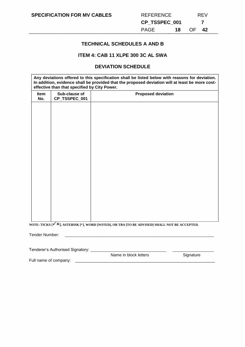
SPECIFICATION FOR MV CABLES REFERENCE REV
CP_TSSPEC_001 7
PAGE 18 OF 42
TECHNICAL SCHEDULES A AND B
ITEM 4: CAB 11 XLPE 300 3C AL SWA
DEVIATION SCHEDULE
Any deviations offered to this specification shall be listed below with reasons for deviation. In addition, evidence shall be provided that the proposed deviation will at least be more cost-effective than that specified by City Power.
Item No.
Sub-clause of CP_TSSPEC_001
Proposed deviation
NOTE: TICKS [], ASTERISK [*], WORD [NOTED], OR TBA [TO BE ADVISED] SHALL NOT BE ACCEPTED.
Tender Number: _________________________________________________________________
Tenderer’s Authorised Signatory: _________________________________ __________________
Name in block letters Signature
Full name of company: _____________________________________________________________

SPECIFICATION FOR MV CABLES REFERENCE REV
CP_TSSPEC_001 7
PAGE 19 OF 42
TECHNICAL SCHEDULES A AND B
ITEM 5: CAB 11 XLPE 500 1C AL AWA Schedule A: Purchaser's specific requirements Schedule B: Guarantees and technical particulars of equipment offered
Item Sub-clause of
CP_TSSPEC_001 Description Schedule A Schedule B
1 Manufacturer’s name XXXXX
2 Country of Origin XXXXX
3 4.1 System operating voltage kV 11
4 4.2 Number of cores (1 or 3 core/s) 1
5 4.2 Conductor size mm2 500
6 4.3 & 4.4 Cable type XLPE XLPE
7 Maximum symmetrical fault level for 1s (SANS 1339)
kA 42.5
8 Earth fault level (1s) kA 25
9 6 Marking requirements Required
10 7 Technical Catalogue to be provided with tender documentation
Required
11 7 Certified copy of type test to be provided with tender documentation
XLPE
SANS 1339 Required
NOTE: TICKS [], ASTERISK [*], WORD [NOTED], OR TBA [TO BE ADVISED] SHALL NOT BE ACCEPTED.
Tender Number: _________________________________________________________________
Tenderer’s Authorised Signatory: _________________________________ __________________
Name in block letters Signature
Full name of company: _____________________________________________________________

SPECIFICATION FOR MV CABLES REFERENCE REV
CP_TSSPEC_001 7
PAGE 20 OF 42
TECHNICAL SCHEDULES A AND B
ITEM 5: CAB 11 XLPE 500 1C AL AWA
DEVIATION SCHEDULE
Any deviations offered to this specification shall be listed below with reasons for deviation. In addition, evidence shall be provided that the proposed deviation will at least be more cost-effective than that specified by City Power.
Item No.
Sub-clause of CP_TSSPEC_001
Proposed deviation
NOTE: TICKS [], ASTERISK [*], WORD [NOTED], OR TBA [TO BE ADVISED] SHALL NOT BE ACCEPTED.
Tender Number: _________________________________________________________________
Tenderer’s Authorised Signatory: _________________________________ __________________
Name in block letters Signature
Full name of company: _____________________________________________________________

SPECIFICATION FOR MV CABLES REFERENCE REV
CP_TSSPEC_001 7
PAGE 21 OF 42
TECHNICAL SCHEDULES A AND B
ITEM 6: CAB 11 XLPE 630 1C AL AWA Schedule A: Purchaser's specific requirements Schedule B: Guarantees and technical particulars of equipment offered
Item Sub-clause of
CP_TSSPEC_001 Description Schedule A Schedule B
1 Manufacturer’s name XXXXX
2 Country of Origin XXXXX
3 4.1 System operating voltage kV 11
4 4.2 Number of cores (1 or 3 core/s) 1
5 4.2 Conductor size mm2 630
6 4.3 & 4.4 Cable type XLPE XLPE
7 Maximum symmetrical fault level for 1s (SANS 133)
kA 55
8 Earth fault level (1s) kA 25
9 6 Marking requirements Required
10 7 Technical Catalogue to be provided with tender documentation
Required
11 7 Certified copy of type test to be provided with tender documentation
XLPE
SANS 1339 Required
NOTE: TICKS [], ASTERISK [*], WORD [NOTED], OR TBA [TO BE ADVISED] SHALL NOT BE ACCEPTED.
Tender Number: _________________________________________________________________
Tenderer’s Authorised Signatory: _________________________________ __________________
Name in block letters Signature
Full name of company: _____________________________________________________________

SPECIFICATION FOR MV CABLES REFERENCE REV
CP_TSSPEC_001 7
PAGE 22 OF 42
TECHNICAL SCHEDULES A AND B
ITEM 6: CAB 11 XLPE 630 1C AL AWA
DEVIATION SCHEDULE
Any deviations offered to this specification shall be listed below with reasons for deviation. In addition, evidence shall be provided that the proposed deviation will at least be more cost-effective than that specified by City Power.
Item No.
Sub-clause of CP_TSSPEC_001
Proposed deviation
NOTE: TICKS [], ASTERISK [*], WORD [NOTED], OR TBA [TO BE ADVISED] SHALL NOT BE ACCEPTED.
Tender Number: _________________________________________________________________
Tenderer’s Authorised Signatory: _________________________________ __________________
Name in block letters Signature
Full name of company: _____________________________________________________________

SPECIFICATION FOR MV CABLES REFERENCE REV
CP_TSSPEC_001 7
PAGE 23 OF 42
TECHNICAL SCHEDULES A & B
ITEM 7: CAB 11 XLPE 1000 1C AL AWA
Schedule A: Purchaser's specific requirements Schedule B: Guarantees and technical particulars of equipment offered
Item Sub-clause of
CP_TSSPEC_001 Description Schedule A Schedule B
1 Manufacturer’s name XXXXX
2 Country of Origin XXXXX
3 4.1 System operating voltage kV 11
4 4.2 Number of cores (1 or 3 core/s) 1
5 4.2 Conductor size mm2 1000
6 4.3 & 4.4 Cable type XLPE XLPE
7 Maximum symmetrical fault level for 1s (SANS 1339)
kA 88
8 Earth fault level(1s) kA 25
9 6 Marking requirements Required
10 7 Technical Catalogue to be provided with tender documentation
Required
11 7 Certified copy of type test to be provided with tender documentation
XLPE
SANS 1339 Required
NOTE: TICKS [], ASTERISK [*], WORD [NOTED], OR TBA [TO BE ADVISED] SHALL NOT BE ACCEPTED.
Tender Number: _________________________________________________________________
Tenderer’s Authorised Signatory: _________________________________ __________________
Name in block letters Signature
Full name of company: _____________________________________________________________

SPECIFICATION FOR MV CABLES REFERENCE REV
CP_TSSPEC_001 7
PAGE 24 OF 42
TECHNICAL SCHEDULES A AND B
ITEM 7: CAB 11 XLPE 1000 1C AL AWA
DEVIATION SCHEDULE
Any deviations offered to this specification shall be listed below with reasons for deviation. In addition, evidence shall be provided that the proposed deviation will at least be more cost-effective than that specified by City Power.
Item No.
Sub-clause of CP_TSSPEC_001
Proposed deviation
NOTE: TICKS [], ASTERISK [*], WORD [NOTED], OR TBA [TO BE ADVISED] SHALL NOT BE ACCEPTED.
Tender Number: _________________________________________________________________
Tenderer’s Authorised Signatory: _________________________________ __________________
Name in block letters Signature
Full name of company: _____________________________________________________________

SPECIFICATION FOR MV CABLES REFERENCE REV
CP_TSSPEC_001 7
PAGE 25 OF 42
TECHNICAL SCHEDULES A AND B
ITEM 8: CAB 22 XLPE 300 1C AL SWA Schedule A: Purchaser's specific requirements Schedule B: Guarantees and technical particulars of equipment offered
Item Sub-clause of
CP_TSSPEC_001 Description Schedule A Schedule B
1 Manufacturer’s name XXXXX
2 Country of Origin XXXXX
3 4.1 System operating voltage kV 22
4 4.2 Number of cores (1 or 3 core/s) 1
5 4.2 Conductor size mm2 300
6 4.3 & 4.4 Cable type XLPE XLPE
7 Maximum symmetrical fault level for 1s (SANS 1339)
kA 25.7
8 Earth fault level (1s) kA 25
9 6 Marking requirements Required
10 7 Technical Catalogue to be provided with tender documentation
Required
11 7 Certified copy of type test to be provided with tender documentation
XLPE
SANS 1339 Required
NOTE: TICKS [], ASTERISK [*], WORD [NOTED], OR TBA [TO BE ADVISED] SHALL NOT BE ACCEPTED.
Tender Number: _________________________________________________________________
Tenderer’s Authorised Signatory: _________________________________ __________________
Name in block letters Signature
Full name of company: _____________________________________________________________

SPECIFICATION FOR MV CABLES REFERENCE REV
CP_TSSPEC_001 7
PAGE 26 OF 42
TECHNICAL SCHEDULES A AND B
ITEM 8: CAB 22 XLPE 300 1C AL SWA
DEVIATION SCHEDULE
Any deviations offered to this specification shall be listed below with reasons for deviation. In addition, evidence shall be provided that the proposed deviation will at least be more cost-effective than that specified by City Power.
Item No.
Sub-clause of CP_TSSPEC_001
Proposed deviation
NOTE: TICKS [], ASTERISK [*], WORD [NOTED], OR TBA [TO BE ADVISED] SHALL NOT BE ACCEPTED.
Tender Number: _________________________________________________________________
Tenderer’s Authorised Signatory: _________________________________ __________________
Name in block letters Signature
Full name of company: _____________________________________________________________

SPECIFICATION FOR MV CABLES REFERENCE REV
CP_TSSPEC_001 7
PAGE 27 OF 42
TECHNICAL SCHEDULES A AND B
ITEM 9: CAB 22 XLPE 300 3C AL SWA Schedule A: Purchaser's specific requirements Schedule B: Guarantees and technical particulars of equipment offered
Item Sub-clause of
CP_TSSPEC_001 Description Schedule A Schedule B
1 Manufacturer’s name XXXXX
2 Country of Origin XXXXX
3 4.1 System operating voltage kV 22
4 4.2 Number of cores (1 or 3 core/s) 3
5 4.2 Conductor size mm2 300
6 4.3 & 4.4 Cable type XLPE XLPE
7 Maximum symmetrical fault level for 1s (SANS 1339)
kA 25.7
8 Earth fault level (1s) kA 25
9 6 Marking requirements Required
10 7 Technical Catalogue to be provided with tender documentation
Required
11 7 Certified copy of type test to be provided with tender documentation
XLPE
SANS 1339 Required
NOTE: TICKS [], ASTERISK [*], WORD [NOTED], OR TBA [TO BE ADVISED] SHALL NOT BE ACCEPTED.
Tender Number: _________________________________________________________________
Tenderer’s Authorised Signatory: _________________________________ __________________
Name in block letters Signature
Full name of company: _____________________________________________________________

SPECIFICATION FOR MV CABLES REFERENCE REV
CP_TSSPEC_001 7
PAGE 28 OF 42
TECHNICAL SCHEDULES A AND B
ITEM 9: CAB 22 XLPE 300 3C AL SWA
DEVIATION SCHEDULE
Any deviations offered to this specification shall be listed below with reasons for deviation. In addition, evidence shall be provided that the proposed deviation will at least be more cost-effective than that specified by City Power.
Item No.
Sub-clause of CP_TSSPEC_001
Proposed deviation
NOTE: TICKS [], ASTERISK [*], WORD [NOTED], OR TBA [TO BE ADVISED] SHALL NOT BE ACCEPTED.
Tender Number: _________________________________________________________________
Tenderer’s Authorised Signatory: _________________________________ __________________
Name in block letters Signature
Full name of company: _____________________________________________________________
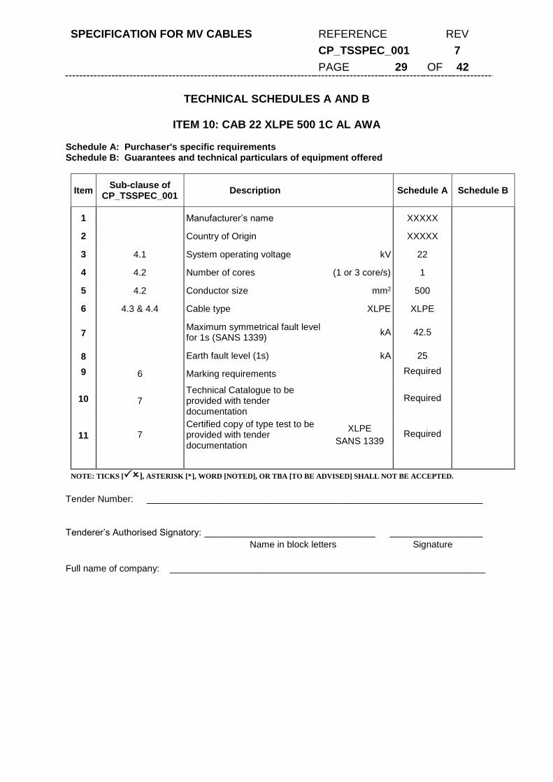
SPECIFICATION FOR MV CABLES REFERENCE REV
CP_TSSPEC_001 7
PAGE 29 OF 42
TECHNICAL SCHEDULES A AND B
ITEM 10: CAB 22 XLPE 500 1C AL AWA Schedule A: Purchaser's specific requirements Schedule B: Guarantees and technical particulars of equipment offered
Item Sub-clause of
CP_TSSPEC_001 Description Schedule A Schedule B
1 Manufacturer’s name XXXXX
2 Country of Origin XXXXX
3 4.1 System operating voltage kV 22
4 4.2 Number of cores (1 or 3 core/s) 1
5 4.2 Conductor size mm2 500
6 4.3 & 4.4 Cable type XLPE XLPE
7 Maximum symmetrical fault level for 1s (SANS 1339)
kA 42.5
8 Earth fault level (1s) kA 25
9 6 Marking requirements Required
10 7 Technical Catalogue to be provided with tender documentation
Required
11 7 Certified copy of type test to be provided with tender documentation
XLPE
SANS 1339 Required
NOTE: TICKS [], ASTERISK [*], WORD [NOTED], OR TBA [TO BE ADVISED] SHALL NOT BE ACCEPTED.
Tender Number: _________________________________________________________________
Tenderer’s Authorised Signatory: _________________________________ __________________
Name in block letters Signature
Full name of company: _____________________________________________________________

SPECIFICATION FOR MV CABLES REFERENCE REV
CP_TSSPEC_001 7
PAGE 30 OF 42
TECHNICAL SCHEDULES A AND B
ITEM 10: CAB 22 XLPE 500 1C AL AWA
DEVIATION SCHEDULE
Any deviations offered to this specification shall be listed below with reasons for deviation. In addition, evidence shall be provided that the proposed deviation will at least be more cost-effective than that specified by City Power.
Item No.
Sub-clause of CP_TSSPEC_001
Proposed deviation
NOTE: TICKS [], ASTERISK [*], WORD [NOTED], OR TBA [TO BE ADVISED] SHALL NOT BE ACCEPTED.
Tender Number: _________________________________________________________________
Tenderer’s Authorised Signatory: _________________________________ __________________
Name in block letters Signature
Full name of company: _____________________________________________________________

SPECIFICATION FOR MV CABLES REFERENCE REV
CP_TSSPEC_001 7
PAGE 31 OF 42
TECHNICAL SCHEDULES A AND B
ITEM 11: CAB 22 XLPE 630 1C AL AWA Schedule A: Purchaser's specific requirements Schedule B: Guarantees and technical particulars of equipment offered
Item Sub-clause of
CP_TSSPEC_001 Description Schedule A Schedule B
1 Manufacturer’s name XXXXX
2 Country of Origin XXXXX
3 4.1 System operating voltage kV 22
4 4.2 Number of cores (1 or 3 core/s) 1
5 4.2 Conductor size mm2 630
6 4.3 & 4.4 Cable type XLPE XLPE
7 Maximum symmetrical fault level for 1s (SANS 133)
kA 55
8 Earth fault level (1s) kA 25
9 6 Marking requirements Required
10 7 Technical Catalogue to be provided with tender documentation
Required
11 7 Certified copy of type test to be provided with tender documentation
XLPE
SANS 1339 Required
NOTE: TICKS [], ASTERISK [*], WORD [NOTED], OR TBA [TO BE ADVISED] SHALL NOT BE ACCEPTED.
Tender Number: _________________________________________________________________
Tenderer’s Authorised Signatory: _________________________________ __________________
Name in block letters Signature
Full name of company: _____________________________________________________________

SPECIFICATION FOR MV CABLES REFERENCE REV
CP_TSSPEC_001 7
PAGE 32 OF 42
TECHNICAL SCHEDULES A AND B
ITEM 11: CAB 22 XLPE 630 1C AL AWA
DEVIATION SCHEDULE
Any deviations offered to this specification shall be listed below with reasons for deviation. In addition, evidence shall be provided that the proposed deviation will at least be more cost-effective than that specified by City Power.
Item No.
Sub-clause of CP_TSSPEC_001
Proposed deviation
NOTE: TICKS [], ASTERISK [*], WORD [NOTED], OR TBA [TO BE ADVISED] SHALL NOT BE ACCEPTED.
Tender Number: _________________________________________________________________
Tenderer’s Authorised Signatory: _________________________________ __________________
Name in block letters Signature
Full name of company: _____________________________________________________________

SPECIFICATION FOR MV CABLES REFERENCE REV
CP_TSSPEC_001 7
PAGE 33 OF 42
TECHNICAL SCHEDULES A AND B
ITEM 12: CAB 33 XLPE 300 3C AL SWA Schedule A: Purchaser's specific requirements Schedule B: Guarantees and technical particulars of equipment offered
Item Sub-clause of
CP_TSSPEC_001 Description Schedule A Schedule B
1 Manufacturer’s name XXXXXX
2 Country of Origin XXXXXX
3 4.1 System operating voltage kV 33
4 4.2 Number of cores (1 or 3 core/s) 3
5 4.2 Conductor size mm2 300
6 4.3 & 4.4 Cable type XLPE XLPE
7 Symmetrical fault level (SANS1339)
kA XXXXX
8 Earth fault level (1s) kA 25 XXXXX
9 6 Marking requirements Required
10 7 Technical Catalogue to be provided with tender documentation
Required
11 7 Certified copy of type test to be provided with tender documentation
XLPE
SANS 1339
Required
NOTE: TICKS [], ASTERISK [*], WORD [NOTED], OR TBA [TO BE ADVISED] SHALL NOT BE ACCEPTED.
Tender Number: _________________________________________________________________
Tenderer’s Authorised Signatory: _________________________________ __________________
Name in block letters Signature
Full name of company: _____________________________________________________________

SPECIFICATION FOR MV CABLES REFERENCE REV
CP_TSSPEC_001 7
PAGE 34 OF 42
TECHNICAL SCHEDULES A AND B
ITEM 12: CAB 33 XLPE 300 3C AL SWA
DEVIATION SCHEDULE
Any deviations offered to this specification shall be listed below with reasons for deviation. In addition, evidence shall be provided that the proposed deviation will at least be more cost-effective than that specified by City Power.
Item No.
Sub-clause of CP_TSSPEC_001
Proposed deviation
NOTE: TICKS [], ASTERISK [*], WORD [NOTED], OR TBA [TO BE ADVISED] SHALL NOT BE ACCEPTED.
Tender Number: _________________________________________________________________
Tenderer’s Authorised Signatory: _________________________________ __________________
Name in block letters Signature
Full name of company: _____________________________________________________________

SPECIFICATION FOR MV CABLES REFERENCE REV
CP_TSSPEC_001 7
PAGE 35 OF 42
TECHNICAL SCHEDULES A AND B
ITEM 13: CAB 33 XLPE 300 1C AL AWA Schedule A: Purchaser's specific requirements Schedule B: Guarantees and technical particulars of equipment offered
Item Sub-clause of
CP_TSSPEC_001 Description Schedule A Schedule B
1 Manufacturer’s name XXXXX
2 Country of Origin XXXXX
3 4.1 System operating voltage kV 33
4 4.2 Number of cores (1 or 3 core/s) 1
5 4.2 Conductor size mm2 300
6 4.3 & 4.4 Cable type XLPE XLPE
7 Symmetrical fault level (SANS 1339)
kA XXXXX
8 Earth fault level(1s) kA 25 XXXXX
9 6 Marking requirements Required
10 7 Technical Catalogue to be provided with tender documentation
Required
11 7
Certified copy of type test to be provided with tender documentation
XLPE
SANS 1339 Required
NOTE: TICKS [], ASTERISK [*], WORD [NOTED], OR TBA [TO BE ADVISED] SHALL NOT BE ACCEPTED.
Tender Number: _________________________________________________________________
Tenderer’s Authorised Signatory: _________________________________ __________________
Name in block letters Signature
Full name of company: _____________________________________________________________

SPECIFICATION FOR MV CABLES REFERENCE REV
CP_TSSPEC_001 7
PAGE 36 OF 42
TECHNICAL SCHEDULES A AND B
ITEM 13: CAB 33 XLPE 300 1C AL AWA
DEVIATION SCHEDULE
Any deviations offered to this specification shall be listed below with reasons for deviation. In addition, evidence shall be provided that the proposed deviation will at least be more cost-effective than that specified by City Power.
Item No.
Sub-clause of CP_TSSPEC_001
Proposed deviation
NOTE: TICKS [], ASTERISK [*], WORD [NOTED], OR TBA [TO BE ADVISED] SHALL NOT BE ACCEPTED.
Tender Number: _________________________________________________________________
Tenderer’s Authorised Signatory: _________________________________ __________________
Name in block letters Signature
Full name of company: _____________________________________________________________

SPECIFICATION FOR MV CABLES REFERENCE REV
CP_TSSPEC_001 7
PAGE 37 OF 42
TECHNICAL SCHEDULES A AND B
ITEM 14: CAB 33 XLPE 185 3C AL SWA Schedule A: Purchaser's specific requirements Schedule B: Guarantees and technical particulars of equipment offered
Item Sub-clause of
CP_TSSPEC_001 Description Schedule A Schedule B
1 Manufacturer’s name XXXXX
2 Country of Origin XXXXX
3 4.1 System operating voltage kV 33
4 4.2 Number of cores (1 or 3 core/s) 3
5 4.2 Conductor size mm2 185
6 4.3 & 4.4 Cable type XLPE XLPE
7 Symmetrical fault level (SANS 1339)
kA 15.7
8 Earth fault level (1s) kA 25 XXXXX
9 6 Marking requirements Required
10 7 Technical Catalogue to be provided with tender documentation
Required
11 7
Certified copy of type test to be provided with tender documentation
XLPE
SANS 1339 Required
NOTE: TICKS [], ASTERISK [*], WORD [NOTED], OR TBA [TO BE ADVISED] SHALL NOT BE ACCEPTED.
Tender Number: _________________________________________________________________
Tenderer’s Authorised Signatory: _________________________________ __________________
Name in block letters Signature
Full name of company: _____________________________________________________________

SPECIFICATION FOR MV CABLES REFERENCE REV
CP_TSSPEC_001 7
PAGE 38 OF 42
TECHNICAL SCHEDULES A AND B
ITEM 14: CAB 33 XLPE 185 3C AL SWA
DEVIATION SCHEDULE
Any deviations offered to this specification shall be listed below with reasons for deviation. In addition, evidence shall be provided that the proposed deviation will at least be more cost-effective than that specified by City Power.
Item No.
Sub-clause of CP_TSSPEC_001
Proposed deviation
NOTE: TICKS [], ASTERISK [*], WORD [NOTED], OR TBA [TO BE ADVISED] SHALL NOT BE ACCEPTED.
Tender Number: _________________________________________________________________
Tenderer’s Authorised Signatory: _________________________________ __________________
Name in block letters Signature
Full name of company: _____________________________________________________________

SPECIFICATION FOR MV CABLES REFERENCE REV
CP_TSSPEC_001 7
PAGE 39 OF 42
TECHNICAL SCHEDULES A AND B
ITEM 14: CAB 33 XLPE 185 1C AL AWA Schedule A: Purchaser's specific requirements Schedule B: Guarantees and technical particulars of equipment offered
Item Sub-clause of
CP_TSSPEC_001 Description Schedule A Schedule B
1 Manufacturer’s name XXXXX
2 Country of Origin XXXXX
3 4.1 System operating voltage kV 33
4 4.2 Number of cores (1 or 3 core/s) 1
5 4.2 Conductor size mm2 185
6 4.3 & 4.4 Cable type Paper / XLPE XLPE
7 Symmetrical fault level (SANS 1339)
kA 15.7
8 Earth fault level (1s) kA 25
9 6 Marking requirements Required
10 7 Technical Catalogue to be provided with tender documentation
Required
11 7
Certified copy of type test to be provided with tender documentation
XLPE
SANS 1339 Required
NOTE: TICKS [], ASTERISK [*], WORD [NOTED], OR TBA [TO BE ADVISED] SHALL NOT BE ACCEPTED.
Tender Number: _________________________________________________________________
Tenderer’s Authorised Signatory: _________________________________ __________________
Name in block letters Signature
Full name of company: _____________________________________________________________

SPECIFICATION FOR MV CABLES REFERENCE REV
CP_TSSPEC_001 7
PAGE 40 OF 42
TECHNICAL SCHEDULES A AND B
ITEM 14: CAB 33 XLPE 185 1C AL AWA
DEVIATION SCHEDULE
Any deviations offered to this specification shall be listed below with reasons for deviation. In addition, evidence shall be provided that the proposed deviation will at least be more cost-effective than that specified by City Power.
Item No.
Sub-clause of CP_TSSPEC_001
Proposed deviation
NOTE: TICKS [], ASTERISK [*], WORD [NOTED], OR TBA [TO BE ADVISED] SHALL NOT BE ACCEPTED.
Tender Number: _________________________________________________________________
Tenderer’s Authorised Signatory: _________________________________ __________________
Name in block letters Signature
Full name of company: _____________________________________________________________

SPECIFICATION FOR MV CABLES REFERENCE REV
CP_TSSPEC_001 7
PAGE 41 OF 42
ANNEXURE D – STOCK ITEMS
Item SAP No. SAP Short Description SAP Long Description
1 3231 CAB 11 XLPE 120 3C AL SWA CABLE 6,35 / 11KV, 120 MM SQ ALUMINIUM CONDUCTOR, THREE CORE, XLPE INSULATED, SCREENED, PVC BEDDED, STEEL WIRE ARMOURED AND HAVING A BLACK POLYETHYLENE OUTER SHEATH. ITEM SPECIFICATION NO. CP_TSSPEC_001
2 3232 CAB 11 XLPE 185 3C AL SWA CABLE 6,35 / 11KV, 185 MM SQ ALUMINIUM CONDUCTOR, THREE CORE, XLPE INSULATED, SCREENED, PVC BEDDED, STEEL WIRE ARMOURED AND HAVING A BLACK POLYETHYLENE OUTER SHEATH. ITEM SPECIFICATION NO. CP_TSSPEC_001
3 911 CAB 11 XLPE 300 1C AL UARM CABLE 6,35 / 11KV, 300 MM SQ ALUMINIUM CONDUCTOR, SINGLE CORE, XLPE INSULATED, SCREENED, PVC BEDDED, UNARMOURED AND HAVING A BLACK POLYETHYLENE OUTER SHEATH. ITEM SPECIFICATION NO. CP_TSSPEC_001.
4 3234 CAB 11 XLPE 300 3C AL SWA CABLE 6,35 / 11KV, 300 MM SQ ALUMINIUM CONDUCTOR, THREE CORE, XLPE INSULATED, SCREENED, PVC BEDDED, STEEL WIRE ARMOURED AND HAVING A BLACK POLYETHYLENE OUTER SHEATH. ITEM SPECIFICATION NO. CP_TSSPEC_001
5 3324 CAB 11 XLPE 500 1C AL AWA CABLE 6,35 / 11KV, 500 MM SQ ALUMINIUM CONDUCTOR, SINGLE CORE, XLPE INSULATED, SCREENED, PVC BEDDED, ALUMINUM WIRE ARMOURED AND HAVING A BLACK POLYETHYLENE OUTER SHEATH. ITEM SPECIFICATION NO. CP_TSSPEC_001
6 2742 CAB 11 XLPE 630 1C AL AWA CABLE 6,35 / 11KV, 630 MM SQ ALUMINIUM CONDUCTOR, SINGLE CORE, XLPE INSULATED, SCREENED, PVC BEDDED, ALUMINUM WIRE ARMOURED AND HAVING A BLACK POLYETHYLENE OUTER SHEATH. ITEM SPECIFICATION NO. CP_TSSPEC_001
7 3236 CAB 11 XLPE 1000 1C AL AWA CABLE 6,35 / 11KV, 1000 MM SQ ALUMINIUM CONDUCTOR, SINGLE CORE, XLPE INSULATED, SCREENED, PVC BEDDED, ALUMINUM WIRE ARMOURED AND HAVING A BLACK POLYETHYLENE OUTER SHEATH. ITEM SPECIFICATION NO. CP_TSSPEC_001
8 4142 CAB 22 XLPE 300 1C AL SWA CABLE 12.7 / 22KV, 300 MM SQ ALUMINIUM CONDUCTOR, SINGLE CORE, XLPE INSULATED, SCREENED, PVC BEDDED, STEEL WIRE ARMOURED AND HAVING A BLACK POLYETHYLENE OUTER SHEATH. ITEM SPECIFICATION NO. CP_TSSPEC_001
9 3326 CAB 22 XLPE 300 3C AL SWA CABLE 12.7 / 22KV, 300 MM SQ ALUMINIUM CONDUCTOR, THREE CORE, XLPE INSULATED, SCREENED, PVC BEDDED, STEEL WIRE ARMOURED AND HAVING A BLACK POLYETHYLENE OUTER SHEATH. ITEM SPECIFICATION NO. CP_TSSPEC_001
10 3328 CAB 22 XLPE 500 1C AL AWA CABLE 12.7 / 22KV, 500 MM SQ ALUMINIUM CONDUCTOR, SINGLE CORE, XLPE INSULATED, SCREENED, PVC BEDDED, ALUMINUM WIRE ARMOURED AND HAVING A BLACK POLYETHYLENE OUTER SHEATH. ITEM SPECIFICATION NO. CP_TSSPEC_001

SPECIFICATION FOR MV CABLES REFERENCE REV
CP_TSSPEC_001 7
PAGE 42 OF 42
11 3329 CAB 22 XLPE 630 1C AL SWA CABLE 12.7 / 22KV, 630 MM SQ ALUMINIUM CONDUCTOR, SINGLE CORE, XLPE INSULATED, SCREENED, PVC BEDDED, STEEL WIRE ARMOURED AND HAVING A BLACK POLYETHYLENE OUTER SHEATH. ITEM SPECIFICATION NO. CP_TSSPEC_001
12 1191 CAB 33 XLPE 300 3CU AL SWA CABLE 19 / 33KV, 300 MM SQ ALUMINIUM CONDUCTOR, THREE CORE, XLPE INSULATED, SCREENED, PVC BEDDED, STEEL WIRE ARMOURED AND BLACK POLYETHYLENE OUTER SHEATH. ITEM SPECIFICATION NO. CP_TSSPEC_001.
13 1481 CAB 33 XLPE 300 1CU AL SWA CABLE 19 / 33KV, 300 MM SQ ALUMINIUM CONDUCTOR, THREE CORE, XLPE INSULATED, SCREENED, PVC BEDDED, STEEL WIRE ARMOURED AND BLACK POLYETHYLENE OUTER SHEATH. ITEM SPECIFICATION NO. CP_TSSPEC_001.
14 1482 CAB 33 XLPE 185 3C AL SWA CABLE 19 / 33KV, 185 MM SQ ALUMINIUM CONDUCTOR, THREE CORE, XLPE INSULATED, SCREENED, PVC BEDDED, STEEL WIRE ARMOURED AND BLACK POLYETHYLENE OUTER SHEATH. ITEM SPECIFICATION NO. CP_TSSPEC_001.
15 1483 CAB 33 XLPE 185 1C AL AWA CABLE 19 / 33KV, 185 MM SQ ALUMINIUM CONDUCTOR, SINGLE CORE, XLPE INSULATED, SCREENED, PVC BEDDED, ALUMINIUM WIRE ARMOURED AND BLACK POLYETHYLENE OUTER SHEATH. ITEM SPECIFICATION NO. CP_TSSPEC_001.

REFERENCE
REV
TITLE SPECIFICATION FOR LV INSULATED WIRE POWER AND MULTI-CORE CABLES
CP_TSSPEC_002 7
DATE: NOVEMBER 2018
PAGE: 1 OF 79
TABLE OF CONTENTS
FOREWORD ................................................................................................................................................................................ 3
1. INTRODUCTION .......................................................................................................................................................... 4
2. SCOPE ............................................................................................................................................................................. 4
3. NORMATIVE REFERENCES ..................................................................................................................................... 4
4. DEFINITIONS AND ABBREVIATIONS .................................................................................................................... 4
5. REQUIREMENTS ......................................................................................................................................................... 4
6 PACKAGING AND MARKING ................................................................................................................................... 8
7 DOCUMENTATION ..................................................................................................................................................... 8
8 TESTS .............................................................................................................................................................................. 9
9 QUALITY MANAGEMENT ........................................................................................................................................ 9
10 ENVIRONMENTAL MANAGEMENT ....................................................................................................................... 9
11 OCCUPATIONAL HEALTH AND SAFETY (OHS) MANAGEMENT ................................................................ 10
ANNEX B - REVISION INFORMATION ............................................................................................................................... 12
ANNEX C - TECHNICAL SCHEDULES A & B: SAP No. 1722........................................................................................... 14
ANNEX C - TECHNICAL SCHEDULES A & B: SAP No. 1521........................................................................................... 16
ANNEX C - TECHNICAL SCHEDULES A & B: SAP No. 1724........................................................................................... 18
ANNEX C - TECHNICAL SCHEDULES A & B: SAP No. 1723........................................................................................... 20
ANNEX C - TECHNICAL SCHEDULES A & B: SAP No. 1725........................................................................................... 22
DEVIATION SCHEDULE: SAP No. 1725 ............................................................................................................................... 23
ANNEX C - TECHNICAL SCHEDULES A & B: SAP No. 3923........................................................................................... 24

SPECIFICATION FOR LV INSULATED WIRE POWER AND MULTI-CORE CONTROL CABLES
REFERENCE REV
CP_TSSPEC_002 7
PAGE 2 OF 79
ANNEX C - TECHNICAL SCHEDULES A & B: SAP No. 3924........................................................................................... 26
ANNEX C - TECHNICAL SCHEDULES A & B: SAP No. 3925........................................................................................... 28
ANNEX C - TECHNICAL SCHEDULES A & B: SAP No. 3926........................................................................................... 30
ANNEX C - TECHNICAL SCHEDULES A & B: SAP No. 3927........................................................................................... 32
ANNEX C - TECHNICAL SCHEDULES A & B: SAP No. 3911........................................................................................... 34
ANNEX C - TECHNICAL SCHEDULES A & B: SAP No. 3921........................................................................................... 36
ANNEX C - TECHNICAL SCHEDULES A & B: SAP No. 3922........................................................................................... 38
ANNEX C - TECHNICAL SCHEDULES A & B: SAP No. 1726........................................................................................... 40
ANNEX C - TECHNICAL SCHEDULES A & B: SAP No. 1721........................................................................................... 44
ANNEX C - TECHNICAL SCHEDULES A & B: SAP No. 1727........................................................................................... 46
ANNEX C - TECHNICAL SCHEDULES A & B: SAP No. 1532........................................................................................... 48
ANNEX C - TECHNICAL SCHEDULES A & B: SAP No. 1301........................................................................................... 50
ANNEX C - TECHNICAL SCHEDULES A & B: SAP No. 1088........................................................................................... 52
ANNEX C - TECHNICAL SCHEDULES A & B: SAP No. 1511........................................................................................... 54
ANNEX C - TECHNICAL SCHEDULES A & B: SAP No. 5040........................................................................................... 56
ANNEX C - TECHNICAL SCHEDULES A & B: SAP No. 5082........................................................................................... 58
ANNEX C - TECHNICAL SCHEDULES A & B: SAP No. 3928........................................................................................... 60
ANNEX C - TECHNICAL SCHEDULES A & B: SAP No. 3929........................................................................................... 62
ANNEX C - TECHNICAL SCHEDULES A & B: SAP No. 3930........................................................................................... 64
ANNEX C - TECHNICAL SCHEDULES A & B: SAP No. 3931........................................................................................... 66
ANNEX C - TECHNICAL SCHEDULES A & B: SAP No. 3932........................................................................................... 68
ANNEX C - TECHNICAL SCHEDULES A & B: SAP No. 3933........................................................................................... 70
ANNEX C - TECHNICAL SCHEDULES A & B: SAP No. 3934........................................................................................... 72
ANNEX C - TECHNICAL SCHEDULES A & B: SAP No. 5107........................................................................................... 74
ANNEX D-CABLE IND ............................................................................................................................................................. 76
ANNEX D-CABLE LV ............................................................................................................................................................... 78

SPECIFICATION FOR LV INSULATED WIRE POWER AND MULTI-CORE CONTROL CABLES
REFERENCE REV
CP_TSSPEC_002 7
PAGE 3 OF 79
FOREWORD
Recommendations for corrections, additions or deletions should be addressed to the: Technology Services Manager
City Power Johannesburg (Pty) Ltd
P O Box 38766
Booysens
2016

SPECIFICATION FOR LV INSULATED WIRE POWER AND MULTI-CORE CONTROL CABLES
REFERENCE REV
CP_TSSPEC_002 7
PAGE 4 OF 79
1. INTRODUCTION
City Power has undertaken to utilize the SABS support structures that monitor compliance to specification and quality of manufacture of low voltage cables. City Power will therefore only purchase cable that bears the SANS 1507 mark of approval.
2. SCOPE
This specification covers City Power’s requirements for low voltage insulated wire, power and control cables.
3. NORMATIVE REFERENCES
The following document contains provisions that, through reference in the text, constitute requirements of this specification. At the time of publication, the edition indicated was valid. All standards and specifications are subject to revision, and parties to agreements based on this specification are encouraged to investigate the possibility of applying the most recent edition of the document listed below.
SANS 10292, Earthing of low-voltage (LV) distribution systems
SANS 6284; Test methods for cross-linked polyethylene (XLPE) insulated electric cables
SANS 1507, Electric cables with extruded solid dielectric insulation for fixed installations (300/500 V to 1 900/3 300 V).
SANS 1507, Electric cables – Flexible cords and flexible cables.
VC 8075, Compulsory specification for the safety of electric cables with extruded solid dielectric insulation for fixed installations (300/500 V to 1 900/3 300 V).
4. DEFINITIONS AND ABBREVIATIONS
The definitions and abbreviations in SANS 1507 and SANS 1507 shall apply to this specification.
5. REQUIREMENTS
5.1 General
As per the compulsory specification VC 8075 for low voltage cable, all low voltage cables shall comply with SANS 1507. Low voltage flexible cables (SAP number 1511) shall comply with SANS 1507. Item 5068 and 5055 shall not comply with any SANS standard, but shall be rated at 11 kV and shall be designated “Danger unscreened 11 kV PVC jumpers”.
5.2 Equivalents: Copper vs. Aluminum Cables
COPPER CURRENT RATING Volt
drop(3ɸ)
ALUMINIUM CURRENT RATING Volt
drop(3ɸ)
Cable size
(mm²)
Ground
(A)
Duct
(A)
Air
(A)
Cable size
(mm²)
Ground
(A)
Duct
(A)
Air (A)
16 94 110 76 2.546 25 115 92 108 1.813
25 123 96 110 1.515 35 129 104 119 1.342

SPECIFICATION FOR LV INSULATED WIRE POWER AND MULTI-CORE CONTROL CABLES
REFERENCE REV
CP_TSSPEC_002 7
PAGE 5 OF 79
35 148 116 135 1.097 50 158 130 151 0.933
50 177 138 163 0.817 70 192 157 186 0.681
70 216 171 207 0.576 95 219 179 216 0.545
95 258 302 209 0.448 120 278 229 287 0.369
120 293 344 238 0.365 150 324 268 342 0.296
150 329 387 268 0.307 185 324 268 342 0.296
185 371 435 302 0.260 240 392 325 438 0.309
Table 1: 3/4C XLPE Insulated PVC bedded, SWA PVC Sheathed 600/1000 V)
Copper 1C vs Stranded Aluminum 1C Armoured XLPE insulated PVC bedded, SWA PVC Sheathed
600/1000 V)
COPPER CURRENT RATING Volt
drop(3ɸ)
ALUMINIUM CURRENT RATING Volt
drop(3ɸ)
Cable size
(mm²)
Ground
(A)
Duct
(A)
Air
(A)
Cable size
(mm²)
Ground
(A)
Duct
(A)
Air (A)
25 127 111 112 1.52 35 150 116 145 1.93
35 153 132 141 1.10 50 192 163 176 1.43
50 180 155 172 0.82 70 238 202 220 0.99
70 221 190 223 0.58 95 292 249 274 0.72
95 265 226 273 0.43 120 329 279 313 0.58
120 301 256 318 0.36 150 364 310 348 0.48
150 338 287 369 0.30 185 412 350 397 0.39
185 381 323 424 0.26 240 487 414 476 0.31
240 442 372 504 0.22 300 555 472 548 0.26

SPECIFICATION FOR LV INSULATED WIRE POWER AND MULTI-CORE CONTROL CABLES
REFERENCE REV
CP_TSSPEC_002 7
PAGE 6 OF 79
300 499 419 584 0.20 400 560 476 560 0.21
400 565 472 679 0.18 500 572 486 579 0.19
500 634 532 778 0.17 630 582 495 597 0.17
630 718 603 892 0.15 800 588 500 611 0.15
Table 2: 1C XLPE Insulated PVC bedded, SWA PVC Sheathed (600/1000 V)
5.3 Rated voltages
4.3.1 The rated voltage of low voltage insulated wire shall be 600/1000 V
4.3.2 The rated voltage of low voltage power and control cables, and flexible cable, shall be 600/1000 V.
4.3.3 The rated voltage of item 5068 and 5055 shall be 6,35/11 kV.
5.4 Materials and construction
5.4.1 Conductors
Conductors shall be compacted stranded annealed copper for cable sizes 2.5 mm2 up to 16mm2 and stranded Aluminium for cable sizes 25mm2 and above
5.4.2 Insulation material
Insulating material shall be , PVC type D2 for cable sizes
NOTE: As insulated wires are unarmoured they shall not be laid underground. However, they are used in overhead applications where they are exposed to solar radiation and therefore the insulation should be UV resistant.
5.4.3 Core identification
Core identification of insulated wires and flexible cable shall be as indicated in table 3:
Colour(s) of wires Wire sizes (mm2) Application
Red 2.5 & 16
95 & 285
Metering & LV service connections
MV cable leads
Yellow 2.5 & 16
120
Metering & LV service connections
LV cable leads for MCCB’s in MSS
Blue 2.5 & 16 Metering & LV service connections
Black 2.5 & 16
50
Metering & LV service connections
LV overhead distribution
Green & Yellow 2.5 & 16
70
Metering & LV service connections
Earthing
Table 3 – Core identification for insulated wires and flexible cables

SPECIFICATION FOR LV INSULATED WIRE POWER AND MULTI-CORE CONTROL CABLES
REFERENCE REV
CP_TSSPEC_002 7
PAGE 7 OF 79
Core identification of power cables shall be as indicated in table 4:
Number of phase cores
Colour(s) of phase cores
Colour of neutral core
Sizes of Cores (mm2)
Application
1 Red Black 2.5, 4 & 16 Protection & single phase LV service connections
3 Red, yellow and blue
Black 2.5, 4 & 16 Protection & three phase LV service connections
3 Red, yellow and blue
Black 25, 35,50, 70, 120,150 & 185
Distribution networks & special low voltage LV service connections
Table 4 – Core identification for power cables
NOTE: City Power applies a TN-C-S earthing system as per SANS 10292, therefore the neutral conductor is a combined protective neutral earth conductor. Only armoured power cable shall be laid in the ground.
Core identification of multi-core control cables (with more than five cores) shall be as indicated in table 5:
Number of cores
Colour(s) of phase cores
Sizes of Cores (mm2)
Application
12 Black with white numbering
2.5 Metering systems and panel interconnection wiring
Table 5 – Core identification for multi-core control cables
NOTE: Multi-core control cables shall be numbered numerically from number 1 to the total number of cores.
5.4.4 Bedding under armoring
Cables shall have black PVC type B bedding.
5.4.5 Armor
Armoured cables shall have galvanized steel wire armour.
5.4.6 Outer sheath
Cables shall have a black PVC type S2 outer sheath unless otherwise stated in the description.

SPECIFICATION FOR LV INSULATED WIRE POWER AND MULTI-CORE CONTROL CABLES
REFERENCE REV
CP_TSSPEC_002 7
PAGE 8 OF 79
6 PACKAGING AND MARKING
6.1 Packaging
6.1.1 Insulated wires shall be supplied in coil lengths of 100 m.
6.1.2 Power cables smaller than 16 mm2 shall be supplied in drum lengths of 500 m.
6.1.3 Power cables greater than 16 mm2 shall be supplied in drum lengths of 300 m.
6.1.4 Multi-core control cables shall be supplied in drum lengths of 500 m.
6.2 Marking
Cables shall be legibly marked in accordance with the requirements of SANS 1507, but the marking shall include the specification number to which the cable has been manufactured, the conductor size in mm2 and material i.e. copper (Cu). A typical legend would be:
XXXXXXXX CABLES 2000 600/1000 V 16 MM SQ Cu SANS 1507.
In addition, all cables with a conductor cross-sectional area of 120 mm2 and greater shall be marked with the letters “CPJ” to identify the cable as property of City Power.
The cable shall also bear the SANS 1507 mark of approval.
The cable shall be sequentially marked at one metre intervals with the legend 000 m, 001 m etc. starting with 000 m at the barrel of the drum and finishing with the number indicating the length of cable on the drum at the outer end of the cable. The error in the length marking shall be less than 1 %.
The cable shall have the property of reduced flame propagation and shall therefore have a red stripe longitudinally along the outer sheath.
7 DOCUMENTATION
A technical product catalogue that gives the following information shall be provided at the time of tender for the full range of cables manufactured in accordance with SANS 1507:
7.1 Cable dimensional data:
7.1.1 Diameter over conductor;
7.1.2 Diameter over insulation;
7.1.3 Diameter over bedding;
7.1.4 Diameter over armor wires (if applicable); and
7.1.5 Diameter over sheath.
7.2 Maximum sustained current rating in ground, air and ducts.
NOTE The standard installation conditions assumed shall be stated.
i. Short-circuit ratings.
ii. Cable mass (kg/m).
iii. Gross mass per standard drum length (kg).
iv. The 50 Hz a.c. resistance at maximum sustained conductor operating temperature (ohm/km).
v. Reactance per phase (ohm/km).

SPECIFICATION FOR LV INSULATED WIRE POWER AND MULTI-CORE CONTROL CABLES
REFERENCE REV
CP_TSSPEC_002 7
PAGE 9 OF 79
vi. Capacitance per phase (nF/km).
vii. Zero sequence impedance and capacitance per phase at maximum sustained conductor operating temperature (ohm/km).
NOTE: The sequence impedances need only be provided for the range of cables required with an enquiry.
8 TESTS
8.1 Type Test
8.1.1 The type test report shall clearly identify the cables and accessories in accordance with
SANS 1507.
8.1.2 The following type tests shall be performed;
a) Bending test
b) Load cycling test
c) Partial discharge test
d) Impulse voltage withstand tests
e) High voltage withstand
f) Conductor resistance test
8.2 Factory Acceptance Test (FAT)
Factory Acceptance Test (FAT) shall be carried out as per SANS 1507, with the presence of City
Power Personnel before the cable is released from the manufacturer.
8.3 Site Acceptance Test (SAT)
8.3.1 On-site tests after installation shall be carried out as per SANS 1507
8.3.2 DC voltage test on the outer sheath
8.3.3 AC voltage withstand test of the insulation
8.3.4 Partial discharge (PD) measurements on site
9 QUALITY MANAGEMENT
A quality management system shall be set up in order to assure the quality of work is according to City Power’s requirements. Guidance on the requirements for a quality management system may be found in the following standards: SANS ISO 9001.
10 ENVIRONMENTAL MANAGEMENT
An environmental management plan shall be set up in order to assure the proper environmental management. Guidance on the requirements for an environmental management system may be found in ISO 14001 standards. The details shall be subject to agreement between City Power and the Supplier. This is to ensure that the asset conforms to environmental standards and City Power SHEQ Policy.

SPECIFICATION FOR LV INSULATED WIRE POWER AND MULTI-CORE CONTROL CABLES
REFERENCE REV
CP_TSSPEC_002 7
PAGE 10 OF 79
11 OCCUPATIONAL HEALTH AND SAFETY (OHS) MANAGEMENT
The OHS management shall be set up in order to ensure the compliance to standards. Guidance on the requirements for an OHS management system may be found in SANS ISO 18001. The details shall be subject to agreement between the City Power and service provider. This is to ensure that the pesticides and services conforms to standard operating procedures and City Power SHERQ Policy. The details shall be subject to agreement between City Power and the Supplier.

SPECIFICATION FOR LV INSULATED WIRE POWER AND MULTI-CORE CONTROL CABLES
REFERENCE REV
CP_TSSPEC_002 7
PAGE 11 OF 79
ANNEX A - BIBLIOGRAPHY
SCSSCABA1: 2000, Eskom specification for LV power and control cables with rated voltages 600/1000V.

SPECIFICATION FOR LV INSULATED WIRE POWER AND MULTI-CORE CONTROL CABLES
REFERENCE REV
CP_TSSPEC_002 7
PAGE 12 OF 79
ANNEX B - REVISION INFORMATION
DATE REV. NO.
NOTES
December 2002 0 First issue.
July 2003 1 4.3.3.2 & ANNEX D Add 185 x 4 core SAP number 5082
August 2003 2 Add complete technical schedules.
August 2005 3 Added 35 mm2 PVC insulated copper wire
Added 70 mm2 PVC insulated copper wire
Added 70 mm2 bare copper wire
Added 185 mm2 11 kV PVC insulated copper wire
Added 2,5 mm2 grey PVC insulated copper wire
General editing
Update of technical schedules
September 2006 4 Added 95 mm2 flexible cable
Added reference to SANS 1507
General editing
Updated technical schedules
Amended SAP codes in Annex D
February 2008 5 Added 70 mm2 MV lead
Changed references to “jumpers” in table 1 to “ MV cable leads” and “LV cable leads” respectively
Addition of section 7 – Environmental Management
General editing
Updated technical schedules
Amended SAP codes in Annex D
June 2016 6
Removed items 414, 415, 416, 417, 1502, 1513, 1502, 5039, 5055, 5068, 5069 Updated technical schedules Annealed copper for cable sizes 2.5 mm2 up to 16mm2 Stranded Aluminium for cable sizes 25mm2 and above

SPECIFICATION FOR LV INSULATED WIRE POWER AND MULTI-CORE CONTROL CABLES
REFERENCE REV
CP_TSSPEC_002 7
PAGE 13 OF 79
November 2018 7 Amended clause8 and added Factory Acceptance test and Site
Acceptance tests Amended Type Tests to SANS 1507 Removed duplicate items 5073, 5104, 5105, 5106, 417, 418, General Editing

SPECIFICATION FOR LV INSULATED WIRE POWER AND MULTI-CORE CONTROL CABLES
REFERENCE REV
CP_TSSPEC_002 7
PAGE 14 OF 79
ANNEX C - TECHNICAL SCHEDULES A & B: SAP No. 1722 ITEM 1: CAB LV PVC 2,5 1CU RED
Schedule A: Purchaser's specific requirements Schedule B: Guarantees and technical particulars of equipment offered
Item
Sub-clause of CP_TSSPEC_002
Description Schedule
A Schedule
B
1 Manufacturer’s name Required
2 Country of Origin XXXXXX
3 Symmetrical fault level for power cables only
kA N/A XXXXXX
4 Earth fault level for power cables only
kA N/A XXXXXX
5 4.3.3 Conductor size mm2 2,5 XXXXXX
6 4.3.3 Type of LV cable (Insulated wire, power or multi-core control)
Insulated
wire XXXXXX
7 4.3.3 Number of cores 1 XXXXXX
8 4.4.2 Marking requirements Required XXXXXX
9 4.5 Technical Catalogue to be provided with tender documentation
Required XXXXXX
10 5 Certified copy of type test to be provided with tender documentation
SANS 1507
XXXXXX
11 Annual estimated length required
m XXXXXX
Note: Ticks, Cross [√, X], Astrick [*], Word [Noted] or TBA [“To Be Advice”] will not be accepted
Tender Number: ___________________________________________________________________
Tenderer’s Authorized Signatory: ______________________________________________________ Name in block letters Signature
Full name of company: ______________________________________________________________

SPECIFICATION FOR LV INSULATED WIRE POWER AND MULTI-CORE CONTROL CABLES
REFERENCE REV
CP_TSSPEC_002 7
PAGE 15 OF 79
DEVIATION SCHEDULE: SAP No. 1722 CAB LV PVC 2,5 1CU RED
Any deviations offered to this specification shall be listed below with reasons for deviation. In addition, evidence shall be provided that the proposed deviation will at least be more cost-effective than that specified by City Power.
Item No.
Sub-clause of CP_TSSPEC_002
Proposed deviation
Note: Ticks, Cross [√, X], Astrick [*], Word [Noted] or TBA [“To Be Advice”] will not be accepted
Tender Number: ___________________________________________________________________
Tenderer’s Authorised Signatory: ______________________________________________________ Name in block letters Signature
Full name of company: ______________________________________________________________

SPECIFICATION FOR LV INSULATED WIRE POWER AND MULTI-CORE CONTROL CABLES
REFERENCE REV
CP_TSSPEC_002 7
PAGE 16 OF 79
ANNEX C - TECHNICAL SCHEDULES A & B: SAP No. 1521
ITEM 2: CAB LV PVC 2,5 1CU YELLOW Schedule A: Purchaser's specific requirements Schedule B: Guarantees and technical particulars of equipment offered
Item Sub-clause of
CP_TSSPEC_002 Description Schedule A Schedule B
1 Manufacturer’s name Required
2 Country of Origin XXXXXX
3 Symmetrical fault level for power cables only
kA N/A XXXXXX
4 Earth fault level for power cables only
kA N/A XXXXXX
5 4.3.3 Conductor size mm2 2,5 XXXXXX
6 4.3.3 Type of LV cable (Insulated wire, power or multi-core control)
Insulated wire
XXXXXX
7 4.3.3 Number of cores 1 XXXXXX
8 4.4.2 Marking requirements Required XXXXXX
9 4.5 Technical Catalogue to be provided with tender documentation
Required XXXXXX
10 5 Certified copy of type test to be provided with tender documentation
SANS 1507 XXXXXX
11 Annual estimated length required m XXXXXX
Note: Ticks, Cross [√, X], Astrick [*], Word [Noted] or TBA [“To Be Advice”] will not be accepted
Tender Number: ___________________________________________________________________
Tenderer’s Authorised Signatory: ______________________________________________________
Name in block letters Signature
Full name of company: ______________________________________________________________

SPECIFICATION FOR LV INSULATED WIRE POWER AND MULTI-CORE CONTROL CABLES
REFERENCE REV
CP_TSSPEC_002 7
PAGE 17 OF 79
DEVIATION SCHEDULE: SAP No. 1521 ITEM 2: CAB LV PVC 2,5 1CU YELLOW
Any deviations offered to this specification shall be listed below with reasons for deviation. In addition, evidence shall be provided that the proposed deviation will at least be more cost-effective than that specified by City Power.
Item No.
Sub-clause of CP_TSSPEC_002
Proposed deviation
Note: Ticks, Cross [√, X], Astrick [*], Word [Noted] or TBA [“To Be Advice”] will not be accepted
Tender Number: ___________________________________________________________________
Tenderer’s Authorised Signatory: ______________________________________________________
Name in block letters Signature
Full name of company: ______________________________________________________________

SPECIFICATION FOR LV INSULATED WIRE POWER AND MULTI-CORE CONTROL CABLES
REFERENCE REV
CP_TSSPEC_002 7
PAGE 18 OF 79
ANNEX C - TECHNICAL SCHEDULES A & B: SAP No. 1724
ITEM 3: CAB LV PVC 2,5 1CU BLUE Schedule A: Purchaser's specific requirements Schedule B: Guarantees and technical particulars of equipment offered
Item Sub-clause of
CP_TSSPEC_002 Description Schedule A Schedule B
1 Manufacturer’s name Required
2 Country of Origin XXXXXX
3 Symmetrical fault level for power cables only
kA N/A XXXXXX
4 Earth fault level for power cables only
kA N/A XXXXXX
5 4.3.3 Conductor size mm2 2,5 XXXXXX
6 4.3.3 Type of LV cable (Insulated wire, power or multi-core control)
Insulated wire
XXXXXX
7 4.3.3 Number of cores 1 XXXXXX
8 4.4.2 Marking requirements Required XXXXXX
9 4.5 Technical Catalogue to be provided with tender documentation
Required XXXXXX
10 5 Certified copy of type test to be provided with tender documentation
SANS 1507 XXXXXX
11 Annual estimated length required m XXXXXX
Note: Ticks, Cross [√, X], Astrick [*], Word [Noted] or TBA [“To Be Advice”] will not be accepted
Tender Number: ___________________________________________________________________
Tenderer’s Authorised Signatory: ______________________________________________________
Name in block letters Signature
Full name of company: ______________________________________________________________

SPECIFICATION FOR LV INSULATED WIRE POWER AND MULTI-CORE CONTROL CABLES
REFERENCE REV
CP_TSSPEC_002 7
PAGE 19 OF 79
DEVIATION SCHEDULE: SAP No. 1724
CAB LV PVC 2,5 1CU BLUE
Any deviations offered to this specification shall be listed below with reasons for deviation. In addition, evidence shall be provided that the proposed deviation will at least be more cost-effective than that specified by City Power.
Item No.
Sub-clause of CP_TSSPEC_002
Proposed deviation
Note: Ticks, Cross [√, X], Astrick [*], Word [Noted] or TBA [“To Be Advice”] will not be accepted
Tender Number: ___________________________________________________________________
Tenderer’s Authorised Signatory: ______________________________________________________
Name in block letters Signature
Full name of company: ______________________________________________________________

SPECIFICATION FOR LV INSULATED WIRE POWER AND MULTI-CORE CONTROL CABLES
REFERENCE REV
CP_TSSPEC_002 7
PAGE 20 OF 79
ANNEX C - TECHNICAL SCHEDULES A & B: SAP No. 1723
ITEM 4: CAB LV PVC 2,5 1CU BLACK Schedule A: Purchaser's specific requirements Schedule B: Guarantees and technical particulars of equipment offered
Sub-clause of
CP_TSSPEC_002 Description Schedule A Schedule B
1 Manufacturer’s name Required
2 Country of Origin XXXXXX
3 Symmetrical fault level for power cables only
kA N/A XXXXXX
4 Earth fault level for power cables only
kA N/A XXXXXX
5 4.3.3 Conductor size mm2 2,5 XXXXXX
6 4.3.3 Type of LV cable (Insulated wire, power or multi-core control)
Insulated wire
XXXXXX
7 4.3.3 Number of cores 1 XXXXXX
8 4.4.2 Marking requirements Required XXXXXX
9 4.5 Technical Catalogue to be provided with tender documentation
Required XXXXXX
10 5 Certified copy of type test to be provided with tender documentation
SANS 1507 XXXXXX
11 Annual estimated length required m XXXXXX
Note: Ticks, Cross [√, X], Astrick [*], Word [Noted] or TBA [“To Be Advice”] will not be accepted
Tender Number: ___________________________________________________________________
Tenderer’s Authorised Signatory: ______________________________________________________
Name in block letters Signature
Full name of company: ______________________________________________________________

SPECIFICATION FOR LV INSULATED WIRE POWER AND MULTI-CORE CONTROL CABLES
REFERENCE REV
CP_TSSPEC_002 7
PAGE 21 OF 79
DEVIATION SCHEDULE: SAP No. 1723
CAB LV PVC 2,5 1CU BLACK
Any deviations offered to this specification shall be listed below with reasons for deviation. In addition, evidence shall be provided that the proposed deviation will at least be more cost-effective than that specified by City Power.
Item No.
Sub-clause of CP_TSSPEC_002
Proposed deviation
Note: Ticks, Cross [√, X], Astrick [*], Word [Noted] or TBA [“To Be Advice”] will not be accepted
Tender Number: ___________________________________________________________________
Tenderer’s Authorised Signatory: ______________________________________________________
Name in block letters Signature
Full name of company: ______________________________________________________________

SPECIFICATION FOR LV INSULATED WIRE POWER AND MULTI-CORE CONTROL CABLES
REFERENCE REV
CP_TSSPEC_002 7
PAGE 22 OF 79
ANNEX C - TECHNICAL SCHEDULES A & B: SAP No. 1725
ITEM 5: CAB LV PVC 2,5 1CU YELLOW & GREEN Schedule A: Purchaser's specific requirements Schedule B: Guarantees and technical particulars of equipment offered
Item Sub-clause of
CP_TSSPEC_002 Description Schedule A Schedule B
1 Manufacturer’s name Required
2 Country of Origin XXXXXX
3 Symmetrical fault level for power cables only
kA N/A XXXXXX
4 Earth fault level for power cables only
kA N/A XXXXXX
5 4.3.3 Conductor size mm2 2,5 XXXXXX
6 4.3.3 Type of LV cable (Insulated wire, power or multi-core control)
Insulated wire
XXXXXX
7 4.3.3 Number of cores 1 XXXXXX
8 4.4.2 Marking requirements Required XXXXXX
9 4.5 Technical Catalogue to be provided with tender documentation
Required XXXXXX
10 5 Certified copy of type test to be provided with tender documentation
SANS 1507 XXXXXX
11 Annual estimated length required m XXXXXX
Note: Ticks, Cross [√, X], Astrick [*], Word [Noted] or TBA [“To Be Advice”] will not be accepted
Tender Number: ___________________________________________________________________
Tenderer’s Authorised Signatory: ______________________________________________________
Name in block letters Signature
Full name of company: ______________________________________________________________

SPECIFICATION FOR LV INSULATED WIRE POWER AND MULTI-CORE CONTROL CABLES
REFERENCE REV
CP_TSSPEC_002 7
PAGE 23 OF 79
DEVIATION SCHEDULE: SAP No. 1725
CAB LV PVC 2,5 1CU YELLOW & GREEN
Any deviations offered to this specification shall be listed below with reasons for deviation. In addition, evidence shall be provided that the proposed deviation will at least be more cost-effective than that specified by City Power.
Item No.
Sub-clause of CP_TSSPEC_002
Proposed deviation
Note: Ticks, Cross [√, X], Astrick [*], Word [Noted] or TBA [“To Be Advice”] will not be accepted
Tender Number: ___________________________________________________________________
Tenderer’s Authorised Signatory: ______________________________________________________
Name in block letters Signature
Full name of company: ______________________________________________________________

SPECIFICATION FOR LV INSULATED WIRE POWER AND MULTI-CORE CONTROL CABLES
REFERENCE REV
CP_TSSPEC_002 7
PAGE 24 OF 79
ANNEX C - TECHNICAL SCHEDULES A & B: SAP No. 3923
ITEM 6: CAB LV XLPE 25 1C AL RED Schedule A: Purchaser's specific requirements Schedule B: Guarantees and technical particulars of equipment offered
Item Sub-clause of
CP_TSSPEC_002 Description Schedule A Schedule B
1 Manufacturer’s name Required
2 Country of Origin XXXXXX
3 Symmetrical fault level for power cables only
kA N/A XXXXXX
4 Earth fault level for power cables only
kA N/A XXXXXX
5 4.3.3 Conductor size mm2 25 XXXXXX
6 4.3.3 Type of LV cable (Insulated wire, power or multi-core control)
Insulated wire
XXXXXX
7 4.3.3 Number of cores 1 XXXXXX
8 4.4.2 Marking requirements Required XXXXXX
9 4.5 Technical Catalogue to be provided with tender documentation
Required XXXXXX
10 5 Certified copy of type test to be provided with tender documentation
SANS 1507 XXXXXX
11 Annual estimated length required m XXXXXX
Note: Ticks, Cross [√, X], Astrick [*], Word [Noted] or TBA [“To Be Advice”] will not be accepted
Tender Number: ___________________________________________________________________
Tenderer’s Authorised Signatory: ______________________________________________________
Name in block letters Signature
Full name of company: ______________________________________________________________

SPECIFICATION FOR LV INSULATED WIRE POWER AND MULTI-CORE CONTROL CABLES
REFERENCE REV
CP_TSSPEC_002 7
PAGE 25 OF 79
DEVIATION SCHEDULE: SAP No. 3923
CAB LV XLPE 25 1C AL RED
Any deviations offered to this specification shall be listed below with reasons for deviation. In addition, evidence shall be provided that the proposed deviation will at least be more cost-effective than that specified by City Power.
Item No.
Sub-clause of CP_TSSPEC_002
Proposed deviation
Note: Ticks, Cross [√, X], Astrick [*], Word [Noted] or TBA [“To Be Advice”] will not be accepted
Tender Number: ___________________________________________________________________
Tenderer’s Authorised Signatory: ______________________________________________________ Name in block letters Signature
Full name of company: ______________________________________________________________

SPECIFICATION FOR LV INSULATED WIRE POWER AND MULTI-CORE CONTROL CABLES
REFERENCE REV
CP_TSSPEC_002 7
PAGE 26 OF 79
ANNEX C - TECHNICAL SCHEDULES A & B: SAP No. 3924
ITEM 7: CAB LV XLPE 25 1C AL YELLOW Schedule A: Purchaser's specific requirements Schedule B: Guarantees and technical particulars of equipment offered
Item
Sub-clause of CP_TSSPEC_00
2 Description
Schedule A
Schedule B
1 Manufacturer’s name Required
2 Country of Origin XXXXXX
3
Symmetrical fault level for power cables only
kA N/A XXXXXX
4
Earth fault level for power cables only
kA N/A XXXXXX
5 4.3.3 Conductor size mm2 25 XXXXXX
6
4.3.3
Type of LV cable (Insulated wire, power or multi-core control)
Insulated
wire XXXXXX
7 4.3.3 Number of cores 1 XXXXXX
8 4.4.2 Marking requirements Required XXXXXX
9
4.5 Technical Catalogue to be provided with tender documentation
Required XXXXXX
10
5 Certified copy of type test to be provided with tender documentation
SANS 1507
XXXXXX
11
Annual estimated length required
m XXXXXX
Note: Ticks, Cross [√, X], Astrick [*], Word [Noted] or TBA [“To Be Advice”] will not be accepted
Tender Number: ___________________________________________________________________
Tenderer’s Authorised Signatory: ______________________________________________________ Name in block letters Signature
Full name of company: ______________________________________________________________

SPECIFICATION FOR LV INSULATED WIRE POWER AND MULTI-CORE CONTROL CABLES
REFERENCE REV
CP_TSSPEC_002 7
PAGE 27 OF 79
DEVIATION SCHEDULE: SAP No. 3924
CAB LV XLPE 25 1C AL YELLOW
Any deviations offered to this specification shall be listed below with reasons for deviation. In addition, evidence shall be provided that the proposed deviation will at least be more cost-effective than that specified by City Power.
Item No.
Sub-clause of CP_TSSPEC_002
Proposed deviation
Note: Ticks, Cross [√, X], Astrick [*], Word [Noted] or TBA [“To Be Advice”] will not be accepted
Tender Number: ___________________________________________________________________
Tenderer’s Authorised Signatory: ______________________________________________________ Name in block letters Signature
Full name of company: ______________________________________________________________

SPECIFICATION FOR LV INSULATED WIRE POWER AND MULTI-CORE CONTROL CABLES
REFERENCE REV
CP_TSSPEC_002 7
PAGE 28 OF 79
ANNEX C - TECHNICAL SCHEDULES A & B: SAP No. 3925
ITEM 8: CAB LV XLPE 25 1C AL BLUE Schedule A: Purchaser's specific requirements Schedule B: Guarantees and technical particulars of equipment offered
Item Sub-clause of
CP_TSSPEC_002 Description Schedule A Schedule B
1 Manufacturer’s name Required
2 Country of Origin XXXXXX
3 Symmetrical fault level for power cables only
kA N/A XXXXXX
4 Earth fault level for power cables only
kA N/A XXXXXX
5 4.3.3 Conductor size mm2 25 XXXXXX
6 4.3.3 Type of LV cable (Insulated wire, power or multi-core control)
Insulated wire
XXXXXX
7 4.3.3 Number of cores 1 XXXXXX
8 4.4.2 Marking requirements Required XXXXXX
9 4.5 Technical Catalogue to be provided with tender documentation
Required XXXXXX
10 5 Certified copy of type test to be provided with tender documentation
SANS 1507 XXXXXX
11 Annual estimated length required m XXXXXX
Note: Ticks, Cross [√, X], Astrick [*], Word [Noted] or TBA [“To Be Advice”] will not be accepted
Tender Number: ___________________________________________________________________
Tenderer’s Authorised Signatory: ______________________________________________________ Name in block letters Signature
Full name of company: ______________________________________________________________

SPECIFICATION FOR LV INSULATED WIRE POWER AND MULTI-CORE CONTROL CABLES
REFERENCE REV
CP_TSSPEC_002 7
PAGE 29 OF 79
DEVIATION SCHEDULE: SAP No. 3925
CAB LV XLPE 25 1C AL BLUE
Any deviations offered to this specification shall be listed below with reasons for deviation. In addition, evidence shall be provided that the proposed deviation will at least be more cost-effective than that specified by City Power.
Item No.
Sub-clause of CP_TSSPEC_002
Proposed deviation
Note: Ticks, Cross [√, X], Astrick [*], Word [Noted] or TBA [“To Be Advice”] will not be accepted
Tender Number: ___________________________________________________________________
Tenderer’s Authorised Signatory: ______________________________________________________ Name in block letters Signature
Full name of company: ______________________________________________________________

SPECIFICATION FOR LV INSULATED WIRE POWER AND MULTI-CORE CONTROL CABLES
REFERENCE REV
CP_TSSPEC_002 7
PAGE 30 OF 79
ANNEX C - TECHNICAL SCHEDULES A & B: SAP No. 3926
ITEM 9: CAB LV XLPE 25 1C AL BLACK Schedule A: Purchaser's specific requirements Schedule B: Guarantees and technical particulars of equipment offeredItem
Item Sub-clause of
CP_TSSPEC_002 Description Schedule A Schedule B
1 Manufacturer’s name Required
2 Country of Origin XXXXXX
3 Symmetrical fault level for power cables only
kA N/A XXXXXX
4 Earth fault level for power cables only
kA N/A XXXXXX
5 4.3.3 Conductor size mm2 25 XXXXXX
6 4.3.3 Type of LV cable (Insulated wire, power or multi-core control)
Insulated wire
XXXXXX
7 4.3.3 Number of cores 1 XXXXXX
8 4.4.2 Marking requirements Required XXXXXX
9 4.5 Technical Catalogue to be provided with tender documentation
Required XXXXXX
10 5 Certified copy of type test to be provided with tender documentation
SANS 1507 XXXXXX
11 Annual estimated length required m XXXXXX
Note: Ticks, Cross [√, X], Astrick [*], Word [Noted] or TBA [“To Be Advice”] will not be accepted
Tender Number: ___________________________________________________________________
Tenderer’s Authorised Signatory: ______________________________________________________ Name in block letters Signature
Full name of company: ______________________________________________________________

SPECIFICATION FOR LV INSULATED WIRE POWER AND MULTI-CORE CONTROL CABLES
REFERENCE REV
CP_TSSPEC_002 7
PAGE 31 OF 79
DEVIATION SCHEDULE: SAP No. 3926
CAB LV XLPE 25 1C AL BLACK
Any deviations offered to this specification shall be listed below with reasons for deviation. In addition, evidence shall be provided that the proposed deviation will at least be more cost-effective than that specified by City Power.
Item No.
Sub-clause of CP_TSSPEC_002
Proposed deviation
Note: Ticks, Cross [√, X], Astrick [*], Word [Noted] or TBA [“To Be Advice”] will not be accepted
Tender Number: ___________________________________________________________________
Tenderer’s Authorised Signatory: ______________________________________________________ Name in block letters Signature
Full name of company: ______________________________________________________________

SPECIFICATION FOR LV INSULATED WIRE POWER AND MULTI-CORE CONTROL CABLES
REFERENCE REV
CP_TSSPEC_002 7
PAGE 32 OF 79
ANNEX C - TECHNICAL SCHEDULES A & B: SAP No. 3927
ITEM 10: CAB LV XLPE 25 1C AL YELLOW & GREEN Schedule A: Purchaser's specific requirements Schedule B: Guarantees and technical particulars of equipment offered
Item Sub-clause of
CP_TSSPEC_002 Description Schedule A Schedule B
1 Manufacturer’s name Required
2 Country of Origin XXXXXX
3 Symmetrical fault level for power cables only
kA N/A XXXXXX
4 Earth fault level for power cables only
kA N/A XXXXXX
5 4.3.3 Conductor size mm2 25 XXXXXX
6 4.3.3 Type of LV cable (Insulated wire, power or multi-core control)
Insulated wire
XXXXXX
7 4.3.3 Number of cores 1 XXXXXX
8 4.4.2 Marking requirements Required XXXXXX
9 4.5 Technical Catalogue to be provided with tender documentation
Required XXXXXX
10 5 Certified copy of type test to be provided with tender documentation
SANS 1507 XXXXXX
11 Annual estimated length required m XXXXXX
Note: Ticks, Cross [√, X], Astrick [*], Word [Noted] or TBA [“To Be Advice”] will not be accepted
Tender Number: ___________________________________________________________________
Tenderer’s Authorised Signatory: ______________________________________________________ Name in block letters Signature
Full name of company: ______________________________________________________________

SPECIFICATION FOR LV INSULATED WIRE POWER AND MULTI-CORE CONTROL CABLES
REFERENCE REV
CP_TSSPEC_002 7
PAGE 33 OF 79
DEVIATION SCHEDULE: SAP No. 3927
CAB LV XLPE 25 1C AL YELLOW & GREEN
Any deviations offered to this specification shall be listed below with reasons for deviation. In addition, evidence shall be provided that the proposed deviation will at least be more cost-effective than that specified by City Power.
Item No.
Sub-clause of CP_TSSPEC_002
Proposed deviation
Note: Ticks, Cross [√, X], Astrick [*], Word [Noted] or TBA [“To Be Advice”] will not be accepted
Tender Number: ___________________________________________________________________
Tenderer’s Authorised Signatory: ______________________________________________________ Name in block letters Signature
Full name of company: ______________________________________________________________

SPECIFICATION FOR LV INSULATED WIRE POWER AND MULTI-CORE CONTROL CABLES
REFERENCE REV
CP_TSSPEC_002 7
PAGE 34 OF 79
ANNEX C - TECHNICAL SCHEDULES A & B: SAP No. 3911
ITEM 11: CAB LV XLPE 50 1C AL BLACK Schedule A: Purchaser's specific requirements Schedule B: Guarantees and technical particulars of equipment offered
Item Sub-clause of
CP_TSSPEC_002 Description Schedule A Schedule B
1 Manufacturer’s name Required
2 Country of Origin XXXXXX
3 Symmetrical fault level for power cables only
kA N/A XXXXXX
4 Earth fault level for power cables only
kA N/A XXXXXX
5 4.3.3 Conductor size mm2 50 XXXXXX
6 4.3.3 Type of LV cable (Insulated wire, power or multi-core control)
Insulated wire
XXXXXX
7 4.3.3 Number of cores 1 XXXXXX
8 4.4.2 Marking requirements Required XXXXXX
9 4.5 Technical Catalogue to be provided with tender documentation
Required XXXXXX
10 5 Certified copy of type test to be provided with tender documentation
SANS 1507 XXXXXX
11 Annual estimated length required m XXXXXX
Note: Ticks, Cross [√, X], Astrick [*], Word [Noted] or TBA [“To Be Advice”] will not be accepted
Tender Number: ___________________________________________________________________
Tenderer’s Authorised Signatory: ______________________________________________________ Name in block letters Signature
Full name of company: ______________________________________________________________

SPECIFICATION FOR LV INSULATED WIRE POWER AND MULTI-CORE CONTROL CABLES
REFERENCE REV
CP_TSSPEC_002 7
PAGE 35 OF 79
DEVIATION SCHEDULE: SAP No. 3911
CAB LV XLPE 50 1CU BLACK
Any deviations offered to this specification shall be listed below with reasons for deviation. In addition, evidence shall be provided that the proposed deviation will at least be more cost-effective than that specified by City Power.
Item No.
Sub-clause of CP_TSSPEC_002
Proposed deviation
Note: Ticks, Cross [√, X], Astrick [*], Word [Noted] or TBA [“To Be Advice”] will not be accepted
Tender Number: ___________________________________________________________________
Tenderer’s Authorised Signatory: ______________________________________________________ Name in block letters Signature
Full name of company: ______________________________________________________________

SPECIFICATION FOR LV INSULATED WIRE POWER AND MULTI-CORE CONTROL CABLES
REFERENCE REV
CP_TSSPEC_002 7
PAGE 36 OF 79
ANNEX C - TECHNICAL SCHEDULES A & B: SAP No. 3921
ITEM 12: CAB LV XLPE 95 1C AL YELLOW & GREEN Schedule A: Purchaser's specific requirements Schedule B: Guarantees and technical particulars of equipment offered
Item Sub-clause of
CP_TSSPEC_002 Description Schedule A Schedule B
1 Manufacturer’s name Required
2 Country of Origin XXXXXX
3 Symmetrical fault level for power cables only
kA N/A XXXXXX
4 Earth fault level for power cables only
kA N/A XXXXXX
5 4.3.3 Conductor size mm2 95 XXXXXX
6 4.3.3 Type of LV cable (Insulated wire, power or multi-core control)
Insulated wire
XXXXXX
7 4.3.3 Number of cores 1 XXXXXX
8 4.4.2 Marking requirements Required XXXXXX
9 4.5 Technical Catalogue to be provided with tender documentation
Required XXXXXX
10 5 Certified copy of type test to be provided with tender documentation
SANS 1507 XXXXXX
11 Annual estimated length required m XXXXXX
Note: Ticks, Cross [√, X], Astrick [*], Word [Noted] or TBA [“To Be Advice”] will not be accepted
Tender Number: ___________________________________________________________________
Tenderer’s Authorised Signatory: ______________________________________________________ Name in block letters Signature
Full name of company: ______________________________________________________________

SPECIFICATION FOR LV INSULATED WIRE POWER AND MULTI-CORE CONTROL CABLES
REFERENCE REV
CP_TSSPEC_002 7
PAGE 37 OF 79
DEVIATION SCHEDULE: SAP No. 3921 CAB LV XLPE 95 1C AL YELLOW & GREEN
Any deviations offered to this specification shall be listed below with reasons for deviation. In addition, evidence shall be provided that the proposed deviation will at least be more cost-effective than that specified by City Power.
Item No.
Sub-clause of CP_TSSPEC_002
Proposed deviation
Note: Ticks, Cross [√, X], Astrick [*], Word [Noted] or TBA [“To Be Advice”] will not be accepted
Tender Number: ___________________________________________________________________
Tenderer’s Authorised Signatory: ______________________________________________________ Name in block letters Signature
Full name of company: ______________________________________________________________

SPECIFICATION FOR LV INSULATED WIRE POWER AND MULTI-CORE CONTROL CABLES
REFERENCE REV
CP_TSSPEC_002 7
PAGE 38 OF 79
ANNEX C - TECHNICAL SCHEDULES A & B: SAP No. 3922
ITEM 13: CAB LV XLPE FLEXIBLE 120 1C AL YELLOW Schedule A: Purchaser's specific requirements Schedule B: Guarantees and technical particulars of equipment offered
Item Sub-clause of
CP_TSSPEC_002 Description Schedule A Schedule B
1 Manufacturer’s name Required
2 Country of Origin XXXXXX
3 Symmetrical fault level for power cables only
kA XXXX
4 Earth fault level for power cables only
kA N/A XXXXXX
5 4.3.3 Conductor size mm2 120 XXXXXX
6 4.3.3 Type of LV cable (Insulated wire, power or multi-core control)
Insulated wire
XXXXXX
7 4.3.3 Number of cores 1 XXXXXX
8 4.4.2 Marking requirements Required XXXXXX
9 4.5 Technical Catalogue to be provided with tender documentation
Required XXXXXX
10 5 Certified copy of type test to be provided with tender documentation
SANS 1507 XXXXXX
11 Annual estimated length required m XXXXXX
Note: Ticks, Cross [√, X], Astrick [*], Word [Noted] or TBA [“To Be Advice”] will not be accepted
Tender Number: ___________________________________________________________________
Tenderer’s Authorised Signatory: ______________________________________________________ Name in block letters Signature
Full name of company: ______________________________________________________________

SPECIFICATION FOR LV INSULATED WIRE POWER AND MULTI-CORE CONTROL CABLES
REFERENCE REV
CP_TSSPEC_002 7
PAGE 39 OF 79
DEVIATION SCHEDULE: SAP No. 3922
CAB LV XLPE FLEXIBLE 120 1C AL YELLOW
Any deviations offered to this specification shall be listed below with reasons for deviation. In addition, evidence shall be provided that the proposed deviation will at least be more cost-effective than that specified by City Power.
Item No.
Sub-clause of CP_TSSPEC_002
Proposed deviation
Note: Ticks, Cross [√, X], Astrick [*], Word [Noted] or TBA [“To Be Advice”] will not be accepted
Tender Number: ___________________________________________________________________
Tenderer’s Authorised Signatory: ______________________________________________________ Name in block letters Signature
Full name of company: ______________________________________________________________

SPECIFICATION FOR LV INSULATED WIRE POWER AND MULTI-CORE CONTROL CABLES
REFERENCE REV
CP_TSSPEC_002 7
PAGE 40 OF 79
ANNEX C - TECHNICAL SCHEDULES A & B: SAP No. 1726
ITEM 14: CAB LV XLPE 25 1C AL RED Schedule A: Purchaser's specific requirements Schedule B: Guarantees and technical particulars of equipment offered
Item Sub-clause of
CP_TSSPEC_002 Description Schedule A Schedule B
1 Manufacturer’s name Required
2 Country of Origin XXXXXX
3 Symmetrical fault level for power cables only
kA XXXX
4 Earth fault level for power cables only
kA N/A XXXXXX
5 4.3.3 Conductor size mm2 25 XXXXXX
6 4.3.3 Type of LV cable (Insulated wire, power or multi-core control)
Insulated wire
XXXXXX
7 4.3.3 Number of cores 1 XXXXXX
8 4.4.2 Marking requirements Required XXXXXX
9 4.5 Technical Catalogue to be provided with tender documentation
Required XXXXXX
10 5 Certified copy of type test to be provided with tender documentation
SANS 1507 XXXXXX
11 Annual estimated length required m XXXXXX
Note: Ticks, Cross [√, X], Astrick [*], Word [Noted] or TBA [“To Be Advice”] will not be accepted
Tender Number: ___________________________________________________________________
Tenderer’s Authorised Signatory: ______________________________________________________
Name in block letters Signature
Full name of company: ______________________________________________________________

SPECIFICATION FOR LV INSULATED WIRE POWER AND MULTI-CORE CONTROL CABLES
REFERENCE REV
CP_TSSPEC_002 7
PAGE 41 OF 79
DEVIATION SCHEDULE: SAP No. 1726
CAB LV XLPE 25 1C AL RED
Any deviations offered to this specification shall be listed below with reasons for deviation. In addition, evidence shall be provided that the proposed deviation will at least be more cost-effective than that specified by City Power.
Item No.
Sub-clause of CP_TSSPEC_002
Proposed deviation
Note: Ticks, Cross [√, X], Astrick [*], Word [Noted] or TBA [“To Be Advice”] will not be accepted
Tender Number: ___________________________________________________________________
Tenderer’s Authorised Signatory: ______________________________________________________
Name in block letters Signature
Full name of company: ______________________________________________________________

SPECIFICATION FOR LV INSULATED WIRE POWER AND MULTI-CORE CONTROL CABLES
REFERENCE REV
CP_TSSPEC_002 7
PAGE 42 OF 79
ANNEX C - TECHNICAL SCHEDULES A & B:SAP No. 1503
ITEM 15: CAB LV XLPE 25 IC AL YELLOW
Schedule A: Purchaser's specific requirements Schedule B: Guarantees and technical particulars of equipment offered
Item Sub-clause of
CP_TSSPEC_002 Description Schedule A Schedule B
1 Manufacturer’s name Required
2 Country of Origin XXXXXX
3 Symmetrical fault level for power cables only
kA XXXX
4 Earth fault level for power cables only
kA N/A XXXXXX
5 4.3.3 Conductor size mm2 25 XXXXXX
6 4.3.3 Type of LV cable (Insulated wire, power or multi-core control)
Insulated wire
XXXXXX
7 4.3.3 Number of cores 1 XXXXXX
8 4.4.2 Marking requirements Required XXXXXX
9 4.5 Technical Catalogue to be provided with tender documentation
Required XXXXXX
10 5 Certified copy of type test to be provided with tender documentation
SANS 1507 XXXXXX
11 Annual estimated length required m XXXXXX
Note: Ticks, Cross [√, X], Astrick [*], Word [Noted] or TBA [“To Be Advice”] will not be accepted
Tender Number: ___________________________________________________________________
Tenderer’s Authorised Signatory: ______________________________________________________
Name in block letters Signature
Full name of company: ______________________________________________________________

SPECIFICATION FOR LV INSULATED WIRE POWER AND MULTI-CORE CONTROL CABLES
REFERENCE REV
CP_TSSPEC_002 7
PAGE 43 OF 79
DEVIATION SCHEDULE: SAP No. 1503
CAB LV XLPE 25 IC AL YELLOW
Any deviations offered to this specification shall be listed below with reasons for deviation. In addition, evidence shall be provided that the proposed deviation will at least be more cost-effective than that specified by City Power.
Item No.
Sub-clause of CP_TSSPEC_002
Proposed deviation
Note: Ticks, Cross [√, X], Astrick [*], Word [Noted] or TBA [“To Be Advice”] will not be accepted
Tender Number: ___________________________________________________________________
Tenderer’s Authorised Signatory: ______________________________________________________
Name in block letters Signature
Full name of company: ______________________________________________________________

SPECIFICATION FOR LV INSULATED WIRE POWER AND MULTI-CORE CONTROL CABLES
REFERENCE REV
CP_TSSPEC_002 7
PAGE 44 OF 79
ANNEX C - TECHNICAL SCHEDULES A & B: SAP No. 1721
ITEM 16: CAB LV XLPE 16 1C CU BLUE Schedule A: Purchaser's specific requirements Schedule B: Guarantees and technical particulars of equipment offered
Item Sub-clause of
CP_TSSPEC_002 Description Schedule A Schedule B
1 Manufacturer’s name Required
2 Country of Origin XXXXXX
3 Symmetrical fault level for power cables only
kA XXXX
4 Earth fault level for power cables only
kA N/A XXXXXX
5 4.3.3 Conductor size mm2 16 XXXXXX
6 4.3.3 Type of LV cable (Insulated wire, power or multi-core control)
Insulated wire
XXXXXX
7 4.3.3 Number of cores 1 XXXXXX
8 4.4.2 Marking requirements Required XXXXXX
9 4.5 Technical Catalogue to be provided with tender documentation
Required XXXXXX
10 5 Certified copy of type test to be provided with tender documentation
SANS 1507 XXXXXX
11 Annual estimated length required m XXXXXX
Note: Ticks, Cross [√, X], Astrick [*], Word [Noted] or TBA [“To Be Advice”] will not be accepted
Tender Number: ___________________________________________________________________
Tenderer’s Authorised Signatory: ______________________________________________________
Name in block letters Signature
Full name of company: ______________________________________________________________

SPECIFICATION FOR LV INSULATED WIRE POWER AND MULTI-CORE CONTROL CABLES
REFERENCE REV
CP_TSSPEC_002 7
PAGE 45 OF 79
DEVIATION SCHEDULE: SAP No. 1721
CAB LV XLPE 16 1C CU BLUE
Any deviations offered to this specification shall be listed below with reasons for deviation. In addition, evidence shall be provided that the proposed deviation will at least be more cost-effective than that specified by City Power.
Item No.
Sub-clause of CP_TSSPEC_002
Proposed deviation
Note: Ticks, Cross [√, X], Astrick [*], Word [Noted] or TBA [“To Be Advice”] will not be accepted
Tender Number: ___________________________________________________________________
Tenderer’s Authorised Signatory: ______________________________________________________
Name in block letters Signature
Full name of company: ______________________________________________________________

SPECIFICATION FOR LV INSULATED WIRE POWER AND MULTI-CORE CONTROL CABLES
REFERENCE REV
CP_TSSPEC_002 7
PAGE 46 OF 79
ANNEX C - TECHNICAL SCHEDULES A & B: SAP No. 1727
ITEM 17: CAB LV XLPE 16 1C CU BLACK Schedule A: Purchaser's specific requirements Schedule B: Guarantees and technical particulars of equipment offered
Item Sub-clause of
CP_TSSPEC_002 Description Schedule A Schedule B
1 Manufacturer’s name Required
2 Country of Origin XXXXXX
3 Symmetrical fault level for power cables only
kA XXXX
4 Earth fault level for power cables only
kA N/A XXXXXX
5 4.3.3 Conductor size mm2 16 XXXXXX
6 4.3.3 Type of LV cable (Insulated wire, power or multi-core control)
Insulated wire
XXXXXX
7 4.3.3 Number of cores 1 XXXXXX
8 4.4.2 Marking requirements Required XXXXXX
9 4.5 Technical Catalogue to be provided with tender documentation
Required XXXXXX
10 5 Certified copy of type test to be provided with tender documentation
SANS 1507 XXXXXX
11 Annual estimated length required m XXXXXX
Note: Ticks, Cross [√, X], Astrick [*], Word [Noted] or TBA [“To Be Advice”] will not be accepted
Tender Number: ___________________________________________________________________
Tenderer’s Authorised Signatory: ______________________________________________________
Name in block letters Signature
Full name of company: ______________________________________________________________

SPECIFICATION FOR LV INSULATED WIRE POWER AND MULTI-CORE CONTROL CABLES
REFERENCE REV
CP_TSSPEC_002 7
PAGE 47 OF 79
DEVIATION SCHEDULE: SAP No. 1727
CAB LV XLPE 16 1C CU BLACK
Any deviations offered to this specification shall be listed below with reasons for deviation. In addition, evidence shall be provided that the proposed deviation will at least be more cost-effective than that specified by City Power.
Item No.
Sub-clause of CP_TSSPEC_002
Proposed deviation
Note: Ticks, Cross [√, X], Astrick [*], Word [Noted] or TBA [“To Be Advice”] will not be accepted
Tender Number: ___________________________________________________________________
Tenderer’s Authorised Signatory: ______________________________________________________
Name in block letters Signature
Full name of company: ______________________________________________________________

SPECIFICATION FOR LV INSULATED WIRE POWER AND MULTI-CORE CONTROL CABLES
REFERENCE REV
CP_TSSPEC_002 7
PAGE 48 OF 79
ANNEX C - TECHNICAL SCHEDULES A & B: SAP No. 1532
ITEM 18: CAB LV XLPE 16 1C CU YELLOW & GREEN Schedule A: Purchaser's specific requirements Schedule B: Guarantees and technical particulars of equipment offered
Item Sub-clause of
CP_TSSPEC_002 Description Schedule A Schedule B
1 Manufacturer’s name Required
2 Country of Origin XXXXXX
3 Symmetrical fault level for power cables only
kA XXXX
4 Earth fault level for power cables only
kA N/A XXXXXX
5 4.3.3 Conductor size mm2 16 XXXXXX
6 4.3.3 Type of LV cable (Insulated wire, power or multi-core control)
Insulated wire
XXXXXX
7 4.3.3 Number of cores 1 XXXXXX
8 4.4.2 Marking requirements Required XXXXXX
9 4.5 Technical Catalogue to be provided with tender documentation
Required XXXXXX
10 5 Certified copy of type test to be provided with tender documentation
SANS 1507 XXXXXX
11 Annual estimated length required m XXXXXX
Note: Ticks, Cross [√, X], Astrick [*], Word [Noted] or TBA [“To Be Advice”] will not be accepted
Tender Number: ___________________________________________________________________
Tenderer’s Authorised Signatory: ______________________________________________________
Name in block letters Signature
Full name of company: ______________________________________________________________

SPECIFICATION FOR LV INSULATED WIRE POWER AND MULTI-CORE CONTROL CABLES
REFERENCE REV
CP_TSSPEC_002 7
PAGE 49 OF 79
DEVIATION SCHEDULE: SAP No. 1532
CAB LV XLPE 16 1C CU YELLOW & GREEN
Any deviations offered to this specification shall be listed below with reasons for deviation. In addition, evidence shall be provided that the proposed deviation will at least be more cost-effective than that specified by City Power.
Item No.
Sub-clause of CP_TSSPEC_002
Proposed deviation
Note: Ticks, Cross [√, X], Astrick [*], Word [Noted] or TBA [“To Be Advice”] will not be accepted
Tender Number: ___________________________________________________________________
Tenderer’s Authorised Signatory: ______________________________________________________
Name in block letters Signature
Full name of company: ______________________________________________________________

SPECIFICATION FOR LV INSULATED WIRE POWER AND MULTI-CORE CONTROL CABLES
REFERENCE REV
CP_TSSPEC_002 7
PAGE 50 OF 79
ANNEX C - TECHNICAL SCHEDULES A & B: SAP No. 1301
ITEM 19: CAB LV XLPE 50 1C AL BLACK Schedule A: Purchaser's specific requirements Schedule B: Guarantees and technical particulars of equipment offered
Item Sub-clause of
CP_TSSPEC_002 Description Schedule A Schedule B
1 Manufacturer’s name Required
2 Country of Origin XXXXXX
3 Symmetrical fault level for power cables only
kA XXXX
4 Earth fault level for power cables only
kA N/A XXXXXX
5 4.3.3 Conductor size mm2 50 XXXXXX
6 4.3.3 Type of LV cable (Insulated wire, power or multi-core control)
Insulated wire
XXXXXX
7 4.3.3 Number of cores 1 XXXXXX
8 4.4.2 Marking requirements Required XXXXXX
9 4.5 Technical Catalogue to be provided with tender documentation
Required XXXXXX
10 5 Certified copy of type test to be provided with tender documentation
SANS 1507 XXXXXX
11 Annual estimated length required m XXXXXX
Note: Ticks, Cross [√, X], Astrick [*], Word [Noted] or TBA [“To Be Advice”] will not be accepted
Tender Number: ___________________________________________________________________
Tenderer’s Authorised Signatory: ______________________________________________________
Name in block letters Signature
Full name of company: ______________________________________________________________

SPECIFICATION FOR LV INSULATED WIRE POWER AND MULTI-CORE CONTROL CABLES
REFERENCE REV
CP_TSSPEC_002 7
PAGE 51 OF 79
DEVIATION SCHEDULE: SAP No. 1301
CAB LV XLPE 50 1C AL BLACK
Any deviations offered to this specification shall be listed below with reasons for deviation. In addition, evidence shall be provided that the proposed deviation will at least be more cost-effective than that specified by City Power.
Item No.
Sub-clause of CP_TSSPEC_002
Proposed deviation
Note: Ticks, Cross [√, X], Astrick [*], Word [Noted] or TBA [“To Be Advice”] will not be accepted
Tender Number: ___________________________________________________________________
Tenderer’s Authorised Signatory: ______________________________________________________
Name in block letters Signature
Full name of company: ______________________________________________________________

SPECIFICATION FOR LV INSULATED WIRE POWER AND MULTI-CORE CONTROL CABLES
REFERENCE REV
CP_TSSPEC_002 7
PAGE 52 OF 79
ANNEX C - TECHNICAL SCHEDULES A & B: SAP No. 1088
ITEM 20: CAB LV XLPE 95 1C AL YELLOW & GREEN Schedule A: Purchaser's specific requirements Schedule B: Guarantees and technical particulars of equipment offered
Item Sub-clause of
CP_TSSPEC_002 Description Schedule A Schedule B
1 Manufacturer’s name Required
2 Country of Origin XXXXXX
3 Symmetrical fault level for power cables only
kA XXXX
4 Earth fault level for power cables only
kA N/A XXXXXX
5 4.3.3 Conductor size mm2 95 XXXXXX
6 4.3.3 Type of LV cable (Insulated wire, power or multi-core control)
Insulated wire
XXXXXX
7 4.3.3 Number of cores 1 XXXXXX
8 4.4.2 Marking requirements Required XXXXXX
9 4.5 Technical Catalogue to be provided with tender documentation
Required XXXXXX
10 5 Certified copy of type test to be provided with tender documentation
SANS 1507 XXXXXX
11 Annual estimated length required m XXXXXX
Note: Ticks, Cross [√, X], Astrick [*], Word [Noted] or TBA [“To Be Advice”] will not be accepted
Tender Number: ___________________________________________________________________
Tenderer’s Authorised Signatory: ______________________________________________________
Name in block letters Signature
Full name of company: ______________________________________________________________

SPECIFICATION FOR LV INSULATED WIRE POWER AND MULTI-CORE CONTROL CABLES
REFERENCE REV
CP_TSSPEC_002 7
PAGE 53 OF 79
DEVIATION SCHEDULE: SAP No. 1088
CAB LV XLPE 95 1C AL YELLOW & GREEN
Any deviations offered to this specification shall be listed below with reasons for deviation. In addition, evidence shall be provided that the proposed deviation will at least be more cost-effective than that specified by City Power.
Item No.
Sub-clause of CP_TSSPEC_002
Proposed deviation
Note: Ticks, Cross [√, X], Astrick [*], Word [Noted] or TBA [“To Be Advice”] will not be accepted
Tender Number: ___________________________________________________________________
Tenderer’s Authorised Signatory: ______________________________________________________
Name in block letters Signature
Full name of company: ______________________________________________________________

SPECIFICATION FOR LV INSULATED WIRE POWER AND MULTI-CORE CONTROL CABLES
REFERENCE REV
CP_TSSPEC_002 7
PAGE 54 OF 79
ANNEX C - TECHNICAL SCHEDULES A & B: SAP No. 1511
ITEM 21: CAB LV XLPE FLEXIBLE 120 1C AL YELLOW Schedule A: Purchaser's specific requirements Schedule B: Guarantees and technical particulars of equipment offered
Item Sub-clause of
CP_TSSPEC_002 Description Schedule A Schedule B
1 Manufacturer’s name Required
2 Country of Origin XXXXXX
3 Symmetrical fault level for power cables only
kA XXXX
4 Earth fault level for power cables only
kA N/A XXXXXX
5 4.3.3 Conductor size mm2 120 XXXXXX
6 4.3.3 Type of LV cable (Insulated wire, power or multi-core control)
Insulated wire
XXXXXX
7 4.3.3 Number of cores 1 XXXXXX
8 4.4.2 Marking requirements Required XXXXXX
9 4.5 Technical Catalogue to be provided with tender documentation
Required XXXXXX
10 5 Certified copy of type test to be provided with tender documentation
SANS 1507 XXXXXX
11 Annual estimated length required m XXXXXX
Note: Ticks, Cross [√, X], Astrick [*], Word [Noted] or TBA [“To Be Advice”] will not be accepted
Tender Number: ___________________________________________________________________
Tenderer’s Authorised Signatory: ______________________________________________________
Name in block letters Signature
Full name of company: ______________________________________________________________

SPECIFICATION FOR LV INSULATED WIRE POWER AND MULTI-CORE CONTROL CABLES
REFERENCE REV
CP_TSSPEC_002 7
PAGE 55 OF 79
DEVIATION SCHEDULE: SAP No. 1511
CAB LV XLPE FLEXIBLE 120 1C AL YELLOW
Any deviations offered to this specification shall be listed below with reasons for deviation. In addition, evidence shall be provided that the proposed deviation will at least be more cost-effective than that specified by City Power.
Item No.
Sub-clause of CP_TSSPEC_002
Proposed deviation
Note: Ticks, Cross [√, X], Astrick [*], Word [Noted] or TBA [“To Be Advice”] will not be accepted
Tender Number: ___________________________________________________________________
Tenderer’s Authorised Signatory: ______________________________________________________
Name in block letters Signature
Full name of company: ______________________________________________________________

SPECIFICATION FOR LV INSULATED WIRE POWER AND MULTI-CORE CONTROL CABLES
REFERENCE REV
CP_TSSPEC_002 7
PAGE 56 OF 79
ANNEX C - TECHNICAL SCHEDULES A & B: SAP No. 5040
ITEM 22: CAB LV PVC 2,5 4CU SWA Schedule A: Purchaser's specific requirements Schedule B: Guarantees and technical particulars of equipment offered
Item Sub-clause of
CP_TSSPEC_002 Description Schedule A Schedule B
1 Manufacturer’s name Required
2 Country of Origin XXXXXX
3 Symmetrical fault level for power cables only
kA 0,3
4 Earth fault level for power cables only
kA 1
5 4.3.3 Conductor size mm2 2,5 XXXXXX
6 4.3.3 Type of LV cable (Insulated wire, power or multi-core control)
Power XXXXXX
7 4.3.3 Number of cores 4 XXXXXX
8 4.4.2 Marking requirements Required XXXXXX
9 4.5 Technical Catalogue to be provided with tender documentation
Required XXXXXX
10 5 Certified copy of type test to be provided with tender documentation
SANS 1507 XXXXXX
11 Annual estimated length required m XXXXXX
Note: Ticks, Cross [√, X], Astrick [*], Word [Noted] or TBA [“To Be Advice”] will not be accepted
Tender Number: ___________________________________________________________________
Tenderer’s Authorised Signatory: ______________________________________________________
Name in block letters Signature
Full name of company: ______________________________________________________________

SPECIFICATION FOR LV INSULATED WIRE POWER AND MULTI-CORE CONTROL CABLES
REFERENCE REV
CP_TSSPEC_002 7
PAGE 57 OF 79
DEVIATION SCHEDULE: SAP No. 5040
CAB LV PVC 2,5 4CU SWA
Any deviations offered to this specification shall be listed below with reasons for deviation. In addition, evidence shall be provided that the proposed deviation will at least be more cost-effective than that specified by City Power.
Item No.
Sub-clause of CP_TSSPEC_002
Proposed deviation
Note: Ticks, Cross [√, X], Astrick [*], Word [Noted] or TBA [“To Be Advice”] will not be accepted
Tender Number: ___________________________________________________________________
Tenderer’s Authorised Signatory: ______________________________________________________
Name in block letters Signature
Full name of company: ______________________________________________________________

SPECIFICATION FOR LV INSULATED WIRE POWER AND MULTI-CORE CONTROL CABLES
REFERENCE REV
CP_TSSPEC_002 7
PAGE 58 OF 79
ANNEX C - TECHNICAL SCHEDULES A & B: SAP No. 5082
ITEM 23: CAB LV XLPE 240 4C AL SWA Schedule A: Purchaser's specific requirements Schedule B: Guarantees and technical particulars of equipment offered
Item Sub-clause of
CP_TSSPEC_002 Description Schedule A Schedule B
1 Manufacturer’s name Required
2 Country of Origin XXXXXX
3 Symmetrical fault level for power cables only
kA 2.2
4 Earth fault level for power cables only
kA 1,8
5 4.3.3 Conductor size mm2 240 XXXXXX
6 4.3.3 Type of LV cable (Insulated wire, power or multi-core control)
Power XXXXXX
7 4.3.3 Number of cores 4 XXXXXX
8 4.4.2 Marking requirements Required XXXXXX
9 4.5 Technical Catalogue to be provided with tender documentation
Required XXXXXX
10 5 Certified copy of type test to be provided with tender documentation
SANS 1507 XXXXXX
11 Annual estimated length required m XXXXXX
Note: Ticks, Cross [√, X], Astrick [*], Word [Noted] or TBA [“To Be Advice”] will not be accepted
Tender Number: ___________________________________________________________________
Tenderer’s Authorised Signatory: ______________________________________________________
Name in block letters Signature
Full name of company: ______________________________________________________________

SPECIFICATION FOR LV INSULATED WIRE POWER AND MULTI-CORE CONTROL CABLES
REFERENCE REV
CP_TSSPEC_002 7
PAGE 59 OF 79
DEVIATION SCHEDULE: SAP No. 5082
CAB LV XLPE 240 4C AL SWA
Any deviations offered to this specification shall be listed below with reasons for deviation. In addition, evidence shall be provided that the proposed deviation will at least be more cost-effective than that specified by City Power.
Item No.
Sub-clause of CP_TSSPEC_002
Proposed deviation
Note: Ticks, Cross [√, X], Astrick [*], Word [Noted] or TBA [“To Be Advice”] will not be accepted
Tender Number: ___________________________________________________________________
Tenderer’s Authorised Signatory: ______________________________________________________
Name in block letters Signature
Full name of company: ______________________________________________________________

SPECIFICATION FOR LV INSULATED WIRE POWER AND MULTI-CORE CONTROL CABLES
REFERENCE REV
CP_TSSPEC_002 7
PAGE 60 OF 79
ANNEX C - TECHNICAL SCHEDULES A & B: SAP No. 3928
ITEM 24: CAB LV XLPE 25 2C AL SWA Schedule A: Purchaser's specific requirements Schedule B: Guarantees and technical particulars of equipment offered
Item Sub-clause of
CP_TSSPEC_002 Description Schedule A Schedule B
1 Manufacturer’s name Required
2 Country of Origin XXXXXX
3 Symmetrical fault level for power cables only
kA 2.2
4 Earth fault level for power cables only
kA 1,8
5 4.3.3 Conductor size mm2 25 XXXXXX
6 4.3.3 Type of LV cable (Insulated wire, power or multi-core control)
Power XXXXXX
7 4.3.3 Number of cores 2 XXXXXX
8 4.4.2 Marking requirements Required XXXXXX
9 4.5 Technical Catalogue to be provided with tender documentation
Required XXXXXX
10 5 Certified copy of type test to be provided with tender documentation
SANS 1507 XXXXXX
11 Annual estimated length required m XXXXXX
Note: Ticks, Cross [√, X], Astrick [*], Word [Noted] or TBA [“To Be Advice”] will not be accepted
Tender Number: ___________________________________________________________________
Tenderer’s Authorised Signatory: ______________________________________________________
Name in block letters Signature
Full name of company: ______________________________________________________________

SPECIFICATION FOR LV INSULATED WIRE POWER AND MULTI-CORE CONTROL CABLES
REFERENCE REV
CP_TSSPEC_002 7
PAGE 61 OF 79
DEVIATION SCHEDULE: SAP No. 3928
CAB LV XLPE 25 2C AL SWA
Any deviations offered to this specification shall be listed below with reasons for deviation. In addition, evidence shall be provided that the proposed deviation will at least be more cost-effective than that specified by City Power.
Item No.
Sub-clause of CP_TSSPEC_002
Proposed deviation
Note: Ticks, Cross [√, X], Astrick [*], Word [Noted] or TBA [“To Be Advice”] will not be accepted
Tender Number: ___________________________________________________________________
Tenderer’s Authorised Signatory: ______________________________________________________
Name in block letters Signature
Full name of company: ______________________________________________________________

SPECIFICATION FOR LV INSULATED WIRE POWER AND MULTI-CORE CONTROL CABLES
REFERENCE REV
CP_TSSPEC_002 7
PAGE 62 OF 79
ANNEX C - TECHNICAL SCHEDULES A & B: SAP No. 3929
ITEM 25: CAB LV XLPE 25 4C AL SWA Schedule A: Purchaser's specific requirements Schedule B: Guarantees and technical particulars of equipment offered
Item Sub-clause of
CP_TSSPEC_002 Description Schedule A Schedule B
1 Manufacturer’s name Required
2 Country of Origin XXXXXX
3 Symmetrical fault level for power cables only
kA 2.2
4 Earth fault level for power cables only
kA 1,8
5 4.3.3 Conductor size mm2 25 XXXXXX
6 4.3.3 Type of LV cable (Insulated wire, power or multi-core control)
Power XXXXXX
7 4.3.3 Number of cores 4 XXXXXX
8 4.4.2 Marking requirements Required XXXXXX
9 4.5 Technical Catalogue to be provided with tender documentation
Required XXXXXX
10 5 Certified copy of type test to be provided with tender documentation
SANS 1507 XXXXXX
11 Annual estimated length required m XXXXXX
Note: Ticks, Cross [√, X], Astrick [*], Word [Noted] or TBA [“To Be Advice”] will not be accepted
Tender Number: ___________________________________________________________________
Tenderer’s Authorised Signatory: ______________________________________________________
Name in block letters Signature
Full name of company: ______________________________________________________________

SPECIFICATION FOR LV INSULATED WIRE POWER AND MULTI-CORE CONTROL CABLES
REFERENCE REV
CP_TSSPEC_002 7
PAGE 63 OF 79
DEVIATION SCHEDULE: SAP No. 3929
CAB LV XLPE 25 4C AL SWA
Any deviations offered to this specification shall be listed below with reasons for deviation. In addition, evidence shall be provided that the proposed deviation will at least be more cost-effective than that specified by City Power.
Item No.
Sub-clause of CP_TSSPEC_002
Proposed deviation
Note: Ticks, Cross [√, X], Astrick [*], Word [Noted] or TBA [“To Be Advice”] will not be accepted
Tender Number: ___________________________________________________________________
Tenderer’s Authorised Signatory: ______________________________________________________
Name in block letters Signature
Full name of company: ______________________________________________________________

SPECIFICATION FOR LV INSULATED WIRE POWER AND MULTI-CORE CONTROL CABLES
REFERENCE REV
CP_TSSPEC_002 7
PAGE 64 OF 79
ANNEX C - TECHNICAL SCHEDULES A & B: SAP No. 3930
ITEM 26: CAB LV XLPE 35 4C AL SWA Schedule A: Purchaser's specific requirements Schedule B: Guarantees and technical particulars of equipment offered
Item Sub-clause of
CP_TSSPEC_002 Description Schedule A Schedule B
1 Manufacturer’s name Required
2 Country of Origin XXXXXX
3 Symmetrical fault level for power cables only
kA 3
4 Earth fault level for power cables only
kA 4
5 4.3.3 Conductor size mm2 35 XXXXXX
6 4.3.3 Type of LV cable (Insulated wire, power or multi-core control)
Power XXXXXX
7 4.3.3 Number of cores 4 XXXXXX
8 4.4.2 Marking requirements Required XXXXXX
9 4.5 Technical Catalogue to be provided with tender documentation
Required XXXXXX
10 5 Certified copy of type test to be provided with tender documentation
SANS 1507 XXXXXX
11 Annual estimated length required m XXXXXX
Note: Ticks, Cross [√, X], Astrick [*], Word [Noted] or TBA [“To Be Advice”] will not be accepted
Tender Number: ___________________________________________________________________
Tenderer’s Authorised Signatory: ______________________________________________________
Name in block letters Signature
Full name of company: ______________________________________________________________

SPECIFICATION FOR LV INSULATED WIRE POWER AND MULTI-CORE CONTROL CABLES
REFERENCE REV
CP_TSSPEC_002 7
PAGE 65 OF 79
DEVIATION SCHEDULE: SAP No. 3930
CAB LV XLPE 35 4C AL SWA
Any deviations offered to this specification shall be listed below with reasons for deviation. In addition, evidence shall be provided that the proposed deviation will at least be more cost-effective than that specified by City Power.
Item No.
Sub-clause of CP_TSSPEC_002
Proposed deviation
Note: Ticks, Cross [√, X], Astrick [*], Word [Noted] or TBA [“To Be Advice”] will not be accepted
Tender Number: ___________________________________________________________________
Tenderer’s Authorised Signatory: ______________________________________________________
Name in block letters Signature
Full name of company: ______________________________________________________________

SPECIFICATION FOR LV INSULATED WIRE POWER AND MULTI-CORE CONTROL CABLES
REFERENCE REV
CP_TSSPEC_002 7
PAGE 66 OF 79
ANNEX C - TECHNICAL SCHEDULES A & B: SAP No. 3931
ITEM 27: CAB LV XLPE 50 4C AL SWA Schedule A: Purchaser's specific requirements Schedule B: Guarantees and technical particulars of equipment offered
Item Sub-clause of
CP_TSSPEC_002 Description Schedule A Schedule B
1 Manufacturer’s name Required
2 Country of Origin XXXXXX
3 Symmetrical fault level for power cables only
kA 4.1
4 Earth fault level for power cables only
kA 4
5 4.3.3 Conductor size mm2 50 XXXXXX
6 4.3.3 Type of LV cable (Insulated wire, power or multi-core control)
Power XXXXXX
7 4.3.3 Number of cores 4 XXXXXX
8 4.4.2 Marking requirements Required XXXXXX
9 4.5 Technical Catalogue to be provided with tender documentation
Required XXXXXX
10 5 Certified copy of type test to be provided with tender documentation
SANS 1507 XXXXXX
11 Annual estimated length required m XXXXXX
Note: Ticks, Cross [√, X], Astrick [*], Word [Noted] or TBA [“To Be Advice”] will not be accepted
Tender Number: ___________________________________________________________________
Tenderer’s Authorised Signatory: ______________________________________________________
Name in block letters Signature
Full name of company: ______________________________________________________________

SPECIFICATION FOR LV INSULATED WIRE POWER AND MULTI-CORE CONTROL CABLES
REFERENCE REV
CP_TSSPEC_002 7
PAGE 67 OF 79
DEVIATION SCHEDULE: SAP No. 3931
CAB LV XLPE 50 4C AL SWA
Any deviations offered to this specification shall be listed below with reasons for deviation. In addition, evidence shall be provided that the proposed deviation will at least be more cost-effective than that specified by City Power.
Item No.
Sub-clause of CP_TSSPEC_002
Proposed deviation
Note: Ticks, Cross [√, X], Astrick [*], Word [Noted] or TBA [“To Be Advice”] will not be accepted
Tender Number: ___________________________________________________________________
Tenderer’s Authorised Signatory: ______________________________________________________
Name in block letters Signature
Full name of company: ______________________________________________________________

SPECIFICATION FOR LV INSULATED WIRE POWER AND MULTI-CORE CONTROL CABLES
REFERENCE REV
CP_TSSPEC_002 7
PAGE 68 OF 79
ANNEX C - TECHNICAL SCHEDULES A & B: SAP No. 3932
ITEM 28: CAB LV XLPE 95 4C AL SWA Schedule A: Purchaser's specific requirements Schedule B: Guarantees and technical particulars of equipment offered
Item Sub-clause of
CP_TSSPEC_002 Description Schedule A Schedule B
1 Manufacturer’s name Required
2 Country of Origin XXXXXX
3 Symmetrical fault level for power cables only
kA 8.2
4 Earth fault level for power cables only
kA 7
5 4.3.3 Conductor size mm2 95 XXXXXX
6 4.3.3 Type of LV cable (Insulated wire, power or multi-core control)
Power XXXXXX
7 4.3.3 Number of cores 4 XXXXXX
8 4.4.2 Marking requirements Required XXXXXX
9 4.5 Technical Catalogue to be provided with tender documentation
Required XXXXXX
10 5 Certified copy of type test to be provided with tender documentation
SANS 1507 XXXXXX
11 Annual estimated length required m XXXXXX
Note: Ticks, Cross [√, X], Astrick [*], Word [Noted] or TBA [“To Be Advice”] will not be accepted
Tender Number: ___________________________________________________________________
Tenderer’s Authorised Signatory: ______________________________________________________
Name in block letters Signature
Full name of company: ______________________________________________________________

SPECIFICATION FOR LV INSULATED WIRE POWER AND MULTI-CORE CONTROL CABLES
REFERENCE REV
CP_TSSPEC_002 7
PAGE 69 OF 79
DEVIATION SCHEDULE: SAP No. 3932
CAB LV XLPE 95 4C AL SWA
Any deviations offered to this specification shall be listed below with reasons for deviation. In addition, evidence shall be provided that the proposed deviation will at least be more cost-effective than that specified by City Power.
Item No.
Sub-clause of CP_TSSPEC_002
Proposed deviation
Note: Ticks, Cross [√, X], Astrick [*], Word [Noted] or TBA [“To Be Advice”] will not be accepted
Tender Number: ___________________________________________________________________
Tenderer’s Authorised Signatory: ______________________________________________________
Name in block letters Signature
Full name of company: ______________________________________________________________

SPECIFICATION FOR LV INSULATED WIRE POWER AND MULTI-CORE CONTROL CABLES
REFERENCE REV
CP_TSSPEC_002 7
PAGE 70 OF 79
ANNEX C - TECHNICAL SCHEDULES A & B: SAP No. 3933
ITEM 29: CAB LV XLPE 150 4C AL SWA Schedule A: Purchaser's specific requirements Schedule B: Guarantees and technical particulars of equipment offered
Item Sub-clause of
CP_TSSPEC_002 Description Schedule A Schedule B
1 Manufacturer’s name Required
2 Country of Origin XXXXXX
3 Symmetrical fault level for power cables only
kA 12.7
4 Earth fault level for power cables only
kA 10
5 4.3.3 Conductor size mm2 150 XXXXXX
6 4.3.3 Type of LV cable (Insulated wire, power or multi-core control)
Power XXXXXX
7 4.3.3 Number of cores 4 XXXXXX
8 4.4.2 Marking requirements Required XXXXXX
9 4.5 Technical Catalogue to be provided with tender documentation
Required XXXXXX
10 5 Certified copy of type test to be provided with tender documentation
SANS 1507 XXXXXX
11 Annual estimated length required m XXXXXX
Note: Ticks, Cross [√, X], Astrick [*], Word [Noted] or TBA [“To Be Advice”] will not be accepted
Tender Number: ___________________________________________________________________
Tenderer’s Authorised Signatory: ______________________________________________________
Name in block letters Signature
Full name of company: ______________________________________________________________

SPECIFICATION FOR LV INSULATED WIRE POWER AND MULTI-CORE CONTROL CABLES
REFERENCE REV
CP_TSSPEC_002 7
PAGE 71 OF 79
DEVIATION SCHEDULE: SAP No. 3933
CAB LV XLPE 150 4C AL SWA
Any deviations offered to this specification shall be listed below with reasons for deviation. In addition, evidence shall be provided that the proposed deviation will at least be more cost-effective than that specified by City Power.
Item No.
Sub-clause of CP_TSSPEC_002
Proposed deviation
Note: Ticks, Cross [√, X], Astrick [*], Word [Noted] or TBA [“To Be Advice”] will not be accepted
Tender Number: ___________________________________________________________________
Tenderer’s Authorised Signatory: ______________________________________________________
Name in block letters Signature
Full name of company: ______________________________________________________________

SPECIFICATION FOR LV INSULATED WIRE POWER AND MULTI-CORE CONTROL CABLES
REFERENCE REV
CP_TSSPEC_002 7
PAGE 72 OF 79
ANNEX C - TECHNICAL SCHEDULES A & B: SAP No. 3934
ITEM 30: CAB LV XLPE 185 4C AL SWA Schedule A: Purchaser's specific requirements Schedule B: Guarantees and technical particulars of equipment offered
Item Sub-clause of
CP_TSSPEC_002 Description Schedule A Schedule B
1 Manufacturer’s name Required
2 Country of Origin XXXXXX
3 Symmetrical fault level for power cables only
kA 20.9
4 Earth fault level for power cables only
kA 12
5 4.3.3 Conductor size mm2 185 XXXXXX
6 4.3.3 Type of LV cable (Insulated wire, power or multi-core control)
Power XXXXXX
7 4.3.3 Number of cores 4 XXXXXX
8 4.4.2 Marking requirements Required XXXXXX
9 4.5 Technical Catalogue to be provided with tender documentation
Required XXXXXX
10 5 Certified copy of type test to be provided with tender documentation
SANS 1507 XXXXXX
11 Annual estimated length required m XXXXXX
Note: Ticks, Cross [√, X], Astrick [*], Word [Noted] or TBA [“To Be Advice”] will not be accepted
Tender Number: ___________________________________________________________________
Tenderer’s Authorised Signatory: ______________________________________________________
Name in block letters Signature
Full name of company: ______________________________________________________________

SPECIFICATION FOR LV INSULATED WIRE POWER AND MULTI-CORE CONTROL CABLES
REFERENCE REV
CP_TSSPEC_002 7
PAGE 73 OF 79
DEVIATION SCHEDULE: SAP No. 3934 CAB LV XLPE 185 4C AL SWA
Any deviations offered to this specification shall be listed below with reasons for deviation. In addition, evidence shall be provided that the proposed deviation will at least be more cost-effective than that specified by City Power.
Item No.
Sub-clause of CP_TSSPEC_002
Proposed deviation
Note: Ticks, Cross [√, X], Astrick [*], Word [Noted] or TBA [“To Be Advice”] will not be accepted
Tender Number: ___________________________________________________________________
Tenderer’s Authorised Signatory: ______________________________________________________
Name in block letters Signature
Full name of company: ______________________________________________________________

SPECIFICATION FOR LV INSULATED WIRE POWER AND MULTI-CORE CONTROL CABLES
REFERENCE REV
CP_TSSPEC_002 7
PAGE 74 OF 79
ANNEX C - TECHNICAL SCHEDULES A & B: SAP No. 5107
ITEM 31: CAB LV PVC 2,5 12CU SWA Schedule A: Purchaser's specific requirements Schedule B: Guarantees and technical particulars of equipment offered
Item Sub-clause of
CP_TSSPEC_002 Description Schedule A Schedule B
1 Manufacturer’s name Required
2 Country of Origin XXXXXX
3 Symmetrical fault level for power cables only
kA N/A XXXXXX
4 Earth fault level for power cables only
kA N/A XXXXXX
5 4.3.3 Conductor size mm2 2,5 XXXXXX
6 4.3.3 Type of LV cable (Insulated wire, power or multi-core control)
Multi-core control
XXXXXX
7 4.3.3 Number of cores 12 XXXXXX
8 4.4.2 Marking requirements Required XXXXXX
9 4.5 Technical Catalogue to be provided with tender documentation
Required XXXXXX
10 5 Certified copy of type test to be provided with tender documentation
SANS 1507 XXXXXX
11 Annual estimated length required m XXXXXX
Note: Ticks, Cross [√, X], Astrick [*], Word [Noted] or TBA [“To Be Advice”] will not be accepted
Tender Number: ___________________________________________________________________
Tenderer’s Authorised Signatory: ______________________________________________________
Name in block letters Signature
Full name of company: ______________________________________________________________

SPECIFICATION FOR LV INSULATED WIRE POWER AND MULTI-CORE CONTROL CABLES
REFERENCE REV
CP_TSSPEC_002 7
PAGE 75 OF 79
DEVIATION SCHEDULE: SAP No. 5107
CAB LV PVC 2,5 12CU SWA
Any deviations offered to this specification shall be listed below with reasons for deviation. In addition, evidence shall be provided that the proposed deviation will at least be more cost-effective than that specified by City Power.
Item No.
Sub-clause of CP_TSSPEC_002
Proposed deviation
Note: Ticks, Cross [√, X], Astrick [*], Word [Noted] or TBA [“To Be Advice”] will not be accepted
Tender Number: ___________________________________________________________________
Tenderer’s Authorised Signatory: ______________________________________________________
Name in block letters Signature
Full name of company: ______________________________________________________________

SPECIFICATION FOR LV INSULATED WIRE POWER AND MULTI-CORE CONTROL CABLES
REFERENCE REV
CP_TSSPEC_002 7
PAGE 76 OF 79
ANNEX D-CABLE IND
Material Group: CABLE IND
Item SAP No.
SAP Short Description
(Copper)
SAP Long Description
(Copper)
1 1722 CAB LV PVC 2,5 1CU
RED
CABLE, 600/1000 V, 2,5 MM SQ SINGLE CORE STRANDED COPPER CONDUCTOR, PVC INSULATED, RED. ITEM SPECIFICATION NO.
CP_TSSPEC_002.
2 1521 CAB LV PVC 2,5 1CU
YELLOW
CABLE, 600/1000 V, 2, 5 MM SQ SINGLE CORE STRANDED COPPER CONDUCTOR, PVC INSULATED, YELLOW. ITEM SPECIFICATION NO.
CP_TSSPEC_002.
3 1724 CAB LV PVC 2,5 1CU BLUE
CABLE, 600/1000 V, 2, 5 MM SQ SINGLE CORE STRANDED COPPER CONDUCTOR, PVC INSULATED, BLUE. ITEM SPECIFICATION NO.
CP_TSSPEC_002.
4 1723 CAB LV PVC 2,5 1CU BLACK
CABLE, 600/1000 V, 2, 5 MM SQ SINGLE CORE STRANDED COPPER CONDUCTOR, PVC INSULATED, BLACK. ITEM SPECIFICATION NO.
CP_TSSPEC_002.
5 1725 CAB LV PVC 2,5 1CU YELLOW & GREEN
CABLE, 600/1000 V, 2, 5 MM SQ SINGLE CORE STRANDED COPPER CONDUCTOR, PVC INSULATED, YELLOW / GREEN. ITEM
SPECIFICATION NO. CP_TSSPEC_002.
6 3923 CAB LV XLPE 25 1C
AL RED
CABLE, 600/1000 V, 25 MM SQ SINGLE CORE STRANDED ALUMINIUM CONDUCTOR, XLPE INSULATED, RED ITEM SPECIFICATION NO.
CP_TSSPEC_002.
7 3924 CAB LV XLPE 25 1C
AL YELLOW
CABLE, 600/1000 V, 25 MM SQ SINGLE CORE STRANDED ALUMINIUM CONDUCTOR, XLPE INSULATED, YELLOW ITEM SPECIFICATION NO.
CP_TSSPEC_002
8 3925 CAB LV XLPE 25 1C
AL BLUE
CABLE, 600/1000 V, 25 MM SQ SINGLE CORE STRANDED ALUMINIUM CONDUCTOR, XLPE INSULATED, BLUE ITEM SPECIFICATION NO.
CP_TSSPEC_002.
9 3926 CAB LV XLPE 25 1C
AL BLACK
CABLE, 600/1000 V, 25 MM SQ SINGLE CORE STRANDED ALUMINIUM CONDUCTOR, XLPE INSULATED, BLACK. ITEM SPECIFICATION NO.
CP_TSSPEC_002
10 3927 CAB LV XLPE 25 1C
AL YELLOW & GREEN
CABLE, 600/1000 V, 25 MM SQ SINGLE CORE STRANDED ALUMINIUM CONDUCTOR, XLPE INSULATED, YELLOW / GREEN. ITEM
SPECIFICATION NO. CP_TSSPEC_002.
11 3911 CAB LV XLPE 50 1C
AL BLACK
CABLE, 600/1000 V, 50 MM SQ SINGLE CORE STRANDED ALUMINIUM CONDUCTOR, XLPE INSULATED, BLACK. ITEM SPECIFICATION NO.
CP_TSSPEC_002
12 3921 CAB LV XLPE 95 1C
AL YELLOW & GREEN
CABLE, 600/1000 V, 95 MM SQ SINGLE CORE STRANDED ALUMINIUM CONDUCTOR, XLPE INSULATED, FLEXIBLE, YELLOW. ITEM
SPECIFICATION NO. CP_TSSPEC_002
13 3922 CAB LV XLPE 1201C
AL YELLOW
CABLE, 600/1000 V, 120 MM SQ SINGLE CORE STRANDED ALUMINIUM CONDUCTOR, XLPE INSULATED, FLEXIBLE, YELLOW. ITEM
SPECIFICATION NO. CP_TSSPEC_002.

SPECIFICATION FOR LV INSULATED WIRE POWER AND MULTI-CORE CONTROL CABLES
REFERENCE REV
CP_TSSPEC_002 7
PAGE 77 OF 79
14 1726
CAB LV XLPE 25 1CAL RED
CABLE, 600/1000 V, 25 MM SQ SINGLE CORE STRANDED ALUMINIUM CONDUCTOR, XLPE INSULATED, RED ITEM SPECIFICATION NO.
CP_TSSPEC_002.
15 1503
CAB LV XLPE 25 1C AL YELLOW
CABLE, 600/1000 V, 25 MM SQ SINGLE CORE STRANDED ALUMINIUM CONDUCTOR, XLPE INSULATED, YELLOW ITEM SPECIFICATION NO.
CP_TSSPEC_002.
16 1721
CAB LV XLPE 16 1C CU BLUE
CABLE, 600/1000 V, 16 MM SQ SINGLE CORE STRANDED COPPER CONDUCTOR, XLPE INSULATED, BLUE ITEM SPECIFICATION NO.
CP_TSSPEC_002.
17 1727
CAB LV XLPE 16 1C CU BLACK
CABLE, 600/1000 V, 16 MM SQ SINGLE CORE STRANDED COPPER CONDUCTOR, XLPE INSULATED, BLACK ITEM SPECIFICATION NO.
CP_TSSPEC_002.
18 1532
CAB LV XLPE 16 1C CU YELLOW AND
GREEN
CABLE, 600/1000 V, 16 MM SQ SINGLE CORE STRANDED COPPER CONDUCTOR, XLPE INSULATED, YELLOW AND GREEN ITEM
SPECIFICATION NO. CP_TSSPEC_002.
19 1301
CAB LV XLPE 50 1C AL BLACK
CABLE, 600/1000 V, 50 MM SQ SINGLE CORE STRANDED ALUMINIUM CONDUCTOR, XLPE INSULATED, BLACK. ITEM SPECIFICATION NO.
CP_TSSPEC_002
20 1088
CAB LV XLPE 95 1C AL YELLOW &
GREEN
CABLE, 600/1000 V, 95 MM SQ SINGLE CORE STRANDED ALUMINIUM CONDUCTOR, XLPE INSULATED, YELLOW/GREEN. ITEM
SPECIFICATION NO. CP_TSSPEC_002
21 1511 CAB LV XLPE
FLEXIBLE 120 1C AL YELLOW
CABLE, 600/1000 V, 120 MM SQ SINGLE CORE STRANDED ALUMINIUM CONDUCTOR, XLPE INSULATED, FLEXIBLE, YELLOW. ITEM
SPECIFICATION NO. CP_TSSPEC_002.
Material Group: CABLE LV
Item SAP
No.
SAP Short Description
(Copper)
SAP Long
Description
(Copper)
22 5040 CAB LV PVC 2,5 4CU SWA
CABLE, 600/1000 V, 2,5 MM SQ FOUR CORE STRANDED COPPER CONDUCTOR, PVC INSULATED, BEDDED AND SHEATHED WITH GALVANISED STEEL WIRE ARMOUR. ITEM SPECIFICATION NO.
CP_TSSPEC_002.
23 5082
CAB LV XLPE 240 4C AL SWA
CABLE, 600/1000 V, 240 MM SQ FOUR CORE STRANDED ALUMINIUM CONDUCTOR, ,, XLPE INSULATED, BEDDED AND SHEATHED WITH
GALVANISED STEEL WIRE ARMOUR. ITEM SPECIFICATION NO. CP_TSSPEC_002.

SPECIFICATION FOR LV INSULATED WIRE POWER AND MULTI-CORE CONTROL CABLES
REFERENCE REV
CP_TSSPEC_002 7
PAGE 78 OF 79
ANNEX D-CABLE LV Material Group: CABLE LV
Item
SAP No.
SAP Short Description
SAP Long Description
24 3928
CAB LV XLPE 25 2C
AL SWA
CABLE, 600/1000 V, 25 MM SQ 2 CORE STRANDED ALUMINIUM CONDUCTOR, ,, XLPE INSULATED, BEDDED AND SHEATHED WITH
GALVANISED STEEL WIRE ARMOUR. ITEM SPECIFICATION NO. CP_TSSPEC_002
25 3929
CAB LV XLPE 25 4C
AL SWA
CABLE, 600/1000 V, 25 MM SQ FOUR CORE STRANDED ALUMINIUM CONDUCTOR, ,, XLPE INSULATED, BEDDED AND SHEATHED WITH
GALVANISED STEEL WIRE ARMOUR. ITEM SPECIFICATION NO. CP_TSSPEC_002
26 3930
CAB LV XLPE 35 4C
AL SWA
CABLE, 600/1000 V, 35 MM SQ FOUR CORE STRANDED ALUMINIUM CONDUCTOR, ,, XLPE INSULATED, BEDDED AND SHEATHED WITH
GALVANISED STEEL WIRE ARMOUR. ITEM SPECIFICATION NO. CP_TSSPEC_002
27 3931
CAB LV XLPE 50 4C
AL SWA
CABLE, 600/1000 V, 50 MM SQ FOUR CORE STRANDED ALUMINIUM CONDUCTOR, ,, XLPE INSULATED, BEDDED AND SHEATHED WITH
GALVANISED STEEL WIRE ARMOUR. ITEM SPECIFICATION NO. CP_TSSPEC_002
28 3932
CAB LV XLPE 95 4C
AL SWA
CABLE, 600/1000 V, 95 MM SQ FOUR CORE STRANDED ALUMINIUM CONDUCTOR, ,, XLPE INSULATED, BEDDED AND SHEATHED WITH
GALVANISED STEEL WIRE ARMOUR. ITEM SPECIFICATION NO. CP_TSSPEC_002
29 3933
CAB LV XLPE 150
4C AL SWA
CABLE, 600/1000 V, 150 MM SQ FOUR CORE STRANDED ALUMINIUM CONDUCTOR, ,, XLPE INSULATED, BEDDED AND SHEATHED WITH
GALVANISED STEEL WIRE ARMOUR. ITEM SPECIFICATION NO. CP_TSSPEC_002
30 3934
CAB LV XLPE 185
4C AL SWA
CABLE, 600/1000 V, 185MM SQ FOUR CORE STRANDED ALUMINIUM CONDUCTOR, ,, XLPE INSULATED, BEDDED AND SHEATHED WITH
GALVANISED STEEL WIRE ARMOUR. ITEM SPECIFICATION NO. CP_TSSPEC_002
Material Group: CABLE PT
Item
SAP No.
SAP Short Description
SAP Long Description
31 5107 CAB LV PVC 2,5 12CU SWA
CABLE, 600/1000 V, 2,5 MM SQ TWELVE CORE STRANDED COPPER CONDUCTOR, ,, PVC INSULATED AND SHEATHED, GALVANISED STEEL
WIRE ARMOURED. ITEM SPECIFICATION NO. CP_TSSPEC_002.

TABLE OF CONTENTS
Page
FOREWORD ...................................................................................................................................... 3
INTRODUCTION ................................................................................................................................ 4
1. SCOPE .......................................................................................................................................... 4
2. NORMATIVE REFERENCES ....................................................................................................... 4
3. DEFINITIONS AND ABBREVIATIONS ........................................................................................ 4
4. REQUIREMENTS ......................................................................................................................... 4
4.1 General .................................................................................................................................. 4
4.2 Service conditions ................................................................................................................. 5
4.3 Ratings .................................................................................................................................. 5
4.4 Design and construction ........................................................................................................ 7
4.5 SCADA interface ................................................................................................................. 11
4.6 Protection ............................................................................................................................ 12
4.7 Voltage drop and supply interruption .................................................................................. 12
4.8 Electromagnetic compatibility (EMC) .................................................................................. 13
4.9 Luminous indicators ............................................................................................................ 13
4.10 Voltage detection system (VDS) ......................................................................................... 13
4.11 Flammability ........................................................................................................................ 13
4.12 Terminals ............................................................................................................................. 13
4.13 Rating Plates ....................................................................................................................... 13
5. TESTS ......................................................................................................................................... 14
5.1 Type tests ............................................................................................................................ 14
5.2 Routine Tests ...................................................................................................................... 14
5.3 Inspection of equipment ...................................................................................................... 14
6. DOCUMENTATION .................................................................................................................... 14
7. TRAINING ................................................................................................................................... 14
8. QUALITY MANAGEMENT ......................................................................................................... 15
9. ENVIRONMENTAL MANAGEMENT.......................................................................................... 15
Annex a - Bibliography .................................................................................................................. 16
Annex B - Revision information .................................................................................................... 17
Annex C - Technical schedules A and B for 11 kV switchgear ................................................. 20
REFERENCE REV
TITLE SPECIFICATION FOR METAL CLAD WITHDRAWABLE SWITCHGEAR
CP_TSSPEC_035 4
DATE: AUGUST 2014
PAGE: 1 OF 38
REVISION DATE: JULY 2019

SPECIFICATION FOR 11kV AND 22 kV INDOOR METAL-CLAD SWITCHGEAR FOR DISTRIBUTION SUB-STATIONS
REFERENCE REV
CP_TSSPEC_035 4
PAGE 2 OF 38
Annex C - Technical schedules A and B for 22 kV switchgear ................................................. 29
Annex D – Stock Items ................................................................................................................... 38

SPECIFICATION FOR 11kV AND 22 kV INDOOR METAL-CLAD SWITCHGEAR FOR DISTRIBUTION SUB-STATIONS
REFERENCE REV
CP_TSSPEC_035 4
PAGE 3 OF 38
FOREWORD
Recommendations for corrections, additions or deletions should be addressed to the: Technology Services General Manager
City Power Johannesburg (SOC) Ltd
P O Box 38766
Booysens
2016

SPECIFICATION FOR 11kV AND 22 kV INDOOR METAL-CLAD SWITCHGEAR FOR DISTRIBUTION SUB-STATIONS
REFERENCE REV
CP_TSSPEC_035 4
PAGE 4 OF 38
INTRODUCTION
City Power utilises traditional withdraw able metal clad switchgear in their distribution substations, to open and close (under normal and fault conditions), isolate and earth sections of the power system. The panels are intended for indoor application with secure and restricted access to the building. These panels have to meet specified technical requirements to ensure their reliability and safety to personnel.
1. SCOPE
This specification details specific requirements for 11kV and 22kV indoor metal-clad switchgear and control gear to be installed in City Power’s substations in accordance with IEC 62271-200.
2. NORMATIVE REFERENCES
The following documents contain provisions that, through reference in the text, constitute requirements of this specification. All standards and specifications are subject to revision, and parties to agreements based on this specification are encouraged to investigate the possibility of applying the most recent editions of the documents listed below.
IEC 62271-200, High-voltage switchgear and control gear – Part 200: A.C. metal-enclosed switchgear and control gear for rated voltages above 1 kV and up to and including 52 kV.
IEC 62271-100, High-voltage switchgear and control gear – Part 100: High-voltage alternating-current circuit-breakers.
IEC 62271-102, High-voltage switchgear and control gear Part 102: Alternating current disconnectors and earthing switches
IEC 60947-5-1, Low-voltage switchgear and control gear Part 5-1: Control circuit devices and switching elements — Electromechanical control circuit devices.
IEC 61000-4-29, Electromagnetic compatibility (EMC) Part 4-29: Testing and measurement techniques – Voltage dips, short interruptions and voltage variations on D.C. input power port immunity tests
IEC 60529, Degrees of protection provided by enclosures (IP Code) IEC 60071-1.Insulation co – ordination – Part 1: Definitions, principles and rules. IEC 61243-5, Live working — Voltage detectors Part 5: Voltage detecting systems (VDS) SANS 61869-1, Instrument Transformers Part1: General Requirements SANS 60694, Common specifications for high-voltage switchgear and control gear standards. SANS 1885, AC metal-enclosed switchgear and control gear for rated voltages above 1 kV and up to
and including 36 kV SANS 1019, Standard voltages, currents and insulation levels for electricity supply SANS 1091, National colour standard SANS 876, Cable terminations and live conductors within air-insulated enclosures (insulation co-
ordination) for rated A.C. voltages of 7.2 kV and up to and including 36 kV. CP_TSSPEC_001, Specification for 11 kV and 22 kV PILC and XLPE cables CP_TSSPEC_002, Specification for low voltage insulated wires, power and multi-core control cables CP_TSSPEC_053, Accessories for medium voltage power cables for systems with nominal voltage of
11 kV to 33 kV City Power Environmental Policy
3. DEFINITIONS AND ABBREVIATIONS
The definitions and abbreviations in the above normative references shall apply to this specification.
4. REQUIREMENTS
4.1 General
4.1.1 Metal-clad switchgear and control gear shall be manufactured in accordance with IEC 62271-200. Where conflicting requirements with IEC 62271-200 occur, this specification shall take precedence.

SPECIFICATION FOR 11kV AND 22 kV INDOOR METAL-CLAD SWITCHGEAR FOR DISTRIBUTION SUB-STATIONS
REFERENCE REV
CP_TSSPEC_035 4
PAGE 5 OF 38
4.1.2 Metal-enclosed switchgear and control gear shall be designed so that the following events
could be done safely:
normal service,
inspection,
maintenance operations,
determination of the energized or de-energized state of the main circuit,
checking of phase sequence,
earthing of connected cables,
test plug to facilitate the locating of cable faults,
voltage tests on connected cables or other apparatus,
the elimination of dangerous electrostatic charges and
Condition monitoring.
4.1.3 All removable parts and components of the same type, rating, and construction shall be
mechanically and electrically interchangeable.
4.2 Service conditions
The switchgear shall be suitable for operating under the following environmental conditions:
Altitude 1800m AMSL (Above Mean Sea Level)
Ambient temperature 5°C to 40°C
Relative humidity 10% to 95%
Pollution levels within enclosure Light for indoor application.
4.3 Ratings
4.3.1 Rated voltage
4.3.1.1 The rated voltage of the switchgear shall be in accordance with the values given in Table 1. The rated voltage will be specified in schedule A.
4.3.1.2 The number of phases shall be three.
4.3.2 Rated insulation level (BIL)
4.3.3.1 The rated insulation levels of the switchgear shall be in accordance with the values given in Table 1. The rated insulation levels offered shall be in stated in schedule B.
4.3.3.2 The network frequency shall be 50Hz.
Table 1: Rated voltage and insulation levels¹
Nominal system voltage Un [kV
(rms.)]
Rated voltage Ur [kV (rms.)]
Rated short – duration power –
frequency withstand voltage Ud
[kV (rms.)]
Rated peak lightning impulse withstand
voltage Up
[kV(peak)]

SPECIFICATION FOR 11kV AND 22 kV INDOOR METAL-CLAD SWITCHGEAR FOR DISTRIBUTION SUB-STATIONS
REFERENCE REV
CP_TSSPEC_035 4
PAGE 6 OF 38
Common value Common value
11 12 28 95
22 24 50 150
1. The information in this table is extracted from SANS 1019
4.3.3 Rated normal current
4.3.3.1 For 11kV switchgear, the rated normal current of the bus bar, bus-section and incomer panel main circuits shall be 1250 A or 2500 A.
4.3.3.2 For 22kV switchgear, the rated normal current of the bus bar, bus-section and incomer panel main circuits shall be 1250 A.
4.3.3.3 The rated normal current of all feeder panel main circuits shall be 800 A or 1250 A.
4.3.3.4 The standard rated normal currents of the panel main circuits are given in Table 2.
Table 2: Rated normal currents (Ir)
Nominal system voltage
Un [kV]
1250 A Busbar rating 2500 A Busbar rating
Panel application Panel application
Incomer Bus-
section Feeder Incomer
Bus-section
Feeder
Ir [A]
Ir [A]
Ir [A]
Ir [A]
Ir [A]
Ir [A]
1250 1250 800/1250 2500 2500 800/1250
11 x x x x x x
22 x x x - - -
4.3.3.5 The associated temperature rise for the normal currents given in Table 2 shall be in accordance with SANS 62271-200
4.3.3.6 All normal current rating and associated temperature rises shall be based on natural air cooling. Forced air cooling shall not be accepted.

SPECIFICATION FOR 11kV AND 22 kV INDOOR METAL-CLAD SWITCHGEAR FOR DISTRIBUTION SUB-STATIONS
REFERENCE REV
CP_TSSPEC_035 4
PAGE 7 OF 38
4.3.4 Rated short time and peak withstand currents
4.3.4.1 The rated R.M.S. short-time withstand current (Ik) of the main circuit (i.e. including bus bars and circuit breakers) and earthing switches shall be in accordance with the values given in Table 3. The rated short-time withstand current offered shall be stated in schedule B.
4.3.4.2 The rated R.M.S. short-time withstand current (Ike) of the earthing circuit of the switchgear (i.e. earthing bars of the earthing system) shall be in accordance with the values given in Table 3. The rated short-time withstand current offered shall be stated in schedule B.
4.3.4.3 The rated peak withstand current (Ip) of the main circuit (i.e. including busbars and circuit breakers) and earthing switches shall be in accordance with the values given in Table 3. The rated short-time withstand current offered shall be stated in schedule B.
4.3.4.4 The rated peak withstand current (Ipe) of the earthing circuit of the switchgear (i.e. earthing bars of the earthing system) shall be in accordance with the values given in Table 3. The rated short-time withstand current offered shall be stated in schedule B.
4.3.4.5 Rate of operating sequence shall be as specified in schedule A.
Table 3: Rated short-time and peak withstand current
Nominal system voltage Un
[kV]
Rated short-time withstand current Ik, Ike
[kA(rms.)]
Rated peak withstand current
Ip,Ipe
[kA(peak)]
11 25 63
22 20 50
4.4 Design and construction
4.4.1 Loss of service continuity category (LSC)
The panels shall be classified LSC2B-PM and the mechanism of the shutters shall be designed to be failure proof.
4.4.2 Internal arc classification (IAC)
Internal arc classification (IAC) shall be AFLR in accordance with IEC 62271-200, i.e. restricted access and tested for all sides (front, lateral and rear).
Note: A pressure relief duct, to release the gases resulting from a possible internal arc can be additionally provided to improve the level of safety for the operators.
4.4.3 Internal arc detection
4.4.3.1 The circuit breaker, bus bar and cable compartments of the circuit breaker panel shall be fitted with arc-light detection sensors for detecting internal arcs. The designs shall have been successfully tested according to Internal Arc Classification.
4.4.3.2 The arc protection detection device shall be positioned such that the breakers are not tripped due to the light from the arc inside the vacuum interrupter.

SPECIFICATION FOR 11kV AND 22 kV INDOOR METAL-CLAD SWITCHGEAR FOR DISTRIBUTION SUB-STATIONS
REFERENCE REV
CP_TSSPEC_035 4
PAGE 8 OF 38
4.4.4 Circuit breaker type
4.4.4.1 Trolley type withdrawable type circuit breaker shall be acceptable.
4.4.4.2 Circuit breakers shall be suitable for the following switching duties:
mechanical endurance class M2;
electrical endurance class E2 and
Capacitive switching class C2.
4.4.5 Circuit breaker interrupting medium
4.4.5.1 Only circuit breakers utilising vacuum interrupting medium shall be acceptable.
4.4.5.2 Vacuum bottles shall be capable of 30 000 operations for normal load and fault current handling before replacement.
4.4.5.3 The Vacuum bottles shall be accompanied by the Manufacturer’s Data Sheet proving the quantity/number of operation the bottle can do.
4.4.6 Busbars
4.4.6.1 The panel shall be of single bus bar configuration.
4.4.6.2 Busbar insulating materials shall be of the heat shrink type with non-static characteristics.
4.4.6.3 The insulation material shall not contribute to the partial discharge of the switchboard and shall be identical to the material used in the type testing for insulation testing (impulse, power frequency type testing and temperature rise type testing).
4.4.6.4 All power circuit insulation and segregation materials shall have an expected life exceeding the switchgear life by a factor of two without degrading due to age, temperature for normal service conditions or contribute to the partial discharge of the entire switchboard.
4.4.6.5 The point of connection of the cable/s onto the switchgear shall provide for each cable-core to be connected by means of a lug onto a separate copper bus bar section. The arrangement is intended to allow for the fitting of a shroud over the lug and fasteners.
4.4.6.6 The creepage distances for post insulators holding the bus bars shall be 20 mm/kV.
4.4.7 Enclosure
4.4.7.1 Protection against corrosion shall be ensured by the use of suitable materials, taking into account the intended conditions of use and in accordance with the service conditions.
4.4.7.2 Degrees of protection shall be detailed in schedule A for all enclosures of MV switchgear and control gear containing parts.
4.4.7.3 Hole pre-drilling and vermin proofing shall be provided to all cable access points.
4.4.7.4 Enclosure shall be designed for ease of access to the cables for the purposes of termination and connecting. The termination enclosure cover and the glade plate shall be removable
Note: The gland plate shall have a predrilled/punched cable entry hole of the diameter of 630mm²(single core) or 185mm²(three core) cable for copper cables and 1000mm
2(single
core) or 300mm2 for aluminium cables.

SPECIFICATION FOR 11kV AND 22 kV INDOOR METAL-CLAD SWITCHGEAR FOR DISTRIBUTION SUB-STATIONS
REFERENCE REV
CP_TSSPEC_035 4
PAGE 9 OF 38
4.4.8 Power cable terminations enclosure
4.4.8.1 The power cable compartment shall be accessible from the rear of the switchboard.
4.4.8.2 Power cable terminations for feeder and distribution transformer panels shall be suitable for three-core XLPE insulated cables that comply with City Power cable specification (CP_TSSPEC_053).
4.4.8.3 Only type 2 terminations with fully shrouded cable terminals shall be acceptable.
4.4.8.4 Power cable terminations and live conductor arrangements in air-filled enclosures shall comply with the minimum clearances c and d of NRS 012.
4.4.8.5 No surge arresters shall be installed in feeder panels.
Note: Possible connection for incomer 12 x 630mm² (4x630mm² per phase) for copper and 12 x
1000mm2(4x1000mm
2 per phase) for
aluminium single core XLPE insulated cables
Note: Type 2 termination: lugs connected onto bushings or post insulators with a shrouded insulation termination.
4.4.9 Interlocks
4.4.9.1 The panel shall be designed for full operation behind closed doors.
4.4.9.2 The circuit breaker interlocks shall be designed so that the circuit breaker when in the service position can only be operated if the auxiliary supply is connected. Conversely, it shall prevent the disconnection of the auxiliary circuits with the circuit-breaker closed in the service position.
4.4.10 Panel colours
The panel colour coding system provided shall be as per table 1.
Panel Type Colour required on
panel
Colour required on shatters
Bus bars Cable
Incomer & Inter-connector Signal Red (A11) Signal Red (A11) Signal Red (A11)
Bus-section Orange (B26) Golden Yellow (B29) Golden Yellow (B29)
Pairing inter-connectors Light Stone (C37) Signal Red (A11) Signal Red (A11)
Feeder Grey (G29) Signal Red (A11) Golden Yellow (B29)
Table 1: Panel colour coding system
4.4.11 Inspection window
An inspection window shall be provided for the enclosure with at least the degree of protection specified for the enclosure. It shall be covered by a transparent sheet of mechanical strength comparable to that of the enclosure. Precautions shall be taken to prevent the formation of dangerous electrostatic charges, either by clearance or by electrostatic shielding.
4.4.12 Infra-Red Scanning Window
4.4.12.1 Infra-Red scanning windows shall be provided at all cable boxes and on the side of the busbars.

SPECIFICATION FOR 11kV AND 22 kV INDOOR METAL-CLAD SWITCHGEAR FOR DISTRIBUTION SUB-STATIONS
REFERENCE REV
CP_TSSPEC_035 4
PAGE 10 OF 38
4.4.12.2 These windows shall be tested for internal arc at 12kV or 24 kV according to the requirements of IEC 62271-200.
4.4.12.3 Full type test reports shall be provided.
4.4.13 Earthing
To ensure personnel protection during maintenance work, all parts of the main circuit to which access is required shall be capable of being earthed prior to becoming accessible.
4.4.13.1 Busbar or bus section earthing facility shall not be provided.
4.4.13.2 Earthing facilities for all main circuits shall be provided and comply with IEC 62271-102; and have a class of E2 rating.
4.4.13.3 The earthing shall have a fault make capacity that can with stand the switchboard short circuit current rating.
4.4.13.4 The earth switch shall be properly interlocked and manually operated from the front of the switchboard.
4.4.13.5 NO earthing by means of a specially designed earth truck will be accepted.
4.4.14 Energy storage in springs
It shall not be possible for the moving contacts to move from the open position unless the charge is sufficient for satisfactory completion of the closing operation.
Note: It must also not be possible to activate the closing of the breaker if the spring is not fully charged.
4.4.14.1 Manual charging
If a spring is charged by hand, the direction of motion of the handle shall be marked.
4.4.14.2 Motor charging
Motors and their electrically operated auxiliary equipment for charging a spring shall operate satisfactorily at the rated supply voltage.
4.4.15 Position indication
4.4.15.1 In order to provide increased operator safety and minimise the chance of error, all metal-clad switchgear shall be supplied with an indication on the front panel.
4.4.15.2 The colours of the position-indicating device in the open, closed, or, where appropriate, earthed position shall be in accordance with IEC 60073.
4.4.15.3 The closed position shall be marked, preferably with an, I. The open position shall be
marked, preferably with an O as per IEC 60417.
4.4.16 Auxiliary and control circuits
4.4.16.1 The supply voltage for auxiliary and control circuits shall be 110V D.C.

SPECIFICATION FOR 11kV AND 22 kV INDOOR METAL-CLAD SWITCHGEAR FOR DISTRIBUTION SUB-STATIONS
REFERENCE REV
CP_TSSPEC_035 4
PAGE 11 OF 38
4.4.17 Wiring
4.4.17.1 Current and voltage transformer wiring shall be 2, 5 mm2 and colour coded according
to the phase colours.
4.4.17.2 All auxiliary wires shall be 1, 5 mm2 and grey.
4.4.17.3 If auxiliary wiring has two different voltage levels, the lower voltage level shall be purple in colour to differentiate it from the other wiring.
4.4.17.4 All wiring shall comply with the requirements of CP_TSSPEC_002.
4.4.18 Protection of auxiliary circuits
All DC circuits shall be protected by double pole MCB’s fitted with an auxiliary contact (one normally open and one normally closed contact).
4.4.19 Current and voltage measuring facilities
4.4.19.1 Ammeters and voltmeters for measuring primary current and voltage respectively shall NOT be provided.
4.4.19.2 A voltmeter shall be installed onto the LV compartment of the incomer panel for measuring the battery voltage.
4.4.19.3 It shall be possible to read the circuit breaker voltage, current, power demand and for measuring the DC voltage on the incomer panel via a LCD display on the protection and control IED.
4.4.19.4 The detailed current transformer and voltage transformer requirements shall be as
specified by City Power Protection Department in the relevant tender document.
4.4.20 Auxiliary termination boxes
All auxiliary termination boxes shall be provided horizontally across the back of all circuit breaker panels.
4.4.21 Control facilities
4.4.21.1 All protection and control equipment shall be housed in a separate control room. The protection and control facilities shall be housed in clearly designated, custom designed cubicles with tiled mimics and shall be linked to the switchgear by a multi core cable.
4.4.21.2 The protection, control and metering cable shall be run in ducts or on cable trays within the confines of the substation.
4.4.21.3 Remote control hand-held units shall be provided as specified in clause 4.4.21.4 of this specification.
4.4.21.4 It is possible that in retrofitting existing substations, no separate control room will be available. This would require mounting of control equipment on the switchgear in the conventional manner, in which case the switchgear shall be supplied with an umbilical cord and remote control unit for operating of the switchgear in the event of SCADA failure.
4.5 SCADA interface
4.5.1 Circuit breaker and other bay information shall be linked to an RTU via a serial communication port or a fibre optic connection on the rear of the protection and control

SPECIFICATION FOR 11kV AND 22 kV INDOOR METAL-CLAD SWITCHGEAR FOR DISTRIBUTION SUB-STATIONS
REFERENCE REV
CP_TSSPEC_035 4
PAGE 12 OF 38
IED. The IED to RTU communication protocol interface shall be IEC 61850 as specified in the SCADA/RTU specification.
4.5.2 Facilities shall be available to manually operate the circuit breaker at the switch bay, in the separate control room and via SCADA.
4.5.3 The RTU shall be housed in the separate control room when the room is provided.
4.5.4 Each switchgear panel shall have a manually operating switch to select the breaker operation on Local/Supervisory.
4.5.5 Within each switchgear panel, the protection IED shall provide one hard-wired output contact to indicate a protection failure alarm in the event of the IED device failing or the DC power to the device failing (fail safe mode). This shall be paralleled with any indication of an MCB’s (miniature circuit breaker) trip that results in inoperable protection, to indicate a PROTECTION URGENT ALARM.
NOTE: The detailed SCADA requirements shall be as specified in the relevant tender document.
4.6 Protection
4.6.1 Incoming and outgoing circuit breakers shall be fitted with IDMT and DT overcurrent and IDMT and DT sensitive earth fault protection, operating a trip coil shunted by a relay.
4.6.2 Incomer switchgear shall have facilities for differential protection if so stated in tender. It may be necessary to adapt to existing systems.
4.6.3 Only relays operating from the auxiliary station DC supply shall be utilised. This will depend on the arrangement at the substation concerned and shall be clarified in the tender. The station DC supply shall be as specified in relevant tender document.
4.6.4 The cable box compartment shall be protected using arc protection. Only the circuit breaker associated with the cable box must trip for a fault within the cable box. An arc fault in the incomer cable compartment shall also trip the associated HV breaker to isolate the affected transformer. A trip shall be initiated by the detection of arc-light AND current.
4.6.5 The bus bar and circuit breaker compartment shall be protected using arc protection. The entire switchgear zone associated with the bus bar or circuit breaker compartment arc fault must trip. A trip shall be initiated by the detection of arc light AND current.
4.6.6 Each circuit breaker shall have a single IED that will incorporate protection, control, interlocking and SCADA.
4.6.7 Incomers and parallel feeders shall have unit protection of the differential type.
4.6.8 All generic switchgear wiring schematic shall be adopted as per drawing number CP_TSDRAW_050/052/053 and 054, final approval shall be provided by Protection.
Note: The detailed Incomer, Bus Section and Feeder protection requirements shall be as specified in relevant tender document.
4.7 Voltage drop and supply interruption
The system shall be considered to perform correctly even if a sequential supply interruption has taken place and there are no false operations; no false alarms or false remote signaling and any pending action is correctly completed, even with a short delay.

SPECIFICATION FOR 11kV AND 22 kV INDOOR METAL-CLAD SWITCHGEAR FOR DISTRIBUTION SUB-STATIONS
REFERENCE REV
CP_TSSPEC_035 4
PAGE 13 OF 38
4.8 Electromagnetic compatibility (EMC)
The secondary system shall be able to withstand electromagnetic disturbances without damage or malfunction. This applies both under normal operation and under switching conditions, including interruption of fault currents in the main circuit. EMC requirements shall comply with sub-clause 2.1.1 g) of IEC 60694.
4.9 Luminous indicators
4.9.1 Indicator lights are associated with the control circuit equipment; therefore, they shall meet the requirements of IEC 60947-5-1.
4.9.2 Trip indicators shall be a green indicator and the closed indicator shall be red.
4.10 Voltage detection system (VDS)
4.10.1 Each incoming and feeder cubicle shall be fitted with live voltage detection system.
4.10.2 The system shall detect the voltage on power cables connected to the cubicle, and indicate the presence of voltage via lamps.
4.10.3 It shall be possible to connect phase balance or phase comparators to VDS system in front.
4.10.4 The voltage detection system shall comply with IEC 61243-5.
4.11 Flammability
The auxiliary materials shall be chosen and designed such that they retard the propagation of any flame resulting from accidental overheating in the switchgear and control gear.
4.12 Terminals
4.12.1 Only hook blade type lugs shall be provided.
4.12.2 No joints shall be allowed in any panel wiring.
4.13 Rating Plates
4.13.1 The switchboard rating plate shall be attached to the front of the bus section’s LV compartment.
4.13.2 The removable parts shall have a separate nameplate with the data relating to the functional units.
4.13.3 This plate shall be of intrinsically corrosion-resistant material with the following details legibly and indelibly marked as follows:
The manufacturer's name;
The product type number;
The voltage and current rating; and
The insulation level.

SPECIFICATION FOR 11kV AND 22 kV INDOOR METAL-CLAD SWITCHGEAR FOR DISTRIBUTION SUB-STATIONS
REFERENCE REV
CP_TSSPEC_035 4
PAGE 14 OF 38
5. TESTS
5.1 Type tests
5.1.1 Type tests shall be performed as per IEC 62271-200.
5.1.2 Internal arc tests shall be mandatory as detailed in this specification.
5.1.3 The circuit breaker shall be tested for M2, E2 and C2 classification for electrical, mechanical and capacitive tests respectively in accordance with IEC 62271-100.
5.2 Routine Tests
5.2.1 Routine tests shall be performed as per IEC 62271-200. The following minimum test shall apply:
Wiring and function tests
Equipment verification tests
Low voltage circuit insulation test
High voltage power frequency test
All current and voltage transformers shall be partial discharged tested. The results for phase to neutral shall be partial discharge free.
5.3 Inspection of equipment
City Power retains the right to inspect any switchgear before delivery. This inspection entails a thorough check to ensure complete compliance with this specification, switchgear schedules and the approved manufacturer’s drawings by Protection department.
6. DOCUMENTATION
6.1 Technical product catalogue, tools, operating, installation and maintenance manuals shall be provided.
6.2 Full detailed dimensions drawings shall be provided.
6.3 A copy of all type test reports shall be provided.
6.4 A copy of the proposed routine test reports shall be provided.
Note: All the above documents shall be in English.
7. TRAINING
7.1 The following certified training courses, for City Power’s staff; shall be provided:
7.1.1 Operating and troubleshooting of switchgear supplied,
7.1.2 minor service/ first line maintenance of switchgear supplied,
7.1.3 condition monitoring & refurbishment of units and
7.1.4 Protections relay programming and setting (if applicable).

SPECIFICATION FOR 11kV AND 22 kV INDOOR METAL-CLAD SWITCHGEAR FOR DISTRIBUTION SUB-STATIONS
REFERENCE REV
CP_TSSPEC_035 4
PAGE 15 OF 38
7.2 Basic training material in the form of hardcopy material as well as electronic format must be handed to the attendees.
7.3 The associated costs for the certified training courses in 7.1 shall be given per person and shall be fixed for the period of the contract/tender.
8. QUALITY MANAGEMENT
A quality management plan shall be set up in order to assure the proper quality management of the metal-clad switchgear during design, development, production, installation and servicing phases. Guidance on the requirements for a quality management plan may be found in the ISO 9001. The details shall be subject to agreement between City Power and the Supplier.
9. ENVIRONMENTAL MANAGEMENT
An environmental management plan shall be set up in order to assure the proper environmental management of the metal-clad switchgear throughout its entire life cycle (i.e. during design, development, production, installation, operation and maintenance, decommissioning and disposal phases). Guidance on the requirements for an environmental management system may be found in ISO 14001 standards. The details shall be subject to agreement between City Power and the Supplier. This is to ensure that the asset created conforms to environmental standards and City Power SHEQ Policy.

SPECIFICATION FOR 11kV AND 22 kV INDOOR METAL-CLAD SWITCHGEAR FOR DISTRIBUTION SUB-STATIONS
REFERENCE REV
CP_TSSPEC_035 4
PAGE 16 OF 38
Annex a - Bibliography DSP_34-1157 REV 2: Eskom distribution groups requirements for 11kV, 22kV and 33kV indoor switchgear manufactured in accordance with NRS 003.

SPECIFICATION FOR 11kV AND 22 kV INDOOR METAL-CLAD SWITCHGEAR FOR DISTRIBUTION SUB-STATIONS
REFERENCE REV
CP_TSSPEC_035 4
PAGE 17 OF 38
Annex B - Revision information
DATE REV. NO. NOTES
Dec 2002 0 First issue
Mar 2006 1 Reference to IEC 62271-200
Feeder breaker normal current rating revised to 630 A (minimum)
Specified only vacuum interrupting medium
Included material of partitions and shutters, loss of supply continuity, internal arc classification, protection and SCADA requirements, DC voltmeter required on the LV compartment of the incomer panel.
Reviewed type tests to include mandatory internal arc testing for all categories in accordance with IEC 62271-200.
Included the environmental management system
Jun 2006 2 Addition of clause 4.2.2 point 2): 1250 A rating for incomers to be used in secondary (switching) stations.

SPECIFICATION FOR 11kV AND 22 kV INDOOR METAL-CLAD SWITCHGEAR FOR DISTRIBUTION SUB-STATIONS
REFERENCE REV
CP_TSSPEC_035 4
PAGE 18 OF 38
June 2009 3 Updated logos and title
Edited general requirements (4.1)
Inclusion of Service conditions (4.2)
Exclusion of 1250A incomer to secondary switching stations (4.3.2).
Inclusion of a note below (4.3.4)
Inclusion of detailed design and construction sub-clues (4.4)
Inclusion of generic schematic drawing number (4.6)
Inclusion of voltage drop and supply interruption (4.7)
Inclusion of electromagnetic compatibility (EMC) (4.8)
Inclusion of voltage detection system(VDS) (4.10)
Inclusion of flammability (4.11)
Edited rating plates (4.13)
Edited tests requirements (5)
Edited documentation (6)
Edited training requirements (7)
Edited quality management (8)
Edited environmental management (9)

SPECIFICATION FOR 11kV AND 22 kV INDOOR METAL-CLAD SWITCHGEAR FOR DISTRIBUTION SUB-STATIONS
REFERENCE REV
CP_TSSPEC_035 4
PAGE 19 OF 38
August 2014
4 Title change
Inclusion of 22kV in the Scope
Rephrasing of sub heading 4.3.1
Rephrasing of sub heading 4.3.2
Rephrasing of sub heading 4.3.3
Rephrasing of sub heading 4.3.4
Addition of Table 1 to 3
Revised Annex A: Bibliography
Addition of Annex C- Technical Schedule A and B for 22kVswitchgear.
Addition of Deviation schedule for 22kV switchgear.

SPECIFICATION FOR 11kV AND 22 kV INDOOR METAL-CLAD SWITCHGEAR FOR DISTRIBUTION SUB-STATIONS
REFERENCE REV
CP_TSSPEC_035 4
PAGE 20 OF 38
Annex C - Technical schedules A and B for 11 kV switchgear
Schedule A: Purchaser's specific requirements Schedule B: Guarantees and technical particulars of equipment offered
Item Clause Description Schedule A Schedule B
1 General
a) Manufacturer XXXX
b) Country of origin XXXX
c) Catalogue model/type designation XXXX
d) Total switchboard mass Kg XXXX
2 4.2 Service conditions XXXX
a) Altitude (AMSL) m 1800
b) Ambient air temperature range C -5 to 40
c) Relative humidity range % 10 to 95
d) Pollution conditions light for indoor
enclosures
3 4.3 Ratings XXXX
Metal-clad switchgear manufacturing standard Yes/No IEC 62271-
200
Rated voltage kV 12
4.3.2.1 Incomer and Inter-connector rated nominal current
A 2500
Feeder: rated nominal current A 800
Rated peak insulation level (BIL) kV 95
Rated rms. short time withstand current kA 28
Network frequency Hz 50
Rated internal arc withstand current @ 3sec kA 25
Rated peak withstand current kA 63
Internal arc withstand current @ 200 ms kA 25
Auxiliary supply voltage? V 110 V D.C
Rated operating sequence O-0,3s-CO-
3min-Co
NOTE: TICKS [], ASTERISK [*], WORD [NOTED], OR TBA [TO BE ADVISED] WILL NOT BE ACCEPTED.
Tender Number: _________________________________________________________________
Tenderer’s Authorised Signatory: _________________________________ __________________
Name in block letters Signature
Full name of company: ____________________________________________________________

SPECIFICATION FOR 11kV AND 22 kV INDOOR METAL-CLAD SWITCHGEAR FOR DISTRIBUTION SUB-STATIONS
REFERENCE REV
CP_TSSPEC_035 4
PAGE 21 OF 38
Annex C - Technical schedules A and B for 11kV switchgear (continues)
Schedule A: Purchaser's specific requirements Schedule B: Guarantees and technical particulars of equipment offered
Item Clause Description Schedule A Schedule B
4 4.4 Design and construction XXXX
Loss of service continuity category LSC2B
Material for partitions and shutters Metallic
Internal arc classification AFLR
Internal arc detection sensors (IAC) Yes/No Yes
Internal arc protection using arc-light and current
Required
4.4.4.1 Circuit breaker type (withdraw able) Truck or trolley
4.4.4.2 Circuit breaker switching duties:
a) mechanical endurance class M2
b) electrical endurance class E2
c) capacitive switching class C2
4.4.5 Circuit-breaker interrupting medium Vacuum
4.4.5.2 Vacuum bottle number of operations (On-Load and fault condition)
30 000
4.4.5.3 Manufacturer’s Data Sheet for Vacuum bottles
Yes/No Yes
4.4.6 Bus bars XXXX
Complying with Single bus bar configuration? Yes/No Yes
Bus bars insulated Yes/No Yes
Creepage distance mm/kV 20
4.4.7 Enclosure XXXX
a) Degree of protection - Compartment IP2X
b) Degree of protection - Enclosure IP 4X
c) Pre-drill cable entries and vermin
proofed Yes/No
Yes
NOTE: TICKS [], ASTERISK [*], WORD [NOTED], OR TBA [TO BE ADVISED] WILL NOT BE ACCEPTED.
Tender Number: _________________________________________________________________
Tenderer’s Authorised Signatory: _________________________________ __________________
Name in block letters Signature
Full name of company: _____________________________________________________________

SPECIFICATION FOR 11kV AND 22 kV INDOOR METAL-CLAD SWITCHGEAR FOR DISTRIBUTION SUB-STATIONS
REFERENCE REV
CP_TSSPEC_035 4
PAGE 22 OF 38
Annex C - Technical schedules A and B for 11kV switchgear (continues)
Schedule A: Purchaser's specific requirements Schedule B: Guarantees and technical particulars of equipment offered
Item Clause Description Schedule A Schedule B
4 cont.
4.4.8 Power cable compartment XXXX
a) Cable compartment accessible side Rear
b) Suitable for PILC/XLPE Yes/No Yes
c) Cable termination offered for
Incomers, inter-connectors and Feeders
Type 2
d) Surge arresters on feeder panels Not required
4.4.9 Interlocks XXXX
Full operation behind closed doors Yes/No Yes
4.4.10 Panel colours XXXX
Complies to colour coding system on Table 1? Yes/No Yes
4.4.11 Inspection window provided? Yes/No Yes
4.4.12 Earthing XXXX
Clearance hole or stud size of earthing bar offered
M12
Front accessible earthing facilities required for all main circuits?
Required
Earthing facilities offered complying to class of E2 rating
Yes/No Yes
Busbar or Bus section earthing facility? Not required
NOTE: TICKS [], ASTERISK [*], WORD [NOTED], OR TBA [TO BE ADVISED] WILL NOT BE ACCEPTED.
Tender Number: _________________________________________________________________
Tenderer’s Authorised Signatory: _________________________________ __________________
Name in block letters Signature
Full name of company: _____________________________________________________________

SPECIFICATION FOR 11kV AND 22 kV INDOOR METAL-CLAD SWITCHGEAR FOR DISTRIBUTION SUB-STATIONS
REFERENCE REV
CP_TSSPEC_035 4
PAGE 23 OF 38
Annex C - Technical schedules A and B for 11kV switchgear (continues)
Schedule A: Purchaser's specific requirements Schedule B: Guarantees and technical particulars of equipment offered
Item Clause Description Schedule A Schedule B
4 cont.
4.4.13 Circuit-breaker open / closing mechanism Mechanical
Spring
Charging spring motor supply voltage V 110
Number of trip coils per mechanism for incomers, inter-connectors, bus-sections / couplers panels
2
Number of close coils per mechanism 1
4.4.14 Breaker position indication provided Yes/No Yes
4.4.16 Current and voltage transformer wiring and colour coded
mm2 2.5
Auxiliary wires (Grey) mm² 1.5
4.4.17 Protection of auxiliary circuits Double pole
MCB
4.4.18 Voltmeter on incomer panel for battery voltage indication provided?
Yes/No Yes
4.4.19 Auxiliary termination boxes at the back of panel
Yes/No Yes
4.4.20 Complying to control facilities requirements? Yes/No Yes
4.4.20.3 Remote control hand-held units provided? (See Note under control facilities)
Yes/No Yes
5 4.5
Complying with SCADA interface requirements?
(See Note under control facilities)
Yes/No Yes
6 4.6
Comply with Protection requirements?
Note: Request for generic switchgear wiring schematics CP_TSDRAW_050/052/053/054.
Yes/No Yes
7 4.7 Complying with voltage drop and supply interruption requirements?
Yes/No Yes
NOTE: TICKS [], ASTERISK [*], WORD [NOTED], OR TBA [TO BE ADVISED] WILL NOT BE ACCEPTED.
Tender Number: _________________________________________________________________
Tenderer’s Authorised Signatory: _________________________________ __________________
Name in block letters Signature
Full name of company: _____________________________________________________________

SPECIFICATION FOR 11kV AND 22 kV INDOOR METAL-CLAD SWITCHGEAR FOR DISTRIBUTION SUB-STATIONS
REFERENCE REV
CP_TSSPEC_035 4
PAGE 24 OF 38
Annex C - Technical schedules A and B for 11kV switchgear (continues)
Schedule A: Purchaser's specific requirements Schedule B: Guarantees and technical particulars of equipment offered
Item Clause Description Schedule A Schedule B
8 4.8 Complying with EMC requirements? Yes/No Yes
9 4.9 Complying with luminous indicators requirements?
Yes/No Yes
10 4.10 Comply with voltage detection system requirements?
Yes/No Yes
11 4.11 Complying with flammability requirements? Yes/No Yes
12 4.12 Complying with terminals requirements? Yes/No Yes
13 4.13 Complying with rating plate requirements? Yes/No Yes
14 4.6 * Number of current transformers required for:
XXXX
a) overcurrent and earth fault protection
b) differential protection
c) metering
15 *State the following requirements for each current transformer application:
XXXX
a) class CI
b) burden VA
c) tap ratios
d) tap points
e) knee-point voltage V
f) secondary resistance
g) excitation current at knee-point voltage mA
*Note: This section is to be completed by Protection Department
Tender Number: _________________________________________________________________
Tenderer’s Authorised Signatory: _________________________________ __________________
Name in block letters Signature
Full name of company: _____________________________________________________________

SPECIFICATION FOR 11kV AND 22 kV INDOOR METAL-CLAD SWITCHGEAR FOR DISTRIBUTION SUB-STATIONS
REFERENCE REV
CP_TSSPEC_035 4
PAGE 25 OF 38
Annex C - Technical schedules A and B for 11kV switchgear (continues)
Schedule A: Purchaser's specific requirements Schedule B: Guarantees and technical particulars of equipment offered
Item Clause Description Schedule A Schedule B
16 * Details of terminal block/rail mounted terminals offered for current transformers
17 * Where are voltage transformers required
* Information on required voltage transformers:
a) one or three-phase
b) ratio
c) class CI
d) burden VA
e) voltage factor 1.9
f) location of test block
g) number of limbs 3 / 5
h) primary connection cable side
18 Details of protection equipment offered
XXXX
a) manufacturer
b) type
c) rating
19
Details of alarm circuits required
XXXX
Are there alternative wiring requirements?
Yes/No XXXX
If yes, state details
Is approval required for any alternative wiring offered?
Yes/No XXXX
NOTE: TICKS [], ASTERISK [*], WORD [NOTED], OR TBA [TO BE ADVISED] WILL NOT BE ACCEPTED.
Tender Number: _________________________________________________________________
Tenderer’s Authorised Signatory: _________________________________ __________________
Name in block letters Signature
Full name of company: _____________________________________________________________

SPECIFICATION FOR 11kV AND 22 kV INDOOR METAL-CLAD SWITCHGEAR FOR DISTRIBUTION SUB-STATIONS
REFERENCE REV
CP_TSSPEC_035 4
PAGE 26 OF 38
Annex C - Technical schedules A and B for 11kV switchgear (continues)
Schedule A: Purchaser's specific requirements Schedule B: Guarantees and technical particulars of equipment offered
Item Clause Description Schedule A Schedule B
20 Requirements for protection equipment XXXX
Details of terminal blocks offered XXXX
Markings of current and voltage transformers terminals if other than as specified
XXXX
State alternative circuit designations required
21 State method used to attach rating pates XXXX
22 State method used to attach labels XXXX
State requirements for main circuit designation labels
XXXX
State details of labels XXXX
Test blocks required? Yes/No Yes
If yes, type required
Type of test blocks offered XXXX
Is the switchgear to be joined to an existing switchboard?
Yes/No XXXX
Make of existing switchboard (if applicable) XXXX
23 Minimum number of spare contacts over and above the contacts required for circuitry design:
a) circuit-breaker auxiliary ‘a’
2
b) circuit-breaker auxiliary ‘b’
2
c) circuit-breaker earthed
2
d) circuit-breaker racked in / out
2
24 4.12 Comply with rating nameplate requirements Yes/No Yes
NOTE: TICKS [], ASTERISK [*], WORD [NOTED], OR TBA [TO BE ADVISED] WILL NOT BE ACCEPTED.
Tender Number: _________________________________________________________________
Tenderer’s Authorised Signatory: _________________________________ __________________
Name in block letters Signature
Full name of company: _____________________________________________________________

SPECIFICATION FOR 11kV AND 22 kV INDOOR METAL-CLAD SWITCHGEAR FOR DISTRIBUTION SUB-STATIONS
REFERENCE REV
CP_TSSPEC_035 4
PAGE 27 OF 38
Annex C - Technical schedules A and B for 11kV switchgear (continues)
Schedule A: Purchaser's specific requirements Schedule B: Guarantees and technical particulars of equipment offered
Item Clause Description Schedule A Schedule
B
25 Dimensions of panel
Height
XXXX
Width (Incomer/Feeder)
XXXX
Depth
XXXX
26 Isolation displacement of circuit-breaker Vertical / horizontal
27 Provided :-Integral circuit-breaker transporting device (Two for feeders, one for incomers and Bus-section/Bus-couples)
Yes/No Yes
28 Withdraw able circuit breaker Horizontal
29 5.10 Equipment type tested? (With certificates) Yes/No Yes
30 5.11 Equipment routine tested as specified in clause 5.11? (With certificates)
Yes/No Yes
31 6 Required technical documents provided? Yes/No Yes
32 7 Training provided Yes/No XXXX
33 8 Quality management accreditation Yes/No XXXX
34 9 Environment management accreditation Yes/No XXXX
NOTE: TICKS [], ASTERISK [*], WORD [NOTED], OR TBA [TO BE ADVISED] WILL NOT BE ACCEPTED.
Tender Number: _________________________________________________________________
Tenderer’s Authorised Signatory: _________________________________ __________________
Name in block letters Signature
Full name of company: _____________________________________________________________

SPECIFICATION FOR 11kV AND 22 kV INDOOR METAL-CLAD SWITCHGEAR FOR DISTRIBUTION SUB-STATIONS
REFERENCE REV
CP_TSSPEC_035 4
PAGE 28 OF 38
Technical schedules A and B for 11kV switchgear
Deviation schedule
Any deviations offered to this specification shall be listed below with reasons for deviation. In addition, evidence shall be provided that the proposed deviation will at least be more cost-effective than that specified by City Power.
Item Sub clause of CP_TSSPEC_035
Proposed deviation
Tender Number: _________________________________________________________________
Tenderer’s Authorised Signatory: _________________________________ __________________
Name in block letters Signature
Full name of company: _____________________________________________________________

SPECIFICATION FOR 11kV AND 22 kV INDOOR METAL-CLAD SWITCHGEAR FOR DISTRIBUTION SUB-STATIONS
REFERENCE REV
CP_TSSPEC_035 4
PAGE 29 OF 38
Annex C - Technical schedules A and B for 22 kV switchgear
Schedule A: Purchaser's specific requirements Schedule B: Guarantees and technical particulars of equipment offered
Item Clause Description Schedule A Schedule B
1 General
e) Manufacturer XXXX
f) Country of origin XXXX
g) Catalogue model/type designation XXXX
h) Total switchboard mass Kg XXXX
2 4.2 Service conditions XXXX
e) Altitude (AMSL) m 1800
f) Ambient air temperature range C -5 to 40
g) Relative humidity range % 10 to 95
h) Pollution conditions light for indoor
enclosures
3 4.3 Ratings XXXX
Metal-clad switchgear manufacturing standard Yes/No IEC 62271-
200
Rated voltage kV 24
4.3.2.1 Incomer and Inter-connector rated nominal current
A 1250
Feeder: rated nominal current A 800
Rated peak insulation level (BIL) kV 125
Rated rms. short time withstand current kA 50
Network frequency Hz 50
Rated internal arc withstand current @ 3sec kA 20
Rated peak withstand current kA 50
Internal arc withstand current @ 200 ms kA 20
Auxiliary supply voltage? V 110 V D.C
Rated operating sequence O-0,3s-CO-
3min-Co
NOTE: TICKS [], ASTERISK [*], WORD [NOTED], OR TBA [TO BE ADVISED] WILL NOT BE ACCEPTED.
Tender Number: _________________________________________________________________
Tenderer’s Authorised Signatory: _________________________________ __________________
Name in block letters Signature
Full name of company: ____________________________________________________________

SPECIFICATION FOR 11kV AND 22 kV INDOOR METAL-CLAD SWITCHGEAR FOR DISTRIBUTION SUB-STATIONS
REFERENCE REV
CP_TSSPEC_035 4
PAGE 30 OF 38
Annex C - Technical schedules A and B for 22kV switchgear (continues)
Schedule A: Purchaser's specific requirements Schedule B: Guarantees and technical particulars of equipment offered
Item Clause Description Schedule A Schedule B
4 4.4 Design and construction XXXX
Loss of service continuity category LSC2B
Material for partitions and shutters Metallic
Internal arc classification AFLR
Internal arc detection sensors (IAC) Yes/No Yes
Internal arc protection using arc-light and current
Required
4.4.4.1 Circuit breaker type (withdraw able) Truck or trolley
4.4.4.2 Circuit breaker switching duties:
d) mechanical endurance class M2
e) electrical endurance class E2
f) capacitive switching class C2
4.4.5 Circuit-breaker interrupting medium Vacuum
4.4.5.2 Vacuum bottle number of operations (On-Load and fault condition)
30 000
4.4.6 Bus bars XXXX
Complying with Single bus bar configuration? Yes/No Yes
Bus bars insulated Yes/No Yes
Creepage distance mm/kV 20
4.4.7 Enclosure XXXX
d) Degree of protection - Compartment IP2X
e) Degree of protection - Enclosure IP 4X
f) Pre-drill cable entries and vermin
proofed Yes/No
Yes
NOTE: TICKS [], ASTERISK [*], WORD [NOTED], OR TBA [TO BE ADVISED] WILL NOT BE ACCEPTED.
Tender Number: _________________________________________________________________
Tenderer’s Authorised Signatory: _________________________________ __________________
Name in block letters Signature
Full name of company: ____________________________________________________________

SPECIFICATION FOR 11kV AND 22 kV INDOOR METAL-CLAD SWITCHGEAR FOR DISTRIBUTION SUB-STATIONS
REFERENCE REV
CP_TSSPEC_035 4
PAGE 31 OF 38
Annex C - Technical schedules A and B for 22 kV switchgear (continues)
Schedule A: Purchaser's specific requirements Schedule B: Guarantees and technical particulars of equipment offered
Item Clause Description Schedule A Schedule B
4 cont.
4.4.8 Power cable compartment XXXX
a) Cable compartment accessible side Rear
b) Suitable for PILC/XLPE Yes/No Yes
c) Cable termination offered for
Incomers, inter-connectors and Feeders
Type 2
d) Surge arresters on feeder panels Not required
4.4.9 Interlocks XXXX
Full operation behind closed doors Yes/No Yes
4.4.10 Panel colours XXXX
Complies to colour coding system on Table 1? Yes/No Yes
4.4.11 Inspection window provided? Yes/No Yes
4.4.12 Earthing XXXX
Clearance hole or stud size of earthing bar offered
M12
Front accessible earthing facilities required for all main circuits?
Required
Earthing facilities offered complying to class of E2 rating
Yes/No Yes
Busbar or Bus section earthing facility? Not required
NOTE: TICKS [], ASTERISK [*], WORD [NOTED], OR TBA [TO BE ADVISED] WILL NOT BE ACCEPTED.
Tender Number: _________________________________________________________________
Tenderer’s Authorised Signatory: _________________________________ __________________
Name in block letters Signature
Full name of company: _____________________________________________________________

SPECIFICATION FOR 11kV AND 22 kV INDOOR METAL-CLAD SWITCHGEAR FOR DISTRIBUTION SUB-STATIONS
REFERENCE REV
CP_TSSPEC_035 4
PAGE 32 OF 38
Annex C - Technical schedules A and B for 22 kV switchgear (continues)
Schedule A: Purchaser's specific requirements Schedule B: Guarantees and technical particulars of equipment offered
Item Clause Description Schedule A Schedule B
4 cont.
4.4.13 Circuit-breaker open / closing mechanism Mechanical
Spring
Charging spring motor supply voltage V 110
Number of trip coils per mechanism for incomers, inter-connectors, bus-sections / couplers panels
2
Number of close coils per mechanism 1
4.4.14 Breaker position indication provided Yes/No Yes
4.4.16 Current and voltage transformer wiring and colour coded
mm2 2.5
Auxiliary wires (Grey) mm² 1.5
4.4.17 Protection of auxiliary circuits Double pole
MCB
4.4.18 Voltmeter on incomer panel for battery voltage indication provided?
Yes/No Yes
4.4.19 Auxiliary termination boxes at the back of panel
Yes/No Yes
4.4.20 Complying to control facilities requirements? Yes/No Yes
4.4.20.3 Remote control hand-held units provided? (See Note under control facilities)
Yes/No Yes
5 4.5
Complying with SCADA interface requirements?
(See Note under control facilities)
Yes/No Yes
6 4.6
Comply with Protection requirements?
Note: Request for generic switchgear wiring schematics CP_TSDRAW_050/052/053/054.
Yes/No Yes
7 4.7 Complying with voltage drop and supply interruption requirements?
Yes/No Yes
NOTE: TICKS [], ASTERISK [*], WORD [NOTED], OR TBA [TO BE ADVISED] WILL NOT BE ACCEPTED.
Tender Number: _________________________________________________________________
Tenderer’s Authorised Signatory: _________________________________ __________________
Name in block letters Signature
Full name of company: _____________________________________________________________

SPECIFICATION FOR 11kV AND 22 kV INDOOR METAL-CLAD SWITCHGEAR FOR DISTRIBUTION SUB-STATIONS
REFERENCE REV
CP_TSSPEC_035 4
PAGE 33 OF 38
Annex C - Technical schedules A and B for 22kV switchgear (continues)
Schedule A: Purchaser's specific requirements Schedule B: Guarantees and technical particulars of equipment offered
Item Clause Description Schedule A Schedule B
8 4.8 Complying with EMC requirements? Yes/No Yes
9 4.9 Complying with luminous indicators requirements?
Yes/No Yes
10 4.10 Comply with voltage detection system requirements?
Yes/No Yes
11 4.11 Complying with flammability requirements? Yes/No Yes
12 4.12 Complying with terminals requirements? Yes/No Yes
13 4.13 Complying with rating plate requirements? Yes/No Yes
14 4.6 * Number of current transformers required for:
XXXX
a) overcurrent and earth fault protection
b) differential protection
c) metering
15 *State the following requirements for each current transformer application:
XXXX
a) class CI
b) burden VA
c) tap ratios
d) tap points
e) knee-point voltage V
f) secondary resistance
g) excitation current at knee-point voltage mA
*Note: This section is to be completed by Protection Department
Tender Number: _________________________________________________________________
Tenderer’s Authorised Signatory: _________________________________ __________________
Name in block letters Signature
Full name of company: _____________________________________________________________

SPECIFICATION FOR 11kV AND 22 kV INDOOR METAL-CLAD SWITCHGEAR FOR DISTRIBUTION SUB-STATIONS
REFERENCE REV
CP_TSSPEC_035 4
PAGE 34 OF 38
Annex C - Technical schedules A and B for 22kV switchgear (continues)
Schedule A: Purchaser's specific requirements Schedule B: Guarantees and technical particulars of equipment offered
Item Clause Description Schedule A Schedule B
16 * Details of terminal block/rail mounted terminals offered for current transformers
17 * Where are voltage transformers required
* Information on required voltage transformers:
a) one or three-phase
b) ratio
c) class CI
d) burden VA
e) voltage factor 1.9
f) location of test block
g) number of limbs 3 / 5
h) primary connection cable side
18 Details of protection equipment offered
XXXX
a) manufacturer
b) type
c) rating
19
Details of alarm circuits required
XXXX
Are there alternative wiring requirements?
Yes/No XXXX
If yes, state details
Is approval required for any alternative wiring offered?
Yes/No XXXX
NOTE: TICKS [], ASTERISK [*], WORD [NOTED], OR TBA [TO BE ADVISED] WILL NOT BE ACCEPTED.
Tender Number: _________________________________________________________________
Tenderer’s Authorised Signatory: _________________________________ __________________
Name in block letters Signature
Full name of company: _____________________________________________________________

SPECIFICATION FOR 11kV AND 22 kV INDOOR METAL-CLAD SWITCHGEAR FOR DISTRIBUTION SUB-STATIONS
REFERENCE REV
CP_TSSPEC_035 4
PAGE 35 OF 38
Annex C - Technical schedules A and B for 22kV switchgear (continues)
Schedule A: Purchaser's specific requirements Schedule B: Guarantees and technical particulars of equipment offered
Item Clause Description Schedule A Schedule B
20 Requirements for protection equipment XXXX
Details of terminal blocks offered XXXX
Markings of current and voltage transformers terminals if other than as specified
XXXX
State alternative circuit designations required
21 State method used to attach rating pates XXXX
22 State method used to attach labels XXXX
State requirements for main circuit designation labels
XXXX
State details of labels XXXX
Test blocks required? Yes/No Yes
If yes, type required
Type of test blocks offered XXXX
Is the switchgear to be joined to an existing switchboard?
Yes/No XXXX
Make of existing switchboard (if applicable) XXXX
23 Minimum number of spare contacts over and above the contacts required for circuitry design:
a) circuit-breaker auxiliary ‘a’
2
b) circuit-breaker auxiliary ‘b’
2
c) circuit-breaker earthed
2
d) circuit-breaker racked in / out
2
24 4.12 Comply with rating nameplate requirements Yes/No Yes
NOTE: TICKS [], ASTERISK [*], WORD [NOTED], OR TBA [TO BE ADVISED] WILL NOT BE ACCEPTED.
Tender Number: _________________________________________________________________
Tenderer’s Authorised Signatory: _________________________________ __________________
Name in block letters Signature
Full name of company: __________________________________________________________

SPECIFICATION FOR 11kV AND 22 kV INDOOR METAL-CLAD SWITCHGEAR FOR DISTRIBUTION SUB-STATIONS
REFERENCE REV
CP_TSSPEC_035 4
PAGE 36 OF 38
Annex C - Technical schedules A and B for 22kV switchgear (continues)
Schedule A: Purchaser's specific requirements Schedule B: Guarantees and technical particulars of equipment offered
Item Clause Description Schedule A Schedule
B
25 Dimensions of panel
Height
XXXX
Width (Incomer/Feeder)
XXXX
Depth
XXXX
26 Isolation displacement of circuit-breaker Vertical / horizontal
27 Provided :-Integral circuit-breaker transporting device (Two for feeders, one for incomers and Bus-section/Bus-couples)
Yes/No Yes
28 Withdrawable circuit breaker Horizontal
29 5.10 Equipment type tested? (With certificates) Yes/No Yes
30 5.11 Equipment routine tested as specified in clause 5.11? (With certificates)
Yes/No Yes
31 6 Required technical documents provided? Yes/No Yes
32 7 Training provided Yes/No XXXX
33 8 Quality management accreditation Yes/No XXXX
34 9 Environment management accreditation Yes/No XXXX
NOTE: TICKS [], ASTERISK [*], WORD [NOTED], OR TBA [TO BE ADVISED] WILL NOT BE ACCEPTED.
Tender Number: _________________________________________________________________
Tenderer’s Authorised Signatory: _________________________________ __________________
Name in block letters Signature
Full name of company: _____________________________________________________________

SPECIFICATION FOR 11kV AND 22 kV INDOOR METAL-CLAD SWITCHGEAR FOR DISTRIBUTION SUB-STATIONS
REFERENCE REV
CP_TSSPEC_035 4
PAGE 37 OF 38
Technical schedules A and B for 22kV switchgear
Deviation schedule
Any deviations offered to this specification shall be listed below with reasons for deviation. In addition, evidence shall be provided that the proposed deviation will at least be more cost-effective than that specified by City Power.
Item Sub clause of CP_TSSPEC_035
Proposed deviation
Tender Number: _________________________________________________________________
Tenderer’s Authorised Signatory: _________________________________ __________________
Name in block letters Signature
Full name of company: _____________________________________________________________

SPECIFICATION FOR 11kV AND 22 kV INDOOR METAL-CLAD SWITCHGEAR FOR DISTRIBUTION SUB-STATIONS
REFERENCE REV
CP_TSSPEC_035 4
PAGE 38 OF 38
Annex D – Stock Items
It is not intended that City Power should keep stock of these items.

REFERENCE REV
TITLE ACCESSORIES FOR MEDIUM VOLTAGE POWER CABLES FOR SYSTEMS WITH NOMINAL VOLTAGES OF 11 kV TO 33 kV
CP_TSSPEC_053 5
DATE: SEPTEMBER2016
PAGE: 1 OF 173
TABLE OF CONTENTS
Page
1 SCOPE .............................................................................................................................................................. 7
2 NORMATIVE REFERENCES ...................................................................................................................... 8
3 DEFINITIONS AND ABBREVIATIONS ..................................................................................................... 9
3.1 Definitions ........................................................................................................................................................... 9
3.2 Abbreviations .................................................................................................................................................... 10
4 REQUIREMENTS ........................................................................................................................................ 10
4.1 General ............................................................................................................................................................. 10
4.2 Marking/packing ............................................................................................................................................... 16
4.3 Storage .............................................................................................................................................................. 16
4.4 Voltage designations and maximum conductor temperatures ........................................................................... 17
4.5 Conditions and range of approval .................................................................................................................... 17
5 DOCUMENTATION,SAMPLES AND QUALITY MANAGEMENT ..................................................... 17
5.1 Installation instructions .................................................................................................................................... 17
5.2 Bill of materials (BOM) .................................................................................................................................... 17
5.3 Type test certificates/reports ............................................................................................................................. 17
5.4 Samples ............................................................................................................................................................. 18
6 QUALITY MANAGEMENT ....................................................................................................................... 18
7 ENVIRONMENTAL MANAGEMENT ...................................................................................................... 18
8 TRAINING ..................................................................................................................................................... 18
9 TESTS ............................................................................................................................................................. 18
ANNEX A - BIBLIOGRAPHY ........................................................................................................................................ 19
ANNEX B - REVISION INFORMATION ..................................................................................................................... 20
ANNEX C - ITEM 1: JNT 11 TRANS PI-XLPE 25-95 3C(SAP 582) ........................................................................... 22
ANNEX C - ITEM 2 : JNT 11 TRANS PI-XLPE 95 - 185 3C (SAP 583) ..................................................................... 24
ANNEX C - ITEM 3: JNT 11 TRANS PI-XLPE 185 - 300 3C(SAP 2194) ................................................................... 26
ANNEX C - ITEM 4: JNT 11 XLPE 95–185 3C(SAP 589) ............................................................................................ 28

ACCESSORIES FOR MEDIUM VOLTAGE POWER CABLES FOR SYSTEMS WITH NOMINAL VOLTAGES OF 11 kV TO 33 kV
REFERENCE REV
CP_TSSPEC_053 5
PAGE 2 OF 173
ANNEX C - ITEM 5: JNT 11 XLPE 185-300 3C(SAP 915) .......................................................................................... 30
ANNEX C - ITEM 6: JNT 22 XLPE 400 1C (SAP 3721) ............................................................................................... 32
ANNEX C - ITEM 7: JNT 22 TRANS PI- XLPE 95- 185 3C(SAP 6053) ..................................................................... 34
ANNEX C - ITEM 8: JNT 22 TRANS PI- XLPE 185- 300 3C (SAP 3722) .................................................................. 36
ANNEX C – ITEM 9: JNT 33 TRANS PI- XLPE 95- 185 3C (SAP 590) ..................................................................... 38
ANNEX C - ITEM 10: JNT 33 TRANS PI- XLPE 185- 300 3C (SAP 3723) ................................................................ 40
ANNEX C - ITEM 11: JNT 11 TRANS PI- XLPE 630 1C (SAP 5270) ........................................................................ 42
ANNEX C - ITEM 12: JNT 22 TRANS PI- XLPE 630 1C (SAP 591) .......................................................................... 45
ANNEX C - ITEM 13: JNT 33 TRANS PI- XLPE 630 1C (SAP 592) .......................................................................... 46
ANNEX C - ITEM 14 : JNT 11 TRIF 95 - 185 3C (SAP 1363) ..................................................................................... 48
ITEM 14: JNT 11 TRIF 95 - 185 3C (SAP 1363) ............................................................................................................ 49
ANNEX C - ITEM 15 : JNT 11 TRIF 185 - 300 3C (SAP 1364).................................................................................... 50
ANNEX C - ITEM 16 : JNT 22 TRIF 95 - 185 3C (SAP 3724) ..................................................................................... 52
ANNEX C - ITEM 17 : JNT 22 TRIF 185 - 300 3C (SAP 3725).................................................................................... 54
ANNEX C - ITEM 18 : JNT 33 TRIF 95 - 185 3C (SAP 3726) ..................................................................................... 56
ANNEX C - ITEM 19 : JNT 33 TRIF 185 - 300 3C (SAP 3727).................................................................................... 58
ANNEX C - ITEM 20: JNT 11 XLPE 630 1C (SAP 3728 .............................................................................................. 60
ANNEX C - ITEM 21: JNT 22 XLPE 630 1C (SAP 3729) ............................................................................................. 62
ANNEX C - ITEM 22: JNT 33 XLPE 6301C (SAP 3730) .............................................................................................. 64
ANNEX C - ITEM 23: JNT 11 XLPE 1000 1C (SAP 3731) ........................................................................................... 66
ANNEX C - ITEM 24: JNT 22 XLPE 1000 1C (SAP 3732) ........................................................................................... 68
ANNEX C - ITEM 25: JNT 33 XLPE 1000 1C (SAP 3733) ........................................................................................... 70
ANNEX C - ITEM 26: END CAP 3 PI & XLPE 50-185 (SAP 5295) ............................................................................ 72
ANNEX C - ITEM 27: END CAP 3 PI & XLPE 240 – 400 (SAP 5307) ....................................................................... 74
ANNEX C - ITEM 28: END CAP 3 PI & XLPE 630 – 1000 (SAP 3734) ..................................................................... 76
ANNEX C -ITEM 29: TRM 11 XLPE 25- 95 1C TYPE 2 INDOOR(SAP5286) .......................................................... 78
ANNEX C -ITEM 30: TRM 11 TAIL XLPE 25 - 95 1C TYPE 4 EXTENSIBLESCREENED
SEPARABLECONNECTOR(SAP 3735) .................................................................................................... 80
ANNEX C -ITEM 31: TRM TAIL 11 XLPE 25 - 95 SSC1C TYPE 4 INDOOR ......................................................... 82
(SAP 3736) 82
ANNEX C -ITEM 32: TRMTAIL 11 95- 185 1CTYPE 2 INDOOR(SAP 5935) .......................................................... 84

ACCESSORIES FOR MEDIUM VOLTAGE POWER CABLES FOR SYSTEMS WITH NOMINAL VOLTAGES OF 11 kV TO 33 kV
REFERENCE REV
CP_TSSPEC_053 5
PAGE 3 OF 173
ANNEX C - ITEM 33: TRM TAIL 11 95- 185 1C TYPE 4 EXTENSIBLE SCREENED SEPERABLE
CONNECTOR (SAP 3737) ........................................................................................................................... 86
ANNEX C -ITEM 34: TRM TAIL 11 185-300 1CTYPE 2 INDOOR(SAP 3838) ........................................................ 88
ANNEX-ITEM 36:TRM TAIL 11 XLPE 95- 185 3C TYPE 4 SSC INDOOR ............................................................. 92
(SAP 1441) 92
ANNEX C - ITEM 37: TRM TAIL 11 XLPE 185- 300 3C TYPE 4 SSC INDOOR(SAP1913) .................................. 94
ANNEX C - ITEM 38: TRM TAIL 11 XLPE 95- 1853C SSC TYPE 4EXT INDOOR(SAP 3739) ............................ 96
ANNEX C - ITEM 39: TRM TAIL 11 XLPE 95-185 MM² 1C TYPE 4 EXTENSIBLE SCREENED SEPERABLE
CONNECTOR (SAP 3740) ........................................................................................................................... 98
ANNEX C - ITEM 40: TRM TAIL 11 XLPE 95- 185 1C SSC TYPE 4EXT INDOOR(SAP 1367) ......................... 100
ANNEX C- ITEM 41: TRM 22 XLPE 400 TYPE 2 EXT INDOOR ........................................................................... 102
(SAP 3741) 102
Schedule A: Purchaser's specific requirements ........................................................................................................... 102
ANNEX C- ITEM 42: TRM 22 XLPE 400MM² 1C TYPE 4 EXTENSIBLE SCREENED SEPERABLE
CONNECTOR(SAP 3742) .......................................................................................................................... 104
Schedule A: Purchaser's specific requirements ........................................................................................................... 104
Schedule B: Guarantees and technical particulars of equipment offered ................................................................. 104
ANNEX C - ITEM 43: TRM 22 XLPE 400 SSC TYPE 4 EXT INDOOR.................................................................. 106
ANNEX C - ITEM 44:MV MSS TYPE A TAILS 3 X 1600 MM(SAP 5047) ............................................................. 108
ANNEX C - ITEM 45:MV MSS TYPE B TAILS 3 X 1600 MM(SAP 2431) ............................................................. 110
ANNEX C - ITEM 46:MV TAILS PREMADE 11 XLPE AL 95 MM² TAILS 5000 MM (SAP3801) .................... 112
ANNEX C - ITEM 47: MV TAILS PREMADE 11 XLPE AL 185 MM² TAILS 5000 MM (SAP 3802) ................ 114
ANNEX C - ITEM 48:MV TAILS PREMADE 11 XLPE AL 300 MM² TAILS 5000 MM (SAP 3803) ................. 116
ANNEX C - ITEM 49:MV TAILS PREMADE 11 XLPE CU 300 MM² TAILS 5000 MM (3804) ......................... 118
ANNEX C -ITEM 50: TRM 11XLPE630 1C TYPE 2 INDOOR ................................................................................ 120
(SAP 3032) 120
ANNEX C- ITEM 51:TRM 11 XLPE 630 MM² 1C TYPE 4 EXTENSIBLE SCREENED SEPERABLE
CONNECTOR ............................................................................................................................................. 122
(SAP 3743) 122
ANNEX C - ITEM 52: TRM 11XLPE 630 1C TYPE 4 SSC INDOOR ...................................................................... 124
(SAP 3744) 124
ANNEX C - ITEM 53: TRM 11XLPE1000 1C TYPE 2INDOOR .............................................................................. 126

ACCESSORIES FOR MEDIUM VOLTAGE POWER CABLES FOR SYSTEMS WITH NOMINAL VOLTAGES OF 11 kV TO 33 kV
REFERENCE REV
CP_TSSPEC_053 5
PAGE 4 OF 173
(SAP 3745) 126
ANNEX C - ITEM 53: TRM 11XLPE1000 1C TYPE 2 INDOOR ............................................................................. 127
(SAP 3745) 127
ANNEX C - ITEM 54: TRM 11 XLPE 1000 MM² 1C TYPE 4EXTENSIBLE SCREENED SEPERABLE
CONNECTOR ............................................................................................................................................. 128
(SAP 3746) 128
ANNEX C - ITEM 54: TRM 11 XLPE 1000 MM² 1C TYPE 4 EXTENSIBLE SCREENED SEPERABLE
CONNECTOR ............................................................................................................................................. 129
(SAP 3746) 129
ANNEX C - ITEM 55: TRM 11XLPE1000 1C TYPE 4 SSC INDOOR ..................................................................... 130
(SAP 3747) 130
ANNEX C - ITEM 55: TRM 11XLPE1000 1C TYPE 4 SSC INDOOR ..................................................................... 131
(SAP 3747) 131
ANNEX C - ITEM 56: TRM 11 XLPE630 1C TYPE 4 SSCOUTDOOR ................................................................... 132
(SAP 3033) 132
ANNEX C - ITEM 57: TRM 11 XLPE 1000 1C TYPE 4 SSC OUTDOOR ............................................................... 134
(SAP 3748) 134
ANNEX C- ITEM 58: TRM 22 XLPE 630 1C TYPE 2 INDOOR .............................................................................. 136
(SAP 3749) 136
ANNEX C - ITEM 59: TRM 22 XLPE 630 MM² 1C TYPE 4 SSC EXTENSIBLE SCREENED SEPERABLE
CONNECTOR (SAP 3750) ......................................................................................................................... 138
ANNEX C - ITEM 60: TRM 22 XLPE 630 1C TYPE 4 SSC INDOOR ..................................................................... 140
(SAP 3751) 140
ANNEX C - ITEM 61: TRM 22 XLPE 1000 1C TYPE 2 INDOOR ........................................................................... 142
(SAP 3752) 142
ANNEX C - ITEM 62:TRM 22 XLPE 1000 MM² 1C TYPE 4 EXTENSIBLE SCREENED SEPERABLE
CONNECTOR(SAP 3753) .......................................................................................................................... 144
ANNEX C - ITEM 63: TRM 22 XLPE 1000 1C TYPE 4 SSC INDOOR ................................................................... 146
(SAP 3754) 146
ANNEX C - ITEM 64: TRM 22 XLPE 630 1C TYPE 4 SSC OUTDOOR ................................................................. 148
(SAP 3755) 148
ANNEX C - ITEM 65: TRM 22 XLPE 1000 1C TYPE 4 SSC OUTDOOR ............................................................... 150

ACCESSORIES FOR MEDIUM VOLTAGE POWER CABLES FOR SYSTEMS WITH NOMINAL VOLTAGES OF 11 kV TO 33 kV
REFERENCE REV
CP_TSSPEC_053 5
PAGE 5 OF 173
(SAP 3756) 150
ANNEX C - ITEM 66: TRM 33 XLPE 630 1C TYPE 2 INDOOR ............................................................................. 152
(SAP 3757) 152
ANNEX C - ITEM 67: TRM 33 XLPE 630 MM² 1C TYPE 4 EXTENSIBLE SCREENED SEPERABLE
CONNECTOR(SAP 3758) .......................................................................................................................... 154
ANNEX C - ITEM 68: TRM 33 XLPE 630 1C TYPE 4 SSC INDOOR ..................................................................... 156
(SAP 3759) 156
ANNEX C - ITEM 69: TRM 33 XLPE1000 1C TYPE 2 INDOOR ............................................................................ 158
(SAP 3760) 158
ANNEX C - ITEM 70: TRM 33 XLPE1000 MM² 1C TYPE 4 EXTENSIBLE SCREENED SEPERABLE
CONNECTOR(SAP 3761) .......................................................................................................................... 160
ANNEX C - ITEM 71: TRM 33 XLPE 1000 1C TYPE 4 SSC INDOOR ................................................................... 162
(SAP 3762) 162
ANNEX C - ITEM 72: TRM 33 XLPE 630 1C TYPE 4 SSC OUTDOOR ................................................................. 164
(SAP 3763) 164
ANNEX C - ITEM 73: TRM 33 XLPE 1000 1C TYPE 4 OUTDOOR ....................................................................... 166
(SAP 3764) 166
ANNEX D – STOCK ITEMS ......................................................................................................................................... 168

ACCESSORIES FOR MEDIUM VOLTAGE POWER CABLES FOR SYSTEMS WITH NOMINAL VOLTAGES OF 11 kV TO 33 kV
REFERENCE REV
CP_TSSPEC_053 5
PAGE 6 OF 173
FOREWORD
Recommendations for corrections, additions or deletions should be addressed to the: Technology Services General Manager
City Power Johannesburg (SOC) Ltd
P O Box 38766
Booysens
2016

ACCESSORIES FOR MEDIUM VOLTAGE POWER CABLES FOR SYSTEMS WITH NOMINAL VOLTAGES OF 11 kV TO 33 kV
REFERENCE REV
CP_TSSPEC_053 5
PAGE 7 OF 173
INTRODUCTION
The effect of a medium voltage cable accessory failure is generally severe in terms of customer outage as well as repair cost to City Power. It is therefore important to ensure that medium voltage cable accessories comply with this specification’s requirements and are of high quality.
To ensure the quality and performance of medium voltage cable accessories City Power shall adopt the stringent requirements of SANS 1332.
1 SCOPE
1.1 This specification covers City Power’s requirements for the testing and supply of medium-voltage accessories for power cables used on A.C. systems with nominal voltages of 11 kV up to and including 33 kV.
1.2 The accessories are intended for use on the following types of longitudinally water blocked cable:
a) Three-core95,185 and 300 mm2x 3 core ,Type A XLPE-insulated cable with polyethylene outer sheath to SANS 1339;
b) Single-core, 35mm2, 95 mm2, 185 mm2and 300mm2TypeB copper wire screen unarmoured XLPE-insulated cable with polyethylene outer sheath to SANS 1339.
c) Single-core, 500 mm2, 630 mm2 and 1000mm2Type A AWAXLPE-insulated cable with polyethylene outer sheath to SANS 1339.
1.3 The accessories covered by this specification are:
a) Indoor and outdoor terminations of all designs;
b) Type 2 shrouded terminations for application in air-filled enclosures;
c) Straight joints, trifurcating and transition joints of all designs, suitable for use in underground or in air; and
d) Type 4 screened separable connectors.
1.4 The test requirements for accessories for XLPE-insulated cables shall comply with this specification. The tests methods are based on SANS 61442.
1.5 Approval in terms of this specification may be obtained by:
a) Successful completion of the appropriate tests required by this specification by an accredited test authority.
NOTE Verification of accreditation of the test authority shall be provided by SANAS and shall be subject to City Power approval.
b) Provision of test certificates from an accredited test authority based upon an alternative specification, with test requirements at least equivalent to this specification. The onus shall be on the supplier to provide proof of compliance with this requirement.
1.6 All medium voltage accessories shall comply with the requirements of SANS 1332.

ACCESSORIES FOR MEDIUM VOLTAGE POWER CABLES FOR SYSTEMS WITH NOMINAL VOLTAGES OF 11 kV TO 33 kV
REFERENCE REV
CP_TSSPEC_053 5
PAGE 8 OF 173
2 NORMATIVE REFERENCES
The following documents contain provisions that, through reference in the text, constitute requirements of this specification. At the time of publication, the editions indicated were valid. All standards and specifications are subject to revision, and parties to agreements based on this specification are encouraged to investigate the possibility of applying the most recent editions of the documents listed below.
SANS 61442 : Electric cables: Test methods for accessories for power cables with rated voltages from 6 kV (Um – 7,2 kV) up to 30 kV (Um = 36 kV).
CENELEC 629.1 S1 : Test requirements on accessories for use on power cables of rated voltage from 3,6/6(7,2) kV up to 20,8/36 (42) kV – Part 1: Cables with extruded insulation.
CENELEC 629.2 S1 : Test requirements on accessories for use on power cables of rated voltage from 3,6/6(7,2) kV up to 20,8/36 (42) kV – Part 2: Cables with impregnated paper insulation.
SANS 60502-4 : Power cables with extruded insulation and their accessories for rated voltages from 1 kV (Um = 1,2 kV) up to 30 kV (Um = 36 kV) – Part 4: Test requirements on accessories for cables with rated voltages from 6 kV (Um = 7,2 kV) up to 30 kV (Um = 36 kV).
SANS 1339 : Electric cables – Cross-linked polyethylene (XLPE)-insulated cables for voltages from 3,8/6,6 kV up to 19/33 kV.
SANS 1332 : Accessories for medium voltage power cables (3,8/6,6 kV to 19/33 kV).
SANS 876 : Cable terminations and live conductors within air insulated enclosures (insulation co-ordination) for rated a.c. voltages of 7,2 and up to and including 36kV.
CP_TSSPEC_023 : City Power specification for mechanical torque shear connectors.
NRS 075 : Mechanical torque shear connectors.
CP_TSPROC_001 : City Power procedure for screened XLPE tails for Type A miniature substations.

ACCESSORIES FOR MEDIUM VOLTAGE POWER CABLES FOR SYSTEMS WITH NOMINAL VOLTAGES OF 11 kV TO 33 kV
REFERENCE REV
CP_TSSPEC_053 5
PAGE 9 OF 173
3 DEFINITIONS AND ABBREVIATIONS
For the purposes of this specification the following definitions apply:
3.1 Definitions 3.1.1 air-filled enclosure: A metallic enclosure designed to protect the ends of the cables and
bushings, providing a weatherproof enclosure with a minimum rating of IP54.
3.1.2 armour clamp: An adjustable stainless steel clamp used to connect the main earthing
conductor of an accessory to the armour wires of a cable.
3.1.3 bolted-type screened separable connector: A screened separable connector in which the
electrical contact is made via16mm2 bolted arrangement.
3.1.4 connector: A metallic device to connect cable conductors together. [IEV 461-17-03]
3.1.5 constant force spring (CFS): A strip of non-magnetic stainless steel that is wound to form a
spring and intended to maintain a constant force on a circular object.
3.16 Extensible screened separable connector: A separable connector that has a screened
external surface and is able to plug into the back of another screened separable connector. (Type 4 as per SANS 876)
3.1.8 indoor termination: A termination intended for use where it is not exposed to either solar
radiation or weathering.
3.1.9 main earthing conductor: A conductor that maintains earth continuity throughout a cable joint,
or connects the earth circuit of a cable to the metallic enclosure of terminal equipment and that is rated to carry the prospective earth fault current of the system.
3.1.10 outdoor termination: A termination intended for use where it is exposed to either solar
radiation or weathering or both.
3.1.11 range-taking accessory: An accessory designed to accommodate more than one size of
cable.
3.1.12 screened separable connector: A separable connector that has a fully screened external
surface.
3.1.13 secondary earthing conductor: A conductor that for XLPE-insulated cable connects the
copper screen of the cable to the main earthing conductor at a joint or termination.
3.1.14 shrouded termination: A type 2 indoor termination used in an air-filled enclosure that is
insulated but unscreened at the terminal connection.
3.1.15 straight joint: An accessory making a connection between two cables to form a continuous
circuit. [IEV 461-11-01]
3.1.16 termination: A device fitted to the end of a cable to ensure electrical connection with other
parts of the system and to maintain the insulation up to the point of connection. [IEV 461-10-01]
3.1.17 termination tail: The part of a cable termination that for an impregnated paper-insulated cable
extends from the end of the lead sheath to the end of the core insulation and in the case of an XLPE-insulated cable extends from the extruded bedding cut to the end of the core insulation.
3.1.18 transition joint: A straight joint making a connection between cables with different types of
insulation and/ or construction.
3.1.19 trifurcating joint: A straight joint making a connection between a 3 core cable with either XLPE
or PILC to three single core XLPE cables with copper wire screen.

ACCESSORIES FOR MEDIUM VOLTAGE POWER CABLES FOR SYSTEMS WITH NOMINAL VOLTAGES OF 11 kV TO 33 kV
REFERENCE REV
CP_TSSPEC_053 5
PAGE 10 OF 173
3.2 Abbreviations
AWA Aluminium wire armour
SWA Steel wire armour
CWS Copper wire screen
DSTA Galvanized double steel-tape armour
SANAS South African National Accreditation Service
XLPE Cross-linked polyethylene
SSC Screened Separable Connector
ESSC Extensible Screened Separable Connector
4 REQUIREMENTS
4.1 General
4.1.1 Standard operating conditions
All accessories shall be suitable for operation under the following conditions:
a) altitude: not exceeding 1800 m;
b) ambient air temperature: –5 C to 40 C,
c) lightning ground flash density: severe (14 flashes/km2/year);
d) maximum solar radiation: 1250 W/m2;
e) ultraviolet radiation: high;
f) relative humidity: 10 % to 100 %; and
g) pollution conditions: very heavy.
4.1.2 Standard ranges for accessories
All accessories shall be range-taking in accordance with the SANS 1332.
4.1.3 Accessory earthing
4.1.3.1 The main earthing conductor of all joints and terminations shall be tinned copper braid with a cross-sectional area of 70 mm2.
4.1.3.2 The main earthing conductor supplied with a termination shall be 700 mm long and shall be terminated with a tinned copper connector having an M12 fixing hole.
4.1.3.3 The cable termination main earthing conductor shall be water blocked to prevent ingress of moisture into the termination. The correct position of the water block shall be clearly indicated in the accessory installation instruction.
4.1.3.4 Constant force springs (CFS’s) used to connect the main earthing conductor to the lead sheath or armour of a cable shall have a minimum width of 20 mm and shall be suitable for the relevant cable dimension..
4.1.3.6 CFS’s that form part of the main earthing connection shall not be used to secure any ferrous metal enclosures or components used for mechanical protection of a three-core cable joint.
4.1.3.7 The main earthing conductor of a joint shall be separated from the individual core insulation by a collective insulating inner sleeve that:
a) For an XLPE-insulated cable extends from bedding to bedding; and
b) For a transition joint extends from lead sheath to bedding; and

ACCESSORIES FOR MEDIUM VOLTAGE POWER CABLES FOR SYSTEMS WITH NOMINAL VOLTAGES OF 11 kV TO 33 kV
REFERENCE REV
CP_TSSPEC_053 5
PAGE 11 OF 173
c) Is effectively sealed at each bedding or lead sheath interface.
NOTE: In the case of cold shrink and resin protected joints that are resin-filled, a collective insulating inner sleeve shall not be required.
4.1.3.8 The sharp edges of a CFS shall be smoothed using a suitable filler tape positioned around the CFS.
NOTE: In the case of a CFS the filler tape shall also serve to restrain the spring.
4.1.3.9 XLPE-insulated cables
a) Secondary earthing conductors shall be tinned copper braid and shall have a cross-sectional area of at least 16 mm2.
b) The connection between the secondary earthing conductor and the copper screen of each cable core shall be made with a CFS.
c) The main earthing conductor of a joint or termination shall be connected to the armour wires of the cable with a CFS or an armour clamp.
d) The armour wires directly below the CFS or armour clamp of a three-core cable shall be supported with an adjustable stainless steel support ring.
NOTE: Support below the armour wires is required to accommodate the triangular shape of certain XLPE-insulated cables.
e) For AWA single core cables they shall be supplied with brass glands and anticorrosion grease.
4.1.4 Cable terminations
4.1.4.1 Terminations shall be classified as:
a) Indoor terminations for use in air-filled enclosures; and
NOTE Clearance within the enclosure shall be in accordance with SANS 876.
b) Outdoor terminations.
4.1.4.2 The design of the cable termination shall take into account changes to the electrical field distribution caused by pollution deposited on the surface of the termination in indoor and outdoor applications.
4.1.4.3 The specific creepage for indoor and outdoor terminations shall be at least 31 mm/kV. The actual creepage distance offered shall be stated in schedule B of the enquiry document.
NOTE The creepage distance shall be measured from the end of the cable insulation at the lug, along the surface of the termination tail, to the nearest exposed earthed point (i.e. typically the main earthing conductor of the termination or conductive break-out boot if applicable).
4.1.4.4 All cable termination instructions shall be based upon the “top down” principle of measurement and shall clearly indicate the minimum dimensions required from the bottom end of the lug barrel to the top of the stress control tube. See Figure 1.
NOTE: The intention of the “top down” measurement is to maximise the length of screened tail to allow for core crossing in the screened section of the termination.
4.1.4.5 Outdoor cable terminations shall have:
a) Tail lengths of 1600 mm.
b) The stress control tube positioned so that the top of the tube is at a dimension of “X + 600 mm” from the bottom of the lug barrel.
NOTE: The reason for positioning the stress control tube at “X + 600 mm” is to allow for the 1600 mm termination to be trimmed back to 1000 mm where necessary.
4.1.4.6 Three-core cable terminations shall be designed to accommodate crossing of cable cores within the screened section of the tri-furcated cores. The method of core crossing along with minimum clearances shall be indicated in the termination instruction.
4.1.4.7 The design of the cable termination shall ensure that no part of the armour or lead sheath of the cable is exposed once the termination is completed. In the case of a three-core termination this shall be achieved by either ensuring that the length of the break-out boot is adequate or provision of a separate earthing/armour tube.

ACCESSORIES FOR MEDIUM VOLTAGE POWER CABLES FOR SYSTEMS WITH NOMINAL VOLTAGES OF 11 kV TO 33 kV
REFERENCE REV
CP_TSSPEC_053 5
PAGE 12 OF 173
4.1.4.8 Outdoor cable terminations shall be provided with crutch support to prevent damage to the cable crutch and core insulation from over tri-furcating.
Figure 1:Minimum dimensions
4.1.4.9 Cable terminations shall be provided with a method of sealing the interface between the termination tail insulating tube and the lug barrel either by:
a) allowing for at least 100 mm of additional length of termination tail insulating tube that covers the lug barrel; or
b) providing lug insulating tubes of at least 150 mm.
The method used and application shall be clearly indicated in the termination instruction.
4.1.4.10 Cable terminations for single-core cable shall be supplied in sets of three i.e. allowing for the termination of three single-core cables.
4.1.4.11 An indoor cable termination referred to as an “extended screen termination” shall be supplied for the termination of 11/22 kV, 95 mm2 and 185 mm2 cable within an air-filled cable box that is fitted with low-voltage current transformers. The termination design shall allow for the core screen of the cable to extend through the current transformers by having a tail length of 800 mm.
4.1.5 Cable joints
4.1.5.1 All XLPE to XLPE cable joints shall be of the non-filled type.
4.1.5.2 All cable transition joints shall be of the filled type i.e.:
a) Heat shrink type joints shall be provided with a core separator and filler mastics; and
b) Cold shrink, resin protected and slip-on type joints shall be resin filled.
4.1.5.3 Three-core cable joints shall be designed to accommodate crossing of cable cores within the joint. The method of core crossing shall be indicated in the jointing instruction.
END OF LUG BARREL
END OF CORE
SCREEN
STRESS CONTROL TUBE
MAIN EARTH BRAID

ACCESSORIES FOR MEDIUM VOLTAGE POWER CABLES FOR SYSTEMS WITH NOMINAL VOLTAGES OF 11 kV TO 33 kV
REFERENCE REV
CP_TSSPEC_053 5
PAGE 13 OF 173
4.1.5.4 Cable joints for single-core cable shall be supplied individually in order to allow for the jointing of one single-core cable.
4.1.5.5 Trifurcating joints shall be supplied for the purpose of jointing either;
1) 3 single core XLPE-insulated cables to a three core PILC cable (filler mastic required), or
2) 3 single core XLPE-insulated cables to a three core XLPE cable (no filler mastic required)
4.1.6 Straight shrouds for indoor terminations onto metal-clad and resin insulated switchgear(For all Type 2 terminations)
4.1.6.1 Straight shrouds shall have a minimum length of 200 mm and shall be suitable for insulating the cable to copper conductor connection in metal-clad and resin insulated switchgear.
4.1.6.2 The shrouds shall be suitable for application with indoor cable terminations that are rated for use on systems with nominal voltages of 11 kV.
4.1.6.3 The outer covering of the shroud shall be anti-track heat shrink tubing.
NOTE: Shrouds with taped outer layers are not acceptable.
4.1.6.4 The shrouds shall be supplied with three lengths of self-amalgamating filler tape having minimum dimensions of 300 mm x 50 mm x 3mm that shall be used for covering of all sharp edges of the cable/copper conductor connection.
4.1.6.5 The shroud installation instruction shall clearly indicate the minimum thickness of insulation required at any point of the shroud.
4.1.6.6 The straight shrouds shall be supplied in sets of three in order to allow for the termination of one three-core cable or three single-core cables.
4.1.6.7 The shrouds shall be tested as a shrouded termination in accordance with SANS 60055-1 or SANS 60502-4 at the minimum phase-to-phase and phase-to-earth clearances recommended by the supplier.
NOTE: The phase-to-phase and phase-to-earth clearances at which the shrouds are tested shall not exceed those given in SANS 876.
4.1.7 Screened Separable connectors (SSC)
4.1.7.1 The SSC shall be of type 4 cable terminations in accordance with SANS 876. 4.1.7.2 The SSC shall be supplied in sets of three in order to allow the termination of one three core
cable or three single core cables. 4.1.7.3 The SSC shall be range taking in accordance to SANS 1332. 4.1.7.4 Each SSC shall be supplied with stainless steel fixing stem and all associated components
(e.g. end test plug, a test point cap).
4.1.8 Cable sealing end caps
4.1.8.1 Cable sealing end caps shall so designed to fit over the outer sheath of the largest cable that is specified in the range required in accordance to SANS 1332.
4.1.8.2 Once applied to the cable end, an adequate amount of sealant shall ensure that no moisture enters into the cable.
4.1.9 Trifurcating termination kits for screened separable connectors used with three-core cable
NOTE A trifurcating termination kit is used when a three-core XLPE-insulated cable is to be terminated
with three screened separable connectors. The purpose of the kit is to:
a)Separate the three screened cable cores;
b)Provide an earth connection to the copper core screens and the armour wires of the three-core cable; and
c) Provide a waterproof seal for the screened cores, cable crutch and earth connection.

ACCESSORIES FOR MEDIUM VOLTAGE POWER CABLES FOR SYSTEMS WITH NOMINAL VOLTAGES OF 11 kV TO 33 kV
REFERENCE REV
CP_TSSPEC_053 5
PAGE 14 OF 173
4.1.9.1A trifurcating termination kit shall be range-taking in accordance with the SANS 1332. 4.1.9.2An earthing kit shall be provided for connecting to the copper core screens and armour
wires and shall comply with the requirements of 4.1.3 and shall have passed a thermal short-circuit(screen) test in accordance with 5.4.4.
4.1.9.3A trifurcating termination kit shall include all components required for sealing the screened
cable cores, cable crutch and earth connection. 4.1.9.4The tail length of a trifurcated cable shall be 2 m although the length of the
Insulating/sealing tubes provided may be 2mm i.e. it may be assumed that the SSC housing is of length at least 150 mm long.
4.1.9.5The trifurcating termination kit shall be supplied together with the screened separable
connector kit.
4.1.9.6 The main earth braid to be pre insulated and 2m in length.
4.1.10 Extensible screened separable connectors (EXT SSC)
4.1.10.1 Extensible SSC’s shall be designed to be used on 11 kV XLPE cable terminations onto all equipment that has a Type C interface with a rated current of ≤ 630 A.
4.1.10.2 The maximum intended cable size for this application is 300 mm2.
4.1.10.3 Extensible SSC’s shall be of the dead-break, bolted type and shall be suitable for connecting to a Type C bushing in accordance with EN 50180 and having an M16 × 2 thread.
4.1.10.4 The SSC’s shall be suitable for use on systems with a nominal voltage of 12kV.
4.1.10.5 The SSC’s shall be range taking in accordance with the standard ranges specified in column 1 and column 2 of Table 1.
4.1.10.6 Each SSC shall be supplied with a stainless steel fixing stem and all associated components (e.g. end plug, test point cap etc.).
4.1.10.7 The SSC’s shall be supplied insets of three.
4.1.10.8 The SSC’s shall be supplied with mechanical torque shear lugs, complying with the requirements of CP_TSSPEC_023with the relaxation that the lug profile shall be centered and be suitable for the standard cable sizes.The SSC shall have a fixed earth connection attached to the connector.
4.1.10.9 The total length of the SSC’s when extended and including the screened end cap shall not exceed 290 mm.
4.1.11 Pre-made XLPE Tails
General
4.1.11.1 All pre-made XLPE tails shall be PD tested at a maximum voltage of 1.73 Uo and the PD shall be less than 5pc. Routine test reports shall be supplied with ever tail. Every tails shall also have a unique serial number for quality purposes.
4.1.11.2 The XLPE tails shall have copper wire screening with a rating of 13 KA rating.
4.1.11.3 Type 2 XLPE tails
4.1.11.3.1 The XLPE type 2tails shall be installed between the resin insulated compact switchgear and transformer of Type ‘A’ and Type ‘B’ miniature substations.
4.1.11.3.2 These tails shall be constructed from 95mm2 aluminium conductor, single core, XLPE insulated, copper tape screened, unarmoured and having a black PVC outer sheath.
4.1.11.4 The screened XLPE tails shall comply with CP_TSPROC_001.
4.1.11.5 Relaxation may be given for the materials used in the preparation of these tails, as it may vary from that described in CP_TSPROC_001. Full details of alternative materials shall be provided at the time of tender.

ACCESSORIES FOR MEDIUM VOLTAGE POWER CABLES FOR SYSTEMS WITH NOMINAL VOLTAGES OF 11 kV TO 33 kV
REFERENCE REV
CP_TSSPEC_053 5
PAGE 15 OF 173
4.1.11.6 Type 4 XLPE tails
4.1.11.6.1 The XLPE Type 4tails shall be used between a trifurcating joint and the miniature substation/switchgear with a type C bushing. The joint end of the tail shall be made of ready to be jointed on site and the SSC shall be already installed. The length of such tails will be 5m. These tails shall be supplied in a set of 3 tails and shall be suitably packaged to prevent damage and loss of any components of the SSC.
4.1.12 Stand-alone earthing kits
4.1.12.1 The stand alone earthing kit shall be supplied in kit form.
4.1.12.2 The kit shall comprise the following:
a)1500 mm of 70 mm2braided tinned copper earth lead;
b)2 x CFS (constant force spring);
c)500 mm black mastic filler tape;
d)Cleaning kit, and
e)Installation/ application instructions.
4.1.13 Mechanical torque shear connectors and crimped ferrules and lugs
4.1.13.1 All joint and terminations shall be supplied with three appropriately sized mechanical torque shear connectors. No crimped connectors shall be supplied.
4.1.13.2 The mechanical torque shear connectors shall comply with CP_TSSPEC_023. Proof of compliance with the requirements of CP_TSSPEC_023 is required.
4.1.13.3 All joint and terminations for single core 25mm2 up to 1000mm2cables shall be supplied with three appropriately sized mechanical torque shear-ferrules and lugs respectively.
4.1.13.5 All mechanical lugs shall have M16 fixing holes.
4.1.13.6 All installation instructions shall clearly indicate how to install the mechanical torque shear connectors and the crimped ferrules and lugs in the respective joints and terminations.
4.1.13.7 No mechanical torque shear connectors or crimped ferrules and lugs shall be supplied with straight shrouds and cable sealing end caps.
4.1.14 Special requirements
4.1.14.1 Where heat shrink materials are used for the purpose of electrical insulation they shall have a minimum wall thickness of at least 2 mm after application.
4.1.14.2 An coloured installation instruction shall be provided with every accessory supplied.
4.1.14.3 The jointing and termination instructions for accessories used with XLPE-insulated cables shall clearly indicate the cable preparation required for cables having an outer sheath made of polyethylene.
4.1.14.4 Cleaning kits for cable joints, terminations and tri-furcating kits shall consist of at least the following:
a) non-oil based cleaning solvent supplied in a sealed container that prevents leakage or evaporation;
b) 50 mm 600 mm aluminium-oxide or glass based abrasive tape;
c) 1 m of twine for cutting core insulation (supplied only with accessories for XLPE-insulated cables);
d) eight pieces of 150 mm 150 mm lint free cloth; and
e) a material safety data sheet.
4.1.14.5The original manufacturers of the material(s)written approval in respect of the electrical properties of any locally manufactured materials that are supplied in the above MV accessories

ACCESSORIES FOR MEDIUM VOLTAGE POWER CABLES FOR SYSTEMS WITH NOMINAL VOLTAGES OF 11 kV TO 33 kV
REFERENCE REV
CP_TSSPEC_053 5
PAGE 16 OF 173
shall be provided to ensure that the electrical properties of the material(s) are not changed in any way due to different manufacturing processes. Proof of this written approval shall be provided.
4.2 Marking/packing
4.2.1 Marking
All accessories shall be clearly and durably marked as follows:
a) the manufacturer’s identification mark and part number (to be visible on the accessory packaging);
b) the rated voltage and accessory description (e.g. 12 kV Outdoor termination (XLPE));
c) the accessory range (to be visible on the accessory packaging);
d) the City Power SAP number (stock number);
e) all components forming part of an accessory shall be marked with the manufacturer’s identification mark as well as a part number. This part number shall be referenced in the bill of materials;
NOTE Components that are physically impossible to mark shall be individually packed and the packaging shall be marked.
f) all components or consumables that are subject to a shelf life limitation, shall be individually packed and have the expiry date prominently and permanently shown on the packaging;
g) where an accessory contains components or consumables that have an expiry date it shall be clearly marked on the outside of the cardboard container; and
h) The completed accessory shall be provided with an indelible label that indicates the manufacturer/supplier, accessory part number and allows the jointer and City Powers supervisors to record their name and date of installation. The installation instruction shall show how the label is to be installed. This label shall be weather proof.
NOTE: A label is not required for fully-insulated separable connector kits.
4.2.2 Packing
4.2.2.1 Each accessory shall be packed in a cardboard container to protect it from mechanical damage. Individual parts shall be packed in sealed plastic bags. The package shall contain:
a) an installation instruction;
b) all necessary components and consumables required to complete the installation in accordance with the instruction i.e. accessory components, cleaning kit and earthing kit; and
c) a bill of materials.
4.2.2.2 Plastic packing shall be such as to permit easy identification of the components without their removal from the packing.
4.2.2.3 Mastic fillers shall be packed in the required lengths for the various applications i.e. it shall not be left to the jointer to decide how much mastic should be used in each application.
4.2.2.4 Where accessories are bulk packed the mass of each container shall not exceed 30 kg. The container shall be marked with the following information:
a) the name of the manufacturer;
b) the accessory reference;
c) the number of accessories per container; and
d) the purchaser's order number.
4.3 Storage
Components shall be capable of being stored without deterioration within the temperature range of
–10 °C to + 45 °C for at least 24 months.

ACCESSORIES FOR MEDIUM VOLTAGE POWER CABLES FOR SYSTEMS WITH NOMINAL VOLTAGES OF 11 kV TO 33 kV
REFERENCE REV
CP_TSSPEC_053 5
PAGE 17 OF 173
4.4 Voltage designations and maximum conductor temperatures
4.4.1 Rated voltages
The rated voltages U0/U of accessories considered in this specification shall be as specified in SANS97 and SANS 1339.
4.4.2 Maximum conductor temperatures
The accessories shall be suitable for use on cables with conductor temperatures specified in SANS97 and SANS 1339 for normal operation and under fault conditions.
4.5 Conditions and range of approval
The conditions and range of approval shall be in accordance with clause 4.3 of SANS 1332.
5 DOCUMENTATION,SAMPLES AND QUALITY MANAGEMENT
NOTE: All documentation shall be in English.
5.1 Installation instructions
Installation instructions shall:
a) Be printed in colour, not only black and white.
b) Be unique to the rated voltage and the cable type for which the accessory has been designed;
c) For terminations be unique for indoor and outdoor applications;
d) Be supported by legible illustrations, that clearly indicate the application and assembly of all components of the accessory;
e) Reference the bill of materials by utilising the short description and by quoting the relevant part number at least once when describing the components;
f) Indicate a date of issue and revision number.
g) Be provided with a cover page on which the jointer and City Power supervisor shall sign.
Note: The signed front cover page shall be kept for record purposes for the work completed.
5.2 Bill of materials (BOM)
The bill of materials shall provide the following information for each component:
a) a short description;
b) the quantity;
c) a part number (see clause 4.2.1 e).
5.3 Type test certificates/reports
5.3.1 All required type test certificates shall be submitted to City Power by the manufacturer at the time of tendering. Single copies of all type-test reports and certificates, in English, for the accessories offered shall be supplied to City Power for approval at the tender stage. Certificates supplied for previous tenders shall be re-submitted.
5.3.2 The type test reports shall include an installation instruction and bill of materials that form an integral part of the test report issued by the test authority.
5.3.3 Full routine test certificates shall be provided with the accessories supplied. Original manufacturer’s test certificates/reports for bought out (out-sourced) equipment shall be provided with the equipment supplied.
5.3.4 Any additional test certificates shall be marked “Additional Tests” and kept separate from the required test certificates.

ACCESSORIES FOR MEDIUM VOLTAGE POWER CABLES FOR SYSTEMS WITH NOMINAL VOLTAGES OF 11 kV TO 33 kV
REFERENCE REV
CP_TSSPEC_053 5
PAGE 18 OF 173
5.3.5 terminations shall be subjected to a natural aging test at the Eskom Koeberg Insulator Pollution Test Site (KIPTS). This test replaces the 1000-hour salt fog test specified in IEC 60055-1 and SANS 60502-4.
NOTE Users are referred to the Eskom document DPC 34-211 for KIPTS testing.
Proof of successful completion of the Eskom KIPTS natural aging test shall be provided.
5.4 Samples
Samples of all accessories shall be supplied when requested during the evaluation stage of the tender process.
6 QUALITY MANAGEMENT
A quality management plan shall be set up in order to assure the proper quality management of the cable accessories during design, development, production, installation and servicing phases. Guidance on the requirements for a quality management plan may be found in the SANS ISO 9001. The details shall be subject to agreement between City Power and the Supplier.
7 ENVIRONMENTAL MANAGEMENT
An environmental management plan shall be set up in order to assure the proper environmental management of the cable accessories throughout its entire life cycle (i.e. during design, development, production, installation, operation and maintenance, decommissioning and disposal phases). Guidance on the requirements for an environmental management system may be found in SANS ISO 14001 standards. The details shall be subject to agreement between City Power and the Supplier. This is to ensure that the asset created conforms to environmental standards and City Power SHEQ Policy.
8 TRAINING
The supplier shall provide the following details with the tender regarding certified training offered:
a) the available training courses;
b) the duration of each course;
c) the cost per delegate for training at City Power’s jointing school;
d) the minimum number of delegates required; and
e) on-site training and back-up.
9 TESTS
All accessories shall be tested in accordance with SANS 1332.

ACCESSORIES FOR MEDIUM VOLTAGE POWER CABLES FOR SYSTEMS WITH NOMINAL VOLTAGES OF 11 kV TO 33 kV
REFERENCE REV
CP_TSSPEC_053 5
PAGE 19 OF 173
ANNEX A - BIBLIOGRAPHY SCSSCAAP3: 2002, Eskom specification for accessories for medium - voltage power cables for
systems with nominal voltages of 11 kV to 33 kV

ACCESSORIES FOR MEDIUM VOLTAGE POWER CABLES FOR SYSTEMS WITH NOMINAL VOLTAGES OF 11 kV TO 33 kV
REFERENCE REV
CP_TSSPEC_053 5
PAGE 20 OF 173
ANNEX B - REVISION INFORMATION
DATE REV. NO. NOTES
May2003 0 First issue
January 2006
1 Second Issue
Added clause 4.1.5.4
Added clause 4.1.9.
Added clause 4.1.10.
Added clause 4.1.11
Added clause 4.1.12
Added clause 4.1.13.5
Added Annex C and Annex D item 6
Added Annex C and Annex D item 7
Added Annex C and Annex D item 9
Added Annex C and Annex D item 38
Added Annex C and Annex D item 39
Added Annex C and Annex D item 40
Added Annex C and Annex D item 41
Added Annex C and Annex D item 42
Added Annex C and Annex D item 43
Added Annex C and Annex D item 44
Added Annex C and Annex D item 45
Added Annex C and Annex D item 46
May 2007 2 Item 12 - 14: Changed tinned copper connectors to mechanical torque shear ferrules.
Item 29 – 34: Changed tinned copper connectors to mechanical torque shear lugs.

ACCESSORIES FOR MEDIUM VOLTAGE POWER CABLES FOR SYSTEMS WITH NOMINAL VOLTAGES OF 11 kV TO 33 kV
REFERENCE REV
CP_TSSPEC_053 5
PAGE 21 OF 173
February 2009
3 Added SAP 2194
February 2010
4 Added 300mm² x3 core XLPE cable
Removed BS 7197/7215 as a reference
Added USC and SSC to the definitions
Requested a adjustable support ring for the CFS
Added the right angle USC as a new item
Added the Trifurcating kit as a new item
Removed the non extensible SSC from the item list
Changed the range of the torque shear connector to start from 16 mm2
Added the list of requirements on the labelling that is provided by the jointer
Specify that the installation instruction must be printed in colour
Added the requirements for the Eskom KIPTS test certificate
Added the extensible connector to the items
September 2016
5 Added new list of Study Committee
Updated ranges for Joints and termination
Updated technical schedule to XLPE
Removed accessories related to PILC (paper) cables only
Addition of MV Tails Premade 11 XLPE

ACCESSORIES FOR MEDIUM VOLTAGE POWER CABLES FOR SYSTEMS WITH NOMINAL VOLTAGES OF 11 kV TO 33 kV
REFERENCE REV
CP_TSSPEC_053 5
PAGE 22 OF 173
ANNEX C - ITEM 1: JNT 11 TRANS PI-XLPE 25-95 3C(SAP 582)
Schedule A: Purchaser's specific requirements Schedule B: Guarantees and technical particulars of equipment offered
Item Sub clause of CP_TSSPEC_053
Description Schedule A Schedule B
1 Joint range (PI – XLPE) mm2 25 - 95
2 Brand Name of Joint XXXXXX
3 Manufacturer of Joint (International and
local components to be identified, if
applicable)
XXXXXX
4 Joint compliance with CP_TSSPEC_053 Yes /
No
XXXXXX
5 Mechanical torque shear connector ferrule
range
mm2 25 - 95
6 Brand Name of mechanical torque shear
connector ferrules
XXXXXX
7 Manufacturer of mechanical torque shear
connector ferrules
XXXXXX
8 Mechanical torque shear connector
ferrules compliance with
CP_TSSPEC_023
Yes /
No
XXXXXX
9 Type of jointing technology Heat or
cold shrink
or resin
protected
10 Method of attaching copper braid to
armour
XXXXXX
11 Shelf life of joints years XXXXXX
12 Tools required for the preparation of the
cable and the installation of the joint
XXXXXX
13 Approximate time required for preparation
of cable and completion of joint
min XXXXXX
14 5.1 Installation instruction included Required
15 5.2 Bill of materials included Required
16 5.3 Type test certificates provided Required
17 5.4
Sample to be provided Required
18 6 Details of certified training offered Required
Note: Ticks, Cross [√, X], Astrick [*], Word [Noted] or TBA [“To Be Advice”] will not be accepted Tender Number: ___________________________________________________________________ Tenderer’s Authorised Signatory: _________________________________ __________________
Name in block letters Signature
Full name of company: _____________________________________________________________

ACCESSORIES FOR MEDIUM VOLTAGE POWER CABLES FOR SYSTEMS WITH NOMINAL VOLTAGES OF 11 kV TO 33 kV
REFERENCE REV
CP_TSSPEC_053 5
PAGE 23 OF 173
ITEM 1: JNT 11 TRANS PI-XLPE 25-95 3C (SAP 582)
Deviation schedule
Any deviations offered to this specification shall be listed below with reasons for deviation. In addition, evidence shall be provided that the proposed deviation will at least be more cost-effective than that specified by City Power.
Item Sub clause of CP_TSSPEC_053
Proposed deviation
Note: Ticks, Cross [√, X], Astrick [*], Word [Noted] or TBA [“To Be Advice”] will not be accepted Tender Number :__________________________________________________________________ Tenderer’s Authorised Signatory: _________________________________ ________________
Name in block letters Signature Full name of company: __________________________________________________________

ACCESSORIES FOR MEDIUM VOLTAGE POWER CABLES FOR SYSTEMS WITH NOMINAL VOLTAGES OF 11 kV TO 33 kV
REFERENCE REV
CP_TSSPEC_053 5
PAGE 24 OF 173
ANNEX C - ITEM 2 : JNT 11 TRANS PI-XLPE 95 - 185 3C (SAP 583)
Schedule A: Purchaser's specific requirements Schedule B: Guarantees and technical particulars of equipment offered
Item Sub clause of CP_TSSPEC_053
Description Schedule A Schedule B
1 Joint range (PI – XLPE) mm2 95 – 185
2 Brand Name of Joint XXXXXX
3 Manufacturer of Joint (International and
local components to be identified, if
applicable)
XXXXXX
4 Joint compliance with CP_TSSPEC_053 Yes /
No
XXXXXX
5 Mechanical torque shear connector ferrule
range
mm2 95 – 185
6 Brand Name of mechanical torque shear
connector ferrules
XXXXXX
7 Manufacturer of mechanical torque shear
connector ferrules
XXXXXX
8 Mechanical torque shear connector
ferrules compliance with
CP_TSSPEC_023
Yes /
No
XXXXXX
9 Type of jointing technology Heat or
cold shrink
or resin
protected
10 Method of attaching copper braid to
armour
XXXXXX
11 Shelf life of joints years XXXXXX
12 Tools required for the preparation of the
cable and the installation of the joint
XXXXXX
13 Approximate time required for preparation
of cable and completion of joint
min XXXXXX
14 5.1 Installation instruction included Required
15 5.2 Bill of materials included Required
16 5.3 Type test certificates provided Required
17 5.4
Sample to be provided Required
18 6 Details of certified training offered Required
Note: Ticks, Cross [√, X], Astrick [*], Word [Noted] or TBA [“To Be Advice”] will not be accepted Tender Number: ___________________________________________________________________ Tenderer’s Authorised Signatory: _________________________________ __________________
Name in block letters Signature
Full name of company: ___________________________________________________________

ACCESSORIES FOR MEDIUM VOLTAGE POWER CABLES FOR SYSTEMS WITH NOMINAL VOLTAGES OF 11 kV TO 33 kV
REFERENCE REV
CP_TSSPEC_053 5
PAGE 25 OF 173
ITEM 2: JNT 11 TRANS PI-XLPE 95 - 185 3C(SAP 583)
Deviation schedule
Any deviations offered to this specification shall be listed below with reasons for deviation. In addition, evidence shall be provided that the proposed deviation will at least be more cost-effective than that specified by City Power.
Item Sub-clause of CP_TSSPEC_053
Proposed deviation
Note: Ticks, Cross [√, X], Astrick [*], Word [Noted] or TBA [“To Be Advice”] will not be accepted Tender Number:
____________________________________________________________________ Tenderer’s Authorised Signatory: _________________________________ _____________
Name in block letters Signature Full name of company: __________________________________________________________

ACCESSORIES FOR MEDIUM VOLTAGE POWER CABLES FOR SYSTEMS WITH NOMINAL VOLTAGES OF 11 kV TO 33 kV
REFERENCE REV
CP_TSSPEC_053 5
PAGE 26 OF 173
ANNEX C - ITEM 3: JNT 11 TRANS PI-XLPE 185 - 300 3C(SAP 2194)
Schedule A: Purchaser's specific requirements Schedule B: Guarantees and technical particulars of equipment offered
Item Sub clause of CP_TSSPEC_053
Description Schedule A Schedule B
1 Joint range (PI – XLPE) mm2 185 – 300
2 Brand Name of Joint XXXXXX
3 Manufacturer of Joint (International and
local components to be identified, if
applicable)
XXXXXX
4 Joint compliance with CP_TSSPEC_053 Yes /
No
XXXXXX
5 Mechanical torque shear connector ferrule
range
mm2 185– 300
6 Brand Name of mechanical torque shear
connector ferrules
XXXXXX
7 Manufacturer of mechanical torque shear
connector ferrules
XXXXXX
8 Mechanical torque shear connector
ferrules compliance with
CP_TSSPEC_023
Yes /
No
XXXXXX
9 Type of jointing technology Heat or
cold shrink
or resin
protected
10 Method of attaching copper braid to
armour
XXXXXX
11 Shelf life of joints years XXXXXX
12 Tools required for the preparation of the
cable and the installation of the joint
XXXXXX
13 Approximate time required for preparation
of cable and completion of joint
min XXXXXX
14 5.1 Installation instruction included Required
15 5.2 Bill of materials included Required
16 5.3 Type test certificates provided Required
17 5.4
Sample to be provided Required
18 6 Details of certified training offered Required
Note: Ticks, Cross [√, X], Astrick [*], Word [Noted] or TBA [“To Be Advice”] will not be accepted Tender Number: _________________________________________________________________ Tenderer’s Authorised Signatory: _________________________________ _________________
Name in block letters Signature
Full name of company: _____________________________________________________________

ACCESSORIES FOR MEDIUM VOLTAGE POWER CABLES FOR SYSTEMS WITH NOMINAL VOLTAGES OF 11 kV TO 33 kV
REFERENCE REV
CP_TSSPEC_053 5
PAGE 27 OF 173
ITEM 3: JNT 11 TRANS PI-XLPE 185 - 300 3C (SAP 2194)
Deviation schedule
Any deviations offered to this specification shall be listed below with reasons for deviation. In addition, evidence shall be provided that the proposed deviation will at least be more cost-effective than that specified by City Power.
Item Sub clause of CP_TSSPEC_053
Proposed deviation
Note: Ticks, Cross [√, X], Astrick [*], Word [Noted] or TBA [“To Be Advice”] will not be accepted Tender Number: _________________________________________________________________ Tenderer’s Authorised Signatory: _________________________________ __________________
Name in block letters Signature

ACCESSORIES FOR MEDIUM VOLTAGE POWER CABLES FOR SYSTEMS WITH NOMINAL VOLTAGES OF 11 kV TO 33 kV
REFERENCE REV
CP_TSSPEC_053 5
PAGE 28 OF 173
ANNEX C - ITEM 4: JNT 11 XLPE 95–185 3C(SAP 589)
Schedule A: Purchaser's specific requirements Schedule B: Guarantees and technical particulars of equipment offered
Item Sub clause of CP_TSSPEC_053
Description Schedule A Schedule B
1 Joint range XLPE mm2 95 – 185
2 Brand Name of Joint XXXXXX
3 Manufacturer of Joint (International and
local components to be identified, if
applicable)
XXXXXX
4 Joint compliance with CP_TSSPEC_053 Yes /
No
XXXXXX
5 Mechanical torque shear connector ferrule
range
mm2 95 – 185
6 Brand Name of mechanical torque shear
connector ferrules
XXXXXX
7 Manufacturer of mechanical torque shear
connector ferrules
XXXXXX
8 Mechanical torque shear connector
ferrules compliance with
CP_TSSPEC_023
Yes /
No
XXXXXX
9 Type of jointing technology Heat or
cold shrink
or resin
protected
10 Method of attaching copper braid to
armour
XXXXXX
11 Shelf life of joints years XXXXXX
12 Tools required for the preparation of the
cable and the installation of the joint
XXXXXX
13 Approximate time required for preparation
of cable and completion of joint
min XXXXXX
14 5.1 Installation instruction included Required
15 5.2 Bill of materials included Required
16 5.3 Type test certificates provided Required
17 5.4
Sample to be provided Required
18 6 Details of certified training offered Required
Note: Ticks, Cross [√, X], Astrick [*], Word [Noted] or TBA [“To Be Advice”] will not be accepted Tender Number: ___________________________________________________________________ Tenderer’s Authorised Signatory: _________________________________ __________________
Name in block letters Signature
Full name of company: ____________________________________________________________

ACCESSORIES FOR MEDIUM VOLTAGE POWER CABLES FOR SYSTEMS WITH NOMINAL VOLTAGES OF 11 kV TO 33 kV
REFERENCE REV
CP_TSSPEC_053 5
PAGE 29 OF 173
ITEM 4: JNT 11 XLPE 95–185 3C (SAP 589)
Deviation schedule
Any deviations offered to this specification shall be listed below with reasons for deviation. In addition, evidence shall be provided that the proposed deviation will at least be more cost-effective than that specified by City Power.
Item Sub clause of CP_TSSPEC_053
Proposed deviation
Note: Ticks, Cross [√, X], Astrick [*], Word [Noted] or TBA [“To Be Advice”] will not be accepted Tender Number:
____________________________________________________________________ Tenderer’s Authorised Signatory: _________________________________ __________________
Name in block letters Signature Full name of company:_____________________________________________________________

ACCESSORIES FOR MEDIUM VOLTAGE POWER CABLES FOR SYSTEMS WITH NOMINAL VOLTAGES OF 11 kV TO 33 kV
REFERENCE REV
CP_TSSPEC_053 5
PAGE 30 OF 173
ANNEX C - ITEM 5: JNT 11 XLPE 185-300 3C(SAP 915)
Schedule A: Purchaser's specific requirements Schedule B: Guarantees and technical particulars of equipment offered
Item Sub clause of CP_TSSPEC_053
Description Schedule A Schedule B
1 Joint range (XLPE) mm2 185 – 300
2 Brand Name of Joint XXXXXX
3 Manufacturer of Joint (International and
local components to be identified, if
applicable)
XXXXXX
4 Joint compliance with CP_TSSPEC_053 Yes /
No
XXXXXX
5 Mechanical torque shear connector ferrule
range
mm2 185 – 300
6 Brand Name of mechanical torque shear
connector ferrules
XXXXXX
7 Manufacturer of mechanical torque shear
connector ferrules
XXXXXX
8 Mechanical torque shear connector
ferrules compliance with
CP_TSSPEC_023
Yes /
No
XXXXXX
9 Type of jointing technology Heat or
cold shrink
or resin
protected
10 Method of attaching copper braid to
armour
XXXXXX
11 Shelf life of joints years XXXXXX
12 Tools required for the preparation of the
cable and the installation of the joint
XXXXXX
13 Approximate time required for preparation
of cable and completion of joint
min XXXXXX
14 5.1 Installation instruction included Required
15 5.2 Bill of materials included Required
16 5.3 Type test certificates provided Required
17 5.4
Sample to be provided Required
18 6 Details of certified training offered Required
Note: Ticks, Cross [√, X], Astrick [*], Word [Noted] or TBA [“To Be Advice”] will not be accepted Tender Number: ___________________________________________________________________ Tenderer’s Authorised Signatory: _________________________________ __________________
Name in block letters Signature
Full name of company: ___________________________________________________________

ACCESSORIES FOR MEDIUM VOLTAGE POWER CABLES FOR SYSTEMS WITH NOMINAL VOLTAGES OF 11 kV TO 33 kV
REFERENCE REV
CP_TSSPEC_053 5
PAGE 31 OF 173
ITEM 5: JNT 11 XLPE 185-300 3C(SAP 915)
Deviation schedule
Any deviations offered to this specification shall be listed below with reasons for deviation. In addition, evidence shall be provided that the proposed deviation will at least be more cost-effective than that specified by City Power.
Item Sub clause of CP_TSSPEC_053
Proposed deviation
Note: Ticks, Cross [√, X], Astrick [*], Word [Noted] or TBA [“To Be Advice”] will not be accepted Tender Number: ____________________________________________________________________ Tenderer’s Authorised Signatory: _________________________________ __________________
Name in block letters Signature Full name of company: _____________________________________________________________

ACCESSORIES FOR MEDIUM VOLTAGE POWER CABLES FOR SYSTEMS WITH NOMINAL VOLTAGES OF 11 kV TO 33 kV
REFERENCE REV
CP_TSSPEC_053 5
PAGE 32 OF 173
ANNEX C - ITEM 6: JNT 22 XLPE 400 1C (SAP 3721)
Schedule A: Purchaser's specific requirements Schedule B: Guarantees and technical particulars of equipment offered
Item Sub clause of CP_TSSPEC_053
Description Schedule A Schedule B
1 Joint range (XLPE) mm2 400
2 Brand Name of Joint XXXXXX
3 Manufacturer of Joint (International and
local components to be identified, if
applicable)
XXXXXX
4 Joint compliance with CP_TSSPEC_053 Yes /
No
XXXXXX
5 Mechanical torque shear connector ferrule
range
mm2 400
6 Brand Name of mechanical torque shear
connector ferrules
XXXXXX
7 Manufacturer of mechanical torque shear
connector ferrules
XXXXXX
8 Mechanical torque shear connector
ferrules compliance with
CP_TSSPEC_023
Yes /
No
XXXXXX
9 Type of jointing technology Heat or
cold shrink
or resin
protected
10 Method of attaching copper braid to
armour
XXXXXX
11 Shelf life of joints years XXXXXX
12 Tools required for the preparation of the
cable and the installation of the joint
XXXXXX
13 Approximate time required for preparation
of cable and completion of joint
min XXXXXX
14 5.1 Installation instruction included Required
15 5.2 Bill of materials included Required
16 5.3 Type test certificates provided Required
17 5.4
Sample to be provided Required
18 6 Details of certified training offered Required
Note: Ticks, Cross [√, X], Astrick [*], Word [Noted] or TBA [“To Be Advice”] will not be accepted Tender Number: ___________________________________________________________________ Tenderer’s Authorised Signatory: _________________________________ __________________
Name in block letters Signature
Full name of company: ___________________________________________________________

ACCESSORIES FOR MEDIUM VOLTAGE POWER CABLES FOR SYSTEMS WITH NOMINAL VOLTAGES OF 11 kV TO 33 kV
REFERENCE REV
CP_TSSPEC_053 5
PAGE 33 OF 173
ITEM 6: JNT 22 XLPE 4001C(SAP 3721)
Deviation schedule
Any deviations offered to this specification shall be listed below with reasons for deviation. In addition, evidence shall be provided that the proposed deviation will at least be more cost-effective than that specified by City Power.
Item Sub clause of CP_TSSPEC_053
Proposed deviation
Note: Ticks, Cross [√, X], Astrick [*], Word [Noted] or TBA [“To Be Advice”] will not be accepted Tender Number:
____________________________________________________________________ Tenderer’s Authorised Signatory: _________________________________ __________________
Name in block letters Signature Full name of company: _____________________________________________________________

ACCESSORIES FOR MEDIUM VOLTAGE POWER CABLES FOR SYSTEMS WITH NOMINAL VOLTAGES OF 11 kV TO 33 kV
REFERENCE REV
CP_TSSPEC_053 5
PAGE 34 OF 173
ANNEX C - ITEM 7: JNT 22 TRANS PI- XLPE 95- 185 3C(SAP 6053)
Schedule A: Purchaser's specific requirements Schedule B: Guarantees and technical particulars of equipment offered
Item Sub clause of CP_TSSPEC_053
Description Schedule A Schedule B
1 Joint range (XLPE) mm2 95 – 185
2 Brand Name of Joint XXXXXX
3 Manufacturer of Joint (International and
local components to be identified, if
applicable)
XXXXXX
4 Joint compliance with CP_TSSPEC_053 Yes /
No
XXXXXX
5 Mechanical torque shear connector ferrule
range
mm2 95 – 185
6 Brand Name of mechanical torque shear
connector ferrules
XXXXXX
7 Manufacturer of mechanical torque shear
connector ferrules
XXXXXX
8 Mechanical torque shear connector
ferrules compliance with
CP_TSSPEC_023
Yes /
No
XXXXXX
9 Type of jointing technology Heat or
cold shrink
or resin
protected
10 Method of attaching copper braid to
armour
XXXXXX
11 Shelf life of joints years XXXXXX
12 Tools required for the preparation of the
cable and the installation of the joint
XXXXXX
13 Approximate time required for preparation
of cable and completion of joint
min XXXXXX
14 5.1 Installation instruction included Required
15 5.2 Bill of materials included Required
16 5.3 Type test certificates provided Required
17 5.4
Sample to be provided Required
18 6 Details of certified training offered Required
Note: Ticks, Cross [√, X], Astrick [*], Word [Noted] or TBA [“To Be Advice”] will not be accepted Tender Number: ___________________________________________________________________ Tenderer’s Authorised Signatory: _________________________________ __________________
Name in block letters Signature
Full name of company: ___________________________________________________________

ACCESSORIES FOR MEDIUM VOLTAGE POWER CABLES FOR SYSTEMS WITH NOMINAL VOLTAGES OF 11 kV TO 33 kV
REFERENCE REV
CP_TSSPEC_053 5
PAGE 35 OF 173
ITEM 7: JNT 22 TRANS PI- XLPE 95- 185 3C(SAP 6053)
Deviation schedule
Any deviations offered to this specification shall be listed below with reasons for deviation. In addition, evidence shall be provided that the proposed deviation will at least be more cost-effective than that specified by City Power.
Item Sub clause of CP_TSSPEC_053
Proposed deviation
Note: Ticks, Cross [√, X], Astrick [*], Word [Noted] or TBA [“To Be Advice”] will not be accepted Tender Number:
____________________________________________________________________ Tenderer’s Authorised Signatory: _________________________________ __________________
Name in block letters Signature Full name of company: _____________________________________________________________

ACCESSORIES FOR MEDIUM VOLTAGE POWER CABLES FOR SYSTEMS WITH NOMINAL VOLTAGES OF 11 kV TO 33 kV
REFERENCE REV
CP_TSSPEC_053 5
PAGE 36 OF 173
ANNEX C - ITEM 8: JNT 22 TRANS PI- XLPE 185- 300 3C (SAP 3722)
Schedule A: Purchaser's specific requirements Schedule B: Guarantees and technical particulars of equipment offered
Item Sub clause of CP_TSSPEC_053
Description Schedule A Schedule B
1 Joint range (XLPE) mm2 185 – 300
2 Brand Name of Joint XXXXXX
3 Manufacturer of Joint (International and
local components to be identified, if
applicable)
XXXXXX
4 Joint compliance with CP_TSSPEC_053 Yes /
No
XXXXXX
5 Mechanical torque shear connector ferrule
range
mm2 185 – 300
6 Brand Name of mechanical torque shear
connector ferrules
XXXXXX
7 Manufacturer of mechanical torque shear
connector ferrules
XXXXXX
8 Mechanical torque shear connector
ferrules compliance with
CP_TSSPEC_023
Yes /
No
XXXXXX
9 Type of jointing technology Heat or
cold shrink
or resin
protected
10 Method of attaching copper braid to
armour
XXXXXX
11 Shelf life of joints years XXXXXX
12 Tools required for the preparation of the
cable and the installation of the joint
XXXXXX
13 Approximate time required for preparation
of cable and completion of joint
min XXXXXX
14 5.1 Installation instruction included Required
15 5.2 Bill of materials included Required
16 5.3 Type test certificates provided Required
17 5.4
Sample to be provided Required
18 6 Details of certified training offered Required
Note: Ticks, Cross [√, X], Astrick [*], Word [Noted] or TBA [“To Be Advice”] will not be accepted Tender Number: ___________________________________________________________________ Tenderer’s Authorised Signatory: _________________________________ __________________
Name in block letters Signature
Full name of company: ___________________________________________________________

ACCESSORIES FOR MEDIUM VOLTAGE POWER CABLES FOR SYSTEMS WITH NOMINAL VOLTAGES OF 11 kV TO 33 kV
REFERENCE REV
CP_TSSPEC_053 5
PAGE 37 OF 173
ITEM 8: JNT 22 TRANS PI- XLPE 185- 300 3C (SAP 3722)
Deviation schedule
Any deviations offered to this specification shall be listed below with reasons for deviation. In addition, evidence shall be provided that the proposed deviation will at least be more cost-effective than that specified by City Power.
Item Sub clause of CP_TSSPEC_053
Proposed deviation
Note: Ticks, Cross [√, X], Astrick [*], Word [Noted] or TBA [“To Be Advice”] will not be accepted Tender Number: ____________________________________________________________________ Tenderer’s Authorised Signatory: _________________________________ __________________
Name in block letters Signature Full name of company: _____________________________________________________________

ACCESSORIES FOR MEDIUM VOLTAGE POWER CABLES FOR SYSTEMS WITH NOMINAL VOLTAGES OF 11 kV TO 33 kV
REFERENCE REV
CP_TSSPEC_053 5
PAGE 38 OF 173
ANNEX C – ITEM 9: JNT 33 TRANS PI- XLPE 95- 185 3C (SAP 590)
Schedule A: Purchaser's specific requirements Schedule B: Guarantees and technical particulars of equipment offered
Item Sub clause of CP_TSSPEC_053
Description Schedule A Schedule B
1 Joint range (XLPE) mm2 95 – 185
2 Brand Name of Joint XXXXXX
3 Manufacturer of Joint (International and
local components to be identified, if
applicable)
XXXXXX
4 Joint compliance with CP_TSSPEC_053 Yes /
No
XXXXXX
5 Mechanical torque shear connector ferrule
range
mm2 95 – 185
6 Brand Name of mechanical torque shear
connector ferrules
XXXXXX
7 Manufacturer of mechanical torque shear
connector ferrules
XXXXXX
8 Mechanical torque shear connector
ferrules compliance with
CP_TSSPEC_023
Yes /
No
XXXXXX
9 Type of jointing technology Heat or
cold shrink
or resin
protected
10 Method of attaching copper braid to
armour
XXXXXX
11 Shelf life of joints years XXXXXX
12 Tools required for the preparation of the
cable and the installation of the joint
XXXXXX
13 Approximate time required for preparation
of cable and completion of joint
min XXXXXX
14 5.1 Installation instruction included Required
15 5.2 Bill of materials included Required
16 5.3 Type test certificates provided Required
17 5.4
Sample to be provided Required
18 6 Details of certified training offered Required
Note: Ticks, Cross [√, X], Astrick [*], Word [Noted] or TBA [“To Be Advice”] will not be accepted Tender Number: ___________________________________________________________________ Tenderer’s Authorised Signatory: _________________________________ __________________
Name in block letters Signature
Full name of company: ___________________________________________________________

ACCESSORIES FOR MEDIUM VOLTAGE POWER CABLES FOR SYSTEMS WITH NOMINAL VOLTAGES OF 11 kV TO 33 kV
REFERENCE REV
CP_TSSPEC_053 5
PAGE 39 OF 173
ITEM 9 : JNT 33 TRANS PI- XLPE 95- 185 3C(SAP 590)
Deviation schedule
Any deviations offered to this specification shall be listed below with reasons for deviation. In addition, evidence shall be provided that the proposed deviation will at least be more cost-effective than that specified by City Power.
Item Sub clause of CP_TSSPEC_053
Proposed deviation
Note: Ticks, Cross [√, X], Astrick [*], Word [Noted] or TBA [“To Be Advice”] will not be accepted Tender Number:
____________________________________________________________________ Tenderer’s Authorised Signatory: _________________________________ __________________
Name in block letters Signature Full name of company: _____________________________________________________________

ACCESSORIES FOR MEDIUM VOLTAGE POWER CABLES FOR SYSTEMS WITH NOMINAL VOLTAGES OF 11 kV TO 33 kV
REFERENCE REV
CP_TSSPEC_053 5
PAGE 40 OF 173
ANNEX C - ITEM 10: JNT 33 TRANS PI- XLPE 185- 300 3C (SAP 3723)
Schedule A: Purchaser's specific requirements Schedule B: Guarantees and technical particulars of equipment offered
Item Sub clause of CP_TSSPEC_053
Description Schedule A Schedule B
1 Joint range (XLPE) mm2 185-300
2 Brand Name of Joint XXXXXX
3 Manufacturer of Joint (International and
local components to be identified, if
applicable)
XXXXXX
4 Joint compliance with CP_TSSPEC_053 Yes /
No
XXXXXX
5 Mechanical torque shear connector ferrule
range
mm2 185-300
6 Brand Name of mechanical torque shear
connector ferrules
XXXXXX
7 Manufacturer of mechanical torque shear
connector ferrules
XXXXXX
8 Mechanical torque shear connector
ferrules compliance with
CP_TSSPEC_023
Yes /
No
XXXXXX
9 Type of jointing technology Heat or
cold shrink
or resin
protected
10 Method of attaching copper braid to
armour
XXXXXX
11 Shelf life of joints years XXXXXX
12 Tools required for the preparation of the
cable and the installation of the joint
XXXXXX
13 Approximate time required for preparation
of cable and completion of joint
min XXXXXX
14 5.1 Installation instruction included Required
15 5.2 Bill of materials included Required
16 5.3 Type test certificates provided Required
17 5.4
Sample to be provided Required
18 6 Details of certified training offered Required
Note: Ticks, Cross [√, X], Astrick [*], Word [Noted] or TBA [“To Be Advice”] will not be accepted Tender Number: ___________________________________________________________________ Tenderer’s Authorised Signatory: _________________________________ __________________
Name in block letters Signature
Full name of company: ___________________________________________________________

ACCESSORIES FOR MEDIUM VOLTAGE POWER CABLES FOR SYSTEMS WITH NOMINAL VOLTAGES OF 11 kV TO 33 kV
REFERENCE REV
CP_TSSPEC_053 5
PAGE 41 OF 173
ANNEX C - ITEM 10: JNT 11 TRANS PI- XLPE 185-300 3C (SAP 3723)
Deviation schedule
Any deviations offered to this specification shall be listed below with reasons for deviation. In addition, evidence shall be provided that the proposed deviation will at least be more cost-effective than that specified by City Power.
Item Sub clause of CP_TSSPEC_053
Proposed deviation
Note: Ticks, Cross [√, X], Astrick [*], Word [Noted] or TBA [“To Be Advice”] will not be accepted Tender Number:
____________________________________________________________________ Tenderer’s Authorised Signatory: _________________________________ __________________
Name in block letters Signature Full name of company: _____________________________________________________________

ACCESSORIES FOR MEDIUM VOLTAGE POWER CABLES FOR SYSTEMS WITH NOMINAL VOLTAGES OF 11 kV TO 33 kV
REFERENCE REV
CP_TSSPEC_053 5
PAGE 42 OF 173
ANNEX C - ITEM 11: JNT 11 TRANS PI- XLPE 630 1C (SAP 5270)
Schedule A: Purchaser's specific requirements Schedule B: Guarantees and technical particulars of equipment offered
Item Sub clause of CP_TSSPEC_053
Description Schedule A Schedule B
1 Joint range (XLPE) mm2 630
2 Brand Name of Joint XXXXXX
3 Manufacturer of Joint (International and
local components to be identified, if
applicable)
XXXXXX
4 Joint compliance with CP_TSSPEC_053 Yes /
No
XXXXXX
5 Mechanical torque shear connector ferrule
range
mm2 630
6 Brand Name of mechanical torque shear
connector ferrules
XXXXXX
7 Manufacturer of mechanical torque shear
connector ferrules
XXXXXX
8 Mechanical torque shear connector
ferrules compliance with
CP_TSSPEC_023
Yes /
No
XXXXXX
9 Type of jointing technology Heat or
cold shrink
or resin
protected
10 Method of attaching copper braid to
armour
XXXXXX
11 Shelf life of joints years XXXXXX
12 Tools required for the preparation of the
cable and the installation of the joint
XXXXXX
13 Approximate time required for preparation
of cable and completion of joint
min XXXXXX
14 5.1 Installation instruction included Required
15 5.2 Bill of materials included Required
16 5.3 Type test certificates provided Required
17 5.4
Sample to be provided Required
18 6 Details of certified training offered Required
Note: Ticks, Cross [√, X], Astrick [*], Word [Noted] or TBA [“To Be Advice”] will not be accepted Tender Number: ___________________________________________________________________ Tenderer’s Authorised Signatory: _________________________________ __________________
Name in block letters Signature
Full name of company: ___________________________________________________________

ACCESSORIES FOR MEDIUM VOLTAGE POWER CABLES FOR SYSTEMS WITH NOMINAL VOLTAGES OF 11 kV TO 33 kV
REFERENCE REV
CP_TSSPEC_053 5
PAGE 43 OF 173
ANNEX C - ITEM 11: JNT 11 TRANS PI- XLPE 630 1C (SAP 5270)
Deviation schedule
Any deviations offered to this specification shall be listed below with reasons for deviation. In addition, evidence shall be provided that the proposed deviation will at least be more cost-effective than that specified by City Power.
Item Sub clause of CP_TSSPEC_053
Proposed deviation
Note: Ticks, Cross [√, X], Astrick [*], Word [Noted] or TBA [“To Be Advice”] will not be accepted Tender Number:
____________________________________________________________________ Tenderer’s Authorised Signatory: _________________________________ __________________
Name in block letters Signature - Full name of company: _____________________________________________________________

ACCESSORIES FOR MEDIUM VOLTAGE POWER CABLES FOR SYSTEMS WITH NOMINAL VOLTAGES OF 11 kV TO 33 kV
REFERENCE REV
CP_TSSPEC_053 5
PAGE 44 OF 173
ANNEX C - ITEM 12: JNT 22 TRANS PI- XLPE 630 1C (SAP 591)
Schedule A: Purchaser's specific requirements Schedule B: Guarantees and technical particulars of equipment offered
Item Sub clause of CP_TSSPEC_053
Description Schedule A Schedule B
1 Joint range (XLPE) mm2 630
2 Brand Name of Joint XXXXXX
3 Manufacturer of Joint (International and
local components to be identified, if
applicable)
XXXXXX
4 Joint compliance with CP_TSSPEC_053 Yes /
No
XXXXXX
5 Mechanical torque shear connector ferrule
range
mm2 630
6 Brand Name of mechanical torque shear
connector ferrules
XXXXXX
7 Manufacturer of mechanical torque shear
connector ferrules
XXXXXX
8 Mechanical torque shear connector
ferrules compliance with
CP_TSSPEC_023
Yes /
No
XXXXXX
9 Type of jointing technology Heat or
cold shrink
or resin
protected
10 Method of attaching copper braid to
armour
XXXXXX
11 Shelf life of joints years XXXXXX
12 Tools required for the preparation of the
cable and the installation of the joint
XXXXXX
13 Approximate time required for preparation
of cable and completion of joint
min XXXXXX
14 5.1 Installation instruction included Required
15 5.2 Bill of materials included Required
16 5.3 Type test certificates provided Required
17 5.4
Sample to be provided Required
18 6 Details of certified training offered Required
Note: Ticks, Cross [√, X], Astrick [*], Word [Noted] or TBA [“To Be Advice”] will not be accepted Tender Number: ___________________________________________________________________ Tenderer’s Authorised Signatory: _________________________________ __________________
Name in block letters Signature
Full name of company: ___________________________________________________________

ACCESSORIES FOR MEDIUM VOLTAGE POWER CABLES FOR SYSTEMS WITH NOMINAL VOLTAGES OF 11 kV TO 33 kV
REFERENCE REV
CP_TSSPEC_053 5
PAGE 45 OF 173
ANNEX C - ITEM 12: JNT 22 TRANS PI- XLPE 630 1C (SAP 591)
Deviation schedule
Any deviations offered to this specification shall be listed below with reasons for deviation. In addition, evidence shall be provided that the proposed deviation will at least be more cost-effective than that specified by City Power.
Item Sub clause of CP_TSSPEC_053
Proposed deviation
Note: Ticks, Cross [√, X], Astrick [*], Word [Noted] or TBA [“To Be Advice”] will not be accepted Tender Number:
____________________________________________________________________ Tenderer’s Authorised Signatory: _________________________________ __________________
Name in block letters Signature Full name of company: _____________________________________________________________

ACCESSORIES FOR MEDIUM VOLTAGE POWER CABLES FOR SYSTEMS WITH NOMINAL VOLTAGES OF 11 kV TO 33 kV
REFERENCE REV
CP_TSSPEC_053 5
PAGE 46 OF 173
ANNEX C - ITEM 13: JNT 33 TRANS PI- XLPE 630 1C (SAP 592)
Schedule A: Purchaser's specific requirements Schedule B: Guarantees and technical particulars of equipment offered
Item Sub clause of CP_TSSPEC_053
Description Schedule A Schedule B
1 Joint range (XLPE) mm2 630
2 Brand Name of Joint XXXXXX
3 Manufacturer of Joint (International and
local components to be identified, if
applicable)
XXXXXX
4 Joint compliance with CP_TSSPEC_053 Yes /
No
XXXXXX
5 Mechanical torque shear connector ferrule
range
mm2 630
6 Brand Name of mechanical torque shear
connector ferrules
XXXXXX
7 Manufacturer of mechanical torque shear
connector ferrules
XXXXXX
8 Mechanical torque shear connector
ferrules compliance with
CP_TSSPEC_023
Yes /
No
XXXXXX
9 Type of jointing technology Heat or
cold shrink
or resin
protected
10 Method of attaching copper braid to
armour
XXXXXX
11 Shelf life of joints years XXXXXX
12 Tools required for the preparation of the
cable and the installation of the joint
XXXXXX
13 Approximate time required for preparation
of cable and completion of joint
min XXXXXX
14 5.1 Installation instruction included Required
15 5.2 Bill of materials included Required
16 5.3 Type test certificates provided Required
17 5.4
Sample to be provided Required
18 6 Details of certified training offered Required
Note: Ticks, Cross [√, X], Astrick [*], Word [Noted] or TBA [“To Be Advice”] will not be accepted Tender Number: ___________________________________________________________________ Tenderer’s Authorised Signatory: _________________________________ __________________
Name in block letters Signature
Full name of company: ___________________________________________________________

ACCESSORIES FOR MEDIUM VOLTAGE POWER CABLES FOR SYSTEMS WITH NOMINAL VOLTAGES OF 11 kV TO 33 kV
REFERENCE REV
CP_TSSPEC_053 5
PAGE 47 OF 173
ANNEX C - ITEM 13: JNT 33 XLPE 630 1C (SAP 592)
Deviation schedule
Any deviations offered to this specification shall be listed below with reasons for deviation. In addition, evidence shall be provided that the proposed deviation will at least be more cost-effective than that specified by City Power.
Item Sub clause of CP_TSSPEC_053
Proposed deviation
Note: Ticks, Cross [√, X], Astrick [*], Word [Noted] or TBA [“To Be Advice”] will not be accepted Tender Number:
____________________________________________________________________ Tenderer’s Authorised Signatory: _________________________________ __________________
Name in block letters Signature Full name of company: _____________________________________________________________

ACCESSORIES FOR MEDIUM VOLTAGE POWER CABLES FOR SYSTEMS WITH NOMINAL VOLTAGES OF 11 kV TO 33 kV
REFERENCE REV
CP_TSSPEC_053 5
PAGE 48 OF 173
ANNEX C - ITEM 14 : JNT 11 TRIF 95 - 185 3C (SAP 1363)
Schedule A: Purchaser's specific requirements Schedule B: Guarantees and technical particulars of equipment offered
Item Sub clause of CP_TSSPEC_053
Description Schedule A Schedule B
1 Joint range Tri-Furcating mm2 95 – 185
2 Brand Name of Joint XXXXXX
3 Manufacturer of Joint (International and
local components to be identified, if
applicable)
XXXXXX
4 Joint compliance with CP_TSSPEC_053 Yes /
No
XXXXXX
5 Mechanical torque shear connector ferrule
range
mm2 95 – 185
6 Brand Name of mechanical torque shear
connector ferrules
XXXXXX
7 Manufacturer of mechanical torque shear
connector ferrules
XXXXXX
8 Mechanical torque shear connector
ferrules compliance with
CP_TSSPEC_023
Yes /
No
XXXXXX
9 Type of jointing technology Heat or
cold shrink
or resin
protected
10 Method of attaching CWS to armour XXXXXX
11 Shelf life of joints years XXXXXX
12 Tools required for the preparation of the
cable and the installation of the joint
XXXXXX
13 Approximate time required for preparation
of cable and completion of joint
min XXXXXX
14 5.1 Installation instruction included Required
15 5.2 Bill of materials included Required
16 5.3 Type test certificates provided Required
17 5.4
Sample to be provided Required
18 6 Details of certified training offered Required
Note: Ticks, Cross [√, X], Astrick [*], Word [Noted] or TBA [“To Be Advice”] will not be accepted Tender Number: ___________________________________________________________________ Tenderer’s Authorised Signatory: _________________________________ __________________
Name in block letters Signature
Full name of company: ___________________________________________________________

ACCESSORIES FOR MEDIUM VOLTAGE POWER CABLES FOR SYSTEMS WITH NOMINAL VOLTAGES OF 11 kV TO 33 kV
REFERENCE REV
CP_TSSPEC_053 5
PAGE 49 OF 173
ITEM 14: JNT 11 TRIF 95 - 185 3C (SAP 1363)
Deviation schedule
Any deviations offered to this specification shall be listed below with reasons for deviation. In addition, evidence shall be provided that the proposed deviation will at least be more cost-effective than that specified by City Power.
Item Sub-clause of CP_TSSPEC_053
Proposed deviation
Note: Ticks, Cross [√, X], Astrick [*], Word [Noted] or TBA [“To Be Advice”] will not be accepted Tender Number:
____________________________________________________________________ Tenderer’s Authorised Signatory: _________________________________ _____________
Name in block letters Signature Full name of company: __________________________________________________________

ACCESSORIES FOR MEDIUM VOLTAGE POWER CABLES FOR SYSTEMS WITH NOMINAL VOLTAGES OF 11 kV TO 33 kV
REFERENCE REV
CP_TSSPEC_053 5
PAGE 50 OF 173
ANNEX C - ITEM 15 : JNT 11 TRIF 185 - 300 3C (SAP 1364)
Schedule A: Purchaser's specific requirements Schedule B: Guarantees and technical particulars of equipment offered
Item Sub clause of CP_TSSPEC_053
Description Schedule A Schedule B
1 Joint range Tri-Furcating mm2 185 – 300
2 Brand Name of Joint XXXXXX
3 Manufacturer of Joint (International and
local components to be identified, if
applicable)
XXXXXX
4 Joint compliance with CP_TSSPEC_053 Yes /
No
XXXXXX
5 Mechanical torque shear connector ferrule
range
mm2 185 – 300
6 Brand Name of mechanical torque shear
connector ferrules
XXXXXX
7 Manufacturer of mechanical torque shear
connector ferrules
XXXXXX
8 Mechanical torque shear connector
ferrules compliance with
CP_TSSPEC_023
Yes /
No
XXXXXX
9 Type of jointing technology Heat or
cold shrink
or resin
protected
10 Method of attaching CWS to armour XXXXXX
11 Shelf life of joints years XXXXXX
12 Tools required for the preparation of the
cable and the installation of the joint
XXXXXX
13 Approximate time required for preparation
of cable and completion of joint
min XXXXXX
14 5.1 Installation instruction included Required
15 5.2 Bill of materials included Required
16 5.3 Type test certificates provided Required
17 5.4
Sample to be provided Required
18 6 Details of certified training offered Required
Note: Ticks, Cross [√, X], Astrick [*], Word [Noted] or TBA [“To Be Advice”] will not be accepted Tender Number: ___________________________________________________________________ Tenderer’s Authorised Signatory: _________________________________ __________________
Name in block letters Signature
Full name of company: ___________________________________________________________

ACCESSORIES FOR MEDIUM VOLTAGE POWER CABLES FOR SYSTEMS WITH NOMINAL VOLTAGES OF 11 kV TO 33 kV
REFERENCE REV
CP_TSSPEC_053 5
PAGE 51 OF 173
ITEM 15: JNT 11 TRIF 185 – 300 3C (SAP 1364)
Deviation schedule
Any deviations offered to this specification shall be listed below with reasons for deviation. In addition, evidence shall be provided that the proposed deviation will at least be more cost-effective than that specified by City Power.
Item Sub-clause of CP_TSSPEC_053
Proposed deviation
Note: Ticks, Cross [√, X], Astrick [*], Word [Noted] or TBA [“To Be Advice”] will not be accepted Tender Number:
____________________________________________________________________ Tenderer’s Authorised Signatory: _________________________________ _____________
Name in block letters Signature Full name of company: __________________________________________________________

ACCESSORIES FOR MEDIUM VOLTAGE POWER CABLES FOR SYSTEMS WITH NOMINAL VOLTAGES OF 11 kV TO 33 kV
REFERENCE REV
CP_TSSPEC_053 5
PAGE 52 OF 173
ANNEX C - ITEM 16 : JNT 22 TRIF 95 - 185 3C (SAP 3724)
Schedule A: Purchaser's specific requirements Schedule B: Guarantees and technical particulars of equipment offered
Item Sub clause of CP_TSSPEC_053
Description Schedule A Schedule B
1 Joint range Tri-Furcating mm2 95 – 185
2 Brand Name of Joint XXXXXX
3 Manufacturer of Joint (International and
local components to be identified, if
applicable)
XXXXXX
4 Joint compliance with CP_TSSPEC_053 Yes /
No
XXXXXX
5 Mechanical torque shear connector ferrule
range
mm2 95 – 185
6 Brand Name of mechanical torque shear
connector ferrules
XXXXXX
7 Manufacturer of mechanical torque shear
connector ferrules
XXXXXX
8 Mechanical torque shear connector
ferrules compliance with
CP_TSSPEC_023
Yes /
No
XXXXXX
9 Type of jointing technology Heat or
cold shrink
or resin
protected
10 Method of attaching CWS to armour XXXXXX
11 Shelf life of joints years XXXXXX
12 Tools required for the preparation of the
cable and the installation of the joint
XXXXXX
13 Approximate time required for preparation
of cable and completion of joint
min XXXXXX
14 5.1 Installation instruction included Required
15 5.2 Bill of materials included Required
16 5.3 Type test certificates provided Required
17 5.4
Sample to be provided Required
18 6 Details of certified training offered Required
Note: Ticks, Cross [√, X], Astrick [*], Word [Noted] or TBA [“To Be Advice”] will not be accepted Tender Number: ___________________________________________________________________ Tenderer’s Authorised Signatory: _________________________________ __________________
Name in block letters Signature
Full name of company: ___________________________________________________________

ACCESSORIES FOR MEDIUM VOLTAGE POWER CABLES FOR SYSTEMS WITH NOMINAL VOLTAGES OF 11 kV TO 33 kV
REFERENCE REV
CP_TSSPEC_053 5
PAGE 53 OF 173
ITEM 16: JNT 22 TRIF 95 – 185 3C (SAP 3724)
Deviation schedule
Any deviations offered to this specification shall be listed below with reasons for deviation. In addition, evidence shall be provided that the proposed deviation will at least be more cost-effective than that specified by City Power.
Item Sub-clause of CP_TSSPEC_053
Proposed deviation
Note: Ticks, Cross [√, X], Astrick [*], Word [Noted] or TBA [“To Be Advice”] will not be accepted Tender Number:
____________________________________________________________________ Tenderer’s Authorised Signatory: _________________________________ _____________
Name in block letters Signature Full name of company: __________________________________________________________

ACCESSORIES FOR MEDIUM VOLTAGE POWER CABLES FOR SYSTEMS WITH NOMINAL VOLTAGES OF 11 kV TO 33 kV
REFERENCE REV
CP_TSSPEC_053 5
PAGE 54 OF 173
ANNEX C - ITEM 17 : JNT 22 TRIF 185 - 300 3C (SAP 3725)
Schedule A: Purchaser's specific requirements Schedule B: Guarantees and technical particulars of equipment offered
Item Sub clause of CP_TSSPEC_053
Description Schedule A Schedule B
1 Joint range Tri-Furcating mm2 185 – 300
2 Brand Name of Joint XXXXXX
3 Manufacturer of Joint (International and
local components to be identified, if
applicable)
XXXXXX
4 Joint compliance with CP_TSSPEC_053 Yes /
No
XXXXXX
5 Mechanical torque shear connector ferrule
range
mm2 185 – 300
6 Brand Name of mechanical torque shear
connector ferrules
XXXXXX
7 Manufacturer of mechanical torque shear
connector ferrules
XXXXXX
8 Mechanical torque shear connector
ferrules compliance with
CP_TSSPEC_023
Yes /
No
XXXXXX
9 Type of jointing technology Heat or
cold shrink
or resin
protected
10 Method of attaching CWS to armour XXXXXX
11 Shelf life of joints years XXXXXX
12 Tools required for the preparation of the
cable and the installation of the joint
XXXXXX
13 Approximate time required for preparation
of cable and completion of joint
min XXXXXX
14 5.1 Installation instruction included Required
15 5.2 Bill of materials included Required
16 5.3 Type test certificates provided Required
17 5.4
Sample to be provided Required
18 6 Details of certified training offered Required
Note: Ticks, Cross [√, X], Astrick [*], Word [Noted] or TBA [“To Be Advice”] will not be accepted Tender Number: ___________________________________________________________________ Tenderer’s Authorised Signatory: _________________________________ __________________
Name in block letters Signature
Full name of company: ___________________________________________________________

ACCESSORIES FOR MEDIUM VOLTAGE POWER CABLES FOR SYSTEMS WITH NOMINAL VOLTAGES OF 11 kV TO 33 kV
REFERENCE REV
CP_TSSPEC_053 5
PAGE 55 OF 173
ITEM 17: JNT 22 TRIF 185 – 300 3C (SAP 3725)
Deviation schedule
Any deviations offered to this specification shall be listed below with reasons for deviation. In addition, evidence shall be provided that the proposed deviation will at least be more cost-effective than that specified by City Power.
Item Sub-clause of CP_TSSPEC_053
Proposed deviation
Note: Ticks, Cross [√, X], Astrick [*], Word [Noted] or TBA [“To Be Advice”] will not be accepted Tender Number:
____________________________________________________________________ Tenderer’s Authorised Signatory: _________________________________ _____________
Name in block letters Signature Full name of company: __________________________________________________________

ACCESSORIES FOR MEDIUM VOLTAGE POWER CABLES FOR SYSTEMS WITH NOMINAL VOLTAGES OF 11 kV TO 33 kV
REFERENCE REV
CP_TSSPEC_053 5
PAGE 56 OF 173
ANNEX C - ITEM 18 : JNT 33 TRIF 95 - 185 3C (SAP 3726)
Schedule A: Purchaser's specific requirements Schedule B: Guarantees and technical particulars of equipment offered
Item Sub clause of CP_TSSPEC_053
Description Schedule A Schedule B
1 Joint range Tri-Furcating mm2 95 – 185
2 Brand Name of Joint XXXXXX
3 Manufacturer of Joint (International and
local components to be identified, if
applicable)
XXXXXX
4 Joint compliance with CP_TSSPEC_053 Yes /
No
XXXXXX
5 Mechanical torque shear connector ferrule
range
mm2 95 – 185
6 Brand Name of mechanical torque shear
connector ferrules
XXXXXX
7 Manufacturer of mechanical torque shear
connector ferrules
XXXXXX
8 Mechanical torque shear connector
ferrules compliance with
CP_TSSPEC_023
Yes /
No
XXXXXX
9 Type of jointing technology Heat or
cold shrink
or resin
protected
10 Method of attaching CWS to armour XXXXXX
11 Shelf life of joints years XXXXXX
12 Tools required for the preparation of the
cable and the installation of the joint
XXXXXX
13 Approximate time required for preparation
of cable and completion of joint
min XXXXXX
14 5.1 Installation instruction included Required
15 5.2 Bill of materials included Required
16 5.3 Type test certificates provided Required
17 5.4
Sample to be provided Required
18 6 Details of certified training offered Required
Note: Ticks, Cross [√, X], Astrick [*], Word [Noted] or TBA [“To Be Advice”] will not be accepted Tender Number: ___________________________________________________________________ Tenderer’s Authorised Signatory: _________________________________ __________________
Name in block letters Signature
Full name of company: ___________________________________________________________

ACCESSORIES FOR MEDIUM VOLTAGE POWER CABLES FOR SYSTEMS WITH NOMINAL VOLTAGES OF 11 kV TO 33 kV
REFERENCE REV
CP_TSSPEC_053 5
PAGE 57 OF 173
ITEM 18: JNT 33 TRIF 95 – 185 3C (SAP 3726)
Deviation schedule
Any deviations offered to this specification shall be listed below with reasons for deviation. In addition, evidence shall be provided that the proposed deviation will at least be more cost-effective than that specified by City Power.
Item Sub-clause of CP_TSSPEC_053
Proposed deviation
Note: Ticks, Cross [√, X], Astrick [*], Word [Noted] or TBA [“To Be Advice”] will not be accepted Tender Number:
____________________________________________________________________ Tenderer’s Authorised Signatory: _________________________________ _____________
Name in block letters Signature Full name of company: __________________________________________________________

ACCESSORIES FOR MEDIUM VOLTAGE POWER CABLES FOR SYSTEMS WITH NOMINAL VOLTAGES OF 11 kV TO 33 kV
REFERENCE REV
CP_TSSPEC_053 5
PAGE 58 OF 173
ANNEX C - ITEM 19 : JNT 33 TRIF 185 - 300 3C (SAP 3727)
Schedule A: Purchaser's specific requirements Schedule B: Guarantees and technical particulars of equipment offered
Item Sub clause of CP_TSSPEC_053
Description Schedule A Schedule B
1 Joint range Tri-Furcating mm2 185 – 300
2 Brand Name of Joint XXXXXX
3 Manufacturer of Joint (International and
local components to be identified, if
applicable)
XXXXXX
4 Joint compliance with CP_TSSPEC_053 Yes /
No
XXXXXX
5 Mechanical torque shear connector ferrule
range
mm2 185 – 300
6 Brand Name of mechanical torque shear
connector ferrules
XXXXXX
7 Manufacturer of mechanical torque shear
connector ferrules
XXXXXX
8 Mechanical torque shear connector
ferrules compliance with
CP_TSSPEC_023
Yes /
No
XXXXXX
9 Type of jointing technology Heat or
cold shrink
or resin
protected
10 Method of attaching CWS to armour XXXXXX
11 Shelf life of joints years XXXXXX
12 Tools required for the preparation of the
cable and the installation of the joint
XXXXXX
13 Approximate time required for preparation
of cable and completion of joint
min XXXXXX
14 5.1 Installation instruction included Required
15 5.2 Bill of materials included Required
16 5.3 Type test certificates provided Required
17 5.4
Sample to be provided Required
18 6 Details of certified training offered Required
Note: Ticks, Cross [√, X], Astrick [*], Word [Noted] or TBA [“To Be Advice”] will not be accepted Tender Number: ___________________________________________________________________ Tenderer’s Authorised Signatory: _________________________________ __________________
Name in block letters Signature
Full name of company: ___________________________________________________________

ACCESSORIES FOR MEDIUM VOLTAGE POWER CABLES FOR SYSTEMS WITH NOMINAL VOLTAGES OF 11 kV TO 33 kV
REFERENCE REV
CP_TSSPEC_053 5
PAGE 59 OF 173
ITEM 19: JNT 33 TRIF 185 – 300 3C (SAP 3727)
Deviation schedule
Any deviations offered to this specification shall be listed below with reasons for deviation. In addition, evidence shall be provided that the proposed deviation will at least be more cost-effective than that specified by City Power.
Item Sub-clause of CP_TSSPEC_053
Proposed deviation
Note: Ticks, Cross [√, X], Astrick [*], Word [Noted] or TBA [“To Be Advice”] will not be accepted Tender Number:
____________________________________________________________________ Tenderer’s Authorised Signatory: _________________________________ _____________
Name in block letters Signature Full name of company: __________________________________________________________

ACCESSORIES FOR MEDIUM VOLTAGE POWER CABLES FOR SYSTEMS WITH NOMINAL VOLTAGES OF 11 kV TO 33 kV
REFERENCE REV
CP_TSSPEC_053 5
PAGE 60 OF 173
ANNEX C - ITEM 20: JNT 11 XLPE 630 1C (SAP 3728
Schedule A: Purchaser's specific requirements Schedule B: Guarantees and technical particulars of equipment offered
Item Sub clause of CP_TSSPEC_053
Description Schedule A Schedule B
1 Joint range (XLPE) mm2 630
2 Brand Name of Joint XXXXXX
3 Manufacturer of Joint (International and
local components to be identified, if
applicable)
XXXXXX
4 Joint compliance with CP_TSSPEC_053 Yes /
No
XXXXXX
5 Mechanical torque shear connector ferrule
range
mm2 630
6 Brand Name of mechanical torque shear
connector ferrules
XXXXXX
7 Manufacturer of mechanical torque shear
connector ferrules
XXXXXX
8 Mechanical torque shear connector
ferrules compliance with
CP_TSSPEC_023
Yes /
No
XXXXXX
9 Type of jointing technology Heat or
cold shrink
or resin
protected
10 Method of attaching AWA to armour Mechanical
connector
11 Shelf life of joints years XXXXXX
12 Tools required for the preparation of the
cable and the installation of the joint
XXXXXX
13 Approximate time required for preparation
of cable and completion of joint
min XXXXXX
14 5.1 Installation instruction included Required
15 5.2 Bill of materials included Required
16 5.3 Type test certificates provided Required
17 5.4
Sample to be provided Required
18 6 Details of certified training offered Required
Note: Ticks, Cross [√, X], Astrick [*], Word [Noted] or TBA [“To Be Advice”] will not be accepted Tender Number: ___________________________________________________________________ Tenderer’s Authorised Signatory: _________________________________ __________________
Name in block letters Signature
Full name of company: ___________________________________________________________

ACCESSORIES FOR MEDIUM VOLTAGE POWER CABLES FOR SYSTEMS WITH NOMINAL VOLTAGES OF 11 kV TO 33 kV
REFERENCE REV
CP_TSSPEC_053 5
PAGE 61 OF 173
ANNEX C - ITEM 20: JNT 11 XLPE 630 1C (SAP 3728)
Deviation schedule
Any deviations offered to this specification shall be listed below with reasons for deviation. In addition, evidence shall be provided that the proposed deviation will at least be more cost-effective than that specified by City Power.
Item Sub clause of CP_TSSPEC_053
Proposed deviation
Note: Ticks, Cross [√, X], Astrick [*], Word [Noted] or TBA [“To Be Advice”] will not be accepted Tender Number:
____________________________________________________________________ Tenderer’s Authorised Signatory: _________________________________ __________________
Name in block letters Signature Full name of company: _____________________________________________________________

ACCESSORIES FOR MEDIUM VOLTAGE POWER CABLES FOR SYSTEMS WITH NOMINAL VOLTAGES OF 11 kV TO 33 kV
REFERENCE REV
CP_TSSPEC_053 5
PAGE 62 OF 173
ANNEX C - ITEM 21: JNT 22 XLPE 630 1C (SAP 3729)
Schedule A: Purchaser's specific requirements Schedule B: Guarantees and technical particulars of equipment offered
Item Sub clause of CP_TSSPEC_053
Description Schedule A Schedule B
1 Joint range (XLPE) mm2 630
2 Brand Name of Joint XXXXXX
3 Manufacturer of Joint (International and
local components to be identified, if
applicable)
XXXXXX
4 Joint compliance with CP_TSSPEC_053 Yes /
No
XXXXXX
5 Mechanical torque shear connector ferrule
range
mm2 630
6 Brand Name of mechanical torque shear
connector ferrules
XXXXXX
7 Manufacturer of mechanical torque shear
connector ferrules
XXXXXX
8 Mechanical torque shear connector
ferrules compliance with
CP_TSSPEC_023
Yes /
No
XXXXXX
9 Type of jointing technology Heat or
cold shrink
or resin
protected
10 Method of attaching AWA to armour Mechanical
connector
11 Shelf life of joints years XXXXXX
12 Tools required for the preparation of the
cable and the installation of the joint
XXXXXX
13 Approximate time required for preparation
of cable and completion of joint
min XXXXXX
14 5.1 Installation instruction included Required
15 5.2 Bill of materials included Required
16 5.3 Type test certificates provided Required
17 5.4
Sample to be provided Required
18 6 Details of certified training offered Required
Note: Ticks, Cross [√, X], Astrick [*], Word [Noted] or TBA [“To Be Advice”] will not be accepted Tender Number: ___________________________________________________________________ Tenderer’s Authorised Signatory: _________________________________ __________________
Name in block letters Signature
Full name of company: ___________________________________________________________

ACCESSORIES FOR MEDIUM VOLTAGE POWER CABLES FOR SYSTEMS WITH NOMINAL VOLTAGES OF 11 kV TO 33 kV
REFERENCE REV
CP_TSSPEC_053 5
PAGE 63 OF 173
ITEM 21: JNT 22 XLPE 630 1C (SAP 3729)
Deviation schedule
Any deviations offered to this specification shall be listed below with reasons for deviation. In addition, evidence shall be provided that the proposed deviation will at least be more cost-effective than that specified by City Power.
Item Sub clause of CP_TSSPEC_053
Proposed deviation
Note: Ticks, Cross [√, X], Astrick [*], Word [Noted] or TBA [“To Be Advice”] will not be accepted Tender Number:
____________________________________________________________________ Tenderer’s Authorised Signatory: _________________________________ __________________
Name in block letters Signature Full name of company: _____________________________________________________________

ACCESSORIES FOR MEDIUM VOLTAGE POWER CABLES FOR SYSTEMS WITH NOMINAL VOLTAGES OF 11 kV TO 33 kV
REFERENCE REV
CP_TSSPEC_053 5
PAGE 64 OF 173
ANNEX C - ITEM 22: JNT 33 XLPE 6301C (SAP 3730)
Schedule A: Purchaser's specific requirements Schedule B: Guarantees and technical particulars of equipment offered
Item Sub clause of CP_TSSPEC_053
Description Schedule A Schedule B
1 Joint range (XLPE) mm2 1000
2 Brand Name of Joint XXXXXX
3 Manufacturer of Joint (International and
local components to be identified, if
applicable)
XXXXXX
4 Joint compliance with CP_TSSPEC_053 Yes /
No
XXXXXX
5 Mechanical torque shear connector ferrule
range
mm2 630
6 Brand Name of mechanical torque shear
connector ferrules
XXXXXX
7 Manufacturer of mechanical torque shear
connector ferrules
XXXXXX
8 Mechanical torque shear connector
ferrules compliance with
CP_TSSPEC_023
Yes /
No
XXXXXX
9 Type of jointing technology Heat or
cold shrink
or resin
protected
10 Method of attaching AWA to armour Mechanical
connector
11 Shelf life of joints years XXXXXX
12 Tools required for the preparation of the
cable and the installation of the joint
XXXXXX
13 Approximate time required for preparation
of cable and completion of joint
min XXXXXX
14 5.1 Installation instruction included Required
15 5.2 Bill of materials included Required
16 5.3 Type test certificates provided Required
17 5.4
Sample to be provided Required
18 6 Details of certified training offered Required
Note: Ticks, Cross [√, X], Astrick [*], Word [Noted] or TBA [“To Be Advice”] will not be accepted Tender Number: ___________________________________________________________________ Tenderer’s Authorised Signatory: _________________________________ __________________
Name in block letters Signature
Full name of company: ___________________________________________________________

ACCESSORIES FOR MEDIUM VOLTAGE POWER CABLES FOR SYSTEMS WITH NOMINAL VOLTAGES OF 11 kV TO 33 kV
REFERENCE REV
CP_TSSPEC_053 5
PAGE 65 OF 173
ITEM 22: JNT 33 XLPE 630 1C (SAP 3730)
Deviation schedule
Any deviations offered to this specification shall be listed below with reasons for deviation. In addition, evidence shall be provided that the proposed deviation will at least be more cost-effective than that specified by City Power.
Item Sub clause of CP_TSSPEC_053
Proposed deviation
Note: Ticks, Cross [√, X], Astrick [*], Word [Noted] or TBA [“To Be Advice”] will not be accepted Tender Number:
____________________________________________________________________ Tenderer’s Authorised Signatory: _________________________________ __________________
Name in block letters Signature Full name of company: _____________________________________________________________

ACCESSORIES FOR MEDIUM VOLTAGE POWER CABLES FOR SYSTEMS WITH NOMINAL VOLTAGES OF 11 kV TO 33 kV
REFERENCE REV
CP_TSSPEC_053 5
PAGE 66 OF 173
ANNEX C - ITEM 23: JNT 11 XLPE 1000 1C (SAP 3731)
Schedule A: Purchaser's specific requirements Schedule B: Guarantees and technical particulars of equipment offered
Item Sub clause of CP_TSSPEC_053
Description Schedule A Schedule B
1 Joint range (XLPE) mm2 1000
2 Brand Name of Joint XXXXXX
3 Manufacturer of Joint (International and
local components to be identified, if
applicable)
XXXXXX
4 Joint compliance with CP_TSSPEC_053 Yes /
No
XXXXXX
5 Mechanical torque shear connector ferrule
range
mm2 1000
6 Brand Name of mechanical torque shear
connector ferrules
XXXXXX
7 Manufacturer of mechanical torque shear
connector ferrules
XXXXXX
8 Mechanical torque shear connector
ferrules compliance with
CP_TSSPEC_023
Yes /
No
XXXXXX
9 Type of jointing technology Heat or
cold shrink
or resin
protected
10 Method of attaching AWA to armour Mechanical
connector
11 Shelf life of joints years XXXXXX
12 Tools required for the preparation of the
cable and the installation of the joint
XXXXXX
13 Approximate time required for preparation
of cable and completion of joint
min XXXXXX
14 5.1 Installation instruction included Required
15 5.2 Bill of materials included Required
16 5.3 Type test certificates provided Required
17 5.4
Sample to be provided Required
18 6 Details of certified training offered Required
Note: Ticks, Cross [√, X], Astrick [*], Word [Noted] or TBA [“To Be Advice”] will not be accepted Tender Number: ___________________________________________________________________ Tenderer’s Authorised Signatory: _________________________________ __________________
Name in block letters Signature
Full name of company: ___________________________________________________________

ACCESSORIES FOR MEDIUM VOLTAGE POWER CABLES FOR SYSTEMS WITH NOMINAL VOLTAGES OF 11 kV TO 33 kV
REFERENCE REV
CP_TSSPEC_053 5
PAGE 67 OF 173
ITEM 23: JNT 11 XLPE 1000 1C (SAP 731)
Deviation schedule
Any deviations offered to this specification shall be listed below with reasons for deviation. In addition, evidence shall be provided that the proposed deviation will at least be more cost-effective than that specified by City Power.
Item Sub clause of CP_TSSPEC_053
Proposed deviation
Note: Ticks, Cross [√, X], Astrick [*], Word [Noted] or TBA [“To Be Advice”] will not be accepted Tender Number:
____________________________________________________________________ Tenderer’s Authorised Signatory: _________________________________ __________________
Name in block letters Signature Full name of company: _____________________________________________________________

ACCESSORIES FOR MEDIUM VOLTAGE POWER CABLES FOR SYSTEMS WITH NOMINAL VOLTAGES OF 11 kV TO 33 kV
REFERENCE REV
CP_TSSPEC_053 5
PAGE 68 OF 173
ANNEX C - ITEM 24: JNT 22 XLPE 1000 1C (SAP 3732)
Schedule A: Purchaser's specific requirements Schedule B: Guarantees and technical particulars of equipment offered
Item Sub clause of CP_TSSPEC_053
Description Schedule A Schedule B
1 Joint range (XLPE) mm2 1000
2 Brand Name of Joint XXXXXX
3 Manufacturer of Joint (International and
local components to be identified, if
applicable)
XXXXXX
4 Joint compliance with CP_TSSPEC_053 Yes /
No
XXXXXX
5 Mechanical torque shear connector ferrule
range
mm2 1000
6 Brand Name of mechanical torque shear
connector ferrules
XXXXXX
7 Manufacturer of mechanical torque shear
connector ferrules
XXXXXX
8 Mechanical torque shear connector
ferrules compliance with
CP_TSSPEC_023
Yes /
No
XXXXXX
9 Type of jointing technology Heat or cold
shrink or
resin
protected
10 Method of attaching AWA to armour Mechanical
connector
11 Shelf life of joints years XXXXXX
12 Tools required for the preparation of the
cable and the installation of the joint
XXXXXX
13 Approximate time required for preparation
of cable and completion of joint
min XXXXXX
14 5.1 Installation instruction included Required
15 5.2 Bill of materials included Required
16 5.3 Type test certificates provided Required
17 5.4
Sample to be provided Required
18 6 Details of certified training offered Required
Note: Ticks, Cross [√, X], Astrick [*], Word [Noted] or TBA [“To Be Advice”] will not be accepted Tender Number: ___________________________________________________________________ Tenderer’s Authorised Signatory: _________________________________ __________________
Name in block letters Signature
Full name of company: ___________________________________________________________

ACCESSORIES FOR MEDIUM VOLTAGE POWER CABLES FOR SYSTEMS WITH NOMINAL VOLTAGES OF 11 kV TO 33 kV
REFERENCE REV
CP_TSSPEC_053 5
PAGE 69 OF 173
ANNEX C - ITEM 24: JNT 22 XLPE 1000 1C (SAP 3732)
Deviation schedule
Any deviations offered to this specification shall be listed below with reasons for deviation. In addition, evidence shall be provided that the proposed deviation will at least be more cost-effective than that specified by City Power.
Item Sub clause of CP_TSSPEC_053
Proposed deviation
Note: Ticks, Cross [√, X], Astrick [*], Word [Noted] or TBA [“To Be Advice”] will not be accepted Tender Number:
____________________________________________________________________ Tenderer’s Authorised Signatory: _________________________________ __________________
Name in block letters Signature Full name of company: _____________________________________________________________

ACCESSORIES FOR MEDIUM VOLTAGE POWER CABLES FOR SYSTEMS WITH NOMINAL VOLTAGES OF 11 kV TO 33 kV
REFERENCE REV
CP_TSSPEC_053 5
PAGE 70 OF 173
ANNEX C - ITEM 25: JNT 33 XLPE 1000 1C (SAP 3733)
Schedule A: Purchaser's specific requirements Schedule B: Guarantees and technical particulars of equipment offered
Item Sub clause of CP_TSSPEC_053
Description Schedule A Schedule B
1 Joint range (XLPE) mm2 1000
2 Brand Name of Joint XXXXXX
3 Manufacturer of Joint (International and
local components to be identified, if
applicable)
XXXXXX
4 Joint compliance with CP_TSSPEC_053 Yes /
No
XXXXXX
5 Mechanical torque shear connector ferrule
range
mm2 1000
6 Brand Name of mechanical torque shear
connector ferrules
XXXXXX
7 Manufacturer of mechanical torque shear
connector ferrules
XXXXXX
8 Mechanical torque shear connector
ferrules compliance with
CP_TSSPEC_023
Yes /
No
XXXXXX
9 Type of jointing technology Heat or cold
shrink or
resin
protected
10 Method of attaching AWA to armour Mechanical
connector
11 Shelf life of joints years XXXXXX
12 Tools required for the preparation of the
cable and the installation of the joint
XXXXXX
13 Approximate time required for preparation
of cable and completion of joint
min XXXXXX
14 5.1 Installation instruction included Required
15 5.2 Bill of materials included Required
16 5.3 Type test certificates provided Required
17 5.4
Sample to be provided Required
18 6 Details of certified training offered Required
Note: Ticks, Cross [√, X], Astrick [*], Word [Noted] or TBA [“To Be Advice”] will not be accepted Tender Number: ___________________________________________________________________ Tenderer’s Authorised Signatory: _________________________________ __________________
Name in block letters Signature
Full name of company: ___________________________________________________________

ACCESSORIES FOR MEDIUM VOLTAGE POWER CABLES FOR SYSTEMS WITH NOMINAL VOLTAGES OF 11 kV TO 33 kV
REFERENCE REV
CP_TSSPEC_053 5
PAGE 71 OF 173
ANNEX C - ITEM 25: JNT 33 XLPE 1000 1C (SAP 3733)
Deviation schedule
Any deviations offered to this specification shall be listed below with reasons for deviation. In addition, evidence shall be provided that the proposed deviation will at least be more cost-effective than that specified by City Power.
Item Sub clause of CP_TSSPEC_053
Proposed deviation
Note: Ticks, Cross [√, X], Astrick [*], Word [Noted] or TBA [“To Be Advice”] will not be accepted Tender Number:
____________________________________________________________________ Tenderer’s Authorised Signatory: _________________________________ __________________
Name in block letters Signature Full name of company: _____________________________________________________________

ACCESSORIES FOR MEDIUM VOLTAGE POWER CABLES FOR SYSTEMS WITH NOMINAL VOLTAGES OF 11 kV TO 33 kV
REFERENCE REV
CP_TSSPEC_053 5
PAGE 72 OF 173
ANNEX C - ITEM 26: END CAP 3 PI & XLPE 50-185 (SAP 5295)
Schedule A: Purchaser's specific requirements Schedule B: Guarantees and technical particulars of equipment offered
Item Sub clause of CP_TSSPEC_053
Description Schedule A Schedule B
1 End cap range (PI & XLPE) mm2 50 - 185
2 Brand name of end cap XXXXXX
3 Manufacturer of end cap (International and
local components to be identified, if
applicable)
XXXXXX
4 End cap compliance with
CP_TSSPEC_053
Yes /
No
XXXXXX
5 Type of end cap technology Heat shrink
6 Shelf life of end cap years XXXXXX
7 Tools required for the preparation of the
cable and the installation of the end cap
XXXXXX
8 Approximate time required for preparation
of cable and completion of end cap
min XXXXXX
9 5.1 Installation instruction included Required
10 5.2 Bill of materials included Required
11 5.3 Type test certificates provided Required
12 5.4 Sample to be provided Required
13 6 Details of certified training offered Required
Note: Ticks, Cross [√, X], Astrick [*], Word [Noted] or TBA [“To Be Advice”] will not be accepted Tender Number: ___________________________________________________________________ Tenderer’s Authorised Signatory: _________________________________ __________________
Name in block letters Signature
Full name of company:____________________________________________________________

ACCESSORIES FOR MEDIUM VOLTAGE POWER CABLES FOR SYSTEMS WITH NOMINAL VOLTAGES OF 11 kV TO 33 kV
REFERENCE REV
CP_TSSPEC_053 5
PAGE 73 OF 173
ITEM 26: END CAP 3 PI & XLPE 50-185 (SAP 5295)
Deviation schedule
Any deviations offered to this specification shall be listed below with reasons for deviation. In addition, evidence shall be provided that the proposed deviation will at least be more cost-effective than that specified by City Power.
Item Sub clause of CP_TSSPEC_053
Proposed deviation
Note: Ticks, Cross [√, X], Astrick [*], Word [Noted] or TBA [“To Be Advice”] will not be accepted Tender Number: ____________________________________________________________________ Tenderer’s Authorised Signatory: _________________________________ __________________
Name in block letters Signature Full name of company: _____________________________________________________________

ACCESSORIES FOR MEDIUM VOLTAGE POWER CABLES FOR SYSTEMS WITH NOMINAL VOLTAGES OF 11 kV TO 33 kV
REFERENCE REV
CP_TSSPEC_053 5
PAGE 74 OF 173
ANNEX C - ITEM 27: END CAP 3 PI & XLPE 240 – 400 (SAP 5307)
Schedule A: Purchaser's specific requirements Schedule B: Guarantees and technical particulars of equipment offered
Item Sub clause of CP_TSSPEC_053
Description Schedule A Schedule B
1 End cap range (PI & XLPE) mm2 240 - 400
2 Brand name of end cap XXXXXX
3 Manufacturer of end cap (International and
local components to be identified, if
applicable)
XXXXXX
4 End cap compliance with
CP_TSSPEC_053
Yes /
No
XXXXXX
5 Type of end cap technology Heat shrink
6 Shelf life of end cap years XXXXXX
7 Tools required for the preparation of the
cable and the installation of the end cap
XXXXXX
8 Approximate time required for preparation
of cable and completion of end cap
min XXXXXX
9 5.1 Installation instruction included Required
10 5.2 Bill of materials included Required
11 5.3 Type test certificates provided Required
12 5.4 Sample to be provided Required
13 6 Details of certified training offered Required
Note: Ticks, Cross [√, X], Astrick [*], Word [Noted] or TBA [“To Be Advice”] will not be accepted Tender Number: ___________________________________________________________________ Tenderer’s Authorised Signatory: _________________________________ __________________
Name in block letters Signature
Full name of company: ___________________________________________________________

ACCESSORIES FOR MEDIUM VOLTAGE POWER CABLES FOR SYSTEMS WITH NOMINAL VOLTAGES OF 11 kV TO 33 kV
REFERENCE REV
CP_TSSPEC_053 5
PAGE 75 OF 173
ITEM 27: END CAP 3 PI & XLPE 240 – 400 (SAP 5307)
Deviation schedule
Any deviations offered to this specification shall be listed below with reasons for deviation. In addition, evidence shall be provided that the proposed deviation will at least be more cost-effective than that specified by City Power.
Item Sub clause of CP_TSSPEC_053
Proposed deviation
Note: Ticks, Cross [√, X], Astrick [*], Word [Noted] or TBA [“To Be Advice”] will not be accepted Tender Number:
____________________________________________________________________ Tenderer’s Authorised Signatory: _________________________________ _________________
Name in block letters Signature Full name of company: ____________________________________________________________

ACCESSORIES FOR MEDIUM VOLTAGE POWER CABLES FOR SYSTEMS WITH NOMINAL VOLTAGES OF 11 kV TO 33 kV
REFERENCE REV
CP_TSSPEC_053 5
PAGE 76 OF 173
ANNEX C - ITEM 28: END CAP 3 PI & XLPE 630 – 1000 (SAP 3734)
Schedule A: Purchaser's specific requirements Schedule B: Guarantees and technical particulars of equipment offered
Item Sub clause of CP_TSSPEC_053
Description Schedule A Schedule B
1 End cap range (PI & XLPE) mm2 630 - 1000
2 Brand name of end cap XXXXXX
3 Manufacturer of end cap (International and
local components to be identified, if
applicable)
XXXXXX
4 End cap compliance with
CP_TSSPEC_053
Yes /
No
XXXXXX
5 Type of end cap technology Heat shrink
6 Shelf life of end cap years XXXXXX
7 Tools required for the preparation of the
cable and the installation of the end cap
XXXXXX
8 Approximate time required for preparation
of cable and completion of end cap
min XXXXXX
9 5.1 Installation instruction included Required
10 5.2 Bill of materials included Required
11 5.3 Type test certificates provided Required
12 5.4 Sample to be provided Required
13 6 Details of certified training offered Required
Note: Ticks, Cross [√, X], Astrick [*], Word [Noted] or TBA [“To Be Advice”] will not be accepted Tender Number: ___________________________________________________________________ Tenderer’s Authorised Signatory: _________________________________ __________________
Name in block letters Signature
Full name of company: ___________________________________________________________

ACCESSORIES FOR MEDIUM VOLTAGE POWER CABLES FOR SYSTEMS WITH NOMINAL VOLTAGES OF 11 kV TO 33 kV
REFERENCE REV
CP_TSSPEC_053 5
PAGE 77 OF 173
ITEM 28: END CAP 3 PI & XLPE 630 – 1000 (SAP 3734)
Deviation schedule
Any deviations offered to this specification shall be listed below with reasons for deviation. In addition, evidence shall be provided that the proposed deviation will at least be more cost-effective than that specified by City Power.
Item Sub clause of CP_TSSPEC_053
Proposed deviation
Note: Ticks, Cross [√, X], Astrick [*], Word [Noted] or TBA [“To Be Advice”] will not be accepted Tender Number:
____________________________________________________________________ Tenderer’s Authorised Signatory: _________________________________ _________________
Name in block letters Signature

ACCESSORIES FOR MEDIUM VOLTAGE POWER CABLES FOR SYSTEMS WITH NOMINAL VOLTAGES OF 11 kV TO 33 kV
REFERENCE REV
CP_TSSPEC_053 5
PAGE 78 OF 173
ANNEX C -ITEM 29: TRM 11 XLPE 25- 95 1C TYPE 2 INDOOR(SAP5286)
Schedule A: Purchaser's specific requirements Schedule B: Guarantees and technical particulars of equipment offered
Item Sub clause of CP_TSSPEC_053
Description Schedule A Schedule B
1 TRM 11 XLPE 50- 120 1C TYPE 2
INDOOR
mm2 25 – 95
2 Brand Name of Joint XXXXXX
3 Manufacturer of Joint (International and
local components to be identified, if
applicable)
XXXXXX
4 Joint compliance with CP_TSSPEC_053 Yes /
No
XXXXXX
5 Mechanical torque shear connector ferrule
range
mm2 25 – 95
6 Brand Name of mechanical torque shear
connector ferrules
XXXXXX
7 Manufacturer of mechanical torque shear
connector ferrules
XXXXXX
8 Mechanical torque shear connector
ferrules compliance with
CP_TSSPEC_023
Yes /
No
XXXXXX
9 Type of jointing technology Heat or
cold shrink
10 Method of attaching copper braid to
armour
XXXXXX
11 Shelf life of joints years XXXXXX
12 Tools required for the preparation of the
cable and the installation of the joint
XXXXXX
13 Approximate time required for preparation
of cable and completion of joint
min XXXXXX
14 5.1 Installation instruction included Required
15 5.2 Bill of materials included Required
16 5.3 Type test certificates provided Required
17 5.4
Sample to be provided Required
18 6 Details of certified training offered Required
Note: Ticks, Cross [√, X], Astrick [*], Word [Noted] or TBA [“To Be Advice”] will not be accepted Tender Number: ___________________________________________________________________ Tenderer’s Authorised Signatory: _________________________________ __________________
Name in block letters Signature
Full name of company: ___________________________________________________________

ACCESSORIES FOR MEDIUM VOLTAGE POWER CABLES FOR SYSTEMS WITH NOMINAL VOLTAGES OF 11 kV TO 33 kV
REFERENCE REV
CP_TSSPEC_053 5
PAGE 79 OF 173
ANNEX C -ITEM 29: TRM 11 XLPE 25 - 95 1C TYPE 2 INDOOR(SAP 5286)
Deviation schedule
Any deviations offered to this specification shall be listed below with reasons for deviation. In addition, evidence shall be provided that the proposed deviation will at least be more cost-effective than that specified by City Power.
Item Sub clause of CP_TSSPEC_053
Proposed deviation
Note: Ticks, Cross [√, X], Astrick [*], Word [Noted] or TBA [“To Be Advice”] will not be accepted Tender Number:
____________________________________________________________________ Tenderer’s Authorised Signatory: _________________________________ __________________
Name in block letters Signature Full name of company: _____________________________________________________________

ACCESSORIES FOR MEDIUM VOLTAGE POWER CABLES FOR SYSTEMS WITH NOMINAL VOLTAGES OF 11 kV TO 33 kV
REFERENCE REV
CP_TSSPEC_053 5
PAGE 80 OF 173
ANNEX C -ITEM 30: TRM 11 TAIL XLPE 25 - 95 1C TYPE 4 EXTENSIBLESCREENED SEPARABLECONNECTOR(SAP 3735)
Schedule A: Purchaser's specific requirements Schedule B: Guarantees and technical particulars of equipment offered
Item Sub clause of CP_TSSPEC_053
Description Schedule A Schedule B
1 TRM 11 TAIL XLPE 25 - 95 1C TYPE 4
EXTENSIBLE SCREENEDSEPARABLE
CONNECTOR
mm2 25 - 95
2 Brand Name of Joint XXXXXX
3 Manufacturer of Joint (International and
local components to be identified, if
applicable)
XXXXXX
4 Joint compliance with CP_TSSPEC_053 Yes /
No
XXXXXX
5 Mechanical torque shear connector ferrule
range
mm2 25 - 95
6 Brand Name of mechanical torque shear
connector ferrules
XXXXXX
7 Manufacturer of mechanical torque shear
connector ferrules
XXXXXX
8 Mechanical torque shear connector
ferrules compliance with
CP_TSSPEC_023
Yes /
No
XXXXXX
9 Type of jointing technology Plug on
Silicon or
EPDM
10 Method of attaching CWS to armour XXXXXX
11 Shelf life of joints years XXXXXX
12 Tools required for the preparation of the
cable and the installation of the joint
XXXXXX
13 Approximate time required for preparation
of cable and completion of joint
min XXXXXX
14 5.1 Installation instruction included Required
15 5.2 Bill of materials included Required
16 5.3 Type test certificates provided Required
17 5.4
Sample to be provided Required
18 6 Details of certified training offered Required
Note: Ticks, Cross [√, X], Astrick [*], Word [Noted] or TBA [“To Be Advice”] will not be accepted Tender Number: ___________________________________________________________________ Tenderer’s Authorised Signatory: _________________________________ __________________
Name in block letters Signature
Full name of company: ___________________________________________________________

ACCESSORIES FOR MEDIUM VOLTAGE POWER CABLES FOR SYSTEMS WITH NOMINAL VOLTAGES OF 11 kV TO 33 kV
REFERENCE REV
CP_TSSPEC_053 5
PAGE 81 OF 173
ANNEX C -ITEM 30:ITEM 30: TRM TAIL 11 XLPE 25 - 95 1C TYPE 4 EXTENSIBLE SCREENED SEPERABLE CONNECTOR (SAP 3735)
Deviation schedule
Any deviations offered to this specification shall be listed below with reasons for deviation. In addition, evidence shall be provided that the proposed deviation will at least be more cost-effective than that specified by City Power.
Item Sub clause of CP_TSSPEC_053
Proposed deviation
Note: Ticks, Cross [√, X], Astrick [*], Word [Noted] or TBA [“To Be Advice”] will not be accepted Tender Number:
____________________________________________________________________ Tenderer’s Authorised Signatory: _________________________________ __________________
Name in block letters Signature Full name of company: _____________________________________________________________

ACCESSORIES FOR MEDIUM VOLTAGE POWER CABLES FOR SYSTEMS WITH NOMINAL VOLTAGES OF 11 kV TO 33 kV
REFERENCE REV
CP_TSSPEC_053 5
PAGE 82 OF 173
ANNEX C -ITEM 31: TRM TAIL 11 XLPE 25 - 95 SSC1C TYPE 4 INDOOR
(SAP 3736)
Schedule A: Purchaser's specific requirements Schedule B: Guarantees and technical particulars of equipment offered
Item Sub clause of CP_TSSPEC_053
Description Schedule A Schedule B
1 TRM TAIL 11 XLPE 25 - 95 1C SSC TYPE
4 INDOOR
mm2 25 - 95
2 Brand Name of Joint XXXXXX
3 Manufacturer of Joint (International and
local components to be identified, if
applicable)
XXXXXX
4 Joint compliance with CP_TSSPEC_053 Yes /
No
XXXXXX
5 Mechanical torque shear connector ferrule
range
mm2 25 - 95
6 Brand Name of mechanical torque shear
connector ferrules
XXXXXX
7 Manufacturer of mechanical torque shear
connector ferrules
XXXXXX
8 Mechanical torque shear connector
ferrules compliance with
CP_TSSPEC_023
Yes /
No
XXXXXX
9 Type of jointing technology Plug on
Silicon or
EPDM
10 Method of attaching CWS to armour XXXXXX
11 Shelf life of joints years XXXXXX
12 Tools required for the preparation of the
cable and the installation of the joint
XXXXXX
13 Approximate time required for preparation
of cable and completion of joint
min XXXXXX
14 5.1 Installation instruction included Required
15 5.2 Bill of materials included Required
16 5.3 Type test certificates provided Required
17 5.4
Sample to be provided Required
18 6 Details of certified training offered Required
Note: Ticks, Cross [√, X], Astrick [*], Word [Noted] or TBA [“To Be Advice”] will not be accepted Tender Number: ___________________________________________________________________ Tenderer’s Authorised Signatory: _________________________________ __________________
Name in block letters Signature
Full name of company: ___________________________________________________________

ACCESSORIES FOR MEDIUM VOLTAGE POWER CABLES FOR SYSTEMS WITH NOMINAL VOLTAGES OF 11 kV TO 33 kV
REFERENCE REV
CP_TSSPEC_053 5
PAGE 83 OF 173
ANNEX C -ITEM 31:TRM TAIL 11 XLPE 25 - 95 1C SSC TYPE 4 INDOOR (SAP 3736)
Deviation schedule
Any deviations offered to this specification shall be listed below with reasons for deviation. In addition, evidence shall be provided that the proposed deviation will at least be more cost-effective than that specified by City Power.
Item Sub clause of CP_TSSPEC_053
Proposed deviation
Note: Ticks, Cross [√, X], Astrick [*], Word [Noted] or TBA [“To Be Advice”] will not be accepted Tender Number:
____________________________________________________________________ Tenderer’s Authorised Signatory: _________________________________ __________________
Name in block letters Signature Full name of company: _____________________________________________________________

ACCESSORIES FOR MEDIUM VOLTAGE POWER CABLES FOR SYSTEMS WITH NOMINAL VOLTAGES OF 11 kV TO 33 kV
REFERENCE REV
CP_TSSPEC_053 5
PAGE 84 OF 173
ANNEX C -ITEM 32: TRMTAIL 11 95- 185 1CTYPE 2 INDOOR(SAP 5935)
Schedule A: Purchaser's specific requirements Schedule B: Guarantees and technical particulars of equipment offered
Item Sub clause of CP_TSSPEC_053
Description Schedule A Schedule B
1 TRM TAIL 11 XLPE 95- 185 1C TYPE
2INDOOR
mm2 95 – 185
2 Name of Termination XXXXXX
3 Manufacturer of Joint (International and
local components to be identified, if
applicable)
XXXXXX
4 Joint compliance with CP_TSSPEC_053 Yes /
No
XXXXXX
5 Mechanical torque shear connector ferrule
range
mm2 95 – 185
6 Name of mechanical torque shear
connector ferrules
XXXXXX
7 Manufacturer of mechanical torque shear
connector ferrules
XXXXXX
8 Mechanical torque shear connector
ferrules compliance with
CP_TSSPEC_023
Yes /
No
XXXXXX
9 Type of jointing technology Heat or
cold shrink
10 Method of attaching CWS to armour XXXXXX
11 Shelf life of joints years XXXXXX
12 Tools required for the preparation of the
cable and the installation of the joint
XXXXXX
13 Approximate time required for preparation
of cable and completion of joint
min XXXXXX
14 5.1 Installation instruction included Required
15 5.2 Bill of materials included Required
16 5.3 Type test certificates provided Required
17 5.4 Sample to be provided Required
18 6 Details of certified training offered Required
Note: Ticks, Cross [√, X], Astrick [*], Word [Noted] or TBA [“To Be Advice”] will not be accepted Tender Number: ___________________________________________________________________ Tenderer’s Authorised Signatory: _________________________________ __________________
Name in block letters Signature
Full name of company: ___________________________________________________________

ACCESSORIES FOR MEDIUM VOLTAGE POWER CABLES FOR SYSTEMS WITH NOMINAL VOLTAGES OF 11 kV TO 33 kV
REFERENCE REV
CP_TSSPEC_053 5
PAGE 85 OF 173
ANNEX C - ITEM 32: TRM TAIL 11 95- 185 1C TYPE 2 INDOOR(5935)
Deviation schedule
Any deviations offered to this specification shall be listed below with reasons for deviation. In addition, evidence shall be provided that the proposed deviation will at least be more cost-effective than that specified by City Power.
Item Sub clause of CP_TSSPEC_053
Proposed deviation
Note: Ticks, Cross [√, X], Astrick [*], Word [Noted] or TBA [“To Be Advice”] will not be accepted Tender Number:
____________________________________________________________________ Tenderer’s Authorised Signatory: _________________________________ __________________
Name in block letters Signature Full name of company: _____________________________________________________________

ACCESSORIES FOR MEDIUM VOLTAGE POWER CABLES FOR SYSTEMS WITH NOMINAL VOLTAGES OF 11 kV TO 33 kV
REFERENCE REV
CP_TSSPEC_053 5
PAGE 86 OF 173
ANNEX C - ITEM 33: TRM TAIL 11 95- 185 1C TYPE 4 EXTENSIBLE SCREENED SEPERABLE CONNECTOR (SAP 3737)
Schedule A: Purchaser's specific requirements Schedule B: Guarantees and technical particulars of equipment offered
Item Sub clause of CP_TSSPEC_053
Description Schedule A Schedule B
1 TRM TAIL 11 XLPE 95- 185 1C TYPE 4
EXTENSIBLE SCREENED SEPERABLE
CONNECTOR
mm2 95 – 185
2 Name of Termination XXXXXX
3 Manufacturer of Joint (International and
local components to be identified, if
applicable)
XXXXXX
4 Joint compliance with CP_TSSPEC_053 Yes /
No
XXXXXX
5 Mechanical torque shear connector ferrule
range
mm2 95 – 185
6 Name of mechanical torque shear
connector ferrules
XXXXXX
7 Manufacturer of mechanical torque shear
connector ferrules
XXXXXX
8 Mechanical torque shear connector
ferrules compliance with
CP_TSSPEC_023
Yes /
No
XXXXXX
9 Type of jointing technology Plug on
Silicon or
EPDM
10 Method of attaching CWS to armour XXXXXX
11 Shelf life of joints years XXXXXX
12 Tools required for the preparation of the
cable and the installation of the joint
XXXXXX
13 Approximate time required for preparation
of cable and completion of joint
min XXXXXX
14 5.1 Installation instruction included Required
15 5.2 Bill of materials included Required
16 5.3 Type test certificates provided Required
17 5.4 Sample to be provided Required
18 6 Details of certified training offered Required
Note: Ticks, Cross [√, X], Astrick [*], Word [Noted] or TBA [“To Be Advice”] will not be accepted Tender Number: ___________________________________________________________________ Tenderer’s Authorised Signatory: _________________________________ __________________
Name in block letters Signature
Full name of company: ___________________________________________________________

ACCESSORIES FOR MEDIUM VOLTAGE POWER CABLES FOR SYSTEMS WITH NOMINAL VOLTAGES OF 11 kV TO 33 kV
REFERENCE REV
CP_TSSPEC_053 5
PAGE 87 OF 173
ANNEX C - ITEM 33: TRM TAIL 11 95- 185 1C TYPE 4 EXTENSIBLE SCREENED SEPERABLE CONNECTOR
(SAP 3737)
Deviation schedule
Any deviations offered to this specification shall be listed below with reasons for deviation. In addition, evidence shall be provided that the proposed deviation will at least be more cost-effective than that specified by City Power.
Item Sub clause of CP_TSSPEC_053
Proposed deviation
Note: Ticks, Cross [√, X], Astrick [*], Word [Noted] or TBA [“To Be Advice”] will not be accepted Tender Number:
____________________________________________________________________ Tenderer’s Authorised Signatory: _________________________________ __________________
Name in block letters Signature Full name of company: _____________________________________________________________

ACCESSORIES FOR MEDIUM VOLTAGE POWER CABLES FOR SYSTEMS WITH NOMINAL VOLTAGES OF 11 kV TO 33 kV
REFERENCE REV
CP_TSSPEC_053 5
PAGE 88 OF 173
ANNEX C -ITEM 34: TRM TAIL 11 185-300 1CTYPE 2 INDOOR(SAP 3838)
Schedule A: Purchaser's specific requirements Schedule B: Guarantees and technical particulars of equipment offered
Item Sub clause of CP_TSSPEC_053
Description Schedule A Schedule B
1 TRM TAIL 11 XLPE 95- 185 1C TYPE 2
INDOOR
mm2 185 – 300
2 Name of Termination XXXXXX
3 Manufacturer of Joint (International and
local components to be identified, if
applicable)
XXXXXX
4 Joint compliance with CP_TSSPEC_053 Yes /
No
XXXXXX
5 Mechanical torque shear connector ferrule
range
mm2 95 – 185
6 Name of mechanical torque shear
connector ferrules
XXXXXX
7 Manufacturer of mechanical torque shear
connector ferrules
XXXXXX
8 Mechanical torque shear connector
ferrules compliance with
CP_TSSPEC_023
Yes /
No
XXXXXX
9 Type of jointing technology Heat or
cold shrink
10 Method of attaching CWS to armour XXXXXX
11 Shelf life of joints years XXXXXX
12 Tools required for the preparation of the
cable and the installation of the joint
XXXXXX
13 Approximate time required for preparation
of cable and completion of joint
min XXXXXX
14 5.1 Installation instruction included Required
15 5.2 Bill of materials included Required
16 5.3 Type test certificates provided Required
17 5.4 Sample to be provided Required
18 6 Details of certified training offered Required
Note: Ticks, Cross [√, X], Astrick [*], Word [Noted] or TBA [“To Be Advice”] will not be accepted Tender Number: ___________________________________________________________________ Tenderer’s Authorised Signatory: _________________________________ __________________
Name in block letters Signature
Full name of company: ___________________________________________________________

ACCESSORIES FOR MEDIUM VOLTAGE POWER CABLES FOR SYSTEMS WITH NOMINAL VOLTAGES OF 11 kV TO 33 kV
REFERENCE REV
CP_TSSPEC_053 5
PAGE 89 OF 173
ANNEX C -ITEM 34: TRM TAIL 185-300 1C TYPE 2 INDOOR(SAP 3838)
Deviation schedule
Any deviations offered to this specification shall be listed below with reasons for deviation. In addition, evidence shall be provided that the proposed deviation will at least be more cost-effective than that specified by City Power.
Item Sub clause of CP_TSSPEC_053
Proposed deviation
Note: Ticks, Cross [√, X], Astrick [*], Word [Noted] or TBA [“To Be Advice”] will not be accepted Tender Number:
____________________________________________________________________ Tenderer’s Authorised Signatory: _________________________________ __________________
Name in block letters Signature Full name of company: _____________________________________________________________

ACCESSORIES FOR MEDIUM VOLTAGE POWER CABLES FOR SYSTEMS WITH NOMINAL VOLTAGES OF 11 kV TO 33 kV
REFERENCE REV
CP_TSSPEC_053 5
PAGE 90 OF 173
ANNEX C - ITEM 35:TRM TAIL 11 XLPE 185- 300 TYPE 4 EXTENSIBLE SCREENED SEPERABLE CONNECTOR(SAP 5665)
Schedule A: Purchaser's specific requirements Schedule B: Guarantees and technical particulars of equipment offered
Item Sub clause of CP_TSSPEC_053
Description Schedule A Schedule B
1 TRM TAIL 11 XLPE 185- 300 TYPE 4 EXTENSIBLE SCREENED SEPERABLE CONNECTOR
mm2 185 – 300
2 Brand Name of Joint XXXXXX
3 Manufacturer of Joint (International and
local components to be identified, if
applicable)
XXXXXX
4 Joint compliance with CP_TSSPEC_053 Yes /
No
XXXXXX
5 Mechanical torque shear connector ferrule
range
mm2 95 – 300
6 Brand Name of mechanical torque shear
connector ferrules
XXXXXX
7 Manufacturer of mechanical torque shear
connector ferrules
XXXXXX
8 Mechanical torque shear connector
ferrules compliance with
CP_TSSPEC_023
Yes /
No
XXXXXX
9 Type of jointing technology Plug on
Silicon or
EPDM
10 Method of attaching CWS to armour XXXXXX
11 Shelf life of joints years XXXXXX
12 Tools required for the preparation of the
cable and the installation of the joint
XXXXXX
13 Approximate time required for preparation
of cable and completion of joint
min XXXXXX
14 5.1 Installation instruction included Required
15 5.2 Bill of materials included Required
16 5.3 Type test certificates provided Required
17 5.4
Sample to be provided Required
18 6 Details of certified training offered Required
Note: Ticks, Cross [√, X], Astrick [*], Word [Noted] or TBA [“To Be Advice”] will not be accepted Tender Number: ___________________________________________________________________ Tenderer’s Authorised Signatory: _________________________________ __________________
Name in block letters Signature
Full name of company: ___________________________________________________________

ACCESSORIES FOR MEDIUM VOLTAGE POWER CABLES FOR SYSTEMS WITH NOMINAL VOLTAGES OF 11 kV TO 33 kV
REFERENCE REV
CP_TSSPEC_053 5
PAGE 91 OF 173
ANNEX C - ITEM 35: TRM TAIL 11 185- 300EXTENSIBLE SCREENED SEPERABLE CONNECTOR (SAP 5665)
Deviation schedule
Any deviations offered to this specification shall be listed below with reasons for deviation. In addition, evidence shall be provided that the proposed deviation will at least be more cost-effective than that specified by City Power.
Item Sub clause of CP_TSSPEC_053
Proposed deviation
Note: Ticks, Cross [√, X], Astrick [*], Word [Noted] or TBA [“To Be Advice”] will not be accepted Tender Number:
____________________________________________________________________ Tenderer’s Authorised Signatory: _________________________________ __________________
Name in block letters Signature Full name of company: _____________________________________________________________

ACCESSORIES FOR MEDIUM VOLTAGE POWER CABLES FOR SYSTEMS WITH NOMINAL VOLTAGES OF 11 kV TO 33 kV
REFERENCE REV
CP_TSSPEC_053 5
PAGE 92 OF 173
ANNEX-ITEM 36:TRM TAIL 11 XLPE 95- 185 3C TYPE 4 SSC INDOOR
(SAP 1441)
Schedule A: Purchaser's specific requirements Schedule B: Guarantees and technical particulars of equipment offered
Item Sub clause of CP_TSSPEC_053
Description Schedule A Schedule B
1 TRM TAIL 11 XLPE 95- 185 3C TYPE 4
SSC INDOOR
mm2 95– 185
2 Brand Name of Joint XXXXXX
3 Manufacturer of Joint (International and
local components to be identified, if
applicable)
XXXXXX
4 Joint compliance with CP_TSSPEC_053 Yes /
No
XXXXXX
5 Mechanical torque shear connector ferrule
range
mm2 95 – 185
6 Brand Name of mechanical torque shear
connector ferrules
XXXXXX
7 Manufacturer of mechanical torque shear
connector ferrules
XXXXXX
8 Mechanical torque shear connector
ferrules compliance with
CP_TSSPEC_023
Yes /
No
XXXXXX
9 Type of jointing technology EPDM or
SILICON
10 Method of attaching CWS to armour XXXXXX
11 Shelf life of joints years XXXXXX
12 Tools required for the preparation of the
cable and the installation of the joint
XXXXXX
13 Approximate time required for preparation
of cable and completion of joint
min XXXXXX
14 5.1 Installation instruction included Required
15 5.2 Bill of materials included Required
16 5.3 Type test certificates provided Required
17 5.4
Sample to be provided Required
18 6 Details of certified training offered Required
Note: Ticks, Cross [√, X], Astrick [*], Word [Noted] or TBA [“To Be Advice”] will not be accepted Tender Number: ___________________________________________________________________ Tenderer’s Authorised Signatory: _________________________________ __________________
Name in block letters Signature
Full name of company: ___________________________________________________________

ACCESSORIES FOR MEDIUM VOLTAGE POWER CABLES FOR SYSTEMS WITH NOMINAL VOLTAGES OF 11 kV TO 33 kV
REFERENCE REV
CP_TSSPEC_053 5
PAGE 93 OF 173
ANNEX C - ITEM 36: TRM TAIL 11 XLPE 95- 185 3C TYPE 4 SSC INDOOR (SAP 1441)
Deviation schedule
Any deviations offered to this specification shall be listed below with reasons for deviation. In addition, evidence shall be provided that the proposed deviation will at least be more cost-effective than that specified by City Power.
Item Sub clause of CP_TSSPEC_053
Proposed deviation
Note: Ticks, Cross [√, X], Astrick [*], Word [Noted] or TBA [“To Be Advice”] will not be accepted Tender Number: ____________________________________________________________________ Tenderer’s Authorised Signatory: _________________________________ __________________
Name in block letters Signature Full name of company: _____________________________________________________________

ACCESSORIES FOR MEDIUM VOLTAGE POWER CABLES FOR SYSTEMS WITH NOMINAL VOLTAGES OF 11 kV TO 33 kV
REFERENCE REV
CP_TSSPEC_053 5
PAGE 94 OF 173
ANNEX C - ITEM 37: TRM TAIL 11 XLPE 185- 300 3C TYPE 4 SSC INDOOR(SAP1913)
Schedule A: Purchaser's specific requirements Schedule B: Guarantees and technical particulars of equipment offered
Item Sub clause of CP_TSSPEC_053
Description Schedule A Schedule B
1 TRM TAIL 11 XLPE 185- 300 3C SSC
INDOOR
mm2 185 – 300
2 Brand Name of Joint XXXXXX
3 Manufacturer of Joint (International and
local components to be identified, if
applicable)
XXXXXX
4 Joint compliance with CP_TSSPEC_053 Yes /
No
XXXXXX
5 Mechanical torque shear connector ferrule
range
mm2 185 – 300
6 Brand Name of mechanical torque shear
connector ferrules
XXXXXX
7 Manufacturer of mechanical torque shear
connector ferrules
XXXXXX
8 Mechanical torque shear connector
ferrules compliance with
CP_TSSPEC_023
Yes /
No
XXXXXX
9 Type of jointing technology Plug on
Silicon or
EPDM
10 Method of attaching CWS to armour XXXXXX
11 Shelf life of joints years XXXXXX
12 Tools required for the preparation of the
cable and the installation of the joint
XXXXXX
13 Approximate time required for preparation
of cable and completion of joint
min XXXXXX
14 5.1 Installation instruction included Required
15 5.2 Bill of materials included Required
16 5.3 Type test certificates provided Required
17 5.4
Sample to be provided Required
18 6 Details of certified training offered Required
Note: Ticks, Cross [√, X], Astrick [*], Word [Noted] or TBA [“To Be Advice”] will not be accepted Tender Number: ___________________________________________________________________ Tenderer’s Authorised Signatory: _________________________________ __________________
Name in block letters Signature
Full name of company: ___________________________________________________________

ACCESSORIES FOR MEDIUM VOLTAGE POWER CABLES FOR SYSTEMS WITH NOMINAL VOLTAGES OF 11 kV TO 33 kV
REFERENCE REV
CP_TSSPEC_053 5
PAGE 95 OF 173
ANNEX C - ITEM 37: TRM TAIL 11 XLPE 185- 300 3C TYPE 4 SSCINDOOR(1913)
Deviation schedule
Any deviations offered to this specification shall be listed below with reasons for deviation. In addition, evidence shall be provided that the proposed deviation will at least be more cost-effective than that specified by City Power.
Item Sub clause of CP_TSSPEC_053
Proposed deviation
Note: Ticks, Cross [√, X], Astrick [*], Word [Noted] or TBA [“To Be Advice”] will not be accepted Tender Number:
____________________________________________________________________ Tenderer’s Authorised Signatory: _________________________________ __________________
Name in block letters Signature Full name of company: _____________________________________________________________

ACCESSORIES FOR MEDIUM VOLTAGE POWER CABLES FOR SYSTEMS WITH NOMINAL VOLTAGES OF 11 kV TO 33 kV
REFERENCE REV
CP_TSSPEC_053 5
PAGE 96 OF 173
ANNEX C - ITEM 38: TRM TAIL 11 XLPE 95- 1853C SSC TYPE 4EXT INDOOR(SAP 3739)
Schedule A: Purchaser's specific requirements Schedule B: Guarantees and technical particulars of equipment offered
Item Sub clause of CP_TSSPEC_053
Description Schedule A Schedule B
1 TRM TAIL 11 XLPE 95- 185 SSC TYPE 4
EXT INDOOR
mm2 95 – 185
2 Brand Name of Joint XXXXXX
3 Manufacturer of Joint (International and
local components to be identified, if
applicable)
XXXXXX
4 Joint compliance with CP_TSSPEC_053 Yes /
No
XXXXXX
5 Mechanical torque shear connector ferrule
range
mm2 95 – 185
6 Brand Name of mechanical torque shear
connector ferrules
XXXXXX
7 Manufacturer of mechanical torque shear
connector ferrules
XXXXXX
8 Mechanical torque shear connector
ferrules compliance with
CP_TSSPEC_023
Yes /
No
XXXXXX
9 Type of jointing technology Plug on
Silicon or
EPDM
10 Method of attaching CWS to armour XXXXXX
11 Shelf life of joints years XXXXXX
12 Tools required for the preparation of the
cable and the installation of the joint
XXXXXX
13 Approximate time required for preparation
of cable and completion of joint
min XXXXXX
14 5.1 Installation instruction included Required
15 5.2 Bill of materials included Required
16 5.3 Type test certificates provided Required
17 5.4
Sample to be provided Required
18 6 Details of certified training offered Required
Note: Ticks, Cross [√, X], Astrick [*], Word [Noted] or TBA [“To Be Advice”] will not be accepted Tender Number: ___________________________________________________________________ Tenderer’s Authorised Signatory: _________________________________ __________________
Name in block letters Signature
Full name of company: ___________________________________________________________

ACCESSORIES FOR MEDIUM VOLTAGE POWER CABLES FOR SYSTEMS WITH NOMINAL VOLTAGES OF 11 kV TO 33 kV
REFERENCE REV
CP_TSSPEC_053 5
PAGE 97 OF 173
ITEM 38: TRM TAIL 11 XLPE 95- 1853C SSC TYPE 4EXT INDOOR(SAP 3739)
Deviation schedule
Any deviations offered to this specification shall be listed below with reasons for deviation. In addition, evidence shall be provided that the proposed deviation will at least be more cost-effective than that specified by City Power.
Item Sub clause of CP_TSSPEC_053
Proposed deviation
Note: Ticks, Cross [√, X], Astrick [*], Word [Noted] or TBA [“To Be Advice”] will not be accepted Tender Number:
____________________________________________________________________ Tenderer’s Authorised Signatory: _________________________________ __________________
Name in block letters Signature Full name of company: _____________________________________________________________

ACCESSORIES FOR MEDIUM VOLTAGE POWER CABLES FOR SYSTEMS WITH NOMINAL VOLTAGES OF 11 kV TO 33 kV
REFERENCE REV
CP_TSSPEC_053 5
PAGE 98 OF 173
ANNEX C - ITEM 39: TRM TAIL 11 XLPE 95-185 MM² 1C TYPE 4 EXTENSIBLE SCREENED SEPERABLE CONNECTOR (SAP 3740)
Schedule A: Purchaser's specific requirements Schedule B: Guarantees and technical particulars of equipment offered
Item Sub clause of CP_TSSPEC_053
Description Schedule A Schedule B
1 TRM TAIL 11 XLPE 95-185 MM² 1C TYPE 4 EXT
SSC CONNECTOR
mm2 95 – 185
2 Brand Name of Joint XXXXXX
3 Manufacturer of Joint (International and
local components to be identified, if
applicable)
XXXXXX
4 Joint compliance with CP_TSSPEC_053 Yes /
No
XXXXXX
5 Mechanical torque shear connector ferrule
range
mm2 95 – 185
6 Brand Name of mechanical torque shear
connector ferrules
XXXXXX
7 Manufacturer of mechanical torque shear
connector ferrules
XXXXXX
8 Mechanical torque shear connector
ferrules compliance with
CP_TSSPEC_023
Yes /
No
XXXXXX
9 Type of jointing technology Plug on
Silicon or
EPDM
10 Method of attaching CWS to armour XXXXXX
11 Shelf life of joints years XXXXXX
12 Tools required for the preparation of the
cable and the installation of the joint
XXXXXX
13 Approximate time required for preparation
of cable and completion of joint
min XXXXXX
14 5.1 Installation instruction included Required
15 5.2 Bill of materials included Required
16 5.3 Type test certificates provided Required
17 5.4
Sample to be provided Required
18 6 Details of certified training offered Required
Note: Ticks, Cross [√, X], Astrick [*], Word [Noted] or TBA [“To Be Advice”] will not be accepted Tender Number: ___________________________________________________________________ Tenderer’s Authorised Signatory: _________________________________ __________________
Name in block letters Signature
Full name of company: ___________________________________________________________

ACCESSORIES FOR MEDIUM VOLTAGE POWER CABLES FOR SYSTEMS WITH NOMINAL VOLTAGES OF 11 kV TO 33 kV
REFERENCE REV
CP_TSSPEC_053 5
PAGE 99 OF 173
ITEM 39: TRM TAIL 11 XLPE 95-185 MM² 1C TYPE 4 EXTENSIBLE SCREENED SEPERABLE CONNECTOR (SAP 3740)
Deviation schedule
Any deviations offered to this specification shall be listed below with reasons for deviation. In addition, evidence shall be provided that the proposed deviation will at least be more cost-effective than that specified by City Power.
Item Sub clause of CP_TSSPEC_053
Proposed deviation
Note: Ticks, Cross [√, X], Astrick [*], Word [Noted] or TBA [“To Be Advice”] will not be accepted Tender Number:
____________________________________________________________________ Tenderer’s Authorised Signatory: _________________________________ __________________
Name in block letters Signature Full name of company: _____________________________________________________________

ACCESSORIES FOR MEDIUM VOLTAGE POWER CABLES FOR SYSTEMS WITH NOMINAL VOLTAGES OF 11 kV TO 33 kV
REFERENCE REV
CP_TSSPEC_053 5
PAGE 100 OF 173
ANNEX C - ITEM 40: TRM TAIL 11 XLPE 95- 185 1C SSC TYPE 4EXT INDOOR(SAP 1367)
Schedule A: Purchaser's specific requirements Schedule B: Guarantees and technical particulars of equipment offered
Item Sub clause of CP_TSSPEC_053
Description Schedule A Schedule B
1 TRM TAIL 11 XLPE 95- 185 1C SSC
TYPE 4 EXT INDOOR
mm2 95 – 185
2 Brand Name of Joint XXXXXX
3 Manufacturer of Joint (International and
local components to be identified, if
applicable)
XXXXXX
4 Joint compliance with CP_TSSPEC_053 Yes /
No
XXXXXX
5 Mechanical torque shear connector ferrule
range
mm2 95 – 185
6 Brand Name of mechanical torque shear
connector ferrules
XXXXXX
7 Manufacturer of mechanical torque shear
connector ferrules
XXXXXX
8 Mechanical torque shear connector
ferrules compliance with
CP_TSSPEC_023
Yes /
No
XXXXXX
9 Type of jointing technology Plug on
Silicon or
EPDM
10 Method of attaching CWS to armour XXXXXX
11 Shelf life of joints years XXXXXX
12 Tools required for the preparation of the
cable and the installation of the joint
XXXXXX
13 Approximate time required for preparation
of cable and completion of joint
min XXXXXX
14 5.1 Installation instruction included Required
15 5.2 Bill of materials included Required
16 5.3 Type test certificates provided Required
17 5.4
Sample to be provided Required
18 6 Details of certified training offered Required
Note: Ticks, Cross [√, X], Astrick [*], Word [Noted] or TBA [“To Be Advice”] will not be accepted Tender Number: ___________________________________________________________________ Tenderer’s Authorised Signatory: _________________________________ __________________
Name in block letters Signature
Full name of company: ___________________________________________________________

ACCESSORIES FOR MEDIUM VOLTAGE POWER CABLES FOR SYSTEMS WITH NOMINAL VOLTAGES OF 11 kV TO 33 kV
REFERENCE REV
CP_TSSPEC_053 5
PAGE 101 OF 173
ITEM 40: TRM 11 XLPE 95- 185 SSC 1C TYPE 4EXT INDOOR(SAP 1367)
Deviation schedule
Any deviations offered to this specification shall be listed below with reasons for deviation. In addition, evidence shall be provided that the proposed deviation will at least be more cost-effective than that specified by City Power.
Item Sub clause of CP_TSSPEC_053
Proposed deviation
Note: Ticks, Cross [√, X], Astrick [*], Word [Noted] or TBA [“To Be Advice”] will not be accepted Tender Number:
____________________________________________________________________ Tenderer’s Authorised Signatory: _________________________________ __________________
Name in block letters Signature Full name of company: _____________________________________________________________

ACCESSORIES FOR MEDIUM VOLTAGE POWER CABLES FOR SYSTEMS WITH NOMINAL VOLTAGES OF 11 kV TO 33 kV
REFERENCE REV
CP_TSSPEC_053 5
PAGE 102 OF 173
ANNEX C- ITEM 41: TRM 22 XLPE 400 TYPE 2 EXT INDOOR
(SAP 3741)
Schedule A: Purchaser's specific requirements
Schedule B: Guarantees and technical particulars of equipment offered
Item Sub clause of CP_TSSPEC_053
Description Schedule A Schedule B
1 TRM 11 XLPE 400 TYPE 2 EXT INDOOR mm2 400
2 Brand Name of Joint XXXXXX
3 Manufacturer of Joint (International and
local components to be identified, if
applicable)
XXXXXX
4 Joint compliance with CP_TSSPEC_053 Yes /
No
XXXXXX
5 Mechanical torque shear connector ferrule
range
mm2 400
6 Brand Name of mechanical torque shear
connector ferrules
XXXXXX
7 Manufacturer of mechanical torque shear
connector ferrules
XXXXXX
8 Mechanical torque shear connector
ferrules compliance with
CP_TSSPEC_023
Yes /
No
XXXXXX
9 Type of jointing technology Heat or
cold shrink
10 Method of attaching copper braid to
armour
XXXXXX
11 Shelf life of joints years XXXXXX
12 Tools required for the preparation of the
cable and the installation of the joint
XXXXXX
13 Approximate time required for preparation
of cable and completion of joint
min XXXXXX
14 5.1 Installation instruction included Required
15 5.2 Bill of materials included Required
16 5.3 Type test certificates provided Required
17 5.4
Sample to be provided Required
18 6 Details of certified training offered Required
Note: Ticks, Cross [√, X], Astrick [*], Word [Noted] or TBA [“To Be Advice”] will not be accepted Tender Number: ___________________________________________________________________ Tenderer’s Authorised Signatory: _________________________________ __________________
Name in block letters Signature
Full name of company: ___________________________________________________________

ACCESSORIES FOR MEDIUM VOLTAGE POWER CABLES FOR SYSTEMS WITH NOMINAL VOLTAGES OF 11 kV TO 33 kV
REFERENCE REV
CP_TSSPEC_053 5
PAGE 103 OF 173
ANNEX C - ITEM 41: TRM 22 XLPE 400 TYPE 2 EXT INDOOR (SAP 3741)
Deviation schedule
Any deviations offered to this specification shall be listed below with reasons for deviation. In addition, evidence shall be provided that the proposed deviation will at least be more cost-effective than that specified by City Power.
Item Sub clause of CP_TSSPEC_053
Proposed deviation
Note: Ticks, Cross [√, X], Astrick [*], Word [Noted] or TBA [“To Be Advice”] will not be accepted Tender Number:
____________________________________________________________________ Tenderer’s Authorised Signatory: _________________________________ __________________
Name in block letters Signature Full name of company: _____________________________________________________________

ACCESSORIES FOR MEDIUM VOLTAGE POWER CABLES FOR SYSTEMS WITH NOMINAL VOLTAGES OF 11 kV TO 33 kV
REFERENCE REV
CP_TSSPEC_053 5
PAGE 104 OF 173
ANNEX C- ITEM 42: TRM 22 XLPE 400MM² 1C TYPE 4 EXTENSIBLE SCREENED SEPERABLE CONNECTOR(SAP 3742)
Schedule A: Purchaser's specific requirements
Schedule B: Guarantees and technical particulars of equipment offered
Item Sub clause of CP_TSSPEC_053
Description Schedule A Schedule B
1 TRM 22 XLPE 400MM² 1C TYPE 4 EXT SSC CONNECTOR
mm2 400
2 Brand Name of Joint XXXXXX
3 Manufacturer of Joint (International and
local components to be identified, if
applicable)
XXXXXX
4 Joint compliance with CP_TSSPEC_053 Yes /
No
XXXXXX
5 Mechanical torque shear connector ferrule
range
mm2 400
6 Brand Name of mechanical torque shear
connector ferrules
XXXXXX
7 Manufacturer of mechanical torque shear
connector ferrules
XXXXXX
8 Mechanical torque shear connector
ferrules compliance with
CP_TSSPEC_023
Yes /
No
XXXXXX
9 Type of jointing technology Plug on
Silicon or
EPDM
10 Method of attaching copper braid to
armour
XXXXXX
11 Shelf life of joints years XXXXXX
12 Tools required for the preparation of the
cable and the installation of the joint
XXXXXX
13 Approximate time required for preparation
of cable and completion of joint
min XXXXXX
14 5.1 Installation instruction included Required
15 5.2 Bill of materials included Required
16 5.3 Type test certificates provided Required
17 5.4
Sample to be provided Required
18 6 Details of certified training offered Required
Note: Ticks, Cross [√, X], Astrick [*], Word [Noted] or TBA [“To Be Advice”] will not be accepted Tender Number: ___________________________________________________________________ Tenderer’s Authorised Signatory: _________________________________ __________________
Name in block letters Signature
Full name of company: ___________________________________________________________

ACCESSORIES FOR MEDIUM VOLTAGE POWER CABLES FOR SYSTEMS WITH NOMINAL VOLTAGES OF 11 kV TO 33 kV
REFERENCE REV
CP_TSSPEC_053 5
PAGE 105 OF 173
ANNEX C - ITEM 42:TRM 22 XLPE 400 MM² 1C TYPE 4 EXTENSIBLE SCREENED SEPERABLE CONNECTOR(SAP 3742)
Deviation schedule
Any deviations offered to this specification shall be listed below with reasons for deviation. In addition, evidence shall be provided that the proposed deviation will at least be more cost-effective than that specified by City Power.
Item Sub clause of CP_TSSPEC_053
Proposed deviation
Note: Ticks, Cross [√, X], Astrick [*], Word [Noted] or TBA [“To Be Advice”] will not be accepted Tender Number:
____________________________________________________________________ Tenderer’s Authorised Signatory: _________________________________ __________________
Name in block letters Signature Full name of company: _____________________________________________________________

ACCESSORIES FOR MEDIUM VOLTAGE POWER CABLES FOR SYSTEMS WITH NOMINAL VOLTAGES OF 11 kV TO 33 kV
REFERENCE REV
CP_TSSPEC_053 5
PAGE 106 OF 173
ANNEX C - ITEM 43: TRM 22 XLPE 400 SSC TYPE 4 EXT INDOOR
(1368)
Schedule A: Purchaser's specific requirements Schedule B: Guarantees and technical particulars of equipment offered
Item Sub clause of CP_TSSPEC_053
Description Schedule A Schedule B
1 TRM 11 XLPE 400 SSC TYPE 4 EXT INDOOR
mm2 400
2 Brand Name of Joint XXXXXX
3 Manufacturer of Joint (International and
local components to be identified, if
applicable)
XXXXXX
4 Joint compliance with CP_TSSPEC_053 Yes /
No
XXXXXX
5 Mechanical torque shear connector ferrule
range
mm2 400
6 Brand Name of mechanical torque shear
connector ferrules
XXXXXX
7 Manufacturer of mechanical torque shear
connector ferrules
XXXXXX
8 Mechanical torque shear connector
ferrules compliance with
CP_TSSPEC_023
Yes /
No
XXXXXX
9 Type of jointing technology Plug on
Silicon or
EPDM
10 Method of attaching copper braid to
armour
XXXXXX
11 Shelf life of joints years XXXXXX
12 Tools required for the preparation of the
cable and the installation of the joint
XXXXXX
13 Approximate time required for preparation
of cable and completion of joint
min XXXXXX
14 5.1 Installation instruction included Required
15 5.2 Bill of materials included Required
16 5.3 Type test certificates provided Required
17 5.4
Sample to be provided Required
18 6 Details of certified training offered Required
Note: Ticks, Cross [√, X], Astrick [*], Word [Noted] or TBA [“To Be Advice”] will not be accepted Tender Number: ___________________________________________________________________ Tenderer’s Authorised Signatory: _________________________________ __________________
Name in block letters Signature
Full name of company: ___________________________________________________________

ACCESSORIES FOR MEDIUM VOLTAGE POWER CABLES FOR SYSTEMS WITH NOMINAL VOLTAGES OF 11 kV TO 33 kV
REFERENCE REV
CP_TSSPEC_053 5
PAGE 107 OF 173
ANNEX C - ITEM 43: TRM 22 XLPE 400 SSC TYPE 4 EXT INDOOR (SAP 1368)
Deviation schedule
Any deviations offered to this specification shall be listed below with reasons for deviation. In addition, evidence shall be provided that the proposed deviation will at least be more cost-effective than that specified by City Power.
Item Sub clause of CP_TSSPEC_053
Proposed deviation
Note: Ticks, Cross [√, X], Astrick [*], Word [Noted] or TBA [“To Be Advice”] will not be accepted Tender Number:
____________________________________________________________________ Tenderer’s Authorised Signatory: _________________________________ __________________
Name in block letters Signature Full name of company: _____________________________________________________________

ACCESSORIES FOR MEDIUM VOLTAGE POWER CABLES FOR SYSTEMS WITH NOMINAL VOLTAGES OF 11 kV TO 33 kV
REFERENCE REV
CP_TSSPEC_053 5
PAGE 108 OF 173
ANNEX C - ITEM 44:MV MSS TYPE A TAILS 3 X 1600 MM(SAP 5047)
Schedule A: Purchaser's specific requirements Schedule B: Guarantees and technical particulars of equipment offered
Item Sub clause of CP_TSSPEC_053
Description Schedule A Schedule B
1 MV MSS TYPE A TAILS 3 X 1600 mm2 95
2 Brand Name of Joint XXXXXX
3 Manufacturer of Joint (International and
local components to be identified, if
applicable)
XXXXXX
4 Joint compliance with CP_TSSPEC_053 Yes /
No
XXXXXX
5 Mechanical torque shear connector ferrule
range
mm2 25-95
6 Brand Name of mechanical torque shear
connector ferrules
XXXXXX
7 Manufacturer of mechanical torque shear
connector ferrules
XXXXXX
8 Mechanical torque shear connector
ferrules compliance with
CP_TSSPEC_023
Yes /
No
XXXXXX
9 Type of jointing technology Heat or
cold shrink
or resin
protected
10 Method of attaching CWS to earth terminal XXXXXX
11 Shelf life of joints years XXXXXX
12 Tools required for the preparation of the
cable and the installation of the joint
XXXXXX
13 Approximate time required for preparation
of cable and completion of joint
min XXXXXX
14 5.1 Installation instruction included Required
15 5.2 Bill of materials included Required
16 5.3 Type test certificates provided Required
17 5.4
Sample to be provided Required
18 6 Details of certified training offered Required
Note: Ticks, Cross [√, X], Astrick [*], Word [Noted] or TBA [“To Be Advice”] will not be accepted Tender Number: ___________________________________________________________________ Tenderer’s Authorised Signatory: _________________________________ __________________
Name in block letters Signature
Full name of company: ___________________________________________________________

ACCESSORIES FOR MEDIUM VOLTAGE POWER CABLES FOR SYSTEMS WITH NOMINAL VOLTAGES OF 11 kV TO 33 kV
REFERENCE REV
CP_TSSPEC_053 5
PAGE 109 OF 173
ANNEX C - ITEM 44: MV MSS TYPE A TAILS 3 X 1600 MM(SAP 5047)
Deviation schedule
Any deviations offered to this specification shall be listed below with reasons for deviation. In addition, evidence shall be provided that the proposed deviation will at least be more cost-effective than that specified by City Power.
Item Sub clause of CP_TSSPEC_053
Proposed deviation
Note: Ticks, Cross [√, X], Astrick [*], Word [Noted] or TBA [“To Be Advice”] will not be accepted Tender Number:
____________________________________________________________________ Tenderer’s Authorised Signatory: _________________________________ __________________
Name in block letters Signature Full name of company: _____________________________________________________________

ACCESSORIES FOR MEDIUM VOLTAGE POWER CABLES FOR SYSTEMS WITH NOMINAL VOLTAGES OF 11 kV TO 33 kV
REFERENCE REV
CP_TSSPEC_053 5
PAGE 110 OF 173
ANNEX C - ITEM 45:MV MSS TYPE B TAILS 3 X 1600 MM(SAP 2431)
Schedule A: Purchaser's specific requirements Schedule B: Guarantees and technical particulars of equipment offered
Item Sub clause of CP_TSSPEC_053
Description Schedule A Schedule B
1 MV MSS TYPE B TAILS 3 X 1600 MM mm2 95
2 Brand Name XXXXXX
3 Manufacturer of Joint (International and
local components to be identified, if
applicable)
XXXXXX
4 Joint compliance with CP_TSSPEC_053 Yes /
No
XXXXXX
5 Mechanical torque shear connector ferrule
range
mm2 25-95
6 Brand Name of mechanical torque shear
connector ferrules
XXXXXX
7 Manufacturer of mechanical torque shear
connector ferrules
XXXXXX
8 Mechanical torque shear connector
ferrules compliance with
CP_TSSPEC_023
Yes /
No
XXXXXX
9 Type of jointing technology Heat or
cold shrink
or resin
protected
10 Method of attaching CWS to earth bar XXXXXX
11 Shelf life of joints years XXXXXX
12 Tools required for the preparation of the
cable and the installation of the joint
XXXXXX
13 Approximate time required for preparation
of cable and completion of joint
min XXXXXX
14 5.1 Installation instruction included Required
15 5.2 Bill of materials included Required
16 5.3 Type test certificates provided Required
17 5.4
Sample to be provided Required
18 6 Details of certified training offered Required
Note: Ticks, Cross [√, X], Astrick [*], Word [Noted] or TBA [“To Be Advice”] will not be accepted Tender Number: ___________________________________________________________________ Tenderer’s Authorised Signatory: _________________________________ __________________
Name in block letters Signature
Full name of company: ___________________________________________________________

ACCESSORIES FOR MEDIUM VOLTAGE POWER CABLES FOR SYSTEMS WITH NOMINAL VOLTAGES OF 11 kV TO 33 kV
REFERENCE REV
CP_TSSPEC_053 5
PAGE 111 OF 173
ANNEX C - ITEM 45: MV MSS TYPE B TAILS 3 X 1600 MM(SAP 2431)
Deviation schedule
Any deviations offered to this specification shall be listed below with reasons for deviation. In addition, evidence shall be provided that the proposed deviation will at least be more cost-effective than that specified by City Power.
Item Sub clause of CP_TSSPEC_053
Proposed deviation
Note: Ticks, Cross [√, X], Astrick [*], Word [Noted] or TBA [“To Be Advice”] will not be accepted Tender Number:
____________________________________________________________________ Tenderer’s Authorised Signatory: _________________________________ __________________
Name in block letters Signature Full name of company: _____________________________________________________________

ACCESSORIES FOR MEDIUM VOLTAGE POWER CABLES FOR SYSTEMS WITH NOMINAL VOLTAGES OF 11 kV TO 33 kV
REFERENCE REV
CP_TSSPEC_053 5
PAGE 112 OF 173
ANNEX C - ITEM 46:MV TAILS PREMADE 11 XLPE AL 95 MM² TAILS 5000 MM (SAP3801)
Schedule A: Purchaser's specific requirements Schedule B: Guarantees and technical particulars of equipment offered
Item Sub clause of CP_TSSPEC_053
Description Schedule A Schedule B
1 MV tails 11 XLPE AL 95 MM² tails 5000
mm
mm2 95
2 Brand Name XXXXXX
3 Manufacturer of Joint (International and
local components to be identified, if
applicable)
XXXXXX
4 Joint compliance with CP_TSSPEC_053 Yes /
No
XXXXXX
5 Mechanical torque shear connector ferrule
range
mm2 25-95
6 Brand Name of mechanical torque shear
connector ferrules
XXXXXX
7 Manufacturer of mechanical torque shear
connector ferrules
XXXXXX
8 Mechanical torque shear connector
ferrules compliance with
CP_TSSPEC_023
Yes /
No
XXXXXX
9 Type of jointing technology Heat or
cold shrink
or resin
protected
10 Method of attaching CWS to armour XXXXXX
11 Shelf life of joints years XXXXXX
12 Tools required for the preparation of the
cable and the installation of the joint
XXXXXX
13 Approximate time required for preparation
of cable and completion of joint
min XXXXXX
14 5.1 Installation instruction included Required
15 5.2 Bill of materials included Required
16 5.3 Type test certificates provided Required
17 5.4
Sample to be provided Required
18 6 Details of certified training offered Required
Note: Ticks, Cross [√, X], Astrick [*], Word [Noted] or TBA [“To Be Advice”] will not be accepted Tender Number: ___________________________________________________________________ Tenderer’s Authorised Signatory: _________________________________ __________________
Name in block letters Signature
Full name of company: ___________________________________________________________

ACCESSORIES FOR MEDIUM VOLTAGE POWER CABLES FOR SYSTEMS WITH NOMINAL VOLTAGES OF 11 kV TO 33 kV
REFERENCE REV
CP_TSSPEC_053 5
PAGE 113 OF 173
ANNEX C - ITEM 46: MV TAILS PREMADE 11 XLPE AL 95 MM² TAILS 5000 MM (SAP 3801)
Deviation schedule
Any deviations offered to this specification shall be listed below with reasons for deviation. In addition, evidence shall be provided that the proposed deviation will at least be more cost-effective than that specified by City Power.
Item Sub clause of CP_TSSPEC_053
Proposed deviation
Note: Ticks, Cross [√, X], Astrick [*], Word [Noted] or TBA [“To Be Advice”] will not be accepted Tender Number:
____________________________________________________________________ Tenderer’s Authorised Signatory: _________________________________ __________________
Name in block letters Signature Full name of company: _____________________________________________________________

ACCESSORIES FOR MEDIUM VOLTAGE POWER CABLES FOR SYSTEMS WITH NOMINAL VOLTAGES OF 11 kV TO 33 kV
REFERENCE REV
CP_TSSPEC_053 5
PAGE 114 OF 173
ANNEX C - ITEM 47: MV TAILS PREMADE 11 XLPE AL 185 MM² TAILS 5000 MM (SAP 3802)
Schedule A: Purchaser's specific requirements Schedule B: Guarantees and technical particulars of equipment offered
Item Sub clause of CP_TSSPEC_053
Description Schedule A Schedule B
1 MV tails 11 XLPE AL 185 MM² tails
5000 mm
mm2 185
2 Brand Name XXXXXX
3 Manufacturer of Joint (International and
local components to be identified, if
applicable)
XXXXXX
4 Joint compliance with CP_TSSPEC_053 Yes /
No
XXXXXX
5 Mechanical torque shear connector ferrule
range
mm2 95-240
6 Brand Name of mechanical torque shear
connector ferrules
XXXXXX
7 Manufacturer of mechanical torque shear
connector ferrules
XXXXXX
8 Mechanical torque shear connector
ferrules compliance with
CP_TSSPEC_023
Yes /
No
XXXXXX
9 Type of jointing technology Heat or
cold shrink
or resin
protected
10 Method of attaching CWS to armour XXXXXX
11 Shelf life of joints years XXXXXX
12 Tools required for the preparation of the
cable and the installation of the joint
XXXXXX
13 Approximate time required for preparation
of cable and completion of joint
min XXXXXX
14 5.1 Installation instruction included Required
15 5.2 Bill of materials included Required
16 5.3 Type test certificates provided Required
17 5.4
Sample to be provided Required
18 6 Details of certified training offered Required
Note: Ticks, Cross [√, X], Astrick [*], Word [Noted] or TBA [“To Be Advice”] will not be accepted Tender Number: ___________________________________________________________________ Tenderer’s Authorised Signatory: _________________________________ __________________
Name in block letters Signature
Full name of company: ___________________________________________________________

ACCESSORIES FOR MEDIUM VOLTAGE POWER CABLES FOR SYSTEMS WITH NOMINAL VOLTAGES OF 11 kV TO 33 kV
REFERENCE REV
CP_TSSPEC_053 5
PAGE 115 OF 173
ANNEX C - ITEM 47: MV TAILS PREMADE 11 XLPE AL 185 MM² TAILS 5000 MM (SAP3802 )
Deviation schedule
Any deviations offered to this specification shall be listed below with reasons for deviation. In addition, evidence shall be provided that the proposed deviation will at least be more cost-effective than that specified by City Power.
Item Sub clause of CP_TSSPEC_053
Proposed deviation
Note: Ticks, Cross [√, X], Astrick [*], Word [Noted] or TBA [“To Be Advice”] will not be accepted Tender Number:
____________________________________________________________________ Tenderer’s Authorised Signatory: _________________________________ __________________
Name in block letters Signature Full name of company: ____________________________________________________________

ACCESSORIES FOR MEDIUM VOLTAGE POWER CABLES FOR SYSTEMS WITH NOMINAL VOLTAGES OF 11 kV TO 33 kV
REFERENCE REV
CP_TSSPEC_053 5
PAGE 116 OF 173
ANNEX C - ITEM 48:MV TAILS PREMADE 11 XLPE AL 300 MM² TAILS 5000 MM (SAP 3803)
Schedule A: Purchaser's specific requirements Schedule B: Guarantees and technical particulars of equipment offered
Item Sub clause of CP_TSSPEC_053
Description Schedule A Schedule B
1 MV tails 11 XLPE AL 300 MM² tails
5000 mm
mm2 300
2 Brand Name XXXXXX
3 Manufacturer of Joint (International and
local components to be identified, if
applicable)
XXXXXX
4 Joint compliance with CP_TSSPEC_053 Yes /
No
XXXXXX
5 Mechanical torque shear connector ferrule
range
mm2 300-400
6 Brand Name of mechanical torque shear
connector ferrules
XXXXXX
7 Manufacturer of mechanical torque shear
connector ferrules
XXXXXX
8 Mechanical torque shear connector
ferrules compliance with
CP_TSSPEC_023
Yes /
No
XXXXXX
9 Type of jointing technology Heat or
cold shrink
or resin
protected
10 Method of attaching CWS to armour XXXXXX
11 Shelf life of joints years XXXXXX
12 Tools required for the preparation of the
cable and the installation of the joint
XXXXXX
13 Approximate time required for preparation
of cable and completion of joint
min XXXXXX
14 5.1 Installation instruction included Required
15 5.2 Bill of materials included Required
16 5.3 Type test certificates provided Required
17 5.4
Sample to be provided Required
18 6 Details of certified training offered Required
Note: Ticks, Cross [√, X], Astrick [*], Word [Noted] or TBA [“To Be Advice”] will not be accepted Tender Number: ___________________________________________________________________ Tenderer’s Authorised Signatory: _________________________________ __________________
Name in block letters Signature
Full name of company: ___________________________________________________________

ACCESSORIES FOR MEDIUM VOLTAGE POWER CABLES FOR SYSTEMS WITH NOMINAL VOLTAGES OF 11 kV TO 33 kV
REFERENCE REV
CP_TSSPEC_053 5
PAGE 117 OF 173
ANNEX C - ITEM 48:MV TAILS PREMADE 11 XLPE AL 300 MM² TAILS 5000 MM (3803)
Deviation schedule
Any deviations offered to this specification shall be listed below with reasons for deviation. In addition, evidence shall be provided that the proposed deviation will at least be more cost-effective than that specified by City Power.
Item Sub clause of CP_TSSPEC_053
Proposed deviation
Note: Ticks, Cross [√, X], Astrick [*], Word [Noted] or TBA [“To Be Advice”] will not be accepted Tender Number:
____________________________________________________________________ Tenderer’s Authorised Signatory: _________________________________ __________________
Name in block letters Signature Full name of company: _____________________________________________________________

ACCESSORIES FOR MEDIUM VOLTAGE POWER CABLES FOR SYSTEMS WITH NOMINAL VOLTAGES OF 11 kV TO 33 kV
REFERENCE REV
CP_TSSPEC_053 5
PAGE 118 OF 173
ANNEX C - ITEM 49:MV TAILS PREMADE 11 XLPE CU 300 MM² TAILS 5000 MM (3804)
Schedule A: Purchaser's specific requirements Schedule B: Guarantees and technical particulars of equipment offered
Item Sub clause of CP_TSSPEC_053
Description Schedule A Schedule B
1 MV tails 11 XLPE CU 300 MM² tails
5000 mm
mm2 300
2 Brand Name XXXXXX
3 Manufacturer of Joint (International and
local components to be identified, if
applicable)
XXXXXX
4 Joint compliance with CP_TSSPEC_053 Yes /
No
XXXXXX
5 Mechanical torque shear connector ferrule
range
mm2 300 - 400
6 Brand Name of mechanical torque shear
connector ferrules
XXXXXX
7 Manufacturer of mechanical torque shear
connector ferrules
XXXXXX
8 Mechanical torque shear connector
ferrules compliance with
CP_TSSPEC_023
Yes /
No
XXXXXX
9 Type of jointing technology Heat or
cold shrink
or resin
protected
10 Method of attaching CWS to armour XXXXXX
11 Shelf life of joints years XXXXXX
12 Tools required for the preparation of the
cable and the installation of the joint
XXXXXX
13 Approximate time required for preparation
of cable and completion of joint
min XXXXXX
14 5.1 Installation instruction included Required
15 5.2 Bill of materials included Required
16 5.3 Type test certificates provided Required
17 5.4
Sample to be provided Required
18 6 Details of certified training offered Required
Note: Ticks, Cross [√, X], Astrick [*], Word [Noted] or TBA [“To Be Advice”] will not be accepted Tender Number: ___________________________________________________________________ Tenderer’s Authorised Signatory: _________________________________ __________________
Name in block letters Signature
Full name of company: ___________________________________________________________

ACCESSORIES FOR MEDIUM VOLTAGE POWER CABLES FOR SYSTEMS WITH NOMINAL VOLTAGES OF 11 kV TO 33 kV
REFERENCE REV
CP_TSSPEC_053 5
PAGE 119 OF 173
ANNEX C - ITEM 49: MV TAILS PREMADE 11 XLPE CU 300 MM² TAILS 5000 MM (SAP 3804)
Deviation schedule
Any deviations offered to this specification shall be listed below with reasons for deviation. In addition, evidence shall be provided that the proposed deviation will at least be more cost-effective than that specified by City Power.
Item Sub clause of CP_TSSPEC_053
Proposed deviation
Note: Ticks, Cross [√, X], Astrick [*], Word [Noted] or TBA [“To Be Advice”] will not be accepted Tender Number:
____________________________________________________________________ Tenderer’s Authorised Signatory: _________________________________ __________________
Name in block letters Signature Full name of company: _____________________________________________________________

ACCESSORIES FOR MEDIUM VOLTAGE POWER CABLES FOR SYSTEMS WITH NOMINAL VOLTAGES OF 11 kV TO 33 kV
REFERENCE REV
CP_TSSPEC_053 5
PAGE 120 OF 173
ANNEX C -ITEM 50: TRM 11XLPE630 1C TYPE 2 INDOOR
(SAP 3032)
Schedule A: Purchaser's specific requirements Schedule B: Guarantees and technical particulars of equipment offered
Item Sub clause of CP_TSSPEC_053
Description Schedule A Schedule B
1 Termination range (XLPE) TYPE 2 mm2 630
2 Brand name of termination XXXXXX
3 Manufacturer of termination (International and local components to be identified, if applicable)
XXXXXX
4 Termination compliance with CP_TSSPEC_053
Yes / No
XXXXXX
5 Tinned copper lug size mm2 630
6 Brand Name of tinned copper lugs XXXXXX
7 Manufacturer of tinned copper lugs XXXXXX
8 Tinned copper lugs compliance with
CP_TSSPEC_022 Yes / No
XXXXXX
9 Type of terminating technology Heat or
cold shrink
10 4.1.4.3 Specific creepage distance mm / kV
31
11 4.1.4.4 Tail length mm 350
12 Method of attaching copper braid to
armour
Brass Cable gland
13 Shelf life of terminations years XXXXXX
14 Tools required for the preparation of the cable and the installation of the termination
XXXXXX
15 Approximate time required for preparation of cable and completion of termination
min XXXXXX
16 5.1 Installation instruction included Required
17 5.2 Bill of materials included Required
18 5.3 Type test certificates provided Required
19 5.4 Sample to be provided Required
20 6 Details of certified training offered Required
Note: Ticks, Cross [√, X], Astrick [*], Word [Noted] or TBA [“To Be Advice”] will not be accepted Tender Number: ___________________________________________________________________ Tenderer’s Authorised Signatory: _________________________________ __________________
Name in block letters Signature
Full name of company: ____________________________________________________________

ACCESSORIES FOR MEDIUM VOLTAGE POWER CABLES FOR SYSTEMS WITH NOMINAL VOLTAGES OF 11 kV TO 33 kV
REFERENCE REV
CP_TSSPEC_053 5
PAGE 121 OF 173
ITEM 50: TRM 11XLPE 630 1C TYPE 2 INDOOR(SAP 3032)
Deviation schedule
Any deviations offered to this specification shall be listed below with reasons for deviation. In addition, evidence shall be provided that the proposed deviation will at least be more cost-effective than that specified by City Power.
Item Sub clause of CP_TSSPEC_053
Proposed deviation
Note: Ticks, Cross [√, X], Astrick [*], Word [Noted] or TBA [“To Be Advice”] will not be accepted Tender Number:
____________________________________________________________________ Tenderer’s Authorised Signatory: _________________________________ __________________
Name in block letters Signature Full name of company:_____________________________________________________________

ACCESSORIES FOR MEDIUM VOLTAGE POWER CABLES FOR SYSTEMS WITH NOMINAL VOLTAGES OF 11 kV TO 33 kV
REFERENCE REV
CP_TSSPEC_053 5
PAGE 122 OF 173
ANNEX C- ITEM 51:TRM 11 XLPE 630 MM² 1C TYPE 4 EXTENSIBLE SCREENED SEPERABLE CONNECTOR
(SAP 3743)
Schedule A: Purchaser's specific requirements Schedule B: Guarantees and technical particulars of equipment offered
Item Sub clause of CP_TSSPEC_053
Description Schedule A Schedule B
1 TRM 11 XLPE 630 MM² 1C TYPE 4 EXTENSIBLE
SCREENED SEPERABLE CONNECTOR mm2 630
2 Brand name of termination XXXXXX
3 Manufacturer of termination (International and local components to be identified, if applicable)
XXXXXX
4 Termination compliance with CP_TSSPEC_053
Yes / No
XXXXXX
5 Tinned copper lug size mm2 630
6 Brand Name of tinned copper lugs XXXXXX
7 Manufacturer of tinned copper lugs XXXXXX
8 Tinned copper lugs compliance with
CP_TSSPEC_022
Yes / No
XXXXXX
9 Type of terminating technology Plug on
Silicon or EPDM
10 4.1.4.3 Specific creepage distance mm / kV
31
11 Method of attaching AWA to armour Brass Cable gland
12 Shelf life of terminations years XXXXXX
13 Tools required for the preparation of the cable and the installation of the termination
XXXXXX
14 Approximate time required for preparation of cable and completion of termination
min XXXXXX
15 5.1 Installation instruction included Required
16 5.2 Bill of materials included Required
17 5.3 Type test certificates provided Required
18 5.4 Sample to be provided Required
19 6 Details of certified training offered Required
Note: Ticks, Cross [√, X], Astrick [*], Word [Noted] or TBA [“To Be Advice”] will not be accepted Tender Number: ___________________________________________________________________ Tenderer’s Authorised Signatory: _________________________________ __________________
Name in block letters Signature
Full name of company: ____________________________________________________________

ACCESSORIES FOR MEDIUM VOLTAGE POWER CABLES FOR SYSTEMS WITH NOMINAL VOLTAGES OF 11 kV TO 33 kV
REFERENCE REV
CP_TSSPEC_053 5
PAGE 123 OF 173
ITEM 51: TRM 11 XLPE 630 MM² 1C TYPE 4EXTENSIBLE SCREENED SEPERABLE CONNECTOR(SAP 3743)
Deviation schedule
Any deviations offered to this specification shall be listed below with reasons for deviation. In addition, evidence shall be provided that the proposed deviation will at least be more cost-effective than that specified by City Power.
Item Sub clause of CP_TSSPEC_053
Proposed deviation
Note: Ticks, Cross [√, X], Astrick [*], Word [Noted] or TBA [“To Be Advice”] will not be accepted Tender Number:
____________________________________________________________________ Tenderer’s Authorised Signatory: _________________________________ __________________
Name in block letters Signature Full name of company:_____________________________________________________________

ACCESSORIES FOR MEDIUM VOLTAGE POWER CABLES FOR SYSTEMS WITH NOMINAL VOLTAGES OF 11 kV TO 33 kV
REFERENCE REV
CP_TSSPEC_053 5
PAGE 124 OF 173
ANNEX C - ITEM 52: TRM 11XLPE 630 1C TYPE 4 SSC INDOOR
(SAP 3744)
Schedule A: Purchaser's specific requirements Schedule B: Guarantees and technical particulars of equipment offered
Item Sub clause of CP_TSSPEC_053
Description Schedule A Schedule B
1 Termination range (XLPE) TYPE 4 mm2 630
2 Brand name of termination XXXXXX
3 Manufacturer of termination (International and local components to be identified, if applicable)
XXXXXX
4 Termination compliance with CP_TSSPEC_053
Yes / No
XXXXXX
5 Tinned copper lug size mm2 630
6 Brand Name of tinned copper lugs XXXXXX
7 Manufacturer of tinned copper lugs XXXXXX
8 Tinned copper lugs compliance with
CP_TSSPEC_022 Yes / No
XXXXXX
9 Type of terminating technology Plug on
Silicon or EPDM
10 4.1.4.3 Specific creepage distance mm / kV
31
11 Method of attaching AWA to armour Brass Cable gland
12 Shelf life of terminations years XXXXXX
13 Tools required for the preparation of the cable and the installation of the termination
XXXXXX
14 Approximate time required for preparation of cable and completion of termination
min XXXXXX
15 5.1 Installation instruction included Required
16 5.2 Bill of materials included Required
17 5.3 Type test certificates provided Required
18 5.4 Sample to be provided Required
19 6 Details of certified training offered Required
Note: Ticks, Cross [√, X], Astrick [*], Word [Noted] or TBA [“To Be Advice”] will not be accepted Tender Number: ___________________________________________________________________ Tenderer’s Authorised Signatory: _________________________________ __________________
Name in block letters Signature
Full name of company: ____________________________________________________________

ACCESSORIES FOR MEDIUM VOLTAGE POWER CABLES FOR SYSTEMS WITH NOMINAL VOLTAGES OF 11 kV TO 33 kV
REFERENCE REV
CP_TSSPEC_053 5
PAGE 125 OF 173
ITEM 52: TRM 11XLPE 630 1C TYPE 4 SSC INDOOR(SAP 3744)
Deviation schedule
Any deviations offered to this specification shall be listed below with reasons for deviation. In addition, evidence shall be provided that the proposed deviation will at least be more cost-effective than that specified by City Power.
Item Sub clause of CP_TSSPEC_053
Proposed deviation
Note: Ticks, Cross [√, X], Astrick [*], Word [Noted] or TBA [“To Be Advice”] will not be accepted Tender Number:
____________________________________________________________________ Tenderer’s Authorised Signatory: _________________________________ __________________
Name in block letters Signature Full name of company:_____________________________________________________________

ACCESSORIES FOR MEDIUM VOLTAGE POWER CABLES FOR SYSTEMS WITH NOMINAL VOLTAGES OF 11 kV TO 33 kV
REFERENCE REV
CP_TSSPEC_053 5
PAGE 126 OF 173
ANNEX C - ITEM 53: TRM 11XLPE1000 1C TYPE 2INDOOR
(SAP 3745)
Schedule A: Purchaser's specific requirements Schedule B: Guarantees and technical particulars of equipment offered
Item Sub clause of CP_TSSPEC_053
Description Schedule A Schedule B
1 Termination range (XLPE) TYPE mm2 1000
2 Brand name of separable connector XXXXXX
3 Manufacturer of separable connector (International and local components to be identified, if applicable)
XXXXXX
4 Separable connector compliance with CP_TSSPEC_053
Yes / No
XXXXXX
5 Type of shroud Heat shrink
or Cold
6 4.1.4.3 Specific creepage distance mm / kV
31
7 Shelf life of straight shroud years XXXXXX
8 Tools required for the preparation of the cable and the installation of the separable connector
XXXXXX
9 Approximate time required for preparation of cable and completion of separable connector
min XXXXXX
10 5.1 Installation instruction included Required
11 5.2 Bill of materials included Required
12 5.3 Type test certificates provided Required
13 5.4 Sample to be provided Required
14 6 Details of certified training offered Required
Note: Ticks, Cross [√, X], Astrick [*], Word [Noted] or TBA [“To Be Advice”] will not be accepted Tender Number: ___________________________________________________________________ Tenderer’s Authorised Signatory: _________________________________ __________________
Name in block letters Signature
Full name of company: ____________________________________________________________

ACCESSORIES FOR MEDIUM VOLTAGE POWER CABLES FOR SYSTEMS WITH NOMINAL VOLTAGES OF 11 kV TO 33 kV
REFERENCE REV
CP_TSSPEC_053 5
PAGE 127 OF 173
ANNEX C - ITEM 53: TRM 11XLPE1000 1C TYPE 2 INDOOR
(SAP 3745)
Deviation schedule
Any deviations offered to this specification shall be listed below with reasons for deviation. In addition, evidence shall be provided that the proposed deviation will at least be more cost-effective than that specified by City Power.
Item Sub clause of CP_TSSPEC_053
Proposed deviation
Note: Ticks, Cross [√, X], Astrick [*], Word [Noted] or TBA [“To Be Advice”] will not be accepted Tender Number: __________________________________________________________________ Tenderer’s Authorised Signatory: _________________________________ __________________
Name in block letters Signature Full name of company: _____________________________________________________________

ACCESSORIES FOR MEDIUM VOLTAGE POWER CABLES FOR SYSTEMS WITH NOMINAL VOLTAGES OF 11 kV TO 33 kV
REFERENCE REV
CP_TSSPEC_053 5
PAGE 128 OF 173
ANNEX C - ITEM 54: TRM 11 XLPE 1000 MM² 1C TYPE 4EXTENSIBLE SCREENED SEPERABLE CONNECTOR
(SAP 3746)
Schedule A: Purchaser's specific requirements Schedule B: Guarantees and technical particulars of equipment offered
Item Sub clause of CP_TSSPEC_053
Description Schedule A Schedule B
1 TRM 11 XLPE 1000 MM² 1C TYPE 4 EXTENSIBLE SCREENED SEPERABLE CONNECTOR mm2 1000
2 Brand name of separable connector XXXXXX
3 Manufacturer of separable connector (International and local components to be identified, if applicable)
XXXXXX
4 Separable connector compliance with CP_TSSPEC_053
Yes / No
XXXXXX
5 Type of shroud technology Plug on Silicon or EPDM
6 4.1.4.3 Specific creepage distance mm / kV
31
7 Shelf life of straight shroud years XXXXXX
8 Tools required for the preparation of the cable and the installation of the separable connector
XXXXXX
9 Approximate time required for preparation of cable and completion of separable connector
min XXXXXX
10 5.1 Installation instruction included Required
11 5.2 Bill of materials included Required
12 5.3 Type test certificates provided Required
13 5.4 Sample to be provided Required
14 6 Details of certified training offered Required
Note: Ticks, Cross [√, X], Astrick [*], Word [Noted] or TBA [“To Be Advice”] will not be accepted Tender Number: ___________________________________________________________________ Tenderer’s Authorised Signatory: _________________________________ __________________
Name in block letters Signature
Full name of company: ____________________________________________________________

ACCESSORIES FOR MEDIUM VOLTAGE POWER CABLES FOR SYSTEMS WITH NOMINAL VOLTAGES OF 11 kV TO 33 kV
REFERENCE REV
CP_TSSPEC_053 5
PAGE 129 OF 173
ANNEX C - ITEM 54: TRM 11 XLPE 1000 MM² 1C TYPE 4 EXTENSIBLE SCREENED SEPERABLE CONNECTOR
(SAP 3746)
Deviation schedule
Any deviations offered to this specification shall be listed below with reasons for deviation. In addition, evidence shall be provided that the proposed deviation will at least be more cost-effective than that specified by City Power.
Item Sub clause of CP_TSSPEC_053
Proposed deviation
Note: Ticks, Cross [√, X], Astrick [*], Word [Noted] or TBA [“To Be Advice”] will not be accepted Tender Number: __________________________________________________________________ Tenderer’s Authorised Signatory: _________________________________ __________________
Name in block letters Signature Full name of company: _____________________________________________________________

ACCESSORIES FOR MEDIUM VOLTAGE POWER CABLES FOR SYSTEMS WITH NOMINAL VOLTAGES OF 11 kV TO 33 kV
REFERENCE REV
CP_TSSPEC_053 5
PAGE 130 OF 173
ANNEX C - ITEM 55: TRM 11XLPE1000 1C TYPE 4 SSC INDOOR
(SAP 3747)
Schedule A: Purchaser's specific requirements Schedule B: Guarantees and technical particulars of equipment offered
Item Sub clause of CP_TSSPEC_053
Description Schedule A Schedule B
1 Termination range (XLPE) mm2 1000
2 Brand name of separable connector XXXXXX
3 Manufacturer of separable connector (International and local components to be identified, if applicable)
XXXXXX
4 Separable connector compliance with CP_TSSPEC_053
Yes / No
XXXXXX
5 Type of Screened separable connector technology
Plug on
Silicon or EPDM
6 4.1.4.3 Specific creepage distance mm / kV
31
7 Shelf life of straight shroud years XXXXXX
8 Tools required for the preparation of the cable and the installation of the separable connector
XXXXXX
9 Approximate time required for preparation of cable and completion of separable connector
min XXXXXX
10 5.1 Installation instruction included Required
11 5.2 Bill of materials included Required
12 5.3 Type test certificates provided Required
13 5.4 Sample to be provided Required
14 6 Details of certified training offered Required
Note: Ticks, Cross [√, X], Astrick [*], Word [Noted] or TBA [“To Be Advice”] will not be accepted Tender Number: ___________________________________________________________________ Tenderer’s Authorised Signatory: _________________________________ __________________
Name in block letters Signature
Full name of company: ____________________________________________________________

ACCESSORIES FOR MEDIUM VOLTAGE POWER CABLES FOR SYSTEMS WITH NOMINAL VOLTAGES OF 11 kV TO 33 kV
REFERENCE REV
CP_TSSPEC_053 5
PAGE 131 OF 173
ANNEX C - ITEM 55: TRM 11XLPE1000 1C TYPE 4 SSC INDOOR
(SAP 3747)
Deviation schedule
Any deviations offered to this specification shall be listed below with reasons for deviation. In addition, evidence shall be provided that the proposed deviation will at least be more cost-effective than that specified by City Power.
Item Sub clause of CP_TSSPEC_053
Proposed deviation
Note: Ticks, Cross [√, X], Astrick [*], Word [Noted] or TBA [“To Be Advice”] will not be accepted Tender Number: __________________________________________________________________ Tenderer’s Authorised Signatory: _________________________________ __________________
Name in block letters Signature Full name of company: _____________________________________________________________

ACCESSORIES FOR MEDIUM VOLTAGE POWER CABLES FOR SYSTEMS WITH NOMINAL VOLTAGES OF 11 kV TO 33 kV
REFERENCE REV
CP_TSSPEC_053 5
PAGE 132 OF 173
ANNEX C - ITEM 56: TRM 11 XLPE630 1C TYPE 4 SSCOUTDOOR
(SAP 3033)
Schedule A: Purchaser's specific requirements Schedule B: Guarantees and technical particulars of equipment offered
Item Sub clause of CP_TSSPEC_053
Description Schedule A Schedule B
1 Termination range (XLPE) mm2 630
2 Brand name of termination XXXXXX
3 Manufacturer of termination (International and local components to be identified, if applicable)
XXXXXX
4 Termination compliance with CP_TSSPEC_053
Yes / No
XXXXXX
5 Mechanical torque shear connector lug
range mm2
630
6 Brand Name of Mechanical torque shear
connector lugs
XXXXXX
7 Manufacturer of mechanical torque shear
connector lugs
XXXXXX
8 Mechanical torque shear connector lugs
compliance with CP_TSSPEC_023
Yes / No
XXXXXX
9 Type of terminating technology Plug on
Silicon or EPDM
10 4.1.4.3 Specific creepage distance mm / kV
31
11 Method of attaching AWA to armour Brass Cable gland
12 Shelf life of terminations years XXXXXX
13 Tools required for the preparation of the cable and the installation of the termination
XXXXXX
14 Approximate time required for preparation of cable and completion of termination
min XXXXXX
15 5.1 Installation instruction included Required
16 5.2 Bill of materials included Required
17 5.3 Type test certificates provided Required
18 5.4 Sample to be provided Required
19 6 Details of certified training offered Required
Note: Ticks, Cross [√, X], Astrick [*], Word [Noted] or TBA [“To Be Advice”] will not be accepted Tender Number: ___________________________________________________________________ Tenderer’s Authorised Signatory: _________________________________ __________________
Name in block letters Signature
Full name of company: _____________________________________________________________

ACCESSORIES FOR MEDIUM VOLTAGE POWER CABLES FOR SYSTEMS WITH NOMINAL VOLTAGES OF 11 kV TO 33 kV
REFERENCE REV
CP_TSSPEC_053 5
PAGE 133 OF 173
ITEM 56: TRM 11 XLPE 630 1C TYPE 4 SSC OUTDOOR(SAP 3033)
Deviation schedule
Any deviations offered to this specification shall be listed below with reasons for deviation. In addition, evidence shall be provided that the proposed deviation will at least be more cost-effective than that specified by City Power.
Item Sub clause of CP_TSSPEC_053
Proposed deviation
Tender Number:__________________________________________________________________ Tenderer’s Authorised Signatory: _________________________________ ________________
Name in block letters Signature Full name of company:_____________________________________________________________

ACCESSORIES FOR MEDIUM VOLTAGE POWER CABLES FOR SYSTEMS WITH NOMINAL VOLTAGES OF 11 kV TO 33 kV
REFERENCE REV
CP_TSSPEC_053 5
PAGE 134 OF 173
ANNEX C - ITEM 57: TRM 11 XLPE 1000 1C TYPE 4 SSC OUTDOOR
(SAP 3748)
Schedule A: Purchaser's specific requirements Schedule B: Guarantees and technical particulars of equipment offered
Item Sub clause of CP_TSSPEC_053
Description Schedule A Schedule B
1 Termination range (XLPE) mm2 1000
2 Brand name of termination XXXXXX
3 Manufacturer of termination (International and local components to be identified, if applicable)
XXXXXX
4 Termination compliance with CP_TSSPEC_053
Yes / No
XXXXXX
5 Mechanical torque shear connector lug
range mm2
1000
6 Brand Name of Mechanical torque shear
connector lugs
XXXXXX
7 Manufacturer of mechanical torque shear
connector lugs
XXXXXX
8 Mechanical torque shear connector lugs
compliance with CP_TSSPEC_023 Yes / No
XXXXXX
9 Type of terminating technology Plug on
Silicon or EPDM
10 4.1.4.3 Specific creepage distance mm / kV
31
11 4.1.4.4 Tail length mm 350
12 Method of attaching AWA to armour Brass Cable gland
13 Shelf life of terminations years XXXXXX
14 Tools required for the preparation of the cable and the installation of the termination
XXXXXX
15 Approximate time required for preparation of cable and completion of termination
min XXXXXX
16 5.1 Installation instruction included Required
17 5.2 Bill of materials included Required
18 5.3 Type test certificates provided Required
19 5.4 Sample to be provided Required
20 6 Details of certified training offered Required
Note: Ticks, Cross [√, X], Astrick [*], Word [Noted] or TBA [“To Be Advice”] will not be accepted Tender Number: ___________________________________________________________________ Tenderer’s Authorised Signatory: _________________________________ __________________
Name in block letters Signature
Full name of company: _____________________________________________________________

ACCESSORIES FOR MEDIUM VOLTAGE POWER CABLES FOR SYSTEMS WITH NOMINAL VOLTAGES OF 11 kV TO 33 kV
REFERENCE REV
CP_TSSPEC_053 5
PAGE 135 OF 173
ITEM 57: TRM 11 XLPE 1000 1C TYPE 4 SSC OUTDOOR(SAP 3748)
Deviation schedule
Any deviations offered to this specification shall be listed below with reasons for deviation. In addition, evidence shall be provided that the proposed deviation will at least be more cost-effective than that specified by City Power.
Item Sub clause of CP_TSSPEC_053
Proposed deviation
Note: Ticks, Cross [√, X], Astrick [*], Word [Noted] or TBA [“To Be Advice”] will not be accepted Tender Number:__________________________________________________________________ Tenderer’s Authorised Signatory: _________________________________ ________________
Name in block letters Signature Full name of company:_____________________________________________________________

ACCESSORIES FOR MEDIUM VOLTAGE POWER CABLES FOR SYSTEMS WITH NOMINAL VOLTAGES OF 11 kV TO 33 kV
REFERENCE REV
CP_TSSPEC_053 5
PAGE 136 OF 173
ANNEX C- ITEM 58: TRM 22 XLPE 630 1C TYPE 2 INDOOR
(SAP 3749)
Schedule A: Purchaser's specific requirements Schedule B: Guarantees and technical particulars of equipment offered
Item Sub clause of CP_TSSPEC_053
Description Schedule A Schedule B
1 Termination range (XLPE) mm2 630
2 Brand name of separable connector XXXXXX
3 Manufacturer of separable connector (International and local components to be identified, if applicable)
XXXXXX
4 Separable connector compliance with CP_TSSPEC_053
Yes / No
XXXXXX
5 Type of separable connector technology Heat
Shrink/Cold Shrink
6 4.1.4.3 Specific creepage distance mm / kV
31
7 Shelf life of straight shroud years XXXXXX
8 Tools required for the preparation of the cable and the installation of the separable connector
XXXXXX
9 Approximate time required for preparation of cable and completion of separable connector
min XXXXXX
10 5.1 Installation instruction included Required
11 5.2 Bill of materials included Required
12 5.3 Type test certificates provided Required
13 5.4 Sample to be provided Required
14 6 Details of certified training offered Required
Note: Ticks, Cross [√, X], Astrick [*], Word [Noted] or TBA [“To Be Advice”] will not be accepted Tender Number: ___________________________________________________________________ Tenderer’s Authorised Signatory: _________________________________ __________________
Name in block letters Signature
Full name of company: ____________________________________________________________

ACCESSORIES FOR MEDIUM VOLTAGE POWER CABLES FOR SYSTEMS WITH NOMINAL VOLTAGES OF 11 kV TO 33 kV
REFERENCE REV
CP_TSSPEC_053 5
PAGE 137 OF 173
ANNEX C - ITEM 58: TRM 22 XLPE 630 1C TYPE 2 INDOOR (SAP 3749)
Deviation schedule
Any deviations offered to this specification shall be listed below with reasons for deviation. In addition, evidence shall be provided that the proposed deviation will at least be more cost-effective than that specified by City Power.
Item Sub clause of CP_TSSPEC_053
Proposed deviation
Note: Ticks, Cross [√, X], Astrick [*], Word [Noted] or TBA [“To Be Advice”] will not be accepted Tender Number: __________________________________________________________________ Tenderer’s Authorised Signatory: _________________________________ __________________
Name in block letters Signature Full name of company: _____________________________________________________________

ACCESSORIES FOR MEDIUM VOLTAGE POWER CABLES FOR SYSTEMS WITH NOMINAL VOLTAGES OF 11 kV TO 33 kV
REFERENCE REV
CP_TSSPEC_053 5
PAGE 138 OF 173
ANNEX C - ITEM 59: TRM 22 XLPE 630 MM² 1C TYPE 4 SSC EXTENSIBLE SCREENED SEPERABLE CONNECTOR (SAP 3750)
Schedule A: Purchaser's specific requirements Schedule B: Guarantees and technical particulars of equipment offered
Item Sub clause of CP_TSSPEC_053
Description Schedule A Schedule B
1 TRM 22 XLPE 630 MM² 1C TYPE 4 SSC
EXTENSIBLE SCREENED SEPERABLE mm2 630
2 Brand name of separable connector XXXXXX
3 Manufacturer of separable connector (International and local components to be identified, if applicable)
XXXXXX
4 Separable connector compliance with CP_TSSPEC_053
Yes / No
XXXXXX
5 Type of separable connector technology Plug on
Silicon OR EPDM
6 4.1.4.3 Specific creepage distance mm / kV
31
7 Shelf life of straight shroud years XXXXXX
8 Tools required for the preparation of the cable and the installation of the separable connector
XXXXXX
9 Approximate time required for preparation of cable and completion of separable connector
min XXXXXX
10 5.1 Installation instruction included Required
11 5.2 Bill of materials included Required
12 5.3 Type test certificates provided Required
13 5.4 Sample to be provided Required
14 6 Details of certified training offered Required
Note: Ticks, Cross [√, X], Astrick [*], Word [Noted] or TBA [“To Be Advice”] will not be accepted Tender Number: ___________________________________________________________________ Tenderer’s Authorised Signatory: _________________________________ __________________
Name in block letters Signature
Full name of company: ____________________________________________________________

ACCESSORIES FOR MEDIUM VOLTAGE POWER CABLES FOR SYSTEMS WITH NOMINAL VOLTAGES OF 11 kV TO 33 kV
REFERENCE REV
CP_TSSPEC_053 5
PAGE 139 OF 173
ANNEX C - ITEM 59: TRM 22 XLPE 630 MM² 1C TYPE 4 SSC EXTENSIBLE SCREENED SEPERABLE CONNECTOR (SAP 3750)
Deviation schedule
Any deviations offered to this specification shall be listed below with reasons for deviation. In addition, evidence shall be provided that the proposed deviation will at least be more cost-effective than that specified by City Power.
Item Sub clause of CP_TSSPEC_053
Proposed deviation
Note: Ticks, Cross [√, X], Astrick [*], Word [Noted] or TBA [“To Be Advice”] will not be accepted Tender Number: __________________________________________________________________ Tenderer’s Authorised Signatory: _________________________________ __________________
Name in block letters Signature Full name of company: _____________________________________________________________

ACCESSORIES FOR MEDIUM VOLTAGE POWER CABLES FOR SYSTEMS WITH NOMINAL VOLTAGES OF 11 kV TO 33 kV
REFERENCE REV
CP_TSSPEC_053 5
PAGE 140 OF 173
ANNEX C - ITEM 60: TRM 22 XLPE 630 1C TYPE 4 SSC INDOOR
(SAP 3751)
Schedule A: Purchaser's specific requirements Schedule B: Guarantees and technical particulars of equipment offered
Item Sub clause of CP_TSSPEC_053
Description Schedule A Schedule B
1 Termination range (XLPE) mm2 630
2 Brand name of separable connector XXXXXX
3 Manufacturer of separable connector (International and local components to be identified, if applicable)
XXXXXX
4 Separable connector compliance with CP_TSSPEC_053
Yes / No
XXXXXX
5 Type of separable connector technology Plug on
Silicon or EPDM
6 4.1.4.3 Specific creepage distance mm / kV
31
7 Shelf life of straight shroud years XXXXXX
8 Tools required for the preparation of the cable and the installation of the separable connector
XXXXXX
9 Approximate time required for preparation of cable and completion of separable connector
min XXXXXX
10 5.1 Installation instruction included Required
11 5.2 Bill of materials included Required
12 5.3 Type test certificates provided Required
13 5.4 Sample to be provided Required
14 6 Details of certified training offered Required
Note: Ticks, Cross [√, X], Astrick [*], Word [Noted] or TBA [“To Be Advice”] will not be accepted Tender Number: ___________________________________________________________________ Tenderer’s Authorised Signatory: _________________________________ __________________
Name in block letters Signature
Full name of company: ____________________________________________________________

ACCESSORIES FOR MEDIUM VOLTAGE POWER CABLES FOR SYSTEMS WITH NOMINAL VOLTAGES OF 11 kV TO 33 kV
REFERENCE REV
CP_TSSPEC_053 5
PAGE 141 OF 173
ANNEX C - ITEM 60: TRM 22 XLPE 630 1C TYPE 4 SSC INDOOR (SAP 3751)
Deviation schedule
Any deviations offered to this specification shall be listed below with reasons for deviation. In addition, evidence shall be provided that the proposed deviation will at least be more cost-effective than that specified by City Power.
Item Sub clause of CP_TSSPEC_053
Proposed deviation
Note: Ticks, Cross [√, X], Astrick [*], Word [Noted] or TBA [“To Be Advice”] will not be accepted Tender Number: __________________________________________________________________ Tenderer’s Authorised Signatory: _________________________________ __________________
Name in block letters Signature Full name of company: _____________________________________________________________

ACCESSORIES FOR MEDIUM VOLTAGE POWER CABLES FOR SYSTEMS WITH NOMINAL VOLTAGES OF 11 kV TO 33 kV
REFERENCE REV
CP_TSSPEC_053 5
PAGE 142 OF 173
ANNEX C - ITEM 61: TRM 22 XLPE 1000 1C TYPE 2 INDOOR
(SAP 3752)
Schedule A: Purchaser's specific requirements Schedule B: Guarantees and technical particulars of equipment offered
Item Sub clause of CP_TSSPEC_053
Description Schedule A Schedule B
1 Termination range (XLPE) mm2 1000
2 Brand name of separable connector XXXXXX
3 Manufacturer of separable connector (International and local components to be identified, if applicable)
XXXXXX
4 Separable connector compliance with CP_TSSPEC_053
Yes / No
XXXXXX
5 Type of separable connector technology Heat Shrink
6 4.1.4.3 Specific creepage distance mm / kV
31
7 Shelf life of straight shroud years XXXXXX
8 Tools required for the preparation of the cable and the installation of the separable connector
XXXXXX
9 Approximate time required for preparation of cable and completion of separable connector
min XXXXXX
10 5.1 Installation instruction included Required
11 5.2 Bill of materials included Required
12 5.3 Type test certificates provided Required
13 5.4 Sample to be provided Required
14 6 Details of certified training offered Required
Note: Ticks, Cross [√, X], Astrick [*], Word [Noted] or TBA [“To Be Advice”] will not be accepted Tender Number: ___________________________________________________________________ Tenderer’s Authorised Signatory: _________________________________ __________________
Name in block letters Signature
Full name of company: ____________________________________________________________

ACCESSORIES FOR MEDIUM VOLTAGE POWER CABLES FOR SYSTEMS WITH NOMINAL VOLTAGES OF 11 kV TO 33 kV
REFERENCE REV
CP_TSSPEC_053 5
PAGE 143 OF 173
ANNEX C - ITEM 61: TRM 22 XLPE 1000 1C TYPE 2 INDOOR (SAP 3752)
Deviation schedule
Any deviations offered to this specification shall be listed below with reasons for deviation. In addition, evidence shall be provided that the proposed deviation will at least be more cost-effective than that specified by City Power.
Item Sub clause of CP_TSSPEC_053
Proposed deviation
Note: Ticks, Cross [√, X], Astrick [*], Word [Noted] or TBA [“To Be Advice”] will not be accepted Tender Number: __________________________________________________________________ Tenderer’s Authorised Signatory: _________________________________ __________________
Name in block letters Signature Full name of company: _____________________________________________________________

ACCESSORIES FOR MEDIUM VOLTAGE POWER CABLES FOR SYSTEMS WITH NOMINAL VOLTAGES OF 11 kV TO 33 kV
REFERENCE REV
CP_TSSPEC_053 5
PAGE 144 OF 173
ANNEX C - ITEM 62:TRM 22 XLPE 1000 MM² 1C TYPE 4 EXTENSIBLE SCREENED SEPERABLE CONNECTOR(SAP 3753)
Schedule A: Purchaser's specific requirements Schedule B: Guarantees and technical particulars of equipment offered
Item Sub clause of CP_TSSPEC_053
Description Schedule A Schedule B
1 TRM 22 XLPE 1000 MM² 1C TYPE 4 EXT SSC
CONNECTOR mm2 1000
2 Brand name of separable connector XXXXXX
3 Manufacturer of separable connector (International and local components to be identified, if applicable)
XXXXXX
4 Separable connector compliance with CP_TSSPEC_053
Yes / No
XXXXXX
5 Type of separable connector technology Plug on
Silicon or EPDM
6 4.1.4.3 Specific creepage distance mm / kV
31
7 Shelf life of straight shroud years XXXXXX
8 Tools required for the preparation of the cable and the installation of the separable connector
XXXXXX
9 Approximate time required for preparation of cable and completion of separable connector
min XXXXXX
10 5.1 Installation instruction included Required
11 5.2 Bill of materials included Required
12 5.3 Type test certificates provided Required
13 5.4 Sample to be provided Required
14 6 Details of certified training offered Required
Note: Ticks, Cross [√, X], Astrick [*], Word [Noted] or TBA [“To Be Advice”] will not be accepted Tender Number: ___________________________________________________________________ Tenderer’s Authorised Signatory: _________________________________ __________________
Name in block letters Signature
Full name of company: ____________________________________________________________

ACCESSORIES FOR MEDIUM VOLTAGE POWER CABLES FOR SYSTEMS WITH NOMINAL VOLTAGES OF 11 kV TO 33 kV
REFERENCE REV
CP_TSSPEC_053 5
PAGE 145 OF 173
ANNEX C - ITEM 62: TRM 22 XLPE 1000 MM² 1C TYPE 4 EXTENSIBLE SCREENED SEPERABLE CONNECTOR (SAP 3753)
Deviation schedule
Any deviations offered to this specification shall be listed below with reasons for deviation. In addition, evidence shall be provided that the proposed deviation will at least be more cost-effective than that specified by City Power.
Item Sub clause of CP_TSSPEC_053
Proposed deviation
Note: Ticks, Cross [√, X], Astrick [*], Word [Noted] or TBA [“To Be Advice”] will not be accepted Tender Number: __________________________________________________________________ Tenderer’s Authorised Signatory: _________________________________ __________________
Name in block letters Signature Full name of company: _____________________________________________________________

ACCESSORIES FOR MEDIUM VOLTAGE POWER CABLES FOR SYSTEMS WITH NOMINAL VOLTAGES OF 11 kV TO 33 kV
REFERENCE REV
CP_TSSPEC_053 5
PAGE 146 OF 173
ANNEX C - ITEM 63: TRM 22 XLPE 1000 1C TYPE 4 SSC INDOOR
(SAP 3754)
Schedule A: Purchaser's specific requirements Schedule B: Guarantees and technical particulars of equipment offered
Item Sub clause of CP_TSSPEC_053
Description Schedule A Schedule B
1 Termination range (XLPE) mm2 1000
2 Brand name of separable connector XXXXXX
3 Manufacturer of separable connector (International and local components to be identified, if applicable)
XXXXXX
4 Separable connector compliance with CP_TSSPEC_053
Yes / No
XXXXXX
5 Type of separable connector technology Plug on
Silicon or EPDM
6 4.1.4.3 Specific creepage distance mm / kV
31
7 Shelf life of straight shroud years XXXXXX
8 Tools required for the preparation of the cable and the installation of the separable connector
XXXXXX
9 Approximate time required for preparation of cable and completion of separable connector
min XXXXXX
10 5.1 Installation instruction included Required
11 5.2 Bill of materials included Required
12 5.3 Type test certificates provided Required
13 5.4 Sample to be provided Required
14 6 Details of certified training offered Required
Note: Ticks, Cross [√, X], Astrick [*], Word [Noted] or TBA [“To Be Advice”] will not be accepted Tender Number: ___________________________________________________________________ Tenderer’s Authorised Signatory: _________________________________ __________________
Name in block letters Signature
Full name of company: ____________________________________________________________

ACCESSORIES FOR MEDIUM VOLTAGE POWER CABLES FOR SYSTEMS WITH NOMINAL VOLTAGES OF 11 kV TO 33 kV
REFERENCE REV
CP_TSSPEC_053 5
PAGE 147 OF 173
ANNEX C - ITEM 63: TRM 22 XLPE 1000 1C TYPE 4 SSC INDOOR (SAP 3754)
Deviation schedule
Any deviations offered to this specification shall be listed below with reasons for deviation. In addition, evidence shall be provided that the proposed deviation will at least be more cost-effective than that specified by City Power.
Item Sub clause of CP_TSSPEC_053
Proposed deviation
Note: Ticks, Cross [√, X], Astrick [*], Word [Noted] or TBA [“To Be Advice”] will not be accepted Tender Number: __________________________________________________________________ Tenderer’s Authorised Signatory: _________________________________ __________________
Name in block letters Signature Full name of company: _____________________________________________________________

ACCESSORIES FOR MEDIUM VOLTAGE POWER CABLES FOR SYSTEMS WITH NOMINAL VOLTAGES OF 11 kV TO 33 kV
REFERENCE REV
CP_TSSPEC_053 5
PAGE 148 OF 173
ANNEX C - ITEM 64: TRM 22 XLPE 630 1C TYPE 4 SSC OUTDOOR
(SAP 3755)
Schedule A: Purchaser's specific requirements Schedule B: Guarantees and technical particulars of equipment offered
Item Sub clause of CP_TSSPEC_053
Description Schedule A Schedule B
1 Termination range (XLPE) mm2 630
2 Brand name of termination XXXXXX
3 Manufacturer of termination (International and local components to be identified, if applicable)
XXXXXX
4 Termination compliance with CP_TSSPEC_053
Yes / No
XXXXXX
5 Mechanical torque shear connector lug
range mm2
630
6 Brand Name of Mechanical torque shear
connector lugs
XXXXXX
7 Manufacturer of mechanical torque shear
connector lugs
XXXXXX
8 Mechanical torque shear connector lugs
compliance with CP_TSSPEC_023
Yes / No
XXXXXX
9 Type of terminating technology Plug on
Silicon or EPDM
10 4.1.4.3 Specific creepage distance mm / kV
31
11 Method of attaching AWA to armour Brass Cable gland
12 Shelf life of terminations years XXXXXX
13 Tools required for the preparation of the cable and the installation of the termination
XXXXXX
14 Approximate time required for preparation of cable and completion of termination
min XXXXXX
15 5.1 Installation instruction included Required
16 5.2 Bill of materials included Required
17 5.3 Type test certificates provided Required
18 5.4 Sample to be provided Required
19 6 Details of certified training offered Required
Note: Ticks, Cross [√, X], Astrick [*], Word [Noted] or TBA [“To Be Advice”] will not be accepted Tender Number: ___________________________________________________________________ Tenderer’s Authorised Signatory: _________________________________ __________________
Name in block letters Signature
Full name of company: _____________________________________________________________

ACCESSORIES FOR MEDIUM VOLTAGE POWER CABLES FOR SYSTEMS WITH NOMINAL VOLTAGES OF 11 kV TO 33 kV
REFERENCE REV
CP_TSSPEC_053 5
PAGE 149 OF 173
ITEM 64: TRM 22 XLPE 6301C TYPE 4 SSC OUTDOOR (SAP 3755)
Deviation schedule
Any deviations offered to this specification shall be listed below with reasons for deviation. In addition, evidence shall be provided that the proposed deviation will at least be more cost-effective than that specified by City Power.
Item Sub clause of CP_TSSPEC_053
Proposed deviation
Note: Ticks, Cross [√, X], Astrick [*], Word [Noted] or TBA [“To Be Advice”] will not be accepted Tender Number:__________________________________________________________________ Tenderer’s Authorised Signatory: _________________________________ ________________
Name in block letters Signature Full name of company:_____________________________________________________________

ACCESSORIES FOR MEDIUM VOLTAGE POWER CABLES FOR SYSTEMS WITH NOMINAL VOLTAGES OF 11 kV TO 33 kV
REFERENCE REV
CP_TSSPEC_053 5
PAGE 150 OF 173
ANNEX C - ITEM 65: TRM 22 XLPE 1000 1C TYPE 4 SSC OUTDOOR
(SAP 3756)
Schedule A: Purchaser's specific requirements Schedule B: Guarantees and technical particulars of equipment offered
Item Sub clause of CP_TSSPEC_053
Description Schedule A Schedule B
1 Termination range (XLPE) mm2 1000
2 Brand name of termination XXXXXX
3 Manufacturer of termination (International and local components to be identified, if applicable)
XXXXXX
4 Termination compliance with CP_TSSPEC_053
Yes / No
XXXXXX
5 Mechanical torque shear connector lug
range mm2
1000
6 Brand Name of Mechanical torque shear
connector lugs
XXXXXX
7 Manufacturer of mechanical torque shear
connector lugs
XXXXXX
8 Mechanical torque shear connector lugs
compliance with CP_TSSPEC_023 Yes / No
XXXXXX
9 Type of terminating technology Plug on
Silicon or EPDM
10 4.1.4.3 Specific creepage distance mm / kV
31
11 4.1.4.4 Tail length mm 450
12 Method of attaching AWA to armour Brass Cable gland
13 Shelf life of terminations years XXXXXX
14 Tools required for the preparation of the cable and the installation of the termination
XXXXXX
15 Approximate time required for preparation of cable and completion of termination
min XXXXXX
16 5.1 Installation instruction included Required
17 5.2 Bill of materials included Required
18 5.3 Type test certificates provided Required
19 5.4 Sample to be provided Required
20 6 Details of certified training offered Required
Note: Ticks, Cross [√, X], Astrick [*], Word [Noted] or TBA [“To Be Advice”] will not be accepted Tender Number: ___________________________________________________________________ Tenderer’s Authorised Signatory: _________________________________ __________________
Name in block letters Signature
Full name of company: _____________________________________________________________

ACCESSORIES FOR MEDIUM VOLTAGE POWER CABLES FOR SYSTEMS WITH NOMINAL VOLTAGES OF 11 kV TO 33 kV
REFERENCE REV
CP_TSSPEC_053 5
PAGE 151 OF 173
ITEM 65: TRM 22 XLPE 1000 1C TYPE 4 SSC OUTDOOR(SAP 3756)
Deviation schedule
Any deviations offered to this specification shall be listed below with reasons for deviation. In addition, evidence shall be provided that the proposed deviation will at least be more cost-effective than that specified by City Power.
Item Sub clause of CP_TSSPEC_053
Proposed deviation
Note: Ticks, Cross [√, X], Astrick [*], Word [Noted] or TBA [“To Be Advice”] will not be accepted Tender Number:__________________________________________________________________ Tenderer’s Authorised Signatory: _________________________________ ________________
Name in block letters Signature Full name of company:_____________________________________________________________

ACCESSORIES FOR MEDIUM VOLTAGE POWER CABLES FOR SYSTEMS WITH NOMINAL VOLTAGES OF 11 kV TO 33 kV
REFERENCE REV
CP_TSSPEC_053 5
PAGE 152 OF 173
ANNEX C - ITEM 66: TRM 33 XLPE 630 1C TYPE 2 INDOOR
(SAP 3757)
Schedule A: Purchaser's specific requirements Schedule B: Guarantees and technical particulars of equipment offered
Item Sub clause of CP_TSSPEC_053
Description Schedule A Schedule B
1 Termination range (XLPE) mm2 630
2 Brand name of separable connector XXXXXX
3 Manufacturer of separable connector (International and local components to be identified, if applicable)
XXXXXX
4 Separable connector compliance with CP_TSSPEC_053
Yes / No
XXXXXX
5 Type of separable connector technology Heat shrink
6 4.1.4.3 Specific creepage distance mm / kV
31
7 Shelf life of straight shroud years XXXXXX
8 Tools required for the preparation of the cable and the installation of the separable connector
XXXXXX
9 Approximate time required for preparation of cable and completion of separable connector
min XXXXXX
10 5.1 Installation instruction included Required
11 5.2 Bill of materials included Required
12 5.3 Type test certificates provided Required
13 5.4 Sample to be provided Required
14 6 Details of certified training offered Required
Note: Ticks, Cross [√, X], Astrick [*], Word [Noted] or TBA [“To Be Advice”] will not be accepted Tender Number: ___________________________________________________________________ Tenderer’s Authorised Signatory: _________________________________ __________________
Name in block letters Signature
Full name of company: ____________________________________________________________

ACCESSORIES FOR MEDIUM VOLTAGE POWER CABLES FOR SYSTEMS WITH NOMINAL VOLTAGES OF 11 kV TO 33 kV
REFERENCE REV
CP_TSSPEC_053 5
PAGE 153 OF 173
ANNEX C - ITEM 66: TRM 33 XLPE 630 1C TYPE 2 INDOOR (SAP 3757)
Deviation schedule
Any deviations offered to this specification shall be listed below with reasons for deviation. In addition, evidence shall be provided that the proposed deviation will at least be more cost-effective than that specified by City Power.
Item Sub clause of CP_TSSPEC_053
Proposed deviation
Note: Ticks, Cross [√, X], Astrick [*], Word [Noted] or TBA [“To Be Advice”] will not be accepted Tender Number: __________________________________________________________________ Tenderer’s Authorised Signatory: _________________________________ __________________
Name in block letters Signature Full name of company: _____________________________________________________________

ACCESSORIES FOR MEDIUM VOLTAGE POWER CABLES FOR SYSTEMS WITH NOMINAL VOLTAGES OF 11 kV TO 33 kV
REFERENCE REV
CP_TSSPEC_053 5
PAGE 154 OF 173
ANNEX C - ITEM 67: TRM 33 XLPE 630 MM² 1C TYPE 4 EXTENSIBLE SCREENED SEPERABLE CONNECTOR(SAP 3758)
Schedule A: Purchaser's specific requirements Schedule B: Guarantees and technical particulars of equipment offered
Item Sub clause of CP_TSSPEC_053
Description Schedule A Schedule B
1 TRM 33 XLPE 630 MM² 1C TYPE 4 EXT SSC
CONNECTOR mm2 630
2 Brand name of separable connector XXXXXX
3 Manufacturer of separable connector (International and local components to be identified, if applicable)
XXXXXX
4 Separable connector compliance with CP_TSSPEC_053
Yes / No
XXXXXX
5 Type of separable connector technology Plug on Silicon
6 4.1.4.3 Specific creepage distance mm / kV
31
7 Shelf life of straight shroud years XXXXXX
8 Tools required for the preparation of the cable and the installation of the separable connector
XXXXXX
9 Approximate time required for preparation of cable and completion of separable connector
min XXXXXX
10 5.1 Installation instruction included Required
11 5.2 Bill of materials included Required
12 5.3 Type test certificates provided Required
13 5.4 Sample to be provided Required
14 6 Details of certified training offered Required
Note: Ticks, Cross [√, X], Astrick [*], Word [Noted] or TBA [“To Be Advice”] will not be accepted Tender Number: ___________________________________________________________________ Tenderer’s Authorised Signatory: _________________________________ __________________
Name in block letters Signature
Full name of company: ____________________________________________________________

ACCESSORIES FOR MEDIUM VOLTAGE POWER CABLES FOR SYSTEMS WITH NOMINAL VOLTAGES OF 11 kV TO 33 kV
REFERENCE REV
CP_TSSPEC_053 5
PAGE 155 OF 173
ANNEX C - ITEM 67:TRM 33 XLPE 630 MM² 1C TYPE 4 EXTENSIBLE SCREENED SEPERABLE CONNECTOR(SAP 3758))
Deviation schedule
Any deviations offered to this specification shall be listed below with reasons for deviation. In addition, evidence shall be provided that the proposed deviation will at least be more cost-effective than that specified by City Power.
Item Sub clause of CP_TSSPEC_053
Proposed deviation
Note: Ticks, Cross [√, X], Astrick [*], Word [Noted] or TBA [“To Be Advice”] will not be accepted Tender Number: __________________________________________________________________ Tenderer’s Authorised Signatory: _________________________________ __________________
Name in block letters Signature Full name of company: _____________________________________________________________

ACCESSORIES FOR MEDIUM VOLTAGE POWER CABLES FOR SYSTEMS WITH NOMINAL VOLTAGES OF 11 kV TO 33 kV
REFERENCE REV
CP_TSSPEC_053 5
PAGE 156 OF 173
ANNEX C - ITEM 68: TRM 33 XLPE 630 1C TYPE 4 SSC INDOOR
(SAP 3759)
Schedule A: Purchaser's specific requirements Schedule B: Guarantees and technical particulars of equipment offered
Item Sub clause of CP_TSSPEC_053
Description Schedule A Schedule B
1 Termination range (XLPE) mm2 630
2 Brand name of separable connector XXXXXX
3 Manufacturer of separable connector (International and local components to be identified, if applicable)
XXXXXX
4 Separable connector compliance with CP_TSSPEC_053
Yes / No
XXXXXX
5 Type of separable connector technology Plug on
Silicon or EPDM
6 4.1.4.3 Specific creepage distance mm / kV
31
7 Shelf life of straight shroud years XXXXXX
8 Tools required for the preparation of the cable and the installation of the separable connector
XXXXXX
9 Approximate time required for preparation of cable and completion of separable connector
min XXXXXX
10 5.1 Installation instruction included Required
11 5.2 Bill of materials included Required
12 5.3 Type test certificates provided Required
13 5.4 Sample to be provided Required
14 6 Details of certified training offered Required
Note: Ticks, Cross [√, X], Astrick [*], Word [Noted] or TBA [“To Be Advice”] will not be accepted Tender Number: ___________________________________________________________________ Tenderer’s Authorised Signatory: _________________________________ __________________
Name in block letters Signature
Full name of company: ____________________________________________________________

ACCESSORIES FOR MEDIUM VOLTAGE POWER CABLES FOR SYSTEMS WITH NOMINAL VOLTAGES OF 11 kV TO 33 kV
REFERENCE REV
CP_TSSPEC_053 5
PAGE 157 OF 173
ANNEX C - ITEM 68: TRM 33 XLPE 630 1C TPPE 4 SSC INDOOR (SAP 3759)
Deviation schedule
Any deviations offered to this specification shall be listed below with reasons for deviation. In addition, evidence shall be provided that the proposed deviation will at least be more cost-effective than that specified by City Power.
Item Sub clause of CP_TSSPEC_053
Proposed deviation
Note: Ticks, Cross [√, X], Astrick [*], Word [Noted] or TBA [“To Be Advice”] will not be accepted Tender Number: __________________________________________________________________ Tenderer’s Authorised Signatory: _________________________________ __________________
Name in block letters Signature Full name of company: _____________________________________________________________

ACCESSORIES FOR MEDIUM VOLTAGE POWER CABLES FOR SYSTEMS WITH NOMINAL VOLTAGES OF 11 kV TO 33 kV
REFERENCE REV
CP_TSSPEC_053 5
PAGE 158 OF 173
ANNEX C - ITEM 69: TRM 33 XLPE1000 1C TYPE 2 INDOOR
(SAP 3760)
Schedule A: Purchaser's specific requirements Schedule B: Guarantees and technical particulars of equipment offered
Item Sub clause of CP_TSSPEC_053
Description Schedule A Schedule B
1 Termination range (XLPE) mm2 1000
2 Brand name of separable connector XXXXXX
3 Manufacturer of separable connector (International and local components to be identified, if applicable)
XXXXXX
4 Separable connector compliance with CP_TSSPEC_053
Yes / No
XXXXXX
5 Type of separable connector technology Heat shrink
or Cold Shrink
6 4.1.4.3 Specific creepage distance mm / kV
31
7 Shelf life of straight shroud years XXXXXX
8 Tools required for the preparation of the cable and the installation of the separable connector
XXXXXX
9 Approximate time required for preparation of cable and completion of separable connector
min XXXXXX
10 5.1 Installation instruction included Required
11 5.2 Bill of materials included Required
12 5.3 Type test certificates provided Required
13 5.4 Sample to be provided Required
14 6 Details of certified training offered Required
Note: Ticks, Cross [√, X], Astrick [*], Word [Noted] or TBA [“To Be Advice”] will not be accepted Tender Number: ___________________________________________________________________ Tenderer’s Authorised Signatory: _________________________________ __________________
Name in block letters Signature
Full name of company: ____________________________________________________________

ACCESSORIES FOR MEDIUM VOLTAGE POWER CABLES FOR SYSTEMS WITH NOMINAL VOLTAGES OF 11 kV TO 33 kV
REFERENCE REV
CP_TSSPEC_053 5
PAGE 159 OF 173
ANNEX C - ITEM 69: TRM 33 XLPE 1000 1C TYPE 2 INDOOR (SAP 3760)
Deviation schedule
Any deviations offered to this specification shall be listed below with reasons for deviation. In addition, evidence shall be provided that the proposed deviation will at least be more cost-effective than that specified by City Power.
Item Sub clause of CP_TSSPEC_053
Proposed deviation
Note: Ticks, Cross [√, X], Astrick [*], Word [Noted] or TBA [“To Be Advice”] will not be accepted Tender Number: __________________________________________________________________ Tenderer’s Authorised Signatory: _________________________________ __________________
Name in block letters Signature Full name of company: _____________________________________________________________

ACCESSORIES FOR MEDIUM VOLTAGE POWER CABLES FOR SYSTEMS WITH NOMINAL VOLTAGES OF 11 kV TO 33 kV
REFERENCE REV
CP_TSSPEC_053 5
PAGE 160 OF 173
ANNEX C - ITEM 70: TRM 33 XLPE1000 MM² 1C TYPE 4 EXTENSIBLE SCREENED SEPERABLE CONNECTOR(SAP 3761)
Schedule A: Purchaser's specific requirements Schedule B: Guarantees and technical particulars of equipment offered
Item Sub clause of CP_TSSPEC_053
Description Schedule A Schedule B
1 TRM 33 XLPE 1000 MM² 1C TYPE 4 EXT SSC
CONNECTOR mm2 1000
2 Brand name of separable connector XXXXXX
3 Manufacturer of separable connector (International and local components to be identified, if applicable)
XXXXXX
4 Separable connector compliance with CP_TSSPEC_053
Yes / No
XXXXXX
5 Type of separable connector technology Plug on
Silicon OR EPDM
6 4.1.4.3 Specific creepage distance mm / kV
31
7 Shelf life of straight shroud years XXXXXX
8 Tools required for the preparation of the cable and the installation of the separable connector
XXXXXX
9 Approximate time required for preparation of cable and completion of separable connector
min XXXXXX
10 5.1 Installation instruction included Required
11 5.2 Bill of materials included Required
12 5.3 Type test certificates provided Required
13 5.4 Sample to be provided Required
14 6 Details of certified training offered Required
Note: Ticks, Cross [√, X], Astrick [*], Word [Noted] or TBA [“To Be Advice”] will not be accepted Tender Number: ___________________________________________________________________ Tenderer’s Authorised Signatory: _________________________________ __________________
Name in block letters Signature
Full name of company: ____________________________________________________________

ACCESSORIES FOR MEDIUM VOLTAGE POWER CABLES FOR SYSTEMS WITH NOMINAL VOLTAGES OF 11 kV TO 33 kV
REFERENCE REV
CP_TSSPEC_053 5
PAGE 161 OF 173
ANNEX C - ITEM 70:TRM 33 XLPE1000 MM² 1C TYPE 4 EXTENSIBLE SCREENEDSEPERABLE CONNECTOR (SAP 3761)
Deviation schedule
Any deviations offered to this specification shall be listed below with reasons for deviation. In addition, evidence shall be provided that the proposed deviation will at least be more cost-effective than that specified by City Power.
Item Sub clause of CP_TSSPEC_053
Proposed deviation
Note: Ticks, Cross [√, X], Astrick [*], Word [Noted] or TBA [“To Be Advice”] will not be accepted Tender Number: __________________________________________________________________ Tenderer’s Authorised Signatory: _________________________________ __________________
Name in block letters Signature Full name of company: _____________________________________________________________

ACCESSORIES FOR MEDIUM VOLTAGE POWER CABLES FOR SYSTEMS WITH NOMINAL VOLTAGES OF 11 kV TO 33 kV
REFERENCE REV
CP_TSSPEC_053 5
PAGE 162 OF 173
ANNEX C - ITEM 71: TRM 33 XLPE 1000 1C TYPE 4 SSC INDOOR
(SAP 3762)
Schedule A: Purchaser's specific requirements Schedule B: Guarantees and technical particulars of equipment offered
Item Sub clause of CP_TSSPEC_053
Description Schedule A Schedule B
1 Termination range (XLPE) mm2 1000
2 Brand name of separable connector XXXXXX
3 Manufacturer of separable connector (International and local components to be identified, if applicable)
XXXXXX
4 Separable connector compliance with CP_TSSPEC_053
Yes / No
XXXXXX
5 Type of separable connector technology Plug on
Silicon or EPDM
6 4.1.4.3 Specific creepage distance mm / kV
31
7 Shelf life of straight shroud years XXXXXX
8 Tools required for the preparation of the cable and the installation of the separable connector
XXXXXX
9 Approximate time required for preparation of cable and completion of separable connector
min XXXXXX
10 5.1 Installation instruction included Required
11 5.2 Bill of materials included Required
12 5.3 Type test certificates provided Required
13 5.4 Sample to be provided Required
14 6 Details of certified training offered Required
Note: Ticks, Cross [√, X], Astrick [*], Word [Noted] or TBA [“To Be Advice”] will not be accepted Tender Number: ___________________________________________________________________ Tenderer’s Authorised Signatory: _________________________________ __________________
Name in block letters Signature
Full name of company: ____________________________________________________________

ACCESSORIES FOR MEDIUM VOLTAGE POWER CABLES FOR SYSTEMS WITH NOMINAL VOLTAGES OF 11 kV TO 33 kV
REFERENCE REV
CP_TSSPEC_053 5
PAGE 163 OF 173
ANNEX C - ITEM 71: TRM 33 XLPE 1000 1C TYPE 4 SSC INDOOR (SAP 3762)
Deviation schedule
Any deviations offered to this specification shall be listed below with reasons for deviation. In addition, evidence shall be provided that the proposed deviation will at least be more cost-effective than that specified by City Power.
Item Sub clause of CP_TSSPEC_053
Proposed deviation
Note: Ticks, Cross [√, X], Astrick [*], Word [Noted] or TBA [“To Be Advice”] will not be accepted Tender Number: __________________________________________________________________ Tenderer’s Authorised Signatory: _________________________________ __________________
Name in block letters Signature Full name of company: _____________________________________________________________

ACCESSORIES FOR MEDIUM VOLTAGE POWER CABLES FOR SYSTEMS WITH NOMINAL VOLTAGES OF 11 kV TO 33 kV
REFERENCE REV
CP_TSSPEC_053 5
PAGE 164 OF 173
ANNEX C - ITEM 72: TRM 33 XLPE 630 1C TYPE 4 SSC OUTDOOR
(SAP 3763)
Schedule A: Purchaser's specific requirements Schedule B: Guarantees and technical particulars of equipment offered
Item Sub clause of CP_TSSPEC_053
Description Schedule A Schedule B
1 Termination range (XLPE) mm2 630
2 Brand name of termination XXXXXX
3 Manufacturer of termination (International and local components to be identified, if applicable)
XXXXXX
4 Termination compliance with CP_TSSPEC_053
Yes / No
XXXXXX
5 Mechanical torque shear connector lug
range mm2
630
6 Brand Name of Mechanical torque shear
connector lugs
XXXXXX
7 Manufacturer of mechanical torque shear
connector lugs
XXXXXX
8 Mechanical torque shear connector lugs
compliance with CP_TSSPEC_023
Yes / No
XXXXXX
9 Type of terminating technology Plug on
Silicon or EPDM
10 4.1.4.3 Specific creepage distance mm / kV
31
11 4.1.4.4 Tail length mm 650
12 Method of attaching AWA to armour Brass Cable gland
13 Shelf life of terminations years XXXXXX
14 Tools required for the preparation of the cable and the installation of the termination
XXXXXX
15 Approximate time required for preparation of cable and completion of termination
min XXXXXX
16 5.1 Installation instruction included Required
17 5.2 Bill of materials included Required
18 5.3 Type test certificates provided Required
19 5.4 Sample to be provided Required
20 6 Details of certified training offered Required
Note: Ticks, Cross [√, X], Astrick [*], Word [Noted] or TBA [“To Be Advice”] will not be accepted Tender Number: ___________________________________________________________________ Tenderer’s Authorised Signatory: _________________________________ __________________
Name in block letters Signature
Full name of company: _____________________________________________________________

ACCESSORIES FOR MEDIUM VOLTAGE POWER CABLES FOR SYSTEMS WITH NOMINAL VOLTAGES OF 11 kV TO 33 kV
REFERENCE REV
CP_TSSPEC_053 5
PAGE 165 OF 173
ITEM 72: TRM 33 XLPE 630 1C TYPE 4 SSC OUTDOOR(SAP 3763)
Deviation schedule
Any deviations offered to this specification shall be listed below with reasons for deviation. In addition, evidence shall be provided that the proposed deviation will at least be more cost-effective than that specified by City Power.
Item Sub clause of CP_TSSPEC_053
Proposed deviation
Note: Ticks, Cross [√, X], Astrick [*], Word [Noted] or TBA [“To Be Advice”] will not be accepted Tender Number:__________________________________________________________________ Tenderer’s Authorised Signatory: _________________________________ ________________
Name in block letters Signature Full name of company:_____________________________________________________________

ACCESSORIES FOR MEDIUM VOLTAGE POWER CABLES FOR SYSTEMS WITH NOMINAL VOLTAGES OF 11 kV TO 33 kV
REFERENCE REV
CP_TSSPEC_053 5
PAGE 166 OF 173
ANNEX C - ITEM 73: TRM 33 XLPE 1000 1C TYPE 4 OUTDOOR
(SAP 3764)
Schedule A: Purchaser's specific requirements Schedule B: Guarantees and technical particulars of equipment offered
Item Sub clause of CP_TSSPEC_053
Description Schedule A Schedule B
1 Termination range (XLPE) mm2 1000
2 Brand name of termination XXXXXX
3 Manufacturer of termination (International and local components to be identified, if applicable)
XXXXXX
4 Termination compliance with CP_TSSPEC_053
Yes / No
XXXXXX
5 Mechanical torque shear connector lug
range mm2
1000
6 Brand Name of Mechanical torque shear
connector lugs
XXXXXX
7 Manufacturer of mechanical torque shear
connector lugs
XXXXXX
8 Mechanical torque shear connector lugs
compliance with CP_TSSPEC_023
Yes / No
XXXXXX
9 Type of terminating technology Plug on
Silicon or EPDM
10 4.1.4.3 Specific creepage distance mm / kV
31
11 4.1.4.4 Tail length mm 650
12 Method of attaching AWA to armour Brass Cable gland
13 Shelf life of terminations years XXXXXX
14 Tools required for the preparation of the cable and the installation of the termination
XXXXXX
15 Approximate time required for preparation of cable and completion of termination
min XXXXXX
16 5.1 Installation instruction included Required
17 5.2 Bill of materials included Required
18 5.3 Type test certificates provided Required
19 5.4 Sample to be provided Required
20 6 Details of certified training offered Required
Note: Ticks, Cross [√, X], Astrick [*], Word [Noted] or TBA [“To Be Advice”] will not be accepted Tender Number: ___________________________________________________________________ Tenderer’s Authorised Signatory: _________________________________ __________________
Name in block letters Signature
Full name of company: _____________________________________________________________

ACCESSORIES FOR MEDIUM VOLTAGE POWER CABLES FOR SYSTEMS WITH NOMINAL VOLTAGES OF 11 kV TO 33 kV
REFERENCE REV
CP_TSSPEC_053 5
PAGE 167 OF 173
ITEM 73: TRM 33 XLPE 10001C TYPE 4 SSC OUTDOOR (SAP364)
Deviation schedule
Any deviations offered to this specification shall be listed below with reasons for deviation. In addition, evidence shall be provided that the proposed deviation will at least be more cost-effective than that specified by City Power.
Item Sub clause of CP_TSSPEC_053
Proposed deviation
Note: Ticks, Cross [√, X], Astrick [*], Word [Noted] or TBA [“To Be Advice”] will not be accepted Tender Number:__________________________________________________________________ Tenderer’s Authorised Signatory: _________________________________ ________________
Name in block letters Signature Full name of company:_____________________________________________________________

ACCESSORIES FOR MEDIUM VOLTAGE POWER CABLES FOR SYSTEMS WITH NOMINAL VOLTAGES OF 11 kV TO 33 kV
REFERENCE REV
CP_TSSPEC_053 5
PAGE 168 OF 173
ANNEX D – STOCK ITEMS
Material Group: CONT JNT
Item SAP No. SAP Short Description SAP Long Description
1 582 JNT 11 TRANS PI-XLPE 25 –
95MM² 3C
JOINT, 11KV TRANSITION SCREENED CABLES FOR UNDERGROUND USE ON 25 - 95 MM² X 3 CORE PAPER-INSULATED TO XLPE 3-CORE ARMOURED CABLE. ITEM SPECIFICATION NO. CP_TSSPEC_053
2 583 JNT 11 TRANS PI-XLPE 95-185
MM² 3C
JOINT, 11KV TRANSITION SCREENED CABLES FOR UNDERGROUND USE ON 95-185 MM² X 3 CORE PAPER-INSULATED TO XLPE 3 CORE ARMOURED CABLE. ITEM SPECIFICATION NO. CP_TSSPEC_053
3 2194 JNT 11 TRANS PI-XLPE 185 - 300
MM² 3C
JOINT, 11KV TRANSITION SCREENED CABLES FOR UNDERGROUND USE ON 185-300 MM² X 3 CORE PAPER-INSULATED TO XLPE 3 CORE ARMOURED CABLE. ITEM SPECIFICATION NO. CP_TSSPEC_053
4 589 JNT 11XLPE 95-185 MM² 3C JOINT, 11KV SCREENED CABLES FOR UNDERGROUND USE ON 95-185 MM² X 3 CORE XLPE ARMOURED CABLE. ITEM SPECIFICATION NO. CP_TSSPEC_053
5 915 JNT 11 XLPE 185-300 MM² 3C JOINT, 11KV SCREENED CABLES FOR UNDERGROUND USE ON 185-300 MM² X 3 CORE XLPE ARMOURED CABLE. ITEM SPECIFICATION NO. CP_TSSPEC_053
6 3721 JNT 22 XLPE 400 MM² 1C JOINT, 22 KV SCREENED CABLES FOR UNDERGROUND USE ON 400 MM² X 1 CORE XLPE ARMOURED CABLE. ITEM SPECIFICATION NO. CP_TSSPEC_053
7 6053 JNT 22 TRANS PI- XLPE 95-
185MM² 3C
JOINT, 22KV TRANSITION SCREENED CABLES FOR UNDERGROUND USE ON 95-185 MM² X 3 CORE PAPER-INSULATED TO XLPE 3 CORE ARMOURED CABLE. ITEM SPECIFICATION NO. CP_TSSPEC_053
8 3722 JNT 22 TRANS PI- XLPE 185-
300MM² 3C
JOINT, 22KV TRANSITION SCREENED CABLES FOR UNDERGROUND USE ON 185-300 MM² X 3 CORE PAPER-INSULATED TO XLPE 3 CORE ARMOURED CABLE. ITEM SPECIFICATION NO. CP_TSSPEC_053
9 590 JNT 33 TRANS PI- XLPE 95-
185MM² 3C
JOINT, 33KV TRANSITION SCREENED CABLES FOR UNDERGROUND USE ON 95-185 MM² X 3 CORE PAPER-INSULATED TO XLPE 3 CORE ARMOURED CABLE. ITEM SPECIFICATION NO. CP_TSSPEC_053
10 3723 JNT 33 TRANS PI- XLPE 185-300
MM² 3C
JOINT, 33KV TRANSITION SCREENED CABLES FOR UNDERGROUND USE ON 185-300 MM² X 3 CORE PAPER-INSULATED TO XLPE 3 CORE ARMOURED CABLE. ITEM SPECIFICATION NO. CP_TSSPEC_053
11 5270 JNT 11 TRANS PI- XLPE 630 MM²
1C
JOINT, 11KV TRANSITION SCREENED CABLES FOR UNDERGROUND USE ON 630 MM² X 1 CORE PAPER-INSULATED TO XLPE ARMOURED CABLE. ITEM SPECIFICATION NO. CP_TSSPEC_053
12
591
JNT 22 TRANS PI- XLPE 630 MM² 1C
JOINT, 22KV TRANSITION SCREENED CABLES FOR UNDERGROUND USE ON 630 MM² X 1 CORE PAPER-INSULATED TO XLPE ARMOURED CABLE. ITEM SPECIFICATION NO. CP_TSSPEC_053
13 592 JNT 33 TRANS PI- XLPE 630 MM² 1C
JOINT, 33KV TRANSITION SCREENED CABLES FOR UNDERGROUND USE ON 630 MM² X 1 CORE PAPER-INSULATED TO XLPE ARMOURED CABLE. ITEM SPECIFICATION NO. CP_TSSPEC_053
14 1363 JNT 11 TRIF 95-185 MM² 3C JOINT, 11KV TRI-FURCATING SCREENED CABLES FOR UNDERGROUND USE ON 95-185 MM² X 3 CORE PAPER-

ACCESSORIES FOR MEDIUM VOLTAGE POWER CABLES FOR SYSTEMS WITH NOMINAL VOLTAGES OF 11 kV TO 33 kV
REFERENCE REV
CP_TSSPEC_053 5
PAGE 169 OF 173
INSULATED TO 3 SINGLE CORE XLPE ARMOURED CABLE. ITEM SPECIFICATION NO. CP_TSSPEC_053
15 1364 JNT 11 TRIF 185-300 MM² 3C
JOINT, 11KV TRI-FURCATING SCREENED CABLES FOR UNDERGROUND USE ON 185-300 MM² X 3 CORE PAPER-INSULATED TO 3 SINGLE XLPE ARMOURED CABLE. ITEM SPECIFICATION NO. CP_TSSPEC_053
16 3724 JNT 22 TRIF 95-185 MM² 3C
JOINT, 22KV TRI-FURCATING SCREENED CABLES FOR UNDERGROUND USE ON 95-185 MM² X 3 CORE PAPER-INSULATED TO 3 SINGLE XLPE ARMOURED CABLE. ITEM SPECIFICATION NO. CP_TSSPEC_053
17 3725 JNT 22 TRIF 185-300 MM² 3C
JOINT, 22KV TRI-FURCATING SCREENED CABLES FOR UNDERGROUND USE ON 185-300 MM² X 3 CORE PAPER-INSULATED TO 3 SINGLE XLPE ARMOURED CABLE. ITEM SPECIFICATION NO. CP_TSSPEC_053
18 3726 JNT 33 TRIF 95-185 MM² 3C
JOINT, 33KV TRI-FURCATING SCREENED CABLES FOR UNDERGROUND USE ON 95-185 MM² X 3 CORE PAPER-INSULATED TO 3 SINGLE XLPE ARMOURED CABLE. ITEM SPECIFICATION NO. CP_TSSPEC_053
19 3727 JNT 33 TRIF 185-300 MM² 3C
JOINT, 33 KV TRI-FURCATING SCREENED CABLES FOR UNDERGROUND USE ON 185-300 MM² X 3 CORE PAPER-INSULATED TO 3 SINGLE XLPE ARMOURED CABLE. ITEM SPECIFICATION NO. CP_TSSPEC_053
20 3728 JNT 11 XLPE 630 MM² 1C JOINT, 11KV SCREENED CABLES FOR UNDERGROUND USE ON 630MM SQUARE X 1 CORE XLPE ARMOURED CABLES. ITEM SPECIFICATION. CP_TSSPEC_053
21 3729 JNT 22 XLPE 630MM² 1C JOINT, 22KV SCREENED CABLES FOR UNDERGROUND USE ON 630MM SQUARE X 1 CORE XLPE ARMOURED CABLES. ITEM SPECIFICATION. CP_TSSPEC_053
22 3730 JNT 33 XLPE 630MM² 1C JOINT, 33KV SCREENED CABLES FOR UNDERGROUND USE ON 630 MM SQUARE X 1 CORE XLPE ARMOURED CABLES. ITEM SPECIFICATION. CP_TSSPEC_053
23 3731 JNT 11 XLPE 1000 MM² 1C JOINT, 11KV SCREENED CABLES FOR UNDERGROUND USE ON 1000 MM SQUARE X 1 CORE XLPE ARMOURED CABLES. ITEM SPECIFICATION. CP_TSSPEC_053
24 3732 JNT 22 XLPE 1000 MM² 1C JOINT, 22KV SCREENED CABLES FOR UNDERGROUND USE ON 1000 MM SQUARE X 1 CORE XLPE ARMOURED CABLES. ITEM SPECIFICATION. CP_TSSPEC_053
25 3733 JNT 33 XLPE 1000 MM² 1C JOINT, 33KV SCREENED CABLES FOR UNDERGROUND USE ON 1000 MM SQUARE X 1 CORE XLPE ARMOURED CABLES. ITEM SPECIFICATION. CP_TSSPEC_053
26 5295 END CAP 3 PI & XL PE 50-185
MM²
END CAPS, FOR SEALING 50-185 MM2 3 CORE PAPER-INSULATED AND XLPE CABLE. ITEM SPECIFICATION NO. CP_TSSPEC_053
27 5307 END CAP 3 PI & XLPE 240-400
MM²
END CAPS, FOR SEALING 240-400 MM2 3 CORE PAPER-INSULATED AND XLPE CABLE. ITEM SPECIFICATION NO. CP_TSSPEC_053
28 3734 END CAP 3 PI & XLPE 630-1000
MM²
END CAPS, FOR SEALING 630-1000 MM2 3 CORE PAPER-INSULATED AND XLPE CABLE. ITEM SPECIFICATION NO. CP_TSSPEC_053

ACCESSORIES FOR MEDIUM VOLTAGE POWER CABLES FOR SYSTEMS WITH NOMINAL VOLTAGES OF 11 kV TO 33 kV
REFERENCE REV
CP_TSSPEC_053 5
PAGE 170 OF 173
Material Group: CONT TRM
Item SAP No. SAP Short Description SAP Long Description
29 5286 TRM 11XLPE 50-120 MM² 1C TYPE 2 INDOOR
TERMINATION, 11KV SINGLE CORE CABLES TYPE 2 INDOOR FOR50-120 MM² SINGLE CORE XLPE INSULATED CABLE. TAIL LENGTH OF 350 MM ITEM SPECIFICATION NO. CP_TSSPEC_053
30 3735 TRM 11XLPE 50-120 MM² 1C TYPE 4 EXT SSC CONNECTOR
TERMINATION, 11KV SINGLE CORE TYPE 4 EXTENSIBLE SCREENED SEPARABLE CONNECTOR XLPEFOR MORE FOR 50-120 MM² . ITEM SPECIFICATION NO. CP_TSSPEC_053
31 3736 TRM 11XLPE 50-120 MM² 1C TYPE 4 SSC INDOOR
TERMINATION, 11KV SINGLE CORE SCREENED CABLES FOR TYPE4 INDOOR USE ON 50-120 MM² SINGLE CORE XLPE INSULATED CABLE. ITEM SPECIFICATION NO. CP_TSSPEC_053
32 5935 TRM 11 95-185 MM² TYPE 2 INDOOR TERMINATION, 11KV SINGLE CORE CABLES XLPE TYPE 2 INDOOR, FOR 95 MM2 -185 MM2 CABLE. ITEM SPECIFICATION NO. CP_TSSPEC_053
33 3737 TRM 11 95-185 MM² 1C TYPE 4 EXT SSC CONNECTOR
TERMINATION, 11KV SINGLE CORE TYPE 4 EXTENSBLESCREENED SEPERABLE CONNECTOR XLPEFOR 95 MM2 -185 MM2 CABLE. ITEM SPECIFICATION NO. CP_TSSPEC_053
34 3738 TRM 11 185-300 MM² TYPE 2 INDOOR TERMINATION, 11KV INDOOR CONNECTOR KIT SUITABLE FOR 185-300 MM2TYPE 2 CABLE ON TO A TYPE C BUSHING. ITEM SPECIFICATION NO. CP_TSSPEC_053
35 5665 TRM 11 185-300 MM² 1C TYPE 4 EXT CONNECTOR
TERMINATION, 11KV SINGLE CORE TYPE 4 EXTENSIBLESCREENED SEPERABLE CONNECTORXLPE FOR 185-300 MM2. ITEM SPECIFICATION NO. CP_TSSPEC_053
36 1441 TRM 11 XLPE 95-185 MM²TYPE 4 SSC INDOOR
TERMINATION, 11KV THREE CORE TYPE 4 SCREENED CABLES FOR INDOOR USE ON 95-185 MM² THREE CORE XLPE INSULATED CABLE. ITEM SPECIFICATION NO. CP_TSSPEC_053
37 913 TRM 11 XLPE 185-300 MM² 3 C TYPE 4 SSC INDOOR
TERMINATION, 11KV THREE CORE SCREENED SEPERABLE CONNECTOR CABLES FOR INDOOR TYPE 4 USE ON 185-300 MM² THREE CORE XLPE INSULATED CABLE. TAIL LENGTH OF 650 MM ITEM SPECIFICATION NO. CP_TSSPEC_053
38 3739 TRM 11 XLPE 95-185 MM² SSC EXT INDOOR TYPE 4
TERMINATION, 11KV INDOOR TYPE 4 EXTENSIBLE SCREENED SEPARABLE CONNECTOR KIT SUITABLE FOR TERMINATING TO 95-185 MM² THREE SINGLE CORE SCREENED UNARMOURED XLPE CABLES ONTO A TYPE C BUSHING. ITEM SPECIFICATION NO. CP_TSSPEC_053
39 3740 TRM 11 XLPE 95-185 MM² 1C TYPE 4 EXT SSC CONNECTOR
TERMINATION, 11KV SINGLE CORE TYPE 4 EXTENSIBLESCREENED SEPERABLE CONNECTOR XLPE FOR 95-185 MM². ITEM SPECIFICATION NO. CP_TSSPEC_053
40 1367 TRM 11 XLPE 95-185 MM² SSC EXT INDOOR TYPE 4
TERMINATION, 11KV INDOOR TYPE 4 EXTENSIBLE
SCREENED SEPARABLE CONNECTOR KIT SUITABLE FOR
TERMINATING TO 95-185 MM² THREE SINGLE CORE
SCREENED UNARMOURED XLPE CABLES ONTO A TYPE C
BUSHING. ITEM SPECIFICATION NO. CP_TSSPEC_053

ACCESSORIES FOR MEDIUM VOLTAGE POWER CABLES FOR SYSTEMS WITH NOMINAL VOLTAGES OF 11 kV TO 33 kV
REFERENCE REV
CP_TSSPEC_053 5
PAGE 171 OF 173
41 3741 TRM 22 XLPE 400MM² TYPE 2 EXT INDOOR
TERMINATION, 22 KV INDOOR TYPE 2 EXTENSIBLE CONNECTOR KIT SUITABLEFOR TYPE 2TERMINATING TWO 400 MM² THREE SINGLE CORE XLPE CABLES ONTO A TYPE C BUSHING. ITEM SPECIFICATION NO. CP_TSSPEC_053
42 3742 TRM 22 XLPE 400MM² 1C TYPE 4 EXT SSC CONNECTOR
TERMINATION, 22KV SINGLE CORE TYPE 4 EXTENSIBLE SCREENEED SEPERABLE CONNECTOR SUITABLE FOR 400MM² . ITEM SPECIFICATION NO. CP_TSSPEC_053
43 1368 TRM 22 XLPE 400MM² SSC TYPE 4 EXT INDOOR
TERMINATION, 22KV INDOOR TYPE 4EXTENSIBLE SCREENED SEPARABLE CONNECTOR KIT SUITABLEFOR TYPE 4 TERMINATING TWO 400 MM² THREE SINGLE CORE SCREENED UNARMOURED XLPE CABLES ONTO A TYPE C BUSHING. ITEM SPECIFICATION NO. CP_TSSPEC_053
44 5047 MV MSS TYPE A TAILS 3 X 1600MM
TAILS FOR TYPE 2. SET OF 3 X 1600 MM. MEDIUM VOLTAGE. 95 MM SQ ALUMINIUM CONDUCTOR, SINGLE CORE, XLPE INSULATED, COPPER WIRE SCREENED, UNARMOURED AND HAVING A BLACK PVC OUTER SHEATH. COMPLETE WITH M12 LUGS AND EARTHING. ITEM SPECIFICATION NO. CP_TSSPEC_053
45 2431 MV MSS TYPE BTAILS 3 X 1600MM
TAILS FOR TYPE 4. SET OF 3 X 1600 MM. MEDIUM VOLTAGE. 95 MM SQ ALUMINIUM CONDUCTOR, SINGLE CORE, XLPE INSULATED, COPPER WIRE SCREENED, UNARMOURED AND HAVING A BLACK PVC OUTER SHEATH. COMPLETE WITH M16 LUGS AND EARTHING. ITEM SPECIFICATION NO. CP_TSSPEC_053
46 3801 MV TAILS PREMADE 11 XLPE AL 95 MM² TAILS 5000 MM
TAILS FOR TYPE 4. SET OF 3 X 5000 MM. MEDIUM VOLTAGE. 95 MM SQ ALUMINIUM CONDUCTOR, SINGLE CORE, XLPE INSULATED, COPPER WIRE SCREENED, UNARMOURED AND HAVING A BLACK PVC OUTER SHEATH. COMPLETE WITH M16 LUGS AND EARTHING. ITEM SPECIFICATION NO. CP_TSSPEC_053
47 3802 MV TAILS PREMADE 11 XLPE AL 185 MM² TAILS 5000 MM
TAILS FOR TYPE 4. SET OF 3 X 5000 MM. MEDIUM VOLTAGE. 185 MM SQ ALUMINIUM CONDUCTOR, SINGLE CORE, XLPE INSULATED, COPPER WIRE SCREENED, UNARMOURED AND HAVING A BLACK PVC OUTER SHEATH. COMPLETE WITH M16 LUGS AND EARTHING. ITEM SPECIFICATION NO. CP_TSSPEC_053
48 3803 MV TAILS PREMADE 11 XLPE AL 300 MM² TAILS 5000 MM
TAILS FOR TYPE 4. SET OF 3 X 5000 MM. MEDIUM VOLTAGE. 300 MM SQ ALUMINIUM CONDUCTOR, SINGLE CORE, XLPE INSULATED, COPPER WIRE SCREENED, UNARMOURED AND HAVING A BLACK PVC OUTER SHEATH. COMPLETE WITH M16 LUGS AND EARTHING. ITEM SPECIFICATION NO. CP_TSSPEC_053
49 3804 MV TAILS PREMADE 11 XLPE CU 300 MM² TAILS 5000 MM
TAILS FOR TYPE 4. SET OF 3 X 5000 MM. MEDIUM VOLTAGE. 300 MM SQ COPPER CONDUCTOR, SINGLE CORE, XLPE INSULATED, COPPER WIRE SCREENED, UNARMOURED AND HAVING A BLACK PVC OUTER SHEATH. COMPLETE WITH M16 LUGS AND EARTHING. ITEM SPECIFICATION NO. CP_TSSPEC_053
50 3032 TRM 11 XLPE 630 MM² 1C TYPE 2 INDOOR
TERMINATION, 11KV SINGLE CORE CABLES FOR TYPE 2 INDOOR USE ON 630 MM² SINGLE CORE XLPE INSULATED CABLE. TAIL LENGTH OF 350 MM ITEM SPECIFICATION NO. CP_TSSPEC_053
51 3743 TRM 11 XLPE 630 MM² 1C TYPE 4 EXT SSC CONNECTOR
TERMINATION, 11KV SINGLE CORE CABLE TYPE 4 EXTENSIBLE SCREENED SEPERABLE CONNECTOR USE ON 630 MM² SINGLE CORE XLPE INSULATED CABLE.ITEM SPECIFICATION NO. CP_TSSPEC_053
52 3744 TRM 11 XLPE 630 MM² 1C TYPE 4 INDOOR
TERMINATION, 11KV SINGLE CORE CABLES FOR TYPE 4 INDOOR USE ON 630 MM² SINGLE CORE XLPE INSULATED CABLE. ITEM SPECIFICATION NO. CP_TSSPEC_053
53 3745 TRM 11 XLPE 1000 MM² 1C TYPE 2 INDOOR
TERMINATION, 11KV SINGLE CORE SCREENED CABLES FOR TYPE 2 INDOOR USE ON 1000 MM² SINGLE CORE XLPE INSULATED CABLE. TAIL LENGTH OF 350 MM ITEM SPECIFICATION NO. CP_TSSPEC_053
54 3746 TRM 11 XLPE 1000 MM² 1C TYPE 4 SSC EXTENSIBLE SCREENED SEPERABLE
TERMINATION, 11KV SINGLE CORE SCREENED CABLES FOR TYPE 4 EXTENSIBLE SCREENED SEPERABLE CONNECTORUSE ON 1000 MM² SINGLE CORE XLPE

ACCESSORIES FOR MEDIUM VOLTAGE POWER CABLES FOR SYSTEMS WITH NOMINAL VOLTAGES OF 11 kV TO 33 kV
REFERENCE REV
CP_TSSPEC_053 5
PAGE 172 OF 173
INSULATED CABLES ITEM SPECIFICATION NO. CP_TSSPEC_053
55 3747 TRM 11 XLPE 1000 MM² 1C TYPE 4 SSC INDOOR
TERMINATION, 11KV SINGLE CORE SCREENED CABLES FOR TYPE 4INDOOR USE ON 1000 MM² SINGLE CORE XLPE INSULATED CABLE. ITEM SPECIFICATION NO. CP_TSSPEC_053
56 3033 TRM 11 XLPE 630 MM² 1C TYPE 4 SSC OUTDOOR
TERMINATION, 11KV SINGLE CORE SCREENED CABLES FOR OUTDOOR USE ON 630 MM² SINGLE CORE XLPE INSULATED CABLE. ITEM SPECIFICATION NO. CP_TSSPEC_053
57 3748 TRM 11 XLPE 1000 MM² 1C TYPE 4 SSC OUTDOOR
TERMINATION, 11KV SINGLE CORE SCREENED CABLES FOR OUTDOOR USE ON 1000 MM² SINGLE CORE XLPE INSULATED CABLE. ITEM SPECIFICATION NO. CP_TSSPEC_053
58 3749 TRM 22 XLPE 630 MM² 1C TYPE 2 INDOOR
TERMINATION, 22KV SINGLE CORE SCREENED CABLES FOR TYPE 2 INDOOR USE ON 630 MM² SINGLE CORE XLPE INSULATED CABLE. TAIL LENGTH OF 450 MM ITEM SPECIFICATION NO. CP_TSSPEC_053
59 3750 TRM 22 XLPE 630 MM² 1C TYPE 4 SSC EXTENSIBLE SCREENED SEPERABLE
TERMINATION, 22KV SINGLE CORE CABLE TYPE 4 EXTENSIBLE SCREENED SEPERABLE CONNECTOR USE ON 630 MM² SINGLE CORE XLPE INSULATED CABLE. ITEM SPECIFICATION NO. CP_TSSPEC_053
60 3751 TRM 22 XLPE 630 MM² 1C TYPE 4 SSC INDOOR
TERMINATION, 22KV SINGLE CORE SCREENED CABLES FOR TYPE 4 INDOOR USE ON 630 MM² SINGLE CORE XLPE INSULATED CABLE. ITEM SPECIFICATION NO. CP_TSSPEC_053
61 3752 TRM 22 XLPE 1000 MM² 1C TYPE 2 INDOOR
TERMINATION, 22KV SINGLE CORE CABLES FOR TYPE 2 INDOOR USE ON 1000 MM² SINGLE CORE XLPE INSULATED CABLE. TAIL LENGTH OF 450 MM ITEM SPECIFICATION NO. CP_TSSPEC_053
62 3753 TRM 22 XLPE 1000 MM² 1C TYPE 4 EXT SSC CONNECTOR
TERMINATION, 22KV SINGLE CORE SCREENED CABLES TYPE 4 EXTENSIBLESCREENED SEPERABLE CONNECTOR USE ON 1000 MM² SINGLE CORE XLPE INSULATED CABLE. ITEM SPECIFICATION NO. CP_TSSPEC_053
63 3754 TRM 22 XLPE 1000 MM² 1C TYPE 4 SSC INDOOR
TERMINATION, 22KV SINGLE CORE SCREENED CABLES FOR TYPE 4 INDOOR USE ON 1000 MM² SINGLE CORE XLPE INSULATED CABLE. SPECIFICATION NO. CP_TSSPEC_053
64 3755 TRM 22 XLPE 630 MM² 1C TYPE 4 SSC OUTDOOR
TERMINATION, 22KV SINGLE CORE SCREENED CABLES FOR TYPE 4 OUTDOOR USE ON 630 MM² SINGLE CORE XLPE INSULATED CABLE. ITEM SPECIFICATION NO. CP_TSSPEC_053
65 3756 TRM 22 XLPE 1000 MM² 1C TYPE 4 SSC OUTDOOR
TERMINATION, 22KV SINGLE CORE SCREENED CABLES FOR TYPE 4 OUTDOOR USE ON 1000 MM² SINGLE CORE XLPE INSULATED CABLE. ITEM SPECIFICATION NO. CP_TSSPEC_053
66 3757 TRM 33 XLPE 630 MM² 1C TYPE 2 INDOOR
TERMINATION, 33KV SINGLE CORE CABLES FOR TYPE 2INDOOR USE ON 630 MM² SINGLE CORE XLPE INSULATED CABLE. TAIL LENGTH OF 650 MM ITEM SPECIFICATION NO. CP_TSSPEC_053
67 3758 TRM 33 XLPE 630 MM² 1C TYPE 4 EXT SSC CONNECTOR
TERMINATION, 33KV SINGLE CORE SCREENED CABLE TYPE 4 EXTENSIBLE SCREENED SEPERABLE CONNECTOR FOR USE ON 630 MM² SINGLE CORE XLPE INSULATED CABLE. ITEM SPECIFICATION NO. CP_TSSPEC_053
68 3759 TRM 33 XLPE 630 MM² 1C TYPE 4 SSC INDOOR
TERMINATION, 33KV SINGLE CORE SCREENED CABLES FOR TYPE 4 INDOOR USE ON 630 MM² SINGLE CORE XLPE INSULATED CABLE. ITEM SPECIFICATION NO. CP_TSSPEC_053
69 3760 TRM 33 XLPE 1000 MM² 1C TYPE 2 NDOOR
TERMINATION, 33KV SINGLE CORE SCREENED CABLES FOR INDOOR USE ON 1000 MM² SINGLE CORE XLPE INSULATED CABLE. ITEM SPECIFICATION NO. CP_TSSPEC_053
70 3761 TRM 33 XLPE 1000 MM² 1C TYPE 4 EXT SSC CONNECTOR
TERMINATION, 33KV SINGLE CORE SCREENED CABLES TYPE 4 EXTENSIBLESCREENED SEPERABLE CONNECTORUSE ON 1000 MM² SINGLE CORE XLPE INSULATED CABLE. ITEM SPECIFICATION NO. CP_TSSPEC_053
71 3762 TRM 33 XLPE 1000 MM² 1C TYPE 4 SSC INDOOR
TERMINATION, 33KV SINGLE CORE SCREENED CABLES FOR INDOOR USE ON 1000 MM² SINGLE CORE XLPE INSULATED CABLE. ITEM SPECIFICATION NO. CP_TSSPEC_053

ACCESSORIES FOR MEDIUM VOLTAGE POWER CABLES FOR SYSTEMS WITH NOMINAL VOLTAGES OF 11 kV TO 33 kV
REFERENCE REV
CP_TSSPEC_053 5
PAGE 173 OF 173
72 3763 TRM 33 XLPE 630 MM² 1C TYPE 4 SSC OUTDOOR
TERMINATION, 33KV SINGLE CORE SCREENED CABLES FOR OUTDOOR USE ON 630 MM² SINGLE CORE XLPE INSULATED CABLE. ITEM SPECIFICATION NO. CP_TSSPEC_053
73 3764 TRM 33 XLPE 1000MM² 1C TYPE 4 SSC OUTDOOR
TERMINATION, 33KV SINGLE CORE SCREENED CABLES FOR OUTDOOR USE ON 1000 MM² SINGLE CORE XLPE INSULATED CABLE. ITEM SPECIFICATION NO. CP_TSSPEC_053

REFERENCE REV
TITLE CABLE JOINTING KITS FOR POWER AND CONTROL CABLE WITH RATED VOLTAGE 600/1000 V
CP_TSSPEC_054 4
DATE: MAY 20167
PAGE: 1 OF 26
TABLE OF CONTENTS
Page
FOREWORD ........................................................................................................................... 3
INTRODUCTION ..................................................................................................................................... 4
1 SCOPE ....................................................................................................................................... 4
2 NORMATIVE REFERENCES .................................................................................................... 4
3 DEFINITIONS AND ABBREVIATIONS ..................................................................................... 4
4 REQUIREMENTS ....................................................................................................................... 4
5 TESTS ........................................................................................................................................ 6
6 MARKING, PACKING AND STORAGE .................................................................................... 6
6.1 MARKING .................................................................................................................................. 6
6.2 PACKING ................................................................................................................................... 6
6.3 STORAGE .................................................................................................................................. 7
7 DOCUMENTATION AND SAMPLES ........................................................................................ 7
7.1 Installation instructions ............................................................................................................... 7
7.2 Samples ...................................................................................................................................... 8
8 QUALITY MANAGEMENT ....................................................................................................... 8
9 ENVIRONMENTAL MANAGEMENT ......................................................................................... 8
10 TRAINING .................................................................................................................................. 8
ANNEX A - BIBLIOGRAPHY.................................................................................................................. 9
ANNEX B - REVISION INFORMATION ............................................................................................... 10
ANNEX C - ITEM NO 1 – JNT LV 2.5 – 4 12 - 27C .............................................................................. 12
ANNEX C - ITEM NO 2 – JNT LV 4 – 10 4C ........................................................................................ 14
ANNEX C - ITEM NO 3 – JNT LV 16 – 25 4C ...................................................................................... 16
ANNEX C - ITEM NO 4 – JNT LV 35 – 70 4C ...................................................................................... 18
ANNEX C - ITEM NO 5 – JNT LV 70 – 120 4C .................................................................................... 20
ANNEX C - ITEM NO 6 – JNT LV 120 – 185 4C .................................................................................. 22

CABLE JOINTING KITS FOR POWER AND CONTROL CABLE WITH RATED VOLTAGE 600/1000 V
REFERENCE REV
CP_TSSPEC_054 4
PAGE 2 OF 26
ANNEX C - ITEM NO 7 – JNT LV 185 – 240 4C .................................................................................. 24
ANNEX D – STOCK ITEMS .................................................................................................................. 26

CABLE JOINTING KITS FOR POWER AND CONTROL CABLE WITH RATED VOLTAGE 600/1000 V
REFERENCE REV
CP_TSSPEC_054 4
PAGE 3 OF 26
FOREWORD
Recommendations for corrections, additions or deletions should be addressed to the:
Technology Services General Manager
City Power Johannesburg (SOC) Ltd
P O Box 38766
Booysens
2016

CABLE JOINTING KITS FOR POWER AND CONTROL CABLE WITH RATED VOLTAGE 600/1000 V
REFERENCE REV
CP_TSSPEC_054 4
PAGE 4 OF 26
INTRODUCTION
The effect of a low-voltage cable joint failure is generally severe in terms of customer outage, as well as the repair cost to City Power. It is therefore important to ensure that LV cable joint kits comply with the required specifications and are of acceptable quality.
1 SCOPE
This specification covers City Power’s requirements for low-voltage joint kits in accordance with BS EN 50393. The joint kits are intended for use with 600/1000 V cables manufactured in accordance with the requirements of CP_TSSPEC_002.
2 NORMATIVE REFERENCES
The following documents contain provisions that, through reference in the text, constitute requirements of this specification. At the time of publication, the editions indicated were valid. All standards and specifications are subject to revision, and parties to agreements based on this specification are encouraged to investigate the possibility of applying the most recent editions of the documents listed below.
BS EN 50393: Test methods and requirements for accessories for use on distribution cables of rated voltage 0,6/1,0 kV (1.2).
SANS 1507: Electric cables with extruded solid dielectric insulation for fixed installations (300/500 V to 1900/3300 V).
SANS 61238-1: Compression and mechanical connectors for power cables for rated voltages up to 30kV (Um = 36kV).
SANS 9001: Quality systems – Model for quality assurance in production, installation and servicing.
CP_TSSPEC_002: City Power specification for low voltage insulated wires, power and multi-core control cables.
CP_TSSPEC_023: City Power specification for connecting lugs and ferrules.
CP_TSSPEC_023: City Power specification for mechanical torque shear connectors.
3 DEFINITIONS AND ABBREVIATIONS
The definitions in BS EN 50393 shall apply to this specification.
4 REQUIREMENTS
4.1 General
4.1.1 The joints shall comply with BS EN 50393 and the requirements of this specification.
4.1.2 Joints shall be suitable for use in the following installation conditions:
a) average altitude: 1800 m;

CABLE JOINTING KITS FOR POWER AND CONTROL CABLE WITH RATED VOLTAGE 600/1000 V
REFERENCE REV
CP_TSSPEC_054 4
PAGE 5 OF 26
b) ambient air temperature: 5 C to 40 C;
c) direct burial;
d) maximum solar radiation: 1250 watts/m2;
e) ultraviolet radiation: high; and
f) relative humidity: 10 % to 100 %.
4.1.3 The joints shall use the resin system and shall be suitable for use with multi-core 600/1000 V PVC insulated, PVC bedded, steel wire armoured and PVC sheathed cable complying with CP_TSSPEC_002 as described in table 1.
4.1.4 Jointing kits shall be range-taking in accordance with the standard ranges given in table 1.
4.1.5 The joint shell shall:
a) have the minimum dimensions specified in table 1 for the respective cable ranges;
Item Cable cross-sectional area
(mm2)
Minimum shell dimensions
(mm)
Number of cores
Number of Resin Packs
Shell length Shell diameter
1 2,5 to 4 400 69 12 to 27 Not more than 2
2 4 to 10 275 49 2 to 4 Not more than 2
3 16 to 25 400 69 2 to 4 Not more than 2
4 35 to 70 435 95 4 Not more than 2
5 70 to 120 580 105 4 1 mixer container
6 120 to 185 700 140 4 2 mixer container
7 185 to 240 700 140 4 2 mixer container
Table 1 – Standard ranges and minimum dimensions for LV joint kits
Note: The minimum dimensions are specified to ensure adequate space for colour to colour jointing (i.e. crossed-cores) as well as maintaining electrical continuity of the armour wires of the cable.
b) be transparent to allow for visual inspection of clearances, and
c) be flame retardant.
4.1.6 Four appropriately sized low voltage mechanical torque shear connectors that comply with the technical requirements of CP_TSSPEC_023 and not the physical sizes shall be provided with the joint kit for items 3 – 7 of table 1.
4.1.7 The resin shall be clear flame retardant and have sufficient volume to fill the joint shell when empty. The resin shall be hydrolytically stable and shall have a density of 1,0 – 1,2 kg/m3. The resin shall have an impact resistance of greater than 20 Joules/cm2.
4.1.8 Individual EPR tape strips shall be provided for insulating the ferrules, earth braid over ferrules and sealing both ends of the joint shell prior to the filling process. The strips shall be 400 mm long and for items 1 – 8, 18 strips shall be provided. A rubber four sectioned spacer shall be provided to adequately separate the mechanical torque shear connectors, to avoid internal flash over.
4.1.9 A pair of disposable gloves shall be provided with each joint kit.

CABLE JOINTING KITS FOR POWER AND CONTROL CABLE WITH RATED VOLTAGE 600/1000 V
REFERENCE REV
CP_TSSPEC_054 4
PAGE 6 OF 26
4.1.10 A tinned copper braid of minimum cross-sectional area as given in table 2 shall be provided with each joint kit. A method shall be provided and indicated in the jointing instruction to ensure that the copper braid is in contact with all of the armour wires. The length of the tinned copper braid shall be 1,5 times the length of the joint shell.
4.1.11 Two constant force springs shall be provided to connect the tinned copper braid to the steel wire armour at either end of the joint.
Cable cross-sectional area
(mm2)
Tinned copper braid minimum cross-sectional area
(mm2)
50 16
95 35
240 70
Table 2 – Earthing conductor minimum cross-sectional areas
Note: The tinned copper braid minimum cross-sectional areas are based upon the equivalent cross sectional area of the steel wire armour.
4.1.12 A container and spatula shall be provided to mix the resin supplied for joint kit items 6 - 8 in Table 1.
4.1.13 The chemical composition and classification of the components or resin shall be provided. The inhalation of fumes or vapours produced by any of the components or the curing resin shall have no adverse effects on the health of any person.
4.1.14 Each joint shall be supplied with two appropriately sized cable ties that shall be used to pull the cores together before placing the joint shell over the joined cables.
4.1.15 Each joint container/packaging shall be clearly marked with the expiry date of the resin.
5 TESTS
5.1 All detailed tests performed during manufacturing shall be supplied by the manufacture.
5.2 Type test reports, required by this specification from an independent accredited laboratory.
6 MARKING, PACKING AND STORAGE
6.1 Marking
6.1.1 Marking shall comply with the requirements of BS EN 50393.
6.1.2 Where an accessory contains components or consumables that have an expiry date, such date shall be clearly marked on the outside of the cardboard container/plastic bag.
6.2 Packing
6.2.1 Each accessory shall be packed in a cardboard container to protect it from mechanical damage. Individual parts shall be packed in sealed plastic bags. The package shall contain:
a) an approved installation instruction (approved by City Power),
b) all necessary components and consumables required to complete the installation in accordance with the instruction, and

CABLE JOINTING KITS FOR POWER AND CONTROL CABLE WITH RATED VOLTAGE 600/1000 V
REFERENCE REV
CP_TSSPEC_054 4
PAGE 7 OF 26
c) a bill of materials.
6.2.2 Plastic packing shall be such as to permit easy identification of the components without their removal from the packing.
6.2.3 Where accessories are bulk-packed the mass of each container shall not exceed 30 kg. The container shall be marked with the following information:
a) the name of the manufacturer;
b) the accessory reference;
c) the number of accessories per container;
d) the purchaser's order number;
e) City Power SAP commodity number;
f) the date of expiry of the resin (for shelf life purposes);
g) Cable type and maximum voltage rating;
h) Cable size minimum and maximum cable diameters;
i) Mixing instructions for resin and safety information; and
j) Warnings (if applicable).
6.2.3 Storage
Detailed storage instructions shall be supplied by the manufacture. Components shall be capable of being stored without deterioration within the temperature range of – 10 °C to + 45 °C for at least 24 months. Written guarantees shall be provide as proof of compliance to this specific requirement.
7 DOCUMENTATION AND SAMPLES
7.1 Installation instructions
Installation instructions shall be written in English and shall:
a) be supported by legible, colour illustrations, that clearly indicate the application and assembly of all components of the accessory, and
b) reference the bill of materials by quoting the relevant part number at least once when describing the components.
c) photostats of jointing instructions are not permitted.

CABLE JOINTING KITS FOR POWER AND CONTROL CABLE WITH RATED VOLTAGE 600/1000 V
REFERENCE REV
CP_TSSPEC_054 4
PAGE 8 OF 26
7.2 Samples
A sample of the joint kit/s shall be supplied if requested in writing by City Power.
8 QUALITY MANAGEMENT
8.1 A quality management plan shall be set up in order to assure the proper quality management of the cable jointing kits for power and control cables with rated voltage 600/1000 V during design, development, production, installation and servicing phases. Guidance on the requirements for a quality management plan may be found in the ISO 9001. The details shall be subject to agreement between City Power and Supplier.
8.2 Foreign and third party manufacturers, shall, in addition, hold valid certification of their quality management system. Such certification shall be from a national quality systems certification body (Registrar), duly accredited by a QMS accreditation body, which is signatory to a mutual recognition agreement with South Africa.
9 ENVIRONMENTAL MANAGEMENT
An environmental management plan shall be set up in order to assure the proper environmental management of the cable jointing kits for power and control cables with rated voltage 600/1000 V throughout its entire life cycle (i.e. during design, development, production, installation, operation and maintenance, decommissioning and disposal phases). Guidance on the requirements for an environmental management system may be found in ISO 14001 standards. The details shall be subject to agreement between City Power and the Supplier. This is to ensure that the asset created conforms to environmental standards and City Power SHEQ Policy.
10 TRAINING
The supplier shall provide the following details with regard to ESETA certified staff training offered:
a) the available training courses and their duration;
b) the cost per delegate;
c) the minimum number of delegates required;
d) the certification of delegates;
e) on-site training, and
f) training course content.

CABLE JOINTING KITS FOR POWER AND CONTROL CABLE WITH RATED VOLTAGE 600/1000 V
REFERENCE REV
CP_TSSPEC_054 4
PAGE 9 OF 26
ANNEX A - BIBLIOGRAPHY DSP-34-1626 (DISSCAAX8): Eskom specification for cable jointing kits for power and control
cable with rated voltage 600/1000 V.

CABLE JOINTING KITS FOR POWER AND CONTROL CABLE WITH RATED VOLTAGE 600/1000 V
REFERENCE REV
CP_TSSPEC_054 4
PAGE 10 OF 26
ANNEX B - REVISION INFORMATION
DATE REV. NO.
NOTES
March 2003 0 First issue
January 2006 1 Normative References: Added CENELEC HD 623 S1.
Clause 4.1.1: Added CENELEC HD 623 S1.
Clause 4.1.6: Added low voltage.
Clause 4.1.7: Removed reference to transparency.
Clause 4.1.13: The chemical……provided.
Clause 5 Tests: Added CENELEC HD 623 S1.
Clause 5.2: Added entire sentence.
February 2010 2 Normative Reference: BS 6910-1 has been replaced by BE EN 50393
CENELEC HD 623 S1 has been removed as an accepted alternative specification and replaced by BS EN 50393.
Table 1. Joint LV 2.5 -44C has been removed.
Clause 4.1.7: Added clear in the first sentence.
Clause 5. Detailed test performed shall be submitted by manufacture
Clause 6.2.3 : Added detailed storage instruction.
Clause 8.1 : Updated the whole sentence.
Clause 9: : Added new clause, ENVIRONMENTAL MANAGEMENT.
ANNEX A-BIBLIOGRAPHY: SCSSCAAX8: 2001 has been changed to DSP-34-1626 ( DISSCAAX8: 2009)
Specified that container must be provided to mix resin in

CABLE JOINTING KITS FOR POWER AND CONTROL CABLE WITH RATED VOLTAGE 600/1000 V
REFERENCE REV
CP_TSSPEC_054 4
PAGE 11 OF 26
June 2010 3
4.1.6 ......shall be provided with the joint kit for items 3-7 of table 1.
May 2016 4 New Study Committee

CABLE JOINTING KITS FOR POWER AND CONTROL CABLE WITH RATED VOLTAGE 600/1000 V
REFERENCE REV
CP_TSSPEC_054 4
PAGE 12 OF 26
ANNEX C - ITEM NO 1 – JNT LV 2.5 – 4 12 - 27C Schedule A: Purchaser's specific requirements Schedule B: Guarantees and technical particulars of equipment offered
Item Subclause of CP_TSSPEC_054
Description Schedule A Schedule B
1 4.1.1 Compliance with BS EN 50393 Required
2 4.1.5 a) Accessory range. mm2 2.5 - 4 x 12–27C
3 4.1.5 a) Dimensions of joint shell offered.
Length range or specific mm XXXXXX
Diameter mm XXXXXX
4 4.1.7 Type of resin XXXXXX
5 4.1.8 Number of strips of EPR tape
provided.
XXXXXX
6 4.1.8 Total length of EPR tape provided. mm XXXXXX
7 4.1.10 Length of copper braid provided. mm XXXXXX
8 4.1.10 Cross-sectional area of copper
braid.
mm2 XXXXXX
9 4.1.11 Method of attaching copper braid to
SWA.
XXXXXX
10 4.1.12 Method of mixing resin for joint kit
supplied.
XXXXXX
11 6.2.3 Shelf life of joints XXXXXX
12 Detailed storage instruction Yes
13 Tools required for the preparation
of the cable and the installation of
the LV joint
XXXXXX
14 Approximate time required for
preparation of cable and
completion of joint
Minute
s
XXXXXX
15 6.2.1 c) Bill of materials included Yes
16 5 Type test certificates provided Yes
17 7.1 Installation instruction included Yes
18 9 Details of training offered XXXXXX
Tender Number: __________________________________________________________________ Tenderer’s Authorised Signatory: ____________________________ _________________
Name in block letters Signature
Full name of company: _____________________________________________________________
ITEM NO 1 – JNT LV 2.5 – 4 12 - 27C

CABLE JOINTING KITS FOR POWER AND CONTROL CABLE WITH RATED VOLTAGE 600/1000 V
REFERENCE REV
CP_TSSPEC_054 4
PAGE 13 OF 26
Deviation schedule
Any deviations offered to this specification shall be listed below with reasons for deviation. In addition, evidence shall be provided that the proposed deviation will at least be more cost-effective than that specified by City Power.
Item Subclause of CP_TSSPEC_054
Proposed deviation
Tender Number: _________________________________________________________________ Tenderer’s Authorised Signatory: ________________________________ _________________
Name in block letters Signature Full name of company: _____________________________________________________________

CABLE JOINTING KITS FOR POWER AND CONTROL CABLE WITH RATED VOLTAGE 600/1000 V
REFERENCE REV
CP_TSSPEC_054 4
PAGE 14 OF 26
ANNEX C - ITEM NO 2 – JNT LV 4 – 10 4C Schedule A: Purchaser's specific requirements Schedule B: Guarantees and technical particulars of equipment offered
Item Subclause of CP_TSSPEC_054
Description Schedule A Schedule B
1 4.1.1 Compliance with BS EN 50393 Required
2 4.1.5 a) Accessory range. mm2 4 – 10 x 4C
3 4.1.5 a) Dimensions of joint shell offered.
Length range or specific mm XXXXXX
Diameter mm XXXXXX
4 4.1.7 Type of resin XXXXXX
5 4.1.8 Number of strips of EPR tape
provided.
XXXXXX
6 4.1.8 Total length of EPR tape provided. mm XXXXXX
7 4.1.10 Length of copper braid provided. mm XXXXXX
8 4.1.10 Cross-sectional area of copper braid. mm2 XXXXXX
9 4.1.11 Method of attaching copper braid to
SWA.
XXXXXX
10 4.1.12 Method of mixing resin for joint kit
supplied.
XXXXXX
11
6.2.3 Shelf life of joints XXXXXX
12
Detailed storage instruction Yes
13 Tools required for the preparation of
the cable and the installation of the LV
joint
XXXXXX
14 Approximate time required for
preparation of cable and completion of
joint
Minutes XXXXXX
15 6.2.1 c) Bill of materials included Yes
16 5 Type test certificates provided Yes
17 7.1 Installation instruction included Yes
18 9 Details of training offered XXXXXX
Tender Number: __________________________________________________________________ Tenderer’s Authorised Signatory: ____________________________ _________________
Name in block letters Signature
Full name of company: _____________________________________________________________

CABLE JOINTING KITS FOR POWER AND CONTROL CABLE WITH RATED VOLTAGE 600/1000 V
REFERENCE REV
CP_TSSPEC_054 4
PAGE 15 OF 26
ITEM NO 2 – JNT LV 4 – 10 4C
Deviation schedule
Any deviations offered to this specification shall be listed below with reasons for deviation. In addition, evidence shall be provided that the proposed deviation will at least be more cost-effective than that specified by City Power.
Item Subclause of CP_TSSPEC_054
Proposed deviation
Tender Number: _________________________________________________________________ Tenderer’s Authorised Signatory: ________________________________ _________________
Name in block letters Signature Full name of company: _____________________________________________________________

CABLE JOINTING KITS FOR POWER AND CONTROL CABLE WITH RATED VOLTAGE 600/1000 V
REFERENCE REV
CP_TSSPEC_054 4
PAGE 16 OF 26
ANNEX C - ITEM NO 3 – JNT LV 16 – 25 4C Schedule A: Purchaser's specific requirements Schedule B: Guarantees and technical particulars of equipment offered
Item Subclause of CP_TSSPEC_054
Description Schedule A Schedule B
1 4.1.1 Compliance with BS EN 50393 Required
2 4.1.5 a) Accessory range. mm2 16 – 25 x
4C
3 4.1.5 a) Dimensions of joint shell offered.
Length range or specific mm XXXXXX
Diameter mm XXXXXX
4 4.1.7 Type of resin XXXXXX
5 4.1.8 Number of strips of EPR tape
provided.
XXXXXX
6 4.1.8 Total length of EPR tape provided. mm XXXXXX
7 4.1.10 Length of copper braid provided. mm XXXXXX
8 4.1.10 Cross-sectional area of copper braid. mm2 XXXXXX
9 4.1.11 Method of attaching copper braid to
SWA.
XXXXXX
10 4.1.12 Method of mixing resin for joint kit
supplied.
XXXXXX
11
6.2.3 Shelf life of joints XXXXXX
12
Detailed storage instruction Yes
13 Tools required for the preparation of
the cable and the installation of the LV
joint
XXXXXX
14 Approximate time required for
preparation of cable and completion of
joint
Minutes XXXXXX
15 6.2.1 c) Bill of materials included Yes
16 5 Type test certificates provided Yes
17 7.1 Installation instruction included Yes
18 9 Details of training offered XXXXXX
Tender Number: __________________________________________________________________ Tenderer’s Authorised Signatory: ____________________________ _________________
Name in block letters Signature
Full name of company: _____________________________________________________________

CABLE JOINTING KITS FOR POWER AND CONTROL CABLE WITH RATED VOLTAGE 600/1000 V
REFERENCE REV
CP_TSSPEC_054 4
PAGE 17 OF 26
ITEM NO 3 – JNT LV 16 – 25 4C
Deviation schedule
Any deviations offered to this specification shall be listed below with reasons for deviation. In addition, evidence shall be provided that the proposed deviation will at least be more cost-effective than that specified by City Power.
Item Subclause of CP_TSSPEC_054
Proposed deviation
Tender Number: _________________________________________________________________ Tenderer’s Authorised Signatory: ________________________________ _________________
Name in block letters Signature Full name of company: ____________________________________________________________

CABLE JOINTING KITS FOR POWER AND CONTROL CABLE WITH RATED VOLTAGE 600/1000 V
REFERENCE REV
CP_TSSPEC_054 4
PAGE 18 OF 26
ANNEX C - ITEM NO 4 – JNT LV 35 – 70 4C Schedule A: Purchaser's specific requirements Schedule B: Guarantees and technical particulars of equipment offered
Item Subclause of CP_TSSPEC_054
Description Schedule A Schedule B
1 4.1.1 Compliance with BS EN 50393 Required
2 4.1.5 a) Accessory range. mm2 35 – 70 x
4C
3 4.1.5 a) Dimensions of joint shell offered.
Length range or specific mm XXXXXX
Diameter mm XXXXXX
4 4.1.7 Type of resin XXXXXX
5 4.1.8 Number of strips of EPR tape
provided.
XXXXXX
6 4.1.8 Total length of EPR tape provided. mm XXXXXX
7 4.1.10 Length of copper braid provided. mm XXXXXX
8 4.1.10 Cross-sectional area of copper braid. mm2 XXXXXX
9 4.1.11 Method of attaching copper braid to
SWA.
XXXXXX
10 4.1.12 Method of mixing resin for joint kit
supplied.
XXXXXX
11 6.2.3 Shelf life of joints XXXXXX
12 Detailed storage instruction Yes
13 Tools required for the preparation of
the cable and the installation of the LV
joint
XXXXXX
14 Approximate time required for
preparation of cable and completion of
joint
Minutes XXXXXX
15 6.2.1 c) Bill of materials included Yes
16 5 Type test certificates provided Yes
17 7.1 Installation instruction included Yes
18 9 Details of training offered XXXXXX
Tender Number: __________________________________________________________________ Tenderer’s Authorised Signatory: ____________________________ _________________
Name in block letters Signature
Full name of company: _____________________________________________________________

CABLE JOINTING KITS FOR POWER AND CONTROL CABLE WITH RATED VOLTAGE 600/1000 V
REFERENCE REV
CP_TSSPEC_054 4
PAGE 19 OF 26
ITEM NO 4 – JNT LV 35 – 70 4C
Deviation schedule
Any deviations offered to this specification shall be listed below with reasons for deviation. In addition, evidence shall be provided that the proposed deviation will at least be more cost-effective than that specified by City Power.
Item Subclause of CP_TSSPEC_054
Proposed deviation
Tender Number: _________________________________________________________________ Tenderer’s Authorised Signatory: ________________________________ _________________
Name in block letters Signature Full name of company: _____________________________________________________________

CABLE JOINTING KITS FOR POWER AND CONTROL CABLE WITH RATED VOLTAGE 600/1000 V
REFERENCE REV
CP_TSSPEC_054 4
PAGE 20 OF 26
ANNEX C - ITEM NO 5 – JNT LV 70 – 120 4C Schedule A: Purchaser's specific requirements Schedule B: Guarantees and technical particulars of equipment offered
Item Subclause of CP_TSSPEC_054
Description Schedule A Schedule B
1 4.1.1 Compliance with BS EN 50393 Required
2 4.1.5 a) Accessory range. mm2 70 – 120 x 4C
3 4.1.5 a) Dimensions of joint shell offered.
Length range or specific mm XXXXXX
Diameter mm XXXXXX
4 4.1.7 Type of resin XXXXXX
5 4.1.8 Number of strips of EPR tape
provided.
XXXXXX
6 4.1.8 Total length of EPR tape provided. mm XXXXXX
7 4.1.10 Length of copper braid provided. mm XXXXXX
8 4.1.10 Cross-sectional area of copper braid. mm2 XXXXXX
9 4.1.11 Method of attaching copper braid to
SWA.
XXXXXX
10 4.1.12 Method of mixing resin for joint kit
supplied.
XXXXXX
11 6.2.3 Shelf life of joints XXXXXX
12 Detailed storage instruction Yes
13 Tools required for the preparation of
the cable and the installation of the LV
joint
XXXXXX
14 Approximate time required for
preparation of cable and completion of
joint
Minutes XXXXXX
15 6.2.1 c) Bill of materials included Yes
16 5 Type test certificates provided Yes
17 7.1 Installation instruction included Yes
18 9 Details of training offered XXXXXX
Tender Number: __________________________________________________________________ Tenderer’s Authorised Signatory: ____________________________ _________________
Name in block letters Signature
Full name of company: _____________________________________________________________

CABLE JOINTING KITS FOR POWER AND CONTROL CABLE WITH RATED VOLTAGE 600/1000 V
REFERENCE REV
CP_TSSPEC_054 4
PAGE 21 OF 26
ITEM NO 5 – JNT LV 70 – 120 4C
Deviation schedule
Any deviations offered to this specification shall be listed below with reasons for deviation. In addition, evidence shall be provided that the proposed deviation will at least be more cost-effective than that specified by City Power.
Item Subclause of CP_TSSPEC_054
Proposed deviation
Tender Number: _________________________________________________________________ Tenderer’s Authorised Signatory: ________________________________ _________________
Name in block letters Signature Full name of company: _____________________________________________________________

CABLE JOINTING KITS FOR POWER AND CONTROL CABLE WITH RATED VOLTAGE 600/1000 V
REFERENCE REV
CP_TSSPEC_054 4
PAGE 22 OF 26
ANNEX C - ITEM NO 6 – JNT LV 120 – 185 4C Schedule A: Purchaser's specific requirements Schedule B: Guarantees and technical particulars of equipment offered
Item Subclause of CP_TSSPEC_054
Description Schedule A Schedule B
1 4.1.1 Compliance with BS EN 50393 Required
2 4.1.5 a) Accessory range. mm2 120 – 185 x 4C
3 4.1.5 a) Dimensions of joint shell offered.
Length range or specific mm XXXXXX
Diameter mm XXXXXX
4 4.1.7 Type of resin XXXXXX
5 4.1.8 Number of strips of EPR tape
provided.
XXXXXX
6 4.1.8 Total length of EPR tape provided. mm XXXXXX
7 4.1.10 Length of copper braid provided. mm XXXXXX
8 4.1.10 Cross-sectional area of copper braid. mm2 XXXXXX
9 4.1.11 Method of attaching copper braid to
SWA.
XXXXXX
10 4.1.12 Method of mixing resin for joint kit
supplied.
XXXXXX
11 6.2.3 Shelf life of joints XXXXXX
12 Detailed storage instruction Yes
13 Tools required for the preparation of
the cable and the installation of the
LV joint
XXXXXX
14 Approximate time required for
preparation of cable and completion
of joint
Minutes XXXXXX
15 6.2.1 c) Bill of materials included Yes
16 5 Type test certificates provided Yes
17 7.1 Installation instruction included Yes
18 9 Details of training offered XXXXXX
Tender Number: __________________________________________________________________ Tenderer’s Authorised Signatory: ____________________________ _________________
Name in block letters Signature
Full name of company: _____________________________________________________________

CABLE JOINTING KITS FOR POWER AND CONTROL CABLE WITH RATED VOLTAGE 600/1000 V
REFERENCE REV
CP_TSSPEC_054 4
PAGE 23 OF 26
ITEM NO 6 – JNT LV 120 – 185 4C
Deviation schedule
Any deviations offered to this specification shall be listed below with reasons for deviation. In addition, evidence shall be provided that the proposed deviation will at least be more cost-effective than that specified by City Power.
Item Subclause of CP_TSSPEC_054
Proposed deviation
Tender Number: _________________________________________________________________ Tenderer’s Authorised Signatory: ________________________________ _________________
Name in block letters Signature Full name of company: _____________________________________________________________

CABLE JOINTING KITS FOR POWER AND CONTROL CABLE WITH RATED VOLTAGE 600/1000 V
REFERENCE REV
CP_TSSPEC_054 4
PAGE 24 OF 26
ANNEX C - ITEM NO 7 – JNT LV 185 – 240 4C Schedule A: Purchaser's specific requirements Schedule B: Guarantees and technical particulars of equipment offered
Item Subclause of CP_TSSPEC_054
Description Schedule A Schedule B
1 4.1.1 Compliance with BS EN 50393 Required
2 4.1.5 a) Accessory range. mm2 185 – 240 x 4C
3 4.1.5 a) Dimensions of joint shell offered.
Length range or specific mm XXXXXX
Diameter mm XXXXXX
4 4.1.7 Type of resin XXXXXX
5 4.1.8 Number of strips of EPR tape
provided.
XXXXXX
6 4.1.8 Total length of EPR tape provided. mm XXXXXX
7 4.1.10 Length of copper braid provided. mm XXXXXX
8 4.1.10 Cross-sectional area of copper braid. mm2 XXXXXX
9 4.1.11 Method of attaching copper braid to
SWA.
XXXXXX
10 4.1.12 Method of mixing resin for joint kit
supplied.
XXXXXX
11 6.2.3 Shelf life of joints XXXXXX
12 Detailed storage instruction Yes
13 Tools required for the preparation of
the cable and the installation of the
LV joint
XXXXXX
14 Approximate time required for
preparation of cable and completion
of joint
Minutes XXXXXX
15 6.2.1 c) Bill of materials included Yes
16 5 Type test certificates provided Yes
17 7.1 Installation instruction included Yes
18 9 Details of training offered XXXXXX
Tender Number: __________________________________________________________________ Tenderer’s Authorised Signatory: ____________________________ _________________
Name in block letters Signature
Full name of company: _____________________________________________________________

CABLE JOINTING KITS FOR POWER AND CONTROL CABLE WITH RATED VOLTAGE 600/1000 V
REFERENCE REV
CP_TSSPEC_054 4
PAGE 25 OF 26
ITEM NO 7 – JNT LV 185 – 240 4C
Deviation schedule
Any deviations offered to this specification shall be listed below with reasons for deviation. In addition, evidence shall be provided that the proposed deviation will at least be more cost-effective than that specified by City Power.
Item Subclause of CP_TSSPEC_054
Proposed deviation
Tender Number: _________________________________________________________________ Tenderer’s Authorised Signatory: ________________________________ _________________
Name in block letters Signature Full name of company: _____________________________________________________________

CABLE JOINTING KITS FOR POWER AND CONTROL CABLE WITH RATED VOLTAGE 600/1000 V
REFERENCE REV
CP_TSSPEC_054 4
PAGE 26 OF 26
ANNEX D – STOCK ITEMS
Material Group: CONT- JNT
Item SAP No. SAP Short Description SAP Long Description
1 850 JNT LV 2.5 – 4 12 – 27C JOINT, LOW VOLTAGE KIT FOR ARMOURED PVC/PVC/SWA/PVC FOR UNDERGROUND 2.5 - 4 MM2 X 12 - 27 CORE ARMOURED CABLE. ITEM SPECIFICATION NO. CP_TSSPEC_054
2 5614 JNT LV 4 – 10 4C JOINT, LOW VOLTAGE KIT FOR ARMOURED PVC/PVC/SWA/PVC FOR UNDERGROUND 4-10 MM2 X 4 CORE ARMOURED CABLE. ITEM SPECIFICATION NO. CP_TSSPEC_054
3 5615 JNT LV 16 - 25 4C JOINT, LOW VOLTAGE KIT FOR ARMOURED PVC/PVC/SWA/PVC FOR UNDERGROUND 16-25 MM2 X 4 CORE ARMOURED CABLE. ITEM SPECIFICATION NO. CP_TSSPEC_054
4 5616 JNT LV 35 - 70 4C JOINT, LOW VOLTAGE KIT FOR ARMOURED PVC/PVC/SWA/PVC FOR UNDERGROUND 35-70 MM2 X 4 CORE ARMOURED CABLE. ITEM SPECIFICATION NO. CP_TSSPEC_054
5 5291 JNT LV 70 - 120 4C JOINT, LOW VOLTAGE KIT FOR ARMOURED PVC/PVC/SWA/PVC FOR UNDERGROUND 70-120 MM2 X 4 CORE ARMOURED CABLE. ITEM SPECIFICATION NO. CP_TSSPEC_054
6 5341 JNT LV 120 - 185 4C JOINT, LOW VOLTAGE KIT FOR ARMOURED PVC/PVC/SWA/PVC FOR UNDERGROUND 120-185 MM2 X 4 CORE ARMOURED CABLE. ITEM SPECIFICATION NO. CP_TSSPEC_054
7 5294 JNT LV 185 - 240 4C JOINT, LOW VOLTAGE KIT FOR ARMOURED PVC/PVC/SWA/PVC FOR UNDERGROUND 185-240 MM2 X 4 CORE ARMOURED CABLE. ITEM SPECIFICATION NO. CP_TSSPEC_054

REFERENCE REV
CP_TSSPEC_151 0 DATE: JUNE 2006PAGE: 1 OF 11
TITLE SPECIFICATION FOR NICKEL CADMIUM BATTERY CELLS
TABLE OF CONTENTS
Page
FOREWORD.......................................................................................................................................2
INTRODUCTION.................................................................................................................................3
1. SCOPE...........................................................................................................................................3
2. NORMATIVE REFERENCES........................................................................................................3
3. DEFINITIONS AND ABBREVIATIONS ........................................................................................3
4. REQUIREMENTS ..........................................................................................................................3
5. TESTS............................................................................................................................................4
6. MARKING, LABELLING AND PACKING.....................................................................................4
7. DOCUMENTATION .......................................................................................................................4
8. TRAINING......................................................................................................................................4
9. QUALITY ASSURANCE ...............................................................................................................5
10. ENVIRONMENTAL MANAGEMENT ............................................................................................5
Annex A- Bibliography......................................................................................................................6
Annex B - Revision information.......................................................................................................7
Annex C - Technical schedules A and B ........................................................................................8

REFERENCE REV
CP_TSSPEC_151 0
SPECIFICATION FOR NICKEL CADMIUM BATTERY
PAGE 2 OF 11
FOREWORD
Recommendations for corrections, additions or deletions should be addressed to the:
Technology Services Manager City Power Johannesburg (Pty) Ltd P O Box 38766 Booysens 2016

REFERENCE REV
CP_TSSPEC_151 0
SPECIFICATION FOR NICKEL CADMIUM BATTERY
PAGE 3 OF 11
INTRODUCTION
This specification details City Power’s requirements for nickel cadmium battery cells.
1. SCOPE
This specification covers the design, manufacture at works, testing, quality assurance, and delivery to site, off-loading, erection and commissioning of nickel cadmium battery cells in accordance with SANS 1632-3 in City Power’s substations.
2. NORMATIVE REFERENCES
The following specification contains provisions that, through reference in the text, constitute requirements of this specification. All specifications are subject to revision and parties to agreements based on this specification are encouraged to investigate the possibility of applying the most recent editions of the specifications listed below.
SANS 1632–1 Batteries: General information – Definitions, abbreviations and symbols
SANS 1632–3 Batteries: Vented-type prismatic nickel-cadmium cells and batteries
SANS 60623 Secondary cells and batteries containing alkaline or other non-acid electrolytes – Vented nickel-cadmium prismatic rechargeable single cells
IEC 60993 Electrolyte for vented nickel-cadmium cells
City Power Environmental Policy
3. DEFINITIONS AND ABBREVIATIONS
The definitions and abbreviations in the above documents shall apply to this specification.
4. REQUIREMENTS
4.1 General
4.1.1 Nothing in this specification shall lessen the obligations of the supplier. The supplier shall be fully responsible for the design and its satisfactory performance in service. Approval by City Power shall not relieve the supplier of the responsibility for the adequacy of the design.
4.1.2 This specification covers the requirements for nickel-cadmium battery. Nickel-cadmium battery shall be manufactured in accordance with SANS 1632-3. Where conflicting requirements with SANS 1632-3 occur, this specification shall take precedence.
4.2 Type of battery
4.2.1 The battery shall be nickel-cadmium.
4.2.2 The electrolyte of the battery shall not be refillable.

REFERENCE REV
CP_TSSPEC_151 0
SPECIFICATION FOR NICKEL CADMIUM BATTERY
PAGE 4 OF 11
4.3 Battery ratings
4.3.1 The battery bank shall be rated at 110V.
4.4 Maintenance
4.4.1 The supplier shall specify the maintenance required for the battery supplied.
4.4.2 The maintenance equipment and tools shall comply with SANS 1632-3.
5. TESTS
All components shall be tested in accordance with SANS 1632-3. Full operational tests are to be conducted after the installation on site by a qualified engineer approved by the manufacturer.
6. MARKING, LABELLING AND PACKING
The marking, labeling and packing shall comply with the requirements of SANS 1632-3.
7. DOCUMENTATION
7.1 Drawings of the type and size specified in the conditions of contract shall be submitted in duplicate.
The following drawings shall be supplied:
a) a drawing of the completely assembled cell or battery (including terminals), showing all relevant dimensions and the mass of the assembly;
b) a drawing, in graphical form, showing the discharge characteristics of a cell, based initially on constant current and finally on constant voltage charging;
c) a drawing, in graphical form, showing the discharge characteristics at the reference conditions specified
7.2 Technical product catalogue and operating and installation manuals shall be provided.
7.3 A copy of all type tests reports shall be provided.
7.4 A copy of the proposed routine test reports shall be provided.
7.5 Logbooks shall be provided per battery bank.
8. TRAINING
8.1 A necessary certified training course shall be offered to relevant City Power staff. The training shall include, amongst other things, the operation, maintenance and installation of the battery charger.

REFERENCE REV
CP_TSSPEC_151 0
SPECIFICATION FOR NICKEL CADMIUM BATTERY
PAGE 5 OF 11
8.2 The associated costs for the certified training course in 8.1 shall be given per person and shall be fixed for the period of the contract.
9. QUALITY ASSURANCE
A quality management system shall be set up in order to assure the quality of the nickel-cadmium battery during design, development, production, installation and servicing. Guidance on the requirements for a quality management system may be found in the following standards: SANS 9000, SANS 9001, and SANS 9004. The details shall be subject to agreement between the purchaser and supplier.
10. ENVIRONMENTAL MANAGEMENT
The environmental management system shall be set up in order to assure the environmental compliance of the nickel-cadmium battery throughout its entire life cycle (i.e. during design, development, production, installation, operation and maintenance, decommissioning and disposal phases). Guidance on the requirements for an environmental management system may be found in SANS 14001. The details shall be subject to agreement between the purchaser and supplier. This is to ensure that the asset created conforms to environmental standards required by SANS 14001 and City Power’s Environmental Policy.

REFERENCE REV
CP_TSSPEC_151 0
SPECIFICATION FOR NICKEL CADMIUM BATTERY
PAGE 6 OF 11
Annex A- Bibliography None

REFERENCE REV
CP_TSSPEC_151 0
SPECIFICATION FOR NICKEL CADMIUM BATTERY
PAGE 7 OF 11
Annex B - Revision information
DATE REV. NO. NOTES
June 2006 0 First issue

REFERENCE REV
CP_TSSPEC_151 0
SPECIFICATION FOR NICKEL CADMIUM BATTERY
PAGE 8 OF 11
Annex C - Technical schedules A and B Schedule A: Purchaser's specific requirements Schedule B: Guarantees and technical particulars of equipment offered
Item Sub-clause Description Schedule A Schedule B
1 Service Conditions
a) ambient air temperature Max. 0C 40
Min. 0C -10
b) altitude up to m 1800
c) relative humidity Max. % 85
d) capable to withstand shock and vibration
Yes
e) is the battery required for electric traction equipment?
Yes
f) details of shock resistance XXXX
2 Battery dimensions
a) length mm XXXX
b) height mm XXXX
c) depth mm XXXX
d) mass kg XXXX
e) number of cells XXXX
Method of indicating electrolyte XXXX
Type of electrolyte XXXX
Electrolyte reserve/cell ℓ XXXX
% XXXX Tender Number: _________________________________________________________________ Tenderer’s Authorized Signatory: _____________________________ ____________________
Name in block letters Signature Full name of company: _____________________________________________________________

REFERENCE REV
CP_TSSPEC_151 0
SPECIFICATION FOR NICKEL CADMIUM BATTERY
PAGE 9 OF 11
Item Sub-clause Description Schedule A Schedule B
3 a) Required rated capacity A.h
b) Duty cycle
c) Required discharge time hrs 10
d) Rated battery voltage V 110
e) Reference temperature of electrolyte
oC XXXX
f) The minimum operating voltage V 99
g) Discharge curve or table required Yes
4 a) Limits for electrolyte relative density
XXXX
b) Limits for cell voltage XXXX
c) Recommended frequency of equalizing charges
days XXXX
5 a) Expected life of battery years XXXX
b) Value of expected end-of-life capacity
A.h XXXX
c) Value of rate of expected deterioration
XXXX
6 a) Short-circuit current A XXXX
b) Internal resistance Ohm XXXX
7 a) Maximum r.m.s. value of ripple A XXXX
b) Effect on battery life % XXXX
8 a) Type of cell required/offered XXXX
b) Construction of cells required/offered
XXXX
Tender Number: _________________________________________________________________ Tenderer’s Authorized Signatory: _____________________________ ____________________
Name in block letters Signature Full name of company: _____________________________________________________________

REFERENCE REV
CP_TSSPEC_151 0
SPECIFICATION FOR NICKEL CADMIUM BATTERY
PAGE 10 OF 11
Item Sub-clause Description Schedule A Schedule B
9 a) Is an enclosure or stillage required to be supplied with the battery
Yes
b) If YES, give details of the stillage or enclosure to be supplied
XXXX
10 Are there any limiting factors in the environmental conditions?
XXXX
11 Details of any maintenance equipment or tools offered or required
XXXX
12 Details of the type test certificates required
XXXX
13 Details of discharge type test XXXX
14 Are acceptance tests required? No
15 Transit damage liability
a) is inspection required before delivery?
XXXX
b) is inspection required after delivery?
XXXX
16 Drawings supplied in duplicate:
a) complete assembly showing all relevant dimensions and mass
Drawing No.
b) charge characteristics Drawing No.
c) discharge characteristics Drawing No.
d) enclosure or stillage Drawing No. Tender Number: _________________________________________________________________ Tenderer’s Authorized Signatory: _____________________________ ___________________
Name in block letters Signature Full name of company: _____________________________________________________________

REFERENCE REV
CP_TSSPEC_151 0
SPECIFICATION FOR NICKEL CADMIUM BATTERY
PAGE 11 OF 11
Technical schedules A and B
Deviation schedule
Any deviations offered to this specification shall be listed below with reasons for deviation. In addition, evidence shall be provided that the proposed deviation will at least be more cost-effective than that specified by City Power.
Item Sub-clause of CP_TSSPEC_151
Proposed deviation
Tender Number: _________________________________________________________________ Tenderer’s Authorised Signatory: _________________________________ __________________
Name in block letters Signature Full name of company: _____________________________________________________________

REFERENCE REV
CP_TSSPEC_160 0
DATE: MARCH 2008
TITLE SPECIFICATION FOR BATTERY CHARGER
PAGE: 1 OF 19
TABLE OF CONTENTS
Page
FOREWORD ...................................................................................................................................... 3
INTRODUCTION................................................................................................................................ 4
1 SCOPE.......................................................................................................................................... 4
2 NORMATIVE REFERENCES ....................................................................................................... 4
3 DEFINITIONS AND ABBREVIATIONS ........................................................................................ 4
4 GENERAL REQUIREMENTS....................................................................................................... 4
4.1 Service conditions ................................................................................................................. 4
4.2 Alternating current (A.C.) input .............................................................................................. 5
4.3 Direct current (D.C.) output ................................................................................................... 5
4.4 Current-limiting facility ........................................................................................................... 6
4.5 Radio frequency interference ................................................................................................ 6
4.6 Controls, alarms and instruments.......................................................................................... 6
4.7 Components .......................................................................................................................... 7
4.8 Enclosure............................................................................................................................... 7
4.9 Colour .................................................................................................................................... 8
4.10 Bolts, nuts, screws and washers ........................................................................................... 8
4.11 Clearance and creepage distances ....................................................................................... 8
4.12 Maintenance .......................................................................................................................... 8
4.13 Spares ................................................................................................................................... 8
5 TESTS........................................................................................................................................... 8
6 MARKING, LABELLING AND PACKAGING ............................................................................... 9
7 DOCUMENTATION ...................................................................................................................... 9
8 TRAINING ..................................................................................................................................... 9
9 QUALITY ASSURANCE ............................................................................................................... 9

REFERENCE REV
CP_TSSPEC_160 0
SPECIFICATION FOR BATTERY CHARGER
PAGE 2 OF 19
10 ENVIRONMENTAL MANAGEMENT.......................................................................................... 10
Annex A- Bibliography ................................................................................................................... 11
Annex B - Revision information .................................................................................................... 12
Annex C - Technical schedules A and B for battery charger ..................................................... 13
Annex D – Stock Items................................................................................................................... 19

REFERENCE REV
CP_TSSPEC_160 0
SPECIFICATION FOR BATTERY CHARGER
PAGE 3 OF 19
FOREWORD
Recommendations for corrections, additions or deletions should be addressed to the:
Technology Services Manager City Power Johannesburg (Pty) Ltd P O Box 38766 Booysens 2016

REFERENCE REV
CP_TSSPEC_160 0
SPECIFICATION FOR BATTERY CHARGER
PAGE 4 OF 19
INTRODUCTION
This specification details requirements for battery chargers to be designed for City Power’s substations, for charging the batteries and simultaneously to power the connected direct current (D.C.) system load of the feeder boards during normal operating conditions.
1 SCOPE
This specification covers the design, manufacture, testing, quality assurance, delivery to site, off-loading, erection and commissioning of a battery charger to be ordered for upgrade and new substations. The specification also allows for replacements of lead acid and nickel-cadmium battery chargers that are damaged at existing substations.
2 NORMATIVE REFERENCES
The following standards and specifications contain provisions which, through reference in this text, constitute provisions of this specification. All standards and specifications are subject to revision, all parties to agreements based on this specification are encouraged to investigate the possibility of applying the most recent editions of the specifications listed below.
SANS 1652, Battery chargers – Industrial type.
SANS 1091, National Colour Standard.
SANS 1632–3, Batteries: Vented-type prismatic nickel-cadmium cells and batteries.
SANS 10103, The measurement and rating of environmental noise with respect to land use, health, annoyance and to speech communication.
SANS 14001, Environmental systems – Requirements with guidance for use.
CP_TSSPEC_017, Miniature Circuit Breakers.
City Power Environmental Policy.
3 DEFINITIONS AND ABBREVIATIONS
The definitions and abbreviations in the above documents shall apply to this specification.
4 GENERAL REQUIREMENTS
4.1 Service conditions
4.1.1 The requirements in this specification apply to battery chargers for use under the following general conditions:
a) indoors;
b) altitude : 1 800 m(above sea level);
c) ambient air temperatures : + 40 ºC
: −10 ºC;

REFERENCE REV
CP_TSSPEC_160 0
SPECIFICATION FOR BATTERY CHARGER
PAGE 5 OF 19
d) relative humidity : ± 90 %.
e) Area : High lightning area
4.2 Alternating current (A.C.) input
4.2.1 The a.c. input voltage shall be within ±10 % of 400V which is the nominal voltage.
4.2.2 The a.c. input frequency shall be 50 Hz ± 2, 5 Hz and the a.c. input system shall be earthed.
4.2.3 All protective devices that are not capable of breaking the prospective short-circuit fault current shall have appropriate short-circuit back-up protection at the point of installation.
4.2.4 The protective devices shall be circuit-breakers that comply with CP_TSSPEC_017.
4.2.5 For the purposes of servicing, a disconnecting device or devices shall be provided to isolate the battery charger from the supply. Parts in the battery charger on the supply side of the disconnect device that remain energized when the disconnect device is switched off, shall be so guarded as to prevent accidental contact by personnel.
4.2.6 The disconnecting device shall isolate all three phase conductors of supply simultaneously and shall be provided with key-operated locking facilities.
4.2.7 The battery chargers shall be fitted with surge arresting devices to protect the battery charger against the effects of lightning surges. The devices shall be rated to withstand the voltage and current impulses given in table 1.
1 2 3 4
Impulse
Waveform Amplitude
Type of load circuit
Energy absorbed by an arrester
with a maximum clamping voltage of 1 000 V
1,2/50 µs 8/20 µs
6 kV 3 kA
High impedance Low impedance
- 80 J
Table 1: Standard lightning impulse voltage and lightning impulse current for indoor environment
4.3 Direct current (D.C.) output
4.3.1 The output voltage of the battery charger shall be rated according to specific equipment it is to supply.
4.3.2 The output voltage adjustment controls shall be automatic to provide for the outputs specified in clause 4.3.1.The adjustment controls shall allow continuous adjustment over the given range.
4.3.3 The float, boost, equalize and initial charge voltage ranges per cell at the battery terminals and at an ambient battery temperature of 20 °C for a nickel-cadmium cell shall be specified in schedule B.

REFERENCE REV
CP_TSSPEC_160 0
SPECIFICATION FOR BATTERY CHARGER
PAGE 6 OF 19
4.3.4 The nickel-cadmium batteries to be charged, the number of cells and the ampere-hour capacity, for the specific substation shall be detailed in schedule B.
4.3.5 The maximum and minimum voltage levels that the load can tolerate, and also the maximum and rated load current, shall be specified in schedule B.
4.3.6 The allowable time for the batteries to sustain power shall be 8 hours after A.C. power failure.
4.3.7 The ripple voltage generated by the battery charger at the D.C. output terminals shall not exceed the values specified in schedule A. For this condition, the battery charger shall feed a resistive load of up to 100 % of the rated full load D.C. output current, with the battery disconnected.
4.4 Current-limiting facility
4.4.1 A battery charger shall have a current-limiting facility in order to enable it to limit its total output to the full load value. The battery charger shall be capable of starting up or operating continuously at this value, without incurring any damage or causing the operation of any protective device.
4.4.2 The battery charging current shall be limited, automatically, to the pre-selected current values specified according to clause 4.2.4, for all modes of operation.
4.4.3 The battery charger shall be capable of feeding into a short-circuit condition, without incurring any damage, until the protective device operates.
4.5 Radio frequency interference
The battery charger shall comply with the limits of radio frequency interference, as given in the Radio Regulations.
4.6 Controls, alarms and instruments
4.6.1 Status indications and abnormal operating (alarm) conditions shall be indicated by means of visual (LED) and audible signals. The colours LED’s shall be as specified in SANS 1652 clause 4.3.6.
4.6.2 All alarm indications shall remain until they are reset, even if the alarm initiating condition disappears.
4.6.3 The following alarms from the charger shall be forwarded to the SCADA system:
a) AC fail alarm;
b) Charger fault;
c) Battery low voltage warning ( 60% left of the capacity);
d) DC fail and
e) Positive or Negative earth fault.
4.6.4 Preference shall be given to fully automated and maintenance free systems.
4.6.5 These features shall be included on the automated system:
a) Battery voltage and current (DC) status;

REFERENCE REV
CP_TSSPEC_160 0
SPECIFICATION FOR BATTERY CHARGER
PAGE 7 OF 19
b) Load voltage and current (DC) status;
c) Input voltage (AC) status and
d) Displaying screen (LCD screen) or LEDs for alarms
4.7 Components
4.7.1 Transformers and reactors
4.7.1.1 Transformers shall be of the double-wound dry type, with the primary winding galvanically isolated from the secondary winding(s).
4.7.1.2 An electrostatic screen that is connected to the earthing conductor direct shall be placed between the primary and secondary windings. Windings of power transformers and smoothing reactors shall be treated to exclude moisture.
4.7.1.3 The insulation systems used for power transformers and smoothing reactors shall be suitable for use within the temperature limits specified in SANS 60146-1-3 and shall not break down when tested.
4.7.2 Semiconductors
4.7.2.1 Semiconductor rectifying elements used in the convertor stage shall be adequately rated for their particular applications and to withstand the surge conditions on the a.c. input and the effects of short-circuit on the output.
4.7.2.2 Rectifier diodes and thyristors used in the A.C/D.C. convertor stage shall be protected by current-limiting circuit-breakers.
4.7.2.3 All electronic components shall be of an industrial grade.
4.7.2.4 The A-weighted sound power level, in decibels (dB (A)), emitted by a battery charger shall be as specified in schedule A.
4.8 Enclosure
4.8.1 The material used for the enclosure shall be metallic and the other parts of the enclosure (doors, casings, lids, covers and similar components) shall be of such a thickness as to provide strength and rigidity to prevent distortion.
4.8.2 Provision shall be made for opening the enclosure or parts of the enclosure, to facilitate cabling and to allow service access to all components that could require maintenance or replacement, without having to dismantle any other part of the circuitry.
4.8.3 All parts that carry hazardous voltages shall be screened to prevent contact by service personnel and have warning labels,
4.8.4 The enclosure shall have openings to allow natural ventilation.
4.8.5 Facilities shall be provided for easy handling and transporting of the battery charger, such as removable lifting devices, or facilities for forklift handling, or other acceptable methods.
4.8.6 The battery charger shall be provided with an earthing terminal which is clearly identified. The non-current-carrying metal parts shall be electrically connected to this terminal.

REFERENCE REV
CP_TSSPEC_160 0
SPECIFICATION FOR BATTERY CHARGER
PAGE 8 OF 19
4.8.7 The earthing terminal shall be placed next to the a.c. input terminals. The current rating of the earthing terminal shall be at least that of the earth fault rating of the input or output cables connected to the battery charger.
4.8.8 Internal conductors between battery charger terminals and the charger load terminals shall comply with the requirements of the relevant parts of SANS 1507. The nominal cross-sectional area of internal conductors shall be such that the maximum permitted temperature rise of the conductor insulation is not exceeded.
4.9 Colour
4.9.1 All external and internal surfaces of the enclosure shall be finished in light grey colour and mounting chassis & plate’s surfaces shall be cloud white colour.
4.9.2 The paint/coating processes adopted shall take into account of the intended conditions of use, the environment and the maintenance of the battery charger.
4.9.3 The paint/coating finish shall be smooth, uniformly applied and free from visible defects.
4.10 Bolts, nuts, screws and washers
4.10.1 All bolts, nuts, screws and washers used in the construction of a battery charger shall comply with the requirements of ISO 4014 series also ISO 4032 series and shall be of an intrinsically corrosion-resistant metal or shall have been so treated as to render them resistant to corrosion.
4.10.2 Spaced-thread (sheet metal) or thread-cutting (self-tapping) screws shall not be used.
4.11 Clearance and creepage distances
4.11.1 All apparatus that forms part of a battery charger shall have clearances and creepage distances that comply with those given in a relevant SANS or IEC standard.
4.11.2 These distances shall be maintained during normal service conditions.
4.12 Maintenance
4.12.1 The supplier shall specify the maintenance required for the battery charger supplied.
4.12.2 The maintenance equipment and tools shall comply with SANS 1652.
4.13 Spares
4.13.1 A comprehensive, spare parts list shall be provided by the supplier, to allow the City Power to request any spares to be delivered with the equipment.
4.13.2 The supplier shall maintain spare parts for the battery charger for a period of ten years from the date of delivery and shall guarantee this in schedule B.
5 TESTS
All components shall be tested in accordance with SANS 1652. Full operational tests are to be conducted after the installation on site by a qualified engineer approved by the manufacturer.

REFERENCE REV
CP_TSSPEC_160 0
SPECIFICATION FOR BATTERY CHARGER
PAGE 9 OF 19
6 MARKING, LABELLING AND PACKAGING
The marking, labelling and packaging shall comply with the requirements of SANS 1652.
7 DOCUMENTATION
The supplier shall provide the following documentation with each tender:
a) completed technical schedule B;
b) a typical drawing of each type of battery charger;
c) a typical general arrangement of the battery charger;
d) a schematic diagram detailing all circuitry connections;
e) a set of technical manuals (i.e. operation, installation, maintenance and technical catalogue);
f) routine test and type test certificates and reports; and
g) if applicable, the number of units of the battery charger offered that are currently in use in South Africa.
8 TRAINING
8.1 A certified training course shall be offered to relevant City Power staff.
8.2 The training shall include, amongst other things,
a) Equipment operating,
b) maintenance and
c) installation of the battery charger.
8.3 The associated costs for the certified training course in 8.1 shall be given per person and shall be fixed for the period of the contract.
9 QUALITY ASSURANCE
A quality management plan shall be set up in order to assure the proper quality management of the battery charger during design, development, production, installation and servicing phases. Guidance on the requirements for a quality management plan may be found in the ISO 9001. The details shall be subject to agreement between City Power and supplier.

REFERENCE REV
CP_TSSPEC_160 0
SPECIFICATION FOR BATTERY CHARGER
PAGE 10 OF 19
10 ENVIRONMENTAL MANAGEMENT
An environmental management plan shall be set up in order to assure the proper environmental management of the battery charger throughout its entire life cycle (i.e. during design, development, production, installation, operation and maintenance, decommissioning and disposal phases). Guidance on the requirements for an environmental management system may be found in ISO 14001standards. The details shall be subject to agreement between City Power and supplier. This is to ensure that the asset created conforms to environmental standards and City Power SHER Policy.

REFERENCE REV
CP_TSSPEC_160 0
SPECIFICATION FOR BATTERY CHARGER
PAGE 11 OF 19
Annex A- Bibliography
None

REFERENCE REV
CP_TSSPEC_160 0
SPECIFICATION FOR BATTERY CHARGER
PAGE 12 OF 19
Annex B - Revision information
DATE REV. NO. NOTES
March 2008 0 First issue

REFERENCE REV
CP_TSSPEC_160 0
SPECIFICATION FOR BATTERY CHARGER
PAGE 13 OF 19
Annex C - Technical schedules A and B for battery charger
Schedule A: Purchaser's specific requirements Schedule B: Guarantees and technical particulars of equipment offered
Item Sub-clause CP_TSSPEC
_160
Description Schedule A Schedule B
1 4.1 Service Conditions
a) Ambient air temperature
- Maximum 0C 40
- Minimum 0C -10
b) Altitude (above sea level) m 1800
c) Relative humidity Max. % 90
d) High lightning area Yes
2 4.2 Details of A.C. input system
a) Nominal voltage V 400±10%
b) Nominal frequency Hz 50
c) Full load current A XXXX
d) Number of wires 3 phase 4 wires
3 4.3.3 Battery requirements
a) nominal D.C. voltage V XXXX
b) battery float voltage V XXXX
c) battery boost voltage V XXXX
d) battery equalize voltage V XXXX
e) battery initial charger voltage V XXXX
f) is initial charge capacity required Yes/No Yes
4 4.2.5 Circuit-breakers comply with CP_TSSPEC_017 Yes/No Yes
Tender Number: ____________________________________________________________________
Tenderer’s Authorized Signatory: _____________________________ ______________________
Name in block letters Signature
Full name of company: _______________________________________________________________

REFERENCE REV
CP_TSSPEC_160 0
SPECIFICATION FOR BATTERY CHARGER
PAGE 14 OF 19
Annex C - Technical schedules A and B for battery charger (Continuous)
Schedule A: Purchaser's specific requirements Schedule B: Guarantees and technical particulars of equipment offered
Item Sub-clause CP_TSSPEC
_160
Description Schedule A Schedule B
5 4.2.6 Earth fault detection
a) Type of disconnect device 3 phase
b) Are key-operated locks on the disconnect device required?
Yes/No Yes
6 4.2.7 Surge arresting device required Yes/No Yes
7 4.3/4.3.4 D.C. requirements (Per Specific Substation)
a) Nominal DC voltage
b) Type of battery
c) Number of cells
d) Ampere-hour capacity
V
Ah
XXXX
NiCad
XXXX
XXXX
8 4.3.2 Type of voltage output adjustment Automatic
9 4.3/4.3.5 DC load (Per Specific Substation)
a) Maximum load voltage permissible V XXXX
b) Minimum load voltage permissible V XXXX
c) Maximum load current permissible A XXXX
d) Rated load current A XXXX
10 4.3.6 Allowable time for batteries to sustain power after failure
h 8
11 4.3.8 Maximum r.m.s. ripple voltage on DC output mV 100
12 Maximum r.m.s. ripple current % 1
13 Fault level
a) Input circuit kA 5
b) Battery kA XXXX
14 4.4 Is current limiting facility provided Yes/No Yes
Tender Number: ____________________________________________________________________
Tenderer’s Authorized Signatory: _____________________________ ______________________
Name in block letters Signature
Full name of company: _______________________________________________________________

REFERENCE REV
CP_TSSPEC_160 0
SPECIFICATION FOR BATTERY CHARGER
PAGE 15 OF 19
Annex C - Technical schedules A and B for battery charger (Continuous)
Schedule A: Purchaser's specific requirements Schedule B: Guarantees and technical particulars of equipment offered
Item Sub-clause CP_TSSPEC
_160
Description Schedule A Schedule B
15 4.5 Is the Battery Charger complying with radio frequency regulations?
Yes/No Yes
16 4.6 Method of indicating abnormal conditions Visual & Audible
17 4.6.2 Alarm indications to remain until manually rested Yes
18 4.6.3 Are Battery charger alarms to be forwarded to SCADA?
Yes/No Yes
19 4.6.4 Is the system fully automated and maintenance free? Yes/No Yes
20 4.6.5 Type of features in the fully automated system provided
a) Input a.c. volts V XXXX
b) Battery volts and current (DC) V & A XXXX
c) Load voltage and current (DC) V & A XXXX
d) LSD screen or LEDs for alarms XXXX
e) Accuracy % 95
21 4.7.1 Is the transformer with electrostatic screen? Yes/No Yes
22 4.7.2 Are the Electronic components graded for industrial use?
Yes/No Yes
23 4.7.2.4 Maximum noise level dB(A) < 55
Output transducers mA 4 - 20
Details of remote instruments to be used XXXX
Maximum voltage drop between charger battery terminals and the charger load busbars
V XXXX
Is reverse battery connection protection provided? Yes/No Yes
Tender Number: ____________________________________________________________________
Tenderer’s Authorized Signatory: _____________________________ ______________________
Name in block letters Signature
Full name of company: _______________________________________________________________

REFERENCE REV
CP_TSSPEC_160 0
SPECIFICATION FOR BATTERY CHARGER
PAGE 16 OF 19
Annex C - Technical schedules A and B for battery charger (Continuous)
Schedule A: Purchaser's specific requirements Schedule B: Guarantees and technical particulars of equipment offered
Item Sub-clause CP_TSSPEC
_160
Description Schedule A Schedule B
24 4.8 Enclosure type and details
a) Floor mounting Yes/No Yes
b) Access to cabling Underneath (floor )
4.8.2 c) Access for maintenance Top, front
d) Locks on enclosure No
4.8.4 e) Enclosure ventilation natural Yes/No Yes
4.8.5 f) Method of handling XXXX
25 4.8 Enclosure type and details (Continuous)
g) Gross mass of heaviest item kg XXXX
4.8.7 h) Earthing terminal placed next to AC input terminals
Yes/No Yes
4.8.8 i) Internal conductor complying with SANS 1507 Yes/No Yes
j) Type of connectors offered? XXXX
k) Conductor size of A.C. input cable XXXX
l) Conductor size of D.C. output cable XXXX
m) Rating of contacts XXXX
26 4.9 Colour
a) Colour of external and internal surfaces Light grey
b) Colour of mounting chassis & plates Cloud white
27 4.10 Bolts, nuts, screws and washers comply ISO 4014 series
Yes/No Yes
28 4.11 Clearance and creepage distance comply to SANS or IEC standards.
Yes/No Yes
29 4.12 Maintenance intervals specified by supplier/manufacture
XXXX
Tender Number: ____________________________________________________________________
Tenderer’s Authorized Signatory: _____________________________ ______________________
Name in block letters Signature
Full name of company: _______________________________________________________________

REFERENCE REV
CP_TSSPEC_160 0
SPECIFICATION FOR BATTERY CHARGER
PAGE 17 OF 19
Annex C - Technical schedules A and B for battery charger (Continuous)
Schedule A: Purchaser's specific requirements Schedule B: Guarantees and technical particulars of equipment offered
Item Sub-clause CP_TSSPEC
_160
Description Schedule A Schedule B
30 4.13 Comprehensive Spares list provided and guaranteed for next 10 years
Yes/No Yes
31 Communication XXXX
32 Guaranteed power efficiency % XXXX
33 6 Method of attaching function labels XXXX
34 6 Details of terminal markings if other than the preferred markings
XXXX
35 7 Language of instruction labels English
36 The purchaser’s identification number(s) required Yes
37 7 Required number of copies of the following:
a) Final schematic diagram 2
b) Wiring diagram 2
c) Installation instructions 2
d) Operating instruction manual 2
e) Detailed parts list
f) Dimensional outline drawing
2
2
38 9 Quality management ISO 9001 approval Yes
39 10 Environmental management ISO 14001 certificate
( EMP shall be submitted with the tender document) Yes
Tender Number: ____________________________________________________________________
Tenderer’s Authorized Signatory: _____________________________ ______________________
Name in block letters Signature
Full name of company: _______________________________________________________________

REFERENCE REV
CP_TSSPEC_160 0
SPECIFICATION FOR BATTERY CHARGER
PAGE 18 OF 19
Battery Charger
Deviation schedule
Any deviations offered to this specification shall be listed below with reasons for deviation. In addition, evidence shall be provided that the proposed deviation will at least be more cost-effective than that specified by City Power.
Item Sub-clause CP_TSSPEC
_160 Proposed deviation
Tender Number: ____________________________________________________________________
Tenderer’s Authorized Signatory: _____________________________ ______________________
Name in block letters Signature
Full name of company: _______________________________________________________________

REFERENCE REV
CP_TSSPEC_160 0
SPECIFICATION FOR BATTERY CHARGER
PAGE 19 OF 19
Annex D – Stock Items
It is not intended that City Power should keep stock of these items.

REFERENCE REV
TITLE SPECIFICATION FOR COPPER-CLAD STEEL CONDUCTOR
CP_TSSPEC_202 0
DATE: May 2014
PAGE: 1 OF 15
TABLE OF CONTENTS
Page
FOREWORD ....................................................................................................................................... 2
INTRODUCTION ................................................................................................................................. 3
1 SCOPE ................................................................................................................................... 3
2 NORMATIVE REFERENCES ................................................................................................ 3
3 DEFINITIONS AND ABBREVIATIONS ................................................................................. 3
4 REQUIREMENTS .................................................................................................................. 3
4.1 General .................................................................................................................................. 3
4.2 Annealed Copper clad steel conductors ............................................................................... 3
4.3 Connection types ................................................................................................................... 4
5 TESTS .................................................................................................................................... 4
6 PACKAGING AND MARKING .............................................................................................. 5
7 DOCUMENTATION ............................................................................................................... 5
8 TRAINING .............................................................................................................................. 5
9 QUALITY ASSURANCE ........................................................................................................ 5
10 ENVIRONMENTAL MANAGEMENT ..................................................................................... 5
Annex A – Bibliography .................................................................................................................... 6
Annex B - Revision information ....................................................................................................... 7
Annex C – Technical schedule A and B for 16 mm2 CCS Wire copper equivalent ..................... 8
Annex C – Technical schedule A and B for 16 mm2 CCS Wire copper equivalent - Continued.9
Annex C - Technical schedules A and B for 16 mm2 CCS Wire copper equivalent ................. 10
Annex C – Technical schedule A and B for 70 mm2 CCS Wire copper equivalent ................... 11
Annex C – Technical schedule A and B for 70 mm2 CCS Wire copper equivalent - Continued.12
Annex C - Technical schedules A and B for 70 mm2 CCS Wire copper equivalent ................. 13
Annex D – Stock Items.................................................................................................................... 14

SPECIFICATION FOR COPPER-CLAD STEEL CONDUCTOR
REFERENCE REV
CP_TSSPEC_202 0
PAGE 2 OF 14
FOREWORD
Recommendations for corrections, additions or deletions should be addressed to the: Technology Services General Manager
City Power Johannesburg (Pty) Ltd
P O Box 38766
Booysens
2016

SPECIFICATION FOR COPPER-CLAD STEEL CONDUCTOR
REFERENCE REV
CP_TSSPEC_202 0
PAGE 3 OF 14
INTRODUCTION
Copper is a preferred material for earthing systems due to favourable corrosion resistance and high conductivity as compared to alternative materials. Due to the relatively high scrap value and the accessibility of most earthing systems, there is a high risk of theft associated with these systems. It is clear that the risk of copper theft extends to all electrical installations in the City Power area of supply.
Copper Cladded Steel is preferred as an alternative material that meets the technical requirements, yet possesses essentially no scrap value, and as such should dramatically curb theft.
1 SCOPE
This specification details City Power’s specific requirements for Copper Clad Steel wire that may be utilised in all
electrical installations for the purpose of earthing.
2 NORMATIVE REFERENCES
The following standards and specifications contain provisions that, through reference in the text, constitute requirements of this specification. At the time of publication the editions indicated were valid. All standards and specification are subject to revision and parties to agreements based on this standard are encouraged to investigate the possibility of applying the most recent editions of the standards and specification listed below.
IEEE 80 Guide for safety in AC substations grounding
NRS 102 Theft Deterrent Earthing Materials
ASTM B910 Specification for soft annealed copper clad steel wire
ASTM B193 Test Method for Resistivity of Electrical Conductor Materials
CP_TSSPEC_055 Specification for an exothermic welding system
3 DEFINITIONS AND ABBREVIATIONS
The definitions and abbreviations in the above documents shall apply to this specification.
IACS: International Annealed Copper Standard
4 REQUIREMENTS
4.1 General
4.1.1 Nothing in this specification shall lessen the obligations of the supplier. The supplier shall be fully responsible for the design and manufacture of the copper clad steel wire and its satisfactory performance in service. This specification shall be in accordance with ASTM B910; NRS 102 and IEEE 80.
4.2 Annealed Copper clad steel conductors
4.4.1 Material: The wire shall consist of a core of homogenous open-hearth, electric-furnace, or basic-oxygen steel with a continuous outer cladding of copper thoroughly bonded to the core throughout. The copper clad steel shall be manufactured in accordance to ASTM B910. Only Copper Clad Steel wire that is 40% conductivity shall be accepted by City Power.
4.4.2 Tensile strength and elongation: The copper-clad steel wire shall conform to the tensile strength requirements of Table1. The elongation shall be a minimum of 15% for all diameters. 4.4.3 Adhesion and surface defects: The copper clad steel wire shall not reveal any seams, pits, slivers, or other imperfection of sufficient magnitude to indicate inherent defects or imperfections. 4.4.4 Joints: The finished wire shall contain no joints or splices.

SPECIFICATION FOR COPPER-CLAD STEEL CONDUCTOR
REFERENCE REV
CP_TSSPEC_202 0
PAGE 4 OF 14
4.4.5 Finish: The wire shall be free from copper discontinuities and all imperfections. 4.4.6 Copper Thickness: The minimum copper thickness due to eccentricity shall not be less than the values shown in Table 1.
4.4.7 Resistivity: The electrical resistivity at a temperature of 20°C shall not exceed the values prescribed in Table 1.
Nominal Conductivity [%IACS]
Normal Density [g/cm3]
Maximum Resistivity at 20°C
[Ωmm2/m]
Minimum Conductivity
[%IACS]
40 8.21 0.0440 39.21
Table 1: Density and Resistivity at 20°C
Nominal Conductivity [%IACS]
Minimum Tensile Strength [N/mm2]
Minimum Copper Thickness
[% of Diameter]
Nominal Copper Thickness
[% of Diameter]
40 276 5.0 9
Table 2: Tensile and Minimum Copper Thickness
4.3 Connection types
Exothermic connections are recommended wherever practical for the following reasons:
a. Optimum conductor utilization resulting in less conductor cross-sectional area being required b. No maintenance requirements since there is no connection interface for corrosion c. High mechanical integrity
With exothermic connections it shall be ensured that the connections are performed by an accredited contractor and that all connections are quality checked. If correctly done, exothermic connections are the most reliable connection, requiring no maintenance. If for some reason e.g. in cable basements, exothermic connections cannot be utilized and bolted connections are used, these connections should be applied according to SANS 1063.
5 TESTS
6.1 Tensile Strength and Elongation: This shall be determined in accordance with the Test Method laid out in ASTM B910. The test report shall be submitted.
6.2 Resistivity: This shall be determined in accordance with Test method ASTM B293 and a report shall be submitted.
6.3 Dimensional Measurements: This shall be determined in accordance with the Test Method laid out in ASTM B910. The test report shall be submitted.
6.4 Torsion [twist] Test: This shall be determined in accordance with the Test Method laid out in ASTM B910. The test report shall be submitted.
6.5 Finish: This shall be determined in accordance with the Test Method laid out in ASTM B910. The test report shall be submitted.
6.6 Copper Thickness: This shall be determined in accordance with the Test Method laid out in ASTM B910. The test report shall be submitted.

SPECIFICATION FOR COPPER-CLAD STEEL CONDUCTOR
REFERENCE REV
CP_TSSPEC_202 0
PAGE 5 OF 14
6 PACKAGING AND MARKING
7.1 Packaging
7.1.1 The copper-clad steel wire shall be securely strapped or bound together on 500 m length drums.
7.1.2 The ends of the copper-clad steel wire shall be wrapped or covered in protective material to prevent damage during handling, transportation and storage.
7.2 Marking
The copper-clad steel wire shall be appropriately marked so as to distinguish the wire from copper or other similar materials.
7 DOCUMENTATION
6.1 Technical product catalogue and operating and installation manuals shall be provided
6.2 Full detailed dimensions drawings shall be provided.
6.3 Full detailed data sheet.
6.4 A copy of all type test reports shall be provided.
6.5 A copy of the proposed routine test reports shall be provided.
8 TRAINING
9.1 The following certified training courses, for City Power’s staff, shall be provided:
9.1.1 Installation, jointing and
9.1.1 Testing of the copper-clad steel wire earthing continuity
9.2 The associated costs for the certified training courses in 9.1 shall be given per person and shall be fixed for the period of the contract.
9 QUALITY ASSURANCE
A quality management system shall be set up in order to assure the quality of the theft deterrent materials during design, development, production, installation and servicing. Guidance on the requirements for a quality management system may be found in the following standards: ISO 9001. The details shall be subject to agreement between the purchaser and supplier.
10 ENVIRONMENTAL MANAGEMENT
An environmental management system shall be set up in order to assure the environmental compliance of the theft deterrent materials throughout their entire life cycle (i.e. during design, development, production, installation, operation and maintenance, decommissioning and disposal phases). Guidance on the requirements for an environmental management system may be found in ISO 14001 and City Power Policy. The details shall be subject to agreement between the purchaser and supplier.

SPECIFICATION FOR COPPER-CLAD STEEL CONDUCTOR
REFERENCE REV
CP_TSSPEC_202 0
PAGE 6 OF 14
Annex A – Bibliography
None

SPECIFICATION FOR COPPER-CLAD STEEL CONDUCTOR
REFERENCE REV
CP_TSSPEC_202 0
PAGE 7 OF 14
Annex B - Revision information
DATE REV. NO. NOTES
June 2014 0
First issue

SPECIFICATION FOR COPPER-CLAD STEEL CONDUCTOR
REFERENCE REV
CP_TSSPEC_202 0
PAGE 8 OF 14
Annex C – Technical schedule A and B for 16 mm2 CCS Wire copper equivalent: SAP No. 2972
Schedule A: Purchaser's specific requirements Schedule B: Guarantees and technical particulars of equipment offered
Item Sub clause of CP_TSSPEC_202
Description Schedule A Schedule B
1 Name of manufacturer XXXX
2 Place of manufacture XXXX
3 Manufacturer’s identification reference XXXX
4 Specification to which earth CCS complies
NRS 102 /ASTM B910
General
5 Method of coupling Exothermic welding
6 Corrosion withstand Years 40
7 Copper-clad steel wire compatible to exothermic welding
Yes/No Yes
Mechanical requirements
8 Comply to percussion strength (Test report included)
Required
9 Comply to tensile strength (Test report included)
Required
10 Comply to bending strength (Test report included)
Required
11a) Minimum thickness of copper on steel core
% of Diameter
5
11b) Nominal thickness of copper to steel core
% of Diameter
9
12 Length of copper-clad steel wire (wooden drum)
m 500
13 Copper-clad steel wire overall diameter mm 12.94 max
14 Tests comply to ASTM B910 and B293 (Report)
Yes/No Required
NOTE: TICKS [], ASTERISK [*], WORD [NOTED], OR TBA [TO BE ADVISED] WILL NOT BE ACCEPTED.
Tender Number: __________________________________________________________________
Tenderer’s Authorised Signatory: _________________________ _______________________
Name in block letters Signature
Full name of company: _____________________________________________________________

SPECIFICATION FOR COPPER-CLAD STEEL CONDUCTOR
REFERENCE REV
CP_TSSPEC_202 0
PAGE 9 OF 14
Annex C – Technical schedule A and B for 16 mm2 CCS Wire copper equivalent – Continued: SAP 2972
Schedule A: Purchaser's specific requirements Schedule B: Guarantees and technical particulars of equipment offered
Item Sub clause of CP_TSSPEC_202
Description Schedule A Schedule B
Packaging and Marking
17 6.1 Comply to packaging requirements Yes/No Yes
18 6.2 Comply to marking requirements Yes/No Yes
Colour of the product Treated Not resembling
copper
19 7 Documentation provided Required
20 8 Training required Required
21 9 Quality management accreditation Required
22 10 Environmental management accreditation
Required
NOTE: TICKS [], ASTERISK [*], WORD [NOTED], OR TBA [TO BE ADVISED] WILL NOT BE ACCEPTED.
Tender Number: __________________________________________________________________
Tenderer’s Authorised Signatory: _________________________ _______________________
Name in block letters Signature
Full name of company: _____________________________________________________________

SPECIFICATION FOR COPPER-CLAD STEEL CONDUCTOR
REFERENCE REV
CP_TSSPEC_202 0
PAGE 10 OF 14
Annex C - Technical schedules A and B for 16 mm2 CCS Wire copper equivalent: SAP 2972
Deviation schedule
Any deviations offered to this specification shall be listed below with reasons for deviation. In addition, evidence shall be provided that the proposed deviation will at least be more cost-
effective than that specified by City Power.
Item Sub clause of
CP_TSSPEC_202 Proposed deviation
Tender Number: __________________________________________________________________
Tenderer’s Authorised Signatory: _________________________ _______________________
Name in block letters Signature
Full name of company: _____________________________________________________________

SPECIFICATION FOR COPPER-CLAD STEEL CONDUCTOR
REFERENCE REV
CP_TSSPEC_202 0
PAGE 11 OF 14
Annex C – Technical schedule A and B for 70 mm2 CCS Wire copper equivalent: SAP 2971
Schedule A: Purchaser's specific requirements Schedule B: Guarantees and technical particulars of equipment offered
Item Sub clause of CP_TSSPEC_202
Description Schedule A Schedule B
1 Name of manufacturer XXXX
2 Place of manufacture XXXX
3 Manufacturer’s identification reference XXXX
4 Specification to which earth CCS complies
NRS 102 /ASTM B910
General
5 Method of coupling Exothermic welding
6 Corrosion withstand Years 40
7 Copper-clad steel wire compatible to exothermic welding
Yes/No Yes
Mechanical requirements
8 Comply to percussion strength (Test report included)
Required
9 Comply to tensile strength (Test report included)
Required
10 Comply to bending strength (Test report included)
Required
11 Minimum thickness of copper on steel core
% of Diameter
5
Nominal thickness of copper on steel core
% of Diameter
9
12 Length of copper-clad steel wire (wooden drum)
m 500
13 Copper-clad steel wire overall diameter mm 23.5 max
14 Tests comply to ASTM B910 and B293 (Report)
Yes/No Required
NOTE: TICKS [], ASTERISK [*], WORD [NOTED], OR TBA [TO BE ADVISED] WILL NOT BE ACCEPTED.
Tender Number: __________________________________________________________________
Tenderer’s Authorised Signatory: _________________________ _______________________
Name in block letters Signature
Full name of company: _____________________________________________________________

SPECIFICATION FOR COPPER-CLAD STEEL CONDUCTOR
REFERENCE REV
CP_TSSPEC_202 0
PAGE 12 OF 14
Annex C – Technical schedule A and B for 70 mm2 CCS Wire copper equivalent –
Continued: SAP 2971
Schedule A: Purchaser's specific requirements
Schedule B: Guarantees and technical particulars of equipment offered
Item Sub clause of CP_TSSPEC_202
Description Schedule A Schedule B
Packaging and Marking
17 6.1 Comply to packaging requirements Yes/No Yes
18 6.2 Comply to marking requirements Yes/No Yes
Colour of the product Treated Not resembling
copper
19 7 Documentation provided Required
20 8 Training required Required
21 9 Quality management accreditation Required
22 10 Environmental management accreditation
Required
NOTE: TICKS [], ASTERISK [*], WORD [NOTED], OR TBA [TO BE ADVISED] WILL NOT BE ACCEPTED.
Tender Number: __________________________________________________________________
Tenderer’s Authorised Signatory: _________________________ _______________________
Name in block letters Signature
Full name of company: _____________________________________________________________

SPECIFICATION FOR COPPER-CLAD STEEL CONDUCTOR
REFERENCE REV
CP_TSSPEC_202 0
PAGE 13 OF 14
Annex C - Technical schedules A and B for 70 mm2 CCS Wire copper equivalent: SAP 2971
Deviation schedule
Any deviations offered to this specification shall be listed below with reasons for deviation. In addition, evidence shall be provided that the proposed deviation will at least be more cost-
effective than that specified by City Power.
Item Sub clause of
CP_TSSPEC_202 Proposed deviation
Tender Number: __________________________________________________________________
Tenderer’s Authorised Signatory: _________________________ _______________________
Name in block letters Signature
Full name of company: _____________________________________________________________

SPECIFICATION FOR COPPER-CLAD STEEL CONDUCTOR
REFERENCE REV
CP_TSSPEC_202 0
PAGE 14 OF 14
Annex D – Stock Items
Item SAP No. SAP Short Description SAP Long Description
1 2972 CCS wire 16 mm2 Cu equivalent
Copper Clad Steel wire equivalent to 16 mm2
bare copper, but with 40% IACS conductivity,
manufactured through a metallurgical
process and comprises solid oxygen –free
copper and steel core.
Item specification number is
CP_TSSPEC_202.
2 2971 CCS wire 70 mm2 Cu equivalent
Copper Clad Steel wire equivalent to 70 mm2
bare copper, but with 40% IACS conductivity,
manufactured through a metallurgical
process and comprises solid oxygen –free
copper and steel core.
Item specification number is
CP_TSSPEC_202.

REFERENCE REV
TITLE SPECIFICATION FOR PROTECTION
RELAYS
CP_TSSPEC_214 3
DATE: JANUARY 2019
PAGE: 1 OF 33
TABLE OF CONTENTS
Page
FOREWORD ...................................................................................................................................... 3
INTRODUCTION ................................................................................................................................ 4
1 SCOPE........................................................................................................................................ 4
2 NORMATIVE REFERENCES ..................................................................................................... 4
3 DEFINITIONS ............................................................................................................................. 6
4 NOTE .......................................................................................................................................... 6
5 SERVICE CONDITIONS ............................................................................................................. 6
6 MAJOR PROTECTION EQUIPMENT: General hardware and software requirements ........ 7
7 MAJOR PROTECTION EQUIPMENT: logic and setting Configurations .............................. 7
8 MAJOR PROTECTION EQUIPMENT: IED Communication ports ......................................... 7
9 MAJOR PROTECTION EQUIPMENT: DigSilent StationWare compatibility ......................... 8
10 DESCRIPTION OF THE MAJOR PROTECTION EQUIPMENT ................................................ 8
10.1 MAINI – MULTI PURPOSE INCOMER OVERCURENT PROTECTION RELAY ............ 8
10.2 MAINF – MULTI PURPOSE BACKUP OVERCURRENT PROTECTION RELAY ........... 8
10.3 DIFFO - FIBRE OPTIC LINE DIFFERENTIAL RELAY ..................................................... 9
10.4 DIFFT - TRANSFORMER DIFFERENTIAL AND RESTRICTED EARTH FAULT RELAY9
10.5 AVR - TRANSFORMER AUTOMATIC VOLTAGE REGULATOR ................................... 9
10.6 STBYEF - STANDBY EARTH FAULT RELAY ............................................................... 10
10.7 LO1 & LO2 & MTR - LOCKOUT RELAY ELECTROMECHANICAL RELAY .................. 10
10.8 MAINFO - MULTI PURPOSE MAIN FEEDER RELAY ................................................... 10
10.9 RADIALF - RADIAL FEEDER OVER CURRENT RELAY .............................................. 10
11 TESTS ...................................................................................................................................... 11
12 DOCUMENTATION .................................................................................................................. 11
13 MARKING AND LABELLING ................................................................................................... 12
14 TRAINING ................................................................................................................................. 12
15 QUALITY MANAGEMENT ....................................................................................................... 12

SPECIFICATION FOR PROTECTION RELAYS REFERENCE REV
CP_TSSPEC_214 3
PAGE 2 OF 33
16 HEALTH AND SAFETY ............................................................................................................ 12
17 ENVIRONMENTAL MANAGEMENT ....................................................................................... 12
ANNEXURE A - Bibliography ......................................................................................................... 13
ANNEXURE B - Revision information ........................................................................................... 14
ANNEXURE C - MAINI – TECHNICAL SCHEDULES ..................................................................... 16
ANNEXURE C - MAINF – TECHNICAL SCHEDULES ................................................................... 18
ANNEXURE C - DIFFO – TECHNICAL SCHEDULES .................................................................... 20
ANNEXURE C - DIFFT – TECHNICAL SCHEDULES..................................................................... 22
ANNEXURE C - AVR – TECHNICAL SCHEDULES ....................................................................... 24
ANNEXURE C - STBYEF – TECHNICAL SCHEDULES................................................................. 26
ANNEXURE C – LO1 & LO2 & MTR – TECHNICAL SCHEDULES ............................................... 28
ANNEXURE C – MAINFO – TECHNICAL SCHEDULES ................................................................ 29
ANNEXURE C – RADIALF – TECHNICAL SCHEDULES .............................................................. 31

SPECIFICATION FOR PROTECTION RELAYS REFERENCE REV
CP_TSSPEC_214 3
PAGE 3 OF 33
FOREWORD
Technology Services General Manager
City Power Johannesburg (MOC) Ltd
P O Box 38766
Booysens
2016

SPECIFICATION FOR PROTECTION RELAYS REFERENCE REV
CP_TSSPEC_214 3
PAGE 4 OF 33
INTRODUCTION
The City Power Johannesburg electrical network is an amalgamation of five separate electrical utility networks. These five networks are Johannesburg, Roodepoort, Midrand, Randburg, and the South. Each network was historically developed in a unique manner respective to one another due to the different local municipal authorities responsible at the time. As a result there are many different protection scheme types as well as associated relays installed on these networks as detailed in this document. In order to control the burgeoning relay manufacturer types and models on the system, the number of relay models and manufacturers thereof need to be controlled and limited for a period of time.
1 SCOPE
City Power will utilize this specification to evaluate major protection equipment that is required on the network. Only the major protection equipment evaluated and passed under this specification shall be deemed as fit for use by City Power.
2 NORMATIVE REFERENCES
The following documents contain provisions that through reference in the text constitute requirements of this standard. At the time of publication the editions indicated were valid. All standards and specifications are subject to revision and parties to agreements based on this specification are encouraged to investigate the possibility of applying the most recent editions of the documents listed below.
IEC 61850-1: Introduction and overview Part 1.
IEC 61850-2: Glossary: Part 2
IEC 61850-3: General Requirements Part 3
IEC 61850-4 : Systems and Project Management Part 4
IEC 61850-5: Communication requirements for functions and device models Part 5
IEC 61850-6: Configuration description language for communication in electrical substations related to IEDs Part 6
IEC 61850-7-1: Basic communication structure for substation and feeder equipment. Principles and models Part 7-1
IEC 61850-7-2: Basic communication structure for substation and feeder equipment. Compatible logical node classes and data classes Part 7-2
IEC 61850-8-1: Specific Communication Service Mapping (SCSM). Mappings to MMS (ISO 9506-1 and ISO 9506-2) and to ISO/IEC 8802-3 Part 8-1
IEC 61850-9-1: Specific Communication Service Mapping (SCSM). Sampled values over serial unidirectional multi-drop point to point link Part 9-1
IEC 61850-9-2: Specific Communication Service Mapping (SCSM) Sampled values over ISO/IEC 8802-3 Part 9-2
IEC 61850-10: Conformance testing Part 10
EN 50263 1999: Electromagnetic Compatibility (EMC) : Electromagnetic Emissions

SPECIFICATION FOR PROTECTION RELAYS REFERENCE REV
CP_TSSPEC_214 3
PAGE 5 OF 33
EN 60255-26-:2009 Measuring relays and protection equipment - Part 26: Electromagnetic compatibility requirements
IEC 61000-4-3 2010: Electromagnetic compatibility (EMC) - Part 4-3: Testing and measurement techniques - Radiated, radio-frequency, electromagnetic field immunity test IEC 61000-4-11 2017 Electromagnetic compatibility (EMC) - Part 4-11: Testing and measurement techniques - Voltage dips, short interruptions and voltage variations immunity tests
IEC 60255-11 1979 : Electromagnetic Compatibility Immunity: Power Supply Immunity
IEC 61000-4-8 2009: Electromagnetic compatibility (EMC) – Part 4-8: Testing and measurement techniques – Power frequency magnetic field immunity test
IEC 61000-4-9 2016: Electromagnetic compatibility (EMC) - Part 4-9: Testing and measurement techniques - Impulse magnetic field immunity test
IEC 61000-4-2: 2008: Electromagnetic compatibility (EMC) - Part 4-2: Testing and measurement techniques - Electrostatic discharge immunity test.
IEC 60255-26:2013: Measuring relays and protection equipment - Part 26: Electromagnetic compatibility requirements
IEC 60068-2-1: 2007: : Environmental testing - Test A: Cold
IEC 60068-2-2 2007: Environmental Environmental testing - Test B: Dry heat
IEC 60255-21-1 1998: Class 1
IEC 60255-21-2: 1998: Class 1
IEC 60255-21-3 1993: : Electrical relays: Vibration, shock, bump and seismic tests on measuring relays and protection equipment: Seismic tests
IEC 60529: 2015: Degrees of protection provided by enclosures (IP Code)
IEC 60255-1 2009: Measuring relays and protection equipment - Part 1: Common requirements
ENA TS 50-19: 2004: Standard Numbering For Small Wiring: for Switchgear And Transformers Together With Their Associated Relay Panels)
SANS ISO 9001: Quality Management
OHSAS 18001: Occupational health and safety management systems

SPECIFICATION FOR PROTECTION RELAYS REFERENCE REV
CP_TSSPEC_214 3
PAGE 6 OF 33
3 DEFINITIONS
The definitions and abbreviations in the above documents (Normative Reference) shall apply to this specification.
OEM Original Equipment Manufacturer. The manufacturer and source of the protection relay and not any intermediary, re-seller, modifier, or agent thereof.
IED An intelligent electronic device. A protection relay that has an embedded microprocessor for protection and control functionality and is able to serially communicate to another device using a standard protocol.
SCADA Supervisory control and data acquisition. The ability to receive and send information to and from a remote control Centre and a intelligent electronic device.
I/O Relay inputs and outputs. The MAJOR PROTECTION EQUIPMENT’s opto-isolated digital inputs and contact output relays used for protection, control and SCADA functionality.
BYCH Bay Controller. Any MAJOR PROTECTION EQUIPMENT that has SCADA, automation and control functionality using integral I/O’s and Boolean type programmable logic to execute such functionality.
Major Protection Equipment
Protection equipment that has significant strategic, functional and cost value e.g. protection relays, auxiliary tripping relays.
Supplier An OEM or their official representatives based in South Africa
4 NOTE
Nothing in this specification shall lessen the obligations of the supplier. The supplier shall be fully responsible for the design and supply of electronic intelligent devices; and its satisfactory performance in service. Approval by City Power shall not relieve the supplier of the responsibility for the adequacy of the design.
5 SERVICE CONDITIONS
The requirements in this specification apply to equipment for use under the following conditions:
5.1 indoors;
5.2 at an altitude above sea level up to 1 800 m;
5.3 at maximum ambient air temperatures for design purposes:
a. minimum -10 ºC and maximum 45 ºC
b. daily average 30 ºC
c. yearly average 25 ºC
5.4 relative humidity: 30 % to 90 %;
5.5 maximum wind speed: 40m/s;
5.6 mean annual rain fall : 1065mm and
5.7 Maximum solar radiation: 2 1200 W/m

SPECIFICATION FOR PROTECTION RELAYS REFERENCE REV
CP_TSSPEC_214 3
PAGE 7 OF 33
6 MAJOR PROTECTION EQUIPMENT: General hardware and software
requirements
All IED digital inputs shall be of the opto-coupler type and must be rated to the station DC battery
supply. The use of resistors to drop the voltage into the digital inputs shall not be accepted. All
relays shall be of the flush mounting type.
The numeric relays shall utilise programmable scheme logic to configure the output relays, binary
inputs, internal relay elements, timers and logic variables. Every digital input and output contact
shall able to be freely incorporated into the user configurable programmable logic.
Operating of an IED element shall be clearly and positively indicated on the relay by an indicating
LCD display. Primary protection functions and important alarms shall at all times be indicated by
a red LED.
The adjustable settings on all relays shall be easily accessible, from the relay LCD and a remote
terminal. At no time shall the downloading of new settings to the relay compromise the relay
protection functions.
All major protection equipment output contacts shall be rated to the station DC battery supply.
The nominal voltage transformer input is 110 Vac.
The burden of each voltage input shall not exceed 1VA at nominal input voltage.
The nominal current transformer input is 1 Amp and/or 5 Amp as specified.
The current inputs shall be continuously rated for 300% of nominal current inputs.
The burden of each current input shall not exceed 1VA at nominal input current.
All major protection equipment shall perform extensive and continuous self-checking of hardware
and software. A subsequent fault shall be indicated clearly on the face of the major protection
equipment and the condition signaled immediately via an output contact
7 MAJOR PROTECTION EQUIPMENT: logic and setting Configurations
The major protection equipment shall have user programmable logic functionality as specified in order to execute the specified control and protection schemes. Every digital input and output contact shall able to be freely incorporated into the user configurable programmable logic. The MAJOR PROTECTION EQUIPMENT programmable logic configurations shall have a minimum number of timers, Boolean functions, latch’s, local and remote bit elements as specified.
8 MAJOR PROTECTION EQUIPMENT: IED Communication ports
The IED’s shall be supplied with communications ports. For a bay control type IED (See Section - Overview descriptions of the Major Protection Equipment: - BYCH), three communication ports are required; one port is required on the front face of the IED and two ports are required on the rear. The front port will be used for local engineering access and the rear ports for SCADA and remote engineering. All other IED’s require two communication ports; one port is required on the front face of the IED and one port is required on the rear. The front port will be used for local engineering access and the rear port for remote engineering. It shall be possible change the settings, configure the logics and download fault records of any IED via the front face communication port using Citypower’s laptops, notebooks or computers and the OEM’s software.

SPECIFICATION FOR PROTECTION RELAYS REFERENCE REV
CP_TSSPEC_214 3
PAGE 8 OF 33
The ports and the software shall be upgradeble to accommodate Citypowers expansion and needs. For the BYCH, the first rear communication port shall communicate directly with the substation RTU using IEC61850. No intermediate protocol converter shall be allowed whether attached to the IED or remote to the IED. The second rear communication port shall be utilised for an engineering channel from the substation to City Power - Protection offices (Reuven). It shall be possible to view and alter all relay settings and logic configurations remotely via the engineering channel. It shall also be possible to receive fault records remotely via the engineering channel. It shall be possible to link to the BYC engineering channel directly via a WAN connection and also via telephone modem.
9 MAJOR PROTECTION EQUIPMENT: DigSilent StationWare compatibility
All the IED type relays shall each be supplied with a settings file that can be used by DigSilent StationWare software for the import and export of the IED settings. The supplier shall be responsible to work with DigSilent in creating and providing the settings file. Only IED’s supplied with a DigSilent StationWare settings file shall be considered for evaluation. The contents of the DigSilent StationWare settings file must contain all(!) settings parameters with the following information: Name, Function/Chapter, Settings group, Range (also for enumeration types), Unit (e.g. ‘A’), Description text, Type of parameter (integer, double, string, enum), Default value, Actual value.
10 DESCRIPTION OF THE MAJOR PROTECTION EQUIPMENT
10.1 MAINI – MULTI PURPOSE INCOMER OVERCURENT PROTECTION RELAY An incomer is classified as a source of energy. A source may be a remote feeding station, a local transformer, a local generator etc. The MAINI IED shall protect the source from over loading and fault currents as well as the downstream equipment such as bus-bars and feeders. The IED shall monitor the tripping (opening) time of the CB to ensure that they do not exceed adjustable thresholds. The trip time shall be displayed on the IED LCD screen and an external alarm generated should an adjustable time threshold be exceeded. Each IED shall have a minimum number of protection elements shown below.
Table 1: Summary of minimum protection element requirements per MAINI IED:
10.2 MAINF – MULTI PURPOSE BACKUP OVERCURRENT PROTECTION RELAY The MAINF IED will protect the outgoing feeders of a substation from over loading and fault currents as well as any downstream equipment. Only non-directional protection is required
Element Qty Type Curve Range (xIn) Time Delay/Time Multiplier
O/C 2 Directional Definite Time 20-2000% 0-10000 ms
E/F 2 Directional Definite Time 10-80% 0-10000 ms
O/C 1 Directional IDMT (SI, VI, EI) 20-2000% 0.05 – 1.0
E/F 1 Directional IDMT (SI, VI, EI) 10-80% 0.05 – 1.0
O/C 2 Non Directional Definite Time 20-2000% 0-10000 ms
E/F 2 Non Directional Definite Time 10-80% 0-10000 ms
SE/F 1 Non Directional Definite Time 2-30% 0-10000 ms
O/C 2 Non Directional IDMT (SI, VI, EI) 20-2000% 0.05 – 1.0
E/F 2 Non Directional IDMT (SI, VI, EI) 10-80% 0.05 – 1.0
SE/F 1 Non Directional IDMT (SI, VI, EI) 2-10% 0.05 – 1.0
SPECIFICATION FOR PROTECTION RELAYS REFERENCE REV
CP_TSSPEC_214 3
PAGE 9 OF 33
and therefore the MAINF IED shall have the same non-directional protection elements as specified for the MAINI IED. The IED shall monitor the tripping (opening) time of the CB to ensure that they do not exceed adjustable thresholds. The trip time shall be displayed on the IED LCD screen and an external alarm generated should an adjustable time threshold be exceeded.
10.3 DIFFO - FIBRE OPTIC LINE DIFFERENTIAL RELAY The DIFFO IED shall provide high speed, two-ended, phase segregated current differential protection of overhead lines and underground cables. The differential protection shall be current biased with two adjustable slopes. The IED shall also provide CT ratio correction, CT vector correction and inrush restraint to allow for CT mismatch and in-zone transformers. The IED’s shall be connected using direct fibre (1300nm Single-Mode, 850nm Multi-Mode fibre) and multiplexed digital links (G.703, V.35, and X.21 interfaces). It shall be possible to send multiple discreet inter-trip signals over the protection communication channel. The IED shall have 1A and 5A CT inputs on one device to allow for CT mismatching.
10.4 DIFFT - TRANSFORMER DIFFERENTIAL AND RESTRICTED EARTH FAULT RELAY A DIFFT IED is required to protect two winding and auto power transformers. The IED shall include low impedance REF protection for the transformer MV and HV windings. The differential current protection shall be phase segregated, biased and with two adjustable slopes. The IED shall also provide CT ratio correction, CT vector correction, and 2nd and 5th inrush restraint and blocking. A separate unrestrained differential element will provide fast clearance of high magnitude internal faults. The IED shall also cater for dc offset currents during transformer energisation. The REF elements shall function without the use of external stabilizing resistors or equipment of any kind. It shall be possible to apply REF to an auto transformer using internal programming logic only. The neutral phases shall have IDMT and definite time over-current protection elements. The IED shall provide a visual display on an integral LCD screen all the operating parameters (input current phasors, differential currents, bias currents, harmonics, and sequence currents).
10.5 AVR - TRANSFORMER AUTOMATIC VOLTAGE REGULATOR A transformer automatic voltage regulator IED is required to control the MV output voltage i.e. secondary side voltage of a step-down power transformer. The regulator shall constantly compare the actual voltage value and a fixed or load-dependent set-point value and, depending on the deviation, determine the correcting action for the tap changer of the transformer. The regulator parameters shall be optimally adjusted to the dynamic time behaviour of the network voltage to allow for a high control quality at a low number of tap changer switching operations. All regulators shall be able to control up to six transformers connected in parallel to one bus-bar without any additional devices. Parallel operation of transformers on one or several bus-bars shall be performed using Master-slave for identical transformers with equal tap change, ΔI sin ϕ for identical transformers with equal or different tap-changes, ΔI sin ϕ (S) for transformers with different powers and different or equal tap-changes, or freely switched in parallel using Δ cos ϕ. The regulator shall monitor and record the transformer oil temperature directly via a PT 100 a mA transducer input. The regulator shall trend, display and record the voltage that is to be regulated over time and the transformer oil temperature. The regulator shall have freely user programmable inputs and outputs. Every regulator shall constantly indicate which reactive current I sin ϕ is being used. The regulator shall have integral user operated controls for placing the device on Auto or Manual mode, and Local or Remote control. All important information (tap-change position, voltage, etc.) shall be displayed on a large backlit LCD screen. A statistics function shall be provided on the regulator to record the total number of tap-changer switching operations and switching operations per tap. Inputs for tap-changer

SPECIFICATION FOR PROTECTION RELAYS REFERENCE REV
CP_TSSPEC_214 3
PAGE 10 OF 33
position shall include potentiometer, mA transducer, and BCD (binary coded decimal). Outputs for tap changer position shall include hard wired mA and BCD.
10.6 STBYEF - STANDBY EARTH FAULT RELAY A STBYEF IED is required to provide backup earth fault protection for all source downstream equipment as well as provide earth fault backup protection to MV faults of a step down transformer. The IED shall rejects harmonics caused by CT saturation. The STBYEF IED shall also be used for high impedance transformer REF applications by using external series stabilizing resistors and also non-linear resistors (Metrosils).
Table 2: Summary of minimum protection element requirements per STBYEF IED:
.
10.7 LO1 & LO2 & MTR - LOCKOUT RELAY ELECTROMECHANICAL RELAY An independant LO1 and LO2 lockout electromechanical relay relay is required to reinforce the main tripping contact of protection IED’s, to prevent the closure of primary devices as well as provide an operational flag indication. A MTR is used for inter-tripping in a local substation environment when dc source isolation is required. The lockout relay output contacts shall be mechanically latched and manually hand reset with a user signed operating flag. The relays shall have a high operating speed and be of the high burden type providing immunity to capacitance discharge in the wiring. The relays shall have an instantaneous cut off contact to break the operating coil circuit once the relay mechanism has completely operated. The relays shall be of the electro-mechanical type. This functionality may not be perfomed internal to an IED using latched contacts and logics.
10.8 MAINFO - MULTI PURPOSE MAIN FEEDER RELAY The MAINFO relay shall protect the incoming feeders of a substation from over loading and fault currents as well as any downstream equipment. Both directional and non-directional protection is required and therefore the MAINFO shall have the same protection elements as specified for the MAINI.
The IED shall also provide high speed, two-ended, phase segregated current differential protection of overhead lines and underground cables. The differential protection shall be current biased with two adjustable slopes. The IED shall also provide CT ratio correction. The IED’s shall be connected using direct fibre (1300nm Single-Mode), or multiplexed digital links (G.703, V.35, and X.21 interfaces). It shall be possible to send multiple discreet inter-trip signals over the protection communication channel. The IED shall have 1A and 5A CT inputs on one device to allow for CT mismatching.
The IED shall monitor the tripping (opening) time of the CB to ensure that they do not exceed adjustable thresholds. The trip time shall be displayed on the IED LCD screen and an external alarm generated should an adjustable time threshold be exceeded.
10.9 RADIALF - RADIAL FEEDER OVER CURRENT RELAY The RADIALF relay shall protect the outgoing feeders of a substation from over loading and fault currents as well as any downstream equipment. Only non-directional protection is required and therefore the RADIAL shall have the same non-directional protection elements as specified for the MAINI. The relay shall monitor the tripping (opening) time of the CB to ensure that they do not exceed adjustable thresholds. The trip time shall be displayed on the IED LCD screen and an external alarm generated should an adjustable time threshold be exceeded
Element Qty Type Curve Range (xIn) Time Delay/Time Multiplier
E/F 2 Non Directional Definite Time 10-80% 0-10000 ms
SE/F 1 Non Directional Definite Time 2-30% 0-10000 ms
E/F 2 Non Directional IDMT (SI, VI, EI) 10-80% 0.05 – 1.0
SE/F 1 Non Directional IDMT (SI, VI, EI) 2-10% 0.05 – 1.0

SPECIFICATION FOR PROTECTION RELAYS REFERENCE REV
CP_TSSPEC_214 3
PAGE 11 OF 33
11 TESTS
11.1 The issuing testing laboratory shall hold valid accreditation from either: a) a National accreditation body that holds valid (International Laboratory Accreditation Cooperation (ILAC) membership (e.g. South African National Accreditation System (SANAS) in South Africa); or b) a member of a regional accreditation body that has been accredited by ILAC. Details about ILAC and its members are available from http://www.ilac.org.
11.2 Type testing will be at the service providers expence.
11.3 Type tests
The following type test shall be performed in accordace with SANS/IEC66100-4-(1-34):
11.3.1 Electronic discharge immunity test
11.3.2 Radiated, radio frequency, electromacnetic test
11.3.3 Electrical fast transients/burst immunity test
11.3.4 Surge immunity test
11.3.5 Power frequency magnetic field test
11.3.6 Variation of power frequency, immunity test
11.3.7 Electromagnetic Compatibility tests
11.3.8 Unbalanced immunity test
11.3.9 Electromagnetic compatibility test
11.4 Environmental testing
The following routine test shall be performed in a voltage transformers based on as to IEC 60068:
11.4.1 Cold test
11.4.2 Dry heat test
11.4.3 Change of temeperature test
12 DOCUMENTATION
12.1 Technical product catalogue and two operating manuals shall be provided in both hard and soft copies.
12.2 Full detailed dimensions drawings shall be provided.
12.3 A copy of all test reports shall be provided.
12.4 A copy of proposed maintenance schedules shall be provided in hard and soft copies.

SPECIFICATION FOR PROTECTION RELAYS REFERENCE REV
CP_TSSPEC_214 3
PAGE 12 OF 33
13 MARKING AND LABELLING
13.1 The following information shall appear in legible and indelible marking on the outside of the IED’s.
13.1.1 The manufacturer’s name or trademark;
13.1.2 Serial number for tracking
13.1.3 Year of manufacturing
14 TRAINING
14.1 The suppliers shall provide comprehensive training courses on the configuration, installation, operation and maintenance of the antennas.
14.2 The suppliers shall provide technical support on system and equipment queries for the duration of the contract.
15 QUALITY MANAGEMENT
A quality management system shall be set up in order to assure quality of all relayss during design, development, production and servicing. Guidance on the requirements for a quality management system may be found in the following standards: ISO 9001. The details shall be subject to agreement between the purchaser and supplier.
16 HEALTH AND SAFETY
A health and safety plan shall be set up in order to ensure proper management and compliance of the relays during installation, operation, maintenance, and decommissioning phase/s. Guidance on the requirements of a health and safety plan/system may be found in OHSAS 18001: 2007 standards. This is to ensure that the asset conforms to standard operating procedures and City Power SHERQ Policy.The details shall be subject to agreement between City Power and the Supplier..
17 ENVIRONMENTAL MANAGEMENT
An environmental management plan shall be set up in order to ensure the proper environmental management and compliance of the relays during their entire life cycle (i.e. during design, development, production, installation, operation and maintenance, decommissioning as well as disposal phases). Guidance on the requirements for an environmental management system may be found in ISO 14001:2015 standards. The details shall be subject to agreement between City Power and the Supplier. This is to ensure that the asset created conforms to environmental standards and City Power SHERQ policy

SPECIFICATION FOR PROTECTION RELAYS REFERENCE REV
CP_TSSPEC_214 3
PAGE 13 OF 33
ANNEXURE A - Bibliography
None

SPECIFICATION FOR PROTECTION RELAYS REFERENCE REV
CP_TSSPEC_214 3
PAGE 14 OF 33
ANNEXURE B - Revision information
DATE REV. NO. NOTES
March 2014
March 2015
0
1
First issue
Second issue
May 2018
2 Third issue
Updated committee members
Nominative reference; added ENA TS 50-19:2004
Nominative reference; updated with IEC 60255-26-:2009
Nominative reference; updated with IEC 61000-4-3 2010
Nominative reference; updated with IEC 61000-4-8 2009
Nominative reference; updated with IEC 61000-4-9 2016
Nominative reference; updated with IEC 60255-26 2013
Nominative reference; updated with IEC 61000-4-2: 2008
Nominative reference; updated with IEC 60068-2-2 2007
Nominative reference; updated with IEC 60255-21-3 1993
Nominative reference; updated with IEC 60529: 2015
Clause 10.7: replaced branding with end relay.
Clause 10.8: replaced branding with end relay
Clause 10.23: Added entire clause as a new item.
Clause 10.24 :Added entire clause as a new item.
Clause 11 :Added entire clause as a new item
Clause 12 :Added entire clause as a new item.
Clause 15 :Added entire clause as a new item.
Annex C: Added new schedules for clauses 10.23, 10.24, as items 24 and 25

SPECIFICATION FOR PROTECTION RELAYS REFERENCE REV
CP_TSSPEC_214 3
PAGE 15 OF 33
DATE REV. NO. NOTES
Jan 2019
3 Fouth issue
Clause 10: Removed items
Clause 11: Added tests as to IEC: 61000 and 60068
Annexure C: Updated technical schedule
General Editing.

SPECIFICATION FOR PROTECTION RELAYS REFERENCE REV
CP_TSSPEC_214 2
PAGE 16 OF 33
ANNEXURE C - MAINI – TECHNICAL SCHEDULES
Schedule A: Purchaser's specific requirements
Schedule B: Guarantees and technical particulars of equipment offered
ITEM
DESCRIPTION
SCHEDULE A SCHEDULE B
10.1
TECHNICAL DETAIL FOR A MULTI
PURPOSE MAIN INCOMER OVER
CURRENT RELAY (MAINI).
Manufacturer State
Type/Model State
Minimum Functionality
10.1.1 DigSilent StationWare settings file State
10.1.2 Multiple element directional and non-
directional over-current protection Yes
10.1.3 Multiple element directional and non-
directional earth fault protection Yes
10.1.4 Sensitive earth fault protection
Note: This functionalitycan be provided as a
separate relay: if so then– see STBYEF
relayand compete STBYEF technical
schedule)
Yes
10.1.5 LCD Display Interface Yes
10.1.6 Password protection Yes
10.1.7 Breaker Fail protection Yes
10.1.8 3 stage under frequency protection State
10.1.9 Breaker I2t condition monitoring State
10.1.10 Internal trip timer (CB opening time) with
alarm output (element or logics) Yes
10.1.11 Fault waveform recording with a minimum of
4 records Yes
10.1.12 Sequential event recording with a minimum
of 100 events Yes
10.1.13 Multi shot Auto Re-close State
10.1.14 Trip circuit supervision Yes
10.1.15 Synchronizing Check and Energization
Check (Dead Bus /Dead Line included) State
10.1.16 3 phase maximum demand power, three
phase real power, apparent power and
power factor display on LCD.
Yes
10.1.17 Internal hardware and Software Supervision Yes
10.1.18 Minimum Programmable Heavy Duty
Tripping Output Relays >=2
10.1.19 Minimum Programmable Signal Output >=4
10.1.20 Minimum Number of Binary Inputs >=6
10.1.21 Minimum number of user programmable and
configurable indication LED's State

SPECIFICATION FOR PROTECTION RELAYS REFERENCE REV
CP_TSSPEC_214 2
PAGE 17 OF 33
ITEM
DESCRIPTION
SCHEDULE A SCHEDULE B
10.1.22 User programmable logic Yes
10.1.23 Rear Data Communication ports for remote
engineering access and DNP3.0 and
IEC60870, RS485/ ETHERNET/ RS232
State
10.1.24 Front Local Data Communication Port RS232
/ USB State
10.1.25 Internal clock synchronization Yes
10.1.26
Relay casing material
Steel or
Aluminium
Technical Details
10.1.27 Number of Voltage Inputs >=3
10.1.28 Rated Voltage Input (Un) 110V
10.1.29 Rated Voltage Withstand: Continuously State
10.1.30 Number of Current Inputs >=4
10.1.31 Rated Frequency (fn) 50Hz
10.1.32 Rated Current (In) 1A or 5A
10.1.33 Thermal Current Withstand: Continuous State
10.1.34 Thermal Current Withstand: Continuous rating State
10.1.35 Thermal Current Withstand: 1s State
10.1.36 Input Impedance: (In = 1A) State
10.1.37 Output Contact Rated Voltage 110V or 230V
ac/dc
10.1.38 Power/ Signal Contact Thermal Withstand
capability: Continuous State
10.1.39 Power/ Signal Contact Thermal Withstand
capability: 3s State
10.1.40 Power/ Signal Contact Thermal Withstand
capability: 0.5s State
10.1.41 Power Contact Thermal Breaking capability:
L/R = 40ms @ 110VDC State
10.1.42 Binary Input Voltage Range 30V or 110V dc
10.1.43 Rated Auxiliary Supply Voltage 30V or 110V dc
10.1.44 Rated Auxiliary Supply Voltage Operation
Range 80% - 120%
10.1.45 CTs terminals connection type Ring or Flat
10.1.46 Maximum relay dimensions in mm (width,
height, depth) 300, 300, 300
10.1.47 Maximum Power Consumption State
Note: Ticks, Cross [√, X], Astrick [*], Word [Noted] or TBA [“To Be Advice”] will not be accepted.
Tender Number: _________________________________________________________________
Tenderer’s Authorised Signatory: _________________________________ __________________
Name in block letters Signature
Full name of company: _____________________________________________________________

SPECIFICATION FOR PROTECTION RELAYS REFERENCE REV
CP_TSSPEC_214 2
PAGE 18 OF 33
ANNEXURE C - MAINF – TECHNICAL SCHEDULES
Schedule A: Purchaser's specific requirements
Schedule B: Guarantees and technical particulars of equipment offered
ITEM
DESCRIPTION
SCHEDULE A SCHEDULE B
10.2 TECHNICAL DETAIL FOR A MULTI
PURPOSE MAIN FEEDER OVER
CURRENT RELAY (MAINF).
Manufacturer State
Type/Model State
Minimum Functionality
10.2.1 DigSilent StationWare settings file State
10.2.2 Multiple element over-current protection Yes
10.2.3 Multiple element earth fault protection Yes
10.2.4 Sensitive earth fault protection
Note: This functionalitycan be provided as
a separate relay: if so then– see STBYEF
relayand compete STBYEF technical
schedule)
Yes
10.2.5 LCD Display Interface Yes
10.2.6 Password protection Yes
10.2.7 Breaker Fail protection Yes
10.2.8 3 stage under frequency protection State
10.2.9 Breaker I2t condition monitoring State
10.2.10 Internal trip timer (CB opening time) with
alarm output (element or logics) Yes
10.2.11 Fault waveform recording with a minimum
of 4 records Yes
10.2.12 Sequential event recording with a
minimum of 100 events Yes
10.2.13 Multi shot Auto Re-close State
10.2.14 Trip circuit supervision Yes
10.2.15 3 phase current display on LCD. Yes
10.2.16 Internal hardware and Software
Supervision Yes
10.2.17 Minimum Programmable Heavy Duty
Tripping Output Relays >=2
10.2.18 Minimum Programmable Signal Output
Relays >=4
10.2.19 Minimum Number of Binary Inputs >=6
10.2.20 Minimum number of user programmable
and configurable indication LED's State
10.2.21 User programmable logic Yes

SPECIFICATION FOR PROTECTION RELAYS REFERENCE REV
CP_TSSPEC_214 2
PAGE 19 OF 33
ITEM
DESCRIPTION
SCHEDULE A SCHEDULE B
10.2.22 Rear Data Communication ports for
remote engineering access and DNP3.0
and IEC60870, RS485/ ETHERNET/
RS232
State
10.2.23 Front Local Data Communication Port
RS232 / USB State
10.2.24 Relay casing material Steel or Aluminium
Technical Details
10.2.25 Number of Current Inputs >=4
10.2.26 Rated Frequency (fn) 50Hz
10.2.27 Rated Current (In) 1A or 5A
10.2.28 Thermal Current Withstand: Continuous State
10.2.29 Thermal Current Withstand: Continuous
rating State
10.2.30 Thermal Current Withstand: 1s State
10.2.31 Input Impedance: (In = 1A) State
10.2.32 Output Contact Rated Voltage 110/230V AC/DC
10.2.33 Power/ Signal Contact Thermal
Withstand capability: Continuous State
10.2.34 Power/ Signal Contact Thermal
Withstand capability: 3s State
10.2.35 Power/ Signal Contact Thermal
Withstand capability: 0.5s State
10.2.36 Power Contact Thermal Breaking
capability: L/R = 40ms @ 110VDC State
10.2.37 Binary Input Voltage Range 30V or 110 Vor 220V
dc
10.2.38 Rated Auxiliary Supply Voltage 30V or 110 or 220V
dc
10.2.39 Rated Auxiliary Supply Voltage Operation
Range 80% - 120%
10.2.40 CTs terminals connection type Ring or Flat
10.2.41 Maximum relay dimensions in mm (width,
height, depth) 300, 300, 300
10.2.42 Maximum Power Consumption State
Note: Ticks, Cross [√, X], Astrick [*], Word [Noted] or TBA [“To Be Advice”] will not be accepted.
Tender Number: _________________________________________________________________
Tenderer’s Authorised Signatory: _________________________________ __________________
Name in block letters Signature
Full name of company: _____________________________________________________________

SPECIFICATION FOR PROTECTION RELAYS REFERENCE REV
CP_TSSPEC_214 2
PAGE 20 OF 33
ANNEXURE C - DIFFO – TECHNICAL SCHEDULES
Schedule A: Purchaser's specific requirements
Schedule B: Guarantees and technical particulars of equipment offered
ITEM DISCRIPTION SCHEDULE A SCHEDULE B
10.3 TECHNICAL DETAIL FOR A FIBER
OPTIC LINE DIFFERENTIAL
RELAY (DIFFO).
Manufacturer State
Type/Model State
Minimum Functionality
10.3.1 DigSilent StationWare settings file State
10.3.2 Phase segregated current differential
protection over fibre
Yes
10.3.3 Internal CT mismatch correction Yes
10.3.4 Internal CT vector compensation Yes
10.3.5 Internal inrush current detection Yes
10.3.6 LCD Display Interface Yes
10.3.7 Password protection State
10.3.8 Breaker Fail protection Yes
10.3.9 Fault waveform recording with a minimum
of 4 records Yes
10.3.10 Sequential event recording with a
minimum of 100 events Yes
10.3.11 3 phase current display on LCD. Yes
10.3.12 Internal hardware and Software
Supervision Yes
10.3.13 Minimum Programmable Heavy Duty
Tripping Output Relays >=2
10.3.14 Minimum Programmable Signal Output
Relays >=4
10.3.15 Minimum Number of Binary Inputs >=6
10.3.16 Minimum number of user programmable
and configurable indication LED's State
10.3.17 User programmable logic Yes
10.3.18 Rear Data Communication ports for
remote engineering access and DNP3.0
and IEC60870, RS485/ ETHERNET/
RS232
State
10.3.19 Front Local Data Communication Port
RS232 / USB State
10.3.20 Internal clock synchronization Yes
10.3.21 Relay casing material Steel or Aluminium
Technical Details
10.3.22 Number of Current Inputs >=4
10.3.23 Rated Frequency (fn) 50Hz

SPECIFICATION FOR PROTECTION RELAYS REFERENCE REV
CP_TSSPEC_214 2
PAGE 21 OF 33
ITEM
DESCRIPTION
SCHEDULE A SCHEDULE B
10.3.24 Rated Current (In) 1A or 5A
10.3.25 Thermal Current Withstand: Continuous State
10.3.26 Thermal Current Withstand: 1s State
10.3.27 Input Impedance: (In = 1A) State
10.3.28 Output Contact Rated Voltage 110V or 230V ac/dc
10.3.29 Power/ Signal Contact Thermal
Withstand capability: Continuous State
10.3.30 Power/ Signal Contact Thermal
Withstand capability: 3s State
10.3.31 Power/ Signal Contact Thermal
Withstand capability: 0.5s State
10.3.32 Power Contact Thermal Breaking
capability: L/R = 40ms @ 110VDC State
10.3.33 Binary Input Voltage Range 30V or 110Vdc
10.3.34 Rated Auxiliary Supply Voltage 30V or 110Vdc
10.3.35 Rated Auxiliary Supply Voltage Operation
Range 80% - 120%
10.3.36 CTs terminals connection type Ring or Flat
10.3.37 Maximum relay dimensions in mm (width,
height, depth) 300, 300, 300
10.3.38 Maximum Power Consumption State
Note: Ticks, Cross [√, X], Astrick [*], Word [Noted] or TBA [“To Be Advice”] will not be accepted.
Tender Number: _________________________________________________________________
Tenderer’s Authorised Signatory: _________________________________ __________________
Name in block letters Signature
Full name of company: _____________________________________________________________

SPECIFICATION FOR PROTECTION RELAYS REFERENCE REV
CP_TSSPEC_214 2
PAGE 22 OF 33
ANNEXURE C - DIFFT – TECHNICAL SCHEDULES
Schedule A: Purchaser's specific requirements
Schedule B: Guarantees and technical particulars of equipment offered
ITEM
DESCRIPTION
SCHEDULE A SCHEDULE B
10.4 TECHNICAL DETAIL FOR A
TRANSFORMER DIFFERENTIAL
RELAY (DIFFT).
Manufacturer State
Type State
Minimum Functionality
10.4.1 DigSilent StationWare settings file State
10.4.2 Integrated Two Winding Differential
restrained and unrestrained protection
Yes
10.4.3 Restricted Earth Fault Functions suitable
for star (Y) and auto-transformers
Yes
10.4.4 Under voltage protection Yes
10.4.5 Over/under frequency protection Yes
10.4.6 Neutral over current protection Yes
10.4.7 Second Harmonic Restraint for
Transformer Inrush
Yes
10.4.8 Fifth Harmonic Restraint with Adjustable
Deactivation Level
Yes
10.4.9 Internal CT Ratio Correction and Vector
Group Matching
Yes
10.4.10 Phase Current and Angle Display to
Confirm Vector Group matching
Yes
10.4.11 Fault recording with a minimum of 4
waveform records
Yes
10.4.12 Sequential event recording with a
minimum of 100 time tagged events
Yes
10.4.13 Over-fluxing Protection V/F State
10.4.14 User configurable Indication LEDs State
10.4.15 Voltage and Current Measuring Functions Yes
10.4.16 Internal hardware and Software
Supervision Yes
10.4.17 Minimum Programmable Heavy Duty
Output Relays >=4
10.4.18 Minimum Programmable Signal Output
Relays >=5
10.4.19 Minimum Number of Binary Inputs >=14
10.4.20 User programmable logic Yes
10.4.21 Minimum Number of Indication LED's State

SPECIFICATION FOR PROTECTION RELAYS REFERENCE REV
CP_TSSPEC_214 2
PAGE 23 OF 33
ITEM
DESCRIPTION
SCHEDULE A SCHEDULE B
10.4.22
Rear Data Communication ports for
remote engineering access and DNP3.0
and IEC60870, RS485/ ETHERNET/
RS232 State
10.4.23 Internal clock synchronization Yes
10.4.24 Relay casing material Steel or Aluminium
10.4.25 Internal hardware and Software
Supervision Yes
Technical Details
10.4.26 Password protection Yes
10.4.27 Breaker Fail protection Yes
10.4.28 Number of Voltage Inputs >=4
10.4.29 Rated Voltage (Un) 110V
10.4.30 Rated Voltage Withstand: Continuously State
10.4.31 Number of phase current Inputs >=6
10.4.32 Number of neutral current Inputs >=2
10.4.33 Rated Frequency (fn) 50Hz
10.4.34 Rated Current of phase elements (In) 1A or 5A
10.4.35 Rated Current of Neutral Elements (In) 1A or 5A
10.4.36 Thermal Current Withstand: Continuous State
10.4.37 Thermal Current Withstand: Continuous
rating
State
10.4.38 Thermal Current Withstand: 1s State
10.4.39 Input Impedance: (In = 1A) State
10.4.40 Output Contact Rated Voltage 110V or 230V ac/dc
10.4.41 Power/ Signal Contact Thermal
Withstand capability: Continuous
State
10.4.42 Power/ Signal Contact Thermal
Withstand capability: 0.5s
State
10.4.43 Binary Input Voltage Range 110V or 220 V dc
10.4.44 Rated Auxiliary Supply Voltage 110V or 220 V dc
10.4.45 Rated Auxiliary Supply Voltage Operation
Range
80% - 120%
10.4.46 CTs terminals connection type Ring or Flat
10.4.47 Maximum Power Consumption State

SPECIFICATION FOR PROTECTION RELAYS REFERENCE REV
CP_TSSPEC_214 2
PAGE 24 OF 33
ANNEXURE C - AVR – TECHNICAL SCHEDULES
Schedule A: Purchaser's specific requirements
Schedule B: Guarantees and technical particulars of equipment offered
ITEM
DESCRIPTION
SCHEDULE A SCHEDULE B
10.5 TECHNICAL DETAIL FOR A
TRANSFORMER AUTOMATIC
VOLTAGE REGULATOR (AVR).
Manufacturer State
Type State
Minimum Functionality
10.5.1 DigSilent StationWare settings file State
10.5.2 Three Phase Over-current and Under-
voltage Blocking
Yes
10.5.3 Line Voltage Drop Compensation Yes
10.5.4 Tap Position Indication Yes
10.5.5 Transformer Paralleling Control.
State
10.5.6 Ohm, BCD, mA tap-changer inputs Yes
10.5.7 Local and remote Tap Change Control Yes
10.5.8 Definite and Inverse Time Voltage
Control Characteristic
State
10.5.9 External Blocking Input State
10.5.10 User programmable logic State
10.5.11 Minimum Number of Indication LED's State
10.5.12 Minimum Programmable Signal Output
Relays State
10.5.13 Minimum Number of Binary Inputs >=6
10.5.14 Rear Data Communication ports for
remote engineering access and DNP3.0
and IEC60870, RS485/ ETHERNET/
RS232 State
10.5.15 Front Local Data Communication Port
RS232 / USB State
10.5.16 Internal clock synchronization - State
10.5.17 Relay casing material Steel or Aluminium
10.5.18 Internal hardware and Software
Supervision Yes
Technical Details
10.5.19 Selectable Voltage Input (Un) 110V
10.5.20 Continuous Voltage Withstand State
10.5.21 Rated Frequency (fn) 50Hz
10.5.22 Rated Current (In) 1A or 5A
10.5.23 Thermal Current Withstand: Continuous State
10.5.24 Thermal Current Withstand: 10s State

SPECIFICATION FOR PROTECTION RELAYS REFERENCE REV
CP_TSSPEC_214 2
PAGE 25 OF 33
ITEM
DESCRIPTION
SCHEDULE A SCHEDULE B
10.5.25 Thermal Current Withstand: 1s State
10.5.26 Input Impedance: (In = 1A) State
10.5.27 Output Contact Rated Voltage 110V or 230V ac/dc
10.5.28 Control/ Signal Contact Thermal
Withstand capability: Continuous
State
10.5.29 Control/ Signal Contact Thermal
Withstand Capability: 3s
State
10.5.30 Control/ Signal Contact Thermal
Withstand Capability: 0.5s
State
10.5.31 Binary Input Voltage Range 110V or 220V dc
10.5.32 Rated Auxiliary Supply Voltage 110V or 220V dc
10.5.33 Rated Auxiliary Supply Voltage Operation
Range
80% - 120%
10.5.34 Maximum Power Consumption State
Note: Ticks, Cross [√, X], Astrick [*], Word [Noted] or TBA [“To Be Advice”] will not be accepted.
Tender Number: _________________________________________________________________
Tenderer’s Authorised Signatory: _________________________________ __________________
Name in block letters Signature
Full name of company: _____________________________________________________________

SPECIFICATION FOR PROTECTION RELAYS REFERENCE REV
CP_TSSPEC_214 2
PAGE 26 OF 33
ANNEXURE C - STBYEF – TECHNICAL SCHEDULES
Schedule A: Purchaser's specific requirements
Schedule B: Guarantees and technical particulars of equipment offered
ITEM
DESCRIPTION
SCHEDULE A SCHEDULE B
10.6 TECHNICAL DETAIL FOR STRANDBY
EARTH FAULT RELAY
(STBYEF).
Manufacturer State
Type State
Minimum Functionality
10.6.1 DigSilent StationWare settings file State
10.6.2 EF and SEF over current protection Yes
10.6.3 Internal hardware and Software
Supervision Yes
10.6.4 Minimum Programmable Heavy Duty
Output Relays >=2
10.6.5 Minimum Programmable Signal Output
Relays >=2
10.6.6 Minimum Number of Binary Inputs >=2
10.6.7 User programmable logic State
10.6.8 Minimum Number of Indication LED's State
10.6.9 Rear Data Communication ports for
remote engineering access and DNP3.0
and IEC60870, RS485/ ETHERNET/
RS232 State
10.6.10 Front Local Data Communication Port
RS232 / USB State
10.6.11 Internal clock synchronization State
10.6.12 Relay casing material Steel or Aluminium
10.6.13 Internal hardware and Software
Supervision Yes
Technical Details
10.6.14 Password protection State
10.6.15 Breaker Fail protection State
10.6.16 Rated Current (In) 1A or 5A
10.6.17 Rated Current of SEF Element (In) 0.2A or 1A
10.6.18 Thermal Current Withstand: Continuous State
10.6.19 Thermal Current Withstand: Continuous
for SEF input
State
10.6.20 Thermal Current Withstand: 1s State
10.6.21 Input Impedance: (In = 1A) State
10.6.22 Output Contact Rated Voltage 110/230V ac/dc
10.6.23 Power/ Signal Contact Thermal
Withstand capability: Continuous
State

SPECIFICATION FOR PROTECTION RELAYS REFERENCE REV
CP_TSSPEC_214 2
PAGE 27 OF 33
ITEM
DESCRIPTION
SCHEDULE A SCHEDULE B
10.6.24 Power/ Signal Contact Thermal
Withstand capability: 0.5s
State
10.6.25 Binary Input Voltage Range 30V or 110 or 220V
dc
10.6.26 Rated Auxiliary Supply Voltage 30V or 110 or 220V
dc
10.6.27 Rated Auxiliary Supply Voltage Operation
Range
80% - 120%
10.6.28 Fault recording with a minimum of 4
waveform records
Yes
10.6.29 Sequential event recording with a
minimum of 100 time tagged events
Yes
10.6.30 CTs terminals connection type Ring or Flat
10.6.31 Maximum Power Consumption State
Note: Ticks, Cross [√, X], Astrick [*], Word [Noted] or TBA [“To Be Advice”] will not be accepted.
Tender Number: _________________________________________________________________
Tenderer’s Authorised Signatory: _________________________________ __________________
Name in block letters Signature
Full name of company: _____________________________________________________________

SPECIFICATION FOR PROTECTION RELAYS REFERENCE REV
CP_TSSPEC_214 2
PAGE 28 OF 33
ANNEXURE C – LO1 & LO2 & MTR – TECHNICAL SCHEDULES
Schedule A: Purchaser's specific requirements
Schedule B: Guarantees and technical particulars of equipment offered
ITEM
DESCRIPTION
SCHEDULE A SCHEDULE B
10.7 TECHNICAL DETAIL FOR A LOCKOUT
AND MASTER TRIP (LO1 & LO2 &
MTR) ELECTROMECHANICAL RELAY
Manufacturer State
Type State
Minimum Functionality
10.7.1 Mechanically Latched contacts Yes
10.7.2 Flagged Indication Yes
10.7.3 Hand Reset contacts Yes
10.7.4 Number of Power Normally open
Contacts
>=3
10.7.5 Number of Power Normally closed
Contacts
>=3
10.7.6 Instantaneous coil break contact Yes
Technical Details
10.7.7 Maximum Operation time State
10.7.8 Rated Supply Voltage 30V or 110V or 220V
dc
10.7.9 Rated Supply Voltage Operation Range 80% - 120%
10.7.10 Output Contact Rated Voltage 110V or 230V ac/dc
10.7.11 Contact dc current continuous capability State
10.7.12 Contact dc current 3 second capability State
10.7.13 Contact dc current Breaking capability:
resistive/inductive
State
10.7.14 Capacitive discharge immunity State
10.7.15 CTs terminals connection type Ring or Flat
10.7.16 Maximum Power Consumption State
10.7.17 Maximum relay dimensions in mm (width,
height, depth) 300, 300, 300
Note: Ticks, Cross [√, X], Astrick [*], Word [Noted] or TBA [“To Be Advice”] will not be accepted.
Tender Number: _________________________________________________________________
Tenderer’s Authorised Signatory: _________________________________ __________________
Name in block letters Signature
Full name of company: _____________________________________________________________

SPECIFICATION FOR PROTECTION RELAYS REFERENCE REV
CP_TSSPEC_214 2
PAGE 29 OF 33
ANNEXURE C – MAINFO – TECHNICAL SCHEDULES
Schedule A: Purchaser's specific requirements
Schedule B: Guarantees and technical particulars of equipment offered
ITEM
DESCRIPTION
SCHEDULE A SCHEDULE B
10.8 TECHNICAL DETAIL FOR A MULTI
PURPOSE MAIN FEEDER RELAY
(MAINFO).
Manufacturer State
Type/Model State
Minimum Functionality
10.8.1 DigSilent StationWare settings file State
10.8.2 Phase Segregated Differential protection
Yes
10.8.3 Single Mode 1300nm fibre optic connections
Yes
10.8.4 Inter-trip Commands Across Communication Channel
Yes
10.8.5 Internal CT Ratio Correction Yes
10.8.6 Multiple element directional and non-directional over-current protection
Yes
10.8.7 Multiple element directional and non-directional earth fault protection
Yes
10.8.8 Sensitive earth fault protection
Note: This functionalitycan be provided as a separate relay: if so then– see STBYEF relayand compete STBYEF technical schedule)
Yes
10.8.9 LCD Display Interface Yes
10.8.10 Password protection Yes
10.8.11 Breaker Fail protection Yes
10.8.12 Internal trip timer (CB opening time)
with alarm output ( Element or Logics) Yes
10.8.13 Fault waveform recording with a
minimum of 4 records Yes
10.8.14 Sequential event recording with a
minimum of 100 events Yes
10.8.15 Trip circuit supervision Yes
10.8.16 3 phase maximum demand power,
three phase real power, apparent
power and power factor display on
LCD.
Yes
10.8.17 Internal hardware and Software
Supervision Yes
10.8.18 Minimum Programmable Heavy Duty
Tripping Output Relays >=2

SPECIFICATION FOR PROTECTION RELAYS REFERENCE REV
CP_TSSPEC_214 2
PAGE 30 OF 33
ITEM
DESCRIPTION
SCHEDULE A SCHEDULE B
10.8.19 Minimum Programmable Signal Output >=4
10.8.20 Minimum Number of Binary Inputs >=6
10.8.21 Minimum number of user programmable and
configurable indication LED's State
10.8.22 User programmable logic Yes
10.8.23 Rear Data Communication ports for remote
engineering access and DNP3.0 over
RS485/ ETHERNET/ RS232
State
10.8.24 Front Local Data Communication Port
RS232 / USB State
10.8.25 Internal clock synchronization Yes
10.8.26
Relay casing material
Steel or
Aluminium
Technical Details
10.8.27 Number of Voltage Inputs (three)
10.8.28 Rated Voltage Input (Un) 110V
10.8.29 Rated Voltage Withstand: Continuously State
10.8.30 Number of Current Inputs >=4
10.8.31 Rated Frequency (fn) 50Hz
10.8.32 Rated Current (In) 1A or 5A
10.8.33 Thermal Current Withstand: Continuous State
10.8.34 Thermal Current Withstand: Continuous for
In = 0.2A State
10.8.35 Thermal Current Withstand: 1s State
10.8.36 Input Impedance: (In = 1A) State
10.8.37 Output Contact Rated Voltage 110V or 230V
ac/dc
10.8.38 Power/ Signal Contact Thermal Withstand
capability: Continuous State
10.8.39 Power/ Signal Contact Thermal Withstand
capability: 3s State
10.8.40 Power/ Signal Contact Thermal Withstand
capability: 0.5s State
10.8.41 Power Contact Thermal Breaking capability:
L/R = 40ms @ 110VDC State
10.8.42 Binary Input Voltage Range 30V or 110V dc
10.8.43 Rated Auxiliary Supply Voltage 30V or 110V dc
10.8.44 Rated Auxiliary Supply Voltage Operation
Range 80% - 120%
10.8.45 CTs terminals connection type Ring or Flat
10.8.46 Maximum relay dimensions in mm (width,
height, depth) 300, 300, 300
10.8.47 Maximum Power Consumption State

SPECIFICATION FOR PROTECTION RELAYS REFERENCE REV
CP_TSSPEC_214 2
PAGE 31 OF 33
ANNEXURE C – RADIALF – TECHNICAL SCHEDULES
Schedule A: Purchaser's specific requirements
Schedule B: Guarantees and technical particulars of equipment offered
ITEM
DESCRIPTION
SCHEDULE A SCHEDULE B
10.9.1 TECHNICAL DETAIL FOR A
RADIAL FEEDER RELAY
(RADIALF).
Manufacturer State
Type/Model State
Minimum Functionality
10.9.2 DigSilent StationWare settings file State 10.9.3 Multiple element over-current
protection Yes
10.9.4 Multiple element earth fault
protection Yes
10.9.5 Sensitive earth fault protection
Note: This functionalitycan be
provided as a separate relay: if so
then– see STBYEF relayand
compete STBYEF technical
schedule)
Yes
10.9.6 LCD Display Interface Yes 10.9.7 Password protection Yes 10.9.8 Breaker Fail protection Yes 10.9.9 Internal trip timer (CB opening time)
with alarm output (element or logics) Yes
10.9.10 Fault waveform recording with a
minimum of 4 records Yes
10.9.11 Sequential event recording with a
minimum of 100 events Yes
10.9.12 Trip circuit supervision Yes 10.9.13 3 phase current display on LCD. Yes 10.9.14 Internal hardware and Software
Supervision Yes
10.9.15 Minimum Programmable Heavy
Duty Tripping Output Relays >=2
10.9.16 Minimum Programmable Signal
Output Relays >=4
10.9.17 Minimum Number of Binary Inputs >=6 10.9.18 number of user programmable and
Nonfigurable indication LED's State
10.9.19 User programmable logic Yes 10.9.20 Rear Data Communication ports for
remote engineering access and
DNP3.0 over RS485/ ETHERNET/
RS232
State
10.9.21 Front Local Data Communication
Port RS232 / USB State

SPECIFICATION FOR PROTECTION RELAYS REFERENCE REV
CP_TSSPEC_214 2
PAGE 32 OF 33
10.9.22 Internal clock synchronization Yes
10.9.23 Relay casing material Steel or Aluminium
Technical Details
10.9.24 Number of Current Inputs >=4
10.9.25 Rated Frequency (fn) 50Hz
10.9.26 Rated Current (In) 1A or 5A
10.9.27 Thermal Current Withstand:
Continuous State
10.9.28 Thermal Current Withstand:
Continuous rating State
10.9.29 Thermal Current Withstand: 1s State
10.9.30 Input Impedance: (In = 1A) State
10.9.31 Output Contact Rated Voltage 110V or 230V ac/dc
10.9.32 Power/ Signal Contact Thermal
Withstand capability: Continuous State
10.9.33 Power/ Signal Contact Thermal
Withstand capability: 3s State
10.9.34 Power/ Signal Contact Thermal
Withstand capability: 0.5s State
10.9.35 Power Contact Thermal Breaking
capability: L/R = 40ms @ 110VDC State
10.9.36 Binary Input Voltage Range 30V or 110V dc
10.9.37 Rated Auxiliary Supply Voltage 30V or 110V dc
10.9.38 Rated Auxiliary Supply Voltage
Operation Range 80% - 120%
10.9.39 CTs terminals connection type Ring or Flat
10.9.40 Maximum relay dimensions in mm
(width, height, depth) 300, 300, 300
10.9.41 Maximum Power Consumption State
Note: Ticks, Cross [√, X], Astrick [*], Word [Noted] or TBA [“To Be Advice”] will not be accepted.
Tender Number: _________________________________________________________________
Tenderer’s Authorised Signatory: _________________________________ __________________
Name in block letters Signature
Full name of company: _____________________________________________________________

SPECIFICATION FOR PROTECTION RELAYS REFERENCE REV
CP_TSSPEC_214 2
PAGE 33 OF 33
Items – PROTECTION EQUIPMENT
Deviation schedule
Any deviations offered to this specification shall be listed below with reasons for deviation.
In addition, evidence shall be provided that the proposed deviation will at least be more cost-
effective than that specified by City Power.
Item Sub clause of
CP_TSSPEC_214
Proposed deviation
Tender Number: _________________________________________________________________
Tenderer’s Authorised Signatory: _________________________________ __________________
Name in block letters Signature
Full name of company: _____________________________________________________________