
BHAKRA BEAS MANAGEMENT BOARD - BBMB - Tender
293
1 BHAKRA BEAS MANAGEMENT BOARD (POWER WING) AGREEMENT FOR IMPLEMENTATION OF RENOVATION, MODERNISATION & UPRATING OF FIVE HYDRO GENERATING UNITS at BHAKRA LEFT BANK POWER HOUSE BETWEEN BHAKRA BEAS MANAGEMENT BOARD AND M/S SUMITOMO CORPORATION AND M/S HITACHI, LTD. AND M/S VA TECH HYDRO GmbH VOLUME - I
-
Upload
khangminh22 -
Category
Documents
-
view
3 -
download
0
Transcript of BHAKRA BEAS MANAGEMENT BOARD - BBMB - Tender

1
BHAKRA BEAS MANAGEMENT BOARD (POWER WING)
AGREEMENT FOR
IMPLEMENTATION
OF
RENOVATION, MODERNISATION & UPRATING
OF
FIVE HYDRO
GENERATING UNITS
at
BHAKRA LEFT BANK POWER HOUSE BETWEEN
BHAKRA BEAS MANAGEMENT BOARD
AND
M/S SUMITOMO CORPORATION
AND
M/S HITACHI, LTD.
AND
M/S VA TECH HYDRO GmbH
VOLUME - I

2
AGREEMENT
This Contract Agreement (“Agreement”) is made at Chandigarh, India on this 2nd day of November, 2007 by and amongst
1. Bhakra Beas Management Board, a statutory body constituted under Section-79 read with
Section 80(6) of the Punjab Re-Organisation Act,1966 and having its principal place of business at BBMB Board Secretariat, Sector-19-B, Madhya Marg, Chandigarh through its Special Secretary (hereinafter referred to as the “Purchaser” which expression shall, unless repugnant to the context or meaning thereof, include its successors and permitted assigns) of the One Part; AND
2. Sumitomo Corporation, Japan a body corporate organized and existing under the laws of Japan and having its principal place of business at 1-8-11, Harumi, Chuo- Ku, TOKYO 104-8610, Japan (hereinafter called “Sumitomo” which expression shall, unless repugnant to the context or meaning thereof, include its successors and permitted assigns) of the Second Part; AND
Hitachi, Ltd., a body corporate organized and existing under the laws of Japan and having its principal place of business at 6-6 Marunouchi 1-chome, Chiyoda ku , Tokyo, 100-8280, Japan (hereinafter referred to as “Hitachi” which expression shall, unless repugnant to the context or meaning thereof, include its successors and permitted assigns) of the Third Part;
AND
VA Tech Hydro GmbH, Austria., a body corporate organized and existing under Austrian law and having its principal place of business at Penzingerstrasse 76, A-1141 Vienna (hereinafter referred to as “VA Tech Hydro” which expression shall, unless repugnant to the context or meaning thereof, include its successors and permitted assigns) of the Fourth Part;

3
Sumitomo, Hitachi and VA Tech Hydro are individually referred to as “Contractor” and collectively as “Contractors”.
The Purchaser, Sumitomo, Hitachi and VA Tech Hydro shall hereinafter individually be referred to as “Party” and collectively as “Parties”.
WHEREAS
A The Contractors had submitted a bid bearing reference No. L-ELEFZ-3679 dated 13.7.2006 as a consortium with Sumitomo as consortium leader and Hitachi and VA Tech Hydro as members of the consortium in response to Global Tender Document No. BBMB/PHD/BHAKRA/PP:171 read with subsequent Corrigendum No.1 dated 16.5.2006, Corrigendum No.2 dated 13.6.2006, Corrigendum No.3 dated 15.6.2006 and Corrigendum No.3 dated 27.6.2006 w.r.t. Global NIT No. 247 / BBMB/PHD/ BHAKRA-II/413 DATED 20.01.2006 (collectively the “Tender”) for the Renovation, Modernization and Uprating of 5(five) Hydro Generating Units of Bhakra Left Bank Power House involving design, engineering (including reverse engineering), model testing, manufacture and fabrication of equipment compatible to existing one (wherever required), testing at Works, supply and delivery of Plant and Equipment and Mandatory Spares (from abroad as well as within India), transportation, erection, testing, Commissioning, performance testing and handing over etc., as more fully described in this Agreement (the “Work”).
B Subsequent to the submission of bid by the Contractors and discussions between the Purchaser and the Contractors, the Purchaser agreed to award the Work including the off-shore supplies, on-shore supplies and the on-shore services in India and performances of all obligations as more fully described in this Agreement, to the Contractors.
C The Work being undertaken and executed by the Contractors is through separate Contracts on a coordinated basis with the OFF SHORE SUPPLY Contract, being with Sumitomo, the ON SHORE SUPPLY Contract being with VA Tech Hydro, the ON SHORE SERVICE for Turbine Portion Contract, being with Hitachi and ON SHORE SERVICE for Generator Portion Contract, being with VA Tech Hydro with the understanding that notwithstanding entering into separate contracts as aforesaid, the execution of the Work under said four Contracts shall not in any manner dilute the respective obligations including responsibilities and liabilities of the Parties with respect to the completeness of the Work including the Facilities in all respects in a timely manner within and in accordance with the time schedule for Execution of Complete Work setout in the Form VI, Section V contained in Appendix-D of this Agreement. (hereinafter referred to as the “Time Schedule”).
D It is deemed necessary and expedient to enter into this Agreement to, inter alia, provide for the obligations including the responsibilities and liabilities of the Contractors in respect of the execution and completion in all respects of the Work notwithstanding entering into of separate Contracts as aforesaid and the responsibilities of Sumitomo as the leader of the Consortium comprising of the Contractors (“Leader”) and the joint and several responsibility and liability of the Contractors in respect of the execution of Work including completion of the Facilities in accordance with this Agreement and the above referred four Contracts.
NOW THEREFORE IN VIEW OF THE FOREGOING AND IN CONSIDERATION OF THE MUTUAL COVENANTS AND AGREEMENTS HEREIN SET FORTH IT IS HEREBY AGREED TO BY AND BETWEEN THE PARTIES HERETO AS FOLLOWS

4
1. INTERPRETATION
1.1 In this Agreement, except where the context otherwise requires, the following expressions shall
have the meanings hereinafter respectively assigned to them: 1.1.1 “OFF SHORE SUPPLY Contract” shall mean the contract entered into simultaneously
herewith between the Purchaser and Sumitomo for off-shore supply portion of the Work as more fully described therein.
1.1.2 “ON SHORE SUPPLY Contract” shall mean the contract entered into simultaneously
herewith between the Purchaser and VA Tech Hydro for on-shore supply portion of the Work as more fully described therein.
1.1.3 “ON SHORE SERVICE for Turbine Portion Contract” shall mean the contract entered into
simultaneously herewith between the Purchaser and Hitachi for supply of on-shore services for Turbine Portion within India as more fully described therein.
1.1.4 “ON SHORE SERVICE for Generator Portion Contract” shall mean the contract entered
into simultaneously herewith between the Purchaser and VA Tech Hydro for supply of on-shore services for Generator Portion within India as more fully described therein.
1.1.5 "Contracts" shall mean any or all of OFF SHORE SUPPLY Contract, ON SHORE SUPPLY
Contract ON SHORE SERVICE for Turbine Portion Contract and ON SHORE SERVICE for Generator Portion Contract.
1.1.6 "General Conditions" shall mean the General Conditions of Contract as specified in Section-I
Appendix-C, Volume-II of this Agreement and agreed between the Parties and shall be deemed to form part of each of the Contracts and which conditions shall in addition to the Contracts regulate the implementation of Works.
1.1.7. "Facilities" shall mean the Plant and Equipment to be supplied and installed, as well as all the
installation services including design, fabrication, manufacture, supply, transportation, dismantlement, repair, modification of equipment/parts of facilities to be retained, erection, testing and Commissioning to be carried out by the Contractor under the Contract and having various warranties/guarantees and the performance of the units as guaranteed under this Agreement and the contracts by the Contractor.
1.1.8 “Performance Guarantee” shall mean the performance guarantee given by the Contractors in
respect of the Facilities as setforth herein and the Contracts. 1.1.9 “Special Conditions” shall mean the Special Conditions of Contract as setforth in Section-II
Appendix-C, Volume-II to this Agreement and agreed between the Parties and which shall be deemed to be part of each of the Contracts.
1.1.10 “Time For Completion” shall mean the 1795 days (end of 59 months) period for
Commissioning all the five units as given by the Contractor in his technical offer and as set out in the General Conditions within which the Facilities shall be completed by the Contractors in all respects in accordance with the Contracts and this Agreement which is in accordance with the “Time Schedule” as set out in the Form VI, Section V contained in Appendix-D of this Agreement and which the parties have agreed, is the agreed binding time schedule for performance of Work including Completion, Commissioning, Trial operation and handing over of Facilities in all respects.
1.1.11 "Work" shall mean the sum of the works including Design, Engineering (including Reverse
Engineering), Model Testing, Manufacture & Fabrication of Equipment compatible to existing

5
one (wherever required), Testing at Works, Supply and Delivery of Plant Equipment and Mandatory Spares (from abroad as well as from within India), Erection, Testing, Commissioning, Performance Testing and Handing over etc., and shall include all permanent and temporary works to be executed, all items and things to be supplied/done and services and activities to be performed for execution and completion of the Work by the Contractors pursuant to and in accordance with this Agreement .
1.2 All words importing singular shall include plural and vice versa, where the context requires, 1.3 Headings of the Articles are for the sake of convenience only and shall not affect the
interpretation, scope or construction of any provision hereof. 1.4 All expressions used but not defined herein shall have the same meaning as is ascribed thereto
in this Agreement and failing that in the Contracts and failing that in the Special Conditions and further failing that in the General Conditions.
1.5 The Appendices to this Agreement form an integral part of this Agreement and will be in full
force and effect as though they were expressly set out in the body of this Agreement. 1.6 References to Recitals, Articles, Clauses, Sub-clauses, or Appendices in this Agreement shall,
except where the context otherwise requires, be deemed to be references to Recitals, Articles, Clauses, Sub-clauses, and Appendices of this Agreement.
1.7 Any reference to any period commencing “from” a specified day or date and “till” or “until” a
specified day or date shall include both such days or dates. 1.8 No modification or amendment to this Agreement or any of the Contracts shall be valid and
effectual unless expressly agreed as an amendment thereto and is in writing and dated, expressly refers to the Contract and is duly executed by the authorized representatives of the Parties thereto.
1.9 All the Forms & Proformas as referred to in this Agreement & the Contracts are attached to Section III & IV, Appendix C of this Agreement.
1.10 In the event of any conflict or inconsistency between any provision of this Agreement and all or any of the Contracts, the provisions of this Agreement shall prevail.
1.11 In the event of any conflict or inconsistency between any provisions of main body of this
Agreement & the provisions contained in any documents constituting this Agreement including any Appendices hereto, the provisions in the main body of this Agreement shall prevail.
ARTICLE 2: AGREEMENT DOCUMENTS:
2.1 The following Documents constitute this Agreement between the Purchaser and the Contractors for the Work, and each of which shall be deemed to be and read and construed as an integral part of this Agreement as if expressly incorporated herein:
VOLUME-I 1. AGREEMENT FOR IMPLEMENTATION ( Main Body ) 2. Appendix-A : NOTIFICATION OF AWARD

6
i) Section-I: Notification Of Awards By BBMB relating to the Off-Shore Supply Contract, On-Shore Supply Contract On Shore Service for Turbine Portion Contract and On-Shore Service for Generator Portion Contract
ii) Section-II: Acceptance By The Contractor 3. Appendix-F :List of major plant, equipment including spares, etc. to be supplied
relating to Off-Shore Supply Contract and On-Shore Supply Contract
VOLUME-II 1. Appendix-B :General Instructions As Per Tender Document
i) Section-I: Salient Clause Relating To Instructions To The Tenderers ii) Section-II: Information About Contact Person’s Name & Address, etc. of “Contractor” iii) Section-III: Information About Contact Person’s Name & Address, etc. of “Purchaser” iv) Section-IV: Attachments
2. Appendix-C: Commercial Conditions of The Contract i) Section-I: General Conditions Of Contract (G.C.C.) ii) Section-II: Special Conditions Of Contract (S.C.C.) iii) Section-III: Forms iv) Section-IV: Proformas
VOLUME-III-A 1. Appendix-D: Technical Specification i) Section-I: General ii) Section-II: General Specifications & Requirements iii) Section-III: Scope of Work iv) Section-IV: Technical Specifications for Plant & Equipment v) Section-IV-A: Turbine vi) Section-IV-B: Generator and Auxiliaries vii) Section-IV-C: Static Excitation System viii) Section-IV-D: 11KV Bus Duct, CTs, LAVTs, NGTs, NGRs ix) Section-IV-E: Control Panels x) Section-V: Forms
VOLUME-III-B 1. Appendix-D (Contd.) Technical Specification i) Section-VI: Documents As Furnished By The Contractor
Part-A: General (Resources available, Quality Manual, etc.)
VOLUME-III-C 1. Appendix-D (Contd.) Technical Specification i) Section-VI Documents As Furnished By The Contractor
Part-B: Turbine, Governor etc. ii) Part-C: Generator, Excitation,11 KV Bus Duct, CTs, PTs, LAVTs, NGTs,
NGRs, etc.
iii) Section-VII Drawings as attached in the Tender Document
2.2 In the event of any ambiguity in any of the Contracts or this Agreement including any Appendix thereto reference may be made to the Tender Document and correspondence, which is attached as Appendix “E” in Volume IV hereto between the Purchaser and the Contractors and all documents shall be mutually explanatory to one another.

7
3. EXECUTION OF THE FACILITIES
Each of the Contractors agrees and undertakes to execute the Work complete in all respects under and in accordance with this Agreement and all the Contracts.
4. JOINT AND SEVERAL RESPONSIBILITY
4.1 In consideration of the Purchaser at the request of the Contractors having agreed to and entering into several Contracts for the execution, completion in all respects and Commissioning of the Facilities and having the performance as per the Performance Guarantees, the Contractors hereby jointly and severally agree and covenant with and guarantee to the Purchaser that the Contractors shall jointly and severally be and remain responsible and liable to the Purchaser for the execution of the Work and due and faithful performance of their respective obligations under the Contracts and this Agreement, including responsibility and liability for the execution, completion in all respects and Commissioning of the Facilities and performance as per the Performance Guarantees, all in accordance with the terms of the Contracts and this Agreement and the signing of separate Contracts shall not relieve all or any of them in any manner whatsoever of their joint and several obligations hereunder including responsibility and liability for the proper execution of the Facilities under the Contracts and hereunder , and in the event of failure of any of the Contractors to perform and fulfill any of its obligations under its Contracts (the “Defaulting Contractor”), the other Contractors shall perform and fulfill the obligations of the Defaulting Contractor hereunder and its Contracts and unconditionally assume and guarantee the supply, execution, completion in all respects and Commissioning of the Facilities and realization of the Performance Guarantees. It is expressly agreed that for the purposes hereof any breach by any of the Contractors of its/their respective obligations under any of the Contracts and/or hereunder shall be deemed to be a breach by all the Contractors under all the Contracts and this Agreement and shall entitle the Purchaser, without prejudice to any of the Purchaser’s rights and remedies under the Contracts and under this Agreement, to require the Contractors to perform and fulfill jointly and severally the obligations of the Defaulting Contractor(s).
4.2 All the Contractors agree and acknowledge that any delay or deficiency in the execution & performance of the Work under any of the other Contracts shall not be a ground for delay or deficiency in the performance by the Contractors of any of its/their obligations under its/their Contract/s.
4.3 All the Contractors warrant that performance by them of their obligations under their respective
Contracts shall result in the realisation of the Facilities and its completion in all respects in accordance with this Agreement and Contracts and shall be such as shall meet and satisfy the Performance Guarantees as proved and established by the performance guarantee tests to be held as provided in the General Conditions.
4.4 Neither (i) any lack of validity or enforceability of any part hereof or of any of the Contracts or
any other agreement or instrument relating thereto nor (ii) any amendment to, waiver of or consent to departure from any part hereof or of the Contracts, shall affect the liability of each Party under the Contracts or this Agreement or any other agreement or instrument relating thereto with respect to the obligations undertaken by it thereunder, which shall be absolute and irrespective of said invalidity/unenforceability, amendment, waiver or consent. Further, the liability of all the Contractors under this Agreement and the Contracts with respect to the obligations undertaken by it hereunder or thereunder shall be absolute and irrespective of:
(i) the insolvency of any of the Contractors or any proceeding, voluntary or involuntary,
involving the bankruptcy, insolvency, receivership, reorganization, arrangement, dissolution or liquidation of any of the Contractors ; and

8
(ii) any change in ownership of any of the Contractors or any change, whether direct or indirect and without limitation by reason of any merger or any sale, transfer, issuance, or other disposition of any stock of any of the Contractors.
4.5 The obligations assumed hereunder by the Contractors shall be construed as a continuing and
absolute obligation of causing each of the Contractors to perform their respective obligations under and in accordance with the terms of their respective Contracts and realisation of the Facilities by the performance of the Contracts read with this Agreement and shall not be conditional or contingent upon the pursuit by the Purchaser at any time of any right or remedy against or with any of the Contractors.
4.6 Notwithstanding the entering into of the separate Contracts and the provisions contained
therein, the Contractors shall be bound by the provisions of this Agreement and each of the Contractors shall be severally and jointly liable : a) to execute and perform or cause to be executed and performed the Contracts;
b) to satisfy the obligations and liabilities of any and all of the Contractors as set out in the
Contracts and/or this Agreement; and c) to execute and perform the Work for realization of the Facilities in accordance with the
Time Schedule. 4.7 Contractors acknowledge that the obligations assumed and to be performed by each of the
Contractors under their respective Contracts include the work and services which are necessary to complete the Facilities ("Interface Obligation”). Each Contractor agrees and undertakes to procure the performance of the Interface Obligation by the other Contractors and agrees that if a Contractor fails to perform the Interface Obligation or if there is any deficiency therein which the concerned Contractor fails to remedy, the other Contractors shall procure the performance thereof at their cost and expense. The Contractors agree and acknowledge that the Contractors shall manage internally the interfaces between the Contractors under their respective Contracts and no claims due to the failure of the Interface Obligations between the Contractors would be admissible by the Purchaser with respect to the performance, execution and implementation of the Work within the Time Schedule.
4.8 Should any gap or deficiency arise in or between the work and obligations to be carried out
respectively by the Contractors under their respective Contracts, the same shall be remedied by the Contractors jointly and severally at no additional cost to the Purchaser provided it is not specifically excluded by the terms of the Tender.
4.9 Any default or breach by any Contractor under its Contract shall be deemed to be breach by the
Contractors under the other Contracts and accordingly the Purchaser shall be entitled to all the rights and remedies available for breach of Contract under the Contracts.
4.10 Nothing contained in this Agreement is intended by the Contractors nor shall be construed as
creating a joint venture, partnership, agency or association of persons among the Contractors for the purpose of execution of the Works and realization of the Facilities. Without prejudice to the joint and several obligations, responsibility and liability setforth in this Agreement, each Contractor shall be individually responsible for the performance of the Work and realization of the Facilities under its respective Contracts as well as for their respective loss or profit occurring thereunder.
5. GENERAL COORDINATION
5.1 Conditions Precedent This Agreement shall come into force and effect on the coming into force and effect of all the Contracts.

9
This Agreement shall become effective if and when the following condition of both (i) and (ii) are fulfilled and the schedule of Delivery, Erection, Testing & Commissioning (as mentioned in the Contract Document) shall be reckoned from this Effective Date. i) Signing of the Contracts by BBMB and each of Sumitomo, Hitachi and VA Tech
Hydro ; ii) a) Advance payment of 10% of the aggregate Contract Price under the Contracts is
received by the Contractor in accordance with the Contract terms & conditions, within 10 working days from the date of TDS order issued by Income Tax Department.
OR
b) Acceptable LC specified in Clause 8.29 of Section I, Appendix B of Agreement is
received by Contractor (whichever comes earlier). Contractors shall submit “application draft to BBMB for obtaining TDS rate”, “Invoice for the Advance Payment” and “Copy of Advance Payment Bond” within three working days from the signing of the Contracts. Both parties shall make the best effort to achieve the Effective Date at the earliest.
5.2 The Contractors shall perform and cause to be performed the Contracts in close cooperation
amongst themselves and under the leadership of Sumitomo who as the Leader, shall ensure the performance of the Contract.
5.3 Sumitomo shall as the Leader coordinate amongst the Contractors the execution of the Work
and performance of their respective obligations under the Contracts so as to ensure the completion of the Facilities in accordance with the Time Schedule and the Time for Completion and for realization of the Performance Guarantees and for all other guarantees and warranties setforth in this Agreement and the Contracts.
6. DELAY IN CONTRACTOR’S PERFORMANCE
6.1 Delay by any of the Contractors in the performance of its obligations under its Contract shall entitle the Purchaser to liquidated damages setforth in this Article 6. The Parties acknowledge and agree that the said liquidated damages (“LD”) (i) are genuine pre-estimated loss and damage for such delay that the Contractors are liable for the payment of liquidated damages under the Contract and shall not be construed or interpreted as penalty,(ii) The Contractors shall be jointly and severally liable for the payment of LD, and (iii) shall be payable by the Contractors without the Purchaser being required to furnish any proof of actual loss or damage and all sums payable by way of liquidated damages hereunder or any of the Contracts.
6.2 Damages for Delay /Penalty Charges/Liquidated Damages Penalty Charges/Liquidated Damages/Damages for Delay shall be levied in accordance with the provisions of GCC Clause 12.0.
6.3 Parties agree that each of the Contractors shall be jointly and severally liable for payment of damages for delay and liquidated damages as setforth in Articles 6.2 and 6.3 herein above, as principals and not as surety.
6.4 The Purchaser’s right to damages for delay and liquidated damages as setforth hereinabove is
and shall always be without prejudice to all or any of the rights and remedies which the

10
Purchaser may have against the Contractors under the Contracts or this Agreement including Clauses 12.0 and 30.2 of the General Conditions of the Contract at Appendix – ‘C’ to this Agreement.
7. EXTENT OF GENERAL LIABILITY
Except as otherwise specifically provided in the Contracts or this Agreement neither the Contractors nor the Purchaser shall be liable to the other for any indirect or consequential loss/damage, including damages for loss of profit or use of the Facilities, provided however, that the aforesaid shall not be construed so as to relieve either the Contractors or the Purchaser from their respective obligations under the Contracts and this Agreement and the Contractors from their liability for liquidated damages in accordance with the provisions of the Contracts and this Agreement. For the avoidance of doubt, the aggregate liability of the Contractors shall in any case be subject to the limitation of liability set forth in the General Conditions annexed as Section I, Appendix C to this Agreement
8. PRECEDENCE
This Agreement shall prevail over any or all the Contracts notwithstanding anything to the contrary contained therein.
9. GOVERNING LAW \ COURTS
This Agreement shall be construed and interpreted and be governed by the Laws of India and the Courts at Chandigarh(UT), India shall have exclusive jurisdiction in respect of matters arising out of or in relation to this Agreement provided however any award made in any arbitration hereunder may be enforced in any Court of competent jurisdiction.
10. SETTLEMENT OF DISPUTES Any dispute or difference which may arise between the parties out of or in connection with this Agreement, which the parties are unable to settle amicably, shall be settled in accordance with the provisions of Clause 6.0 (Settlement of Disputes) of the General Conditions of Contract (GCC) in this Agreement provided however notwithstanding to the contrary contained in Clause 6.0 of GCC, the Contractors shall collectively appoint one arbitrator and the purchaser shall appoint one arbitrator.
IN WITNESS WHEREOF the Parties have hereto caused this Agreement to be executed by their duly authorised representatives on the day and year first above written.
Signed by for & on behalf of Bhakra Beas Management Board
Signature:
__________________________________________________________
Name ER. R.K. Sehgal
Designation SPECIAL SECRETARY,
B.B.M.B., SECTOR-19-B, CHANDIGARH.
In the presence of Witnesses :
1) Signature
__________________________________________

11
Name ER. G.D. Mehta
Designation CHIEF ENGINEER/SYSTEM OPERATION, Address B.B.M.B.(PW), S.L.D.C. COMPLEX,
66 KV SUB-STATION, INDUSTRIAL AREA,PHASE-I, CHANDIGARH.
2) Signature __________________________________________
Name ER. Tejwant Singh
Designation DIRECTOR/P&D (PPs),
Address B.B.M.B.(PW), PLOT NO.6-B, 1st FLOOR MADHYA MARG.SECTOR-19-B,
CHANDIGARH.
Signed by for & on behalf of Sumitomo Corporation, Japan
Signature
_________________________________________________________
Name _________________________________________________________
Designation _________________________________________________________
Address
__________________________________________________________
In the presence of Witnesses:
1) Signature ___________________________________________
Name ___________________________________________
Designation ___________________________________________
Address
2) Signature ___________________________________________
Name ___________________________________________
Designation ___________________________________________
Address
___________________________________________
Signed by for & on behalf of Hitachi, Ltd. Japan

12
Signature:
__________________________________________________________
Name _________________________________________________________
Designation
_____________________________________________________
Address
______________________________________________________
In the presence of Witnesses :
1) Signature
__________________________________________
Name ________________________________________
Designation
__________________________________________
Address
_________________________________________
2) Signature __________________________________________
Name ________________________________________
Designation ________________________________________
Address ________________________________________
Signed by for & on behalf of VA TECH Hydro GmbH, Austria
Signature:
__________________________________________________________
Name _________________________________________________________
Designation
_____________________________________________________
Address
______________________________________________________
In the presence of Witnesses :
1) Signature
__________________________________________
Name ________________________________________

13
Designation
__________________________________________
Address
_________________________________________
2) Signature __________________________________________
Name ________________________________________
Designation ________________________________________
Address ________________________________________
AGREEMENT signed dated the 2nd Day of November, 2007 at Chandigarh (UT) – INDIA.
BETWEEN
Bhakra Beas Management Board
And
M/s Sumitomo Corporation, Japan
And
M/s. Hitachi, Ltd., Japan
And
VA TECH Hydro GmbH, Austria
(ER. R.K. Sehgal)
SPECIAL SECRETARY,
B.B.M.B., CHANDIGARH.

14
BHAKRA BEAS MANAGEMENT BOARD
(POWER WING)
From
The Chief Engineer/System Operation, P&D(PPs)Dte., PHD(BH-II)Cell, Plot No:6B, 1st Floor Sector-19-B, Madhya Marg, Chandigarh-160019. FAX NO:0172-5046571 To
Kind Attn. Mr. Takayuki Saito (Mgr.) M/s SUMITOMO CORPORATION (Consortium) JAPAN: Power project Sect. No. 3 8-11, HARUMI, 1-chome, Tel: 81-3-5166-5453 Power & Plant EPC Deptt. No. 2, CHUO-KU, Fax: 81-3-5166-6673
TOKYO-104-8610,
JAPAN.
Memo No. 2627-28 /PHD(BH-II)-413 Dated :27.10.2007
Sub: Notification of Award of Contract for ‘OFF-SHORE SUPPLY’ i.e. “C.I.F.
Supply of all Off Shore Plant & Equipment, Mandatory Spare Parts, Recommended
Spare Parts & Items, etc. from abroad and undertake Model Testing applicable for
only one set (Common for all units) which is to be performed at the works of M/s
Hitachi Ltd., Japan” for Renovation, Modernization & Uprating of Five Hydro
Generating units at Bhakra Left Bank Power House against Global NIT
No.247/BBMB/PHD/BH-II/413 dated 20.01.2006 and as per Global Tender Document
No. BBMB/PHD/BHAKRA-II /PP:171.
Dear Sirs,
This is with reference to your tender offer submitted vide your letter No:L-ELEFZ-3679 dated
13.7.2006 and subsequent correspondence exchanged between BBMB and M/s Sumitomo
Corporation, Japan (Consortium) resting with your latest communication vide letter No. L-
ELEFZ- 9448 dated 25.10.2007 on the subject cited NIT.
II. Bhakra Beas Management Board confirms having accepted your tender offer submitted vide
letter no. L-ELEFZ-3679 dated 13.7.2006 read in conjunction with all the specifications, terms
and conditions of the Global Tender Document and subsequent upto date correspondence,
resting with letter as mentioned in Para-I above and therefore hereby awards on you the
Contract for the work of ‘OFF SHORE SUPPLY’ i.e. “C.I.F. Supply of all Off Shore Plant &
Equipment, Mandatory Spare Parts, Recommended Spare Parts & Items, etc. from abroad and
undertake Model Testing applicable for only one set (Common for all units) which is to be
performed at the works of M/s Hitachi Ltd., Japan” for Renovation, Modernization & Uprating
of Five Hydro Generating units at Bhakra Left Bank Power House against Global NIT

15
No.247 /BBMB/PHD/BH-II/413 dated 20.01.2006 as per Global Tender Document No.
BBMB /PHD /BHAKRA-II/PP:171 (hereinafter referred to as the ‘OFF SHORE SUPPLY
CONTRACT’).
III. We have also conveyed our confirmation to accept your tender offer for the following works
forming part of the subject cited tender for award of Other Contracts on you (hereinafter
referred to as ‘Other Contracts’) for RM&U of 5 Hydro Generating Units of Bhakra Left
Bank Power House involving Design, Engineering (Including Reverse Engineering), Model
Testing, Manufacture & Fabrication of Equipment compatible to existing one (wherever
required), Testing at Works, Supply and Delivery of Plant and Equipment, Mandatory Spare
Parts and Recommended Spare Parts, Disassembly/Dismantling, Erection, Testing and
Commissioning, Repair/Modification and Supervision, Performance Testing and Handing
Over, etc.
(i) ‘ON SHORE SUPPLY’ i.e. “Ex-works supply of all Plant & Equipment, Mandatory Spare
Parts, Recommended Spare Parts & Items, etc. from within India” (hereinafter referred to
as the ‘ON SHORE SUPPLY CONTRACT’)
(ii) ‘ON SHORE SERVICE FOR TURBINE PORTION’ i.e “Providing all On Shore
services which includes Inland Transportation Works (including Custom’s Clearance, Port-
Clearance, Transit Insurance for all the supplies under ‘OFF SHORE SUPPLY
CONTRACT’ & undertaking the Installation Services (including
Disassembly/Dismantling, Erection, Installation, Testing, Repair/Modification, Pre-
Commissioning, Commissioning & Supervision and Performance Guarantee Test of
Turbine portion, etc.) in respect of all Plant & Equipment, Spare Parts, Items, etc supplied
under ‘OFF SHORE SUPPLY CONTRACT’ & other Services” (hereinafter referred to
as the ‘ON SHORE SERVICE FOR TURBINE PORTION CONTRACT’)
(iii) ‘ON SHORE SERVICE FOR GENERATOR PORTION’ i.e “Providing all On Shore
Services which includes Inland Transportation Works, Transit Insurance for all the
supplies under ‘ON SHORE SUPPLY CONTRACT’ & undertaking the Installation
Services (including Disassembly/Dismantling, Erection, Installation, Testing,
Repair/Modification, Pre-Commissioning, Commissioning & Supervision and
Performance Guarantee Test of Generator portion, etc.) in respect of all Plant &
Equipment, Spare Parts, Items, etc. supplied under ‘ON SHORE SUPPLY CONTRACT’
& other Services” (hereinafter referred to as the ‘ON SHORE SERVICE FOR
GENERATOR PORTION CONTRACT’).
IV. You shall also be fully responsible for the works to be executed under the above Contracts and
it is expressly understood and agreed by you that any breach under the ‘Other Contracts’
shall automatically be deemed as a breach of this contract and vice versa and any such breach

16
or occurrence or default giving us a right to terminate the ‘Other Contracts’ and/or recover
damages there under this Contract as well and vice versa. However, such breach or default or
occurrence in any of the ‘Other Contracts’ shall not automatically relieve you of any of your
responsibility/ obligations under this Contract. It is also expressly understood and agreed by
you that the equipment/items to be supplied, transported, installed and commissioned by you
under this Contract and/or ‘Other Contracts’ shall give satisfactory performance in
accordance with the provisions of the Contract.
V. Contract Price
1. The Total Contract Price for the entire scope of work under this ‘OFF SHORE SUPPLY
CONTRACT’ without taxes & duties is as under:-
Sr. No.
Description of item Reference of Schedule
of Prices
Foreign portion in Japanese Yen
A. AGAINST SET-1 OF TENDER DOCUMENT 1 Plant equipment and mandatory spare parts supplied
from abroad (For one unit) Schedule-1A 469,740,000
(FIRM)
2. Plant equipment and mandatory spare parts supplied from abroad (For Five units)
- 2,348,700,000
3. Plant equipment & mandatory spares supplied from within India (common for all units)
Schedule-1B 545,730,000
4. Model testing Charges (Common for all units)
Schedule- 5 73,245,000
5. Sub total for Five Units (2+3+4) - 2,967,675,000
6. Recommended spare parts for 10 years (common for all the five machines)
Schedule -6 9,570,000
7. TOTAL OF SET -1 (5+6) 2,977,245,000(FIRM)
B. AGAINST SET-2 OF TENDER DOCUMENT: (Optional)- The contractor shall carry out non-destructive testing and furnish detailed report giving complete calculations within 3 months of signing of Contract Agreement. In case any/all the existing shafts fail/ indicate chances of their failure or do not pass in non-destructive testing (NDT) the same shall be replaced with new ones at the Per Unit rates as mentioned at B-1 below: 1 Plant equipment and mandatory spare parts supplied
from abroad (Per unit) Schedule 1A 52,650,000
(FIRM)2 TOTAL SET-2 In case of replacement For all 5
Units - 263,250,000
C TOTAL: SET-1 +SET-2OFF SHORE SUPPLY CONTRACT (A7+B2)
3,240,495,000(FIRM)
Total Contract Price under ‘OFF SHORE SUPPLY CONTRACT’ JPY:
3,240,495,000 (Japanese Yen Three Billion Two Hundred Forty Million Four Hundred Ninety
Five Thousand Only).

17
2 The prices including individual components thereof as setforth above in clause V-1
hereinabove:-
i) The above prices are ‘FIRM’ and not subject to any escalation on any account
whatsoever.
ii) The above prices for complete Plant & Equipment, Mandatory Spare Parts,
Recommended Spare Parts, and Items etc. supplied from abroad are in Japanese Yen
& are w.r.t. “C.I.F. Indian port/Dry port at or around Delhi (including Marine
Insurance)”.
iii) The prices for “Model testing Charges” (common for all the Five Hydro Generating
Units) are applicable for one set only & are in Japanese Yen as the Model Testing is to
be performed at the works of M/s Hitachi Ltd., Japan.
iv) The above prices are inclusive of all taxes, levies & duties outside India and exclusive
of all the applicable Taxes (excluding taxes on income) and Duties leviable thereon in
India, which shall be to the account of and be borne by the purchaser.
v) The above prices are inclusive of packing & forwarding charges for Plant &
Equipment & Spares and other items to be supplied from abroad mentioned above.
3. Payment on account of replacement of shafts shall be made only in case the need arises after
carrying out NDT on existing shafts.
VI The requisite detailed Contract Documents after incorporating all the acceptable clauses/
agreed points arrived at during various stages of clarifications/discussions in the course of the
evaluation of tender shall be sent separately for signing of the formal Contract Agreement in
the presence of representatives of BBMB. Clarification in respect of points raised vide this
office Memo No.2623-24/PHD/BH-II-413 dated 25.10.2007 is still pending and will be
incorporated in the Contract Agreement.
VII Please take necessary action for ensuring the supply of the following documents:
i) Performance Security equal to 10% of Contract Price in the form of a Bank Guarantee
within 30 days of signing of Contract as per provisions of Clause-16/ Part-A/Volume-1 &
Clause-15.3 /Section-I/Vol-III.
ii) Item-wise break-up of the prices/details for various Price Schedules of your price offer to
be provided immediately as required in this office Memo No. 2623-24/PHD/BH-II-413
dated 25.10.2007.
iii) Advance Payment Bond (copy), Invoice for Advance Payment & Application draft to
BBMB for obtaining TDS rate, to be submitted within 3 (three) days from signing of
Contract Agreement.
iv) Submission of Crossed Demand Draft of an equivalent amount of Submitted Bank
Guarantee as Security Deposit immediately on Award of Contract which is to be done
within the validity period of the Bank Guarantee.

18
v) Requisite details regarding opening of Letter of Credit within 15 days of signing of
Contract agreement.
vi) Compliance of provisions of Tender Document/Tender Offer and subsequent
correspondence may be made for various activities of the Contract to be signed.
vii) Any other item which is not covered above but is otherwise required to be supplied for the
successful completion of the Project (on the part of Contractor).
VIII. This Notification of Award is being issued to you in duplicate. It is requested to please
acknowledge the receipt of this award and return its duplicate copy duly signed and stamped on
each page by authorized signatory of your company in token of unconditional acceptance.
The above is without prejudice to the clarifications required to be supplied by you in reference to our
Memo No. 2623-24/PHD/BH-II-413 dated 25.10.2007.
Thanking you,
Yours faithfully,
DA/Duplicate copy of this letter Sd/-
(Er. G. D. Mehta) Chief Engineer/System Operation, BBMB(PW), Chandigarh.
CC:
Kind Attn. M/s Sumitomo Corporation of India Ltd., 4th Floor, DLF Centre, Sansad Marg, New Delhi-
110 001(India). Mr. H. Doi Sr. General Manager Power Project Deptt.

19
BHAKRA BEAS MANAGEMENT BOARD (POWER WING) From The Chief Engineer/System Operation, FAX NO:0172-5046571 P&D(PPs)Dte., PHD(BH-II)Cell, Plot No:6B, 1st Floor Sector-19-B, Madhya Marg ,Chandigarh-160019. To
Kind Attn. Mr. Takayuki Saito (Mgr.) M/s SUMITOMO CORPORATION (Consortium) JAPAN: Power project Sect. No. 3 8-11, HARUMI, 1-chome, Tel: 81-3-5166-5453 Power & Plant EPC Deptt. No. 2, CHUO-KU, Fax: 81-3-5166-6673
TOKYO-104-8610,
JAPAN.
Memo No: 2629-30 /PHD(BH-II)-413 Dated : 27.10.2007
Sub: Notification of Award of Contract for “ON-SHORE SUPPLY” i.e. “Ex-Works
Supply of all Plant & Equipment, Mandatory Spare Parts & Recommended Spare
Parts & Items, etc from within India” for Renovation, Modernization & Uprating of
Five Hydro Generating units at Bhakra Left Bank Power House against Global NIT
No.247/BBMB/PHD/BH-II/413 dated 20.01.2006 and as per Global Tender Document
No. BBMB /PHD /BHAKRA-II /PP:171.
Dear Sirs,
This is with reference to your tender offer submitted vide your letter No:L-ELEFZ-3679 dated
13.7.2006 and subsequent correspondence exchanged between BBMB and M/s Sumitomo
Corporation, Japan (Consortium) resting with your latest communication vide letter No. L-
ELEFZ- 9448 dated 25.10.2007 on the subject cited NIT.
II. Bhakra Beas Management Board confirms having accepted your tender offer submitted vide
letter no. L-ELEFZ-3679 dated 13.7.2006 read in conjunction with all the specifications, terms
and conditions of the Global Tender Document and subsequent upto date correspondence,
resting with letter as mentioned in Para-I above and therefore hereby awards on you the
Contract for the work of “ON SHORE SUPPLY” i.e. “Ex-Works Supply of all Plant &
Equipment, Mandatory Spare Parts & Recommended Spare Parts & Items, etc. from within
India” for Renovation, Modernization & Uprating of Five Hydro Generating units at Bhakra
Left Bank Power House against Global NIT No.247 /BBMB/PHD/BH-II/413 dated 20.01.2006
as per Global Tender Document No. BBMB/PHD/BHAKRA-II/PP:171 (hereinafter referred to
as the “ON SHORE SUPPLY CONTRACT”).
III. We have also conveyed our confirmation to accept your tender offer for the following works
forming part of the subject cited tender for award of Other Contracts on you (hereinafter

20
referred to as ‘Other Contracts’) for RM&U of 5 Hydro Generating Units of Bhakra Left
Bank Power House involving Design, Engineering (Including Reverse Engineering), Model
Testing, Manufacture & Fabrication of Equipment compatible to existing one (wherever
required), Testing at Works, Supply and Delivery of Plant and Equipment, Mandatory Spare
Parts and Recommended Spare Parts, Disassembly/ Dismantling, Erection, Testing and
Commissioning, Repair/Modification and Supervision, Performance Testing and Handing
Over, etc.
(i) “OFF SHORE SUPPLY” i.e. “C.I.F. Supply of all Off Shore Plant & Equipment,
Mandatory Spare Parts, Recommended Spare Parts & Items, etc. from abroad and
undertake Model Testing applicable for only one set (Common for all units) which is to be
performed at the works of M/s Hitachi Ltd., Japan” (hereinafter referred to as the “OFF
SHORE SUPPLY CONTRACT).
(ii) “ON SHORE SERVICE FOR TURBINE PORTION” i.e. “Providing all On Shore
services which includes Inland Transportation Works (including Custom’s Clearance, Port-
Clearance, Transit Insurance for all the supplies under ‘OFF SHORE SUPPLY
CONTRACT’ & undertaking the Installation Services (including Disassembly/
Dismantling, Erection, Installation, Testing, Repair/Modification, Pre-Commissioning,
Commissioning & Supervision and Performance Guarantee Test of Turbine portion, etc.)
in respect of all Plant & Equipment, Spare Parts, Items, etc supplied under ‘OFF SHORE
SUPPLY CONTRACT’ & other Services” (hereinafter referred to as the “ON SHORE
SERVICE FOR TURBINE PORTION CONTRACT”)
(iii) “ON SHORE SERVICE FOR GENERATOR PORTION” i.e. “Providing all On Shore
Services which includes Inland Transportation Works, Transit Insurance for all the
supplies under ‘ON SHORE SUPPLY CONTRACT’ & undertaking the Installation
Services (including Disassembly/Dismantling, Erection, Installation, Testing,
Repair/Modification, Pre-Commissioning, Commissioning & Supervision and
Performance Guarantee Test of Generator portion, etc.) in respect of all Plant &
Equipment, Spare Parts, Items, etc. supplied under ‘ON SHORE SUPPLY CONTRACT’
& other Services” (hereinafter referred to as the “ON SHORE SERVICE FOR
GENERATOR PORTION CONTRACT”).
IV. You shall also be fully responsible for the works to be executed under the above Contracts and
it is expressly understood and agreed by you that any breach under the ‘Other Contracts’ shall
automatically be deemed as a breach of this contract and vice versa and any such breach or
occurrence or default giving us a right to terminate the ‘Other Contracts’ and/or recover
damages there under this Contract as well and vice versa. However, such breach or default or
occurrence in any of the ‘Other Contracts’ shall not automatically relieve you of any of your
responsibility/ obligations under this Contract. It is also expressly understood and agreed by

21
you that the equipment/items to be supplied, transported, installed and commissioned by you
under this Contract and/or ‘Other Contracts’ shall give satisfactory performance in
accordance with the provisions of the Contract.
V. Contract Price
1. The Total Contract Price for the entire scope of work under this “ON SHORE
SUPPLY CONTRACT” without taxes & duties is as under:-
Sr. No.
Description of item Reference –Schedule of
Prices
Local Portion in Indian Rupees
A. AGAINST SET-1 OF TENDER DOCUMENT 1.
Plant equipment and mandatory spare parts supplied from within India (Per unit)
Schedule 2-A 269,956,498 (VARIABLE)
2. Plant equipment and mandatory spare parts supplied from within India (For 5 units)
- 1,349,782,490 (VARIABLE)
3. Plant equipment & mandatory spares supplied from within India (common for all units)
Schedule 2-B 95,607,926 (VARIABLE)
4 Sub total for Five Units (2+3) 1,445,390,416(VARIABLE)
5 Recommended spare parts for 10 years (common for all the five machines)
Schedule -6 Nil
6. TOTAL OF SET-1
1,445,390,416(VARIABLE)
B. AGAINST SET-3 (OF TENDER DOCUMENT) 11 KV Bus Duct (Main and auxiliary), CTs, LAVTs, NGTs and NGRs
1. Plant equipment and mandatory spare parts supplied from within India (Per unit)
Schedule-2 19,262,846 (VARIABLE)
2. Plant equipment and mandatory spare parts supplied from within India (For five unit)
- 96,314,230 (VARIABLE
3. TOTAL OF SET-3 96,314,230(VARIABLE)
C. GRAND TOTAL OF SET-1 & SET-3 (A6+B3) 1,541,704,646
(VARIABLE)D. AGAINST SET-2 OF TENDER DOCUMENT:
(Optional)- The contractor shall carry out non-destructive testing and furnish detailed report giving complete calculations within 3 months of signing of Contract Agreement. In case any/all the existing shafts fail/indicate chances of their failure or do not pass in non-destructive testing (NDT) the same shall be replaced with new ones at the Per Unit rates as mentioned at D-1 below:
1 Plant equipment and mandatory spare parts supplied from within India (Per unit)
Schedule-2A 26,793,503(VARIABLE)

22
2 TOTAL SET-2 In case of replacement For all 5 Units
- 133,967,515(VARIABLE)
E. TOTAL: SET-1 + SET-2 + SET-3
ON SHORE SUPPLY CONTRACT (C+D2)
1,675,672,161
(VARIABLE)
Total Contract Price under “ON SHORE SUPPLY CONTRACT” =
INR 1,675,672,161 (Rupees One Billion Six Hundred Seventy Five Million Six Hundred
Seventy Two Thousand One Hundred Sixty One Only)
2 The prices including individual components thereof as setforth in clause V-1
hereinabove:-
vi) The above prices are ‘VARIABLE’.
vii) The above prices for complete Plant & Equipment, Mandatory Spare Parts,
Recommended Spare Parts, and Items etc. to be supplied from within India are
“Ex-works” and are in Indian Rupees.
viii) The above prices are exclusive of all the applicable Taxes (excluding taxes on
income) and Duties leviable thereon in India, which shall be to the account of and
be borne by the purchaser.
ix) The above prices are inclusive of packing & forwarding charges for Plant &
Equipment & Spares and other items to be supplied from within India as
mentioned above.
x) CENVAT benefit has been considered while quoting the prices.
3 Payment on account of replacement of shafts shall be made only in case the need arises
after carrying out NDT on existing shafts.
VI The requisite detailed Contract Documents after incorporating all the acceptable clauses/
agreed points arrived at during various stages of clarifications/discussions in the course of the
evaluation of tender shall be sent separately for signing of the formal Contract Agreement in
the presence of representatives of BBMB. Clarification in respect of points raised vide this
office Memo No.2623-24/PHD/BH-II-413 dated 25.10.2007 is still pending and will be
incorporated in the Contract Agreement.
VII Please take necessary action for ensuring the supply of the following documents:
viii) Performance Security equal to 10% of Contract Price in the form of a Bank Guarantee
within 30 days of signing of Contract as per provisions of Clause-16/ Part-A/Volume-1 &
Clause-15.3 /Section-I/Vol-III.
ix) Item-wise break-up of the prices/details for various Price Schedules of your price offer to
be provided immediately as required in this office Memo No. 2623-24/PHD/BH-II-413
dated 25.10.2007.

23
x) Advance Payment Bond (copy), Invoice for Advance Payment & Application draft to
BBMB for obtaining TDS rate, to be submitted within 3 (three) days from signing of
Contract Agreement.
xi) Submission of Crossed Demand Draft of an equivalent amount of Submitted Bank
Guarantee as Security Deposit immediately on Award of Contract which is to be done
within the validity period of the Bank Guarantee.
xii) Requisite details regarding opening of Letter of Credit within 15 days of signing of
Contract agreement.
xiii) Compliance of provisions of Tender Document/Tender Offer and subsequent
correspondence may be made for various activities of the Contract to be signed.
xiv) Any other item which is not covered above but is otherwise required to be supplied for the
successful completion of the Project (on the part of Contractor).
VIII. This Notification of Award is being issued to you in duplicate. It is requested to please
acknowledge the receipt of this award and return its duplicate copy duly signed and stamped on
each page by the authorized signatories of your company and M/s VA Tech Hydro GmbH,
Austria in token of unconditional acceptance.
The above is without prejudice to the clarifications required to be supplied by you in reference to our
Memo No. 2623-24/PHD/BH-II-413 dated 25.10.2007.
Thanking you,
Yours faithfully,
DA/Duplicate copy of this letter Sd/-
(Er. G. D. Mehta) Chief Engineer/System Operation, BBMB(PW), Chandigarh.
CC:
Kind Attn. M/s Sumitomo Corporation of India Ltd., 4th Floor, DLF Centre, Sansad Marg, New Delhi-
110 001(India). Mr. H. Doi Sr. General Manager Power Project Deptt.

24
BHAKRA BEAS MANAGEMENT BOARD
(POWER WING)
From
The Chief Engineer/System Operation, FAX NO:0172-5046571 P&D(PPs)Dte., PHD(BH-II)Cell, Plot No:6B, 1st Floor Sector-19-B, Madhya Marg, Chandigarh-160019. To
Kind Attn.
Mr. Takayuki Saito (Mgr.) M/s SUMITOMO CORPORATION (Consortium) JAPAN: Power project Sect. No. 3 8-11, HARUMI, 1-chome, Tel: 81-3-5166-5453 Power & Plant EPC Deptt. No. 2, CHUO-KU, Fax: 81-3-5166-6673
TOKYO-104-8610,
JAPAN.
Memo No: 2631-32 /PHD (BH-II)-413 Dated: 27. 10.2007
Sub: Notification of Award of Contract for “ON SHORE SERVICE FOR TURBINE
PORTION” i.e. “Providing all On Shore services which includes Inland
Transportation Works (including Custom’s Clearance, Port-Clearance, Transit
Insurance for all the supplies under ‘OFF SHORE SUPPLY CONTRACT’ &
undertaking the Installation Services (including Disassembly/Dismantling, Erection,
Installation, Testing, Repair/Modification, Pre-Commissioning, Commissioning &
Supervision and Performance Guarantee Test of Turbine portion, etc.) in respect of all
Plant & Equipment, Spare Parts, Items, etc supplied under ‘OFF SHORE SUPPLY
CONTRACT’ & other Services” for Renovation, Modernization & Uprating of Five
Hydro Generating units at Bhakra Left Bank Power House against Global NIT
No.247/BBMB/PHD/BH-II/413 dated 20.01.2006 and as per Global Tender Document
No. BBMB/PHD/BHAKRA-II /PP:171
Dear Sirs,
This is with reference to your tender offer submitted vide your letter No:L-ELEFZ-3679 dated
13.7.2006 and subsequent correspondence exchanged between BBMB and M/s Sumitomo
Corporation, Japan (Consortium) resting with your latest communication vide letter No. L-
ELEFZ- 9448 dated 25.10.2007 on the subject cited NIT.
II. Bhakra Beas Management Board confirms having accepted your tender offer submitted vide
letter no. L-ELEFZ-3679 dated 13.7.2006 read in conjunction with all the specifications, terms
and conditions of the Global Tender Document and subsequent upto date correspondence,
resting with letter as mentioned in Para-I above and therefore hereby awards on you the
Contract for the work of “ON SHORE SERVICE FOR TURBINE PORTION” i.e.
“Providing all On Shore services which includes Inland Transportation Works (including

25
Custom’s Clearance, Port-Clearance, Transit Insurance for all the supplies under ‘OFF
SHORE SUPPLY CONTRACT’ & undertaking the Installation Services (including
Disassembly/Dismantling, Erection, Installation, Testing, Repair/Modification, Pre-
Commissioning, Commissioning & Supervision and Performance Guarantee Test of Turbine
portion, etc.) in respect of all Plant & Equipment, Spare Parts, Items, etc supplied under ‘OFF
SHORE SUPPLY CONTRACT’ & other Services” for Renovation, Modernization &
Uprating of Five Hydro Generating units at Bhakra Left Bank Power House against Global
NIT No.247 /BBMB/PHD/BH-II/413 dated 20.01.2006 as per Global Tender Document No.
BBMB/PHD/BHAKRA-II/PP:171 (hereinafter referred to as the “ON SHORE SERVICE
FOR TURBINE PORTION CONTRACT”)
III. We have also conveyed our confirmation to accept your tender offer for the following works
forming part of the subject cited tender for award of Other Contracts on you (hereinafter
referred to as ‘Other Contracts’) for RM&U of 5 Hydro Generating Units of Bhakra Left
Bank Power House involving Design, Engineering (Including Reverse Engineering), Model
Testing, Manufacture & Fabrication of Equipment compatible to existing one (wherever
required), Testing at Works, Supply and Delivery of Plant and Equipment, Mandatory Spare
Parts and Recommended Spare Parts, Disassembly/Dismantling, Erection, Testing and
Commissioning, Repair/Modification and Supervision, Performance Testing and Handing
Over, etc.
(i) “OFF SHORE SUPPLY” i.e. “C.I.F. Supply of all Off Shore Plant & Equipment,
Mandatory Spare Parts, Recommended Spare Parts & Items, etc. from abroad and
undertake Model Testing applicable for only one set (Common for all units) which is
to be performed at the works of M/s Hitachi Ltd., Japan” (hereinafter referred to as the
“OFF SHORE SUPPLY CONTRACT).
(ii) “ON SHORE SUPPLY” i.e. “Ex-works supply of all Plant & Equipment, Mandatory
Spare Parts, Recommended Spare Parts & Items, etc. from within India (hereinafter
referred to as the “ON SHORE SUPPLY CONTRACT”)
(iii) “ON SHORE SERVICE FOR GENERATOR PORTION” i.e. “Providing all On
Shore Services which includes Inland Transportation Works, Transit Insurance for all
the supplies under ‘ON SHORE SUPPLY CONTRACT’ & undertaking the
Installation Services (including Disassembly/Dismantling, Erection, Installation,
Testing, Repair/Modification, Pre-Commissioning, Commissioning & Supervision and
Performance Guarantee Test of Generator portion, etc.) in respect of all Plant &
Equipment, Spare Parts, Items, etc. supplied under ‘ON SHORE SUPPLY
CONTRACT’ & other Services” (hereinafter referred to as the “ON SHORE
SERVICE FOR GENERATOR PORTION CONTRACT”).

26
IV. You shall also be fully responsible for the works to be executed under the above Contracts and
it is expressly understood and agreed by you that any breach under the ‘Other Contracts’ shall
automatically be deemed as a breach of this contract and vice versa and any such breach or
occurrence or default giving us a right to terminate the ‘Other Contracts’ and/or recover
damages there under this Contract as well and vice versa. However, such breach or default or
occurrence in any of the ‘Other Contracts’ shall not automatically relieve you of any of your
responsibility/ obligations under this Contract. It is also expressly understood and agreed by
you that the equipment/items to be supplied, transported, installed and commissioned by you
under this Contract and/or ‘Other Contracts’ shall give satisfactory performance in
accordance with the provisions of the Contract.
V. Contract Price
1. The Total Contract Price for the entire scope of work under this “ON SHORE SERVICE
FOR TURBINE PORTION CONTRACT” without taxes & duties is as under:-
Sr. No.
Description of item Reference –Schedule of
Prices
Foreign portion in Japanese Yen
Local Portion in Indian Rupees
A. AGAINST SET-1 OF TENDER DOCUMENT 1.
Transportation including port clearance, port charges & inland insurance upto destination site in India only (Per unit)
Schedule -3 - 6,289,157 (VARIABLE)
2.
Installation services (Per unit) Schedule- 4 99,653,000 (FIRM)
33,250,196 (VARIABLE)
3 Sub Total for One Unit (1+2) 99,653,000 39,539,353
4 Sub Total for Five Units
498,265,000 (FIRM)
197,696,765(VARIABLE)
5 Recommended spare parts for 10 years (common for all the five machines)
Schedule -6 - 180,000 (VARIABLE)
6 TOTAL OF SET-1 (4+5) 498,265,000 (FIRM)
197,876,765(VARIABLE)
B. AGAINST SET-2 OF TENDER DOCUMENT: (Optional) The contractor shall carry out non-destructive testing and furnish detailed report giving complete calculations within 3 months of signing of Contract Agreement. In case any/all the existing shafts fail/ indicate chances of their failure or do not pass in non-destructive testing (NDT) the same shall be replaced with new ones at the Per Unit rates as mentioned in “OFF SHORE SUPPLY CONTRACT” and respective Unit charges towards Services shall be as at B-1 below:
1. Transportation including port clearance, port charges & inland insurance upto destination site in India only (Per unit)
Schedule-3 Nil 506,500 (VARIABLE)
2. TOTAL SET-2 In case of replacement for all Five units
Nil 2,532,500
(VARIABLE)C. TOTAL: SET-1 + SET-2 + SET-3 498,265,000 200,409,265

27
ON SHORE SERVICE FOR TURBINE PORTION CONTRACT (A6+B2)
(FIRM) (VARIABLE)
Total Contract Price under “ON SHORE SERVICE FOR TURBINE PORTION CONTRACT”=
JPY: 498,265,000 + INR: 200,409,265 (Japanese Yen Four Hundred Ninety Eight Million Two
Hundred Sixty Five Thousand Plus Indian Rupees Two Hundred Million Four Hundred Nine
Thousand Two Hundred Sixty Five Only).
2 The prices including individual components thereof as setforth in clause V-1 hereinabove:-
i) The quoted prices for foreign currency portion in Japanese Yen are ‘FIRM’ and for
local currency portion in Indian Rupees are VARIABLE.
ii) The above prices are inclusive of all taxes, levies & duties outside India and exclusive
of all the applicable Taxes (excluding taxes on income) and Duties leviable thereon in
India, which shall be to the account of and be borne by the purchaser.
3 Payment on account of replacement of shafts shall be made only in case the need arises
after carrying out NDT on existing shafts.
VI The requisite detailed Contract Documents after incorporating all the acceptable clauses/
agreed points arrived at during various stages of clarifications/discussions in the course of the
evaluation of tender shall be sent separately for signing of the formal Contract Agreement in
the presence of representatives of BBMB. Clarification in respect of points raised vide this
office Memo No.2623-24/PHD/BH-II-413 dated 25.10.2007 is still pending and will be
incorporated in the Contract Agreement.
VII Please take necessary action for ensuring the supply of the following documents:
xv) Performance Security equal to 10% of Contract Price in the form of a Bank Guarantee
within 30 days of signing of Contract as per provisions of Clause-16/ Part-A/Volume-1 &
Clause-15.3 /Section-I/Vol-III.
xvi) Item-wise break-up of the prices/details for various Price Schedules of your price offer to
be provided immediately as required in this office Memo No. 2623-24/PHD/BH-II-413
dated 25.10.2007.
xvii) Advance Payment Bond (copy), Invoice for Advance Payment & Application draft to
BBMB for obtaining TDS rate, to be submitted within 3 (three) days from signing of
Contract Agreement.
xviii) Submission of Crossed Demand Draft of an equivalent amount of Submitted Bank
Guarantee as Security Deposit immediately on Award of Contract which is to be done
within the validity period of the Bank Guarantee.
xix) Requisite details regarding opening of Letter of Credit within 15 days of signing of
Contract agreement.

28
xx) Compliance of provisions of Tender Document/Tender Offer and subsequent
correspondence may be made for various activities of the Contract to be signed.
xxi) Any other item which is not covered above but is otherwise required to be supplied for the
successful completion of the Project (on the part of Contractor).
VIII. This Notification of Award is being issued to you in duplicate. It is requested to please
acknowledge the receipt of this award and return its duplicate copy duly signed and stamped on
each page by the authorized signatories of your company and M/s Hitachi, Ltd., Japan in token
of unconditional acceptance.
The above is without prejudice to the clarifications required to be supplied by you in reference to our
Memo No. 2623-24/PHD/BH-II-413 dated 25.10.2007.
Thanking you,
Yours faithfully,
DA/Duplicate copy of this letter Sd/-
(Er. G. D. Mehta) Chief Engineer/System Operation, BBMB (PW), Chandigarh.
CC:
Kind Attn. M/s Sumitomo Corporation of India Ltd., 4th Floor, DLF Centre, Sansad Marg, New Delhi-
110 001(India). Mr. H. Doi Sr. General Manager Power Project Deptt.

29
BHAKRA BEAS MANAGEMENT BOARD
(POWER WING)
From
The Chief Engineer/System Operation, P&D(PPs)Dte., PHD(BH-II)Cell, Plot No:6B, 1st Floor Sector-19-B, Madhya Marg, Chandigarh-160019. FAX NO:0172-5046571 To
Kind Attn. Mr. Takayuki Saito (Mgr.) M/s SUMITOMO CORPORATION (Consortium) JAPAN: Power project Sect. No. 3 8-11, HARUMI, 1-chome, Tel: 81-3-5166-5453 Power & Plant EPC Deptt. No. 2, CHUO-KU, Fax: 81-3-5166-6673
TOKYO-104-8610,
JAPAN.
Memo No : 2633-34 /PHD(BH-II)-413 Dated : 27. 10.2007
Sub: Notification of Award of Contract for ‘ON SHORE SERVICE FOR GENERATOR
PORTION’ i.e. “Providing all On Shore Services which includes Inland
Transportation Works, Transit Insurance for all the supplies under ‘ON SHORE
SUPPLY CONTRACT’ & undertaking the Installation Services (including
Disassembly/Dismantling, Erection, Installation, Testing, Repair/Modification, Pre-
Commissioning, Commissioning & Supervision and Performance Guarantee Test of
Generator portion, etc.) in respect of all Plant & Equipment, Spare Parts, Items, etc.
supplied under ‘ON SHORE SUPPLY CONTRACT’ & other Services” for
Renovation, Modernization & Uprating of Five Hydro Generating units at Bhakra Left
Bank Power House against Global NIT No.247/BBMB/PHD/BH-II/413 dated
20.01.2006 and as per Global Tender Document No. BBMB /PHD /BHAKRA-II
/PP:171
Dear Sirs,
This is with reference to your tender offer submitted vide your letter No:L-ELEFZ-3679 dated
13.7.2006 and subsequent correspondence exchanged between BBMB and M/s
Sumitomo Corporation, Japan (Consortium) resting with your latest communication vide letter
No. L-ELEFZ- 9448 dated 25.10.2007 on the subject cited NIT.
II. Bhakra Beas Management Board confirms having accepted your tender offer submitted vide
letter no. L-ELEFZ-3679 dated 13.7.2006 read in conjunction with all the specifications, terms
and conditions of the Global Tender Document and subsequent upto date correspondence,
resting with letter as mentioned in Para-I above and therefore hereby awards on you the

30
Contract for the work of “ON SHORE SERVICE FOR GENERATOR PORTION” i.e.
“Providing all On Shore Services which includes Inland Transportation Works, Transit
Insurance for all the supplies under ‘ON SHORE SUPPLY CONTRACT’ & undertaking the
Installation Services (including Disassembly/Dismantling, Erection, Installation, Testing,
Repair/Modification, Pre-Commissioning, Commissioning & Supervision and Performance
Guarantee Test of Generator portion, etc.) in respect of all Plant & Equipment, Spare Parts,
Items, etc. supplied under ‘ON SHORE SUPPLY CONTRACT’ & other Services” for
Renovation, Modernization & Uprating of Five Hydro Generating units at Bhakra Left Bank
Power House against Global NIT No.247 /BBMB/PHD/BH-II/413 dated 20.01.2006 as per
Global Tender Document No. BBMB /PHD /BHAKRA-II /PP:171 (hereinafter referred to as
the “ON SHORE SERVICE FOR GENERATOR PORTION CONTRACT”).
III. We have also conveyed our confirmation to accept your tender offer for the following works
forming part of the subject cited tender for award of Other Contracts on you (hereinafter
referred to as ‘Other Contracts’) for RM&U of 5 Hydro Generating Units of Bhakra Left
Bank Power House involving Design, Engineering (Including Reverse Engineering), Model
Testing, Manufacture & Fabrication of Equipment compatible to existing one (wherever
required), Testing at Works, Supply and Delivery of Plant and Equipment, Mandatory Spare
Parts and Recommended Spare Parts, Disassembly/Dismantling, Erection, Testing and
Commissioning, Repair/Modification and Supervision, Performance Testing and Handing
Over, etc.
(i) “OFF SHORE SUPPLY” i.e “C.I.F. Supply of all Off Shore Plant & Equipment,
Mandatory Spare Parts, Recommended Spare Parts & Items, etc. from abroad and
undertake Model Testing applicable for only one set (Common for all units) which is to be
performed at the works of M/s Hitachi Ltd., Japan” (hereinafter referred to as the “OFF
SHORE SUPPLY CONTRACT).
(ii) “ON SHORE SUPPLY” i.e. “Ex-works supply of all Plant & Equipment, Mandatory
Spare Parts, Recommended Spare Parts & Items, etc. from within India (hereinafter
referred to as the “ON SHORE SUPPLY CONTRACT”)
(iii) “ON SHORE SERVICE FOR TURBINE PORTION” i.e. “Providing all On Shore
services which includes Inland Transportation Works (including Custom’s Clearance, Port-
Clearance, Transit Insurance for all the supplies under ‘OFF SHORE SUPPLY
CONTRACT’ & undertaking the Installation Services (including
Disassembly/Dismantling, Erection, Installation, Testing, Repair/Modification, Pre-
Commissioning, Commissioning & Supervision and Performance Guarantee Test of
Turbine portion, etc.) in respect of all Plant & Equipment, Spare Parts, Items, etc supplied
under ‘OFF SHORE SUPPLY CONTRACT’ & other Services” (hereinafter referred to
as the “ON SHORE SERVICE FOR TURBINE PORTION CONTRACT”)
31
VI. You shall also be fully responsible for the works to be executed under the above Contracts and it is
expressly understood and agreed by you that any breach under the ‘Other Contracts’ shall
automatically be deemed as a breach of this contract and vice versa and any such breach or
occurrence or default giving us a right to terminate the ‘Other Contracts’ and/or recover damages
there under this Contract as well and vice versa. However, such breach or default or occurrence in
any of the ‘Other Contracts’ shall not automatically relieve you of any of your responsibility/
obligations under this Contract. It is also expressly understood and agreed by you that the
equipment/items to be supplied, transported, installed and commissioned by you under this Contract
and/or ‘Other Contracts’ shall give satisfactory performance in accordance with the provisions of
the Contract.
VII. Contract Price
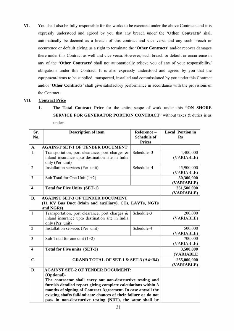
1. The Total Contract Price for the entire scope of work under this “ON SHORE
SERVICE FOR GENERATOR PORTION CONTRACT” without taxes & duties is as
under:-
Sr. No.
Description of item Reference –Schedule of
Prices
Local Portion in Rs
A. AGAINST SET-1 OF TENDER DOCUMENT 1.
Transportation, port clearance, port charges & inland insurance upto destination site in India only (Per unit)
Schedule- 3 4,400,000 (VARIABLE)
2 Installation services (Per unit) Schedule- 4 45,900,000 (VARIABLE)
3 Sub Total for One Unit (1+2) 50,300,000(VARIABLE)
4 Total for Five Units (SET-1)
251,500,000(VARIABLE)
B. AGAINST SET-3 OF TENDER DOCUMENT (11 KV Bus Duct (Main and auxiliary), CTs, LAVTs, NGTs
and NGRs)
1 Transportation, port clearance, port charges & inland insurance upto destination site in India only (Per unit)
Schedule-3 200,000 (VARIABLE)
2 Installation services (Per unit) Schedule-4 500,000 (VARIABLE)
3 Sub-Total for one unit (1+2) 700,000 (VARIABLE)
4 Total for Five units (SET-3) 3,500,000 (VARIABLE
C. GRAND TOTAL OF SET-1 & SET-3 (A4+B4) 255,000,000(VARIABLE)
D. AGAINST SET-2 OF TENDER DOCUMENT: (Optional)- The contractor shall carry out non-destructive testing and furnish detailed report giving complete calculations within 3 months of signing of Contract Agreement. In case any/all the existing shafts fail/indicate chances of their failure or do not pass in non-destructive testing (NDT), the same shall be

32
replaced with new ones at the Per Unit rates as mentioned in “ON SHORE SUPPLY CONTRACT” and respective Unit charges towards Services shall be as under:
1. Transportation and Installation Charges - Nil
E. TOTAL SET-1 + SET-2 + SET-3
ON SHORE SERVICE FOR GENERATOR PORTION CONTRACT (C+D1)
255,000,000(VARIABLE)
Total Contract Price Under “ON SHORE SERVICE FOR GENERATOR PORTION
CONTRACT”= INR: 255,000,000 (Indian Rupees Two Hundred Fifty Five Million Only).
2 The prices including individual components thereof as setforth in clause V-1 hereinabove:-
xi) The above prices are ‘VARIABLE’.
xii) The above prices are exclusive of all the applicable Taxes (excluding taxes on income)
and Duties leviable thereon in India, which shall be to the account of and be borne by
the purchaser.
VI The requisite detailed Contract Documents after incorporating all the acceptable clauses/
agreed points arrived at during various stages of clarifications/discussions in the course of the
evaluation of tender shall be sent separately for signing of the formal Contract Agreement in
the presence of representatives of BBMB. Clarification in respect of points raised vide this
office Memo No.2623-24/PHD/BH-II-413 dated 25.10.2007 is still pending and will be
incorporated in the Contract Agreement.
VII Please take necessary action for ensuring the supply of the following documents:
xxii) Performance Security equal to 10% of Contract Price in the form of a Bank Guarantee
within 30 days of signing of Contract as per provisions of Clause-16/ Part-A/Volume-1 &
Clause-15.3 /Section-I/Vol-III.
xxiii) Item-wise break-up of the prices/details for various Price Schedules of your price offer
to be provided immediately as required in this office Memo No. 2623-24/PHD/BH-II-413
dated 25.10.2007.
xxiv) Advance Payment Bond (copy), Invoice for Advance Payment & Application draft to
BBMB for obtaining TDS rate, to be submitted within 3 (three) days from signing of
Contract Agreement.
xxv) Submission of Crossed Demand Draft of an equivalent amount of Submitted Bank
Guarantee as Security Deposit immediately on Award of Contract which is to be done
within the validity period of the Bank Guarantee.
xxvi) Requisite details regarding opening of Letter of Credit within 15 days of signing of
Contract agreement.
33
xxvii) Compliance of provisions of Tender Document/Tender Offer and subsequent
correspondence may be made for various activities of the Contract to be signed.
xxviii) Any other item which is not covered above but is otherwise required to be supplied for
the successful completion of the Project (on the part of Contractor).
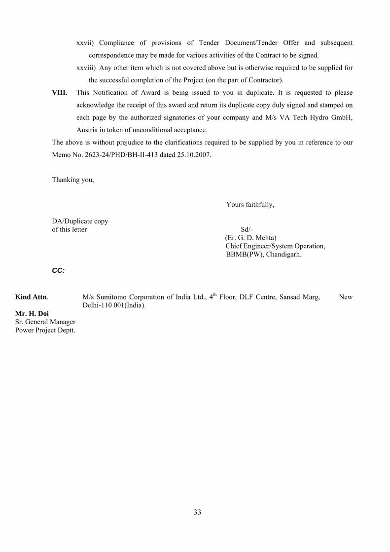
VIII. This Notification of Award is being issued to you in duplicate. It is requested to please
acknowledge the receipt of this award and return its duplicate copy duly signed and stamped on
each page by the authorized signatories of your company and M/s VA Tech Hydro GmbH,
Austria in token of unconditional acceptance.
The above is without prejudice to the clarifications required to be supplied by you in reference to our
Memo No. 2623-24/PHD/BH-II-413 dated 25.10.2007.
Thanking you,
Yours faithfully,
DA/Duplicate copy of this letter Sd/-
(Er. G. D. Mehta) Chief Engineer/System Operation, BBMB(PW), Chandigarh.
CC:
Kind Attn. M/s Sumitomo Corporation of India Ltd., 4th Floor, DLF Centre, Sansad Marg, New
Delhi-110 001(India). Mr. H. Doi Sr. General Manager Power Project Deptt.

34
APPENDIX-B

35
SECTION – I
Salient Clauses Relating
To Instruction To Tenderers

36
SALIENT CLAUSES RELATING TO INSTRUCTION TO TENDERERS
A) INTRODUCTION:
All the clauses as mentioned in Part-A, Volume-I of BBMB Tender Document No.
BBMB/PHD/Bhakra/PP:171 basically provided the information necessary for tenderers to
prepare responsive tenders, in accordance with the requirements of the Purchaser besides
covering information on Tender Submission, Tender Opening, Tender Evaluation & on
Contract Award, etc.
B) CLAUSES ACCEPTED BY THE CONTRACTOR:
All the provisions against Clauses of Part-A “Instructions to Tenderes” of Vol.I of BBMB
Tender Document No. BBMB/PHD/Bhakra/PP:171 as mentioned below stand noted and
confirmed of acceptance by the Contractor in totality except certain comments/clarifications as
intimated by the Contractor in respect of clauses 8 (8.18 (v), 8.27(ii),8.28, 8.29,8.30) and 17.
Clause No. Description PART-A 1.0 Intent 2.0 Eligible Tenderers 3.0 Acknowledgement of the Tender Documents 4.0 Cost of Tender 5.0 Tender Document 6.0 Clarification of Tender Document 7.0 Amendment to Tender Documents 8.0 Preparation of Tenders (Except sub clauses 8.18 (v), 8.27(ii),8.28,
8.29,8.30) 9.0 Earnest Money Deposit (EMD)/Security Deposit 10.0 Submission of Tender Offer 11.0 Tender Opening & Evaluation 12.0 Award Criteria 13.0 Process to be Confidential 14.0 BBMB’S Right To Accept Any Tender/Reject Any Or All Tenders 15.0 Notification Of Award 16.0 Performance Security 18.0 Corrupt Or Fraudulent Practices
C) CLAUSES COMMENTED BY THE CONTRACTOR BESIDES OTHER ACCEPTED
SALIENT CLAUSES
Some of the important clauses of Part-A “Instruction to Tenderer” which are considered useful
for the execution of the contract and those clauses on which the Contractor has submitted their
clarifications/comments during the evaluation of the tender are given below:-

37
1) Clause 6 – Clarification on Tender Document
Sub Clause 6.3
The ‘Disclaimer” as submitted by the M/s Sumitomo Corporation, Japan; M/s Hitachi,
Ltd., Japan and M/s VA TECH HYDRO GmbH, Austria in the tender offer is attached
as Attachment-I, Attachment-II and Attachment-III respectively.
2) Clause 8 – Preparation of Tenders:
a) Sub Clause 8.18
The Contractor shall keep the following in view:-
i) Assigning of part of the Contract, if required, shall be only with prior approval
of BBMB.
ii) The Contractor shall be responsible for arranging all the testing equipment,
special tools and tackles and all consumables (Welding rods, gaskets, paints,
grease, oils etc.) as required at site.
iii) The personnel/operators to be employed for performing various works shall
have adequate qualification, knowledge and experience in their respective
fields. The Contractor shall provide a list of personnel to be deployed with
their qualification and experience to BBMB.
iv) A good working knowledge of English language is desirable for key
professional staff deployed. Otherwise, desired number of interpreters should
be provided at Contractor’s cost.
v) The successful tenderer shall be responsible for obtaining necessary permits
and statutory clearances, if any, for import and export of equipment required
for execution of works and for testing etc. into or out of India and for arranging
transport and insurance/safe keeping of the equipment at site/works.
NOTE:
All permits are to be obtained (now and in the future) by the Contractor.
BBMB shall extend assistance if required. Any permit statutorily
required to be obtained by the Purchaser shall be obtained by BBMB.
vi) The Contractor shall be responsible for insurance and safety of their staff and
engineers at site and also for disbursement of wages and payments of all
statutory dues viz. Employees Provident Fund, income tax and other taxes etc.
vii) BBMB does not have design/manufacturing drawings of the above said
machines with it.
b) Sub Clause 8.20.1

38
The following documents as submitted by the Contractor in their tender offer (in
line with requirement of the Tender Document) are attached herewith:-
i) The “Power of Attorney” alongwith “Certificate of Signatures” by M/s
Sumitomo Corporation, Japan in the tender offer are attached as
Attachment-IV and Attachment-V respectively. The revised Power of
Attorney and “Notarial Certificate” are attached alongwith.
ii) The “Power of Attorney” alongwith “Notarial Certificate” by M/s Hitachi,
Ltd., Japan attached as Attachment-VI and Attachment-VII respectively.
iii) The “Power of Attorney” alongwith “Signature Authenticity Certificate” by
M/s VA TECH HYDRO GmbH, Austria is attached as Attachment-VIII and
Attachment-IX respectively.
iv) The “Affidavit” alongwith “Notarial Certificate” by M/s Sumitomo
Corporation, Japan authorizing his representative for submission of Tender
offer is attached as Attachment-X and Attachment-XI respectively.
v) The “Affidavit” alongwith “Notarial Certificate” by M/s Hitachi, Ltd., Japan
authorizing his representative for submission of Tender offer is attached as
Attachment-XII and Attachment-XIII respectively.
vi) The “Affidavit” alongwith “Signature Authenticity Certificate” by M/s VA
TECH HYDRO GmbH, Austria, authorizing his representative for submission
of Tender offer is attached as Attachment- XIV and Attachment-XV
respectively.
vii) The Memorandum Of Understanding between all the three consortium
members is attached as Attachment-XVI.
c) Sub clause 8.21
The information as furnished by the tenderer in their Tender offer shall become
the property of BBMB.
d) Sub Clause 8.22
BBMB reserves the right to use and interpret the documentation they receive in
accordance with their own judgment and their own methods for evaluation etc.
without interference from any outside source.
e) Sub Clause 8.27
i) The escalation only on that portion of the contract price will be paid as is
payable against dispatch documents. No escalation shall be payable on the
variable portion of the contract price, which has been paid in advance. Price
variation with respect to a part of supply/ work against each invoice shall be
subject to the quoted ceiling. In the absence of any price variation clause,

39
the prices will be treated as FIRM. The price variation will be payable
upto the contractual delivery period only.
ii) There are imported components and raw materials which shall be used in the
manufacture/supply of On-shore equipment and their bid is based on the
consideration that Concessional Custom Duty will be applicable for
Renovation and Modernisation of Power Generation Plants (Para 236 of
Notification no. 21/2002 dt. 1/03/02 as amended by Notification no. 21/2006
dt. 28/02/06) @ 5% Basic Custom Duty+16% CVD + 4% Special Additional
Duty on the CIF value of these imported items. CENVAT benefit has been
considered in the prices. This concessional Custom Duty (equal to 5.44%)
which is included in the Indian Rupees portion has been calculated at the
Exchange Rate of 1Euro=INR. 55/-. Any variation in the exchange rate of
Euro at the time of actual payment of custom duty will alter the amount of
Custom Duty assumed in the prices. Such variations in the custom duty
caused due to fluctuations in the exchange rate will be borne by BBMB and
the payment will be released after such adjustments. BBMB shall do the
needful and furnish all the relevant documents as per rules to avail of this
concessional Custom Duty.
Also CIF costs of above imported items are not expected to exceed Euro.
7,000,000.00 (Euro Seven Million Only) for Electrical Package items which
is equivalent to INR 385,000,000/- (Indian Rupees Three hundred and Eighty
Five Million Only)) based on above exchange rate. Any variation in the
exchange rate of Euro at the time of actual payment will be borne by BBMB
and the payment will be released after such adjustments
ii) The supplier shall furnish all such documentary evidences as may be
required by the Purchaser in support of the increase/decrease in the
prices/cost of each item of raw material/components/wages etc. in respect of
which the variation is admissible.
The Purchaser reserves the right to examine or ask for the audit of any of the
documents of the supplier at his cost in connection with the price variation
and the supplier shall render all facilities to the Purchaser’s representatives
for examination of the said documents.
f) Sub Clause 8.28
The expected detailed delivery schedule will be submitted after the Effective
Date with the following understanding:
“Since the scope of work for this project includes erection, testing and
commissioning, Contractor committed the time of completion of taking

40
over for the 1st Unit, namely 31 months from the Effective Date. In other
words, the Contractor can coordinate at his discretion the schedule of
delivery & site work for this project within the fixed deadline of
completion.”
However, the indicative schedule will be submitted by the Contractor after
signing of Contract.
g) Sub Clause 8.29
Payment through automatic revolving Letter Of Credit (L/C) shall be
governed by following conditions:-
1) L/C charges
- L/C in Foreign Currency
All Bank charges at Japanese side relating to L/C shall be borne by the
Contractor.
- L/C in Indian Rupees
Only negotiation (document handling between opening and advising
Bank) charges for payment collection at Indian side shall be borne by
the Contractor.
Other than above mentioned charges, any Bank charges at Indian side
including establishing L/C and its operational charges, its amendment(s),
if any, will be borne by the Purchaser.
Any other charges concerning bank guarantees, which the Contractor will
arrange in accordance with the Contract, shall be borne by the
Contractor.
2) The amount and time of opening of revolving L/C according to anticipated
build up of cost for implementation as per the schedule given shall be
furnished by the Contractor.
3) The L/C shall be opened within 45 days after signing the contract provided
the requisite details are furnished by the Contractor within 15 days of
signing of contract.
4) In case of any subsequent amendments or extension beyond the date
initially agreed to and incorporated in the L/C, then the bank charges for
such amendments/ extensions of L/C shall be borne by the party to whom
the reasons for such amendments/extensions are attributable.
5) The cost for extension of L/C to be recovered from the Contractor if any
can not be included in the LD for delay and shall be recoverable over and
above the LD for delay.
h) Sub Clause 8.30

41
BBMB might increase the quantity at the time of placing the Contract up to
15% at BBMB’s discretion. The price for such increase in quantity shall be
adjusted based on the price already indicated in the Price Offer. The decrease
of quantity shall be on mutual agreement between BBMB and Contractor.
3) Clause 9 –Earnest Money Deposit (EMD)/ Security Deposit:
a) Sub Clause 9.2
The Earnest Money Deposit is to protect the BBMB against risk of Tenderer’s
conduct which would warrant the forfeiture of security pursuant to sub clause 9.7.
b) Sub Clause 9.6
The earnest money deposit shall be converted into Security Deposit immediately
on the issue of the Purchase Order/Contract in the case of tenderer on whom the
purchase order/Contract is placed and shall be retained as a guarantee for faithful
and satisfactory execution of the purchase Order/Contract and shall be refunded
after expiry of the warranty period provided nothing is due from the
Supplier/Contractor on any account. c) Sub Clause 9.7 (Also refer Clause 15.5/Section-I/Appendix-C)
The Earnest Money / Security Deposit for an amount of US $ 650,000 (US Dollars
Six hundred fifty thousand only) in the form of Bank Guarantee as furnished by the
tenderer i.e. M/s Sumitomo Corporation, Japan (Consortium) as per photocopy
attached as Attachment-XVI shall be forfeited in part or in full (as deemed fit by
the BBMB), under the following circumstances:-
i) If the tenderer withdraws his tender at any stage during the currency of its
validity period, his earnest money shall be forfeited in full.
ii) In case the successful tenderer fails to: -
• Furnish the requisite performance security in accordance with ITT
clause 16
• Sign the contract Agreement, in accordance with ITT Clause No 17 within
the specified time limit.
iii) If the PO/contract has been issued but the Supplier/Contractor refuses to
comply with it, the security deposit deposited by him shall be forfeited in full,
irrespective of the fact whether the Board sustains any loss on account of his
default or not. This encashment shall be without prejudice to the right of the
Board to claim any other damages as admissible under the law as well as to
take such executive action against the supplier as blacklisting etc.

42
iv) Where the purchase order/contract has been accepted but the Supplier/
Contractor stops making the supplies after partially fulfilling the purchase
order/contract, the Security Deposit shall be retained and adjusted against any
loss that may be caused to the Board through risk purchase from alternative
source and/or any other damages recoverable from the Supplier/Contractor
under the terms & conditions of the contract.
v) In the event of a breach of contract in any manner the Security Deposit shall be
forfeited and adjusted against the claim of the Board on the
Supplier/Contractor for any damages or for any loss sustained by the Board on
account of such breach.
vi) Security deposits not claimed within three years from the date of completion
of purchase order/contract, including the period of warranty shall be treated as
“Lapsed Deposits” and no claim for a refund thereof shall be entertained from
the Supplier/Contractor thereafter.
vii) If tenderer does not accept the correction of errors as per sub clause11.4.2 of
‘Instructions to Tenderers’ of Volume-I of BBMB tender document.
4) Clause 13.0 – Process to be confidential
a) Sub clause 13.3
The tenderer/Contractor shall not communicate or use in advertising publicity
or in any other medium, photographs of the works or description of works
under this contract or drawings, etc. from the tender document unless prior
written permission has been obtained from BBMB.
b) Sub Clause 13.4
All documents, correspondence, decisions and other matters concerning the
contract shall be considered confidential and of restricted nature by the
tenderer/Contractor.
5) Clause 15.0 - Notification of Award :
The Notification of award as conveyed by BBMB will constitute the formation of the
Contract.
6) Clause 16.0 - Performance Security :
Within 30 days of the signing of the Contract, the Contractor shall furnish the
performance security equal to 10% of contract price in the form of a bank guarantee.
7) Clause 17.0 - Signing of Contract Agreement :

43
a) Sub Clause 17.1
After BBMB notifies the successful tenderer that his tender offer has been
accepted, BBMB will send the Contract Agreement to the Contractor
incorporating all agreements between the Parties. The successful tenderer
shall sign the Contract Agreement in the presence of BBMB
representatives within 14 days of receipt of the Contract Agreement
provided that the Contract Agreement has incorporated all the points
agreed between BBMB and the tenderer during the negotiation stage.
b) Sub Clause 17.2
Failure of the successful tenderer to comply with the requirement of Clauses
16.0 and 17.1 referred to above shall constitute sufficient grounds for the
annulment of the contract and forfeiture of EMD in which case the BBMB may
make the award to the next lowest evaluated/responsive tender offer or call for
fresh tender offers.
D. NOTES:
a) The following relevant Forms/Documents as submitted by Contractor in their Tender
Offer (in line with the requirements of BBMB Documents) are attached in the relevant
Appendix-D relating to Technical Specification.
i) Resources available with the Tenderer /Consortium Members.
ii) Proven Skills in respect of following spheres:
iii) Broad Procedure and Methodology to be adopted/proposed for RM &U works
for Bhakra Left Bank Power House.
b) The general information about Contractor i.e. Contact Person’s Addresses, etc. as
given by all the consortium members in the tender offer submitted by M/s Sumitomo
Corporation, Japan (Consortium) is attached in “Section-II” of this Appendix.
c) The general information about Purchaser i.e. Contact Person’s Addresses, etc. is given
in “Section-III” of this Appendix.
d) All the Attachments as mentioned in above paras are attached in “Section-IV” of this
Appendix.

44
SECTION- III
General Information About
Purchaser

45
General Information about Purchaser A) About Contract Placing Authority Sr. No. Description Particulars
1. Name, Designation & Addresses of Contract Placing Authority.
i) Chief Engineer/System Operation, Bhakra Beas Management Board(Power Wing),
SLDC Complex, 66 KV Sub Station, Industrial Area (Phase-I), Chandigarh – 160 002 (India) Tel: +91-172-2653660 Fax: + 91 –172-2659204 E-Mail: ceso @ bbmb.gov.in ii) Director/P & D (PPs) Dte.,
Bhakra Beas Management Board (Power Wing) Plot No. 6-B, 1st Floor, Sector 19-B, Madhya Marg, Chandigarh –160 019 (India) Tele Fax: + 91-172-5046571 E-Mail: dirpd @ bbmb.gov.in
B. About Engineer-In-Charge (For Site Works) Sr. No. Description Particulars 2. Name, Designation & Address
of Field Officers. i) Chief Engineer/Generation,
Bhakra Beas Management Board (Power Wing) Nangal Township (District Ropar) Punjab – 140 124 – INDIA Tel: +91-1887-223355 Fax: +91-1887-223307 ii) Superintending Engineer/Bhakra Power Houses
Circle. Bhakra Beas Management Board (Power Wing) Nangal Township (District Ropar) Punjab – 140 124 – INDIA Tele fax: +91-1887-223261
C. Other Associated Officers (connected with RM &U works)
Sr. No.
Description Particulars
1. Consignee to whom equipment should be consigned
The Sub Divisional Officer, Store Sub Division, Bhakra Beas Management Board (Power Wing)
Nangal (District Ropar) Punjab –India Tel: +91-1887-220231
2. Concerned Divisional Officer The Sr. Executive Engineer /STP&D Division, Bhakra Beas Management Board (Power Wing)
Nangal Township (District Ropar) Punjab –India Tel: +91-1887-223353
3. Concerned Accounts Officer i) Dy. CAO/Field Office of the F. A. & C. A. O.,
Bhakra Beas Management Board (Power Wing) Nangal Township (District Ropar) Punjab –India

46
Tel: +91-1887-223085 ii) The Sr. Accounts Officer/Works(PW),
Office of the F. A. & C. A. O., Bhakra Beas Management Board (Power Wing)
Nangal Township (District Ropar) Punjab –India Tel: +91-1887-227387
ii) The Sr. Accounts Officer/Payments, Office of the F. A. & C. A. O.,
Bhakra Beas Management Board (Power Wing) Nangal Township (District Ropar) Punjab –India
Tel: +91-1887-223256 4. Name of Bankers State Bank of India,
Naya Nangal, District Ropar-140124 Punjab-India Tel: +91-1887-221010, 220603

47
APPENDIX-C

48
SECTION-I
General Conditions of the Contract
(GCC)

49
General Conditions of Contract (GCC)
A CONTRACT AND INTERPRETATION:
1.0 Definitions The following words and expressions shall have the meanings hereby assigned to them: "Commissioning" means completion of the complete facilities by the Contractor, which operation is to be carried out by the Contractor as provided in GCC Clause “Commissioning & Operational Acceptance” hereof, for the purpose of carrying out Guarantee Test (s). "Completion" means that the Facilities have been completed operationally and structurally and that all work in respect of Pre-commissioning of the Facilities has been completed and Commissioning has been attained as per Technical Specifications.
"Contract" means the Contract Agreement entered into between the Purchaser and the Contractor, together with the Contract Documents referred to therein, and the term "the Contract" shall in all such documents be construed accordingly.
“Contract Price” means the sum specified in of the Contract Agreement, subject to such additions and adjustments thereto or deductions there from, as may be made pursuant to the Contract. "Contractor" means the successful tenderer whose tender to execute the Contract has been accepted by the Purchaser and is named as such in the Contract Agreement, and includes the legal successors or permitted assigns of the Contractor, for carrying out the services in accordance with the tender document.
"Contractor's Equipment" means all plant, equipment, machinery, tools, apparatus, appliances or things of every kind required in or for transportation, installation, completion and maintenance of Facilities that are to be provided by the Contractor, but does not include Plant And Equipment, or other things intended to form or forming part of the Facilities. "Contractor's Representative" means any person nominated by the Contractor and approved by the Purchaser in the manner provided in GCC Sub-Clause “Contractor's Representative and Construction Manager” authorised to perform the duties delegated by the Contractor as per Contract Agreement. “Consignee” means a person authorised by the Purchaser to receive the complete Plant and Equipment at the site. "Day" means calendar day of the Gregorian calendar. “Month” means calendar month of the Gregorian calendar. "Defect Liability/Warranty Period" means the period of validity of the warranties given by the Contractor commencing at Completion of the Facilities during which the Contractor is responsible for defects with respect to the Facilities as provided in GCC Clause “ Defect Liability /Warranty” hereof.
"Effective Date" shall be the date on which Contract shall become effective if and when the following condition of both (i) and (ii) are fulfilled and the schedule of Delivery, Erection, Testing & Commissioning (as mentioned in the Contract Document) shall be reckoned from this Effective Date. iii) Signing of the Contract by BBMB and the Contractor iv) a) Advance payment of 10% of the Contract Price is received by the Contractor
in accordance with the Contract terms & conditions, within 10 working days from the date of the TDS order issued by Income Tax Department.
OR b) Acceptable LC specified in Clause 8.29 of Section-I of APPENDIX-B of this
Agreement is received by Contractor (whichever comes earlier). Contractor shall submit “Application draft to BBMB for obtaining TDS rate” “Invoice for the Advance Payment” and “Copy of Advance Payment Bond” within three working days from Contract signing. Both parties shall make the best effort to achieve the Effective Date at the earliest.

50
NOTE: For On Shore Supplies (But not On Shore Services), the full 10% shall be paid if there is no TDS liability as per the prevailing Income Tax laws.
"Purchaser" means Bhakra Beas Management Board (Power Wing), having its Design Directorate/Power Plant at Plot No. 6-B, Sector 19-B, Madhya Marg Chandigarh-160019 (Fax No. 91-172-5046571) and includes the legal successors and permitted assigns of the Purchaser.
"Engineer-in-Charge" means the person named as such in the GCC to perform the duties of the Purchaser in the manner mentioned in GCC Clause entitled “Engineer-in- Charge”.
"Facilities means the Plant and Equipment to be supplied and installed, as well as all the installation services including design, fabrication, manufacture, supply, transportation, dismantlement, repair, modifications of equipment/parts of facilities to be retained, erection, testing and Commissioning to be carried out by the Contractor under the Contract. “Government” means the Government of India or the respective State Governments as applicable. ‘Foreign Currency” means any currency other than Indian currency. "Functional & Guarantee Test(s)" means the test(s) specified in the Technical Specifications to be carried out to ascertain whether the Facilities are able to attain the Performance/Functional Guarantees specified in the Technical Specifications in accordance with the provisions of GCC Clause “Commissioning & Operation Acceptance” thereof.
"Installation Services" means all those services ancillary to the supply of the Plant and Equipment for the Facilities, to be provided by the Contractor under the Contract; e.g., testing & inspection, expediting site preparation works (including the provision and use of Contractor's Equipment and the supply of all consumable materials required etc.), installation, testing, Pre-commissioning, Commissioning, and training, etc.
“Member” in case the Contractor is a consortium of more than one entity, means any of these entities, and, “Members” mean all of these entities. “Local currency” means Indian Rupees “Local Personnel” mean such persons who at the time of being so hired are citizens of India by birth. Taking over/Operational Acceptance” means the acceptance by Purchaser of the Facilities which certifies the Contractor’s fulfilment of the Contract in respect of Functional/Performance Guarantees of the Facilities in accordance with the provisions of GCC Clause “Performance/ Functional Guarantees” hereof and shall include deemed acceptance in accordance with GCC Clause “Commissioning and Operational Acceptance” thereof.
“Personnel” means the persons hired by Contractor /sub- Contractor as employees/ consultants and assigned the performance of the services or any part thereof.
"Plant and Equipment" means permanent plant, equipment, machinery, apparatus, articles and things of all kinds to be provided and incorporated in the Facilities by the Contractor under the Contract (including the spare parts, tools & tackles, consumables etc.) to be supplied by the Contractor, but does not include Contractor's Equipment.
“Party” means the Contractor or Purchaser, as the case may be and Parties means both of them.
"Pre-commissioning,” means the testing, checking and other requirements specified in the Technical Specifications that are to be carried out by the Contractor in preparation for Commissioning as provided in GCC Clause “Completion” hereof.
"SCC" means the Special Conditions of Contract. "Site" means the land and other places upon which the Facilities are to be installed i.e. Bhakra
Left Bank Power House. “Subcontractor, vendor, Sub-vendor” means any person named in the Contract to whom
execution of any part of the Facilities, including preparation of any design or supply of Plant and Equipment, is sub-Contracted by the Contractor, and includes its legal successors of permitted assigns. “Specification” shall mean Technical Specifications as to forming a part of the Contract & such other schedules & drawings as may be mutually agreed upon.

51
"Time for Completion" means the time within which Completion of the Facilities as a whole is to be attained in accordance with the stipulations in the relevant provisions of the Contract. “Third Party” means any person or entity other than the government, the Purchaser & the Contractor including its sub-Contractors/sub vendors. However, for testing purposes it could be a government laboratory.
2.0 Contract Documents: All documents forming an integral part of the Contract agreement (and all parts thereof) including any amendments thereto are intended to be correlative, complementary and mutually explanatory. The Contract shall be read as a whole.
3.0 Interpretation: 3.1. Language All Contract Documents, correspondence and communications to be given and all other
documentation to be prepared and supplied under the Contract shall be written in English, and the Contract shall be construed and interpreted in accordance with that language.
3.2. If any of the Contract Documents, correspondence or communications are prepared in any language other than the governing language as stated above, the English translation of such documents, correspondence or communications shall prevail in matters of interpretation, at the Contractor’s cost.
3.3. Singular and Plural: The Singular shall include the plural and the plural shall include the singular except where the context otherwise requires.
3.4. Headings & Marginal Notes: The headings/ sub headings in the General Conditions of Contract are included for ease of
reference, and shall not limit or affect or alter interpretation of this document. Marginal notes to any clause of Contract shall not effect or control the construction of
such clause. 3.5. Persons:
Words importing persons or parties shall include firms, companies, corporations and government entities.
3.6. Incoterms: Unless inconsistent with any provision of the Contract, the meaning of any trade term and the rights and obligations of parties there under shall be as prescribed by Incoterms. Incoterms means international rules for interpreting trade terms published by the International Chamber of Commerce (latest edition). Note:- The latest edition of INCOTERMS is “Incoterms 2000(ICC Publication No.560)”
3.7. Entire Agreement: The Contract constitutes the entire agreement between the Purchaser and Contractor with respect to the subject matter of Contract and supersedes all communications, negotiations and agreements (whether written or oral) of parties with respect thereto made prior to the date, the Contract agreement is signed by the Purchaser and the Contractor. The Contractor, subject to this Contract, has complete charge of personnel performing the services and shall be fully responsible for the services performed by them or on their behalf under this Contract. The Contract contains all covenants, stipulations and provisions as agreed by the parties. No agent or representative of either party has authority to make (and the Parties shall not be bound by or be liable for), any statement, representation, promise or agreement not set forth herein.
3.8. Amendment: No amendment or other variation of the terms and conditions of the Contract shall be
effective unless it is in writing, is dated, expressly refers to the Contract, and is requested by proper reasoning & signed by a duly authorized representative of each party hereto. Each party shall give due consideration to proposal for amendment/ modification made by other party.

52
3.9. Independent Contractor: The Contractor shall be an independent Contractor performing the Contract. The Contract does not create any agency, partnership, joint venture or other joint relationship between the parties hereto. subject to the provision of the Contract, the Contractor shall be solely responsible for the manner in which the Contract is performed. All employees, representatives or Subcontractors engaged by the Contractor in connection with the performance of the Contract shall be under the complete control of the Contractor and shall not be deemed to be employees of the Purchaser, and nothing contained in the Contract or in any subcontract awarded by the Contractor shall be construed to create any Contractual relationship between any such employees, representatives or Subcontractors and the Purchaser.
3.10. Consortium: As the Contractor has quoted as a consortium of three firms, all such firms shall be jointly and severally bound to the Purchaser for the fulfillment of the provisions of the Contract and shall designate one of such persons to act as a leader with authority to bind the consortium and in exercising all the Contractor’s rights & obligations towards Purchaser under the Contract & shall furnish requisite documentary proofs. The consortium shall not be altered during the pendency of Contract i.e. till expiration or termination of Contract, without the prior written consent of the Purchaser.
3.11. Non-Waiver: Subject to Sub-Clause as stated below, no relaxation, forbearance, delay or indulgence by either party in enforcing any of the terms and conditions of the Contract or the granting of time by either party to the other shall prejudice, affect or restrict the rights of that party under the Contract, nor shall any waiver by either party of any breach of Contract operate as waiver of any subsequent or continuing breach of Contract. Any waiver of a party's rights, powers or remedies under the Contract must be in writing, must be dated and signed by an authorized representative of the party granting such waiver, and must specify the right and the extent to which it is being waived.
3.12. Severability: If any provision or condition of the Contract is prohibited or rendered invalid or unenforceable by law, such prohibition, invalidity or unenforceability shall not affect the validity or enforceability of any other provisions and conditions of the Contract.
3.13. Country of Origin: "Origin" means the place where the materials, equipment and other supplies for the Plant and Equipment are mined, grown, produced or manufactured, and for which the required services are provided.
3.14. Authorised Representatives: Any action required or permitted to be taken, & any documents required or permitted to be executed under this Contract by the Purchaser or the Contractor may be taken or executed by only authorised representative from both parties. The Authorised Representatives of the Contractor are specified in Section-II of Appendix-B. The authorised representatives of the Purchaser are Engineer-In-Chief or Chief Engineer/ System Operation, BBMB (PW), Chandigarh or Director/P&D(PPs), BBMB(PW), Chandigarh. Their addresses are as given in Section-III of Appendix-B.
4.0 Notices 4.1 Unless otherwise stated in the Contract, all notices to be given under the Contract shall
be in writing, and shall be sent by personal delivery, airmail post, special courier, E-mail, telegraph, telex, facsimile to the address of the relevant party, with the following provisions. 4.1.1 Any notice sent by cable, telegraph, telex, facsimile or e-mail shall be
confirmed within two (2) days after date of dispatch by notice and confirmation sent by airmail post or special courier, except as otherwise specified in the Contract.

53
4.1.2 Any notice sent by airmail, post or special courier shall be deemed (in the absence of evidence of earlier receipt) to have delivered within 7 (seven) days of the date of despatch. In proving the fact of despatch, it shall be sufficient to show that the envelope containing such notice are properly addressed, stamped and conveyed to the postal authorities or courier service for transmission by air mail or special courier. Maximum 7 (seven) days postal allowance for all intents and purposes is permissible.
4.1.3 Any notice delivered personally shall be deemed to have been delivered on date of its delivery & as sent by cable, telegraph, telex, facsimile or e-mail shall be deemed to have been delivered within 2 (two) days of confirmed transmission.
4.1.4 Either party may change its postal, e-mail telex, facsimile or e-mail address or addressee for receipt of such notices by giving ten (10) days notice to the other party in writing.
4.2 Notices shall be deemed to include any approvals, consents, instructions, orders and certificates to be given under the Contract.
4.3 Notice shall contain complete addresses of both parties 4.4 The Purchaser’s address for notice purposes shall be as stated above at Clause 3.14. 4.5 The time period for receipt of Contract Agreement sent by Purchaser is maximum 21
(Twenty one) days including 7 (Seven) days postal allowance.
5.0 Governing Law/Courts: 5.1 All the matters arising under this Contract shall be governed by and interpreted in
accordance with laws and any other instruments having the force of law in India, as they may be issued & in force from time to time.
5.2 Jurisdiction of court In case of any dispute between the parties, the Courts at Chandigarh (U.T.)-INDIA only shall have the jurisdiction to settle/decide and adjudicate upon such matters. Before approaching the court of law, any dispute or difference arising in connection with the Contract shall be referred by either party for adjudications/arbitration in accordance with Clause-6 below.
6.0 Settlement of Disputes:
6.1. Arbitration: 6.1.1. If at any time, any question, dispute or difference whatsoever, arises between the
Purchaser and the Contractor, upon or in relation to or in connection with the Contract, either party may forthwith give to the other, notice in writing of the existence of such question, dispute, or difference and the same shall be referred to the award of two arbitrators, one to be nominated by the Purchaser and the other to be nominated by the Contractor or in the case of the said Arbitrators not agreeing, then to the award of an umpire to be appointed by the arbitrators in writing before proceeding with the reference and the decision of the Arbitrators, or in the event of their not agreeing, of the Umpire appointed by them, shall be final and binding on the parties and the provision of the Indian Arbitration and Conciliation Act, 1996 and of the rules thereunder and any statutory amendment/modification or reenactment thereof, for the time being in force, shall be deemed to apply to and be incorporated in the Contract. Such a notice of the existence of any question, dispute or difference in connection with Contract shall be served by either party within 90 days of the issue of Receipt by the Consignee for each consignment or within 120 days of question, dispute or difference on account of any design defect/inspection, erection, testing & Commissioning etc, failing which all rights and claims under the Contract shall be deemed to have been forfeited and absolutely barred. Upon every or any such reference, the cost of and incidental to the reference and award respectively, shall be in the discretion of the Arbitrators, or, in the event of their not agreeing, of the umpire appointed by them who may

54
determine the amount thereof or direct by whom and to whom and in what manner the same be borne and paid. The work under the Contract shall, if reasonably possible, continue during the arbitration proceedings and no payment due or payable as per original Contract terms by Purchaser shall be withheld on account of such proceedings.
6.1.2 If for any reason an arbitrator is unable to perform its function, the mandate of the Arbitration shall terminate in accordance with provisions of applicable laws as mentioned in GCC, Clause 5.
6.1.3 Arbitration proceedings shall be conducted as laid down below: -The venue of arbitration proceedings shall be Chandigarh., India /site.
-The language shall be English for all purposes. 6.1.4 The arbitrator(s) shall give reasoned award. 6.1.5 Should the Arbitrator of either party resign or die, a new Arbitrator shall be
appointed by the respective party.
B. SUBJECT MATTER OF CONTRACT: 7.0 Scope of Facilities:
7.1 Unless otherwise expressly limited in the Technical Specification (Appendix-D of Contract Agreement), the Contractor's obligations cover the provision of all Plant and Equipment and the performance of all Installation Services required for the design, manufacture (including reverse engineering), procurement, delivery, quality assurance, transportation from Purchaser’s store to site, handling, dismantlement, installation including any work involved on existing civil structure and Pre-commissioning of the Plant and Equipment and the installation, completion, Commissioning and performance testing of the Facilities in accordance with the plans, procedures, specifications, drawings, codes and applicable standards and any other documents as specified in the Technical Specifications i.e. Appendix –D of Contract Agreement Such specifications include, but are not limited to, the provision of dismantlement, erection, supervision and engineering services; the supply of labour, materials, equipment, tools, consumables, spare parts and accessories; Contractor's Equipment, temporary materials/ structures and facilities; transportation(including, without limitation, hauling and handling from Purchaser’s store to site); insurance and unloading at site (all sorts of) and release of material at port. However, loading/unloading & storage at Purchaser’s stores including insurance during storage in Purchaser’s stores shall be in scope of Purchaser. The insurance for all items relating to plant & equipment during transit from contactors works to Purchaser’s store and thereafter i.e. from the moment of withdrawal from Purchaser’s Stores for the purpose of Erection, Testing & Commissioning etc. till taking over by the Purchaser will be Contractor’s responsibility.
7.2 The Contractor shall, unless specifically excluded in the Contract, perform all such
work and/or supply all such items, materials and services not specifically mentioned in the Contract but that can be reasonably inferred from the Contract as being required for completeness & attaining Completion of the Facilities as if such work and/or items and materials were expressly mentioned in the Contract. Note:- The Contractor will supply all the Plant and Equipment in accordance with the Technical Specifications of the Contract. Also, Contractor will ensure completeness of said supplies. In addition to above, in case of any additional/ extra work arising due to any “Unforeseen Conditions” the Contractor shall only consider doing the said work without additional cost if the Contractor judges that as minor.
7.3 In addition to the supply of Mandatory Spare Parts included in the Tender Document the Contractor shall supply spare parts as recommended by him that are required for the operation and maintenance of the Facilities for a period of 10 (ten) years.

55
However, the identity, specifications and quantities of such spare parts and the terms and conditions relating to the supply thereof are to be agreed upon between the Purchaser and the Contractor, and the itemwise price of each spare part, shall be as given in the price Schedule. The statutory taxes, duties, etc. applicable for spares as quoted by the Contractor are as mentioned in Appendix-A of relevant contracts in their schedule & these should not be included in their quoted prices.
7.4 The Contractor shall carry sufficient inventories to ensure an ex-stock supply of consumable and spares for the Plant and Equipment
7.5 In addition, in the event of termination of the production of spare parts, advance notification will be made to the Purchaser of the impending termination, with twenty four (24) months time to permit the Purchaser to procure the requirement. Following such termination, the Contractor shall supply at no cost to the Purchaser the blueprints, manufacturing drawings and specifications of the spare parts including metallurgy, if requested and permit their use for arranging spare parts from alternate sources. Note:- As per Clause 4 of SCC.
8.0 Time for Commencement and Completion: 8.1 The Contractor shall commence work on the Facilities from the Effective Date and the
Contractor shall thereafter proceed with the Facilities in accordance with the time schedule as specified in the Contract Agreement. Note:- Deemed Commencement Date of Shutdown shall be date on which shut down Period of a unit is deemed to commence in case Contractor unreasonably delays in requesting the shutdown of the Unit “Deemed Commencement Date of shutdown” shall be the working day next to date of fulfilling either of following conditions whichever comes later; i) all the Plant and Equipment is arrived at site for the unit. ii) the previous unit is handed over to the Purchaser
8.2 The Contractor shall adhere to attaining Completion of the complete Facilities within the time schedule as stated in the Contract or within such extended time to which the Contractor shall be entitled under GCC Clause “Extension of Time for Completion” hereof. The time period for completion is as stated in Appendix-D (Technical Specification). The Contractor shall organise his resources and perform the work so as to complete it not later than date agreed to.
8.3 Expiration of Contract: - Unless terminated, this Contract shall expire when works/services have been completed to the entire satisfaction of the Purchaser and warranty period has expired & nothing is due from the Contractor on any account.
9.0 Contractor's Responsibilities: 9.1 Standard of Performance:
The Contractor shall design, manufacture( including associated purchases and /or sub Contracting ) & perform the services and carry out his obligations hereunder with due diligence, efficiency and economy, in accordance with generally accepted professional techniques and practices, and shall observe sound management practices, and employ appropriate advanced state of art technology, safe and effective equipment, machinery, materials and methods. The Contractor shall always act, in respect of any matter relating to this Contract or to the works/services, as faithful adviser to the Purchaser, and shall at all times support and safeguard the Purchaser’s legitimate interest in any dealings with Sub vendor or third parties.
9.2 The Contractor shall confirm in an undertaking that he has entered into this Contract on the basis of a proper & careful examination of the data relating to the Facilities provided by the Purchaser, and on the basis of information that the Contractor could have obtained from a visual inspection of the Site and of other data readily available to him relating to the Facilities. The Contractor acknowledges that any failure to acquaint himself with all such data and information shall not relieve him of his responsibility for
56
properly estimating the cost of successfully executing the Contract & guaranteeing the output parameters. Note:- However, it was agreed by the Contractor that at the time or after conducting the Reverse Engineering, the Contractor might request BBMB to furnish certain information such as details/data on Elevation, Level, Dimensions, Foundation, etc., liability towards the correctness of which should be with Purchaser.
9.3 i) The Contractor shall acquire in his name and at his own cost and by his own arrangements all permits, clearances, approvals and/or licenses from all local, state or national government authorities, Reserve Bank of India or public service undertakings in India (and even abroad as the case be) that are necessary for the performance of the Contract, including, without limitation, visas, residence permits/exchange permits & other documents for the Contractor's and Subcontractor's personnel and entry permits for all imported Contractor's Equipment. The Contractor shall also acquire all other permits, approvals and/or licenses that are not the responsibility of the Purchaser as per clause “Purchaser’s Responsibility” hereof and that are necessary for the performance of the Contract and visas/personal effects of personnel and their eligible dependents.
ii) The Contractor shall acquire and pay for all permits, approvals and/or licenses, clearances on behalf of the Purchaser from all local/ state /national government authorities or public service undertakings in India or abroad( if such authorities or undertakings require these to be obtained in the Purchaser's name).
Note:- All permits are to be obtained (now and in the future) by the Contractor. BBMB
shall extend assistance if required. Any permit statutorily required to be obtained by the Purchaser shall be obtained by BBMB.
9.4 The Contractor or his sub-Contractor or his personnel shall comply with all applicable governing laws in force in India. The laws will include all national, provincial, municipal or other laws that affect the performance of the Contract and bind upon the Contractor. The Contractor shall indemnify and hold harmless the Purchaser from and against any and all liabilities, damages, claims, fines, penalties and expenses of whatever nature arising or resulting from the violation of such laws by the Contractor or its personnel, including the Subcontractors and their personnel. Note:- These rules are applicable to Contractor for his personnel whether from India or abroad, and BBMB is already under the rules of Government of India.
9.5 The Contractor shall supply and make available all raw materials, lubricants, chemicals, catalysts, other materials and facilities and shall perform all work and services of whatsoever nature required by him to properly carry out disassembly/ dismantling, assembly, erection, pre-commissioning, Commissioning, trial operation and guarantee tests till taking over by the Purchaser.
9.6 All other requirements as stated else where in the Contract Agreement. 9.7 Conflict of Interests:
9.7.1 Contractor not to Benefit from Commissions, Discounts etc. The Contract payments made to the Contractor hereof shall constitute the Contractor’s sole remuneration in connection with this Contract and the Contractor shall not accept for their own benefit any trade commission, discount or similar payment in connection with activities pursuant to this Contract or to the Services or in the discharge of their obligations hereunder. The Contractor shall also use his best efforts to ensure that any Sub-Vendor, as well as the personnel of either of them, similarly shall not receive any such additional remuneration.
9.7.2 Contractor’s Advice in Activities of Purchaser: If the Contractor, as part of the services, has the responsibility of advising the Purchaser on the procurement of goods, works or services, the Contractor shall

57
comply with any applicable procurement guidelines as the case may be and shall at all times exercise such responsibility in the best interest of the Purchaser.
9.8 Contractor’s Actions requiring Purchaser’s prior Approval: The Contractor shall obtain the Purchaser’s prior approval in writing before taking any of the actions specified in Contract Agreement which warrants so. Note:- All said prior approval means only those approvals required as per Tender/Contract Document.
9.9 Reporting Obligations: Contractor shall submit to the Purchaser the required report, documents and updating of PERT/CPM as specified in Contract Agreement. The reporting requirements are indicated in Form-I, as submitted by tenderer. Note:- The Contractor confirmed that the necessary actions relating to this clause shall be taken by the Contractor after the Effective Date.
9.10. Equipment and Materials furnished by the Purchaser: Equipment and materials made available to the Contractor by the Purchaser shall be the property of the Purchaser and shall be marked accordingly. Upon termination or expiration of this Contract, the Contractor shall make available to the Purchaser an inventory of such equipment and materials and shall return such equipment and materials in accordance with the Purchaser’s instructions. While in possession of such equipment and materials, the Contractor, unless otherwise instructed by the Purchaser in writing, shall insure them at his own expense for an amount equal to their replacement value. The Contractor shall have to pay the cost/ charges as per rules and regulations of the Purchaser for the aforesaid equipment and materials.
Note:- The Extension of time for completion shall be allowed if the use of EOT crane along with its operator is denied when required by the Contractor during active execution period due to BBMB’s own emergency /other reasons at a rate of one day extension for every 8 to 16 hours (more than one shift) period of denial on unit wise accumulation basis.
If the work is being conducted with 1 shift, per day, 8 hours non-availability shall be counted for 1 day extension.
9.11 The Contractor shall get his personnel and workers including those of his Sub Contractor registered with the local Police Station as per their instructions.
10.0 Purchaser's Responsibilities:
10.1 The Purchaser shall endeavour the accuracy of all information and/or data to be supplied by the Purchaser except when otherwise expressly stated in the Contract, however, Contractor is to confirm its correctness as per sub clause 9.2 of this Contract Agreement. Note:- However, it was agreed that at the time or after conducting the Reverse Engineering, the Contractor might request BBMB to furnish certain information such as details/data on Elevation, Level, Dimensions, Foundation, etc., liability towards the correctness of which should be with Purchaser.
10.2 If, requested by the Contractor, the Purchaser without binding itself shall use its best endeavours to assist the Contractor at his cost & provide with all such information as necessary to Govt. in obtaining in a timely and expeditious manner all permits, approvals, clearances and/or licenses etc necessary for the prompt & effective execution of the Contract from all local, state or national government authorities or public sector undertakings in the name of Contractor/sub-Contractor/Purchaser that such authorities or undertakings require the Contractor or Subcontractors or the personnel of the Contractor or Subcontractors or Purchaser, as the case may be, to obtain. Note:-

58
All permits are to be obtained (now and in the future) by the Contractor. BBMB shall extend assistance if required. Any permit statutorily required to be obtained by the purchaser shall be obtained by BBMB.
10.3 The Purchaser’s/Engineer-In-Charge’s representatives shall have effective supervision with respect to the Contractor’s work viz disassembly, assembly, testing, Pre-commissioning, Commissioning and Guarantee Tests etc. till taking over, to ascertain whether work is being carried out as per Contract agreement.
10.4 The Purchaser after taking over of the Facilities on completion shall be responsible for their continued operation in accordance with GCC Sub-Clause “Completion of Facilities”.
11.0 Delivery:
11.1 Delivery Period/Execution of complete Contract: The entire work including design, manufacture, supply, delivery including erection testing and Commissioning and other items as mentioned in this Contract shall be completed by the Contractor within the stipulated period from the Effective Date. The timely delivery of material & Commissioning of the units as provided in the terms and conditions of the Contract shall be the essence of the Contract between the Contractor and the Purchaser. In case the Contractor is unable to complete whole or any item(s) of work within the stipulated period, for recognized reasons of “Force Majeure” mentioned in relevant Clause below, he shall be responsible to furnish well in time sufficient evidence and data to the satisfaction of the Purchaser to prove the existence of conditions, their likely duration & cause(s) mentioned in the “Force Majeure” Clause so as to justify grant of extension by the Purchaser. Such extension will be granted by the Purchaser after evaluating the situation at his discretion for the period for which the completion of work is proved by the Contractor to have been delayed for the said reasons due to ‘Force Majeure’, in which case the extension shall be ratified by an amendment to the Contract agreement, but the Purchaser shall not be liable to pay a higher price in terms of the price variation clause if applicable or any increase in taxes, duties etc., beyond what would have been payable, had the supplies been effected according to the original Contractual delivery period. If the material is despatched by the Contractor after the expiry of the period of the delivery period without any approval from the Purchaser, such a supply will be at the sole liability and risk of the Contractor.
11.2 Date of Delivery: In the absence of any specific provision in the Contract to the contrary as regards
reckoning of the date of delivery for Contractual purpose and levy of penalty etc., the date of delivery shall be reckoned as the date of receipt of material by consignee at the Purchaser’s stores. Note:- All parts shall be delivered as per the Contract i.e. before the Shut Down of each unit except the runner for the 1st unit. However, Contractor will seek Purchaser’s approval for the commencement of Shut Down in case of non arrival of some minor material at site. There shall be no item-wise delivery schedule, but just one cut-off date for all supplies for each unit as per schedule submitted. Items delayed beyond that date will be subjected to LD on the value of delayed items as per clause 12.1.
12.0 Delay in Contractor’s Performance/Penalty Charges/Liquidated Damages(LD:
Delay by the Contractor in the performance of its obligations under the Contract shall render him to any or all the following sanctions: - imposition of the penalty/ liquidated damages, termination of the Contract, forfeiture of performance security, etc.
12.1 Liquidated Damages: If the Contractor fails to abide by the provisions of clause ‘Execution of Complete Contract’, he shall be liable to pay @ ½% per week of delay or part thereof of the

59
Contract value of such portion of material as has not been delivered/executed within the ‘period of execution of complete Contract completion time subject to maximum of 10% of the Contract value as Liquidated Damages. No supplies/consignments received after the date on which they were actually due according to clause ‘delivery period/ execution of complete contract’ shall be accepted by the Consignee, except with the approval of the Purchaser. In case the Purchaser decides to accept a delayed supply, the Contractor shall still remain liable to pay Liquidated Damages at the aforesaid rate for the period of delay. Note: Liquidated Damages for delivery specified in clause 12.1 shall not be applicable if the Commissioning of each unit is completed within the time schedule as specified in the Contract
12.2 Liquidated Damages(LD) 12.2.1 Liquidated Damages are applicable also if the Commissioning is not completed
as per Contract within time schedule as specified in the Contract. The Contractor shall be liable to pay @ ½% of the Contract price per week of delay or part thereof subject to the maximum of 10% of the Contract price.
12.2.2 On account of non-drawl of loan advances in time, attributable to delayed delivery /Commissioning of equipment or delay in services to be provided by the Contractor, the liquidated damages on this account if any shall be recoverable from the Contractor.
Note:- Clause no. 12.2 shall be read as follows: Liquidated Damages are applicable if the dismantling, erection, testing & successful Commissioning is not executed within 210 days at each unit as specified in the Contract. The Contractor shall be liable to pay LD @1/2% per week or part thereof of the Contract Price of On Shore Service Portion on unit wise basis subject to maximum of 10% of the said Contract Price.
In case the Contractor should be liable to pay Liquidated Damages specified in sub clause 12.2, if the Contractor can reduce the period of shutdown in the other units, one half of the aggregated reduced duration shall be offset to the said delay provided the reduced period is not adjusted by the Contractor against delayed delivery as per clause 12.1. No bonus to the Contractor shall be granted even if the total shutdown period of 5 units become less than 1050 days.
12.3 If the Contractor fails to meet with various performance & functional guarantees as specified in Volume-II, Technical Specification, he is liable to pay penalty charges as specified.
C. PAYMENT:
13.0 Contract Price: 13.1 The Contract Price shall be as specified in Contract Agreement and in Appendix-A of
each of the Contract. 13.2 The Contract price shall be adjusted in accordance with the provisions of Price variations,
if any, as specified in the Contract. 13.3 Subject to “Unforeseen Conditions” hereof, the Contractor shall be deemed to have
satisfied itself as to the correctness and sufficiency of the Contract Price, which shall, except as otherwise provided for in the Contract, cover all its obligations under the Contract.
13.4 The itemwise prices shall be supplied by the Contractor after Effective Date. 13.5 In the absence of any price variation clause, the prices will be treated as ‘FIRM” as
already mentioned in clause 8.27 (i) of Volume ‘I’ of BBMB Tender Document.

60
14.0 Terms of Payment:
The terms of payment shall be as under:- A. OFF SHORE SUPPLY PORTION
1) 10% of the Contract Price for Off Shore Supply portion shall be paid as advance payment through Telegraphic Transfer (T/T) within 30 days after the signing date of the Contract against presentation of invoices by the Contractor along with a bank guarantee of equal amount acceptable to the Purchaser, the validity of which remains effective until the date of Taking Over Certificate provided that the amount of such bank guarantee shall be deducted in proportion to each shipment.
2) 90% of the Contract Price for Off Shore Supply portion and 90% of Model Test shall be paid through automatic revolving Letter Of Credit (L/C) (as per the conditions mentioned against Clause No. 8.29/Section-I/Appendix-B), towards each shipment at the port of lading or the receipt of detailed report of the Model Test to be conducted at the Contractor’s Works and its acceptance by the Purchaser, as the case may be, upon Contractor’s presentation of the Contractor’s commercial invoice in triplicate, copy of Bill of lading/Airway Bill, Marine Insurance Policy and copy of packing list.
B. ON SHORE SUPPLY PORTION
1) 10% of the Contract Price for On Shore Supply portion shall be paid as advance payment through Telegraphic Transfer (T/T) within 30 days after the signing date of the Contract against presentation of invoices by the Contractor along with a bank guarantee of equal amount acceptable to the Purchaser, the validity of which remains effective until the date of Taking Over Certificate provided that the amount of such bank guarantee shall be deducted in proportion to each shipment.
2) 90% of the Contract Price for On Shore Supply portion together with 100% of applicable taxes & duties etc. shall be paid through automatic revolving Letter Of Credit (L/C) (as per the conditions mentioned against Clause No.8.29/Section-I/ Appendix-B), towards each dispatch free on carriers, upon Contractor’s presentation of the Contractor’s commercial invoice in triplicate, copy of Dispatch Documents, Insurance Policy and copy of packing list.
C. ON SHORE SERVICE (TURBINE PORTION) 1) 10% of the Contract Price for On Shore Service for Turbine portion shall be paid
as advance payment through T/T within 30 days after the signing date of the Contract against presentation of invoices by the Contractor along with a bank guarantee of equal amount acceptable to the Purchaser, the validity of which remains effective until the date of Taking Over Certificate provided that the amount of such bank guarantee shall be deducted in proportion to each delivery and erection/services amount.
2) 90% of the Contract Price for On Shore Service for Turbine portion together with 100% of applicable taxes & duties etc. shall be paid upon Contractor’s presentation of the Contractor’s commercial invoice in triplicate and the progress certificate for the works (Disassembly/Dismantling for 20%, Turbine Shaft Free for 30%, Installation/Erection for 30%, TOC for 10%) signed by the Purchaser (Engineer-in-charge) through T/T remittance.
3) 90% of the Contract Price for the transportation including port clearance & custom clearance & port charges & inland insurance together with 100% of applicable taxes & duties, etc. shall be paid upon Contractor’s presentation of the Contractor’s commercial invoice in triplicate through T/T remittance. Common note for above 2) and 3): Payment for 90% price of On-shore Services shall be through T/T while Purchaser shall provide irrevocable Bank Guarantee, which conditions shall be

61
acceptable to the Contractor of value 90% of the Contract Price plus 100% of applicable taxes & duties for the Services Part reducing with the successive payments to be made.
D. ON SHORE SERVICE (GENERATOR PORTION) 1) 10% of the Contract Price for On Shore Service portion shall be paid as advance
payment through T/T within 30 days after the signing date of the Contract against presentation of invoices by the Contractor along with a Bank Guarantee of equal amount acceptable to the Purchaser, the validity of which remains effective until the date of Taking Over Certificate provided that the amount of such Bank Guarantee shall be deducted in proportion to each delivery and erection/services amount.
2) 90% of the Contract Price for On Shore Service portion together with 100% of applicable taxes & duties etc. shall be paid upon Contractor’s presentation of the Contractor’s commercial invoice in triplicate and the progress certificate for the works (Disassembly/Dismantling for 20%, Turbine Shaft Free for 30%, Installation/Erection for 30%, TOC for 10%) signed by the Purchaser (Engineer-in-charge) through T/T remittance.
3) 90% of the Contract Price for the transportation including port clearance & custom clearance & port charges & inland insurance together with 100% of applicable taxes & duties, etc. shall be paid upon Contractor’s presentation of the Contractor’s commercial invoice in triplicate through T/T remittance. Common note for above 2) and 3): Payment for 90% price of On-shore Services shall be through T/T while Purchaser shall provide irrevocable Bank Guarantee, which conditions shall be acceptable to the Contractor of value 90% of the Contract Price plus 100% of applicable taxes & duties for the Services Part reducing with the successive payments to be made. Notes:- 1. All payments shall be made through an irrevocable L/C which condition shall
be acceptable to Contractor(s) except for advance payment & portion specified in above. The charges for L/C shall be as per Clause 8.29/Section-I/Appendix-B. And the charges for Bank Guarantees to be arranged by Purchaser, its establishment and amendments, if any shall be borne by the Purchaser. The Purchaser shall provide L/C/ Bank Guarantees within 45 days after signing of Contract. In case Purchaser fails to provide with L/C/Bank Guarantees within foregoing period, Contractor(s) shall have right to review & extend the Delivery period/Execution of complete contract.
2. Advance payment shall be released only after receipt of original Advance Payment Bonds.
15.0 Securities: 15.1 Issuance of Securities:
The Contractor shall provide the securities specified below in favour of the Purchaser at the times, and in the amount, manner and form specified below (as per the case requirements.)
15.2 Advance Payment- Security: 15.2.1 Pursuant to Clause 14.1 the Contractor shall furnish advance payment security
in the form of a bank guarantee of an amount equal to the 10% of ex-works Contract Price with a validity upto one year after the date of final taking over of Facilities (last unit) by the Purchaser.

62
Note:- In accordance with the comments on Clause 14, the Contractor shall
furnish (if applicable) a security of an amount equal to the 10% of Contract Price with a validity up to the date of issue of each TOC.
15.2.2 The bank guarantee shall be as per proforma attached as Proforma-A attached in this document. The security in the form of a Bank Guarantee for amount in Indian Rupee shall be preferred which should be issued by any Indian Nationalized Bank/Scheduled Bank or a foreign Bank notified as Scheduled Bank under the provisions of "Indian Banking Companies Regulations Act" through any of its branches in India. Guarantees for amount in foreign currencies (other than that of Local Currency) shall be considered/acceptable only if these are issued by a Bank of international repute from its branches outside India or by an authorised dealer in India & the guarantee is confirmed by any of the Nationalised banks in India and meet with guidelines of Reserve Bank of India (RBI) from time to time, provided all documentary proofs are supplemented by the Contractor.
15.3 Performance Security: 15.3.1 The Contractor shall, within thirty(30) days of the signing of contract furnish
a performance security in the form of Bank Guarantee provided for the due performance of the Contract to cover satisfactory working of the Plant & equipment during the Warranty /Defect Liability period for an amount equivalent to 10(ten) percent of Contract Price.
15.3.2 The performance security shall be denominated in the Indian currency or currency of the Contract, acceptable to the Purchaser, only if the Purchaser deems appropriate, and shall be in the form of bank guarantee proforma attached as Proforma-B. The security in the form of a Bank Guarantee for amount in Indian Rupees shall be preferred which should be issued by any Indian Nationalized Bank/Scheduled Bank or a foreign Bank notified as Scheduled Bank under the provisions of Indian Banking Companies Regulations Act” though any of its branches in India. Guarantees for amount in foreign currency (other than that of Local Currency) shall be considered/ acceptable only if these are issued by a Bank of international repute from its branches outside India or by an authorised dealer in India & such guarantee is confirmed by any of nationalised banks only in India & meets with guidelines of Reserve Bank of India from time to time, provided the Contractor supplements it with all the documentary proofs.
15.3.3 The security shall be returned to the Contractor immediately after its expiration, provided, however, that if the Contractor is liable for an extended warranty/defect liability obligation, the performance security shall be extended for a subsequent period from the time such replacement/repairs of the Facilities or any part thereof becomes applicable..
15.3.4 The Performance Bank guarantee shall be kept valid till such time any claim of the Purchaser is pending against the Contractor. At first instant, it shall be kept valid for a period of 60 days beyond the warranty/defect liability period and Contractor shall get the validity period of the Bank Guarantee extended from time to time at his cost and shall furnish the extended Bank Guarantee one month before the expiry date of original Bank Guarantee. In case the revised Bank guarantee is not received by Purchaser within the specified period, Purchaser shall be at liberty to encash the bank guarantee.
15.3.5 No interest shall be payable by the Purchaser for this security. 15.3.6 Failure to provide performance security, within specified time shall be the
cause for cancellation of the Contract agreement and the forfeiture of earnest money deposit/ security deposit, besides taking other legal action as deemed fit.
15.4 Claims under Security:

63
Whether or not the Performance Security is stated by its terms to be payable on the demand of the Purchaser, the Purchaser shall not make a claim under the Performance Security unless one of the following conditions is satisfied and the Contractor fails to remedy the breach within reasonable time after receiving written notice from the Purchaser requiring him to do so. The notice shall state the intention to claim under the Performance Security, the amount claimed and the breach relied upon : a) The Contractor is in breach of any kind of the Contract or b) Any amount that has not been paid by the Contractor, which is otherwise due
for payment to the Purchaser, or c) The Purchaser has obtained an award of arbitration and the amount awarded
has not been paid, or d) The Contractor has gone into liquidation or is bankrupt, or e) The Facilities or any part are not meeting with terms and conditions of
Contract, or f) Any kind of defects, shortages, loss, etc or other reasons as laid in Bank
Guarantee Performa, or g) Any other reason specifying the default of the Contractor by the Purchaser or
failure to complete the obligations under the Contract by Contractor. In each case, the Purchaser shall, when making the claim, send a claim to the
guarantor with a copy to the Contractor.
15.5 Earnest money/security deposit: The earnest Money of US $ 650,000 (US $ Six Hundred Fifty Thousand only), deposited by the Contractor in the form of an irrevocable Bank Guarantee with his tender shall be converted into Security Deposit immediately on award of the Contract. The Contractor shall furnish a crossed Demand Draft of an equivalent amount as Security deposit immediately on award of Contract within validity period of the Bank Guarantee. The security deposit shall be retained as a guarantee for faithful and satisfactory execution of the Contract and shall be refunded only after expiry of the warranty/defect liability period provided nothing is due from the Contractor on any account. However, the Earnest Money/Security Deposit shall be forfeited in part or full, as the case may be under the following circumstances:- a) In case, the successful tenderer fails to do the following within the specified time
limit:- i) Sign the Contract Agreement. ii) Furnish the requisite performance security.
b ) If the Contract has been issued to the Contractor, but he refuses to comply with it, the earnest money deposited by him shall be forfeited in full, irrespective of the fact whether the Purchaser sustains any loss on account of his default or not. This forfeiture shall be without prejudice to the right of the Purchaser to claim any other damages as admissible under the law as well as to take such executive action against the Contractor as blacklisting, etc.
c) Where the Contract has been accepted but the Contractor stops making the supplies after partially fulfilling the Contract, the Security Deposit shall be retained and adjusted against any loss that may be caused to the Purchaser through risk purchase from alternative source and/or any other damages recoverable from the Contractor under the terms of the Contract.
d) In the event of a breach of Contract in any manner, the Security Deposit shall be forfeited and adjusted against the claim of the Purchaser on the Contractor for any damages or for any loss sustained by the Purchaser on account of such breach.
e) Security deposits not claimed within three years from the date of completion of Contract, including the period of warranty shall be treated as “Lapsed Deposits” and no claim for a refund thereof shall be entertained from the Contractor thereafter.
f) No interest shall be payable on the security deposit by the Purchaser.

64
16.0 Taxes and Duties:
16.1 Except as otherwise specifically provided in the Contract, the Contractor shall bear/ pay all kinds of taxes, duties, levies, liabilities, deductions (Income tax, Service tax, work Contract tax, etc.) custom clearance, port related charges, etc. and charges assessed on the Contractor, its Subcontractors or their employees by municipal, state or national authorities/government as may be statutory under the Governing Law, in connection with the Facilities in and outside India.
16.2 If any exemptions, concessions, relief, reductions, allowances or privileges , rebates on account of excise duty, custom duty, taxes ,etc are allowed by Government. of India, the Contractor will have to pass on the complete benefits to the Purchaser. The Purchaser shall use its best endeavours to enable the Contractor in this regard to the maximum allowable extent.
16.3 Excise Duty & Central Sales Tax/State Sales Tax and other duties/taxes: a) Central Sales Tax: The Central Sales Tax will be paid extra at concessional rate against form ‘C’ as
applicable at the time of supply subject to rates prevailing within the Contractual delivery period/ period of execution of complete Contract as per Clause-11 above. The Contractor shall furnish original vouchers and/or following certificates duly recorded on the invoices and signed by the Contractor:- i) Certified that the transaction, on which Sales Tax has been claimed, has
been/shall be included in the returns submitted /to be submitted to the Sales Tax Authorities for the assessment of the Sales Tax and the amount claimed from the Purchaser has been/shall be paid to Sales Tax Authorities.
ii) Certified that the goods on which Sales Tax has been charged have not been exempted under the Central Sales Tax Act or the rules made thereunder and the charges on account of Sales tax on these goods are correct under the provisions of the relevant act or rules made thereunder.
iii) Certified that we shall indemnify the Purchaser in case it is found at a later stage that wrong or incorrect payment has been claimed on account of the sales tax paid by Contractor.
iv) Certified that we are registered as a dealer under the Central Sales Tax in the State of __________ and our Registration No. is ____________for the purpose of sales tax.
b) Excise Duty: The payment of the Statutory excise duty ,if due, will be made extra at the rates given in the Contractor’s quotation limited to the rates prevailing within the Contractual delivery period as per Clause-11 above and subject to furnishing of documentary proof of payment having been made by the Contractor to the Excise Department. The Contractor shall also furnish the following certificates duly recorded on the invoices and signed by him while claiming payment of Excise Duty:- i) Certified that the sum of Rs…………….(Rupees …………………….)
towards excise duty has been paid to the Central Excise Authorities towards despatch of (Name of Materials) effected from………..(Station) to…………(Station) consigned to ………….under R.R/G.R No ……….Dated ………… vide Bill No……………Dated …………..
ii) Certified that the excise duty charged is at the prevailing rates and no part of the same is refundable. In case, any excise duty paid on this material, is refunded to the Contractor, it will be passed on to the Purchaser.
iii) Certified that the goods, on which Excise duty has been charged, have not been exempted under the Central Excise Duty and the Central Excise Duty charged on these goods is not more than what is payable under the provisions of the relevant act or rules made thereunder.

65
iv) Certified that we shall indemnify the Purchaser in case it is found at a later stage that wrong or incorrect payment has been claimed on account of Excise Duty paid by us.
Note: All the above provisions shall be identical/equivalent in case of customs duty and apply in case of foreign Contractors.
c) Octroi and other statutory duties/taxes(applicable in India): Octroi and other statutory duties/taxes, if leviable on the finished goods at the station of despatch at the time of supply shall be paid at actuals subject to production of original payment documents and subject to the rates prevailing within the Contractual delivery period / period of execution of complete Contract as per clause-11 “Delivery” above, if the same have not been included in the quoted prices. To avoid any complication, with regard to octroi at the destination station, the material shall be despatched in the name of Consignee and not to self. However, Octroi charges as applicable at the destination station shall be borne by the Purchaser
d) In case of foreign Contractors, the statutory taxes/duties applicable in India within the Contractual delivery period shall only be payable by the Purchaser.
16.4 However, the price variation adjustments would be restricted to direct transactions between the Purchaser and the Contractor and not on procurement of raw materials, intermediary components etc. by the Contractor/sub-Contractor/sub vendors.
16.5 The break-up of prices giving basic prices, taxes & duties, etc. are as indicated in. The respective Contract Agreements.
Note:- All taxes & duties levied in India will be borne by BBMB except Income Tax, which is to be levied on the Contractor reasonably. The contractor has quoted the Price Offer accordingly i.e. excluding taxes & duties leviable in India.
D. INTELLECTUAL PROPERTY:
17.0 Copyright: The Purchaser shall be free to reproduce all drawings, documents, software and other material furnished to the Purchaser for the purpose of the Contract including, if required, for operation and maintenance and any other study/work
Note :-
The said copies will be referred internally by BBMB and also relevant portions of said copies can be referred for the purpose of erection/Commissioning of other equipments (in the scope of Purchaser) for this project only
18.0 Confidential Information: 18.1 All data, documents and other information submitted by the Contractor in response to
Contract agreement during pendency of the Contract shall become and remain property of the Purchaser, who also does not accept any responsibility for maintaining confidentiality of the material/ documents/drawings submitted during Contract, nor any trade secrets and proprietary data provided and contained therein. The Contractor shall, even in the event of termination or expiration of this Contract, deliver all such documents and software to the Contractor together with a detailed inventory thereof.
18.2 The Contractor/his Subcontractors and personnel shall not use such documents, data and other information as received from the Purchaser for any purpose other than the design, procurement of Plant and Equipment, construction or such other work and services as are required for the performance of this Contract They shall also not communicate or use in advertising, publicity, sales, releases or in any medium disclose any proprietary or confidential information relating to the site services, this Contract or Purchaser’s operations or photographs or dimensions, quality

66
or quantity or other information concerning the works and surrounding area without prior consent from Purchaser.
18.3 Notwithstanding the above, the Contractor may furnish to its Subcontractor(s) such documents, data and other information it receives from the Purchaser to the extent required by the Sub Contractor(s) to perform its work under the Contract, in which event, the Contractor shall obtain from such Subcontractor(s) an undertaking of confidentiality similar to that imposed under Clause 18.2.
18.4 The provisions of this Clause shall not in any way modify any undertaking of confidentiality given by Contractor prior to the date of the tender opening.
18.5 The provisions of this Clause, shall survive termination, for whatever reason, of the Contract.
18.6 Prohibition of conflicting activities Neither the Contractor nor his Subcontractor(s) nor the personnel of either of them shall engage, either directly or indirectly in any of the following:- a) during term of this Contract, any business or professional activities which would
conflict with the activities assigned to them under the Contract. b) After the termination of this Contract, such other activities as are specified in
respective clauses. Note:- As per note above on Clause 17.0 “Copyright”.
E. WORK EXECUTION:
19.0 Representatives: 19.1 Engineer in Charge:
The Purchaser shall designate Engineer-In-Charge for Coordination of supervision, general guidance and facilitation of services for smooth execution of this Contract. The Engineer-In-Charge will be as follows, who will take all reasonable care that the entire dismantling, erection, testing & Commissioning work is completed as per Contract agreement/schedules. “The Engineer-in-Chief/Chief Engineer/Generation, BBMB(PW), Nangal Township (Distt. Ropar) Punjab –140124(India).” The Engineer in Charge shall represent and act for the Purchaser at all times during the currency of the Contract. All notices, instructions, orders, certificates, approvals and all other communications thereof under the Contract shall be given by either Engineer in Charge/ Purchaser.
19.2 Contractor’s Representative & Resident Project Manager : 19.2.1 After receiving intimation from the Purchaser, the Contractor shall position his
authorized representative within (21) days of the intimation by Purchaser to commence dismantlement, erection, testing & Commissioning work and if Purchaser has any objection immediate thereof, the earlier appointed representative will be substituted.
19.2.2 The contractor shall ensure at site presence of his representative at the time of taking delivery of the consignments by the Consignee from the transporter at the destination station, so as to witness the condition of packages and for checking/verification of contents in the packages received with packing lists and preparation of joint verification reports. Claims for any loss/damage in transit shall be lodged by the Contractor.
19.2.3 The Contractor’s authorised Representative shall represent and act for the Contractor at all times during the currency of the Contract and shall give to the Purchaser & Engineer in Charge all the Contractor’s notices, instructions, information and all other communications under the Contract.
All notices, instructions, information and all other communications given by the Purchaser /Engineer in Charge to the Contractor under the Contract shall be given to

67
the Contractor’s authorised representative or, in his absence, to his deputy, except as herein otherwise provided.
The Contractor shall not revoke the appointment of the Contractor’s Representative without the Purchaser’s prior written consent, which shall not be unreasonably withheld. If the Purchaser consents thereto, the Contractor shall appoint some other person as the Contractor’s Representative, pursuant to the procedure set out in GCC Sub-Clause 19.2.1.
19.2.4 The Contractor’s Representative may, subject to the approval of the Purchaser (which shall not be unreasonably withheld), at any time delegate to any person any of the powers, functions and authorities vested in him or her. Any such delegation may be revoked at any time. Any such delegation or revocation shall be subject to a prior notice signed by the Contractor’s Representative, and shall specify the powers, functions and authorities thereby delegated or revoked. No such delegation or revocation shall take effect unless and until a copy thereof has been delivered to the Purchaser and the Engineer in Charge.
Any act or exercise by any person of powers, functions and authorities so delegated to him or her in accordance with this GCC Sub-Clause shall be deemed to be an act or exercise by the Contractor’s Representative.
Notwithstanding anything stated in above Sub-Clauses for the purpose of execution of Contract, the Purchaser and the Contractor shall finalise and agree to a Contract Co-ordination Procedure and all the communications under the Contract shall be in accordance with such Contract Coordination Procedure.
19.2.5 From the commencement of installation of the Facilities at the Site until taking over, the Contractor’s Representative shall appoint a suitable person as the construction manager (thereinafter referred to as “the Resident Project Manager”). The Resident Project Manger shall supervise all work done at the Site by the Contractor and shall be present at the Site throughout normal working hours except when on leave, sick or absent for reasons connected with the proper performance of the Contract. Whenever the Resident Project Manager is absent from the Site, a suitable person shall be appointed to act as his or her deputy.
19.2.6 The Purchaser may by notice to the Contractor object to any representative or person employed by the Contractor in the execution of the Contract who, in the reasonable opinion of the Purchaser, may behave inappropriately, may be incompetent or negligent, or may commit a serious breach of the Site regulations or laws of land or is considered a threat to the security whereupon the Contractor shall forthwith remove such person from the site.
19.2.7 If any representative or person employed by the Contractor is removed in accordance with GCC Sub-Clause 19.2.6, the Contractor shall, where required, promptly appoint a replacement.
20.0 Work Program:
20.1 Contractor’s Organization 20.1.1 The Contractor shall supply to the Purchaser and the Engineer in Charge a chart
showing the proposed organization to be established by the Contractor for carrying out work on the Facilities. The chart shall include the identities of the key personnel together with the curricula vitae of such key personnel to be employed, as submitted with tender are in Form-II attached in Section-III of this Appendix-C. The Contractor shall promptly inform the Purchaser and the Engineer in Charge in writing of any revision or alteration of such an organization chart.
Note:- The curricula vitae of such key personnel shall be submitted within 4 weeks
prior to their departure. 20.1.2 The Contractor shall employ and provide such qualified and experienced personnel
as are required to render the services. 20.1.3 If the Purchaser finds that any of the Personnel has committed serious misconduct or
has been charged with having committed a criminal action, or (ii) has reasonable

68
cause to be dissatisfied with the performance of any of the Personnel, then the Contractor shall, at the Purchaser’s written request specifying the grounds thereof, forthwith withdraw him/her from the site and provide as a replacement a person with qualifications and experience acceptable to the Purchaser.
20.2 Program of Performance: One calender month after the Effective Date of the Contract, the Contractor shall prepare and submit to the Purchaser/ Engineer in Charge a detailed program of performance of the Contract, made in the form of the critical path method (CPM), the PERT network, or other internationally used programme showing the sequence in which it proposes to design, manufacture, transport, dismantle, assemble, install and pre-commission the Facilities, etc. The program so submitted by the Contractor shall accord with the Time Schedule of the Contract Agreement and any other dates and periods specified in the Contract. The Contractor shall update and revise the program as and when appropriate or when required by the Purchaser/Engineer in Charge, but without modification in the time for Completion given and any extension granted, and shall submit all such revisions to the Engineer in Charge.
20.3 Progress Report: The Contractor shall monitor progress of all the activities specified in the program referred to in GCC Sub-Clause “Program of Performance” mentioned above, and supply a detailed bimonthly progress report to the Engineer in Charge/Purchaser. The progress report shall be in a form acceptable to the Engineer-in-Charge/Purchaser and shall indicate: (a) percentage completion achieved compared with the planned percentage completion for each activity; and (b) where any activity is behind the program, giving comments and likely consequences and stating the corrective action being taken. If at any time the Contractor’s actual progress falls behind the program referred to in GCC Sub-Clause “Program of Performance”, or it becomes apparent that it will so fall behind, the Contractor shall prepare and submit to the Engineer-in-Charge/Purchaser a revised program, taking into account the prevailing circumstances, and shall notify the Engineer in Charge of the steps being taken to expedite progress..
20.4 Work Procedures The Contract shall be executed in accordance with the Contract Documents. The Contractor may execute the Contract in accordance with its own standard project execution plans and procedures to the extent that they do not conflict with the provisions contained in the Contract and are approved by the Purchaser.
21.0 Subcontracting:
The Contractor submitted a list of Subcontractors for each item for inclusion in such list in Form-III attached in Section-III of this Appendix-C. The Contractor may from time to time propose any addition to or deletion from any such list The Contractor shall submit any such list or any modification thereto, to the Purchaser for its approval sufficient in advance so as not to impede the progress of work on the Facilities. Such approval by the Purchaser for any of the Subcontractors shall not relieve the Contractor from any of its obligations, duties or responsibilities under the Contract.
Note:- The Purchaser shall not unreasonably delay nor withhold such approval so that the progress of the work should not be impeded. The bidder was informed that the list of sub-contractor’s or modifications thereto should be submitted sufficient in advance so as not to impede the progress of work and to avoid delays.
22.0 Design and Engineering: 22.1 Specifications and Drawings:

69
The Contractor shall execute the basic, detailed design and the engineering work in compliance with provisions of the Contract, or where not so specified, in accordance with good engineering practice. The Contractor shall be responsible for any discrepancies, errors or omissions in the specifications, drawings and other technical documents which have been prepared, whether such specifications, drawings and other documents have been approved by the Engineer in Charge/Purchaser or other wise.
22.2 Codes and Standards Wherever references are made in the Contract to codes and standards in accordance
with which the Contract is to be executed, in such a case, any changes in such codes and standards or their revised versions during Contract execution shall be applied only after approval by the Purchaser, without any additional charges on any account.
22.3 Approval/Review of Technical Documents by Engineer- in-Charge/ Purchaser. 22.3.1 The Contractor shall prepare (or cause its Subcontractors to prepare) and
furnish to the Purchaser /Engineer in Charge, the requisite documents as listed in the Contract Agreement for its approval or review as specified and as in accordance with the requirements of GCC Sub-Clause 20.3 (Progress Report). Any part of the Facilities covered by or related to the documents to be approved by the Engineer-in-charge/Purchaser shall be executed only after his approval thereof. The following GCC Sub-Clauses shall apply to those documents requiring the Purchaser or Engineer-in-Charge’s approval, but not to those furnished to the Purchaser/Engineer in Charge for its review only.
22.3.2 The Purchaser or Engineer-in-Charge shall not disapprove any document, except on the grounds that the document does not comply with some specified provision of the Contract or that it is contrary to good engineering practice.
22.3.3 If any dispute or difference occurs between the Purchaser and the Contractor in connection with or arising out of the disapproval by the Purchaser or Engineer-in-Charge of any document or any modification (s) thereto that cannot be settled between the parties within a reasonable period, then such dispute or difference may be referred to an Adjudicator. In case of such dispute or difference is referred to an Adjudicator, the Engineer-in-Charge shall give instructions as to whether and if so, how, performance of the Contract is to proceed. The Contractor shall proceed with the Contract in accordance with the Purchaser or Engineer-in-Charge’s instructions
22.3.4 The Purchaser or Engineer-in-Charge’s approval, with or without modification of the document furnished by the Contractor, shall not relieve the Contractor of any responsibility or liability imposed upon it by any provisions of the Contract.
22.3.5 The Contractor shall not depart from any approved document unless the Contractor has first submitted to the Purchaser or Engineer-in-Charge an amended document and obtained the Engineer in Charge’s approval thereof.
23.0 Procurement & Transportation: 23.1 Plant and Equipment:
The Contractor shall manufacture/supply and transport all the Plant and Equipment in expeditious and orderly manner to the destination sites.
23.2 Transportation: 23.2.1 Transportation, Insurance & Handling of Material:
The Contractor shall be responsible for transportation, insurance and handling of material upto the Purchaser’s stores and from Purchaser’s store to/at site. The material shall be despatched ‘Freight Pre-paid’. The Purchaser shall have the right to lodge claim/claims for shortage/damages etc., if any, during transit with the Contractor within 30 days of the receipt of material at the Purchaser’s stores by Consignee. The settlement of such claims with the underwriters shall be Contractor’s responsibility. In case of any apparent damage to the package, Consignee shall obtain an Open Delivery

70
Certificate from the Carrier and supply the same to the Contractor. The Consignee shall also lodge proper claims with the Carriers.
23.2.2 The Contractor shall at its own risk and expense transport all the Plant and Equipment and the Contractor’s Equipment to the Site by the mode of transport that the Contractor judges most suitable under all the circumstances.
23.2.3 Upon dispatch of each shipment of the Plant and Equipment and the Contractor’s Equipment, the Contractor shall notify the Purchaser by telex, cable, facsimile or E-Mail of the description of the Plant and Equipment and of the Contractor’s Equipment, the point and means of dispatch, and the estimated time and point of arrival at Ports of India, if applicable, and at the Site. The Contractor shall furnish the Purchaser with relevant shipping /other relevant documents to be agreed upon between the parties. Note:- Sub-clause 23.2.3 The Contractor has agreed to arrange shipment through Government Of India’s (G.O.I.’s) forwarding agents in accordance with the policy/shipping arrangements/ instructions of Ministry of Shipping of G.O.I., New Delhi. However, for any departure from the above, the Contractor with prior approval of the concerned authorities in Govt. of India can be entitled to select an appropriate agent in order to meet with the scheduled time for the smooth implementation of the Project. In this case, the Contractor shall try to arrange Certificate that the Shipment has been made in accordance with International guidelines.
23.2.4 Contractor shall be responsible for arranging and obtaining, if necessary, approvals and all clearances from the authorities for transportation of the Plant and Equipment and the Contractor’s equipment upto the site. The Contractor shall, at its own expense handle/deliver all imported Plant and Equipment to the Purchaser’s stores. The Purchaser shall use its best endeavours in a timely and expeditious manner to assist the Contractor in obtaining such approvals, if requested by the Contractor. The Contractor shall indemnify and hold harmless the Purchaser from and against any claim for damage to third party, property, roads, bridges or any other traffic facilities that may be caused by the transport of the Plant and Equipment and the Contractor’s Equipment to the Site.
23.3 Import licence: 23.3.1 In case of Indian Contractors, no import licence shall be provided by the Purchaser for
the procurement of raw material, part of equipment, etc. and as such the procurement of the same will be the responsibility of the Contractor. No assistance will be rendered by the Purchaser in this regard. Even, in case the tender is submitted on C.I.F. basis for complete equipment by the foreign tenderer, necessary actual user’s import licence will be arranged by the Contractor.
23.3.2 Customs Clearance: The Contractor shall, at its own expense, handle all imported Plant and Equipment and
Contractor’s Equipment at the point (s) of export/import, as the case be, and shall handle any formalities for customs clearance including liability for port charges, port clearance charges, loading/unloading, handling, warehouse, wharfage etc. under all circumstances, take all necessary steps to comply with such laws or regulations. In the event of delays in customs clearance due to any reason, the Contractor shall not be entitled to an extension in the Time for Completion, or any demurrage/wharfage charges etc. Note:- However with regard to payment of Custom Duty, Contractor shall inform the Purchaser in writing of the appropriate custom duty likely to be levied at least 10 days in advance of the likely date of arrival of shipment. On receipt of this information, the Purchaser shall deposit the amount of probable custom duty with the custom authority through the Contractor. In case of any short fall, in the advance as deposited, the same shall be paid by the Contractor initially, and the goods shall be cleared promptly. The Purchaser shall reimburse this amount to the Contractor on the Contractor’s presentation of the concerned documentary proof.

71
24.0 Installation:
24.1 Setting Out/Supervision/Labour: 24.1.1 The Contractor shall be responsible for the true, accurate and proper setting-out of the
Facilities in relation to bench marks, reference marks and lines either provided to it in writing by or on behalf of the Purchaser or of the existing plant & equipment as available at site.
If, at any time during the progress of installation of the Facilities, any error shall appear in the position, level or alignment of the Facilities, the Contractor shall forthwith notify the Engineer-in-Charge of such error and, at its own expense, immediately rectify such error to the reasonable satisfaction of the Engineer in Charge.
24.1.2 The Contractor shall give or provide all necessary labour for disassembly, assembly, erection &, superintendence during the installation of the Facilities, and the Construction Manager or its deputy with their team of supervisors shall be constantly on the Site to provide full-time superintendence of the installation. The Contractor shall provide and employ only technical personnel who are skilled and experienced in their respective callings and supervisory staff who are competent to adequately supervise the work at hand.
24.2 Labour: a) The Contractor shall provide and employ on the Site in the dismantlement/
installation of the Facilities such skilled, semi-skilled and unskilled labour as is necessary for the proper and timely execution of the Contract. The Contractor is encouraged to use local labour having the necessary skills.
b) The Contractor shall be fully responsible for the recruitment, transportation, accommodation and catering of all labour, local or expatriate, required for the execution of the Contract and for all payments in connection therewith.
b) The Contractor shall be responsible for obtaining all necessary permit(s) and/or visa (s) from the appropriate authorities for the entry of all labour and personnel to be employed on the Site.
c) The Contractor shall at its own expense provide the means of repatriation to all of its and its Subcontractor’s personnel employed on the Contract at the Site to their various home countries. It shall also provide suitable temporary maintenance of all such persons from the cessation of their employment on the Contract to the date programmed for their departure. In the event that the Contractor defaults in providing such means of transportation and temporary maintenance, the Purchaser may provide the same to such personnel and recover the cost of doing so from the Contractor.
d) The Contractor shall at all times during the progress of the Contract use its best endeavours to prevent any unlawful, riotous or disorderly conduct or behaviour by or amongst its employees and the labour of its Subcontractors.
e) The Contractor shall, in all dealings with its labour and the labour of its Subcontractors employed on or connected with the Contract., pay due regard to all recognized festivals, official holidays, religious or other customs and all local laws and regulations pertaining to the employment of labour.
f) The Contractor shall be fully responsible for obeying all statutory regulations regarding his workers/ personnel including those of his Sub Contractors & payment of all statutory obligation viz Employees Provident Fund, Employees State Insurance, overtime , pension, gratuity etc., etc.
24.2.1 Contractor’s Equipment : Contractor’s Equipment brought by the Contractor onto the Site shall be deemed to be intended to be used exclusively for the execution of the Contract. The Contractor shall not remove the same from the Site without the Engineer in Charge’s consent that such Contractor’s Equipment is no longer required for the execution of the Contract.
24.2.2 Unless otherwise specified in the Contract, upon completion of the Facilities, the Contractor shall remove from the Site all Equipment brought by the Contractor onto the Site and any surplus materials remaining thereon.

72
24.2.3 The Purchaser may, if requested, use its best endeavours to assist the Contractor in obtaining any local, state or national government permission required by the Contractor for the export of the Contractor’s Equipment imported by the Contractor for use in the execution of the Contract that is no longer required for the execution of the Contract.
24.2 Site Regulations and Safety: The Purchaser and the Contractor shall establish Site regulations setting out the rules to
be observed in the execution of the Contract at the Site and shall comply therewith. The Contractor shall prepare proposed site regulations and submit to the Engineer-in-Charge,.
Such site regulations shall include, but shall not be limited to, rules in respect of security, safety of the Facilities, Insurance, sanitation, medical care, and fire prevention etc. The Contractor shall be fully responsible in furnishing reports to Government Bodies as per relevant Laws.
Above all, the Contractor shall be responsible for any damage to work place/any property thereon during execution of the Contract by him.
24.3 Emergency Work: If, by reason arising in connection with the execution of the Contract, any protective or remedial work is necessary as a matter of urgency to prevent damage to the Facilities, the Contractor shall immediately carry out such work. If the Contractor is unable or unwilling to do such work immediately, the Purchaser may do or cause such work to be done as the Purchaser may determine is necessary in order to prevent damage to the Facilities. In such event the Purchaser shall, as soon as practicable after the occurrence of any such emergency, notify the Contractor in writing of such emergency, the work done and the reasons thereof. If the work done or caused to be done by the Purchaser, is work that the Contractor was liable to do at its own expense under the Contract, the reasonable costs incurred by the Purchaser in connection therewith shall be paid by the Contractor to the Purchaser.
24.4 Site Clearance: 24.4.1 Site Clearance in Course of Performance:
In the course of carrying out the Contract, the Contractor shall at all times keep the Site reasonably free from all unnecessary obstruction, store or remove any surplus materials, clear away any wreckage, rubbish or temporary structures from the work’s Site, and remove any Contractor’s Equipment no longer required for execution of the Contract.
24.4.2 The dismantled equipment not required for assembling shall be cleared and transported by the Contractor to the Purchaser’s stores.
24.4.3 Clearance of Site after Completion: After Completion of the Facilities, the Contractor shall clear away and remove all wreckage, rubbish and debris of any kind from the Site, and shall leave the Site and Facilities clean and safe.
24.4.4 All the transportation costs involved in site clearance shall be borne by the Contractor.
24.5 Watch & Ward and Lighting: The Contractor shall provide and maintain at its own expense watch & ward, lighting and fencing when and where necessary for the proper execution and the protection of the Facilities, or for the safety of the Purchaser and occupiers of adjacent property and for the safety of the public employees of Purchaser. The above will be subject to prevalent rules and regulations/security measures and instructions as conveyed/approved by Engineer-In-charge.
24.6 Work on Holidays: 24.6.1 Unless otherwise provided in the Contract, no work shall be carried out during the field
holidays of Punjab Government (India) declared under the Negotiable Instruments Act, without prior written consent of the Purchaser, except where work is necessary or required to ensure safety of the Facilities or for the protection of life, or to prevent loss or damage to property.

73
24.6.2 Notwithstanding above, if and when the Contractor considers it necessary to carry out work on public holidays so as to meet the Time for Completion and requests for the Purchaser’s consent thereto, the Purchaser shall not unreasonably withhold such consent.
25.0 Test and Inspection:
25.1 The Contractor shall at its own expense carry out at the place of manufacture and/or on the Site all such tests and/or inspections of the Plant and Equipment and any part of the Facilities as are specified in the Contract.
25.2 The Purchaser and the Engineer in Charge or their designated representatives shall be entitled to witness all the aforesaid tests and/or inspection. Purchaser shall bear all travelling, boarding and lodging expenses
25.3 The Contractor shall not proceed further in manufacturing/despatch, etc. unless & until the Purchaser accords its approval for go ahead on all Purchaser hold points.
25.4 The Contractor shall provide the Engineer in Charge with a certified report of the results of any such test and/or inspection
If the Purchaser or Engineer in Charge (or their designated representatives) fails to attend the test and/or inspection OR if it is intimated in writing by the Purchaser, then the Contractor may proceed with the test and/or inspection in the absence of Purchaser’s representatives and may provide the Engineer in charge with a certified report of the results thereof.
25.5 If any Plant and Equipment or any part of the Facilities fails to pass any test and/or inspection, the Contractor shall either rectify or replace such Plant and Equipment or part of the Facilities and shall repeat the test and/or inspection. However, in this case, the Contractor will be liable to bear all the test expenses including travelling, boarding & lodging, expenses of Purchaser’s representatives.
25.6 If any dispute or difference of opinion shall arise between the parties in connection with or arising out of the test and/or inspection of the Plant and Equipment or part of the Facilities that cannot be settled between the parties within a reasonable period of time, it may be referred to an Adjudicator for determination in accordance with GCC Sub-clause 6.1 (Reference to Adjudicator).
25.7 The Contractor shall afford the Purchaser and the Engineer in Charge, at the Purchaser’s expense, access at any reasonable time to any place where the Plant and Equipment are being manufactured or at any other place in order to inspect the progress and the manner of manufacture or installation.
25.8 Neither the execution of a test and/or inspection of Plant and Equipment or any part of the Facilities, nor the attendance by the Purchaser/ Engineer in Charge, nor the issue of any test certificate nor the approval of test certificates by the Purchaser shall release the Contractor from any of the obligations and responsibilities under the Contract.
25.9 Material destroyed during test: Material destroyed during tests shall not be counted against quantities to be supplied
against the Contract and no payment whatsoever shall be made for such material. 25.10 Tests & Inspection and Despatch Authorisation
When the tests and inspection have been satisfactorily carried out by the Inspector at the manufacturer’s works/premises, the test certificates of each batch of supply shall be submitted in sextuplicate by the Contractor to the Director, Planning & Design (Power Plants) ,BBMB(PW), Plot No.6-B, Sector-19-B, Madhya Marg Chandigarh –160019 for approval. The Purchaser shall then convey approval of Test Certificates and issue despatch authorisation. The inspected material shall then be despatched by the Contractor according to the despatch instructions given under the Contract, within 7 days from the date of receipt of despatch authorisation. The issue of the despatch authorisation shall not, however, relieve the Contractor of his responsibility towards proper quality and performance of material ordered. No material shall be dispatched without prior inspection, approval of test certificates and despatch authorisation from the Purchaser unless otherwise directed.
25.11 Consignee’s right of rejection

74
Notwithstanding any approval which the Purchaser may have given in respect of the material, it shall be lawful for the Consignee to reject the material or any part thereof on behalf of the Purchaser/Engineer in Charge within a reasonable time after actual receipt thereof by him if the material or any part thereof is not in conformity with the terms and conditions of the Contract whether on account of any loss, deterioration or damage before despatch/delivery or during transit and the Contractor shall be responsible for replacement/ratification of all defects noticed by the Consginee after receipt of material & follow-up all the related claims to insurance company, etc.
25.12 Submission Of Inspection Test Reports with despatch documents. A photocopy of the Inspection/Test reports signed/approved by the Purchaser as per sub-clause 25.11 above or of letter conveying approval of Test Certificates and despatch authorisation shall be attached by the Contractor to the receipted goods challan. However, if the inspection is waived off by the Purchaser, the Contractor shall attach a copy of the Purchaser’s letter waiving off inspection to the Receipted goods challan.
Note ( w.r.t. Clause 25.0):- The Purchaser shall do an utmost favour for the Contractor to execute the work on such factor as specifying the witness inspection items, swift confirmation of the test report, swift issuance of every kind of certification, etc.
26.0 Completion of the Facilities:
26.1 As soon as the Facilities (or any part thereof has) in the opinion of the Contractor, been completed operationally and structurally and after completion of all tests excluding minor items not materially affecting the operation or safety of the Facilities, the Contractor shall so notify the Purchaser in writing.
26.2 The Contractor shall then commence Pre commissioning of the Facilities or the relevant part thereof in preparation for Commissioning.
26.3 As soon as all works in respect of Pre commissioning are completed and, in the opinion of the Contractor, the Facilities (or any part thereof) is ready for Commissioning, the Contractor shall after notifying the Engineer-in-Charge in writing commence Commissioning as per procedures stipulated in Technical Specification/National/International Standards. After Commissioning is satisfactorily completed, the Contractor shall so notify the Engineer in Charge in writing.
26.4 If the Engineer in Charge notifies the Contractor of any defects and/or deficiencies, the Contractor shall then correct such defects and/or deficiencies, and shall repeat the procedure described in GCC Sub-Clause 26.3 & 26.4.
26.5 The Contractor shall complete all outstanding minor items, if any, so that the Facilities are fully in accordance with the requirements of the Contract, failing which the Purchaser will deduct the costs thereof from any payment pending to the Contractor.
26.6 Upon completion and handing over of all the Facilities by the Contractor to the Purchaser, the Purchaser shall be responsible for the care and custody of the facilities thereof.
27.0 Commissioning and Operational Acceptance:
27.1 Commissioning: 27.1.1 Commissioning of all the Facilities shall be completed by the Contractor as per procedures
detailed in Technical Specifications. All kinds of raw materials, utilities, lubricants, chemicals, catalysts, facilities, services and other consumable materials required for Commissioning shall be provided by the Contractor, unless otherwise specified in the Technical Specifications.
27.2 Guarantee Test The Guarantee Test (and repeats thereof) shall be conducted by the Contractor before or
after Commissioning of the Facilities at the discretion of Purchaser but before taking over by the Purchaser/Engineer-in-Charge, to ascertain whether the facilities can attain the performance/functional guarantees specified in the Contract documents. The Purchaser or Engineer in Charge’s personnel shall witness the Guarantee Tests. If necessitated, the

75
Purchaser may provide the Contractor with such information as the Contractor may reasonably require in relation to the conduct and results of the guarantee Test (and any repeats thereof).
27.3 Taking Over/Operational Acceptance:
27.3.1 Taking Over/Operational Acceptance shall occur in respect of the Facilities when: (a) All the Guarantee Tests have been successfully completed and the
Functional/Performance Guarantees are met; or (b) The Contractor has paid the liquidated damages.
27.3.2 The Contractor can request to the Engineer in Charge/Purchaser for the issue of Taking Over/Operational Acceptance Certificate in respect of the complete Facilities after the events as mentioned in above sub clause have been accomplished.
27.3.3 The Engineer in Charge may after consultation with the Purchaser issue a Taking Over/Operational Acceptance Certificate.
F. GUARANTEES AND LIABILITIES:
28.0 Completion Time Guarantee: 28.1 The Contractor guarantees that it shall attain Completion of the Facilities within the
Time for Completion specified in the Contract or within such extended time to which the Contractor shall be entitled.
28.2 No bonus/benefit will be given for earlier Completion of the Facilities or part thereof. 29.0 Warranty/ Defect Liability:
29.1 The Contractor shall Warrant that the Plant and Equipment shall be new and in accordance with the Contract document and free from defects in the design, engineering, material, manufacture and workmanship of the Facilities.
29.2 The Contractor’s obligations under this Clause shall also apply to any part/equipment that are retained/supplied by the Purchaser and are damaged as a consequence of any activity of the Contractor under the Contract.
Note:- This sub-clause shall be applied if the relevant causes of such damages are
attributable to the Contractor. 29.3 The warranty/ Defect Liability Period shall be twenty-four(24) months from the date of
provisional taking over of the complete Facilities of the respective unit under the scope of the Contract
29.4 The Contractor shall promptly, in consultation and agreement with the Purchaser regarding appropriate remedying of the defects, at its own cost may repair, replace or otherwise make good such defect as well as any damage to the Facilities caused by such defect during the Warranty/Defect Liability period.
29.5 The Contractor shall be fully responsible to replace free of cost , with no repair or transportation or insurance cost or custom duty or excise duty or other taxes, etc to the Purchaser upto the destination site, the whole or any part of the material which in normal and proper use proves defective in design, engineering, quality of materials, manufacture or workmanship and not meeting with any functional/performance guarantees subject to the condition that the defects are noticed as per sub clause 29.3. The Consignee or any other officer of the Purchaser or Engineer-in-Charge actually using the material will give prompt notice of each such defect to the Contractor. The replacement shall be effected by the Contractor within a reasonable time but not in any case exceeding 60 (sixty) days, from the date of intimation of defects. The Contractor shall also arrange to remove the defective supply within a reasonable period, but not exceeding 60days from the date of issue of the notice in respect thereof, failing which the Purchaser shall reserve the right to dispose off the defective material in any manner as considered fit at the sole risk and cost of the Contractor. Any sale proceeds of the defective material after meeting the expenses incurred on its custody, disposal,

76
handling etc. shall, however, be credited/debited to the Contractor’s account and set off against any outstanding dues of the Purchaser against the Contractor.
These provisions shall also equally apply to the replaced material/renewals. In case the material is again found to be defective within a period of 24 (twenty four) months of its replacement, it shall also have to be replaced similarly.
29.6 The Purchaser shall afford the Contractor all necessary access to the facilities and the site to enable the Contractor to perform its obligations under this Clause.
The Contractor may, with the consent of the Purchaser, remove from the site any plant and equipment or any part of the facilities that are defective if the nature of the defect and/or any damage to the facilities caused by the defect is such that repairs cannot be expeditiously carried out at the site.
29.7 If the repair, replacement or making good is of such a character that it may affect the efficiency, useful life, functional/performance guarantee of the facilities or any part thereof, the Purchaser may give to the Contractor a notice requiring that tests of the defective part of the facilities shall be made by the Contractor immediately upon completion of such remedial work, whereupon the Contractor shall carry out such tests at his own cost.
If such part fails the tests, the Contractor shall carry out further repairs, replacement or making good (as the case may be) until that part of the facilities passes such tests. The tests in character shall in any case be not less than what has already been agreed by the Purchaser and the Contractor for the original equipment/part of the facilities.
29.8 If the facilities or any part thereof cannot be used by reason of such defect and/or making good of such defect, the Warranty/Defect Liability Period of the Facilities or such part, as the case may be shall be extended by a period equal to the period during which the facilities or such part cannot be used by the Purchaser because of any of the aforesaid reasons i.e. defects, damages, etc.
Upon correction of the defects in the facilities or any part thereof by repair/replacement, such repair/replacement shall have the Warranty/Defect Liability Period extended by a period of twenty-four(24) months from the time of such replacement/repair of the Facilities or any part thereof.
29.9 However, the Contractor’s liability for defects inherently lying within the material or arising out of design deficiency shall be limited to a period of five (5) years from the end of Defect Liability/ Warranty period.
29.10 The Contractor shall execute a Warranty Deed on the attached Proforma-C , on a non-judicial stamp paper required for such deeds as per the relevant act of the State/country in which it will be executed and signed and shall be kept valid for the Warranty/Defect Liability period as mentioned above. The Warranty Deed shall be supplied by the Contractor within one month of date of signing of Contract agreement.
29.11 Replacement of Rejected Material:
i) Material found damaged, sub-standard, and defective or not conforming to the prescribed specifications in any manner at the Consignee’s end, shall not be accepted and an intimation to this effect shall be given to the Contractor and the Purchaser by the Consignee. The Contractor shall rectify or replace the defective/sub-standard material forthwith and in any case, within a period of 60 days from the date of intimation of rejected supplies. If the Contractor fails to rectify or replace the defective/sub-standard material or make good the damages within the period specified above, the balance payment/Bank Guarantee as the case may be, shall be with held until the defective material has been replaced by or the advance payment made in respect thereof refunded by the Contractor. The Purchaser shall reserve the right to get the defect/damages rectified at the Contractor’s cost or to dispose off such material and adjust the sale proceeds thereof, if any, against its claim on Contractor. The cost of rectification or balance of Purchaser’s claim against the Contractor shall be adjusted from the Contractor’s pending dues and/or security deposits against this or any other Contract in force and the balance of the cost/claim shall be recovered from the Contractor by action

77
of the law. All expenses involved in the replacement by way of handling, transportation, storage etc. shall be on Contractor’s account.
ii) In respect of the damaged/defective/sub-standard supplies or supplies not conforming to the prescribed specifications in any manner at the Consignee end, the date on which such a supply is replaced, shall be reckoned as the Effective Date of delivery there against and the delay shall be worked out accordingly with reference to the date on which the supply was due as per the terms of Contract, for the purpose of determining penalty/liquidated charges recoverable.
The provisions of sub-clause (i) and (ii) above shall apply mutatis mutandis, to the material found substandard or defective during the period of Warranty.
29.12. The Contractor shall be fully responsible for designs/specifications/ data as supplied by the Purchaser, for which the Contractor is to disclaim full responsibility of the entire site conditions before signing the Contract agreement.
Note:- At the time or after conducting the Reverse Engineering, the Contractor might request BBMB to furnish certain information such as details/data on Elevation, Level, Dimensions, Foundation, etc., liability towards the correctness of which should be with Purchaser.
Note (w.r.t. Clause 29.0):- The Contractor shall not warrant the Facilities or any repaired or replacement parts against the following: 1) Proven improper operation or maintenance of the installed Facilities by the
Purchaser; 2) Erosion or Corrosion 3) Normal wears and tears 4) Consumable items In case any delay occurs due to reasons not attributable to the Contractor, the validity of such warranty shall be for 24 months from the date of the completion of Commissioning of the respective unit or 36 months after receipt of complete materials necessary for Commissioning of the respective unit, whichever comes earlier.
30.0 Performance / Functional guarantees: 30.1 The Contractor shall guarantee that during the functional/performance guarantee tests,
the Facilities and all parts thereof shall attain all the required performance/functional guarantees as specified in this specification/Contract document subject to and upon the conditions therein specified.
30.2 If, for reasons attributable to the Contractor, the minimum level of the performance/ functional guarantees as specified are not met either in whole or in part, the Contractor shall at its cost and expense make such changes, modifications and/or additions to the plant or any part thereof as may be necessary to meet at least the minimum level of such Guarantees.
The Contractor shall repeat the guarantee test until the minimum level of the guarantees are met. If the Contractor eventually fails to meet the minimum level of performance/functional guarantees, the Purchaser may consider termination of the Contract and/or recover the payments already made to the Contractor.
30.3 If, for reasons attributable to the Contractor, the performance/functional guarantees are not attained either in whole or in part, the Contractor shall carry out at the Purchaser’s option either of the following or both of these: a) make such changes, modifications and/or additions at his cost and expense within
a mutually agreed time as is required to achieve the performance/ functional guarantees, and shall repeat the guarantee test

78
b) pay liquidated damages to the Purchaser in respect of the failure to meet the performance/functional guarantees in accordance with the provisions in the specification.
Note:- The Contractor agreed that he shall carry out at Purchaser’s option either of the Sub-clause a) or b) or both of these in the sequence of a), b). If the final performance guarantee figure is achieved as a result of a), then b) shall not be applied. Also the modification specified in option a) shall be made maximum 2(Two) times.
31.0 Patent indemnity: 31.1 Royalties and fees for patents covering materials, articles, apparatus, devices,
equipments or processes used in the Works shall be deemed to have been included in the Contract Price. The Contractor shall satisfy all demands that may be made at any time for such royalties or fees and he alone shall be liable for any damages or claims for patent infringements and shall keep the Purchaser indemnified in that regard.
31.2 The Contractor shall indemnify and hold harmless the Purchaser and its employees and officers from and against any and all suits, actions or administrative proceedings, claims, demands, losses, damages, costs, and expenses of whatsoever nature, including attorney’s fee and expenses, which the Purchaser may suffer as a result of any infringement or alleged infringement of any patent, utility model registered design, trademark, copyright or other intellectual property right registered or otherwise existing at the date of the Contract by reason of the installation of the Facilities by the Contractor or the use of the Facilities in India . Such indemnity shall not cover any use of the Facilities or any part thereof other than that for the purpose indicated by or to be reasonably inferred from the Contract, any infringement resulting from the use of the Facilities or any part thereof, or any products produced thereby in association or combination with any other equipment, plant or materials not supplied by the Contractor, pursuant to the Contract agreement.
31.3 If any proceedings are brought or any claim is made against the Purchaser arising out of the matters referred to in above clause, the Purchaser shall promptly give the Contractor a notice thereof, and the Contractor may at its own expense and in the Purchaser’s name conduct such proceedings or claim and any negotiations for the settlement of any such proceedings or claim.
32.0 Limitation of Liability
32.1 Subject to any additional provisions set forth in this tender document, the Contractor’s liability under this Contract shall be subject to the Governing Law.
32.2 (a) Except in cases of criminal negligence or willful misconduct on the part of Contractor or on part of any persons, or firm acting on behalf of Contractor in carrying out services: i) the Contractor shall not be liable to the Purchaser, whether in Contract, tort, or
otherwise, for any indirect or consequential loss or damage, loss of use, loss of production, or loss of profits or interest costs, provided that this exclusion shall not apply to any obligation of the Contractor to pay liquidated damages to the Purchaser and
ii) the aggregated liability of the Contractor to the Purchaser including any obligations to bear the cost of repairing of replacement of defective equipment under Clause 29.0 or to indemnify the Purchaser with respect to patent infringement, whether under the contract, in tort or otherwise, shall not, exceed the total Contract Price.
(b) This limitation of liability shall not affect Contractor’s liability, if any, for damage to third parties caused by the Contractor’s or any person or firm acting on behalf of the Contractor in carrying out services.
The above stipulations are subject to Laws applicable in India.

79
F. RISK DISTRIBUTION:
33.0 Transfer of ownership: 33.1 Ownership of the Plant and Equipment (including spare parts) to be imported into India
(as the case be) or procured within India shall be transferred to the Purchaser upon loading on to the mode of transport to be used, to transport the Plant and equipment from the country of origin to India and upon endorsement of the dispatch documents in favour of the Purchaser.
33.2 Ownership of the Contractor’s equipment to be used by the Contractor and its sub-Contractors/sub-vendors in connection with the Contract shall remain with the Contractor or its sub-Contractors/sub-vendors.
33.3 Ownership of any consumables, etc. in excess of the requirements for the Facilities shall revert to the Contractor upon taking over of the Facilities except plant, equipment and consumables, etc. specifically stipulated in the Contract shall remain to be the property of the Purchaser whether or not consumed or incorporated in the Facilities.
33.4 Notwithstanding the transfer of Ownership of the Plant and Equipment, the responsibility for care and custody thereof together with the risk of loss or damage thereto shall remain with the Contractor pursuant to GCC clause 34.0 “Care of Facilities” hereof until taking over by Purchaser after completion of the Facilities in which such Plant and Equipment are incorporated.
Note:- The transfer of ownership will be at FOB for the plant & equipment to be imported and at EXW for those to be supplied in India
34.0 Care of facilities:
34.1 The Engineer-in-Charge shall be responsible for the care and custody of the facilities or any part thereof in the stores till period these are handed over to Contractor for erection, testing & Commissioning until the date of taking over by the Purchaser after completion of the Facilities and shall make good at its own cost any loss or damage that may occur to the Facilities or the relevant part thereof from any cause whatsoever during such period. The Contractor shall also be responsible for any loss or damage to the Facilities caused by the Contractor or its Subcontractors/sub-vendors in the course of any work carried out. Notwithstanding the foregoing, the Contractor shall also be liable for any loss or damage to the Facilities or part thereof caused by reason of any of the matters as specified below in clause 34.2.
34.2 If any loss or damage occurs to the Facilities or any part thereof or to the Contractor’s temporary facilities by reason of:-
(insofar as they relate to the country where the site is located) nuclear reaction, nuclear radiation, radioactive contamination, pressure wave caused by aircraft or other aerial objects, or any other occurrences that an experienced Contractor could not reasonably foresee, or if reasonably foreseeable could not reasonably make provision for or insure including War Risks and Political Risks, taken out under GCC Clause “Insurance” hereof. The Purchaser shall not pay to the Contractor any sum payable in respect of the Facilities executed, notwithstanding that the same be lost, destroyed or damaged, and will not pay to the Contractor, the replacement value of all the Facilities and all parts thereof lost, destroyed or damaged. If the Purchaser requests the Contractor in writing to make good any loss or damage to the Facilities thereby occasioned, the Contractor shall make good the same at the cost of the Purchaser in accordance with GCC clause “Change in the Facilities”. If the Purchaser does not request the Contractor in writing to make good any loss or damage to the Facilities thereby occasioned, the Purchaser shall either request a change in accordance with GCC clause “Change in the Facilities”, excluding the performance of that part of the Facilities thereby lost, destroyed or damaged, or where the loss or damage affects a substantial part of the Facilities, the Purchaser shall terminate the Contract pursuant to GCC Sub-Clause 44.1 “Termination for Purchaser’s Convenience” hereof, except that the

80
Contractor shall have no entitlement to profit in respect of any unexecuted Facilities as at the date of termination.
34.3 The Purchaser shall not be liable for any loss of or damage to any Contractor’s equipment, or any other property of the Contractor used or intended to be used for purposes of the Facilities.
Note:- This clause shall not be applicable in case of any events specified in clause “Force
Majeure” affecting the clause “Care of Facilities”. 35.0 Loss of or Damage to Property, Accident or Injury to workers; Indemnification:
35.1 The Contractor shall indemnify and hold harmless the Purchaser and its employees and officers from and against any and all suits, actions or administrative proceedings, claims, demands, losses, damages, costs, and expenses of whatsoever nature, including attorney’s fee and expenses, in respect of the death or injury of any person or loss of or damage to any property, arising in connection with the supply and installation of the Facilities and by reason of the negligence of the Contractor or its Subcontractors/sub-vendors, or their employees, officers or agents.
35.2 The Contractor shall take all reasonable measures to mitigate any loss or damage which has occurred.
36.0 Insurance:
36.1 The Contractor shall at its expense take out and maintain in effect, or cause to be taken out and maintained in effect, during the performance of the Contract, the insurances set forth below. The identity of the insurers and the form of the policies shall be subject to the approval of the Purchaser, who should not unreasonably withhold such approval.
(a) Cargo Insurance During Transport: Covering loss or damage occurring while in transit from the Contractor’s or subContractor/sub-vendor’s works or stores to Purchaser’s stores and while in transit from Purchaser’s stores to site, to the Plant and Equipment (including spare parts, tools, consumables, etc. therefore) and to the Contractor’s equipment.
(b) Installation All Risks Insurance: Covering physical loss or damage to the Facilities, Contractor’s equipment at the site,
occurring during storage at site, dismantling, erection, testing & Commissioning prior to taking over of the Facilities, with an extended maintenance coverage for the Contractor’s liability in respect of any loss or damage occurring during Warranty/Defect Liability Period while the Contractor is on the site for the purpose of performing its obligations during Warranty/Defect Liability Period.
(c) Third Party Liability Insurance: Covering bodily injury or death suffered by third parties (including the Purchaser’s
personnel) and loss of or damage to property occurring in connection with the supply and installation of the Facilities under question or on account of any reason during their tenure of stay at the site.
(d) Automobile Liability Insurance: Covering use of all vehicles used by the Contractor or its subContractors( whether or
not owned by them) in connection with the execution of the Contract. (e) Worker’s Compensation:
In respect of the personnel of Contractor and of sub-Contractor, in accordance with the statutory requirements applicable in the country where the Contract or any part thereof is executed, to cover life, health, accident, travel or other insurance as may be appropriate.
(f) Purchaser’s Liability: In accordance with the statutory requirements applicable in India.
Note: As per agreed in the meeting held from April 24th -26th, 2007.
(g) Other Insurances:

81
Such other insurances as may be specifically agreed upon by the parties hereto in the Contract or as deemed fit & necessary by the Contractor.
36.2 The Purchaser shall be named as co-insured under all insurance policies taken out by the Contractor except for the third party liability, workers compensation and Purchaser’s liability Insurances. The Contractor’s/subContractors shall be named as co-insureds under all insurance policies taken out by the Contractor except for the Cargo Insurance During Transport, Worker’s Compensation and Purchaser’s Liability Insurances. All insurer’s rights of subrogation against such co-insureds for losses or claims arising out of the performance of the Contract shall be waived under such policies.
36.3 The Contractor shall, in accordance with the provisions of to the Contract Agreement, deliver to the Purchaser certificates of insurance (or copies of the insurance policies) as evidence that the required policies are in full force and effect. The certificates shall provide that no less than twenty-one (21) day’s notice shall be given to the Purchaser by insurers prior to cancellation or material modification of a policy.
36.4 The Contractor shall ensure that, where applicable its subContractor(s) shall take out and maintain in effect adequate insurance policies for their personnel and vehicles and for work executed by them under the Contract, unless such subContractors are covered by the policies taken out by the Contractor.
36.5 If the Contractor fails to take out and/or maintain in effect the insurances referred to above, the Purchaser may take out and maintain in effect any such insurances and may from time to time deduct from any amount due to Contractor under the Contract any premium that the Purchaser shall have paid to the insurer, or may otherwise recover such amount as a debt due from the Contractor.
36.6 Unless otherwise provided in the Contract, the Contractor shall prepare and conduct all and any claims made under the policies effected by it pursuant to this Clause, and the moneys payable by any insurers shall be paid to the Contractor or as the case may be. The Purchaser shall give to the Contractor all such reasonable assistance as may be required by the Contractor.
With respect to insurance claims in which the Purchaser’s interest is involved, the Contractor shall not give any release or make any compromise with the insurer without the prior written consent of the Purchaser.
37.0 Change in laws and regulations: If in India any law, regulation, ordinance, order or by-law having the force of law is enacted, promulgated, abrogated or changed (which shall be deemed to include any change in interpretation or application by the competent authorities) that subsequently affects the costs and expenses of the Contractor and/or the Time for Completion, the Contract Price shall be correspondingly increased or decreased, and/or the Time for Completion shall be reasonably adjusted to the extent that the Contractor has thereby been affected in the performance of any of its obligations under the Contract provided the Contractor has specifically mentioned so in the tender and is agreed to by the Purchaser. However, these adjustments would be restricted to direct transactions between the Purchaser and the Contractor and not on procurement of raw materials, intermediary components etc. by the Contractor. Notwithstanding the foregoing, such additional or reduced costs shall not be separately paid or credited if the same has already been accounted for in the price adjustment provisions where applicable, in accordance with the Contract agreement.
38.0 Force Majeure: 38.1 “Force Majeure” shall mean any event beyond the reasonable control of the Purchaser
or of the Contractor, as the case may be which makes party’s performance of its obligations under Contract impossible or so impractical as reasonably to be considered impossible in circumstances, and which is unavoidable notwithstanding the reasonable care of the party affected. The failure of a Contractor to fulfil any of its obligation under the Contract shall not be considered to be breach of, or default under, this Contract in so far as such inability arises from an event of Force Majeure, provided that

82
the Contractor affected by such an event has taken all reasonable precautions, due care and reasonable alternative measures, in order to carry out the terms and conditions of this Contract, and has informed the Purchaser as soon as possible about occurrence of such an event.
38.2 The Contractor shall not be liable for any penalty charges due to the delay in manufacture or delivery of material or execution of Contract resulting from any causes beyond the Contractor’s reasonable control including but not limited to compliance with the regulations, orders or instructions of Central/State or Municipal Govt. or Agency thereto, Acts of God, acts of civil and military authorities, fires, floods, strikes, lockouts and freight embargoes, war risks, riots and civil commotions. The Contractor will seek extension of Contractual Delivery Period / Execution of Complete Contract within three weeks of occurrence of such an event and clearly state the anticipated delay in supply on account of such an event/events. On receipt of such a request from the Contractor, extension in the Delivery Period / Execution of Complete Contract may be granted for the period for which the completion of work is proved by the Contractor to have been delayed for circumstances covered by reasons of Force Majeure subject to the further condition that if the Delivery Period / Execution of Complete Contract is likely to be extended by more than sixty days on account of the event, the Purchaser shall have the option to accept any portion of the balance material and cancel the order for the rest provided, however, that if any material had been manufactured exclusively for the Purchaser under the Contract prior to the commencement of Force Majeure circumstances, it shall be accepted by the Purchaser and the cancellation will be without any liability for damages on the part of the Contractor and without any payment of the compensation by the Purchaser. If the performance of the Contract is prevented or delayed for a single period of more than 60 days or an aggregated period of more than 120 days on account of one or more events of Force Majeure, the Purchaser and the Contractor shall develop a mutually satisfactory solution
38.3 Delay or non-performance by Contractor except the cause by the occurrence of any event of Force Majeure, changes in laws and regulations and unforeseen conditions shall constitute a default or breach of the Contract.
38.4 The Contractor affected by an event of Force Majeure shall take all reasonable measures to remove such in ability to fulfil its delegations with a minimum of delay. The parties shall take all reasonable measures to minimise the consequences of any event of Force Majeure.
G. CHANGE IN THE FACILITIES:
39.0 Introducing a Change: 39.1 The Purchaser, shall have the right to propose, and subsequently require, that the
Engineer in Charge order the Contractor from time to time during the performance of the Contract to make any change, modification, addition or deletion to, in or from the Facilities (hereinafter called “Change”), provided that such Change falls within the general scope of the Facilities and does not constitute unrelated work and that it is technically practicable, taking into account both the state of advancement of the Facilities and the technical compatibility of the Change envisaged with the nature of the Facilities & conditions as specified in the Contract. In such cases, no additional price shall be payable to the Contractor.
39.2 The Contractor may from time to time during its performance of the Contract propose to the Purchaser (with a copy to the Engineer in Charge) any Change that the Contractor considers necessary or desirable to improve the quality, efficiency or safety of the Facilities. The Purchaser/Engineer-In-Charge may at its discretion, approve or reject any Change proposed by the Contractor, provided that the Purchaser shall approve any Change proposed by The Contractor to ensure the safety of the Facilities.

83
39.3 In addition to above Sub-Clauses any change made necessary because of any default of the Contractor in the performance of its obligations under the Contract shall be deemed to be a Change, and such change shall not result in any adjustment of the Contract Price or the Time for Completion.
40.0 Extension of time for completion:
40.1 The Time (s) for Completion specified in the Contract maybe extended by the Purchaser at his discretion, if the Contractor’s work is delayed or impeded in the performance of any of its obligations under the Contract by reason of any of the following: a) Any occurrence of Force Majeure & unforeseen conditions. b) Any order by the Purchaser for reduction in the rate of progress or suspension. c) Any changes in laws and regulations d) Any other matter specifically mentioned in the Contract. e) If Purchaser defers the delivery period.
By such period as shall be fair and reasonable in all the circumstances and as shall fairly reflect the delay or impediment sustained by the Contractor.
40.2 Except where otherwise specifically provided in the Contract, the Contractor shall submit to the Engineer in Charge a notice of a claim for an extension of the Time for Completion, together with particulars of the event or circumstance justifying such extension as soon as reasonably practicable after the commencement of such event or circumstance. Soon after receipt of such notice and supporting particulars of the claim in a reasonably practicable time, the Purchaser and the Contractor shall agree upon the period of such extension. In the event that the Contractor does not accept the Purchaser’s estimate of a fair and reasonable time extension, the Contractor shall be entitled to refer the matter to an Arbitrator. However, the work in such a case shall not be stopped or slowed down.
40.3 The Contractor shall at all times use its reasonable efforts to minimize any delay in the performance of its obligations under the Contract.
Note:- The conditions mentioned in this clause such as Unforeseen Conditions, Deferment, Suspension, etc, have already been confirmed / commented by the Contractor at relevant places. The Contractor confirmed that unintentional delays are covered in this clause. However, in case the Time of Completion is extended due to the following reasons attributable to Purchaser then the Contractor should be compensated by 3% of the Contract Price for installation service portion (consisting of Disassembly/Dismantling, Erection/Testing/Commissioning, Repair/Modification, and Supervision charges) per a week amicably for any additional costs / expenses due to such reasons based on mutually agreed conditions at that time, provided that such compensated amount shall not exceed 40% of the Total Contract Price for installation service portion (consisting of Disassembly/Dismantling, Erection/Testing/Commissioning, Repair/ Modification and Supervision charges) 1) Due to the conditions of Clause no. 1.0 of Section-II of SCC except for the reasons,
which are mutually agreed as beyond control of the Purchaser. 2) If the Contractor is unable to proceed with executing the Contract due to
Purchaser’s intentional delay in fulfilling its responsibilities under the Contract such as stopping operation of the existing plants to be refurbished & providing the Contractor with the Equipment / Materials to be used for the rehabilitation work, payments of the concerned custom duty, etc. even after suitable notice of 7 days from Contractor’s side to take remedial actions.”
The compensation shall be reckoned and calculated from the day a week after the Contractor officially gives the Purchaser a notice in writing.
41.0 Suspension:
41.1 The Purchaser/ Engineer in Charge, by clear notice of three weeks to the Contractor, may order the Contractor to suspend performance of any or all of Contractor’s

84
obligations under the Contract. Such notice shall specify the obligation of which performance is to be suspended, the Effective Date of the suspension and the reasons thereof. The Contractor shall thereupon suspend performance of such obligation (except those obligations necessary for the care or preservation of the Facilities) until ordered in writing to resume such performance by the Engineer in Charge /Purchaser.
If, by virtue of a suspension order given by the Engineer in Charge, other than by reason of the Contractor’s failure, performance of any of its obligations, is suspended for an aggregate period of more than ninety (90) days, then at any time thereafter and provided that at that time such performance is still suspended, the Contractor may request the Engineer in Charge requiring that the Purchaser can request the resumption of such performance. The Contractor is to resume the performance of suspended obligation in all cases within three weeks of receipt of the notice. The notice of suspension in case of failure of Contractor to perform any of the obligations of Contractor under this Contract, the Purchaser shall request the Contractor to remedy such failure within a period not exceeding 30(thirty) days after receipt by the Contractor of such notice of suspension.
41.2 No additional costs or expenses incurred by the Contractor as a result of suspension or reduction in the case of Contractor’s default or breach of the Contract shall be paid by the Purchaser to the Contractor in addition to the Contract Price.
41.3 During the period of suspension, the Contractor shall not remove from the Site, any Plant and Equipment, any part of the Facilities or any Contractor’s Equipment, without the prior written consent of the Purchaser.
Note:- The Contractor may suspend the Work or reduce the Scope of Work included in the Contractor’s Scope of Work after giving a written notice in 3 weeks advance to the Purchaser, unless remedial actions have not been taken by the Purchaser, a) if the Contractor has not received any amount due within 14 days from the Purchaser
after giving a written notice to the Purchaser, or b) if the Contractor fails to receive L/C pursuant to Clause 14.0., or c) if the Purchaser willfully delays in performing its obligations under the Contract such
as stopping operation of the existing plants to be refurbished & providing the Contractor with the Equipment / Materials to be used for the rehabilitation work, payment of the concerned custom duty, etc.
42.0 Deferment:
The Purchaser may defer the supply of any material/Plant and Equipment complete or part thereof for any period but limited to 45 days in total by giving prior notice of two months. In this case, the Contractual Period of Execution of Complete Contract shall be extended for the deferred period, however, no additional costs or expenses as incurred by the Contractor shall be paid by the Purchaser.
NOTE: In case, deferred period is beyond 45 days, the Contractor should be compensated based upon mutual discussions & consent at that time.
43.0 Termination:
43.1 Termination for Purchaser’s Convenience: 43.1.1 Cancellation of Contract: The Purchaser shall have the right to amend or cancel the Contract at any time before
the receipt of intimation regarding manufacturing of material, if he is satisfied that the delay in execution of the Contract by the Contractor is wilful and detrimental to the interest of the Purchaser. In case where after the commencement of manufacture, there is a wilful delay on the part of the Contractor to manufacture/despatch of the material,

85
the Purchaser may cancel the Contract for whole/unexecuted portion after giving a notice of 15 days to the Contractor.
43.1.2 The Purchaser shall have the right to cancel /terminate the Contract ,in case the operational performance of the Ist unit after Commissioning is not found satisfactory or the performance guarantees are not met with as specified in technical specification, or for any other reasons, the Purchaser feels that the completion of work may not be in the interest of the Purchaser.
43.1.3 Upon receipt of the notice of termination, the Contractor shall either immediately or within the date specified in the notice of termination. a) Cease all further work/services in a prompt or orderly manner, except for such
work as the Purchaser may specify in the notice of termination for the sole purpose of protecting that part of the Facilities already executed, or any work required to leave the Site in a clean and safe condition.
b) Terminate all subcontracts, except those to be assigned to the Purchaser pursuant to paragraph (d)(ii) below
c) Remove all Contractor’s Equipment from the Site, repatriate the Contractor’s and its Subcontractor’s personnel from the Site, remove from the Site any wreckage, rubbish and debris of any kind, and leave the whole of the Site in a clean and safe condition.
d) In addition, the Contractor, subject to the payment specified in GCC Sub-Clause 43.1.4. shall: i) deliver to the Purchaser the parts of the Facilities executed by the Contractor up
to the date of termination. ii) to the extent legally possible, assign to the Purchaser all right, titles and benefits
of the Contractor to the Facilities and to the Plant and Equipment as at the date of termination, and, as may be required by the Purchaser, in any subcontracts executed between the Contractor and its Subcontractors.
iii) Deliver to the Purchaser all non-proprietary drawings, specifications and other documents prepared by the Contractor or its Subcontractors as at the date of termination in connection with the Facilities.
43.1.4 In the event of cancellation/termination of the Contract under GCC Sub-Clause 43.1.1, the Purchaser shall not be liable to pay to the Contractor any additional amounts except due payments.
43.2 Termination for Contractor’s Default: 43.2.1 The Purchaser, without prejudice to any other rights or remedies it may possess, may
cancel/terminate the Contract forthwith in the following additional circumstances by giving a notice of termination and its reasons thereof to the Contractor, referring to this Clause. a) If the Contractor commits any act of the bankruptcy or being a corporation
commences to wind up except for reconstruction purposes, or carry on its business under a receiver, the executors, successors or other representative(s) in law of the state of the Contractor or any such receiver, liquidator, or any person(s) in whom the Contract may become vested, shall forthwith give notice thereof in writing to the Purchaser and shall for one month, during which the Contractor shall take all reasonable steps to prevent stoppage of the work, have the option of carrying out the Contract subject to the Contractor providing such Guarantees as may be required by the Purchaser but not exceeding the value of the work for the time being remaining unexecuted. In the event of stoppage of the work, the period of the option under this clause shall be fourteen(14) days only. Provided that, should the above option not be exercised, the Contract may be terminated by the Purchaser by notice in writing to the Contractor and the same powers and provisions reserved to the Purchaser in the last preceding clause of taking the work out of the Contractor’s hands shall immediately become operative
b) If the Contractor or if the Contractor consists of more than one entity, if any of their members become bankrupt or insolvent, has a receiving order issued against

86
it, compounds with its creditors, or, if Contractor is a corporation, a resolution is passed or order is made for its winding up (other than a voluntary liquidation for the purposes of amalgamation or reconstruction), a receiver is appointed over any part of its undertaking or assets, or if the Contractor takes or suffers any other analogous action in consequence of debt or enter into any agreement with their creditors for relief of debt or takes any advantages of any law for benefit of debtors or go into liquidation
c) if the Contractor assigns or transfers the Contract or any right or interest therein in violation of the provision of GCC Clause 45.0 “Assignment”.
d) If the Contractor, in the judgment of the Purchaser has engaged in corrupt or fraudulent practices in competing for or in execution the Contract. The terms ‘Corrupt Practice’ and ‘Fraudulent Practice’ have been described in clause 18.0 of Appendix –B, Section-I, Vol.I of Contract Agreement.
43.2.2 If the Contractor
a) has abandoned or repudiated the Contract b) has without valid reason failed to commence work on the Facilities promptly or has
suspended the progress of Contract performance for more than three weeks days after receiving a written instruction from the Purchaser to proceed
c) persistently fails to execute the Contract in accordance with the Contract or persistently neglects to carry out the performance of its obligations under the Contract without just cause.
d) Refuses or is unable to provide sufficient materials, services or labour to execute and complete the Facilities in the manner specified in the program furnished under GCC Clause “Program of Performance” at rates of progress that give reasonable assurance to the Purchaser that the Contractor can attain Completion of the Facilities by the Time for Completion as extended.
e) fails to comply with any decisions as a result of settlement of disputes; f) submits to Purchaser a statement which has a material effect on the rights,
obligations or interests of the Purchaser and which the Contractor knows to be false.
g) as a result of Force Majeure, the Contractor is unable to perform a material portion of the services for a period of not less than as specified in Force-Majeure clause.
Then the Purchaser may, without prejudice to any other rights it may possess under the Contract and give a notice to the Contractor stating the nature of the default and requiring the Contractor to remedy the same. If the Contractor fails to remedy to take steps to remedy the same within fifteen (15) days of its receipt of such notice, then the Purchaser may terminate the Contract forthwith by giving a notice of cancellation/ termination to the Contractor.
43.2.3 The Purchaser may enter upon to execute work, expel the Contractor, and complete the Facilities itself or by employing any third party. The Purchaser may, to the exclusion of any right of the Contractor over the same, take over and use the Contractor’s equipment with the payment of a fair rental rate to the Contractor, with all the maintenance costs to the account of the Purchaser and with an indemnification by the Purchaser for all liability including damage or injury to persons arising out of the Purchaser’s use of such equipment, for such reasonable period as the Purchaser considers expedient for the supply and installation of the Facilities. Only work done shall be paid & services used shall be booked to payable part only.
43.2.4 The Contractor shall be entitled to be paid the Contract Price attributable to the Facilities executed as at the date of termination, provided these are satisfactorily performed and accepted by Purchaser prior to termination, the value of any unused or partially used Plant and Equipment on the Site. Any sums due including the costs incurred in protecting the Facilities and in leaving the Purchaser from the Contractor accruing prior to the date of termination shall be deducted from the amount to be paid to the Contractor under this Contract.

87
43.2.5 If the Purchaser completes the Facilities, the cost of completing the Facilities by the Purchaser shall be determined & deducted from the bills of Contractor.
43.2.6 In this GCC Clause 43, the expression “Facilities executed” shall include all work executed, installation Services provided, any all Plant and Equipment acquired (or subject to a legally binding obligation to purchase) by the Contractor and used or intended to be used for the purpose of the Facilities, up to and including the date of termination.
Note:- 1. The Contractor may terminate all of its obligation under the Contract on the
occurrence of any of the following events after giving a 14 days written notice to the Purchaser, i) if the Contractor has not received any amount due from the Purchaser
within 60 days after such due date, or ii) if the Contractor fails to receive L/C pursuant to Clause 14.0 and such
failure is not remedied 75days thereafter, or iii) if the Purchaser becomes bankrupt or insolvent, goes into liquidation, has
a receiver or administration order made against him, compounds with his creditors, or carries on business under a receiver, trustee or manager for the benefit of the creditors, or if any act is done or event occurs which (under any applicable law) has a similar effect to any of these acts or events, or
iv) if the Purchaser willfully delays in performing its obligations under the Contract such as stopping operation of the existing plants to be refurbished & providing the Contractor with the Equipment / Materials to be used for the rehabilitation work, for a period of 30 days after the Contractor submits to the Purchaser a written notice, claiming that the Purchaser is in default, or
v) if the halt of execution of the Contract such as the events mentioned in Clause Suspension or in Clause Force Majeure, continues for more than 6 months without probability to start again and it is reasonably judged by either Party with considerable reason(s) that the execution of the Contract is impossible to proceed.
2. With a view to ensure that the Contractor cannot impose Terminations in case of sanctions by Government of Japan, the Contractor confirmed that under the said situation of sanction by Government of Japan, the Contract would not be terminated even though such situation/condition exceed 6 months period.
However, under the said condition, the Contract remains suspended since restarting the execution of Contract is only after the said sanctions are lifted by Government of Japan.
Further, at any stage during or after the said period/situation, if either party reasonably judges the need to decide further actions to be taken then both parties should mutually agree & decide the terms & conditions towards it.
44.0 Negligence:
If the Contractor neglects to execute the work with due diligence and expedition or refuses or neglects to comply with any reasonable order(s) given in writing by the Purchaser in connection with purchase order or shall contravene the provisions of the Contract, the Purchaser may give 21days notice in writing to the Contractor to make good the failure, neglect or contravention complained of and should the Contractor fail to comply with the notice within a reasonable time from the date of service thereof, in case of failure, neglect or contravention capable of being made good, within that time or otherwise within such time as may be reasonably necessary for making it good, then and in such case(s) the Purchaser shall be at liberty to take the work wholly or partly out of the hands of the Contractor and recontract at reasonable price with any other person or persons. In such an event, it shall be lawful for

88
the Purchaser to retain any such balance which may otherwise be due by him to the Contractor on any account including the amount of Bank Guarantee and apply the same towards the execution of whole or balance of the work so recontracted, as aforesaid. If no such balance is due by the Purchaser to the Contractor or, if due, is not sufficient to cover the amount thus recoverable from the Contractor, it shall be lawful for the Purchaser to recover the whole or balance of the amount from the Contractor by the action of the law.
45.0 Assignment: Neither the Purchaser nor the Contractor shall not, without the express prior written consent of the Purchaser, assign to any third party the Contract or any part thereof, or any right, benefit, obligation or interest therein or thereunder.
46.0 Signing of Contract agreement:
As per clause 17.1 of Vol.-I the successful tenderer shall sign 4 copies of Contract Agreement on Non Judicial Stamp Papers of appropriate value in the presence of BBMB’s representative within 14 days of receipt of a copy of Draft Contract Agreement. Each and every page of the Contract agreement shall be signed by the authorised representative of the Contractor in token of unconditional acceptance of the Contract agreement. One copy of duly signed contract agreement shall be provided to the contractor and remaining three copies shall be retained by BBMB. The Contractor shall also furnish documentary proof evidencing that the signatory is an authorised representative of the Contractor. Note:- Confirmed this clause with an understanding that all the points agreed between BBMB & Contractor at clarification/ negotiation stage shall be incorporated in the Draft of the Contract Agreement.
47.0 Departure from specifications: 47.1 The Certificate regarding acceptance of important conditions as submitted by the
Contractor is attached as Form-IV Section-III of this Appendix-C. 47.2 The clarification and confirmations against various commercial clauses as intimated by
the Contractor in their commercial offer and subsequent correspondence have been incorporated at the respective clauses in the Contract Document. Form –V “Schedule of Commercial Deviations” as submitted by Contractor in their tender is attached in Section –III, Appendix –C.
NOTES: 1. All the ‘Forms’ as mentioned in above GCC clauses are attached in ‘Section-III’ of this
APPENDIX-C. 2. All the “PERFORMAS” as mentioned in above GCC clauses are attached in ‘Section-IV’ of
this Appendix-C. 3. The Contractor has accepted all the uncommented clauses of the BBMB Tender Document.
And while confirming acceptance of the uncommented clauses, the confirmation to its respective sub clause(s) are deemed to have been considered and confirmed of acceptance by the Contractor.

89

90
Section-II
Special Conditions of Contract
(SCC)

91
SPECIAL CONDITIONS OF CONTRACT (SCC)
The Special Conditions of Contract (SCC) shall supplement the General Conditions of Contract (GCC) covered in Section-I of APPENDIX-C. Whenever there is a conflict, the provisions herein shall prevail over provisions made elsewhere in the Contract. 1.0 GCC Clause 26.3 , 27.2 and 27.3 i.e. Completion-Guarantee Test-Acceptance:
1.1 In the event, that the Contractor is unable to proceed with the Pre-commissioning/Performance Guarantee Tests of the Facilities for reasons attributable to the Purchaser either on account of non-availability of other facilities (i.e. not covered in this Contract) or for reasons beyond the Purchaser’s control, the Contractor shall be entitled to the following: “The Time of completion shall be extended for the period of suspension without imposition of liquidated damages for aforesaid period of suspension on account of non completion in specified schedule.”
2.0 Construction of the Contract(s): 2.1 The Construction of Contracts as finally agreed shall be as below:
a) Off Shore Supply Contract: To be concluded between BBMB and M/s. Sumitomo Corporation, Japan in Japanese Yen.
b) On Shore Supply Contract: To be concluded between BBMB and M/s. VA TECH Hydro GmbH, Austria (in Indian Rupees).
c) On Shore Service for Turbine Portion Contract: To be concluded between BBMB and M/s. Hitachi Ltd., Japan. (in Japanese Yen and Indian Rupees) for transportation and installation services relating to turbine portion.
d) On shore Service for Generator Portion Contract: To be concluded between BBMB and VA TECH Hydro GmbH, Austria. (in Indian Rupees) for transportation and installation services relating to Generator and other Electrical Portion.
2.2 Agreement for Implementation shall also be signed with all Consortium members i.e. M/s. Sumitomo Corporation, Japan, M/s. Hitachi, Ltd., Japan and M/s. VA TECH Hydro GmbH, Austria so as to legally bind all of the members of the consortium for smooth implementation of the whole scheme of RM&U works of five machines of Bhakra Left Bank Power House.
NOTE (The above clauses 2.1 & 2.2 to be read in conjunction with note below):- The Contractor has quoted in their tender offer to conclude the On Shore Supply Contract and On Shore Service for Generator Portion Contract with VA TECH Hydro India Pvt. Ltd., Mandideep, Bhopal (VATHI) based on assignment from their consortium. Subsequently confirmed that contracts for On Shore Supply and On Shore Service for Generator portion will be signed by VA TECH Hydro GmbH Austria (VATH) & all the contractual activities of VATH will be done by VATH’s 100% subsidiary in India, M/s VA TECH. Hydro India Pvt. Ltd., Mandideep, Bhopal (VATHI) entrusting with all the Contractual activities such as supply, services, invoicing etc. for On Shore Supply Contract and On-Shore Service for Generator Portion Contract. VATHI shall raise direct invoices to BBMB and receive payments for the work, directly from BBMB. The consent letter of VATHI giving their unequivocal consent to be the assignee of the Consortium for executing the On Shore Supply and Service Contract for the Generator portion has been submitted by the Contractor. However, the assignment shall be considered by Purchaser only after signing of the Contracts provided the request by the Contractor is received in this regard.

92
27.4 The award of above Contract(s) shall not in any way dilute the responsibility of the
Contractor(s) for the successful completion of the Facilities as per Specifications and a breach in one Contract(s) shall automatically be construed as a breach of the other Contract(s) which will confer a right on the Purchaser to terminate the other Contract(s) also at the risk and the cost of the Contractor(s).
27.5 If the foreign Tenderer has proposed an Assignee in his tender and has also furnished
written unequivocal consent of the proposed Assignee to work as Sub-Contractor on the terms offered by the Tenderer and the Purchaser is satisfied with experience/qualification of the proposed Assignee, the Contractor may enter into the Contract with the said Assignee. However, this will not relieve the main-Contractor of his liabilities/responsibilities as per the provisions of main Contract. It is expressly understood and agreed that both the Contracts shall contain the aforesaid cross fall breach clause.
3.0 Purchaser’s equipment:
When the Engineer-In-Charge hands over his equipment to the Contractor or his representative for executing the Contract, then the Contractor shall, at the time of taking delivery of the equipment through Purchaser’s stores, furnish Indemnity Bond in favour of the Purchaser in the form acceptable to the Engineer-In-Charge for keeping the equipment in safe custody and to utilise the same exclusively for the purpose of the said Contract. Sample of Performa for the Indemnity Bond is enclosed as per PROFORMA-D in Section-IV of Appendix-C. The Engineer-In-Charge may issue a separate Authorization Letter to the Contractor to enable him to take physical delivery of plant, equipment and materials from the Engineer-In-Charge.
4.0 Spares: 4.1 The Contractor shall agree that the spare parts recommended by him for 10 years
operation and quoted in Schedule No. 6 shall be supplied by him at the same terms and conditions as are otherwise applicable to this Contract.
4.2 All the spares for the equipment under the Contract will strictly conform to the Contract Document and other relevant documents and will be identical to the corresponding main equipment/components supplied under the Contract and shall be fully interchangeable.
4.3 The supply of mandatory spares given in Annexure-II, Section-V of Vol. II of tender document shall be made as under: a) Spares for 1st unit shall be supplied alongwith supply of main plant and equipment
for 1st unit. b) Spares for remaining four units shall be supplied alongwith main plant &
equipment for last unit.
4.4 The quality plan and the inspection requirement finalised for the main plant & equipment will also be applicable to the corresponding spares.
4.5 The Contractor shall provide the Purchaser with the manufacturing drawings, catalogues, assembly drawings and any other document required by the Purchaser so as to enable the Purchaser to identify the recommended spares. Such details will be furnished to the Purchaser alongwith their tender offer. However, all such documents will be supplied by the Contractor after the Effective Date.
4.6 The Contractor will provide the Purchaser with all the addresses and particulars of his sub-vendor’s while placing the order on Sub-vendors for items/components/ equipment’s covered under the Contract and will further ensure with his Sub-vendors that the Purchaser, if so desires, will have the right to place order for spares directly on them on the same agreed prices, terms & conditions as of this Contract document. Note:-

93
The Purchaser can place direct order on sub vendors without any liability on the Contractor.
4.7 Warranty/ Defect Liability of Spares: 4.7.1 The Contractor shall warrant that all spares supplied will be new and in
accordance with the Contract Documents and will be free from defects in design, material and workmanship and shall further guarantee as under:
a) For 10 years spares (both mandatory and recommended): For any item of spares ordered or to be ordered by the Purchaser for 10
years operational requirement of the plant & equipment which are manufactured as a continuous operation together with the corresponding main equipment/component, the Warranty/defect liability period will be 24 months from the scheduled date of taking over of main plant & equipment of last unit under the Contract. Such declaration of taking over by the Purchaser, however, shall not relieve or prejudice the Contractor of any of his obligations under the Contract. In case of any failure in the original component/equipment’s due to faulty designs, materials and workmanship etc. the corresponding spares parts, if any supplied will be replaced without any extra cost to the Purchaser. Such replaced spares parts will have the same warranty/defect liability as applicable to the replacement made for the defective original part/component provided that such replacement for the original equipment and the spare replaced are again manufactured together.
b) For the item of spares ordered or to be ordered by the Purchaser for 10 years operational requirement of the plant & equipment, which with the written approval of the Purchaser, are not manufactured as a continuous operation together with the manufacture of the corresponding main equipment/component, will be warranted for 24 months trouble free operation.
c) For long term requirement. For item of spares that may be ordered by the Purchaser to cover requirements
beyond 10 years of initial operation of the plant, the warranty will be the trouble free operation for 24 months from the date they are put to use.
4.7.2 The spares that are not used within 24 months from the respective dates of the delivery at Site covered in para (b) and (c) above will however, be stored/maintained/preserved in accordance with Contractor’s standard recommended practice, by Purchaser.
NOTE (With reference to clause 4.7): The Contractor agrees to the above clause as it is already covered in clause 29.0 of Section-I / Appendix-C (GCC).
4.8 To enable the Purchaser to finalize the requirement of spares recommended by the Contractor along with placement of Contract for main plant & equipment, in addition to necessary technical details, catalogue and such other information brought-out herein above, the Contractor will also provide a justification in support of reasonableness of the quoted prices of spares which will, inter-alia, include documentary evidence that the prices quoted by the Contractor to the Purchaser are not higher than those charged by him from other customers in the same period. Note:-
The Contractor shall submit their certificate in lines with this S.C.C. clause. 4.9 In addition to the spares recommended by the Contractor, if the Purchaser further
identifies certain particular items of spares, the Contractor will submit the prices and delivery quotation for such spares within 30 days of receipt of such request with a validity period of 12 months for consideration by the Purchaser and for subsequent action as deemed fit by Purchaser.
4.10 The Contractor shall guarantee the long-term availability of spares to the Purchaser for the full life of the plant & equipment covered under the Contract. The Contractor shall guarantee that before going out of production for spare parts of the equipment covered under the Contract, he shall give the Purchaser at least 2 years advance notice so

94
that the latter may order his bulk requirement of spares, if the Purchaser so desires. The same provision will also be applicable to Sub-Contractors. Further, in case of discontinuance of manufacture of any spares by the Contractor and/or his Sub-Contractors, the Contractor will provide the Purchaser two years in advance, with full manufacturing drawings, material specifications and technical information including information on alternative equivalent makes required by the Purchaser for the purpose of manufacture/procurement of such items.
Note:- i) The Contractor shall make their efforts to provide the Purchaser with at least
1 year advance notice. ii) However in case it is practically impossible for the Contractor to make such a
notice, a Contractor shall provide BBMB with such a notice as soon as practically possible.
4.11 The Contractor will indicate in advance the delivery period of the items of spares, which the Purchaser may procure in accordance with above Sub-Clause. In case of emergency requirements of spares, the Contractor would make every effort to expedite the manufacture and delivery of such spares on the basis of mutually agreed time schedule.
4.12 In case the Contractor fails to supply the mandatory, recommended or long term spares in the terms stipulated above, the Purchaser shall be entitled to purchase the same from the alternate sources at the risk and the cost of the Contractor and recover from the Contractor the excess amount paid by the Purchaser over the rates worked on the above basis. In the event of such risk purchase by the Purchaser, the purchases will be as per the Purchase Procedure of the Purchaser prevalent at the time of such purchases.
Note:- Keeping in view the comments of Contractor for sub-clause no. 4.10, the Contractor will supply long term spares whenever they are required in future. In case manufacturing of such spares is stopped/discontinued, the Contractor will supply items interchangeable to those.
4.13 It is expressly understood that the final settlement between the parties in terms of relevant clauses of the Contract documents shall not relieve the Contractor of any of his obligations under the provision of long term availability of spare and such provisions shall continue to be enforced till the expiry of 10 years period reckoned from the scheduled date of taking over of last unit unless otherwise discharged expressly in writing by the Purchaser.
Note:- The note as given under SCC sub-clause 4.12 shall be applicable.
5.0 Taking-Over Certificate:
5.1 The Facilities shall be taken over by the Purchaser when they have been completed in accordance with the Contract, the activities of precommissioning, commissioning and trial runs have been accomplished successfully and have passed all the tests (including Operational Acceptance, Performance & Functional Test) in accordance with the Contract and the Purchaser has taken over the Facilities.
5.2 The Purchaser and/or Engineer in charge reserves the right to issue or to delay the issuance of Taking-Over Certificate (TOC) until such time he is satisfied that all defects/ deficiencies including defects if any, during the Trial Operation period are rectified and all the pending shortages/discrepancies are replenished by the Contractor.
Note:- However, in case the issuance of TOC delays more than one month after all the tests and successful Trial Run Operation, or up to twelve months after the receipt date of major plant & equipment at site due to reasons not attributable to the Contractor, the Contractor shall be entitled to receive payment for each TOC automatically i.e. Deemed TOC and Warranty/Defect liability period shall be reckoned from such deemed TOC date. And keeping in view to Contractor’s responsibility for completion time of Contract and shutdown period, the Contractor should be allowed to carry out the Trial

95
Operation/Tests accordingly, the timing for which shall be intimated to Purchaser appropriately.
6.0 Tender Prices:
6.1 The Contractor has quoted for the entire Facilities on a “Single responsibility” basis such that the total tender price covers all the Contractor’s obligations mentioned in or to be reasonably inferred from the Contract Agreement in respect of the design (including reverse engineering), manufacture, including procurement and subcontracting (if any), delivery, transportation, storage and handling at site, insurance, dismantlement, installation and completion of the Facilities including supply of mandatory and recommended spares if any. This includes all requirements under the Contractor’s responsibilities for testing, pre-commissioning and commissioning of the Facilities and the acquisition of all permits, approvals and licenses, etc. the operation, maintenance and training services and such other items and services as may be specified in the Contract Agreement, all in accordance with the requirements of the General and Special Conditions of Contract.
6.2 The Contractor has quoted the price for the commercial, contractual and technical obligations outlined in the tender documents. The deviations/clarifications have been incorporated in the Contract at the respective places. The Contractor has no cost of withdrawl towards any of the Technical and Commercial clauses.
6.3 Tenderer has given a breakdown of the prices in the manner and detail called for in the Price Schedules.
Separate numbered Schedules have been used for each of the following elements. The total amount from each Schedule (1 to 4) shall be summarized in a Grand Summary (Schedule 5) giving the total tender price(s) to be entered in the Tender Form/Proposal.
Schedule No.1 Plant and Equipment (including Mandatory Spare Parts) supplied
from Abroad. Schedule No.2 Plant and Equipment (including Mandatory Spare Parts) supplied
from within the Purchaser’s Country. Schedule No.3 Local Transportation including Port Clearance & Port Charges
and Inland insurance. Schedule No.4 Installation services Schedule No.5 Grand Summary (Schedules Nos. 1 to 4) Schedule No.6 Recommended Spare Parts Schedule No.7 Taxes and duties Schedule No.8 Schedule of unit rates for Extra works Schedule No.9 Performa to be filled by the Tenderers
All materials including consumables required for site storage, erection, testing, pre commissioning and commissioning activities shall be included and priced under Schedule No.4, (Installation Services). Four independent sets each comprising of 9 schedules have been attached in Section IV of Volume III of tender document, which are to be completed/used as under: a) 1st Set:
For Main Offer: covering the scope of work mentioned in Section IVA, IVB and IVC of Volume II of Tender Specification.
b) 2nd Set: For Alternative Offer: covering replacement of both the shafts i.e. Turbine shaft and Generator shaft in addition to the scope of works covered at Sr No.. (a) above.
c) 3rd Set:

96
For the scope of work covered in Section IV-D Volume II of Tender Specification relating to 11KV Isolated phase bus ducts (main & auxiliary), CTs, LAVTs, NGTs & NGRs etc. These prices shall be included in the evaluated price of the tender.
d) 4th Set: Price break-up details of additional supplies/services in case working oil pressure of Governing System is raised from 21.1Kg/CM2 to 40Kg/cm2 as described in Section IV-E Volume-II of the tender document. These prices are not to be included in the evaluated tender price.
NOTE:- The price schedules for 1st Set, 2nd Set (Optional) and 3rd Set have been incorporated in Appendix-A of the respective Contract Agreements. The prices for 4th Set have not been considered in the Contract Prices.
6.4 In the Schedules, Tenderer has given the required details and a breakdown of their prices as follows: a) Plant and equipment including mandatory spares to be supplied from abroad
(Schedule No.1) shall be quoted on a CIF Any Indian Port/Dry Port at or around Delhi inclusive of marine/transit insurance. This schedule will not be applicable to Indian tenderers offering any imported components.
b) Plant and equipment including mandatory spares manufactured or fabricated in India (Schedule No.2) shall be quoted on an Ex-Works basis. This schedule is applicable to Indian tenderers and foreign tenderers having part of equipment supplied from India.
c) Transportation, insurance, port clearance and port charges (as applicable) and other local costs incidental to delivery of the Plant and Equipment at Purchaser’s stores ( Schedule No.3): Rates quoted in this Schedule shall be exclusive of all taxes, duties, levies and charges payable in India;
d) Installation Services shall be quoted separately (Schedule No.4) and shall include transportation of plant & equipment from Purchaser’s stores to the site(which is in the Contractor’s scope),rates or prices for all labour, Contractor’s equipment, temporary works, materials, consumables, performance of all tests and all matters and things of whatsoever nature, including the provision of operation and maintenance manuals, training etc. where identified in the tender documents, as necessary for the proper execution of the installation Services.
e) Recommended spare parts shall be quoted separately (Schedule 6) as specified in either sub paragraph (a) or (b) above in accordance with the origin of the spare parts.
f) Excise Duty/ Custom Duty, Sales Tax, local tax and other levies in India in respect of direct transaction between the Purchaser and the Contractor shall not be included in Ex-works prices but shall be quoted separately in Schedule No.7.
6.5 Export Benefits: Where the tenderer has quoted taking into account any export benefits, he must give all information required for issue of Project Authority/Payment certificate in terms of the Export Import Policy of the Govt. of India alongwith his tender. The Project Authority/Payment certificate will be issued on this basis only and no subsequent change will be permitted.
6.6 In case variable price is quoted by the tenderer, subject to adjustment during performance of the Contract to reflect changes in the cost of labour, material etc:
1. The tenderer shall indicate the source of labour and material indices and the base date indices in its tender.
The base date has been specified in the price offer. 2. If the currency in which the Contract price is other than that of currency of the
country of origin of the labour and/or materials indices, a correction factor shall be applied by tenderer to avoid incorrect adjustments of the Contract

97
price. The correction factor shall correspond to the ratio of exchange rates between the two currencies on the base date and the date of variation.
7.0 Details of Facilities:
The Contractor has furnished the complete details of the Facilities as mentioned in Form-VI attached in Section-III.
Note: Any other Facility required as per provisions of the Contract Agreement shall be
provided by the Contractor. NOTES: 4. All the ‘Forms’ as mentioned in above SCC clauses are attached in ‘Section-III’ of this
APPENDIX-C. 5. All the “PROFORMAS” as mentioned in above SCC clauses are attached in ‘Section-IV’
of this Appendix-C. 6. The Contractor has accepted all the uncommented clauses of the BBMB Tender
Document. And while confirming acceptance of the uncommented clauses, the confirmation to its respective sub clause(s) are deemed to have been considered and confirmed of acceptance by the Contractor.

98
Section-IV
Proformas

99
PROFORMA-A
Performa of Bank Guarantee for obtaining Advance payment (To be executed on the appropriate
value of Non-Judicial Stamp papers).
This Agreement is made this ___________day of ______________ between
M/s. __________________(Banker's name) , through (Designation of person signing the Bank
Guarantee on behalf of the Guarantor) a company registered under the companies Act, 1956/Banking
Statute/ a body corporate constituted under the Banking companies (Acquisition and Transfer of
Undertaking) Act-V of 1970 having its registered office at ________________ (hereinafter called the "
Guarantor" which expression shall unless repugnant to the context or meaning thereof, include its
successors and assigns) of the first part M/s. _________________ (Contractor's name) through
(Designation of the person signing the bank Guarantee on behalf of the Contractor), a company
registered under the Companies Act, 1956 having its registered office at
____________________(hereinafter called the 'Contractor' which expression shall unless repugnant to
the context or meaning thereof include its successors and assigns) of the second part and the Bhakra
Beas Management Board, through Chief Engineer/System Operation a statutory body constituted under
section 79 read with section 80(6) of the Punjab Re-organisation Act, 1966 (hereinafter called the "
Purchaser" which expression shall unless repugnant to the context or meaning thereof include its
successors and assigns) of the third part.
Whereas the Contractor had, interalia, agreed to supply to the
Purchaser__________________ (hereinafter called as the ' said equipment') on the terms and conditions
contained in the Contract No. ______________________ dated __________________ (hereinafter
called the "said Contract" placed by the Purchaser on the Contractor and unconditionally accepted by
the Contractor.
And whereas under Clause______________of the said Contract the Contractor is
required to furnish a Bank Guarantee for a sum not less than ____________% of Contracted value
prorata of each of the consignment (s) of the said equipment on account of retention money, which but
for this guarantee would be withheld by the Purchaser till such time that the said equipment is received
at site in good condition and in accordance with the specification of the same, and also till such time
that any claim of the Purchaser is pending against the Contractor, to guarantee the payment of the
retention money on bills submitted against supply of _________________________ (Quantity) of the
said equipment on Order from time to time upto a maximum amount of the sum of Rs.
________________/-(Rupees ___________________ only).
And whereas at the request of the Contractor the Purchaser has agreed not to retain
_______________% of the Contract price prorata of each consignment(s) and in lieu thereof to accept a
Bank Guarantee from the Guarantor as a Guarantee for the aforesaid purchases for the due performance
of the said Contract by the said Contractor on the terms and conditions herein contained.
100
Now this deed, therefore, witnesseth and it is hereby agreed by and between the parties
hereto as follows:-
Guarantor hereby guarantees to the Purchaser the quality, workmanship and design of
the said equipment in accordance with the prescribed specifications and the terms of the said Contract
and agrees to indemnify and keep indemnified the Purchaser to the extent of Rs.______________/-
(Rupees____________________only) in the aggregate against all losses, damages, costs, charges and
expenses which may be suffered or incurred , by the Purchaser on account of any defect in the said
equipment or on account of any breach on the part of the Contractor of any of the terms and conditions
of the said Contract in the supply of the said equipment. The Guarantor further agrees that the
Purchaser shall be the sole Judge whether the supplies have been made according to the prescribed
specifications, design and workmanship as laid down in the said Contract and whether the Contractor
had committed breach or breaches of any of the terms and conditions of the said Contract and the extent
of loss/damages, cost, charges or expenses suffered or incurred by the Purchaser on account thereof and
the Guarantor shall immediately on receipt of any claim or claims from the Purchaser pay to the
Purchaser to the extent of the amount of
Rs___________________(Rupees____________________only) and the Contractor shall not have any
right to interfere. The right to get the Bank Guarantee encashed shall rest with the Purchaser solely at
his discretion without assigning any reasons whatsoever.
The Guarantor further agrees that this guarantee shall remain in full force and effect up
to XXX (date of completion) from the date of its issue in the first instance and shall be revalidated
subsequently to cover the required period till the date of the Taking Over Certificate Provided that the
amount secured by such bank guarantee shall be reduced by the amounts in proportion to the value of
each shipment upon the receipt by the Purchaser as per clause_______________ of the said Contract
and till such time any claim of the Purchaser is pending against the Contractor in respect of the relevant
consignment (s).
The Guarantor also agrees and under takes not to revoke this guarantee before the same
is discharged as aforesaid except with the previous consent of the Purchaser in writing.
The Guarantor hereby further agrees that the Purchaser shall have the fullest liberty
without effecting in any manner the obligation of the Guarantor hereunder with or without the consent
of the Guarantor to vary any of the terms of the said Contract or to extend time of performance of the
said Contract by the Contractor from time to time or to postpone for any time or from time to time any
of the powers exercisable by the Purchaser against the Contractor and either to forebear or enforce any
of the terms or conditions relating to the said Contract and the Guarantor shall not be relieved from his
liability by reasons of any variations or any extension being granted to the Contractor or for any fore-
bearance, act or omission on the part of the Purchaser or any indulgence by the Purchaser to the
Contractor or by any such matter or thing whatsoever which under the law relating to sureties would but
for this provision have effect of so relieving the Guarantor. Nor shall it be necessary for the Purchaser

101
to sue the Contractor before suing the Guarantor for the amount/damage due under this deed of
guarantee.
The Guarantor hereby further declares that this guarantee has been executed by its
lawfully constituted attorney legally competent to sign and execute and has been stamped as required
for such guarantees under the relevant Act of the state in which it has been executed and signed.
The Guarantor hereby further agrees that any claim or dispute arising under this deed
shall fall within the exclusive jurisdiction of courts at Chandigarh.
Not withstanding any thing herein before contained, Guarantor's liability under this
guarantee is restricted to Rs.______________/-(Rupees_______________________only). This
guarantee shall remain in force untill______________. Unless a claim in writing is presented to the
Guarantor within six months from that date and if unpaid a suit or action to enforce such claim is filed
against the Guarantor within said period of six months, all the rights of the Purchaser under the said
guarantee shall be forfeited and the Guarantor shall be released and discharged from all liabilities
thereunder.
In witness whereof the parties hereto have put their respective hands on the day and the
year first above mentioned.
Witness:- For and on behalf of the Guarantor
1. Signature, Name, Designation & Full address.
2. Signature, Name, Designation & Full address. Signature _________________
Name & Designation _________
Full Address with Rubber Seal
Witness:- For and on behalf of the Contractor
1. Signature, Name, Designation & Full address.
2. Signature, Name, Designation & Full address. Signature _________________
Name & Designation _________
Full Address with Rubber Seal
Witness:- For and on behalf of the purchaser
1. Signature, Name, Designation & Full address.
2. Signature, Name, Designation & Full address. Signature _________________
Name & Designation _________
Full Address with Rubber Seal

102
PROFORMA-B
PERFORMANCE BANK GUARANTEE
(To be executed on the Appropriate value of Non- Judicial Stamped papers).
This agreement is made this _____________ day of ____________ between M/s.
_______Banker’s Name_____________through (designation of the person signing the Bank
Guarantee, on behalf of the Guarantor), a company registered under the Companies Act, 1956 /Banking
Statute/body corporate constituted under the Banking Companies(Acquisition and Transfer of
undertakings) Act-V of 1970 having its registered office at Address of Registered Office. (hereinafter
called “Guarantor” which expression shall unless repugnant to the context of meaning thereof include
its successors and assigns) of the first part M/s. _____________________ through (designation of the
person signing of Bank Guarantee on behalf of the Contractor company registered under Companies
Act, 1956, having its registered office at (Address of Registered Office) herein after called the
“Contractor” which expression shall unless repugnant to the context or meaning thereof include its
successors and assigns) of the second part and the Bhakra Beas Management Board, through Chief
Engineer/System Operation a statutory body constituted under Section 79 read with Section 80(6) of the
Punjab Re-organization Act, 1966 (hereinafter called the ‘Purchaser’ which expression shall unless
repugnant to the context or meaning thereof include its successors and assigns) of the third part.
Whereas the Contractor had, interalia, agree to supply the Purchaser
_______________________ (hereinafter called the “said Purchaser”) on the terms & conditions
contained in the Contract No. ________________ dated __________(hereinafter called the
“Said Contract” placed by the Purchaser on the Contractor and unconditionally accepted by the
Contractor.
And whereas under clause ____________ of the said Contract and the Contractor is
required to furnish a Bank Guarantee for a sum of Rs. _____________ (Rupees
______________________________) being the 10% price of all the consignments of the said
equipment on account of retention money, which but for this guarantee would be with held by the
Purchaser till such time that the said equipment is received in good condition and in accordance with
the specifications of the same, has given satisfactory performance during its warranty period as per
clause _______of the said Contract, and also till such time that any claim of the Purchaser is pending
against the Contractor, to guarantee the payment of the retention money on bills submitted against
supply of the said equipment on order from time to time upto maximum amount of the sum of Rs.
__________________(Rupees ______________________________________).
And whereas the request of the Contractor, the Purchaser has agreed not to retain
_____________% of the Contract price of all the consignments and in lieu thereof to accept a Bank
Guarantee equivalent to the _____% of the Contract price all the consignments from the Guarantor for

103
the aforesaid purposes for the due performance of the said Contract by the Contractor on the terms and
conditions herein contained. Now this deed, therefore, witnessth and it is hereby agreed by the between
the parties hereto as follows:-
The Guarantor hereby guarantees to the Purchaser the quality workmanship and design
of the said equipment in accordance with the prescribed specifications and the terms of the said
Contract and its satisfactory performance during the warranty period as per clause______ of the
Contract and agrees to indemnify and keep indemnified the Purchaser to the extent of Rs. ________ in
the aggregate against all losses, damages, cost, charges and expenses which may be suffered or incurred
by the Purchaser on account of any defect in the said equipment or on account of any breach on the part
of the Contractor of any of the terms and conditions of the said Contract in the supply of and during the
warranty period of the said equipment.
The Guarantor further agrees that the Purchaser shall be the sole judge whether the
supplies have been made according to the prescribed specifications, design and workmanship as laid
down in the said Contract and the said equipment has given satisfactory performance during its
warranty period and whether the Contractor had committed breach or breaches of any of the terms and
conditions of the said Contract and the extent of loss, damages, cost, charges or expenses suffered or
incurred by the Purchaser on account thereof and the Guarantor shall immediately on receipt of any
claim or claims from the Purchaser pay to the Purchaser to the extent of the amount of Rs.
_________________ and the Contractor shall not have any right to interfere. The right to get the Bank
guarantee can be encashed by the Purchaser in case the claim is arising due to any of the conditions as
per GCC clause 15.4 of the Contract.
The Guarantor further agrees that this guarantee shall remain in full force and effect for
the period of 60(sixty) days beyond the warranty/defect liability period in the first instance. This
guarantee shall be revalidated subsequently for a further period as per terms & conditions of the said
Contract by the Contractor at his own cost and shall furnish the extended Bank Guarantee one month
before the expiry date of original Bank guarantee.
The Guarantor also agrees and undertakes not to revoke this guarantee before the same
is discharged as aforesaid except with the previous consent of the Purchaser in writing.
The Guarantor hereby further agrees that the Purchaser shall have the fullest liberty
without effecting in any manner the obligation of the Guarantor hereunder with or without any consent
of the Guarantor to vary any of the terms of said Contract. or to extend from time to time or to
postpone for any time or from time to time any of the powers exercisable by the Purchaser against the
Contractor and either to forbear or enforce, any of the terms or conditions relating to the said Contract
and the Guarantor shall not be relieved from his liability by reasons of any variation or any extension
being granted to the Contractor or for any fore-bearance, act, or omission on the part of the Purchaser or
any indulgence by the Purchaser to the Contractor or by any such matter or thing whatsoever which

104
under the law relating to sureties would but for this provision have effect of so relieving the Guarantor.
Nor shall it be necessary for the Purchaser to sue the Contractor before suing the Guarantor for the
amount/damages due under this deed of guarantee.
The Guarantor hereby further declares that this guarantee has been executed by its
lawfully constituted attorney legally competent to sign and execute and has been stamped as required
for such guarantees under the relevant act of the State in which it has been executed and signed.
The Guarantor hereby further agrees that any claim or dispute rising under this deed
shall fall within the exclusive jurisdiction of courts at Chandigarh.
Not withstanding, any thing, herein before contained the Guarantor’s liability under the
guarantee is restricted to Rs. ____________ (Rupees _____________________). This guarantee shall
remain in force until ____________.Unless a claim in writing is presented to the Guarantor within six
months from the that date and if unpaid, a suit or action to enforce such claim under this guarantee is
filed against the Guarantor within said period of six months, all the rights of the Purchaser under the
said guarantee shall be forfeited and the Guarantor shall be released and discharged from all liability
hereunder.
In witness whereof the parties hereto have put their respective hands on the day and the
year first above mentioned.
Witness:- For and on behalf of the Guarantor
1. Signature, Name, Designation & Full address.
2. Signature, Name, Designation & Full address. Signature _________________
Name & Designation _________
Full Address with Rubber Seal
Witness:- For and on behalf of the Contractor
1. Signature, Name, Designation & Full address.
2. Signature, Name, Designation & Full address. Signature _________________
Name & Designation _________
Full Address with Rubber Seal
Witness:- For and on behalf of the purchaser
1. Signature, Name, Designation & Full address.
2. Signature, Name, Designation & Full address. Signature _________________
Name & Designation _________

105
Full Address with Rubber Seal
PROFORMA-C
WARRANTY DEED
This warranty deed made this day the _________________between Messers
(Contractor’s name) through M/s. ______________________ hereinafter referred to as “The
Contractor” which expression shall include is legal representatives, successor and assigns, of the one
part, and the Bhakra Beas Management Board through Chief Engineer/System Operation a statutory
body constituted under Section 79 read with Section 80 of the Punjab Re-organization Act, 1966
hereinafter referred to as “The Purchaser” which expression shall include it successors and assigns of
the other part.
Whereas the Purchaser has placed on the Contractor, Contract No.
_____________________ dated________________ for the design, engineering( including reverse
engineering), manufacturing & fabrication, testing at works, supply, delivery, matching of all
components, erection, testing & commissioning with supervision of the plant and equipment alongwith
the spares of the material as specifically and fully described in the Contract and whereas the above said
Contract has been accepted by the Contractor vide their letter No. __________ thus constituted a
legally enforceable Contract between the parties above named.
NOW THEREFORE THE DEED WITNESSTH AND THE CONTRACTOR HEREBY
WARRANTIES AS UNDER that the Contractor shall be responsible to replace free of cost, with no
transportation or insurance cost or custom duty or excise duty or any other taxes / duties to the
Purchaser upto the destination, as specified in the Contract/ Despatch instructions issued in pursuance
of the Contract, the whole or any part of the material under the scope of contract which is normal and
proper use proves defective in quality or workmanship subject to the condition that the defect is noticed
within 24 months from the date of taking over of the respective unit in complete by the Purchaser.
However, the Contractor’s liability for defects lying within the material or arising out of design
deficiency shall be limited to a period of five (5) years from the end of Warranty/defect liability period.
The consignee or any other representative of the Purchaser actually using the material will give prompt
written notice of each such defect to the Contractor. The replacement shall be affected by the
Contractor within a reasonable time but not in any case exceeding 60(sixty) days. The Contractor shall
also arrange to remove the defective supply within a reasonable period but not exceeding 60 days from
the date of issue of the notice in respect thereof failing which the Purchaser shall reserve the right to
dispose off the defective material in any manner considered fit by it at the sole risk and cost of the
Contractor. Any sale proceeds of the defective material after meeting the expenses incurred on its
custody, disposal, handling etc. shall, however, be credited to the Contractor’s account and set off
against any outstanding dues of the Purchaser against the Contractor. That the above provisions shall

106
also equally apply to the replaced material. In case the material is again found to be defective within a
period of 24 months of its replacement it shall also have to be replaced similarly. The Contractor further
declares that this Deed has been executed by its lawfully constituted attorney legally competent to sign
and execute and has been stamped as required under the relevant act of the State in which it has been
executed.
In witness whereof the parties hereto have executed this deed on the date and year first above
mentioned.
Witness:- For and on behalf of the Contractor
1. Signature, Name, Designation & Full address.
2. Signature, Name, Designation & Full address. Signature _________________
Name & Designation _________
Full Address with Rubber Seal
Witness:- For and on behalf of the purchaser
1. Signature, Name, Designation & Full address.
2. Signature, Name, Designation & Full address. Signature _________________
Name & Designation _________
Full Address with Rubber Seal

107
PROFORMA-D
FORM OF INDEMNITY BOND TO BE EXEXUTED BY THE CONTRACTOR FOR THE
EQUIPMENT HANDED OVER BY THE PURCHASER FOR PERFORMANCE OF ITS
CONTRACT (IF APPLICABLE)
(On non-Judicial stamp paper of appropriate value)
INDEMNITY BOND
THIS INDEMNITY BOND is made this………day of ………………200….by…………..
(Contractor’s name) a Company registered under the Companies Act,1956/Partnership firm/ Proprietary
concern or “Obligor” having its Registered Office at …………(hereinafter called as ‘Contractor’ or
“Obligor” which expression shall include its successors and permitted assigns) in favour of Chief
Engineer/System Operation, BBMB, Chandigarh a statutory body constituted under Section 79 read
with Section 80(6) of the Punjab Re-organization Act, 1966 and its sites at Bhakra Left Bank Power
House (hereinafter called Purchaser which expression shall include its successors and assigns).
WHEREAS Purchaser has awarded to the Contractor, a Contract for…………..vide its Notification of
Award/Contract No……….. dated………..and its Amendment No…………..and Amendment
No…………… (applicable when amendments have been issued (hereinafter called the Contract”) in
terms of which PURCHASER is required to hand over various Equipment to the Contractor from the
Purchaser’s stores for execution of the Contract.
AND WHEREAS by virtue of Clause No……. of the said Contract, the Contractor is required to
execute an Indemnity Bond in favour of PURCHASER for the Equipment handed over to it by
PURCHASER for the purpose of performance of the Contract/Erection portion of the
Contract(hereinafter called the “Equipment”).
AND THEREFORE, This Indemnity Bond witnesseth as follows:
1. That in consideration of various Equipment as mentioned in the Contract, valued at
(Currency and amount in Figures)………………….(Currency and amount in
words)……………………handed over to the Contractor in one lot/ in instalments from
time to time for the purpose of performance of the Contract, the Contractor hereby
undertakes to indemnify and shall keep PURCHASER indemnified, for the full value of the
Equipment. The Contractor hereby acknowledges actual receipt of the Equipment etc. as
per dispatch title documents handed over to the Contractor as detailed in the schedule

108
appended hereto. The Contractor shall hold such equipment etc. in trust as a “Trustee” for
and on behalf of PURCHASER.
2. That the Contractor is obliged and shall remain absolutely responsible for the safe
transit/protection and custody of the Equipment at PURCHASER’s project site against all
risks whatsoever till the Equipment is duly used/erected in accordance with the terms of
the Contract and the plant/package duly erected and commissioned in accordance with the
terms of the Contract is taken over by PURCHASER. The Contractor undertakes to keep
PURCHASER harmless against any loss or damage that may be caused to the Equipment.
3. The Contractor undertakes that the Equipment shall be used exclusively for the
performance/execution of the Contract strictly in accordance with its terms and conditions
and no part of the equipment shall be utilized for any other work or purpose whatsoever. It
is clearly understood by the Contractor that non-observance of the obligations under this
Indemnity Bond by the Contractor shall inter-alia constitute a criminal breach of trust on
the part of the Contractor for all intents and purpose including legal/penal consequences.
4. That PURCHASER is and shall remain the exclusive owner of the equipment free from all
encumbrances, charges ,etc of any kind, whatsoever. The Equipment shall at all times be
open to inspection and checking by the Engineer in charge or other employees/agents
authorized by him in this regard. Further, PURCHASER shall always be free at all times
to take possession of the Equipment likely to be endangered, misutilised or converted to
uses other than those specified in the Contract, by any acts of omission or commission on
the part of the Contractor or any other person or on account of any reason whatsoever and
the Contractor binds himself and undertakes to comply with the directions or demand of
PURCHASER to return the Equipment without any demur or reservation.
5. That this Indemnity Bond is irrevocable. If at any time any loss or damage occurs to the
Equipment or the same or any part thereof is misutilised in any manner whatsoever, then
the Contractor hereby agrees that the decision of the Engineer-In-Charge/Purchaser as to
assessment of loss or damage to the Equipment shall be final and binding on the
Contractor. The Contractor binds itself and undertakes to replace the lost and/or damaged
Equipment at its own cost and/or shall pay the amount of loss to PURCHASER without
any demur, reservation or protest. This is without prejudice to any other right or remedy
that may be available to PURCHASER against the Contractor under the Contract and under
this Indemnity Bond.
6. NOW THE CONDITION of this Bond is that if the Contractor shall duly and punctually
comply with the terms and conditions of this Bond to the satisfaction of PURCHASER,
THEN , the above Bond shall be void, but otherwise, it shall remain in full force and virtue.

109
IN WITNESS WHEREOF, the Contractor has hereunto set its hand through its authorized
representative under the common seal of the company, the day, month and year first above mentioned.
SCHEDULE
Particulars of
equipment
handed over
Quantity Carrier & Particulars of Despatch
title Documents
RR/GR/Bill of lading No. &
Date
Value of the
equipment
Signature of the
Attorney in
token of receipt.
Witness:-
1.Signature, Name, Designation & Full address. For and on behalf of the Contractor
2.Signature, Name, Designation & Full address. Signature ________________
Name & Designation of authorized
representative *_____________________
Full Address with Rubber Seal
*Indemnity Bond is to be executed by the authorized person having the Power of Attorney issued
under common seal of the company with authority to execute Indemnity Bond.

110
APPENDIX-D
TECHNICAL SPECIFICATION
W.R.T.
GLOBAL N.I.T. NO. 247/BBMB/PHD/BHAKRA-II-413
DATED 20.01.2006
AND BBMB TENDER DOCUMENT NO : BBMB/PHD/BHAKRA/PP:171

111
FOR
RENOVATION, MODERNISATION & UPRATING
OF
FIVE HYDRO GENERATING UNITS
AT
BHAKRA LEFT BANK POWER HOUSE
SECTION-I
GENERAL

112

113
SECTION-I GENERAL
A) INTRODUCTION All the clauses as mentioned in Section-I of Volume-II of BBMB Tender
Document No. BBMB/PHD/BHAKRA-II/PP-171 basically provided
information about the site of work.
B) CLAUSES-ACCEPTABLE TO CONTRACTOR The Contractor has notified in their tender Proposal that all uncommented
clauses of specification are acceptable to them in all respects. The
uncommented clauses relating to Section-I are as under:
Clause No.
Description
1.1 About BBMB
1.2 Location
1.3 Climatic Conditions
1.4 Seismic Forces
1.5 Water Analysis
1.6 Introduction of the Project
1.7 Civil Layout
1.8 Auxiliary Services available at Power House
1.9 Water intake system, operating heads & corresponding
discharge
1.10 Capital maintenance/ Major Repairs
1.11 Running Hours
C) Some of the important relevant portions of the clauses relating to Section-I
of BBMB Tender Document which are considered useful towards the
execution of works are as given below:
1. Clause 1.2 “LOCATION”
Nangal Township is situated on the Left Bank of River Satluj and is about 356 Km North of
Delhi. From Nangal, a 12 Km winding road flanked on both sides by huge grey rocks leads to
the two Power Houses at the foot of the Bhakra Dam, one on the Left Bank of the river with a
total installed capacity of 540 MW (five units of 108 MW each) and the other on its Right
Bank of 785 MW (Five units of 157 MW each). Both the Power Houses are approachable
from Nangal by train also. The railway from Nangal Dam to Bhakra belongs to BBMB and is
run for and by the staff of BBMB.

114
2. Clause 1.3 “CLIMATIC CONDITIONS”:
The climatic conditions prevailing at sites under which the offered equipment shall operate
satisfactorily are as under:-
Sr.No. Particulars Climatic Conditions
1 Maximum temperature of air in shade 50oC
2 Minimum temperature of air in shade 0oC
3 Maximum Daily average ambient temperature 45oC
4 Maximum yearly average ambient temperature 32oC
5 Maximum temperature of cooling water 30oC
6 Maximum Relative humidity 100%
7 Average number of dust storm days per annum. 48 Nos. for wind speed
above 50 Km/hr.
8 Average number of rainy days per annum 90 days
9 Average annual rain fall 1300mm
10. Number of months during which tropical
monsoon conditions prevail
3 months
11 Maximum wind pressure 150 Kg/Sq. m
12 Altitude above mean sea level 373 m
13. Atmospheric pollution Normal
3. Clause 1.4 “SEISMIC FORCES”:
The site is susceptible to earthquakes. The seismic forces likely to be experienced by the
equipment are as under:
Forces:
a) Horizontal acceleration 0.24g
b) Vertical acceleration 0.16g
4. Clause 1.5 “WATER ANALYSIS”:
The characteristics of river water available at site and passing through Generating machines are
given below for the guide lines of the tenderer for proper design of coolers.
Sr.No. Name of constituents Value
1 Total solids 160 PPM
2 Soluble solids 134 PPM
3 Suspended solids 26 PPM
4 Lime content 22 PPM
5 Carbonates Nil

115
6 Bi-carbonates 82.35 mg/Litre
7 Total hardness 56 PPM
8 Sulphates 29.29 PPM
9 Chlorides 31.91 PPM
10 PH value 7.4
5. Clause 1.7 “CIVIL LAYOUT”:
The elevations of various floors/equipment above Mean sea level are as under:
1. Min. tail race water level 355.40 m (1166 ft.)
2. Centre Line of turbines 355.10 m (1165 ft.)
3. Annual flood tail race water level 360.09 m (1184 ft.)
4. Turbine floor 359.06 m (1178 ft)
5. Generator Hall floor 363.33 m (1192 ft.)
6. Control Room elevation 368.05 m (1207.5 ft.)
7. Service Bay 373.38 m (1225 ft.)
8. E.O.T. Crane Track level 383.14 m (1257 ft)
6. Clause 1.8 “AUXILIARY SERVICES AVAILABLE AT POWER HOUSE”:
The following facilities and auxiliary services have been provided in the Power Plant.
a. 3.3 KV auxiliary Power supply system.
b. 400 Volts LT Power supply system.
c. Penstock and Draft tube dewatering system.
d. Cooling water system
e. Governor/bearing lubricating oil handling system
f. Compressed air system
g. Air conditioning & ventilation system
h. Drainage sumps and pumps for their dewatering.
i. Upstream back fill drainage.
j. Uplift relief and grounding system.
k. Workshop
l. Transformer oil Handling system
m. Overhead travelling cranes (EOT)
n. Gantry crane (for draft tube gates).
o. Treated water system
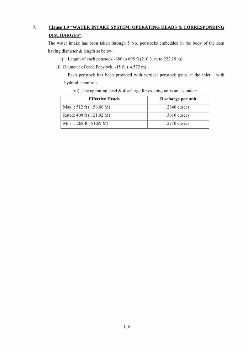
116
7. Clause 1.9 “WATER INTAKE SYSTEM, OPERATING HEADS & CORRESPONDING
DISCHARGES”:
The water intake has been taken through 5 No. penstocks embedded in the body of the dam
having diameter & length as below:
i) Length of each penstock -680 to 695 ft.(210.31m to 222.19 m)
ii) Diameter of each Penstock. -15 ft. ( 4.572 m)
Each penstock has been provided with vertical penstock gates at the inlet with
hydraulic controls.
iii) The operating head & discharge for existing units are as under:
Effective Heads Discharge per unit
Max : 512 ft ( 156.06 M) 2840 cusecs
Rated: 400 ft ( 121.92 M) 3610 cusecs
Min : 268 ft ( 81.69 M) 2710 cusecs

117
SECTION-II
General Specification And
Requirements

118
SECTION-II GENERAL SPECIFICATION AND REQUIREMENTS
2.1 GENERAL: 2.1.1 BBMB (hereinafter referred to as ‘Purchaser’) intends to implement the Renovation,
Modernisation & Uprating Works of Turbine, Generator, Excitation, and other equipment etc.(herein after referred to as “Plant & Equipment”) in respect of 5 Nos. Hydro generating Units installed at Bhakra Left Bank Power House (hereinafter referred to as “the site”).
2.1.2 It is intended through this section to provide Contractor with the general requirements and specification of the plant & equipment. The Contractor shall, however, shall adhere to complete specification as per relevant standards and ensure that the plant & equipment is compatible with the existing equipment being retained, site conditions and layout.
2.1.3 The general technical requirements covered in this section shall supplement the technical specification brought out in Section III & IV of this Appendix-D. Contractor’s proposal is considered to have been based upon the use of equipment and materials complying fully with the requirements specified herein and the relevant standards.
2.1.4 This section describes the general technical features, basic design parameters of the generating units and other equipment, and general conditions of delivery, supply etc. which are generally applicable for supply of the plant & equipment described under each of the succeeding sections dealing with the specifications of the particular plant and equipment. This will form an integral part of the contract. The Contractor shall carefully study and be familiarized with the requirements detailed in this section and other portions of this specification for the plant and equipment. The Purchaser shall take for granted the Contractor’s agreement with the conditions given in this section and other portions unless disagreements/deviations are specifically brought out in the Schedule of deviations (Form-I/ Section-V)
2.1.5 The Contractor shall duly perform the following works as also detailed in the Section III (Appendix-D) of Contract, which broadly covers the following:- (i) Design and engineering (including reverse engineering), manufacturing and
fabrication, testing and inspection of complete equipment including shop testing.
(ii) Turbine model testing for new design of runner. (iii) Submission of all documents & engineering drawings for BBMB’s approval
before commencement of manufacturing/dispatch (as the case be). (iv) Packing, transportation from manufacturer’s works, fully insured delivery upto
the destination site and storage during erection, insurance during transportation from Purchaser’s store to site, handling, erection, testing and commissioning. However, insurance during storage in Purchaser’s stores shall be borne by the Purchaser.
(v) Loading/unloading, Receipt, storage, preservation and conservation of plant & equipment, all of these enroute upto Purchaser’s stores and at site, Transportation from Purchaser’s stores to site and loading/unloading at site.
(vi) Disassembly, dismantling and removal of all such components of existing plant which are to be replaced by new components or to be fitted with new components.
(vii) Repair/modification of equipment (if required, as per site requirement). (viii) Transportation of plant and equipment to place of pre -assembly, fabrication
and erection (ix) Repair welding, cleaning by shot / sand blasting and painting with epoxy
primer & paint of Draft tube liner. (x) Cleaning by shot/sand blasting and painting works of spiral casing & stay ring
after surface preparation. (xi) Erection, Testing and Commissioning of all the plant & equipment.

119
2.1.6 The Contractor shall be responsible for all work required for all equipment to be
supplied by the Contractor & equipment retained from existing units.
2.2 GUARANTEES: 2.2.1 The Contractor shall guarantee among other things the following:
(a) Quality and strength of material (b) Adequate factors of safety for all parts of equipment to withstand
mechanical/electrical stresses developed therein. These are assumed to have been taken care in tender proposal.
(c) Satisfactory repair/modification, erection and commissioning of the plant at site.
(d) The efficiency, output, temperature rise and other performance data for the equipment as applicable in accordance with the standards and provisions of these specifications.
(e) The delivery periods and schedule of commissioning/repairs/ modifications given in the Contract Agreement.
(f) Satisfactory operation of the plant & equipment at all guaranteed parameters during warranty period.
(g) Suitability of design & workmanship of plant & equipment for the conditions envisaged in these specifications.
2.2.2 It must be clearly understood that the Contractor shall be responsible for replacing at site, free of cost, any part of the equipment that may prove faulty or fail on account of non conformance/ non compliance with the requirements of the sub-clause 2.2.1 within twenty four months (24 months) after the plant & equipment has been taken over as per clause 2.38 of this Section.
2.2.3 The Contractor shall furnish copies of the test certificates for the materials used for manufacture and also the test certificates for the tests conducted on the equipment after manufacture and assembly in the works.
2.3 DESCRIPTIVE INFORMATION:
2.3.1 GENERAL: The Contractor shall submit the following information to the Purchaser for review and acceptance as outlined herein and in other sections of the Specification.
a. Drawings of Equipment and assembly drawings, etc. b. Design Data. c. Instruction Manuals, Instructions for installation, operation and maintenance,
Functional checkout and start-up procedures, etc. d. Test procedure/reports. e. Catalogues, wherever applicable. f. Equipment data
The makes of mechanical and electrical equipment to be used in the work, together with performance characteristics and other significant information, shall be submitted for the Purchaser’s reference.
g. Any other documents as listed in subsequent paras/specification. The descriptive information must be formally submitted, bearing a certification signed by an authorized representative of the Contractor stating that the information shown thereon has been checked by the Contractor and that it is complete and correct for use in the project. Descriptive information of preliminary nature furnished for information and/or reference shall be clearly identified as such.
2.3.2 Schedule for Descriptive Information & drawings. The Contractor shall furnish immediately after the Effective Date of the Contract for
Purchaser’s reference “Schedule for submission of Descriptive Information and drawings” that the Contractor proposes to submit, showing the proposed date of submission of such information. The sequence for submittal shall be such that information required for review of a particular piece of descriptive information is

120
available when the descriptive information is received. The Contractor shall provide any additional descriptive information that is required to define the Plant & Equipment, and this additional information shall be included in the “Schedule for Descriptive Information”.
2.3.3 Submittal of Descriptive Information: The Contractor shall provide Ten (10) copies of each piece of descriptive information.
The information shall be forwarded/transmitted directly to the Purchaser at the address as mentioned in Appendix-B of Contract Agreement.
2.3.4 Time required for Purchaser’s Review of Reports, Drawings, and Other Descriptive Information: The date of submittal for descriptive information shall be considered to be the date the information is received by the Purchaser for review. The period of submission of all required documents has been specified in respective section. The Purchaser will require approximately one calendar month for review of each piece of descriptive information or each corrected re-submittal including turbine model test report.
2.3.5 Purchaser’s Review of Descriptive Information: The Purchaser will return one print copy of each piece of descriptive information marked with one of the following notations within the time specified as below: • Approved • Approved subject to observations • Not Approved
2.3.6 Action upon Completion of Purchaser’s Review: Prints marked “Approved” and “Approved subject to observations”, authorise the Contractor to proceed with construction or fabrication of the Equipment covered by such descriptive information with corrections, if any indicated thereon. If minor revisions are made after descriptive information has been returned to the Contractor marked “Approved”, the Contractor shall furnish without delay Ten copies along with drawings in electronic form subsequent to each revision. No major revision affecting the design or shop detail shall be made after descriptive information has been marked “Approved”, without resubmitting the descriptive information. When prints have been marked “Approved subject to observations” or “Not Approved”, the Contractor shall make the necessary corrections, and resubmit Ten (10) print copies within One Calendar month. Number, date, and subject in a revision block shall show every revision. In addition, each revised piece of descriptive information shall have its latest revision clearly indicated.
2.4 TENDERER ( NOW CONTRACTOR) TO INFORM HIMSELF: The tenderer (now Contractor) is deemed to have made an independent enquiry as to the conditions and circumstances affecting his tender estimate and to the possibility of executing the works as described. In assessing the tender, it will be deemed that the tenderer (now Contractor) has inspected and examined the site, its surroundings and satisfied himself (as far as it is practicable) as to the form and nature of the site, the quantities and materials necessary for the completion of the work and the means of transport and access to the site, the accommodation he may require, the general labour position at the site and has fixed his prices taking into account the risks, contingencies and other circumstances which may influence or affect the execution of the contract.
2.5 CORRESPONDENCE/LANGUAGE.
All correspondence including drawings, design data, instructions, catalogues, illustrations, or printed specifications shall be in English language and dispatched by the fastest commercial means.
2.6 COMPLETENESS OF TENDER:
Equipment furnished shall be complete in every respect with all mountings, fittings, fixtures, instruments and standard accessories normally provided with such equipment and/or needed for erection, completion, efficient monitoring and safe operation of the equipment as required by

121
applicable codes even though may not have been specifically detailed in the respective specifications, unless included in the list of exclusions.
2.7 ENGINEERING DATA:
2.7.1 The furnishing of engineering data by the Contractor shall be in accordance with requirements as laid in specification. The review of the engineering data will cover only the general conformance of the data to the specifications and documents interfaces with the equipment provided under the specifications, external connections and of the dimensions which might affect plant layout. This review by the Purchaser may not indicate a thorough review of all dimensions, quantities and details of the equipment, materials, any device or item indicated or the accuracy of the information submitted. The review and/or approval by the Purchaser shall not be construed by the Contractor as limiting any of his responsibilities and liabilities for mistakes and deviations from the requirements specified under these specifications & documents.
2.7.2 All engineering data submitted by the Contractor after final process including review and approval by the Purchaser shall form part of the contract documents and the entire works covered under these specifications shall be performed in strict conformity, unless otherwise expressly requested by the Purchaser in writing.
2.8 INTERCHANGEABILITY:
All corresponding components/parts of all the five units and spares supplied shall be made to gauge or jig and shall be interchangeable in every respect.
2.9 MANUFACTURING PROGRAMME AND SCHEDULES: 2.9.1 The Contractor shall submit for approval of the Purchaser, within one calendar month
from the Effective Date of the Contract , a detailed programme in the form of PERT/CPM network indicating various activities involving design, drawings, manufacture, shop-testing, shipment to site etc. for all equipment based on contract delivery periods.
2.9.2 The manufacturing programme and schedules shall be reviewed, updated and submitted to the Purchaser, once every month thereafter, by the Contractor. Schedules shall also include the materials and equipment purchased from sub-vendors/sub-Contractor. The monthly progress reports should include: i) Status of various activities with reference to original schedule. ii) Reason for delay, if any. iii) Remedial measures to cover up delays. The Contractor shall also provide the required number of photographs together with the negatives showing the actual progress during the various stages of manufacture at no extra cost to the Purchaser.
2.9.3 The Purchaser reserves the right to call for further detailed programme during currency of the contract so as to enable him to adequately follow-up the progress of the work.
2.10 DESIGN IMPROVEMENTS:
2.10.1 During the pendency of the contract, the Purchaser or the Contractor may propose changes in the specification of the equipment or quality thereof and if both the parties agree upon any such changes, the specifications shall be modified accordingly.
2.10.2 If any such agreed upon change is such that it affects the price and schedule of completion, the parties shall agree in writing as to the extent of any change in the price and/or schedule of completion before the Contractor proceeds with the change. Following such agreement the provisions, thereof, shall be deemed to have been amended accordingly.
2.11 TROPICAL TREATMENT: All equipment shall be suitably designed and treated for normal life and satisfactory operation
under the tropical climatic conditions prevalent at the site. The sequence of preservative shop coating/painting at site etc. shall be got approved by Contractor from the Purchaser.

122
2.12 QUALITY ASSURANCE:
2.12.1 Quality Assurance Programme: To ensure that the plant & equipment under the scope of this contract whether
manufactured or performed within the Contractor’s works or at his sub-Contractor’s premises or at the Purchaser’s site or at any other place of work are in accordance with the specifications, the Contractor shall adopt suitable quality assurance program to control such activities at all points. Such programs as outlined by the tenderer (now Contractor) in their tender offer are attached in Section-VI of Appendix-D. A quality assurance program of the Contractor generally covered the following: (i) Contractor’s organisational structure for the management and implementation
of the proposed quality assurance program. (ii) Documentation control system. (iii) Qualification and experience data of Contractor’s personnel. (iv) The procedure for selection & purchase of materials, parts, components and
selection of sub-Contractor’s service including Contractor’s analysis, source inspection, incoming raw-material inspection, testing and verification of materials purchased etc.
(v) System for identification and traceability of parts/components/ products/ instruments/control devices.
(vi) System for process control, fabrication and assembly control during shop manufacturing and site erection.
(vii) System for indication and appraisal of inspection and testing when parts/components/raw material/instruments/control devices are received during manufacture and during final product/equipment/assembly inspection and testing.
(viii) Control of calibration and testing of measuring and testing equipment. (ix) System of documentation to indicate conformance or non conformance of
product to specifications, inspection and test status. Also control of non-conforming items and system for corrective actions.
(x) System for handling, storage, packaging, transportation and delivery at site. (xi) System for maintenance of quality records. (xii) System for quality audit. (xiii) System for authorising release of manufactured/repaired product to owner. (xiv) A quality plan detailing out the specific quality control procedure adopted for
controlling the quality characteristics relevant to each item of equipment/component furnished.
2.12.2 Quality Assurance Documents: The Contractor shall be required to submit the following applicable Quality Assurance Documents prior to manufacture/testing & inspection/ dispatch of the equipment and also covering repair/modification work at site. i) All non-destructive examination procedures, stress relieving and weld repair
procedure actually used during fabrication. ii) Welder and welding operators qualification and experience certificates. iii) Welder identification list, listing welder’s and welding operator’s qualification
procedure and welding identification symbols. iv) Material casting/ forging mill test reports on components as specified by the
specification. v) The inspection plan with verification, inspection plan check points, verification
sketches, if used, and methods used to verify that the inspection and testing points in the inspection plan were performed satisfactorily.
vi) Sketches and drawings used for indicating the method of traceability of the radiographs to the location on the equipment.
vii) All Non-destructive examination result reports including ultrasonic test interpretation reports
viii) Stress relief time temperature charts.

123
ix) Factory test results for testing required as per applicable codes and standards referred in the specification.
x) Inspection reports duly signed by Quality Assurance personnel of the Purchaser and the Contractor for the agreed inspection hold points. During the course of inspection, the following will also be recorded. (a) Any important repair work carried out or to be carried out to make the
job acceptable. (b) The repair work remains part of the accepted product quality.
2.12.3 Quality Assurance Plan(QAP): A Quality assurance plan detailing specific control procedure to be adopted for controlling the quality characteristics relevant to each item of equipment shall be furnished for the approval of the Purchaser. These shall include but not to be limited to the following to ensure conformance of equipment specifications and relevant codes/standards. i. Material test of raw material.
ii. Non-destructive examination. iii. Component Inspection and Tests. iv. Assembly Inspection and Tests. v. Pressure test/high voltage dielectric and other test.
vi. Operational tests. vii. Performance and efficiency tests as applicable.
Purchaser hold points shall be clearly identified in the QAP. 2.12.4 The Purchaser or his duly authorized representative reserves the right to carry out
Quality Audit and Quality surveillance of the systems and procedures of the Contractor/his vendors Quality Management and Control Activities.
Note:- The Contractor has informed that as per their standard, radiographic examination is not used for generator components and Ultrasonic test and Magnetic particle examination shall be carried out.
2.13 DEPARTURE FROM SPECIFICATIONS: The Schedule of Technical Deviations are as listed in Section-V of Appendix-D of this Contract Agreement. The plant & equipment offered shall be deemed to comply in every respect with these specifications except deviations as brought out in this Contract Agreement.
2.14 STANDARDS: 2.14.1 All material plant and equipment shall comply in all respects with the requirements of
the latest edition/issue/revision of the relevant Indian Standards(IS)/International Electro-Technical Commission (IEC) Standards/ASME Standards or any other equivalent standards, as amended upto date.
2.14.2 It shall be understood that the latest issue or revision in effect at time of submission of proposal shall apply.
2.14.3 Where a certain equipment is stated not to comply with the Indian, IEC or any other equivalent standard, the salient points of comparison between the standard adopted and those mentioned above are deemed to have been noted & clearly brought out in the tender. At the same time necessary corrections shall be made for operation under the conditions specified herein provided they are substantially equivalent (equal or higher performance) to design standards provided acceptance is obtained from the Purchaser. A complete or particular set of adopted standards in English language shall be supplied by the Contractor, free of charge, before the award of the contract or during the evaluation of tender, if necessitated by Purchaser. Wherever a standard is specifically mentioned in these specifications, it is understood that the corresponding standards or standards from amongst the sources mentioned above shall also apply. It is, however, understood that the plant and equipment offered shall comply with one consistent set of

124
standards except in so far as they are modified by the requirements of these specifications.
2.14.4 In case of a conflict between such codes and/or standards and the specifications, the latter shall govern. Such codes and/or standards referred to shall mean the latest revision, amendments/changes adopted and published by the relevant Institutions. In case of any further conflict in this regard, the same shall be referred to the Purchaser, whose decision shall be final and binding on the Contractor.
2.14.5 All codes and/or standards used including those listed in the equipment specification must be listed in the schedules. One (1) English language copy of all national and international codes and/or standards used/ adopted in the design of the plant and equipment and listed in the Contractor’s offer and approved by the Purchaser shall be provided by the Contractor to the Purchaser within two calendar months from the Effective Date of the Contract
2.15 MANUFACTURER’S STANDARDS:
2.15.1 The general principles on which these specifications are drawn up is to permit the adoption of modern manufacturing standards. The Contractor may offer their own standard equipment and employ their standard practice in manufacture, repair/modification, as far as possible provided, these comply with the requirement of these specifications, and, have quality controls as per latest International Standards. However, should the tenderer (now Contractor) had wished to depart from provisions of these specifications either on account of manufacturing practice or for any other reasons, it is deemed that tenderer (now Contractor) has drawn the attention of the BBMB to the proposed points of departure and submitted such full information, drawings and specifications as well enable the relative merits of his proposals to be fully appreciated.
2.15.2 In the event of these specifications or a part thereof and the Contractor’s drawings, specifications, forms, tables, etc. being found to disagree during the execution of the contract, these specifications shall be held as binding unless the departures have been duly approved in writing by the Purchaser.
2.16 MATERIAL AND WORKMANSHIP.
2.16.1 GENERAL: i) All parts shall be manufactured true to drawings dimensions. All tolerances shall be
defined on the Contractors drawings for both manufacturing and installation purposes.
ii) All the materials used in the manufacture of equipment/construction of the plant shall be new & of high first-class i.e. the best quality obtainable of their respective kinds and suitable for the purpose, free from defects & imperfections, selected particularly to meet the duties required of them. The material specification shall be indicated in Contractor’s detailed drawings. The whole of the work shall be of highest class, well finished and of approved design and make. All material and workmanship shall be of the highest quality conforming to the latest editions of relevant standards so as to ensure smooth and vibration free operation under all possible operating conditions and the design, dimensions and materials of all parts shall be so chosen that the stress to which they may be subjected shall not render them liable to distortion or damage under the most severe conditions encountered in actual service.
2.16.2 Lubrication & Insulating Oils: The Contractor has confirmed to supply VG 46 grade of lubricating & insulating oil,
which conform to IS:1012. The specified oil grade is available in India with all leading oil companies like IOCL, BPCL, Shell, Castrol etc..
2.16.3 Piping: i) All pipes and fittings supplied by Contractors shall conform to the appropriate
standards. ii) Each piping system shall be provided with adequate number (to be approved by the
Purchaser) of valves, drain plugs/cocks, test plugs/cocks, sight flow indicators

125
etc. so as to ensure ease and flexibility of operation coupled with reliability, soundness and ease of maintenance of the system. All pipes and valves should be clean from inside & provided with blind covers, properly tagged and to be erected suitably with proper slope etc. as per relevant standards.
iii) All piping, valves and other fittings shall be painted as per relevant code/standard. 2.16.4 Fasteners:
Nuts, bolts, studs and washers for incorporation in the plant & equipment shall conform to the requirements of the relevant standards. Where there is risk of corrosion, bolts and studs shall be finished flush with the surface of the nuts. Bolts except for high strength friction grip bolts shall be designed so that with the nuts fully tightened, the stress intensity at the bottom of the thread shall not exceed half the yield point of the material even under worst conditions. All bolts, nuts and screws which shall be subjected to frequent adjustment or frequent removal in the course of operation shall be made of corrosion-resistant steel or bronze. Spring type washers shall not be permitted where they may damage surface protective coatings.
2.16.5 Forgings: All forging in excess of 150mm in diameter shall be subjected to examination internally for the detection of flaws and heat treatment for the relief of residual stresses. Particulars of the heat treatment proposed for all forgings shall be submitted to the Purchaser.
2.16.6 Castings: Castings shall be free from blow holes, cracks or other defects & shall be smooth, close grained and of true forms and dimensions. i) The parts of cast steel shall not contain damaging defects (i.e. free from injurious
defects) and shall be satisfactorily cleaned before their intended use. The surfaces those are not machine-finished and which will remain exposed after their final installation shall be such that grinding at the site will not be required before painting & shall be dressed for good appearance and for painting. The presence of defective material with location of existing defects shall be determined & all defects that impair the strength or utility of coating shall be removed down to sound metal. The cast parts shall be homogeneous and free from excessive non-metallic inclusions. The casting shall be tested using radiographic (not used for Generator components), ultrasonic, dye penetration, magnetic particles or any other non destructive test method.
ii) Repair Welding: A complete descriptive report of the part and defects including drawings showing the location and size of major defects, supplemented with sketches, photographs, metallurgical test results, results of examination by non-destructive testing, dimensional stability of the casting in relation to overall design dimensions, section metal thickness, core shift, shrinkage, wrappings etc, shall be submitted to the Purchaser for reference prior to any repair of defects. The report shall define the type of defect, its probable cause, and any recommended changes in design of the part or casting technique to avoid similar defects on successive castings. A detailed repair procedure including the examination by non-destructive testing to be applied during welding and for the finished repairs shall also be submitted.
iii) Acceptability of Castings shall be governed by provisions outlined in Indian/ASTM standards.
2.16.7 Welding: i) General:
Contractor shall specify clearly on all relevant drawings, the amount and type of material for each type of weld. Contractor shall also provide detailed drawings showing joint preparation required for each type of welding to be carried out at site and at manufacturer’s works. If the manufacturer has special requirements relating to welding procedure for welds at terminals of equipment, to be procured by Purchaser, the requirements shall be submitted as deviations, in advance of commencement of work.

126
ii) The Contractor shall also specify type of welding rods. 2.16.8 Drilling:
Holes shall be drilled full size or under size and reamed during shop assembly. Punched holes shall only be permitted in plates 20mm or less in thickness provided all such holes are subsequently reamed full size during shop assembly.
2.17 INSTRUCTION MANUALS:
2.17.1 The Contractor shall submit to the Purchaser, instruction manuals for erection of all the equipment, covered under the contract four (4) months before commencement of supply of the equipment for the first unit. The instruction manuals shall contain full details and drawings of all the equipment furnished, the storage instructions, loading/unloading instructions, the erection procedures and check out & start up field testing procedures separately. These instruction manuals shall be submitted in the form of One (1) reproducible original and ten (10) complete durable bound copies shall be of an accepted quality & type. In addition, one soft copy of the same shall also be furnished.
2.17.2 If after the commissioning and initial operation of the Plant, the instruction manuals require any modifications/additions/changes, the same shall be incorporated and then only the updated portion of the manuals (supplementary) in the form of one (1) reproducible original and ten (10) copies shall be submitted by the Contractor to the Purchaser.
2.17.3 Operation and Maintenance : Ten (10) copies of complete detailed operating and maintenance instructions together with drawing(other than shop drawings) of the equipment as completed shall be supplied at the time of handing over of the equipment and shall be in sufficient detail to enable the Purchaser to operate, maintain, repair, dismantle, reassemble and adjust all parts of the equipment. A separate section of manual shall be for each type of equipment and shall contain a detailed description of construction and operation, together with relevant brochures and drawings. These shall give steps/precautions to be carried out during the life of the equipment. These shall give a step by step procedure for all operations likely to be carried out during the life of the equipment including erection, testing & commissioning, operation, maintenance, dismantling and repair. It will give details for identification of parts for ordering replacements and procedure thereof. Each manual shall also include a complete set of approved drawings together with performance/rating curves of the equipment and test certificates wherever applicable. The operating instructions shall include all required liquid levels, flows, pressure settings and settings of all auxiliary protective devices. The maintenance instructions shall identify various maintenance activities under heading viz., routine, preventive, annual, capital etc. and the recommended frequency / interval for carrying out such maintenance. Maintenance instructions include charts showing lubrication checking, testing and replacement procedures to be carried out daily, weekly, monthly and at longer intervals to ensure trouble free operation. Where applicable, fault location charts shall be included to facilitate finding the cause of mal-operation or breakdown. A collection of the manufacturer’s standard leaflets will not be accepted to be taken as a compliance of this clause. The manual shall be specifically compiled for the concerned project.
2.17.4 Field Work Procedure: The Contractor shall provide a Turbine and Generator Field Work Procedure to the Purchaser to install, align and adjust all items furnished by him even though it is in the scope of Contractor. Ten copies of the Field Work Procedure shall be submitted together with reduced-size copies of all drawings and applicable schematics or sketches necessary to clarify the written procedures. The Field Work Procedure shall include but not be limited to the following. a. The erection sequence. b. Information on handling and slinging of the major pieces of equipment. c. Erection tolerances. d. Special precautions to be taken in the installation.
127
e. Procedures, dimensions, and tolerances for any required machining or modification of existing parts.
f. Attachment of turbine runner to turbine shaft. g. Connecting the Equipment with the existing equipment.
2.17.5 Storage: Complete detailed instructions with illustration, diagrams and weights regarding the storage and care of the equipment at site shall be furnished by the Contractor. The instructions shall include. a) Space requirements for outdoor and indoor storage. b) In-storage inspection and care. c) Periodic rotation of components, where required. d) Application of protective coatings. If at any time during the storage of equipment at site, Purchaser or his representative desires to draw the attention of the Contractor to the conditions of storage which in his opinion might effect the state of the equipment stored, he shall do so in writing to the Contractor.
2.17.6 Equipment Unloading and Handling Instructions: Detailed instructions for unloading and handling of the plant & Equipment shall be
submitted together with sketches in advance. The sketches shall show slings details, equipment weights, required crane capacities, and transportation of the Plant & Equipment. The description and sketches shall focus on large size and/or heavy equipment items with special emphasis on the runner & stator segments, etc. Unloading and handling equipment furnished by the Contractor shall be conspicuously identified.
2.17.7 Spare Parts Catalogue: Complete set of spare parts catalogue should also be furnished.
2.18 EARTHING: 2.18.1 The Contractor shall provide earthing terminals on all the equipment supplied under the
contract as per latest relevant standards and shall connect the earthing conductors to these terminals as approved or directed by the Purchaser.
2.18.2 Unless specified otherwise, the earthing conductors from the station earthing bus to the equipment will be provided by the Contractor. The Contractor shall provide suitable test terminals at convenient points of the equipment being supplied to enable periodic testing of the resistivity and insulation levels of the equipment.
2.19 UNITS:
Metric units according to the latest edition of the relevant Indian/IEC publications shall be used for this contract.
2.20 DESIGN AND STRESSES:
2.20.1 The design, dimensions and materials of all parts of the plant & equipment shall be such that they will not suffer damage under the most adverse service conditions. Mechanism shall be so constructed as to avoid sticking due to rust or corrosion.
2.20.2 The equipment shall be designed for operation in an earthquake zone. The equipment and each part of it shall be strong enough and sufficiently well connected to resist total operating stresses including any stresses resulting from an earthquake.
2.20.3 The plant shall be designed to:- (i) minimise the risk of fire and any consequential damage;
(ii) prevent accidental contact with live parts; (iii) be capable of continuous operation or as required with minimum attention and maintenance under the conditions prevailing in a hydro generating power plant development in a tropical climate.
2.21 Maximum Allowable Stresses:

128
Adequate factors of safety shall be used throughout the design, especially in the design of parts subject to alternating stresses, vibration, impact, or shock. The design of the equipment shall include an earthquake factor equal to gravity horizontal and vertical acceleration mentioned in para 1.4 of Section-I of this Volume or greater than ‘9’ on Richter scale (whichever is maximum). Under the most severe conditions of loading expected in normal operation, stresses in the materials shall not exceed the values listed below- i. Maximum shear stresses in cast iron shall not exceed limits based on chosen material
classification, provided it does not effect the performance of machine. ii. Maximum shear stresses in other ferrous materials shall not exceed sixty percent (60%)
of the allowable stresses in tension. iii. For temporary overloads exceeding the maximum turbine output, unit stresses shall not
exceed one-half (1/2) the Yield strength. iv. The maximum design stresses in tension or compression shall not exceed one-third (1/3)
of the yield strength or one-fifth (1/5) of the ultimate tensile strength of material. v. Under the maximum runaway speed conditions, stresses shall not exceed two-thirds (2/3)
of the Yield strength. Complete information regarding factors of safety & maximum unit stresses in the design shall be provided by the Contractor in support of above. NOTE (w.r.t. GENERATOR): Contractor clarified that as per their understanding the project site falls in Zone IV according to seismic Zoning Map of India and therefore magnitude of 9 on Richter Scale as specified in the bid specification is very high and does not confirm to the seismic zone. Contractor has further confirmed to comply with IS 1893 (Reaffirmed) & IS-1893 (Part-3)-2002 regarding equipment withstand capability for accelerations due to seismic activity and based upon classified seismic zone –IV for project site. The site falls in Zone –IV and as per IS 1893 (Part-I) 2002 the earthquake factor is specified greater than 8 on Richter scale and has confirmed regarding capability of equipment to withstand seismic forces as per seismic zone –IV.
2.22 PROTECTION AND SAFETY MEASURES: 2.22.1 All coated surfaces shall be protected against abrasion, impact, discoloration and any
other damages. All exposed threaded portions shall be suitably protected with either a metallic or a non-metallic protecting device. All ends of all valves, piping and conduit and equipment connections shall be properly sealed with suitable devices to protect them from damage. The parts which are likely to get rusted due to exposure to weather shall also be properly treated for normal life and satisfactory operation under the climatic condition prevalent at the site and shall be dust and vermin proof. All parts and surfaces which are subject to corrosion shall be made of such material and shall be provided with such protecting finishes as would protect the equipment installed from any injurious effects of excessive humidity. All Electrical auxiliary equipment shall be specially treated for tropical conditions and the materials and method for this treatment shall be got approved in advance.
2.22.2 Preservative Shop Coating/Painting: (i) All non-machined surfaces except bronze, copper or stainless steel shall be painted.
All paints must be lead free. (ii) All exposed metallic surfaces subject to corrosion shall be protected by shop
application of suitable coatings. All surfaces which will not be easily accessible after the shop assembly, shall be treated and protected for the life of the equipment. All surfaces to be painted shall be thoroughly cleaned of all mill- scale, oxide weld scatter, dirt, rust, grease, & other foreign substances and other coatings and prepared in the shop. All the sharp corners and jagged edges shall be smoothed off prior to painting. The surfaces those are to be finish-painted after installation or require corrosion protection until installation, shall be shop painted with atleast two coats of primer. All important component parts such as, thrust runner, bearings, journal surfaces etc., shall be specially protected with a protective coating and other measures to ensure prevention of rusting of the machine surfaces during

129
storage of the material prior to erection. Any special instructions for inspection and maintenance of such vital parts during storage deemed necessary by the Contractor to ensure the protection of such parts shall be supplied. Electrical equipment shall be shop finished with one or more coats of primer and two coats of high grade resistance enamel. The finished colours shall be as per manufacturer’s standards to be selected and specified by the Purchaser at a later date.
(iii) Shop primer for all steel surfaces which will be exposed to high operating temperatures shall be selected by Contractor after obtaining specific approval of Purchaser regarding quality of primer to be applied..
(iv) All other steel surfaces which are not to be painted shall be coated with suitable dust preventive compound.
(v) Generator and all the auxiliary plant shall be given two coats of finishing paints of approved colour over a coat of filler paint. The turbines, outdoor equipment and all the allied plant & equipment shall be given two priming coats of approved rust resisting paint in plain colour before packing. Parts not so painted shall be protected against deterioration during shipment. All bright steel parts shall be given a thick coat of approved rust resisting paint in plain colour to prevent rusting during shipment and transport. All gun metal or brass parts shall be coated with a removable dark paint as a precaution against pilferage during transit. All unfinished surfaces in contact with oil shall be cleaned and painted with a special oil resistant paint.
(vi) All the seams and joints which will be riveted together at site shall be given a coat of varnish before despatch from manufacturer’s works. The interior metallic surfaces of oil filled apparatus shall be treated with oil resistant paint or varnish after thorough cleaning. A sufficient quantity of finishing paint shall be supplied for applying two further coats to all the parts which are painted with unfinished paint after the complete erection of the machinery
(vii) The steel structures such as spiral casing and stay ring etc. shall be painted with two coats each of epoxy primer and epoxy black paint after thorough cleaning of surface by Contractor by shot /sand blasting or any method approved by Purchaser.
(viii) The draft tube liner shall be weld repaired to achieve original dimensions and cleaned thoroughly by shot /sand blasting for two coats of epoxy primer and two coats of Epoxy Black paint.
2.22.3 Galvanising: All materials to be galvanised shall be of the full dimensions shown or specified and all
punching, cutting, drilling, screw tapping and the removal of burrs shall be completed before the galvanising process commences. All galvanising shall be done by the hot-dip process with spelter, not less than ninety-eight percent (98%) of which must be pure zinc. No alternative process may be used without the approval of the Purchaser. No components shall be galvanised which are likely to come into subsequent contact with oil. Bolts shall be completely galvanised including the threads, but the threads shall be left uncoated in the case of nuts. The zinc coating shall be uniform, clean, smooth and free from spangle as for as possible. In the case of component parts, the zinc coating shall weigh not less than 0.6 Kg/m2 over the area covered and be not less than 0.09mm in thickness. All galvanising shall comply with the requirements of the relevant Indian or ASTM Standards. All galvanised parts shall be protected from injury to the zinc coating due to differential aeration and abrasion during the period of transit, storage and erection. Damaged areas of the coating shall be touched up with an approved zinc-dust paint or other approved flake metallic compound by the Contractor.
2.22.4 Surface finish of the turbine runner: The turbine runner water passages shall be finished smooth by grinding and shall be
free from blow holes, depressions, projections, or other surface imperfections that could cause local cavitation or hydraulic losses. The surface finish on the runner shall be shown on the drawings and the surface roughness shall not exceed the limits as specified in IEC-60193.

130
2.22.5 Protective Guards: Suitable guards shall be provided for protection of personnel on all exposed rotating and/or machine parts. All such guards with necessary fittings and accessories shall be designed for easy operation and removal for maintenance purpose.
2.23 DESIGN CO-ORDINATION:
2.23.1 The Contractor shall be responsible for the selection and design of appropriate equipment to provide best co-ordinated performance of the entire system. The basic design requirements are detailed out in Technical Specifications. The design of various components, sub- assemblies and assemblies shall be so done so as to facilitate easy field assembly and maintenance. All of the rotating components shall be so selected that natural frequency of the complete unit is not critical at or close to the operating range of the unit.
2.23.2 Design Coordination Meeting: Contractor will be called upon to attend design coordination meeting with the Purchaser/other consultants/other Contractors during period of contract. The Contractor shall attend such meetings at his own cost at Chandigarh/Site or at mutually agreed venues as and when required and fully cooperate with such persons & agencies involved during these discussions. The Purchaser at their expenses shall also visit the works of Contractor(s) within 6 months of Effective Date of Contract for Design Coordination meeting.
2.24 RATING PLATES,NAME PLATES AND LABEL: 2.24.1 A rating plate of non-corrosive or non-corrodible material shall be attached to each
major and auxiliary item of plant & equipment. This plate shall be permanently engraved in a legible & durable manner with the designed full load ratings, manufacturer’s name, serial number, type, date of manufacture and other identification deemed necessary shall also be supplied.
2.24.2 A name plate shall be provided to identify the service of all items of plant supplied. The identifying inscription, (with all markings) shall be submitted alongwith drawing after award of contract and approved by the Purchaser. Devices shall be identified by name plates on both front and rear of all desks, panels, cubicles etc.
2.24.3 Name plates or labels shall be manufactured of non-hygroscopic material with engraving of a contrasting colour
2.24.4 Items of plants & equipment such as valves, which are subject to handling, are to be provided with an engraved chromium plated nameplate or label with engraving, filled with enamel.
2.24.5 The wording on all nameplates shall be in English only. 2.25 PACKAGING, SHIPPING AND TRANSPORTATION:
2.25.1 The Contractor shall wrap, pack, coat and crate all plant & equipment included in the work or part thereof, suitable for shipment to a tropical location and in a manner which facilitates handling and protects the plant & equipment from damage in rail, truck, ocean or air shipment as applicable and within the size and weight limitations imposed by the carrier. The packing/transportation should be so as to prevent damage or deterioration during transit, handling & storage at site. An approved drying agent such as silica-gel shall be packed in containers or packages holding plant which may be adversely affected by moisture or excessive humidity. The Contractor shall check on the way restrictions, right of way clearances, alternate routes, mode of transportation and weight limitations and make all shipping and transportation arrangements.
2.25.2 All apparatus and equipment shall be securely packed for safe delivery at destination and the supplier shall be responsible for all losses or damages caused or occasioned, due to improper or defective packing. Double boxing to give extra protection to the equipment against mechanical injury shall be used, if required.

131
2.25.3 All parts requiring protection from moisture including polished parts which rust rapidly, shall be double boxed with trapper or in such other approved manner. All parts such as coils, parts containing coils for electrical machines, instruments, relays, meters etc. requiring utmost protection against moisture shall be packed in metal lined sealed boxes with trapper or sisal craft paper or any other approved material inserted between the metal lined box and the outer layer of boxing.
2.25.4 All Plant & equipment parts shall be marked to facilitate erection. All packing crates shall be clearly and indelibly marked before shipping to indicate the contract number and shipping address, volume, weight, name, number and unit number of the contents, slinging and weight bearing points. All boxes shall be marked with signs indicating the up & down sides of the boxes & also unpacking instructions considered necessary by Contractor.
2.25.5 The contents of boxes shall have place marks corresponding to the number in packing list to enable easy identification. Each packing crate shall contain a packing list in a water-proof envelope. Three copies of the packing list shall be forwarded to the Purchaser prior to despatch. Parts shall be described and also identified by their numbered marking in the packing list. The Contractor shall be responsible for any loss or damage during transportation, handling and storage. BBMB takes no responsibility of the availability of wagons/trailers and variation in dimensions. All requisite arrangements/permissions in this regard will be the sole responsibility of the Contractor.
2.26 ELECTRICITY RULES:
All works shall conform to the rules in force under the Indian Electricity Act and other applicable legislations.
2.27 TRAINING: The supplier shall provide facilities for training of the personnel to be deputed by the Purchaser at their manufacturing works and/or design office and at testing shops. The schedule of completion of design works and schedule of manufacture of equipment under this contract or similar equipment to be manufactured at the works shall be intimated by the supplier well in time, so that the Purchaser may at his option depute adequate number of persons for training to facilitate subsequent handling, operation/maintenance of the plant and equipment, etc. The training shall be arranged in such a way that the personnel under training shall be acquainted with the handling and erection of the equipment. The period of each training shall not exceed one month. All expenses in respect of ‘to and fro’ travelling charges to the manufacturer’s premises/place of training and all other expenses for boarding and lodging of the trainee(s) shall be borne by the Purchaser.
2.28 CO-ORDINATION AND CO-OPERATION WITH OTHER MANUFACTURERS: 2.28.1 It is envisaged that there will be a number of areas where there would be an interface
between equipment to be supplied under this contract and the equipment proposed to be purchased under other contracts. Thus the Contractor shall co-operate with all other manufacturers for the execution of work contracted and/or related to Contractor’s own work. The Purchaser will co-ordinate in this regard, if required.
2.28.2 Contractor shall exchange, with the other manufacturers of items not covered in this specification or alternatively covered in this specification but forming partial supply of others, all necessary drawings, templates, gauges and other information required to ensure complete and proper design and co-ordinate manufacture of all connected or related parts of the various equipments.
2.29 DRAWINGS:
2.29.1 All drawings submitted by the Contractor including those submitted at the time of tender shall be in sufficient detail to indicate the type, size, material, weight of each component, maximum overall dimensions, weight of the package to be transported, break down for packing and shipment, the external connection, fixing/anchoring

132
arrangement, the dimensions required for installation and inter-connections with other equipment, clearances and space required between various portions of the equipment and any other information specifically requested/considered necessary in incorporating the equipment on the existing structure.
2.29.2 Each drawing submitted by the Contractor shall be clearly marked with the name of the Purchaser, the unit designation, the specifications title, the specification number and name of the project. If standard catalogue pages are submitted, the applicable items shall be indicated therein. All titles, notings, marking and writings on the drawing shall be in English Language. All dimensions shall be in metric units. All revisions should be marked giving brief details.
2.29.3 Drawings to be furnished The tenderer (now Contractor) was required to shall submit with the tender, the
drawings enumerated below and in various other sections of the specifications: Equipment drawings. Drawings showing transverse section through turbine and generator. Foundation details of generator with existing sole plates. Schematic diagrams of generator /bearing coolers. Control and schematic diagrams for unit control boards / T.G. panels,
instrumentation and safety devices etc. Erection procedure to be followed in installation of generating units. Bill of material covering entire scope of work. Characteristic curves/graphs showing the performance of various equipment. Any other drawing considered necessary subsequently by Purchaser.
Note: Drawings/Technical Documents as submitted with tender offer are attached in succeeding Sections of Appendix-D are preliminary and all of these shall be resubmitted for approval at later stage.
2.29.4 Drawings to be furnished after award of contract: i) Contract drawings (10 copies each) as listed below shall be supplied by the Contractor to the Purchaser for information /approval as per schedule to be submitted with respect to clause 2.3.2. Prior to proceeding with manufacture, the Contractor shall submit the Purchaser all general assembly, subassembly, and detail drawings for all items being supplied to demonstrate fully that all parts will conform to the provisions and intent of the Specification/Contract Agreement and to the requirements of their installation, operation, and maintenance. These drawings shall completely describe and define each and every component or part supplied under this Specification/Contract Agreement. a) All drawings specified as tender drawings above together with those specified in
individual sections of the specifications incorporating such modifications as may be required by the Purchaser.
b) Key-diagrams and schematic diagrams of all piping systems, control, instrumentation, protection and alarm systems. Wiring diagrams for all electrical circuits, cabling layout including cable schedules.
c) Foundation drawings of all component parts of the plant clearly showing the details of the foundation wherever required. Drawings shall contain details for associated civil works (if required) for installation of equipment.
d) Detailed drawings of the entire equipment; these shall include separate drawings of all important component parts of the plant clearly showing all details, mode of fastening etc. The drawings shall be sufficient to furnish a complete understanding of the design and working of the entire plant & equipment and shall contain all the necessary information required for its erection and maintenance.
e) Erection Schedules f) Inter connection diagrams g) Control Schematics(including mimic diagrams)

133
h) All documentation (detailed bill of material, technical details/literature) for the turbine, generator, excitation system and other allied equipment as listed in respective sections.
i) The drawings shall be accompanied by appropriate design calculations. j) All necessary dimensions and fabrication details, including the type and grade of
materials, the details of welded and bolted joint connections, tolerances on fits and clearances.
k) Level of pre-assembly in which the Contractor proposes to ship the equipment. l) Locations and sizes of auxiliary connections for oil, grease, water and air. m) Where appropriate, a bill of materials shall be included on the drawings. n) Any other drawing as required by Purchaser.
ii) Detailed drawings or design data for the purpose of checking the adequacy of the Contractor’s designs by calculations shall not ordinarily be required but the Purchaser reserves the right to call for these in certain cases at his discretion. No manufacturing work/repair and modification work etc. or despatch of equipment shall be performed prior to the approval of drawings in writing by the Purchaser.
iii) Any manufacturing and fabrication work in connection with the equipment prior to the approval of the drawings shall be at the Contractor’s risk.
iv) The drawings submitted by the Contractor will be reviewed by the Purchaser as far as practicable within one calendar month of their receipt and shall be commented upon by the Purchaser if any modifications and/or corrections are required. One set of drawings will be returned to the Contractor by the Purchaser marked with corrections. The Contractor shall incorporate such modifications and/or correction & submit the final drawings for approval. Any delays arising on account of failure by the Contractor to rectify the drawings in reasonable time shall not have any bearing on the contract completion date.
v) When revised drawings are submitted for approval, the changes from the previous submittals shall be clearly identified on the drawings, with every revision made during the life of the contract shown by number, date and subject in a revision block and a notation shall be given in the drawing margin. The drawings shall be clear and legible in all respects.
vi) The Purchaser shall have the right to require the Contractor to make any changes in the design, which may be necessary in the opinion of the Purchaser to make equipment conform to the provisions and intent of these specifications without additional cost to the Purchaser.
Approval by the Purchaser of Contractor’s drawings shall not be held to relieve the Contractor of any part of the Contractor’s obligations and liabilities to meet all the requirements of these specifications or of the responsibility for the correctness of Contractor’s drawings.
2.29.5 Drawings to be furnished after completion of work: i) Within 3 months after the completion of the erection work, the Contractor shall
furnish 10 sets of complete drawings of all the approved drawings including changes/amendments, full sized and accurately scaled. The drawings in electronic form should also be supplied.
ii) In addition, such detailed drawings as may be necessary for erection, maintenance, repair, identification of plant components/parts and for ordering replacement parts shall be supplied by the Contractor as may be required by the Purchaser.
iii) Further work by Contractor shall be in strict accordance with these drawings and no deviations shall be permitted without the written approval of the Purchaser/Engineer-In-Charge if so required.
2.30 CONSUMABLES:
All the consumables such as oils, lubricants, welding electrodes, cleaning agents, gaskets, packings, shims, packers, protective coatings, paints etc. which will be required to put into plant & equipment covered under the scope of specification & upto successful trial operation of equipment plus 10% extra to take care of minor leakages/spillage etc. shall be included in the

134
scope of supply unless specifically excluded under the deviations in these specifications. Any other consumables not stated above but required for erection, testing & commissioning of all the machines shall also be in the scope of the contract. The list of consumables in the scope of supply of Contractor shall be as indicated in Form-II of this volume. NOTES: 1. The Contractor has confirmed that any other consumables not stated in
Form-II “List of Consumables” plus 10% extra required for the execution of Erection, Testing and Commissioning works for all machines shall be arranged by him.
2. Also refer Sub-clause 3.1(r) of Section-III/Appendix-D of Contract Agreement. 3. Detailed list will be furnished by the Contractor during Project Execution stage.
2.31 SPARE PARTS
2.31.1 The Contractor shall include, as a separate item, one set of spare parts (common for plant and equipment of all five units) required if recommended by him in Form-III “Schedule of Recommended Spare Parts” attached in Section-V of Appendix-D of Contract Agreement for satisfactory operation of the plant & equipment for a period of ten years in addition to the spares as mentioned in scope of supply as specified in Annexure-II/ Section-V of specifications. The spare parts shall include the items as indicated in the technical specifications.
2.31.2 The supply of mandatory spares given in Annexure-II Section-V of the specification shall be made as under: c) Spares for 1st unit shall be supplied along with supply of main plant and
equipment for 1st unit. d) Spares for remaining four units shall be supplied along with main plant &
equipment for last unit. 2.32 TOOLS AND PLANTS:
A complete outfit of (including all special tools and tackles) spanners, gauges, slings, lifting devices, instruments and all other appliances necessary for the complete assembly, erection at site, dismantling and maintenance of the plant along with racks for holding them shall be supplied and included in the contract & specified in Form-IV/ Section-V of Appendix-D of Contract Agreement. Spanners shall be single handed and made to fit each size of nut and bolt of the plant. Two sets of spanners, tools and appliances shall be supplied. However, these will be separately packaged and brought on to the sites. NOTES: 1. Certain tools will be used for stator core stacking and winding at site which are
manufacturing tools and will be brought to site by Contractor on returnable basis. 2. Notwithstanding what is stated in the list of tools, the contractor has further
confirmed that any additional special tools & tackles to be required for use in this contract shall be arranged by them without any additional cost.
3. Contractor has clarified that general tools are minor tools, details of which will be furnished by them during project execution.
4. Form-IV lists tools which will be retained at site. Contractor has clarified that other temporary tools which will be brought by them to site for erection/commissioning work and which will not be required for such annual/capital maintenance will be taken by them on completion of work. Details of such tools will be furnished during project execution stage
2.33 EXTRA WORKS:
Contractor shall, when asked in writing by the Purchaser to perform extra work and furnish extra material not covered by the specifications or included in the schedule but forming an inseparable part of the work contracted shall carry out the extra work/furnish extra material. The payments for such extra work or material shall be mutually agreed upon in advance. However, in case of completeness of tender and any repair/modifications are required to match the site requirements, all the expenses incidental to it shall be completely borne by the Contractor. The Contractor has provided the unit rates for supervision charges.

135
2.34 TESTING AND INSPECTION The provisions outlined in the Indian or I.E.C. Tests codes or other approved International Equivalents shall generally be used as a guide for all the test procedures, tolerances etc. unless otherwise specified in the technical specifications. In order for both the parties to confirm all the concerned provisions as well as the further course of testing & inspection, the Purchaser at their expenses shall visit the office of the Consortium Leader within 3 months of Effective Date of the Contract. 2.34.1 Material Tests:
a) General All material or parts used in the Plant & Equipment shall be tested in accordance with the requirement of the specifications mentioned in this specification. Stocked material may be used, provided evidence is furnished to the Purchaser showing that such material meets the requirements specified herein. The Purchaser may check the invoices of raw materials to ascertain its source, etc. b) Chemical Analysis, Tension and Hardness Tests Each lot of material used for casting and other requirements as per Section-IV/Appendix-D of Contract Agreement shall be tested for chemical composition to prove that it conforms to the material requirements specified in the applicable standard/specifications. Mechanical test samples shall be poured from each lot of material used for a casting and the tension and hardness tests shall be performed to verify the yield and ultimate strength and Brinell hardness of the material in accordance with the applicable standards. c) Nondestructive testing
i) General The Contractor’s drawings shall indicate type, extent, and severity level of non
destructive examination as it applies to each component or weld. ii) Examination of Castings Components, which are castings, shall be given complete non destructive examination, including Ultrasonic Testing (UT) and Magnetic particles Testing (MT) examination of the most critical areas. The Contractor’s drawings submitted to the Purchaser shall define the area and extent of UT and other non destructive examination to be performed on castings. The Contractor’s drawings shall be accompanied by a detailed inspection procedure, together with acceptance/ rejection criteria, which must be reviewed and accepted by the Purchaser. Non destructive examination of castings shall be in accordance with accepted good practice to assure sound castings. The non destructive examinations shall be in accordance with the following standards.
Ultrasonic testing
ASME, “Boiler and Pressure Vessel Code” , Section VIII, Appendix 12
Magnetic particle testing
ATM-E709, ‘standard practice for Magnetic Particle Examination”.
Radio- graphic testing
ATM-E94, “Standard Guide for Radiographic Testing”. ASME, “Boiler and Pressure Vessel Code”, Section VIII, Division 1, Paragraph UW-51
ASTME-142, “Standard Method for Controlling Quality of Radiographic Testing”
Dye Penetrant testing
ASTM-E165, “Standard Practice for Liquid Penetrant Inspection Method”.
NOTE:

136
Radiographic Examination for Generator components is not used as per their standards and Ultrasonic test & Magnetic Particle Examination shall be carried out. The radiographic examination acceptance standard shall be severity level 3 in any of the categories of grade discontinuities listed in the appropriate ASTM standard.
d) Test Certificates Certified material test reports (six copies) shall be furnished to the Purchaser as soon as possible after the tests for approval. The test certificates shall identify the component for which the material is to be used and shall contain all information necessary to verify compliance with the specification.
2.34.2 Shop Tests: a) Standard Tests:
All the equipment/material shall be subjected to the Routine Test’ for all the machines as specified in the Section-IV/Appendix-D of Contract Agreement at Contractor’s/sub-Contractor’s works/laboratories without any extra charges to the Purchaser’s account. Certified copies of all the test certificates/ calculations not furnished with the Contractor’s tender or otherwise required shall be supplied to the Purchaser for approval/acceptance. In case test certificate(s) for any of the type tests is found to be un-acceptable by the Purchaser, the supplier shall arrange to carry out the said test(s) afresh without any extra cost to the Purchaser.
b) Intimation of Inspection: The Purchaser reserves the right to send his representative at any time for carrying out / witnessing inspection / tests on the material during the manufacture / completion at the works of the Contractor. The Contractor shall intimate 15 days in advance to the Purchaser, the place and probable date on which the manufacture of equipment / material is likely to commence to enable him to make arrangements for inspection during manufacture and witnessing tests. The Contractor shall provide all necessary facilities for inspection/tests.
c) Tests during manufacturing /on completion of manufacture i) When any material is ready for stage inspection/type/ routine/final tests, the
Contractor shall give to the Purchaser 15 days written notice of its being ready for inspection & testing and the Purchaser’s representative (s) unless witnessing of test inspection is waived, shall endeavour to attend the manufacturer’s premises for inspection and witnessing the routine/shop or stage inspection/testing within 15 days of the receipt of clear notice from the Contractor. In case the representative (s) of Purchaser finds on arrival at supplier’s premises that the material is not ready for inspection and notice given was infructuous, the expenditure incurred by the Purchaser on arranging for such inspection shall be recovered from the supplier.
ii) The Purchaser and his duly authorized representative shall have, at all reasonable times, access to the manufacturer’s works or premises and shall have the power/right to inspect and examine the equipment, material and workmanship during the course of manufacture or erection. If part of the material/requirement is being manufactured at other premises, the Contractor shall obtain for Purchasers representatives, permission to inspect as if at manufacturer’s premises.
iii) Tests on assemblies/sub-assemblies as detailed in Section-IV/ Appendix-D of Contract Agreement shall be carried out in manufacturer’s works at any stage of manufacturing process as per standard practice in the presence of Purchaser’s representatives, wherever considered necessary.
iv) The Purchaser shall give notice to the Contractor of any objection to any equipment and workmanship, which in his opinion is not in accordance with the contract. The Contractor shall give due consideration to such objection and

137
shall make necessary modifications that may be necessary and repeat the tests, if so desired by the Purchaser.
v) Dimensions and clearances shall be measured and recorded on illustrated shop inspection forms, showing both the design dimensions and the actual measured dimensions. Copies of all shop inspection forms shall be furnished to the Purchaser prior to shipment of the Equipment from the Contractor’s shop.
d) Shop Assembly i) All the Equipment that can be assembled in the shop without requiring any of the
existing turbine parts shall be so assembled to verify the design, construction, and machining for proper alignment, fits and clearances. Parts shall be properly match-marked, identified, and doweled to assure correct assembly and alignment in the field. Prior to major shop assemblies and tests, the Contractor shall submit an outline of the procedures and tests it plans to perform. The Purchaser or his representatives will have the option of witnessing said procedures and tests.
ii) No shipment/despatch of any portion of the equipment shall be made from manufacturers shop till the test certificates of the tests conducted at the works are duly approved by the Purchaser. One advance copy of the test certificates of materials used for manufacture and also for the prescribed tests conducted on equipment after manufacture and assembly in their works shall be sent for approval to the Purchaser by air mail or by registered post/courier/ e-mail provided complete copy is sent.
iii) In all cases where the contract provides for tests whether at the premises or works of the Contractor or of any Sub-Contractor, the Contractor, except where otherwise specified, shall provide free of charge such items as labour, materials, electricity, fuel, water, stores, apparatus and instruments as may be reasonably demanded by the Purchaser or his authorized representative to carry out effectively such tests of the equipment in accordance with the contract and shall give facilities to the Purchaser or to his authorized representative to accomplish testing. However, the boarding, lodging, to and fro air / rail / road expenses of the Purchaser representatives shall be borne by Purchaser.
iv) The inspection by Purchaser and issue of Inspection Certificate, thereon shall in no way limit the liabilities and responsibilities of the Contractor in respect of the agreed quality assurance programme forming a part of the contract.
e) Test Reports The Contractor shall furnish six (6) copies of all shop test reports, i.e. tests,
laboratory tests, and inspection reports etc. The reports shall be bound for permanent reference use & Contractor shall get them approved before proceeding ahead with manufacturing/dispatch as the case may be.
2.35 SITE TESTS
2.35.1 On completion of erection of the equipment and completion of R,M&U works, each item of the equipment shall be thoroughly cleaned and then inspected by the Contractor in the presence of Purchaser’s representative for correctness and completeness of installation and acceptability for start up for trial operation. All site tests specified in the respective sections of the specifications shall be carried out by the Contractor at his own expense, however, duly witnessed by Purchaser. All these shall form ‘hold points’ in quality assurance programme.
2.35.2 Rotational Check of Combined Shaft After the turbine and generator shafts have been installed, connected and aligned, the
Contractor will perform rotational check in accordance with NEMA Standard Publication MG 5.2, Section 5.2.1 3.01, “Vertical Hydraulic Turbine-Generator Shaft Run out Tolerances – installation Check” under his supervision.
2.35.3 Operational Tests

138
After each turbine has been reassembled, the generator and other related equipment reinstalled, and before it is considered ready for commercial operation, the Contractor will check the equipment and perform initial operational / functional tests as required to assure that the plant & Equipment has been installed and adjusted properly, in presence of Purchaser’s representatives and that it will function safely and properly under continuous operation. Load rejection and load-acceptance tests etc. shall be made to adjust the governor timing elements, settings of speed switches and other protective devices.
2.35.4 The Contractor’s commissioning engineers specifically identified as far as possible shall be responsible for carrying out all the pre-commissioning tests as specified in Section IV. On completion of inspection, checking and after the pre-commissioning tests are satisfactorily over, the complete equipment shall be placed on Initial Operation during which period the complete equipment shall be operated integral with sub-systems and supporting equipments whether in this scope of contract or otherwise.
2.36 TRIAL OPERATION:
2.36.1 The unit shall be on Trial Operation while all necessary adjustments shall be made and operation over the full load range shall enable the plant & equipment to be ready for performance and guarantee tests. The duration of Trial Operation of full equipment shall be 14 days including at least Seventy Two (72) hours (commercial commissioning) shall be continuous operation at full load or at load corresponding to available head without any abnormality. In case full load can not be attained due to available head being less than rated head, trial operation shall be carried out again when rated head is available for establishing the performance and operational guarantees within one year after the Trial operation at load corresponding to available head. In case of any abnormality, the 72 hours operation at full load will have to be repeated in either case. The Trial operation shall be considered successful provided that each item of the equipment can operate continuously at the specified operating characteristics for the period of Trial operation. In case full load can not be attained due to available head being less than rated head, “Provisional TOC” shall be issued upon successful Trial Operation at load corresponding to available head. The Warranty period shall start upon issue of the Provisional TOC.
Further, in case the Trial Operation can not be carried out at the rated head within one year as mentioned above, the Provisional TOC shall automatically become the TOC.
2.36.2 A Trial operation report (in triplicate) comprising of observations and recording of various parameters shall be prepared by the Contractor and signed by both parties. The report, besides recording the details of various observations during trial run, shall also include the dates of start and finish of the Trial operations, details of interruptions occurred, adjustment made and any minor repairs done during the Trial operation. Based on the observations, necessary modifications/repairs to the plant shall be carried out by the Contractor to the full satisfaction of the Purchaser to enable the latter to accord permission to carry out Performance and Guarantee Tests on the Plant & equipment. However, minor defects which do not endanger the safe operation of the equipment (to be decided by Purchaser) shall not be considered as reason for withholding the aforesaid permission.
2.37 PERFORMANCE AND GURANTEE TEST:
2.37.1 On successful completion of Trial Operation runs, all the specific performance and guarantee tests shall be conducted by the Contractor in presence of the Purchaser within a period of one Year from the TOC/provisional TOC
2.37.2 These tests shall be binding on both the parties to the contract to determine compliance of the equipment with the performance guarantees.

139
2.37.3 All instrumentation and test devices required for performance and guarantee tests shall be arranged by the Contractor free of cost. However, the instrumentation and control equipment available with the Purchaser may be used during such tests and the Contractor will get calibrated at his cost all such measuring equipment and devices from approved test houses / laboratories. However, immeasurable parameters shall be taken into account in a reasonable manner by the engineer, for the requirement of these tests. The tests will be conducted at the specified load points and as near the specified cycle condition as practicable. The engineer will apply proper corrections in calculation, to take into account conditions which do not correspond to the specified conditions.
2.37.4 Any special equipment, tools and tackles and any sort of arrangements if required for the successful completion of the performance and guarantee tests shall be provided by the Contractor, free of cost.
2.37.5 The guaranteed performance figures of the equipment shall be proved by the Contractor during these performance and guarantee tests. Should the results of these tests show any decrease from the guaranteed values, the Contractor shall modify the equipment as required to enable it to meet the guarantees. In such case, Performance and Guarantee Tests shall be repeated within one month, from the date the equipment is ready for re-test and all cost for modifications including labour, materials and the cost of additional testing to prove that the equipment meets the guarantees, shall be borne by the Contractor otherwise, the Contractor is liable to bear liquidated damages.
2.37.6 The specific tests to be conducted on equipment have been brought out in the respective section of Technical Specifications (Section-IV/Appendix-D of Contract Agreement).
2.37.7 Performance and Guarantee Test shall make allowance for instrumentation errors as may be decided by the Engineer-in-Charge/Purchaser keeping in view the provisions available in the relevant Indian/International standards.
Notes:- 1. The guaranteed output and turbine efficiency tests shall be carried out at
maximum, rated and minimum head on the first unit in case required conditions as mentioned in IEC standard are achieved and further the efficiency testing on the remaining units shall be carried out at rated head.
2. These tests shall be carried out in accordance with the Hitachi’s document No. W0N-BKR-054- R1. (Attached in Section-VI /Appendix-D of Contract Agreement)
3. The document No. “W0N-BKR-054_R1 dated 30.1.2007 Site Test Items for Hydraulic Turbine” contains following provisions/clarifications: The efficiency test will be performed on all five (5) units. However, the efficiency test will be carried out at maximum, rated and minimum head for first unit, and at rated head only for the remaining 4 units. (i) As indicated the tests at maximum head of 512 ft. and at (especially)
minimum head of 300 ft may not be carried out within the head range of around +6% between test head and specified head specified in Clause 5.2.2 of IEC 60041. Hitachi would like to propose that the test of the maximum head of first unit will be carried out on September (or period of higher head condition) and the test of the minimum head will be carried out on May (or period of lower head condition), within one year after Taking Over or Provisional Taking Over, although the test head reach to the specified head or not. The test results will be calculated or corrected in according to Clause 6.1 of IEC 60041, if the deviation of test head from specified head is outside the range specified IEC, (that is case of 6.1.2.2 c) of IEC 60041), the efficiency hill diagram for correction will be used the test results of model test.
(ii) At the first unit the weighted average efficiency will be calculated from the field test results. At the remaining 4 units the comparison of efficiency at rated head against the efficiency of first unit at rated head will be performed within 6

140
months after Taking Over or Provisional Taking Over. In case that the efficiency at rated head is same with tolerance as the efficiency at rated head of the first unit, it is considered that the efficiency of the tested unit and the efficiency of the first unit are regarded as also same at the other head.
(iii) In case that the field efficiency tests would not be able to perform within one year after Taking Over or Provisional Taking Over due to any reason not attributable to the Contractor, the guarantee turbine efficiency shall be confirmed by the Model Test results.
2.38 TAKING OVER: Upon successful completion of all the tests to be performed at site on equipment supplied, erected and repaired / modified, the Purchaser may issue to the Contractor a taking over certificate. In case the performance and operational guarantees can not be established due to head constraints, the formal taking over shall be conditional subject to successful trial operation and establishment of performance & operational guarantees at specified head subsequently. This certificate however shall not relieve the Contractor of any of his obligations and responsibilities under the contract, which otherwise survive, by the terms and conditions of contract after issuance of such certificate. Note:- However, in case the issuance of TOC delays more than one month after all the tests and successful Trial Run Operation, or up to twelve months after the receipt date of major plant & equipment at site due to reasons not attributable to the Contractor, the Contractor shall be entitled to receive payment for each TOC automatically i.e. Deemed TOC, warranty/defect liability period shall be reckoned from such deemed TOC date and keeping in view to Contractor’s responsibility for completion time of Contract on the first Unit within 31 months from Effective date and shutdown period of 210 days, the Contractor should be allowed to carry out the Trial Operation / Tests accordingly, the timing for which shall be intimated to Purchaser appropriately.
2.39 DELIVERIES AND SCHEDULE OF REPAIRS / MODIFICATIONS/
COMMISSIONING: i) The delivery of equipment (including spares), schedule of dismantlement, Repairs/
modifications works (if necessitated/required) erection, testing and commissioning of plant shall suit the completion schedule is as specified in Form-V& VI.
ii) The Contractor shall indicate the schedule for shutdown required on any one of the five units for the purpose of reverse engineering is limited to 30 days for Generator as specified in Form-VII.
The following aspects shall be kept in view a) The shutdown period for RM&U of units shall be kept minimum so as to minimize
loss of generation. b) Only one unit will be under shutdown at a time.
2.40 ELECTRICAL EQUIPMENT: 2.40.1 General The various auxiliaries and controls shall be suitable for AC 415 V +10%, 3 ph.; AC
230 V+10%, 1 phase and 220 V, DC supplies respectively. 2.40.2 Pumps
i) Unless otherwise specified, all pumps shall be directly coupled to driving motors and their type, capacity and performance shall be best suited to the requirements. The efficiencies of the pumps shall be as high as practicable consistent with good design. As far as possible the pumps shall be of standard size to facilitate replacement of parts.
ii) Driving motors to which pumps will be coupled shall conform to the general standards laid down in this specification. Gear motors if employed, shall be subject to the Purchaser’s approval. The pump capacities and the ratings of the

141
driving motors shall have liberal margin over the requirements and ensure satisfactory operation without any noise or vibration.
iii) All pumps shall be complete with the necessary piping, both on the suction and delivery sides and with all fittings suited to the size and duty of the pump. Adequate number of valves as stated earlier shall be furnished with each pumping unit to suit its operation and maintenance. Wherever necessary, pumps shall be provided with suitable flow meters or flow indicators and pressure gauges to measure the discharge pressure delivered by the pumps. Suitable eye-bolts or lifting lugs shall be provided on each pumping set to facilitate handling.
2.40.3 Electric motors and motor control gear i) All motors, furnished by the Contractor for driving the unit auxiliaries and other
apparatus, shall be of standard make and directly coupled to the apparatus driven and shall be suitable for operation on either (i) 415+10% volts, 3 phase, 50+3%.Hz A.C. or (ii) 230 + 10% volts single phase, 50 +3% Hz A.C. or (iii) 220 Volts, DC. Supply, as specified in the relevant clauses of this specifications. The enclosure of each motor shall be of the type best suited to the service conditions of the motor and shall be subject to the approval of the Purchaser in every case. The motor shall generally conform to the relevant Indian or IEC/other equivalent standards. The insulation shall be moisture, oil and oil vapour proof and the motors shall be entirely suitable for the operation in the tropical climatic conditions prevailing at site.
ii) Each motor shall be provided with closed conduit box suitably located for ease of access and with eye-bolts or lugs for lifting. The terminals box shall be fitted by means for terminating the external wiring for outdoor use. Varnished cambric or glass insulation shall be used for connections from the windings to the terminals. All motor terminals shall be of the stud type and totally enclosed.
iii) The capacity, speed and torque characteristics of the motors shall be suitable for the starting and operating requirements of the associated apparatus.
iv) Special type of motors, not adequately covered by this specification may be offered for any special application, but these shall be subject to the approval of the purchase.
2.40.4 Panel and other wiring i) All electric wiring of the various equipment panels, etc. shall be completed at the
manufacturer’s works (as far as possible) and be arranged neatly into flat or rectangular groups and shall be adequately supported with cable ties/ cleats etc. The wiring shall be so arranged as to reduce the number of bond or crossing to a minimum. There shall be no splices in the wire and all connections shall be made at the terminal blocks. Similar circuits shall be arranged to terminate to the extent possible, on adjacent terminals to facilitate grouping and to minimize the number of inter connecting cables. Secondary or control wiring including leads from the current transformers, temperature detectors, alarm contacts, speed and pressure switch etc. shall be enclosed in conduits and shall be carried to dust and water proof and oil tight cabinets located conveniently for connections to the control cables.
ii) Circuits shall be suitably protected so that failure of one circuit shall not cause the progressive failure of adjacent circuits. Alternating current circuits, direct current circuits and circuits operating at different voltages shall be grouped separately and the wiring for each of these groups shall preferably be segregated. For signals, screened cables are to be used.
iii) For the purpose of easy identification, tracing and reconnection, the wiring shall be colour coded and shall be fitted near the terminals with ferrules or such other caps indelibly marked with the identification number corresponding with that of the associated terminal blocks. When an electrical circuit is extended to several pieces of equipment necessitating sectionalising of circuit wiring at the terminal blocks of the corresponding equipment, common identification numbers shall be used for the designation of the circuits at all the terminal blocks and connections.

142
The terminals and circuits designating for all wiring shall be subject to the approval of the Purchaser.
iv) All small wiring shall be switch board type single conductor, tinned annealed copper wire, PVC insulated cables preferably FRLS as per relevant Indian/International Standards or insulated with varnished cambric, which has proved its utility in tropical region against hot and moist climatic conditions and vermins, complying with the relevant international standards. All small wring shall have oil and oil vapour-proof insulation. The sizes of the wiring for different circuits shall be so chosen as to provide ample margin for the purpose intended and shall be subject to the approval of the Purchaser.
2.40.5 Terminal Blocks
i) Terminal blocks shall preferably be made of suitable moulded plastic material and shall be provided with brass stud inserts for terminating the outgoing ends of the cubicle wiring and the corresponding wiring of the incoming end. Provision shall be made on each pillar for holding 20% extra connections.
ii) All blocks shall be shrouded by easily removable shrouds moulded from transparent dielectric material. The terminal block shall be of disconnecting type and suitable for 660 volts service /otherwise suitably specified.
iii) Sufficient space for receiving the control cables inside the switch board at the bottom of the switch board cubicles and mounting arrangements for the terminal glands shall be provided.
iv) Terminal block compartment shall be separated from the remainder of the equipment by oil and oil vapour proof barriers and seals, wherever necessary.
2.40.6 Measuring Instruments i) All instruments and meters shall be suitable for operation under the climatic
conditions prevailing at site. The instrument cases shall be dust proof, water tight, vermin proof and specially constructed to adequately protect the instruments against damages or deterioration due to high ambient temperatures and humidity. The dials, pointers, etc. shall be designed to facilitate accurate reading by minimizing parallax and glare from the instrument window and by providing clear, bold dial markings. The scale plates of panel mounted indicating instruments shall have a permanent white matty finish with black graduations. The pointer or the pointer indicating contact setting (in contact working instruments) shall be distinguished from the main pointer by a distinct colour and/or shape. Moving elements shall be equipped to with zero adjustment on the face of each instruments.
ii) Instruments mounted on panels shall be of the flush type and shall be back-connected. The proposed instrument and panels shall be aesthetically suitable to the existing ones. All instruments on a switchboard or instrument panel shall be of matching pattern, shape and finish so as to present a pleasing appearance consistent with the functional requirements. The finish of the instrument case shall be subject to the approval of the Purchaser. All instruments shall be designed for accurate measurement of the quantity or state under all conditions of operations and any errors due to change in the ambient temperature, over the entire range of temperatures obtainable at site, shall be kept to a minimum. The instruments shall be provided with all the auxiliary appliances and any special tools required for their maintenance.
iii) The metric units shall be used for marking the instrument dials. iv) All electrical instrument coils shall be designed for continuous operation for at least
120 percent of the full rated parameters without loss of accuracy. The instrument coil rating shall be coordinated with those of the associated instrument transformers (CT’s, PT’s).
v) Ammeter and Voltmeter coils shall withstand 120% of rated current/voltage continuously and ten times the rated current/voltage for 0.5 sec. respectively without loss of accuracy. The VA burden of instrument coils shall be as low as possible, consistent with the best modern design.

143
vi) Electrical indicating instruments shall comply generally with the requirements of Indian/IEC or any other international standards and shall be of the accuracy specified in relevant sections.
vii) Contact making instruments shall have contacts suitable for 230 Volts, A.C. or 220 volts D.C. circuits.
viii) The instruments shall be capable of withstanding the following tests viz. Effect of shock, effect of vibration and effect of humidity and dielectric tests of 2000 volts RMS to ground for one minute etc. in accordance with relevant standards.
2.41 CONTRACTOR’S EMPLOYEES AT SITE:
Contractor’s representatives shall conform to all general safety and statutory regulations in force at the site and to any special conditions affecting the local administration issued by the Purchaser or his duly authorised representatives. All employees of the Contractor living on the lands belonging to the Purchaser shall be deemed to be aware of danger and risks incidental to the activities of the Purchaser and other Contractors and the Purchaser shall not be responsible for any injury arising there from. The wives, children and other dependents of any such employees being on or around the land or works of the Purchaser shall enter and be there entirely at their own risk.
2.42 ERECTION AND SUPERVISION: 2.42.1 Contractor is to arrange manpower in requisite numbers & skills and expert supervision
for the dismantlement, assembly, erection and testing & commissioning at site of all the plant and equipment to be supplied under these specifications/Contract Agreement and shall accept the responsibility for the plant and equipment for meeting all guarantees. The recommended personnel and the charges on account of dismantlement, erection, testing and supervision of erection shall be stated in the tender separately.
2.42.2 The Contractor is to arrange for all required qualified & competent team of workers / supervisors / engineers / labour who shall be capable of speaking English / local language and will be responsible for obtaining all work permits / clearance from labour department and security authorities. Contractor shall be responsible for the safety and insurance of his personnel including payments of their wages, salary, EPF, ESI and other dues etc. The Contractor shall provide all tools and plants including special tools to properly perform the work.
2.42.3 The schedule of dismantlement, erection, testing & commissioning should be intimated separately.
2.43 OPERATIONAL REQUIREMENTS AND CONTROLS:
2.43.1 The units shall be required to run in Generating mode of operation only.
2.43.2 Machine Controls a) The turbine, generator, excitation equipment and other associated equipment shall
be controlled in the following manner:- i) Manual Mechanical Control
To be performed by direct hand operation of the primary controls on the individual items of the equipment.
ii) Manual Electrical Control To be performed with the help of individual control switches, provided on the unit control panel and control desk in the control room, for the separate events which collectively constitute a starting or stopping or any other sequence.
iii) Automatic Control To be performed with help of control switches, provided on the unit control
panel and control desks in the control room. b) Remote control of the machine shall be performed from the unit control panel in
the control room. Necessary control Switches, sequential controller, status indicator and other devices such as metering, alarm/annunciation facia, etc. as

144
may be required for starting, stopping and monitoring operation of the generating unit in any one of the specified modes of operation shall be provided on the unit control panel. A local/remote selector switch shall also be provided on the unit control panel for selecting the starting of the unit either remotely from the control panel in the control room or from Governor panel.
c) The existing status indicators and other devices of governors which are being retained shall be provided on the unit control panels in consultation with Engineer-In-charge or his representative
d) The control desks for all the five units shall be provided in control room as per location to be decided in consultation with Engineer-In-Charge or his representative. The proposed Control desks shall be compact to be accommodated in approximate floor area of (2500x 3000) mm. The control desk of each unit shall have the following features in parallel with unit control panel:
i) For monitoring: Measuring instruments for following parameters: - Load, MVAR, output voltage, current in each phase. - Field voltage & current, balance indicator. - Governor speed, Guide vane limit, guide vane position, balance indicator,
speed setting indicator and output setting indicator. ii) For Control:
Control switches for following operations: -Auto / manual mode of excitation. -Manual raising / lowering of excitation. - Field breaker switching operation - Load raising / lowering - Guide vane limit raising/lowering - Emergency stopping. - Breaker control switch for emergency tripping - Push button for Alarm cancellation
The automatic synchronizer shall be mounted in the control room. e) The turbine gauge panel / board, generator gauge panel, etc. shall be located near
each unit as far as possible subject to decision of Engineer-in-Charge / Purchaser. f) Excitation and AVR panels shall be located / placed in consultation with Purchaser. g) In regard to starting of motors for the unit auxiliaries, the starter shall be placed at
locations close to the respective motors amenable to local operation. However, push-buttons for remote starting & stopping of motors of unit auxiliaries shall be provided on the respective control boards in suitable functional arrangement so as to permit all manual electrical control to be performed from the location.
h) The dimensions and outside appearances of each group of panels shall be properly coordinated to present streamlined appearance. The dimensions and appearance of the control panel to be housed in the control room shall also match with that of the control and relay panels to be arranged separately by the Purchaser.
i) Supply of unit control panels & desks and other panels listed above for the generating units shall be part of the supplies of the Contractor. Safety devices and controls required for the turbines, generators, etc. are also in scope of Contractor.
j) Any other Control Panel wherever required for satisfactory operation of the Plant & equipment supplied by the Contractor shall be in Contractor’s scope of supply.
NOTE:- In the present control scheme there is no provision of detection of creeping in any of the units nor does such a provision exist in the tender document. However, during discussion and persuasion by BBMB, Contractor has agreed to provide creep speed signal as output of control system in the new control scheme for uprated machines.
2.44 PERFORMANCE GUARANTEE: 2.44.1 The performance guarantee of the equipment under the scope of the contract is as
detailed under Section-IV-A (Clause-4.2) and Section-IV-B (Clause-4.13). These

145
guarantees shall supplement the general guarantee provisions as covered under Clause titled Guarantee’ at Sr.No. 2.2 of this Section.
2.44.2 Penalty Charges for not meeting performance guarantee during the performance and guarantee tests shall be assessed and recovered from the Contractor, as detailed under clauses 4.2 and 4.13 in Section IV-A& IV-B respectively.
NOTE: The Contractor shall furnish an affidavit duly notarized, that the liquidated damages(LD) on account of shortfall in technical performance and delays as mentioned below shall be honoured by them:- i) LD on account of short fall in technical performance (output/ efficiency) upto
30% of the contract price for complete scope of work. (Maximum). ii) LD on account of delays upto 10% maximum of the contract price for complete
scope of supplies and services. iii) The sum of the above two LDs shall not increase 30% of the total contract price for
complete scope of supply and services upto the commissioning of the facilities.
2.45 MODEL TEST: The Contractor shall design, manufacture and conduct model tests (common for all units) to verify the capability of design of new runner fitted in existing water path to meet the guaranteed values for all the machines. Tests will be conducted at the Hydro Turbine Laboratory of the successful Contractor’s works. The model tests shall be carried out in accordance with standard / IEC – 60193/1999 upto date amended, in the presence of Purchaser’s engineers. The hydraulic parts of this model shall be homologous with the corresponding parts of prototype turbine. The scope of model test shall cover the following & shall subsequently submit model test reports. i) Performance (efficiency & output) test under various conditions. ii) Cavitation characteristics: Photographs of Cavitation phenomenon and vortex in the
draft tube. These shall show flow edges of the runner blades and vortex below the runner
iii) Runaway test iv) Hydraulic thrust v) Pressure Pulsation test The results shall be limited to all recommended operating zones of the machine at rated net head.
2.46 TIME REQUIRED FOR R,M&U WORKS: a) The maximum period for completion of the complete job (from the dewatering stage to
successful commissioning) for one machine will not be more than as indicated in the table below:
Sr. No.
Unit No.
Start of work
Completion of work
Commissioning Trial Operations Handing Over
1 1st Unit
731 days (25 months)
937 days (30 months & 23 days)
(Same as left) (Same as left) 943 days (end of 31 months)
2 2nd Unit
944 days (32 months)
1150days (37 months & 23 days)
(Same as left) (Same as left) 1156 days (end of 38 months)
3 3rd Unit
1157 days (39 months)
1363days (44 months & 23 days)
(Same as left) (Same as left) 1369 days (end of 45 months)
4 4th 1370 days 1576 days (Same as left) (Same as left) 1582 days

146
Unit (46 months) (51 months & 23 days)
(end of 52 months)
5 5th Unit
1583 days (53 months)
1789 days (58 months & 23 days)
(Same as left) (Same as left) 1795 days (end of 59 months)
b) A period of 943 days (end of 31 months) is for completion of the work for first unit right
from the Effective Date of the contract agreement till taking over as per clause 2.38/Section-II/Appendix-D. For the completion of work for all the five machines, the period shall be 1795 days (end of 59 months) from the Effective Date of the Contract Agreement.
2.47 GUARANTEED & OTHER TECHNICAL PARTICULARS:
Guaranteed and other technical particulars as furnished by the tenderer (now Contractor) are attached in Form-VIII and other relevant information in Forms IX of Section-V of this Appendix-D of Contract Agreement.
2.48 NOISE LEVEL & VIBRATIONS : The noise levels &vibrations of the complete plant & equipment shall be within the permissible limits as stipulated in the relevant Indian/International standards. Note:- The Contractor confirmed that noise level inside the cabin for operation personnel shall not exceed 85 dB (A). If existing noise level inside the cabin is more than 85 dB, the same noise level will be maintained.

147
SECTION-III
Scope of Works

148
SECTION-III
3.1 SCOPE OF WORK:
The Contract Agreement contains the following scope of work:-
Design & Engineering (including reverse engineering), model testing, manufacture &
fabrication of equipment compatible to existing one (wherever required), testing at works,
supply & delivery and erection, testing and commissioning of equipment as detailed in Section-
IV of Appendix D of this Contract (the extent indicated in Section-IV is for one unit only).
a) Design, engineering including reverse engineering
b) Manufacture, supply & delivery of plant and equipment as detailed in Section IV
c) Dismantlement of units / assemblies
d) Cleaning, inspection & refurbishment of components for assembling
e) Assembly, erection and retrofitting of original / modified / new components viz, Runner,
Guide Vanes , Guide bearings, Thrust Bearing, Shaft arrangement, Generator Stator &
Rotor Poles, Static Excitation Equipment etc.
f) Repair welding, cleaning by shot / sand blasting, preparation of surface for painting &
painting with epoxy based primer & paint of Draft Tube Liner.
g) Cleaning by shot / sand blasting, preparation of surface for painting & painting of Spiral
Casing and Stay Ring with epoxy based primer & paint.
h) Thorough cleaning and enamel painting of existing equipment / component of turbine
and generator which are to be retained.
i) Supply, laying, termination and ferruling of all the AC / DC control / Power cables with
in and for interconnecting the panels and plant and equipment including termination and
ferruling (thimble ends) at panels where inputs are required to be provided from the plant
& equipment supplied by the Contractor. However, incoming AC / DC power cables will
be supplied by the Purchaser.
j) Model Testing of Turbine Runner (common for five machines) as per IEC 60193 (1999)
“Hydraulic Turbines, Storage Pumps and Pump - Turbines –Model Acceptance Tests”.
k) Refurbishment of head cover and other equipment not covered under replacement.
l) On Line Monitoring Equipment for vibration monitoring, partial discharge measurement,
in 11 KV stator windings, leakage current measurement in generator shaft, air gap
monitoring.
Note:-
The Contractor will supply hand held portable instrument for noise level
measurement.

149
m) Erection, testing, supervision and successful commissioning of the units till taking over
by Purchaser.
n) Arranging all sorts of labour (skilled / semi-skilled / unskilled) including riggers,
slingers, supervisors and engineers etc.
o) Packing, transportation from manufacturer’s works and fully insured delivery up to
Purchaser’s stores, besides insurance coverage towards erection (including transportation
from Purchaser’s store to site, handling and storage during erection), testing & successful
commissioning of the units till taking over by the Purchaser.
p) Loading / unloading, receipt, storage, preservation & conservation of plant and
equipment, all of these enroute upto Purchaser’s stores and at site after issue from
Purchaser’s stores including transportation from Purchaser’s stores to site and loading/
unloading at site.
q) Any type of civil works involved during dismantling / assembling
r) Supply of all consumables including electrodes, paints, tapes, grease, shims, packers,
protective coatings, jointings, packings, cleaning oil compounds, gaskets, lubricants,
cotton waste for cleaning etc. of standard /reputed make:
Note:-
Also refer Clause 2.30/Section-II/Appendix-D of Contract Agreement.
s) Any kind of matching / modification / repair / rectification of plant & equipment to be
carried out at site / works including transportation / handling of such equipment shall be
got carried out by the Contractor at his own cost.
t) Supply of a complete set of spanners, gauges, slings and tools including all the special
tools and tackles.
u) The Contractor shall also take into consideration all the provisions as contained in
Section-II (General Technical Particulars) & Section-IV (Technical specifications).
NOTES:
For Turbine Portion and Generator & other Electrical Portion, refer respective FORMS
and Technical Specifications attached in Appendix-D.
3.2 FACILITIES TO BE PROVIDED FREE (BY PURCHASER)
The following facilities shall be provided by the Purchaser to the Contractor for the
execution of contract free of cost for execution of the work:
a) 2 Nos. EOT cranes each of capacity 2x(115+25) tons with operators
b) Rotor lifting beam of capacity 400 Tons. In case the capacity of existing lifting beam is
inadequate the same shall be in the scope of Contractor’s supplies.

150
c) Electricity for power and lighting (415 V) auxiliary supply at single point).
d) Water supply & compressed air.
e) Site for temporary stores for Plant & Equipment, T&P and other consumable materials at
one point.
f) Covered space for site office at one point.
3.3 FACILITIES TO BE PROVIDED ON CHARGEABLE BASIS:
The following facilities may be extended if available with Purchaser on chargeable basis:-
a) Existing Workshop facilities available with BBMB.
b) Purchaser may provide Mobile Crane service on request in emergency conditions on
chargeable basis, if available.
c) Guest House / Field Hostel accommodation (if available) for Contractor’s executives /
engineers only at rates applicable to BBMB employees on duty.
d) Medical facilities for Contractor’s personnel in Purchaser's hospital at Nangal.
3.4 COMPONENTS LIKELY TO BE RETAINED:
3.4.1 Major components that may not require to be replaced are as under:
a) Turbine shaft
b) Generator shaft
Note {for items a) and b)}
The Contractor has furnished an alternative offer covering replacement of both the shafts i.e. turbine shaft and generator shaft. The Contractor will carry out Non-Destructive Testing and furnish detailed report giving calculations within 3 months of signing of Contract Agreement. However, the replacement of the shafts will be decided based upon the furnishing of detailed report by the Contractor.
c) Rotor Rim
d) Rotor Core
e) Head Cover
In addition to the above the following embedded parts shall be retained:-
a) Scroll case
b) Pen stock
c) Draft tube
d) Stay Ring and Vanes
e) Generator and lower bracket sole plates.
The healthiness in respect of embedded parts particularly stay vanes, lower bracket
sole plates and generator sole plates shall be checked and ensured by corrective
action if required by the Contractor for mechanical strength. The Contractor in this
respect shall confirm in writing and guarantee their healthiness.

151
3.4.2 The following items for each machine shall be procured by BBMB through separate
tendering process:
a) Unit transformer
b) Control & Protection Relays equipment.
However, the Contractor will furnish all the required technical data/schedules/
drawings/wiring diagrams, etc. for proper interfacing/matching of above items with the
plant and equipment to be supplied by him.
3.5 IMPORTANT NOTES:
a) The machining work (wherever required) of various components, i.e. turbine shaft, drilling
holes in runner & matching the same with the existing turbine shaft holes, fitting of main
shaft sleeves etc., including delay (if any caused on this account) shall be entirely to the
Contractors account.
b) All the components / equipment to be furnished by the Contractor shall be manufactured
from high grade material as per latest relevant standards.
c) Wherever matching / compatibility with existing components equipment shall be required,
it shall entirely be the responsibility of the Contractor to accomplish the same conforming
to highest quality standards and accomplish to the satisfaction of the Purchaser.
d) It is deemed to be understood and agreed by the Contractor that the work described in
Section-IV of this Appendix-D is complete in every respect even though any item such as
components, instrument / wiring etc. that may necessarily be required for the satisfactory
functioning / performing / monitoring of each equipment and hydro generating unit as a
whole but not specifically mentioned in the specification due to any reason, shall be
deemed to included in the scope of the Contractor and shall therefore be supplied by the
Contractor without any extra cost to the Purchaser.
e) The Purchaser reserves the right to modify the extent of scope of supply, technical
parameters and specification at any time during the contract. The cost of increase /
decrease shall be adjustable on basis of quoted unit rates.
f) The design / fabrication of equipment shall be carried out such that it is complete and
compatible with existing equipment (wherever required) in all respects and does not
require any rectification / modification work at site.
g) The units shall be designed for over loading up to 5% in all operating conditions.

152
SECTION-IV
TECHNICAL SPECIFICATIONS FOR
PLANT & EQUIPMENT

153
SECTION-IVA
TURBINE

154
4.1 TECHNICAL SPECIFICATIONS FOR TURBINE AND AUXILIARIES 4.1.1 TECHNICAL PARTICULARS AND GUARANTEED DATA OF EXISTING
TURBINES AND AUXILIARY EQUIPMENT:
A. TURBINE: 1. No of units Five 2. Type Vertical shaft Francis 3. Manufacturer Hitachi Ltd. Japan 4. Effective Head Max. 512 ft
Rated 400 ft Min. 268 ft.
5. Output At Max. head 1,50,000 HP At Rated head 1,50,000 HP At Min. head 71,000 HP
6. Discharge At Max. head 2840 Cusecs. At Rated head 3610 Cusecs. At Min. head 2710 Cusecs.
7. Turbine Efficiency% a) Max. Head b) Rated Head c) Min. Head
Full Load 91.1 91.6 86.3
Max. 91.1 93.0 86.6
8. Speed Rated 166.7 rpm. Runaway 338 rpm.
9. Momentary speed rise under lrejection (%)
35%
10. Maximum penstock pressure under load rejection(ft)
691
11. Minimum tail race level(ft) 1166 12. Centre line elevation of distributor 1165 13. Suction Head (ft) 1 14. Hydraulic thrust (ton) 370 15 Runner weight 30.5 Tonnes 16 Turbine shaft weight. 35.6 tonnes. 17 Shaft diameter 38. inches ( 96.4 cm) 18 Runner diameter 13 ft – 7- 21/32 inches ( 415.7 cm) 19 No. of Guide Vanes 20 20 No. of stay vanes 20 21 No. of runner vanes 17 22 Max. thickness of blade 2.11/16 inches (6.8 cm) 23 Min. thickness of blade 1 ½ inch ( 3.8 cm) B. SCROLL CASING: 1. Total weight of assembled sc
casing with speed ring 165 tonnes
2. No. of sections 10 3. Type of construction Bolted construction with speed ring welded
scroll cases. C. GOVERNOR. 1. Type G-40 Electro Hydraulic 2. Manufacturer M/s BHEL Bhopal 3. Operating oil pressure 250-300 lb/Sq. inch.
(18-21.1Kg /Cm2)

155
4. SSG (Speed signalling generator) Toothed wheel type with magnetic pick up 5. Speed reference adjustment 45 to 55 Hz 6. Gate reference setting 0 to 100% D. SERVOMOTORS: ( 2 NOS PER UNIT) 1 Stroke 425mm 2 Cylinder Diameter 800mm 3 Capacity 83, 000 m Kg ( 6,00,000 ft. lbs) 4 Closing time 4.5 to 5 sec. 5 Opening time 7.5 to 9 sec. 6 Pressure oil tank capacity 8.7m3 ( 307 ft3) 7. Governor oil volume 2.26 cubic meters 8. Governor air volume 5.85 cubic meters 9 Governor oil Pump capacity 0.34m3 /Min. ( 12 ft3 /Min) 10 Oil pump motor 3 phase, 50 HP, 65 amps, 10 pole, 575 rpm. 11 Lifting time of penstock head gate 1100 sec. 12 Dropping time of penstock head gat 100 sec. E. TURBINE GUIDE BEARING 1. Turbine bearing pads 12 Nos. 2. Turbine bearing cooler Coil type
4.1.2 OPERATING REGIME:
On the basis of data for weighted average reservoir levels in the past ten years & average Tail Race level at Bhakra Power Houses for the last 20 years. The operating regime shall be as under for a turbine output of 172500 HP
Head Proposed i) Max. head 512 ft. ii) Rated head 440 ft. iii) Min. head 300 ft
4.1.3 DETAIL OF MAJOR EQUIPMENT FOR REPLACEMENT FOR EACH UNIT: 4.1.3.1 TURBINE: A. General:
Replacement of existing Vertical Shaft Francis type Hydro Turbines complete with associated equipment comprising of the following :- Replacement of complete existing runner with new one of new design having output of 128.63 MW (172500 HP), optimised shape, better efficiency & metallurgical properties which can meet the actual head variations by means of applying sophisticated/ computerised design methods. The runner shall be a cast welded runner and the composition of runner material will be 13 % Cr. & 5 % Ni. Stainless steel. The runner shall be machined for its proper matching with existing turbine shaft. The water passage should be homologous with the tested and approved model runner.
The following shall also be included in the scope of supply:-
Sr. No. Description Qty. Material 1 Fabricated steel Runner cone 1 No Steel Sheet 2 Runner keys 2 Nos Steel 3 Fixing Bolts for Runner & Runner cone 1 set Steel
The fixing bolts and runner keys shall be matching with the existing shaft recess and key way respectively. Any modification required shall be carried out by the Contractor as per actual site requirement.
B. Interchangeability: All the runners shall be interchangeable. C. Balancing of runner: The complete runner shall be statically balanced at the Contractor’s works in accordance with
latest relevant IEC standard. D. Template for profile check.

156
Templates cut from adequate thickness of aluminium sheet shall be supplied by the Contractor to verify the runner profile as per model design. These templates shall be used by the Purchaser subsequently for restoring the runner profile to their original contour during repair welding of the cavitated area.
Note: Contractor has confirmed that the maximum axial downward hydraulic thrust of new runner will not exceed 370 ton since construction of uprating runner will be nearly same as the existing runner
4.1.3.2 AERATION PIPE:
The existing aeration pipe below the runner cone in the turbine pit shall be replaced with new modified improved system.
Note:- Contractor has confirmed that the existing aeration pipe below the Runner will be
dispensable in case Turbine shaft (which have air admission hole) is replaced. 4.1.3.3 GUIDE VANES: A. There are 20 (twenty Nos.) Guide vanes provided in the existing system which shall be replaced
with new ones. The guide vanes shall be of cast stainless steel with integral stem having new design/profile for better efficiency.
B. These shall be designed to maintain closing tendency under normal operating conditions. C. Each guide vane shall be machined on top, bottom & along the line of control at full closing. Guide
vanes shall easily turn in three self lubricated bearings two in top guide vane housing & one in pivot ring.
D. Non Destructive tests i.e. ultra sound examination, Dye penetration test, magnetic particle test etc. and other tests as specified in relevant standard shall be performed to check the strength/soundless of the guide vanes.
The following bushes shall be in the scope of supplies:
Sr. No. Description Qty. Material 1 GV upper Stem Bush 20 Nos. Self lubricating type 2 GV Middle Stem Bush 20 Nos. Self lubricating type 3 GV lower Stem Bush 20 Nos. Self lubricating type
The guide vane overall dimensions and outer diameter of the bushes shall be as per existing units.
4.1.3.4 GATE OPERATING MECHANISM: The following equipment /components pertaining to existing Gate Operating Mechanism shall be replaced with new gate operating mechanisms comprising: Sr. No. Description Qty. Material 1 GV link bushings 40 Nos. Self lubricating type 2 Connecting pins 20 Nos. 3 Shear pins 20 Nos. 4 Gate operating ring liners 2 sets Self lubricating type 5 Eye-End bushing of Connec
rod 2 Nos. Self lubricating type
6 Eye-End pin of Connecting rod 2 Nos. 7 GV adjusting device 20 Nos. Steel 8 GV stem packing 20 sets Synthetic rubber.
For item No.3 i.e. shear pin, a failure circuit shall be provided which shall be electrically continuous if all pins are healthy and open if any pin is sheared with alarm and annunciation on the unit control panel. The above components mentioned in the table above shall be of same dimensions as that of existing ones. Note:-

157
Contractor has confirmed that he shall supply panel in the operating room having requisite failure circuits for all the five units.
4.1.3.5 GATE SERVOMOTORS:
The following components of the Gate Servomotors shall be replaced with new ones and other existing components shall be retained: Sr. No. Description Qty. Material 1 Eye end bushing of connec
rod 2 Nos. Self lubricating type
2. Chevron type Packing 2 Nos. Synthetic Rubber The dimensions of these components shall be same as that of existing ones.
4.1.3.6 TURBINE GUIDE BEARING:
The following components of Turbine Guide Bearing shall be replaced with new ones and the other existing components shall be retained. Sr. No Description Qty. Material 1 Turbine Guide Bearing pads 12 Nos. Steel case with babbit lining. 2. Turbine Guide Bearing coo
coil 1 No. Cupro Nickel tubes.
The bearing pads shall be individually adjustable and easy to dismantle. The dimensions of the pads and the cooling coil shall be suitable/compatible with rest of the existing bearing components.
4.1.3.7 TURBINE SHAFT:
The Contractor shall check up the suitability and adequacy of the existing shafts for increased output and extended life of 25 years by carrying out non destructive testing and shall furnish a detailed report giving complete calculations within three months of signing of Contract Agreement.
The following components connected with turbine shaft shall however be replaced with new ones: Sr. No Description Qty. 1 Turbine shaft sleeve 1 Set. 2 Coupling cover (Runner- Shaft) 1 Set 3 Coupling bolts with nuts (Runner- turbine shaft) 1 Set
The dimensions of above components shall be compatible to the existing components to be retained. Note:-
1. The Contractor has furnished an alternative offer covering replacement of both the shafts i.e. turbine shaft and generator shaft as detailed in Clause 3.4.1 Section-III ‘Scope of supplies’. However, the replacement of the shafts will be decided based upon the furnishing of detailed report by the Contractor.
4.1.3.8 HEAD COVER PARTS:
The following parts of the Head cover shall be replaced with new one: Sr. No. Description Qty. 1 Head cover seal ring liner 1 No. 2. Inner head cover liner 1 No. 3. Outer head cover liner 1 No.
The liner shall be of same configuration as that of existing ones. 4.1.3.9 SHAFT SEALING:
To prevent leakage of water through gap between turbine shaft sleeves & turbine cover, new shaft sealing shall be provided below the guide bearing as replacement of existing one. Two rubber rings as sealing elements shall be used against stainless steel shaft sleeve mounted on the shaft. Filtered water shall be supplied at a required pressure between the two rings to check

158
the entry of the dirty water from below. Replacement of sealing rubber should be possible without de-watering of the unit with the help of isolating seal of inflated type and without dismantlement of turbine guide bearing. Flow indicator and a duplex pressure gauge with electric contacts for annunciation of low flow and low pressure of air and water shall also be in the scope of supply.
Note: Two rubber seal packings will be possible to be replaced without dewatering of units as using the maintenance seal.
4.1.3.10 RING LINERS: The Contractor shall furnish the replacements for the following ring lines:
Sr. No Description Qty. 1 Discharge ring liner 1 No. 2 Sealing ring liner 1 No. 3 Throat ring liner 1 No. 4. Shaft flange liner 1 No. 5. Bottom cover liner 1 No.
The above liners shall have same configuration as that of existing ones.
4.1.3.11 GOVERNING SYSTEM: Original mechanical type Governors have already been replaced with ‘G-40’ Type BHEL make Electro Hydraulic governors for all the five units and shall be retained. Existing Air tank, Pressurised oil tanks & Sump tanks shall be retained, however following existing equipment shall be replaced with new ones:
A. OIL PRESSURE MOTOR PUMP SETS: i) Two sets of motor driven Governor oil pressure pumps for continuous running duty shall be
provided by the Contractor having capacity as per existing (0.34 m3/min. or 12 ft3 /min.) to maintain a working pressure of 21.1 Kg /CM2(300 PSI). The rating of existing motor is 50 HP, 3 phase, 415 Volts, 65Amp. and 575 RPM.
ii) At a given time one motor pump set shall be in service and the second will act as stand by. iii) Un-loader valve, safety valves, pressure relief device, pressure switches /relays and local
control panel shall be provided along with motor pump sets. Note:- Contractor has confirmed to provide one no. Control panel for two sets of motor driven pressure oil pumps for each unit (total 5 panels for 5 units) will be supplied without any additional cost ( VATH supply).
B. AIR COMPRESSORS:
i) Two sets(common for all five units) of high pressure air compressors AC motor driven and Air cooled type complete in all respects shall be furnished by the Contractor. The capacity of each compressor units shall be adequate to meet with the requirement of existing system. Existing compressors (to be replaced) are of 21.1 Kg/Cm2, 147.0 Cubic metre per hour rating each. Motor shall be suitable for 415 Volts, 3 phase, 50 Hz. supply.
ii) The air compressors shall be equipped with suitable starting and protective devices including single phase preventor etc. Various valves like unloader valves, safety valves, non return valves etc. shall form part of complete equipment.
iii) A local control panel shall also be furnished by the Contractor.
Note:- Contractor has confirmed that air compressors of 2.45 m3/min. capacity will be supplied without any additional cost.
C. PIPING FOR OIL AND AIR: The existing oil & air piping shall be replaced with new ones of adequate size and
strength fully equipped with valves etc. as per existing arrangement.

159
4.1.3.12 INSTRUMENT PANEL FOR TURBINE AND ALLIED EQUIPMENT: Turbine gauge panel shall be provided at EL: 1178’ equipped with instruments for
turbine & allied equipment of reputed make and of latest features. The layout of panel shall be decided in consultation with the Purchaser. The following minimum instrumentation along with indicating devices shall be provided on Turbine panel.
All cables and laying of cables for instrumentation, annunciation, control and protections shall be in the scope of Contractor.
Sr. N Item Indicating
device. Qty. Remarks
TEMPERATURE: 1. Turbine guide bearing
pads DTT RTD
DTT: On alternate pads (6 nos) RTD : In each pad (12 nos.)
For indication For indication record
2. Turbine guide bearing DTT RTD
1 No. 1 No.
For indication For indication record
3. Cooling water at outlet of Guide Bearing
DTT RTD
1 No. 1 No.
For indication For indication record
LEVEL: 4. Turbine oil level
Gauge Sight gauge Level switch
1 No. 2 Nos.
For indication For low and high levels
PRESSURE: 5. Spiral case pressure PG 1 No. For indication 6. Crown pressure PVG 1 No. For indication 7. Draft tube pressure PVG 1 No. For indication 8. Inlet & outlet of
cooling water to guide bearing
PG 2 Nos. For indication
9. Shaft seal cooling water
PG 1 No. For indication
10. Shaft seal air pressure PG 1 No. For indication * DTT- Dial Type Thermometer (with electric contacts for alarm and annunciation wherever
required in consultation with Purchaser) * RTD- Resistance Temperature Detectors (duplex type) of Pt 100.
* PG- Pressure Gauge * PVG- Pressure/Vacuum Gauge
i) In addition to the above, flow indicators on cooling water circuits of turbine guide bearing and shaft seal shall be provided.
ii) There may be slight variation in respect of quantity of instruments indicated above which shall be provided as per actual requirement at site in consultation with Purchaser. The Contractor shall offer his own instrumentation scheme for the entire equipment as per his design for effective/ better monitoring as the scope for instrumentation given above is minimum required.
4.1.3.13 CONTROL DESKS AND PANELS:
The scope is as detailed in Section-IV-E/Appendix-D of this Contract Agreement.

160
4.1.3.14 ON LINE MONITORING EQUIPMENT:
The Contractor shall provide On Line Monitoring Equipment for the following: -Vibration monitoring of the complete unit with pick-ups installed at suitable locations -Non contact, ultra sound type flow measurement system for flow through scroll casing, - Measurement of reservoir water level, tail race water level and net head etc. for effective monitoring of the units.
Note:- Contractor has clarified that the on line monitoring system will be supplied with the generator portion and the on line monitoring equipment for vibration monitoring & noise level monitoring is included in generator portion. The on line monitoring equipment for vibration monitoring & noise level monitoring will be same equipment for turbine and generator. The head and flow measurement equipment for on line monitoring system will be supplied along with the turbine portion supplies. For Noise level measurement, the Contractor (VA Tech) will provide Portable hand held noise level measuring system for monitoring of noise level instead of on-line noise level measurement system.
4.1.3.15 REPAIRS, WELDING AND PAINTING: The following repairs, surface preparations, cleaning and painting works shall fall in the scope of
supply/works to be carried by the Contractor:- A) Cleaning by shot/sand blasting, surface preparation and Painting with epoxy primer and
black epoxy paint of Spiral Casing. B) Cleaning by shot/sand blasting, surface preparation and Painting with epoxy primer and
black epoxy paint of Stay ring. C) Repair welding, Cleaning by shot/sand blasting, surface preparation and Painting with
epoxy primer and black epoxy paint of Draft tube liner. Note: Hitachi Document No. WON-BKR-065V1 as supplied by the Contractor be referred.
Contractor has confirmed that site machining works described in this document will be their responsibility with their cost.
4.2 PERFORMANCE GUARANTEES: 4.2.1 EFFICIENCY GUARANTEE:
The weighted average efficiency of turbine shall be calculated at efficiencies of 100%, 80%, 60% of turbine output. The weighted average efficiency shall be guaranteed for 92.70% minimum. The field test shall be the basis for proving the above guaranteed weighted average efficiency. The field tests shall be carried out in accordance with the International Electro Technical Commission (IEC) test code No.41 for ‘ Field Acceptance Tests for Hydro Turbines’. For this purpose the provision of inspection and necessary instrumentation /cabling for field tests shall be in Contractor’s scope. The penalty on account of shortfall in efficiency shall be at the rate of 3% of the FOR ex-works contract price of each runner for each 0.01% i.e. each one hundredth of 1% by which the test figure is below the guaranteed value after taking the IEC tolerances into account for each turbine. For fractional values of the shortfalls in percentage, the penalty amounts will be computed on pro-rata basis. If however, the shortfall is 3% or more than guaranteed weighted average efficiency, after taking tolerances into account, during the field tests, the BBMB shall have the right to reject the turbine. The formula for calculating the Weighted Average Efficiency shall be as under:- Eav= 0.2(0.60 E100+0.25 E80 +0.15 E60) at max. head + 0.6(0.60 E100+0.25 E80 +0.15 E60) at rated head +0.2 (0.60 E100+0.25 E80 +0.15 E60) at min. head Where Eav = Weighted Average Efficiency & E100, E80 and E60 are efficiencies of turbine at 100% , 80% & 60% respectively of turbine output.
4.2.2 OUTPUT GUARANTEE
161
The turbine shall be guaranteed for an output of 172500 HP at rated head of 440 ft. with measurement tolerances as per IEC code 41 for field tests. The penalty on account of shortfall in output shall be at the rate of 3% of the FOR ex-works contract price of each runner for each 0.01% i.e. each one hundredth of 1% by which the test figure is below the guaranteed value after taking the IEC tolerances into account for each turbine. For fractional values of the shortfalls in percentage, the penalty amounts will be computed on pro-rata basis. If however, the shortfall is 3% or more than guaranteed output, after taking tolerances into account, during the field tests, the BBMB shall have the right to reject the turbine.
4.2.3 CAVITATION GUARANTEE: The turbine runner shall be guaranteed against excessive pitting due to cavitation for a period of
8000 hours of actual operation. Existence of excessive pitting is defined as the rate of metal removal from runner due to cavitation of an amount more than 0.1D2 per 1000 hours of actual operation in Kg. Where D is runner throat diameter in metres.
4.3 TURBINE MODEL TESTS:
4.3.1 SUMMARY: A) A model test common for all units shall be conducted by the Contractor in the presence of
Purchaser’s representatives. The Contractor shall be responsible for conducting a model test to verify whether the hydraulic performances meet the contract requirements. The results of this model test will form the basis of design and verification of design, efficiency, output and cavitation performance. This model test shall be conducted at the Contractor’s hydraulic laboratories.
B) The model shall consist of the Contractor’s proposed Francis turbine runner with the existing inlet and distributor.
4.3.2 PERFORMANCE VERIFICATION AND EVALUATION OF RESULTS: Following the completion of the developmental testing, the Contractor shall demonstrate to the Purchaser that the Contractor’s design meets all requirements set forth in this Specification. The demonstration shall consist of the Preliminary Model Test Report and a witness test.
4.3.3 APPLICABLE TEST CODES: The model test shall be conducted in accordance with applicable provisions of the following IEC
publications. IEC 60193(1999) “Hydraulic Turbines, Storage Pumps and Pump- Turbines-Model Acceptance tests” upto date amended.
4.3.4 MODEL TURBINE CONSTRUCTION: A) The model water passage from the spiral casing to draft tube shall be preserved well until the
prototype completely meets the contract requirements and till the completion of warranty period.
And the water passage dimensional tolerance of the model and runner blade shall be according to IEC 60193 (1999) upto date amended or other related standards.
B) Model Construction Technique: The model turbines shall be constructed using modern state of the art model manufacturing
and construction techniques. The models shall be capable of being disassembled or split so that all significant hydraulic features are accessible for measurement.
C) Surface Finish: The surface finish on the model internal surfaces shall be such that the flow passages are
“Hydraulically smooth”. D) Wicket Gates: The model wicket gates shall be capable of being positioned at any gate opening between
full closed and 100% gate, with 100% gate defined as the maximum gate opening for the Contractor’s proposed wicket gates.
E) Draft Tube Observation Window:

162
A section of the draft tube below the runner shall be made of transparent material to permit direct visual observation and photographing under stroboscopic lighting of the flow in that region, including development of cavitation and of draft tube vortices.
F) Pressure Pulsation: Two pressure transducers shall be located in the draft tube and one in the scroll case or
turbine inlet for the purpose of measuring pressure pulsation. G) Measurements at the Laboratory: All significant dimensions of hydraulically effective parts of the model runner, new
components and existing components, as well as “spot check” measurements of existing Contractor components shall be made by the Contractor.
If a model feature for an existing unmodified component is found to be outside in accordance with IEC 60193, a modification to bring the feature within tolerance may be required.
Measurements of the Contractor’s model runner will be made for the purpose of verifying that the built model conforms to the Contractor’s basis of design. If in the Purchaser’s opinion a model dimension differs significantly from the basis of design, the Purchaser may require that the basis of design be modified to the dimension measured for the model.
H) The overall tolerance of the test stand shall be as per IEC standards mentioned above. 4.3.5 ITEMS OF MODEL TEST:
The following performances and characteristics shall be tested in the presence of Purchaser’s representatives.
• Efficiency and output • Cavitation characteristics • Pressure pulsation performance • Runaway performance • Any other test proposed by the Contractor and or Purchaser w.r.t. applicable
international standard. 4.3.5.1 PERFORMANCE TESTING (EFFICIENCY & OUTPUT)
A) The performance test shall determine the relationship to power output, flow rate and efficiency over the range of prototype wicket gate opening from full closed to 100% at prototype net head range.
B) The performance test shall be done in condition of non-cavitation. The performance test shall be done in the whole range of net heads and the guide vane openings from full close to maximum. The range of performance test point shall be measured and the corresponding curves of the efficiency, the output and the discharge shall be made to completely define the model hill curve over the aforementioned gate and head range.
4.3.5.2 CAVITATION TESTS:
A) Cavitation characteristics shall be determined over the entire operating range of the prototype turbine. The model conditions shall correspond to prototype heads suitably covering the entire range including the efficiency, designed for the following conditions: 1. The minimum outputs for continuous normal operation without excessive cavitation. 2. The gate opening resulting in peak efficiency, at the turbine design heads. 3. The turbine power output corresponding to 100% gate opening.
B) The cavitation test shall be done according to IEC 60193 considering the possible range of head and output in turbine. The pictures shall be made for the typical cavitation phenomenon.
C) To determine the cavitation characteristics for any specific prototype turbine head and power output, the model shall be operated at the highest test head available in the test stand at a fixed gate opening suitable to produce a model power output corresponding to the desired value of prototype turbine power. The number of sigma( suction side conditions) for each operating condition shall be sufficient to completely define the shape of the sigma break curve. Throughout the cavitation testing, the test stand water shall be maintained at as

163
constant a temperature as is possible. The air content of the water shall be maintained constant within the capabilities of the test stand, with totally degasified water not allowed. During the testing, the water temperature and air content shall be monitored and recorded.
D) Visual Observations: During the cavitation testing, the runner shall be observed visually under stroboscopic lighting,
and the significance of the observations shall be evaluated. Typical cavitation observation showing the type, location, extent and intensity of cavitation for given sigma values, including those at plant sigma and critical sigma shall be recorded by photographs and sketches.
4.3.5.3 PRESSURE PULSATIONS:
A) The pressure pulsation test shall be done in the whole range of head, different guide vane opening and the output, to measure the amplitude and frequency of the pressure pulsation related to the unstable flow. The barometer shall be located at such place so as to measure the maximum pressure pulsation amplitude, which shall be recorded by computer through pressure converter.
B) The measurements shall be made with suction side conditions corresponding to plant sigma. The amplitude and frequency of the pulsation shall be defined at model conditions equivalent to corresponding prototype heads. The gate openings shall range from full closed to 100%.
C) Visual Observations: The operating conditions under which visible draft tube vortices develop shall be recorded, and
the vortices shall be documented in photographs and sketches.
4.3.5.4 RUNAWAY SPEED: A) The runaway test shall be done in the whole operating head range and from the close position
to the maximum opening of the guide vane under the plant cavitation coefficient. B) The runaway speed characteristics shall be determined on the model to verify the maximum
runaway speed guarantees of the prototype. Note:- The Contractor confirmed vide letter dated 11.12.06 (Attached in Section V of
Appendix –D) that 338 rpm is the maximum limiting speed and runaways speed for design head of 512 ft.
4.3.6 WITNESS TESTING:
Following the Purchaser’s review and acceptance of Preliminary Model Test Report (Clause 4.3.7B) a series of tests witnessed by the Purchaser shall be conducted at the Contractor’s hydraulic laboratory. The content and schedule for the tests shall be listed in the witness test plan submitted as part of the Preliminary Model Test Report. As a minimum, the witness testing shall consist of the following: A) Examination of Development Test Data: Clause 4.3.7 “Model Test Report” requires information to verify that sufficient testing has
been conducted for the purpose of generating all of the information required in the Model test Report, the Contractor’s test data and records shall be examined.
B) Verification of Efficiency and Power Output: The runner hydraulic performanceshall be demonstrated at model conditions corresponding
to relevant prototype heads at increments of 10% gate opening ranging from full closed to 100% opening.
During the testing, the amplitude and frequency of pressure pulsation shall also be determined and phenomena such as cavitation and draft tube vortices will be observed.
C) Determination of Cavitation Characteristics:

164
Cavitation sigma break curves shall be generated following the method prescribed in Clause 4.3.5.2 Testing shall be conducted at model conditions corresponding to the prototype net heads at which cavitation is determined to be most severe.
D) Determination of Pressure Pulsation: The draft tube pressure pulsation shall be determined as per Clause 4.3.5.3 at operating
conditions where the deviations are determined to be the largest. E) Verification of Runaway Speed: A demonstration will be conducted as per Clause 4.3.5.4 to show that the runaway speed for
the prototype is less than the value guaranteed. F) Test Stand Calibration: The instrumentation used to measure head(specific energy), flow rate; torque and speed shall
be calibrated from an approved test house/laboratory. G) Other: Any additional testing determined by the Purchaser or the Contractor to be of interest.
4.3.7 MODEL TEST REPORT: A) Contractor should make the model test report according to related requirements in IEC-
60193 specification upto date amended. B) Preliminary Model Test Report:
After acceptable performance has been achieved in the Contractor’s developmental model tests, the Contractor shall submit a Preliminary Model test Report. The purpose of this report is to verify that the Contractor’s design meets all of the guarantees and requirements; set forth in this Specification and the Contractor’s tender. To maximize the amount of time that Contractor has for developmental testing , the Preliminary Model Test Report need not contain all of the information required by Clause 4.3.7 C Final Model Test Report. The report shall be submitted at least six weeks in advance of the Clause 4.3.6 Witness Testing.
C) Final Model test Report: i) Following Purchaser’s acceptance of the witness tests, the Contractor shall submit for
review and acceptance a Model Test Report. A draft copy of the report shall be submitted within 90 days of the completion of the witness testing. The final report shall be due 30 days following the Purchaser’s acceptance of the draft. Ten copies of the Model Test Report will be required to be submitted by the Contractor.
ii) The test reports shall be written in the English language. The results for the prototype
shall be expressed in the ISO system of units.The Model Test Report shall show complete test results for the Contractor’s developmental model test. The minimum contents of the report are listed below.
iii) Complete set of dimensions of the model passages shall be attached to the model test report. The model test report, which shall be submitted by the Contractor, is listed in the numbered items below The model test report shall, at least, include the following
1. Drawing: Drawings for all model components. 2. As built Model Measurements: A report shall list the as-built dimensions for all model components.
3. Laboratory and test Stand Description: A description of the test stand, equipment, and instrumentation. Drawings, schematics, and photographs shall be included.
4. Calibration Methods and Results: A description of the method by which head, flow rate, torque, speed and other test
quantities measured and how each measurement calibrated. The results of the calibrations shall list the systematic, random and total errors.
5. Methods for Analysis: For Clause 4.3.5 specified tests, the computation methods and formula used for the calculation of test results, characteristic parameters, and the scale-up to prototype, sample calculations shall be included.
6. Test Program Description:

165
For Clause 4.3.5 specified tests, a description of the test procedure listing the test conditions and the range of model test heads and rotational speeds used.
7. Dimensionless Curves: Dimensionless characteristic curves covering and exceeding the full turbine operating
range. 8. Hill Diagram: Complete characteristic efficiency hill diagram. 9. Model Performance Curves: Model Turbine performance curves. 10. Prototype Performance Curves: Prototype turbine performance curves showing the relationship of gate opening, flow
rate and efficiency, all versus power output, over the entire range of prototype wicket gate openings from fully closed to 100% gate at requisite prototype heads. All curves shall show both model and prototype efficiency.
11. Sigma Break Curves: Sigma break curves showing efficiency and significant performance parameters plotted against sigma for various representative gate openings, including those listed in Clause 4.3.5.2 The model conditions shall correspond to requisite prototype heads. The curves shall indicate plant sigma, critical sigma and the sigma at which bubbles first begin to form.
12. Prototype Turbine Cavitation Diagram: Prototype turbine cavitation diagrams showing values of plant sigma and critical sigma plotted against turbine discharge for operation at requisite heads.
13. Cavitation Photographs and Sketches: Photographs and sketches of the runner during cavitation testing at the conditions listed in Clause 4.3.5.2 A.
14. Pressure Pulsation Results: For each of the Clause 4.3.5.3 required pressure transducers, the amplitude and frequency of the pressure pulsation at model conditions equivalent to requisite prototype heads. The gate openings shall range from full closed to 100%. The magnitude of the draft tube pulsation predicted for the prototype shall be shown as a percentage of prototype net heads.
15 Runaway Characteristics: Runaway speed and runaway discharge curves plotted against wicket gate opening for
both the model and the model results scaled to the prototype.
4.4 TESTING DEVICES AND INSTRUMENTS FOR TESTING DURING ASSEMBLY/ERECTION AT SITE AND FOR FIELD ACCEPTANCE TESTS: A) All devices and instruments required for site testing of Turbine & other associated equipment
shall be provided by the Contractor. B) Similarly, all instruments and devices, cabling etc. and arrangement for their installation which
is required for the field acceptance tests are to be conducted by the Contractor in the presence of the Purchaser for fulfillment of efficiency and output guarantees etc. shall be in Contractor’s scope.
Note: The preliminary list is as attached as Document “WON-BKR-058” in Section-VI/ Appendix-D of Contract Agreement.
4.5 SHOP ASSEMBLES, REQUIREMENTS AND TESTS: A) All the turbines shall be assembled in shop to the maximum possible extent and shall be
properly match-marked and dowelled to ensure correct assembly and alignment in the field except that, where necessary, suitable dowels shall be furnished for insertion after field assembly and drilling.
B) The equipment such as pipings, coolers, etc. which shall be subjected to oil (or water) pressure shall be shop-tested at a pressure equal to 150 (one hundred and fifty) percent of maximum operating oil/water pressure inclusive of maximum water hammer in such equipments for half an hour.

166
C) All motors and other auxiliary equipment covered by this Section of the Contract shall be tested in accordance with the requirements of the latest relevant approved standard to which the equipment conforms, and also in accordance with the requirements of the specifications.
D) The following shop/routine tests shall be conducted on various components connected with turbines in the presence of the Purchaser at Contractors works:- i) Static balancing of runner ii) Non destructive test inspection on runner assembly as per applicable code. iii) NDT of guide vanes. iv) Testing of oil pumping unit for complete operation. v) Pressure testing of guide bearing coolers. vi) Testing of all electro-magnetic valves and pressure switches for operation. vii) Dimensional and appearance inspection of all turbine & guide vane components as per
approved drawings. viii) Material testing for important components such as runner, guide vanes, etc. by analyzing
chemical composition, mechanical test etc. ix) All tests as per relevant standards on various components of turbine & guide vanes .
E) In addition to above, each mechanical and electrical sub assembly shall be tested for its proper
functioning and continuity of the electrical circuits. The tenderer shall furnish a list of the proposed shop assemblies for the turbine, and associated equipment for the approval of the Purchaser. Note: The Contractor has clarified that shop assembly of guide vanes is impossible. In case shop assembly is carried out, bottom ring and/or head cover is necessary for the assembly. Therefore shop machining without shop assembly is recommended by the Contractor. The Contractor has confirmed that site machining works described in their document No. WON-BKR-065V1 will be their responsibility with their cost.
F) A record shall be made of shop measurements of all critical dimensions, diameters, concentricties, run-outs, clearances, etc. of the turbine moving and stationary parts, which may affect the field erection and alignment or normal operation of the turbine. Before shipment is made, 10(ten) complete sets of these records shall be forwarded to the Purchaser for reference during field erection and for record purposes.
G) The Purchaser or his authorized representative shall have access to the manufacturer’s works for the purposes of witnessing the manufacture, inspection of assembly, match-marking, etc. for testing of all components. The equipment shall be assembled and shop- tested in the presence of the Purchaser or his authorized representative prior to shipment. Any work found defective or unsatisfactory shall be rejected.
4.6 SITE TESTS:
B) The Contractor shall furnish a list of all the pre-commissioning tests to be performed alongwith procedure during site assembly and erection of the turbine prior to commissioning
for approval of the Purchaser. Following tests in particular shall be undertaken:- i) Measurement of clearance between runner and throat ring.
A) Hydraulic pressure tests, leakage tests and operational tests, wherever applicableperformed on turbine components, valves, piping system etc.
ii) Measurement of clearance between shaft and guide bearings. iii) Measurement of guide vane gaps. iv) Determination of guide vanes opening for starting and no load run. v) Operation test of gate mechanism by Governor system vi) Shaft alignment check vii) Operational/mechanical run viii) Provisional and final acceptance tests for load rejection and turbine output,
emergency stop, quick stop, no-load-no excitation run test, over speed and continuous operation etc.

167
ix) Efficiency test x) Vibration, Balancing, load rejection & Noise Test. Notes:- 1. The Contractor has confirmed that they will complete the site tests of Sr. No. iv, v,
vii & viii above with the governor manufacturer (BHEL), to be coordinated and arranged by the Purchaser with the responsibility and account of the Purchaser, according to Clause 2.28 of Section-II/Appendix-D of Contract Agreement. In absence of non-availability of manufacturer’s (BHEL’s) representatives, site testing shall be completed in presence of representative of Engineer-in-charge..
2. Contractor has confirmed that site machining works described in their document No. WON-BKR-065V1 will be their responsibility with their cost.
C) Commissioning and field Testing:
a. General: Prior to acceptance of the turbine by the Purchaser, commissioning and field tests shall
be carried out in accordance with I.E.C. Field Acceptance Test Code Publication No.41 and I.E.C. Commissioning Guide Publication No.545. I.E.C. Publication No.60308, upto date amended.
b. During commissioning and field tests on the turbine, the Contractor shall be fully responsible for the operation and safety of the equipment and personnel The Contractor shall prepare a detailed programme and procedure for conducting field tests and commissioning of the turbines and shall submit the same to the Purchaser for his approval not later than twelve months prior to the scheduled date of commissioning of the first unit for approval of the Purchaser. However, the Purchaser reserves the right/option of getting the field acceptance tests/Performance Guarantee Tests conducted through a third party at Purchaser’s cost. The Contractor, in such case, shall fully co-operate with test conducting agency and shall be fully responsible for operation and safety of his plant & equipment during these tests.
c. Accessories required to be embedded/installed for conducting the field tests including efficiency and output tests shall be supplied by the Contractor.
d. The Contractor shall provide and calibrate all necessary test instruments and equipment for the commissioning tests and for field acceptance tests.
e. The Contractor was required to recommend the method of flow measurement for field acceptance tests. The entire cost for the efficiency testing equipment etc. shall be to Contractors account
f. The Contractor shall, on all the turbines, make the necessary provision (such as pick-ups, embedded connections, etc.) if possible for efficiency tests.
Note:- Flow measurement for determination of field efficiency may be done using the available pressure taps. Location of pressure taps is a indicated in Document No. WON-BKR 054.
4.7 INDEX TESTS:
A) The index test shall be performed on each unit in order to confirm the shape of the efficiency curve, confirm that the guaranteed power output is met and to calibrate the flow meter. A tolerance of + 0.5 (decimal five) percent or better shall be allowed from measuring inaccuracies for the index test curve then superimposed over the curve inter-secting guaranteed efficiency points.
B) The index tests shall be performed in accordance with the IEC Field Test Code including the latest revision of the draft chapter on Index Tests.
4.8 DRAWING, DATA, MANUALS AND GUARANTEED PARTICULARS:
Drawings, Data, Manuals, etc. and documentation to be furnished by the Contractor The following drawings, data, manuals and other necessary literature shall be furnished by the
Contractor:- i) Model test report, characteristic curves, etc.

168
ii) Complete specifications of the materials and specifications relating to inspection and testing of materials and finished components.
iii) Comprehensive operation, maintenance and installation instructions in form of O&M Manuals.
iv) Runner, guide vanes & other equipment detailed drawings. v) Information regarding governing guarantees and other calculations. vi) Schematic drawings of electrical, hydraulic & pneumatic controls. vii) Complete itemwise Bill of Material.

169
SECTION-IV B Technical Specification
of Generators and Auxiliaries

170
SECTION-IV-B
4.9 TECHNICAL SPECIFICATION FOR GENERATORS & AUXILIARIES: 4.9.1 TECHNICAL PARTICULARS AND GUARANTEED DATA OF EXISTING
GENERATORS & AUXILIARIES:- 1. GENERATOR PARTICULARS AND DATA 1. Name of manufacturer Associated Electrical Industries Ltd.
Manchester 2. Type and Class Vertical Water Wheel. 3. Capacity 120 MVA 4. Normal rated voltage between phases. 11,000 V. 5. Armature current 6300 Amp. 6. Frequency 50 Hz. 7. No. of poles 36 8. Rated speed 166.7 RPM 9. Power factor 90% 10. Runaway speed 338 11. Fly wheel effect 10,200 T-M2
12. Armature winding i) No. of parallel circuits 3 ii) Type of coil One turn half iii) No. of turns per coil 2 iv) No. and size of conductors in each turn
Upper bars Lower bars
56 (1.98 x 4.95) 42(2.69 x 5.00)
v) Current density 3.86 vi) Insulation class F –Class vii) No. of RTDs and their location 11,between coil sides 13. Stator core: i) Outside diameter of stator frame 7493 mm ii) Inside diameter of core 6807mm iii) Core height 2160 mm iv) No. of ventilation ducts 37 v) Ventilation duct height 10mm vi) No. of slots 378 vii) Stacking method Divided stacking, frame in 3 divisions viii) Material of core 3.5% silicon alloy steel ix) No. & type of embedded temperature
detectors. 22 Nos. 8-10 ohm @ 25 oC E.T.D.
14. Rotor: i) Generator shaft dia 965.2 mm ii) Material of shaft Carbon steel forging iii) Type of Spider construction Welded box type iv) Rim material Stampings of good quality steel v) Brake track location Rolled steel plate (in 18 segments)
dowelled to lower end of spider. vi) No. of fans Two, one at each end of rotor 15. Field pole i) Rotor diameter 6,760.2 mm ii) Min. air gap 23.4mm iii) No. of turns per pole 36 iv) Conductor area 401mm2

171
v) Current density 2.5 A/mm2
16. Resistance i) Stator coil 0.00456 ohm / Phase ii) Field coil 0.376 ohm 17. Field current i) At open circuit 536 A ii) At three phase short circuit 524A iii) At rated load 750 A iv) At rated load 1015 18. Short circuit ratio 1.02 pu 19. Exciter rating i) Capacity 420 KW ii) Voltage 396 V iii) Current 1060 A 20. Temperature rise i) Armature winding 390 K ii) Field winding 350 K 21. Losses and efficiency i) Field I 2 R loss 387 KW ii) Exciter & Exciter rheostat loss 37 KW iii) Friction & windage loss 469.3 KW iv) Core loss 287 KW v) Armature I2 R loss. 543 KW vi) Stray load losses 286 KW vii) Total losses 2009.3 KW viii) Output 108,000 KW ix) Efficiency 98.17% 22. Reactances & Resistances: i) Direct axis synchronous reactance Xd. 97.8 ohm ii) Direct axis transient reactance X’d.
33.6 ohm
iii) Direct axis sub-Transient reactance X”d 27.2 ohm iv) Quadrature axis synchronous reactance
Xq. 67.2 ohm
v) Quadrature axis sub transient reactance X”q. unsaturated
27.7 ohm
vi) Negative phase sequence reactance X2 27.5 ohm vii) Zero sequence reactance Xo 14.1 ohm 23.Generator time constants: i) Td’ 2.3 seconds ii) Td” 0.04 seconds 24. Type & rating of earthing transformer for generator neutral earthing. i) Capacity 75 KVA ii) Ratio 11000/380 V iii) Size, type and rating of resistor
connected across the secondary (low voltage winding of the transformer).
Grid type to pass 270 amps. at 220 V single phase for 30 seconds.
4.9.2 VOLTAGE REGULATORS: 1.
Name of Manufacturer. M/s A.E.I. Export Ltd. England

172
2. Type, class and rating. VTSR (Transductor type). 3 Guaranteed sensitivity for quick response
element. No. dead band.
4 Minimum time taken to respond at given sensitivity on ½ % variation in generator terminal voltage.
0.02 seconds
5 Range of voltage level setting. + 10% 4.9.3 UPPER BRACKET: 1 Total weight of the bracket 71,670 Kg. (158,000 lbs). 2 No. of radial arms 9 arms of deep 1-Section.
4.9.4 THRUST BEARING: 1 Effective bearing surface 25590 Sq. cm (3950 sq. in). 2 Capacity 0.864x 10⁶ Kg (1.9x10⁶ Lbs). 3 Thrust collar Steel casting, machined shrunk fitted to
the shaft by high pressure fluid, 4 Runner disc. Forged steel disc. Bolted and insulated
to the under side of the thrust block 5 Thrust pads 8 Nos. made of stress relieved mild
steel and faced with white metal 6 No. of springs supporting the thrust pads 888 pre compressed springs. 7 Oil cooler. 90 aluminium brass tubes (10 in width
x 9 in depth). 8 Quantity of oil required 4773 litres (1050 Gal). 9 Oil grade Servo Prime 57 of Indian Oil
Corporation 10 Max. bearing temperature by RTD 650C 11 Quantity of cooling water required 682 litres/min. (150 gal/min. max.) 12 Max. cooling water temp. (summer) 250C 13 No. of RTD’s in thrust pads. 8 Nos. one in each pad 14 No. of RTD’s in thrust bearing oil 2 Nos. 15 No. of thermostat 1 16 No. of dial type thermo - meters. 3, one each in metal, oil and water.
4.9.5 UPPER GUIDE BEARING: i) Effective bearing surface 2967.74 Sq. cm ( 460 Sq. in) ii) Type of bearing Journal type self Lubricating, oil
immersed, water cooled iii) Material of the bearing White metal lined iv) Diametrical clearance of bearing with
no cooling water. 0.673-0.762mm( 0.0265-0.03 in)
v) Quantity of oil 204.6 Lit. (45 Gal.) vi) Oil grade Servo Prime 57 of Indian Oil Corporation vii) Quantity of cooling water required
(max.) 114 lit. / min (25 Gal./min.)
viii) Pressure drop of water in the bearing 0.7 Kg/Cm2 (10 lbs/Sq. in). ix) Max. bearing temp (by RTD) 50oC x) Max. cooling water temp 25oC xi) No. of R.T.Ds. 2, one in metal and one in oil. xii) No. of thermostat 1

173
xiii) No. of dial type thermo-meters. 3, one each in metal, oil and water. 4.9.6 LOWER BRACKET: 1 Total weight 15875 Kg (35000 lbs). 2 No. of arms 8 deep –I-section. 3 No. of sole plates 8 4 Total loading on each sole plate 63500 Kg. (140,000 lbs)
4.9.7 LOWER GUIDE BEARING: i) Type of bearing Journal, oil immersed, water cooled, self
lubricating ii) Effective bearing surface 3871 sq. mm (600 sq. in) iii) Material of the bearing shell B.S. bearing shell lined with white metal iv) Diametrical clearance of bearing with
no cooling water 0.673-0. 762 mm (0.02650-0.030 in).
v) Quantity of oil 273 litres (60 gal.) vi) Oil grade Servo Prime 57 of Indian Oil Corporation vii) Quantity of cooling water required.
max. 114 litres/min. (25 Gal./min)
viii) Pressure drop of water in the bearing 0.7 Kg/Cm2 (10 lbs Sq. inch) ix) Max. bearing temp. (by R.T.D.) 500C x) Max. cooling water temp. (summer) 250C xi) No. of R.T.D.’s 2, one in metal and one in oil. xii) No. of thermostat 1 xiii) No. of dial type thermometers 3, one each in metal oil and water.
4.9.8 BRAKES AND JACKING SYSTEM: i) No. of brake cylinder blocks 8 ii) No. of brake cylinder per block 2 iii) Type and size of the brake lining Ferodo, 355. 6x367.5x38.1mm
(14”x14.15/32”x 1 ½”). iv) Operation
When used as brakes When used as jacks.
Air operated from 7.03 Kg/Cm2 (100 lbs/Sq. in.) air supply. Oil operated from 63.27 Kg/Cm2 (900 lbs/Sq.in)
v) Minimum running clearance between brake lining and brake track
6.35 mm (0.25 in)
vi) Brake lining wearing depth. 19.05 mm (0.75 in.). 4.9.9 GENERATOR VENTILATION: i) Type Totally enclosed ventilating system ii) No. of water-cooled air coolers 9 iii) Total cooling surface area. 180660 Sq. cms (28000 Sq. in). vi) Pressure drop of water in each cooler 0.562 Kg/Cm2 (8 lbs/Sq. in). vii) Max. temp. of cooling water (summer). 25 oC viii) Max. temp. difference between inlet
water and cooled air. 15 oC

174
4.9.10 GENERATOR CASING:
i) Material Welded steel
ii) Diameter of the cylindrical structure. 10.516 m (34’-6”). iii) Height 4.115m (13’-6”). iv) Air volume within the enclosure for
CO2 application 331.30 cum (11700 cu. Ft.)
4.9.11 WEIGHT AND DIMENSIONS: A) NET WEIGHTS. i) Complete generator including exciters,
and surface air coolers. 694,000 Kg. (15,30,000 Lbs)
ii) All rotating parts including exciters 423,200 Kg (933,000 Lbs) iii) Complete rotor with field coils without
shaft. 355,600 Kg. (784,000 Lbs)
iv) Generator shaft 50,800 Kg. (112,000 Lbs) v) Assembled stator with coils 137,400Kg. (303,000 Lbs) vi) Water coolers 1578 Kg. (3480 Lbs) vii) Each section of stator. 45,800 Kg (101,000 Lbs) B. HEAVIEST /LARGEST PACKAGE. i) Name 1/3rd generator stator ii) Weight 50,800 Kg (50 tons) iii) Overall dimensions 2895.6x3505.2x7848.6 mm
(9’-6’x 11’-6”x25’-9”). C. HEAVIEST /LARGEST ASSEMBLY LIFTED BY MAIN CRANE. i) Name Rotor with shaft. ii) Weight 406,400 Kg. Plus lifting beam. iii) Overall dimensions 6756.4mm dia x 2806.7mm
(266” dia x 110 ½ ”). D. LARGEST ASSEMBLY TAKEN OUT THROUGH THE GENERATOR
STATOR BORE. i) Name Bottom bracket centre. ii) Dimensions 2895.6 x2895.6x850.90mm
(114” x 114”x 33 ½”). 4.9.12 EOT CRANE:
The EOT cranes (2 Nos) at Bhakra Left Bank Power House are of following capacity and make:
i) Capacity a) Main hook b) Aux. Hook
2x(115+25) Tons 115 Tons 25 Tons
ii) Make TITOVO ZAVODI LITOSTROJ
iii) Lifting beam capacity 230 Tons (2 Nos.) iv) Equalizing beam
capacity 400 Tons
4.10 PROPOSED UPRATING PLAN: This specification calls for rehabilitation, modernization and up rating of all the five generators
of the unit and allied equipment having present installed capacity of 108 MW. The units are to be uprated for generator output capacity of 126 MW at a power factor of
0.9 (lagging).

175
4.11 GENERAL REQUIREMENTS:
1. All new parts for rehabilitation, modification and uprating of generator shall be designed and manufactured for easy assembly and erection as per existing facilities at site.
2. The generator shall be designed so as to have mechanical strength to safely withstand rush current flowing during sudden three phase short circuit at the terminal ends of generator under full load generating conditions without deformation in the stator windings or any other injury.
3. The equipment furnished under this Contract shall be guaranteed for performance described in column of this section.
4. In case the tenderer had wished to offer superior insulation or materials having better metallurgical properties for the replaced part, these should had been clearly specified in their deviations and support the same with requisite documentation.
5. Any pipe, valves, relays wherever existing, damaged & non functional, the replacement/ matching of these components shall be to Contractor’s account
Notes:- 1. The Contractor clarified that Pipe, valves, relays which are damaged & non
functional, their replacement/matching of these components shall be limited to the specified/given scope of work only. However the scope of work shall include the Generator and its associated equipment i.e. Generator Air Cooler and all the Oil Coolers for Generator Bearings.
2. The Contractor has agreed to provide new dome light and barrel lights for new Generator to be supplied by them.
3. In the present control scheme there is no provision of detection of creeping in any of the units nor does such a provision exist in the tender document. However, Contractor has agreed to provide creep speed signal as out put of control system.
4.12 GENERATOR: Description / salient features of major equipment to be replaced in the existing generator are as detailed below:-
4.12.1 STATOR: The following major components shall be supplied with high grade material and having latest
design features:
Sr. No.
Description Qty. Material
1. Stator Frame Complete Carbon steel 2. Stator core 1 Set Complete High grade cold rolled non grain
oriented silicon alloy steel 3. Stator
winding Complete Set Rectangular copper strips in parallel
and Roebel transposed to form bars. 4.12.1.1 Stator Frame & core:
Complete Stator i.e., frame, continuous ring core & winding shall be supplied for final assembly at site. 1. The stator frame shall be made of welded steel structure and the frame joints between
segments will be heavily flanged internally & coupled by a number of short bolts. 2. Each joint will be dowelled & so designed that sections of laminated core will make
close contacts without the risk of distortion either of core or frame. 3. Adequate number and size of locking dowels shall be provided for fixing of the new
stator frame with existing sole plate at site in order to prevent any undue movement of stator frame resulting from short circuit conditions, system jerks or faulty synchronisation.

176
4. The frame will be bolted to existing sole plates and healthiness/levelling of stator with respect to the existing sole plates embedded in concrete shall be ensured by the Contractor.
5. The stator core shall be of continuous ring type built up of segmental stampings of high grade non-ageing cold rolled non-grain oriented silicon alloy steel, varnished on both sides.
6. The laminations used for fabrication of core shall be free from burrs. 7. The core shall be suitably pressed at desired pressure values during assembling and
clamping and fixtures used shall be of high quality. 8. Ventilating ducts shall be provided at interval along the stator core of non-magnetic steel
spacer. 9. Suitable no. of RTD’s shall be provided in stator core for measurement or temperature
of core.
4.12.1.2 Stator Winding: 1. The stator winding shall be made of rectangular copper strips laid in parallel and
Roebel transposed to form a bar. 2. The stator winding should have epoxy resin insulating system of class F insulation with
high grade insulating systematic resin. The winding shall be assembled in stator slots at site.
3. The bars shall have arrangement to reduce circulating current losses through transposition. Suitable care shall be taken for complete elimination of voids to have high factor of safety against breakdown.
4. The end winding portion of bars shall be insulated with samica flux silicon bonded mica tape or equivalent and the connections shall be made by copper / silver brazing method or according to manufacturer’s standard procedure, provided it does not effect the performance of machine.
5. All insulating materials used shall be of fire retarding type. 6. The arrangement of the bars shall be such that these can be replaced in case of fault by
removing one or two rotor poles. 7. The bars shall have adequate corona shielding with semi-conducting compound / tape
and shall withstand specified continuous temperature without any adverse affect. 8. Suitable number of platinum resistance type temperature detectors (RTD) of 100 ohms
at 00C as discussed under 4.12.12- Schedule of indicating and recording instruments for generator and allied equipment shall also be provided in stator slots between coils. RTD’s should be duplex type.
9. Sensing devices for CO2 release system in generator shall be provided. 10. All material including consumables required to complete the winding work required at
site (plus 10% extra) for segment joint portions shall be supplied by the Contractor. 11. The stator shall be capable of withstanding maximum forces which may occur due to
severe short circuit condition as laid down in IS-4722 / IEC 60034. 12. The line terminals and neutral side terminals of the stator winding shall be brought out
separately 600 to 900 apart, but to suit the existing arrangement. 4.12.2. GENERATOR AIR COOLERS:
The following major components / equipment manufactured from high grade material shall be supplied: a. Generator air coolers with Cupro Nickel tubes. b. Main ring pipe with valves and cooler air vent pipe. 1. The Contractor shall provide adequate number of coolers as deemed suitable as per his
design for dissipation of heat due to losses. 2. The heat dissipation capacity of air coolers will be such that it will be possible to
generate rated output with one cooler out of service. 3. The coolers shall be mounted directly on the stator frame & connected to the stator
frame by means of suitable fixing arrangement of adequate mechanical strength. 4. The cooler tubes will be of Cupro Nickel alloy.

177
5. Each air cooler unit will consist of a rectangular nest of tubes between two water chambers, arranged for the air to flow over the tubes through which cooling water flows.
6. The transfer of heat from the air to the tubes will be assisted by copper wire/ fins spreads on outer surface of cooler tubes over the majority of its length.
7. Drain valve & air vent will also be provided. 8. Scope shall include piping, valves, flow indicators drain valve & air vent etc. required
for complete assembly and proper operation of Air coolers. 4.12.3 ROTOR:
Existing rotor (spider & rim) is to be retained. Following items shall be replaced with new ones:
Sr. No.
Description Qty. Material
1. Field pole including winding 36 Steel sheet and Tough-Pitch Copper Strip and Coiled Sheet
2. Pole keys 36 sets Carbon Steel Plate 3. Rotor brake ring track 1 Set Rolled steel plate The following major components shall be supplied having high grade material:-
1. Complete Rotor pole assembly i.e. core & winding with epoxy insulation, damper
winding, brush gear and excitation cable (FRLS type) up to slip ring shall be replaced. 2. The poles shall be of laminated construction consisting of thin sheet steel pole punching
clamped between heavy steel end plates by steel studs. 3. The poles shall be suitable to fit on the existing rotor rim with adequate air gaps. 4. Low resistance damper winding shall be provided to minimize over voltage due to
faults. The damper winding bars will be shorted by damper segments and interconnected by flexible copper connectors.
5. The field coils shall be fabricated from electrolytic grade copper (Cu-ETP) strips butt joined using silver brazing foil by process of induction heating. The insulation between turns will be of epoxy treated & insulations to ground will have epoxy based glass laminates. The class ‘F’ insulation shall be used through out.
6. The assembled coils shall be electrically treated and pressed to cure the turn insulation and thus consolidate the coil.
7. All connections between field coils and between field coil & slip rings will be of mechanically strong construction & firmly secured with rotor.
8. The poles shall be fastened to rotor by means of T-head matching similar slots in rotor rim and secured firmly by tapered keys.
Note:- The approximate weight of new Rotor Pole will be 2.7 Tonnes.
4.12.4 SLIP RING: 1. Slip ring with brush gear, brush plates, brush boxes, brushes, connecting D.C. cables
shall be supplied by the Contractor. 2. The collector will be of steel to be mounted on the existing generator shaft (which is
proposed to be retained) as per existing arrangement. 3. The brush gear will be mounted on insulated studs & arranged in such a manner that it is
convenient to access them for maintenance / inspection. 4. The insulation for slip rings and their connection will be non hygroscopic & oil resistant.
Leads from collector to generator field poles will be taken as per existing arrangement.
4.12.5 THRUST BEARING. Complete thrust bearing comprising of: a) Thrust bearing pads with Teflon coating b) Support (Pivot ) c) Housing with cover plate and oil seal.

178
d) Plug in type coolers with cupro - nickel tubes 1. The above equipment shall be fabricated from high grade material having latest
design features. 2. The thrust bearing shall be of adequate strength to bear the weight of rotating parts
i.e. complete rotor and turbine assembly. 3. The thrust bearing pads shall be suitably insulated from rotating system to prevent
flow of shaft current through bearing pads. 4. The thrust bearing shall be so designed so as to be capable of operating without
water for 15 minutes under normal working conditions. 5. The bearing shall be capable of operating without any damage with in a range of 10
RPM starting at normal operating temperature to runaway speed for ½ an hour at maximum permissible temperature.
4.12.6 THRUST COLLAR:
Sr. No.
Description Qty. Material
1. Thrust collar 1 No. Steel forging 2. Runner disc. 1 No. Stainless Steel (mirror surfaced on one side)
The existing thrust collar is to be replaced with new one which will be of steel
forging & will have a runner disc which will run against the thrust pads. The underside of runner disc will be machined so as to be perpendicular to the axis of shaft & will be polished to fine limits. The design and technical features of thrust collar and runner disc shall be as per existing arrangement.
Note:- Details of achieving super finish of Bearing Journal shall be furnished by the
Contractor during project execution. 4.12.7 UPPER & LOWER GUIDE BEARING: The upper and lower guide bearing shall completely be replaced including the following
items: Sr. No.
Description Qty. Material
1. Housing & frames 1 each Carbon steel 2. Plug in type coolers 1 Set each With cupro nickel tubes. 3. Guide pads
As per design Steel structure with babbit
coating. 4. Oil retaining sleeve etc. 1 Set each -
The guide bearings will be of the pivoted pad type consisting of a row of babbit lined pads arrangements. The robust construction of the bearings will be ensured for guide bearing to support to lateral forces including the earth quake force. To prevent shaft current through the guide bearing, they shall be suitably insulated from rotating system.
4.12.8 UPPER & LOWER BRACKETS:
The following shall be supplied of high grade material for adequate mechanical strength: Sr. No.
Description Qty. Construction
1. Upper bracket 1 Deep I section 2. Upper bracket boss 1 - 3. Lower bracket 1 Deep I section
4.12.8.1 Upper bracket:

179
1. The upper bracket shall be fabricated from deep I Sections of sufficient mechanical strength to support the hydraulic thrust from the turbine in addition to weight of rotating parts of generator, turbine and partially of flooring.
2. It will be mounted on generator and fixing arrangement shall include bolts and dowel. 3. Jacking bolts shall be provided for centering the unit.
4.12.8.2 Lower bracket:
1. The lower bracket shall also be fabricated from deep-I sections of sufficient mechanical strength to support the weight of stationary rotor and turbine assemblies.
2. It shall be mounted on the existing sole plates provided in the pit for this purpose with suitable bolts / dowels as per existing arrangement.
3. The Contractor shall ensure healthiness and ensure levelling of lower bracket to suit the existing sole plates embedded in concrete.
4. The dimensions of the lower brackets shall be so designed that it could be lifted through stator bore.
5. The brake and jack units shall be mounted on the lower bracket. Note: The lower bracket will be with 8 arms.
4.12.9 BRAKING SYSTEM: The braking system shall include the following equipment compatible to existing system:
Sr. No.
Description Qty. Material
1. Brake assemblies 8 units with single cylinder each
Steel structure with non asbestos shoes
2.
Piping & valve for Air / oil Ckts.
1 Set
Steel pipes.
3. Limit switches 8 units as per Sr. No.1 - 4. Brake panel 1 -
Note:- As the lower bracket will be with 8 arms and hence 8 nos. brake cylinders can be placed on each arm under the brake track. Single cylinder brakes will be of adequate capacity suitable for braking and lifting of Generator Rotor. Brakes application will be pneumatic, while retracting will be through spring action. Braking system with single cylinder double acting (pneumatic application & spring retraction) type having capacity equivalent to that of existing two cylinders shall be supplied by the Contractor as being more reliable.
4.12.10 TECHNICAL DETAILS OF BRAKING SYSTEM:
1. New air operated braking system shall be of latest design & having non asbestos shoes. Brake dust collection system for extracting and collecting dust generated during operation outside the generator housing shall also be in scope of supply.
2. Brake shoe linings shall be free from asbestos and will be replaceable type. These shall operate against polished circular steel brake ring track which is included in the scope of supplies.
3. Brakes will operate automatically when speed of rotor reduces to preset speed & shall remain applied continuously so that unit stop completely. The brakes should get released after complete stopping of rotor after a preset time delay.
4 . Requisite limit switches and interlocks shall be provided for each brake in order to prevent the restart of machine if any brake is in the raised position.
5. The brake pads shall also be suitable for use as rotor jacks using high pressure oil. 6. The system will be complete with piping and valves and in scope of supplies. 7. Brake / jack system shall be supplied complete with pipes, valves, instruments and
control panel etc. for operation of braking and jacking system. 8. Two Nos. portable trolley mounted motorised jacking pumps common for all units and
complete in all respects shall be in the scope of supplies.

180
4.12.11 OTHER EQUIPMENT: The following equipment shall also be refurbished:
Sr. No.
Description
1. Generator Air Housing 2 Flow relays electro magnetic type in all the water circuits. 3 Generator housing floor plates
All these equipment shall be of adequate strength of standard material and as per existing arrangement wherever in position
Note:- The refurbishing of existing generator housing floor plates will broadly include
cleaning welding/repair (if required) painting etc. 4.12.12. SCHEDULE OF INDICATING AND RECORDING INSTRUMENTS FOR
GENERATOR AND ALLIED EQUIPMENT:
The Contractor shall supply for the following minimum instrumentation including indicating devices on generator panel for monitoring of the generator and allied equipment. The scope given below shall not be a limiting restriction as the Contractor may offer his own instrumentation scheme as per his design for better / effective monitoring. All cables and laying of cables for instrumentation, annunciation, control and protection shall be in the scope of Contractor.
Sr. No
Equipment Type of instrument Qty. Remarks.
A TEMPERATURE: 1 STATOR i) Stator winding RTD 27 For indicating and
recording ii) Stator core RTD 18 -do- 2 ROTOR Temp Indicator 1 -do- 3 GENERTOR AIR COOLER i) I
Generator Air cooler inlet (air)
RTD TSD
9 9
-do- For indication
Generator Air cooler outlet (air)
RTD TSD
9 9
For indication and recording For indication
Common cooling water inlet to cooler
RTD TSD
1 1
For indication and recording For indication
Common cooling water outlet to coolers
RTD TSD
1 1
For indication and recording For indication
4. THRUST BEARING i) Thrust bearing pads RTD(in each pad)
TSD (in alternate pad) 8 4
For indication and recording For indication only
ii) Thrust bearing oil RTD TSD
1 1
For indication and recording For indication only
iii) Common cooling water outlet for thrust bearing
RTD TSD
1 1
For indication and recording For indication only
5. UPPER GUIDE BEARING

181
i) Pads RTD TSD
One in each pad One in alternate pad.
For indication and recording For indication only
ii) U.G. Bearing oil RTD TSD
1 1
For indication and recording For indication only (These are included as part of thrust bearing above)
iii) Common Cooling water outlet for upper guide bearing
RTD TSD
1 1
For indication and recording For indication only (These are included as part of thrust bearing above)
6. LOWER GUIDE BEARING i) Lower guide bearing
pads RTD TSD
One in each pad. One each in alternate pad
For indication and recording For indication only
ii) Lower guide bearing oil
RTD TSD
1 1
For indication and recording For indication only
iii) Common cooling water outlet of lower guide bearing
RTD TSD
1 1
For indication and recording For indication only
B. PRESSURE: 1.
Air coolers
i) Cooling water inlet to air coolers
PG 1 For indication
ii) Cooling water outlet to air coolers
PG 1 For indication
2. Thrust bearing i) Cooling water inlet
to thrust bearing cooler
PG 1 For indication
ii) Cooling water outlet to thrust bearing cooler
PG 1 For indication
3 Upper guide bearing i) Cooling water inlet
to upper guide bearing cooler
PG 1 For indication (These are included as part of thrust bearing above)
ii) Cooling water outlet to upper guide bearing cooler
PG 1 For indication (These are included as part of thrust bearing above)
4. Lower Guide bearing i) Common cooling
water inlet to lower guide bearing coolers
PG 1 For indication

182
ii) Common cooling water outlet to lower guide bearing coolers
PG 1 For indication
5 Compressed Air supply to brakes
PG 1 For indication
6. Oil to jacking system PG 1 For indication C. Levels: i) Oil level in lower
guide bearing oil bath
Sight gauge Level gauge with high and low switches
1 1
For indication For indication and recording
ii) Oil level in upper guide bearing oil bath
Sight gauge Level gauge with high and low switches
1 1
For indication For indication and recording
1. RTD - Resistance Temperature Detector (Duplex type) of Pt 100 ohms at 00C 2. TSD - Thermal sensing device (with contacts for alarm & tripping) 3. PG - Pressure Gauge. Note:-
1. The size of pads will be furnished by the Contractor during detailed design. 2. The total load including hydraulic thrust distribution on stator sole plates along with
load distribution on lower bracket / sole plates during braking action and jacked up condition of the rotor, will be furnished by the Contractor during detailed design
3. Contractor has confirmed to supply the following:-
i) RTD’s for thrust bearing pads 11 No. (9 Nos. for pads, 1 No. each for oil & water)
ii) DTT’s for thrust bearing pads 7 Nos. (5 Nos. for alternate pads, 1 No. each for oil & water).
iii) RTD’s for lower guide bearing 10 Nos.(8 No. for pads, 1 No. each for oil and water)
iv) DTT’s for lower guide bearing 6 Nos.(4 Nos. for alternate pads) v) RTD’s for upper guide bearing 9 Nos. as upper guide bearing is combined
with thrust and guide bearing and oil and water are covered under thrust bearing.
vi) DTT’s for lower guide bearing 5 Nos. as upper guide bearing is combined with thrust and guide bearing and oil and water are covered under thrust bearing.
4. The Contractor has confirmed that DTT’s and other recording instruments will be
mounted on a wall mounting type cubicle, which can be located near the generator enclosure.
5. The tenderer has clarified that the provision of a Thermostat is not required as every pad
of each bearing shall have an RTD and every alternate pad shall have a TSD
4.12.13 ON LINE MONITORING EQUIPMENT: Contractor shall provide On Line Monitoring Equipment for vibration monitoring, partial discharge measurement, leakage current measurement, air gap monitoring for effective monitoring on the units. Note:- The Contractor has agreed to provide requisite on -line monitoring for vibration, partial discharge leakage current and air gap, but for noise level measurement hand held Portable type instrument shall be provided by the Contractor.
4.13 PERFORMANCE GUARANTEES:

183
The Contractor shall furnish Performance Guarantees in respect of following: 4.13.1 Weighted average efficiency guarantee:
The efficiencies will be determined by summation of losses method with winding temperature of 75 oC, in accordance with IS:4889 and IEC: 34-2 as amended upto date. The efficiencies of the generator will be measured including excitation system losses at rated voltage and power factor with winding temperature of 75 oC and full guide bearing losses and thrust bearing losses corresponding to weight of generator rotating parts. Efficiencies guaranteed will be without tolerances but with tolerances in computation of losses for determining the efficiencies in accordance with IEC:34-2.
The guaranteed weighted average efficiency of generator should be more than 98.17 % at rated output and 0.9 power factor (lagging) at any voltage and frequency within operation range and within the limits of temperature rise specified in item 14 of guaranteed particulars. The generator efficiencies while delivering full load, 80% full load & 60% full load at 11 KV terminal voltage, 0.9 p.f. (lagging) as well as weighted average efficiencies as given in item 15 of the GTP’s shall also be guaranteed. The field test shall be the basis for proving the above guaranteed weighted average efficiency as per relevant ISS/IEC standard.
Formula for calculating the Weighted Average Efficiency of Generator shall be as under:- Gav = (0.6 G 100 +0.25 G 80 +0.15 G 60)
Where G 100, G 80 and G 60 are efficiencies of generator at 100 %, 80% and 60 % of rated output.
For any shortfall in test values of weighted average efficiency from the guaranteed value, penalty shall be applied @ 2% of the ex-works contract price of each generator for each 0.1% (one tenth of one percent) by which the test figures are less than the corresponding guaranteed figures. For fractional values of shortfalls in percentage, the penalty amount will be computed on pro-rata basis.
If however the shortfall is 2 % or more than the corresponding guaranteed weighted average efficiency during the field tests, the Purchaser shall have the right to reject the equipment.
4.13.2 Output and Temperature rise: The Generator shall be guaranteed for maximum continuous output of 126 MW and
maximum continuous overload output as specified in item 13 of GTPs without exceeding the temperature rises for stator and rotor winding as specified below with 250C maximum temperature of cooling water for Generator surface air coolers and 400C cold air inlet temperature:
Sr. No.
Description At continuous rated output
At maximum continuous
overload of 5%. a) Stator winding by embedded
resistance type temperature detectors 60K 80K
b) Rotor winding by resistance method 60K 80K c) Cores & Other mechanical by
thermometers 50K 65K
In case the actual temperature rises being higher than the corresponding guaranteed values, the penalty will be applied for each generator by calculating the corrected price of hydro generator in the following manner:
Corrected output = a x b ½ KVA c
Where, a = Guaranteed output, KVA b = Corresponding guaranteed temperature rise. c = Actual temperature rise at guaranteed output. Corrected price of hydro generator = p x d a
Where, p = Contract price of hydro generator

184
d = Corrected output in KVA a = Guaranteed output in KVA. Penalty = (Contract price –Corrected price) The generator will be liable for rejection if the temperature rise of stator and rotor winding
exceeds the guaranteed temperature rise specified in the schedule of technical particulars by 150C.
The penalty on account of short fall in output & efficiency of generator shall be computed
separately & the total amount of penalty shall be sum of above two & as per clause 4.2 of Section IV-A. NOTE:- As per comments against Clause 2.44/Section-III/Appendix-D of Agreement, Liquidated Damages on account of shortfall in technical performance (output/efficiency) shall be upto 30% of the Contract price for complete scope of work (Maximum)
4.14 TESTING DEVICES & INSTRUMENTS FOR TESTING:
A. All devices, instruments and cables and their installation required for site testing of the generator and other associated equipment shall be provided by the Contractor and its transportation to and from the site shall be at his cost.
B. Similarly, all instruments, devices and their installation required for the field acceptance tests to be conducted in the presence of the Purchaser for fulfillment of efficiency, output and temperature rise guarantees etc. shall be provided by the Contractor. Note:- Contractor has confirmed that they will bring all testing devices and instruments for testing, to site on returnable basis. List of such testing devices & instruments which are not part of scope of supply will be established & furnished later during Project execution/detailed engineering. The complete list of testing devices and instruments will be furnished by him during project execution.
4.15 TESTING OF GENERATORS AND ASSOCIATED AUXILIARY EQUIPMENT: 4.15.1 General:
A. The tests on the generators and associated auxiliary equipment shall be carried out in accordance with the detailed schedule to be furnished by Contractor for approval by the Purchaser.
B. During manufacture, all necessary tests shall be conducted to the satisfaction of the Purchaser so as to ensure the quality of the materials, workman-ship and adequacy of design and tests reports / data shall be furnished for approval of the Purchaser.
C. On completion of work at site, all equipment shall be tested to the satisfaction of the Purchaser to demonstrate that the unit complies in every way with the specifications, that all guarantees have been met and that the equipment is suitable for commercial operation.
D. The Contractor shall intimate the Purchaser for tests to be conducted at his works sufficiently in advance so that the tests may be witnessed by the Purchaser or his authorized representative. The witnessing of tests shall, however, not relieve the Contractor of his responsibilities to fulfill / meet with the requirements of the specifications and guarantees.
E. The test reports shall be supplied to the Purchaser as per the procedure described in Section-II, Clause 2.34. No shipment / dispatch of any portion of the equipment shall be made till the test certificates of the tests conducted at the factory are approved by the Purchaser in writing.
4.15.2 Shop Assemblies And Tests: 4.15.2.1. Routine Tests:
The following routine tests on various components and accessories on all the Generators shall be carried out as per relevant ISI / IEC or equivalent standards at Contractor’s works:-

185
1. High voltage tests, tan delta test on individual stator bars. Note:- In lieu of tangent delta test on all bars, partial discharge test will be conducted, and maximum level of partial discharge of 2000 pC is permissible for bars.
2. High voltage tests on individual field coils assembled on poles. 3. Insulation resistance test for stator and rotor windings, bearings and embedded
temperature detectors. 4. Impedance and voltage tests on field coils. 5. Static flux test on unwound stator frame and core assembly. Note:- This test will be carried out by the Contractor at site as the stator frame joining
and core building will be carried out by them at site and all arrangements for Static flux test of complete stator core in the Power House including the thermo-vision camera and temperature sensors etc. shall be made by them.
6. Calibration of over speed devices. Note:- Signal will be taken from the Governor System for speed sensing and will be
calibrated in the control room during commissioning and thus no need of extra sensor.
7. Test for accuracy of each R.T.D. and dial type thermometer. Note:- Supplier’s test report will be furnished by the Contractor. 8. Hydrostatic tests on all oil and air coolers and associated piping. Note:- Supplier’s test report will be furnished by the Contractor for Hydrostatic tests on
coolers. Hydrostatic tests on piping will be carried out at site. However, the Purchaser reserves its right to witness these tests at manufacturer’s work.
9. Hydrostatic tests on brakes/jacks. Note:- Supplier’s test report will be furnished by the Contractor. However, the Purchaser
reserves its right to witness these tests at manufacturer’s work. 10. Additional tests, if any, required for judging the performance of generator and its
auxiliaries / as recommended by standards. 11. Testing of all pumps, motors, relays electro magnetic valves, pressure switches, etc. for
operation. 12. Dimension and appearance test on thrust and guide bearings, field pole, stator core,
stator winding etc. as per final approved drawings. 13. Material test of stator winding, stator core lamination, stator frame, thrust & guide
bearing by Analysis of chemical compositions, mechanical test, etc. 14. Non-destructive inspection test of thrust and guide bearings, stator frame.
4.15.3 Tests At Site:
The Generator site tests shall be carried out by the Contractor in conjunction with the turbine site tests .These site tests for each of the generator shall include the following tests, which shall be conducted as per the relevant IEC, ISI or equivalent standards:-
Measurement of air gap length. Mechanical run (checking, balance, bearing temperatures, vibration, automatic braking
etc.) Measurement of stator and rotor winding insulation resistances. High voltage dielectric tests on stator and rotor. Measurement of stator and rotor winding resistances. Alignment of generator rotor and turbine runner and shaft system. Rotor and Stator wave form and measurement of magnetic axis. Braking tests for verifying stopping time. Measurement of shaft voltage.

186
Phase sequence test. Open circuit characteristic curve. Short circuit characteristic curve. Load acceptance tests at selected loads from no load to full load. Load rejection tests at selected load from no load to full load, Time-rpm deceleration curve from synchronous speed to brake application. Hydrostatic pressure testing on each air cooler and each bearing cooler.
Note:- Above testing shall be conducted as per standard erection procedure. Potential drop and polarity check tests for field coils.
Note:- The above tests shall be repeated at site by the Contractor on finished poles
before installation. Cooling water requirement tests. Voltage distribution measurement of field winding. Adjustment of AVR Automatic start and stop test Synchronizing test Quick and emergency stop test Impedance test of field coils. Checking and commissioning of various other auxiliary equipment. Waveform test Tan delta and capacitance test of stator winding. Any other test mutually agreed by the Contractor and the Purchaser.
4.15.4 Acceptance Tests: The following acceptance tests at site shall be conducted by the Contractor after erection /
commissioning of the generating units:- 1. Efficiency tests. (by summation of losses method) 2. Temperature rise and output tests.
3. Vibration tests. 4. Line charging capacity test.
However, the Purchaser reserves the right to call on any third party to make field tests to determine whether or not any of the generator purchased under this specification meets the guarantees of efficiency, temperature rise, output, etc. at Purchaser’s cost. In such case, the Contractor shall fully cooperate and shall assume full responsibility for the operation and safety of his equipment and personnel during these tests.
4.16 DRAWING, DATA AND GUARANTEED PARTICULARS: A. The drawings and data submitted by the Contractor in their tender proposal and
subsequent Correspondence are Preliminary and are subject to approval at a later date, if need arises. Accordingly, the drawings as already submitted/ as those mentioned below (as per BBMB Tender document) need to be resubmitted by the Contractor:- 1. The general arrangement and overall dimensions of the generator showing position
of main and neutral leads, bearing arrangement, etc. in plan and sections. 2. Drawings showing thrust bearing and guide bearing assemblies. 3. Diagram of lubrication system. 4. Drawings showing arrangement of air coolers, air ducts, etc. 5. Physical and schematic drawings of excitation system, automatic voltage regulator
equipment, field discharge equipment and descriptive literature. 6. Graphs showing predicted characteristics of the generator (capability curves.) 7. Layout and dimensional drawings of unit control boards, control desks, neutral
grounding cubicles, etc. 8. Details of fire detection equipment to be installed inside the generator barrel.

187
B. The data /information guaranteed and other technical particulars as furnished by the Contractor in their Tender proposal and subsequent correspondence are given in Form-VIII & Form-IX(Attached in Section-V of Appendix-D of this Contract).
C. The Contractor after the award of the contract shall furnish all drawings, data, manuals
and other necessary literature required as listed in Section-II of the Agreement. The Contractor shall in addition supply the following information;- 1. Complete specification of the materials and specifications relating to inspection
and testing of materials and finished components. 2. Comprehensive operation, maintenance and installation instructions in form of
O&M manuals. 3. Information regarding excitation and regulation guarantees and other
calculations. 4. Schematic drawings of electrical controls for the unit and associated auxiliaries. 5. Complete item wise Bill of Material.
NOTES(w.r. t Section-IV-B):- A). The Forms and Attachments as mentioned in this Section are placed in Section----
Appendix –D. H) The documents pertaining to the Generator under “Part-D“ of Section –VIII, Appendix-
D be also referred. I) The GTPs and other information as furnished by the Contractor placed at Form-VIII
and Form-IX of Section-V/ Appendix-D be also referred.

188
SECTION-IV-C
STATIC EXCITATION SYSTEM

189
SECTION-IV C
4.17 TECHNICAL SPECIFICATION FOR EXCITATION SYSTEM 4.17.1 GENERAL REQUIREMENTS: In the existing set up, the excitation to the machine is through conventional rotating
main exciters installed above the rotor. The existing excitation system is to be replaced with a static excitation system without rotating exciter suitable for uprated generator capacity of 126 MW. The excitation equipment shall derive its excitation power from the generator terminals/ system auxiliary power supply source through a step down transformer. The AC input supply to all the electronic components shall be given from secondary of the excitation transformer through suitable intermediate transformers. The secondary of the excitation transformer shall feed the thyristor bridge which shall consist of parallel connected bridges to meet the field current requirement of the machine. The DC output of the thyristor bridge shall feed the generator field through field breaker. The system shall be designed to have the following features:- a) Quick response. b) Precise voltage control with small control error. c) Various kinds of optional functions should be available. d) Highly reliable and easily maintainable. e) The equipment comprising of semi conductors should be compact.
4.17.2 SCOPE OF SUPPLY:
The static excitation equipment shall broadly comprise of the following equipment: a) Automatic voltage Regulator panels. b) Thyristor Rectifier panels. c) Field circuit Breaker with field flashing equipment panel. d) Excitation power transformer with control panel. In addition to the above, the following material and works shall also be part of Contractor’s scope of supply and work.
1. AC circuit between Generator Main Circuit & excitation transformer 2. DC circuit between excitation system and Generator. 3. Cabling interconnections between different panels and excitation transformer 4. Materials required for laying/supporting the cables. 5. Removal of existing excitation system and modification work, if any. 6. Installation, testing and commissioning of various panels of static excitation system
and excitation transformer. Note:-
The layout plans of various excitation system panels and excitation transformer shall be finalised in consultation with site engineers as per site requirements and the plan layout drawings shall be got approved before detailed design/ manufacturing.
OTHER NOTES: Contractor has confirmed the following: 1. They will supply excitation transformer with CTs. However protection co-
ordination will not in their scope of supply. 2. Detailed Bill of Material (Clause 4.17.2 and 4.17.3) shall be submitted during detailed
engineering phase.
4.17.3 BRIEF DETAILS: A. EXCITATION SOURCE: Excitation power shall be supplied from the generator output circuit/system auxiliary power
supply source/ station battery source through an excitation transformer.

190
B. THYRISTOR EXCITER:
The thyristor connector shall consist of three phase full wave thyristor bridges. The thyristor connector shall consist of 2 parallel bridges. In case of one parallel bridge being out of service, the other should be capable of delivering continuously the excitation power required for the generator rated output. The thyristor exciter shall be air cooled by fans provided in the cubicles. Each thyristor bridge shall be equipped with a separate cooling fan with power source both from station Auxiliary and thyristor converter’s primary through auxiliary transformer, with facility for change over of supply to other. Thyristor cubicle shall broadly comprise of following main components:- 1 Three phase fully controlled thyristor bridge with fuses & heat sinks 2 Parallel sharing reactors 3 Off load isolators 4 Thyristor bridge cooling fans 5 Pulse final stage & power pack 6. Transformer for thyristor 7. Test moulding 8. Current transformer 9. Gate circuit 10. Other miscellaneous items
Note: Thyristor bridges are protected against temperature, cooling fans, semiconductor fuses for short circuit protection, condition monitoring.
C. FIELD FLASHING Field flashing for voltage build up shall be required as the residual voltage of the generators
are generally very low and voltage built up of generator voltage upto a level so that electronic power supplies function is necessary. The field flashing should be possible through station battery source or through station auxiliary 220 V AC.
Field Breaker cubicle shall broadly comprise of following components in addition to other allied equipment:
1 Field circuit Breaker 2 Field ammeter with shunt 3 Field voltmeter 4 Voltage dropping resistance assembly
Field flashing cubicle shall broadly comprise of following main component:-
1 Field discharge resistor assembly 2 Field flashing diode bridge ( for field flashing from AC supply). 3. Field flashing diode stack (for field flashing from DC supply) 4 Field flashing contactor 5 Over voltage protector 6. Thyristor fan supply transformer 7. Over voltage protector 8. Field flashing transformer 9. Other miscellaneous items.
Note: The requirement of DC field flashing current is 80A DC.
D. AUTOMATIC VOLTAGE REGULATOR:

191
The Automatic voltage regulator shall consist of synchronous machine terminal voltage control system (AVR), field current control system (A&R) and other control and protective devices. The AVR and A&R circuit shall be composed of independent digital control.
The Automatic Voltage Regulator cubicle shall broadly comprise of following components with allied accessories.
1 Power supply & slip stabilization rack 2 Limiter Rack 3 Metering and control rack 4 Indication rack 5. Automatic voltage regulator rack 6. Reference value and follow up rack 7. Intermediate stage & Gate control rack 8. Ventilation fan rack 9. Special racks 10 DC/DC converter rack 11. Net work filter 12. Line drop compensation unit 13. Voltage, over current and rotor earth fault relays 14. Regulator, auxiliary supply and current transformers 15. Logic cards housed in racks 16 Other miscellaneous items.
E. TRANSFORMER CUBICLE Transformer cubicle shall broadly comprise of the following:- 1. Excitation transformer with temperature surveillance unit 2. Current transformer 3. Other miscellaneous items 4.17.4 TESTS
The following tests are proposed to be conducted on static excitation equipment:- A. INTERNAL TESTING:
h) Mechanical assembly check on completed equipment as per General arrangement drawing. i) Visual inspection and continuity check ii) High voltage test iii) Functional check on electronic modules by simulation iv) Control sequence/interlock test on integrated equipment with all cubicles inter
connection as per schematic diagram. v) Light load test on each thyristor bridge vi) Current sharing test on thyristor bridges
B. TESTS TO BE CONDUCTED IN PRESENCE OF BBMB i) Functional check on electronic modules by simulation. ii) Control sequence / interlock test on integrated equipment with all cubicles inter
connection as per schematic diagram. iii) Light load test on each thyristor bridge iv) Current sharing test on thyristor bridges v) Heat run test on thyristor bridges on one set of static excitation equipment
NOTE:- a) The following tests will be conducted at suppliers work on excitation transformer:
i) Routine test as per IEC 726 or equivalent standard ii) Heat run test on one excitation transformer.
b) The routine test and type test results shall be furnished for record. HV test if required to be witnessed shall be conducted at 80% of value at which HV test was conducted during internal testing.
C. TESTS AT SITE i) Pre-commissioning checks for control logics and electronic modules.

192
ii) Voltage built up tests in auto and manual mode of control iii) Test for determining control range in auto and manual mode of control. iv) Step response test for checking the response of AVR in auto control. v) Step response test for Limiters vi) Load throw off test at various loads.
NOTE:- These tests will have to be conducted by the commissioning personnel as per
instructions furnished in the O&M manual (to be supplied by bidder along with the equipment) of static Excitation Equipment

193
SECTION-IV-D Technical Specification
for
11KV BUS DUCT,
CTs, LAVTs, NGTs, NGRs

194
SECTION-IV-D 4.18 11KV BUS DUCT, CTs, LAVTs, NGTs, NGRs
The below given technical details are of existing equipment which shall be replaced with relevant items of rating/capacity suitable for up-rated machines.
4.18.1 DETAILS OF EXISTING 11 KV BUS DUCT BETWEEN GENERATOR TERMINALS AND UNIT TRANSFORMERS, CTs, LAVT, NGT & NGR. Existing arrangement is shown in Appendix XI,XII,XIII and XIV of Section VII. a) Main Bus Duct:
The existing 11 KV isolated phase bus ducts connecting the generator terminals & unit transformers are Identical having a current carrying rating of 6000 A box type copper conductor made of double U-Section (220x80x15mm). The length of main 11 KV bus duct per phase in respect of Unit Nos. 1,2& 3 is approximately 22.3 meters and in respect of unit No. 4& 5 is approximately 19.00 meters.
b) Auxiliary Bus There are two Nos. auxiliary transformers of rating 11 KV/3.3 KV, 3 MVA each. These auxiliary transformers are fed directly of main 11 KV bus. Auxiliary transformer No.1 can be fed either from Unit No.1 or from Unit No.2 controlled through two Nos. hand operated/isolating switches which can be locked in position. Auxiliary transformer No 2 is fed from Unit No.3 directly through an isolating switch. The size of the Auxiliary Bus is single copper conductor in U Section having size of 100x40x10 mm. The total length of auxiliary transformer bus for both the auxiliary transformers per phase is approximately 22.7 meters. The existing bus ducts i.e. main & auxiliary alongwith three number disconnecting switches are proposed to be replaced with new copper buses of suitable current rating corresponding to uprated capacity of units after their RM &U.
4.18.2 11 KV GENERATOR CTs.
The complete detail of 11 KV CTs presently installed on each machine are attached as Appendix -XV /Section-VI All the above CT’s shall be replaced during RM &U with CT’s of suitable rating /type. Note: The Contractor shall supply 11 KV CTs as per GTPs given in Form -VIII. and has confirmed that left out technical particulars shall be supplied during detailed engineering.
4.18.3 LAVTs
4.18.3.1 11 KV PTs: The particulars of 11 KV PTs installed on each generator are given below:-
1 Ratio
11 KV 110 V, 110 V √3 √3 √3
2 VA Burden 150, 150 3 Highest system
voltage 12 KV
4 Class 0.5/3 5 Insulation level 28/75 KV 6 Insulation Class E
All the above PT’s shall be replaced during RM &U with PT’s of suitable rating /type.
Note:

195
The Contractor shall supply 11 KV PTs as per GTPs given in Form -VIII and has confirmed that left out technical particulars shall be supplied during detailed engineering.
4.18.3.2 LIGHTENING ARRESTOR: Metrosil surge divertors having following particulars have been provided. a) Metrosil:
Metrosil surge divertors (Type G9M7D) are provided to protect the generators against damage from lighting and switching surges. Each divertor consists of an assembly of special non linear resistors and spark gaps, enclosed in a porcelain rain shield and connected phase to earth. Its characteristics are such that it diverts any lightning or excessive switching surges, but insulates the line from earth at maximum service voltage or even during normal switching surges. After a surge has been diverted to earth the metrosil surge diverter restore the line to the normal insulator condition.
i) Working line voltage r.m.s 11 KV ii) Maximum Permissible line to neutral voltage (r.m..s) 13.5 KV iii) System earthing Transformer iv) 50 Hz. Gap flashover voltage (r.m.s) 29.5 KV v) 1/50 full wave impulse gap flashover voltage (r.m.s) 49 KV vi) Standard rate of rise of wave front 110 KV /Sec. vii) Gap Flashover voltage (peak valve) 56 KV viii) Residual voltage at 1500 A 41 KV ix) Residual voltage at 5000 A 50 KV x) Residual voltage at 10000 A 56 KV
b) Capacitor = 0.25 micro farad
Note: The Contractor shall supply 11 KV Lightening Arrestors as per GTPs given in Form –VIII and has confirmed that left out technical particulars shall be supplied during detailed engineering.
4.18.4 NEUTRAL GROUNDING TRANSFORMER (NGT)
The neutral grounding transformer is a single phase oil filled transformer, rated at 11 KV / 380 V, 75 KVA with two tapings at + 2 ½ & + 5%. The new transformer coil to be installed in its place for neutral grounding of generator shall be cast resin dry type suitable for indoor use. Note: The Contractor shall supply 11 KV Neutral Grounding Transformer (NGT) as per GTPs given in Form –VIII and has confirmed that left out technical particulars shall be supplied during detailed engineering.
4.18.5 NEUTRAL GROUNDING RESISTOR( NGR) The earthing resistor is made up of cast iron grids (0.815 ohm) capable of passing 270 amp.
for 30 seconds with a temperature rise of 300oC. Note: The Contractor shall supply Neutral Grounding Resistor (NGRs) as per GTPs given in Form –VIII and has confirmed that left out technical particulars shall be supplied during detailed engineering.
4.18.6 SALIENT FEATURES OF NEW 11 KV BUS DUCT TO BE PROVIDED BETWEEN GENERATORS & UNIT TRANSFORMERS, CT’s, LAVT’s, NGT & NGR’s. a) The 11 KV bus duct shall be isolated phase, continuous type, natural air cooled, rigid,
fully air insulated and metal enclosed conforming to IS:8084-1976 upto date amended.

196
Salient features shall be as described below:- i) The rated current for the new main bus duct suitable for up-rated machines shall be
8000A. The tenderer shall propose his design for auxiliary bus ducts to the unit auxiliary transformers and excitation transformers.
ii) The voltage rating of bus shall be 17.5KV iii) The material of the bus conductor shall be copper and that of its enclosure a non
magnetic material like aluminum alloy. The bus conductor shall preferably be of continuous type having adequate short time current rating and strictly conforming to IS –8084-1976 upto date amended. It shall be designed to withstand worst conditions of combination of faults which may occur and can cause thermal/dynamic or insulation failure.
iv) The limits of Temp. rise for bus conductor and its enclosure and degree of protection i.e. water tightness and air tightness shall be strictly conforming to IS 8084-1976 upto date amended.
v) The construction of new isolated phase bus duct shall be such as to facilitate its erection and placement with adequate clearance in the existing space available in the power house.
vi) All welds on electrical conducting parts shall have equal or better conductivity and mechanical properties than the parts to be welded.
vii) Adequate provisions shall be made in both the bus conductor and enclosures for expansion and contraction caused by temperature variation from minimum to maximum operating temperature and also for minimizing vibrations under all conditions of operation.
viii) All components, parts, pieces and accessories of the isolated phase buses shall be identical, thus allowing for interchange of the components as between the units.
ix) Each bus shall have suitable tap point at EL 1192 for extending connection to the static excitation transformer cubicle.
x) Bolted type isolating links of suitable rating shall be provided at generator end. xi) Jumpers of suitable capacity for connection with the unit transformer shall also be in
the scope of supply including necessary flanges for connection of isolated phase bus duct with power transformer.
xii) The bus enclosure shall be properly connected with the earth connection available in the power house. The necessary clamp, hardware, accessories required for connection to station ground shall be in the scope of supply.
xiii) Stray currents in the supporting members shall be minimized. Short circuiting bands shall be provided to reduce temperature rise due to stray currents.
b) Painting:
i) The inside of bus enclosure shall be given a matt finish of black colour paint to facilitate heat dissipation. The paint shall not deteriorate at maximum permissible temperature as per IS-8084-1976 upto date amended of the bus conductor and enclosure.
c) Inspection covers Inspection covers shall be provided on the bus enclosure at suitable locations for periodic
inspection of interior parts. The inspection covers shall be large enough to permit maintenance and renewal of interior parts. These shall be provided with flanged ends with neoprene rubber gaskets and shall be of bolted type. The assembly shall be dust and weather proof.
d) Clamps and Hardware i) The bus conductor clamps and insulators shall be designed to withstand the forces
due to short circuit. They shall permit free longitudinal movement of the bus conductor during expansion and contraction.
ii) All bolts, nuts and lock washers used in the bus assembly shall be of high tensile steel, and properly protected against corrosion.
e) Shorting Links

197
i) Shorting jumpers for the purpose of dry out of the equipment/generator before its commissioning or for carrying out short circuit test shall also be supplied.
ii) The shorting links shall have similar connecting arrangement/ dimensions matching those of the main bus conductor/isolating links. Suitable supporting structures/ insulators if required for the shorting links shall also be supplied.
f) Bus support insulator: i) The insulators shall be made of epoxy and shall be tested for partial discharge. The
partial discharge at 5 per cent over voltage of the highest system voltage shall not exceed 100 pico coulombs. It shall be corona free at a voltage of 1.1 pu. The insulator material shall not deteriorate under normal operating temperatures or due to temperature rise under fault conditions.
ii) The insulator shall possess sufficient mechanical strength to withstand the weight of the bus conductor, the seismic forces and the forces due to short circuit currents.
4.18.7 SCOPE OF SUPPY
Contractor’s scope of supply shall include supply, erection, testing and commissioning of: a) 11 KV isolated phase Main Bus Duct (complete in all respect) for all the 5 units
of 126 MW. b) 11 KV isolated phase Auxiliary bus tapped directly from the main buses of Unit
No. 1 & 2 equipped with two nos. disconnecting switches for feeding the UAT No.1.
c) 11 KV isolated phase Auxiliary bus tapped directly from main bus of Unit No.3 equipped with disconnecting switch for feeding the UAT No.2.
d) Supply of required No. of 11 KV CTs both for line end neutral end of main generator having adequate no. of secondary windings for protection, control and instrumentation.
e) Supply of LAVT cubicle suitable for protection and control of main generator. f) Supply of NGT and NGR of dry and indoor type for neutral grounding of main
generator. g) Supply of Spares as per Clause No. 4.18.15 Notes:- Contractor has confirmed to supply the following: 1. AC/DC power supplies, MCCs, PDB’s Auxiliary panel in the scope of supply
and work wherever required in respect of new equipment to be supplied 2. General tools and devices required for complete dismantling, assembly &
erection at site shall be supplied by the Contractor. 3. Necessary sets of 11 KV, 1000 A, Continuous rated tap of IPBD with
necessary bends, tees, elbows, frames, couplings, links etc. alongwith 3 Nos. disconnection switches for 11 KV isolated phase bus duct and associated cubicles as per Tender Document.
In addition to above the following material and works shall also be part of contractor’s scope of work: i) Material required for laying/supporting / fixing and connecting of the equipment
mentioned above from (a) to (f). ii) Dismantlement of existing equipment and installation, testing and
commissioning of all the new items of equipment. Note: The layout plans of new bus ducts shall be finalized in consultation with site Engineers and the plan layout drawings shall be got approved before manufacturing.
4.18.8 Tests The testing of 11KV Bus Duct, CTs, LAVTs, NGTs, NGRs shall be conducted as per relevant International/ISS amended up to date.

198
4.18.9 LAVT Cubicle: LAVT cubicle will house two sets of PT’s (3 single phase PTs in one set), one set of lightning arrestors and one set of surge capacitors. This cubicle shall be of compartmental design, provided with lockable doors and bolted covers for easy access to equipment inside as and when required. A marshalling box attached to the side of the cubicle shall house the secondary and auxiliary terminals and fuses/MCB for VT’s. The VT’s of each phase and ZnO type LA’s with surge capacitors shall be mounted in separate compartments. Two separate earth connections shall be provided for earthing of LA’s and surge capacitors inside the LAVT cubicle. The LA’s and surge capacitors shall conform to IS: 15086:2001 and IS: 11548:1986 respectively both up to date amended. The size and location of LAVT cubicle shall be finalised to suit the site conditions.
4.18.10 Voltage Transformers: Following two sets (each of 3 No single phase VT’s) of voltage transformers of resin cast, dry type for indoor use shall be provided for each unit. These should be suitable for services indicated and shall be complete in all respects conforming to IS:3156:1992 upto date amended. The VT’s shall be provided with fuse protection on their primary (HV) side as well.
Sr.No
PT No. as per Appendix XV –A
Rated burden
Accuracy class
Voltage Ratio & frequency
Quantity Purpose
1 PT-1 2x100 VA 2-Core
0.5/3P 11 K V 110 V , √3 √3 110 V , 50 Hz √3
3 Nos per unit i.e. one per phase
Metering and protection
2 PT-2 1x60 VA single core
0.5 11 K V 110 V , √3 √3 50 Hz
3 Nos per unit i.e. one per phase
Excitation System
4.18.11 Lightning Arrestors:
These shall be of heavy duty special class for protection of 11 KV generators against lightning and switching surges. One lightning arrestor shall be provided on each phase and housed properly in the LAVT cubicle with independent and proper earth connection. The required quantity per unit shall be 3 Nos. These shall be confirming to IS: 15086 -2001 and IEC –600991: 1991 upto date amended. Note:- Insulation level & no. of surges LA can bear before failure, this shall be as per relevant standards.
4.18.12 Surge capacitors: These shall be single phase, indoor cubicle mounting type specially designed for surge protection, with high dv/dt rate and suitable for repeated surge applications. These shall conform to IS: 11548 upto date amended.
4.18.13 Current Transformers: The 11 KV current transformers shall be of indoor, single phase, resin cast, ring type, suitable for services indicated in the below given table and confirming to IS:2705:1992 (Part-I to IV) upto date amended or equivalent international standard:
Sr.No.
CT No. as per drawing on Appendix XV –A
Proposed CT Ratio
Rated burden
Accuracy class
Quantity required per unit
Purpose
1 CT-1 8000/5 - PS 3 Nos Overall differential protection
2 CT-2 & CT-6
8000/5 - PS 6 Generator differential protection

199
3 CT-3 8000/5 60 VA 0.5 3 Metering 4 CT-4 8000/5 - PS 3 AVR 5 CT-5 8000/5 60 VA 5P10 3 Negative phase
sequence 6 CT-8 800/0.5 - PS 3 Overall protection for
auxiliary transformer.
4.18.14 NGT & NGR Cubicle NGT and NGR of SS punched grid type shall be housed in a cubicle of suitable size/dimensions to be finalised to suit the site conditions. NGT shall be a single phase cast resin, natural air cooled indoor type dry transformer of suitable rating having Class–F insulation manufactured from best quality materials. Note:- 1. The resistance of new NGR suitable for uprated capacity of generator shall be
furnished during detailed engineering based on capacitance of various equipment.
2. Calculations for offered capacity of 75 KVA for the new NGT cubicle suitable for uprated capacity of generator shall be furnished during detailed engineering.
4.18.15 Spares
Contractor shall provide following spares for this package.
1. Support Insulators – 20 Nos. 2. Current Transformer – 01 Nos of each type 3. Voltage Transformer – 01 No of each type 4. Surge Arrester – 01 No 5. Capacitor – 01 No 6. Seal Off Bushings for Main IPBD – 01 No 7. Seal off bushing for tapoff – 01 No 8. Gasket – 01 Set

200
SECTION-IV-E
CONTROL SYSTEM

201
CONTROL SYSTEM
1. CONTROL DESKS AND PANELS:
The following fully equipped panels to be installed in the main control room at EL 1207
shall be furnished by the Contractor:
Sr.
No.
Description Qty
(Per Machine)
1. Control panel for unit operation 1 set
2. Annunciators /Alarm panel 1 set
3. Control desk 1 set
4. Auto synchroniser panel with auto /manual
selection.
1 Set
(Common for all)
The Control Panel, Annunciation/Alarm Panel shall have all the features as provided in the
existing system. D.C.S. control with latest additional features as in practice and as per
Contractors own design shall be provided to have better monitoring, control, operation and
protection of the units. The layout of these panels shall be decided in consultation with
Engineer-in-charge.
Notes:-
1. Annunciation/Alarm:
Alarm/annunciation feature is included in Control Panel of the unit in the form of touch
panel is in line with latest standard and practices. Touch panel will include all the alarms
as present in the existing system.
2. Control Desk:
The computer for HMI is the Control Desk of the system.
3. The documents relating to Automatic & control system (SCADA System) as supplied by
contractor are attached in Section-VI /Appendix-D of Contract Agreement. The same be
referred read with following:-
a) All signals coming from equipment being retained by Purchaser viz UAT’s
Governor, 220/66KV Circuit breakers, CTs, PTs, Isolators and in addition the
Generator Transformers, Control & Protection equipment (to be replaced by

202
Purchaser during the execution of this R,M&U works) & coming to the control room
will be interfaced with the new SCADA system.
b) The provision has been made to sense the RTD’s for temperature sensing. Suitable
sensors (RTDs) are also in scope of supply of Contractor..
c) The unit controller to be supplied shall be capable to monitor all the parameters of
the control systems as specified in the clause 2.43.2 of Section –II of Appendix-D of
Contract Agreement..
d) The existing Unit Control/Annunciation Panels are duplex type of size 740x1700
(including Gallery) x 2060 (WxDxH) having all the protection relays of the unit at the
rear end. The panels to be supplied shall be of same size for uniformity. The height of
the unit control panel to be supplied shall be the same as per existing one, as the
existing mimic panels (H=640mm) fitted above the unit control panels shall be
retained. The available ground clearance from the floor of the control room to ceiling
is 2730mm.
e) The configuration of PC shall be as detailed below :-
i) Pentium IV Processor or latest version
ii) 512 MB RAM
iii) 80 GB Hard Disk
iv) 19” flat monitors
v) Mouse (Optical)
vi) Keyboard
vii) UPS of capacity suitable for MMI requirement
f) Recovery/Installation CD’s of various soft wares, installed in the computers shall be
part of supply.
g) Scope of supply for spare parts is one set of important modules. List of modules
included in one set is as under:
i) Power supply module (220VDC) 1No.
ii) Communication and processing module 1No.
iii) Analog input module (4-20mA) 1No.
iv) Analog input module (for Pt100inputs) 1No.
v) Digital input module 1No.
h) SAT 200 is the name of the main product platform for the software of MMI. SAT
230 is the specific name of software.
i) Configuration Diagram of SCADA system as supplied by Contractor vide letter No.
L-ELEFZ-3697 dated 15.12.2006 is attached at Page -281 of APPENDIX-E
“Correspondence between Purchaser & Contractor”.

203
j) Contractor confirmed that there will be compatibility and inter-facing of the offered
unit Control System with the various existing equipments to be retained.
k) Services for supervision of erection & commissioning shall be provided till complete
taking over of all the units.
l) The details of Special Peripheral Boards and their place of installation along with
their inter-connection with unit controller and RTD’s shall be submitted during
detailed engineering phase.
m) The offered scheme of operation shall be with the provision for manual operation and
synchronization of machines in case of failure / non–operation of automatic mode of
operation due to any reasons.
n) The annunciators shall have 60 windows for accommodating the annunciation with
respect to unit breaker and unit transformers. ( Refer Note-1).
o) Supply of complete equipment including optical fiber cable for communication shall
be provided for satisfactory completion of works specified in Contract Agreement .
p) Creep speed signal as out put of control system shall be provided.
q) Regarding calibration of Over speed devices the signal will be taken from the
Governor System for speed sensing and will be calibrated in the control room during
commissioning and thus no need of extra sensor.
r) Regarding “Protocol for communication Port” Contractor informed that IEC-61850
is meant for “Communication networks and systems in sub-stations”. That means
IEC-61850 protocol is used for communication networks and systems in sub-stations
automation only. For Hydro automation (SCADA) LAN is based on IEC-60870-5-104
protocol for communication within entire control system, which is followed by all
major suppliers world wide. If required, this issue shall be discussed and finalized
during detailed engineering.
s) The representative of Contractor visited the site to check the feasibility to make
provision of space/slots in the new panels to be supplied, for accommodating existing
C&I equipment/instruments which are likely to be retained even after R, M&U. The
Contractor clarified the following:
“At site it was found that the equipment to be retained refers to annunciation
windows on the existing cubicles for various alarms, analog meters for various
currents voltages etc., manual operation devices like push buttons, illuminated push
buttons, key switches etc. We wish to inform that VA TECH control system do not
require these equipment. All the required functions and facilities as per the tender
specifications are provided in our panel via a touch panel and the cubicle. Hence there
will be no need to provide slots/spaces in unit controllers for these existing equipment
as they will not be used in our system. However, as per the requirement of Engineer-

204
in-Chief , the Contractor agreed to confirm that the parameter and control switches
shall be provided/ displayed continuously on the new unit controllers to be supplied
by the Contractor. Only monitoring shall be provided in the new system and also
mentioned that breaker tripping coil, supervision relays as part of the protection
system is not part of their scope. In regard to provision of sensors required by
Engineer-in-Charge, the Contractor confirmed that supply of sensors etc. is not part
of the scope of the subject tender. Contractor shall interface only the signals which are
already coming to the control room with the new SCADA system. Contractor also
confirmed that auto-synchronization of units, auto-synchronization as well as manual
synchronization scheme for interlinking transformers and bus couplers shall be in
their scope of supply.

205
SECTION-V
FORMS

206
FORM-I
TECHNICAL DEVIATIONS
The deviations taken by the Contractor and as accepted by the Purchaser has been incorporated at respective places in the Contract.

207
FORM-II LIST OF CONSUMABLES
(Clause No. 2.30 of Section-II-Volume-II)
A) FOR TURBINE
Sr. No.
Description Application
1. Paints For turbine
2. Welding electrodes For turbine
NOTES:
a. Operating oil and lubricating oil for turbine as consumables will be supplied by VA TECH. alongwith operating oil and lubricating oil for Generator.
b. Further Contractor confirmed during technical evaluation that any other consumables not stated in Form-II but required for Erection, Testing & Commissioning plus 10% for all machines shall also be arranged by the Contractor.
B) FOR GENERATOR
Sr. No.
Description Application Remarks
1. Welding electrodes Welding of piping etc.
2. Cotton wool General cleaning
3. Paint and primer Final touch -up paint
4. CRC, CTC Cleaning
5. Gaskets Sealing
6. Shims Adjustments
7. Lubricating Oil For turbine Agreed vide letter No.L-ELEFZ-3694 dated 11.12.06
8. Operating Oil For turbine Agreed vide letter No.L-ELEFZ-3694 dated 11.12.06
NOTES:- Contractor has clarified that:-
a) Oil required for first fill + 10% extra for Thrust bearing and Guide bearing is covered as part of scope of supply & will be supplied along with above consumables.
b) Detailed list of consumables will be furnished during project execution. a. Any other consumables not stated in Form-II but required for Erection, Testing &
Commissioning plus 10% for all machines shall also be arranged by the Contractor.
FORM-III SCHEDULE OF RECOMMENDED SPARE PARTS
(Clause No.2.31 of Section-II Volume-II)

208
A). TURBINE
Sr.No. Description Quantity
1. Shaft isolating seal 05 (Five)
2. Rubber ring for shaft seal 06 (Six)
NOTE: The above is as per Document No. W0N-BKR-060 R1 (Sr. No. 3).
B). GENERATOR 1. The Contractor in the stipulated FORM-III has indicated the recommended spares as
“NONE” 2. However, as per Annexure-II “List of Spares” specifying the spares in the tender
document, it mentioned that the Contractor was to recommend his own set of spares for i) Static Excitation System (Sr.No.III) ii) 11 KV Bust Duct, CT’s, LAVT’s, NGTs & NGRs (Sr.No.IV) Accordingly, the Contractor has recommended the following
a) One set of Spares for Static Excitation System as under:-
Sr.No. Description Quantity 1. Module of Digital Voltage
Regulator (As per VA TECH System):
1 No. cards of each type: (NGT2,PGS3, MRB3,DE32, DA32, Elterm 1, ZUP & 1WK)
2 Thyristor Equipment i) Thyristor: 6 No. ii) Thyristor Fuses 6 No iii) Cooling Fan: 2 No
3. Transformer O/C Relay 1 No. 4. Diode bridge for AC FF 1 set 5. Blocking diode for DC FF 1 set
b) One set of Spares for 11 KV Bus Duct, CT’s LAVT’s, NGT’s NGR’s intimated
during technical evaluation:- Sr.No. Description Quantity
1. Support Insulators 20 Nos. 2 Current Transformer 01 No of each type 3. Voltage Transformer 01 No of each type 4. Surge Arrestor 01 No. 5. Capacitor 01 No. 6. Seal off Bushings for main IPBD 01 No. 7 Seal Off Bushings for Tap off 01 No. 8. Gasket 01 No.
3. The Contractor in their tender offer under ‘Scope’ for ‘Automation & Control System’
has mentioned as spare of ‘one set of Important Modules’. During technical evaluation, the Contractor intimated the following is the List of Modules as contained in the one set of Modules:

209
Sr.No. Description Quantity
1. Power supply module (220 VDC) 1 No. 2 Communication & Processing module 1 No. 3. Analog input module ( 4-20 mA) 1 No. 4. Analog input module (For Pt-100 inputs) 1 No. 5. Digital input module 1 No.
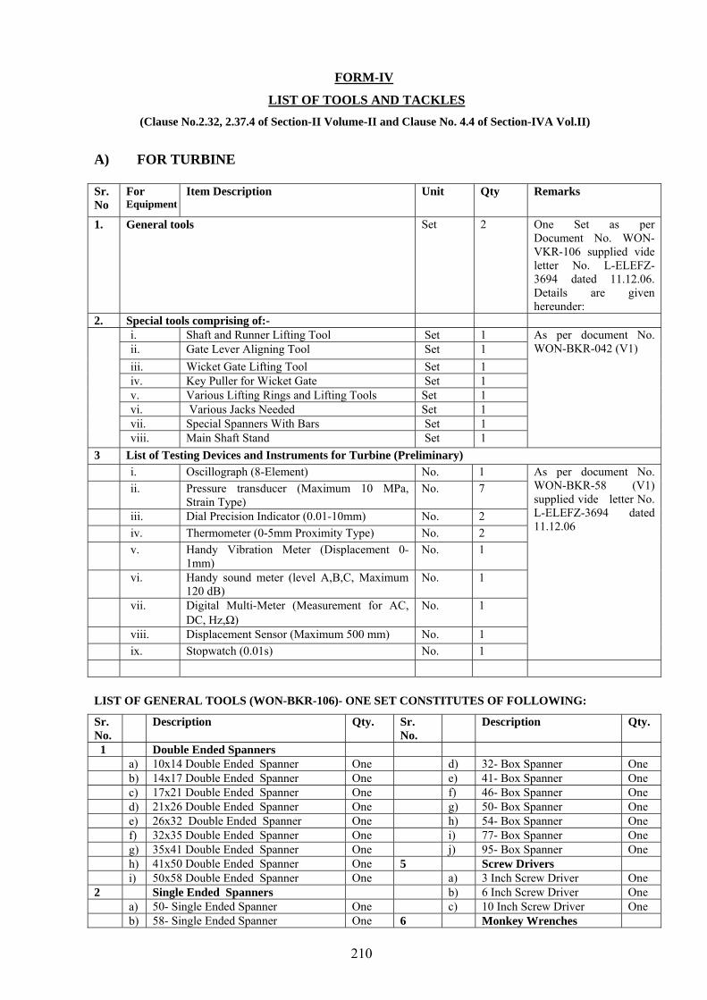
210
FORM-IV
LIST OF TOOLS AND TACKLES (Clause No.2.32, 2.37.4 of Section-II Volume-II and Clause No. 4.4 of Section-IVA Vol.II)
A) FOR TURBINE Sr. No
For Equipment
Item Description Unit Qty Remarks
1. General tools Set 2 One Set as per Document No. WON-VKR-106 supplied vide letter No. L-ELEFZ-3694 dated 11.12.06. Details are given hereunder:
2. Special tools comprising of:- i. Shaft and Runner Lifting Tool Set 1 ii. Gate Lever Aligning Tool Set 1 iii. Wicket Gate Lifting Tool Set 1 iv. Key Puller for Wicket Gate Set 1 v. Various Lifting Rings and Lifting Tools Set 1 vi. Various Jacks Needed Set 1
vii. Special Spanners With Bars Set 1
As per document No. WON-BKR-042 (V1)
viii. Main Shaft Stand Set 1 3 List of Testing Devices and Instruments for Turbine (Preliminary) i. Oscillograph (8-Element) No. 1 ii. Pressure transducer (Maximum 10 MPa,
Strain Type) No. 7
iii. Dial Precision Indicator (0.01-10mm) No. 2 iv. Thermometer (0-5mm Proximity Type) No. 2 v. Handy Vibration Meter (Displacement 0-
1mm) No. 1
vi. Handy sound meter (level A,B,C, Maximum 120 dB)
No. 1
vii. Digital Multi-Meter (Measurement for AC, DC, Hz,Ω)
No. 1
viii. Displacement Sensor (Maximum 500 mm) No. 1 ix. Stopwatch (0.01s) No. 1
As per document No. WON-BKR-58 (V1) supplied vide letter No. L-ELEFZ-3694 dated 11.12.06
LIST OF GENERAL TOOLS (WON-BKR-106)- ONE SET CONSTITUTES OF FOLLOWING:
Sr. No.
Description Qty. Sr. No.
Description Qty.
1 Double Ended Spanners a) 10x14 Double Ended Spanner One d) 32- Box Spanner One b) 14x17 Double Ended Spanner One e) 41- Box Spanner One c) 17x21 Double Ended Spanner One f) 46- Box Spanner One d) 21x26 Double Ended Spanner One g) 50- Box Spanner One e) 26x32 Double Ended Spanner One h) 54- Box Spanner One f) 32x35 Double Ended Spanner One i) 77- Box Spanner One g) 35x41 Double Ended Spanner One j) 95- Box Spanner One h) 41x50 Double Ended Spanner One 5 Screw Drivers i) 50x58 Double Ended Spanner One a) 3 Inch Screw Driver One 2 Single Ended Spanners b) 6 Inch Screw Driver One a) 50- Single Ended Spanner One c) 10 Inch Screw Driver One b) 58- Single Ended Spanner One 6 Monkey Wrenches
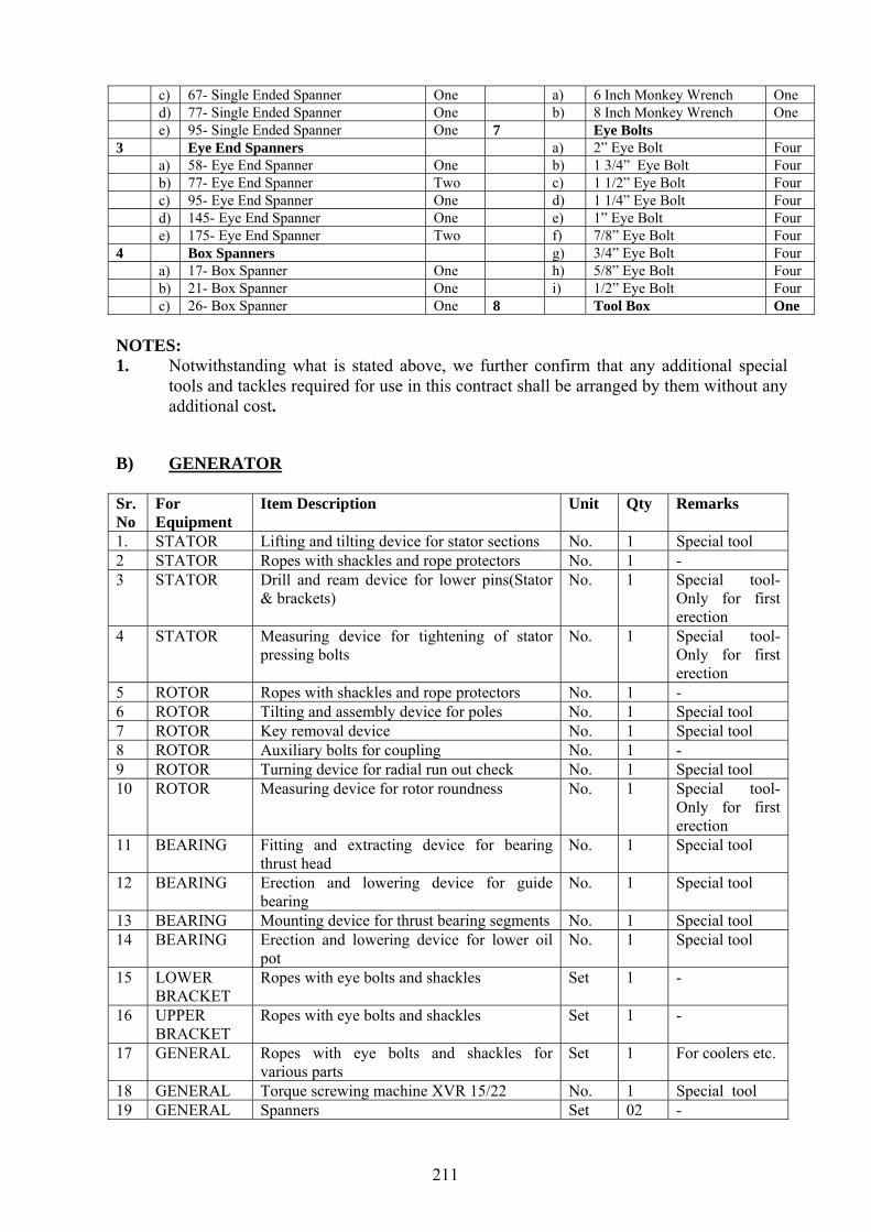
211
c) 67- Single Ended Spanner One a) 6 Inch Monkey Wrench One d) 77- Single Ended Spanner One b) 8 Inch Monkey Wrench One e) 95- Single Ended Spanner One 7 Eye Bolts 3 Eye End Spanners a) 2” Eye Bolt Four a) 58- Eye End Spanner One b) 1 3/4” Eye Bolt Four b) 77- Eye End Spanner Two c) 1 1/2” Eye Bolt Four c) 95- Eye End Spanner One d) 1 1/4” Eye Bolt Four d) 145- Eye End Spanner One e) 1” Eye Bolt Four e) 175- Eye End Spanner Two f) 7/8” Eye Bolt Four 4 Box Spanners g) 3/4” Eye Bolt Four a) 17- Box Spanner One h) 5/8” Eye Bolt Four b) 21- Box Spanner One i) 1/2” Eye Bolt Four c) 26- Box Spanner One 8 Tool Box One NOTES: 1. Notwithstanding what is stated above, we further confirm that any additional special
tools and tackles required for use in this contract shall be arranged by them without any additional cost.
B) GENERATOR
Sr. No
For Equipment
Item Description Unit Qty Remarks
1. STATOR Lifting and tilting device for stator sections No. 1 Special tool 2 STATOR Ropes with shackles and rope protectors No. 1 - 3 STATOR Drill and ream device for lower pins(Stator
& brackets) No. 1 Special tool-
Only for first erection
4 STATOR Measuring device for tightening of stator pressing bolts
No. 1 Special tool-Only for first erection
5 ROTOR Ropes with shackles and rope protectors No. 1 - 6 ROTOR Tilting and assembly device for poles No. 1 Special tool 7 ROTOR Key removal device No. 1 Special tool 8 ROTOR Auxiliary bolts for coupling No. 1 - 9 ROTOR Turning device for radial run out check No. 1 Special tool 10 ROTOR Measuring device for rotor roundness No. 1 Special tool-
Only for first erection
11 BEARING Fitting and extracting device for bearing thrust head
No. 1 Special tool
12 BEARING Erection and lowering device for guide bearing
No. 1 Special tool
13 BEARING Mounting device for thrust bearing segments No. 1 Special tool 14 BEARING Erection and lowering device for lower oil
pot No. 1 Special tool
15 LOWER BRACKET
Ropes with eye bolts and shackles Set 1 -
16 UPPER BRACKET
Ropes with eye bolts and shackles Set 1 -
17 GENERAL Ropes with eye bolts and shackles for various parts
Set 1 For coolers etc.
18 GENERAL Torque screwing machine XVR 15/22 No. 1 Special tool 19 GENERAL Spanners Set 02 -

212
Notes:- 1. Apart from the above, certain tools will be used for stator core stacking and winding at site
which are manufacturing tools and will be brought to site on returnable basis. 2. Notwithstanding what is stated above, additional special tools & tackles to be required for use
in this contract shall be arranged by the contractor without any additional cost. 3. Contractor has clarified that general tools are minor tools, details of which will be
furnished by them during project execution. 4. Suitable lifting arrangement (01 set common for all units) for complete stator will be
arranged by Contractor at no extra cost. 5. “Only for first erection” means that these Special Tools will not be used for normal
maintenance and operation but only once during initial erection of generator thrust bearing.
6. Tools against which it is not mentioned “only for first erection” can be used, if required, for annual /capital maintenance.
7. Form-IV lists tools which will be retained at site. 8. Contractor has clarified that other temporary tools which will be brought by them to site
for erection/commissioning work and which will not be required for such annual /capital maintenance will be taken by them on completion of work. Details of such tools will be furnished during project execution stage.

213
FORM-V
DELIVERY OF EQUIPMENT AND SPARES
(Clause No.2.39 of Section-II Volume-II)
M/s HITACHI LTD. JAPAN AND M/s VA TECH HYDRO
Sr. No.
Items of works/activities
Month wise programme in the form of Bar Chart
1st 2nd ---
24th ---
26th ---
31st ---
---
---
52nd ---
---
1 Turbine (except Runner) and Generator parts for unit No.1
2 Turbine Runner for unit No. 1
3 Turbine (including Runner ) and Generator parts for unit No.2
--- 7 months interval between # 2 and # 5
---
4 Turbine (including Runner ) and Generator parts for unit No.5
NOTES: 1. The month means from the Effective Date of Contract. 2. The above schedule is as per tender offer of Contractor.

FORM-VI COMPLETION SCHEDULE
(Clause -2.39 of Section-II)
Sr. No.
Unit No. Start of work latest by
Completion of work
Commissioning of units
Notes:
214
Trial operations
Handing Over
1 1st Unit 731st day (25 months)
937 days (30 months & 23 days)
(Same as left) (Same as left)
943rd day (end of 31 months)
2 2nd Unit
944th day (32 months)
1150days (37 months & 23 days)
(Same as left) (Same as left)
1156th day (end of 38 months)
3 3rd Unit 1157th day (39 months)
1363days (44 months & 23 days)
(Same as left) (Same as left)
1369th day (end of 45 months)
4 4th Unit 1370th day (46 months)
1576 days (51 months & days)
(Same as left) (Same as left)
1582nd day (end of 52 months)
5 5th Unit 1583rd day (53 months)
1789 days (58 months & 23 days)
(Same as left) (Same as left)
1795th day (end of 59 months)
1. The above is as per schedule attached by the CONTRACTOR in their schedule. 2. Even in case of replacement of turbine and generator shafts, the schedule shall not be affected.

Note:- 1st , 2nd are the months from the effective date.
OVERALL COMPLETION OF SCHEDULE
215

216
FORM-VII
SCHEDULE OF SHUT DOWN REQUIRED FOR REVERSE EGINEERING (Clause 2.39/Section-II Volume-II)
A. FOR TURBINE
Sr. No Unit No. Duration of Shut Down from --- ------------
--to ---
Remarks
1 N.A. N.A.
Note:-
No shutdown required for reverse engineering of turbine since Contractor is the original manufacturer of Turbine.
B. FOR GENERATOR
Sr. No
Unit No. Duration of Shut Down from --- -------
-------to ---
Remarks
1 Unit No. 1 30 days
Note:-
The contractor has confirmed that the shutdown period fpr reverse engineering shall be limited to 30 days as per tender specifications.

217
FORM-VIII
TURBINE
(Guaranteed values Indicated by a mark *) M/s HITACHI LTD JAPAN
Sr. No.
Brief Description Unit M /S Sumitomo Corporation, Japan. Remarks
1. Name of turbine manufacturer Hitachi, Ltd.
2. Type Vertical shaft, Francis 3. Speed: i) Specific speed at 126 MW and
440 ft Rpm-m-kw
131.0
ii) Rated speed Rpm *166.7 iii) Maximum runaway speed under
transient conditions Rpm *Not more than 338 Guaranteed
@@
iv) Steady state runaway speed at design head of 512 ft.
Rpm * Not more than 338 rpm.
Guaranteed @@
4. Direction of rotation as viewed
from above. Clock wise
5. Guaranteed performance Load % 100 90 80 70 60 50
Out put, MW 128.63 115.77 102.91 90.04 77.18 64.32
Efficiency, % 93.52 93.12 92.21 90.62 88.15 84.63
Max. head 512 ft.
Discharge, cusecs. 3176 2871 2577 2294 2022 1755
Out put, MW *128.63 115.77 102.91 90.04 77.18 64.32 Efficiency, % 95.03 95.19 94.6 93.16 90.75 87.26
Rated head 440 ft. Discharge, cusecs. 3637 3268 2923 2597 2285 1980
Out put, MW 73.89 66.50 59.11 51.72 44.34 36.95
Efficiency, % 92.34 91.88 90.54 88.34 85.31 81.46 Min. head 300 ft. Discharge, cusecs. 3154 2852 2573 2307 2048 1787
6. Point of Best efficiency: i) Output MW 115.77 ii) Head Ft 440 iii) Discharge Cusec
s 3268
iv) Efficiency % 95.19 v) Gate opening % 82 7. Weighted average efficiency % *93.21 8. Factor of safety: i) Guaranteed minimum factor of
safety under worst conditions based on yield point strength of material
Normal operation 3.0 against yield stress Run away speed 1.5 against yield stress
ii) Name and location of the part having the factor of safety as listed above
Runner Vane
9, a) Momentary rise in speed on suddenly reducing load to zero from (At 440 ft head)
%

218
i) Full load *Not more than 40% ii) 3/4 full load Not more than 40% iii) 1/2 full load Not more than 40% iv) 1/4 full load Not more than 40% b) Max. momentary speed rise % Not more than 40% c) Time for guide vane closure for
above regulation Sec.
i) Full load rejection Approx 4.5 Sec. ii) 3/4 full load rejection Approx 3.4 Sec. iii) 1/2 full load rejection Approx 2.5 Sec. iv) 1/4 full load rejection Approx 1.6 Sec. d) Full guide vane closing time Sec. 0 – Full 5 Sec. 10, a)
Momentary drop in speed on increasing load from zero to :
i) Full load Corresponding to Governor ii) 3 /4 full load Corresponding to Governor iii) 1 /2 full load Corresponding to Governor iv) 1 /4 full load Corresponding to Governor b) Time of guide vane opening for
above regulation: Sec.
i) Full load Corresponding to Governor ii) 3 /4 full load Corresponding to Governor iii) 1 /2 full load Corresponding to Governor iv) 1 /4 full load Corresponding to Governor 11. Maximum water hammer pressure Metre 210.6 12. Fly wheel effect for regulation as
above T-m2 The flywheel effect of the up-rating
generator and turbine cannot increase more than the existing one for existing construction.
@ @
i) For entire generating unit 10620 ii) Contribution from turbine rotating
parts 420
iii) From matching generator rotating parts.
10200
13. Load on thrust bearing: Tons i) Due to turbine rotating parts. 82 ii) Due to maximum axial hydraulic
thrust (Down) *370 Ton (Max.).
Max. axial download hydraulic thrust will be verified by model test.
Guaranteed @@
iii) Total originating from turbine 452 14. Critical sigma Rated head 0.63 15. Recommended plant sigma Rated head 0.73 16. Cavitation guarantee/8000 hours
of operation Kg *10
17. Maximum noise level at various places/locations
db 85 dB(A), If existing noise level inside the cabin for operator personnel (at EL 1170’ in front of Turbine pits) is more than 85 dB, same noise level will be maintained.
Agreed in the meeting
dt. 18-20.1.07
18. Turbine runner: i) Material and composition 13 Cr. 5 Ni stainless steel welding ii) Number of runner blades No 17 iii) Diameter of runner mm Max dia 4156 iv) Weight of turbine runner
excluding shaft Tons 42
v) Velocity of water at runner exit at rated conditions
m/s 10.3

219
19 Shaft Sleeve i) Material and construction of shaft
sleeve UNS S41000 (or its equivalent)
ii) Method of fixing shaft sleeve to shaft
Pin and welding
20. Turbine guide bearing: i) No. of pads and size No. 12 Pads/Unit ii) Material of bearing pads ASTM A283-93a B + ASTM B23 No. 2
lining (or its equivalent)
iii) Type and number No. Segment type a) Embedded temperature detectors No. 14 Agreed in
the meeting dt.
18-20.1.07 b) Dial type thermometer No. 8 @ c) Thermostats No. 1 /Unit iv) Cooling water requirements a) Quantity Ltr/Sec 7 b) Pressure range Kg/cm2 2 v) Cooling arrangement a) Number of coolers No 1 Set/Unit b) Maximum safe working pressure Kg/cm2 5 c) Bursting pressure Kg/cm2 Higher than 7.5 kg/ cm2
((Test Pressure) d) Pressure drop of water through
the cooler Kg/cm2 1.3 Kg/ cm2
@
vi) Normal working temperature of bearing
oC 45
vii) Maximum permissible temperature of bearing.
oC 65
viii) Temperature rise by RTD’s of the bearing while delivering rated output with cooling water supply at 300C
oC
a) Pads oC 65 b) Oil oC 60 ix) Operation capability of guide
bearing (in minutes) for following conditions of operation
Minutes
a) At rated speed without cooling water supply
Minutes 15 @
b) At runway speed with cooling water supply
Minutes 10 @
c) At runway speed without cooling water supply
Minutes 3 @
21 Shaft Seal i) Type Packing box ii) Material and composition Material: Stainless steel case + Rubber
seal Composition : Refer to 310 S C21-599
iii) Material of maintenance seal (Isolating seal)
Acrylonitrile butadiene rubber
iv) Requirement of water inlet to the sealing
a) Quantity Ltr/Min 50 b) Pressure range Kg/cm2 0.5

220
v) Maximum leakage through the shaft seal under maximum static head.
Ltr/Min 100
22. Head cover liners i) Material & construction Material: ANCI SAE 1045 (JIS G4051
S45C) or its equivalent construction. Refer to WON-BKR-024
ii) Thickness mm 30 iii) No. of sections No 2 vi) Weight of head cover liners Kg 1937.2 23 Guide apparatus: i) Material of guide vanes ASTM A743 CA15 or Equivalent ii) Leakage through all guide vanes
under maximum static head m2/sec 0.5
iii) Torque due to (ii) above Kg-m 10800 iv) Sealing on vertical mating edges Face to face v) Details of bushings for guide vane
stems (upper, middle and lower) Bushing for GV stems (upper & lower)
is self lubricating bushings @
vi) Details of end seals for the guide vanes in top cover and bottom ring.
(No End Seals)
vii) Weight of each guide vane Kg 1100 24. Pressure oil motor pumps for
Governing system:
i) No. of oil pumps for each unit 2 sets ii) Type Screw type or Gear type iii) Capacity 0.6 m3 /min. (21.1 Kg/cm2) iv) Type of operation (continuous or
intermittent) Lpm Intermittent
v) Capacity and speed of pump motor
Kw, Rpm
3 phase, 45 KW, 415 VAC 1000 min-1
vi) Class of insulation of pump motor Class F 25. Compressors for Governing
system:
i) Type of compressors Air Cooling type ii) No. of compressors 2 sets iii) Rating and pressure Kg/cm2 2.45 m3 /min
(23.2 Kg/Cm2
Agreed in the meeting
dt. 18-20.1.07
iv) Type of operation (continuous/intermittent)
Intermittent
v) Motor rating and class of insulation
3 phase, 22 KW, 415V AC, 1000 min-1, Class F
26. Heaviest package for shipment: i) Name Runner ii) Weight Tonne 45 iii) Dimensions (LxWxH) m 4.16 x 4.16 x 1.61 27. Largest package for shipment i) Name Runner ii) Weight Ton 45 @ iii) Dimensions (LxWxH) m 4.16 x 4.16 x 1.61 28. Heaviest assembly to be lifted by
Power House Cranes:
i) Name Turbine rotating parts ii) Weight Ton 86 iii) Dimensions (LxWxH) m 4.16 x 4.16 x 7.58

221
NOTE: @ Clarified/Agreed vide letter No.L-ELEFZ-3694 dated 11/12/2006 @@ Clarified/Agreed vide letter No.L-ELEFZ-3702 dated 12/01/2007

222
FORM-VIII
GENERATOR (Guaranteed values Indicated by a mark *)
M/s VA TECH HYDRO
S.No. Description Unit Value Remarks 1. Name of manufacturer VA TECH Hydro 2. Standards to be followed for manufacture of
the equipment IEC 60034
3. Type and reference Ssv 692/36-266 4. Voltage between phases Volts i) Maximum (+5%) 11550 ii) Normal 11000 iii) Minimum (-5%) 10450 5. Rated power factor 0.9 6. Rated synchronous speed (for a system
frequency of 50 Hz.) Rpm * 166.7 Guaranteed-@
7. Frequency range (Hz) 50 8. Flywheel effect of the rotating parts of the
generator (GD2 ) (Tm2
) 10,200
9. Inertia constant of the generator based on the rated KVA
(KW-Sec/KVA)
2.77
10. Short circuit ratio P.U. 0.95 11. Maximum (runway) speed which all parts are
guaranteed to withstand safely for 15 minutes Rpm * 338 Guaranteed-@
12. Direction of rotation Same as existing 13. Guaranteed output for temperature rise
mentioned in specification under condition of: MVA
i) Rated output at (.90 power factor (lagging) at any voltage and frequency within the operation range.
* 140 Guaranteed-@
ii) Rated voltage, zero leading power factor during line charging with 5% of F.L. positive excitation margin.
106
iii) 95% of rated voltage, zero leading power factor during line charging with 5% of F.L. positive excitation margin
95
iv) 0.90 Power factor lagging, continuous over-load capacity at any voltage and frequency within the operating range.
147 according to Vol.II Section-III Clause 3.5 h) of
bid specifications.
14 i) Guaranteed maximum temperature rise for the output guaranteed under item 13 (i) above at rated voltage and frequency over & above the cooled air temperature of 400C with cooling water temperature not exceeding 250C.
0C Cooling water temperature 250C
a) Stator winding by embedded temperature detector
* 60K
b) Rotor winding by resistance measurement * 60K c) Bearings by embedded temperature detector. * 65 oC (Absolute) d) Other parts by thermometer * 50K
Guaranteed-@

223
ii) Guaranteed maximum temperature rise for the output guaranteed under item 13 (iv) above at rated voltage & frequency over and above the cooled air temperature of 400C with cooling water temperature not exceeding 250C
0C
Cooling water temperature 250C
a) Stator winding by embedded temperature detector
* 80 K
b) Rotor winding by resistance measurement * 80 K c) Bearings by embedded temperature detector. * 65 oC(absolute) d) Other parts by thermometer (stator core) * 65 K
Guaranteed-@
15. Guaranteed overall efficiency of the generator at rated voltage, 0.90 Power factor lagging and 750C winding temperature at:
(%)
i) Full load 98.79 ii) 80% full load 98.76 iii) 60% full load 98.63 iv) Maximum over-load 98.79 v) Weighted average * 98.76 Guaranteed-@ 16. Inherent regulation i.e. increase in voltage at
constant speed and excitation on taking off; (%)
i) Full load 30 ii) 80% full load 25 iii) 60% full load 21 iv) 40% full load 15 17 Maximum permissible continuous negative
phase sequence current (%) 8
18 Reactancss (Referred to rated generator KVA base)
a) Direct axis p.u 1.26 b) Quadrature axis p.u 0.79 i) Direct axis transient reactances: a) Saturated p.u 0.33 b) Unsaturated p.u 0.36 iii) Sub-transient reactances: a) Direct axis (unsaturated) p.u 0.29 b) Quadrature axis (unsaturated) p.u 0.28 iv) Negative phase sequence reactance p.u 0.285 v) Zero phase sequence reactances p.u 0.128 vi) Armature leakage reactance p.u 0.165 vii) Field leakage reactance p.u 0.24 viii) Ratio of quadrature axis sub transient reactance
to the direct axis sub-transient reactance 0.97
19. Generator resistances (at 750C): Ohms i) Resistance of armature winding per phase 0.0026 ii) Resistance of field winding 0.1739 iii) Resistance of damper winding along D-axis 0.0435 iv) Resistance of damper winding along Q-axis. 0.0119 20 Time constants: Seconds i) Direct axis, open circuit, transient time
constant 8.37
ii) Direct axis, short circuit, transient time constant
2.39
iii) Quadrature axis, short circuit, transient time constant
0.627
iv) Direct axis, open circuit, sub-transient time constant
0.0372

224
v) Short circuit time constant for armature winding
0.3091
vi) Short circuit time constant of damper winding with excitation short circuited.
0.025
21. Short –circuit conditions: Amp. i) Maximum value of three phase symmetrical
short circuit current (RMS) when the machine is delivering rated output at 0.90 power factor under voltage regulator control.
55810
ii) Maximum value of single phase/ short circuit current (RMS), under the above conditions
69440
iii) Sustained three phase, short circuit current (RMS) with exciter circuit for normal full load and the voltage regulator cut-out.
13326
iv) Sustained single phase, short circuit current (RMS) under above conditions.
30054
v) Maximum duration of short circuit which the generator can withstand without injury.
Sec 03
22. Maximum I2 t value of the generator 20 23. Synchronising power at rated terminal voltage,
50 Hz, 0.90 power factor lagging. MVA 1.57/2.17
Static /dynamic
24 Allowable continuous single phase loading at rated voltage& power factor between two lines
% 13.8 line to line
25. Wave form deviation factor % <=5 26. Telephone harmonic factor i) Balance <=70 ii) Residual <=50
27 Schedule of losses (KW) Losses at rated voltage, power factor and
frequency
Item of losses Full Load
0.80 full load
0.60 full load
Max. load
i) Friction and windage losses 276 276 276 276 ii) Core losses 364 364 364 364 iii) Armature I2R losses at 750C 377 241 136 416 iv) Stray load losses 180 115 65 198 v) Field I2R losses at 750C 3 324 2
253 1 1 96
3 344
vi) Static excitation system losses 1 19 1 14
1 10
2 21
vii) Total losses 1540 1263 1047 1619
28. Stator i) No. of sections in which stator is divided for
transportation No 03(stator frame)
ii) Material of stator core CRNGO Silicon sheet steel
iii) Grade, thickness and insulation of stator laminations
M 270-50A, 0.5 mm and 6 microns on
both sides
iv) Specific losses in core material W/Kg 2.7 (at 1.5T and 50 Hz) v) Stator core dimensions a) Length (gross & net) mm 2160/1890 b) Inside diameter mm 6700 c) Outside diameter mm 7420 d) Outside diameter of frame mm 8636 v) Stator height mm 2890 vi) No. and width of air ducts 45/6mm

225
vii) Net weight of active iron Kg 93000 approx. viii) Width of air gap at centre of pole tip. mm 20 ix) Total number of slots 351 x) Finished slots size mm 156.5 x 22 xi) Flux density at rated voltage on no load:- a) Air gap 0.89 b) Stator core 1.1 c) Teeth 1.7 d) Pole body 1.55 xii) Type of winding and number of parallel paths
per phase Bar winding
03
xiii) Insulation of winding: a) Slot portion Vacuband Class F b) Over hang portion Vacuband Class F xiv) Current density in stator winding Amp/
mm22.88
xv) Cross sectional area of copper in winding mm2 900 xvi) Weight of copper in winding Kg 20330 xvii) Resistance of stator winding/ phase at 200C. Ohm 0.00174 xviii) Calculated value of capacitance of the stator
winding to ground per phase µF 1.81
xix) Details of transposition of stator bars 360o xx) Schedule of stage wise dielectric tests to be
conducted on the stator bars during manufacture.
Please Refer Generator test plan ITP-
O720.2620011-002 enclosed
xxi) Value of impulse withstand voltage level of the stator winding insulation system.
KV According to IEC
xxii) Weight and size (dimensions) of each of the stator winding packets for transportation (Joint bars only).
Kg
Complete stator bars will be packed and dispatched to
site in wooden cases. Bar insertion will be
carried out at site.
29 Rotor: i) Materials a) Pole end plate Forged steel b) Pole punching 1mm thick sheet steel ii) Type of constructions for field poles T-head type with laminated
pole body.
iii) Factor of safety at maximum speed based on yield strength of material
1.5
iv) Method of attaching field poles to the rotor rim.
With pole fixing keys to suit the existing rim design.
v) Width and height of pole body mm 332x241 vi) Weight of active iron in each field pole Kg 1568 (Laminated part) viii) Class of insulation of field winding Class F viii) Material and thickness of inter-turn insulation NOMEX: 0.25mm ix) Cross –sectional area of copper in field
winding mm2 604
x) Maximum current density in field winding Amp/ mm2
2.2
xi) Weight of copper in field per pole. Kg 750 xii) Damper winding: a) Constructional details of damper winding Copper-bars b) Number and diameter of damper bars/pole 5 bars; 21mm c) Whether connected between poles Yes xiii) Resistance of field winding at 200C. Ohm 0.14

226
xiv) Material of collector rings Steel xv) Type of collector ring brushes Carbon brushes xvi) Collector plain or grooved Plain xvii) No. of brushes/collector ring 18 xviii) Diameter of assembled rotor mm 6660 xix) Total weight of the rotor Kg 405310 Approx. 30. Thrust bearing: i) Type of bearing and thrust runner. Kingsbury type with tilting
segments
ii) Diameter of bearing a) Inside dia mm 785 b) Outside dia. mm 2060 iii) No. of pads and size 09 iv) Effective bearing area mm2 2018792 v) Composition of pad material Teflon Coating @@@ vi) Thickness of pad material mm 09 @@ vii) Type , number and location of: a) Temperature detectors RTDs: 11 Nos.
(09 for pads +01 for oil + 1for water)
@@
b) Dial type thermometers DTTs: 7 Nos. ( 05 for alternate pads+01 for oil + 1 No. for water)
@@
c) Thermostats Nil ix) Cooling water requirements: a) Quantity Lt/min 208.3 b) Pressure range Kg/cm2 1 to 6 x) Cooler system Plug in type @ a) Number of coolers 01 b) Maximum safe working pressure Kg/cm2 1 to 6 c) Test pressure Kg/cm2 10 d) Bursting pressure Kg/cm2 20 approx. e) Pressure drop of water through the cooling
coils Kg/cm2 0.8 approx.
xi) Normal working temperature of bearing 0C 45 xii) Maximum permissible temperature of bearing 0C 65 xiii) Total load on trust bearing including hydraulic
thrust Kg 863405
a) Design load Kg 863405 b) Actual during working conditions Kg 863405
Load distribution will
be furnished during detailed design stage.
xiv) Operation capability of thrust bearing (in minutes for the following conditions of operations:-
Min
a) At rated speed without cooling water supply 15 b) At runway speed with cooling water supply Continuous c) At runway speed without cooling water supply 5 d) At low speed of 4-5% of the rated speed
without cooling water supply. Continuous
xv) Guaranteed temperature by RTD’s of the bearing with cooling water at 250C under rated conditions:-
0C Cooling water temperature 25 0C
@
a) Pads 65 b) Oil 50 xvi) Temperature by RTD’s of the bearing while
delivering the maximum output with cooling water supply at 250C:
0C Cooling water temperature 25 0C
@

227
a) Pads 65 b) Oil 50 xvii) Distance through which rotor to be raised for
removal of thrust bearing pads Mm 25
31. Guide bearing (Separately for lower and upper Guide bearings)
Lower guide
bearing
Upper guide
bearing
i) Type Segmental Segmental ii) No. of pads and size Pcs/
mm 8/300 x 300 9/300 x 300 @@
iii) Bearing area mm2 900000 720000 iv) Material of bearing pads Steel /White
metal Steel /White
metal
v) Type, number and location: a) Embedded temperature detectors. Nos. 10
(8 No. for pads, 1 No. for oil and 1
No.for water)
09 (RTDs for water and
oil are covered
under thrust bearing)
b) Dial type thermometers Nos. 06 (4 No.
for alternate pads, 1 No. for oil and 1 No.for water)
05 (DTTs for water and
oil are covered
under thrust bearing)
@@
c) Thermostats Nos. Nil Nil vii) Cooling water requirement: a) Quantity Lt/min 152 58 b) Pressure Kg/cm2 2.5 2.5 viii) Cooling system a) No. of coolers 1 1 b) Maximum safe working pressure 1 - 6 1- 6 c) Test pressure 10 10 d) Bursting pressure 20 20 e) Pressure drop of water through the cooling
coils Kg/cm2 0.4 0.2
ix) Normal working temperature of bearing 0C 56 56 x) Maximum permissible temperature of bearing 0C 90 90 xi) Temperature by RTD’s of the bearing while
delivering rated output with cooling water supply at 250C:
0C Cooling water temperature
25 0C
Cooling water temperature
25 0C
a) Pads 0C 65 65 b) Oil 0C 50 50 xii) Temperature by RTD’s of the bearing while
delivering maximum output with cooling water supply at 250C:
0C Cooling water temperature
25 0C
Cooling water temperature
25 0C
a) Pads 65 65 b) Oil 50 50 xiii) Operation capability of guide bearing (in
minutes) for the following conditions of operation:
Min
a) At rated speed without cooling water supply >15 b) At runway speed with cooling water supply Continuous c) At runway speed without cooling water supply 30

228
d) At low speed of 4-5% of the rated speed without cooling water supply.
Continuous
32. Oil: i) Type & Grade or specifications ISO VG 46 $ ii) Standard to which it shall conform ISO iii) Quantity of oil for first fillings: a) Thrust bearing Ltr. 3000 b) Guide bearings (Upper) & (Lower) Ltr. 700 /800 33. Bearing brackets: lower upper
i) Material & composition Mild steel Mild steel ii) Type of construction Star shaped Star shaped iii) No. of arms 08 09 iv) Deflection at maximum load <0.5 <0.5 v) Weight Tonne 12.5 50.0 34. Generator Brakes: i) No. of brake/Jack units 08 ii) Size of brake shoe 360X240 approx. iii) Size of piston 210 (dia) approx. iv) Material of brake ring and shoes Brake Ring: S 235J2G3
conforming to EN 10025
Brake Shoes: Steel Break Pads: Non Asbestos
material
@
v) Air pressure required for operation Kg/cm2
7.0
a) Speed at which the air brakes are applied in case of normal shut down
Rpm 50 (The mechanical braking time from this speed to
stand still will be approximately 130 sec.)
@@
b) Speed at which air brakes are applied in case of emergency shut down.
Rpm 83.3
vi) Time required to bring the machine to rest from full speed.
Sec 130
vii) Brake application% speed 30 viii) Details of mechanical locking provided for
rotor The brake piston is
threaded in its upper part outside the cylinder and is equipped with a ring nut. After lifting the ring nut is turned down and fixes the piston mechanically against the cylinder structure.
ix) Lifting capacity of brakes when used as jacks. Tonnes >500 35. Generator cooling system: i) Type and method of cooling. Air Water cooled, Closed
cooling system; Self ventilation
ii) Number of surface air coolers. 09 iii) Maximum safe working pressure for coolers. Kg/cm2 03 iv) Bursting pressure for coolers Kg/cm2 20 v) Test pressure for coolers Kg/cm2 09 vi) Cooling water requirements for inlet water
temperature of 25oC while delivering rated output:
Cooling Water temperature 25 0C
@

229
a) Quantity Lt/min 4250 b) Pressure range Kg/cm2 2.5 vii) Water pressure drop across coolers Kg/cm2 0.55 viii) No. of air coolers required for maximum
output of the generator 09
ix) Maximum output with one cooler out of circuit MVA 140 x) Maximum output with two cooler out of circuit MVA 123 xi) Temperature of air entering the generator from
coolers 0C 40
xii) Material of pipes, valves, tubes, water boxes, etc. of Air Coolers
Tubes: Cupro Nickel Water boxes: Steel
Valves: Cast steel Cooler tube fins: Cupro
Nickel
@
36 Unit Control Panels I) Instruments & meters As per requirment a) Type Analogue /Digital b) Size mm 96 x 96 c) Whether magnetically shielded or not Yes d) Limits of error in the effective range - e) Maximum scale length angular movement 240 deg f) Whether tropicalised Yes g) Short time over-load capacity - h) VA burden - i) Current coil - ii) Potential coil - i) Power consumption: - i) Current coil - ii) Potential coil - j) Temperature at which the instruments are
calibrated Operating range: -100C to
+ 550C
II) Annunciation a) Type of annunciator Microprocessor based
system
b) Type and particulars of windows 48 window with super bright LED’s
c) Particulars of wiring Screw terminals suitable upto 2.5 sq. mm. wire.
d) Rated voltage Volts Supply: Station battery, input interrogation voltage + 12V DC(Final voltage which can be 12V, 24V or 48V DC depending upon system requirements will be confirmed during detailed engg.)
@ Source of such
voltage is in scope of supplier.
e) Power consumption KW 1.8 watt per window. f) Instantaneous making capacity of contacts 2 Amps at 230 V AC g) Breaking capacity of contacts. 0.5A at 220 V DC
(inductive)
h) Overall dimensions of annunciator DFU1- 216x166x80mm + DFU2 – 144x144x70mm
III) Sequential controller a) Type ACP 1703 b) Overall dimensions UCB: 2200 mm(H) x
800mm (D) x1600mm (W)

230
37 Details of proposed operation sequence including minimum time required for the following operations (diagrams to be enclosed)
ii) Standstill to full load generation Later ii) Full load generation to standstill. Later 38 Weight of total generator rotating parts. Tonnes 406.4 39 Heaviest package for transportation i) Name Upper bracket
(without arms)
ii) Weight Tonnes 34.3 iii) Dimensions (LX BX H) mm 8495 x 6080 x1500 approx. 40. Largest package for transportation: i) Name Upper bracket
(without arms)
ii) Weight Tonnes 34.3 iii) Dimensions (LX BX H) mm 8495 x 6080 x1500 approx. 41 Heaviest assembly to be lifted by power
house cranes:
i) Name Rotor ii) Weight Tonnes 406.4 + lifting beam iii) Dimensions dia x height mm 6660 (dia) x 8800 42. Largest assembly to be lifted by power
house cranes:
i) Name Rotor ii) Weight Tonnes 406.4 + lifting beam iii) Dimensions dia x height mm 6660 (dia) x 8800 NOTE: @ Clarified/Agreed vide letter No.L-ELEFZ-3694 dated 11/12/2006 @@ Clarified/Agreed vide letter No.L-ELEFZ-3698 dated 28/12/2006 @@@ Clarified/Agreed vide letter No.L-ELEFZ-3706 dated 23/03/2007 $ Oil grade VG 46 is available in India with all leading companies as IOCL(Servo Prime 46),
BPCL, (Hydrol 46), Castrol ( Hyspin AWS 46), Exxon Mobil Co. India Pvt Ltd. (Mobil DTE Medium) and Shell(Shell Turbo Oil T46)

231
FORM-VIII
EXCITATION SYSTEM M/s VA TECH HYDRO
(Guaranteed values Indicated by a mark *)
S.No. Description Unit Value Remarks.
i) Rating V,A,KW 250.5,1330.8, 333.36 ii) Excitation power transformer rating and
voltage ratio KVA KV
940, 11 KV/430 V
iii) Direct current requirement of excitation control system
A 1330.8
iv) Range of voltage level setting % *85-110% of Ugn (Adjustable)
Guaranteed @@
v) a) Sensitivity at which generator voltage is held
% + 0.5
b) Ceiling voltage of excitation system % 200 vi) Excitation system response time ms *< 20 Guarant
eed @ vii) Regulator gain Pu 2-8 viii) Regulator time constant ms 0.2-0.7 ix) Feed back gain NA x) Feed back time constant NA xi) Maximum- Minimum limits of exciter
voltage in p.u. (per unit) 0.2-1.80
xii) Damping signal stabiliser gain Ex.u/Hz NA xiii) Damping signal time constant S NA xiv) Percentage transformer drop compensation % + 20 xv) Maximum change in generator voltage
when AVR is transferred from “Auto to Manual” under all conditions of excitation.
V Nil
xvi) Manual control range of excitation % 10-115 % Ifn xvii) Thyristor type, rating, its temperature
limitations PIV, efficiencies. KT 1200/16 E, 1600V (V rrm)
-40 to 125oC (Tvj) Semikron make
xviii) Cooling method for the thyristors Forced cooling xix) Redundancy available in bridges 100 % redundancy (Total
No.of Bridges is 2) @@
xx) Monitoring arrangements for the
conductivity of thyristors. Thyristor conduction
supervision provided
xxi) Field current for various operating conditions:
a) Field current at 1.0 P.U. Terminal voltage, open circuit
A 707
b) Field current at 1.0 P.U. terminal voltage, rated KVA load and 0.9 power factor lagging.
A 1330.8
c) Field current required for operation at maximum output at 1.1 P.U. and 1.0 P.U. terminal voltage, 0.9 power factor lagging.
A 1371
xxii) Rupturing capacity of D.C. field circuit breaker
V,A 700V, 500 A( For discharge pole) Breaker is rated at 1600
Amp.

232
xxiii) Losses in static excitation system. KW 28 NOTE: @ Clarified/Agreed vide letter No.L-ELEFZ-3694 dated 11/12/2006 @@ Clarified/Agreed vide letter No.L-ELEFZ-3698 dated 28/12/2006
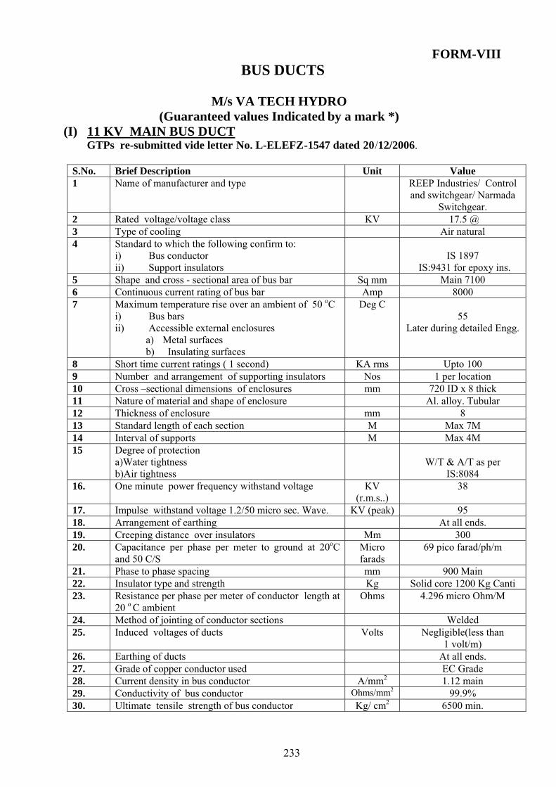
233
FORM-VIII BUS DUCTS
M/s VA TECH HYDRO
(Guaranteed values Indicated by a mark *) (I) 11 KV MAIN BUS DUCT
GTPs re-submitted vide letter No. L-ELEFZ-1547 dated 20/12/2006. S.No. Brief Description Unit Value 1 Name of manufacturer and type REEP Industries/ Control
and switchgear/ Narmada Switchgear.
2 Rated voltage/voltage class KV 17.5 @ 3 Type of cooling Air natural 4 Standard to which the following confirm to:
i) Bus conductor ii) Support insulators
IS 1897
IS:9431 for epoxy ins. 5 Shape and cross - sectional area of bus bar Sq mm Main 7100 6 Continuous current rating of bus bar Amp 8000 7 Maximum temperature rise over an ambient of 50 oC
i) Bus bars ii) Accessible external enclosures
a) Metal surfaces b) Insulating surfaces
Deg C 55
Later during detailed Engg.
8 Short time current ratings ( 1 second) KA rms Upto 100 9 Number and arrangement of supporting insulators Nos 1 per location 10 Cross –sectional dimensions of enclosures mm 720 ID x 8 thick 11 Nature of material and shape of enclosure Al. alloy. Tubular 12 Thickness of enclosure mm 8 13 Standard length of each section M Max 7M 14 Interval of supports M Max 4M 15 Degree of protection
a)Water tightness b)Air tightness
W/T & A/T as per
IS:8084 16. One minute power frequency withstand voltage KV
(r.m.s..) 38
17. Impulse withstand voltage 1.2/50 micro sec. Wave. KV (peak) 95 18. Arrangement of earthing At all ends. 19. Creeping distance over insulators Mm 300 20. Capacitance per phase per meter to ground at 20oC
and 50 C/S Micro farads
69 pico farad/ph/m
21. Phase to phase spacing mm 900 Main 22. Insulator type and strength Kg Solid core 1200 Kg Canti 23. Resistance per phase per meter of conductor length at
20 o C ambient Ohms 4.296 micro Ohm/M
24. Method of jointing of conductor sections Welded 25. Induced voltages of ducts Volts Negligible(less than
1 volt/m) 26. Earthing of ducts At all ends. 27. Grade of copper conductor used EC Grade 28. Current density in bus conductor A/mm2 1.12 main 29. Conductivity of bus conductor Ohms/mm2 99.9% 30. Ultimate tensile strength of bus conductor Kg/ cm2 6500 min.

234
31. Material i) Bus bar ii) Joints iii) Bolts, Nuts and Washers
(i)Elec. Cu (ii)Elec. Cu (iii) HTS for
bus bars & MS galvanized for encl accessories.
NOTE: @ Agreed in the meeting dated 18-20.1.07.
(II) ISOLATING LINKS
32. Name of manufacturer REEPIndustries/ Control and
switchgear/Narmada switchgear.
33. Standard to which it confirms Not applicable 34. Maximum continuous rating Amp. Same as bus bar 35. One second short time rating Amp. Same as bus bar. 36. Temperature rise corresponding to
i) Continuous rating ii) Short time rating
oC oC
105 250
37. Current density at maximum continuous rating Less than bus bar 38. Cross –section of blade. Not applicable.
(III) SHORTING LINKS
39. Name of manufacturer REEP
Industries/Control and switchgear/Narmada
switchgear. 40. Standard to which it confirms Not applicable
41. Maximum continuous rating Amp. Same as bus bar
42. One second short time rating Amp. Same as bus bar.
43. Temperature rise corresponding to iii) Rated current iv) Short circuit current
o C o C
55
250 44. Current density at maximum continuous rating Amp./mm2 Less than bus bar
45. Cross –section of blade. Amp./mm2 Not applicable.
(IV) 11 KV AUXILIARY BUS DUCT (TO UAT’s AND EXCITATION
TRANSFORMERS)
Sr. No. Brief Description Unit Value 1 Rated voltage/voltage class KV 17.5 2 Type of cooling Air Natural 3 Shape and cross - sectional area of bus bar Sq. mm 1200 copper flat 4 Continuous current rating of bus bar Amp Upto 1000 5 Maximum temperature rise over an ambient of 50 o C
i) Bus bars ii) Accessible external enclosures
a) Metal surfaces b) Insulating surfaces
Deg C
55 for bus bar
30 for encl accessories
6 Short time current rating ( 1 second) KA Up to 100
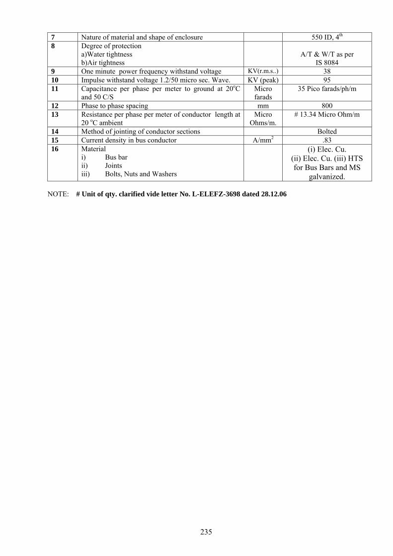
235
7 Nature of material and shape of enclosure 550 ID, 4th
8 Degree of protection a)Water tightness b)Air tightness
A/T & W/T as per
IS 8084 9 One minute power frequency withstand voltage KV(r.m.s..) 38 10 Impulse withstand voltage 1.2/50 micro sec. Wave. KV (peak) 95 11 Capacitance per phase per meter to ground at 20oC
and 50 C/S Micro farads
35 Pico farads/ph/m
12 Phase to phase spacing mm 800 13 Resistance per phase per meter of conductor length at
20 oC ambient Micro
Ohms/m. # 13.34 Micro Ohm/m
14 Method of jointing of conductor sections Bolted 15 Current density in bus conductor A/mm2 .83 16 Material
i) Bus bar ii) Joints iii) Bolts, Nuts and Washers
(i) Elec. Cu. (ii) Elec. Cu. (iii) HTS for Bus Bars and MS
galvanized. NOTE: # Unit of qty. clarified vide letter No. L-ELEFZ-3698 dated 28.12.06

236
11 KV CURRENT TRANSFORMERS:
M/s VA TECH HYDRO (Guaranteed values Indicated by a mark *)
(1) CT-1,2,4 & 6 (PS Class CTs) - 3 Nos. of each CT per unit
GTPs submitted vide letter No. L-ELEFZ-1547 dated 20/12/2006 Sr. No. Brief Description Unit Value Remarks
1. Applicable standard IS2705:1992 (Part-I to Part-V)
2. Highest system voltage and frequency KV/Hz 12/50 # 3. Ratio of rated primary and secondary current A 8000/5 4. Rated short time thermal current withstand
capability and its duration KA 40 for 1 Sec.
5. Dynamic over current rating KA 100 6. Maximum temperature rise over ambient
temperature of 500C Deg.C As per IS
7. Maximum temperature rise after passing rated short circuit current for 3 second
Deg.C As per IS
8. Insulation level of primary winding i) One minute power frequency withstand
voltage ii) 1.2 / 50 micro second impulse withstand
voltage
KV 28
75
9. One minute power frequency withstand voltage of secondary winding
KV 2
10. Insulation class # 11. Rated burden VA NA 12. Class of accuracy - PS 13. Rated accuracy limit factor for protection CTs NA 14. Instrument security factor for metering CTs. NA 15. Secondary winding resistance at 75 0C Ohm $ # 16. Knee point voltage V $ # 17. Excitation current at
i) Knee point voltage ii) 50% of knee point voltage iii) 25% of knee point voltage
A $ #
18. I.R. values i) Primary to secondary winding ii) Primary to earth
Ohm $ #
19. Details of provision made for fixing of CTs (Please attach drawing)
- $
20. Total weight Kg $ 21. Overall dimensions mm $
Note: # The CTs shall be suitable for the requirement as clarified vide letter No. L-ELEFZ-3698 dt.
28.12.06 $ Later during detailed engineering

237
(2) CT-3 (Metering CTs)- 3 Nos. per units 1. Applicable standard IS2705:1992 (Part-
I to Part-V) Remarks
2. Highest system voltage and frequency KV/Hz 12/50 3. Ratio of rated primary and secondary current A 8000/5 4. Rated short time thermal current withstand
capability and its duration KA 40 for 1 sec.
5. Dynamic over current rating KA 100 6. Maximum temperature rise over ambient
temperature of 500C Deg. C As per IS
7. Maximum temperature rise after passing rated short circuit current for 3 second
Deg. C As per IS
8. Insulation level of primary winding iii) One minute power frequency withstand
voltage iv) 1.2 / 50 micro second impulse withstand
voltage
KV 28
75
9. One minute power frequency withstand voltage of secondary winding
KV 2
10. Insulation class $ # 11. Rated burden VA 60 12. Class of accuracy - 0.5 13. Rated accuracy limit factor for protection CTs N.A 14. Instrument security factor for metering CTs. 0.5 15. Secondary winding resistance at 75 0C Ohm $ # 16. Knee point voltage V N.A 17. Excitation current at
i) Knee point voltage ii) 50% of knee point voltage iii) 25% of knee point voltage
A N.A
18. I.R. values i) Primary to secondary winding ii) Primary to earth
Ohm $ #
19. Details of provision made for fixing of CTs (Please attach drawing)
- $
20. Total weight Kg $ 21. Overall dimensions mm $
Note: # The CTs shall be suitable for the requirement as clarified vide letter No. L-ELEFZ-3698 dt. 28.12.06.
$ Later during detailed engineering
( 3) CT-5 (Protection Class CTs) - 3 Nos.per units Sr.No. Brief Description Unit Value Remarks 1. Applicable standard IS2705:1992
(Part-I to Part-V)
2. Highest system voltage and frequency KV/Hz 12/50 # 3. Ratio of rated primary and secondary current A 8000/5 4. Rated short time thermal current withstand
capability and its duration KA 40 for 1 Sec.
5. Dynamic over current rating KA 100 6. Maximum temperature rise over ambient
temperature of 500C Deg.C As per IS

238
7. Maximum temperature rise after passing rated short circuit current for 3 second
Deg.C As per IS
8. Insulation level of primary winding i) One minute power frequency withstand voltage ii) 1.2/50 micro second impulse withstand voltage
KV 28 75
9. One minute power frequency withstand voltage of secondary winding
KV 2
10. Insulation class $ # 11. Rated burden VA 60 12. Class of accuracy - 5P 10 13. Rated accuracy limit factor for protection CTs 5P 10 14. Instrument security factor for metering CTs. N.A 15. Secondary winding resistance at 75 0C Ohm $ # 16. Knee point voltage V N.A 17. Excitation current at
i) Knee point voltage ii) 50% of knee point voltage iii) 25% of knee point voltage
A N.A
18. I.R. values i)Primary to secondary winding ii)Primary to earth
Ohm $ #
19. Details of provision made for fixing of CTs (Please attach drawing)
- $
20. Total weight Kg $ 21. Overall dimensions mm $
Note: # The CTs shall be suitable for the requirement as clarified vide letter No. L-ELEFZ-3698 dt. 28.12.06
$ Later during detailed engineering
(4) CT-7 (Protection Class CTs) - 3 Nos per unit Sr.No. Brief Description Unit Value Remarks 1. Applicable standard IS 2705:1992
(Part-I to Part-V)
2. Highest system voltage and frequency KV/Hz 12/50 3. Ratio of rated primary and secondary current A 800/1 4. Rated short time thermal current withstand
capability and its duration KA 40 for 1 sec.
5. Dynamic over current rating KA 100 6. Maximum temperature rise over ambient
temperature of 500C Deg.C As per IS
7. Maximum temperature rise after passing rated short circuit current for 3 second
Deg.C As per IS
8. Insulation level of primary winding i) One minute power frequency withstand
voltage ii) 1.2 / 50 micro second impulse withstand
voltage
KV 28
75
9. One minute power frequency withstand voltage of secondary winding
KV 2
10. Insulation class $ # 11. Rated burden VA 60 12. Class of accuracy - 5P10 13. Rated accuracy limit factor for protection CTs 5P10

239
14. Instrument security factor for metering CTs. N.A. 15. Secondary winding resistance at 75 0C Ohm $ # 16. Knee point voltage V N.A. 17. Excitation current at
i) Knee point voltage ii) 50% of knee point voltage III) 25% of knee point voltage
A N.A.
18. I.R. values i) Primary to secondary winding ii) Primary to earth
Ohm $ #
19. Details of provision made for fixing of CTs (Please attach drawing)
- $
20. Total weight Kg $ 21. Overall dimensions mm $
Note: # The CTs shall be suitable for the requirement as clarified vide letter No. L-ELEFZ-3698 dt. 28.12.06
$ Later during detailed engineering
(5) CT-8 (PS Class CTs) - 03 Nos. per units Sr.No. Brief Description Unit Value Remarks 1. Applicable standard IS2705:1992 (Part-
I to Part-V)
2. Highest system voltage and frequency KV/Hz 12/50 3. Ratio of rated primary and secondary current A 800/1 4. Rated short time thermal current withstand
capability and its duration KA 40 for 1 sec.
5. Dynamic over current rating KA 100 6. Maximum temperature rise over ambient
temperature of 500C Deg.C As per IS
7. Maximum temperature rise after passing rated short circuit current for 3 second
Deg.C As per IS
8. Insulation level of primary winding v) One minute power frequency withstand
voltage vi) 1.2 / 50 micro second impulse withstand
voltage
KV 28
75
9. One minute power frequency withstand voltage of secondary winding
KV 2
10. Insulation class $ # 11. Rated burden VA N.A. 12. Class of accuracy - PS 13. Rated accuracy limit factor for protection CTs N.A. 14. Instrument security factor for metering CTs. N.A 15. Secondary winding resistance at 75 0C Ohm $ # 16. Knee point voltage V $ # 17. Excitation current at
i) Knee point voltage ii) 50% of knee point voltage iii) 25% of knee point voltage
A $ #
18. I.R. values i) Primary to secondary winding ii) Primary to earth
Ohm $ #

240
19. Details of provision made for fixing of CTs (Please attach drawing)
- $
20. Total weight Kg $ 21. Overall dimensions mm $
Note: # The CTs shall be suitable for the requirement as clarified vide letter No. L-ELEFZ-3698 dt. 28.12.06.
$ Later during detailed engineering
(6) OVER CURRENT CTs (Excitation Transformer)- 03 No.per unit
Submitted vide Letter No. L-ELEFZ-3706 dated 23.3.2007 Sr. No.
Brief Description Unit Value Remarks
1. Applicable standard IS2705:1992 (Part-I to Part-
V)
2. Highest system voltage and frequency. KV/Hz 12/50 3. Ratio of rated primary and secondary current . A 100/1 4. Rated short time thermal current withstand capability
and its duration. KA 40 for 1 Sec.
5. Dynamic over current rating. KA 100 6. Maximum temperature rise over ambient temperature
of 500C. Deg.C As per IS
7. Maximum temperature rise after passing rated short circuit current for 3 second.
Deg.C As per IS
8. Insulation level of primary winding i) One minute power frequency withstand voltage ii) 1.2 / 50 micro second impulse withstand voltage
KV 28
75
9. One minute power frequency withstand voltage of secondary winding
KV 2
10. Insulation class $ 11. Rated burden VA 30 12. Class of accuracy - 5P20 13. Rated accuracy limit factor for protection CTs 5P20 14. Instrument security factor for metering CTs. N.A 15. Secondary winding resistance at 75 0C Ohm $ 16. Knee point voltage V N.A 17. Excitation current at
i) Knee point voltage ii) 50% of knee point voltage iii) 25% of knee point voltage
A N.A
18. I.R. values i) Primary to secondary winding ii) Primary to earth
Ohm $
19. Details of provision made for fixing of CTs (Please attach drawing)
- $
20. Total weight Kg $ 21. Overall dimensions mm $
$ Later during detailed engineering

241
(7) OVER ALL DIFFERENTIAL CT (Excitation Tap Off)- 03 Nos.per unit
Submitted vide Letter No. L-ELEFZ-3706 dated 23.3.2007
Sr.No.
Brief Description Unit Value
1. Applicable standard IS2705:1992 (Part-I to Part-V) 2. Highest system voltage and frequency KV/Hz 12/50 3. Ratio of rated primary and secondary current A 8000/5 4. Rated short time thermal current withstand capability
and its duration KA 40 for 1 sec
5. Dynamic over current rating KA 100 6. Maximum temperature rise over ambient temperature
of 500C Deg.C As per IS
7. Maximum temperature rise after passing rated short circuit current for 3 second
Deg.C As per IS
8. Insulation level of primary winding vii) One minute power frequency withstand
voltage viii) 1.2 / 50 micro second impulse withstand
voltage
KV 28
75
9. One minute power frequency withstand voltage of secondary winding
KV 2
10. Insulation class $ 11. Rated burden VA N.A 12. Class of accuracy - PS/ 13. Rated accuracy limit factor for protection CTs N.A 14. Instrument security factor for metering CTs. N.A 15. Secondary winding resistance at 75 0C Ohm $ 16. Knee point voltage V $ (As per requirement) 17. Excitation current at
i)Knee point voltage ii)50% of knee point voltage iii)25% of knee point voltage
A $ (As per requirement)
18. I.R. values i)Primary to secondary winding ii)Primary to earth
Ohm $
19. Details of provision made for fixing of CTs (Please attach drawing)
- $
20. Total weight Kg $ 21. Overall dimensions Mm $
$ Later during detailed engineering

242
FORM-VIII 11 KV VOLTAGE TRANSFORMER
M/s VA TECH HYDRO (For Both VTs) - 03 No.per unit
GTPs submitted vide letter No. L-ELEFZ-1547 dated 20/12/2006 Sr.No. Brief Description Unit Value Remarks 1. Applicable Standard IS: 3156-1992 2. Ratio (Primary/Secondary voltage)
PT-1 11kV/√3 110V/√3, 110V/ √3
PT-2 11kV/√3 110V/ √3
3. Rated frequency Hz 50 4. Highest system voltage Kv 12 5. Class of accuracy - 0.5/3 (PT-1), 0.5
(PT-2)
6. No of Cores 2 Core / Single Core
7. Rated burden VA 100(PT-1, both cores) ,60(PT-2)
8. Rated over voltage factor $
#
9. Insulation level i) One minute power frequency withstand
voltage ii) 1.2 / 50 micro second impulse withstand
voltage
KV KV
28 75
10. Insulation class Class E 11. Maximum temperature rise above 500 C $
#
12. Total weight $ 13. Overall dimensions $
Note: # Clarified and confirmed vide letter No. L-ELEFZ-3698 Dt. 28.12.06 that PTs will be suitable for
requirement. $ Later during detailed engineering

243
12 KV SURGE CAPACITORS: M/s VA TECH HYDRO
GTPs submitted vide letter No. L-ELEFZ-1547 dated 20/12/2006 Sr.No. Brief Description Unit Value Remarks 1. Applicable standard IS-11548 2. Rated frequency & voltage Hz./KV 50/11 3. Rated current A 10k A rms
(Pressure relief current)
4. Insulation level 12KV 5. Capacitance mf. 0.25 uf 6. Impulse withstand voltage of capacitor , bushing
(BIL) KV 75
7. Discharge time of discharge resistor. $ $$ 8. One minute power frequency withstand voltage KV 28 9. Total weight $ 10. Overall dimensions $
$ Later during detailed engineering $$ Clarified vide SC letter No. L-ELEFZ-3698 Dt. 28.12.06. However it is confirmed that it will be
suitable for requirement.

244
FORM-VIII
12 KV LIGHTNING ARRESTOR (GAPLESS) M/s VA TECH HYDRO
GTPs submitted vide letter No. L-ELEFZ-1547 dated 20/12/2006 Sr. No.
Brief Description Unit Value Remarks
1. Applicable standard IS-15086 2001 / IEC 600991:1991
2. Rated voltage & frequency Hz/kV 50/11 3. Nominal discharge current kA 10 4. Spark over voltage (1.2/50 micro
second wave)) kV 49
5. Front of wave impulse spark over voltage (maximum)
kV 110
6. Insulation level As per IS 15086/IEC 991 7. No. of surges the LA can bear
before failure As per IS 15086/IEC 991
8. Total weight $ 9. Overall dimensions $
$ Later during detailed engineering

245
FORM-VIII
11 KV NEUTRAL GROUNDING TRANSFORMERS:
M/s VA TECH HYDRO GTPs submitted vide letter No. L-ELEFZ-1547 dated 20/12/2006
Sr.No. Brief Description Unit Value Remarks 1. Applicable standard IS 11171 2. Nominal/ highest system voltage kV/kV 11/12 3. Rated frequency and number of phases Hz. 50/3 4. Rated voltage of HV/LV winding kV/V 11/380 5. KVA rating kVA 75 (Calculatio
ns will be furnished during detail engg.)
6. Short time rating and duration kA 40kA for 1 sec. 7. Insulation level
i) One minute power frequency withstand voltage
ii) 1.2 / 50 micro second impulse withstand voltage
kV
28
75
8. Insulation class Class F 9. Maximum temperature rise above 500C 0C 45 10. Type of cooling Air Natural 11. D.C. resistance
a) Primary (H.V.) winding b) Secondary (L.V.) winding
$
12. Leakage reactance of secondary (LV) winding $ 13. Zero sequence impedance $ 14. NGT maximum current density at normal rating
i) Primary winding(HV) ii) Secondary winding (LV)
$
15. Conductor size i) Primary winding(HV) ii) Secondary winding (LV)
$
16. Maximum short circuit current density i) Primary winding(HV) ii) Secondary winding (LV)
$
17. Material of core $ 18. Flux density $ 19. Core Area $ 20. Details of connection of NGT Primary with
Generator neutral $
21. Weight $ 22. Overall dimension $
$ Later during detailed engineering

FORM-VIII
NEUTRAL GROUNDING RESISTOR M/s VA TECH HYDRO
GTPs submitted vide letter No. L-ELEFZ-1547 dated 20/12/2006 Sr.No. Brief Description Unit Value Remarks 1. Applicable standard IS-11171 2. Current carrying capacity A 270 3. Resistance value Ohm 0.815 4. Material of Resistor SS Punched grid 5. Total weight $ 6. Overall dimensions $
$ Later during detailed engineering
246

FORM-IX INFORMATION TO BE SUPPLIED TOGETHER WITH THE TENDER[
Sr.No. Description as per BBMB Tender Document As per Remarks of the Contractor
A. TURBINE 1. Computations for pressure rise at turbine inlet under the most
unfavourable conditions (load acceptance and rejection). Conditions considered as well as governor acting times to be clarified & indicated in the computations
Refer to Document No. BKR-056
2. Computations for turbine speed rise under conditions as above and for following load rejection parameters. • from 110 % rated output to zero • from 100 % rated output to zero • from 75 % rated output to zero • from 50 % rated output to zero • from 25 % rated output to zero
According to Form VIII refer to Document No. WON-BKR-056
3. Expected flow characteristics during closing and opening of wicket gates as function of time.
Refer to Document No. BKR-056
4. Expected performance curves for the net heads (rated, maximum & minimum). The curves shall also show the overload output at maximum possible wicket gates opening extending beyond the guarantee points
Refer to Document No. BKR-057
5. Dimensional drawing (cross section) of turbine and associated equipment showing main dimensions
Refer to 310QB 67-257
6. Proposed shaft sealing arrangement preferably illustrated by schematic diagram. Figures of the required quantities of sealing water and compressed air to be given
Refer to HC-180-660 Rev. A and 310SC21-599
7. Applicable method and type of vibration monitoring system Refer to General Specification of hardware and Software for -Vibration monitoring - Partial discharge measurement -Leakage current measurement -Air-gap monitoring -Noise level measurement
8. Information on model or field performance tests performed on a turbine which is hydraulically similar to the proposed turbine. At least the following shall be Indicated :
place of model or field tests designed rated turbine output vis-à-vis guaranteed output,
rated speed
Information to be supplied together with the tender.
9. Vol.II/Sec.II i. Drawings to be furnished The Tenderer shall submit with the tender, the drawings enumerated below and in various other sections of the specifications. • Equipment drawings • Drawings showing transfer section through turbine and
generator. • A foundation details of generator with existing sole plates. • Schematic diagrams of generator/bearing coolers. • Control and schematic diagrams for unit control
boards/T.G.panels, instrumentation and safety devices etc. • Bill of material covering entire scope of work. • Characteristic curves/graphs showing the performance of
various equipment. • Any other drawing considered necessary subsequently by
Purchaser.
Refer to 310QB67-257 Refer to 310QB67-257 Refer to Drawing No. 4 282938 Refer to Description of the generator. Refer to WON-BKR-036(V2) Refer to Bill of material Refer to WON-BKR-057 Refer to WON-BKR-050 and its attached drawing
247

10. Vol.II/Sec.IV-A 4.8 Drawing, data, manuals and Guaranteed Particulars i) Drawings clearly showing the various component parts/assemblies of the turbine, guide vanes and other auxiliary equipment, etc. in plans and elevation/section. ii) Schematic drawings of piping systems, control systems and instrumentation. iii) Graphs/curves showing performance characteristics of the
turbine. iv) Plant and machine sigma curves at various heads v) Curves showing area and velocities at different sections of
the draft tube. vi) A list of tests to be performed at site on sub-assemblies/
assemblies and equipment. Vii) Details of field acceptance tests and methods to be adopted. viii) A complete list of detailed equipment, auxiliaries, etc. covered in the quotation. ix) Complete list of spares for turbine and auxiliary equipment. x) Details of Unit Rates of material and all kinds of ancillary
works. xi) The Tenderer shall furnish all the data, information especially guaranteed and other technical particulars called for in the Form-VIII and shall also include information above his experience in the manufacture of the turbines, giving details of their technical particulars in Form-IX.
Refer to 310QB67-257 Refer to HC-192-095 Refer to WON-BKR-057 Refer to WON-BKR-057 Refer to WON-BKR-055 Refer to WON-BKR-054 Refer to WON-BKR-054 Refer to WON-BKR-051 Refer to WON-BKR-051 Refer to WON-BKR-051 We noted
B. GENERATOR 1. Description of proposed construction and procedure for
erection at site for the generator stator with view to transport limitations
2. Description of applicable stator winding insulation (material, insulation method etc.)
3. Drawing showing Cross section through a slot with winding
4. Description of rotor pole mounting. Description of proposed bearing insulation to prevent shaft currents
5. Description of bearing seal arrangement including measures to prevent leakage of oil from bearing
6. Description of high pressure oil system for jacking. 7. Description and schematic diagram of the combined braking
and jacking system 8. Description of the brake dust collection system 9. Applicable method and type of vibration monitoring system 10. Dimensional drawing of the generator with major dimensions 11. Diagrams with electrical characteristics
• no load
Refer to the PART-C “Documents related to Generator” attached in Section-VI of this Appendix-D.
• short circuit curve • capacity curves (power chart) for rated output at
nominal power factor and 0.9/1.0/1.1 x nominal voltage • load curves (V-curves) • Inverse current 12 = f (t)
12. Calculated no-load harmonics in the voltage wave form 13. Supporting documents for the guaranteed generator output and
efficiencies (references) 14. Reference list of comparable generators already supplied and
comprising of at least following information Rated output vis-à-vis guaranteed output (MVA) speed (pair of poles) year of delivery name of station and country.
C. EXCITATION SYSTEM 1. Description and schematic diagram of the proposed excitation
system including field flashing equipment 2. Description of the voltage regulating system giving technical
characteristics and all necessary information on automatic and
Refer to the PART-C “Documents related to Generator” attached in Section-VI of this Appendix-D.
248

manual control, change over from automatic to manual control and vice versa, as well as on the protective and limiting devices
3. Method of equal load sharing between rectifier elements 4. Method to prevent damage due to reverse field current.
Information on field winding monitoring system 5. Method to provide a signal to annunciate failure of thyristor
and/or fuse D. BUS DUCTS, LAVT, NGT & NGR CUBICLES
1. Calculations for capacity of NGT & NGR. Contractor shall furnish the information during detailed engineering. 2. Calculations for capacity of surge capacitor.
E. AUTOMATION AND CONTROL SYSTEM (SCADA) Refer documents attached in Section-VI of this APPENDIX-D.
249

DRAWINGS AS ATTACHED IN
THE TENDER DOCUMENT
250

251

252

253

254

255

256

257

258

259
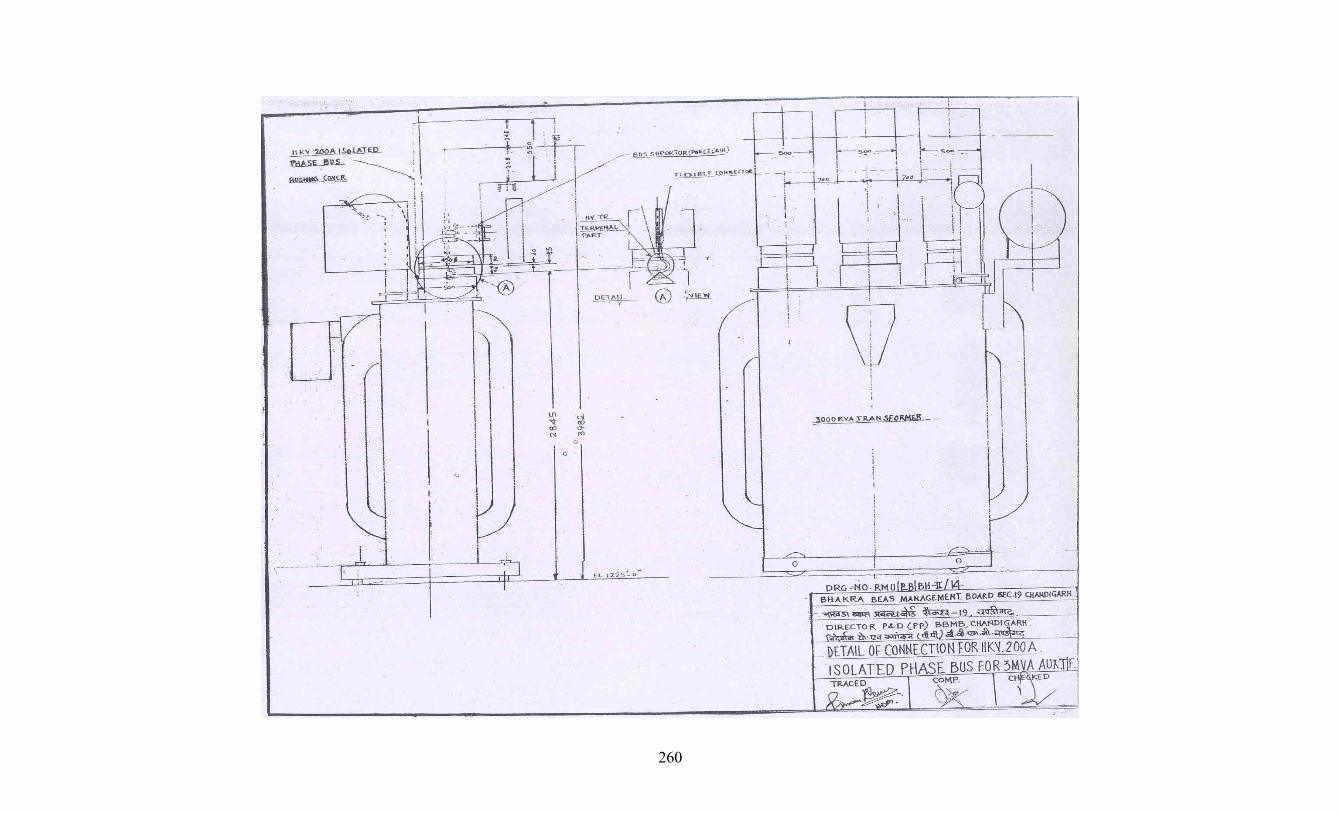
260

261

262

263

264

- 265 -

- 266 -

- 267 -

APPENDIX –E CORRESPONDENCE BETWEEN PURCHASER
AND CONTRACTOR
- 268 -

CORRESPONDENCE BETWEEN PURCHASER AND CONTRACTOR
Correspondence as exchanged between BBMB & M/s. Sumitomo Corporation, Japan through their New Delhi Office i.e. M/s. Sumitomo Corporation India Ltd., New Delhi (since issue of copy Global NIT No. 247/BBMB/PH/BH-II/413 Dated 20.1.2006 before issue of Notification of Award) is as follows:- S. Fax/ Letter No. & Date From To Subject Page
No. No. 1. Letter No. 199-223/PHD/BH-II/413 dated
1.2.2006. BBMB Sumitomo Copy of Global NIT sent
to M/s Sumitomo. 1-4
2. Letter No. L-ELEFZ-190406-2 Dated 19/04/2006 through New. Delhi office letter no. L-NDLKP-4834 dated 19/4/2006
Sumitomo BBMB Request for Extension of Due Dates
5-6
3. Letter No. L-ELEFZ-200406-1 Dated 20/04/2006 through N. Delhi office letter no. L-NDLKP-4836 dated 20/4/2006
Sumitomo BBMB ‘Queries list’ for Pre-Bid Conference to be held on 27/4/2006
7-9
4. Endst. no. 783/PHD/BH-II/413 Dated 24/4/2006
BBMB Sumitomo Extension of Due Dates 10
5. Letter No. L-ELEFZ-240406-4 Dated 24/04/2006 through N. Delhi office letter no. L-NDLKP-4840 dated 25/4/2006
Sumitomo BBMB ‘Queries list’ for Pre-Bid Conference to be held on 01 June,2006
11-13
6. Letter No. L-ELEFZ-280406-1 Dated 28/04/2006 through New. Delhi office letter no. L-NDLKP-4846 dated 28/4/2006
Sumitomo BBMB Visit to Bhakra Bank Power House for site Survey
14-22
7. Letter No. L-ELEFZ-3669 Dated 16/5/2006 through N. Delhi office letter no. L-NDLKP-4865 dated 16/5/2006
Sumitomo BBMB Visit to Bhakra Bank Power House for site Survey
23-24
8. Letter No. 881/PHD/BH-II/420 dated 17.05.06.
BBMB Sumitomo Corrigendum No. 1 to Tender Document.
25-26
9. Letter No. L-ELEFZ-250506-2 Dated 25/5/2006 through N. Delhi office letter no. L-NDLKP-250506-2 dated 25/5/2006
Sumitomo BBMB Pre-Bid Conference to be held on 01st June,2006
27-28
10. Letter No. L-ELEFZ-6083 Dated 31/5/2006 through N. Delhi office letter no. L-NDLKP-4893 dated 31/5/2006
Sumitomo BBMB Request for Due Date Extension
29-30
11. Pre-Bid conference held on 1.6.06 -Attendance Sheet
- - - 31
12. Letter No. 917/PHD/BH-II/420 dated 2.6.2006
BBMB Sumitomo Reply to queries of pre-Bid conference held on 1.6.06.
32-33
13. Letter No. L-ELEFZ-3672 Dated 07/06/2006 through N. Delhi office letter no. L-NDLKP-4908 dated 07/6/2006
Sumitomo BBMB Visit to Bhakra Left Bank Power House for site Survey by Engineers of Sumitomo.
34-35
14. Endst. no. 930/PHD/BH-II/413 Dated 8/6/2006
BBMB Sumitomo Extension of Due Dates 36
15. Endst. no. 944-45/PHD/BH-II/413 Dated 9/6/2006
BBMB Sumitomo Conveying permission to visit Bhakra Left Bank Power House.
37
16. Letter No. L-ELEFZ-3673 Dated 12/06/2006 through N. Delhi office letter no. L-NDLKP-4916 dated 12/6/2006
Sumitomo BBMB Request for approval from MOHA for visit to Hitachi Engineers to site
38-40
17. Letter No. L-ELEFZ-3674 Dated 13/06/2006 through New Delhi office letter no. L-NDLKP-4919 dated 13/6/2006
Sumitomo BBMB Draft of EMD format 41-45
18. Endst. no. 954/PHD/BH-II/413 Dated 14/6/2006
BBMB Sumitomo Corrigendum No.2 dated 13/6/2006 to Tender Document
46-50
19. Endst. no. 3467-68/PHD/BH-II/413 Dated BBMB Sumitomo Denying request of M/s 51
- 269 -

14/6/2006 Sumitomo regarding visit to Bhakra Left Bank Power House by their 30 specialists.
20. Endst. no. 963/PHD/BH-II/413 Dated 15/6/2006
BBMB Sumitomo Corrigendum No.2 dated 13/6/2006 to Tender Document
52-53
21. Endst. no. 1008/PHD/BH-II/413 Dated 27/6/2006
BBMB Sumitomo Corrigendum No. 3 to NIT regarding payment of Tender fee.
54-55
22. Letter No. L-ELEFZ-260606-1 Dated 26/06/2006 through N. Delhi office letter no L-NDLKP-4944 dated 27/6/2006
Sumitomo BBMB Request for payment of Tender fee.
56-57
23. Endst. No. 1041/PHD/BH-II/413 Dated 05/7/2006 .
BBMB Sumitomo Confirmation regarding supply of EMD Proforma for Bank Guarantee
58
24. Endst. No. 1078/PHD/BH-II/413 Dated 13/7/2006.
BBMB Sumitomo Extension of Due Dates 59
25. Endst. No. 4928/PHD/BH-II/413 Dated 14/8/2006.
BBMB Sumitomo Extension of Due Dates 60
26. Endst. No. 5640/PHD/BH-II/413 Dated 11/9/2006.
BBMB Sumitomo Extension of Due Dates 61
27. Endst. No. 5887/PHD/BH-II/413 Dated 18/9/2006.
BBMB Sumitomo Extension of Due Dates 62
28. Letter No. L-ELEFZ-280906-1 Dated 28/9/2006.
Sumitomo BBMB Confirmation regarding participation in the opening of Technical & Commercial Offer on 29th Sept, 2006:
63
29. Endst. no. 1325-26/PHD/BH-II/413 Dated 31/10/2006 .
BBMB Sumitomo Clarifications about eligibility criteria
64
30. Endst. no. 1343/PHD/BH-II/413 Dated 8/11/2006 .
BBMB Sumitomo Clarifications regarding eligibility criteria
65
31. Endst. no. 7378/PHD/BH-II/413 Dated 15/11/2006
BBMB Sumitomo Clarifications regarding eligibility criteria
66
32. Letter No. E-NDLKF 1117-1 dated 17/11/2006 sent through E-mail dated 17.11.2006.
Sumitomo BBMB Financial Statements of VA Tech Hydro GmbH received From Sumitomo Corporation Japan.
67-113
33. Endst. no. 1358-59/PHD/BH-II/413 Dated 20.11.06.
BBMB Sumitomo Clarifications regarding Part-I of the tender offer.
114-127
34. Letter No. L-ELEFZ-3687 Dated 17/11/2006 through N. Delhi office letter no. L-NDLKP-5104 dated 20/11/2006.
Sumitomo BBMB Clarifications about eligibility criteria
128-129
35. Endst. no. 1365-66/PHD/BH-II/413 Dated 21/11/2006
BBMB Sumitomo Financial Statements of VA Tech Hydro GmbH
130
36. Letter No. L-ELEFZ-3688 Dated 24/11/2006 through New. Delhi office letter no. L-NDLKP-5104-A dated 24/11/2006
Sumitomo BBMB Financial statements of VA TECH Hydro GmbH
131-145
37. Endst. no. 7733/PHD/BH-II/413 Dated 30/11/2006
BBMB Sumitomo Clarification about eligibility criteria.
146
38. Letter No. L-ELEFZ-3691 Dated 30/11/2006 through New Delhi office e-mail no. L-NDLKP-301106-1 dated 30/11/2006 .
Sumitomo BBMB Financial statements of M/s VATECH Hydro.
147-148
39. Endst. no. 7789-90PHD/BH-II/413 Dated 4/12/2006
BBMB Sumitomo Clarification/ confirmation on technical part of the tender offer.
149
40. Endst. no. 1416/PHD/BH-II/413 Dated BBMB Sumitomo Reminder for submission 150
- 270 -

4/12/2006 of Audited Financial statements of VA TECH Hydro GmbH.
41. Letter No. L-ELEFZ-3693 Dated 5/12/2006 through New Delhi office e-mail no. E-NDLKP-061201-1 dated 6/12/2006
Sumitomo BBMB Balance sheet of M/s VA Tech Hydro GmbH
151-156
42. Letter. no.1421/PHD/BH-II/413 Dated 8/12/2006
BBMB Sumitomo Clarification on commercial part of Tender Offer.
157-163
43. Letter No. L-ELEFZ-3694 Dated 11/12/2006 through New Delhi office e-mail no. E-NDLKP-111206-1 dated 11/12/2006
Sumitomo BBMB Reply to technical clarification
164-250
44. Letter No. L-ELEFZ-3694-A Dated 12/12/2006 through New Delhi office e-mail no. L-NDLKP-111206-1B dated 12.12.2006
Sumitomo BBMB Submission of technical reply.
251-254
45. Blank Page - - - 255 46. Endst. No. 1427-28/PHD/BH-II/413 dated
13.12.06. BBMB Sumitomo Regarding Pending
Technical clarification. 256
47. Endst. No. 1429/PHD/BH-II/413 dated 17.12.06.
BBMB Sumitomo Regarding signing of each page by Consortium members.
257
48. Endst. No. 1433-34/PHD/BH-II/413 dated 21.12.06
BBMB Sumitomo Evaluation of Commercial offer.
258
49. Endst. No. 1435-36/PHD/BH-II/413 dated 22.12.06
BBMB Sumitomo Regarding Technical clarification.
259-265
50. Endst. No. 1437-39/PHD/BH-II/413 dated 28.12.06
BBMB Sumitomo Evaluation of technical part- fixing the date of meeting.
266
51. Endst. No. 1440-42/PHD/BH-II/413 dated 28.12.06
BBMB Sumitomo Evaluation of Commercial offer.
266A
52. Endst. No. 2-3/PHD/BH-II/413 dated 4.1.2007
BBMB Sumitomo Regarding Evaluation of Technical & Commercial Part
267
Letter No. L-ELEFZ-3699 Dated 9.1.2007 through New. Delhi office letter no. E-NDLKP-091207-1 dated 9.1.2007
Sumitomo BBMB Regarding Fixing date of Meeting as on 18-20 .1.2007
268-269 53.
54. Letter No. L-ELEFZ-1547 Dated 20.12.2006’ L-ELEFZ-3697 Dated 15.12.2007 & L-ELEFZ-3694 Dated 11.12.2006 (last letter sent through N. Delhi office letter no. L-NDLKP-5148 dated 9.1.2007
Sumitomo BBMB Signed & stamped copy of Technical Reply
270-357
55. Endst No. 22-23/PHD/BH-II/413 dated 12.1.2007.
BBMB Sumitomo Confirming date of Meeting as on 18-20 .1.2007
358
56. Minutes of meeting technical (18-20.1.2007)
- - - 359-368
57. Letter no. Spl-1/PHD/BH-II/413 Dated 20.1-2007
BBMB Sumitomo Copy of MOM held on 18-20.1.2007
369-382
58. Blank Pages - - - 383-384 59. Endst. no. 36/PHD/BH-II/413 Dated
23.1.2007 BBMB Sumitomo Regarding audited
financial statements of M/s VA TECH Hydro for determination of eligibility criteria.
385
60. Letter No. L-ELEFZ-3702 Dated 12.1.2007 & L-ELEFZ-3698 Dated 28.12.2007 through N. Delhi office letter no L-NDLKP-5155 dated 24.1.2007
Sumitomo BBMB Signed & stamped copy of Technical Reply
386-430
- 271 -

61. Document No. WON-BKR-054-R1 dated 30.1.2007
Sumitomo BBMB Site test items 385for Hydraulic Turbine
431-436
62. Letter No. L-ELEFZ-3703 Dated 31.1.2007 through N. Delhi office letter no. E-NDLKP-311207-1 dated.31.1.2007
Sumitomo BBMB Commercial clarifications 437-453
63. Letter No. L-ELEFZ-3703 Dated 31.1.2007 through N. Delhi office letter no. E-NDLKP-010207-1 dated 1.2.2007
Sumitomo BBMB Reply to the pending portion of MOM held on 18-20.1.2007
454-458
64. Endst. No. 714-16/PHD/BH-II/413 dated 31.1.2007
BBMB Sumitomo Replies about audited financial statements of M/s VA Tech.
459
[[[
65.
Letter No. L-ELEFZ-3704 dated 13/2/2007 sent through New Delhi office e. mail. No. E- NDLKP-130207-1 dated 13.2.2007
Sumitomo BBMB Visit of VA Tech Engineers of Bhakra Left Bank Power House regarding C R Panels
460-61
66. Letter No. 159-62/PHD/BH-II dated
19.2.06. BBMB Sumitomo Conveying approval
/confirmation about visit of VA TECH. Engineers.
462
67. Letter No. L-ELEFZ-3703 Dated 31/1/2007 through N. Delhi office letter no. L-NDLKP-5162 dated 19/02/2007
Sumitomo BBMB Clarifications regarding Part-I of the tender offer
463-484
68. Endst. no. 282-85/PHD/BH-II/413 Dated 28/2/2007.
BBMB Sumitomo Report about site visit to Bhakra Left Bank Power House.
485
69. New Delhi office Letter No. L-NDLKP-5172 dated 02/03/2007.
Sumitomo BBMB Clarifications regarding Part-I of the tender offer
486-87
70. Letter No. L-ELEFZ-3705 Dated 5/03/2007 through N. Delhi office letter no. L-NDLKP-5175 dated 02/3/2007.
Sumitomo BBMB Clarifications regarding Part-I of the tender offer
488-90
71. Memo no. 359-60/PHD/BH-II/413 Dated 8/03/2007.
BBMB Sumitomo Pending issues on Technical Part of the Tender Offer.
491-92
72. Memo no. 494-95/PHD/BH-II/413 Dated 20/03/2007 .
BBMB Sumitomo Replies on Pending issues of Commercial Part of the Tender Offer
493-97
73. Memo no. 583-85/PHD/BH-II/413 Dated 30/03/2007 .
BBMB Sumitomo Clarifications regarding Part-I of the tender offer
498
74. Letter No. L-ELEFZ-3706 Dated 23/03/2007 through N. Delhi office letter no. L-NDLKP-5188 dated 02/4/2007 .
Sumitomo BBMB Replies towards Technical queries sought in letter dated 8/3/2007.
499-506
75. Letter No.L-ELEFZ-3707 dated 12/4/2007 through New Delhi Office e.mail No. E-NDLKP-120407-I dated 12.4.2007
Sumitomo BBMB Replies towards Clarifications regarding Part-I of the tender offer
507-509
76. Memo no. 737-38/PHD/BH-II/413 Dated 16/04/2007.
BBMB Sumitomo Replies on pending issues of Commercial Part of the Tender Offer
510
77. New Delhi office Letter No. L-NDLKP-5194 dated 19/4/2007.
Sumitomo BBMB Commercial offer-clarifications
511
78. Memo no. 905-08/PHD/BH-II/413 Dated 02/5/2007
BBMB Sumitomo Minutes of Meeting held on 24- 25.04.2007.
512-524
79. Memo no. 917-20/PHD/BH-II/413 Dated 02/5/2007 .
BBMB Sumitomo Minutes of Meeting held on 1.5.2007 & 2.5.2007
525-27
80. E-mail dated 09/5/2007. BBMB Sumitomo MOM- 24-26.04.2007 Submission of documents of VA Tech hydro India.
527-530
Letter No. L-ELEFZ-9074 dated 14.5.07 through New Delhi office letter No. L-NDLKP-5211 dated 21/5/2007
Sumitomo BBMB Minutes of Meeting - 24th & 26th /04/2007- Submission of documents of VA Tech hydro India.
531-670 81.
82. Memo no. 1293-95/PHD/BH-II/413 Dated BBMB Sumitomo Regarding Commercial 671
- 272 -
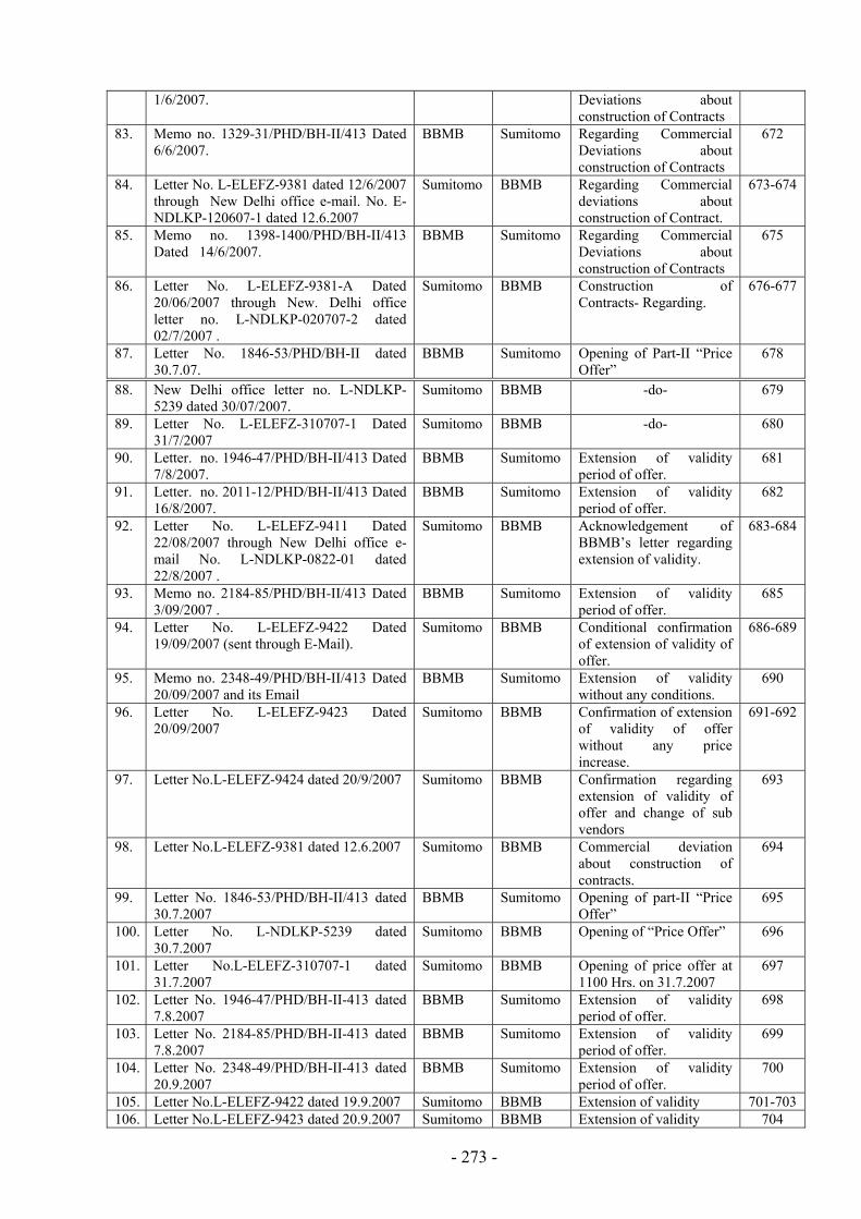
1/6/2007. Deviations about construction of Contracts
83. Memo no. 1329-31/PHD/BH-II/413 Dated 6/6/2007.
BBMB Sumitomo Regarding Commercial Deviations about construction of Contracts
672
84. Letter No. L-ELEFZ-9381 dated 12/6/2007 through New Delhi office e-mail. No. E-NDLKP-120607-1 dated 12.6.2007
Sumitomo BBMB Regarding Commercial deviations about construction of Contract.
673-674
85. Memo no. 1398-1400/PHD/BH-II/413 Dated 14/6/2007.
BBMB Sumitomo Regarding Commercial Deviations about construction of Contracts
675
86. Letter No. L-ELEFZ-9381-A Dated 20/06/2007 through New. Delhi office letter no. L-NDLKP-020707-2 dated 02/7/2007 .
Sumitomo BBMB Construction of Contracts- Regarding.
676-677
87. Letter No. 1846-53/PHD/BH-II dated 30.7.07.
BBMB Sumitomo Opening of Part-II “Price Offer”
678 [
88. New Delhi office letter no. L-NDLKP-5239 dated 30/07/2007.
Sumitomo BBMB -do- 679
89. Letter No. L-ELEFZ-310707-1 Dated 31/7/2007
Sumitomo BBMB -do- 680
90. Letter. no. 1946-47/PHD/BH-II/413 Dated 7/8/2007.
BBMB Sumitomo Extension of validity period of offer.
681
91. Letter. no. 2011-12/PHD/BH-II/413 Dated 16/8/2007.
BBMB Sumitomo Extension of validity period of offer.
682
92. Letter No. L-ELEFZ-9411 Dated 22/08/2007 through New Delhi office e-mail No. L-NDLKP-0822-01 dated 22/8/2007 .
Sumitomo BBMB Acknowledgement of BBMB’s letter regarding extension of validity.
683-684
93. Memo no. 2184-85/PHD/BH-II/413 Dated 3/09/2007 .
BBMB Sumitomo Extension of validity period of offer.
685
94. Letter No. L-ELEFZ-9422 Dated 19/09/2007 (sent through E-Mail).
Sumitomo BBMB Conditional confirmation of extension of validity of offer.
686-689
95. Memo no. 2348-49/PHD/BH-II/413 Dated 20/09/2007 and its Email
BBMB Sumitomo Extension of validity without any conditions.
690
96. Letter No. L-ELEFZ-9423 Dated 20/09/2007
Sumitomo BBMB Confirmation of extension of validity of offer without any price increase.
691-692
97. Letter No.L-ELEFZ-9424 dated 20/9/2007 Sumitomo BBMB Confirmation regarding extension of validity of offer and change of sub vendors
693
98. Letter No.L-ELEFZ-9381 dated 12.6.2007 Sumitomo BBMB Commercial deviation about construction of contracts.
694
99. Letter No. 1846-53/PHD/BH-II/413 dated 30.7.2007
BBMB Sumitomo Opening of part-II “Price Offer”
695
100. Letter No. L-NDLKP-5239 dated 30.7.2007
Sumitomo BBMB Opening of “Price Offer” 696
101. Letter No.L-ELEFZ-310707-1 dated 31.7.2007
Sumitomo BBMB Opening of price offer at 1100 Hrs. on 31.7.2007
697
102. Letter No. 1946-47/PHD/BH-II-413 dated 7.8.2007
BBMB Sumitomo Extension of validity period of offer.
698
103. Letter No. 2184-85/PHD/BH-II-413 dated 7.8.2007
BBMB Sumitomo Extension of validity period of offer.
699
104. Letter No. 2348-49/PHD/BH-II-413 dated 20.9.2007
BBMB Sumitomo Extension of validity period of offer.
700
105. Letter No.L-ELEFZ-9422 dated 19.9.2007 Sumitomo BBMB Extension of validity 701-703 106. Letter No.L-ELEFZ-9423 dated 20.9.2007 Sumitomo BBMB Extension of validity 704
- 273 -

107. Letter No.L-ELEFZ-9424 dated 20.9.2007 Sumitomo BBMB Extension of validity 705 108. Letter No.L-ELEFZ-9432 dated 28.9.2007 Sumitomo BBMB Shaft NDT proposal for
generator 706-707
109. Letter No.E-NDLKP-280907-03 dated 28.9.2007
Sumitomo BBMB Letter from SC-Tokyo (L-ELEFZ-9424 dated 20.9.2007
708
110. Letter No.L-ELEFZ-9428 dated 28.9.2007 Sumitomo BBMB Extension of validity 709-720 111. Letter No.L-ELEFZ-9433 dated 1.10.2007 Sumitomo BBMB Extension of validity 721-722 112. Letter No.E-NDLKP-051007-1 dated
5.10.2007 Sumitomo BBMB NDT testing of shaft 723
113. Letter No.L-ELEFZ-9435 dated 5.10.2007 Sumitomo BBMB Shaft NDT proposal for Generator
724-726
114. Letter No. L-ELEFZ-9435 Dated 5/10/2007 (sent through E-Mail).
Sumitomo BBMB NDT testing of shaft 727-732
115. Letter No.E-NDLKP-5255 dated 9.10.2007
Sumitomo BBMB Extension of validity 733-757
116. Letter No.E-NDLKP-101007-1 dated 10.10.2007
Sumitomo BBMB EMD Validity Extension 758-760
117. Letter No. 2495/PHD/BH-II-413 dated 11.10.2007
BBMB Sumitomo House seeking approval of Govt. of India for import on CIF basis.
761
118. Letter No. L-ELEFZ-9439 dated 12.10.2007 through letter No. E-NDLKP-151007-1 dated 15.10.2007
Sumitomo BBMB Shipment information 762-763
119. Letter No. 2543-44/PHD/BH-II-413 dated 19.10.2007
BBMB Sumitomo EMD Validity Extension 764
120. Letter No. L-ELEFZ-9441 dated 17.10.2007 through letter No. E-NDLKP-1017-1 dated 17.10.2007
Sumitomo BBMB Shaft NDT proposal for Generator
765-766
121. Letter No. L-ELEFZ-9442 dated 22.10.2007
Sumitomo BBMB Shaft NDT proposal – Sketches
767-772
122. Letter No. 2623-24/PHD/BH-II-413 dated 25.10.2007
BBMB Sumitomo Clarification in respect of price offer
773-775
123. Letter No. L-ELEFZ-9448-2 dated 29.10.2007 through letter No. E-NDLKP-291007-1 dated 29.10.2007
Sumitomo BBMB Clarification in respect of price offer
776-783
124. Letter No. 2635-36/PHD/BH-II-413 dated 27.10.2007
BBMB Sumitomo Reply to post price opening clarifications (Reminder)
784
125. Letter No. L-ELEFZ-9451 dated 29.10.2007 through letter No. E-NDLKP-291007-2 dated 29.10.2007
Sumitomo BBMB Notification of Awards/Extension of tender offer validity
785-787
126. Letter No. 2651/PHD/BH-II-413 dated 30.10.2007
BBMB Sumitomo Clarification in respect of price offer.
788
127. Letter No. 2676/PHD/BH-II-413 dated 31.10.2007
BBMB Sumitomo Acceptance of notification of Awards – Regarding withdrawal of conditions.
789
128. Letter No. L-ELEFZ-9443 to 9446 dated 30.10.2007 through letter No. E-NDLKP-1031-02 dated 31.10.2007
Sumitomo BBMB Clarification in respect of price offer
790-795
129. Letter No. L-ELEFZ-9453 dated 30.10.2007
Sumitomo BBMB Clarification in respect of price offer
796-798
130. Minutes of Meeting held on 1.11.2007 between BBMB & Sumitomo corporation
-- -- -- 799
131. Letter No. 98/PA/PHD/BH-II/413 dated 1.11.2007
BBMB Sumitomo Notification of Award/Extension of Tender Offer validity
800
132. Sumitomo Corporation Letter No. L- ELEFZ-9455 dated 1-11.2007
Sumitomo BBMB Notification of Award/Extension of Tender Offer validity
801
133. Sumitomo Corporation Letter No. L- Sumitomo BBMB Clarification in respect of 802
- 274 -

ELEFZ-9460 dated 1.11.2007 Price Offer 134. Sumitomo Corporation Letter No. L-
ELEFZ-9459 dated 2.11.2007 Sumitomo BBMB Clarification in respect of
Price Offer 803
135. Sumitomo Corporation Letter No. L- ELEFZ-9452 dated 1.11.2007
Sumitomo BBMB Terms of payment-LC and BG conditions
804-814
136. Sumitomo Corporation Letter No. L- ELEFZ-9460-A dated 02.11.2007
Sumitomo BBMB Clarification in respect of Price Offer
815
137. Sumitomo Corporation Japan Letter No. L - ELEFZ-9448 dated 25.10.2007
Sumitomo BBMB Clarification in respect of Price Offer
816-19
Note: Page Nos 99 to 106 (machine nos.) have not been used. Note:-The following correspondence have been attached with Appendix-A
1. Memo No. 2627-28/PHD/BH-II/413 dated 27.10.2007 BBMB Sumitomo NOA for Off Shore Supply.
2. Memo No. 2629-30/PHD/BH-II/413 dated 27.10.2007 BBMB Sumitomo NOA for On Shore Supply. 3. Memo No. 2631-32/PHD/BH-II/413 dated 27.10.2007 BBMB Sumitomo NOA for On Shore Service
for Turbine Portion. 4. Memo No. 2633-34/PHD/BH-II/413 dated 27.10.2007 BBMB Sumitomo NOA for On Shore Service
for Generator Portion.
- 275 -

APPENDIX - F
BILL OF MATERIAL
W.R.T.
GLOBAL N.I.T. NO. 247/BBMB/PHD/BHAKRA-II-413 DATED 20.01.2006
AND BBMB TENDER DOCUMENT NO : BBMB/PHD/BHAKRA/PP:171
FOR
RENOVATION, MODERNISATION & UPRATING
OF
FIVE HYDRO GENERATING UNITS
AT BHAKRA LEFT BANK POWER HOUSES
- 276 -

Set-1 Appendix-F
BILL OF MATERIAL
SCHEDULE -1A
TURBINE PLANT, EQUIPMENT & MANDATORY SPARE PARTS
SUPPLIED FROM ABROAD. (PER UNIT)
Sr. No. Description
Of Item Unit Qty.
1 2 3 4
1 Guide Vanes a Guide Vanes with Keys 20 b GV Upper Stem Bushings 20 c GV Middle Stem Bushings 20 d GV Lower Stem Bushings 20 2 Gate Operating Mechanism a GV Adjusting Devices 20 b GV Link Bushing 40 c Gate Operating Ring Liner set 4 d Eye-End Bushing of Connecting Rod 2 e Connecting Pin 20 f Shear Pin 20 g Eye-End Pin of Connecting Rod 2 h GV Stem Packing 20
i Failure circuit for shear pins 1set
for all unit
Incl. in 1B
3 Gate Servomotor a Eye-End Bushing Connecting Rod 2 b Chevron Type Packing set 2 4 Turbine Guide Bearing Parts a Bearing Pad set 1 b Cooling Coil set 1 5 Turbine Shaft Parts a Shaft Sleeve set 1 b Coupling Cover (Runner-Shaft) set 1
c Coupling Bolts (Runner-turbine shaft) set 1
- 277 -

6 Shaft Sealing Box a Shaft seal set 1
b Flow indicator 1
c Duplex pressure gauge 1 7 Runner Assembly a Runner (New Design) 1 b Runner Cone 1 c Runner Key set 1 d Fixing Bolt for Runner and Runner Cone set 1
e Runner Template Gauge Incl. in 1B 8 Head Cover parts a Head Cover Seal Ring Liner set 1 b Inner Head Cover Liner set 1 c Outer Head Cover Liner set 1 9 Ring Liners a Discharge Ring Liner set 1 b Throat Ring Liner set 1 c Sealing Ring Liner set 1 d Shaft Flange Liner set 1 e Bottom Cover Liner set 1
10 Governor Parts a Governor Oil & Air Supply System
b Oil Pressure Motor Pump set 2
c Air Compressor with motor, Common for all units
Incl. in 1B
d Piping of Oil and Air with valves set 1 11 Portable Motorized Jacking Pumps Incl. in 1B 12 Aeration Pipe
a Aeration Pipe set 1 13 On Line Monitoring Equipment a System with Vibration measurement - Shaft vibration sensor 1 - Head cover vibration sensor 1
b Noise level measurement N/A
c Flow Meter (ultra sonic type) 1 d Pressure Transducer 2
e Float Type Water Level Measurement 1 14 Consumable Lot 1 15 Spares Incl. in 1B 16 Overhaul parts a Packing, Washers, etc for Overhauls
- 278 -

1) Fixing bolts for Liners set 1 2) Small size bolts and nuts set 1 3) Shaft cover plate set 1 4) Water resistant round rubber packing set 1
5) Oil resistant round rubber packing set 1
N E 1 e 2 h r
OT S:
. R garding Item 13 ‘Noise Level Measurement’, The Set-1 for Generator be referred.
. T e details under Sr.No.14 “Consumable” are as given in FORM-II/Section V/Addendix D of this ag eement.
- 279 -

Set-1 Appendix-F
BILL OF MATERIAL
TURBINE PORTION
SCHEDULE -1B PLANT, EQUIPMENT & MANDATORY SPARE PARTS
SUPPLIED FROM ABROAD. (Common for All Five Units)
Sr. No. Description
Of Item Unit Qty.
1 2 3 4
A Gate Operating Mechanism Failure circuit for shear pins set 1 B Runner Assembly Runner Template Gauge set 1 C Governor Parts Air Compressor with motor, Common for all units sets 2 D Portable Motorized Jacking Pumps sets 2 E Spares I) Runner Runner (New Design) set 1 Runner cone set 1 Runner keys set 2 Fixing bolts of runner & runner cone set 1 II) Guide vanes Guide vanes Nos 20 Guide vane adjusting device Nos 4 Guide vane upper stem Bush Nos 20 Guide vane Middle Bush Nos 20 Guide vane Lower Bush Nos 20 III) Guide Vane operating Mechanism Guide vane connecting pin Nos 20 Guide vane eccentric shear pin Nos 20 IV) Gate Servomotor Parts Chevron type packing sets 2 V) Turbine Guide Bearing Parts Turbine guide bearing pads Nos 12 Cooling coil for turbine bearing set 1 VI) Turbine Shaft Parts Turbine shaft sleeve No 1 Coupling bolts for runner & turbine shaft Nos 14 Coupling bolts for generator -turbine shaft Nos 18
VII) Head Cover Parts
- 280 -

Head cover seal Ring liner set 1 Inner Head cover liner set 1 Outer Head cover liner set 1 VIII) Shaft Sealing Shaft isolating seal (inflated type) Nos 10 Rubber ring Packing for Shaft Seal Nos 20 IX) Ring Liners Discharge ring liner set 1 Sealing ring liner set 1 Throat ring liner set 1 Shaft flange liner set 1 Bottom cover liner set 1 X) Governor Parts Governor oil pump and motor set No 1
Spares for air compressor being used for in Governor oil pressure system set (*1) 1
XI) Instruments
R.T.D's / Vapor pressure or equivalent of turbine guide bearing metal Temp. detector sets 2
Equipment / Instruments required for installation and commissioning of turbine
No of each type (*2) 1
F Overhaul parts I Tools a General tools for Rehabilitation Work sets 2 b Special Tools - Shaft and runner lifting tool set 1 - Gate lever aligning tool set 1 - Gate lifting tool set 1 - Key puller for Guide Vane set 1 - Sling wire for Head cover set 1 - Hydraulic jack set 1 - Special Spanner (hydro Wrench) set 1 - Shaft stand set 1
II Testing Devices and Instruments for Testing during Assembly/ Erection at site and for Field Acceptance Tests
a [Testing Device] 1) Digital oscillograph No 1 2) Displacement converter Nos 2 3) Digital multimeter No 1 4) Pressure transducer Nos 7 5) Handy vibration meter No 1 6) Displacement sensor No 1
- 281 -

7) Thermometer Nos 2 8) Strain meter with code No 1 9) Pipes, joints and wires No 1 10) Digital sound meter No 1 11) Dial precision indicator Nos 2 12) Stop watch No 1 13) Efficiency and Index test devices - Digital power meter No 1 - Digital manometer Nos 2 - Other instruments No 1 b [Testing Instruments] 1) Temperature relay No 1 2) RTD Nos 14 3) Dial thermometer No 8 4) Oil level gauge No 1 5) Pressure gauge Nos 7 6) Flow meter No 2 c ( Instrument parts) 1) Turbine instrument panel sets 5
2) Dial thermo meter set (8 x 5units) 1
3) RTD set (14 x 5units) 1
4) Turbine oil level gauge sets 5
5) Turbine oil level switch set (2 x 5units) 1
6) Spiral case pressure gauge sets 5
7) Crown pressure/vacuum gauge sets 5
8) Draft tube pressure/vacuum gauge sets 5
9) Pressure gauge for Inlet & outlet of cooling water to guide bearing
set (2 x 5 units) 1
10) Shaft seal cooling water pressure gauge sets 5 11) Shaft seal air pressure gauge sets 5
Note: *1. 1 set includs followings: 1) Spring for unloader - one of each type 2) Safety valve - one of each type 3) Packing and gusket - 1 set of the required quontity for one compressor *2. 1 No of each type includs followings; 1) Dial precision indicator - 1 No.
- 282 -

2) Thermometor - 1 No. 3) Stopwatch - 1 No.
- 283 -
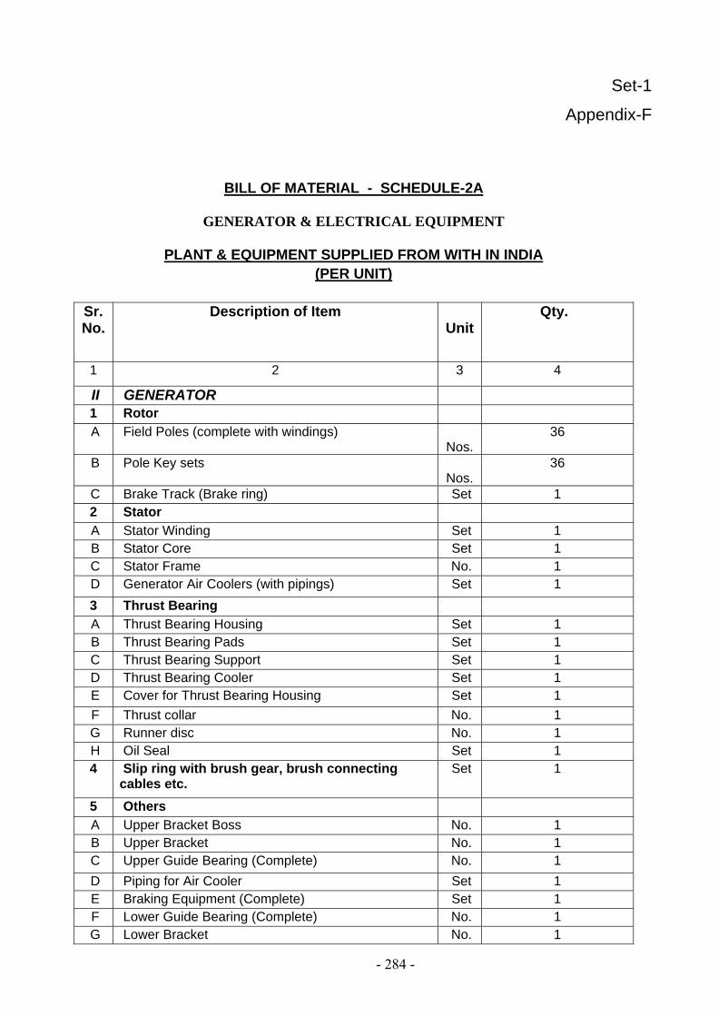
Set-1
Appendix-F
BILL OF MATERIAL - SCHEDULE-2A
GENERATOR & ELECTRICAL EQUIPMENT
PLANT & EQUIPMENT SUPPLIED FROM WITH IN INDIA (PER UNIT)
Sr.No.
Description of Item Unit
Qty.
1 2 3 4
II GENERATOR 1 Rotor A Field Poles (complete with windings)
Nos. 36
B Pole Key sets Nos.
36
C Brake Track (Brake ring) Set 1 2 Stator A Stator Winding Set 1 B Stator Core Set 1 C Stator Frame No. 1 D Generator Air Coolers (with pipings) Set 1 3 Thrust Bearing A Thrust Bearing Housing Set 1 B Thrust Bearing Pads Set 1 C Thrust Bearing Support Set 1 D Thrust Bearing Cooler Set 1 E Cover for Thrust Bearing Housing Set 1 F Thrust collar No. 1 G Runner disc No. 1 H Oil Seal Set 1 4 Slip ring with brush gear, brush connecting
cables etc. Set 1
5 Others A Upper Bracket Boss No. 1 B Upper Bracket No. 1 C Upper Guide Bearing (Complete) No. 1 D Piping for Air Cooler Set 1 E Braking Equipment (Complete) Set 1 F Lower Guide Bearing (Complete) No. 1 G Lower Bracket No. 1
- 284 -

H Housing Floor Plate Set 1 I Generator Air Housing Plate No. 1 J Flow Relays (Electromagnetic type)
Oil and water circuits Set 1
K Turbine-Generator guage panel No. 1 III STATIC EXCITATION SYSTEM
A Automatic Voltage Regulator Panels Set 1
B Thyristor Rectifier panels Set 1 C Field Circuit Breaker with field flashing equipment
panel Set 1
D Excitation power transformer with control panel. Set 1
IV CONTROL PANELS AND DESKS A Control Panel for Unit Set 1 B Annunciation/Alarm Panel Set 1 C Unit Control Desk Set 1 D Auto Synchronizer Panel Set 1
Notes:-
1. Annunciation/Alarm Panel: Alarm/annunciation feature is included in Control Panel of the unit in the form of touch panel is in line with latest standard and practices. Touch panel will include all the alarms as present in the existing system.
2. Unit Control Desk: The computer for HMI is the Unit Control Desk of the system. 3. For noise level measurement hand held Portable type instrument shall be provided by the
Contractor. 4. Condition monitoring is part of Control System
- 285 -
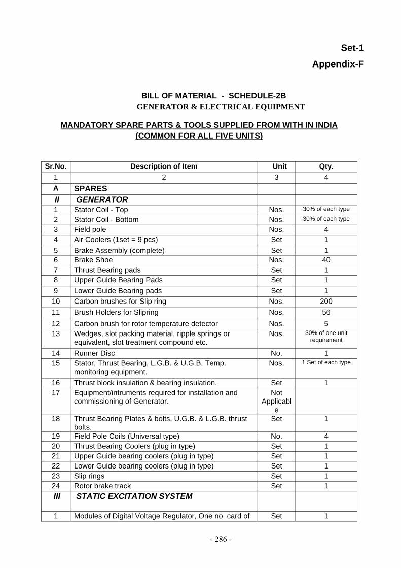
Set-1 Appendix-F
BILL OF MATERIAL - SCHEDULE-2B GENERATOR & ELECTRICAL EQUIPMENT
MANDATORY SPARE PARTS & TOOLS SUPPLIED FROM WITH IN INDIA
(COMMON FOR ALL FIVE UNITS) Sr.No. Description of Item Unit Qty.
1 2 3 4 A SPARES II GENERATOR 1 Stator Coil - Top Nos. 30% of each type
2 Stator Coil - Bottom Nos. 30% of each type
3 Field pole Nos. 4 4 Air Coolers (1set = 9 pcs) Set 1 5 Brake Assembly (complete) Set 1 6 Brake Shoe Nos. 40 7 Thrust Bearing pads Set 1 8 Upper Guide Bearing Pads Set 1 9 Lower Guide Bearing pads Set 1
10 Carbon brushes for Slip ring Nos. 200 11 Brush Holders for Slipring Nos. 56 12 Carbon brush for rotor temperature detector Nos. 5 13 Wedges, slot packing material, ripple springs or
equivalent, slot treatment compound etc. Nos. 30% of one unit
requirement
14 Runner Disc No. 1 15 Stator, Thrust Bearing, L.G.B. & U.G.B. Temp.
monitoring equipment. Nos. 1 Set of each type
16 Thrust block insulation & bearing insulation. Set 1 17 Equipment/intruments required for installation and
commissioning of Generator. Not
Applicable
18 Thrust Bearing Plates & bolts, U.G.B. & L.G.B. thrust bolts.
Set 1
19 Field Pole Coils (Universal type) No. 4 20 Thrust Bearing Coolers (plug in type) Set 1 21 Upper Guide bearing coolers (plug in type) Set 1 22 Lower Guide bearing coolers (plug in type) Set 1 23 Slip rings Set 1 24 Rotor brake track Set 1 III STATIC EXCITATION SYSTEM
1 Modules of Digital Voltage Regulator, One no. card of Set 1
- 286 -

each type 2 Thyristor Equipment
i)Thyristor Nos. 6 ii)Thyristor Fuses Nos. 6 iii)Cooling Fan Nos. 2
3 Transformer O/C Relay No. 1 4 Diode bridge for AC FF Set 1 5 Blocking diode for DC FF Set 1 B TOOLS AS PER LIST Set 1
NOTES 1 The Contractor shall provide adequate number of coolers as deemed suitable as
per his design and accordingly has quoted for 9 pieces of Air coolers in one set. 2 Regarding Item No.17 ‘Equipment /Instruments required for installation &
commissioning of Generator’ the Contractor has clarified in their tender under ‘Schedule of Deviation’ that no duplicate set as spare will be supplied as they will supply 01 set of complete outfit of special tools & tackles (common for all units) & all testing devices & instrument for testing shall be brought to site on returnable basis.
3 The Contractor has recommended his own set of spares for static excitation system under this schedule ‘Mandatory Spares’ against Item-III.
4 The list of tools to be supplied are as per FORM-IV-B/Section V Appendix D
5 The Contractor has quoted ‘One set of important Module for Automation and Control System (SCADA System)' as speres consisting of following list of modules:
i Power Supply module(220 V DC) ii Communication and processing Module iii Analog input module (4-20 mA) iv Analog input module(For Pt 100 Inputs) 1 No. v) Digital Input module
6 Regarding Item Nos 20, 21 and 22, the Contractor in their tender under "Schedule of Deviations" has clarified that they have considered one no. cooler each as spare for external oil coolers for bearings.
- 287 -

Set-1 Appendix-F
BILL OF MATERIAL GENERATOR & ELECTRICAL EQUIPMENT
SCHEDULE-6 Recommended Spare Parts for 10 years (Common for all the five Units).
Sr.No. Description
Of Item
Unit Qty.
1 2 3 4 1.
NIL
Note: The Contractor has intimated his own set of spares of Excitation System. The Contractor has quoted
his own set of spares of Excitation System agains5t Item-III under Schedule -2B
- 288 -

Set-1 Appendix-F
BILL OF MATERIAL TURBINE PORTION
SCHEDULE-6 Recommended Spare Parts for 10 years (Common for all the five Units).
Sr.No.
Description
Of Item
Unit Qty.
1 2 3 4 1 Shaft Isolating Seal Sets 5
(1 pcs for 1 set) 2 Rubber Ring Packing for Shaft Seal Sets 6
(2 pcs for 1 set)
- 289 -

Set-2 Appendix-F
SCHEDULE-1A BILL OF MATERIAL
TURBINE PORTION
PLANT, EQUIPMENT & MANDATORY SPARE PARTS SUPPLIED FROM ABROAD.
(PER UNIT)
Sr.No. Description
Of Item
Unit Qty.
1 2 3 4 2. Turbine Shaft No. 1 3. Water shedder No. 1 4. Air admission
system through shaft
a Automatic vacuum valve
No. 1
b Pipings Set 1 c Valve mounting
shaft, Drain box and Cover
Set 1
- 290 -

Set-2 Appendix-F
SCHEDULE-2 BILL OF MATERIAL
GENERATOR & ELECTRICAL PORTION
PLANT& EQUIPMENT SUPPLIED FROM WITH IN INDIA.
(PER UNIT)
Sr.No. Description of
Item Unit Qty.
1 2 3 4 II Generator 1 Rotor A Generator Shaft No. 1
- 291 -

Set-3 Appendix-F
BILL OF MATERIAL
SCHEDULE-2
PLANT & EQUIPMENT
SUPPLIED FROM WITH IN INDIA.
(PER UNIT)
Sr.No. Description of Item
Unit Qty.
1 2 3 4 i 11 KV Bus Duct
(Main and auxiliary)
Set 1
ii CTs, LAVTs, NGTs, NGRs
Set 1
- 292 -

Set-3
Appendix-F
BILL OF MATERIAL SCHEDULE-6
Recommended Spare Parts for 10 years (Common for all the five Units).
PLANT & EQUIPMENT
SUPPLIED FROM WITH IN INDIA.
(PER UNIT)
Sr. No.
Description Qty
1 Support Insulators 20 Nos. 2 Current Transformer 01 No. of
each type
3 Voltage Transformer 01 No. of each type
4 Surge Arrestor 01 No. 5 Capacitor 01 No. 6 Seal off Bushings for
Main IPBD 01 No.
7 Seal off Bushings for
Tap-off 01 No
8 Gasket 01 Set.
- 293 -