Behaviour Prediction Framework in System Architecture Development
11
Behaviour Prediction Framework in System Architecture Development Krešimir Osman 1,a , Mario Štorga 1,b , Tino Stanković 1,c , Dorian Marjanović 1,d 1 Faculty of Mechanical Engineering and Naval Architecture, University of Zagreb, Ivana Lučića 5, 10000 Zagreb, Croatia a [email protected], b [email protected], c [email protected], d [email protected] Keywords: behaviour prediction framework, structural complexity management, model predictive control, managing uncertainty Abstract This paper proposes a Behaviour Prediction Framework with an objective to help designers tackling the problem of uncertainty emerging from system architecture and the effects of the uncertain operating conditions. The proposed framework combines structural and dynamic system model. The Design Structure Matrix is applied to model structural arrangements and dependencies between the subsystems. The Model Predictive Control is applied to model the system in discrete and continuous dynamic domains. As the result of the proposed framework, stability analysis of subsystems in interaction become possible and feedback on system architecture could be provided. To test validity of the proposed approach, the test case involving climate chamber with heat regeneration is presented. Introduction Design as an activity is based on the principle of generation and testing solution alternatives until they conform to designer’s understanding of what has to be designed. At any abstraction level used during the design process two aspects interfere: establishment of the system architecture and evaluation the system behaviour which emerged as the result of the proposed architectural structure [1, 2]. Thus, the system’s performance is dependent on designer’s understanding of a design problem including personal beliefs and experience, and on the emergent behaviour of the system which was designed to perform within certain acceptable limits. Achieved by a designer, behaviour of a technical system may reflect only aspects and traits of behaviour modes which can emerge from established system’s architecture introducing in such way uncertainty in the respect to the system functionality. In the literature the uncertainty is defined as a state of having limited knowledge where it is impossible to exactly describe existing state or future outcome, more than one possible outcome [3]. From complex system’s research area [4] it is known that even a small change into system’s architecture can lead to unexpected or even unstable behaviour of the whole system, or likewise that small perturbation of input conditions as unforeseen environmental conditions or modes of use yield in an undesired system’s behaviour. In simple cases uncertainty arising from system environment can be handled by estimating the probabilities of such events or can be handled by use feedback to correct for unexpected or incorrectly predicted environment changes. This work presents Behaviour Prediction Framework which is aimed to provide designer with a feedback about expected behaviour of predefined subsystem architecture in two cases: under the given operating conditions and in a case of their unexpected change. Provided feedback should point out the elements within system architecture which are not able to operate within given parameters thus causing unstable system behaviour. Although the long term research goal is to establish automated feedback between structural and behavioural domains, at the current research stage the transformation between domains is performed manually, as well as resolving the implications of simulation results to system’s architecture. Applied Mechanics and Materials Vol. 104 (2012) pp 3-12 Online available since 2011/Sep/27 at www.scientific.net © (2012) Trans Tech Publications, Switzerland doi:10.4028/www.scientific.net/AMM.104.3 All rights reserved. No part of contents of this paper may be reproduced or transmitted in any form or by any means without the written permission of TTP, www.ttp.net. (ID: 161.53.118.48-29/09/11,09:42:17)
Transcript of Behaviour Prediction Framework in System Architecture Development
Behaviour Prediction Framework in System Architecture Development
Krešimir Osman1,a, Mario Štorga1,b, Tino Stanković1,c, Dorian Marjanović1,d 1Faculty of Mechanical Engineering and Naval Architecture, University of Zagreb, Ivana Lučića 5,
10000 Zagreb, Croatia [email protected], [email protected], [email protected],
Keywords: behaviour prediction framework, structural complexity management, model predictive control, managing uncertainty
Abstract This paper proposes a Behaviour Prediction Framework with an objective to help
designers tackling the problem of uncertainty emerging from system architecture and the effects of
the uncertain operating conditions. The proposed framework combines structural and dynamic
system model. The Design Structure Matrix is applied to model structural arrangements and
dependencies between the subsystems. The Model Predictive Control is applied to model the system
in discrete and continuous dynamic domains. As the result of the proposed framework, stability
analysis of subsystems in interaction become possible and feedback on system architecture could be
provided. To test validity of the proposed approach, the test case involving climate chamber with
heat regeneration is presented.
Introduction
Design as an activity is based on the principle of generation and testing solution alternatives until
they conform to designer’s understanding of what has to be designed. At any abstraction level used
during the design process two aspects interfere: establishment of the system architecture and
evaluation the system behaviour which emerged as the result of the proposed architectural structure
[1, 2]. Thus, the system’s performance is dependent on designer’s understanding of a design
problem including personal beliefs and experience, and on the emergent behaviour of the system
which was designed to perform within certain acceptable limits. Achieved by a designer, behaviour
of a technical system may reflect only aspects and traits of behaviour modes which can emerge
from established system’s architecture introducing in such way uncertainty in the respect to the
system functionality. In the literature the uncertainty is defined as a state of having limited
knowledge where it is impossible to exactly describe existing state or future outcome, more than
one possible outcome [3]. From complex system’s research area [4] it is known that even a small
change into system’s architecture can lead to unexpected or even unstable behaviour of the whole
system, or likewise that small perturbation of input conditions as unforeseen environmental
conditions or modes of use yield in an undesired system’s behaviour. In simple cases uncertainty
arising from system environment can be handled by estimating the probabilities of such events or
can be handled by use feedback to correct for unexpected or incorrectly predicted environment
changes.
This work presents Behaviour Prediction Framework which is aimed to provide designer with a
feedback about expected behaviour of predefined subsystem architecture in two cases: under the
given operating conditions and in a case of their unexpected change. Provided feedback should
point out the elements within system architecture which are not able to operate within given
parameters thus causing unstable system behaviour. Although the long term research goal is to
establish automated feedback between structural and behavioural domains, at the current research
stage the transformation between domains is performed manually, as well as resolving the
implications of simulation results to system’s architecture.
Applied Mechanics and Materials Vol. 104 (2012) pp 3-12Online available since 2011/Sep/27 at www.scientific.net© (2012) Trans Tech Publications, Switzerlanddoi:10.4028/www.scientific.net/AMM.104.3
All rights reserved. No part of contents of this paper may be reproduced or transmitted in any form or by any means without the written permission of TTP,www.ttp.net. (ID: 161.53.118.48-29/09/11,09:42:17)
The background of this research in the following section will present related work which attempt
at unify structural and dynamic system models. Third section will provide more detailed description
of the behaviour prediction methodology. Section four will provide description of Behaviour
Prediction Framework what is followed by a case study with a goal to evaluate applicability of the
proposed framework. Discussion on obtained results and conclusions close this paper.
Combining Structural and Dynamic System Models
There are two meaningful kinds of complexity relevant for the modern technical systems:
structural and behavioural complexity. Modelling the system’s structure and its dynamics within the
same methodology is gaining importance as it improves the system’s understanding. Two domains
are usually considered as separate issues: structural complexity management models cannot
describe the system’s behaviour and dynamical system modelling methods cannot be applied to
large scale or complex systems as it requires detailed and expensive process to acquire information
about all interactions. One of the recent approaches to combine two domains is presented in work of
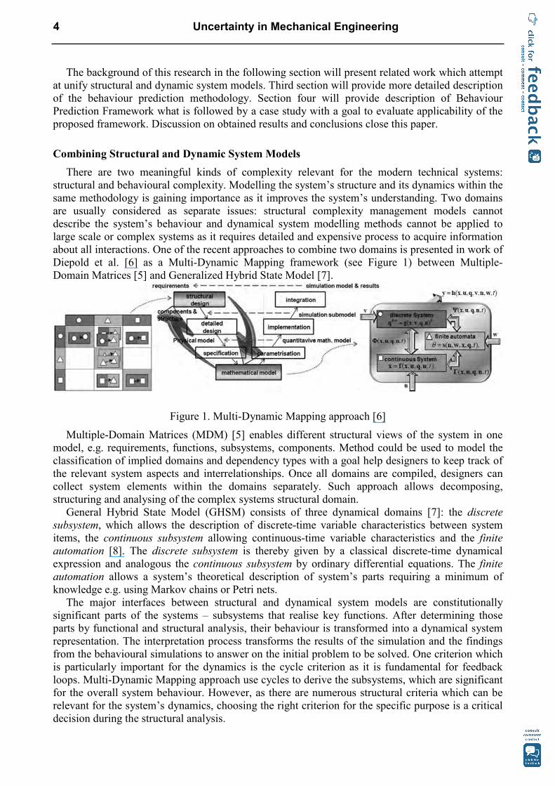
Diepold et al. [6] as a Multi-Dynamic Mapping framework (see Figure 1) between Multiple-
Domain Matrices [5] and Generalized Hybrid State Model [7].
Figure 1. Multi-Dynamic Mapping approach [6]
Multiple-Domain Matrices (MDM) [5] enables different structural views of the system in one
model, e.g. requirements, functions, subsystems, components. Method could be used to model the
classification of implied domains and dependency types with a goal help designers to keep track of
the relevant system aspects and interrelationships. Once all domains are compiled, designers can
collect system elements within the domains separately. Such approach allows decomposing,
structuring and analysing of the complex systems structural domain.
General Hybrid State Model (GHSM) consists of three dynamical domains [7]: the discrete
subsystem, which allows the description of discrete-time variable characteristics between system
items, the continuous subsystem allowing continuous-time variable characteristics and the finite
automation [8]. The discrete subsystem is thereby given by a classical discrete-time dynamical
expression and analogous the continuous subsystem by ordinary differential equations. The finite
automation allows a system’s theoretical description of system’s parts requiring a minimum of
knowledge e.g. using Markov chains or Petri nets.
The major interfaces between structural and dynamical system models are constitutionally
significant parts of the systems – subsystems that realise key functions. After determining those
parts by functional and structural analysis, their behaviour is transformed into a dynamical system
representation. The interpretation process transforms the results of the simulation and the findings
from the behavioural simulations to answer on the initial problem to be solved. One criterion which
is particularly important for the dynamics is the cycle criterion as it is fundamental for feedback
loops. Multi-Dynamic Mapping approach use cycles to derive the subsystems, which are significant
for the overall system behaviour. However, as there are numerous structural criteria which can be
relevant for the system’s dynamics, choosing the right criterion for the specific purpose is a critical
decision during the structural analysis.
4 Uncertainty in Mechanical Engineering
In example given by Diepold et al. [6], the mapping framework is implemented on very simple
mechanical system (the ball-pen) in order to illustrate the potential of the proposed models for
adjusting the structural design in consequence of the system’s performance. In his work [9],
Diepold presented structured process modelling approach by extending the DSM to the DynS-DSM
(Dynamical System DSM). The properties of structural analysis are thereby kept up during the
whole modelling procedure, which results in a discrete-time representation of the system’s
dynamics. Structural analysis and the effects of structural changes are thus directly transferable into
the system’s dynamics supporting a coupled system optimization. DynS-DSM approach is extended
to a framework (called quad-I/HS), which supports modelling of hybrid dynamical systems [9].
After the analysis of described work we have identified several drawbacks and defined the
following possible extensions:
• In contrast to Diepold’s mapping framework [6] our approach should offer possibility to mathematically model all of the subsystems behaviour during the operation time. Our
assumption is that all subsystems are linear invariant thus represented in state space model,
which is suitable for the further system stability analysis.
• System representation in nonlinear form (as in [6]), omits further possibilities to transform the model into linear form. That will be resolved by using Model Predictive Control (MPC) [10,
11] which allows control and adjustment of working parameters both in discrete and
continuous domains thus enabling the modelling of the system in real working conditions.
Based on the obtained model, stability analysis of subsystems in interaction becomes
possible. Thus, relating the MPC methodology to manage uncertainty is a fundamental
contribution and advantage of the presented approach.
• Finally, the improvement of the system is conducted directly within system’s dynamical behaviour model, thus reducing the design iteration steps.
Model Predictive Control
Model predictive control (MPC) is a methodology originating from the process industry
denominating a collection of methods which enable control of constrained linear and non linear
systems to meet a desired behaviour [10, 11, 12]. Objective in MPC is understood both as the limit
to which the system performance is guided to in order to be economically feasible and as an
assurance of the performance stability. The former implies that the limit values have to be known a
priori, or to be predicted with a degree of uncertainty if necessary, in order to be able to calculate
required signals for corrections. The assurance of the performance stability requires that control
must provide precise inputs and effects which will be able to meet on-the-fly uncertainties of the
performed system behaviour.
In comparison with conventional control methods which try to rectify the outputs based on the
feedback provided as a response to actions undertaken, MPC aims at targeting intended (predicted)
behaviour. In order to do so, model a discrete time model of the system is utilized to obtain an
estimate of its future behaviour.
Estimation of the future behaviour is accomplished by applying a set of input sequences to a
model with measured state/output as initial condition, while taking into account imposed
constraints. An optimisation problem built around a performance oriented cost function is then
solved to choose an optimal sequence of controls from all feasible sequences as close as possible to
desired behaviour. To summarise, the MPC is built based on the following principles [10]:
• The explicit use of a process model for calculating predictions of the system behaviour based on the architecture of considered system.
• The optimisations of an objective function subject to constraints, which yields with control trying to maintain system’s stability with optimal performance.
• The receding horizon strategy as a goal behaviour which designer expects from the system. Directing up to prescribed performance values rather than be directed by past behaviour
deviations is observed within system design process when experienced designer produces solutions
directed by own in-filed knowledge tin order to meet requirements. Search for set of inputs which
Applied Mechanics and Materials Vol. 104 5
are able to maintain system stability by the MPC can tackle the portion of uncertainties showing to
the designer that intended behaviour of the system can be kept stable under imposed conditions.
Design process congruent features alongside the MPC’s the applicability of multivariable problems
and ease of use not requiring in-depth control knowledge qualifies MPC based approach as a strong
candidate providing robust behavioural system modelling.
Behavior Prediction Framework
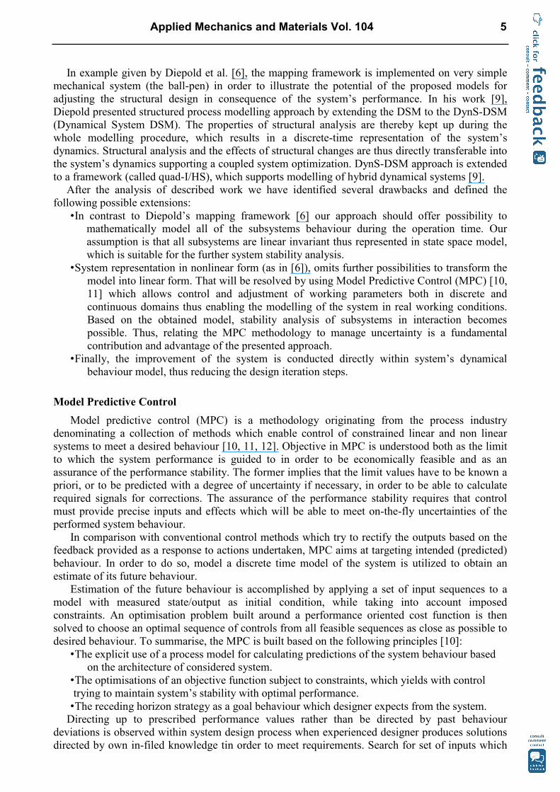
The proposed Behaviour Prediction Framework (see Figure 2) is aimed to be used during system
architecture design phase for structural and behaviour modelling of the systems. We decided to
model system structural complexity in only one domain (subsystems domain) in order to point out
the importance of the interaction at this level of system abstraction. By using subsystems domain as
a generalisation of a more concrete components domain [13], the functional and geometrical
complexity of the system may be reduced to a manageable level. The Design Structure Matrix
(DSM) [6, 13, 14] is applied to model arrangements and dependencies between the subsystems. In
order to confirm that proposed subsystems arrangements suffice the performance that is expected
from the system, the continuous and discrete behaviour domain should be also modelled (see Figure
2) according to general principles of system dynamics.
Figure 2. A schema of Behaviour Prediction Framework
The goal of the behaviour modelling is to obtain a linear model in state space representation of
the system architecture. The starting point is a non-linear behaviour model of the considered system
which may refer to either continuous or discrete time domains. The most common linearization
method, which could be applied here, is the expansion in Taylor’s series around the equilibrium
point [15]. Based on the [16], a high order linear model of dynamical system can be decomposed
thus representing it with collections of linear models at different levels of hierarchy. The latter is
applied within GHSM [5] module in the framework (Figure 2)
After linearization, the feedback mechanism of the MPC is used to compensate deviations of
state variables (system performance) for the predicted equilibrium point. The application of the
MPC is to predict the response of the system’s output variables relevant for the functionality of the
considered system. After applying the MPC the stability is checked for each subsystem for
continuous and discrete domain. For energy-based stability analysis Lyapunov method [17] is
applied.
6 Uncertainty in Mechanical Engineering
After performance stability is checked for each of subsystems, the result may suggest that some
of them are unstable under imposed working conditions. In case of instability, a parameters tuning
is performed in mathematical model of the subsystem (e.g. air and water volume flow or other
parameters which are in correlation), until the subsystem reaches one of the stable condition states
(according to [15]). The next step is to check the stability of subsystems that are in interaction. In
case of their instability, a refinement of the system architecture within a DSM is required (e.g. we
have to add or remove some entities in system architecture and change their relations in order to
improve stability of the interactions). The proposed framework will be further explained and
illustrated with a case study of climate chamber with heat regeneration that is described in
following section.
Case study – climate chamber with heat regeneration
The purpose of the case study is to show how Behaviour Prediction Framework can support
designers during conceptual design on the example of the climate chamber. Based on the
specification of the initial working conditions the simulations of the chamber subsystems behaviour
were performed and accordingly to the feedbacks the final system architecture was proposed.
Climate chamber with heat regeneration is very often an integral part of HVAC for large objects
(e.g. shopping malls, hotels or business objects). As within energy management (energy cost) the
heat regeneration is very desirable goal, fulfilment of the demand for shorter heating/cooling
process time in respect to uncertain environmental conditions is very important. For our particular
case study initial working conditions for winter period are given as follows: outdoor (environment)
temperature To = -10 °C (which is average outdoor temperature for town Zagreb, Croatia) and air
flow of qva = 8,5 m3/s. Our goal in the case study was to propose architecture for mentioned
working conditions and check the stability of the proposed solution for given working conditions.
Also, the proposed architecture should be tested to unexpected working conditions in order to
simulate the chamber response on the temperature drop assumed at -30°C, simulating in such way
uncertainty of the working conditions that are stochastically happening in Zagreb area.
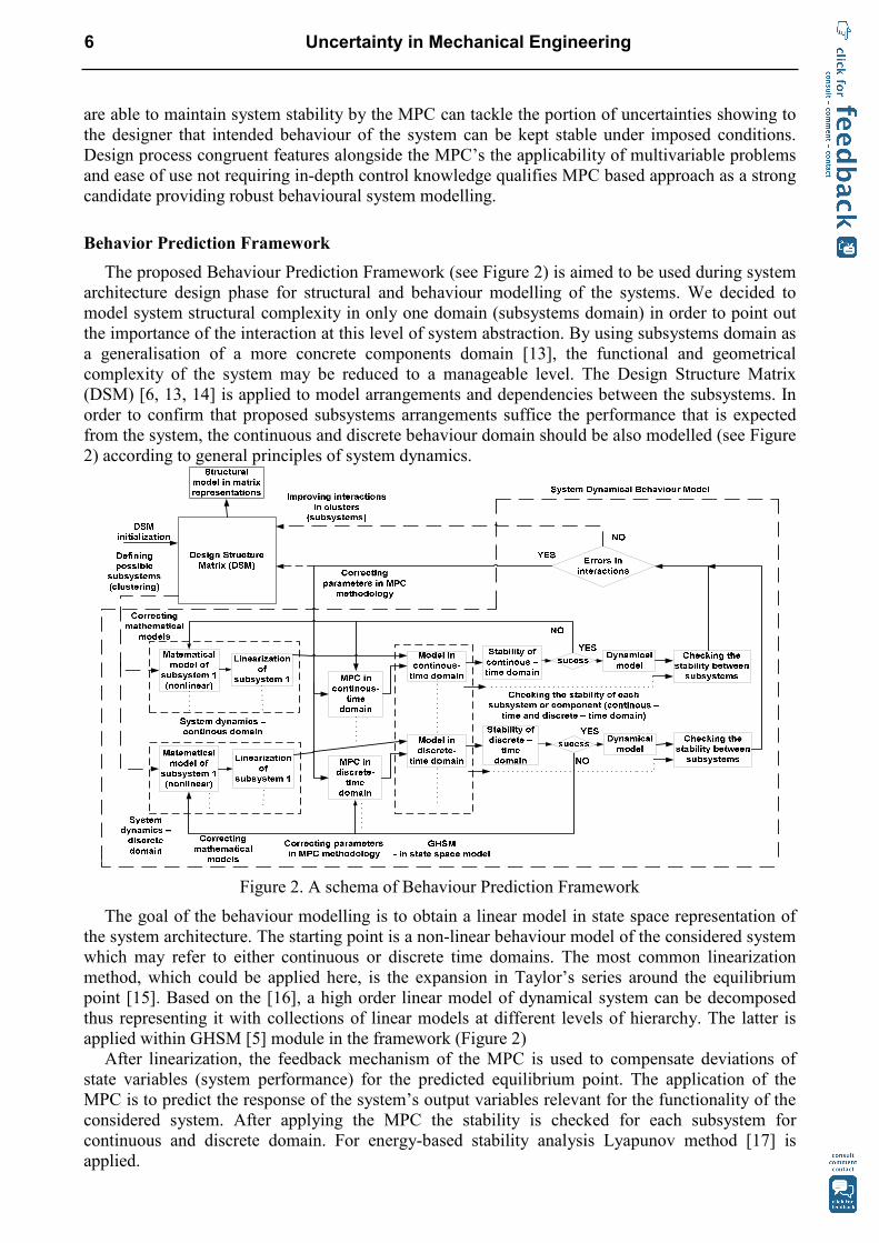
The first concept of the chamber architecture was developed based on the designer experience
with similar systems as presented on Figure 3. This scheme (for initial working conditions) is a
starting point for understanding the relationship between main subsystems. A DSM based on Figure
3 is presented on Figure 4.
Figure 3. Simplified schema of starting conceptual design of climate chamber
The LOOMEO© (www.teseon.com) was used as a tool for describing climate chamber
subsystem structure for further analysis. Possibility for modularization of chamber’s subsystems is
determined by performing clustering operation over DSM. Figure 4a shows a portion of DSM
matrix representation of the architecture after the several steps of refinement including clustering
has been conducted. Figure 5b presents DSM in graph representation.
Based on the proposed module clustering [13], the behaviour modelling was conducted as
follows. First, the initial proposal of the detailed schema for entire system (climate chamber with
heat regeneration) was developed (Figure 5). Three subsystems (two air heaters and moisturizer,
Applied Mechanics and Materials Vol. 104 7
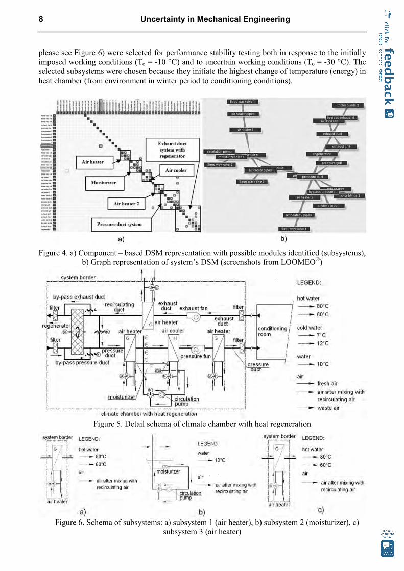
please see Figure 6) were selected for performance stability testing both in response to the initially
imposed working conditions (To = -10 °C) and to uncertain working conditions (To = -30 °C). The
selected subsystems were chosen because they initiate the highest change of temperature (energy) in
heat chamber (from environment in winter period to conditioning conditions).
Figure 4. a) Component – based DSM representation with possible modules identified (subsystems),
b) Graph representation of system’s DSM (screenshots from LOOMEO®)
Figure 5. Detail schema of climate chamber with heat regeneration
Figure 6. Schema of subsystems: a) subsystem 1 (air heater), b) subsystem 2 (moisturizer), c)
subsystem 3 (air heater)
8 Uncertainty in Mechanical Engineering
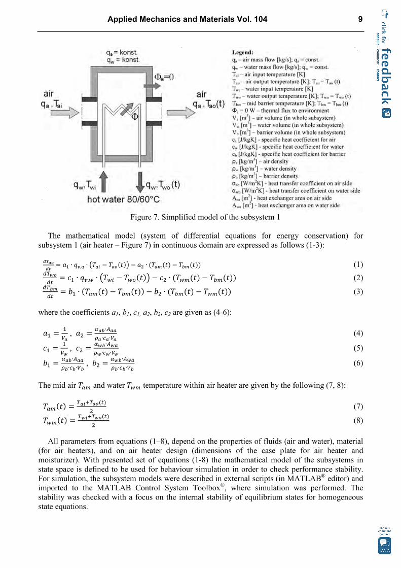
Figure 7. Simplified model of the subsystem 1
The mathematical model (system of differential equations for energy conservation) for
subsystem 1 (air heater – Figure 7) in continuous domain are expressed as follows (1-3):
������
� �� ∙ �, ∙ �� � � � ����� � �� ∙ �� ���� � ������� (1) ������
� �� ∙ �,� ∙ ���� � ������� � �� ∙ ������� � ������� (2) ������
� �� ∙ �� ���� � ������� � �� ∙ ������� � ������� (3)
where the coefficients a1, b1, c1, a2, b2, c2 are given as (4-6):
�� ��
� , �� �
!��∙"��#�∙$�∙ �
(4)
�� ��
� , �� �
!��∙"��#�∙$�∙ �
(5)
�� �!��∙"��#�∙$�∙ �
, �� �!��∙"��#�∙$�∙ �
(6)
The mid air � � and water ��� temperature within air heater are given by the following (7, 8):
� ���� ���%&������
� (7)
������ ���%&������
� (8)
All parameters from equations (1–8), depend on the properties of fluids (air and water), material
(for air heaters), and on air heater design (dimensions of the case plate for air heater and
moisturizer). With presented set of equations (1-8) the mathematical model of the subsystems in
state space is defined to be used for behaviour simulation in order to check performance stability.
For simulation, the subsystem models were described in external scripts (in MATLAB® editor) and
imported to the MATLAB Control System Toolbox®, where simulation was performed. The
stability was checked with a focus on the internal stability of equilibrium states for homogeneous
state equations.
Applied Mechanics and Materials Vol. 104 9
Discussion
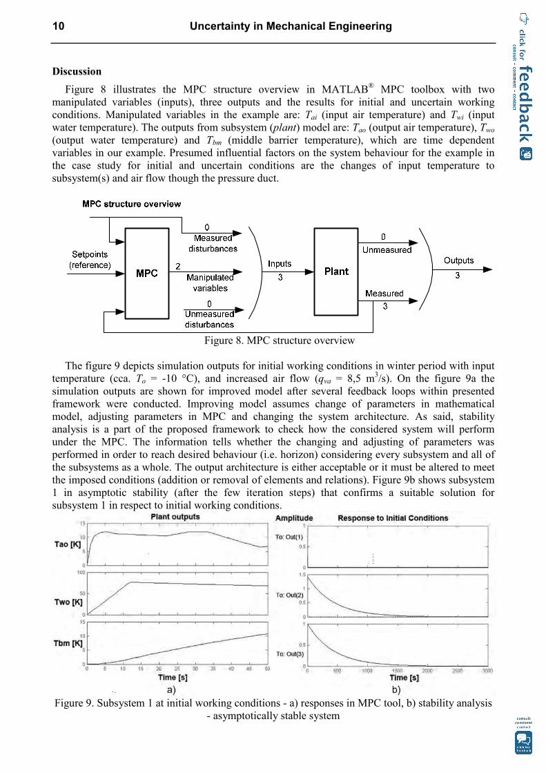
Figure 8 illustrates the MPC structure overview in MATLAB® MPC toolbox with two
manipulated variables (inputs), three outputs and the results for initial and uncertain working
conditions. Manipulated variables in the example are: Tai (input air temperature) and Twi (input
water temperature). The outputs from subsystem (plant) model are: Tao (output air temperature), Two
(output water temperature) and Tbm (middle barrier temperature), which are time dependent
variables in our example. Presumed influential factors on the system behaviour for the example in
the case study for initial and uncertain conditions are the changes of input temperature to
subsystem(s) and air flow though the pressure duct.
Figure 8. MPC structure overview
The figure 9 depicts simulation outputs for initial working conditions in winter period with input
temperature (cca. To = -10 °C), and increased air flow (qva = 8,5 m3/s). On the figure 9a the
simulation outputs are shown for improved model after several feedback loops within presented
framework were conducted. Improving model assumes change of parameters in mathematical
model, adjusting parameters in MPC and changing the system architecture. As said, stability
analysis is a part of the proposed framework to check how the considered system will perform
under the MPC. The information tells whether the changing and adjusting of parameters was
performed in order to reach desired behaviour (i.e. horizon) considering every subsystem and all of
the subsystems as a whole. The output architecture is either acceptable or it must be altered to meet
the imposed conditions (addition or removal of elements and relations). Figure 9b shows subsystem
1 in asymptotic stability (after the few iteration steps) that confirms a suitable solution for
subsystem 1 in respect to initial working conditions.
Figure 9. Subsystem 1 at initial working conditions - a) responses in MPC tool, b) stability analysis
- asymptotically stable system
10 Uncertainty in Mechanical Engineering
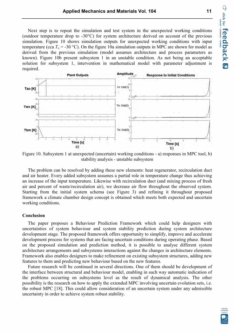
Next step is to repeat the simulation and test system in the unexpected working conditions
(outdoor temperature drop to -30°C) for system architecture derived on account of the previous
simulation. Figure 10 shows simulation outputs for unexpected working conditions with input
temperature (cca To = -30 °C). On the figure 10a simulation outputs in MPC are shown for model as
derived from the previous simulation (model assumes architecture and process parameters as
known). Figure 10b present subsystem 1 in an unstable condition. As not being an acceptable
solution for subsystem 1, intervention in mathematical model with parameter adjustment is
required.
Figure 10. Subsystem 1 at unexpected (uncertain) working conditions - a) responses in MPC tool, b)
stability analysis - unstable subsystem
The problem can be resolved by adding these new elements: heat regenerator, recirculation duct
and air heater. Every added subsystem assumes a partial role in temperature change thus achieving
an increase of the input temperature. Likewise with recirculation duct (and mixing process of fresh
air and percent of waste/recirculation air), we decrease air flow throughout the observed system.
Starting from the initial system schema (see Figure 3) and refining it throughout proposed
framework a climate chamber design concept is obtained which meets both expected and uncertain
working conditions.
Conclusion
The paper proposes a Behaviour Prediction Framework which could help designers with
uncertainties of system behaviour and system stability prediction during system architecture
development stage. The proposed framework offers opportunity to simplify, improve and accelerate
development process for systems that are facing uncertain conditions during operating phase. Based
on the proposed simulation and prediction method, it is possible to analyse different system
architecture arrangements and subsystems interactions against the changes in architecture elements.
Framework also enables designers to make refinement on existing subsystem structures, adding new
features to them and predicting new behaviour based on the new features.
Future research will be continued in several directions. One of them should be development of
the interface between structural and behaviour model, enabling in such way automatic indication of
the problems occurring on subsystems level as the result of dynamical analysis. The other
possibility is the research on how to apply the extended MPC involving uncertain evolution sets, i.e.
the robust MPC [18]. This could allow consideration of an uncertain system under any admissible
uncertainty in order to achieve system robust stability.
Applied Mechanics and Materials Vol. 104 11

Acknowledgements
This research is part of funded project “Models and methods of knowledge management in product
development” supported by the Ministry of Science and Technology of the Republic of Croatia.
References
[1] V. Hubka, W. E. Eder: Engineering Design: General Procedural Model of Engineering Design
(Springer – Verlag Berlin Heidelberg, Germany, 1992)
[2] C. T. Hansen, M. M. Andreasen: Two approaches to synthesis based on the domain theory,In
Engineering Design Synthesis, (ed. A. Chakrabarti), chapter 6, (Springer-Verlag London Limited,
UK, 2002), p. 93 – 108.
[3] D. Hubbard: How to Measure Anything: Finding the Value of Intangibles in Business (John
Wiley & Sons, USA, 2007)
[4] M. Mitchell: Complexity: A Guided Tour (Oxford University Press, USA, 2009)
[5] U. Lindemann, M. Maurer and T. Braun: Structural Complexity Management – An Approach for
the Field of Product Design (Springer – Verlag Berlin Heidelberg, Germany 2009)
[6] K. J. Diepold, W. Biedermann, K. G. M. Eben, S. Kortler, B. Lohmann and U. Lindemann:
Combining Structural Complexity Management and Hybrid Dynamical System Modelling, In:
Proceedings of DESIGN 2010, Dubrovnik, Croatia, volume 2, (2010), p. 1045 - 1054.
[7] M. Buss, M. Glocker, M. Hardt, O. von Stryk, R. Bulirsch, G. Schmidt: Nonlinear Hybrid
Dynamical Systems: Modelling, Optimal Control, and Applications, In: Analysis and Design of
Hybrid Systems - Lecture Notes in Control and Information Science (LNCIS), Springer Berlin,
Germany, 2002, p. 311–335.
[8] T.A. Helzinger T.A.: The Theory of Hybrid Automata (Berkley, USA, 1996)
[9] K. J. Diepold, F. J. Winkler, B. Lohmann: Systematical hybrid state modelling of complex
dynamical systems: The quad - I/HS framework, In: Mathematical and Computer Modelling of
Dynamical Systems, Vol. 16, No. 4 (2010), p. 347 - 371.
[10] E.F. Camacho and C. Bordons: Model Predictive Control (Springer – New York, USA 2004)
[11] L. Wang: Model Predictive Control System Design and Implementation Using MATLAB,
(Spinger – Verlag London Limited, 2009)
[12] M. Lazar: Model Predictive Control of Hybrid Systems: Stability and Robustness, PhD thesis
(Technische Universiteit Eindhoven, Eindhoven, 2006)
[13] D. Steward: The Design Structure Matrix: A Method for Managing the Design of Complex
Systems, In: IEEE Transaction on Engineering Management, Vol. 28, No. 3 (1981), p. 321-342.
[14] T. U. Pimmler, S. D. Eppinger: Integration Analysis of Product Decompositions. In:
Proceedings of the 1994 ASME-DTM Conference (ASME, Minneapolis, USA, 1994)
[15] R. C. Dorf, R. H. Bishop: Modern Control Systems (Pearson Education, Inc., Upper Saddle
River, New Jersey, USA, 2011)
[16] W. Stanislawski, M. Rydel: Hierarchical mathematical models of complex plants on the basis
of power boiler example, In: Archives of Control Sciences, Vol. 20, No. 4, (2010), p. 381–416.
[17] A. Bacciotti, L. Rosier: Liapunov Functions and Stability in Control Theory, 2nd edition
(Springer - Verlag Berlin Heidelberg, Germany, 2005)
[18] A. Bemporad, M. Morari: Robust Model Predictive Control: A Survey, In: Robustness in
Identification and Control, Vol. 245, A. Garulli, A. Tesi, A. Vicino (Eds.), Lecture Notes in Control
and Information Sciences, Springer -Verlag (1999), pp. 207-226
12 Uncertainty in Mechanical Engineering

Uncertainty in Mechanical Engineering doi:10.4028/www.scientific.net/AMM.104 Behaviour Prediction Framework in System Architecture Development doi:10.4028/www.scientific.net/AMM.104.3