
BE1-11m Instruction Manual - Basler Electric
610
12570 Route 143 • Highland, Illinois 62249-1074 USA Tel +1 618.654.2341 • Fax +1 618.654.2351 www.basler.com • [email protected] Publication 9424200996, Rev AA February 2022 BE1-11m Motor Protection System Instruction Manual
-
Upload
khangminh22 -
Category
Documents
-
view
1 -
download
0
Transcript of BE1-11m Instruction Manual - Basler Electric
12570 Route 143 • Highland, Illinois 62249-1074 USA Tel +1 618.654.2341 • Fax +1 618.654.2351 www.basler.com • [email protected]
Publication 9424200996, Rev AA
February 2022
BE1-11m Motor Protection System
Instruction Manual

WARNING: California's Proposition 65 requires special warnings for products that may contain chemicals known to the state of California to cause cancer, birth defects, or other reproductive harm. Please note that by posting this Proposition 65 warning, we are notifying you that one or more of the Proposition 65 listed chemicals may be present in products we sell to you. For more information about the specific chemicals found in this product, please visit https://www.basler.com/Prop65.
9424200996 i
BE1-11m Preface
Preface This instruction manual provides information about the installation and operation of the BE1-11m Motor Protection System. To accomplish this, the following information is provided:
• General information and a quick start guide • Controls and indicators • Inputs and outputs • Protection and control functions • Reporting and alarms information • Mounting and connection diagrams • BESTCOMSPlus® software • Communication and security • Testing and troubleshooting procedures • Specifications • Time curve characteristics • RTD module (optional)
Optional instruction manuals for the BE1-11m include: • Modbus® communication protocol (Basler Electric part number 9424200774) • Distributed Network Protocol (DNP) (Basler Electric part number 9424200773) • IEC 61850 communication protocol (Basler Electric part number 9424200892)
Conventions Used in this Manual
Important safety and procedural information is emphasized and presented in this manual through warning, caution, and note boxes. Each type is illustrated and defined as follows.
Warning!
Warning boxes call attention to conditions or actions that may cause personal injury or death.
Caution Caution boxes call attention to operating conditions that may lead to equipment or property damage.
Note Note boxes emphasize important information pertaining to installation or operation.
ii 9424200996
Preface BE1-11m
12570 State Route 143
Highland IL 62249-1074 USA www.basler.com [email protected]
Tel: +1 618.654.2341 Fax: +1 618.654.2351
© 2022 by Basler Electric
All rights reserved First printing: September 2010
Warning!
READ THIS MANUAL. Read this manual before installing, operating, or maintaining the BE1-11m. Note all warnings, cautions, and notes in this manual as well as on the product. Keep this manual with the product for reference. Only qualified personnel should install, operate, or service this system. Failure to follow warning and cautionary labels may result in personal injury or property damage. Exercise caution at all times.
Caution Installing previous versions of firmware may result in compatibility issues causing the inability to operate properly and may not have the enhancements and resolutions to issues that more recent versions provide. Basler Electric highly recommends using the latest version of firmware at all times. Using previous versions of firmware is at the user’s risk and may void the warranty of the unit.
Basler Electric does not assume any responsibility to compliance or noncompliance with national code, local code, or any other applicable code. This manual serves as reference material that must be well understood prior to installation, operation, or maintenance.
For terms of service relating to this product and software, see the Commercial Terms of Products and Services document available at www.basler.com/terms. This publication contains confidential information of Basler Electric Company, an Illinois corporation. It is loaned for confidential use, subject to return on request, and with the mutual understanding that it will not be used in any manner detrimental to the interests of Basler Electric Company and used strictly for the purpose intended.
It is not the intention of this manual to cover all details and variations in equipment, nor does this manual provide data for every possible contingency regarding installation or operation. The availability and design of all features and options are subject to modification without notice. Over time, improvements and revisions may be made to this publication. Before performing any of the following procedures, contact Basler Electric for the latest revision of this manual. The English-language version of this manual serves as the only approved manual version.

9424200996 iii
BE1-11m Revision History
Revision History A historical summary of the changes made to this instruction manual is provided below. Revisions are listed in reverse chronological order.
Visit www.basler.com to download the latest hardware, firmware, and BESTCOMSPlus® revision histories.
Instruction Manual Revision History Manual
Revision and Date Change
AA, Feb-22 • Added UKCA Compliance to the BE1-11m and RTD Module Z, Jul-21 • Removed the RTD Module’s UL Recognition for use in Hazardous Locations
• Minor text edits Y, Jul-21 • Added information on terminal strip kit and BE3-GPR adapter plate to the
Mounting chapter • Updated backup battery types • Added Self-Balancing Configuration description to the Phase Current
Differential (87) Protection chapter • Minor text edits throughout manual
X, Sep-19 • Added support for BESTCOMSPlus version 4.00.00 • Removed Rev Letter from all pages • Changed sequential numbering to sectional numbering • Moved Instruction Manual Revision History into Preface • Removed standalone Revision History chapter • Minor text edits throughout manual
W, Feb-19 • Added descriptions for settings in the Power Quality chapter • Added RoHS 2 to the Specifications chapter • Removed references to RTD module part numbers 944410103 and
944410104 from the RTD Module chapter • Minor text edits throughout manual
V1, Nov-18 • Added Prop 65 warning on back of cover page V, Aug-18 • Added description for DNP Time in UTC setting
• Other minor improvements U, Apr-18 • Corrected Power metering ranges listed in the Metering and Specification
chapters • Added revision history for new versions of hardware, firmware, and software
T, Nov-17 • Updated description of Unbalance mode for 50 and 51 elements • Updated description of Pulse mode for 43 Virtual Control Switches • Updated 52 Trip Circuit Monitor circuit drawing and table for current draw • Added specifications for new RTD module part numbers 9444100103 and
9444100104 • Other minor text edits
S, Jul-17 • Added support for BE1-11m BESTCOMSPlus version 3.17.01 R, May-17 • Added support for BE1-11m firmware version 2.11.01 and BESTCOMSPlus
version 3.17.00 • Minor text edits throughout manual
Q • This revision letter not used P, Feb-17 • Added USB Driver Did Not Install Properly to the Troubleshooting chapter
• Added caution statement about nonvolatile memory to the BESTlogicPlus chapter
• Text edits throughout manual O • This revision letter not used
iv 9424200996
Revision History BE1-11m
Manual Revision and Date Change
N, Jul-16 • Added support for BE1-11m firmware version 2.10.00 and BESTCOMSPlus version 3.14.00
• Minor text edits M, Dec-15 • Added support for BE1-11m firmware version 2.09.00 and BESTCOMSPlus
version 3.11.00 • Replaced several BESTCOMSPlus settings screens showing primary and
secondary values • Added Units of Selectable Parameters table in the RTD Module chapter • Updated manual accordingly to reflect the new front-panel overlay with QR
code • Added BESTCOMSPlus Settings Loader Tool chapter • Minor text edits
L, Sep-14 • Added Conformal Coating to Option 2 in Figures 1 and 234 • Corrected Figures 290 (A1 Curve), 301 (B1 Curve), and 306 (C1 Curve) in
the Time Curve Characteristics chapter • Text edits throughout manual
K, May-14 • Corrected terminal numbering for CT2 in Figure 182, Typical AC Connections for Three-Phase Current
J, Apr-14 • Added support for BE1-11m firmware version 2.08.00 and BESTCOMSPlus version 3.06.00
• Added Step 2 and updated Step 3 under Element Operation, Control of Virtual Control Switches in the Virtual Control Switches (43) chapter
• Added Offline Logic Simulator description in the BESTlogicPlus chapter • Change the order of the Inverse Overcurrent (51) curves in the Time Curve
Characteristics chapter I • This revision letter not used
H, Feb-14 • Removed product registration information G, Dec-13 • Added support for BE1-11m firmware version 2.07.00 and BESTCOMSPlus
version 3.05.02 • Moved revision history to the back of the manual • Updated PC requirements for BESTCOMSPlus software • Moved Frequently Asked Questions from the Troubleshooting chapter into a
new chapter • Corrected trip circuit monitor jumper illustration
F, Mar-13 • Added 10-Second Frequency description in the Power Quality chapter • Added case overlap in Figure 164, J Type Case - Cutout and Drilling
Dimensions in the Mounting chapter • Added Figure 176, Single-Phase Current Sensing Connections in the Typical
Connections chapter • Added Specifications - 25 Hz Operation chapter • Added Storage statement in the RTD Module chapter • Added Digital Points chapter
E, Nov-12 • Added Storage statement in the Quick Start chapter • Minor text edits throughout manual
D, Sep-12 • Converted manual into new style and structure • Added support for BE1-11m firmware version 2.06.00 and BESTCOMSPlus
version 3.00.02 C, Feb-12 • Clarified specifications for contact-sensing inputs in Sections 1, 7, and 13
• Added ® to BESTCOMSPlus® throughout manual • Added Advanced Properties and Figure 3-8 in Section 3 • Clarified equations for 49TC curves in Section 9 and Appendix A • Added Application Tips in Section 12 • Minor edits throughout manual

9424200996 v
BE1-11m Revision History
Manual Revision and Date Change
B, Nov-11 • Added Isolation under General Specifications in Section 1 • Added GOST-R Certification in Section 1 • Replaced Figure 3-5, BE1-11 Connection Screen (Added Advanced button) • Added explanation of IRIG Decoding setting and replaced Figure 4-9, Clock
Setup Screen • Added information on Output Override Alarms in Section 8 • Changed listing of Metered Frequency Range from 10-75 Hz to 10-125 Hz in
Sections 1 and 11 • Replaced Figure 11-11, Motor Meter Screen (Added Thermal Capacity Reset
button) • Improved Settings Calculation Example in Section 12 • Added equations for Standard Curve and IEC Curve under 49TC Time
Curves in Appendix A • Added UL Approval for hazardous locations in Appendix E • Minor text edits and other improvements throughout manual
A, Jan-11 • Added DNP Certification in Section 1 • Added Figure D-2, Re-Attaching the Front Cover • Added RTD Module Communications Setup Procedure in Appendix E
—, Sep-10 • Initial release

vi 9424200996
Revision History BE1-11m

9424200996 vii
BE1-11m Contents
Contents Introduction................................................................................................................................................. 1-1
Quick Start.................................................................................................................................................. 2-1
Controls and Indicators .............................................................................................................................. 3-1
Contact Inputs and Outputs ....................................................................................................................... 4-1
Phase Undervoltage (27P) Protection ....................................................................................................... 5-1
Negative-Sequence Voltage (47) Protection .............................................................................................. 6-1
Phase Overvoltage (59P) Protection ......................................................................................................... 7-1
Auxiliary Overvoltage (59X) Protection ...................................................................................................... 8-1
Frequency (81) Protection .......................................................................................................................... 9-1
Instantaneous Undercurrent (37) Protection ............................................................................................ 10-1
Negative-Sequence Overcurrent (46) Protection ..................................................................................... 11-1
Instantaneous Overcurrent (50) Protection .............................................................................................. 12-1
Breaker Failure (50BF) Protection ........................................................................................................... 13-1
Inverse Overcurrent (51) Protection ......................................................................................................... 14-1
Phase Current Differential (87) Protection ............................................................................................... 15-1
Power (32) Protection .............................................................................................................................. 16-1
Loss of Excitation - Reverse Var Based (40Q) Protection ....................................................................... 17-1
Power Factor (55) Protection ................................................................................................................... 18-1
Resistance Temperature Detector (49RTD) Protection ........................................................................... 19-1
Thermal Curve (49TC) Protection ............................................................................................................ 20-1
Incomplete Sequence (48) Protection ...................................................................................................... 21-1
Starts per Time Interval (66) Protection ................................................................................................... 22-1
Restart Inhibit Protection .......................................................................................................................... 23-1
Analog Input Protection ............................................................................................................................ 24-1
Virtual Control Switches (43).................................................................................................................... 25-1
Logic Timers (62) ..................................................................................................................................... 26-1
Lockout Functions (86) ............................................................................................................................. 27-1
Breaker Control Switch (101) ................................................................................................................... 28-1
Setting Groups ......................................................................................................................................... 29-1
Metering ................................................................................................................................................... 30-1
Digital Points ............................................................................................................................................ 31-1
Sequence of Events ................................................................................................................................. 32-1
Fault Reporting ......................................................................................................................................... 33-1
Motor Reporting ....................................................................................................................................... 34-1
Alarms ...................................................................................................................................................... 35-1
Differential Reporting ............................................................................................................................... 36-1
viii 9424200996
Contents BE1-11m
Breaker Monitoring ................................................................................................................................... 37-1
Demands .................................................................................................................................................. 38-1
Load Profile .............................................................................................................................................. 39-1
Power Quality ........................................................................................................................................... 40-1
Trip Circuit Monitor (52TCM).................................................................................................................... 41-1
Fuse Loss (60FL) ..................................................................................................................................... 42-1
BESTnet™Plus.......................................................................................................................................... 43-1
Mounting................................................................................................................................................... 44-1
Terminals and Connectors ....................................................................................................................... 45-1
Typical Connections ................................................................................................................................. 46-1
BESTCOMSPlus® Software ..................................................................................................................... 47-1
BESTlogic™Plus ....................................................................................................................................... 48-1
Communication ........................................................................................................................................ 49-1
Security .................................................................................................................................................... 50-1
Timekeeping ............................................................................................................................................. 51-1
Device Information ................................................................................................................................... 52-1
Configuration ............................................................................................................................................ 53-1
Introduction to Testing .............................................................................................................................. 54-1
Acceptance Testing .................................................................................................................................. 55-1
Commissioning Testing ............................................................................................................................ 56-1
Periodic Testing ....................................................................................................................................... 57-1
Phase Undervoltage (27P) Test ............................................................................................................... 58-1
Phase Overvoltage (59P) Test ................................................................................................................. 59-1
Auxiliary Overvoltage (59X) Test ............................................................................................................. 60-1
Frequency (81) Test ................................................................................................................................. 61-1
Instantaneous Undercurrent (37) Test ..................................................................................................... 62-1
Instantaneous Overcurrent (50) Test ....................................................................................................... 63-1
Breaker Fail (50BF) Test .......................................................................................................................... 64-1
Inverse Overcurrent (51) Test .................................................................................................................. 65-1
Phase Current Differential (87) Test ........................................................................................................ 66-1
Power (32) Test ........................................................................................................................................ 67-1
Loss of Excitation - Reverse Var Based (40Q) Test ................................................................................ 68-1
Power Factor (55) Test ............................................................................................................................ 69-1
Thermal Curve (49TC) Test ..................................................................................................................... 70-1
Incomplete Sequence (48) Test ............................................................................................................... 71-1
Starts per Time Interval (66) Test ............................................................................................................ 72-1
Restart Inhibit Test ................................................................................................................................... 73-1
Virtual Control Switches (43) Test ........................................................................................................... 74-1
Logic Timers (62) Test ............................................................................................................................. 75-1
9424200996 ix
BE1-11m Contents
Lockout Functions (86) Test..................................................................................................................... 76-1
Breaker Control Switch (101) Test ........................................................................................................... 77-1
Frequently Asked Questions (FAQ) ......................................................................................................... 78-1
Troubleshooting ....................................................................................................................................... 79-1
Specifications ........................................................................................................................................... 80-1
Specifications - 25 Hz Operation ............................................................................................................. 81-1
Time Curve Characteristics ...................................................................................................................... 82-1
RTD Module ............................................................................................................................................. 83-1
Settings Calculation Examples ................................................................................................................ 84-1
BESTCOMSPlus® Settings Loader Tool .................................................................................................. 85-1

x 9424200996
Contents BE1-11m
9424200996 1-1
BE1-11m Introduction
1 • Introduction The BE1-11m Motor Protection System provides flexible, reliable, and economical protection, control, monitoring, and measurement functions for medium and large motors. The BE1-11m offers thermal protection of the motor with a current-based thermal model that includes unbalanced current biasing, custom voltage dependent curves, RTD biasing, and emergency start override. The system offers differential and overcurrent protection for internal faults as well as overcurrent, voltage, frequency, and power elements for protection against abnormal system and process conditions. The BE1-11m offers motor maintenance data, learns and records start data, breaker- and trip-circuit monitoring, oscillography, and sequential events recording. Control features include manual and emergency starting, thermal capacity start inhibiting, start and stop buttons, virtual selector switches, virtual lockout, and variable-mode timers. System metering and status information are available at the BE1-11m front panel and through the BE1-11m communication ports. The capabilities of the BE1-11m make it appropriate for use in medium and large motor applications and in critical small motor applications. BE1-11m applications include utility power generation facilities, water treatment facilities, petroleum drilling and refining, pulp and paper mills, and chemical plants.
A front-panel USB port or optional rear Ethernet port enables local communication between the BE1-11m and a PC operating with BESTCOMSPlus® software. BESTCOMSPlus software simplifies the commissioning process by providing a graphical interface for setting the BE1-11m and configuring a protection and control scheme for your application. Through BESTCOMSPlus, all BE1-11m settings and logic can be retained in a file for printing or uploading to other BE1-11m protection systems. Oscillography and sequential events records can be retrieved from a BE1-11m, viewed, and printed.
Front panel features include a large, backlit alphanumeric display and LED indicators that display system parameters, BE1-11m settings, and BE1-11m status. Pushbuttons enable navigation through the display menu, changes to settings, and resetting of targets (with password access).
Applications
The capabilities of the BE1-11m make it ideally suited for applications with the following attributes:
• Applications with large motor or important process that require comprehensive motor protection and control
• Applications that require loss of excitation protection for synchronous motors
• Applications requiring an interface between the protection and control package and the process control systems
• Isolation between the RTDs and the BE1-11m due to distance between the BE1-11m package and the RTD module
• Low burden to extend the linear range of CTs
• The flexibility provided by wide setting ranges, multiple setting groups, and multiple coordination curves in one unit
• The economy and space savings provided by a multifunction, multiphase unit. This one unit can provide all of the protection, control, metering, and local and remote indication functions required for typical applications.
• High-speed Ethernet communications and protocol support
• The capabilities of a numeric multifunction relay
• The small size and limited behind-panel projection facilitates modernizing protection and control systems in existing equipment
• Detection of low ground current levels (SEF option)
• IEC 61850 functionality
1-2 9424200996
Introduction BE1-11m
Features
The BE1-11m protection system includes many features for the protection, monitoring, and control of power system equipment. These features include protection and control functions, metering functions, and reporting and alarm functions. A highly flexible programmable logic system called BESTlogic™Plus allows the user to apply the available functions with complete flexibility and customize the system to meet the requirements of the protected power system. Programmable I/O, extensive communication features, and an advanced user interface provide easy access to the features provided.
The following information summarizes the capabilities of this multifunction device. Each feature, along with along with its setup and use, is described in greater detail in the later chapters of this manual.
General Features
HMI (Human-Machine Interface)
Each BE1-11m has a front-panel display and 12 LED indicators: Power Supply Status, Relay Trouble Alarm, Minor Alarm, Major Alarm, Trip, Select Control Switch, Operate Control Switch, and Indicator 1 through 7 (programmable in BESTlogicPlus. The backlit, liquid crystal display (LCD) allows the BE1-11m to replace local indication and control functions such as panel metering, alarm annunciation, and control switches. Four scrolling pushbuttons enable navigation through the LCD menu tree. Parameters are changed using the Edit pushbutton. Targets, alarms, and other registers are cleared with the Reset pushbutton. In Edit mode, the scrolling pushbuttons provide data entry selections. Edit mode is indicated by an LED on the Edit pushbutton. Start and Stop pushbuttons are programmable in BESTlogicPlus.
The LCD has automatic priority logic to govern which metering values are displayed on the screen so that when an operator approaches, the metering data of most interest is automatically displayed without having to navigate the menu structure. Scrollable metering parameters are selected on the General Settings, Front Panel HMI settings screen in BESTCOMSPlus.
Device Information
The version of the embedded software (firmware), serial number, and style number are available from the front-panel display or the communication ports.
Three free-form fields (Device ID, Station ID, and User ID) can be used to enter information to identify the BE1-11m. These fields are used by many of the reporting functions to identify the BE1-11m reporting the information. Examples of BE1-11m identification field uses include motor name and motor number.
Device Security
Security settings affect read and write access. Passwords provide access security for six distinct functional access areas: Read, Control, Operator, Settings, Design, and Administrator. Each username/password is assigned an access area with access to that area and each area below it. An administrator password provides access to all six of the functional areas.
A second dimension of security is provided by the ability to restrict access for any of the access areas to only specific communication ports. For example, you could set up security to deny access to control commands through the Ethernet port.
Setting Groups
Four setting groups allow adaptive relaying to be implemented to optimize BE1-11m settings for various operating conditions. Automatic and external logic can be employed to select the active setting group.
Clock
The clock is used by the logging functions to timestamp events. BE1-11m timekeeping can be self-managed by the internal clock or coordinated with an external source through a network or IRIG device.
A backup capacitor and additional battery backup are provided for the clock. During a loss of operating power, the backup capacitor maintains timekeeping for up to 24 hours depending on conditions. As the capacitor nears depletion, the backup battery takes over and maintains timekeeping. The backup battery has a life expectancy of greater than five years depending on conditions.

9424200996 1-3
BE1-11m Introduction
IRIG
A standard unmodulated IRIG-B input receives time synchronization signals from a master clock. Automatic daylight saving time compensation can be enabled and set for floating or fixed dates.
NTP (Network Time Protocol)
NTP synchronizes the real-time clock to network time servers through the Ethernet port. BESTCOMSPlus is used to establish the priority of time reference sources available to the BE1-11m, IRIG-B, NTP, DNP, and RTC (real-time clock). The NTP address is set using BESTCOMSPlus.
Communications Three independent communication ports provide access to all BE1-11m functions. A USB (universal serial bus) port is located on the front panel, a two-wire RS-485 port is located on the rear panel, and an optional Ethernet port is located on the rear panel. The RS-485 and Ethernet ports are electrically isolated.
Modbus® and DNP3 protocols are optionally available for the RS-485 or Ethernet communication port. The IEC 61850 protocol is optionally available for the Ethernet port when RS-485 option is N (None). Separate instruction manuals cover each available protocol. Consult the product bulletin or Basler Electric for availability of these options and instruction manuals. Modbus sessions can be operated simultaneously over the Ethernet and RS-485 ports.
System Parameters Three-phase currents and voltages are digitally sampled and the fundamental is extracted using a Discrete Fourier Transform (DFT) algorithm.
The voltage sensing circuits can be configured for single-phase, three-phase-three-wire, or four-wire voltage transformer circuits. Voltage sensing circuitry provides voltage protection, frequency protection, polarizing, and watt/var metering. Neutral-shift, positive-sequence, and negative-sequence voltage magnitudes are derived from the three-phase voltages. Digital sampling of the measured frequency provides high accuracy at off-nominal values.
An auxiliary voltage sensing input (Vx) provides protection capabilities for over/undervoltage monitoring of the fundamental and third harmonic voltage of the VT source connected to the Vx input. This capability is useful for ground fault protection.
Each current sensing circuit has low burden and is isolated. Neutral, positive-sequence, and negative-sequence current magnitudes are derived from the three-phase currents. An independent ground current input is available for direct measurement of the current in a transformer neutral, tertiary winding or flux balancing current transformer. Either one or two sets of CTs are provided in the BE1-11m depending on the style number. Refer to the style chart for more information.
Programmable Inputs and Outputs Programmable inputs and outputs are described in the following paragraphs.
Programmable Inputs
Either seven or 10 programmable contact sensing inputs with programmable signal conditioning provide a binary logic interface to the protection and control system. Refer to the style chart for I/O options. Each input function and label is programmable using BESTlogicPlus. A user-meaningful label can be assigned to each input and to each state (energized and de-energized) for use in reporting functions. Board mounted jumpers support dual voltage ratings.
Programmable Outputs
Either eight or five programmable general-purpose contact outputs provide a binary logic interface to the protection and control system. Refer to the style chart for I/O options. One programmable, failsafe contact output serves as an alarm output. Each output function and label is programmable using BESTlogicPlus. A user-meaningful name can be assigned to each output and to each state (energized and de-energized)

1-4 9424200996
Introduction BE1-11m
for use in reporting functions. Output logic can be overridden to open, close, or pulse each output contact for testing or control purposes. All output contacts are trip rated.
Reporting and Alarms Several reporting and alarm functions provide fault reporting, differential reporting, demand, breaker, and trip circuit monitoring. Reporting of power quality, energy data, general status, and motor status is also provided.
Motor Status
Motor status is available on the front-panel display and through the communication ports. Motor status is fully programmable with BESTlogicPlus.
Alarms
Extensive self-diagnostics will trigger a fatal relay trouble alarm if any of the BE1-11m core functions are compromised. Fatal relay trouble alarms are not programmable and are dedicated to the Alarm output (OUTA) and the front panel Relay Trouble LED. Additional relay trouble alarms and all other alarm functions are programmable for major or minor priority. Programmed alarms are indicated by major or minor alarm LEDs on the front panel. Major and minor alarm points can also be programmed to any output contact including OUTA. Over 50 alarm conditions are available to be monitored including user-definable logic conditions using BESTlogicPlus.
Active alarms can be read and reset at the front panel or through the communication ports. A historical sequence of events report with time stamps lists when each alarm occurred and cleared. These reports are available through the communication ports.
Breaker Monitoring
Breaker statistics are recorded for a single breaker. They include the number of operations, fault current interruption duty, and breaker time to trip. Each of these conditions can be set to trigger an alarm.
Trip Circuit Monitor (52TCM)
The trip circuit of a breaker or lockout relay can be monitored for loss of voltage (fuse blown) or loss of continuity (trip coil open). Additional trip or close circuit monitors can be implemented in BESTlogicPlus using additional inputs, logic timers, and programmable logic alarms.
Demands
Demand values are continuously calculated for phase currents, neutral current, negative-sequence current, ground current, real power, reactive power, and apparent power. The demand interval and demand calculation method are independently settable for phase, neutral, and negative-sequence measurements. Demand reporting records peak and present demand with time stamps for each register.
Power Quality
The BE1-11m offers IEC 61000-4-30 Class B power quality measurement performance. Power quality settings include a fixed or sliding reference mode, dip hysteresis, dip ratio, swell hysteresis, and swell ratio.
Energy Data Reporting
Energy information in the form of watthours and varhours is measured and reported by the BE1-11m. Both positive and negative values are reported in three-phase, primary units.
General Status Reporting
The BE1-11m provides extensive general status reporting for monitoring, commissioning, and troubleshooting. Status reports are available from the front-panel display or communication ports.
Fault Reporting
Fault reports consist of simple target information, fault summary reports, and detailed oscillography records to enable the user to retrieve information about disturbances in as much detail as is desired. The
9424200996 1-5
BE1-11m Introduction
BE1-11m records and reports oscillography data in industry-standard IEEE, COMTRADE format to allow using any fault analysis software. Basler Electric provides a Windows® based program called BESTwave™ that can read and plot binary or ASCII format files that are in the COMTRADE format. A copy of BESTwave is included on the BE1-11 product CD.
Sequence of Events Recorder
A Sequence of Events Recorder (SER) records and time stamps all BE1-11m inputs and outputs as well as all alarm conditions monitored by the BE1-11m. Time stamp resolution is to the nearest half-cycle. I/O and Alarm reports can be extracted from the records as well as reports of events recorded during the time span associated with a specific fault report.
Protection and Control The BE1-11m includes protection elements that monitor voltage, current, power, phase angle, frequency, temperature, and more to provide protection against faults and abnormal operating conditions. Control elements make the BE1-11m capable of controlling complex distribution configurations. The following paragraphs describe each protection and control function.
Undervoltage (27P) and Overvoltage (59P) Protection
Four phase undervoltage and two phase overvoltage elements are included. Phase undervoltage/overvoltage protection can be set to operate when one, two, or three phases decrease below the pickup level. When a four-wire voltage transformer connection is used, under/overvoltage protection can be set for either phase-to-phase voltage or phase-to-neutral voltage. The 27P elements are equipped with an undervoltage inhibit feature. Inverse or definite time can be selected.
Auxiliary Overvoltage (59X) Protection
Two auxiliary overvoltage elements provide overvoltage protection. Auxiliary overvoltage protection elements can be set to monitor separately the third harmonic, neutral-shift, positive-sequence, negative-sequence, or auxiliary fundamental voltages. Ground unbalance protection is provided when the auxiliary voltage input is connected to a source of 3V0 such as a broken-delta VT or when 3V0 mode is selected to obtain calculated offset voltage from the phase quantities. Inverse or definite time can be selected.
Frequency (81) Protection
Four independent frequency elements can be set for over, under, or rate of change (81R) frequency operation. Each can be set separately to monitor the frequency on the main three-phase voltage input or the Vx input. Rate of change can be set to operate on positive, negative, or “either”.
Note BE1-11m protection systems enabled for IEC-61850 communication (style Mxxxx5xxxxxxxx) have their frequency protection elements fixed at two underfrequency elements and two overfrequency elements.
Instantaneous Undercurrent (37) Protection
One instantaneous undercurrent element operates with three-phase current. This protective function will trip the motor when a loss of load occurs.
Instantaneous Overcurrent (50) Protection
Six instantaneous overcurrent elements can be set for single-phase, three-phase, ground, neutral, positive-sequence, negative-sequence, or unbalanced protection.
Breaker Failure (50BF) Protection
One breaker failure function provides protection and security for the power system against failure of the monitored breaker.
1-6 9424200996
Introduction BE1-11m
Inverse Overcurrent (51) Protection
Five inverse overcurrent elements can be set for single-phase, three-phase, ground, neutral, positive-sequence, negative-sequence, or unbalanced protection. Inverse-overcurrent functions employ a dynamic integrating timing algorithm covering a range from pickup to 40 times pickup with selectable instantaneous or integrated reset characteristics. Inverse time overcurrent curves conform to IEEE Std C37.112-1996 - IEEE Standard Inverse-Time Characteristic Equations for Overcurrent Relays, and include seven curves similar to Westinghouse/ABB CO curves, five curves similar to GE IAC curves, four table curves, a fixed time curve, and a user programmable curve.
Negative-sequence current protection (46) is included as a mode of the 51 (inverse overcurrent) element.
A separate ground current input provides ground overcurrent protection for a separate ground CT. Optionally, an SEF (sensitive earth fault) version of the separate ground CT is available.
Note BE1-11m protection systems enabled for IEC-61850 communication (style Mxxxx5xxxxxxxx) do not allow voltage controlled or restrained overcurrent elements. Blocking a 51 with an Undervoltage (27) element may allow control pending application requirements.
Phase Current Differential (87) Protection
One phase current differential element provides three-phase, percentage-restrained, differential protection with dual-slope, in-phase, differential mode. In flux balance mode, the differential CTs are connected in a flux balancing configuration.
Power (32) Protection
A directional power element can be set for forward or reverse, overpower or underpower protection. The element can be used for any application requiring directional power flow detection including intertie protection (interconnects between an electric utility and a source of non-utility generation). The power measurement algorithm is adapted as appropriate for any possible three-phase or single-phase voltage transformer connection. Directional Power Protection can be set for one of three, two of three, three of three, or total power.
Note BE1-11m protection systems enabled for IEC-61850 communication (style Mxxxx5xxxxxxxx) have their power protection elements fixed at one underpower element.
Loss of Excitation - Reverse Var Based (40Q) Protection
One loss of excitation element operates on excessive var flow into the machine, indicating abnormally low field excitation.
Power Factor (55) Protection
A power factor element protects synchronous motors from receiving vars from the external power system due to loss of field excitation.
Thermal Curve (49TC) Protection
A thermal curve element provides thermal protection of the motor with a current-based thermal model that includes unbalanced current biasing, custom voltage-dependent curves, RTD biasing, and emergency start override.

9424200996 1-7
BE1-11m Introduction
Resistance Temperature Detector (49RTD)
Fourteen resistance temperature detector elements provide over/undertemperature protection in applications where a remote RTD module is connected to the BE1-11m via Ethernet or RS-485 cable. For more information, refer to the RTD Module chapter.
Incomplete Sequence (48) Protection
An incomplete sequence element protects the motor from damage by announcing an incomplete sequence if the motor starts and does not reach the running state after the user-settable time delay expires.
Starts per Time Interval (66) Protection
A starts per time interval element prevents the motor from starting if the user-defined number of starts is exceeded within a user-defined time interval.
Restart Inhibit Protection
A restart inhibit element prevents the motor from being started when motor or system conditions are such that a motor start would not be successful due to thermal limits, or motor starting is not desired for process or system reasons.
Analog Input Protection
Eight analog input protection elements monitor external analog input signals when two remote RTD modules are connected via an Ethernet or RS-485 cable. Four analog inputs are provided with each RTD module.
Fuse Loss (60FL)
A fuse loss element protects against false tripping due to a loss of voltage sensing. Voltage transformer circuit monitoring adds security by detecting problems in the voltage transformer sensing circuits and preventing misoperations of the 27, 32, 55, 59, and 51/27 functions.
Breaker Control Switch (101)
Tripping and closing of a selected breaker can be controlled by the virtual breaker control switch. The virtual breaker control switch is accessed locally at the front panel or remotely through the communication ports.
Virtual Control Switches (43)
Five virtual control switches are accessed locally at the front panel or remotely through the communication ports. Virtual switches can be used to trip and close additional switches or breakers, or enable and disable certain functions.
Logic Timers (62)
Eight logic timers with six modes of operation emulate virtually any type of timer.
Lockout Functions (86)
Two lockout elements are provided.
BESTlogic™Plus Programmable Logic Each BE1-11m protection and control function is implemented in an independent function element. Every function block is equivalent to its single function, discrete device counterpart so it is immediately familiar to the protection engineer. Each independent function block has all of the inputs and outputs that the discrete component counterpart may have. Programming with BESTlogicPlus is equivalent to choosing the devices required by your protection and control scheme and then drawing schematic diagrams to connect the inputs and outputs to obtain the desired operating logic.
Custom logic settings allow you to tailor the BE1-11m functionality to match the needs of your operation's practices and power system requirements.
1-8 9424200996
Introduction BE1-11m
Metering Functions Metering is provided for the following parameters:
• Primary and secondary voltages (P-P, P-N, V1, V2, 3V0, Vx, Vx 3rd harmonic) • Frequency (phase and auxiliary) • Primary and secondary currents (phase, ground, I1, I2, 3I0) • Power (real, reactive, apparent) • Power factor • Phase differential (Iop, Ir) • Energy (total watthours and total varhours) • Analog input and output values • RTD input temperatures • Motor (thermal capacity, voltage unbalance, effective motor current)
Model and Style Number Description
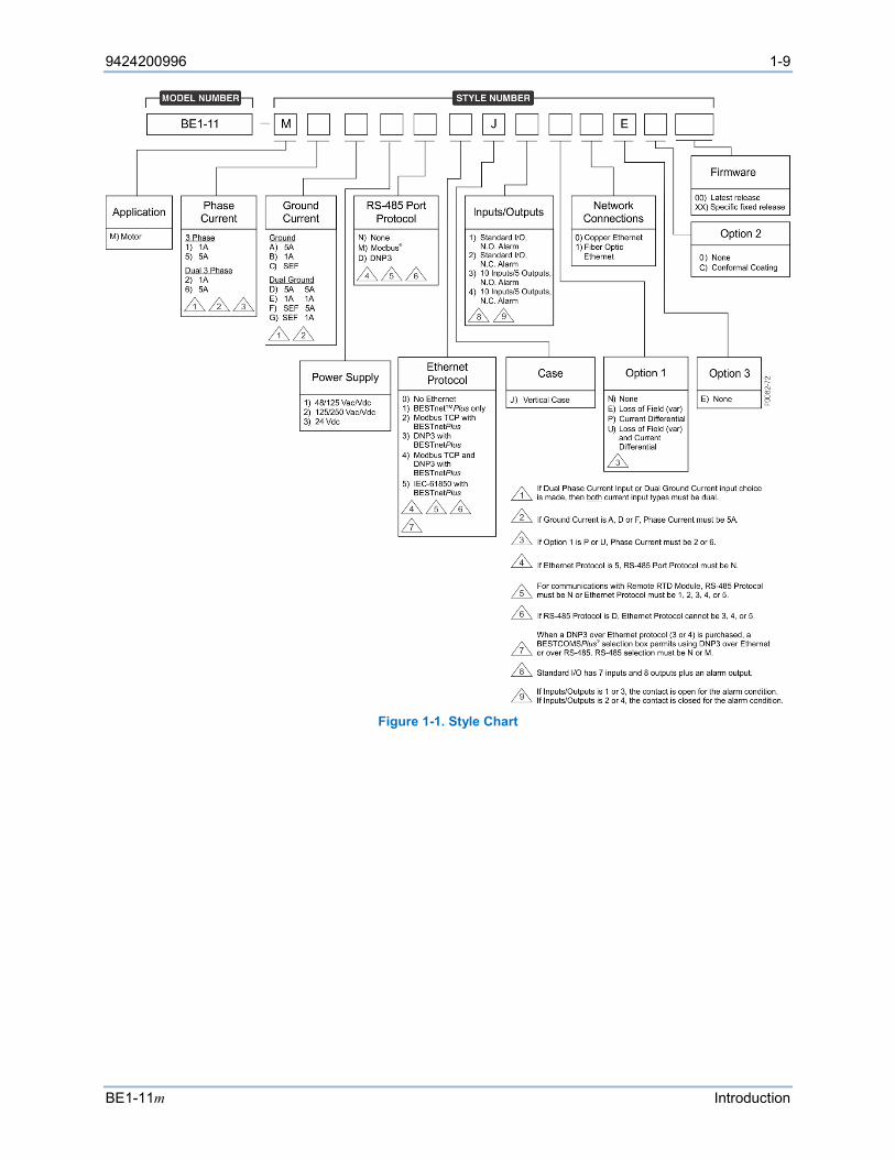
BE1-11m electrical characteristics and operational features are defined by a combination of letters and numbers that make up the style number. The style number describes the options included in a specific device and appears on labels located on the front panel and inside the case. Upon receipt of a BE1-11m, be sure to check the style number against the requisition and the packing list to ensure that they agree. The model number and style number are shown in Figure 1-1.
9424200996 1-9
BE1-11m Introduction
Figure 1-1. Style Chart

1-10 9424200996
Introduction BE1-11m
9424200996 2-1
BE1-11m Quick Start
2 • Quick Start This chapter provides basic installation and setup information about the BE1-11m Motor Protection System. BE1-11m protection systems are delivered with a BE1-11 product CD. Upon receipt of the BE1-11m, check the model and style number against the requisition and packing list for agreement. If there is evidence of shipping damage, file a claim with the carrier, and notify the Basler Electric Regional Sales Office, your sales representative, or a sales representative at Basler Electric, Highland, Illinois.
If the BE1-11m is not installed immediately, store it in the original shipping carton in a moisture- and dust-free environment.
Included on the BE1-11 product CD: • BESTCOMSPlus® Software • BESTwave™ Software • BEST61850™ Software • Quick Start Guide • Instruction Manual • Modbus® Instruction Manual • DNP Instruction Manual • IEC 61850 Instruction Manual
Note Do not connect a USB cable between the PC and the BE1-11m until BESTCOMSPlus is installed. Connecting a USB cable before setup is complete may result in errors.
Maintenance
Preventive maintenance consists of periodic replacement of the backup battery and periodically checking that the connections between the BE1-11m and the system are clean and tight. The front cover should be removed only when replacing the backup battery for the real-time clock. Ensure that the BE1-11m is powered off and taken out of service before removing the front cover. BE1-11m units are manufactured using state-of-the-art, surface-mount technology. As such, Basler Electric recommends that no repair procedures be attempted by anyone other than Basler Electric personnel.
Storage
This device contains long-life aluminum electrolytic capacitors. For devices that are not in service (spares in storage), the life of these capacitors can be maximized by energizing the device for 30 minutes once per year.
Install BESTCOMSPlus® Software
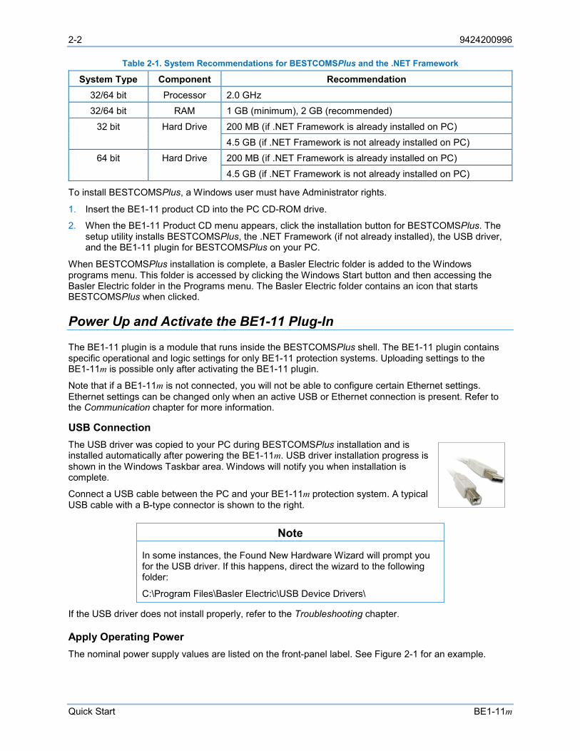
BESTCOMSPlus software is built on the Microsoft® .NET Framework. The setup utility that installs BESTCOMSPlus on your PC also installs the BE1-11 plugin and the required version of .NET Framework (if not already installed). BESTCOMSPlus operates with systems using Windows® 7 SP1, Windows 8.1, and Windows 10 version 1607 (Anniversary Edition) or later. System recommendations for the .NET Framework and BESTCOMSPlus are listed in Table 2-1.
2-2 9424200996
Quick Start BE1-11m
Table 2-1. System Recommendations for BESTCOMSPlus and the .NET Framework
System Type Component Recommendation 32/64 bit Processor 2.0 GHz 32/64 bit RAM 1 GB (minimum), 2 GB (recommended)
32 bit Hard Drive 200 MB (if .NET Framework is already installed on PC) 4.5 GB (if .NET Framework is not already installed on PC)
64 bit Hard Drive 200 MB (if .NET Framework is already installed on PC)
4.5 GB (if .NET Framework is not already installed on PC)
To install BESTCOMSPlus, a Windows user must have Administrator rights.
1. Insert the BE1-11 product CD into the PC CD-ROM drive.
2. When the BE1-11 Product CD menu appears, click the installation button for BESTCOMSPlus. The setup utility installs BESTCOMSPlus, the .NET Framework (if not already installed), the USB driver, and the BE1-11 plugin for BESTCOMSPlus on your PC.
When BESTCOMSPlus installation is complete, a Basler Electric folder is added to the Windows programs menu. This folder is accessed by clicking the Windows Start button and then accessing the Basler Electric folder in the Programs menu. The Basler Electric folder contains an icon that starts BESTCOMSPlus when clicked.
Power Up and Activate the BE1-11 Plug-In
The BE1-11 plugin is a module that runs inside the BESTCOMSPlus shell. The BE1-11 plugin contains specific operational and logic settings for only BE1-11 protection systems. Uploading settings to the BE1-11m is possible only after activating the BE1-11 plugin.
Note that if a BE1-11m is not connected, you will not be able to configure certain Ethernet settings. Ethernet settings can be changed only when an active USB or Ethernet connection is present. Refer to the Communication chapter for more information.
USB Connection The USB driver was copied to your PC during BESTCOMSPlus installation and is installed automatically after powering the BE1-11m. USB driver installation progress is shown in the Windows Taskbar area. Windows will notify you when installation is complete.
Connect a USB cable between the PC and your BE1-11m protection system. A typical USB cable with a B-type connector is shown to the right.
Note
In some instances, the Found New Hardware Wizard will prompt you for the USB driver. If this happens, direct the wizard to the following folder:
C:\Program Files\Basler Electric\USB Device Drivers\
If the USB driver does not install properly, refer to the Troubleshooting chapter.
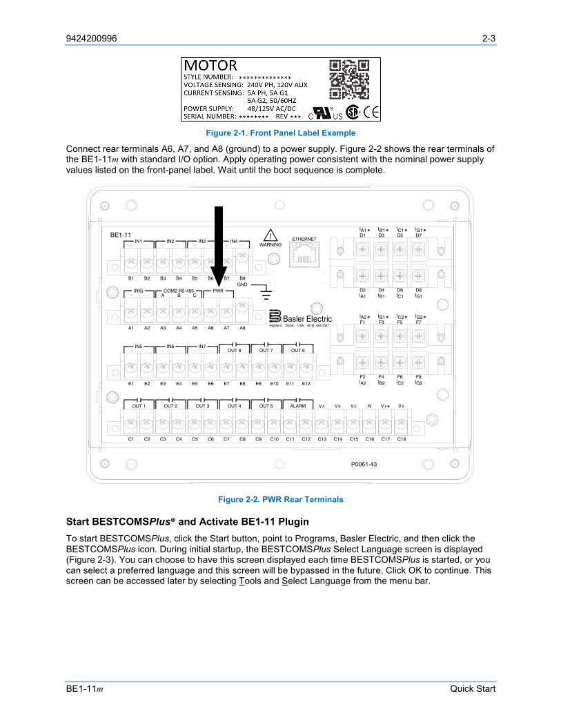
Apply Operating Power The nominal power supply values are listed on the front-panel label. See Figure 2-1 for an example.
9424200996 2-3
BE1-11m Quick Start
Figure 2-1. Front Panel Label Example
Connect rear terminals A6, A7, and A8 (ground) to a power supply. Figure 2-2 shows the rear terminals of the BE1-11m with standard I/O option. Apply operating power consistent with the nominal power supply values listed on the front-panel label. Wait until the boot sequence is complete.
Figure 2-2. PWR Rear Terminals
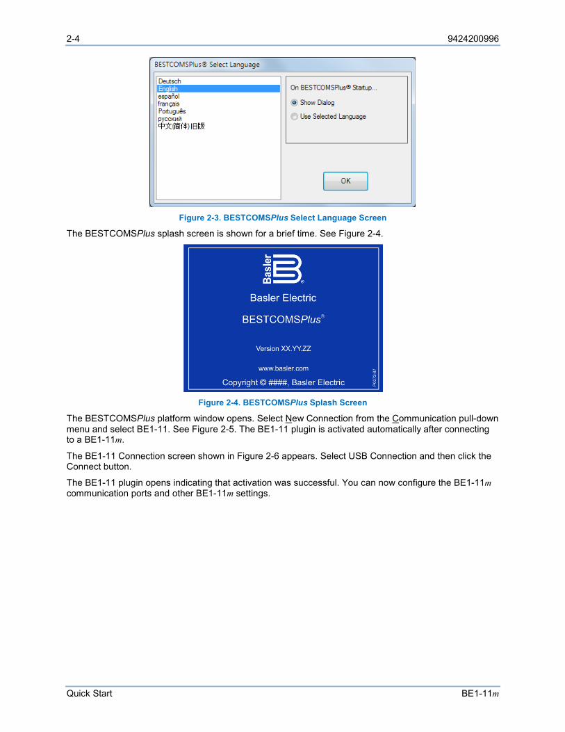
Start BESTCOMSPlus® and Activate BE1-11 Plugin To start BESTCOMSPlus, click the Start button, point to Programs, Basler Electric, and then click the BESTCOMSPlus icon. During initial startup, the BESTCOMSPlus Select Language screen is displayed (Figure 2-3). You can choose to have this screen displayed each time BESTCOMSPlus is started, or you can select a preferred language and this screen will be bypassed in the future. Click OK to continue. This screen can be accessed later by selecting Tools and Select Language from the menu bar.
ETHERNET!WARNING
BE1-11
C12C11C10C9C8C7C6C5C4C3C2C1 C13 C14 C15 C16 C17 C18
V AOUT 2 OUT 3 OUT 4 OUT 5OUT 1 ALARM V B VC V XV XN
E12E11E10E9E8E7E6E5E4E3E2E1
OUT 8 OUT 7IN5 IN6 IN7
OUT 6
A8A7A6A5A4A3A2A1
IRIG PWRCA B
COM2 RS-485GNDB8B7B6B5B4B3B2B1
IN1 IN2 IN3 IN4D1 D3 D5 D7IA1 IB1 IC1 IG1
IA1D2 D4 D6 D8
IB1 IC1 IG1
IA2F2 F4 F6 F8
IB2 IC2 IG2
F1 F3 F5 F7IA2 IB1 IC2 IG2
P0061-43
2-4 9424200996
Quick Start BE1-11m
Figure 2-3. BESTCOMSPlus Select Language Screen
The BESTCOMSPlus splash screen is shown for a brief time. See Figure 2-4.
Figure 2-4. BESTCOMSPlus Splash Screen
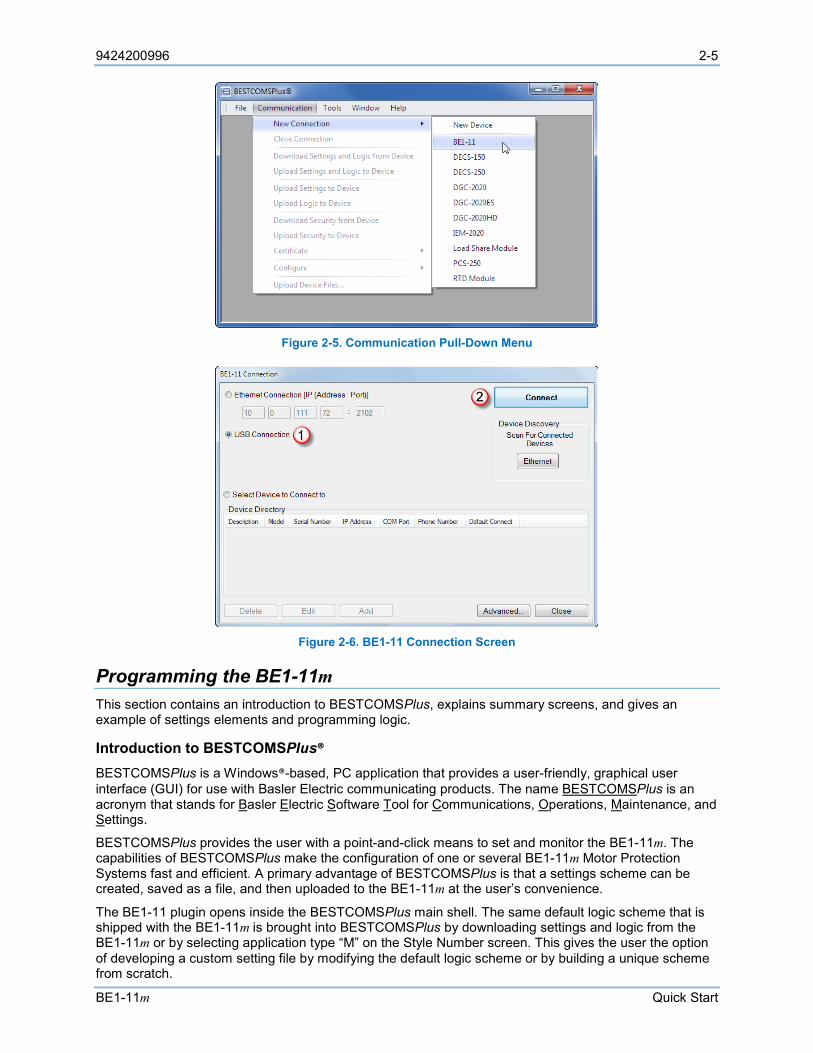
The BESTCOMSPlus platform window opens. Select New Connection from the Communication pull-down menu and select BE1-11. See Figure 2-5. The BE1-11 plugin is activated automatically after connecting to a BE1-11m.
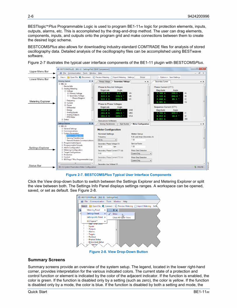
The BE1-11 Connection screen shown in Figure 2-6 appears. Select USB Connection and then click the Connect button.
The BE1-11 plugin opens indicating that activation was successful. You can now configure the BE1-11m communication ports and other BE1-11m settings.
9424200996 2-5
BE1-11m Quick Start
Figure 2-5. Communication Pull-Down Menu
Figure 2-6. BE1-11 Connection Screen
Programming the BE1-11m This section contains an introduction to BESTCOMSPlus, explains summary screens, and gives an example of settings elements and programming logic.
Introduction to BESTCOMSPlus® BESTCOMSPlus is a Windows®-based, PC application that provides a user-friendly, graphical user interface (GUI) for use with Basler Electric communicating products. The name BESTCOMSPlus is an acronym that stands for Basler Electric Software Tool for Communications, Operations, Maintenance, and Settings.
BESTCOMSPlus provides the user with a point-and-click means to set and monitor the BE1-11m. The capabilities of BESTCOMSPlus make the configuration of one or several BE1-11m Motor Protection Systems fast and efficient. A primary advantage of BESTCOMSPlus is that a settings scheme can be created, saved as a file, and then uploaded to the BE1-11m at the user’s convenience.
The BE1-11 plugin opens inside the BESTCOMSPlus main shell. The same default logic scheme that is shipped with the BE1-11m is brought into BESTCOMSPlus by downloading settings and logic from the BE1-11m or by selecting application type “M” on the Style Number screen. This gives the user the option of developing a custom setting file by modifying the default logic scheme or by building a unique scheme from scratch.
2-6 9424200996
Quick Start BE1-11m
BESTlogic™Plus Programmable Logic is used to program BE1-11m logic for protection elements, inputs, outputs, alarms, etc. This is accomplished by the drag-and-drop method. The user can drag elements, components, inputs, and outputs onto the program grid and make connections between them to create the desired logic scheme.
BESTCOMSPlus also allows for downloading industry-standard COMTRADE files for analysis of stored oscillography data. Detailed analysis of the oscillography files can be accomplished using BESTwave software.
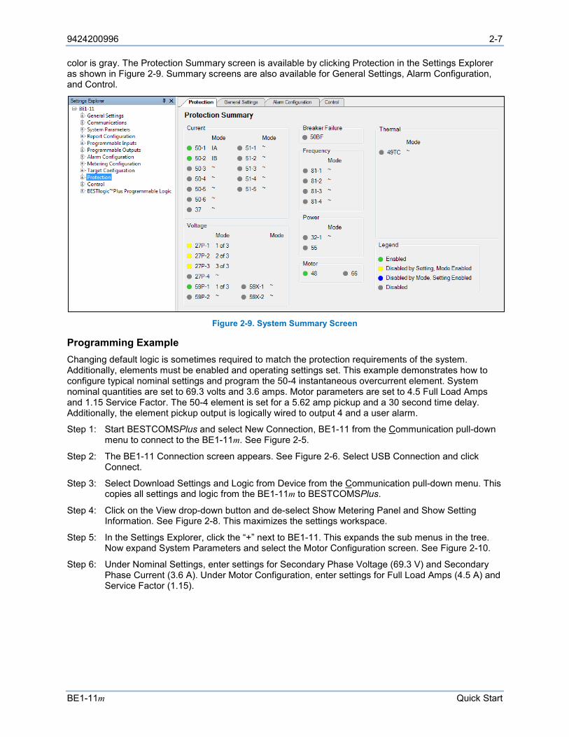
Figure 2-7 illustrates the typical user interface components of the BE1-11 plugin with BESTCOMSPlus.
Figure 2-7. BESTCOMSPlus Typical User Interface Components
Click the View drop-down button to switch between the Settings Explorer and Metering Explorer or split the view between both. The Settings Info Panel displays settings ranges. A workspace can be opened, saved, or set as default. See Figure 2-8.
Figure 2-8. View Drop-Down Button
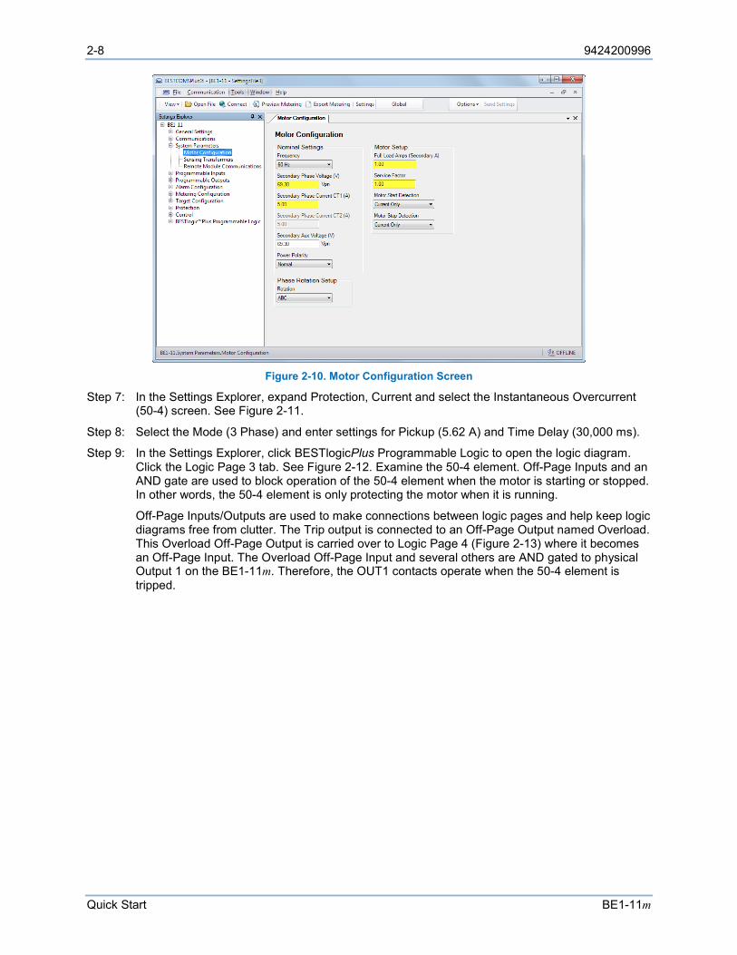
Summary Screens Summary screens provide an overview of the system setup. The legend, located in the lower right-hand corner, provides interpretation for the various indicated colors. The current state of a protection and control function or element is indicated by the color of the adjacent indicator. If the function is enabled, the color is green. If the function is disabled only by a setting (such as zero), the color is yellow. If the function is disabled only by a mode, the color is blue. If the function is disabled by both a setting and mode, the
9424200996 2-7
BE1-11m Quick Start
color is gray. The Protection Summary screen is available by clicking Protection in the Settings Explorer as shown in Figure 2-9. Summary screens are also available for General Settings, Alarm Configuration, and Control.
Figure 2-9. System Summary Screen
Programming Example Changing default logic is sometimes required to match the protection requirements of the system. Additionally, elements must be enabled and operating settings set. This example demonstrates how to configure typical nominal settings and program the 50-4 instantaneous overcurrent element. System nominal quantities are set to 69.3 volts and 3.6 amps. Motor parameters are set to 4.5 Full Load Amps and 1.15 Service Factor. The 50-4 element is set for a 5.62 amp pickup and a 30 second time delay. Additionally, the element pickup output is logically wired to output 4 and a user alarm.
Step 1: Start BESTCOMSPlus and select New Connection, BE1-11 from the Communication pull-down menu to connect to the BE1-11m. See Figure 2-5.
Step 2: The BE1-11 Connection screen appears. See Figure 2-6. Select USB Connection and click Connect.
Step 3: Select Download Settings and Logic from Device from the Communication pull-down menu. This copies all settings and logic from the BE1-11m to BESTCOMSPlus.
Step 4: Click on the View drop-down button and de-select Show Metering Panel and Show Setting Information. See Figure 2-8. This maximizes the settings workspace.
Step 5: In the Settings Explorer, click the “+” next to BE1-11. This expands the sub menus in the tree. Now expand System Parameters and select the Motor Configuration screen. See Figure 2-10.
Step 6: Under Nominal Settings, enter settings for Secondary Phase Voltage (69.3 V) and Secondary Phase Current (3.6 A). Under Motor Configuration, enter settings for Full Load Amps (4.5 A) and Service Factor (1.15).
2-8 9424200996
Quick Start BE1-11m
Figure 2-10. Motor Configuration Screen
Step 7: In the Settings Explorer, expand Protection, Current and select the Instantaneous Overcurrent (50-4) screen. See Figure 2-11.
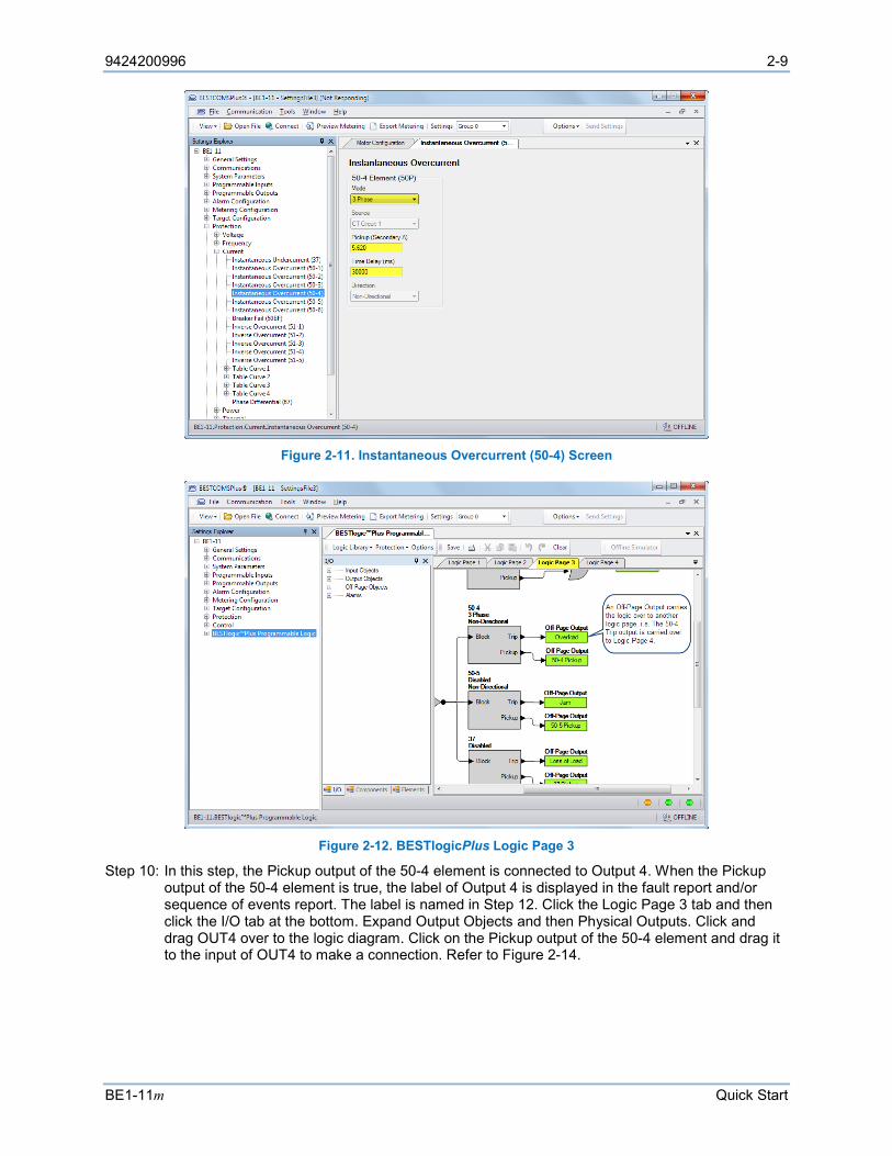
Step 8: Select the Mode (3 Phase) and enter settings for Pickup (5.62 A) and Time Delay (30,000 ms).
Step 9: In the Settings Explorer, click BESTlogicPlus Programmable Logic to open the logic diagram. Click the Logic Page 3 tab. See Figure 2-12. Examine the 50-4 element. Off-Page Inputs and an AND gate are used to block operation of the 50-4 element when the motor is starting or stopped. In other words, the 50-4 element is only protecting the motor when it is running.
Off-Page Inputs/Outputs are used to make connections between logic pages and help keep logic diagrams free from clutter. The Trip output is connected to an Off-Page Output named Overload. This Overload Off-Page Output is carried over to Logic Page 4 (Figure 2-13) where it becomes an Off-Page Input. The Overload Off-Page Input and several others are AND gated to physical Output 1 on the BE1-11m. Therefore, the OUT1 contacts operate when the 50-4 element is tripped.
9424200996 2-9
BE1-11m Quick Start
Figure 2-11. Instantaneous Overcurrent (50-4) Screen
Figure 2-12. BESTlogicPlus Logic Page 3
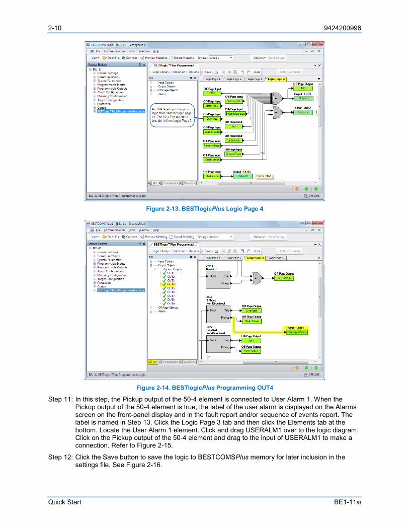
Step 10: In this step, the Pickup output of the 50-4 element is connected to Output 4. When the Pickup output of the 50-4 element is true, the label of Output 4 is displayed in the fault report and/or sequence of events report. The label is named in Step 12. Click the Logic Page 3 tab and then click the I/O tab at the bottom. Expand Output Objects and then Physical Outputs. Click and drag OUT4 over to the logic diagram. Click on the Pickup output of the 50-4 element and drag it to the input of OUT4 to make a connection. Refer to Figure 2-14.
2-10 9424200996
Quick Start BE1-11m
Figure 2-13. BESTlogicPlus Logic Page 4
Figure 2-14. BESTlogicPlus Programming OUT4
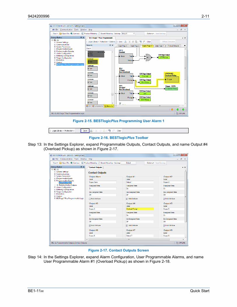
Step 11: In this step, the Pickup output of the 50-4 element is connected to User Alarm 1. When the Pickup output of the 50-4 element is true, the label of the user alarm is displayed on the Alarms screen on the front-panel display and in the fault report and/or sequence of events report. The label is named in Step 13. Click the Logic Page 3 tab and then click the Elements tab at the bottom. Locate the User Alarm 1 element. Click and drag USERALM1 over to the logic diagram. Click on the Pickup output of the 50-4 element and drag to the input of USERALM1 to make a connection. Refer to Figure 2-15.
Step 12: Click the Save button to save the logic to BESTCOMSPlus memory for later inclusion in the settings file. See Figure 2-16.
9424200996 2-11
BE1-11m Quick Start
Figure 2-15. BESTlogicPlus Programming User Alarm 1
Figure 2-16. BESTlogicPlus Toolbar
Step 13: In the Settings Explorer, expand Programmable Outputs, Contact Outputs, and name Output #4 (Overload Pickup) as shown in Figure 2-17.
Figure 2-17. Contact Outputs Screen
Step 14: In the Settings Explorer, expand Alarm Configuration, User Programmable Alarms, and name User Programmable Alarm #1 (Overload Pickup) as shown in Figure 2-18.

2-12 9424200996
Quick Start BE1-11m
Figure 2-18. User Programmable Alarms Screen
Step 15: Figure 2-19 shows the user-defined labels of OUT4 and USERALM1 that were named in Step 13 and Step 14.
Figure 2-19. OUT4 and USERALM1 with User-Defined Labels
Step 16: Select Save from the File pull-down menu to save your new settings file.
Step 17: To make your new settings active in the BE1-11m, select Upload Settings and Logic to Device from the Communication pull-down menu. Enter the username and password.
9424200996 3-1
BE1-11m Controls and Indicators
3 • Controls and Indicators BE1-11m controls and indicators are located on the front panel and include sealed membrane switches, LED (light emitting diode) indicator lamps, and a multiple-line, alphanumeric LCD (liquid crystal display).
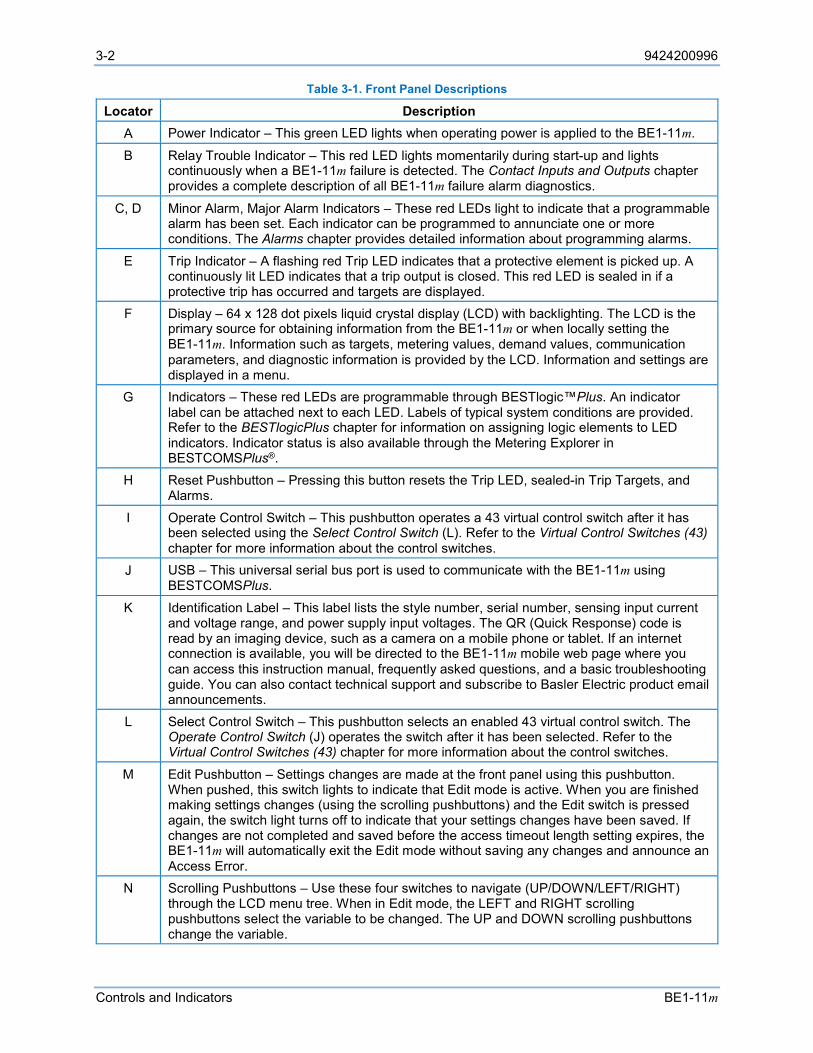
Illustrations and Descriptions
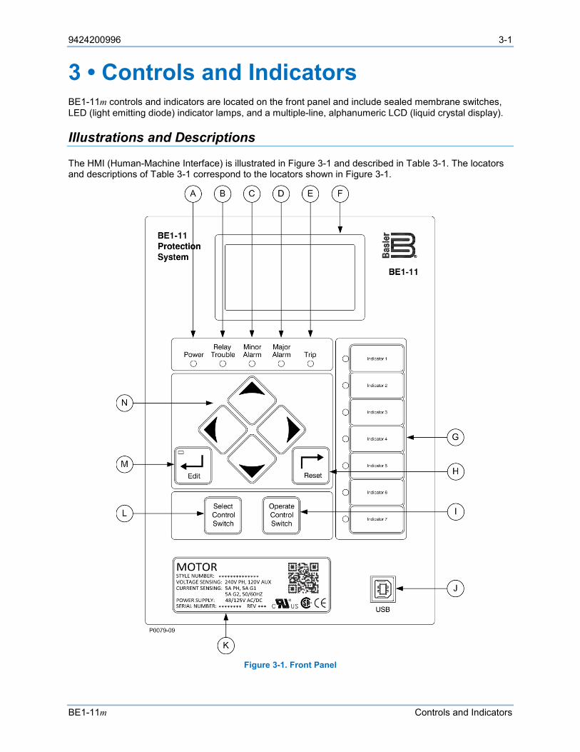
The HMI (Human-Machine Interface) is illustrated in Figure 3-1 and described in Table 3-1. The locators and descriptions of Table 3-1 correspond to the locators shown in Figure 3-1.
Figure 3-1. Front Panel
3-2 9424200996
Controls and Indicators BE1-11m
Table 3-1. Front Panel Descriptions
Locator Description A Power Indicator – This green LED lights when operating power is applied to the BE1-11m.
B Relay Trouble Indicator – This red LED lights momentarily during start-up and lights continuously when a BE1-11m failure is detected. The Contact Inputs and Outputs chapter provides a complete description of all BE1-11m failure alarm diagnostics.
C, D Minor Alarm, Major Alarm Indicators – These red LEDs light to indicate that a programmable alarm has been set. Each indicator can be programmed to annunciate one or more conditions. The Alarms chapter provides detailed information about programming alarms.
E Trip Indicator – A flashing red Trip LED indicates that a protective element is picked up. A continuously lit LED indicates that a trip output is closed. This red LED is sealed in if a protective trip has occurred and targets are displayed.
F Display – 64 x 128 dot pixels liquid crystal display (LCD) with backlighting. The LCD is the primary source for obtaining information from the BE1-11m or when locally setting the BE1-11m. Information such as targets, metering values, demand values, communication parameters, and diagnostic information is provided by the LCD. Information and settings are displayed in a menu.
G Indicators – These red LEDs are programmable through BESTlogic™Plus. An indicator label can be attached next to each LED. Labels of typical system conditions are provided. Refer to the BESTlogicPlus chapter for information on assigning logic elements to LED indicators. Indicator status is also available through the Metering Explorer in BESTCOMSPlus®.
H Reset Pushbutton – Pressing this button resets the Trip LED, sealed-in Trip Targets, and Alarms.
I Operate Control Switch – This pushbutton operates a 43 virtual control switch after it has been selected using the Select Control Switch (L). Refer to the Virtual Control Switches (43) chapter for more information about the control switches.
J USB – This universal serial bus port is used to communicate with the BE1-11m using BESTCOMSPlus.
K Identification Label – This label lists the style number, serial number, sensing input current and voltage range, and power supply input voltages. The QR (Quick Response) code is read by an imaging device, such as a camera on a mobile phone or tablet. If an internet connection is available, you will be directed to the BE1-11m mobile web page where you can access this instruction manual, frequently asked questions, and a basic troubleshooting guide. You can also contact technical support and subscribe to Basler Electric product email announcements.
L Select Control Switch – This pushbutton selects an enabled 43 virtual control switch. The Operate Control Switch (J) operates the switch after it has been selected. Refer to the Virtual Control Switches (43) chapter for more information about the control switches.
M Edit Pushbutton – Settings changes are made at the front panel using this pushbutton. When pushed, this switch lights to indicate that Edit mode is active. When you are finished making settings changes (using the scrolling pushbuttons) and the Edit switch is pressed again, the switch light turns off to indicate that your settings changes have been saved. If changes are not completed and saved before the access timeout length setting expires, the BE1-11m will automatically exit the Edit mode without saving any changes and announce an Access Error.
N Scrolling Pushbuttons – Use these four switches to navigate (UP/DOWN/LEFT/RIGHT) through the LCD menu tree. When in Edit mode, the LEFT and RIGHT scrolling pushbuttons select the variable to be changed. The UP and DOWN scrolling pushbuttons change the variable.
9424200996 3-3
BE1-11m Controls and Indicators
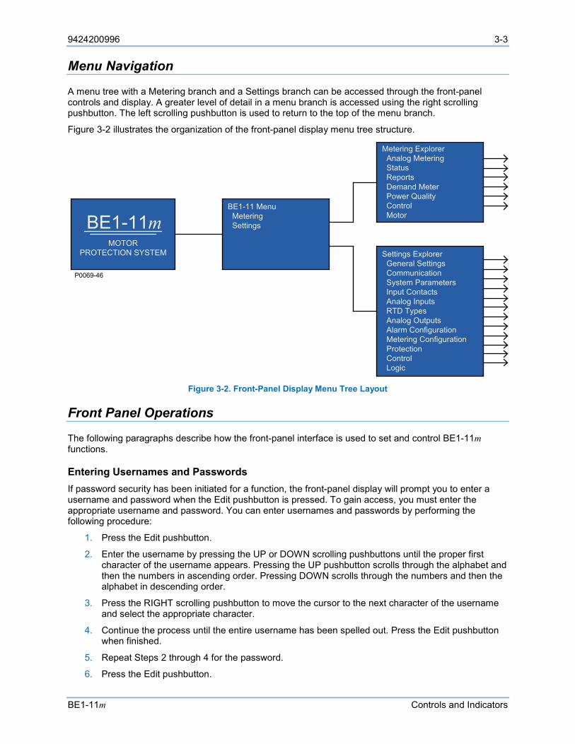
Menu Navigation
A menu tree with a Metering branch and a Settings branch can be accessed through the front-panel controls and display. A greater level of detail in a menu branch is accessed using the right scrolling pushbutton. The left scrolling pushbutton is used to return to the top of the menu branch.
Figure 3-2 illustrates the organization of the front-panel display menu tree structure.
Figure 3-2. Front-Panel Display Menu Tree Layout
Front Panel Operations
The following paragraphs describe how the front-panel interface is used to set and control BE1-11m functions.
Entering Usernames and Passwords If password security has been initiated for a function, the front-panel display will prompt you to enter a username and password when the Edit pushbutton is pressed. To gain access, you must enter the appropriate username and password. You can enter usernames and passwords by performing the following procedure:
1. Press the Edit pushbutton.
2. Enter the username by pressing the UP or DOWN scrolling pushbuttons until the proper first character of the username appears. Pressing the UP pushbutton scrolls through the alphabet and then the numbers in ascending order. Pressing DOWN scrolls through the numbers and then the alphabet in descending order.
3. Press the RIGHT scrolling pushbutton to move the cursor to the next character of the username and select the appropriate character.
4. Continue the process until the entire username has been spelled out. Press the Edit pushbutton when finished.
5. Repeat Steps 2 through 4 for the password.
6. Press the Edit pushbutton.
BE1-11mBE1-11 Menu Metering Settings
Metering Explorer Analog Metering Status Reports Demand Meter Power Quality Control Motor
P0069-46
Settings Explorer General Settings Communication System Parameters Input Contacts Analog Inputs RTD Types Analog Outputs Alarm Configuration Metering Configuration Protection Control Logic
MOTORPROTECTION SYSTEM
3-4 9424200996
Controls and Indicators BE1-11m
7. If the proper username and password have been entered, the screen will flash the type of access that has been granted. If an incorrect password has been entered, the screen will flash “Read Access”.
8. Once you gain access, it remains in effect until the access timeout length setting expires. As long as you continue to press the Edit key for a function for which you have gained access, the five-minute timer will be refreshed and you will not be prompted for a password.
To close access immediately, press the Reset button while any non-settings screen is displayed. The BE1-11m should flash “Read Only” on the LCD screen to indicate access through the front panel has been terminated.
Entering Settings Settings for protection functions can be edited by using the RIGHT, LEFT, UP, and DOWN front-panel navigation keys. Navigate to Settings > Protection.
To edit a setting using the manual scrolling pushbuttons, perform the following procedures:
1. After scrolling to the desired settings group and element category, scroll to the screen that displays the function to be edited.
2. Press the Edit pushbutton to gain access. If password security has been initiated for settings, you will be prompted to enter the appropriate username and password. See the paragraphs, Entering Usernames and Passwords, for details on entering usernames and passwords from the front panel. Once access has been gained, the Edit LED will be lit and a cursor will appear in the first settings field on the screen.
3. Press the UP or DOWN scrolling key to select the desired setting. Some settings must be entered one character at a time. For example, to enter a 51-1 pickup as 7.3 amps, you would place the cursor in the Pickup field and press the UP pushbutton until the 7 is showing. Then press the RIGHT pushbutton to move the cursor over to the right side of the decimal and press the UP pushbutton until the 3 is showing. Other settings require scrolling through a list of selections. For example, you would move the cursor over to the Curve Index field and then scroll through a list of available time characteristic curves.
4. Once all of the settings on the screen have been entered, press the Edit pushbutton a second time and the settings will be validated. If the settings are in range, the Edit LED will go out. If you want to abort the edit session without changing any settings, press the Reset pushbutton before you press the Edit pushbutton the second time. The Edit LED will go out.
Performing Control Operations Control operations can be executed by navigating to Metering, Control. These functions allow you to control the state of virtual switches, override logic, control the active setting group, and control the state of output contacts. All of these functions work similarly to the process of entering settings in that you press the Edit pushbutton for the action to be executed.
To operate the switch, use the following procedure:
1. Use the scrolling pushbuttons to scroll to Settings > Control > Virtual Switch 43 > 43-1 and verify that the 43-1 is set for Switch/Pulse mode.
2. Use the scrolling pushbuttons to scroll to Metering > Control > Virtual Switches > 43-1 > Operate.
3. Press the Edit pushbutton to gain access. If password security has been initiated for control functions, you will be prompted to enter the appropriate username and password. Once access is gained to the control function, press the Edit pushbutton and the Edit LED will light.
4. Press the UP or DOWN scrolling key to select the new state for the switch. The “Pulse” selection will pulse the state of the switch from its present state to the opposite state for approximately 200 milliseconds. The “Set” selection will set the state of the switch to true. The “Reset” selection will set the state of the switch to false. The allowable states are dependent upon the logic mode setting for the switch. If the switch is set to Switch mode, only the “Set” and “Reset” will function.
9424200996 3-5
BE1-11m Controls and Indicators
If the switch is set to Pulse mode, only the “Pulse” selection will function. If the switch is set to Switch/Pulse mode, any of the selections will function.
5. Press the Edit pushbutton a second time and the switch will change to the selected position and the Edit LED will go out. If you want to abort the editing session without changing any controls, press the Reset pushbutton before you press the Edit pushbutton the second time. The Edit LED will go out.
Resetting Functions The Reset pushbutton is context sensitive. Its function is dependent upon the screen that is presently being displayed. For example, pressing the Reset key when Targets screen is displayed will reset the targets, but it will not reset the alarms, etc. It is necessary to scroll through the menu tree to the appropriate alarm screen to reset an alarm. You are prompted for a username and password when using the Reset key.
Display Setup
BESTCOMSPlus Navigation Path: Settings Explorer, General Settings, Front Panel HMI
HMI Navigation Path: Settings Explorer, Control, General Settings, Front Panel HMI
Front-panel display settings are described in the following paragraphs. The BESTCOMSPlus Front Panel HMI screen is illustrated in Figure 3-3.
LCD Setup The contrast of the front-panel LCD (liquid crystal display) can be adjusted to suit the viewing angle used or compensate for environmental conditions. When Invert Display is enabled, the display is inverted to have blue letters on a white background.
Sleep Mode Setup A power saving feature, referred to as Sleep mode, will dim the front-panel LCD backlight when a front-panel key is not pressed for more than the user settable time delay. Normal display operation is resumed when any front-panel button is pressed. Sleep mode is enabled and disabled in BESTCOMSPlus.
Language Setup The language can be set for English or Russian. Language changes will affect the front-panel LCD, sequence of events, fault reports, oscillography reports, load profile, and web pages.
Screen Scrolling Setup When Screen Scrolling is enabled, the front-panel summary screen will scroll through the list of Scrolling Screen items. The Scroll Time Delay determines the scrolling speed. The Show Splash Screen setting allows the splash screen to be shown or hidden from screen scrolling. When screen scrolling is enabled and no screens are selected, the splash screen is displayed even if the Show Splash Screen setting is disabled. Scrolling screen items can only be selected in BESTCOMSPlus.
Targets and alarms are automatically displayed on the front-panel LCD when they become active if on the splash screen. After targets and alarms are reset, the BE1-11m returns to the main screen and begins scrolling if scrolling is enabled. Press the RIGHT navigation key to access the menu when targets and alarms are being displayed.
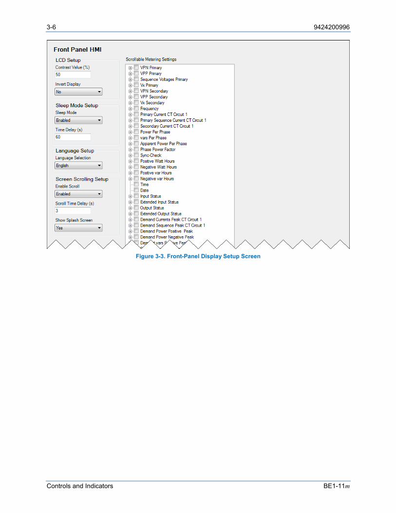
3-6 9424200996
Controls and Indicators BE1-11m
Figure 3-3. Front-Panel Display Setup Screen
9424200996 4-1
BE1-11m Contact Inputs and Outputs
4 • Contact Inputs and Outputs BE1-11m Motor Protection Systems provide seven contact inputs, eight general-purpose contact outputs, and one dedicated fail-safe alarm contact output. Each input and output is isolated and terminated at separate terminals. This section describes the function and setup of each input and output.
Contact-Sensing Inputs
Either seven or 10 contact inputs are available to initiate BE1-11m protection system actions. Refer to the style chart for I/O options. Each isolated input requires an external wetting voltage. The nominal voltage(s) of the external dc source(s) must fall within the BE1-11m dc power supply input voltage range. To enhance user flexibility, the BE1-11m protection system uses wide-range ac/dc power supplies that cover several common control voltage ratings. To enhance flexibility, the input circuits are designed to respond to voltages at the lower end of the control voltage range while not overheating at the high end of the control voltage range.
The contact input circuits are polarity sensitive. When an ac wetting voltage is applied, the input signal is half-wave rectified by the opto-isolator diodes. The contact inputs drive BESTlogic™Plus variables IN1 through IN10. Each contact input is completely programmable so meaningful labels can be assigned to each input and the logic-high and logic-low states. The BESTlogicPlus chapter provides more information about using contact inputs in your programmable logic scheme.
Contact-Sensing Input Jumpers
Note The BE1-11m protection system is delivered with the jumpers in the HIGH position. Read the following paragraphs before placing the BE1-11m in service.
Energizing levels for the contact-sensing inputs are jumper selectable for a minimum of approximately 5 Vdc for 24 Vdc nominal sensing voltages, 26 Vdc for 48 Vdc nominal sensing voltages, or 69 Vdc for 125 Vdc nominal sensing voltages. See Table 4-1 for the contact-sensing turn-on voltages.
Table 4-1. Contact-Sensing Turn-On Voltages
Style Option Nominal Input Voltage Contact Sensing Turn-On Voltage *
Jumper Installed (Low Position)
Jumper Not Installed (High Position)
Mxx1xxxxxxxxxx 48 Vdc or 125 Vac/dc 26 to 38 Vdc 69 to 100 Vdc 56 to 97 Vac
Mxx2xxxxxxxxxx 125/250 Vac/dc 69 to 100 Vdc 56 to 97 Vac
138 to 200 Vdc 112 to 194 Vac
Mxx3xxxxxxxxxx 24 Vdc n/a Approx. 5 Vdc
* AC voltage ranges are calculated using the default recognition time (4 ms) and debounce time (16 ms).
Each BE1-11m is delivered with the contact-sensing jumpers disconnected for operation in the higher end of the control voltage range. If the contact-sensing inputs are to be operated at the lower end of the control voltage range, the jumpers must be installed.
The following paragraphs describe how to locate and remove/change the contact-sensing input jumpers:
1. Remove the BE1-11m from service and de-energize it.
2. The contact-sensing input jumpers are located behind the rear terminal blocks that are used for input connections. Using a 7/64” hex tool, remove the rear terminal block(s) associated with the
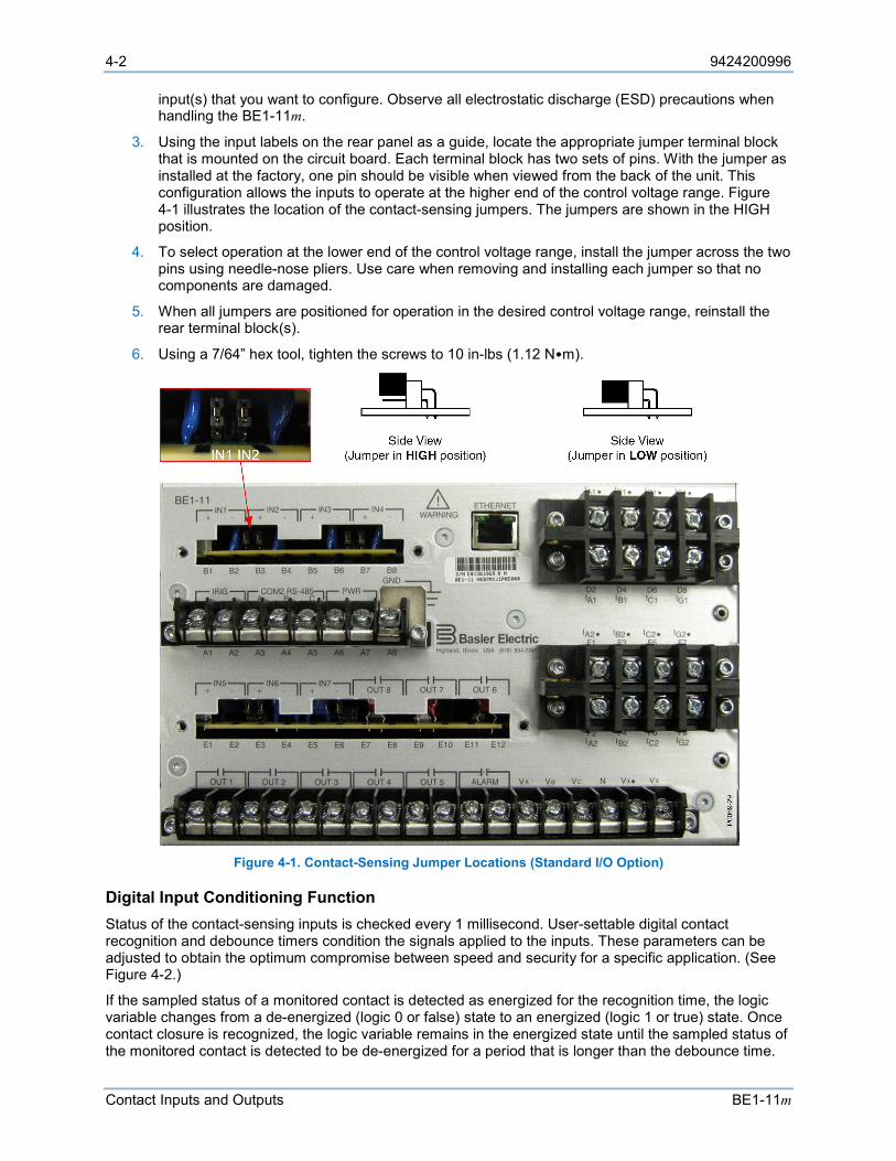
4-2 9424200996
Contact Inputs and Outputs BE1-11m
input(s) that you want to configure. Observe all electrostatic discharge (ESD) precautions when handling the BE1-11m.
3. Using the input labels on the rear panel as a guide, locate the appropriate jumper terminal block that is mounted on the circuit board. Each terminal block has two sets of pins. With the jumper as installed at the factory, one pin should be visible when viewed from the back of the unit. This configuration allows the inputs to operate at the higher end of the control voltage range. Figure 4-1 illustrates the location of the contact-sensing jumpers. The jumpers are shown in the HIGH position.
4. To select operation at the lower end of the control voltage range, install the jumper across the two pins using needle-nose pliers. Use care when removing and installing each jumper so that no components are damaged.
5. When all jumpers are positioned for operation in the desired control voltage range, reinstall the rear terminal block(s).
6. Using a 7/64” hex tool, tighten the screws to 10 in-lbs (1.12 N•m).
Figure 4-1. Contact-Sensing Jumper Locations (Standard I/O Option)
Digital Input Conditioning Function Status of the contact-sensing inputs is checked every 1 millisecond. User-settable digital contact recognition and debounce timers condition the signals applied to the inputs. These parameters can be adjusted to obtain the optimum compromise between speed and security for a specific application. (See Figure 4-2.)
If the sampled status of a monitored contact is detected as energized for the recognition time, the logic variable changes from a de-energized (logic 0 or false) state to an energized (logic 1 or true) state. Once contact closure is recognized, the logic variable remains in the energized state until the sampled status of the monitored contact is detected to be de-energized for a period that is longer than the debounce time.
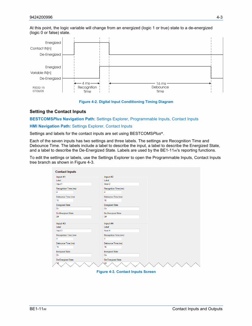
9424200996 4-3
BE1-11m Contact Inputs and Outputs
At this point, the logic variable will change from an energized (logic 1 or true) state to a de-energized (logic 0 or false) state.
Figure 4-2. Digital Input Conditioning Timing Diagram
Setting the Contact Inputs BESTCOMSPlus Navigation Path: Settings Explorer, Programmable Inputs, Contact Inputs
HMI Navigation Path: Settings Explorer, Contact Inputs
Settings and labels for the contact inputs are set using BESTCOMSPlus®.
Each of the seven inputs has two settings and three labels. The settings are Recognition Time and Debounce Time. The labels include a label to describe the input, a label to describe the Energized State, and a label to describe the De-Energized State. Labels are used by the BE1-11m's reporting functions.
To edit the settings or labels, use the Settings Explorer to open the Programmable Inputs, Contact Inputs tree branch as shown in Figure 4-3.
Figure 4-3. Contact Inputs Screen
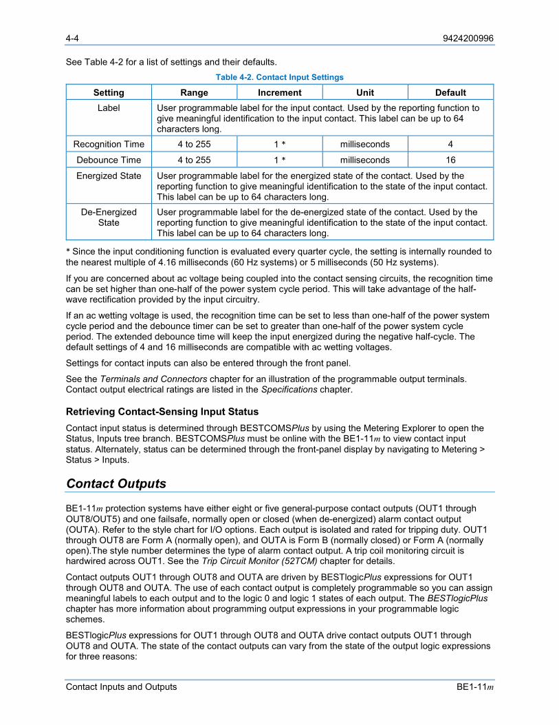
4-4 9424200996
Contact Inputs and Outputs BE1-11m
See Table 4-2 for a list of settings and their defaults. Table 4-2. Contact Input Settings
Setting Range Increment Unit Default Label User programmable label for the input contact. Used by the reporting function to
give meaningful identification to the input contact. This label can be up to 64 characters long.
Recognition Time 4 to 255 1 * milliseconds 4
Debounce Time 4 to 255 1 * milliseconds 16
Energized State User programmable label for the energized state of the contact. Used by the reporting function to give meaningful identification to the state of the input contact. This label can be up to 64 characters long.
De-Energized State
User programmable label for the de-energized state of the contact. Used by the reporting function to give meaningful identification to the state of the input contact. This label can be up to 64 characters long.
* Since the input conditioning function is evaluated every quarter cycle, the setting is internally rounded to the nearest multiple of 4.16 milliseconds (60 Hz systems) or 5 milliseconds (50 Hz systems).
If you are concerned about ac voltage being coupled into the contact sensing circuits, the recognition time can be set higher than one-half of the power system cycle period. This will take advantage of the half-wave rectification provided by the input circuitry.
If an ac wetting voltage is used, the recognition time can be set to less than one-half of the power system cycle period and the debounce timer can be set to greater than one-half of the power system cycle period. The extended debounce time will keep the input energized during the negative half-cycle. The default settings of 4 and 16 milliseconds are compatible with ac wetting voltages.
Settings for contact inputs can also be entered through the front panel.
See the Terminals and Connectors chapter for an illustration of the programmable output terminals. Contact output electrical ratings are listed in the Specifications chapter.
Retrieving Contact-Sensing Input Status Contact input status is determined through BESTCOMSPlus by using the Metering Explorer to open the Status, Inputs tree branch. BESTCOMSPlus must be online with the BE1-11m to view contact input status. Alternately, status can be determined through the front-panel display by navigating to Metering > Status > Inputs.
Contact Outputs
BE1-11m protection systems have either eight or five general-purpose contact outputs (OUT1 through OUT8/OUT5) and one failsafe, normally open or closed (when de-energized) alarm contact output (OUTA). Refer to the style chart for I/O options. Each output is isolated and rated for tripping duty. OUT1 through OUT8 are Form A (normally open), and OUTA is Form B (normally closed) or Form A (normally open).The style number determines the type of alarm contact output. A trip coil monitoring circuit is hardwired across OUT1. See the Trip Circuit Monitor (52TCM) chapter for details.
Contact outputs OUT1 through OUT8 and OUTA are driven by BESTlogicPlus expressions for OUT1 through OUT8 and OUTA. The use of each contact output is completely programmable so you can assign meaningful labels to each output and to the logic 0 and logic 1 states of each output. The BESTlogicPlus chapter has more information about programming output expressions in your programmable logic schemes.
BESTlogicPlus expressions for OUT1 through OUT8 and OUTA drive contact outputs OUT1 through OUT8 and OUTA. The state of the contact outputs can vary from the state of the output logic expressions for three reasons:
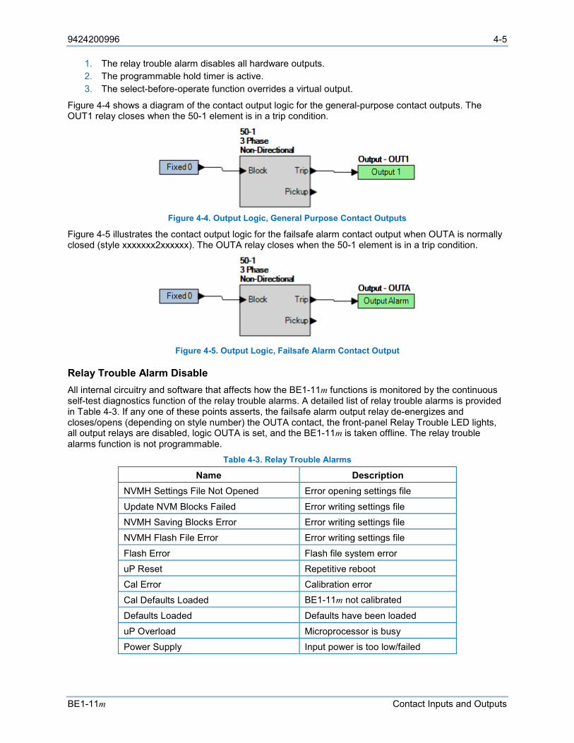
9424200996 4-5
BE1-11m Contact Inputs and Outputs
1. The relay trouble alarm disables all hardware outputs. 2. The programmable hold timer is active. 3. The select-before-operate function overrides a virtual output.
Figure 4-4 shows a diagram of the contact output logic for the general-purpose contact outputs. The OUT1 relay closes when the 50-1 element is in a trip condition.
Figure 4-4. Output Logic, General Purpose Contact Outputs
Figure 4-5 illustrates the contact output logic for the failsafe alarm contact output when OUTA is normally closed (style xxxxxxx2xxxxxx). The OUTA relay closes when the 50-1 element is in a trip condition.
Figure 4-5. Output Logic, Failsafe Alarm Contact Output
Relay Trouble Alarm Disable All internal circuitry and software that affects how the BE1-11m functions is monitored by the continuous self-test diagnostics function of the relay trouble alarms. A detailed list of relay trouble alarms is provided in Table 4-3. If any one of these points asserts, the failsafe alarm output relay de-energizes and closes/opens (depending on style number) the OUTA contact, the front-panel Relay Trouble LED lights, all output relays are disabled, logic OUTA is set, and the BE1-11m is taken offline. The relay trouble alarms function is not programmable.
Table 4-3. Relay Trouble Alarms
Name Description NVMH Settings File Not Opened Error opening settings file Update NVM Blocks Failed Error writing settings file NVMH Saving Blocks Error Error writing settings file NVMH Flash File Error Error writing settings file Flash Error Flash file system error uP Reset Repetitive reboot Cal Error Calibration error Cal Defaults Loaded BE1-11m not calibrated Defaults Loaded Defaults have been loaded uP Overload Microprocessor is busy Power Supply Input power is too low/failed
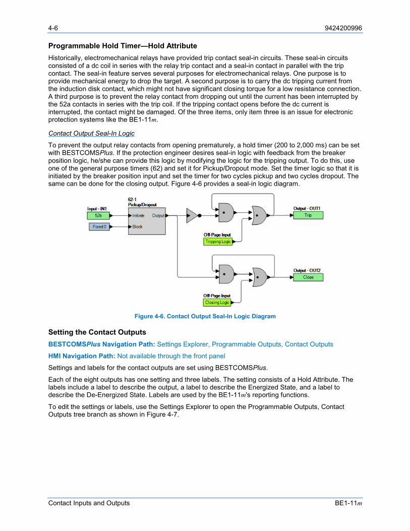
4-6 9424200996
Contact Inputs and Outputs BE1-11m
Programmable Hold Timer—Hold Attribute Historically, electromechanical relays have provided trip contact seal-in circuits. These seal-in circuits consisted of a dc coil in series with the relay trip contact and a seal-in contact in parallel with the trip contact. The seal-in feature serves several purposes for electromechanical relays. One purpose is to provide mechanical energy to drop the target. A second purpose is to carry the dc tripping current from the induction disk contact, which might not have significant closing torque for a low resistance connection. A third purpose is to prevent the relay contact from dropping out until the current has been interrupted by the 52a contacts in series with the trip coil. If the tripping contact opens before the dc current is interrupted, the contact might be damaged. Of the three items, only item three is an issue for electronic protection systems like the BE1-11m.
Contact Output Seal-In Logic
To prevent the output relay contacts from opening prematurely, a hold timer (200 to 2,000 ms) can be set with BESTCOMSPlus. If the protection engineer desires seal-in logic with feedback from the breaker position logic, he/she can provide this logic by modifying the logic for the tripping output. To do this, use one of the general purpose timers (62) and set it for Pickup/Dropout mode. Set the timer logic so that it is initiated by the breaker position input and set the timer for two cycles pickup and two cycles dropout. The same can be done for the closing output. Figure 4-6 provides a seal-in logic diagram.
Figure 4-6. Contact Output Seal-In Logic Diagram
Setting the Contact Outputs BESTCOMSPlus Navigation Path: Settings Explorer, Programmable Outputs, Contact Outputs
HMI Navigation Path: Not available through the front panel
Settings and labels for the contact outputs are set using BESTCOMSPlus.
Each of the eight outputs has one setting and three labels. The setting consists of a Hold Attribute. The labels include a label to describe the output, a label to describe the Energized State, and a label to describe the De-Energized State. Labels are used by the BE1-11m's reporting functions.
To edit the settings or labels, use the Settings Explorer to open the Programmable Outputs, Contact Outputs tree branch as shown in Figure 4-7.

9424200996 4-7
BE1-11m Contact Inputs and Outputs
Figure 4-7. Contact Outputs Screen
Contact Output Logic Override Control BESTCOMSPlus Navigation Path: Metering Explorer, Control, Output Override
HMI Navigation Path: Metering Explorer, Control, Output Override Contacts
Each contact output can be controlled directly using the select-before-operate output control function. The output logic expression that normally controls the state of an output can be overridden and the contact pulsed, held open, or held closed. This function is useful for testing purposes. An alarm point is available in the programmable alarm function for monitoring when the output logic has been overridden. See the Alarms chapter for more information about programmable alarms. Output logic override control is achieved using the front-panel interface or BESTCOMSPlus. Use the Metering Explorer to open the Control, Output Override screen. Refer to Figure 4-8.
Figure 4-8. Output Override Screen
Enabling Logic Override Control
By default, logic override control is disabled. Output logic override must be enabled before the control can be used. Enabling of the output logic override control is not possible at the front panel. It can only be enabled through a communication port using BESTCOMSPlus (Figure 4-8). Click on the Disabled button next to the output you want to control. This button will change to Enabled and the following three action choices will appear to the right: Reset, Set, and Pulse.
Pulsing a Contact Output
Pulsing BE1-11m outputs provides the user the ability to test the operability of an output without energizing a measuring or timing element. This feature is useful when testing the protection and control system. When pulsed, an output changes from the current state (as determined by the virtual output logic expression) to the opposite state for 200 milliseconds. After 200 milliseconds, the output is returned automatically to logic control.
4-8 9424200996
Contact Inputs and Outputs BE1-11m
In the Action column, select Pulse from the drop-down menu and click on the green arrow to the right. Pulse override control can also be accessed at the Metering > Control > Override Output Contacts screen of the front-panel display by selecting PUL in the Override State field for the output contact to be pulsed.
Changing the State of a Contact Output
Outputs can be forced to an energized (logic 1 or true) state or to a de-energized (logic 0 or false) state. This feature can be used to disable a contact during testing.
In the Action column, select Set or Reset from the drop-down menu and click on the green arrow to the right. Contact output override control can also be accessed at the Metering > Control > Override Output Contacts screen of the front-panel display by entering a SET (logic 1 or true) or RST (logic 0 or false) in the Override State field for the contact output to be controlled.
Returning a Contact Output to Logic Control
When the output logic has been overridden and the contact is held in an energized or de-energized state, it is necessary to return the output to logic control.
Click on the Enabled button next to the output you want to change to logic control. This button changes to Disabled and the action choices disappear. Logic control can also be achieved at the Metering > Control > Override Output Contacts screen of the front-panel display by setting Override Enable to Disabled.
See the Terminals and Connectors chapter for an illustration of the programmable output terminals. Contact output electrical ratings are listed in the Specifications chapter.
Retrieving Contact Output Status Output status is determined through BESTCOMSPlus by using the Metering Explorer to open the Status/Outputs tree branch. BESTCOMSPlus must be online with the BE1-11m to view contact output status. Alternately, status can be determined through the front-panel display by navigating to Metering > Status > Outputs.
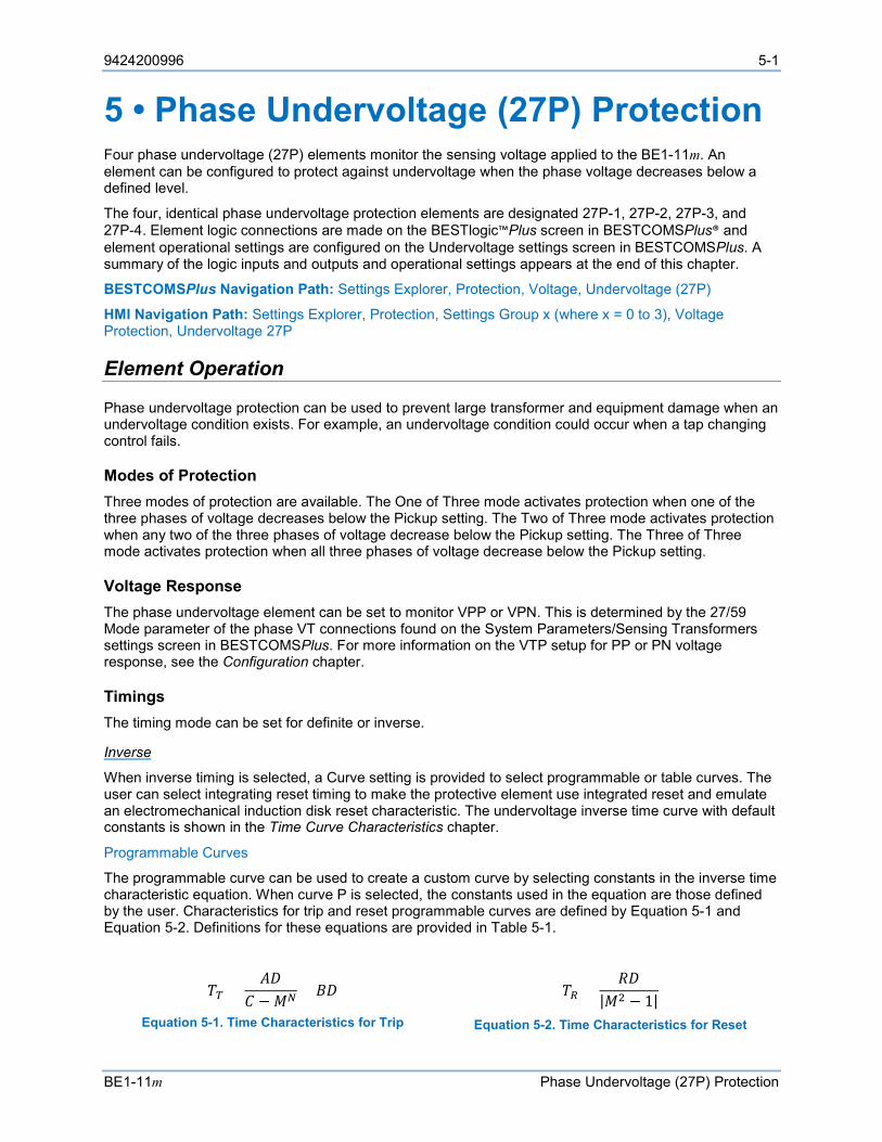
9424200996 5-1
BE1-11m Phase Undervoltage (27P) Protection
5 • Phase Undervoltage (27P) Protection Four phase undervoltage (27P) elements monitor the sensing voltage applied to the BE1-11m. An element can be configured to protect against undervoltage when the phase voltage decreases below a defined level.
The four, identical phase undervoltage protection elements are designated 27P-1, 27P-2, 27P-3, and 27P-4. Element logic connections are made on the BESTlogic™Plus screen in BESTCOMSPlus® and element operational settings are configured on the Undervoltage settings screen in BESTCOMSPlus. A summary of the logic inputs and outputs and operational settings appears at the end of this chapter.
BESTCOMSPlus Navigation Path: Settings Explorer, Protection, Voltage, Undervoltage (27P)
HMI Navigation Path: Settings Explorer, Protection, Settings Group x (where x = 0 to 3), Voltage Protection, Undervoltage 27P
Element Operation
Phase undervoltage protection can be used to prevent large transformer and equipment damage when an undervoltage condition exists. For example, an undervoltage condition could occur when a tap changing control fails.
Modes of Protection Three modes of protection are available. The One of Three mode activates protection when one of the three phases of voltage decreases below the Pickup setting. The Two of Three mode activates protection when any two of the three phases of voltage decrease below the Pickup setting. The Three of Three mode activates protection when all three phases of voltage decrease below the Pickup setting.
Voltage Response The phase undervoltage element can be set to monitor VPP or VPN. This is determined by the 27/59 Mode parameter of the phase VT connections found on the System Parameters/Sensing Transformers settings screen in BESTCOMSPlus. For more information on the VTP setup for PP or PN voltage response, see the Configuration chapter.
Timings The timing mode can be set for definite or inverse.
Inverse
When inverse timing is selected, a Curve setting is provided to select programmable or table curves. The user can select integrating reset timing to make the protective element use integrated reset and emulate an electromechanical induction disk reset characteristic. The undervoltage inverse time curve with default constants is shown in the Time Curve Characteristics chapter.
Programmable Curves
The programmable curve can be used to create a custom curve by selecting constants in the inverse time characteristic equation. When curve P is selected, the constants used in the equation are those defined by the user. Characteristics for trip and reset programmable curves are defined by Equation 5-1 and Equation 5-2. Definitions for these equations are provided in Table 5-1.
𝑇𝑇𝑇𝑇 =𝐴𝐴𝐴𝐴
𝐶𝐶 −𝑀𝑀𝑁𝑁 + 𝐵𝐵𝐴𝐴
Equation 5-1. Time Characteristics for Trip
𝑇𝑇𝑅𝑅 =𝑅𝑅𝐴𝐴
|𝑀𝑀2 − 1|
Equation 5-2. Time Characteristics for Reset

5-2 9424200996
Phase Undervoltage (27P) Protection BE1-11m
Table 5-1. Definitions for Equation 5-1 and Equation 5-2
Parameter Description Explanation TT Time to trip Time that the 27P-x function will take to time out and trip. D Time dial setting Time dial setting for the 27P-x function.
M Multiple of pickup Measured current in multiples of pickup. The timing algorithm has a dynamic range of 0 to 1 times pickup.
A Constant specific to selected curve Affects the effective range of the time dial.
B Constant specific to selected curve
Affects a constant term in the timing equation. Has greatest effect on curve shape at high multiples of tap.
C Constant specific to selected curve
Affects the multiple of PU where the curve would approach infinity if allowed to continue below pickup. Has greatest effect on curve shape near pickup.
N Exponent specific to selected curve
Affects how inverse the characteristics are. Has greatest effect on curve shape at low to medium multiples of tap.
TR Time to reset Relevant if 27P-x function is set for integrating reset.
R Constant specific to selected curve Affects the speed of reset when integrating reset is selected.
Curve constants are entered on the Undervoltage (27P) settings screen in BESTCOMSPlus. Programmable curve constants can be entered only when the P curve is chosen for the protection element from the Curve drop-down menu.
Table Curves
BESTCOMSPlus is used to set the 27P element Table Curves (T1, T2, T3, and T4). Using the Settings Explorer within BESTCOMSPlus, open the Protection, Voltage, Undervoltage Table Curves, Table Curve (1, 2, 3, or 4) tree branch and select the table curve to be modified. Refer to Figure 5-1. A minimum of 2 and maximum of 40 points can be entered for any one T curve. When you are satisfied with the values chosen, select Save Curve. Use the Settings Explorer to browse to the 27P-x element you wish to program and use the drop-down menu under Curve to select T1, T2, T3, or T4.
Table curves can be entered regardless of the curve chosen for the protection element. However, the table curve will not be enabled until T1, T2, T3, or T4 is selected as the curve for the protective element.
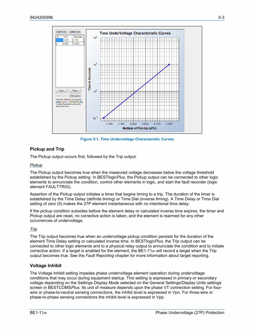
9424200996 5-3
BE1-11m Phase Undervoltage (27P) Protection
Figure 5-1. Time Undervoltage Characteristic Curves
Pickup and Trip The Pickup output occurs first, followed by the Trip output.
Pickup
The Pickup output becomes true when the measured voltage decreases below the voltage threshold established by the Pickup setting. In BESTlogicPlus, the Pickup output can be connected to other logic elements to annunciate the condition, control other elements in logic, and start the fault recorder (logic element FAULTTRIG).
Assertion of the Pickup output initiates a timer that begins timing to a trip. The duration of the timer is established by the Time Delay (definite timing) or Time Dial (inverse timing). A Time Delay or Time Dial setting of zero (0) makes the 27P element instantaneous with no intentional time delay.
If the pickup condition subsides before the element delay or calculated inverse time expires, the timer and Pickup output are reset, no corrective action is taken, and the element is rearmed for any other occurrences of undervoltage.
Trip
The Trip output becomes true when an undervoltage pickup condition persists for the duration of the element Time Delay setting or calculated inverse time. In BESTlogicPlus, the Trip output can be connected to other logic elements and to a physical relay output to annunciate the condition and to initiate corrective action. If a target is enabled for the element, the BE1-11m will record a target when the Trip output becomes true. See the Fault Reporting chapter for more information about target reporting.
Voltage Inhibit The Voltage Inhibit setting impedes phase undervoltage element operation during undervoltage conditions that may occur during equipment startup. This setting is expressed in primary or secondary voltage depending on the Settings Display Mode selected on the General Settings/Display Units settings screen in BESTCOMSPlus. Its unit of measure depends upon the phase VT connection setting. For four-wire or phase-to-neutral sensing connections, the inhibit level is expressed in Vpn. For three-wire or phase-to-phase sensing connections the inhibit level is expressed in Vpp.

5-4 9424200996
Phase Undervoltage (27P) Protection BE1-11m
Element Blocking
Fuse Loss
The fuse loss (60FL) element of the BE1-11m can be used to block 27P protection when fuse loss or loss of potential is detected in a three-phase system.
If the 60FL element trip logic is true and Block Phase/V1 is enabled, all functions that use the phase voltage are blocked. See the Fuse Loss (60FL) chapter for more information on the 60FL function.
Protective elements blocked by 60FL should be set so that trip times are 60 milliseconds or greater to assure proper coordination of blocking.
Block Logic Input
The Block input provides logic-supervision control of the element. When true, the Block input disables the element by forcing the Trip and Pickup outputs to logic 0 and resetting the element timer. Connect the element Block input to the desired logic in BESTlogicPlus. When the element is initially selected from the Elements view, the default condition of the Block input is a logic 0.
Logic Connections
Phase undervoltage element logic connections are made on the BESTlogicPlus screen in BESTCOMSPlus. The phase undervoltage element logic block is illustrated in Figure 5-2. Logic inputs and outputs are summarized in Table 5-2.
Figure 5-2. Phase Undervoltage Element Logic Block
Table 5-2. Logic Inputs and Outputs
Name Logic Function Purpose Block Input Disables the 27P function when true Trip Output True when the 27P element is in a trip condition
Pickup Output True when the 27P element is in a pickup condition
Operational Settings
Phase undervoltage element operational settings are configured on the Undervoltage (27P) settings screen (Figure 5-3) in BESTCOMSPlus.
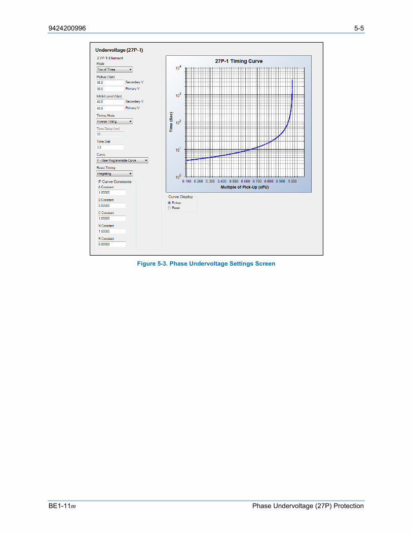
9424200996 5-5
BE1-11m Phase Undervoltage (27P) Protection
Figure 5-3. Phase Undervoltage Settings Screen

5-6 9424200996
Phase Undervoltage (27P) Protection BE1-11m

9424200996 6-1
BE1-11m Negative-Sequence Voltage (47) Protection
6 • Negative-Sequence Voltage (47) Protection Negative-sequence voltage protection is included as a mode of the 59X (Auxiliary Overvoltage) element. Refer to the Auxiliary Overvoltage (59X) Protection chapter for information on how to set up and program the V2 (negative-sequence voltage) mode of the 59X element.
Negative-sequence voltage protection is used to sense power-system imbalance. This situation occurs when a large single-phase load is switched onto the system, or when transformer-input fuses blow in only one or two phases. Negative-sequence voltage protection is good for detecting improper phasing when an oncoming generator is paralleled to the power system. All motor loads should be protected from the heating caused by unbalanced voltage (either on the bus or on each motor feeder). Industry standards state that the existence of unbalanced voltage feed results in 4 to 10 times the current imbalance. For a motor feeder, the negative-sequence voltage unbalances should not exceed 5 percent to avoid overheating and damage.

6-2 9424200996
Negative-Sequence Voltage (47) Protection BE1-11m
9424200996 7-1
BE1-11m Phase Overvoltage (59P) Protection
7 • Phase Overvoltage (59P) Protection Two phase overvoltage (59P) elements monitor the sensing voltage applied to the BE1-11m. An element can be configured to protect against overvoltage when the phase voltage increases above a defined level.
The two, identical overvoltage protection elements are designated 59P-1 and 59P-2. Element logic connections are made on the BESTlogic™Plus screen in BESTCOMSPlus® and element operational settings are configured on the Overvoltage settings screen in BESTCOMSPlus. A summary of the logic inputs and outputs and operational settings appears at the end of this chapter.
BESTCOMSPlus Navigation Path: Settings Explorer, Protection, Voltage, Overvoltage (59P)
HMI Navigation Path: Settings Explorer, Protection, Settings Group x (where x = 0 to 3), Voltage Protection, Overvoltage 59P
Element Operation
Overvoltage protection can be used to prevent large transformer and equipment damage when an overvoltage condition exists. For example, an overvoltage condition could occur when the tap changing control fails.
Modes of Protection Three modes of protection are available. The One of Three mode activates protection when one of the three phases of voltage increases above the Pickup setting. The Two of Three mode activates protection when any two of the three phases of voltage increases above the Pickup setting. The Three of Three mode activates protection when all three phases of voltage increase above the Pickup setting.
Voltage Response The overvoltage element can be set to monitor VPP or VPN. This is determined by the 27/59 Mode parameter of the phase VT connections found on the System Parameters/Sensing Transformers settings screen in BESTCOMSPlus. For more information on the VTP setup for PP or PN voltage response, see the Configuration chapter.
Timings The timing mode can be set for definite or inverse.
Inverse
When inverse timing is selected, a Curve setting is provided to select programmable or table curves. The user can select integrating reset timing to make the protective element use integrated reset and emulate an electromechanical induction disk reset characteristic. The overvoltage inverse time curve with default constants is shown in the Time Curve Characteristics chapter.
Programmable Curves
The programmable curve can be used to create a custom curve by selecting constants in the inverse time characteristic equation. When curve P is selected, the constants used in the equation are those defined by the user. Characteristics for trip and reset programmable curves are defined by Equation 7-1 and Equation 7-2. Definitions for these equations are provided in Table 7-1.
𝑇𝑇𝑇𝑇 =𝐴𝐴𝐴𝐴
𝑀𝑀𝑁𝑁 − 𝐶𝐶+ 𝐵𝐵𝐴𝐴
Equation 7-1. Time Characteristics for Trip
𝑇𝑇𝑅𝑅 =𝑅𝑅𝐴𝐴
|𝑀𝑀2 − 1|
Equation 7-2. Time Characteristics for Reset

7-2 9424200996
Phase Overvoltage (59P) Protection BE1-11m
Table 7-1. Definitions for Equation 7-1 and Equation 7-2
Parameter Description Explanation TT Time to trip Time that the 59P-x function will take to time out and trip. D Time dial setting Time dial setting for the 59P-x function.
M Multiple of pickup Measured current in multiples of pickup. The timing algorithm has a dynamic range of 1 to 3 times pickup.
A Constant specific to selected curve Affects the effective range of the time dial.
B Constant specific to selected curve
Affects a constant term in the timing equation. Has greatest effect on curve shape at high multiples of tap.
C Constant specific to selected curve
Affects the multiple of PU where the curve would approach infinity if allowed to continue below pickup. Has greatest effect on curve shape near pickup.
N Exponent specific to selected curve
Affects how inverse the characteristics are. Has greatest effect on curve shape at low to medium multiples of tap.
TR Time to reset Relevant if 59P-x function is set for integrating reset.
R Constant specific to selected curve Affects the speed of reset when integrating reset is selected.
Curve constants are entered on the Overvoltage (59P) settings screen in BESTCOMSPlus. Programmable curve constants can be entered only when the P curve is chosen for the protection element from the Curve drop-down menu.
Table Curves
BESTCOMSPlus is used to set the 27P element Table Curves (T1, T2, T3, and T4). Using the Settings Explorer within BESTCOMSPlus, open the Protection, Voltage, Overvoltage, Table Curves, Table Curve (1, 2, 3, or 4) tree branch and select the table curve to be modified. Refer to Figure 7-1. A minimum of 2 and maximum of 40 points can be entered for any one T curve. When you are satisfied with the values chosen, select Save Curve. Use the Settings Explorer to browse to the 59P-x element you wish to program and use the drop-down menu under Curve to select T1, T2, T3, or T4.
Table curves can be entered regardless of the curve chosen for the protection element. However, the table curve will not be enabled until T1, T2, T3, or T4 is selected as the curve for the protective element.

9424200996 7-3
BE1-11m Phase Overvoltage (59P) Protection
Figure 7-1. Time Overvoltage Characteristic Curves
Pickup and Trip The Pickup output occurs first, followed by the Trip output.
Pickup
The Pickup output becomes true when the measured voltage increases above the voltage threshold established by the Pickup setting. In BESTlogicPlus, the Pickup output can be connected to other logic elements to annunciate the condition, control other elements in logic, and start the fault recorder (logic element FAULTTRIG).
Assertion of the Pickup output initiates a timer that begins timing to a trip. The duration of the timer is established by the Time Delay (definite timing) or Time Dial (inverse timing). A Time Delay or Time Dial setting of zero (0) makes the 59P element instantaneous with no intentional time delay.
Trip
The Trip output becomes true if an overvoltage pickup condition persists for the duration of the element Time Delay setting or calculated inverse time. In BESTlogicPlus, the Trip output can be connected to other logic elements and to a physical relay output to annunciate the condition and to initiate corrective action. If a target is enabled for the element, the BE1-11m will record a target when the Trip output becomes true. See the Fault Reporting chapter for more information about target reporting.
If the pickup condition subsides before the element delay or calculated inverse time expires, the timer and Pickup output are reset, no corrective action is taken, and the element is rearmed for any other occurrences of overvoltage.
Element Blocking
Fuse Loss
The fuse loss (60FL) element of the BE1-11m can be used to block 59P protection when fuse loss or loss of potential is detected in a three-phase system.
If the 60FL element trip logic is true and Block Phase/V1 is enabled, all functions that use the phase voltage are blocked. See the Fuse Loss (60FL) chapter for more information on the 60FL function.
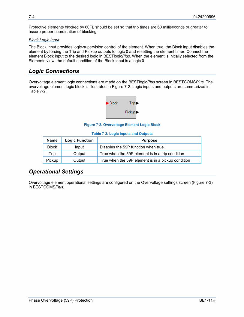
7-4 9424200996
Phase Overvoltage (59P) Protection BE1-11m
Protective elements blocked by 60FL should be set so that trip times are 60 milliseconds or greater to assure proper coordination of blocking.
Block Logic Input
The Block input provides logic-supervision control of the element. When true, the Block input disables the element by forcing the Trip and Pickup outputs to logic 0 and resetting the element timer. Connect the element Block input to the desired logic in BESTlogicPlus. When the element is initially selected from the Elements view, the default condition of the Block input is a logic 0.
Logic Connections
Overvoltage element logic connections are made on the BESTlogicPlus screen in BESTCOMSPlus. The overvoltage element logic block is illustrated in Figure 7-2. Logic inputs and outputs are summarized in Table 7-2.
Figure 7-2. Overvoltage Element Logic Block
Table 7-2. Logic Inputs and Outputs
Name Logic Function Purpose Block Input Disables the 59P function when true Trip Output True when the 59P element is in a trip condition
Pickup Output True when the 59P element is in a pickup condition
Operational Settings
Overvoltage element operational settings are configured on the Overvoltage settings screen (Figure 7-3) in BESTCOMSPlus.
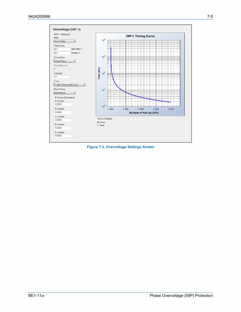
9424200996 7-5
BE1-11m Phase Overvoltage (59P) Protection
Figure 7-3. Overvoltage Settings Screen

7-6 9424200996
Phase Overvoltage (59P) Protection BE1-11m
9424200996 8-1
BE1-11t Auxiliary Overvoltage (59X) Protection
8 • Auxiliary Overvoltage (59X) Protection Two auxiliary overvoltage (59X) elements monitor the phase and auxiliary voltage applied to the BE1-11m. An element can be configured to protect against overvoltage by monitoring neutral-shift voltage, positive-sequence voltage, negative-sequence voltage, fundamental voltage on the Vx input, or third-harmonic voltage on the Vx input.
The two, identical auxiliary overvoltage protection elements are designated 59X-1 and 59X-2. Element logic connections are made on the BESTlogic™Plus screen in BESTCOMSPlus® and element operational settings are configured on the Overvoltage (59X) settings screen in BESTCOMSPlus. A summary of the logic inputs and outputs and operational settings appears at the end of this chapter.
BESTCOMSPlus Navigation Path: Settings Explorer, Protection, Voltage, Overvoltage (59X)
HMI Navigation Path: Settings Explorer, Protection, Settings Group x (where x = 0 to 3), Voltage Protection, Overvoltage 59X
Element Operation
Auxiliary overvoltage protection can be used to protect equipment from damage caused by phase failure, positive/negative phase sequence, or phase unbalance.
Modes of Protection Five modes of protection are available: 3V0, V1, V2, Vx Fundamental, and Vx Third Harmonic.
3V0 Mode
3V0 mode provides voltage unbalance protection in a three-phase system. The 3V0 measurement increases as the three-phase voltages become unbalanced.
V1 Mode
V1 mode provides positive phase-sequence protection in a three-phase system. The V1 measurement increases as the phase sequence is brought forward.
V2 Mode
V2 mode provides negative phase-sequence protection in a three-phase system. The V2 measurement increases as voltage becomes unbalanced or the phase sequence is reversed.
Vx Fundamental Mode
Vx Fundamental mode provides ground offset detection on high impedance ground systems or phase overvoltage protection in sync-check applications.
Vx Third Harmonic Mode
Vx Third Harmonic mode detects an increase in third harmonic.
Connections Connections are made on the rear of the BE1-11m. The phase VT inputs (Va, Vb, Vc) are used when 3V0, V1, or V2 mode is selected. The auxiliary VT input (Vx) is used when Vx Fundamental or Vx Third Harmonic mode is selected. For an illustration of terminals, refer to the Terminals and Connectors chapter.
8-2 9424200996
Auxiliary Overvoltage (59X) Protection BE1-11m
Sensing Configuration When using the Vx input, setting the Aux VT Connection parameter provides the correct labeling of settings and metering data found in BESTCOMSPlus and fault reports. The Aux VT Connection parameter set to AB, for example, will display the metering data as AB in fault records and display the pickup setting as Vpp in BESTCOMSPlus. See Table 8-1 for a full list of possible settings. The Aux VT Connection parameter is found on the System Parameters/Sensing Transformers settings screen in BESTCOMSPlus. For more information on the auxiliary VT setup, see the Configuration chapter.
Table 8-1. Auxiliary VT Configuration
Aux VT Connection Mode Unit AB, BC, CA Vx Fundamental, Vx Third Harmonic VPP
AN, BN, CN Vx Fundamental, Vx Third Harmonic VPN Ground Vx Fundamental, Vx Third Harmonic VPN
Any V1, V2, and 3V0 VPN
Timings The timing mode can be set for definite or inverse.
Inverse
When inverse timing is selected, a Curve setting is provided to select programmable or table curves. The user can select integrating reset timing to make the protective element use integrated reset and emulate an electromechanical induction disk reset characteristic. The overvoltage inverse time curve with default constants is shown in the Time Curve Characteristics chapter.
Programmable Curves
The programmable curve can be used to create a custom curve by selecting constants in the inverse time characteristic equation. When curve P is selected, the constants used in the equation are those defined by the user. Characteristics for trip and reset programmable curves are defined by Equation 8-1 and Equation 8-2. Definitions for these equations are provided in Table 8-2.
𝑇𝑇𝑇𝑇 =𝐴𝐴𝐴𝐴
𝑀𝑀𝑁𝑁 − 𝐶𝐶+ 𝐵𝐵𝐴𝐴
Equation 8-1. Time Characteristics for Trip
𝑇𝑇𝑅𝑅 =𝑅𝑅𝐴𝐴
|𝑀𝑀2 − 1|
Equation 8-2. Time Characteristics for Reset
Table 8-2. Definitions for Equation 8-1 and Equation 8-2
Parameter Description Explanation TT Time to trip Time that the 59X-x function will take to time out and trip. D Time dial setting Time dial setting for the 59X-x function.
M Multiple of pickup Measured current in multiples of pickup. The timing algorithm has a dynamic range of 1 to 3 times pickup.
A Constant specific to selected curve Affects the effective range of the time dial.
B Constant specific to selected curve
Affects a constant term in the timing equation. Has greatest effect on curve shape at high multiples of tap.
C Constant specific to selected curve
Affects the multiple of PU where the curve would approach infinity if allowed to continue below pickup. Has greatest effect on curve shape near pickup.
N Exponent specific to selected curve
Affects how inverse the characteristics are. Has greatest effect on curve shape at low to medium multiples of tap.
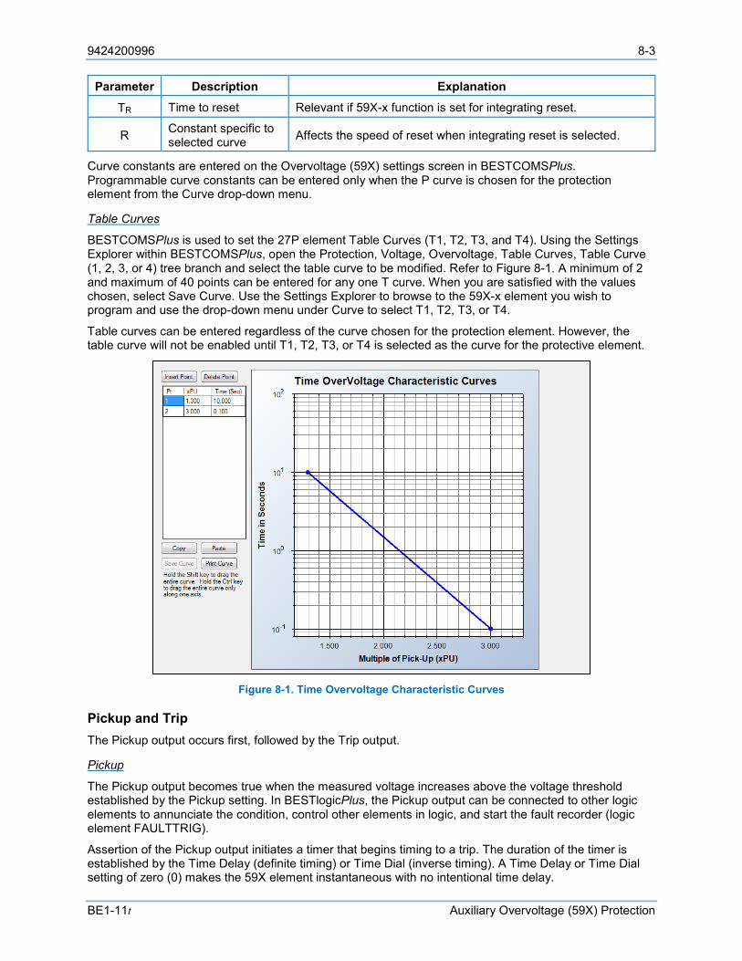
9424200996 8-3
BE1-11t Auxiliary Overvoltage (59X) Protection
Parameter Description Explanation
TR Time to reset Relevant if 59X-x function is set for integrating reset.
R Constant specific to selected curve Affects the speed of reset when integrating reset is selected.
Curve constants are entered on the Overvoltage (59X) settings screen in BESTCOMSPlus. Programmable curve constants can be entered only when the P curve is chosen for the protection element from the Curve drop-down menu.
Table Curves
BESTCOMSPlus is used to set the 27P element Table Curves (T1, T2, T3, and T4). Using the Settings Explorer within BESTCOMSPlus, open the Protection, Voltage, Overvoltage, Table Curves, Table Curve (1, 2, 3, or 4) tree branch and select the table curve to be modified. Refer to Figure 8-1. A minimum of 2 and maximum of 40 points can be entered for any one T curve. When you are satisfied with the values chosen, select Save Curve. Use the Settings Explorer to browse to the 59X-x element you wish to program and use the drop-down menu under Curve to select T1, T2, T3, or T4.
Table curves can be entered regardless of the curve chosen for the protection element. However, the table curve will not be enabled until T1, T2, T3, or T4 is selected as the curve for the protective element.
Figure 8-1. Time Overvoltage Characteristic Curves
Pickup and Trip The Pickup output occurs first, followed by the Trip output.
Pickup
The Pickup output becomes true when the measured voltage increases above the voltage threshold established by the Pickup setting. In BESTlogicPlus, the Pickup output can be connected to other logic elements to annunciate the condition, control other elements in logic, and start the fault recorder (logic element FAULTTRIG).
Assertion of the Pickup output initiates a timer that begins timing to a trip. The duration of the timer is established by the Time Delay (definite timing) or Time Dial (inverse timing). A Time Delay or Time Dial setting of zero (0) makes the 59X element instantaneous with no intentional time delay.

8-4 9424200996
Auxiliary Overvoltage (59X) Protection BE1-11m
If the pickup condition subsides before the element delay or calculated inverse time expires, the timer and Pickup output are reset, no corrective action is taken, and the element is rearmed for any other occurrences of overvoltage.
Trip
The Trip output becomes true if an overvoltage pickup condition persists for the duration of the element Time Delay setting or calculated inverse time. In BESTlogicPlus, the Trip output can be connected to other logic elements and to a physical relay output to annunciate the condition and to initiate corrective action. If a target is enabled for the element, the BE1-11m will record a target when the Trip output becomes true. See the Fault Reporting chapter for more information about target reporting.
Element Blocking
Fuse Loss
The fuse loss (60FL) element of the BE1-11m can be used to block 59X protection when fuse loss or loss of potential is detected in a three-phase system.
If the 60FL element trip logic is true and Block Phase/V1 is enabled, the 59X function will be blocked when configured for V1 mode. If Block V2 is enabled, the 59X function will be blocked when configured for V2 mode. If Block 3V0 is enabled, the 59X function will be blocked when configured for 3V0 mode. See the Fuse Loss (60FL) chapter for more information on the 60FL function.
Protective elements blocked by 60FL should be set so that trip times are 60 milliseconds or greater to assure proper coordination of blocking.
Block Logic Input
The Block input provides logic-supervision control of the element. When true, the Block input disables the element by forcing the Trip and Pickup outputs to logic 0 and resetting the element timer. Connect the element Block input to the desired logic in BESTlogicPlus. When the element is initially selected from the Elements view, the default condition of the Block input is a logic 0.
Logic Connections
Auxiliary overvoltage element logic connections are made on the BESTlogicPlus screen in BESTCOMSPlus. The auxiliary overvoltage element logic block is illustrated in Figure 8-2. Logic inputs and outputs are summarized in Table 8-3.
Figure 8-2. Auxiliary Overvoltage Element Logic Block
Table 8-3. Logic Inputs and Outputs
Name Logic Function Purpose Block Input Disables the 59X function when true Trip Output True when the 59X element is in a trip condition
Pickup Output True when the 59X element is in a pickup condition
Operational Settings
Auxiliary overvoltage element operational settings are configured on the Overvoltage (59X) settings screen (Figure 8-3) in BESTCOMSPlus.
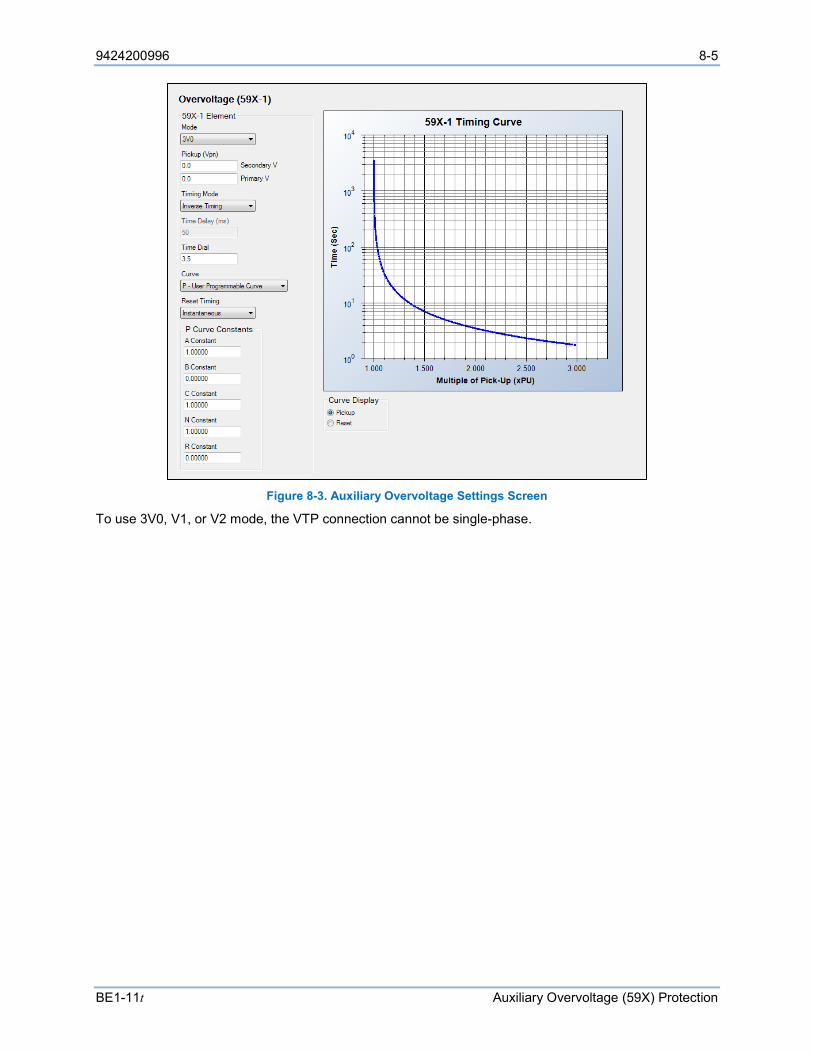
9424200996 8-5
BE1-11t Auxiliary Overvoltage (59X) Protection
Figure 8-3. Auxiliary Overvoltage Settings Screen
To use 3V0, V1, or V2 mode, the VTP connection cannot be single-phase.

8-6 9424200996
Auxiliary Overvoltage (59X) Protection BE1-11m
9424200996 9-1
BE1-11m Frequency (81) Protection
9 • Frequency (81) Protection Four frequency (81) elements monitor the frequency of the sensing voltage applied to the BE1-11m. An element can be configured to protect against underfrequency, overfrequency, or the rate of frequency change.
The four, identical frequency protection elements are designated 81-1, 81-2, 81-3, and 81-4. Element logic connections are made on the BESTlogic™Plus screen in BESTCOMSPlus® and element operational settings are configured on the Frequency settings screen in BESTCOMSPlus. A summary of the logic inputs and outputs and operational settings appears at the end of this chapter.
Note BE1-11m protection systems enabled for IEC-61850 communication (style Mxxxx5xxxxxxxx) have their frequency protection elements fixed at two underfrequency elements and two overfrequency elements.
BESTCOMSPlus Navigation Path: Settings Explorer, Protection, Frequency, Frequency (81)
HMI Navigation Path: Settings Explorer, Protection, Settings Group x (where x = 0 to 3), Frequency Protection 81
Frequency Measurement
For four-wire or single-phase sensing connections, the power system frequency is measured through the BE1-11m A-phase sensing voltage input. For a three-wire connection, the power system frequency is measured through the A- and B-phase sensing voltage connections. Refer to the Typical Connections chapter for information on voltage connections. Power system frequency is also measured through the BE1-11m auxiliary voltage (Vx) sensing input. Refer to the Typical Connections chapter for information on voltage connections.
To measure frequency, the voltage sensed by the BE1-11m must be greater than 10 Vac. The measured frequency is the average of two cycles of voltage measurement.
Underfrequency and Overfrequency Protection
Underfrequency and overfrequency protection can be useful for detecting load shedding or islanding. For example, when a source of distributed generation (DG) is suddenly separated or isolated from the electric utility, the frequency will change quickly from the nominal value (except for the improbable case of a perfect load-to-generation match). This makes frequency measurement an excellent method for detecting an island condition.
Any of the four 81 elements can be configured for underfrequency or overfrequency protection.
Mode Underfrequency or overfrequency protection is selected through the Mode setting. A setting of Under selects underfrequency protection and a setting of Over selects overfrequency protection.
Sensing Source Underfrequency or overfrequency protection can be applied to the voltage sensed at the BE1-11m phase VT input or auxiliary VT (Vx) input. A Source setting of Phase VT selects the voltage sensed at the phase VT input and a Source setting of Aux VT selects the voltage sensed at the Vx input. The Auxiliary VT (Vx) input can be connected to a voltage transformer on the motor side of the breaker to determine if the motor is spinning when the breaker is open.
9-2 9424200996
Frequency (81) Protection BE1-11m
Pickup and Trip The Pickup output occurs first, followed by the Trip output.
Pickup
The Pickup output becomes true when the measured frequency decreases below (underfrequency protection) or increases above (overfrequency protection) the frequency threshold established by the Pickup setting for three consecutive sensing voltage cycles. In BESTlogicPlus, the Pickup output can be connected to other logic elements to annunciate the condition, control other elements in logic, and start the fault recorder (logic element FAULTTRIG).
Assertion of the Pickup output initiates a timer that begins timing to a trip. The duration of the timer is established by the Time Delay setting. A Time Delay setting of zero (0) makes the 81 element instantaneous with no intentional time delay.
If the pickup condition subsides before the element delay expires, the timer and Pickup output are reset, no corrective action is taken, and the element is rearmed for any other occurrences of underfrequency or overfrequency.
Trip
The Trip output becomes true if an underfrequency or overfrequency pickup condition persists for the duration of the element Time Delay setting. In BESTlogicPlus, the Trip output can be connected to other logic elements and to a physical relay output to annunciate the condition and to initiate corrective action. If a target is enabled for the element, the BE1-11m will record a target when the Trip output becomes true. See the Fault Reporting chapter for more information about target reporting.
Voltage Inhibit The Voltage Inhibit setting impedes underfrequency/overfrequency element operation during undervoltage conditions that may occur during equipment startup. This setting is expressed in primary or secondary voltage depending on the Settings Display Mode selected on the General Settings/Display Units settings screen in BESTCOMSPlus and its unit of measure depends upon the phase VT connection setting. For four-wire or phase-to-neutral sensing connections that inhibit level is expressed in Vpn. For three-wire or phase-to-phase sensing connections the inhibit level is expressed in Vpp.
Element Blocking The Block input provides logic-supervision control of the element. When true, the Block input disables the element by forcing the Trip and Pickup outputs to logic 0 and resetting the element timer. Connect the element Block input to the desired logic in BESTlogicPlus. When the element is initially selected from the Elements view, the default condition of the Block input is a logic 0.
Frequency Rate-of-Change Protection
When a source of distributed generation is suddenly separated from the electric utility, the frequency rate-of-change (ROC) will increase or decrease rapidly. Frequency ROC protection provides high-speed detection of an islanding situation that may not be detected by overfrequency or underfrequency protection. A frequency ROC protection element can be used for load shedding in conjunction with an underfrequency protection element to accelerate shedding during a substantial overload or inhibit shedding following a sudden, transient decrease in frequency. An 81 element can be configured to respond to positive ROC, negative ROC, or either condition.
Any of the four 81 elements can be configured for frequency rate-of-change (ROC) protection.
Mode An 81 element is configured for rate-of-change protection, only positive rate-of-change protection, or only negative rate-of-change protection through the Mode setting.

9424200996 9-3
BE1-11m Frequency (81) Protection
Sensing Source Frequency ROC protection can be applied to the voltage sensed at the BE1-11m phase VT input or auxiliary VT (Vx) input. A Source setting of Phase VT selects the voltage sensed at the phase VT input and a Source setting of Aux VT selects the voltage sensed at the Vx input. The Auxiliary VT (Vx) input can be connected to a voltage transformer on the motor side of the breaker to determine if the motor is spinning when the breaker is open.
Pickup and Trip When the rate of frequency change (expressed in hertz per second) exceeds the threshold established by the Pickup setting for three consecutive sensing voltage cycles, the element Pickup output becomes true. Pickup detection time varies according to the value of the fault frequency. When the frequency greatly exceeds the pickup setting, pickup detection occurs very quickly. More precise and less quick pickup detection occurs when the fault frequency is much closer to the Pickup setting. Pickup detection times are summarized as follows:
• Faults exceeding the pickup setting by 0.57 Hz/s are detected in 2 cycles
• Faults exceeding the pickup setting by 0.24 Hz/s are detected in 4 cycles
• Faults exceeding the pickup setting by 0.08 Hz/s are detected in 8 cycles
• No pickup detection time will be greater than 16 cycles
In BESTlogicPlus, the Pickup output can be connected to other logic elements to annunciate the condition or control other elements in logic.
Assertion of the Pickup output initiates a timer, which begins timing toward a trip. The duration of the timer is established by the Time Delay setting. A Time Delay setting of zero (0) makes the 81 element instantaneous (with the exception of the pickup detection time).
If an ROC pickup condition persists for the duration of the element Time Delay setting, the element Trip output becomes true. In BESTlogicPlus, the Trip output can be connected to other logic elements or a physical relay output to annunciate the condition and initiate corrective action. If a target is enabled for the element, the BE1-11m will record a target when the Trip output becomes true. See the Fault Reporting chapter for more information about target reporting.
If the pickup condition subsides before the element time delay expires, the timer and Pickup output are reset, no corrective action is taken, and the element is rearmed for any other occurrences of a frequency ROC fault.
Inhibit Functions Frequency ROC protection can be inhibited by the degree of underfrequency or overfrequency or the percentage of negative sequence voltage.
The Overfrequency Inhibit setting disables frequency ROC protection when the sensed frequency exceeds the setting threshold. Likewise, the Underfrequency Inhibit setting disables frequency ROC protection when the sensed frequency decreases below the setting threshold.
Frequency ROC protection can be inhibited when the percentage of negative sequence voltage exceeds the limit established by the Negative Sequence Inhibit setting. A Negative Sequence Inhibit setting of zero (0) inhibits this feature.
Element Blocking This input allows for logic supervision or control of the element.
Each frequency protection element has a Block logic input, which when true, disables an element by forcing the Trip and Pickup outputs to logic 0 and resetting the element timer. An element Block input is connected to the desired logic in BESTlogicPlus.
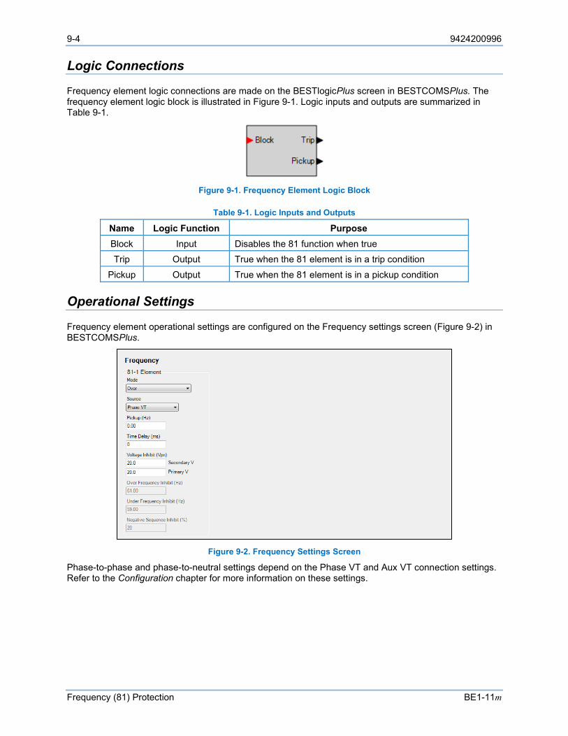
9-4 9424200996
Frequency (81) Protection BE1-11m
Logic Connections
Frequency element logic connections are made on the BESTlogicPlus screen in BESTCOMSPlus. The frequency element logic block is illustrated in Figure 9-1. Logic inputs and outputs are summarized in Table 9-1.
Figure 9-1. Frequency Element Logic Block
Table 9-1. Logic Inputs and Outputs
Name Logic Function Purpose Block Input Disables the 81 function when true Trip Output True when the 81 element is in a trip condition
Pickup Output True when the 81 element is in a pickup condition
Operational Settings
Frequency element operational settings are configured on the Frequency settings screen (Figure 9-2) in BESTCOMSPlus.
Figure 9-2. Frequency Settings Screen
Phase-to-phase and phase-to-neutral settings depend on the Phase VT and Aux VT connection settings. Refer to the Configuration chapter for more information on these settings.

9424200996 10-1
BE1-11m Instantaneous Undercurrent (37) Protection
10 • Instantaneous Undercurrent (37) Protection The instantaneous undercurrent (37) element monitors the three-phase sensing current and protects against loss of load conditions, such as a breaking motor belt. This protective function will trip the motor when a loss of load occurs.
Element logic connections are made on the BESTlogic™Plus screen in BESTCOMSPlus® and element operational settings are configured on the Instantaneous Undercurrent settings screen in BESTCOMSPlus. A summary of the logic inputs and outputs and operational settings appears at the end of this chapter.
BESTCOMSPlus Navigation Path: Settings Explorer, Protection, Current, Instantaneous Undercurrent (37)
HMI Navigation Path: Settings Explorer, Protection, Settings Group x (where x = 0 to 3), Current Protection, Instant Undercurrent 37
Element Operation
When enabled, the instantaneous undercurrent element monitors IA, IB, and IC and makes pickup and trip decisions from the lowest of the three phases.
CT Source The CT Source setting configures the instantaneous undercurrent element to monitor CT circuit 1 or CT circuit 2 on protection systems equipped with two sets of CTs. CT circuit 1 terminals are designated D1 (IA1) through D8 (IG1) and CT circuit 2 terminals are designated F1 (IA2) through F8 (IG2). For an illustration, refer to the Terminals and Connectors chapter.
Pickup and Trip The Pickup output occurs first, followed by the Trip output.
Pickup
The Pickup output becomes true when the measured current decreases below the current threshold established by the Pickup setting. In BESTlogicPlus, the Pickup output can be connected to other logic elements to annunciate the condition, control other elements in logic, and start the fault recorder (logic element FAULTTRIG).
Assertion of the Pickup output initiates a timer that begins timing to a trip. The duration of the timer is established by the Time Delay setting. A Time Delay of zero (0) makes the 37 element instantaneous with no intentional time delay.
If the pickup condition subsides before the element delay expires, the timer and Pickup output are reset, no corrective action is taken, and the element is rearmed for any other occurrences of undercurrent.
Trip
The Trip output becomes true if an undercurrent condition persists for the duration of the element Time Delay. In BESTlogicPlus, the Trip output can be connected to other logic elements and to a physical relay output to annunciate the condition and to initiate corrective action. If a target is enabled for the element, the BE1-11m will record a target when the Trip output becomes true. See the Fault Reporting chapter for more information about target reporting.
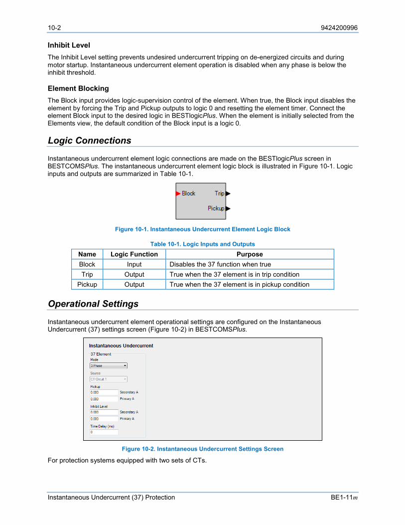
10-2 9424200996
Instantaneous Undercurrent (37) Protection BE1-11m
Inhibit Level The Inhibit Level setting prevents undesired undercurrent tripping on de-energized circuits and during motor startup. Instantaneous undercurrent element operation is disabled when any phase is below the inhibit threshold.
Element Blocking The Block input provides logic-supervision control of the element. When true, the Block input disables the element by forcing the Trip and Pickup outputs to logic 0 and resetting the element timer. Connect the element Block input to the desired logic in BESTlogicPlus. When the element is initially selected from the Elements view, the default condition of the Block input is a logic 0.
Logic Connections
Instantaneous undercurrent element logic connections are made on the BESTlogicPlus screen in BESTCOMSPlus. The instantaneous undercurrent element logic block is illustrated in Figure 10-1. Logic inputs and outputs are summarized in Table 10-1.
Figure 10-1. Instantaneous Undercurrent Element Logic Block
Table 10-1. Logic Inputs and Outputs Name Logic Function Purpose Block Input Disables the 37 function when true Trip Output True when the 37 element is in trip condition
Pickup Output True when the 37 element is in pickup condition
Operational Settings
Instantaneous undercurrent element operational settings are configured on the Instantaneous Undercurrent (37) settings screen (Figure 10-2) in BESTCOMSPlus.
Figure 10-2. Instantaneous Undercurrent Settings Screen
For protection systems equipped with two sets of CTs.
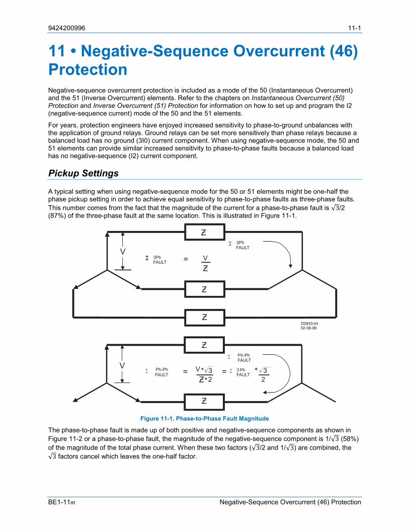
9424200996 11-1
BE1-11m Negative-Sequence Overcurrent (46) Protection
11 • Negative-Sequence Overcurrent (46) Protection Negative-sequence overcurrent protection is included as a mode of the 50 (Instantaneous Overcurrent) and the 51 (Inverse Overcurrent) elements. Refer to the chapters on Instantaneous Overcurrent (50) Protection and Inverse Overcurrent (51) Protection for information on how to set up and program the I2 (negative-sequence current) mode of the 50 and the 51 elements.
For years, protection engineers have enjoyed increased sensitivity to phase-to-ground unbalances with the application of ground relays. Ground relays can be set more sensitively than phase relays because a balanced load has no ground (3I0) current component. When using negative-sequence mode, the 50 and 51 elements can provide similar increased sensitivity to phase-to-phase faults because a balanced load has no negative-sequence (I2) current component.
Pickup Settings
A typical setting when using negative-sequence mode for the 50 or 51 elements might be one-half the phase pickup setting in order to achieve equal sensitivity to phase-to-phase faults as three-phase faults. This number comes from the fact that the magnitude of the current for a phase-to-phase fault is √3/2 (87%) of the three-phase fault at the same location. This is illustrated in Figure 11-1.
Figure 11-1. Phase-to-Phase Fault Magnitude
The phase-to-phase fault is made up of both positive and negative-sequence components as shown in Figure 11-2 or a phase-to-phase fault, the magnitude of the negative-sequence component is 1/√3 (58%) of the magnitude of the total phase current. When these two factors (√3/2 and 1/√3) are combined, the √3 factors cancel which leaves the one-half factor.
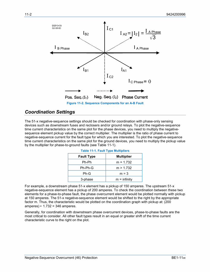
11-2 9424200996
Negative-Sequence Overcurrent (46) Protection BE1-11m
Figure 11-2. Sequence Components for an A-B Fault
Coordination Settings
The 51-x negative-sequence settings should be checked for coordination with phase-only sensing devices such as downstream fuses and reclosers and/or ground relays. To plot the negative-sequence time current characteristics on the same plot for the phase devices, you need to multiply the negative-sequence element pickup value by the correct multiplier. The multiplier is the ratio of phase current to negative-sequence current for the fault type for which you are interested. To plot the negative-sequence time current characteristics on the same plot for the ground devices, you need to multiply the pickup value by the multiplier for phase-to-ground faults (see Table 11-1).
Table 11-1. Fault Type Multipliers
Fault Type Multiplier Ph-Ph m = 1.732
Ph-Ph-G m > 1.732 Ph-G m = 3
3-phase m = infinity
For example, a downstream phase 51-x element has a pickup of 150 amperes. The upstream 51-x negative-sequence element has a pickup of 200 amperes. To check the coordination between these two elements for a phase-to-phase fault, the phase overcurrent element would be plotted normally with pickup at 150 amperes. The 51-x negative-sequence element would be shifted to the right by the appropriate factor m. Thus, the characteristic would be plotted on the coordination graph with pickup at: (200 amperes) ∗ 1.732 = 346 amperes.
Generally, for coordination with downstream phase overcurrent devices, phase-to-phase faults are the most critical to consider. All other fault types result in an equal or greater shift of the time current characteristic curve to the right on the plot.

9424200996 12-1
BE1-11m Instantaneous Overcurrent (50) Protection
12 • Instantaneous Overcurrent (50) Protection Six instantaneous overcurrent (50) elements monitor the current applied to the BE1-11m. An element can be configured to protect against overcurrent by monitoring a single- or three-phase system, neutral current, positive-sequence current, negative-sequence current, ground current, or unbalanced current.
The six, identical instantaneous overcurrent protection elements are designated 50-1, 50-2, 50-3, 50-4, 50-5, and 50-6. Element logic connections are made on the BESTlogicPlus screen in BESTCOMSPlus and element operational settings are configured on the Instantaneous Overcurrent settings screen in BESTCOMSPlus. A summary of the logic inputs and outputs and operational settings appears at the end of this chapter.
BESTCOMSPlus Navigation Path: Settings Explorer, Protection, Current, Instantaneous Overcurrent (50)
HMI Navigation Path: Settings Explorer, Protection, Settings Group x (where x = 0 to 3), Current Protection, Instant Overcurrent 50
Element Operation
Instantaneous overcurrent protection can be used to protect equipment from damage caused by phase failure, forward/reverse phase sequence, or phase unbalance.
Modes of Protection Nine modes of protection are available: IA, IB, IC, Three-Phase, 3I0, I1, I2, IG, and Unbalance.
IA, IB, or IC Mode
The instantaneous overcurrent protection elements include three independent comparators, one for each phase. Mode selection determines which phase pickup is required to activate protection.
Three-Phase Mode
The instantaneous overcurrent protection elements include three independent comparators, one for each phase. Protection is activated when any of the three phases increases above the Pickup setting.
3I0 Mode
3I0 mode provides neutral overcurrent protection in a three-phase system.
I1 Mode
I1 mode provides positive-sequence overcurrent protection in a three-phase system.
I2 Mode
I2 mode provides negative-sequence overcurrent protection in a three-phase system. Refer to the Negative-Sequence Overcurrent (46) Protection chapter for more information.
IG Mode
IG mode provides ground fault protection in a three-phase system.
Unbalance Mode
Unbalance mode provides unbalanced current protection. Two methods are available to calculate unbalanced current. The first method is based on the negative-sequence current divided by the positive-sequence current while the second method is based on the average current. The calculation method must be specified on the System Parameters, Sensing Transformers screen in BESTCOMSPlus. Refer to the
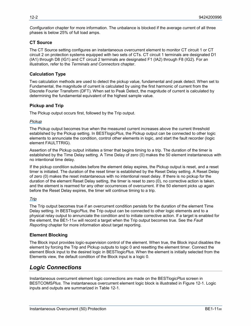
12-2 9424200996
Instantaneous Overcurrent (50) Protection BE1-11m
Configuration chapter for more information. The unbalance is blocked if the average current of all three phases is below 25% of full load amps.
CT Source The CT Source setting configures an instantaneous overcurrent element to monitor CT circuit 1 or CT circuit 2 on protection systems equipped with two sets of CTs. CT circuit 1 terminals are designated D1 (IA1) through D8 (IG1) and CT circuit 2 terminals are designated F1 (IA2) through F8 (IG2). For an illustration, refer to the Terminals and Connectors chapter.
Calculation Type Two calculation methods are used to detect the pickup value, fundamental and peak detect. When set to Fundamental, the magnitude of current is calculated by using the first harmonic of current from the Discrete Fourier Transform (DFT). When set to Peak Detect, the magnitude of current is calculated by determining the fundamental equivalent of the highest sample value.
Pickup and Trip The Pickup output occurs first, followed by the Trip output.
Pickup
The Pickup output becomes true when the measured current increases above the current threshold established by the Pickup setting. In BESTlogicPlus, the Pickup output can be connected to other logic elements to annunciate the condition, control other elements in logic, and start the fault recorder (logic element FAULTTRIG).
Assertion of the Pickup output initiates a timer that begins timing to a trip. The duration of the timer is established by the Time Delay setting. A Time Delay of zero (0) makes the 50 element instantaneous with no intentional time delay.
If the pickup condition subsides before the element delay expires, the Pickup output is reset, and a reset timer is initiated. The duration of the reset timer is established by the Reset Delay setting. A Reset Delay of zero (0) makes the reset instantaneous with no intentional reset delay. If there is no pickup for the duration of the element Reset Delay setting, the timer is reset to zero (0), no corrective action is taken, and the element is rearmed for any other occurrences of overcurrent. If the 50 element picks up again before the Reset Delay expires, the timer will continue timing to a trip.
Trip
The Trip output becomes true if an overcurrent condition persists for the duration of the element Time Delay setting. In BESTlogicPlus, the Trip output can be connected to other logic elements and to a physical relay output to annunciate the condition and to initiate corrective action. If a target is enabled for the element, the BE1-11m will record a target when the Trip output becomes true. See the Fault Reporting chapter for more information about target reporting.
Element Blocking The Block input provides logic-supervision control of the element. When true, the Block input disables the element by forcing the Trip and Pickup outputs to logic 0 and resetting the element timer. Connect the element Block input to the desired logic in BESTlogicPlus. When the element is initially selected from the Elements view, the default condition of the Block input is a logic 0.
Logic Connections
Instantaneous overcurrent element logic connections are made on the BESTlogicPlus screen in BESTCOMSPlus. The instantaneous overcurrent element logic block is illustrated in Figure 12-1. Logic inputs and outputs are summarized in Table 12-1.
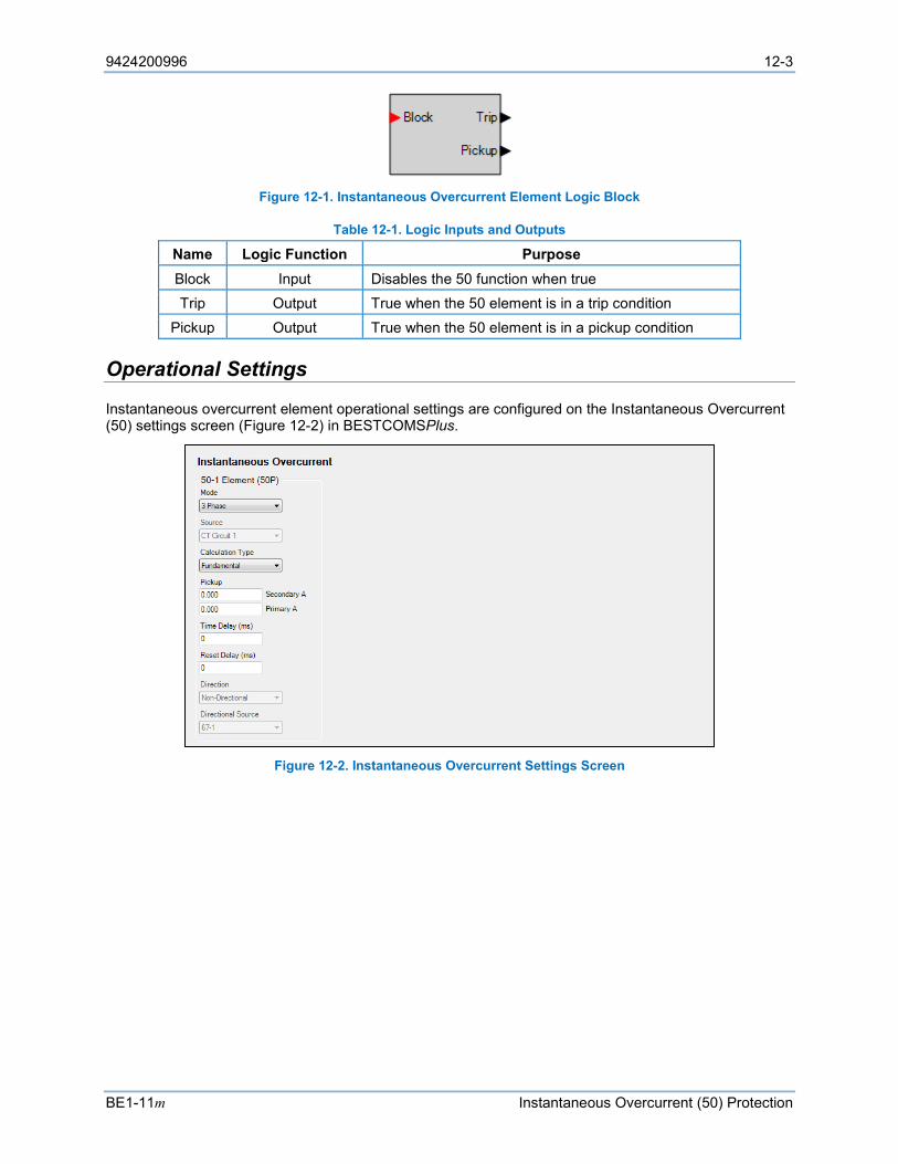
9424200996 12-3
BE1-11m Instantaneous Overcurrent (50) Protection
Figure 12-1. Instantaneous Overcurrent Element Logic Block
Table 12-1. Logic Inputs and Outputs
Name Logic Function Purpose Block Input Disables the 50 function when true Trip Output True when the 50 element is in a trip condition
Pickup Output True when the 50 element is in a pickup condition
Operational Settings
Instantaneous overcurrent element operational settings are configured on the Instantaneous Overcurrent (50) settings screen (Figure 12-2) in BESTCOMSPlus.
Figure 12-2. Instantaneous Overcurrent Settings Screen

12-4 9424200996
Instantaneous Overcurrent (50) Protection BE1-11m
9424200996 13-1
BE1-11m Breaker Failure (50BF) Protection
13 • Breaker Failure (50BF) Protection The breaker failure (50BF) element provides protection and security for the power system against the monitored breaker failing to open.
Element logic connections are made on the BESTlogic™Plus screen in BESTCOMSPlus® and element operational settings are configured on the Breaker Fail (50BF) settings screen in BESTCOMSPlus. A summary of the logic inputs and outputs and operational settings appears at the end of this chapter.
BESTCOMSPlus Navigation Path: Settings Explorer, Protection, Current, Breaker Fail (50BF)
HMI Navigation Path: Settings Explorer, Protection, Settings Group x (where x = 0 to 3), Current Protection, Breaker Fail 50BF
Element Operation
The 50BF element uses two methods to determine when the breaker has failed to open. The first method uses the breaker status (52a or 52b input) to determine if the breaker has successfully opened. The second method uses the monitored current to detect if the breaker has successfully opened.
In the first method, the breaker is closed when the Breaker Status (BRKSTAT) logic element is true. The 52BFI logic input is used to signal the breaker to open. When the BRKSTAT logic element and the 52BFI logic input are true, a delay timer is initiated to allow time for the breaker to transition. If the time delay expires and the BRKSTAT logic element and the 52BFI logic input are still true, the Trip output becomes true, signaling that the breaker has failed to trip.
In the second method, monitored current is used to determine if the breaker is closed. The 50BFI logic input of the Breaker Failure logic block is used to signal the breaker to open. When current is present and the 50BFI logic input is true, a timer is initiated to allow time for the fault to clear. If the time delay expires and current is still present, the Trip output becomes true, signaling that the breaker has failed to open. A control timer specifies the duration the breaker can remain closed before a Breaker Fail alarm will occur.
In both methods above, a Breaker Fail Retrip (BFRT) will be true while the delay timer is true. A breaker fail trip indicates a failed breaker. The Trip signal can be used to trip the next set of breakers upstream in the power system. Breaker failure protection may be applied to any portion of the power system where failure of a circuit breaker to operate properly could result in severe system damage or instability.
Contact Sensing Before any relay output can occur, there must first be an initiating signal to the Breaker Failure logic element. There are two possible initiating signals. The 52 Breaker Fail Initiate (52BFI) signal is the initiation signal when breaker status is used to determine a breaker failure. The 50 Breaker Fail Initiate (50BFI) is the initiation signal when current is used to determine a breaker failure. These initiate inputs can be driven by other relays through BE1-11m contact inputs or GOOSE over IEC 61850. Alternately, they can come from trip signals from other protective elements within the BE1-11m. Breaker status input is provided by the BRKSTAT logic element.
Information on setting up the breaker status logic can be found in the Breaker Monitoring chapter.
Control Timer The control timer provides a window of opportunity for a breaker failure Trip output to remain closed when the 50BFI logic input is used to signal the breaker to open. It improves dependability by sealing in the initiate request to prevent stopping of a breaker failure timing if the tripping relay drops out prematurely. The control timer is initiated by a 50BFI signal. Upon sensing the 50BFI transition from a 0 to 1 state, the control timer seals in the 50BFI signal for the duration of the Control Timer setting. If the control timer expires and the 50BFI signal is still present, an alarm signal occurs. A control timer setting of zero (0) disables the control timer seal-in function allowing the control timer to follow the 50BFI input.
13-2 9424200996
Breaker Failure (50BF) Protection BE1-11m
ReTrip and Trip The adjustable delay timer allows time for current to clear or the breaker status to transition after signaling the breaker to trip. The delay timer is initiated when either the 52BFI input or the 50BFI input becomes true. When both signals are false, the breaker delay timer is stopped.
ReTrip
The ReTrip output is true when the delay timer is actively timing. The delay timer can be stopped by several methods depending on the timer initiate source. When initiated by a 50BFI signal, the timer is stopped when current decreases below the pickup setting, when the fast current dropout detector detects that current has dropped out, or when the control timer expires. When initiated by a 52BFI signal, the timer is stopped when the BRKSTAT logic element indicates that the breaker is open. Regardless of initiate method, asserting the Block logic input also stops the timer. In BESTlogicPlus, the ReTrip output can be connected to other logic elements to annunciate the condition, control other elements in logic, and start the fault recorder (logic element FAULTTRIG).
Trip
The Trip output becomes true when the delay timer expires. In BESTlogicPlus, the Trip output can be connected to other logic elements and to a physical relay output to annunciate the condition and to initiate corrective action. If a target is enabled for the element, the BE1-11m will record a target when the Trip output becomes true. See the Fault Reporting chapter for more information about target reporting.
Fast Current Detector The fast current detector directly determines when the current in the poles of the breaker has been interrupted without having to wait for the fault current samples to clear the one-cycle filter time used by the normal current measurement function. This function has less than one cycle dropout time.
The fast current detector logic is true if the current has been interrupted and is used to stop the breaker failure timer. The I=0 algorithm looks at the sample data directly and does not rely upon the 1 cycle phasor estimation calculation. It rejects dc tail-off by looking for the characteristic exponential decay. Current is deemed to be interrupted when the current in all three phases is below 5% nominal or if the current is decaying exponentially. Only the three phase currents are monitored by this function.
CT Source The CT Source setting configures the breaker failure element to monitor CT circuit 1 or CT circuit 2 on protection systems equipped with two sets of CTs. CT circuit 1 terminals are designated D1 (IA1) through D8 (IG1) and CT circuit 2 terminals are designated F1 (IA2) through F8 (IG2). For an illustration, refer to the Terminals and Connectors chapter.
Programmable Alarm A Breaker Failure alarm is provided to indicate an alarm condition when the 50BF element trips. The alarm appears on the front-panel display, web page interface, and on the Alarms metering screen in BESTCOMSPlus. Refer to the Alarms chapter for information on how to program alarms.
Element Blocking The Block input provides logic-supervision control of the element. Element blocking is a useful feature to prevent inadvertent backup tripping during testing.
When true, the Block input disables the element by forcing the Trip and ReTrip outputs to logic 0 and resetting the element timers. Connect the element Block input to the desired logic in BESTlogicPlus. When the element is initially selected from the Elements view, the default condition of the Block input is a logic 0.
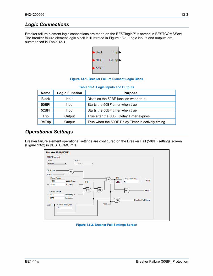
9424200996 13-3
BE1-11m Breaker Failure (50BF) Protection
Logic Connections
Breaker failure element logic connections are made on the BESTlogicPlus screen in BESTCOMSPlus. The breaker failure element logic block is illustrated in Figure 13-1. Logic inputs and outputs are summarized in Table 13-1.
Figure 13-1. Breaker Failure Element Logic Block
Table 13-1. Logic Inputs and Outputs
Name Logic Function Purpose Block Input Disables the 50BF function when true 50BFI Input Starts the 50BF timer when true
52BFI Input Starts the 50BF timer when true Trip Output True after the 50BF Delay Timer expires
ReTrip Output True when the 50BF Delay Timer is actively timing
Operational Settings
Breaker failure element operational settings are configured on the Breaker Fail (50BF) settings screen (Figure 13-2) in BESTCOMSPlus.
Figure 13-2. Breaker Fail Settings Screen

13-4 9424200996
Breaker Failure (50BF) Protection BE1-11m
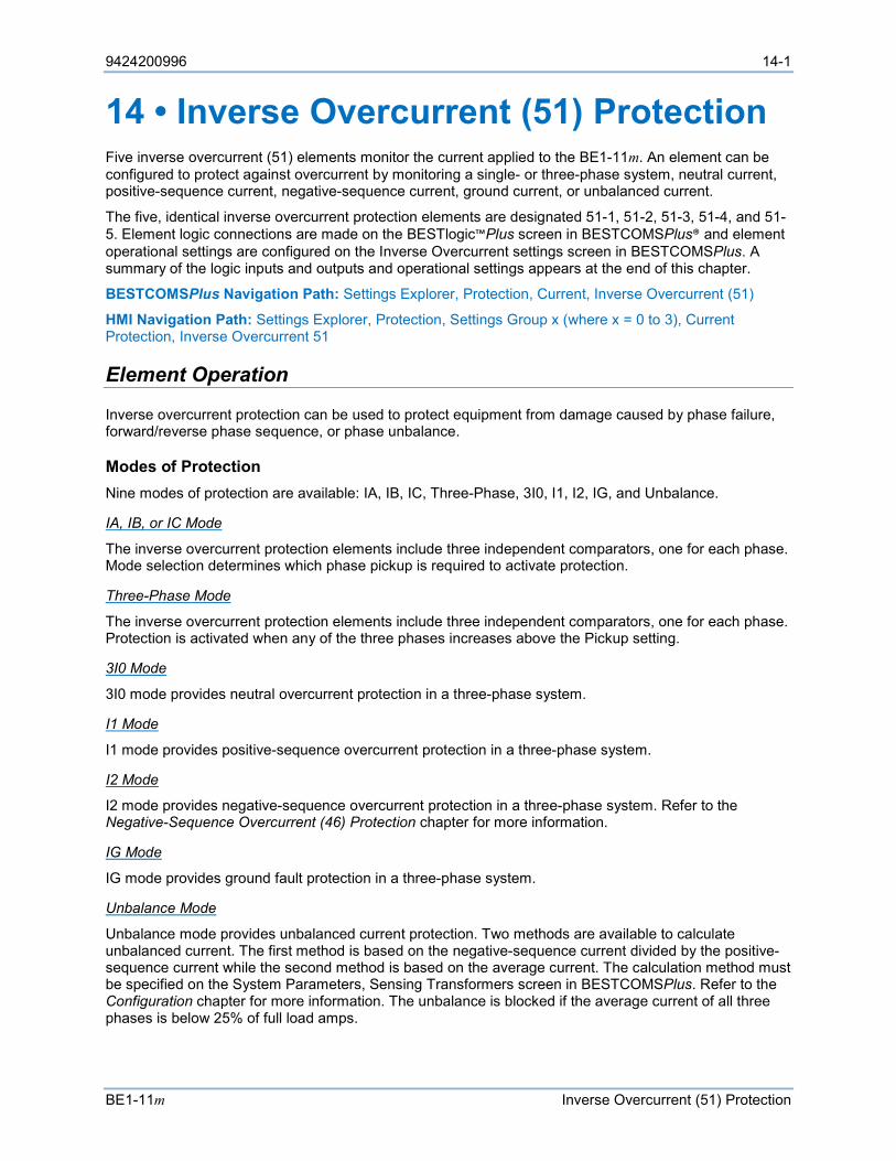
9424200996 14-1
BE1-11m Inverse Overcurrent (51) Protection
14 • Inverse Overcurrent (51) Protection Five inverse overcurrent (51) elements monitor the current applied to the BE1-11m. An element can be configured to protect against overcurrent by monitoring a single- or three-phase system, neutral current, positive-sequence current, negative-sequence current, ground current, or unbalanced current.
The five, identical inverse overcurrent protection elements are designated 51-1, 51-2, 51-3, 51-4, and 51-5. Element logic connections are made on the BESTlogic™Plus screen in BESTCOMSPlus® and element operational settings are configured on the Inverse Overcurrent settings screen in BESTCOMSPlus. A summary of the logic inputs and outputs and operational settings appears at the end of this chapter.
BESTCOMSPlus Navigation Path: Settings Explorer, Protection, Current, Inverse Overcurrent (51)
HMI Navigation Path: Settings Explorer, Protection, Settings Group x (where x = 0 to 3), Current Protection, Inverse Overcurrent 51
Element Operation
Inverse overcurrent protection can be used to protect equipment from damage caused by phase failure, forward/reverse phase sequence, or phase unbalance.
Modes of Protection Nine modes of protection are available: IA, IB, IC, Three-Phase, 3I0, I1, I2, IG, and Unbalance.
IA, IB, or IC Mode
The inverse overcurrent protection elements include three independent comparators, one for each phase. Mode selection determines which phase pickup is required to activate protection.
Three-Phase Mode
The inverse overcurrent protection elements include three independent comparators, one for each phase. Protection is activated when any of the three phases increases above the Pickup setting.
3I0 Mode
3I0 mode provides neutral overcurrent protection in a three-phase system.
I1 Mode
I1 mode provides positive-sequence overcurrent protection in a three-phase system.
I2 Mode
I2 mode provides negative-sequence overcurrent protection in a three-phase system. Refer to the Negative-Sequence Overcurrent (46) Protection chapter for more information.
IG Mode
IG mode provides ground fault protection in a three-phase system.
Unbalance Mode
Unbalance mode provides unbalanced current protection. Two methods are available to calculate unbalanced current. The first method is based on the negative-sequence current divided by the positive-sequence current while the second method is based on the average current. The calculation method must be specified on the System Parameters, Sensing Transformers screen in BESTCOMSPlus. Refer to the Configuration chapter for more information. The unbalance is blocked if the average current of all three phases is below 25% of full load amps.

14-2 9424200996
Inverse Overcurrent (51) Protection BE1-11m
CT Source The CT Source setting configures an inverse overcurrent element to monitor CT circuit 1 or CT circuit 2 on protection systems equipped with two sets of CTs. CT circuit 1 terminals are designated D1 (IA1) through D8 (IG1) and CT circuit 2 terminals are designated F1 (IA2) through F8 (IG2). For an illustration, refer to the Terminals and Connectors chapter.
Timings Each inverse overcurrent element has a Curve setting. The following paragraphs describe the available timing curves. The user can select integrating reset timing to make the protective element use integrated reset and emulate an electromechanical induction disk reset characteristic.
Standard Curves
There are 22 standard curves available including standard inverse, short inverse, moderately inverse, long inverse, very inverse, and extremely inverse. Refer to the Time Curve Characteristics chapter for specific information on each curve.
Programmable Curves
An available programmable curve can be used to create a custom curve by selecting coefficients in the inverse time characteristic equation. When inverse time overcurrent characteristic curve P is selected, the coefficients used in the equation are those defined by the user. Inverse overcurrent characteristics for trip and reset programmable curves are defined by Equation 14-1 and Equation 14-2. These equations comply with IEEE Std C37.112-1996 - IEEE Standard Inverse-Time Characteristic Equations for Overcurrent Relays. Definitions for these equations are provided in Table 14-1. The curve-specific coefficients are defined for the standard curves as listed in the Time Curve Characteristics chapter.
𝑇𝑇𝑇𝑇 =𝐴𝐴𝐴𝐴
𝑀𝑀𝑁𝑁 − 𝐶𝐶+ 𝐵𝐵𝐴𝐴 + 𝐾𝐾
Equation 14-1. Time OC Characteristics for Trip
𝑇𝑇𝑅𝑅 =𝑅𝑅𝐴𝐴
|𝑀𝑀2 − 1|
Equation 14-2. Time OC Characteristics for Reset
Table 14-1. Definitions for Equation 14-1 and Equation 14-2
Parameter Description Explanation TT Time to trip Time that the 51-x function will take to time out and trip. D Time dial setting Time dial setting for the 51-x function.
M Multiple of pickup Measured current in multiples of pickup. The timing algorithm has a dynamic range of 1 to 40 times pickup.
A Coefficient specific to selected curve
Affects the effective range of the time dial.
B Coefficient specific to selected curve
Affects a constant term in the timing equation. Has greatest effect on curve shape at high multiples of tap.
C Coefficient specific to selected curve
Affects the multiple of PU where the curve would approach infinity if allowed to continue below pickup. Has greatest effect on curve shape near pickup.
N Exponent specific to selected curve
Affects how inverse the characteristics are. Has greatest effect on curve shape at low to medium multiples of tap.
K Constant Characteristic minimum delay term.
TR Time to reset Relevant if 51-x function is set for integrating reset.
R Coefficient specific to selected curve
Affects the speed of reset when integrating reset is selected.

9424200996 14-3
BE1-11m Inverse Overcurrent (51) Protection
Curve coefficients are entered on the Inverse Overcurrent (51) settings screen in BESTCOMSPlus. Programmable curve coefficients can be entered only when the P curve is chosen for the protection element from the Curve drop-down menu.
Table Curves
BESTCOMSPlus is used to set the 51 element Table Curves (T1, T2, T3, and T4). Using the Settings Explorer within BESTCOMSPlus, open the Protection, Current, Table Curve (1, 2, 3, or 4) tree branch and select the table curve to be modified. Refer to Figure 14-1. A minimum of 2 and maximum of 40 points can be entered for any one T curve. When you are satisfied with the values chosen, select Save Curve. Use the Settings Explorer to browse to the 51-x element you wish to program and use the drop-down menu under Curve to select T1, T2, T3, or T4.
Table curves can be entered regardless of the curve chosen for the protection element. However, the table curve will not be enabled until T1, T2, T3, or T4 is selected as the curve for the protective element.
Figure 14-1. Inverse Overcurrent Table Curve
46 Curve
The 46 curve is a special curve designed to emulate the I2t withstand ratings of motors using what is frequently referred to as the motor’s K factor. Do not confuse the 46 curve with the I2 mode. The 46 curve was designed for use with the I2 mode. However, in actuality, the 46 curve can be selected for use with any mode of the inverse overcurrent element as well.
To use the 46 curve, the user should determine the K factor of the motor and the continuous (I2)2t rating of the motor (supplied by the manufacturer) and use this to set the time dial and pickup for the 46 curve by the process described in the Time Curve Characteristics chapter. The K factor is the time the motor can withstand 1 per unit I2 where 1 pu is the BE1-11m setting for nominal current.
Pickup and Trip The Pickup output occurs first, followed by the Trip output.
Pickup
The Pickup output becomes true when the measured current increases above the current threshold established by the Pickup setting. In BESTlogicPlus, the Pickup output can be connected to other logic

14-4 9424200996
Inverse Overcurrent (51) Protection BE1-11m
elements to annunciate the condition, control other elements in logic, and start the fault recorder (logic element FAULTTRIG).
Assertion of the Pickup output initiates a timer that begins timing to a trip. The duration of the timer is established by the Time Dial and Curve settings. A Time Dial setting of zero (0) makes the 51 element instantaneous with no intentional time delay.
If the pickup condition subsides before the calculated inverse time expires, the timer and Pickup outputs are reset, no corrective action is taken, and the element is rearmed for any other occurrences of overcurrent.
Trip
The Trip output becomes true if an overcurrent pickup condition persists for the duration of the calculated inverse time. In BESTlogicPlus, the Trip output can be connected to other logic elements and to a physical relay output to annunciate the condition and to initiate corrective action. If a target is enabled for the element, the BE1-11m will record a target when the Trip output becomes true. See the Fault Reporting chapter for more information about target reporting.
Voltage Restraint Mode (51/27R) When a 51 element is set for 3 Phase, IA, IB, or IC mode, the 51 element can be set for voltage control or voltage restraint mode of operation. This feature is used to allow increased phase overcurrent sensitivity while providing security from operation due to load current.
A Voltage Restraint threshold of zero (0) disables voltage restraint/control and allows the 51 element to operate normally.
Note BE1-11m protection systems enabled for IEC-61850 communication (style Mxxxx5xxxxxxxx) do not allow voltage controlled or restrained overcurrent elements. Blocking a 51 with an Undervoltage (27) element may allow control pending application requirements.
Control Mode
When set for Control mode of operation, the 51 element is disabled until the measured voltage drops below the Voltage Restraint threshold. Thus, as long as the voltage on the appropriate phase is above the Voltage Restraint threshold, the 51 element will be blocked. When set for this mode of operation, the 51 Pickup setting is typically set near or below load current levels.
Restraint Mode
When set for Restraint mode of operation, the pickup of the 51 element is adjusted based upon the magnitude of the measured voltage. Figure 14-2 shows how the 51 Pickup setting is adjusted in response to the measured voltage level. Equation 14-3 determines the pickup level for the 51 element when the measured voltage is between 25% and 100% of the Voltage Restraint threshold. Below 25%, the pickup level stays at 25%. Above 100%, the pickup level stays at 100%. For example, if the Voltage Restraint threshold is set for 120 V and the measured voltage on the appropriate phase is 100 V (83% of the Voltage Restraint threshold), the phase overcurrent pickup level will be reduced to 83% of its setting. When set for this mode of operation, the 51 element Pickup setting is typically set above worst case, load current levels.
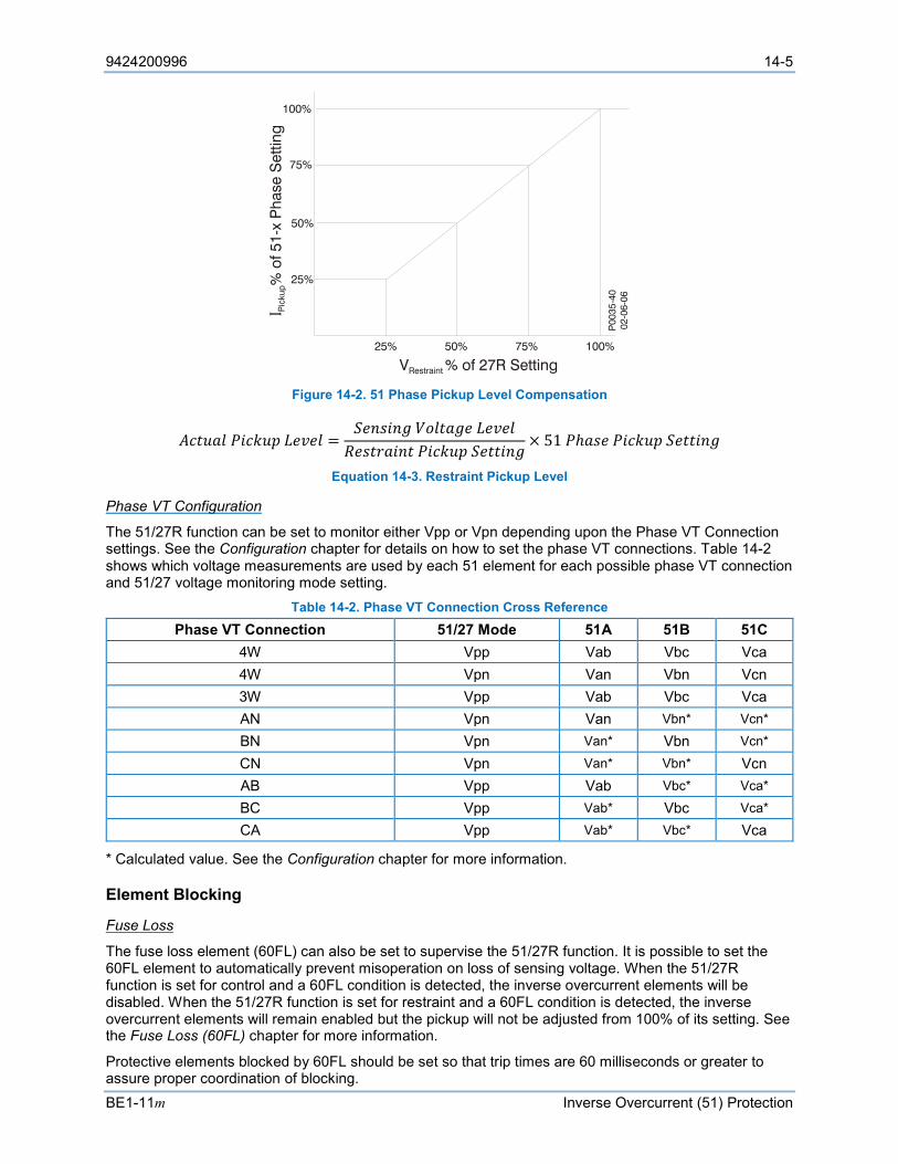
9424200996 14-5
BE1-11m Inverse Overcurrent (51) Protection
Figure 14-2. 51 Phase Pickup Level Compensation
𝐴𝐴𝐴𝐴𝐴𝐴𝐴𝐴𝐴𝐴𝐴𝐴 𝑃𝑃𝑃𝑃𝐴𝐴𝑃𝑃𝐴𝐴𝑃𝑃 𝐿𝐿𝐿𝐿𝐿𝐿𝐿𝐿𝐴𝐴 =𝑆𝑆𝐿𝐿𝑆𝑆𝑆𝑆𝑃𝑃𝑆𝑆𝑆𝑆 𝑉𝑉𝑉𝑉𝐴𝐴𝐴𝐴𝐴𝐴𝑆𝑆𝐿𝐿 𝐿𝐿𝐿𝐿𝐿𝐿𝐿𝐿𝐴𝐴𝑅𝑅𝐿𝐿𝑆𝑆𝐴𝐴𝑅𝑅𝐴𝐴𝑃𝑃𝑆𝑆𝐴𝐴 𝑃𝑃𝑃𝑃𝐴𝐴𝑃𝑃𝐴𝐴𝑃𝑃 𝑆𝑆𝐿𝐿𝐴𝐴𝐴𝐴𝑃𝑃𝑆𝑆𝑆𝑆
× 51 𝑃𝑃ℎ𝐴𝐴𝑆𝑆𝐿𝐿 𝑃𝑃𝑃𝑃𝐴𝐴𝑃𝑃𝐴𝐴𝑃𝑃 𝑆𝑆𝐿𝐿𝐴𝐴𝐴𝐴𝑃𝑃𝑆𝑆𝑆𝑆
Equation 14-3. Restraint Pickup Level
Phase VT Configuration
The 51/27R function can be set to monitor either Vpp or Vpn depending upon the Phase VT Connection settings. See the Configuration chapter for details on how to set the phase VT connections. Table 14-2 shows which voltage measurements are used by each 51 element for each possible phase VT connection and 51/27 voltage monitoring mode setting.
Table 14-2. Phase VT Connection Cross Reference Phase VT Connection 51/27 Mode 51A 51B 51C
4W Vpp Vab Vbc Vca 4W Vpn Van Vbn Vcn 3W Vpp Vab Vbc Vca AN Vpn Van Vbn* Vcn*
BN Vpn Van* Vbn Vcn*
CN Vpn Van* Vbn* Vcn AB Vpp Vab Vbc* Vca*
BC Vpp Vab* Vbc Vca*
CA Vpp Vab* Vbc* Vca
* Calculated value. See the Configuration chapter for more information.
Element Blocking
Fuse Loss
The fuse loss element (60FL) can also be set to supervise the 51/27R function. It is possible to set the 60FL element to automatically prevent misoperation on loss of sensing voltage. When the 51/27R function is set for control and a 60FL condition is detected, the inverse overcurrent elements will be disabled. When the 51/27R function is set for restraint and a 60FL condition is detected, the inverse overcurrent elements will remain enabled but the pickup will not be adjusted from 100% of its setting. See the Fuse Loss (60FL) chapter for more information.
Protective elements blocked by 60FL should be set so that trip times are 60 milliseconds or greater to assure proper coordination of blocking.

14-6 9424200996
Inverse Overcurrent (51) Protection BE1-11m
Block Logic Input
The Block input provides logic-supervision control of the element. When true, the Block input disables the element by forcing the Trip and Pickup outputs to logic 0 and resetting the element timer. Connect the element Block input to the desired logic in BESTlogicPlus. When the element is initially selected from the Elements view, the default condition of the Block input is a logic 0.
Logic Connections
Inverse overcurrent element logic connections are made on the BESTlogicPlus screen in BESTCOMSPlus. The inverse overcurrent element logic block is illustrated in Figure 14-3. Logic inputs and outputs are summarized in Table 14-3.
Figure 14-3. Inverse Overcurrent Element Logic Block
Table 14-3. Logic Inputs and Outputs
Name Logic Function Purpose Block Input Disables the 51 function when true Trip Output True when the 51 element is in a trip condition
Pickup Output True when the 51 element is in a pickup condition
Operational Settings
Inverse overcurrent element operational settings are configured on the Inverse Overcurrent (51) settings screen (Figure 14-4) in BESTCOMSPlus.
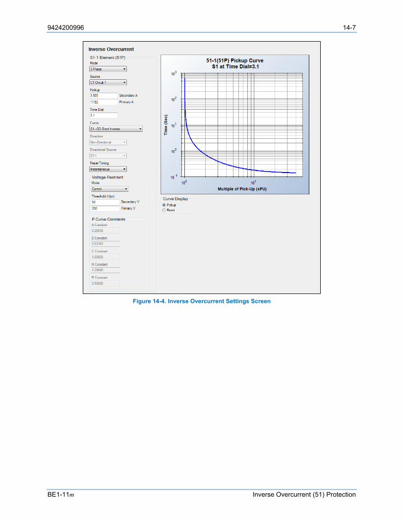
9424200996 14-7
BE1-11m Inverse Overcurrent (51) Protection
Figure 14-4. Inverse Overcurrent Settings Screen

14-8 9424200996
Inverse Overcurrent (51) Protection BE1-11m
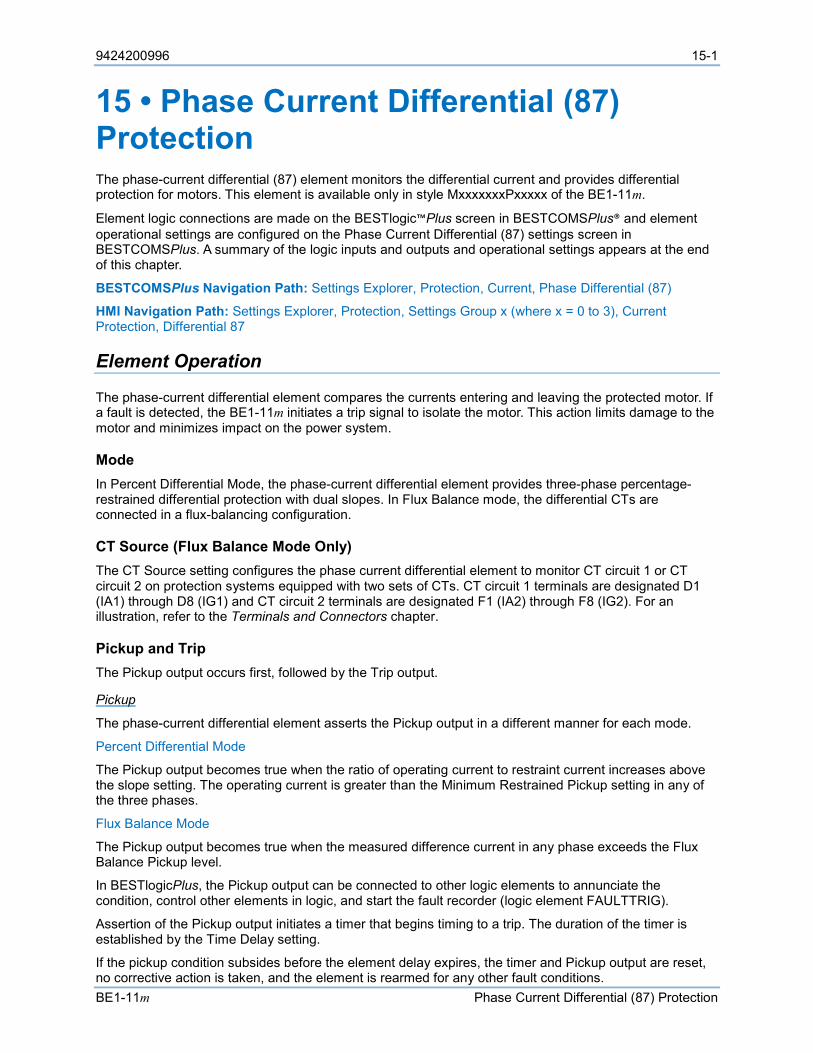
9424200996 15-1
BE1-11m Phase Current Differential (87) Protection
15 • Phase Current Differential (87) Protection The phase-current differential (87) element monitors the differential current and provides differential protection for motors. This element is available only in style MxxxxxxxPxxxxx of the BE1-11m.
Element logic connections are made on the BESTlogic™Plus screen in BESTCOMSPlus® and element operational settings are configured on the Phase Current Differential (87) settings screen in BESTCOMSPlus. A summary of the logic inputs and outputs and operational settings appears at the end of this chapter.
BESTCOMSPlus Navigation Path: Settings Explorer, Protection, Current, Phase Differential (87)
HMI Navigation Path: Settings Explorer, Protection, Settings Group x (where x = 0 to 3), Current Protection, Differential 87
Element Operation
The phase-current differential element compares the currents entering and leaving the protected motor. If a fault is detected, the BE1-11m initiates a trip signal to isolate the motor. This action limits damage to the motor and minimizes impact on the power system.
Mode In Percent Differential Mode, the phase-current differential element provides three-phase percentage-restrained differential protection with dual slopes. In Flux Balance mode, the differential CTs are connected in a flux-balancing configuration.
CT Source (Flux Balance Mode Only) The CT Source setting configures the phase current differential element to monitor CT circuit 1 or CT circuit 2 on protection systems equipped with two sets of CTs. CT circuit 1 terminals are designated D1 (IA1) through D8 (IG1) and CT circuit 2 terminals are designated F1 (IA2) through F8 (IG2). For an illustration, refer to the Terminals and Connectors chapter.
Pickup and Trip The Pickup output occurs first, followed by the Trip output.
Pickup
The phase-current differential element asserts the Pickup output in a different manner for each mode.
Percent Differential Mode
The Pickup output becomes true when the ratio of operating current to restraint current increases above the slope setting. The operating current is greater than the Minimum Restrained Pickup setting in any of the three phases.
Flux Balance Mode
The Pickup output becomes true when the measured difference current in any phase exceeds the Flux Balance Pickup level.
In BESTlogicPlus, the Pickup output can be connected to other logic elements to annunciate the condition, control other elements in logic, and start the fault recorder (logic element FAULTTRIG).
Assertion of the Pickup output initiates a timer that begins timing to a trip. The duration of the timer is established by the Time Delay setting.
If the pickup condition subsides before the element delay expires, the timer and Pickup output are reset, no corrective action is taken, and the element is rearmed for any other fault conditions.
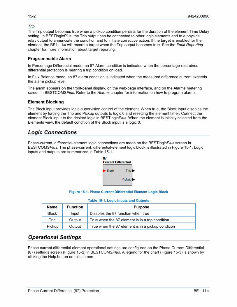
15-2 9424200996
Phase Current Differential (87) Protection BE1-11m
Trip The Trip output becomes true when a pickup condition persists for the duration of the element Time Delay setting. In BESTlogicPlus, the Trip output can be connected to other logic elements and to a physical relay output to annunciate the condition and to initiate corrective action. If the target is enabled for the element, the BE1-11m will record a target when the Trip output becomes true. See the Fault Reporting chapter for more information about target reporting.
Programmable Alarm In Percentage Differential mode, an 87 Alarm condition is indicated when the percentage-restrained differential protection is nearing a trip condition on load.
In Flux Balance mode, an 87 alarm condition is indicated when the measured difference current exceeds the alarm pickup level.
The alarm appears on the front-panel display, on the web-page interface, and on the Alarms metering screen in BESTCOMSPlus. Refer to the Alarms chapter for information on how to program alarms.
Element Blocking The Block input provides logic-supervision control of the element. When true, the Block input disables the element by forcing the Trip and Pickup outputs to logic 0 and resetting the element timer. Connect the element Block input to the desired logic in BESTlogicPlus. When the element is initially selected from the Elements view, the default condition of the Block input is a logic 0.
Logic Connections
Phase-current, differential-element logic connections are made on the BESTlogicPlus screen in BESTCOMSPlus. The phase-current, differential-element logic block is illustrated in Figure 15-1. Logic inputs and outputs are summarized in Table 15-1.
Figure 15-1. Phase Current Differential Element Logic Block
Table 15-1. Logic Inputs and Outputs
Name Function Purpose Block Input Disables the 87 function when true Trip Output True when the 87 element is in a trip condition
Pickup Output True when the 87 element is in a pickup condition
Operational Settings
Phase current differential element operational settings are configured on the Phase Current Differential (87) settings screen (Figure 15-2) in BESTCOMSPlus. A legend for the chart (Figure 15-3) is shown by clicking the Help button on this screen.
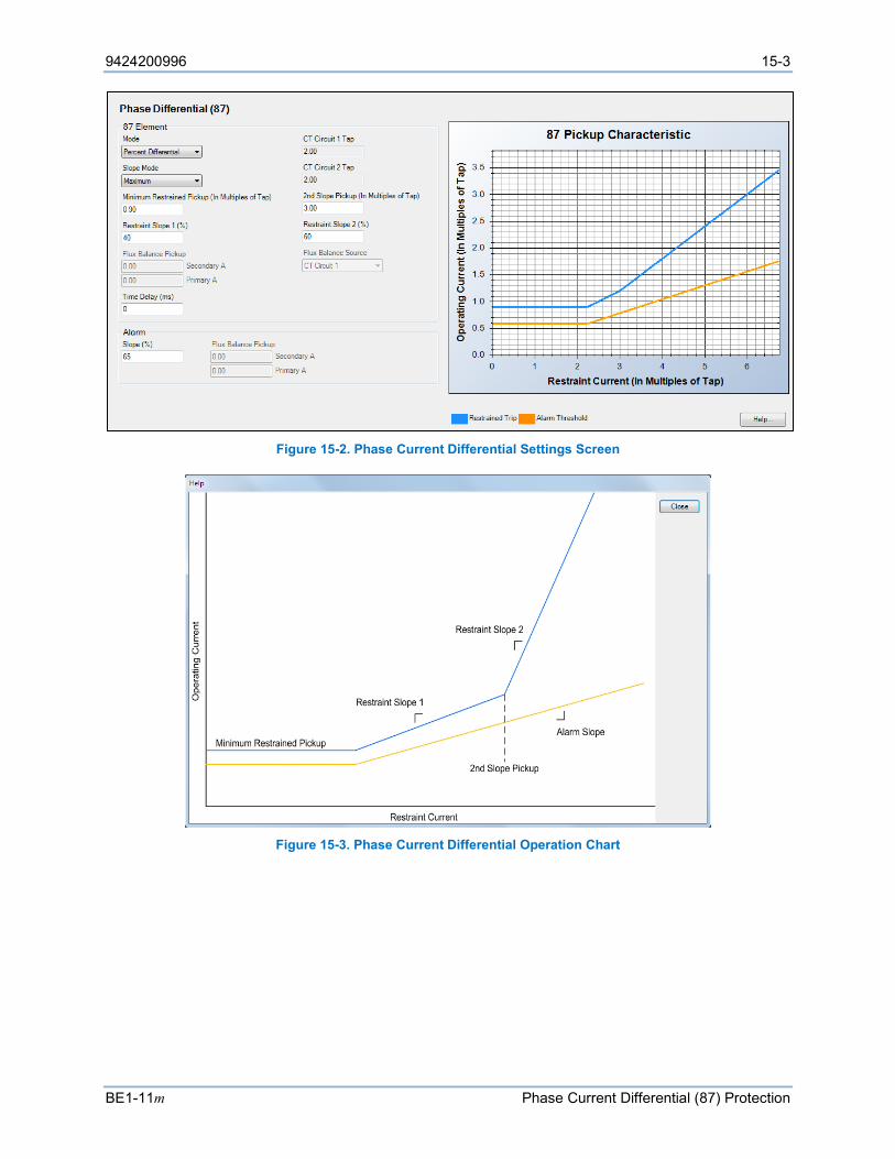
9424200996 15-3
BE1-11m Phase Current Differential (87) Protection
Figure 15-2. Phase Current Differential Settings Screen
Figure 15-3. Phase Current Differential Operation Chart
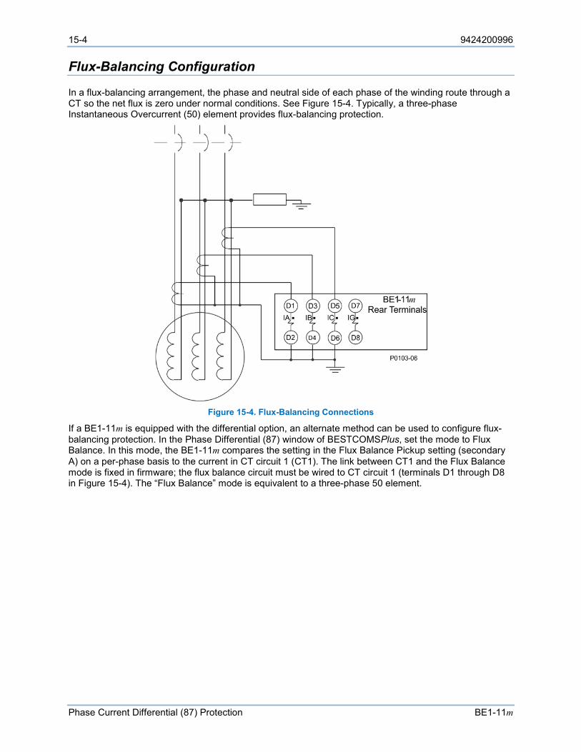
15-4 9424200996
Phase Current Differential (87) Protection BE1-11m
Flux-Balancing Configuration
In a flux-balancing arrangement, the phase and neutral side of each phase of the winding route through a CT so the net flux is zero under normal conditions. See Figure 15-4. Typically, a three-phase Instantaneous Overcurrent (50) element provides flux-balancing protection.
Figure 15-4. Flux-Balancing Connections
If a BE1-11m is equipped with the differential option, an alternate method can be used to configure flux-balancing protection. In the Phase Differential (87) window of BESTCOMSPlus, set the mode to Flux Balance. In this mode, the BE1-11m compares the setting in the Flux Balance Pickup setting (secondary A) on a per-phase basis to the current in CT circuit 1 (CT1). The link between CT1 and the Flux Balance mode is fixed in firmware; the flux balance circuit must be wired to CT circuit 1 (terminals D1 through D8 in Figure 15-4). The “Flux Balance” mode is equivalent to a three-phase 50 element.
9424200996 16-1
BE1-11m Power (32) Protection
16 • Power (32) Protection The power (32) element monitors three-phase real power (watts). The element can be configured to protect against overpower or underpower conditions.
Element logic connections are made on the BESTlogic™Plus screen in BESTCOMSPlus® and element operational settings are configured on the Power settings screen in BESTCOMSPlus. A summary of the logic inputs and outputs and operational settings appears at the end of this chapter.
Note BE1-11m protection systems enabled for IEC-61850 communication (style Mxxxx5xxxxxxxx) have their power protection element fixed at one underpower element.
BESTCOMSPlus Navigation Path: Settings Explorer, Protection, Power, Power (32)
HMI Navigation Path: Settings Explorer, Protection, Settings Group x (where x = 0 to 3), Power Protection, Power 32
Element Operation
Power protection can be used in applications where excessive power flow in the tripping direction is undesirable. Directional power protection is desirable in applications where:
• Reduced power can indicate a loss of load on the motor.
• Power flows into the secondary of a station distribution transformer, indicating an industrial or private customer is supplying power into the utility system.
• Excessive load has been connected to a system.
• Overload has been placed on a distribution system.
• Overspeeding is a prime concern.
• An open breaker creates an overload on a local generation facility.
Mode Four modes of protection are available. One of Three mode activates protection when the power on one of the three phases exceeds the Pickup setting. Two of Three mode activates protection when the power on any two of the three phases exceeds the Pickup setting. Three of Three mode activates protection when the power on all three phases exceeds the Pickup setting. Total Power mode activates protection when the total power exceeds the Pickup setting. The element remains in the picked-up condition until power flow falls below the dropout ratio of 95% of the actual pickup.
To clarify the difference between Three of Three and Total Power modes, assume that Two of Three mode has been selected and the pickup setting is 30 watts. Therefore, the BE1-11m picks up when two of the three phases have exceeded 30 watts. Alternately, if two phases are zero (0) watts and the third phase is 70 watts, the BE1-11m does not pickup because two of the phases have not exceeded the pickup threshold required for operation in Two of Three mode. Any two phases must exceed the pickup threshold for operation to occur. However, if the 32 element was set for Total Power mode, the same power values previously mentioned would result in a pickup condition because “Total Power” (0 + 0 + 70 watts) exceeds the three-phase pickup setting of 30 watts. For details on power calculations, refer to the Configuration chapter.
Bus CT Configuration On protection systems equipped with two sets of CTs, the power element can monitor CT circuit 1 or CT circuit 2. The CT source is selected on the Sensing Transformers settings screen in BESTCOMSPlus.
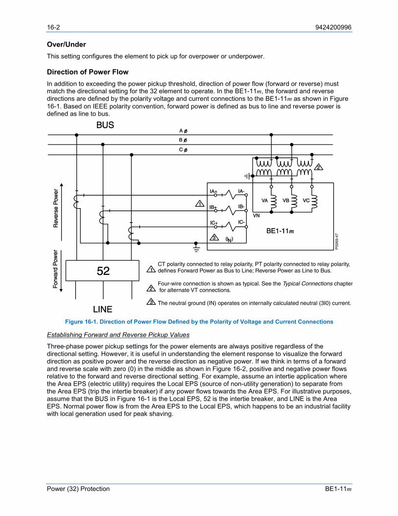
16-2 9424200996
Power (32) Protection BE1-11m
Over/Under This setting configures the element to pick up for overpower or underpower.
Direction of Power Flow In addition to exceeding the power pickup threshold, direction of power flow (forward or reverse) must match the directional setting for the 32 element to operate. In the BE1-11m, the forward and reverse directions are defined by the polarity voltage and current connections to the BE1-11m as shown in Figure 16-1. Based on IEEE polarity convention, forward power is defined as bus to line and reverse power is defined as line to bus.
Figure 16-1. Direction of Power Flow Defined by the Polarity of Voltage and Current Connections
Establishing Forward and Reverse Pickup Values
Three-phase power pickup settings for the power elements are always positive regardless of the directional setting. However, it is useful in understanding the element response to visualize the forward direction as positive power and the reverse direction as negative power. If we think in terms of a forward and reverse scale with zero (0) in the middle as shown in Figure 16-2, positive and negative power flows relative to the forward and reverse directional setting. For example, assume an intertie application where the Area EPS (electric utility) requires the Local EPS (source of non-utility generation) to separate from the Area EPS (trip the intertie breaker) if any power flows towards the Area EPS. For illustrative purposes, assume that the BUS in Figure 16-1 is the Local EPS, 52 is the intertie breaker, and LINE is the Area EPS. Normal power flow is from the Area EPS to the Local EPS, which happens to be an industrial facility with local generation used for peak shaving.
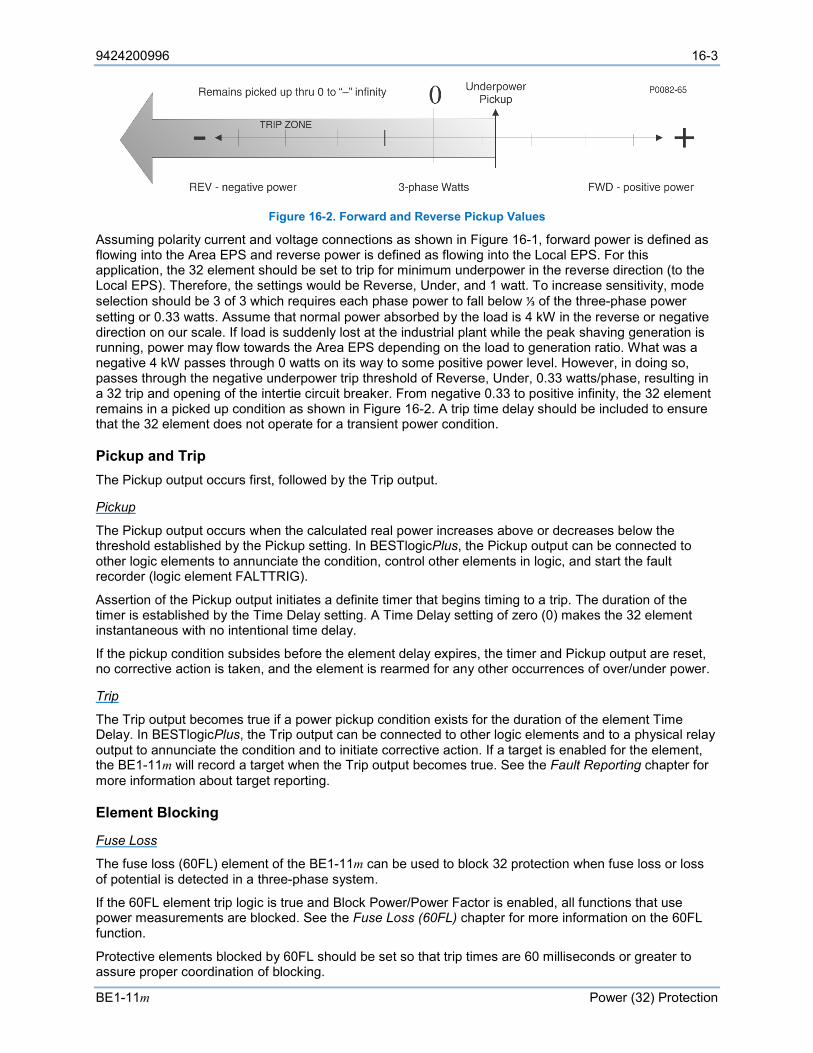
9424200996 16-3
BE1-11m Power (32) Protection
Figure 16-2. Forward and Reverse Pickup Values
Assuming polarity current and voltage connections as shown in Figure 16-1, forward power is defined as flowing into the Area EPS and reverse power is defined as flowing into the Local EPS. For this application, the 32 element should be set to trip for minimum underpower in the reverse direction (to the Local EPS). Therefore, the settings would be Reverse, Under, and 1 watt. To increase sensitivity, mode selection should be 3 of 3 which requires each phase power to fall below ⅓ of the three-phase power setting or 0.33 watts. Assume that normal power absorbed by the load is 4 kW in the reverse or negative direction on our scale. If load is suddenly lost at the industrial plant while the peak shaving generation is running, power may flow towards the Area EPS depending on the load to generation ratio. What was a negative 4 kW passes through 0 watts on its way to some positive power level. However, in doing so, passes through the negative underpower trip threshold of Reverse, Under, 0.33 watts/phase, resulting in a 32 trip and opening of the intertie circuit breaker. From negative 0.33 to positive infinity, the 32 element remains in a picked up condition as shown in Figure 16-2. A trip time delay should be included to ensure that the 32 element does not operate for a transient power condition.
Pickup and Trip The Pickup output occurs first, followed by the Trip output.
Pickup
The Pickup output occurs when the calculated real power increases above or decreases below the threshold established by the Pickup setting. In BESTlogicPlus, the Pickup output can be connected to other logic elements to annunciate the condition, control other elements in logic, and start the fault recorder (logic element FALTTRIG).
Assertion of the Pickup output initiates a definite timer that begins timing to a trip. The duration of the timer is established by the Time Delay setting. A Time Delay setting of zero (0) makes the 32 element instantaneous with no intentional time delay.
If the pickup condition subsides before the element delay expires, the timer and Pickup output are reset, no corrective action is taken, and the element is rearmed for any other occurrences of over/under power.
Trip
The Trip output becomes true if a power pickup condition exists for the duration of the element Time Delay. In BESTlogicPlus, the Trip output can be connected to other logic elements and to a physical relay output to annunciate the condition and to initiate corrective action. If a target is enabled for the element, the BE1-11m will record a target when the Trip output becomes true. See the Fault Reporting chapter for more information about target reporting.
Element Blocking
Fuse Loss
The fuse loss (60FL) element of the BE1-11m can be used to block 32 protection when fuse loss or loss of potential is detected in a three-phase system.
If the 60FL element trip logic is true and Block Power/Power Factor is enabled, all functions that use power measurements are blocked. See the Fuse Loss (60FL) chapter for more information on the 60FL function.
Protective elements blocked by 60FL should be set so that trip times are 60 milliseconds or greater to assure proper coordination of blocking.
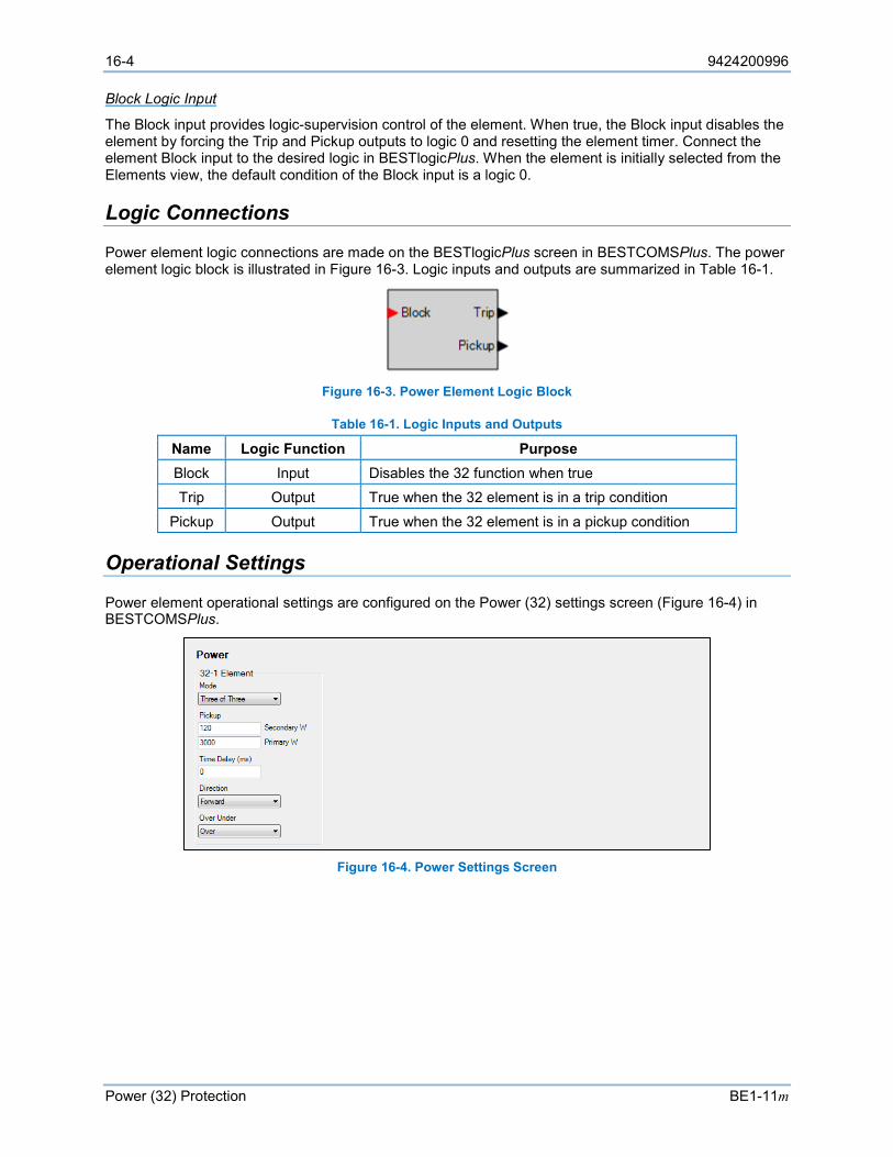
16-4 9424200996
Power (32) Protection BE1-11m
Block Logic Input
The Block input provides logic-supervision control of the element. When true, the Block input disables the element by forcing the Trip and Pickup outputs to logic 0 and resetting the element timer. Connect the element Block input to the desired logic in BESTlogicPlus. When the element is initially selected from the Elements view, the default condition of the Block input is a logic 0.
Logic Connections
Power element logic connections are made on the BESTlogicPlus screen in BESTCOMSPlus. The power element logic block is illustrated in Figure 16-3. Logic inputs and outputs are summarized in Table 16-1.
Figure 16-3. Power Element Logic Block
Table 16-1. Logic Inputs and Outputs
Name Logic Function Purpose Block Input Disables the 32 function when true Trip Output True when the 32 element is in a trip condition
Pickup Output True when the 32 element is in a pickup condition
Operational Settings
Power element operational settings are configured on the Power (32) settings screen (Figure 16-4) in BESTCOMSPlus.
Figure 16-4. Power Settings Screen

9424200996 17-1
BE1-11m Loss of Excitation - Reverse Var Based (40Q) Protection
17 • Loss of Excitation - Reverse Var Based (40Q) Protection The loss of excitation - reverse var based (40Q) element monitors total reactive power (vars).
Element logic connections are made on the BESTlogic™Plus screen in BESTCOMSPlus® and element operational settings are configured on the Loss of Excitation - Reverse var Based (40Q) settings screen in BESTCOMSPlus. A summary of the logic inputs and outputs and operational settings appears at the end of this chapter.
BESTCOMSPlus Navigation Path: Settings Explorer, Protection, Power, Loss of Excitation - Reverse var Based (40Q)
HMI Navigation Path: Settings Explorer, Protection, Settings Group x (where x = 0 to 3), Power Protection, Reverse var 40Q
Element Operation
The loss of excitation element operates on excessive var flow into the machine, indicating abnormally low field excitation. Operation of synchronous motors drawing reactive power from the system can result in overheating in parts of the rotor that do not normally carry current. The 40Q pickup response is shown in Figure 17-1.
Figure 17-1. 40Q Pickup Response
Bus CT Configuration On protection systems equipped with two sets of CTs, the 40Q element can monitor CT circuit 1 or CT circuit 2. The CT source is selected on the Sensing Transformers settings screen in BESTCOMSPlus.
Pickup and Trip The Pickup output occurs first, followed by the Trip output.
Pickup
The Pickup output becomes true when the calculated reactive power increases above or decreases below the threshold established by the Pickup setting. In BESTlogicPlus, the Pickup output can be connected to other logic elements to annunciate the condition, control other elements in logic, and start the fault recorder (logic element FAULTTRIG).
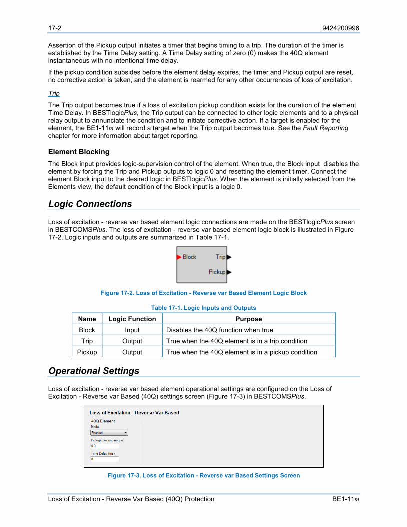
17-2 9424200996
Loss of Excitation - Reverse Var Based (40Q) Protection BE1-11m
Assertion of the Pickup output initiates a timer that begins timing to a trip. The duration of the timer is established by the Time Delay setting. A Time Delay setting of zero (0) makes the 40Q element instantaneous with no intentional time delay.
If the pickup condition subsides before the element delay expires, the timer and Pickup output are reset, no corrective action is taken, and the element is rearmed for any other occurrences of loss of excitation.
Trip
The Trip output becomes true if a loss of excitation pickup condition exists for the duration of the element Time Delay. In BESTlogicPlus, the Trip output can be connected to other logic elements and to a physical relay output to annunciate the condition and to initiate corrective action. If a target is enabled for the element, the BE1-11m will record a target when the Trip output becomes true. See the Fault Reporting chapter for more information about target reporting.
Element Blocking The Block input provides logic-supervision control of the element. When true, the Block input disables the element by forcing the Trip and Pickup outputs to logic 0 and resetting the element timer. Connect the element Block input to the desired logic in BESTlogicPlus. When the element is initially selected from the Elements view, the default condition of the Block input is a logic 0.
Logic Connections
Loss of excitation - reverse var based element logic connections are made on the BESTlogicPlus screen in BESTCOMSPlus. The loss of excitation - reverse var based element logic block is illustrated in Figure 17-2. Logic inputs and outputs are summarized in Table 17-1.
Figure 17-2. Loss of Excitation - Reverse var Based Element Logic Block
Table 17-1. Logic Inputs and Outputs
Name Logic Function Purpose Block Input Disables the 40Q function when true Trip Output True when the 40Q element is in a trip condition
Pickup Output True when the 40Q element is in a pickup condition
Operational Settings
Loss of excitation - reverse var based element operational settings are configured on the Loss of Excitation - Reverse var Based (40Q) settings screen (Figure 17-3) in BESTCOMSPlus.
Figure 17-3. Loss of Excitation - Reverse var Based Settings Screen
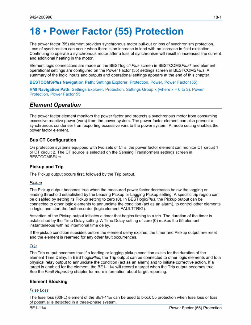
9424200996 18-1
BE1-11m Power Factor (55) Protection
18 • Power Factor (55) Protection The power factor (55) element provides synchronous motor pull-out or loss of synchronism protection. Loss of synchronism can occur when there is an increase in load with no increase in field excitation. Continuing to operate a synchronous motor after a loss of synchronism will result in increased line current and additional heating in the motor.
Element logic connections are made on the BESTlogic™Plus screen in BESTCOMSPlus® and element operational settings are configured on the Power Factor (55) settings screen in BESTCOMSPlus. A summary of the logic inputs and outputs and operational settings appears at the end of this chapter.
BESTCOMSPlus Navigation Path: Settings Explorer, Protection, Power, Power Factor (55)
HMI Navigation Path: Settings Explorer, Protection, Settings Group x (where x = 0 to 3), Power Protection, Power Factor 55
Element Operation
The power factor element monitors the power factor and protects a synchronous motor from consuming excessive reactive power (vars) from the power system. The power factor element can also prevent a synchronous condenser from exporting excessive vars to the power system. A mode setting enables the power factor element.
Bus CT Configuration On protection systems equipped with two sets of CTs, the power factor element can monitor CT circuit 1 or CT circuit 2. The CT source is selected on the Sensing Transformers settings screen in BESTCOMSPlus.
Pickup and Trip The Pickup output occurs first, followed by the Trip output.
Pickup
The Pickup output becomes true when the measured power factor decreases below the lagging or leading threshold established by the Leading Pickup or Lagging Pickup setting. A specific trip region can be disabled by setting its Pickup setting to zero (0). In BESTlogicPlus, the Pickup output can be connected to other logic elements to annunciate the condition (act as an alarm), to control other elements in logic, and start the fault recorder (logic element FAULTTRIG).
Assertion of the Pickup output initiates a timer that begins timing to a trip. The duration of the timer is established by the Time Delay setting. A Time Delay setting of zero (0) makes the 55 element instantaneous with no intentional time delay.
If the pickup condition subsides before the element delay expires, the timer and Pickup output are reset and the element is rearmed for any other fault occurrences.
Trip
The Trip output becomes true if a leading or lagging pickup condition exists for the duration of the element Time Delay. In BESTlogicPlus, the Trip output can be connected to other logic elements and to a physical relay output to annunciate the condition (act as an alarm) and to initiate corrective action. If a target is enabled for the element, the BE1-11m will record a target when the Trip output becomes true. See the Fault Reporting chapter for more information about target reporting.
Element Blocking
Fuse Loss
The fuse loss (60FL) element of the BE1-11m can be used to block 55 protection when fuse loss or loss of potential is detected in a three-phase system.
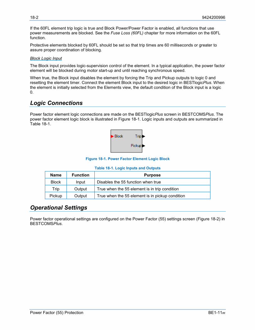
18-2 9424200996
Power Factor (55) Protection BE1-11m
If the 60FL element trip logic is true and Block Power/Power Factor is enabled, all functions that use power measurements are blocked. See the Fuse Loss (60FL) chapter for more information on the 60FL function.
Protective elements blocked by 60FL should be set so that trip times are 60 milliseconds or greater to assure proper coordination of blocking.
Block Logic Input
The Block input provides logic-supervision control of the element. In a typical application, the power factor element will be blocked during motor start-up and until reaching synchronous speed.
When true, the Block input disables the element by forcing the Trip and Pickup outputs to logic 0 and resetting the element timer. Connect the element Block input to the desired logic in BESTlogicPlus. When the element is initially selected from the Elements view, the default condition of the Block input is a logic 0.
Logic Connections
Power factor element logic connections are made on the BESTlogicPlus screen in BESTCOMSPlus. The power factor element logic block is illustrated in Figure 18-1. Logic inputs and outputs are summarized in Table 18-1.
Figure 18-1. Power Factor Element Logic Block
Table 18-1. Logic Inputs and Outputs
Name Function Purpose Block Input Disables the 55 function when true Trip Output True when the 55 element is in trip condition
Pickup Output True when the 55 element is in pickup condition
Operational Settings
Power factor operational settings are configured on the Power Factor (55) settings screen (Figure 18-2) in BESTCOMSPlus.
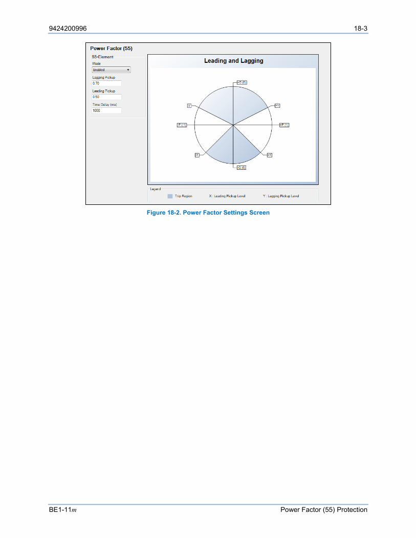
9424200996 18-3
BE1-11m Power Factor (55) Protection
Figure 18-2. Power Factor Settings Screen

18-4 9424200996
Power Factor (55) Protection BE1-11m
9424200996 19-1
BE1-11m Resistance Temperature Detector (49RTD) Protection
19 • Resistance Temperature Detector (49RTD) Protection Fourteen resistance temperature detector (49RTD) elements provide over/undertemperature protection in applications when a remote RTD module is connected via Ethernet or RS-485. There are 12 physical RTD sensors per RTD module. Each element can be set to monitor a single physical RTD sensor or a group of them. Refer to the RTD Module chapter for information on mounting, connections, communication setup, and specifications.
The fourteen, identical remote RTD protection elements are designated 49RTD-1 through 49RTD-14. Element logic connections are made on the BESTlogic™Plus screen in BESTCOMSPlus® and element operational settings are configured on the Remote RTD (49RTD) settings screen in BESTCOMSPlus. A summary of the logic inputs and outputs and operational settings appears at the end of this section.
BESTCOMSPlus Navigation Path: Settings Explorer, Protection, Thermal, Resistance Temperature Detector (49RTD)
HMI Navigation Path: Settings Explorer, Protection, Settings Group x (where x = 0 to 3), Thermal Protection, Resistance Temp 49RTD
Element Operation
Each RTD input can be configured to protect against high, low, or both temperature conditions.
Modes of Protection Three modes of protection are available: Over, Under, and Over/Under.
In Over mode, if the temperature of the RTD is above the Over Pickup setting, the element will pick up. In Under mode, if the temperature of the RTD is below the Under Pickup setting, the element will pick up. In Over/Under mode, if the temperature of the RTD is above the Over Pickup setting or below the Under Pickup setting, the element will pick up. The element will remain in the picked-up condition and continue timing towards a trip unless the temperature falls below the Over Pickup setting or rises above the Under Pickup setting.
Source The Source setting selects which RTD input to monitor. Refer to the RTD Module chapter for more information.
Pickup and Trip The Pickup output occurs first, followed by the Trip output.
Pickup
The Pickup output becomes true when the measured remote RTD input value increases above (Over mode) or decreases below (Under mode) the pickup setting. In BESTlogicPlus, the Pickup output can be connected to other logic elements to annunciate the condition, control other elements in logic, and start the fault recorder (logic element FAULTTRIG).
Assertion of the Pickup output initiates a timer that begins timing to a trip. The duration of the timer is established by the Time Delay setting. A Time Delay setting of zero (0) makes the element instantaneous with no intentional time delay.
If the pickup condition subsides before the element delay expires, the timer and Pickup output are reset and no corrective action is taken.
19-2 9424200996
Resistance Temperature Detector (49RTD) Protection BE1-11m
Trip
The Trip output becomes true if a pickup condition persists for the duration of the element Time Delay. In BESTlogicPlus, the Trip output can be connected to other logic elements and to a physical relay output to annunciate the condition and to initiate corrective action. If a target is enabled for the element, the BE1-11m will record a target when the Trip output becomes true. See the Fault Reporting chapter for more information about target reporting.
Voting The Voting parameter defines the number of RTDs in the group that must exceed the pickup setting to cause a trip. For example, if the 49RTD-1 Voting setting is three, then at least 3 RTDs in the selected group must exceed the pickup setting to cause a trip.
Element Blocking The Block input provides logic-supervision control of the element. When true, the Block input disables the element by forcing the Trip and Pickup outputs to logic 0 and resetting the element timer. Connect the element Block input to the desired logic in BESTlogicPlus. When the element is initially selected from the Elements view, the default condition of the Block input is a logic 0.
Logic Connections
Remote RTD input element logic connections are made on the BESTlogicPlus screen in BESTCOMSPlus. The remote RTD input element logic block is illustrated in Figure 19-1. Logic inputs and outputs are summarized in Table 19-1.
Figure 19-1. Remote RTD Input Element Logic Block
Table 19-1. Logic Inputs and Outputs
Name Function Purpose Block Input Disables the 49RTD function when true Trip Output True when the 49RTD element is in trip condition
Pickup Output True when the 49RTD element is in pickup condition
Operational Settings
Remote RTD input element operational settings are configured on the Resistance Temperature Detector settings screen (Figure 19-2) in BESTCOMSPlus.
9424200996 19-3
BE1-11m Resistance Temperature Detector (49RTD) Protection
Figure 19-2. Resistance Temperature Detector Settings Screen
Remote RTD Metering
RTD metering values are obtained through BESTCOMSPlus by using the Metering Explorer to open the Analog Metering, RTD Meter tree branch. BESTCOMSPlus must be online with the BE1-11m to view RTD metering. Alternately, values can be obtained through the front-panel display by navigating to the Metering, Analog Metering, RTD Meter Input screen.

19-4 9424200996
Resistance Temperature Detector (49RTD) Protection BE1-11m
9424200996 20-1
BE1-11m Thermal Curve (49TC) Protection
20 • Thermal Curve (49TC) Protection The thermal curve (49TC) element models the thermal capacity in a motor to provide thermal protection. The element uses voltage level, negative-sequence current, and three-phase maximum current on CT1 to modify the thermal curve.
Element logic connections are made on the BESTlogic™Plus screen in BESTCOMSPlus® and element operational settings are configured on the Thermal Curve (49TC) settings screen in BESTCOMSPlus. A summary of the logic inputs and outputs and operational settings appears at the end of this chapter.
BESTCOMSPlus Navigation Path: Settings Explorer, Protection, Thermal, Thermal Curve (49TC)
HMI Navigation Path: Settings Explorer, Protection, Settings Group x (where x = 0 to 3), Thermal Protection, Thermal Curve 49TC
Element Operation
Modes of Protection Three modes of protection are available: Standard Curve, IEC Curve, and User Curve.
Standard Curve
The Standard Curve Time Dial setting determines the time to trip when the 49TC element is configured for Standard Curve mode. The standard curve provides a I2 curve with a range of time dial settings that accommodate a wide range of motor timings. The standard curve equation is shown in Equation 20-1.
t = TD × 88.744132 × ln
⎣⎢⎢⎢⎡
IeqS ∙ SF ∙ FLA
2
Ieq
S ∙ SF ∙ FLA2− 1⎦
⎥⎥⎥⎤
With max value of Ieq/(S•SF•FLA) of 10.
Equation 20-1. Standard Curve
Where: t = Operating time Ieq = Measured equivalent motor current TD = Time Dial FLA = Full Load Amps SF = Service Factor S = Overload Scalar ln = Natural log
IEC Curve
IEC curves provide the ability to automatically change between two curves based on whether the motor is hot or cold. The hot or cold status is shown on the front-panel display under Metering Explorer, Status, Motor Status, Thermal Curve.
An internal cold-to-hot timer is initiated when the motor is started from a cold state. The timer continues after the motor is running. The motor is determined as hot when the internal timer exceeds the Running Cool Time Constant (RCTC) setting and the hot curve shown in Equation 20-2 is used. If the motor is stopped before the RCTC setting is exceeded, the motor remains in a cold state and the timer resets at zero. It is recommended that the IEC Hot Curve Current setting (Ip) is set no greater than 95% of the thermal current pickup (S • SF • FLA).
An internal hot-to-cold timer is initiated when the motor is stopped while in a hot state and the thermal capacity is less than 10%. The motor is determined as cold when the internal timer exceeds the Stopped
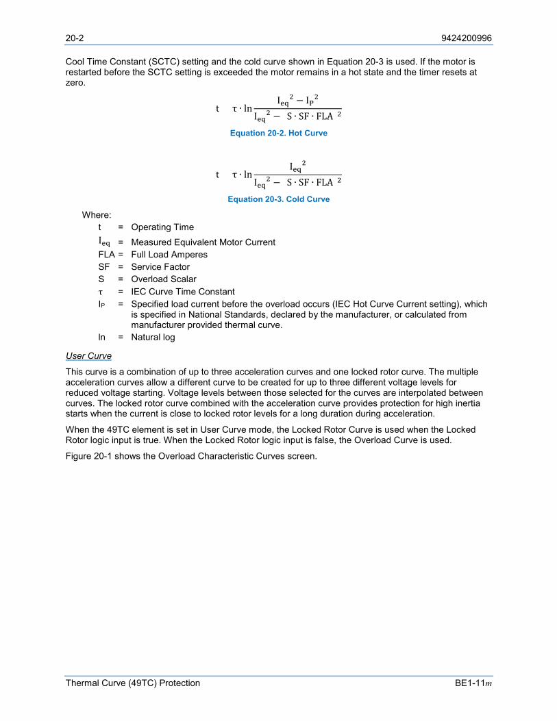
20-2 9424200996
Thermal Curve (49TC) Protection BE1-11m
Cool Time Constant (SCTC) setting and the cold curve shown in Equation 20-3 is used. If the motor is restarted before the SCTC setting is exceeded the motor remains in a hot state and the timer resets at zero.
t = τ ∙ lnIeq2 − IP2
Ieq2 − (S ∙ SF ∙ FLA)2
Equation 20-2. Hot Curve
t = τ ∙ lnIeq2
Ieq2 − (S ∙ SF ∙ FLA)2
Equation 20-3. Cold Curve
Where: t = Operating Time
Ieq = Measured Equivalent Motor Current FLA = Full Load Amperes SF = Service Factor S = Overload Scalar τ = IEC Curve Time Constant
IP = Specified load current before the overload occurs (IEC Hot Curve Current setting), which is specified in National Standards, declared by the manufacturer, or calculated from manufacturer provided thermal curve.
ln = Natural log
User Curve
This curve is a combination of up to three acceleration curves and one locked rotor curve. The multiple acceleration curves allow a different curve to be created for up to three different voltage levels for reduced voltage starting. Voltage levels between those selected for the curves are interpolated between curves. The locked rotor curve combined with the acceleration curve provides protection for high inertia starts when the current is close to locked rotor levels for a long duration during acceleration.
When the 49TC element is set in User Curve mode, the Locked Rotor Curve is used when the Locked Rotor logic input is true. When the Locked Rotor logic input is false, the Overload Curve is used.
Figure 20-1 shows the Overload Characteristic Curves screen.
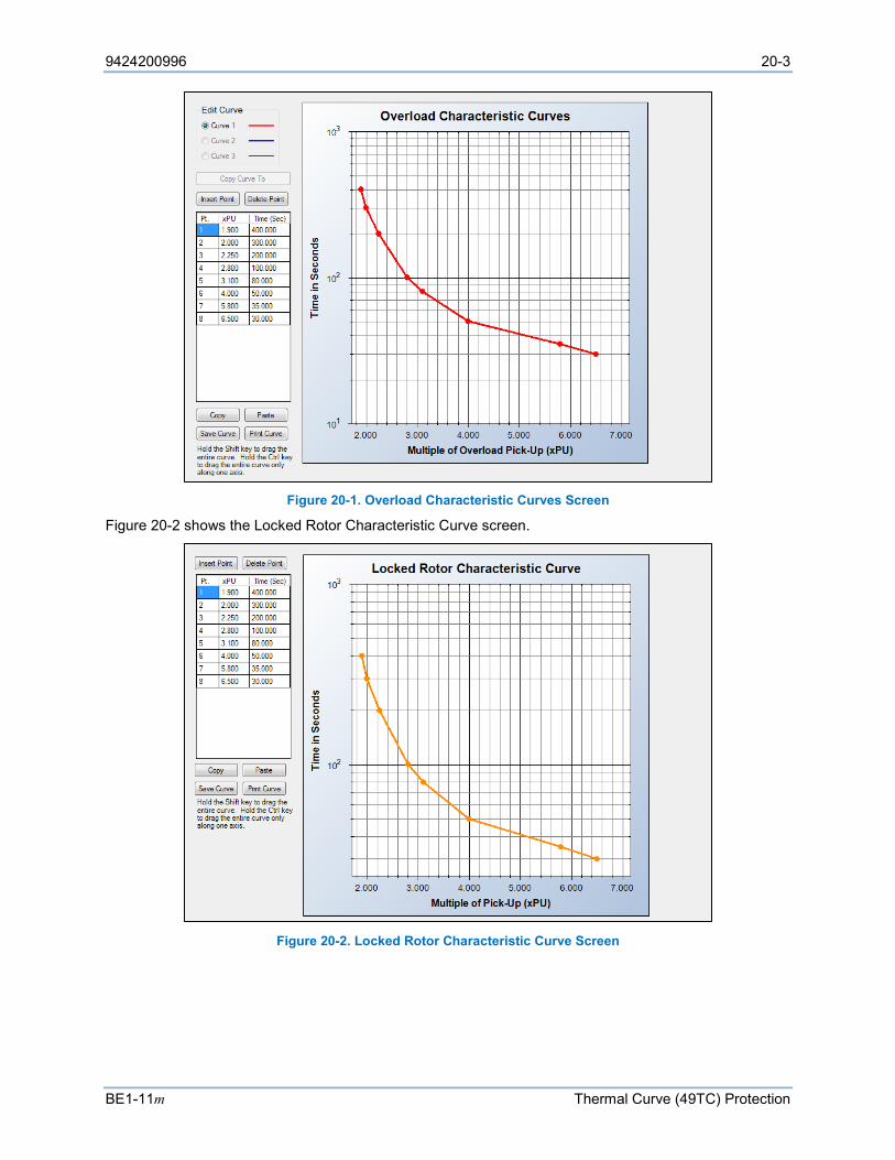
9424200996 20-3
BE1-11m Thermal Curve (49TC) Protection
Figure 20-1. Overload Characteristic Curves Screen
Figure 20-2 shows the Locked Rotor Characteristic Curve screen.
Figure 20-2. Locked Rotor Characteristic Curve Screen
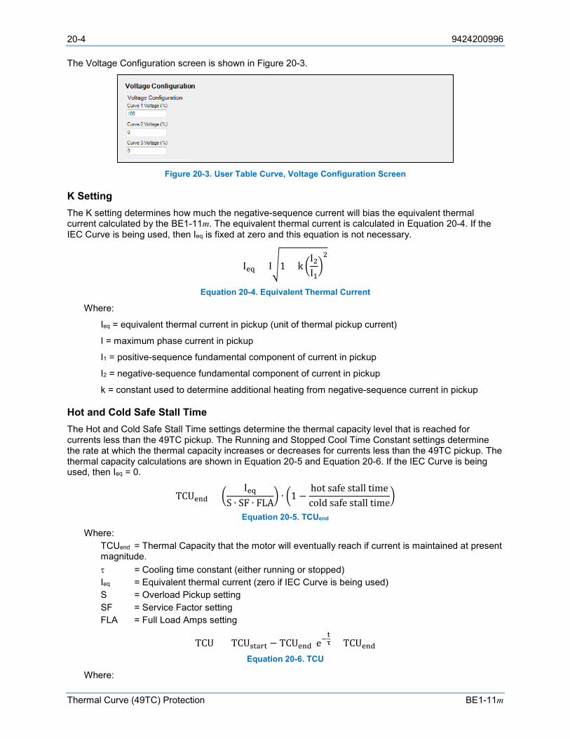
20-4 9424200996
Thermal Curve (49TC) Protection BE1-11m
The Voltage Configuration screen is shown in Figure 20-3.
Figure 20-3. User Table Curve, Voltage Configuration Screen
K Setting The K setting determines how much the negative-sequence current will bias the equivalent thermal current calculated by the BE1-11m. The equivalent thermal current is calculated in Equation 20-4. If the IEC Curve is being used, then Ieq is fixed at zero and this equation is not necessary.
Ieq = I1 + k I2I12
Equation 20-4. Equivalent Thermal Current
Where:
Ieq = equivalent thermal current in pickup (unit of thermal pickup current)
I = maximum phase current in pickup
I1 = positive-sequence fundamental component of current in pickup
I2 = negative-sequence fundamental component of current in pickup
k = constant used to determine additional heating from negative-sequence current in pickup
Hot and Cold Safe Stall Time The Hot and Cold Safe Stall Time settings determine the thermal capacity level that is reached for currents less than the 49TC pickup. The Running and Stopped Cool Time Constant settings determine the rate at which the thermal capacity increases or decreases for currents less than the 49TC pickup. The thermal capacity calculations are shown in Equation 20-5 and Equation 20-6. If the IEC Curve is being used, then Ieq = 0.
TCUend = Ieq
S ∙ SF ∙ FLA ∙ 1 −
hot safe stall timecold safe stall time
Equation 20-5. TCUend
Where: TCUend = Thermal Capacity that the motor will eventually reach if current is maintained at present
magnitude. τ = Cooling time constant (either running or stopped) Ieq
= Equivalent thermal current (zero if IEC Curve is being used) S = Overload Pickup setting SF = Service Factor setting FLA = Full Load Amps setting
TCU = (TCUstart − TCUend)e−tτ + TCUend
Equation 20-6. TCU
Where:
9424200996 20-5
BE1-11m Thermal Curve (49TC) Protection
TCU = Present Thermal Capacity TCUend = Thermal Capacity that the motor will eventually reach if current is maintained at present
magnitude. TCUstart = Thermal Capacity T = Time since last calculation τ = Cooling time constant (either running or stopped)
RTD Biasing and Hot/Cold Safe Stall Ratio The thermal overload curves are based on the assumption of a normal 40°C ambient and normal motor cooling. In the case of unusual ambient temperature or blocked or reduced motor cooling, the optional installed RTDs can be used to improve the estimation of thermal capacity.
The user provides a curve showing RTD thermal capacity used. The curve includes a minimum of three points and a maximum of 40 points. Three typical points are Ambient RTD Temperature (40°C) and 0% TC, Full Load Amps running RTD temperature and thermal capacity, and Maximum Safe Stator RTD temperature (typically 155°C).
Equation 20-7 is used to calculate the Full Load Amp thermal Capacity.
RTD Bias TCU = 1 −hot safe stall timecold safe stall time
Equation 20-7. RTD Bias TCU
RTD Bias TCU is linearly interpolated when RTD temperature is between defined temperatures.
When the 49TC is in overload and the RTD Bias TCU is higher than the current-based TCU, RTD Bias TCU is used to update the 49TC thermal capacity. The current based model continues to calculate thermal capacity from this new bias level. RTD Bias TCU alone will not result in a thermal model trip. Current must be above the thermal model current pickup.
Overload and Trip The Overload output occurs first, followed by the Trip output.
Overload
The 49TC pickup level is determined by the Overload setting along with the Service Factor and Full Load Amps settings located on the System Parameters, Motor Configuration screen in BESTCOMSPlus. The Overload output becomes true when the equivalent thermal current increases above the pickup current. In BESTlogicPlus, the Overload output can be connected to other logic elements to annunciate the condition, control other elements in logic, and start the fault recorder (logic element FAULTTRIG).
Assertion of the Overload output initiates a timer that begins timing to a thermal trip. The duration of the timer is established by the thermal curve.
If the pickup condition subsides before the element delay expires, the timer and Overload output are reset, no corrective action is taken, and the element is rearmed for any other overload conditions.
Trip
The Trip output becomes true if an overload condition exists for the duration of the element timer. In BESTlogicPlus, the Trip output can be connected to other logic elements and to a physical relay output to annunciate the condition and to initiate corrective action. If a target is enabled for the element, the BE1-11m will record a target when the Trip output becomes true. See the Fault Reporting chapter for more information about target reporting.
Emergency Start When performing an emergency start, the Max Emergency Thermal Capacity setting determines the maximum thermal capacity allowed. An emergency start is requested when the Emergency input of the Motor Status logic block is true. The emergency start condition remains until the thermal capacity drops
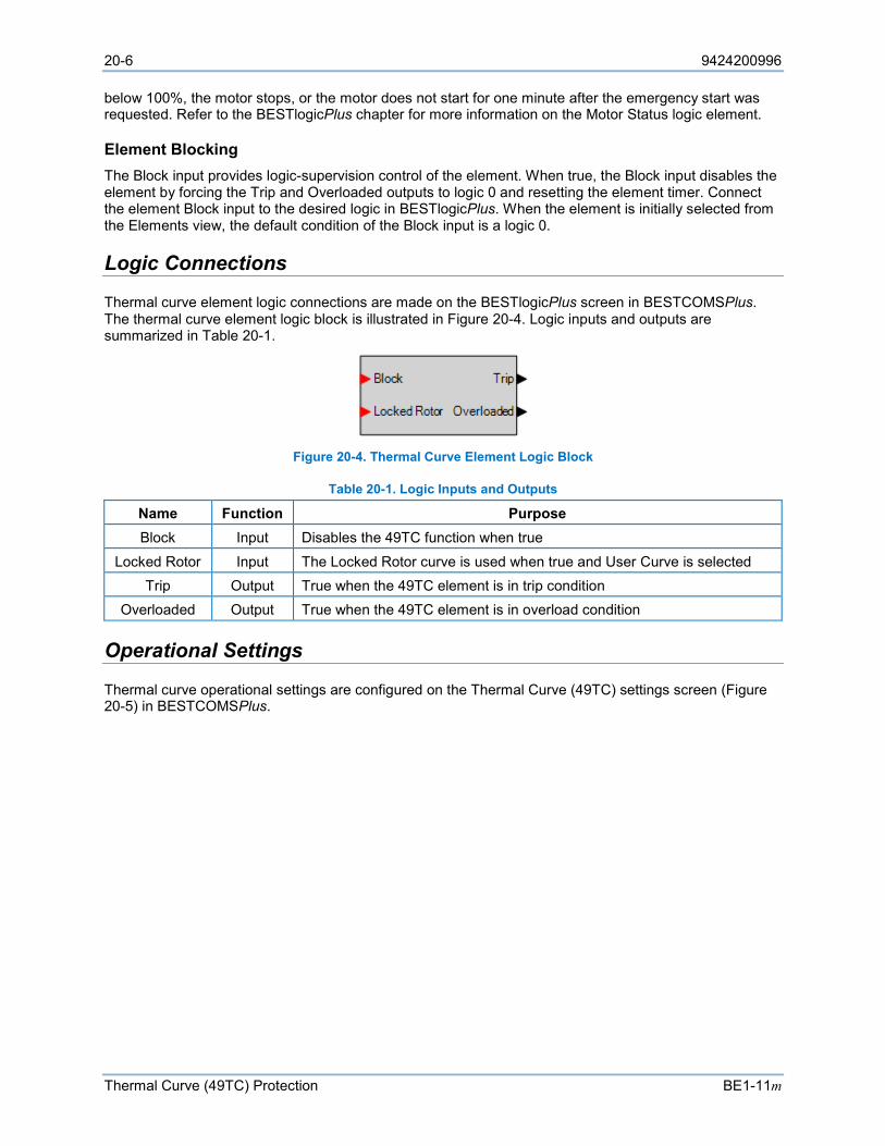
20-6 9424200996
Thermal Curve (49TC) Protection BE1-11m
below 100%, the motor stops, or the motor does not start for one minute after the emergency start was requested. Refer to the BESTlogicPlus chapter for more information on the Motor Status logic element.
Element Blocking The Block input provides logic-supervision control of the element. When true, the Block input disables the element by forcing the Trip and Overloaded outputs to logic 0 and resetting the element timer. Connect the element Block input to the desired logic in BESTlogicPlus. When the element is initially selected from the Elements view, the default condition of the Block input is a logic 0.
Logic Connections
Thermal curve element logic connections are made on the BESTlogicPlus screen in BESTCOMSPlus. The thermal curve element logic block is illustrated in Figure 20-4. Logic inputs and outputs are summarized in Table 20-1.
Figure 20-4. Thermal Curve Element Logic Block
Table 20-1. Logic Inputs and Outputs
Name Function Purpose Block Input Disables the 49TC function when true
Locked Rotor Input The Locked Rotor curve is used when true and User Curve is selected Trip Output True when the 49TC element is in trip condition
Overloaded Output True when the 49TC element is in overload condition
Operational Settings
Thermal curve operational settings are configured on the Thermal Curve (49TC) settings screen (Figure 20-5) in BESTCOMSPlus.
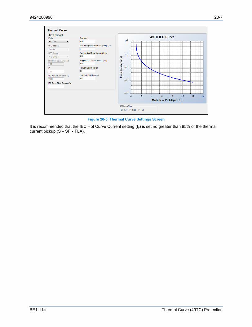
9424200996 20-7
BE1-11m Thermal Curve (49TC) Protection
Figure 20-5. Thermal Curve Settings Screen
It is recommended that the IEC Hot Curve Current setting (Ip) is set no greater than 95% of the thermal current pickup (S • SF • FLA).

20-8 9424200996
Thermal Curve (49TC) Protection BE1-11m

9424200996 21-1
BE1-11m Incomplete Sequence (48) Protection
21 • Incomplete Sequence (48) Protection The incomplete sequence (48) element announces an incomplete sequence if the motor starts but does not reach the running state before the time interval expires.
Element operational settings are configured on the Restart Inhibit settings screen in BESTCOMSPlus®. A summary of the logic inputs and outputs and operational settings appears at the end of this chapter.
BESTCOMSPlus Navigation Path: Settings Explorer, Protection, Motor, Incomplete Sequence (48)
HMI Navigation Path: Settings Explorer, Protection, Settings Group x (where x = 0 to 3), Motor Protection, Incomplete Sequence 48
Element Operation
Note
The 48 element will not operate when Motor Start Detection is configured for Contacts Only. Refer to Motor Configuration Settings in the Configuration chapter for more information.
Trip Assertion of the Starting output of the Motor Status logic element initiates a timer that begins timing to a trip. The duration of the timer is established by the Time Interval setting. A Time Interval of zero (0) makes the 48 element instantaneous with no intentional time delay. In BESTlogic™Plus, the Starting output can be connected to other logic elements to annunciate the condition or control other elements in logic.
The Trip output becomes true if the time interval expires before the Running output of the Motor Status logic element becomes true. In BESTlogicPlus, the Trip output can be connected to other logic elements and to a physical relay output to annunciate the condition and to initiate corrective action. If a target is enabled for the element, the BE1-11m will record a target when the Trip output becomes true. See the Fault Reporting chapter for more information about target reporting.
If the Running output of the Motor Status logic element becomes true before the element time interval expires, the timer is reset, no corrective action is taken, and the element is rearmed for any other incomplete sequence occurrences.
Refer to the BESTlogicPlus chapter for more information on the Motor Status logic element.
Element Blocking The Block input provides logic-supervision control of the element. When true, the Block input disables the element by forcing the Trip output to logic 0 and resetting the element timer. Connect the element Block input to the desired logic in BESTlogicPlus. When the element is initially selected from the Elements view, the default condition of the Block input is a logic 0.
Logic Connections
Incomplete sequence element logic connections are made on the BESTlogicPlus screen in BESTCOMSPlus. The incomplete sequence element logic block is illustrated in Figure 21-1. Logic inputs and outputs are summarized in Table 21-1.
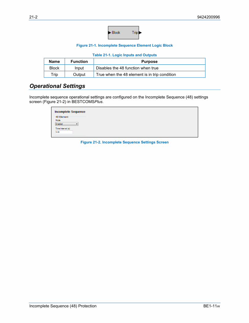
21-2 9424200996
Incomplete Sequence (48) Protection BE1-11m
Figure 21-1. Incomplete Sequence Element Logic Block
Table 21-1. Logic Inputs and Outputs
Name Function Purpose Block Input Disables the 48 function when true Trip Output True when the 48 element is in trip condition
Operational Settings
Incomplete sequence operational settings are configured on the Incomplete Sequence (48) settings screen (Figure 21-2) in BESTCOMSPlus.
Figure 21-2. Incomplete Sequence Settings Screen
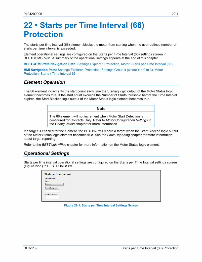
9424200996 22-1
BE1-11m Starts per Time Interval (66) Protection
22 • Starts per Time Interval (66) Protection The starts per time interval (66) element blocks the motor from starting when the user-defined number of starts per time interval is exceeded.
Element operational settings are configured on the Starts per Time Interval (66) settings screen in BESTCOMSPlus®. A summary of the operational settings appears at the end of this chapter.
BESTCOMSPlus Navigation Path: Settings Explorer, Protection, Motor, Starts per Time Interval (66)
HMI Navigation Path: Settings Explorer, Protection, Settings Group x (where x = 0 to 3), Motor Protection, Starts / Time Interval 66
Element Operation
The 66 element increments the start count each time the Starting logic output of the Motor Status logic element becomes true. If the start count exceeds the Number of Starts threshold before the Time Interval expires, the Start Blocked logic output of the Motor Status logic element becomes true.
Note
The 66 element will not increment when Motor Start Detection is configured for Contacts Only. Refer to Motor Configuration Settings in the Configuration chapter for more information.
If a target is enabled for the element, the BE1-11m will record a target when the Start Blocked logic output of the Motor Status logic element becomes true. See the Fault Reporting chapter for more information about target reporting.
Refer to the BESTlogic™Plus chapter for more information on the Motor Status logic element.
Operational Settings
Starts per time interval operational settings are configured on the Starts per Time Interval settings screen (Figure 22-1) in BESTCOMSPlus.
Figure 22-1. Starts per Time Interval Settings Screen

22-2 9424200996
Starts per Time Interval (66) Protection BE1-11m

9424200996 23-1
BE1-11m Restart Inhibit Protection
23 • Restart Inhibit Protection The restart inhibit function prevents motor starting when motor or system conditions dictate. A restart can be inhibited when thermal limits are exceeded or insufficient time has elapsed since motor shutdown.
Element operational settings are configured on the Restart Inhibit settings screen in BESTCOMSPlus®. A summary of the operational settings appears at the end of this chapter.
BESTCOMSPlus Navigation Path: Settings Explorer, Protection, Motor, Restart Inhibit
HMI Navigation Path: Settings Explorer, Protection, Settings Group x (where x = 0 to 3), Motor Protection, Restart Inhibit
Element Operation
Thermal Capacity Inhibit The Thermal Capacity Inhibit setting prevents the motor from starting when the thermal level resulting from a start exceeds the thermal capacity. Enter a value higher than the thermal capacity needed to start the motor. For example, if a motor uses 35% of its thermal capacity to start, a value of 40% would provide a 5% margin by preventing the motor from starting when the thermal capacity was 60% or higher.
Restart Delay The Restart Delay setting is a user-selectable time that an operator must wait after stopping the motor before starting it again.
Time Between Starts The Time Between Starts setting is a user-selectable time that an operator must wait between each start of the motor.
Operational Settings
Restart inhibit operational settings are configured on the Restart Inhibit settings screen (Figure 23-1) in BESTCOMSPlus.
Figure 23-1. Restart Inhibit Settings Screen

23-2 9424200996
Restart Inhibit Protection BE1-11m
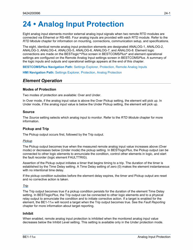
9424200996 24-1
BE1-11m Analog Input Protection
24 • Analog Input Protection Eight analog input elements monitor external analog input signals when two remote RTD modules are connected via Ethernet or RS-485. Four analog inputs are provided with each RTD module. Refer to the RTD Module chapter for information on mounting, connections, communication setup, and specifications.
The eight, identical remote analog input protection elements are designated ANALOG-1, ANALOG-2, ANALOG-3, ANALOG-4, ANALOG-5, ANALOG-6, ANALOG-7, and ANALOG-8. Element logic connections are made on the BESTlogic™Plus screen in BESTCOMSPlus® and element operational settings are configured on the Remote Analog Input settings screen in BESTCOMSPlus. A summary of the logic inputs and outputs and operational settings appears at the end of this chapter.
BESTCOMSPlus Navigation Path: Settings Explorer, Protection, Remote Analog Inputs
HMI Navigation Path: Settings Explorer, Protection, Analog Protection
Element Operation
Modes of Protection Two modes of protection are available: Over and Under.
In Over mode, if the analog input value is above the Over Pickup setting, the element will pick up. In Under mode, if the analog input value is below the Under Pickup setting, the element will pick up.
Source The Source setting selects which analog input to monitor. Refer to the RTD Module chapter for more information.
Pickup and Trip The Pickup output occurs first, followed by the Trip output.
Pickup
The Pickup output becomes true when the measured remote analog input value increases above (Over mode) or decreases below (Under mode) the pickup setting. In BESTlogicPlus, the Pickup output can be connected to other logic elements to annunciate the condition, control other elements in logic, and start the fault recorder (logic element FAULTTRIG).
Assertion of the Pickup output initiates a timer that begins timing to a trip. The duration of the timer is established by the Time Delay setting. A Time Delay setting of zero (0) makes the element instantaneous with no intentional time delay.
If the pickup condition subsides before the element delay expires, the timer and Pickup output are reset and no corrective action is taken.
Trip
The Trip output becomes true if a pickup condition persists for the duration of the element Time Delay setting. In BESTlogicPlus, the Trip output can be connected to other logic elements and to a physical relay output to annunciate the condition and to initiate corrective action. If a target is enabled for the element, the BE1-11m will record a target when the Trip output becomes true. See the Fault Reporting chapter for more information about target reporting.
Inhibit When enabled, remote analog input protection is inhibited when the monitored analog input value decreases below the Inhibit Level setting. This setting is available only in the Under protection mode.
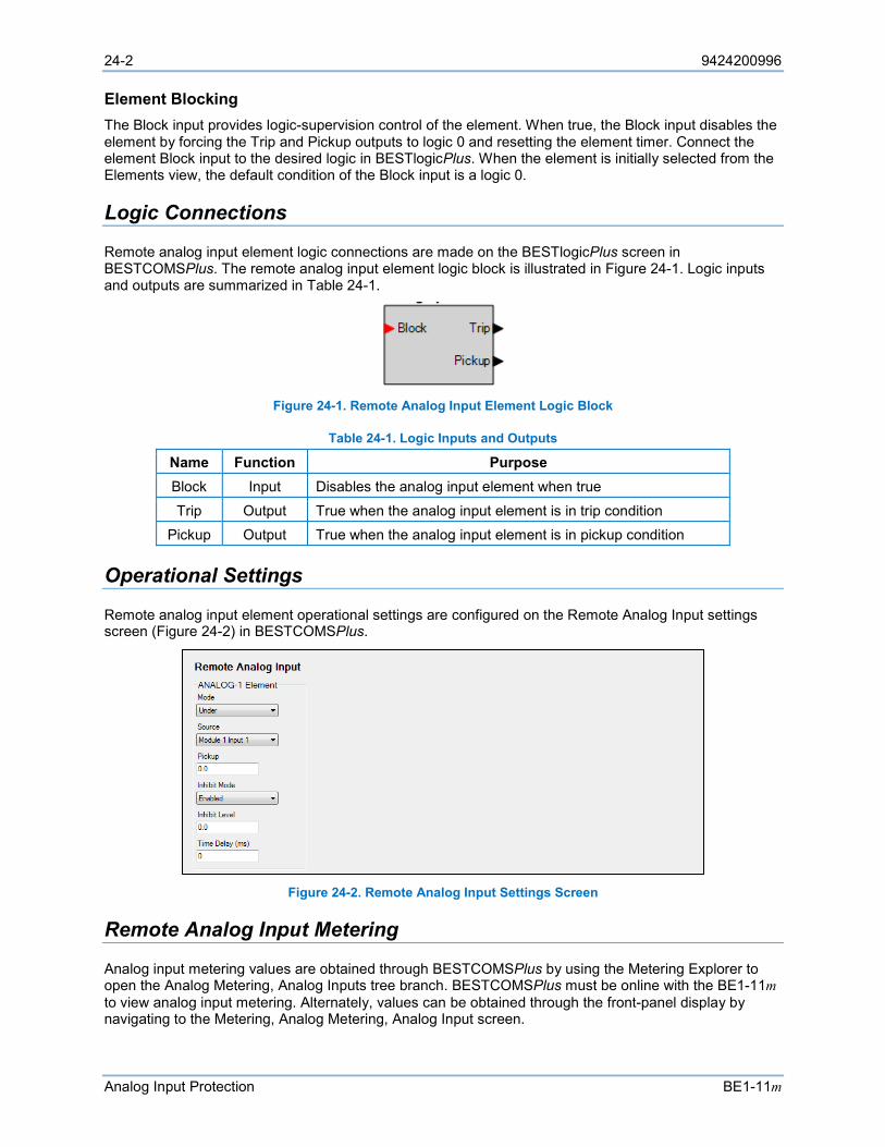
24-2 9424200996
Analog Input Protection BE1-11m
Element Blocking The Block input provides logic-supervision control of the element. When true, the Block input disables the element by forcing the Trip and Pickup outputs to logic 0 and resetting the element timer. Connect the element Block input to the desired logic in BESTlogicPlus. When the element is initially selected from the Elements view, the default condition of the Block input is a logic 0.
Logic Connections
Remote analog input element logic connections are made on the BESTlogicPlus screen in BESTCOMSPlus. The remote analog input element logic block is illustrated in Figure 24-1. Logic inputs and outputs are summarized in Table 24-1.
Figure 24-1. Remote Analog Input Element Logic Block
Table 24-1. Logic Inputs and Outputs
Name Function Purpose Block Input Disables the analog input element when true
Trip Output True when the analog input element is in trip condition Pickup Output True when the analog input element is in pickup condition
Operational Settings
Remote analog input element operational settings are configured on the Remote Analog Input settings screen (Figure 24-2) in BESTCOMSPlus.
Figure 24-2. Remote Analog Input Settings Screen
Remote Analog Input Metering
Analog input metering values are obtained through BESTCOMSPlus by using the Metering Explorer to open the Analog Metering, Analog Inputs tree branch. BESTCOMSPlus must be online with the BE1-11m to view analog input metering. Alternately, values can be obtained through the front-panel display by navigating to the Metering, Analog Metering, Analog Input screen.
9424200996 25-1
BE1-11m Virtual Control Switches (43)
25 • Virtual Control Switches (43) Five virtual control switch (43) elements provide manual control, locally and remotely, without using physical switches and/or interposing relays.
The five, identical virtual control switch elements are designated 43-1, 43-2, 43-3, 43-4, and 43-5. Element logic connections are made on the BESTlogic™Plus screen in BESTCOMSPlus® and element operational settings are configured on the Virtual Control Switches (43) settings screen in BESTCOMSPlus. A summary of the logic inputs and outputs and operational settings appears at the end of this chapter.
BESTCOMSPlus Settings Navigation Path: Settings Explorer, Control, Virtual Control Switches (43)
HMI Settings Navigation Path: Settings Explorer, Control, Virtual Switch 43
BESTCOMSPlus Control Navigation Path: Metering Explorer, Control, Virtual Switches
HMI Control Navigation Path: Metering Explorer, Control, Virtual Switches
Element Operation
Virtual control switches can emulate virtually any type of binary (two-position) switch. An example would be an application that requires a ground cutoff switch. The traditional approach might be to install a switch on the panel and wire the output to a contact sensing input on the BE1-11m or in series with the ground trip output of the BE1-11m. Instead, a virtual control switch can be used to reduce costs with the added benefit of being able to operate the switch both locally through the front panel and remotely from a substation computer or through an Ethernet connection to a remote operator’s console.
Mode Three modes of operation are available: Switch/Pulse, Switch, and Pulse. Because switch status information is saved in nonvolatile memory, the BE1-11m powers up with the switches in the same state as when the BE1-11m was powered down.
Switch/Pulse Mode
In Switch/Pulse mode, each switch can be controlled to reset, set, or pulse. Assertion of the Set input forces the output to set (logic 1). Assertion of the Reset input forces the output to reset (logic 0). Assertion of the Pulse input toggles the virtual output from its current state to the opposite state for 200 ms then back to the original state. An additional Hold Time can be set when the virtual output is connected to a physical output in BESTlogicPlus. See the Contact Inputs and Outputs chapter for more information.
Switch Mode
In Switch mode, the switch emulates a two-position selector switch, and only set and reset commands are accepted. Assertion of the Set input forces the output to set (logic 1). Assertion of the Reset input forces the output to reset (logic 0).
Pulse Mode
In Pulse mode, a momentary close, spring-return switch is emulated and only the pulse command is accepted. Assertion of the Pulse input toggles the virtual output from its current state to the opposite state for 200 ms and then back to the original state. An additional Hold Time can be set when the virtual output is connected to a physical output in BESTlogicPlus. See the Contact Inputs and Outputs chapter for more information.
Customized Labels User specified labels can be assigned to each virtual switch and to both states of each switch. The labels can be up to 64 characters long. In the previous ground cutoff switch example, you may enable one of the switches in the Switch mode and connect the output of that switch to the blocking input of a 59X protection element. This would disable the ground overvoltage protection when the switch is closed
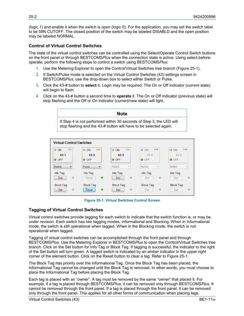
25-2 9424200996
Virtual Control Switches (43) BE1-11m
(logic 1) and enable it when the switch is open (logic 0). For the application, you may set the switch label to be 59N CUTOFF. The closed position of the switch may be labeled DISABLD and the open position may be labeled NORMAL.
Control of Virtual Control Switches The state of the virtual control switches can be controlled using the Select/Operate Control Switch buttons on the front panel or through BESTCOMSPlus when the connection state is active. Using select-before-operate, perform the following steps to control a switch using BESTCOMSPlus:
1. Use the Metering Explorer to open the Control/Virtual Switches tree branch (Figure 25-1). 2. If Switch/Pulse mode is selected on the Virtual Control Switches (43) settings screen in
BESTCOMSPlus, use the drop-down box to select either Switch or Pulse. 3. Click the 43-# button to select it. Login may be required. The On or Off indicator (current state)
will begin to flash. 4. Click on the 43-# button a second time to operate it. The On or Off indicator (previous state) will
stop flashing and the Off or On indicator (current/new state) will light.
Note If Step 4 is not performed within 30 seconds of Step 3, the LED will stop flashing and the 43-# button will have to be selected again.
Figure 25-1. Virtual Switches Control Screen
Tagging of Virtual Control Switches Virtual control switches provide tagging for each switch to indicate that the switch function is, or may be, under revision. Each switch has two tagging modes, Informational and Blocking. When in Informational mode, the switch is still operational when tagged. When in the Blocking mode, the switch is not operational when tagged.
Tagging of virtual control switches can be accomplished through the front panel and through BESTCOMSPlus. Use the Metering Explorer in BESTCOMSPlus to open the Control/Virtual Switches tree branch. Click on the Set button for Info Tag or Block Tag. If tagging is successful, the indicator to the right of the Set button will turn green. A tagged switch is indicated by an amber indicator in the upper right corner of the element button. Click on the Reset button to clear a tag. Refer to Figure 25-1.
The Block Tag has priority over the Informational Tag. Once the Block Tag has been placed, the Informational Tag cannot be changed until the Block Tag is removed. In other words, you must choose to place the Informational Tag before placing the Block Tag.
Each tag is placed with an “owner”. A tag must be removed by the same “owner” that placed it. For example, if a tag is placed through BESTCOMSPlus, it can be removed only through BESTCOMSPlus. It cannot be removed through the front panel. If a tag is placed through the front panel, it can be removed only through the front panel. This applies for all other forms of communication when placing tags.
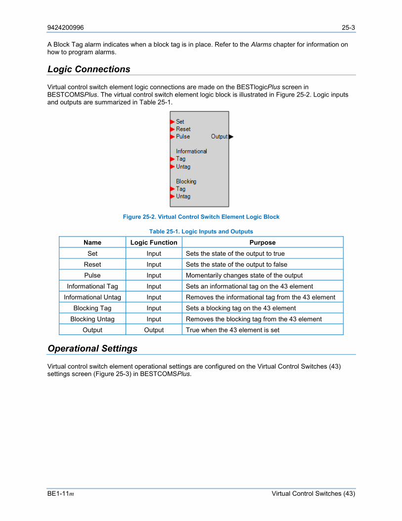
9424200996 25-3
BE1-11m Virtual Control Switches (43)
A Block Tag alarm indicates when a block tag is in place. Refer to the Alarms chapter for information on how to program alarms.
Logic Connections
Virtual control switch element logic connections are made on the BESTlogicPlus screen in BESTCOMSPlus. The virtual control switch element logic block is illustrated in Figure 25-2. Logic inputs and outputs are summarized in Table 25-1.
Figure 25-2. Virtual Control Switch Element Logic Block
Table 25-1. Logic Inputs and Outputs
Name Logic Function Purpose Set Input Sets the state of the output to true
Reset Input Sets the state of the output to false Pulse Input Momentarily changes state of the output
Informational Tag Input Sets an informational tag on the 43 element Informational Untag Input Removes the informational tag from the 43 element
Blocking Tag Input Sets a blocking tag on the 43 element
Blocking Untag Input Removes the blocking tag from the 43 element Output Output True when the 43 element is set
Operational Settings
Virtual control switch element operational settings are configured on the Virtual Control Switches (43) settings screen (Figure 25-3) in BESTCOMSPlus.
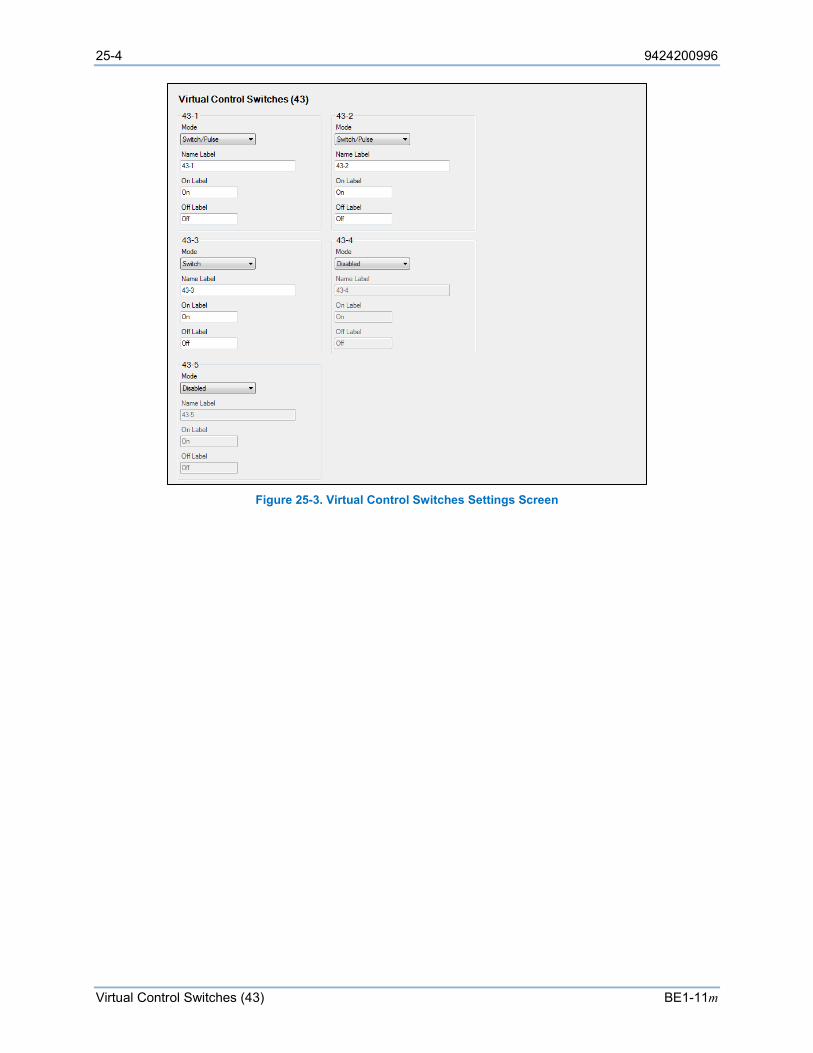
25-4 9424200996
Virtual Control Switches (43) BE1-11m
Figure 25-3. Virtual Control Switches Settings Screen
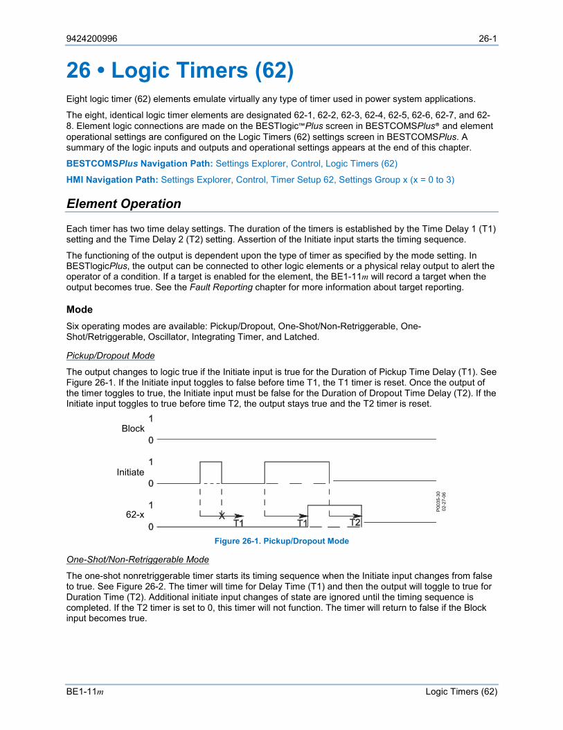
9424200996 26-1
BE1-11m Logic Timers (62)
26 • Logic Timers (62) Eight logic timer (62) elements emulate virtually any type of timer used in power system applications.
The eight, identical logic timer elements are designated 62-1, 62-2, 62-3, 62-4, 62-5, 62-6, 62-7, and 62-8. Element logic connections are made on the BESTlogic™Plus screen in BESTCOMSPlus® and element operational settings are configured on the Logic Timers (62) settings screen in BESTCOMSPlus. A summary of the logic inputs and outputs and operational settings appears at the end of this chapter.
BESTCOMSPlus Navigation Path: Settings Explorer, Control, Logic Timers (62)
HMI Navigation Path: Settings Explorer, Control, Timer Setup 62, Settings Group x (x = 0 to 3)
Element Operation
Each timer has two time delay settings. The duration of the timers is established by the Time Delay 1 (T1) setting and the Time Delay 2 (T2) setting. Assertion of the Initiate input starts the timing sequence.
The functioning of the output is dependent upon the type of timer as specified by the mode setting. In BESTlogicPlus, the output can be connected to other logic elements or a physical relay output to alert the operator of a condition. If a target is enabled for the element, the BE1-11m will record a target when the output becomes true. See the Fault Reporting chapter for more information about target reporting.
Mode Six operating modes are available: Pickup/Dropout, One-Shot/Non-Retriggerable, One-Shot/Retriggerable, Oscillator, Integrating Timer, and Latched.
Pickup/Dropout Mode
The output changes to logic true if the Initiate input is true for the Duration of Pickup Time Delay (T1). See Figure 26-1. If the Initiate input toggles to false before time T1, the T1 timer is reset. Once the output of the timer toggles to true, the Initiate input must be false for the Duration of Dropout Time Delay (T2). If the Initiate input toggles to true before time T2, the output stays true and the T2 timer is reset.
Figure 26-1. Pickup/Dropout Mode
One-Shot/Non-Retriggerable Mode
The one-shot nonretriggerable timer starts its timing sequence when the Initiate input changes from false to true. See Figure 26-2. The timer will time for Delay Time (T1) and then the output will toggle to true for Duration Time (T2). Additional initiate input changes of state are ignored until the timing sequence is completed. If the T2 timer is set to 0, this timer will not function. The timer will return to false if the Block input becomes true.
P003
5-30
02-2
7-06
62-x
Block
Initiate
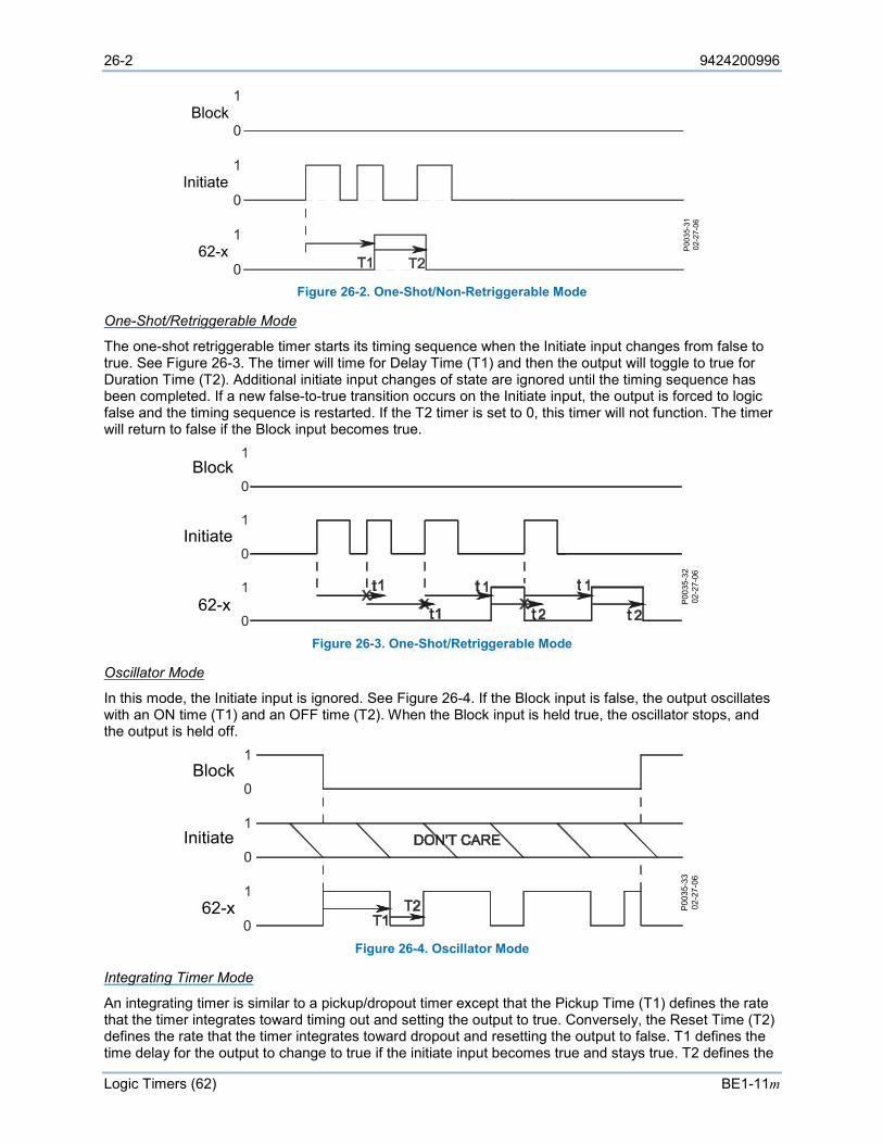
26-2 9424200996
Logic Timers (62) BE1-11m
Figure 26-2. One-Shot/Non-Retriggerable Mode
One-Shot/Retriggerable Mode
The one-shot retriggerable timer starts its timing sequence when the Initiate input changes from false to true. See Figure 26-3. The timer will time for Delay Time (T1) and then the output will toggle to true for Duration Time (T2). Additional initiate input changes of state are ignored until the timing sequence has been completed. If a new false-to-true transition occurs on the Initiate input, the output is forced to logic false and the timing sequence is restarted. If the T2 timer is set to 0, this timer will not function. The timer will return to false if the Block input becomes true.
Figure 26-3. One-Shot/Retriggerable Mode
Oscillator Mode
In this mode, the Initiate input is ignored. See Figure 26-4. If the Block input is false, the output oscillates with an ON time (T1) and an OFF time (T2). When the Block input is held true, the oscillator stops, and the output is held off.
Figure 26-4. Oscillator Mode
Integrating Timer Mode
An integrating timer is similar to a pickup/dropout timer except that the Pickup Time (T1) defines the rate that the timer integrates toward timing out and setting the output to true. Conversely, the Reset Time (T2) defines the rate that the timer integrates toward dropout and resetting the output to false. T1 defines the time delay for the output to change to true if the initiate input becomes true and stays true. T2 defines the
P003
5-31
02-2
7 -06
Block
Initiate
62-x
P00
35-3
202
-27-
06
Block
Initiate
62-x
P003
5-33
02-2
7-06
Block
Initiate
62-x

9424200996 26-3
BE1-11m Logic Timers (62)
time delay for the output to change to false if it is presently true and the initiate input becomes false and stays false.
In the example shown in Figure 26-5, T2 is set to half of the T1 setting. The initiate input becomes true and the timer starts integrating toward pickup. Prior to timing out, the Initiate input toggles to false and the timer starts resetting at twice the rate as it was integrating toward time out. It stays false long enough for the integrating timer to reset completely but then toggles back to true and stays true for the entire duration of time T1. At that point, the timer’s output is toggled to true. Then later, the initiate Input becomes false and stays false for the duration of T2. At that point, the output of the timer is toggled to false.
This type of timer is useful in applications where a monitored signal might be hovering at its threshold between on and off. For example, it is desired to take some action when current is above a certain level for a certain period. An instantaneous overcurrent (50) element could be used to monitor the current level. Thus, if the current level is near the threshold so that the Initiate input toggles between true and false from time to time, the function will still time out as long as the time that it is true is longer than the time that it is false. With a simple pickup/dropout timer, the timing function would reset to zero and start over each time the Initiate input became false.
Figure 26-5. Integrating Timer Mode
Latched Mode
A one shot timer starts its timing sequence when the Initiate input changes from false to true. The timer will operate for Delay Time (T1) and then the output will latch true. Additional Initiate input changes of state are ignored. Time (T2) is ignored. Refer to Figure 26-6.
Figure 26-6. Latched Mode
Element Blocking The Block input provides logic-supervision control of the element. When true, the Block input disables the element by forcing the element output to logic 0 and resetting the element timer. Connect the element
P003
5-34
02-2
7-06
62-x
Block
Initiate
100%
0%
Timer
P00
35-3
502
-27-
06
Block
Initiate
62-x
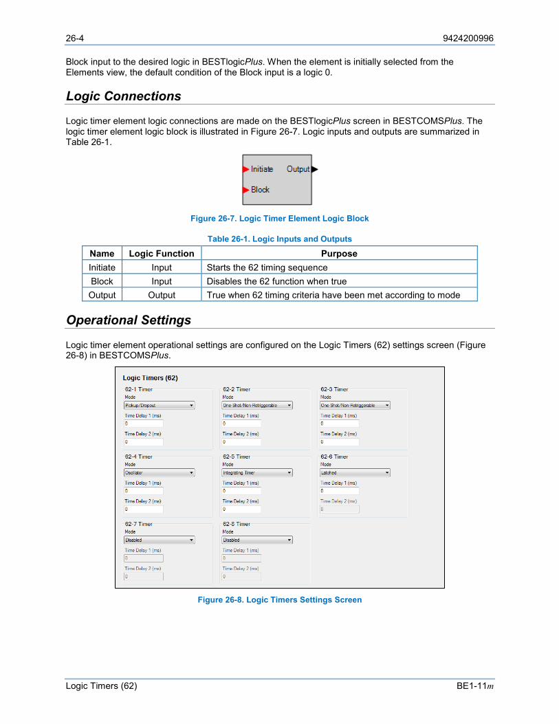
26-4 9424200996
Logic Timers (62) BE1-11m
Block input to the desired logic in BESTlogicPlus. When the element is initially selected from the Elements view, the default condition of the Block input is a logic 0.
Logic Connections
Logic timer element logic connections are made on the BESTlogicPlus screen in BESTCOMSPlus. The logic timer element logic block is illustrated in Figure 26-7. Logic inputs and outputs are summarized in Table 26-1.
Figure 26-7. Logic Timer Element Logic Block
Table 26-1. Logic Inputs and Outputs
Name Logic Function Purpose Initiate Input Starts the 62 timing sequence Block Input Disables the 62 function when true Output Output True when 62 timing criteria have been met according to mode
Operational Settings
Logic timer element operational settings are configured on the Logic Timers (62) settings screen (Figure 26-8) in BESTCOMSPlus.
Figure 26-8. Logic Timers Settings Screen
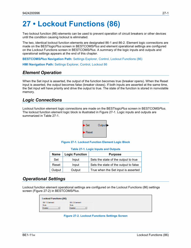
9424200996 27-1
BE1-11m Lockout Functions (86)
27 • Lockout Functions (86) Two lockout function (86) elements can be used to prevent operation of circuit breakers or other devices until the condition causing lockout is eliminated.
The two, identical lockout function elements are designated 86-1 and 86-2. Element logic connections are made on the BESTlogicPlus screen in BESTCOMSPlus and element operational settings are configured on the Lockout Functions screen in BESTCOMSPlus. A summary of the logic inputs and outputs and operational settings appears at the end of this chapter.
BESTCOMSPlus Navigation Path: Settings Explorer, Control, Lockout Functions (86)
HMI Navigation Path: Settings Explorer, Control, Lockout 86
Element Operation
When the Set input is asserted, the output of the function becomes true (breaker opens). When the Reset input is asserted, the output becomes false (breaker closes). If both inputs are asserted at the same time, the Set input will have priority and drive the output to true. The state of the function is stored in nonvolatile memory.
Logic Connections
Lockout function element logic connections are made on the BESTlogicPlus screen in BESTCOMSPlus. The lockout function element logic block is illustrated in Figure 27-1. Logic inputs and outputs are summarized in Table 27-1.
Figure 27-1. Lockout Function Element Logic Block
Table 27-1. Logic Inputs and Outputs
Name Logic Function Purpose Set Input Sets the state of the output to true
Reset Input Sets the state of the output to false Output Output True when the Set input is asserted
Operational Settings
Lockout function element operational settings are configured on the Lockout Functions (86) settings screen (Figure 27-2) in BESTCOMSPlus.
Figure 27-2. Lockout Functions Settings Screen
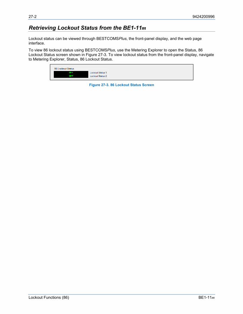
27-2 9424200996
Lockout Functions (86) BE1-11m
Retrieving Lockout Status from the BE1-11m
Lockout status can be viewed through BESTCOMSPlus, the front-panel display, and the web page interface.
To view 86 lockout status using BESTCOMSPlus, use the Metering Explorer to open the Status, 86 Lockout Status screen shown in Figure 27-3. To view lockout status from the front-panel display, navigate to Metering Explorer, Status, 86 Lockout Status.
Figure 27-3. 86 Lockout Status Screen
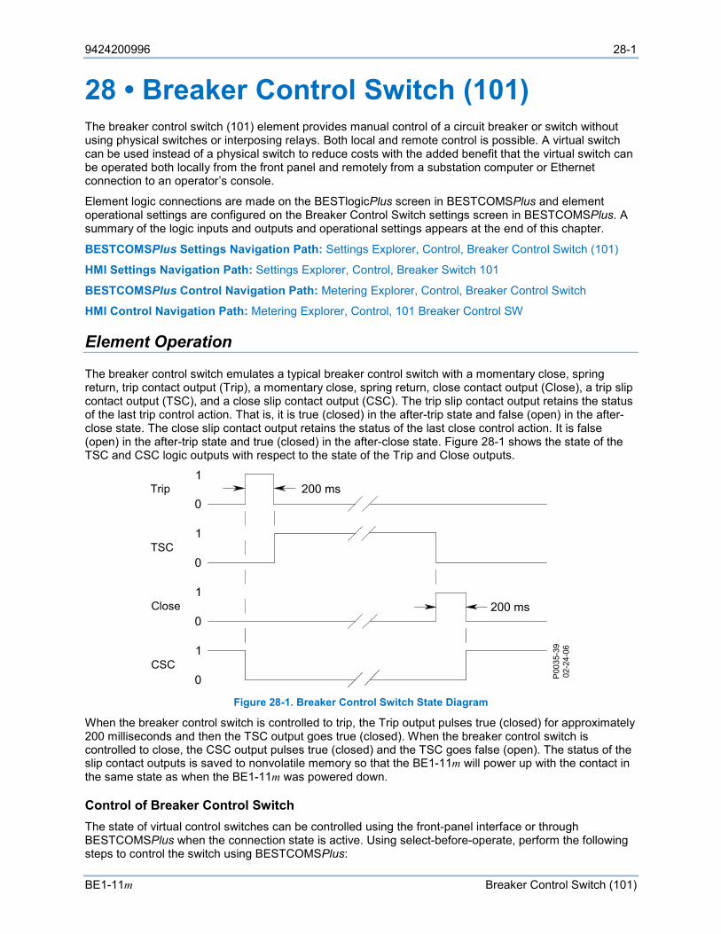
9424200996 28-1
BE1-11m Breaker Control Switch (101)
28 • Breaker Control Switch (101) The breaker control switch (101) element provides manual control of a circuit breaker or switch without using physical switches or interposing relays. Both local and remote control is possible. A virtual switch can be used instead of a physical switch to reduce costs with the added benefit that the virtual switch can be operated both locally from the front panel and remotely from a substation computer or Ethernet connection to an operator’s console.
Element logic connections are made on the BESTlogicPlus screen in BESTCOMSPlus and element operational settings are configured on the Breaker Control Switch settings screen in BESTCOMSPlus. A summary of the logic inputs and outputs and operational settings appears at the end of this chapter.
BESTCOMSPlus Settings Navigation Path: Settings Explorer, Control, Breaker Control Switch (101)
HMI Settings Navigation Path: Settings Explorer, Control, Breaker Switch 101
BESTCOMSPlus Control Navigation Path: Metering Explorer, Control, Breaker Control Switch
HMI Control Navigation Path: Metering Explorer, Control, 101 Breaker Control SW
Element Operation
The breaker control switch emulates a typical breaker control switch with a momentary close, spring return, trip contact output (Trip), a momentary close, spring return, close contact output (Close), a trip slip contact output (TSC), and a close slip contact output (CSC). The trip slip contact output retains the status of the last trip control action. That is, it is true (closed) in the after-trip state and false (open) in the after-close state. The close slip contact output retains the status of the last close control action. It is false (open) in the after-trip state and true (closed) in the after-close state. Figure 28-1 shows the state of the TSC and CSC logic outputs with respect to the state of the Trip and Close outputs.
Figure 28-1. Breaker Control Switch State Diagram
When the breaker control switch is controlled to trip, the Trip output pulses true (closed) for approximately 200 milliseconds and then the TSC output goes true (closed). When the breaker control switch is controlled to close, the CSC output pulses true (closed) and the TSC goes false (open). The status of the slip contact outputs is saved to nonvolatile memory so that the BE1-11m will power up with the contact in the same state as when the BE1-11m was powered down.
Control of Breaker Control Switch The state of virtual control switches can be controlled using the front-panel interface or through BESTCOMSPlus when the connection state is active. Using select-before-operate, perform the following steps to control the switch using BESTCOMSPlus:
Trip
TSC
Close
CSC
P003
5-39
02-2
4-06

28-2 9424200996
Breaker Control Switch (101) BE1-11m
1. Use the Metering Explorer to open the Control/Breaker Control Switch tree branch (Figure 28-2). 2. Click on either the TRIP or CLOSE button to select it. Login may be required. The green
selection indicator will begin to flash. 3. Click on the TRIP or CLOSE button a second time to operate it. The green selection indicator will
stop flashing and the proper status indicator will light.
Note If Step 3 is not performed within 25 seconds of Step 2, the button will stop flashing and either the TRIP or CLOSE button will have to be re-selected.
Figure 28-2. Breaker Control Switch Control Screen
Tagging of Breaker Control Switch The breaker control switch provides tagging to indicate that the switch function is, or may be, under revision. There are two tagging modes, Informational and Blocking. When in Informational mode, the switch will still be operational when tagged. When in the Blocking mode, the switch will not be operational while tagged. A tagged switch is indicated by an amber indicator on this screen.
Tagging of the breaker control switch can be accomplished through the front panel and through BESTCOMSPlus. Use the Metering Explorer in BESTCOMSPlus to open the Control/Breaker Control Switch tree branch. Click on the Set button for Informational Tag, Blocking Tag, or both. If tagging is successful, a green LED to the right of the Set button will light.
The Blocking Tag has priority over the Informational Tag. Once the Blocking Tag has been placed, the Informational Tag cannot be changed until the Blocking Tag is removed. In other words, you must choose to place the Informational Tag before placing the Blocking Tag.
Each tag is placed with an “owner”. A tag must be removed by the same “owner” that placed it. For example, if a tag is placed through BESTCOMSPlus, it can be removed only through BESTCOMSPlus. It cannot be removed through the front panel. If a tag is placed through the front panel, it can be removed only through the front panel. This applies for all other forms of communication when placing tags.
A 101 Tag alarm is also provided to indicate that the 101 is tagged. Refer to the Alarms chapter for information on how to program alarms.
Logic Connections
Breaker control element logic connections are made on the BESTlogicPlus screen in BESTCOMSPlus. The breaker control element logic block is illustrated in Figure 28-3. All logic inputs use rising-edge detection for recognition. Logic inputs and outputs are summarized in Table 28-1.
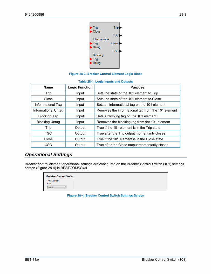
9424200996 28-3
BE1-11m Breaker Control Switch (101)
Figure 28-3. Breaker Control Element Logic Block
Table 28-1. Logic Inputs and Outputs
Name Logic Function Purpose Trip Input Sets the state of the 101 element to Trip
Close Input Sets the state of the 101 element to Close Informational Tag Input Sets an informational tag on the 101 element
Informational Untag Input Removes the informational tag from the 101 element Blocking Tag Input Sets a blocking tag on the 101 element
Blocking Untag Input Removes the blocking tag from the 101 element Trip Output True if the 101 element is in the Trip state TSC Output True after the Trip output momentarily closes Close Output True if the 101 element is in the Close state CSC Output True after the Close output momentarily closes
Operational Settings
Breaker control element operational settings are configured on the Breaker Control Switch (101) settings screen (Figure 28-4) in BESTCOMSPlus.
Figure 28-4. Breaker Control Switch Settings Screen

28-4 9424200996
Breaker Control Switch (101) BE1-11m
9424200996 29-1
BE1-11m Setting Groups
29 • Setting Groups Four setting groups allow for adapting the coordination settings to optimize them for a predictable situation. Sensitivity and time coordination settings can be adjusted to optimize sensitivity or clearing time based upon source conditions or to improve security during overload conditions. The possibilities for improving protection by eliminating compromises in coordination settings with adaptive setting groups are endless.
The four setting groups are designated Setting Group 0, Setting Group 1, Setting Group 2, and Setting Group 3. Setting group logic connections are made on the BESTlogic™Plus screen in BESTCOMSPlus® and setting group operational settings are configured on the Setting Group Setup screen in BESTCOMSPlus. A summary of the logic inputs and outputs and operational settings appears at the end of this chapter.
BESTCOMSPlus Navigation Path: Settings Explorer, General Settings, Setting Group Setup
HMI Navigation Path: Settings Explorer, General Settings, Settings Group
Setting Group Functions
The group of settings that is active at any point in time is controlled by the setting group selection logic. This function logic allows for manual (logic) selection.
Logic Inputs The function monitors logic inputs, D0 through D3 and changes the active setting group according to the status of these inputs. These inputs can be connected to logic expressions such as contact sensing outputs.
Logic Outputs The function logic has four logic variable outputs, SG0 through SG3. The appropriate variable is asserted when each setting group is active. These logic variables can be used in programmable logic to modify the logic based upon which setting group is active.
The SGCACTIVE logic output is asserted when setting group control is active. The SGCLOVRD logic output is asserted when setting group control is overridden by logic.
Changing Setting Groups When the BE1-11m switches to a new setting group, all functions are reset and initialized with the new operating parameters. The settings change occurs instantaneously so at no time is the BE1-11m off line. The active setting group is saved in nonvolatile memory so that the BE1-11m will power up using the same setting group that was active when it was powered down. To prevent the BE1-11m from changing settings while a fault condition is in process, setting group changes are blocked when the BE1-11m is in a picked-up state. Since the BE1-11m is completely programmable, the fault condition is defined by the pickup logic expression in the fault reporting functions. See the Fault Reporting chapter for more information.
Setting Group Selection Selection of the active setting group provided by this function logic can also be overridden. When logic override is used, a setting group is made active and the BE1-11m stays in that group regardless of the state of the manual logic control conditions.
Manual (logic) selection reads the status of the logic inputs to the setting group selection function block to determine what setting group should be active. For the logic inputs to determine which setting group should be active, the AUTOMATIC input must be logic 0. The function block operational mode setting determines how it reads these logic inputs. There are three possible logic modes as shown in Table 29-3.

29-2 9424200996
Setting Groups BE1-11m
Discrete Inputs
When the setting group selection function block is enabled for Discrete Inputs, there is a direct correlation between each discrete logic input and the setting group that will be selected. That is, asserting input D0 selects SG0 and asserting input D1 selects SG1, etc. The active setting group latches-in after the input is read. It is not necessary that the input be maintained. If one or more inputs are asserted at the same time, the numerically higher setting group will be activated. A pulse must be present for approximately one second for the setting group change to occur. After a setting group change occurs, no setting group change can occur within two times the SGC alarm on time. Any pulses to the inputs will be ignored during that period.
Figure 29-1 shows an example of how the inputs are read when the setting group selection function mode is enabled for Discrete Inputs. Note that a pulse on the D3 input while D0 is also active does not cause a setting group change to SG3 because the AUTOMATIC input is active.
Figure 29-1. Input Control Discrete Inputs
When the setting group selection function block is enabled for Binary Inputs, the inputs on D0 and D1 are read as binary encoded (Table 29-1). Inputs D2 and D3 are ignored. A new coded input must be stable for approximately one second for the setting group change to occur. After a setting group change occurs, no setting group change can occur within two times the SGC alarm on time.
Table 29-1. Setting Group Binary Codes
Binary Code Setting Group
D1 D0 0 0 SG0
0 1 SG1 1 0 SG2 1 1 SG3
Binary Inputs
When the setting group selection function mode is enabled for Binary Inputs, the active setting group is controlled by a binary signal applied to discrete inputs D0 and D1. This requires separate logic equations for only D0 and D1 if all setting groups are to be used. Figure 29-2 shows how the active setting group follows the binary sum of the D0 and D1 inputs except when blocked by the AUTOMATIC input. Note that a pulse on the D1 input while D0 is also active does not cause a setting change to SG3 because the AUTOMATIC input is active.
D3
D2
D1
D0
AUTO
SG3
SG2
SG1
SG0
SGC P003
5-28
05-0
3-06
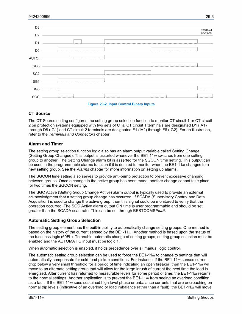
9424200996 29-3
BE1-11m Setting Groups
Figure 29-2. Input Control Binary Inputs
CT Source The CT Source setting configures the setting group selection function to monitor CT circuit 1 or CT circuit 2 on protection systems equipped with two sets of CTs. CT circuit 1 terminals are designated D1 (IA1) through D8 (IG1) and CT circuit 2 terminals are designated F1 (IA2) through F8 (IG2). For an illustration, refer to the Terminals and Connectors chapter.
Alarm and Timer The setting group selection function logic also has an alarm output variable called Setting Change (Setting Group Changed). This output is asserted whenever the BE1-11m switches from one setting group to another. The Setting Change alarm bit is asserted for the SGCON time setting. This output can be used in the programmable alarms function if it is desired to monitor when the BE1-11m changes to a new setting group. See the Alarms chapter for more information on setting up alarms.
The SGCON time setting also serves to provide anti-pump protection to prevent excessive changing between groups. Once a change in the active group has been made, another change cannot take place for two times the SGCON setting.
The SGC Active (Setting Group Change Active) alarm output is typically used to provide an external acknowledgment that a setting group change has occurred. If SCADA (Supervisory Control and Data Acquisition) is used to change the active group, then this signal could be monitored to verify that the operation occurred. The SGC Active alarm output ON time is user programmable and should be set greater than the SCADA scan rate. This can be set through BESTCOMSPlus®.
Automatic Setting Group Selection The setting group element has the built-in ability to automatically change setting groups. One method is based on the history of the current sensed by the BE1-11m. Another method is based upon the status of the fuse loss logic (60FL). To enable automatic change of setting groups, setting group selection must be enabled and the AUTOMATIC input must be logic 1.
When automatic selection is enabled, it holds precedence over all manual logic control.
The automatic setting group selection can be used to force the BE1-11m to change to settings that will automatically compensate for cold-load pickup conditions. For instance, if the BE1-11m senses current drop below a very small threshold for a period of time indicating an open breaker, then the BE1-11m will move to an alternate setting group that will allow for the large inrush of current the next time the load is energized. After current has returned to measurable levels for some period of time, the BE1-11m returns to the normal settings. Another application is to prevent the BE1-11m from seeing an overload condition as a fault. If the BE1-11m sees sustained high level phase or unbalance currents that are encroaching on normal trip levels (indicative of an overload or load imbalance rather than a fault), the BE1-11m will move
P0037-4405-03-06
D3
D2
D1
D0
AUTO
SG3
SG2
SG1
SG0
SGC

29-4 9424200996
Setting Groups BE1-11m
to an alternate setting group that can accommodate the condition. The BE1-11m can be set to alarm for this condition using the programmable logic alarms.
The BE1-11m has the logic to automatically change setting groups based upon the status of the fuse loss (60FL).
Automatic Control by Monitoring Line Current
The setting group Switch Threshold and Return Threshold settings determine how the function selects the active setting group when automatic selection is enabled.
Automatic control of the active setting group allows the BE1-11m to automatically change configuration for optimum protection based on the current system conditions. For example, in locations where seasonal changes can cause large variations in loading, the overcurrent protection can be set with sensitive settings during the majority of the time and switch to a setting group with lower sensitivity (higher pickups) during the few days of the year when the loading is at peak.
The BE1-11m will switch to a setting group when current rises above the "switch threshold" for the "switch time" and will return from the setting group when current falls below the "return threshold" for the "return time." However, if the Switch Threshold is 0 and a nonzero switch-to time is entered, the BE1-11m will change to the indicated setting group after the switch-to time.
If a group's switch threshold is zero, the group’s switch time delay is zero, and current is being monitored, then the BE1-11m will never automatically switch to that setting group.
Five settings for each group are used for automatic control. Each group has a Switch Threshold and Switch Time, a Return Threshold and Return Time, and a Monitor Setting. The Switch and Return thresholds are set in amps. If you wish to switch settings based upon loading, you could set the Monitor Setting to Max Phase Current. If you wish to switch settings based upon unbalance, you could set it to Neutral Current, or Negative-Sequence Current.
This function can also be used to automatically change the active setting group for cold load pickup conditions. If the Switch Threshold for a group is set to 0 amps, the function will switch to that group when there is no current flow for the time delay period, indicating that the breaker is open or the circuit source is out of service.
Note the difference in operation when a switch threshold of 0.5 amps is used. For this setting, the group is selected when current rises above 0.5 amps.
When the Switch criteria are met for more than one setting group at a time, the function will use the numerically higher of the enabled setting groups. If the switch-to time delay setting is set to 0 for a setting group, automatic control for that group is disabled. If the return time delay setting is set to 0 for a setting group, automatic return for that group is disabled and the BE1-11m will remain in that setting group until returned manually by logic override control.
Group Control by Monitoring Fuse Loss Status
The active setting group can also be controlled by the status of the fuse loss function (60FL). The BE1-11m can be instructed to change to Setting Group 1. If the monitored element is 60FL, the switch threshold, return time, and return threshold are ignored.
Logic Connections
Setting group logic connections are made on the BESTlogicPlus screen in BESTCOMSPlus. The setting group logic block is illustrated in Figure 29-3. Logic inputs and outputs are summarized in Table 29-2.
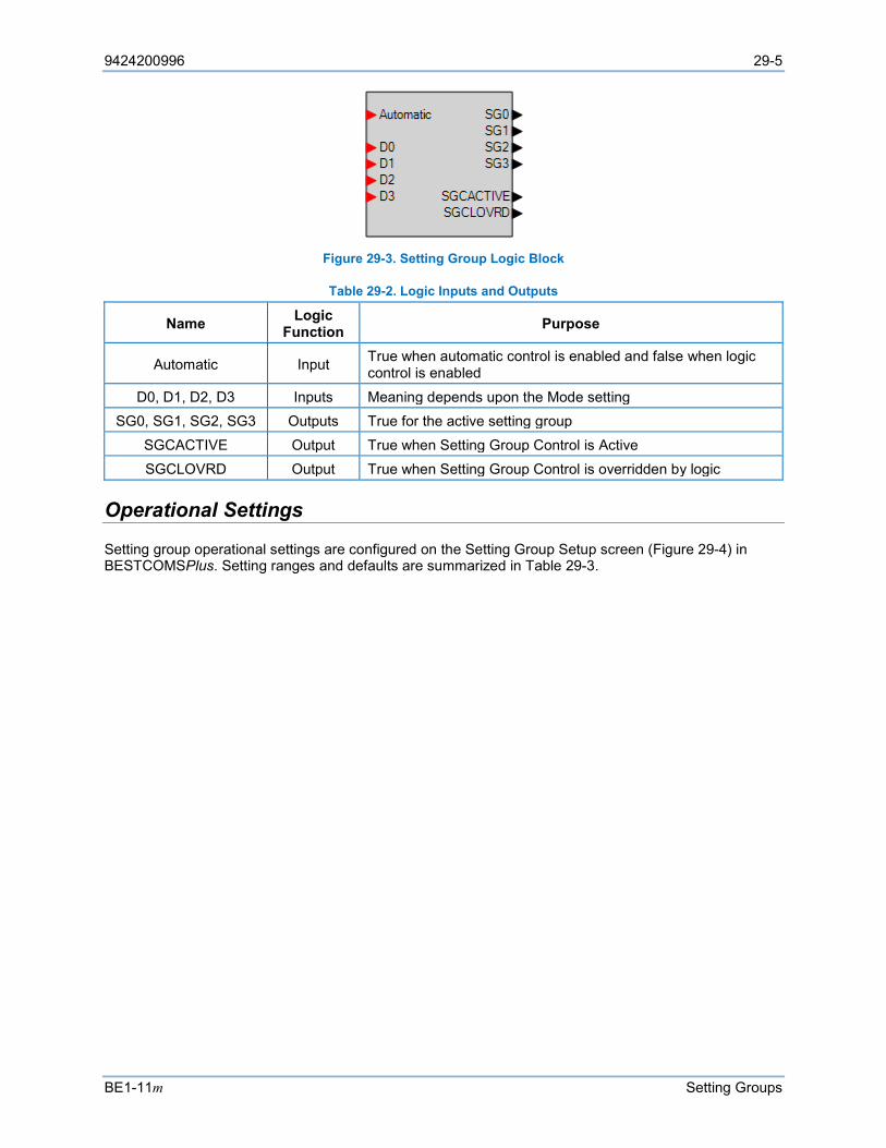
9424200996 29-5
BE1-11m Setting Groups
Figure 29-3. Setting Group Logic Block
Table 29-2. Logic Inputs and Outputs
Name Logic Function Purpose
Automatic Input True when automatic control is enabled and false when logic control is enabled
D0, D1, D2, D3 Inputs Meaning depends upon the Mode setting SG0, SG1, SG2, SG3 Outputs True for the active setting group
SGCACTIVE Output True when Setting Group Control is Active SGCLOVRD Output True when Setting Group Control is overridden by logic
Operational Settings
Setting group operational settings are configured on the Setting Group Setup screen (Figure 29-4) in BESTCOMSPlus. Setting ranges and defaults are summarized in Table 29-3.
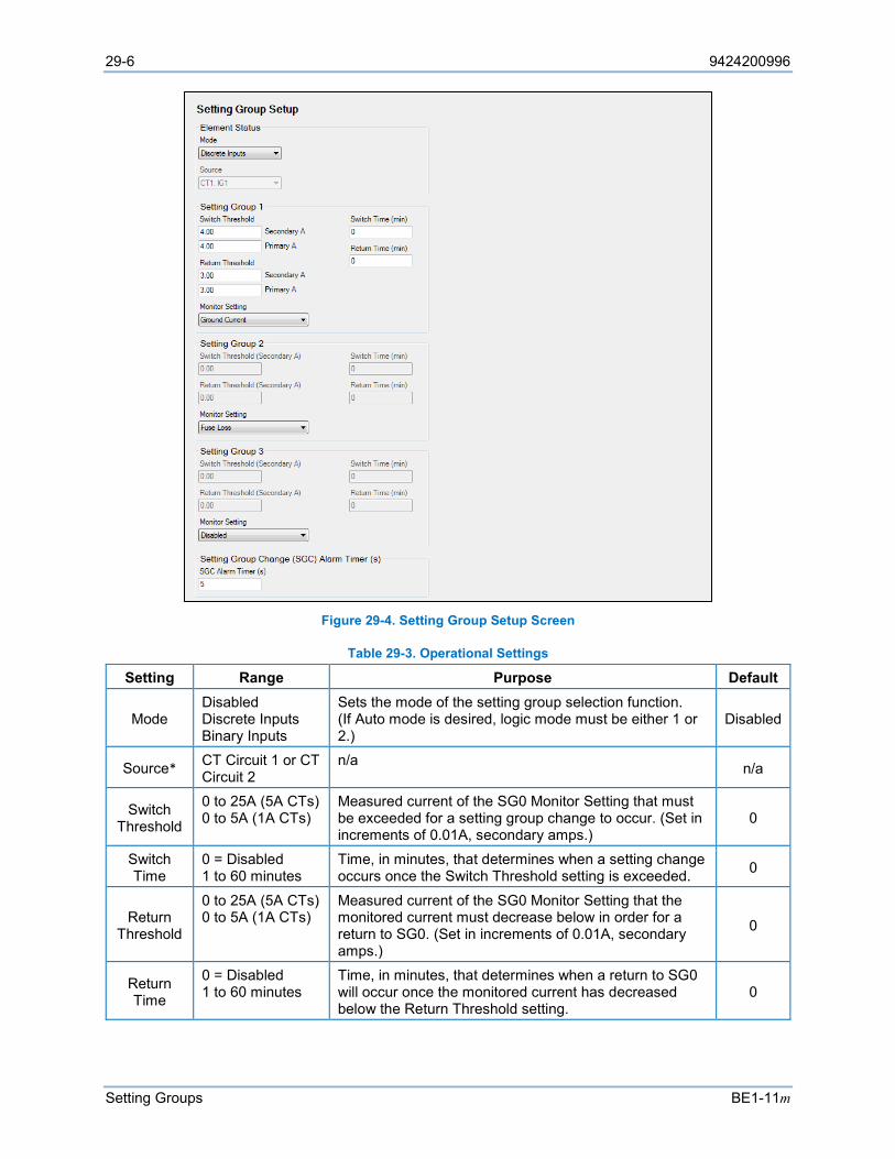
29-6 9424200996
Setting Groups BE1-11m
Figure 29-4. Setting Group Setup Screen
Table 29-3. Operational Settings
Setting Range Purpose Default
Mode Disabled Discrete Inputs Binary Inputs
Sets the mode of the setting group selection function. (If Auto mode is desired, logic mode must be either 1 or 2.)
Disabled
Source* CT Circuit 1 or CT Circuit 2
n/a n/a
Switch Threshold
0 to 25A (5A CTs) 0 to 5A (1A CTs)
Measured current of the SG0 Monitor Setting that must be exceeded for a setting group change to occur. (Set in increments of 0.01A, secondary amps.)
0
Switch Time
0 = Disabled 1 to 60 minutes
Time, in minutes, that determines when a setting change occurs once the Switch Threshold setting is exceeded. 0
Return Threshold
0 to 25A (5A CTs) 0 to 5A (1A CTs)
Measured current of the SG0 Monitor Setting that the monitored current must decrease below in order for a return to SG0. (Set in increments of 0.01A, secondary amps.)
0
Return Time
0 = Disabled 1 to 60 minutes
Time, in minutes, that determines when a return to SG0 will occur once the monitored current has decreased below the Return Threshold setting.
0
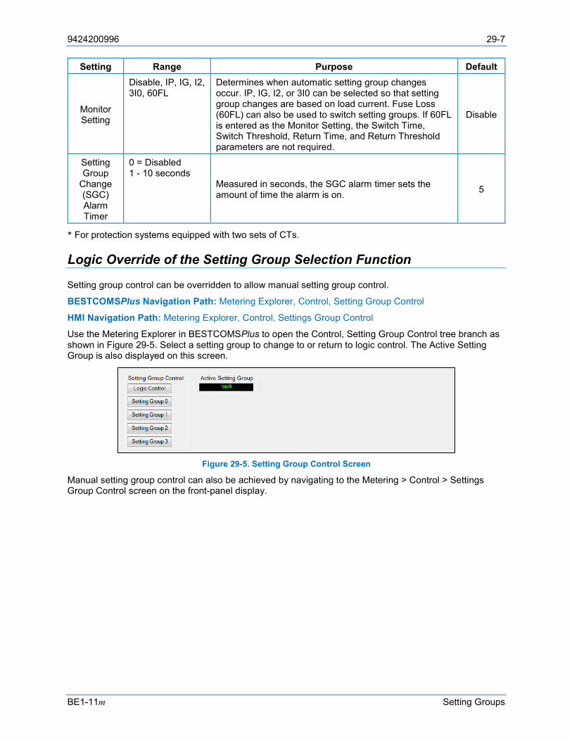
9424200996 29-7
BE1-11m Setting Groups
Setting Range Purpose Default
Monitor Setting
Disable, IP, IG, I2, 3I0, 60FL
Determines when automatic setting group changes occur. IP, IG, I2, or 3I0 can be selected so that setting group changes are based on load current. Fuse Loss (60FL) can also be used to switch setting groups. If 60FL is entered as the Monitor Setting, the Switch Time, Switch Threshold, Return Time, and Return Threshold parameters are not required.
Disable
Setting Group
Change (SGC) Alarm Timer
0 = Disabled 1 - 10 seconds
Measured in seconds, the SGC alarm timer sets the amount of time the alarm is on. 5
* For protection systems equipped with two sets of CTs.
Logic Override of the Setting Group Selection Function
Setting group control can be overridden to allow manual setting group control.
BESTCOMSPlus Navigation Path: Metering Explorer, Control, Setting Group Control
HMI Navigation Path: Metering Explorer, Control, Settings Group Control
Use the Metering Explorer in BESTCOMSPlus to open the Control, Setting Group Control tree branch as shown in Figure 29-5. Select a setting group to change to or return to logic control. The Active Setting Group is also displayed on this screen.
Figure 29-5. Setting Group Control Screen
Manual setting group control can also be achieved by navigating to the Metering > Control > Settings Group Control screen on the front-panel display.

29-8 9424200996
Setting Groups BE1-11m
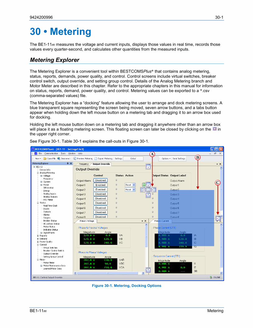
9424200996 30-1
BE1-11m Metering
30 • Metering The BE1-11m measures the voltage and current inputs, displays those values in real time, records those values every quarter-second, and calculates other quantities from the measured inputs.
Metering Explorer
The Metering Explorer is a convenient tool within BESTCOMSPlus® that contains analog metering, status, reports, demands, power quality, and control. Control screens include virtual switches, breaker control switch, output override, and setting group control. Details of the Analog Metering branch and Motor Meter are described in this chapter. Refer to the appropriate chapters in this manual for information on status, reports, demand, power quality, and control. Metering values can be exported to a *.csv (comma-separated values) file.
The Metering Explorer has a “docking” feature allowing the user to arrange and dock metering screens. A blue transparent square representing the screen being moved, seven arrow buttons, and a tabs button appear when holding down the left mouse button on a metering tab and dragging it to an arrow box used for docking.
Holding the left mouse button down on a metering tab and dragging it anywhere other than an arrow box will place it as a floating metering screen. This floating screen can later be closed by clicking on the in the upper right corner.
See Figure 30-1. Table 30-1 explains the call-outs in Figure 30-1.
Figure 30-1. Metering, Docking Options

30-2 9424200996
Metering BE1-11m
Table 30-1. Explanation of Figure 30-1 Call-Outs
Call-Out Explanation A Holding the left mouse button down on a metering tab and dragging it to one of the four
arrow boxes will place it inside the selected window on the location selected. To place the metering tab as a tab inside the selected window, drop it on the tabs button in the center of the arrow buttons.
B This blue transparent square represents the screen being moved. C Holding the left mouse button down on a metering tab and dragging it to the right, down,
left, or up arrow box will place it across the side/bottom/top of the screen. Click on the (thumbtack) to dock it on the side bar. To display a screen that is docked, simply use the mouse to hover the pointer over the tab on the side bar.
Analog Metering Functions
BE1-11m analog metering functions include voltage, frequency, current, power, differential, and energy. Metered values are viewed through the Metering Explorer in BESTCOMSPlus, the front-panel display, or the web page interface on Ethernet equipped protection systems. Refer to the BESTnet™Plus chapter for more information. Metering functions are summarized in the following paragraphs. For information on power, VA, and var calculations, refer to the Configuration chapter.
Auto Ranging The BE1-11m automatically scales metered values. Table 30-2 illustrates the ranges for each value metered.
Table 30-2. Auto Ranging Scales for Metered Values
Metered Value Unit Display Ranges
Whole Units Kilo Units Mega Units Giga Units Current 0 A to 999 A 10 kA to 999 kA 1 MA n/a
Voltage 0 V to 999 V 0 kV to 999 kV n/a n/a Apparent Power n/a 0 kVA to 999 kVA 1 MVA to 999 MVA 1 GVA to 1000 GVA Reactive Power n/a 0 kvar to 999 kvar 1 Mvar to 999 Mvar 1 Gvar to 1000 Gvar
Real Power n/a 0 kW to 999 kW 1 MW to 999 MW 1 GW to 1000 GW Frequency 10 to 125 Hz n/a n/a n/a
Voltage - Primary and Secondary The BE1-11m meters primary and secondary phase-to-neutral voltages (VA, VB, VC), phase-to-phase voltages (VAB, VBC, VCA), positive-sequence voltage (V1), negative-sequence voltage (V2), neutral-shift voltage (3V0), auxiliary voltage (Vx), and 3rd harmonic auxiliary voltage (Vx 3rd Harmonic). The Phase VT connection determines what is measured. The auxiliary voltage input is user selectable. Refer to the Configuration chapter for more information on configuring Phase VT and AUX VT.
Primary and secondary voltage metering data is found in BESTCOMSPlus (Figure 30-2) and on the Metering > Analog Metering > Voltage screen of the front-panel display. A phasor diagram is also provided in BESTCOMSPlus.
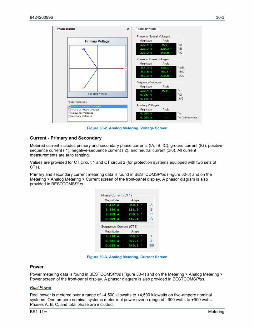
9424200996 30-3
BE1-11m Metering
Figure 30-2. Analog Metering, Voltage Screen
Current - Primary and Secondary Metered current includes primary and secondary phase currents (IA, IB, IC), ground current (IG), positive-sequence current (I1), negative-sequence current (I2), and neutral current (3I0). All current measurements are auto ranging.
Values are provided for CT circuit 1 and CT circuit 2 (for protection systems equipped with two sets of CTs).
Primary and secondary current metering data is found in BESTCOMSPlus (Figure 30-3) and on the Metering > Analog Metering > Current screen of the front-panel display. A phasor diagram is also provided in BESTCOMSPlus.
Figure 30-3. Analog Metering, Current Screen
Power Power metering data is found in BESTCOMSPlus (Figure 30-4) and on the Metering > Analog Metering > Power screen of the front-panel display. A phasor diagram is also provided in BESTCOMSPlus.
Real Power
Real power is metered over a range of –4,500 kilowatts to +4,500 kilowatts on five-ampere nominal systems. One-ampere nominal systems meter real power over a range of –900 watts to +900 watts. Phases A, B, C, and total phase are included.
30-4 9424200996
Metering BE1-11m
Reactive Power
Reactive power is metered over a range of −4,500 kilovars to +4,500 kilovars on five-ampere nominal systems. One-ampere systems meter reactive power over a range of −900 kilovars to +900 kilovars. Phases A, B, C, and total phase are included.
Apparent Power
Metered apparent power is displayed over a range of –4,500 kilovoltamperes to +4,500 kilovoltamperes on five-ampere nominal systems. One-ampere nominal systems meter reactive power over a range of –900 kilovoltamperes to +900 kilovoltamperes. Phases A, B, C, and total phase are included.
Power Factor
Power factor is metered over a range of maximum lagging (−0.00) to unity (1.00) to maximum leading (+0.00) for phases A, B, and C, and for total phase.
Figure 30-4. Analog Metering, Power Screen
Frequency Frequency is metered over a range of 10 to 125 hertz. If the measured frequency is outside this range, the display will show “---“.
Frequency is sensed from Va to N on the back of the BE1-11m. Refer to the Typical Connections chapter for three-wire and four-wire connection diagrams. The frequency of the auxiliary voltage input (VX) is also measured.
Frequency metering data is found in BESTCOMSPlus (Figure 30-5) and on the Metering > Analog Metering > Frequency screen of the front-panel display.
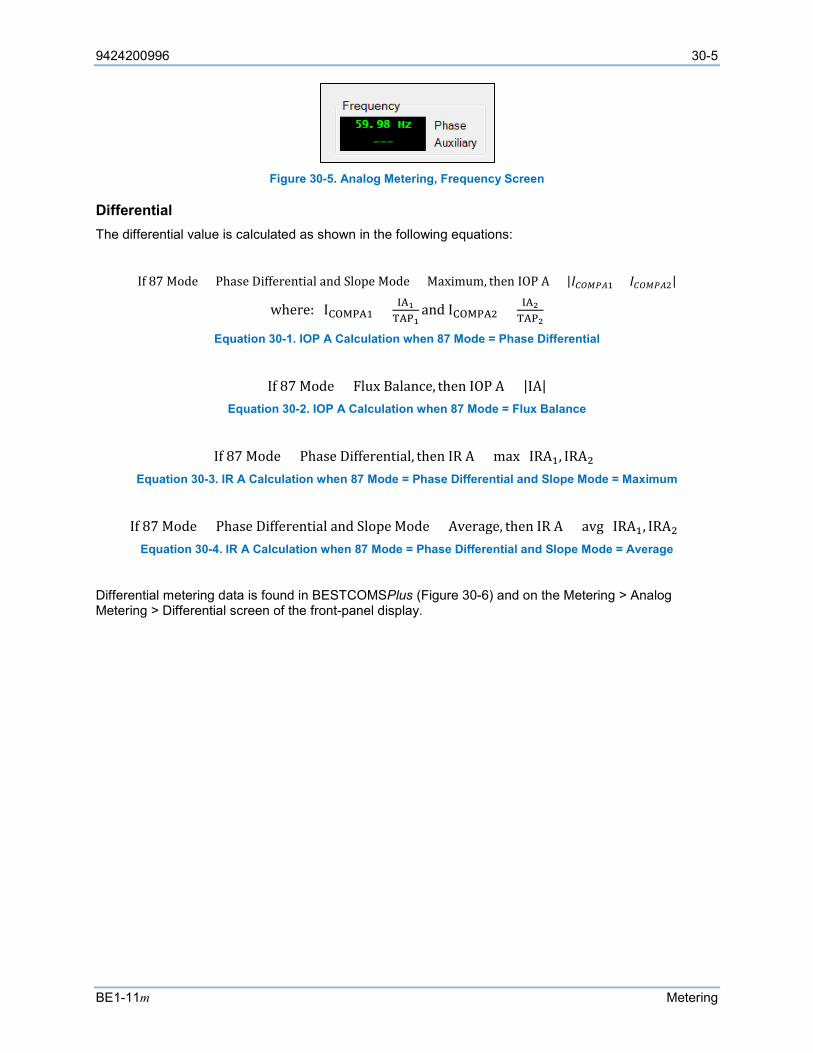
9424200996 30-5
BE1-11m Metering
Figure 30-5. Analog Metering, Frequency Screen
Differential The differential value is calculated as shown in the following equations:
If 87 Mode = Phase Differential and Slope Mode = Maximum, then IOP A = |𝐼𝐼𝐶𝐶𝐶𝐶𝐶𝐶𝐶𝐶𝐶𝐶1 + 𝐼𝐼𝐶𝐶𝐶𝐶𝐶𝐶𝐶𝐶𝐶𝐶2|
where: ICOMPA1 = IA1TAP1
and ICOMPA2 = IA2TAP2
Equation 30-1. IOP A Calculation when 87 Mode = Phase Differential
If 87 Mode = Flux Balance, then IOP A = |IA| Equation 30-2. IOP A Calculation when 87 Mode = Flux Balance
If 87 Mode = Phase Differential, then IR A = max (IRA1, IRA2)
Equation 30-3. IR A Calculation when 87 Mode = Phase Differential and Slope Mode = Maximum
If 87 Mode = Phase Differential and Slope Mode = Average, then IR A = avg (IRA1, IRA2)
Equation 30-4. IR A Calculation when 87 Mode = Phase Differential and Slope Mode = Average
Differential metering data is found in BESTCOMSPlus (Figure 30-6) and on the Metering > Analog Metering > Differential screen of the front-panel display.
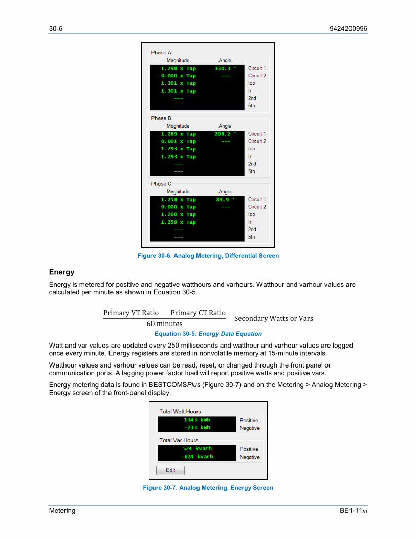
30-6 9424200996
Metering BE1-11m
Figure 30-6. Analog Metering, Differential Screen
Energy Energy is metered for positive and negative watthours and varhours. Watthour and varhour values are calculated per minute as shown in Equation 30-5.
Primary VT Ratio × Primary CT Ratio60 minutes
× Secondary Watts or Vars
Equation 30-5. Energy Data Equation
Watt and var values are updated every 250 milliseconds and watthour and varhour values are logged once every minute. Energy registers are stored in nonvolatile memory at 15-minute intervals.
Watthour values and varhour values can be read, reset, or changed through the front panel or communication ports. A lagging power factor load will report positive watts and positive vars.
Energy metering data is found in BESTCOMSPlus (Figure 30-7) and on the Metering > Analog Metering > Energy screen of the front-panel display.
Figure 30-7. Analog Metering, Energy Screen
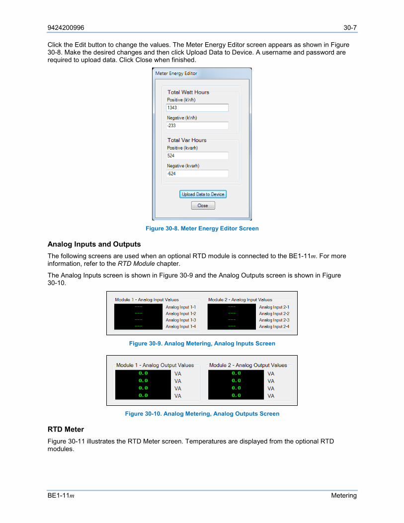
9424200996 30-7
BE1-11m Metering
Click the Edit button to change the values. The Meter Energy Editor screen appears as shown in Figure 30-8. Make the desired changes and then click Upload Data to Device. A username and password are required to upload data. Click Close when finished.
Figure 30-8. Meter Energy Editor Screen
Analog Inputs and Outputs The following screens are used when an optional RTD module is connected to the BE1-11m. For more information, refer to the RTD Module chapter.
The Analog Inputs screen is shown in Figure 30-9 and the Analog Outputs screen is shown in Figure 30-10.
Figure 30-9. Analog Metering, Analog Inputs Screen
Figure 30-10. Analog Metering, Analog Outputs Screen
RTD Meter Figure 30-11 illustrates the RTD Meter screen. Temperatures are displayed from the optional RTD modules.
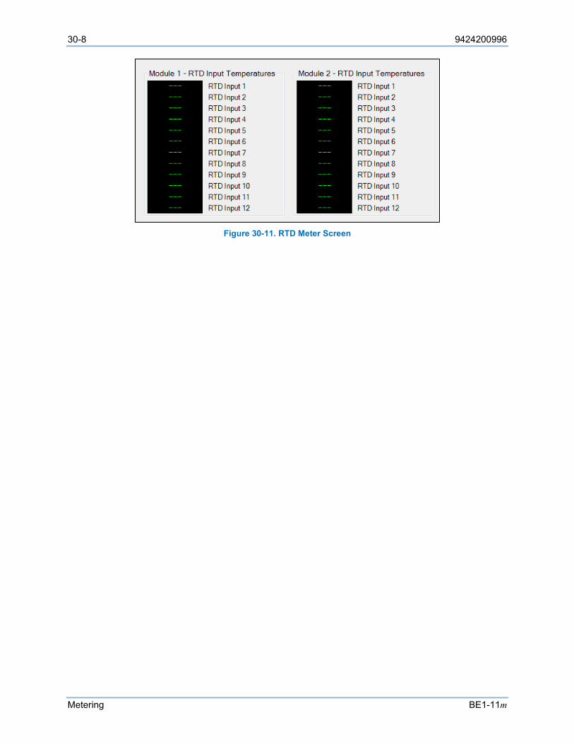
30-8 9424200996
Metering BE1-11m
Figure 30-11. RTD Meter Screen
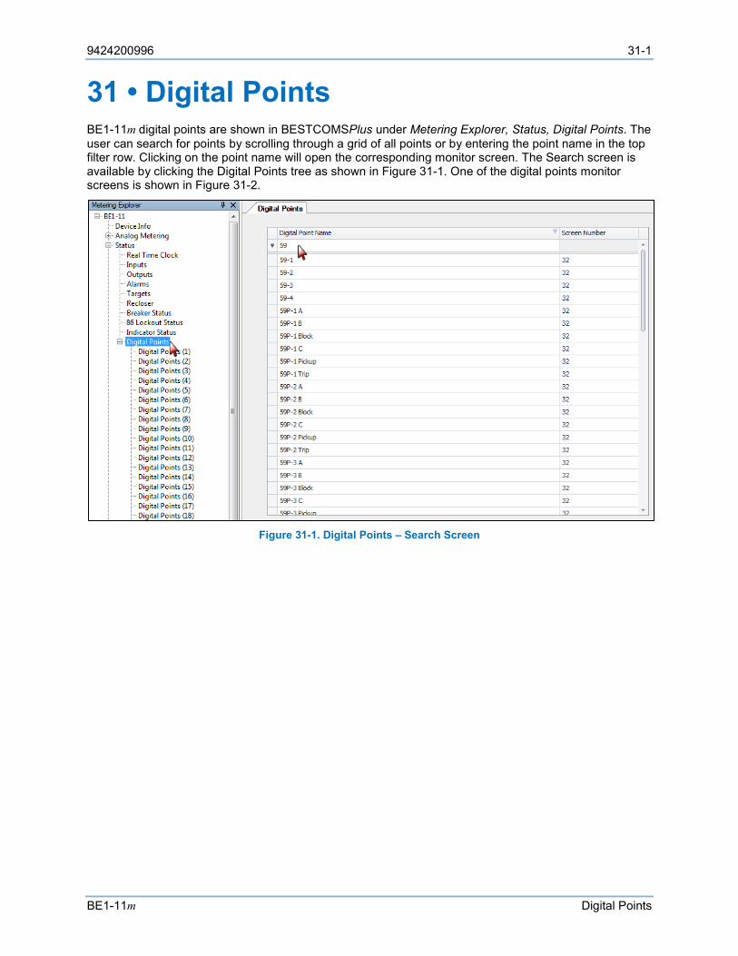
9424200996 31-1
BE1-11m Digital Points
31 • Digital Points BE1-11m digital points are shown in BESTCOMSPlus under Metering Explorer, Status, Digital Points. The user can search for points by scrolling through a grid of all points or by entering the point name in the top filter row. Clicking on the point name will open the corresponding monitor screen. The Search screen is available by clicking the Digital Points tree as shown in Figure 31-1. One of the digital points monitor screens is shown in Figure 31-2.
Figure 31-1. Digital Points – Search Screen
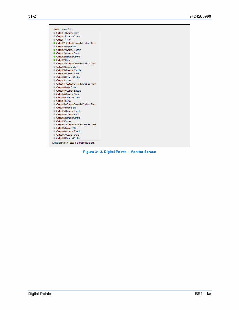
31-2 9424200996
Digital Points BE1-11m
Figure 31-2. Digital Points – Monitor Screen

9424200996 32-1
BE1-11m Sequence of Events
32 • Sequence of Events A sequence of events recorder (SER) report is very useful in reconstructing the exact sequence and timing of events during a power disturbance or even normal system operations. The SER tracks over 700 data points by monitoring the internal and external status of the BE1-11m. Data points are scanned every quarter-cycle. All changes of state that occur during each scan are time tagged to 1 millisecond resolution. Over 1,000 records are stored in nonvolatile memory; when the SER memory becomes full, the oldest record is replaced by the latest one acquired.
The SER monitors the following points and conditions: • Single-state events such as resetting demands or targets, changing settings, etc. • Programmable logic variables • Targets • Relay trouble alarm variables • Programmable alarm variables • Output contact status • Fault reporting trigger expressions
BE1-11m protection systems have three BE1-11m identification fields: Device ID, Station ID, and User ID. These fields are used in the header information lines of the sequence of events records. Refer to the BESTCOMSPlus® Software chapter for information on BE1-11m identification settings.
For user-programmable logic variables (contact sensing inputs, contact outputs, and virtual control switches), the user-programmed variable name, and state names are logged in the SER report instead of the generic variable name and state names.
When a monitored event occurs or a monitored variable changes state, the SER logs all event data listed in Table 32-1.
Table 32-1. Event Data Recorded
Event Data Recorded Description
TIME STAMP Date of change in format YYYY-MM-DD Time of change in 24 hour format HH:MM:SS.mmm
SYNC Time Sync Status, one of: IRIGB, DNP, NTP, RTC, NO_SYNC
DEVICE ID User entered device name string
TYPE Point Type, one of: ALRM (alarm), CONF (configurable), LGIC (logic), PROT (protection), STAT (status), TRBL (trouble), TRGT (target), USER (user)
NUM Basler Point Name (not localized to local language) DESCRIPTION Localized or user entered string description of point
STATUS Localized or user entered string status of point (Open, Closed, Trip, etc.)
Sequence of Events Setup
The Sequence of Events Setup screen is shown in Figure 32-1. Select events to be recorded in the Sequence of Events Log. All events are enabled by default.
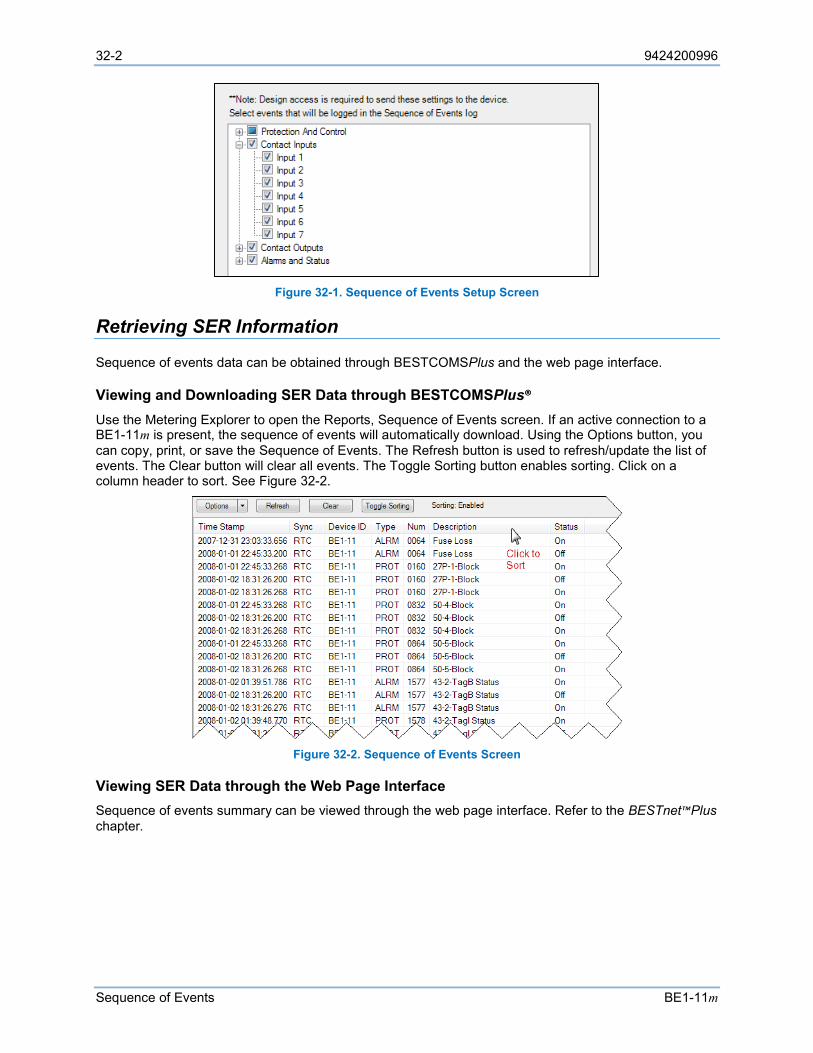
32-2 9424200996
Sequence of Events BE1-11m
Figure 32-1. Sequence of Events Setup Screen
Retrieving SER Information
Sequence of events data can be obtained through BESTCOMSPlus and the web page interface.
Viewing and Downloading SER Data through BESTCOMSPlus® Use the Metering Explorer to open the Reports, Sequence of Events screen. If an active connection to a BE1-11m is present, the sequence of events will automatically download. Using the Options button, you can copy, print, or save the Sequence of Events. The Refresh button is used to refresh/update the list of events. The Clear button will clear all events. The Toggle Sorting button enables sorting. Click on a column header to sort. See Figure 32-2.
Figure 32-2. Sequence of Events Screen
Viewing SER Data through the Web Page Interface Sequence of events summary can be viewed through the web page interface. Refer to the BESTnet™Plus chapter.
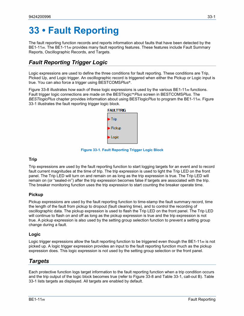
9424200996 33-1
BE1-11m Fault Reporting
33 • Fault Reporting The fault reporting function records and reports information about faults that have been detected by the BE1-11m. The BE1-11m provides many fault reporting features. These features include Fault Summary Reports, Oscillographic Records, and Targets.
Fault Reporting Trigger Logic
Logic expressions are used to define the three conditions for fault reporting. These conditions are Trip, Picked Up, and Logic trigger. An oscillographic record is triggered when either the Pickup or Logic input is true. You can also force a trigger using BESTCOMSPlus®.
Figure 33-8 illustrates how each of these logic expressions is used by the various BE1-11m functions. Fault trigger logic connections are made on the BESTlogic™Plus screen in BESTCOMSPlus. The BESTlogicPlus chapter provides information about using BESTlogicPlus to program the BE1-11m. Figure 33-1 illustrates the fault reporting trigger logic block.
Figure 33-1. Fault Reporting Trigger Logic Block
Trip Trip expressions are used by the fault reporting function to start logging targets for an event and to record fault current magnitudes at the time of trip. The trip expression is used to light the Trip LED on the front panel. The Trip LED will turn on and remain on as long as the trip expression is true. The Trip LED will remain on (or “sealed-in”) after the trip expression becomes false if targets are associated with the trip. The breaker monitoring function uses the trip expression to start counting the breaker operate time.
Pickup Pickup expressions are used by the fault reporting function to time-stamp the fault summary record, time the length of the fault from pickup to dropout (fault clearing time), and to control the recording of oscillographic data. The pickup expression is used to flash the Trip LED on the front panel. The Trip LED will continue to flash on and off as long as the pickup expression is true and the trip expression is not true. A pickup expression is also used by the setting group selection function to prevent a setting group change during a fault.
Logic Logic trigger expressions allow the fault reporting function to be triggered even though the BE1-11m is not picked up. A logic trigger expression provides an input to the fault reporting function much as the pickup expression does. This logic expression is not used by the setting group selection or the front panel.
Targets
Each protective function logs target information to the fault reporting function when a trip condition occurs and the trip output of the logic block becomes true (refer to Figure 33-8 and Table 33-1, call-out B). Table 33-1 lists targets as displayed. All targets are enabled by default.
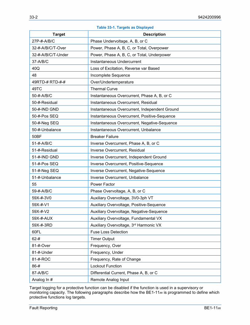
33-2 9424200996
Fault Reporting BE1-11m
Table 33-1. Targets as Displayed
Target Description 27P-#-A/B/C Phase Undervoltage, A, B, or C 32-#-A/B/C/T-Over Power, Phase A, B, C, or Total, Overpower
32-#-A/B/C/T-Under Power, Phase A, B, C, or Total, Underpower 37-A/B/C Instantaneous Undercurrent 40Q Loss of Excitation, Reverse var Based
48 Incomplete Sequence 49RTD-# RTD-#-# Over/Undertemperature 49TC Thermal Curve
50-#-A/B/C Instantaneous Overcurrent, Phase A, B, or C 50-#-Residual Instantaneous Overcurrent, Residual 50-#-IND GND Instantaneous Overcurrent, Independent Ground
50-#-Pos SEQ Instantaneous Overcurrent, Positive-Sequence 50-#-Neg SEQ Instantaneous Overcurrent, Negative-Sequence 50-#-Unbalance Instantaneous Overcurrent, Unbalance
50BF Breaker Failure 51-#-A/B/C Inverse Overcurrent, Phase A, B, or C 51-#-Residual Inverse Overcurrent, Residual
51-#-IND GND Inverse Overcurrent, Independent Ground 51-#-Pos SEQ Inverse Overcurrent, Positive-Sequence 51-#-Neg SEQ Inverse Overcurrent, Negative-Sequence
51-#-Unbalance Inverse Overcurrent, Unbalance 55 Power Factor 59-#-A/B/C Phase Overvoltage, A, B, or C
59X-#-3V0 Auxiliary Overvoltage, 3V0-3ph VT 59X-#-V1 Auxiliary Overvoltage, Positive-Sequence 59X-#-V2 Auxiliary Overvoltage, Negative-Sequence
59X-#-AUX Auxiliary Overvoltage, Fundamental VX 59X-#-3RD Auxiliary Overvoltage, 3rd Harmonic VX 60FL Fuse Loss Detection
62-# Timer Output 81-#-Over Frequency, Over 81-#-Under Frequency, Under
81-#-ROC Frequency, Rate of Change 86-# Lockout Function 87-A/B/C Differential Current, Phase A, B, or C Analog In # Remote Analog Input
Target logging for a protective function can be disabled if the function is used in a supervisory or monitoring capacity. The following paragraphs describe how the BE1-11m is programmed to define which protective functions log targets.
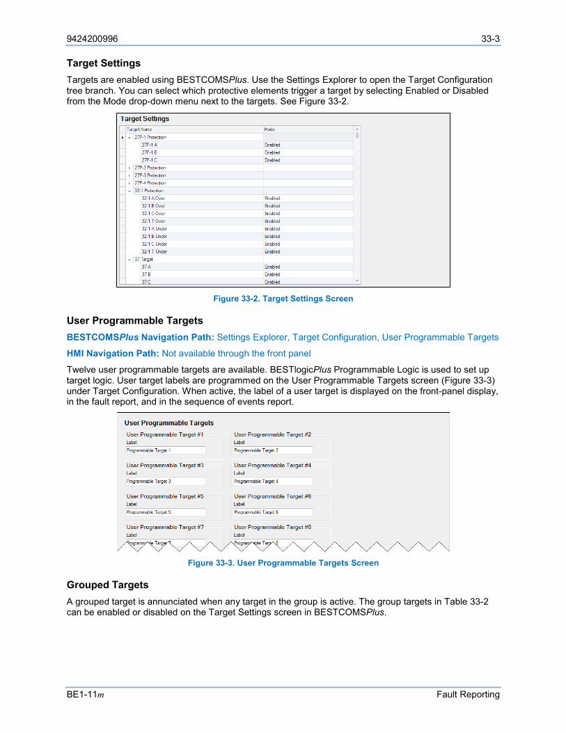
9424200996 33-3
BE1-11m Fault Reporting
Target Settings Targets are enabled using BESTCOMSPlus. Use the Settings Explorer to open the Target Configuration tree branch. You can select which protective elements trigger a target by selecting Enabled or Disabled from the Mode drop-down menu next to the targets. See Figure 33-2.
Figure 33-2. Target Settings Screen
User Programmable Targets BESTCOMSPlus Navigation Path: Settings Explorer, Target Configuration, User Programmable Targets
HMI Navigation Path: Not available through the front panel
Twelve user programmable targets are available. BESTlogicPlus Programmable Logic is used to set up target logic. User target labels are programmed on the User Programmable Targets screen (Figure 33-3) under Target Configuration. When active, the label of a user target is displayed on the front-panel display, in the fault report, and in the sequence of events report.
Figure 33-3. User Programmable Targets Screen
Grouped Targets A grouped target is annunciated when any target in the group is active. The group targets in Table 33-2 can be enabled or disabled on the Target Settings screen in BESTCOMSPlus.
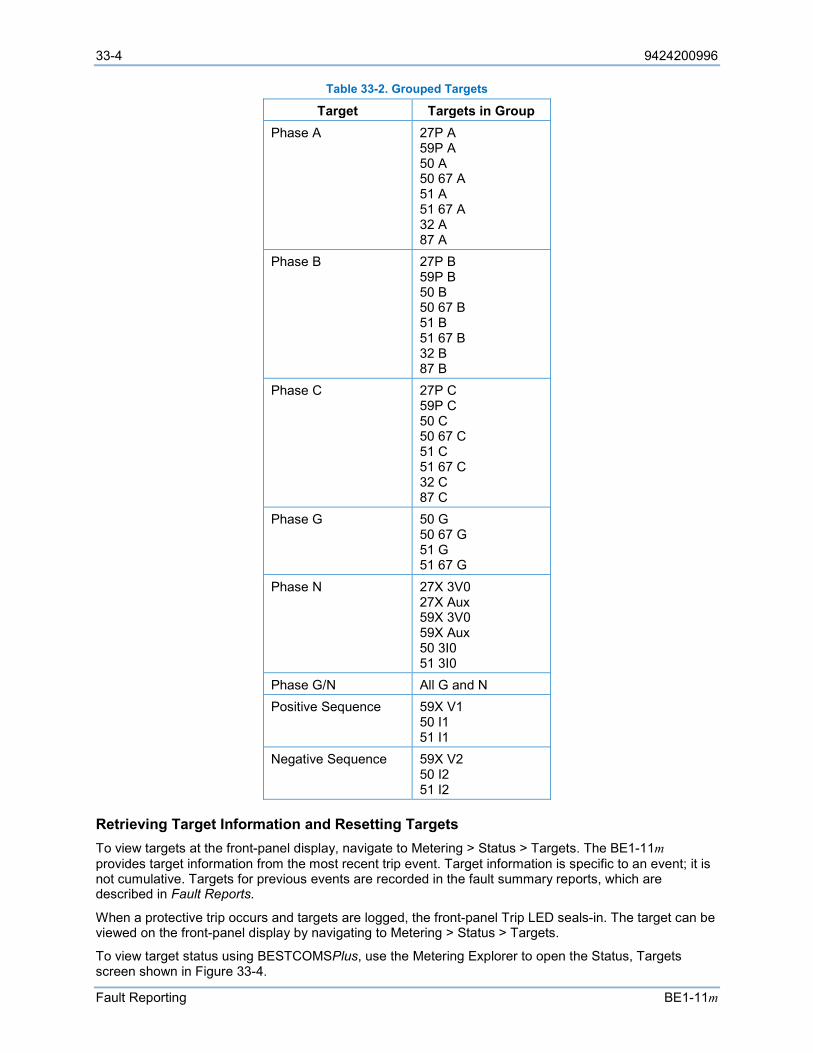
33-4 9424200996
Fault Reporting BE1-11m
Table 33-2. Grouped Targets
Target Targets in Group Phase A 27P A
59P A 50 A 50 67 A 51 A 51 67 A 32 A 87 A
Phase B 27P B 59P B 50 B 50 67 B 51 B 51 67 B 32 B 87 B
Phase C 27P C 59P C 50 C 50 67 C 51 C 51 67 C 32 C 87 C
Phase G 50 G 50 67 G 51 G 51 67 G
Phase N 27X 3V0 27X Aux 59X 3V0 59X Aux 50 3I0 51 3I0
Phase G/N All G and N Positive Sequence 59X V1
50 I1 51 I1
Negative Sequence 59X V2 50 I2 51 I2
Retrieving Target Information and Resetting Targets To view targets at the front-panel display, navigate to Metering > Status > Targets. The BE1-11m provides target information from the most recent trip event. Target information is specific to an event; it is not cumulative. Targets for previous events are recorded in the fault summary reports, which are described in Fault Reports.
When a protective trip occurs and targets are logged, the front-panel Trip LED seals-in. The target can be viewed on the front-panel display by navigating to Metering > Status > Targets.
To view target status using BESTCOMSPlus, use the Metering Explorer to open the Status, Targets screen shown in Figure 33-4.
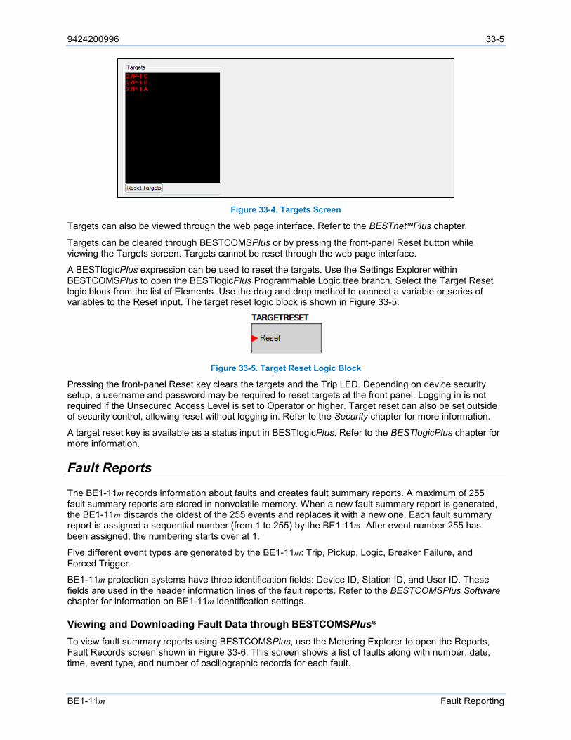
9424200996 33-5
BE1-11m Fault Reporting
Figure 33-4. Targets Screen
Targets can also be viewed through the web page interface. Refer to the BESTnet™Plus chapter.
Targets can be cleared through BESTCOMSPlus or by pressing the front-panel Reset button while viewing the Targets screen. Targets cannot be reset through the web page interface.
A BESTlogicPlus expression can be used to reset the targets. Use the Settings Explorer within BESTCOMSPlus to open the BESTlogicPlus Programmable Logic tree branch. Select the Target Reset logic block from the list of Elements. Use the drag and drop method to connect a variable or series of variables to the Reset input. The target reset logic block is shown in Figure 33-5.
Figure 33-5. Target Reset Logic Block
Pressing the front-panel Reset key clears the targets and the Trip LED. Depending on device security setup, a username and password may be required to reset targets at the front panel. Logging in is not required if the Unsecured Access Level is set to Operator or higher. Target reset can also be set outside of security control, allowing reset without logging in. Refer to the Security chapter for more information.
A target reset key is available as a status input in BESTlogicPlus. Refer to the BESTlogicPlus chapter for more information.
Fault Reports
The BE1-11m records information about faults and creates fault summary reports. A maximum of 255 fault summary reports are stored in nonvolatile memory. When a new fault summary report is generated, the BE1-11m discards the oldest of the 255 events and replaces it with a new one. Each fault summary report is assigned a sequential number (from 1 to 255) by the BE1-11m. After event number 255 has been assigned, the numbering starts over at 1.
Five different event types are generated by the BE1-11m: Trip, Pickup, Logic, Breaker Failure, and Forced Trigger.
BE1-11m protection systems have three identification fields: Device ID, Station ID, and User ID. These fields are used in the header information lines of the fault reports. Refer to the BESTCOMSPlus Software chapter for information on BE1-11m identification settings.
Viewing and Downloading Fault Data through BESTCOMSPlus® To view fault summary reports using BESTCOMSPlus, use the Metering Explorer to open the Reports, Fault Records screen shown in Figure 33-6. This screen shows a list of faults along with number, date, time, event type, and number of oscillographic records for each fault.
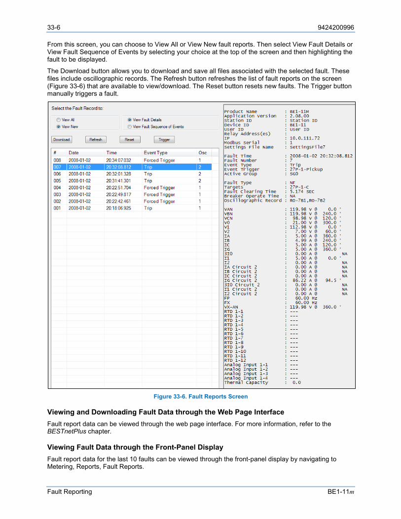
33-6 9424200996
Fault Reporting BE1-11m
From this screen, you can choose to View All or View New fault reports. Then select View Fault Details or View Fault Sequence of Events by selecting your choice at the top of the screen and then highlighting the fault to be displayed.
The Download button allows you to download and save all files associated with the selected fault. These files include oscillographic records. The Refresh button refreshes the list of fault reports on the screen (Figure 33-6) that are available to view/download. The Reset button resets new faults. The Trigger button manually triggers a fault.
Figure 33-6. Fault Reports Screen
Viewing and Downloading Fault Data through the Web Page Interface Fault report data can be viewed through the web page interface. For more information, refer to the BESTnetPlus chapter.
Viewing Fault Data through the Front-Panel Display Fault report data for the last 10 faults can be viewed through the front-panel display by navigating to Metering, Reports, Fault Reports.
9424200996 33-7
BE1-11m Fault Reporting
Fault Summary Report Items A fault summary report collects several items of information about a fault that can aid in determining why a fault occurred without having to sort through all of the detailed information available. The following items are contained in a typical fault summary report.
Product Name
This line reports the product name.
Application Version
This line reports the version of firmware inside the product.
Station ID, Device ID, and User ID
These lines report station, device, and user information as defined by BESTCOMSPlus on the Device Info screen.
Relay Address
This line reports the communications port address(es) that the report was requested from. The addresses are assigned using BESTCOMSPlus or the front-panel interface.
Settings File Name
This line reports the name of the settings file that was active at the time of the fault.
Fault Time
This line reports the time and date of the initial trigger of the event. This is based on either the pickup logic expression or the logic trigger expression becoming true as defined by the Fault Trigger logic. Refer to Figure 33-8 and Table 33-3, call-out A.
Fault Number
This line reports the sequential number (from 1 to 255) assigned to the report by the BE1-11m.
Event Type
This line reports the type of event that occurred. There are five event categories: 1. Trip: A fault was detected as defined by the pickup expression and the BE1-11m tripped to
clear the fault. 2. Pickup: A fault was detected as defined by the pickup expression but the BE1-11m never
tripped indicating that the fault was cleared by another device. 3. Logic: A fault report was recorded by the logic trigger expression but no fault was detected as
defined by the pickup expression. 4. Breaker Failure: A fault was detected as defined by the pickup expression and the breaker
failure trip became true before the fault was cleared. 5. Forced Trigger: A fault report was triggered through the BESTCOMSPlus interface.
Event Trigger
This line reports the logic variables in the picked up or logic trigger expressions that became true to trigger the recording of the event.
Active Group
This line reports what setting group was active at the time that the fault occurred.
Fault Type
Indication of phases involved in the fault.

33-8 9424200996
Fault Reporting BE1-11m
Targets
This line reports the targets that were logged to the fault report between the time that the trip expression became true until the end of the fault. Refer to Figure 33-8 and Table 33-3, call-out B.
Fault Clearing Time
This line reports the time from when the BE1-11m detected the fault until the BE1-11m detected that the fault had cleared. Refer to Figure 33-8 and Table 33-3, call-out C.
• If the fault report was triggered through the BESTCOMSPlus interface, the recording of the report was terminated after 60 seconds and this line is reported as n/a.
• If the pickup or logic expressions stay true for more than 60 seconds, an alarm bit in the programmable alarm function is set and this line is reported as n/a. In this situation, the fault reporting functions (including targets) will not operate again until the pickup and logic trigger expressions return to a false state to enable another trigger.
Breaker Operate Time
This line reports the breaker trip time from the breaker monitoring and alarm function. This is the time measured from when the breaker is trigged until the fast current detector function detects that the arc has been extinguished.
Oscillographic Record
This line reports the number of oscillographic records that are stored in memory for this fault report. Refer to Figure 33-8 and Table 33-3, call-out E. Recording of oscillographic records is described later in this chapter.
VA, IA, IA Circuit 2, VB, IB, IB Circuit 2, VC, IC, IC Circuit 2
These lines report the phase voltage and current magnitudes and angles measured two power system cycles immediately following the trip trigger. If the fault is cleared prior to the BE1-11m tripping, the recorded fault voltages and currents are for the power system cycle two cycles prior to the end of the fault. Refer to Figure 33-8 and Table 33-3, call-out F.
V0, V1, V2
These lines report the three-phase residual, positive-sequence, and negative-sequence voltage magnitudes and angles measured two power system cycles immediately following the trip trigger. If the fault is cleared prior to the BE1-11m tripping, the recorded fault voltages are for the power system cycle two cycles prior to the end of the fault. Refer to Figure 33-8 and Table 33-3, call-out F.
IG, IG Circuit 2
This line reports the ground current magnitude and angle measured two power system cycles immediately following the trip trigger. If the fault is cleared prior to the BE1-11m tripping, the recorded fault current is for the power system cycle two cycles prior to the end of the fault. Refer to Figure 33-8 and Table 33-3, call-out F.
3I0, 3I0 Circuit 2, I1, I1 Circuit 2, I2, I2 Circuit 2
These lines report the three-phase residual, positive-sequence, and negative-sequence current magnitudes and angles measured two power system cycles immediately following the trip trigger. If the fault is cleared prior to the BE1-11m tripping, the recorded fault currents are for the power system cycle two cycles prior to the end of the fault. Refer to Figure 33-8 and Table 33-3, call-out F.
FP, FX
This line reports the frequency for the phase voltage input and auxiliary voltage input measured immediately following the trip trigger. Refer to Figure 33-8 and Table 33-3, call-out F.
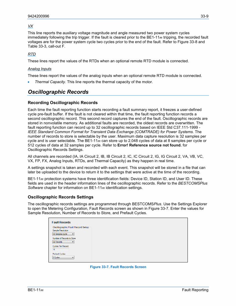
9424200996 33-9
BE1-11m Fault Reporting
VX
This line reports the auxiliary voltage magnitude and angle measured two power system cycles immediately following the trip trigger. If the fault is cleared prior to the BE1-11m tripping, the recorded fault voltages are for the power system cycle two cycles prior to the end of the fault. Refer to Figure 33-8 and Table 33-3, call-out F.
RTD
These lines report the values of the RTDs when an optional remote RTD module is connected.
Analog Inputs
These lines report the values of the analog inputs when an optional remote RTD module is connected. • Thermal Capacity. This line reports the thermal capacity of the motor.
Oscillographic Records
Recording Oscillographic Records Each time the fault reporting function starts recording a fault summary report, it freezes a user-defined cycle pre-fault buffer. If the fault is not cleared within that time, the fault reporting function records a second oscillographic record. This second record captures the end of the fault. Oscillographic records are stored in nonvolatile memory. As additional faults are recorded, the oldest records are overwritten. The fault reporting function can record up to 32 oscillographic records based on IEEE Std C37.111-1999 - IEEE Standard Common Format for Transient Data Exchange (COMTRADE) for Power Systems. The number of records to store is selectable by the user. Maximum data capture resolution is 32 samples per cycle and is user selectable. The BE1-11m can store up to 2,048 cycles of data at 8 samples per cycle or 512 cycles of data at 32 samples per cycle. Refer to Error! Reference source not found. for Oscillographic Records Settings.
All channels are recorded (IA, IA Circuit 2, IB, IB Circuit 2, IC, IC Circuit 2, IG, IG Circuit 2, VA, VB, VC, VX, FP, FX, Analog Inputs, RTDs, and Thermal Capacity) as they happen in real time.
A settings snapshot is taken and recorded with each event. This snapshot will be stored in a file that can later be uploaded to the device to return it to the settings that were active at the time of the recording.
BE1-11m protection systems have three identification fields: Device ID, Station ID, and User ID. These fields are used in the header information lines of the oscillographic records. Refer to the BESTCOMSPlus Software chapter for information on BE1-11m identification settings.
Oscillographic Records Settings The oscillographic records settings are programmed through BESTCOMSPlus. Use the Settings Explorer to open the Metering Configuration, Fault Records screen as shown in Figure 33-7. Enter the values for Sample Resolution, Number of Records to Store, and Prefault Cycles.
Figure 33-7. Fault Records Screen

33-10 9424200996
Fault Reporting BE1-11m
Retrieving Oscillographic Records Oscillographic records can be downloaded through the Reports, Fault Reports screen in BESTCOMSPlus (Figure 33-6). See Fault Reports earlier in this chapter. Oscillographic records can also be downloaded through the web page interface. For more information, refer to the BESTnetPlus chapter.
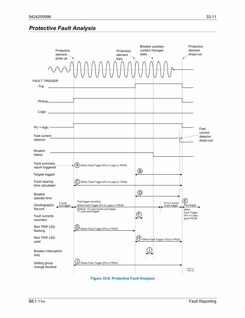
9424200996 33-11
BE1-11m Fault Reporting
Protective Fault Analysis
Figure 33-8. Protective Fault Analysis
Protective element picks up
Protective element trips
Breaker auxiliary contact changes state
Protective element drops out
Fast current detector drops out
FAULT TRIGGER
-Pickup
-Logic
PU + logic
Fast current detector
Breaker status
Fault summary report triggered
(When Fault Trigger (PU or Logic) is TRUE)AB
Targets logged
CFault clearing time calculated
DBreaker operate time
OscillographicRecord
4 cyclepre-trigger
Post-trigger recording
(Default: 15 cycle record, pre-trigger, 11 cycle post-trigger)
Post-trigger1/4 to 5 cycles of pre-trigger
E
FFault currents recorded
GRed TRIP LED flashing
(When Fault Trigger (PU) is TRUE)
HRed TRIP LED solid
Breaker interruption duty
Setting group change blocked
I
JP0037-1203-23-06
-Trip
WhenFault Trigger (PU or Logic) goes FALSE
(When Fault Trigger (PU or Logic) is TRUE)
(When Fault Trigger (PU or Logic) is TRUE)
(When Fault Trigger (PU) is TRUE)
(When Fault Trigger (Trip) is TRUE)
33-12 9424200996
Fault Reporting BE1-11m
Table 33-3. Legend for Figure 33-8
Locator Description A A fault summary report and an oscillograph record are triggered when the Pickup logic
expression becomes true. B During the time that the Trip expression is true, targets are logged from each of the
protective functions that reach a trip state. If a protective function is not being used for tripping purposes, the associated target function can be disabled through BESTCOMSPlus.
C Fault clearing time is calculated as the duration of the time that the Pickup logic expression is true.
D Breaker operate time is calculated as the time from when the Trip logic expression becomes true until the fast current detector senses that the breaker has successfully interrupted the current in all poles of the breaker.
E A second oscillographic record is triggered to record the end of the fault if the Pickup logic expression remains in the true state at the time that the first oscillographic record ends. This second record will have from ¼ to five cycles of pre-trigger data depending upon when the Pickup logic expression becomes false.
F Recorded fault current and voltage magnitudes are displayed on the Targets screen of the front-panel display. The same information including phase voltage frequency, auxiliary voltage frequency, and voltage and current angles are recorded in the fault summary report. The magnitude and angle results are based on data captured two cycles after the trip output goes true. This two-cycle delay allows the line transients to settle to provide data that is more accurate. If the Trip expression does not become true, the fault was cleared by a down-stream device. For these pickup-only events, fault current, voltage, and angle recorded in the fault summary report will be for the power system cycle ending two cycles prior to the end of the fault record. This is also the case if the fault record was triggered through BESTCOMSPlus.
G During the time that the Pickup expression is true, the red Trip LED on the front panel flashes indicating that the BE1-11m is picked up.
H During the time the Trip expression is true, the red Trip LED on the front panel lights steadily indicating that the BE1-11m is in a tripped state. If targets have been logged for the fault, the Trip LED is sealed in until the targets have been reset.
I Breaker operations and interruption duty functions are driven by the breaker status function. The operations counter is incremented on breaker opening. The magnitudes of the currents that are used for accumulating breaker duty are recorded for the power system cycle ending when the breaker status changes state. Thus, breaker duty is accumulated every time that the breaker opens even if it is not opening under fault.
J Setting group changes are blocked when the Pickup expression is true to prevent protective functions from being reinitialized with new operating parameters while a fault is occurring.
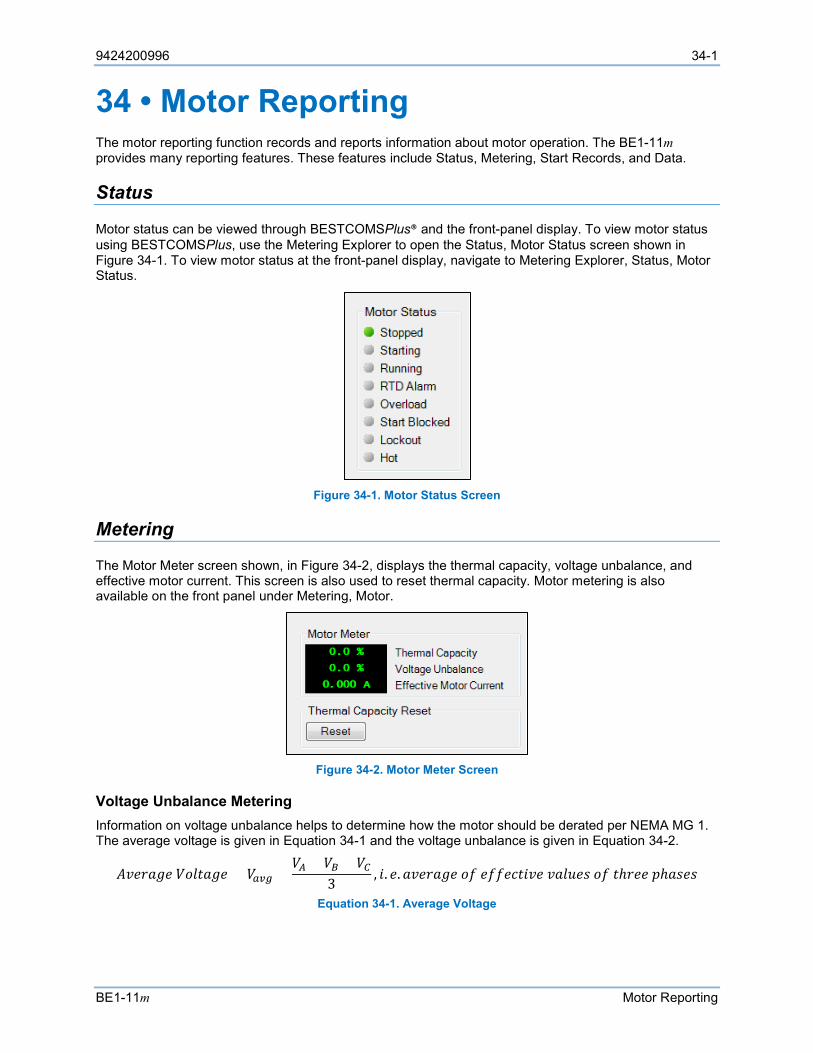
9424200996 34-1
BE1-11m Motor Reporting
34 • Motor Reporting The motor reporting function records and reports information about motor operation. The BE1-11m provides many reporting features. These features include Status, Metering, Start Records, and Data.
Status
Motor status can be viewed through BESTCOMSPlus® and the front-panel display. To view motor status using BESTCOMSPlus, use the Metering Explorer to open the Status, Motor Status screen shown in Figure 34-1. To view motor status at the front-panel display, navigate to Metering Explorer, Status, Motor Status.
Figure 34-1. Motor Status Screen
Metering
The Motor Meter screen shown, in Figure 34-2, displays the thermal capacity, voltage unbalance, and effective motor current. This screen is also used to reset thermal capacity. Motor metering is also available on the front panel under Metering, Motor.
Figure 34-2. Motor Meter Screen
Voltage Unbalance Metering Information on voltage unbalance helps to determine how the motor should be derated per NEMA MG 1. The average voltage is given in Equation 34-1 and the voltage unbalance is given in Equation 34-2.
𝐴𝐴𝐴𝐴𝐴𝐴𝐴𝐴𝐴𝐴𝐴𝐴𝐴𝐴 𝑉𝑉𝑉𝑉𝑉𝑉𝑉𝑉𝐴𝐴𝐴𝐴𝐴𝐴 = 𝑉𝑉𝑎𝑎𝑎𝑎𝑎𝑎 =𝑉𝑉𝐴𝐴 + 𝑉𝑉𝐵𝐵 + 𝑉𝑉𝐶𝐶
3, 𝑖𝑖. 𝐴𝐴.𝐴𝐴𝐴𝐴𝐴𝐴𝐴𝐴𝐴𝐴𝐴𝐴𝐴𝐴 𝑉𝑉𝑜𝑜 𝐴𝐴𝑜𝑜𝑜𝑜𝐴𝐴𝑒𝑒𝑉𝑉𝑖𝑖𝐴𝐴𝐴𝐴 𝐴𝐴𝐴𝐴𝑉𝑉𝑣𝑣𝐴𝐴𝑣𝑣 𝑉𝑉𝑜𝑜 𝑉𝑉ℎ𝐴𝐴𝐴𝐴𝐴𝐴 𝑝𝑝ℎ𝐴𝐴𝑣𝑣𝐴𝐴𝑣𝑣
Equation 34-1. Average Voltage
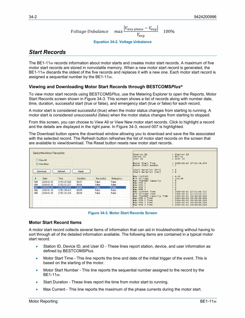
34-2 9424200996
Motor Reporting BE1-11m
𝑉𝑉𝑉𝑉𝑉𝑉𝑉𝑉𝐴𝐴𝐴𝐴𝐴𝐴 𝑈𝑈𝑈𝑈𝑈𝑈𝐴𝐴𝑉𝑉𝐴𝐴𝑈𝑈𝑒𝑒𝐴𝐴 = 𝑚𝑚𝐴𝐴𝑚𝑚𝑉𝑉𝑎𝑎𝑎𝑎𝑎𝑎 𝑝𝑝ℎ𝑎𝑎𝑎𝑎𝑎𝑎 − 𝑉𝑉𝑎𝑎𝑎𝑎𝑎𝑎
𝑉𝑉𝑎𝑎𝑎𝑎𝑎𝑎× 100%
Equation 34-2. Voltage Unbalance
Start Records
The BE1-11m records information about motor starts and creates motor start records. A maximum of five motor start records are stored in nonvolatile memory. When a new motor start record is generated, the BE1-11m discards the oldest of the five records and replaces it with a new one. Each motor start record is assigned a sequential number by the BE1-11m.
Viewing and Downloading Motor Start Records through BESTCOMSPlus® To view motor start records using BESTCOMSPlus, use the Metering Explorer to open the Reports, Motor Start Records screen shown in Figure 34-3. This screen shows a list of records along with number date, time, duration, successful start (true or false), and emergency start (true or false) for each record.
A motor start is considered successful (true) when the motor status changes from starting to running. A motor start is considered unsuccessful (false) when the motor status changes from starting to stopped.
From this screen, you can choose to View All or View New motor start records. Click to highlight a record and the details are displayed in the right pane. In Figure 34-3, record 007 is highlighted.
The Download button opens the download window allowing you to download and save the file associated with the selected record. The Refresh button refreshes the list of motor start records on the screen that are available to view/download. The Reset button resets new motor start records.
Figure 34-3. Motor Start Records Screen
Motor Start Record Items A motor start record collects several items of information that can aid in troubleshooting without having to sort through all of the detailed information available. The following items are contained in a typical motor start record.
• Station ID, Device ID, and User ID - These lines report station, device, and user information as defined by BESTCOMSPlus.
• Motor Start Time - This line reports the time and date of the initial trigger of the event. This is based on the starting of the motor.
• Motor Start Number - This line reports the sequential number assigned to the record by the BE1-11m.
• Start Duration - These lines report the time from motor start to running.
• Max Current - This line reports the maximum of the phase currents during the motor start.
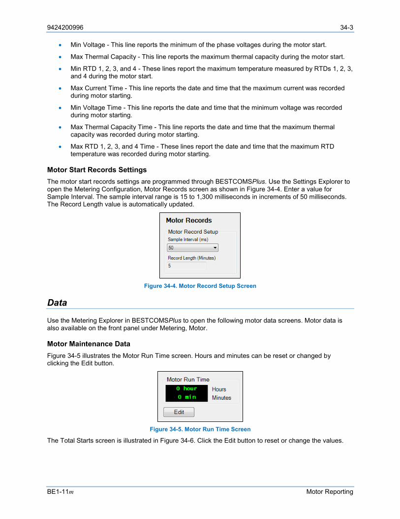
9424200996 34-3
BE1-11m Motor Reporting
• Min Voltage - This line reports the minimum of the phase voltages during the motor start.
• Max Thermal Capacity - This line reports the maximum thermal capacity during the motor start.
• Min RTD 1, 2, 3, and 4 - These lines report the maximum temperature measured by RTDs 1, 2, 3, and 4 during the motor start.
• Max Current Time - This line reports the date and time that the maximum current was recorded during motor starting.
• Min Voltage Time - This line reports the date and time that the minimum voltage was recorded during motor starting.
• Max Thermal Capacity Time - This line reports the date and time that the maximum thermal capacity was recorded during motor starting.
• Max RTD 1, 2, 3, and 4 Time - These lines report the date and time that the maximum RTD temperature was recorded during motor starting.
Motor Start Records Settings The motor start records settings are programmed through BESTCOMSPlus. Use the Settings Explorer to open the Metering Configuration, Motor Records screen as shown in Figure 34-4. Enter a value for Sample Interval. The sample interval range is 15 to 1,300 milliseconds in increments of 50 milliseconds. The Record Length value is automatically updated.
Figure 34-4. Motor Record Setup Screen
Data
Use the Metering Explorer in BESTCOMSPlus to open the following motor data screens. Motor data is also available on the front panel under Metering, Motor.
Motor Maintenance Data Figure 34-5 illustrates the Motor Run Time screen. Hours and minutes can be reset or changed by clicking the Edit button.
Figure 34-5. Motor Run Time Screen
The Total Starts screen is illustrated in Figure 34-6. Click the Edit button to reset or change the values.
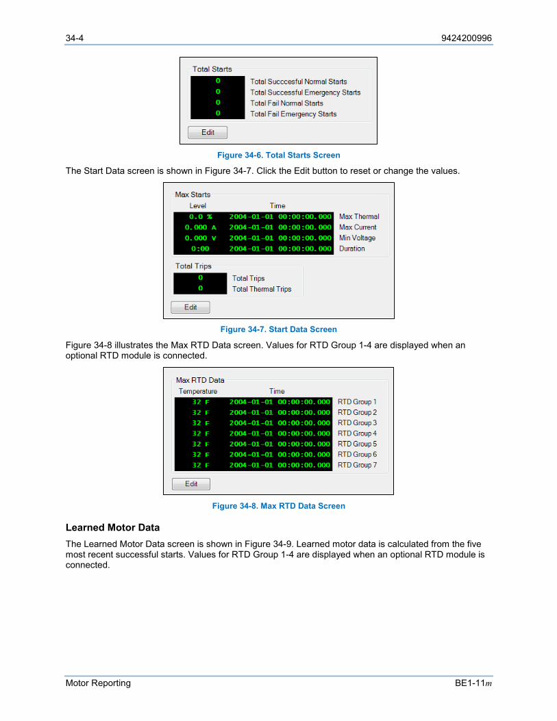
34-4 9424200996
Motor Reporting BE1-11m
Figure 34-6. Total Starts Screen
The Start Data screen is shown in Figure 34-7. Click the Edit button to reset or change the values.
Figure 34-7. Start Data Screen
Figure 34-8 illustrates the Max RTD Data screen. Values for RTD Group 1-4 are displayed when an optional RTD module is connected.
Figure 34-8. Max RTD Data Screen
Learned Motor Data The Learned Motor Data screen is shown in Figure 34-9. Learned motor data is calculated from the five most recent successful starts. Values for RTD Group 1-4 are displayed when an optional RTD module is connected.
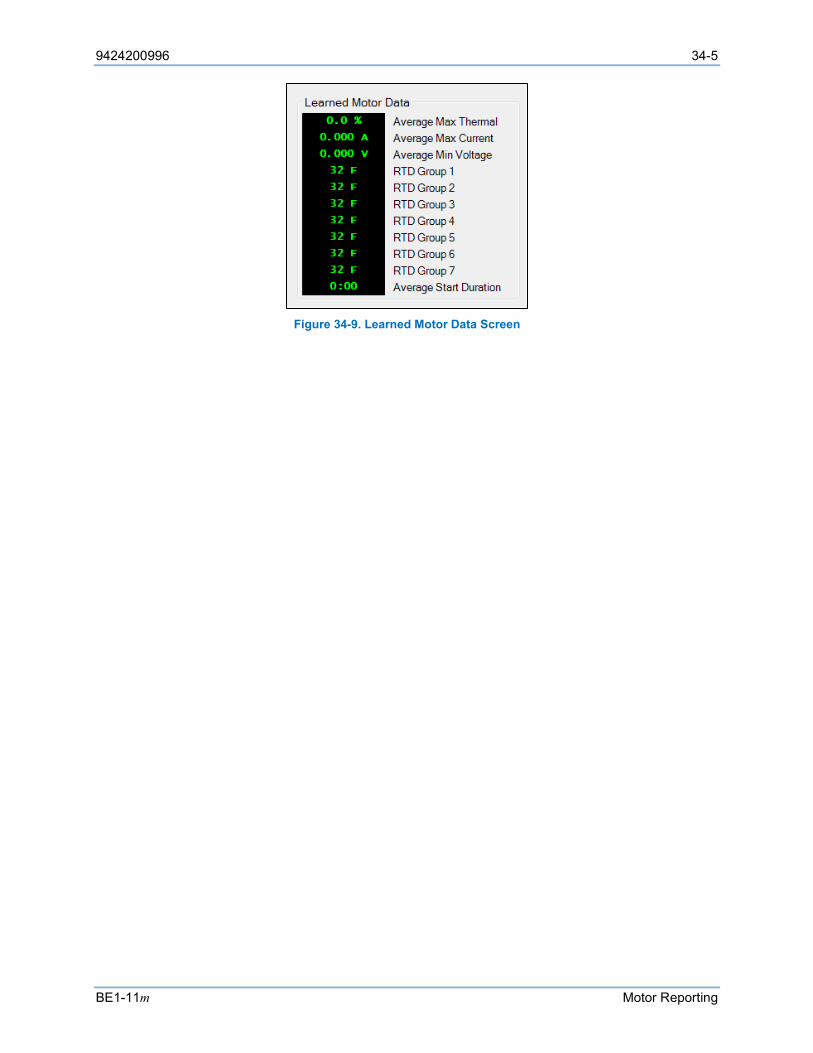
9424200996 34-5
BE1-11m Motor Reporting
Figure 34-9. Learned Motor Data Screen

34-6 9424200996
Motor Reporting BE1-11m
9424200996 35-1
BE1-11m Alarms
35 • Alarms The BE1-11m monitors internal systems, external interfaces, and power system equipment and annunciates an alarm when one of these components fail. An alarm can be configured as latching or non-latching with a status of major or minor. It can also be used as an input to other logic blocks in BESTlogic™Plus. Latching alarms are stored in nonvolatile memory and are retained even when BE1-11m operating power is lost. Active alarms are displayed on the front-panel display, web page interface, and through BESTCOMSPlus® until they are cleared. Non-latching alarms are cleared when BE1-11m operating power is lost.
If an alarm is configured as Major, a front-panel Major Alarm LED lights when the alarm is active. The front-panel Minor Alarm LED operates in a similar manner. Each alarm provides a logic output that can be connected to a physical output or other logic input using BESTlogicPlus Programmable Logic.
The ability to program the reporting and display of alarms along with the automatic display priority feature of the front-panel display gives the BE1-11m the functionality of a local and remote alarm annunciator. See the Controls and Indicators chapter for more information on the automatic display priority logic.
A detailed list of alarms is provided in Table 35-1. Table 35-1. Available Alarms
Name Description 101 Blocking Tag Status 101 breaker control switch block tag is set
3I0 Demand Neutral current unbalance demand 43-1 Blocking Tag Status 43-1 virtual switch block tag set 43-2 Blocking Tag Status 43-2 virtual switch block tag set 43-3 Blocking Tag Status 43-3 virtual switch block tag set
43-4 Blocking Tag Status 43-4 virtual switch block tag set 43-5 Blocking Tag Status 43-5 virtual switch block tag set 87 Alarm Current Differential
Analog Analog-to-digital converter error Breaker Fail Breaker failure Breaker Monitor 1 Breaker alarm 1 threshold exceeded
Breaker Monitor 2 Breaker alarm 2 threshold exceeded Breaker Monitor 3 Breaker alarm 3 threshold exceeded Changes Lost Password access lost. Read only
Date Time Set The date/time was set by the user Default Cal Loaded Error reading the RTD module nonvolatile calibration settings which
forces default calibration settings to be loaded. This alarm is set by the remote RTD module.
Defaults Loaded Error reading the RTD module nonvolatile settings which forces default settings to be loaded. This alarm is set by the remote RTD module.
DNP Polls Error DNP polling failure
Ethernet Excess Traffic Local network overloaded Ethernet Link Lost Ethernet communication lost Fault Report Timeout True if fault event trigger lasts longer than 60 seconds Firmware Change Firmware has been changed
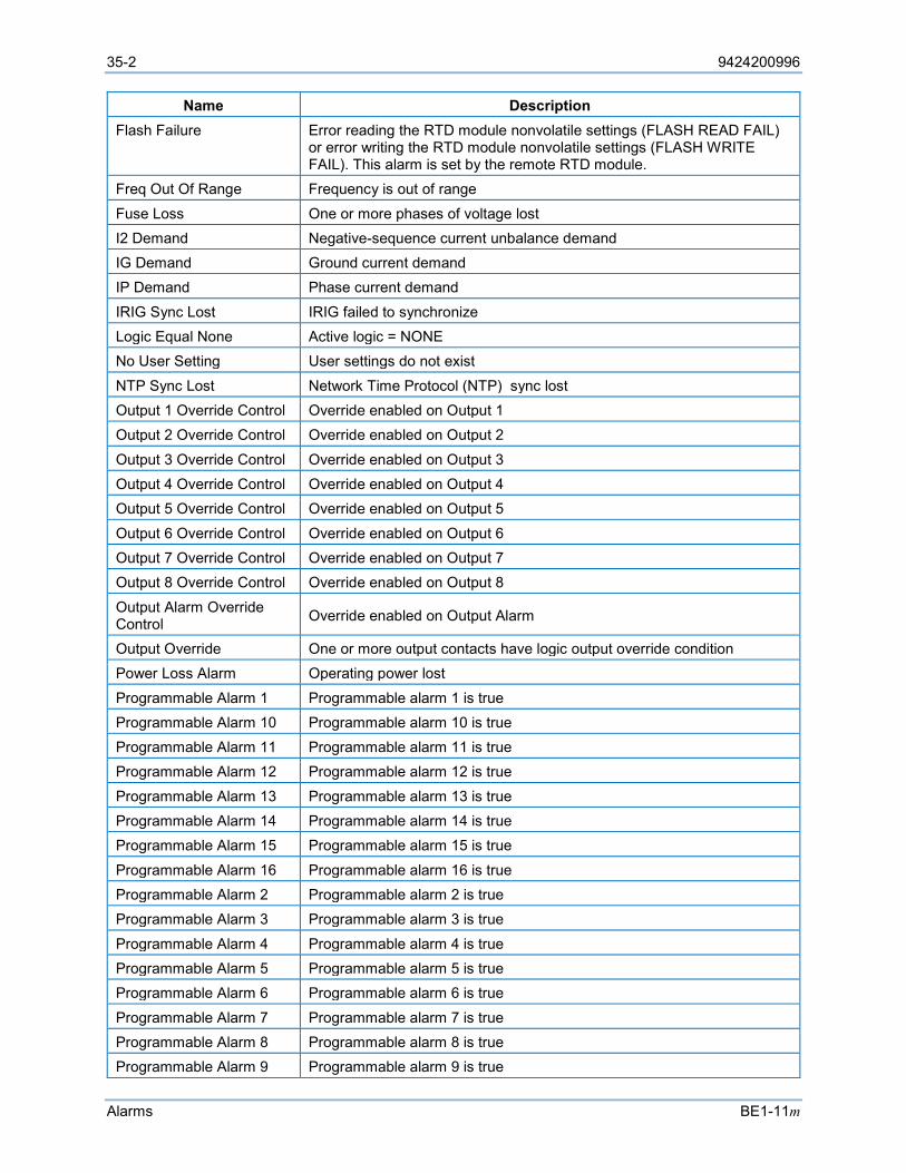
35-2 9424200996
Alarms BE1-11m
Name Description Flash Failure Error reading the RTD module nonvolatile settings (FLASH READ FAIL)
or error writing the RTD module nonvolatile settings (FLASH WRITE FAIL). This alarm is set by the remote RTD module.
Freq Out Of Range Frequency is out of range
Fuse Loss One or more phases of voltage lost I2 Demand Negative-sequence current unbalance demand IG Demand Ground current demand IP Demand Phase current demand
IRIG Sync Lost IRIG failed to synchronize Logic Equal None Active logic = NONE No User Setting User settings do not exist
NTP Sync Lost Network Time Protocol (NTP) sync lost Output 1 Override Control Override enabled on Output 1 Output 2 Override Control Override enabled on Output 2
Output 3 Override Control Override enabled on Output 3 Output 4 Override Control Override enabled on Output 4 Output 5 Override Control Override enabled on Output 5
Output 6 Override Control Override enabled on Output 6 Output 7 Override Control Override enabled on Output 7 Output 8 Override Control Override enabled on Output 8
Output Alarm Override Control Override enabled on Output Alarm
Output Override One or more output contacts have logic output override condition Power Loss Alarm Operating power lost
Programmable Alarm 1 Programmable alarm 1 is true Programmable Alarm 10 Programmable alarm 10 is true Programmable Alarm 11 Programmable alarm 11 is true Programmable Alarm 12 Programmable alarm 12 is true
Programmable Alarm 13 Programmable alarm 13 is true Programmable Alarm 14 Programmable alarm 14 is true Programmable Alarm 15 Programmable alarm 15 is true
Programmable Alarm 16 Programmable alarm 16 is true Programmable Alarm 2 Programmable alarm 2 is true Programmable Alarm 3 Programmable alarm 3 is true
Programmable Alarm 4 Programmable alarm 4 is true Programmable Alarm 5 Programmable alarm 5 is true Programmable Alarm 6 Programmable alarm 6 is true
Programmable Alarm 7 Programmable alarm 7 is true Programmable Alarm 8 Programmable alarm 8 is true Programmable Alarm 9 Programmable alarm 9 is true
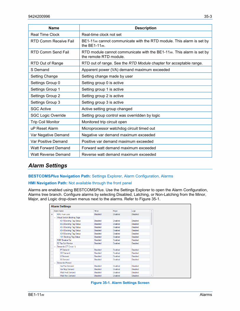
9424200996 35-3
BE1-11m Alarms
Name Description Real Time Clock Real-time clock not set
RTD Comm Receive Fail BE1-11m cannot communicate with the RTD module. This alarm is set by the BE1-11m.
RTD Comm Send Fail RTD module cannot communicate with the BE1-11m. This alarm is set by the remote RTD module.
RTD Out of Range RTD out of range. See the RTD Module chapter for acceptable range.
S Demand Apparent power (VA) demand maximum exceeded
Setting Change Setting change made by user Settings Group 0 Setting group 0 is active Settings Group 1 Setting group 1 is active
Settings Group 2 Setting group 2 is active Settings Group 3 Setting group 3 is active SGC Active Active setting group changed
SGC Logic Override Setting group control was overridden by logic Trip Coil Monitor Monitored trip circuit open uP Reset Alarm Microprocessor watchdog circuit timed out
Var Negative Demand Negative var demand maximum exceeded Var Positive Demand Positive var demand maximum exceeded Watt Forward Demand Forward watt demand maximum exceeded Watt Reverse Demand Reverse watt demand maximum exceeded
Alarm Settings
BESTCOMSPlus Navigation Path: Settings Explorer, Alarm Configuration, Alarms
HMI Navigation Path: Not available through the front panel
Alarms are enabled using BESTCOMSPlus. Use the Settings Explorer to open the Alarm Configuration, Alarms tree branch. Configure alarms by selecting Disabled, Latching, or Non-Latching from the Minor, Major, and Logic drop-down menus next to the alarms. Refer to Figure 35-1.
Figure 35-1. Alarm Settings Screen
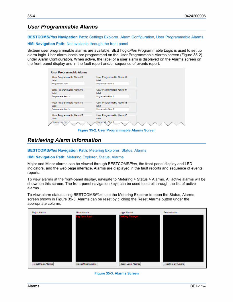
35-4 9424200996
Alarms BE1-11m
User Programmable Alarms
BESTCOMSPlus Navigation Path: Settings Explorer, Alarm Configuration, User Programmable Alarms
HMI Navigation Path: Not available through the front panel
Sixteen user programmable alarms are available. BESTlogicPlus Programmable Logic is used to set up alarm logic. User alarm labels are programmed on the User Programmable Alarms screen (Figure 35-2) under Alarm Configuration. When active, the label of a user alarm is displayed on the Alarms screen on the front-panel display and in the fault report and/or sequence of events report.
Figure 35-2. User Programmable Alarms Screen
Retrieving Alarm Information
BESTCOMSPlus Navigation Path: Metering Explorer, Status, Alarms
HMI Navigation Path: Metering Explorer, Status, Alarms
Major and Minor alarms can be viewed through BESTCOMSPlus, the front-panel display and LED indicators, and the web page interface. Alarms are displayed in the fault reports and sequence of events reports.
To view alarms at the front-panel display, navigate to Metering > Status > Alarms. All active alarms will be shown on this screen. The front-panel navigation keys can be used to scroll through the list of active alarms.
To view alarm status using BESTCOMSPlus, use the Metering Explorer to open the Status, Alarms screen shown in Figure 35-3. Alarms can be reset by clicking the Reset Alarms button under the appropriate column.
Figure 35-3. Alarms Screen
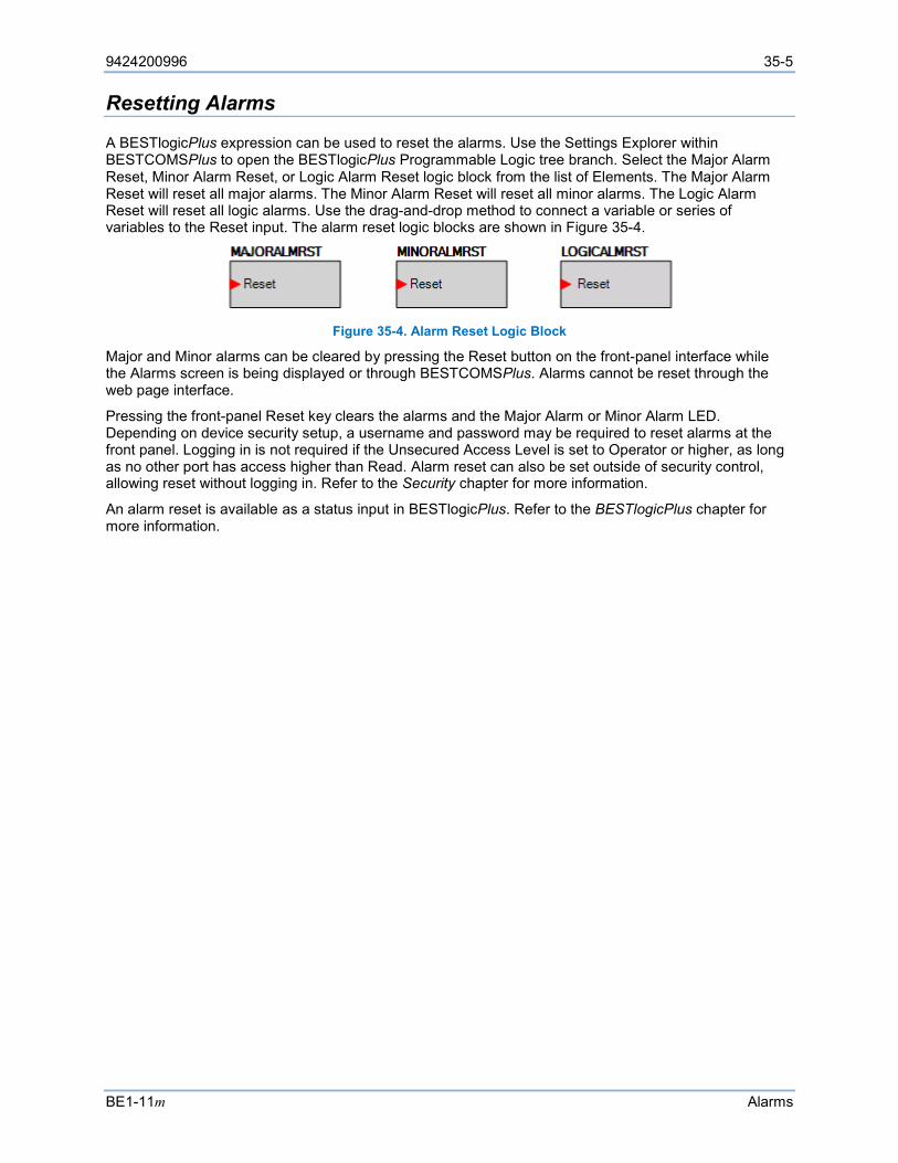
9424200996 35-5
BE1-11m Alarms
Resetting Alarms
A BESTlogicPlus expression can be used to reset the alarms. Use the Settings Explorer within BESTCOMSPlus to open the BESTlogicPlus Programmable Logic tree branch. Select the Major Alarm Reset, Minor Alarm Reset, or Logic Alarm Reset logic block from the list of Elements. The Major Alarm Reset will reset all major alarms. The Minor Alarm Reset will reset all minor alarms. The Logic Alarm Reset will reset all logic alarms. Use the drag-and-drop method to connect a variable or series of variables to the Reset input. The alarm reset logic blocks are shown in Figure 35-4.
Figure 35-4. Alarm Reset Logic Block
Major and Minor alarms can be cleared by pressing the Reset button on the front-panel interface while the Alarms screen is being displayed or through BESTCOMSPlus. Alarms cannot be reset through the web page interface.
Pressing the front-panel Reset key clears the alarms and the Major Alarm or Minor Alarm LED. Depending on device security setup, a username and password may be required to reset alarms at the front panel. Logging in is not required if the Unsecured Access Level is set to Operator or higher, as long as no other port has access higher than Read. Alarm reset can also be set outside of security control, allowing reset without logging in. Refer to the Security chapter for more information.
An alarm reset is available as a status input in BESTlogicPlus. Refer to the BESTlogicPlus chapter for more information.

35-6 9424200996
Alarms BE1-11m
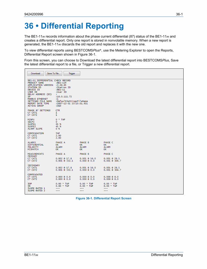
9424200996 36-1
BE1-11m Differential Reporting
36 • Differential Reporting The BE1-11m records information about the phase current differential (87) status of the BE1-11m and creates a differential report. Only one report is stored in nonvolatile memory. When a new report is generated, the BE1-11m discards the old report and replaces it with the new one.
To view differential reports using BESTCOMSPlus®, use the Metering Explorer to open the Reports, Differential Report screen shown in Figure 36-1.
From this screen, you can choose to Download the latest differential report into BESTCOMSPlus, Save the latest differential report to a file, or Trigger a new differential report.
Figure 36-1. Differential Report Screen

36-2 9424200996
Differential Reporting BE1-11m

9424200996 37-1
BE1-11m Breaker Monitoring
37 • Breaker Monitoring Breaker monitoring helps manage equipment inspection and maintenance expenses by providing extensive monitoring and alarms for the circuit breaker. Breaker monitoring functions include breaker status and operations counter reporting, fault current interruption duty monitoring and trip-speed monitoring. Each function can be set up as a programmable alarm. The Alarms chapter has more information about the use of programmable alarms. The breaker trip circuit voltage and continuity monitor is a related function and is described in the Trip Circuit Monitor (52TCM) chapter.
Breaker Status Reporting
The breaker status monitoring function monitors the position of the breaker for reporting purposes. Opening breaker strokes are also counted and recorded in the breaker operations counter register. Circuit breaker status is also used by the 50BF function, the 60FL function, and the 52TCM function. The breaker status logic block is shown in Figure 37-1.
Figure 37-1. Breaker Status Logic Block
BESTlogic™Plus Settings for Breaker Status Since the BE1-11m is completely programmable, it is necessary to program which logic variable will monitor breaker status. Breaker status is programmed using BESTCOMSPlus®. Use the Settings Explorer to open the BESTlogicPlus Programmable Logic tree branch and select the Breaker Status logic block from the list of Elements. Use the drag and drop method to connect a variable or group of variables to the input. Refer to the BESTlogicPlus chapter for more information on setting BESTlogicPlus programmable logic.
Table 37-1 summarizes the BESTlogicPlus settings for Breaker Status. Table 37-1. BESTlogicPlus Settings for Breaker Status
Setting Range/Purpose Default Breaker Status True when the breaker is closed (e.g., 52a logic). 0
Retrieving Breaker Status and Operation Counter Information BESTCOMSPlus Navigation Path: Metering Explorer, Status, Breaker Status
HMI Navigation Path: Metering Explorer, Status, Breaker Status
Breaker status can be viewed through BESTCOMSPlus, the front-panel display, and the web page interface.
To view breaker status using BESTCOMSPlus, use the Metering Explorer to open the Status, Breaker Status screen shown in Figure 37-2. To view breaker status at the front-panel display, navigate to Metering Explorer, Status, Breaker Status.
Figure 37-2. Breaker Status Screen
The number of breaker operations can be read at the front-panel display. The counter value can be adjusted using the Edit key. This allows the BE1-11m counter value to be matched to an existing mechanical cyclometer on a breaker mechanism. Write access to the reports functions must be gained to
37-2 9424200996
Breaker Monitoring BE1-11m
edit this value at the front-panel display. To view the breaker status using BESTCOMSPlus, use the Metering Explorer to open the Control, Breaker Control Switch tree branch.
The breaker operations counter can be monitored to give an alarm when the value exceeds a threshold. See Breaker Alarms in this chapter for more information about this feature.
Breaker duty monitoring is discussed in the following paragraphs.
Breaker Duty Monitoring
When the breaker opens, the current interrupted in each pole of the circuit breaker is accumulated by the breaker duty monitor. Breaker opening is defined by the breaker status monitoring function (Breaker Status). Figure 37-3 illustrates breaker status during a fault and protective trip. Table 37-2 serves as a legend for the call-outs of Figure 37-3.
Each time the breaker trips, the breaker duty monitor updates two sets of registers for each pole of the breaker. In the Accumulated I Duty registers, the breaker duty monitor adds the measured current in primary amperes. In the Accumulated I2 Duty registers, the function adds the measured current in primary amperes squared. The user selects which of the two sets of duty registers are reported and monitored when setting up the breaker duty monitor.
Even though duty register values are calculated and stored in primary amperes or primary amperes-squared, the duty value is reported as a percent of maximum. The user sets the value that the BE1-11m will use for 100 percent duty (DMAX). The value set for maximum duty is used directly for reporting the accumulated I Duty. The square of the value set for maximum duty is used for reporting the accumulated I2 duty.
Since the true measure of contact wear includes a factor for arcing time (t), an assumed arcing time for the breaker should be included when choosing the setting for 100 percent interruption duty (DMAX).
When testing the BE1-11m by injecting currents, the values in the duty registers should be read and recorded prior to the start of testing. Once testing is complete and the BE1-11m is returned to service, the registers should be reset to the original pre-test values. A block accumulation logic input can be used when testing so that simulated breaker duty is not added to the duty registers. The Block logic input of the breaker duty function is an OR logic term (e.g., IN1 or OUT5) which blocks the breaker monitoring logic when true (1). Block is set to zero to disable blocking. When breaker monitoring is blocked (logic expression equals 1), breaker duty is not accumulated.
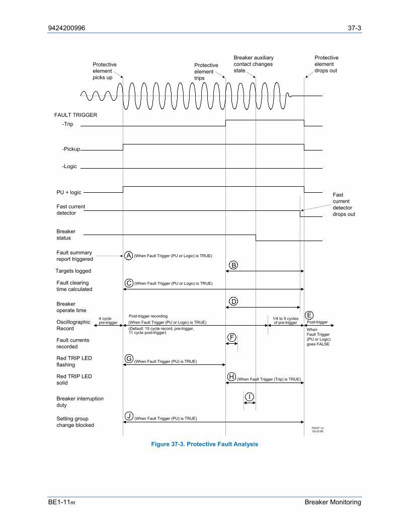
9424200996 37-3
BE1-11m Breaker Monitoring
Figure 37-3. Protective Fault Analysis
Protective element picks up
Protective element trips
Breaker auxiliary contact changes state
Protective element drops out
Fast current detector drops out
FAULT TRIGGER
-Pickup
-Logic
PU + logic
Fast current detector
Breaker status
Fault summary report triggered
(When Fault Trigger (PU or Logic) is TRUE)AB
Targets logged
CFault clearing time calculated
DBreaker operate time
OscillographicRecord
4 cyclepre-trigger
Post-trigger recording
(Default: 15 cycle record, pre-trigger, 11 cycle post-trigger)
Post-trigger1/4 to 5 cycles of pre-trigger
E
FFault currents recorded
GRed TRIP LED flashing
(When Fault Trigger (PU) is TRUE)
HRed TRIP LED solid
Breaker interruption duty
Setting group change blocked
I
JP0037-1203-23-06
-Trip
WhenFault Trigger (PU or Logic) goes FALSE
(When Fault Trigger (PU or Logic) is TRUE)
(When Fault Trigger (PU or Logic) is TRUE)
(When Fault Trigger (PU) is TRUE)
(When Fault Trigger (Trip) is TRUE)
37-4 9424200996
Breaker Monitoring BE1-11m
Table 37-2. Legend for Figure 37-3
Locator Description A A fault summary report and an oscillograph record are triggered when the Pickup logic
expression becomes true. B During the time that the Trip expression is true, targets are logged from each of the
protective functions that reach a trip state. If a protective function is not being used for tripping purposes, the associated target function can be disabled through BESTCOMSPlus.
C Fault clearing time is calculated as the duration of the time that the Pickup logic expression is true.
D Breaker operate time is calculated as the time from when the Trip logic expression becomes true until the fast current detector senses that the breaker has successfully interrupted the current in all poles of the breaker.
E A second oscillographic record is triggered to record the end of the fault if the Pickup logic expression remains in the true state at the time that the first oscillographic record ends. This second record will have from ¼ to five cycles of pre-trigger data depending upon when the Pickup logic expression becomes false.
F Recorded fault current and voltage magnitudes are displayed on the Targets screen of the front-panel display. The same information including phase voltage frequency, auxiliary voltage frequency, and voltage and current angles are recorded in the fault summary report. The magnitude and angle results are based on data captured two cycles after the trip output goes true. This two-cycle delay allows the line transients to settle to provide data that is more accurate. If the Trip expression does not become true, the fault was cleared by a down-stream device. For these pickup-only events, fault current, voltage, and angle recorded in the fault summary report will be for the power system cycle ending two cycles prior to the end of the fault record. This is also the case if the fault record was triggered through BESTCOMSPlus.
G During the time that the Pickup expression is true, the red Trip LED on the front panel flashes indicating that the BE1-11m is picked up.
H During the time the Trip expression is true, the red Trip LED on the front panel lights steadily indicating that the BE1-11m is in a tripped state. If targets have been logged for the fault, the Trip LED is sealed in until the targets have been reset.
I Breaker operations and interruption duty functions are driven by the breaker status function. The operations counter is incremented on breaker opening. The magnitudes of the currents that are used for accumulating breaker duty are recorded for the power system cycle ending when the breaker status changes state. Thus, breaker duty is accumulated every time that the breaker opens even if it is not opening under fault.
J Setting group changes are blocked when the Pickup expression is true to prevent protective functions from being reinitialized with new operating parameters while a fault is occurring.
Setting the Breaker Duty Monitoring Function BESTCOMSPlus Navigation Path: Settings Explorer, Alarm Configuration, Breaker Monitoring
HMI Navigation Path: Settings Explorer, Alarm Configuration, Breaker Monitor
Breaker Duty Monitoring settings are made using BESTCOMSPlus. Use the Settings Explorer to open the Alarm Configuration, Breaker Monitoring tree branch shown in Figure 37-4.
Using the pull-down menus and settings boxes, make the application-appropriate settings to the breaker duty monitoring function.
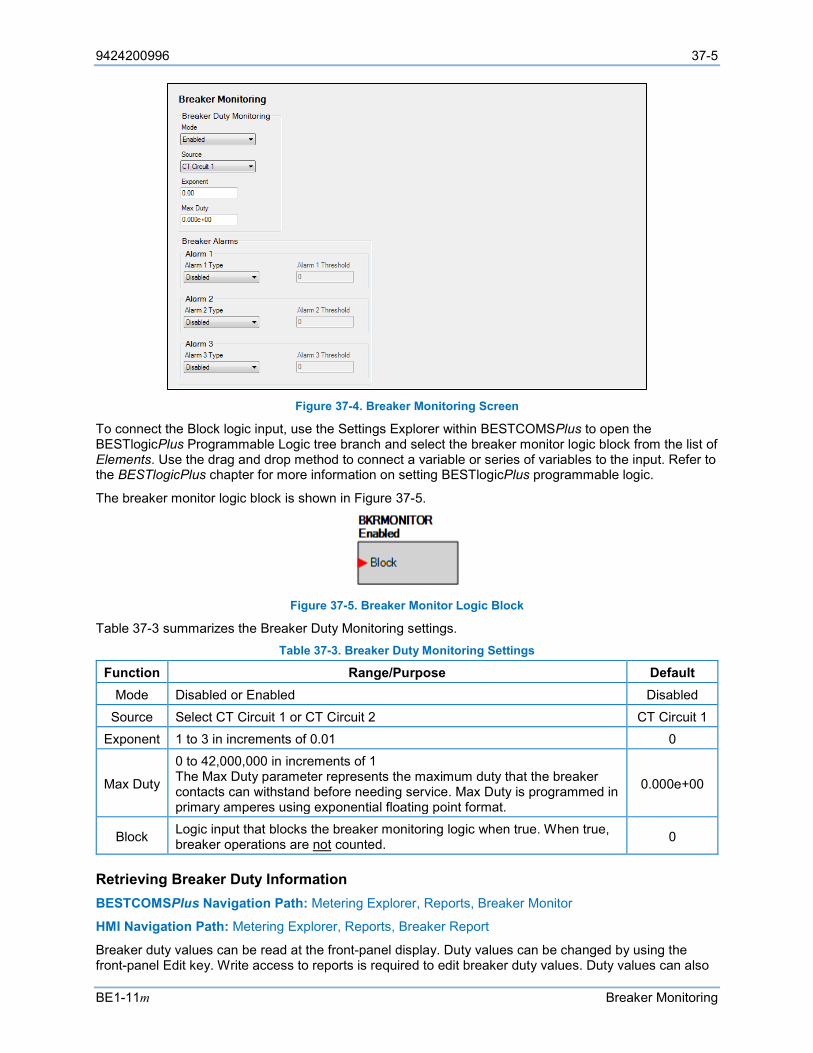
9424200996 37-5
BE1-11m Breaker Monitoring
Figure 37-4. Breaker Monitoring Screen
To connect the Block logic input, use the Settings Explorer within BESTCOMSPlus to open the BESTlogicPlus Programmable Logic tree branch and select the breaker monitor logic block from the list of Elements. Use the drag and drop method to connect a variable or series of variables to the input. Refer to the BESTlogicPlus chapter for more information on setting BESTlogicPlus programmable logic.
The breaker monitor logic block is shown in Figure 37-5.
Figure 37-5. Breaker Monitor Logic Block
Table 37-3 summarizes the Breaker Duty Monitoring settings. Table 37-3. Breaker Duty Monitoring Settings
Function Range/Purpose Default Mode Disabled or Enabled Disabled
Source Select CT Circuit 1 or CT Circuit 2 CT Circuit 1 Exponent 1 to 3 in increments of 0.01 0
Max Duty
0 to 42,000,000 in increments of 1 The Max Duty parameter represents the maximum duty that the breaker contacts can withstand before needing service. Max Duty is programmed in primary amperes using exponential floating point format.
0.000e+00
Block Logic input that blocks the breaker monitoring logic when true. When true, breaker operations are not counted. 0
Retrieving Breaker Duty Information BESTCOMSPlus Navigation Path: Metering Explorer, Reports, Breaker Monitor
HMI Navigation Path: Metering Explorer, Reports, Breaker Report
Breaker duty values can be read at the front-panel display. Duty values can be changed by using the front-panel Edit key. Write access to reports is required to edit breaker duty values. Duty values can also
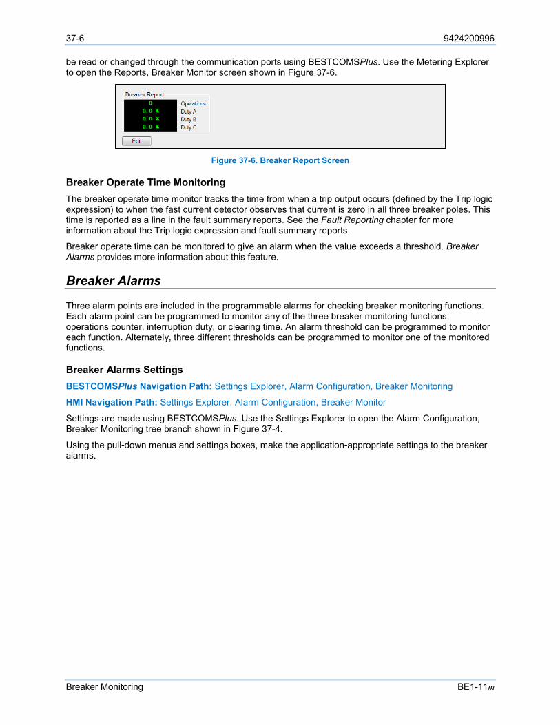
37-6 9424200996
Breaker Monitoring BE1-11m
be read or changed through the communication ports using BESTCOMSPlus. Use the Metering Explorer to open the Reports, Breaker Monitor screen shown in Figure 37-6.
Figure 37-6. Breaker Report Screen
Breaker Operate Time Monitoring The breaker operate time monitor tracks the time from when a trip output occurs (defined by the Trip logic expression) to when the fast current detector observes that current is zero in all three breaker poles. This time is reported as a line in the fault summary reports. See the Fault Reporting chapter for more information about the Trip logic expression and fault summary reports.
Breaker operate time can be monitored to give an alarm when the value exceeds a threshold. Breaker Alarms provides more information about this feature.
Breaker Alarms
Three alarm points are included in the programmable alarms for checking breaker monitoring functions. Each alarm point can be programmed to monitor any of the three breaker monitoring functions, operations counter, interruption duty, or clearing time. An alarm threshold can be programmed to monitor each function. Alternately, three different thresholds can be programmed to monitor one of the monitored functions.
Breaker Alarms Settings BESTCOMSPlus Navigation Path: Settings Explorer, Alarm Configuration, Breaker Monitoring
HMI Navigation Path: Settings Explorer, Alarm Configuration, Breaker Monitor
Settings are made using BESTCOMSPlus. Use the Settings Explorer to open the Alarm Configuration, Breaker Monitoring tree branch shown in Figure 37-4.
Using the pull-down menus and settings boxes, make the application-appropriate settings to the breaker alarms.
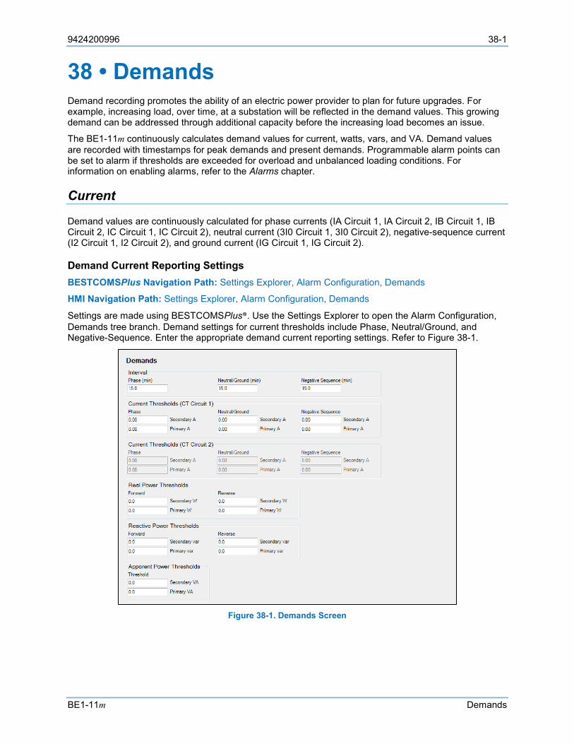
9424200996 38-1
BE1-11m Demands
38 • Demands Demand recording promotes the ability of an electric power provider to plan for future upgrades. For example, increasing load, over time, at a substation will be reflected in the demand values. This growing demand can be addressed through additional capacity before the increasing load becomes an issue.
The BE1-11m continuously calculates demand values for current, watts, vars, and VA. Demand values are recorded with timestamps for peak demands and present demands. Programmable alarm points can be set to alarm if thresholds are exceeded for overload and unbalanced loading conditions. For information on enabling alarms, refer to the Alarms chapter.
Current
Demand values are continuously calculated for phase currents (IA Circuit 1, IA Circuit 2, IB Circuit 1, IB Circuit 2, IC Circuit 1, IC Circuit 2), neutral current (3I0 Circuit 1, 3I0 Circuit 2), negative-sequence current (I2 Circuit 1, I2 Circuit 2), and ground current (IG Circuit 1, IG Circuit 2).
Demand Current Reporting Settings BESTCOMSPlus Navigation Path: Settings Explorer, Alarm Configuration, Demands
HMI Navigation Path: Settings Explorer, Alarm Configuration, Demands
Settings are made using BESTCOMSPlus®. Use the Settings Explorer to open the Alarm Configuration, Demands tree branch. Demand settings for current thresholds include Phase, Neutral/Ground, and Negative-Sequence. Enter the appropriate demand current reporting settings. Refer to Figure 38-1.
Figure 38-1. Demands Screen
38-2 9424200996
Demands BE1-11m
Power
Demand values are continuously calculated for real power (A kW, B kW, C kW, Total kW), reactive power (A var, B var, C var, Total var), and apparent power (A VA, B VA, C VA, Total VA).
Demand Power Reporting Settings BESTCOMSPlus Navigation Path: Settings Explorer, Alarm Configuration, Demands
HMI Navigation Path: Settings Explorer, Alarm Configuration, Demands
Settings are made using BESTCOMSPlus. Use the Settings Explorer to open the Alarm Configuration, Demands tree branch. Demand settings for real power thresholds include Forward Watt and Reverse Watt. Demand settings for reactive power include Forward Var and Reverse Var. A setting for apparent power threshold is also provided. The demand power interval is defined by the Phase Interval setting. Enter the appropriate demand power reporting settings. Refer to Figure 38-1.
Retrieving Demand Reporting Information
BESTCOMSPlus Navigation Path: Metering Explorer, Demand
HMI Navigation Path: Metering Explorer, Demand Meter
Values and timestamps in the demand registers are reported in primary values. They can be read at the front-panel display, through BESTCOMSPlus, and through the web page interface.
Peak demand values can be preset by pressing the Edit key and changing the value. Write access to the Reports functional area is required to preset values at the front panel.
To access demand data through BESTCOMSPlus, use the Metering Explorer to open the Demand tree branch and select Demand Current (Figure 38-2), Demand Power (Figure 38-3), Demand Reactive Power, or Demand Apparent Power. The Demand Reactive Power and Demand Apparent Power screens are similar.
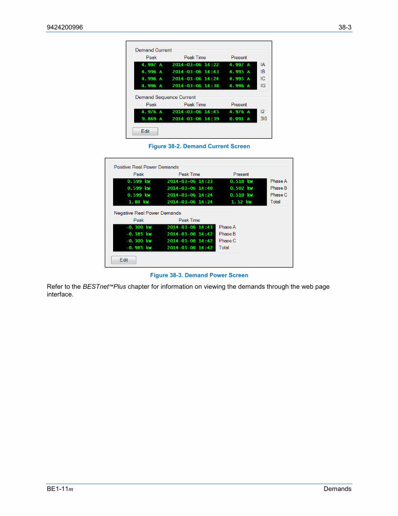
9424200996 38-3
BE1-11m Demands
Figure 38-2. Demand Current Screen
Figure 38-3. Demand Power Screen
Refer to the BESTnet™Plus chapter for information on viewing the demands through the web page interface.

38-4 9424200996
Demands BE1-11m
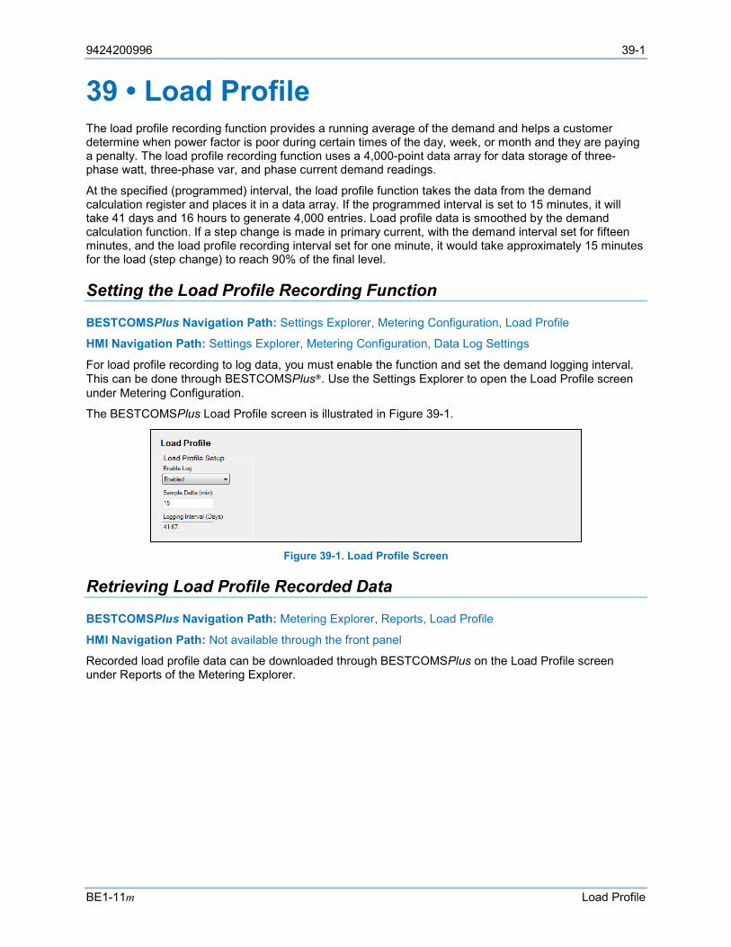
9424200996 39-1
BE1-11m Load Profile
39 • Load Profile The load profile recording function provides a running average of the demand and helps a customer determine when power factor is poor during certain times of the day, week, or month and they are paying a penalty. The load profile recording function uses a 4,000-point data array for data storage of three-phase watt, three-phase var, and phase current demand readings.
At the specified (programmed) interval, the load profile function takes the data from the demand calculation register and places it in a data array. If the programmed interval is set to 15 minutes, it will take 41 days and 16 hours to generate 4,000 entries. Load profile data is smoothed by the demand calculation function. If a step change is made in primary current, with the demand interval set for fifteen minutes, and the load profile recording interval set for one minute, it would take approximately 15 minutes for the load (step change) to reach 90% of the final level.
Setting the Load Profile Recording Function
BESTCOMSPlus Navigation Path: Settings Explorer, Metering Configuration, Load Profile
HMI Navigation Path: Settings Explorer, Metering Configuration, Data Log Settings
For load profile recording to log data, you must enable the function and set the demand logging interval. This can be done through BESTCOMSPlus®. Use the Settings Explorer to open the Load Profile screen under Metering Configuration.
The BESTCOMSPlus Load Profile screen is illustrated in Figure 39-1.
Figure 39-1. Load Profile Screen
Retrieving Load Profile Recorded Data
BESTCOMSPlus Navigation Path: Metering Explorer, Reports, Load Profile
HMI Navigation Path: Not available through the front panel
Recorded load profile data can be downloaded through BESTCOMSPlus on the Load Profile screen under Reports of the Metering Explorer.

39-2 9424200996
Load Profile BE1-11m

9424200996 40-1
BE1-11m Power Quality
40 • Power Quality The BE1-11m offers class B power quality measurement performance as defined by IEC 610004-30. Power quality data consists of voltage, distortion, dips/swells, and harmonics. Power quality is reported through BESTCOMSPlus®, the front-panel interface, and the web page interface. Refer to the BESTnet™Plus chapter for information on viewing the demands through the web page interface.
Operation
A dip event begins when any one phase decreases below the dip threshold and ends when all phases return above the dip threshold and dip hysteresis. A swell event begins when any one phase increases above the swell threshold and ends when all phases return below the swell threshold and swell hysteresis. A dip event reports dip duration and the residual voltage measured during the dip event. A swell event reports swell duration and the maximum voltage measured during the swell event. It is possible for a dip or swell event to begin on one phase and end on another. It is also possible for a dip and a swell to occur at the same time on different phases.
Reference Mode In Sliding mode, dip and swell thresholds are calculated based on the sliding average voltage, which changes over time. In Fixed mode, dip and swell thresholds are calculated based on the system rated voltage.
Dip Hysteresis This setting determines the hysteresis of the dip threshold. For example, a value of 1.02 sets the hysteresis to 2% of the dip threshold.
Dip Ratio This setting determines the dip threshold. For example, a value of 0.90 sets the dip threshold to 90% of the reference voltage.
Swell Hysteresis This setting determines the hysteresis of the swell threshold. For example, a value of 0.98 sets the hysteresis to 2% of the swell threshold.
Swell Ratio This setting determines the swell threshold. For example, a value of 1.10 sets the swell threshold to 110% of the reference voltage.
Settings
BESTCOMSPlus Navigation Path: Settings Explorer, Metering Configuration, Power Quality
HMI Navigation Path: Settings Explorer, Metering Configuration, Power Quality
Settings are made using BESTCOMSPlus. Use the Settings Explorer to open the Metering Configuration, Power Quality tree branch. The Power Quality screen is illustrated in Figure 40-1.

40-2 9424200996
Power Quality BE1-11m
Figure 40-1. Metering Configuration, Power Quality Screen
Metering
BESTCOMSPlus Navigation Path: Metering Explorer, Power Quality
HMI Navigation Path: Metering Explorer, Power Quality
Power quality data can be viewed using BESTCOMSPlus, through the front-panel interface, and through the web page interface. To view data using BESTCOMSPlus, use the Metering Explorer to open the Power Quality tree branch.
Voltage Figure 40-2 illustrates the Power Quality, Voltage screen.
Figure 40-2. Power Quality, Voltage Screen
10-Second Frequency
A 10-second average of the frequency is calculated using Equation 40-1. 𝑁𝑁𝑁𝑁𝑁𝑁𝑁𝑁𝑁𝑁𝑁𝑁 𝑜𝑜𝑜𝑜 𝐼𝐼𝐼𝐼𝐼𝐼𝑁𝑁𝐼𝐼𝑁𝑁𝐼𝐼𝐼𝐼 𝐶𝐶𝐶𝐶𝐶𝐶𝐼𝐼𝑁𝑁𝐶𝐶
𝑇𝑇𝑜𝑜𝐼𝐼𝐼𝐼𝐼𝐼 𝐷𝐷𝑁𝑁𝑁𝑁𝐼𝐼𝐼𝐼𝐷𝐷𝑜𝑜𝐼𝐼 𝑜𝑜𝑜𝑜 𝐼𝐼𝐼𝐼𝐼𝐼𝑁𝑁𝐼𝐼𝑁𝑁𝑁𝑁 𝐶𝐶𝐶𝐶𝐶𝐶𝐼𝐼𝑁𝑁𝐶𝐶
Equation 40-1. 10-Second Frequency Calculation
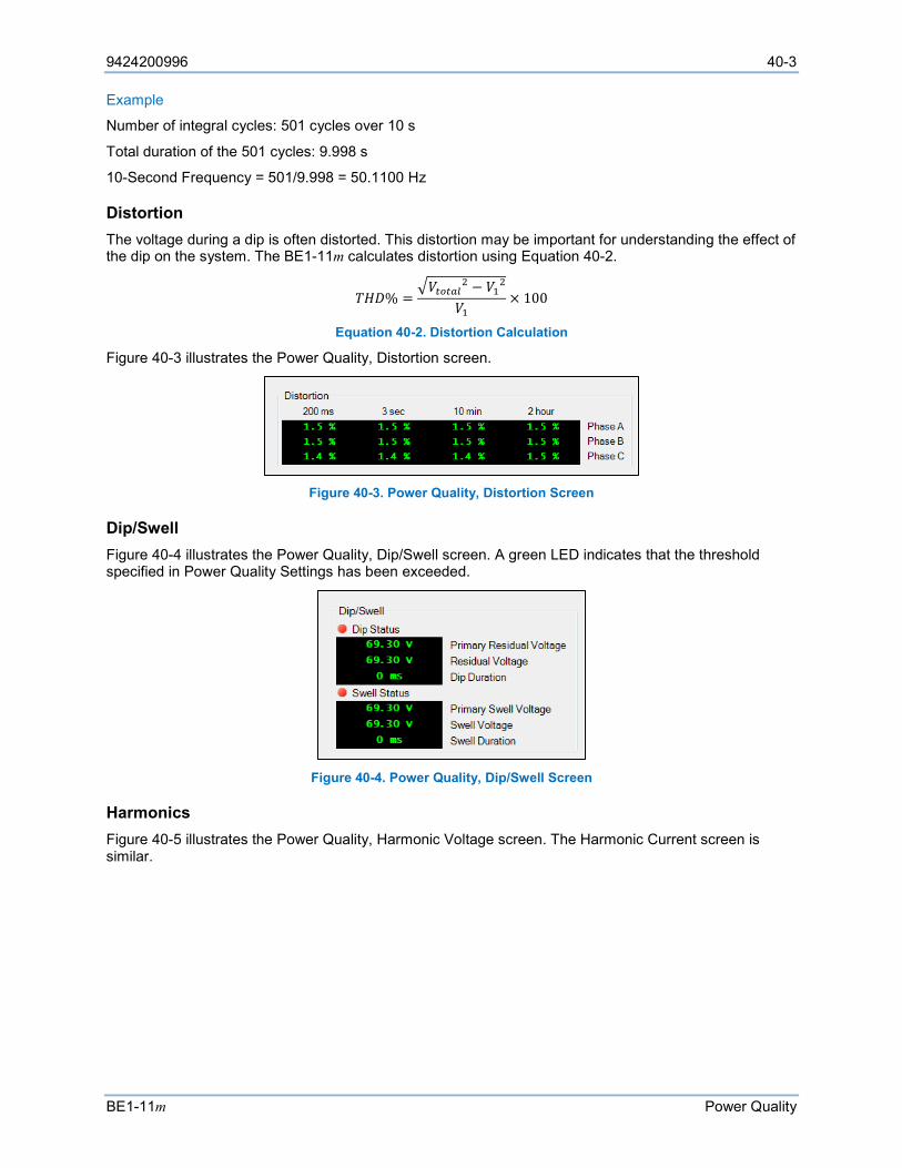
9424200996 40-3
BE1-11m Power Quality
Example
Number of integral cycles: 501 cycles over 10 s
Total duration of the 501 cycles: 9.998 s
10-Second Frequency = 501/9.998 = 50.1100 Hz
Distortion The voltage during a dip is often distorted. This distortion may be important for understanding the effect of the dip on the system. The BE1-11m calculates distortion using Equation 40-2.
𝑇𝑇𝑇𝑇𝐷𝐷% =𝑉𝑉𝑡𝑡𝑡𝑡𝑡𝑡𝑡𝑡𝑡𝑡2 − 𝑉𝑉12
𝑉𝑉1× 100
Equation 40-2. Distortion Calculation
Figure 40-3 illustrates the Power Quality, Distortion screen.
Figure 40-3. Power Quality, Distortion Screen
Dip/Swell Figure 40-4 illustrates the Power Quality, Dip/Swell screen. A green LED indicates that the threshold specified in Power Quality Settings has been exceeded.
Figure 40-4. Power Quality, Dip/Swell Screen
Harmonics Figure 40-5 illustrates the Power Quality, Harmonic Voltage screen. The Harmonic Current screen is similar.
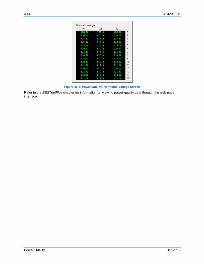
40-4 9424200996
Power Quality BE1-11m
Figure 40-5. Power Quality, Harmonic Voltage Screen
Refer to the BESTnetPlus chapter for information on viewing power quality data through the web page interface.
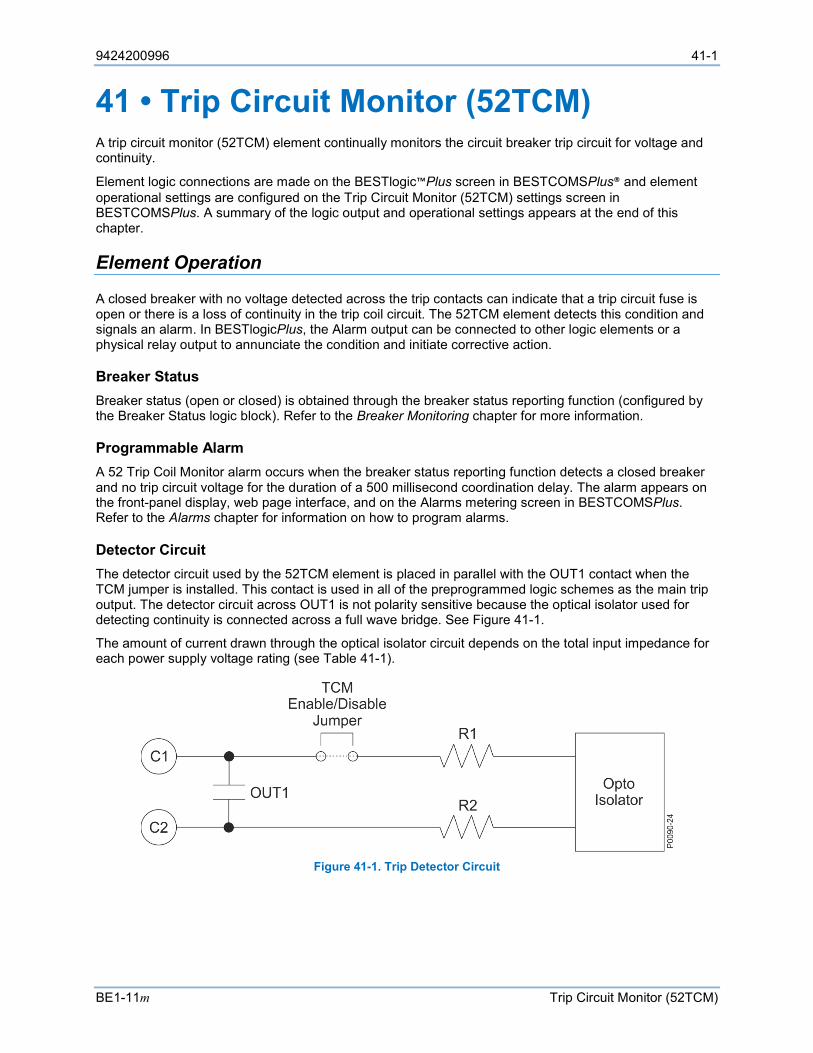
9424200996 41-1
BE1-11m Trip Circuit Monitor (52TCM)
41 • Trip Circuit Monitor (52TCM) A trip circuit monitor (52TCM) element continually monitors the circuit breaker trip circuit for voltage and continuity.
Element logic connections are made on the BESTlogic™Plus screen in BESTCOMSPlus® and element operational settings are configured on the Trip Circuit Monitor (52TCM) settings screen in BESTCOMSPlus. A summary of the logic output and operational settings appears at the end of this chapter.
Element Operation
A closed breaker with no voltage detected across the trip contacts can indicate that a trip circuit fuse is open or there is a loss of continuity in the trip coil circuit. The 52TCM element detects this condition and signals an alarm. In BESTlogicPlus, the Alarm output can be connected to other logic elements or a physical relay output to annunciate the condition and initiate corrective action.
Breaker Status Breaker status (open or closed) is obtained through the breaker status reporting function (configured by the Breaker Status logic block). Refer to the Breaker Monitoring chapter for more information.
Programmable Alarm A 52 Trip Coil Monitor alarm occurs when the breaker status reporting function detects a closed breaker and no trip circuit voltage for the duration of a 500 millisecond coordination delay. The alarm appears on the front-panel display, web page interface, and on the Alarms metering screen in BESTCOMSPlus. Refer to the Alarms chapter for information on how to program alarms.
Detector Circuit The detector circuit used by the 52TCM element is placed in parallel with the OUT1 contact when the TCM jumper is installed. This contact is used in all of the preprogrammed logic schemes as the main trip output. The detector circuit across OUT1 is not polarity sensitive because the optical isolator used for detecting continuity is connected across a full wave bridge. See Figure 41-1.
The amount of current drawn through the optical isolator circuit depends on the total input impedance for each power supply voltage rating (see Table 41-1).
Figure 41-1. Trip Detector Circuit

41-2 9424200996
Trip Circuit Monitor (52TCM) BE1-11m
Table 41-1. Current Draw for each Power Supply Voltage Rating
Power Supply Voltage Rating R1 R2 R Total
Optical Isolator Off (25% V) On (80% V)
24 Vdc 9.4 kΩ 6.8 kΩ 16.2 kΩ 6.0 V (0.370 mA) 19.2 V (1.19 mA) 48/125 Vdc 9.4 kΩ 24 kΩ 33.4 kΩ 12.0 V (0.359 mA) 38.4 V (1.15 mA) 125/250 Vdc 9.4 kΩ 82 kΩ 91.4 kΩ 31.2 V (0.342 mA) 100 V (1.09 mA)
Figure 41-2 illustrates typical trip circuit monitor connections for the BE1-11m.
Figure 41-2. Trip Circuit Voltage and Continuity Monitor
Caution
Applications that place other device inputs in parallel with the breaker trip coil may not perform as desired. The connection of other devices in parallel with the trip coil causes a voltage divider to occur when the breaker or trip circuit is open. This may cause false tripping of the other devices and prevent the BE1-11m trip circuit monitor from reliably detecting an open circuit. Contact Basler Electric for advice on this application. The circuit monitor sensing element has the same rating as the power supply voltage. If the trip circuit voltage is significantly greater than the power supply voltage (for example, when using a capacitor trip device), the user should program the BE1-11m to use one of the other output relays for tripping. In this situation, the trip circuit monitor function will not be available.
In Figure 41-3, a 62X auxiliary relay is shown. In this case, the impedance of the 62X coil is small compared to the impedance of the TCM circuit so the TCM optical isolator is always on and the TCM is always at logic 1. This prevents the TCM logic from working even if the trip coil is open. To prevent this problem, a diode was added as shown in Figure 41-3 to isolate the TCM circuit from the effects of 62X.

9424200996 41-3
BE1-11m Trip Circuit Monitor (52TCM)
Figure 41-3. TCM with Other Devices
Trip Circuit Monitor (52TCM) Enable/Disable Jumper
Note A BE1-11m in a J type case is delivered with the trip circuit monitor enabled (TCM jumper connected). Read the following paragraphs before placing the BE1-11m in service.
The trip circuit monitor draws a small amount of current, even when the contact is open. See Table 41-1 for actual values. If the output is connected to light loads or digital inputs, it may be necessary to remove the jumper to prevent the trip circuit monitor from activating those inputs.
The following paragraphs describe how to locate and connect/remove the trip circuit monitor jumper: 1. The trip circuit monitor jumper is located behind the rear terminal block that is used for OUT1
through OUTA and voltage sensing input connections. Using a 7/64” hex tool, remove the rear terminal block. Observe all electrostatic discharge (ESD) precautions when handling the BE1-11m.
2. Locate the jumper terminal block that is mounted on the left side of the circuit board. The terminal block has four pins. With the jumper as installed at the factory, the jumper should be connected across pins 1 and 2 (left side) when viewed from the back of the unit. This jumper configuration enables the trip circuit monitor. Figure 41-4 illustrates the location of the jumper terminal block as well as the position of the jumper connected.
3. To disable the trip circuit monitor, remove the jumper from the two pins using needle-nose pliers. Use care when removing the jumper so that no components are damaged. Retain the jumper for enabling the trip circuit monitor in the future.
4. After removing the jumper to disable the trip circuit monitor, reinstall the rear terminal block. 5. Tighten the screws using a 7/64” hex tool. A torque of 10 in-lbs (1.12 N•m) is recommended.
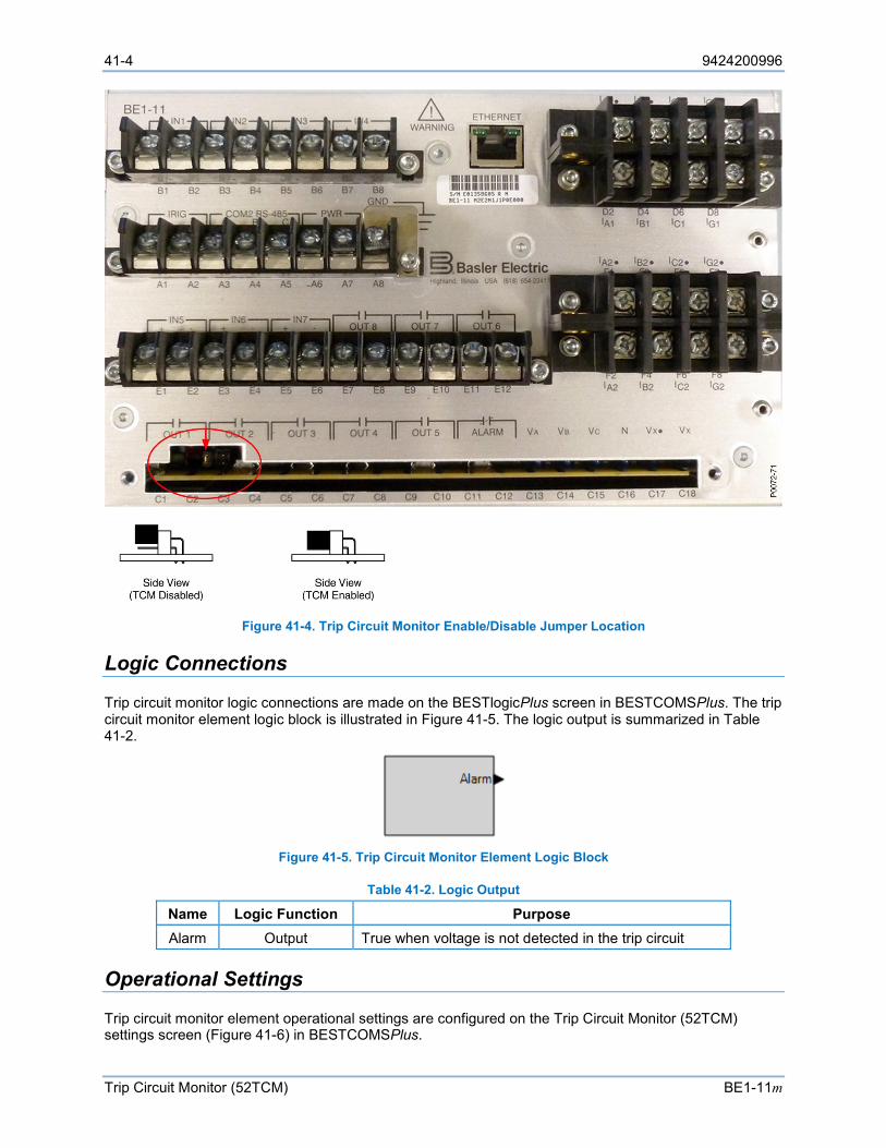
41-4 9424200996
Trip Circuit Monitor (52TCM) BE1-11m
Figure 41-4. Trip Circuit Monitor Enable/Disable Jumper Location
Logic Connections
Trip circuit monitor logic connections are made on the BESTlogicPlus screen in BESTCOMSPlus. The trip circuit monitor element logic block is illustrated in Figure 41-5. The logic output is summarized in Table 41-2.
Figure 41-5. Trip Circuit Monitor Element Logic Block
Table 41-2. Logic Output
Name Logic Function Purpose Alarm Output True when voltage is not detected in the trip circuit
Operational Settings
Trip circuit monitor element operational settings are configured on the Trip Circuit Monitor (52TCM) settings screen (Figure 41-6) in BESTCOMSPlus.

9424200996 41-5
BE1-11m Trip Circuit Monitor (52TCM)
Figure 41-6. Trip Circuit Monitor Settings Screen

41-6 9424200996
Trip Circuit Monitor (52TCM) BE1-11m
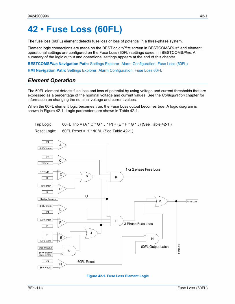
9424200996 42-1
BE1-11m Fuse Loss (60FL)
42 • Fuse Loss (60FL) The fuse loss (60FL) element detects fuse loss or loss of potential in a three-phase system.
Element logic connections are made on the BESTlogic™Plus screen in BESTCOMSPlus® and element operational settings are configured on the Fuse Loss (60FL) settings screen in BESTCOMSPlus. A summary of the logic output and operational settings appears at the end of this chapter.
BESTCOMSPlus Navigation Path: Settings Explorer, Alarm Configuration, Fuse Loss (60FL)
HMI Navigation Path: Settings Explorer, Alarm Configuration, Fuse Loss 60FL
Element Operation
The 60FL element detects fuse loss and loss of potential by using voltage and current thresholds that are expressed as a percentage of the nominal voltage and current values. See the Configuration chapter for information on changing the nominal voltage and current values.
When the 60FL element logic becomes true, the Fuse Loss output becomes true. A logic diagram is shown in Figure 42-1. Logic parameters are shown in Table 42-1.
Trip Logic: 60FL Trip = (A * C * G * J * P) + (E * F * G * J) (See Table 42-1.)
Reset Logic: 60FL Reset = H * /K */L (See Table 42-1.)
Figure 42-1. Fuse Loss Element Logic
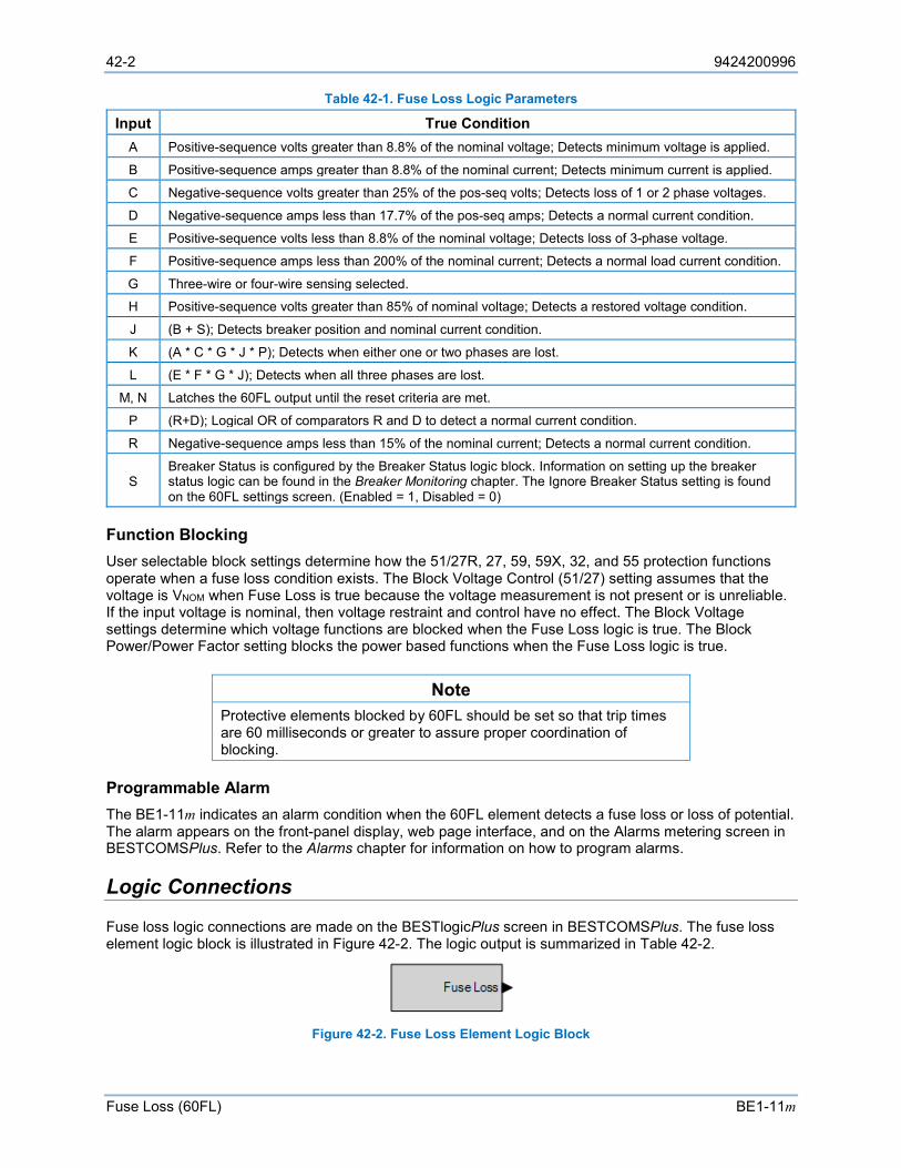
42-2 9424200996
Fuse Loss (60FL) BE1-11m
Table 42-1. Fuse Loss Logic Parameters
Input True Condition A Positive-sequence volts greater than 8.8% of the nominal voltage; Detects minimum voltage is applied.
B Positive-sequence amps greater than 8.8% of the nominal current; Detects minimum current is applied.
C Negative-sequence volts greater than 25% of the pos-seq volts; Detects loss of 1 or 2 phase voltages.
D Negative-sequence amps less than 17.7% of the pos-seq amps; Detects a normal current condition.
E Positive-sequence volts less than 8.8% of the nominal voltage; Detects loss of 3-phase voltage.
F Positive-sequence amps less than 200% of the nominal current; Detects a normal load current condition.
G Three-wire or four-wire sensing selected.
H Positive-sequence volts greater than 85% of nominal voltage; Detects a restored voltage condition.
J (B + S); Detects breaker position and nominal current condition.
K (A * C * G * J * P); Detects when either one or two phases are lost.
L (E * F * G * J); Detects when all three phases are lost.
M, N Latches the 60FL output until the reset criteria are met.
P (R+D); Logical OR of comparators R and D to detect a normal current condition.
R Negative-sequence amps less than 15% of the nominal current; Detects a normal current condition.
S Breaker Status is configured by the Breaker Status logic block. Information on setting up the breaker status logic can be found in the Breaker Monitoring chapter. The Ignore Breaker Status setting is found on the 60FL settings screen. (Enabled = 1, Disabled = 0)
Function Blocking User selectable block settings determine how the 51/27R, 27, 59, 59X, 32, and 55 protection functions operate when a fuse loss condition exists. The Block Voltage Control (51/27) setting assumes that the voltage is VNOM when Fuse Loss is true because the voltage measurement is not present or is unreliable. If the input voltage is nominal, then voltage restraint and control have no effect. The Block Voltage settings determine which voltage functions are blocked when the Fuse Loss logic is true. The Block Power/Power Factor setting blocks the power based functions when the Fuse Loss logic is true.
Note Protective elements blocked by 60FL should be set so that trip times are 60 milliseconds or greater to assure proper coordination of blocking.
Programmable Alarm The BE1-11m indicates an alarm condition when the 60FL element detects a fuse loss or loss of potential. The alarm appears on the front-panel display, web page interface, and on the Alarms metering screen in BESTCOMSPlus. Refer to the Alarms chapter for information on how to program alarms.
Logic Connections
Fuse loss logic connections are made on the BESTlogicPlus screen in BESTCOMSPlus. The fuse loss element logic block is illustrated in Figure 42-2. The logic output is summarized in Table 42-2.
Figure 42-2. Fuse Loss Element Logic Block
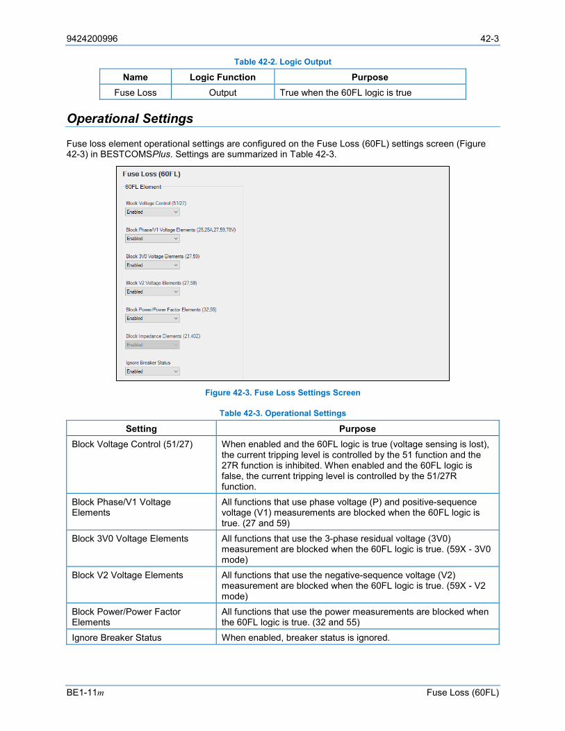
9424200996 42-3
BE1-11m Fuse Loss (60FL)
Table 42-2. Logic Output
Name Logic Function Purpose Fuse Loss Output True when the 60FL logic is true
Operational Settings
Fuse loss element operational settings are configured on the Fuse Loss (60FL) settings screen (Figure 42-3) in BESTCOMSPlus. Settings are summarized in Table 42-3.
Figure 42-3. Fuse Loss Settings Screen
Table 42-3. Operational Settings
Setting Purpose Block Voltage Control (51/27) When enabled and the 60FL logic is true (voltage sensing is lost),
the current tripping level is controlled by the 51 function and the 27R function is inhibited. When enabled and the 60FL logic is false, the current tripping level is controlled by the 51/27R function.
Block Phase/V1 Voltage Elements
All functions that use phase voltage (P) and positive-sequence voltage (V1) measurements are blocked when the 60FL logic is true. (27 and 59)
Block 3V0 Voltage Elements All functions that use the 3-phase residual voltage (3V0) measurement are blocked when the 60FL logic is true. (59X - 3V0 mode)
Block V2 Voltage Elements All functions that use the negative-sequence voltage (V2) measurement are blocked when the 60FL logic is true. (59X - V2 mode)
Block Power/Power Factor Elements
All functions that use the power measurements are blocked when the 60FL logic is true. (32 and 55)
Ignore Breaker Status When enabled, breaker status is ignored.

42-4 9424200996
Fuse Loss (60FL) BE1-11m
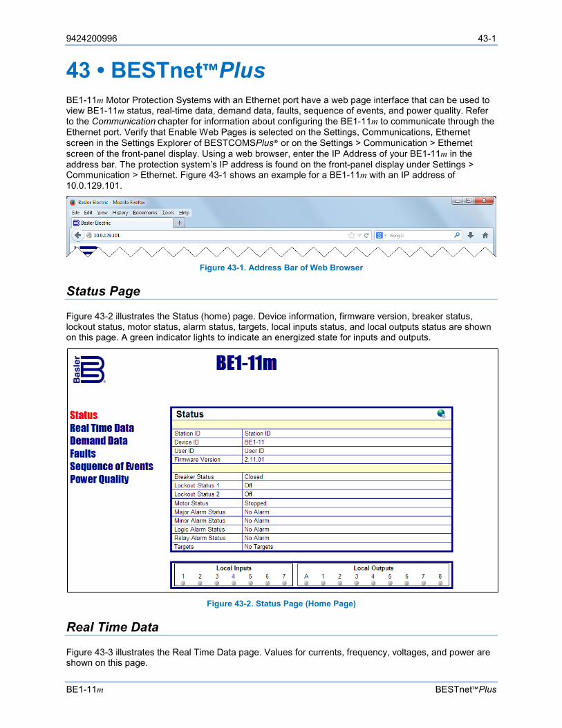
9424200996 43-1
BE1-11m BESTnet™Plus
43 • BESTnet™Plus BE1-11m Motor Protection Systems with an Ethernet port have a web page interface that can be used to view BE1-11m status, real-time data, demand data, faults, sequence of events, and power quality. Refer to the Communication chapter for information about configuring the BE1-11m to communicate through the Ethernet port. Verify that Enable Web Pages is selected on the Settings, Communications, Ethernet screen in the Settings Explorer of BESTCOMSPlus® or on the Settings > Communication > Ethernet screen of the front-panel display. Using a web browser, enter the IP Address of your BE1-11m in the address bar. The protection system’s IP address is found on the front-panel display under Settings > Communication > Ethernet. Figure 43-1 shows an example for a BE1-11m with an IP address of 10.0.129.101.
Figure 43-1. Address Bar of Web Browser
Status Page
Figure 43-2 illustrates the Status (home) page. Device information, firmware version, breaker status, lockout status, motor status, alarm status, targets, local inputs status, and local outputs status are shown on this page. A green indicator lights to indicate an energized state for inputs and outputs.
Figure 43-2. Status Page (Home Page)
Real Time Data
Figure 43-3 illustrates the Real Time Data page. Values for currents, frequency, voltages, and power are shown on this page.
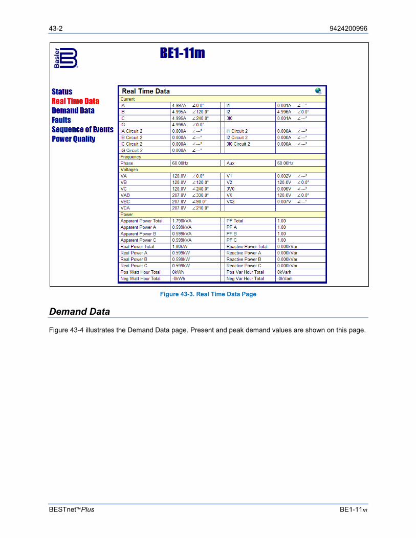
43-2 9424200996
BESTnet™Plus BE1-11m
Figure 43-3. Real Time Data Page
Demand Data
Figure 43-4 illustrates the Demand Data page. Present and peak demand values are shown on this page.
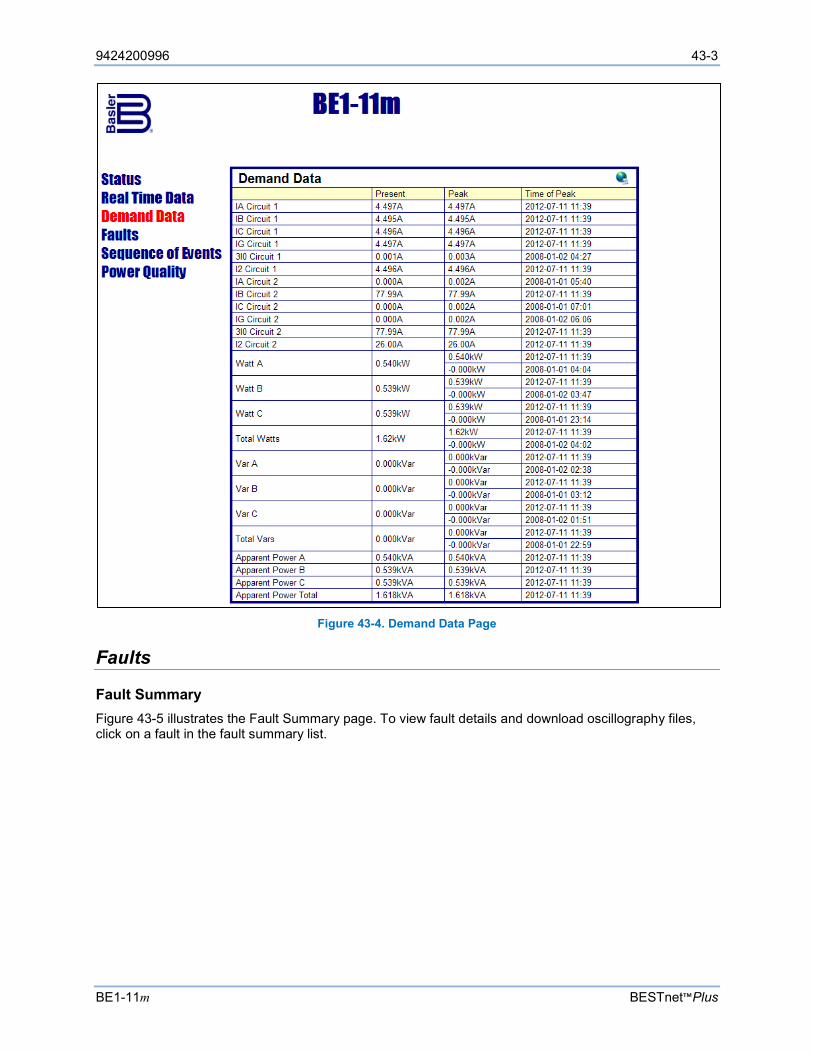
9424200996 43-3
BE1-11m BESTnet™Plus
Figure 43-4. Demand Data Page
Faults
Fault Summary Figure 43-5 illustrates the Fault Summary page. To view fault details and download oscillography files, click on a fault in the fault summary list.
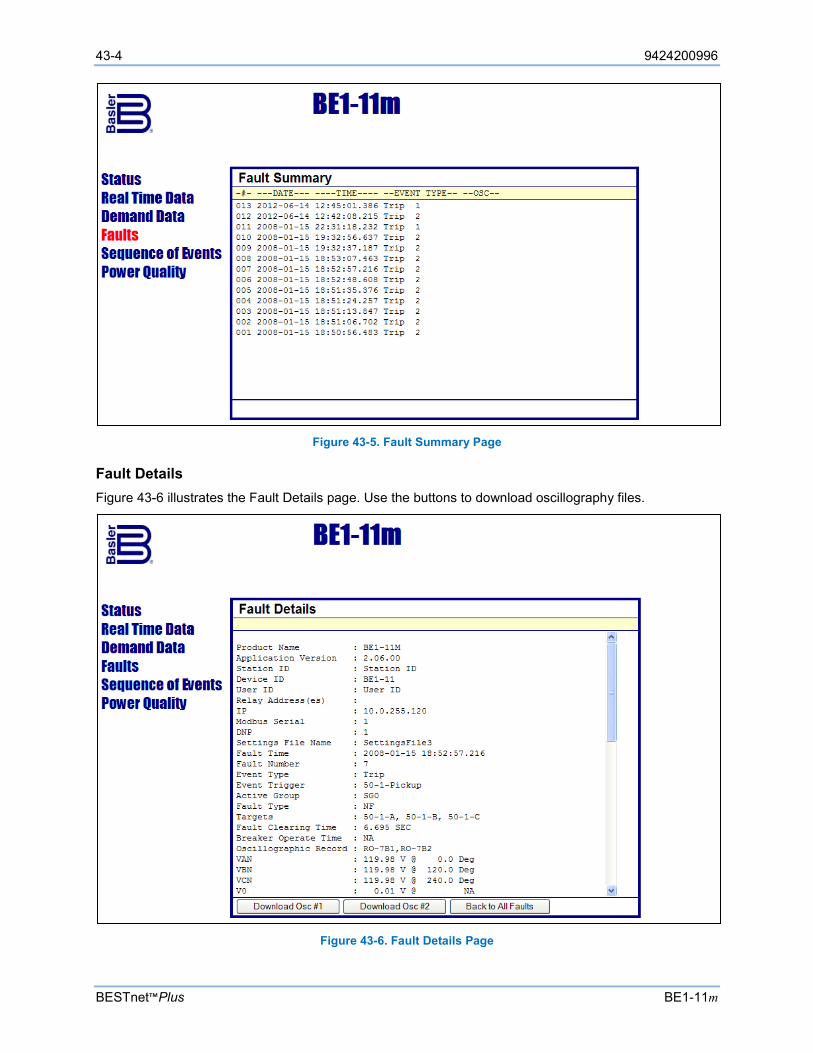
43-4 9424200996
BESTnet™Plus BE1-11m
Figure 43-5. Fault Summary Page
Fault Details Figure 43-6 illustrates the Fault Details page. Use the buttons to download oscillography files.
Figure 43-6. Fault Details Page
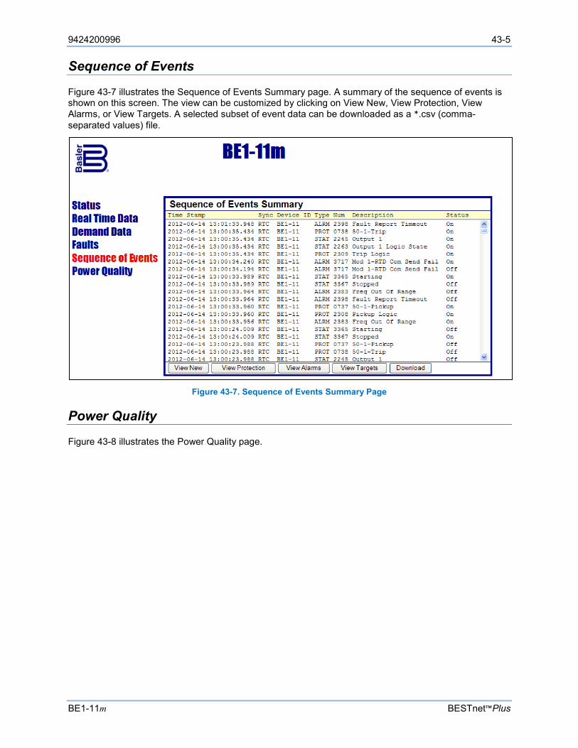
9424200996 43-5
BE1-11m BESTnet™Plus
Sequence of Events
Figure 43-7 illustrates the Sequence of Events Summary page. A summary of the sequence of events is shown on this screen. The view can be customized by clicking on View New, View Protection, View Alarms, or View Targets. A selected subset of event data can be downloaded as a *.csv (comma-separated values) file.
Figure 43-7. Sequence of Events Summary Page
Power Quality
Figure 43-8 illustrates the Power Quality page.
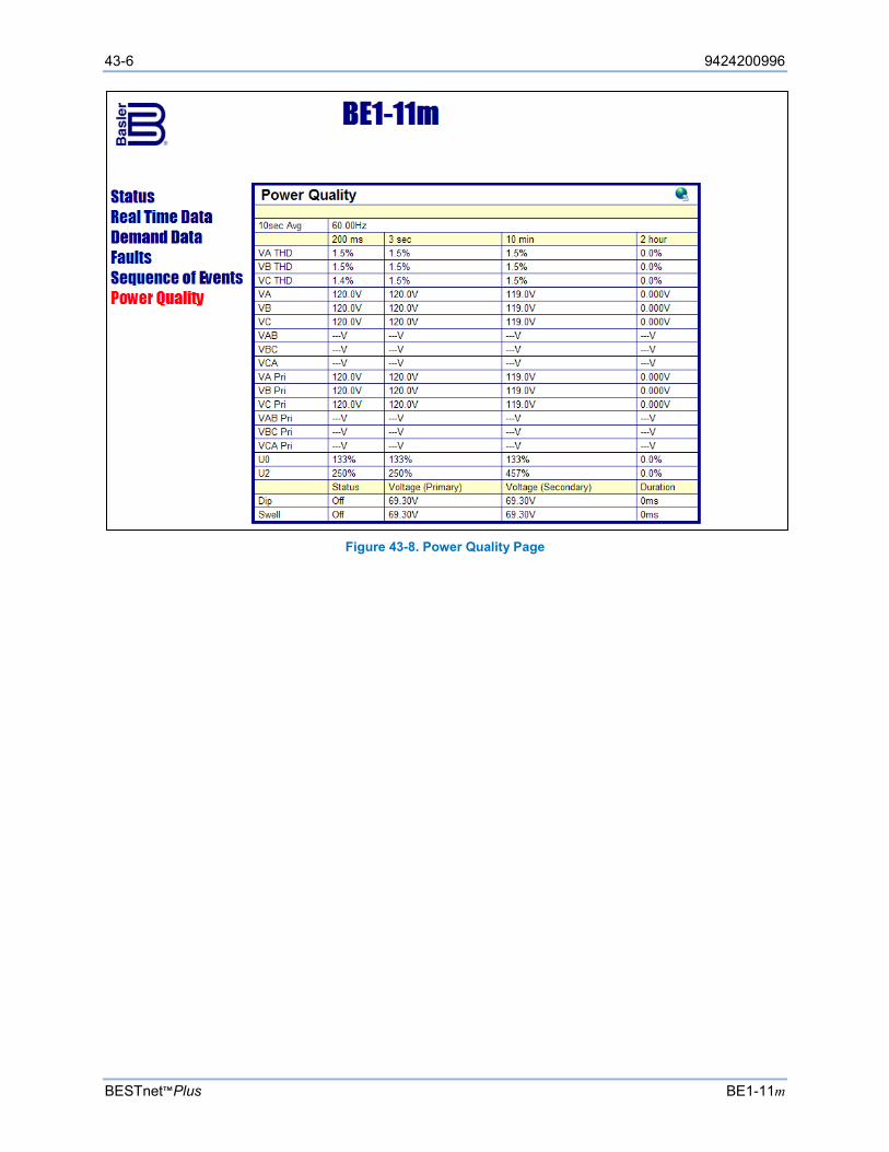
43-6 9424200996
BESTnet™Plus BE1-11m
Figure 43-8. Power Quality Page
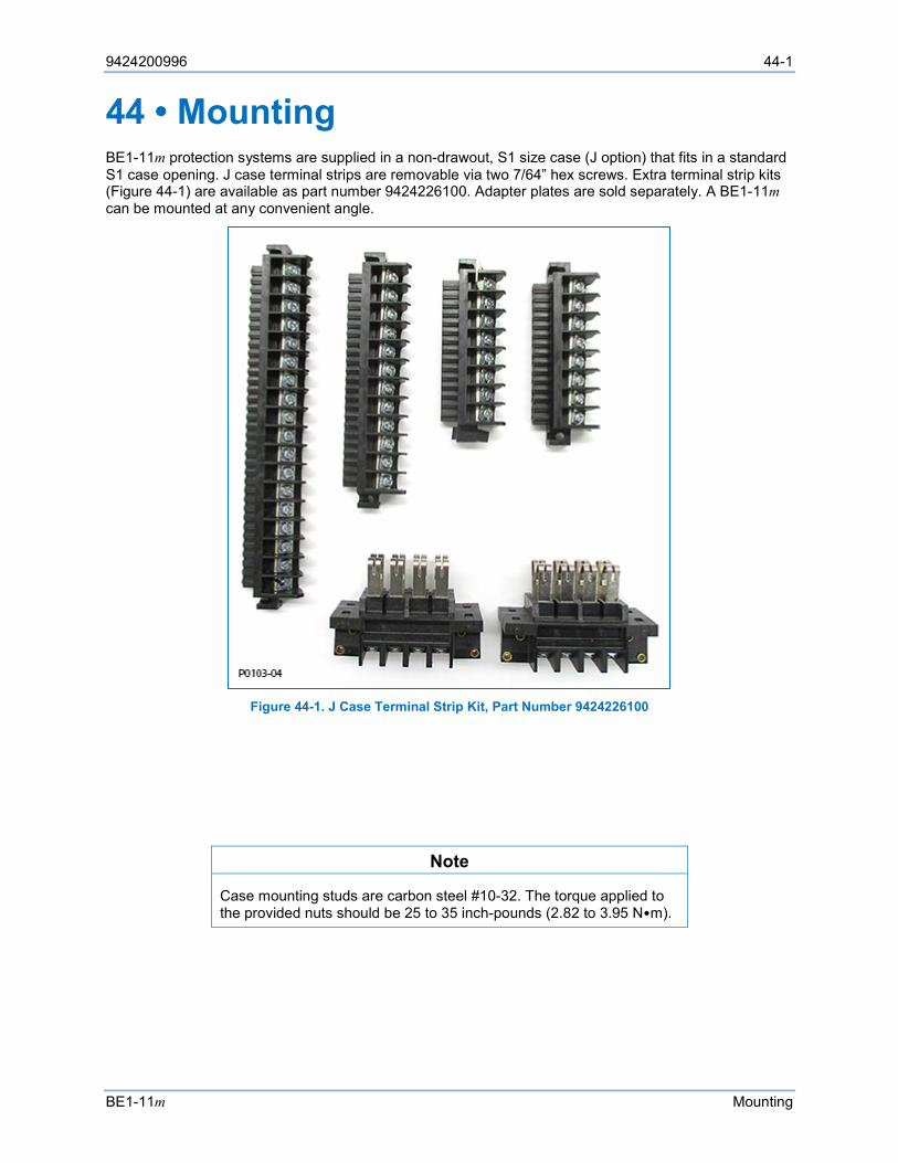
9424200996 44-1
BE1-11m Mounting
44 • Mounting BE1-11m protection systems are supplied in a non-drawout, S1 size case (J option) that fits in a standard S1 case opening. J case terminal strips are removable via two 7/64” hex screws. Extra terminal strip kits (Figure 44-1) are available as part number 9424226100. Adapter plates are sold separately. A BE1-11m can be mounted at any convenient angle.
Figure 44-1. J Case Terminal Strip Kit, Part Number 9424226100
Note
Case mounting studs are carbon steel #10-32. The torque applied to the provided nuts should be 25 to 35 inch-pounds (2.82 to 3.95 N•m).

44-2 9424200996
Mounting BE1-11m
Case Cutouts and Dimensions
Front dimensions are shown in Figure 44-2 and side dimensions are shown in Figure 44-3. Dimensions are shown in inches [millimeters].
Figure 44-2. Case Front Dimensions
USB
7.00 [177.79]
9.12 [231.64]
P0072-74
BE1-11ProtectionSystem
Relay Minor MajorPower Trouble Alarm Alarm Trip
Edit Reset
Indicator 1
Indicator 2
Indicator 3
Indicator 4
Indicator 5
Indicator 6
Indicator 7
SelectControlSwitch
OperateControlSwitch
BE1-11
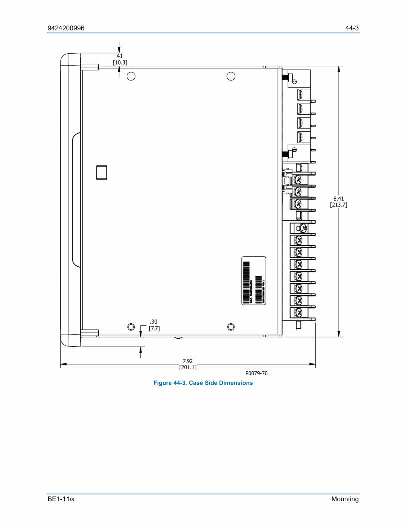
9424200996 44-3
BE1-11m Mounting
Figure 44-3. Case Side Dimensions
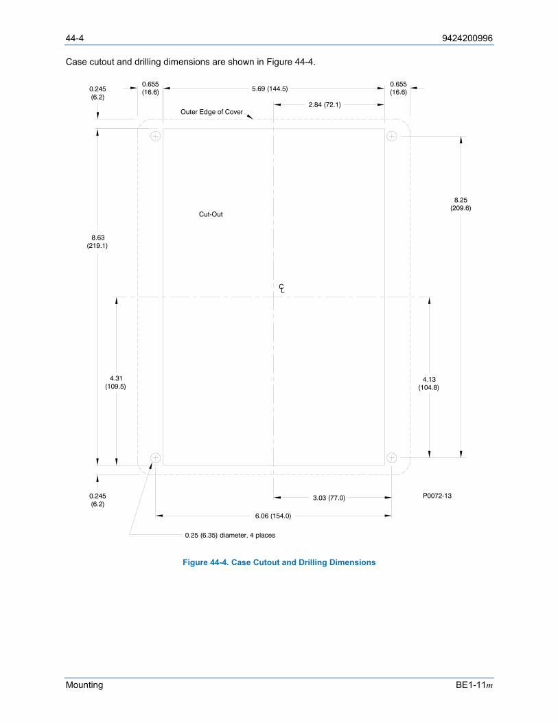
44-4 9424200996
Mounting BE1-11m
Case cutout and drilling dimensions are shown in Figure 44-4.
Figure 44-4. Case Cutout and Drilling Dimensions
3.03 (77.0)
6.06 (154.0)
0.25 (6.35) diameter, 4 places
CL
Cut-Out
8.63(219.1)
0.245(6.2)
5.69 (144.5)
Outer Edge of Cover
0.655(16.6)
8.25(209.6)
4.13(104.8)
2.84 (72.1)
4.31(109.5)
0.245(6.2)
0.655(16.6)
P0072-13

9424200996 44-5
BE1-11m Mounting
An adapter plate to mount a J case in a GE S2 or ABB FT-21 cutout is shown in Figure 44-5. Order Basler part number 9108551021.
Figure 44-5. Adapter Plate (Basler P/N: 9108551021)
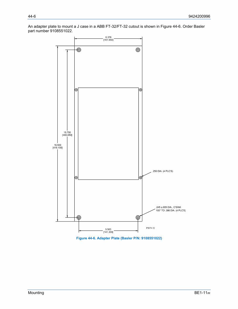
44-6 9424200996
Mounting BE1-11m
An adapter plate to mount a J case in a ABB FT-32/FT-32 cutout is shown in Figure 44-6. Order Basler part number 9108551022.
Figure 44-6. Adapter Plate (Basler P/N: 9108551022)
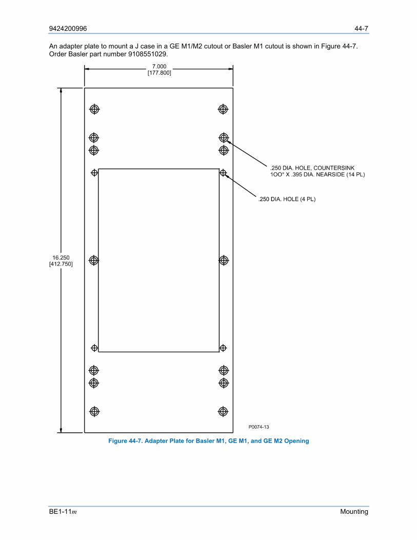
9424200996 44-7
BE1-11m Mounting
An adapter plate to mount a J case in a GE M1/M2 cutout or Basler M1 cutout is shown in Figure 44-7. Order Basler part number 9108551029.
Figure 44-7. Adapter Plate for Basler M1, GE M1, and GE M2 Opening
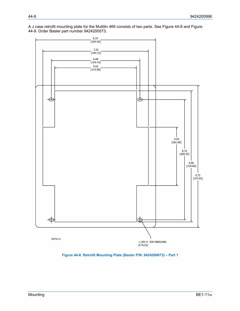
44-8 9424200996
Mounting BE1-11m
A J case retrofit mounting plate for the Multilin 469 consists of two parts. See Figure 44-8 and Figure 44-9. Order Basler part number 9424200073.
Figure 44-8. Retrofit Mounting Plate (Basler P/N: 9424200073) – Part 1
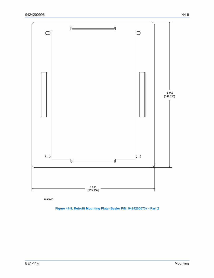
9424200996 44-9
BE1-11m Mounting
Figure 44-9. Retrofit Mounting Plate (Basler P/N: 9424200073) – Part 2
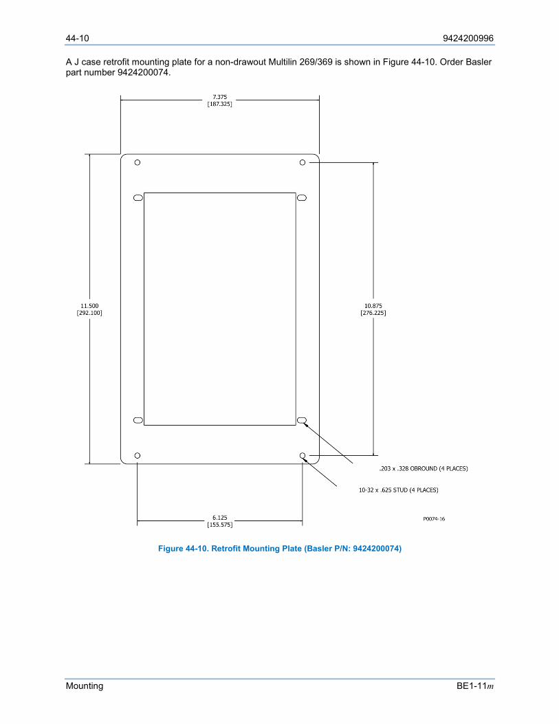
44-10 9424200996
Mounting BE1-11m
A J case retrofit mounting plate for a non-drawout Multilin 269/369 is shown in Figure 44-10. Order Basler part number 9424200074.
Figure 44-10. Retrofit Mounting Plate (Basler P/N: 9424200074)
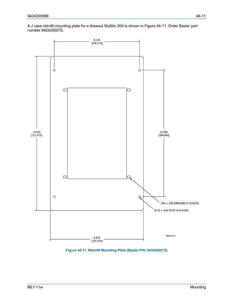
9424200996 44-11
BE1-11m Mounting
A J case retrofit mounting plate for a drawout Multilin 269 is shown in Figure 44-11. Order Basler part number 9424200075.
Figure 44-11. Retrofit Mounting Plate (Basler P/N: 9424200075)
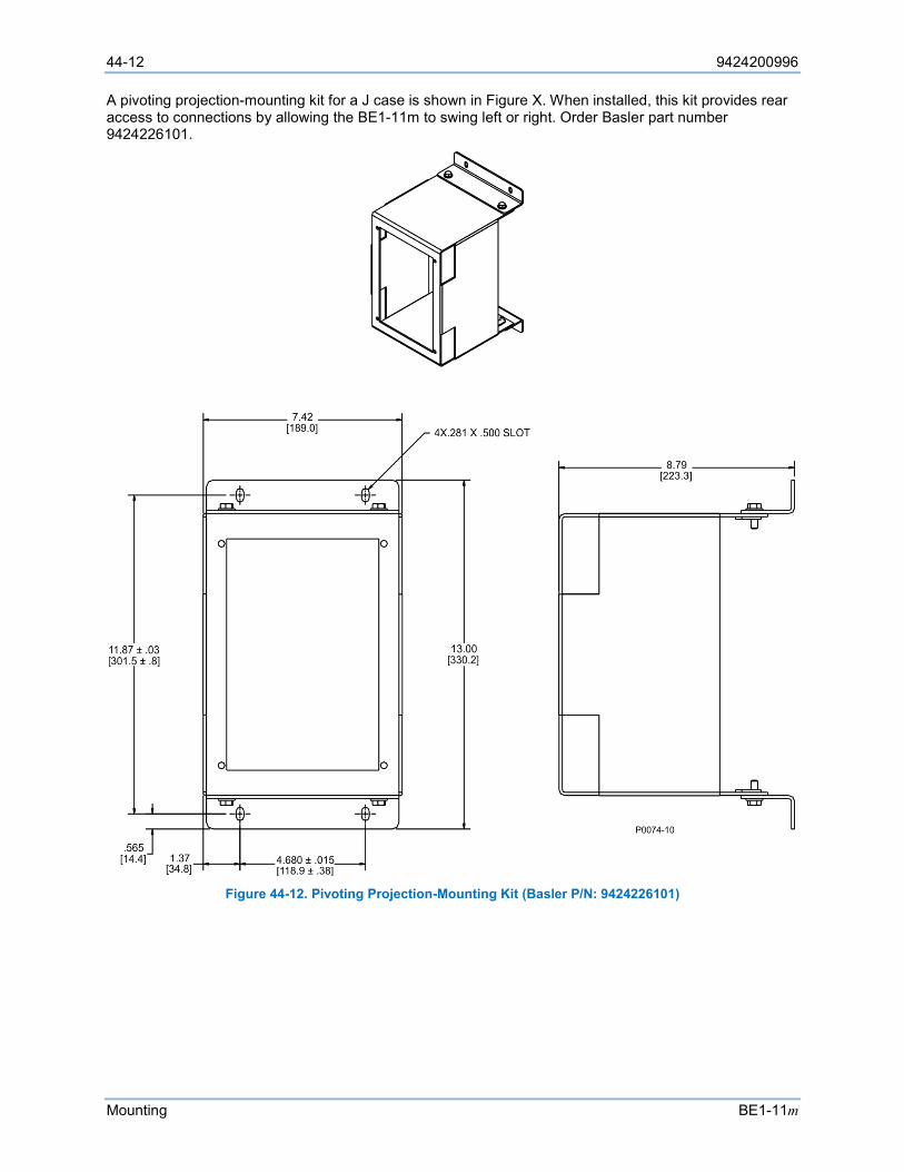
44-12 9424200996
Mounting BE1-11m
A pivoting projection-mounting kit for a J case is shown in Figure X. When installed, this kit provides rear access to connections by allowing the BE1-11m to swing left or right. Order Basler part number 9424226101.
Figure 44-12. Pivoting Projection-Mounting Kit (Basler P/N: 9424226101)
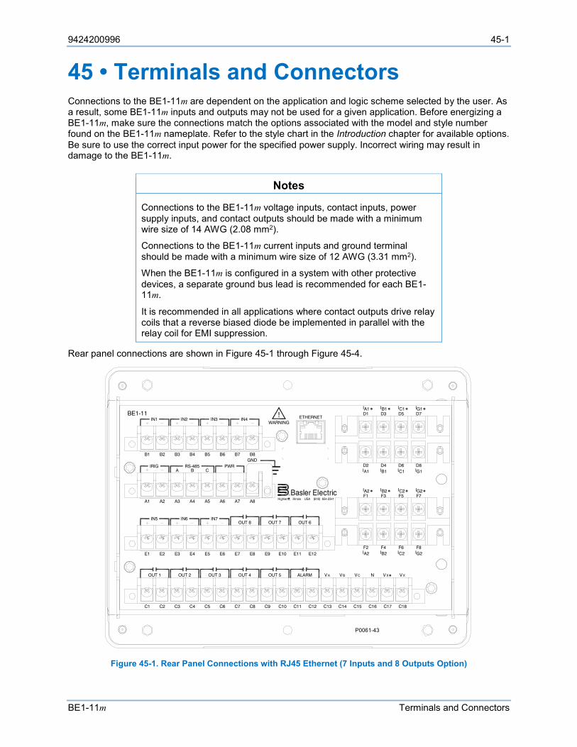
9424200996 45-1
BE1-11m Terminals and Connectors
45 • Terminals and Connectors Connections to the BE1-11m are dependent on the application and logic scheme selected by the user. As a result, some BE1-11m inputs and outputs may not be used for a given application. Before energizing a BE1-11m, make sure the connections match the options associated with the model and style number found on the BE1-11m nameplate. Refer to the style chart in the Introduction chapter for available options. Be sure to use the correct input power for the specified power supply. Incorrect wiring may result in damage to the BE1-11m.
Notes
Connections to the BE1-11m voltage inputs, contact inputs, power supply inputs, and contact outputs should be made with a minimum wire size of 14 AWG (2.08 mm2).
Connections to the BE1-11m current inputs and ground terminal should be made with a minimum wire size of 12 AWG (3.31 mm2).
When the BE1-11m is configured in a system with other protective devices, a separate ground bus lead is recommended for each BE1-11m.
It is recommended in all applications where contact outputs drive relay coils that a reverse biased diode be implemented in parallel with the relay coil for EMI suppression.
Rear panel connections are shown in Figure 45-1 through Figure 45-4.
Figure 45-1. Rear Panel Connections with RJ45 Ethernet (7 Inputs and 8 Outputs Option)
ETHERNET!WARNING
BE1-11
C12C11C10C9C8C7C6C5C4C3C2C1 C13 C14 C15 C16 C17 C18
V AOUT 2 OUT 3 OUT 4 OUT 5OUT 1 ALARM V B VC V XV XN
E12E11E10E9E8E7E6E5E4E3E2E1
OUT 8 OUT 7IN5 IN6 IN7
OUT 6
A8A7A6A5A4A3A2A1
IRIG PWRCA B
RS-485GNDB8B7B6B5B4B3B2B1
IN1 IN2 IN3 IN4D1 D3 D5 D7IA1 IB1 IC1 IG1
IA1D2 D4 D6 D8
IB1 IC1 IG1
IA2F2 F4 F6 F8
IB2 IC2 IG2
F1 F3 F5 F7IA2 IB2 IC2 IG2
P0061-43
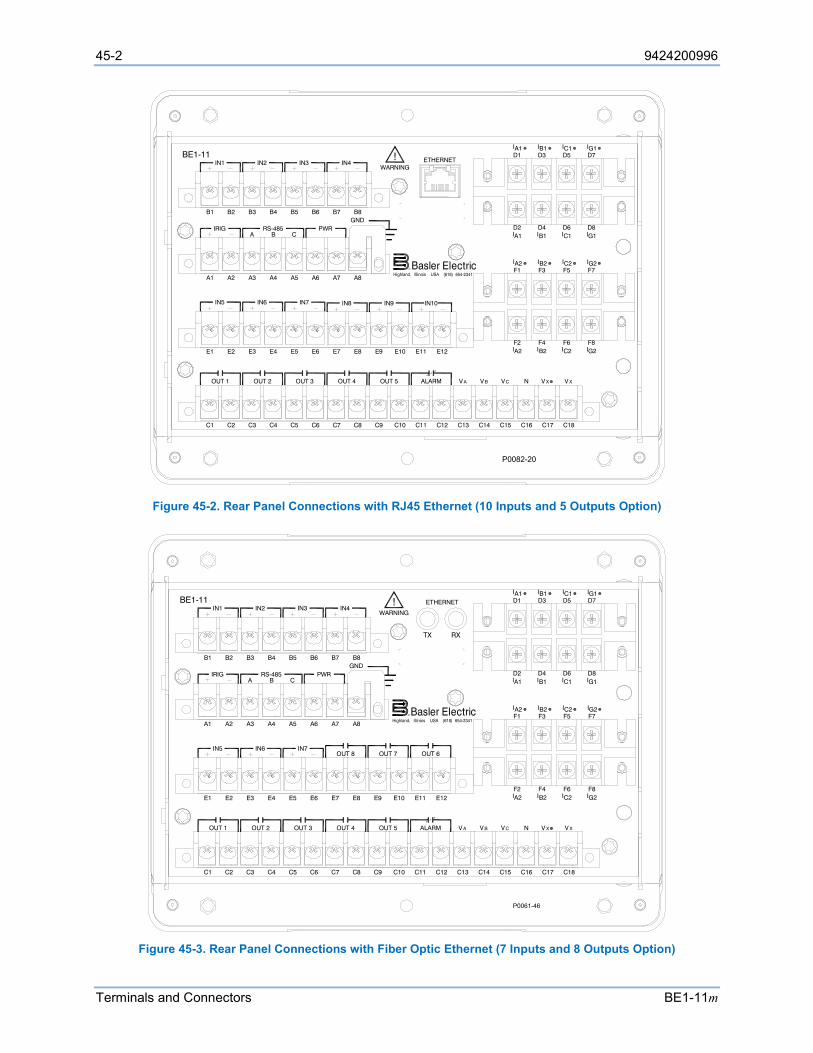
45-2 9424200996
Terminals and Connectors BE1-11m
Figure 45-2. Rear Panel Connections with RJ45 Ethernet (10 Inputs and 5 Outputs Option)
Figure 45-3. Rear Panel Connections with Fiber Optic Ethernet (7 Inputs and 8 Outputs Option)
ETHERNET!WARNING
BE1-11
C12C11C10C9C8C7C6C5C4C3C2C1 C13 C14 C15 C16 C17 C18
V AOUT 2 OUT 3 OUT 4 OUT 5OUT 1 ALARM V B VC V XV XN
E12E11E10E9E8E7E6E5E4E3E2E1
IN5 IN6 IN7
A8A7A6A5A4A3A2A1
IRIG PWRCA B
RS-485GNDB8B7B6B5B4B3B2B1
IN1 IN2 IN3 IN4D1 D3 D5 D7IA1 IB1 IC1 IG1
IA1D2 D4 D6 D8
IB1 IC1 IG1
IA2F2 F4 F6 F8
IB2 IC2 IG2
F1 F3 F5 F7IA2 IB2 IC2 IG2
P0082-20
IN8 IN9 IN10
!WARNING
BE1-11
C12C11C10C9C8C7C6C5C4C3C2C1 C13 C14 C15 C16 C17 C18
V AOUT 2 OUT 3 OUT 4 OUT 5OUT 1 ALARM V B VC V XV XN
E12E11E10E9E8E7E6E5E4E3E2E1
OUT 8 OUT 7IN5 IN6 IN7
OUT 6
A8A7A6A5A4A3A2A1
IRIG PWRCA B
RS-485GNDB8B7B6B5B4B3B2B1
IN1 IN2 IN3 IN4D1 D3 D5 D7IA1 IB1 IC1 IG1
IA1D2 D4 D6 D8
IB1 IC1 IG1
IA2F2 F4 F6 F8
IB2 IC2 IG2
F1 F3 F5 F7IA2 IB2 IC2 IG2
ETHERNET
TX RX
P0061-46
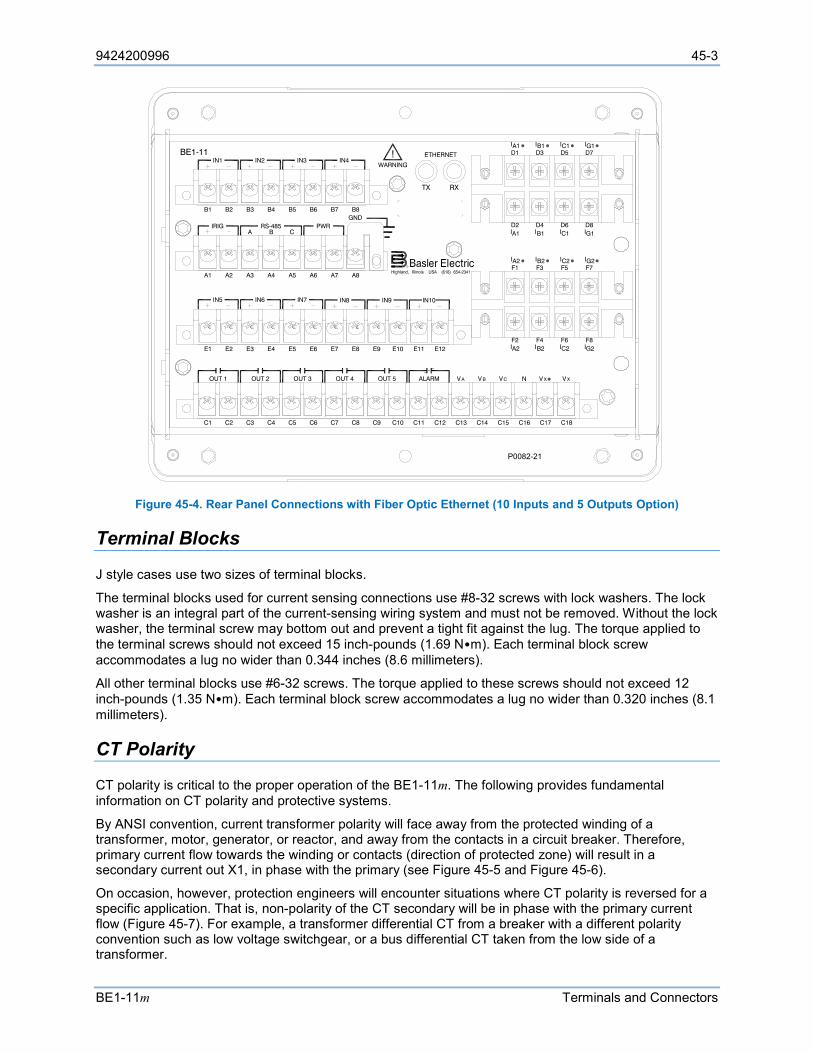
9424200996 45-3
BE1-11m Terminals and Connectors
Figure 45-4. Rear Panel Connections with Fiber Optic Ethernet (10 Inputs and 5 Outputs Option)
Terminal Blocks
J style cases use two sizes of terminal blocks.
The terminal blocks used for current sensing connections use #8-32 screws with lock washers. The lock washer is an integral part of the current-sensing wiring system and must not be removed. Without the lock washer, the terminal screw may bottom out and prevent a tight fit against the lug. The torque applied to the terminal screws should not exceed 15 inch-pounds (1.69 N•m). Each terminal block screw accommodates a lug no wider than 0.344 inches (8.6 millimeters).
All other terminal blocks use #6-32 screws. The torque applied to these screws should not exceed 12 inch-pounds (1.35 N•m). Each terminal block screw accommodates a lug no wider than 0.320 inches (8.1 millimeters).
CT Polarity
CT polarity is critical to the proper operation of the BE1-11m. The following provides fundamental information on CT polarity and protective systems.
By ANSI convention, current transformer polarity will face away from the protected winding of a transformer, motor, generator, or reactor, and away from the contacts in a circuit breaker. Therefore, primary current flow towards the winding or contacts (direction of protected zone) will result in a secondary current out X1, in phase with the primary (see Figure 45-5 and Figure 45-6).
On occasion, however, protection engineers will encounter situations where CT polarity is reversed for a specific application. That is, non-polarity of the CT secondary will be in phase with the primary current flow (Figure 45-7). For example, a transformer differential CT from a breaker with a different polarity convention such as low voltage switchgear, or a bus differential CT taken from the low side of a transformer.
!WARNING
BE1-11
C12C11C10C9C8C7C6C5C4C3C2C1 C13 C14 C15 C16 C17 C18
V AOUT 2 OUT 3 OUT 4 OUT 5OUT 1 ALARM V B VC V XV XN
E12E11E10E9E8E7E6E5E4E3E2E1
IN5 IN6 IN7
A8A7A6A5A4A3A2A1
IRIG PWRCA B
RS-485GNDB8B7B6B5B4B3B2B1
IN1 IN2 IN3 IN4D1 D3 D5 D7IA1 IB1 IC1 IG1
IA1D2 D4 D6 D8
IB1 IC1 IG1
IA2F2 F4 F6 F8
IB2 IC2 IG2
F1 F3 F5 F7IA2 IB2 IC2 IG2
ETHERNET
TX RX
IN8 IN9 IN10
P0082-21
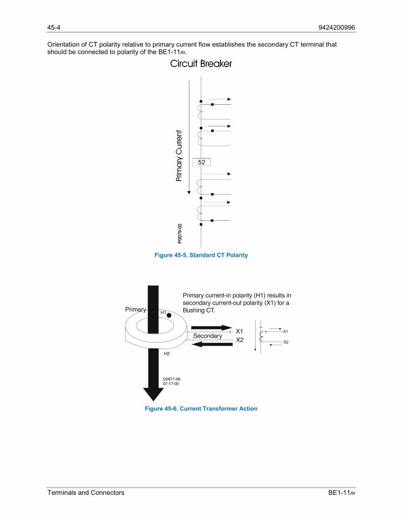
45-4 9424200996
Terminals and Connectors BE1-11m
Orientation of CT polarity relative to primary current flow establishes the secondary CT terminal that should be connected to polarity of the BE1-11m.
Figure 45-5. Standard CT Polarity
Figure 45-6. Current Transformer Action
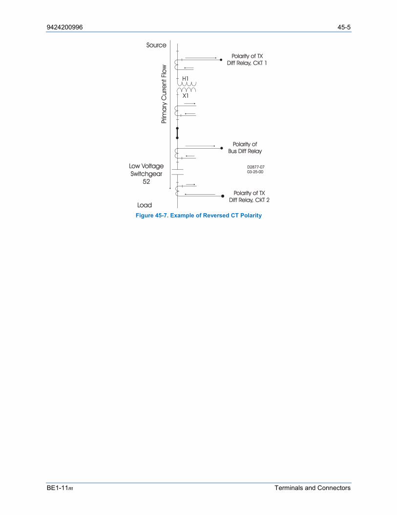
9424200996 45-5
BE1-11m Terminals and Connectors
Figure 45-7. Example of Reversed CT Polarity

45-6 9424200996
Terminals and Connectors BE1-11m
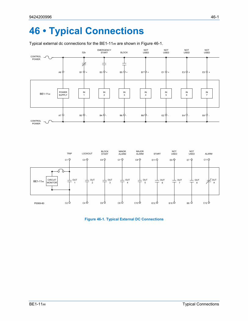
9424200996 46-1
BE1-11m Typical Connections
46 • Typical Connections Typical external dc connections for the BE1-11m are shown in Figure 46-1.
Figure 46-1. Typical External DC Connections
POWERSUPPLY 1
IN IN2 4
ININ3
CIRCUITMONITOR
A6
A7 B2
B1 +
-
+B3
-B4 B6 -
B5 +
-B8
+B7
BE1-11m
CONTROLPOWER
POWERCONTROL
EMERGENCYSTART52b
C1
C2
OUT1 2
OUT
C4
C3 C5
C6
OUT3 4
OUT
C8
C7 C9
C10
OUT5 A
OUT
C12
C11
TRIP LOCKOUTBLOCKSTART
MINORALARM
MAJORALARM ALARM
P0069-80
BLOCK
IN5
E2 -
E1 +
NOTUSED
IN6
E4 -
E3 +
NOTUSED
IN7
E6 -
E5 +
NOTUSED
NOTUSED
E11
E12
OUT6
START
E9
E10
OUT7
NOTUSED
E7
E8
OUT8
NOTUSED
BE1-11m
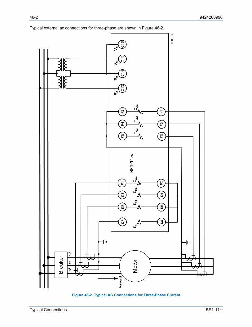
46-2 9424200996
Typical Connections BE1-11m
Typical external ac connections for three-phase are shown in Figure 46-2.
Figure 46-2. Typical AC Connections for Three-Phase Current
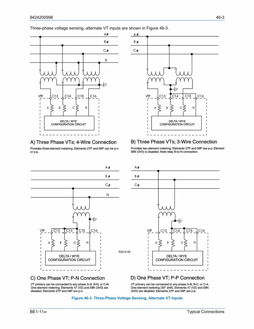
9424200996 46-3
BE1-11m Typical Connections
Three-phase voltage sensing, alternate VT inputs are shown in Figure 46-3.
Figure 46-3. Three-Phase Voltage Sensing, Alternate VT Inputs
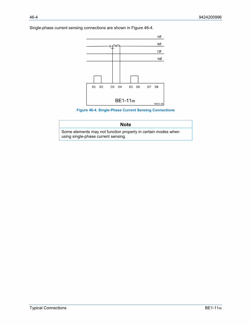
46-4 9424200996
Typical Connections BE1-11m
Single-phase current sensing connections are shown in Figure 46-4.
Figure 46-4. Single-Phase Current Sensing Connections
Note Some elements may not function properly in certain modes when using single-phase current sensing.
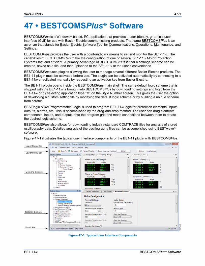
9424200996 47-1
BE1-11m BESTCOMSPlus® Software
47 • BESTCOMSPlus® Software BESTCOMSPlus is a Windows®-based, PC application that provides a user-friendly, graphical user interface (GUI) for use with Basler Electric communicating products. The name BESTCOMSPlus is an acronym that stands for Basler Electric Software Tool for Communications, Operations, Maintenance, and Settings.
BESTCOMSPlus provides the user with a point-and-click means to set and monitor the BE1-11m. The capabilities of BESTCOMSPlus make the configuration of one or several BE1-11m Motor Protection Systems fast and efficient. A primary advantage of BESTCOMSPlus is that a settings scheme can be created, saved as a file, and then uploaded to the BE1-11m at the user’s convenience.
BESTCOMSPlus uses plugins allowing the user to manage several different Basler Electric products. The BE1-11 plugin must be activated before use. The plugin can be activated automatically by connecting to a BE1-11m or activated manually by requesting an activation key from Basler Electric.
The BE1-11 plugin opens inside the BESTCOMSPlus main shell. The same default logic scheme that is shipped with the BE1-11m is brought into BESTCOMSPlus by downloading settings and logic from the BE1-11m or by selecting application type “M” on the Style Number screen. This gives the user the option of developing a custom setting file by modifying the default logic scheme or by building a unique scheme from scratch.
BESTlogic™Plus Programmable Logic is used to program BE1-11m logic for protection elements, inputs, outputs, alarms, etc. This is accomplished by the drag-and-drop method. The user can drag elements, components, inputs, and outputs onto the program grid and make connections between them to create the desired logic scheme.
BESTCOMSPlus also allows for downloading industry-standard COMTRADE files for analysis of stored oscillography data. Detailed analysis of the oscillography files can be accomplished using BESTwave™ software.
Figure 47-1 illustrates the typical user interface components of the BE1-11 plugin with BESTCOMSPlus.
Figure 47-1. Typical User Interface Components
47-2 9424200996
BESTCOMSPlus® Software BE1-11m
System Recommendations
BESTCOMSPlus software is built on the Microsoft® .NET Framework. The setup utility that installs BESTCOMSPlus on your PC also installs the BE1-11 plugin and the required version of .NET Framework (if not already installed). BESTCOMSPlus operates with systems using Windows® 7 SP1, Windows 8.1, and Windows 10 version 1607 (Anniversary Edition) or later. System recommendations for the .NET Framework and BESTCOMSPlus are listed in Table 47-1.
Table 47-1. System Recommendations for BESTCOMSPlus and the .NET Framework
System Type Component Recommendation 32/64 bit Processor 2.0 GHz 32/64 bit RAM 1 GB (minimum), 2 GB (recommended)
32 bit Hard Drive 200 MB (if .NET Framework is already installed on PC) 4.5 GB (if .NET Framework is not already installed on PC)
64 bit Hard Drive 200 MB (if .NET Framework is already installed on PC) 4.5 GB (if .NET Framework is not already installed on PC)
To install BESTCOMSPlus, a Windows user must have Administrator rights.
Installation
Note Do not connect a USB cable until setup completes successfully. Connecting a USB cable before setup is complete may result in unwanted or unexpected errors.
Run the setup file for the BESTCOMSPlus application. The setup utility installs BESTCOMSPlus, the .NET Framework (if not already installed), the USB driver, and the BE1-11 plugin for BESTCOMSPlus on your PC.
When BESTCOMSPlus installation is complete, a Basler Electric folder is added to the Windows programs menu. This folder is accessed by clicking the Windows Start button and then accessing the Basler Electric folder in the Programs menu. The Basler Electric folder contains an icon that starts BESTCOMSPlus when clicked.
Activate the BE1-11 Plugin for BESTCOMSPlus®
The BE1-11 plugin is a module that runs inside the BESTCOMSPlus shell. The BE1-11 plugin contains specific operational and logic settings for only the BE1-11m. Uploading settings to the BE1-11m is possible only after activating the BE1-11 plugin.
The BE1-11 plugin can be activated automatically or manually. Automatic activation is achieved by using a USB cable to establish communication between the BE1-11m and BESTCOMSPlus. Manual activation is initiated by contacting Basler Electric for an activation key and entering the key into BESTCOMSPlus. Manual activation is useful if you want to create a settings file prior to receiving your BE1-11m. Note that if a BE1-11m is not connected, you will not be able to configure certain Ethernet settings. Ethernet settings can be changed only when an active USB or Ethernet connection is present. Refer to the Communication chapter.
Connect a USB Cable The USB driver was copied to your PC during BESTCOMSPlus installation and is installed automatically after powering the BE1-11m. USB driver installation progress is shown in the Windows taskbar area. Windows will notify you when installation is complete.

9424200996 47-3
BE1-11m BESTCOMSPlus® Software
Connect a USB cable between the PC and your BE1-11m. Apply operating power (per style chart in the Introduction chapter) to the BE1-11m at rear terminals A6 and A7. Wait until the boot sequence is complete.
Note
In some instances, the Found New Hardware Wizard will prompt you for the USB driver. If this happens, direct the wizard to the following folder:
C:\Program Files\Basler Electric\USB Device Drivers\
If the USB driver does not install properly, refer to the Troubleshooting chapter.
Start BESTCOMSPlus® and Activate BE1-11 Plugin Automatically To start BESTCOMSPlus, click the Start button, point to Programs, Basler Electric, and then click the BESTCOMSPlus icon. During initial startup, the BESTCOMSPlus Select Language screen is displayed (Figure 47-2). You can choose to have this screen displayed each time BESTCOMSPlus is started, or you can select a preferred language and this screen will be bypassed in the future. Click OK to continue. This screen can be accessed later by selecting Tools and Select Language from the menu bar.
Figure 47-2. BESTCOMSPlus Select Language Screen
The BESTCOMSPlus splash screen is shown for a brief time. See Figure 47-3.
Figure 47-3. BESTCOMSPlus Splash Screen
The BESTCOMSPlus platform window opens. Select New Connection from the Communication pull-down menu and select BE1-11. See Figure 47-4. The BE1-11 plugin is activated automatically after connecting to a BE1-11m.
The BE1-11 Connection screen shown in Figure 47-5 appears. Select USB Connection and then click the Connect button.
47-4 9424200996
BESTCOMSPlus® Software BE1-11m
The BE1-11 plugin opens indicating that activation was successful. You can now configure the BE1-11m communication ports and other BE1-11m settings.
Figure 47-4. Communication Pull-Down Menu
Figure 47-5. BE1-11 Connection Screen
Manual Activation of the BE1-11 Plugin Manual activation of the BE1-11 plugin is required only if your initial use of BESTCOMSPlus will be on a PC that is not connected to a BE1-11m. Manual activation is described in the following paragraphs.
Requesting an Activation Key
When initially running the BE1-11 plugin, the Activate Device Plugin pop-up appears. You must contact Basler Electric for an activation key before you can activate the BE1-11 plugin. Click the Email button to request an activation key from Basler Electric. Once you receive your activation key, click the Activate button. See Figure 47-6.
9424200996 47-5
BE1-11m BESTCOMSPlus® Software
Figure 47-6. Device Plugin Requires Activation
The Activate Device Plugin pop-up appears. Refer to Figure 47-7.
Figure 47-7. Activate Device Plugin
Entering an Activation Key
Select BE1-11 from the Device pull-down menu. Enter your Email Address and Activation Key provided by Basler Electric. If you received an email containing the Activation Key, you can select all of the text in the email and copy it to the Windows clipboard using normal Windows techniques as shown in Figure 47-8.
The Get Data button extracts the Device, Email Address, and Activation Key from the Windows clipboard and pastes it into the appropriate fields. See Figure 47-9. Click the Activate button to continue. The Activate Device Plugin screen is also found by selecting Activate Device from the Tools pull-down menu of the BESTCOMSPlus main screen.
47-6 9424200996
BESTCOMSPlus® Software BE1-11m
Figure 47-8. Activation Key Email
Figure 47-9. Activate Device Plugin
Establishing Communication Communication between BESTCOMSPlus and the BE1-11m is established by clicking on the Connect button on the BE1-11 Connection screen (see Figure 47-5) or by clicking on the Connect button on the lower menu bar of the main BESTCOMSPlus screen (Figure 47-1). If you receive an “Unable to Connect to Device” error message, verify that communications are configured properly. Only one Ethernet connection is allowed at one time. Download all settings and logic from the BE1-11m by selecting Download Settings and Logic from the Communication pull-down menu. BESTCOMSPlus will read all settings and logic from the BE1-11m and load them into BESTCOMSPlus memory. See Figure 47-10.
Figure 47-10. Processing, Please Wait…
9424200996 47-7
BE1-11m BESTCOMSPlus® Software
Advanced Properties
Click the Advanced button on the Connection screen to display the Advanced Properties dialog. Default settings are shown in Figure 47-11.
Figure 47-11. Advanced Properties Dialog
Menu Bars
The menu bars are located near the top of the BESTCOMSPlus screen (see Figure 47-1). The upper menu bar has five pull-down menus. With the upper menu bar, it is possible to manage settings files, configure communication settings, upload and download settings/security files, and compare settings files. The lower menu bar consists of clickable icons. The lower menu bar is used to change BESTCOMSPlus views, open a settings file, connect/disconnect, preview metering printout, export metering, switch to live mode, and send settings after a change is made when not in live mode.
Upper Menu Bar (BESTCOMSPlus® Shell) Upper menu bar functions are listed and described in Table 47-2.
Table 47-2. Upper Menu Bar (BESTCOMSPlus Shell)
Menu Item Description File
New Create a new settings file
Open Open an existing settings file
Close Close settings file
Save Save settings file
Save As Save settings file with a different name
Export To File Save settings as a *.csv file
Print Print, export, or send a settings file
Properties View properties of a settings file
History View history of a settings file
Recent Files Open a previously opened file
Exit Close BESTCOMSPlus program
Communication New Connection Choose new device or BE1-11
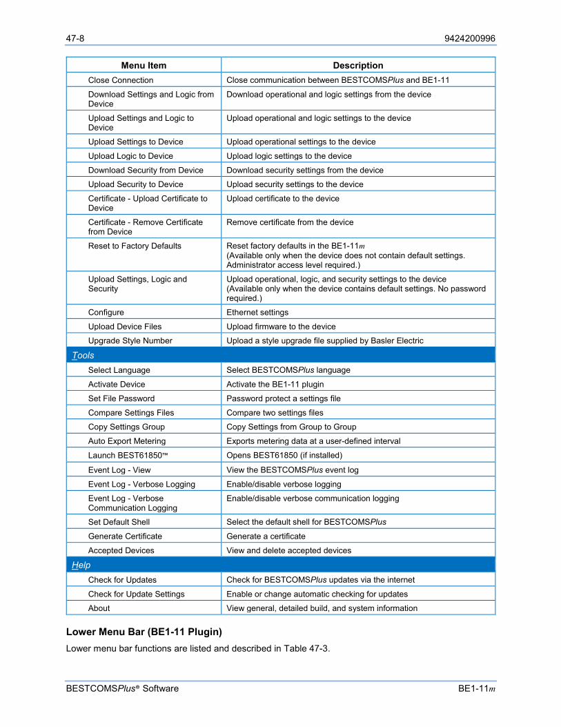
47-8 9424200996
BESTCOMSPlus® Software BE1-11m
Menu Item Description Close Connection Close communication between BESTCOMSPlus and BE1-11
Download Settings and Logic from Device
Download operational and logic settings from the device
Upload Settings and Logic to Device
Upload operational and logic settings to the device
Upload Settings to Device Upload operational settings to the device
Upload Logic to Device Upload logic settings to the device
Download Security from Device Download security settings from the device
Upload Security to Device Upload security settings to the device
Certificate - Upload Certificate to Device
Upload certificate to the device
Certificate - Remove Certificate from Device
Remove certificate from the device
Reset to Factory Defaults Reset factory defaults in the BE1-11m (Available only when the device does not contain default settings. Administrator access level required.)
Upload Settings, Logic and Security
Upload operational, logic, and security settings to the device (Available only when the device contains default settings. No password required.)
Configure Ethernet settings
Upload Device Files Upload firmware to the device
Upgrade Style Number Upload a style upgrade file supplied by Basler Electric
Tools Select Language Select BESTCOMSPlus language
Activate Device Activate the BE1-11 plugin
Set File Password Password protect a settings file
Compare Settings Files Compare two settings files
Copy Settings Group Copy Settings from Group to Group
Auto Export Metering Exports metering data at a user-defined interval
Launch BEST61850™ Opens BEST61850 (if installed)
Event Log - View View the BESTCOMSPlus event log
Event Log - Verbose Logging Enable/disable verbose logging
Event Log - Verbose Communication Logging
Enable/disable verbose communication logging
Set Default Shell Select the default shell for BESTCOMSPlus
Generate Certificate Generate a certificate
Accepted Devices View and delete accepted devices
Help Check for Updates Check for BESTCOMSPlus updates via the internet
Check for Update Settings Enable or change automatic checking for updates
About View general, detailed build, and system information
Lower Menu Bar (BE1-11 Plugin) Lower menu bar functions are listed and described in Table 47-3.
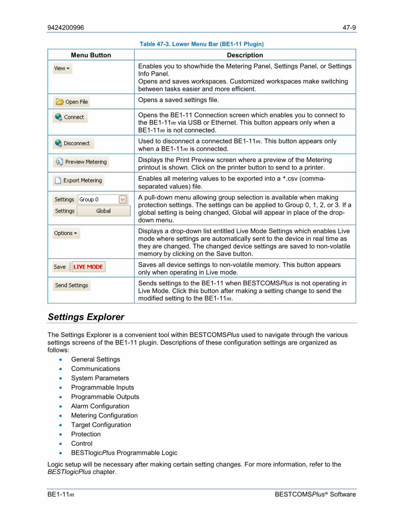
9424200996 47-9
BE1-11m BESTCOMSPlus® Software
Table 47-3. Lower Menu Bar (BE1-11 Plugin)
Menu Button Description
Enables you to show/hide the Metering Panel, Settings Panel, or Settings Info Panel. Opens and saves workspaces. Customized workspaces make switching between tasks easier and more efficient.
Opens a saved settings file.
Opens the BE1-11 Connection screen which enables you to connect to the BE1-11m via USB or Ethernet. This button appears only when a BE1-11m is not connected.
Used to disconnect a connected BE1-11m. This button appears only when a BE1-11m is connected.
Displays the Print Preview screen where a preview of the Metering printout is shown. Click on the printer button to send to a printer.
Enables all metering values to be exported into a *.csv (comma-separated values) file.
A pull-down menu allowing group selection is available when making protection settings. The settings can be applied to Group 0, 1, 2, or 3. If a global setting is being changed, Global will appear in place of the drop-down menu.
Displays a drop-down list entitled Live Mode Settings which enables Live mode where settings are automatically sent to the device in real time as they are changed. The changed device settings are saved to non-volatile memory by clicking on the Save button.
Saves all device settings to non-volatile memory. This button appears only when operating in Live mode.
Sends settings to the BE1-11 when BESTCOMSPlus is not operating in Live Mode. Click this button after making a setting change to send the modified setting to the BE1-11m.
Settings Explorer
The Settings Explorer is a convenient tool within BESTCOMSPlus used to navigate through the various settings screens of the BE1-11 plugin. Descriptions of these configuration settings are organized as follows:
• General Settings • Communications • System Parameters • Programmable Inputs • Programmable Outputs • Alarm Configuration • Metering Configuration • Target Configuration • Protection • Control • BESTlogicPlus Programmable Logic
Logic setup will be necessary after making certain setting changes. For more information, refer to the BESTlogicPlus chapter.
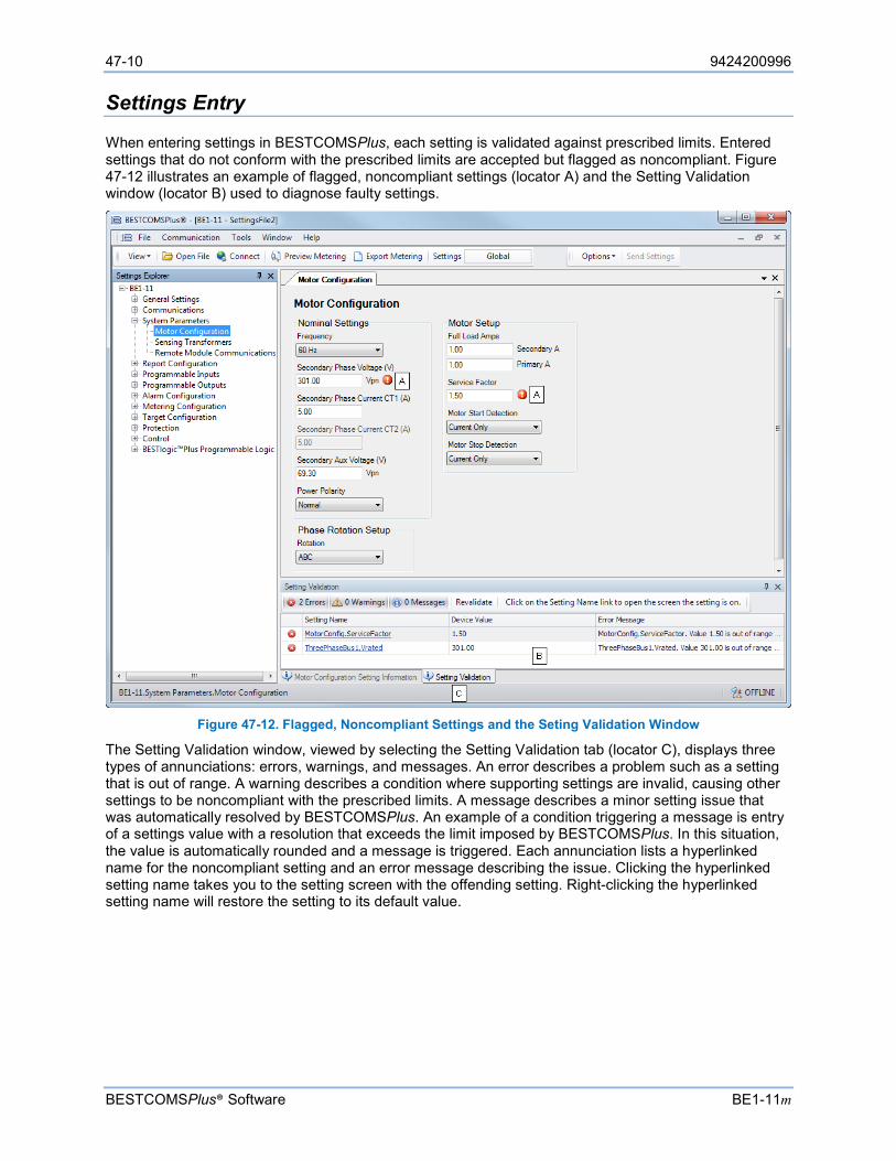
47-10 9424200996
BESTCOMSPlus® Software BE1-11m
Settings Entry
When entering settings in BESTCOMSPlus, each setting is validated against prescribed limits. Entered settings that do not conform with the prescribed limits are accepted but flagged as noncompliant. Figure 47-12 illustrates an example of flagged, noncompliant settings (locator A) and the Setting Validation window (locator B) used to diagnose faulty settings.
Figure 47-12. Flagged, Noncompliant Settings and the Seting Validation Window
The Setting Validation window, viewed by selecting the Setting Validation tab (locator C), displays three types of annunciations: errors, warnings, and messages. An error describes a problem such as a setting that is out of range. A warning describes a condition where supporting settings are invalid, causing other settings to be noncompliant with the prescribed limits. A message describes a minor setting issue that was automatically resolved by BESTCOMSPlus. An example of a condition triggering a message is entry of a settings value with a resolution that exceeds the limit imposed by BESTCOMSPlus. In this situation, the value is automatically rounded and a message is triggered. Each annunciation lists a hyperlinked name for the noncompliant setting and an error message describing the issue. Clicking the hyperlinked setting name takes you to the setting screen with the offending setting. Right-clicking the hyperlinked setting name will restore the setting to its default value.
9424200996 47-11
BE1-11m BESTCOMSPlus® Software
Note It is possible to save a BE1-11 settings file in BESTCOMSPlus with noncompliant settings. However, it is not possible to upload noncompliant settings to the BE1-11.
Metering Explorer
The Metering Explorer is described in the Metering chapter.
Settings File Management
A settings file contains all BE1-11m settings including logic.
A settings file created in BESTCOMSPlus will have one of two file extensions. Settings files created in version 4.00.00 and later are given an extension of “bst4”. Settings files created in versions prior to 4.00.00 will have an extension of “bstx”.
It is possible to save only the BE1-11m logic displayed on the BESTlogicPlus Programmable Logic screen as a separate logic library file. This ability is helpful when similar logic is required for several BE1-11m systems. The file extension of a logic file created in BESTCOMSPlus will be either “bsl4” (version 4.00.00 and later) or “bslx” (versions prior to 4.00.00).
It is important to note that settings and logic can be uploaded to the device separately or together, but are always downloaded together. For more information on logic files, refer to the BESTlogicPlus chapter.
Opening a Settings File To open a BE1-11m settings file with BESTCOMSPlus, pull down the File menu and choose Open. The Open dialog box appears. This dialog box allows you to use normal Windows techniques to select the file that you want to open. Select the file and choose Open. You can also open a file by clicking on the Open File button on the lower menu bar. If connected to a device, you will be asked to upload the settings and logic from the file to the current device. If you choose Yes, the settings displayed in BESTCOMSPlus instance will be overwritten with the settings of the opened file.
Saving a Settings File Select Save or Save As from the File pull-down menu. A dialog box pops up allowing you to enter a filename and location to save the file. Select the Save button to complete the save.
Upload Settings and/or Logic to Device To upload a settings file to the BE1-11m, open the file or create a new file through BESTCOMSPlus. Then pull down the Communication menu and select Upload Settings and Logic to Device. If you want to upload operational settings without logic, select Upload Settings to Device. If you want to upload logic without operational settings, select Upload Logic to Device. You are prompted to enter the username and password. The default username is “A” and the default password is “A”. If the username and password are correct, the upload begins and the progress bar is shown.
Upload Settings, Logic, and Security to Device This function is available only when the device contains default settings. A password is not required. To upload settings, logic, and security to the BE1-11m, pull down the Communication menu and select Upload Settings, Logic, and Security.
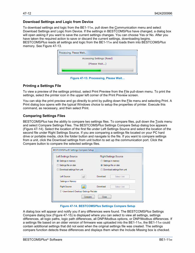
47-12 9424200996
BESTCOMSPlus® Software BE1-11m
Download Settings and Logic from Device To download settings and logic from the BE1-11m, pull down the Communication menu and select Download Settings and Logic from Device. If the settings in BESTCOMSPlus have changed, a dialog box will open asking if you want to save the current settings changes. You can choose Yes or No. After you have taken the required action to save or discard the current settings, downloading begins. BESTCOMSPlus reads all settings and logic from the BE1-11m and loads them into BESTCOMSPlus memory. See Figure 47-13.
Figure 47-13. Processing, Please Wait…
Printing a Settings File To view a preview of the settings printout, select Print Preview from the File pull-down menu. To print the settings, select the printer icon in the upper left corner of the Print Preview screen.
You can skip the print preview and go directly to print by pulling down the File menu and selecting Print. A Print dialog box opens with the typical Windows choice to setup the properties of printer. Execute this command, as necessary, and then select Print.
Comparing Settings Files BESTCOMSPlus has the ability to compare two settings files. To compare files, pull down the Tools menu and select Compare Settings Files. The BESTCOMSPlus Settings Compare Setup dialog box appears (Figure 47-14). Select the location of the first file under Left Settings Source and select the location of the second file under Right Settings Source. If you are comparing a settings file located on your PC hard drive or portable media, click the folder button and navigate to the file. If you want to compare settings from a unit, click the Download settings from unit button to set up the communication port. Click the Compare button to compare the selected settings files.
Figure 47-14. BESTCOMSPlus Settings Compare Setup
A dialog box will appear and notify you if any differences were found. The BESTCOMSPlus Settings Compare dialog box (Figure 47-15) is displayed where you can select to view all settings, settings differences, all logic paths, logic path differences, all DNP/Modbus options, or DNP/Modbus differences. If a settings file based on an older version of firmware was uploaded into the BE1-11m, the BE1-11m could contain additional settings that did not exist when the original settings file was created. The settings compare function detects these differences and displays them when the Include Missing box is checked.
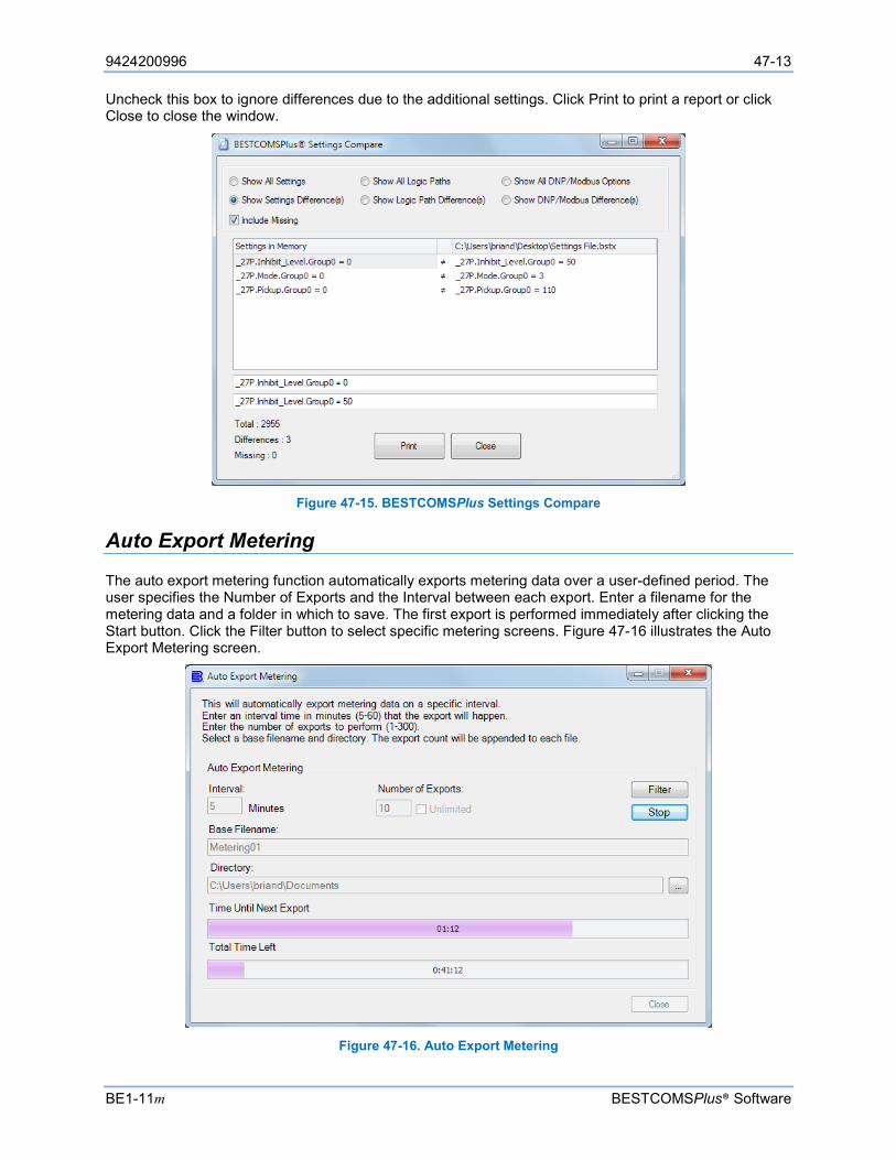
9424200996 47-13
BE1-11m BESTCOMSPlus® Software
Uncheck this box to ignore differences due to the additional settings. Click Print to print a report or click Close to close the window.
Figure 47-15. BESTCOMSPlus Settings Compare
Auto Export Metering
The auto export metering function automatically exports metering data over a user-defined period. The user specifies the Number of Exports and the Interval between each export. Enter a filename for the metering data and a folder in which to save. The first export is performed immediately after clicking the Start button. Click the Filter button to select specific metering screens. Figure 47-16 illustrates the Auto Export Metering screen.
Figure 47-16. Auto Export Metering
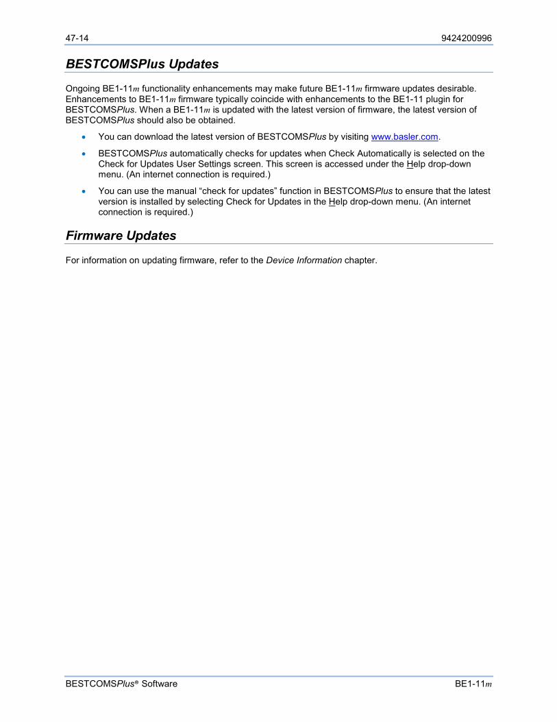
47-14 9424200996
BESTCOMSPlus® Software BE1-11m
BESTCOMSPlus Updates
Ongoing BE1-11m functionality enhancements may make future BE1-11m firmware updates desirable. Enhancements to BE1-11m firmware typically coincide with enhancements to the BE1-11 plugin for BESTCOMSPlus. When a BE1-11m is updated with the latest version of firmware, the latest version of BESTCOMSPlus should also be obtained.
• You can download the latest version of BESTCOMSPlus by visiting www.basler.com.
• BESTCOMSPlus automatically checks for updates when Check Automatically is selected on the Check for Updates User Settings screen. This screen is accessed under the Help drop-down menu. (An internet connection is required.)
• You can use the manual “check for updates” function in BESTCOMSPlus to ensure that the latest version is installed by selecting Check for Updates in the Help drop-down menu. (An internet connection is required.)
Firmware Updates
For information on updating firmware, refer to the Device Information chapter.
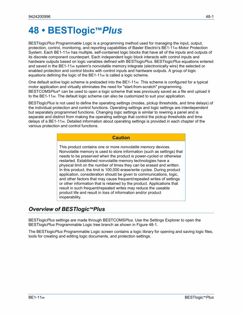
9424200996 48-1
BE1-11m BESTlogic™Plus
48 • BESTlogic™Plus BESTlogicPlus Programmable Logic is a programming method used for managing the input, output, protection, control, monitoring, and reporting capabilities of Basler Electric's BE1-11m Motor Protection System. Each BE1-11m has multiple, self-contained logic blocks that have all of the inputs and outputs of its discrete component counterpart. Each independent logic block interacts with control inputs and hardware outputs based on logic variables defined with BESTlogicPlus. BESTlogicPlus equations entered and saved in the BE1-11m system's nonvolatile memory integrate (electronically wire) the selected or enabled protection and control blocks with control inputs and hardware outputs. A group of logic equations defining the logic of the BE1-11m is called a logic scheme.
One default active logic scheme is preloaded into the BE1-11m. This scheme is configured for a typical motor application and virtually eliminates the need for "start-from-scratch" programming. BESTCOMSPlus® can be used to open a logic scheme that was previously saved as a file and upload it to the BE1-11m. The default logic scheme can also be customized to suit your application.
BESTlogicPlus is not used to define the operating settings (modes, pickup thresholds, and time delays) of the individual protection and control functions. Operating settings and logic settings are interdependent but separately programmed functions. Changing logic settings is similar to rewiring a panel and is separate and distinct from making the operating settings that control the pickup thresholds and time delays of a BE1-11m. Detailed information about operating settings is provided in each chapter of the various protection and control functions.
Caution
This product contains one or more nonvolatile memory devices. Nonvolatile memory is used to store information (such as settings) that needs to be preserved when the product is power-cycled or otherwise restarted. Established nonvolatile memory technologies have a physical limit on the number of times they can be erased and written. In this product, the limit is 100,000 erase/write cycles. During product application, consideration should be given to communications, logic, and other factors that may cause frequent/repeated writes of settings or other information that is retained by the product. Applications that result in such frequent/repeated writes may reduce the useable product life and result in loss of information and/or product inoperability.
Overview of BESTlogic™Plus
BESTlogicPlus settings are made through BESTCOMSPlus. Use the Settings Explorer to open the BESTlogicPlus Programmable Logic tree branch as shown in Figure 48-1.
The BESTlogicPlus Programmable Logic screen contains a logic library for opening and saving logic files, tools for creating and editing logic documents, and protection settings.
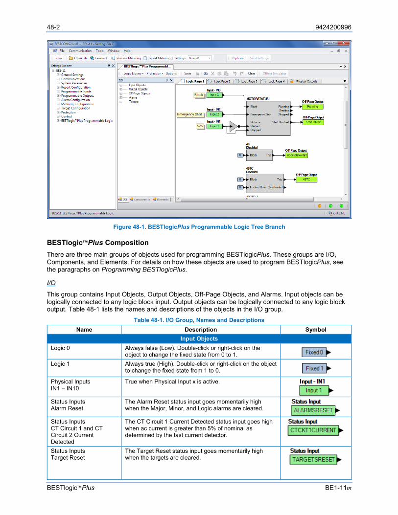
48-2 9424200996
BESTlogic™Plus BE1-11m
Figure 48-1. BESTlogicPlus Programmable Logic Tree Branch
BESTlogic™Plus Composition There are three main groups of objects used for programming BESTlogicPlus. These groups are I/O, Components, and Elements. For details on how these objects are used to program BESTlogicPlus, see the paragraphs on Programming BESTlogicPlus.
I/O
This group contains Input Objects, Output Objects, Off-Page Objects, and Alarms. Input objects can be logically connected to any logic block input. Output objects can be logically connected to any logic block output. Table 48-1 lists the names and descriptions of the objects in the I/O group.
Table 48-1. I/O Group, Names and Descriptions Name Description Symbol
Input Objects Logic 0 Always false (Low). Double-click or right-click on the
object to change the fixed state from 0 to 1. Logic 1 Always true (High). Double-click or right-click on the object
to change the fixed state from 1 to 0. Physical Inputs IN1 – IN10
True when Physical Input x is active.
Status Inputs Alarm Reset
The Alarm Reset status input goes momentarily high when the Major, Minor, and Logic alarms are cleared.
Status Inputs CT Circuit 1 and CT Circuit 2 Current Detected
The CT Circuit 1 Current Detected status input goes high when ac current is greater than 5% of nominal as determined by the fast current detector.
Status Inputs Target Reset
The Target Reset status input goes momentarily high when the targets are cleared.
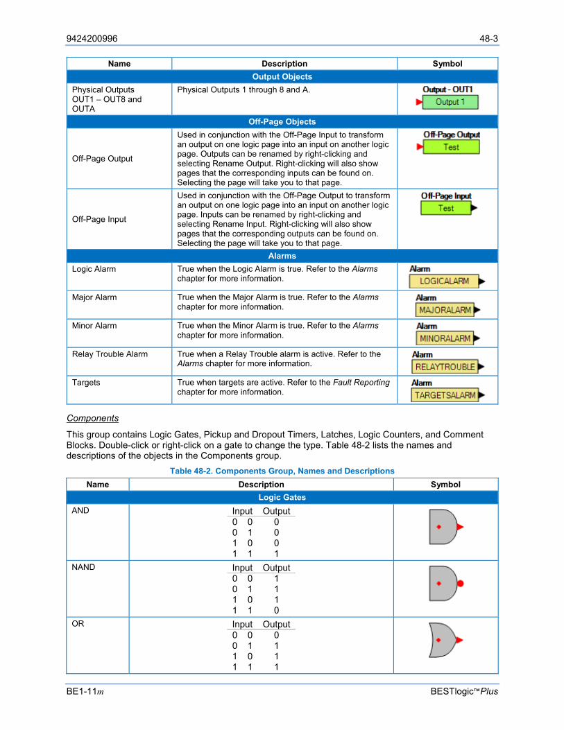
9424200996 48-3
BE1-11m BESTlogic™Plus
Name Description Symbol Output Objects
Physical Outputs OUT1 – OUT8 and OUTA
Physical Outputs 1 through 8 and A.
Off-Page Objects
Off-Page Output
Used in conjunction with the Off-Page Input to transform an output on one logic page into an input on another logic page. Outputs can be renamed by right-clicking and selecting Rename Output. Right-clicking will also show pages that the corresponding inputs can be found on. Selecting the page will take you to that page.
Off-Page Input
Used in conjunction with the Off-Page Output to transform an output on one logic page into an input on another logic page. Inputs can be renamed by right-clicking and selecting Rename Input. Right-clicking will also show pages that the corresponding outputs can be found on. Selecting the page will take you to that page.
Alarms Logic Alarm True when the Logic Alarm is true. Refer to the Alarms
chapter for more information.
Major Alarm True when the Major Alarm is true. Refer to the Alarms chapter for more information.
Minor Alarm True when the Minor Alarm is true. Refer to the Alarms
chapter for more information.
Relay Trouble Alarm True when a Relay Trouble alarm is active. Refer to the Alarms chapter for more information.
Targets True when targets are active. Refer to the Fault Reporting
chapter for more information.
Components
This group contains Logic Gates, Pickup and Dropout Timers, Latches, Logic Counters, and Comment Blocks. Double-click or right-click on a gate to change the type. Table 48-2 lists the names and descriptions of the objects in the Components group.
Table 48-2. Components Group, Names and Descriptions Name Description Symbol
Logic Gates AND Input Output
0 0 0 0 1 0 1 0 0 1 1 1
NAND Input Output 0 0 1 0 1 1 1 0 1 1 1 0
OR Input Output 0 0 0 0 1 1 1 0 1 1 1 1
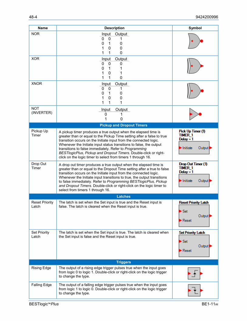
48-4 9424200996
BESTlogic™Plus BE1-11m
Name Description Symbol NOR Input Output
0 0 1 0 1 0 1 0 0 1 1 0
XOR Input Output 0 0 0 0 1 1 1 0 1 1 1 0
XNOR Input Output 0 0 1 0 1 0 1 0 0 1 1 1
NOT (INVERTER)
Input Output 0 1 1 0
Pickup and Dropout Timers
Pickup Up Timer
A pickup timer produces a true output when the elapsed time is greater than or equal to the Pickup Time setting after a false to true transition occurs on the Initiate input from the connected logic. Whenever the Initiate input status transitions to false, the output transitions to false immediately. Refer to Programming BESTlogicPlus, Pickup and Dropout Timers. Double-click or right-click on the logic timer to select from timers 1 through 16.
Drop Out Timer
A drop out timer produces a true output when the elapsed time is greater than or equal to the Dropout Time setting after a true to false transition occurs on the Initiate input from the connected logic. Whenever the Initiate input transitions to true, the output transitions to false immediately. Refer to Programming BESTlogicPlus, Pickup and Dropout Timers. Double-click or right-click on the logic timer to select from timers 1 through 16.
Latches Reset Priority Latch
The latch is set when the Set input is true and the Reset input is false. The latch is cleared when the Reset input is true.
Set Priority Latch
The latch is set when the Set input is true. The latch is cleared when the Set input is false and the Reset input is true.
Triggers
Rising Edge The output of a rising edge trigger pulses true when the input goes from logic 0 to logic 1. Double-click or right-click on the logic trigger to change the type.
Falling Edge The output of a falling edge trigger pulses true when the input goes
from logic 1 to logic 0. Double-click or right-click on the logic trigger to change the type.

9424200996 48-5
BE1-11m BESTlogic™Plus
Name Description Symbol Logic Counters
Logic Counters
A logic counter produces a true Alarm output when the elapsed count is greater than or equal to the Trigger Count setting after a false to true transition occurs on the Count Up input from the connected logic. A positive going edge on the Reset input will reset the counter. The count will be reduced by 1 each time a false to true transition occurs on the Count Down input. Double-click or right-click on the logic counter to select from counters 1 through 8.
Other
Logic Comment Block
The logic comment block is used to place notes on the logic.
Elements
This group contains elements for the 27P, 32, 37, 40Q, 43, 48, 49RTD, 49TC, 50, 50BF, 51, 55, 59P, 59X, 60FL, 62, 81, 86, 87, and 101. It also contains elements for 52TCM, Breaker Monitor, Breaker Status, Fault Trigger, Email Trigger, Setting Group Control, Analog Inputs 1-8, User Programmable Alarms 1-16, User Programmable Targets 1-12, Motor Status, Logic Labels 1-12, Indicators 1-7, Major Alarm Reset, Minor Alarm Reset, Logic Alarm Reset, and Target Reset.
Table 48-3 lists the names and descriptions of the elements in the Elements group. Table 48-3. Elements Group, Names and Descriptions
Name Description Symbol Protection
27P-x Phase Undervoltage Protection. Refer to the Phase Undervoltage (27P) Protection chapter.
32-x Power Protection.
Refer to the Power (32) Protection chapter.
37 Instantaneous Undercurrent Protection.
Refer to the Instantaneous Undercurrent (37) Protection chapter.
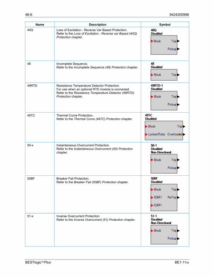
48-6 9424200996
BESTlogic™Plus BE1-11m
Name Description Symbol 40Q Loss of Excitation - Reverse Var Based Protection.
Refer to the Loss of Excitation - Reverse var Based (40Q) Protection chapter.
48 Incomplete Sequence. Refer to the Incomplete Sequence (48) Protection chapter.
49RTD Resistance Temperature Detector Protection.
For use when an optional RTD module is connected. Refer to the Resistance Temperature Detector (49RTD) Protection chapter.
49TC Thermal Curve Protection.
Refer to the Thermal Curve (49TC) Protection chapter.
50-x Instantaneous Overcurrent Protection.
Refer to the Instantaneous Overcurrent (50) Protection chapter.
50BF Breaker Fail Protection.
Refer to the Breaker Fail (50BF) Protection chapter.
51-x Inverse Overcurrent Protection.
Refer to the Inverse Overcurrent (51) Protection chapter.
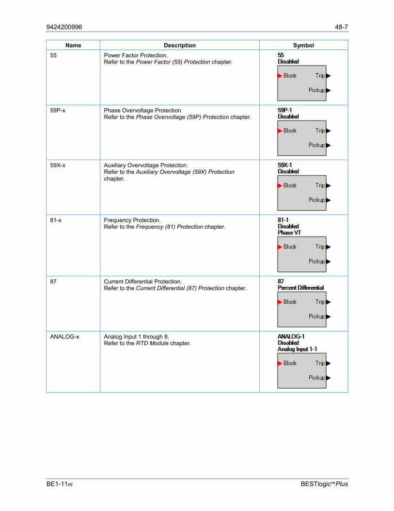
9424200996 48-7
BE1-11m BESTlogic™Plus
Name Description Symbol 55 Power Factor Protection.
Refer to the Power Factor (55) Protection chapter.
59P-x Phase Overvoltage Protection.
Refer to the Phase Overvoltage (59P) Protection chapter.
59X-x Auxiliary Overvoltage Protection.
Refer to the Auxiliary Overvoltage (59X) Protection chapter.
81-x Frequency Protection.
Refer to the Frequency (81) Protection chapter.
87 Current Differential Protection.
Refer to the Current Differential (87) Protection chapter.
ANALOG-x Analog Input 1 through 8.
Refer to the RTD Module chapter.
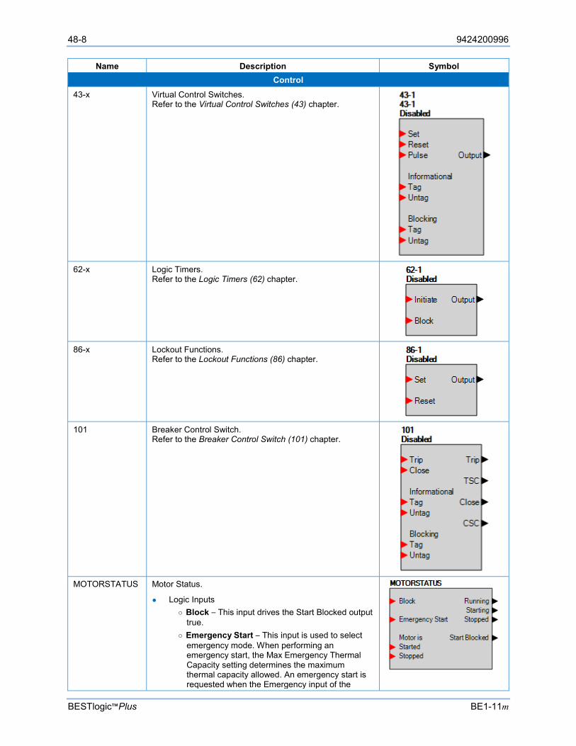
48-8 9424200996
BESTlogic™Plus BE1-11m
Name Description Symbol Control
43-x Virtual Control Switches. Refer to the Virtual Control Switches (43) chapter.
62-x Logic Timers.
Refer to the Logic Timers (62) chapter.
86-x Lockout Functions.
Refer to the Lockout Functions (86) chapter.
101 Breaker Control Switch.
Refer to the Breaker Control Switch (101) chapter.
MOTORSTATUS Motor Status.
Logic Inputs Block – This input drives the Start Blocked output
true. Emergency Start – This input is used to select
emergency mode. When performing an emergency start, the Max Emergency Thermal Capacity setting determines the maximum thermal capacity allowed. An emergency start is requested when the Emergency input of the
9424200996 48-9
BE1-11m BESTlogic™Plus
Name Description Symbol Motor Status logic block is true. The emergency start condition remains until the thermal capacity drops below 100%, the motor stops, or the motor does not start for one minute after the emergency start was requested.
Motor is Started – This input can be used with current or stand alone to detect the motor has started as determined by the Motor Start Detection setting.
Motor is Stopped – This input can be used with current or stand alone to detect the motor has stopped as determined by the Motor Start Detection setting.
Logic Outputs Running – This output is true when the motor is
running. The Motor Start Detection setting controls how the BE1-11m identifies when a motor is running. Current Only From a normal motor start - The motor is
deemed “running” when all three phases of current drop below 2 X FLA for 100 ms.
From a soft motor start - The motor is deemed “running” when all three phases of current are below 2 X FLA, but above 5% FLA for 300 ms.
Current and Contacts From a normal motor start - The motor is
deemed “running” when all three phases of current drop below 2 X FLA for 100 ms and the Motor is Started logic input of the Motor Status logic block becomes true.
From a soft motor start - The motor is deemed “running” when all three phases of current are below 2 X FLA, but above 5% FLA for 300 ms, and the Motor Started logic input of the Motor Status logic block becomes true.
Contacts Only The motor is deemed “running” when, from a stopped condition, the Motor is Started logic input of the Motor Status logic block becomes true.
Starting – This output is true when the motor is starting. The Motor Start Detection setting controls how the BE1-11m identifies when a motor is started. Current Only Normal start - The motor is deemed “starting”
when, from a stopped condition, the current on any phase increases to greater than 2 X FLA.
Soft start - The motor is deemed “starting” when, from a stopped condition, the current on any phase is below 2 X FLA, but above 5% FLA for 300 ms.
Current and Contacts Normal start - The motor is deemed “starting”
when, from a stopped condition, the current on any phase increases to greater than 2 X FLA and the Motor is Started logic input of the Motor Status logic block becomes true.
Soft start - The motor is deemed “starting” when, from a stopped condition, the current
48-10 9424200996
BESTlogic™Plus BE1-11m
Name Description Symbol on any phase is below 2 X FLA, but above 5% FLA for 300 ms, and the Motor is Started logic input of the Motor Status logic block becomes true.
Contacts Only The Starting output is always false when Motor Start Detection is configured for Contacts Only. From a stopped condition, the BE1-11m goes directly to the Running state if the Motor is Started logic input of the Motor Status logic block becomes true. The 66 element will not increment and the 48 element will not operate when Motor Start Detection is configured for Contacts Only.
Stopped – This output is true when the motor is stopped. The Motor Stop Detection setting controls how the BE1-11m identifies when a motor is stopped. Current Only The motor is deemed “stopped” when all three phases of current drop below 2% of FLA for 100 ms. Current and Contacts The motor is deemed “stopped” when all three phases of current drop below 2% of FLA for 100 ms and the Motor is Stopped logic input of the Motor Status logic block becomes true. Contacts Only The motor is deemed “stopped” when the Motor is Stopped logic input of the Motor Status logic block becomes true.
Start Blocked – This output is true when any one of the following is true. The sequence of events report identifies which condition is causing the block.
The Block input is true. The Starts per Time Interval (66) is
exceeded. Existing TC% + Avg. Start TC% exceeds
100%. Until the Restart Delay setting is
exceeded. Until the Time Between Starts setting is
exceeded. Figure 48-2 shows how the motor transitions between stopped > starting > running > stopped based on a normal current start. Figure 48-3 shows the transitions based on a low-current start.
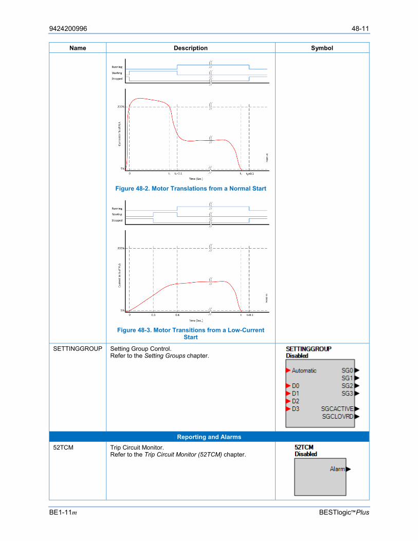
9424200996 48-11
BE1-11m BESTlogic™Plus
Name Description Symbol
Figure 48-2. Motor Translations from a Normal Start
Figure 48-3. Motor Transitions from a Low-Current
Start
SETTINGGROUP Setting Group Control. Refer to the Setting Groups chapter.
Reporting and Alarms
52TCM Trip Circuit Monitor. Refer to the Trip Circuit Monitor (52TCM) chapter.
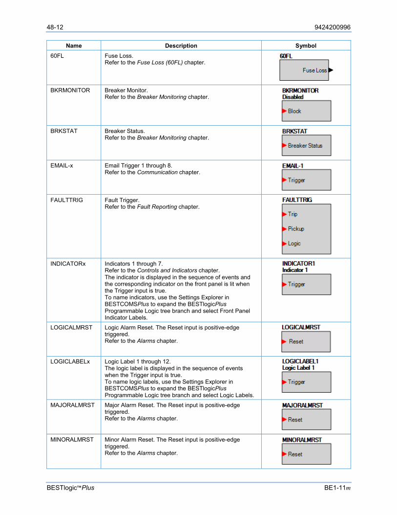
48-12 9424200996
BESTlogic™Plus BE1-11m
Name Description Symbol 60FL Fuse Loss.
Refer to the Fuse Loss (60FL) chapter.
BKRMONITOR Breaker Monitor.
Refer to the Breaker Monitoring chapter.
BRKSTAT Breaker Status.
Refer to the Breaker Monitoring chapter.
EMAIL-x Email Trigger 1 through 8.
Refer to the Communication chapter.
FAULTTRIG Fault Trigger.
Refer to the Fault Reporting chapter.
INDICATORx Indicators 1 through 7.
Refer to the Controls and Indicators chapter. The indicator is displayed in the sequence of events and the corresponding indicator on the front panel is lit when the Trigger input is true. To name indicators, use the Settings Explorer in BESTCOMSPlus to expand the BESTlogicPlus Programmable Logic tree branch and select Front Panel Indicator Labels.
LOGICALMRST Logic Alarm Reset. The Reset input is positive-edge triggered. Refer to the Alarms chapter.
LOGICLABELx Logic Label 1 through 12.
The logic label is displayed in the sequence of events when the Trigger input is true. To name logic labels, use the Settings Explorer in BESTCOMSPlus to expand the BESTlogicPlus Programmable Logic tree branch and select Logic Labels.
MAJORALMRST Major Alarm Reset. The Reset input is positive-edge triggered. Refer to the Alarms chapter.
MINORALMRST Minor Alarm Reset. The Reset input is positive-edge
triggered. Refer to the Alarms chapter.

9424200996 48-13
BE1-11m BESTlogic™Plus
Name Description Symbol TARGETRESET Target Reset. The Reset input is positive-edge triggered.
Refer to the Fault Reporting chapter.
USERALARMx User Programmable Alarms 1 through 16.
Refer to the Alarms chapter.
USERTARGx User Programmable Targets 1 through 12.
Refer to the Targets chapter.
Logic Schemes
A logic scheme is a group of logic variables that defines the operation of a BE1-11m. Each logic scheme is given a unique name. This gives you the ability to select a specific scheme and be confident that the selected scheme is in operation. One logic scheme is configured for typical control applications and is the default active logic scheme. Only one logic scheme can be active at a given time. In most applications, preprogrammed logic schemes eliminate the need for custom programming. Preprogrammed logic schemes can provide more inputs, outputs, or features than are needed for a particular application. This is because a preprogrammed scheme is designed for a large number of applications with no special programming required. Unneeded logic block outputs can be left open to disable a function or a function block can be disabled through operating settings.
When a custom logic scheme is required, programming time is reduced by modifying the default logic scheme.
Default Logic Scheme All BE1-11m protection systems are delivered with the default logic scheme pre-loaded in memory. If the function block configuration and output logic of the default logic scheme meets the requirements of your application, then only the operating settings (power system parameters and threshold settings) need to be adjusted before placing the BE1-11m in service.
Details of Default Logic Scheme describes the characteristics of the logic scheme and how it combines to create a Motor Protection System. A detailed description of the default scheme is also provided.
The default logic scheme is designed to accommodate most common motor protection schemes. The protection engineer can adapt it by changing the function block operation and settings. This eliminates the need to create a custom logic scheme.
It should be noted that the default logic scheme also illustrates typical ways of using or controlling various functions. The user can choose to create a custom logic scheme by mixing the logic from the default scheme. The flexibility of BESTlogicPlus allows the protection engineer to create a custom scheme that exactly meets the requirements of the application.
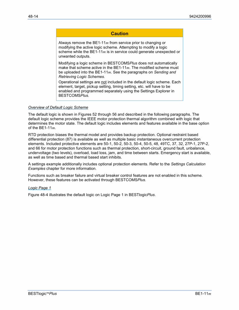
48-14 9424200996
BESTlogic™Plus BE1-11m
Caution
Always remove the BE1-11m from service prior to changing or modifying the active logic scheme. Attempting to modify a logic scheme while the BE1-11m is in service could generate unexpected or unwanted outputs.
Modifying a logic scheme in BESTCOMSPlus does not automatically make that scheme active in the BE1-11m. The modified scheme must be uploaded into the BE1-11m. See the paragraphs on Sending and Retrieving Logic Schemes. Operational settings are not included in the default logic scheme. Each element, target, pickup setting, timing setting, etc. will have to be enabled and programmed separately using the Settings Explorer in BESTCOMSPlus.
Overview of Default Logic Scheme
The default logic is shown in Figures 52 through 56 and described in the following paragraphs. The default logic scheme provides the IEEE motor protection thermal algorithm combined with logic that determines the motor state. The default logic includes elements and features available in the base option of the BE1-11m.
RTD protection biases the thermal model and provides backup protection. Optional restraint based differential protection (87) is available as well as multiple basic instantaneous overcurrent protection elements. Included protective elements are 50-1, 50-2, 50-3, 50-4, 50-5, 48, 49TC, 37, 32, 27P-1, 27P-2, and 66 for motor protection functions such as thermal protection, short-circuit, ground fault, unbalance, undervoltage (two levels), overload, load loss, jam, and time between starts. Emergency start is available, as well as time based and thermal based start inhibits.
A settings example additionally includes optional protection elements. Refer to the Settings Calculation Examples chapter for more information.
Functions such as breaker failure and virtual breaker control features are not enabled in this scheme. However, these features can be activated through BESTCOMSPlus.
Logic Page 1
Figure 48-4 illustrates the default logic on Logic Page 1 in BESTlogicPlus.
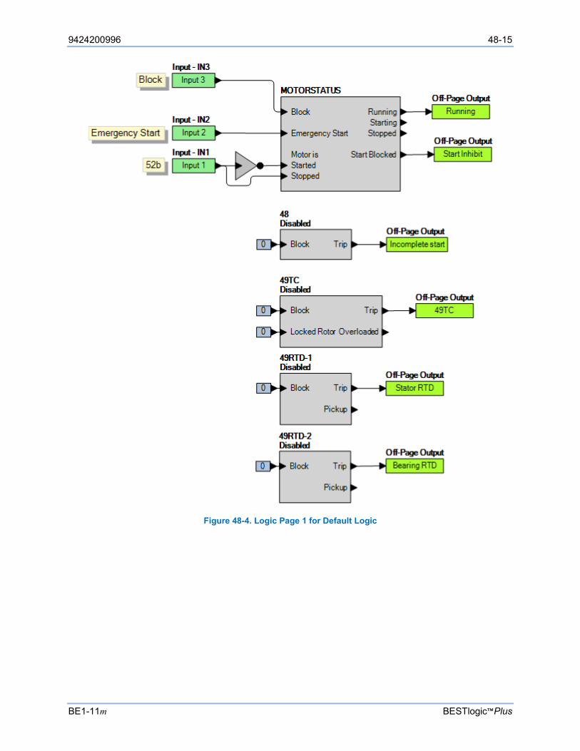
9424200996 48-15
BE1-11m BESTlogic™Plus
Figure 48-4. Logic Page 1 for Default Logic
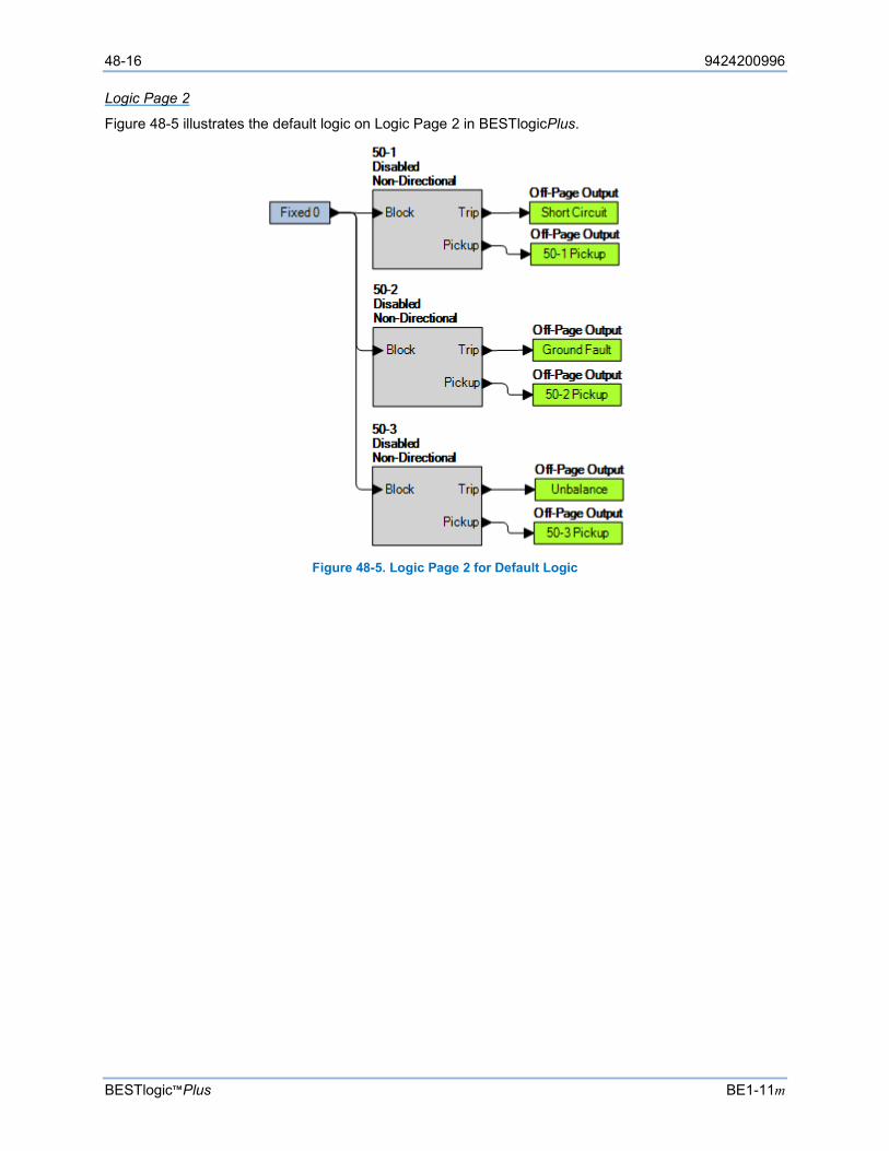
48-16 9424200996
BESTlogic™Plus BE1-11m
Logic Page 2
Figure 48-5 illustrates the default logic on Logic Page 2 in BESTlogicPlus.
Figure 48-5. Logic Page 2 for Default Logic
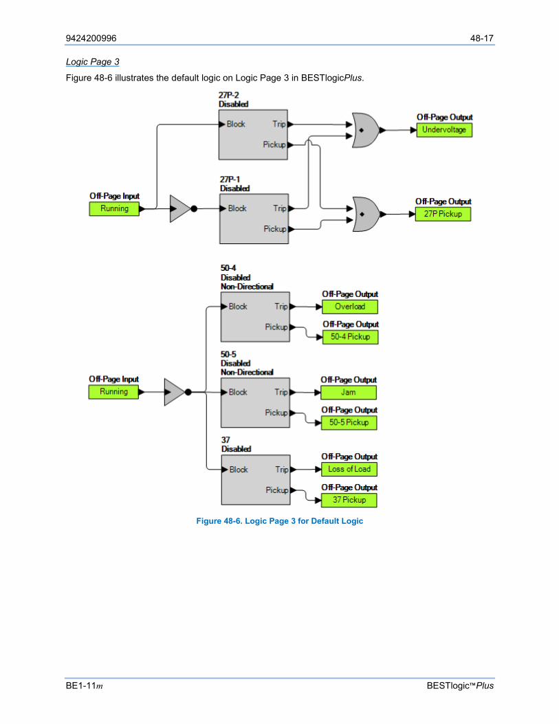
9424200996 48-17
BE1-11m BESTlogic™Plus
Logic Page 3
Figure 48-6 illustrates the default logic on Logic Page 3 in BESTlogicPlus.
Figure 48-6. Logic Page 3 for Default Logic
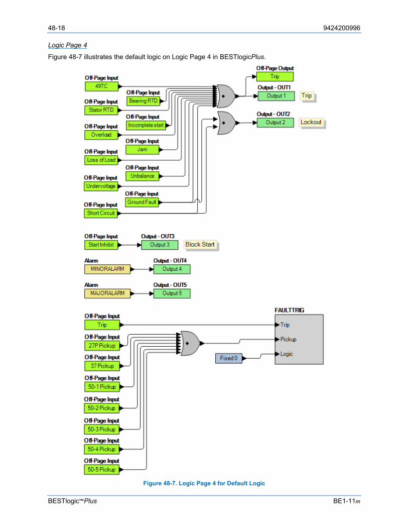
48-18 9424200996
BESTlogic™Plus BE1-11m
Logic Page 4
Figure 48-7 illustrates the default logic on Logic Page 4 in BESTlogicPlus.
Figure 48-7. Logic Page 4 for Default Logic
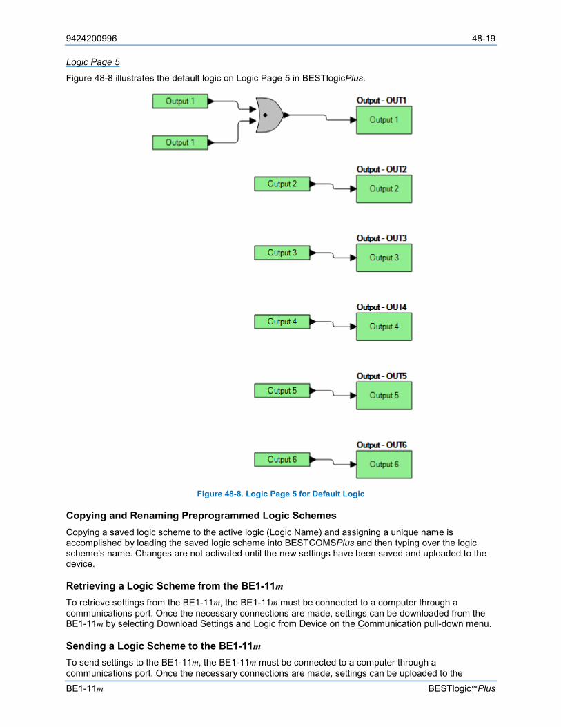
9424200996 48-19
BE1-11m BESTlogic™Plus
Logic Page 5
Figure 48-8 illustrates the default logic on Logic Page 5 in BESTlogicPlus.
Figure 48-8. Logic Page 5 for Default Logic
Copying and Renaming Preprogrammed Logic Schemes Copying a saved logic scheme to the active logic (Logic Name) and assigning a unique name is accomplished by loading the saved logic scheme into BESTCOMSPlus and then typing over the logic scheme's name. Changes are not activated until the new settings have been saved and uploaded to the device.
Retrieving a Logic Scheme from the BE1-11m To retrieve settings from the BE1-11m, the BE1-11m must be connected to a computer through a communications port. Once the necessary connections are made, settings can be downloaded from the BE1-11m by selecting Download Settings and Logic from Device on the Communication pull-down menu.
Sending a Logic Scheme to the BE1-11m To send settings to the BE1-11m, the BE1-11m must be connected to a computer through a communications port. Once the necessary connections are made, settings can be uploaded to the

48-20 9424200996
BESTlogic™Plus BE1-11m
BE1-11m by selecting Upload Settings and Logic to Device or Upload Logic to Device on the Communication pull-down menu.
Programming BESTlogic™Plus
BESTCOMSPlus is used to program BESTlogicPlus. Using BESTCOMSPlus is analogous to physically attaching wire between discrete BE1-11m terminals. To program BESTlogicPlus, use the Settings Explorer within BESTCOMSPlus to open the BESTlogicPlus Programmable Logic tree branch as shown in Figure 48-1.
The drag-and-drop method is used to connect a variable or series of variables to the logic inputs, outputs, components, and elements. To draw a wire/link from port to port (triangles), use the primary mouse button to click on a port, pull the wire onto another port, and release the left mouse button. A red port indicates that a connection to the port is required or missing. A black port indicates that a connection to the port is not required. Drawing wires/links from input to input or output to output is not allowed. Only one wire/link can be connected to any one output. If the proximity of the endpoint of the wire/link is not exact, it may attach to an unintended port.
If an element is disabled by the style number, it will have a red X on it. To enable the element, configure the style number to include the element. Refer to the Device Information chapter for more details.
The view of Logic Page 1 through 4 and Physical Outputs can be automatically arranged by clicking the right mouse button on the window and selecting Auto-Layout.
Logic tabs can be renamed by clicking the right mouse button in the logic drawing area and selecting Rename Logic Tabs.
The following must be met before BESTCOMSPlus will allow logic to be uploaded to the BE1-11m:
• A minimum of two inputs and a maximum of 32 inputs on any multi-port (AND, OR, NAND, NOR, XOR, and XNOR) gate.
• A maximum of 32 logic elements in series.
• A maximum of 256 logic elements per diagram.
Three status indicators are located in the lower right corner of the BESTlogicPlus window. These indicators show the Logic Save Status, Logic Diagram Status, and Logic Layer Status. Table 48-4 defines the colors for each indicator.
Table 48-4. Status Indicators
Indicator Color Definition
Logic Save Status (Left Indicator)
Amber Logic has changed since last save
Green Logic has NOT changed since last save
Logic Diagram Status (Center Indicator)
Red Requirements NOT met as listed above Green Requirements met as listed above
Logic Layer Status (Right Indicator)
Red Requirements NOT met as listed above Green Requirements met as listed above
Pickup and Dropout Timers Pickup and dropout timer logic blocks are shown in Figure 48-9.
To program logic timer settings, use the Settings Explorer within BESTCOMSPlus to open the BESTlogicPlus Programmable Logic, Logic Timers tree branch. Enter a Name label that you want to appear on the timer logic block. The Time Delay value range is 0.0 to 1800.0 seconds in 0.1-second increments.
Next, open the Components tab inside the BESTlogicPlus window and drag a timer onto the program grid. Right click on the timer to select the timer you want to use that was previously set on the Logic Timers tree branch. The Logic Timer Properties Dialog Box will appear. Select the timer you want to use.
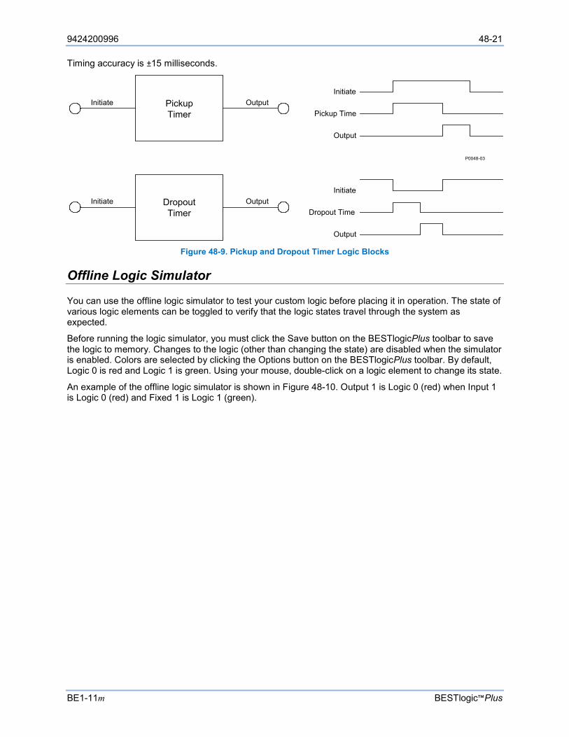
9424200996 48-21
BE1-11m BESTlogic™Plus
Timing accuracy is ±15 milliseconds.
Figure 48-9. Pickup and Dropout Timer Logic Blocks
Offline Logic Simulator
You can use the offline logic simulator to test your custom logic before placing it in operation. The state of various logic elements can be toggled to verify that the logic states travel through the system as expected.
Before running the logic simulator, you must click the Save button on the BESTlogicPlus toolbar to save the logic to memory. Changes to the logic (other than changing the state) are disabled when the simulator is enabled. Colors are selected by clicking the Options button on the BESTlogicPlus toolbar. By default, Logic 0 is red and Logic 1 is green. Using your mouse, double-click on a logic element to change its state.
An example of the offline logic simulator is shown in Figure 48-10. Output 1 is Logic 0 (red) when Input 1 is Logic 0 (red) and Fixed 1 is Logic 1 (green).
Initiate
Pickup Time
Output
Initiate
Dropout Time
Output
Pickup Timer
Dropout Timer
Output
Output
Initiate
Initiate
P0048-03
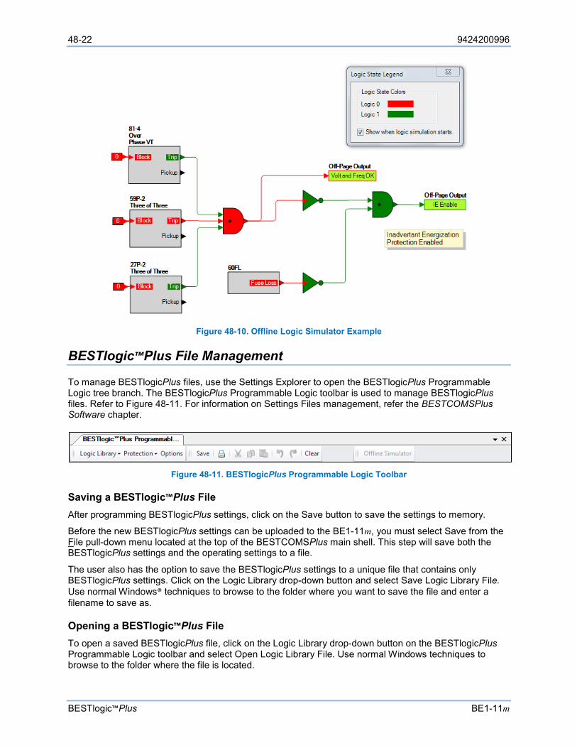
48-22 9424200996
BESTlogic™Plus BE1-11m
Figure 48-10. Offline Logic Simulator Example
BESTlogic™Plus File Management
To manage BESTlogicPlus files, use the Settings Explorer to open the BESTlogicPlus Programmable Logic tree branch. The BESTlogicPlus Programmable Logic toolbar is used to manage BESTlogicPlus files. Refer to Figure 48-11. For information on Settings Files management, refer the BESTCOMSPlus Software chapter.
Figure 48-11. BESTlogicPlus Programmable Logic Toolbar
Saving a BESTlogic™Plus File After programming BESTlogicPlus settings, click on the Save button to save the settings to memory.
Before the new BESTlogicPlus settings can be uploaded to the BE1-11m, you must select Save from the File pull-down menu located at the top of the BESTCOMSPlus main shell. This step will save both the BESTlogicPlus settings and the operating settings to a file.
The user also has the option to save the BESTlogicPlus settings to a unique file that contains only BESTlogicPlus settings. Click on the Logic Library drop-down button and select Save Logic Library File. Use normal Windows® techniques to browse to the folder where you want to save the file and enter a filename to save as.
Opening a BESTlogic™Plus File To open a saved BESTlogicPlus file, click on the Logic Library drop-down button on the BESTlogicPlus Programmable Logic toolbar and select Open Logic Library File. Use normal Windows techniques to browse to the folder where the file is located.
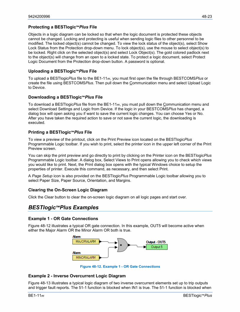
9424200996 48-23
BE1-11m BESTlogic™Plus
Protecting a BESTlogic™Plus File Objects in a logic diagram can be locked so that when the logic document is protected these objects cannot be changed. Locking and protecting is useful when sending logic files to other personnel to be modified. The locked object(s) cannot be changed. To view the lock status of the object(s), select Show Lock Status from the Protection drop-down menu. To lock object(s), use the mouse to select object(s) to be locked. Right click on the selected object(s) and select Lock Object(s). The gold colored padlock next to the object(s) will change from an open to a locked state. To protect a logic document, select Protect Logic Document from the Protection drop-down button. A password is optional.
Uploading a BESTlogic™Plus File To upload a BESTlogicPlus file to the BE1-11m, you must first open the file through BESTCOMSPlus or create the file using BESTCOMSPlus. Then pull down the Communication menu and select Upload Logic to Device.
Downloading a BESTlogic™Plus File To download a BESTlogicPlus file from the BE1-11m, you must pull down the Communication menu and select Download Settings and Logic from Device. If the logic in your BESTCOMSPlus has changed, a dialog box will open asking you if want to save the current logic changes. You can choose Yes or No. After you have taken the required action to save or not save the current logic, the downloading is executed.
Printing a BESTlogic™Plus File To view a preview of the printout, click on the Print Preview icon located on the BESTlogicPlus Programmable Logic toolbar. If you wish to print, select the printer icon in the upper left corner of the Print Preview screen.
You can skip the print preview and go directly to print by clicking on the Printer icon on the BESTlogicPlus Programmable Logic toolbar. A dialog box, Select Views to Print opens allowing you to check which views you would like to print. Next, the Print dialog box opens with the typical Windows choice to setup the properties of printer. Execute this command, as necessary, and then select Print.
A Page Setup icon is also provided on the BESTlogicPlus Programmable Logic toolbar allowing you to select Paper Size, Paper Source, Orientation, and Margins.
Clearing the On-Screen Logic Diagram Click the Clear button to clear the on-screen logic diagram on all logic pages and start over.
BESTlogic™Plus Examples
Example 1 - OR Gate Connections Figure 48-12 illustrates a typical OR gate connection. In this example, OUT5 will become active when either the Major Alarm OR the Minor Alarm OR both is true.
Figure 48-12. Example 1 - OR Gate Connections
Example 2 - Inverse Overcurrent Logic Diagram Figure 48-13 illustrates a typical logic diagram of two inverse overcurrent elements set up to trip outputs and trigger fault reports. The 51-1 function is blocked when IN1 is true. The 51-1 function is blocked when

48-24 9424200996
BESTlogic™Plus BE1-11m
IN2 is true. OUT1 is true when either the 51-1 or 51-2 is in a trip condition. OUT2 is true when either the 51-1 or 51-2 is in a pickup condition. The fault trigger logic block ensures that faults are recorded.
Figure 48-13. Example 2 - Inverse Overcurrent Logic Diagram

9424200996 49-1
BE1-11m Communication
49 • Communication This chapter describes the connections and settings for BE1-11m communication. In addition to standard USB, RS-485, and optional Ethernet communication, the BE1-11m is capable of sending email messages to a selected recipient with details about a user-selected condition. The configuration of email notifications is described later in this chapter.
Available ports for communicating with the BE1-11m include USB, RS-485, and Ethernet. DHCP (Dynamic Host Configuration Protocol) is enabled by default allowing the BE1-11m to send a broadcast request for configuration information. The DHCP server receives the request and responds with configuration information. Settings for Ethernet must be made through the front-panel USB port if not using DHCP.
Connections
The following paragraphs describe the communication connections for the BE1-11m. Refer to the Terminals and Connectors chapter for views of the communication ports.
USB Connection A front-panel B-type USB connector provides local communication with a PC operating BESTCOMSPlus® software.
Ethernet Connection BE1-11m protection systems with style numbers xxxxx1xxxxxxxx, xxxxx2xxxxxxxx, xxxxx3xxxxxxxx, xxxxx4xxxxxxxx, and xxxxx5xxxxxxxx have a rear-panel Ethernet port. For style number xxxxxxxxx0xxxx (Copper Ethernet Connection), a 10BASE-T/100BASE-TX port is an eight-pin RJ45 connector that connects to shielded, twisted-pair, Category 5 copper wire media. For style number xxxxxxxxx1xxxx (Fiber Optic Ethernet Connection), a 100BASE-FX ST type connector port uses a 1300 nanometer near-infrared (NIR) light wavelength transmitted via two strands of multimode optical fiber, one for receive (RX) and the other for transmit (TX).
RS-485 Connections RS-485 connections are made at a three-position terminal block connector that mates with a standard communication cable. A twisted-pair cable is recommended. Connector pin numbers, functions, names, and signal directions are shown in Table 49-1. An RS-485 connection diagram is provided in Figure 49-1.
Table 49-1. RS-485 Pinouts
Terminal Function Name Direction A Send/Receive A (SDA/RDA) In/Out B Send/Receive B (SDB/RDB) In/Out C Signal Ground (GND) n/a
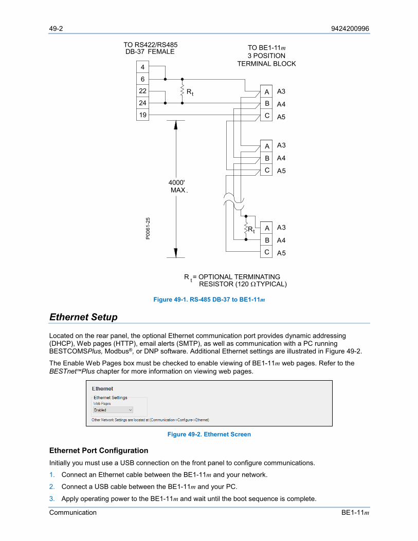
49-2 9424200996
Communication BE1-11m
Figure 49-1. RS-485 DB-37 to BE1-11m
Ethernet Setup
Located on the rear panel, the optional Ethernet communication port provides dynamic addressing (DHCP), Web pages (HTTP), email alerts (SMTP), as well as communication with a PC running BESTCOMSPlus, Modbus®, or DNP software. Additional Ethernet settings are illustrated in Figure 49-2.
The Enable Web Pages box must be checked to enable viewing of BE1-11m web pages. Refer to the BESTnet™Plus chapter for more information on viewing web pages.
Figure 49-2. Ethernet Screen
Ethernet Port Configuration Initially you must use a USB connection on the front panel to configure communications.
1. Connect an Ethernet cable between the BE1-11m and your network.
2. Connect a USB cable between the BE1-11m and your PC.
3. Apply operating power to the BE1-11m and wait until the boot sequence is complete.
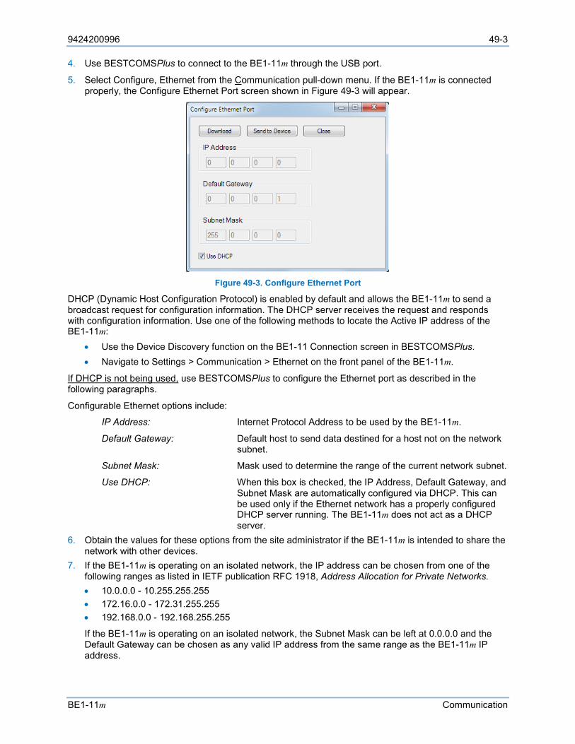
9424200996 49-3
BE1-11m Communication
4. Use BESTCOMSPlus to connect to the BE1-11m through the USB port.
5. Select Configure, Ethernet from the Communication pull-down menu. If the BE1-11m is connected properly, the Configure Ethernet Port screen shown in Figure 49-3 will appear.
Figure 49-3. Configure Ethernet Port
DHCP (Dynamic Host Configuration Protocol) is enabled by default and allows the BE1-11m to send a broadcast request for configuration information. The DHCP server receives the request and responds with configuration information. Use one of the following methods to locate the Active IP address of the BE1-11m:
• Use the Device Discovery function on the BE1-11 Connection screen in BESTCOMSPlus. • Navigate to Settings > Communication > Ethernet on the front panel of the BE1-11m.
If DHCP is not being used, use BESTCOMSPlus to configure the Ethernet port as described in the following paragraphs.
Configurable Ethernet options include:
IP Address: Internet Protocol Address to be used by the BE1-11m.
Default Gateway: Default host to send data destined for a host not on the network subnet.
Subnet Mask: Mask used to determine the range of the current network subnet.
Use DHCP: When this box is checked, the IP Address, Default Gateway, and Subnet Mask are automatically configured via DHCP. This can be used only if the Ethernet network has a properly configured DHCP server running. The BE1-11m does not act as a DHCP server.
6. Obtain the values for these options from the site administrator if the BE1-11m is intended to share the network with other devices.
7. If the BE1-11m is operating on an isolated network, the IP address can be chosen from one of the following ranges as listed in IETF publication RFC 1918, Address Allocation for Private Networks. • 10.0.0.0 - 10.255.255.255 • 172.16.0.0 - 172.31.255.255 • 192.168.0.0 - 192.168.255.255
If the BE1-11m is operating on an isolated network, the Subnet Mask can be left at 0.0.0.0 and the Default Gateway can be chosen as any valid IP address from the same range as the BE1-11m IP address.
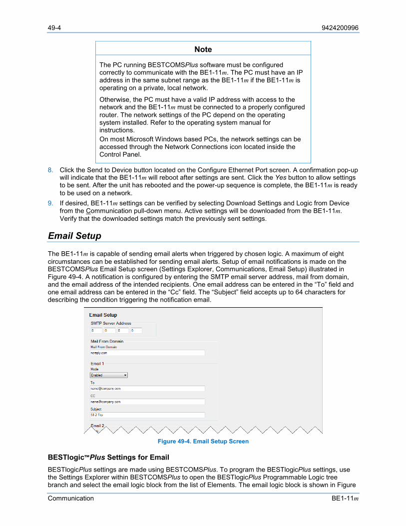
49-4 9424200996
Communication BE1-11m
Note
The PC running BESTCOMSPlus software must be configured correctly to communicate with the BE1-11m. The PC must have an IP address in the same subnet range as the BE1-11m if the BE1-11m is operating on a private, local network.
Otherwise, the PC must have a valid IP address with access to the network and the BE1-11m must be connected to a properly configured router. The network settings of the PC depend on the operating system installed. Refer to the operating system manual for instructions. On most Microsoft Windows based PCs, the network settings can be accessed through the Network Connections icon located inside the Control Panel.
8. Click the Send to Device button located on the Configure Ethernet Port screen. A confirmation pop-up will indicate that the BE1-11m will reboot after settings are sent. Click the Yes button to allow settings to be sent. After the unit has rebooted and the power-up sequence is complete, the BE1-11m is ready to be used on a network.
9. If desired, BE1-11m settings can be verified by selecting Download Settings and Logic from Device from the Communication pull-down menu. Active settings will be downloaded from the BE1-11m. Verify that the downloaded settings match the previously sent settings.
Email Setup
The BE1-11m is capable of sending email alerts when triggered by chosen logic. A maximum of eight circumstances can be established for sending email alerts. Setup of email notifications is made on the BESTCOMSPlus Email Setup screen (Settings Explorer, Communications, Email Setup) illustrated in Figure 49-4. A notification is configured by entering the SMTP email server address, mail from domain, and the email address of the intended recipients. One email address can be entered in the “To” field and one email address can be entered in the “Cc” field. The “Subject” field accepts up to 64 characters for describing the condition triggering the notification email.
Figure 49-4. Email Setup Screen
BESTlogic™Plus Settings for Email BESTlogicPlus settings are made using BESTCOMSPlus. To program the BESTlogicPlus settings, use the Settings Explorer within BESTCOMSPlus to open the BESTlogicPlus Programmable Logic tree branch and select the email logic block from the list of Elements. The email logic block is shown in Figure

9424200996 49-5
BE1-11m Communication
49-5. Use the drag-and-drop method to connect a variable or series of variables to the input. Refer to the BESTlogicPlus chapter for more information on setting BESTlogicPlus programmable logic.
Figure 49-5. Email Logic Block
Table 49-2 lists the BESTlogicPlus settings for email. Table 49-2. BESTlogicPlus Settings for Email
Name Function Purpose Default Trigger Input Triggers an email message. 0
RS-485 Setup
The RS-485 communication port is located on the rear panel and provides communication with a PC operating Modbus® or DNP software. The Baud Rate is the rate at which the BE1-11m will communicate. Bits Per Character can be 8 Bits or 7 Bits. Parity can be None, Odd, or Even. Stop Bits can be set to 1 or 2. The BESTCOMSPlus RS485 Setup screen is illustrated in Figure 49-6.
Figure 49-6. RS485 Setup Screen
DNP Setup
Settings for DNP are made by using the Settings Explorer to open the Communications, DNP tree branch. Settings can be made for DNP Analog Points Mapping, DNP Binary Points Mapping, DNP Analog Input Scaling, and DNP Analog Output Scaling. A list of DNP data objects accessible by a master station can be found in Basler Electric publication 9424200773, Distributed Network Protocol (DNP3) Instruction Manual.
DNP Settings The Communications, DNP, DNP Settings tree branch contains screens for miscellaneous DNP settings, unsolicited response support, and default variations.
Miscellaneous Settings
The Miscellaneous Settings screen (Figure 49-7) is used to configure the physical port, type of Ethernet endpoint, local Ethernet port number, client IP address, UDP endpoint, listening end point, link layer, time sync support, application layer, alarm mask, and DNP time in UTC.
Alarm Mask
The Alarm Mask setting allows active alarms that are not enabled in an alarm list to be annunciated in DNP.
DNP Time In UTC
The DNP Time in UTC setting, when enabled, sets the DNP time base to UTC.

49-6 9424200996
Communication BE1-11m
Note
Physical Port Selection (Ethernet or RS-485) is available only for Ethernet Protocol options 3 and 4 and only when RS-485 port protocol option is N (None). RTD module communication over RS-485 is not available when the physical port for DNP communication is RS-485.
Figure 49-7. DNP Settings, Miscellaneous Settings Screen
Unsolicited Response Support
The Unsolicited Response Support screen (Figure 49-8) configures BE1-11m unsolicited responses over a DNP network and selects the classes of events that trigger the responses.
Figure 49-8. DNP Settings, Unsolicited Response Support Screen
Default Variations
The Default Variations screen (Figure 49-9) is used to configure the binary and analog inputs and analog output status.

9424200996 49-7
BE1-11m Communication
Figure 49-9. Default Variations Screen
DNP Analog Points Mapping Analog points can be mapped to any of the available analog user map registers. Use the Settings Explorer in BESTCOMSPlus to open the Communications, DNP, DNP Analog Points Mapping tree branch as shown in Figure 49-10.
To map an Analog Point to the Analog User Map: 1. Select an analog point in the left-hand column. 2. Click on the Add >> button to add the analog point to the analog user map list. 3. Use the Move Up or Move Down buttons above the analog user map list to arrange the analog user
maps. 4. Click on the orange Save button to save the settings to BESTCOMSPlus memory. This button
changes to white indicating that the settings have been saved to BESTCOMSPlus memory.
Upload settings to the device by selecting Communication from the top pull-down menu and then Upload Settings to Device.
Figure 49-10. DNP Analog Points Mapping Screen
DNP Binary Points Mapping Binary points can be mapped to any of the available binary user map registers. Use the Settings Explorer in BESTCOMSPlus to open the Communications, DNP, DNP Binary Points Mapping tree branch as shown in Figure 49-11.
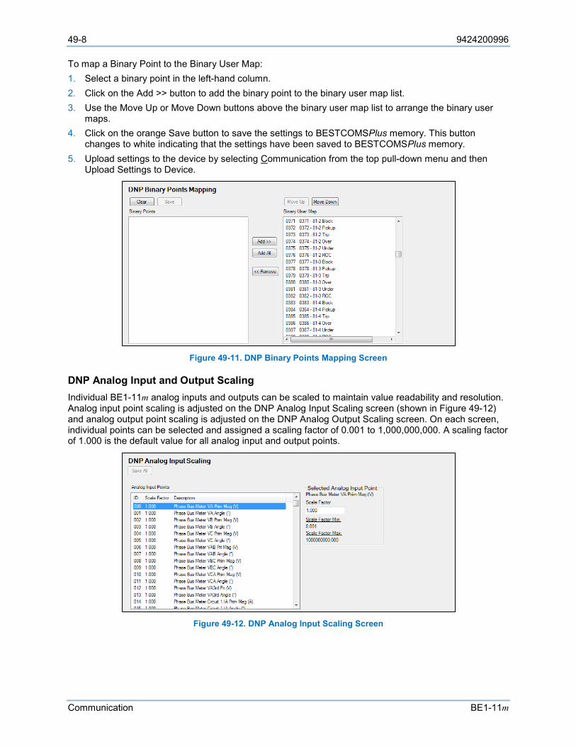
49-8 9424200996
Communication BE1-11m
To map a Binary Point to the Binary User Map: 1. Select a binary point in the left-hand column. 2. Click on the Add >> button to add the binary point to the binary user map list. 3. Use the Move Up or Move Down buttons above the binary user map list to arrange the binary user
maps. 4. Click on the orange Save button to save the settings to BESTCOMSPlus memory. This button
changes to white indicating that the settings have been saved to BESTCOMSPlus memory. 5. Upload settings to the device by selecting Communication from the top pull-down menu and then
Upload Settings to Device.
Figure 49-11. DNP Binary Points Mapping Screen
DNP Analog Input and Output Scaling Individual BE1-11m analog inputs and outputs can be scaled to maintain value readability and resolution. Analog input point scaling is adjusted on the DNP Analog Input Scaling screen (shown in Figure 49-12) and analog output point scaling is adjusted on the DNP Analog Output Scaling screen. On each screen, individual points can be selected and assigned a scaling factor of 0.001 to 1,000,000,000. A scaling factor of 1.000 is the default value for all analog input and output points.
Figure 49-12. DNP Analog Input Scaling Screen
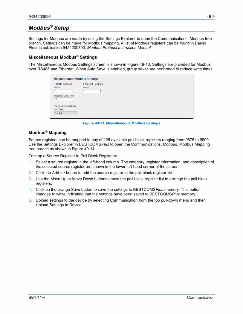
9424200996 49-9
BE1-11m Communication
Modbus® Setup
Settings for Modbus are made by using the Settings Explorer to open the Communications, Modbus tree branch. Settings can be made for Modbus mapping. A list of Modbus registers can be found in Basler Electric publication 9424200890, Modbus Protocol Instruction Manual.
Miscellaneous Modbus® Settings The Miscellaneous Modbus Settings screen is shown in Figure 49-13. Settings are provided for Modbus over RS485 and Ethernet. When Auto Save is enabled, group saves are performed to reduce write times.
Figure 49-13. Miscellaneous Modbus Settings
Modbus® Mapping Source registers can be mapped to any of 125 available poll block registers ranging from 9875 to 9999. Use the Settings Explorer in BESTCOMSPlus to open the Communications, Modbus, Modbus Mapping tree branch as shown in Figure 49-14.
To map a Source Register to Poll Block Registers: 1. Select a source register in the left-hand column. The category, register information, and description of
the selected source register are shown in the lower left-hand corner of the screen. 2. Click the Add >> button to add the source register to the poll block register list. 3. Use the Move Up or Move Down buttons above the poll block register list to arrange the poll block
registers. 4. Click on the orange Save button to save the settings to BESTCOMSPlus memory. This button
changes to white indicating that the settings have been saved to BESTCOMSPlus memory. 5. Upload settings to the device by selecting Communication from the top pull-down menu and then
Upload Settings to Device.

49-10 9424200996
Communication BE1-11m
Figure 49-14. Modbus Mapping Screen

9424200996 50-1
BE1-11m Security
50 • Security Multiple levels of BE1-11m security give personnel the level of access appropriate for the tasks they routinely perform while securing critical settings from unauthorized access.
Note
The BE1-11m does not support factory password reset in the field and will need to be returned to Basler Electric for service if all Admin passwords are lost or expired.
Access Levels
Passwords provide access security for six distinct functional access areas: Read, Control, Operator, Settings, Design, and Administrator (Admin). Each functional area can be assigned a unique password or one password can be assigned to multiple areas. Functional areas are not independent of one another. For example, an Admin password is used to access levels 6, 5, 4, 3, 2, and 1; a Design password is used to access levels 5, 4, 3, 2, and 1. Table 50-1 lists the access levels and descriptions.
Table 50-1. Access Levels and Descriptions
Access Level Description 6 - Admin (highest) Create, edit, and delete users and device security.
5 - Design Create or change programmable logic and reboot device.
4 - Settings Change all settings values. Logic equations cannot be created or changed.
3 - Operator Set date and time, reset accumulated metering values, and erase event data.
2 - Control Operate real-time controls.
1 - Read Read all system parameters. No changes or operation allowed.
0 - None All access denied.
Additional security is provided by controlling the functional areas that can be accessed through a particular communication port. For example, security can be configured so that front panel access is permitted at a lower access level than BESTCOMSPlus® or Modbus access.
The communication ports and password parameters act as a two-dimensional control to limit changes. The entered password must be correct and the command must be entered through a valid port. Only one port at a time can be in use with higher than Read access. For example, if a user gains Settings access at the front-panel USB port, users at other areas (rear Ethernet and front panel) will be able to gain Read access only after the user with Settings access at the front-panel USB port disconnects from the device. Read access is always allowed for all simultaneous users with access level 1 or higher.
If a port holding higher than Read access sees no activity for the duration of the Access Timeout setting, access privileges will automatically be lowered to Read access. This feature ensures that password protection cannot be accidentally left in a state where access privileges are enabled for one area and other areas locked out for an indefinite period.
Username Setup
1. Use the Settings Explorer in BESTCOMSPlus to select Username Setup under General Settings, Device Security Setup. The Login dialog box appears. See Figure 50-1. An administrator access level is required to set up usernames and passwords.
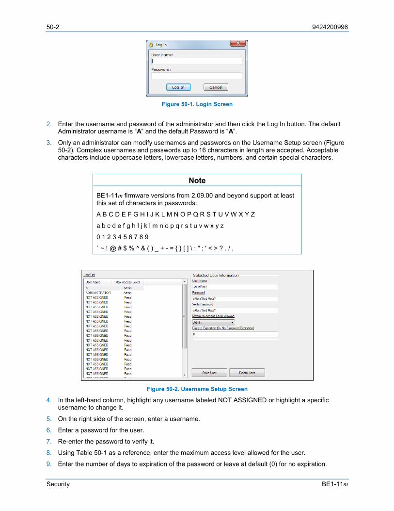
50-2 9424200996
Security BE1-11m
Figure 50-1. Login Screen
2. Enter the username and password of the administrator and then click the Log In button. The default Administrator username is “A” and the default Password is “A”.
3. Only an administrator can modify usernames and passwords on the Username Setup screen (Figure 50-2). Complex usernames and passwords up to 16 characters in length are accepted. Acceptable characters include uppercase letters, lowercase letters, numbers, and certain special characters.
Note
BE1-11m firmware versions from 2.09.00 and beyond support at least this set of characters in passwords:
A B C D E F G H I J K L M N O P Q R S T U V W X Y Z
a b c d e f g h I j k l m n o p q r s t u v w x y z
0 1 2 3 4 5 6 7 8 9
` ~ ! @ # $ % ^ & ( ) _ + - = [ ] \ : " ; ' < > ? . / ,
Figure 50-2. Username Setup Screen
4. In the left-hand column, highlight any username labeled NOT ASSIGNED or highlight a specific username to change it.
5. On the right side of the screen, enter a username.
6. Enter a password for the user.
7. Re-enter the password to verify it.
8. Using Table 50-1 as a reference, enter the maximum access level allowed for the user.
9. Enter the number of days to expiration of the password or leave at default (0) for no expiration.
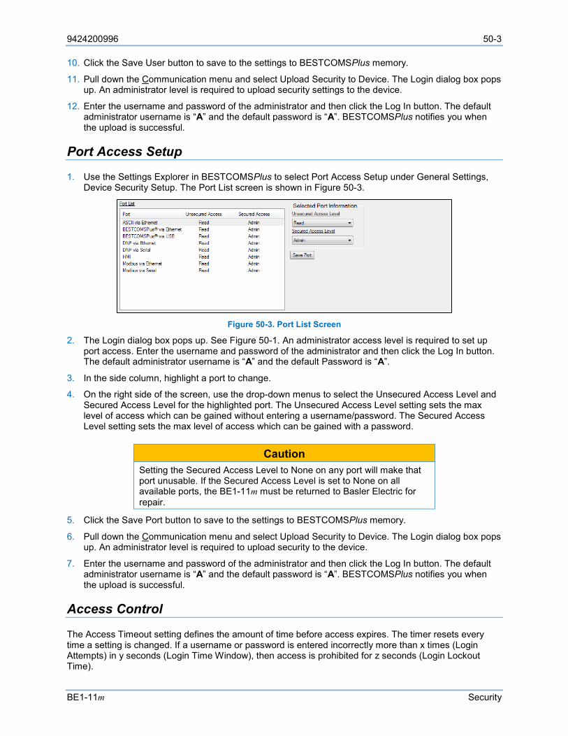
9424200996 50-3
BE1-11m Security
10. Click the Save User button to save to the settings to BESTCOMSPlus memory.
11. Pull down the Communication menu and select Upload Security to Device. The Login dialog box pops up. An administrator level is required to upload security settings to the device.
12. Enter the username and password of the administrator and then click the Log In button. The default administrator username is “A” and the default password is “A”. BESTCOMSPlus notifies you when the upload is successful.
Port Access Setup
1. Use the Settings Explorer in BESTCOMSPlus to select Port Access Setup under General Settings, Device Security Setup. The Port List screen is shown in Figure 50-3.
Figure 50-3. Port List Screen
2. The Login dialog box pops up. See Figure 50-1. An administrator access level is required to set up port access. Enter the username and password of the administrator and then click the Log In button. The default administrator username is “A” and the default Password is “A”.
3. In the side column, highlight a port to change.
4. On the right side of the screen, use the drop-down menus to select the Unsecured Access Level and Secured Access Level for the highlighted port. The Unsecured Access Level setting sets the max level of access which can be gained without entering a username/password. The Secured Access Level setting sets the max level of access which can be gained with a password.
Caution
Setting the Secured Access Level to None on any port will make that port unusable. If the Secured Access Level is set to None on all available ports, the BE1-11m must be returned to Basler Electric for repair.
5. Click the Save Port button to save to the settings to BESTCOMSPlus memory.
6. Pull down the Communication menu and select Upload Security to Device. The Login dialog box pops up. An administrator level is required to upload security to the device.
7. Enter the username and password of the administrator and then click the Log In button. The default administrator username is “A” and the default password is “A”. BESTCOMSPlus notifies you when the upload is successful.
Access Control
The Access Timeout setting defines the amount of time before access expires. The timer resets every time a setting is changed. If a username or password is entered incorrectly more than x times (Login Attempts) in y seconds (Login Time Window), then access is prohibited for z seconds (Login Lockout Time).
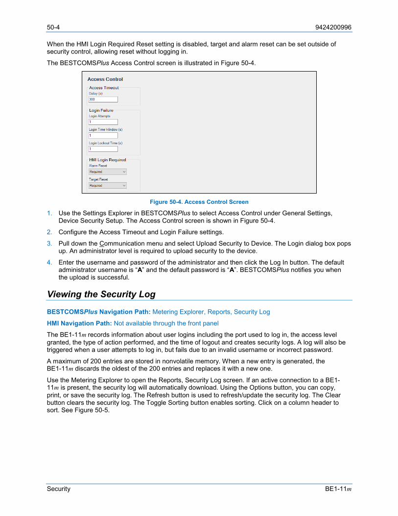
50-4 9424200996
Security BE1-11m
When the HMI Login Required Reset setting is disabled, target and alarm reset can be set outside of security control, allowing reset without logging in.
The BESTCOMSPlus Access Control screen is illustrated in Figure 50-4.
Figure 50-4. Access Control Screen
1. Use the Settings Explorer in BESTCOMSPlus to select Access Control under General Settings, Device Security Setup. The Access Control screen is shown in Figure 50-4.
2. Configure the Access Timeout and Login Failure settings.
3. Pull down the Communication menu and select Upload Security to Device. The Login dialog box pops up. An administrator level is required to upload security to the device.
4. Enter the username and password of the administrator and then click the Log In button. The default administrator username is “A” and the default password is “A”. BESTCOMSPlus notifies you when the upload is successful.
Viewing the Security Log
BESTCOMSPlus Navigation Path: Metering Explorer, Reports, Security Log
HMI Navigation Path: Not available through the front panel
The BE1-11m records information about user logins including the port used to log in, the access level granted, the type of action performed, and the time of logout and creates security logs. A log will also be triggered when a user attempts to log in, but fails due to an invalid username or incorrect password.
A maximum of 200 entries are stored in nonvolatile memory. When a new entry is generated, the BE1-11m discards the oldest of the 200 entries and replaces it with a new one.
Use the Metering Explorer to open the Reports, Security Log screen. If an active connection to a BE1-11m is present, the security log will automatically download. Using the Options button, you can copy, print, or save the security log. The Refresh button is used to refresh/update the security log. The Clear button clears the security log. The Toggle Sorting button enables sorting. Click on a column header to sort. See Figure 50-5.

9424200996 50-5
BE1-11m Security
Figure 50-5. Security Log
Authenticity and Encryption
The BE1-11m supports authentication and encryption of communications with BESTCOMSPlus. This is done using the Transport Layer Security protocol, version 1.2 (TLS 1.2). To enable this mode, an X.509 certificate and private key must be uploaded to the BE1-11m.
In TLS 1.2, a certificate is used to verify the authenticity of the server (BE1-11m). The supported certificate formats are Standard PEM, DER/Binary, and PFX (PKCS#12). The BE1-11m supports RSA encryption up to 8192 bit keys. The recommended key length is 2048 as longer keys will slow the initial connection. DER and PEM formats commonly have the private key stored in a separate file. If this is the case, you will be asked for an additional file containing the key. If a password is required for the key, you will also need to enter it into the form. It is recommended that certificates be uploaded over a trusted connection or through the USB port.
Generate a Certificate BESTCOMSPlus is used to generate a self-signed X.509 certificate for use in identifying a connected device. In order for the certificate to work, the common name must match the domain name or the IP address of the device. Alternate names can be used if multiple domain names match the device. The valid dates specify how long the certificate may be used. A new certificate should be issued after one expires.
To generate a certificate, click on the Tools drop-down menu in BESTCOMSPlus and select Generate Certificate. Fill in all applicable fields. A password is optional. Click Save to generate a .pfx file which is the certificate and the private key required to upload to the BE1-11m.
Self-signed certificates can be less secure than using a Certificate Authority to sign the certificate for the device. It will allow encryption from end to end. Use caution when choosing this method. Distribution of the generated file compromises security.
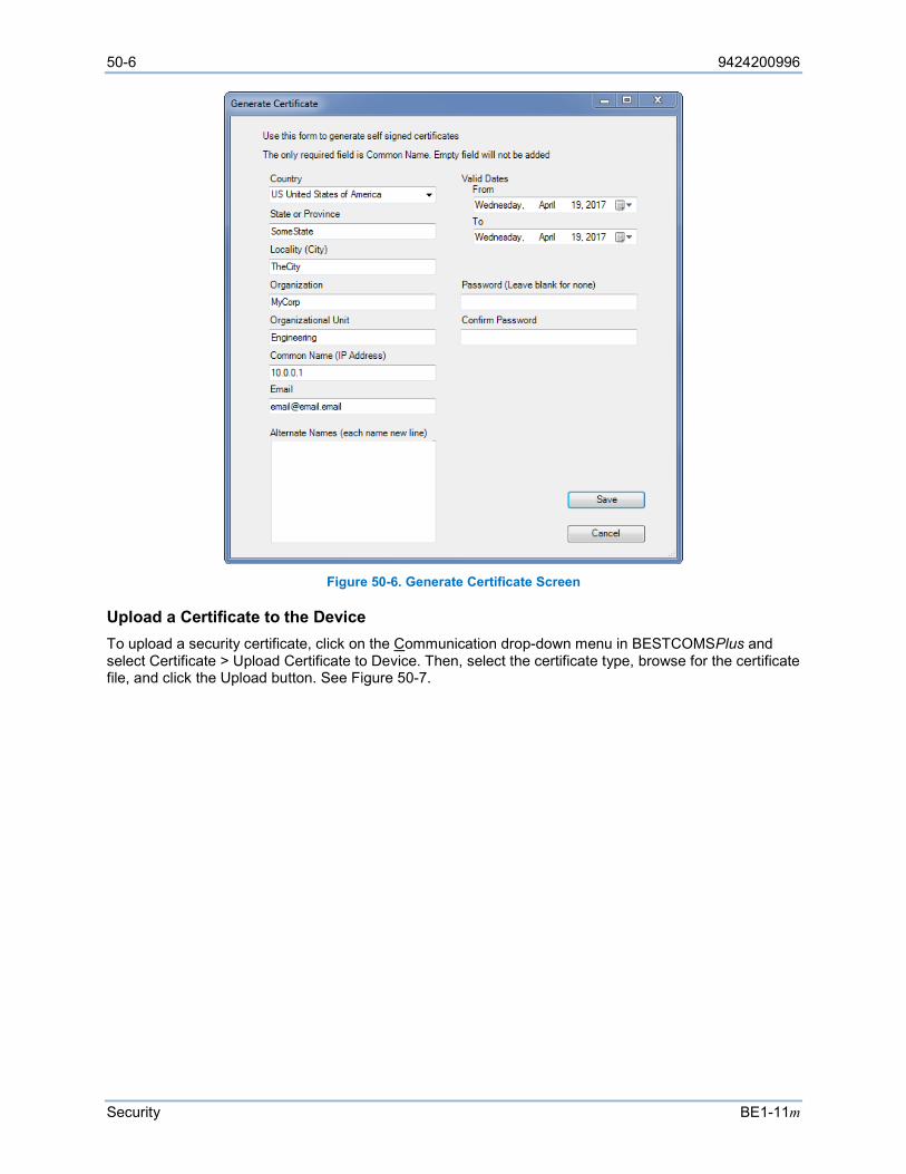
50-6 9424200996
Security BE1-11m
Figure 50-6. Generate Certificate Screen
Upload a Certificate to the Device To upload a security certificate, click on the Communication drop-down menu in BESTCOMSPlus and select Certificate > Upload Certificate to Device. Then, select the certificate type, browse for the certificate file, and click the Upload button. See Figure 50-7.
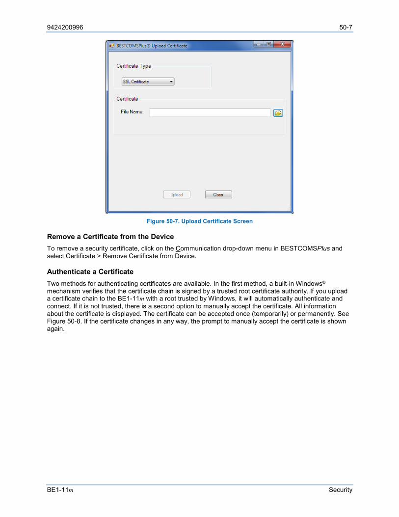
9424200996 50-7
BE1-11m Security
Figure 50-7. Upload Certificate Screen
Remove a Certificate from the Device To remove a security certificate, click on the Communication drop-down menu in BESTCOMSPlus and select Certificate > Remove Certificate from Device.
Authenticate a Certificate Two methods for authenticating certificates are available. In the first method, a built-in Windows® mechanism verifies that the certificate chain is signed by a trusted root certificate authority. If you upload a certificate chain to the BE1-11m with a root trusted by Windows, it will automatically authenticate and connect. If it is not trusted, there is a second option to manually accept the certificate. All information about the certificate is displayed. The certificate can be accepted once (temporarily) or permanently. See Figure 50-8. If the certificate changes in any way, the prompt to manually accept the certificate is shown again.
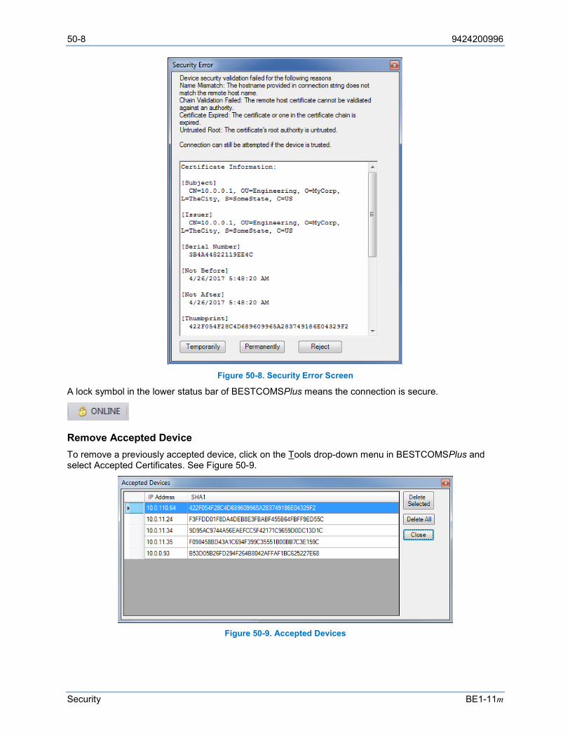
50-8 9424200996
Security BE1-11m
Figure 50-8. Security Error Screen
A lock symbol in the lower status bar of BESTCOMSPlus means the connection is secure.
Remove Accepted Device To remove a previously accepted device, click on the Tools drop-down menu in BESTCOMSPlus and select Accepted Certificates. See Figure 50-9.
Figure 50-9. Accepted Devices
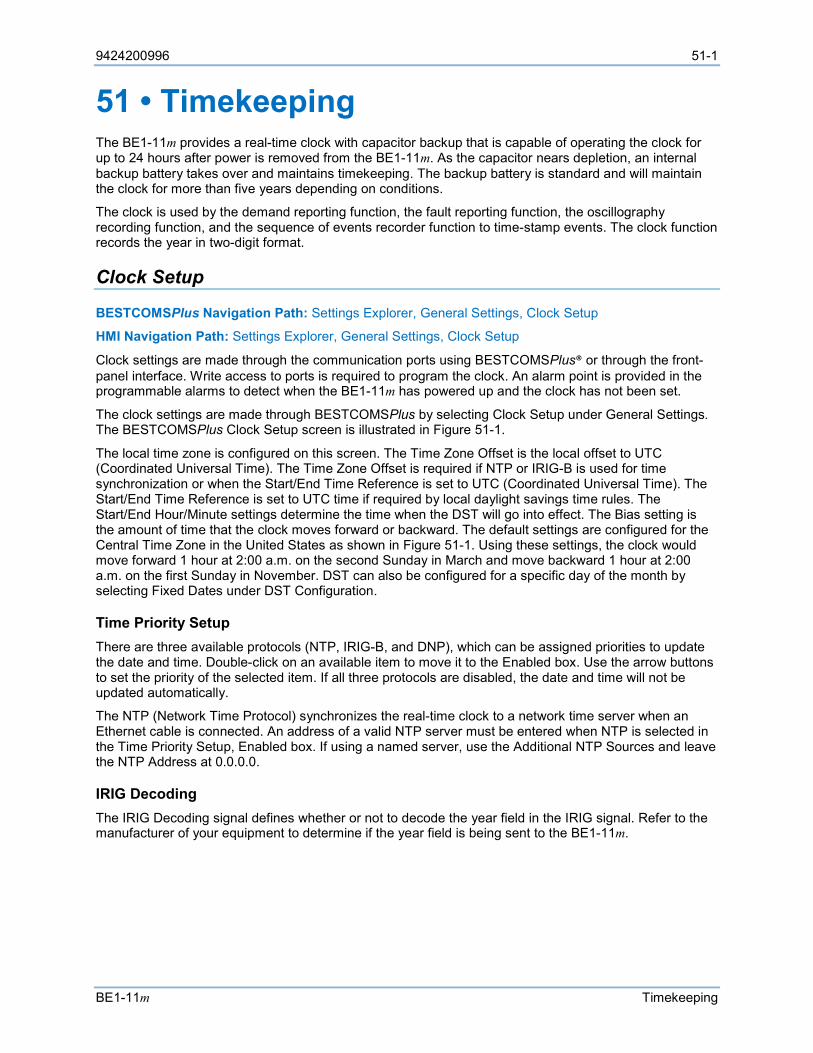
9424200996 51-1
BE1-11m Timekeeping
51 • Timekeeping The BE1-11m provides a real-time clock with capacitor backup that is capable of operating the clock for up to 24 hours after power is removed from the BE1-11m. As the capacitor nears depletion, an internal backup battery takes over and maintains timekeeping. The backup battery is standard and will maintain the clock for more than five years depending on conditions.
The clock is used by the demand reporting function, the fault reporting function, the oscillography recording function, and the sequence of events recorder function to time-stamp events. The clock function records the year in two-digit format.
Clock Setup
BESTCOMSPlus Navigation Path: Settings Explorer, General Settings, Clock Setup
HMI Navigation Path: Settings Explorer, General Settings, Clock Setup
Clock settings are made through the communication ports using BESTCOMSPlus® or through the front-panel interface. Write access to ports is required to program the clock. An alarm point is provided in the programmable alarms to detect when the BE1-11m has powered up and the clock has not been set.
The clock settings are made through BESTCOMSPlus by selecting Clock Setup under General Settings. The BESTCOMSPlus Clock Setup screen is illustrated in Figure 51-1.
The local time zone is configured on this screen. The Time Zone Offset is the local offset to UTC (Coordinated Universal Time). The Time Zone Offset is required if NTP or IRIG-B is used for time synchronization or when the Start/End Time Reference is set to UTC (Coordinated Universal Time). The Start/End Time Reference is set to UTC time if required by local daylight savings time rules. The Start/End Hour/Minute settings determine the time when the DST will go into effect. The Bias setting is the amount of time that the clock moves forward or backward. The default settings are configured for the Central Time Zone in the United States as shown in Figure 51-1. Using these settings, the clock would move forward 1 hour at 2:00 a.m. on the second Sunday in March and move backward 1 hour at 2:00 a.m. on the first Sunday in November. DST can also be configured for a specific day of the month by selecting Fixed Dates under DST Configuration.
Time Priority Setup There are three available protocols (NTP, IRIG-B, and DNP), which can be assigned priorities to update the date and time. Double-click on an available item to move it to the Enabled box. Use the arrow buttons to set the priority of the selected item. If all three protocols are disabled, the date and time will not be updated automatically.
The NTP (Network Time Protocol) synchronizes the real-time clock to a network time server when an Ethernet cable is connected. An address of a valid NTP server must be entered when NTP is selected in the Time Priority Setup, Enabled box. If using a named server, use the Additional NTP Sources and leave the NTP Address at 0.0.0.0.
IRIG Decoding The IRIG Decoding signal defines whether or not to decode the year field in the IRIG signal. Refer to the manufacturer of your equipment to determine if the year field is being sent to the BE1-11m.
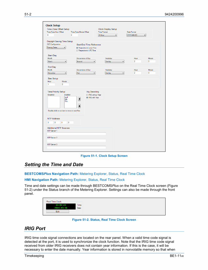
51-2 9424200996
Timekeeping BE1-11m
Figure 51-1. Clock Setup Screen
Setting the Time and Date
BESTCOMSPlus Navigation Path: Metering Explorer, Status, Real Time Clock
HMI Navigation Path: Metering Explorer, Status, Real Time Clock
Time and date settings can be made through BESTCOMSPlus on the Real Time Clock screen (Figure 51-2) under the Status branch of the Metering Explorer. Settings can also be made through the front panel.
Figure 51-2. Status, Real Time Clock Screen
IRIG Port
IRIG time code signal connections are located on the rear panel. When a valid time code signal is detected at the port, it is used to synchronize the clock function. Note that the IRIG time code signal received from older IRIG receivers does not contain year information. If this is the case, it will be necessary to enter the date manually. Year information is stored in nonvolatile memory so that when
9424200996 51-3
BE1-11m Timekeeping
operating power is restored after an outage and the clock is re-synchronized the current year is restored. When the clock rolls over to a new year, the year is automatically incremented in nonvolatile memory. An alarm bit is included in the programmable alarm function for loss of IRIG signal. The alarm point monitors for IRIG signal loss once a valid signal is detected at the IRIG port.
Connections IRIG connections are located on a terminal block shared with the RS-485 and input power terminals. Terminal designations and functions are shown in Table 51-1.
Table 51-1. IRIG Terminal Assignments
Terminal Function A1 (+) Signal
A2 (–) Reference
Specifications Interface supports IRIG Standard 200-04, Format B006. Input Signal ............................................................... Demodulated dc. Level-shifted, digital signal Input Voltage Range ................................................. ±10 Vdc maximum Input Resistance ....................................................... Nonlinear, approximately 4 kΩ at 3.5 Vdc, approximately 3 kΩ at 20 Vdc
Logic Voltage Threshold High ........................................................................... 3.5 Vdc minimum Low ............................................................................ 0.5 Vdc maximum
Real-Time Clock Specifications
Resolution ................................................................. 1 s Accuracy.................................................................... ±1.73 s/d at 77°F (25°C)
Clock Holdup Capacitor Holdup Time ............................................. Up to 24 hours depending on conditions Battery Holdup Time ................................................. Greater than 5 years depending on conditions Battery Type .............................................................. BR2032 or CR2032, coin-type, 3 Vdc, 195 mAh Basler Electric P/N 38526
Backup Battery for the Real-Time Clock
The backup battery for the real time clock is a standard feature of the BE1-11m. A battery is used to maintain clock function during loss of power supply voltage. In mobile substation and line-powered applications, the voltage that supplies the BE1-11m power supply may be disconnected for extended periods (weeks, months) between uses. Without battery backup for the real time clock, clock functions will cease if battery input power is removed.
The backup battery has a life expectancy of greater than five years depending on conditions. After this time, you should contact Basler Electric to order a new battery, Basler Electric P/N 38526.

51-4 9424200996
Timekeeping BE1-11m
Caution
Replacement of the backup battery for the real-time clock should be performed only by qualified personnel. Do not short-circuit the battery, reverse battery polarity, or attempt to recharge the battery. Observe polarity markings on the battery socket when inserting a new battery. The battery polarity must be correct in order to provide backup for the real-time clock.
Note Failure to replace the battery with Basler Electric P/N 38526 may void the warranty.
Battery Replacement Procedure Battery access is located behind the front cover of the BE1-11m on the front-panel circuit board. See Figure 51-3.
Step 1: Remove the BE1-11m from service.
Step 2: Use a 7/64” hex tool to remove the front cover screws and remove the cover.
Step 3: Locate the battery holder attached to the rear of the cover. Remove the old battery. Consult your local ordinance for proper battery disposal.
Step 4: Insert the new battery so that the polarity markings on the battery match the polarity markings on the battery holder and circuit board.
Step 5: Reattach the front cover by pressing equally and firmly on both sides as shown in Figure 51-4. Using a 7/64” hex tool, tighten the front cover screws to 10 in-lbs (1.12 N•m).
Step 6: Return the BE1-11m to service.
9424200996 51-5
BE1-11m Timekeeping
Figure 51-3. Front-Panel Circuit Board, Backup Battery Location
51-6 9424200996
Timekeeping BE1-11m
Figure 51-4. Re-Attaching the Front Cover
P0072-79
(Press equally and firmly.)
USB
BE1-11ProtectionSystem
Relay Minor MajorPower Trouble Alarm Alarm Trip
Edit Reset
Indicator 1
Indicator 2
Indicator 3
Indicator 4
Indicator 5
Indicator 6
Indicator 7
SelectControlSwitch
OperateControlSwitch
BE1-11
9424200996 52-1
BE1-11m Device Information
52 • Device Information BE1-11m identification labels, firmware version, serial number, and style number are found on the Device Info screen in BESTCOMSPlus®.
Style Number
The model number, together with the style number, describes the options included in a specific device and appears on labels located on the front panel and inside the case.
The style number of the BE1-11m is displayed on the BESTCOMSPlus Style Number screen after downloading settings from the device. When configuring BE1-11m settings off-line, the style number for the unit to be configured can be entered into BESTCOMSPlus to enable configuration of the required settings. The BESTCOMSPlus Style Number screen is illustrated in Figure 52-1.
Figure 52-1. Style Number Screen
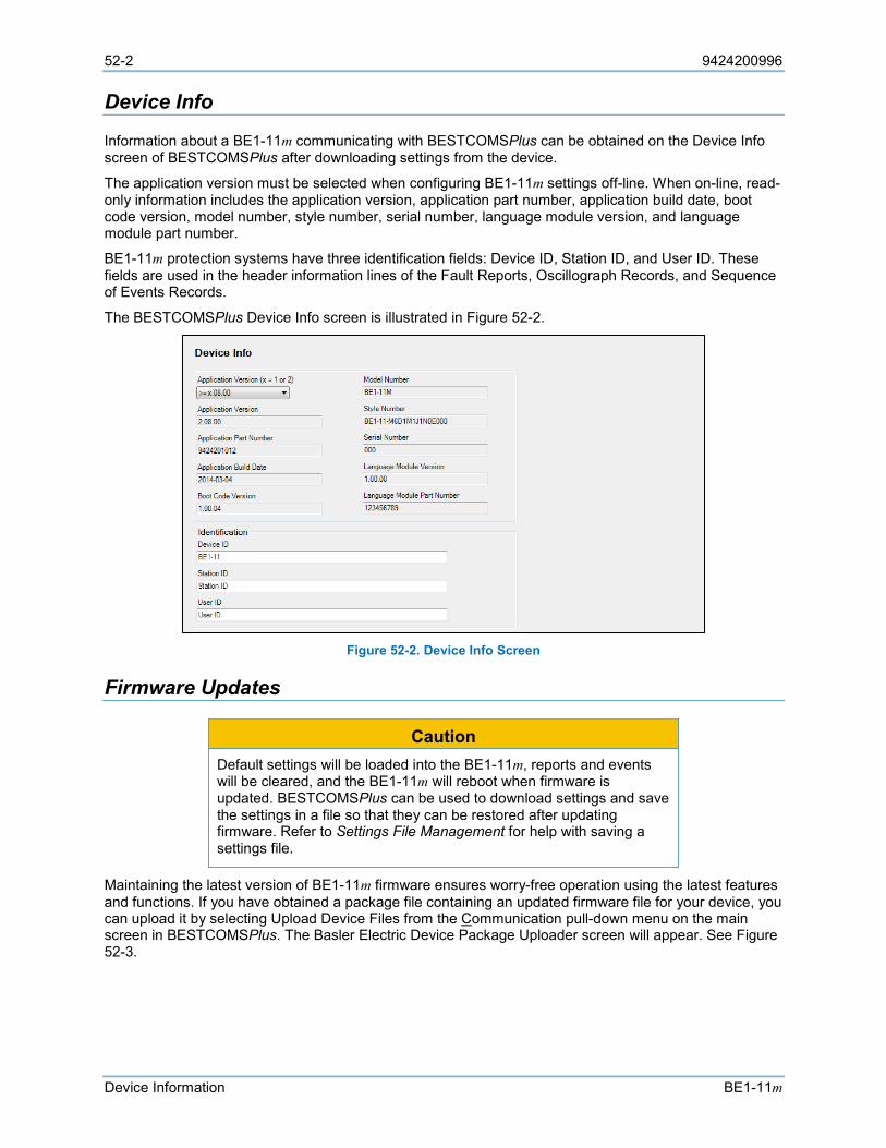
52-2 9424200996
Device Information BE1-11m
Device Info
Information about a BE1-11m communicating with BESTCOMSPlus can be obtained on the Device Info screen of BESTCOMSPlus after downloading settings from the device.
The application version must be selected when configuring BE1-11m settings off-line. When on-line, read-only information includes the application version, application part number, application build date, boot code version, model number, style number, serial number, language module version, and language module part number.
BE1-11m protection systems have three identification fields: Device ID, Station ID, and User ID. These fields are used in the header information lines of the Fault Reports, Oscillograph Records, and Sequence of Events Records.
The BESTCOMSPlus Device Info screen is illustrated in Figure 52-2.
Figure 52-2. Device Info Screen
Firmware Updates
Caution Default settings will be loaded into the BE1-11m, reports and events will be cleared, and the BE1-11m will reboot when firmware is updated. BESTCOMSPlus can be used to download settings and save the settings in a file so that they can be restored after updating firmware. Refer to Settings File Management for help with saving a settings file.
Maintaining the latest version of BE1-11m firmware ensures worry-free operation using the latest features and functions. If you have obtained a package file containing an updated firmware file for your device, you can upload it by selecting Upload Device Files from the Communication pull-down menu on the main screen in BESTCOMSPlus. The Basler Electric Device Package Uploader screen will appear. See Figure 52-3.
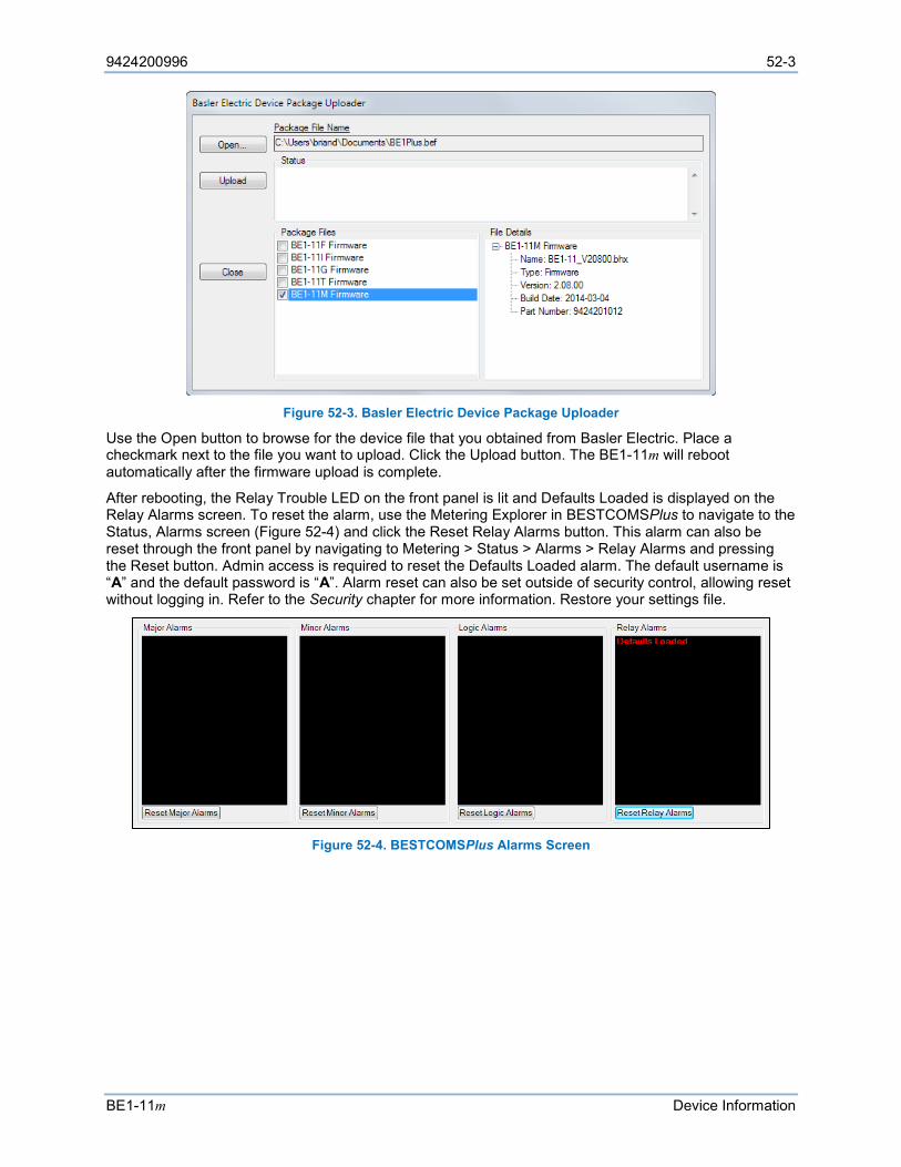
9424200996 52-3
BE1-11m Device Information
Figure 52-3. Basler Electric Device Package Uploader
Use the Open button to browse for the device file that you obtained from Basler Electric. Place a checkmark next to the file you want to upload. Click the Upload button. The BE1-11m will reboot automatically after the firmware upload is complete.
After rebooting, the Relay Trouble LED on the front panel is lit and Defaults Loaded is displayed on the Relay Alarms screen. To reset the alarm, use the Metering Explorer in BESTCOMSPlus to navigate to the Status, Alarms screen (Figure 52-4) and click the Reset Relay Alarms button. This alarm can also be reset through the front panel by navigating to Metering > Status > Alarms > Relay Alarms and pressing the Reset button. Admin access is required to reset the Defaults Loaded alarm. The default username is “A” and the default password is “A”. Alarm reset can also be set outside of security control, allowing reset without logging in. Refer to the Security chapter for more information. Restore your settings file.
Figure 52-4. BESTCOMSPlus Alarms Screen

52-4 9424200996
Device Information BE1-11m
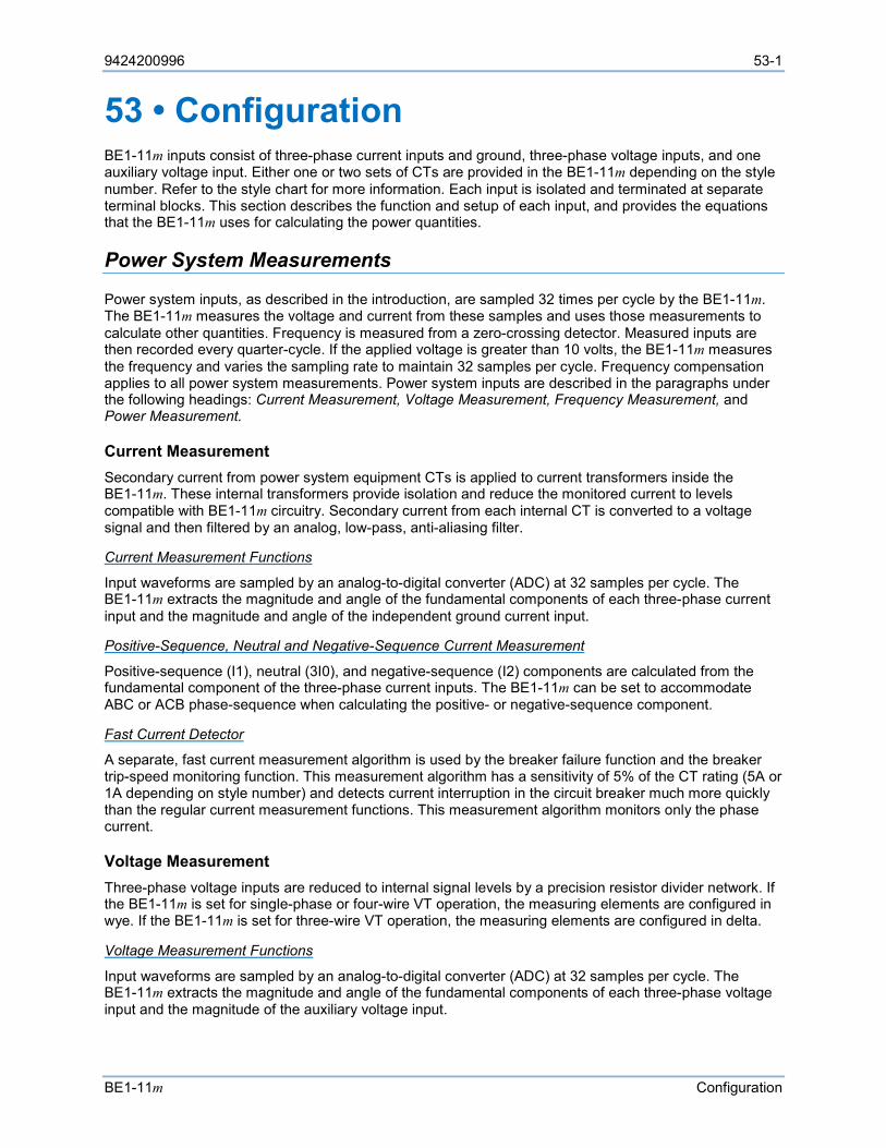
9424200996 53-1
BE1-11m Configuration
53 • Configuration BE1-11m inputs consist of three-phase current inputs and ground, three-phase voltage inputs, and one auxiliary voltage input. Either one or two sets of CTs are provided in the BE1-11m depending on the style number. Refer to the style chart for more information. Each input is isolated and terminated at separate terminal blocks. This section describes the function and setup of each input, and provides the equations that the BE1-11m uses for calculating the power quantities.
Power System Measurements
Power system inputs, as described in the introduction, are sampled 32 times per cycle by the BE1-11m. The BE1-11m measures the voltage and current from these samples and uses those measurements to calculate other quantities. Frequency is measured from a zero-crossing detector. Measured inputs are then recorded every quarter-cycle. If the applied voltage is greater than 10 volts, the BE1-11m measures the frequency and varies the sampling rate to maintain 32 samples per cycle. Frequency compensation applies to all power system measurements. Power system inputs are described in the paragraphs under the following headings: Current Measurement, Voltage Measurement, Frequency Measurement, and Power Measurement.
Current Measurement Secondary current from power system equipment CTs is applied to current transformers inside the BE1-11m. These internal transformers provide isolation and reduce the monitored current to levels compatible with BE1-11m circuitry. Secondary current from each internal CT is converted to a voltage signal and then filtered by an analog, low-pass, anti-aliasing filter.
Current Measurement Functions
Input waveforms are sampled by an analog-to-digital converter (ADC) at 32 samples per cycle. The BE1-11m extracts the magnitude and angle of the fundamental components of each three-phase current input and the magnitude and angle of the independent ground current input.
Positive-Sequence, Neutral and Negative-Sequence Current Measurement
Positive-sequence (I1), neutral (3I0), and negative-sequence (I2) components are calculated from the fundamental component of the three-phase current inputs. The BE1-11m can be set to accommodate ABC or ACB phase-sequence when calculating the positive- or negative-sequence component.
Fast Current Detector
A separate, fast current measurement algorithm is used by the breaker failure function and the breaker trip-speed monitoring function. This measurement algorithm has a sensitivity of 5% of the CT rating (5A or 1A depending on style number) and detects current interruption in the circuit breaker much more quickly than the regular current measurement functions. This measurement algorithm monitors only the phase current.
Voltage Measurement Three-phase voltage inputs are reduced to internal signal levels by a precision resistor divider network. If the BE1-11m is set for single-phase or four-wire VT operation, the measuring elements are configured in wye. If the BE1-11m is set for three-wire VT operation, the measuring elements are configured in delta.
Voltage Measurement Functions
Input waveforms are sampled by an analog-to-digital converter (ADC) at 32 samples per cycle. The BE1-11m extracts the magnitude and angle of the fundamental components of each three-phase voltage input and the magnitude of the auxiliary voltage input.

53-2 9424200996
Configuration BE1-11m
VT Connections
When four-wire VT connections are used, the BE1-11m measures the three-phase to neutral voltages and calculates the phase voltage quantities. Overvoltage and undervoltage functions (27/59) can be set to operate on either the phase-to-neutral (PN) or phase-to-phase (PP) quantities. Three-wire VT connections limit 27/59 operation to PP quantities. When single-phase VT connections are used, the 27/59 elements operate as appropriate for the single-phase voltage applied.
Neutral-Shift Voltage
When four-wire VT connections are used, the BE1-11m calculates the neutral-shift voltage (3V0). Neutral-shift voltage measurement is not available when single-phase or three-wire VT connections are used. The 59X can be set to monitor the neutral-shift voltage.
Negative-Sequence Voltage
Negative-sequence voltage (V2) is calculated from the fundamental component of the three-phase voltage inputs. It is available only on three-phase, three-wire, or three-phase, four-wire systems. V2 is calibrated to the phase-to-neutral base. Negative-sequence measurements accommodate either an ABC or ACB phase-sequence.
Positive-Sequence Voltage
Positive-sequence voltage (V1) is calculated from the fundamental component of the three-phase voltage inputs. It is available only on three-phase, three-wire, or three-phase, four-wire systems. V1 is calibrated to the phase-to-neutral base. Positive-sequence measurements can accommodate either ABC or ACB phase-sequence.
Frequency Measurement Power system frequency is monitored on the A-phase voltage input or the AB voltage input when in three-wire mode. When the applied voltage is greater than 10 volts, the BE1-11m measures the frequency. The measured frequency is used by the 81 function and applies to all measurements and calculations.
Frequency Compensation
After measuring the frequency, the BE1-11m varies the sampling rate to maintain 32 samples per cycle over a frequency of 10 to 125 hertz. If the voltage is too low for accurate frequency measurement or if the measured frequency is out of range, the analog-to-digital converter (ADC) defaults to a sampling rate appropriate for the BE1-11m nominal frequency setting. The sampling rate is adjusted every 50 milliseconds (3 cycles).
Nominal Frequency
Nominal frequency (Fnom) can be set for 25-, 50-, 60-, or 100-hertz power systems. When the voltage and current are too low for reliable frequency measurement, the ADC sample rate defaults to operation at the nominal frequency setting.
Power Measurement The measured fundamental component of current and voltage as described previously in this chapter is used to calculate the power per the equations following:
9424200996 53-3
BE1-11m Configuration
For Sensing Type: Four-wire
)cos(IVWatts AAANA φ= )cos(IVWatts BBBNB φ= )cos(IVWatts CCCNC φ=
CBA3 WWWWatts ++=φ
)sin(IVVars AAANA φ= )sin(IVVars BBBNB φ= )sin(IVVars CCCNCA φ=
CBA3 VarsVarsVarsVars ++=φ
where: XPNP IV ∠−∠=φ
For Sensing Type: Three-wire
In three-wire sensing mode, the equivalent LN voltages are determined from the LL voltages assuming 3V0 = 0V. This allows per-phase watts and vars to be determined and provides improved accuracy over a two-element method when neutral current is present.
)VV(3/1V CAABAN −⋅= )VV(3/1V ABBCBN −⋅= )VV(3/1V BCCACN −⋅=
Using the computed PN voltages, watts and vars are then computed using the equations listed under four-wire sensing type, above.
For Single Phase Sensing Types: AN, BN, CN, AB, BC, CA
In single-phase sensing mode, the unknown PN voltages are calculated. Assuming a balanced three-phase voltage is applied, the unknown PN voltages can be determined by scaling and rotating the measured voltage as follows:
ABC Rotation
AN Sensing: °−∠⋅= 1201VV ANBN °∠⋅= 1201VV ANCN
BN Sensing: °∠⋅= 1201VV BNAN °−∠⋅= 1201VV BNCN
CN Sensing: °−∠⋅= 1201VV CNAN °∠⋅= 1201VV CNBN
AB Sensing: °−∠⋅= 301VV ABAN31 °−∠⋅= 1501VV ABBN
31 °∠⋅= 901VV ABCN
31
BC Sensing: °∠⋅= 901VV ABAN31 °−∠⋅= 301VV ABBN
31 °−∠⋅= 1501VV ABCN
31
CA Sensing: °−∠⋅= 1501VV ABAN31 °∠⋅= 901VV ABBN
31 °−∠⋅= 301VV ABCN
31
ACB Rotation
AN Sensing: °∠⋅= 1201VV ANBN °−∠⋅= 1201VV ANCN
BN Sensing: °−∠⋅= 1201VV BNAN °∠⋅= 1201VV BNCN
CN Sensing: °∠⋅= 1201VV CNAN °−∠⋅= 1201VV CNBN
AB Sensing: °∠⋅= 301VV ABAN31 °∠⋅= 1501VV ABBN
31 °−∠⋅= 901VV ABCN
31
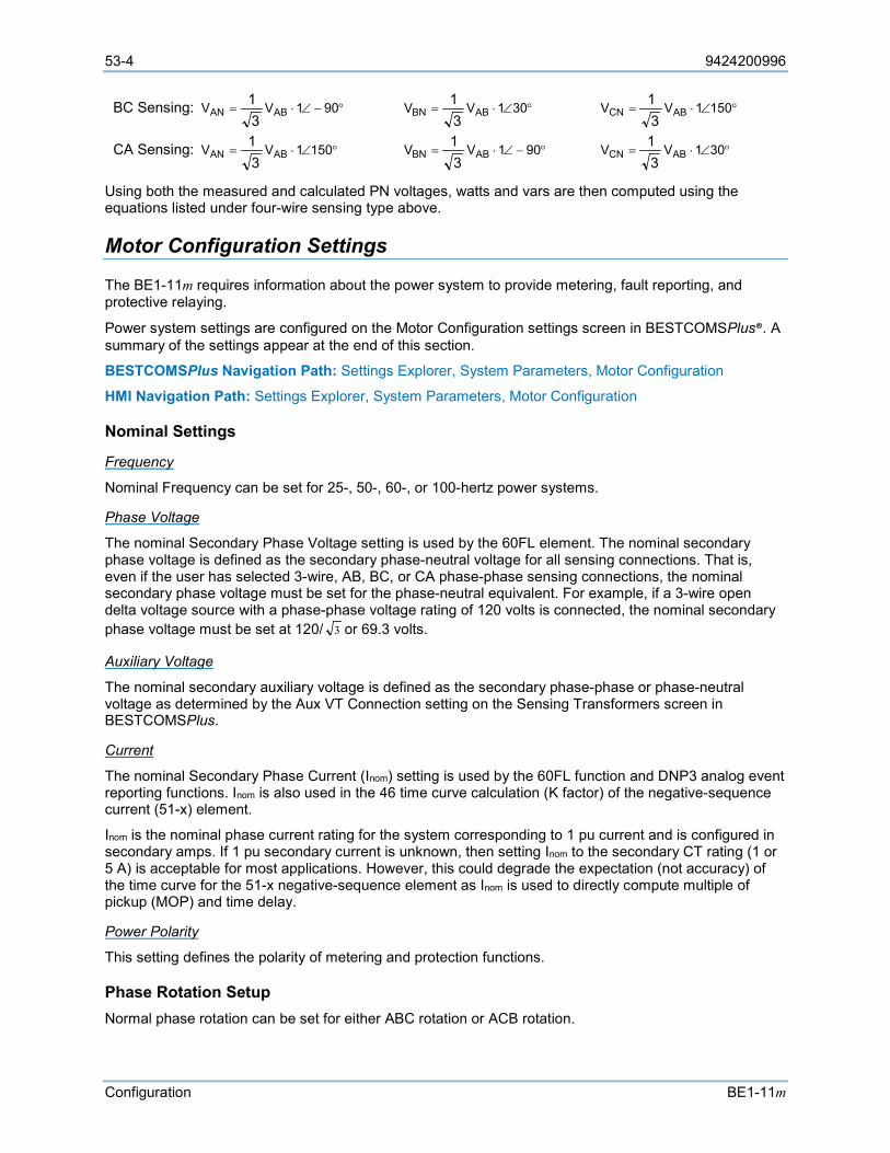
53-4 9424200996
Configuration BE1-11m
BC Sensing: °−∠⋅= 901VV ABAN31 °∠⋅= 301VV ABBN
31 °∠⋅= 1501VV ABCN
31
CA Sensing: °∠⋅= 1501VV ABAN31 °−∠⋅= 901VV ABBN
31 °∠⋅= 301VV ABCN
31
Using both the measured and calculated PN voltages, watts and vars are then computed using the equations listed under four-wire sensing type above.
Motor Configuration Settings
The BE1-11m requires information about the power system to provide metering, fault reporting, and protective relaying.
Power system settings are configured on the Motor Configuration settings screen in BESTCOMSPlus®. A summary of the settings appear at the end of this section.
BESTCOMSPlus Navigation Path: Settings Explorer, System Parameters, Motor Configuration
HMI Navigation Path: Settings Explorer, System Parameters, Motor Configuration
Nominal Settings
Frequency
Nominal Frequency can be set for 25-, 50-, 60-, or 100-hertz power systems.
Phase Voltage
The nominal Secondary Phase Voltage setting is used by the 60FL element. The nominal secondary phase voltage is defined as the secondary phase-neutral voltage for all sensing connections. That is, even if the user has selected 3-wire, AB, BC, or CA phase-phase sensing connections, the nominal secondary phase voltage must be set for the phase-neutral equivalent. For example, if a 3-wire open delta voltage source with a phase-phase voltage rating of 120 volts is connected, the nominal secondary phase voltage must be set at 120/ 3 or 69.3 volts.
Auxiliary Voltage
The nominal secondary auxiliary voltage is defined as the secondary phase-phase or phase-neutral voltage as determined by the Aux VT Connection setting on the Sensing Transformers screen in BESTCOMSPlus.
Current
The nominal Secondary Phase Current (Inom) setting is used by the 60FL function and DNP3 analog event reporting functions. Inom is also used in the 46 time curve calculation (K factor) of the negative-sequence current (51-x) element.
Inom is the nominal phase current rating for the system corresponding to 1 pu current and is configured in secondary amps. If 1 pu secondary current is unknown, then setting Inom to the secondary CT rating (1 or 5 A) is acceptable for most applications. However, this could degrade the expectation (not accuracy) of the time curve for the 51-x negative-sequence element as Inom is used to directly compute multiple of pickup (MOP) and time delay.
Power Polarity
This setting defines the polarity of metering and protection functions.
Phase Rotation Setup Normal phase rotation can be set for either ABC rotation or ACB rotation.
9424200996 53-5
BE1-11m Configuration
Motor Setup The motor configuration settings are used in thermal capacity (49TC) calculations. Values for these settings can usually be found on the motor data sheet. If the service factor is unknown, keep the default value of 1.
Start/Stop Contacts The Motor Status logic element provides the operating status of the motor. It identifies the motor as starting, running, or stopped. The status indicators are enable or disable elements as desired based on the operation of the motor. The Motor Start Detection and Motor Stop Detection settings control how the BE1-11m identifies when a motor is started, stopped, or running.
Motor Start Detection
Current Only
• Normal Start - The BE1-11m recognizes the motor is starting when from a stopped condition the current on any phase increases to greater than two times FLA.
• Soft Start - The BE1-11m recognizes the motor is starting when from a stopped condition the current on any phase is below two times FLA, but above 5% FLA for 300ms.
Current and Contacts
• Normal Start - The BE1-11m recognizes the motor is starting when from a stopped condition the current on any phase increases to greater than two times FLA and the Motor is Started logic input of the Motor Status logic block becomes true.
• Soft Start - The BE1-11m recognizes the motor is starting when from a stopped condition the current on any phase is below two times FLA, but above 5% FLA for 300 ms, and the Motor is Started logic input of the Motor Status logic block becomes true.
Contacts Only
The BE1-11m recognizes the motor is running when the Motor is Started logic input of the Motor Status logic block becomes true. The motor is deemed running because current is not considered and the transition from the starting to running states cannot be detected.
Motor Stop Detection
Current Only
The BE1-11m recognizes the motor is stopped when the current on all three phases drops below 2% of full load amps for 100 ms.
Current and Contacts
The BE1-11m recognizes the motor is stopped when the current on all three phases drops below 2% of full load amps for 100 ms and the Motor is Stopped logic input of the Motor Status logic block becomes true.
Contacts Only
The BE1-11m recognizes the motor is stopped when the Motor is Stopped logic input of the Motor Status logic block becomes true.
Settings Motor configuration settings are configured on the Motor Configuration settings screen (Figure 53-1) in BESTCOMSPlus.
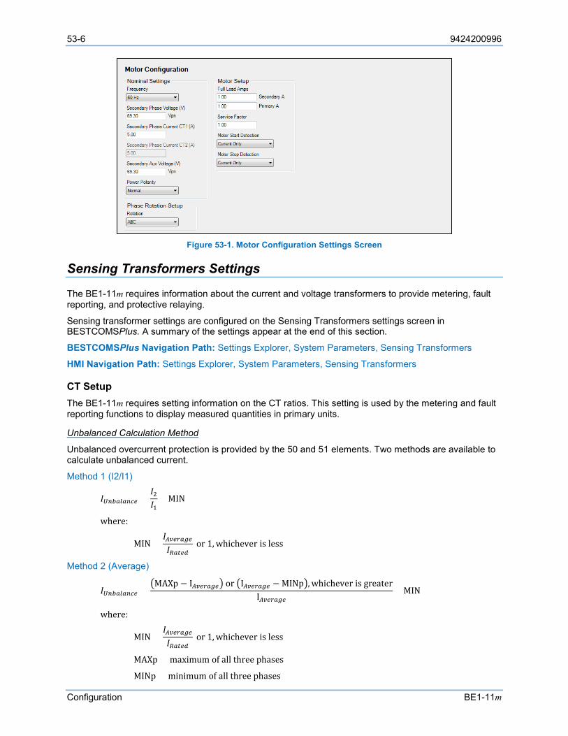
53-6 9424200996
Configuration BE1-11m
Figure 53-1. Motor Configuration Settings Screen
Sensing Transformers Settings
The BE1-11m requires information about the current and voltage transformers to provide metering, fault reporting, and protective relaying.
Sensing transformer settings are configured on the Sensing Transformers settings screen in BESTCOMSPlus. A summary of the settings appear at the end of this section.
BESTCOMSPlus Navigation Path: Settings Explorer, System Parameters, Sensing Transformers
HMI Navigation Path: Settings Explorer, System Parameters, Sensing Transformers
CT Setup The BE1-11m requires setting information on the CT ratios. This setting is used by the metering and fault reporting functions to display measured quantities in primary units.
Unbalanced Calculation Method
Unbalanced overcurrent protection is provided by the 50 and 51 elements. Two methods are available to calculate unbalanced current.
Method 1 (I2/I1)
𝐼𝐼𝑈𝑈𝑈𝑈𝑈𝑈𝑈𝑈𝑈𝑈𝑈𝑈𝑈𝑈𝑈𝑈𝑈𝑈 =𝐼𝐼2𝐼𝐼1
× MIN
where:
MIN =𝐼𝐼𝐴𝐴𝐴𝐴𝑈𝑈𝐴𝐴𝑈𝑈𝐴𝐴𝑈𝑈𝐼𝐼𝑅𝑅𝑈𝑈𝑅𝑅𝑈𝑈𝑅𝑅
or 1, whichever is less
Method 2 (Average)
𝐼𝐼𝑈𝑈𝑈𝑈𝑈𝑈𝑈𝑈𝑈𝑈𝑈𝑈𝑈𝑈𝑈𝑈𝑈𝑈 =MAXp − I𝐴𝐴𝐴𝐴𝑈𝑈𝐴𝐴𝑈𝑈𝐴𝐴𝑈𝑈 or I𝐴𝐴𝐴𝐴𝑈𝑈𝐴𝐴𝑈𝑈𝐴𝐴𝑈𝑈 − MINp, whichever is greater
I𝐴𝐴𝐴𝐴𝑈𝑈𝐴𝐴𝑈𝑈𝐴𝐴𝑈𝑈× MIN
where:
MIN =𝐼𝐼𝐴𝐴𝐴𝐴𝑈𝑈𝐴𝐴𝑈𝑈𝐴𝐴𝑈𝑈𝐼𝐼𝑅𝑅𝑈𝑈𝑅𝑅𝑈𝑈𝑅𝑅
or 1, whichever is less
MAXp = maximum of all three phases
MINp = minimum of all three phases
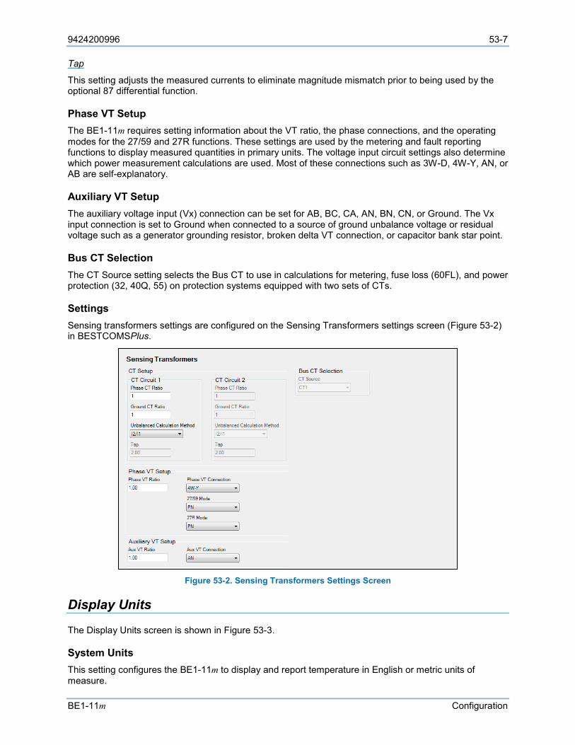
9424200996 53-7
BE1-11m Configuration
Tap
This setting adjusts the measured currents to eliminate magnitude mismatch prior to being used by the optional 87 differential function.
Phase VT Setup The BE1-11m requires setting information about the VT ratio, the phase connections, and the operating modes for the 27/59 and 27R functions. These settings are used by the metering and fault reporting functions to display measured quantities in primary units. The voltage input circuit settings also determine which power measurement calculations are used. Most of these connections such as 3W-D, 4W-Y, AN, or AB are self-explanatory.
Auxiliary VT Setup The auxiliary voltage input (Vx) connection can be set for AB, BC, CA, AN, BN, CN, or Ground. The Vx input connection is set to Ground when connected to a source of ground unbalance voltage or residual voltage such as a generator grounding resistor, broken delta VT connection, or capacitor bank star point.
Bus CT Selection The CT Source setting selects the Bus CT to use in calculations for metering, fuse loss (60FL), and power protection (32, 40Q, 55) on protection systems equipped with two sets of CTs.
Settings Sensing transformers settings are configured on the Sensing Transformers settings screen (Figure 53-2) in BESTCOMSPlus.
Figure 53-2. Sensing Transformers Settings Screen
Display Units
The Display Units screen is shown in Figure 53-3.
System Units This setting configures the BE1-11m to display and report temperature in English or metric units of measure.

53-8 9424200996
Configuration BE1-11m
Figure 53-3. Display Units Screen

9424200996 54-1
BE1-11m Introduction to Testing
54 • Introduction to Testing The need to test protection systems to confirm performance as designed by manufacturers has always existed. However, numeric system design is changing the industry testing paradigms that have been in use since the first protective relay was built. Each time a fault occurs, the numeric protection system is tested, and because of its fault and event recording capability, the test is documented. In the unlikely event of a protection system problem, continuous monitoring along with remote communications capability provide for removing the affected device from service, auto switching to backup systems, and immediate notification of an attended facility. These features have virtually eliminated the need for periodic maintenance. Simple acceptance tests that verify the integrity of the BE1-11m measuring circuits and commissioning tests that verify the BE1-11m “electronic wiring” (control logic) are Basler Electric’s recommended pre-installation tests.
The testing chapters provide guidelines for performing these tests and others. For assistance in conducting BE1-11m self-tests and troubleshooting using internal diagnostics, contact Basler Electric Technical Support Services.
Testing Philosophies
Testing is generally divided into the following categories:
• Acceptance
• Commissioning
• Periodic (user scheduled maintenance)
• Functional
While all types of tests can be performed, all users do not generally perform these tests. Likewise, the degree to which you will conduct each type of test depends on need, economics, and perceived system value.
Acceptance Testing Acceptance testing confirms that a particular BE1-11m delivered to a customer meets published specifications. Because this is a numerical BE1-11m whose characteristics are defined by software, Basler Electric does not require the user to test each operational setting in the BE1-11m. Successful completion of the Acceptance Test verifies proper response of the protection system’s input and output circuits as well as its response to all external sensing input quantities (voltage, current, frequency).
Basler Electric performs detailed acceptance testing on all devices to verify all functions meet published specifications. All products are packaged and shipped with the strictest standards. The BE1-11m is a microprocessor-based device whose operating characteristics will not change over time. The BE1-11m will also not experience any change in operating characteristics during transit. However, it remains important that the user perform these acceptance tests to verify the device has not suffered any degradation in transit. Basler Electric warrants all products against any decay in performance outside of the published specified tolerances that result from problems created during transit.
Commissioning Testing Commissioning testing verifies all physical connections and functional aspects of the BE1-11m for a new installation. This includes a thorough review and documentation of the operational settings to verify that the users calculated values match the actual values on each enabled protection element of the BE1-11m. All of the following connections or functions can be verified during commissioning tests:
• Proper connection and sensing of current and voltage signals as applicable
• Connections of I/O contacts
• I/O sensing versus virtual sensing
54-2 9424200996
Introduction to Testing BE1-11m
• Setting validation
• Proper operation of equipment (main or auxiliary)
• Proper alarming (to SCADA) and/or targeting
Periodic Testing Periodic testing can be performed at regularly scheduled intervals or upon an indication of problems or questionable operations within the BE1-11m. Verifying the integrity of the protection system’s performance, short of playback of recorded events, may be necessary by performing certain tests similar to those accomplished in the Acceptance Testing chapter. Verification that the BE1-11m is measuring signals faithfully, that BE1-11m logic is appropriate, and that protective elements and equipment (main or auxiliary) operate correctly are goals that can be achieved during this type of testing.
Basler Electric recommends that all captured fault records and sequence of event records be analyzed and kept on file as in-service periodic test results for this particular device. This is an indication that all protective elements and the associated equipment are operating satisfactorily.
It is not the intent of this manual to elaborate on every conceivable test possible because this would encroach on individual preferences, techniques, and philosophies. It is the intent to pursue relevant testing methods to verify this BE1-11m meets published design specifications and applicability.
Functional Testing Functional (or application) testing is significantly more comprehensive in nature and tests suitability for a particular application. Functional testing also provides a means to familiarize the user with the logic and operation of this device. Test setups are generally more involved and often include ancillary equipment beyond voltage or current source type equipment. While economics may at times prohibit full functional testing, it is recommended that some functional testing be performed when published specifications lack appropriate detail to satisfy application testing requirements.
Basler Electric performs a thorough and comprehensive functional test of all protection systems before shipping. This ensures that this device is within specified tolerances, measures accurately, and operates correctly as designed.
Testing and Troubleshooting Aids
Under test or in-service, the BE1-11m provides several ways to check operations, targets, or events. The status of the system is monitored by a continuous self-test. The most basic reporting function is targets. Targets can be viewed through BESTCOMSPlus® or the front-panel display. Fault Summary Reports, Sequence of Events Recorder (SER) Reports, and Oscillographic Records yield more detail.
Each time a system disturbance occurs in or around this BE1-11m zone of protection, it is a test of the BE1-11m performance during the fault. If a questionable operation results in the need for troubleshooting, you have several ways in which to troubleshoot the BE1-11m, the installation, and overall application.
Performance Testing Performance testing can be accomplished through the capture and playback of system fault records. In actual applications, this type of test realizes further confirmation of faithful BE1-11m responses during system disturbances. For specific power system disturbances, protection systems can be subjected to a re-creation of captured events with the aid of equipment capable of replicating COMTRADE record files. In these instances, there is significant merit in testing protection systems in this manner to assess BE1-11m performance. Correct response of BE1-11m action in a performance test is supplemental verification of the conclusions drawn from functional (or application) tests.
This type of testing verifies not only whether the device operated correctly for a particular system disturbance but also offers additional confirmation of your protection philosophy in this application. It is beyond the scope of this manual to develop performance tests for this device. For assistance in developing these types of tests, please consult Basler Electric and your test equipment.
9424200996 54-3
BE1-11m Introduction to Testing
BE1-11m Self-Test All internal circuitry and software that affect the BE1-11m core functionality are monitored by the continuous self-test diagnostics. For specific relay trouble alarms, the self-test diagnostics force the microprocessor to reset and try to correct the problem. If unsuccessful, OUTA operates, the Relay Trouble LED on the front panel turns ON, all of the output relays are disabled, internal logic point ALMREL is set, and the BE1-11m is taken off line. For more information on self-test diagnostics and relay trouble alarms, see the Contact Inputs and Outputs chapter.
Status Reporting Features Status reporting is available by using the Metering Explorer in BESTCOMSPlus. This report assembles all of the information required to determine the BE1-11m status.
Fault reporting and target data is dependent on the proper setting of trip, pickup, and logic trigger expressions (via BESTlogic™Plus Programmable Logic) and the assignment of protective elements to be logged as targets (via BESTCOMSPlus).
While the design of the BE1-11m facilitates obtaining and verifying targets and event data, it is not always necessary to use the BE1-11m functions to determine if the device operated while testing. You can simply use an ohmmeter or continuity tester to monitor the output contact status.
The following is a summary of where target and event data can be viewed in BESTCOMSPlus:
• Fault records in memory - Metering Explorer/Reports/Fault Records
• Target data - Metering Explorer/Status/Targets
• Sequence of events (SOE) records - Metering Explorer/Reports/Sequence of Events
For more information on front-panel display menu trees, see the Controls and Indicators chapter.
Event Reporting Features The SOE function of the BE1-11m records protective element output changes, overcurrent element pickup or dropout, input/output contact state changes, logic triggers, setting group changes, and setting changes. For more information on event reporting, see the Sequence of Events chapter.
The following summarizes the reporting capabilities of the BE1-11m through the front-panel display:
• Trip LED (Flashing): flashes during pickup of protective elements based on the pickup logic expression set in BESTlogicPlus Programmable Logic.
• Trip LED (Sealed-In): stays lit after trip logic becomes true based on the trip logic expression set in BESTlogicPlus Programmable Logic.
• TARGETS: Metering > Status > Targets screen provides target data.
• ALARMS: Metering > Status > Alarms screen provides alarm data.
• FAULT REPORTS: Metering > Fault Reports screen indicates new fault reports.

54-4 9424200996
Introduction to Testing BE1-11m
9424200996 55-1
BE1-11m Acceptance Testing
55 • Acceptance Testing Although Basler Electric performs detailed acceptance testing on all new protection systems, it is generally recommended that you perform each of the following acceptance test steps before installation. The following steps test each function of the BE1-11m to validate that it was manufactured properly and that no degradation of performance occurred because of shipping.
Test Equipment
Suitable test equipment requires a minimum of two current sources, two voltage sources, and a contact wetting voltage. Test equipment should also have the capability of varying the frequency and the angle of the voltage and current sources. A PC with BESTCOMSPlus® installed and configured for communication with the BE1-11m is also required.
Power Up
Purpose: To verify that the BE1-11m performs the power-up sequence.
Step 1: Apply voltage to input power terminals A6 and A7. Table 55-1 shows the appropriate input voltage for each BE1-11m style.
Table 55-1. Input Voltages
Style Number Voltage Input Mxx1xxxxxxxxxx 48/125 Vac/dc Mxx2xxxxxxxxxx 125/250 Vac/dc
Mxx3xxxxxxxxxx 24 Vdc
Step 2: Verify that the Power LED is ON, and that characters are displayed on the front panel. Upon power-up, the BE1-11m will perform a brief self-test. During this brief test, the display indicates each step of the self-test; Performing BIOS Tests…, Loading Application…, Initializing Protection…, and then the default display screen. Contact Basler Electric Technical Support Services if anything appears out of the ordinary or if an LCD error message appears.
Communications
Purpose: To verify that the BE1-11m communicates through the USB and optional Ethernet port.
Step 1: Use BESTCOMSPlus to connect to the BE1-11m through the front-panel USB port and through the optional rear panel Ethernet port. Refer to the Communication chapter.
Style Number and Serial Number Verification
Purpose: To verify that the BE1-11m style number and serial number matches the unit and unit labels.
Step 1: Connect to the BE1-11m through BESTCOMSPlus.
Step 2: Use the Settings Explorer to open the General Settings, Style Number screen and verify that the style number matches the unit labels.
Step 3: Use the Settings Explorer to open the General Settings, Device Info screen and verify that the serial number matches the unit labels.
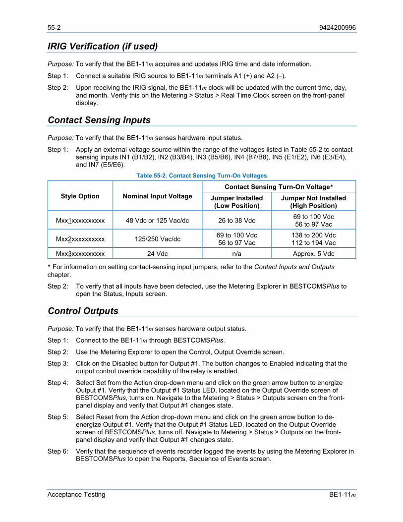
55-2 9424200996
Acceptance Testing BE1-11m
IRIG Verification (if used)
Purpose: To verify that the BE1-11m acquires and updates IRIG time and date information.
Step 1: Connect a suitable IRIG source to BE1-11m terminals A1 (+) and A2 (–).
Step 2: Upon receiving the IRIG signal, the BE1-11m clock will be updated with the current time, day, and month. Verify this on the Metering > Status > Real Time Clock screen on the front-panel display.
Contact Sensing Inputs
Purpose: To verify that the BE1-11m senses hardware input status.
Step 1: Apply an external voltage source within the range of the voltages listed in Table 55-2 to contact sensing inputs IN1 (B1/B2), IN2 (B3/B4), IN3 (B5/B6), IN4 (B7/B8), IN5 (E1/E2), IN6 (E3/E4), and IN7 (E5/E6).
Table 55-2. Contact Sensing Turn-On Voltages
Style Option Nominal Input Voltage Contact Sensing Turn-On Voltage*
Jumper Installed (Low Position)
Jumper Not Installed (High Position)
Mxx1xxxxxxxxxx 48 Vdc or 125 Vac/dc 26 to 38 Vdc 69 to 100 Vdc 56 to 97 Vac
Mxx2xxxxxxxxxx 125/250 Vac/dc 69 to 100 Vdc 56 to 97 Vac
138 to 200 Vdc 112 to 194 Vac
Mxx3xxxxxxxxxx 24 Vdc n/a Approx. 5 Vdc
* For information on setting contact-sensing input jumpers, refer to the Contact Inputs and Outputs chapter.
Step 2: To verify that all inputs have been detected, use the Metering Explorer in BESTCOMSPlus to open the Status, Inputs screen.
Control Outputs
Purpose: To verify that the BE1-11m senses hardware output status.
Step 1: Connect to the BE1-11m through BESTCOMSPlus.
Step 2: Use the Metering Explorer to open the Control, Output Override screen.
Step 3: Click on the Disabled button for Output #1. The button changes to Enabled indicating that the output control override capability of the relay is enabled.
Step 4: Select Set from the Action drop-down menu and click on the green arrow button to energize Output #1. Verify that the Output #1 Status LED, located on the Output Override screen of BESTCOMSPlus, turns on. Navigate to the Metering > Status > Outputs screen on the front-panel display and verify that Output #1 changes state.
Step 5: Select Reset from the Action drop-down menu and click on the green arrow button to de-energize Output #1. Verify that the Output #1 Status LED, located on the Output Override screen of BESTCOMSPlus, turns off. Navigate to Metering > Status > Outputs on the front-panel display and verify that Output #1 changes state.
Step 6: Verify that the sequence of events recorder logged the events by using the Metering Explorer in BESTCOMSPlus to open the Reports, Sequence of Events screen.
9424200996 55-3
BE1-11m Acceptance Testing
Step 7: Use the Metering Explorer in BESTCOMSPlus to return to the Control, Output Override screen and click on the Enabled button for Output #1. The button changes to Disabled indicating that the output control override capability of the relay is disabled.
Step 8: Repeat Steps 3 through 7 for all desired output contacts.
Current Circuit Verification
CT Circuit 1 Step 1: To verify 3I0, I1, and I2, connect an ac current source to Terminals D1 and D2.
Step 2: Apply the appropriate current values in Table 55-3 to the BE1-11m. Measured 3I0 should correspond to values in Table 55-3 while I1 and I2 should be 1/3 the applied value ±1.5% (For example, if the applied value equals 2 amps, I2 = 2/3 = 0.667 amps ±1.5% or ±0.01 amps.) Verify current measuring accuracy by opening the Analog Metering, Current, CT Circuit 1, Secondary Current screen inside the Metering Explorer of BESTCOMSPlus. 3I0, I1, and I2 current measurements can also be verified on the Metering > Analog Metering > Current > Current Circuit 1 > Secondary Current screen of the front-panel display.
Table 55-3. Current Circuit Verification Values
Sensing Type Applied Current Measured Current
Lower Limit Upper Limit
5 A
1 amps 0.99 A 1.01 A
5 amps 4.95 A 5.05 A 10 amps 9.90 A 10.10 A 15 amps 14.85 A 15.15 A
20 amps 19.80 A 20.20 A
1 A
0.25 amps 0.2475 A 0.2525 A 1 amps 0.99 A 1.01 A
2 amps 1.98 A 2.02 A 3 amps 2.97 A 3.03 A 4 amps 3.96 A 4.04 A
Step 3: To verify IA1, IB1, IC1, and IG1, connect the four current inputs in series by connecting suitably sized jumper wires between terminals D2 and D3, D4 and D5, and D6 and D7. Then connect an ac current source to terminals D1 and D8.
Step 4: Apply the appropriate current values in Table 55-3 to the BE1-11m. Verify current measuring accuracy on the Analog Metering, Current, CT Circuit 1, Secondary Current screen inside the Metering Explorer of BESTCOMSPlus. IA1, IB1, IC1, and IG1 current measurements can also be verified on the Metering > Analog Metering > Current > Current Circuit 1 > Secondary Current screen of the front-panel display.
Step 5: Leave current circuit connected and de-energized. These test connections will be used later when verifying power readings.
CT Circuit 2 (Optional) Step 1: To verify 3I0, I1, and I2, connect an ac current source to Terminals F1 and F2.
Step 2: Apply the appropriate current values in Table 55-3 to the BE1-11m. Measured 3I0 should correspond to values in Table 55-3 while I1 and I2 should be 1/3 the applied value ±1.5% (For example, if the applied value equals 2 amps, I2 = 2/3 = 0.667 amps ±1.5% or ±0.01 amps.) Verify current measuring accuracy by opening the Analog Metering, Current, CT Circuit 2, Secondary Current screen inside the Metering Explorer of BESTCOMSPlus. 3I0, I1, and I2
55-4 9424200996
Acceptance Testing BE1-11m
current measurements can also be verified on the Metering > Analog Metering > Current > Current Circuit 2 > Secondary Current screen of the front-panel display.
Step 3: To verify IA2, IB2, IC2, and IG2, connect the four current inputs in series by connecting suitably sized jumper wires between terminals F2 and F3, F4 and F5, and F6 and F7. Then connect an ac current source to terminals F1 and F8.
Step 4: Apply the appropriate current values in Table 55-3 to the BE1-11m. Verify current measuring accuracy on the Analog Metering, Current, CT Circuit 2, Secondary Current screen inside the Metering Explorer of BESTCOMSPlus. IA2, IB2, IC2, and IG2 current measurements can also be verified on the Metering > Analog Metering > Current > Current Circuit 2 > Secondary Current screen of the front-panel display.
Step 5: Leave current circuit connected and de-energized. These test connections will be used later when verifying power readings.
Three-Phase Voltage Circuit Verification
Step 1: Connect an ac voltage source at nominal frequency between BE1-11m Terminals C13 (A-phase) and C16 (Neutral terminal). Apply 100 volts and verify voltage-measuring accuracy by using the Metering Explorer in BESTCOMSPlus to open the Analog Metering, Secondary Voltage screen. Readings should be: VA = 100 volts ±0.5%, VAB = 100 volts ±0.5%, VCA = 100 volts ±0.5%, 3V0 = 100 volts ±0.75%, V1 = 33.4 volts ±0.75% (applied divided by 3), and V2 = 33.4 volts ±0.75% (applied divided by 3). The Metering > Analog Metering > Voltage > Secondary Voltage screen of the front-panel display can also be monitored to verify voltage measurements.
Step 2: Connect an ac voltage source at nominal frequency between BE1-11m Terminals C14 (B-phase) and C16 (Neutral Terminal). Apply 100 volts and verify voltage-measuring accuracy by using the Metering Explorer in BESTCOMSPlus to open the Analog Metering, Voltage, Secondary Voltage screen. Readings should be: VB = 100 volts ±0.5%, VAB = 100 volts ±0.5%, VBC = 100 volts ±0.5%, 3V0 = 100 volts ±0.75%, V1 = 33.4 volts ±0.75% (applied divided by 3), and V2 = 33.4 volts ±0.75% (applied divided by 3). The Metering > Analog Metering > Voltage > Secondary Voltage screen of the front-panel display can also be monitored to verify voltage measurements.
Step 3: Connect an ac voltage source at nominal frequency between BE1-11m Terminals C15 (C-phase) and C16 (Neutral Terminal). Apply 100 volts and verify voltage-measuring accuracy by using the Metering Explorer in BESTCOMSPlus to open the Analog Metering, Voltage, Secondary Voltage screen. Readings should be: VC = 100 volts ±0.5%, VBC = 100 volts ±0.5%, VCA = 100 volts ±0.5%, 3V0 = 100 volts ±0.75%, V1 = 33.4 volts ±0.75% (applied divided by 3), and V2 = 33.4 volts ±0.75% (applied divided by 3). The Metering > Analog Metering > Voltage > Secondary Voltage screen of the front-panel display can also be monitored to verify voltage measurements.
Step 4: Connect BE1-11m Terminals C13 (A-phase), C14 (B-phase), and C15 (C-phase) together. Connect an ac voltage source at nominal frequency to the three jumpered terminals and the Neutral Terminal (C16).
Step 5: Apply the voltage values listed in Table 55-4 and verify voltage-measuring accuracy by using the Metering Explorer in BESTCOMSPlus to open the Analog Metering, Voltage, Secondary Voltage screen. The Metering > Analog Metering > Voltage > Secondary Voltage screen of the front-panel display can also be monitored to verify voltage measurements.
Table 55-4. Voltage Circuit Verification Values
Applied Voltage Measured Voltage
Lower Limit Upper Limit 80 volts 79.6 V 80.4 V 100 volts 99.5 V 100.5 V
9424200996 55-5
BE1-11m Acceptance Testing
Applied Voltage Measured Voltage
Lower Limit Upper Limit 120 volts 119.4 V 120.6 V 140 volts 139.3 V 140.7 V 160 volts 159.2 V 160.8 V
Power Reading Verification
Step 1: Use the same voltage connections as in the previous test, polarity voltage jumpered to C13, 14, and 15, neutral tied to C16. Use the same current connection as in Steps 3 and 4 of Current Circuit Verification, CT Circuit 1; that is, polarity current in D1 out D8 with D2 and D3, D4 and D5, D6 and D7 jumpered together. Note: For protection systems equipped with two sets of CTs, be sure that CT1 is selected for the Bus CT Selection setting found on the System Parameters, Sensing Transformers screen in BESTCOMSPlus.
Note Power readings in this procedure are based on a 5 amp BE1-11m; for 1 amp values, divide by 5.
Step 2: Apply 100 volts at angle 0 degrees and 5 amps to the BE1-11m. Verify the accuracy of the power reading by using the Metering Explorer in BESTCOMSPlus to open the Analog Metering, Power screen. Power should be 1.5 kW ±1.0% and reactive should read near 0 vars. The Metering > Analog Metering > Power/Watts > Vars screen of the front-panel display can also be monitored to verify power and reactive readings. The apparent power should be 1.5 kVA ±1.0% at unity power factor. The Metering > Analog Metering > Power > VA/PF screen of the front-panel display can also be monitored to verify apparent power.
Step 3: Reverse the current polarity and apply the same values as in Step 2. Note that the power reading is –1.5 kW, which indicates “power in” to the zone being protected.
Step 4: Return the current polarity back to Step 1 position. Apply 100 volts at angle 0 degrees and 5 amps at angle –90 degrees (I lags E by 90°) to the BE1-11m, and verify reactive power accuracy by using the Metering Explorer in BESTCOMSPlus to open the Analog Metering, Power screen. Power should be nearly 0 kW, and reactive should read 1.5 kvar ±1.0%. The Metering > Analog Metering > Power screen of the front-panel display can also be monitored to verify power and reactive values. Note power factor reads near 0 with a negative sign indicating a lagging power factor angle.
Step 5: Reverse the current polarity and apply the same values as in Step 4. Note that the reactive power reading is –1.5 kvar, which indicates reactive power in to the device being protected. Also note that the power factor angle is a positive value near zero. A positive power factor angle indicates leading power factor.
Step 6: Repeat Steps 2 and 4 for current values of 10 and 20 amps. Corresponding power reading should be 3 kW/kvar and 6 kW/kvar ±1.0%.
Auxiliary Voltage Input Verification - VX and VX 3rd
(Fundamental and Third Harmonic)
Step 1: Connect BE1-11m terminals C17 (polarity) and C18 to a 60 hertz ac voltage source.
Step 2: Apply the voltage values listed in Table 55-5 and verify voltage-measuring accuracy by using the Metering Explorer in BESTCOMSPlus to open the Analog Metering, Voltage, Secondary Voltage screen. The Metering > Analog Metering > Voltage > Secondary Voltage screen of the front-panel display can also be monitored to verify voltage measurements. Accuracy is ±0.5%.
55-6 9424200996
Acceptance Testing BE1-11m
Step 3: Connect BE1-11m Terminals C17 (polarity) and C18 to a 180 Hz (third harmonic) ac voltage source.
Step 4: Apply the voltage values listed in Table 55-5 and verify voltage-measuring accuracy by using the Metering Explorer in BESTCOMSPlus to open the Analog Metering, Voltage, Secondary Voltage screen. The Metering > Analog Metering > Voltage > Secondary Voltage screen of the front-panel display can also be monitored to verify voltage measurements. Accuracy is ±0.5%.
Table 55-5. Aux Voltage Circuit Verification VX & VX 3rd Values
Applied Voltage Measured Voltage
Lower Limit Upper Limit 30 volts 29.85 V 30.15 V 50 volts 49.75 V 50.25 V 70 volts 69.65 V 70.35 V
90 volts 89.55 V 90.45 V 110 volts 109.45 V 110.55 V
Frequency Verification
Step 1: Connect BE1-11m Terminals C13 (polarity) and C16 (A to Neutral of the three-phase voltage input) to a 60 hertz ac voltage source (line voltage).
Step 2: Connect BE1-11m Terminals C17 (polarity) and C18 (Auxiliary Voltage Input) to a second 60-hertz ac voltage source (bus voltage).
Step 3: Apply 115 volts at 0 degrees and 60 hertz to both sources. Verify the measuring accuracy of the line and bus frequency by using the Metering Explorer in BESTCOMSPlus to open the Analog Metering, Frequency screen. The Metering > Analog Metering > Frequency screen of the front-panel display can also be monitored to verify frequency measurements.
9424200996 56-1
BE1-11m Commissioning Testing
56 • Commissioning Testing Special precautions should be taken to ensure that all tests are performed with safety as the greatest concern. Any CT circuit signals routed through this device as part of a protection scheme, including discrete relays or as a stand-alone device, should be shorted and isolated from this BE1-11m during these tests.
If this BE1-11m is being installed in an existing installation, be aware of the equipment monitoring features of this device, especially if the monitoring logic will be utilized. Make note of any pretest operation levels, duty levels, etc. on existing equipment (e.g., breakers or transformers). As the user, you can make the determination of what values the BE1-11m should have as initial monitoring values when the BE1-11m is placed in service.
It may on occasion be necessary to temporarily disable some of the protective elements while testing the BE1-11m to isolate testing of individual functions. Always remember to enable these functions before placing the BE1-11m in service.
To assist you in the commissioning testing of this BE1-11m, you can refer to the related reporting and alarms chapters.
Please refer to the related protection and control chapters of the instruction manual for assistance on any particular functions of the BE1-11m. If you require further assistance, contact Basler Electric field application personnel or the factory.
Digital I/O Connection Verification
Contact Sensing Inputs Purpose: To verify operation, labels, and logic settings of the contact sensing inputs.
Chapter Reference: Contact Inputs and Outputs
Step 1: Use the Settings Explorer in BESTCOMSPlus® to open the Programmable Inputs, Contact Inputs screen and verify the Input 1 through Input 10 user-defined name, recognition time, debounce time, energized state label, and de-energized state label. Refer to the style chart for I/O options.
Step 2: Use the Metering Explorer in BESTCOMSPlus to open the Status, Inputs screen. Verify the status of Input 1. From the actual field device, energize (or de-energize) the specific contact that supplies BE1-11m Input 1. While maintaining contact position, verify that Input 1 has changed state on the Status, Inputs screen of BESTCOMSPlus or the front-panel display. Return the field contact to its original state, verifying that Input 1 returns to its original state. Use the Metering Explorer in BESTCOMSPlus to open the Reports, Sequence of Events screen. Click on the Download button and review the events associated with the field contact change.
Step 3: Repeat Step 2 for each connected input.
Output Contacts Purpose: To verify operation, labels, and logic settings of the output contacts.
Chapter Reference: Contact Inputs and Outputs
Step 1: Use the Settings Explorer in BESTCOMSPlus to open the Programmable Output, Output Contacts screen and verify the output 1 through output 8, and output A label, energized state label, de-energized state label, and hold attribute. Refer to the style chart for I/O options.
Step 2: Use the Metering Explorer in BESTCOMSPlus to open the Control, Output Override screen. Verify the status of OUT1 through OUT8. Use the procedure outlined under Acceptance Testing, Control Outputs to actuate selected output contacts (OUT1 through OUT8) and actually trip or close the connected field device (circuit breaker, lockout, etc.). Verify that the selected output has changed state on the Control, Output Override screen of BESTCOMSPlus or the
56-2 9424200996
Commissioning Testing BE1-11m
front-panel display. Return the output to its original state, verifying that the output returns to its original state. Use the Metering Explorer in BESTCOMSPlus to open the Reports, Sequence of Events screen. Click on the Download button and review the events associated with the output contact change.
Step 3: Repeat Step 2 to verify that operation of the alarm output relay (OUTA) initiates the appropriate alarm response.
Virtual Selector Switches
Purpose: To verify operation, labels, and logic settings of the 43 switches.
Chapter Reference: Virtual Control Switches (43)
Step 1: Use the Settings Explorer in BESTCOMSPlus to open the Control, Virtual Control Switches screen and verify the 43-1 through 43-5 mode, name label, on label, and off label.
Step 2: Use the Metering Explorer in BESTCOMSPlus to open the Control, Virtual Switches screen and obtain the position of the five virtual selector switches. Alternately, the virtual selector switch positions can be obtained on the Metering > Control > Virtual Switches screen of the front-panel display.
Step 3: Obtain write access to the BE1-11m. For each virtual selector switch enabled in your logic scheme, change the switch position by following the procedure described in the Virtual Control Switches (43) chapter.
Step 4: Verify each switch position change on the Control, Virtual Switches screen of BESTCOMSPlus or on the front-panel display.
Step 5: Return each virtual selector switch to the original position.
Step 6: Use the Metering Explorer in BESTCOMSPlus to open the Reports, Sequence of Events screen. Click on the Download button and review the events associated with the virtual switch activities.
Virtual Control Switch
Purpose: To verify operation and logic setting for the 101 switch.
Chapter Reference: Breaker Control Switch (101)
Step 1: Use the Settings Explorer in BESTCOMSPlus to open the Control, Breaker Control Switch screen and verify the 101 element mode.
Step 2: Use the Metering Explorer in BESTCOMSPlus to open the Control, Breaker Control Switch screen and obtain the position of the breaker control switch. Alternately, the breaker control switch position can be obtained on the Metering > Control > 101 Breaker Control SW screen of the front-panel display.
Step 3: Obtain write access to the BE1-11m. Change the switch position by following the procedure described in the Breaker Control Switch (101) chapter.
Step 4: Verify the switch position change on the Control, Breaker Control Switch screen of BESTCOMSPlus or on the front-panel display.
Step 5: Return the breaker control switch to the original position.
Step 6: Use the Metering Explorer in BESTCOMSPlus to open the Reports, Sequence of Events screen. Click on the Download button and review the events associated with the breaker control switch.

9424200996 56-3
BE1-11m Commissioning Testing
Protection and Control Function Verification
Before placing the BE1-11m in service, the user should ensure that all system ac and dc connections are correct, that the BE1-11m functions as intended with user settings applied, and that all equipment external to the BE1-11m operates as intended. All connected or monitored inputs and outputs, and polarity and phase rotation of ac connections should be tested. Verify that:
• Power supply voltages and contact wetting voltages are correct.
• User desired protection and control functions are enabled and connected to the correct CT and VT input circuits.
• The programmable logic settings (electronic wiring) provide the proper interconnection of these functions with the I/O of the BE1-11m.
Simple user-designed fault tests should be used to verify that the operational settings are correct, that the proper output relays are actuated and proper targeting occurs. It is not necessary to test every protection element, timer, and function in these tests.
Use of the fault and event recording capability of the BE1-11m will aid in the verification of the protection and control logic. Use the Metering Explorer in BESTCOMSPlus to open the Reports, Sequence of Events screen. In addition, it is helpful to click on the Clear button prior to starting a test. This allows the user to review only those operations recorded since the sequence of events was last cleared. Refer to the Sequence of Events chapter for more detail.
It may be necessary to disable protection elements or change setting logic to verify a specific function. To guard against placing the BE1-11m in service with unwanted operational or logic settings, it is good practice to save a copy of the original setting file before the testing process begins. When testing is complete, compare the copy of the saved settings to the actual settings as a final verification.
Use the settings compare feature in BESTCOMSPlus to compare setting files. Refer to the BESTCOMSPlus Software chapter for more information.
Verify Other Setpoints as Appropriate
Consult the individual functional testing chapters for guidelines on testing and verifying setpoints of other protection and control functions.
Reporting and Alarm Functions
Just prior to placing the BE1-11m in service, the following reporting and alarm functions should be reset and/or verified.
Clock Display BESTCOMSPlus Navigation Path: Metering Explorer, Status, Real Time Clock
HMI Navigation Path: Metering Explorer, Status, Real Time Clock
Chapter Reference: Timekeeping
Set the real time clock to the current date and time. If an IRIG signal or NTP server is used, day, time, and year are automatically synchronized with the source. Note that the time code signal from older IRIG time code generating equipment does not contain the current year information thus necessitating the entry of the year.

56-4 9424200996
Commissioning Testing BE1-11m
Energy Data and Demand BESTCOMSPlus Navigation Path: Metering Explorer, Demand
HMI Navigation Path: Metering Explorer, Demand Meter
Chapter Reference: Demands
Read, change, or reset KWH and KVARH records. Use the following to reset the peak current, watt, and var demand registers to “0” or a pre-existing value:
Breaker Monitoring BESTCOMSPlus Navigation Path: Metering Explorer, Reports, Breaker Monitor
HMI Navigation Path: Metering Explorer, Reports, Breaker Report
Chapter Reference: Breaker Monitoring
If the Breaker Monitoring features of the BE1-11m are enabled, use the following to reset the counter and the duty registers to “0” or a pre-existing value:
Relay Trouble Alarms BESTCOMSPlus Navigation Path: Metering Explorer, Status, Alarms
HMI Navigation Path: Metering Explorer, Status, Alarms
Chapter Reference: Alarms
Reset and verify that the relay trouble alarm is not lit. If required, alarm information can be read by using the Metering Explorer in BESTCOMSPlus to open the Status, Alarms screen. To attempt clearing a Relay Trouble Alarm, press the Reset Relay Alarms button or navigate to Metering > Status > Alarms > Relay Alarms on the front-panel display and press the front-panel Reset button. Refer to the Alarms chapter for setting details.
Major/Minor Programmable Alarms BESTCOMSPlus Navigation Path: Metering Explorer, Status, Alarms
HMI Navigation Path: Metering Explorer, Status, Alarms
Chapter Reference: Alarms
Reset and verify that the programmable alarms, Major and Minor, as set to meet user needs, are not lit or asserted. If required, alarm information can be read by using the Metering Explorer in BESTCOMSPlus to open the Status, Alarms screen. To reset a Major/Minor alarm, press the Reset Major, Minor Alarms button or navigate to Metering > Status > Alarms > Major or Minor Alarms on the front-panel display and press the front-panel Reset button. Refer to the Alarms chapter for settings details.
Targets BESTCOMSPlus Navigation Path: Metering Explorer, Status, Targets
HMI Navigation Path: Metering Explorer, Status, Targets
Chapter Reference: Fault Reporting
Reset any active targets and verify that they clear. Targets are reset by navigating to Metering > Status > Targets on the front-panel display and pressing the Reset button or by using the Metering Explorer in BESTCOMSPlus to open the Status, Targets screen and clicking on the Reset Targets button. Write access is required to reset targets through BESTCOMSPlus. Refer to the Fault Reporting chapter for setting details.
9424200996 56-5
BE1-11m Commissioning Testing
Fault Summary Reports BESTCOMSPlus Navigation Path: Metering Explorer, Reports, Fault Records
HMI Navigation Path: Metering Explorer, Reports, Fault Reports
Chapter Reference: Fault Reporting
Reset “new” fault summary directory records to “0” by using the Metering Explorer in BESTCOMSPlus to open the Reports, Fault Records screen and clicking on the Reset button. Write access is required. Verify the new faults are “0” by clicking on the Refresh button. Refer to the Fault Reporting chapter for setting details.
Sequence of Events Recorder (SER) BESTCOMSPlus Navigation Path: Metering Explorer, Reports, Sequence of Events
HMI Navigation Path: Not available through the front panel
Chapter Reference: Sequence of Events
Reset the “new” SER records counter to “0” by using the Metering Explorer in BESTCOMSPlus to open the Reports, Sequence of Events screen and clicking on the Clear button. Write access is required. Verify that the new records are “0” by clicking on the Download button. Refer to the Sequence of Events chapter setting details.
Just Prior to Energizing - Report Documentation After completing the previous steps, use the Metering Explorer in BESTCOMSPlus to open the Status tree branch. Capture and save the information for Inputs, Outputs, Alarms, Targets, and Digital Points. This report should be kept in a permanent record file of the device so the data can be used for comparison in future maintenance procedures.
Also, save the entire settings record for future reference by using BESTCOMSPlus and selecting Download Settings and Logic from the Communication pull-down menu. After settings and logic are downloaded into BESTCOMSPlus memory, select Save from the File pull-down menu. Use this record during the maintenance cycle or during the analysis of an operation to verify that the “as found” settings are exactly as left during the commissioning process.
Refer to the related reporting and alarms chapters and the BESTCOMSPlus Software chapter.
In Service Readings After energizing the equipment, use the Metering Explorer in BESTCOMSPlus to verify the following analog metering values.
• Secondary voltage and current to verify VT and CT ratios. • Polarity of energy readings to verify polarity of VT and CT connections. • I2 and V2 to verify proper phase-sequence connections. • Anything else that the user may find helpful.
Save this record along with the status record mentioned earlier for future reference.

56-6 9424200996
Commissioning Testing BE1-11m
9424200996 57-1
BE1-11m Periodic Testing
57 • Periodic Testing Because the BE1-11m has extensive internal test capabilities, periodic testing of the protection system can be greatly reduced. BE1-11m operating characteristics are a function of programming instructions that do not drift over time. Thus, the user may wish to verify items that the protection system’s self-testing features cannot completely determine. Periodic testing may consist of the following settings and function checks:
• Verify that the setpoints that were proven during commissioning have not been changed.
• Verify proper interfacing between the inputs and outputs and the rest of the protection and control system.
• Verify that the power system analog parameters used by the protection and control functions are measured accurately.
Settings Verification
Verification of the BE1-11m digital I/O connections can be accomplished in different ways. The method used depends on your preferences and practices. You may choose to use either of the following two methods:
• Repeat the digital I/O connection and label verification under commissioning tests.
• Monitor SER, status, and fault reports for proper sensing of digital signals and proper output tripping during normal operation.
Note In redundant protection systems where multiple relays will trip a given breaker or other device for a fault, fault record monitoring may not indicate a failed output contact. The BE1-11m may report that it energized an output when tripping was actually accomplished by the redundant relay. In this situation, testing the contact is recommended.
Analog Circuit Verification
Verification of BE1-11m analog measurement circuits can be accomplished in multiple ways and depends on your preferences and practices. Either of the two following methods may be used:
• Repeat the acceptance tests by injecting test quantities into the BE1-11m.
• Use the BE1-11m metering functions to compare the protection system’s measurements with those made by similar devices that are measuring the same signals. Redundant protection systems or metering devices can provide this independent confirmation of measured signals. If the BE1-11m is connected to an integration system, this verification can even be automated and done on a semi-continuous basis.
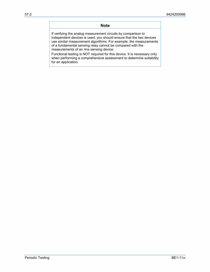
57-2 9424200996
Periodic Testing BE1-11m
Note
If verifying the analog measurement circuits by comparison to independent devices is used, you should ensure that the two devices use similar measurement algorithms. For example, the measurements of a fundamental sensing relay cannot be compared with the measurements of an rms sensing device. Functional testing is NOT required for this device. It is necessary only when performing a comprehensive assessment to determine suitability for an application.
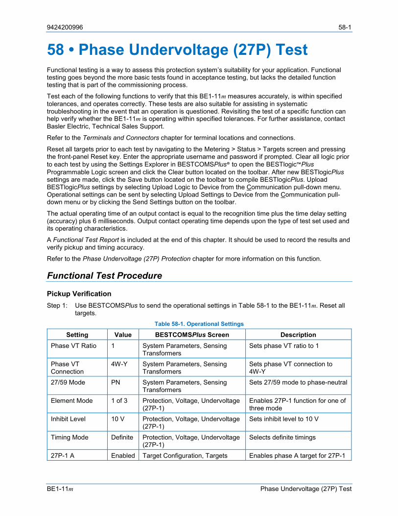
9424200996 58-1
BE1-11m Phase Undervoltage (27P) Test
58 • Phase Undervoltage (27P) Test Functional testing is a way to assess this protection system’s suitability for your application. Functional testing goes beyond the more basic tests found in acceptance testing, but lacks the detailed function testing that is part of the commissioning process.
Test each of the following functions to verify that this BE1-11m measures accurately, is within specified tolerances, and operates correctly. These tests are also suitable for assisting in systematic troubleshooting in the event that an operation is questioned. Revisiting the test of a specific function can help verify whether the BE1-11m is operating within specified tolerances. For further assistance, contact Basler Electric, Technical Sales Support.
Refer to the Terminals and Connectors chapter for terminal locations and connections.
Reset all targets prior to each test by navigating to the Metering > Status > Targets screen and pressing the front-panel Reset key. Enter the appropriate username and password if prompted. Clear all logic prior to each test by using the Settings Explorer in BESTCOMSPlus® to open the BESTlogic™Plus Programmable Logic screen and click the Clear button located on the toolbar. After new BESTlogicPlus settings are made, click the Save button located on the toolbar to compile BESTlogicPlus. Upload BESTlogicPlus settings by selecting Upload Logic to Device from the Communication pull-down menu. Operational settings can be sent by selecting Upload Settings to Device from the Communication pull-down menu or by clicking the Send Settings button on the toolbar.
The actual operating time of an output contact is equal to the recognition time plus the time delay setting (accuracy) plus 6 milliseconds. Output contact operating time depends upon the type of test set used and its operating characteristics.
A Functional Test Report is included at the end of this chapter. It should be used to record the results and verify pickup and timing accuracy.
Refer to the Phase Undervoltage (27P) Protection chapter for more information on this function.
Functional Test Procedure
Pickup Verification Step 1: Use BESTCOMSPlus to send the operational settings in Table 58-1 to the BE1-11m. Reset all
targets. Table 58-1. Operational Settings
Setting Value BESTCOMSPlus Screen Description Phase VT Ratio 1 System Parameters, Sensing
Transformers Sets phase VT ratio to 1
Phase VT Connection
4W-Y System Parameters, Sensing Transformers
Sets phase VT connection to 4W-Y
27/59 Mode PN System Parameters, Sensing Transformers
Sets 27/59 mode to phase-neutral
Element Mode 1 of 3 Protection, Voltage, Undervoltage (27P-1)
Enables 27P-1 function for one of three mode
Inhibit Level 10 V Protection, Voltage, Undervoltage (27P-1)
Sets inhibit level to 10 V
Timing Mode Definite Protection, Voltage, Undervoltage (27P-1)
Selects definite timings
27P-1 A Enabled Target Configuration, Targets Enables phase A target for 27P-1
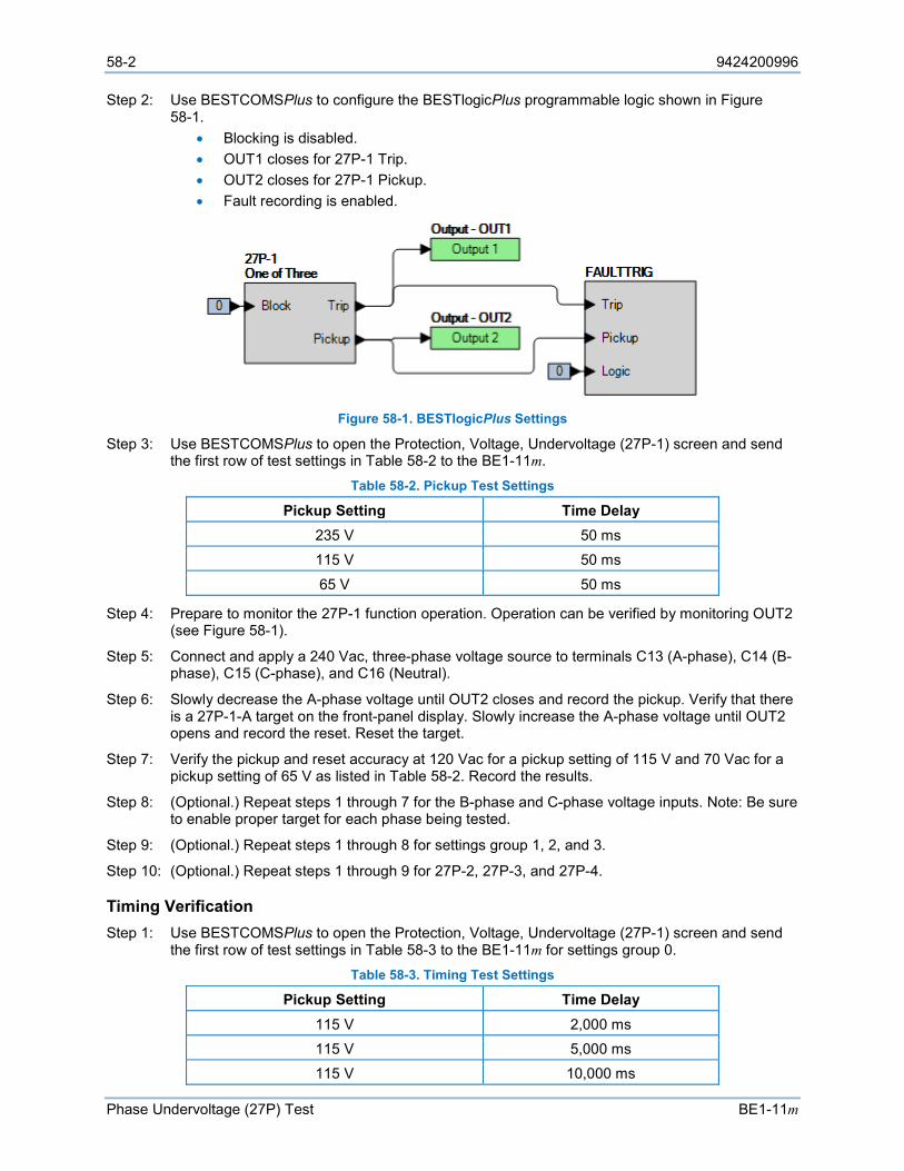
58-2 9424200996
Phase Undervoltage (27P) Test BE1-11m
Step 2: Use BESTCOMSPlus to configure the BESTlogicPlus programmable logic shown in Figure 58-1.
• Blocking is disabled. • OUT1 closes for 27P-1 Trip. • OUT2 closes for 27P-1 Pickup. • Fault recording is enabled.
Figure 58-1. BESTlogicPlus Settings
Step 3: Use BESTCOMSPlus to open the Protection, Voltage, Undervoltage (27P-1) screen and send the first row of test settings in Table 58-2 to the BE1-11m.
Table 58-2. Pickup Test Settings
Pickup Setting Time Delay 235 V 50 ms 115 V 50 ms
65 V 50 ms
Step 4: Prepare to monitor the 27P-1 function operation. Operation can be verified by monitoring OUT2 (see Figure 58-1).
Step 5: Connect and apply a 240 Vac, three-phase voltage source to terminals C13 (A-phase), C14 (B-phase), C15 (C-phase), and C16 (Neutral).
Step 6: Slowly decrease the A-phase voltage until OUT2 closes and record the pickup. Verify that there is a 27P-1-A target on the front-panel display. Slowly increase the A-phase voltage until OUT2 opens and record the reset. Reset the target.
Step 7: Verify the pickup and reset accuracy at 120 Vac for a pickup setting of 115 V and 70 Vac for a pickup setting of 65 V as listed in Table 58-2. Record the results.
Step 8: (Optional.) Repeat steps 1 through 7 for the B-phase and C-phase voltage inputs. Note: Be sure to enable proper target for each phase being tested.
Step 9: (Optional.) Repeat steps 1 through 8 for settings group 1, 2, and 3.
Step 10: (Optional.) Repeat steps 1 through 9 for 27P-2, 27P-3, and 27P-4.
Timing Verification Step 1: Use BESTCOMSPlus to open the Protection, Voltage, Undervoltage (27P-1) screen and send
the first row of test settings in Table 58-3 to the BE1-11m for settings group 0. Table 58-3. Timing Test Settings
Pickup Setting Time Delay 115 V 2,000 ms 115 V 5,000 ms 115 V 10,000 ms

9424200996 58-3
BE1-11m Phase Undervoltage (27P) Test
Step 2: Prepare to monitor the 27P-1 timings. Timing accuracy is verified by measuring the elapsed time between a sensing voltage change and OUT1 closing.
Step 3: Connect and apply a 120 Vac, three-phase voltage source to terminals C13 (A-phase), C14 (B-phase), C15 (C-phase), and C16 (Neutral).
Step 4: Step the A-phase voltage down to 110 volts. Measure the time delay and record the result.
Step 5: Repeat step 4 for the 5,000 ms and 10,000 ms time delays of Table 58-3. Record the results.
Step 6: (Optional.) Repeat steps 1 through 5 for the B-phase and C-phase voltage inputs. Note: Be sure to enable proper target for each phase being tested.
Step 7: (Optional.) Repeat steps 1 through 6 through 6 for settings group 1, 2, and 3.
Step 8: (Optional.) Repeat steps 1 through 7 for 27P-2, 27P-3, and 27P-4.
Functional Test Report
Pickup Verification Pickup Setting Range = 1 to 300 V
Pickup Accuracy = ±2% or ±1 V, whichever is greater
Reset/Pickup Ratio = 102% ±1% Step Pickup Setting Low Actual Pickup High Low* Actual Reset High* Pass/Fail
6 235.0 V 230.3 V 239.7 V 237.3 V 242.0 V P / F
7 115.0 V 112.7 V 117.3 V 116.1 V 118.4 V P / F
7 65.0 V 63.7 V 61.2 V 65.6 V 66.9 V P / F
* Reset range is calculated from the pickup setting and may need adjusted based on actual pickup.
Timing Verification Time Delay Range = 50 to 600,000 ms
Timing Accuracy = ±0.5% or ±2 cycles, whichever is greater Step Time Delay Setting Low Actual Timing High Pass/Fail
4 2,000 ms 1,968 ms 2,032 ms P / F
5 5,000 ms 4,968 ms 5,032 ms P / F
5 10,000 ms 9,950 ms 10,050 ms P / F

58-4 9424200996
Phase Undervoltage (27P) Test BE1-11m
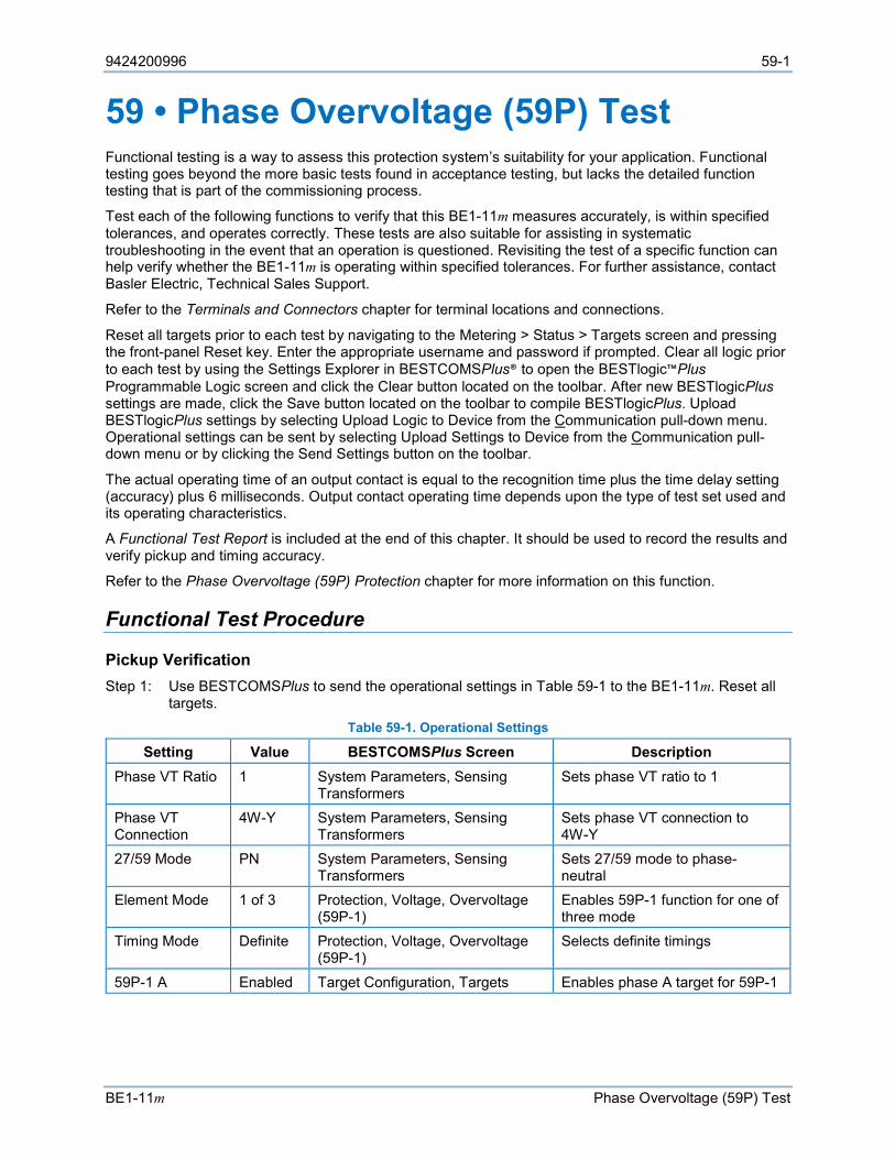
9424200996 59-1
BE1-11m Phase Overvoltage (59P) Test
59 • Phase Overvoltage (59P) Test Functional testing is a way to assess this protection system’s suitability for your application. Functional testing goes beyond the more basic tests found in acceptance testing, but lacks the detailed function testing that is part of the commissioning process.
Test each of the following functions to verify that this BE1-11m measures accurately, is within specified tolerances, and operates correctly. These tests are also suitable for assisting in systematic troubleshooting in the event that an operation is questioned. Revisiting the test of a specific function can help verify whether the BE1-11m is operating within specified tolerances. For further assistance, contact Basler Electric, Technical Sales Support.
Refer to the Terminals and Connectors chapter for terminal locations and connections.
Reset all targets prior to each test by navigating to the Metering > Status > Targets screen and pressing the front-panel Reset key. Enter the appropriate username and password if prompted. Clear all logic prior to each test by using the Settings Explorer in BESTCOMSPlus® to open the BESTlogic™Plus Programmable Logic screen and click the Clear button located on the toolbar. After new BESTlogicPlus settings are made, click the Save button located on the toolbar to compile BESTlogicPlus. Upload BESTlogicPlus settings by selecting Upload Logic to Device from the Communication pull-down menu. Operational settings can be sent by selecting Upload Settings to Device from the Communication pull-down menu or by clicking the Send Settings button on the toolbar.
The actual operating time of an output contact is equal to the recognition time plus the time delay setting (accuracy) plus 6 milliseconds. Output contact operating time depends upon the type of test set used and its operating characteristics.
A Functional Test Report is included at the end of this chapter. It should be used to record the results and verify pickup and timing accuracy.
Refer to the Phase Overvoltage (59P) Protection chapter for more information on this function.
Functional Test Procedure
Pickup Verification Step 1: Use BESTCOMSPlus to send the operational settings in Table 59-1 to the BE1-11m. Reset all
targets. Table 59-1. Operational Settings
Setting Value BESTCOMSPlus Screen Description Phase VT Ratio 1 System Parameters, Sensing
Transformers Sets phase VT ratio to 1
Phase VT Connection
4W-Y System Parameters, Sensing Transformers
Sets phase VT connection to 4W-Y
27/59 Mode PN System Parameters, Sensing Transformers
Sets 27/59 mode to phase-neutral
Element Mode 1 of 3 Protection, Voltage, Overvoltage (59P-1)
Enables 59P-1 function for one of three mode
Timing Mode Definite Protection, Voltage, Overvoltage (59P-1)
Selects definite timings
59P-1 A Enabled Target Configuration, Targets Enables phase A target for 59P-1
59-2 9424200996
Phase Overvoltage (59P) Test BE1-11m
Step 2: Use BESTCOMSPlus to configure the BESTlogicPlus programmable logic shown in Figure 59-1.
• Blocking is disabled. • OUT1 closes for 59P-1 Trip. • OUT2 closes for 59P-1 Pickup. • Fault recording is enabled.
Figure 59-1. BESTlogicPlus Settings
Step 3: Use BESTCOMSPlus to open the Protection, Voltage, Overvoltage (59P-1) screen and send the first row of test settings in Table 59-2 to the BE1-11m.
Table 59-2. Pickup Test Settings
Pickup Setting Time Delay 245 V 50 ms 125 V 50 ms 75 V 50 ms
Step 4: Prepare to monitor the 59P-1 function operation. Operation can be verified by monitoring OUT2 (see Figure 59-1).
Step 5: Connect and apply a 240 Vac, three-phase voltage source to terminals C13 (A-phase), C14 (B-phase), C15 (C-phase), and C16 (Neutral).
Step 6: Slowly increase the A-phase voltage until OUT2 closes and record the pickup. Verify that there is a 59P-1-A target on the front-panel display. Slowly decrease the A-phase voltage until OUT2 opens and record the dropout. Reset the target.
Step 7: Verify the pickup and dropout accuracy at 120 Vac for a pickup setting of 125 V and 70 Vac for a pickup setting of 75 V as listed in Table 59-2. Record the results.
Step 8: (Optional.) Repeat steps 1 through 7 for the B-phase and C-phase voltage inputs. Note: Be sure to enable proper target for each phase being tested.
Step 9: (Optional.) Repeat steps 1 through 8 for settings group 1, 2, and 3.
Step 10: (Optional.) Repeat steps 1 through 9 for 59P-2.
Timing Verification Step 1: Use BESTCOMSPlus to open the Protection, Voltage, Overvoltage (59P-1) screen and send
the first row of test settings in Table 59-3 to the BE1-11m for settings group 0. Table 59-3. Timing Test Settings
Pickup Setting Time Delay 125 V 2,000 ms
125 V 5,000 ms 125 V 10,000 ms
9424200996 59-3
BE1-11m Phase Overvoltage (59P) Test
Step 2: Prepare to monitor the 59P-1 timings. Timing accuracy is verified by measuring the elapsed time between a sensing voltage change and OUT1 closing.
Step 3: Connect and apply a 120 Vac, three-phase voltage source to terminals C13 (A-phase), C14 (B-phase), C15 (C-phase), and C16 (Neutral).
Step 4: Step the A-phase voltage up to 130 volts. Measure the time delay and record the result.
Step 5: Repeat step 4 for the 5,000 ms and 10,000 ms time delay settings of Table 59-3. Record the results.
Step 6: (Optional.) Repeat steps 1 through 5 for the B-phase and C-phase voltage inputs. Note: Be sure to enable proper target for each phase being tested.
Step 7: (Optional.) Repeat steps 1 through 6 for settings group 1, 2, and 3.
Step 8: (Optional.) Repeat steps 1 through 7 for 59P-2.
Functional Test Report
Pickup Verification Pickup Setting Range = 1 to 300 V
Pickup Accuracy = ±2% or ±1 V, whichever is greater
Dropout/Pickup Ratio = 98% ±1% Step Pickup Setting Low Actual Pickup High Low* Actual Dropout High* Pass/Fail
6 245.0 V 240.1 V 249.9 V 237.6 V 242.5 V P / F
7 125.0 V 122.5 V 127.5 V 121.3 V 123.8 V P / F
7 75.0 V 73.5 V 76.6 V 72.8 V 74.3 V P / F
* Dropout range is calculated from the pickup setting and may need adjusted based on actual pickup.
Timing Verification Time Delay Range = 50 to 600,000 ms
Timing Accuracy = ±0.5% or ±2 cycles, whichever is greater Step Time Delay Setting Low Actual Timing High Pass/Fail
4 2,000 ms 1,968 ms 2,032 ms P / F
5 5,000 ms 4,968 ms 5,032 ms P / F
5 10,000 ms 9,950 ms 10,050 ms P / F

59-4 9424200996
Phase Overvoltage (59P) Test BE1-11m
9424200996 60-1
BE1-11m Auxiliary Overvoltage (59X) Test
60 • Auxiliary Overvoltage (59X) Test Functional testing is a way to assess this protection system’s suitability for your application. Functional testing goes beyond the more basic tests found in acceptance testing, but lacks the detailed function testing that is part of the commissioning process.
Test each of the following functions to verify that this BE1-11m measures accurately, is within specified tolerances, and operates correctly. These tests are also suitable for assisting in systematic troubleshooting in the event that an operation is questioned. Revisiting the test of a specific function can help verify whether the BE1-11m is operating within specified tolerances. For further assistance, contact Basler Electric, Technical Sales Support.
Refer to the Terminals and Connectors chapter for terminal locations and connections.
Reset all targets prior to each test by navigating to the Metering > Status > Targets screen and pressing the front-panel Reset key. Enter the appropriate username and password if prompted. Clear all logic prior to each test by using the Settings Explorer in BESTCOMSPlus® to open the BESTlogic™Plus Programmable Logic screen and click the Clear button located on the toolbar. After new BESTlogicPlus settings are made, click the Save button located on the toolbar to compile BESTlogicPlus. Upload BESTlogicPlus settings by selecting Upload Logic to Device from the Communication pull-down menu. Operational settings can be sent by selecting Upload Settings to Device from the Communication pull-down menu or by clicking the Send Settings button on the toolbar.
The actual operating time of an output contact is equal to the recognition time plus the time delay setting (accuracy) plus 6 milliseconds. Output contact operating time depends upon the type of test set used and its operating characteristics.
A Functional Test Report is included at the end of this chapter. It should be used to record the results and verify pickup and timing accuracy.
Refer to the Auxiliary Overvoltage (59X) Protection chapter for more information on this function.
Functional Test Procedure
Pickup Verification (3V0 Mode) Step 1: Use BESTCOMSPlus to send the operational settings in Table 60-1 to the BE1-11m. Reset all
targets. Table 60-1. Operational Settings (3V0 Mode)
Setting Value BESTCOMSPlus Screen Description Phase VT Ratio 1 System Parameters, Sensing
Transformers Sets phase VT ratio to 1
Phase VT Connection
4W-Y System Parameters, Sensing Transformers
Sets phase VT connection to 4W-Y
27/59 Mode PN System Parameters, Sensing Transformers
Sets 27/59 mode to phase-neutral
Element Mode 3V0 Protection, Voltage, Overvoltage (59X-1)
Enables 59X-1 function for 3V0 mode
Timing Mode Definite Protection, Voltage, Overvoltage (59X-1)
Selects definite timings
59X-1 3V0 Enabled Target Configuration, Targets Enables 3V0 target for 59X-1
60-2 9424200996
Auxiliary Overvoltage (59X) Test BE1-11m
Step 2: Use BESTCOMSPlus to configure the BESTlogicPlus programmable logic shown in Figure 60-1.
• Blocking is disabled. • OUT1 closes for 59X-1 Trip. • OUT2 closes for 59X-1 Pickup. • Fault recording is enabled.
Figure 60-1. BESTlogicPlus Settings (3V0 Mode)
Step 3: Use BESTCOMSPlus to open the Protection, Voltage, Overvoltage (59X-1) screen and send the first row of test settings in Table 60-2 to the BE1-11m.
Table 60-2. Pickup Test Settings (3V0 Mode)
Pickup Setting Time Delay 115 V 50 ms 65 V 50 ms 20 V 50 ms
Step 4: Prepare to monitor the 59X-1 function operation. Operation can be verified by monitoring OUT2 (see Figure 60-1).
Step 5: Connect and apply a 150 Vac, three-phase voltage source to terminals C13 (A-phase), C14 (B-phase), C15 (C-phase), and C16 (neutral).
Step 6: Slowly increase the A-phase voltage until OUT2 closes around 265 volts (150 Vac nominal + 115 V 3V0 pickup setting) and record the pickup. Verify that there is a 59X-1-3V0 target on the front-panel display. Slowly decrease the A-phase voltage until OUT2 opens and record the dropout. Reset the target.
Step 7: Verify the pickup and dropout accuracy at a pickup setting of 65 V and 20 V as listed in Table 60-2. Record the results.
Step 8: (Optional.) Repeat steps 1 through 7 for the B-phase and C-phase voltage inputs.
Step 9: (Optional.) Repeat steps 1 through 8 for settings group 1, 2, and 3.
Step 10: (Optional.) Repeat steps 1 through 9 for 59X-2.
Timing Verification (3V0 Mode) Step 1: Use BESTCOMSPlus to open the Protection, Voltage, Overvoltage (59X-1) screen and send
the first row of test settings in Table 60-3 to the BE1-11m for settings group 0. Table 60-3. Timing Test Settings (3V0 Mode)
Pickup Setting Time Delay 65 V 2,000 ms
65 V 5,000 ms 65 V 10,000 ms
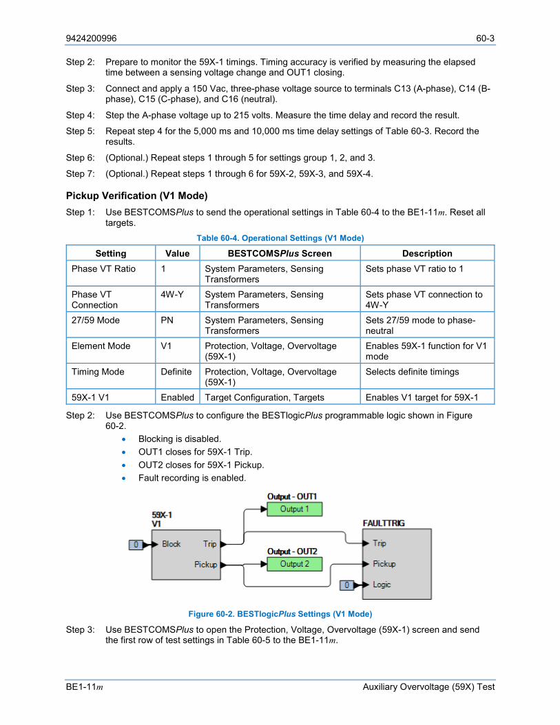
9424200996 60-3
BE1-11m Auxiliary Overvoltage (59X) Test
Step 2: Prepare to monitor the 59X-1 timings. Timing accuracy is verified by measuring the elapsed time between a sensing voltage change and OUT1 closing.
Step 3: Connect and apply a 150 Vac, three-phase voltage source to terminals C13 (A-phase), C14 (B-phase), C15 (C-phase), and C16 (neutral).
Step 4: Step the A-phase voltage up to 215 volts. Measure the time delay and record the result.
Step 5: Repeat step 4 for the 5,000 ms and 10,000 ms time delay settings of Table 60-3. Record the results.
Step 6: (Optional.) Repeat steps 1 through 5 for settings group 1, 2, and 3.
Step 7: (Optional.) Repeat steps 1 through 6 for 59X-2, 59X-3, and 59X-4.
Pickup Verification (V1 Mode) Step 1: Use BESTCOMSPlus to send the operational settings in Table 60-4 to the BE1-11m. Reset all
targets. Table 60-4. Operational Settings (V1 Mode)
Setting Value BESTCOMSPlus Screen Description Phase VT Ratio 1 System Parameters, Sensing
Transformers Sets phase VT ratio to 1
Phase VT Connection
4W-Y System Parameters, Sensing Transformers
Sets phase VT connection to 4W-Y
27/59 Mode PN System Parameters, Sensing Transformers
Sets 27/59 mode to phase-neutral
Element Mode V1 Protection, Voltage, Overvoltage (59X-1)
Enables 59X-1 function for V1 mode
Timing Mode Definite Protection, Voltage, Overvoltage (59X-1)
Selects definite timings
59X-1 V1 Enabled Target Configuration, Targets Enables V1 target for 59X-1
Step 2: Use BESTCOMSPlus to configure the BESTlogicPlus programmable logic shown in Figure 60-2.
• Blocking is disabled. • OUT1 closes for 59X-1 Trip. • OUT2 closes for 59X-1 Pickup. • Fault recording is enabled.
Figure 60-2. BESTlogicPlus Settings (V1 Mode)
Step 3: Use BESTCOMSPlus to open the Protection, Voltage, Overvoltage (59X-1) screen and send the first row of test settings in Table 60-5 to the BE1-11m.
60-4 9424200996
Auxiliary Overvoltage (59X) Test BE1-11m
Table 60-5. Pickup Test Settings (V1 Mode)
Pickup Setting Time Delay 82 V 50 ms 42 V 50 ms
25 V 50 ms
Step 4: Prepare to monitor the 59X-1 function operation. Operation can be verified by monitoring OUT2 (see Figure 60-2).
Step 5: Connect and apply a 240 Vac, single-phase voltage source to terminals C13 (A-phase) and C16 (neutral). For a single-phase input test, V1 = A-phase voltage / 3. Therefore, the BE1-11m should pick up at a value of three times the setting value when applying only a single-phase input. For example, to determine the pickup voltage value required for a BE1-11m with a pickup setting of 82, it would require 82 times 3 or 246 volts of input voltage.
Step 6: Slowly increase the voltage until OUT2 closes and record the pickup. Verify that there is a 59X-1-V1 target on the front-panel display. Slowly decrease the voltage until OUT2 opens and record the dropout. Reset the target.
Step 7: Verify the pickup and dropout accuracy at 120 Vac for a pickup setting of 42 V (126 Vac on test set) and 70 Vac for a pickup setting of 25 V (75 Vac on test set) as listed in Table 60-5. Record the results.
Step 8: (Optional.) Repeat steps 1 through 7 for the B-phase and C-phase voltage inputs.
Step 9: (Optional.) Repeat steps 1 through 8 for settings group 1, 2, and 3.
Step 10: (Optional.) Repeat steps 1 through 9 for 59X-2.
Timing Verification (V1 Mode) Step 1: Use BESTCOMSPlus to open the Protection, Voltage, Overvoltage (59X-1) screen and send
the first row of test settings in Table 60-6 to the BE1-11m for settings group 0. Table 60-6. Timing Test Settings (V1 Mode)
Pickup Setting Time Delay 42 V 2,000 ms 42 V 5,000 ms
42 V 10,000 ms
Step 2: Prepare to monitor the 59X-1 timings. Timing accuracy is verified by measuring the elapsed time between a sensing voltage change and OUT1 closing.
Step 3: Connect and apply a 120 Vac, single-phase voltage source to terminals C13 (A-phase) and C16 (neutral).
Step 4: Step the voltage up to 130 volts. Measure the time delay and record the result.
Step 5: Repeat step 4 for the 5,000 ms and 10,000 ms time delay settings of Table 60-6. Record the results.
Step 6: (Optional.) Repeat steps 1 through 5 for settings group 1, 2, and 3.
Step 7: (Optional.) Repeat steps 1 through 6 for 59X-2.
Pickup Verification (V2 Mode) Step 1: Use BESTCOMSPlus to send the operational settings in Table 60-7 to the BE1-11m. Reset all
targets.
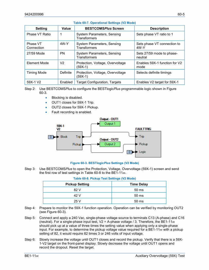
9424200996 60-5
BE1-11m Auxiliary Overvoltage (59X) Test
Table 60-7. Operational Settings (V2 Mode)
Setting Value BESTCOMSPlus Screen Description Phase VT Ratio 1 System Parameters, Sensing
Transformers Sets phase VT ratio to 1
Phase VT Connection
4W-Y System Parameters, Sensing Transformers
Sets phase VT connection to 4W-Y
27/59 Mode PN System Parameters, Sensing Transformers
Sets 27/59 mode to phase-neutral
Element Mode V2 Protection, Voltage, Overvoltage (59X-1)
Enables 59X-1 function for V2 mode
Timing Mode Definite Protection, Voltage, Overvoltage (59X-1)
Selects definite timings
59X-1 V2 Enabled Target Configuration, Targets Enables V2 target for 59X-1
Step 2: Use BESTCOMSPlus to configure the BESTlogicPlus programmable logic shown in Figure 60-3.
• Blocking is disabled. • OUT1 closes for 59X-1 Trip. • OUT2 closes for 59X-1 Pickup. • Fault recording is enabled.
Figure 60-3. BESTlogicPlus Settings (V2 Mode)
Step 3: Use BESTCOMSPlus to open the Protection, Voltage, Overvoltage (59X-1) screen and send the first row of test settings in Table 60-8 to the BE1-11m.
Table 60-8. Pickup Test Settings (V2 Mode)
Pickup Setting Time Delay 82 V 50 ms 42 V 50 ms
25 V 50 ms
Step 4: Prepare to monitor the 59X-1 function operation. Operation can be verified by monitoring OUT2 (see Figure 60-3).
Step 5: Connect and apply a 240 Vac, single-phase voltage source to terminals C13 (A-phase) and C16 (neutral). For a single-phase input test, V2 = A-phase voltage / 3. Therefore, the BE1-11m should pick up at a value of three times the setting value when applying only a single-phase input. For example, to determine the pickup voltage value required for a BE1-11m with a pickup setting of 82, it would require 82 times 3 or 246 volts of input voltage.
Step 6: Slowly increase the voltage until OUT1 closes and record the pickup. Verify that there is a 59X-1-V2 target on the front-panel display. Slowly decrease the voltage until OUT1 opens and record the dropout. Reset the target.
60-6 9424200996
Auxiliary Overvoltage (59X) Test BE1-11m
Step 7: Verify the pickup and dropout accuracy at 120 Vac for a pickup setting of 42 V (126 Vac on test set) and 70 Vac for a pickup setting of 25 V (75 Vac on test set) as listed in Table 60-8. Record the results.
Step 8: (Optional.) Repeat steps 1 through 7 for the B-phase and C-phase voltage inputs.
Step 9: (Optional.) Repeat steps 1 through 8 for settings group 1, 2, and 3.
Step 10: (Optional.) Repeat steps 1 through 9 for 59X-2.
Timing Verification (V2 Mode) Step 1: Use BESTCOMSPlus to open the Protection, Voltage, Overvoltage (59X-1) screen and send
the first row of test settings in Table 60-9 to the BE1-11m for settings group 0. Table 60-9. Timing Test Settings (V2 Mode)
Pickup Setting Time Delay 42 V 2,000 ms 42 V 5,000 ms 42 V 10,000 ms
Step 2: Prepare to monitor the 59X-1 timings. Timing accuracy is verified by measuring the elapsed time between a sensing voltage change and OUT1 closing.
Step 3: Connect and apply a 120 Vac, single-phase voltage source to terminals C13 (A-phase) and C16 (neutral).
Step 4: Step the voltage up to 130 volts. Measure the time delay and record the result.
Step 5: Repeat step 4 for the 5,000 ms and 10,000 ms time delay settings of Table 60-9. Record the results.
Step 6: (Optional.) Repeat steps 1 through 5 for settings group 1, 2, and 3.
Step 7: (Optional.) Repeat steps 1 through 6 for 59X-2.
Pickup Verification (Vx Fundamental Mode) Step 1: Use BESTCOMSPlus to send the operational settings in Table 60-10 to the BE1-11m. Reset all
targets. Table 60-10. Operational Settings (Vx Fundamental Mode)
Setting Value BESTCOMSPlus Screen Description Aux VT Ratio 1 System Parameters, Sensing
Transformers Sets auxiliary VT ratio to 1
Aux VT Connection
AN System Parameters, Sensing Transformers
Sets auxiliary VT connection to AN
Element Mode Vx Fundamental
Protection, Voltage, Overvoltage (59X-1)
Enables 59X-1 function for Vx Fundamental mode
Timing Mode Definite Protection, Voltage, Overvoltage (59X-1)
Selects definite timings
59X-1 AUX Enabled Target Configuration, Targets Enables Vx Fundamental target for 59X-1
Step 2: Use BESTCOMSPlus to configure the BESTlogicPlus programmable logic shown in Figure 60-4.
• Blocking is disabled. • OUT1 closes for 59X-1 Trip. • OUT2 closes for 59X-1 Pickup.
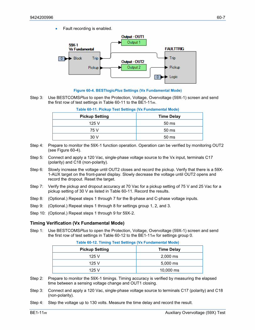
9424200996 60-7
BE1-11m Auxiliary Overvoltage (59X) Test
• Fault recording is enabled.
Figure 60-4. BESTlogicPlus Settings (Vx Fundamental Mode)
Step 3: Use BESTCOMSPlus to open the Protection, Voltage, Overvoltage (59X-1) screen and send the first row of test settings in Table 60-11 to the BE1-11m.
Table 60-11. Pickup Test Settings (Vx Fundamental Mode)
Pickup Setting Time Delay 125 V 50 ms 75 V 50 ms 30 V 50 ms
Step 4: Prepare to monitor the 59X-1 function operation. Operation can be verified by monitoring OUT2 (see Figure 60-4).
Step 5: Connect and apply a 120 Vac, single-phase voltage source to the Vx input, terminals C17 (polarity) and C18 (non-polarity).
Step 6: Slowly increase the voltage until OUT2 closes and record the pickup. Verify that there is a 59X-1-AUX target on the front-panel display. Slowly decrease the voltage until OUT2 opens and record the dropout. Reset the target.
Step 7: Verify the pickup and dropout accuracy at 70 Vac for a pickup setting of 75 V and 25 Vac for a pickup setting of 30 V as listed in Table 60-11. Record the results.
Step 8: (Optional.) Repeat steps 1 through 7 for the B-phase and C-phase voltage inputs.
Step 9: (Optional.) Repeat steps 1 through 8 for settings group 1, 2, and 3.
Step 10: (Optional.) Repeat steps 1 through 9 for 59X-2.
Timing Verification (Vx Fundamental Mode) Step 1: Use BESTCOMSPlus to open the Protection, Voltage, Overvoltage (59X-1) screen and send
the first row of test settings in Table 60-12 to the BE1-11m for settings group 0. Table 60-12. Timing Test Settings (Vx Fundamental Mode)
Pickup Setting Time Delay 125 V 2,000 ms 125 V 5,000 ms 125 V 10,000 ms
Step 2: Prepare to monitor the 59X-1 timings. Timing accuracy is verified by measuring the elapsed time between a sensing voltage change and OUT1 closing.
Step 3: Connect and apply a 120 Vac, single-phase voltage source to terminals C17 (polarity) and C18 (non-polarity).
Step 4: Step the voltage up to 130 volts. Measure the time delay and record the result.
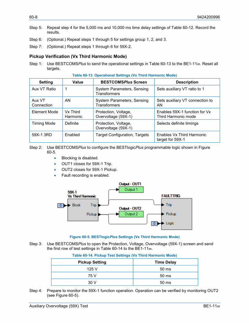
60-8 9424200996
Auxiliary Overvoltage (59X) Test BE1-11m
Step 5: Repeat step 4 for the 5,000 ms and 10,000 ms time delay settings of Table 60-12. Record the results.
Step 6: (Optional.) Repeat steps 1 through 5 for settings group 1, 2, and 3.
Step 7: (Optional.) Repeat steps 1 through 6 for 59X-2.
Pickup Verification (Vx Third Harmonic Mode) Step 1: Use BESTCOMSPlus to send the operational settings in Table 60-13 to the BE1-11m. Reset all
targets. Table 60-13. Operational Settings (Vx Third Harmonic Mode)
Setting Value BESTCOMSPlus Screen Description Aux VT Ratio 1 System Parameters, Sensing
Transformers Sets auxiliary VT ratio to 1
Aux VT Connection
AN System Parameters, Sensing Transformers
Sets auxiliary VT connection to AN
Element Mode Vx Third Harmonic
Protection, Voltage, Overvoltage (59X-1)
Enables 59X-1 function for Vx Third Harmonic mode
Timing Mode Definite Protection, Voltage, Overvoltage (59X-1)
Selects definite timings
59X-1 3RD Enabled Target Configuration, Targets Enables Vx Third Harmonic target for 59X-1
Step 2: Use BESTCOMSPlus to configure the BESTlogicPlus programmable logic shown in Figure 60-5.
• Blocking is disabled. • OUT1 closes for 59X-1 Trip. • OUT2 closes for 59X-1 Pickup. • Fault recording is enabled.
Figure 60-5. BESTlogicPlus Settings (Vx Third Harmonic Mode)
Step 3: Use BESTCOMSPlus to open the Protection, Voltage, Overvoltage (59X-1) screen and send the first row of test settings in Table 60-14 to the BE1-11m.
Table 60-14. Pickup Test Settings (Vx Third Harmonic Mode)
Pickup Setting Time Delay 125 V 50 ms 75 V 50 ms 30 V 50 ms
Step 4: Prepare to monitor the 59X-1 function operation. Operation can be verified by monitoring OUT2 (see Figure 60-5).
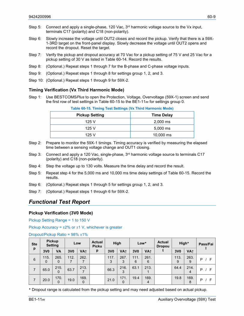
9424200996 60-9
BE1-11m Auxiliary Overvoltage (59X) Test
Step 5: Connect and apply a single-phase, 120 Vac, 3rd harmonic voltage source to the Vx input, terminals C17 (polarity) and C18 (non-polarity).
Step 6: Slowly increase the voltage until OUT2 closes and record the pickup. Verify that there is a 59X-1-3RD target on the front-panel display. Slowly decrease the voltage until OUT2 opens and record the dropout. Reset the target.
Step 7: Verify the pickup and dropout accuracy at 70 Vac for a pickup setting of 75 V and 25 Vac for a pickup setting of 30 V as listed in Table 60-14. Record the results.
Step 8: (Optional.) Repeat steps 1 through 7 for the B-phase and C-phase voltage inputs.
Step 9: (Optional.) Repeat steps 1 through 8 for settings group 1, 2, and 3.
Step 10: (Optional.) Repeat steps 1 through 9 for 59X-2.
Timing Verification (Vx Third Harmonic Mode) Step 1: Use BESTCOMSPlus to open the Protection, Voltage, Overvoltage (59X-1) screen and send
the first row of test settings in Table 60-15 to the BE1-11m for settings group 0. Table 60-15. Timing Test Settings (Vx Third Harmonic Mode)
Pickup Setting Time Delay 125 V 2,000 ms 125 V 5,000 ms 125 V 10,000 ms
Step 2: Prepare to monitor the 59X-1 timings. Timing accuracy is verified by measuring the elapsed time between a sensing voltage change and OUT1 closing.
Step 3: Connect and apply a 120 Vac, single-phase, 3rd harmonic voltage source to terminals C17 (polarity) and C18 (non-polarity).
Step 4: Step the voltage up to 130 volts. Measure the time delay and record the result.
Step 5: Repeat step 4 for the 5,000 ms and 10,000 ms time delay settings of Table 60-15. Record the results.
Step 6: (Optional.) Repeat steps 1 through 5 for settings group 1, 2, and 3.
Step 7: (Optional.) Repeat steps 1 through 6 for 59X-2.
Functional Test Report
Pickup Verification (3V0 Mode) Pickup Setting Range = 1 to 150 V
Pickup Accuracy = ±2% or ±1 V, whichever is greater
Dropout/Pickup Ratio = 98% ±1%
Step
Pickup Setting Low Actual
Pickup
High Low* Actual Dropou
t
High* Pass/Fail
3V0 VA 3V0 VA† 3V0 VA† 3V0 VA† 3V0 VA†
6 115.0
265.0
112.7
262.7 117.
3 267.
3 111.
6 261.
6 113.9
263.9 P / F
7 65.0 215.0 63.7 213.
7 66.3 216.3
63.1 213.1 64.4 214.
4 P / F
7 20.0 170.0 19.0 169.
0 21.0 171.0
19.4 169.4 19.8 169.
8 P / F
* Dropout range is calculated from the pickup setting and may need adjusted based on actual pickup.

60-10 9424200996
Auxiliary Overvoltage (59X) Test BE1-11m
† VA Low and High values are calculated as VA=3V0+150 V nominal.
Timing Verification (3V0 Mode) Time Delay Range = 50 to 600,000 ms
Timing Accuracy = ±0.5% or ±2 cycles, whichever is greater Step Time Delay Setting Low Actual Timing High Pass/Fail
4 2,000 ms 1,968 ms 2,032 ms P / F
5 5,000 ms 4,968 ms 5,032 ms P / F
5 10,000 ms 9,950 ms 10,050 ms P / F
Pickup Verification (V1 Mode) Pickup Setting Range = 1 to 150 V
Pickup Accuracy = ±2% or ±1 V, whichever is greater
Dropout/Pickup Ratio = 98% ±1%
Step Pickup Setting Low Actual
Pickup High Low* Actual
Dropout High*
Pass/Fail V1 VA V1 VA V1 VA V1 VA V1 VA
6 82.0 246.0 80.3 240.9 83.6 250.8 82.8 248.4 84.4 253.2 P / F
7 42.0 126.0 41.0 123.0 43.0 129.0 42.4 127.2 43.2 129.6 P / F
7 25.0 75.0 24.0 72.0 26.0 78.0 25.2 75.6 25.7 77.1 P / F
* Dropout range is calculated from the pickup setting and may need adjusted based on actual pickup.
Timing Verification (V1 Mode) Time Delay Range = 50 to 600,000 ms
Timing Accuracy = ±0.5% or ±2 cycles, whichever is greater Step Time Delay Setting Low Actual Timing High Pass/Fail
4 2,000 ms 1,968 ms 2,032 ms P / F
5 5,000 ms 4,968 ms 5,032 ms P / F
5 10,000 ms 9,950 ms 10,050 ms P / F
Pickup Verification (V2 Mode) Pickup Setting Range = 1 to 150 V
Pickup Accuracy = ±2% or ±1 V, whichever is greater
Dropout/Pickup Ratio = 98% ±1%
Step Pickup Setting Low Actual
Pickup High Low* Actual
Dropout High*
Pass/Fail V1 VA V1 VA V1 VA V1 VA V1 VA
6 82.0 246.0 80.3 240.9 83.6 250.8 82.8 248.4 84.4 253.2 P / F
7 42.0 126.0 41.0 123.0 43.0 129.0 42.4 127.2 43.2 129.6 P / F
7 25.0 75.0 24.0 72.0 26.0 78.0 25.2 75.6 25.7 77.1 P / F
* Dropout range is calculated from the pickup setting and may need adjusted based on actual pickup.
Timing Verification (V2 Mode) Time Delay Range = 50 to 600,000 ms
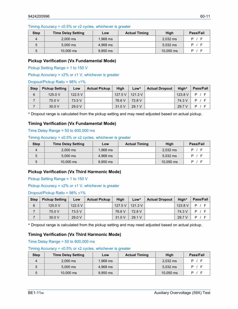
9424200996 60-11
BE1-11m Auxiliary Overvoltage (59X) Test
Timing Accuracy = ±0.5% or ±2 cycles, whichever is greater Step Time Delay Setting Low Actual Timing High Pass/Fail
4 2,000 ms 1,968 ms 2,032 ms P / F
5 5,000 ms 4,968 ms 5,032 ms P / F
5 10,000 ms 9,950 ms 10,050 ms P / F
Pickup Verification (Vx Fundamental Mode) Pickup Setting Range = 1 to 150 V
Pickup Accuracy = ±2% or ±1 V, whichever is greater
Dropout/Pickup Ratio = 98% ±1% Step Pickup Setting Low Actual Pickup High Low* Actual Dropout High* Pass/Fail
6 125.0 V 122.5 V 127.5 V 121.3 V 123.8 V P / F
7 75.0 V 73.5 V 76.6 V 72.8 V 74.3 V P / F
7 30.0 V 29.0 V 31.0 V 29.1 V 29.7 V P / F
* Dropout range is calculated from the pickup setting and may need adjusted based on actual pickup.
Timing Verification (Vx Fundamental Mode) Time Delay Range = 50 to 600,000 ms
Timing Accuracy = ±0.5% or ±2 cycles, whichever is greater Step Time Delay Setting Low Actual Timing High Pass/Fail
4 2,000 ms 1,968 ms 2,032 ms P / F
5 5,000 ms 4,968 ms 5,032 ms P / F
5 10,000 ms 9,950 ms 10,050 ms P / F
Pickup Verification (Vx Third Harmonic Mode) Pickup Setting Range = 1 to 150 V
Pickup Accuracy = ±2% or ±1 V, whichever is greater
Dropout/Pickup Ratio = 98% ±1% Step Pickup Setting Low Actual Pickup High Low* Actual Dropout High* Pass/Fail
6 125.0 V 122.5 V 127.5 V 121.3 V 123.8 V P / F
7 75.0 V 73.5 V 76.6 V 72.8 V 74.3 V P / F
7 30.0 V 29.0 V 31.0 V 29.1 V 29.7 V P / F
* Dropout range is calculated from the pickup setting and may need adjusted based on actual pickup.
Timing Verification (Vx Third Harmonic Mode) Time Delay Range = 50 to 600,000 ms
Timing Accuracy = ±0.5% or ±2 cycles, whichever is greater Step Time Delay Setting Low Actual Timing High Pass/Fail
4 2,000 ms 1,968 ms 2,032 ms P / F
5 5,000 ms 4,968 ms 5,032 ms P / F
5 10,000 ms 9,950 ms 10,050 ms P / F

60-12 9424200996
Auxiliary Overvoltage (59X) Test BE1-11m

9424200996 61-1
BE1-11m Frequency (81) Test
61 • Frequency (81) Test Functional testing is a way to assess this protection system’s suitability for your application. Functional testing goes beyond the more basic tests found in acceptance testing, but lacks the detailed function testing that is part of the commissioning process.
Test each of the following functions to verify that this BE1-11m measures accurately, is within specified tolerances, and operates correctly. These tests are also suitable for assisting in systematic troubleshooting in the event that an operation is questioned. Revisiting the test of a specific function can help verify whether the BE1-11m is operating within specified tolerances. For further assistance, contact Basler Electric, Technical Sales Support.
Refer to the Terminals and Connectors chapter for terminal locations and connections.
Reset all targets prior to each test by navigating to the Metering > Status > Targets screen and pressing the front-panel Reset key. Enter the appropriate username and password if prompted. Clear all logic prior to each test by using the Settings Explorer in BESTCOMSPlus® to open the BESTlogic™Plus Programmable Logic screen and click the Clear button located on the toolbar. After new BESTlogicPlus settings are made, click the Save button located on the toolbar to compile BESTlogicPlus. Upload BESTlogicPlus settings by selecting Upload Logic to Device from the Communication pull-down menu. Operational settings can be sent by selecting Upload Settings to Device from the Communication pull-down menu or by clicking the Send Settings button on the toolbar.
The actual operating time of an output contact is equal to the recognition time plus the time delay setting (accuracy) plus 6 milliseconds. Output contact operating time depends upon the type of test set used and its operating characteristics.
A Functional Test Report is included at the end of this chapter. It should be used to record the results and verify pickup and timing accuracy.
Refer to the Frequency (81) Protection chapter for more information on this function.
Note Testing the 81 Rate of Change (ROC) mode requires a voltage source capable of smoothly sweeping the frequency of the applied voltage for a variable positive and negative rate of change. Frequency step changes at 1 millisecond intervals (maximum) are required to support the accuracy requirement of the element.
Functional Test Procedure
Overfrequency Pickup Verification Step 1: Use BESTCOMSPlus to send the operational settings in Table 61-1 to the BE1-11m. Reset all
targets. Table 61-1. Operational Settings (Overfrequency)
Setting Value BESTCOMSPlus Screen Description Element Mode Over Protection, Frequency (81-1) Enables 81-1 function for Over mode Source Phase VT Protection, Frequency (81-1) Sets source to Phase VT Voltage Inhibit 40 V Protection, Frequency (81-1) Sets voltage inhibit pickup to 40 V
81-1 Over Enabled Target Configuration, Targets Enables Over target for 81-1
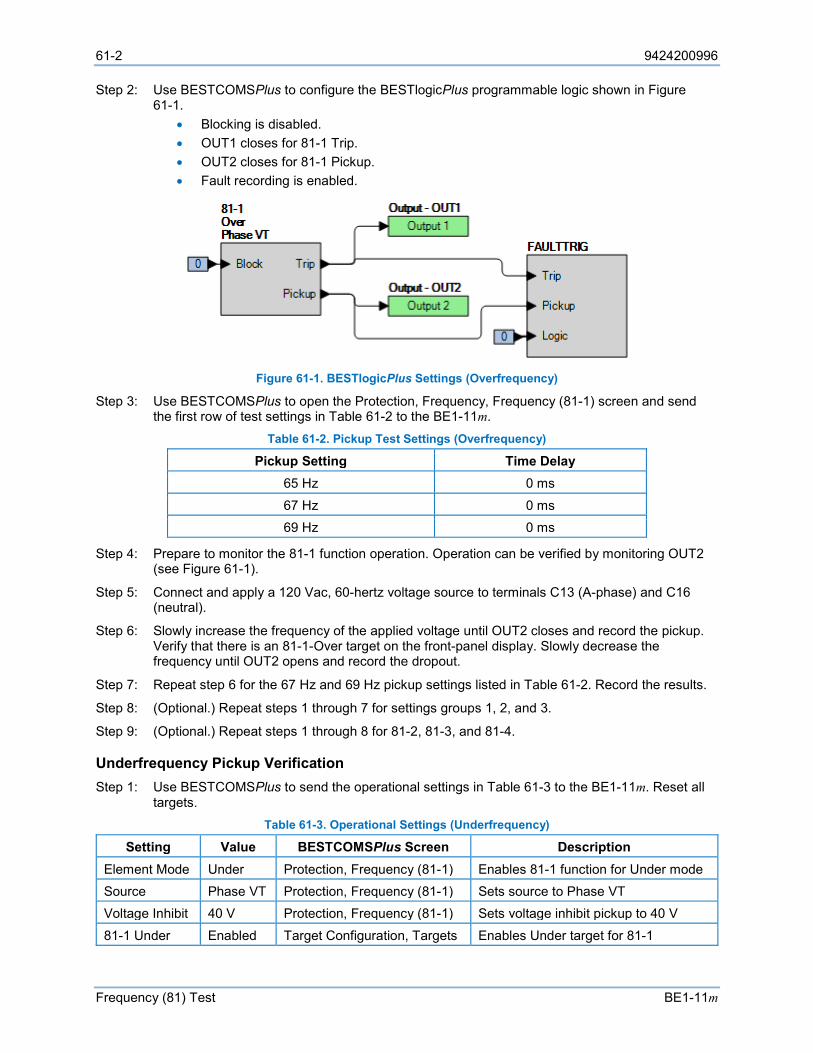
61-2 9424200996
Frequency (81) Test BE1-11m
Step 2: Use BESTCOMSPlus to configure the BESTlogicPlus programmable logic shown in Figure 61-1.
• Blocking is disabled. • OUT1 closes for 81-1 Trip. • OUT2 closes for 81-1 Pickup. • Fault recording is enabled.
Figure 61-1. BESTlogicPlus Settings (Overfrequency)
Step 3: Use BESTCOMSPlus to open the Protection, Frequency, Frequency (81-1) screen and send the first row of test settings in Table 61-2 to the BE1-11m.
Table 61-2. Pickup Test Settings (Overfrequency)
Pickup Setting Time Delay 65 Hz 0 ms
67 Hz 0 ms 69 Hz 0 ms
Step 4: Prepare to monitor the 81-1 function operation. Operation can be verified by monitoring OUT2 (see Figure 61-1).
Step 5: Connect and apply a 120 Vac, 60-hertz voltage source to terminals C13 (A-phase) and C16 (neutral).
Step 6: Slowly increase the frequency of the applied voltage until OUT2 closes and record the pickup. Verify that there is an 81-1-Over target on the front-panel display. Slowly decrease the frequency until OUT2 opens and record the dropout.
Step 7: Repeat step 6 for the 67 Hz and 69 Hz pickup settings listed in Table 61-2. Record the results.
Step 8: (Optional.) Repeat steps 1 through 7 for settings groups 1, 2, and 3.
Step 9: (Optional.) Repeat steps 1 through 8 for 81-2, 81-3, and 81-4.
Underfrequency Pickup Verification Step 1: Use BESTCOMSPlus to send the operational settings in Table 61-3 to the BE1-11m. Reset all
targets. Table 61-3. Operational Settings (Underfrequency)
Setting Value BESTCOMSPlus Screen Description Element Mode Under Protection, Frequency (81-1) Enables 81-1 function for Under mode Source Phase VT Protection, Frequency (81-1) Sets source to Phase VT Voltage Inhibit 40 V Protection, Frequency (81-1) Sets voltage inhibit pickup to 40 V
81-1 Under Enabled Target Configuration, Targets Enables Under target for 81-1
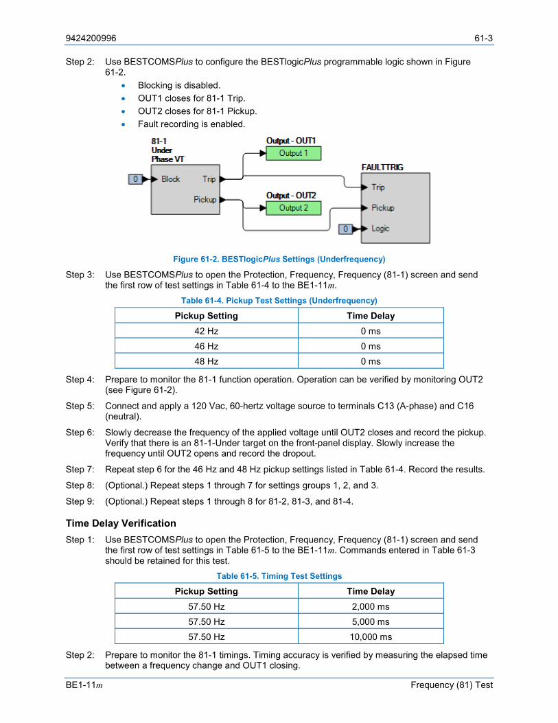
9424200996 61-3
BE1-11m Frequency (81) Test
Step 2: Use BESTCOMSPlus to configure the BESTlogicPlus programmable logic shown in Figure 61-2.
• Blocking is disabled. • OUT1 closes for 81-1 Trip. • OUT2 closes for 81-1 Pickup. • Fault recording is enabled.
Figure 61-2. BESTlogicPlus Settings (Underfrequency)
Step 3: Use BESTCOMSPlus to open the Protection, Frequency, Frequency (81-1) screen and send the first row of test settings in Table 61-4 to the BE1-11m.
Table 61-4. Pickup Test Settings (Underfrequency)
Pickup Setting Time Delay 42 Hz 0 ms 46 Hz 0 ms 48 Hz 0 ms
Step 4: Prepare to monitor the 81-1 function operation. Operation can be verified by monitoring OUT2 (see Figure 61-2).
Step 5: Connect and apply a 120 Vac, 60-hertz voltage source to terminals C13 (A-phase) and C16 (neutral).
Step 6: Slowly decrease the frequency of the applied voltage until OUT2 closes and record the pickup. Verify that there is an 81-1-Under target on the front-panel display. Slowly increase the frequency until OUT2 opens and record the dropout.
Step 7: Repeat step 6 for the 46 Hz and 48 Hz pickup settings listed in Table 61-4. Record the results.
Step 8: (Optional.) Repeat steps 1 through 7 for settings groups 1, 2, and 3.
Step 9: (Optional.) Repeat steps 1 through 8 for 81-2, 81-3, and 81-4.
Time Delay Verification Step 1: Use BESTCOMSPlus to open the Protection, Frequency, Frequency (81-1) screen and send
the first row of test settings in Table 61-5 to the BE1-11m. Commands entered in Table 61-3 should be retained for this test.
Table 61-5. Timing Test Settings
Pickup Setting Time Delay 57.50 Hz 2,000 ms 57.50 Hz 5,000 ms 57.50 Hz 10,000 ms
Step 2: Prepare to monitor the 81-1 timings. Timing accuracy is verified by measuring the elapsed time between a frequency change and OUT1 closing.

61-4 9424200996
Frequency (81) Test BE1-11m
Step 3: Connect and apply a 120 Vac, 60-hertz voltage source to terminals C13 (A-phase) and C16 (neutral).
Step 4: Step the frequency of the applied voltage down to 55-hertz. Measure the time delay and record the result.
Step 5: Repeat step 4 for the 5,000 ms and 10,000 ms time delays listed in Table 61-5. Record the results.
Step 6: (Optional.) Repeat steps 1 through 5 for settings groups 1, 2, and 3.
Step 7: (Optional.) Repeat steps 1 through 6 for 81-2, 81-3, and 81-4.
Pickup Verification (ROC Frequency) Step 1: Use BESTCOMSPlus to send the operational settings in Table 61-6 to the BE1-11m. Reset all
targets. Table 61-6. Operational Settings (ROC Frequency)
Setting Value BESTCOMSPlus Screen Description
Element Mode Rate of Change
Protection, Frequency (81-1)
Enables 81-1 function for Rate of Change mode
Source Phase VT Protection, Frequency (81-1)
Sets source to Phase VT
Pickup 10 Hz/sec Protection, Frequency (81-1)
Sets pickup to 10 Hz/sec
Voltage Inhibit 40 V Protection, Frequency (81-1)
Sets voltage inhibit pickup to 40 V
Over Frequency Inhibit
64 Hz Protection, Frequency (81-1)
Sets over frequency inhibit to 64 Hz
Under Frequency Inhibit
46 Hz Protection, Frequency (81-1)
Sets under frequency inhibit to 46 Hz
81-1 ROC Enabled Target Configuration, Targets
Enables ROC target for 81-1
Step 2: Use BESTCOMSPlus to configure the BESTlogicPlus programmable logic shown in Figure 61-3.
• Blocking is disabled. • OUT1 closes for 81-1 Trip. • OUT2 closes for 81-1 Pickup. • Fault recording is enabled.
Figure 61-3. BESTlogicPlus Settings (ROC Frequency)
Step 3: Prepare to monitor the 81-1 function operation. Operation can be verified by monitoring OUT2 (see Figure 61-3).
9424200996 61-5
BE1-11m Frequency (81) Test
Step 4: Connect a 120 Vac voltage source capable of smoothly sweeping the frequency from 35 Hz to 75 Hz to terminals C13 (A-phase) and C16 (neutral).
Step 5: Set the ramp rate at 0.001 seconds/step (max level, lower if possible) and set the total number steps at 1,000 (one second total for the sweep test).
Step 6: Set the frequency range of the sweep (ramp) for 55.0 to 64.7 Hz. This equates to a ROC of 9.7 Hz/sec (3.0% below the 10.0 Hz/sec pickup setting).
Step 7: Initiate the sweep (ramp) which simultaneously applies voltage to the BE1-11m and note that there is no operation of OUT2.
Step 8: Increase the rate of change in increments of 1% (9.8, 9.9 Hz/sec) up to 9.9 Hz/sec and 0.5% thereafter until OUT2 closes and record the pickup.
Step 9: Repeat steps 3 through 8 with the pickup value set at 2 Hz/sec. Begin the test by applying a rate of change value 8% below pickup (1.84 Hz/sec or a frequency sweep range of 59 to 60.84 Hz). Increase the rate of change in 1% increments until OUT2 closes and record the pickup.
Step 10: (Optional.) Repeat steps 1 through 9 in Positive ROC mode. Additionally, verify that a sweep from a high to low frequency does not cause an operation.
Step 11: (Optional.) Repeat steps 1 through 9 in Negative ROC mode by reversing the sweep rate from high to low to simulate negative rate of change. Additionally, verify that a sweep from a low to high frequency does not cause an operation.
Step 12: (Optional.) Repeat steps 1 through 11 for settings group 1, 2, and 3.
Step 13: (Optional.) Repeat steps 1 through 12 for 81-2, 81-3, and 81-4.
Time Delay Verification (ROC Frequency) Time delay verification is not necessary for the ROC mode as the same timers are used as in the over/underfrequency timing tests. Timing starts when the 81 Pickup goes high whether the cause is over, under, or rate of change.
Inhibit Quantities (ROC Inhibit) Operation in the rate of change mode can be inhibited by sensing voltage, negative-sequence voltage, and frequency limits or range, the latter of which creates a “frequency window” of operation. The sensing voltage inhibit is the same feature used for the over/underfrequency elements and has already been tested. The following tests verify the negative-sequence and frequency limit inhibits.
Step 1: Use the Settings Explorer in BESTCOMSPlus to open the Protection, Frequency, Frequency (81-1) screen and send the operational settings in Table 61-7 to the BE1-11m.
Table 61-7. Operational Settings (ROC Inhibit)
Setting Value Description Element Mode Rate of Change Enables 81-1 function for Rate of Change mode Source Phase VT Sets source to Phase VT Pickup 2 Hz/sec Sets pickup to 2 Hz/sec
Time Delay 0 ms Sets time delay to minimum Voltage Inhibit 40 V Sets voltage inhibit pickup to 40 V Over Frequency Inhibit 64 Hz Sets overfrequency inhibit to 64 Hz
Under Frequency Inhibit 46 Hz Sets underfrequency inhibit to 46 Hz Negative Sequence Inhibit 20% Sets negative-sequence inhibit to 20%
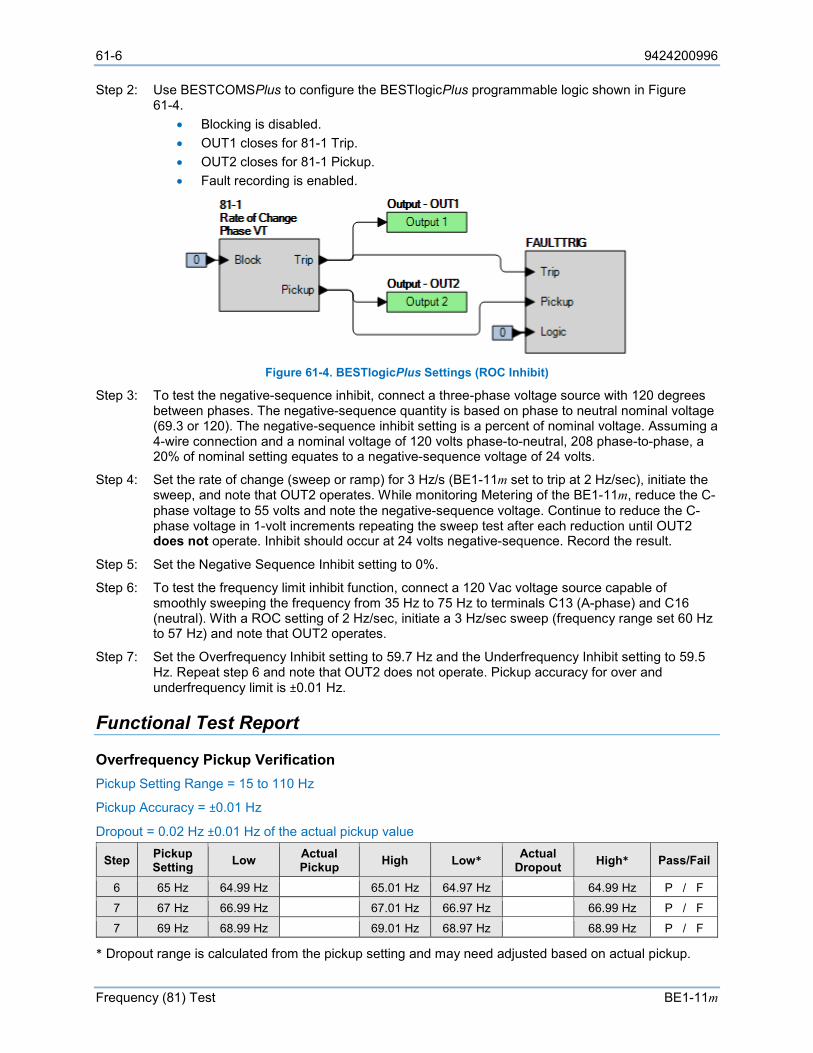
61-6 9424200996
Frequency (81) Test BE1-11m
Step 2: Use BESTCOMSPlus to configure the BESTlogicPlus programmable logic shown in Figure 61-4.
• Blocking is disabled. • OUT1 closes for 81-1 Trip. • OUT2 closes for 81-1 Pickup. • Fault recording is enabled.
Figure 61-4. BESTlogicPlus Settings (ROC Inhibit)
Step 3: To test the negative-sequence inhibit, connect a three-phase voltage source with 120 degrees between phases. The negative-sequence quantity is based on phase to neutral nominal voltage (69.3 or 120). The negative-sequence inhibit setting is a percent of nominal voltage. Assuming a 4-wire connection and a nominal voltage of 120 volts phase-to-neutral, 208 phase-to-phase, a 20% of nominal setting equates to a negative-sequence voltage of 24 volts.
Step 4: Set the rate of change (sweep or ramp) for 3 Hz/s (BE1-11m set to trip at 2 Hz/sec), initiate the sweep, and note that OUT2 operates. While monitoring Metering of the BE1-11m, reduce the C-phase voltage to 55 volts and note the negative-sequence voltage. Continue to reduce the C-phase voltage in 1-volt increments repeating the sweep test after each reduction until OUT2 does not operate. Inhibit should occur at 24 volts negative-sequence. Record the result.
Step 5: Set the Negative Sequence Inhibit setting to 0%.
Step 6: To test the frequency limit inhibit function, connect a 120 Vac voltage source capable of smoothly sweeping the frequency from 35 Hz to 75 Hz to terminals C13 (A-phase) and C16 (neutral). With a ROC setting of 2 Hz/sec, initiate a 3 Hz/sec sweep (frequency range set 60 Hz to 57 Hz) and note that OUT2 operates.
Step 7: Set the Overfrequency Inhibit setting to 59.7 Hz and the Underfrequency Inhibit setting to 59.5 Hz. Repeat step 6 and note that OUT2 does not operate. Pickup accuracy for over and underfrequency limit is ±0.01 Hz.
Functional Test Report
Overfrequency Pickup Verification Pickup Setting Range = 15 to 110 Hz
Pickup Accuracy = ±0.01 Hz
Dropout = 0.02 Hz ±0.01 Hz of the actual pickup value
Step Pickup Setting Low Actual
Pickup High Low* Actual Dropout High* Pass/Fail
6 65 Hz 64.99 Hz 65.01 Hz 64.97 Hz 64.99 Hz P / F
7 67 Hz 66.99 Hz 67.01 Hz 66.97 Hz 66.99 Hz P / F
7 69 Hz 68.99 Hz 69.01 Hz 68.97 Hz 68.99 Hz P / F
* Dropout range is calculated from the pickup setting and may need adjusted based on actual pickup.
9424200996 61-7
BE1-11m Frequency (81) Test
Underfrequency Pickup Verification Pickup Setting Range = 15 to 110 Hz
Pickup Accuracy = ±0.01 Hz
Reset = 0.02 Hz ±0.01 Hz of the actual pickup value
Step Pickup Setting Low Actual
Pickup High Low* Actual Dropout High* Pass/Fail
6 42 Hz 41.99 Hz 42.01 Hz 41.97 Hz 41.99 Hz P / F
7 46 Hz 45.99 Hz 46.01 Hz 45.97 Hz 45.99 Hz P / F
7 48 Hz 47.99 Hz 48.01 Hz 47.97 Hz 47.99 Hz P / F
* Reset range is calculated from the pickup setting and may need adjusted based on actual pickup.
Time Delay Verification Time Delay Range = 0 to 600,000 ms
Timing Accuracy = ±0.5% or ±1 cycle, whichever is greater + 3 cycles recognition time for time delay settings < 50 ms
Step Time Delay Setting Low Actual Timing High Pass/Fail 4 2,000 ms 1,983 ms 2,017 ms P / F
5 5,000 ms 4,975 ms 5,025 ms P / F
5 10,000 ms 9,950 ms 10,050 ms P / F
Pickup Verification (ROC Frequency) ROC Pickup Setting Range = 0.2 to 20 Hz/sec
Accuracy = ±2% or ±0.1 Hz/sec, whichever is greater Step Setting Low Pickup High Pass/Fail
8 10 Hz/sec 9.8 Hz/sec 10.2 Hz/sec P / F
9 2 Hz/sec 1.9 Hz/sec 2.1 Hz/sec P / F

61-8 9424200996
Frequency (81) Test BE1-11m
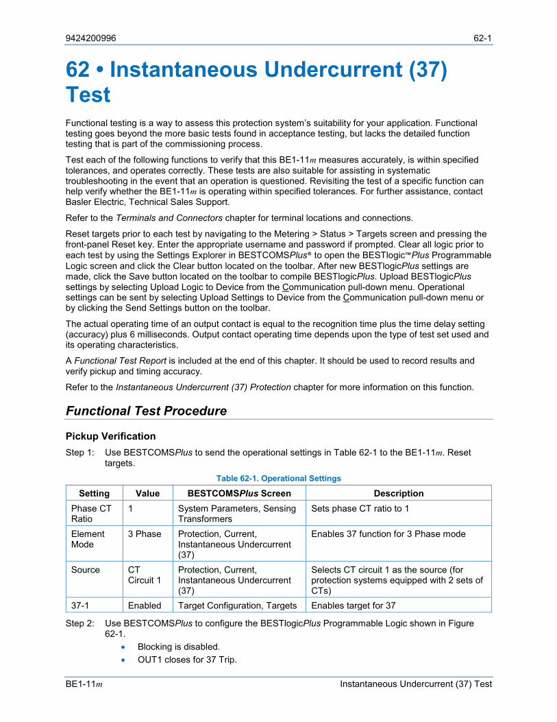
9424200996 62-1
BE1-11m Instantaneous Undercurrent (37) Test
62 • Instantaneous Undercurrent (37) Test Functional testing is a way to assess this protection system’s suitability for your application. Functional testing goes beyond the more basic tests found in acceptance testing, but lacks the detailed function testing that is part of the commissioning process.
Test each of the following functions to verify that this BE1-11m measures accurately, is within specified tolerances, and operates correctly. These tests are also suitable for assisting in systematic troubleshooting in the event that an operation is questioned. Revisiting the test of a specific function can help verify whether the BE1-11m is operating within specified tolerances. For further assistance, contact Basler Electric, Technical Sales Support.
Refer to the Terminals and Connectors chapter for terminal locations and connections.
Reset targets prior to each test by navigating to the Metering > Status > Targets screen and pressing the front-panel Reset key. Enter the appropriate username and password if prompted. Clear all logic prior to each test by using the Settings Explorer in BESTCOMSPlus® to open the BESTlogic™Plus Programmable Logic screen and click the Clear button located on the toolbar. After new BESTlogicPlus settings are made, click the Save button located on the toolbar to compile BESTlogicPlus. Upload BESTlogicPlus settings by selecting Upload Logic to Device from the Communication pull-down menu. Operational settings can be sent by selecting Upload Settings to Device from the Communication pull-down menu or by clicking the Send Settings button on the toolbar.
The actual operating time of an output contact is equal to the recognition time plus the time delay setting (accuracy) plus 6 milliseconds. Output contact operating time depends upon the type of test set used and its operating characteristics.
A Functional Test Report is included at the end of this chapter. It should be used to record results and verify pickup and timing accuracy.
Refer to the Instantaneous Undercurrent (37) Protection chapter for more information on this function.
Functional Test Procedure
Pickup Verification Step 1: Use BESTCOMSPlus to send the operational settings in Table 62-1 to the BE1-11m. Reset
targets. Table 62-1. Operational Settings
Setting Value BESTCOMSPlus Screen Description Phase CT Ratio
1 System Parameters, Sensing Transformers
Sets phase CT ratio to 1
Element Mode
3 Phase Protection, Current, Instantaneous Undercurrent (37)
Enables 37 function for 3 Phase mode
Source CT Circuit 1
Protection, Current, Instantaneous Undercurrent (37)
Selects CT circuit 1 as the source (for protection systems equipped with 2 sets of CTs)
37-1 Enabled Target Configuration, Targets Enables target for 37
Step 2: Use BESTCOMSPlus to configure the BESTlogicPlus Programmable Logic shown in Figure 62-1.
• Blocking is disabled. • OUT1 closes for 37 Trip.

62-2 9424200996
Instantaneous Undercurrent (37) Test BE1-11m
• OUT2 closes for 37 Pickup. • Fault recording is enabled.
Figure 62-1. BESTlogicPlus Settings
Step 3: Use BESTCOMSPlus to open the Protection, Current, Instantaneous Undercurrent (37) screen and send the low range test settings (minimum pickup setting) to the BE1-11m for your sensing input type in Table 62-2.
Table 62-2. Pickup Test Settings
Sensing Input Type Range Pickup Setting Time Delay
5 A Low 0.5 A 0 ms
Middle 5.0 A 0 ms High 20.0 A 0 ms
1 A Low 0.1 A 0 ms
Middle 1.0 A 0 ms High 4.0 A 0 ms
Step 4: Prepare to monitor the 37 function operation. Operation can be verified by monitoring OUT2 (see Figure 62-1).
Step 5: Connect a current source and apply 0.6 Aac to terminals D1 and D2 (A-phase). Note that IA, IB, or IC can be used for this test. Test is conducted on IA.
Step 6: Slowly decrease the A-phase current until OUT2 closes and record pickup. Verify the 37-1 target on the front-panel display. Slowly increase the applied current until OUT2 opens and record reset.
Step 7: Repeat step 6 for the middle and high range pickup settings for your sensing input type. Record the results.
Step 8: (Optional.) Repeat steps 1 through 7 for settings group 1, 2, and 3.
Step 9: (Optional.) Repeat steps 1 through 8 with CT Circuit 2 as the source for protection systems equipped with two sets of CTs. In step 5, replace D1 with F1, D2 with F2, etc.
Timing Verification Step 1: Use BESTCOMSPlus to open the Protection, Current, Instantaneous Undercurrent (37) screen
and send the first row of test settings in Table 62-3 to the BE1-11m for settings group 0. Table 62-3. Timing Test Settings
Pickup Setting Time Delay 0.5 A 2000 ms 0.5 A 5000 ms 0.5 A 10000 ms
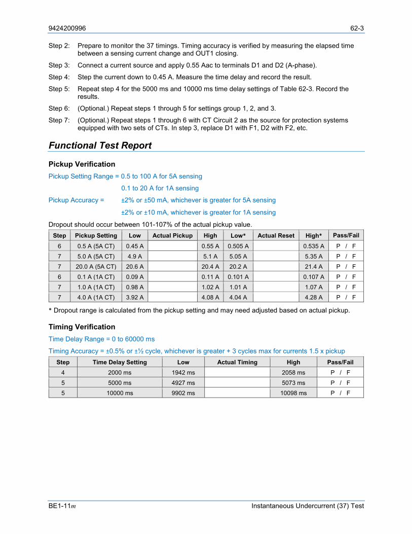
9424200996 62-3
BE1-11m Instantaneous Undercurrent (37) Test
Step 2: Prepare to monitor the 37 timings. Timing accuracy is verified by measuring the elapsed time between a sensing current change and OUT1 closing.
Step 3: Connect a current source and apply 0.55 Aac to terminals D1 and D2 (A-phase).
Step 4: Step the current down to 0.45 A. Measure the time delay and record the result.
Step 5: Repeat step 4 for the 5000 ms and 10000 ms time delay settings of Table 62-3. Record the results.
Step 6: (Optional.) Repeat steps 1 through 5 for settings group 1, 2, and 3.
Step 7: (Optional.) Repeat steps 1 through 6 with CT Circuit 2 as the source for protection systems equipped with two sets of CTs. In step 3, replace D1 with F1, D2 with F2, etc.
Functional Test Report
Pickup Verification Pickup Setting Range = 0.5 to 100 A for 5A sensing
0.1 to 20 A for 1A sensing
Pickup Accuracy = ±2% or ±50 mA, whichever is greater for 5A sensing
±2% or ±10 mA, whichever is greater for 1A sensing
Dropout should occur between 101-107% of the actual pickup value. Step Pickup Setting Low Actual Pickup High Low* Actual Reset High* Pass/Fail
6 0.5 A (5A CT) 0.45 A 0.55 A 0.505 A 0.535 A P / F
7 5.0 A (5A CT) 4.9 A 5.1 A 5.05 A 5.35 A P / F
7 20.0 A (5A CT) 20.6 A 20.4 A 20.2 A 21.4 A P / F
6 0.1 A (1A CT) 0.09 A 0.11 A 0.101 A 0.107 A P / F
7 1.0 A (1A CT) 0.98 A 1.02 A 1.01 A 1.07 A P / F
7 4.0 A (1A CT) 3.92 A 4.08 A 4.04 A 4.28 A P / F
* Dropout range is calculated from the pickup setting and may need adjusted based on actual pickup.
Timing Verification Time Delay Range = 0 to 60000 ms
Timing Accuracy = ±0.5% or ±½ cycle, whichever is greater + 3 cycles max for currents 1.5 x pickup Step Time Delay Setting Low Actual Timing High Pass/Fail
4 2000 ms 1942 ms 2058 ms P / F
5 5000 ms 4927 ms 5073 ms P / F
5 10000 ms 9902 ms 10098 ms P / F

62-4 9424200996
Instantaneous Undercurrent (37) Test BE1-11m
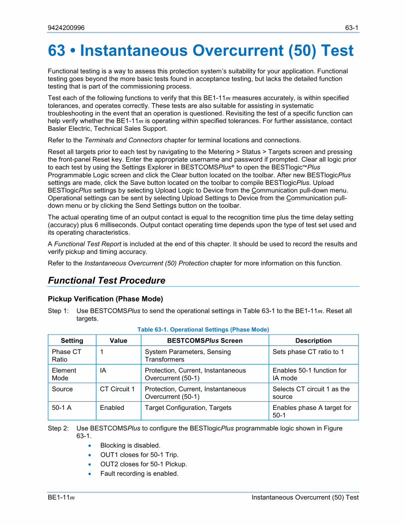
9424200996 63-1
BE1-11m Instantaneous Overcurrent (50) Test
63 • Instantaneous Overcurrent (50) Test Functional testing is a way to assess this protection system’s suitability for your application. Functional testing goes beyond the more basic tests found in acceptance testing, but lacks the detailed function testing that is part of the commissioning process.
Test each of the following functions to verify that this BE1-11m measures accurately, is within specified tolerances, and operates correctly. These tests are also suitable for assisting in systematic troubleshooting in the event that an operation is questioned. Revisiting the test of a specific function can help verify whether the BE1-11m is operating within specified tolerances. For further assistance, contact Basler Electric, Technical Sales Support.
Refer to the Terminals and Connectors chapter for terminal locations and connections.
Reset all targets prior to each test by navigating to the Metering > Status > Targets screen and pressing the front-panel Reset key. Enter the appropriate username and password if prompted. Clear all logic prior to each test by using the Settings Explorer in BESTCOMSPlus® to open the BESTlogic™Plus Programmable Logic screen and click the Clear button located on the toolbar. After new BESTlogicPlus settings are made, click the Save button located on the toolbar to compile BESTlogicPlus. Upload BESTlogicPlus settings by selecting Upload Logic to Device from the Communication pull-down menu. Operational settings can be sent by selecting Upload Settings to Device from the Communication pull-down menu or by clicking the Send Settings button on the toolbar.
The actual operating time of an output contact is equal to the recognition time plus the time delay setting (accuracy) plus 6 milliseconds. Output contact operating time depends upon the type of test set used and its operating characteristics.
A Functional Test Report is included at the end of this chapter. It should be used to record the results and verify pickup and timing accuracy.
Refer to the Instantaneous Overcurrent (50) Protection chapter for more information on this function.
Functional Test Procedure
Pickup Verification (Phase Mode) Step 1: Use BESTCOMSPlus to send the operational settings in Table 63-1 to the BE1-11m. Reset all
targets. Table 63-1. Operational Settings (Phase Mode)
Setting Value BESTCOMSPlus Screen Description Phase CT Ratio
1 System Parameters, Sensing Transformers
Sets phase CT ratio to 1
Element Mode
IA Protection, Current, Instantaneous Overcurrent (50-1)
Enables 50-1 function for IA mode
Source CT Circuit 1 Protection, Current, Instantaneous Overcurrent (50-1)
Selects CT circuit 1 as the source
50-1 A Enabled Target Configuration, Targets Enables phase A target for 50-1
Step 2: Use BESTCOMSPlus to configure the BESTlogicPlus programmable logic shown in Figure 63-1.
• Blocking is disabled. • OUT1 closes for 50-1 Trip. • OUT2 closes for 50-1 Pickup. • Fault recording is enabled.
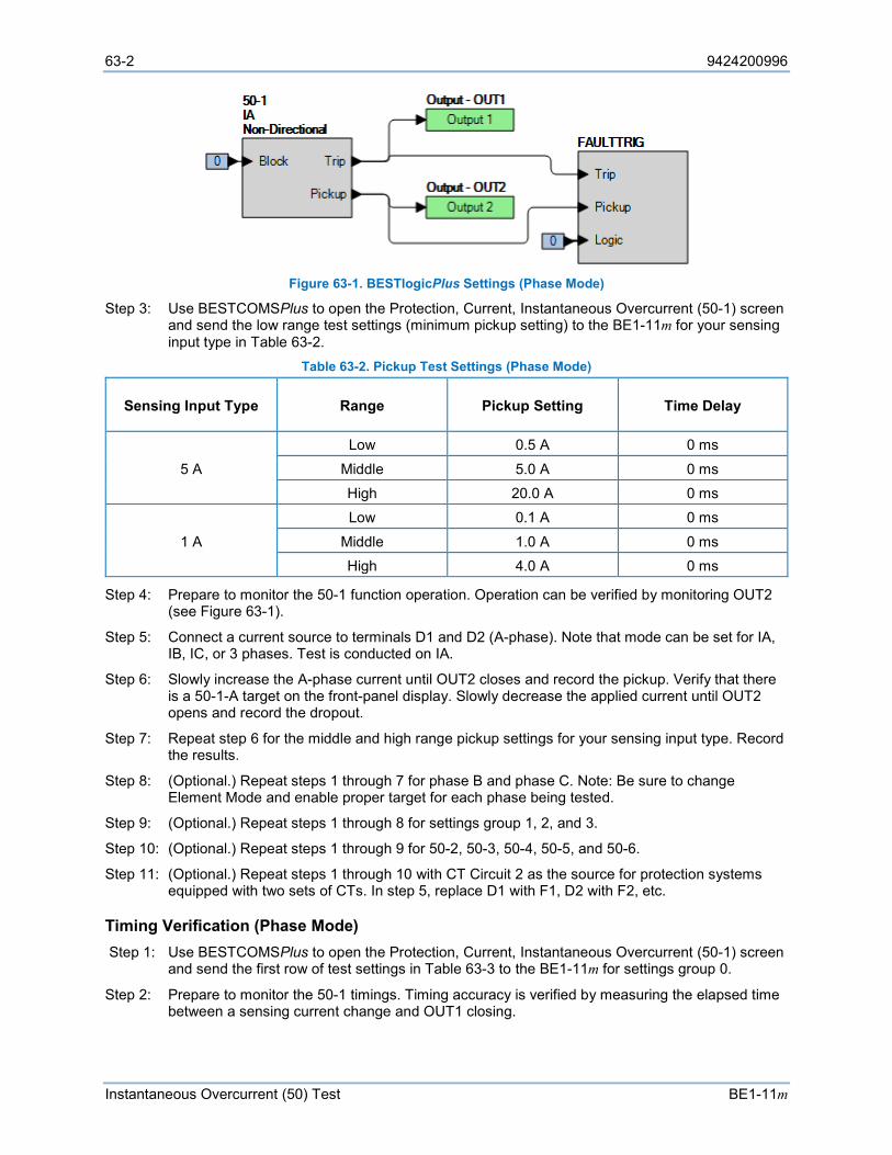
63-2 9424200996
Instantaneous Overcurrent (50) Test BE1-11m
Figure 63-1. BESTlogicPlus Settings (Phase Mode)
Step 3: Use BESTCOMSPlus to open the Protection, Current, Instantaneous Overcurrent (50-1) screen and send the low range test settings (minimum pickup setting) to the BE1-11m for your sensing input type in Table 63-2.
Table 63-2. Pickup Test Settings (Phase Mode)
Sensing Input Type Range Pickup Setting Time Delay
5 A
Low 0.5 A 0 ms
Middle 5.0 A 0 ms High 20.0 A 0 ms
1 A
Low 0.1 A 0 ms
Middle 1.0 A 0 ms High 4.0 A 0 ms
Step 4: Prepare to monitor the 50-1 function operation. Operation can be verified by monitoring OUT2 (see Figure 63-1).
Step 5: Connect a current source to terminals D1 and D2 (A-phase). Note that mode can be set for IA, IB, IC, or 3 phases. Test is conducted on IA.
Step 6: Slowly increase the A-phase current until OUT2 closes and record the pickup. Verify that there is a 50-1-A target on the front-panel display. Slowly decrease the applied current until OUT2 opens and record the dropout.
Step 7: Repeat step 6 for the middle and high range pickup settings for your sensing input type. Record the results.
Step 8: (Optional.) Repeat steps 1 through 7 for phase B and phase C. Note: Be sure to change Element Mode and enable proper target for each phase being tested.
Step 9: (Optional.) Repeat steps 1 through 8 for settings group 1, 2, and 3.
Step 10: (Optional.) Repeat steps 1 through 9 for 50-2, 50-3, 50-4, 50-5, and 50-6.
Step 11: (Optional.) Repeat steps 1 through 10 with CT Circuit 2 as the source for protection systems equipped with two sets of CTs. In step 5, replace D1 with F1, D2 with F2, etc.
Timing Verification (Phase Mode) Step 1: Use BESTCOMSPlus to open the Protection, Current, Instantaneous Overcurrent (50-1) screen
and send the first row of test settings in Table 63-3 to the BE1-11m for settings group 0.
Step 2: Prepare to monitor the 50-1 timings. Timing accuracy is verified by measuring the elapsed time between a sensing current change and OUT1 closing.
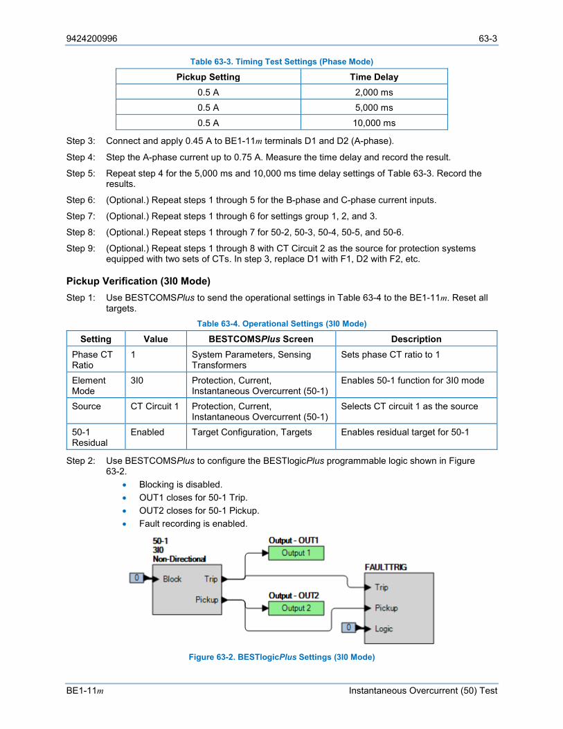
9424200996 63-3
BE1-11m Instantaneous Overcurrent (50) Test
Table 63-3. Timing Test Settings (Phase Mode)
Pickup Setting Time Delay 0.5 A 2,000 ms 0.5 A 5,000 ms
0.5 A 10,000 ms
Step 3: Connect and apply 0.45 A to BE1-11m terminals D1 and D2 (A-phase).
Step 4: Step the A-phase current up to 0.75 A. Measure the time delay and record the result.
Step 5: Repeat step 4 for the 5,000 ms and 10,000 ms time delay settings of Table 63-3. Record the results.
Step 6: (Optional.) Repeat steps 1 through 5 for the B-phase and C-phase current inputs.
Step 7: (Optional.) Repeat steps 1 through 6 for settings group 1, 2, and 3.
Step 8: (Optional.) Repeat steps 1 through 7 for 50-2, 50-3, 50-4, 50-5, and 50-6.
Step 9: (Optional.) Repeat steps 1 through 8 with CT Circuit 2 as the source for protection systems equipped with two sets of CTs. In step 3, replace D1 with F1, D2 with F2, etc.
Pickup Verification (3I0 Mode) Step 1: Use BESTCOMSPlus to send the operational settings in Table 63-4 to the BE1-11m. Reset all
targets. Table 63-4. Operational Settings (3I0 Mode)
Setting Value BESTCOMSPlus Screen Description Phase CT Ratio
1 System Parameters, Sensing Transformers
Sets phase CT ratio to 1
Element Mode
3I0 Protection, Current, Instantaneous Overcurrent (50-1)
Enables 50-1 function for 3I0 mode
Source CT Circuit 1 Protection, Current, Instantaneous Overcurrent (50-1)
Selects CT circuit 1 as the source
50-1 Residual
Enabled Target Configuration, Targets Enables residual target for 50-1
Step 2: Use BESTCOMSPlus to configure the BESTlogicPlus programmable logic shown in Figure 63-2.
• Blocking is disabled. • OUT1 closes for 50-1 Trip. • OUT2 closes for 50-1 Pickup. • Fault recording is enabled.
Figure 63-2. BESTlogicPlus Settings (3I0 Mode)
63-4 9424200996
Instantaneous Overcurrent (50) Test BE1-11m
Step 3: Use BESTCOMSPlus to open the Protection, Current, Instantaneous Overcurrent (50-1) screen and send the low range test settings (minimum pickup setting) to the BE1-11m for your sensing input type in Table 63-5.
Table 63-5. Pickup Test Settings (3I0 Mode)
Sensing Input Type Range Pickup Setting Time Delay
5 A Low 0.5 A 0 ms
Middle 5.0 A 0 ms High 20.0 A 0 ms
1 A Low 0.1 A 0 ms
Middle 1.0 A 0 ms High 4.0 A 0 ms
Step 4: Prepare to monitor the 50-1 function operation. Operation can be verified by monitoring OUT2 (see Figure 63-2).
Step 5: Connect a current source to terminals D1 and D2 (A-phase).
Step 6: Slowly increase the A-phase current until OUT2 closes and record the pickup. Verify that there is a 50-1-Residual target on the front-panel display. Slowly decrease the applied current until OUT2 opens and record the dropout.
Step 7: Repeat step 6 for the middle and high range pickup settings for your sensing input type. Record the results.
Step 8: (Optional.) Repeat steps 1 through 7 for settings group 1, 2, and 3.
Step 9: (Optional.) Repeat steps 1 through 8 for 50-2, 50-3, 50-4, 50-5, and 50-6.
Step 10: (Optional.) Repeat steps 1 through 9 with CT Circuit 2 as the source for protection systems equipped with two sets of CTs. In step 5, replace D1 with F1, D2 with F2, etc.
Timing Verification (3I0 Mode) Step 1: Use BESTCOMSPlus to open the Protection, Current, Instantaneous Overcurrent (50-1) screen
and send the first row of test settings in Table 63-6 to the BE1-11m for settings group 0. Table 63-6. Timing Test Settings (3I0 Mode)
Pickup Setting Time Delay 0.5 A 2,000 ms
0.5 A 5,000 ms 0.5 A 10,000 ms
Step 2: Prepare to monitor the 50-1 timings. Timing accuracy is verified by measuring the elapsed time between a sensing current change and OUT1 closing.
Step 3: Connect and apply 0.45 A to BE1-11m terminals D1 and D2 (A-phase).
Step 4: Step the A-phase current up to 0.55 A. Measure the time delay and record the result.
Step 5: Repeat step 4 for the 5,000 ms and 10,000 ms time delay settings of Table 63-6. Record the results.
Step 6: (Optional.) Repeat steps 1 through 5 for settings group 1, 2, and 3.
Step 7: (Optional.) Repeat steps 1 through 6 for 50-2, 50-3, 50-4, 50-5, and 50-6.
Step 8: (Optional.) Repeat steps 1 through 7 with CT Circuit 2 as the source for protection systems equipped with two sets of CTs. In step 5, replace D1 with F1, D2 with F2, etc.
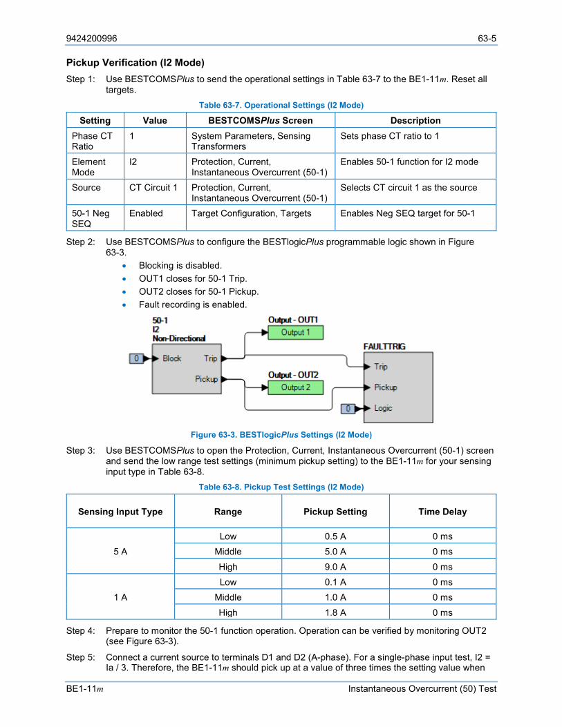
9424200996 63-5
BE1-11m Instantaneous Overcurrent (50) Test
Pickup Verification (I2 Mode) Step 1: Use BESTCOMSPlus to send the operational settings in Table 63-7 to the BE1-11m. Reset all
targets. Table 63-7. Operational Settings (I2 Mode)
Setting Value BESTCOMSPlus Screen Description Phase CT Ratio
1 System Parameters, Sensing Transformers
Sets phase CT ratio to 1
Element Mode
I2 Protection, Current, Instantaneous Overcurrent (50-1)
Enables 50-1 function for I2 mode
Source CT Circuit 1 Protection, Current, Instantaneous Overcurrent (50-1)
Selects CT circuit 1 as the source
50-1 Neg SEQ
Enabled Target Configuration, Targets Enables Neg SEQ target for 50-1
Step 2: Use BESTCOMSPlus to configure the BESTlogicPlus programmable logic shown in Figure 63-3.
• Blocking is disabled. • OUT1 closes for 50-1 Trip. • OUT2 closes for 50-1 Pickup. • Fault recording is enabled.
Figure 63-3. BESTlogicPlus Settings (I2 Mode)
Step 3: Use BESTCOMSPlus to open the Protection, Current, Instantaneous Overcurrent (50-1) screen and send the low range test settings (minimum pickup setting) to the BE1-11m for your sensing input type in Table 63-8.
Table 63-8. Pickup Test Settings (I2 Mode)
Sensing Input Type Range Pickup Setting Time Delay
5 A Low 0.5 A 0 ms
Middle 5.0 A 0 ms
High 9.0 A 0 ms
1 A Low 0.1 A 0 ms
Middle 1.0 A 0 ms
High 1.8 A 0 ms
Step 4: Prepare to monitor the 50-1 function operation. Operation can be verified by monitoring OUT2 (see Figure 63-3).
Step 5: Connect a current source to terminals D1 and D2 (A-phase). For a single-phase input test, I2 = Ia / 3. Therefore, the BE1-11m should pick up at a value of three times the setting value when
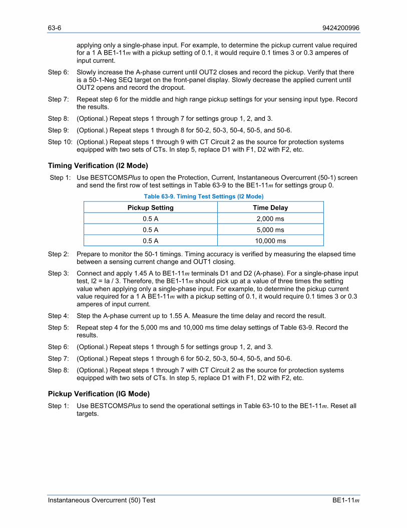
63-6 9424200996
Instantaneous Overcurrent (50) Test BE1-11m
applying only a single-phase input. For example, to determine the pickup current value required for a 1 A BE1-11m with a pickup setting of 0.1, it would require 0.1 times 3 or 0.3 amperes of input current.
Step 6: Slowly increase the A-phase current until OUT2 closes and record the pickup. Verify that there is a 50-1-Neg SEQ target on the front-panel display. Slowly decrease the applied current until OUT2 opens and record the dropout.
Step 7: Repeat step 6 for the middle and high range pickup settings for your sensing input type. Record the results.
Step 8: (Optional.) Repeat steps 1 through 7 for settings group 1, 2, and 3.
Step 9: (Optional.) Repeat steps 1 through 8 for 50-2, 50-3, 50-4, 50-5, and 50-6.
Step 10: (Optional.) Repeat steps 1 through 9 with CT Circuit 2 as the source for protection systems equipped with two sets of CTs. In step 5, replace D1 with F1, D2 with F2, etc.
Timing Verification (I2 Mode) Step 1: Use BESTCOMSPlus to open the Protection, Current, Instantaneous Overcurrent (50-1) screen
and send the first row of test settings in Table 63-9 to the BE1-11m for settings group 0. Table 63-9. Timing Test Settings (I2 Mode)
Pickup Setting Time Delay 0.5 A 2,000 ms 0.5 A 5,000 ms 0.5 A 10,000 ms
Step 2: Prepare to monitor the 50-1 timings. Timing accuracy is verified by measuring the elapsed time between a sensing current change and OUT1 closing.
Step 3: Connect and apply 1.45 A to BE1-11m terminals D1 and D2 (A-phase). For a single-phase input test, I2 = Ia / 3. Therefore, the BE1-11m should pick up at a value of three times the setting value when applying only a single-phase input. For example, to determine the pickup current value required for a 1 A BE1-11m with a pickup setting of 0.1, it would require 0.1 times 3 or 0.3 amperes of input current.
Step 4: Step the A-phase current up to 1.55 A. Measure the time delay and record the result.
Step 5: Repeat step 4 for the 5,000 ms and 10,000 ms time delay settings of Table 63-9. Record the results.
Step 6: (Optional.) Repeat steps 1 through 5 for settings group 1, 2, and 3.
Step 7: (Optional.) Repeat steps 1 through 6 for 50-2, 50-3, 50-4, 50-5, and 50-6.
Step 8: (Optional.) Repeat steps 1 through 7 with CT Circuit 2 as the source for protection systems equipped with two sets of CTs. In step 5, replace D1 with F1, D2 with F2, etc.
Pickup Verification (IG Mode) Step 1: Use BESTCOMSPlus to send the operational settings in Table 63-10 to the BE1-11m. Reset all
targets.
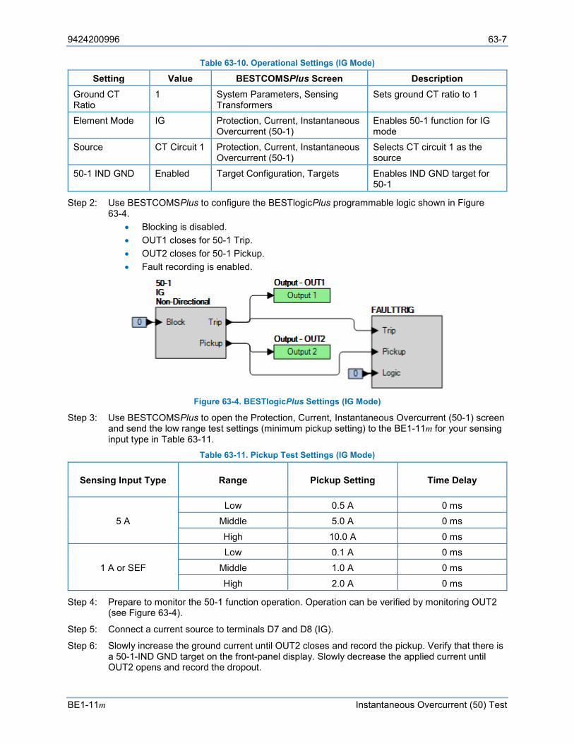
9424200996 63-7
BE1-11m Instantaneous Overcurrent (50) Test
Table 63-10. Operational Settings (IG Mode)
Setting Value BESTCOMSPlus Screen Description Ground CT Ratio
1 System Parameters, Sensing Transformers
Sets ground CT ratio to 1
Element Mode IG Protection, Current, Instantaneous Overcurrent (50-1)
Enables 50-1 function for IG mode
Source CT Circuit 1 Protection, Current, Instantaneous Overcurrent (50-1)
Selects CT circuit 1 as the source
50-1 IND GND Enabled Target Configuration, Targets Enables IND GND target for 50-1
Step 2: Use BESTCOMSPlus to configure the BESTlogicPlus programmable logic shown in Figure 63-4.
• Blocking is disabled. • OUT1 closes for 50-1 Trip. • OUT2 closes for 50-1 Pickup. • Fault recording is enabled.
Figure 63-4. BESTlogicPlus Settings (IG Mode)
Step 3: Use BESTCOMSPlus to open the Protection, Current, Instantaneous Overcurrent (50-1) screen and send the low range test settings (minimum pickup setting) to the BE1-11m for your sensing input type in Table 63-11.
Table 63-11. Pickup Test Settings (IG Mode)
Sensing Input Type Range Pickup Setting Time Delay
5 A Low 0.5 A 0 ms
Middle 5.0 A 0 ms
High 10.0 A 0 ms
1 A or SEF Low 0.1 A 0 ms
Middle 1.0 A 0 ms
High 2.0 A 0 ms
Step 4: Prepare to monitor the 50-1 function operation. Operation can be verified by monitoring OUT2 (see Figure 63-4).
Step 5: Connect a current source to terminals D7 and D8 (IG).
Step 6: Slowly increase the ground current until OUT2 closes and record the pickup. Verify that there is a 50-1-IND GND target on the front-panel display. Slowly decrease the applied current until OUT2 opens and record the dropout.
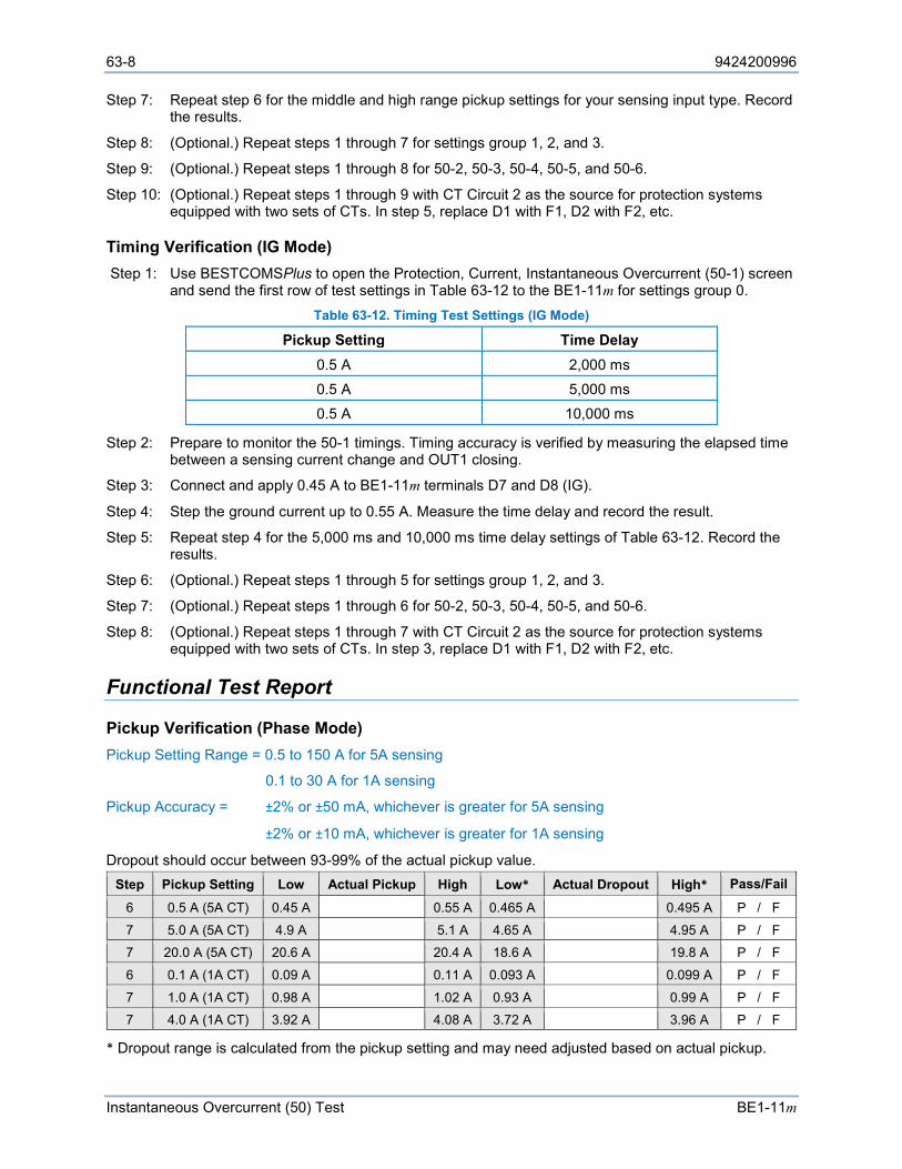
63-8 9424200996
Instantaneous Overcurrent (50) Test BE1-11m
Step 7: Repeat step 6 for the middle and high range pickup settings for your sensing input type. Record the results.
Step 8: (Optional.) Repeat steps 1 through 7 for settings group 1, 2, and 3.
Step 9: (Optional.) Repeat steps 1 through 8 for 50-2, 50-3, 50-4, 50-5, and 50-6.
Step 10: (Optional.) Repeat steps 1 through 9 with CT Circuit 2 as the source for protection systems equipped with two sets of CTs. In step 5, replace D1 with F1, D2 with F2, etc.
Timing Verification (IG Mode) Step 1: Use BESTCOMSPlus to open the Protection, Current, Instantaneous Overcurrent (50-1) screen
and send the first row of test settings in Table 63-12 to the BE1-11m for settings group 0. Table 63-12. Timing Test Settings (IG Mode)
Pickup Setting Time Delay 0.5 A 2,000 ms 0.5 A 5,000 ms 0.5 A 10,000 ms
Step 2: Prepare to monitor the 50-1 timings. Timing accuracy is verified by measuring the elapsed time between a sensing current change and OUT1 closing.
Step 3: Connect and apply 0.45 A to BE1-11m terminals D7 and D8 (IG).
Step 4: Step the ground current up to 0.55 A. Measure the time delay and record the result.
Step 5: Repeat step 4 for the 5,000 ms and 10,000 ms time delay settings of Table 63-12. Record the results.
Step 6: (Optional.) Repeat steps 1 through 5 for settings group 1, 2, and 3.
Step 7: (Optional.) Repeat steps 1 through 6 for 50-2, 50-3, 50-4, 50-5, and 50-6.
Step 8: (Optional.) Repeat steps 1 through 7 with CT Circuit 2 as the source for protection systems equipped with two sets of CTs. In step 3, replace D1 with F1, D2 with F2, etc.
Functional Test Report
Pickup Verification (Phase Mode) Pickup Setting Range = 0.5 to 150 A for 5A sensing
0.1 to 30 A for 1A sensing
Pickup Accuracy = ±2% or ±50 mA, whichever is greater for 5A sensing
±2% or ±10 mA, whichever is greater for 1A sensing
Dropout should occur between 93-99% of the actual pickup value. Step Pickup Setting Low Actual Pickup High Low* Actual Dropout High* Pass/Fail
6 0.5 A (5A CT) 0.45 A 0.55 A 0.465 A 0.495 A P / F
7 5.0 A (5A CT) 4.9 A 5.1 A 4.65 A 4.95 A P / F
7 20.0 A (5A CT) 20.6 A 20.4 A 18.6 A 19.8 A P / F
6 0.1 A (1A CT) 0.09 A 0.11 A 0.093 A 0.099 A P / F
7 1.0 A (1A CT) 0.98 A 1.02 A 0.93 A 0.99 A P / F
7 4.0 A (1A CT) 3.92 A 4.08 A 3.72 A 3.96 A P / F
* Dropout range is calculated from the pickup setting and may need adjusted based on actual pickup.
9424200996 63-9
BE1-11m Instantaneous Overcurrent (50) Test
Timing Verification (Phase Mode) Time Delay Range = 0 to 60,000 ms
Timing Accuracy = ±0.5% or ±½ cycle, whichever is greater + 3 cycles max for currents 1.5 x pickup Step Time Delay Setting Low Actual Timing High Pass/Fail
4 2,000 ms 1,942 ms 2,058 ms P / F
5 5,000 ms 4,927 ms 5,073 ms P / F
5 10,000 ms 9,902 ms 10,098 ms P / F
Pickup Verification (3I0 Mode) Pickup Setting Range = 0.5 to 150 A for 5A sensing
0.1 to 30 A for 1A sensing
Pickup Accuracy = ±3% or ±75 mA, whichever is greater for 5A sensing
±3% or ±15 mA, whichever is greater for 1A sensing
Dropout should occur between 93-99% of the actual pickup value. Step Pickup Setting Low Actual Pickup High Low* Actual Dropout High* Pass/Fail
6 0.5 A (5A CT) 0.425 A 0.575 A 0.465 A 0.495 A P / F
7 5.0 A (5A CT) 4.85 A 5.15 A 4.65 A 4.95 A P / F
7 20.0 A (5A CT) 19.4 A 20.6 A 18.6 A 19.8 A P / F
6 0.1 A (1A CT) 0.085 A 0.115 A 0.093 A 0.099 A P / F
7 1.0 A (1A CT) 0.97 A 1.03 A 0.93 A 0.99 A P / F
7 4.0 A (1A CT) 3.88 A 4.12 A 3.72 A 3.96 A P / F
* Dropout range is calculated from the pickup setting and may need adjusted based on actual pickup.
Timing Verification (3I0 Mode) Time Delay Range = 0 to 60,000 ms
Timing Accuracy = ±1% or ±½ cycle, whichever is greater + 3 cycles max for currents 1.5 x pickup Step Time Delay Setting Low Actual Timing High Pass/Fail
4 2,000 ms 1,942 ms 2,058 ms P / F
5 5,000 ms 4,927 ms 5,073 ms P / F
5 10,000 ms 9,902 ms 10,098 ms P / F
Pickup Verification (I2 Mode) Pickup Setting Range = 0.5 to 150 A for 5A sensing
0.1 to 30 A for 1A sensing
Pickup Accuracy = ±3% or ±75 mA, whichever is greater for 5A sensing
±3% or ±15 mA, whichever is greater for 1A sensing
Dropout should occur between 93-99% of the actual pickup value.
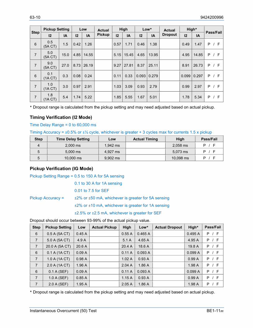
63-10 9424200996
Instantaneous Overcurrent (50) Test BE1-11m
Step Pickup Setting Low Actual
Pickup High Low* Actual
Dropout High*
Pass/Fail I2 IA I2 IA I2 IA I2 IA I2 IA
6 0.5 (5A CT) 1.5 0.42 1.26 0.57 1.71 0.46 1.38 0.49 1.47 P / F
7 5.0 (5A CT) 15.0 4.85 14.55 5.15 15.45 4.65 13.95 4.95 14.85 P / F
7 9.0 (5A CT) 27.0 8.73 26.19 9.27 27.81 8.37 25.11 8.91 26.73 P / F
6 0.1 (1A CT) 0.3 0.08 0.24 0.11 0.33 0.093 0.279 0.099 0.297 P / F
7 1.0 (1A CT) 3.0 0.97 2.91 1.03 3.09 0.93 2.79 0.99 2.97 P / F
7 1.8 (1A CT) 5.4 1.74 5.22 1.85 5.55 1.67 5.01 1.78 5.34 P / F
* Dropout range is calculated from the pickup setting and may need adjusted based on actual pickup.
Timing Verification (I2 Mode) Time Delay Range = 0 to 60,000 ms
Timing Accuracy = ±0.5% or ±½ cycle, whichever is greater + 3 cycles max for currents 1.5 x pickup Step Time Delay Setting Low Actual Timing High Pass/Fail
4 2,000 ms 1,942 ms 2,058 ms P / F
5 5,000 ms 4,927 ms 5,073 ms P / F
5 10,000 ms 9,902 ms 10,098 ms P / F
Pickup Verification (IG Mode) Pickup Setting Range = 0.5 to 150 A for 5A sensing
0.1 to 30 A for 1A sensing
0.01 to 7.5 for SEF
Pickup Accuracy = ±2% or ±50 mA, whichever is greater for 5A sensing
±2% or ±10 mA, whichever is greater for 1A sensing
±2.5% or ±2.5 mA, whichever is greater for SEF
Dropout should occur between 93-99% of the actual pickup value. Step Pickup Setting Low Actual Pickup High Low* Actual Dropout High* Pass/Fail
6 0.5 A (5A CT) 0.45 A 0.55 A 0.465 A 0.495 A P / F
7 5.0 A (5A CT) 4.9 A 5.1 A 4.65 A 4.95 A P / F
7 20.0 A (5A CT) 20.6 A 20.4 A 18.6 A 19.8 A P / F
6 0.1 A (1A CT) 0.09 A 0.11 A 0.093 A 0.099 A P / F
7 1.0 A (1A CT) 0.98 A 1.02 A 0.93 A 0.99 A P / F
7 2.0 A (1A CT) 1.96 A 2.04 A 1.86 A 1.98 A P / F
6 0.1 A (SEF) 0.09 A 0.11 A 0.093 A 0.099 A P / F
7 1.0 A (SEF) 0.85 A 1.15 A 0.93 A 0.99 A P / F
7 2.0 A (SEF) 1.95 A 2.05 A 1.86 A 1.98 A P / F
* Dropout range is calculated from the pickup setting and may need adjusted based on actual pickup.
9424200996 63-11
BE1-11m Instantaneous Overcurrent (50) Test
Timing Verification (IG Mode) Time Delay Range = 0 to 60,000 ms
Timing Accuracy = ±0.5% or ±½ cycle, whichever is greater + 3 cycles max for currents 1.5 x pickup Step Time Delay Setting Low Actual Timing High Pass/Fail
4 2,000 ms 1,942 ms 2,058 ms P / F
5 5,000 ms 4,927 ms 5,073 ms P / F
5 10,000 ms 9,902 ms 10,098 ms P / F

63-12 9424200996
Instantaneous Overcurrent (50) Test BE1-11m
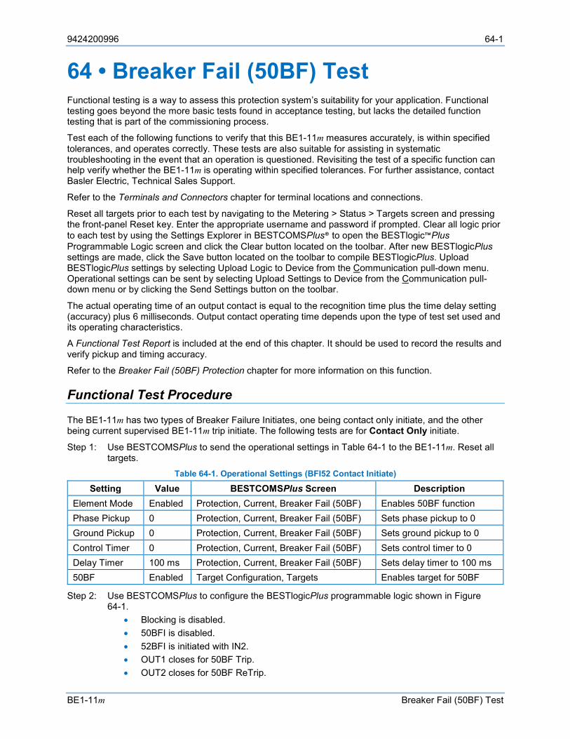
9424200996 64-1
BE1-11m Breaker Fail (50BF) Test
64 • Breaker Fail (50BF) Test Functional testing is a way to assess this protection system’s suitability for your application. Functional testing goes beyond the more basic tests found in acceptance testing, but lacks the detailed function testing that is part of the commissioning process.
Test each of the following functions to verify that this BE1-11m measures accurately, is within specified tolerances, and operates correctly. These tests are also suitable for assisting in systematic troubleshooting in the event that an operation is questioned. Revisiting the test of a specific function can help verify whether the BE1-11m is operating within specified tolerances. For further assistance, contact Basler Electric, Technical Sales Support.
Refer to the Terminals and Connectors chapter for terminal locations and connections.
Reset all targets prior to each test by navigating to the Metering > Status > Targets screen and pressing the front-panel Reset key. Enter the appropriate username and password if prompted. Clear all logic prior to each test by using the Settings Explorer in BESTCOMSPlus® to open the BESTlogic™Plus Programmable Logic screen and click the Clear button located on the toolbar. After new BESTlogicPlus settings are made, click the Save button located on the toolbar to compile BESTlogicPlus. Upload BESTlogicPlus settings by selecting Upload Logic to Device from the Communication pull-down menu. Operational settings can be sent by selecting Upload Settings to Device from the Communication pull-down menu or by clicking the Send Settings button on the toolbar.
The actual operating time of an output contact is equal to the recognition time plus the time delay setting (accuracy) plus 6 milliseconds. Output contact operating time depends upon the type of test set used and its operating characteristics.
A Functional Test Report is included at the end of this chapter. It should be used to record the results and verify pickup and timing accuracy.
Refer to the Breaker Fail (50BF) Protection chapter for more information on this function.
Functional Test Procedure
The BE1-11m has two types of Breaker Failure Initiates, one being contact only initiate, and the other being current supervised BE1-11m trip initiate. The following tests are for Contact Only initiate.
Step 1: Use BESTCOMSPlus to send the operational settings in Table 64-1 to the BE1-11m. Reset all targets.
Table 64-1. Operational Settings (BFI52 Contact Initiate)
Setting Value BESTCOMSPlus Screen Description Element Mode Enabled Protection, Current, Breaker Fail (50BF) Enables 50BF function Phase Pickup 0 Protection, Current, Breaker Fail (50BF) Sets phase pickup to 0 Ground Pickup 0 Protection, Current, Breaker Fail (50BF) Sets ground pickup to 0 Control Timer 0 Protection, Current, Breaker Fail (50BF) Sets control timer to 0 Delay Timer 100 ms Protection, Current, Breaker Fail (50BF) Sets delay timer to 100 ms 50BF Enabled Target Configuration, Targets Enables target for 50BF
Step 2: Use BESTCOMSPlus to configure the BESTlogicPlus programmable logic shown in Figure 64-1.
• Blocking is disabled. • 50BFI is disabled. • 52BFI is initiated with IN2. • OUT1 closes for 50BF Trip. • OUT2 closes for 50BF ReTrip.
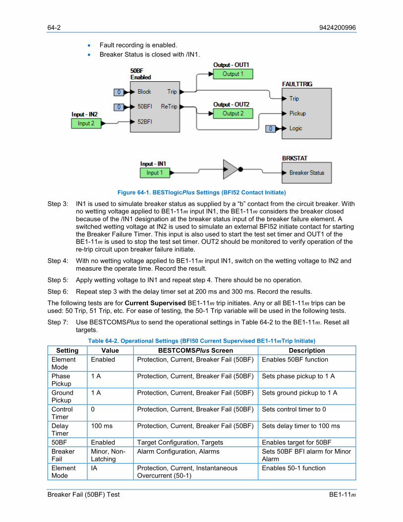
64-2 9424200996
Breaker Fail (50BF) Test BE1-11m
• Fault recording is enabled. • Breaker Status is closed with /IN1.
Figure 64-1. BESTlogicPlus Settings (BFI52 Contact Initiate)
Step 3: IN1 is used to simulate breaker status as supplied by a “b” contact from the circuit breaker. With no wetting voltage applied to BE1-11m input IN1, the BE1-11m considers the breaker closed because of the /IN1 designation at the breaker status input of the breaker failure element. A switched wetting voltage at IN2 is used to simulate an external BFI52 initiate contact for starting the Breaker Failure Timer. This input is also used to start the test set timer and OUT1 of the BE1-11m is used to stop the test set timer. OUT2 should be monitored to verify operation of the re-trip circuit upon breaker failure initiate.
Step 4: With no wetting voltage applied to BE1-11m input IN1, switch on the wetting voltage to IN2 and measure the operate time. Record the result.
Step 5: Apply wetting voltage to IN1 and repeat step 4. There should be no operation.
Step 6: Repeat step 3 with the delay timer set at 200 ms and 300 ms. Record the results.
The following tests are for Current Supervised BE1-11m trip initiates. Any or all BE1-11m trips can be used: 50 Trip, 51 Trip, etc. For ease of testing, the 50-1 Trip variable will be used in the following tests.
Step 7: Use BESTCOMSPlus to send the operational settings in Table 64-2 to the BE1-11m. Reset all targets.
Table 64-2. Operational Settings (BFI50 Current Supervised BE1-11mTrip Initiate) Setting Value BESTCOMSPlus Screen Description
Element Mode
Enabled Protection, Current, Breaker Fail (50BF) Enables 50BF function
Phase Pickup
1 A Protection, Current, Breaker Fail (50BF) Sets phase pickup to 1 A
Ground Pickup
1 A Protection, Current, Breaker Fail (50BF) Sets ground pickup to 1 A
Control Timer
0 Protection, Current, Breaker Fail (50BF) Sets control timer to 0
Delay Timer
100 ms Protection, Current, Breaker Fail (50BF) Sets delay timer to 100 ms
50BF Enabled Target Configuration, Targets Enables target for 50BF Breaker Fail
Minor, Non-Latching
Alarm Configuration, Alarms Sets 50BF BFI alarm for Minor Alarm
Element Mode
IA Protection, Current, Instantaneous Overcurrent (50-1)
Enables 50-1 function
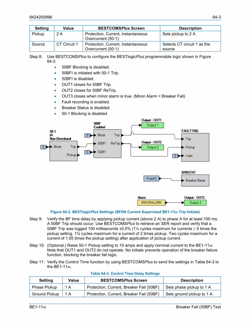
9424200996 64-3
BE1-11m Breaker Fail (50BF) Test
Setting Value BESTCOMSPlus Screen Description Pickup 2 A Protection, Current, Instantaneous
Overcurrent (50-1) Sets pickup to 2 A
Source CT Circuit 1 Protection, Current, Instantaneous Overcurrent (50-1)
Selects CT circuit 1 as the source
Step 8: Use BESTCOMSPlus to configure the BESTlogicPlus programmable logic shown in Figure 64-2.
• 50BF Blocking is disabled. • 50BFI is initiated with 50-1 Trip. • 52BFI is disabled. • OUT1 closes for 50BF Trip. • OUT2 closes for 50BF ReTrip. • OUT3 closes when minor alarm is true. (Minor Alarm = Breaker Fail) • Fault recording is enabled. • Breaker Status is disabled. • 50-1 Blocking is disabled.
Figure 64-2. BESTlogicPlus Settings (BFI50 Current Supervised BE1-11m Trip Initiate)
Step 9: Verify the BF time delay by applying pickup current (above 2 A) to phase A for at least 100 ms. A 50BF Trip should occur. Use BESTCOMSPlus to retrieve an SER report and verify that a 50BF Trip was logged 100 milliseconds ±0.5% (1¼ cycles maximum for currents ≥ 5 times the pickup setting. 1¾ cycles maximum for a current of 2 times pickup. Two cycles maximum for a current of 1.05 times the pickup setting) after application of pickup current.
Step 10: (Optional.) Raise 50-1 Pickup setting to 10 amps and apply nominal current to the BE1-11m. Note that OUT1 and OUT2 do not operate. No initiate prevents operation of the breaker failure function, blocking the breaker fail logic.
Step 11: Verify the Control Time function by using BESTCOMSPlus to send the settings in Table 64-3 to the BE1-11m.
Table 64-3. Control Time Delay Settings
Setting Value BESTCOMSPlus Screen Description Phase Pickup 1 A Protection, Current, Breaker Fail (50BF) Sets phase pickup to 1 A Ground Pickup 1 A Protection, Current, Breaker Fail (50BF) Sets ground pickup to 1 A
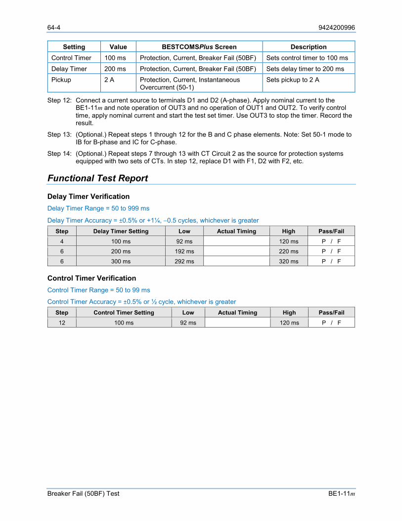
64-4 9424200996
Breaker Fail (50BF) Test BE1-11m
Setting Value BESTCOMSPlus Screen Description Control Timer 100 ms Protection, Current, Breaker Fail (50BF) Sets control timer to 100 ms
Delay Timer 200 ms Protection, Current, Breaker Fail (50BF) Sets delay timer to 200 ms Pickup 2 A Protection, Current, Instantaneous
Overcurrent (50-1) Sets pickup to 2 A
Step 12: Connect a current source to terminals D1 and D2 (A-phase). Apply nominal current to the BE1-11m and note operation of OUT3 and no operation of OUT1 and OUT2. To verify control time, apply nominal current and start the test set timer. Use OUT3 to stop the timer. Record the result.
Step 13: (Optional.) Repeat steps 1 through 12 for the B and C phase elements. Note: Set 50-1 mode to IB for B-phase and IC for C-phase.
Step 14: (Optional.) Repeat steps 7 through 13 with CT Circuit 2 as the source for protection systems equipped with two sets of CTs. In step 12, replace D1 with F1, D2 with F2, etc.
Functional Test Report
Delay Timer Verification Delay Timer Range = 50 to 999 ms
Delay Timer Accuracy = ±0.5% or +1¼, −0.5 cycles, whichever is greater Step Delay Timer Setting Low Actual Timing High Pass/Fail
4 100 ms 92 ms 120 ms P / F
6 200 ms 192 ms 220 ms P / F
6 300 ms 292 ms 320 ms P / F
Control Timer Verification Control Timer Range = 50 to 99 ms
Control Timer Accuracy = ±0.5% or ½ cycle, whichever is greater Step Control Timer Setting Low Actual Timing High Pass/Fail 12 100 ms 92 ms 120 ms P / F
9424200996 65-1
BE1-11m Inverse Overcurrent (51) Test
65 • Inverse Overcurrent (51) Test Functional testing is a way to assess this protection system’s suitability for your application. Functional testing goes beyond the more basic tests found in acceptance testing, but lacks the detailed function testing that is part of the commissioning process.
Test each of the following functions to verify that this BE1-11m measures accurately, is within specified tolerances, and operates correctly. These tests are also suitable for assisting in systematic troubleshooting in the event that an operation is questioned. Revisiting the test of a specific function can help verify whether the BE1-11m is operating within specified tolerances. For further assistance, contact Basler Electric, Technical Sales Support.
Refer to the Terminals and Connectors chapter for terminal locations and connections.
Reset all targets prior to each test by navigating to the Metering > Status > Targets screen and pressing the front-panel Reset key. Enter the appropriate username and password if prompted. Clear all logic prior to each test by using the Settings Explorer in BESTCOMSPlus® to open the BESTlogic™Plus Programmable Logic screen and click the Clear button located on the toolbar. After new BESTlogicPlus settings are made, click the Save button located on the toolbar to compile BESTlogicPlus. Upload BESTlogicPlus settings by selecting Upload Logic to Device from the Communication pull-down menu. Operational settings can be sent by selecting Upload Settings to Device from the Communication pull-down menu or by clicking the Send Settings button on the toolbar.
The actual operating time of an output contact is equal to the recognition time plus the time delay setting (accuracy) plus 6 milliseconds. Output contact operating time depends upon the type of test set used and its operating characteristics.
A Functional Test Report is included at the end of this chapter. It should be used to record the results and verify pickup and timing accuracy.
Refer to the Inverse Overcurrent (51) Protection chapter for more information on this function.
Functional Test Procedure
Pickup Verification (Phase Mode) Step 1: Use BESTCOMSPlus to send the operational settings in Table 65-1 to the BE1-11m. Reset all
targets. Table 65-1. Operational Settings (Phase Mode)
Setting Value BESTCOMSPlus Screen Description Phase CT Ratio
1 System Parameters, Sensing Transformers
Sets phase CT ratio to 1
Element Mode
IA Protection, Current, Inverse Overcurrent (51-1)
Enables 51-1 function for IA mode
Source CT Circuit 1 Protection, Current, Instantaneous Overcurrent (51-1)
Selects CT circuit 1 as the source
51-1 A Enabled Target Configuration, Targets Enables phase A target for 51-1
Step 2: Use BESTCOMSPlus to configure the BESTlogicPlus programmable logic shown in Figure 65-1.
• Blocking is disabled. • OUT1 closes for 51-1 Trip. • OUT2 closes for 51-1 Pickup. • Fault recording is enabled.
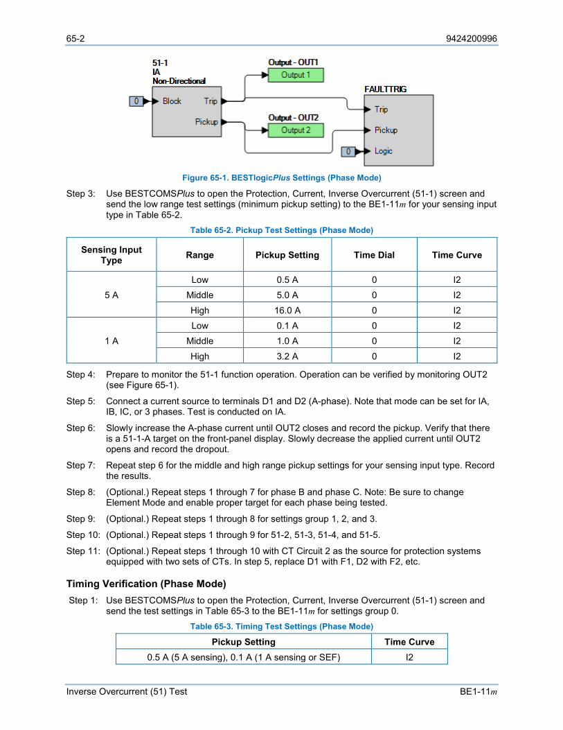
65-2 9424200996
Inverse Overcurrent (51) Test BE1-11m
Figure 65-1. BESTlogicPlus Settings (Phase Mode)
Step 3: Use BESTCOMSPlus to open the Protection, Current, Inverse Overcurrent (51-1) screen and send the low range test settings (minimum pickup setting) to the BE1-11m for your sensing input type in Table 65-2.
Table 65-2. Pickup Test Settings (Phase Mode)
Sensing Input Type Range Pickup Setting Time Dial Time Curve
5 A Low 0.5 A 0 I2
Middle 5.0 A 0 I2
High 16.0 A 0 I2
1 A Low 0.1 A 0 I2
Middle 1.0 A 0 I2
High 3.2 A 0 I2
Step 4: Prepare to monitor the 51-1 function operation. Operation can be verified by monitoring OUT2 (see Figure 65-1).
Step 5: Connect a current source to terminals D1 and D2 (A-phase). Note that mode can be set for IA, IB, IC, or 3 phases. Test is conducted on IA.
Step 6: Slowly increase the A-phase current until OUT2 closes and record the pickup. Verify that there is a 51-1-A target on the front-panel display. Slowly decrease the applied current until OUT2 opens and record the dropout.
Step 7: Repeat step 6 for the middle and high range pickup settings for your sensing input type. Record the results.
Step 8: (Optional.) Repeat steps 1 through 7 for phase B and phase C. Note: Be sure to change Element Mode and enable proper target for each phase being tested.
Step 9: (Optional.) Repeat steps 1 through 8 for settings group 1, 2, and 3.
Step 10: (Optional.) Repeat steps 1 through 9 for 51-2, 51-3, 51-4, and 51-5.
Step 11: (Optional.) Repeat steps 1 through 10 with CT Circuit 2 as the source for protection systems equipped with two sets of CTs. In step 5, replace D1 with F1, D2 with F2, etc.
Timing Verification (Phase Mode) Step 1: Use BESTCOMSPlus to open the Protection, Current, Inverse Overcurrent (51-1) screen and
send the test settings in Table 65-3 to the BE1-11m for settings group 0. Table 65-3. Timing Test Settings (Phase Mode)
Pickup Setting Time Curve 0.5 A (5 A sensing), 0.1 A (1 A sensing or SEF) I2
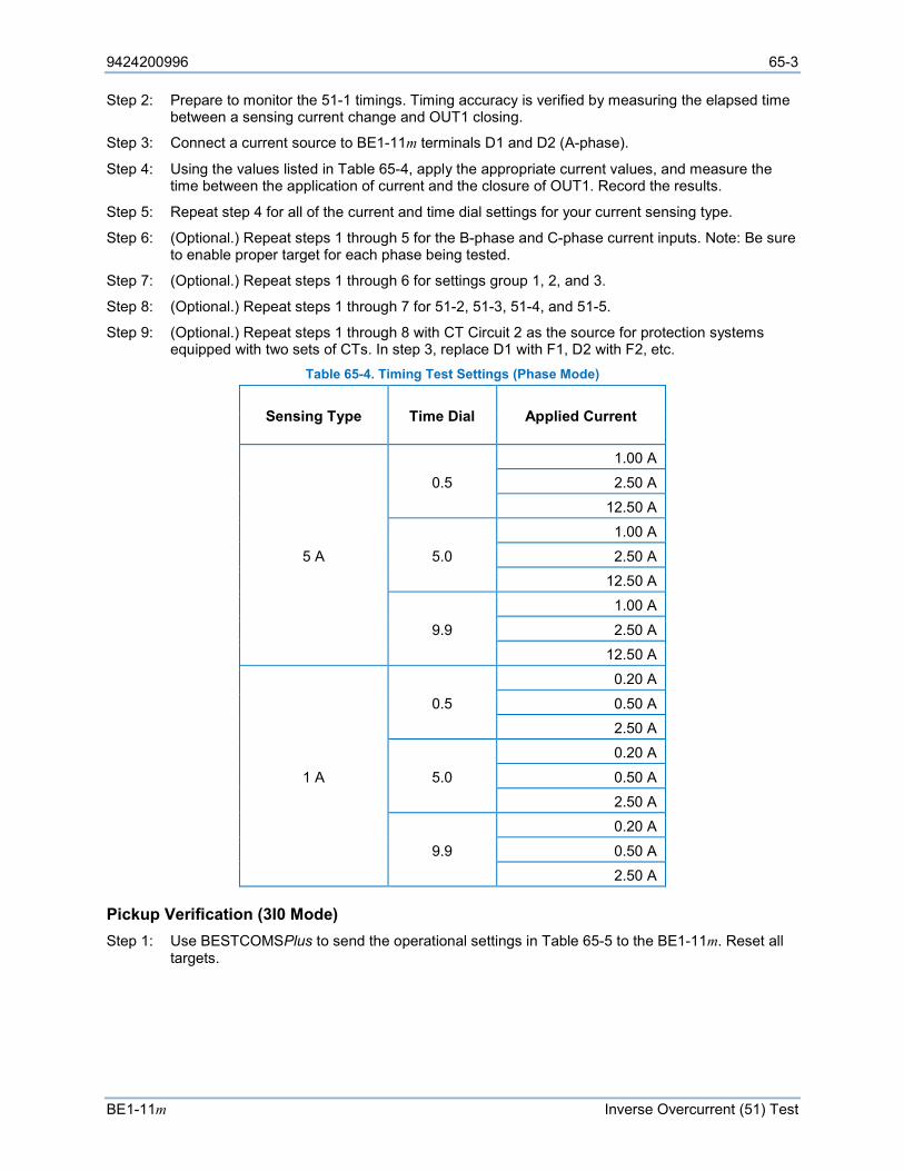
9424200996 65-3
BE1-11m Inverse Overcurrent (51) Test
Step 2: Prepare to monitor the 51-1 timings. Timing accuracy is verified by measuring the elapsed time between a sensing current change and OUT1 closing.
Step 3: Connect a current source to BE1-11m terminals D1 and D2 (A-phase).
Step 4: Using the values listed in Table 65-4, apply the appropriate current values, and measure the time between the application of current and the closure of OUT1. Record the results.
Step 5: Repeat step 4 for all of the current and time dial settings for your current sensing type.
Step 6: (Optional.) Repeat steps 1 through 5 for the B-phase and C-phase current inputs. Note: Be sure to enable proper target for each phase being tested.
Step 7: (Optional.) Repeat steps 1 through 6 for settings group 1, 2, and 3.
Step 8: (Optional.) Repeat steps 1 through 7 for 51-2, 51-3, 51-4, and 51-5.
Step 9: (Optional.) Repeat steps 1 through 8 with CT Circuit 2 as the source for protection systems equipped with two sets of CTs. In step 3, replace D1 with F1, D2 with F2, etc.
Table 65-4. Timing Test Settings (Phase Mode)
Sensing Type Time Dial Applied Current
5 A
0.5
1.00 A
2.50 A 12.50 A
5.0
1.00 A
2.50 A 12.50 A
9.9
1.00 A
2.50 A 12.50 A
1 A
0.5
0.20 A
0.50 A 2.50 A
5.0
0.20 A
0.50 A 2.50 A
9.9
0.20 A
0.50 A 2.50 A
Pickup Verification (3I0 Mode) Step 1: Use BESTCOMSPlus to send the operational settings in Table 65-5 to the BE1-11m. Reset all
targets.
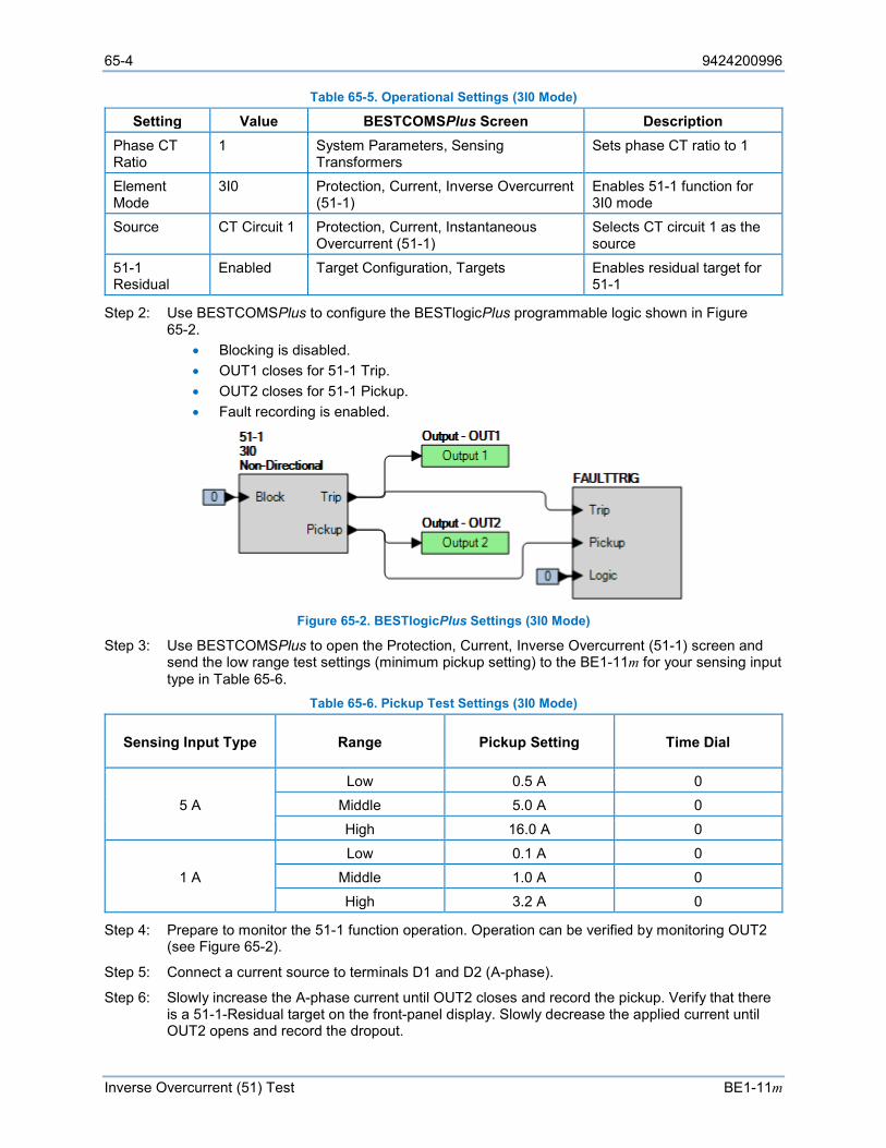
65-4 9424200996
Inverse Overcurrent (51) Test BE1-11m
Table 65-5. Operational Settings (3I0 Mode)
Setting Value BESTCOMSPlus Screen Description Phase CT Ratio
1 System Parameters, Sensing Transformers
Sets phase CT ratio to 1
Element Mode
3I0 Protection, Current, Inverse Overcurrent (51-1)
Enables 51-1 function for 3I0 mode
Source CT Circuit 1 Protection, Current, Instantaneous Overcurrent (51-1)
Selects CT circuit 1 as the source
51-1 Residual
Enabled Target Configuration, Targets Enables residual target for 51-1
Step 2: Use BESTCOMSPlus to configure the BESTlogicPlus programmable logic shown in Figure 65-2.
• Blocking is disabled. • OUT1 closes for 51-1 Trip. • OUT2 closes for 51-1 Pickup. • Fault recording is enabled.
Figure 65-2. BESTlogicPlus Settings (3I0 Mode)
Step 3: Use BESTCOMSPlus to open the Protection, Current, Inverse Overcurrent (51-1) screen and send the low range test settings (minimum pickup setting) to the BE1-11m for your sensing input type in Table 65-6.
Table 65-6. Pickup Test Settings (3I0 Mode)
Sensing Input Type Range Pickup Setting Time Dial
5 A Low 0.5 A 0
Middle 5.0 A 0 High 16.0 A 0
1 A Low 0.1 A 0
Middle 1.0 A 0 High 3.2 A 0
Step 4: Prepare to monitor the 51-1 function operation. Operation can be verified by monitoring OUT2 (see Figure 65-2).
Step 5: Connect a current source to terminals D1 and D2 (A-phase).
Step 6: Slowly increase the A-phase current until OUT2 closes and record the pickup. Verify that there is a 51-1-Residual target on the front-panel display. Slowly decrease the applied current until OUT2 opens and record the dropout.
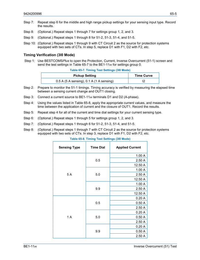
9424200996 65-5
BE1-11m Inverse Overcurrent (51) Test
Step 7: Repeat step 6 for the middle and high range pickup settings for your sensing input type. Record the results.
Step 8: (Optional.) Repeat steps 1 through 7 for settings group 1, 2, and 3.
Step 9: (Optional.) Repeat steps 1 through 8 for 51-2, 51-3, 51-4, and 51-5.
Step 10: (Optional.) Repeat steps 1 through 9 with CT Circuit 2 as the source for protection systems equipped with two sets of CTs. In step 5, replace D1 with F1, D2 with F2, etc.
Timing Verification (3I0 Mode) Step 1: Use BESTCOMSPlus to open the Protection, Current, Inverse Overcurrent (51-1) screen and
send the test settings in Table 65-7 to the BE1-11m for settings group 0. Table 65-7. Timing Test Settings (3I0 Mode)
Pickup Setting Time Curve 0.5 A (5 A sensing), 0.1 A (1 A sensing) I2
Step 2: Prepare to monitor the 51-1 timings. Timing accuracy is verified by measuring the elapsed time between a sensing current change and OUT1 closing.
Step 3: Connect a current source to BE1-11m terminals D1 and D2 (A-phase).
Step 4: Using the values listed in Table 65-8, apply the appropriate current values, and measure the time between the application of current and the closure of OUT1. Record the results.
Step 5: Repeat step 4 for all of the current and time dial settings for your current sensing type.
Step 6: (Optional.) Repeat steps 1 through 5 for settings group 1, 2, and 3.
Step 7: (Optional.) Repeat steps 1 through 6 for 51-2, 51-3, 51-4, and 51-5.
Step 8: (Optional.) Repeat steps 1 through 7 with CT Circuit 2 as the source for protection systems equipped with two sets of CTs. In step 3, replace D1 with F1, D2 with F2, etc.
Table 65-8. Timing Test Settings (3I0 Mode)
Sensing Type Time Dial Applied Current
5 A
0.5 1.00 A 2.50 A
12.50 A
5.0 1.00 A 2.50 A
12.50 A
9.9 1.00 A 2.50 A
12.50 A
1 A
0.5 0.20 A 0.50 A 2.50 A
5.0 0.20 A 0.50 A 2.50 A
9.9 0.20 A 0.50 A 2.50 A
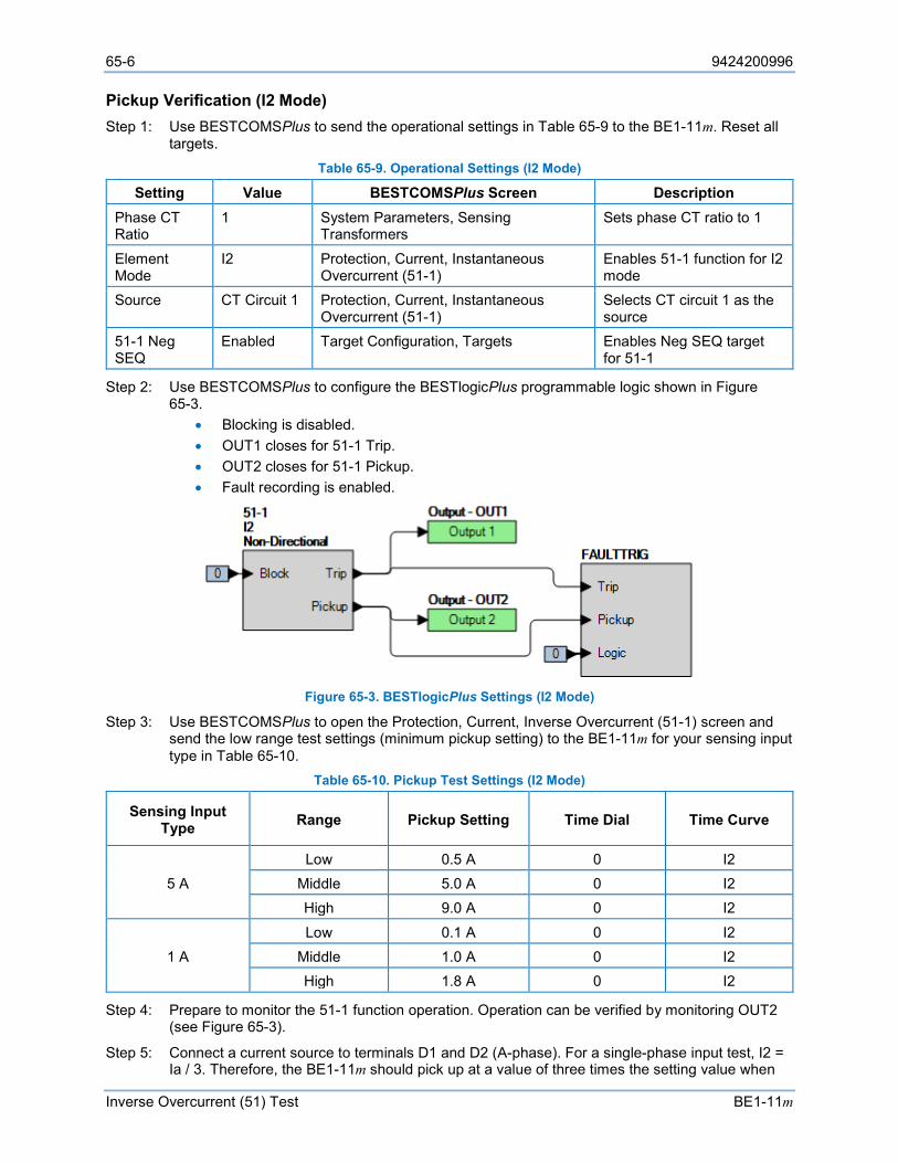
65-6 9424200996
Inverse Overcurrent (51) Test BE1-11m
Pickup Verification (I2 Mode) Step 1: Use BESTCOMSPlus to send the operational settings in Table 65-9 to the BE1-11m. Reset all
targets. Table 65-9. Operational Settings (I2 Mode)
Setting Value BESTCOMSPlus Screen Description Phase CT Ratio
1 System Parameters, Sensing Transformers
Sets phase CT ratio to 1
Element Mode
I2 Protection, Current, Instantaneous Overcurrent (51-1)
Enables 51-1 function for I2 mode
Source CT Circuit 1 Protection, Current, Instantaneous Overcurrent (51-1)
Selects CT circuit 1 as the source
51-1 Neg SEQ
Enabled Target Configuration, Targets Enables Neg SEQ target for 51-1
Step 2: Use BESTCOMSPlus to configure the BESTlogicPlus programmable logic shown in Figure 65-3.
• Blocking is disabled. • OUT1 closes for 51-1 Trip. • OUT2 closes for 51-1 Pickup. • Fault recording is enabled.
Figure 65-3. BESTlogicPlus Settings (I2 Mode)
Step 3: Use BESTCOMSPlus to open the Protection, Current, Inverse Overcurrent (51-1) screen and send the low range test settings (minimum pickup setting) to the BE1-11m for your sensing input type in Table 65-10.
Table 65-10. Pickup Test Settings (I2 Mode)
Sensing Input Type Range Pickup Setting Time Dial Time Curve
5 A Low 0.5 A 0 I2
Middle 5.0 A 0 I2 High 9.0 A 0 I2
1 A Low 0.1 A 0 I2
Middle 1.0 A 0 I2 High 1.8 A 0 I2
Step 4: Prepare to monitor the 51-1 function operation. Operation can be verified by monitoring OUT2 (see Figure 65-3).
Step 5: Connect a current source to terminals D1 and D2 (A-phase). For a single-phase input test, I2 = Ia / 3. Therefore, the BE1-11m should pick up at a value of three times the setting value when
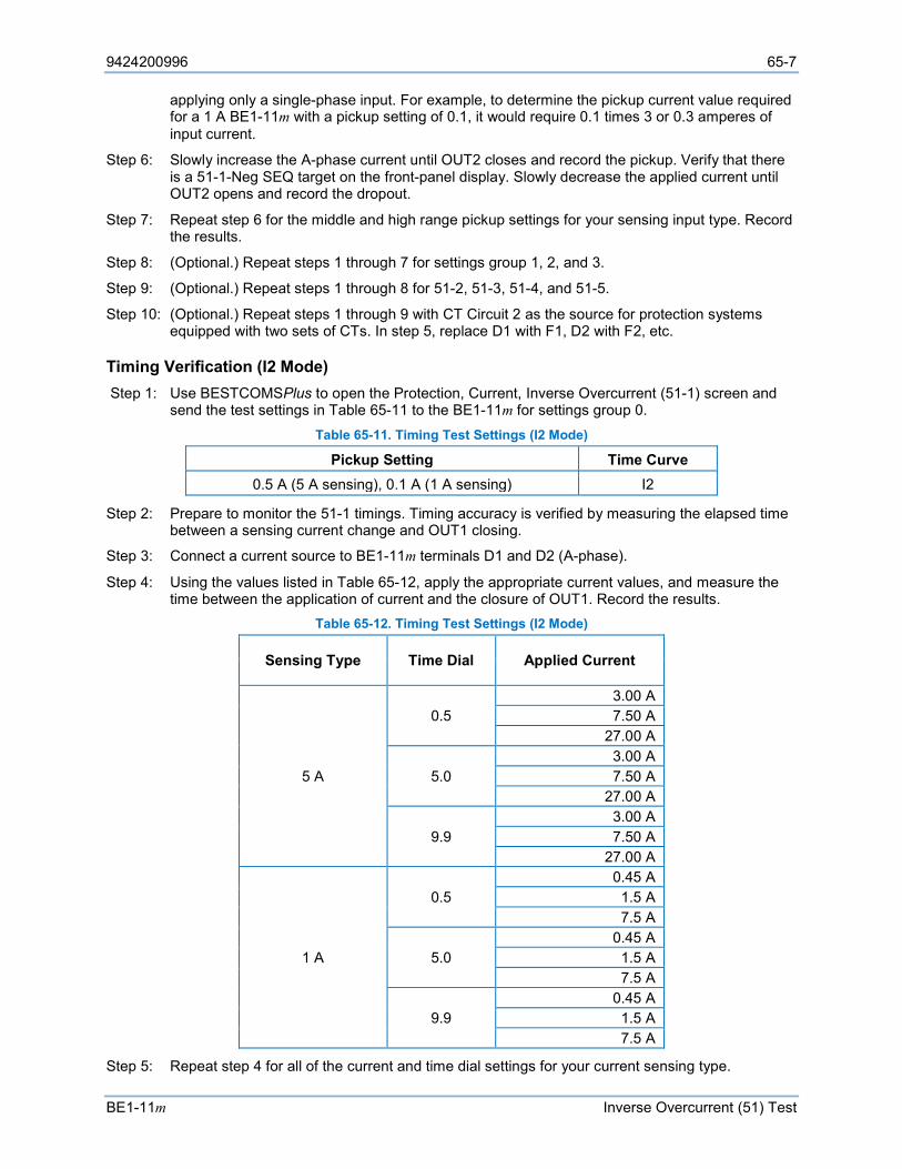
9424200996 65-7
BE1-11m Inverse Overcurrent (51) Test
applying only a single-phase input. For example, to determine the pickup current value required for a 1 A BE1-11m with a pickup setting of 0.1, it would require 0.1 times 3 or 0.3 amperes of input current.
Step 6: Slowly increase the A-phase current until OUT2 closes and record the pickup. Verify that there is a 51-1-Neg SEQ target on the front-panel display. Slowly decrease the applied current until OUT2 opens and record the dropout.
Step 7: Repeat step 6 for the middle and high range pickup settings for your sensing input type. Record the results.
Step 8: (Optional.) Repeat steps 1 through 7 for settings group 1, 2, and 3.
Step 9: (Optional.) Repeat steps 1 through 8 for 51-2, 51-3, 51-4, and 51-5.
Step 10: (Optional.) Repeat steps 1 through 9 with CT Circuit 2 as the source for protection systems equipped with two sets of CTs. In step 5, replace D1 with F1, D2 with F2, etc.
Timing Verification (I2 Mode) Step 1: Use BESTCOMSPlus to open the Protection, Current, Inverse Overcurrent (51-1) screen and
send the test settings in Table 65-11 to the BE1-11m for settings group 0. Table 65-11. Timing Test Settings (I2 Mode)
Pickup Setting Time Curve 0.5 A (5 A sensing), 0.1 A (1 A sensing) I2
Step 2: Prepare to monitor the 51-1 timings. Timing accuracy is verified by measuring the elapsed time between a sensing current change and OUT1 closing.
Step 3: Connect a current source to BE1-11m terminals D1 and D2 (A-phase).
Step 4: Using the values listed in Table 65-12, apply the appropriate current values, and measure the time between the application of current and the closure of OUT1. Record the results.
Table 65-12. Timing Test Settings (I2 Mode)
Sensing Type Time Dial Applied Current
5 A
0.5 3.00 A 7.50 A
27.00 A
5.0 3.00 A 7.50 A
27.00 A
9.9 3.00 A 7.50 A
27.00 A
1 A
0.5 0.45 A 1.5 A 7.5 A
5.0 0.45 A 1.5 A 7.5 A
9.9 0.45 A 1.5 A 7.5 A
Step 5: Repeat step 4 for all of the current and time dial settings for your current sensing type.
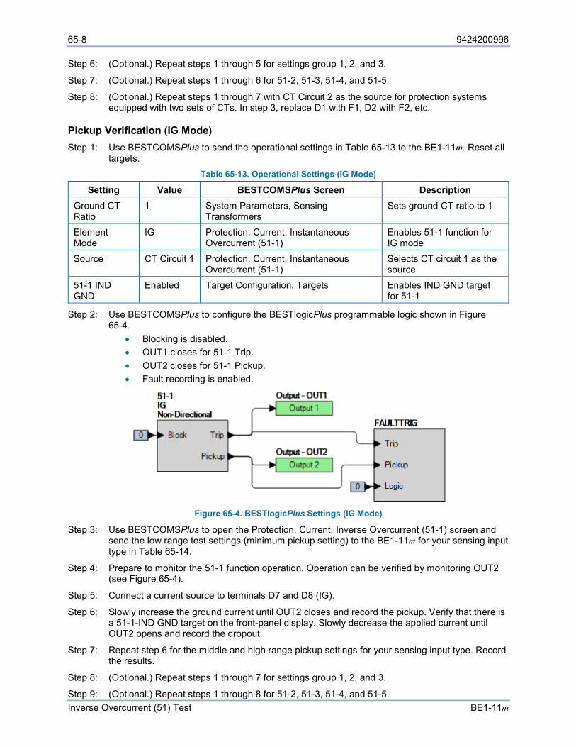
65-8 9424200996
Inverse Overcurrent (51) Test BE1-11m
Step 6: (Optional.) Repeat steps 1 through 5 for settings group 1, 2, and 3.
Step 7: (Optional.) Repeat steps 1 through 6 for 51-2, 51-3, 51-4, and 51-5.
Step 8: (Optional.) Repeat steps 1 through 7 with CT Circuit 2 as the source for protection systems equipped with two sets of CTs. In step 3, replace D1 with F1, D2 with F2, etc.
Pickup Verification (IG Mode) Step 1: Use BESTCOMSPlus to send the operational settings in Table 65-13 to the BE1-11m. Reset all
targets. Table 65-13. Operational Settings (IG Mode)
Setting Value BESTCOMSPlus Screen Description Ground CT Ratio
1 System Parameters, Sensing Transformers
Sets ground CT ratio to 1
Element Mode
IG Protection, Current, Instantaneous Overcurrent (51-1)
Enables 51-1 function for IG mode
Source CT Circuit 1 Protection, Current, Instantaneous Overcurrent (51-1)
Selects CT circuit 1 as the source
51-1 IND GND
Enabled Target Configuration, Targets Enables IND GND target for 51-1
Step 2: Use BESTCOMSPlus to configure the BESTlogicPlus programmable logic shown in Figure 65-4.
• Blocking is disabled. • OUT1 closes for 51-1 Trip. • OUT2 closes for 51-1 Pickup. • Fault recording is enabled.
Figure 65-4. BESTlogicPlus Settings (IG Mode)
Step 3: Use BESTCOMSPlus to open the Protection, Current, Inverse Overcurrent (51-1) screen and send the low range test settings (minimum pickup setting) to the BE1-11m for your sensing input type in Table 65-14.
Step 4: Prepare to monitor the 51-1 function operation. Operation can be verified by monitoring OUT2 (see Figure 65-4).
Step 5: Connect a current source to terminals D7 and D8 (IG).
Step 6: Slowly increase the ground current until OUT2 closes and record the pickup. Verify that there is a 51-1-IND GND target on the front-panel display. Slowly decrease the applied current until OUT2 opens and record the dropout.
Step 7: Repeat step 6 for the middle and high range pickup settings for your sensing input type. Record the results.
Step 8: (Optional.) Repeat steps 1 through 7 for settings group 1, 2, and 3.
Step 9: (Optional.) Repeat steps 1 through 8 for 51-2, 51-3, 51-4, and 51-5.
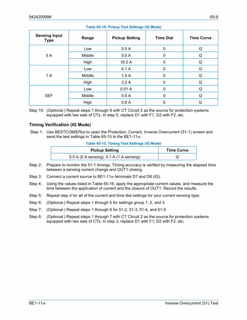
9424200996 65-9
BE1-11m Inverse Overcurrent (51) Test
Table 65-14. Pickup Test Settings (IG Mode)
Sensing Input Type Range Pickup Setting Time Dial Time Curve
5 A Low 0.5 A 0 I2
Middle 5.0 A 0 I2
High 16.0 A 0 I2
1 A Low 0.1 A 0 I2
Middle 1.0 A 0 I2
High 3.2 A 0 I2
SEF Low 0.01 A 0 I2
Middle 0.5 A 0 I2 High 0.8 A 0 I2
Step 10: (Optional.) Repeat steps 1 through 9 with CT Circuit 2 as the source for protection systems equipped with two sets of CTs. In step 5, replace D1 with F1, D2 with F2, etc.
Timing Verification (IG Mode) Step 1: Use BESTCOMSPlus to open the Protection, Current, Inverse Overcurrent (51-1) screen and
send the test settings in Table 65-15 to the BE1-11m. Table 65-15. Timing Test Settings (IG Mode)
Pickup Setting Time Curve 0.5 A (5 A sensing), 0.1 A (1 A sensing) I2
Step 2: Prepare to monitor the 51-1 timings. Timing accuracy is verified by measuring the elapsed time between a sensing current change and OUT1 closing.
Step 3: Connect a current source to BE1-11m terminals D7 and D8 (IG).
Step 4: Using the values listed in Table 65-16, apply the appropriate current values, and measure the time between the application of current and the closure of OUT1. Record the results.
Step 5: Repeat step 4 for all of the current and time dial settings for your current sensing type.
Step 6: (Optional.) Repeat steps 1 through 5 for settings group 1, 2, and 3.
Step 7: (Optional.) Repeat steps 1 through 6 for 51-2, 51-3, 51-4, and 51-5.
Step 8: (Optional.) Repeat steps 1 through 7 with CT Circuit 2 as the source for protection systems equipped with two sets of CTs. In step 3, replace D1 with F1, D2 with F2, etc.
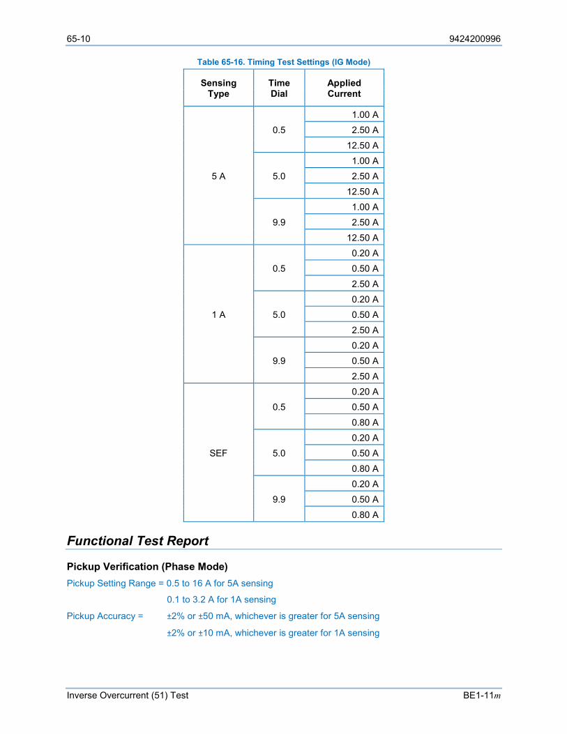
65-10 9424200996
Inverse Overcurrent (51) Test BE1-11m
Table 65-16. Timing Test Settings (IG Mode)
Sensing Type
Time Dial
Applied Current
5 A
0.5 1.00 A 2.50 A
12.50 A
5.0 1.00 A 2.50 A
12.50 A
9.9 1.00 A 2.50 A
12.50 A
1 A
0.5 0.20 A 0.50 A
2.50 A
5.0 0.20 A 0.50 A
2.50 A
9.9 0.20 A 0.50 A
2.50 A
SEF
0.5 0.20 A 0.50 A
0.80 A
5.0 0.20 A 0.50 A
0.80 A
9.9 0.20 A 0.50 A
0.80 A
Functional Test Report
Pickup Verification (Phase Mode) Pickup Setting Range = 0.5 to 16 A for 5A sensing
0.1 to 3.2 A for 1A sensing
Pickup Accuracy = ±2% or ±50 mA, whichever is greater for 5A sensing
±2% or ±10 mA, whichever is greater for 1A sensing
9424200996 65-11
BE1-11m Inverse Overcurrent (51) Test
Dropout should occur between 93-99% of the actual pickup value.
Step Pickup Setting Low Actual Pickup High Low* Actual
Dropout High* Pass/Fail
6 0.5 A (5A sensing) 0.45 A 0.55 A 0.46 A 0.49 A P / F
7 5.0 A (5A sensing) 4.90 A 5.10 A 4.65 A 4.95 A P / F
7 16.0 A (5A sensing) 15.68 A 16.32 A 14.88 A 15.84 A P / F
6 0.1 A (1A sensing) 0.09 A 0.11 A 0.09 A 0.09 A P / F
7 1.0 A (1A sensing) 0.98 A 1.02 A 0.93 A 0.99 A P / F
7 3.2 A (1A sensing) 3.13 A 3.26 A 2.97 A 3.16 A P / F
* Dropout range is calculated from the pickup setting and may need adjusted based on actual pickup.
Timing Verification (Phase Mode, 5A Sensing) Time Dial Range = 0.0 to 9.9
Timing Accuracy = ±5% or ±1½ cycles, whichever is greater Step Time Dial Time Curve Applied Current Low Actual Timing High Pass/Fail
4 0.5 I2 1.00 A 0.444 sec 0.491 sec P / F
4 0.5 I2 2.50 A 0.190 sec 0.240 sec P / F
4 0.5 I2 12.50 A 0.100 sec 0.150 sec P / F
4 5.0 I2 1.00 A 4.204 sec 4.647 sec P / F
4 5.0 I2 2.50 A 1.798 sec 1.988 sec P / F
4 5.0 I2 12.50 A 0.944 sec 1.044 sec P / F
4 9.9 I2 1.00 A 8.300 sec 9.173 sec P / F
4 9.9 I2 2.50 A 3.535 sec 3.907 sec P / F
4 9.9 I2 12.50 A 1.844 sec 2.038 sec P / F
Timing Verification (Phase Mode, 1A Sensing) Time Dial Range = 0.0 to 9.9
Timing Accuracy = ±5% or ±1½ cycles, whichever is greater Step Time Dial Time Curve Applied Current Low Actual Timing High Pass/Fail
4 0.5 I2 0.20 A 0.444 sec 0.491 sec P / F
4 0.5 I2 0.50 A 0.190 sec 0.240 sec P / F
4 0.5 I2 2.50 A 0.100 sec 0.150 sec P / F
4 5.0 I2 0.20 A 4.204 sec 4.647 sec P / F
4 5.0 I2 0.50 A 1.798 sec 1.988 sec P / F
4 5.0 I2 2.50 A 0.944 sec 1.044 sec P / F
4 9.9 I2 0.20 A 8.300 sec 9.173 sec P / F
4 9.9 I2 0.50 A 3.535 sec 3.907 sec P / F
4 9.9 I2 2.50 A 1.844 sec 2.038 sec P / F
Pickup Verification (3I0 Mode) Pickup Setting Range = 0.5 to 16 A for 5A sensing
0.1 to 3.2 A for 1A sensing
Pickup Accuracy = ±3% or ±75 mA, whichever is greater for 5A sensing
±3% or ±15 mA, whichever is greater for 1A sensing
65-12 9424200996
Inverse Overcurrent (51) Test BE1-11m
Dropout should occur between 93-99% of the actual pickup value.
Step Pickup Setting Low Actual Pickup High Low* Actual
Dropout High* Pass/Fail
6 0.5 A (5A sensing) 0.425 A 0.575 A 0.465 A 0.495 A P / F
7 5.0 A (5A sensing) 4.85 A 5.15 A 4.65 A 4.95 A P / F
7 16.0 A (5A sensing) 15.52 A 16.48 A 14.88 A 15.84 A P / F
6 0.1 A (1A sensing) 0.085 A 0.115 A 0.093 A 0.099 A P / F
7 1.0 A (1A sensing) 0.97 A 1.03 A 0.93 A 0.99 A P / F
7 3.2 A (1A sensing) 3.104 A 3.296 A 2.976 A 3.168 A P / F
* Dropout range is calculated from the pickup setting and may need adjusted based on actual pickup.
Timing Verification (3I0 Mode, 5A Sensing) Time Dial Range = 0.0 to 9.9
Timing Accuracy = ±5% or ±1½ cycles, whichever is greater Step Time Dial Time Curve Applied Current Low Actual Timing High Pass/Fail
4 0.5 I2 1.00 A 0.444 sec 0.491 sec P / F
4 0.5 I2 2.50 A 0.190 sec 0.240 sec P / F
4 0.5 I2 12.50 A 0.100 sec 0.150 sec P / F
4 5.0 I2 1.00 A 4.204 sec 4.647 sec P / F
4 5.0 I2 2.50 A 1.798 sec 1.988 sec P / F
4 5.0 I2 12.50 A 0.944 sec 1.044 sec P / F
4 9.9 I2 1.00 A 8.300 sec 9.173 sec P / F
4 9.9 I2 2.50 A 3.535 sec 3.907 sec P / F
4 9.9 I2 12.50 A 1.844 sec 2.038 sec P / F
Timing Verification (3I0 Mode, 1A Sensing) Time Dial Range = 0.0 to 9.9
Timing Accuracy = ±5% or ±1½ cycles, whichever is greater Step Time Dial Time Curve Applied Current Low Actual Timing High Pass/Fail
4 0.5 I2 0.20 A 0.444 sec 0.491 sec P / F
4 0.5 I2 0.50 A 0.190 sec 0.240 sec P / F
4 0.5 I2 2.50 A 0.100 sec 0.150 sec P / F
4 5.0 I2 0.20 A 4.204 sec 4.647 sec P / F
4 5.0 I2 0.50 A 1.798 sec 1.988 sec P / F
4 5.0 I2 2.50 A 0.944 sec 1.044 sec P / F
4 9.9 I2 0.20 A 8.300 sec 9.173 sec P / F
4 9.9 I2 0.50 A 3.535 sec 3.907 sec P / F
4 9.9 I2 2.50 A 1.844 sec 2.038 sec P / F
Pickup Verification (I2 Mode) Pickup Setting Range = 0.5 to 16 A for 5A sensing
0.1 to 3.2 A for 1A sensing
Pickup Accuracy = ±3% or ±75 mA, whichever is greater for 5A sensing
±3% or ±15 mA, whichever is greater for 1A sensing
9424200996 65-13
BE1-11m Inverse Overcurrent (51) Test
Dropout should occur between 93-99% of the actual pickup value.
Step Pickup Setting Low Actual
Pickup High Low* Actual
Dropout High*
Pass/Fail I2 IA I2 IA I2 IA I2 IA I2 IA
6 0.5 (5A CT) 1.50 0.42 1.26 0.57 1.71 0.46 1.38 0.49 1.47 P / F
7 5.0 (5A CT) 15.00 4.85 14.55 5.15 15.45 4.65 13.95 4.95 14.85 P / F
7 9.0 (5A CT) 27.00 8.73 26.19 9.27 27.81 8.37 25.11 8.91 26.73 P / F
6 0.1 (1A CT) 0.30 0.08 0.24 0.11 0.33 0.093 0.279 0.099 0.297 P / F
7 1.0 (1A CT) 3.00 0.97 2.91 1.03 3.09 0.93 2.79 0.99 2.97 P / F
7 1.8 (1A CT) 5.40 1.74 5.22 1.85 5.55 1.67 5.01 1.78 5.34 P / F
* Dropout range is calculated from the pickup setting and may need adjusted based on actual pickup.
Timing Verification (I2 Mode, 5A Sensing) Time Dial Range = 0.0 to 9.9
Timing Accuracy = ±5% or ±1½ cycles, whichever is greater Step Time Dial Time Curve Applied Current Low Actual Timing High Pass/Fail
4 0.5 I2 3.00 A 0.444 sec 0.491 sec P / F
4 0.5 I2 7.50 A 0.190 sec 0.240 sec P / F
4 0.5 I2 27.00 A 0.094 sec 0.174 sec P / F
4 5.0 I2 3.00 A 4.204 sec 4.647 sec P / F
4 5.0 I2 7.50 A 1.798 sec 1.988 sec P / F
4 5.0 I2 27.00 A 1.035 sec 1.145 sec P / F
4 9.9 I2 3.00 A 8.300 sec 9.173 sec P / F
4 9.9 I2 7.50 A 3.535 sec 3.907 sec P / F
4 9.9 I2 27.00 A 2.023 sec 2.237 sec P / F
Timing Verification (I2 Mode, 1A Sensing) Time Dial Range = 0.0 to 9.9
Timing Accuracy = ±5% or ±1½ cycles, whichever is greater Step Time Dial Time Curve Applied Current Low Actual Timing High Pass/Fail
4 0.5 I2 0.60 A 0.444 sec 0.491 sec P / F
4 0.5 I2 1.50 A 0.190 sec 0.240 sec P / F
4 0.5 I2 7.50 A 0.100 sec 0.150 sec P / F
4 5.0 I2 0.60 A 4.204 sec 4.647 sec P / F
4 5.0 I2 1.50 A 1.798 sec 1.988 sec P / F
4 5.0 I2 7.50 A 0.944 sec 1.044 sec P / F
4 9.9 I2 0.60 A 8.300 sec 9.173 sec P / F
4 9.9 I2 1.50 A 3.535 sec 3.907 sec P / F
4 9.9 I2 7.50 A 1.844 sec 2.038 sec P / F
65-14 9424200996
Inverse Overcurrent (51) Test BE1-11m
Pickup Verification (IG Mode) Pickup Setting Range = 0.5 to 16 A for 5A sensing
0.1 to 3.2 A for 1A sensing
0.01 to 0.8 A for SEF
Pickup Accuracy = ±2% or ±50 mA, whichever is greater for 5A sensing
±2% or ±10 mA, whichever is greater for 1A sensing
±2.5% or ±2.5 mA, whichever is greater for SEF
Dropout should occur between 93-99% of the actual pickup value.
Step Pickup Setting Low Actual Pickup High Low* Actual
Dropout High* Pass/Fail
6 0.5 A (5A sensing) 0.45 A 0.55 A 0.465 A 0.495 A P / F
7 5.0 A (5A sensing) 4.90 A 5.10 A 4.65 A 4.95 A P / F
7 16.0 A (5A sensing) 15.68 A 16.32 A 14.88 A 15.84 A P / F
6 0.1 A (1A sensing) 0.09 A 0.11 A 0.09 A 0.09 A P / F
7 1.0 A (1A sensing) 0.98 A 1.02 A 0.93 A 0.99 A P / F
7 3.2 A (1A sensing) 3.13 A 3.26 A 2.97 A 3.16 A P / F
6 0.1 A (SEF sensing) 0.0075 A 0.0125 A 0.0093 A 0.0099 A P / F
7 0.5 A (SEF sensing) 0.317 A 0.682 A 0.465 A 0.495 A P / F
7 0.8 A (SEF sensing) 0.63 A 0.97 A 0.074 A 0.792 A P / F
* Dropout range is calculated from the pickup setting and may need adjusted based on actual pickup.
Timing Verification (IG Mode, 5A Sensing) Time Dial Range = 0.0 to 9.9
Timing Accuracy = ±5% or ±1½ cycles, whichever is greater Step Time Dial Time Curve Applied Current Low Actual Timing High Pass/Fail
4 0.5 I2 1.00 A 0.444 sec 0.491 sec P / F
4 0.5 I2 2.50 A 0.190 sec 0.240 sec P / F
4 0.5 I2 12.50 A 0.100 sec 0.150 sec P / F
4 5.0 I2 1.00 A 4.204 sec 4.647 sec P / F
4 5.0 I2 2.50 A 1.798 sec 1.988 sec P / F
4 5.0 I2 12.50 A 0.944 sec 1.044 sec P / F
4 9.9 I2 1.00 A 8.300 sec 9.173 sec P / F
4 9.9 I2 2.50 A 3.535 sec 3.907 sec P / F
4 9.9 I2 12.50 A 1.844 sec 2.038 sec P / F
Timing Verification (IG Mode, 1A Sensing) Time Dial Range = 0.0 to 9.9
Timing Accuracy = ±5% or ±1½ cycles, whichever is greater Step Time Dial Time Curve Applied Current Low Actual Timing High Pass/Fail
4 0.5 I2 0.20 A 0.444 sec 0.491 sec P / F
4 0.5 I2 0.50 A 0.190 sec 0.240 sec P / F
4 0.5 I2 2.50 A 0.100 sec 0.150 sec P / F
4 5.0 I2 0.20 A 4.204 sec 4.647 sec P / F
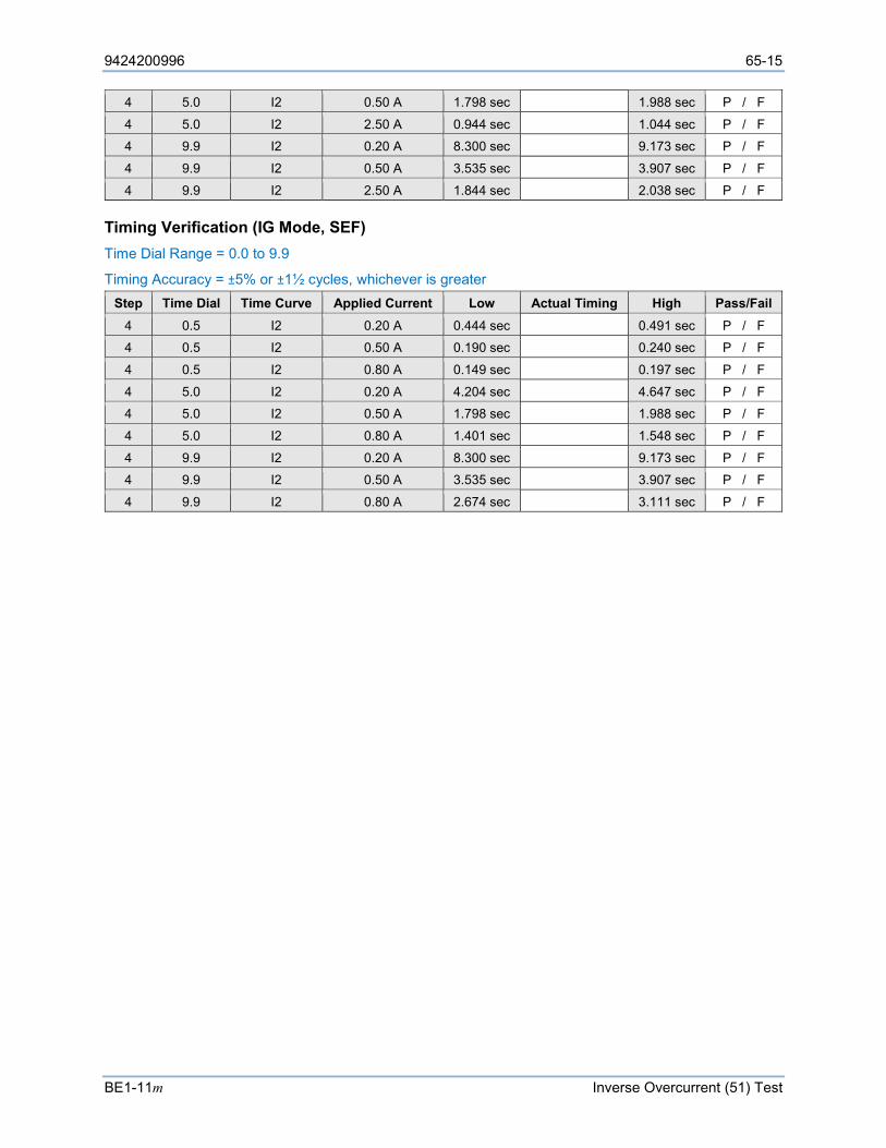
9424200996 65-15
BE1-11m Inverse Overcurrent (51) Test
4 5.0 I2 0.50 A 1.798 sec 1.988 sec P / F
4 5.0 I2 2.50 A 0.944 sec 1.044 sec P / F
4 9.9 I2 0.20 A 8.300 sec 9.173 sec P / F
4 9.9 I2 0.50 A 3.535 sec 3.907 sec P / F
4 9.9 I2 2.50 A 1.844 sec 2.038 sec P / F
Timing Verification (IG Mode, SEF) Time Dial Range = 0.0 to 9.9
Timing Accuracy = ±5% or ±1½ cycles, whichever is greater Step Time Dial Time Curve Applied Current Low Actual Timing High Pass/Fail
4 0.5 I2 0.20 A 0.444 sec 0.491 sec P / F
4 0.5 I2 0.50 A 0.190 sec 0.240 sec P / F
4 0.5 I2 0.80 A 0.149 sec 0.197 sec P / F
4 5.0 I2 0.20 A 4.204 sec 4.647 sec P / F
4 5.0 I2 0.50 A 1.798 sec 1.988 sec P / F
4 5.0 I2 0.80 A 1.401 sec 1.548 sec P / F
4 9.9 I2 0.20 A 8.300 sec 9.173 sec P / F
4 9.9 I2 0.50 A 3.535 sec 3.907 sec P / F
4 9.9 I2 0.80 A 2.674 sec 3.111 sec P / F

65-16 9424200996
Inverse Overcurrent (51) Test BE1-11m

9424200996 66-1
BE1-11m Phase Current Differential (87) Test
66 • Phase Current Differential (87) Test Functional testing is a way to assess this protection system’s suitability for your application. Functional testing goes beyond the more basic tests found in acceptance testing, but lacks the detailed function testing that is part of the commissioning process.
Test each of the following functions to verify that this BE1-11m measures accurately, is within specified tolerances, and operates correctly. These tests are also suitable for assisting in systematic troubleshooting in the event that an operation is questioned. Revisiting the test of a specific function can help verify whether the BE1-11m is operating within specified tolerances. For further assistance, contact Basler Electric, Technical Sales Support.
Refer to the Terminals and Connectors chapter for terminal locations and connections.
Reset all targets prior to each test by navigating to the Metering > Status > Targets screen and pressing the front-panel Reset key. Enter the appropriate username and password if prompted. Clear all logic prior to each test by using the Settings Explorer in BESTCOMSPlus® to open the BESTlogic™Plus Programmable Logic screen and click the Clear button located on the toolbar. After new BESTlogicPlus settings are made, click the Save button located on the toolbar to compile BESTlogicPlus. Upload BESTlogicPlus settings by selecting Upload Logic to Device from the Communication pull-down menu. Operational settings can be sent by selecting Upload Settings to Device from the Communication pull-down menu or by clicking the Send Settings button on the toolbar.
The actual operating time of an output contact is equal to the recognition time plus the time delay setting (accuracy) plus 6 milliseconds. Output contact operating time depends upon the type of test set used and its operating characteristics.
A Functional Test Report is included at the end of this chapter. It should be used to record the results and verify pickup and timing accuracy.
Refer to the Phase Current Differential (87) Protection chapter for more information on this function.
Restrained Functional Test Procedure
Pickup Verification (Maximum Restraint) Step 1: Use BESTCOMSPlus to send the operational settings in Table 66-1. Reset all targets.
Table 66-1. Operational Settings (87R - Maximum)
Setting Value BESTCOMSPlus Screen Description Nominal Phase Voltage
69.3 V System Parameters, Motor Configuration
Sets the nominal secondary sensing voltage to 69.3 V
Nominal Phase Current
5 A System Parameters, Motor Configuration
Sets the nominal secondary sensing current to 5 A
Nominal Aux. Voltage
69.3 V System Parameters, Motor Configuration
Sets the nominal secondary auxiliary voltage to 69.3 V
Phase CT 1 Ratio
1 System Parameters, Sensing Transformers
Sets the phase CT 1 ratio to 1
Phase CT 2 Ratio
1 System Parameters, Sensing Transformers
Sets the phase CT 2 ratio to 1
Phase VT Ratio
1 System Parameters, Sensing Transformers
Sets phase VT ratio to 1
Phase VT Connection
4W-Y System Parameters, Sensing Transformers
Sets phase VT connection to 4W-Y
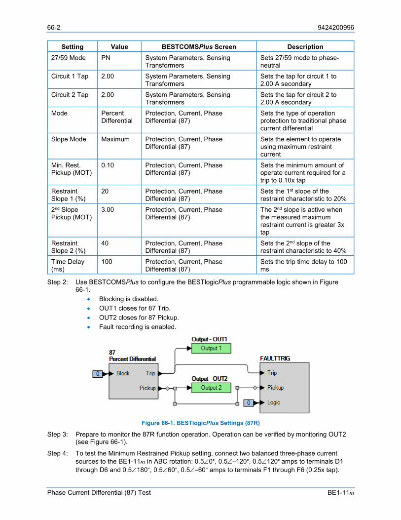
66-2 9424200996
Phase Current Differential (87) Test BE1-11m
Setting Value BESTCOMSPlus Screen Description 27/59 Mode PN System Parameters, Sensing
Transformers Sets 27/59 mode to phase-neutral
Circuit 1 Tap 2.00 System Parameters, Sensing Transformers
Sets the tap for circuit 1 to 2.00 A secondary
Circuit 2 Tap 2.00 System Parameters, Sensing Transformers
Sets the tap for circuit 2 to 2.00 A secondary
Mode Percent Differential
Protection, Current, Phase Differential (87)
Sets the type of operation protection to traditional phase current differential
Slope Mode Maximum Protection, Current, Phase Differential (87)
Sets the element to operate using maximum restraint current
Min. Rest. Pickup (MOT)
0.10 Protection, Current, Phase Differential (87)
Sets the minimum amount of operate current required for a trip to 0.10x tap
Restraint Slope 1 (%)
20 Protection, Current, Phase Differential (87)
Sets the 1st slope of the restraint characteristic to 20%
2nd Slope Pickup (MOT)
3.00 Protection, Current, Phase Differential (87)
The 2nd slope is active when the measured maximum restraint current is greater 3x tap
Restraint Slope 2 (%)
40 Protection, Current, Phase Differential (87)
Sets the 2nd slope of the restraint characteristic to 40%
Time Delay (ms)
100 Protection, Current, Phase Differential (87)
Sets the trip time delay to 100 ms
Step 2: Use BESTCOMSPlus to configure the BESTlogicPlus programmable logic shown in Figure 66-1.
• Blocking is disabled. • OUT1 closes for 87 Trip. • OUT2 closes for 87 Pickup. • Fault recording is enabled.
Figure 66-1. BESTlogicPlus Settings (87R)
Step 3: Prepare to monitor the 87R function operation. Operation can be verified by monitoring OUT2 (see Figure 66-1).
Step 4: To test the Minimum Restrained Pickup setting, connect two balanced three-phase current sources to the BE1-11m in ABC rotation: 0.5∠0°, 0.5∠–120°, 0.5∠120° amps to terminals D1 through D6 and 0.5∠180°, 0.5∠60°, 0.5∠–60° amps to terminals F1 through F6 (0.25x tap).
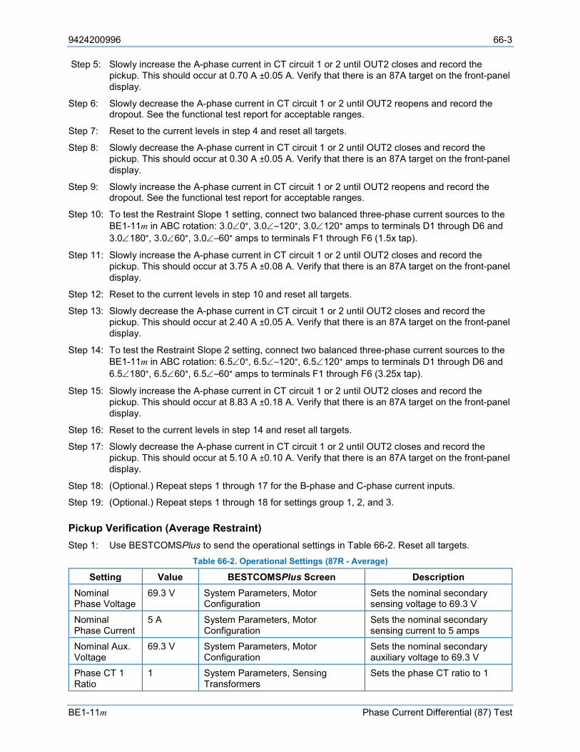
9424200996 66-3
BE1-11m Phase Current Differential (87) Test
Step 5: Slowly increase the A-phase current in CT circuit 1 or 2 until OUT2 closes and record the pickup. This should occur at 0.70 A ±0.05 A. Verify that there is an 87A target on the front-panel display.
Step 6: Slowly decrease the A-phase current in CT circuit 1 or 2 until OUT2 reopens and record the dropout. See the functional test report for acceptable ranges.
Step 7: Reset to the current levels in step 4 and reset all targets.
Step 8: Slowly decrease the A-phase current in CT circuit 1 or 2 until OUT2 closes and record the pickup. This should occur at 0.30 A ±0.05 A. Verify that there is an 87A target on the front-panel display.
Step 9: Slowly increase the A-phase current in CT circuit 1 or 2 until OUT2 reopens and record the dropout. See the functional test report for acceptable ranges.
Step 10: To test the Restraint Slope 1 setting, connect two balanced three-phase current sources to the BE1-11m in ABC rotation: 3.0∠0°, 3.0∠–120°, 3.0∠120° amps to terminals D1 through D6 and 3.0∠180°, 3.0∠60°, 3.0∠–60° amps to terminals F1 through F6 (1.5x tap).
Step 11: Slowly increase the A-phase current in CT circuit 1 or 2 until OUT2 closes and record the pickup. This should occur at 3.75 A ±0.08 A. Verify that there is an 87A target on the front-panel display.
Step 12: Reset to the current levels in step 10 and reset all targets.
Step 13: Slowly decrease the A-phase current in CT circuit 1 or 2 until OUT2 closes and record the pickup. This should occur at 2.40 A ±0.05 A. Verify that there is an 87A target on the front-panel display.
Step 14: To test the Restraint Slope 2 setting, connect two balanced three-phase current sources to the BE1-11m in ABC rotation: 6.5∠0°, 6.5∠–120°, 6.5∠120° amps to terminals D1 through D6 and 6.5∠180°, 6.5∠60°, 6.5∠–60° amps to terminals F1 through F6 (3.25x tap).
Step 15: Slowly increase the A-phase current in CT circuit 1 or 2 until OUT2 closes and record the pickup. This should occur at 8.83 A ±0.18 A. Verify that there is an 87A target on the front-panel display.
Step 16: Reset to the current levels in step 14 and reset all targets.
Step 17: Slowly decrease the A-phase current in CT circuit 1 or 2 until OUT2 closes and record the pickup. This should occur at 5.10 A ±0.10 A. Verify that there is an 87A target on the front-panel display.
Step 18: (Optional.) Repeat steps 1 through 17 for the B-phase and C-phase current inputs.
Step 19: (Optional.) Repeat steps 1 through 18 for settings group 1, 2, and 3.
Pickup Verification (Average Restraint) Step 1: Use BESTCOMSPlus to send the operational settings in Table 66-2. Reset all targets.
Table 66-2. Operational Settings (87R - Average)
Setting Value BESTCOMSPlus Screen Description Nominal Phase Voltage
69.3 V System Parameters, Motor Configuration
Sets the nominal secondary sensing voltage to 69.3 V
Nominal Phase Current
5 A System Parameters, Motor Configuration
Sets the nominal secondary sensing current to 5 amps
Nominal Aux. Voltage
69.3 V System Parameters, Motor Configuration
Sets the nominal secondary auxiliary voltage to 69.3 V
Phase CT 1 Ratio
1 System Parameters, Sensing Transformers
Sets the phase CT ratio to 1
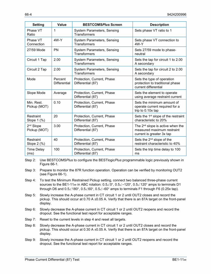
66-4 9424200996
Phase Current Differential (87) Test BE1-11m
Setting Value BESTCOMSPlus Screen Description Phase VT Ratio
1 System Parameters, Sensing Transformers
Sets phase VT ratio to 1
Phase VT Connection
4W-Y System Parameters, Sensing Transformers
Sets phase VT connection to 4W-Y
27/59 Mode PN System Parameters, Sensing Transformers
Sets 27/59 mode to phase-neutral
Circuit 1 Tap 2.00 System Parameters, Sensing Transformers
Sets the tap for circuit 1 to 2.00 A secondary
Circuit 2 Tap 2.00 System Parameters, Sensing Transformers
Sets the tap for circuit 2 to 2.00 A secondary
Mode Percent Differential
Protection, Current, Phase Differential (87)
Sets the type of operation protection to traditional phase current differential
Slope Mode Average Protection, Current, Phase Differential (87)
Sets the element to operate using average restraint current
Min. Rest. Pickup (MOT)
0.10 Protection, Current, Phase Differential (87)
Sets the minimum amount of operate current required for a trip to 0.10x tap
Restraint Slope 1 (%)
20 Protection, Current, Phase Differential (87)
Sets the 1st slope of the restraint characteristic to 20%
2nd Slope Pickup (MOT)
3.00 Protection, Current, Phase Differential (87)
The 2nd slope is active when the measured maximum restraint current is greater 3x tap
Restraint Slope 2 (%)
40 Protection, Current, Phase Differential (87)
Sets the 2nd slope of the restraint characteristic to 40%
Time Delay (ms)
100 Protection, Current, Phase Differential (87)
Sets the trip time delay to 100 ms
Step 2: Use BESTCOMSPlus to configure the BESTlogicPlus programmable logic previously shown in Figure 66-1.
Step 3: Prepare to monitor the 87R function operation. Operation can be verified by monitoring OUT2 (see Figure 66-1).
Step 4: To test the Minimum Restrained Pickup setting, connect two balanced three-phase current sources to the BE1-11m in ABC rotation: 0.5∠0°, 0.5∠–120°, 0.5∠120° amps to terminals D1 through D6 and 0.5∠180°, 0.5∠60°, 0.5∠–60° amps to terminals F1 through F6 (0.25x tap).
Step 5: Slowly increase the A-phase current in CT circuit 1 or 2 until OUT2 closes and record the pickup. This should occur at 0.70 A ±0.05 A. Verify that there is an 87A target on the front-panel display.
Step 6: Slowly decrease the A-phase current in CT circuit 1 or 2 until OUT2 reopens and record the dropout. See the functional test report for acceptable ranges.
Step 7: Reset to the current levels in step 4 and reset all targets.
Step 8: Slowly decrease the A-phase current in CT circuit 1 or 2 until OUT2 closes and record the pickup. This should occur at 0.30 A ±0.05 A. Verify that there is an 87A target on the front-panel display.
Step 9: Slowly increase the A-phase current in CT circuit 1 or 2 until OUT2 reopens and record the dropout. See the functional test report for acceptable ranges.
9424200996 66-5
BE1-11m Phase Current Differential (87) Test
Step 10: To test the Restraint Slope 1 setting, connect two balanced three-phase current sources to the BE1-11m in ABC rotation: 3.0∠0°, 3.0∠–120°, 3.0∠120° amps to terminals D1 through D6 and 3.0∠180°, 3.0∠60°, 3.0∠–60° amps to terminals F1 through F6 (1.5x tap).
Step 11: Slowly increase the A-phase current in CT circuit 1 or 2 until OUT2 closes and record the pickup. This should occur at 3.67 A ±0.07 A. Verify that there is an 87A target on the front-panel display.
Step 12: Reset to the current levels in step 10 and reset all targets.
Step 13: Slowly decrease the A-phase current in CT circuit 1 or 2 until OUT2 closes and record the pickup. This should occur at 2.46 A ±0.05 A. Verify that there is an 87A target on the front-panel display.
Step 14: To test the Restraint Slope 2 setting, connect two balanced three-phase current sources to the BE1-11m in ABC rotation:6.5∠0°, 6.5∠–120°, 6.5∠120° amps to terminals D1 through D6 and 6.5∠180°, 6.5∠60°, 6.5∠–60° amps to terminals F1 through F6 (3.25x tap).
Step 15: Slowly increase the A-phase current in CT circuit 1 or 2 until OUT2 closes and record the pickup. This should occur at 8.25 A ±0.17 A. Verify that there is an 87A target on the front-panel display.
Step 16: Reset to the current levels in step 14 and reset all targets.
Step 17: Slowly decrease the A-phase current in CT circuit 1 or 2 until OUT2 closes and record the pickup. This should occur at 5.32 A ±0.11 A. Verify that there is an 87A target on the front-panel display.
Step 18: (Optional.) Repeat steps 1 through 17 for the B-phase and C-phase current inputs.
Step 19: (Optional.) Repeat steps 1 through 18 for settings group 1, 2, and 3.
Timing Verification (Maximum or Average Restraint) Step 1: Use BESTCOMSPlus to verify the operational settings in Table 66-1 (Maximum) or 2 (Average)
and logic in Figure 66-1. Reset all targets.
Step 2: Prepare to monitor the 87 timings. Timing accuracy is verified by measuring the elapsed time between OUT2 (pickup) and OUT1 (trip) closing.
Step 3: Connect two balanced three-phase current sources to the BE1-11m in ABC rotation: 3.0∠0°, 3.0∠–120°, 3.0∠120° amps to terminals D1 through D6 and 3.0∠180°, 3.0∠60°, 3.0∠–60° amps to terminals F1 through F6.
Step 4: Slowly increase the A-phase current in CT circuit 1 or 2 until OUT2 closes. Record the time between OUT2 and OUT1 closing. This should be 100 ms ± (50 ms + 2 cycles).
Step 5: (Optional) Repeat steps 1 through4 for settings group 1, 2, and 3.
Functional Test Reports
Restrained Pickup Verification (Maximum Restraint) Pickup Accuracy = ±2% or ±0.05A, whichever is greater.
Dropout = (1 - 0.1) * pickup
Step Pickup Setting Low Actual
Pickup High Low Actual Dropout High Pass/Fail
5/6 - MRPU 0.70 A 0.65 A 0.75 A 0.59 A 0.68 A P / F
8/9 - MRPU 0.30 A 0.25 A 0.35 A 0.28 A 0.39 A P / F
11 – Slope 1 3.75 A 3.68 A 3.83 A N/A* N/A* N/A* P / F
13 – Slope 1 2.40 A 2.35 A 2.45 A N/A* N/A* N/A* P / F
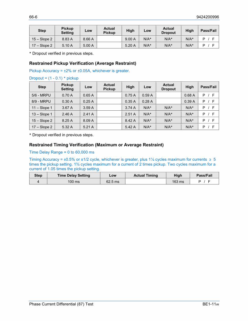
66-6 9424200996
Phase Current Differential (87) Test BE1-11m
Step Pickup Setting Low Actual
Pickup High Low Actual Dropout High Pass/Fail
15 – Slope 2 8.83 A 8.66 A 9.00 A N/A* N/A* N/A* P / F
17 – Slope 2 5.10 A 5.00 A 5.20 A N/A* N/A* N/A* P / F
* Dropout verified in previous steps.
Restrained Pickup Verification (Average Restraint) Pickup Accuracy = ±2% or ±0.05A, whichever is greater.
Dropout = (1 - 0.1) * pickup
Step Pickup Setting Low Actual
Pickup High Low Actual Dropout High Pass/Fail
5/6 - MRPU 0.70 A 0.65 A 0.75 A 0.59 A 0.68 A P / F
8/9 - MRPU 0.30 A 0.25 A 0.35 A 0.28 A 0.39 A P / F
11 – Slope 1 3.67 A 3.59 A 3.74 A N/A* N/A* N/A* P / F
13 – Slope 1 2.46 A 2.41 A 2.51 A N/A* N/A* N/A* P / F
15 – Slope 2 8.25 A 8.09 A 8.42 A N/A* N/A* N/A* P / F
17 – Slope 2 5.32 A 5.21 A 5.42 A N/A* N/A* N/A* P / F
* Dropout verified in previous steps.
Restrained Timing Verification (Maximum or Average Restraint) Time Delay Range = 0 to 60,000 ms
Timing Accuracy = ±0.5% or ±1/2 cycle, whichever is greater, plus 1¼ cycles maximum for currents ≥ 5 times the pickup setting. 1¾ cycles maximum for a current of 2 times pickup. Two cycles maximum for a current of 1.05 times the pickup setting.
Step Time Delay Setting Low Actual Timing High Pass/Fail 4 100 ms 62.5 ms 163 ms P / F

9424200996 67-1
BE1-11m Power (32) Test
67 • Power (32) Test Functional testing is a way to assess this protection system’s suitability for your application. Functional testing goes beyond the more basic tests found in acceptance testing, but lacks the detailed function testing that is part of the commissioning process.
Test each of the following functions to verify that this BE1-11m measures accurately, is within specified tolerances, and operates correctly. These tests are also suitable for assisting in systematic troubleshooting in the event that an operation is questioned. Revisiting the test of a specific function can help verify whether the BE1-11m is operating within specified tolerances. For further assistance, contact Basler Electric, Technical Sales Support.
Refer to the Terminals and Connectors chapter for terminal locations and connections.
Reset all targets prior to each test by navigating to the Metering > Status > Targets screen and pressing the front-panel Reset key. Enter the appropriate username and password if prompted. Clear all logic prior to each test by using the Settings Explorer in BESTCOMSPlus® to open the BESTlogic™Plus Programmable Logic screen and click the Clear button located on the toolbar. After new BESTlogicPlus settings are made, click the Save button located on the toolbar to compile BESTlogicPlus. Upload BESTlogicPlus settings by selecting Upload Logic to Device from the Communication pull-down menu. Operational settings can be sent by selecting Upload Settings to Device from the Communication pull-down menu or by clicking the Send Settings button on the toolbar.
The actual operating time of an output contact is equal to the recognition time plus the time delay setting (accuracy) plus 6 milliseconds. Output contact operating time depends upon the type of test set used and its operating characteristics.
A Functional Test Report is included at the end of this chapter. It should be used to record the results and verify pickup and timing accuracy.
Refer to the Power (32) Protection chapter for more information on this function.
Functional Test Procedure
Step 1: Use BESTCOMSPlus to send the operational settings in Table 67-1 to the BE1-11m. Reset all targets. There are four enable modes for the 32 element 1 of 3, 2 of 3, 3 of 3, and Total Power (Modes 1, 2, 3, and 4). The following test uses Single Phase Tripping (1 of 3) Mode 1. Regardless of mode, the element is set for three-phase power. Single-phase modes automatically operate at the three-phase setting divided by the appropriate mode. Optionally, the user can test Modes 2, 3, and 4 but they are not shown.
Table 67-1. Operational Settings
Setting Value BESTCOMSPlus Screen Description Phase VT Ratio 1 System Parameters,
Sensing Transformers Sets phase VT ratio to 1
Phase VT Connection
4W-Y System Parameters, Sensing Transformers
Sets phase VT connection to 4W-Y
Phase CT Ratio 1 System Parameters, Sensing Transformers
Sets phase CT ratio to 1
Bus CT Selection, CT Source
CT1 System Parameters, Sensing Transformers
Selects CT circuit 1 as the bus source (for protection systems equipped with 2 sets of CTs)
Element Mode 1 of 3 Protection, Power, Power (32-1)
Enables 32-1 function for 1 of 3 mode
Time Delay 50 ms Protection, Power, Power (32-1)
Sets time delay to 50 ms
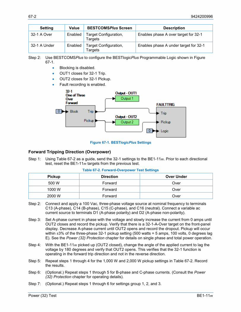
67-2 9424200996
Power (32) Test BE1-11m
Setting Value BESTCOMSPlus Screen Description 32-1 A Over Enabled Target Configuration,
Targets Enables phase A over target for 32-1
32-1 A Under Enabled Target Configuration, Targets
Enables phase A under target for 32-1
Step 2: Use BESTCOMSPlus to configure the BESTlogicPlus Programmable Logic shown in Figure 67-1.
• Blocking is disabled. • OUT1 closes for 32-1 Trip. • OUT2 closes for 32-1 Pickup. • Fault recording is enabled.
Figure 67-1. BESTlogicPlus Settings
Forward Tripping Direction (Overpower) Step 1: Using Table 67-2 as a guide, send the 32-1 settings to the BE1-11m. Prior to each directional
test, reset the BE1-11m targets from the previous test. Table 67-2. Forward-Overpower Test Settings
Pickup Direction Over Under 500 W Forward Over 1000 W Forward Over 2000 W Forward Over
Step 2: Connect and apply a 100 Vac, three-phase voltage source at nominal frequency to terminals C13 (A-phase), C14 (B-phase), C15 (C-phase), and C16 (neutral). Connect a variable ac current source to terminals D1 (A-phase polarity) and D2 (A-phase non-polarity).
Step 3: Set A-phase current in phase with the voltage and slowly increase the current from 0 amps until OUT2 closes and record the pickup. Verify that there is a 32-1-A-Over target on the front-panel display. Decrease A-phase current until OUT2 opens and record the dropout. Pickup will occur within ±3% of the three-phase 32-1 pickup setting (500 watts = 5 amps, 100 volts, 0 degrees lag E). See the Power (32) Protection chapter for details on single phase and total power operation.
Step 4: With the BE1-11m picked up (OUT2 closed), change the angle of the applied current to lag the voltage by 180 degrees and verify that OUT2 opens. This verifies that the 32-1 function is operating in the forward trip direction and not in the reverse direction.
Step 5: Repeat steps 1 through 4 for the 1,000 W and 2,000 W pickup settings in Table 67-2. Record the results.
Step 6: (Optional.) Repeat steps 1 through 5 for B-phase and C-phase currents. (Consult the Power (32) Protection chapter for operating details).
Step 7: (Optional.) Repeat steps 1 through 6 for settings group 1, 2, and 3.
9424200996 67-3
BE1-11m Power (32) Test
Step 8: (Optional.) Repeat steps 1 through 7 with CT2 as the bus CT selection for protection systems equipped with two sets of CTs. In step 2, replace D1 with F1, D2 with F2, etc.
Reverse Tripping Direction (Overpower) Step 1: Using Table 67-3 as a guide, send the 32-1 settings to the BE1-11m. Prior to each test, reset
the BE1-11m targets from the previous test. Table 67-3. Reverse-Overpower Test Settings
Pickup Direction Over Under 500 W Reverse Over
Step 2: Connect and apply a 100 Vac, three-phase voltage source at nominal frequency to terminals C13 (A-phase), C14 (B-phase), C15 (C-phase), and C16 (neutral). Connect a variable ac current source to terminals D1 (A-phase polarity) and D2 (A-phase non-polarity).
Step 3: Set A-phase current to lag the voltage by 180 degrees and slowly increase the current from 0 amps until OUT2 closes and record the pickup. Verify that there is a 32-1-A-Over target on the front-panel display. Decrease A-phase current until OUT2 opens and record the dropout. Pickup will occur within ±3% of the 32-1 pickup setting (500 watts = 5 amps, 100 volts, 180 degrees I lag E).
Step 4: With the BE1-11m picked up (OUT2 closed), change the angle so that it’s in phase with the voltage and verify that OUT2 opens. This verifies that the 32-1 function is operating in the reverse trip direction and not in the forward direction.
Step 5: (Optional.) Repeat steps 1 through 4 for B-phase and C-phase currents. (Consult the Power (32) Protection chapter for operating details).
Step 6: (Optional.) Repeat steps 1 through 5 for settings group 1, 2, and 3.
Step 7: (Optional.) Repeat steps 1 through 6 with CT2 as the bus CT selection for protection systems equipped with two sets of CTs. In step 2, replace D1 with F1, D2 with F2, etc.
Forward Tripping Direction (Underpower) Step 1: Using Table 67-4 as a guide, send the 32-1 settings to the BE1-11m. Prior to each directional
test, reset the BE1-11m targets from the previous test. Table 67-4. Forward-Underpower Test Settings
Pickup Direction Over Under 500 W Forward Under 250 W Forward Under 50 W Forward Under
Step 2: Connect and apply a 100 Vac, three-phase voltage source at nominal frequency to terminals C13 (A-phase), C14 (B-phase), C15 (C-phase), and C16 (neutral). Connect a variable ac current source to terminals D1 (A-phase polarity) and D2 (A-phase non-polarity). Note that OUT2 is closed with no current applied.
Step 3: Apply 4 amps A-phase current (in phase with the voltage) noting that OUT2 drops out. Slowly decrease the current until OUT2 closes and record the pickup. Verify that there is a 32-1-A-Under target on the front-panel display. Increase A-phase current until OUT2 opens and record the reset. Under power pickup will occur within ±3% of the 32-1 pickup setting (500 watts = 5 amps, 100 volts, 0 degrees I lag E).
Step 4: With the BE1-11m picked up (OUT2 closed), change the angle to lag the voltage by 180 degrees and verify that OUT2 opens. This verifies that the 32-1 function is operating in the forward trip direction and not in the reverse direction.
Step 5: Repeat steps 1 through 4 for the 250 W and 50 W pickup settings in Table 67-4. Record the results.
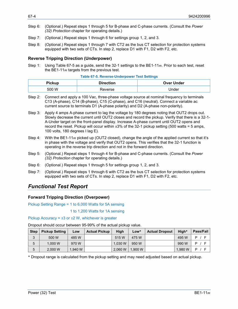
67-4 9424200996
Power (32) Test BE1-11m
Step 6: (Optional.) Repeat steps 1 through 5 for B-phase and C-phase currents. (Consult the Power (32) Protection chapter for operating details.)
Step 7: (Optional.) Repeat steps 1 through 6 for settings group 1, 2, and 3.
Step 8: (Optional.) Repeat steps 1 through 7 with CT2 as the bus CT selection for protection systems equipped with two sets of CTs. In step 2, replace D1 with F1, D2 with F2, etc.
Reverse Tripping Direction (Underpower) Step 1: Using Table 67-5 as a guide, send the 32-1 settings to the BE1-11m. Prior to each test, reset
the BE1-11m targets from the previous test. Table 67-5. Reverse-Underpower Test Settings
Pickup Direction Over Under 500 W Reverse Under
Step 2: Connect and apply a 100 Vac, three-phase voltage source at nominal frequency to terminals C13 (A-phase), C14 (B-phase), C15 (C-phase), and C16 (neutral). Connect a variable ac current source to terminals D1 (A-phase polarity) and D2 (A-phase non-polarity).
Step 3: Apply 4 amps A-phase current to lag the voltage by 180 degrees noting that OUT2 drops out. Slowly decrease the current until OUT2 closes and record the pickup. Verify that there is a 32-1-A-Under target on the front-panel display. Increase A-phase current until OUT2 opens and record the reset. Pickup will occur within ±3% of the 32-1 pickup setting (500 watts = 5 amps, 100 volts, 180 degrees I lag E).
Step 4: With the BE1-11m picked up (OUT2 closed), change the angle of the applied current so that it’s in phase with the voltage and verify that OUT2 opens. This verifies that the 32-1 function is operating in the reverse trip direction and not in the forward direction.
Step 5: (Optional.) Repeat steps 1 through 4 for B-phase and C-phase currents. (Consult the Power (32) Protection chapter for operating details.)
Step 6: (Optional.) Repeat steps 1 through 5 for settings group 1, 2, and 3.
Step 7: (Optional.) Repeat steps 1 through 6 with CT2 as the bus CT selection for protection systems equipped with two sets of CTs. In step 2, replace D1 with F1, D2 with F2, etc.
Functional Test Report
Forward Tripping Direction (Overpower) Pickup Setting Range = 1 to 6,000 Watts for 5A sensing
1 to 1,200 Watts for 1A sensing
Pickup Accuracy = ±3 or ±2 W, whichever is greater
Dropout should occur between 95-99% of the actual pickup value. Step Pickup Setting Low Actual Pickup High Low* Actual Dropout High* Pass/Fail
3 500 W 485 W 515 W 475 W 495 W P / F 5 1,000 W 970 W 1,030 W 950 W 990 W P / F 5 2,000 W 1,940 W 2,060 W 1,900 W 1,980 W P / F
* Dropout range is calculated from the pickup setting and may need adjusted based on actual pickup.
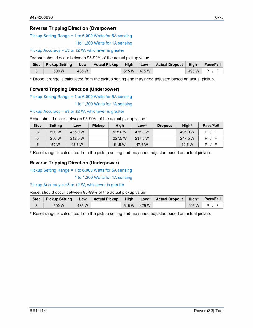
9424200996 67-5
BE1-11m Power (32) Test
Reverse Tripping Direction (Overpower) Pickup Setting Range = 1 to 6,000 Watts for 5A sensing
1 to 1,200 Watts for 1A sensing
Pickup Accuracy = ±3 or ±2 W, whichever is greater
Dropout should occur between 95-99% of the actual pickup value. Step Pickup Setting Low Actual Pickup High Low* Actual Dropout High* Pass/Fail
3 500 W 485 W 515 W 475 W 495 W P / F
* Dropout range is calculated from the pickup setting and may need adjusted based on actual pickup.
Forward Tripping Direction (Underpower) Pickup Setting Range = 1 to 6,000 Watts for 5A sensing
1 to 1,200 Watts for 1A sensing
Pickup Accuracy = ±3 or ±2 W, whichever is greater
Reset should occur between 95-99% of the actual pickup value. Step Setting Low Pickup High Low* Dropout High* Pass/Fail
3 500 W 485.0 W 515.0 W 475.0 W 495.0 W P / F 5 250 W 242.5 W 257.5 W 237.5 W 247.5 W P / F 5 50 W 48.5 W 51.5 W 47.5 W 49.5 W P / F
* Reset range is calculated from the pickup setting and may need adjusted based on actual pickup.
Reverse Tripping Direction (Underpower) Pickup Setting Range = 1 to 6,000 Watts for 5A sensing
1 to 1,200 Watts for 1A sensing
Pickup Accuracy = ±3 or ±2 W, whichever is greater
Reset should occur between 95-99% of the actual pickup value. Step Pickup Setting Low Actual Pickup High Low* Actual Dropout High* Pass/Fail
3 500 W 485 W 515 W 475 W 495 W P / F
* Reset range is calculated from the pickup setting and may need adjusted based on actual pickup.

67-6 9424200996
Power (32) Test BE1-11m
9424200996 68-1
BE1-11m Loss of Excitation - Reverse Var Based (40Q) Test
68 • Loss of Excitation - Reverse Var Based (40Q) Test Functional testing is a way to assess this protection system’s suitability for your application. Functional testing goes beyond the more basic tests found in acceptance testing, but lacks the detailed function testing that is part of the commissioning process.
Test each of the following functions to verify that this BE1-11m measures accurately, is within specified tolerances, and operates correctly. These tests are also suitable for assisting in systematic troubleshooting in the event that an operation is questioned. Revisiting the test of a specific function can help verify whether the BE1-11m is operating within specified tolerances. For further assistance, contact Basler Electric, Technical Sales Support.
Refer to the Terminals and Connectors chapter for terminal locations and connections.
Reset all targets prior to each test by navigating to the Metering > Status > Targets screen and pressing the front-panel Reset key. Enter the appropriate username and password if prompted. Clear all logic prior to each test by using the Settings Explorer in BESTCOMSPlus® to open the BESTlogic™Plus Programmable Logic screen and click the Clear button located on the toolbar. After new BESTlogicPlus settings are made, click the Save button located on the toolbar to compile BESTlogicPlus. Upload BESTlogicPlus settings by selecting Upload Logic to Device from the Communication pull-down menu. Operational settings can be sent by selecting Upload Settings to Device from the Communication pull-down menu or by clicking the Send Settings button on the toolbar.
The actual operating time of an output contact is equal to the recognition time plus the time delay setting (accuracy) plus 6 milliseconds. Output contact operating time depends upon the type of test set used and its operating characteristics.
A Functional Test Report is included at the end of this chapter. It should be used to record the results and verify pickup and timing accuracy.
Refer to the Loss of Excitation - Reverse var Based (40Q) Protection chapter for more information on this function.
Functional Test Procedure
Pickup Verification Step 1: Use BESTCOMSPlus to send the operational settings in Table 68-1 to the BE1-11m. Reset all
targets. Table 68-1. Operational Settings
Setting Value BESTCOMSPlus Screen Description Phase VT Ratio 1 System Parameters, Sensing Transformers Sets phase VT ratio to 1 Phase VT Connection
4W-Y System Parameters, Sensing Transformers Sets phase VT connection to 4W-Y
Phase CT Ratio 1 System Parameters, Sensing Transformers Sets phase CT ratio to 1 Element Mode Enabled Protection, Power, Loss of Excitation -
Reverse Var Based (40Q) Enables 40Q function
Time Delay 0 Protection, Power, Loss of Excitation - Reverse Var Based (40Q)
Sets time delay to 0 seconds.
40Q Enabled Target Configuration, Targets Enables target for 40Q

68-2 9424200996
Loss of Excitation - Reverse Var Based (40Q) Test BE1-11m
Step 2: Use BESTCOMSPlus to configure the BESTlogicPlus Programmable Logic shown in Figure 68-1.
• Blocking is disabled. • OUT1 closes for 40Q Trip. • OUT2 closes for 40Q Pickup. • Fault recording is enabled.
Figure 68-1. BESTlogicPlus Settings
Step 3: Use BESTCOMSPlus to open the Protection, Power, Loss of Excitation - Reverse Var Based (40Q) screen and send the first row of test settings in Table 68-2 to the BE1-11m.
Table 68-2. Pickup Test Settings
Pickup Setting Time Delay 500 var 50 ms
1,000 var 50 ms 2,000 var 50 ms
Step 4: Connect and apply a 100 Vac, three-phase voltage source at nominal frequency to terminals C13 (A-phase), C14 (B-phase), C15 (C-phase), and C16 (Neutral). Connect a variable ac current source to terminals D1 (A-phase polarity) and D2 (A-phase non-polarity).
Step 5: Set A-phase current to lag the voltage by 90 degrees and slowly increase the current from 0 amps until OUT2 closes and record the pickup. Verify the 40Q target on the front-panel display. Decrease the A-phase current until OUT2 opens and record the dropout.
Step 6: With the BE1-11m picked up (OUT2 closed), change the angle of the applied current to 90 degrees I lag E and verify that OUT2 opens. This verifies that the 40Q function is operating on leading var.
Step 7: Repeat steps 5 and 6 for the 1,000 var and 2,000 var pickup settings in Table 68-2. Record the results.
Step 8: (Optional.) Repeat steps 1 through 7 for settings group 1, 2, and 3.
Timing Verification Step 1: Use BESTCOMSPlus to open the Protection, Power, Loss of Excitation - Reverse Var Based
(40Q) screen and send the first row of test settings in Table 68-3 to the BE1-11m for settings group 0.
Table 68-3. Timing Test Settings
Pickup Setting Time Delay 500 var 2,000 ms 500 var 5,000 ms 500 var 10,000 ms
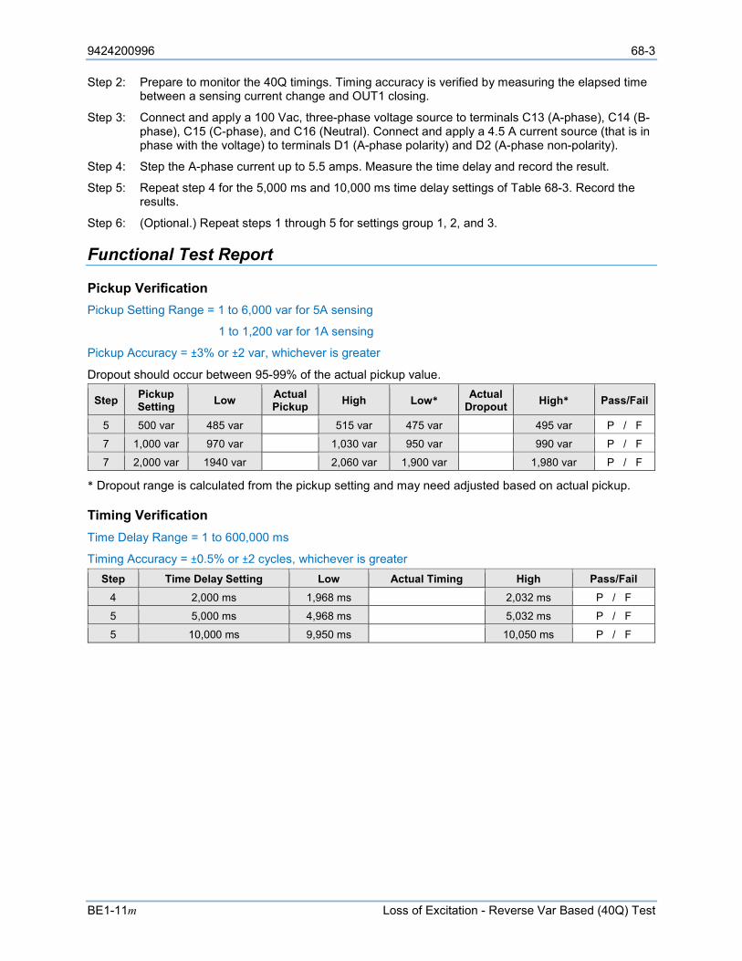
9424200996 68-3
BE1-11m Loss of Excitation - Reverse Var Based (40Q) Test
Step 2: Prepare to monitor the 40Q timings. Timing accuracy is verified by measuring the elapsed time between a sensing current change and OUT1 closing.
Step 3: Connect and apply a 100 Vac, three-phase voltage source to terminals C13 (A-phase), C14 (B-phase), C15 (C-phase), and C16 (Neutral). Connect and apply a 4.5 A current source (that is in phase with the voltage) to terminals D1 (A-phase polarity) and D2 (A-phase non-polarity).
Step 4: Step the A-phase current up to 5.5 amps. Measure the time delay and record the result.
Step 5: Repeat step 4 for the 5,000 ms and 10,000 ms time delay settings of Table 68-3. Record the results.
Step 6: (Optional.) Repeat steps 1 through 5 for settings group 1, 2, and 3.
Functional Test Report
Pickup Verification Pickup Setting Range = 1 to 6,000 var for 5A sensing
1 to 1,200 var for 1A sensing
Pickup Accuracy = ±3% or ±2 var, whichever is greater
Dropout should occur between 95-99% of the actual pickup value.
Step Pickup Setting Low Actual
Pickup High Low* Actual Dropout High* Pass/Fail
5 500 var 485 var 515 var 475 var 495 var P / F
7 1,000 var 970 var 1,030 var 950 var 990 var P / F
7 2,000 var 1940 var 2,060 var 1,900 var 1,980 var P / F
* Dropout range is calculated from the pickup setting and may need adjusted based on actual pickup.
Timing Verification Time Delay Range = 1 to 600,000 ms
Timing Accuracy = ±0.5% or ±2 cycles, whichever is greater Step Time Delay Setting Low Actual Timing High Pass/Fail
4 2,000 ms 1,968 ms 2,032 ms P / F
5 5,000 ms 4,968 ms 5,032 ms P / F
5 10,000 ms 9,950 ms 10,050 ms P / F

68-4 9424200996
Loss of Excitation - Reverse Var Based (40Q) Test BE1-11m
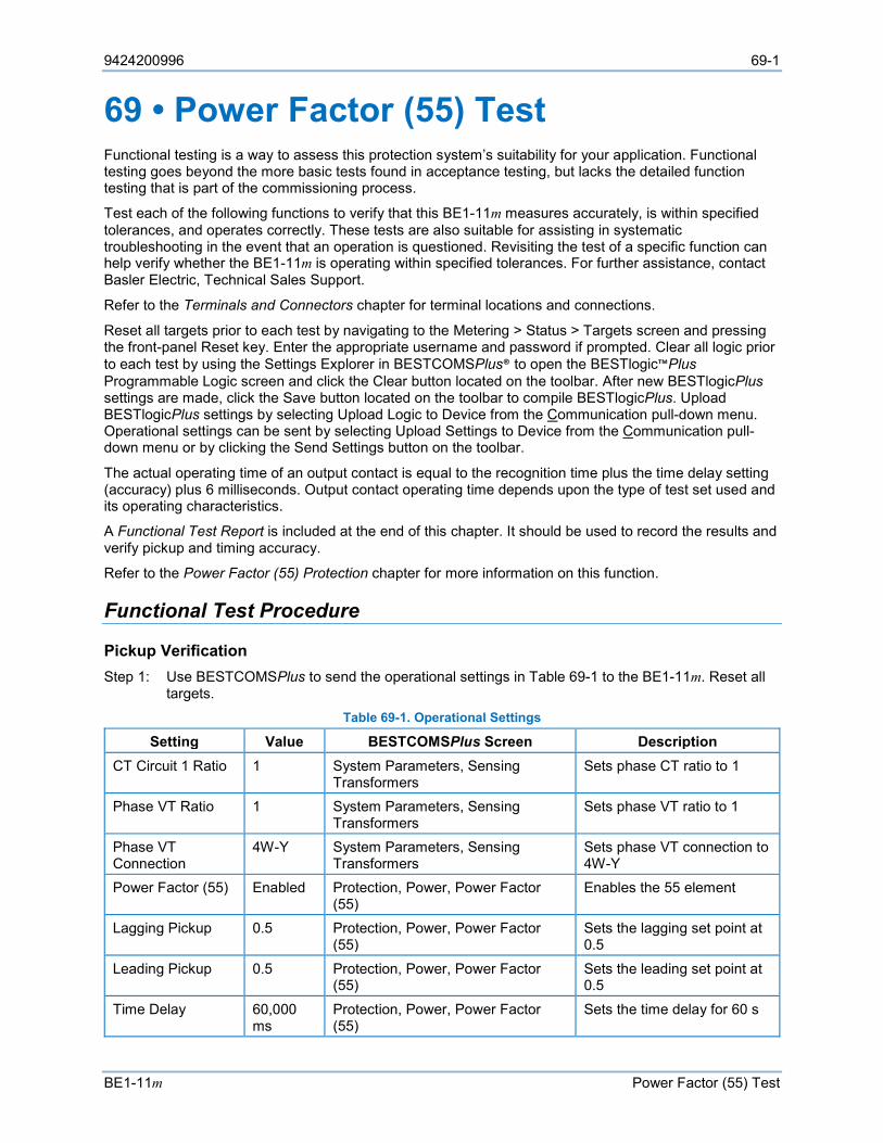
9424200996 69-1
BE1-11m Power Factor (55) Test
69 • Power Factor (55) Test Functional testing is a way to assess this protection system’s suitability for your application. Functional testing goes beyond the more basic tests found in acceptance testing, but lacks the detailed function testing that is part of the commissioning process.
Test each of the following functions to verify that this BE1-11m measures accurately, is within specified tolerances, and operates correctly. These tests are also suitable for assisting in systematic troubleshooting in the event that an operation is questioned. Revisiting the test of a specific function can help verify whether the BE1-11m is operating within specified tolerances. For further assistance, contact Basler Electric, Technical Sales Support.
Refer to the Terminals and Connectors chapter for terminal locations and connections.
Reset all targets prior to each test by navigating to the Metering > Status > Targets screen and pressing the front-panel Reset key. Enter the appropriate username and password if prompted. Clear all logic prior to each test by using the Settings Explorer in BESTCOMSPlus® to open the BESTlogic™Plus Programmable Logic screen and click the Clear button located on the toolbar. After new BESTlogicPlus settings are made, click the Save button located on the toolbar to compile BESTlogicPlus. Upload BESTlogicPlus settings by selecting Upload Logic to Device from the Communication pull-down menu. Operational settings can be sent by selecting Upload Settings to Device from the Communication pull-down menu or by clicking the Send Settings button on the toolbar.
The actual operating time of an output contact is equal to the recognition time plus the time delay setting (accuracy) plus 6 milliseconds. Output contact operating time depends upon the type of test set used and its operating characteristics.
A Functional Test Report is included at the end of this chapter. It should be used to record the results and verify pickup and timing accuracy.
Refer to the Power Factor (55) Protection chapter for more information on this function.
Functional Test Procedure
Pickup Verification Step 1: Use BESTCOMSPlus to send the operational settings in Table 69-1 to the BE1-11m. Reset all
targets. Table 69-1. Operational Settings
Setting Value BESTCOMSPlus Screen Description CT Circuit 1 Ratio 1 System Parameters, Sensing
Transformers Sets phase CT ratio to 1
Phase VT Ratio 1 System Parameters, Sensing Transformers
Sets phase VT ratio to 1
Phase VT Connection
4W-Y System Parameters, Sensing Transformers
Sets phase VT connection to 4W-Y
Power Factor (55) Enabled Protection, Power, Power Factor (55)
Enables the 55 element
Lagging Pickup 0.5 Protection, Power, Power Factor (55)
Sets the lagging set point at 0.5
Leading Pickup 0.5 Protection, Power, Power Factor (55)
Sets the leading set point at 0.5
Time Delay 60,000 ms
Protection, Power, Power Factor (55)
Sets the time delay for 60 s
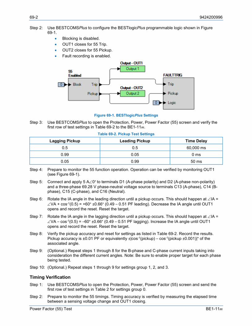
69-2 9424200996
Power Factor (55) Test BE1-11m
Step 2: Use BESTCOMSPlus to configure the BESTlogicPlus programmable logic shown in Figure 69-1.
• Blocking is disabled. • OUT1 closes for 55 Trip. • OUT2 closes for 55 Pickup. • Fault recording is enabled.
Figure 69-1. BESTlogicPlus Settings
Step 3: Use BESTCOMSPlus to open the Protection, Power, Power Factor (55) screen and verify the first row of test settings in Table 69-2 to the BE1-11m.
Table 69-2. Pickup Test Settings
Lagging Pickup Leading Pickup Time Delay 0.5 0.5 60,000 ms 0.99 0.05 0 ms
0.05 0.99 50 ms
Step 4: Prepare to monitor the 55 function operation. Operation can be verified by monitoring OUT1 (see Figure 69-1).
Step 5: Connect and apply 5 A∠0° to terminals D1 (A-phase polarity) and D2 (A-phase non-polarity) and a three-phase 69.28 V phase-neutral voltage source to terminals C13 (A-phase), C14 (B-phase), C15 (C-phase), and C16 (Neutral).
Step 6: Rotate the IA angle in the leading direction until a pickup occurs. This should happen at ∠IA = ∠VA + cos-1(0.5) = +60° ±0.66° (0.49 – 0.51 PF leading). Decrease the IA angle until OUT1 opens and record the reset. Reset the target.
Step 7: Rotate the IA angle in the lagging direction until a pickup occurs. This should happen at ∠IA = ∠VA – cos-1(0.5) = –60° ±0.66° (0.49 – 0.51 PF lagging). Increase the IA angle until OUT1 opens and record the reset. Reset the target.
Step 8: Verify the pickup accuracy and reset for settings as listed in Table 69-2. Record the results. Pickup accuracy is ±0.01 PF or equivalently ±|cos-1(pickup) – cos-1(pickup ±0.001)|° of the associated angle.
Step 9: (Optional.) Repeat steps 1 through 8 for the B-phase and C-phase current inputs taking into consideration the different current angles. Note: Be sure to enable proper target for each phase being tested.
Step 10: (Optional.) Repeat steps 1 through 9 for settings group 1, 2, and 3.
Timing Verification Step 1: Use BESTCOMSPlus to open the Protection, Power, Power Factor (55) screen and send the
first row of test settings in Table 2 for settings group 0.
Step 2: Prepare to monitor the 55 timings. Timing accuracy is verified by measuring the elapsed time between a sensing voltage change and OUT1 closing.
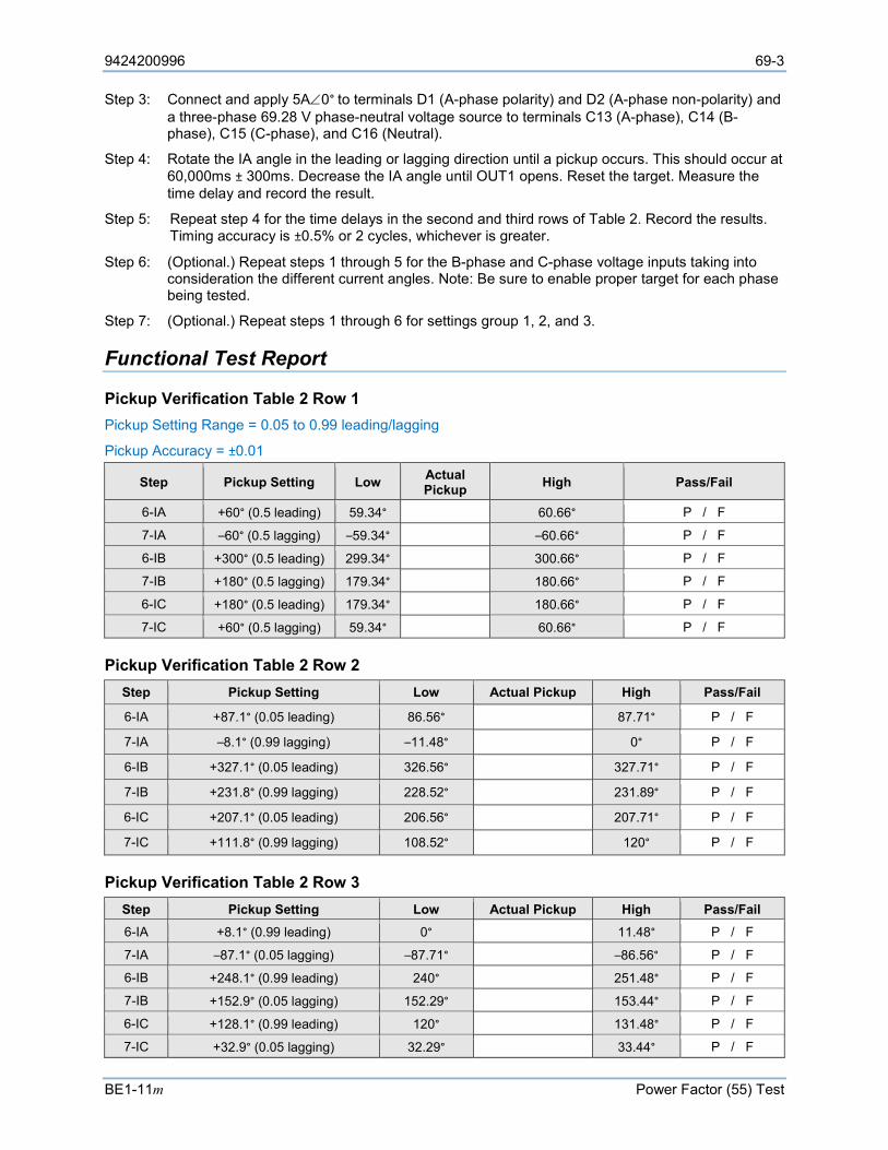
9424200996 69-3
BE1-11m Power Factor (55) Test
Step 3: Connect and apply 5A∠0° to terminals D1 (A-phase polarity) and D2 (A-phase non-polarity) and a three-phase 69.28 V phase-neutral voltage source to terminals C13 (A-phase), C14 (B-phase), C15 (C-phase), and C16 (Neutral).
Step 4: Rotate the IA angle in the leading or lagging direction until a pickup occurs. This should occur at 60,000ms ± 300ms. Decrease the IA angle until OUT1 opens. Reset the target. Measure the time delay and record the result.
Step 5: Repeat step 4 for the time delays in the second and third rows of Table 2. Record the results. Timing accuracy is ±0.5% or 2 cycles, whichever is greater.
Step 6: (Optional.) Repeat steps 1 through 5 for the B-phase and C-phase voltage inputs taking into consideration the different current angles. Note: Be sure to enable proper target for each phase being tested.
Step 7: (Optional.) Repeat steps 1 through 6 for settings group 1, 2, and 3.
Functional Test Report
Pickup Verification Table 2 Row 1 Pickup Setting Range = 0.05 to 0.99 leading/lagging
Pickup Accuracy = ±0.01
Step Pickup Setting Low Actual Pickup High Pass/Fail
6-IA +60° (0.5 leading) 59.34° 60.66° P / F
7-IA –60° (0.5 lagging) –59.34° –60.66° P / F
6-IB +300° (0.5 leading) 299.34° 300.66° P / F
7-IB +180° (0.5 lagging) 179.34° 180.66° P / F
6-IC +180° (0.5 leading) 179.34° 180.66° P / F
7-IC +60° (0.5 lagging) 59.34° 60.66° P / F
Pickup Verification Table 2 Row 2 Step Pickup Setting Low Actual Pickup High Pass/Fail
6-IA +87.1° (0.05 leading) 86.56° 87.71° P / F
7-IA –8.1° (0.99 lagging) –11.48° 0° P / F
6-IB +327.1° (0.05 leading) 326.56° 327.71° P / F
7-IB +231.8° (0.99 lagging) 228.52° 231.89° P / F
6-IC +207.1° (0.05 leading) 206.56° 207.71° P / F
7-IC +111.8° (0.99 lagging) 108.52° 120° P / F
Pickup Verification Table 2 Row 3 Step Pickup Setting Low Actual Pickup High Pass/Fail 6-IA +8.1° (0.99 leading) 0° 11.48° P / F
7-IA –87.1° (0.05 lagging) –87.71° –86.56° P / F
6-IB +248.1° (0.99 leading) 240° 251.48° P / F
7-IB +152.9° (0.05 lagging) 152.29° 153.44° P / F
6-IC +128.1° (0.99 leading) 120° 131.48° P / F
7-IC +32.9° (0.05 lagging) 32.29° 33.44° P / F

69-4 9424200996
Power Factor (55) Test BE1-11m
Timing Verification Time Delay Range = 0 ms or 50 to 600,000 ms
Timing Accuracy = ±0.5% or ±2 cycles, whichever is greater Step Time Delay Setting Low Actual Timing High Pass/Fail
4 60,000 ms 59,700 ms 60,300 ms P / F
5 0 ms 0 ms 34 ms P / F
5 50 ms 17 ms 84 ms P / F

9424200996 70-1
BE1-11m Thermal Curve (49TC) Test
70 • Thermal Curve (49TC) Test Functional testing is a way to assess this protection system’s suitability for your application. Functional testing goes beyond the more basic tests found in acceptance testing, but lacks the detailed function testing that is part of the commissioning process.
Test each of the following functions to verify that this BE1-11m measures accurately, is within specified tolerances, and operates correctly. These tests are also suitable for assisting in systematic troubleshooting in the event that an operation is questioned. Revisiting the test of a specific function can help verify whether the BE1-11m is operating within specified tolerances. For further assistance, contact Basler Electric, Technical Sales Support.
Refer to the Terminals and Connectors chapter for terminal locations and connections.
Reset all targets prior to each test by navigating to the Metering > Status > Targets screen and pressing the front-panel Reset key. Enter the appropriate username and password if prompted. Clear all logic prior to each test by using the Settings Explorer in BESTCOMSPlus® to open the BESTlogic™Plus Programmable Logic screen and click the Clear button located on the toolbar. After new BESTlogicPlus settings are made, click the Save button located on the toolbar to compile BESTlogicPlus. Upload BESTlogicPlus settings by selecting Upload Logic to Device from the Communication pull-down menu. Operational settings can be sent by selecting Upload Settings to Device from the Communication pull-down menu or by clicking the Send Settings button on the toolbar.
The actual operating time of an output contact is equal to the recognition time plus the time delay setting (accuracy) plus 6 milliseconds. Output contact operating time depends upon the type of test set used and its operating characteristics.
A Functional Test Report is included at the end of this chapter. It should be used to record the results and verify pickup and timing accuracy.
Refer to the Thermal Curve (49TC) Protection chapter for more information on this function.
Functional Test Procedure
Note Read through each step entirely before performing the actions.
Standard Curve The following items will be tested for the standard curve.
• Overload pickup (Step 6) • Timing from motor stopped condition (Step 7) • Steady state thermal capacity (Step 9) • Timing from motor running condition (Step 11) • Emergency start (Step 13)
Step 1: Use BESTCOMSPlus to send the operational settings in Table 70-1 to the BE1-11m. Reset all targets.
Table 70-1. Operational Settings, Standard Curve
Setting Value BESTCOMSPlus Screen Description Frequency 60 System Parameters, Motor
Configuration Sets Nominal Frequency to 60 Hz
Secondary Phase Current CT1
5 System Parameters, Motor Configuration
Sets Secondary Phase Current CT1 to 5 A

70-2 9424200996
Thermal Curve (49TC) Test BE1-11m
Setting Value BESTCOMSPlus Screen Description Full Load Amps 2 System Parameters, Motor
Configuration Sets Full Load Amps to 3
Service Factor 1 System Parameters, Motor Configuration
Sets Service Factor to 1
Element Mode Standard Curve
Protection, Thermal, Thermal Curve (49TC)
Selects Standard Curve mode
Standard Curve Time Dial
10 Protection, Thermal, Thermal Curve (49TC)
Sets Standard Curve Time Dial to 10
K 0 Protection, Thermal, Thermal Curve (49TC)
Sets K to 0
Overload 1 Protection, Thermal, Thermal Curve (49TC)
Sets Overload pickup to 1
Max Emergency Thermal Capacity
0 Protection, Thermal, Thermal Curve (49TC)
Sets Max Emergency Thermal Capacity to 0%
Running Cool Time Constant
1 Protection, Thermal, Thermal Curve (49TC)
Sets Running Cool Time Constant to 1 minute
Stopped Cool Time Constant
1 Protection, Thermal, Thermal Curve (49TC)
Sets Stopped Cool Time Constant to 1 minute
Hot Safe Stall Time 1 Protection, Thermal, Thermal Curve (49TC)
Sets Hot Safe Stall Time to 1 second
Cold Safe Stall Time 1 Protection, Thermal, Thermal Curve (49TC)
Sets Cold Safe Stall Time to 1 second
49TC Enabled Target Configuration, Targets Enables 49TC target
Step 2: Use BESTCOMSPlus to configure the BESTlogicPlus Programmable Logic shown in Figure 70-1.
Figure 70-1. BESTlogicPlus Settings, Standard Curve

9424200996 70-3
BE1-11m Thermal Curve (49TC) Test
Step 3: Prepare to monitor the 49TC function operation. Operation can be verified by monitoring OUT1 (Tripped) and OUT2 (Overloaded). See Figure 70-1.
Step 4: Connect a three-phase 60 Hz current source to terminals D1 and D2 (IA), D3 and D4 (IB), and D5 and D6 (IC).
Step 5: The following calculations are referenced in this test procedure.
The Overload Pickup Current is calculated in Equation 70-1.
𝐼𝐼𝑡𝑡𝑡𝑡𝑡𝑡 = 𝑆𝑆 × 𝑆𝑆𝑆𝑆 × 𝑆𝑆𝐹𝐹𝐹𝐹 = 1 × 1 × 2 = 2 𝐹𝐹 Equation 70-1. Overload Pickup Current
Where:
S = Overload Scaler
SF = Scale Factor
FLA = Full Load Amps
The Equivalent Thermal Current is calculated in Equation 70-2. Assume a three-phase balanced current of 10 A.
𝐼𝐼𝑒𝑒𝑒𝑒 = 𝐼𝐼1 + 𝑘𝑘 𝐼𝐼2𝐼𝐼12
= 101 + 0 𝐼𝐼2𝐼𝐼12
= 10 𝐹𝐹
Equation 70-2. Equivalent Thermal Current
Where:
Ieq = equivalent thermal current in pickup (unit of thermal pickup current)
I = maximum phase current in pickup
I1 = positive-sequence fundamental component of current in pickup
I2 = negative-sequence fundamental component of current in pickup
k = constant used to determine additional heating from negative-sequence current in pickup
The Standard Curve Timing is calculated in Equation 70-3.
𝑡𝑡 = 𝑇𝑇𝑇𝑇 × 88.744132 × 𝑙𝑙𝑙𝑙
⎣⎢⎢⎢⎡
𝐼𝐼𝑒𝑒𝑒𝑒𝐼𝐼𝑡𝑡𝑡𝑡𝑡𝑡
2
𝐼𝐼𝑒𝑒𝑒𝑒𝐼𝐼𝑡𝑡𝑡𝑡𝑡𝑡
2− 1⎦
⎥⎥⎥⎤
= 10 × 88.744132 × 𝑙𝑙𝑙𝑙 10
2 2
102
2− 1
= 36.22 𝑠𝑠𝑠𝑠𝑠𝑠𝑠𝑠𝑙𝑙𝑠𝑠𝑠𝑠
Equation 70-3. Standard Curve Timing
Where: t = Operating Time Ieq = Equivalent Thermal Current TD = Time Dial Itpu = Overload Pickup Current
Step 6: Apply 1.9 Aac three-phase current. Slowly raise the current until OUT2 (Overloaded) closes and record the pickup. Slowly lower the current until OUT2 (Overloaded) opens and record the dropout. Remove three-phase current and wait until thermal capacity falls to 0% before proceeding. The thermal capacity can be monitored at Metering > Motor > Motor Meter on the front-panel display.
Step 7: Simulate motor starting by applying 10 Aac, three-phase current. Verify that OUT2 (Overloaded) closes indicating an overloaded condition. Verify that OUT4 (Starting) closes. Measure and record the time from when current is applied until OUT1 (Tripped) closes and the thermal capacity reaches 100%. The expected timing is 36.22 seconds per Equation 70-3. The thermal
70-4 9424200996
Thermal Curve (49TC) Test BE1-11m
capacity (0 - 100%) can be monitored at Metering, Motor, Motor Meter on the front-panel display. Verify that there is a 49TC target on the front-panel display at Metering > Status > Targets.
Step 8: Remove three-phase current and wait until thermal capacity falls to 0% before proceeding. (Note: The thermal capacity is forced to 0% if the 49TC element is disabled and re-enabled.) Verify that OUT5 (Stopped) closes. Reset all targets.
Step 9: Use BESTCOMSPlus to open the Thermal Curve (49TC) settings screen. Set the Hot Safe Stall Time to 1,300 seconds and set the Cold Safe Stall Time to 1,500 seconds. An equivalent current of 1.8 A is used for the steady state thermal capacity test.
The Steady State Thermal Capacity (TCU) is calculated in Equation 70-4.
𝑇𝑇𝑇𝑇𝑇𝑇𝑒𝑒𝑒𝑒𝑒𝑒 = 𝐼𝐼𝑒𝑒𝑒𝑒𝐼𝐼𝑡𝑡𝑡𝑡𝑡𝑡
× 1 −ℎ𝑠𝑠𝑡𝑡 𝑠𝑠𝑠𝑠𝑠𝑠𝑠𝑠 𝑠𝑠𝑡𝑡𝑠𝑠𝑙𝑙𝑙𝑙 𝑡𝑡𝑡𝑡𝑡𝑡𝑠𝑠𝑠𝑠𝑠𝑠𝑙𝑙𝑠𝑠 𝑠𝑠𝑠𝑠𝑠𝑠𝑠𝑠 𝑠𝑠𝑡𝑡𝑠𝑠𝑙𝑙𝑙𝑙 𝑡𝑡𝑡𝑡𝑡𝑡𝑠𝑠
= 1.82 × 1 −
13001500
= 0.12 × 100 = 12% 𝑇𝑇𝑇𝑇𝑇𝑇
Equation 70-4. Steady State Thermal Capacity
Where: Ieq = Equivalent Thermal Current Itpu = Overload Pickup Current
Step 10: Apply 10 Aac three-phase current for five seconds (simulate motor starting). Step three-phase current down to 1.8 Aac (simulate motor running). Navigate to Metering > Motor > Motor Meter on the front-panel display and wait until the Thermal Capacity is 12% per Equation 70-4.
Step 11: Step the three-phase current up to 10 Aac (simulate motor starting). Verify that OUT2 (Overloaded) closes indicating an overloaded condition. Measure and record the time from when current is raised to 10 Aac until OUT1 (Tripped) closes and the thermal capacity reaches 100%. The expected timing is 31.87 seconds (88% of 36.22 seconds because %TC starts at 12%). Reference Equation 70-3. The thermal capacity (12 to 100%) can be monitored at Metering > Motor > Motor Meter on the front-panel display. Verify that there is a 49TC target on the front-panel display at Metering > Status > Targets.
Step 12: Remove three-phase current and wait until thermal capacity falls to 0% before proceeding. Verify that OUT5 (Stopped) closes. Reset all targets.
Step 13: Use BESTCOMSPlus to open the Thermal Curve (49TC) settings screen. Set the Max Emergency Thermal Capacity to 200%.
Step 14: Momentarily close IN1 to enable an emergency start. An emergency start expires after one minute if current is not applied. OUT3 toggles when Input 1 is closed. Apply 10 Aac three-phase current (simulate motor starting). Verify that OUT2 (Overloaded) closes indicating an overloaded condition. Verify that OUT4 (Starting) closes. Measure and record the time from when current is applied until OUT1 (Tripped) closes and the thermal capacity reaches 200%. The expected timing is 72.44 seconds per Equation 70-3 multiplied by 2 since the 49TC is set to trip at 200% thermal capacity. The thermal capacity (0 to 200%) can be monitored at Metering > Motor > Motor Meter on the front-panel display. Verify that there is a 49TC target on the front-panel display at Metering > Status > Targets.
Step 15: Remove three-phase current and wait until thermal capacity falls to 0% before proceeding. (Note: The thermal capacity is forced to 0% if the 49TC element is disabled and re-enabled.) Verify that OUT5 (Stopped) closes. Reset all targets.
RTD Biasing (Optional) If the RTD Biasing test will not be performed, skip to User Curve (Step 25).
Step 16: Use BESTCOMSPlus to send the operational settings in Table 70-2 to the BE1-11m. Reset all targets.
9424200996 70-5
BE1-11m Thermal Curve (49TC) Test
Table 70-2. Operational Settings, RTD Biasing
Setting Value BESTCOMSPlus Screen Description System Units Metric General Settings, Display Units Sets System Units to
Metric (°C)
Frequency 60 System Parameters, Motor Configuration
Sets Nominal Frequency to 60 Hz
Secondary Phase Current CT1
5 System Parameters, Motor Configuration
Sets Secondary Phase Current CT1 to 5 A
Full Load Amps 2 System Parameters, Motor Configuration
Sets Full Load Amps to 2
Service Factor 1 System Parameters, Motor Configuration
Sets Service Factor to 1
Phase CT Ratio CT1 1 System Parameters, Sensing Transformers
Sets Phase CT Ratio CT1 to 1
RTD1 Status Enabled System Parameters, Remote Module Communications
Enables Remote Module
RTD1 Communication Type
Ethernet or RS485
System Parameters, Remote Module Communications
Selects Ethernet or RS485 Communication
RTD1 Remote Module ID
Set per Remote Module ID
System Parameters, Remote Module Communications
Defines the Remote Module ID
RTD #1 Type 100 Ω Platinum
Programmable Inputs, Remote RTD, RTD Type Selection
Simulates a 100 Ω Platinum Resistor for RTD #1
RTD 1 Enabled Programmable Inputs, Remote RTD, RTD Block Configuration
Enables RTD 1 for Remote Module 1
Point 1 Temp °C 40 Protection, Thermal, RTD Bias Curve
Sets Point 1 Temp to 40°C
Point 1 %TC 10 Protection, Thermal, RTD Bias Curve
Sets Point 1 to 10% TC
Point 2 Temp °C 250 Protection, Thermal, RTD Bias Curve
Sets Point 2 Temp to 250°C
Point 2 %TC 80 Protection, Thermal, RTD Bias Curve
Sets Point 2 to 80% TC
Element Mode Standard Curve
Protection, Thermal, Thermal Curve (49TC)
Selects Standard Curve mode
RTD Biasing Enabled Protection, Thermal, Thermal Curve (49TC)
Enables RTD Biasing
RTD Source RTD Group 1 Protection, Thermal, Thermal Curve (49TC)
Selects RTD Group 1 Block
Standard Curve Time Dial
10 Protection, Thermal, Thermal Curve (49TC)
Sets Standard Curve Time Dial to 10
K 0 Protection, Thermal, Thermal Curve (49TC)
Sets K to 0
Overload 1 Protection, Thermal, Thermal Curve (49TC)
Sets Overload pickup to 1
Max Emergency Thermal Capacity
0 Protection, Thermal, Thermal Curve (49TC)
Sets Max Emergency Thermal Capacity to 0%
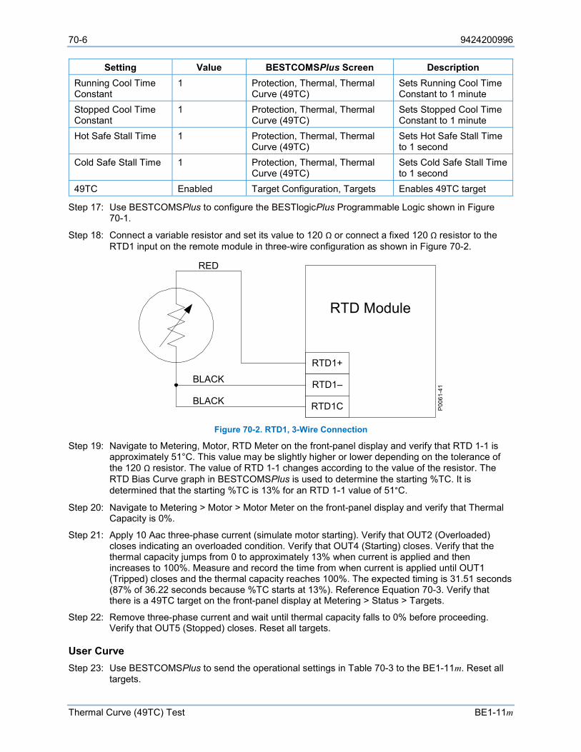
70-6 9424200996
Thermal Curve (49TC) Test BE1-11m
Setting Value BESTCOMSPlus Screen Description Running Cool Time Constant
1 Protection, Thermal, Thermal Curve (49TC)
Sets Running Cool Time Constant to 1 minute
Stopped Cool Time Constant
1 Protection, Thermal, Thermal Curve (49TC)
Sets Stopped Cool Time Constant to 1 minute
Hot Safe Stall Time 1 Protection, Thermal, Thermal Curve (49TC)
Sets Hot Safe Stall Time to 1 second
Cold Safe Stall Time 1 Protection, Thermal, Thermal Curve (49TC)
Sets Cold Safe Stall Time to 1 second
49TC Enabled Target Configuration, Targets Enables 49TC target
Step 17: Use BESTCOMSPlus to configure the BESTlogicPlus Programmable Logic shown in Figure 70-1.
Step 18: Connect a variable resistor and set its value to 120 Ω or connect a fixed 120 Ω resistor to the RTD1 input on the remote module in three-wire configuration as shown in Figure 70-2.
Figure 70-2. RTD1, 3-Wire Connection
Step 19: Navigate to Metering, Motor, RTD Meter on the front-panel display and verify that RTD 1-1 is approximately 51°C. This value may be slightly higher or lower depending on the tolerance of the 120 Ω resistor. The value of RTD 1-1 changes according to the value of the resistor. The RTD Bias Curve graph in BESTCOMSPlus is used to determine the starting %TC. It is determined that the starting %TC is 13% for an RTD 1-1 value of 51°C.
Step 20: Navigate to Metering > Motor > Motor Meter on the front-panel display and verify that Thermal Capacity is 0%.
Step 21: Apply 10 Aac three-phase current (simulate motor starting). Verify that OUT2 (Overloaded) closes indicating an overloaded condition. Verify that OUT4 (Starting) closes. Verify that the thermal capacity jumps from 0 to approximately 13% when current is applied and then increases to 100%. Measure and record the time from when current is applied until OUT1 (Tripped) closes and the thermal capacity reaches 100%. The expected timing is 31.51 seconds (87% of 36.22 seconds because %TC starts at 13%). Reference Equation 70-3. Verify that there is a 49TC target on the front-panel display at Metering > Status > Targets.
Step 22: Remove three-phase current and wait until thermal capacity falls to 0% before proceeding. Verify that OUT5 (Stopped) closes. Reset all targets.
User Curve Step 23: Use BESTCOMSPlus to send the operational settings in Table 70-3 to the BE1-11m. Reset all
targets.
RTD1+
RTD1–
RTD1C
RTD Module
P00
61-4
1
RED
BLACK
BLACK
9424200996 70-7
BE1-11m Thermal Curve (49TC) Test
Table 70-3. Operational Settings, User Curve
Setting Value BESTCOMSPlus Screen Description Nominal Frequency 60 System Parameters, Motor
Configuration Sets Nominal Frequency to 60 Hz
Nominal Secondary Phase Voltage
69.3 System Parameters, Motor Configuration
Sets Nominal Secondary Phase Voltage to 69.3 V
Nominal Secondary Phase Current CT1
5 System Parameters, Motor Configuration
Sets Secondary Phase Current CT1 to 5 A
Full Load Amps 2 System Parameters, Motor Configuration
Sets Full Load Amps to 2
Service Factor 1 System Parameters, Motor Configuration
Sets Service Factor to 1
Phase CT Ratio CT1 1 System Parameters, Sensing Transformers
Sets Phase CT Ratio CT1 to 1
Phase VT Ratio 1 System Parameters, Sensing Transformers
Sets Phase CT Ratio CT1 to 1
Phase VT Connection 3W-D System Parameters, Sensing Transformers
Selects 3W-D Phase VT Connection
Element Mode User Curve
Protection, Thermal, Thermal Curve (49TC)
Selects User Curve mode
RTD Biasing Disabled Protection, Thermal, Thermal Curve (49TC)
Disables RTD Biasing
Standard Curve Time Dial
10 Protection, Thermal, Thermal Curve (49TC)
Sets Standard Curve Time Dial to 10
K 0 Protection, Thermal, Thermal Curve (49TC)
Sets K to 0
Overload 1 Protection, Thermal, Thermal Curve (49TC)
Sets Overload pickup to 1
Max Emergency Thermal Capacity
0 Protection, Thermal, Thermal Curve (49TC)
Sets Max Emergency Thermal Capacity to 0%
Running Cool Time Constant
1 Protection, Thermal, Thermal Curve (49TC)
Sets Running Cool Time Constant to 1 minute
Stopped Cool Time Constant
1 Protection, Thermal, Thermal Curve (49TC)
Sets Stopped Cool Time Constant to 1 minute
Hot Safe Stall Time 1 Protection, Thermal, Thermal Curve (49TC)
Sets Hot Safe Stall Time to 1 second
Cold Safe Stall Time 1 Protection, Thermal, Thermal Curve (49TC)
Sets Cold Safe Stall Time to 1 second
Curve 1 Voltage % 90 Protection, Thermal, 49TC User Table Curve, Voltage Configuration
Sets Curve 1 Voltage to 90%
Curve 1 Point 1 xPU 1.3 Protection, Thermal, 49TC User Table Curve, Overload Curve
Sets Curve 1, Point 1 xPU to 1.3
Curve 1 Point 1 Time 20 Protection, Thermal, 49TC User Table Curve, Voltage Configuration
Sets Curve 1, Point 1 Time to 20 seconds.
Curve 1 Point 2 xPU 10 Protection, Thermal, 49TC User Table Curve, Overload Curve
Sets Curve 1, Point 1 xPU to 10
Curve 1 Point 2 Time 0.1 Protection, Thermal, 49TC User Table Curve, Voltage Configuration
Sets Curve 1, Point 1 Time to 100 milliseconds
70-8 9424200996
Thermal Curve (49TC) Test BE1-11m
Setting Value BESTCOMSPlus Screen Description 49TC Enabled Target Configuration, Targets Enables 49TC target
Step 24: Use BESTCOMSPlus to configure the BESTlogicPlus Programmable Logic shown in Figure 70-1.
Step 25: Prepare to monitor the 49TC function operation. Operation can be verified by monitoring OUT1 (Tripped) and OUT2 (Overloaded). See Figure 70-1.
Step 26: Connect a three-phase current source to terminals D1 and D2 (IA), D3 and D4 (IB), and D5 and D6 (IC).
Step 27: Connect a three-wire delta voltage source to terminals C13 (VA), C14 (VB), C15 (VC), and C16 (VN). The multiple acceleration curves allow a different curve to be created for up to three different voltage levels for reduced voltage starting. Voltage levels between those selected for the curves are interpolated between curves.
Step 28: Apply 10 Aac three-phase current and 108 V L-L voltage (90% of 120 V nominal). Note that Curve 1 Voltage % is set to 90%. This means that Curve 1 is used when 90% of nominal voltage is applied. Verify that OUT2 (Overloaded) closes indicating an overloaded condition. Verify that OUT4 (Starting) closes. Measure and record the time from when current is applied until OUT1 (Tripped) closes and the thermal capacity reaches 100%. The expected timing is 11.52 seconds per the Overload Characteristic Curve 1 graph in BESTCOMSPlus. The thermal capacity (0 to 100%) can be monitored at Metering > Motor > Motor Meter on the front-panel display. Verify that there is a 49TC target on the front-panel display at Metering > Status > Targets.
Step 29: Remove three-phase current and L-L voltage. Wait until thermal capacity falls to 0% before proceeding. Verify that OUT5 (Stopped) closes. Reset all targets.
Functional Test Report
Overload (Standard Curve) Setting Range = 0.9 to 1.2 (Expected overload pickup current is calculated in Table 70-1.)
Pickup Accuracy = ±2% or ±50 mA, whichever is greater
Dropout should occur between 93-99% of the actual pickup value.
Step Expected Pickup Low Actual
Pickup High Low* Actual Dropout High* Pass/Fail
6 2.0 A 1.95 A 2.05 A 1.86 A 1.98 A P / F
* Dropout range is calculated from the expected pickup and may need adjusted based on actual pickup.
Timing Verification (Standard Curve) Time Dial Range = 1 to 20
Timing Accuracy = ±5% or ±2½ cycles, whichever is greater Step Time Dial Applied Current Low Actual Timing High Pass/Fail
7 10 10 A 34.409 sec 38.031 sec P / F
11 10 10 A 30.276 sec 33.463 sec P / F

9424200996 70-9
BE1-11m Thermal Curve (49TC) Test
Timing Verification (Standard Curve with Emergency Start) Time Dial Range = 1 to 20
Timing Accuracy = ±5% or ±2½ cycles, whichever is greater Step Time Dial Applied Current Low Actual Timing High Pass/Fail 17 10 10 A 68.818 sec 76.062 sec P / F
Timing Verification (Standard Curve with RTD Biasing) Time Dial Range = 1 to 20
Timing Accuracy = ±5% or ±2½ cycles, whichever is greater Step Time Dial Applied Current Low Actual Timing High Pass/Fail 22 10 10 A 29.934 sec 33.085 sec P / F

70-10 9424200996
Thermal Curve (49TC) Test BE1-11m
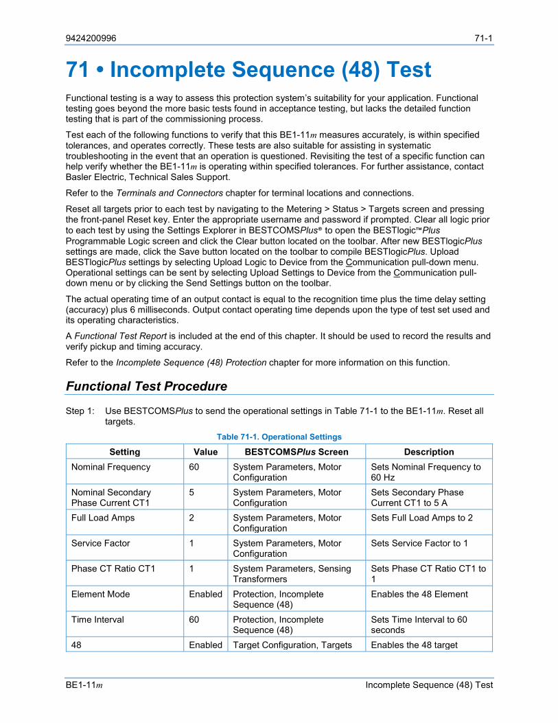
9424200996 71-1
BE1-11m Incomplete Sequence (48) Test
71 • Incomplete Sequence (48) Test Functional testing is a way to assess this protection system’s suitability for your application. Functional testing goes beyond the more basic tests found in acceptance testing, but lacks the detailed function testing that is part of the commissioning process.
Test each of the following functions to verify that this BE1-11m measures accurately, is within specified tolerances, and operates correctly. These tests are also suitable for assisting in systematic troubleshooting in the event that an operation is questioned. Revisiting the test of a specific function can help verify whether the BE1-11m is operating within specified tolerances. For further assistance, contact Basler Electric, Technical Sales Support.
Refer to the Terminals and Connectors chapter for terminal locations and connections.
Reset all targets prior to each test by navigating to the Metering > Status > Targets screen and pressing the front-panel Reset key. Enter the appropriate username and password if prompted. Clear all logic prior to each test by using the Settings Explorer in BESTCOMSPlus® to open the BESTlogic™Plus Programmable Logic screen and click the Clear button located on the toolbar. After new BESTlogicPlus settings are made, click the Save button located on the toolbar to compile BESTlogicPlus. Upload BESTlogicPlus settings by selecting Upload Logic to Device from the Communication pull-down menu. Operational settings can be sent by selecting Upload Settings to Device from the Communication pull-down menu or by clicking the Send Settings button on the toolbar.
The actual operating time of an output contact is equal to the recognition time plus the time delay setting (accuracy) plus 6 milliseconds. Output contact operating time depends upon the type of test set used and its operating characteristics.
A Functional Test Report is included at the end of this chapter. It should be used to record the results and verify pickup and timing accuracy.
Refer to the Incomplete Sequence (48) Protection chapter for more information on this function.
Functional Test Procedure
Step 1: Use BESTCOMSPlus to send the operational settings in Table 71-1 to the BE1-11m. Reset all targets.
Table 71-1. Operational Settings
Setting Value BESTCOMSPlus Screen Description Nominal Frequency 60 System Parameters, Motor
Configuration Sets Nominal Frequency to 60 Hz
Nominal Secondary Phase Current CT1
5 System Parameters, Motor Configuration
Sets Secondary Phase Current CT1 to 5 A
Full Load Amps 2 System Parameters, Motor Configuration
Sets Full Load Amps to 2
Service Factor 1 System Parameters, Motor Configuration
Sets Service Factor to 1
Phase CT Ratio CT1 1 System Parameters, Sensing Transformers
Sets Phase CT Ratio CT1 to 1
Element Mode Enabled Protection, Incomplete Sequence (48)
Enables the 48 Element
Time Interval 60 Protection, Incomplete Sequence (48)
Sets Time Interval to 60 seconds
48 Enabled Target Configuration, Targets Enables the 48 target
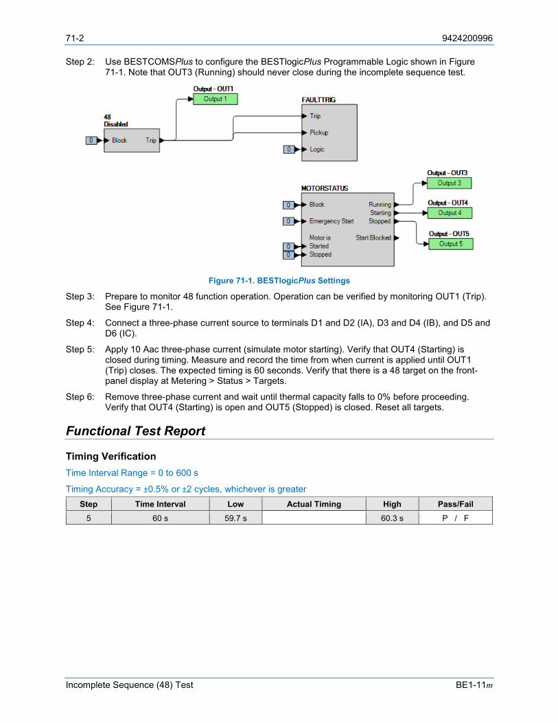
71-2 9424200996
Incomplete Sequence (48) Test BE1-11m
Step 2: Use BESTCOMSPlus to configure the BESTlogicPlus Programmable Logic shown in Figure 71-1. Note that OUT3 (Running) should never close during the incomplete sequence test.
Figure 71-1. BESTlogicPlus Settings
Step 3: Prepare to monitor 48 function operation. Operation can be verified by monitoring OUT1 (Trip). See Figure 71-1.
Step 4: Connect a three-phase current source to terminals D1 and D2 (IA), D3 and D4 (IB), and D5 and D6 (IC).
Step 5: Apply 10 Aac three-phase current (simulate motor starting). Verify that OUT4 (Starting) is closed during timing. Measure and record the time from when current is applied until OUT1 (Trip) closes. The expected timing is 60 seconds. Verify that there is a 48 target on the front-panel display at Metering > Status > Targets.
Step 6: Remove three-phase current and wait until thermal capacity falls to 0% before proceeding. Verify that OUT4 (Starting) is open and OUT5 (Stopped) is closed. Reset all targets.
Functional Test Report
Timing Verification Time Interval Range = 0 to 600 s
Timing Accuracy = ±0.5% or ±2 cycles, whichever is greater Step Time Interval Low Actual Timing High Pass/Fail
5 60 s 59.7 s 60.3 s P / F
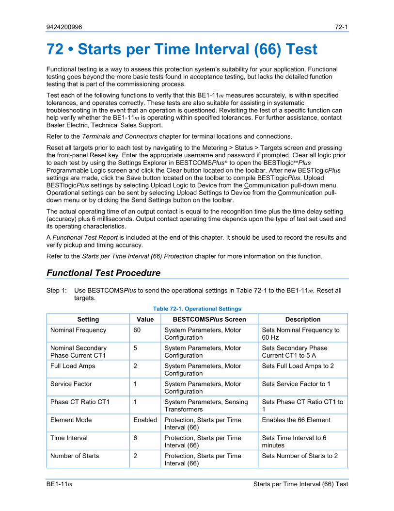
9424200996 72-1
BE1-11m Starts per Time Interval (66) Test
72 • Starts per Time Interval (66) Test Functional testing is a way to assess this protection system’s suitability for your application. Functional testing goes beyond the more basic tests found in acceptance testing, but lacks the detailed function testing that is part of the commissioning process.
Test each of the following functions to verify that this BE1-11m measures accurately, is within specified tolerances, and operates correctly. These tests are also suitable for assisting in systematic troubleshooting in the event that an operation is questioned. Revisiting the test of a specific function can help verify whether the BE1-11m is operating within specified tolerances. For further assistance, contact Basler Electric, Technical Sales Support.
Refer to the Terminals and Connectors chapter for terminal locations and connections.
Reset all targets prior to each test by navigating to the Metering > Status > Targets screen and pressing the front-panel Reset key. Enter the appropriate username and password if prompted. Clear all logic prior to each test by using the Settings Explorer in BESTCOMSPlus® to open the BESTlogic™Plus Programmable Logic screen and click the Clear button located on the toolbar. After new BESTlogicPlus settings are made, click the Save button located on the toolbar to compile BESTlogicPlus. Upload BESTlogicPlus settings by selecting Upload Logic to Device from the Communication pull-down menu. Operational settings can be sent by selecting Upload Settings to Device from the Communication pull-down menu or by clicking the Send Settings button on the toolbar.
The actual operating time of an output contact is equal to the recognition time plus the time delay setting (accuracy) plus 6 milliseconds. Output contact operating time depends upon the type of test set used and its operating characteristics.
A Functional Test Report is included at the end of this chapter. It should be used to record the results and verify pickup and timing accuracy.
Refer to the Starts per Time Interval (66) Protection chapter for more information on this function.
Functional Test Procedure
Step 1: Use BESTCOMSPlus to send the operational settings in Table 72-1 to the BE1-11m. Reset all targets.
Table 72-1. Operational Settings
Setting Value BESTCOMSPlus Screen Description Nominal Frequency 60 System Parameters, Motor
Configuration Sets Nominal Frequency to 60 Hz
Nominal Secondary Phase Current CT1
5 System Parameters, Motor Configuration
Sets Secondary Phase Current CT1 to 5 A
Full Load Amps 2 System Parameters, Motor Configuration
Sets Full Load Amps to 2
Service Factor 1 System Parameters, Motor Configuration
Sets Service Factor to 1
Phase CT Ratio CT1 1 System Parameters, Sensing Transformers
Sets Phase CT Ratio CT1 to 1
Element Mode Enabled Protection, Starts per Time Interval (66)
Enables the 66 Element
Time Interval 6 Protection, Starts per Time Interval (66)
Sets Time Interval to 6 minutes
Number of Starts 2 Protection, Starts per Time Interval (66)
Sets Number of Starts to 2
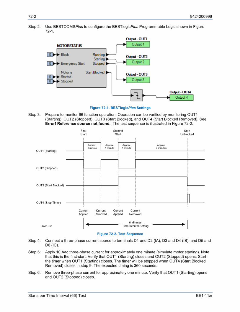
72-2 9424200996
Starts per Time Interval (66) Test BE1-11m
Step 2: Use BESTCOMSPlus to configure the BESTlogicPlus Programmable Logic shown in Figure 72-1.
Figure 72-1. BESTlogicPlus Settings
Step 3: Prepare to monitor 66 function operation. Operation can be verified by monitoring OUT1 (Starting), OUT2 (Stopped), OUT3 (Start Blocked), and OUT4 (Start Blocked Removed). See Error! Reference source not found.. The test sequence is illustrated in Figure 72-2.
Figure 72-2. Test Sequence
Step 4: Connect a three-phase current source to terminals D1 and D2 (IA), D3 and D4 (IB), and D5 and D6 (IC).
Step 5: Apply 10 Aac three-phase current for approximately one minute (simulate motor starting). Note that this is the first start. Verify that OUT1 (Starting) closes and OUT2 (Stopped) opens. Start the timer when OUT1 (Starting) closes. The timer will be stopped when OUT4 (Start Blocked Removed) closes in step 9. The expected timing is 360 seconds.
Step 6: Remove three-phase current for approximately one minute. Verify that OUT1 (Starting) opens and OUT2 (Stopped) closes.
OUT1 (Starting)
OUT2 (Stopped)
OUT3 (Start Blocked)
OUT4 (Stop Timer)
First Start
Second Start
Start Unblocked
Current Applied
Current Applied
Current Removed
Current Removed
6 MinutesTime Interval SettingP0061-55
Approx. 1 minute
Approx. 1 minute
Approx. 1 minute
Approx.3 minutes
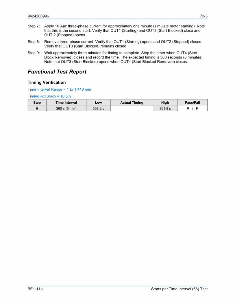
9424200996 72-3
BE1-11m Starts per Time Interval (66) Test
Step 7: Apply 10 Aac three-phase current for approximately one minute (simulate motor starting). Note that this is the second start. Verify that OUT1 (Starting) and OUT3 (Start Blocked) close and OUT 2 (Stopped) opens.
Step 8: Remove three-phase current. Verify that OUT1 (Starting) opens and OUT2 (Stopped) closes. Verify that OUT3 (Start Blocked) remains closed.
Step 9: Wait approximately three minutes for timing to complete. Stop the timer when OUT4 (Start Block Removed) closes and record the time. The expected timing is 360 seconds (6 minutes). Note that OUT3 (Start Blocked) opens when OUT4 (Start Blocked Removed) closes.
Functional Test Report
Timing Verification Time Interval Range = 1 to 1,440 min
Timing Accuracy = ±0.5% Step Time Interval Low Actual Timing High Pass/Fail
9 360 s (6 min) 358.2 s 361.8 s P / F

72-4 9424200996
Starts per Time Interval (66) Test BE1-11m
9424200996 73-1
BE1-11m Restart Inhibit Test
73 • Restart Inhibit Test Functional testing is a way to assess this protection system’s suitability for your application. Functional testing goes beyond the more basic tests found in acceptance testing, but lacks the detailed function testing that is part of the commissioning process.
Test each of the following functions to verify that this BE1-11m measures accurately, is within specified tolerances, and operates correctly. These tests are also suitable for assisting in systematic troubleshooting in the event that an operation is questioned. Revisiting the test of a specific function can help verify whether the BE1-11m is operating within specified tolerances. For further assistance, contact Basler Electric, Technical Sales Support.
Refer to the Terminals and Connectors chapter for terminal locations and connections.
Reset all targets prior to each test by navigating to the Metering > Status > Targets screen and pressing the front-panel Reset key. Enter the appropriate username and password if prompted. Clear all logic prior to each test by using the Settings Explorer in BESTCOMSPlus® to open the BESTlogic™Plus Programmable Logic screen and click the Clear button located on the toolbar. After new BESTlogicPlus settings are made, click the Save button located on the toolbar to compile BESTlogicPlus. Upload BESTlogicPlus settings by selecting Upload Logic to Device from the Communication pull-down menu. Operational settings can be sent by selecting Upload Settings to Device from the Communication pull-down menu or by clicking the Send Settings button on the toolbar.
The actual operating time of an output contact is equal to the recognition time plus the time delay setting (accuracy) plus 6 milliseconds. Output contact operating time depends upon the type of test set used and its operating characteristics.
A Functional Test Report is included at the end of this chapter. It should be used to record the results and verify pickup and timing accuracy.
Refer to the Restart Inhibit Protection chapter for more information on this function.
Functional Test Procedure
Restart Delay Step 1: Use BESTCOMSPlus to send the operational settings in Table 73-1 to the BE1-11m. Reset all
targets. Table 73-1. Operational Settings (Restart Delay)
Setting Value BESTCOMSPlus Screen Description Nominal Frequency 60 System Parameters, Motor
Configuration Sets Nominal Frequency to 60 Hz
Nominal Secondary Phase Current CT1
5 System Parameters, Motor Configuration
Sets Secondary Phase Current CT1 to 5 A
Full Load Amps 2 System Parameters, Motor Configuration
Sets Full Load Amps to 2
Service Factor 1 System Parameters, Motor Configuration
Sets Service Factor to 1
Phase CT Ratio CT1 1 System Parameters, Sensing Transformers
Sets Phase CT Ratio CT1 to 1
Restart Delay 1 Protection, Restart Inhibit Sets Restart Delay to 1 minute
Step 2: Use BESTCOMSPlus to configure the BESTlogicPlus Programmable Logic shown in Figure 73-1.
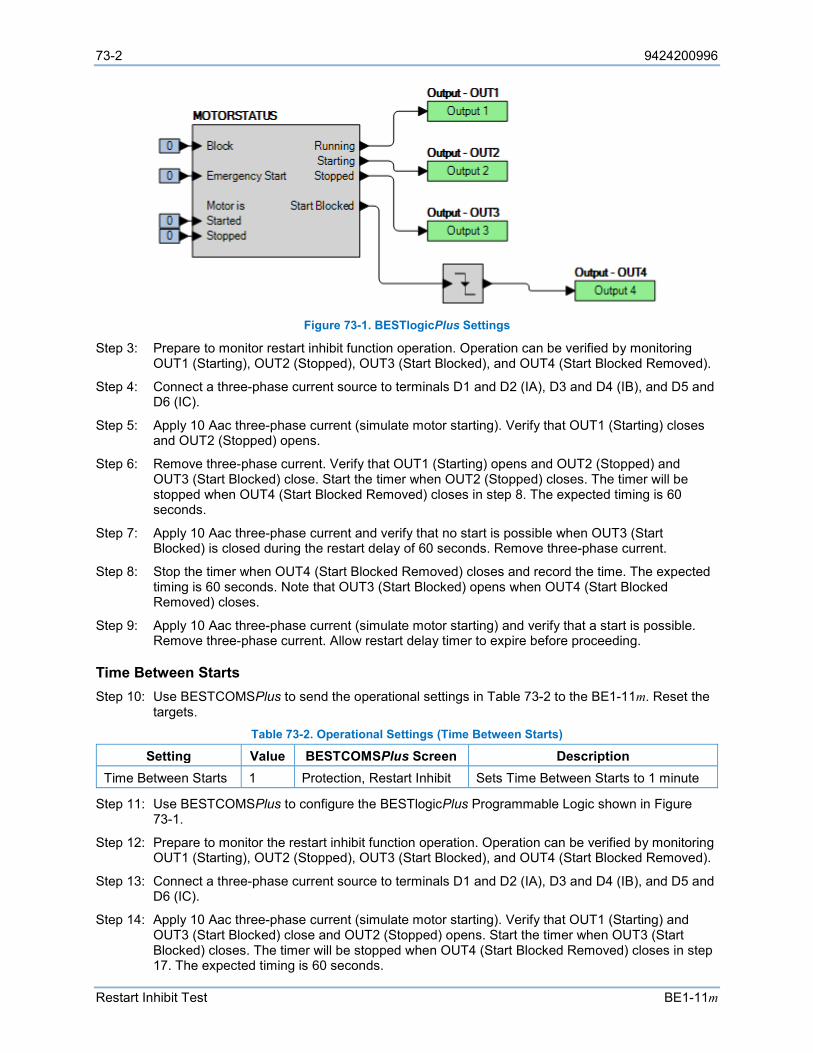
73-2 9424200996
Restart Inhibit Test BE1-11m
Figure 73-1. BESTlogicPlus Settings
Step 3: Prepare to monitor restart inhibit function operation. Operation can be verified by monitoring OUT1 (Starting), OUT2 (Stopped), OUT3 (Start Blocked), and OUT4 (Start Blocked Removed).
Step 4: Connect a three-phase current source to terminals D1 and D2 (IA), D3 and D4 (IB), and D5 and D6 (IC).
Step 5: Apply 10 Aac three-phase current (simulate motor starting). Verify that OUT1 (Starting) closes and OUT2 (Stopped) opens.
Step 6: Remove three-phase current. Verify that OUT1 (Starting) opens and OUT2 (Stopped) and OUT3 (Start Blocked) close. Start the timer when OUT2 (Stopped) closes. The timer will be stopped when OUT4 (Start Blocked Removed) closes in step 8. The expected timing is 60 seconds.
Step 7: Apply 10 Aac three-phase current and verify that no start is possible when OUT3 (Start Blocked) is closed during the restart delay of 60 seconds. Remove three-phase current.
Step 8: Stop the timer when OUT4 (Start Blocked Removed) closes and record the time. The expected timing is 60 seconds. Note that OUT3 (Start Blocked) opens when OUT4 (Start Blocked Removed) closes.
Step 9: Apply 10 Aac three-phase current (simulate motor starting) and verify that a start is possible. Remove three-phase current. Allow restart delay timer to expire before proceeding.
Time Between Starts Step 10: Use BESTCOMSPlus to send the operational settings in Table 73-2 to the BE1-11m. Reset the
targets. Table 73-2. Operational Settings (Time Between Starts)
Setting Value BESTCOMSPlus Screen Description Time Between Starts 1 Protection, Restart Inhibit Sets Time Between Starts to 1 minute
Step 11: Use BESTCOMSPlus to configure the BESTlogicPlus Programmable Logic shown in Figure 73-1.
Step 12: Prepare to monitor the restart inhibit function operation. Operation can be verified by monitoring OUT1 (Starting), OUT2 (Stopped), OUT3 (Start Blocked), and OUT4 (Start Blocked Removed).
Step 13: Connect a three-phase current source to terminals D1 and D2 (IA), D3 and D4 (IB), and D5 and D6 (IC).
Step 14: Apply 10 Aac three-phase current (simulate motor starting). Verify that OUT1 (Starting) and OUT3 (Start Blocked) close and OUT2 (Stopped) opens. Start the timer when OUT3 (Start Blocked) closes. The timer will be stopped when OUT4 (Start Blocked Removed) closes in step 17. The expected timing is 60 seconds.
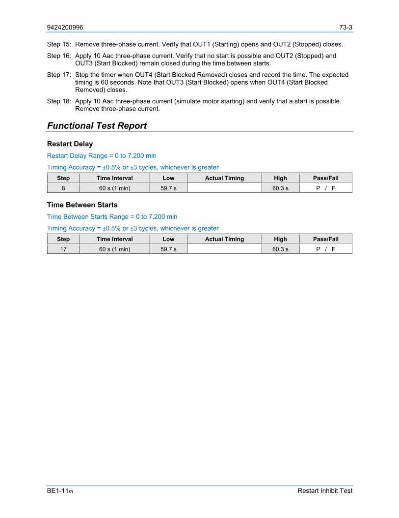
9424200996 73-3
BE1-11m Restart Inhibit Test
Step 15: Remove three-phase current. Verify that OUT1 (Starting) opens and OUT2 (Stopped) closes.
Step 16: Apply 10 Aac three-phase current. Verify that no start is possible and OUT2 (Stopped) and OUT3 (Start Blocked) remain closed during the time between starts.
Step 17: Stop the timer when OUT4 (Start Blocked Removed) closes and record the time. The expected timing is 60 seconds. Note that OUT3 (Start Blocked) opens when OUT4 (Start Blocked Removed) closes.
Step 18: Apply 10 Aac three-phase current (simulate motor starting) and verify that a start is possible. Remove three-phase current.
Functional Test Report
Restart Delay Restart Delay Range = 0 to 7,200 min
Timing Accuracy = ±0.5% or ±3 cycles, whichever is greater Step Time Interval Low Actual Timing High Pass/Fail
8 60 s (1 min) 59.7 s 60.3 s P / F
Time Between Starts Time Between Starts Range = 0 to 7,200 min
Timing Accuracy = ±0.5% or ±3 cycles, whichever is greater Step Time Interval Low Actual Timing High Pass/Fail 17 60 s (1 min) 59.7 s 60.3 s P / F

73-4 9424200996
Restart Inhibit Test BE1-11m

9424200996 74-1
BE1-11m Virtual Control Switches (43) Test
74 • Virtual Control Switches (43) Test Functional testing is a way to assess this protection system’s suitability for your application. Functional testing goes beyond the more basic tests found in acceptance testing, but lacks the detailed function testing that is part of the commissioning process.
Test each of the following functions to verify that this BE1-11m measures accurately, is within specified tolerances, and operates correctly. These tests are also suitable for assisting in systematic troubleshooting in the event that an operation is questioned. Revisiting the test of a specific function can help verify whether the BE1-11m is operating within specified tolerances. For further assistance, contact Basler Electric, Technical Sales Support.
Refer to the Terminals and Connectors chapter for terminal locations and connections.
Reset all targets prior to each test by navigating to the Metering > Status > Targets screen and pressing the front-panel Reset key. Enter the appropriate username and password if prompted. Clear all logic prior to each test by using the Settings Explorer in BESTCOMSPlus® to open the BESTlogic™Plus Programmable Logic screen and click the Clear button located on the toolbar. After new BESTlogicPlus settings are made, click the Save button located on the toolbar to compile BESTlogicPlus. Upload BESTlogicPlus settings by selecting Upload Logic to Device from the Communication pull-down menu. Operational settings can be sent by selecting Upload Settings to Device from the Communication pull-down menu or by clicking the Send Settings button on the toolbar.
The actual operating time of an output contact is equal to the recognition time plus the time delay setting (accuracy) plus 6 milliseconds. Output contact operating time depends upon the type of test set used and its operating characteristics.
A Functional Test Report is included at the end of this chapter. It should be used to record the results and verify pickup and timing accuracy.
Refer to the Virtual Control Switches (43) chapter for more information on this function.
Functional Test Procedure
Switch/Pulse Mode Step 1: Use BESTCOMSPlus to send the operational settings in Table 74-1 to the BE1-11m.
Table 74-1. Operational Settings
Setting Value BESTCOMSPlus Screen Description 43-1 Mode Switch/Pulse Control, Virtual Control Switches
(43) Sets 43-1 to Switch/Pulse mode
43-1 Name Label
Test Control, Virtual Control Switches (43)
Names 43-1 Name label to “Test”
43-1 On Label On Control, Virtual Control Switches (43)
Names 43-1 On label to “On”
43-1 Off Label Off Control, Virtual Control Switches (43)
Names 43-1 Off label to “Off”
Step 2: Use BESTCOMSPlus to configure the BESTlogicPlus programmable logic shown in Figure 74-1.
• All inputs are set to logic 0. • OUT1 closes when 43-1 output is true.
Step 3: Prepare to monitor the virtual switch operation. An ohmmeter or continuity tester can be used to monitor the contact status of OUT1.
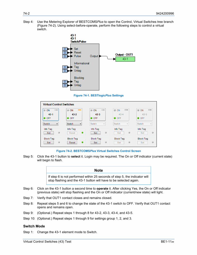
74-2 9424200996
Virtual Control Switches (43) Test BE1-11m
Step 4: Use the Metering Explorer of BESTCOMSPlus to open the Control, Virtual Switches tree branch (Figure 74-2). Using select-before-operate, perform the following steps to control a virtual switch.
Figure 74-1. BESTlogicPlus Settings
Figure 74-2. BESTCOMSPlus Virtual Switches Control Screen
Step 5: Click the 43-1 button to select it. Login may be required. The On or Off indicator (current state) will begin to flash.
Note If step 6 is not performed within 25 seconds of step 5, the indicator will stop flashing and the 43-1 button will have to be selected again.
Step 6: Click on the 43-1 button a second time to operate it. After clicking Yes, the On or Off indicator (previous state) will stop flashing and the On or Off indicator (current/new state) will light.
Step 7: Verify that OUT1 contact closes and remains closed.
Step 8: Repeat steps 5 and 6 to change the state of the 43-1 switch to OFF. Verify that OUT1 contact opens and remains open.
Step 9: (Optional.) Repeat steps 1 through 8 for 43-2, 43-3, 43-4, and 43-5.
Step 10: (Optional.) Repeat steps 1 through 9 for settings group 1, 2, and 3.
Switch Mode Step 1: Change the 43-1 element mode to Switch.
9424200996 74-3
BE1-11m Virtual Control Switches (43) Test
Step 2: Prepare to monitor the virtual switch operation. An ohmmeter or continuity tester can be used to monitor the contact status of OUT1.
Step 3: Use the Metering Explorer of BESTCOMSPlus to open the Control, Virtual Switches tree branch (Figure 74-2). Using select-before-operate, perform the following steps to control a virtual switch.
Step 4: Click the 43-1 button to select it. Login may be required. The On or Off indicator (current state) will begin to flash.
Note If step 5 is not performed within 25 seconds of step 4, the indicator will stop flashing and the 43-1 button will have to be re-selected.
Step 5: Click on the 43-1 button a second time to operate it. After clicking Yes, the On or Off indicator (previous state) will stop flashing and the On or Off indicator (current/new state) will light.
Step 6: Verify that OUT1 contact closes and remains closed.
Step 7: Repeat steps 4 and 5 to change the state of the 43-1 switch to OFF. Verify that OUT1 contact opens and remains open.
Step 8: (Optional.) Repeat steps 1 through 7 for 43-2, 43-3, 43-4, and 43-5.
Step 9: (Optional.) Repeat steps 1 through 8 for settings group 1, 2, and 3.
Pulse Mode Step 1: Use BESTCOMSPlus to change the 43-1 element mode to Pulse.
Step 2: Prepare to monitor the virtual switch operation. An ohmmeter or continuity tester can be used to monitor the contact status of OUT1.
Step 3: Using the front-panel display, navigate to Metering > Control > Virtual Switches. Highlight the first switch (43-1) and press the Right key on the front panel to enter the 43-1 control screen. Use the Edit key to login. Highlight Operate and then press the Edit key to change the state of the 43-1. Using the Up/Down keys select PUL and then press the Edit key. Verify that OUT1 contact closes for 200 milliseconds and returns to the open state.
Step 4: (Optional.) Repeat steps 1 through 3 for 43-2, 43-3, 43-4, and 43-5.
Step 5: (Optional.) Repeat steps 1 through 4 for settings group 1, 2, and 3.
Functional Test Report
Function Pass/Fail Switch/Pulse Mode P / F
Switch Mode P / F
Pulse Mode P / F

74-4 9424200996
Virtual Control Switches (43) Test BE1-11m

9424200996 75-1
BE1-11m Logic Timers (62) Test
75 • Logic Timers (62) Test Functional testing is a way to assess this protection system’s suitability for your application. Functional testing goes beyond the more basic tests found in acceptance testing, but lacks the detailed function testing that is part of the commissioning process.
Test each of the following functions to verify that this BE1-11m measures accurately, is within specified tolerances, and operates correctly. These tests are also suitable for assisting in systematic troubleshooting in the event that an operation is questioned. Revisiting the test of a specific function can help verify whether the BE1-11m is operating within specified tolerances. For further assistance, contact Basler Electric, Technical Sales Support.
Refer to the Terminals and Connectors chapter for terminal locations and connections.
Reset all targets prior to each test by navigating to the Metering > Status > Targets screen and pressing the front-panel Reset key. Enter the appropriate username and password if prompted. Clear all logic prior to each test by using the Settings Explorer in BESTCOMSPlus® to open the BESTlogic™Plus Programmable Logic screen and click the Clear button located on the toolbar. After new BESTlogicPlus settings are made, click the Save button located on the toolbar to compile BESTlogicPlus. Upload BESTlogicPlus settings by selecting Upload Logic to Device from the Communication pull-down menu. Operational settings can be sent by selecting Upload Settings to Device from the Communication pull-down menu or by clicking the Send Settings button on the toolbar.
The actual operating time of an output contact is equal to the recognition time plus the time delay setting (accuracy) plus 6 milliseconds. Output contact operating time depends upon the type of test set used and its operating characteristics.
A Functional Test Report is included at the end of this chapter. It should be used to record the results and verify pickup and timing accuracy.
Refer to the Logic Timers (62) chapter for more information on this function.
Functional Test Procedure
Pickup/Dropout Mode Step 1: Use BESTCOMSPlus to send the operational settings in Table 75-1 to the BE1-11m.
Table 75-1. Operational Settings (Pickup/Dropout Mode)
Setting Value BESTCOMSPlus Screen Description 62-1 Mode Pickup/Dropout Control, Logic Timers (62) Sets 62-1 to Pickup/Dropout
mode 62-1 Time Delay 1 (T1)
400 ms Control, Logic Timers (62) Sets 62-1 pickup time delay to 400 ms
62-1 Time Delay 2 (T2)
2,000 ms Control, Logic Timers (62) Sets 62-1 dropout time delay to 2,000 ms
43-1 Mode Switch Control, Virtual Control Switches (43)
Sets 43-1 to Switch mode
62-1 Target Enabled Target Configuration, Targets screen.
Enables 62-1 target
Step 2: Use BESTCOMSPlus to configure the BESTlogicPlus programmable logic shown in Figure 75-1.
• Blocking is disabled. • 62-1 initiates when 43-1 output is true. • OUT1 closes when 62-1 output is true.
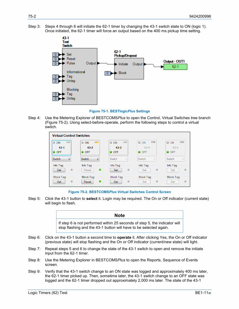
75-2 9424200996
Logic Timers (62) Test BE1-11m
Step 3: Steps 4 through 6 will initiate the 62-1 timer by changing the 43-1 switch state to ON (logic 1). Once initiated, the 62-1 timer will force an output based on the 400 ms pickup time setting.
Figure 75-1. BESTlogicPlus Settings
Step 4: Use the Metering Explorer of BESTCOMSPlus to open the Control, Virtual Switches tree branch (Figure 75-2). Using select-before-operate, perform the following steps to control a virtual switch.
Figure 75-2. BESTCOMSPlus Virtual Switches Control Screen
Step 5: Click the 43-1 button to select it. Login may be required. The On or Off indicator (current state) will begin to flash.
Note If step 6 is not performed within 25 seconds of step 5, the indicator will stop flashing and the 43-1 button will have to be selected again.
Step 6: Click on the 43-1 button a second time to operate it. After clicking Yes, the On or Off indicator (previous state) will stop flashing and the On or Off indicator (current/new state) will light.
Step 7: Repeat steps 5 and 6 to change the state of the 43-1 switch to open and remove the initiate input from the 62-1 timer.
Step 8: Use the Metering Explorer in BESTCOMSPlus to open the Reports, Sequence of Events screen.
Step 9: Verify that the 43-1 switch change to an ON state was logged and approximately 400 ms later, the 62-1 timer picked up. Then, sometime later, the 43-1 switch change to an OFF state was logged and the 62-1 timer dropped out approximately 2,000 ms later. The state of the 43-1
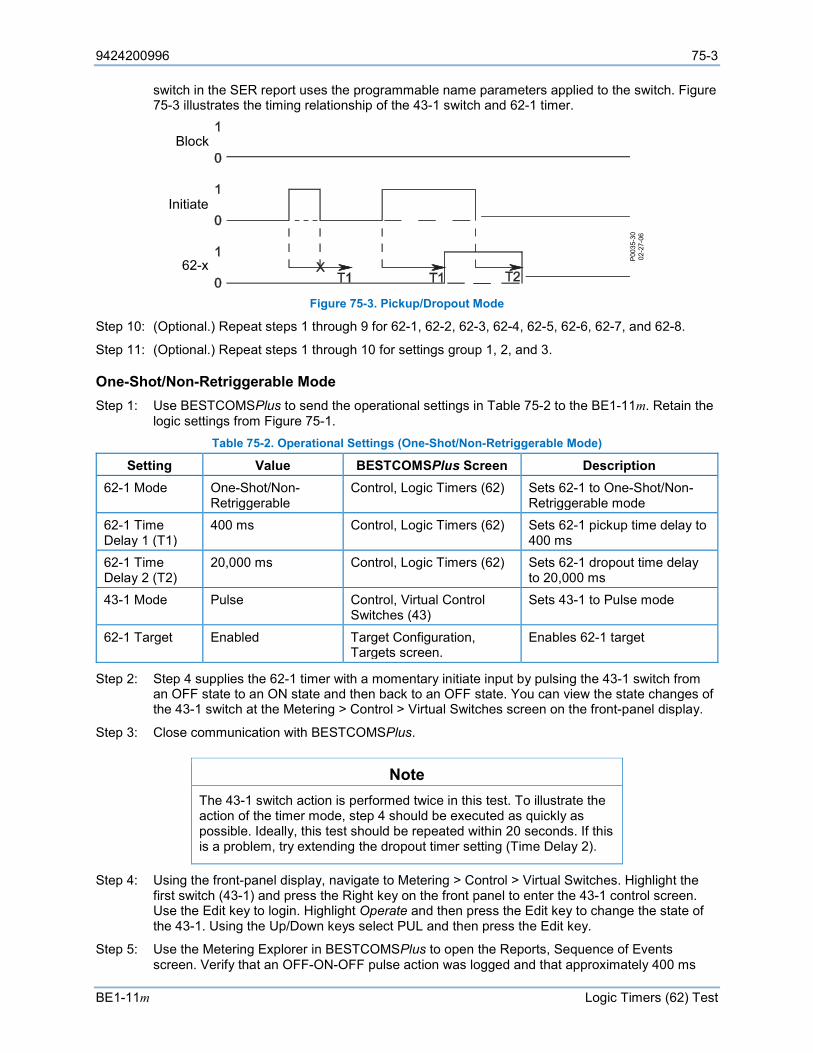
9424200996 75-3
BE1-11m Logic Timers (62) Test
switch in the SER report uses the programmable name parameters applied to the switch. Figure 75-3 illustrates the timing relationship of the 43-1 switch and 62-1 timer.
Figure 75-3. Pickup/Dropout Mode
Step 10: (Optional.) Repeat steps 1 through 9 for 62-1, 62-2, 62-3, 62-4, 62-5, 62-6, 62-7, and 62-8.
Step 11: (Optional.) Repeat steps 1 through 10 for settings group 1, 2, and 3.
One-Shot/Non-Retriggerable Mode Step 1: Use BESTCOMSPlus to send the operational settings in Table 75-2 to the BE1-11m. Retain the
logic settings from Figure 75-1. Table 75-2. Operational Settings (One-Shot/Non-Retriggerable Mode)
Setting Value BESTCOMSPlus Screen Description 62-1 Mode One-Shot/Non-
Retriggerable Control, Logic Timers (62) Sets 62-1 to One-Shot/Non-
Retriggerable mode 62-1 Time Delay 1 (T1)
400 ms Control, Logic Timers (62) Sets 62-1 pickup time delay to 400 ms
62-1 Time Delay 2 (T2)
20,000 ms Control, Logic Timers (62) Sets 62-1 dropout time delay to 20,000 ms
43-1 Mode Pulse Control, Virtual Control Switches (43)
Sets 43-1 to Pulse mode
62-1 Target Enabled Target Configuration, Targets screen.
Enables 62-1 target
Step 2: Step 4 supplies the 62-1 timer with a momentary initiate input by pulsing the 43-1 switch from an OFF state to an ON state and then back to an OFF state. You can view the state changes of the 43-1 switch at the Metering > Control > Virtual Switches screen on the front-panel display.
Step 3: Close communication with BESTCOMSPlus.
Note The 43-1 switch action is performed twice in this test. To illustrate the action of the timer mode, step 4 should be executed as quickly as possible. Ideally, this test should be repeated within 20 seconds. If this is a problem, try extending the dropout timer setting (Time Delay 2).
Step 4: Using the front-panel display, navigate to Metering > Control > Virtual Switches. Highlight the first switch (43-1) and press the Right key on the front panel to enter the 43-1 control screen. Use the Edit key to login. Highlight Operate and then press the Edit key to change the state of the 43-1. Using the Up/Down keys select PUL and then press the Edit key.
Step 5: Use the Metering Explorer in BESTCOMSPlus to open the Reports, Sequence of Events screen. Verify that an OFF-ON-OFF pulse action was logged and that approximately 400 ms
P003
5-30
02-2
7-06
62-x
Block
Initiate
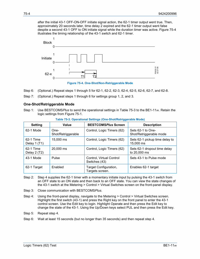
75-4 9424200996
Logic Timers (62) Test BE1-11m
after the initial 43-1 OFF-ON-OFF initiate signal action, the 62-1 timer output went true. Then, approximately 20 seconds later, time delay 2 expired and the 62-1 timer output went false despite a second 43-1 OFF to ON initiate signal while the duration timer was active. Figure 75-4 illustrates the timing relationship of the 43-1 switch and 62-1 timer.
Figure 75-4. One-Shot/Non-Retriggerable Mode
Step 6: (Optional.) Repeat steps 1 through 5 for 62-1, 62-2, 62-3, 62-4, 62-5, 62-6, 62-7, and 62-8.
Step 7: (Optional.) Repeat steps 1 through 6 for settings group 1, 2, and 3.
One-Shot/Retriggerable Mode Step 1: Use BESTCOMSPlus to send the operational settings in Table 75-3 to the BE1-11m. Retain the
logic settings from Figure 75-1. Table 75-3. Operational Settings (One-Shot/Retriggerable Mode)
Setting Value BESTCOMSPlus Screen Description 62-1 Mode One-
Shot/Retriggerable Control, Logic Timers (62) Sets 62-1 to One-
Shot/Retriggerable mode 62-1 Time Delay 1 (T1)
15,000 ms Control, Logic Timers (62) Sets 62-1 pickup time delay to 15,000 ms
62-1 Time Delay 2 (T2)
20,000 ms Control, Logic Timers (62) Sets 62-1 dropout time delay to 20,000 ms
43-1 Mode Pulse Control, Virtual Control Switches (43)
Sets 43-1 to Pulse mode
62-1 Target Enabled Target Configuration, Targets screen.
Enables 62-1 target
Step 2: Step 4 supplies the 62-1 timer with a momentary initiate input by pulsing the 43-1 switch from an OFF state to an ON state and then back to an OFF state. You can view the state changes of the 43-1 switch at the Metering > Control > Virtual Switches screen on the front-panel display.
Step 3: Close communication with BESTCOMSPlus.
Step 4: Using the front-panel display, navigate to the Metering > Control > Virtual Switches screen. Highlight the first switch (43-1) and press the Right key on the front panel to enter the 43-1 control screen. Use the Edit key to login. Highlight Operate and then press the Edit key to change the state of the 43-1. Using the Up/Down keys select PUL and then press the Edit key.
Step 5: Repeat step 4.
Step 6: Wait at least 15 seconds (but no longer than 35 seconds) and then repeat step 4.
P003
5-31
02-2
7 -06
Block
Initiate
62-x
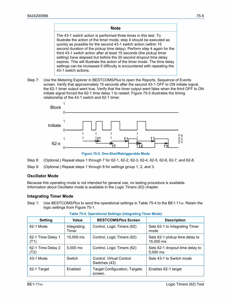
9424200996 75-5
BE1-11m Logic Timers (62) Test
Note The 43-1 switch action is performed three times in this test. To illustrate the action of the timer mode, step 4 should be executed as quickly as possible for the second 43-1 switch action (within 15 second duration of the pickup time delay). Perform step 4 again for the third 43-1 switch action after at least 15 seconds (the pickup timer setting) have elapsed but before the 20 second dropout time delay expires. This will illustrate the action of the timer mode. The time delay settings can be increased if difficulty is encountered with repeating the 43-1 switch actions.
Step 7: Use the Metering Explorer in BESTCOMSPlus to open the Reports, Sequence of Events screen. Verify that approximately 15 seconds after the second 43-1 OFF to ON initiate signal, the 62-1 timer output went true. Verify that the timer output went false when the third OFF to ON initiate signal forced the 62-1 time delay 1 to restart. Figure 75-5 illustrates the timing relationship of the 43-1 switch and 62-1 timer.
Figure 75-5. One-Shot/Retriggerable Mode
Step 8: (Optional.) Repeat steps 1 through 7 for 62-1, 62-2, 62-3, 62-4, 62-5, 62-6, 62-7, and 62-8.
Step 9: (Optional.) Repeat steps 1 through 8 for settings group 1, 2, and 3.
Oscillator Mode Because this operating mode is not intended for general use, no testing procedure is available. Information about Oscillator mode is available in the Logic Timers (62) chapter.
Integrating Timer Mode Step 1: Use BESTCOMSPlus to send the operational settings in Table 75-4 to the BE1-11m. Retain the
logic settings from Figure 75-1. Table 75-4. Operational Settings (Integrating Timer Mode)
Setting Value BESTCOMSPlus Screen Description 62-1 Mode Integrating
Timer Control, Logic Timers (62) Sets 62-1 to Integrating Timer
mode
62-1 Time Delay 1 (T1)
15,000 ms Control, Logic Timers (62) Sets 62-1 pickup time delay to 15,000 ms
62-1 Time Delay 2 (T2)
5,000 ms Control, Logic Timers (62) Sets 62-1 dropout time delay to 5,000 ms
43-1 Mode Switch Control, Virtual Control Switches (43)
Sets 43-1 to Switch mode
62-1 Target Enabled Target Configuration, Targets screen.
Enables 62-1 target
P00
35-3
202
-27-
06
Block
Initiate
62-x
75-6 9424200996
Logic Timers (62) Test BE1-11m
Step 2: Steps 3 through 5 supply the 62-1 timer with a block input by changing the 43-1 switch state to ON. You can view the state changes of the 43-1 switch at the Metering > Control > Virtual Switches screen on the front-panel display.
Note The 43-1 switch action is performed three times in this test. Follow the timing sequence to illustrate timer mode action. The time delay settings can be increased if difficulty is encountered with repeating the 43-1 switch actions.
Step 3: Use the Metering Explorer of BESTCOMSPlus to open the Control, Virtual Switches tree branch (Figure 75-2). Using select-before-operate, perform the following steps to control a virtual switch.
Step 4: Click the 43-1 button to select it. Login may be required. The On or Off indicator (current state) will begin to flash.
Note If step 5 is not performed within 25 seconds of step 4, the indicator will stop flashing and the 43-1 button will have to be selected again.
Step 5: Click on the 43-1 button a second time to operate it. After clicking Yes, the On or Off indicator (previous state) will stop flashing and the On or Off indicator (current/new state) will light.
Step 6: Wait no longer than 10 seconds to interrupt time delay 1.
Step 7: Repeat steps 4 and 5 to change the state of the 43-1 switch to OFF and remove the initiate input from the 62-1 timer.
Step 8: Wait at least 5 seconds for time delay 2 to reset.
Step 9: Repeat steps 4 and 5 to change the state of the 43-1 switch to OFF and remove the initiate input from the 62-1 timer.
Step 10: Use the Metering Explorer in BESTCOMSPlus to open the Reports, Sequence of Events screen. Verify that the 62-1 timer output remained false between the first 43-1 switch action (ON) and the second 43-1 switch action (ON), the 62-1 timer output went true after the second 43-1 switch action (ON), and the 62-1 timer output returned to an OFF state.
Figure 75-6 illustrates the timing relationship of the 43-1 switch and 62-1 timer.
Step 11: (Optional.) Repeat steps 1 through 10 for 62-1, 62-2, 62-3, 62-4, 62-5, 62-6, 62-7, and 62-8.
Step 12: (Optional.) Repeat steps 1 through 11 for settings group 1, 2, and 3.
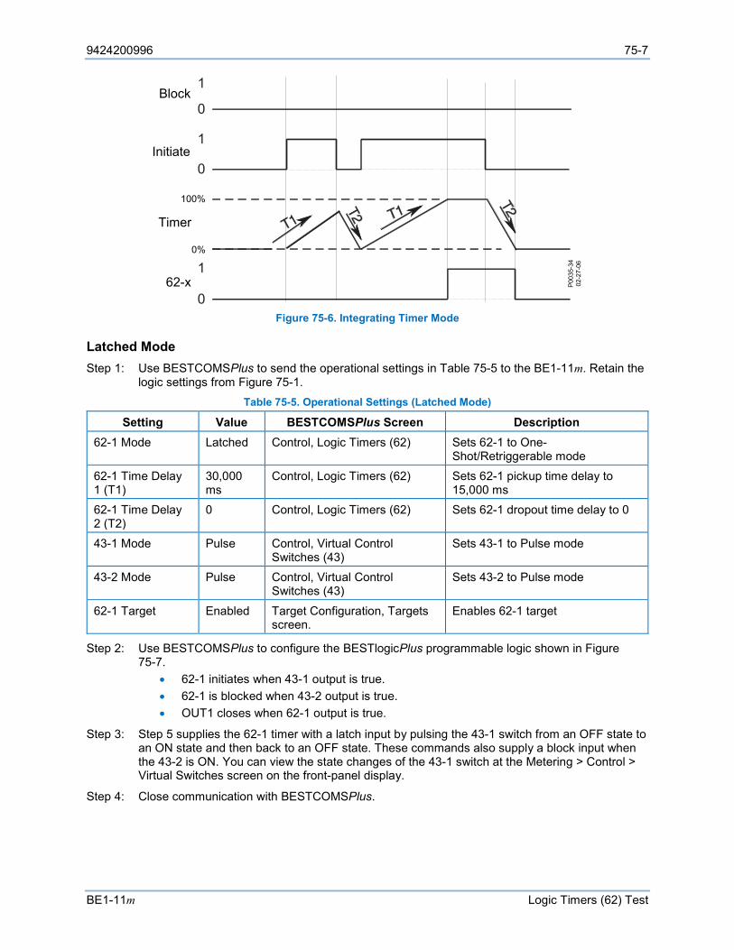
9424200996 75-7
BE1-11m Logic Timers (62) Test
Figure 75-6. Integrating Timer Mode
Latched Mode Step 1: Use BESTCOMSPlus to send the operational settings in Table 75-5 to the BE1-11m. Retain the
logic settings from Figure 75-1. Table 75-5. Operational Settings (Latched Mode)
Setting Value BESTCOMSPlus Screen Description 62-1 Mode Latched Control, Logic Timers (62) Sets 62-1 to One-
Shot/Retriggerable mode 62-1 Time Delay 1 (T1)
30,000 ms
Control, Logic Timers (62) Sets 62-1 pickup time delay to 15,000 ms
62-1 Time Delay 2 (T2)
0 Control, Logic Timers (62) Sets 62-1 dropout time delay to 0
43-1 Mode Pulse Control, Virtual Control Switches (43)
Sets 43-1 to Pulse mode
43-2 Mode Pulse Control, Virtual Control Switches (43)
Sets 43-2 to Pulse mode
62-1 Target Enabled Target Configuration, Targets screen.
Enables 62-1 target
Step 2: Use BESTCOMSPlus to configure the BESTlogicPlus programmable logic shown in Figure 75-7.
• 62-1 initiates when 43-1 output is true. • 62-1 is blocked when 43-2 output is true. • OUT1 closes when 62-1 output is true.
Step 3: Step 5 supplies the 62-1 timer with a latch input by pulsing the 43-1 switch from an OFF state to an ON state and then back to an OFF state. These commands also supply a block input when the 43-2 is ON. You can view the state changes of the 43-1 switch at the Metering > Control > Virtual Switches screen on the front-panel display.
Step 4: Close communication with BESTCOMSPlus.
P003
5-34
02-2
7-06
62-x
Block
Initiate
100%
0%
Timer
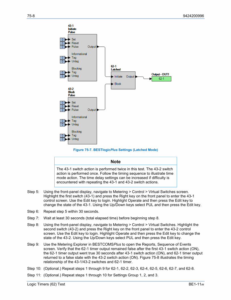
75-8 9424200996
Logic Timers (62) Test BE1-11m
Figure 75-7. BESTlogicPlus Settings (Latched Mode)
Note The 43-1 switch action is performed twice in this test. The 43-2 switch action is performed once. Follow the timing sequence to illustrate time mode action. The time delay settings can be increased if difficulty is encountered with repeating the 43-1 and 43-2 switch actions.
Step 5: Using the front-panel display, navigate to Metering > Control > Virtual Switches screen. Highlight the first switch (43-1) and press the Right key on the front panel to enter the 43-1 control screen. Use the Edit key to login. Highlight Operate and then press the Edit key to change the state of the 43-1. Using the Up/Down keys select PUL and then press the Edit key.
Step 6: Repeat step 5 within 30 seconds.
Step 7: Wait at least 30 seconds (total elapsed time) before beginning step 8.
Step 8: Using the front-panel display, navigate to Metering > Control > Virtual Switches. Highlight the second switch (43-2) and press the Right key on the front panel to enter the 43-2 control screen. Use the Edit key to login. Highlight Operate and then press the Edit key to change the state of the 43-2. Using the Up/Down keys select PUL and then press the Edit key.
Step 9: Use the Metering Explorer in BESTCOMSPlus to open the Reports, Sequence of Events screen. Verify that the 62-1 timer output remained false after the first 43-1 switch action (ON), the 62-1 timer output went true 30 seconds after 43-1 switch action (ON), and 62-1 timer output returned to a false state with the 43-2 switch action (ON). Figure 75-8 illustrates the timing relationship of the 43-1/43-2 switches and 62-1 timer.
Step 10: (Optional.) Repeat steps 1 through 9 for 62-1, 62-2, 62-3, 62-4, 62-5, 62-6, 62-7, and 62-8.
Step 11: (Optional.) Repeat steps 1 through 10 for Settings Group 1, 2, and 3.
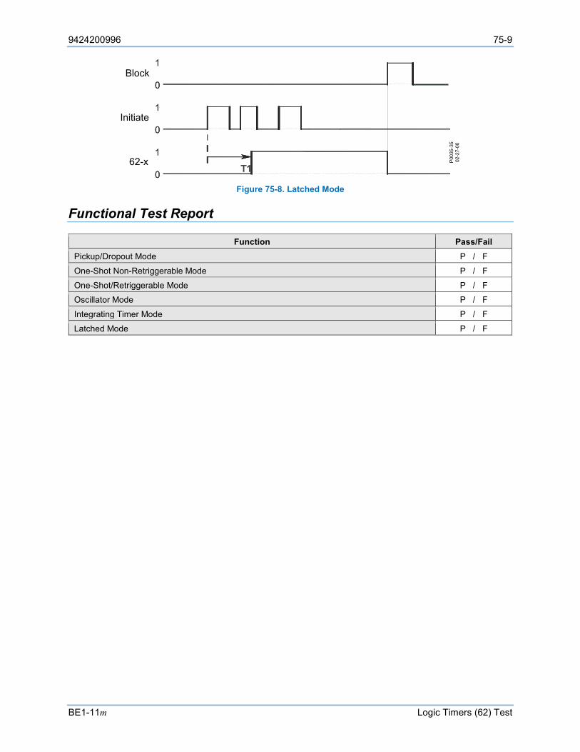
9424200996 75-9
BE1-11m Logic Timers (62) Test
Figure 75-8. Latched Mode
Functional Test Report
Function Pass/Fail Pickup/Dropout Mode P / F
One-Shot Non-Retriggerable Mode P / F
One-Shot/Retriggerable Mode P / F
Oscillator Mode P / F
Integrating Timer Mode P / F
Latched Mode P / F
P00
35-3
502
-27-
06
Block
Initiate
62-x

75-10 9424200996
Logic Timers (62) Test BE1-11m
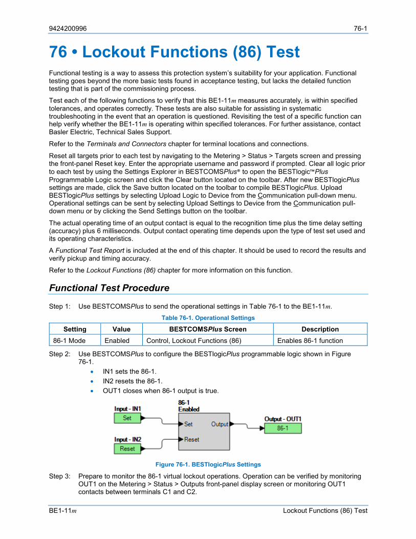
9424200996 76-1
BE1-11m Lockout Functions (86) Test
76 • Lockout Functions (86) Test Functional testing is a way to assess this protection system’s suitability for your application. Functional testing goes beyond the more basic tests found in acceptance testing, but lacks the detailed function testing that is part of the commissioning process.
Test each of the following functions to verify that this BE1-11m measures accurately, is within specified tolerances, and operates correctly. These tests are also suitable for assisting in systematic troubleshooting in the event that an operation is questioned. Revisiting the test of a specific function can help verify whether the BE1-11m is operating within specified tolerances. For further assistance, contact Basler Electric, Technical Sales Support.
Refer to the Terminals and Connectors chapter for terminal locations and connections.
Reset all targets prior to each test by navigating to the Metering > Status > Targets screen and pressing the front-panel Reset key. Enter the appropriate username and password if prompted. Clear all logic prior to each test by using the Settings Explorer in BESTCOMSPlus® to open the BESTlogic™Plus Programmable Logic screen and click the Clear button located on the toolbar. After new BESTlogicPlus settings are made, click the Save button located on the toolbar to compile BESTlogicPlus. Upload BESTlogicPlus settings by selecting Upload Logic to Device from the Communication pull-down menu. Operational settings can be sent by selecting Upload Settings to Device from the Communication pull-down menu or by clicking the Send Settings button on the toolbar.
The actual operating time of an output contact is equal to the recognition time plus the time delay setting (accuracy) plus 6 milliseconds. Output contact operating time depends upon the type of test set used and its operating characteristics.
A Functional Test Report is included at the end of this chapter. It should be used to record the results and verify pickup and timing accuracy.
Refer to the Lockout Functions (86) chapter for more information on this function.
Functional Test Procedure
Step 1: Use BESTCOMSPlus to send the operational settings in Table 76-1 to the BE1-11m. Table 76-1. Operational Settings
Setting Value BESTCOMSPlus Screen Description 86-1 Mode Enabled Control, Lockout Functions (86) Enables 86-1 function
Step 2: Use BESTCOMSPlus to configure the BESTlogicPlus programmable logic shown in Figure 76-1.
• IN1 sets the 86-1. • IN2 resets the 86-1. • OUT1 closes when 86-1 output is true.
Figure 76-1. BESTlogicPlus Settings
Step 3: Prepare to monitor the 86-1 virtual lockout operations. Operation can be verified by monitoring OUT1 on the Metering > Status > Outputs front-panel display screen or monitoring OUT1 contacts between terminals C1 and C2.

76-2 9424200996
Lockout Functions (86) Test BE1-11m
Step 4: Connect power supply to IN1 terminals.
Step 5: Apply voltage to IN1. Verify that OUT1 closes and remains closed.
Step 6: Power down the BE1-11m and verify that OUT1 opens. Wait 10 seconds and power up the BE1-11m. Verify that OUT1 closes. This verifies that the 86-1 position is stored in non-volatile memory. Remove voltage from IN1.
Step 7: Connect power supply to IN2 terminals.
Step 8: Apply voltage to IN2. Verify that OUT1 opens and remains open.
Step 9: Apply voltage to both IN1 and IN2. OUT1 should close. This verifies that the Set input has priority over the Reset input.
Step 10: Repeat steps 1 through 9 for the 86-2 element.
Step 11: Repeat steps 1 through 10 for settings group 1, 2, and 3.
Functional Test Report
Pass/Fail P / F
9424200996 77-1
BE1-11m Breaker Control Switch (101) Test
77 • Breaker Control Switch (101) Test Functional testing is a way to assess this protection system’s suitability for your application. Functional testing goes beyond the more basic tests found in acceptance testing, but lacks the detailed function testing that is part of the commissioning process.
Test each of the following functions to verify that this BE1-11m measures accurately, is within specified tolerances, and operates correctly. These tests are also suitable for assisting in systematic troubleshooting in the event that an operation is questioned. Revisiting the test of a specific function can help verify whether the BE1-11m is operating within specified tolerances. For further assistance, contact Basler Electric, Technical Sales Support.
Refer to the Terminals and Connectors chapter for terminal locations and connections.
Reset all targets prior to each test by navigating to the Metering > Status > Targets screen and pressing the front-panel Reset key. Enter the appropriate username and password if prompted. Clear all logic prior to each test by using the Settings Explorer in BESTCOMSPlus® to open the BESTlogic™Plus Programmable Logic screen and click the Clear button located on the toolbar. After new BESTlogicPlus settings are made, click the Save button located on the toolbar to compile BESTlogicPlus. Upload BESTlogicPlus settings by selecting Upload Logic to Device from the Communication pull-down menu. Operational settings can be sent by selecting Upload Settings to Device from the Communication pull-down menu or by clicking the Send Settings button on the toolbar.
The actual operating time of an output contact is equal to the recognition time plus the time delay setting (accuracy) plus 6 milliseconds. Output contact operating time depends upon the type of test set used and its operating characteristics.
A Functional Test Report is included at the end of this chapter. It should be used to record the results and verify pickup and timing accuracy.
Refer to the Breaker Control Switch (101) chapter for more information on this function.
Functional Test Procedure
Step 1: Use BESTCOMSPlus to send the operational settings in Table 77-1 to the BE1-11m. Table 77-1. Operational Settings
Setting Value BESTCOMSPlus Screen Description 101 Mode Enabled Control, Breaker Control Switch (101) Enables 101 function
Step 2: Use BESTCOMSPlus to configure the BESTlogicPlus Programmable Logic shown in Figure 77-1.
• OUT1 closes when 101 Trip output is true. • OUT2 closes when 101 TSC output is true. • OUT3 closes when 101 Close output is true. • OUT4 closes when 101 CSC output is true.
Step 3: Prepare to monitor the 101 breaker control switch operations. Operation can be verified by monitoring the programmed output contacts on the Metering > Status > Outputs front-panel display screen.
Step 4: Place the 101 in the TRIP position by using the Metering Explorer in BESTCOMSPlus to open the Control, Breaker Control Switch tree branch. Click on the TRIP button to select it. Login may be required. The green selection LED will begin to flash. Within 25 seconds, click on the TRIP button a second time to operate it. The green selection LED will stop flashing and the trip status LED will light.
Result: OUT1 closes for 200 ms and returns to the open state. OUT2 closes (TRIP state) and remains closed.
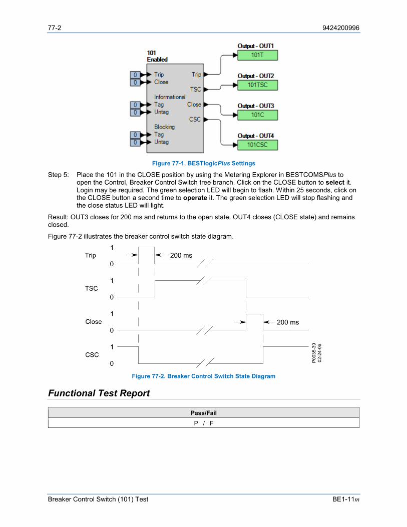
77-2 9424200996
Breaker Control Switch (101) Test BE1-11m
Figure 77-1. BESTlogicPlus Settings
Step 5: Place the 101 in the CLOSE position by using the Metering Explorer in BESTCOMSPlus to open the Control, Breaker Control Switch tree branch. Click on the CLOSE button to select it. Login may be required. The green selection LED will begin to flash. Within 25 seconds, click on the CLOSE button a second time to operate it. The green selection LED will stop flashing and the close status LED will light.
Result: OUT3 closes for 200 ms and returns to the open state. OUT4 closes (CLOSE state) and remains closed.
Figure 77-2 illustrates the breaker control switch state diagram.
Figure 77-2. Breaker Control Switch State Diagram
Functional Test Report
Pass/Fail P / F
Trip
TSC
Close
CSC
P00
35-3
902
-24-
06

9424200996 78-1
BE1-11m Frequently Asked Questions (FAQ)
78 • Frequently Asked Questions (FAQ) Electrical/Connections
Is the power supply polarity sensitive? No, the power supply will accept either an ac or dc voltage input. Refer to the Typical Connections chapter.
Are the sensing contacts polarity sensitive? Yes, refer to the Typical Connections chapter for more information.
What voltage level is used to develop current flow through the contact sensing inputs? Voltage level is dependent on the power supply option (called out in the BE1-11m style chart). For additional information, refer to the Contact Inputs and Outputs chapter and the style chart in the Introduction chapter.
Can the IRIG signal be daisy-chained to multiple BE1-11m units? Yes, multiple BE1-11m units can use the same IRIG-B input signal by daisy-chaining the BE1-11m inputs. The burden data is nonlinear, approximately 4 kΩ at 3.5 Vdc and 3 kΩ at 20 Vdc. See the Specifications chapter for additional information.
General Operation
Does the BE1-11m trip output contact latch after a fault? The answer to the question is yes and no. In general, once the fault goes away the output contacts open. The BE1-11m does offer an option to ensure that the contact will stay closed for at least 200 milliseconds. See the Contact Inputs and Outputs chapter for additional information on that function. Also, a Set Priority Latch in BESTlogic™Plus can keep the relay outputs closed as long as power is applied.
Can I make logic settings at the front panel? No, logic settings cannot be made at the front panel. Logic settings must be programmed using BESTCOMSPlus® communication software.
Since the BE1-11m is a programmable device, what are the factory defaults? Default settings are shown with each function in the instruction manual. For input or output default settings see the Contact Inputs and Outputs chapter. For protection and control functions, see the appropriate chapters. The factory default logic scheme is defined in the BESTlogicPlus chapter.
Does the BE1-11m have a battery installed as the backup power source for the internal clock on loss of power? A ride-through capacitor, up to 24 hours, and a backup battery, greater than five years, are standard features of the BE1-11m. Refer to the Timekeeping chapter for more information on the backup battery including replacement.
How are reports and other information obtained from the BE1-11m saved in files for future use? BESTCOMSPlus can be used to view sequence of events, fault records, security log, load profile, and breaker status. See the appropriate chapters for more information.
78-2 9424200996
Frequently Asked Questions (FAQ) BE1-11m
How can I check the version number of my BE1-11m? The application version can be found in four different ways: One, on the Settings > General Settings > Device Information screen of the front-panel display. Two, on the Settings Explorer, General Settings, Device Info screen of BESTCOMSPlus. Three, on the Status (home) page of the web page interface. Four, on the Metering Explorer, Device Info screen of BESTCOMSPlus.
Features
How many overcurrent elements does the BE1-11m have available? The BE1-11m has six instantaneous overcurrent and five inverse overcurrent elements. Like any element, each element can be assigned to any output for building logic equations.
Communications
Is the IRIG signal modulated or demodulated? The BE1-11m accepts an IRIG-B signal that is demodulated (dc level-shifted digital signal). See the Specifications chapter for additional information.
9424200996 79-1
BE1-11m Troubleshooting
79 • Troubleshooting Basler microprocessor-based protection systems are similar in nature to a panel of electromechanical or solid-state component relays. Both must be wired together with inputs and outputs, and have operating settings applied. Logic settings determine which protection elements are electronically wired to the inputs and outputs of the device. Operating settings determine the pickup thresholds and time delays.
The logic and operating settings should be tested by applying actual inputs and operating quantities and verifying proper output response. For more details, refer to the testing chapters. All of the following connections and functions should be verified during commissioning tests:
• Proper connection and sensing of current and voltage signals
• Input and output contact connections
• I/O sensing
• Settings validation
• Proper operation of equipment (main or auxiliary)
• Proper alarming (to SCADA) and/or targeting
If you do not get the results that you expect from the BE1-11m, first check the programmable settings for the appropriate function. Use the following troubleshooting procedures when difficulties are encountered in the operation of your BE1-11m.
Warning!
Troubleshooting of the BE1-11m should be performed only by qualified personnel. High voltage may be present on the rear terminals of the BE1-11m.
Communications
Ethernet Port Does Not Operate Properly Step 1. Verify that the proper port of your computer is being used. For more information, refer to the
Communication chapter.
Step 2. Verify that the network configuration of the BE1-11m is set up properly. For more information, refer to the Communication chapter.
USB Port Does Not Operate Properly Verify that the USB driver was installed properly. For more information, refer to the BESTCOMSPlus Software chapter.
USB Driver Did Not Install Properly on Windows® 7, 8, or 10 Step 1. If the message in Figure 79-1 is shown, close all programs and restart the computer.
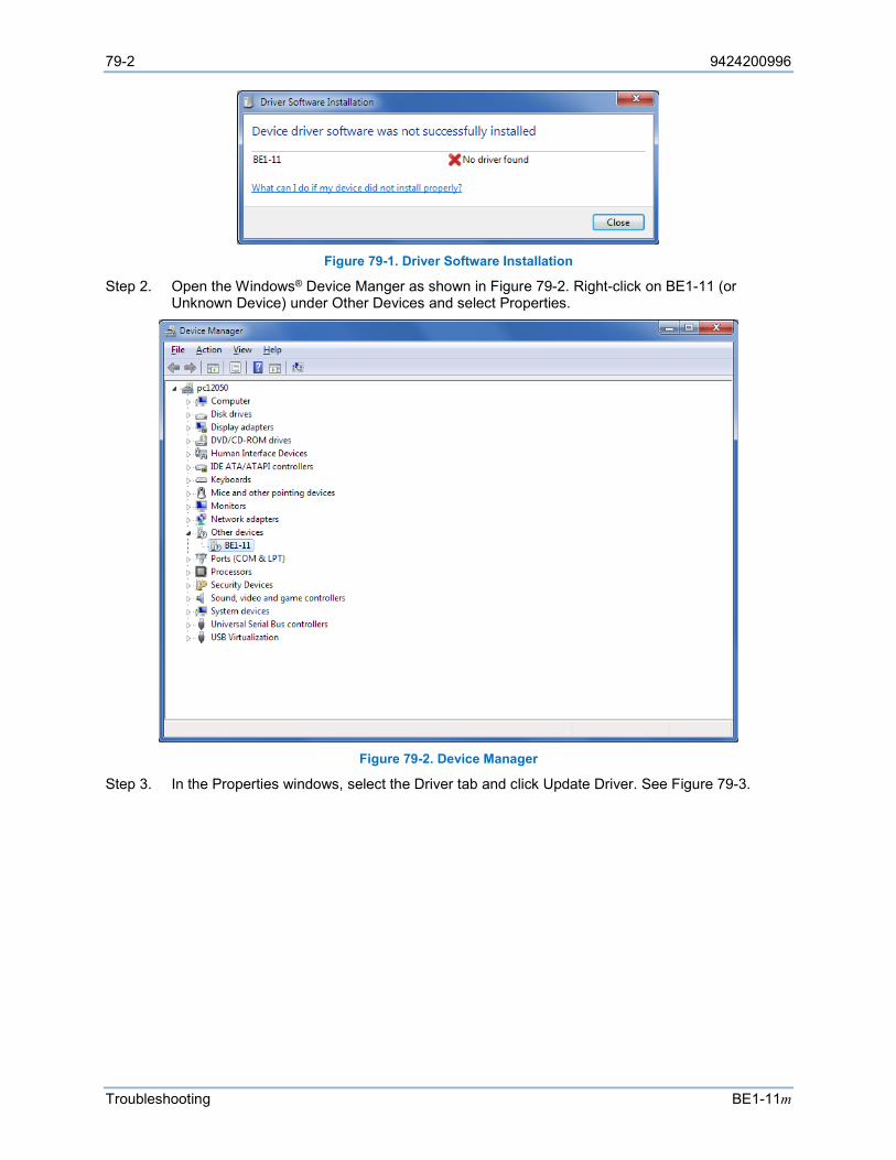
79-2 9424200996
Troubleshooting BE1-11m
Figure 79-1. Driver Software Installation
Step 2. Open the Windows® Device Manger as shown in Figure 79-2. Right-click on BE1-11 (or Unknown Device) under Other Devices and select Properties.
Figure 79-2. Device Manager
Step 3. In the Properties windows, select the Driver tab and click Update Driver. See Figure 79-3.
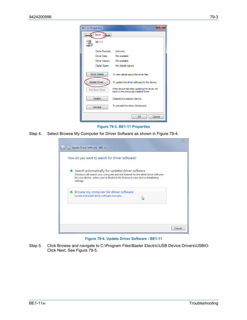
9424200996 79-3
BE1-11m Troubleshooting
Figure 79-3. BE1-11 Properties
Step 4. Select Browse My Computer for Driver Software as shown in Figure 79-4.
Figure 79-4. Update Driver Software - BE1-11
Step 5. Click Browse and navigate to C:\Program Files\Basler Electric\USB Device Drivers\USBIO. Click Next. See Figure 79-5.
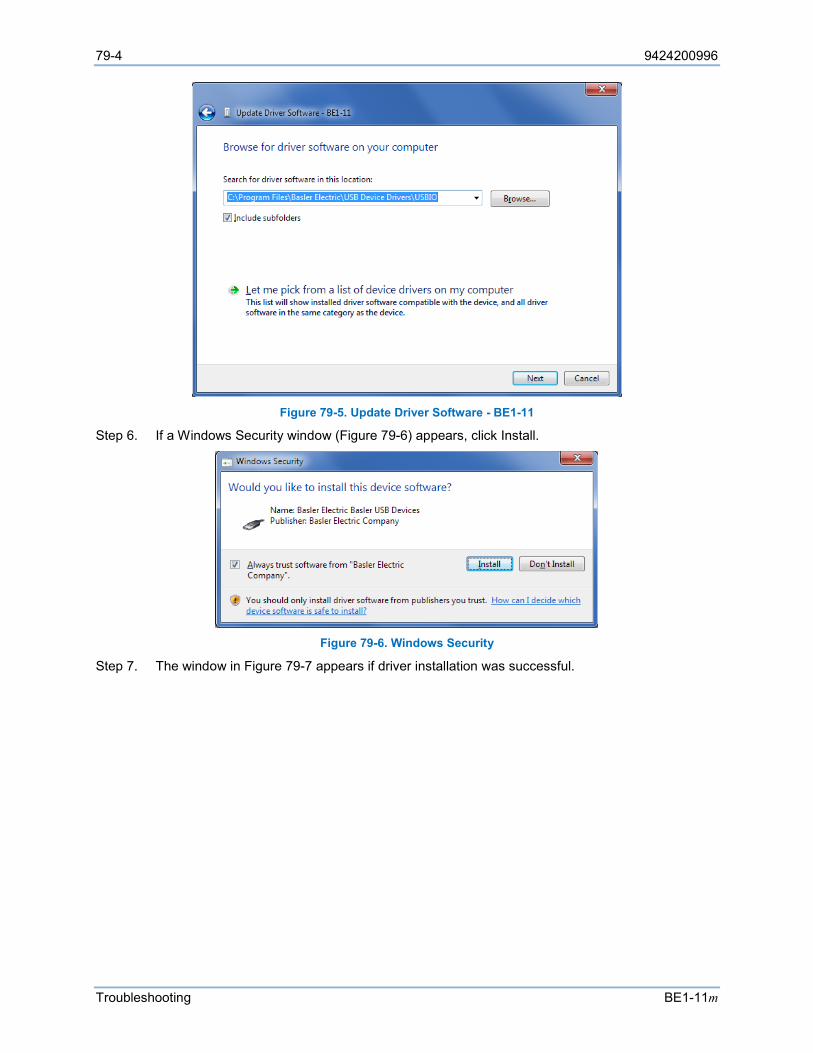
79-4 9424200996
Troubleshooting BE1-11m
Figure 79-5. Update Driver Software - BE1-11
Step 6. If a Windows Security window (Figure 79-6) appears, click Install.
Figure 79-6. Windows Security
Step 7. The window in Figure 79-7 appears if driver installation was successful.
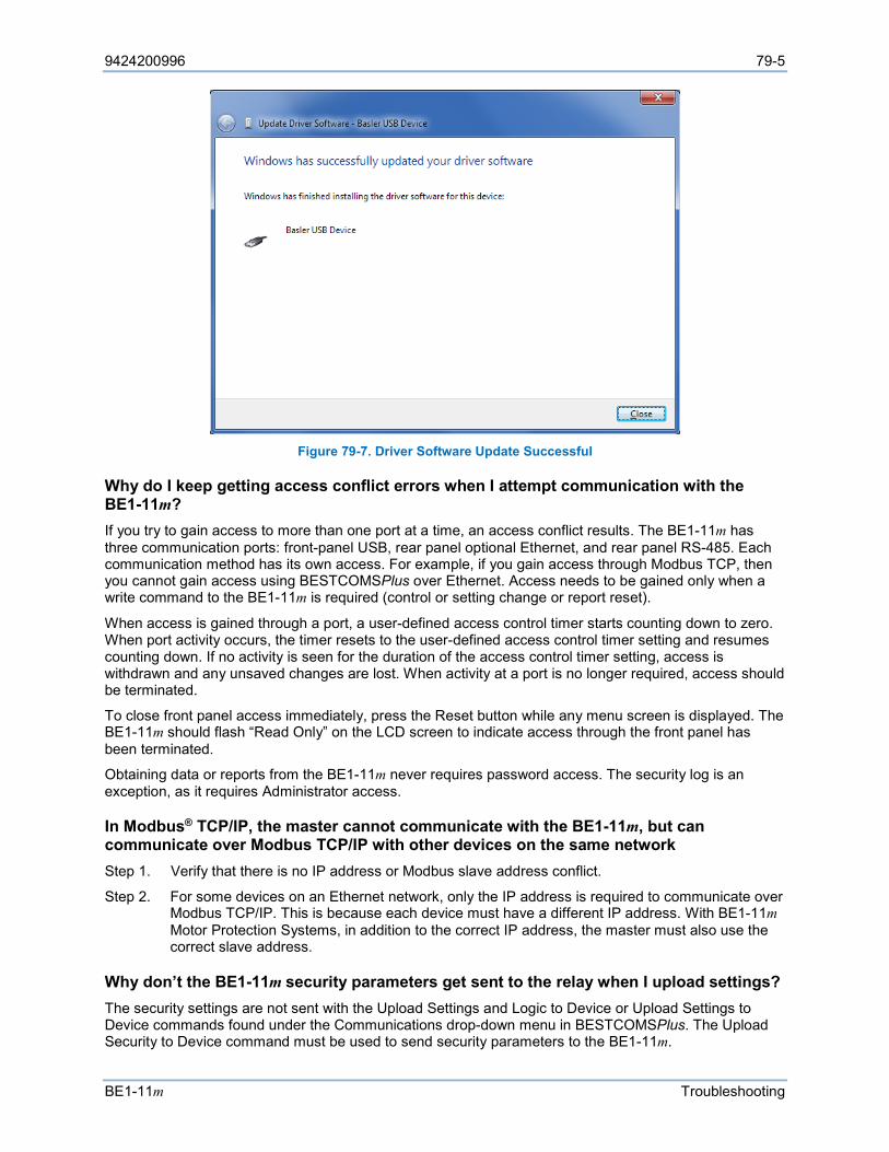
9424200996 79-5
BE1-11m Troubleshooting
Figure 79-7. Driver Software Update Successful
Why do I keep getting access conflict errors when I attempt communication with the BE1-11m? If you try to gain access to more than one port at a time, an access conflict results. The BE1-11m has three communication ports: front-panel USB, rear panel optional Ethernet, and rear panel RS-485. Each communication method has its own access. For example, if you gain access through Modbus TCP, then you cannot gain access using BESTCOMSPlus over Ethernet. Access needs to be gained only when a write command to the BE1-11m is required (control or setting change or report reset).
When access is gained through a port, a user-defined access control timer starts counting down to zero. When port activity occurs, the timer resets to the user-defined access control timer setting and resumes counting down. If no activity is seen for the duration of the access control timer setting, access is withdrawn and any unsaved changes are lost. When activity at a port is no longer required, access should be terminated.
To close front panel access immediately, press the Reset button while any menu screen is displayed. The BE1-11m should flash “Read Only” on the LCD screen to indicate access through the front panel has been terminated.
Obtaining data or reports from the BE1-11m never requires password access. The security log is an exception, as it requires Administrator access.
In Modbus® TCP/IP, the master cannot communicate with the BE1-11m, but can communicate over Modbus TCP/IP with other devices on the same network Step 1. Verify that there is no IP address or Modbus slave address conflict.
Step 2. For some devices on an Ethernet network, only the IP address is required to communicate over Modbus TCP/IP. This is because each device must have a different IP address. With BE1-11m Motor Protection Systems, in addition to the correct IP address, the master must also use the correct slave address.
Why don’t the BE1-11m security parameters get sent to the relay when I upload settings? The security settings are not sent with the Upload Settings and Logic to Device or Upload Settings to Device commands found under the Communications drop-down menu in BESTCOMSPlus. The Upload Security to Device command must be used to send security parameters to the BE1-11m.
79-6 9424200996
Troubleshooting BE1-11m
Inputs and Outputs
Programmable Inputs Do Not Operate as Expected Step 1. Verify that all wiring is properly connected. Refer to the Typical Connections chapter.
Step 2. Verify that the inputs are programmed properly.
Step 3. Verify that the sensing input jumpers are in the correct position. Refer to the Contact Inputs and Outputs chapter.
Programmable Outputs Do Not Operate as Expected Step 1. Verify that all wiring is properly connected. Refer to the Typical Connections chapter.
Step 2. Verify that the outputs are programmed properly.
Step 3. Verify that the output is not being set by other means. There can be more than one connection to an output (check the physical outputs tab in BESTlogicPlus). Also, check that the output override is not set for the output.
Metering/Display
Incorrect Display of Current Step 1. Verify that all wiring is properly connected. Refer to the Typical Connections chapter.
Step 2. Verify that the proper current is present at BE1-11m current sensing inputs IA1 (D1/D2), IB1 (D3/D4), IC1 (D5/D6), and IG1 (D7/D8). If two sets of CTs are present, also verify proper current at IA2 (F1/F2), IB2 (F3/F4), IC2 (F5/F6), and IG2 (F7/F8).
Step 3. Verify that the current transformer ratio and sensing configuration is correct.
Step 4. Verify that the current sensing transformers are correct and properly installed.
Incorrect Display of Voltage Step 1. Verify that all wiring is properly connected. Refer to the Typical Connections chapter.
Step 2. Verify that the proper voltage is present at BE1-11m voltage sensing inputs VA (C13), VB (C14), VC (C15), and VN (C16).
Step 3. Verify that the voltage transformer ratio and sensing configuration is correct.
Step 4. Verify that the voltage sensing transformers are correct and properly installed.
General Operation
Why won't the Trip LED reset when I press the Reset key on the front panel? The Reset key is context sensitive. To reset the Trip LED or the targets, the Targets screen must be displayed. To reset the alarms, the Alarms screen must be displayed.
Why won’t the 60FL alarm or target reset when I press the Reset key on the front panel? The only way to reset the Fuse Loss alarm or target is to apply more than 85% of rated positive-sequence voltage. Refer to the Fuse Loss (60FL) chapter for more information.
Do I have to log in to reset the targets or alarms? It depends on the security setup. You can reset the targets or alarms through a specific port without logging in if the Unsecured Access Level is set to Operator or higher on that port. Target and alarm reset can also be set outside of security control, allowing reset through the front-panel interface without logging in. Refer to the Security chapter for more information.

9424200996 79-7
BE1-11m Troubleshooting
Why don't the targets or trip LED work properly? If a protective element is tripping at the desired level, but the targets aren't behaving as expected, use BESTCOMSPlus to verify that the targets are enabled for the protective function. Refer to the Fault Reporting chapter for detailed information about targets.
Trip LED behavior depends on the pickup and trip expression of the protective function. When the functions pickup expression is true and the trip expression is false, the Trip LED flashes. In other words, a flashing LED means that a protection element is in a picked up state and is timing toward a trip. When both the pickup and trip expression is true, the Trip LED lights steadily. The Trip LED also lights steadily when neither expression is true but latched targets exist. When resetting a target, the Trip LED will not turn off if the fault is still present. The truth table of Table 79-1 serves as an aid to interpreting Trip LED indications.
Table 79-1. Trip LED Truth Table
Trip Pickup Targets Trip LED No No No Off No No Yes On No Yes No Flash No Yes Yes Flash Yes No No On Yes No Yes On Yes Yes No On Yes Yes Yes On
Why are voltage dependent elements (51/27, 27, 59, 32, 55) not operating as expected when testing by secondary injections? The BE1-11m has the ability to distinguish a loss of fuse from a loss of voltage. Check the sequence of events for a Fuse Loss alarm. If a Fuse Loss alarm is active, voltage dependent elements will not operate. Refer to the Fuse Loss (60FL) chapter for information on applying voltage and current so the BE1-11m does not detect a fuse loss. Fuse Loss protection can also be disabled for the protection element being tested.

79-8 9424200996
Troubleshooting BE1-11m
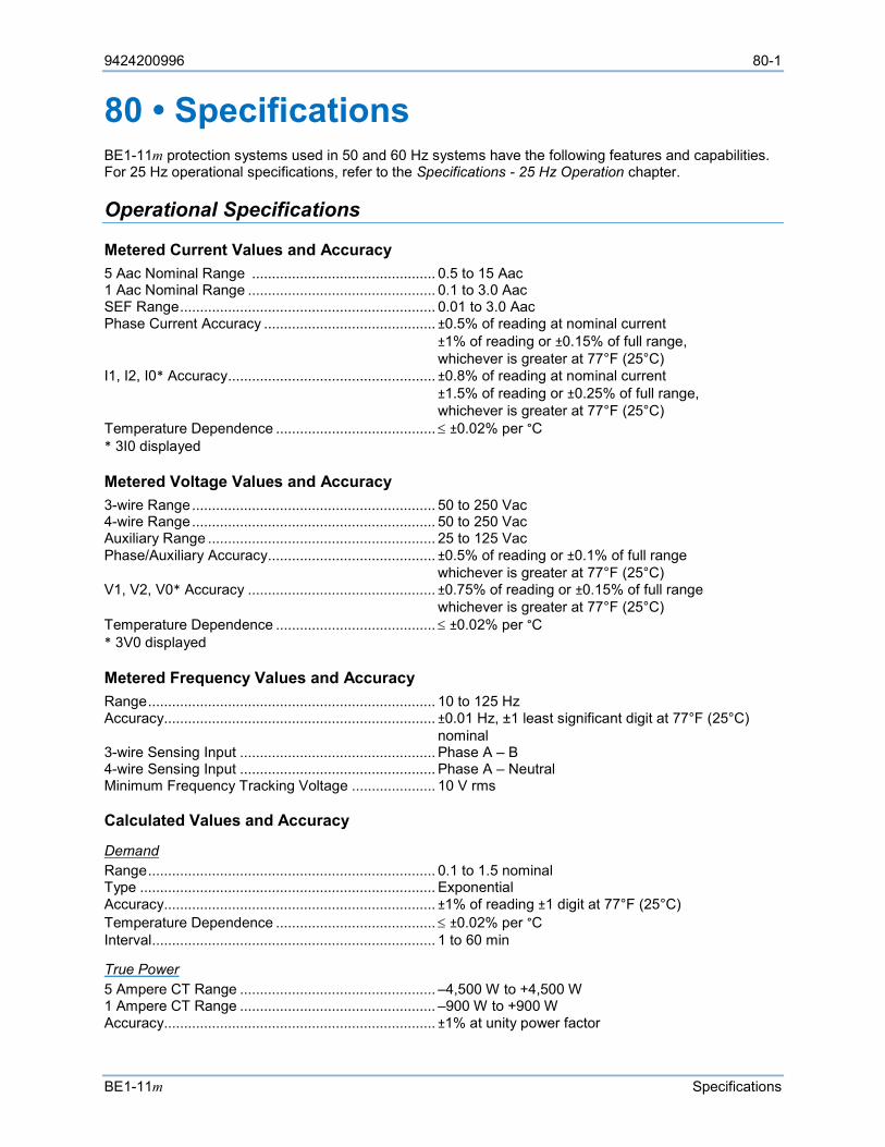
9424200996 80-1
BE1-11m Specifications
80 • Specifications BE1-11m protection systems used in 50 and 60 Hz systems have the following features and capabilities. For 25 Hz operational specifications, refer to the Specifications - 25 Hz Operation chapter.
Operational Specifications
Metered Current Values and Accuracy 5 Aac Nominal Range .............................................. 0.5 to 15 Aac 1 Aac Nominal Range ............................................... 0.1 to 3.0 Aac SEF Range ................................................................ 0.01 to 3.0 Aac Phase Current Accuracy ........................................... ±0.5% of reading at nominal current ±1% of reading or ±0.15% of full range, whichever is greater at 77°F (25°C) I1, I2, I0* Accuracy .................................................... ±0.8% of reading at nominal current ±1.5% of reading or ±0.25% of full range, whichever is greater at 77°F (25°C) Temperature Dependence ........................................ ≤ ±0.02% per °C * 3I0 displayed
Metered Voltage Values and Accuracy 3-wire Range ............................................................. 50 to 250 Vac 4-wire Range ............................................................. 50 to 250 Vac Auxiliary Range ......................................................... 25 to 125 Vac Phase/Auxiliary Accuracy .......................................... ±0.5% of reading or ±0.1% of full range whichever is greater at 77°F (25°C) V1, V2, V0* Accuracy ............................................... ±0.75% of reading or ±0.15% of full range whichever is greater at 77°F (25°C) Temperature Dependence ........................................ ≤ ±0.02% per °C * 3V0 displayed
Metered Frequency Values and Accuracy Range ........................................................................ 10 to 125 Hz Accuracy.................................................................... ±0.01 Hz, ±1 least significant digit at 77°F (25°C) nominal 3-wire Sensing Input ................................................. Phase A – B 4-wire Sensing Input ................................................. Phase A – Neutral Minimum Frequency Tracking Voltage ..................... 10 V rms
Calculated Values and Accuracy
Demand Range ........................................................................ 0.1 to 1.5 nominal Type .......................................................................... Exponential Accuracy.................................................................... ±1% of reading ±1 digit at 77°F (25°C) Temperature Dependence ........................................ ≤ ±0.02% per °C Interval ....................................................................... 1 to 60 min
True Power 5 Ampere CT Range ................................................. –4,500 W to +4,500 W 1 Ampere CT Range ................................................. –900 W to +900 W Accuracy.................................................................... ±1% at unity power factor
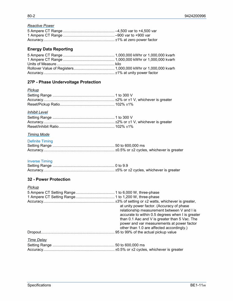
80-2 9424200996
Specifications BE1-11m
Reactive Power 5 Ampere CT Range ................................................. –4,500 var to +4,500 var 1 Ampere CT Range ................................................. –900 var to +900 var Accuracy.................................................................... ±1% at zero power factor
Energy Data Reporting 5 Ampere CT Range ................................................. 1,000,000 kWhr or 1,000,000 kvarh 1 Ampere CT Range ................................................. 1,000,000 kWhr or 1,000,000 kvarh Units of Measure ....................................................... kilo Rollover Value of Registers....................................... 1,000,000 kWhr or 1,000,000 kvarh Accuracy.................................................................... ±1% at unity power factor
27P - Phase Undervoltage Protection
Pickup Setting Range ........................................................... 1 to 300 V Accuracy.................................................................... ±2% or ±1 V, whichever is greater Reset/Pickup Ratio .................................................... 102% ±1%
Inhibit Level Setting Range ........................................................... 1 to 300 V Accuracy.................................................................... ±2% or ±1 V, whichever is greater Reset/Inhibit Ratio ..................................................... 102% ±1%
Timing Mode
Definite Timing Setting Range ........................................................... 50 to 600,000 ms Accuracy.................................................................... ±0.5% or ±2 cycles, whichever is greater
Inverse Timing Setting Range ........................................................... 0 to 9.9 Accuracy.................................................................... ±5% or ±2 cycles, whichever is greater
32 - Power Protection
Pickup 5 Ampere CT Setting Range ..................................... 1 to 6,000 W, three-phase 1 Ampere CT Setting Range ..................................... 1 to 1,200 W, three-phase Accuracy.................................................................... ±3% of setting or ±2 watts, whichever is greater,
at unity power factor. (Accuracy of phase relationship measurement between V and I is accurate to within 0.5 degrees when I is greater than 0.1 Aac and V is greater than 5 Vac. The power and var measurements at power factor other than 1.0 are affected accordingly.)
Dropout ...................................................................... 95 to 99% of the actual pickup value
Time Delay Setting Range ........................................................... 50 to 600,000 ms Accuracy.................................................................... ±0.5% or ±2 cycles, whichever is greater
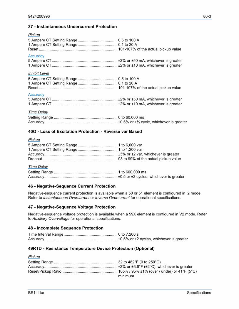
9424200996 80-3
BE1-11m Specifications
37 - Instantaneous Undercurrent Protection
Pickup 5 Ampere CT Setting Range ..................................... 0.5 to 100 A 1 Ampere CT Setting Range ..................................... 0.1 to 20 A Reset ......................................................................... 101-107% of the actual pickup value
Accuracy 5 Ampere CT ............................................................. ±2% or ±50 mA, whichever is greater 1 Ampere CT ............................................................. ±2% or ±10 mA, whichever is greater
Inhibit Level 5 Ampere CT Setting Range ..................................... 0.5 to 100 A 1 Ampere CT Setting Range ..................................... 0.1 to 20 A Reset ......................................................................... 101-107% of the actual pickup value
Accuracy 5 Ampere CT ............................................................. ±2% or ±50 mA, whichever is greater 1 Ampere CT ............................................................. ±2% or ±10 mA, whichever is greater
Time Delay Setting Range ........................................................... 0 to 60,000 ms Accuracy.................................................................... ±0.5% or ±½ cycle, whichever is greater
40Q - Loss of Excitation Protection - Reverse var Based
Pickup 5 Ampere CT Setting Range ..................................... 1 to 6,000 var 1 Ampere CT Setting Range ..................................... 1 to 1,200 var Accuracy.................................................................... ±3% or ±2 var, whichever is greater Dropout ...................................................................... 93 to 99% of the actual pickup value
Time Delay Setting Range ........................................................... 1 to 600,000 ms Accuracy.................................................................... ±0.5 or ±2 cycles, whichever is greater
46 - Negative-Sequence Current Protection Negative-sequence current protection is available when a 50 or 51 element is configured in I2 mode. Refer to Instantaneous Overcurrent or Inverse Overcurrent for operational specifications.
47 - Negative-Sequence Voltage Protection Negative-sequence voltage protection is available when a 59X element is configured in V2 mode. Refer to Auxiliary Overvoltage for operational specifications.
48 - Incomplete Sequence Protection Time Interval Range .................................................. 0 to 7,200 s Accuracy.................................................................... ±0.5% or ±2 cycles, whichever is greater
49RTD - Resistance Temperature Device Protection (Optional)
Pickup Setting Range ........................................................... 32 to 482°F (0 to 250°C) Accuracy.................................................................... ±2% or ±3.6°F (±2°C), whichever is greater Reset/Pickup Ratio .................................................... 105% / 95% ±1% (over / under) or 41°F (5°C) minimum
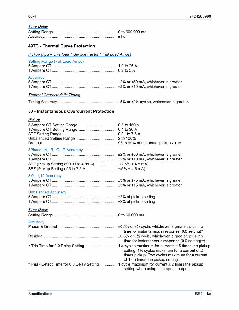
80-4 9424200996
Specifications BE1-11m
Time Delay Setting Range ........................................................... 0 to 600,000 ms Accuracy.................................................................... ±1 s
49TC - Thermal Curve Protection
Pickup (Itpu = Overload * Service Factor * Full Load Amps)
Setting Range (Full Load Amps) 5 Ampere CT ............................................................. 1.0 to 25 A 1 Ampere CT ............................................................. 0.2 to 5 A
Accuracy 5 Ampere CT ............................................................. ±2% or ±50 mA, whichever is greater 1 Ampere CT ............................................................. ±2% or ±10 mA, whichever is greater
Thermal Characteristic Timing
Timing Accuracy ........................................................ ±5% or ±2½ cycles, whichever is greater.
50 - Instantaneous Overcurrent Protection
Pickup 5 Ampere CT Setting Range ..................................... 0.5 to 150 A 1 Ampere CT Setting Range ..................................... 0.1 to 30 A SEF Setting Range ................................................... 0.01 to 7.5 A Unbalanced Setting Range ....................................... 2 to 100% Dropout ..................................................................... 93 to 99% of the actual pickup value
3Phase, IA, IB, IC, IG Accuracy 5 Ampere CT ............................................................. ±2% or ±50 mA, whichever is greater 1 Ampere CT ............................................................. ±2% or ±10 mA, whichever is greater SEF (Pickup Setting of 0.01 to 4.99 A) ..................... ±(2.5% + 4.5 mA) SEF (Pickup Setting of 5 to 7.5 A) ............................ ±(5% + 4.5 mA)
3I0, I1, I2 Accuracy 5 Ampere CT ............................................................. ±3% or ±75 mA, whichever is greater 1 Ampere CT ............................................................. ±3% or ±15 mA, whichever is greater
Unbalanced Accuracy 5 Ampere CT ............................................................. ±2% of pickup setting 1 Ampere CT ............................................................. ±2% of pickup setting
Time Delay Setting Range ........................................................... 0 to 60,000 ms
Accuracy Phase & Ground ........................................................ ±0.5% or ±½ cycle, whichever is greater, plus trip
time for instantaneous response (0.0 setting)* Residual .................................................................... ±0.5% or ±½ cycle, whichever is greater, plus trip
time for instantaneous response (0.0 setting)*† * Trip Time for 0.0 Delay Setting .............................. 1¼ cycles maximum for currents ≥ 5 times the pickup
setting. 1¾ cycles maximum for a current of 2 times pickup. Two cycles maximum for a current of 1.05 times the pickup setting.
† Peak Detect Time for 0.0 Delay Setting ................. 1 cycle maximum for current ≥ 2 times the pickup setting when using high-speed outputs.
9424200996 80-5
BE1-11m Specifications
50BF - Breaker Failure Protection
Phase & Ground Pickup 5 Ampere CT Setting Range ..................................... 0.25 to 10 A 1 Ampere CT Setting Range ..................................... 0.05 to 2 A SEF ........................................................................... 0.01 to 0.5 A
Accuracy 5 Ampere CT ............................................................. ±2% or ±50 mA, whichever is greater 1 Ampere CT ............................................................. ±2% or ±10 mA, whichever is greater SEF ........................................................................... ±(2.5% + 2.5 mA)
Time Delay & Control Time Setting Range ........................................................... 50 to 999 ms Accuracy.................................................................... ±0.5% or +1¼, –0.5 cycles, whichever is greater
51 - Inverse Overcurrent Protection
Pickup 5 Ampere CT Setting Range ..................................... 0.5 to 16 A 1 Ampere CT Setting Range ..................................... 0.1 to 3.2 A SEF Setting Range ................................................... 0.01 to 0.8 A Unbalanced Setting Range ....................................... 2 to 100% Dropout ..................................................................... 93 to 99% of the actual pickup value
3Phase, IA, IB, IC, IG Accuracy 5 Ampere CT ............................................................. ±2% or ±50 mA, whichever is greater 1 Ampere CT ............................................................. ±2% or ±10 mA, whichever is greater SEF ........................................................................... ±(2.5% + 2.5 mA)
3I0, I1, I2 Accuracy 5 Ampere CT ............................................................. ±3% or ±75 mA, whichever is greater 1 Ampere CT ............................................................. ±3% or ±15 mA, whichever is greater
Unbalanced Accuracy 5 Ampere CT ............................................................. ±2% of pickup setting 1 Ampere CT ............................................................. ±2% of pickup setting
Time Current Characteristic Curves Timing Accuracy (All 51 Functions) .......................... ±5% or ±1½ cycles, whichever is greater, for time dial
settings greater than 0.1 and multiples of 2 to 40 times the pickup setting but not over 150 A for 5 A CT units or 30 A for 1 A CT units. Refer to the Time Curve Characteristics chapter for information on available timing curves.
Voltage Restraint Control/Restraint Range ............................................ 30 to 250 V Accuracy.................................................................... ±2% or ±1 V, whichever is greater
55 - Power Factor Protection
Lagging/Leading Pickup Setting Range ........................................................... 0.05 to 0.99 Accuracy.................................................................... ±0.01
Time Delay Setting Range ........................................................... 50 to 60,000 ms Accuracy.................................................................... ±0.5% or ±2 cycles, whichever is greater
80-6 9424200996
Specifications BE1-11m
59P - Phase Overvoltage Protection
Pickup Setting Range ........................................................... 1 to 300 V Accuracy.................................................................... ±2% or ±1 V, whichever is greater Dropout/Pickup Ratio ................................................ 98% ±1%
Timing Mode
Definite Timing Setting Range ........................................................... 50 to 600,000 ms Accuracy.................................................................... ±0.5% or ±2 cycles, whichever is greater
Inverse Timing Setting Range ........................................................... 0 to 9.9 Accuracy.................................................................... ±5% or ±2 cycles, whichever is greater
59X - Auxiliary Overvoltage Protection
Pickup Setting Range ........................................................... 1 to 150 V Accuracy.................................................................... ±2% or ±1 V, whichever is greater Dropout/Pickup Ratio ................................................ 98% ±1%
Timing Mode
Definite Timing Setting Range ........................................................... 50 to 600,000 ms Accuracy.................................................................... ±0.5% or ±2 cycles, whichever is greater
Inverse Timing Setting Range ........................................................... 0 to 9.9 Accuracy.................................................................... ±5% or ±2 cycles, whichever is greater
60FL - Fuse Loss Time Delay ................................................................ Fixed at 50 ms
62 - Logic Timers Modes ........................................................................ Pickup/Dropout, One-Shot/Non-Retriggerable,
One-Shot/Retriggerable, Oscillator, Integrating Timer, Latched
Setting Range ........................................................... 0 to 9,999,000 ms Accuracy.................................................................... ±0.5% or ±12 ms, whichever is greater
66 - Starts per Time Interval Protection Time Interval Setting Range ........................................................... 1 to 1,440 min Accuracy.................................................................... ±0.5%
Number of Starts Setting Range ........................................................... 1 to 100
9424200996 80-7
BE1-11m Specifications
81 - Frequency Protection
O/U
Pickup Setting Range ........................................................... 15 to 110 Hz Accuracy.................................................................... ±0.01 Hz Dropout ...................................................................... 0.02 Hz ±0.01 Hz of the actual pickup value
Time Delay Setting Range ........................................................... 0 to 600,000 ms Accuracy.................................................................... ±0.5% or ±1 cycle, whichever is greater, plus 3 cycle recognition time for time delays < 50 ms
ROC
Pickup Setting Range ........................................................... 0.2 to 20 Hz/sec (positive, negative, or either) Accuracy.................................................................... ±2% or ±0.1 Hz/sec of the setting, whichever is greater Dropout ...................................................................... ±3% of the actual pickup value
Over/Underfrequency Inhibit Setting Range ........................................................... 15 to 110 Hz Increment .................................................................. 0.01 Hz Accuracy.................................................................... ±0.01 Hz
Negative-Sequence Inhibit Setting Range ........................................................... 0 to 99% of nominal voltage Accuracy.................................................................... ±0.5% or ±1 V, whichever is greater
Time Delay Setting Range ........................................................... 0 to 600,000 ms Accuracy.................................................................... ±0.5% or ±1 cycle, whichever is greater, plus recognition time* * Recognition time = 2 cycles for 0.57 > pickup, 4 cycles for 0.24 > pickup, 8 cycles for 0.08 > pickup, 16 cycles at pickup
O/U/ROC Voltage Inhibit Setting Range ........................................................... 15 to 250 V Accuracy.................................................................... ±2% or ±1 V, whichever is greater
87 - Phase Current Differential Protection
Restrained Differential 5 Ampere CT Pickup Accuracy ................................. ±4% or ±75 mA, whichever is greater 1 Ampere CT Pickup Accuracy ................................. ±4% or ±25 mA, whichever is greater Response Time ......................................................... <2 cycles at 5 times pickup <3 cycles at 1.5 times pickup
TAP 5 Ampere CT Setting Range ..................................... 2.00 to 20.0 A 1 Ampere CT Setting Range ..................................... 0.40 to 4.00 A
Minimum Restraint Pickup (Iop) Setting Range ........................................................... 0.1 to 1.00 per unit
2nd Slope Pickup (Ires) Setting Range ........................................................... 0.1 to 20.0 per unit

80-8 9424200996
Specifications BE1-11m
Restraint Slope 1 Setting Range ........................................................... 5 to 100%
Restraint Slope 2 Setting Range ........................................................... 15 to 140%
Time Delay Setting Range ........................................................... 0 to 60,000 ms Accuracy.................................................................... ±0.5% or ±½ cycle, whichever is greater, plus trip
time for instantaneous response (0.0 setting)* * Trip Time for 0.0 Delay Setting .............................. 1¼ cycles maximum for currents ≥ 5 times the pickup
setting. 1¾ cycles maximum for a current of 2 times pickup. Two cycles maximum for a current of 1.05 times the pickup setting.
Restart Inhibit Protection
Restart Delay Setting Range ........................................................... 0 to 7,200 min Accuracy.................................................................... ±0.5% or ±3 cycles
Time Between Starts Setting Range ........................................................... 0 to 7,200 min Accuracy.................................................................... ±0.5% or ±3 cycles
Automatic Setting Group Characteristics Number of Setting Groups ........................................ 4
Control Modes Automatic .................................................................. Cold-Load Pickup, Dynamic Load or Unbalance External ..................................................................... Discrete Input Logic, Binary Input Logic
Switch Threshold Range ........................................................................ 0.1 to 25 A (5 A), 0.02 to 5 A (1 A) Accuracy.................................................................... ±2% or ±0.05 A (5 A), ±2% or ±0.01 A (1 A)
Switch Time Range ........................................................................ 0 to 60 min with 1 min increments where 0 = disabled Accuracy.................................................................... ±0.5% or ±2 s, whichever is greater
BESTlogic™Plus Update Rate .............................................................. ¼ cycle
General Specifications
AC Current Inputs
5 Ampere CT Continuous Rating ..................................................... 20 A One Second Rating ................................................... 400 A
For other current levels, use the formula: I= (K/t) ½ where t = time in seconds, K = 160,000. Begins to Clip (Saturate) ........................................... 150 A Burden ....................................................................... <10 mΩ
9424200996 80-9
BE1-11m Specifications
1 Ampere CT Continuous Rating ..................................................... 4 A One Second Rating ................................................... 80 A
For other current levels, use the following formula: I = (K/t) ½ where t = time in seconds, K = 6,400. Begins to Clip (Saturate) ........................................... 30 A Burden ....................................................................... <10 mΩ
SEF Continuous Rating ..................................................... 4 A One Second Rating ................................................... 80 A Begins to Clip (Saturate) ........................................... 7.5 A Burden ....................................................................... <22 mΩ
Terminals (CT1) IA1 ............................................................................. D1, D2 IB1 ............................................................................. D3, D4 IC1 ............................................................................. D5, D6 IN1 ............................................................................. D7, D8
Terminals (CT2) (Optional) IA2 ............................................................................. F1, F2 IB2 ............................................................................. F3, F4 IC2 ............................................................................. F5, F6 IN2 ............................................................................. F7, F8
Phase AC Voltage Inputs Continuous Rating ..................................................... 300 V, Line to Line One Second Rating ................................................... 600 V, Line to Neutral Burden ....................................................................... <1 VA @ 300 Vac
Terminals VA .............................................................................. C13 VB .............................................................................. C14 VC ............................................................................. C15 N ................................................................................ C16
Auxiliary AC Voltage Input Continuous Rating ..................................................... 150 V, Line to Line One Second Rating ................................................... 600 V, Line to Neutral Burden ....................................................................... <1 VA @ 150 Vac Terminals................................................................... C17, C18
Analog to Digital Converter Type .......................................................................... 16-bit Sampling Rate ........................................................... 32 samples per cycle, adjusted to input frequency (10 to 125 Hz)
Power Supply Terminals................................................................... A6, A7
Option 1 (48/125 Vac/dc) DC Operating Range ................................................. 35 to 150 Vdc AC Operating Range ................................................. 55 to 135 Vac

80-10 9424200996
Specifications BE1-11m
Option 2 (125/250 Vac/dc) DC Operating Range ................................................. 90 to 300 Vdc AC Operating Range ................................................. 90 to 270 Vac
Option 3 (24 Vdc) Operating Range ....................................................... 17 to 32 Vdc (down to 8 Vdc momentarily)
Frequency Range Options 1 and 2 only ................................................. 40 to 70 Hz
Burden Options 1, 2, and 3 .................................................... 12 W continuous, 14 W maximum with all outputs
energized
Output Contacts Make and Carry for Tripping Duty ............................. 30 A, 250 Vdc for 0.2 seconds per IEEE Std C37.90-
2005 - IEEE Standard for Relays and Relay Systems Associated with Electric Power Apparatus; 7 A continuous AC or DC
Break Resistive or Inductive...................................... 0.3 A at 125 or 250 Vdc (L/R = 0.04 maximum)
Terminals OUT 1 ........................................................................ C1, C2 OUT 2 ........................................................................ C3, C4 OUT 3 ........................................................................ C5, C6 OUT 4 ........................................................................ C7, C8 OUT 5 ........................................................................ C9, C10 OUT 6 ........................................................................ E11, E12 OUT 7 ........................................................................ E9, E10 OUT 8 ........................................................................ E7, E8 OUT A ....................................................................... C11, C12
Contact-Sensing Inputs
Maximum Input Voltage
The maximum input voltages are the highest voltage for each power-supply range listed under the Power Supply section.
Turn-On Voltage
Contact-sensing turn-on voltages are listed in Table 80-1. Table 80-1. Contact-Sensing Turn-On Voltages
Style Option Nominal Input Voltage Contact-Sensing Turn-On Voltage*
Jumper Installed (Low Position) †
Jumper Not Installed (High Position) †
Mxx1xxxxxxxxxx 48 Vdc or 125 Vac/dc 26 to 38 Vdc 69 to 100 Vdc 56 to 97 Vac
Mxx2xxxxxxxxxx 125/250 Vac/dc 69 to 100 Vdc 56 to 97 Vac
138 to 200 Vdc 112 to 194 Vac
Mxx3xxxxxxxxxx 24 Vdc n/a Approx. 5 Vdc
* AC voltage ranges are calculated using the default recognition time (4 ms) and debounce time (4 ms).
† Voltage ranges depend on jumper configurations. See the Contact Inputs and Outputs chapter for more information.
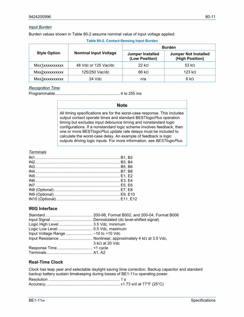
9424200996 80-11
BE1-11m Specifications
Input Burden
Burden values shown in Table 80-2 assume nominal value of input voltage applied. Table 80-2. Contact-Sensing Input Burden
Style Option Nominal Input Voltage Burden
Jumper Installed (Low Position)
Jumper Not Installed (High Position)
Mxx1xxxxxxxxxx 48 Vdc or 125 Vac/dc 22 kΩ 53 kΩ
Mxx2xxxxxxxxxx 125/250 Vac/dc 66 kΩ 123 kΩ
Mxx3xxxxxxxxxx 24 Vdc n/a 6 kΩ
Recognition Time Programmable ........................................................... 4 to 255 ms
Note All timing specifications are for the worst-case response. This includes output contact operate times and standard BESTlogicPlus operation timing but excludes input debounce timing and nonstandard logic configurations. If a nonstandard logic scheme involves feedback, then one or more BESTlogicPlus update rate delays must be included to calculate the worst-case delay. An example of feedback is logic outputs driving logic inputs. For more information, see BESTlogicPlus.
Terminals IN1 ............................................................................. B1, B2 IN2 ............................................................................. B3, B4 IN3 ............................................................................. B5, B6 IN4 ............................................................................. B7, B8 IN5 ............................................................................. E1, E2 IN6 ............................................................................. E3, E4 IN7 ............................................................................. E5, E6 IN8 (Optional) ............................................................ E7, E8 IN9 (Optional) ............................................................ E9, E10 IN10 (Optional) .......................................................... E11, E12
IRIG Interface Standard ........................................... 200-98, Format B002, and 200-04, Format B006 Input Signal ...................................... Demodulated (dc level-shifted signal) Logic High Level ............................... 3.5 Vdc, minimum Logic Low Level ............................... 0.5 Vdc, maximum Input Voltage Range ........................ –10 to +10 Vdc Input Resistance .............................. Nonlinear, approximately 4 kΩ at 3.5 Vdc,
3 kΩ at 20 Vdc Response Time ................................ <1 cycle Terminals.......................................... A1, A2
Real-Time Clock Clock has leap year and selectable daylight saving time correction. Backup capacitor and standard backup battery sustain timekeeping during losses of BE1-11m operating power. Resolution ................................................................. 1 s Accuracy.................................................................... ±1.73 s/d at 77°F (25°C)
80-12 9424200996
Specifications BE1-11m
Clock Holdup Capacitor Holdup Time ............................................. Up to 24 hours depending on conditions Battery Holdup Time ................................................. Greater than 5 years depending on conditions Battery Type .............................................................. BR2032 or CR2032, coin-type, 3 Vdc, 195 mAh Basler Electric P/N 38526
Caution
Replacement of the backup battery for the real-time clock should be performed only by qualified personnel. Observe polarity markings on the battery socket while inserting a new battery. The battery polarity must be correct in order to provide backup for the real-time clock.
Note Failure to replace the battery with Basler Electric P/N 38526 may void the warranty.
Communication Ports Communication ports consist of USB, serial, and Ethernet connections.
USB
A front-panel B-type USB connector provides local communication with a PC operating BESTCOMSPlus® software. Compatible with USB 2.0 specification. Data Transfer Speed ................................................. 12 MB/s (Full Speed)
RS-485
Rear-panel RS-485 port (compression terminals) that supports Modbus and DNP3. Port Speed (Baud) .................................................... Up to 115,200
Terminals A ................................................................................ A3 B ................................................................................ A4 C ................................................................................ A5
Ethernet (Optional)
Either an RJ45 or a fiber optic Ethernet port is available. See style chart. These connectors provide dynamic addressing (DHCP), web pages (HTTP), e-mail alerts (SMTP), network time protocol (NTP) to synchronize the real-time clock, as well as communication with BESTCOMSPlus software. Modbus, DNP3, and IEC 61850 communication through Ethernet is optional.
Copper Type (RJ45 Connector) Version ...................................................................... 10BASE-T/100BASE-TX Maximum Length (One Network Segment) ............... 328 ft (100 m)
Fiber Optic Type (ST Connector) Version ...................................................................... 100BASE-FX, multimode Maximum Length (Half-Duplex) ................................ 1,310 ft (399 m) Maximum Length (Full-Duplex) ................................. 6,600 ft (2,011 m)
9424200996 80-13
BE1-11m Specifications
Panel Display 64 by 128 dot pixels LCD with LED backlight. Operating Temperature ............................................. –40 to 158°F (–40 to 70°C). Display contrast adjustment may be impaired below −4°F (−20°C).
Temperature Operating Temperature Range ................................. –40 to 158°F (–40 to 70°C)* Storage Temperature Range .................................... –40 to 158°F (–40 to 70°C) * Display is inoperative below −4°F (−20°C)
Isolation Meets IEC 255-5 and exceeds IEEE C37.90 one minute dielectric test as follows: All Circuits to Ground* .............................................. 2,000 Vac or 2,828 Vdc Input Circuits to Output Circuits ................................ 2,000 Vac or 2,828 Vdc Communication Ports to Ground ............................... 700 Vdc for one minute * Excludes communication ports.
Standards IEC Standards:
• IEC 60068-1 – Environmental Testing Part 1: General and Guidance. Temperature Test • IEC 60068-2-1 – Basic Environmental Testing Procedures, Part 2: Tests - Test Ad: Cold (Type
Test) • IEC 60068-2-2 – Basic Environmental Testing Procedures, Part 2: Tests - Test Bd: Dry Heat
(Type Test) • IEC 60068-2-28 – Environmental Testing Part 2: Testing-Guidance for Damp Heat Tests • IEC 60255-4 – Single Input Energizing Quantity Measuring Relays with Dependent Specified
Time • IEC 60255-5 – Electrical Insulation Tests for Electrical Relays. Dielectric Test and Impulse Test • IEC 60255-6 – Electrical Relays - Measuring Relays and Protection Equipment • IEC 60255-21-1 – Vibration, Shock, Bump, and Seismic Tests on Measuring Relays and
Protective Equipment (Section 1 - Vibration Test - Sinusoidal). Class 1 • IEC 60255-21-2 – Vibration, Shock, Bump, and Seismic Tests on Measuring Relays and
Protective Equipment (Section 2 - Shock and Bump Test - Sinusoidal). Class 1
IEEE Standards: • IEEE Std C37.90.1-2002 – IEEE Standard Surge Withstand Capability (SWC) Tests for Relays
and Relay Systems Associated with Electric Power Apparatus • IEEE Std C37.90.2-2004 – IEEE Standard Withstand Capability of Relay Systems to Radiated
Electromagnetic Interference from Transceivers • IEEE Std C37.90.3-2001 – IEEE Standard Electrostatic Discharge Test for Protective Relays
CE and UKCA Compliance This product has been evaluated and complies with the relevant essential requirements set forth by the EU legislation and UK Parliament.
EC Directives: • LVD 2014/35/EU • EMC 2014/30/EU • RoHS 2 2011/65/EU

80-14 9424200996
Specifications BE1-11m
Harmonized standards used for evaluation: • EN 50178 – Electronic Equipment for use in Power Installations • EN 61000-6-2 – Electromagnetic Compatibility (EMC), Generic Standards, Immunity for Industrial
Environments • EN 61000-6-4 – Electromagnetic Compatibility (EMC), Generic Standards, Emission Standard for
Industrial Environments
UL Recognition This product is recognized to applicable U.S. and Canadian safety standards and requirements by UL.
Standard used for evaluation: • UL 508
UL Recognition for Style xxxxxxxxxxxCxx
This product is recognized to applicable U.S. and Canadian safety standards and requirements by UL. Evaluation to Class 1, Div 2, Groups A, B, C, and D, Temperature Code T4 for Hazardous Location Service. Suitable for use in Class 1, Division 2, Groups A, B, C, and D hazardous locations only.
Standards used for evaluation: • UL 508 • ISA 12.12.01 • CSA C22.2 No. 213-M1987
Warning! - EXPLOSION HAZARD
Do not disconnect equipment unless power has been switched off or the area is known to be non-hazardous.
Substitution of components may impair suitability for Class 1, Division 2.
Do not engage USB unless power has been switched off or the area is known to be non-hazardous.
CSA Certification This product was tested and has met the certification requirements for industrial control equipment.
Standards used for evaluation: • CSA C22.2 No. 14
HALT (Highly Accelerated Life Testing) Basler Electric uses HALT to prove that our products will provide the user with many years of reliable service. HALT subjects the device to extremes in temperature, shock, and vibration to simulate years of operation, but in a much shorter period span. HALT allows Basler Electric to evaluate all possible design elements that will add to the life of this device. As an example of some of the extreme testing conditions, the BE1-11m was subjected to temperature extremes of –80°C to +130°C, vibration extremes of 5 to 45 G at +20°C, and temperature/vibration extremes of 45 G over a temperature range of –60°C to +110°C. Combined temperature and vibration testing at these extremes proves that the BE1-11m is expected to provide long-term operation in a rugged environment. Note that the vibration and temperature extremes listed in this paragraph are specific to HALT and do not reflect recommended operation levels. These operational ratings are listed under Temperature.
DNP Certification DNP3-2009, V2.6 compliant, Subset Level 2, by Advanced Control Systems, Inc.

9424200996 80-15
BE1-11m Specifications
IEC 61850 Certification KEMA certified per IEC 61850 Certificate Level A.
Physical Weight ....................................................................... 5.1 lb (2.3 kg) IP Class ..................................................................... IP50 Case Size .................................................................. Refer to the Mounting chapter.

80-16 9424200996
Specifications BE1-11m
9424200996 81-1
BE1-11m Specifications - 25 Hz Operation
81 • Specifications - 25 Hz Operation BE1-11m protection systems used in 25 Hz systems have the following features and capabilities.
Operational Specifications
Metered Current Values and Accuracy 5 Aac Nominal Range .............................................. 0.5 to 15 Aac 1 Aac Nominal Range ............................................... 0.1 to 3.0 Aac SEF Range ................................................................ 0.01 to 3.0 Aac Phase Current Accuracy ........................................... ±1.5% of reading at nominal current ±2.5% of reading or ±0.15% of full range, whichever is greater at 77°F (25°C) I1, I2, I0* Accuracy .................................................... ±2% of reading at nominal current ±3% of reading or ±0.5% of full range, whichever is greater at 77°F (25°C) Temperature Dependence ........................................ ≤ ±0.02% per °C * 3I0 displayed
Metered Voltage Values and Accuracy 3-wire Range ............................................................. 50 to 250 Vac 4-wire Range ............................................................. 50 to 250 Vac Auxiliary Range ......................................................... 25 to 125 Vac Phase/Auxiliary Accuracy .......................................... ±1% of reading or ±0.2% of full range whichever is greater at 77°F (25°C) V1, V2, V0* Accuracy ............................................... ±1.5% of reading or ±0.3% of full range whichever is greater at 77°F (25°C) Temperature Dependence ........................................ ≤ ±0.02% per °C * 3V0 displayed
Metered Frequency Values and Accuracy Range ........................................................................ 10 to 125 Hz Accuracy.................................................................... ±0.01 Hz, ±1 least significant digit at 77°F (25°C) nominal 3-wire Sensing Input ................................................. Phase A – B 4-wire Sensing Input ................................................. Phase A – Neutral Minimum Frequency Tracking Voltage ..................... 10 V rms
Calculated Values and Accuracy
Demand Range ........................................................................ 0.1 to 1.5 nominal Type .......................................................................... Exponential Accuracy.................................................................... ±2% of reading ±1 digit at 77°F (25°C) Temperature Dependence ........................................ ≤ ±0.02% per °C Interval ....................................................................... 1 to 60 min
True Power 5 Ampere CT Range ................................................. –4,500 W to +4,500 W 1 Ampere CT Range ................................................. –900 W to +900 W Accuracy.................................................................... ±3% at unity power factor
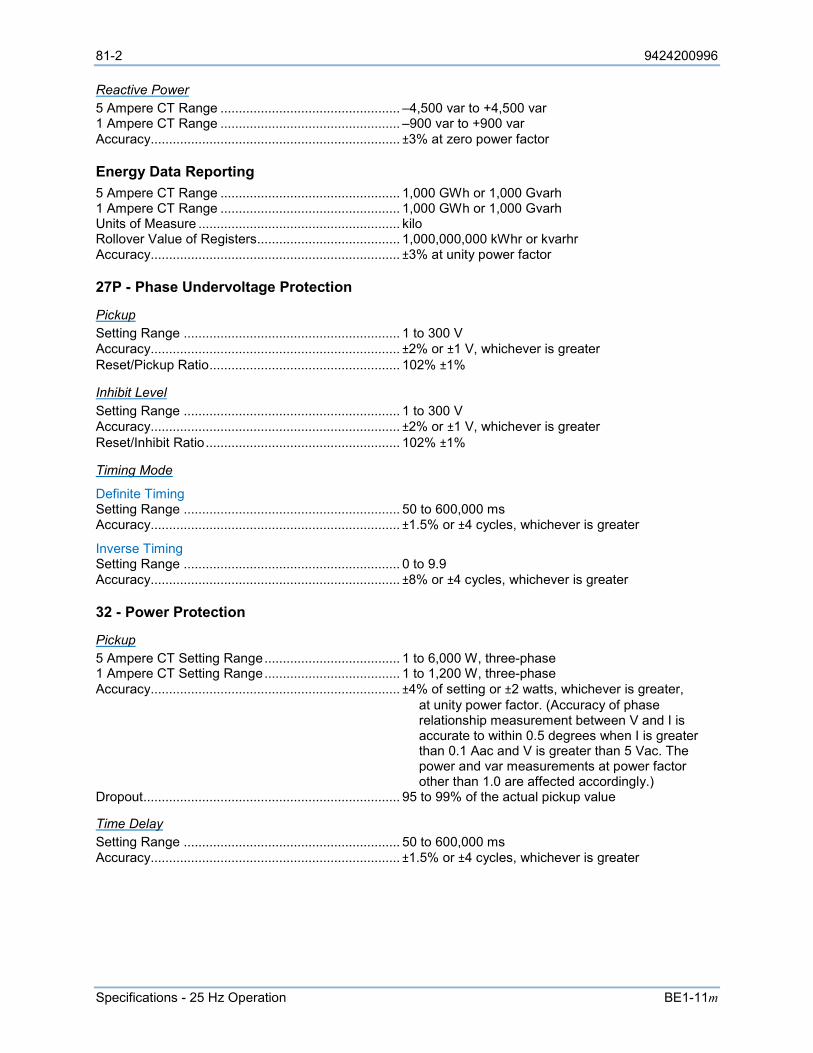
81-2 9424200996
Specifications - 25 Hz Operation BE1-11m
Reactive Power 5 Ampere CT Range ................................................. –4,500 var to +4,500 var 1 Ampere CT Range ................................................. –900 var to +900 var Accuracy.................................................................... ±3% at zero power factor
Energy Data Reporting 5 Ampere CT Range ................................................. 1,000 GWh or 1,000 Gvarh 1 Ampere CT Range ................................................. 1,000 GWh or 1,000 Gvarh Units of Measure ....................................................... kilo Rollover Value of Registers....................................... 1,000,000,000 kWhr or kvarhr Accuracy.................................................................... ±3% at unity power factor
27P - Phase Undervoltage Protection
Pickup Setting Range ........................................................... 1 to 300 V Accuracy.................................................................... ±2% or ±1 V, whichever is greater Reset/Pickup Ratio .................................................... 102% ±1%
Inhibit Level Setting Range ........................................................... 1 to 300 V Accuracy.................................................................... ±2% or ±1 V, whichever is greater Reset/Inhibit Ratio ..................................................... 102% ±1%
Timing Mode
Definite Timing Setting Range ........................................................... 50 to 600,000 ms Accuracy.................................................................... ±1.5% or ±4 cycles, whichever is greater
Inverse Timing Setting Range ........................................................... 0 to 9.9 Accuracy.................................................................... ±8% or ±4 cycles, whichever is greater
32 - Power Protection
Pickup 5 Ampere CT Setting Range ..................................... 1 to 6,000 W, three-phase 1 Ampere CT Setting Range ..................................... 1 to 1,200 W, three-phase Accuracy.................................................................... ±4% of setting or ±2 watts, whichever is greater,
at unity power factor. (Accuracy of phase relationship measurement between V and I is accurate to within 0.5 degrees when I is greater than 0.1 Aac and V is greater than 5 Vac. The power and var measurements at power factor other than 1.0 are affected accordingly.)
Dropout ...................................................................... 95 to 99% of the actual pickup value
Time Delay Setting Range ........................................................... 50 to 600,000 ms Accuracy.................................................................... ±1.5% or ±4 cycles, whichever is greater
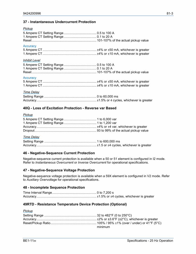
9424200996 81-3
BE1-11m Specifications - 25 Hz Operation
37 - Instantaneous Undercurrent Protection
Pickup 5 Ampere CT Setting Range ..................................... 0.5 to 100 A 1 Ampere CT Setting Range ..................................... 0.1 to 20 A Reset ......................................................................... 101-107% of the actual pickup value
Accuracy 5 Ampere CT ............................................................. ±4% or ±50 mA, whichever is greater 1 Ampere CT ............................................................. ±4% or ±10 mA, whichever is greater
Inhibit Level 5 Ampere CT Setting Range ..................................... 0.5 to 100 A 1 Ampere CT Setting Range ..................................... 0.1 to 20 A Reset ......................................................................... 101-107% of the actual pickup value
Accuracy 5 Ampere CT ............................................................. ±4% or ±50 mA, whichever is greater 1 Ampere CT ............................................................. ±4% or ±10 mA, whichever is greater
Time Delay Setting Range ........................................................... 0 to 60,000 ms Accuracy.................................................................... ±1.5% or 4 cycles, whichever is greater
40Q - Loss of Excitation Protection - Reverse var Based
Pickup 5 Ampere CT Setting Range ..................................... 1 to 6,000 var 1 Ampere CT Setting Range ..................................... 1 to 1,200 var Accuracy.................................................................... ±4% or ±4 var, whichever is greater Dropout ...................................................................... 93 to 99% of the actual pickup value
Time Delay Setting Range ........................................................... 1 to 600,000 ms Accuracy.................................................................... ±1.5 or ±4 cycles, whichever is greater
46 - Negative-Sequence Current Protection Negative-sequence current protection is available when a 50 or 51 element is configured in I2 mode. Refer to Instantaneous Overcurrent or Inverse Overcurrent for operational specifications.
47 - Negative-Sequence Voltage Protection Negative-sequence voltage protection is available when a 59X element is configured in V2 mode. Refer to Auxiliary Overvoltage for operational specifications.
48 - Incomplete Sequence Protection Time Interval Range .................................................. 0 to 7,200 s Accuracy.................................................................... ±1.5% or ±4 cycles, whichever is greater
49RTD - Resistance Temperature Device Protection (Optional)
Pickup Setting Range ........................................................... 32 to 482°F (0 to 250°C) Accuracy.................................................................... ±2% or ±3.6°F (±2°C), whichever is greater Reset/Pickup Ratio .................................................... 105% / 95% ±1% (over / under) or 41°F (5°C) minimum
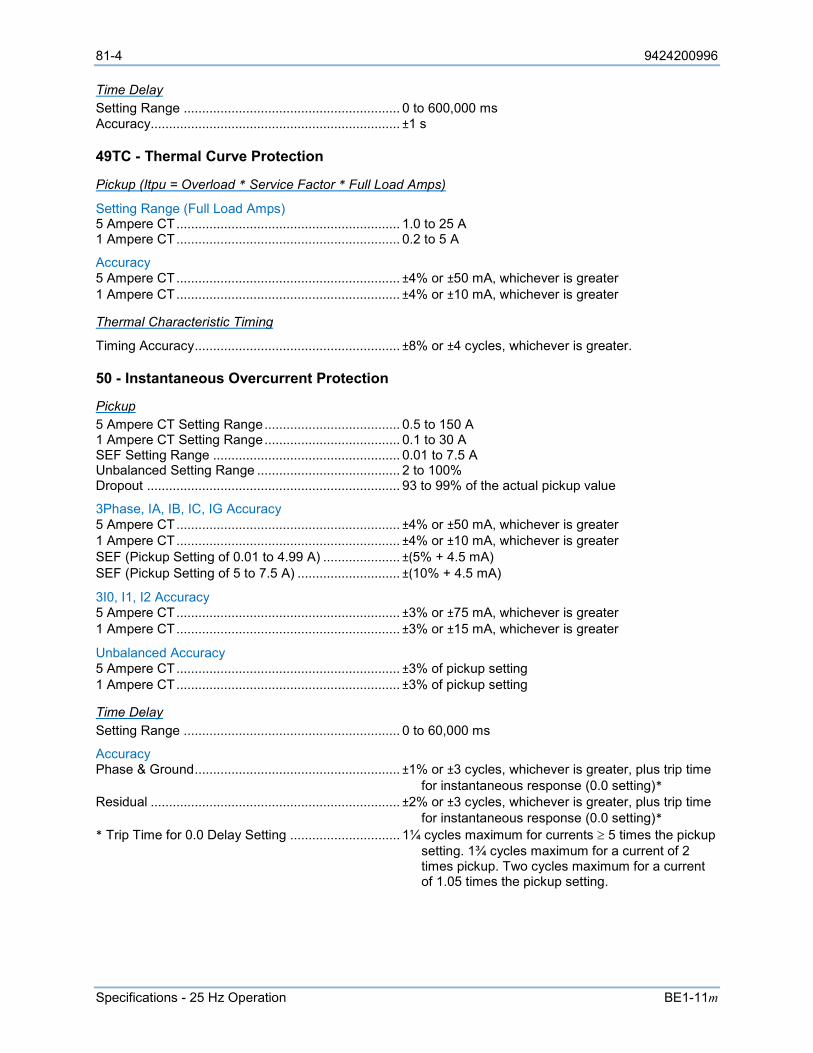
81-4 9424200996
Specifications - 25 Hz Operation BE1-11m
Time Delay Setting Range ........................................................... 0 to 600,000 ms Accuracy.................................................................... ±1 s
49TC - Thermal Curve Protection
Pickup (Itpu = Overload * Service Factor * Full Load Amps)
Setting Range (Full Load Amps) 5 Ampere CT ............................................................. 1.0 to 25 A 1 Ampere CT ............................................................. 0.2 to 5 A
Accuracy 5 Ampere CT ............................................................. ±4% or ±50 mA, whichever is greater 1 Ampere CT ............................................................. ±4% or ±10 mA, whichever is greater
Thermal Characteristic Timing
Timing Accuracy ........................................................ ±8% or ±4 cycles, whichever is greater.
50 - Instantaneous Overcurrent Protection
Pickup 5 Ampere CT Setting Range ..................................... 0.5 to 150 A 1 Ampere CT Setting Range ..................................... 0.1 to 30 A SEF Setting Range ................................................... 0.01 to 7.5 A Unbalanced Setting Range ....................................... 2 to 100% Dropout ..................................................................... 93 to 99% of the actual pickup value
3Phase, IA, IB, IC, IG Accuracy 5 Ampere CT ............................................................. ±4% or ±50 mA, whichever is greater 1 Ampere CT ............................................................. ±4% or ±10 mA, whichever is greater SEF (Pickup Setting of 0.01 to 4.99 A) ..................... ±(5% + 4.5 mA) SEF (Pickup Setting of 5 to 7.5 A) ............................ ±(10% + 4.5 mA)
3I0, I1, I2 Accuracy 5 Ampere CT ............................................................. ±3% or ±75 mA, whichever is greater 1 Ampere CT ............................................................. ±3% or ±15 mA, whichever is greater
Unbalanced Accuracy 5 Ampere CT ............................................................. ±3% of pickup setting 1 Ampere CT ............................................................. ±3% of pickup setting
Time Delay Setting Range ........................................................... 0 to 60,000 ms
Accuracy Phase & Ground ........................................................ ±1% or ±3 cycles, whichever is greater, plus trip time
for instantaneous response (0.0 setting)* Residual .................................................................... ±2% or ±3 cycles, whichever is greater, plus trip time
for instantaneous response (0.0 setting)* * Trip Time for 0.0 Delay Setting .............................. 1¼ cycles maximum for currents ≥ 5 times the pickup
setting. 1¾ cycles maximum for a current of 2 times pickup. Two cycles maximum for a current of 1.05 times the pickup setting.
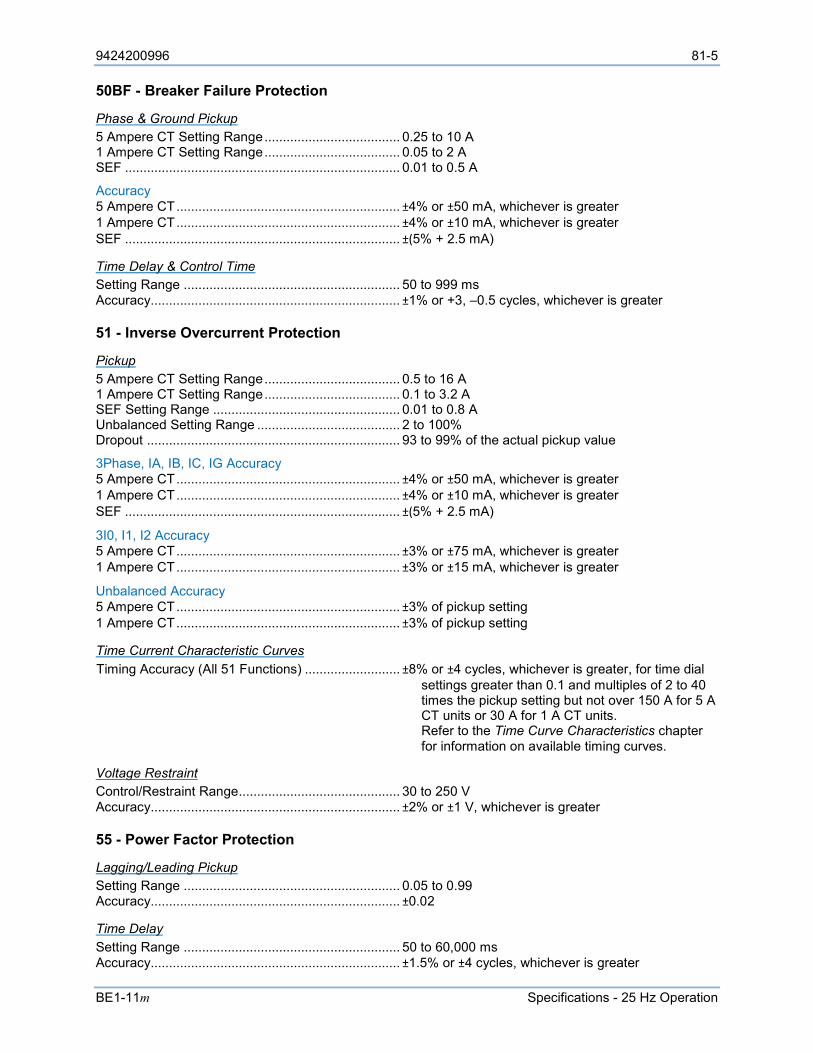
9424200996 81-5
BE1-11m Specifications - 25 Hz Operation
50BF - Breaker Failure Protection
Phase & Ground Pickup 5 Ampere CT Setting Range ..................................... 0.25 to 10 A 1 Ampere CT Setting Range ..................................... 0.05 to 2 A SEF ........................................................................... 0.01 to 0.5 A
Accuracy 5 Ampere CT ............................................................. ±4% or ±50 mA, whichever is greater 1 Ampere CT ............................................................. ±4% or ±10 mA, whichever is greater SEF ........................................................................... ±(5% + 2.5 mA)
Time Delay & Control Time Setting Range ........................................................... 50 to 999 ms Accuracy.................................................................... ±1% or +3, –0.5 cycles, whichever is greater
51 - Inverse Overcurrent Protection
Pickup 5 Ampere CT Setting Range ..................................... 0.5 to 16 A 1 Ampere CT Setting Range ..................................... 0.1 to 3.2 A SEF Setting Range ................................................... 0.01 to 0.8 A Unbalanced Setting Range ....................................... 2 to 100% Dropout ..................................................................... 93 to 99% of the actual pickup value
3Phase, IA, IB, IC, IG Accuracy 5 Ampere CT ............................................................. ±4% or ±50 mA, whichever is greater 1 Ampere CT ............................................................. ±4% or ±10 mA, whichever is greater SEF ........................................................................... ±(5% + 2.5 mA)
3I0, I1, I2 Accuracy 5 Ampere CT ............................................................. ±3% or ±75 mA, whichever is greater 1 Ampere CT ............................................................. ±3% or ±15 mA, whichever is greater
Unbalanced Accuracy 5 Ampere CT ............................................................. ±3% of pickup setting 1 Ampere CT ............................................................. ±3% of pickup setting
Time Current Characteristic Curves Timing Accuracy (All 51 Functions) .......................... ±8% or ±4 cycles, whichever is greater, for time dial
settings greater than 0.1 and multiples of 2 to 40 times the pickup setting but not over 150 A for 5 A CT units or 30 A for 1 A CT units. Refer to the Time Curve Characteristics chapter for information on available timing curves.
Voltage Restraint Control/Restraint Range ............................................ 30 to 250 V Accuracy.................................................................... ±2% or ±1 V, whichever is greater
55 - Power Factor Protection
Lagging/Leading Pickup Setting Range ........................................................... 0.05 to 0.99 Accuracy.................................................................... ±0.02
Time Delay Setting Range ........................................................... 50 to 60,000 ms Accuracy.................................................................... ±1.5% or ±4 cycles, whichever is greater
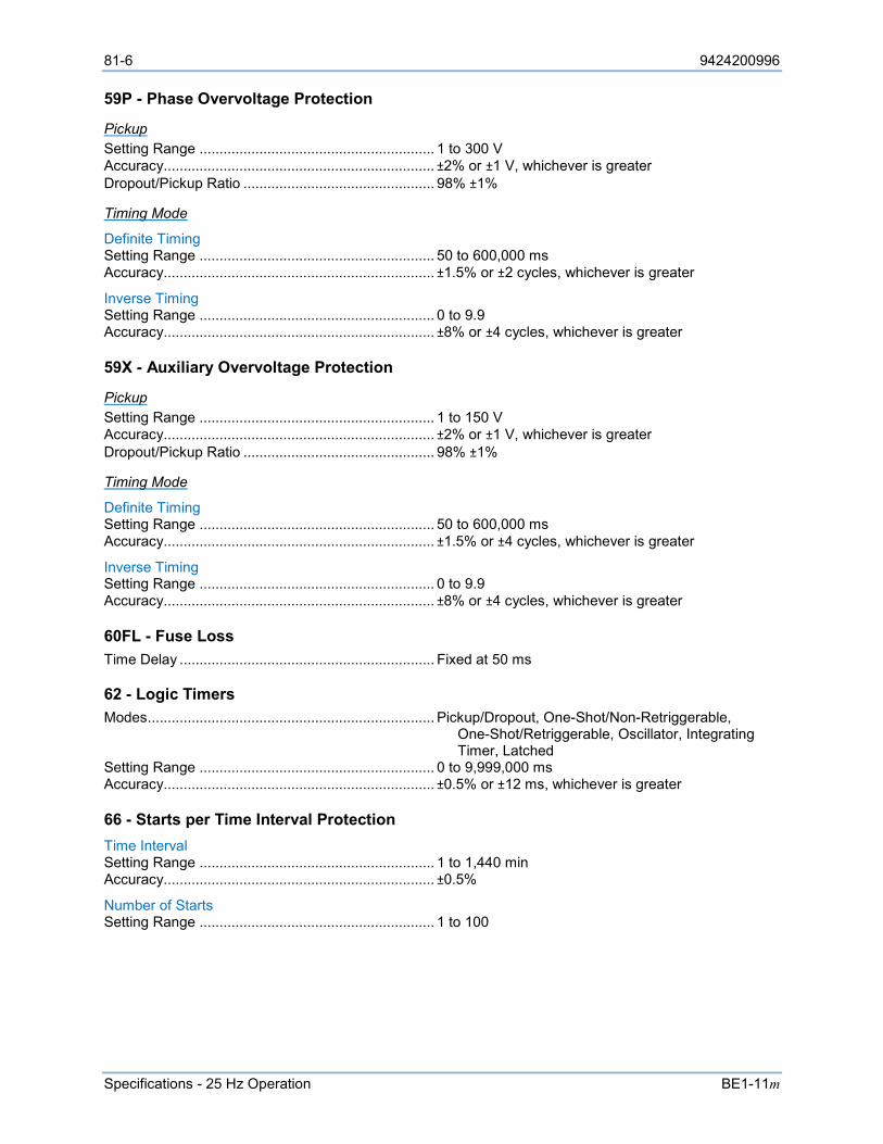
81-6 9424200996
Specifications - 25 Hz Operation BE1-11m
59P - Phase Overvoltage Protection
Pickup Setting Range ........................................................... 1 to 300 V Accuracy.................................................................... ±2% or ±1 V, whichever is greater Dropout/Pickup Ratio ................................................ 98% ±1%
Timing Mode
Definite Timing Setting Range ........................................................... 50 to 600,000 ms Accuracy.................................................................... ±1.5% or ±2 cycles, whichever is greater
Inverse Timing Setting Range ........................................................... 0 to 9.9 Accuracy.................................................................... ±8% or ±4 cycles, whichever is greater
59X - Auxiliary Overvoltage Protection
Pickup Setting Range ........................................................... 1 to 150 V Accuracy.................................................................... ±2% or ±1 V, whichever is greater Dropout/Pickup Ratio ................................................ 98% ±1%
Timing Mode
Definite Timing Setting Range ........................................................... 50 to 600,000 ms Accuracy.................................................................... ±1.5% or ±4 cycles, whichever is greater
Inverse Timing Setting Range ........................................................... 0 to 9.9 Accuracy.................................................................... ±8% or ±4 cycles, whichever is greater
60FL - Fuse Loss Time Delay ................................................................ Fixed at 50 ms
62 - Logic Timers Modes ........................................................................ Pickup/Dropout, One-Shot/Non-Retriggerable,
One-Shot/Retriggerable, Oscillator, Integrating Timer, Latched
Setting Range ........................................................... 0 to 9,999,000 ms Accuracy.................................................................... ±0.5% or ±12 ms, whichever is greater
66 - Starts per Time Interval Protection Time Interval Setting Range ........................................................... 1 to 1,440 min Accuracy.................................................................... ±0.5%
Number of Starts Setting Range ........................................................... 1 to 100

9424200996 81-7
BE1-11m Specifications - 25 Hz Operation
81 - Frequency Protection
O/U
Pickup Setting Range ........................................................... 15 to 110 Hz Accuracy.................................................................... ±0.01 Hz Dropout ...................................................................... 0.02 Hz ±0.01 Hz of the actual pickup value
Time Delay Setting Range ........................................................... 0 to 600,000 ms Accuracy.................................................................... ±1% or ±2 cycles, whichever is greater, plus 3 cycle recognition time for time delays < 50 ms
ROC
Pickup Setting Range ........................................................... 0.2 to 20 Hz/sec (positive, negative, or either) Accuracy.................................................................... ±2% or ±0.1 Hz/sec of the setting, whichever is greater Dropout ...................................................................... ±3% of the actual pickup value
Over/Underfrequency Inhibit Setting Range ........................................................... 15 to 110 Hz Increment .................................................................. 0.01 Hz Accuracy.................................................................... ±0.01 Hz
Negative-Sequence Inhibit Setting Range ........................................................... 0 to 99% of nominal voltage Accuracy.................................................................... ±0.5% or ±1 V, whichever is greater
Time Delay Setting Range ........................................................... 0 to 600,000 ms Accuracy.................................................................... ±0.5% or ±1 cycle, whichever is greater, plus recognition time* * Recognition time = 2 cycles for 0.57 > pickup, 4 cycles for 0.24 > pickup, 8 cycles for 0.08 > pickup, 16 cycles at pickup
O/U/ROC Voltage Inhibit Setting Range ........................................................... 15 to 250 V Accuracy.................................................................... ±2% or ±1 V, whichever is greater
87 - Phase Current Differential Protection
Restrained Differential 5 Ampere CT Pickup Accuracy ................................. ±5% or ±75 mA, whichever is greater 1 Ampere CT Pickup Accuracy ................................. ±5% or ±25 mA, whichever is greater Response Time ......................................................... <2 cycles at 5 times pickup <3 cycles at 1.5 times pickup
TAP 5 Ampere CT Setting Range ..................................... 2.00 to 20.0 A 1 Ampere CT Setting Range ..................................... 0.40 to 4.00 A
Minimum Restraint Pickup (Iop) Setting Range ........................................................... 0.1 to 1.00 per unit
2nd Slope Pickup (Ires) Setting Range ........................................................... 0.1 to 20.0 per unit
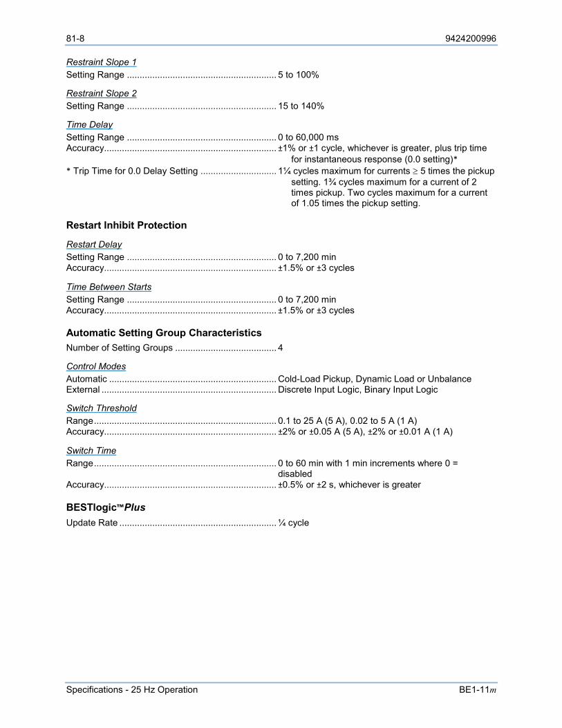
81-8 9424200996
Specifications - 25 Hz Operation BE1-11m
Restraint Slope 1 Setting Range ........................................................... 5 to 100%
Restraint Slope 2 Setting Range ........................................................... 15 to 140%
Time Delay Setting Range ........................................................... 0 to 60,000 ms Accuracy.................................................................... ±1% or ±1 cycle, whichever is greater, plus trip time
for instantaneous response (0.0 setting)* * Trip Time for 0.0 Delay Setting .............................. 1¼ cycles maximum for currents ≥ 5 times the pickup
setting. 1¾ cycles maximum for a current of 2 times pickup. Two cycles maximum for a current of 1.05 times the pickup setting.
Restart Inhibit Protection
Restart Delay Setting Range ........................................................... 0 to 7,200 min Accuracy.................................................................... ±1.5% or ±3 cycles
Time Between Starts Setting Range ........................................................... 0 to 7,200 min Accuracy.................................................................... ±1.5% or ±3 cycles
Automatic Setting Group Characteristics Number of Setting Groups ........................................ 4
Control Modes Automatic .................................................................. Cold-Load Pickup, Dynamic Load or Unbalance External ..................................................................... Discrete Input Logic, Binary Input Logic
Switch Threshold Range ........................................................................ 0.1 to 25 A (5 A), 0.02 to 5 A (1 A) Accuracy.................................................................... ±2% or ±0.05 A (5 A), ±2% or ±0.01 A (1 A)
Switch Time Range ........................................................................ 0 to 60 min with 1 min increments where 0 = disabled Accuracy.................................................................... ±0.5% or ±2 s, whichever is greater
BESTlogic™Plus Update Rate .............................................................. ¼ cycle
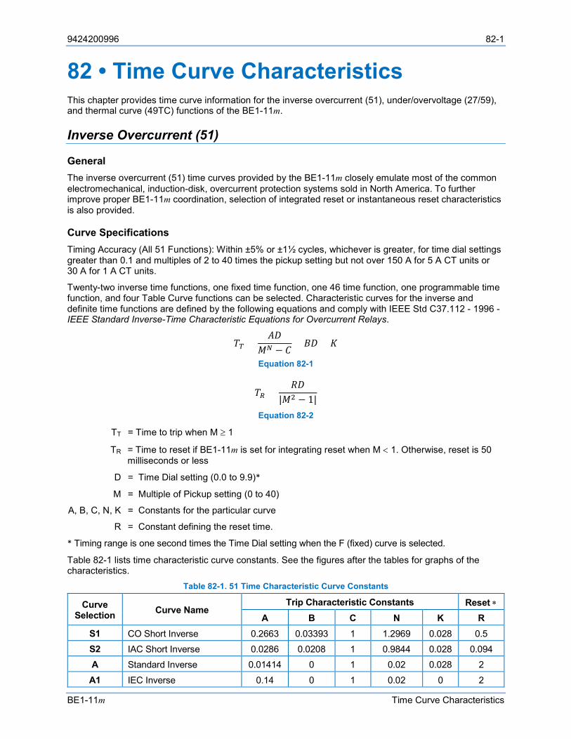
9424200996 82-1
BE1-11m Time Curve Characteristics
82 • Time Curve Characteristics This chapter provides time curve information for the inverse overcurrent (51), under/overvoltage (27/59), and thermal curve (49TC) functions of the BE1-11m.
Inverse Overcurrent (51)
General The inverse overcurrent (51) time curves provided by the BE1-11m closely emulate most of the common electromechanical, induction-disk, overcurrent protection systems sold in North America. To further improve proper BE1-11m coordination, selection of integrated reset or instantaneous reset characteristics is also provided.
Curve Specifications Timing Accuracy (All 51 Functions): Within ±5% or ±1½ cycles, whichever is greater, for time dial settings greater than 0.1 and multiples of 2 to 40 times the pickup setting but not over 150 A for 5 A CT units or 30 A for 1 A CT units.
Twenty-two inverse time functions, one fixed time function, one 46 time function, one programmable time function, and four Table Curve functions can be selected. Characteristic curves for the inverse and definite time functions are defined by the following equations and comply with IEEE Std C37.112 - 1996 - IEEE Standard Inverse-Time Characteristic Equations for Overcurrent Relays.
𝑇𝑇𝑇𝑇 =𝐴𝐴𝐴𝐴
𝑀𝑀𝑁𝑁 − 𝐶𝐶+ 𝐵𝐵𝐴𝐴 + 𝐾𝐾
Equation 82-1
𝑇𝑇𝑅𝑅 =𝑅𝑅𝐴𝐴
|𝑀𝑀2 − 1| Equation 82-2
TT = Time to trip when M ≥ 1
TR = Time to reset if BE1-11m is set for integrating reset when M < 1. Otherwise, reset is 50 milliseconds or less
D = Time Dial setting (0.0 to 9.9)*
M = Multiple of Pickup setting (0 to 40)
A, B, C, N, K = Constants for the particular curve
R = Constant defining the reset time.
* Timing range is one second times the Time Dial setting when the F (fixed) curve is selected.
Table 82-1 lists time characteristic curve constants. See the figures after the tables for graphs of the characteristics.
Table 82-1. 51 Time Characteristic Curve Constants
Curve Selection Curve Name
Trip Characteristic Constants Reset ∗ A B C N K R
S1 CO Short Inverse 0.2663 0.03393 1 1.2969 0.028 0.5 S2 IAC Short Inverse 0.0286 0.0208 1 0.9844 0.028 0.094 A Standard Inverse 0.01414 0 1 0.02 0.028 2 A1 IEC Inverse 0.14 0 1 0.02 0 2

82-2 9424200996
Time Curve Characteristics BE1-11m
Curve Selection Curve Name
Trip Characteristic Constants Reset ∗ A B C N K R
I1 CO Inverse Time 8.9341 0.17966 1 2.0938 0.028 9 I2 IAC Inverse Time 0.2747 0.10426 1 0.4375 0.028 0.8868 M CO Moderately Inverse 0.3022 0.1284 1 0.5 0.028 1.75 D1 IEEE Moderately Inverse 0.0515 0.114 1 0.02 0 4.85 L1 CO Long Inverse 5.6143 2.18592 1 1 0.028 15.75 L2 IAC Long Inverse 2.3955 0 1 0.3125 0.028 7.8001
G Long Time Inverse (I2t) 12.1212 0 1 1 0.028 29
V1 CO Very Inverse 5.4678 0.10814 1 2.0469 0.028 5.5 V2 IAC Very Inverse 4.4309 0.0991 1 1.9531 0.028 5.8231
B Very Inverse (I2t) 1.4636 0 1 1.0469 0.028 3.25
B1 IEC Very Inverse 13.5 0 1 1 0 3.25 E3 IEEE Very Inverse 19.61 0.491 1 2 0 21.6 E1 CO Extremely Inverse 7.7624 0.02758 1 2.0938 0.028 7.75 E2 IAC Extremely Inverse 4.9883 0.0129 1 2.0469 0.028 4.7742
C Extremely Inverse (I2t) 8.2506 0 1 2.0469 0.028 8
C1 IEC Extremely Inverse 80 0 1 2 0 8 F1 IEEE Extremely Inverse 28.2 0.1217 1 2 0 29.1 D CO Definite Time 0.4797 0.21359 1 1.5625 0.028 0.875 F Fixed Time ‡ 0 1 0 0 0 1 46 K Factor † 0 0 2 0.028 100 P User Programmable § 0 to 600 0 to 25 0 to 1 0.5 to 2.5 0.028 0 to 30 T1 User Table 1 n/a n/a n/a n/a n/a n/a T2 User Table 2 n/a n/a n/a n/a n/a n/a T3 User Table 3 n/a n/a n/a n/a n/a n/a T4 User Table 4 n/a n/a n/a n/a n/a n/a
∗ Instantaneous or integrating reset is selected on the Inverse Overcurrent setup screen in BESTCOMSPlus®.
† Constant A is variable for the 46 curve and is determined, as necessary, based on system full-load current setting, minimum pickup, and K factor settings.
‡ Curve F has a fixed delay of one second times the Time Dial setting.
§ The programmable curve allows for four significant digits after the decimal place for every variable.
There is a minimum of 2 and maximum of 40 points that can be entered for any one T curve. For information on setting T curves, refer to the Inverse Overcurrent (51) Protection chapter.
Time Overcurrent Characteristic Curve Graphs The figures after the tables illustrate the characteristic curves of the BE1-11m. Table 82-2 cross-references each curve to existing electromechanical relay characteristics. Equivalent time dial settings were calculated at a value of five times pickup.
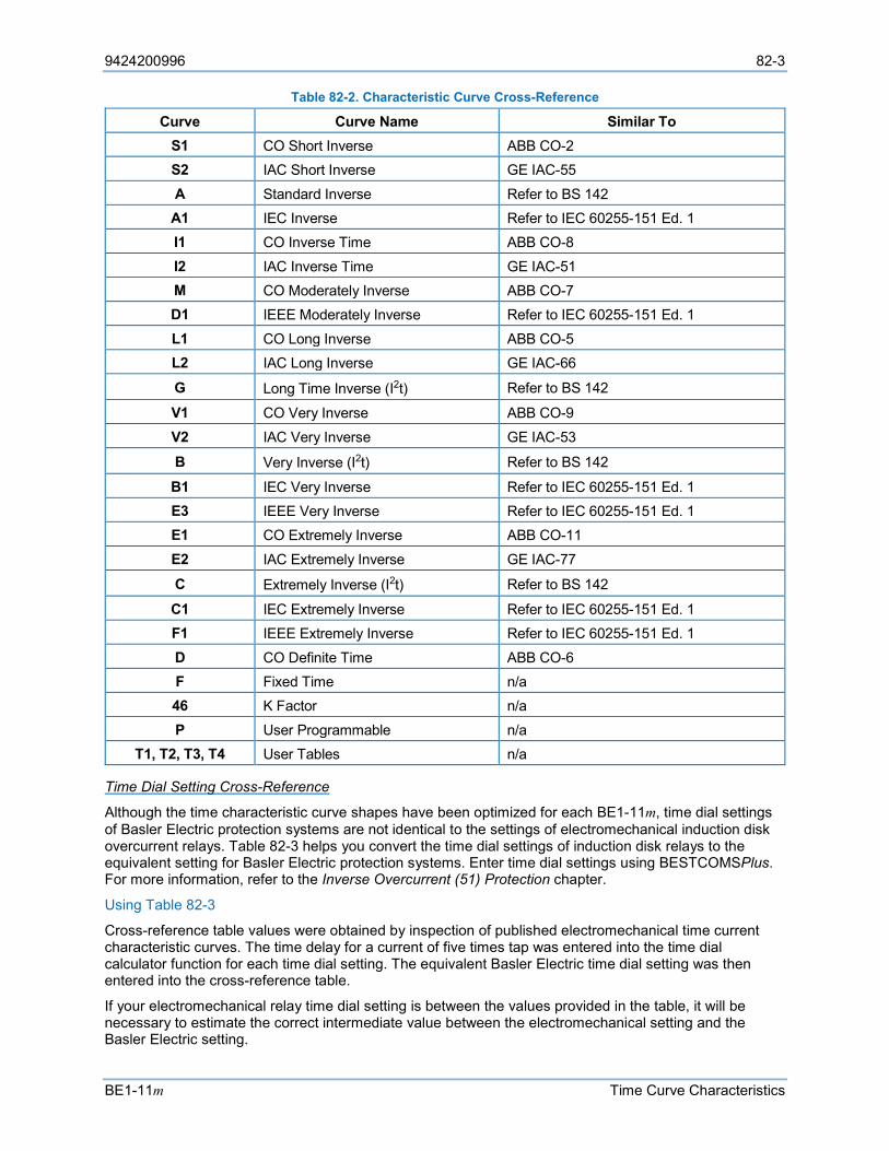
9424200996 82-3
BE1-11m Time Curve Characteristics
Table 82-2. Characteristic Curve Cross-Reference
Curve Curve Name Similar To S1 CO Short Inverse ABB CO-2 S2 IAC Short Inverse GE IAC-55 A Standard Inverse Refer to BS 142 A1 IEC Inverse Refer to IEC 60255-151 Ed. 1 I1 CO Inverse Time ABB CO-8 I2 IAC Inverse Time GE IAC-51 M CO Moderately Inverse ABB CO-7 D1 IEEE Moderately Inverse Refer to IEC 60255-151 Ed. 1 L1 CO Long Inverse ABB CO-5 L2 IAC Long Inverse GE IAC-66
G Long Time Inverse (I2t) Refer to BS 142
V1 CO Very Inverse ABB CO-9 V2 IAC Very Inverse GE IAC-53
B Very Inverse (I2t) Refer to BS 142
B1 IEC Very Inverse Refer to IEC 60255-151 Ed. 1 E3 IEEE Very Inverse Refer to IEC 60255-151 Ed. 1 E1 CO Extremely Inverse ABB CO-11 E2 IAC Extremely Inverse GE IAC-77
C Extremely Inverse (I2t) Refer to BS 142
C1 IEC Extremely Inverse Refer to IEC 60255-151 Ed. 1 F1 IEEE Extremely Inverse Refer to IEC 60255-151 Ed. 1 D CO Definite Time ABB CO-6 F Fixed Time n/a 46 K Factor n/a P User Programmable n/a
T1, T2, T3, T4 User Tables n/a
Time Dial Setting Cross-Reference
Although the time characteristic curve shapes have been optimized for each BE1-11m, time dial settings of Basler Electric protection systems are not identical to the settings of electromechanical induction disk overcurrent relays. Table 82-3 helps you convert the time dial settings of induction disk relays to the equivalent setting for Basler Electric protection systems. Enter time dial settings using BESTCOMSPlus. For more information, refer to the Inverse Overcurrent (51) Protection chapter.
Using Table 82-3
Cross-reference table values were obtained by inspection of published electromechanical time current characteristic curves. The time delay for a current of five times tap was entered into the time dial calculator function for each time dial setting. The equivalent Basler Electric time dial setting was then entered into the cross-reference table.
If your electromechanical relay time dial setting is between the values provided in the table, it will be necessary to estimate the correct intermediate value between the electromechanical setting and the Basler Electric setting.

82-4 9424200996
Time Curve Characteristics BE1-11m
Basler Electric protection systems have a maximum time dial setting of 9.9. The Basler Electric equivalent time dial setting for the electromechanical maximum setting is provided in the cross-reference table even if it exceeds 9.9. This allows interpolation as noted above.
Basler Electric time current characteristics are determined by a linear mathematical equation. The induction disk of an electromechanical relay has a certain degree of non-linearity due to inertial and friction effects. For this reason, even though every effort has been made to provide characteristic curves with minimum deviation from the published electromechanical curves, slight deviations can exist between them.
In applications where the time coordination between curves is extremely close, we recommend that you choose the optimal time dial setting by inspection of the coordination study. In applications where coordination is tight, it is recommended that you retrofit your circuits with Basler Electric electronic protection systems to ensure high timing accuracy.
Table 82-3. Time Dial Setting Cross-Reference
Curve Equivalent To
Electromechanical Relay Time Dial Setting 0.5 1.0 2.0 3.0 4.0 5.0 6.0 7.0 8.0 9.0 10.0 11.0
Basler Electric Equivalent Time Dial Setting S1 ABB CO-2 0.3 0.8 1.7 2.4 3.4 4.2 5.0 5.8 6.7 7.7 8.6 9.7 S2 GE IAC-55 0.2 1.0 2.0 3.1 4.0 4.9 6.1 7.2 8.1 8.9 9.8 n/a I1 ABB CO-8 0.3 0.7 1.5 2.3 3.2 4.0 5.0 5.8 6.8 7.6 8.7 n/a I2 GE IAC-51 0.6 1.0 1.9 2.7 3.7 4.8 5.7 6.8 8.0 9.3 n/a n/a M ABB CO-7 0.4 0.8 1.7 2.5 3.3 4.3 5.3 6.1 7.0 8.0 9.0 9.8 L1 ABB CO-5 0.4 0.8 1.5 2.3 3.3 4.2 5.0 6.0 7.0 7.8 8.8 9.9 L2 GE IAC-66 0.4 0.9 1.8 2.7 3.9 4.9 6.3 7.2 8.5 9.7 n/a n/a V1 ABB CO-9 0.3 0.7 1.4 2.1 3.0 3.9 4.8 5.7 6.7 7.8 8.7 9.6 V2 GE IAC-53 0.4 0.8 1.6 2.4 3.4 4.3 5.1 6.3 7.2 8.4 9.6 n/a E1 ABB CO-11 0.3 0.7 1.5 2.4 3.2 4.2 5.0 5.7 6.6 7.8 8.5 n/a E2 GE IAC-77 0.5 1.0 1.9 2.7 3.5 4.3 5.2 6.2 7.4 8.2 9.9 n/a D ABB CO-6 0.5 1.1 2.0 2.9 3.7 4.5 5.0 5.9 7.2 8.0 8.9 n/a
The 46 Curve The 46 curve (Figure 82-23) is a special curve designed to emulate the (I2)2 t withstand ratings of generators using what is frequently referred to as the generator K factor.
The 46 Curve Characteristics
46 Pickup Current
Generators have a maximum continuous rating for negative sequence current. This is typically expressed as a percent of stator rating. When using the 46 curve, the user should convert the continuous I2 rating data to actual secondary current at the BE1-11m. This value (plus some margin, if appropriate) should be entered as the pickup setting. For example, if a generator’s rated full-load current is 5 amperes, a pu setting of 0.5 A would allow 10% continuous I2.
46 Time Dial (= Generator K factor)
The amount of time that a generator can withstand a given level of unbalance is defined by Equation 82-3.

9424200996 82-5
BE1-11m Time Curve Characteristics
𝑡𝑡 =𝐾𝐾
(𝐼𝐼2)2
Equation 82-3
The K factor gives the time that a generator can withstand 1 per unit negative sequence current. For example, with a K factor of 20, since (I2)2 becomes 1 at 1 per unit of current, the generator can withstand the condition for 20 seconds. Typical values for generator K factors are in the 2 to 40 range. The BE1-11m uses the “nominal current” setting of the BE1-11m to determine what corresponds to 1 per unit current in the generator.
When curve 46 is selected, the BE1-11m changes the range of the allowed time dial to 1 to 99 (instead of the time dial range of 0.1 to 9.9 for all the other curves). The user should enter the “K” factor of the generator into the time dial field.
BE1-11m Equation
When the 46 function is used, the BE1-11m uses the K factor (i.e., 46 time dial setting), 46 minimum pickup setting and generator full-load current to create a constant Z (see Equation 82-4).
𝑍𝑍 = 46 𝑇𝑇𝑇𝑇𝑇𝑇𝑇𝑇 𝐴𝐴𝑇𝑇𝐷𝐷𝐷𝐷 𝐼𝐼𝑁𝑁𝑁𝑁𝑁𝑁 𝑆𝑆𝑆𝑆𝑆𝑆𝑆𝑆𝑆𝑆𝑆𝑆𝑆𝑆
46 𝑃𝑃𝑇𝑇𝑃𝑃𝑃𝑃𝑃𝑃𝑃𝑃 𝑆𝑆𝑇𝑇𝑡𝑡𝑡𝑡𝑇𝑇𝑆𝑆𝑆𝑆2
Equation 82-4
The time to trip equation used in the BE1-11m is:
𝑇𝑇𝑇𝑇 =𝑍𝑍𝑀𝑀2 + 0.028 𝑠𝑠𝑇𝑇𝑃𝑃𝑠𝑠𝑆𝑆𝑠𝑠𝑠𝑠
Equation 82-5
where:
𝑀𝑀 =𝑀𝑀𝑇𝑇𝐷𝐷𝑠𝑠𝑃𝑃𝑀𝑀𝑇𝑇𝑠𝑠 𝐼𝐼2
46 𝑃𝑃𝑇𝑇𝑃𝑃𝑃𝑃𝑃𝑃𝑃𝑃 𝑆𝑆𝑇𝑇𝑡𝑡𝑡𝑡𝑇𝑇𝑆𝑆𝑆𝑆
Equation 82-6
which, when M > 1, reduces to:
𝑇𝑇𝑇𝑇 = 46 𝑇𝑇𝑇𝑇𝑇𝑇𝑇𝑇 𝐴𝐴𝑇𝑇𝐷𝐷𝐷𝐷 𝐼𝐼𝑁𝑁𝑁𝑁𝑁𝑁 𝑆𝑆𝑆𝑆𝑆𝑆𝑆𝑆𝑆𝑆𝑆𝑆𝑆𝑆
𝐼𝐼2𝑀𝑀𝑇𝑇𝐷𝐷𝑠𝑠𝑃𝑃𝑀𝑀𝑇𝑇𝑠𝑠2
Equation 82-7

82-6 9424200996
Time Curve Characteristics BE1-11m
Figure 82-1. Time Characteristic Curve S1, Short Inverse (Similar to ABB CO-2)
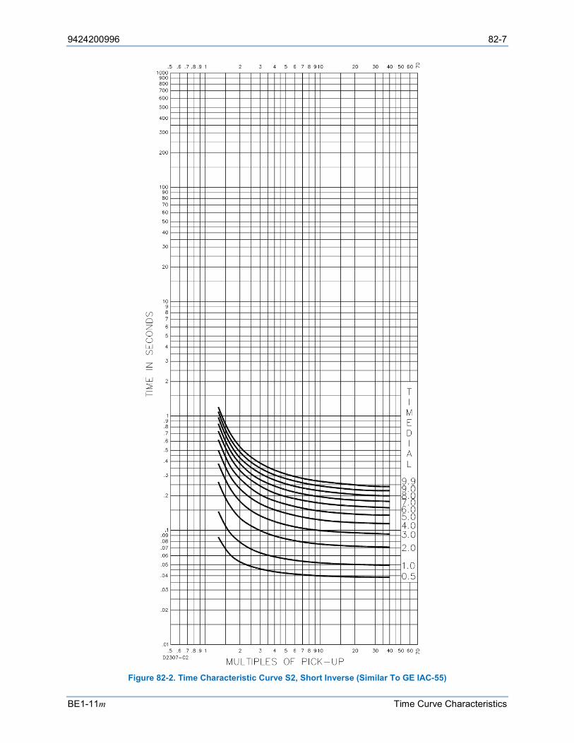
9424200996 82-7
BE1-11m Time Curve Characteristics
Figure 82-2. Time Characteristic Curve S2, Short Inverse (Similar To GE IAC-55)
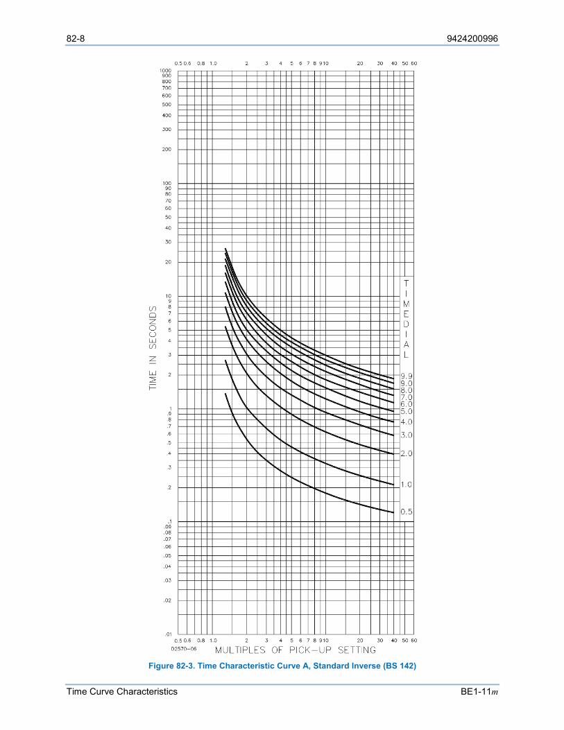
82-8 9424200996
Time Curve Characteristics BE1-11m
Figure 82-3. Time Characteristic Curve A, Standard Inverse (BS 142)
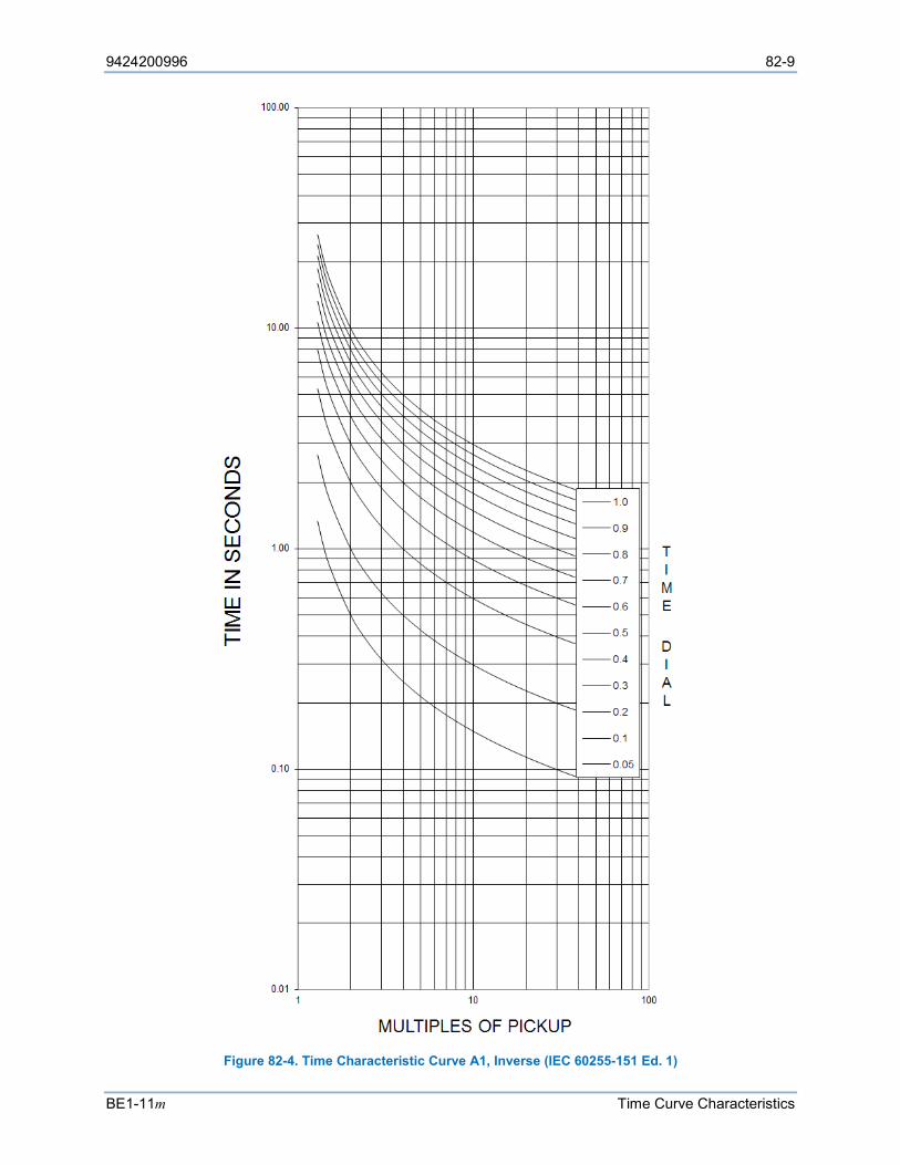
9424200996 82-9
BE1-11m Time Curve Characteristics
Figure 82-4. Time Characteristic Curve A1, Inverse (IEC 60255-151 Ed. 1)
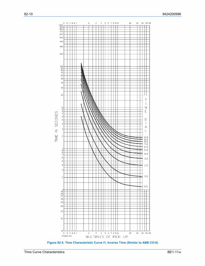
82-10 9424200996
Time Curve Characteristics BE1-11m
Figure 82-5. Time Characteristic Curve I1, Inverse Time (Similar to ABB CO-8)
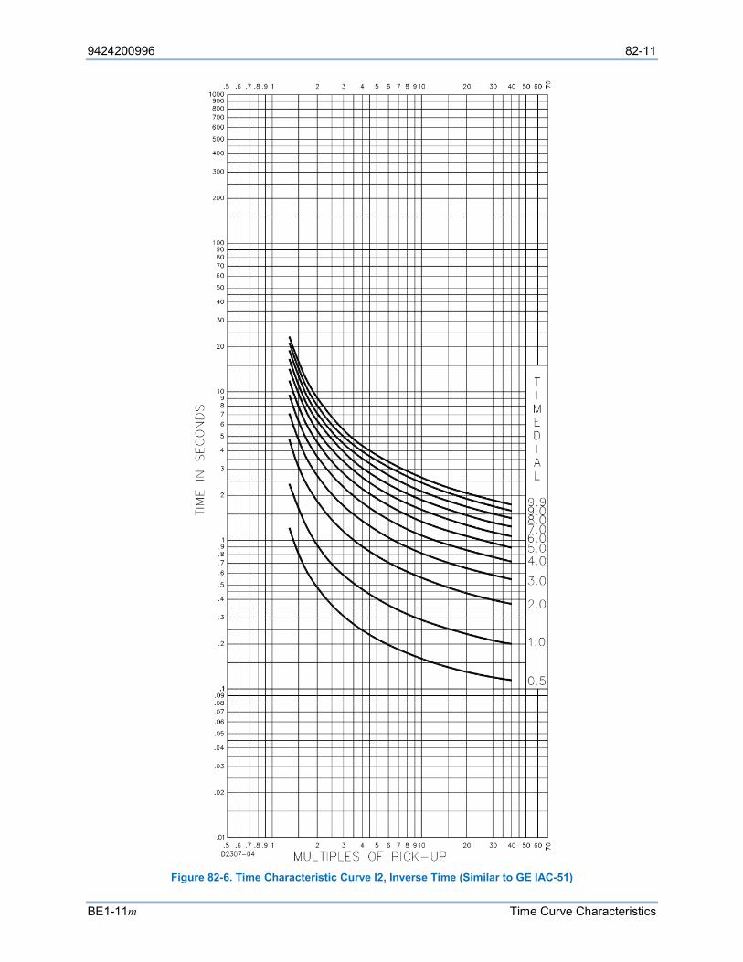
9424200996 82-11
BE1-11m Time Curve Characteristics
Figure 82-6. Time Characteristic Curve I2, Inverse Time (Similar to GE IAC-51)
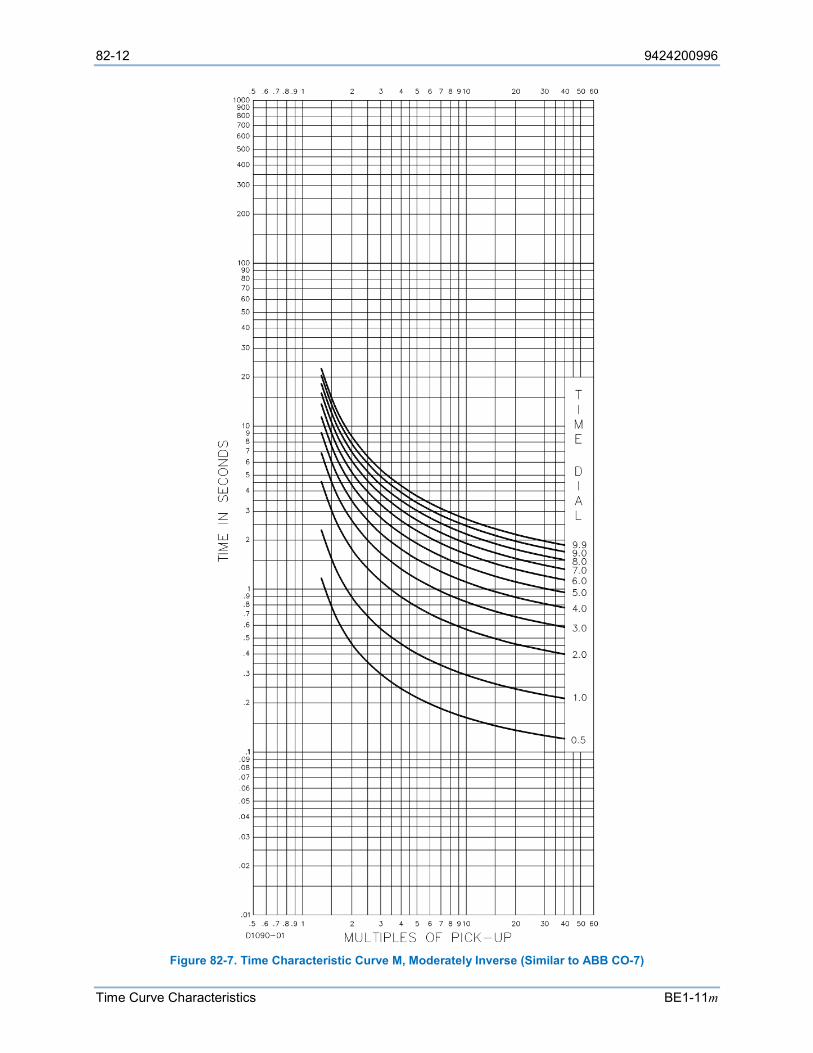
82-12 9424200996
Time Curve Characteristics BE1-11m
Figure 82-7. Time Characteristic Curve M, Moderately Inverse (Similar to ABB CO-7)
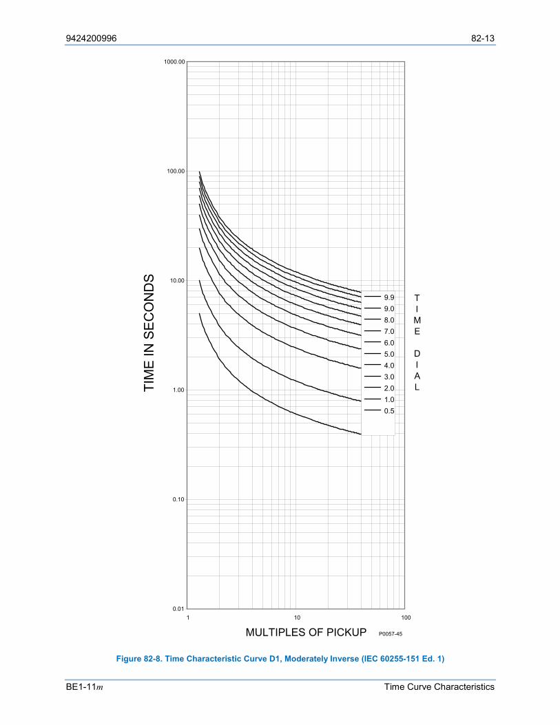
9424200996 82-13
BE1-11m Time Curve Characteristics
Figure 82-8. Time Characteristic Curve D1, Moderately Inverse (IEC 60255-151 Ed. 1)
0.01
0.10
1.00
10.00
100.00
1000.00
1 10 100
MULTIPLES OF PICKUP
TIM
E IN
SE
CO
ND
S
9.99.08.07.06.05.04.03.02.01.00.5
TIME
DIAL
P0057-45
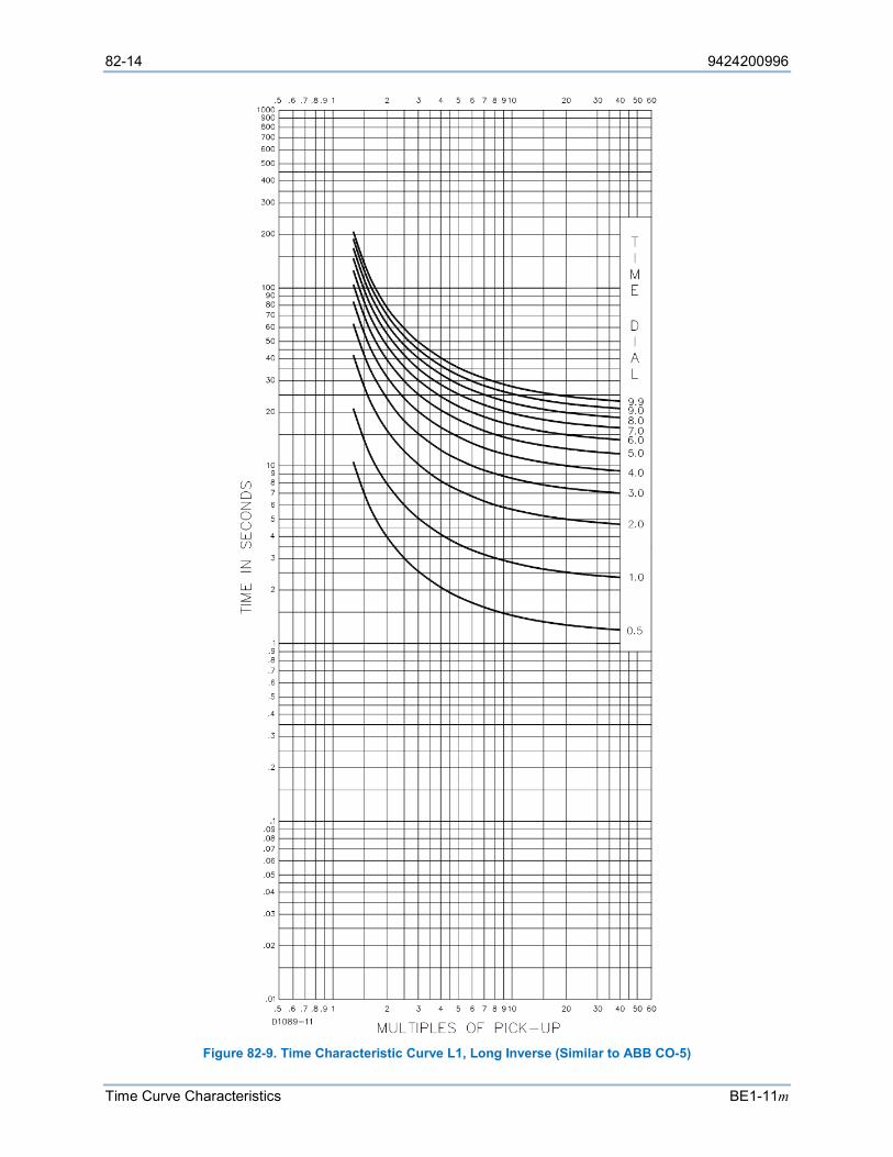
82-14 9424200996
Time Curve Characteristics BE1-11m
Figure 82-9. Time Characteristic Curve L1, Long Inverse (Similar to ABB CO-5)
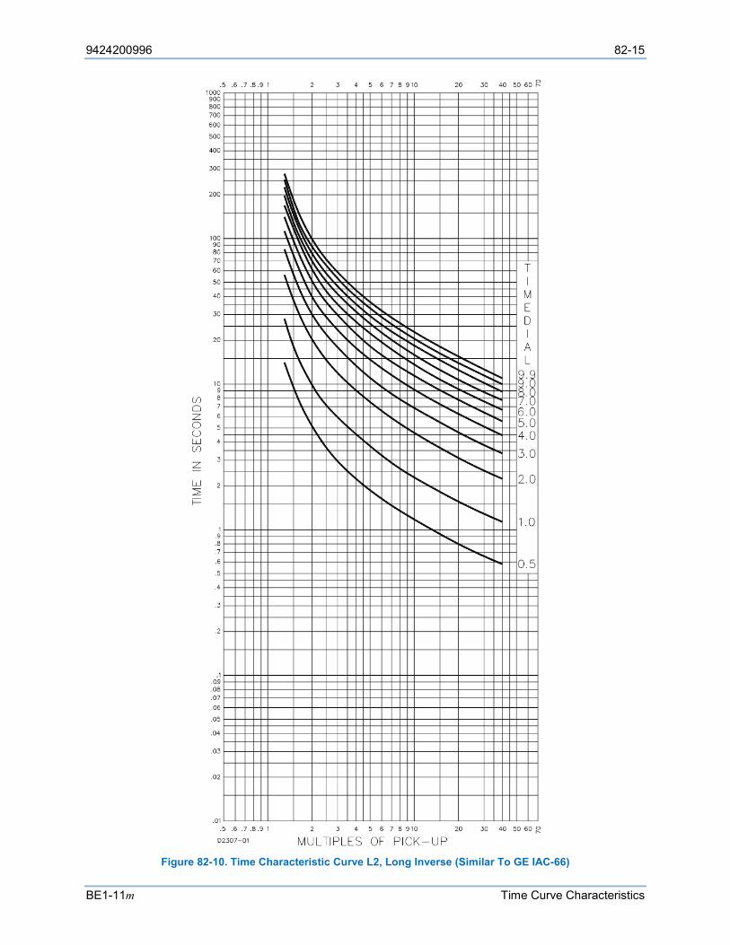
9424200996 82-15
BE1-11m Time Curve Characteristics
Figure 82-10. Time Characteristic Curve L2, Long Inverse (Similar To GE IAC-66)
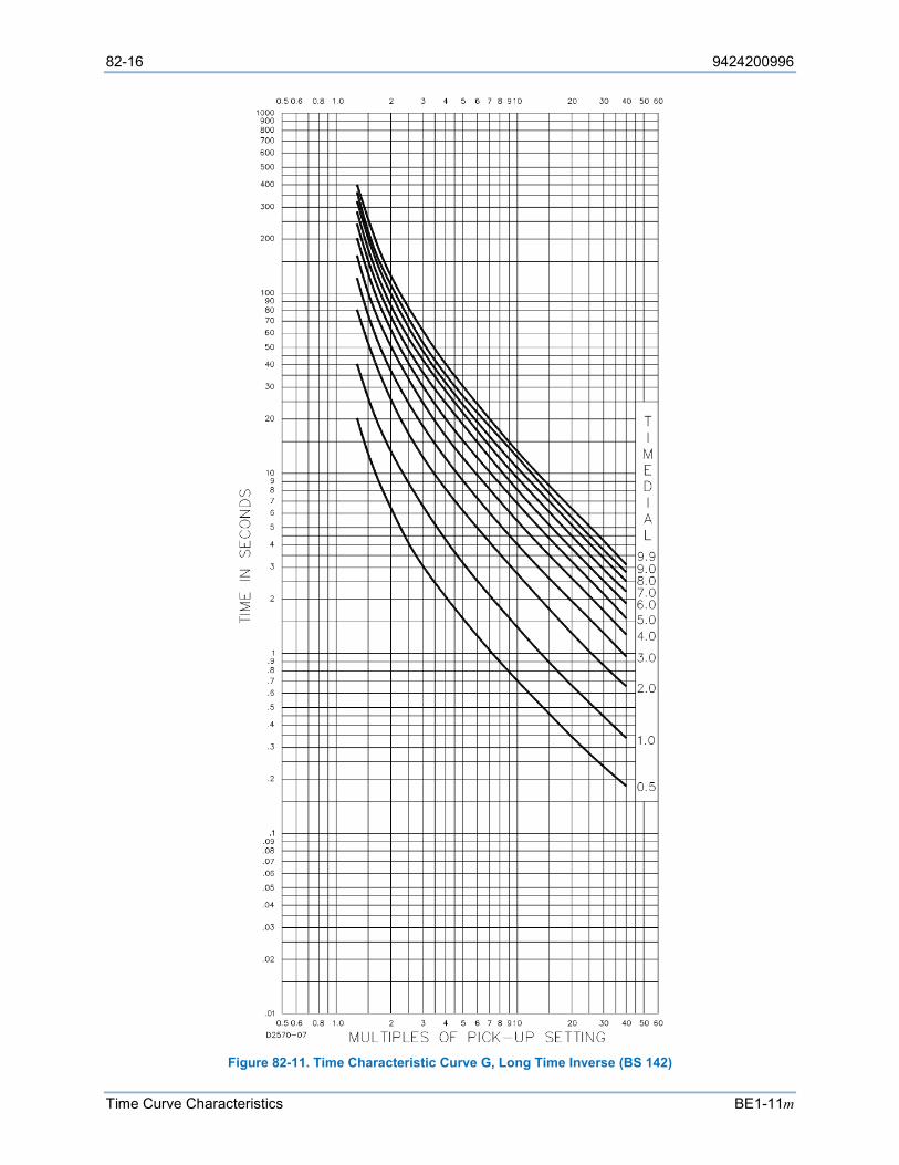
82-16 9424200996
Time Curve Characteristics BE1-11m
Figure 82-11. Time Characteristic Curve G, Long Time Inverse (BS 142)
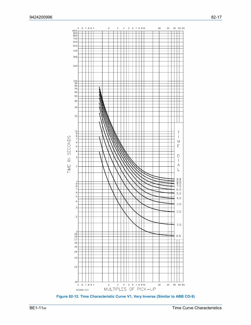
9424200996 82-17
BE1-11m Time Curve Characteristics
Figure 82-12. Time Characteristic Curve V1, Very Inverse (Similar to ABB CO-9)

82-18 9424200996
Time Curve Characteristics BE1-11m
Figure 82-13. Time Characteristic Curve V2, Very Inverse (Similar to GE IAC-53)
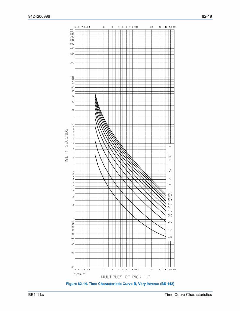
9424200996 82-19
BE1-11m Time Curve Characteristics
Figure 82-14. Time Characteristic Curve B, Very Inverse (BS 142)
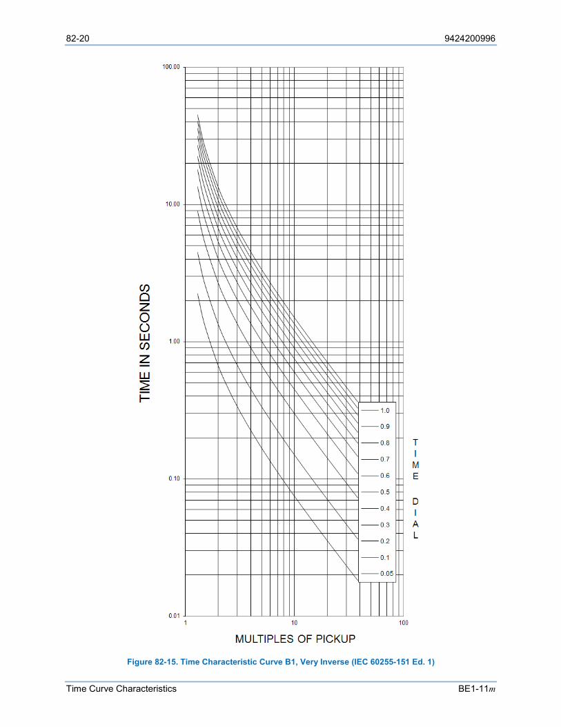
82-20 9424200996
Time Curve Characteristics BE1-11m
Figure 82-15. Time Characteristic Curve B1, Very Inverse (IEC 60255-151 Ed. 1)
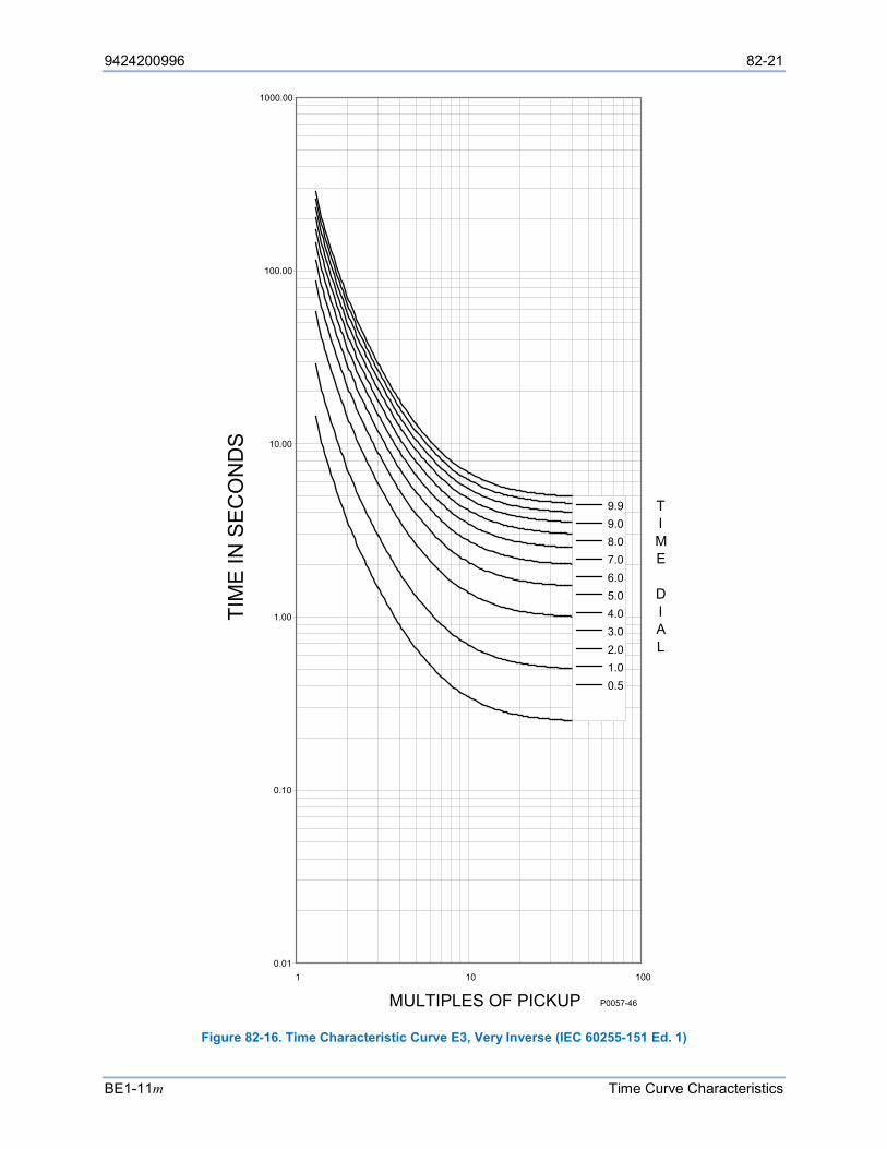
9424200996 82-21
BE1-11m Time Curve Characteristics
Figure 82-16. Time Characteristic Curve E3, Very Inverse (IEC 60255-151 Ed. 1)
0.01
0.10
1.00
10.00
100.00
1000.00
1 10 100
MULTIPLES OF PICKUP
TIM
E IN
SE
CO
ND
S
9.99.08.07.06.05.04.03.02.01.00.5
TIME
DIAL
P0057-46
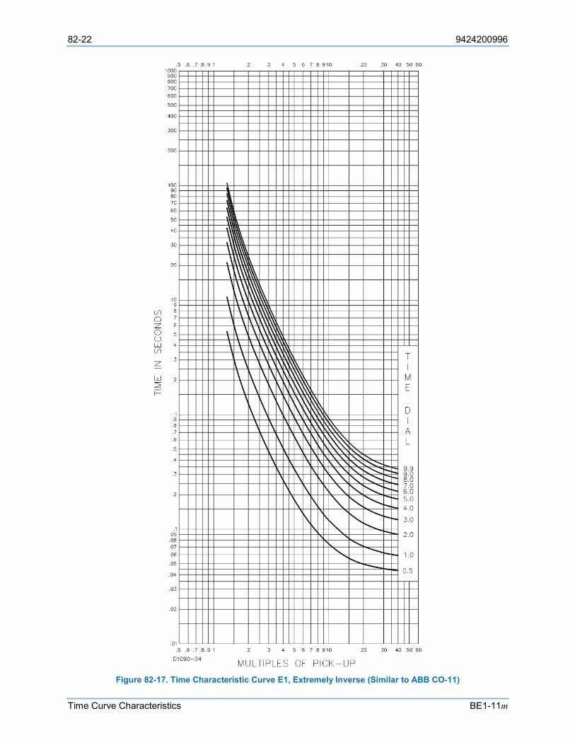
82-22 9424200996
Time Curve Characteristics BE1-11m
Figure 82-17. Time Characteristic Curve E1, Extremely Inverse (Similar to ABB CO-11)
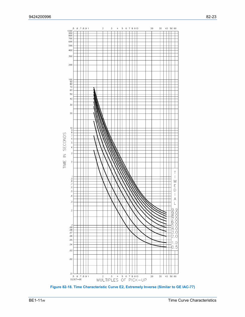
9424200996 82-23
BE1-11m Time Curve Characteristics
Figure 82-18. Time Characteristic Curve E2, Extremely Inverse (Similar to GE IAC-77)
82-24 9424200996
Time Curve Characteristics BE1-11m
Figure 82-19. Time Characteristic Curve C, Extremely Inverse (BS 142)
9424200996 82-25
BE1-11m Time Curve Characteristics
Figure 82-20. Time Characteristic Curve C1, Extremely Inverse (IEC 60255-151 Ed. 1)
82-26 9424200996
Time Curve Characteristics BE1-11m
Figure 82-21. Time Characteristic Curve F1, Extremely Inverse (IEC 60255-151 Ed. 1)
0.01
0.10
1.00
10.00
100.00
1000.00
1 10 100
MULTIPLES OF PICKUP
TIM
E IN
SE
CO
ND
S
9.99.08.07.06.05.04.03.02.01.00.5
TIME
DIAL
P0057-47
9424200996 82-27
BE1-11m Time Curve Characteristics
Figure 82-22. Time Characteristic Curve D, Definite Time (Similar To ABB CO-6)
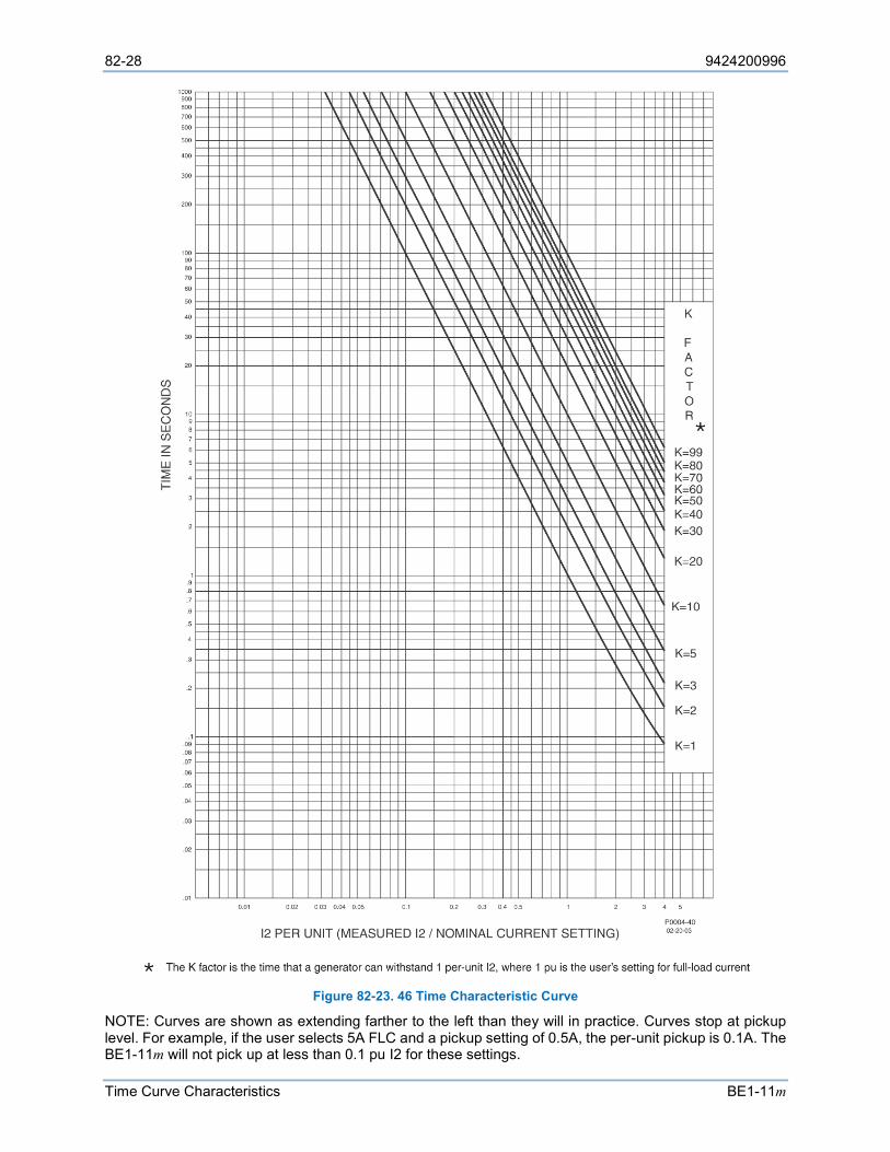
82-28 9424200996
Time Curve Characteristics BE1-11m
Figure 82-23. 46 Time Characteristic Curve
NOTE: Curves are shown as extending farther to the left than they will in practice. Curves stop at pickup level. For example, if the user selects 5A FLC and a pickup setting of 0.5A, the per-unit pickup is 0.1A. The BE1-11m will not pick up at less than 0.1 pu I2 for these settings.

9424200996 82-29
BE1-11m Time Curve Characteristics
Under/Overvoltage (27/59)
The 27 and 59 elements have independent user defined definite and inverse time delays. The inverse time curves are defined below.
Undervoltage (27) Inverse Time Curve The undervoltage inverse time curve is defined by Equation 82-8. The undervoltage inverse time curve with default constants is shown in Figure 82-24.
𝑇𝑇𝑇𝑇 =𝐴𝐴𝐴𝐴
𝐶𝐶 −𝑀𝑀𝑁𝑁 + 𝐵𝐵𝐴𝐴
Equation 82-8
𝑇𝑇𝑅𝑅 =𝑅𝑅𝐴𝐴
|𝑀𝑀2 − 1| Equation 82-9
TT = Time to trip when M ≤ 1
TR = Time to reset if BE1-11m is set for integrating reset when M > 1. Otherwise, reset is 50 milliseconds or less
D = Time Dial setting (0.0 to 9.9)
M = Multiple of Pickup setting
A, B, C, N = Constants for the particular curve
R = Constant defining the reset time.
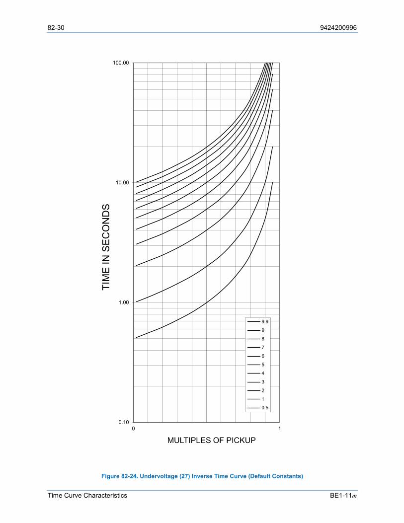
82-30 9424200996
Time Curve Characteristics BE1-11m
Figure 82-24. Undervoltage (27) Inverse Time Curve (Default Constants)
0.10
1.00
10.00
100.00
0 1
TIM
E IN
SE
CO
ND
S
MULTIPLES OF PICKUP
9.9
9
8
7
6
5
4
3
2
1
0.5

9424200996 82-31
BE1-11m Time Curve Characteristics
Overvoltage (59) Inverse Time Curve The undervoltage inverse time curve is defined by Equation 82-10. The undervoltage inverse time curve with default constants is shown in Figure 82-25.
𝑇𝑇𝑇𝑇 =𝐴𝐴𝐴𝐴
𝑀𝑀𝑁𝑁 − 𝐶𝐶+ 𝐵𝐵𝐴𝐴
Equation 82-10
𝑇𝑇𝑅𝑅 =𝑅𝑅𝐴𝐴
|𝑀𝑀2 − 1| Equation 82-11
TT = Time to trip when M ≥ 1
TR = Time to reset if BE1-11m is set for integrating reset when M < 1. Otherwise, reset is 50 milliseconds or less
D = Time Dial setting (0.0 to 9.9)
M = Multiple of Pickup setting
A, B, C, N = Constants for the particular curve
R = Constant defining the reset time.
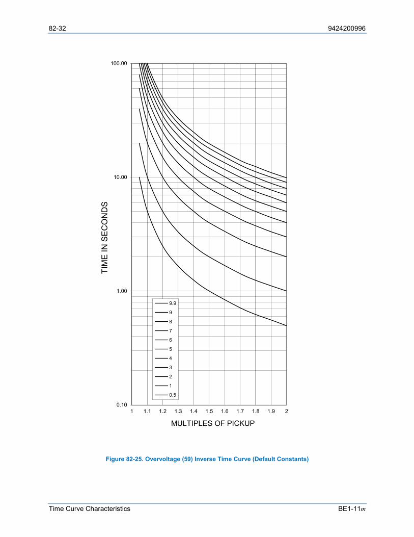
82-32 9424200996
Time Curve Characteristics BE1-11m
Figure 82-25. Overvoltage (59) Inverse Time Curve (Default Constants)
0.10
1.00
10.00
100.00
1 1.1 1.2 1.3 1.4 1.5 1.6 1.7 1.8 1.9 2
TIM
E IN
SE
CO
ND
S
MULTIPLES OF PICKUP
9.9
9
8
7
6
5
4
3
2
1
0.5
9424200996 82-33
BE1-11m Time Curve Characteristics
Thermal Curve (49TC)
The Standard and IEC curves are defined below.
Standard Curve The Standard Curve Time Dial setting determines the time to trip when the 49TC element is configured for Standard Curve mode. The standard curve provides a Ieq2 curve with a range of time dial settings that accommodate a wide range of motor timings. The standard curve equation is shown in Equation 82-12.
t = TD × 88.744132 × ln
⎣⎢⎢⎢⎡
IeqS ∙ SF ∙ FLA
2
Ieq
S ∙ SF ∙ FLA2− 1⎦
⎥⎥⎥⎤
With max value of Ieq/(S•SF•FLA) of 10.
Equation 82-12. Standard Curve
Where: t = Operating time Ieq = Measured equivalent motor current TD = Time Dial FLA = Full Load Amps SF = Service Factor S = Overload Scaler ln = Natural log
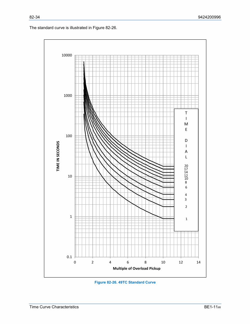
82-34 9424200996
Time Curve Characteristics BE1-11m
The standard curve is illustrated in Figure 82-26.
Figure 82-26. 49TC Standard Curve
0.1
1
10
100
1000
10000
0 2 4 6 8 10 12 14
TIM
E IN
SEC
ON
DS
Multiple of Overload Pickup
TI
ME
DIAL
20171412
4
1086
3
2
1
9424200996 82-35
BE1-11m Time Curve Characteristics
IEC Curve IEC curves provide the ability to automatically change between two curves based on if the motor is hot or cold. The hot or cold status is shown on the Motor Status > Thermal Curve metering screen on the front-panel.
An internal cold-to-hot timer is initiated when the motor is started from a cold state. The timer continues after the motor is running. The motor is determined as hot when the internal timer exceeds the Running Cool Time Constant (RCTC) setting and the hot curve shown in Equation 82-13 is used. If the motor is stopped before the RCTC setting is exceeded, the motor remains in a cold state and the timer resets at zero. It is recommended that the IEC Hot Curve Current setting (Ip) is set no greater than 95% of the thermal current pickup (S • SF • FLA). An internal hot-to-cold timer is initiated when the motor is stopped while in a hot state and the thermal capacity is less than 10%. The motor is determined as cold when the internal timer exceeds the Stopped Cool Time Constant (SCTC) setting and the cold curve shown in Equation 82-14 is used. If the motor is restarted before the SCTC setting is exceeded the motor remains in a hot state and the timer resets at zero.
t = τ ∙ lnIeq2 − IP2
Ieq2 − (S ∙ SF ∙ FLA)2
Equation 82-13. Hot Curve
t = τ ∙ lnIeq2
Ieq2 − (S ∙ SF ∙ FLA)2
Equation 82-14. Cold Curve
Where: t = Operating Time
Ieq = Measured Equivalent Motor Current FLA = Full Load Amperes SF = Service Factor S = Overload Scaler τ = Motor running time constant
IP = Specified load current before the overload occurs (IEC Hot Curve Current setting), which is specified in National Standards, declared by the manufacturer, or calculated from manufacturer provided thermal curve.
ln = Natural log
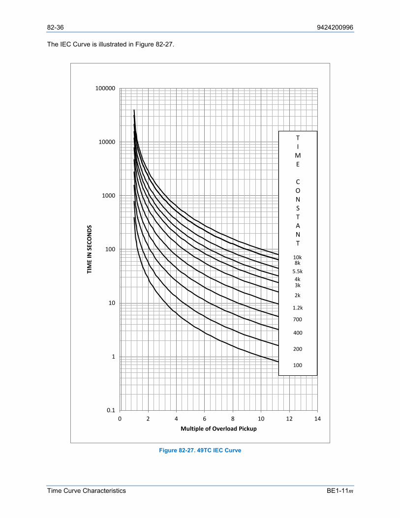
82-36 9424200996
Time Curve Characteristics BE1-11m
The IEC Curve is illustrated in Figure 82-27.
Figure 82-27. 49TC IEC Curve
0.1
1
10
100
1000
10000
100000
0 2 4 6 8 10 12 14
TIM
E IN
SEC
ON
DS
Multiple of Overload Pickup
TI
ME
CONSTANT
10k8k
5.5k4k
700
3k
2k
1.2k
400
200
100
9424200996 83-1
BE1-11m RTD Module
83 • RTD Module The RTD (Resistance Temperature Detector) module is an optional remote device that provides RTD inputs, analog inputs, and analog outputs for motor protection applications.
Features
RTD modules have the following features: • 12 RTD Inputs • 4 Analog Inputs • 4 Analog Outputs • Secured Read/Write Access* • Reporting and Alarm Functions • Communications via Ethernet or RS-485
* The default password for uploading settings to the RTD module is “OEM” in upper case letters.
Functional Description
A functional description of the RTD module’s inputs and outputs is provided below.
Analog Inputs The RTD module provides four analog inputs that are user-selectable for 4 to 20 mAdc or 0 to 10 Vdc. Each analog input has under/over thresholds that when exceeded, trip an analog input protection element. RTD modules with firmware 1.01.01 and above limit measurements in relation to the 4 to 20 mAdc or 0 to 10 Vdc range. Firmware below 1.01.01 is not operational outside the ranges. The label text of each analog input is customizable.
RTD Inputs The RTD module provides 12 user-configurable RTD inputs for monitoring motor systems. Each RTD input can be configured to protect against high or low temperature conditions. The label text of each RTD input is customizable.
Analog Outputs The RTD module provides four analog outputs that are user-selectable for 4 to 20 mAdc or 0 to 10 Vdc. A wide selection of parameters including BE1-11m metered voltages and currents, analog inputs, and RTD inputs can be configured as analog outputs. Refer to the Programmable Outputs, Remote Analog Outputs screen in BESTCOMSPlus® for a full list of parameter selections.
Alarm Contact Functions The RTD module provides form C (SPDT) alarm contacts that operate when an internal RTD module failure exists. The contacts also operate when operating power is cycled.
Real-Time Status Functions The RTD module is equipped with a multi-function LED with the following functions.
• Slow Flashing - Communications established • Quick Flashing - Communications lost • Steady On - Power applied
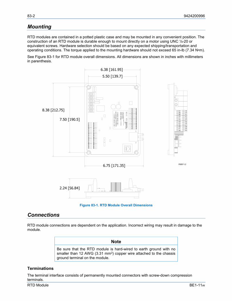
83-2 9424200996
RTD Module BE1-11m
Mounting
RTD modules are contained in a potted plastic case and may be mounted in any convenient position. The construction of an RTD module is durable enough to mount directly on a motor using UNC ¼-20 or equivalent screws. Hardware selection should be based on any expected shipping/transportation and operating conditions. The torque applied to the mounting hardware should not exceed 65 in-lb (7.34 N•m).
See Figure 83-1 for RTD module overall dimensions. All dimensions are shown in inches with millimeters in parenthesis.
Figure 83-1. RTD Module Overall Dimensions
Connections
RTD module connections are dependent on the application. Incorrect wiring may result in damage to the module.
Note Be sure that the RTD module is hard-wired to earth ground with no smaller than 12 AWG (3.31 mm2) copper wire attached to the chassis ground terminal on the module.
Terminations The terminal interface consists of permanently mounted connectors with screw-down compression terminals.
8.38 [212.75]
6.75 [171.35]
6.38 [161.95]
2.24 [56.84]
P0097-12
5.50 [139.7]
7.50 [190.5]
9424200996 83-3
BE1-11m RTD Module
RTD module connections are made with one 6-position connector, two 12-position connectors, and two 15-position connectors. Connector screw terminals accept a maximum wire size of 12 AWG (3.31 mm2). Maximum screw torque is 5 inch-pounds (0.56 N•m) for the 12- and 15-position connectors. Maximum screw torque is 9 inch-pounds (1.01 N•m) for the 6-position connector.
Operating Power The RTD module operating power input accepts 125/250 Vac/dc and tolerates voltage over the range of 90 to 270 Vac or 90 to 300 Vdc. The operating power inputs are not polarity sensitive. Operating power terminals are listed in Table 83-1.
Table 83-1. Operating Power Terminals
Terminal Description TB1-1 Operating power input TB1-2 Operating power input TB1-3 Chassis ground connection
Alarm Contacts These terminals provide form C (SPDT) alarm contacts. Alarm contact terminals are listed in Table 83-2.
Table 83-2. Alarm Contact Terminals
Terminal Description TB1-4 Normally Open TB1-5 Common TB1-6 Normally Closed
RTD Module Inputs and Outputs Input and output terminals are shown in Figure 83-2 and listed in Table 83-3.
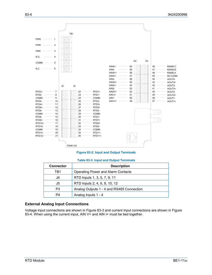
83-4 9424200996
RTD Module BE1-11m
Figure 83-2. Input and Output Terminals
Table 83-3. Input and Output Terminals
Connector Description TB1 Operating Power and Alarm Contacts J4 RTD Inputs 1, 3, 5, 7, 9, 11 J5 RTD Inputs 2, 4, 6, 8, 10, 12 P3 Analog Outputs 1 - 4 and RS485 Connection P4 Analog Inputs 1 - 4
External Analog Input Connections Voltage input connections are shown in Figure 83-3 and current input connections are shown in Figure 83-4. When using the current input, AIN V+ and AIN I+ must be tied together.
789101112131415161718192021
222324252627282930313233343536
484746454443424140393837
605958575655545352515049
RTD2+RTD2-COMMRTD4-RTD4+RTD6+RTD6-COMMRTD8-RTD8+RTD10+RTD10-COMMRTD12-RTD12+
RTD1+RTD1-COMMRTD3-RTD3+RTD5+RTD5-COMMRTD7-RTD7+RTD9+RTD9-COMMRTD11-RTD11+
RS485 CRS485 BRS485 ANO CONNAOUT4-AOUT4+AOUT3-AOUT3+AOUT2-AOUT2+AOUT1-AOUT1+
AIN4I+AIN4-AIN4V+AIN3I+AIN3-AIN3V+AIN2I+AIN2-AIN2V+AIN1I+AIN1-AIN1V+
P4 P3
J5 J4
1
2
3
4
5
6
PWR
PWR
GND
N.O.
COMM
N.C.
TB1
P0061-54
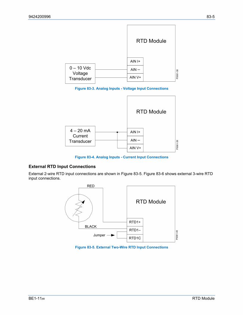
9424200996 83-5
BE1-11m RTD Module
Figure 83-3. Analog Inputs - Voltage Input Connections
Figure 83-4. Analog Inputs - Current Input Connections
External RTD Input Connections External 2-wire RTD input connections are shown in Figure 83-5. Figure 83-6 shows external 3-wire RTD input connections.
Figure 83-5. External Two-Wire RTD Input Connections
AIN I+
AIN –
AIN V+
RTD Module
P006
1-38
0 – 10 VdcVoltage
Transducer
AIN I+
AIN –
AIN V+
RTD Module
P006
1-39
4 – 20 mACurrent
Transducer
RTD1+
RTD1–
RTD1C
RTD Module
Jumper
P006
1-40
BLACK
RED
83-6 9424200996
RTD Module BE1-11m
Figure 83-6. External Three-Wire RTD Input Connections
RTD Module Communications Setup Procedure
Communication between the BE1-11m and the RTD module can be accomplished via Ethernet or RS-485. For RS-485 communication, RS-485 Port Protocol option must be “N”. Initial settings for the RTD module must be made via Ethernet.
An IP address is assigned to the RTD module in all cases even if the connection between the RTD module and the BE1-11m will be RS-485. Assigning an IP address to the RTD module gives the user the option to save a settings file and to view the serial number and firmware version of the RTD module using BESTCOMSPlus.
Perform one of the following procedures to set up the RTD module. It is assumed that the BE1-11m is already connected to the PC or network.
Procedure 1 The PC and BE1-11m are connected through a network or the PC is connected directly to the BE1-11m via Ethernet cable or USB cable. The RTD module connects to the BE1-11m via Ethernet or RS-485. See Figure 83-7.
Figure 83-7. Procedure 1
Connect to RTD Module
1. Connect an Ethernet cable directly between the PC and RTD module.
2. Apply operating power to the RTD module.
3. Determine the IP address, Subnet Mask, and Default Gateway of the PC Ethernet port for later use. Open a Windows® command prompt by clicking Start > Run. Type “cmd”, and click OK. Type “ipconfig” and press enter.
RTD1+
RTD1–
RTD1C
RTD Module
P006
1-41
RED
BLACK
BLACK
Network
PC
BE1-11m
RTD Module
Ethernet
Ethernet
P006
1-85
RS-485
Ethernet
= Optional
OR
PC
BE1-11m
RTD Module
Ethernet
USB

9424200996 83-7
BE1-11m RTD Module
4. Record the IP address, Subnet Mask, and Default Gateway of the PC Ethernet port that is connected to the RTD module. Close the Windows command prompt window.
5. Open the RTD Module plugin in BESTCOMSPlus.
6. Pull down the Communication menu and select New Connection > RTD Module. The RTD Module Connection screen appears.
7. Under Device Discovery, click the Ethernet button to scan for connected devices.
8. After scanning for connected devices, the Device Discovery screen appears.
9. Use the computer mouse to highlight the desired RTD module and click the Configure button.
10. The Configure - RTD Module screen appears. The BE1-11m uses the Device Address (Remote Module ID) to communicate with the RTD module. The RTD module comes with a default address of 255 (module disabled). Enter the desired device address between 1 and 254.
11. Assign an IP Address to the RTD module by entering an address in the same range as the IP address of the PC recorded in Step 4. For example, if the IP address recorded in Step 4 was 169.254.153.248, you could enter 169.254.153.150 or 169.254.153.45. (The range is 1 to 255.)
12. The PC and RTD module must have the same Subnet Mask and Default Gateway. Assign the Subnet Mask and Default Gateway to the RTD module using the values of the PC recorded in Step 4.
13. Click Send to Device. A password is required. The default password is “OEM”. Click Close.
14. Click Cancel on the Device Discovery screen.
15. Cycle power to the RTD module to activate the new IP address.
Verify RTD Module Communication and Save a Settings File
16. To verify that the IP address of the RTD module was correctly configured or to save a settings file for the RTD module, click the Ethernet button under Device Discovery to scan for connected devices.
17. After scanning for connected devices, the Device Discovery screen appears.
18. Use the computer mouse to highlight the desired RTD module and click the Connect button. If the Device Needs Activated screen appears, refer to RTD Module Plugin for BESTCOMSPlus, later in this section for information on how to activate the plugin. If the connection was successful, BESTCOMSPlus will show Online in the lower right corner.
19. Review settings or save a settings file if desired.
20. Click the Disconnect button near the top of BESTCOMSPlus to close the RTD module connection.
Configure the BE1-11m to Communicate with the RTD Module
21. Connect an Ethernet or USB cable between the PC and BE1-11m.
22. Open the BE1-11 plugin in BESTCOMSPlus and connect to the BE1-11m.
23. Use the Settings Explorer to open the Remote Module Communications screen under System Parameters.
24. Set the Status to Enabled. Set Communication Type to Ethernet or RS485. Set Remote Module ID to match the remote module ID entered in Step 10.
25. Perform this step if the RTD Module is connected to the BE1-11m via a direct Ethernet connection. The BE1-11m communicates with the RTD Module only if its Active IP Address is a nonzero value. To confirm/set the IP Address, open the Ethernet screen under Communication, Configure and de-select the Use DHCP box. Then, enter any nonzero value for the IP Address. Click the Send to Device button to apply the settings to the BE1-11m.
26. Perform this step if the RTD module is connected to the BE1-11m via RS-485. The RTD Module communicates with the BE1-11m only at 19200 baud when using RS-485. Open the RS485 Setup screen under Communications and set Baud Rate to 19200 Baud, Bits Per Character to 8 Bits, Parity to No Parity, and Stop Bits to 1 stop bit.
83-8 9424200996
RTD Module BE1-11m
27. Use BESTCOMSPlus to send settings to the BE1-11m.
Procedure 2 The PC, BE1-11m, and RTD module are connected through a network. See Figure 83-8.
Figure 83-8. Procedure 2
Connect to RTD Module
1. Connect an Ethernet cable directly between the PC and RTD module.
2. Apply operating power to the RTD module.
3. Open the RTD Module plugin in BESTCOMSPlus.
4. Pull down the Communication menu and select New Connection > RTD Module. The RTD Module Connection screen appears.
5. Under Device Discovery, click the Ethernet button to scan for connected devices.
6. After scanning for connected devices, the Device Discovery screen appears.
7. Use the computer mouse to highlight the desired RTD module and click the Configure button.
8. The Configure - RTD Module screen appears. The BE1-11m uses the Device Address (Remote Module ID) to communicate with the RTD module. The RTD module comes with a default address of 255 (module disabled). Enter the desired device address between 1 and 254.
9. DHCP (Dynamic Host Configuration Protocol) allows the RTD module to send a broadcast request for configuration information. The DHCP server receives the request and responds with configuration information. DHCP is disabled by default. To enable, check the DHCP box.
If DHCP is not being used, use BESTCOMSPlus to configure the Ethernet port as described in the following paragraphs.
Configurable Ethernet options include:
IP Address: Internet Protocol Address to be used by the RTD module.
Default Gateway: Default host to send data destined for a host not on the network subnet.
Subnet Mask: Mask used to determine the range of the current network subnet.
Use DHCP: When this box is checked, the IP Address, Default Gateway, and Subnet Mask are automatically configured via DHCP. This can be used only if the Ethernet network has a properly configured DHCP server running. Uncheck the box if DHCP is not being used.
Obtain the values for these options from the site administrator if the RTD module is intended to share the network with other devices.
If the RTD module is operating on an isolated network, the IP address can be chosen from one of the following ranges as listed in IETF publication RFC 1918, Address Allocation for Private Networks.
Network
PC
BE1-11m
RTD Module
Ethernet
Ethernet
P00
61-8
6
Ethernet
USB
= Optional
9424200996 83-9
BE1-11m RTD Module
• 10.0.0.0 - 10.255.255.255 • 172.16.0.0 - 172.31.255.255 • 192.168.0.0 - 192.168.255.255
10. Click Send to Device. A password is required. The default password is “OEM”. Click Close.
11. Click Cancel on the Device Discovery screen.
12. Remove operating power from the RTD module. Connect the RTD module to the network. Apply operating power to the RTD module
Verify RTD Module Communication and Save a Settings File
13. Connect the PC to the same network as the RTD module.
14. To verify that the IP address of the RTD module was correctly configured or to save a settings file for the RTD module, click the Ethernet button under Device Discovery to scan for connected devices.
15. After scanning for connected devices, the Device Discovery screen appears.
16. Use the computer mouse to highlight the desired RTD module and click the Connect button. If the connection was successful, BESTCOMSPlus will show Online in the lower right corner.
17. Review settings or save a settings file if desired.
18. Click the Disconnect button near the top of BESTCOMSPlus to close the RTD module connection.
Configure the BE1-11m to Communicate with the RTD Module
19. Connect an Ethernet or USB cable between the PC and BE1-11m.
20. Open the BE1-11 plugin in BESTCOMSPlus and connect to the BE1-11m.
21. Use the Settings Explorer to open the Remote Module Communications screen under System Parameters.
22. Set the Status to Enabled. Set Communication Type to Ethernet. Set Remote Module ID to match the remote module ID entered in Step 8.
23. Use BESTCOMSPlus to send settings to the BE1-11m.
RTD Module Plugin for BESTCOMSPlus®
The setup utility that installs BESTCOMSPlus on your PC also installs the RTD Module plugin. The RTD Module plugin is used to set the device address, set device security, and view device information such as firmware version and serial number. RTD Module operational settings such as metering and protective elements are found in the BE1-11 plugin for BESTCOMSPlus.
BESTCOMSPlus provides the user with a point-and-click means to set and monitor the RTD module. Installation and operation of BESTCOMSPlus is described in the BESTCOMSPlus Software chapter.
Automatic Activation
To start BESTCOMSPlus, click the Windows® Start button, point to Programs, Basler Electric, and then click the BESTCOMSPlus icon. During initial startup, the BESTCOMSPlus Select Language screen is displayed (Figure 83-9). You can choose to have this screen displayed each time BESTCOMSPlus is started, or you can select a preferred language and this screen will be bypassed in the future. Click OK to continue. This screen can be accessed later by selecting Tools and Select Language from the menu bar.
83-10 9424200996
RTD Module BE1-11m
Figure 83-9. BESTCOMSPlus Select Language Screen
The BESTCOMSPlus splash screen is shown for a brief time. See Figure 83-10.
Figure 83-10. BESTCOMSPlus Splash Screen
The BESTCOMSPlus platform window opens. Select New Connection from the Communication pull-down menu and select RTD Module. See Figure 83-11. The RTD Module plugin is activated automatically after connecting to an RTD module.
Figure 83-11. Communication Pull-Down Menu
The RTD Module Connection screen shown in Figure 83-12 appears. Under Device Discovery, click the Ethernet button.
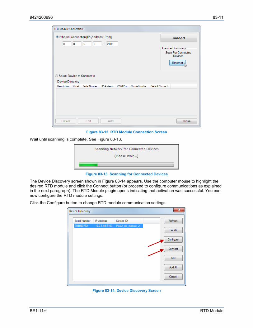
9424200996 83-11
BE1-11m RTD Module
Figure 83-12. RTD Module Connection Screen
Wait until scanning is complete. See Figure 83-13.
Figure 83-13. Scanning for Connected Devices
The Device Discovery screen shown in Figure 83-14 appears. Use the computer mouse to highlight the desired RTD module and click the Connect button (or proceed to configure communications as explained in the next paragraph). The RTD Module plugin opens indicating that activation was successful. You can now configure the RTD module settings.
Click the Configure button to change RTD module communication settings.
Figure 83-14. Device Discovery Screen
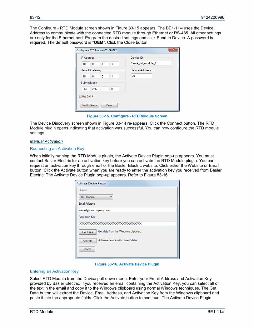
83-12 9424200996
RTD Module BE1-11m
The Configure - RTD Module screen shown in Figure 83-15 appears. The BE1-11m uses the Device Address to communicate with the connected RTD module through Ethernet or RS-485. All other settings are only for the Ethernet port. Program the desired settings and click Send to Device. A password is required. The default password is “OEM”. Click the Close button.
Figure 83-15. Configure - RTD Module Screen
The Device Discovery screen shown in Figure 83-14 re-appears. Click the Connect button. The RTD Module plugin opens indicating that activation was successful. You can now configure the RTD module settings.
Manual Activation
Requesting an Activation Key
When initially running the RTD Module plugin, the Activate Device Plugin pop-up appears. You must contact Basler Electric for an activation key before you can activate the RTD Module plugin. You can request an activation key through email or the Basler Electric website. Click either the Website or Email button. Click the Activate button when you are ready to enter the activation key you received from Basler Electric. The Activate Device Plugin pop-up appears. Refer to Figure 83-16.
Figure 83-16. Activate Device Plugin
Entering an Activation Key
Select RTD Module from the Device pull-down menu. Enter your Email Address and Activation Key provided by Basler Electric. If you received an email containing the Activation Key, you can select all of the text in the email and copy it to the Windows clipboard using normal Windows techniques. The Get Data button will extract the Device, Email Address, and Activation Key from the Windows clipboard and paste it into the appropriate fields. Click the Activate button to continue. The Activate Device Plugin
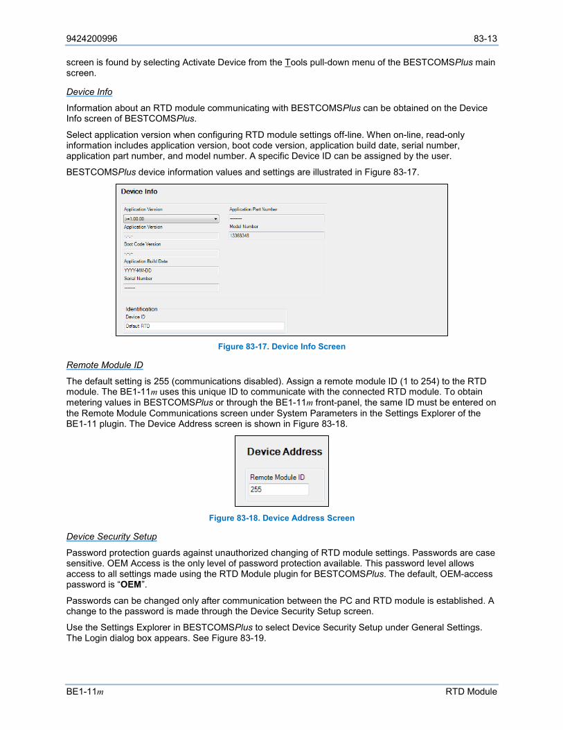
9424200996 83-13
BE1-11m RTD Module
screen is found by selecting Activate Device from the Tools pull-down menu of the BESTCOMSPlus main screen.
Device Info
Information about an RTD module communicating with BESTCOMSPlus can be obtained on the Device Info screen of BESTCOMSPlus.
Select application version when configuring RTD module settings off-line. When on-line, read-only information includes application version, boot code version, application build date, serial number, application part number, and model number. A specific Device ID can be assigned by the user.
BESTCOMSPlus device information values and settings are illustrated in Figure 83-17.
Figure 83-17. Device Info Screen
Remote Module ID
The default setting is 255 (communications disabled). Assign a remote module ID (1 to 254) to the RTD module. The BE1-11m uses this unique ID to communicate with the connected RTD module. To obtain metering values in BESTCOMSPlus or through the BE1-11m front-panel, the same ID must be entered on the Remote Module Communications screen under System Parameters in the Settings Explorer of the BE1-11 plugin. The Device Address screen is shown in Figure 83-18.
Figure 83-18. Device Address Screen
Device Security Setup
Password protection guards against unauthorized changing of RTD module settings. Passwords are case sensitive. OEM Access is the only level of password protection available. This password level allows access to all settings made using the RTD Module plugin for BESTCOMSPlus. The default, OEM-access password is “OEM”.
Passwords can be changed only after communication between the PC and RTD module is established. A change to the password is made through the Device Security Setup screen.
Use the Settings Explorer in BESTCOMSPlus to select Device Security Setup under General Settings. The Login dialog box appears. See Figure 83-19.
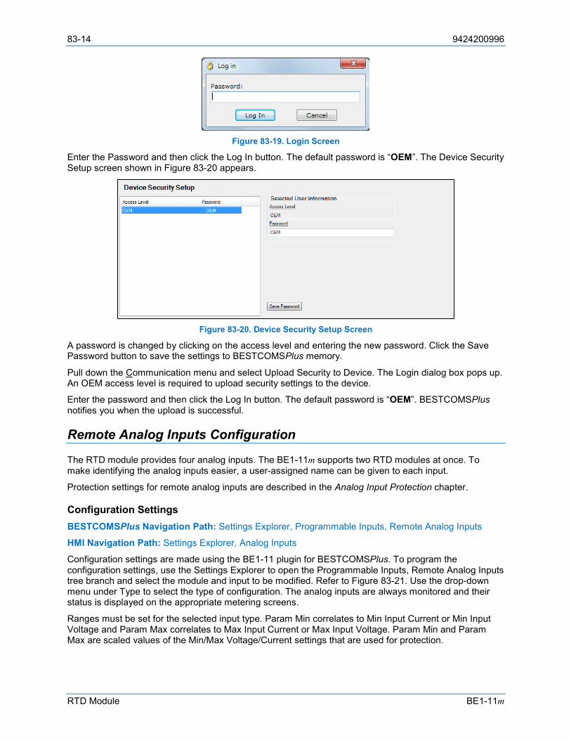
83-14 9424200996
RTD Module BE1-11m
Figure 83-19. Login Screen
Enter the Password and then click the Log In button. The default password is “OEM”. The Device Security Setup screen shown in Figure 83-20 appears.
Figure 83-20. Device Security Setup Screen
A password is changed by clicking on the access level and entering the new password. Click the Save Password button to save the settings to BESTCOMSPlus memory.
Pull down the Communication menu and select Upload Security to Device. The Login dialog box pops up. An OEM access level is required to upload security settings to the device.
Enter the password and then click the Log In button. The default password is “OEM”. BESTCOMSPlus notifies you when the upload is successful.
Remote Analog Inputs Configuration
The RTD module provides four analog inputs. The BE1-11m supports two RTD modules at once. To make identifying the analog inputs easier, a user-assigned name can be given to each input.
Protection settings for remote analog inputs are described in the Analog Input Protection chapter.
Configuration Settings BESTCOMSPlus Navigation Path: Settings Explorer, Programmable Inputs, Remote Analog Inputs
HMI Navigation Path: Settings Explorer, Analog Inputs
Configuration settings are made using the BE1-11 plugin for BESTCOMSPlus. To program the configuration settings, use the Settings Explorer to open the Programmable Inputs, Remote Analog Inputs tree branch and select the module and input to be modified. Refer to Figure 83-21. Use the drop-down menu under Type to select the type of configuration. The analog inputs are always monitored and their status is displayed on the appropriate metering screens.
Ranges must be set for the selected input type. Param Min correlates to Min Input Current or Min Input Voltage and Param Max correlates to Max Input Current or Max Input Voltage. Param Min and Param Max are scaled values of the Min/Max Voltage/Current settings that are used for protection.
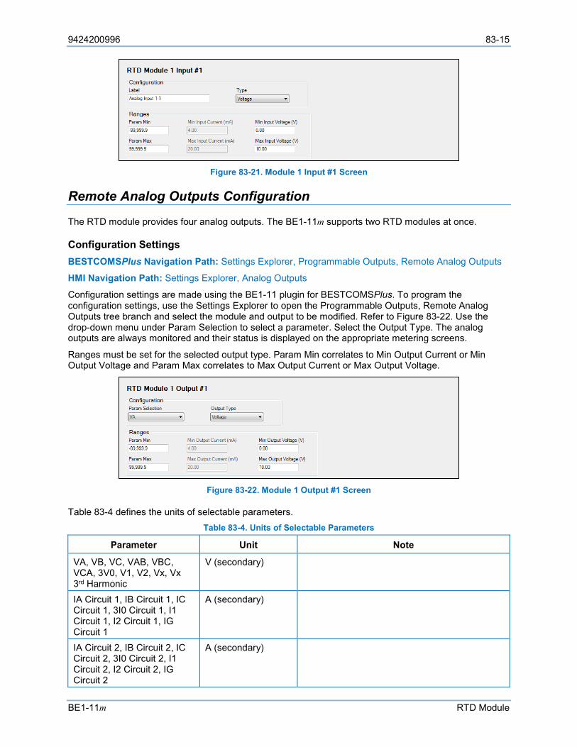
9424200996 83-15
BE1-11m RTD Module
Figure 83-21. Module 1 Input #1 Screen
Remote Analog Outputs Configuration
The RTD module provides four analog outputs. The BE1-11m supports two RTD modules at once.
Configuration Settings BESTCOMSPlus Navigation Path: Settings Explorer, Programmable Outputs, Remote Analog Outputs
HMI Navigation Path: Settings Explorer, Analog Outputs
Configuration settings are made using the BE1-11 plugin for BESTCOMSPlus. To program the configuration settings, use the Settings Explorer to open the Programmable Outputs, Remote Analog Outputs tree branch and select the module and output to be modified. Refer to Figure 83-22. Use the drop-down menu under Param Selection to select a parameter. Select the Output Type. The analog outputs are always monitored and their status is displayed on the appropriate metering screens.
Ranges must be set for the selected output type. Param Min correlates to Min Output Current or Min Output Voltage and Param Max correlates to Max Output Current or Max Output Voltage.
Figure 83-22. Module 1 Output #1 Screen
Table 83-4 defines the units of selectable parameters. Table 83-4. Units of Selectable Parameters
Parameter Unit Note
VA, VB, VC, VAB, VBC, VCA, 3V0, V1, V2, Vx, Vx 3rd Harmonic
V (secondary)
IA Circuit 1, IB Circuit 1, IC Circuit 1, 3I0 Circuit 1, I1 Circuit 1, I2 Circuit 1, IG Circuit 1
A (secondary)
IA Circuit 2, IB Circuit 2, IC Circuit 2, 3I0 Circuit 2, I1 Circuit 2, I2 Circuit 2, IG Circuit 2
A (secondary)
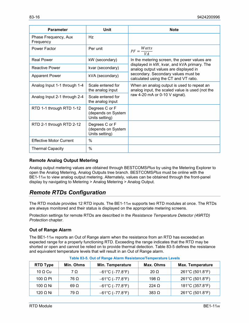
83-16 9424200996
RTD Module BE1-11m
Parameter Unit Note
Phase Frequency, Aux Frequency
Hz
Power Factor Per unit 𝑃𝑃𝑃𝑃 =𝑊𝑊𝑊𝑊𝑊𝑊𝑊𝑊𝑊𝑊𝑉𝑉𝑉𝑉
Real Power kW (secondary) In the metering screen, the power values are displayed in kW, kvar, and kVA primary. The analog output values are displayed in secondary. Secondary values must be calculated using the CT and VT ratio.
Reactive Power kvar (secondary)
Apparent Power kVA (secondary)
Analog Input 1-1 through 1-4 Scale entered for the analog input
When an analog output is used to repeat an analog input, the scaled value is used (not the raw 4-20 mA or 0-10 V signal). Analog Input 2-1 through 2-4 Scale entered for
the analog input RTD 1-1 through RTD 1-12 Degrees C or F
(depends on System Units setting)
RTD 2-1 through RTD 2-12 Degrees C or F (depends on System Units setting)
Effective Motor Current %
Thermal Capacity %
Remote Analog Output Metering Analog output metering values are obtained through BESTCOMSPlus by using the Metering Explorer to open the Analog Metering, Analog Outputs tree branch. BESTCOMSPlus must be online with the BE1-11m to view analog output metering. Alternately, values can be obtained through the front-panel display by navigating to Metering > Analog Metering > Analog Output.
Remote RTDs Configuration
The RTD module provides 12 RTD inputs. The BE1-11m supports two RTD modules at once. The RTDs are always monitored and their status is displayed on the appropriate metering screens.
Protection settings for remote RTDs are described in the Resistance Temperature Detector (49RTD) Protection chapter.
Out of Range Alarm The BE1-11m reports an Out of Range alarm when the resistance from an RTD has exceeded an expected range for a properly functioning RTD. Exceeding the range indicates that the RTD may be shorted or open and cannot be relied on to provide thermal detection. Table 83-5 defines the resistance and equivalent temperature levels that will result in an Out of Range alarm.
Table 83-5. Out of Range Alarm Resistance/Temperature Levels
RTD Type Min. Ohms Min. Temperature Max. Ohms Max. Temperature 10 Ω Cu 7 Ω −61°C (−77.8°F) 20 Ω 261°C (501.8°F)
100 Ω Pt 76 Ω −61°C (−77.8°F) 198 Ω 261°C (501.8°F)
100 Ω Ni 69 Ω −61°C (−77.8°F) 224 Ω 181°C (357.8°F)
120 Ω Ni 79 Ω −61°C (−77.8°F) 383 Ω 261°C (501.8°F)
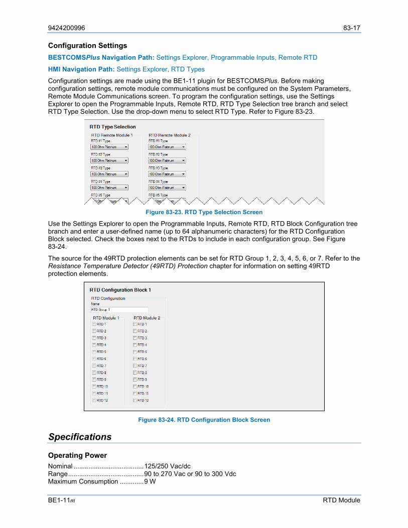
9424200996 83-17
BE1-11m RTD Module
Configuration Settings BESTCOMSPlus Navigation Path: Settings Explorer, Programmable Inputs, Remote RTD
HMI Navigation Path: Settings Explorer, RTD Types
Configuration settings are made using the BE1-11 plugin for BESTCOMSPlus. Before making configuration settings, remote module communications must be configured on the System Parameters, Remote Module Communications screen. To program the configuration settings, use the Settings Explorer to open the Programmable Inputs, Remote RTD, RTD Type Selection tree branch and select RTD Type Selection. Use the drop-down menu to select RTD Type. Refer to Figure 83-23.
Figure 83-23. RTD Type Selection Screen
Use the Settings Explorer to open the Programmable Inputs, Remote RTD, RTD Block Configuration tree branch and enter a user-defined name (up to 64 alphanumeric characters) for the RTD Configuration Block selected. Check the boxes next to the RTDs to include in each configuration group. See Figure 83-24.
The source for the 49RTD protection elements can be set for RTD Group 1, 2, 3, 4, 5, 6, or 7. Refer to the Resistance Temperature Detector (49RTD) Protection chapter for information on setting 49RTD protection elements.
Figure 83-24. RTD Configuration Block Screen
Specifications
Operating Power Nominal ...................................... 125/250 Vac/dc Range ......................................... 90 to 270 Vac or 90 to 300 Vdc Maximum Consumption ............. 9 W
83-18 9424200996
RTD Module BE1-11m
Analog Inputs The RTD module contains four programmable analog inputs. Rating ......................................... 4 to 20 mAdc or 0 to 10 Vdc (user-selectable)
RTD Inputs The RTD module contains 12 programmable RTD inputs. User-Selectable Types ............... 100 Ω Platinum (DIN43760), 10 Ω Copper, 100 Ω Nickel, or 120 Ω Nickel Range ......................................... –50 to 250°C (–58 to 482°F) Accuracy..................................... ±2°C (3.6°F) Maximum Lead Length ............... 150 feet (45.72 m) with 22 AWG (0.326 mm2) wire Sensing Current Level ................ 2.5 mA Isolation ...................................... 35 Vpp
Analog Outputs The RTD module contains four programmable analog outputs. Rating ......................................... 4 to 20 mAdc or 0 to 10 Vdc (user-selectable)
Current Accuracy..................................... ±0.053% of full scale (10 V) at 25°C Temperature Dependence ......... ±0.029% drift per degree Celsius
Voltage Accuracy..................................... ±0.055% of full scale (20 mA) at 25°C Temperature Dependence ......... ±0.04% drift per degree Celsius
Alarm Contact Type ........................................... Form C (SPDT) Rating ......................................... 24/48/125/250 Vdc at:
o 30 A make for 0.2 seconds o 7 A continuous o 0.3 Adc Break (L/R = 0.04)
Communication Interface
Ethernet
An RTD module with part number 9444100101 is equipped with both fiber and copper Ethernet connections. An RTD module with part number 9444100100 is equipped with only a copper Ethernet connection.
Copper Type (RJ45 Connector) Version ...................................................................... 10BASE-T/100BASE-TX Maximum Length (One Network Segment) ............... 328 ft (100 m)
Fiber Optic Type (ST Connector) Version ...................................................................... 100BASE-FX, multimode Maximum Length (Half-Duplex) ................................ 1,310 ft (399 m) Maximum Length (Full-Duplex) ................................. 6,600 ft (2,011 m)
Serial
RS-485 19,200 baud
Temperature Operating Range ........................ –40°C to 70°C (–40°F to 158°F) Storage Range ........................... –40°C to 70°C (–40°F to 158°F)

9424200996 83-19
BE1-11m RTD Module
Standards IEC 60068-1: Environmental Testing Part 1: General and Guidance. Temperature Test
IEC 60068-2-1: Basic Environmental Testing Procedures, Part 2: Tests - Test Ad: Cold (Type Test)
IEC 60068-2-2: Basic Environmental Testing Procedures, Part 2: Tests - Test Bd: Dry Heat (Type Test)
IEC 60068-2-28: Environmental Testing Part 2: Testing-Guidance for Damp Heat Tests
IEC 60255-4: Single Input Energizing Quantity Measuring Relays with Dependent Specified Time
IEC 60255-5: Electrical Insulation Tests for Electrical Relays. Dielectric Test and Impulse Test
IEC 60255-6: Electrical Relays - Measuring Relays and Protection Equipment
IEC 60255-21-1: Vibration, Shock, Bump, and Seismic Tests on Measuring Relays and Protective Equipment (Section 1 - Vibration Test - Sinusoidal). Class 1
IEC 60255-21-2: Vibration, Shock, Bump, and Seismic Tests on Measuring Relays and Protective Equipment (Section 2 - Shock and Bump Test - Sinusoidal). Class 1
IEEE C37.90.1: Surge Withstand Capability (SWC) Tests for Relays and Relay Systems Associated with Electric Power Apparatus
IEEE C37.90.2: Withstand Capability of Relay Systems to Radiated Electromagnetic Interference from Transceivers
UL Approval “cURus” recognized to UL Standard 508 & CSA Standard C22.2 No.14
CSA Certification CSA certified to Standard C22.2 No.14.
CE and UKCA Compliance This product has been evaluated and complies with the requirements set forth by the EU legislation and UK Parliament.
EC Directives: • LVD 2014/35/EU • EMC 2014/30/EU • RoHS2 2011/65/EU
Harmonized Standards used for evaluation: • EN 50178:1997 - Electronic Equipment for use in Power Installations • EN 61000-6-4:2001 - Electromagnetic Compatibility (EMC), Generic Standards, Emission
Standard for Industrial Environments • EN 61000-6-2:2001 - Electromagnetic Compatibility (EMC), Generic Standards, Immunity for
Industrial Environments • EN 61000-4-2: Electrostatic Discharge Immunity • EN 61000-4-3: Radiated, Radio-Frequency, Electromagnetic Field Immunity • EN 61000-4-4: EFT Immunity • EN 61000-4-5: Surge Immunity • EN 61000-4-6: Conducted Immunity • EN 61000-4-8: Power Frequency Magnetic Field Immunity • EN 61000-4-11: Voltage Dips and Interrupts
83-20 9424200996
RTD Module BE1-11m
HALT (Highly Accelerated Life Testing) Basler Electric uses HALT to prove that our products will provide the user with many years of reliable service. HALT subjects the device to extremes in temperature, shock, and vibration to simulate years of operation, but in a much shorter period span. HALT allows Basler Electric to evaluate all possible design elements that will add to the life of this device. As an example of some of the extreme testing conditions, the RTD module was subjected to temperature extremes of –80°C to +130°C, vibration extremes of 5 to 45 G at +20°C, and temperature/vibration extremes of 45 G over a temperature range of –60°C to +110°C. Combined temperature and vibration testing at these extremes proves that the RTD module is expected to provide long-term operation in a rugged environment. Note that the vibration and temperature extremes listed in this paragraph are specific to HALT and do not reflect recommended operation levels. These operational ratings are listed under Temperature.
Physical Weight ........................................ 2.15 lb (0.975 kg) IP Class ...................................... IP50 Size ............................................ Refer to Mounting.
Repair
RTD modules are manufactured using state-of-the-art surface-mount technology. As such, Basler Electric recommends that no repair procedures be attempted by anyone other than Basler Electric personnel.
Before returning the RTD module for repair, contact the Basler Electric Technical Services Department at 618-654-2341 for a return authorization number.
Maintenance Preventive maintenance consists of periodically checking that the connections between the RTD module and the system are clean and tight.
Storage
This device contains long-life aluminum electrolytic capacitors. For devices that are not in service (spares in storage), the life of these capacitors can be maximized by energizing the device for 30 minutes once per year.
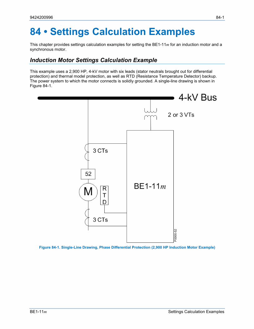
9424200996 84-1
BE1-11m Settings Calculation Examples
84 • Settings Calculation Examples This chapter provides settings calculation examples for setting the BE1-11m for an induction motor and a synchronous motor.
Induction Motor Settings Calculation Example
This example uses a 2,900 HP, 4-kV motor with six leads (stator neutrals brought out for differential protection) and thermal model protection, as well as RTD (Resistance Temperature Detector) backup. The power system to which the motor connects is solidly grounded. A single-line drawing is shown in Figure 84-1.
Figure 84-1. Single-Line Drawing, Phase Differential Protection (2,900 HP Induction Motor Example)
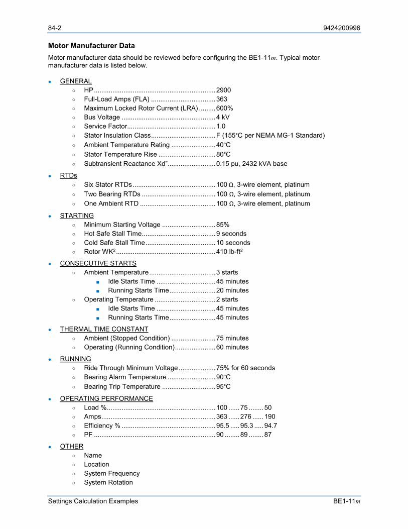
84-2 9424200996
Settings Calculation Examples BE1-11m
Motor Manufacturer Data Motor manufacturer data should be reviewed before configuring the BE1-11m. Typical motor manufacturer data is listed below.
GENERAL HP .................................................................. 2900 Full-Load Amps (FLA) ................................... 363 Maximum Locked Rotor Current (LRA) ......... 600% Bus Voltage ................................................... 4 kV Service Factor................................................ 1.0 Stator Insulation Class ................................... F (155°C per NEMA MG-1 Standard) Ambient Temperature Rating ........................ 40°C Stator Temperature Rise ............................... 80°C Subtransient Reactance Xd”.......................... 0.15 pu, 2432 kVA base
RTDs Six Stator RTDs ............................................. 100 Ω, 3-wire element, platinum Two Bearing RTDs ........................................ 100 Ω, 3-wire element, platinum One Ambient RTD ......................................... 100 Ω, 3-wire element, platinum
STARTING Minimum Starting Voltage ............................. 85% Hot Safe Stall Time ........................................ 9 seconds Cold Safe Stall Time ...................................... 10 seconds Rotor WK2 ...................................................... 410 lb-ft2
CONSECUTIVE STARTS Ambient Temperature .................................... 3 starts
Idle Starts Time ................................ 45 minutes Running Starts Time ......................... 20 minutes
Operating Temperature ................................. 2 starts Idle Starts Time ................................ 45 minutes Running Starts Time ......................... 45 minutes
THERMAL TIME CONSTANT Ambient (Stopped Condition) ........................ 75 minutes Operating (Running Condition) ...................... 60 minutes
RUNNING Ride Through Minimum Voltage .................... 75% for 60 seconds Bearing Alarm Temperature .......................... 90°C Bearing Trip Temperature ............................. 95°C
OPERATING PERFORMANCE Load % ........................................................... 100 ...... 75 ........ 50 Amps .............................................................. 363 ...... 276 ...... 190 Efficiency % ................................................... 95.5 ..... 95.3 ..... 94.7 PF .................................................................. 90 ........ 89 ........ 87
OTHER Name Location System Frequency System Rotation
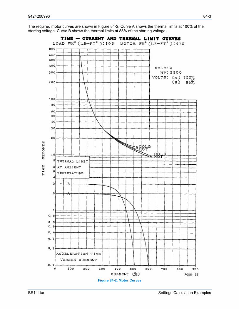
9424200996 84-3
BE1-11m Settings Calculation Examples
The required motor curves are shown in Figure 84-2. Curve A shows the thermal limits at 100% of the starting voltage. Curve B shows the thermal limits at 85% of the starting voltage.
Figure 84-2. Motor Curves
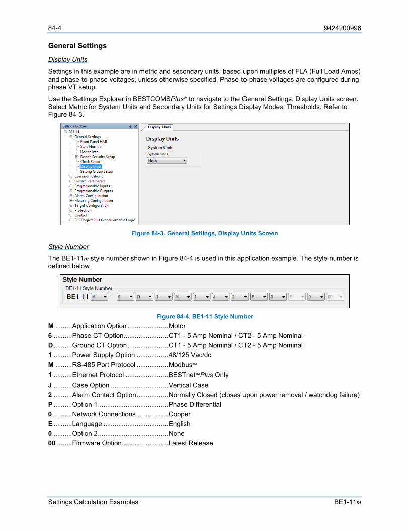
84-4 9424200996
Settings Calculation Examples BE1-11m
General Settings
Display Units
Settings in this example are in metric and secondary units, based upon multiples of FLA (Full Load Amps) and phase-to-phase voltages, unless otherwise specified. Phase-to-phase voltages are configured during phase VT setup.
Use the Settings Explorer in BESTCOMSPlus® to navigate to the General Settings, Display Units screen. Select Metric for System Units and Secondary Units for Settings Display Modes, Thresholds. Refer to Figure 84-3.
Figure 84-3. General Settings, Display Units Screen
Style Number
The BE1-11m style number shown in Figure 84-4 is used in this application example. The style number is defined below.
Figure 84-4. BE1-11 Style Number
M ......... Application Option ...................... Motor 6 .......... Phase CT Option ........................ CT1 - 5 Amp Nominal / CT2 - 5 Amp Nominal D .......... Ground CT Option ...................... CT1 - 5 Amp Nominal / CT2 - 5 Amp Nominal 1 .......... Power Supply Option ................. 48/125 Vac/dc M ......... RS-485 Port Protocol ................. Modbus™ 1 .......... Ethernet Protocol ....................... BESTnet™Plus Only J .......... Case Option ............................... Vertical Case 2 .......... Alarm Contact Option ................. Normally Closed (closes upon power removal / watchdog failure) P .......... Option 1 ...................................... Phase Differential 0 .......... Network Connections ................. Copper E .......... Language ................................... English 0 .......... Option 2 ...................................... None 00 ........ Firmware Option ......................... Latest Release
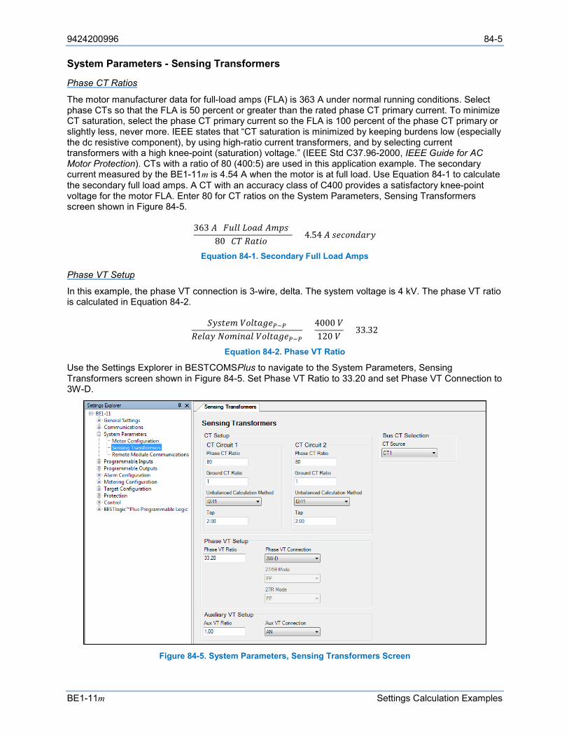
9424200996 84-5
BE1-11m Settings Calculation Examples
System Parameters - Sensing Transformers
Phase CT Ratios
The motor manufacturer data for full-load amps (FLA) is 363 A under normal running conditions. Select phase CTs so that the FLA is 50 percent or greater than the rated phase CT primary current. To minimize CT saturation, select the phase CT primary current so the FLA is 100 percent of the phase CT primary or slightly less, never more. IEEE states that “CT saturation is minimized by keeping burdens low (especially the dc resistive component), by using high-ratio current transformers, and by selecting current transformers with a high knee-point (saturation) voltage.” (IEEE Std C37.96-2000, IEEE Guide for AC Motor Protection). CTs with a ratio of 80 (400:5) are used in this application example. The secondary current measured by the BE1-11m is 4.54 A when the motor is at full load. Use Equation 84-1 to calculate the secondary full load amps. A CT with an accuracy class of C400 provides a satisfactory knee-point voltage for the motor FLA. Enter 80 for CT ratios on the System Parameters, Sensing Transformers screen shown in Figure 84-5.
363 𝐴𝐴 (𝐹𝐹𝐹𝐹𝐹𝐹𝐹𝐹 𝐿𝐿𝐿𝐿𝐿𝐿𝐿𝐿 𝐴𝐴𝐴𝐴𝐴𝐴𝐴𝐴)80 (𝐶𝐶𝐶𝐶 𝑅𝑅𝐿𝐿𝑅𝑅𝑅𝑅𝐿𝐿) = 4.54 𝐴𝐴 𝐴𝐴𝑠𝑠𝑠𝑠𝐿𝐿𝑠𝑠𝐿𝐿𝐿𝐿𝑠𝑠𝑠𝑠
Equation 84-1. Secondary Full Load Amps
Phase VT Setup
In this example, the phase VT connection is 3-wire, delta. The system voltage is 4 kV. The phase VT ratio is calculated in Equation 84-2.
𝑆𝑆𝑠𝑠𝐴𝐴𝑅𝑅𝑠𝑠𝐴𝐴 𝑉𝑉𝐿𝐿𝐹𝐹𝑅𝑅𝐿𝐿𝑉𝑉𝑠𝑠𝑃𝑃−𝑃𝑃𝑅𝑅𝑠𝑠𝐹𝐹𝐿𝐿𝑠𝑠 𝑁𝑁𝐿𝐿𝐴𝐴𝑅𝑅𝑠𝑠𝐿𝐿𝐹𝐹 𝑉𝑉𝐿𝐿𝐹𝐹𝑅𝑅𝐿𝐿𝑉𝑉𝑠𝑠𝑃𝑃−𝑃𝑃
=4000 𝑉𝑉120 𝑉𝑉
= 33.32
Equation 84-2. Phase VT Ratio
Use the Settings Explorer in BESTCOMSPlus to navigate to the System Parameters, Sensing Transformers screen shown in Figure 84-5. Set Phase VT Ratio to 33.20 and set Phase VT Connection to 3W-D.
Figure 84-5. System Parameters, Sensing Transformers Screen
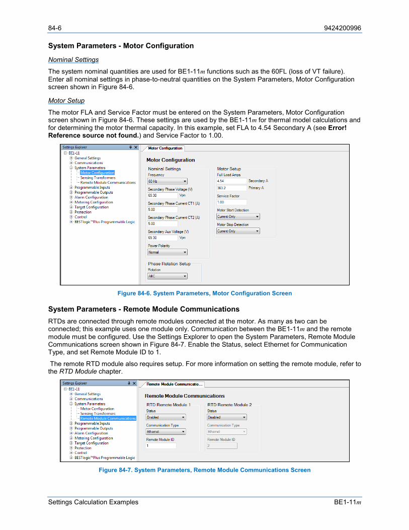
84-6 9424200996
Settings Calculation Examples BE1-11m
System Parameters - Motor Configuration
Nominal Settings
The system nominal quantities are used for BE1-11m functions such as the 60FL (loss of VT failure). Enter all nominal settings in phase-to-neutral quantities on the System Parameters, Motor Configuration screen shown in Figure 84-6.
Motor Setup
The motor FLA and Service Factor must be entered on the System Parameters, Motor Configuration screen shown in Figure 84-6. These settings are used by the BE1-11m for thermal model calculations and for determining the motor thermal capacity. In this example, set FLA to 4.54 Secondary A (see Error! Reference source not found.) and Service Factor to 1.00.
Figure 84-6. System Parameters, Motor Configuration Screen
System Parameters - Remote Module Communications RTDs are connected through remote modules connected at the motor. As many as two can be connected; this example uses one module only. Communication between the BE1-11m and the remote module must be configured. Use the Settings Explorer to open the System Parameters, Remote Module Communications screen shown in Figure 84-7. Enable the Status, select Ethernet for Communication Type, and set Remote Module ID to 1.
The remote RTD module also requires setup. For more information on setting the remote module, refer to the RTD Module chapter.
Figure 84-7. System Parameters, Remote Module Communications Screen
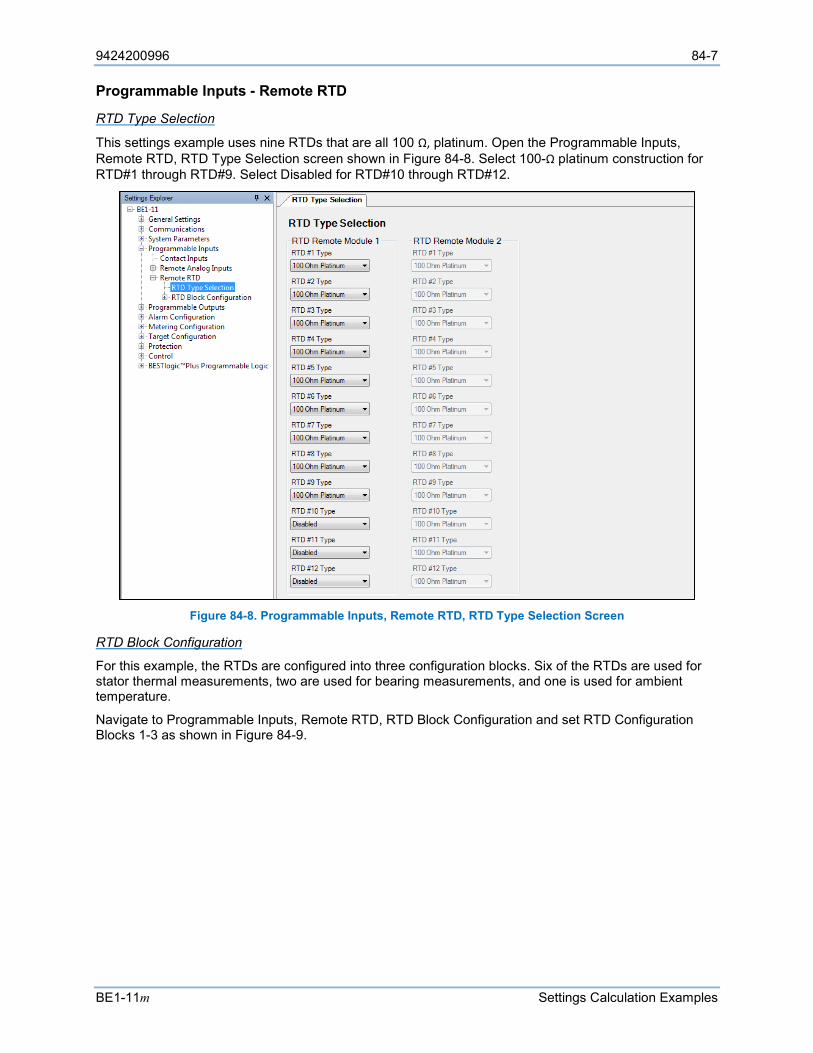
9424200996 84-7
BE1-11m Settings Calculation Examples
Programmable Inputs - Remote RTD
RTD Type Selection
This settings example uses nine RTDs that are all 100 Ω, platinum. Open the Programmable Inputs, Remote RTD, RTD Type Selection screen shown in Figure 84-8. Select 100-Ω platinum construction for RTD#1 through RTD#9. Select Disabled for RTD#10 through RTD#12.
Figure 84-8. Programmable Inputs, Remote RTD, RTD Type Selection Screen
RTD Block Configuration
For this example, the RTDs are configured into three configuration blocks. Six of the RTDs are used for stator thermal measurements, two are used for bearing measurements, and one is used for ambient temperature.
Navigate to Programmable Inputs, Remote RTD, RTD Block Configuration and set RTD Configuration Blocks 1-3 as shown in Figure 84-9.
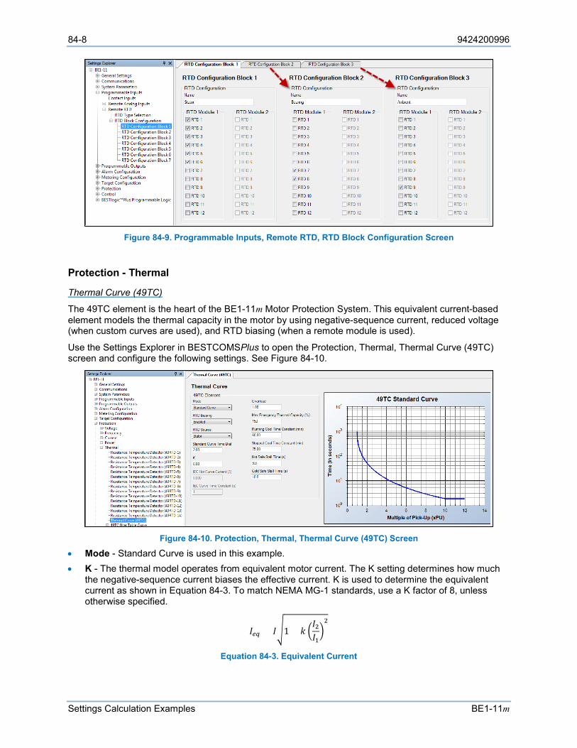
84-8 9424200996
Settings Calculation Examples BE1-11m
Figure 84-9. Programmable Inputs, Remote RTD, RTD Block Configuration Screen
Protection - Thermal
Thermal Curve (49TC)
The 49TC element is the heart of the BE1-11m Motor Protection System. This equivalent current-based element models the thermal capacity in the motor by using negative-sequence current, reduced voltage (when custom curves are used), and RTD biasing (when a remote module is used).
Use the Settings Explorer in BESTCOMSPlus to open the Protection, Thermal, Thermal Curve (49TC) screen and configure the following settings. See Figure 84-10.
Figure 84-10. Protection, Thermal, Thermal Curve (49TC) Screen
• Mode - Standard Curve is used in this example. • K - The thermal model operates from equivalent motor current. The K setting determines how much
the negative-sequence current biases the effective current. K is used to determine the equivalent current as shown in Equation 84-3. To match NEMA MG-1 standards, use a K factor of 8, unless otherwise specified.
𝐼𝐼𝑒𝑒𝑒𝑒 = 𝐼𝐼1 + 𝑘𝑘 𝐼𝐼2𝐼𝐼12
Equation 84-3. Equivalent Current
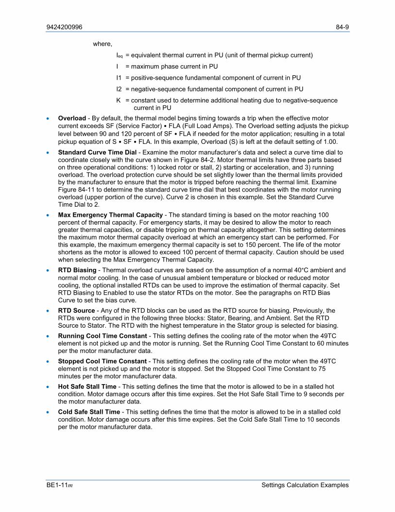
9424200996 84-9
BE1-11m Settings Calculation Examples
where,
Ieq = equivalent thermal current in PU (unit of thermal pickup current)
I = maximum phase current in PU
I1 = positive-sequence fundamental component of current in PU
I2 = negative-sequence fundamental component of current in PU
K = constant used to determine additional heating due to negative-sequence current in PU
• Overload - By default, the thermal model begins timing towards a trip when the effective motor current exceeds SF (Service Factor) • FLA (Full Load Amps). The Overload setting adjusts the pickup level between 90 and 120 percent of SF • FLA if needed for the motor application; resulting in a total pickup equation of S • SF • FLA. In this example, Overload (S) is left at the default setting of 1.00.
• Standard Curve Time Dial - Examine the motor manufacturer’s data and select a curve time dial to coordinate closely with the curve shown in Figure 84-2. Motor thermal limits have three parts based on three operational conditions: 1) locked rotor or stall, 2) starting or acceleration, and 3) running overload. The overload protection curve should be set slightly lower than the thermal limits provided by the manufacturer to ensure that the motor is tripped before reaching the thermal limit. Examine Figure 84-11 to determine the standard curve time dial that best coordinates with the motor running overload (upper portion of the curve). Curve 2 is chosen in this example. Set the Standard Curve Time Dial to 2.
• Max Emergency Thermal Capacity - The standard timing is based on the motor reaching 100 percent of thermal capacity. For emergency starts, it may be desired to allow the motor to reach greater thermal capacities, or disable tripping on thermal capacity altogether. This setting determines the maximum motor thermal capacity overload at which an emergency start can be performed. For this example, the maximum emergency thermal capacity is set to 150 percent. The life of the motor shortens as the motor is allowed to exceed 100 percent of thermal capacity. Caution should be used when selecting the Max Emergency Thermal Capacity.
• RTD Biasing - Thermal overload curves are based on the assumption of a normal 40°C ambient and normal motor cooling. In the case of unusual ambient temperature or blocked or reduced motor cooling, the optional installed RTDs can be used to improve the estimation of thermal capacity. Set RTD Biasing to Enabled to use the stator RTDs on the motor. See the paragraphs on RTD Bias Curve to set the bias curve.
• RTD Source - Any of the RTD blocks can be used as the RTD source for biasing. Previously, the RTDs were configured in the following three blocks: Stator, Bearing, and Ambient. Set the RTD Source to Stator. The RTD with the highest temperature in the Stator group is selected for biasing.
• Running Cool Time Constant - This setting defines the cooling rate of the motor when the 49TC element is not picked up and the motor is running. Set the Running Cool Time Constant to 60 minutes per the motor manufacturer data.
• Stopped Cool Time Constant - This setting defines the cooling rate of the motor when the 49TC element is not picked up and the motor is stopped. Set the Stopped Cool Time Constant to 75 minutes per the motor manufacturer data.
• Hot Safe Stall Time - This setting defines the time that the motor is allowed to be in a stalled hot condition. Motor damage occurs after this time expires. Set the Hot Safe Stall Time to 9 seconds per the motor manufacturer data.
• Cold Safe Stall Time - This setting defines the time that the motor is allowed to be in a stalled cold condition. Motor damage occurs after this time expires. Set the Cold Safe Stall Time to 10 seconds per the motor manufacturer data.
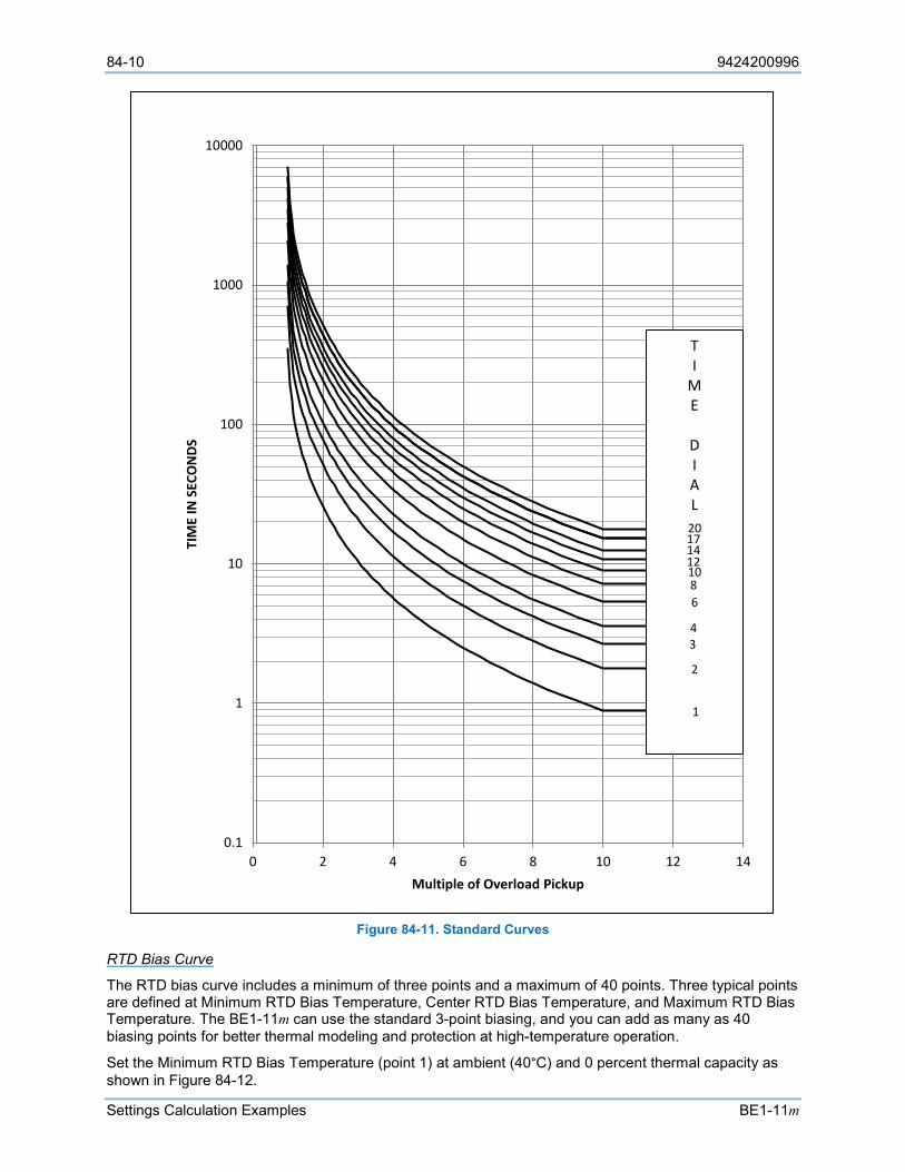
84-10 9424200996
Settings Calculation Examples BE1-11m
Figure 84-11. Standard Curves
RTD Bias Curve
The RTD bias curve includes a minimum of three points and a maximum of 40 points. Three typical points are defined at Minimum RTD Bias Temperature, Center RTD Bias Temperature, and Maximum RTD Bias Temperature. The BE1-11m can use the standard 3-point biasing, and you can add as many as 40 biasing points for better thermal modeling and protection at high-temperature operation.
Set the Minimum RTD Bias Temperature (point 1) at ambient (40°C) and 0 percent thermal capacity as shown in Figure 84-12.
0.1
1
10
100
1000
10000
0 2 4 6 8 10 12 14
TIM
E IN
SEC
ON
DS
Multiple of Overload Pickup
TI
ME
DIAL
20171412
4
1086
3
2
1
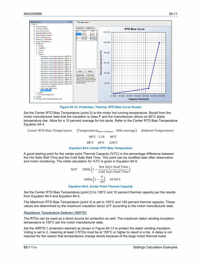
9424200996 84-11
BE1-11m Settings Calculation Examples
Figure 84-12. Protection, Thermal, RTD Bias Curve Screen
Set the Center RTD Bias Temperature (point 2) to the motor hot running temperature. Recall from the motor manufacturer data that the insulation is class F and the manufacturer allows an 80°C stator temperature rise. Allow for a 10 percent overage for hot spots. Refer to the Center RTD Bias Temperature Equation 84-4.
𝐶𝐶𝑠𝑠𝑠𝑠𝑅𝑅𝑠𝑠𝑠𝑠 𝑅𝑅𝐶𝐶𝑅𝑅 𝐵𝐵𝑅𝑅𝐿𝐿𝐴𝐴 𝐶𝐶𝑠𝑠𝐴𝐴𝐴𝐴𝑠𝑠𝑠𝑠𝐿𝐿𝑅𝑅𝐹𝐹𝑠𝑠𝑠𝑠 = 𝐶𝐶𝑠𝑠𝐴𝐴𝐴𝐴𝑠𝑠𝑠𝑠𝐿𝐿𝑅𝑅𝐹𝐹𝑠𝑠𝑠𝑠𝑅𝑅𝑅𝑅𝑅𝑅𝑒𝑒 𝑜𝑜𝑜𝑜 𝑆𝑆𝑆𝑆𝑆𝑆𝑆𝑆𝑜𝑜𝑆𝑆 ∙ 10% 𝐿𝐿𝑜𝑜𝑠𝑠𝑠𝑠𝐿𝐿𝑉𝑉𝑠𝑠 + 𝐴𝐴𝐴𝐴𝐴𝐴𝑅𝑅𝑠𝑠𝑠𝑠𝑅𝑅 𝐶𝐶𝑠𝑠𝐴𝐴𝐴𝐴𝑠𝑠𝑠𝑠𝐿𝐿𝑅𝑅𝐹𝐹𝑠𝑠𝑠𝑠
= (80°𝐶𝐶 ∙ 1.10) + 40°𝐶𝐶
= 88°𝐶𝐶 + 40°𝐶𝐶 = 128°𝐶𝐶 Equation 84-4. Center RTD Bias Temperature
A good starting point for the center point Thermal Capacity (%TC) is the percentage difference between the Hot Safe Stall Time and the Cold Safe Stall Time. This point can be modified later after observation and motor monitoring. The initial calculation for %TC is given in Equation 84-5.
%𝐶𝐶𝐶𝐶 = 100% 1 −𝐻𝐻𝐿𝐿𝑅𝑅 𝑆𝑆𝐿𝐿𝑆𝑆𝑠𝑠 𝑆𝑆𝑅𝑅𝐿𝐿𝐹𝐹𝐹𝐹 𝐶𝐶𝑅𝑅𝐴𝐴𝑠𝑠𝐶𝐶𝐿𝐿𝐹𝐹𝐿𝐿 𝑆𝑆𝐿𝐿𝑆𝑆𝑠𝑠 𝑆𝑆𝑅𝑅𝐿𝐿𝐹𝐹𝐹𝐹 𝐶𝐶𝑅𝑅𝐴𝐴𝑠𝑠
= 100% 1 −9
10 = 10 %𝐶𝐶𝐶𝐶
Equation 84-5. Center Point Thermal Capacity
Set the Center RTD Bias Temperature (point 2) to 128°C and 10 percent thermal capacity per the results from Equation 84-4 and Equation 84-5.
The Maximum RTD Bias Temperature (point 3) is set to 155°C and 100 percent thermal capacity. These values are determined by the maximum insulation factor of F according to the motor manufacturer data.
Resistance Temperature Detector (49RTD)
The RTDs can be used as a direct source for protection as well. The maximum stator winding insulation temperature is 155°C per the motor manufacturer data.
Set the 49RTD-1 protection element as shown in Figure 84-13 to protect the stator winding insulation. Voting is set to 2, meaning at least 2 RTDs must be at 155°C or higher to result in a trip. A delay is not required for the reason that temperatures change slowly because of the large motor thermal mass.
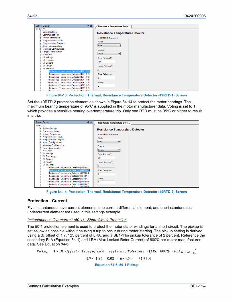
84-12 9424200996
Settings Calculation Examples BE1-11m
Figure 84-13. Protection, Thermal, Resistance Temperature Detector (49RTD-1) Screen
Set the 49RTD-2 protection element as shown in Figure 84-14 to protect the motor bearings. The maximum bearing temperature of 95°C is supplied in the motor manufacturer data. Voting is set to 1, which provides a sensitive bearing overtemperature trip. Only one RTD must be 95°C or higher to result in a trip.
Figure 84-14. Protection, Thermal, Resistance Temperature Detector (49RTD-2) Screen
Protection - Current Five instantaneous overcurrent elements, one current differential element, and one instantaneous undercurrent element are used in this settings example.
Instantaneous Overcurrent (50-1) - Short-Circuit Protection
The 50-1 protection element is used to protect the motor stator windings for a short circuit. The pickup is set as low as possible without causing a trip to occur during motor starting. The pickup setting is derived using a dc offset of 1.7, 125 percent of LRA, and a BE1-11m pickup tolerance of 2 percent. Reference the secondary FLA (Equation 84-1) and LRA (Max Locked Rotor Current) of 600% per motor manufacturer data. See Equation 84-6.
𝑃𝑃𝑅𝑅𝑠𝑠𝑘𝑘𝐹𝐹𝐴𝐴 = 1.7 𝑅𝑅𝐶𝐶 𝑂𝑂𝑆𝑆𝑆𝑆𝐴𝐴𝑠𝑠𝑅𝑅 ∙ (125% 𝐿𝐿𝑆𝑆 𝐿𝐿𝑅𝑅𝐴𝐴 + 2% 𝑃𝑃𝑅𝑅𝑠𝑠𝑘𝑘𝐹𝐹𝐴𝐴 𝐶𝐶𝐿𝐿𝐹𝐹𝑠𝑠𝑠𝑠𝐿𝐿𝑠𝑠𝑠𝑠𝑠𝑠) ∙ 𝐿𝐿𝑅𝑅𝐶𝐶 (600%) ∙ 𝐹𝐹𝐿𝐿𝐴𝐴𝑆𝑆𝑒𝑒𝑆𝑆𝑜𝑜𝑆𝑆𝑆𝑆𝑆𝑆𝑆𝑆𝑆𝑆
= 1.7 ∙ (1.25 + 0.02) ∙ (6 ∙ 4.54) = 71.77 𝐴𝐴 Equation 84-6. 50-1 Pickup
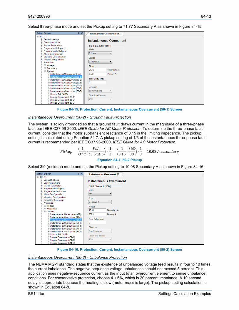
9424200996 84-13
BE1-11m Settings Calculation Examples
Select three-phase mode and set the Pickup setting to 71.77 Secondary A as shown in Figure 84-15.
Figure 84-15. Protection, Current, Instantaneous Overcurrent (50-1) Screen
Instantaneous Overcurrent (50-2) - Ground Fault Protection
The system is solidly grounded so that a ground fault draws current in the magnitude of a three-phase fault per IEEE C37.96-2000, IEEE Guide for AC Motor Protection. To determine the three-phase fault current, consider that the motor subtransient reactance of 0.15 is the limiting impedance. The pickup setting is calculated using Equation 84-7. A pickup setting of 1/3 of the instantaneous three-phase fault current is recommended per IEEE C37.96-2000, IEEE Guide for AC Motor Protection.
𝑃𝑃𝑅𝑅𝑠𝑠𝑘𝑘𝐹𝐹𝐴𝐴 = 1𝑋𝑋"𝐿𝐿
∙𝐹𝐹𝐿𝐿𝐴𝐴
𝐶𝐶𝐶𝐶 𝑅𝑅𝐿𝐿𝑅𝑅𝑅𝑅𝐿𝐿 ∙
13
= 1
0.15∙
36380
∙13
= 10.08 𝐴𝐴 𝐴𝐴𝑠𝑠𝑠𝑠𝐿𝐿𝑠𝑠𝐿𝐿𝐿𝐿𝑠𝑠𝑠𝑠
Equation 84-7. 50-2 Pickup
Select 3I0 (residual) mode and set the Pickup setting to 10.08 Secondary A as shown in Figure 84-16.
Figure 84-16. Protection, Current, Instantaneous Overcurrent (50-2) Screen
Instantaneous Overcurrent (50-3) - Unbalance Protection
The NEMA MG-1 standard states that the existence of unbalanced voltage feed results in four to 10 times the current imbalance. The negative-sequence voltage unbalances should not exceed 5 percent. This application uses negative-sequence current as the input to an overcurrent element to sense unbalance conditions. For conservative protection, choose 4 • 5%, which is 20 percent imbalance. A 10 second delay is appropriate because the heating is slow (motor mass is large). The pickup setting calculation is shown in Equation 84-8.
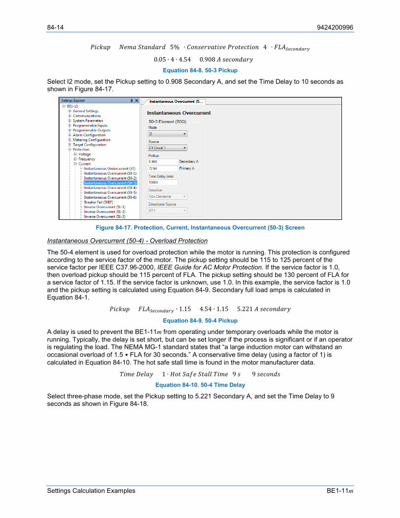
84-14 9424200996
Settings Calculation Examples BE1-11m
𝑃𝑃𝑅𝑅𝑠𝑠𝑘𝑘𝐹𝐹𝐴𝐴 = 𝑁𝑁𝑠𝑠𝐴𝐴𝐿𝐿 𝑆𝑆𝑅𝑅𝐿𝐿𝑠𝑠𝐿𝐿𝐿𝐿𝑠𝑠𝐿𝐿 (5%) ∙ 𝐶𝐶𝐿𝐿𝑠𝑠𝐴𝐴𝑠𝑠𝑠𝑠𝑜𝑜𝐿𝐿𝑅𝑅𝑅𝑅𝑜𝑜𝑠𝑠 𝑃𝑃𝑠𝑠𝐿𝐿𝑅𝑅𝑠𝑠𝑠𝑠𝑅𝑅𝑅𝑅𝐿𝐿𝑠𝑠 (4) ∙ 𝐹𝐹𝐿𝐿𝐴𝐴𝑆𝑆𝑒𝑒𝑆𝑆𝑜𝑜𝑆𝑆𝑆𝑆𝑆𝑆𝑆𝑆𝑆𝑆
= 0.05 ∙ 4 ∙ 4.54 = 0.908 𝐴𝐴 𝐴𝐴𝑠𝑠𝑠𝑠𝐿𝐿𝑠𝑠𝐿𝐿𝐿𝐿𝑠𝑠𝑠𝑠 Equation 84-8. 50-3 Pickup
Select I2 mode, set the Pickup setting to 0.908 Secondary A, and set the Time Delay to 10 seconds as shown in Figure 84-17.
Figure 84-17. Protection, Current, Instantaneous Overcurrent (50-3) Screen
Instantaneous Overcurrent (50-4) - Overload Protection
The 50-4 element is used for overload protection while the motor is running. This protection is configured according to the service factor of the motor. The pickup setting should be 115 to 125 percent of the service factor per IEEE C37.96-2000, IEEE Guide for AC Motor Protection. If the service factor is 1.0, then overload pickup should be 115 percent of FLA. The pickup setting should be 130 percent of FLA for a service factor of 1.15. If the service factor is unknown, use 1.0. In this example, the service factor is 1.0 and the pickup setting is calculated using Equation 84-9. Secondary full load amps is calculated in Equation 84-1.
𝑃𝑃𝑅𝑅𝑠𝑠𝑘𝑘𝐹𝐹𝐴𝐴 = 𝐹𝐹𝐿𝐿𝐴𝐴𝑆𝑆𝑒𝑒𝑆𝑆𝑜𝑜𝑆𝑆𝑆𝑆𝑆𝑆𝑆𝑆𝑆𝑆 ∙ 1.15 = 4.54 ∙ 1.15 = 5.221 𝐴𝐴 𝐴𝐴𝑠𝑠𝑠𝑠𝐿𝐿𝑠𝑠𝐿𝐿𝐿𝐿𝑠𝑠𝑠𝑠
Equation 84-9. 50-4 Pickup
A delay is used to prevent the BE1-11m from operating under temporary overloads while the motor is running. Typically, the delay is set short, but can be set longer if the process is significant or if an operator is regulating the load. The NEMA MG-1 standard states that “a large induction motor can withstand an occasional overload of 1.5 • FLA for 30 seconds.” A conservative time delay (using a factor of 1) is calculated in Equation 84-10. The hot safe stall time is found in the motor manufacturer data.
𝐶𝐶𝑅𝑅𝐴𝐴𝑠𝑠 𝑅𝑅𝑠𝑠𝐹𝐹𝐿𝐿𝑠𝑠 = 1 ∙ 𝐻𝐻𝐿𝐿𝑅𝑅 𝑆𝑆𝐿𝐿𝑆𝑆𝑠𝑠 𝑆𝑆𝑅𝑅𝐿𝐿𝐹𝐹𝐹𝐹 𝐶𝐶𝑅𝑅𝐴𝐴𝑠𝑠 (9 𝐴𝐴) = 9 𝐴𝐴𝑠𝑠𝑠𝑠𝐿𝐿𝑠𝑠𝐿𝐿𝐴𝐴 Equation 84-10. 50-4 Time Delay
Select three-phase mode, set the Pickup setting to 5.221 Secondary A, and set the Time Delay to 9 seconds as shown in Figure 84-18.
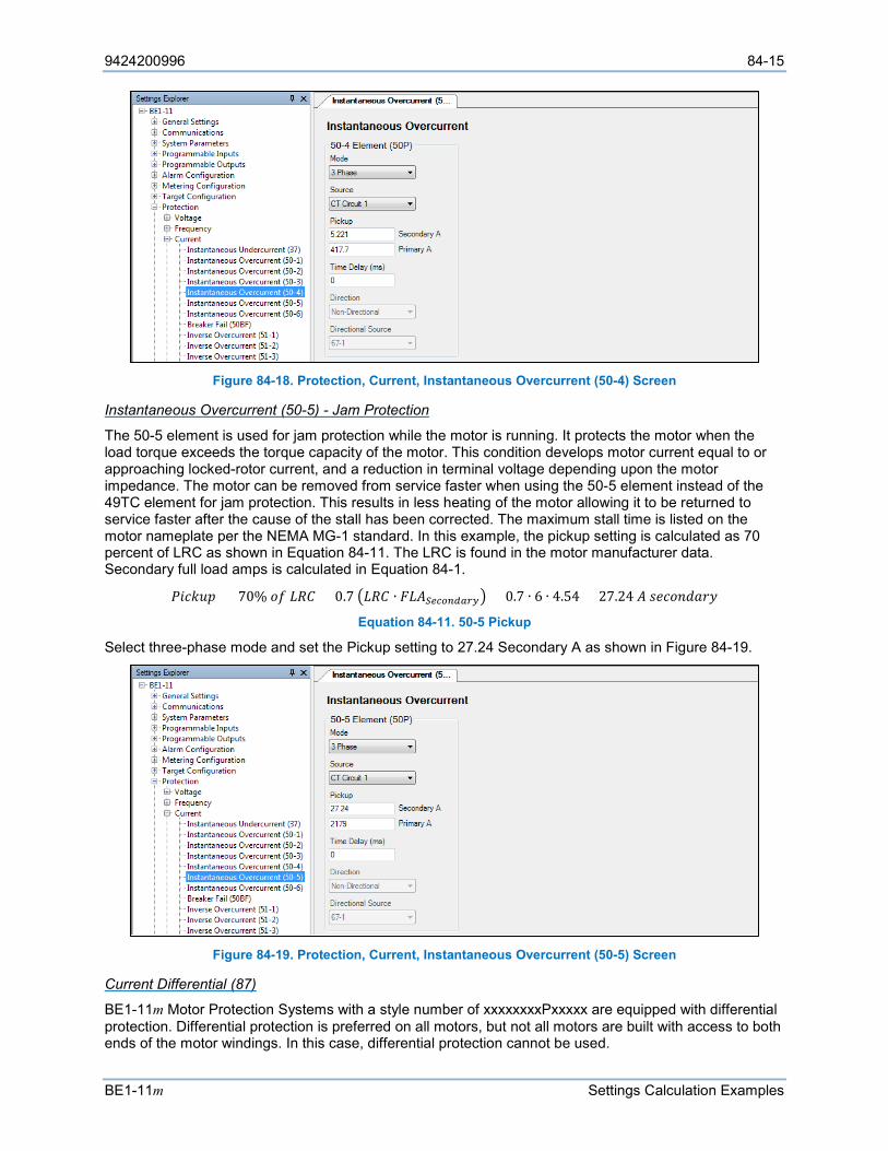
9424200996 84-15
BE1-11m Settings Calculation Examples
Figure 84-18. Protection, Current, Instantaneous Overcurrent (50-4) Screen
Instantaneous Overcurrent (50-5) - Jam Protection
The 50-5 element is used for jam protection while the motor is running. It protects the motor when the load torque exceeds the torque capacity of the motor. This condition develops motor current equal to or approaching locked-rotor current, and a reduction in terminal voltage depending upon the motor impedance. The motor can be removed from service faster when using the 50-5 element instead of the 49TC element for jam protection. This results in less heating of the motor allowing it to be returned to service faster after the cause of the stall has been corrected. The maximum stall time is listed on the motor nameplate per the NEMA MG-1 standard. In this example, the pickup setting is calculated as 70 percent of LRC as shown in Equation 84-11. The LRC is found in the motor manufacturer data. Secondary full load amps is calculated in Equation 84-1.
𝑃𝑃𝑅𝑅𝑠𝑠𝑘𝑘𝐹𝐹𝐴𝐴 = 70% 𝐿𝐿𝑆𝑆 𝐿𝐿𝑅𝑅𝐶𝐶 = 0.7 𝐿𝐿𝑅𝑅𝐶𝐶 ∙ 𝐹𝐹𝐿𝐿𝐴𝐴𝑆𝑆𝑒𝑒𝑆𝑆𝑜𝑜𝑆𝑆𝑆𝑆𝑆𝑆𝑆𝑆𝑆𝑆 = 0.7 ∙ 6 ∙ 4.54 = 27.24 𝐴𝐴 𝐴𝐴𝑠𝑠𝑠𝑠𝐿𝐿𝑠𝑠𝐿𝐿𝐿𝐿𝑠𝑠𝑠𝑠
Equation 84-11. 50-5 Pickup
Select three-phase mode and set the Pickup setting to 27.24 Secondary A as shown in Figure 84-19.
Figure 84-19. Protection, Current, Instantaneous Overcurrent (50-5) Screen
Current Differential (87)
BE1-11m Motor Protection Systems with a style number of xxxxxxxxPxxxxx are equipped with differential protection. Differential protection is preferred on all motors, but not all motors are built with access to both ends of the motor windings. In this case, differential protection cannot be used.
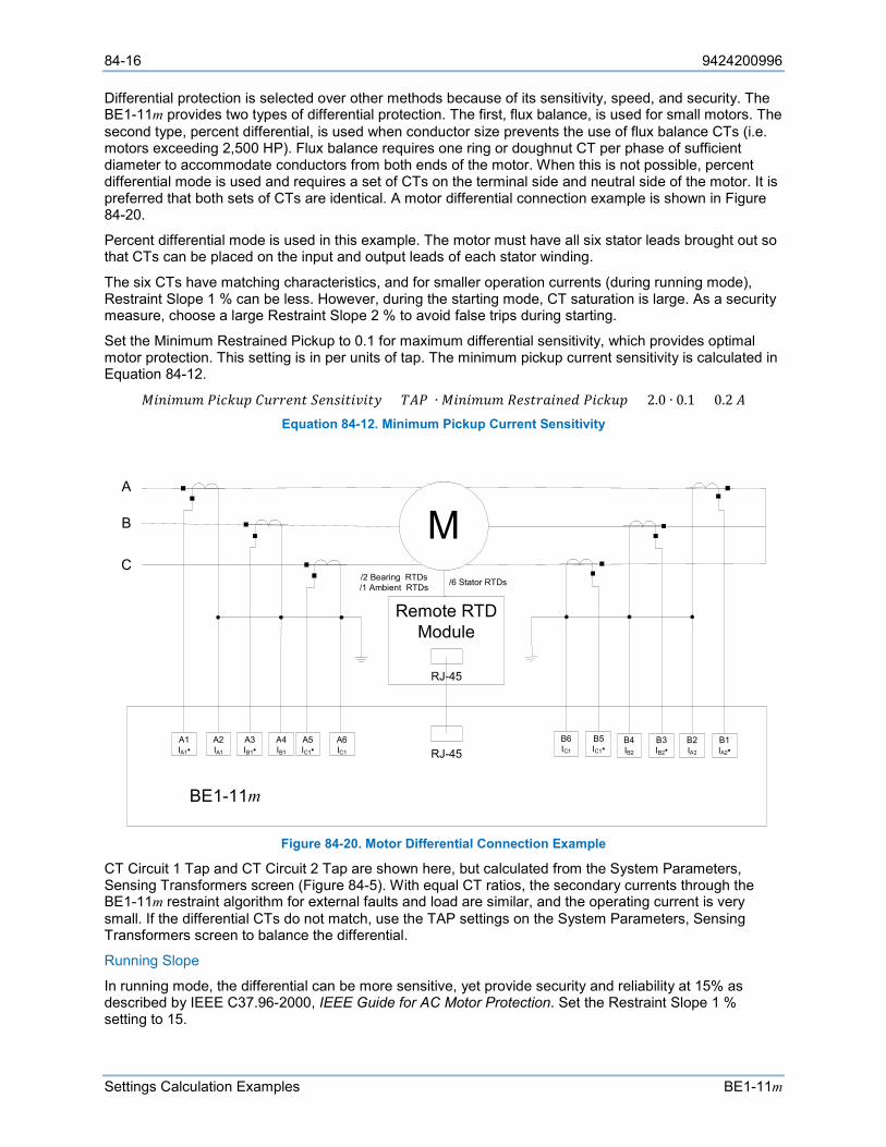
84-16 9424200996
Settings Calculation Examples BE1-11m
Differential protection is selected over other methods because of its sensitivity, speed, and security. The BE1-11m provides two types of differential protection. The first, flux balance, is used for small motors. The second type, percent differential, is used when conductor size prevents the use of flux balance CTs (i.e. motors exceeding 2,500 HP). Flux balance requires one ring or doughnut CT per phase of sufficient diameter to accommodate conductors from both ends of the motor. When this is not possible, percent differential mode is used and requires a set of CTs on the terminal side and neutral side of the motor. It is preferred that both sets of CTs are identical. A motor differential connection example is shown in Figure 84-20.
Percent differential mode is used in this example. The motor must have all six stator leads brought out so that CTs can be placed on the input and output leads of each stator winding.
The six CTs have matching characteristics, and for smaller operation currents (during running mode), Restraint Slope 1 % can be less. However, during the starting mode, CT saturation is large. As a security measure, choose a large Restraint Slope 2 % to avoid false trips during starting.
Set the Minimum Restrained Pickup to 0.1 for maximum differential sensitivity, which provides optimal motor protection. This setting is in per units of tap. The minimum pickup current sensitivity is calculated in Equation 84-12.
𝑀𝑀𝑅𝑅𝑠𝑠𝑅𝑅𝐴𝐴𝐹𝐹𝐴𝐴 𝑃𝑃𝑅𝑅𝑠𝑠𝑘𝑘𝐹𝐹𝐴𝐴 𝐶𝐶𝐹𝐹𝑠𝑠𝑠𝑠𝑠𝑠𝑠𝑠𝑅𝑅 𝑆𝑆𝑠𝑠𝑠𝑠𝐴𝐴𝑅𝑅𝑅𝑅𝑅𝑅𝑜𝑜𝑅𝑅𝑅𝑅𝑠𝑠 = 𝐶𝐶𝐴𝐴𝑃𝑃 ∙ 𝑀𝑀𝑅𝑅𝑠𝑠𝑅𝑅𝐴𝐴𝐹𝐹𝐴𝐴 𝑅𝑅𝑠𝑠𝐴𝐴𝑅𝑅𝑠𝑠𝐿𝐿𝑅𝑅𝑠𝑠𝑠𝑠𝐿𝐿 𝑃𝑃𝑅𝑅𝑠𝑠𝑘𝑘𝐹𝐹𝐴𝐴 = 2.0 ∙ 0.1 = 0.2 𝐴𝐴 Equation 84-12. Minimum Pickup Current Sensitivity
Figure 84-20. Motor Differential Connection Example
CT Circuit 1 Tap and CT Circuit 2 Tap are shown here, but calculated from the System Parameters, Sensing Transformers screen (Figure 84-5). With equal CT ratios, the secondary currents through the BE1-11m restraint algorithm for external faults and load are similar, and the operating current is very small. If the differential CTs do not match, use the TAP settings on the System Parameters, Sensing Transformers screen to balance the differential.
Running Slope
In running mode, the differential can be more sensitive, yet provide security and reliability at 15% as described by IEEE C37.96-2000, IEEE Guide for AC Motor Protection. Set the Restraint Slope 1 % setting to 15.
M
A 1 I A 1 •
A 2 I A 1
A 3 I B 1 •
A 4 I B 1
A 5 I C 1 •
A 6 I C 1
B 5 I C 1 •
B 6 I C 1
B 1 I A 2 •
B 2 I A 2
B 3 I B 2 •
B 4 I B 2
Remote RTD Module
BE 1 - 11 m
/ 6 Stator RTDs / 2 Bearing RTDs / 1 Ambient RTDs
RJ - 45
RJ - 45
A
B
C
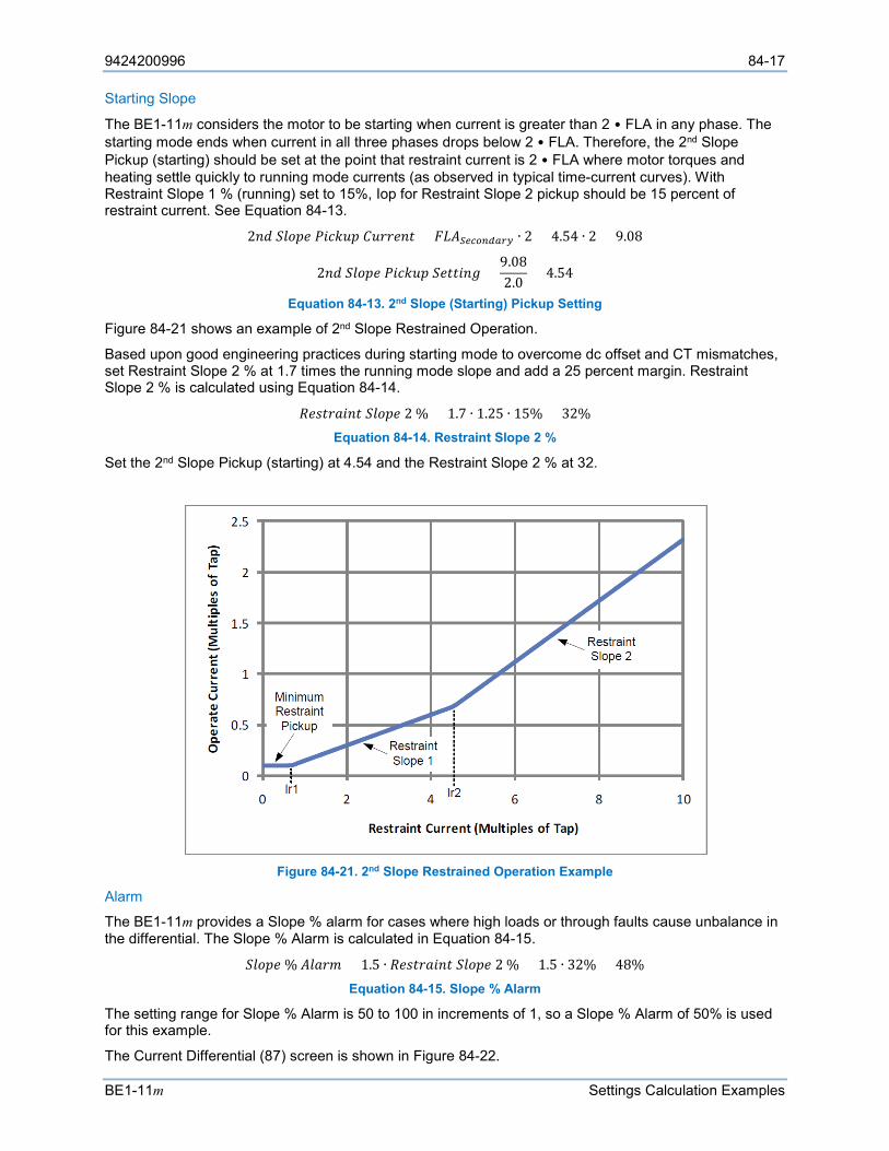
9424200996 84-17
BE1-11m Settings Calculation Examples
Starting Slope
The BE1-11m considers the motor to be starting when current is greater than 2 • FLA in any phase. The starting mode ends when current in all three phases drops below 2 • FLA. Therefore, the 2nd Slope Pickup (starting) should be set at the point that restraint current is 2 • FLA where motor torques and heating settle quickly to running mode currents (as observed in typical time-current curves). With Restraint Slope 1 % (running) set to 15%, Iop for Restraint Slope 2 pickup should be 15 percent of restraint current. See Equation 84-13.
2𝑠𝑠𝐿𝐿 𝑆𝑆𝐹𝐹𝐿𝐿𝐴𝐴𝑠𝑠 𝑃𝑃𝑅𝑅𝑠𝑠𝑘𝑘𝐹𝐹𝐴𝐴 𝐶𝐶𝐹𝐹𝑠𝑠𝑠𝑠𝑠𝑠𝑠𝑠𝑅𝑅 = 𝐹𝐹𝐿𝐿𝐴𝐴𝑆𝑆𝑒𝑒𝑆𝑆𝑜𝑜𝑆𝑆𝑆𝑆𝑆𝑆𝑆𝑆𝑆𝑆 ∙ 2 = 4.54 ∙ 2 = 9.08
2𝑠𝑠𝐿𝐿 𝑆𝑆𝐹𝐹𝐿𝐿𝐴𝐴𝑠𝑠 𝑃𝑃𝑅𝑅𝑠𝑠𝑘𝑘𝐹𝐹𝐴𝐴 𝑆𝑆𝑠𝑠𝑅𝑅𝑅𝑅𝑅𝑅𝑠𝑠𝑉𝑉 =9.082.0
= 4.54
Equation 84-13. 2nd Slope (Starting) Pickup Setting
Figure 84-21 shows an example of 2nd Slope Restrained Operation.
Based upon good engineering practices during starting mode to overcome dc offset and CT mismatches, set Restraint Slope 2 % at 1.7 times the running mode slope and add a 25 percent margin. Restraint Slope 2 % is calculated using Equation 84-14.
𝑅𝑅𝑠𝑠𝐴𝐴𝑅𝑅𝑠𝑠𝐿𝐿𝑅𝑅𝑠𝑠𝑅𝑅 𝑆𝑆𝐹𝐹𝐿𝐿𝐴𝐴𝑠𝑠 2 % = 1.7 ∙ 1.25 ∙ 15% = 32% Equation 84-14. Restraint Slope 2 %
Set the 2nd Slope Pickup (starting) at 4.54 and the Restraint Slope 2 % at 32.
Figure 84-21. 2nd Slope Restrained Operation Example
Alarm
The BE1-11m provides a Slope % alarm for cases where high loads or through faults cause unbalance in the differential. The Slope % Alarm is calculated in Equation 84-15.
𝑆𝑆𝐹𝐹𝐿𝐿𝐴𝐴𝑠𝑠 % 𝐴𝐴𝐹𝐹𝐿𝐿𝑠𝑠𝐴𝐴 = 1.5 ∙ 𝑅𝑅𝑠𝑠𝐴𝐴𝑅𝑅𝑠𝑠𝐿𝐿𝑅𝑅𝑠𝑠𝑅𝑅 𝑆𝑆𝐹𝐹𝐿𝐿𝐴𝐴𝑠𝑠 2 % = 1.5 ∙ 32% = 48% Equation 84-15. Slope % Alarm
The setting range for Slope % Alarm is 50 to 100 in increments of 1, so a Slope % Alarm of 50% is used for this example.
The Current Differential (87) screen is shown in Figure 84-22.
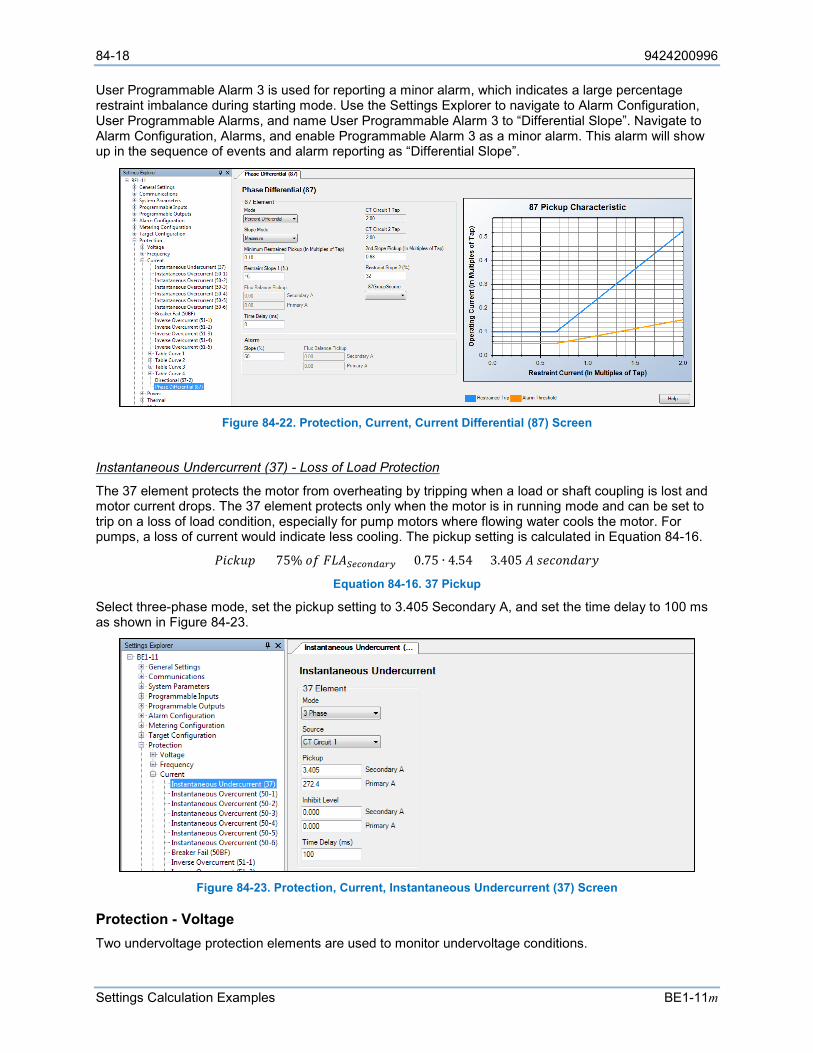
84-18 9424200996
Settings Calculation Examples BE1-11m
User Programmable Alarm 3 is used for reporting a minor alarm, which indicates a large percentage restraint imbalance during starting mode. Use the Settings Explorer to navigate to Alarm Configuration, User Programmable Alarms, and name User Programmable Alarm 3 to “Differential Slope”. Navigate to Alarm Configuration, Alarms, and enable Programmable Alarm 3 as a minor alarm. This alarm will show up in the sequence of events and alarm reporting as “Differential Slope”.
Figure 84-22. Protection, Current, Current Differential (87) Screen
Instantaneous Undercurrent (37) - Loss of Load Protection
The 37 element protects the motor from overheating by tripping when a load or shaft coupling is lost and motor current drops. The 37 element protects only when the motor is in running mode and can be set to trip on a loss of load condition, especially for pump motors where flowing water cools the motor. For pumps, a loss of current would indicate less cooling. The pickup setting is calculated in Equation 84-16.
𝑃𝑃𝑅𝑅𝑠𝑠𝑘𝑘𝐹𝐹𝐴𝐴 = 75% 𝐿𝐿𝑆𝑆 𝐹𝐹𝐿𝐿𝐴𝐴𝑆𝑆𝑒𝑒𝑆𝑆𝑜𝑜𝑆𝑆𝑆𝑆𝑆𝑆𝑆𝑆𝑆𝑆 = 0.75 ∙ 4.54 = 3.405 𝐴𝐴 𝐴𝐴𝑠𝑠𝑠𝑠𝐿𝐿𝑠𝑠𝐿𝐿𝐿𝐿𝑠𝑠𝑠𝑠
Equation 84-16. 37 Pickup
Select three-phase mode, set the pickup setting to 3.405 Secondary A, and set the time delay to 100 ms as shown in Figure 84-23.
Figure 84-23. Protection, Current, Instantaneous Undercurrent (37) Screen
Protection - Voltage Two undervoltage protection elements are used to monitor undervoltage conditions.
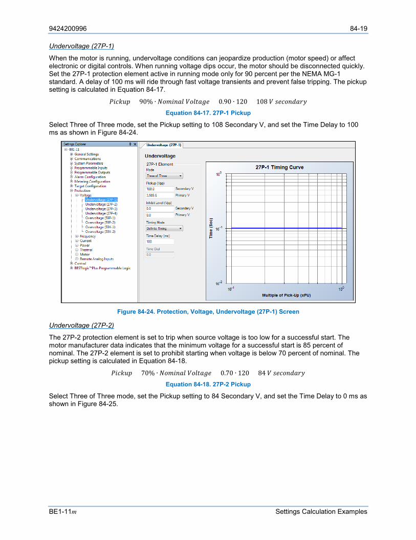
9424200996 84-19
BE1-11m Settings Calculation Examples
Undervoltage (27P-1)
When the motor is running, undervoltage conditions can jeopardize production (motor speed) or affect electronic or digital controls. When running voltage dips occur, the motor should be disconnected quickly. Set the 27P-1 protection element active in running mode only for 90 percent per the NEMA MG-1 standard. A delay of 100 ms will ride through fast voltage transients and prevent false tripping. The pickup setting is calculated in Equation 84-17.
𝑃𝑃𝑅𝑅𝑠𝑠𝑘𝑘𝐹𝐹𝐴𝐴 = 90% ∙ 𝑁𝑁𝐿𝐿𝐴𝐴𝑅𝑅𝑠𝑠𝐿𝐿𝐹𝐹 𝑉𝑉𝐿𝐿𝐹𝐹𝑅𝑅𝐿𝐿𝑉𝑉𝑠𝑠 = 0.90 ∙ 120 = 108 𝑉𝑉 𝐴𝐴𝑠𝑠𝑠𝑠𝐿𝐿𝑠𝑠𝐿𝐿𝐿𝐿𝑠𝑠𝑠𝑠 Equation 84-17. 27P-1 Pickup
Select Three of Three mode, set the Pickup setting to 108 Secondary V, and set the Time Delay to 100 ms as shown in Figure 84-24.
Figure 84-24. Protection, Voltage, Undervoltage (27P-1) Screen
Undervoltage (27P-2)
The 27P-2 protection element is set to trip when source voltage is too low for a successful start. The motor manufacturer data indicates that the minimum voltage for a successful start is 85 percent of nominal. The 27P-2 element is set to prohibit starting when voltage is below 70 percent of nominal. The pickup setting is calculated in Equation 84-18.
𝑃𝑃𝑅𝑅𝑠𝑠𝑘𝑘𝐹𝐹𝐴𝐴 = 70% ∙ 𝑁𝑁𝐿𝐿𝐴𝐴𝑅𝑅𝑠𝑠𝐿𝐿𝐹𝐹 𝑉𝑉𝐿𝐿𝐹𝐹𝑅𝑅𝐿𝐿𝑉𝑉𝑠𝑠 = 0.70 ∙ 120 = 84 𝑉𝑉 𝐴𝐴𝑠𝑠𝑠𝑠𝐿𝐿𝑠𝑠𝐿𝐿𝐿𝐿𝑠𝑠𝑠𝑠 Equation 84-18. 27P-2 Pickup
Select Three of Three mode, set the Pickup setting to 84 Secondary V, and set the Time Delay to 0 ms as shown in Figure 84-25.
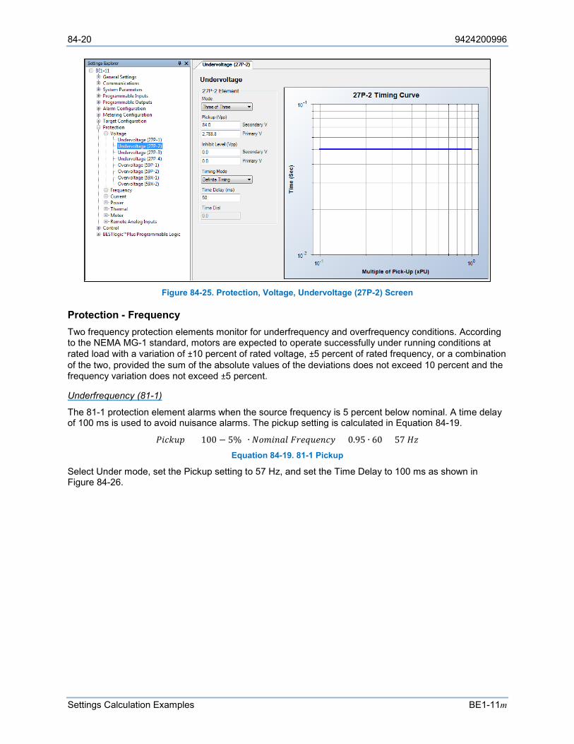
84-20 9424200996
Settings Calculation Examples BE1-11m
Figure 84-25. Protection, Voltage, Undervoltage (27P-2) Screen
Protection - Frequency Two frequency protection elements monitor for underfrequency and overfrequency conditions. According to the NEMA MG-1 standard, motors are expected to operate successfully under running conditions at rated load with a variation of ±10 percent of rated voltage, ±5 percent of rated frequency, or a combination of the two, provided the sum of the absolute values of the deviations does not exceed 10 percent and the frequency variation does not exceed ±5 percent.
Underfrequency (81-1)
The 81-1 protection element alarms when the source frequency is 5 percent below nominal. A time delay of 100 ms is used to avoid nuisance alarms. The pickup setting is calculated in Equation 84-19.
𝑃𝑃𝑅𝑅𝑠𝑠𝑘𝑘𝐹𝐹𝐴𝐴 = (100 − 5%) ∙ 𝑁𝑁𝐿𝐿𝐴𝐴𝑅𝑅𝑠𝑠𝐿𝐿𝐹𝐹 𝐹𝐹𝑠𝑠𝑠𝑠𝐹𝐹𝐹𝐹𝑠𝑠𝑠𝑠𝑠𝑠𝑠𝑠 = 0.95 ∙ 60 = 57 𝐻𝐻𝐻𝐻 Equation 84-19. 81-1 Pickup
Select Under mode, set the Pickup setting to 57 Hz, and set the Time Delay to 100 ms as shown in Figure 84-26.
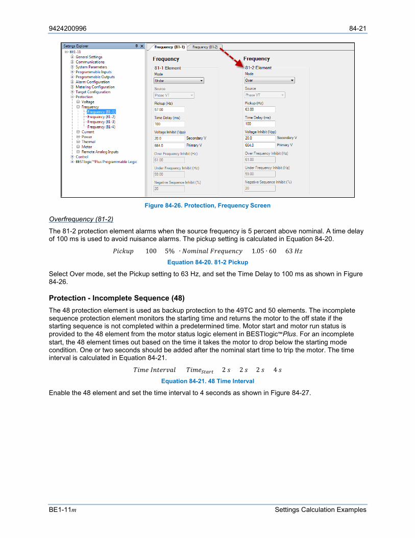
9424200996 84-21
BE1-11m Settings Calculation Examples
Figure 84-26. Protection, Frequency Screen
Overfrequency (81-2)
The 81-2 protection element alarms when the source frequency is 5 percent above nominal. A time delay of 100 ms is used to avoid nuisance alarms. The pickup setting is calculated in Equation 84-20.
𝑃𝑃𝑅𝑅𝑠𝑠𝑘𝑘𝐹𝐹𝐴𝐴 = (100 + 5%) ∙ 𝑁𝑁𝐿𝐿𝐴𝐴𝑅𝑅𝑠𝑠𝐿𝐿𝐹𝐹 𝐹𝐹𝑠𝑠𝑠𝑠𝐹𝐹𝐹𝐹𝑠𝑠𝑠𝑠𝑠𝑠𝑠𝑠 = 1.05 ∙ 60 = 63 𝐻𝐻𝐻𝐻 Equation 84-20. 81-2 Pickup
Select Over mode, set the Pickup setting to 63 Hz, and set the Time Delay to 100 ms as shown in Figure 84-26.
Protection - Incomplete Sequence (48) The 48 protection element is used as backup protection to the 49TC and 50 elements. The incomplete sequence protection element monitors the starting time and returns the motor to the off state if the starting sequence is not completed within a predetermined time. Motor start and motor run status is provided to the 48 element from the motor status logic element in BESTlogic™Plus. For an incomplete start, the 48 element times out based on the time it takes the motor to drop below the starting mode condition. One or two seconds should be added after the nominal start time to trip the motor. The time interval is calculated in Equation 84-21.
𝐶𝐶𝑅𝑅𝐴𝐴𝑠𝑠 𝐼𝐼𝑠𝑠𝑅𝑅𝑠𝑠𝑠𝑠𝑜𝑜𝐿𝐿𝐹𝐹 = 𝐶𝐶𝑅𝑅𝐴𝐴𝑠𝑠𝑆𝑆𝑆𝑆𝑆𝑆𝑆𝑆𝑆𝑆 + 2 𝐴𝐴 = 2 𝐴𝐴 + 2 𝐴𝐴 = 4 𝐴𝐴 Equation 84-21. 48 Time Interval
Enable the 48 element and set the time interval to 4 seconds as shown in Figure 84-27.
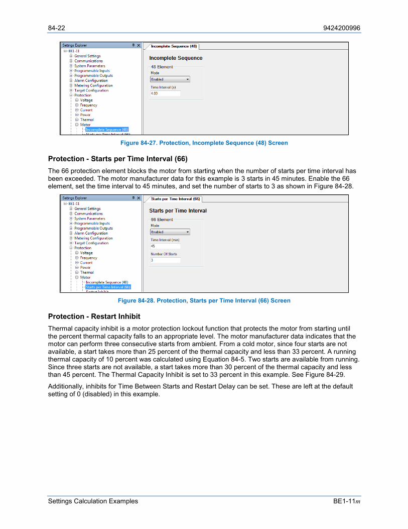
84-22 9424200996
Settings Calculation Examples BE1-11m
Figure 84-27. Protection, Incomplete Sequence (48) Screen
Protection - Starts per Time Interval (66) The 66 protection element blocks the motor from starting when the number of starts per time interval has been exceeded. The motor manufacturer data for this example is 3 starts in 45 minutes. Enable the 66 element, set the time interval to 45 minutes, and set the number of starts to 3 as shown in Figure 84-28.
Figure 84-28. Protection, Starts per Time Interval (66) Screen
Protection - Restart Inhibit Thermal capacity inhibit is a motor protection lockout function that protects the motor from starting until the percent thermal capacity falls to an appropriate level. The motor manufacturer data indicates that the motor can perform three consecutive starts from ambient. From a cold motor, since four starts are not available, a start takes more than 25 percent of the thermal capacity and less than 33 percent. A running thermal capacity of 10 percent was calculated using Equation 84-5. Two starts are available from running. Since three starts are not available, a start takes more than 30 percent of the thermal capacity and less than 45 percent. The Thermal Capacity Inhibit is set to 33 percent in this example. See Figure 84-29.
Additionally, inhibits for Time Between Starts and Restart Delay can be set. These are left at the default setting of 0 (disabled) in this example.
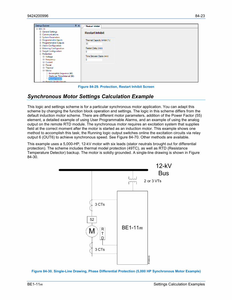
9424200996 84-23
BE1-11m Settings Calculation Examples
Figure 84-29. Protection, Restart Inhibit Screen
Synchronous Motor Settings Calculation Example
This logic and settings scheme is for a particular synchronous motor application. You can adapt this scheme by changing the function block operation and settings. The logic in this scheme differs from the default induction motor scheme. There are different motor parameters, addition of the Power Factor (55) element, a detailed example of using User Programmable Alarms, and an example of using the analog output on the remote RTD module. The synchronous motor requires an excitation system that supplies field at the correct moment after the motor is started as an induction motor. This example shows one method to accomplish this task; the Running logic output switches online the excitation circuits via relay output 6 (OUT6) to achieve synchronous speed. See Figure 84-70. Other methods are available.
This example uses a 5,000-HP, 12-kV motor with six leads (stator neutrals brought out for differential protection). The scheme includes thermal model protection (49TC), as well as RTD (Resistance Temperature Detector) backup. The motor is solidly grounded. A single-line drawing is shown in Figure 84-30.
Figure 84-30. Single-Line Drawing, Phase Differential Protection (5,000 HP Synchronous Motor Example)
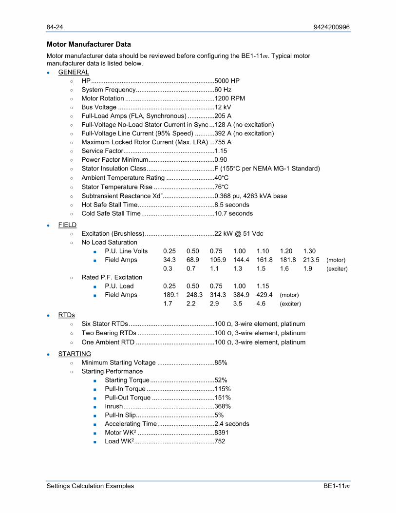
84-24 9424200996
Settings Calculation Examples BE1-11m
Motor Manufacturer Data Motor manufacturer data should be reviewed before configuring the BE1-11m. Typical motor manufacturer data is listed below. GENERAL
HP .....................................................................5000 HP System Frequency ............................................60 Hz Motor Rotation ..................................................1200 RPM Bus Voltage ......................................................12 kV Full-Load Amps (FLA, Synchronous) ...............205 A Full-Voltage No-Load Stator Current in Sync ...128 A (no excitation) Full-Voltage Line Current (95% Speed) ...........392 A (no excitation) Maximum Locked Rotor Current (Max. LRA) ...755 A Service Factor...................................................1.15 Power Factor Minimum .....................................0.90 Stator Insulation Class ......................................F (155°C per NEMA MG-1 Standard) Ambient Temperature Rating ...........................40°C Stator Temperature Rise ..................................76°C Subtransient Reactance Xd”.............................0.368 pu, 4263 kVA base Hot Safe Stall Time ...........................................8.5 seconds Cold Safe Stall Time .........................................10.7 seconds
FIELD Excitation (Brushless) .......................................22 kW @ 51 Vdc No Load Saturation
P.U. Line Volts 0.25 0.50 0.75 1.00 1.10 1.20 1.30 Field Amps 34.3 68.9 105.9 144.4 161.8 181.8 213.5 (motor)
0.3 0.7 1.1 1.3 1.5 1.6 1.9 (exciter) Rated P.F. Excitation
P.U. Load 0.25 0.50 0.75 1.00 1.15 Field Amps 189.1 248.3 314.3 384.9 429.4 (motor)
1.7 2.2 2.9 3.5 4.6 (exciter)
RTDs Six Stator RTDs ................................................100 Ω, 3-wire element, platinum Two Bearing RTDs ...........................................100 Ω, 3-wire element, platinum One Ambient RTD ............................................100 Ω, 3-wire element, platinum
STARTING Minimum Starting Voltage ................................85% Starting Performance
Starting Torque ....................................52% Pull-In Torque ......................................115% Pull-Out Torque ...................................151% Inrush ...................................................368% Pull-In Slip............................................5% Accelerating Time ................................2.4 seconds Motor WK2 ...........................................8391 Load WK2 .............................................752
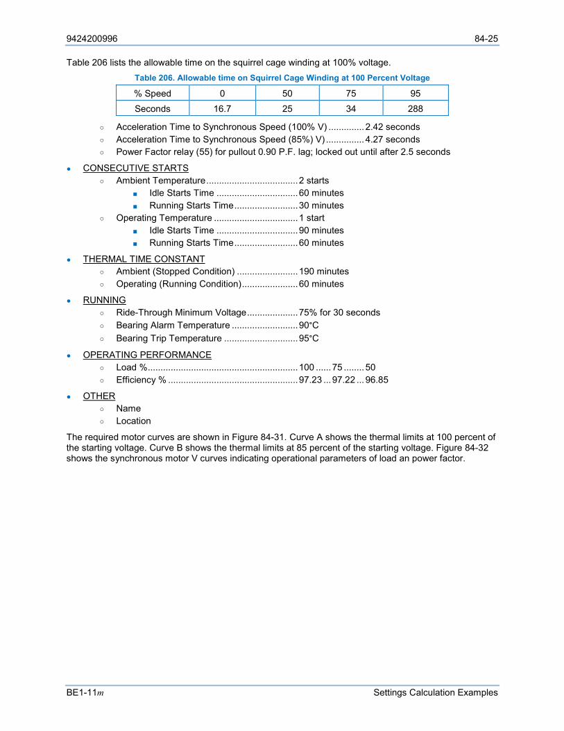
9424200996 84-25
BE1-11m Settings Calculation Examples
Table 206 lists the allowable time on the squirrel cage winding at 100% voltage. Table 206. Allowable time on Squirrel Cage Winding at 100 Percent Voltage
% Speed 0 50 75 95 Seconds 16.7 25 34 288
Acceleration Time to Synchronous Speed (100% V) .............. 2.42 seconds Acceleration Time to Synchronous Speed (85%) V) ............... 4.27 seconds Power Factor relay (55) for pullout 0.90 P.F. lag; locked out until after 2.5 seconds
CONSECUTIVE STARTS Ambient Temperature .................................... 2 starts
Idle Starts Time ................................ 60 minutes Running Starts Time ......................... 30 minutes
Operating Temperature ................................. 1 start Idle Starts Time ................................ 90 minutes Running Starts Time ......................... 60 minutes
THERMAL TIME CONSTANT Ambient (Stopped Condition) ........................ 190 minutes Operating (Running Condition) ...................... 60 minutes
RUNNING Ride-Through Minimum Voltage .................... 75% for 30 seconds Bearing Alarm Temperature .......................... 90°C Bearing Trip Temperature ............................. 95°C
OPERATING PERFORMANCE Load % ........................................................... 100 ...... 75 ........ 50 Efficiency % ................................................... 97.23 ... 97.22 ... 96.85
OTHER Name Location
The required motor curves are shown in Figure 84-31. Curve A shows the thermal limits at 100 percent of the starting voltage. Curve B shows the thermal limits at 85 percent of the starting voltage. Figure 84-32 shows the synchronous motor V curves indicating operational parameters of load an power factor.
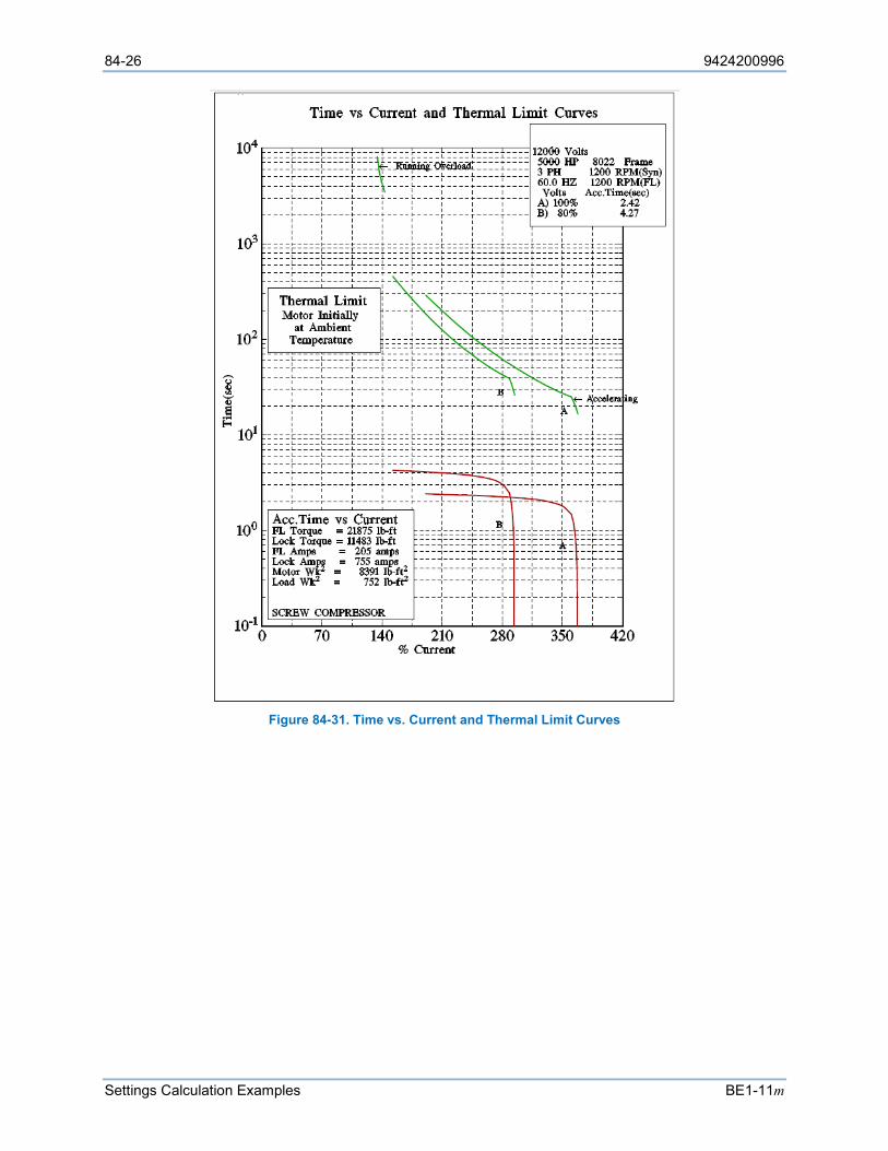
84-26 9424200996
Settings Calculation Examples BE1-11m
Figure 84-31. Time vs. Current and Thermal Limit Curves
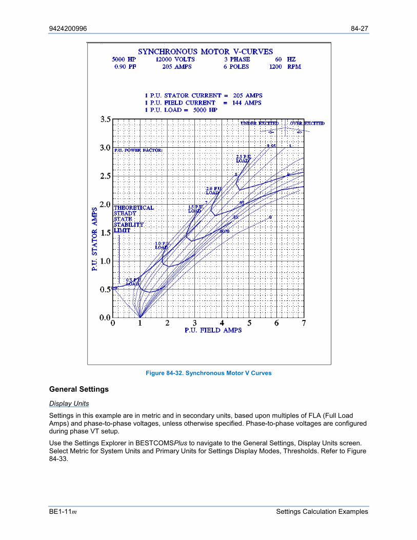
9424200996 84-27
BE1-11m Settings Calculation Examples
Figure 84-32. Synchronous Motor V Curves
General Settings
Display Units
Settings in this example are in metric and in secondary units, based upon multiples of FLA (Full Load Amps) and phase-to-phase voltages, unless otherwise specified. Phase-to-phase voltages are configured during phase VT setup.
Use the Settings Explorer in BESTCOMSPlus to navigate to the General Settings, Display Units screen. Select Metric for System Units and Primary Units for Settings Display Modes, Thresholds. Refer to Figure 84-33.
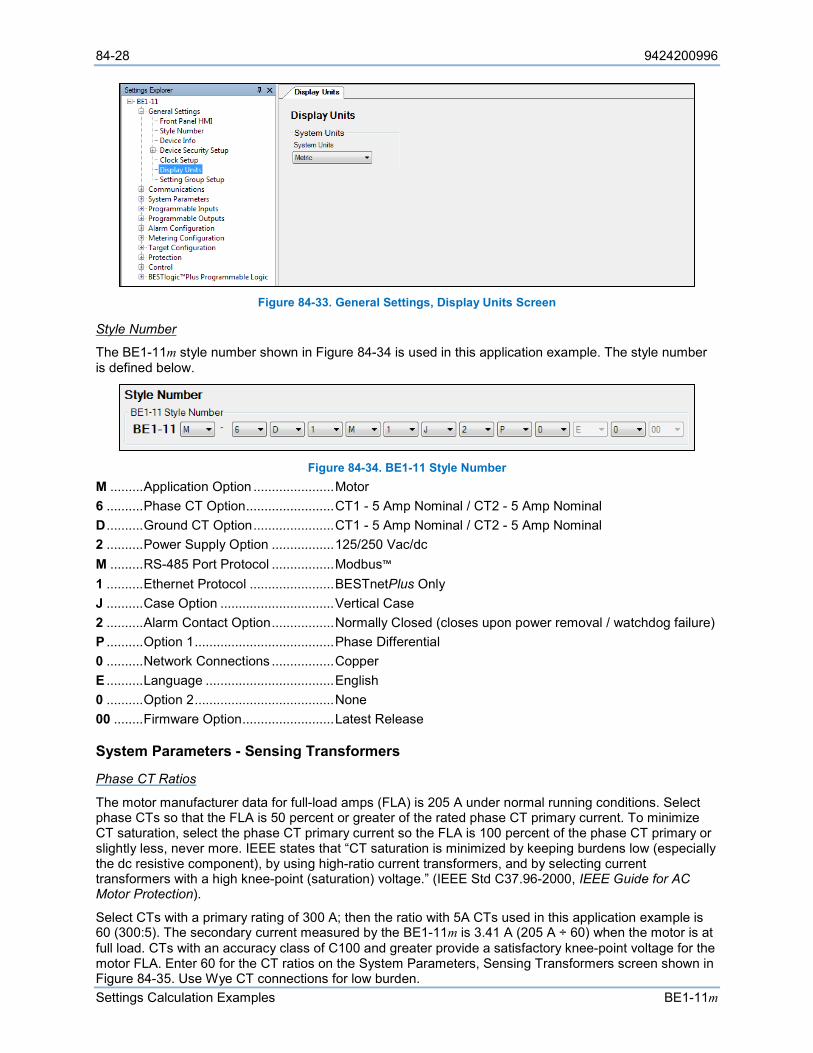
84-28 9424200996
Settings Calculation Examples BE1-11m
Figure 84-33. General Settings, Display Units Screen
Style Number
The BE1-11m style number shown in Figure 84-34 is used in this application example. The style number is defined below.
Figure 84-34. BE1-11 Style Number
M ......... Application Option ...................... Motor 6 .......... Phase CT Option ........................ CT1 - 5 Amp Nominal / CT2 - 5 Amp Nominal D .......... Ground CT Option ...................... CT1 - 5 Amp Nominal / CT2 - 5 Amp Nominal 2 .......... Power Supply Option ................. 125/250 Vac/dc M ......... RS-485 Port Protocol ................. Modbus™ 1 .......... Ethernet Protocol ....................... BESTnetPlus Only J .......... Case Option ............................... Vertical Case 2 .......... Alarm Contact Option ................. Normally Closed (closes upon power removal / watchdog failure) P .......... Option 1 ...................................... Phase Differential 0 .......... Network Connections ................. Copper E .......... Language ................................... English 0 .......... Option 2 ...................................... None 00 ........ Firmware Option ......................... Latest Release
System Parameters - Sensing Transformers
Phase CT Ratios
The motor manufacturer data for full-load amps (FLA) is 205 A under normal running conditions. Select phase CTs so that the FLA is 50 percent or greater of the rated phase CT primary current. To minimize CT saturation, select the phase CT primary current so the FLA is 100 percent of the phase CT primary or slightly less, never more. IEEE states that “CT saturation is minimized by keeping burdens low (especially the dc resistive component), by using high-ratio current transformers, and by selecting current transformers with a high knee-point (saturation) voltage.” (IEEE Std C37.96-2000, IEEE Guide for AC Motor Protection).
Select CTs with a primary rating of 300 A; then the ratio with 5A CTs used in this application example is 60 (300:5). The secondary current measured by the BE1-11m is 3.41 A (205 A ÷ 60) when the motor is at full load. CTs with an accuracy class of C100 and greater provide a satisfactory knee-point voltage for the motor FLA. Enter 60 for the CT ratios on the System Parameters, Sensing Transformers screen shown in Figure 84-35. Use Wye CT connections for low burden.
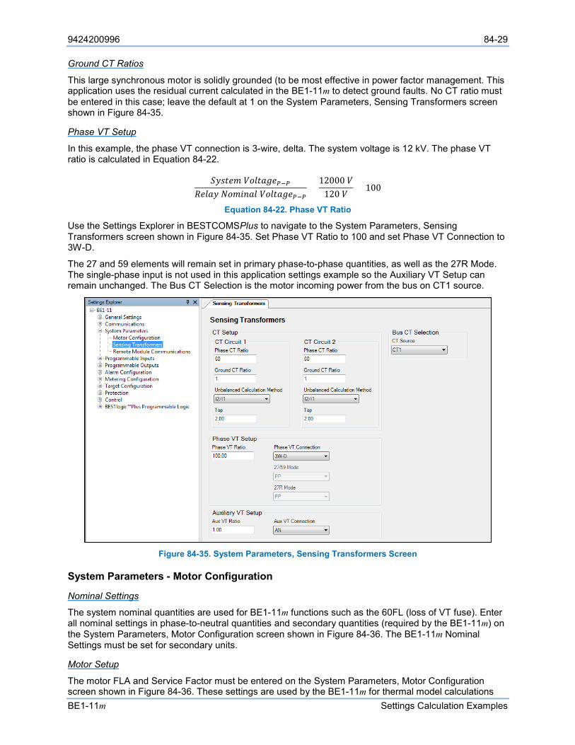
9424200996 84-29
BE1-11m Settings Calculation Examples
Ground CT Ratios
This large synchronous motor is solidly grounded (to be most effective in power factor management. This application uses the residual current calculated in the BE1-11m to detect ground faults. No CT ratio must be entered in this case; leave the default at 1 on the System Parameters, Sensing Transformers screen shown in Figure 84-35.
Phase VT Setup
In this example, the phase VT connection is 3-wire, delta. The system voltage is 12 kV. The phase VT ratio is calculated in Equation 84-22.
𝑆𝑆𝑠𝑠𝐴𝐴𝑅𝑅𝑠𝑠𝐴𝐴 𝑉𝑉𝐿𝐿𝐹𝐹𝑅𝑅𝐿𝐿𝑉𝑉𝑠𝑠𝑃𝑃−𝑃𝑃𝑅𝑅𝑠𝑠𝐹𝐹𝐿𝐿𝑠𝑠 𝑁𝑁𝐿𝐿𝐴𝐴𝑅𝑅𝑠𝑠𝐿𝐿𝐹𝐹 𝑉𝑉𝐿𝐿𝐹𝐹𝑅𝑅𝐿𝐿𝑉𝑉𝑠𝑠𝑃𝑃−𝑃𝑃
=12000 𝑉𝑉
120 𝑉𝑉= 100
Equation 84-22. Phase VT Ratio
Use the Settings Explorer in BESTCOMSPlus to navigate to the System Parameters, Sensing Transformers screen shown in Figure 84-35. Set Phase VT Ratio to 100 and set Phase VT Connection to 3W-D.
The 27 and 59 elements will remain set in primary phase-to-phase quantities, as well as the 27R Mode. The single-phase input is not used in this application settings example so the Auxiliary VT Setup can remain unchanged. The Bus CT Selection is the motor incoming power from the bus on CT1 source.
Figure 84-35. System Parameters, Sensing Transformers Screen
System Parameters - Motor Configuration
Nominal Settings
The system nominal quantities are used for BE1-11m functions such as the 60FL (loss of VT fuse). Enter all nominal settings in phase-to-neutral quantities and secondary quantities (required by the BE1-11m) on the System Parameters, Motor Configuration screen shown in Figure 84-36. The BE1-11m Nominal Settings must be set for secondary units.
Motor Setup
The motor FLA and Service Factor must be entered on the System Parameters, Motor Configuration screen shown in Figure 84-36. These settings are used by the BE1-11m for thermal model calculations
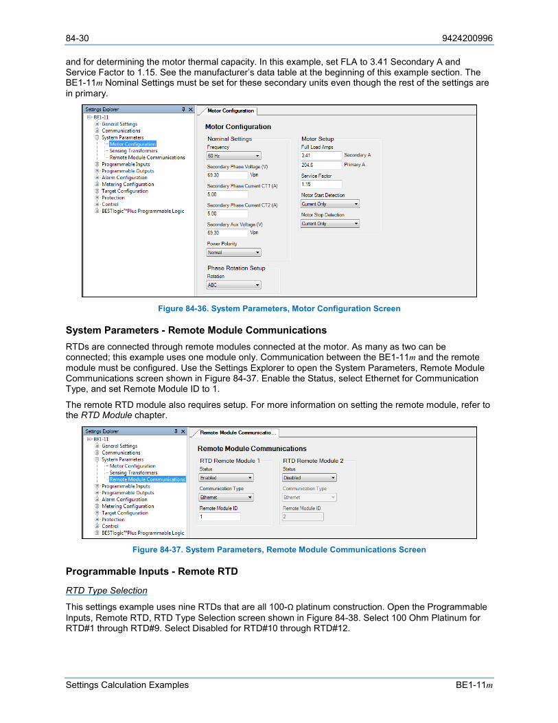
84-30 9424200996
Settings Calculation Examples BE1-11m
and for determining the motor thermal capacity. In this example, set FLA to 3.41 Secondary A and Service Factor to 1.15. See the manufacturer’s data table at the beginning of this example section. The BE1-11m Nominal Settings must be set for these secondary units even though the rest of the settings are in primary.
Figure 84-36. System Parameters, Motor Configuration Screen
System Parameters - Remote Module Communications RTDs are connected through remote modules connected at the motor. As many as two can be connected; this example uses one module only. Communication between the BE1-11m and the remote module must be configured. Use the Settings Explorer to open the System Parameters, Remote Module Communications screen shown in Figure 84-37. Enable the Status, select Ethernet for Communication Type, and set Remote Module ID to 1.
The remote RTD module also requires setup. For more information on setting the remote module, refer to the RTD Module chapter.
Figure 84-37. System Parameters, Remote Module Communications Screen
Programmable Inputs - Remote RTD
RTD Type Selection
This settings example uses nine RTDs that are all 100-Ω platinum construction. Open the Programmable Inputs, Remote RTD, RTD Type Selection screen shown in Figure 84-38. Select 100 Ohm Platinum for RTD#1 through RTD#9. Select Disabled for RTD#10 through RTD#12.
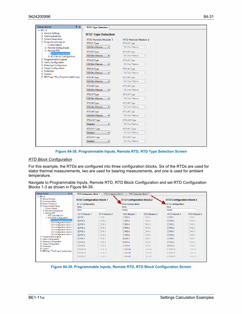
9424200996 84-31
BE1-11m Settings Calculation Examples
Figure 84-38. Programmable Inputs, Remote RTD, RTD Type Selection Screen
RTD Block Configuration
For this example, the RTDs are configured into three configuration blocks. Six of the RTDs are used for stator thermal measurements, two are used for bearing measurements, and one is used for ambient temperature.
Navigate to Programmable Inputs, Remote RTD, RTD Block Configuration and set RTD Configuration Blocks 1-3 as shown in Figure 84-39.
Figure 84-39. Programmable Inputs, Remote RTD, RTD Block Configuration Screen
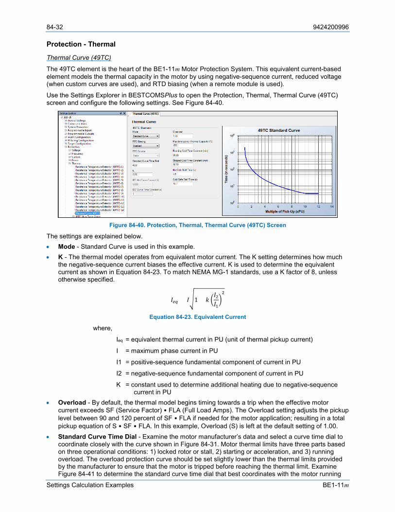
84-32 9424200996
Settings Calculation Examples BE1-11m
Protection - Thermal
Thermal Curve (49TC)
The 49TC element is the heart of the BE1-11m Motor Protection System. This equivalent current-based element models the thermal capacity in the motor by using negative-sequence current, reduced voltage (when custom curves are used), and RTD biasing (when a remote module is used).
Use the Settings Explorer in BESTCOMSPlus to open the Protection, Thermal, Thermal Curve (49TC) screen and configure the following settings. See Figure 84-40.
Figure 84-40. Protection, Thermal, Thermal Curve (49TC) Screen
The settings are explained below. • Mode - Standard Curve is used in this example. • K - The thermal model operates from equivalent motor current. The K setting determines how much
the negative-sequence current biases the effective current. K is used to determine the equivalent current as shown in Equation 84-23. To match NEMA MG-1 standards, use a K factor of 8, unless otherwise specified.
𝐼𝐼𝑒𝑒𝑒𝑒 = 𝐼𝐼1 + 𝑘𝑘 𝐼𝐼2𝐼𝐼12
Equation 84-23. Equivalent Current
where,
Ieq = equivalent thermal current in PU (unit of thermal pickup current)
I = maximum phase current in PU
I1 = positive-sequence fundamental component of current in PU
I2 = negative-sequence fundamental component of current in PU
K = constant used to determine additional heating due to negative-sequence current in PU
• Overload - By default, the thermal model begins timing towards a trip when the effective motor current exceeds SF (Service Factor) • FLA (Full Load Amps). The Overload setting adjusts the pickup level between 90 and 120 percent of SF • FLA if needed for the motor application; resulting in a total pickup equation of S • SF • FLA. In this example, Overload (S) is left at the default setting of 1.00.
• Standard Curve Time Dial - Examine the motor manufacturer’s data and select a curve time dial to coordinate closely with the curve shown in Figure 84-31. Motor thermal limits have three parts based on three operational conditions: 1) locked rotor or stall, 2) starting or acceleration, and 3) running overload. The overload protection curve should be set slightly lower than the thermal limits provided by the manufacturer to ensure that the motor is tripped before reaching the thermal limit. Examine Figure 84-41 to determine the standard curve time dial that best coordinates with the motor running
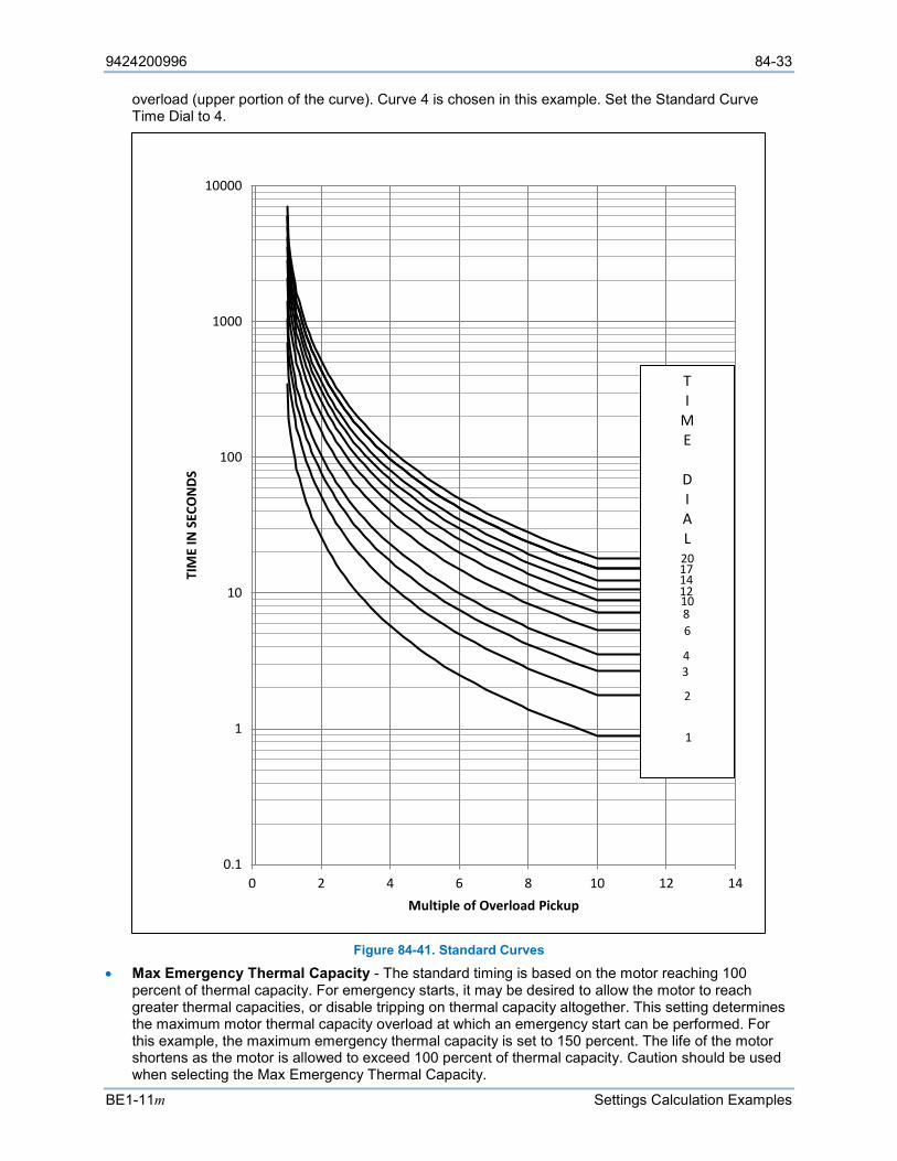
9424200996 84-33
BE1-11m Settings Calculation Examples
overload (upper portion of the curve). Curve 4 is chosen in this example. Set the Standard Curve Time Dial to 4.
Figure 84-41. Standard Curves
• Max Emergency Thermal Capacity - The standard timing is based on the motor reaching 100 percent of thermal capacity. For emergency starts, it may be desired to allow the motor to reach greater thermal capacities, or disable tripping on thermal capacity altogether. This setting determines the maximum motor thermal capacity overload at which an emergency start can be performed. For this example, the maximum emergency thermal capacity is set to 150 percent. The life of the motor shortens as the motor is allowed to exceed 100 percent of thermal capacity. Caution should be used when selecting the Max Emergency Thermal Capacity.
0.1
1
10
100
1000
10000
0 2 4 6 8 10 12 14
TIM
E IN
SEC
ON
DS
Multiple of Overload Pickup
TI
ME
DIAL
20171412
4
1086
3
2
1
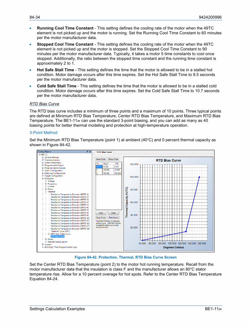
84-34 9424200996
Settings Calculation Examples BE1-11m
• Running Cool Time Constant - This setting defines the cooling rate of the motor when the 49TC element is not picked up and the motor is running. Set the Running Cool Time Constant to 60 minutes per the motor manufacturer data.
• Stopped Cool Time Constant - This setting defines the cooling rate of the motor when the 49TC element is not picked up and the motor is stopped. Set the Stopped Cool Time Constant to 90 minutes per the motor manufacturer data. Typically, it takes a motor 5 time constants to cool once stopped. Additionally, the ratio between the stopped time constant and the running time constant is approximately 2 to 1.
• Hot Safe Stall Time - This setting defines the time that the motor is allowed to be in a stalled hot condition. Motor damage occurs after this time expires. Set the Hot Safe Stall Time to 8.5 seconds per the motor manufacturer data.
• Cold Safe Stall Time - This setting defines the time that the motor is allowed to be in a stalled cold condition. Motor damage occurs after this time expires. Set the Cold Safe Stall Time to 10.7 seconds per the motor manufacturer data.
RTD Bias Curve
The RTD bias curve includes a minimum of three points and a maximum of 10 points. Three typical points are defined at Minimum RTD Bias Temperature, Center RTD Bias Temperature, and Maximum RTD Bias Temperature. The BE1-11m can use the standard 3-point biasing, and you can add as many as 40 biasing points for better thermal modeling and protection at high-temperature operation.
3-Point Method
Set the Minimum RTD Bias Temperature (point 1) at ambient (40°C) and 0 percent thermal capacity as shown in Figure 84-42.
Figure 84-42. Protection, Thermal, RTD Bias Curve Screen
Set the Center RTD Bias Temperature (point 2) to the motor hot running temperature. Recall from the motor manufacturer data that the insulation is class F and the manufacturer allows an 80°C stator temperature rise. Allow for a 10 percent overage for hot spots. Refer to the Center RTD Bias Temperature Equation 84-24.
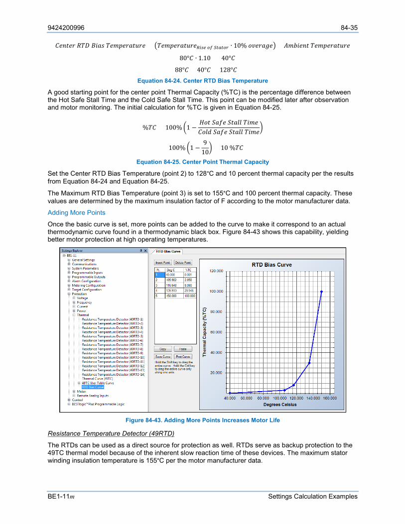
9424200996 84-35
BE1-11m Settings Calculation Examples
𝐶𝐶𝑠𝑠𝑠𝑠𝑅𝑅𝑠𝑠𝑠𝑠 𝑅𝑅𝐶𝐶𝑅𝑅 𝐵𝐵𝑅𝑅𝐿𝐿𝐴𝐴 𝐶𝐶𝑠𝑠𝐴𝐴𝐴𝐴𝑠𝑠𝑠𝑠𝐿𝐿𝑅𝑅𝐹𝐹𝑠𝑠𝑠𝑠 = 𝐶𝐶𝑠𝑠𝐴𝐴𝐴𝐴𝑠𝑠𝑠𝑠𝐿𝐿𝑅𝑅𝐹𝐹𝑠𝑠𝑠𝑠𝑅𝑅𝑅𝑅𝑅𝑅𝑒𝑒 𝑜𝑜𝑜𝑜 𝑆𝑆𝑆𝑆𝑆𝑆𝑆𝑆𝑜𝑜𝑆𝑆 ∙ 10% 𝐿𝐿𝑜𝑜𝑠𝑠𝑠𝑠𝐿𝐿𝑉𝑉𝑠𝑠 + 𝐴𝐴𝐴𝐴𝐴𝐴𝑅𝑅𝑠𝑠𝑠𝑠𝑅𝑅 𝐶𝐶𝑠𝑠𝐴𝐴𝐴𝐴𝑠𝑠𝑠𝑠𝐿𝐿𝑅𝑅𝐹𝐹𝑠𝑠𝑠𝑠
= (80°𝐶𝐶 ∙ 1.10) + 40°𝐶𝐶
= 88°𝐶𝐶 + 40°𝐶𝐶 = 128°𝐶𝐶 Equation 84-24. Center RTD Bias Temperature
A good starting point for the center point Thermal Capacity (%TC) is the percentage difference between the Hot Safe Stall Time and the Cold Safe Stall Time. This point can be modified later after observation and motor monitoring. The initial calculation for %TC is given in Equation 84-25.
%𝐶𝐶𝐶𝐶 = 100% 1 −𝐻𝐻𝐿𝐿𝑅𝑅 𝑆𝑆𝐿𝐿𝑆𝑆𝑠𝑠 𝑆𝑆𝑅𝑅𝐿𝐿𝐹𝐹𝐹𝐹 𝐶𝐶𝑅𝑅𝐴𝐴𝑠𝑠𝐶𝐶𝐿𝐿𝐹𝐹𝐿𝐿 𝑆𝑆𝐿𝐿𝑆𝑆𝑠𝑠 𝑆𝑆𝑅𝑅𝐿𝐿𝐹𝐹𝐹𝐹 𝐶𝐶𝑅𝑅𝐴𝐴𝑠𝑠
= 100% 1 −9
10 = 10 %𝐶𝐶𝐶𝐶
Equation 84-25. Center Point Thermal Capacity
Set the Center RTD Bias Temperature (point 2) to 128°C and 10 percent thermal capacity per the results from Equation 84-24 and Equation 84-25.
The Maximum RTD Bias Temperature (point 3) is set to 155°C and 100 percent thermal capacity. These values are determined by the maximum insulation factor of F according to the motor manufacturer data.
Adding More Points
Once the basic curve is set, more points can be added to the curve to make it correspond to an actual thermodynamic curve found in a thermodynamic black box. Figure 84-43 shows this capability, yielding better motor protection at high operating temperatures.
Figure 84-43. Adding More Points Increases Motor Life
Resistance Temperature Detector (49RTD)
The RTDs can be used as a direct source for protection as well. RTDs serve as backup protection to the 49TC thermal model because of the inherent slow reaction time of these devices. The maximum stator winding insulation temperature is 155°C per the motor manufacturer data.
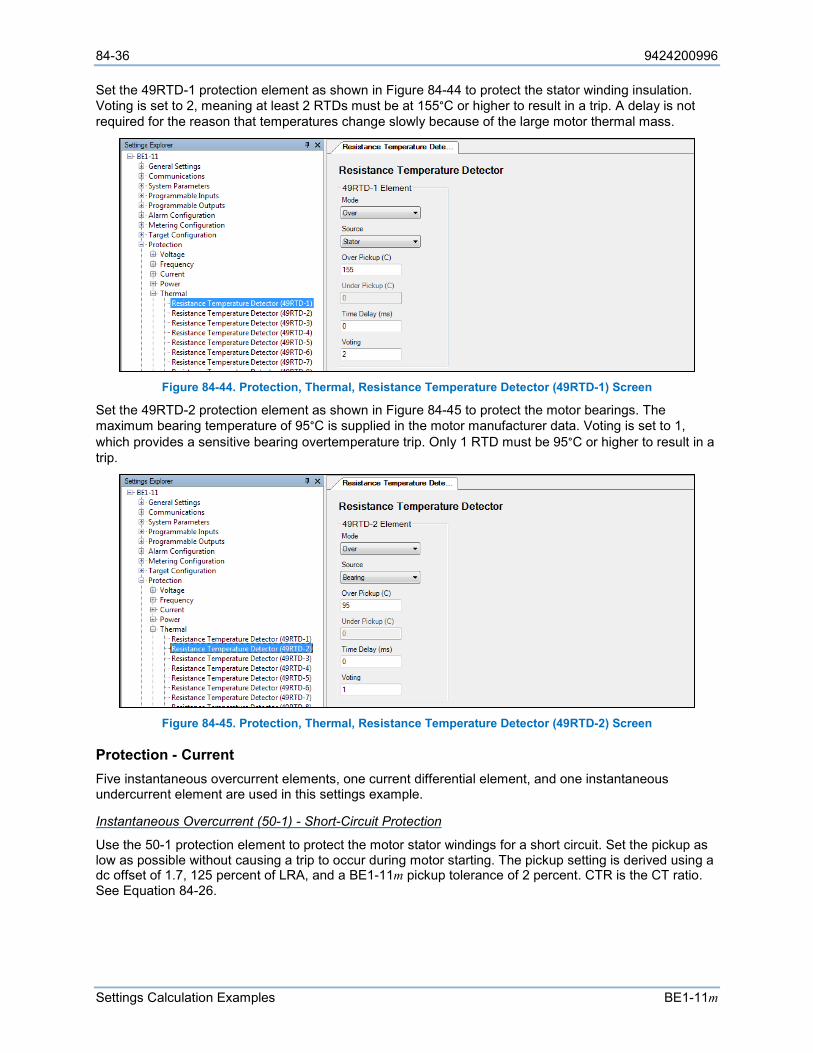
84-36 9424200996
Settings Calculation Examples BE1-11m
Set the 49RTD-1 protection element as shown in Figure 84-44 to protect the stator winding insulation. Voting is set to 2, meaning at least 2 RTDs must be at 155°C or higher to result in a trip. A delay is not required for the reason that temperatures change slowly because of the large motor thermal mass.
Figure 84-44. Protection, Thermal, Resistance Temperature Detector (49RTD-1) Screen
Set the 49RTD-2 protection element as shown in Figure 84-45 to protect the motor bearings. The maximum bearing temperature of 95°C is supplied in the motor manufacturer data. Voting is set to 1, which provides a sensitive bearing overtemperature trip. Only 1 RTD must be 95°C or higher to result in a trip.
Figure 84-45. Protection, Thermal, Resistance Temperature Detector (49RTD-2) Screen
Protection - Current Five instantaneous overcurrent elements, one current differential element, and one instantaneous undercurrent element are used in this settings example.
Instantaneous Overcurrent (50-1) - Short-Circuit Protection
Use the 50-1 protection element to protect the motor stator windings for a short circuit. Set the pickup as low as possible without causing a trip to occur during motor starting. The pickup setting is derived using a dc offset of 1.7, 125 percent of LRA, and a BE1-11m pickup tolerance of 2 percent. CTR is the CT ratio. See Equation 84-26.
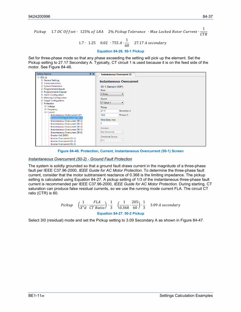
9424200996 84-37
BE1-11m Settings Calculation Examples
𝑃𝑃𝑅𝑅𝑠𝑠𝑘𝑘𝐹𝐹𝐴𝐴 = 1.7 𝑅𝑅𝐶𝐶 𝑂𝑂𝑆𝑆𝑆𝑆𝐴𝐴𝑠𝑠𝑅𝑅 ∙ (125% 𝐿𝐿𝑆𝑆 𝐿𝐿𝑅𝑅𝐴𝐴 + 2% 𝑃𝑃𝑅𝑅𝑠𝑠𝑘𝑘𝐹𝐹𝐴𝐴 𝐶𝐶𝐿𝐿𝐹𝐹𝑠𝑠𝑠𝑠𝐿𝐿𝑠𝑠𝑠𝑠𝑠𝑠) ∙ 𝑀𝑀𝐿𝐿𝑀𝑀 𝐿𝐿𝐿𝐿𝑠𝑠𝑘𝑘𝑠𝑠𝐿𝐿 𝑅𝑅𝐿𝐿𝑅𝑅𝐿𝐿𝑠𝑠 𝐶𝐶𝐹𝐹𝑠𝑠𝑠𝑠𝑠𝑠𝑠𝑠𝑅𝑅 ∙1
𝐶𝐶𝐶𝐶𝑅𝑅
= 1.7 ∙ (1.25 + 0.02) ∙ 755 𝐴𝐴 ∙1
60= 27.17 𝐴𝐴 𝐴𝐴𝑠𝑠𝑠𝑠𝐿𝐿𝑠𝑠𝐿𝐿𝐿𝐿𝑠𝑠𝑠𝑠
Equation 84-26. 50-1 Pickup
Set for three-phase mode so that any phase exceeding the setting will pick up the element. Set the Pickup setting to 27.17 Secondary A. Typically, CT circuit 1 is used because it is on the feed side of the motor. See Figure 84-46.
Figure 84-46. Protection, Current, Instantaneous Overcurrent (50-1) Screen
Instantaneous Overcurrent (50-2) - Ground Fault Protection
The system is solidly grounded so that a ground fault draws current in the magnitude of a three-phase fault per IEEE C37.96-2000, IEEE Guide for AC Motor Protection. To determine the three-phase fault current, consider that the motor subtransient reactance of 0.368 is the limiting impedance. The pickup setting is calculated using Equation 84-27. A pickup setting of 1/3 of the instantaneous three-phase fault current is recommended per IEEE C37.96-2000, IEEE Guide for AC Motor Protection. During starting, CT saturation can produce false residual currents, so we use the running mode current FLA. The circuit CT ratio (CTR) is 60.
𝑃𝑃𝑅𝑅𝑠𝑠𝑘𝑘𝐹𝐹𝐴𝐴 = 1𝑋𝑋"𝐿𝐿
∙𝐹𝐹𝐿𝐿𝐴𝐴
𝐶𝐶𝐶𝐶 𝑅𝑅𝐿𝐿𝑅𝑅𝑅𝑅𝐿𝐿 ∙
13
= 1
0.368∙
20560
∙13
= 3.09 𝐴𝐴 𝐴𝐴𝑠𝑠𝑠𝑠𝐿𝐿𝑠𝑠𝐿𝐿𝐿𝐿𝑠𝑠𝑠𝑠
Equation 84-27. 50-2 Pickup
Select 3I0 (residual) mode and set the Pickup setting to 3.09 Secondary A as shown in Figure 84-47.
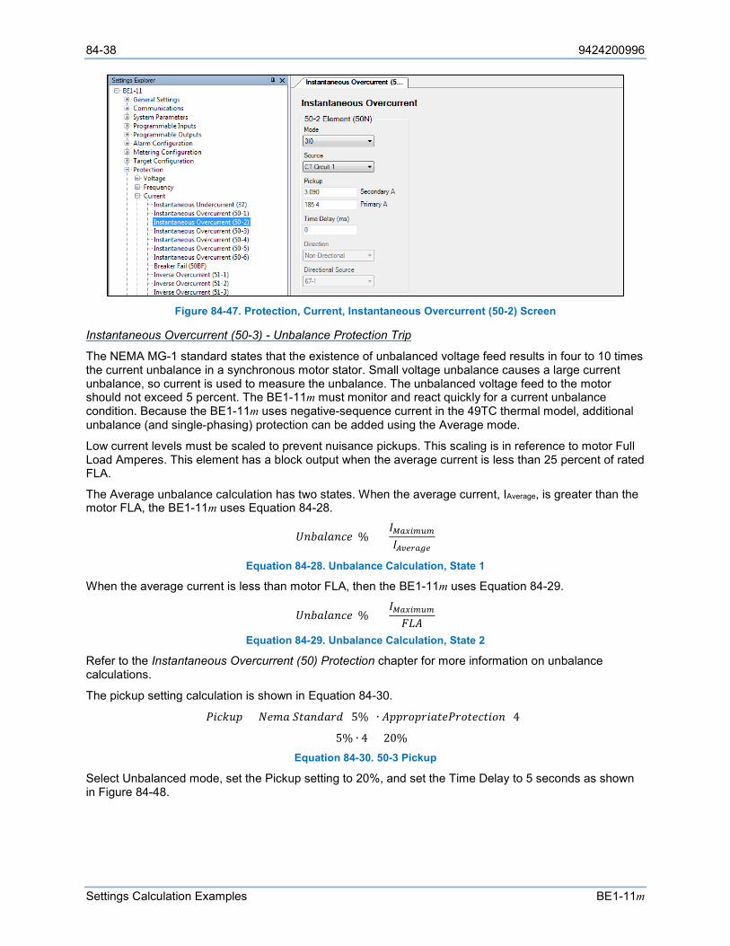
84-38 9424200996
Settings Calculation Examples BE1-11m
Figure 84-47. Protection, Current, Instantaneous Overcurrent (50-2) Screen
Instantaneous Overcurrent (50-3) - Unbalance Protection Trip
The NEMA MG-1 standard states that the existence of unbalanced voltage feed results in four to 10 times the current unbalance in a synchronous motor stator. Small voltage unbalance causes a large current unbalance, so current is used to measure the unbalance. The unbalanced voltage feed to the motor should not exceed 5 percent. The BE1-11m must monitor and react quickly for a current unbalance condition. Because the BE1-11m uses negative-sequence current in the 49TC thermal model, additional unbalance (and single-phasing) protection can be added using the Average mode.
Low current levels must be scaled to prevent nuisance pickups. This scaling is in reference to motor Full Load Amperes. This element has a block output when the average current is less than 25 percent of rated FLA.
The Average unbalance calculation has two states. When the average current, IAverage, is greater than the motor FLA, the BE1-11m uses Equation 84-28.
𝑈𝑈𝑠𝑠𝐴𝐴𝐿𝐿𝐹𝐹𝐿𝐿𝑠𝑠𝑠𝑠𝑠𝑠(%) =𝐼𝐼𝑀𝑀𝑆𝑆𝑀𝑀𝑅𝑅𝑀𝑀𝑀𝑀𝑀𝑀
𝐼𝐼𝐴𝐴𝐴𝐴𝑒𝑒𝑆𝑆𝑆𝑆𝐴𝐴𝑒𝑒
Equation 84-28. Unbalance Calculation, State 1
When the average current is less than motor FLA, then the BE1-11m uses Equation 84-29.
𝑈𝑈𝑠𝑠𝐴𝐴𝐿𝐿𝐹𝐹𝐿𝐿𝑠𝑠𝑠𝑠𝑠𝑠(%) =𝐼𝐼𝑀𝑀𝑆𝑆𝑀𝑀𝑅𝑅𝑀𝑀𝑀𝑀𝑀𝑀
𝐹𝐹𝐿𝐿𝐴𝐴
Equation 84-29. Unbalance Calculation, State 2
Refer to the Instantaneous Overcurrent (50) Protection chapter for more information on unbalance calculations.
The pickup setting calculation is shown in Equation 84-30.
𝑃𝑃𝑅𝑅𝑠𝑠𝑘𝑘𝐹𝐹𝐴𝐴 = 𝑁𝑁𝑠𝑠𝐴𝐴𝐿𝐿 𝑆𝑆𝑅𝑅𝐿𝐿𝑠𝑠𝐿𝐿𝐿𝐿𝑠𝑠𝐿𝐿 (5%) ∙ 𝐴𝐴𝐴𝐴𝐴𝐴𝑠𝑠𝐿𝐿𝐴𝐴𝑠𝑠𝑅𝑅𝐿𝐿𝑅𝑅𝑠𝑠𝑃𝑃𝑠𝑠𝐿𝐿𝑅𝑅𝑠𝑠𝑠𝑠𝑅𝑅𝑅𝑅𝐿𝐿𝑠𝑠 (4)
= 5% ∙ 4 = 20% Equation 84-30. 50-3 Pickup
Select Unbalanced mode, set the Pickup setting to 20%, and set the Time Delay to 5 seconds as shown in Figure 84-48.
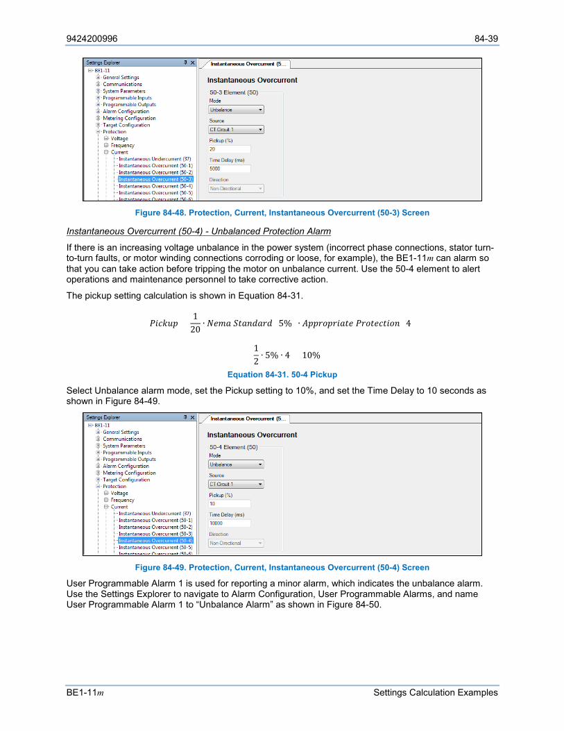
9424200996 84-39
BE1-11m Settings Calculation Examples
Figure 84-48. Protection, Current, Instantaneous Overcurrent (50-3) Screen
Instantaneous Overcurrent (50-4) - Unbalanced Protection Alarm
If there is an increasing voltage unbalance in the power system (incorrect phase connections, stator turn-to-turn faults, or motor winding connections corroding or loose, for example), the BE1-11m can alarm so that you can take action before tripping the motor on unbalance current. Use the 50-4 element to alert operations and maintenance personnel to take corrective action.
The pickup setting calculation is shown in Equation 84-31.
𝑃𝑃𝑅𝑅𝑠𝑠𝑘𝑘𝐹𝐹𝐴𝐴 =1
20∙ 𝑁𝑁𝑠𝑠𝐴𝐴𝐿𝐿 𝑆𝑆𝑅𝑅𝐿𝐿𝑠𝑠𝐿𝐿𝐿𝐿𝑠𝑠𝐿𝐿 (5%) ∙ 𝐴𝐴𝐴𝐴𝐴𝐴𝑠𝑠𝐿𝐿𝐴𝐴𝑠𝑠𝑅𝑅𝐿𝐿𝑅𝑅𝑠𝑠 𝑃𝑃𝑠𝑠𝐿𝐿𝑅𝑅𝑠𝑠𝑠𝑠𝑅𝑅𝑅𝑅𝐿𝐿𝑠𝑠 (4)
=12∙ 5% ∙ 4 = 10%
Equation 84-31. 50-4 Pickup
Select Unbalance alarm mode, set the Pickup setting to 10%, and set the Time Delay to 10 seconds as shown in Figure 84-49.
Figure 84-49. Protection, Current, Instantaneous Overcurrent (50-4) Screen
User Programmable Alarm 1 is used for reporting a minor alarm, which indicates the unbalance alarm. Use the Settings Explorer to navigate to Alarm Configuration, User Programmable Alarms, and name User Programmable Alarm 1 to “Unbalance Alarm” as shown in Figure 84-50.
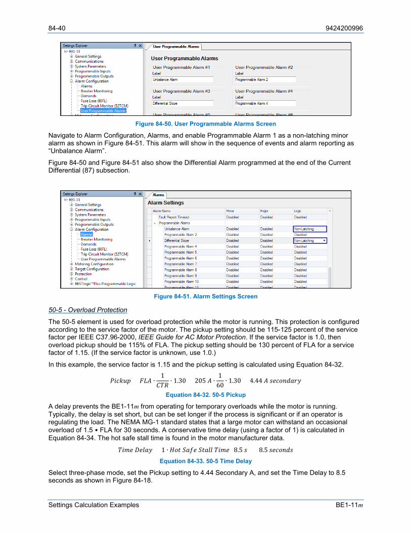
84-40 9424200996
Settings Calculation Examples BE1-11m
Figure 84-50. User Programmable Alarms Screen
Navigate to Alarm Configuration, Alarms, and enable Programmable Alarm 1 as a non-latching minor alarm as shown in Figure 84-51. This alarm will show in the sequence of events and alarm reporting as “Unbalance Alarm”.
Figure 84-50 and Figure 84-51 also show the Differential Alarm programmed at the end of the Current Differential (87) subsection.
Figure 84-51. Alarm Settings Screen
50-5 - Overload Protection
The 50-5 element is used for overload protection while the motor is running. This protection is configured according to the service factor of the motor. The pickup setting should be 115-125 percent of the service factor per IEEE C37.96-2000, IEEE Guide for AC Motor Protection. If the service factor is 1.0, then overload pickup should be 115% of FLA. The pickup setting should be 130 percent of FLA for a service factor of 1.15. (If the service factor is unknown, use 1.0.)
In this example, the service factor is 1.15 and the pickup setting is calculated using Equation 84-32.
𝑃𝑃𝑅𝑅𝑠𝑠𝑘𝑘𝐹𝐹𝐴𝐴 = 𝐹𝐹𝐿𝐿𝐴𝐴 ∙1
𝐶𝐶𝐶𝐶𝑅𝑅∙ 1.30 = 205 𝐴𝐴 ∙
160
∙ 1.30 = 4.44 𝐴𝐴 𝐴𝐴𝑠𝑠𝑠𝑠𝐿𝐿𝑠𝑠𝐿𝐿𝐿𝐿𝑠𝑠𝑠𝑠
Equation 84-32. 50-5 Pickup
A delay prevents the BE1-11m from operating for temporary overloads while the motor is running. Typically, the delay is set short, but can be set longer if the process is significant or if an operator is regulating the load. The NEMA MG-1 standard states that a large motor can withstand an occasional overload of 1.5 • FLA for 30 seconds. A conservative time delay (using a factor of 1) is calculated in Equation 84-34. The hot safe stall time is found in the motor manufacturer data.
𝐶𝐶𝑅𝑅𝐴𝐴𝑠𝑠 𝑅𝑅𝑠𝑠𝐹𝐹𝐿𝐿𝑠𝑠 = 1 ∙ 𝐻𝐻𝐿𝐿𝑅𝑅 𝑆𝑆𝐿𝐿𝑆𝑆𝑠𝑠 𝑆𝑆𝑅𝑅𝐿𝐿𝐹𝐹𝐹𝐹 𝐶𝐶𝑅𝑅𝐴𝐴𝑠𝑠 (8.5 𝐴𝐴) = 8.5 𝐴𝐴𝑠𝑠𝑠𝑠𝐿𝐿𝑠𝑠𝐿𝐿𝐴𝐴 Equation 84-33. 50-5 Time Delay
Select three-phase mode, set the Pickup setting to 4.44 Secondary A, and set the Time Delay to 8.5 seconds as shown in Figure 84-18.
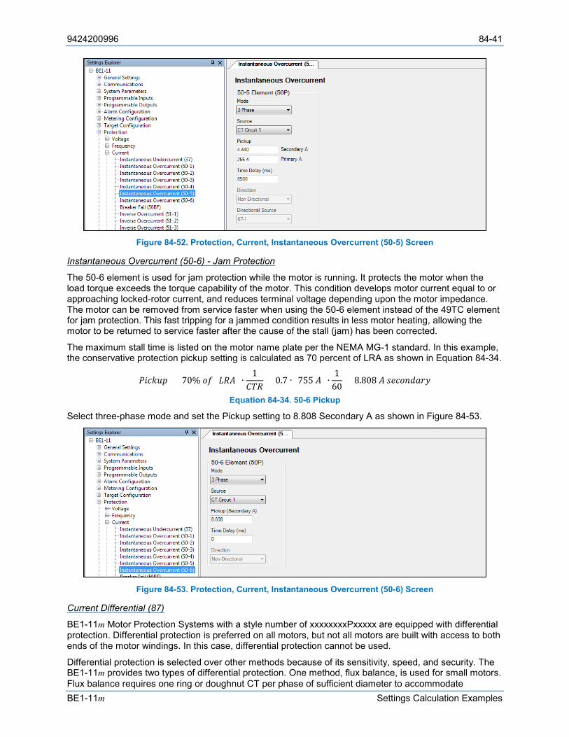
9424200996 84-41
BE1-11m Settings Calculation Examples
Figure 84-52. Protection, Current, Instantaneous Overcurrent (50-5) Screen
Instantaneous Overcurrent (50-6) - Jam Protection
The 50-6 element is used for jam protection while the motor is running. It protects the motor when the load torque exceeds the torque capability of the motor. This condition develops motor current equal to or approaching locked-rotor current, and reduces terminal voltage depending upon the motor impedance. The motor can be removed from service faster when using the 50-6 element instead of the 49TC element for jam protection. This fast tripping for a jammed condition results in less motor heating, allowing the motor to be returned to service faster after the cause of the stall (jam) has been corrected.
The maximum stall time is listed on the motor name plate per the NEMA MG-1 standard. In this example, the conservative protection pickup setting is calculated as 70 percent of LRA as shown in Equation 84-34.
𝑃𝑃𝑅𝑅𝑠𝑠𝑘𝑘𝐹𝐹𝐴𝐴 = 70% 𝐿𝐿𝑆𝑆 (𝐿𝐿𝑅𝑅𝐴𝐴) ∙1
𝐶𝐶𝐶𝐶𝑅𝑅= 0.7 ∙ (755 𝐴𝐴) ∙
160
= 8.808 𝐴𝐴 𝐴𝐴𝑠𝑠𝑠𝑠𝐿𝐿𝑠𝑠𝐿𝐿𝐿𝐿𝑠𝑠𝑠𝑠
Equation 84-34. 50-6 Pickup
Select three-phase mode and set the Pickup setting to 8.808 Secondary A as shown in Figure 84-53.
Figure 84-53. Protection, Current, Instantaneous Overcurrent (50-6) Screen
Current Differential (87)
BE1-11m Motor Protection Systems with a style number of xxxxxxxxPxxxxx are equipped with differential protection. Differential protection is preferred on all motors, but not all motors are built with access to both ends of the motor windings. In this case, differential protection cannot be used.
Differential protection is selected over other methods because of its sensitivity, speed, and security. The BE1-11m provides two types of differential protection. One method, flux balance, is used for small motors. Flux balance requires one ring or doughnut CT per phase of sufficient diameter to accommodate
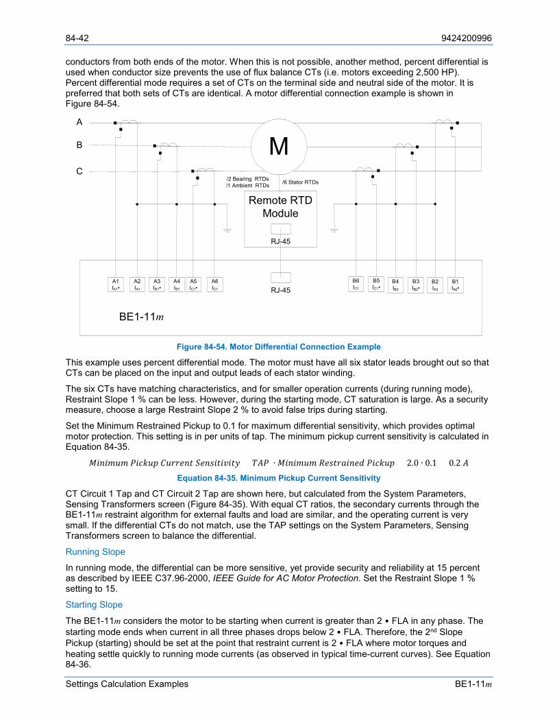
84-42 9424200996
Settings Calculation Examples BE1-11m
conductors from both ends of the motor. When this is not possible, another method, percent differential is used when conductor size prevents the use of flux balance CTs (i.e. motors exceeding 2,500 HP). Percent differential mode requires a set of CTs on the terminal side and neutral side of the motor. It is preferred that both sets of CTs are identical. A motor differential connection example is shown in Figure 84-54.
Figure 84-54. Motor Differential Connection Example
This example uses percent differential mode. The motor must have all six stator leads brought out so that CTs can be placed on the input and output leads of each stator winding.
The six CTs have matching characteristics, and for smaller operation currents (during running mode), Restraint Slope 1 % can be less. However, during the starting mode, CT saturation is large. As a security measure, choose a large Restraint Slope 2 % to avoid false trips during starting.
Set the Minimum Restrained Pickup to 0.1 for maximum differential sensitivity, which provides optimal motor protection. This setting is in per units of tap. The minimum pickup current sensitivity is calculated in Equation 84-35.
𝑀𝑀𝑅𝑅𝑠𝑠𝑅𝑅𝐴𝐴𝐹𝐹𝐴𝐴 𝑃𝑃𝑅𝑅𝑠𝑠𝑘𝑘𝐹𝐹𝐴𝐴 𝐶𝐶𝐹𝐹𝑠𝑠𝑠𝑠𝑠𝑠𝑠𝑠𝑅𝑅 𝑆𝑆𝑠𝑠𝑠𝑠𝐴𝐴𝑅𝑅𝑅𝑅𝑅𝑅𝑜𝑜𝑅𝑅𝑅𝑅𝑠𝑠 = 𝐶𝐶𝐴𝐴𝑃𝑃 ∙ 𝑀𝑀𝑅𝑅𝑠𝑠𝑅𝑅𝐴𝐴𝐹𝐹𝐴𝐴 𝑅𝑅𝑠𝑠𝐴𝐴𝑅𝑅𝑠𝑠𝐿𝐿𝑅𝑅𝑠𝑠𝑠𝑠𝐿𝐿 𝑃𝑃𝑅𝑅𝑠𝑠𝑘𝑘𝐹𝐹𝐴𝐴 = 2.0 ∙ 0.1 = 0.2 𝐴𝐴 Equation 84-35. Minimum Pickup Current Sensitivity
CT Circuit 1 Tap and CT Circuit 2 Tap are shown here, but calculated from the System Parameters, Sensing Transformers screen (Figure 84-35). With equal CT ratios, the secondary currents through the BE1-11m restraint algorithm for external faults and load are similar, and the operating current is very small. If the differential CTs do not match, use the TAP settings on the System Parameters, Sensing Transformers screen to balance the differential.
Running Slope
In running mode, the differential can be more sensitive, yet provide security and reliability at 15 percent as described by IEEE C37.96-2000, IEEE Guide for AC Motor Protection. Set the Restraint Slope 1 % setting to 15.
Starting Slope
The BE1-11m considers the motor to be starting when current is greater than 2 • FLA in any phase. The starting mode ends when current in all three phases drops below 2 • FLA. Therefore, the 2nd Slope Pickup (starting) should be set at the point that restraint current is 2 • FLA where motor torques and heating settle quickly to running mode currents (as observed in typical time-current curves). See Equation 84-36.
M
A 1 I A 1 •
A 2 I A 1
A 3 I B 1 •
A 4 I B 1
A 5 I C 1 •
A 6 I C 1
B 5 I C 1 •
B 6 I C 1
B 1 I A 2 •
B 2 I A 2
B 3 I B 2 •
B 4 I B 2
Remote RTD Module
BE 1 - 11 m
/ 6 Stator RTDs / 2 Bearing RTDs / 1 Ambient RTDs
RJ - 45
RJ - 45
A
B
C
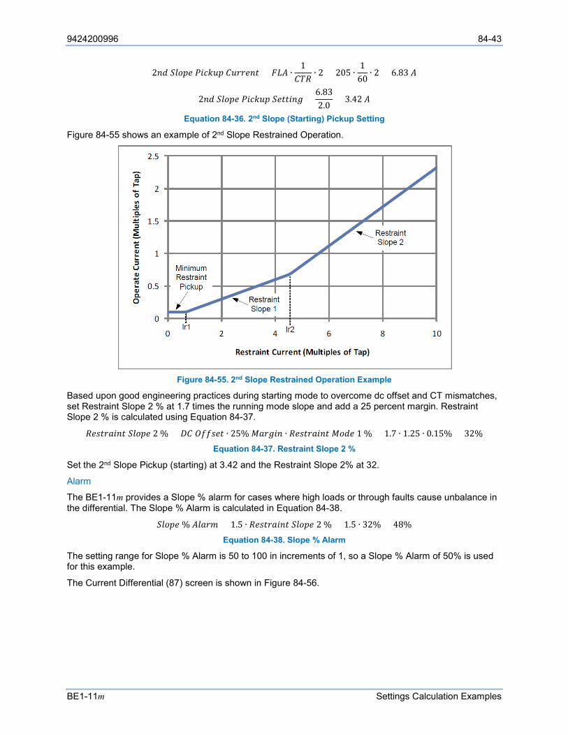
9424200996 84-43
BE1-11m Settings Calculation Examples
2𝑠𝑠𝐿𝐿 𝑆𝑆𝐹𝐹𝐿𝐿𝐴𝐴𝑠𝑠 𝑃𝑃𝑅𝑅𝑠𝑠𝑘𝑘𝐹𝐹𝐴𝐴 𝐶𝐶𝐹𝐹𝑠𝑠𝑠𝑠𝑠𝑠𝑠𝑠𝑅𝑅 = 𝐹𝐹𝐿𝐿𝐴𝐴 ∙1
𝐶𝐶𝐶𝐶𝑅𝑅∙ 2 = 205 ∙
160
∙ 2 = 6.83 𝐴𝐴
2𝑠𝑠𝐿𝐿 𝑆𝑆𝐹𝐹𝐿𝐿𝐴𝐴𝑠𝑠 𝑃𝑃𝑅𝑅𝑠𝑠𝑘𝑘𝐹𝐹𝐴𝐴 𝑆𝑆𝑠𝑠𝑅𝑅𝑅𝑅𝑅𝑅𝑠𝑠𝑉𝑉 =6.832.0
= 3.42 𝐴𝐴
Equation 84-36. 2nd Slope (Starting) Pickup Setting
Figure 84-55 shows an example of 2nd Slope Restrained Operation.
Figure 84-55. 2nd Slope Restrained Operation Example
Based upon good engineering practices during starting mode to overcome dc offset and CT mismatches, set Restraint Slope 2 % at 1.7 times the running mode slope and add a 25 percent margin. Restraint Slope 2 % is calculated using Equation 84-37.
𝑅𝑅𝑠𝑠𝐴𝐴𝑅𝑅𝑠𝑠𝐿𝐿𝑅𝑅𝑠𝑠𝑅𝑅 𝑆𝑆𝐹𝐹𝐿𝐿𝐴𝐴𝑠𝑠 2 % = 𝑅𝑅𝐶𝐶 𝑂𝑂𝑆𝑆𝑆𝑆𝐴𝐴𝑠𝑠𝑅𝑅 ∙ 25% 𝑀𝑀𝐿𝐿𝑠𝑠𝑉𝑉𝑅𝑅𝑠𝑠 ∙ 𝑅𝑅𝑠𝑠𝐴𝐴𝑅𝑅𝑠𝑠𝐿𝐿𝑅𝑅𝑠𝑠𝑅𝑅 𝑀𝑀𝐿𝐿𝐿𝐿𝑠𝑠 1 % = 1.7 ∙ 1.25 ∙ 0.15% = 32% Equation 84-37. Restraint Slope 2 %
Set the 2nd Slope Pickup (starting) at 3.42 and the Restraint Slope 2% at 32.
Alarm
The BE1-11m provides a Slope % alarm for cases where high loads or through faults cause unbalance in the differential. The Slope % Alarm is calculated in Equation 84-38.
𝑆𝑆𝐹𝐹𝐿𝐿𝐴𝐴𝑠𝑠 % 𝐴𝐴𝐹𝐹𝐿𝐿𝑠𝑠𝐴𝐴 = 1.5 ∙ 𝑅𝑅𝑠𝑠𝐴𝐴𝑅𝑅𝑠𝑠𝐿𝐿𝑅𝑅𝑠𝑠𝑅𝑅 𝑆𝑆𝐹𝐹𝐿𝐿𝐴𝐴𝑠𝑠 2 % = 1.5 ∙ 32% = 48% Equation 84-38. Slope % Alarm
The setting range for Slope % Alarm is 50 to 100 in increments of 1, so a Slope % Alarm of 50% is used for this example.
The Current Differential (87) screen is shown in Figure 84-56.
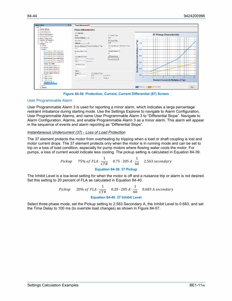
84-44 9424200996
Settings Calculation Examples BE1-11m
Figure 84-56. Protection, Current, Current Differential (87) Screen
User Programmable Alarm
User Programmable Alarm 3 is used for reporting a minor alarm, which indicates a large percentage restraint imbalance during starting mode. Use the Settings Explorer to navigate to Alarm Configuration, User Programmable Alarms, and name User Programmable Alarm 3 to “Differential Slope”. Navigate to Alarm Configuration, Alarms, and enable Programmable Alarm 3 as a minor alarm. This alarm will appear in the sequence of events and alarm reporting as “Differential Slope”.
Instantaneous Undercurrent (37) - Loss of Load Protection
The 37 element protects the motor from overheating by tripping when a load or shaft coupling is lost and motor current drops. The 37 element protects only when the motor is in running mode and can be set to trip on a loss of load condition, especially for pump motors where flowing water cools the motor. For pumps, a loss of current would indicate less cooling. The pickup setting is calculated in Equation 84-39.
𝑃𝑃𝑅𝑅𝑠𝑠𝑘𝑘𝐹𝐹𝐴𝐴 = 75% 𝐿𝐿𝑆𝑆 𝐹𝐹𝐿𝐿𝐴𝐴 ∙1
𝐶𝐶𝐶𝐶𝑅𝑅= 0.75 ∙ 205 𝐴𝐴 ∙
160
= 2.563 𝐴𝐴𝑠𝑠𝑠𝑠𝐿𝐿𝑠𝑠𝐿𝐿𝐿𝐿𝑠𝑠𝑠𝑠
Equation 84-39. 37 Pickup
The Inhibit Level is a low-level setting for when the motor is off and a nuisance trip or alarm is not desired. Set this setting to 20 percent of FLA as calculated in Equation 84-40.
𝑃𝑃𝑅𝑅𝑠𝑠𝑘𝑘𝐹𝐹𝐴𝐴 = 20% 𝐿𝐿𝑆𝑆 𝐹𝐹𝐿𝐿𝐴𝐴 ∙1
𝐶𝐶𝐶𝐶𝑅𝑅= 0.20 ∙ 205 𝐴𝐴 ∙
160
= 0.683 𝐴𝐴 𝐴𝐴𝑠𝑠𝑠𝑠𝐿𝐿𝑠𝑠𝐿𝐿𝐿𝐿𝑠𝑠𝑠𝑠
Equation 84-40. 37 Inhibit Level
Select three-phase mode, set the Pickup setting to 2.563 Secondary A, the Inhibit Level to 0.683, and set the Time Delay to 100 ms (to override load changes) as shown in Figure 84-57.
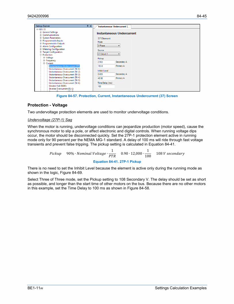
9424200996 84-45
BE1-11m Settings Calculation Examples
Figure 84-57. Protection, Current, Instantaneous Undercurrent (37) Screen
Protection - Voltage Two undervoltage protection elements are used to monitor undervoltage conditions.
Undervoltage (27P-1) Sag
When the motor is running, undervoltage conditions can jeopardize production (motor speed), cause the synchronous motor to slip a pole, or affect electronic and digital controls. When running voltage dips occur, the motor should be disconnected quickly. Set the 27P-1 protection element active in running mode only for 90 percent per the NEMA MG-1 standard. A delay of 100 ms will ride through fast voltage transients and prevent false tripping. The pickup setting is calculated in Equation 84-41.
𝑃𝑃𝑅𝑅𝑠𝑠𝑘𝑘𝐹𝐹𝐴𝐴 = 90% ∙ 𝑁𝑁𝐿𝐿𝐴𝐴𝑅𝑅𝑠𝑠𝐿𝐿𝐹𝐹 𝑉𝑉𝐿𝐿𝐹𝐹𝑅𝑅𝐿𝐿𝑉𝑉𝑠𝑠 ∙1
𝑃𝑃𝐶𝐶𝑅𝑅= 0.90 ∙ 12,000 ∙
1100
= 108 𝑉𝑉 𝐴𝐴𝑠𝑠𝑠𝑠𝐿𝐿𝑠𝑠𝐿𝐿𝐿𝐿𝑠𝑠𝑠𝑠
Equation 84-41. 27P-1 Pickup
There is no need to set the Inhibit Level because the element is active only during the running mode as shown in the logic, Figure 84-69.
Select Three of Three mode, set the Pickup setting to 108 Secondary V. The delay should be set as short as possible, and longer than the start time of other motors on the bus. Because there are no other motors in this example, set the Time Delay to 100 ms as shown in Figure 84-58.
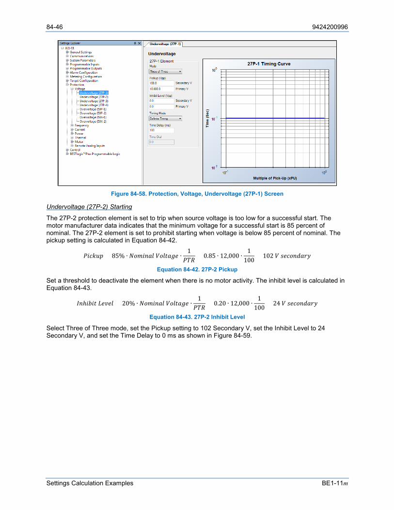
84-46 9424200996
Settings Calculation Examples BE1-11m
Figure 84-58. Protection, Voltage, Undervoltage (27P-1) Screen
Undervoltage (27P-2) Starting
The 27P-2 protection element is set to trip when source voltage is too low for a successful start. The motor manufacturer data indicates that the minimum voltage for a successful start is 85 percent of nominal. The 27P-2 element is set to prohibit starting when voltage is below 85 percent of nominal. The pickup setting is calculated in Equation 84-42.
𝑃𝑃𝑅𝑅𝑠𝑠𝑘𝑘𝐹𝐹𝐴𝐴 = 85% ∙ 𝑁𝑁𝐿𝐿𝐴𝐴𝑅𝑅𝑠𝑠𝐿𝐿𝐹𝐹 𝑉𝑉𝐿𝐿𝐹𝐹𝑅𝑅𝐿𝐿𝑉𝑉𝑠𝑠 ∙1
𝑃𝑃𝐶𝐶𝑅𝑅= 0.85 ∙ 12,000 ∙
1100
= 102 𝑉𝑉 𝐴𝐴𝑠𝑠𝑠𝑠𝐿𝐿𝑠𝑠𝐿𝐿𝐿𝐿𝑠𝑠𝑠𝑠
Equation 84-42. 27P-2 Pickup
Set a threshold to deactivate the element when there is no motor activity. The inhibit level is calculated in Equation 84-43.
𝐼𝐼𝑠𝑠ℎ𝑅𝑅𝐴𝐴𝑅𝑅𝑅𝑅 𝐿𝐿𝑠𝑠𝑜𝑜𝑠𝑠𝐹𝐹 = 20% ∙ 𝑁𝑁𝐿𝐿𝐴𝐴𝑅𝑅𝑠𝑠𝐿𝐿𝐹𝐹 𝑉𝑉𝐿𝐿𝐹𝐹𝑅𝑅𝐿𝐿𝑉𝑉𝑠𝑠 ∙1
𝑃𝑃𝐶𝐶𝑅𝑅= 0.20 ∙ 12,000 ∙
1100
= 24 𝑉𝑉 𝐴𝐴𝑠𝑠𝑠𝑠𝐿𝐿𝑠𝑠𝐿𝐿𝐿𝐿𝑠𝑠𝑠𝑠
Equation 84-43. 27P-2 Inhibit Level
Select Three of Three mode, set the Pickup setting to 102 Secondary V, set the Inhibit Level to 24 Secondary V, and set the Time Delay to 0 ms as shown in Figure 84-59.
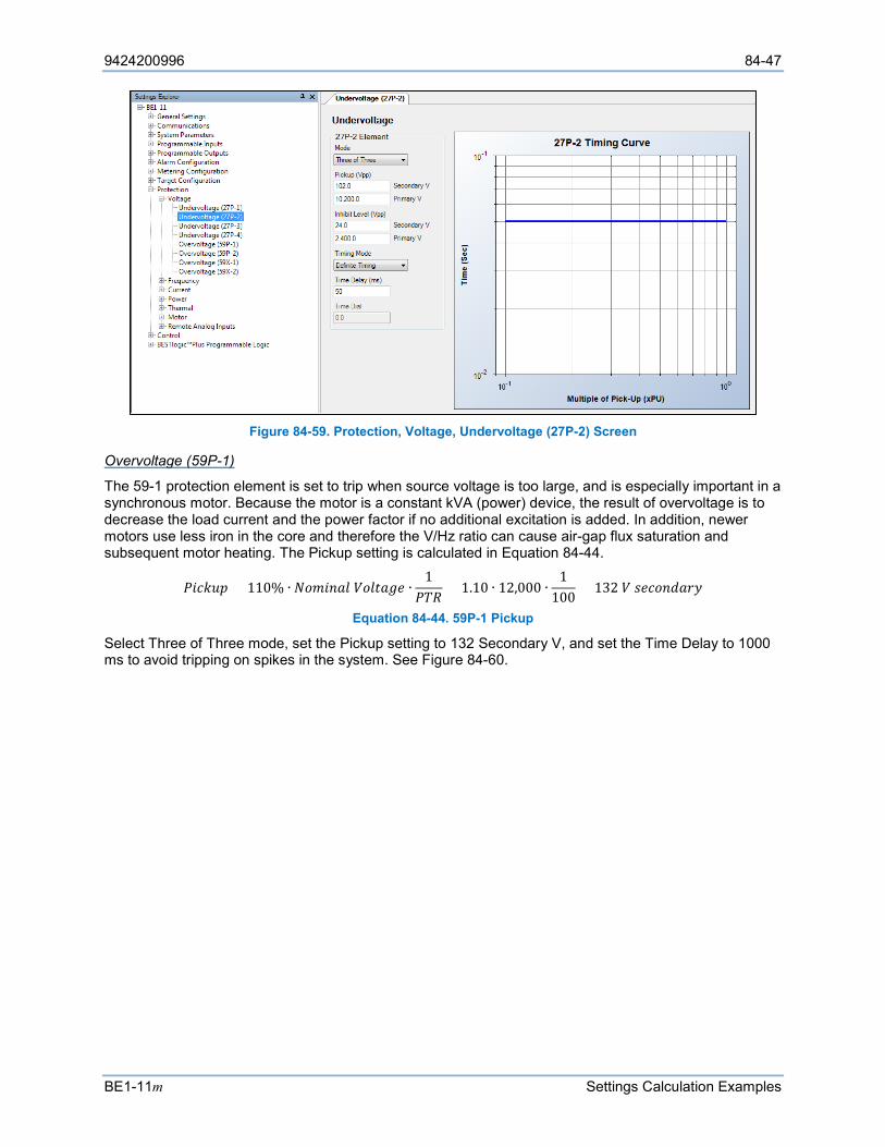
9424200996 84-47
BE1-11m Settings Calculation Examples
Figure 84-59. Protection, Voltage, Undervoltage (27P-2) Screen
Overvoltage (59P-1)
The 59-1 protection element is set to trip when source voltage is too large, and is especially important in a synchronous motor. Because the motor is a constant kVA (power) device, the result of overvoltage is to decrease the load current and the power factor if no additional excitation is added. In addition, newer motors use less iron in the core and therefore the V/Hz ratio can cause air-gap flux saturation and subsequent motor heating. The Pickup setting is calculated in Equation 84-44.
𝑃𝑃𝑅𝑅𝑠𝑠𝑘𝑘𝐹𝐹𝐴𝐴 = 110% ∙ 𝑁𝑁𝐿𝐿𝐴𝐴𝑅𝑅𝑠𝑠𝐿𝐿𝐹𝐹 𝑉𝑉𝐿𝐿𝐹𝐹𝑅𝑅𝐿𝐿𝑉𝑉𝑠𝑠 ∙1
𝑃𝑃𝐶𝐶𝑅𝑅= 1.10 ∙ 12,000 ∙
1100
= 132 𝑉𝑉 𝐴𝐴𝑠𝑠𝑠𝑠𝐿𝐿𝑠𝑠𝐿𝐿𝐿𝐿𝑠𝑠𝑠𝑠
Equation 84-44. 59P-1 Pickup
Select Three of Three mode, set the Pickup setting to 132 Secondary V, and set the Time Delay to 1000 ms to avoid tripping on spikes in the system. See Figure 84-60.
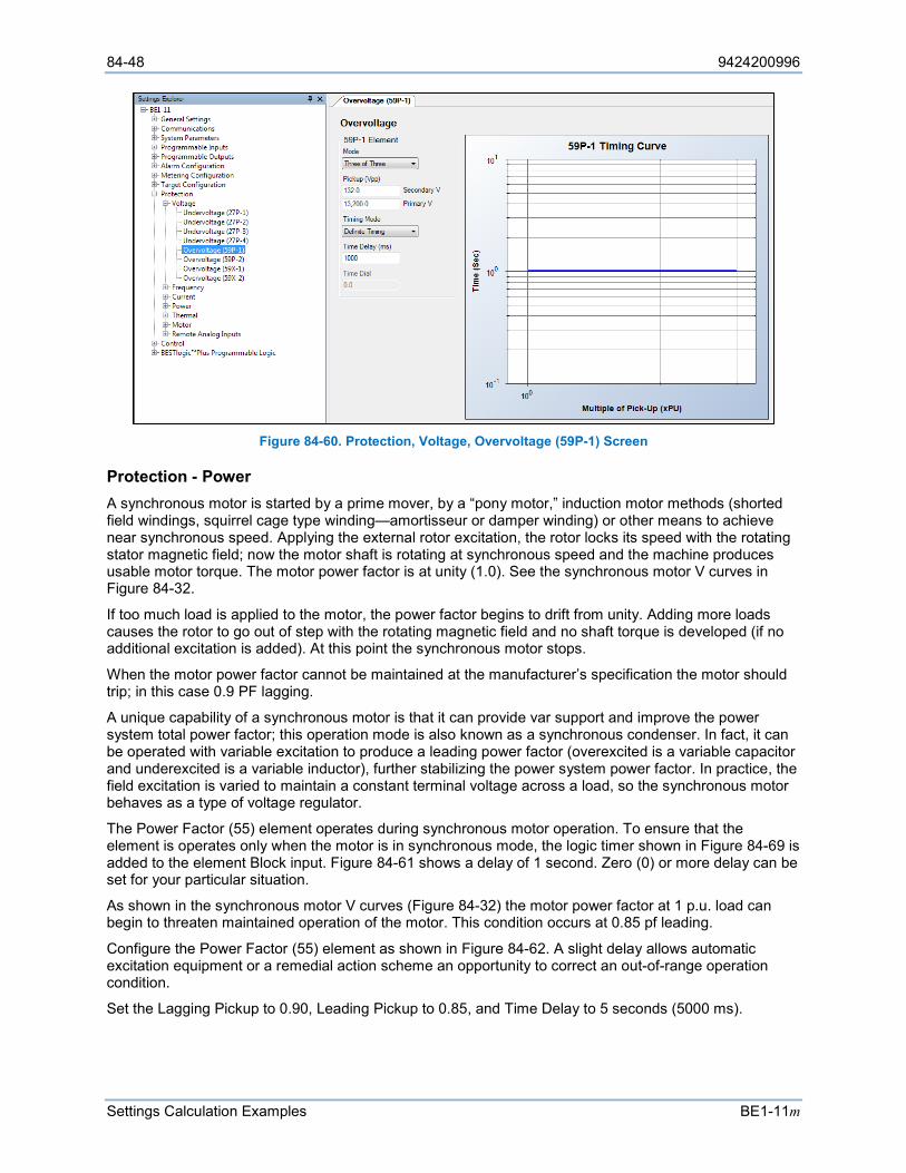
84-48 9424200996
Settings Calculation Examples BE1-11m
Figure 84-60. Protection, Voltage, Overvoltage (59P-1) Screen
Protection - Power A synchronous motor is started by a prime mover, by a “pony motor,” induction motor methods (shorted field windings, squirrel cage type winding—amortisseur or damper winding) or other means to achieve near synchronous speed. Applying the external rotor excitation, the rotor locks its speed with the rotating stator magnetic field; now the motor shaft is rotating at synchronous speed and the machine produces usable motor torque. The motor power factor is at unity (1.0). See the synchronous motor V curves in Figure 84-32.
If too much load is applied to the motor, the power factor begins to drift from unity. Adding more loads causes the rotor to go out of step with the rotating magnetic field and no shaft torque is developed (if no additional excitation is added). At this point the synchronous motor stops.
When the motor power factor cannot be maintained at the manufacturer’s specification the motor should trip; in this case 0.9 PF lagging.
A unique capability of a synchronous motor is that it can provide var support and improve the power system total power factor; this operation mode is also known as a synchronous condenser. In fact, it can be operated with variable excitation to produce a leading power factor (overexcited is a variable capacitor and underexcited is a variable inductor), further stabilizing the power system power factor. In practice, the field excitation is varied to maintain a constant terminal voltage across a load, so the synchronous motor behaves as a type of voltage regulator.
The Power Factor (55) element operates during synchronous motor operation. To ensure that the element is operates only when the motor is in synchronous mode, the logic timer shown in Figure 84-69 is added to the element Block input. Figure 84-61 shows a delay of 1 second. Zero (0) or more delay can be set for your particular situation.
As shown in the synchronous motor V curves (Figure 84-32) the motor power factor at 1 p.u. load can begin to threaten maintained operation of the motor. This condition occurs at 0.85 pf leading.
Configure the Power Factor (55) element as shown in Figure 84-62. A slight delay allows automatic excitation equipment or a remedial action scheme an opportunity to correct an out-of-range operation condition.
Set the Lagging Pickup to 0.90, Leading Pickup to 0.85, and Time Delay to 5 seconds (5000 ms).
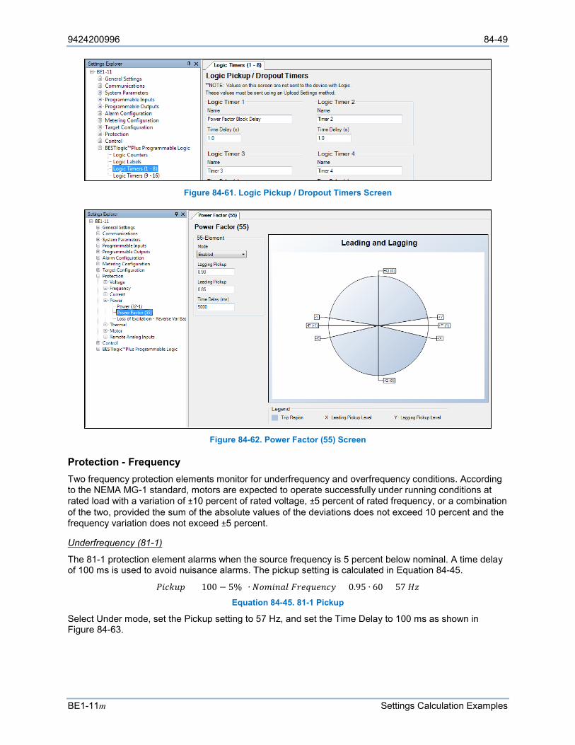
9424200996 84-49
BE1-11m Settings Calculation Examples
Figure 84-61. Logic Pickup / Dropout Timers Screen
Figure 84-62. Power Factor (55) Screen
Protection - Frequency Two frequency protection elements monitor for underfrequency and overfrequency conditions. According to the NEMA MG-1 standard, motors are expected to operate successfully under running conditions at rated load with a variation of ±10 percent of rated voltage, ±5 percent of rated frequency, or a combination of the two, provided the sum of the absolute values of the deviations does not exceed 10 percent and the frequency variation does not exceed ±5 percent.
Underfrequency (81-1)
The 81-1 protection element alarms when the source frequency is 5 percent below nominal. A time delay of 100 ms is used to avoid nuisance alarms. The pickup setting is calculated in Equation 84-45.
𝑃𝑃𝑅𝑅𝑠𝑠𝑘𝑘𝐹𝐹𝐴𝐴 = (100 − 5%) ∙ 𝑁𝑁𝐿𝐿𝐴𝐴𝑅𝑅𝑠𝑠𝐿𝐿𝐹𝐹 𝐹𝐹𝑠𝑠𝑠𝑠𝐹𝐹𝐹𝐹𝑠𝑠𝑠𝑠𝑠𝑠𝑠𝑠 = 0.95 ∙ 60 = 57 𝐻𝐻𝐻𝐻 Equation 84-45. 81-1 Pickup
Select Under mode, set the Pickup setting to 57 Hz, and set the Time Delay to 100 ms as shown in Figure 84-63.
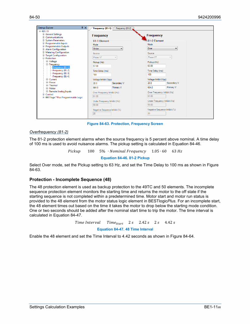
84-50 9424200996
Settings Calculation Examples BE1-11m
Figure 84-63. Protection, Frequency Screen
Overfrequency (81-2)
The 81-2 protection element alarms when the source frequency is 5 percent above nominal. A time delay of 100 ms is used to avoid nuisance alarms. The pickup setting is calculated in Equation 84-46.
𝑃𝑃𝑅𝑅𝑠𝑠𝑘𝑘𝐹𝐹𝐴𝐴 = (100 + 5%) ∙ 𝑁𝑁𝐿𝐿𝐴𝐴𝑅𝑅𝑠𝑠𝐿𝐿𝐹𝐹 𝐹𝐹𝑠𝑠𝑠𝑠𝐹𝐹𝐹𝐹𝑠𝑠𝑠𝑠𝑠𝑠𝑠𝑠 = 1.05 ∙ 60 = 63 𝐻𝐻𝐻𝐻 Equation 84-46. 81-2 Pickup
Select Over mode, set the Pickup setting to 63 Hz, and set the Time Delay to 100 ms as shown in Figure 84-63.
Protection - Incomplete Sequence (48) The 48 protection element is used as backup protection to the 49TC and 50 elements. The incomplete sequence protection element monitors the starting time and returns the motor to the off state if the starting sequence is not completed within a predetermined time. Motor start and motor run status is provided to the 48 element from the motor status logic element in BESTlogicPlus. For an incomplete start, the 48 element times out based on the time it takes the motor to drop below the starting mode condition. One or two seconds should be added after the nominal start time to trip the motor. The time interval is calculated in Equation 84-47.
𝐶𝐶𝑅𝑅𝐴𝐴𝑠𝑠 𝐼𝐼𝑠𝑠𝑅𝑅𝑠𝑠𝑠𝑠𝑜𝑜𝐿𝐿𝐹𝐹 = 𝐶𝐶𝑅𝑅𝐴𝐴𝑠𝑠𝑆𝑆𝑆𝑆𝑆𝑆𝑆𝑆𝑆𝑆 + 2 𝐴𝐴 = 2.42 𝐴𝐴 + 2 𝐴𝐴 = 4.42 𝐴𝐴 Equation 84-47. 48 Time Interval
Enable the 48 element and set the Time Interval to 4.42 seconds as shown in Figure 84-64.
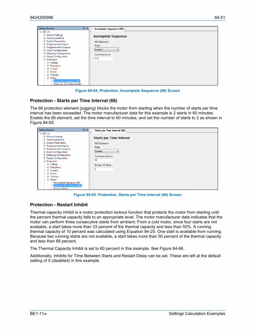
9424200996 84-51
BE1-11m Settings Calculation Examples
Figure 84-64. Protection, Incomplete Sequence (48) Screen
Protection - Starts per Time Interval (66) The 66 protection element (jogging) blocks the motor from starting when the number of starts per time interval has been exceeded. The motor manufacturer data for this example is 2 starts in 60 minutes. Enable the 66 element, set the time interval to 60 minutes, and set the number of starts to 2 as shown in Figure 84-65.
Figure 84-65. Protection, Starts per Time Interval (66) Screen
Protection - Restart Inhibit Thermal capacity inhibit is a motor protection lockout function that protects the motor from starting until the percent thermal capacity falls to an appropriate level. The motor manufacturer data indicates that the motor can perform three consecutive starts from ambient. From a cold motor, since four starts are not available, a start takes more than 33 percent of the thermal capacity and less than 50%. A running thermal capacity of 10 percent was calculated using Equation 84-25. One start is available from running. Because two running starts are not available, a start takes more than 50 percent of the thermal capacity and less than 66 percent.
The Thermal Capacity Inhibit is set to 60 percent in this example. See Figure 84-66.
Additionally, inhibits for Time Between Starts and Restart Delay can be set. These are left at the default setting of 0 (disabled) in this example.
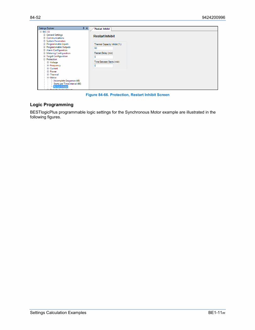
84-52 9424200996
Settings Calculation Examples BE1-11m
Figure 84-66. Protection, Restart Inhibit Screen
Logic Programming BESTlogicPlus programmable logic settings for the Synchronous Motor example are illustrated in the following figures.

9424200996 84-53
BE1-11m Settings Calculation Examples
Figure 84-67. Logic Page 1 (Unchanged from Induction Motor Default)
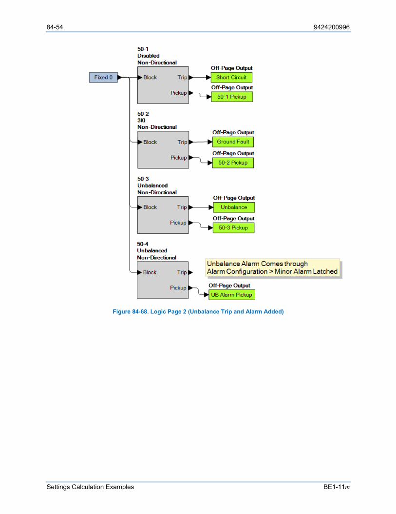
84-54 9424200996
Settings Calculation Examples BE1-11m
Figure 84-68. Logic Page 2 (Unbalance Trip and Alarm Added)
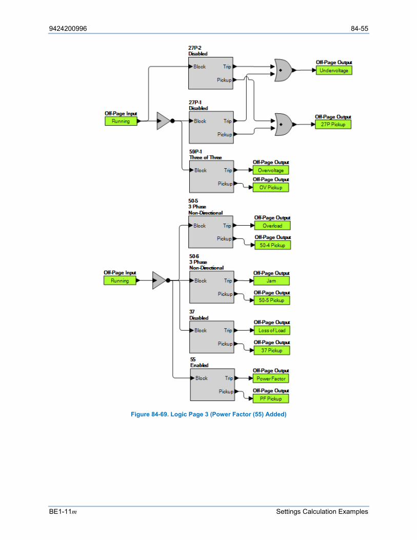
9424200996 84-55
BE1-11m Settings Calculation Examples
Figure 84-69. Logic Page 3 (Power Factor (55) Added)
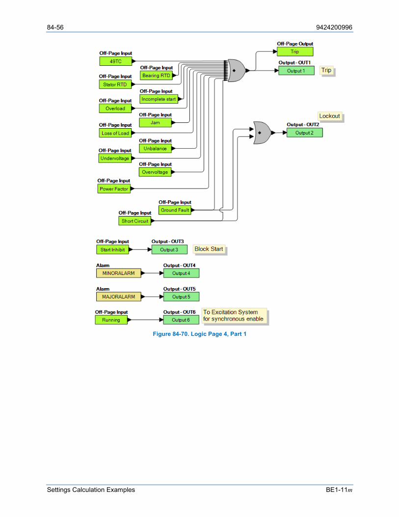
84-56 9424200996
Settings Calculation Examples BE1-11m
Figure 84-70. Logic Page 4, Part 1
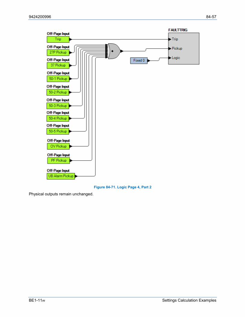
9424200996 84-57
BE1-11m Settings Calculation Examples
Figure 84-71. Logic Page 4, Part 2
Physical outputs remain unchanged.

84-58 9424200996
Settings Calculation Examples BE1-11m

9424200996 85-1
BE1-11m BESTCOMSPlus® Settings Loader Tool
85 • BESTCOMSPlus® Settings Loader Tool Introduction
The BESTCOMSPlus® Settings Loader Tool is a software application which allows the user to instantly upload settings to Basler BESTCOMSPlus-compatible products by scanning a pre-registered bar code which promotes consistency, reduces potential errors, and saves time.
Setup
The BESTCOMSPlus Settings Loader Tool software and a bar code reader (acquired separately) must be installed on the same PC.
BESTCOMSPlus Settings Loader Tool Installation
System Recommendations
The BESTCOMSPlus® Settings Loader Tool is bundled with BESTCOMSPlus software. BESTCOMSPlus software is built on the Microsoft® .NET Framework. The setup utility that installs BESTCOMSPlus on your PC also installs the BESTCOMSPlus Settings Loader Tool and the required version of .NET Framework (if not already installed). BESTCOMSPlus operates with systems using Windows® 7 SP1, Windows 8.1, and Windows 10 version 1607 (Anniversary Edition) or later. Microsoft Internet Explorer 5.01 or later must be installed on your PC before installing BESTCOMSPlus. System recommendations for the .NET Framework and BESTCOMSPlus are listed in Table 85-1.
Table 85-1. System Recommendations for BESTCOMSPlus and the .NET Framework
System Type Component Recommendation 32/64 bit Processor 2.0 GHz
32/64 bit RAM 1 GB (minimum), 2 GB (recommended) 32 bit Hard Drive 200 MB (if .NET Framework is already installed on PC)
4.5 GB (if .NET Framework is not already installed on PC)
64 bit Hard Drive 200 MB (if .NET Framework is already installed on PC) 4.5 GB (if .NET Framework is not already installed on PC)
To install and run BESTCOMSPlus, a Windows user must have Administrator rights.
Installation
Note
Do not connect a USB cable until setup completes successfully. Connecting a USB cable before setup is complete may result in errors.
1. Insert the BESTCOMSPlus CD-ROM into the PC CD-ROM drive.
2. When the BESTCOMSPlus Setup and Documentation CD menu appears, click the Install button for the BESTCOMSPlus application. The setup utility installs BESTCOMSPlus, the .NET Framework (if not already installed), the USB driver, and the BESTCOMSPlus Settings Loader Tool on your PC.
When BESTCOMSPlus installation is complete, a Basler Electric folder is added to the Windows programs menu. This folder is accessed by clicking the Windows Start button and then accessing the Basler Electric folder in the Programs menu. The Basler Electric folder contains an icon that starts the BESTCOMSPlus Settings Loader Tool.

85-2 9424200996
BESTCOMSPlus® Settings Loader Tool BE1-11m
Bar Code Reader and Bar Codes The BESTCOMSPlus Settings Loader Tool is compatible with bar code readers, which conform to UnifiedPOS specifications. Bar code readers and bar code labels are not provided and must be acquired separately. Refer to the bar code reader’s documentation for installation instructions.
Any bar code compatible with your bar code reader may be used.
BESTCOMSPlus® Settings Loader Tool Settings
BESTCOMSPlus Settings Loader Tool settings are found on two main screens, the Loader Grid and Configuration screen. The Loader Grid contains management options for the product settings files and their associated bar codes. The Configuration screen contains product-specific options for the default behavior of the BESTCOMSPlus Settings Loader Tool. These settings are described in the following paragraphs.
Loader Grid One entry, or row, in the Loader Grid contains all of the necessary data to associate a product settings file with a bar code. New entries can be added. Existing entries can be edited, deleted, and uploaded to a Basler product.
Figure 85-1. Loader Grid
Scanning Bar Codes
Place the cursor in the text field, found at the top of the Loader Grid screen, and scan a bar code. If successful, the digits which comprise the bar code appear in the text field. The BESTCOMSPlus Settings Loader Tool automatically searches for this bar code among the entries in the Loader Grid and displays the matching entry. Click Clear to remove the digits from the text field.
Adding an Entry
Click Add to create an entry. The BESTCOMSPlus® Settings Loader Tool: Add Device dialog box appears (Figure 85-2).
9424200996 85-3
BE1-11m BESTCOMSPlus® Settings Loader Tool
Figure 85-2. Add Device Screen
Enter the name of the entry in the Name field. This appears in the first column of the Loader Grid.
Select the product type from the Type drop-down menu. This appears in the second column of the Loader Grid.
Enter the bar code of the entry in the UPC Barcode field by placing the cursor in the UPC Barcode field and scanning the bar code.
To select the product settings file for the entry, click the browse (…) button in the Location field. Use standard Windows methods to navigate to the desired product settings file and click Open. Ensure that the selected product type in the Type field matches that of the product settings file specified in the Location field.
Click OK when finished.
Editing an Entry
To Edit an existing entry, select the entry in the Loader Grid and click Edit. The BESTCOMSPlus Settings Loader Tool: Edit Device dialog box appears. The options are identical to those of the Add Device dialog. When the desired changes have been made, click OK.
Deleting an Entry
To delete an entry from the Loader Grid, select the entry and click the Delete button. A prompt appears providing the option to confirm or cancel the deletion.
Uploading an Entry
Select an entry and click Upload. A dialog appears which provides connection options for the appropriate type of device. Refer to the Basler product instruction manual for detailed connection information. Once a connection is established, the product settings associated with the entry are uploaded.
Configuration Settings For configuration settings, click the Configure button in the bottom left of the Loader Grid. The product tabs on the left represent the compatible Basler products. Each product tab contains tabs for Settings Files and Connection Options. The options on these tabs are described below.
Setting Files Options
Use Saved Path: When enabled, the path specified in the Loader Grid entry is used when uploading the settings file.
Single Folder: When enabled, this specifies a single folder which contains all settings files for the product. The Windows filename specified in the Location field of the Loader Grid entry is searched for in the Single Folder location. For example, all settings files for a product are located in “C:\Files”. The Location field in the Loader Grid entry for a device contains “C:\Documents\Settings\BE1-11

85-4 9424200996
BESTCOMSPlus® Settings Loader Tool BE1-11m
Settings.bstx”. The BESTCOMSPlus Settings Loader Tool searches in “C:\Files” for the filename “BE1-11 Settings.bstx”.
Append Bar-Code to Location: When enabled, the bar code is appended to the specified location when uploading the settings file. For example, an entry with the bar code “0002” is located in C:\Files\0002 and an entry with the bar code “0003” is located in C:\Files\0003.
Logon: If User Name and Password are specified, you will not be prompted for credentials when required.
Save After Upload: After uploading a settings file, the settings are downloaded from the connected device and saved to the specified location, when enabled.
Upload Security: When enabled, the security settings stored in the settings file are uploaded to the device. Credentials will be requested if not already specified.
Figure 85-3 illustrates the Setting Files tab.
Figure 85-3. Configuration, Settings Files Tab
Connection Options
Connection options consist of the three selections described below. Refer to the Basler product instruction manual for detailed connection information.
Always Prompt for Connection: When enabled, a dialog appears which provides connection options for the appropriate type of device each time a connection attempt is made.
Ethernet Connection: When enabled, the BESTCOMSPlus Settings Loader Tool automatically attempts to connect to the specified IP address before uploading settings.
USB Connection: When enabled, the BESTCOMSPlus® Settings Loader Tool automatically attempts to connect to the device via USB port before uploading settings.
Figure 85-4 illustrates the Connection Options tab.
9424200996 85-5
BE1-11m BESTCOMSPlus® Settings Loader Tool
Figure 85-4. Configuration, Connection Options Tab
General Operation
The steps listed below are provided as a general guideline for how to operate the BESTCOMSPlus Settings Loader Tool when the initial setup is complete and the settings files are associated with bar codes.
1. Power on the device which will receive the new settings. Ensure proper communication connections have been made between the device and the PC running BESTCOMSPlus Settings Loader Tool.
2. Run BESTCOMSPlus Settings Loader Tool.
3. Place cursor in search bar.
4. Scan bar code.
5. Settings file is automatically highlighted and isolated in the grid.
6. Click Upload.
7. BESTCOMSPlus Settings Loader Tool automatically connects to device and uploads settings. Device connection is automatic unless “Always prompt for connection” is enabled.

85-6 9424200996
BESTCOMSPlus® Settings Loader Tool BE1-11m


12570 Route 143 Highland IL 62249-1074 USA Tel: +1 618.654.2341 Fax: +1 618.654.2351 email: [email protected]
No. 59 Heshun Road Loufeng District (N) Suzhou Industrial Park 215122 Suzhou P.R. CHINA Tel: +86 512.8227.2888 Fax: +86 512.8227.2887 email: [email protected]
111 North Bridge Road 15-06 Peninsula Plaza Singapore 179098 Tel: +65 68.44.6445 Fax: +65 68.44.8902 email: [email protected]