B. Tech. 1st Sem - SVVV
16
-
Upload
khangminh22 -
Category
Documents
-
view
0 -
download
0
Transcript of B. Tech. 1st Sem - SVVV

l Shri 'Vaishnau 'Vidyapeetn Vishwaoidyaiaya, Indore~
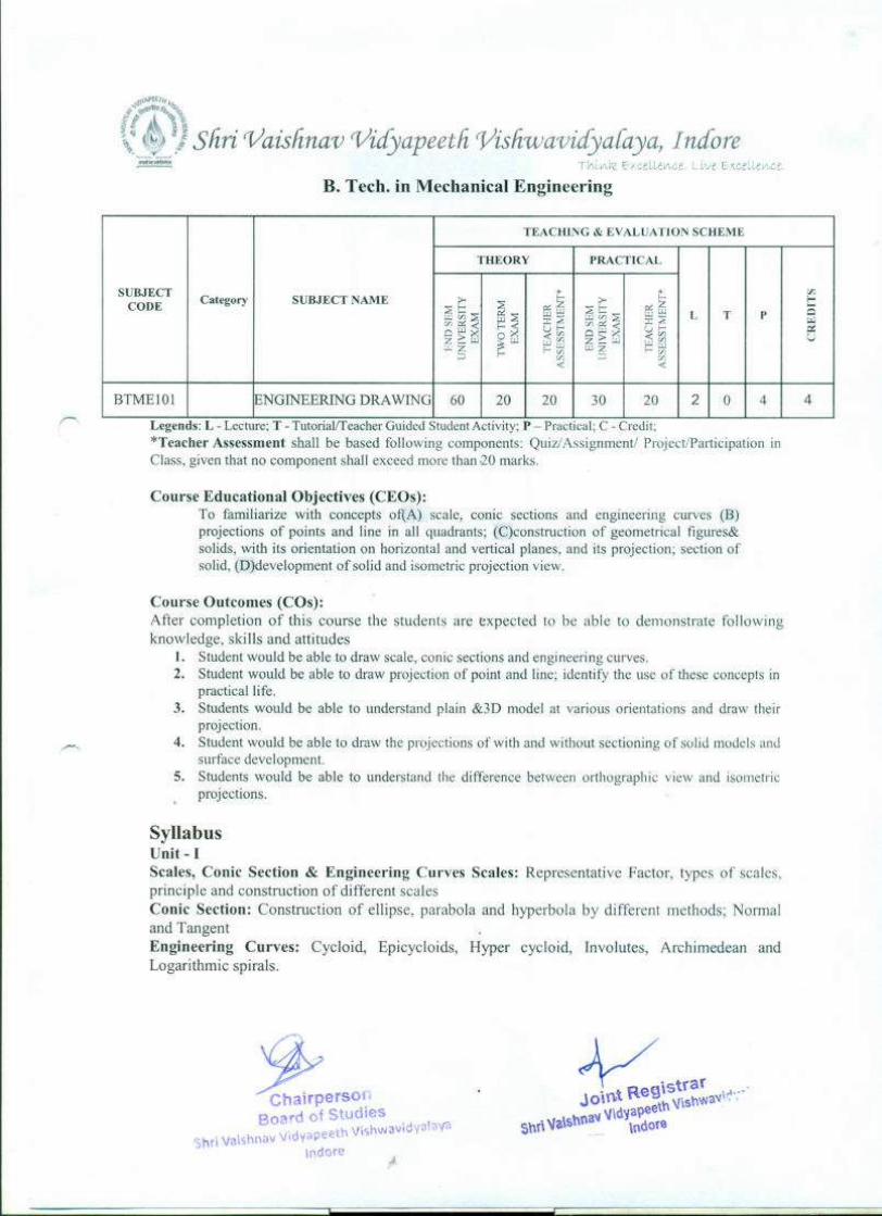
B. Tech. in Mechanical Engineering
TEACHING & EVALUATION SCHEME
THEORY PRACTICAL
SUBJECT * t: o:Category SUBJECT NAME >- f- >- I-
CODE 2t::~2
~z 2t:: ~z 25UJUJ UJUJ L T pUJ(I)2 :r:2 UJ(J)2 :r:2 w(J)n:;;i t::<e C/ln:;;iClUJ uf- ClUJ uf- c:I!
OX <(I) <'" Uz:::UJ:3:UJ UJifl Z::::J.J UJgJ
!.LZf- f-~ UJZ f-VJ
::;) ifl ::;) VJ-c <
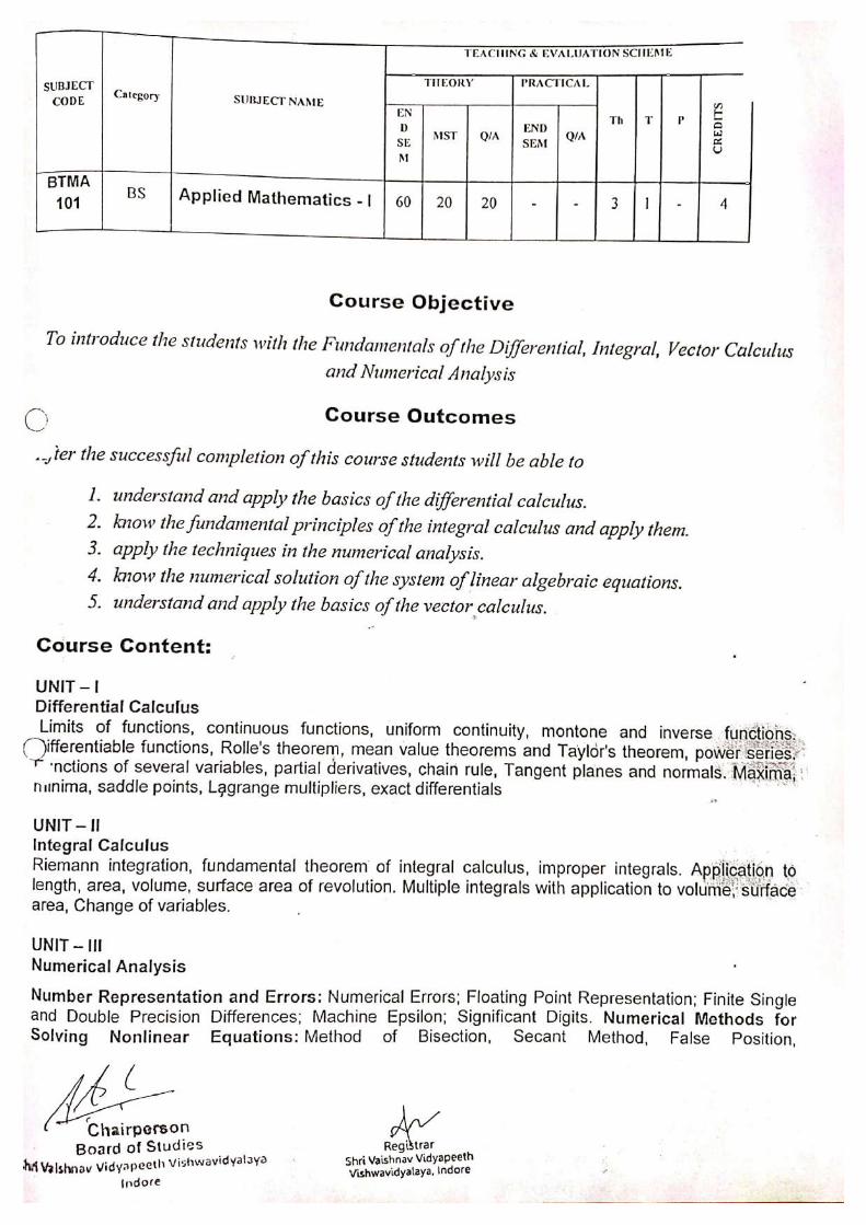
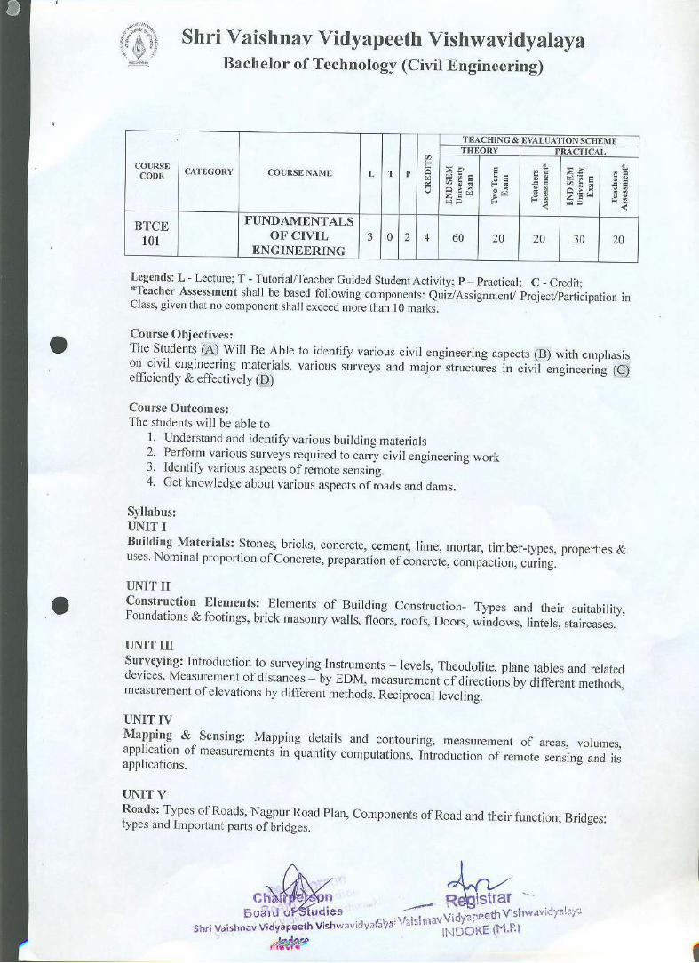
BTMEIOI !ENGINEERING DRAWING 60 20 20 30 20 2 0 4 4
..
,.,--
Legends: L - Lecture; T - Tutonalffeacher Guided Student Activity; P - Practical; C - Credit;
"Teacher Assessment shall be based following components: Quiz/Assignment/ Project/Participation in
Class, given that no component shall exceed more than ·20marks.
Course Educational Objectives (CEOs):
To familiarize with concepts of(A) scale, conic sections and engineering curves (B)projections of points and line in all quadrants; (C)construction of geometrical figures&
solids, with its orientation on horizontal and vertical planes, and its projection; section of
solid, (D)development of solid and isometric projection view.
Course Outcomes (COs):
After completion of this course the students are expected to be able to demonstrate following
knowledge, skills and attitudes
1. Student would be able to draw scale, conic sections and engineering curves.
2. Student would be able to draw projection of point and line; identify the use of these concepts inpractical life.
3. Students would be able to understand plain &3D model at various orientations and draw theirprojection.
4. Student would be able to draw the projections of with and without sectioning of solid models andsurface development.
5. Students would be able to understand the difference between orthographic view and isometric
projections.
SyllabusUnit - I
Scales, Conic Section & Engineering Curves Scales: Representative Factor, types of scales,
principle and construction of different scales
Conic Section: Construction of ellipse, parabola and hyperbola by different methods; Normal
and Tangent
Engineering Curves: Cycloid, Epicycloids, Hyper cycloid, Involutes, Archimedean and
Logarithmic spirals.
~e~oBoard of Studies
. h Vishwavidyalava'S ri Vaishnav Vldyapeet
Indore

Unit - II
Projection of Points & Line Projection: Introduction to projection, Types of projection,
terminology, first angle and third angle
Projection of Points: Introduction of point, conventional representation
Projection of Lines: Introduction of straight line, orientation of straight line, true inclination and
true length, concepts of end projectors, plan and traces and auxiliary planes
Unit - III
Projections of Planes: Introduction of planes, types of planes, orientation of planes, projection
of planes in different positions, traces of planes
Projection of Solids: Introduction of solids, classification of solids, recommended naming of
comers of solids, orientation of solids
Unit - IV
Section of Solids & Development of Surfaces Section of Solids: Introduction of section of
solids, terminology, types of section planes, section of prisms, section of pyramid and section of
composite solids
Development of Surfaces: Introduction of development of surfaces, classification of surfaces,
methods of development, development of prisms, pyramids, cylinder and cone, anti-development
Unit - V
Isometric Projections: Introduction of isometric projection, terminology, isometric projections
and isometric views, isometric views of planes, right solids, truncated solids and composite
solids.
Reference Books:
1. "Engineering Graphics", by Varghese
2. "Engineering Drawing", by Leone! Zurbito
3. "Engineering Drawing", by N.D. Bhatt.
4. "Engineering Drawing", by C. Agarwal & Basant Agarwal.
5. "Engineering Drawing", by P.s. Gill.
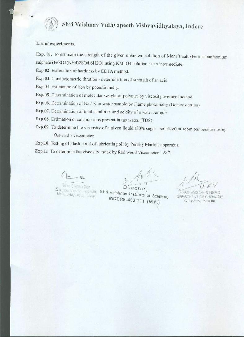
List of Experiments
1. Drawing various types of scales using representative fraction.
2. Drawing various conics section.
3. Projection of points in all quadrants.
4. Projection of straight lines in all quadrants in various orientations.
5. Projection of geometrical planes with various orientations.
6. Projection of solid models with various orientations.
7. Projection of section of solids by using various types of cutting planes.
8. Drawing development of surface using various methods of prisms, pyramids, cone,
~e~oo Studies
I dpeeth 'ish a Ji.
ndor
cylinder, etc.
9. Drawing anti- development of surfaces.
10. Drawing isometric projections using various methods and isometric views.
ChairpersonBoard of Studies
Shrl Valshnav Vidyapeeth Vishwavidyalaya
Indore


,f,<t"
\
.JSliri 'Vaishnau 'Vidyapeeth. 'Vishsuauidyalaya, Indore
B. Tech. in Mechanical Engineering
r
TEACHING & EVALUATION SCHEME
THEORY PRACTICAL
SUBJECT t- *(/J
Category SUBJECT NAME >- >- f- t:CODE ::Et::
~::Ec:r:Z ::Et:: c:r:Z"'-l~ "'-l"'-l L T P Q
"'-lCIJ::E :c::E "'-lCIJ::E :c~ wClJc:r:;i~;i
ClJc:r:;iuf- o"'-l uCIJ ~~g:"'-l
«CIJ U~"'-l we/) z2:"'-l «C/lw"'-lw~ f-i;l wz f-if)f-
<a ::> if)« «
INTRODUCTION TO
BTMEI04 CAD& SOLID 0 0 0 0 50 0 0 4 2
MODELLING..
Legends: L - Lecture; T - Tutorial/Teacher GUided Student Activity; P - Practical; C - Credit;
*Teacher Assessment shall be based following components: Quiz) Assignment/
ProjectlParticipation in Class, given that no component shall exceed more than 20 marks.
Course Educational Objectives (CEOs):
To paraphrases with(A) CAD, related applications with it and its need, (B) 2-D
and 3-D modeling terms, draw and editing commands and utility commands.
Course Outcomes (COs):After completion of this course the students are expected to be able to demonstrate following
knowledge, skills and attitudes
The students will be able to
1. Student would be able to understand CAD, its application and limitations.
2. Students would be able to use 2-D drawing, editing commands and its applications.
3. Student would be able to use solid modelling commands, and to understand various
modelling methods.
4. Students would be able to solve assembly related problems.
5. Students would be able to draw various 2-D, solid models and analyze various
machine assemblies.
Syllabus
Unit - I
Introduction to Cad: Introduction, history of 2D and solid modeling, menus, toolbars,
pointing device, command prompt, function keys
Unit - II
2-D Drawing& Editing Commands: Introduction, line commands, coordinate
systems, orthogonal lines, circle and arc commands, etc
Editing Commands: Introduction, erase and selection commands, move
commands, copy commands, extend command, trim command, mirror command, etc
Layers & Linotypes: Introduction, layers status line weights, object properties.

t~
"~ -¥ .JSliri 'Vaishnau 1/icfyapeetli1/isliwavidyalaya, Indore
'~~~ rh~y\J,< c-/ceLl.ev\c-f" Ct'.it. E'(c ..eLLt:((",(,.:.
Unit - III
Solid modelling
Types of Modelling: Solid modeling, surface modeling and wire frame modeling
Draw Commands: Introduction, polygon, cuboids, donut, ellipse, multiline, conic sections, etc
Editing Commands: Introduction, extrudes, revolve, sweep, etc
Unit - IV
Assembly Drafting: Introduction, constraints, exploded views, interference check,
layout, standard and section views, dimensioning, detailing and plotting.
Unit - V
Part Design: Introduction, 2-d model (triangle, rectangle, circle, etc), solid models (nut,
bolts, small machine parts), machine assemblies
Reference Books:
1. "An Introduction to Computer Aided Design (CAD)", by A. Mustun
2. "Mastering AutoCAD 2016 and AutoCAD LT 2016", by G. Omura
3. "AutoCAD 3D Training Manual", by K.S Kurland
4. "CAD/CAM: Principles and Application", by Rao
5. "Computer Aided Manufacturing", by Rao
6. "CAD/CAM: TheolY and Practices". by Zeid
7. "Mastering CAD/CAM (SIE",) by Zeid
..-...,
List of Experiments
1. To study various software for Computer Aided drafting.
2. To study various drawing commands for 2-D drawing in AutoCAD.
3. To study various editing commands from 2-D drawing in AutoCAD.
4. To draw various 2-D drawing using AutoCAD .
5. To study various solid modelling commands in AutoCAD.
6. To draw various solid models using AutoCAD.
7. To study various utility commands in AutoCAD.
8. To study various assemblies and drafting used in machine components.

~oI'[(j"t
."4' ,,,,~-4t,~ ~~
?tt "%'~
~ Ii:}~}Shri 'Vaishnau 'Vidyapeeti: Visfiu)avidya(aya, Indore~~ T h[ v•.j-< t-, c.~:tLelr~v:~:.C.l'· ;e b,,<c:,~Lrv\,c.e.
B. Tech. in Mechanical Engineering
TEACHlNG & EVALUATION SCHEME
THEORY PRACTICAL
SUBJECTCategory SUBJECT NAME t- t: ~
CODE>- >-
~t: ~ e>::i5 ~t: e>::i5
LUUJ~ fib ~~ LUC/l~ w~ L T P 0UJe>:: UJe>::< If-
:.J
OW f-~ e,.,f-OW>< u<l1
cG
Z2:lU ~lU«<11
z2:w «<11 UlU<I1lUlUlUS f-i;i wz f-<I1f-
<11 ::> <11< «
BTMEI03 WORKSHOP PRACTICES 0 0 0 30 20 0 0 2 I
..Legends: L - Lecture; T - Tutorial/Teacher GUIded Student Activity; P - Practical; C - Credit;
"Teacher Assessment shall be based following components: QuizJAssignmenti Project/Participation in
Class, given that no component shall exceed more than 20 marks.
Course Educational Objectives (CEOs):
To paraphrases with (A) workshop technology, industrial safety, and understand material
properties. (B) Carpentry shop, fitting shop, (C) welding and casting.
Corse Outcomes (COs):
After completion of this course the students are expected to be able to demonstrate following knowledge,
skills and attitudes students will be able to
1. Student would be able to understand the need of workshop, technology related to it, and industrial
safety and precautions.
2. Student would be able to use carpentry tools, analyses various wood joints and their properties.
3. Students would be able to use fitting tools to make various shapes and design.
4. Student would be able to recognize various welding techniques and their needs.
5. Students would be able to design various shapes by using casting technologies.
SyllabusUnit -I
Introduction to Workshop Technology & Industrial Safety
Workshop Technology: Introduction, need of workshop and types of workshop
Industrial Safety- Introduction, objective of industrial safety, causes of accidents, common
sources of accidents, preventive measures, and common safety methods.
Unit -II
Carpentry Shop Carpentry: Introduction, types of timbers, defects in timbers, timber
prevention, characteristics of good timber, common tools used in carpentry shop (marking and
measuring tools; cutting tools and striking tools), and common wood joints (cross-lap, corner-
lap, dovetail and bridle joints).
~pe~oBoard of Studies
hri Vaishnav Vidyapeeth Vishwavidyalayal
Indore
Unit -III
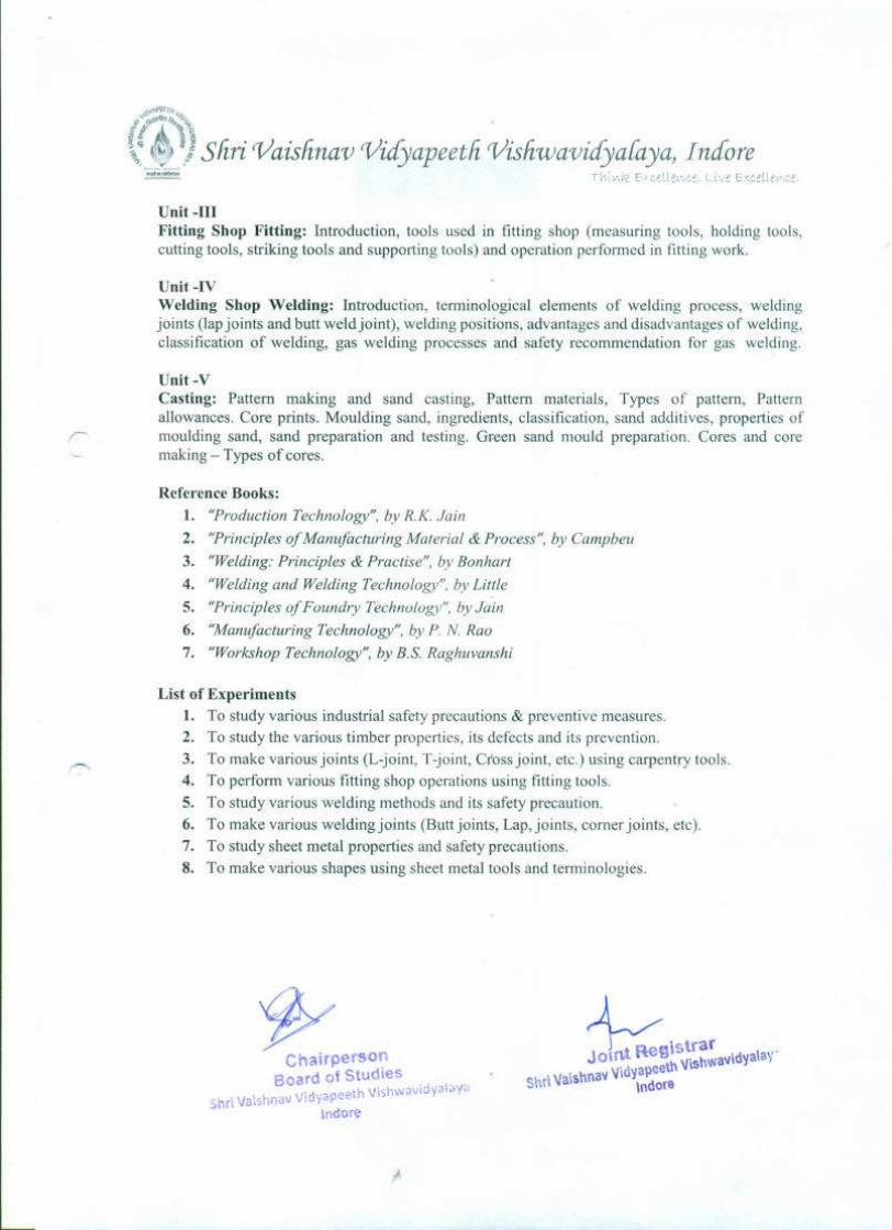
Fitting Shop Fitting: Introduction, tools used in fitting shop (measuring tools, holding tools,
cutting tools, striking tools and supporting tools) and operation performed in fitting work.
Unit -IV
Welding Shop Welding: Introduction, terminological elements of welding process, welding
joints (lap joints and butt weld joint), welding positions, advantages and disadvantages of welding,
classification of welding, gas welding processes and safety recommendation for gas welding.
Unit -vCasting: Pattern making and sand casting, Pattern materials, Types of pattern, Pattern
allowances. Core prints. Moulding sand, ingredients, classification, sand additives, properties of
moulding sand, sand preparation and testing. Green sand mould preparation. Cores and core
making - Types of cores.
Reference Books:
1. "Production Technology", by R.K. Jain
2. "Principles of Manufacturing Material & Process", by Campbeu
3. "Welding: Principles & Practise", by Bonhart
4. "Welding and Welding Technology", by Little
5. "Principles of Foundry Technology", by Jain
6. "Manufacturing Technology", by P. N. Rao
7. "Workshop Technology", by B.S. Raghuvanshi
List of Experiments
1. To study various industrial safety precautions & preventive measures.
2. To study the various timber properties, its defects and its prevention.
3. To make various joints (L-joint, T-joint, Cross joint, etc.) using carpentry tools.
4. To perform various fitting shop operations using fitting tools.
5. To study various welding methods and its safety precaution.
6. To make various welding joints (Butt joints, Lap, joints, corner joints, etc).
7. To study sheet metal properties and safety precautions.
8. To make various shapes using sheet metal tools and terminologies.
'tjYCh irperson
Board of Studies .
hri Vaishnav Vidyapeeth Vishwavloyalaya
meore