
b-l2vpn-cg-ncs5500-73x.pdf - Cisco
458
L2VPN and Ethernet Services Configuration Guide for Cisco NCS 5500 Series Routers, IOS XR Release 7.3.x First Published: 2021-02-01 Americas Headquarters Cisco Systems, Inc. 170 West Tasman Drive San Jose, CA 95134-1706 USA http://www.cisco.com Tel: 408 526-4000 800 553-NETS (6387) Fax: 408 527-0883
-
Upload
khangminh22 -
Category
Documents
-
view
1 -
download
0
Transcript of b-l2vpn-cg-ncs5500-73x.pdf - Cisco

L2VPN and Ethernet Services Configuration Guide for Cisco NCS 5500Series Routers, IOS XR Release 7.3.xFirst Published: 2021-02-01
Americas HeadquartersCisco Systems, Inc.170 West Tasman DriveSan Jose, CA 95134-1706USAhttp://www.cisco.comTel: 408 526-4000
800 553-NETS (6387)Fax: 408 527-0883

THE SPECIFICATIONS AND INFORMATION REGARDING THE PRODUCTS IN THIS MANUAL ARE SUBJECT TO CHANGE WITHOUT NOTICE. ALL STATEMENTS,INFORMATION, AND RECOMMENDATIONS IN THIS MANUAL ARE BELIEVED TO BE ACCURATE BUT ARE PRESENTED WITHOUT WARRANTY OF ANY KIND,EXPRESS OR IMPLIED. USERS MUST TAKE FULL RESPONSIBILITY FOR THEIR APPLICATION OF ANY PRODUCTS.
THE SOFTWARE LICENSE AND LIMITED WARRANTY FOR THE ACCOMPANYING PRODUCT ARE SET FORTH IN THE INFORMATION PACKET THAT SHIPPED WITHTHE PRODUCT AND ARE INCORPORATED HEREIN BY THIS REFERENCE. IF YOU ARE UNABLE TO LOCATE THE SOFTWARE LICENSE OR LIMITED WARRANTY,CONTACT YOUR CISCO REPRESENTATIVE FOR A COPY.
The Cisco implementation of TCP header compression is an adaptation of a program developed by the University of California, Berkeley (UCB) as part of UCB's public domain version ofthe UNIX operating system. All rights reserved. Copyright © 1981, Regents of the University of California.
NOTWITHSTANDING ANY OTHERWARRANTY HEREIN, ALL DOCUMENT FILES AND SOFTWARE OF THESE SUPPLIERS ARE PROVIDED “AS IS" WITH ALL FAULTS.CISCO AND THE ABOVE-NAMED SUPPLIERS DISCLAIM ALL WARRANTIES, EXPRESSED OR IMPLIED, INCLUDING, WITHOUT LIMITATION, THOSE OFMERCHANTABILITY, FITNESS FOR A PARTICULAR PURPOSE AND NONINFRINGEMENT OR ARISING FROM A COURSE OF DEALING, USAGE, OR TRADE PRACTICE.
IN NO EVENT SHALL CISCO OR ITS SUPPLIERS BE LIABLE FOR ANY INDIRECT, SPECIAL, CONSEQUENTIAL, OR INCIDENTAL DAMAGES, INCLUDING, WITHOUTLIMITATION, LOST PROFITS OR LOSS OR DAMAGE TO DATA ARISING OUT OF THE USE OR INABILITY TO USE THIS MANUAL, EVEN IF CISCO OR ITS SUPPLIERSHAVE BEEN ADVISED OF THE POSSIBILITY OF SUCH DAMAGES.
Any Internet Protocol (IP) addresses and phone numbers used in this document are not intended to be actual addresses and phone numbers. Any examples, command display output, networktopology diagrams, and other figures included in the document are shown for illustrative purposes only. Any use of actual IP addresses or phone numbers in illustrative content is unintentionaland coincidental.
All printed copies and duplicate soft copies of this document are considered uncontrolled. See the current online version for the latest version.
Cisco has more than 200 offices worldwide. Addresses and phone numbers are listed on the Cisco website at www.cisco.com/go/offices.
The documentation set for this product strives to use bias-free language. For purposes of this documentation set, bias-free is defined as language that does not imply discrimination based onage, disability, gender, racial identity, ethnic identity, sexual orientation, socioeconomic status, and intersectionality. Exceptions may be present in the documentation due to language thatis hardcoded in the user interfaces of the product software, language used based on standards documentation, or language that is used by a referenced third-party product.
Cisco and the Cisco logo are trademarks or registered trademarks of Cisco and/or its affiliates in the U.S. and other countries. To view a list of Cisco trademarks, go to this URL:https://www.cisco.com/c/en/us/about/legal/trademarks.html. Third-party trademarks mentioned are the property of their respective owners. The use of the word partner does not imply apartnership relationship between Cisco and any other company. (1721R)
© 2020 Cisco Systems, Inc. All rights reserved.
C O N T E N T S
Preface xvP R E F A C E
Changes to This Document xv
Obtaining Documentation and Submitting a Service Request xv
New and Changed VPN Features 1C H A P T E R 1
New and Changed VPN Features 1
Configure Gigabit Ethernet for Layer 2 VPNs 3C H A P T E R 2
Introduction to Layer 2 Virtual Private Networks 3
Introduction to Layer 2 VPNs on Gigabit Ethernet Interfaces 4
Configure Gigabit Ethernet Interfaces for Layer 2 Transport 5
Configure Link Loss Forwarding for Layer 2 Transport 6
Ethernet Data Plane Loopback 7
Configure Ethernet Data Plane Loopback 8
Running Configuration 9
Verification 10
Related Topics 11
Associated Commands 11
Ethernet Local Management Interface (E-LMI) 11
E-LMI Messaging 12
E-LMI Operation 13
Configure Ethernet Local Management Interface (E-LMI) 13
Running Configuration 15
Verify the Ethernet Local Management Interface (E-LMI) Configuration 16
Queueing Support for BUM Traffic on Attachment Circuits 18
L2VPN and Ethernet Services Configuration Guide for Cisco NCS 5500 Series Routers, IOS XR Release 7.3.xiii

Configure Layer 2 Access Control Lists 19C H A P T E R 3
Layer 2 Access Control Lists 19
Prerequisites for Configuring Layer 2 Access Control Lists 19
Layer 2 Access Control Lists Feature Highlights 20
Purpose of Layer 2 Access Control Lists 20
How a Layer 2 Access Control List Works 20
Layer 2 Access Control List Process and Rules 20
Create Layer 2 Access Control List 21
Restrictions for Configuring Layer 2 Access Control Lists 21
Configuration 21
Running Configuration 22
Verification 22
Configure Virtual LANs in Layer 2 VPNs 23C H A P T E R 4
Configure VLAN Sub-Interfaces 25
Introduction to Ethernet Flow Point 27
Identify Frames of an EFP 27
Apply Features 28
Define Data-Forwarding Behavior 29
Ethernet Flow Points Visibility 29
Configuring EFP Visibility 30
Configure VLAN Header Rewrite 31
Rewrite Encapsulation Combinations 35
Rewrite of Priority Tag 38
Configure Rewrite of Priority Tag 39
L2CP Tunneling MEF 41C H A P T E R 5
L2CP Tunneling 41
L2CP Protocol Support on Cisco NCS 5500 Series Router 42
Ethernet Features 45C H A P T E R 6
Layer 2 Protocol Tunneling 45
L2PT in the Forward Mode 46
L2VPN and Ethernet Services Configuration Guide for Cisco NCS 5500 Series Routers, IOS XR Release 7.3.xiv
Contents

Configure Link Bundles for Layer 2 VPNs 51C H A P T E R 7
Configure Gigabit Ethernet Link Bundle 51
Configure VLAN Bundle 54
References for Configuring Link Bundles 55
Characteristics of Link Bundles 56
Methods of Forming Bundles of Ethernet Interfaces 56
Link Aggregation Through LACP 57
Configure Multipoint Layer 2 Services 59C H A P T E R 8
Prerequisites for Implementing Multipoint Layer 2 Services 59
Information About Implementing Multipoint Layer 2 Services 59
Multipoint Layer 2 Services Overview 60
Bridge Domain 60
Bridge Domain and BVI Scale 61
Pseudowires 61
Access Pseudowire 61
Virtual Forwarding Instance 64
VPLS for an MPLS-based Provider Core 64
VPLS for Layer 2 Switching 65
Interoperability Between Cisco IOS XR and Cisco IOS on VPLS LDP Signaling 65
VPLS VFI with BVI as Routed Interface 66
Configure VPLS VFI with BVI as Routed Interface 67
MAC Address-related Parameters 69
MAC Address Flooding 69
MAC Address-based Forwarding 69
MAC Address Source-based Learning 69
MAC Address Aging 69
MAC Address Limit 70
MAC Address Withdrawal 71
How to Implement Services 72
Configuring a Bridge Domain 72
Creating a Bridge Domain 72
Associating Members with a Bridge Domain 73
L2VPN and Ethernet Services Configuration Guide for Cisco NCS 5500 Series Routers, IOS XR Release 7.3.xv
Contents

Configuring Bridge Domain Parameters 74
Disabling a Bridge Domain 76
Flooding Disable 77
Configure Flooding Disable 77
Configuring a Layer 2 Virtual Forwarding Instance 79
Creating the Virtual Forwarding Instance 79
Associating Pseudowires with the Virtual Forwarding Instance 80
Associating a Virtual Forwarding Instance to a Bridge Domain 81
Attaching Pseudowire Classes to Pseudowires 83
Configuring Pseudowires Using Static Labels 84
Disabling a Virtual Forwarding Instance 86
Configuring the MAC Address-related Parameters 87
Configuring the MAC Address Source-based Learning 88
Configuring the MAC Address Limit 89
Configuring the MAC Address Aging 92
Disabling MAC Flush at the Bridge Port Level 93
MAC Address Withdrawal 95
Configure MAC Address Withdrawal 96
Configuration Examples for Multipoint Layer 2 Services 98
Multipoint Layer 2 Services Configuration for Provider Edge-to-Provider Edge: Example 98
Multipoint Layer 2 Services Configuration for Provider Edge-to-Customer Edge: Example 99
Displaying MAC Address Withdrawal Fields: Example 99
Bridging on IOS XR Trunk Interfaces: Example 101
Bridging on Ethernet Flow Points: Example 104
LDP-Based VPLS and VPWS FAT Pseudowire 107
Configure LDP-Based VPLS and VPWS FAT Pseudowire 108
Configure Point-to-Point Layer 2 Services 113C H A P T E R 9
Ethernet over MPLS 114
Ethernet Port Mode 115
VLAN Mode 115
Inter-AS Mode 116
QinQ Mode 117
QinAny Mode 117
L2VPN and Ethernet Services Configuration Guide for Cisco NCS 5500 Series Routers, IOS XR Release 7.3.xvi
Contents

Configure Local Switching Between Attachment Circuits 118
Configure Static Point-to-Point Connections Using Cross-Connect Circuits 122
Configure Dynamic Point-to-point Cross-Connects 124
Configure Inter-AS 124
Flexible Cross-Connect Service 125
Flexible Cross-Connect Service - Single-Homed 125
Flexible Cross-Connect Service - Multi-Homed 125
Flexible Cross-Connect Service Supported Modes 126
VLAN Unaware 126
Configure Single-Homed Flexible Cross-Connect Service using VLAN Unaware 126
Configure Multi-Homed Flexible Cross-Connect Service using VLAN Unaware 128
VLAN Aware 132
Configure Single-Homed Flexible Cross-Connect using VLAN Aware 132
Configure Multi-Homed Flexible Cross-Connect Service using VLAN Aware 133
Local Switching 137
Configure Multi-Homed Flexible Cross-Connect Service using Local Switching 138
AC-Aware VLAN Bundle 140
Configure Preferred Tunnel Path 141
Multisegment Pseudowire 142
Multisegment Pseudowire Redundancy 144
Configure Multisegment Pseudowire 145
Split Horizon Groups 148
Configure Split Horizon Group 2 150
G.8032 Ethernet Ring Protection 151
Configure G.8032 Ethernet Ring Protection 156
Configure ERP Profile 157
Configuring an ERP Instance 157
Configuring G.8032 Ethernet Ring Protection: Example 159
Configuring Interconnection Node: Example 160
Configuring the Node of an Open Ring: Example 161
Pseudowire Redundancy 162
Configure Pseudowire Redundancy 163
Running Configuration 163
Verification 164
L2VPN and Ethernet Services Configuration Guide for Cisco NCS 5500 Series Routers, IOS XR Release 7.3.xvii
Contents

Configure Pseudowire Redundancy 165
Access Pseudowire Redundancy 166
Configure Access Pseudowire Redundancy 166
GTP Load Balancing 168
Multiple Spanning Tree Protocol 171C H A P T E R 1 0
Multiple Spanning Tree Protocol 171
MSTP Supported Features 171
BPDU Guard 172
Flush Containment 172
Bringup Delay 172
Restrictions 173
Configure MSTP 173
Running Configuration 175
Verification 176
Per-VLAN Rapid Spanning Tree 177
Configure PVRST 178
Running Configuration for PVRST 179
Information About Multiple Spanning Tree Protocol 180
Spanning Tree Protocol Overview 180
STP Protocol Operation 181
Topology Changes 181
Variants of STP 182
MSTP Regions 182
MSTP Port Fast 183
MSTP Root Guard 184
MSTP Topology Change Guard 184
EVPN Features 185C H A P T E R 1 1
EVPN Overview 185
EVPN Concepts 186
EVPN Operation 187
EVPN Route Types 189
EVPN Timers 190
L2VPN and Ethernet Services Configuration Guide for Cisco NCS 5500 Series Routers, IOS XR Release 7.3.xviii
Contents

Configure EVPN L2 Bridging Service 191
Running Configuration 192
EVPN Modes 193
EVPN Port-Active Multihoming 193
Configure EVPN Port-Active Multihoming 195
EVPN Single-Flow-Active Load Multihoming Balancing Mode 199
EVPN MPLS Seamless Integration with VPLS 205
Migrate VPLS Network to EVPN Network through Seamless Integration 205
Configure EVPN on the Existing VPLS Network 206
Configure L2 EVPN Address-Family 206
Configure EVI and Corresponding BGP Route Target under EVPN Configuration Mode 207
Configure EVI under a Bridge Domain 207
EVI Configuration Under L2VPN Bridge-Domain 208
Verify EVPN Configuration 209
EVPN Features 213
Configure EVPN MAC Address Limit 213
EVPN Software MAC Learning 215
Configure EVPN Software MAC Learning 216
Supported Modes for EVPN Software MAC Learning 217
Single Home Device or Single Home Network Mode 217
Dual Home Device—All-Active Load Balancing Mode 218
Verify EVPN Software MAC Learning 221
EVPN Out of Service 223
Configure EVPN Out of Service 224
EVPN Multiple Services per Ethernet Segment 227
Configure EVPN Multiple Services per Ethernet Segment 227
EVPN Convergence Using NTP Synchronization 233
EVPN Core Isolation Protection 235
Configure EVPN Core Isolation Protection 236
Highest Random Weight Mode for EVPN DF Election 238
Configure Highest Random Weight Mode for EVPN DF Election 239
Network Convergence using Core Isolation Protection 240
Configure EVPN Convergence using Core Isolation Protection 242
Conditional Advertisement of Default-Originate 246
L2VPN and Ethernet Services Configuration Guide for Cisco NCS 5500 Series Routers, IOS XR Release 7.3.xix
Contents

Configure Conditional Advertisement of Default-Originate 246
EVPN Bridging and VPWS Services over BGP-LU Underlay 249
Configure EVPN Bridging and VPWS Services over BGP-LU Underlay 250
Support for DHCPv4 and DHCPv6 Client over BVI 260
Configure DHCPv4 and DHCPv6 Client over BVI 260
MSTI Flush and Flood 265
Layer 2 Fast Reroute 270
EVPN Preferred Nexthop 276
Configure EVPN Preferred Nexthop 276
EVPN Access-Driven DF Election 278
Configure EVPN Access-Driven DF Election 284
CFM Support for EVPN 288
CFM on EVPN ELAN 288
Configure CFM on EVPN ELAN 289
EVPN Routing Policy 291
EVPN Route Types 292
EVPN RPL Attribute 296
EVPN RPL Attribute Set 298
Configure EVPN RPL Feature 299
Running Configuration 300
Configure EVPN IRB 307C H A P T E R 1 2
EVPN IRB 307
EVPN Single-Homing Access Gateway 309
EVPN Multihoming All-Active 310
EVPN Single-Active Multihoming for Anycast Gateway IRB 310
Configure EVPN Single-Active Multihoming 311
Configure EVPN IRB with Host Routing 311
Configure EVPN Ethernet Segment 312
Configure EVPN Service Instance (EVI) Parameters 313
Configure Layer 2 Interface 313
Configure a Bridge Domain 313
Configure VRF 314
Enable Auto-BGP RT with Manual ESI Configuration 314
L2VPN and Ethernet Services Configuration Guide for Cisco NCS 5500 Series Routers, IOS XR Release 7.3.xx
Contents

Supported EVPN IRB Scenarios 315
Distributed Anycast Gateway 315
EVPN IRB with All-Active Multi-Homing without Subnet Stretch or Host-Routing across theFabric 315
EVPN IRB with All-Active Multihoming with Subnet Stretch or Host-Routing across the Fabric 316
MAC and IP Unicast Control Plane 317
Intra-subnet Unicast Data Plane 318
Inter-subnet Unicast Data Plane 318
VMMobility Support 318
MAC and MAC-IP Sequence Numbers 318
Synchronized MAC and MAC-IP Sequence Numbers 319
Local Sequence Number Updates 319
Best Route Selection after Host Movement 319
Stale Route Deletion after a Host Movement 319
Host Movement Detection through GARP 319
Host Move Detection with Silent Host 319
Host Move Detection without GARP with Data Packet 319
Duplicate MAC Detection 320
Configuring EVPN IRB 320
Running Configuration for EVPN IRB 321
Verify EVPN IRB 323
EVPN IPv6 Hosts with Mobility 333
Configure EVPN IPv6 Hosts with Mobility 334
Duplicate IP Address Detection 343
Configure Duplicate IP Address Detection 344
Configuration Example 345
Running Configuration 345
Verification 345
EVPN Automatic Unfreezing of MAC and IP Addresses 346
Configure EVPN Automatic Unfreezing of MAC or IP Address 347
EVPN E-Tree 348
Configure EVPN E-Tree 352
Configuration Example 352
Running Configuration 353
L2VPN and Ethernet Services Configuration Guide for Cisco NCS 5500 Series Routers, IOS XR Release 7.3.xxi
Contents

Verification 355
EVPN E-Tree Using RT Constraints 357
CE with Multihoming Active-Active and CE with Multihoming Active-Active 358
DHCPv4 Relay on IRB 371
Configure DHCPv4 Relay on IRB 375
Configuration Example 375
Running Configuration 376
DHCPv4 Relay Synchronization for All-Active Multihoming 378
DHCPv6 Relay IAPD on IRB 378
Configure DHCPv6 Relay IAPD on IRB 379
Configuration Example 379
Running Configuration 380
DHCPv6 PD Synchronization for All-Active Multihoming using Session Redundancy 381
Configure DHCPv6 PD Synchronization 382
Configuration Example 382
Running Configuration 382
IAPD Route Distribution and Withdrawal in DHCPv6 Relay 384
L2VPN Services over Segment Routing for Traffic Engineering Policy 385C H A P T E R 1 3
L2VPN Preferred path 386
EVPN VPWS Preferred Path over SR-TE Policy 386
Configure EVPN VPWS Preferred Path over SR-TE Policy 387
Configure Prefix-SID in ISIS 387
Configure Adjacency-SID in ISIS 389
Configure Segment-list 391
Configure SR-TE Policy 392
Configure EVPN VPWS over SR-TE Policy 393
Running Configuration 393
Verify EVPN VPWS Preferred Path over SR-TE Policy Configuration 398
Associated Commands 399
Related Topics 399
L2VPN VPWS Preferred Path over SR-TE Policy 399
Configure L2VPN VPWS Preferred Path over SR-TE Policy 399
Configure Prefix-SID in IS-IS 400
L2VPN and Ethernet Services Configuration Guide for Cisco NCS 5500 Series Routers, IOS XR Release 7.3.xxii
Contents

Configure Adjacency-SID in IS-IS 401
Configure Segment-list 403
Configure SR-TE Policy 404
Configure VPWS over SR-TE Policy 405
Running Configuration 406
Verify L2VPN VPWS Preferred Path over SR-TE Policy Configuration 409
Associated Commands 411
Related Topics 412
EVPN VPWS On-Demand Next Hop with SR-TE 412
Configure EVPN VPWS On Demand Next Hop with SR-TE 413
Topology 413
Configure Prefix-SID in ISIS 413
Configure SR-TE 415
Configure PCE and PCC 416
Configure SR Color 416
Configure EVPN Route Policy 417
Configure BGP 418
Configure EVPN VPWS 418
Configure Flexible Cross-connect Service (FXC) VLAN-unaware 419
Running Configuration 419
Related Topics 426
Overview of Segment Routing 426
How Segment Routing Works 427
Segment Routing Global Block 428
Configure BPDU Transparency with MACsec 429C H A P T E R 1 4
Layer 2 Control Plane Tunneling in MACsec 429
MACsec and MKA Overview 429
L2CP Tunneling 430
L2CP Tunneling in MACsec 430
Configuration 430
Running Configuration 432
Verification 433
L2VPN and Ethernet Services Configuration Guide for Cisco NCS 5500 Series Routers, IOS XR Release 7.3.xxiii
Contents

References 437C H A P T E R 1 5
Gigabit Ethernet Protocol Standards 437
Carrier Ethernet Model References 437
Default Configuration Values for Gigabit Ethernet and 10-Gigabit Ethernet 439
References for Configuring Link Bundles 440
Characteristics of Link Bundles 440
Methods of Forming Bundles of Ethernet Interfaces 441
Link Aggregation Through LACP 441
L2VPN and Ethernet Services Configuration Guide for Cisco NCS 5500 Series Routers, IOS XR Release 7.3.xxiv
Contents

Preface
This preface contains these sections:
• Changes to This Document, on page xv• Obtaining Documentation and Submitting a Service Request, on page xv
Changes to This DocumentThis table lists the technical changes made to this document since it was first released.
Table 1: Changes to This Document
SummaryDate
Initial release of this document.February 2021
Obtaining Documentation and Submitting a Service RequestFor information on obtaining documentation, submitting a service request, and gathering additional information,see the monthly What's New in Cisco Product Documentation, which also lists all new and revised Ciscotechnical documentation, at:
http://www.cisco.com/en/US/docs/general/whatsnew/whatsnew.html
Subscribe to the What's New in Cisco Product Documentation as a Really Simple Syndication (RSS) feedand set content to be delivered directly to your desktop using a reader application. The RSS feeds are a freeservice and Cisco currently supports RSS version 2.0.
L2VPN and Ethernet Services Configuration Guide for Cisco NCS 5500 Series Routers, IOS XR Release 7.3.xxv

L2VPN and Ethernet Services Configuration Guide for Cisco NCS 5500 Series Routers, IOS XR Release 7.3.xxvi
PrefaceObtaining Documentation and Submitting a Service Request

C H A P T E R 1New and Changed VPN Features
This table summarizes the new and changed feature information for the L2VPN and Ethernet ServicesConfiguration Guide for Cisco NCS 5500 Series Routers, and tells you where they are documented.
• New and Changed VPN Features, on page 1
New and Changed VPN FeaturesTable 2: VPN Features Added or Modified in IOS XR Release 7.3.x
Where DocumentedChanged in ReleaseDescriptionFeature
EVPNAccess-Driven DFElection, on page 278
Release 7.3.1This feature wasintroduced.
EVPNAccess-DrivenDFElection
EVPNPreferredNexthop,on page 276
Release 7.3.1This feature wasintroduced.
EVPN Preferred Nexthop
Layer 2 Fast Reroute , onpage 270
Release 7.3.1This feature wasintroduced.
Layer 2 Fast Reroute
MSTI Flush and Flood, onpage 265
Release 7.3.1This feature wasintroduced.
MSTI Flush and Flood
EVPNSingle-Flow-Active LoadMultihoming BalancingMode, on page 199
Release 7.3.1This feature wasintroduced.
EVPNSingle-Flow-ActiveMultihoming LoadBalancing Mode
EVPN ConvergenceUsing NTPSynchronization, on page233
Release 7.3.1This feature wasintroduced.
EVPN ConvergenceUsing NTPSynchronization
Layer 2 ProtocolTunneling, on page 45
Release 7.3.1This feature wasintroduced.
Layer 2 ProtocolTunneling
Ethernet Data PlaneLoopback, on page 7
Release 7.3.1This feature wasintroduced.
CiscoNC57NativeMode
L2VPN and Ethernet Services Configuration Guide for Cisco NCS 5500 Series Routers, IOS XR Release 7.3.x1

L2VPN and Ethernet Services Configuration Guide for Cisco NCS 5500 Series Routers, IOS XR Release 7.3.x2
New and Changed VPN FeaturesNew and Changed VPN Features

C H A P T E R 2Configure Gigabit Ethernet for Layer 2 VPNs
This chapter introduces you to Layer 2 features and standards, and describes how you can configure L2VPNfeatures.
The distributed Gigabit Ethernet (including 10-Gigabit and 100-Gigabit) architecture and features delivernetwork scalability and performance, while enabling service providers to offer high-density, high-bandwidthnetworking solutions designed to interconnect the router with other systems in POPs, including core and edgerouters and Layer 2 and Layer 3 switches.
• Introduction to Layer 2 Virtual Private Networks, on page 3• Introduction to Layer 2 VPNs on Gigabit Ethernet Interfaces, on page 4• Configure Gigabit Ethernet Interfaces for Layer 2 Transport, on page 5• Configure Link Loss Forwarding for Layer 2 Transport, on page 6• Ethernet Data Plane Loopback, on page 7• Ethernet Local Management Interface (E-LMI), on page 11• E-LMI Messaging, on page 12• E-LMI Operation, on page 13• Configure Ethernet Local Management Interface (E-LMI) , on page 13• Queueing Support for BUM Traffic on Attachment Circuits, on page 18
Introduction to Layer 2 Virtual Private NetworksA Layer 2 Virtual Private Network (VPN) emulates a physical sub-network in an IP or MPLS network, bycreating private connections between two points. Building a L2VPN network requires coordination betweenthe service provider and customer. The service provider establishes Layer 2 connectivity. The customer buildsa network by using the data link resources obtained from the service provider. In a L2VPN service, the serviceprovider does not require information about the customer's network topology and other information. Thishelps maintain customer privacy, while using the service provider resources to establish the network.
The service provider requires Provider Edge (PE) routers with the following capabilities:
• Encapsulation of L2 protocol data units (PDU) into Layer 3 (L3) packets.• Interconnection of any-to-any L2 transports.• Support for MPLS tunneling mechanism.• Process databases that include all information related to circuits and their connections.
This section introduces Layer 2 Virtual Private Networks (VPNs) and the corresponding Gigabit Ethernetservices.
L2VPN and Ethernet Services Configuration Guide for Cisco NCS 5500 Series Routers, IOS XR Release 7.3.x3

Introduction to Layer 2 VPNs on Gigabit Ethernet InterfacesAL2VPN network enables service providers (SPs) to provide L2 services to geographically disparate customersites. Typically, a SP uses an access network to connect the customer to the core network. This access networkmay use a mixture of L2 technologies, such as Ethernet and Frame Relay. The connection between the customersite and the nearby SP edge router is known as an attachment circuit (AC). Traffic from the customer travelsover this link to the edge of the SP core network. The traffic then tunnels through a pseudowire over the SPcore network to another edge router. The edge router sends the traffic down another AC to the customer'sremote site.
The L2VPN feature enables the connection between different types of L2 attachment circuits and pseudowires,allowing users to implement different types of end-to-end services.
Cisco IOSXR software supports a point-to-point end-to-end service, where two Ethernet circuits are connectedtogether. An L2VPN Ethernet port can operate in one of two modes:
• Port Mode—In this mode, all packets reaching the port are sent over the pseudowire, regardless of anyVLAN tags that are present on the packets. In Port mode, the configuration is performed under thel2transport configuration mode.
• VLAN Mode—Each VLAN on a CE (customer edge) or access network to PE (provider edge) link canbe configured as a separate L2VPN connection (using either VC type 4 or VC type 5). To configureL2VPN on VLANs, see The Carrier Ethernet Model chapter in this manual. In VLAN mode, theconfiguration is performed under the individual sub-interface.
Switching can take place in the following ways:
• AC-to-PW—Traffic reaching the PE is tunneled over a PW (pseudowire) (and conversely, traffic arrivingover the PW is sent out over the AC). This is the most common scenario.
• Local switching—Traffic arriving on one AC is immediately sent out of another AC without passingthrough a pseudowire.
• PW stitching—Traffic arriving on a PW is not sent to an AC, but is sent back into the core over anotherPW.
• If your network requires that packets are transported transparently, you may need to modify the packet’sdestinationMAC (Media Access Control) address at the edge of the Service Provider (SP) network. Thisprevents the packet from being consumed by the devices in the SP network.
• The encapsulation dot1ad vlan-id and encapsulation dot1ad vlan-id dot1q any commands cannotco-exist on the same physical interface or bundle interface. Similarly, the encapsulation dot1q vlan-idand encap dot1q vlan-id second-dot1q any commands cannot co-exist on the same physical interfaceor bundle interface. If there is a need to co-exist, it is recommended to use the exact keyword in the singletag encapsulation. For example, encap dot1ad vlan-id exact or encap dot1q vlan-id exact.
• In an interface which already has QinQ configuration, you cannot configure the QinQRange sub-interfacewhere outer VLAN range of QinQ Range overlaps with outer VLAN of QinQ. Attempting thisconfiguration results in the splitting of the existing QinQ and QinQ Range interfaces. However, thesystem can be recovered by deleting a recently configured QinQ Range interface.
Note
L2VPN and Ethernet Services Configuration Guide for Cisco NCS 5500 Series Routers, IOS XR Release 7.3.x4
Configure Gigabit Ethernet for Layer 2 VPNsIntroduction to Layer 2 VPNs on Gigabit Ethernet Interfaces

You can use the show interfaces command to display AC and pseudowire information.
Configure Gigabit Ethernet Interfaces for Layer 2 TransportThis section describes how you can configure Gigabit ethernet interfaces for Layer 2 transport.
Configuration Example
/* Enter the interface configuration mode */Router# configureRouter(config)# interface TenGigE 0/0/0/10
/* Configure the ethertype for the 802.1q encapsulation (optional) *//* For VLANs, the default ethertype is 0x8100. In this example, we configure a value of0x9100./* The other assignable value is 0x9200 *//* When ethertype is configured on a physical interface, it is applied to all sub-interfacescreated on this interface */
Router(config-if)# dot1q tunneling ethertype 0x9100
/* Configure Layer 2 transport on the interface, and commit your configuration */Router(config-if)# l2transportRouter(config-if)# no shutdownRouter(config-if)# exitRouter(config)# commit
Running Configuration
configureinterface TenGigE 0/0/0/10dot1q tunneling ethertype 0x9100l2transport!
Verification
Verify that the Ten-Gigabit Ethernet interface is up and operational.
router# show interfaces TenGigE 0/0/0/10
...TenGigE0/0/0/10 is up, line protocol is upInterface state transitions: 1Hardware is TenGigE, address is 0011.1aac.a05a (bia 0011.1aac.a05a)Layer 1 Transport Mode is LANLayer 2 Transport ModeMTU 1514 bytes, BW 10000000 Kbit (Max: 10000000 Kbit)
reliability 255/255, txload 0/255, rxload 0/255Encapsulation ARPA,Full-duplex, 10000Mb/s, link type is force-upoutput flow control is off, input flow control is offCarrier delay (up) is 10 msecloopback not set,
L2VPN and Ethernet Services Configuration Guide for Cisco NCS 5500 Series Routers, IOS XR Release 7.3.x5
Configure Gigabit Ethernet for Layer 2 VPNsConfigure Gigabit Ethernet Interfaces for Layer 2 Transport

...
Associated Commands
• l2transport (Ethernet)
Configure Link Loss Forwarding for Layer 2 TransportLink Loss Forwarding (LLF) is supported on Cisco router. The LLF is used to avoid any packet loss andtrigger the network convergence through alternate links.
LLF sends signals across the PW to the neighbouring device to bring the PW and far-end AC down if thelocal AC goes down. The LLF feature supports the l2transport propagate remote-status command used topropagate Layer 2 transport events.
LLF is supported for TenGigE and GigE interfaces and not supported on the Bundle interfaces.
• Link Loss Forwarding (LLF) does not function on a 1GE copper SFP, irrespective of whetherauto-negotiation is enabled or disabled.
• LLF does not function on a 1 GE fiber SFP, when auto-negotiation is enabled. LLF functions only whenauto-negotiation is disabled on the 1 GE fiber SFP.
• Tx power level does not change to -40dBm, once the interface is in operational DOWN status due toLLF.
Note
Running Configuration
/* Configuring propagation remote-status */interface TenGigE 0/0/0/5l2transportpropagate remote-status!!
L2VPN and Ethernet Services Configuration Guide for Cisco NCS 5500 Series Routers, IOS XR Release 7.3.x6
Configure Gigabit Ethernet for Layer 2 VPNsConfigure Link Loss Forwarding for Layer 2 Transport

Ethernet Data Plane LoopbackTable 3: Feature History Table
DescriptionReleaseFeature Name
This feature is now supported onrouters that have the Cisco NC57line cards installed and operate inthe native mode.
To enable the native mode, use thehw-module profile npunative-mode-enable command inthe configurationmode. Ensure thatyou reload the router afterconfiguring the native mode.
Release 7.3.1CiscoNC57NativeMode: EthernetData Plane Loopback
The Ethernet Data Plane Loopback function allows you to run loopback tests to test the connectivity andquality of connections through a Layer 2 cloud. You can run this test on:
• Main interface or sub-interfaces
• Bundle or its sub-interfaces
• Multiple hops through the underlying network
You can use this feature to test the throughput of an Ethernet port remotely. You can verify the maximumrate of frame transmission with no frame loss.
This feature allows for bidirectional or unidirectional throughput measurement, and on-demand or out-of-service(intrusive) operation during service turn-up.
Two types of Ethernet loopback are supported:
• External loopback - Traffic loopback occurs at the Ingress interface. Traffic does not flow into the routerfor loopback.
• Internal loopback - Traffic loopback occurs at the Egress interface. Traffic loopback occurs after thetraffic flows into the router to the other interface.
Ethernet data traffic can be looped back on per port basis. This feature supports a maximum of 100 concurrentEthernet data plane loopback sessions per system. Filters based on frame header can be used for initiating theloopback session. This ensures that only a subset of traffic that is received on an interface is looped back. Youcan use Source MAC, Destination MAC, and VLAN Priority (COS bits) as filters.
Ethernet Data Plane Loopback Configuration Restrictions
These configuration restrictions are applicable for Ethernet Data Plane Loopback:
• Ethernet data plane loopback is not supported on L3 interfaces or L3 sub-interfaces.
• The following filters are not supported:
L2VPN and Ethernet Services Configuration Guide for Cisco NCS 5500 Series Routers, IOS XR Release 7.3.x7
Configure Gigabit Ethernet for Layer 2 VPNsEthernet Data Plane Loopback

• Outer VLAN or range of outer VLAN
• Inner VLAN or range of inner VLAN
• Ether type
• Only the following combinations of filters are supported for external loopback:
• Source MAC
• Source MAC and Destination MAC
• Source MAC, Destination MAC, and VLAN priority
• Destination MAC
• Destination MAC and VLAN priority
• The rewrite modification on the loopback traffic is not supported.
• Ethernet data plane loopback is not supported on BVI interface.
• Only one Ethernet loopback session, either internal or external, can be active on the same interface atany given instance.
• This feature supports a maximum throughput of 10Gbps for internal loopback over all the sessions. Forexternal loopback, there is no throughput limit.
• Dropping of packets that are received in the non-loopback direction is not supported.
• Ethernet data plane loopback is not supported on packets having destination as multicast MAC address.
However, on Cisco NC57 line cards for systems in native mode, Ethernet data plane loopback is supportedon packets having destination as multicast MAC address.
• External and internal Ethernet data plane loopback is not supported over bridge domain.
Configure Ethernet Data Plane LoopbackThis section describes how you can configure Ethernet Data Plane Loopback on physical interface andsub-interface. Configuring Ethernet Data Plane Loopback involves these steps:
• Configuring Ethernet Data Plane External Loopback
• Starting an Ethernet Data Plane Loopback Session
Configuration Example
/* Configuring Ethernet Data Plane External Loopback */
/* On physical interface */
RP/0/RSP0/CPU0:router# configureRP/0/RSP0/CPU0:router(config)# interface tenGigE 0/0/0/0 l2transportRP/0/RSP0/CPU0:router((config-if-l2)# ethernet loopback permit external
/* Starting an Ethernet Data Plane Loopback Session */
L2VPN and Ethernet Services Configuration Guide for Cisco NCS 5500 Series Routers, IOS XR Release 7.3.x8
Configure Gigabit Ethernet for Layer 2 VPNsConfigure Ethernet Data Plane Loopback

RP/0/RSP0/CPU0:router# ethernet loopback start local interface tenGigE 0/0/0/0 externalsource mac-address 0000.0000.0001 destination mac-address 0000.0000.0002 cos 5 timeout none
/* On physical sub-interface */
RP/0/RSP0/CPU0:router# configureRP/0/RSP0/CPU0:router(config)# interface tenGigE 0/2/0/0/0.1 l2transportRP/0/RSP0/CPU0:router(config-subif)# encapsulation dot1q 100RP/0/RSP0/CPU0:router((config-if-l2)# ethernet loopback permit external
/* Starting an Ethernet Data Plane Loopback Session */
RP/0/RSP0/CPU0:router# ethernet loopback start local interface tenGigE 0/2/0/0/0.1 externalsource mac-address 0000.0000.0001 destination mac-address 0000.0000.0002 cos 5 timeoutnone
/* Configuring Ethernet Data Plane Internal Loopback */
/* On physical interface
RP/0/RSP0/CPU0:router# configureRP/0/RSP0/CPU0:router(config)# interface tenGigE 0/0/0/1 l2transportRP/0/RSP0/CPU0:router((config-if-l2)# ethernet loopback permit internal
/* Starting an Ethernet Data Plane Loopback Session */
RP/0/RSP0/CPU0:router# ethernet loopback start local interface tenGigE 0/0/0/1 internalsource mac-address 0000.0000.0002 destination mac-address 0000.0000.0003 cos 5 timeout none
/* On physical sub-interface */
RP/0/RSP0/CPU0:router# configureRP/0/RSP0/CPU0:router(config)# interface tenGigE 0/2/0/0/0.1 l2transportRP/0/RSP0/CPU0:router(config-subif)# encapsulation dot1q 100RP/0/RSP0/CPU0:router(config-if-l2)# ethernet loopback permit internal
/* Starting an Ethernet Data Plane Loopback Session */
RP/0/RSP0/CPU0:router# ethernet loopback start local interface tenGigE 0/2/0/0/0.1 internalsource mac-address 0000.0000.0002 destination mac-address 0000.0000.0003 cos 5 timeoutnone
/* Stopping an Ethernet Data Plane Loopback Session */
RP/0/RSP0/CPU0:router# ethernet loopback stop local interface tenGigE 0/0/0/0 id 1RP/0/RSP0/CPU0:router# ethernet loopback stop local interface tenGigE 0/0/0/1 id 2RP/0/RSP0/CPU0:router# ethernet loopback stop local interface tenGigE 0/2/0/0/0.1 id 1
Similarly, you can configure the Ethernet Data Plane Loopback session for bundle interface and bundlesub-interface.
Running ConfigurationThis section shows Ethernet Data Plane Loopback running configuration./* External Loopback */
L2VPN and Ethernet Services Configuration Guide for Cisco NCS 5500 Series Routers, IOS XR Release 7.3.x9
Configure Gigabit Ethernet for Layer 2 VPNsRunning Configuration

/* On physical interface */
configureinterface interface tenGigE 0/0/0/0 l2transportethernet loopback permit external!
/* On physical sub-interface */
configureinterface interface tenGigE 0/2/0/0/0.1 l2transportencapsulation dot1q 100ethernet loopback permit external!
/* Internal Loopback */
/* On physical interface */
configureinterface interface tenGigE 0/0/0/1 l2transportethernet loopback permit internal!
/* On physical sub-interface */
configureinterface interface tenGigE 0/2/0/0/0.1 l2transportencapsulation dot1q 100ethernet loopback permit internal!
VerificationThe following example displays the loopback capabilities per interface. The output shows internal loopbackhas been permitted on Ten Gigabit Ethernet 0/0/0/1 interface and external loopback has been permitted onTen Gigabit Ethernet 0/0/0/0 interface.
RP/0/RSP0/CPU0:router# show ethernet loopback permitted
--------------------------------------------------------------------------------Interface Dot1q(s) Direction--------------------------------------------------------------------------------tenGigE 0/0/0/1.1 100 InternaltenGigE 0/0/0/0.1 100 External---------------------------------------------------------------------------------
/* This example shows all active sessions on the router */
RP/0/RSP0/CPU0:router# show ethernet loopback activeThu Jul 20 11:00:57.864 UTCLocal: TenGigE0/0/0/0.1, ID 1============================================Direction: ExternalTime out: NoneTime left: -Status: Active
L2VPN and Ethernet Services Configuration Guide for Cisco NCS 5500 Series Routers, IOS XR Release 7.3.x10
Configure Gigabit Ethernet for Layer 2 VPNsVerification

Filters:Dot1Q: AnySecond-dot1Q: AnySource MAC Address: AnyDestination MAC Address: AnyClass of Service: Any
Local: TenGigE0/0/0/0.1, ID 2============================================Direction: ExternalTime out: NoneTime left: -Status: ActiveFilters:Dot1Q: AnySecond-dot1Q: AnySource MAC Address: 0000.0000.0001Destination MAC Address: 0000.0000.0002Class of Service: 5
Related Topics
• Ethernet Data Plane Loopback, on page 7
Associated Commands
• ethernet loopback
• show ethernet loopback
Related Topics• Ethernet Data Plane Loopback, on page 7
Associated Commands• ethernet loopback
• show ethernet loopback
Ethernet Local Management Interface (E-LMI)The Cisco NCS 5500 Series Router supports the Ethernet Local Management Interface (E-LMI) protocol asdefined by theMetro Ethernet Forum, Technical Specification MEF 16, Ethernet Local Management Interface(E-LMI), January 2006 standard.
E-LMI runs on the link between the customer-edge (CE) device and the provider-edge (PE) device, or UserNetwork Interface (UNI), and provides a way for the CE device to auto-configure or monitor the servicesoffered by the PE device (see this figure).
L2VPN and Ethernet Services Configuration Guide for Cisco NCS 5500 Series Routers, IOS XR Release 7.3.x11
Configure Gigabit Ethernet for Layer 2 VPNsRelated Topics

Figure 1: E-LMI Communication on CE-to-PE Link
E-LMI is an asymmetric protocol whose basic operation involves the User-facing PE (uPE) device providingconnectivity status and configuration parameters to the CE using STATUS messages in response to STATUSENQUIRY messages sent by the CE to the uPE.
E-LMI MessagingThe E-LMI protocol as defined by theMEF 16 standard, defines the use of only twomessage types—STATUSENQUIRY and STATUS.
These E-LMImessages consist of required and optional fields called information elements, and all informationelements are associated with assigned identifiers. All messages contain the Protocol Version, Message Type,and Report Type information elements, followed by optional information elements and sub-informationelements.
E-LMI messages are encapsulated in 46- to 1500-byte Ethernet frames, which are based on the IEEE 802.3untagged MAC-frame format. E-LMI frames consist of the following fields:
• Destination address (6 bytes)—Uses a standard MAC address of 01:80:C2:00:00:07.
• Source address (6 bytes)—MAC address of the sending device or port.
• E-LMI Ethertype (2 bytes)—Uses 88-EE.
• E-LMI PDU (46–1500 bytes)—Data plus 0x00 padding as needed to fulfill minimum 46-byte length.
• CRC (4 bytes)—Cyclic Redundancy Check for error detection.
For more details about E-LMI messages and their supported information elements, refer to theMetro EthernetForum, Technical Specification MEF 16, Ethernet Local Management Interface (E-LMI), January 2006.
L2VPN and Ethernet Services Configuration Guide for Cisco NCS 5500 Series Routers, IOS XR Release 7.3.x12
Configure Gigabit Ethernet for Layer 2 VPNsE-LMI Messaging

E-LMI OperationThe basic operation of E-LMI consists of a CE device sending periodic STATUS ENQUIRY messages to thePE device, followed by mandatory STATUS message responses by the PE device that contain the requestedinformation. Sequence numbers are used to correlate STATUS ENQUIRY and STATUS messages betweenthe CE and PE.
The CE sends the following two forms of STATUS ENQUIRY messages called Report Types:
• E-LMI Check—Verifies a Data Instance (DI) number with the PE to confirm that the CE has the latestE-LMI information.
• Full Status—Requests information from the PE about the UNI and all EVCs.
The CE device uses a polling timer to track sending of STATUS ENQUIRY messages, while the PE devicecan optionally use a Polling Verification Timer (PVT), which specifies the allowable time between transmissionof the PE’s STATUS message and receipt of a STATUS ENQUIRY from the CE device before recording anerror.
In addition to the periodic STATUS ENQUIRY/STATUS message sequence for the exchange of E-LMIinformation, the PE device also can send asynchronous STATUS messages to the CE device to communicatechanges in EVC status as soon as they occur and without any prompt by the CE device to send that information.
Both the CE and PE devices use a status counter (N393) to determine the local operational status of E-LMIby tracking consecutive errors received before declaring a change in E-LMI protocol status.
Configure Ethernet Local Management Interface (E-LMI)Before you configure E-LMI on the router, be sure that you complete the following requirements:
• Identify the local and remote UNIs in your network where you want to run E-LMI, and define a namingconvention for them.
• Enable E-LMI on the corresponding CE interface link on a device that supports E-LMI CE operation.
E-LMI is not supported on physical sub-interfaces and bundle main and sub- interfaces. E-LMI is configurableon Ethernet physical interfaces only.
In order to ensure the correct interaction between the CE and the PE, each device has two configurableparameters. The CE uses a Polling Timer (PT) and a Polling Counter; the PE uses a Polling Verification Timer(PVT) and a Status Counter.
To configure Ethernet LMI, complete the following tasks:
• Configure EVCs for E-LMI (required)
• Configure Ethernet CFM for E-LMI (required)
• Enable E-LMI on the Physical Interface (required)
• Configure the Polling Verification Timer (optional)
• Configure the Status Counter (optional)
L2VPN and Ethernet Services Configuration Guide for Cisco NCS 5500 Series Routers, IOS XR Release 7.3.x13
Configure Gigabit Ethernet for Layer 2 VPNsE-LMI Operation

/* Configure EVCs for E-LMI/
RP/0/RSP0/CPU0:router# configureRP/0/RSP0/CPU0:router(config)# interface TenGigE0/3/0/9/1.1 l2transportRP/0/RSP0/CPU0:router(config-subif)# encapsulation dot1q 1RP/0/RSP0/CPU0:router(config-subif)# xconnect group evpnRP/0/RSP0/CPU0:router(config)# l2vpnRP/0/RSP0/CPU0:router(config-l2vpn)# xconnect group evpnRP/0/RSP0/CPU0:router(config-l2vpn-xc)# p2p p1RP/0/RSP0/CPU0:router(config-l2vpn-xc-p2p)# interface TenGigE0/3/0/9/1.1RP/0/RSP0/CPU0:router(config-l2vpn-xc-p2p)# neighbor evpn evi 1 target 3001 source 1RP/0/RSP0/CPU0:router(config-l2vpn-xc-p2p)#commit
/* Configure Ethernet CFM for E-LMI */
RP/0/RSP0/CPU0:router# configureRP/0/RSP0/CPU0:router(config)#interface TenGigE0/3/0/9/1.1 l2transportRP/0/RSP0/CPU0:router(config-subif)# encapsulation dot1q 1RP/0/RSP0/CPU0:router(config-subif)# ethernet cfmRP/0/RSP0/CPU0:router(config-if-cfm)# mep domain irf_evpn_up service up_mep_evpn_1 mep-id3001RP/0/RSP0/CPU0:router(config-if-cfm-mep)#exitRP/0/RSP0/CPU0:router(config)#ethernet cfmRP/0/RSP0/CPU0:router(config-cfm)# domain irf_evpn_up level 3 id nullRP/0/RSP0/CPU0:router(config-cfm-dmn)#service up_mep_evpn_1 xconnect group evpn p2p p1 idnumber 1RP/0/RSP0/CPU0:router(config-cfm-dmn-svc)# mip auto-create all ccm-learningRP/0/RSP0/CPU0:router(config-cfm-dmn-svc)# continuity-check interval 1m loss-threshold 3RP/0/RSP0/CPU0:router(config-cfm-dmn-svc)#continuity-check archive hold-time 10RP/0/RSP0/CPU0:router(config-cfm-dmn-svc)#mep crosscheckRP/0/RSP0/CPU0:router(config-cfm-xcheck)# mep-id 1RP/0/RSP0/CPU0:router(config-cfm-xcheck)#ais transmission interval 1m cos 6RP/0/RSP0/CPU0:router(config-cfm-dmn-svc)#log aisRP/0/RSP0/CPU0:router(config-cfm-dmn-svc)#log continuity-check errorsRP/0/RSP0/CPU0:router(config-cfm-dmn-svc)#log crosscheck errorsRP/0/RSP0/CPU0:router(config-cfm-dmn-svc)#log continuity-check mep changesRP/0/RSP0/CPU0:router(config-cfm-dmn-svc)#commit
/* Enable E-LMI on the Physical Interface */
RP/0/RSP0/CPU0:router# configureRP/0/RSP0/CPU0:router(config)#interface TenGigE0/3/0/9/1RP/0/RSP0/CPU0:router(config-if)# ethernet lmiRP/0/RSP0/CPU0:router(config-if-elmi)#commit
/* Configure the Polling Verification Timer */
The MEF T392 Polling Verification Timer (PVT) specifies the allowable time betweentransmission of a STATUS message and receipt of a STATUS ENQUIRY from the UNI-C beforerecording an error. The default value is 15 seconds.
RP/0/RSP0/CPU0:router# configureRP/0/RSP0/CPU0:router(config)#interface gigabitethernet 0/0/0/0RP/0/RSP0/CPU0:router(config-if)# ethernet lmiRP/0/RSP0/CPU0:router(config-if-elmi)#polling-verification-timer 30RP/0/RSP0/CPU0:router(config-if-elmi)#commit
/* Configure the Status Counter */
The MEF N393 Status Counter value is used to determine E-LMI operational status by trackingreceipt of consecutive good packets or successive expiration of the PVT on packets. The
L2VPN and Ethernet Services Configuration Guide for Cisco NCS 5500 Series Routers, IOS XR Release 7.3.x14
Configure Gigabit Ethernet for Layer 2 VPNsConfigure Ethernet Local Management Interface (E-LMI)

default counter is four, which means that while the E-LMI protocol is in Down state, fourgood packets must be received consecutively to change the protocol state to Up, or whilethe E-LMI protocol is in Up state, four consecutive PVT expirations must occur before thestate of the E-LMI protocol is changed to Down on the interface.
RP/0/RSP0/CPU0:router# configureRP/0/RSP0/CPU0:router(config)#interface gigabitethernet 0/0/0/0RP/0/RSP0/CPU0:router(config-if)# ethernet lmiRP/0/RSP0/CPU0:router(config-if-elmi)#status-counter 5RP/0/RSP0/CPU0:router(config-if-elmi)#commit
Running ConfigurationThis section shows E-LMI running configuration./* Configure EVCs for E-LMI */
configureinterface TenGigE0/3/0/9/1.1 l2transportencapsulation dot1q 1
!
l2vpnxconnect group evpnp2p p1interface TenGigE0/3/0/9/1.1neighbor evpn evi 1 target 3001 source 1commit
!
/* Configure Ethernet CFM for E-LMI */
configureinterface TenGigE0/3/0/9/1.1 l2transportencapsulation dot1q 1ethernet cfmmep domain irf_evpn_up service up_mep_evpn_1 mep-id 3001
!configureethernet cfmdomain irf_evpn_up level 3 id nullservice up_mep_evpn_1 xconnect group evpn p2p p1 id number 1mip auto-create all ccm-learningcontinuity-check interval 1m loss-threshold 3continuity-check archive hold-time 10mep crosscheckmep-id 1!ais transmission interval 1m cos 6log aislog continuity-check errorslog crosscheck errorslog continuity-check mep changes
!
/* Enable E-LMI on the Physical Interface */
configureinterface TenGigE0/3/0/9/1
L2VPN and Ethernet Services Configuration Guide for Cisco NCS 5500 Series Routers, IOS XR Release 7.3.x15
Configure Gigabit Ethernet for Layer 2 VPNsRunning Configuration

ethernet lmi!
/* Configure the Polling Verification Timer */
configureinterface gigabitethernet 0/0/0/0ethernet lmipolling-verification-timer 30
!
/* Configure the Status Counter */
configureinterface gigabitethernet 0/0/0/0ethernet lmistatus-counter 5
!
Verify the Ethernet Local Management Interface (E-LMI) ConfigurationUse the show ethernet lmi interfaces detail command to display the values for the Ethernet LMI configurationfor a particular interface, or for all interfaces. The following example shows sample output for the command:
RP/0/RSP0/CPU0:router# show ethernet lmi interfaces detail
Interface: TenGigE0/3/0/9/1Ether LMI Link Status: UpLine Protocol State: UpMTU: 1514 (1 PDU reqd. for full report)CE-VLAN/EVC Map Type: Service Multiplexing with no bundling (1 EVC)Configuration: Status counter 4, Polling Verification Timer 15 secondsLast Data Instance Sent: 130Last Sequence Numbers: Sent 179, Received 108
Reliability Errors:Status Enq Timeouts 0 Invalid Sequence Number 0Invalid Report Type 0
Protocol Errors:Malformed PDUs 0 Invalid Protocol Version 0Invalid Message Type 0 Out of Sequence IE 0Duplicated IE 0 Mandatory IE Missing 0Invalid Mandatory IE 0 Invalid non-Mandatory IE 0Unrecognized IE 0 Unexpected IE 0
Full Status Enq Received 00:03:17 ago Full Status Sent 00:03:17 agoPDU Received 00:00:07 ago PDU Sent 00:00:07 agoLMI Link Status Changed 01:59:54 ago Last Protocol Error neverCounters Cleared never
Sub-interface: TenGigE0/3/0/9/1.1VLANs: 1EVC Status: ActiveEVC Type: Point-to-PointOAM Protocol: CFM
L2VPN and Ethernet Services Configuration Guide for Cisco NCS 5500 Series Routers, IOS XR Release 7.3.x16
Configure Gigabit Ethernet for Layer 2 VPNsVerify the Ethernet Local Management Interface (E-LMI) Configuration

CFM Domain: irf_evpn_up (level 3)CFM Service: up_mep_evpn_1
Remote UNI Count: Configured = 1, Active = 1Remote UNI Id Status------------- ------<Remote UNI Reference Id: 1> Up
Make sure:
• The protocol (Ether LMI Link Status) is 'Up'.
• The output does not have "local UNI (UNI Id)" and also it is in provisioned state.
• The interface (Line Protocol State) is 'Up'.
• The CE-VLAN/EVC Map Type is as expected and shows the correct number of EVCs.
• The error counters are all 0.
• The LMI Link Status Changed timer shows the time since the protocol started.
• The sub-interface name(s) corresponds to the EFP(s) configured.
• The VLANs on each interface are as configured.
• The EVC Status is 'Active'.
• The CFM Domain and CFM Service match the provisioning.
• The Remote UNI Id is as provisioned.
Verify CFM (UP MEP)
RP/0/RSP0/CPU0:router# show ethernet cfm peer mepsFlags:> - Ok I - Wrong intervalR - Remote Defect received V - Wrong levelL - Loop (our MAC received) T - Timed outC - Config (our ID received) M - Missing (cross-check)X - Cross-connect (wrong MAID) U - Unexpected (cross-check)* - Multiple errors received S - Standby
Domain irf_evpn_up (level 3), Service up_mep_evpn_1Up MEP on TenGigE0/3/0/9/1.1 MEP-ID 3001================================================================================St ID MAC Address Port Up/Downtime CcmRcvd SeqErr RDI Error-- ----- -------------- ------- ----------- --------- ------ ----- -----> 1 008a.964b.6410 Up 00:09:59 12 0 0 0================================================================================
Ensure St is >, which means it is OK(up)
Related Topics
• Ethernet Local Management Interface (E-LMI), on page 11
• E-LMI Messaging, on page 12
L2VPN and Ethernet Services Configuration Guide for Cisco NCS 5500 Series Routers, IOS XR Release 7.3.x17
Configure Gigabit Ethernet for Layer 2 VPNsVerify the Ethernet Local Management Interface (E-LMI) Configuration

• E-LMI Messaging, on page 12
Associated Commands
• ethernet lmi
• show ethernet lmi interfaces
• show ethernet cfm peer meps
Queueing Support for BUM Traffic on Attachment CircuitsStarting from Cisco IOS XR Release 7.2.2, queueing for BUM traffic is enabled by default. The flood modeac-ingress-replication command has been deprecated from Cisco IOS XR Release 7.2.2 onwards. Werecommend not to use this command starting from Cisco IOS XR Release 7.2.2.
This function is not supported on devices that have multiple NPUs or line cards.
With Ingress Replication, the same interface filter drop for BUM traffic in a bridge domain happens on theegress pipeline in the ASIC. Hence, the packets dropped with the same interface filtering logic will utilize thequeue bandwidth of the incoming port.
Note
On single NPU devices, you can add BUM traffic queueing support for attachment circuits in a bridge domain.Use the flood mode ac-ingress-replication command to enable the function. To support this, BUM trafficis replicated through Ingress Replication, and the replicated packets will use the Ingress VOQ.
Configuration Example
Router# configureRouter(config)# l2vpnRouter(config-l2vpn)# bridge group 10Router(config-l2vpn-bg)# bridge-domain 1Router(config-l2vpn-bg-bd)# flood mode ac-ingress-replicationRouter(config-l2vpn-bg-bd)# commit
Associated Commands
• flood mode ac-ingress-replication
L2VPN and Ethernet Services Configuration Guide for Cisco NCS 5500 Series Routers, IOS XR Release 7.3.x18
Configure Gigabit Ethernet for Layer 2 VPNsQueueing Support for BUM Traffic on Attachment Circuits

C H A P T E R 3Configure Layer 2 Access Control Lists
This chapter introduces you to Layer 2 Access Control Lists and describe how you can configure the Layer2 access control lists.
• Layer 2 Access Control Lists, on page 19• Prerequisites for Configuring Layer 2 Access Control Lists, on page 19• Layer 2 Access Control Lists Feature Highlights, on page 20• Purpose of Layer 2 Access Control Lists, on page 20• How a Layer 2 Access Control List Works, on page 20• Layer 2 Access Control List Process and Rules, on page 20• Create Layer 2 Access Control List, on page 21• Restrictions for Configuring Layer 2 Access Control Lists, on page 21• Configuration, on page 21
Layer 2 Access Control ListsAn Ethernet services access control lists (ACLs) consist of one or more access control entries (ACE) thatcollectively define the Layer 2 network traffic profile. This profile can then be referenced by Cisco IOS XRsoftware features. Each Ethernet services ACL includes an action element (permit or deny) based on criteriasuch as source and destination address, Class of Service (CoS), ether-type, or 802.1ad DEI.
Layer 2 ACLs are supported on ingress traffic only. Layer 2 ACLs are not supported on egress traffic.
Layer 2 access control lists are also known as Ethernet services control access lists.
Ethernet ACL is not supported on NC57-24DD and NC57-18DD-SE line cards.
Prerequisites for Configuring Layer 2 Access Control ListsThis prerequisite applies to configuring the access control lists and prefix lists:
You must be in a user group associated with a task group that includes the proper task IDs. The commandreference guides include the task IDs required for each command.
If you suspect user group assignment is preventing you from using a command, contact your AAA administratorfor assistance.
L2VPN and Ethernet Services Configuration Guide for Cisco NCS 5500 Series Routers, IOS XR Release 7.3.x19

Layer 2 Access Control Lists Feature HighlightsLayer 2 access control lists have these feature highlights:
• The ability to clear counters for an access list using a specific sequence number.
• The ability to copy the contents of an existing access list to another access list.
• Allows users to apply sequence numbers to permit or deny statements.
• Layer 2 ACLs can be applied on interfaces, VLAN subinterfaces, bundle-Ethernet interfaces, bundlesubinterfaces with L2 transport. Atomic replacement of Layer 2 ACLs is supported on these physicaland bundle interfaces.
Purpose of Layer 2 Access Control ListsLayer 2 access control lists perform packet filtering to control which packets move through the network andwhere. Such controls help to limit incoming and outgoing network traffic and restrict the access of users anddevices to the network at the port level.
How a Layer 2 Access Control List WorksA Layer 2 access control list is a sequential list consisting of permit and deny statements that apply to Layer2 configurations. The access list has a name by which it is referenced.
An access list can be configured and named, but it is not in effect until the access list is referenced by acommand that accepts an access list. Multiple commands can reference the same access list. An access listcan control Layer 2 traffic arriving at the router, but not traffic originating at the router and leaving the router.
Layer 2 Access Control List Process and RulesUse this process and rules when configuring Layer 2 access control list:
• The software tests the source or destination address of each packet being filtered against the conditionsin the access list, one condition (permit or deny statement) at a time.
• If a packet does not match an access list statement, the packet is then tested against the next statementin the list.
• If a packet and an access list statement match, the remaining statements in the list are skipped and thepacket is permitted or denied as specified in the matched statement. The first entry that the packet matchesdetermines whether the software permits or denies the packet. That is, after the first match, no subsequententries are considered.
• If the access list denies the address or protocol, the software discards the packet.
• If no conditions match, the software drops the packet because each access list ends with an unwritten orimplicit deny statement. That is, if the packet has not been permitted or denied by the time it was testedagainst each statement, it is denied.
L2VPN and Ethernet Services Configuration Guide for Cisco NCS 5500 Series Routers, IOS XR Release 7.3.x20
Configure Layer 2 Access Control ListsLayer 2 Access Control Lists Feature Highlights

• The access list should contain at least one permit statement or else all packets are denied.
• Because the software stops testing conditions after the first match, the order of the conditions is critical.The same permit or deny statements specified in a different order could result in a packet being passedunder one circumstance and denied in another circumstance.
• Inbound access lists process packets arriving at the router. An inbound access list is efficient because itsaves the overhead of routing lookups if the packet is to be discarded because it is denied by the filteringtests. If the packet is permitted by the tests, it is then processed for routing. For inbound lists, permitmeans continue to process the packet after receiving it on an inbound interface; deny means discard thepacket.
• An access list can not be removed if that access list is being applied by an access group in use. To removean access list, remove the access group that is referencing the access list and then remove the access list.
• An access list must exist before you can use the ethernet-services access-group command.
Create Layer 2 Access Control ListConsider these when creating a Layer 2 access control list:
• Create the access list before applying it to an interface.
• Organize your access list so that more specific references appear before more general ones.
Restrictions for Configuring Layer 2 Access Control ListsThese restrictions apply to configuring Layer 2 access control lists:
• Layer 2 access control lists are not supported over management interfaces.
• NetIO (software slow path) is not supported for Layer 2 access control lists.
• Layer 2 access control lists attachment is possible only in ingress direction on an interface.
• Layer 2 access control lists are supported only for the field's L2 source and destination address, EtherType, Outer VLAN ID, Class of Service (COS), and VLAN Discard Eligibility Indication (DEI). VLANrange is not supported.
ConfigurationThis section describes how you can configure Layer 2 access control lists.
Router# configureRouter(config)# ethernet-services access-list es_acl_1Router(config-es-acl)# deny 00ff.eedd.0010 ff00.0000.00ff 0000.0100.0001 0000.0000.ffffRouter(config-es-acl)# permit host 000a.000b.000c host 00aa.ab99.1122 cos 1 deiRouter(config-es-acl)# deny host 000a.000b.000c host 00aa.dc11.ba99 cos 7 deiRouter(config-es-acl)# commitRouter(config)# interface tengige0/0/0/4
L2VPN and Ethernet Services Configuration Guide for Cisco NCS 5500 Series Routers, IOS XR Release 7.3.x21
Configure Layer 2 Access Control ListsCreate Layer 2 Access Control List

Router(config-if)# l2transportRouter(config-if-l2)# commitRouter(config-if-l2)# exitRouter(config-if)# ethernet-services access-group es_acl_1 ingressRouter(config-if)# commit
Running Configuration
!Configureethernet-services access-list es_acl_110 deny 00ff.eedd.0000 ff00.0000.00ff 0000.0100.0000 0000.0000.ffff20 permit host 000a.000b.000c host 00aa.ab99.1122 cos 1 dei30 deny host 000a.000b.000c host 00aa.dc11.ba99 cos 7 dei!
VerificationVerify that you have configured Layer 2 access control lists.
/* Verify the Layer 2 access control lists configuration */Router# show access-lists ethernet-services es_acl_1 hardware ingress location 0/0/CPU0Fri Oct 21 09:39:52.904 UTCethernet-services access-list es_acl_110 deny 00ff.eedd.0000 ff00.0000.00ff 0000.0100.0000 0000.0000.ffff (2051 matches)20 permit host 000a.000b.000c host 00aa.ab99.1122 cos 1 dei30 deny host 000a.000b.000c host 00aa.dc11.ba99 cos 7 dei (2050 matches)
L2VPN and Ethernet Services Configuration Guide for Cisco NCS 5500 Series Routers, IOS XR Release 7.3.x22
Configure Layer 2 Access Control ListsRunning Configuration

C H A P T E R 4Configure Virtual LANs in Layer 2 VPNs
The Layer 2 Virtual Private Network (L2VPN) feature enables Service Providers (SPs) to provide L2 servicesto geographically disparate customer sites.
A virtual local area network (VLAN) is a group of devices on one or more LANs that are configured so thatthey can communicate as if they were attached to the same wire, when in fact they are located on a numberof different LAN segments. The IEEE's 802.1Q specification establishes a standard method for insertingVLAN membership information into Ethernet frames.
VLANs are very useful for user and host management, bandwidth allocation, and resource optimization. UsingVLANs addresses the problem of breaking large networks into smaller parts so that broadcast and multicasttraffic does not consume more bandwidth than necessary. VLANs also provide a higher level of securitybetween segments of internal networks.
The 802.1Q specification establishes a standard method for inserting VLAN membership information intoEthernet frames. Cisco IOS XR software supports VLAN sub-interface configuration on Gigabit Ethernet and10-Gigabit Ethernet interfaces.
The configuration model for configuring VLAN Attachment Circuits (ACs) is similar to the model used forconfiguring basic VLANs, where the user first creates a VLAN sub-interface, and then configures that VLANin sub-interface configuration mode. To create an Attachment Circuit, you need to include the l2transportkeyword in the interface command string to specify that the interface is a L2 interface.
VLAN ACs support the following modes of L2VPN operation:
• Basic Dot1Q Attachment Circuit—The Attachment Circuit covers all frames that are received and sentwith a specific VLAN tag.
• QinQ Attachment Circuit—The Attachment Circuit covers all frames received and sent with a specificouter VLAN tag and a specific inner VLAN tag. QinQ is an extension to Dot1Q that uses a stack of twotags.
• Q-in-AnyAttachment Circuit—TheAttachment Circuit covers all frames received and sent with a specificouter VLAN tag and any inner VLAN tag, as long as that inner VLAN tag is not Layer 3 terminated.Q-in-Any is an extension to QinQ that uses wildcarding to match any second tag.
L2VPN and Ethernet Services Configuration Guide for Cisco NCS 5500 Series Routers, IOS XR Release 7.3.x23

The Q-in-Any mode is a variation of the basic Dot1Q mode. In Q-in-Any mode,the frames have a basic QinQ encapsulation; however, in Q-in-Any mode theinner tag is not relevant, except for the fact that a few specific inner VLAN tagsare siphoned for specific services. For example, a tag may be used to provide L3services for general internet access.
Note
Each VLAN on a CE-to-PE link can be configured as a separate L2VPN connection (using either VCtype 4 or VC type 5).
Encapsulation
Encapsulation defines the matching criteria that maps a VLAN, a range of VLANs. Different types ofencapsulations are default, dot1q, dot1ad. The following are the supported encapsulation types:
• encapsulation default: Configures the default service instance on a port.
• encapsulation dot1q vlan-id : Defines the matching criteria to map 802.1Q frames ingress on an interfaceto the appropriate service instance.
• encapsulation dot1ad vlan-id : Defines the matching criteria to map 802.1ad frames ingress on aninterface to the appropriate service instance.
• encapsulation dot1q second-dot1q: Defines the matching criteria to map Q-in-Q ingress frames on aninterface to the appropriate service instance.
• encapsulation dot1ad dot1q: Defines the matching criteria to be used in order to map single-tagged802.1ad frames ingress on an interface to the appropriate service instance.
Restrictions and Limitations
To configure VLANs for Layer 2 VPNs, the following restrictions are applicable.
• In a point-to-point connection, the two Attachment Circuits do not have to be of the same type. Forexample, a port mode Ethernet Attachment Circuit can be connected to a Dot1Q Ethernet AttachmentCircuit.
• Pseudowires can run in VLAN mode or in port mode. A pseudowire running in VLAN mode alwayscarries Dot1Q or Dot1ad tag(s), while a pseudowire running in port mode may or may NOT carry tags.To connect these different types of circuits, popping, pushing, and rewriting tags is required.
• The Attachment Circuits on either side of an MPLS pseudowire can be of different types. In this case,the appropriate conversion is carried out at one or both ends of the Attachment Circuit to pseudowireconnection.
• When receiving single or double Dot1Q tagged traffic on an L2VPN pseudowire, the egress rewriteaction Push 1 configured in an attachment circuit is not supported. The egress rewrite action Push 1configured in an attachment circuit is supported only for untagged traffic received on an L2VPNpseudowire.
• Configure VLAN Sub-Interfaces, on page 25• Introduction to Ethernet Flow Point, on page 27• Configure VLAN Header Rewrite, on page 31
L2VPN and Ethernet Services Configuration Guide for Cisco NCS 5500 Series Routers, IOS XR Release 7.3.x24
Configure Virtual LANs in Layer 2 VPNs

• Rewrite of Priority Tag, on page 38
Configure VLAN Sub-InterfacesSub-interfaces are logical interfaces created on a hardware interface. These software-defined interfaces allowfor segregation of traffic into separate logical channels on a single hardware interface as well as allowing forbetter utilization of the available bandwidth on the physical interface.
Sub-interfaces are distinguished from one another by adding an extension on the end of the interface nameand designation. For instance, the Ethernet sub-interface 23 on the physical interface designated TenGigE0/1/0/0 would be indicated by TenGigE 0/1/0/0.23.
Before a sub-interface is allowed to pass traffic, it must have a valid tagging protocol encapsulation and VLANidentifier assigned. All Ethernet sub-interfaces always default to the 802.1Q VLAN encapsulation. However,the VLAN identifier must be explicitly defined.
The sub-interface Maximum Transmission Unit (MTU) is inherited from the physical interface with 4 bytesallowed for the 802.1Q VLAN tag.
The following modes of VLAN sub-interface configuration are supported:
• Basic dot1q Attachment Circuit
• Basic dot1ad Attachment Circuit
• Q-in-Q Attachment Circuit
To configure a basic dot1q Attachment Circuit, use this encapsulation mode:
encapsulation dot1q vlan extra-id
To configure a basic dot1ad Attachment Circuit, use this encapsulation mode:
encapsulation dot1ad vlan-id
To configure a Q-in-Q Attachment Circuit, use the following encapsulation modes:
• encapsulation dot1q vlan-id second-dot1q vlan-id
• encapsulation dot1ad vlan-id dot1q vlan-id
• BVI with Double-Tagged AC—You can configure the attachment circuit (AC) with double-VLAN tagencapsulation on the bridge-group virtual interface (BVI). You must specify the rewrite ingress pop 2symmetric option when you configure the AC on the BVI with double-VLAN tag encapsulation.
Restrictions and Limitations
To configure VLAN sub-interface, the following restrictions are applicable.
• For double-tagged packet, the VLAN range is supported only on the inner tag.
• VLANs separated by comma are called a VLAN lists. VLAN list are not supported on the router.
• If 0x9100/0x9200 is configured as tunneling ether-type, then dot1ad (0x88a8) encapsulation is notsupported.
• If any sub-interface is already configured under a main interface, modifying the tunneling ether-type isnot supported.
L2VPN and Ethernet Services Configuration Guide for Cisco NCS 5500 Series Routers, IOS XR Release 7.3.x25
Configure Virtual LANs in Layer 2 VPNsConfigure VLAN Sub-Interfaces

• Following limitations are applicable to both outer and inner VLAN ranges:
• 32 unique VLAN ranges are supported per system.
• The overlap between outer VLAN ranges on sub-interfaces of the same Network Processor Unit(NPU) is not supported. A sub-interface with a single VLAN tag that falls into a range configuredon another sub-interface of the same NPU is also considered an overlap.
• The overlap between inner VLAN ranges on sub-interfaces of the same NPU is not supported.
• Range 'any' does not result in explicit programming of a VLAN range in hardware and thereforedoes not count against the configured ranges.
Configuration Example
Configuring VLAN sub-interface involves:
• Creating a Ten Gigabit Ethernet sub-interface
• Enabling L2 transport mode on the interface
• Defining the matching criteria (encapsulation mode) to be used in order to map ingress frames on aninterface to the appropriate service instance.
Configuration of Basic dot1q Attachment Circuit
Router# configureRouter(config)# interface TenGigE 0/0/0/10.1 l2transportRouter(config-if)# encapsulation dot1q 10 exactRouter(config-if)# no shutdown
Running Configuration
configureinterface TenGigE 0/0/0/10.1l2transportencapsulation dot1q 10 exact!!
Verification
Verify that the VLAN sub-interface is active:
router# show interfaces TenGigE 0/0/0/10.1
...TenGigE0/0/0/10.1 is up, line protocol is upInterface state transitions: 1Hardware is VLAN sub-interface(s), address is 0011.1aac.a05aLayer 2 Transport ModeMTU 1518 bytes, BW 10000000 Kbit (Max: 10000000 Kbit)
reliability Unknown, txload Unknown, rxload Unknown
L2VPN and Ethernet Services Configuration Guide for Cisco NCS 5500 Series Routers, IOS XR Release 7.3.x26
Configure Virtual LANs in Layer 2 VPNsConfigure VLAN Sub-Interfaces

Encapsulation 802.1Q Virtual LAN,Outer Match: Dot1Q VLAN 10Ethertype Any, MAC Match src any, dest any
loopback not set,...
Associated Commands
• encapsulation dot1ad dot1q
• encapsulation dot1q
• encapsulation dot1q second-dot1q
• l2transport (Ethernet)
• encapsulation dot1ad
Introduction to Ethernet Flow PointAn Ethernet Flow Point (EFP) is a Layer 2 logical sub-interface used to classify traffic under a physical or abundle interface. An EFP is defined by a set of filters ( a set of entries) that are applied to all the ingress trafficto classify the frames that belong to a particular EFP. Each entry usually contains 0, 1 or 2 VLAN tags. Youcan specify a VLAN or QinQ tagging to match against on ingress. A packet that starts with the same tags asan entry in the filter is said to match the filter; if the start of the packet does not correspond to any entry inthe filter, then the packet does not match the filter.
All traffic on ingress are processed by that EFP if a match occurs, and this can in turn change VLAN IDs,add or remove VLAN tags, and change ethertypes. After the frames are matched to a particular EFP, anyappropriate feature (such as, any frame manipulations specified by the configuration as well as things suchas QoS and ACLs) can be applied.
The benefits of EFP include:
• Identifying all frames that belong to a particular flow on a given interface
• Performing VLAN header rewrites
(See, Configure VLAN Header Rewrite, on page 31)
• Adding features to the identified frames
• Optionally defining how to forward the identified frames in the data path
Limitations of EFP
Egress EFP filtering is not supported on Cisco IOS XR.
Identify Frames of an EFPThe EFP identifies frames belonging to a particular flow on a given port, independent of their Ethernetencapsulation. An EFP can flexibly map frames into a flow or EFP based on the fields in the frame header.The frames can be matched to an EFP using VLAN tag(s).
L2VPN and Ethernet Services Configuration Guide for Cisco NCS 5500 Series Routers, IOS XR Release 7.3.x27
Configure Virtual LANs in Layer 2 VPNsIntroduction to Ethernet Flow Point

The frames cannot be matched to an EFP through this:
• Any information outside the outermost Ethernet frame header and its associated tags such as
• IPv4, IPv6, or MPLS tag header data
• C-DMAC, C-SMAC, or C-VLAN
VLAN Tag Identification
Below table describes the different encapsulation types and the EFP identifier corresponding to each.
EFP IdentifierEncapsulation Type
802.1Q customer-tagged Ethernet framesSingle tagged frames
802.1Q (ethertype 0x9100) double tagged frames
802.1ad (ethertype 0x9200) double tagged frames
• In single range, a range of VLAN IDs can beadded for an EFP.
• In Range-in-Q, a range of outer VLAN IDs canhave a single inner VLAN ID.
• In Q-in-Range, a single outer VLAN ID can havea range of inner VLAN IDs.
Double tagged frames
Double tagged frames can be of the following types:
• Single range
• Range-in-Q
• Q-in-Range
You can use wildcards while defining frames that map to a given EFP. EFPs can distinguish flows based ona single VLAN tag, a stack of VLAN tags or a combination of both (VLAN stack with wildcards). It providesthe EFP model, a flexibility of being encapsulation agnostic, and allows it to be extensible as new tagging ortunneling schemes are added.
Apply FeaturesAfter the frames are matched to a particular EFP, any appropriate features can be applied. In this context,“features” means any frame manipulations specified by the configuration as well as things such as QoS andACLs. The Ethernet infrastructure provides an appropriate interface to allow the feature owners to apply theirfeatures to an EFP. Hence, IM interface handles are used to represent EFPs, allowing feature owners to managetheir features on EFPs in the same way the features are managed on regular interfaces or sub-interfaces.
The only L2 features that can be applied on an EFP that is part of the Ethernet infrastructure are the L2 headerencapsulation modifications. The L2 features are described in this section.
Encapsulation Modifications
EFP supports these L2 header encapsulation modifications on both ingress and egress:
• Push 1 or 2 VLAN tags
• Pop 1 or 2 VLAN tags
L2VPN and Ethernet Services Configuration Guide for Cisco NCS 5500 Series Routers, IOS XR Release 7.3.x28
Configure Virtual LANs in Layer 2 VPNsApply Features

This modification can only pop tags that are matched as part of the EFP.Note
• Rewrite 1 or 2 VLAN tags:
• Rewrite outer tag• Rewrite outer 2 tags• Rewrite outer tag and push an additional tag
For each of the VLAN ID manipulations, these can be specified:
• The VLAN tag type, that is, C-VLAN, S-VLAN, or I-TAG. The ethertype of the 802.1Q C-VLAN tagis defined by the dot1q tunneling type command.
• The VLAN ID. 0 can be specified for an outer VLAN tag to generate a priority-tagged frame.
For tag rewrites, the CoS bits from the previous tag should be preserved in the same way as the DEI bit for802.1ad encapsulated frames.
Note
Define Data-Forwarding BehaviorThe EFP can be used to designate the frames belonging to a particular Ethernet flow forwarded in the datapath. These forwarding cases are supported for EFPs in Cisco IOS XR software:
• L2 Switched Service (Bridging)—The EFP is mapped to a bridge domain, where frames are switchedbased on their destination MAC address. This includes multipoint services:
• Ethernet to Ethernet Bridging• Multipoint Layer 2 Services
• L2 Stitched Service (AC to AC xconnect)—This covers point-to-point L2 associations that are staticallyestablished and do not require a MAC address lookup.
• Ethernet to Ethernet Local Switching—The EFP is mapped to an S-VLAN either on the same portor on another port. The S-VLANs can be identical or different.
• Tunneled Service (xconnect)—The EFP is mapped to a Layer 3 tunnel. This covers point-to-point services,such as EoMPLS.
Ethernet Flow Points VisibilityEFP Visibility feature enables you to configure multiple VLANs only when IGMP snooping is enabled andmultiple VLANs and sub-interfaces of same port is configured under the same bridge domain.
An Ethernet flow point (EFP) service instance is a logical interface that connects a bridge domain to a physicalport or to an EtherChannel group. A VLAN tag is used to identify the EFP.
Earlier only one EFP was allowed per bridge-domain. With EFP visibility feature, you can configure amaximum of:
• 600 EFPs per bridge-domain.
L2VPN and Ethernet Services Configuration Guide for Cisco NCS 5500 Series Routers, IOS XR Release 7.3.x29
Configure Virtual LANs in Layer 2 VPNsDefine Data-Forwarding Behavior

• 100 EFPs per port.
Irrespective of number of ports available, you have flexibility to add more EFPs in one bridge group.
Configuring EFP VisibilityThis example shows how to configure IGMP snooping on VLAN interfaces under a bridge domain withmultiple EFPs./* Configure two IGMP Snooping profiles */RP/0/RP0/CPU0:router# configureRP/0/RP0/CPU0:router(config)# igmp snooping profile 1RP/0/RP0/CPU0:router(config-igmp-snooping-profile)# exitRP/0/RP0/CPU0:router(config)# igmp snooping profile 2RP/0/RP0/CPU0:router(config-igmp-snooping-profile)#commit
!
/* Configure VLAN interfaces for L2 transport */RP/0/RP0/CPU0:router# configureRP/0/RP0/CPU0:router(config)# interface gigabitEthernet 0/8/0/8RP/0/RP0/CPU0:router(config-if)# bundle id 2 mode onRP/0/RP0/CPU0:router(config-if)# no shutRP/0/RP0/CPU0:router(config-if)# exitRP/0/RP0/CPU0:router(config)# interface gigabitEthernet 0/8/0/9RP/0/RP0/CPU0:router(config-if)# bundle id 3 mode onRP/0/RP0/CPU0:router(config-if)# no shutRP/0/RP0/CPU0:router(config-if)# exit
RP/0/RP0/CPU0:router(config)# interface Bundle-Ether2RP/0/RP0/CPU0:router(config-if)# exitRP/0/RP0/CPU0:router(config)# interface Bundle-Ether3RP/0/RP0/CPU0:router(config-if)# exit
RP/0/RP0/CPU0:router(config)# interface Bundle-Ether2.2 l2transportRP/0/RP0/CPU0:router(config-subif)# encapsulation dot1q 2RP/0/RP0/CPU0:router(config-subif)# rewrite ingress tag pop 1 symmetricRP/0/RP0/CPU0:router(config-subif)# exitRP/0/RP0/CPU0:router(config)# interface Bundle-Ether2.3 l2transportRP/0/RP0/CPU0:router(config-subif)# encapsulation dot1q 3RP/0/RP0/CPU0:router(config-subif)# rewrite ingress tag pop 1 symmetricRP/0/RP0/CPU0:router(config-subif)# exitRP/0/RP0/CPU0:router(config)# interface Bundle-Ether2.4 l2transportRP/0/RP0/CPU0:router(config-subif)# encapsulation dot1q 4RP/0/RP0/CPU0:router(config-subif)# rewrite ingress tag pop 1 symmetricRP/0/RP0/CPU0:router(config-subif)# exitRP/0/RP0/CPU0:router(config)# interface Bundle-Ether2.5 l2transportRP/0/RP0/CPU0:router(config-subif)# encapsulation dot1q 5RP/0/RP0/CPU0:router(config-subif)# rewrite ingress tag pop 1 symmetricRP/0/RP0/CPU0:router(config-subif)# exit
RP/0/RP0/CPU0:router(config)# interface Bundle-Ether3.2 l2transportRP/0/RP0/CPU0:router(config-subif)# encapsulation dot1q 2RP/0/RP0/CPU0:router(config-subif)# rewrite ingress tag pop 1 symmetricRP/0/RP0/CPU0:router(config-subif)# exitRP/0/RP0/CPU0:router(config)# interface Bundle-Ether3.3 l2transportRP/0/RP0/CPU0:router(config-subif)# encapsulation dot1q 3RP/0/RP0/CPU0:router(config-subif)# rewrite ingress tag pop 1 symmetricRP/0/RP0/CPU0:router(config-subif)# exitRP/0/RP0/CPU0:router(config)# commit
/* Attach a profile and add interfaces to the bridge domain.Attach a profile to one of the interfaces. The other interface
L2VPN and Ethernet Services Configuration Guide for Cisco NCS 5500 Series Routers, IOS XR Release 7.3.x30
Configure Virtual LANs in Layer 2 VPNsConfiguring EFP Visibility

inherits IGMP snooping configuration attributes from the bridge domain profile */
RP/0/RP0/CPU0:router(config)#l2vpnRP/0/RP0/CPU0:router(config-l2vpn)#bridge group VLAN2RP/0/RP0/CPU0:router(config-l2vpn-bg)#bridge-domain VLAN2RP/0/RP0/CPU0:router(config-l2vpn-bg-bd)#efp-visibilityRP/0/RP0/CPU0:router(config-l2vpn-bg-bd)#igmp snooping profile 1RP/0/RP0/CPU0:router(config-l2vpn-bg-bd)#interface bundle-Ether2.2RP/0/RP0/CPU0:router(config-l2vpn-bg-bd-ac)#exitRP/0/RP0/CPU0:router(config-l2vpn-bg-bd)#interface bundle-Ether 2.3RP/0/RP0/CPU0:router(config-l2vpn-bg-bd-ac)#exitRP/0/RP0/CPU0:router(config-l2vpn-bg-bd)#interface bundle-Ether 2.4RP/0/RP0/CPU0:router(config-l2vpn-bg-bd-ac)#exitRP/0/RP0/CPU0:router(config-l2vpn-bg-bd)#interface bundle-Ether 2.5RP/0/RP0/CPU0:router(config-l2vpn-bg-bd-ac)#exitRP/0/RP0/CPU0:router(config-l2vpn-bg-bd)#exitRP/0/RP0/CPU0:router(config-l2vpn-bg)#bridge-domain vlan3RP/0/RP0/CPU0:router(config-l2vpn-bg-bd)#efp-visibilityRP/0/RP0/CPU0:router(config-l2vpn-bg-bd)#igmp snooping profile 2RP/0/RP0/CPU0:router(config-l2vpn-bg-bd)#interface bundle-Ether3.2RP/0/RP0/CPU0:router(config-l2vpn-bg-bd-ac)#exitRP/0/RP0/CPU0:router(config-l2vpn-bg-bd)#interface bundle-Ether 3.3RP/0/RP0/CPU0:router(config-l2vpn-bg-bd-ac)#exitRP/0/RP0/CPU0:router(config-l2vpn-bg-bd)#routed interface bvi2RP/0/RP0/CPU0:router(config-l2vpn-bg-bd-bvi)#exitRP/0/RP0/CPU0:router(config-l2vpn-bg-bd)#evi 2RP/0/RP0/CPU0:router(config-l2vpn-bg-bd-evi)#exitRP/0/RP0/CPU0:router(config-l2vpn-bg-bd)#commit
Verification
Verify the configured bridge ports:RP/0/RP0/CPU0:router# show igmp snooping port
Bridge Domain VLAN2:VLAN2
StatePort Oper STP Red #Grps #SGs---- ---- --- --- ----- ----BVI2 Up - - 0 0Bundle-Ether2.2 Up - - 100 0Bundle-Ether2.3 Up - - 100 0Bundle-Ether2.4 Up - - 100 0Bundle-Ether2.5 Up - - 100 0
Bridge Domain VLAN3:VLAN3
StatePort Oper STP Red #Grps #SGs---- ---- --- --- ----- ----BVI3 Up - - 0 0Bundle-Ether3.2 Up - - 100 0Bundle-Ether3.3 Up - - 100 0
In the above output verify the status of BVI and EFPs are Up, and the #Grps and #SG show the correctnumber of IGMP join received.
Configure VLAN Header RewriteEFP supports the following VLAN header rewrites on both ingress and egress ports:
L2VPN and Ethernet Services Configuration Guide for Cisco NCS 5500 Series Routers, IOS XR Release 7.3.x31
Configure Virtual LANs in Layer 2 VPNsConfigure VLAN Header Rewrite

• Push 1 VLAN tag
• Pop 1 VLAN tag
This rewrite can only pop tags that are matched as part of the EFP.Note
• Translate 1 or 2 VLAN tags:
• Translate 1-to-1 tag: Translates the outermost tag to another tag
• Translate 1-to-2 tags: Translates the outermost tag to two tags
• Translate 2-to-2 tags: Translates the outermost two tags to two other tags
Various combinations of ingress, egress VLAN rewrites with corresponding tag actions during ingress andegress VLAN translation, are listed in the following sections:
Limitations
The limitations for VLAN header rewrites are as follows:
• Push 1 is not supported for dot1ad configuration.
• Push 2 is supported only on:
• Untagged EFP
• Dot1q EFP with exact configuration statement
• Translate 1 to 1 is not supported for dot1ad configuration.
• Translate 1 to 2 is not supported with dot1q tunneling ethertype configuration statement.
• Pop 2 is not supported.
• Translate 2 to 1 is not supported.
• When a single-tag range is used, double tagged traffic does not match.
For example, in the following configuration, dot1q 2-6 is the outer tag.
Router#configureRouter(config)# interface GigabitEthernet0/0/0/0.0 l2transportRouter(config-if)# encapsulation dot1q 2-6
• An incoming packet with an outer tag of 2 and ANY inner tag does not match. For example, the doubletag packet of outer tag 2 and inner tag 1 is not be accepted on the interface 0/0/0/0.0.
• But, an incoming packet with a single tag of 2 is accepted. For example, the single tag packet ofouter tag between 2 to 6 is accepted on the interface 0/0/0/0.0.
Configuration Example
This topic covers VLAN header rewrites on various attachment circuits, such as:
L2VPN and Ethernet Services Configuration Guide for Cisco NCS 5500 Series Routers, IOS XR Release 7.3.x32
Configure Virtual LANs in Layer 2 VPNsConfigure VLAN Header Rewrite

• L2 single-tagged sub-interface
• L2 double-tagged sub-interface
Configuring VLAN header rewrite involves:
• Creating a TenGigabit Ethernet sub-interface
• Enabling L2 transport mode on the interface
• Defining the matching criteria (encapsulation mode) to be used in order to map single-tagged framesingress on an interface to the appropriate service instance
• Specifying the encapsulation adjustment that is to be performed on the ingress frame
Configuration of VLAN Header Rewrite (single-tagged sub-interface)
Router# configureRouter(config)# interface TenGigE 0/0/0/10.1 l2transportRouter(config-if)# encapsulation dot1q 10 exactRouter(config-if)# rewrite ingress tag push dot1q 20 symmteric
Running Configuration
/* Configuration without rewrite */
configureinterface TenGigE0/0/0/0.1 l2transportencapsulation dot1q 10 exact!!
/* Configuration with rewrite */
/* PUSH 1 */interface TenGigE0/0/0/0.1 l2transportencapsulation dot1q 10rewrite ingress tag push dot1q 20 symmteric!!
/* POP 1 */interface TenGigE0/0/0/0.1 l2transportencapsulation dot1q 10rewrite ingress tag pop 1!!
/* TRANSLATE 1-1 */
interface TenGigE0/0/0/0.1 l2transportencapsulation dot1q 10rewrite ingress tag translate 1-to-1 dot1q 20!!
/* TRANSLATE 1-2 */
interface TenGigE0/0/0/0.1 l2transport
L2VPN and Ethernet Services Configuration Guide for Cisco NCS 5500 Series Routers, IOS XR Release 7.3.x33
Configure Virtual LANs in Layer 2 VPNsConfigure VLAN Header Rewrite

encapsulation dot1q 10rewrite ingress tag translate 1-to-2 dot1q 20 second-dot1q 30!!
Running Configuration (VLAN header rewrite on double-tagged sub-interface)
/* Configuration without rewrite */
interface TenGigE0/0/0/0.1 l2transportencapsulation dot1q 10 second-dot1q 11!!
/* Configuration with rewrite */
/* PUSH 1 */interface TenGigE0/0/0/0.1 l2transportencapsulation dot1q 10 second-dot1q 11rewrite ingress tag push dot1q 20 symmteric!!
/* TRANSLATE 1-1 */
interface TenGigE0/0/0/0.1 l2transportencapsulation dot1q 10 second-dot1q 11rewrite ingress tag translate 1-to-1 dot1q 20!!
/* TRANSLATE 1-2 */
interface TenGigE0/0/0/0.1 l2transportencapsulation dot1q 10 second-dot1q 11rewrite ingress tag translate 1-to-2 dot1q 20 second-dot1q 30!!
/* TRANSLATE 2-2 */
interface TenGigE0/0/0/0.1 l2transportencapsulation dot1q 10 second-dot1q 11rewrite ingress tag translate 2-to-2 dot1q 20 second-dot1q 30!!
Associated Commands
• encapsulation dot1ad dot1q
• encapsulation dot1q
• encapsulation dot1q second-dot1q
• l2transport (Ethernet)
• rewrite ingress tag
L2VPN and Ethernet Services Configuration Guide for Cisco NCS 5500 Series Routers, IOS XR Release 7.3.x34
Configure Virtual LANs in Layer 2 VPNsConfigure VLAN Header Rewrite

Rewrite Encapsulation CombinationsThe following table lists the supported and unsupported rewrite combinations:
Table 4: Rewrite Encapsulation Combinations
Unsupported EncapsulationSupported Encapsulation TypeRewrite Action
• dot1q any
• dot1ad any
• untagged
• default
• dot1q range
• dot1ad range
• dot1q priority tagged
• dot1ad priority tagged
• dot1q
• dot1ad
• dot1q double inner tag range
• dot1ad double inner tag range
• dot1q double Inner tag any
• dot1ad double inner tag any
• dot1q double tag
• dot1ad double tag
• custom 9100/9200 double tag
No rewrite
• untagged
• default
• dot1q range
• dot1q any
• dot1ad any
• dot1ad range
• dot1q priority tagged
• dot1ad priority tagged
• dot1q
• dot1ad
• dot1q double inner tag range
• dot1ad double inner tag range
• dot1q double Inner tag any
• dot1ad double inner tag any
• dot1q double tag
• dot1ad double tag
• custom 9100/9200 double tag
Pop 1
L2VPN and Ethernet Services Configuration Guide for Cisco NCS 5500 Series Routers, IOS XR Release 7.3.x35
Configure Virtual LANs in Layer 2 VPNsRewrite Encapsulation Combinations

Unsupported EncapsulationSupported Encapsulation TypeRewrite Action
• untagged
• default
• dot1q range
• dot1q any
• dot1ad any
• dot1ad range
• dot1q priority tagged
• dot1ad priority tagged
• dot1q
• dot1ad
• dot1q double inner tag range
• dot1ad double inner tag range
• dot1q double Inner tag any
• dot1ad double inner tag any
• dot1q double tag
• dot1ad double tag
• custom 9100/9200 double tag
Pop 2
• dot1q any
• dot1ad any
• untagged
• default
• dot1q range
• dot1ad range
• dot1q priority tagged
• dot1ad priority tagged
• dot1q
• dot1ad
• dot1q double inner tag range
• dot1ad double inner tag range
• dot1q double Inner tag any
• dot1ad double inner tag any
• dot1q double tag
• dot1ad double tag
• custom 9100/9200 double tag
Push 1
L2VPN and Ethernet Services Configuration Guide for Cisco NCS 5500 Series Routers, IOS XR Release 7.3.x36
Configure Virtual LANs in Layer 2 VPNsRewrite Encapsulation Combinations

Unsupported EncapsulationSupported Encapsulation TypeRewrite Action
• default
• dot1q range
• dot1q any
• dot1ad any
• dot1ad range
• dot1q double inner tag range
• dot1ad double inner tag range
• dot1q double Inner tag any
• dot1ad double inner tag any
• dot1q double tag
• dot1ad double tag
• custom 9100/9200 double tag
• untagged
• dot1q priority tagged
• dot1ad priority tagged
• dot1q
• dot1ad
Push 2
• untagged
• default
• dot1q range
• dot1q any
• dot1ad any
• dot1ad range
• dot1q priority tagged
• dot1ad priority Tagged
• custom 9100/9200 double tag
• dot1q
• dot1ad
• dot1q double inner tag range
• dot1ad double inner tag range
• dot1q double Inner tag any
• dot1ad double inner tag any
• dot1q double tag
• dot1ad double tag
Translate 1 to 1
untagged
Default
dot1q range
dot1q any
dot1ad any
dot1ad range
dot1q priority tagged
dot1ad priority Tagged
Custom 9100/9200 double tag
• dot1q
• dot1ad
• dot1q double inner tag range
• dot1ad double inner tag range
• dot1q double Inner tag any
• dot1ad double inner tag any
• dot1q double tag
• dot1ad double tag
Translate 1 to 2
L2VPN and Ethernet Services Configuration Guide for Cisco NCS 5500 Series Routers, IOS XR Release 7.3.x37
Configure Virtual LANs in Layer 2 VPNsRewrite Encapsulation Combinations

Unsupported EncapsulationSupported Encapsulation TypeRewrite Action
• untagged
• default
• dot1q range
• dot1q any
• dot1ad any
• dot1ad range
• dot1q priority tagged
• dot1ad priority Tagged
• dot1q
• dot1ad
• dot1q double inner tag range
• dot1ad double inner tag range
• dot1q double Inner tag any
• dot1ad double inner tag any
• dot1q double tag
• dot1ad double tag
• custom 9100/9200 double tag
Translate 2 to 2
Not Supportedtranslate 2-to-1
Not Supporteddot1ad push 1
Not Supporteddot1ad push 2
Not Supporteddot1ad translate 1-to-1
Not Supporteddot1ad translate 1-to-2
Not Supporteddot1ad translate 2-to-2
Not Supporteddot1ad translate 2-to-1
Rewrite of Priority TagThe Rewrite of Priority Tag feature allows you to configure rewrite tag for a priority-tagged VLAN. Thisfeature removes the priority-tagged VLAN in the ingress direction and adds the priority-tagged VLAN in theegress direction.
You can configure the rewrite ingress tag symmetric command for priority-tagged Ethernet VirtualConnections (EVC) on PE1.
This feature supports only rewrite tag pop1 for priority-tag.
L2VPN and Ethernet Services Configuration Guide for Cisco NCS 5500 Series Routers, IOS XR Release 7.3.x38
Configure Virtual LANs in Layer 2 VPNsRewrite of Priority Tag

Figure 2: Rewrite of Priority Tag
Configure Rewrite of Priority TagPerform this task to configure Rewrite of Priority Tag feature.
Router#configureRouter(config)#interface FortyGigE0/5/0/0.1 l2transportRouter(config-subif)#encapsulation dot1q priority-taggedRouter(config-subif)#rewrite ingress tag pop 1 symmetricRouter(config-subif)#commit
Running Configuration
This section shows Rewrite of Priority Tag running configuration.
configureinterface FortyGigE0/5/0/0.1 l2transportencapsulation dot1q priority-taggedrewrite ingress tag pop 1 symmetric
!
Related Topics
Rewrite of Priority Tag, on page 38
Associated Commands
• rewrite ingress tag pop 1 symmetric
L2VPN and Ethernet Services Configuration Guide for Cisco NCS 5500 Series Routers, IOS XR Release 7.3.x39
Configure Virtual LANs in Layer 2 VPNsConfigure Rewrite of Priority Tag

L2VPN and Ethernet Services Configuration Guide for Cisco NCS 5500 Series Routers, IOS XR Release 7.3.x40
Configure Virtual LANs in Layer 2 VPNsConfigure Rewrite of Priority Tag

C H A P T E R 5L2CP Tunneling MEF
This chapter introduces you to L2 Control Protocols (L2CP) tunneling to help initiate control packets from alocal customer-edge (CE) device to a remote CE device.
• L2CP Tunneling, on page 41• L2CP Protocol Support on Cisco NCS 5500 Series Router, on page 42
L2CP TunnelingThe router supports the following tunnel protocols:
• Link Layer Discovery Protocol (LLDP)
• Link Aggregation Control Protocol (LACP)
• Operation, Administration, Management (OAM)
• Ethernet Local Management Interface (ELMI)
• Cisco Discovery Protocol (CDP)
Some of the L2 transport interfaces are:
• VPWS L2 transport main
• VPWS L2 subinterface
• L2 transport main bridge port
• L2 subinterface bridge port
• VPWS L2 bundle main port
• VPWS L2 bundle subinterface
• L2 bundle main bridge port
On a subinterface, when control packets such as LLDP and LACP are tunneled, the system tunnels the samecontrol packets to the main interface.
The LACP packet for VPLS (also known as ELAN service) either gets peered or dropped.
The router tunnels Layer 2 packets between PEs.
L2VPN and Ethernet Services Configuration Guide for Cisco NCS 5500 Series Routers, IOS XR Release 7.3.x41

The following figure depicts Layer 2 protocol tunneling.
Figure 3: L2CP Tunneling
L2CP packets are tunneled from NNI to NNI (depicted in red pipe). The Layer 2 traffic is sent through theCisco NCS 5500 Series Routers, and these routers switch the traffic from end to end.
Restrictions
• VPLS service does not support LACP tunneling.
• VPWS and EVPN-VPWS services support LACP tunneling.
L2CP Protocol Support on Cisco NCS 5500 Series RouterThe router supports Layer 2 peering functionalities on a per Ethernet Flow Point (EFP) basis. It supportsmaximum packet rate of 10 packets per second (per interface) for a protocol, and 100 packets per second forall protocols (on all interfaces).
You do not need to configure L2CP tunneling explicitly. L2CP packets are tunneled over Layer 2 tunnel bydefault.
The following table lists the options that are supported on the router and displays the supported defaults andconfiguration options for the router.
ActionPacket TypeProtocol
PeerUntaggedCDP
PeerUntaggedLACP
Peer else TunneledUntaggedLLDP
PeerUntaggedSTP
PeerUntaggedVTP
PeerUntaggedOAM
TunneledUntaggedBPDU
PeerUntaggedUDLD
TunneledTaggedCDP
TunneledTaggedLACP
TunneledTaggedLLDP
L2VPN and Ethernet Services Configuration Guide for Cisco NCS 5500 Series Routers, IOS XR Release 7.3.x42
L2CP Tunneling MEFL2CP Protocol Support on Cisco NCS 5500 Series Router

ActionPacket TypeProtocol
TunneledTaggedSTP
TunneledTaggedVTP
TunneledTaggedBPDU
TunneledTaggedOAM
TunneledTaggedELMI
PeerTaggedUDLD
Services and Action on Cisco NCS 5700 Series Line CardsProtocol
Enable onInterface
EVTREEEVLANEVPL1E-TreeELANEPL2EPL1
Notsupported
TunnelTunnelTunnelTunnelTunnelTunnelTunnelSTP
Notsupported
TunnelTunnelTunnelTunnelTunnelTunnelTunnelRSTP
PuntDiscardDiscardDiscardDiscardDiscardTunnelTunnelLACP/LAMP
DropNANANATunnelTunnelTunnelTunnelLOAM
PuntTunnelTunnelTunnelTunnelTunnelTunnelTunnelE-LMI
PuntTunnelTunnelTunnelTunnelTunnelTunnelTunnelLLDP
PuntTunnelTunnelTunnelTunnelTunnelTunnelTunnelPTP
Notsupported
NANANATunnelTunnelTunnelTunnelESMC/SynCE
PuntNANANATunnelTunnelTunnelTunnelCDP
Punt-notsupported
Notsupported
Notsupported
Notsupported
TunnelTunnelTunnelTunnelMACSEC
PuntNANANADropDropDropDropUDLD
L2CP protocols over BVI is not supported.
L2CP protocol on Cisco NCS 5700 Series Line Cards is supported from Release 7.6.1.
Note
L2VPN and Ethernet Services Configuration Guide for Cisco NCS 5500 Series Routers, IOS XR Release 7.3.x43
L2CP Tunneling MEFL2CP Protocol Support on Cisco NCS 5500 Series Router

L2VPN and Ethernet Services Configuration Guide for Cisco NCS 5500 Series Routers, IOS XR Release 7.3.x44
L2CP Tunneling MEFL2CP Protocol Support on Cisco NCS 5500 Series Router

C H A P T E R 6Ethernet Features
This chapter describes how to configure Layer 2 (L2) Ethernet features on the Cisco Routers supporting CiscoIOS XR software.
• Layer 2 Protocol Tunneling, on page 45
Layer 2 Protocol TunnelingTable 5: Feature History Table
Feature DescriptionRelease InformationFeature Name
This feature enables you to sendLayer 2 protocol data over IP orother L3 networks. Support of thisfeature is now extended to theCisco NCS 5500 series routers.
This feature introducesthe l2protocol command.
Release 7.3.1Layer 2 Protocol Tunneling
Layer 2 Protocol Tunneling (L2PT) is a Cisco proprietary protocol for tunneling Ethernet protocol framesacross Layer 2 (L2) switching domains.
When an L2 protocol frame enters the interface of an L2 switching device, the switch or router performs oneof these actions on the frame:
• forward—the frame is switched or routed with no exceptional handling.
• drop—the frame is discarded on the router.
• terminate—the router recognizes that the frame is an L2 protocol frame, and therefore sends it to therouter's control plane for protocol processing.
• tunnel—the router encapsulates the frame to hide its identity as a protocol frame. This prevents the framefrom being terminated on other routers. The opposite end of the tunnel performs a decapsulation, returningthe frame to its original state.
L2VPN and Ethernet Services Configuration Guide for Cisco NCS 5500 Series Routers, IOS XR Release 7.3.x45

L2PT Features
• Tunnels these protocols:
• Cisco Discovery Protocol (CDP)
• Spanning Tree Protocol (STP and its derivatives)
• Virtual Trunking Protocol (VTP)
• Supports the forwarding modes of tunneling.
• L2PT is also supported for frames with VLAN tags.
There are no dedicated L2PT counters. There are no L2PT-specific adjustments for QoS or other miscellaneousparameters.
Note
Restrictions
• Supported only on Fixed platforms.
• Dual RP is not supported.
• Reverse tunnel is not supported.
• Drop option is not supported.
L2PT in the Forward ModeThis topology depicts a Service Provider network (S-network).
Figure 4: L2PT in forward mode
• The customer network (C-network) connects to router R1 at the GigabitEthernet subinterface 0/1/0/1.1,and to router R2 at the GigabitEthernet subinterface 0/5/0/2.1.
• The C-network is not shown in the diagram; however, the C-network sends L2 traffic through theS-network, and the S-network switches the traffic from end to end.
• The customer traffic also carries L2 protocol frames. The purpose of L2PT is to allow these protocolframes to pass through the S-network.
• In forward mode, L2PT is applied to the customer facing interfaces of the S-network, R1 GigabitEthernet0/1/0/1.1 and R2 GigabitEthernet 0/5/0/5.1.
L2VPN and Ethernet Services Configuration Guide for Cisco NCS 5500 Series Routers, IOS XR Release 7.3.x46
Ethernet FeaturesL2PT in the Forward Mode

These assumptions are made:
• Customer traffic entering router R1 is trunked, that is all traffic is tagged. The only untagged traffic isthe protocol traffic, which arrives from the customer network.
• The Customer-facing interfaces GigabitEthernet 0/1/0/1 at router R1 and Gigabit Ethernet 0/5/0/5 atrouter R2 belong to the same customer. Customer-facing interfaces GigabitEthernet 0/1/0/2 at router R1and GigabitEthernet 0/5/0/6 at router R2 belong to a different customer.
• Traffic from different customers remain segregated.
• Only L2 protocol traffic is sent through the customer-facing interfaces.
• L2 protocol traffic entering the customer-facing interfaces is untagged.
• Traffic must be L2PT encapsulated to successfully pass through the switch cloud.
The purpose of this topology is that router R1 and R2 must receive customer protocol traffic from multiplecustomer interfaces, and multiplex the traffic across a single service provider interface and link. At thedecapsulation end, the reverse is performed. Traffic entering router R1 on the GigabitEthernet subinterface0/1/0/1.1 exits router R2 from the GigabitEthernet subinterface 0/5/0/5.1 only while traffic entering routerR1 at GigabitEthernet subinterface 0/1/0/2.1 exits router R2 fromGigabitEthernet subinterface 0/5/0/6.1 only.
A protocol frame entering router R1 on GigabitEthernet interface 0/1/0/1 travels through the network in thismanner:
• The protocol frame is directed to GigabitEthernet subinterface 0/1/0/1.1, as the frame is untagged.
• The rewrite statement with GigabitEthernet subinterface 0/1/0/1.1 causes a tag of ID 100 to be added tothe frame.
• The frame enters router R1’s bridge domain r1-bridge.
• The bridge (r1-bridge) floods the frame to all attachment circuits (AC) on the bridge domain, except theoriginating AC (split horizon AC).
• Ethernet egress filtering on GigabitEthernet subinterface 0/1/0/2.1 detects a tag ID mismatch, and dropsthe frame. In this way, the bridge domain’s flooded traffic is prevented from exiting other customerinterfaces.
• A flooded copy of the frame is sent to GigabitEthernet subinterface 0/1/0/3.1.
• GigabitEthernet subinterface 0/1/0/3.1 adds a second tag.
• The frame passes to router R2 GigabitEthernet interface 0/5/0/4 because of the L2PT encapsulation.
The frame is now double-tagged (100 inner, 500 outer) and has the L2PT MACDA.
Note
• The frame after having entered router R2 onGigabitEthernet interface 0/5/0/4 is directed to GigabitEthernetsubinterface 0/5/0/4.1.
• The outer tag ID 500 is removed by GigabitEthernet subinterface 0/5/0/4.1
• Router R2’s bridge (r2-bridge) floods the frames to all ACs.
L2VPN and Ethernet Services Configuration Guide for Cisco NCS 5500 Series Routers, IOS XR Release 7.3.x47
Ethernet FeaturesL2PT in the Forward Mode

• Ethernet egress filtering drops the frames on all ACs except the AC through which the frame exits.
• As the frame exits router R2 from GigabitEthernet subinterface 0/5/0/5.1, the tag of ID 100 is removed.
• The frame that exits router R2 from GigabitEthernet interface 0/5/0/5 is identical to the original framethat entered router R1 through GigabitEthernet interface 0/1/0/1.
L2PT Configuration Notes
Keep these points in mind while configuring L2PT:
• The l2protocol command can be configured on either a main or L2 subinterface.
• The l2protocol command can be configured on physical or bundle interfaces.
• When the l2protocol and ethernet filtering commands are configured on the same interface, L2PTencapsulation occurs before ethernet filtering. This means that L2PT prevents the CDP, STP, and VTPprotocol frames from being dropped by ethernet filtering.
• When L2PT is configured with other interface features, L2PT encapsulation occurs before the processingfor other interface features.
• L2PT encapsulation and decapsulation is supported for untagged protocol frames, single-tagged, anddouble-tagged frames. Tag Ethertypes of 0x8100, 0x88A8, and 0x9100 are supported, however, 0x9200is not.
Configuration Example
At R1:
!interface GigabitEthernet0/1/0/1negotiation auto!interface GigabitEthernet0/1/0/1.1 l2transportencapsulation untaggedrewrite ingress tag push dot1q 100 symmetricl2protocol cpsv tunnel!interface GigabitEthernet0/1/0/2negotiation auto!interface GigabitEthernet0/1/0/2.1 l2transportencapsulation untaggedrewrite ingress tag push dot1q 200 symmetric!interface GigabitEthernet0/1/0/3negotiation auto!interface GigabitEthernet0/1/0/3.1 l2transportencapsulation dot1q 500rewrite ingress tag pop 1 symmetric!l2vpnbridge group examplesbridge-domain r1-bridgeinterface GigabitEthernet0/1/0/1.1!interface GigabitEthernet0/1/0/2.1
!
L2VPN and Ethernet Services Configuration Guide for Cisco NCS 5500 Series Routers, IOS XR Release 7.3.x48
Ethernet FeaturesL2PT in the Forward Mode

interface GigabitEthernet0/1/0/3.1!!!!At R2:
!interface GigabitEthernet0/5/0/4negotiation auto!interface GigabitEthernet0/5/0/4.1 l2transportencapsulation dot1q 500rewrite ingress tag pop 1 symmetric!interface GigabitEthernet0/5/0/5negotiation auto!interface GigabitEthernet0/5/0/5.1 l2transportencapsulation untaggedrewrite ingress tag push dot1q 100 symmetricl2protocol cpsv tunnel!interface GigabitEthernet0/5/0/6negotiation auto!interface GigabitEthernet0/5/0/6.1 l2transportencapsulation untaggedrewrite ingress tag push dot1q 200 symmetric!l2vpnbridge group examplesbridge-domain r2-bridgeinterface GigabitEthernet0/5/0/4.1!interface GigabitEthernet0/5/0/5.1!interface GigabitEthernet0/5/0/6.1!!!!
L2VPN and Ethernet Services Configuration Guide for Cisco NCS 5500 Series Routers, IOS XR Release 7.3.x49
Ethernet FeaturesL2PT in the Forward Mode

L2VPN and Ethernet Services Configuration Guide for Cisco NCS 5500 Series Routers, IOS XR Release 7.3.x50
Ethernet FeaturesL2PT in the Forward Mode

C H A P T E R 7Configure Link Bundles for Layer 2 VPNs
An ethernet link bundle is a group of one or more ports that are aggregated together and treated as a singlelink. Each bundle has a single MAC, a single IP address, and a single configuration set (such as ACLs orQoS).
The advantages of link bundling are:
• Redundancy - Because bundles have multiple links, the failure of a single link does not cause a loss ofconnectivity.
• Increased bandwidth - On bundled interfaces traffic is forwarded over all available members of the bundleaggregating individual port capacity.
There are two types of link bundling supported depending on the type of interface forming the bundle:
• Ethernet interfaces
• VLAN interfaces (bundle sub-interfaces)
This section describes the configuration of ethernet and VLAN link bundles for use in Layer 2 VPNs.
• Configure Gigabit Ethernet Link Bundle, on page 51• Configure VLAN Bundle, on page 54• References for Configuring Link Bundles, on page 55
Configure Gigabit Ethernet Link BundleCisco IOS XR software supports the EtherChannel method of forming bundles of Ethernet interfaces.EtherChannel is a Cisco proprietary technology that allows the user to configure links to join a bundle, buthas no mechanisms to check whether the links in a bundle are compatible.
IEEE 802.3ad encapsulation employs a Link Aggregation Control Protocol (LACP) to ensure that all themember links in an ethernet bundle are compatible. Links that are incompatible or have failed are automaticallyremoved from the bundle.
Cisco NCS 5500 Series Router supports 100G link bundles.
Restrictions
• All links within a single ethernet link bundle must be configured either to run 802.3ad (LACP) orEtherchannel (non-LACP). Mixed links within a single bundle are not supported.
• MAC accounting is not supported on Ethernet link bundles.
L2VPN and Ethernet Services Configuration Guide for Cisco NCS 5500 Series Routers, IOS XR Release 7.3.x51

• The maximum number of supported links in each ethernet link bundle is 64 .
• The maximum number of supported ethernet link bundles is 128 .
• You observe a traffic drop for a few seconds for Layer 2, Layer 3, and BUM traffic when you add bundlemembers to the existing bundles on the NCS57 line card.
Configuration Example
To create a link bundle between two routers, you must complete the following configurations:
1. Create a bundle instance
2. Map physical interface (s) to the bundle.
Sample values are provided in the following figure.
Figure 5: Link Bundle Topology
For an Ethernet bundle to be active, you must perform the same configuration on both connection endpointsof the bundle.
Configuration
/* Enter the global configuration mode and create the ethernet link bundle */Router# configureRouter(config)# interface Bundle-Ether 3Router(config-if)# ipv4 address 10.1.2.3 255.0.0.0Router(config-if)# bundle maximum-active links 32 hot-standbyRouter(config-if)# bundle minimum-active links 1Router(config-if)# bundle minimum-active bandwidth 30000000Router(config-if)# exit
/* Map physical interfaces to the bundle *//* Note: Mixed link bundle mode is supported only when active-standby operation is configured*/Router(config)# interface TenGigE 1/0/0/0Router(config-if)# bundle id 3 mode onRouter(config-if)# no shutdownRouter(config)# exit
Router(config)# interface TenGigE 1/0/0/1Router(config-if)# bundle id 3 mode onRouter(config-if)# no shutdownRouter(config-if)# exit
Router(config)# interface TenGigE 1/0/0/2Router(config-if)# bundle id 3 mode onRouter(config-if)# no shutdownRouter(config-if)# exit
L2VPN and Ethernet Services Configuration Guide for Cisco NCS 5500 Series Routers, IOS XR Release 7.3.x52
Configure Link Bundles for Layer 2 VPNsConfigure Gigabit Ethernet Link Bundle

Running Configuration
Router# show running-configurationconfigureinterface Bundle-Ether 3ipv4 address 10.1.2.3 255.0.0.0bundle maximum-active links 32 hot-standbybundle minimum-active links 1bundle minimum-active bandwidth 30000000!interface TenGigE 1/0/0/0bundle-id 3 mode on!
interface TenGigE 1/0/0/1bundle-id 3 mode on!interface TenGigE 1/0/0/2bundle-id 3 mode on!
Verification
Verify that interfaces forming the bundle are active and the status of the bundle is Up.Router# show bundle bundle-ether 3Tue Feb 4 18:24:25.313 UTC
Bundle-Ether1Status: UpLocal links <active/standby/configured>: 3 / 0 / 3Local bandwidth <effective/available>: 30000000 (30000000) kbpsMAC address (source): 1234.1234.1234 (Configured)Inter-chassis link: NoMinimum active links / bandwidth: 1 / 1 kbpsMaximum active links: 32Wait while timer: 2000 msLoad balancing: DefaultLACP: Not operationalFlap suppression timer: OffCisco extensions: DisabledNon-revertive: Disabled
mLACP: Not configuredIPv4 BFD: Not configured
Port Device State Port ID B/W, kbps-------------------- --------------- ----------- -------------- ----------Te1/0/0/0 Local Active 0x8000, 0x0000 10000000
Link is ActiveTe1/0/0/1 Local Active 0x8000, 0x0000 10000000
Link is ActiveTe1/0/0/2 Local Active 0x8000, 0x0000 10000000
Link is Active
------------------------------------------------------------------------
Associated Commands
• bundle maximum-active links
• interface Bundle-Ether
L2VPN and Ethernet Services Configuration Guide for Cisco NCS 5500 Series Routers, IOS XR Release 7.3.x53
Configure Link Bundles for Layer 2 VPNsConfigure Gigabit Ethernet Link Bundle

• show bundle Bundle-Ether
Configure VLAN BundleThe procedure for creating VLAN bundle is the same as the procedure for creating VLAN sub-interfaces ona physical ethernet interface.
Configuration Example
To configure VLAN bundles, complete the following configurations:
• Create a bundle instance.
• Create a VLAN interface (bundle sub-interface).
• Map the physical interface(s) to the bundle.
For a VLAN bundle to be active, you must perform the same configuration on both end points of the VLANbundle.
Configuration
/* Enter global configuration mode and create VLAN bundle */Router# configureRouter(config)# interface Bundle-Ether 2Router(config-if)# ipv4 address 50.0.0.1/24Router(config-if)# bundle maximum-active links 32 hot-standbyRouter(config-if)# bundle minimum-active bandwidth 30000000Router(config-if)# bundle minimum-active links 1Router(config-if)# commit
/* Create VLAN sub-interface and add to the bundle */Router(config)# interface Bundle-Ether 2.201Router(config-subif)# ipv4 address 12.22.1.1 255.255.255.0Router(config-subif)# encapsulation dot1q 201Router(config-subif)# commit
/* Map the physical interface to the bundle */Router(config)# interface TenGigE 0/0/0/14Router(config-if)# bundle id 2 mode onRouter(config-if)# no shutdownRouter(config-if)# commit
/* Repeat the above steps for all the member interfaces:0/0/0/15, 0/0/0/16 and 0/0/0/17 in this example */
Running Configuration
configureinterface Bundle-Ether2ipv4 address 50.0.0.1 255.255.255.0mac-address 1212.1212.1212bundle maximum-active links 32 hot-standbybundle minimum-active links 1bundle minimum-active bandwidth 30000000!
L2VPN and Ethernet Services Configuration Guide for Cisco NCS 5500 Series Routers, IOS XR Release 7.3.x54
Configure Link Bundles for Layer 2 VPNsConfigure VLAN Bundle

interface Bundle-Ether2.201ipv4 address 12.22.1.1 255.255.255.0encapsulation dot1q 201!interface TenGigE0/0/0/14bundle id 2 mode on!interface TenGigE0/0/0/15bundle id 2 mode on!interface TenGigE0/0/0/16bundle id 2 mode on!interface TenGigE0/0/0/17bundle id 2 mode on!
Verification
Verify that the VLAN status is UP.
Router# show interfaces bundle-ether 2.201
Wed Feb 5 17:19:53.964 UTCBundle-Ether2.201 is up, line protocol is upInterface state transitions: 1Hardware is VLAN sub-interface(s), address is 28c7.ce01.dc7bInternet address is 12.22.1.1/24MTU 1518 bytes, BW 20000000 Kbit (Max: 20000000 Kbit)
reliability 255/255, txload 0/255, rxload 0/255Encapsulation 802.1Q Virtual LAN, VLAN Id 201, loopback not set,Last link flapped 07:45:25ARP type ARPA, ARP timeout 04:00:00Last input 00:00:00, output neverLast clearing of "show interface" counters never5 minute input rate 0 bits/sec, 0 packets/sec5 minute output rate 0 bits/sec, 0 packets/sec
2938 packets input, 311262 bytes, 0 total input drops- - -- - -
Associated Commands
• bundle maximum-active links
• interface Bundle-Ether
• show bundle Bundle-Ether
References for Configuring Link BundlesThis section provides references to configuring link bundles. For an overview of link bundles and configurations,see Configure Link Bundles for Layer 2 VPNs, on page 51.
L2VPN and Ethernet Services Configuration Guide for Cisco NCS 5500 Series Routers, IOS XR Release 7.3.x55
Configure Link Bundles for Layer 2 VPNsReferences for Configuring Link Bundles

Characteristics of Link Bundles• Any type of Ethernet interfaces can be bundled, with or without the use of LACP (Link AggregationControl Protocol).
• Physical layer and link layer configuration are performed on individual member links of a bundle.
• Configuration of network layer protocols and higher layer applications is performed on the bundle itself.
• A bundle can be administratively enabled or disabled.
• Each individual link within a bundle can be administratively enabled or disabled.
• Ethernet link bundles are created in the same way as Etherokinet channels, where the user enters thesame configuration on both end systems.
• The MAC address that is set on the bundle becomes the MAC address of the links within that bundle.
• When LACP configured, each link within a bundle can be configured to allow different keepalive periodson different members.
• Load balancing is done by flow instead of by packet. Data is distributed to a link in proportion to thebandwidth of the link in relation to its bundle.
• QoS is supported and is applied proportionally on each bundle member.
• Link layer protocols, such as CDP, work independently on each link within a bundle.
• Upper layer protocols, such as routing updates and hello messages, are sent over any member link of aninterface bundle.
• Bundled interfaces are point to point.
• A link must be in the UP state before it can be in distributing state in a bundle.
• Access Control List (ACL) configuration on link bundles is identical to ACL configuration on regularinterfaces.
• Multicast traffic is load balanced over the members of a bundle. For a given flow, internal processesselect the member link and all traffic for that flow is sent over that member.
Methods of Forming Bundles of Ethernet InterfacesCisco IOS-XR software supports the following methods of forming bundles of Ethernet interfaces:
• IEEE 802.3ad—Standard technology that employs a Link Aggregation Control Protocol (LACP) toensure that all the member links in a bundle are compatible. Links that are incompatible or have failedare automatically removed from a bundle.
For each link configured as bundle member, information is exchanged between the systems that hosteach end of the link bundle:
• A globally unique local system identifier
• An identifier (operational key) for the bundle of which the link is a member
• An identifier (port ID) for the link
L2VPN and Ethernet Services Configuration Guide for Cisco NCS 5500 Series Routers, IOS XR Release 7.3.x56
Configure Link Bundles for Layer 2 VPNsCharacteristics of Link Bundles

• The current aggregation status of the link
This information is used to form the link aggregation group identifier (LAG ID). Links that share acommon LAG ID can be aggregated. Individual links have unique LAG IDs.
The system identifier distinguishes one router from another, and its uniqueness is guaranteed throughthe use of a MAC address from the system. The bundle and link identifiers have significance only to therouter assigning them, which must guarantee that no two links have the same identifier, and that no twobundles have the same identifier.
The information from the peer system is combinedwith the information from the local system to determinethe compatibility of the links configured to be members of a bundle.
Bundle MAC addresses in the routers come from a set of reservedMAC addresses in the backplane. ThisMAC address stays with the bundle as long as the bundle interface exists. The bundle uses this MACaddress until the user configures a different MAC address. The bundle MAC address is used by allmember links when passing bundle traffic. Any unicast or multicast addresses set on the bundle are alsoset on all the member links.
It is recommended that you avoid modifying the MAC address, because changesin the MAC address can affect packet forwarding.
Note
• EtherChannel—Cisco proprietary technology that allows the user to configure links to join a bundle, buthas no mechanisms to check whether the links in a bundle are compatible.
Link Aggregation Through LACPThe optional Link Aggregation Control Protocol (LACP) is defined in the IEEE 802 standard. LACPcommunicates between two directly connected systems (or peers) to verify the compatibility of bundlemembers.For a router, the peer can be either another router or a switch. LACP monitors the operational state of linkbundles to ensure these:
• All links terminate on the same two systems.
• Both systems consider the links to be part of the same bundle.
• All links have the appropriate settings on the peer.
LACP transmits frames containing the local port state and the local view of the partner system’s state. Theseframes are analyzed to ensure both systems are in agreement.
L2VPN and Ethernet Services Configuration Guide for Cisco NCS 5500 Series Routers, IOS XR Release 7.3.x57
Configure Link Bundles for Layer 2 VPNsLink Aggregation Through LACP

L2VPN and Ethernet Services Configuration Guide for Cisco NCS 5500 Series Routers, IOS XR Release 7.3.x58
Configure Link Bundles for Layer 2 VPNsLink Aggregation Through LACP

C H A P T E R 8Configure Multipoint Layer 2 Services
This module provides the conceptual and configuration information forMultipoint Layer 2 Bridging Services,also called Virtual Private LAN Services (VPLS).
VPLS supports Layer 2VPN technology and provides transparentmultipoint Layer 2 connectivity for customers.This approach enables service providers to host a multitude of new services such as broadcast TV and Layer2 VPNs.
Note
• Prerequisites for Implementing Multipoint Layer 2 Services, on page 59• Information About Implementing Multipoint Layer 2 Services, on page 59• How to Implement Services, on page 72• MAC Address Withdrawal, on page 95• Configuration Examples for Multipoint Layer 2 Services, on page 98• LDP-Based VPLS and VPWS FAT Pseudowire, on page 107
Prerequisites for Implementing Multipoint Layer 2 ServicesBefore configuring Multipoint Layer 2 Services, ensure that these tasks and conditions are met:
• You must be in a user group associated with a task group that includes the proper task IDs. The commandreference guides include the task IDs required for each command.
If you suspect user group assignment is preventing you from using a command, contact your AAAadministrator for assistance.
• Configure IP routing in the core so that the provider edge (PE) routers can reach each other through IP.
• Configure a loopback interface to originate and terminate Layer 2 traffic. Make sure that the PE routerscan access the other router's loopback interface.
Information About Implementing Multipoint Layer 2 ServicesTo implement Multipoint Layer 2 Services, you must understand these concepts:
L2VPN and Ethernet Services Configuration Guide for Cisco NCS 5500 Series Routers, IOS XR Release 7.3.x59

Multipoint Layer 2 Services OverviewMultipoint Layer 2 Services enable geographically separated local-area network (LAN) segments to beinterconnected as a single bridged domain over an MPLS network. The full functions of the traditional LANsuch as MAC address learning, aging, and switching are emulated across all the remotely connected LANsegments that are part of a single bridged domain. A service provider can offer VPLS service to multiplecustomers over the MPLS network by defining different bridged domains for different customers. Packetsfrom one bridged domain are never carried over or delivered to another bridged domain, thus ensuring theprivacy of the LAN service.
VPLS PW is not supported over BGP multipath.Note
Some of the components present in a Multipoint Layer 2 Services network are described in these sections.
Multipoint Layer 2 services are also called as Virtual Private LAN Services.Note
Traffic to directly connected neighbor on EVPN or VPLS bridge won't work in the following scenarios:
• If neighbor doesn't advertise MPLS explicit null.
• If imposition node has a mix of implicit-null and labeled paths in ECMP or LFA deployment.
Note
Bridge DomainThe native bridge domain refers to a Layer 2 broadcast domain consisting of a set of physical or virtual ports(including VFI). Data frames are switched within a bridge domain based on the destination MAC address.Multicast, broadcast, and unknown destination unicast frames are flooded within the bridge domain. In addition,the source MAC address learning is performed on all incoming frames on a bridge domain. A learned addressis aged out. Incoming frames are mapped to a bridge domain, based on either the ingress port or a combinationof both an ingress port and a MAC header field.
When the number of bridge domains exceeds 200, to enable clean up and reprogramming, it takes about 120seconds for unconfiguring L2VPN and rollback.
The following table details the minimum interval required between unconfiguring L2VPN and rollback:
Minimum interval in secondsNumber of BDs
180250
300500
600750 or greater
L2VPN and Ethernet Services Configuration Guide for Cisco NCS 5500 Series Routers, IOS XR Release 7.3.x60
Configure Multipoint Layer 2 ServicesMultipoint Layer 2 Services Overview

Bridge Domain and BVI Scale
Table 6: Feature History Table
Feature DescriptionRelease InformationFeature Name
This feature is now supported on Cisco NCS 5700 seriesfixed port routers and the Cisco NCS 5500 series routersthat have the Cisco NC57 line cards installed and operatingin the native and compatible modes.
Release 7.3.1L2 and BVIInfrastructure
The number of bridge domains (BDs) depends on the number of attachment circuits (ACs) configured perBD and also if Bridge-Group Virtual Interface (BVI) is configured or not. The number of logical interfaces(LIF) supported is less than 4000.
The following table provides an example of how the number of logical interfaces (LIF) required is calculatedwhen two ACs are configured per BD.
Total LIF requiredACNumber of BridgesBridge Domain
37502625BD with BVI
2502125BD without BVI
--750Total BD
Here is how the number of LIF required is calculated:
a*3+b, where a is the number of ACs with BVI and b is the number of ACs without BVI, must not exceed4000.
PseudowiresA pseudowire is a point-to-point connection between pairs of PE routers. Its primary function is to emulateservices like Ethernet over an underlying core MPLS network through encapsulation into a common MPLSformat. By encapsulating services into a common MPLS format, a pseudowire allows carriers to convergetheir services to an MPLS network.
Access PseudowireThe Access Pseudowire feature allows you to reduce the number of pseudowires (PWs) between the networkProvider Edge (N-PE) devices. The user Provider Edge (U-PE) device connects to the N- PE device usingaccess pseudowire (PW). This feature prevents signalling overhead and packet replication.
Unlike traditional VPLSwhere PWs terminate on a physical or logical port, an access PW terminates on N-PEdevices. For each VPLS service, create an access PW between U-PEs and N-PEs.
VPLS requires a full mesh of pseudowire (PWs) between L2VPN PEs that participate in the VPLS service.For each VPLS service, PWs must be set up between the PEs. In a full mesh of PWs, the number of PWsincreases as the number of PEs increases causing scalability issues. You can decrease the number of PWswith a hierarchy of PEs.
L2VPN and Ethernet Services Configuration Guide for Cisco NCS 5500 Series Routers, IOS XR Release 7.3.x61
Configure Multipoint Layer 2 ServicesBridge Domain and BVI Scale

Figure 6: Access Pseudowire
In this topology, a user Provider Edge (U-PE) device has ACs to the CEs. The U-PE device transports the CEtraffic over an access PW to a network Provider Edge (N-PE) device. The N-PE is a core VPLS PE connectedwith other N-PEs in a VPLS mesh. On the N-PE, the access PW coming from the U-PE is much like an AC.The U-PE is not part of the mesh with the other N-PEs. So the N-PE considers the access PW as an AC. TheN-PE forwards traffic from that access PW to the core PWs that are part of the VPLS full mesh. Configurethe core PWs between N-PEs under a VFI. Apply the split horizon rule to all the core PWs configured underthe VFI. Access PWs from U-PEs are not configured under a VFI, so they do not belong to the same SplitHorizon Groups (SHGs) as the VFI PWs. Traffic is forwarded from an access PW to a VFI PW and conversely.
You must configure the access pseudowire in a split-horizon group.
Configure Access Pseudowire
Perform this task to configure Access Pseudowire feature./* Configure U-PE1 */Router#configureRouter(config)# interface TenGigE0/1/0/5.2 l2transportRouter(config-l2vpn-subif)# encapsulation dot1q 2Router(config-l2vpn-subif)# rewrite ingress tag pop 1 symmetricRouter(config-l2vpn-subif)# exitRouter# configureRouter(config)# l2vpnRouter(config-l2vpn)# xconnect group XCON1Router(config-l2vpn-xc)# p2p xc1Router(config-l2vpn-xc-p2p)# interface TenGigE0/1/0/5.2Router(config-l2vpn-xc-p2p)# neighbor 172.16.0.1 pw-id 1Router(config-l2vpn-xc-p2p-pw)# commit
/* Configure N-PE1 */Router#configureRouter(config)l2vpnRouter(config-l2vpn)#router-id 172.16.0.1Router(config-l2vpn)#pw-class class1Router(config-l2vpn-pwc)#encapsulation mplsRouter(config-l2vpn-pwc-mpls)#transport-mode ethernetRouter(config-l2vpn-pwc-mpls)#exitRouter# configureRouter(config)# l2vpnRouter(config-l2vpn)# bridge group bg1Router(config-l2vpn-bg)# bridge-domain bd1Router(config-l2vpn-bg-bd)# interface GigabitEthernet0/1/0/3.2Router(config-l2vpn-bg-bd-ac)# split-horizon groupRouter(config-l2vpn-bg-bd-ac)#exitRouter(config-l2vpn-bg-bd)#vfi vfi1Router(config-l2vpn-bg-bd-vfi)#neighbor 10.0.0.1 pw-id 2Router(config-l2vpn-bg-bd-vfi-pw)#pw-class class1Router(config-l2vpn-bg-bd-vfi-pw-pw)#commit
L2VPN and Ethernet Services Configuration Guide for Cisco NCS 5500 Series Routers, IOS XR Release 7.3.x62
Configure Multipoint Layer 2 ServicesConfigure Access Pseudowire

Running Configuration
This sections shows Access Pseudowire running configuration.
/* On U-PE1 */configureinterface TenGigE0/1/0/5.2encapsulation dot1q 2rewrite ingress tag pop 1 symmetric
!l2vpnxconnect group XCON1p2p xc1interface TenGigE0/1/0/5.2neighbor 172.16.0.1 pw-id 1!
!--------------------------------------------------------------------------/* On N-PE1 */l2vpnrouter-id 172.16.0.1pw-class class1encapsulation mplstransport-mode ethernet!!l2vpnbridge group bg1bridge-domain bd1interface GigabitEthernet0/1/0/3.2split-horizon group!
!!vfi vf1neighbor 10.0.0.1 pw-id 2pw-class class1!
!
Verification
Verify Access Pseudowire configuration.
Router:U-PE1#show l2vpn xconnect group XCON1Legend: ST = State, UP = Up, DN = Down, AD = Admin Down, UR = Unresolved,
SB = Standby, SR = Standby Ready, (PP) = Partially Programmed
XConnect Segment 1 Segment 2Group Name ST Description ST Description ST----------------- ----- -------------- ----------------------------- ------XCON_1 xc1 UP Te0/1/0/5.2 UP 172.16.0.1 1 UP-----------------------------------------------------------------------------------
Router:N-PE1#show l2vpn bridge-domain bd1PW: neighbor 10.0.0.1, PW ID 2, state is up ( established )
PW class mpls, XC ID 0xc0000008Encapsulation MPLS, protocol LDPSource address 172.16.0.1
L2VPN and Ethernet Services Configuration Guide for Cisco NCS 5500 Series Routers, IOS XR Release 7.3.x63
Configure Multipoint Layer 2 ServicesRunning Configuration

PW type Ethernet, control word disabled, interworking nonePW backup disable delay 0 secSequencing not setLSP : Up
PW Status TLV in useMPLS Local Remote------------ ------------------------------ ---------------------------Label 24752 24752Group ID 0x2 0x2Interface Access PW Access PWMTU 1500 1500Control word disabled disabledPW type Ethernet EthernetVCCV CV type 0x2 0x2
(LSP ping verification) (LSP ping verification)VCCV CC type 0x6 0x6
(router alert label) (router alert label)(TTL expiry) (TTL expiry)
------------ ------------------------------ ---------------------------
Related Topics
• Access Pseudowire, on page 61
Associated Commands
• show l2vpn xconnect group
• show l2vpn bridge-domain
Virtual Forwarding InstanceVPLS is based on the characteristic of virtual forwarding instance (VFI). A VFI is a virtual bridge port thatis capable of performing native bridging functions, such as forwarding, based on the destinationMAC address,source MAC address learning and aging, and so forth.
A VFI is created on the PE router for each VPLS instance. The PE routers make packet-forwarding decisionsby looking up the VFI of a particular VPLS instance. The VFI acts like a virtual bridge for a given VPLSinstance.More than one attachment circuit belonging to a given VPLS are connected to the VFI. The PE routerestablishes emulated VCs to all the other PE routers in that VPLS instance and attaches these emulated VCsto the VFI. Packet forwarding decisions are based on the data structures maintained in the VFI.
VPLS for an MPLS-based Provider CoreVPLS is a multipoint Layer 2 VPN technology that connects two or more customer devices using bridgingtechniques. A bridge domain, which is the building block for multipoint bridging, is present on each of thePE routers. The access connections to the bridge domain on a PE router are called attachment circuits. Theattachment circuits can be a set of physical ports, virtual ports, or both that are connected to the bridge at eachPE device in the network.
After provisioning attachment circuits, neighbor relationships across the MPLS network for this specificinstance are established through a set of manual commands identifying the end PEs. When the neighborassociation is complete, a full mesh of pseudowires is established among the network-facing provider edgedevices, which is a gateway between the MPLS core and the customer domain.
L2VPN and Ethernet Services Configuration Guide for Cisco NCS 5500 Series Routers, IOS XR Release 7.3.x64
Configure Multipoint Layer 2 ServicesVirtual Forwarding Instance

The MPLS/IP provider core simulates a virtual bridge that connects the multiple attachment circuits on eachof the PE devices together to form a single broadcast domain. This also requires all of the PE routers that areparticipating in a VPLS instance to form emulated virtual circuits (VCs) among them.
Now, the service provider network starts switching the packets within the bridged domain specific to thecustomer by looking at destination MAC addresses. All traffic with unknown, broadcast, and multicastdestinationMAC addresses is flooded to all the connected customer edge devices, which connect to the serviceprovider network. The network-facing provider edge devices learn the source MAC addresses as the packetsare flooded. The traffic is unicasted to the customer edge device for all the learned MAC addresses.
VPLS for Layer 2 SwitchingVPLS technology includes the capability of configuring the router to perform Layer 2 bridging. In this mode,the router can be configured to operate like other Cisco switches.
• The storm control configuration is supported only on one sub-interface under a main interface, thoughthe system allows you to configure storm control on more than one sub-interface. However, only the firststorm control configuration under a main interface takes effect, though the running configuration showsall the storm control configurations that are committed. After reload, any of the storm controlconfigurations may take effect irrespective of the order of configuration.
• The storm control configuration under a bridge domain is not supported.
• Storm control counters are not supported.
Note
The storm control that is applied to multiple subinterfaces of the same physical port pertains to that physicalport only. All subinterfaces with storm control configured are policed as aggregate under a single policer rateshared by all EFPs. None of the subinterfaces are configured with a dedicated policer rate. When a stormoccurs on several subinterfaces simultaneously, and because subinterfaces share the policer, you can slightlyincrease the policer rate to accommodate additional policing.
These features are supported:
• Bridging IOS XR Trunk Interfaces
• Bridging on EFPs
Interoperability Between Cisco IOS XR and Cisco IOS on VPLS LDP SignalingThe Cisco IOS Software encodes the NLRI length in the fist byte in bits format in the BGP Update message.However, the Cisco IOSXR Software interprets the NLRI length in 2 bytes. Therefore, when the BGP neighborwith VPLS-VPWS address family is configured between the IOS and the IOSXR, NLRImismatch can happen,leading to flapping between neighbors. To avoid this conflict, IOS supports prefix-length-size 2 commandthat needs to be enabled for IOS to work with IOS XR.When the prefix-length-size 2 command is configuredin IOS, the NLRI length is encoded in bytes. This configuration is mandatory for IOS to work with IOS XR.
This is a sample IOS configuration with the prefix-length-size 2 command:
router bgp 1address-family l2vpn vplsneighbor 5.5.5.2 activate
L2VPN and Ethernet Services Configuration Guide for Cisco NCS 5500 Series Routers, IOS XR Release 7.3.x65
Configure Multipoint Layer 2 ServicesVPLS for Layer 2 Switching

neighbor 5.5.5.2 prefix-length-size 2 --------> NLRI length = 2 bytesexit-address-family
VPLS VFI with BVI as Routed InterfaceThe VPLS VFI with BVI as Routed Interface feature allows you to route the VPLS PW traffic over the BVIinterface.
Integrated routing and bridging (IRB) enables you to route the packets in and out of a bridge domain using aBridge-Group Virtual Interface (BVI). The BVI is a virtual interface configured on the router. It acts as agateway routed interface towards the core network.
Configure a BVI on a single bridge domain that represents the link between the bridging and the routingdomains on the router. To receive the packets from a bridged interface that are destined to a routed interface,configure BVI with the appropriate IP address, which is in the same subnet as the hosts in the bridge domain.
Figure 7: VPLS VFI with BVI as Routed Interface
This topology explains two types of traffic flow:
• Routed local traffic: Consider a traffic flow fromAC1Host to Host1. AC1Host sends the traffic to BVI1.Attach AC1 Host and BVI1 to the same bridge domain of PE1. PE1 routs the traffic through BVI1 andsends it to Host1. L3 interface connects Host1 and PE1.
• Routed remote traffic: Consider a traffic flow from AC2 Host to Host2. AC2 Host sends the traffic tothe bridge domain of PE1. PE1 sends the traffic to BVI2. AC2 Host is part of BVI2 subnet. PW sendsthe traffic to the bridge domain of PE2. PE2 routes the traffic through BVI2 and sends it to Host2. L3interface connects Host2 and PE2.
Restrictions
• The following protocols are not supported when the bridge domain is attached with both PW and BVI:DHCP, ERPS, CDP, HSRP, IGMP Snooping, VRRP, CFM, LACP, and BFDoBVI.
L2VPN and Ethernet Services Configuration Guide for Cisco NCS 5500 Series Routers, IOS XR Release 7.3.x66
Configure Multipoint Layer 2 ServicesVPLS VFI with BVI as Routed Interface

Configure VPLS VFI with BVI as Routed InterfacePerform this task to route the VPLS PW traffic dynamically over the BVI interface.
Configuration Example
/* PE1 Configuration */Router# configureRouter(config)#l2vpnRouter(config-l2vpn)#bridge group bg1Router(config-l2vpn-bg)#bridge-domain bd1Router(config-l2vpn-bg-bd)#interface TenGigE0/0/0/0.1 -> AC1-L2 Sub-Interface (AC)Router(config-l2vpn-bg-bd-ac)#exitRouter(config-l2vpn-bg-bd)#vfi coreRouter(config-l2vpn-bg-bd-vfi)#neighbor 209.165.200.225 pw-id 1 -> VPLS Core-PWRouter(config-l2vpn-bg-bd-vfi-pw)#exitRouter(config-l2vpn-bg-bd-vfi)#exitRouter(config-l2vpn-bg-bd)#routed interface BVI1 -> BVI-1 InterfaceRouter(config-l2vpn-bg-bd-bvi)#rootRouter(config)#interface BVI1Router(config-if)#ipv4 address 10.0.0.1 255.0.0.0Router(config-if)#commit
/* PE2 Configuration */Router# configureRouter(config)#l2vpnRouter(config-l2vpn)#bridge group bg1Router(config-l2vpn-bg)#bridge-domain bd1Router(config-l2vpn-bg-bd)#interface TenGigE0/0/0/1.1 -> AC3 L2 subinterface(AC)Router(config-l2vpn-bg-bd-ac)#exitRouter(config-l2vpn-bg-bd)#vfi coreRouter(config-l2vpn-bg-bd-vfi)#neighbor 209.165.200.226 pw-id 1 -> VPLS Core-PWRouter(config-l2vpn-bg-bd-vfi-pw)#exitRouter(config-l2vpn-bg-bd-vfi)#exitRouter(config-l2vpn-bg-bd)#routed interface BVI2 -> BVI-2 InterfaceRouter(config-l2vpn-bg-bd-bvi)#rootRouter(config)#interface BVI2Router(config-if)#ipv4 address 10.0.0.4 255.0.0.0Router(config-if)#commit
Running Configuration
This section shows VPLS VFI with BVI as Routed Interface configuration.
/* PE1 Configuration */configurel2vpnbridge group bg1bridge-domain bd1interface TenGigE0/0/0/0.1 -> AC1-L2 Sub-Interface (AC)!vfi coreneighbor 209.165.200.225 pw-id 1 -> VPLS Core-PW!!routed interface BVI1 -> BVI-1 Interface!
!interface BVI1
L2VPN and Ethernet Services Configuration Guide for Cisco NCS 5500 Series Routers, IOS XR Release 7.3.x67
Configure Multipoint Layer 2 ServicesConfigure VPLS VFI with BVI as Routed Interface

ipv4 address 10.0.0.1 255.0.0.0
/* PE2 Configuration */configurel2vpnbridge group bg1bridge-domain bd2interface TenGigE0/0/0/1.1 -> AC3 L2 Sub-Interface (AC)!vfi coreneighbor 209.165.200.226 pw-id 1 -> VPLS Core-PW!!routed interface BVI2 -> BVI2 Interface!
!interface BVI2ipv4 address 10.0.0.4 255.0.0.0
Verification
Verify that you have configured the VPLS VFI with BVI as Routed Interface feature successfully.
Router-PE1#show l2vpn bridge-domain neighbor 209.165.200.225 detailLegend: pp = Partially Programmed.Bridge group: 1, bridge-domain: 1, id: 0, state: up, ShgId: 0, MSTi: 0VINE state: BVI ResolvedMAC learning: enabledMAC withdraw: enabledFlooding:Broadcast & Multicast: enabledUnknown unicast: enabled
MAC aging time: 300 s, Type: inactivityCreate time: 10/01/2020 04:18:29 (00:14:06 ago)ACs: 2 (2 up), VFIs: 1, PWs: 1 (1 up), PBBs: 0 (0 up), VNIs: 0 (0 up)List of Access PWs:List of VFIs:VFI 1 (up)PW: neighbor 209.165.200.225, PW ID 1, state is up ( established )PW class mpls, XC ID 0xc0000002Encapsulation MPLS, protocol LDPSource address 209.165.200.226PW type Ethernet, control word disabled, interworking noneSequencing not setLSP : Up
PW Status TLV in useMPLS Local Remote------------ ------------------------------ -------------------------Label 24006 24002Group ID 0x0 0x0Interface 1 1MTU 1500 1500Control word disabled disabled
------------ ------------------------------ -------------------------
Related Topics
• VPLS VFI with BVI as Routed Interface, on page 66
L2VPN and Ethernet Services Configuration Guide for Cisco NCS 5500 Series Routers, IOS XR Release 7.3.x68
Configure Multipoint Layer 2 ServicesConfigure VPLS VFI with BVI as Routed Interface

Associated Commands
• show l2vpn bridge-domain detail
MAC Address-related ParametersThe MAC address table contains a list of the known MAC addresses and their forwarding information. In thecurrent VPLS design, the MAC address table and its management are maintained on the route processor (RP)card.
These topics provide information about the MAC address-related parameters:
MAC Address FloodingEthernet services require that frames that are sent to broadcast addresses and to unknown destination addressesbe flooded to all ports. To obtain flooding within VPLS broadcast models, all unknown unicast, broadcast,and multicast frames are flooded over the corresponding pseudowires and to all attachment circuits. Therefore,a PE must replicate packets across both attachment circuits and pseudowires.
MAC Address-based ForwardingTo forward a frame, a PE must associate a destination MAC address with a pseudowire or attachment circuit.This type of association is provided through a static configuration on each PE or through dynamic learning,which is flooded to all bridge ports.
MAC Address Source-based LearningWhen a frame arrives on a bridge port (for example, pseudowire or attachment circuit) and the source MACaddress is unknown to the receiving PE router, the source MAC address is associated with the pseudowire orattachment circuit. Outbound frames to the MAC address are forwarded to the appropriate pseudowire orattachment circuit.
MAC address source-based learning uses the MAC address information that is learned in the hardwareforwarding path. The updated MAC tables are propagated and programs the hardware for the router.
Static MAC move is not supported from one port, interface, or AC to another port, interface, or AC. Forexample, if a static MAC is configured on AC1 (port 1) and then, if you send a packet with the same MACas source MAC on AC2 (port 2), then you can’t attach this MAC to AC2 as a dynamic MAC. Therefore, donot send any packet with a MAC as any of the static MAC addresses configured.
Note
The number of learned MAC addresses is limited through configurable per-port and per-bridge domain MACaddress limits.
MAC Address AgingA MAC address in the MAC table is considered valid only for the duration of the MAC address aging time.When the time expires, the relevant MAC entries are repopulated. When the MAC aging time is configuredonly under a bridge domain, all the pseudowires and attachment circuits in the bridge domain use that configuredMAC aging time.
L2VPN and Ethernet Services Configuration Guide for Cisco NCS 5500 Series Routers, IOS XR Release 7.3.x69
Configure Multipoint Layer 2 ServicesMAC Address-related Parameters

A bridge forwards, floods, or drops packets based on the bridge table. The bridge table maintains both staticentries and dynamic entries. Static entries are entered by the network manager or by the bridge itself. Dynamicentries are entered by the bridge learning process. A dynamic entry is automatically removed after a specifiedlength of time, known as aging time, from the time the entry was created or last updated.
If hosts on a bridged network are likely to move, decrease the aging-time to enable the bridge to adapt to thechange quickly. If hosts do not transmit continuously, increase the aging time to record the dynamic entriesfor a longer time, thus reducing the possibility of flooding when the hosts transmit again.
The range of MAC address aging time is from 300 seconds to 30,000 seconds. The maximum MAC addressaging time among all bridges is considered for calculating the age. You cannot configure the MAC addressaging time on each AC or PW interface. ConfigureMAC address aging time in the bridge domain configurationmode. There is no show command to display the highest MAC address aging time.
MAC Address LimitTheMAC address limit is used to limit the number of learnedMAC addresses. The default value for theMACaddress limit is 64000 for Cisco NCS 5501 and Cisco NCS 5502.
When a limit is exceeded, the system is configured to perform these notifications:
• Syslog (default)
• Simple Network Management Protocol (SNMP) trap
• Syslog and SNMP trap
• None (no notification)
To generate syslogs messages and SNMP trap notifications, use the mac limit notification both commandin the L2VPN bridge-domain configuration mode.
MAC address limit action applies only when the number of local MAC addresses exceeds the configuredlimit. The software unlearns the MAC addresses until it reaches the configured MAC limit threshold value.Later, the router restarts learning new MAC addresses. In the event when the MAC limit threshold is notconfigured, the default threshold is 75% of the configured MAC address limit.
Restrictions
• You can configure up to a maximum of six different mac-limit values under a bridge domain for thefollowing routers and line cards:
• NCS-55A1-24H
• NCS-55A1-48Q6H
• NCS-55A1-36H
• NCS-55A1-36H-SE
• NCS-55A2-MOD-HD-S
• NCS-55A2-MOD-S
• NCS-5502
• NCS-5502-SE
• NCS55-36x100G-S
L2VPN and Ethernet Services Configuration Guide for Cisco NCS 5500 Series Routers, IOS XR Release 7.3.x70
Configure Multipoint Layer 2 ServicesMAC Address Limit

• NC55-24H12F-SE
• NCS55-36x100G-A-SS
• You can configure up to a maximum of 30 different mac-limit values under a bridge domain on routersthat have the Cisco NC57 line cards installed.
• For NCS55xx routers and NCS57 line cards, the mac-limit value programmed in the hardware dependson the:
• Static MAC address configured under the AC for a bridge domain.
• BVI configured under a bridge domain.
Depending on the BVI or static MAC address configured, new mac-limit profiles are required. The followingexample shows the different bridge domains with default mac-limit with static MAC address and BVI.
Example 1
In this example, the bridge domain requires a default mac-limit profile. For instance, default mac-limit = X.bridge-domain 1interface HundredGigE 0/0/0/10
Example 2
In this example, the bridge domain requires a new mac-limit profile with mac-limit = X+1 to accommodatethe static BVI MAC address.bridge-domain 2interface HundredGigE 0/0/0/11routed interface bvi
Example 3
In this example, the bridge domain requires a new mac-limit profile with mac-limit = X+2 to accommodatetwo static MAC addresses configured under the AC.bridge-domain 3interface HundredGigE 0/0/0/12static-mac-address 0000.1111.2222static-mac-address 0000.2222.1111
MAC Address WithdrawalFor faster VPLS convergence, you can remove or unlearn the MAC addresses that are learned dynamically.The Label Distribution Protocol (LDP) Address Withdrawal message is sent with the list of MAC addresses,which need to be withdrawn to all other PEs that are participating in the corresponding VPLS service.
For the Cisco IOSXRVPLS implementation, a portion of the dynamically learnedMAC addresses are clearedby using the MAC addresses aging mechanism by default. The MAC address withdrawal feature is addedthrough the LDP Address Withdrawal message. To enable the MAC address withdrawal feature, use thewithdrawal command in l2vpn bridge group bridge domain MAC configuration mode. To verify that theMAC address withdrawal is enabled, use the show l2vpn bridge-domain command with the detail keyword.
By default, the LDP MAC Withdrawal feature is enabled on Cisco IOS XR.Note
L2VPN and Ethernet Services Configuration Guide for Cisco NCS 5500 Series Routers, IOS XR Release 7.3.x71
Configure Multipoint Layer 2 ServicesMAC Address Withdrawal

The LDP MAC Withdrawal feature is generated due to these events:
• Attachment circuit goes down. You can remove or add the attachment circuit through the CLI.
• MACwithdrawal messages are received over a VFI pseudowire. RFC 4762 specifies that both wildcards(by means of an empty Type, Length and Value [TLV]) and a specific MAC address withdrawal. CiscoIOS XR software supports only a wildcard MAC address withdrawal.
How to Implement ServicesThis section describes the tasks that are required to implement Multipoint Layer 2 Services:
Configuring a Bridge DomainThese topics describe how to configure a bridge domain:
Creating a Bridge DomainPerform this task to create a bridge domain .
Procedure
Step 1 configure
Example:RP/0/RP0/CPU0:router# configure
Enters the XR Config mode.
Step 2 l2vpn
Example:
RP/0/RP0/CPU0:router(config)# l2vpnRP/0/RP0/CPU0:router(config-l2vpn)#
Enters L2VPN configuration mode.
Step 3 bridge group bridge-group-name
Example:
RP/0/RP0/CPU0:router(config-l2vpn)# bridge group cscoRP/0/RP0/CPU0:router(config-l2vpn-bg)#
Creates a bridge group that can contain bridge domains, and then assigns network interfaces to the bridgedomain.
Step 4 bridge-domain bridge-domain-name
Example:
L2VPN and Ethernet Services Configuration Guide for Cisco NCS 5500 Series Routers, IOS XR Release 7.3.x72
Configure Multipoint Layer 2 ServicesHow to Implement Services

RP/0/RP0/CPU0:router(config-l2vpn-bg)# bridge-domain abcRP/0/RP0/CPU0:router(config-l2vpn-bg-bd)#
Establishes a bridge domain and enters L2VPN bridge group bridge domain configuration mode.
Step 5 Use the commit or end command.
commit - Saves the configuration changes and remains within the configuration session.
end - Prompts user to take one of these actions:
• Yes - Saves configuration changes and exits the configuration session.• No - Exits the configuration session without committing the configuration changes.• Cancel - Remains in the configuration mode, without committing the configuration changes.
Associating Members with a Bridge DomainAfter a bridge domain is created, perform this task to assign interfaces to the bridge domain. These types ofbridge ports are associated with a bridge domain:
• Ethernet and VLAN
• VFI
Procedure
Step 1 configure
Example:RP/0/RP0/CPU0:router# configure
Enters the XR Config mode.
Step 2 l2vpn
Example:RP/0/RP0/CPU0:router(config)# l2vpn
Enters L2VPN configuration mode.
Step 3 bridge group bridge group name
Example:
RP/0/RP0/CPU0:router(config-l2vpn)# bridge group cscoRP/0/RP0/CPU0:router(config-l2vpn-bg)#
Creates a bridge group so that it can contain bridge domains and then assigns network interfaces to the bridgedomain.
Step 4 bridge-domain bridge-domain name
L2VPN and Ethernet Services Configuration Guide for Cisco NCS 5500 Series Routers, IOS XR Release 7.3.x73
Configure Multipoint Layer 2 ServicesAssociating Members with a Bridge Domain

Example:
RP/0/RP0/CPU0:router(config-l2vpn-bg)# bridge-domain abcRP/0/RP0/CPU0:router(config-l2vpn-bg-bd)#
Establishes a bridge domain and enters L2VPN bridge group bridge domain configuration mode.
Step 5 interface type interface-path-id
Example:
RP/0/RP0/CPU0:router(config-l2vpn-bg-bd)# interface GigabitEthernet 0/4/0/0RP/0/RP0/CPU0:router(config-l2vpn-bg-bd-ac)#
Enters interface configuration mode and adds an interface to a bridge domain that allows packets to beforwarded and received from other interfaces that are part of the same bridge domain.
Step 6 (Optional) static-mac-address { MAC-address }
Example:
RP/0/RP0/CPU0:router(config-l2vpn-bg-bd-ac)# static-mac-address 1.1.1RP/0/RP0/CPU0:router(config-l2vpn-bg-bd-ac)# exitRP/0/RP0/CPU0:router(config-l2vpn-bg-bd)#
Configures the static MAC address to associate a remote MAC address with a pseudowire or any other bridgeinterface.
Step 7 Use the commit or end command.
commit - Saves the configuration changes and remains within the configuration session.
end - Prompts user to take one of these actions:
• Yes - Saves configuration changes and exits the configuration session.
• No - Exits the configuration session without committing the configuration changes.
• Cancel - Remains in the configuration mode, without committing the configuration changes.
Configuring Bridge Domain ParametersTo configure bridge domain parameters, associate these parameters with a bridge domain:
• Maximum transmission unit (MTU)—Specifies that all members of a bridge domain have the sameMTU.The bridge domain member with a different MTU size is not used by the bridge domain even though itis still associated with a bridge domain.
• Flooding—Flooding is enabled always.
L2VPN and Ethernet Services Configuration Guide for Cisco NCS 5500 Series Routers, IOS XR Release 7.3.x74
Configure Multipoint Layer 2 ServicesConfiguring Bridge Domain Parameters

Procedure
Step 1 configure
Example:RP/0/RP0/CPU0:router# configure
Enters the XR Config mode.
Step 2 l2vpn
Example:
RP/0/RP0/CPU0:router(config)# l2vpnRP/0/RP0/CPU0:router(config-l2vpn)#
Enters the l2vpn configuration mode.
Step 3 bridge group bridge-group-name
Example:
RP/0/RP0/CPU0:router(config-l2vpn)# bridge group cscoRP/0/RP0/CPU0:router(config-l2vpn-bg)#
Creates a bridge group so that it can contain bridge domains and then assigns network interfaces to the bridgedomain.
Step 4 bridge-domain bridge-domain-name
Example:
RP/0/RP0/CPU0:router(config-l2vpn-bg)# bridge-domain abcRP/0/RP0/CPU0:router(config-l2vpn-bg-bd)#
Establishes a bridge domain and enters l2vpn bridge group bridge domain configuration mode.
Step 5 flooding disable
Example:
RP/0/RP0/CPU0:router(config-l2vpn-bg-bd)# flooding disableRP/0/RP0/CPU0:router(config-l2vpn-bg-bd)#
Disables flooding.
Step 6 mtu bytes
Example:
RP/0/RP0/CPU0:router(config-l2vpn-bg-bd)# mtu 1000
Adjusts the maximum packet size or maximum transmission unit (MTU) size for the bridge domain.
• Use the bytes argument to specify the MTU size, in bytes. The range is from 64 to 65535.
L2VPN and Ethernet Services Configuration Guide for Cisco NCS 5500 Series Routers, IOS XR Release 7.3.x75
Configure Multipoint Layer 2 ServicesConfiguring Bridge Domain Parameters

Step 7 Use the commit or end command.
commit - Saves the configuration changes and remains within the configuration session.
end - Prompts user to take one of these actions:
• Yes - Saves configuration changes and exits the configuration session.
• No - Exits the configuration session without committing the configuration changes.
• Cancel - Remains in the configuration mode, without committing the configuration changes.
Disabling a Bridge DomainPerform this task to disable a bridge domain. When a bridge domain is disabled, all VFIs that are associatedwith the bridge domain are disabled. You are still able to attach or detach members to the bridge domain andthe VFIs that are associated with the bridge domain.
Procedure
Step 1 configure
Example:RP/0/RP0/CPU0:router# configure
Enters the XR Config mode.
Step 2 l2vpn
Example:
RP/0/RP0/CPU0:router(config)# l2vpnRP/0/RP0/CPU0:router(config-l2vpn)#
Enters L2VPN configuration mode.
Step 3 bridge group bridge group name
Example:
RP/0/RP0/CPU0:router(config-l2vpn)# bridge group cscoRP/0/RP0/CPU0:router(config-l2vpn-bg)#
Creates a bridge group so that it can contain bridge domains and then assigns network interfaces to the bridgedomain.
Step 4 bridge-domain bridge-domain name
Example:
RP/0/RP0/CPU0:router(config-l2vpn-bg)# bridge-domain abcRP/0/RP0/CPU0:router(config-l2vpn-bg-bd)#
L2VPN and Ethernet Services Configuration Guide for Cisco NCS 5500 Series Routers, IOS XR Release 7.3.x76
Configure Multipoint Layer 2 ServicesDisabling a Bridge Domain

Establishes a bridge domain and enters l2vpn bridge group bridge domain configuration mode.
Step 5 shutdown
Example:
RP/0/RP0/CPU0:router(config-l2vpn-bg-bd)# shutdown
Shuts down a bridge domain to bring the bridge and all attachment circuits and pseudowires under it to admindown state.
Step 6 Use the commit or end command.
commit - Saves the configuration changes and remains within the configuration session.
end - Prompts user to take one of these actions:
• Yes - Saves configuration changes and exits the configuration session.• No - Exits the configuration session without committing the configuration changes.• Cancel - Remains in the configuration mode, without committing the configuration changes.
Flooding DisableThe Flooding Disable feature prevents forwarding of Broadcast, Unknown-unicast and Multicast (BUM)traffic on the bridge domain. You can disable flooding of BUM traffic at the bridge level or at the interfacelevel. By disabling flooding at the bridge level, you can prevent forwarding of BUM traffic on attachmentcircuit (AC), pseudowire (PW), and EVPN LIFs.
You can also disable only unknown unicast traffic at the bridge level or at the interface level. By disablingflooding of unknown unicast traffic at the bridge level, you can prevent forwarding of unknown unicast trafficon attachment circuit (AC), pseudowire (PW), and EVPN LIFs.
By disabling flooding of unknown unicast traffic at the interface level, you can prevent forwarding of unknownunicast traffic on AC alone.
Configure Flooding DisablePerform this task to configure Flooding Disable feature.
You can disable flooding of:
• BUM traffic at the bridge level
• Unknown-unicast traffic at the bridge level
• Unknown-unicast traffic at the interface level
However, the flooding disable of unknown-unicast traffic at the bridge level takes effect only when the floodingdisable command is not configured for BUM traffic at the bridge level.
The flooding disable of unknown-unicast traffic at the interface level takes effect only when flooding disableand flooding unknown-unicast disable commands are not configured at the bridge level.
L2VPN and Ethernet Services Configuration Guide for Cisco NCS 5500 Series Routers, IOS XR Release 7.3.x77
Configure Multipoint Layer 2 ServicesFlooding Disable

Configuration Example
/* Configuration to disable flooding of BUM traffic at the bridge level */Router# configureRouter(config)#l2vpnRouter(config-l2vpn)#bridge group bg1Router(config-l2vpn-bg)#bridge-domain bd1Router(config-l2vpn-bg-bd)#flooding disable\Router(config-l2vpn-bg-bd)#commit
/* Configuration to disable flooding of unknown-unicast traffic at the bridge level */Router# configureRouter(config)#l2vpnRouter(config-l2vpn)#bridge group bg1Router(config-l2vpn-bg)#bridge-domain bd1Router(config-l2vpn-bg-bd)#flooding unknown-unicast disableRouter(config-l2vpn-bg-bd)#commit
/* Configuration to disable flooding of unknown-unicast traffic at the interface level */Router(config-l2vpn)#bridge group bg1Router(config-l2vpn-bg)#bridge-domain bd1Router(config-l2vpn-bg-bd)#interface TenGigE0/0/0/0.2Router(config-l2vpn-bg-bd-ac)#flooding unknown-unicast disableRouter(config-l2vpn-bg-bd-ac)#commit
Running Configuration
This section shows flooding disable running configuration.
/* Configuration to disable flooding of BUM traffic at the bridge level */configurel2vpnbridge group bg1bridge-domain bd1flooding disableflooding unknown-unicast disableinterface TenGigE0/0/0/0.2flooding unknown-unicast disable
!
/* Configuration to disable flooding of unknown-unicast traffic at the bridge level */configurel2vpnbridge group bg1bridge-domain bd1flooding unknown-unicast disable!
!
/* Configuration to disable flooding of unknown-unicast traffic at the interface level */configurel2vpnbridge group bg1bridge-domain bd1interface TenGigE0/0/0/0.2flooding unknown-unicast disable!
!!
L2VPN and Ethernet Services Configuration Guide for Cisco NCS 5500 Series Routers, IOS XR Release 7.3.x78
Configure Multipoint Layer 2 ServicesConfigure Flooding Disable

Associated Commands
• flooding disable
• flooding unknown-unicast disable
Configuring a Layer 2 Virtual Forwarding InstanceThese topics describe how to configure a Layer 2 virtual forwarding instance (VFI):
Creating the Virtual Forwarding InstancePerform this task to create a Layer 2 Virtual Forwarding Instance (VFI) on all provider edge devices underthe bridge domain.
Procedure
Step 1 configure
Example:RP/0/RP0/CPU0:router# configure
Enters the XR Config mode.
Step 2 l2vpn
Example:
RP/0/RP0/CPU0:router(config)# l2vpnRP/0/RP0/CPU0:router(config-l2vpn)#
Enters L2VPN configuration mode.
Step 3 bridge group bridge group name
Example:
RP/0/RP0/CPU0:router(config-l2vpn)# bridge group cscoRP/0/RP0/CPU0:router(config-l2vpn-bg)#
Creates a bridge group so that it can contain bridge domains and then assigns network interfaces to the bridgedomain.
Step 4 bridge-domain bridge-domain name
Example:
RP/0/RP0/CPU0:router(config-l2vpn-bg)# bridge-domain abcRP/0/RP0/CPU0:router(config-l2vpn-bg-bd)#
Establishes a bridge domain and enters L2VPN bridge group bridge domain configuration mode.
Step 5 vfi {vfi-name}
Example:
L2VPN and Ethernet Services Configuration Guide for Cisco NCS 5500 Series Routers, IOS XR Release 7.3.x79
Configure Multipoint Layer 2 ServicesConfiguring a Layer 2 Virtual Forwarding Instance

RP/0/RP0/CPU0:router(config-l2vpn-bg-bd)# vfi v1RP/0/RP0/CPU0:router(config-l2vpn-bg-bd-vfi)#
Configures virtual forwarding interface (VFI) parameters and enters L2VPN bridge group bridge domain VFIconfiguration mode.
Step 6 Use the commit or end command.
commit - Saves the configuration changes and remains within the configuration session.
end - Prompts user to take one of these actions:
• Yes - Saves configuration changes and exits the configuration session.• No - Exits the configuration session without committing the configuration changes.• Cancel - Remains in the configuration mode, without committing the configuration changes.
Associating Pseudowires with the Virtual Forwarding InstanceAfter a VFI is created, perform this task to associate one or more pseudowires with the VFI.
Procedure
Step 1 configure
Example:RP/0/RP0/CPU0:router# configure
Enters the XR Config mode.
Step 2 l2vpn
Example:
RP/0/RP0/CPU0:router(config)# l2vpnRP/0/RP0/CPU0:router(config-l2vpn)#
Enters L2VPN configuration mode.
Step 3 bridge group bridge-group-name
Example:
RP/0/RP0/CPU0:router(config-l2vpn)# bridge group cscoRP/0/RP0/CPU0:router(config-l2vpn-bg)#
Creates a bridge group so that it can contain bridge domains and then assigns network interfaces to the bridgedomain.
Step 4 bridge-domain bridge-domain-name
Example:
L2VPN and Ethernet Services Configuration Guide for Cisco NCS 5500 Series Routers, IOS XR Release 7.3.x80
Configure Multipoint Layer 2 ServicesAssociating Pseudowires with the Virtual Forwarding Instance

RP/0/RP0/CPU0:router(config-l2vpn-bg)# bridge-domain abcRP/0/RP0/CPU0:router(config-l2vpn-bg-bd)#
Establishes a bridge domain and enters L2VPN bridge group bridge domain configuration mode.
Step 5 vfi { vfi name }
Example:
RP/0/RP0/CPU0:router(config-l2vpn-bg-bd)# vfi v1RP/0/RP0/CPU0:router(config-l2vpn-bg-bd-vfi)#
Configures virtual forwarding interface (VFI) parameters and enters L2VPN bridge group bridge domain VFIconfiguration mode.
Step 6 neighbor { A.B.C.D } { pw-id value }
Example:
RP/0/RP0/CPU0:router(config-l2vpn-bg-bd-vfi)# neighbor 10.1.1.2 pw-id 1000RP/0/RP0/CPU0:router(config-l2vpn-bg-bd-vfi-pw)#
Adds a pseudowire port to a bridge domain or a pseudowire to a bridge virtual forwarding interface (VFI).
• Use the A.B.C.D argument to specify the IP address of the cross-connect peer.
• Use the pw-id keyword to configure the pseudowire ID and ID value. The range is 1 to 4294967295.
Step 7 Use the commit or end command.
commit - Saves the configuration changes and remains within the configuration session.
end - Prompts user to take one of these actions:
• Yes - Saves configuration changes and exits the configuration session.• No - Exits the configuration session without committing the configuration changes.• Cancel - Remains in the configuration mode, without committing the configuration changes.
Associating a Virtual Forwarding Instance to a Bridge DomainPerform this task to associate a VFI to be a member of a bridge domain.
Procedure
Step 1 configure
Example:RP/0/RP0/CPU0:router# configure
Enters the XR Config mode.
L2VPN and Ethernet Services Configuration Guide for Cisco NCS 5500 Series Routers, IOS XR Release 7.3.x81
Configure Multipoint Layer 2 ServicesAssociating a Virtual Forwarding Instance to a Bridge Domain

Step 2 l2vpn
Example:
RP/0/RP0/CPU0:router(config)# l2vpnRP/0/RP0/CPU0:router(config-l2vpn)#
Enters the L2VPN configuration mode.
Step 3 bridge group bridge group name
Example:
RP/0/RP0/CPU0:router(config-l2vpn)# bridge group cscoRP/0/RP0/CPU0:router(config-l2vpn-bg)#
Creates a bridge group so that it can contain bridge domains and then assigns network interfaces to the bridgedomain.
Step 4 bridge-domain bridge-domain name
Example:
RP/0/RP0/CPU0:router(config-l2vpn-bg)# bridge-domain abcRP/0/RP0/CPU0:router(config-l2vpn-bg-bd)#
Establishes a bridge domain and enters L2VPN bridge group bridge domain configuration mode.
Step 5 vfi { vfi name }
Example:
RP/0/RP0/CPU0:router(config-l2vpn-bg-bd)# vfi v1RP/0/RP0/CPU0:router(config-l2vpn-bg-bd-vfi)#
Configures virtual forwarding interface (VFI) parameters and enters L2VPN bridge group bridge domain VFIconfiguration mode.
Step 6 neighbor { A.B.C.D } { pw-id value }
Example:
RP/0/RP0/CPU0:router(config-l2vpn-bg-bd-vfi)# neighbor 10.1.1.2 pw-id 1000RP/0/RP0/CPU0:router(config-l2vpn-bg-bd-vfi-pw)#
Adds a pseudowire port to a bridge domain or a pseudowire to a bridge virtual forwarding interface (VFI).
• Use the A.B.C.D argument to specify the IP address of the cross-connect peer.
• Use the pw-id keyword to configure the pseudowire ID and ID value. The range is 1 to 4294967295.
Step 7 static-mac-address { MAC-address }
Example:RP/0/RP0/CPU0:router(config-l2vpn-bg-bd-vfi-pw)# static-mac-address 1.1.1
L2VPN and Ethernet Services Configuration Guide for Cisco NCS 5500 Series Routers, IOS XR Release 7.3.x82
Configure Multipoint Layer 2 ServicesAssociating a Virtual Forwarding Instance to a Bridge Domain

Configures the static MAC address to associate a remote MAC address with a pseudowire or any other bridgeinterface.
Step 8 Use the commit or end command.
commit - Saves the configuration changes and remains within the configuration session.
end - Prompts user to take one of these actions:
• Yes - Saves configuration changes and exits the configuration session.• No - Exits the configuration session without committing the configuration changes.• Cancel - Remains in the configuration mode, without committing the configuration changes.
Attaching Pseudowire Classes to PseudowiresPerform this task to attach a pseudowire class to a pseudowire.
Procedure
Step 1 configure
Example:RP/0/RP0/CPU0:router# configure
Enters the XR Config mode.
Step 2 l2vpn
Example:
RP/0/RP0/CPU0:router(config)# l2vpnRP/0/RP0/CPU0:router(config-l2vpn)#
Enters the L2VPN configuration mode.
Step 3 bridge group bridge group name
Example:
RP/0/RP0/CPU0:router(config-l2vpn)# bridge group cscoRP/0/RP0/CPU0:router(config-l2vpn-bg)#
Creates a bridge group so that it can contain bridge domains and then assigns network interfaces to the bridgedomain.
Step 4 bridge-domain bridge-domain name
Example:
RP/0/RP0/CPU0:router(config-l2vpn-bg)# bridge-domain abcRP/0/RP0/CPU0:router(config-l2vpn-bg-bd)#
L2VPN and Ethernet Services Configuration Guide for Cisco NCS 5500 Series Routers, IOS XR Release 7.3.x83
Configure Multipoint Layer 2 ServicesAttaching Pseudowire Classes to Pseudowires

Establishes a bridge domain and enters L2VPN bridge group bridge domain configuration mode.
Step 5 vfi { vfi-name }
Example:
RP/0/RP0/CPU0:router(config-l2vpn-bg-bd)# vfi v1RP/0/RP0/CPU0:router(config-l2vpn-bg-bd-vfi)#
Configures virtual forwarding interface (VFI) parameters and enters L2VPN bridge group bridge domain VFIconfiguration mode.
Step 6 neighbor { A.B.C.D } { pw-id value }
Example:
RP/0/RP0/CPU0:router(config-l2vpn-bg-bd-vfi)# neighbor 10.1.1.2 pw-id 1000RP/0/RP0/CPU0:router(config-l2vpn-bg-bd-vfi-pw)#
Adds a pseudowire port to a bridge domain or a pseudowire to a bridge virtual forwarding interface (VFI).
• Use the A.B.C.D argument to specify the IP address of the cross-connect peer.• Use the pw-id keyword to configure the pseudowire ID and ID value. The range is 1 to 4294967295.
Step 7 pw-class { class-name }
Example:
RP/0/RP0/CPU0:router(config-l2vpn-bg-bd-vfi-pw)# pw-class canada
Configures the pseudowire class template name to use for the pseudowire.
Step 8 Use the commit or end command.
commit - Saves the configuration changes and remains within the configuration session.
end - Prompts user to take one of these actions:
• Yes - Saves configuration changes and exits the configuration session.• No - Exits the configuration session without committing the configuration changes.• Cancel - Remains in the configuration mode, without committing the configuration changes.
Configuring Pseudowires Using Static LabelsPerform this task to configure the Any Transport over Multiprotocol (AToM) pseudowires by using the staticlabels. A pseudowire becomes a static AToM pseudowire by setting theMPLS static labels to local and remote.
Procedure
Step 1 configure
Example:
L2VPN and Ethernet Services Configuration Guide for Cisco NCS 5500 Series Routers, IOS XR Release 7.3.x84
Configure Multipoint Layer 2 ServicesConfiguring Pseudowires Using Static Labels

RP/0/RP0/CPU0:router# configure
Enters the XR Config mode.
Step 2 l2vpn
Example:
RP/0/RP0/CPU0:router(config)# l2vpnRP/0/RP0/CPU0:router(config-l2vpn)#
Enters the L2VPN configuration mode.
Step 3 bridge group bridge-group-name
Example:
RP/0/RP0/CPU0:router(config-l2vpn)# bridge group cscoRP/0/RP0/CPU0:router(config-l2vpn-bg)#
Creates a bridge group so that it can contain bridge domains and then assigns network interfaces to the bridgedomain.
Step 4 bridge-domain bridge-domain-name
Example:
RP/0/RP0/CPU0:router(config-l2vpn-bg)# bridge-domain abcRP/0/RP0/CPU0:router(config-l2vpn-bg-bd)#
Establishes a bridge domain and enters L2VPN bridge group bridge domain configuration mode.
Step 5 vfi { vfi-name }
Example:
RP/0/RP0/CPU0:router(config-l2vpn-bg-bd)# vfi v1RP/0/RP0/CPU0:router(config-l2vpn-bg-bd-vfi)#
Configures virtual forwarding interface (VFI) parameters and enters L2VPN bridge group bridge domain VFIconfiguration mode.
Step 6 neighbor { A.B.C.D } { pw-id value }
Example:
RP/0/RP0/CPU0:router(config-l2vpn-bg-bd-vfi)# neighbor 10.1.1.2 pw-id 1000RP/0/RP0/CPU0:router(config-l2vpn-bg-bd-vfi-pw)#
Adds a pseudowire port to a bridge domain or a pseudowire to a bridge virtual forwarding interface (VFI).
• Use the A.B.C.D argument to specify the IP address of the cross-connect peer.• Use the pw-id keyword to configure the pseudowire ID and ID value. The range is 1 to 4294967295.
Step 7 mpls static label { local value } { remote value }
L2VPN and Ethernet Services Configuration Guide for Cisco NCS 5500 Series Routers, IOS XR Release 7.3.x85
Configure Multipoint Layer 2 ServicesConfiguring Pseudowires Using Static Labels

Example:
RP/0/RP0/CPU0:router(config-l2vpn-bg-bd-vfi-pw)# mpls static label local 800 remote 500
Configures the MPLS static labels and the static labels for the pseudowire configuration. You can set the localand remote pseudowire labels.
Step 8 Use the commit or end command.
commit - Saves the configuration changes and remains within the configuration session.
end - Prompts user to take one of these actions:
• Yes - Saves configuration changes and exits the configuration session.• No - Exits the configuration session without committing the configuration changes.• Cancel - Remains in the configuration mode, without committing the configuration changes.
Disabling a Virtual Forwarding InstancePerform this task to disable a VFI. When a VFI is disabled, all the previously established pseudowires thatare associated with the VFI are disconnected. LDP advertisements are sent to withdraw the MAC addressesthat are associated with the VFI. However, you can still attach or detach attachment circuits with a VFI aftera shutdown.
Procedure
Step 1 configure
Example:RP/0/RP0/CPU0:router# configure
Enters the XR Config mode.
Step 2 l2vpn
Example:
RP/0/RP0/CPU0:router(config)# l2vpnRP/0/RP0/CPU0:router(config-l2vpn)#
Enters the L2VPN configuration mode.
Step 3 bridge group bridge group name
Example:
RP/0/RP0/CPU0:router(config-l2vpn)# bridge group cscoRP/0/RP0/CPU0:router(config-l2vpn-bg)#
Creates a bridge group so that it can contain bridge domains and then assigns network interfaces to the bridgedomain.
L2VPN and Ethernet Services Configuration Guide for Cisco NCS 5500 Series Routers, IOS XR Release 7.3.x86
Configure Multipoint Layer 2 ServicesDisabling a Virtual Forwarding Instance

Step 4 bridge-domain bridge-domain name
Example:
RP/0/RP0/CPU0:router(config-l2vpn-bg)# bridge-domain abcRP/0/RP0/CPU0:router(config-l2vpn-bg-bd)#
Establishes a bridge domain and enters L2VPN bridge group bridge domain configuration mode.
Step 5 vfi { vfi-name }
Example:
RP/0/RP0/CPU0:router(config-l2vpn-bg-bd)# vfi v1RP/0/RP0/CPU0:router(config-l2vpn-bg-bd-vfi)#
Configures virtual forwarding interface (VFI) parameters and enters L2VPN bridge group bridge domain VFIconfiguration mode.
Step 6 shutdown
Example:
RP/0/RP0/CPU0:router(config-l2vpn-bg-bd-vfi)# shutdown
Disables the virtual forwarding interface (VFI).
Step 7 Use the commit or end command.
commit - Saves the configuration changes and remains within the configuration session.
end - Prompts user to take one of these actions:
• Yes - Saves configuration changes and exits the configuration session.• No - Exits the configuration session without committing the configuration changes.• Cancel - Remains in the configuration mode, without committing the configuration changes.
Step 8 show l2vpn bridge-domain [ detail ]
Example:
RP/0/RP0/CPU0:router# show l2vpn bridge-domain detail
Displays the state of the VFI. For example, if you shut down the VFI, the VFI is shown as shut down underthe bridge domain.
Configuring the MAC Address-related ParametersThese topics describe how to configure the MAC address-related parameters:
The MAC table attributes are set for the bridge domains.
L2VPN and Ethernet Services Configuration Guide for Cisco NCS 5500 Series Routers, IOS XR Release 7.3.x87
Configure Multipoint Layer 2 ServicesConfiguring the MAC Address-related Parameters

The show l2vpn forwarding bridge-domain BRIDGE_GROUP:BRIDGE_DOMAIN mac-addresslocation R/S/I command does not automatically dumpMAC address hardware information. The show outputinformation might not be current. Perform any of the following actions before executing the show l2vpnforwarding bridge-domain BRIDGE_GROUP:BRIDGE_DOMAIN mac-address location R/S/I command:
• Resynchronize the MAC address entries by executing l2vpn resynchronize forwarding mac-addresslocation R/S/I command.
• Dump theMAC address table by running show l2vpn forwarding bridge-domain mac-address locationR/S/I command.
Note
Configuring the MAC Address Source-based LearningPerform this task to configure the MAC address source-based learning.
Procedure
Step 1 configure
Example:
RP/0/RP0/CPU0:router# configure
Enters the XR Config mode.
Step 2 l2vpn
Example:
RP/0/RP0/CPU0:router(config)# l2vpnRP/0/RP0/CPU0:router(config-l2vpn)#
Enters the L2VPN configuration mode.
Step 3 bridge group bridge group name
Example:
RP/0/RP0/CPU0:router(config-l2vpn)# bridge group cscoRP/0/RP0/CPU0:router(config-l2vpn-bg)#
Creates a bridge group so that it can contain bridge domains and then assigns network interfaces to the bridgedomain.
Step 4 bridge-domain bridge-domainname
Example:
RP/0/RP0/CPU0:router(config-l2vpn-bg)# bridge-domain abcRP/0/RP0/CPU0:router(config-l2vpn-bg-bd)#
L2VPN and Ethernet Services Configuration Guide for Cisco NCS 5500 Series Routers, IOS XR Release 7.3.x88
Configure Multipoint Layer 2 ServicesConfiguring the MAC Address Source-based Learning

Establishes a bridge domain and enters L2VPN bridge group bridge domain configuration mode.
Step 5 mac
Example:
RP/0/RP0/CPU0:router(config-l2vpn-bg-bd)# macRP/0/RP0/CPU0:router(config-l2vpn-bg-bd-mac)#
Enters L2VPN bridge group bridge domain MAC configuration mode.
Step 6 learning disable
Example:
RP/0/RP0/CPU0:router(config-l2vpn-bg-bd-mac)# learning disable
Step 7 Use the commit or end command.
commit - Saves the configuration changes and remains within the configuration session.
end - Prompts user to take one of these actions:
• Yes - Saves configuration changes and exits the configuration session.• No - Exits the configuration session without committing the configuration changes.• Cancel - Remains in the configuration mode, without committing the configuration changes.
Step 8 show l2vpn bridge-domain [ detail ]
Example:
RP/0/RP0/CPU0:router# show l2vpn bridge-domain detail
Displays the details that the MAC address source-based learning is disabled on the bridge.
Configuring the MAC Address LimitPerform this task to configure the parameters for the MAC address limit.
MAC Address Limit action is supported only on the ACs and not on the core pseudowires.Note
Procedure
Step 1 configure
Example:RP/0/RP0/CPU0:router# configure
Enters the XR Config mode.
L2VPN and Ethernet Services Configuration Guide for Cisco NCS 5500 Series Routers, IOS XR Release 7.3.x89
Configure Multipoint Layer 2 ServicesConfiguring the MAC Address Limit

Step 2 l2vpn
Example:
RP/0/RP0/CPU0:router(config)# l2vpnRP/0/RP0/CPU0:router(config-l2vpn)#
Enters the L2VPN configuration mode.
Step 3 bridge group bridge group name
Example:
RP/0/RP0/CPU0:router(config-l2vpn)# bridge group cscoRP/0/RP0/CPU0:router(config-l2vpn-bg)#
Creates a bridge group so that it can contain bridge domains and then assigns network interfaces to the bridgedomain.
Step 4 bridge-domain bridge-domain name
Example:
RP/0/RP0/CPU0:router(config-l2vpn-bg)# bridge-domain abcRP/0/RP0/CPU0:router(config-l2vpn-bg-bd)#
Establishes a bridge domain and enters L2VPN bridge group bridge domain configuration mode.
Step 5 (Optional) interface type interface_id
Example:
RP/0/RP0/CPU0:router(config-l2vpn-bg-bd)# interface gigabitEthernet 0/2/0/1RP/0/RP0/CPU0:router(config-l2vpn-bg-bd-ac)#
Enters the interface configuration mode of the specified interface and adds this interface as the bridge domainmember interface.
Run this step if you want to configure the MAC address limit only for a specific interface. Thefurther steps show the router prompt displayed when you have skipped this step to configure theMAC address limit at the bridge domain level.
Note
Step 6 mac
Example:
RP/0/RP0/CPU0:router(config-l2vpn-bg-bd)# macRP/0/RP0/CPU0:router(config-l2vpn-bg-bd-mac)#
Enters L2VPN bridge group bridge domain MAC configuration mode.
Step 7 limit
Example:
L2VPN and Ethernet Services Configuration Guide for Cisco NCS 5500 Series Routers, IOS XR Release 7.3.x90
Configure Multipoint Layer 2 ServicesConfiguring the MAC Address Limit

RP/0/RP0/CPU0:router(config-l2vpn-bg-bd-mac)# limitRP/0/RP0/CPU0:router(config-l2vpn-bg-bd-mac-limit)#
Sets the MAC address limit for action, maximum, and notification and enters L2VPN bridge group bridgedomain MAC limit configuration mode.
Step 8 maximum { value }
Example:
RP/0/RP0/CPU0:router(config-l2vpn-bg-bd-mac-limit)# maximum 5000
Configures the specified action when the number of MAC addresses learned on a bridge is reached.
Step 9 action { flood | no-flood | shutdown }
Example:
RP/0/RP0/CPU0:router(config-l2vpn-bg-bd-mac-limit)# action flood
Configures the bridge behavior when the number of learnedMAC addresses exceed theMAC limit configured.
Step 10 notification { both | none | trap }
Example:
RP/0/RP0/CPU0:router(config-l2vpn-bg-bd-mac-limit)# notification both
Specifies the type of notification that is sent when the number of learnedMAC addresses exceeds the configuredlimit.
Step 11 mac limit threshold 80
Example:
RP/0/RP0/CPU0:router(config-l2vpn)# mac limit threshold 80
Configures the MAC limit threshold. The default is 75% of MAC address limit configured in step 8.
Step 12 Use the commit or end command.
commit - Saves the configuration changes and remains within the configuration session.
end - Prompts user to take one of these actions:
• Yes - Saves configuration changes and exits the configuration session.
• No - Exits the configuration session without committing the configuration changes.
• Cancel - Remains in the configuration mode, without committing the configuration changes.
Step 13 show l2vpn bridge-domain [ detail ]
Example:
L2VPN and Ethernet Services Configuration Guide for Cisco NCS 5500 Series Routers, IOS XR Release 7.3.x91
Configure Multipoint Layer 2 ServicesConfiguring the MAC Address Limit

RP/0/RP0/CPU0:router# show l2vpn bridge-domain detail
Displays the details about the MAC address limit.
Configuring the MAC Address AgingPerform this task to configure the parameters for MAC address aging.
Procedure
Step 1 configure
Example:RP/0/RP0/CPU0:router# configure
Enters the XR Config mode.
Step 2 l2vpn
Example:
RP/0/RP0/CPU0:router(config)# l2vpnRP/0/RP0/CPU0:router(config-l2vpn)#
Enters the L2VPN configuration mode.
Step 3 bridge group bridge-group-name
Example:
RP/0/RP0/CPU0:router(config-l2vpn)# bridge group cscoRP/0/RP0/CPU0:router(config-l2vpn-bg)#
Creates a bridge group so that it can contain bridge domains and then assigns network interfaces to the bridgedomain.
Step 4 bridge-domain bridge-domain-name
Example:
RP/0/RP0/CPU0:router(config-l2vpn-bg)# bridge-domain abcRP/0/RP0/CPU0:router(config-l2vpn-bg-bd)#
Establishes a bridge domain and enters L2VPN bridge group bridge domain configuration mode.
Step 5 mac
Example:
RP/0/RP0/CPU0:router(config-l2vpn-bg-bd)# mac
L2VPN and Ethernet Services Configuration Guide for Cisco NCS 5500 Series Routers, IOS XR Release 7.3.x92
Configure Multipoint Layer 2 ServicesConfiguring the MAC Address Aging

RP/0/RP0/CPU0:router(config-l2vpn-bg-bd-mac)#
Enters L2VPN bridge group bridge domain MAC configuration mode.
Step 6 aging
Example:
RP/0/RP0/CPU0:router(config-l2vpn-bg-bd-mac)# agingRP/0/RP0/CPU0:router(config-l2vpn-bg-bd-mac-aging)#
Enters the MAC aging configuration submode to set the aging parameters such as time and type.
Step 7 time { seconds }
Example:
RP/0/RP0/CPU0:router(config-l2vpn-bg-bd-mac-aging)# time 300
Configures the maximum aging time.
• Use the seconds argument to specify the maximum age of the MAC address table entry. Aging time iscounted from the last time that the switch saw the MAC address. The range of MAC address aging timeis from 300 seconds to 30,000 seconds. The default value is 300 seconds.
Step 8 Use the commit or end command.
commit - Saves the configuration changes and remains within the configuration session.
end - Prompts user to take one of these actions:
• Yes - Saves configuration changes and exits the configuration session.• No - Exits the configuration session without committing the configuration changes.• Cancel - Remains in the configuration mode, without committing the configuration changes.
Step 9 show l2vpn bridge-domain [ detail ]
Example:
RP/0/RP0/CPU0:router# show l2vpn bridge-domain detail
Displays the details about the aging fields.
Disabling MAC Flush at the Bridge Port LevelPerform this task to disable the MAC flush at the bridge domain level.
You can disable the MAC flush at the bridge domain or bridge port level. By default, the MACs learned ona specific port are immediately flushed, when that port becomes nonfunctional.
L2VPN and Ethernet Services Configuration Guide for Cisco NCS 5500 Series Routers, IOS XR Release 7.3.x93
Configure Multipoint Layer 2 ServicesDisabling MAC Flush at the Bridge Port Level

Procedure
Step 1 configure
Example:RP/0/RP0/CPU0:router# configure
Enters the XR Config mode.
Step 2 l2vpn
Example:
RP/0/RP0/CPU0:router(config)# l2vpnRP/0/RP0/CPU0:router(config-l2vpn)#
Enters L2VPN configuration mode.
Step 3 bridge group bridge-group-name
Example:
RP/0/RP0/CPU0:router(config-l2vpn)# bridge group cscoRP/0/RP0/CPU0:router(config-l2vpn-bg)#
Creates a bridge group so that it can contain bridge domains and then assigns network interfaces to the bridgedomain.
Step 4 bridge-domain bridge-domain-name
Example:
RP/0/RP0/CPU0:router(config-l2vpn-bg)# bridge-domain abcRP/0/RP0/CPU0:router(config-l2vpn-bg-bd)#
Establishes a bridge domain and enters l2vpn bridge group bridge domain configuration mode.
Step 5 mac
Example:
RP/0/RP0/CPU0:router(config-l2vpn-bg-bd)# macRP/0/RP0/CPU0:router(config-l2vpn-bg-bd-mac)#
Enters l2vpn bridge group bridge domain MAC configuration mode.
Step 6 port-down flush disable
Example:
RP/0/RP0/CPU0:router(config-l2vpn-bg-bd-mac)#port-down flush disable
Disables MAC flush when the bridge port becomes nonfunctional.
Step 7 Use the commit or end command.
commit - Saves the configuration changes and remains within the configuration session.
end - Prompts user to take one of these actions:
L2VPN and Ethernet Services Configuration Guide for Cisco NCS 5500 Series Routers, IOS XR Release 7.3.x94
Configure Multipoint Layer 2 ServicesDisabling MAC Flush at the Bridge Port Level

• Yes - Saves configuration changes and exits the configuration session.• No - Exits the configuration session without committing the configuration changes.• Cancel - Remains in the configuration mode, without committing the configuration changes.
MAC Address WithdrawalThe MAC Address Withdrawal feature provides faster convergence by removing MAC addresses that aredynamically learned. This feature uses Label Distribution Protocol (LDP)-based MAC address withdrawalmessage. A MAC list Type Length Value (TLV) is part of the MAC address withdrawal message.
This feature also supports optimization of MAC address withdrawal. The optimization allows PEs to retainthe MAC addresses that are learned from the CE devices over the access side. Only MAC addresses that arelearned from peer PEs are flushed out. This avoids unnecessaryMAC flushing toward attachment circuit (AC)side and ensures better utilization of bandwidth and resources.
The MAC address withdrawal feature is enabled by default. Use mac withdraw disable command to disablethe MAC address withdrawal feature.
Topology
Consider the following topology in which CE1 is dual-homed to PE1 and PE2. The link X actively participatesin VPLS while Y is a redundant link. Initially PE1, PE2, PE3, and PE4 learn their MAC forwarding tablesthat are based on the traffic profile and traffic becomes a known unicast. When the MAC address withdrawalfeature is enabled on all PEs, PEs delete MAC entries when they receive MAC address withdrawal message.The following are the MAC address withdrawal messages that are based on the status of link:
• Scenario 1: When link X, which is the AC of PE1 goes down, PE1 sends an LDPMAC withdrawal TLVmessage “FLUSH ALL MAC FROMME” to neighbor PEs. Peer PEs delete MAC addresses that arelearned only from PE1. PE2, PE3, and PE4 flush only MAC addresses that are learned from PE1. ThePE1 initiates MAC flush when its access side AC goes down.
• Scenario 2: When link Y, which is the AC of PE2 comes up, PE2 sends an LDP MAC withdrawal TLVmessage “FLUSH ALL MAC BUT ME” to neighbor PEs. Peer PEs flush all MAC addresses exceptthose from the PE which receives the request.
Figure 8: MAC Address Withdrawal
L2VPN and Ethernet Services Configuration Guide for Cisco NCS 5500 Series Routers, IOS XR Release 7.3.x95
Configure Multipoint Layer 2 ServicesMAC Address Withdrawal

Restrictions
To configure MAC address withdrawal, the following restrictions are applicable:
• This feature is not supported on Access PW.
• This feature is not supported over H-VPLS network.
• This feature is not supported over BGP signaling and discovery.
• MAC withdraw relaying is not supported.
Configure MAC Address Withdrawal
Configuration Example
Perform this task to configure MAC address withdrawal./* Configure MAC address withdrawal on PE1. This configuration is required for scenario 1*/Router# configureRouter(config)# l2vpnRouter(config-l2vpn)# bridge group bg1Router(config-l2vpn-bg)# bridge-domain bd1Router(config-l2vpn-bg-bd)# macRouter(config-l2vpn-bg-bd-mac)# withdraw state-downRouter(config-l2vpn-bg-bd-mac)# exitRouter(config-l2vpn-bg-bd)# interface tenGigE0/0/0/0Router(config-l2vpn-bg-bd-ac)# exitRouter(config-l2vpn-bg-bd)# vfi vf1Router(config-l2vpn-bg-bd-vfi)# neighbor 192.0.2.1 pw-id 1Router(config-l2vpn-bg-bd-vfi-pw)# commit
/* Configure optimization of MAC address withdrawal on PE1. This configuration is requiredfor scenario 1 */Router# configureRouter(config)# l2vpnRouter(config-l2vpn)# bridge group bg1Router(config-l2vpn-bg)# bridge-domain bd1Router(config-l2vpn-bg-bd)# macRouter(config-l2vpn-bg-bd-mac)# withdraw optimizeRouter(config-l2vpn-bg-bd-mac)# exitRouter(config-l2vpn-bg-bd)# neighbor 192.0.2.1 pw-id 1234Router(config-l2vpn-bg-bd-pw)# exitRouter(config-l2vpn-bg-bd)# vfi vf1Router(config-l2vpn-bg-bd-vfi)# neighbor 192.0.2.2 pw-id 1Router(config-l2vpn-bg-bd-vfi-pw)# exitRouter(config-l2vpn-bg-bd-vfi)# neighbor 192.0.2.3 pw-id 2Router(config-l2vpn-bg-bd-vfi-pw)# commit
/* MAC address withdrawal is enabled by default when AC comes up. Use the followingconfiguration if you want to disable MAC address withdrawal. This configuration is requiredfor scenario 2 */Router# configureRouter(config)# l2vpnRouter(config-l2vpn)# bridge group bg1Router(config-l2vpn-bg)# bridge-domain bd1Router(config-l2vpn-bg-bd)# macRouter(config-l2vpn-bg-bd-mac)# withdraw disableRouter(config-l2vpn-bg-bd-mac)# commit
L2VPN and Ethernet Services Configuration Guide for Cisco NCS 5500 Series Routers, IOS XR Release 7.3.x96
Configure Multipoint Layer 2 ServicesConfigure MAC Address Withdrawal

Running Configuration
This section shows the running configuration of MAC address withdrawal.
/* Configure MAC address withdrawal on PE1 */l2vpnbridge group bg1bridge-domain bd1macwithdraw state-down!interface tengige 0/0/0/0!vfi vf1neighbor 192.0.2.1 pw-id 1!
/* Configure optimization of MAC address withdrawal on PE1 */l2vpnbridge group bg1bridge-domain bd1macwithdraw optimize!neighbor neighbor 192.0.2.1 pw-id 1234!vfi vf1neighbor neighbor 192.0.2.2 pw-id 1!neighbor neighbor 192.0.2.3 pw-id 2
/* Disable MAC address widhrawal on PE2 */l2vpnbridge group bg1bridge-domain bd1macwithdraw disable!
Verification
Verify MAC address withdrawal configuration.
/* Verify if MAC address widhrawal is configured on PE1 */Router:PE1# show l2vpn bridge-domain detailMAC learning: enabledMAC withdraw: enabledMAC withdraw sent on: bridge port down
/* Verify if optimization of MAC address withdrawal is configured on PE1 */Router:PE1# show l2vpn bridge-domain detailMAC learning: enabledMAC withdraw: enabledMAC withdraw sent on: bridge port down (optimization)
Related Topics
• MAC Address Withdrawal, on page 95
L2VPN and Ethernet Services Configuration Guide for Cisco NCS 5500 Series Routers, IOS XR Release 7.3.x97
Configure Multipoint Layer 2 ServicesConfigure MAC Address Withdrawal

Associated Commands
• mac withdraw
• show l2vpn bridge-domain detail
Configuration Examples for Multipoint Layer 2 ServicesThis section includes these configuration examples:
Multipoint Layer 2 Services Configuration for Provider Edge-to-Provider Edge:Example
These configuration examples show how to create a Layer 2 VFI with a full-mesh of participating MultipointLayer 2 Services provider edge (PE) nodes.
This configuration example shows how to configure PE 1:configurel2vpnbridge group 1bridge-domain PE1-VPLS-Ainterface TenGigE0/0/0/0vfi 1neighbor 172.16.0.1 pw-id 1neighbor 192.168.0.1 pw-id 1!
!interface loopback 0ipv4 address 10.0.0.1 255.0.0.0
This configuration example shows how to configure PE 2:configurel2vpnbridge group 1bridge-domain PE2-VPLS-Ainterface TenGigE0/0/0/1
vfi 1neighbor 10.0.0.1 pw-id 1neighbor 192.168.0.1 pw-id 1!
!interface loopback 0ipv4 address 172.16.0.1 255.240.0.0
This configuration example shows how to configure PE 3:configurel2vpnbridge group 1bridge-domain PE3-VPLS-Ainterface TenGigE0/0/0/2vfi 1neighbor 10.0.0.1 pw-id 1neighbor 172.16.0.1 pw-id 1!
!
L2VPN and Ethernet Services Configuration Guide for Cisco NCS 5500 Series Routers, IOS XR Release 7.3.x98
Configure Multipoint Layer 2 ServicesConfiguration Examples for Multipoint Layer 2 Services

interface loopback 0ipv4 address 192.168.0.1 255.255.0.0
Multipoint Layer 2Services Configuration for Provider Edge-to-Customer Edge:Example
This configuration shows how to configure Multipoint Layer 2 Services for a PE-to-CE nodes:configureinterface TenGigE0/0/0/0l2transport---AC interface
no ipv4 addressno ipv4 directed-broadcastnegotiation autono cdp enable
Displaying MAC Address Withdrawal Fields: ExampleThis sample output shows the MAC address withdrawal fields:RP/0/RSP0/CPU0:router# show l2vpn bridge-domain detail
Legend: pp = Partially Programmed.Bridge group: 222, bridge-domain: 222, id: 0, state: up, ShgId: 0, MSTi: 0Coupled state: disabledMAC learning: enabledMAC withdraw: enabledMAC withdraw sent on: bridge port upMAC withdraw relaying (access to access): disabled
Flooding:Broadcast & Multicast: enabledUnknown unicast: enabled
MAC aging time: 300 s, Type: inactivityMAC limit: 4000, Action: none, Notification: syslogMAC limit reached: noMAC port down flush: enabledMAC Secure: disabled, Logging: disabledSplit Horizon Group: noneDynamic ARP Inspection: disabled, Logging: disabledIP Source Guard: disabled, Logging: disabledDHCPv4 snooping: disabledIGMP Snooping: enabledIGMP Snooping profile: noneMLD Snooping profile: noneStorm Control: disabledBridge MTU: 1500MIB cvplsConfigIndex: 1Filter MAC addresses:P2MP PW: disabledCreate time: 01/03/2017 11:01:11 (00:21:33 ago)No status change since creationACs: 1 (1 up), VFIs: 1, PWs: 1 (1 up), PBBs: 0 (0 up)List of ACs:AC: TenGigE0/2/0/1.7, state is upType VLAN; Num Ranges: 1Outer Tag: 21VLAN ranges: [22, 22]
L2VPN and Ethernet Services Configuration Guide for Cisco NCS 5500 Series Routers, IOS XR Release 7.3.x99
Configure Multipoint Layer 2 ServicesMultipoint Layer 2 Services Configuration for Provider Edge-to-Customer Edge: Example

MTU 1508; XC ID 0x208000b; interworking noneMAC learning: enabledFlooding:Broadcast & Multicast: enabledUnknown unicast: enabled
MAC aging time: 300 s, Type: inactivityMAC limit: 4000, Action: none, Notification: syslogMAC limit reached: noMAC port down flush: enabledMAC Secure: disabled, Logging: disabledSplit Horizon Group: noneDynamic ARP Inspection: disabled, Logging: disabledIP Source Guard: disabled, Logging: disabledDHCPv4 snooping: disabledIGMP Snooping: enabledIGMP Snooping profile: noneMLD Snooping profile: noneStorm Control: bridge-domain policerStatic MAC addresses:Statistics:packets: received 714472608 (multicast 0, broadcast 0, unknown unicast 0, unicast
0), sent 97708776bytes: received 88594603392 (multicast 0, broadcast 0, unknown unicast 0, unicast
0), sent 12115888224MAC move: 0
Storm control drop counters:packets: broadcast 0, multicast 0, unknown unicast 0bytes: broadcast 0, multicast 0, unknown unicast 0
Dynamic ARP inspection drop counters:packets: 0, bytes: 0
IP source guard drop counters:packets: 0, bytes: 0
List of VFIs:VFI 222 (up)PW: neighbor 10.0.0.1, PW ID 222, state is up ( established )PW class not set, XC ID 0xc000000aEncapsulation MPLS, protocol LDPSource address 21.21.21.21PW type Ethernet, control word disabled, interworking noneSequencing not set
PW Status TLV in useMPLS Local Remote------------ ------------------------------ -------------------------Label 24017 24010Group ID 0x0 0x0Interface 222 222MTU 1500 1500Control word disabled disabledPW type Ethernet EthernetVCCV CV type 0x2 0x2
(LSP ping verification) (LSP ping verification)VCCV CC type 0x6 0x6
(router alert label) (router alert label)(TTL expiry) (TTL expiry)
------------ ------------------------------ -------------------------Incoming Status (PW Status TLV):Status code: 0x0 (Up) in Notification message
MIB cpwVcIndex: 3221225482Create time: 01/03/2017 11:01:11 (00:21:33 ago)Last time status changed: 01/03/2017 11:21:01 (00:01:43 ago)Last time PW went down: 01/03/2017 11:15:21 (00:07:23 ago)MAC withdraw messages: sent 0, received 0Forward-class: 0
L2VPN and Ethernet Services Configuration Guide for Cisco NCS 5500 Series Routers, IOS XR Release 7.3.x100
Configure Multipoint Layer 2 ServicesDisplaying MAC Address Withdrawal Fields: Example

Static MAC addresses:Statistics:packets: received 95320440 (unicast 0), sent 425092569bytes: received 11819734560 (unicast 0), sent 52711478556MAC move: 0
Storm control drop counters:packets: broadcast 0, multicast 0, unknown unicast 0bytes: broadcast 0, multicast 0, unknown unicast 0
DHCPv4 snooping: disabledIGMP Snooping profile: noneMLD Snooping profile: noneVFI Statistics:drops: illegal VLAN 0, illegal length 0
Bridging on IOS XR Trunk Interfaces: ExampleThis example shows how to configure a Cisco NCS 5500 Series Routers as a simple L2 switch.
Important notes:
Create a bridge domain that has four attachment circuits (AC). Each AC is an IOS XR trunk interface (i.e.not a subinterface/EFP).
• This example assumes that the running config is empty, and that all the components are created.
• This example provides all the necessary steps to configure the Cisco NCS 5500 Series Routers to performswitching between the interfaces. However, the commands to prepare the interfaces such as no shut,negotiation auto, etc., have been excluded.
• The bridge domain is in a no shut state, immediately after being created.
• Only trunk (i.e. main) interfaces are used in this example.
• The trunk interfaces are capable of handling tagged (i.e. IEEE 802.1Q) or untagged (i.e. no VLAN header)frames.
• The bridge domain learns, floods, and forwards based on MAC address. This functionality works forframes regardless of tag configuration.
• The bridge domain entity spans the entire system. It is not necessary to place all the bridge domain ACson a single LC. This applies to any bridge domain configuration.
• The show bundle and the show l2vpn bridge-domain commands are used to verify that the router wasconfigured as expected, and that the commands show the status of the new configurations.
• The ACs in this example use interfaces that are in the admin down state.
Configuration ExampleRP/0/RSP0/CPU0:router#configRP/0/RSP0/CPU0:router(config)#interface Bundle-ether10RP/0/RSP0/CPU0:router(config-if)#l2transportRP/0/RSP0/CPU0:router(config-if-l2)#interface GigabitEthernet0/2/0/5RP/0/RSP0/CPU0:router(config-if)#bundle id 10 mode activeRP/0/RSP0/CPU0:router(config-if)#interface GigabitEthernet0/2/0/6RP/0/RSP0/CPU0:router(config-if)#bundle id 10 mode activeRP/0/RSP0/CPU0:router(config-if)#interface GigabitEthernet0/2/0/0RP/0/RSP0/CPU0:router(config-if)#l2transportRP/0/RSP0/CPU0:router(config-if-l2)#interface GigabitEthernet0/2/0/1RP/0/RSP0/CPU0:router(config-if)#l2transportRP/0/RSP0/CPU0:router(config-if-l2)#interface TenGigE0/1/0/2
L2VPN and Ethernet Services Configuration Guide for Cisco NCS 5500 Series Routers, IOS XR Release 7.3.x101
Configure Multipoint Layer 2 ServicesBridging on IOS XR Trunk Interfaces: Example

RP/0/RSP0/CPU0:router(config-if)#l2transportRP/0/RSP0/CPU0:router(config-if-l2)#l2vpnRP/0/RSP0/CPU0:router(config-l2vpn)#bridge group examplesRP/0/RSP0/CPU0:router(config-l2vpn-bg)#bridge-domain test-switchRP/0/RSP0/CPU0:router(config-l2vpn-bg-bd)#interface Bundle-ether10RP/0/RSP0/CPU0:router(config-l2vpn-bg-bd-ac)#exitRP/0/RSP0/CPU0:router(config-l2vpn-bg-bd)#interface GigabitEthernet0/2/0/0RP/0/RSP0/CPU0:router(config-l2vpn-bg-bd-ac)#exitRP/0/RSP0/CPU0:router(config-l2vpn-bg-bd)#interface GigabitEthernet0/2/0/1RP/0/RSP0/CPU0:router(config-l2vpn-bg-bd-ac)#exitRP/0/RSP0/CPU0:router(config-l2vpn-bg-bd)#interface TenGigE0/1/0/2RP/0/RSP0/CPU0:router(config-l2vpn-bg-bd-ac)#commitRP/0/RSP0/CPU0:Jul 26 10:48:21.320 EDT: config[65751]: %MGBL-CONFIG-6-DB_COMMIT :Configuration committed by user 'lab'. Use 'show configuration commit changes 1000000973'to view the changes.RP/0/RSP0/CPU0:router(config-l2vpn-bg-bd-ac)#endRP/0/RSP0/CPU0:Jul 26 10:48:21.342 EDT: config[65751]: %MGBL-SYS-5-CONFIG_I : Configuredfrom console by labRP/0/RSP0/CPU0:router#show bundle Bundle-ether10
Bundle-Ether10Status: DownLocal links <active/standby/configured>: 0 / 0 / 2Local bandwidth <effective/available>: 0 (0) kbpsMAC address (source): 0024.f71e.22eb (Chassis pool)Minimum active links / bandwidth: 1 / 1 kbpsMaximum active links: 64Wait while timer: 2000 msLACP: OperationalFlap suppression timer: Off
mLACP: Not configuredIPv4 BFD: Not configured
Port Device State Port ID B/W, kbps-------------------- --------------- ----------- -------------- ----------Gi0/2/0/5 Local Configured 0x8000, 0x0001 1000000
Link is downGi0/2/0/6 Local Configured 0x8000, 0x0002 1000000
Link is down
RP/0/RSP0/CPU0:router#RP/0/RSP0/CPU0:router#show l2vpn bridge-domain group examplesBridge group: examples, bridge-domain: test-switch, id: 2000, state: up, ShgId: 0, MSTi: 0Aging: 300 s, MAC limit: 4000, Action: none, Notification: syslogFilter MAC addresses: 0ACs: 4 (1 up), VFIs: 0, PWs: 0 (0 up), PBBs: 0 (0 up)List of ACs:BE10, state: down, Static MAC addresses: 0Gi0/2/0/0, state: up, Static MAC addresses: 0Gi0/2/0/1, state: down, Static MAC addresses: 0Te0/5/0/1, state: down, Static MAC addresses: 0
List of VFIs:RP/0/RSP0/CPU0:router#
This table lists the configuration steps (actions) and the corresponding purpose for this example:
Procedure
Step 1 configure
Enters global configuration mode.
L2VPN and Ethernet Services Configuration Guide for Cisco NCS 5500 Series Routers, IOS XR Release 7.3.x102
Configure Multipoint Layer 2 ServicesBridging on IOS XR Trunk Interfaces: Example

Step 2 interface Bundle-ether10
Creates a new bundle trunk interface.
Step 3 l2transport
Changes Bundle-ether10 from an L3 interface to an L2 interface.
Step 4 interface GigabitEthernet0/2/0/5
Enters interface configuration mode. Changes configuration mode to act on GigabitEthernet0/2/0/5.
Step 5 bundle id 10 mode active
Establishes GigabitEthernet0/2/0/5 as a member of Bundle-ether10. Themode active keywords specify LACPprotocol.
Step 6 interface GigabitEthernet0/2/0/6
Enters interface configuration mode. Changes configuration mode to act on GigabitEthernet0/2/0/6.
Step 7 bundle id 10 mode active
Establishes GigabitEthernet0/2/0/6 as a member of Bundle-ether10. Themode active keywords specify LACPprotocol.
Step 8 interface GigabitEthernet0/2/0/0
Enters interface configuration mode. Changes configuration mode to act on GigabitEthernet0/2/0/0.
Step 9 l2transport
Change GigabitEthernet0/2/0/0 from an L3 interface to an L2 interface.
Step 10 interface GigabitEthernet0/2/0/1
Enters interface configuration mode. Changes configuration mode to act on GigabitEthernet0/2/0/1.
Step 11 l2transport
Change GigabitEthernet0/2/0/1 from an L3 interface to an L2 interface.
Step 12 interface TenGigE0/1/0/2
Enters interface configuration mode. Changes configuration mode to act on TenGigE0/1/0/2.
Step 13 l2transport
Changes TenGigE0/1/0/2 from an L3 interface to an L2 interface.
Step 14 l2vpn
Enters L2VPN configuration mode.
Step 15 bridge group examples
Creates the bridge group examples.
Step 16 bridge-domain test-switch
Creates the bridge domain test-switch, that is a member of bridge group examples.
L2VPN and Ethernet Services Configuration Guide for Cisco NCS 5500 Series Routers, IOS XR Release 7.3.x103
Configure Multipoint Layer 2 ServicesBridging on IOS XR Trunk Interfaces: Example

Step 17 interface Bundle-ether10
Establishes Bundle-ether10 as an AC of bridge domain test-switch.
Step 18 exit
Exits bridge domain AC configuration submode, allowing next AC to be configured.
Step 19 interface GigabitEthernet0/2/0/0
Establishes GigabitEthernet0/2/0/0 as an AC of bridge domain test-switch.
Step 20 exit
Exits bridge domain AC configuration submode, allowing next AC to be configured.
Step 21 interface GigabitEthernet0/2/0/1
Establishes GigabitEthernet0/2/0/1 as an AC of bridge domain test-switch.
Step 22 exit
Exits bridge domain AC configuration submode, allowing next AC to be configured.
Step 23 interface TenGigE0/1/0/2
Establishes interface TenGigE0/1/0/2 as an AC of bridge domain test-switch.
Step 24 Use the commit or end command.
commit - Saves the configuration changes and remains within the configuration session.
end - Prompts user to take one of these actions:
• Yes - Saves configuration changes and exits the configuration session.
• No - Exits the configuration session without committing the configuration changes.
• Cancel - Remains in the configuration mode, without committing the configuration changes.
Bridging on Ethernet Flow Points: ExampleThis example shows how to configure a Cisco NCS 5500 Series Router to perform Layer 2 switching ontraffic that passes through Ethernet Flow Points (EFPs). EFP traffic typically has one or more VLAN headers.Although both IOS XR trunks and IOS XR EFPs can be combined as attachment circuits in bridge domains,this example uses EFPs exclusively.
Important notes:
• An EFP is a Layer 2 subinterface. It is always created under a trunk interface. The trunk interface mustexist before the EFP is created.
• In an empty configuration, the bundle interface trunk does not exist, but the physical trunk interfaces areautomatically configured. Therefore, only the bundle trunk is created.
• In this example the subinterface number and the VLAN IDs are identical, but this is out of convenience,and is not a necessity. They do not need to be the same values.
L2VPN and Ethernet Services Configuration Guide for Cisco NCS 5500 Series Routers, IOS XR Release 7.3.x104
Configure Multipoint Layer 2 ServicesBridging on Ethernet Flow Points: Example

• The bridge domain test-efp has three attachment circuits (ACs). All the ACs are EFPs.
• Only frames with a VLAN ID of 999 enter the EFPs. This ensures that all the traffic in this bridge domainhas the same VLAN encapsulation.
• The ACs in this example use interfaces that are in the admin down state (unresolved state). Bridgedomains that use nonexistent interfaces as ACs are legal, and the commit for such configurations doesnot fail. In this case, the status of the bridge domain shows unresolved until you configure the missinginterface.
Configuration Example
RP/0/RSP1/CPU0:router#configureRP/0/RSP1/CPU0:router(config)#interface Bundle-ether10RP/0/RSP1/CPU0:router(config-if)#interface Bundle-ether10.999 l2transportRP/0/RSP1/CPU0:router(config-subif)#encapsulation dot1q 999RP/0/RSP1/CPU0:router(config-subif)#interface GigabitEthernet0/6/0/5RP/0/RSP1/CPU0:router(config-if)#bundle id 10 mode activeRP/0/RSP1/CPU0:router(config-if)#interface GigabitEthernet0/6/0/6RP/0/RSP1/CPU0:router(config-if)#bundle id 10 mode activeRP/0/RSP1/CPU0:router(config-if)#interface GigabitEthernet0/6/0/7.999 l2transportRP/0/RSP1/CPU0:router(config-subif)#encapsulation dot1q 999RP/0/RSP1/CPU0:router(config-subif)#interface TenGigE0/1/0/2.999 l2transportRP/0/RSP1/CPU0:router(config-subif)#encapsulation dot1q 999RP/0/RSP1/CPU0:router(config-subif)#l2vpnRP/0/RSP1/CPU0:router(config-l2vpn)#bridge group examplesRP/0/RSP1/CPU0:router(config-l2vpn-bg)#bridge-domain test-efpRP/0/RSP1/CPU0:router(config-l2vpn-bg-bd)#interface Bundle-ether10.999RP/0/RSP1/CPU0:router(config-l2vpn-bg-bd-ac)#exitRP/0/RSP1/CPU0:router(config-l2vpn-bg-bd)#interface GigabitEthernet0/6/0/7.999RP/0/RSP1/CPU0:router(config-l2vpn-bg-bd-ac)#exitRP/0/RSP1/CPU0:router(config-l2vpn-bg-bd)#interface TenGigE0/1/0/2.999RP/0/RSP1/CPU0:router(config-l2vpn-bg-bd-ac)#commitRP/0/RSP1/CPU0:router(config-l2vpn-bg-bd-ac)#endRP/0/RSP1/CPU0:router#RP/0/RSP1/CPU0:router#show l2vpn bridge group examplesFri Jul 23 21:56:34.473 UTC Bridge group: examples, bridge-domain: test-efp, id: 0, state:up, ShgId: 0, MSTi: 0Aging: 300 s, MAC limit: 4000, Action: none, Notification: syslogFilter MAC addresses: 0ACs: 3 (0 up), VFIs: 0, PWs: 0 (0 up), PBBs: 0 (0 up)List of ACs:BE10.999, state: down, Static MAC addresses: 0Gi0/6/0/7.999, state: unresolved, Static MAC addresses: 0Te0/1/0/2.999, state: down, Static MAC addresses: 0
List of VFIs:RP/0/RSP1/CPU0:router#
This table lists the configuration steps (actions) and the corresponding purpose for this example:
Procedure
Step 1 configure
Enters global configuration mode.
Step 2 interface Bundle-ether10
L2VPN and Ethernet Services Configuration Guide for Cisco NCS 5500 Series Routers, IOS XR Release 7.3.x105
Configure Multipoint Layer 2 ServicesBridging on Ethernet Flow Points: Example

Creates a new bundle trunk interface.
Step 3 interface Bundle-ether10.999 l2transport
Creates an EFP under the new bundle trunk.
Step 4 encapsulation dot1q 999
Assigns VLAN ID of 999 to this EFP.
Step 5 interface GigabitEthernet0/6/0/5
Enters interface configuration mode. Changes configuration mode to act on GigabitEthernet0/6/0/5.
Step 6 bundle id 10 mode active
Establishes GigabitEthernet0/6/0/5 as a member of Bundle-ether10. Themode active keywords specify LACPprotocol.
Step 7 interface GigabitEthernet0/6/0/6
Enters interface configuration mode. Changes configuration mode to act on GigabitEthernet0/6/0/6.
Step 8 bundle id 10 mode active
Establishes GigabitEthernet0/6/0/6 as a member of Bundle-ether10. Themode active keywords specify LACPprotocol.
Step 9 interface GigabitEthernet0/6/0/7.999 l2transport
Creates an EFP under GigabitEthernet0/6/0/7.
Step 10 encapsulation dot1q 999
Assigns VLAN ID of 999 to this EFP.
Step 11 interface TenGigE0/1/0/2.999 l2transport
Creates an EFP under TenGigE0/1/0/2.
Step 12 encapsulation dot1q 999
Assigns VLAN ID of 999 to this EFP.
Step 13 l2vpn
Enters L2VPN configuration mode.
Step 14 bridge group examples
Creates the bridge group named examples.
Step 15 bridge-domain test-efp
Creates the bridge domain named test-efp, that is a member of bridge group examples.
Step 16 interface Bundle-ether10.999
Establishes Bundle-ether10.999 as an AC of the bridge domain named test-efp.
Step 17 exit
L2VPN and Ethernet Services Configuration Guide for Cisco NCS 5500 Series Routers, IOS XR Release 7.3.x106
Configure Multipoint Layer 2 ServicesBridging on Ethernet Flow Points: Example

Exits bridge domain AC configuration submode, allowing next AC to be configured.
Step 18 interface GigabitEthernet0/6/0/7.999
Establishes GigabitEthernet0/6/0/7.999 as an AC of the bridge domain named test-efp.
Step 19 exit
Exits bridge domain AC configuration submode, allowing next AC to be configured.
Step 20 interface TenGigE0/1/0/2.999
Establishes interface TenGigE0/1/0/2.999 as an AC of bridge domain named test-efp.
Step 21 Use the commit or end command.
commit - Saves the configuration changes and remains within the configuration session.
end - Prompts user to take one of these actions:
• Yes - Saves configuration changes and exits the configuration session.
• No - Exits the configuration session without committing the configuration changes.
• Cancel - Remains in the configuration mode, without committing the configuration changes.
LDP-Based VPLS and VPWS FAT PseudowireThe LDP-based VPLS and VPWS FAT Pseudowire feature enables provider (P) routers to use the flow-basedload balancing to forward traffic between the provider edge (PE) devices. This feature uses Flow-AwareTransport (FAT) of pseudowires (PW) over an MPLS packet switched network for load-balancing trafficacross LDP-based signaled pseudowires for Virtual Private LAN Services (VPLS) and Virtual Private WireService (VPWS).
FAT PWs provide the capability to identify individual flows within a PW and provide routers the ability touse these flows to load-balance the traffic. FAT PWs are used to load balance the traffic in the core whenequal cost multipaths (ECMP) are used. A flow label is created based on indivisible packet flows entering animposition PE. This flow label is inserted as the lower most label in the packet. P routers use the flow labelfor load balancing to provide better traffic distribution across ECMP paths or link-bundled paths in the core.A flow is identified either by the source and destination IP address and layer 4 source and destination portsof the traffic, or the source and destination MAC address of the traffic.
The following figure shows a FAT PW with two flows distributing over ECMPs and bundle links.
L2VPN and Ethernet Services Configuration Guide for Cisco NCS 5500 Series Routers, IOS XR Release 7.3.x107
Configure Multipoint Layer 2 ServicesLDP-Based VPLS and VPWS FAT Pseudowire

Figure 9: FAT PW with Two Flows Distributing over ECMPs and Bundle
Links
An extra label is added to the stack, called the flow label, which is generated for each unique incoming flowon the PE. A flow label is a unique identifier that distinguishes a flow within the PW, and is derived fromsource and destination MAC addresses, and source and destination IP addresses. The flow label contains theend of label stack (EOS) bit set. The flow label is inserted after the VC label and before the control word (ifany). The ingress PE calculates and forwards the flow label. The FAT PW configuration enables the flowlabel. The egress PE discards the flow label such that no decisions are made.
All core routers perform load balancing based on the flow label in the FAT PW. Therefore, it is possible todistribute flows over ECMPs and link bundles.
In this topology, the imposition router, PE1, adds a flow label in the traffic. The disposition router, PE2, allowsmixed types of traffic of which some have flow label, others do not. The P router uses flow label to loadbalance the traffic between the PEs. PE2 ignores the flow label in traffic, and uses one label for all unicasttraffic.
Configure LDP-Based VPLS and VPWS FAT PseudowireThis feature is not supported for traffic across BGP-signaled pseudowires for VPLS and VPWS services.
Configuration Example
Perform this task to configure VPLS and VPWS FAT Pseudowire on both PE1 and PE2./* Configure LDP-based VPLS FAT Pseudowire */Router# configureRouter(config)# l2vpnRouter(config-l2vpn)# pw-class vplsRouter(config-l2vpn-pwc)# encapsulation mplsRouter(config-l2vpn-pwc-mpls)# load-balancingRouter(config-l2vpn-pwc-mpls-load-bal)# flow-label bothRouter(config-l2vpn-pwc-mpls-load-bal)# exitRouter# configureRouter(config)# l2vpnRouter(config-l2vpn)# bridge group bg0Router(config-l2vpn-bg)# bridge-domain bd1Router(config-l2vpn-bg-bd)# interface TenGigE0/0/0/5.1Router(config-l2vpn-bg-bd-ac)# exitRouter(config-l2vpn-bg-bd)# vfi 2001Router(config-l2vpn-bg-bd-vfi)# neighbor 192.0.2.1 pw-id 1Router(config-l2vpn-bg-bd-vfi-pw)# pw-class vplsRouter(config-l2vpn-bg-bd-vfi-pw)# commit
/* Configure LDP-based VPWS FAT Pseudowire */
L2VPN and Ethernet Services Configuration Guide for Cisco NCS 5500 Series Routers, IOS XR Release 7.3.x108
Configure Multipoint Layer 2 ServicesConfigure LDP-Based VPLS and VPWS FAT Pseudowire

Router# configureRouter(config)# l2vpnRouter(config-l2vpn)# pw-class vpwsRouter(config-l2vpn-pwc)# encapsulation mplsRouter(config-l2vpn-pwc-mpls)# load-balancingRouter(config-l2vpn-pwc-mpls-load-bal)# flow-label bothRouter(config-l2vpn-pwc-mpls-load-bal)# exitRouter# configureRouter(config)# l2vpnRouter(config-l2vpn)# xconnect group vpwsRouter(config-l2vpn-xc)# p2p 1001Router(config-l2vpn-xc-p2p)# interface TenGigE0/0/0/5.1001Router(config-l2vpn-xc-p2p)# neighbor ipv4 192.0.2.1 pw-id 1001Router(config-l2vpn-xc-p2p-pw)# pw-class vpwsRouter(config-l2vpn-xc-p2p-pw)# commit
Running Configuration
This section shows the running configuration of VPLS and VPWS FAT Pseudowire.
/* Configure LDP-based VPLS FAT Pseudowire */l2vpnpw-class vplsencapsulation mplsload-balancingflow-label both!!
bridge group bg0bridge-domain bd1interface TenGigE0/0/0/5.1!vfi 2001neighbor 192.0.2.1 pw-id 1pw-class vpls!!
/* Configure LDP-based VPWS FAT Pseudowire */l2vpnpw-class vpwsencapsulation mplsload-balancingflow-label both!!
!l2vpnxconnect group vpwsp2p 1001interface interface TenGigE0/0/0/5.1001neighbor ipv4 192.0.2.1 pw-id 1001pw-class vpws!!
Verification
Verify that you have successfully configure the LDP-based VPLS and VPWS FAT Pseudowire feature.
/* Verify the LDP-based VPLS FAT Pseudowire configuration */
L2VPN and Ethernet Services Configuration Guide for Cisco NCS 5500 Series Routers, IOS XR Release 7.3.x109
Configure Multipoint Layer 2 ServicesConfigure LDP-Based VPLS and VPWS FAT Pseudowire

Router# show l2vpn bridge-domain group bg0 bd-name bd1 detailFri May 17 06:00:45.745 UTCList of VFIs:VFI 1 (up)PW: neighbor 192.0.2.1, PW ID 1, state is up ( established )PW class vpws, XC ID 0xc0000001Encapsulation MPLS, protocol LDPSource address 192.0.2.5PW type Ethernet, control word disabled, interworking noneSequencing not setLSP : UpFlow Label flags configured (Tx=1,Rx=1), negotiated (Tx=1,Rx=1)
PW Status TLV in useMPLS Local Remote------------ ------------------------------ -------------------------Label 24000 24000Group ID 0x0 0x0Interface 1 1MTU 1500 1500Control word disabled disabledPW type Ethernet EthernetVCCV CV type 0x2 0x2
(LSP ping verification) (LSP ping verification)VCCV CC type 0x6 0x6
(router alert label) (router alert label)(TTL expiry) (TTL expiry)
------------ ------------------------------ -------------------------Incoming Status (PW Status TLV):Status code: 0x0 (Up) in Notification message
MIB cpwVcIndex: 3221225473Create time: 12/05/2019 11:17:59 (4d18h ago)Last time status changed: 12/05/2019 11:24:03 (4d18h ago)MAC withdraw messages: sent 7, received 9Forward-class: 0Static MAC addresses:Statistics:packets: received 0 (unicast 0), sent 0bytes: received 0 (unicast 0), sent 0MAC move: 0
Storm control drop counters:packets: broadcast 0, multicast 0, unknown unicast 0bytes: broadcast 0, multicast 0, unknown unicast 0
MAC learning: enabledFlooding:Broadcast & Multicast: enabledUnknown unicast: enabled
MAC aging time: 900 s, Type: inactivityMAC limit: 32000, Action: none, Notification: syslogMAC limit reached: no, threshold: 75%MAC port down flush: enabledMAC Secure: disabled, Logging: disabledSplit Horizon Group: noneE-Tree: RootDHCPv4 Snooping: disabledDHCPv4 Snooping profile: noneIGMP Snooping: disabledIGMP Snooping profile: noneMLD Snooping profile: noneStorm Control: bridge-domain policerDHCPv4 Snooping: disabledDHCPv4 Snooping profile: noneIGMP Snooping: disabledIGMP Snooping profile: none
L2VPN and Ethernet Services Configuration Guide for Cisco NCS 5500 Series Routers, IOS XR Release 7.3.x110
Configure Multipoint Layer 2 ServicesConfigure LDP-Based VPLS and VPWS FAT Pseudowire

MLD Snooping profile: none
/* Verify the LDP-based VPWS FAT Pseudowire configuration */Router# show l2vpn xconnect group vpws detailGroup vpws, XC 1001, state is up; Interworking noneAC: TenGigE0/0/0/5.1001, state is upType VLAN; Num Ranges: 1Rewrite Tags: []VLAN ranges: [1001, 1001]MTU 1504; XC ID 0x47f; interworking noneStatistics:packets: received 0, sent 0bytes: received 0, sent 0drops: illegal VLAN 0, illegal length 0
PW: neighbor 192.0.2.1, PW ID 1001, state is up ( established )PW class vpws, XC ID 0xc0000548Encapsulation MPLS, protocol LDPSource address 192.0.2.2PW type Ethernet, control word disabled, interworking nonePW backup disable delay 0 secSequencing not setLSP : UpFlow Label flags configured (Tx=1,Rx=1), negotiated (Tx=1,Rx=1)
PW Status TLV in useMPLS Local Remote------------ ------------------------------ -----------------------------Label 25011 25010Group ID 0xf000190 0x228Interface TenGigE0/0/0/5.1001 HundredGigE0/0/1/0.1001MTU 1504 1504Control word disabled disabledPW type Ethernet EthernetVCCV CV type 0x2 0x2
(LSP ping verification) (LSP ping verification)VCCV CC type 0x6 0x6
(router alert label) (router alert label)(TTL expiry) (TTL expiry)
------------ ------------------------------ -----------------------------Incoming Status (PW Status TLV):Status code: 0x0 (Up) in Notification message
Outgoing Status (PW Status TLV):Status code: 0x0 (Up) in Notification message
MIB cpwVcIndex: 3221226824Create time: 17/05/2019 05:52:59 (00:05:22 ago)Last time status changed: 17/05/2019 05:53:11 (00:05:10 ago)Statistics:packets: received 0, sent 0bytes: received 0, sent 0
Related Topics
• LDP-Based VPLS and VPWS FAT Pseudowire, on page 107
Associated Commands
• show l2vpn xconnect detail
L2VPN and Ethernet Services Configuration Guide for Cisco NCS 5500 Series Routers, IOS XR Release 7.3.x111
Configure Multipoint Layer 2 ServicesConfigure LDP-Based VPLS and VPWS FAT Pseudowire

L2VPN and Ethernet Services Configuration Guide for Cisco NCS 5500 Series Routers, IOS XR Release 7.3.x112
Configure Multipoint Layer 2 ServicesConfigure LDP-Based VPLS and VPWS FAT Pseudowire

C H A P T E R 9Configure Point-to-Point Layer 2 Services
This section introduces you to point-to-point Layer 2 services, and also describes the configuration proceduresto implement it.
The following point-to-point services are supported:
• Local Switching—A point-to-point internal circuit on a router, also known as local connect.
• Attachment circuit—A connection between a PE-CE router pair.
• Pseudowires—Avirtual point-to-point circuit from one PE router to another. Pseudowires are implementedover the MPLS network.
Point-to-point Layer 2 services are also called as MPLS Layer 2 VPNs.Note
• Ethernet over MPLS , on page 114• Configure Local Switching Between Attachment Circuits, on page 118• Configure Static Point-to-Point Connections Using Cross-Connect Circuits, on page 122• Configure Dynamic Point-to-point Cross-Connects, on page 124• Configure Inter-AS, on page 124• Flexible Cross-Connect Service, on page 125• Flexible Cross-Connect Service Supported Modes, on page 126• AC-Aware VLAN Bundle, on page 140• Configure Preferred Tunnel Path, on page 141• Multisegment Pseudowire, on page 142• Configure Multisegment Pseudowire, on page 145• Split Horizon Groups, on page 148• G.8032 Ethernet Ring Protection, on page 151• Configuring G.8032 Ethernet Ring Protection: Example, on page 159• Pseudowire Redundancy , on page 162• Configure Pseudowire Redundancy, on page 165• Access Pseudowire Redundancy, on page 166• GTP Load Balancing, on page 168
L2VPN and Ethernet Services Configuration Guide for Cisco NCS 5500 Series Routers, IOS XR Release 7.3.x113

Ethernet over MPLSEthernet-over-MPLS (EoMPLS) provides a tunnelingmechanism for Ethernet traffic through anMPLS-enabledLayer 3 core, and encapsulates Ethernet protocol data units (PDUs) insideMPLS packets (using label stacking)to forward them across the MPLS network.
The following table summarizes the load balancing behavior for VPLS and VPWSEthernet bundle attachmentcircuits from Release 6.3.3 onwards. In the default configuration mode, the parameters used for load balancingthrough LAGHashing is provided for disposition traffic flowing fromMPLS network, for example, pseudowiresto Ethernet attachment circuits.
VLAN tags (Service and Customer) are not considered for load balancing.Note
Table 7: Load Balancing Parameters for Ethernet Frames
Parameters for Load Balancing Through LAG HashingEthernet Frame Type
• Router ID
• Input Port
• Source Ethernet MAC
• Destination Ethernet MAC
Ethernet Frame with non-IP payload
• Router ID
• Input Port
• Source Ethernet MAC
• Destination Ethernet MAC
• Source IP Address
• Destination IP Address
• IP Protocol
Ethernet Frame with IP payload
L2VPN and Ethernet Services Configuration Guide for Cisco NCS 5500 Series Routers, IOS XR Release 7.3.x114
Configure Point-to-Point Layer 2 ServicesEthernet over MPLS

Parameters for Load Balancing Through LAG HashingEthernet Frame Type
• Router ID
• Input Port
• Source Ethernet MAC
• Destination Ethernet MAC
• Source IP Address
• Destination IP Address
• IP Protocol
• Source TCP/UDP Port
• Destination TCP/UDP Port
Ethernet Frame with IP payload and TCP/UDPpayload
The following sections describe the different modes of implementing EoMPLS.
Ethernet Port ModeIn Ethernet port mode, both ends of a pseudowire are connected to Ethernet ports. In this mode, the port istunneled over the pseudowire or, using local switching (also known as an attachment circuit-to-attachmentcircuit cross-connect) switches packets or frames from one attachment circuit (AC) to another AC attachedto the same PE node.
This figure shows a sample ethernet port mode packet flow:
Figure 10: Ethernet Port Mode Packet Flow
VLAN ModeIn VLAN mode, each VLAN on a customer-end to provider-end link can be configured as a separate L2VPNconnection using virtual connection (VC) type 4 or VC type 5. VC type 5 is the default mode.
As illustrated in the following figure, the Ethernet PE associates an internal VLAN-tag to the Ethernet portfor switching the traffic internally from the ingress port to the pseudowire; however, before moving trafficinto the pseudowire, it removes the internal VLAN tag.
L2VPN and Ethernet Services Configuration Guide for Cisco NCS 5500 Series Routers, IOS XR Release 7.3.x115
Configure Point-to-Point Layer 2 ServicesEthernet Port Mode

Figure 11: VLAN Mode Packet Flow
At the egress VLAN PE, the PE associates a VLAN tag to the frames coming off of the pseudowire and afterswitching the traffic internally, it sends out the traffic on an Ethernet trunk port.
Because the port is in trunk mode, the VLAN PE doesn't remove the VLAN tag and forwards the framesthrough the port with the added tag.
Note
Inter-AS ModeInter-AS is a peer-to-peer type model that allows extension of VPNs throughmultiple provider or multi-domainnetworks. This lets service providers peer up with one another to offer end-to-end VPN connectivity overextended geographical locations.
EoMPLS support can assume a single AS topology where the pseudowire connecting the PE routers at thetwo ends of the point-to-point EoMPLS cross-connects resides in the same autonomous system; or multipleAS topologies in which PE routers can reside on two different ASs using iBGP and eBGP peering.
The following figure illustrates MPLS over Inter-AS with a basic double AS topology with iBGP/LDP ineach AS.
Figure 12: EoMPLS over Inter-AS: Basic Double AS Topology
L2VPN and Ethernet Services Configuration Guide for Cisco NCS 5500 Series Routers, IOS XR Release 7.3.x116
Configure Point-to-Point Layer 2 ServicesInter-AS Mode

QinQ ModeQinQ is an extension of 802.1Q for specifying multiple 802.1Q tags (IEEE 802.1QinQ VLAN Tag stacking).Layer 3 VPN service termination and L2VPN service transport are enabled over QinQ sub-interfaces.
Cisco NCS 500x Series Router implement the Layer 2 tunneling or Layer 3 forwarding depending on thesub-interface configuration at provider edge routers. This function only supports up to two QinQ tags on therouter:
• Layer 2 QinQ VLANs in L2VPN attachment circuit: QinQ L2VPN attachment circuits are configuredunder the Layer 2 transport sub-interfaces for point-to-point EoMPLS based cross-connects using bothvirtual circuit type 4 and type 5 pseudowires and point-to-point local-switching-based cross-connectsincluding full inter-working support of QinQ with 802.1q VLANs and port mode.
• Layer 3 QinQ VLANs: Used as a Layer 3 termination point, both VLANs are removed at the ingressprovider edge and added back at the remote provider edge as the frame is forwarded.
Layer 3 services over QinQ include:
• IPv4 unicast and multicast
• IPv6 unicast and multicast
• MPLS
• Connectionless Network Service (CLNS) for use by Intermediate System-to-Intermediate System (IS-IS)Protocol
In QinQ mode, each CE VLAN is carried into an SP VLAN. QinQ mode should use VC type 5, but VC type4 is also supported. On each Ethernet PE, you must configure both the inner (CE VLAN) and outer (SPVLAN).
The following figure illustrates QinQ using VC type 4.
Figure 13: EoMPLS over QinQ Mode
EoMPLS does not support pseudowire stitching or multi segments.Note
QinAny ModeIn the QinAny mode, the service provider VLAN tag is configured on both the ingress and the egress nodesof the provider edge VLAN. QinAny mode is similar to QinQ mode using a Type 5 VC, except that thecustomer edge VLAN tag is carried in the packet over the pseudowire, as the customer edge VLAN tag isunknown.
L2VPN and Ethernet Services Configuration Guide for Cisco NCS 5500 Series Routers, IOS XR Release 7.3.x117
Configure Point-to-Point Layer 2 ServicesQinQ Mode

Configure Local Switching Between Attachment CircuitsLocal switching involves the exchange of L2 data from one attachment circuit (AC) to the other, and betweentwo interfaces of the same type on the same router. The two ports configured in a local switching connectionform an attachment circuit (AC). A local switching connection works like a bridge domain that has only twobridge ports, where traffic enters from one port of the local connection and leaves through the other.
These are some of the characteristics of Layer 2 local switching:
• Layer 2 local switching uses Layer 2 MAC addresses instead of the Layer 3 IP addresses.
• Because there is no bridging involved in a local connection, there is neither MAC learning nor flooding.
• Unlike in a bridge domain, the ACs in a local connection are not in the UP state if the interface state isDOWN.
• Local switching ACs utilize a full variety of Layer 2 interfaces, including Layer 2 trunk (main) interfaces,bundle interfaces, and EFPs.
• Same-port local switching allows you to switch Layer 2 data between two circuits on the same interface.
Restrictions
• All sub-interfaces under the given physical port support only two Tag Protocol Identifiers (TPIDs), suchas:
• 0x88a8, 0x8100
• 0x9100, 0x8100
• 0x9200, 0x8100
• VLAN and TPID-based ingress packet filtering is not supported.
• Egress TPID rewrite is not supported.
Topology
AnAttachment Circuit (AC) binds a Customer Edge (CE) router to a Provider Edge (PE) router. The PE routeruses a pseudowire over the MPLS network to exchange routes with a remote PE router. To establish apoint-to-point connection in a Layer 2 VPN from one Customer Edge (CE) router to another (remote router),a mechanism is required to bind the attachment circuit to the pseudowire. A Cross-Connect Circuit (CCC) isused to bind attachment circuits to pseudowires to emulate a point-to-point connection in a Layer 2 VPN.
The following topology is used for configuration.
Figure 14: Local Switching Between Attachment Circuits
L2VPN and Ethernet Services Configuration Guide for Cisco NCS 5500 Series Routers, IOS XR Release 7.3.x118
Configure Point-to-Point Layer 2 ServicesConfigure Local Switching Between Attachment Circuits

Configuration
To configure an AC-AC local switching, complete the following configuration:
• Enable Layer 2 transport on main interfaces.
• Create sub-interfaces with Layer 2 transport enabled, and specify the respective encapsulation for each.
• Enable local switching between the main interfaces, and between the sub-interfaces.
• Create a cross-connect group.
• Create a point-to-point cross connect circuit (CCC).
• Assign interface(s) to the point-to-point cross connect group.
/* Enter the interface configuration mode and configureL2 transport on the TenGigE interfaces */
Router# configureRouter(config)# interface TenGigE 0/0/0/1 l2transportRouter(config-if-l2)# no shutdownRouter(config-if)# exitRouter(config)# interface TenGigE 0/0/0/9 l2transportRouter(config-if-l2)# no shutdownRouter(config-if-l2)# commit
/* Configure L2 transport and encapsulation on the VLAN sub-interfaces */Router# configureRouter(config)# interface TenGigE 0/0/0/0.1 l2transportRouter(config-subif)# encapsulation dot1q 5Router(config-subif)# exitRouter(config)# interface TenGigE 0/0/0/8.1 l2transportRouter(config-subif)# encapsulation dot1q 5Router(config-subif)# commit
/* Configure ethernet link bundles */Router# configureRouter(config)# interface Bundle-Ether 3Router(config-if)# ipv4 address 10.1.3.3 255.0.0.0Router(config-if)# bundle maximum-active links 32 hot-standbyRouter(config-if)# bundle minimum-active links 1Router(config-if)# bundle minimum-active bandwidth 30000000Router(config-if)# exit
Router(config)# interface Bundle-Ether 2Router(config-if)# ipv4 address 10.1.2.2 255.0.0.0Router(config-if)# bundle maximum-active links 32 hot-standbyRouter(config-if)# bundle minimum-active links 1Router(config-if)# bundle minimum-active bandwidth 30000000Router(config-if)# exit
/* Add physical interfaces to the ethernet link bundles */Router(config)# interface TenGigE 0/0/0/1Router(config-if)# bundle id 3 mode onRouter(config-if)# no shutdownRouter(config)# exitRouter(config)# interface TenGigE 0/0/0/2Router(config-if)# bundle id 3 mode onRouter(config-if)# no shutdownRouter(config)# exit
L2VPN and Ethernet Services Configuration Guide for Cisco NCS 5500 Series Routers, IOS XR Release 7.3.x119
Configure Point-to-Point Layer 2 ServicesConfigure Local Switching Between Attachment Circuits

Router(config)# interface TenGigE 0/0/0/9Router(config-if)# bundle id 2 mode onRouter(config-if)# no shutdownRouter(config-if)# exitRouter(config)# interface TenGigE 0/0/0/8Router(config-if)# bundle id 2 mode onRouter(config-if)# no shutdownRouter(config-if)# exit
/* Configure Layer 2 transport on the ethernet link bundles */Router(config)# interface Bundle-Ether 3 l2transportRouter(config-if-l2)# no shutdownRouter(config-if)# exitRouter(config)# interface Bundle-Ether 2 l2transportRouter(config-if-l2)# no shutdownRouter(config-if-l2)# commit
/* Configure local switching on the TenGigE Interfaces */Router(config)# l2vpnRouter(config-l2vpn)# xconnect group XCON1Router(config-l2vpn-xc)# p2p XCON1_P2P3Router(config-l2vpn-xc-p2p)# interface TenGigE0/0/0/1Router(config-l2vpn-xc-p2p)# interface TenGigE0/0/0/9Router(config-l2vpn-xc-p2p)# commitRouter(config-l2vpn-xc-p2p)# exit
/* Configure local switching on the VLAN sub-interfaces */Router(config-l2vpn-xc)# p2p XCON1_P2P1Router(config-l2vpn-xc-p2p)# interface TenGigE0/0/0/0.1Router(config-l2vpn-xc-p2p)# interface TenGigE0/0/0/8.1Router(config-l2vpn-xc-p2p)# commitRouter(config-l2vpn-xc-p2p)# exit
/* Configure local switching on ethernet link bundles */Router(config-l2vpn-xc)# p2p XCON1_P2P4Router(config-l2vpn-xc-p2p)# interface Bundle-Ether 3Router(config-l2vpn-xc-p2p)# interface Bundle-Ether 2Router(config-l2vpn-xc-p2p)# commit
Running Configuration
configureinterface tenGigE 0/0/0/1 l2transport!interface tenGigE 0/0/0/9 l2transport!!
interface tenGigE 0/0/0/0.1 l2transportencapsulation dot1q 5rewrite ingress tag push dot1q 20 symmetric!interface tenGigE 0/0/0/8.1 l2transportencapsulation dot1q 5!interface Bundle-Ether 3 l2transport!interface Bundle-Ether 2 l2transport!
L2VPN and Ethernet Services Configuration Guide for Cisco NCS 5500 Series Routers, IOS XR Release 7.3.x120
Configure Point-to-Point Layer 2 ServicesConfigure Local Switching Between Attachment Circuits

l2vpnxconnect group XCON1p2p XCON1_P2P3interface TenGigE0/0/0/1interface TenGigE0/0/0/9!!
!l2vpnxconnect group XCON1p2p XCON1_P2P1interface TenGigE0/0/0/0.1interface TenGigE0/0/0/8.1!!
!l2vpnxconnect group XCON1p2p XCON1_P2P4interface Bundle-Ether 3interface Bundle-Ether 2!!
!
Verification
• Verify if the configured cross-connect is UP
router# show l2vpn xconnect brief
Locally Switching
Like-to-Like UP DOWN UNR
EFP 1 0 0
Total 1 0 0
Total 1 0 0
Total: 1 UP, 0 DOWN, 0 UNRESOLVED
router# show l2vpn xconnect
Legend: ST = State, UP = Up, DN = Down, AD = Admin Down, UR = Unresolved,SB = Standby, SR = Standby Ready, (PP) = Partially Programmed
XConnect Segment 1 Segment 2Group Name ST Description ST Description ST------------------------ -------------------------------------------------------------XCON1 XCON_P2P1 UP Te0/0/0/1 UP Te0/0/0/9 UPXCON1 XCON_P2P3 UP Te0/0/0/0.1 UP Te0/0/0/8.1 UP----------------------------------------------------------------------------------------
L2VPN and Ethernet Services Configuration Guide for Cisco NCS 5500 Series Routers, IOS XR Release 7.3.x121
Configure Point-to-Point Layer 2 ServicesConfigure Local Switching Between Attachment Circuits

Associated Commands
• interface (p2p)
• l2vpn
• p2p
• xconnect group
Configure Static Point-to-Point Connections UsingCross-Connect Circuits
This section describes how you can configure static point-to-point cross connects in a Layer 2 VPN.
Requirements and Limitations
Before you can configure a cross-connect circuit in a Layer 2 VPN, ensure that the following requirementsare met:
• The CE and PE routers are configured to operate in the MPLS network.
• The name of a cross-connect circuit is configured to identify a pair of PE routers and must be uniquewithin the cross-connect group.
• A segment (an attachment circuit or pseudowire) is unique and can belong only to a single cross-connectcircuit.
• A static virtual circuit local label is globally unique and can be used in only one pseudowire.
• A maximum of 16,000 cross-connects can be configured per PE router.
Static pseudowire connections do not use LDP for signaling.Note
Topology
The following topology is used to configure static cross-connect circuits in a Layer 2 VPN.
Figure 15: Static Cross-Connect Circuits in a Layer 2 VPN
L2VPN and Ethernet Services Configuration Guide for Cisco NCS 5500 Series Routers, IOS XR Release 7.3.x122
Configure Point-to-Point Layer 2 ServicesConfigure Static Point-to-Point Connections Using Cross-Connect Circuits

Configuration
/* Configure PE1 */Router# configureRouter(config)# l2vpnRouter(config-l2vpn)# xconnect group XCON1Router(config-l2vpn-xc)# p2p xc1Router(config-l2vpn-xc-p2p)# interface gigabitethernet0/1/0/0.1Router(config-l2vpn-xc-p2p)# neighbor 10.165.100.151 pw-id 100Router(config-l2vpn-xc-p2p-pw)# mpls static label local 50 remote 40Router(config-l2vpn-xc-p2p-pw)# commit
/*Configure PE2 */Router# configureRouter(config)# l2vpnRouter(config-l2vpn)# xconnect group XCON1Router(config-l2vpn-xc)# p2p xc1Router(config-l2vpn-xc-p2p)# interface gigabitethernet0/2/0/0.4Router(config-l2vpn-xc-p2p)# neighbor 10.165.200.254 pw-id 100Router(config-l2vpn-xc-p2p-pw)# mpls static label local 40 remote 50Router(config-l2vpn-xc-p2p-pw)# commit
Running Configuration
/* On PE1 */!l2vpnxconnect group XCON1p2p xc1interface GigabitEthernet0/1/0/0.1neighbor ipv4 10.165.100.151 pw-id 100mpls static label local 50 remote 40
!
/* On PE2 */!l2vpnxconnect group XCON2p2p xc1interface GigabitEthernet0/2/0/0.4neighbor ipv4 10.165.200.254 pw-id 100mpls static label local 40 remote 50
!
Verification
/* Verify the static cross connect on PE1 */Router# show l2vpn xconnectTue Apr 12 20:18:02.971 ISTLegend: ST = State, UP = Up, DN = Down, AD = Admin Down, UR = Unresolved,
SB = Standby, SR = Standby Ready, (PP) = Partially Programmed
XConnect Segment 1 Segment 2Group Name ST Description ST Description ST------------------------ ----------------------------- -----------------------------XCON1 xc1 UP Gi0/1/0/0.1 UP 10.165.100.151 100 UP----------------------------------------------------------------------------------------
/* Verify the static cross connect on PE2 */
Router# show l2vpn xconnectTue Apr 12 20:18:02.971 ISTLegend: ST = State, UP = Up, DN = Down, AD = Admin Down, UR = Unresolved,
L2VPN and Ethernet Services Configuration Guide for Cisco NCS 5500 Series Routers, IOS XR Release 7.3.x123
Configure Point-to-Point Layer 2 ServicesConfigure Static Point-to-Point Connections Using Cross-Connect Circuits

SB = Standby, SR = Standby Ready, (PP) = Partially Programmed
XConnect Segment 1 Segment 2Group Name ST Description ST Description ST------------------------ ----------------------------- -----------------------------XCON2 xc1 UP Gi0/2/0/0.4 UP 10.165.200.254 100 UP----------------------------------------------------------------------------------------
Configure Dynamic Point-to-point Cross-ConnectsPerform this task to configure dynamic point-to-point cross-connects.
For dynamic cross-connects, LDP must be up and running.Note
Configuration
Router# configureRouter(config)# l2vpnRouter(config-l2vpn)# xconnect group vlan_grp_1Router(config-l2vpn-xc)# p2p vlan1Router(config-l2vpn-xc-p2p)# interface TenGigE 0/0/0/0.1Router(config-l2vpn-xc-p2p)# neighbor 2.2.1.1 pw-id 1Router(config-l2vpn-xc-p2p-pw)# commit
Running Configuration
configurel2vpnxconnect group vlan_grp_1p2p vlan1interface TenGigE 0/0/0/0.1neighbor 2.2.1.1 pw-id 1
!
Configure Inter-ASThe Inter-AS configuration procedure is identical to the L2VPN cross-connect configuration tasks (seeConfigure Static Point-to-Point Connections Using Cross-Connect Circuits, on page 122 section and ConfigureDynamic Point-to-point Cross-Connects, on page 124 section), except that the remote PE IP address used bythe cross-connect configuration is now reachable through iBGP peering.
You must be knowledgeable about IBGP, EBGP, and ASBR terminology and configurations to complete thisconfiguration.
Note
L2VPN and Ethernet Services Configuration Guide for Cisco NCS 5500 Series Routers, IOS XR Release 7.3.x124
Configure Point-to-Point Layer 2 ServicesConfigure Dynamic Point-to-point Cross-Connects

Flexible Cross-Connect ServiceThe flexible cross-connect service feature enables aggregation of attachment circuits (ACs) across multipleendpoints in a single Ethernet VPN Virtual Private Wire Service (EVPN-VPWS) service instance, on thesame Provider Edge (PE). ACs are represented either by a single VLAN tag or double VLAN tags. Theassociated AC with the same VLAN tag(s) on the remote PE is cross-connected. The VLAN tags define thematching criteria to be used in order to map the frames on an interface to the appropriate service instance. Asa result, the VLAN rewrite value must be unique within the flexible cross-connect (FXC) instance to createthe lookup table. The VLAN tags can be made unique using the rewrite configuration. The lookup table helpsdetermine the path to be taken to forward the traffic to the corresponding destination AC. This feature reducesthe number of tunnels by muxing VLANs across many interfaces. It also reduces the number of MPLS labelsused by a router. This feature supports both single-homing and multi-homing.
Flexible Cross-Connect Service - Single-HomedConsider the following topology in which the traffic flows from CE1 and CE2 to PE1 through ACs. ACs areaggregated across multiple endpoints on the same PE. The VLAN (rewrite) creates the lookup table based onthe rewrite configured at AC interfaces on PE1. PE1 uses BGP to exchange routes with PE2 and creates atunnel over EVPNMPLS network. The VLANs (rewrite) on PE2 must match the rewrite configured on PE1.Based on the rewrite tag, the PE2 forwards the traffic to the corresponding ACs. For example, if the ACs forCE1 and CE3 are configured with the same rewrite tag, the end-to-end traffic is sent from CE1 to CE3.
Figure 16: Flexible Cross-Connect Service
Flexible Cross-Connect Service - Multi-HomedThe Flexible Cross-Connect Service multihoming capability enables you to connect a customer edge (CE)device to two or more provider edge (PE) devices to provide load balancing and redundant connectivity.Flow-based load balancing is used to send the traffic between PEs and CEs. Flow-based load balancing isused to connect source and remote PEs as well. The customer edge device is connected to PE through Ethernetbundle interface.
When a CE device is multi-homed to two or more PEs and when all PEs can forward traffic to and from themulti-homed device for the VLAN, then such multihoming is referred to as all-active multihoming.
L2VPN and Ethernet Services Configuration Guide for Cisco NCS 5500 Series Routers, IOS XR Release 7.3.x125
Configure Point-to-Point Layer 2 ServicesFlexible Cross-Connect Service

Figure 17: Flexible Cross-Connect Service Multi-Homed
Consider the topology in which CE1 and CE2 are multi-homed to PE1 and PE2; CE3 and CE4 are multi-homedto PE3 and PE4. PE1 and PE2 advertise Ethernet A-D Ethernet Segment (ES-EAD) route to remote PEs thatis PE3 and PE4. Similarly, PE3 and PE4 advertise ES-EAD route to remote PEs that is PE1 and PE2. TheES-EAD route is advertised per main interface.
Consider a traffic flow fromCE1 to CE3. Traffic is sent to either PE1 or PE2. The selection of path is dependenton the CE implementation for forwarding over a LAG. Traffic is encapsulated at each PE and forwarded tothe remote PEs (PE 3 and PE4) through the MPLS tunnel. Selection of the destination PE is established byflow-based load balancing. PE3 and PE4 send the traffic to CE3. The selection of path from PE3 or PE4 toCE3 is established by flow-based load balancing.
Flexible Cross-Connect Service Supported ModesThe Flexible Cross-Connect Service feature supports the following modes:
• VLAN Unaware
• VLAN Aware
• Local Switching
VLAN UnawareIn this mode of operation, a group of normalized ACs on a single ES that are destined to a single endpoint orinterface are multiplexed into a single EVPN VPWS tunnel represented by a single VPWS service ID. TheVLAN-Unaware FXC reduces the number of BGP states. VLAN failure is not signaled over BGP. OneEVI/EAD route is advertised per VLAN-Unaware FXC rather than per AC. In multihoming scenario, therewill be ES-EAD route as well. EVI can be shared with other VLAN-Unaware FXC or EVPN VPWS. If ACgoes down on PE1, the remote PE is not be informed of the failure, and PE3 or PE4 continues to send thetraffic to PE1 and PE2 resulting in packet drop.
Multihoming is supported on VLAN Unaware FXC only if all ACs belong to the same main interface.
If you have multiple ESIs, regardless of whether it is a zero-ESI or non-zero ESI, only ESI 0 is signalled.Only single-home mode is supported in this scenario.
Configure Single-Homed Flexible Cross-Connect Service using VLAN UnawareThis section describes how you can configure single-homed flexible cross-connect service using VLANunaware
L2VPN and Ethernet Services Configuration Guide for Cisco NCS 5500 Series Routers, IOS XR Release 7.3.x126
Configure Point-to-Point Layer 2 ServicesFlexible Cross-Connect Service Supported Modes

/* Configure PE1 */Router# configureRouter(config)# interface GigabitEthernet 0/2/0/3.1 l2transportRouter(config-l2vpn-subif)# encapsulation dot1q 1Router(config-l2vpn-subif)# rewrite ingress tag translate 1-to-2 dot1q 500 second-dot1q 100symetricRouter(config-l2vpn-subif)# commitRouter(config-l2vpn-subif)# exitRouter(config)# interface GigabitEthernet 0/2/0/0.1 l2transportRouter(config-l2vpn-subif)# encapsulation dot1q 1Router(config-l2vpn-subif)# rewrite ingress tag translate 1-to-2 dot1q 600 second-dot1q 200symetricRouter(config-l2vpn-subif)# commitRouter(config-l2vpn-subif)# exitRouter(config)# l2vpnRouter(config-l2vpn)# flexible-xconnect-service vlan-unaware fxs1Router(config-l2vpn-fxs-vu)# interface GigabitEthernet 0/2/0/3.1Router(config-l2vpn-fxs-vu)# interface GigabitEthernet 0/2/0/0.1Router(config-l2vpn-fxs-vu)# neighbor evpn evi 1 target 1Router(config-l2vpn-fxs-vu)# commit
/* Configure PE2 */Router# configureRouter(config)# interface GigabitEthernet 0/0/0/3.1 l2transportRouter(config-l2vpn-subif)# encapsulation dot1q 1Router(config-l2vpn-subif)# rewrite ingress tag translate 1-to-2 dot1q 500 second-dot1q 100symetricRouter(config-l2vpn-subif)# commitRouter(config-l2vpn-subif)# exitRouter(config)# interface GigabitEthernet 0/0/0/0.1 l2transportRouter(config-l2vpn-subif)# encapsulation dot1q 1Router(config-l2vpn-subif)# rewrite ingress tag translate 1-to-2 dot1q 600 second-dot1q 200symetricRouter(config-l2vpn-subif)# commitRouter(config-l2vpn-subif)# exitRouter(config)# l2vpnRouter(config-l2vpn)# flexible-xconnect-service vlan-unaware fxs1Router(config-l2vpn-fxs-vu)# interface GigabitEthernet 0/0/0/3.1Router(config-l2vpn-fxs-vu)# interface GigabitEthernet 0/0/0/0.1Router(config-l2vpn-fxs-vu)# neighbor evpn evi 1 target 1Router(config-l2vpn-fxs-vu)# commit
Running Configuration
/* On PE1 */!Configureinterface GigabitEthernet 0/2/0/3.1 l2transportencapsulation dot1q 1rewrite ingress tag translate 1-to-2 dot1q 500 second-dot1q 100 symetric
!
Configureinterface GigabitEthernet 0/2/0/0.1 l2transportencapsulation dot1q 1rewrite ingress tag translate 1-to-2 dot1q 600 second-dot1q 200 symetric
!
l2vpnflexible-xconnect-service vlan-unaware fxs1interface GigabitEthernet 0/2/0/3.1interface GigabitEthernet0/2/0/0.1neighbor evpn evi 1 target 1
L2VPN and Ethernet Services Configuration Guide for Cisco NCS 5500 Series Routers, IOS XR Release 7.3.x127
Configure Point-to-Point Layer 2 ServicesRunning Configuration

!
/* On PE2 */!Configureinterface GigabitEthernet 0/0/0/3.1 l2transportencapsulation dot1q 1rewrite ingress tag translate 1-to-2 dot1q 500 second-dot1q 100 symetric
!
Configureinterface GigabitEthernet 0/0/0/0.1 l2transportencapsulation dot1q 1rewrite ingress tag translate 1-to-2 dot1q 600 second-dot1q 200 symetric
!
l2vpnflexible-xconnect-service vlan-unaware fxs1interface GigabitEthernet 0/0/0/3.1interface GigabitEthernet0/0/0/0.1neighbor evpn evi 1 target 1
!
Configure Multi-Homed Flexible Cross-Connect Service using VLAN UnawareThis section describes how you can configure multi-homed flexible cross-connect service using VLANunaware./* Configure PE1 */Router# configureRouter(config)# l2vpnRouter(config-l2vpn)# flexible-xconnect-service vlan-unaware fxc1_16Router(config-l2vpn-fxs)# interface Bundle-Ether10.11Router(config-l2vpn-fxs)# interface Bundle-Ether10.12Router(config-l2vpn-fxs)# neighbor evpn evi 1 target 16Router(config-l2vpn-fxs)# commitRouter(config-l2vpn-fxs)# exitRouter(config-l2vpn)# exitRouter(config)# interface Bundle-Ether10.11 l2transportRouter(config-l2vpn-subif)# encapsulation dot1q 1Router(config-l2vpn-subif)# rewrite ingress tag translate 1-to-1 dot1q 11 symmetricRouter(config-l2vpn-subif)# commitRouter(config-l2vpn-subif)# exitRouter(config)# interface Bundle-Ether10.12 l2transportRouter(config-l2vpn-subif)# encapsulation dot1q 2Router(config-l2vpn-subif)# rewrite ingress tag translate 1-to-1 dot1q 12 symmetricRouter(config-subif)# commitRouter(config-subif)# exitRouter(config)# evpnRouter (config-evpn)# interface Bundle-Ether10Router (config-evpn-ac)# ethernet-segmentRouter (config-evpn-ac-es)# identifier type 0 00.01.00.ac.ce.55.00.0a.00Router (config-evpn-ac-es)# commit
/* Configure PE2 */Router# configureRouter(config)# l2vpnRouter(config-l2vpn)# flexible-xconnect-service vlan-unaware fxc1_16Router(config-l2vpn-fxs-vu)# interface Bundle-Ether10.11Router(config-l2vpn-fxs)# interface Bundle-Ether10.12
L2VPN and Ethernet Services Configuration Guide for Cisco NCS 5500 Series Routers, IOS XR Release 7.3.x128
Configure Point-to-Point Layer 2 ServicesConfigure Multi-Homed Flexible Cross-Connect Service using VLAN Unaware

Router(config-l2vpn-fxs)# neighbor evpn evi 1 target 16Router(config-l2vpn-fxs)# commitRouter(config-l2vpn-fxs)# exitRouter(config-l2vpn)# exitRouter(config)# interface Bundle-Ether10.11 l2transportRouter(config-l2vpn-subif)# encapsulation dot1q 1Router(config-l2vpn-subif)# rewrite ingress tag translate 1-to-1 dot1q 11 symmetricRouter(config-l2vpn-subif)# commitRouter(config-l2vpn-subif)# exitRouter(config)# interface Bundle-Ether10.12 l2transportRouter(config-l2vpn-subif)# encapsulation dot1q 2Router(config-l2vpn-subif)# rewrite ingress tag translate 1-to-1 dot1q 12 symmetricRouter(config-subif)# commitRouter(config-subif)# exitRouter(config)# evpnRouter (config-evpn)# interface Bundle-Ether10Router (config-evpn-ac)# ethernet-segmentRouter (config-evpn-ac-es)# identifier type 0 00.01.00.ac.ce.55.00.0a.00Router (config-evpn-ac-es)# commit
/* Configure PE3 */Router# configureRouter(config)# l2vpnRouter(config-l2vpn)# flexible-xconnect-service vlan-unaware fxc1_16Router(config-l2vpn-fxs-vu)# interface Bundle-Ether20.11Router(config-l2vpn-fxs)# interface Bundle-Ether20.12Router(config-l2vpn-fxs)# neighbor evpn evi 1 target 16Router(config-l2vpn-fxs)# commitRouter(config-l2vpn-fxs)# exitRouter(config-l2vpn)# exitRouter(config)# interface Bundle-Ether20.11 l2transportRouter(config-l2vpn-subif)# encapsulation dot1q 1Router(config-l2vpn-subif)# rewrite ingress tag translate 1-to-1 dot1q 11 symmetricRouter(config-l2vpn-subif)# commitRouter(config-subif)# exitRouter(config)# interface Bundle-Ether20.12 l2transportRouter(config-l2vpn-subif)# encapsulation dot1q 2Router(config-l2vpn-subif)# rewrite ingress tag translate 1-to-1 dot1q 12 symmetricRouter(config-l2vpn-subif)# commitRouter(config-subif)# exitRouter(config)# evpnRouter (config-evpn)# interface Bundle-Ether20Router (config-evpn-ac)# ethernet-segmentRouter (config-evpn-ac-es)# identifier type 0 00.01.00.ac.ce.55.00.14.00Router (config-evpn-ac-es)# commit
/* Configure PE4 */Router# configureRouter(config)# l2vpnRouter(config-l2vpn)# flexible-xconnect-service vlan-unaware fxc1_16Router(config-l2vpn-fxs-vu)# interface Bundle-Ether20.11Router(config-l2vpn-fxs)# interface Bundle-Ether20.12Router(config-l2vpn-fxs)# neighbor evpn evi 1 target 16Router(config-l2vpn-fxs)# commitRouter(config-l2vpn-fxs)# exitRouter(config-l2vpn)# exitRouter(config)# interface Bundle-Ether20.11 l2transportRouter(config-l2vpn-subif)# encapsulation dot1q 1Router(config-l2vpn-subif)# rewrite ingress tag translate 1-to-1 dot1q 11 symmetricRouter(config-l2vpn-subif)# commitRouter(config-subif)# exitRouter(config)# interface Bundle-Ether20.12 l2transportRouter(config-l2vpn-subif)# encapsulation dot1q 2
L2VPN and Ethernet Services Configuration Guide for Cisco NCS 5500 Series Routers, IOS XR Release 7.3.x129
Configure Point-to-Point Layer 2 ServicesConfigure Multi-Homed Flexible Cross-Connect Service using VLAN Unaware

Router(config-l2vpn-subif)# rewrite ingress tag translate 1-to-1 dot1q 12 symmetricRouter(config-l2vpn-subif)# commitRouter(config-subif)# exitRouter(config)# evpnRouter (config-evpn)# interface Bundle-Ether20Router (config-evpn-ac)# ethernet-segmentRouter (config-evpn-ac-es)# identifier type 0 00.01.00.ac.ce.55.00.14.00Router (config-evpn-ac-es)# commit
Running Configuration
/* On PE1 */
configurel2vpnflexible-xconnect-service vlan-unaware fxc1_16interface Bundle-Ether10.11interface Bundle-Ether10.12neighbor evpn evi 1 target 16
!
configureinterface Bundle-Ether10.11 l2transportencapsulation dot1q 1rewrite ingress tag translate 1-to-1 dot1q 11 symmetric
!
configureinterface Bundle-Ether10.12 l2transportencapsulation dot1q 2rewrite ingress tag translate 1-to-1 dot1q 12 symmetric
!
evpninterface Bundle-Ether10ethernet-segment identifier type 0 00.01.00.ac.ce.55.00.0a.00
!
/* On PE2 */
configurel2vpnflexible-xconnect-service vlan-unaware fxc1_16interface Bundle-Ether10.11interface Bundle-Ether10.12neighbor evpn evi 1 target 16
!
configureinterface Bundle-Ether10.11 l2transportencapsulation dot1q 1rewrite ingress tag translate 1-to-1 dot1q 11 symmetric
!
configure
L2VPN and Ethernet Services Configuration Guide for Cisco NCS 5500 Series Routers, IOS XR Release 7.3.x130
Configure Point-to-Point Layer 2 ServicesRunning Configuration

interface Bundle-Ether10.12 l2transportencapsulation dot1q 2rewrite ingress tag translate 1-to-1 dot1q 12 symmetric
!
evpninterface Bundle-Ether10ethernet-segment identifier type 0 00.01.00.ac.ce.55.00.0a.00
!
/* On PE3 */
configurel2vpnflexible-xconnect-service vlan-unaware fxc1_16interface Bundle-Ether20.11interface Bundle-Ether20.12neighbor evpn evi 1 target 16
!
configureinterface Bundle-Ether20.11 l2transportencapsulation dot1q 1rewrite ingress tag translate 1-to-1 dot1q 11 symmetric
!
configureinterface Bundle-Ether20.12 l2transportencapsulation dot1q 2rewrite ingress tag translate 1-to-1 dot1q 12 symmetric
!
evpninterface Bundle-Ether20ethernet-segment identifier type 0 00.01.00.ac.ce.55.00.14.00
!
/* On PE4 */
configurel2vpnflexible-xconnect-service vlan-unaware fxc1_16interface Bundle-Ether20.11interface Bundle-Ether20.12neighbor evpn evi 1 target 16
!
configureinterface Bundle-Ether20.11 l2transportencapsulation dot1q 1rewrite ingress tag translate 1-to-1 dot1q 11 symmetric
!
configureinterface Bundle-Ether20.12 l2transportencapsulation dot1q 2
L2VPN and Ethernet Services Configuration Guide for Cisco NCS 5500 Series Routers, IOS XR Release 7.3.x131
Configure Point-to-Point Layer 2 ServicesRunning Configuration

rewrite ingress tag translate 1-to-1 dot1q 12 symmetric
!
evpninterface Bundle-Ether20ethernet-segment identifier type 0 00.01.00.ac.ce.55.00.14.00
!
VLAN AwareIn this mode of operation, normalized ACs across different Ethernet segments and interfaces are multiplexedinto a single EVPN VPWS service tunnel. This single tunnel is represented by many VPWS service IDs (oneper normalizedVLAN ID (VID)) and these normalizedVIDs are signaled using EVPNBGP. TheVLAN-AwareFXC reduces the number of PWs; but it does not reduce the BGP states. VLAN failure is signaled over BGP.The VLAN-Aware FXC advertises one EAD route per AC rather than per FXC. For VLAN-Aware FXC, theEVI must be unique to the FXC itself. It cannot be shared with any other service such as FXC, EVPN,EVPN-VPWS, PBB-EVPN. If a single AC goes down on PE1, it withdraws only the EAD routes associatedwith that AC. The ES-EAD route will also be withdrawn on failure of the main interface. The equal-costmultipath (ECMP) on PE3 or PE4 stops sending traffic for this AC to PE1, and only sends it to PE2.
For the same VLAN-Aware FXC, you can either configure all non-zero ESIs or all zero-ESIs. You cannotconfigure both zero-ESI and non-zero ESI for the same VLAN-Aware FXC. This applies only to single-homemode.
Configure Single-Homed Flexible Cross-Connect using VLAN AwareThis section describes how you can configure single-homed flexible cross-connect service using VLAN aware./* Configure PE1 */Router# configureRouter(config)# interface GigabitEthernet 0/2/0/7.1 l2transportRouter(config-l2vpn-subif)# encapsulation dot1q 1Router(config-l2vpn-subif)# rewrite ingress tag translate 1-to-2 dot1q 500 second-dot1q 100symetricRouter(config-l2vpn-subif)# commitRouter(config-l2vpn-subif)# exitRouter(config)# interface GigabitEthernet 0/2/0/7.2 l2transportRouter(config-l2vpn-subif)# encapsulation dot1q 2Router(config-l2vpn-subif)# rewrite ingress tag translate 1-to-2 dot1q 600 second-dot1q 200symetricRouter(config-l2vpn-subif)# commitRouter(config-l2vpn-subif)# exitRouter(config)# l2vpnRouter(config-l2vpn)# flexible-xconnect-service vlan-aware evi 4Router(config-l2vpn-fxs-va)# interface GigabitEthernet 0/2/0/7.1Router(config-l2vpn-fxs-va)# interface GigabitEthernet 0/2/0/7.2Router(config-l2vpn-fxs-va)# commit
/* Configure PE2 */Router# configureRouter(config)# interface GigabitEthernet 0/0/0/7.1 l2transportRouter(config-l2vpn-subif)# encapsulation dot1q 1Router(config-l2vpn-subif)# rewrite ingress tag translate 1-to-2 dot1q 500 second-dot1q 100symetricRouter(config-l2vpn-subif)# commitRouter(config-l2vpn-subif)# exitRouter(config)# interface GigabitEthernet 0/0/0/7.2 l2transport
L2VPN and Ethernet Services Configuration Guide for Cisco NCS 5500 Series Routers, IOS XR Release 7.3.x132
Configure Point-to-Point Layer 2 ServicesVLAN Aware

Router(config-l2vpn-subif)# encapsulation dot1q 2Router(config-l2vpn-subif)# rewrite ingress tag translate 1-to-2 dot1q 600 second-dot1q 200symetricRouter(config-l2vpn-subif)# commitRouter(config-l2vpn-subif)# exitRouter(config)# l2vpnRouter(config-l2vpn)# flexible-xconnect-service vlan-aware evi 4Router(config-l2vpn-fxs-va)# interface GigabitEthernet 0/0/0/7.1Router(config-l2vpn-fxs-va)# interface GigabitEthernet 0/0/0/7.2Router(config-l2vpn-fxs-va )# commit
Running Configuration
/* On PE1 */!Configureinterface GigabitEthernet 0/2/0/7.1 l2transportencapsulation dot1q 1rewrite ingress tag translate 1-to-2 dot1q 500 second-dot1q 100 symetric
!
Configureinterface GigabitEthernet 0/2/0/7.2 l2transportencapsulation dot1q 2rewrite ingress tag translate 1-to-2 dot1q 600 second-dot1q 200 symetric
!
l2vpnflexible-xconnect-service vlan-aware evi 4interface GigabitEthernet 0/2/0/7.1interface GigabitEthernet 0/2/0/7.2
!
/* On PE2 */!Configureinterface GigabitEthernet 0/0/0/7.1 l2transportencapsulation dot1q 1rewrite ingress tag translate 1-to-2 dot1q 500 second-dot1q 100 symetric
!
Configureinterface GigabitEthernet 0/0/0/7.2 l2transportencapsulation dot1q 2rewrite ingress tag translate 1-to-2 dot1q 600 second-dot1q 200 symetric
!
l2vpnflexible-xconnect-service vlan-aware evi 4interface GigabitEthernet 0/0/0/7.1interface GigabitEthernet 0/0/0/7.2
!
Configure Multi-Homed Flexible Cross-Connect Service using VLAN AwareThis section describes how you can configure multi-homed flexible cross-connect service using VLAN aware./* Configure PE1 */Router# configureRouter(config)# l2vpn
L2VPN and Ethernet Services Configuration Guide for Cisco NCS 5500 Series Routers, IOS XR Release 7.3.x133
Configure Point-to-Point Layer 2 ServicesRunning Configuration

Router(config-l2vpn)# flexible-xconnect-service vlan-aware evi 6Router(config-l2vpn-fxs-va)# interface Bundle-Ether2.1Router(config-l2vpn-fxs-va)# interface Bundle-Ether3.1Router(config-l2vpn-fxs-va)# commitRouter(config-l2vpn-fxs-va)# exitRouter(config-l2vpn)# exitRouter(config)# interface Bundle-Ether2.1 l2transportRouter(config-l2vpn-subif)# encapsulation dot1q 1Router(config-l2vpn-subif)# rewrite ingress tag translate 1-to-1 dot1q 11 symmetricRouter(config-l2vpn-subif)# commitRouter(config-l2vpn-subif)# exitRouter(config)# interface Bundle-Ether3.1 l2transportRouter(config-l2vpn-subif)# encapsulation dot1q 2Router(config-l2vpn-subif)# rewrite ingress tag translate 1-to-1 dot1q 12 symmetricRouter(config-l2vpn-subif)# commitRouter(config-l2vpn-subif)# exitRouter(config)# evpnRouter(config-evpn)# interface Bundle-Ether2Router(config-evpn-ac)# ethernet-segmentRouter(config-evpn-ac-es)# identifier type 0 22.33.44.55.66.77.88.99.aaRouter(config-evpn-ac-es)# commitRouter(config-evpn-ac-es)# exitRouter(config-evpn-ac)# exitRouter(config-evpn)# interface Bundle-Ether3Router(config-evpn-ac)# ethernet-segmentRouter(config-evpn-ac-es)# identifier type 0 33.44.55.66.77.88.99.aa.bbRouter(config-evpn-ac-es)# commit
/* Configure PE2 */Router# configureRouter(config)# l2vpnRouter(config-l2vpn)# flexible-xconnect-service vlan-aware evi 6Router(config-l2vpn-fxs-va)# interface Bundle-Ether2.1Router(config-l2vpn-fxs-va)# interface Bundle-Ether3.1Router(config-l2vpn-fxs-va)# commitRouter(config-l2vpn-fxs-va)# exitRouter(config-l2vpn)# exitRouter(config)# interface Bundle-Ether2.1 l2transportRouter(config-l2vpn-subif)# encapsulation dot1q 1Router(config-l2vpn-subif)# rewrite ingress tag translate 1-to-1 dot1q 11 symmetricRouter(config-l2vpn-subif)# commitRouter(config-l2vpn-subif)# exitRouter(config)# interface Bundle-Ether3.1 l2transportRouter(config-l2vpn-subif)# encapsulation dot1q 2Router(config-l2vpn-subif)# rewrite ingress tag translate 1-to-1 dot1q 12 symmetricRouter(config-l2vpn-subif)# commitRouter(config-l2vpn-subif)# exitRouter(config)# evpnRouter(config-evpn)# interface Bundle-Ether2Router(config-evpn-ac)# ethernet-segmentRouter(config-evpn-ac-es)# identifier type 0 22.33.44.55.66.77.88.99.aaRouter(config-evpn-ac-es)# commitRouter(config-evpn-ac-es)# exitRouter(config-evpn-ac)# exitRouter(config-evpn)# interface Bundle-Ether3Router(config-evpn-ac)# ethernet-segmentRouter(config-evpn-ac-es)# identifier type 0 33.44.55.66.77.88.99.aa.bbRouter(config-evpn-ac-es)# commit
/* Configure PE3 */Router# configureRouter(config)# l2vpnRouter(config-l2vpn)# flexible-xconnect-service vlan-aware evi 6
L2VPN and Ethernet Services Configuration Guide for Cisco NCS 5500 Series Routers, IOS XR Release 7.3.x134
Configure Point-to-Point Layer 2 ServicesConfigure Multi-Homed Flexible Cross-Connect Service using VLAN Aware

Router(config-l2vpn-fxs-va)# interface Bundle-Ether4.1Router(config-l2vpn-fxs-va)# interface Bundle-Ether5.1Router(config-l2vpn-fxs-va)# commitRouter(config-l2vpn-fxs-va)# exitRouter(config-l2vpn)# exitRouter(config)# interface Bundle-Ether4.1 l2transportRouter(config-l2vpn-subif)# encapsulation dot1q 1Router(config-l2vpn-subif)# rewrite ingress tag translate 1-to-1 dot1q 11 symmetricRouter(config-l2vpn-subif)# commitRouter(config-l2vpn-subif)# exitRouter(config)# interface Bundle-Ether5.1 l2transportRouter(config-l2vpn-subif)# encapsulation dot1q 2Router(config-l2vpn-subif)# rewrite ingress tag translate 1-to-1 dot1q 12 symmetricRouter(config-l2vpn-subif)# commitRouter(config-l2vpn-subif)# exitRouter(config)# evpnRouter(config-evpn)# interface Bundle-Ether4Router(config-evpn-ac)# ethernet-segmentRouter(config-evpn-ac-es)# identifier type 0 00.01.00.ac.ce.55.00.14.00Router(config-evpn-ac-es)# commitRouter(config-evpn-ac-es)# exitRouter(config-evpn-ac)# exitRouter(config-evpn)# interface Bundle-Ether5Router(config-evpn-ac)# ethernet-segmentRouter(config-evpn-ac-es)# identifier type identifier type 0 00.01.00.ac.ce.55.00.15.00Router(config-evpn-ac-es)# commit
/* Configure PE4 */Router# configureRouter(config)# l2vpnRouter(config-l2vpn)# flexible-xconnect-service vlan-aware evi 6Router(config-l2vpn-fxs-va)# interface Bundle-Ether4.1Router(config-l2vpn-fxs-va)# interface Bundle-Ether5.1Router(config-l2vpn-fxs-va)# commitRouter(config-l2vpn-fxs-va)# exitRouter(config-l2vpn)# exitRouter(config)# interface Bundle-Ether4.1 l2transportRouter(config-l2vpn-subif)# encapsulation dot1q 1Router(config-l2vpn-subif)# rewrite ingress tag translate 1-to-1 dot1q 11 symmetricRouter(config-l2vpn-subif)# commitRouter(config-l2vpn-subif)# exitRouter(config)# interface Bundle-Ether5.1 l2transportRouter(config-l2vpn-subif)# encapsulation dot1q 2Router(config-l2vpn-subif)# rewrite ingress tag translate 1-to-1 dot1q 12 symmetricRouter(config-l2vpn-subif)# commitRouter(config-l2vpn-subif)# exitRouter(config)# evpnRouter(config-evpn)# interface Bundle-Ether4Router(config-evpn-ac)# ethernet-segmentRouter config-evpn-ac-es)# identifier type 0 00.01.00.ac.ce.55.00.14.00Router(config-evpn-ac-es)# commitRouter(config-evpn-ac-es)# exitRouter(config-evpn-ac)# exitRouter(config-evpn)# interface Bundle-Ether5Router(config-evpn-ac)# ethernet-segmentRouter(config-evpn-ac-es)# identifier type identifier type 0 00.01.00.ac.ce.55.00.15.00Router(config-evpn-ac-es)# commit
Running Configuration
/* On PE1 */!configure
L2VPN and Ethernet Services Configuration Guide for Cisco NCS 5500 Series Routers, IOS XR Release 7.3.x135
Configure Point-to-Point Layer 2 ServicesRunning Configuration

l2vpnflexible-xconnect-service vlan-aware evi 6interface Bundle-Ether2.1interface Bundle-Ether3.1
!
configureinterface Bundle-Ether2.1 l2transportencapsulation dot1q 1rewrite ingress tag translate 1-to-1 dot1q 11 symmetric
!
configureinterface Bundle-Ether3.1 l2transportencapsulation dot1q 2rewrite ingress tag translate 1-to-1 dot1q 12 symmetric
!
evpninterface Bundle-Ether2ethernet-segment identifier type 0 22.33.44.55.66.77.88.99.aainterface Bundle-Ether3ethernet-segment identifier type 0 33.44.55.66.77.88.99.aa.bb
!
/* On PE2 */!configurel2vpnflexible-xconnect-service vlan-aware evi 6interface Bundle-Ether2.1interface Bundle-Ether3.1
!
configureinterface Bundle-Ether2.1 l2transportencapsulation dot1q 1rewrite ingress tag translate 1-to-1 dot1q 11 symmetric
!
configureinterface Bundle-Ether3.1 l2transportencapsulation dot1q 2rewrite ingress tag translate 1-to-1 dot1q 12 symmetric
!
evpninterface Bundle-Ether2ethernet-segment identifier type 0 22.33.44.55.66.77.88.99.aainterface Bundle-Ether3ethernet-segment identifier type 0 33.44.55.66.77.88.99.aa.bb
!
/* On PE3 */!configurel2vpnflexible-xconnect-service vlan-aware evi 6
L2VPN and Ethernet Services Configuration Guide for Cisco NCS 5500 Series Routers, IOS XR Release 7.3.x136
Configure Point-to-Point Layer 2 ServicesRunning Configuration

interface Bundle-Ether4.1interface Bundle-Ether5.1
!
configureinterface Bundle-Ether4.1 l2transportencapsulation dot1q 1rewrite ingress tag translate 1-to-1 dot1q 11 symmetric
!
configureinterface Bundle-Ether5.1 l2transportencapsulation dot1q 2rewrite ingress tag translate 1-to-1 dot1q 12 symmetric
!
evpninterface Bundle-Ether4ethernet-segment identifier type 0 00.01.00.ac.ce.55.00.14.00interface Bundle-Ether5ethernet-segment identifier type 0 00.01.00.ac.ce.55.00.15.00
!
/* On PE4 */!configurel2vpnflexible-xconnect-service vlan-aware evi 6interface Bundle-Ether4.1interface Bundle-Ether5.1
!
configureinterface Bundle-Ether4.1 l2transportencapsulation dot1q 1rewrite ingress tag translate 1-to-1 dot1q 11 symmetric
!
configureinterface Bundle-Ether5.1 l2transportencapsulation dot1q 2rewrite ingress tag translate 1-to-1 dot1q 12 symmetric
!
evpninterface Bundle-Ether4ethernet-segment identifier type 0 00.01.00.ac.ce.55.00.14.00interface Bundle-Ether5ethernet-segment identifier type 0 00.01.00.ac.ce.55.00.15.00
!
Local SwitchingTraffic between the two ACs is locally switched within the PE when two ACs belonging to different EthernetSegment have the same normalization VLANs. Local switching is supported only on FXC VLAN-aware.
L2VPN and Ethernet Services Configuration Guide for Cisco NCS 5500 Series Routers, IOS XR Release 7.3.x137
Configure Point-to-Point Layer 2 ServicesLocal Switching
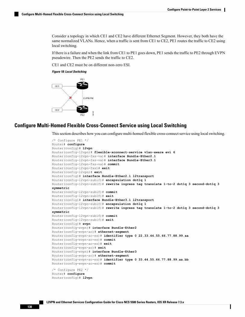
Consider a topology in which CE1 and CE2 have different Ethernet Segment. However, they both have thesame normalized VLANs. Hence, when a traffic is sent from CE1 to CE2, PE1 routes the traffic to CE2 usinglocal switching.
If there is a failure and when the link from CE1 to PE1 goes down, PE1 sends the traffic to PE2 through EVPNpseudowire. Then the PE2 sends the traffic to CE2.
CE1 and CE2 must be on different non-zero ESI.
Figure 18: Local Switching
Configure Multi-Homed Flexible Cross-Connect Service using Local SwitchingThis section describes how you can configure multi-homed flexible cross-connect service using local switching./* Configure PE1 */Router# configureRouter(config)# l2vpnRouter(config-l2vpn)# flexible-xconnect-service vlan-aware evi 6Router(config-l2vpn-fxs-va)# interface Bundle-Ether2.1Router(config-l2vpn-fxs-va)# interface Bundle-Ether3.1Router(config-l2vpn-fxs-va)# commitRouter(config-l2vpn-fxs)# exitRouter(config-l2vpn)# exitRouter(config)# interface Bundle-Ether2.1 l2transportRouter(config-l2vpn-subif)# encapsulation dot1q 1Router(config-l2vpn-subif)# rewrite ingress tag translate 1-to-2 dot1q 3 second-dot1q 3symmetricRouter(config-l2vpn-subif)# commitRouter(config-l2vpn-subif)# exitRouter(config)# interface Bundle-Ether3.1 l2transportRouter(config-l2vpn-subif)# encapsulation dot1q 1Router(config-l2vpn-subif)# rewrite ingress tag translate 1-to-2 dot1q 3 second-dot1q 3symmetricRouter(config-l2vpn-subif)# commitRouter(config-l2vpn-subif)# exitRouter(config)# evpnRouter(config-evpn)# interface Bundle-Ether2Router(config-evpn-ac)# ethernet-segmentRouter(config-evpn-ac-es)# identifier type 0 22.33.44.55.66.77.88.99.aaRouter(config-evpn-ac-es)# commitRouter(config-evpn-ac-es)# exitRouter(config-evpn-ac)# exitRouter(config-evpn)# interface Bundle-Ether3Router(config-evpn-ac)# ethernet-segmentRouter(config-evpn-ac-es)# identifier type 0 33.44.55.66.77.88.99.aa.bbRouter(config-evpn-ac-es)# commit
/* Configure PE2 */Router# configureRouter(config)# l2vpn
L2VPN and Ethernet Services Configuration Guide for Cisco NCS 5500 Series Routers, IOS XR Release 7.3.x138
Configure Point-to-Point Layer 2 ServicesConfigure Multi-Homed Flexible Cross-Connect Service using Local Switching

Router(config-l2vpn)# flexible-xconnect-service vlan-aware evi 6Router(config-l2vpn-fxs-va)# interface Bundle-Ether2.1Router(config-l2vpn-fxs-va)# interface Bundle-Ether3.1Router(config-l2vpn-fxs-va)# commitRouter(config-l2vpn-fxs)# exitRouter(config-l2vpn)# exitRouter(config)# interface Bundle-Ether2.1 l2transportRouter(config-l2vpn-subif)# encapsulation dot1q 1Router(config-l2vpn-subif)# rewrite ingress tag translate 1-to-2 dot1q 3 second-dot1q 3symmetricRouter(config-l2vpn-subif)# commitRouter(config-l2vpn-subif)# exitRouter(config)# interface Bundle-Ether3.1 l2transportRouter(config-l2vpn-subif)# encapsulation dot1q 1Router(config-l2vpn-subif)# rewrite ingress tag translate 1-to-2 dot1q 3 second-dot1q 3symmetricRouter(config-l2vpn-subif)# commitRouter(config-l2vpn-subif)# exitRouter(config)# evpnRouter(config-evpn)# interface Bundle-Ether2Router(config-evpn-ac)# ethernet-segmentRouter(config-evpn-ac-es)# identifier type 0 22.33.44.55.66.77.88.99.aaRouter(config-evpn-ac-es)# commitRouter(config-evpn-ac-es)# exitRouter(config-evpn-ac)# exitRouter(config-evpn)# interface Bundle-Ether3Router(config-evpn-ac)# ethernet-segmentRouter(config-evpn-ac-es)# identifier type 0 33.44.55.66.77.88.99.aa.bbRouter(config-evpn-ac-es)# commit
Running Configuration
/* On PE1 */
configurel2vpnflexible-xconnect-service vlan-aware evi 6interface Bundle-Ether2.1interface Bundle-Ether3.1
!
configureinterface Bundle-Ether2.1 l2transportencapsulation dot1q 1rewrite ingress tag translate 1-to-2 dot1q 3 second-dot1q 3 symmetric
!
configureinterface Bundle-Ether3.1 l2transportencapsulation dot1q 1rewrite ingress tag translate 1-to-2 dot1q 3 second-dot1q 3 symmetric
!
evpninterface Bundle-Ether2ethernet-segment identifier type 0 22.33.44.55.66.77.88.99.aainterface Bundle-Ether3ethernet-segment identifier type 0 33.44.55.66.77.88.99.aa.bb
!
L2VPN and Ethernet Services Configuration Guide for Cisco NCS 5500 Series Routers, IOS XR Release 7.3.x139
Configure Point-to-Point Layer 2 ServicesRunning Configuration

/* On PE2 */
configurel2vpnflexible-xconnect-service vlan-aware evi 6interface Bundle-Ether2.1interface Bundle-Ether3.1
!
configureinterface Bundle-Ether2.1 l2transportencapsulation dot1q 1rewrite ingress tag translate 1-to-2 dot1q 3 second-dot1q 3 symmetric
!
configureinterface Bundle-Ether3.1 l2transportencapsulation dot1q 1rewrite ingress tag translate 1-to-2 dot1q 3 second-dot1q 3 symmetric
!
evpninterface Bundle-Ether2ethernet-segment identifier type 0 22.33.44.55.66.77.88.99.aainterface Bundle-Ether3ethernet-segment identifier type 0 33.44.55.66.77.88.99.aa.bb
!
AC-Aware VLAN BundleThe AC-Aware VLAN Bundle feature allows you to configure more than one subinterface on the same mainport in an EVPN enabled bridge domain.
Without this feature, MAC routes identify originating interface using only ESI. When there are multiplesubinterfaces with the same ESI, there is no way to distinguish one from the other. Bridge Port (BP) stampingis done with only the EVI and ESI.
With this feature a peering node hosting the advertised ESI performs BP-stamping to a proper local subinterface.
L2VPN and Ethernet Services Configuration Guide for Cisco NCS 5500 Series Routers, IOS XR Release 7.3.x140
Configure Point-to-Point Layer 2 ServicesAC-Aware VLAN Bundle

Figure 19: Topology
In this topology, when the traffic from CE1 flows to PE1, PE1 floods the message to the other PEs. As PE2is directly connected to CE1, a loop is formed between these PEs. To avoid the loop, the traffic from localCE1 subinterface on PE1 to remote CE1 subinterface on PE2 is prevented using ESI filtering.
The AC-Aware VLAN Bundle feature is enabled by default which allows you to configure more than onesubinterface on the same main port in an EVPN enabled bridge domain. This feature conforms todraft-sajassi-bess-evpn-ac-aware-bundling. Here, the Attachment Circuit ID (AC-ID) is signaled using newEVPN BGP Extended Community.
Configure Preferred Tunnel PathPreferred tunnel path functionality lets youmap pseudowires to specific traffic-engineering tunnels. Attachmentcircuits are cross-connected to specificMPLS traffic engineering tunnel interfaces instead of remote PE routerIP addresses (reachable using IGP or LDP).
When using a preferred tunnel path, it is assumed that the traffic engineering tunnel that transports the Layer2 traffic runs between the two PE routers (that is, its head starts at the imposition PE router and its tail terminateson the disposition PE router).
L2VPN and Ethernet Services Configuration Guide for Cisco NCS 5500 Series Routers, IOS XR Release 7.3.x141
Configure Point-to-Point Layer 2 ServicesConfigure Preferred Tunnel Path

Configuration
/* Enter global configuration mode */Router# configureRouter(config)# l2vpn
/* Configure pseudowire class name */Router(config-l2vpn)# pw-class path1
/* Configure MPLS encapsulation for the pseudowire */Router(config-l2vpn-pwc)# encapsulation mpls
/* Configure preferred path tunnel settings.If fallback disable configuration is used, and whenthe TE/ tunnel is configured,if the preferred path goes down,the corresponding pseudowire can also go down. */
Router(config-l2vpn-pwc-encap-mpls)# preferred-pathinterface tunnel-te 11 fallback disable
/* Commit your configuration */Router(config-l2vpn-pwc)# exitRouter(config-l2vpn)# commit
Running Configuration
Router# show running-configuration!l2vpnpw-class path1encapsulation mplspreferred-path interface tunnel-te 11 fallback disable!!!
Multisegment PseudowireTheMultisegment Pseudowire feature allows you to extend L2VPN pseudowires across an inter-AS boundaryor across two separate MPLS networks. A multisegment pseudowire connects two or more contiguouspseudowire segments to form an end-to-end multi-hop pseudowire as a single point-to-point pseudowire.These segments act as a single pseudowire, allowing you to:
• Manage the end-to-end service by separating administrative or provisioning domains.
• Keep IP addresses of provider edge (PE) nodes private across interautonomous system (inter-AS)boundaries. Use IP address of autonomous system boundary routers (ASBRs) and treat them as pseudowireaggregation routers. The ASBRs join the pseudowires of the two domains.
Amultisegment pseudowire can span either an inter-AS boundary or twomultiprotocol label switching (MPLS)networks.
A pseudowire is a tunnel between two PE nodes. There are two types of PE nodes:
• A Switching PE (S-PE) node
L2VPN and Ethernet Services Configuration Guide for Cisco NCS 5500 Series Routers, IOS XR Release 7.3.x142
Configure Point-to-Point Layer 2 ServicesMultisegment Pseudowire

• Terminates PSN tunnels of the preceding and succeeding pseudowire segments in a multisegmentpseudowire.
• Switches control and data planes of the preceding and succeeding pseudowire segments of themultisegment pseudowire.
• A Terminating PE (T-PE) node
• Located at both the first and last segments of a multisegment pseudowire.
• Where customer-facing attachment circuits (ACs) are bound to a pseudowire forwarder.
Every end of a multisegment pseudowire must terminate at a T-PE.Note
A multisegment pseudowire is used in two general cases when:
• It is not possible to establish a PW control channel between the source and destination PE nodes.
For the PW control channel to be established, the remote PE node must be accessible. Sometimes, thelocal PE node may not be able to access the remote node due to topology, operational, or securityconstraints.
A multisegment pseudowire dynamically builds two discrete pseudowire segments and performs apseudowire switching to establish a PW control channel between the source and destination PE nodes.
• Pseudowire Edge To Edge Emulation (PWE3) signaling and encapsulation protocols are different.
The PE nodes are connected to networks employing different PW signaling and encapsulation protocols.Sometimes, it is not possible to use a single segment PW.
A multisegment pseudowire, with the appropriate interworking performed at the PW switching points,enables PW connectivity between the PE nodes in the network.
Figure 20: Multisegment Pseudowire
The topology shows MS-PW stitching between PW1 and PW2. You can configure a set of two or morecontiguous PW segments that behave and function as a single point-to-point PW. You can configure static ordynamic multisegment PW (MS-PW). The maximum number of contiguous PW segments is 254. Each endof an MS-PW terminates on a T-PE. A switching PE (S-PE) terminates the PSN tunnels of the preceding and
L2VPN and Ethernet Services Configuration Guide for Cisco NCS 5500 Series Routers, IOS XR Release 7.3.x143
Configure Point-to-Point Layer 2 ServicesMultisegment Pseudowire

succeeding PW segments in an MS-PW. The S-PE switches the control and data planes of the preceding andsucceeding PW segments of the MS-PW. An MS-PW is up when all the SS-PWs are up.
Restrictions
You must consider the following restrictions while configuring the Multisegment Pseudowire feature:
• Connect both segments of an MS-PW to different peers.
• Supports only LDP and does not support L2TPv3. Each PW segment in the MS-PW xconnect can beeither static or dynamic.
• The neighbor pw-id pair of each PW segment of an MS-PW is unique on the node.
• The end-to-end pw-type has to be the same. Hence, both segments of an MS-PW must have the sametransport mode.
• You cannot configure PW redundancy on an MS-PW xconnect at the S-PE. You can configure PWredundancy at the T-PEs.
• Both segments of an MS-PW xconnect can not have the same preferred path.
• Supports MS-PW over LDP, MPLS-TE, SR, and SR-TE as transport protocols.
• Does not support MS-PW over BGP-LU and LDPoTE.
• When you enable MSPW on an S-PE, configure the ip-ttl-propagation disable command for the MSPWping and traceroute to work. Alternatively, use segment-count 255 option for MSPW ping to work fromT-PE1. MSPW does not support the partial ping.
Multisegment Pseudowire RedundancyPseudowire redundancy enables you to create backup MS-PWs between the T-PEs. Pseudowire redundancyallows you to configure your network to detect a failure in the network. And reroute the Layer 2 service toanother endpoint that can continue to provide service.
Figure 21: Multisegment Pseudowire Redundancy
Consider a topology where you create two MS-PWs and multihome CE2 to T-PE2 and T-PE3. Create aprimary MS-PW between T-PE1 and T-PE2 connected through P1, S-PE1, and P2. Create a standby MS-PWbetween T-PE1 and T-PE3 connected through P3, S-PE2, and P4.
L2VPN and Ethernet Services Configuration Guide for Cisco NCS 5500 Series Routers, IOS XR Release 7.3.x144
Configure Point-to-Point Layer 2 ServicesMultisegment Pseudowire Redundancy

When a segment of the primary PW fails, the S-PE1 receives label withdraw message or LDP transport goesdown. S-PE1 sends label withdraw message on the other PW segment and this triggers the switch-over to thebackup at the T-PE. For example:
• T-PE1 detects LDP transport down, sends label withdraw message to S-PE1 and switches over to thebackup MS-PW.
• S-PE1 receives the label withdraw message and sends a label withdraw message to T-PE2.
• T-PE2 performs “Tx Disable” of AC2 after it receives the label withdraw message.
• CE2 starts sending and receiving traffic on AC3.
Configure Multisegment PseudowirePeform this task to configure Multisegment Pseudowire.
/* Configure on T-PE1 */Router#configureRouter(config)#l2vpnRouter(config-l2vpn)#pw-class dynamic_mplsRouter(config-l2vpn-pwc)#encapsulation mplsRouter(config-l2vpn-pwc-encap-mpls)#protocol ldpRouter(config-l2vpn-pwc-encap-mpls)#control-word disableRouter(config-l2vpn-pwc-encap-mpls)#exitRouter(config-l2vpn-pwc)#exitRouter(config-l2vpn)#xconnect group XCON1Router(config-l2vpn-xc)#p2p xc1Router(config-l2vpn-xc-p2p)#description T-PE1 MS-PW to 172.16.0.1 through 192.168.0.1Router(config-l2vpn-xc-p2p)#interface gig0/1/0/0.1Router(config-l2vpn-xc-p2p)#neighbor 192.168.0.1 pw-id 100Router(config-l2vpn-xc-p2p-pw)#pw-class dynamic_mplsRouter(config-l2vpn-xc-p2p-pw)#commit
/* Configure on S-PE1 */Router#configureRouter(config)#l2vpnRouter(config-l2vpn)#xconnect group MS-PW1Router(config-l2vpn-xc)#p2p ms-pw1Router(config-l2vpn-xc-p2p)#description S-PE1 MS-PW between 10.0.0.1 and 172.16.0.1Router(config-l2vpn-xc-p2p)#neighbor 10.0.0.1 pw-id 100Router(config-l2vpn-xc-p2p-pw)#pw-class dynamic_mplsRouter(config-l2vpn-xc-p2p-pw)#exitRouter(config-l2vpn-xc-p2p)#neighbor 172.16.0.1 pw-id 300Router(config-l2vpn-xc-p2p-pw)#pw-class dynamic_mplsRouter(config-l2vpn-xc-p2p-pw)#exitRouter#configureRouter(config)#l2vpnRouter(config-l2vpn)#pw-class dynamic_mplsRouter(config-l2vpn-pwc)#encapsulation mplsRouter(config-l2vpn-pwc-encap-mpls)#protocol ldpRouter(config-l2vpn-pwc-encap-mpls)#control-word disableRouter(config-l2vpn-pwc-encap-mpls)#commit
/* Configure on T-PE2 */Router#configureRouter(config)#l2vpnRouter(config-l2vpn)#pw-class dynamic_mpls
L2VPN and Ethernet Services Configuration Guide for Cisco NCS 5500 Series Routers, IOS XR Release 7.3.x145
Configure Point-to-Point Layer 2 ServicesConfigure Multisegment Pseudowire

Router(config-l2vpn-pwc)#encapsulation mplsRouter(config-l2vpn-pwc-encap-mpls)#protocol ldpRouter(config-l2vpn-pwc-encap-mpls)#control-word disableRouter(config-l2vpn-pwc-encap-mpls)#exitRouter(config-l2vpn-pwc)#exitRouter(config-l2vpn)#xconnect group XCON1Router(config-l2vpn-xc)#p2p xc1Router(config-l2vpn-xc-p2p)#description T-PE2 MS-PW to 10.0.0.1 through 192.168.0.1Router(config-l2vpn-xc-p2p)#interface gig0/2/0/0.4Router(config-l2vpn-xc-p2p)#neighbor 192.168.0.1 pw-id 300Router(config-l2vpn-xc-p2p-pw)#pw-class dynamic_mplsRouter(config-l2vpn-xc-p2p-pw)#commit
Running Configuration
This section shows multisegment pseudowire running configuration.
/* T-PE1 Configuration */Configurel2vpnpw-class dynamic_mplsencapsulation mplsprotocol ldpcontrol-word disable!xconnect group XCON1p2p xc1description T-PE1 MS-PW to 172.16.0.1 through 192.168.0.1interface gig0/1/0/0.1neighbor 192.168.0.1 pw-id 100pw-class dynamic_mpls!
!
/* S-PE1 Configuration */l2vpnxconnect group MS-PW1p2p ms-pw1description S-PE1 MS-PW between 10.0.0.1 and 172.16.0.1neighbor 10.0.0.1 pw-id 100pw-class dynamic_mpls!neighbor 172.16.0.1 pw-id 300pw-class dynamic_mpls!!
l2vpnpw-class dynamic_mplsencapsulation mplsprotocol ldpcontrol-word disable!!
/* T-PE2 Configuration */Configurel2vpnpw-class dynamic_mplsencapsulation mplsprotocol ldpcontrol-word disable!
L2VPN and Ethernet Services Configuration Guide for Cisco NCS 5500 Series Routers, IOS XR Release 7.3.x146
Configure Point-to-Point Layer 2 ServicesConfigure Multisegment Pseudowire

xconnect group XCON1p2p xc1description T-PE1 MS-PW to 10.0.0.1 through 192.168.0.1interface gig0/2/0/0.4neighbor 192.168.0.1 pw-id 300pw-class dynamic_mpls!
!
Verification
Verify that you have configured Multisegment Pseudowire feature successfully.
Router:S-PE1#show l2vpn xocnnectLegend: ST = State, UP = Up, DN = Down, AD = Admin Down, UR = Unresolved,LU = Local Up, RU = Remote Up, CO = Connected
XConnect Group Name ST Segment 1 ST Segment 2 STDescription Description
-------------- ----- ---- ------------- --- ------------- ---MS-PW1 ms-pw1 UP 10.0.0.1 UP 172.16.0.1 UP--------------------------------------------------------------------
Router:S-PE1#show l2vpn xconnect detailGroup MS-PW1, XC ms-pw1, state is up; Interworking nonePW: neighbor 70.70.70.70, PW ID 100, state is up ( established )PW class not setEncapsulation MPLS, protocol LDPPW type Ethernet VLAN, control word enabled, interworking nonePW backup disable delay 0 secSequencing not set
MPLS Local Remote------------ ------------------------------ -----------------------------Label 16004 16006Group ID 0x2000400 0x2000700Interface GigabitEthernet0/1/0/2.2 GigabitEthernet0/1/0/0.3MTU 1500 1500Control word enabled enabledPW type Ethernet VLAN Ethernet VLANVCCV CV type 0x2 0x2
(LSP ping verification) (LSP ping verification)VCCV CC type 0x5 0x7
(control word) (control word)(router alert label)
(TTL expiry) (TTL expiry)------------ ------------------------------ -----------------------------
Incoming PW Switching TLV:IP Address: 70.70.70.70, PW ID: 100Description: T-PE1 MS-PW to 172.16.0.1via 192.168.0.1
Outgoing PW Switching TLV:IP Address: 90.90.90.70, PW ID: 300Description: T-PE2 MS-PW to 10.0.0.1via 192.168.0.1IP Address: 192.168.0.1, PW ID: 100Description: S-PE1 MS-PW between 10.0.0.1and 90.90.90.90
Create time: 04/04/2008 23:18:24 (00:01:24 ago)Last time status changed: 04/04/2008 23:19:30 (00:00:18 ago)Statistics:packet totals: receive 0byte totals: receive 0
PW: neighbor 90.90.90.90, PW ID 300, state is up ( established )PW class not setEncapsulation MPLS, protocol LDP
L2VPN and Ethernet Services Configuration Guide for Cisco NCS 5500 Series Routers, IOS XR Release 7.3.x147
Configure Point-to-Point Layer 2 ServicesConfigure Multisegment Pseudowire

PW type Ethernet VLAN, control word enabled, interworking nonePW backup disable delay 0 secSequencing not set
MPLS Local Remote------------ ------------------------------ -----------------------------Label 16004 16006Group ID 0x2000800 0x2000200Interface GigabitEthernet0/1/0/0.3 GigabitEthernet0/1/0/2.2MTU 1500 1500Control word enabled enabledPW type Ethernet VLAN Ethernet VLANVCCV CV type 0x2 0x2
(LSP ping verification) (LSP ping verification)VCCV CC type 0x5 0x7
(control word) (control word)(router alert label)
(TTL expiry) (TTL expiry)------------ ------------------------------ -----------------------------
Incoming PW Switching TLV:IP Address: 90.90.90.90, PW ID: 300Description: T-PE2 MS-PW to 10.0.0.1via 192.168.0.1
Outgoing PW Switching TLV:IP Address: 70.70.70.70, PW ID: 100Description: T-PE1 MS-PW to 172.16.0.1via 192.168.0.1IP Address: 192.168.0.1, PW ID: 300Description: S-PE1 MS-PW between 10.0.0.1and 90.90.90.90
Create time: 04/04/2008 23:18:24 (00:01:24 ago)Last time status changed: 04/04/2008 23:19:30 (00:00:18 ago)Statistics:packet totals: receive 0byte totals: receive 0
Related Topics
• Multisegment Pseudowire, on page 142
• Multisegment Pseudowire Redundancy, on page 144
Associated Commands
• show l2vpn xconnect
• show l2vpn xconnect detail
• show l2vpn xconnect summary
Split Horizon GroupsCisco IOSXR bridge domain aggregates attachment circuits (ACs) in one of three groups called Split HorizonGroups.When applied to bridge domains, Split Horizon refers to the flooding and forwarding behavior betweenmembers of a Split Horizon group. The following table describes how frames received on one member of asplit horizon group are treated and if the traffic is forwarded out to the other members of the same split horizongroup.
Bridge Domain traffic is either unicast or multicast.
Flooding traffic consists of the following unknown unicast destination MAC address frames.
L2VPN and Ethernet Services Configuration Guide for Cisco NCS 5500 Series Routers, IOS XR Release 7.3.x148
Configure Point-to-Point Layer 2 ServicesSplit Horizon Groups

• The frames are sent to Ethernet multicast addresses (Spanning Tree BPDUs)
• Ethernet broadcast frames (MAC address FF-FF-FF-FF-FF-FF).
The known unicast traffic consists of frames sent to bridge ports that were learned from that port using MAClearning.
Traffic flooding is performed for broadcast, multicast and unknown unicast destination address.
Table 8: Split Horizon Groups Supported on Cisco IOS-XR
Unicast within GroupMulticast withinGroup
Who belongs to this Group?Split HorizonGroup
YesYesDefault—any member notcovered by groups 1 or 2.
0
NoNoAny PW configured under VFI.1
NoNoAny AC configured withsplit-horizon keyword.
2
Important notes on Split Horizon Groups:
• All bridge ports or PWs that are members of a bridge domain must belong to one of the three groups.
• By default, all bridge ports or PWs are members of group 0.
• The VFI configuration submode under a bridge domain configuration indicates that members under thisdomain are included in group 1.
• A PW that is configured in group 0 is called an Access Pseudowire.
• The split-horizon group command is used to designate bridge ports as members of group 2.
• Known unicast is also filtered within the members of the group along with the Broadcast, Unknownunicast and Multicast (BUM) traffic.
Split Horizon Group 2
The Split Horizon Group 2 feature allows you to prevent BUM and known unicast traffic to be flooded fromone AC to other ACwithin the bridge domain. This feature enables efficient bandwidth allocation and resourceoptimization.
Consider the following topology in which AC1 and AC2 are part of the same VPLS bridge domain. Whenyou configure split horizon group 2 over AC1, AC2 on PE3, BUM and known unicast traffic from AC1 isnot flooded to AC2 and vice-versa.
However, BUM traffic coming from the pseduowire on PE3 to AC1 and AC2 that are part of group 2 isflooded. The known unicast traffic is sent to the corresponding AC.
L2VPN and Ethernet Services Configuration Guide for Cisco NCS 5500 Series Routers, IOS XR Release 7.3.x149
Configure Point-to-Point Layer 2 ServicesSplit Horizon Groups

Figure 22: Split Horizon Group 2
If AC1 is part of group 0 and AC2 is part of group 2, BUM and known unicast traffic is flooded between AC1and AC2. Similarly, if AC2 is part of group 0 and AC1 is part of group 2, BUM and known unicast traffic isflooded between AC1 and AC2.
Configure Split Horizon Group 2Perform this task to configure the Split Horizon Group 2 feature.
Configuration Example
This example shows how to configure interfaces for Layer 2 transport, add them to a bridge domain, andassign them to split horizon group 2.
/* Configure on PE3 */Router#configureRouter(config)l2vpnRouter(config-l2vpn)#router-id 192.168.0.1Router(config-l2vpn)#pw-class class1Router(config-l2vpn-pwc)#encapsulation mplsRouter(config-l2vpn-pwc-encapmpls)#protocol ldpRouter(config-l2vpn-pwc-encapmpls)#ipv4 source 192.168.0.1Router(config-l2vpn-pwc-encapmpls)#exitRouter(config-l2vpn-pwc)#exitRouter(config-l2vpn)#bridge goup bg1Router(config-l2vpn-bg)#bridge-domain bdRouter(config-l2vpn-bg-bd)#exitRouter(config-l2vpn-bg)#bridge-domain bd1Router(config-l2vpn-bg-bd)#interface TenGigE0/7/0/18/1Router(config-l2vpn-bg-bd-ac)#split-horizon groupRouter(config-l2vpn-bg-bd-ac)#exitRouter(config-l2vpn-bg-bd)#interface TenGigE0/7/0/18/2
Router(config-l2vpn-bg-bd-ac)#split-horizon groupRouter(config-l2vpn-bg-bd-ac)#exitRouter(config-l2vpn-bg-bd)#vfi vfi1Router(config-l2vpn-bg-bd-vfi)#neighbor 10.0.0.1 pw-id 1
L2VPN and Ethernet Services Configuration Guide for Cisco NCS 5500 Series Routers, IOS XR Release 7.3.x150
Configure Point-to-Point Layer 2 ServicesConfigure Split Horizon Group 2

Router(config-l2vpn-bg-bd-vfi-pw)#pw-class class1Router(config-l2vpn-bg-bd-vfi-pw)#commit
Running Configuration
configurel2vpnrouter-id 192.168.0.1pw-class classs1encapsulation mplsprotocol ldpipv4 source 192.168.0.1!!bridge group bg1bridge-domain bd!bridge-domain bd1interface TenGigE0/7/0/18/1split-horizon group!interface TenGigE0/7/0/18/2split-horizon group!vfi vfi1neighbor 10.0.0.1 pw-id 1pw-class class1!!!
Verification
Verify whether the traffic is egressing out of the respective group 2 AC.
Router#show l2vpn bridge-domain bd-name bd1Thu Jun 14 08:04:47.431 IST
Legend: pp = Partially Programmed.Bridge group: bg1, bridge-domain: bd1, id: 1, state: up, ShgId: 0, MSTi: 0Aging: 300s, MAC limit: 64000, Action: none, Notification: syslongFilter MAC addresses: 0ACs: 2 (2 up), VFIs: 1, PWs: 1 (up), PBBs: 0 (0 up), VNIs: 0 (0 up)List of ACs:Te0/7/0/18/1
, stage: up, Static MAC addresses: 0Te0/7/0/18/2, stage: up, Static MAC addresses: 0
List of Access PWs:List of VFIs:VFI vfi1 (up)Neighbor 10.0.0.1 pw-id 1, stage: up, Static MAC Addresses: 0
G.8032 Ethernet Ring ProtectionThe G.8032 Ethernet Ring Protection feature provides protection for Ethernet traffic in a ring topology. Thisfeature prevents loops within the ring at the Ethernet layer by blocking either a pre-determined link or a failedlink. You can configure this feature on physical and bundle interfaces.
L2VPN and Ethernet Services Configuration Guide for Cisco NCS 5500 Series Routers, IOS XR Release 7.3.x151
Configure Point-to-Point Layer 2 ServicesG.8032 Ethernet Ring Protection

You can configure HQoS on an AC interface that is part of the G.8032 ring. However, this functionality hasa limitation on the G.8032 convergence. The convergence depends on the number of AC interfaces used in aG.8032 ring. This limitation is applicable when the HQOSmode is enabled at the system level or at the G.8032AC level.
Note
Overview
Each Ethernet ring node is connected to adjacent Ethernet ring nodes participating in the Ethernet ring usingtwo independent links. A ring link never allows formation of loops that affect the network. The Ethernet ringuses a specific link to protect the entire Ethernet ring. This specific link is called the ring protection link (RPL).A ring link is bound by two adjacent Ethernet ring nodes and a port for a ring link (also known as a ring port).
The minimum number of Ethernet ring nodes in an Ethernet ring is two.Note
The fundamentals of ring protection switching are:
• The principle of loop avoidance.
• The utilization of learning, forwarding, and Filtering Database (FDB) mechanisms.
Loop avoidance in an Ethernet ring is achieved by ensuring that, at any time, traffic flows on all but one ofthe ring links which is the RPL. Multiple nodes are used to form a ring:
• RPL owner—It is responsible for blocking traffic over the RPL so that no loops are formed in the Ethernettraffic. There can be only one RPL owner in a ring.
• RPL neighbor node—TheRPL neighbor node is an Ethernet ring node adjacent to the RPL. It is responsiblefor blocking its end of the RPL under normal conditions. This node type is optional and prevents RPLusage when protected.
• RPL next-neighbor node—The RPL next-neighbor node is an Ethernet ring node adjacent to RPL ownernode or RPL neighbor node. It is mainly used for FDB flush optimization on the ring. This node is alsooptional.
The following figure illustrates the G.8032 Ethernet ring.
L2VPN and Ethernet Services Configuration Guide for Cisco NCS 5500 Series Routers, IOS XR Release 7.3.x152
Configure Point-to-Point Layer 2 ServicesG.8032 Ethernet Ring Protection

Figure 23: G.8032 Ethernet Ring
Nodes on the ring use control messages called RAPS to coordinate the activities of switching on or off theRPL link. Any failure along the ring triggers a RAPS signal fail (RAPS SF) message along both directions,from the nodes adjacent to the failed link, after the nodes have blocked the port facing the failed link. Onobtaining this message, the RPL owner unblocks the RPL port.
A single link failure in the ring ensures a loop-free topology.Note
Line status and Connectivity Fault Management protocols are used to detect ring link and node failure. Duringthe recovery phase, when the failed link is restored, the nodes adjacent to the restored link send RAPS norequest (RAPS NR) messages. On obtaining this message, the RPL owner blocks the RPL port and sendsRAPS no request, root blocked (RAPS NR, RB) messages. This causes all other nodes, other than the RPLowner in the ring, to unblock all blocked ports. The ERP protocol is robust enough to work for bothunidirectional failure and multiple link failure scenarios in a ring topology.
A G.8032 ring supports these basic operator administrative commands:
• Force switch (FS)—Allows operator to forcefully block a particular ring-port.
• Effective even if there is an existing SF condition
• Multiple FS commands for ring supported
• May be used to allow immediate maintenance operations
• Manual switch (MS)—Allows operator to manually block a particular ring-port.
• Ineffective in an existing FS or SF condition
• Overridden by new FS or SF conditions
• Clears all previous MS commands
L2VPN and Ethernet Services Configuration Guide for Cisco NCS 5500 Series Routers, IOS XR Release 7.3.x153
Configure Point-to-Point Layer 2 ServicesG.8032 Ethernet Ring Protection

• Clear—Cancels an existing FS or MS command on the ring-port
• Used (at RPL Owner) to clear non-revertive mode
ERPSRing Link failures/Force switch/Manual switch events duringMAC flush events results into unpredictableconvergence.
Note
A G.8032 ring can support two instances. An instance is a logical ring running over a physical ring. Suchinstances are used for various reasons, such as load balancing VLANs over a ring. For example, odd VLANsmay go in one direction of the ring, and even VLANs may go in the other direction. Specific VLANs can beconfigured under only one instance. They cannot overlap multiple instances. Otherwise, data traffic or RAPSpacket can cross logical rings, and that is not desirable.
Timers
G.8032 ERP specifies the use of different timers to avoid race conditions and unnecessary switching operations:
• Delay Timers—used by the RPL Owner to verify that the network has stabilized before blocking theRPL
• After SF condition, Wait-to-Restore (WTR) timer is used to verify that SF is not intermittent. TheWTR timer can be configured by the operator, and the default time interval is 5 minutes. The timeinterval ranges from 1 to 12 minutes.
• After FS/MS command, Wait-to-Block timer is used to verify that no background condition exists.
Wait-to-Block timer may be shorter than the Wait-to-Restore timerNote
• Guard Timer—used by all nodes when changing state; it blocks latent outdated messages from causingunnecessary state changes. The Guard timer can be configured and the default time interval is 500 ms.The time interval ranges from 10 to 2000 ms.
• Hold-off timers—used by underlying Ethernet layer to filter out intermittent link faults. The hold-offtimer can be configured and the default time interval is 0 seconds. The time interval ranges from 0 to 10seconds.
• Faults are reported to the ring protection mechanism, only if this timer expires.
Single Link Failure
The following figure represents protection switching in case of a single link failure.
L2VPN and Ethernet Services Configuration Guide for Cisco NCS 5500 Series Routers, IOS XR Release 7.3.x154
Configure Point-to-Point Layer 2 ServicesG.8032 Ethernet Ring Protection

Figure 24: G.8032 Single Link Failure
The above figure represents an Ethernet ring composed of seven Ethernet ring nodes. The RPL is the ringlink between Ethernet ring nodes A and G. In these scenarios, both ends of the RPL are blocked. Ethernetring node G is the RPL owner node, and Ethernet ring node A is the RPL neighbor node.
These symbols are used:
This sequence describes the steps in the single link failure:
1. Link operates in the normal condition.
2. A failure occurs.
3. Ethernet ring nodes C and D detect a local Signal Failure condition and after the holdoff time interval,block the failed ring port and perform the FDB flush.
4. Ethernet ring nodes C and D start sending RAPS (SF) messages periodically along with the (Node ID,BPR) pair on both ring ports, while the SF condition persists.
5. All Ethernet ring nodes receiving an RAPS (SF) message perform FDB flush. When the RPL owner nodeG and RPL neighbor node A receive an RAPS (SF) message, the Ethernet ring node unblocks it’s end ofthe RPL and performs the FDB flush.
6. All Ethernet ring nodes receiving a second RAPS (SF) message perform the FDB flush again; this isbecause of the Node ID and BPR-based mechanism.
7. Stable SF condition—RAPS (SF) messages on the Ethernet Ring. Further RAPS (SF) messages triggerno further action.
The following figure represents reversion in case of a single link failure.
L2VPN and Ethernet Services Configuration Guide for Cisco NCS 5500 Series Routers, IOS XR Release 7.3.x155
Configure Point-to-Point Layer 2 ServicesG.8032 Ethernet Ring Protection

Figure 25: Single link failure Recovery (Revertive operation)
This sequence describes the steps in the single link failure recovery:
1. Link operates in the stable SF condition.
2. Recovery of link failure occurs.
3. Ethernet ring nodes C and D detect clearing of signal failure (SF) condition, start the guard timer andinitiate periodical transmission of RAPS (NR) messages on both ring ports. (The guard timer preventsthe reception of RAPS messages).
4. When the Ethernet ring nodes receive an RAPS (NR) message, the Node ID and BPR pair of a receivingring port is deleted and the RPL owner node starts the WTR timer.
5. When the guard timer expires on Ethernet ring nodes C and D, they may accept the new RAPS messagesthat they receive. Ethernet ring node D receives an RAPS (NR)message with higher Node ID fromEthernetring node C, and unblocks its non-failed ring port.
6. WhenWTR timer expires, the RPL owner node blocks its end of the RPL, sends RAPS (NR, RB)messagewith the (Node ID, BPR) pair, and performs the FDB flush.
7. When Ethernet ring node C receives an RAPS (NR, RB) message, it removes the block on its blockedring ports, and stops sending RAPS (NR) messages. On the other hand, when the RPL neighbor node Areceives an RAPS (NR, RB) message, it blocks its end of the RPL. In addition to this, Ethernet ring nodesA to F perform the FDB flush when receiving an RAPS (NR, RB) message, due to the existence of theNode ID and BPR based mechanism.
Configure G.8032 Ethernet Ring ProtectionThe ERP feature supports both revertive and non-revertive mode of operation. By default, ERP rings operatein revertive mode unless explicitly configured as non-revertive mode under ERP profile configuration.
Perform the following tasks to configure the Ethernet Ring Protection feature:
• Confiigure ERP Profile
L2VPN and Ethernet Services Configuration Guide for Cisco NCS 5500 Series Routers, IOS XR Release 7.3.x156
Configure Point-to-Point Layer 2 ServicesConfigure G.8032 Ethernet Ring Protection

• Configure an ERP Instance
Tag re-write, either push or pop on sub-interface being used as Ring Automatic Protection Switching (RAPS)channel is not supported.
Note
Configure ERP ProfilePerform this task to configure Ethernet ring protection (ERP) profile.
Configuration Examle
Router#configureRouter(config)ethernet ring g8032 profile p1Router(config-g8032-ring-profile)#timer wtr 5Router(config-g8032-ring-profile)#non-revertiveRouter(config-g8032-ring-profile)#commit
Revertive Mode—In this mode, RPL is blocked after a failed ERP link comes up andWTR timer has expired.There is no specific command or configuration to enable this mode. By default, ERP rings operate in revertivemode unless explicitly configured as non-revertive mode under ERP profile configuration.
Non-revertive Mode —In this mode, RPL remains in the blocked state and the recovered link also remainsin a blocked state until you run erp clear command on the RPL owner node, or there is a new SF in the ring.
Running Confiugration
configureEthernet ring g8032 profile p1timer wtr 5non-revertive!!
Configuring an ERP InstancePerform this task to configure an ERP instance.
Configuration Examle
Router#configureRouter(config)l2vpnRouter(config-l2vpn)#ethernet ring g8032 ring1Router(config-l2vpn-erp)#port0 interface TenGigE0/0/0/0/* To configure an ERP on bundle interface, use the following command */Router(config-l2vpn-erp)#port0 interface bundle-ether1Router(config-l2vpn-erp-port0)#exitRouter(config-l2vpn-erp)#port1 interface TenGigE0/0/0/8/* To configure an ERP on bundle interface, use the following command */Router(config-l2vpn-erp)#port1 interface bundle-ether2Router(config-l2vpn-erp-port1)#exitRouter(config-l2vpn-erp)#instance 1Router(config-l2vpn-erp-instance)#profile p1Router(config-l2vpn-erp-instance)#rpl port0 owner
L2VPN and Ethernet Services Configuration Guide for Cisco NCS 5500 Series Routers, IOS XR Release 7.3.x157
Configure Point-to-Point Layer 2 ServicesConfigure ERP Profile

Router(config-l2vpn-erp-instance)#inclusion-list vlan-ids 1,7-150Router(config-l2vpn-erp-instance)#aps-channelRouter(config-l2vpn-erp-instance-aps)#port0 interface TenGigE0/0/0/0.1Router(config-l2vpn-erp-instance-aps)#port1 interface TenGigE0/0/0/8.1/* To configure an ERP instance on bundle sub-interfaces, use the following command */Router(config-l2vpn-erp-instance-aps)#port0 interface bundle-ether1.1Router(config-l2vpn-erp-instance-aps)#port1 interface bundle-ether2.1Router(config-l2vpn-erp-instance-aps)#commit
Inclusion list vlan ids—ports of these vlans are protected and traffic is switched only for these ports.
Exclusion list vlan ids—these vlan ids are not protected by G.8032, traffic for these vlans is forwarded normally,ports of these vlans are not blocked by G.8032.
Vlans not part of either list—are part of default instance and traffic is dropped for these vlans.
Running Confiugration
configurel2vpnethernet ring g8032 ring1port0 interface TenGigE0/0/0/0!port1 interface TenGigE0/0/0/8!instance 1profile frettarpl port0 ownerinclusion-list vlan-ids 1,7-150aps-channelport0 interface TenGigE0/0/0/0.1port1 interface TenGigE0/0/0/8.1!!
!
Verification
Verify the status of Ethernet ring.
Router#show ethernet ring g8032 ring1Thu Jun 14 08:04:47.431 IST
R: Interface is the RPL-linkF: Interface is faultyB: Interface is blockedN: Interface is not presentFS: Local forced switchMS: Local manual switch
RingName Inst NodeType NodeState Port0 Port1--------------------------------------------------------------------------------ring1 1 Owner Idle R,B–––––––––––––––––––––––––––––––––––––––––––––––––––––––––––––––––––––––––––––––––––––––––--
Router#show ethernet ring g8032 statusThu Jun 14 08:05:35.263 IST
Ethernet ring ring1 instance 1 is RPL Owner node in Idle statePort0: TenGigE0/0/0/0 (Monitor: TenGigE0/0/0/0)
L2VPN and Ethernet Services Configuration Guide for Cisco NCS 5500 Series Routers, IOS XR Release 7.3.x158
Configure Point-to-Point Layer 2 ServicesConfiguring an ERP Instance

APS-Channel: TenGigE0/0/0/0.1Status: RPL, blockedRemote R-APS NodeId: 0000.0000.0000, BPR: 0
Port1: TenGigE0/0/0/8 (Monitor: TenGigE0/0/0/8)APS-Channel: TenGigE0/0/0/8.1Status: NonRPLRemote R-APS NodeId: 0000.0000.0000, BPR: 0
APS Level: 7Open APS ring topologyProfile: p1WTR interval: 1 minutesGuard interval: 500 millisecondsHold-off interval: 0 secondsRevertive mode
Configuring G.8032 Ethernet Ring Protection: ExampleThis sample configuration illustrates the elements that a complete G.8032 configuration includes:# Configure the ERP profile characteristics if ERP instance behaviors are non-default.ethernet ring g8032 profile ERP-profiletimer wtr 10timer guard 100timer hold-off 1non-revertive
# Configure CFM MEPs and configure to monitor the ring links.ethernet cfmdomain domain1service link1 down-mepscontinuity-check interval 100ms
efdmep crosscheckmep-id 2domain domain2service link2 down-mepscontinuity-check interval 100ms
efd protection-switchingmep crosscheckmep id 2
Interface Gig 0/0/0/0ethernet cfm mep domain domain1 service link1 mep-id 1
Interface Gig 0/1/0/0ethernet cfm mep domain domain2 service link2 mep-id 1
# Configure the ERP instance under L2VPNl2vpnethernet ring g8032 RingAport0 interface g0/0/0/0port1 interface g0/1/0/0instance 1description BD2-ringprofile ERP-profilerpl port0 ownerinclusion-list vlan-ids 10-100aps channellevel 3port0 interface g0/0/0/0.1port1 interface g0/1/0/0.1
# Set up the bridge domains
L2VPN and Ethernet Services Configuration Guide for Cisco NCS 5500 Series Routers, IOS XR Release 7.3.x159
Configure Point-to-Point Layer 2 ServicesConfiguring G.8032 Ethernet Ring Protection: Example

bridge group ABCbridge-domain BD2interface Gig 0/0/0/0.2
interface Gig 0/1/0/0.2interface Gig 0/2/0/0.2
bridge-domain BD2-APSinterface Gig 0/0/0/0.1interface Gig 0/1/0/0.1
# EFPs configurationinterface Gig 0/0/0/0.1 l2transportencapsulation dot1q 5
interface Gig 0/0/0/0.1 l2transportencapsulation dot1q 5
interface g0/0/0/0.2 l2transportencapsulation dot1q 10-100
interface g 0/1/0/0.2 l2transportencapsulation dot1q 10-100
interface g 0/2/0/0.2 l2transportencapsulation dot1q 10-100
Configuring Interconnection Node: ExampleThis example shows you how to configure an interconnection node. The following figure illustrates an openring scenario.
Figure 26: Open Ring Scenario - interconnection node
The minimum configuration required for configuring G.8032 at Router C (Open ring – Router C):interface Gig 0/0/0/1.1 l2transportencapsulation dot1q 5interface Gig 0/0/0/1.10 l2transportencapsulation dot1q 6interface Gig 0/0/0/2.10 l2transportencapsulation dot1q 6
L2VPN and Ethernet Services Configuration Guide for Cisco NCS 5500 Series Routers, IOS XR Release 7.3.x160
Configure Point-to-Point Layer 2 ServicesConfiguring Interconnection Node: Example

interface Gig 0/0/0/3.10 l2transportencapsulation dot1q 6l2vpnethernet ring g8032 ring8
port0 interface Gig 0/0/0/1port1 none /* This router is connected to an interconnection node. */open-ring!instance 1inclusion-list vlan-ids 1,7-150aps-channelport0 interface Gig 0/0/0/1.1port1 none /* This router is connected to an interconnection node */!
bridge group bg1bridge-domain BD2 /* Data traffic has its own bridge domain */interface Gig 0/0/0/1.10interface Gig 0/0/0/2.10interface Gig 0/0/0/3.10!bridge-domain BD2-APS /* APS-channel has its own bridge domain */interface Gig 0/0/0/1.1 /* There is only one APS-channel at the interconnection node */
Configuring the Node of an Open Ring: ExampleThis example shows you how to configure the node part of an open ring. The following figure illustrates anopen ring scenario.
Figure 27: Open Ring Scenario
The minimum configuration required for configuring G.8032 at the node of the open ring (node part of theopen ring at router F):interface Gig 0/0/0/1.1 l2transportencapsulation dot1q 5interface Gig 0/0/0/2.1 l2transportencapsulation dot1q 5interface Gig 0/0/0/1.10 l2transportencapsulation dot1q 6interface Gig 0/0/0/2.10 l2transport
L2VPN and Ethernet Services Configuration Guide for Cisco NCS 5500 Series Routers, IOS XR Release 7.3.x161
Configure Point-to-Point Layer 2 ServicesConfiguring the Node of an Open Ring: Example

encapsulation dot1q 6l2vpn
ethernet ring g8032 ringBport0 interface Gig 0/0/0/1port1 interface Gig 0/0/0/2open-ring!instance 1inclusion-list vlan-ids 1,7-150rpl port0 owner /* This node is RPL owner and interface Gig 0/0/0/2 is blockedaps-channelport0 interface Gig 0/0/0/1.1port1 interface Gig 0/0/0/2.1
/* Set up the bridge domainbridge group bg1bridge-domain BD2bridge-domain BD2-APS /* APS-channel has its own bridge domain */interface Gig 0/0/0/1.1interface Gig 0/0/0/2.1
!/* Data traffic has its own bridge domain */
bridge-domain BD2interface Gig 0/0/0/1.10interface Gig 0/0/0/2.10
Pseudowire RedundancyThe Pseudowire Redundancy feature allows you to configure a redundant pseudowire that backs up the primarypseudowire. When the primary pseudowire fails, the PE router switches to the redundant pseudowire. Youcan elect to have the primary pseudowire resume operation after it becomes functional. The primary pseudowirefails when the PE router fails or when there is a network outage.
Figure 28: Pseudowire Redundancy
Forcing a Manual Switchover to the Backup Pseudowire
To force the router to switch over to the backup or switch back to the primary pseudowire, use the l2vpnswitchover command in EXEC mode.
A manual switchover is made only if the peer specified in the command is actually available and thecross-connect moves to the fully active state when the command is entered.
L2VPN and Ethernet Services Configuration Guide for Cisco NCS 5500 Series Routers, IOS XR Release 7.3.x162
Configure Point-to-Point Layer 2 ServicesPseudowire Redundancy

Configure Pseudowire RedundancyThis section describes how you can configure pseudowire redundancy.
You must consider the following restrictions while configuring the Pseudowire Redundancy feature:
• 2000 active and 2000 backup PWs are supported.
• Only MPLS LDP is supported.
/* Configure PW on PE1 */Router# configureRouter(config)# l2vpnRouter(config-l2vpn)# xconnect group XCON1Router(config-l2vpn-xc)# p2p xc1Router(config-l2vpn-xc-p2p)# interface GigabitEthernet0/1/0/0.1Router(config-l2vpn-xc-p2p)# neighbor ipv4 172.16.0.1 pw-id 1Router(config-l2vpn-xc-p2p-pw)# backup neighbor 192.168.0.1 pw-id 1Router(config-l2vpn-xc-p2p-pw-backup)# commit
/* Configure PW on PE2 */Router# configureRouter(config)# l2vpnRouter(config-l2vpn)# xconnect group XCON1Router(config-l2vpn-xc)# p2p xc1Router(config-l2vpn-xc-p2p)# interface GigabitEthernet0/1/0/0.1Router(config-l2vpn-xc-p2p)# neighbor ipv4 10.0.0.1 pw-id 1Router(config-l2vpn-xc-p2p-pw)# commit
/* Configure PW on PE3 */Router# configureRouter(config)# l2vpnRouter(config-l2vpn)# xconnect group XCON1Router(config-l2vpn-xc)# p2p xc1Router(config-l2vpn-xc-p2p)# interface GigabitEthernet0/1/0/0.1Router(config-l2vpn-xc-p2p)# neighbor ipv4 10.0.0.1 pw-id 1Router(config-l2vpn-xc-p2p-pw)# commit
Running Configuration/* On PE1 */!l2vpnxconnect group XCON1p2p XCON1_P2P2interface GigabitEthernet 0/1/0/0.1neighbor ipv4 172.16.0.1 pw-id 1backup neighbor 192.168.0.1 pw-id 1
!
/* On PE2 */!l2vpnxconnect group XCON1p2p XCON1_P2P2interface GigabitEthernet 0/1/0/0.1neighbor ipv4 10.0.0.1 pw-id 1
!
/* On PE3 */!l2vpn
L2VPN and Ethernet Services Configuration Guide for Cisco NCS 5500 Series Routers, IOS XR Release 7.3.x163
Configure Point-to-Point Layer 2 ServicesConfigure Pseudowire Redundancy

xconnect group XCON1p2p XCON1_P2P2interface GigabitEthernet 0/1/0/0.1neighbor ipv4 10.0.0.1 pw-id 1
!
VerificationVerify that the configured pseudowire redundancy is up.
/* On PE1 */
Router#show l2vpn xconnect group XCON_1Legend: ST = State, UP = Up, DN = Down, AD = Admin Down, UR = Unresolved,
SB = Standby, SR = Standby Ready, (PP) = Partially Programmed
XConnect Segment 1 Segment 2Group Name ST Description ST Description ST------------------------ ----------------------------- -----------------------------XCON_1 XCON1_P2P2 UP Gi0/1/0/0.1 UP 172.16.0.1 1000 UP
Backup192.168.0.1 1000 SB
-----------------------------------------------------------------------------------
/* On PE2 */
Router#show l2vpn xconnect group XCON_1Tue Jan 17 15:36:12.327 UTCLegend: ST = State, UP = Up, DN = Down, AD = Admin Down, UR = Unresolved,
SB = Standby, SR = Standby Ready, (PP) = Partially Programmed
XConnect Segment 1 Segment 2Group Name ST Description ST Description ST------------------------ ----------------------------- -----------------------------XCON_1 XCON1_P2P2 UP BE100.1 UP 10.0.0.1 1000 UP----------------------------------------------------------------------------------------
/* On PE3 */
Router#show l2vpn xconnect group XCON_1Tue Jan 17 15:38:04.785 UTCLegend: ST = State, UP = Up, DN = Down, AD = Admin Down, UR = Unresolved,
SB = Standby, SR = Standby Ready, (PP) = Partially Programmed
XConnect Segment 1 Segment 2Group Name ST Description ST Description ST------------------------ ----------------------------- -----------------------------XCON_1 XCON1_P2P2 DN BE100.1 UP 10.0.0.1 1000 SB----------------------------------------------------------------------------------------
Router#show l2vpn xconnect summaryNumber of groups: 3950Number of xconnects: 3950Up: 3950 Down: 0 Unresolved: 0 Partially-programmed: 0AC-PW: 3950 AC-AC: 0 PW-PW: 0 Monitor-Session-PW: 0
Number of Admin Down segments: 0Number of MP2MP xconnects: 0Up 0 Down 0Advertised: 0 Non-Advertised: 0
Number of CE Connections: 0Advertised: 0 Non-Advertised: 0
L2VPN and Ethernet Services Configuration Guide for Cisco NCS 5500 Series Routers, IOS XR Release 7.3.x164
Configure Point-to-Point Layer 2 ServicesVerification

Backup PW:Configured : 3950UP : 0Down : 0Admin Down : 0Unresolved : 0Standby : 3950Standby Ready: 0
Backup Interface:Configured : 0UP : 0Down : 0Admin Down : 0Unresolved : 0Standby : 0
Configure Pseudowire RedundancyPseudowire redundancy allows you to configure your network to detect a failure in the network and reroutethe Layer 2 service to another endpoint that can continue to provide service. This feature provides the abilityto recover from a failure of either the remote provider edge (PE) router or the link between the PE and customeredge (CE) routers.
L2VPNs can provide pseudowire resiliency through their routing protocols. When connectivity betweenend-to-end PE routers fails, an alternative path to the directed LDP session and the user data takes over.However, there are some parts of the network in which this rerouting mechanism does not protect againstinterruptions in service.
Pseudowire redundancy enables you to set up backup pseudowires. You can configure the network withredundant pseudowires and redundant network elements.
Prior to the failure of the primary pseudowire, the ability to switch traffic to the backup pseudowire is usedto handle a planned pseudowire outage, such as router maintenance.
Pseudowire redundancy is provided only for point-to-point Virtual PrivateWire Service (VPWS) pseudowires.Note
Configuration
This section describes the configuration for pseudowire redundancy.
/* Configure a cross-connect group with a static point-to-pointcross connect */Router# configureRouter(config)# l2vpnRouter(config-l2vpn)# xconnect group ARouter(config-l2vpn-xc)# p2p xc1ROuter(config-l2vpn-xc-p2p)# interface tengige 0/0/0/0.2Router(config-l2vpn-xc-p2p)# neighbor 10.1.1.2 pw-id 2
/*Configure the pseudowire segment for the cross-connect group */Router(config-l2vpn-xc-p2p-pw)#pw-class path1
/*Configure the backup pseudowire segment for the cross-connect group */Router(config-l2vpn-xc-p2p-pw)# backup neighbor 10.2.2.2 pw-id 5
L2VPN and Ethernet Services Configuration Guide for Cisco NCS 5500 Series Routers, IOS XR Release 7.3.x165
Configure Point-to-Point Layer 2 ServicesConfigure Pseudowire Redundancy

Router(config-l2vpn-xc-p2p-pw-backup)#end
/*Commit your configuration */Router(config-l2vpn-xc-p2p-pw-backup)#commitUncommitted changes found, commit them before exiting(yes/no/cancel)?[cancel]: yes
Running Configuration
Router# show-running configuration...l2vpnencapsulation mpls!xconnect group Ap2p xc1interface tengige 0/0/0/0.2neighbor ipv4 10.1.1.2 pw-id 2pw-class path1backup neighbor 10.2.2.2 pw-id 5!!
...
Access Pseudowire RedundancyThe Access Pseudowire Redundancy feature allows you to configure a backup pseudowire under the bridgedomain. When the primary pseudowire fails, the PE router switches to the backup pseudowire. The primarypseudowire resumes operation after it becomes functional. The primary pseudowire fails when the PE routerfails or when there is a network outage.
Figure 29: Access Pseudowire Redundancy
Configure Access Pseudowire RedundancyThis section describes how you can configure access pseudowire redundancy.
Configuration Example
Router# configureRouter(config)# l2vpnRouter(config-l2vpn)# bridge group r1
L2VPN and Ethernet Services Configuration Guide for Cisco NCS 5500 Series Routers, IOS XR Release 7.3.x166
Configure Point-to-Point Layer 2 ServicesAccess Pseudowire Redundancy

Router(config-l2vpn-bg)# bridge-domain r1Router(config-l2vpn-bg-bd)# interface TenGigE0/1/0/0.4Router(config-l2vpn-bg-bd-ac)# exitRouter(config-l2vpn-bg-bd)# neighbor 10.0.0.1 pw-id 4Router(config-l2vpn-bg-bd-pw)# backup neighbor 172.16.0.1 pw-id 4Router(config-l2vpn-bg-bd-pw-backup)# commitRouter(config-l2vpn-bg-bd-pw-backup)# exit
Router# configureRouter(config)# interface TenGigE0/1/0/0.4 l2transportRouter(config-subif)# encapsulation dot1q 4Router(config-subif)# rewrite ingress tag pop 1 symmetricRouter(config-subif)# commit
Running Configuration
This section shows access pseudowire redundancy running configuration.
configurel2vpnbridge group r1bridge-domain r1interface TenGigE0/1/0/0.4!neighbor 10.0.0.1 pw-id 4backup neighbor 172.16.0.1 pw-id 4!!!!!interface TenGigE0/1/0/0.4 l2transportencapsulation dot1q 4rewrite ingress tag pop 1 symmetric
Verification
Verify the access pseudowire redundancy configuration.
Router# show l2vpn bridge-domain bd-name r1
Thu Apr 30 03:52:13.096 UTCLegend: pp = Partially Programmed.Bridge group: r1, bridge-domain: r1, id: 1, state: up, ShgId: 0, MSTi: 0Aging: 300 s, MAC limit: 32000, Action: none, Notification: syslogFilter MAC addresses: 0ACs: 1 (1 up), VFIs: 0, PWs: 2 (1 up), PBBs: 0 (0 up), VNIs: 0 (0 up)List of ACs:Te0/1/0/0.4, state: up, Static MAC addresses: 0
List of Access PWs:Neighbor 10.0.0.1 pw-id 4, state: up, Static MAC addresses: 0Neighbor 172.16.0.1 pw-id 4, state: standby, Static MAC addresses: 0, backup
List of VFIs:List of Access VFIs:
Related Topics
• Access Pseudowire Redundancy, on page 166
L2VPN and Ethernet Services Configuration Guide for Cisco NCS 5500 Series Routers, IOS XR Release 7.3.x167
Configure Point-to-Point Layer 2 ServicesConfigure Access Pseudowire Redundancy

Associated Commands
• show l2vpn bridge-domain
GTP Load BalancingThe GPRS Tunneling Protocol (GTP) Load Balancing feature enables efficient distribution of traffic in mobilenetworks, and provides increased reliability and availability for the network.
GTP is a tunnel control and management protocol among General Packet Radio Service (GPRS) supportnodes. Wireless networks use GTP tunnels to deliver mobile data. GTP includes GTP signaling (GTP-C) anddata transfer (GTP-U) procedures. GTP-C specifies a tunnel control and management protocol, and creates,deletes and modifies tunnels. GTP-U uses a tunneling mechanism to provide a service for carrying user datapackets over the network.
GTP load balancing is performed on IPv4 or IPv6 incoming packets with GTP payloads and onMPLS incominglabeled packets.
This feature supports GTP hashing only when the GTP UDP port is 2152.
The number of MPLS label stack in the transport layer is limited to three for GTP hashing. GTP hashing isnot considered when the MPLS label stack exceeds three.
You need not reload the router after configuring or unconfiguring the hw-module command for GTP loadbalancing over MPLS to take effect.
The following figure shows an illustration of the mobile transport GTP-U load balancing.
Figure 30: Mobile Transport GTP-U Load-Balancing
The global L3 flow-based load balancing considers the following fields:
L2VPN and Ethernet Services Configuration Guide for Cisco NCS 5500 Series Routers, IOS XR Release 7.3.x168
Configure Point-to-Point Layer 2 ServicesGTP Load Balancing

• source address
• destination address
• router ID
• source port
• destination port
For GTP traffic, however, the number of unique values for these fields is limited; this causes an unevendistribution of traffic. Sometimes, to facilitate redundancy and load balancing in a network, equal cost pathsexist to different destinations. Load balancing does not occur in such scenarios as the source and destinationIP addresses, as well as L4 ports, are the same. In order to achieve a greater distribution of traffic over equalcost links, load balancing (hashing) must occur on the GTP Tunnel Endpoint Identifier (TEID), which isunique for each traffic flow.
If the packet is UDP and the destination port is the GTP-U port (port number 2152), the GTP TEID is consideredfor load balancing. This provides GTP load balancing.
The TEID in the GTP header of a GTP packet identifies individual tunnel endpoints, thus achieving bettermobile traffic load balancing within any given GRE tunnel. Additionally, this also helps in load balancingGTP traffic over Bundles at transit routers.
Load balancing based on tunnel endpoints is supported for Version 1 GTP packet and GTP version 2, if TEIDis present. For GTP version 0, load balancing occurs in the same manner as before, as there is no TEID inversion 0.
GTP load balancing is performed only for GTP-U (user data) packets. The GTP-C (control data) packets usea different destination port number of 2123 and hence, are subject to only the global L3 flow based loadbalancing.
Note
By default, load balancing based on GTP-ID when GTP tunnel is over MPLS is disabled.
To enable GTP load balacing overMPLS, configure the hw-module profile load-balance algorithm gtp-mplscommand.
L2VPN and Ethernet Services Configuration Guide for Cisco NCS 5500 Series Routers, IOS XR Release 7.3.x169
Configure Point-to-Point Layer 2 ServicesGTP Load Balancing

L2VPN and Ethernet Services Configuration Guide for Cisco NCS 5500 Series Routers, IOS XR Release 7.3.x170
Configure Point-to-Point Layer 2 ServicesGTP Load Balancing

C H A P T E R 10Multiple Spanning Tree Protocol
Table 9: Feature History Table
Feature DescriptionRelease InformationFeature Name
Release 7.6.1MSTP andPVRST
• Multiple Spanning Tree Protocol, on page 171• Per-VLAN Rapid Spanning Tree, on page 177• Information About Multiple Spanning Tree Protocol, on page 180
Multiple Spanning Tree ProtocolThe Multiple Spanning Tree Protocol (MSTP) is a Spanning Tree Protocols (STPs) variant that allows youto create multiple and independent spanning trees over the same physical network. You can configure theparameters for each spanning tree separately. You can select different network devices as the root bridge ordifferent paths to form the loop-free topology. Therefore, you can block a given physical interface for someof the spanning trees and unblock for others.
After setting up multiple spanning tree instances, you can partition the set of VLANs in use. For example,you can assign VLANs 1–100 to spanning tree instance 1, VLANs 101–200 to spanning tree instance 2,VLANs 201–300 to spanning tree instance 3, and so on. Since each spanning tree has a different active topologywith different active links, this has the effect of dividing the data traffic among the available redundant linksbased on the VLAN—a form of load balancing.
MSTP Supported FeaturesThe routers support MSTP, as defined in IEEE 802.1Q-2005, on physical Ethernet interfaces and EthernetBundle interfaces.This includes the Port Fast, Backbone Fast, Uplink Fast and Root Guard features found inCisco implementations of legacy STP, RSTP and PVST, as these are encompassed by the standard MSTPprotocol. The routers can operate in either standard 802.1Q mode, or in Provide Edge (802.1ad) mode. Inprovider edge mode, a different MAC address is used for bridge protocol data units (BPDUs), and any BPDUsreceived with the 802.1Q MAC address are forwarded transparently.
When you have not configured the allow-bpdu-guard command on MST default instance, and if one of thebridge ports receives legacy BPDU, the port enters error-disable state.
L2VPN and Ethernet Services Configuration Guide for Cisco NCS 5500 Series Routers, IOS XR Release 7.3.x171

MSTP supports interoperation with RSTP as described in the 802.1Q standard. However, these features donot support interoperation with legacy STP.
Note
BPDU GuardThe BPDU Guard feature allows you to protect against misconfiguration of edge ports. It is an enhancementto the MSTP port fast feature. When you configure port fast on an interface, MSTP considers that interfaceto be an edge port and removes it from consideration when calculating the spanning tree. When you configureBPDU Guard, MSTP additionally shuts down the interface using error-disable when an MSTP BPDU isreceived.
Flush ContainmentThe Flush Containment feature allows you to prevent unnecessary MAC flushes due to unrelated topologychanges in other areas of a network.The following figure shows a network containing four devices. TwoVLANs are in use: VLAN 1 is only used on device D, while VLAN 2 spans devices A, B and C. The twoVLANs are in the same spanning tree instance, but do not share any links.
Figure 31: Flush Containment
If the link BC goes down, then in normal operation, as C brings up its blocked port, it sends out a topologychange notification on all other interfaces, including towards D. This causes a MAC flush to occur for VLAN1, even though the topology change which has taken place only affects VLAN 2.
Flush containment helps deal with this problem by preventing topology change notifications from being senton interfaces on which no VLANs are configured for theMSTI in question. In the example network this wouldmean no topology change notifications would be sent from C to D, and the MAC flushes which take placewould be confined to the right hand side of the network.
Bringup DelayThe Bringup Delay feature allows you to stop MSTP from considering an interface when calculating thespanning tree when the interface is not yet ready to forward traffic. This is useful when a line card first bootsup, as the system may declare that the interfaces on that card are Up before the dataplane is fully ready toforward traffic. According to the standard, MSTP considers the interfaces as soon as they are declared Up,and this may cause it to move other interfaces into the blocking state if the new interfaces are selected instead.
Bringup delay solves this problem by adding a configurable delay period which occurs as interfaces that areconfigured withMSTP first come into existence. Until this delay period ends, the interfaces remain in blockingstate, and are not considered when calculating the spanning tree.
Bringup delay only takes place when interfaces which are already configured with MSTP are created, forexample, on a card reload. No delay takes place if an interface which already exists is later configured withMSTP.
L2VPN and Ethernet Services Configuration Guide for Cisco NCS 5500 Series Routers, IOS XR Release 7.3.x172
Multiple Spanning Tree ProtocolBPDU Guard

RestrictionsThese restrictions apply when using MSTP:
• You must enable MSTP must only on interfaces where the interface itself (if it is in L2 mode) or all ofthe subinterfaces have a simple encapsulation configured. These encapsulation matching criteria areconsidered simple:
• Single-tagged 802.1Q frames
• Double-tagged Q-in-Q frames (only the outermost tag is examined)
• 802.1ad frames (if MSTP is operating in Provider Bridge mode)
• Ranges or lists of tags (any of the above)
• If an L2 interface or subinterface is configured with an encapsulation that matches multiple VLANs,then all of those VLANs must be mapped to the same spanning tree instance. There is therefore a singlespanning tree instance associated with each L2 interface or subinterface.
• All the interfaces or subinterfaces in a given bridge domain must be associated with the same spanningtree instance.
• Multiple subinterfaces on the same interface must not be associated with the same spanning tree instance,unless those subinterfaces are in the same split horizon group. In other words, hair-pinning is not possible.Across the network, L2 interfaces or subinterfaces must be configured on all redundant paths for all theVLANs mapped to each spanning tree instance. This is to avoid inadvertent loss of connectivity due toSTP blocking of a port.
A subinterface with a default or untagged encapsulation leads to an MSTP statemachine failure.
Caution
• When you have not configured the allow-bpdu-guard command on MST default instance, and if oneof the bridge ports receives legacy BPDU, the port enters error-disable state.
Configure MSTPBy default, STP is disabled on all interfaces. You must enable MSTP on each physical or Ethernet Bundleinterface. When you configure MSTP on an interface, all the subinterfaces of that interface are automaticallyMSTP-enabled.
Perform these tasks to configure MSTP:
• Configure VLAN interfaces
• Configure L2VPN bridge-domains
• Configure MSTP
Configuration Example
/* Configure VLAN interfaces */Router# configure
L2VPN and Ethernet Services Configuration Guide for Cisco NCS 5500 Series Routers, IOS XR Release 7.3.x173
Multiple Spanning Tree ProtocolRestrictions

Router(config)# interface TenGigE0/0/0/2.1001 l2transportRouter(config-subif)# encapsulation dot1q 1001Router(config)# interface TenGigE0/0/0/3.1001 l2transportRouter(config-subif)# encapsulation dot1q 1001Router(config)# interface TenGigE0/0/0/14.1001 l2transportRouter(config-subif)# encapsulation dot1q 1001Router(config)# interface TenGigE0/0/0/2.1021 l2transportRouter(config-subif)# encapsulation dot1q 1021Router(config)# interface TenGigE0/0/0/3.1021 l2transportRouter(config-subif)# encapsulation dot1q 1021Router(config)# interface TenGigE0/0/0/14.1021 l2transportRouter(config-subif)# encapsulation dot1q 1021Router(config-subif)# commit
/* Configure L2VPN bridge-domains */Router# configureRouter(config)# l2vpn bridge group mstpRouter(config-l2vpn-bg)# bridge-domain mstp1001Router(config-l2vpn-bg-bd)# int TenGigE 0/0/0/2.1001Router(config-l2vpn-bg-bd-ac)# exitRouter(config-l2vpn-bg-bd)# int TenGigE 0/0/0/3.1001Router(config-l2vpn-bg-bd-ac)# exitRouter(config-l2vpn-bg-bd)# int TenGigE 0/0/0/14.1001Router(config-l2vpn-bg-bd-ac)# exitRouter(config-l2vpn-bg-bd)# exitRouter(config-l2vpn-bg)# exitRouter(config-l2vpn-bg)# bridge-domain mstp1021Router(config-l2vpn-bg-bd)# int TenGigE 0/0/0/2.1021Router(config-l2vpn-bg-bd-ac)# exitRouter(config-l2vpn-bg-bd)# int TenGigE 0/0/0/3.1021Router(config-l2vpn-bg-bd-ac)# exitRouter(config-l2vpn-bg-bd)# int TenGigE 0/0/0/14.1021Router(config-l2vpn-bg-bd-ac)# commit
/* Configure MSTP */
Router# configureRouter(config)# spanning-tree mst abcRouter(config-mstp)# name mstp1Router(config-mstp)# instance 1001Router(config-mstp-inst)# vlan-ids 1001-1020Router(config-mstp-inst)# exitRouter(config-mstp)# instance 1021Router(config-mstp-inst)# vlan-ids 1021-1040Router(config-mstp-inst)# exitRouter(config-mstp)# int tenGigE 0/0/0/2Router(config-mstp-if)# exitRouter(config-mstp)# int tenGigE 0/0/0/3Router(config-mstp-if)# exitRouter(config-mstp)# int tenGigE 0/0/0/14Router(config-mstp-if)# commit
/* Configure MSTP Parameters */Router#configureRouter(config)#spanning-tree mst aRouter(config-mstp)#bringup delay for 10 minutesRouter(config-mstp)#flush containment disableRouter(config-mstp)#name m1Router(config-mstp)#revision 10Router(config-mstp)#forward-delay 20Router(config-mstp)#max age 40Router(config-mstp)#transmit hold-count 8
L2VPN and Ethernet Services Configuration Guide for Cisco NCS 5500 Series Routers, IOS XR Release 7.3.x174
Multiple Spanning Tree ProtocolConfigure MSTP

Router(config-mstp)#provider-bridgeRouter(config-mstp)#instance 101Router(config-mstp-inst)#priority 8192Router(config-mstp-inst)#vlan-id 2-1005Router(config-mstp)#interface FastEthernet 0/0/0/1Router(config-mstp-if)#instance 101 port-priority 160Router(config-mstp-if)#portfast bpduguardRouter(config-mstp-if)#commit
Running ConfigurationThis section show MSTP running configuration.
!Configure/* Configure VLAN interfaces */interface TenGigE0/0/0/2.1001 l2transportencapsulation dot1q 1001!interface TenGigE0/0/0/3.1001 l2transportencapsulation dot1q 1001!interface TenGigE0/0/0/14.1001 l2transportencapsulation dot1q 1001
interface TenGigE0/0/0/2.1021 l2transportencapsulation dot1q 1021!interface TenGigE0/0/0/3.1021l2transportencapsulation dot1q 1021!interface TenGigE0/0/0/14.1021 l2transportencapsulation dot1q 1021!/* Configure L2VPN Bridge-domains */l2vpnbridge group mstpbridge-domain mstp1001interface TenGigE0/0/0/2.1001!interface TenGigE0/0/0/3.1001!interface TenGigE0/0/0/14.1001!
bridge-domain mstp1021interface TenGigE0/0/0/2.1021!interface TenGigE0/0/0/3.1021!interface TenGigE0/0/0/14.1021
!/* Configure MSTP */spanning-tree mst abcname mstp1instance 1001vlan-ids 1001-1020!instance 1021vlan-ids 1021-1040!interface TenGigE0/0/0/2!
L2VPN and Ethernet Services Configuration Guide for Cisco NCS 5500 Series Routers, IOS XR Release 7.3.x175
Multiple Spanning Tree ProtocolRunning Configuration

interface TenGigE0/0/0/3!interface TenGigE0/0/0/14
/* Configure MSTP Parameters */spanning-tree mst abringup delay for 10 minutesflush containment disablename m1revision 10forward-delay 20max hops 30transmit hold-count 8provider-bridgeinstance 101priority 8192vlan-id 2-1005interface FastEthernet 0/0/0/1instance 101 port-priority 160portfast bpduguard
!!
VerificationVerify the MSTP configuration using the show spanning-tree mst command.
/* Verify the MSTP configuration */Router# show spanning-tree mst abc instance 121Mon Jan 23 12:11:48.591 UTCRole: ROOT=Root, DSGN=Designated, ALT=Alternate, BKP=Backup, MSTR=MasterState: FWD=Forwarding, LRN=Learning, BLK=Blocked, DLY=Bringup Delayed
Operating in dot1q mode
MSTI 121:
VLANS Mapped: 121-130
Root ID Priority 32768Address dceb.9456.b9d4This bridge is the rootInt Cost 0Max Age 20 sec, Forward Delay 15 sec
Bridge ID Priority 32768 (priority 32768 sys-id-ext 0)Address dceb.9456.b9d4Max Age 20 sec, Forward Delay 15 secMax Hops 20, Transmit Hold count 6
Interface Port ID Role State Designated Port IDPri.Nbr Cost Bridge ID Pri.Nbr
------------ ------- --------- ---- ----- -------------------- -------BE1 128.1 10000 DSGN FWD 32768 dceb.9456.b9d4 128.1Te0/0/0/1 128.2 2000 DSGN FWD 32768 dceb.9456.b9d4 128.2Te0/0/0/16 128.3 2000 DSGN FWD 32768 dceb.9456.b9d4 128.3Te0/0/0/17 128.4 2000 DSGN FWD 32768 dceb.9456.b9d4 128.4
L2VPN and Ethernet Services Configuration Guide for Cisco NCS 5500 Series Routers, IOS XR Release 7.3.x176
Multiple Spanning Tree ProtocolVerification

Related Topics
• Information About Multiple Spanning Tree Protocol, on page 180
• Multiple Spanning Tree Protocol, on page 171
Associated Commands
• spanning-tree mst
• show spanning-tree mst
Per-VLAN Rapid Spanning TreePer-VLAN Rapid Spanning Tree (PVRST) or Rapid PVST or PVST+ is the IEEE 802.1w (RSTP) standardimplemented per VLAN. A single instance of STP runs on each configured VLAN (if you do not manuallydisable STP). Each Rapid PVST+ instance on a VLAN has a single root switch. When you are running RapidPVST+ you must configure the feature on all VLANs for a particular port.
PVRST uses point-to-point wiring to provide rapid convergence of the spanning tree. The spanning treereconfiguration can occur in less than 1 second with PVRST (in contrast to 50 seconds with the default settingsin the 802.1D STP).
PVRST supports one STP instance for each VLAN.Note
Using PVRST, STP convergence occurs rapidly. Each designated or root port in the STP sends out a BPDUevery 2 seconds by default. On a designated or root port in the topology, if hello messages are missed threeconsecutive times, or if the maximum age expires, the port immediately flushes all protocol information inthe table. A port considers that it loses connectivity to its direct neighbor root or designated port if it missesthree BPDUs or if the maximum age expires. This rapid aging of the protocol information allows quick failuredetection.
PVRST achieves rapid transition to the forwarding state only on edge ports and point-to-point links. Althoughthe link type is configurable, the system automatically derives the link type information from the duplex settingof the port. Full-duplex ports are assumed to be point-to-point ports, while half-duplex ports are assumed tobe shared ports.
PVRST has the following characteristics:
• You can configuration Forward Delay and Max Age timers globally and not per VLAN.
• You can configure Hello timer on per port basis and not per VLAN basis. The Hello timer configuredon a port applies to all VLANs on that specific port.
• The cost of a spanning tree bundle port is always 10000. It is not affected by any of the following:
• Number or speed of the bundle members
• Logical or administrative operational status of the bundle member ports
• Addition or deletion of bundle members
L2VPN and Ethernet Services Configuration Guide for Cisco NCS 5500 Series Routers, IOS XR Release 7.3.x177
Multiple Spanning Tree ProtocolPer-VLAN Rapid Spanning Tree

• Receiving BPDU on an interface configured with the BPDU Guard error-disables the physical interfaceas well as any layer-2 or layer-3 sub-interfaces configured on the physical interface.
• Only Ethernet Flow-points (EFPs) that are untagged or have a single VLAN tag can be protected byPVRST.
• If any one EFP in a bridge-domain is protected by PVRST, then all EFPs in that bridge domain mustbelong to the same VLAN.
• If any one EFP on a port is protected by PVRST, then all EFPs on that port must be protected by PVRST.
• PVRST supports 64 VLANs and 512 EFP’s per router.
Configure PVRSTPerform this task to configure PVRST per VLAN.
Prerequisites
• Define L2 transport subinterfaces with VLAN encapsulation. PVRST does not support dot1adencapsulation.
• Configure L2VPN bridge domains under bridge group for every VLAN running spanning tree.
• Configure corresponding l2transport subinterfaces in the bridge-domain.
Configuration Example
/* Configure PVRST */Router# configureRouter(config)# spanning-tree pvrst stpRouter(config-pvrst)# forward-delay 10Router(config-pvrst)# maximum age 10Router(config-pvrst)# transmit hold-count 4Router(config-pvrst)# vlan 200Router(config-pvrst-vlan)# exitRouter(config-pvrst)# vlan 300Router(config-pvrst-vlan)# exitRouter(config-pvrst)# 400Router(config-pvrst-vlan)# exitRouter(config-pvrst)# interface Bundle-Ether1Router(config-pvrst-if)# exitRouter(config-pvrst)# interface Bundle-Ether2Router(config-if)# exitRouter(config-pvrst)# interface TenGigE0/0/0/21
/* Configure bridge domain */Router(config)# l2vpn bridge group pvrstRouter(config-l2vpn-bg)# bridge-domain pvrst1001Router(config-l2vpn-bg-bd)# interface Bundle-Ether1Router(config-l2vpn-bg-bd-ac)# exitRouter(config-l2vpn-bg-bd)# interface Bundle-Ether2Router(config-l2vpn-bg-bd-ac)# exitRouter(config-l2vpn-bg-bd)# interface TenGigE0/0/0/21Router(config-l2vpn-bg-bd-ac)# commit
L2VPN and Ethernet Services Configuration Guide for Cisco NCS 5500 Series Routers, IOS XR Release 7.3.x178
Multiple Spanning Tree ProtocolConfigure PVRST

Running Configuration for PVRSTThis section shows PVRST running configuration.
/* PVRST Configuration */configurespanning-tree pvrst stpforward-delay 10maximum age 10transmit hold-count 4vlan 200!vlan 300!vlan 400!interface Bundle-Ether1!interface Bundle-Ether2!interface TenGigE0/0/0/21
!/* Configure bridge-domain */l2vpnbridge group pvrstbridge-domain pvrst1001interface Bundle-Ether1
!!
interface Bundle-Ether2!interface TenGigE0/0/0/14.1001
!interface TenGigE0/0/0/21
Verification
Verify the PVRST configuration using the show spanning-tree pvrst command.
Router# show spanning-tree pvrst stpMon Jan 20 22:56:16.242 UTCRole: ROOT=Root, DSGN=Designated, ALT=Alternate, BKP=BackupState: FWD=Forwarding, LRN=Learning, BLK=BlockedVLAN 200:Root ID Priority 32768
Address 008a.9610.08d8Max Age 20 sec, Forward Delay 15 sec
Bridge ID Priority 32768 (priority 32768 sys-id-ext 0)Address 00bc.6021.a4d8Max Age 10 sec, Forward Delay 10 secTransmit Hold count 4
Interface Port ID Role State Designated Port IDPri.Nbr Cost Bridge ID Pri.Nbr
------------ ------- --------- ---- ----- -------------------- -------Te0/0/0/14 128.2 2000 DSGN FWD 32768 00bc.6021.a4d8 128.2Te0/0/0/20 128.3 2000 DSGN FWD 32768 00bc.6021.a4d8 128.3Te0/0/0/26 128.4 2000 DSGN FWD 32768 00bc.6021.a4d8 128.4Te0/0/0/27 128.5 2000 DSGN FWD 32768 00bc.6021.a4d8 128.5Te0/0/0/38 128.6 2000 ALT BLK 32768 008a.9610.08d8 128.4Te0/0/0/6 128.1 2000 ROOT FWD 32768 008a.9610.08d8 128.2------------ ------- --------- ---- ----- -------------------- -------VLAN 300:
L2VPN and Ethernet Services Configuration Guide for Cisco NCS 5500 Series Routers, IOS XR Release 7.3.x179
Multiple Spanning Tree ProtocolRunning Configuration for PVRST

Root ID Priority 32768Address 008a.9610.08d8Max Age 20 sec, Forward Delay 15 sec
Bridge ID Priority 32768 (priority 32768 sys-id-ext 0)Address 00bc.6021.a4d8Max Age 10 sec, Forward Delay 10 secTransmit Hold count 4
Interface Port ID Role State Designated Port IDPri.Nbr Cost Bridge ID Pri.Nbr
------------ ------- --------- ---- ----- -------------------- -------Te0/0/0/14 128.2 2000 DSGN FWD 32768 00bc.6021.a4d8 128.2Te0/0/0/20 128.3 2000 DSGN FWD 32768 00bc.6021.a4d8 128.3Te0/0/0/26 128.4 2000 DSGN FWD 32768 00bc.6021.a4d8 128.4Te0/0/0/27 128.5 2000 DSGN FWD 32768 00bc.6021.a4d8 128.5Te0/0/0/38 128.6 2000 ALT BLK 32768 008a.9610.08d8 128.4Te0/0/0/6 128.1 2000 ROOT FWD 32768 008a.9610.08d8 128.2------------ ------- --------- ---- ----- -------------------- -------VLAN 400:Root ID Priority 32768
Address 008a.9610.08d8Max Age 20 sec, Forward Delay 15 sec
Bridge ID Priority 32768 (priority 32768 sys-id-ext 0)Address 00bc.6021.a4d8Max Age 10 sec, Forward Delay 10 secTransmit Hold count 4
Interface Port ID Role State Designated Port IDPri.Nbr Cost Bridge ID Pri.Nbr
------------ ------- --------- ---- ----- -------------------- -------Te0/0/0/14 128.2 2000 DSGN FWD 32768 00bc.6021.a4d8 128.2Te0/0/0/20 128.3 2000 DSGN FWD 32768 00bc.6021.a4d8 128.3Te0/0/0/26 128.4 2000 DSGN FWD 32768 00bc.6021.a4d8 128.4Te0/0/0/27 128.5 2000 DSGN FWD 32768 00bc.6021.a4d8 128.5Te0/0/0/38 128.6 2000 ALT BLK 32768 008a.9610.08d8 128.4Te0/0/0/6 128.1 2000 ROOT FWD 32768 008a.9610.08d8 128.2------------ ------- --------- ---- ----- -------------------- -------
Related Topics
• Information About Multiple Spanning Tree Protocol, on page 180
• Multiple Spanning Tree Protocol, on page 171
Associated Commands
• spanning-tree pvrst
• show spanning-tree pvrst
Information About Multiple Spanning Tree ProtocolTo configure Multiple Spanning Tree Protocol, you must understand these concepts:
Spanning Tree Protocol OverviewEthernet is no longer just a link-layer technology used to interconnect network vehicles and hosts. Its lowcost and wide spectrum of bandwidth capabilities coupled with a simple plug and play provisioning philosophy
L2VPN and Ethernet Services Configuration Guide for Cisco NCS 5500 Series Routers, IOS XR Release 7.3.x180
Multiple Spanning Tree ProtocolInformation About Multiple Spanning Tree Protocol

have transformed Ethernet into a legitimate technique for building networks, particularly in the access andaggregation regions of service provider networks.
Ethernet networks lacking a TTL field in the Layer 2 (L2) header and, encouraging or requiring multicasttraffic network-wide, are susceptible to broadcast storms if loops are introduced. However, loops are a desirableproperty as they provide redundant paths. Spanning tree protocols (STP) are used to provide a loop freetopology within Ethernet networks, allowing redundancy within the network to deal with link failures.
There are many variants of STP; however, they work on the same basic principle. Within a network that maycontain loops, a sufficient number of interfaces are disabled by STP so as to ensure that there is a loop-freespanning tree, that is, there is exactly one path between any two devices in the network. If there is a fault inthe network that affects one of the active links, the protocol recalculates the spanning tree so as to ensure thatall devices continue to be reachable. STP is transparent to end stations which cannot detect whether they areconnected to a single LAN segment or to a switched LAN containing multiple segments and using STP toensure there are no loops.
STP Protocol OperationAll variants of STP operate in a similar fashion: STP frames (known as bridge protocol data units (BPDUs))are exchanged at regular intervals over Layer 2 LAN segments, between network devices participating inSTP. Such network devices do not forward these frames, but use the information to construct a loop freespanning tree.
The spanning tree is constructed by first selecting a device which is the root of the spanning tree (known asthe root bridge), and then by determining a loop free path from the root bridge to every other device in thenetwork. Redundant paths are disabled by setting the appropriate ports into a blocked state, where STP framescan still be exchanged but data traffic is never forwarded. If a network segment fails and a redundant pathexists, the STP protocol recalculates the spanning tree topology and activates the redundant path, by unblockingthe appropriate ports.
The selection of the root bridge within a STP network is determined by the lowest Bridge ID which is acombination of configured bridge priority and embedded mac address of each device. The device with thelowest priority, or with equal lowest priority but the lowest MAC address is selected as the root bridge.
Root port: is selected based on lowest root path cost to root bridge. If there is a tie with respect to the rootpath cost, port on local switch which receives BPDU with lowest sender bridge ID is selected as root port.
Designated port: Least cost port on local switch towards root bridge is selected as designated port. If there isa tie, lowest number port on local switch is selected as designated port.
The selection of the active path among a set of redundant paths is determined primarily by the port path cost.The port path cost represents the cost of transiting between that port and the root bridge - the further the portis from the root bridge, the higher the cost. The cost is incremented for each link in the path, by an amountthat is (by default) dependent on the media speed. Where two paths from a given LAN segment have an equalcost, the selection is further determined by the lowest bridge ID of the attached devices, and in the case oftwo attachments to the same device, by the configured port priority and port ID of the neighboring attachedports.
Once the active paths have been selected, any ports that do not form part of the active topology are moved tothe blocking state.
Topology ChangesNetwork devices in a switched LAN performMAC learning; that is, they use received data traffic to associateunicast MAC addresses with the interface out of which frames destined for that MAC address should be sent.If STP is used, then a recalculation of the spanning tree (for example, following a failure in the network) can
L2VPN and Ethernet Services Configuration Guide for Cisco NCS 5500 Series Routers, IOS XR Release 7.3.x181
Multiple Spanning Tree ProtocolSTP Protocol Operation

invalidate this learned information. The protocol therefore includes a mechanism to notify topology changesaround the network, so that the stale information can be removed (flushed) and new information can be learnedbased on the new topology.
A Topology Change notification is sent whenever STP moves a port from the blocking state to the forwardingstate. When it is received, the receiving device flushes the MAC learning entries for all ports that are notblocked other than the one where the notification was received, and also sends its own topology changenotification out of those ports. In this way, it is guaranteed that stale information is removed from all thedevices in the network.
Variants of STPThere are many variants of the Spanning Tree Protocol:
• Legacy STP (STP)—The original STP protocol was defined in IEEE 802.1D-1998. This creates a singlespanning tree which is used for all VLANs and most of the convergence is timer-based.
• Rapid STP (RSTP)—This is an enhancement defined in IEEE 802.1D-2004 to provide more event-based,and hence faster, convergence. However, it still creates a single spanning tree for all VLANs.
• Multiple STP (MSTP)—A further enhancement was defined in IEEE 802.1Q-2005. This allows multiplespanning tree instances to be created over the same physical topology. By assigning different VLANsto the different spanning tree instances, data traffic can be load-balanced over different physical links.The number of different spanning tree instances that can be created is restricted to a much smaller numberthan the number of possible VLANs; however, multiple VLANs can be assigned to the same spanningtree instance. The BPDUs used to exchange MSTP information are always sent untagged; the VLANand spanning tree instance data is encoded inside the BPDU.
• Per-Vlan Rapid Spanning Tree (PVRST)—This feature is the IEEE 802.1w (RSTP) standard implementedper VLAN, and is also known as Rapid PVST or PVST+. A single instance of STP runs on each configuredVLAN (if you do not manually disable STP). Each Rapid PVST+ instance on a VLAN has a single rootswitch. You can enable and disable STP on a per-VLAN basis when you are running Rapid PVST+.
PVRST uses point-to-point wiring to provide rapid convergence of the spanning tree. The spanning treereconfiguration can occur in less than one second with PVRST (in contrast to 50 seconds with the defaultsettings in the 802.1D STP).
• REP (Cisco-proprietary ring-redundancy protocol)— This is a Cisco-proprietary protocol for providingresiliency in rings. It is included for completeness, as it providesMSTP compatibility mode, using which,it interoperates with an MSTP peer.
MSTP RegionsAlong with supporting multiple spanning trees, MSTP also introduces the concept of regions. A region is agroup of devices under the same administrative control and have similar configuration. In particular, theconfiguration for the region name, revision, and the mapping of VLANs to spanning tree instances must beidentical on all the network devices in the region. A digest of this information is included in the BPDUs sentby each device, so as to allow other devices to verify whether they are in the same region.
The following figure shows the operation of MST regions when bridges running MSTP are connected tobridges running legacy STP or RSTP. In this example, switches SW1, SW2, SW3, SW4 support MSTP, whileswitches SW5 and SW6 do not.
L2VPN and Ethernet Services Configuration Guide for Cisco NCS 5500 Series Routers, IOS XR Release 7.3.x182
Multiple Spanning Tree ProtocolVariants of STP

Figure 32: MST Interaction with Non-MST Regions
To handle this situation, an Internal Spanning Tree (IST) is used. This is always spanning tree instance 0(zero). When communicating with non-MSTP-aware devices, the entire MSTP region is represented as asingle switch. The logical IST topology in this case is shown in the following figure.
Figure 33: Logical Topology in MST Region Interacting with Non-MST Bridges
The same mechanism is used when communicating with MSTP devices in a different region. For example,SW5 in the above figure could represent a number of MSTP devices, all in a different region compared toSW1, SW2, SW3 and SW4.
MSTP Port FastMSTP includes a Port Fast feature for handling ports at the edge of the switched Ethernet network. For devicesthat only have one link to the switched network (typically host devices), there is no need to run MSTP, asthere is only one available path. Furthermore, it is undesirable to trigger topology changes (and resultantMACflushes) when the single link fails or is restored, as there is no alternative path.
By default, MSTP monitors ports where no BPDUs are received, and after a timeout, places them into edgemode whereby they do not participate in MSTP. However, this process can be speeded up (and convergenceof the whole network thereby improved) by explicitly configuring edge ports as port fast.
L2VPN and Ethernet Services Configuration Guide for Cisco NCS 5500 Series Routers, IOS XR Release 7.3.x183
Multiple Spanning Tree ProtocolMSTP Port Fast

• You must disable and re-enable the port for Port Fast configuration to take effect. Use shutdown andno shutdown command (in interface configuration mode) to disable and re-enable the port.
• Port Fast is implemented as a Cisco-proprietary extension in Cisco implementations of legacy STP.However, it is encompassed in the standards for RSTP and MSTP, where it is known as Edge Port.
Note
MSTP Root GuardIn networks with shared administrative control, it may be desirable for the network administrator to enforceaspects of the network topology and in particular, the location of the root bridge. By default, any device canbecome the root bridge for a spanning tree, if it has a lower priority or bridge ID. However, a more optimalforwarding topology can be achieved by placing the root bridge at a specific location in the centre of thenetwork.
The administrator can set the root bridge priority to 0 in an effort to secure the root bridge position; however,this is no guarantee against another bridge which also has a priority of 0 and has a lower bridge ID.
Note
The root guard feature provides a mechanism that allows the administrator to enforce the location of the rootbridge. When root guard is configured on an interface, it prevents that interface from becoming a root port(that is, a port via which the root can be reached). If superior information is received via BPDUs on theinterface that would normally cause it to become a root port, it instead becomes a backup or alternate port. Inthis case, it is placed in the blocking state and no data traffic is forwarded.
The root bridge itself has no root ports. Thus, by configuring root guard on every interface on a device, theadministrator forces the device to become the root, and interfaces receiving conflicting information are blocked.
Root Guard is implemented as a Cisco-proprietary extension in Cisco implementations of legacy STP andRSTP. However, it is encompassed in the standard for MSTP, where it is known as Restricted Role.
Note
MSTP Topology Change GuardIn certain situations, it may be desirable to prevent topology changes originating at or received at a given portfrom being propagated to the rest of the network. This may be the case, for example, when the network is notunder a single administrative control and it is desirable to prevent devices external to the core of the networkfrom causing MAC address flushing in the core. This behavior can be enabled by configuring TopologyChange Guard on the port.
Topology Change Guard is known as Restricted TCN in the MSTP standard.Note
L2VPN and Ethernet Services Configuration Guide for Cisco NCS 5500 Series Routers, IOS XR Release 7.3.x184
Multiple Spanning Tree ProtocolMSTP Root Guard

C H A P T E R 11EVPN Features
This chapter describes how to configure Layer 2 Ethernet VPN (EVPN) features on the router.
Table 10: Feature History Table
Feature DescriptionRelease InformationFeature Name
This feature is now supported on routers that have CiscoNC57 line cards installed and operate in native andcompatibility modes.
Release 7.3.1EVPNInfrastructure
• EVPN Overview, on page 185• EVPN Concepts, on page 186• EVPN Operation, on page 187• EVPN Route Types, on page 189• EVPN Timers, on page 190• Configure EVPN L2 Bridging Service, on page 191• EVPN Modes, on page 193• EVPN MPLS Seamless Integration with VPLS , on page 205• Configure EVPN on the Existing VPLS Network, on page 206• EVPN Features, on page 213• CFM Support for EVPN, on page 288• CFM on EVPN ELAN, on page 288• EVPN Routing Policy, on page 291
EVPN OverviewEthernet VPN (EVPN) is a solution that provides Ethernet multipoint services over MPLS networks. EVPNoperates in contrast to the existing Virtual Private LAN Service (VPLS) by enabling control-plane basedMAClearning in the core. In EVPN, PEs participating in the EVPN instances learn customer MAC routes incontrol-plane using MP-BGP protocol. Control-plane MAC learning brings a number of benefits that allowEVPN to address the VPLS shortcomings, including support for multihoming with per-flow load balancing.
EVPN provides the solution for network operators for the following emerging needs in their network:
• Data center interconnect operation (DCI)
• Cloud and services virtualization
L2VPN and Ethernet Services Configuration Guide for Cisco NCS 5500 Series Routers, IOS XR Release 7.3.x185

• Remove protocols and network simplification
• Integration of L2 and L3 services over the same VPN
• Flexible service and workload placement
• Multi-tenancy with L2 and L3 VPN
• Optimal forwarding and workload mobility
• Fast convergence
• Efficient bandwidth utilization
EVPN Benefits
The EVPN provides the following benefits:
• Integrated Services: Integrated L2 and L3VPN services, L3VPN-like principles and operational experiencefor scalability and control, all-active multihoming and PE load-balancing using ECMP, and enables loadbalancing of traffic to and from CEs that are multihomed to multiple PEs.
• Network Efficiency: Eliminates flood and learn mechanism, fast-reroute, resiliency, and fasterreconvergence when the link to dual-homed server fails, optimized Broadcast, Unknown-unicast,Multicast(BUM) traffic delivery.
• Service Flexibility: MPLS data plane encapsulation, support existing and new services types (E-LAN,E-Line), peer PE auto-discovery, and redundancy group auto-sensing.
EVPN Modes
The following EVPN modes are supported:
• Single-homing - Enables you to connect a customer edge (CE) device to one provider edge (PE) device.
• Multihoming - Enables you to connect a customer edge (CE) device to more than one provider edge (PE)device. Multihoming ensures redundant connectivity. The redundant PE device ensures that there is notraffic disruption when there is a network failure. Following are the types of multihoming:
• Single-Active - In single-activemode only a single PE among a group of PEs attached to the particularEthernet-Segment is allowed to forward traffic to and from that Ethernet Segment.
• All-Active - In all-active mode all the PEs attached to the particular Ethernet-Segment is allowedto forward traffic to and from that Ethernet Segment.
EVPN ConceptsTo implement EVPN features, you need to understand the following concepts:
• Ethernet Segment (ES): An Ethernet segment is a set of Ethernet links that connects a multihomed device.If a multi-homed device or network is connected to two or more PEs through a set of Ethernet links, thenthat set of links is referred to as an Ethernet segment. The Ethernet segment route is also referred to asRoute Type 4. This route is used for designated forwarder (DF) election for BUM traffic.
L2VPN and Ethernet Services Configuration Guide for Cisco NCS 5500 Series Routers, IOS XR Release 7.3.x186
EVPN FeaturesEVPN Concepts

• Ethernet Segment Identifier (ESI): Ethernet segments are assigned a unique non-zero identifier, whichis called an Ethernet Segment Identifier (ESI). ESI represents each Ethernet segment uniquely across thenetwork.
• EVI: The EVPN instance (EVI) is represented by the virtual network identifier (VNI). An EVI representsa VPN on a PE router. It serves the same role of an IP VPN Routing and Forwarding (VRF), and EVIsare assigned import/export Route Targets (RTs). Depending on the service multiplexing behaviors at theUser to Network Interface (UNI), all traffic on a port (all-to-one bundling), or traffic on a VLAN(one-to-one mapping), or traffic on a list/range of VLANs (selective bundling) can be mapped to a BridgeDomain (BD). This BD is then associated to an EVI for forwarding towards the MPLS core.
• EAD/ES: Ethernet Auto Discovery Route per ES is also referred to as Route Type 1. This route is usedto converge the traffic faster during access failure scenarios. This route has Ethernet Tag of 0xFFFFFFFF.
• EAD/EVI: Ethernet Auto Discovery Route per EVI is also referred to as Route Type 1. This route isused for aliasing and load balancing when the traffic only hashes to one of the switches. This route cannothave Ethernet tag value of 0xFFFFFF to differentiate it from the EAD/ES route.
• Aliasing: It is used for load balancing the traffic to all the connected switches for a given Ethernet segmentusing the Route Type 1 EAD/EVI route. This is done irrespective of the switch where the hosts areactually learned.
• Mass Withdrawal: It is used for fast convergence during the access failure scenarios using the RouteType 1 EAD/ES route.
• DF Election: It is used to prevent forwarding of the loops. Only a single router is allowed to decapsulateand forward the traffic for a given Ethernet Segment.
EVPN OperationAt startup, PEs exchange EVPN routes in order to advertise the following:
• VPN membership: The PE discovers all remote PE members of a given EVI. In the case of a multicastingress replication model, this information is used to build the PEs flood list associated with an EVI.BUM labels and unicast labels are exchanged when MAC addresses are learned.
• Ethernet segment reachability: In multihoming scenarios, the PE auto-discovers remote PE and theircorresponding redundancy mode (all-active or single-active). In case of segment failures, PEs withdrawthe routes used at this stage in order to trigger fast convergence by signaling a MAC mass withdrawalon remote PEs.
• Redundancy Group membership: PEs connected to the same Ethernet segment (multihoming)automatically discover each other and elect a Designated Forwarder (DF) that is responsible for forwardingBroadcast, Unknown unicast and Multicast (BUM) traffic for a given EVI.
L2VPN and Ethernet Services Configuration Guide for Cisco NCS 5500 Series Routers, IOS XR Release 7.3.x187
EVPN FeaturesEVPN Operation

Figure 34: EVPN Operation
EVPN can operate in single-homing or dual-homing mode. Consider single-homing scenario, when EVPNis enabled on PE, Route Type 3 is advertised where each PE discovers all other member PEs for a given EVPNinstance. When an unknown unicast (or BUM) MAC is received on the PE, it is advertised as EVPN RouteType 2 to other PEs. MAC routes are advertised to the other PEs using EVPN Route Type 2. In multihomingscenarios, Route Types 1, 3, and 4 are advertised to discover other PEs and their redundancy modes(single-active or all-active). Use of Route Type 1 is to auto-discover other PE which hosts the same CE. Theother use of this route type is to fast route unicast traffic away from a broken link between CE and PE. RouteType 4 is used for electing designated forwarder. For instance, consider the topology when customer trafficarrives at the PE, EVPNMAC advertisement routes distribute reachability information over the core for eachcustomer MAC address learned on local Ethernet segments. Each EVPNMAC route announces the customerMAC address and the Ethernet segment associated with the port where the MAC was learned from and itsassociated MPLS label. This EVPN MPLS label is used later by remote PEs when sending traffic destined tothe advertised MAC address.
Behavior Change due to ESI Label Assignment
To adhere to RFC 7432 recommendations, the encoding or decoding of MPLS label is modified for extendedcommunity. Earlier, the lower 20 bits of extended community were used to encode the split-horizon group(SHG) label. Now, the SHG label encoding uses from higher 20 bits of extended community.
According to this change, routers in same ethernet-segment running old and new software release versionsdecodes extended community differently. This change causes inconsistent SHG labels on peering EVPN PErouters. Almost always, the router drops BUMpackets with incorrect SHG label. However, in certain conditions,it may cause remote PE to accept such packets and forward to CE potentially causing a loop. One such instanceis when label incorrectly read as NULL.
To overcome this problem, Cisco recommends you to:
• Minimize the time both PEs are running different software release versions.
• Before upgrading to a new release, isolate the upgraded node and shutdown the corresponding AC bundle.
• After upgrading both the PEs to the same release, you can bring both into service.
Similar recommendations are applicable to peering PEs with different vendors with SHG label assignmentthat does not adhere to RFC 7432.
L2VPN and Ethernet Services Configuration Guide for Cisco NCS 5500 Series Routers, IOS XR Release 7.3.x188
EVPN FeaturesEVPN Operation

EVPN Route TypesThe EVPN network layer reachability information (NLRI) provides different route types.
Table 11: EVPN Route Types
UsageNameRoute Type
Few routes are sent per ES, carriesthe list of EVIs that belong to ES
Ethernet Auto-Discovery (AD)Route
1
Advertise MAC, addressreachability, advertise IP/MACbinding
MAC/IP Advertisement Route2
Multicast Tunnel End pointdiscovery
Inclusive Multicast Ethernet TagRoute
3
Redundancy group discovery, DFelection
Ethernet Segment Route4
Advertise IP prefixes.IP Prefix Route5
Route Type 1: Ethernet Auto-Discovery (AD) Route
The Ethernet Auto-Discovery (AD) routes are advertised on per EVI and per ESI basis. These routes are sentper ES. They carry the list of EVIs that belong to the ES. The ESI field is set to zero when a CE is single-homed.This route type is used for mass withdrawal of MAC addresses and aliasing for load balancing.
Route Type 2: MAC/IP Advertisement Route
These routes are per-VLAN routes, so only PEs that are part of a VNI require these routes. The host's IP andMAC addresses are advertised to the peers within NRLI. The control plane learning ofMAC addresses reducesunknown unicast flooding.
Route Type 3: Inclusive Multicast Ethernet Tag Route
This route establishes the connection for broadcast, unknown unicast, and multicast (BUM) traffic from asource PE to a remote PE. This route is advertised on per VLAN and per ESI basis.
Route Type 4: Ethernet Segment Route
Ethernet segment routes enable to connect a CE device to two or PE devices. ES route enables the discoveryof connected PE devices that are connected to the same Ethernet segment.
Route Type 5: IP Prefix Route
The IP prefixes are advertised independently of the MAC-advertised routes. With EVPN IRB, host route /32is advertised using RT-2 and subnet /24 is advertised using RT-5.
L2VPN and Ethernet Services Configuration Guide for Cisco NCS 5500 Series Routers, IOS XR Release 7.3.x189
EVPN FeaturesEVPN Route Types

With EVPN IRB, host route /32 are advertised using RT-2 and subnet /24 are advertised using RT-5.Note
EVPN TimersThe following table shows various EVPN timers:
Table 12: EVPN Timers
SequenceActionApplicabilityTriggerDefaultValue
RangeTimer
1PostponeEVPN startupprocedure andHold AClink(s) down toprevent CE toPE forwarding.Startup-cost-intimer allows PEto set coreprotocols first.
Single-Homed,All-Active,Single-Active
noderecovered*
disabled30-86400startup-cost-in
2PostponeEVPN Startupprocedure.Recovery timerallows PE to setaccessprotocols (STP)beforereachabilitytowards EVPNcore isadvertised.
Single-Homed***,Single-Active
noderecovered,interfacerecovered **
30s20-3600s
StartingfromRelease6.6.3onwards,the rangeis0-3600s.
Note
recovery
L2VPN and Ethernet Services Configuration Guide for Cisco NCS 5500 Series Routers, IOS XR Release 7.3.x190
EVPN FeaturesEVPN Timers

SequenceActionApplicabilityTriggerDefaultValue
RangeTimer
3Starts aftersending EVPNRT4 topostpone rest ofEVPN startupprocedure.Peering timerallows remotePE(multihomingAC with sameESI) to processRT4 before DFelection willhappen.
All-Active,Single-Active
noderecovered,interfacerecovered
3s0-3600speering
• The timers are available in EVPN global configuration mode and in EVPN interface sub-configurationmode.
• Startup-cost-in is available in EVPN global configuration mode only.
• Timers are triggered in sequence (if applicable).
• Cost-out in EVPN global configuration mode brings down AC link(s) to prepare node for reload orsoftware upgrade.
Note
* indicates all required software components are loaded.** indicates link status is up.*** you can change the recovery timer on Single-HomedAC if you do not expect any STP protocol convergenceon connected CE.
Configure EVPN L2 Bridging ServicePerform the following steps to configure EVPN L2 bridging service.
Always ensure to change the label mode from per-prefix to per-VRF label mode. Since L2FIB and VPNv4route (labels) shares the same resource, BVI ping fails when you exhaust the resources.
Note
L2VPN and Ethernet Services Configuration Guide for Cisco NCS 5500 Series Routers, IOS XR Release 7.3.x191
EVPN FeaturesConfigure EVPN L2 Bridging Service

Traffic to directly connected neighbor on EVPN or VPLS bridge won't work in the following scenarios:
• If neighbor doesn't advertise MPLS explicit null.
• If imposition node has a mix of implicit-null and labeled paths in ECMP or LFA deployment.
Note
A device can contain up to 128K MAC address entries. A bridge domain on a device can contain up to 64KMAC address entries.
Note
Flooding disable isn’t supported on EVPN bridge domains.Note
/* Configure address family session in BGP */RP/0/RSP0/CPU0:router# configureRP/0/RSP0/CPU0:router#(config)# router bgp 200RP/0/RSP0/CPU0:router#(config-bgp)# bgp router-id 209.165.200.227RP/0/RSP0/CPU0:router#(config-bgp)# address-family l2vpn evpnRP/0/RSP0/CPU0:router#(config-bgp)# neighbor 10.10.10.10RP/0/RSP0/CPU0:router#(config-bgp-nbr)# remote-as 200RP/0/RSP0/CPU0:router#(config-bgp-nbr)# description MPLSFACING-PEERRP/0/RSP0/CPU0:router#(config-bgp-nbr)# update-source Loopback 0RP/0/RSP0/CPU0:router#(config-bgp-nbr)# address-family l2vpn evpn
/* Configure EVI and define the corresponding BGP route targets */
Router# configureRouter(config)# evpnRouter(config-evpn)# evi 6005Router(config-evpn-evi)# bgpRouter(config-evpn-evi-bgp)# rd 200:50Router(config-evpn-evi-bgp)# route-target import 100:6005Router(config-evpn-evi-bgp)# route-target export 100:6005Router(config-evpn-evi-bgp)# exitRouter(config-evpn-evi)# advertise-mac
/* Configure a bridge domain */Router# configureRouter(config)# l2vpnRouter(config-l2vpn)# bridge group 1Router(config-l2vpn-bg)# bridge-domain 1-1Router(config-l2vpn-bg-bd)# interface GigabitEthernet 0/0/0/1.1Router(config-l2vpn-bg-bd-ac)# evi 6005Router(config-l2vpn-bg-bd-ac-evi)# commitRouter(config-l2vpnbg-bd-ac-evi)# exit
Running Configuration
router bgp 200 bgprouter-id 209.165.200.227address-family l2vpn evpn
L2VPN and Ethernet Services Configuration Guide for Cisco NCS 5500 Series Routers, IOS XR Release 7.3.x192
EVPN FeaturesRunning Configuration

neighbor 10.10.10.10remote-as 200 description MPLS-FACING-PEERupdatesource Loopback0addressfamily l2vpn evpn
!
configureevpnevi 6005bgprd 200:50route-target import 100:6005route-target export 100:6005
!advertise-mac
configurel2vpnbridge group 1bridge-domain 1-1interface GigabitEthernet 0/0/0/1.1
evi 6005!
EVPN ModesThe following EVPN modes are supported:
• Single-homing - Enables you to connect a customer edge (CE) device to one provider edge (PE) device.
• Multihoming - Enables you to connect a customer edge (CE) device to more than one provider edge (PE)device. Multihoming ensures redundant connectivity. The redundant PE device ensures that there is notraffic disruption when there is a network failure. Following are the types of multihoming:
• Single-Active - In this mode, only a single PE among a group of PEs attached to the particularEthernet-Segment is allowed to forward traffic to and from that Ethernet Segment.
• All-Active - In this mode, all PEs attached to the particular Ethernet-Segment is allowed to forwardtraffic to and from that Ethernet Segment.
• Port-Active - In this mode, only the PE which is in the active mode sends and receives the traffic.This mode supports single-active redundancy load balancing at the port-level or the interface-level.
• Single-Flow-Active - In this mode, only the PE that first advertises the host MAC address in aVLAN forwards the traffic in a specific flow.
EVPN Port-Active MultihomingThe EVPN Port-ActiveMultihoming feature supports single-active redundancy load balancing at the port-levelor the interface-level. You can use this feature when you want to forward the traffic to a specific interface,rather than have a per-flow load balancing across multiple PE routers. This feature provides a faster convergenceduring a link failure. This feature enables protocol simplification as only one of the physical ports is activeat a given time. You can enable this feature only on bundle interfaces.
L2VPN and Ethernet Services Configuration Guide for Cisco NCS 5500 Series Routers, IOS XR Release 7.3.x193
EVPN FeaturesEVPN Modes

EVPN port-active provides protocol simplification compared to Inter-Chassis Communication Protocol (ICCP),which runs on top of Label Distribution Protocol (LDP). You can use this feature as an alternative tomulti-chassis link aggregation group (MC-LAG) with ICCP.
Also, you can use this feature when you want certain QoS features to work.
This feature allows one of the PEs to be in active mode and another in the standby mode at the port-level.Only the PE which is in the active mode sends and receives the traffic. The other PE remains in the standbymode. The PEs use the Designated Forwarder (DF) election mechanism to determine which PE must be inthe active mode and which must be in the standby mode. You can use either modulo or Highest RandomWeight (HRW) algorithm for per port DF election. By default, the modulo algorithm is used for per port DFelection.
Figure 35: EVPN Port-Active Multihoming
Consider a topology where the customer edge device (CE) is multihomed to provider edge devices, PE1 andPE2. Use single link aggregation at the CE. Only one of the two interfaces is in the forwarding state, and theother interface is in the standby state. In this topology, PE2 is in the active mode and PE1 is in the standbymode. Hence, PE2 carries traffic from the CE. All services on the PE2 interface operate in the active mode.All services on the PE1 operate in the standby mode.
If the interface is running LACP, then the standby sets the LACP state to Out-of-Service (OOS) instead ofbringing the interface state down. This state enables better convergence on standby to active transition.
If you remove the port-active configuration on both PE1 and PE2 and then add back the port-active configurationon both the PEs, PE2 is chosen as an active interface again.
EVPN port-active is compatible with the following services:
• L2 bridging
• L3 gateway
• L2VPN VPLS
• EVPN ELAN
• EVPN IRB
L2VPN and Ethernet Services Configuration Guide for Cisco NCS 5500 Series Routers, IOS XR Release 7.3.x194
EVPN FeaturesEVPN Port-Active Multihoming

• L2VPN VPWS
• EVPN VPWS
• FXC
This feature supports both L2 and L3 port-active functionality. L2 and L3 port-active can coexist on the samebundle. For example, if you configure port-active on a bundle, the bundle can have a mix of both L3subinterfaces and L2 subinterfaces participating in the services mentioned above.
Configure EVPN Port-Active MultihomingPerform this task to configure EVPN port-active multihoming.
Configure the same ESI on both the routers. Configure Ethernet-Segment in port-active load-balancing modeon peering PEs for a specific interface.
Configuration Example
/* PE1 and PE2 Configuration */
Router#configureRouter(config)#interface Bundle-Ether11Router(config-if)#lacp system mac 3637.3637.3637Router(config-if)#exit
Router(config)#evpnRouter(config-evpn)#interface Bundle-Ether11Router(config-evpn-ac)#ethernet-segmentRouter(config-evpn-ac-es)#identifier type 0 11.11.11.11.11.00.11.11.11Router(config-evpn-ac-es)#load-balancing-mode port-activeRouter(config-evpn-ac-es)#commit
/* If you want enable L3 port-active, configure the IP address */Router#configureRouter(config)#interface Bundle-Ether11Router(config-if)#ipv4 address 10.0.0.1 255.0.0.0Router(config-if)#ipv6 address 10::1/64Router(config-if)#commit
Running Configuration
This section shows port-active running configuration.
configureinterface Bundle-Ether11lacp system mac 3637.3637.3637!
evpninterface Bundle-Ether11ethernet-segmentidentifier type 0 11.11.11.11.11.00.11.11.11load-balancing-mode port-active!!
interface Bundle-Ether11ipv4 address 10.0.0.1 255.0.0.0ipv6 address 10::1/64
L2VPN and Ethernet Services Configuration Guide for Cisco NCS 5500 Series Routers, IOS XR Release 7.3.x195
EVPN FeaturesConfigure EVPN Port-Active Multihoming

!!
Verification
Verify that you have configured the Port-Active Multihoming feature successfully.
Router:PE2#show bundle bundle-ether 11
Bundle-Ether11Status: UpLocal links <active/standby/configured>: 1 / 0 / 1Local bandwidth <effective/available>: 1000000 (1000000) kbpsMAC address (source): 02b4.3cb4.a004 (Chassis pool)Inter-chassis link: NoMinimum active links / bandwidth: 1 / 1 kbpsMaximum active links: 64Wait while timer: 2000 msLoad balancing:Link order signaling: Not configuredHash type: DefaultLocality threshold: None
LACP: OperationalFlap suppression timer: OffCisco extensions: DisabledNon-revertive: Disabled
mLACP: Not configuredIPv4 BFD: Not configuredIPv6 BFD: Not configured
Port Device State Port ID B/W, kbps-------------------- --------------- ----------- --------------Gi0/2/0/8 Local Active 0x8000, 0x0006 1000000
Link is Active
/* PE2 is in the active mode, hence the status shows as Up and the Link as Active. */
Router:PE1#show bundle bundle-ether 11
Bundle-Ether11Status: LACP OOS (out of service)Local links <active/standby/configured>: 0 / 1 / 1Local bandwidth <effective/available>: 0 (0) kbpsMAC address (source): 02cf.94c1.0a04 (Chassis pool)Inter-chassis link: NoMinimum active links / bandwidth: 1 / 1 kbpsMaximum active links: 64Wait while timer: 2000 msLoad balancing:Link order signaling: Not configuredHash type: DefaultLocality threshold: None
LACP: OperationalFlap suppression timer: OffCisco extensions: DisabledNon-revertive: Disabled
mLACP: Not configuredIPv4 BFD: Not configuredIPv6 BFD: Not configured
Port Device State Port ID B/W, kbps-------------------- --------------- ----------- --------------Gi0/2/0/7 Local Standby 0x8000, 0x0006 1000000
L2VPN and Ethernet Services Configuration Guide for Cisco NCS 5500 Series Routers, IOS XR Release 7.3.x196
EVPN FeaturesConfigure EVPN Port-Active Multihoming

Link is in standby due to bundle out of service state
/* PE1 is in the standby mode, hence the status shows as LACP OOS (out of service) and theLink is in standby due to bundle out of service state. */
Router:CE#sshow bundle bundle-ether 11
Bundle-Ether11Status: UpLocal links <active/standby/configured>: 1 / 0 / 2Local bandwidth <effective/available>: 1000000 (1000000) kbpsMAC address (source): 02ff.566c.be04 (Chassis pool)Inter-chassis link: NoMinimum active links / bandwidth: 1 / 1 kbpsMaximum active links: 64Wait while timer: 2000 msLoad balancing:Link order signaling: Not configuredHash type: DefaultLocality threshold: None
LACP: OperationalFlap suppression timer: OffCisco extensions: DisabledNon-revertive: Disabled
mLACP: Not configuredIPv4 BFD: Not configuredIPv6 BFD: Not configured
Port Device State Port ID B/W, kbps-------------------- --------------- ----------- --------------Gi0/0/0/8 Local Active 0x8000, 0x0006 1000000
Link is ActiveGi0/0/0/16 Local Negotiating 0x8000, 0x000b 1000000
Partner is not Synchronized (Waiting, Standby, or LAG ID mismatch)
Router:PE2#show evpn ethernet-segment interface BE11 detail
/* The following output shows that the port-active mode is configured and the port is inthe UP state. */
Ethernet Segment Id Interface Nexthops------------------------ ---------------------------------- --------------------0011.1111.1111.0011.1111 BE11 192.168.0.2
192.168.0.3ES to BGP Gates : ReadyES to L2FIB Gates : ReadyMain port :
Interface name : Bundle-Ether11Interface MAC : 02b4.3cb4.a004IfHandle : 0x00004170State : UpRedundancy : Not Defined
ESI type : 0Value : 11.1111.1111.0011.1111
ES Import RT : 1111.1111.1100 (from ESI)Source MAC : 0000.0000.0000 (N/A)Topology :
Operational : MHConfigured : Port-Active
Service Carving : Auto-selectionMulticast : Disabled
Convergence :Mobility-Flush : Count 0, Skip 0, Last n/a
Peering Details : 2 Nexthops
L2VPN and Ethernet Services Configuration Guide for Cisco NCS 5500 Series Routers, IOS XR Release 7.3.x197
EVPN FeaturesConfigure EVPN Port-Active Multihoming

192.168.0.2 [MOD:P:7fff]192.168.0.3 [MOD:P:00]
Service Carving Results:Forwarders : 0Elected : 0Not Elected : 0
EVPN-VPWS Service Carving Results:Primary : 0Backup : 0Non-DF : 0
MAC Flushing mode : STP-TCNPeering timer : 3 sec [not running]Recovery timer : 20 sec [not running]Carving timer : 0 sec [not running]Local SHG label : NoneRemote SHG labels : 0Access signal mode: Bundle OOS (Default)
Router:PE1#show evpn ethernet-segment interface BE11 detail
/* The following output shows that the por-active mode is configured and the port is in theStandby state. */
Ethernet Segment Id Interface Nexthops------------------------ ---------------------------------- --------------------0011.1111.1111.0011.1111 BE11 192.168.0.2
192.168.0.3ES to BGP Gates : ReadyES to L2FIB Gates : ReadyMain port :
Interface name : Bundle-Ether11Interface MAC : 02cf.941c.0a04IfHandle : 0x00004170State : StandbyRedundancy : Not Defined
ESI type : 0Value : 11.1111.1111.0011.1111
ES Import RT : 1111.1111.1100 (from ESI)Source MAC : 0000.0000.0000 (N/A)Topology :
Operational : MHConfigured : Port-Active
Service Carving : Auto-selectionMulticast : Disabled
Convergence :Mobility-Flush : Count 0, Skip 0, Last n/a
Peering Details : 2 Nexthops192.168.0.2 [MOD:P:00]192.168.0.3 [MOD:P:7fff]
Service Carving Results:Forwarders : 0Elected : 0Not Elected : 0
EVPN-VPWS Service Carving Results:Primary : 0Backup : 0Non-DF : 0
MAC Flushing mode : STP-TCNPeering timer : 3 sec [not running]Recovery timer : 20 sec [not running]Carving timer : 0 sec [not running]Local SHG label : NoneRemote SHG labels : 0
L2VPN and Ethernet Services Configuration Guide for Cisco NCS 5500 Series Routers, IOS XR Release 7.3.x198
EVPN FeaturesConfigure EVPN Port-Active Multihoming

Access signal mode: Bundle OOS (Default)
EVPN Single-Flow-Active Load Multihoming Balancing ModeTable 13: Feature History Table
Feature DescriptionRelease InformationFeature Name
This feature introduces EVPNSingle-Flow-Active multihomingmode to connect PE devices in anaccess network that run Layer 2access gateway protocols. In thismode, only the PE that firstadvertises the host MAC address ina VLAN forwards the traffic in aspecific flow. When the primarylink fails, the traffic quicklyswitches to the standby PE thatlearns the MAC address from theoriginated path, thereby providingfast convergence. A keyword,single-flow-active is added to theload-balancing-mode command.
Release 7.3.1EVPN Single-Flow-ActiveMultihoming Load-BalancingMode
In a ring topology, only one of the PEs, which is the active PE, sends and receives the traffic to prevent atraffic loop.When the link to the active PE fails, the traffic switches over to the standby PE. Traffic switchovertakes a while because the standby PE has to learn the MAC addresses of the connected hosts. There’s a trafficloss until the traffic switch over happens.
The EVPN Single-Flow-Active multihoming mode connects PE devices in an access network, and in theevent of active link failure the switchover happens immediately and reduces the traffic loss.
Both active and standby PEs learn the MAC addresses of the connected host. The PE that learns the MACaddress of the host directly is called the Primary (active) PE. The primary PE advertises the learnt MACaddresses to the peer PE, which is referred as standby PE. As the standby PE learns the MAC address of thehost through the active PE, this learnt path is referred to as the reoriginated path.
When the primary link fails, the convergence happens fast and the traffic is sent through the standby PE(reoriginated path).
Let us understand how EVPN single flow-active mode helps in fast convergence:
• In this topology, the access network devices are connected through a ring topology. The access networkuses Layer-2 gateway protocols such as G.8032, MPLS-TP, STP to prevent traffic loop due to continuousflooding.
L2VPN and Ethernet Services Configuration Guide for Cisco NCS 5500 Series Routers, IOS XR Release 7.3.x199
EVPN FeaturesEVPN Single-Flow-Active Load Multihoming Balancing Mode

• Host 1 is connected to CE1.
• CE1 is connected to both PE1 and PE2, thus is multihomed.
• PE1 and PE2 are Multihoming devices.
• Both PE1 and PE2 is configured with the same non-zero Ethernet Segment ID (ESI) number 036.37.00.00.00.00.00.11.00 for the bundle interface to enable multihoming of the host (CE1).
• PE1 and PE2 belongs to te same VLAN and hence configured with the same EVPN instance (EVI) 100.
Traffic Flow
• Consider a traffic flow from Host 1 to Host 2. The traffic is sent from Host 1 to CE1.
• In this ring topology, the link between CE1 to CE2 is in the blocked state; the link between CE1 to CE3is in the forwarding state. Hence, CE1 sends the traffic to PE2 through CE3.
• PE2 first learns the MAC address of Host1 through CE1. PE2 advertises the learnt MAC address to thepeering PE1.
• As PE2 has learnt the MAC address directly from Host 1, and acts as an active PE.
• The PE which originates the MAC route due to access learning sets the default BGP local preferenceattribute value to 100.
• PE1 learns the MAC address from PE2 and acts as a stand-by PE. As PE1 gets the reoriginated MACroute from PE2, PE1 sets the BGP local preference attribute value to 80.
• The PE that has the higher local preference always sends and receives the traffic. Thus PE1 sends thetraffic to PE3. PE3 sends the traffic to Host 2.
Failure Scenario
When the link between CE1 and CE3 is down or when the link between CE3 and PE2 is down, traffic is sentthrough PE1.
L2VPN and Ethernet Services Configuration Guide for Cisco NCS 5500 Series Routers, IOS XR Release 7.3.x200
EVPN FeaturesEVPN Single-Flow-Active Load Multihoming Balancing Mode

• When the link fails, the link CE1-CE2 changes to the forwarding state.
• PE1 learns the MAC address of Host 1 directly and advertises the learnt MAC address to PE2.
• PE1 sends the traffic to Host 2 through the remote PE3 with a BGP local preference value of 100.
• PE3 sends and receives the traffic from PE1 until the access link between CE1 and CE2 changes to theblocked state.
Configuration Example
• Configure both PE1 and PE2 with the same EVI of 100.
• Configure both PE1 and PE2 with the same ESI 0 36.37.00.00.00.00.00.11.01.
Perform these tasks on both PE1and PE2.
/* Configure advertisement of MAC routes */Router# configureRouter(config)# evpnRouter(config-evpn)# evi 100Router(config-evpn-instance)# advertise-macRouter(config-evpn-instance-mac)# root
/* Configure single-flow-active load-balancing mode */Router(config)# evpnRouter(config-evpn)# interface bundle-ether 700Router(config-evpn-ac)# ethernet-segmentRouter(config-evpn-ac-es)# identifier type 0 77.77.77.77.77.77.77.77.77Router(config-evpn-ac-es)# load-balancing-mode single-flow-activeRouter(config-evpn-ac-es)# root
/* Configure bridge domain and associating the evi to the bridge domain */Router(config)# l2vpnRouter(config-l2vpn)# bridge group 100Router(config-l2vpn-bg)# bridge-domain 100Router(config-l2vpn-bg-bd)# interface Bundle-Ether1Router(config-l2vpn-bg-bd-ac)# evi 100Router(config-l2vpn-bg-bd-ac)# commitRouter(config-l2vpn-bg-bd-evi)# rootRouter(config)# exitRouter#
L2VPN and Ethernet Services Configuration Guide for Cisco NCS 5500 Series Routers, IOS XR Release 7.3.x201
EVPN FeaturesEVPN Single-Flow-Active Load Multihoming Balancing Mode

Running Configuration
evpnevi 100advertise-mac!!interface Bundle-Ether1ethernet-segmentidentifier type 0 36.37.00.00.00.00.00.11.01load-balancing-mode single-flow-active
!!!l2vpnbridge group 100bridge-domain 100interface Bundle-Ether1!evi 100!!!!
Verification
Verify the Ethernet Segment Status:
• Verify that the Ethernet Segment Id is the same as that you have configured: In this example, you noticethat the ESI on PE1 is 0 36.37.00.00.00.00.00.11.01.
• Verify that the Single-flow-active mode is enabled in the Topology section.
The following example shows the output for PE1:Router# show evpn ethernet-segment carving detailThu Aug 6 13:00:37.988 ISTLegend:B - No Forwarders EVPN-enabled,C - Backbone Source MAC missing (PBB-EVPN),RT - ES-Import Route Target missing,E - ESI missing,H - Interface handle missing,I - Name (Interface or Virtual Access) missing,M - Interface in Down state,O - BGP End of Download missing,P - Interface already Access Protected,Pf - Interface forced single-homed,R - BGP RID not received,S - Interface in redundancy standby state,X - ESI-extracted MAC ConflictSHG - No local split-horizon-group label allocated
Ethernet Segment Id Interface Nexthops------------------------ ---------------------------------- --------------------0 36.37.00.00.00.00.00.11.01 BE1 10.0.0.1
172.16.0.1ES to BGP Gates : ReadyES to L2FIB Gates : ReadyMain port :
L2VPN and Ethernet Services Configuration Guide for Cisco NCS 5500 Series Routers, IOS XR Release 7.3.x202
EVPN FeaturesEVPN Single-Flow-Active Load Multihoming Balancing Mode

Interface name : Bundle-Ether1Interface MAC : 008a.96ee.88dcIfHandle : 0x20005f5cState : UpRedundancy : Not Defined
ESI type : 0Value : 00.0000.0000.0000.0001
ES Import RT : 0000.0000.0001 (Local)Source MAC : 0000.0000.0000 (N/A)Topology :
Operational : MH, Single-flow-activeConfigured : Single-flow-active
Service Carving : Auto-selectionMulticast : Disabled
Convergence : MAC-Mobility,Mobility-Flush : Debounce 13 sec, Count 1, Skip 1499
: Last 01/01 05:57:42.468Peering Details : 2 Nexthops10.0.0.1[MOD:P:00:T]172.16.0.1 [MOD:P:7fff:T]
Service Carving Synchronization:Mode : NONEPeer Updates :
Service Carving Results:Forwarders : 1000Elected : 1000
EVI E : 1, 2, 3, 4, 5, 6EVI E : 7, 8, 9, 10, 11, 12,EVI E : 13, 14, 15, 16, 17, 18,EVI E : 19, 20, 21, 22, 23, 24,
[........]EVI E : 979, 980, 981, 982, 983, 984,EVI E : 985, 986, 987, 988, 989, 990,EVI E : 991, 992, 993, 994, 995, 996,EVI E : 997, 998, 999, 1000
Not Elected : 0EVPN-VPWS Service Carving Results:
Primary : 0Backup : 0Non-DF : 0
MAC Flushing mode : STP-TCNPeering timer : 3 sec [not running]Recovery timer : 30 sec [not running]Carving timer : 0 sec [not running]Local SHG label : 29096Remote SHG labels : 1
29096 : nexthop 10.0.0.1Access signal mode: Bundle OOS (Default)
The following example shows the output for PE2:Router# show evpn ethernet-segment carving detailThu Aug 6 13:00:37.988 ISTLegend:B - No Forwarders EVPN-enabled,C - Backbone Source MAC missing (PBB-EVPN),RT - ES-Import Route Target missing,E - ESI missing,H - Interface handle missing,I - Name (Interface or Virtual Access) missing,M - Interface in Down state,O - BGP End of Download missing,P - Interface already Access Protected,Pf - Interface forced single-homed,R - BGP RID not received,
L2VPN and Ethernet Services Configuration Guide for Cisco NCS 5500 Series Routers, IOS XR Release 7.3.x203
EVPN FeaturesEVPN Single-Flow-Active Load Multihoming Balancing Mode

S - Interface in redundancy standby state,X - ESI-extracted MAC ConflictSHG - No local split-horizon-group label allocated
Ethernet Segment Id Interface Nexthops------------------------ ---------------------------------- --------------------0 36.37.00.00.00.00.00.11.01 BE1 10.0.0.1
172.16.0.1ES to BGP Gates : ReadyES to L2FIB Gates : ReadyMain port :
Interface name : Bundle-Ether1Interface MAC : 008a.96ee.88dcIfHandle : 0x20005f5cState : UpRedundancy : Not Defined
ESI type : 0Value : 00.0000.0000.0000.0001
ES Import RT : 0000.0000.0001 (Local)Source MAC : 0000.0000.0000 (N/A)Topology :
Operational : MH, Single-flow-activeConfigured : Single-flow-active
Service Carving : Auto-selectionMulticast : Disabled
Convergence : MAC-Mobility,Mobility-Flush : Debounce 13 sec, Count 1, Skip 1499
: Last 01/01 05:57:42.468Peering Details : 2 Nexthops10.0.0.1[MOD:P:00:T]172.16.0.1 [MOD:P:7fff:T]
Service Carving Synchronization:Mode : NONEPeer Updates :
Service Carving Results:Forwarders : 1000Elected : 1000
EVI E : 1, 2, 3, 4, 5, 6EVI E : 7, 8, 9, 10, 11, 12,EVI E : 13, 14, 15, 16, 17, 18,EVI E : 19, 20, 21, 22, 23, 24,
[........]EVI E : 979, 980, 981, 982, 983, 984,EVI E : 985, 986, 987, 988, 989, 990,EVI E : 991, 992, 993, 994, 995, 996,EVI E : 997, 998, 999, 1000
Not Elected : 0EVPN-VPWS Service Carving Results:
Primary : 0Backup : 0Non-DF : 0
MAC Flushing mode : STP-TCNPeering timer : 3 sec [not running]Recovery timer : 30 sec [not running]Carving timer : 0 sec [not running]Local SHG label : 29098Remote SHG labels : 1
29098 : nexthop 172.16.0.1Access signal mode: Bundle OOS (Default)
Associated Commands
• load-balancing-mode
L2VPN and Ethernet Services Configuration Guide for Cisco NCS 5500 Series Routers, IOS XR Release 7.3.x204
EVPN FeaturesEVPN Single-Flow-Active Load Multihoming Balancing Mode

• show evpn ethernet-segment
EVPN MPLS Seamless Integration with VPLS
Migrate VPLS Network to EVPN Network through Seamless IntegrationIn EVPN network, VPN instances are identified by EVPN instance ID (EVI-ID). Similar to other L2VPNtechnologies, EVPN instances are also associated with route-targets and route-distinguisher. EVPN usescontrol plane for learning and propagating MAC unlike traditional VPLS, where MAC is learnt in the dataplane (learns using "flood and learn technique"). In EVPN, MAC routes are carried by MP-BGP protocol. InEVPN enabled PEs, PEs import the MAC route along with the label to their respective EVPN forwardingtable only if their route targets (RTs) match. An EVPN PE router is capable of performing VPLS and EVPNL2 bridging in the sameVPN instance.When both EVPN and BGP-AD PW are configured in a VPN instance,the EVPN PEs advertise the BGP VPLS auto-discovery (AD) route as well as the BGP EVPN InclusiveMulticast route (type-3) for a given VPN Instance. Route type-3 referred to as ingress replication multicastroute, is used to send broadcast, unknown unicast, and multicast (BUM) traffic. Other remote PEs importtype-3 routes for the same VPN instance only if the sending PE RTs match with their configured RT. Thus,at the end of these route-exchanges, EVPN capable PEs discover all other PEs in the VPN instance and theirassociated capabilities. The type-3 routes used by PE to send its BUM traffic to other PEs ensure that PEswith the same RTs receive the BUM traffic. EVPN advertises the customer MAC address using type-2 route.
EVPN MPLS Seamless Integration with VPLS allows you to upgrade the VPLS PE routers to EVPN one byone without any network service disruption. Consider the following topology where PE1, PE2, PE3, and PE4are interconnected in a full-meshed network using VPLS PW.
Figure 36: EVPN MPLS Seamless Integration with VPLS
The EVPN service can be introduced in the network one PE node at a time. The VPLS to EVPN migrationstarts on PE1 by enabling EVPN in a VPN instance of VPLS service. As soon as EVPN is enabled, PE1 startsadvertising EVPN inclusive multicast route to other PE nodes. Since PE1 does not receive any inclusivemulticast routes from other PE nodes, VPLS pseudo wires between PE1 and other PE nodes remain active.PE1 keeps forwarding traffic using VPLS pseudo wires. At the same time, PE1 advertises all MAC addresslearned fromCE1 using EVPN route type-2. In the second step, EVPN is enabled in PE3. PE3 starts advertisinginclusive multicast route to other PE nodes. Both PE1 and PE3 discover each other through EVPN routes. Asa result, PE1 and PE3 shut down the pseudo wires between them. EVPN service replaces VPLS servicebetween PE1 and PE3. At this stage, PE1 keeps running VPLS service with PE2 and PE4. It starts EVPNservice with PE3 in the same VPN instance. This is called EVPN seamless integration with VPLS. The VPLSto EVPN migration then continues to remaining PE nodes. In the end, all four PE nodes are enabled with
L2VPN and Ethernet Services Configuration Guide for Cisco NCS 5500 Series Routers, IOS XR Release 7.3.x205
EVPN FeaturesEVPN MPLS Seamless Integration with VPLS

EVPN service. VPLS service is completely replaced with EVPN service in the network. All VPLS pseudowires are shut down.
Configure EVPN on the Existing VPLS NetworkPerform the following tasks to configure EVPN on the existing VPLS network.
• Configure L2VPN EVPN address-family
• Configure EVI and corresponding BGP route-targets under EVPN configuration mode
• Configure EVI under a bridge-domain
See EVI Configuration Under L2VPN Bridge-Domain, on page 208 section for how to migrate variousVPLS-based network to EVPN.
Configure L2 EVPN Address-FamilyPerform this task to enable EVPN address family under both BGP and participating neighbor.
Configuration Example
Router# configureRouter(config)#router bgp 65530Router(config-bgp)#nsrRouter(config-bgp)#bgp graceful-restartRouter(config-bgp)#bgp router-id 200.0.1.1Router(config-bgp)#address-family l2vpn evpnRouter(config-bgp-af)#exitRouter(config-bgp)#neighbor 200.0.4.1Router(config-bgp-nbr)#remote-as 65530Router(config-bgp-nbr)#update-source Loopback0Router(config-bgp-nbr)#address-family l2vpn evpnRouter(config-bgp-nbr-af)#commit
Running Configuration
configurerouter bgp 65530nsrbgp graceful-restartbgp router-id 200.0.1.1address-family l2vpn evpn!neighbor 200.0.4.1remote-as 65530update-source Loopback0address-family l2vpn evpn!
!
L2VPN and Ethernet Services Configuration Guide for Cisco NCS 5500 Series Routers, IOS XR Release 7.3.x206
EVPN FeaturesConfigure EVPN on the Existing VPLS Network

Configure EVI and Corresponding BGP Route Target under EVPN ConfigurationMode
Perform this task to configure EVI and define the corresponding BGP route targets. Also, configureadvertise-mac, else the MAC routes (type-2) are not advertised.
Configuration Example
Router# configureRouter(config)#evpnRouter(config-evpn)#evi 1Router(config-evpn-evi-bgp)#bgpRouter(config-evpn-evi-bgp)#table-policy spp-basic-6Router(config-evpn-evi-bgp)#route-target import 100:6005Router(config-evpn-evi-bgp)#route-target export 100:6005Router(config-evpn-evi-bgp)#exitRouter(config-evpn-evi)#advertise-macRouter(config-evpn-evi)#commit
Running Configuration
configureevpnevibgptable-policy spp-basic-6route-target import 100:6005route-target export 100:6005!advertise-mac!!!
Configure EVI under a Bridge DomainPerform this task to configure EVI under the corresponding L2VPN bridge domain.
Configuration Example
Router# configureRouter(config)#l2vpnRouter(config-l2vpn)#bridge group bg1Router(config-l2vpn-bg)#bridge-domain bd1Router(config-l2vpn-bg-bd)#interface GigabitEthernet0/2/0/0.1Router(config-l2vpn-bg-bd-ac)#exitRouter(config-l2vpn-bg-bd)#evi 1Router(config-l2vpn-bg-bd-evi)#exitRouter(config-l2vpn-bg-bd)#vfi v1Router(config-l2vpn-bg-bd-vfi)#neighbor 10.1.1.2 pw-id 1000Router(config-l2vpn-bg-bd-vfi-pw)#mpls static label local 20001 remote 10001Router(config-l2vpn-bg-bd-vfi-pw)#commit
L2VPN and Ethernet Services Configuration Guide for Cisco NCS 5500 Series Routers, IOS XR Release 7.3.x207
EVPN FeaturesConfigure EVI and Corresponding BGP Route Target under EVPN Configuration Mode

Running Configuration
configurel2vpnbridge group bg1bridge-domain bd1interface GigabitEthernet0/2/0/0.1!evi 1!vfi v1neighbor 10.1.1.2 pw-id 1000mpls static label local 20001 remote 10001!!evi 1
!
EVI Configuration Under L2VPN Bridge-DomainThe following examples show EVI configuration under L2VPN bridge-domain for various VPLS-basednetworks:
MPLS Static Labels Based VPLS
l2vpnbridge group bg1bridge-domain bd-1-1interface GigabitEthernet0/2/0/0.1!vfi vfi-1-1neighbor 200.0.2.1 pw-id 1200001mpls static label local 20001 remote 10001!neighbor 200.0.3.1 pw-id 1300001mpls static label local 30001 remote 10001!neighbor 200.0.4.1 pw-id 1400001mpls static label local 40001 remote 10001!
!evi 1
!
AutoDiscovery BGP and BGP Signalling Based VPLS
l2vpnbridge group bg1bridge-domain bd-1-2
interface GigabitEthernet0/2/0/0.2!vfi vfi-1-2vpn-id 2autodiscovery bgprd 101:2route-target 65530:200signaling-protocol bgpve-id 11ve-range 16
L2VPN and Ethernet Services Configuration Guide for Cisco NCS 5500 Series Routers, IOS XR Release 7.3.x208
EVPN FeaturesEVI Configuration Under L2VPN Bridge-Domain

!!evi 2!
Targeted LDP-Based VPLS
bridge-domain bd-1-4interface GigabitEthernet0/2/0/0.4!vfi vfi-1-4neighbor 200.0.2.1 pw-id 1200004!neighbor 200.0.3.1 pw-id 1300004!neighbor 200.0.4.1 pw-id 1400004!evi 3!
Verify EVPN ConfigurationUse the following commands to verify EVPN configuration and MAC advertisement. Verify EVPN status,AC status, and VFI status.
• show l2vpn bridge-domain
• show evpn summary
• show bgp rt l2vpn evpn
• show evpn evi
• show l2route evpn mac all
Router#show l2vpn bridge-domain bd-name bd-1-1Mon Feb 20 21:03:40.244 ESTLegend: pp = Partially Programmed.Bridge group: bg1, bridge-domain: bd-1-1, id: 0, state: up, ShgId: 0, MSTi: 0Aging: 300 s, MAC limit: 4000, Action: none, Notification: syslogFilter MAC addresses: 0ACs: 1 (1 up), VFIs: 1, PWs: 3 (2 up), PBBs: 0 (0 up), VNIs: 0 (0 up)List of EVPNs:EVPN, state: up
List of ACs:Gi0/2/0/0.1, state: up, Static MAC addresses: 0, MSTi: 2
List of Access PWs:List of VFIs:VFI vfi-1-1 (up)Neighbor 200.0.2.1 pw-id 1200001, state: up, Static MAC addresses: 0Neighbor 200.0.3.1 pw-id 1300001, state: down, Static MAC addresses: 0Neighbor 200.0.4.1 pw-id 1400001, state: up, Static MAC addresses: 0
List of Access VFIs:When PEs are evpn enabled, pseudowires that are associated with that BD will be broughtdown. The VPLS BD pseudowires are always up.
Verify the number of EVI’s configured, local and remote MAC-routes that are advertised.
Router#show evpn summary
L2VPN and Ethernet Services Configuration Guide for Cisco NCS 5500 Series Routers, IOS XR Release 7.3.x209
EVPN FeaturesVerify EVPN Configuration

Mon Feb 20 21:05:16.755 EST-----------------------------Global Information-----------------------------Number of EVIs : 6Number of Local EAD Entries : 0Number of Remote EAD Entries : 0Number of Local MAC Routes : 4
MAC : 4MAC-IPv4 : 0MAC-IPv6 : 0
Number of Local ES:Global MAC : 1Number of Remote MAC Routes : 0
MAC : 0MAC-IPv4 : 0MAC-IPv6 : 0
Number of Remote SOO MAC Routes : 0Number of Local IMCAST Routes : 4Number of Remote IMCAST Routes : 4Number of Internal Labels : 0Number of ES Entries : 1Number of Neighbor Entries : 4EVPN Router ID : 200.0.1.1BGP ASN : 65530PBB BSA MAC address : 0026.982b.c1e5Global peering timer : 3 secondsGlobal recovery timer : 30 seconds
Verify EVPN route-targets.
Router#show bgp rt l2vpn evpnMon Feb 20 21:06:18.882 ESTEXTCOMM IMP/EXPRT:65530:1 1 / 1RT:65530:2 1 / 1RT:65530:3 1 / 1RT:65530:4 1 / 1Processed 4 entries
Locally learnt MAC routes can be viewed by forwarding tableshow l2vpn forwarding bridge-domain mac-address location 0/0/cpu0To Resynchronize MAC table from the Network Processors, use the command...
l2vpn resynchronize forwarding mac-address-table location <r/s/i>
Mac Address Type Learned from/Filtered on LC learned Resync Age/Last Change Mappedto-------------- ------- --------------------------- ---------- ----------------------0033.0000.0001 dynamic Gi0/2/0/0.1 N/A 20 Feb 21:06:59 N/A
0033.0000.0002 dynamic Gi0/2/0/0.2 N/A 20 Feb 21:06:59 N/A
0033.0000.0003 dynamic Gi0/2/0/0.3 N/A 20 Feb 21:04:29 N/A
0033.0000.0004 dynamic Gi0/2/0/0.4 N/A 20 Feb 21:06:59 N/A
The remote routes learned via evpn enabled BDshow l2vpn forwarding bridge-domain mac-address location 0/0$To Resynchronize MAC table from the Network Processors, use the command...
l2vpn resynchronize forwarding mac-address-table location <r/s/i>
Mac Address Type Learned from/Filtered on LC learned Resync Age/Last Change Mappedto-------------- ------- --------------------------- ---------- ----------------------0033.0000.0001 EVPN BD id: 0 N/A N/A N/A
L2VPN and Ethernet Services Configuration Guide for Cisco NCS 5500 Series Routers, IOS XR Release 7.3.x210
EVPN FeaturesVerify EVPN Configuration

0033.0000.0002 EVPN BD id: 1 N/A N/A N/A
0033.0000.0003 EVPN BD id: 2 N/A N/A N/A
0033.0000.0004 EVPN BD id: 3 N/A N/A N/A
Verify EVPN MAC routes pertaining to specific VPN instance.
Router#show evpn evi vpn-id 1 macMon Feb 20 21:36:23.574 EST
EVI MAC address IP address NexthopLabel---------- -------------- -------------------------------------------------------------------------1 0033.0000.0001 :: 200.0.1.1 45106
Verify L2 routing.
Router#show l2route evpn mac allMon Feb 20 21:39:43.953 ESTTopo ID Mac Address Prod Next Hop(s)-------- -------------- ------ ----------------------------------------0 0033.0000.0001 L2VPN 200.0.1.1/45106/ME1 0033.0000.0002 L2VPN 200.0.1.1/45108/ME2 0033.0000.0003 L2VPN 200.0.1.1/45110/ME3 0033.0000.0004 L2VPN 200.0.1.1/45112/ME
Verifty EVPN route-type 2 routes.
Router#show bgp l2vpn evpn route-type 2Mon Feb 20 21:43:23.616 ESTBGP router identifier 200.0.3.1, local AS number 65530BGP generic scan interval 60 secsNon-stop routing is enabledBGP table state: ActiveTable ID: 0x0 RD version: 0BGP main routing table version 21BGP NSR Initial initsync version 1 (Reached)BGP NSR/ISSU Sync-Group versions 0/0BGP scan interval 60 secs
Status codes: s suppressed, d damped, h history, * valid, > besti - internal, r RIB-failure, S stale, N Nexthop-discard
Origin codes: i - IGP, e - EGP, ? - incompleteNetwork Next Hop Metric LocPrf Weight Path
Route Distinguisher: 200.0.1.1:1*>i[2][0][48][0033.0000.0001][0]/104
200.0.1.1 100 0 iRoute Distinguisher: 200.0.1.1:2*>i[2][0][48][0033.0000.0002][0]/104
200.0.1.1 100 0 iRoute Distinguisher: 200.0.1.1:3*>i[2][0][48][0033.0000.0003][0]/104
200.0.1.1 100 0 iRoute Distinguisher: 200.0.1.1:4*>i[2][0][48][0033.0000.0004][0]/104
200.0.1.1 100 0 iRoute Distinguisher: 200.0.3.1:1 (default for vrf bd-1-1)
L2VPN and Ethernet Services Configuration Guide for Cisco NCS 5500 Series Routers, IOS XR Release 7.3.x211
EVPN FeaturesVerify EVPN Configuration

*>i[2][0][48][0033.0000.0001][0]/104200.0.1.1 100 0 i
Route Distinguisher: 200.0.3.1:2 (default for vrf bd-1-2)*>i[2][0][48][0033.0000.0002][0]/104
200.0.1.1 100 0 iRoute Distinguisher: 200.0.3.1:3 (default for vrf bd-1-3)*>i[2][0][48][0033.0000.0003][0]/104
200.0.1.1 100 0 iRoute Distinguisher: 200.0.3.1:4 (default for vrf bd-1-4)*>i[2][0][48][0033.0000.0004][0]/104
200.0.1.1 100 0 i
Processed 8 prefixes, 8 paths
Verify inclusive multicast routes and route-type 3 routes.
Router#show bgp l2vpn evpn route-type 3Mon Feb 20 21:43:33.970 ESTBGP router identifier 200.0.3.1, local AS number 65530BGP generic scan interval 60 secsNon-stop routing is enabledBGP table state: ActiveTable ID: 0x0 RD version: 0BGP main routing table version 21BGP NSR Initial initsync version 1 (Reached)BGP NSR/ISSU Sync-Group versions 0/0BGP scan interval 60 secs
Status codes: s suppressed, d damped, h history, * valid, > besti - internal, r RIB-failure, S stale, N Nexthop-discard
Origin codes: i - IGP, e - EGP, ? - incompleteNetwork Next Hop Metric LocPrf Weight Path
Route Distinguisher: 200.0.1.1:1*>i[3][0][32][200.0.1.1]/80
200.0.1.1 100 0 iRoute Distinguisher: 200.0.1.1:2*>i[3][0][32][200.0.1.1]/80
200.0.1.1 100 0 iRoute Distinguisher: 200.0.1.1:3*>i[3][0][32][200.0.1.1]/80
200.0.1.1 100 0 iRoute Distinguisher: 200.0.1.1:4*>i[3][0][32][200.0.1.1]/80
200.0.1.1 100 0 iRoute Distinguisher: 200.0.3.1:1 (default for vrf bd-1-1)*>i[3][0][32][200.0.1.1]/80
200.0.1.1 100 0 i*> [3][0][32][200.0.3.1]/80
0.0.0.0 0 iRoute Distinguisher: 200.0.3.1:2 (default for vrf bd-1-2)*>i[3][0][32][200.0.1.1]/80
200.0.1.1 100 0 i*> [3][0][32][200.0.3.1]/80
0.0.0.0 0 iRoute Distinguisher: 200.0.3.1:3 (default for vrf bd-1-3)*>i[3][0][32][200.0.1.1]/80
200.0.1.1 100 0 i*> [3][0][32][200.0.3.1]/80
0.0.0.0 0 iRoute Distinguisher: 200.0.3.1:4 (default for vrf bd-1-4)*>i[3][0][32][200.0.1.1]/80
200.0.1.1 100 0 i*> [3][0][32][200.0.3.1]/80
0.0.0.0 0 i
L2VPN and Ethernet Services Configuration Guide for Cisco NCS 5500 Series Routers, IOS XR Release 7.3.x212
EVPN FeaturesVerify EVPN Configuration

EVPN FeaturesThis section lists the supported EVPN features and how to configure them:
Configure EVPN MAC Address LimitTo configure EVPN MAC address limit, the following restrictions are applicable:
• Remote MAC addresses are programmed in the hardware irrespective of whether the MAC address limitis configured or not.
• MAC address limit can be modified correctly only when the device is not actively learning any MACaddresses. This is an expected behavior.
• When the MAC learning is enabled, you can configure the MAC address limit up to a maximum of six.However, when theMAC learning is disabled, you can configure theMAC address limit up to a maximumof five.
• The clear l2vpn mac address table command is not supported. The MAC address table is cleared whenshut or no shutdown is performed on an attachment circuit interface or sub interface, or when the MACaging timer expires.
• You can configure both MAC limit Action and MAC notification. However, the configuration does nottake into effect as the functionality is not supported.
Configuration Example
Perform this task to configure EVPN MAC address limit.
This table lists the MAC address limit parameters and values that are configured:
ValueParameter
50MAC address limit
80%MAC limit threshold
Router# configureRouter(config)# l2vpnRouter(config-l2vpn)# bridge group EVPN-BG-SHRouter(config-l2vpn-bg)# bridge-domain EVPN_2701Router(config-l2vpn-bg-bd)# macRouter(config-l2vpn-bg-bd-mac)# limitRouter(config-l2vpn-bg-bd-mac-limit)# maximum 50Router(config-l2vpn-bg-bd-mac-limit)# exitRouter(config-l2vpn-bg-bd)# exitRouter(config-l2vpn-bg)# exitRouter(config-l2vpn)# mac limit threshold 80Router(config-l2vpn)# commit
Running Configuration
l2vpn
L2VPN and Ethernet Services Configuration Guide for Cisco NCS 5500 Series Routers, IOS XR Release 7.3.x213
EVPN FeaturesEVPN Features

bridge group EVPN-BG-SHbridge-domain EVPN_2701maclimitmaximum 50!!
!mac limit threshold 80commit
Verification
Verify the EVPN MAC address limit parameters are set as described in above table:
Router# show l2vpn bridge-domain bd-name EVPN_2701 detailLegend: pp = Partially Programmed.Bridge group: EVPN-BG-SH, bridge-domain: EVPN_2701, id: 25, state: up, ShgId: 0, MSTi: 0Coupled state: disabledVINE state: EVPN NativeMAC learning: enabledMAC withdraw: enabledMAC withdraw for Access PW: enabledMAC withdraw sent on: bridge port upMAC withdraw relaying (access to access): disabled
Flooding:Broadcast & Multicast: enabledUnknown unicast: enabled
MAC aging time: 300 s, Type: inactivityMAC limit: 50, Action: none, Notification: syslogMAC limit reached: no, threshold: 80%MAC port down flush: enabledMAC Secure: disabled, Logging: disabledSplit Horizon Group: noneDynamic ARP Inspection: disabled, Logging: disabledIP Source Guard: disabled, Logging: disabledDHCPv4 Snooping: disabledDHCPv4 Snooping profile: noneIGMP Snooping: disabledIGMP Snooping profile: noneMLD Snooping profile: noneStorm Control: disabledBridge MTU: 1500MIB cvplsConfigIndex: 26Filter MAC addresses:P2MP PW: disabledCreate time: 21/04/2019 16:28:05 (2d23h ago)No status change since creationACs: 1 (1 up), VFIs: 0, PWs: 0 (0 up), PBBs: 0 (0 up), VNIs: 0 (0 up)List of EVPNs:EVPN, state: upevi: 6101XC ID 0x8000040cStatistics:packets: received 0 (unicast 0), sent 0bytes: received 0 (unicast 0), sent 0MAC move: 0
List of ACs:AC: Bundle-Ether101.2701, state is up, active in RG-ID 101Type VLAN; Num Ranges: 1Rewrite Tags: [1000, 2000]VLAN ranges: [2701, 2701]MTU 9112; XC ID 0xa000060b; interworking none; MSTi 6
L2VPN and Ethernet Services Configuration Guide for Cisco NCS 5500 Series Routers, IOS XR Release 7.3.x214
EVPN FeaturesConfigure EVPN MAC Address Limit

MAC learning: enabledFlooding:Broadcast & Multicast: enabledUnknown unicast: enabled
MAC aging time: 300 s, Type: inactivityMAC limit: 50, Action: none, Notification: syslogMAC limit reached: no, threshold: 80%MAC port down flush: enabledMAC Secure: disabled, Logging: disabledSplit Horizon Group: noneDynamic ARP Inspection: disabled, Logging: disabledIP Source Guard: disabled, Logging: disabledDHCPv4 Snooping: disabledDHCPv4 Snooping profile: noneIGMP Snooping: disabledIGMP Snooping profile: noneMLD Snooping profile: noneStorm Control:Broadcast: enabled(160000 pps)Multicast: enabled(160000 pps)Unknown unicast: enabled(160000 pps)
Static MAC addresses:Statistics:packets: received 0 (multicast 0, broadcast 0, unknown unicast 0, unicast 0), sent
0bytes: received 0 (multicast 0, broadcast 0, unknown unicast 0, unicast 0), sent 0MAC move: 0
Storm control drop counters:packets: broadcast 0, multicast 0, unknown unicast 0bytes: broadcast 0, multicast 0, unknown unicast 0
Dynamic ARP inspection drop counters:packets: 0, bytes: 0
IP source guard drop counters:packets: 0, bytes: 0
List of Access PWs:List of VFIs:List of Access VFIs:
EVPN Software MAC LearningThe MAC addresses learned on one device needs to be learned or distributed on the other devices in a VLAN.EVPN Software MAC Learning feature enables the distribution of the MAC addresses learned on one deviceto the other devices connected to a network. The MAC addresses are learnt from the remote devices usingBGP.
A device can contain up to 128K MAC address entries. A bridge domain on a device can contain up to 64KMAC address entries.
Note
L2VPN and Ethernet Services Configuration Guide for Cisco NCS 5500 Series Routers, IOS XR Release 7.3.x215
EVPN FeaturesEVPN Software MAC Learning

Figure 37: EVPN Software MAC Learning
The above figure illustrates the process of software MAC learning. The following are the steps involved inthe process:
1. Traffic comes in on one port in the bridge domain.
2. The source MAC address (AA) is learnt on the PE and is stored as a dynamic MAC entry.
3. The MAC address (AA) is converted into a type-2 BGP route and is sent over BGP to all the remote PEsin the same EVI.
4. The MAC address (AA) is updated on the PE as a remote MAC address.
Configure EVPN Software MAC LearningThe following section describes how you can configure EVPN Software MAC Learning:
On EVPN bridge domain, the Cisco NCS 5500 router does not support control word and does not enablecontrol word by default.
Note
The router does not support flow-aware transport (FAT) pseudowire.Note
/* Configure bridge domain. */
RP/0/RSP0/CPU0:router(config)# l2vpnRP/0/RSP0/CPU0:router(config-l2vpn)# bridge group EVPN_SHRP/0/RSP0/CPU0:router(config-l2vpn-bg)# bridge-domain EVPN_2001RP/0/RSP0/CPU0:router(config-l2vpn-bg-bd)# interface TenGigE0/4/0/10.2001RP/0/RSP0/CPU0:router(config-l2vpn-bg-bd-ac)# exitRP/0/RSP0/CPU0:router(config-l2vpn-bg-bd)# interface BundleEther 20.2001RP/0/RSP0/CPU0:router(config-l2vpn-bg-bd-ac)# storm-control broadcast pps 10000 ← Enablingstorm-control is optionalRP/0/RSP0/CPU0:router(config-l2vpn-bg-bd-ac)# exitRP/0/RSP0/CPU0:router(config-l2vpn-bg-bd)# evi 2001RP/0/RSP0/CPU0:router(config-l2vpn-bg-bd-evi)# commit
/* Configure address family session in BGP. */
RP/0/RSP0/CPU0:router# configureRP/0/RSP0/CPU0:router(config)# router bgp 200RP/0/RSP0/CPU0:router(config-bgp)# bgp router-id 209.165.200.227RP/0/RSP0/CPU0:router(config-bgp)# address-family l2vpn evpn
L2VPN and Ethernet Services Configuration Guide for Cisco NCS 5500 Series Routers, IOS XR Release 7.3.x216
EVPN FeaturesConfigure EVPN Software MAC Learning

RP/0/RSP0/CPU0:router(config-bgp)# neighbor 10.10.10.10RP/0/RSP0/CPU0:router(config-bgp-nbr)# remote-as 200RP/0/RSP0/CPU0:router(config-bgp-nbr)# description MPLSFACINGPEERRP/0/RSP0/CPU0:router(config-bgp-nbr)# update-source Loopback 0RP/0/RSP0/CPU0:router(config-bgp-nbr)# address-family l2vpn evpn
Supported Modes for EVPN Software MAC LearningThe following are the modes in which EVPN Software MAC Learning is supported:
• Single Home Device (SHD) or Single Home Network (SHN)
• Dual Home Device (DHD)—All Active Load Balancing
Single Home Device or Single Home Network ModeThe following section describes how you can configure EVPN Software MAC Learning feature in singlehome device or single home network (SHD/SHN) mode:
Figure 38: Single Home Device or Single Home Network Mode
In the above figure, the PE (PE1) is attached to Ethernet Segment using bundle or physical interfaces. NullEthernet Segment Identifier (ESI) is used for SHD/SHN.
Configure EVPN in Single Home Device or Single Home Network Mode
This section describes how you can configure EVPN Software MAC Learning feature in single home deviceor single home network mode./* Configure bridge domain. */
RP/0/RSP0/CPU0:router(config)# l2vpnRP/0/RSP0/CPU0:router(config-l2vpn)# bridge group EVPN_ALL_ACTIVERP/0/RSP0/CPU0:router(config-l2vpn-bg)# bridge-domain EVPN_2001RP/0/RSP0/CPU0:router(config-l2vpn-bg-bd)# interface Bundle-Ether1.2001RP/0/RSP0/CPU0:router(config-l2vpn-bg-bd)# evi 2001
/* Configure advertisement of MAC routes. */
RP/0/RSP0/CPU0:router(config)# evpnRP/0/RSP0/CPU0:router(config-evpn)# evi 2001RP/0/RSP0/CPU0:router(config-evpn-evi)# advertise-mac
/* Configure address family session in BGP. */
RP/0/RSP0/CPU0:router# configureRP/0/RSP0/CPU0:router#(config)# router bgp 200RP/0/RSP0/CPU0:router#(config-bgp)# bgp router-id 09.165.200.227
L2VPN and Ethernet Services Configuration Guide for Cisco NCS 5500 Series Routers, IOS XR Release 7.3.x217
EVPN FeaturesSupported Modes for EVPN Software MAC Learning

RP/0/RSP0/CPU0:router#(config-bgp)# address-family l2vpn evpnRP/0/RSP0/CPU0:router#(config-bgp)# neighbor 10.10.10.10RP/0/RSP0/CPU0:router#(config-bgp-nbr)# remote-as 200RP/0/RSP0/CPU0:router#(config-bgp-nbr)# description MPLSFACING-PEERRP/0/RSP0/CPU0:router#(config-bgp-nbr)# update-source Loopback 0RP/0/RSP0/CPU0:router#(config-bgp-nbr)# address-family l2vpn evpn
Running Configuration
l2vpnbridge group EVPN_ALL_ACTIVEbridge-domain EVPN_2001interface BundleEther1.2001evi 2001
!evpnevi 2001advertise-mac
!router bgp 200 bgprouter-id 40.40.40.40address-family l2vpn evpnneighbor 10.10.10.10remote-as 200 description MPLS-FACING-PEERupdatesource Loopback0addressfamily l2vpn evpn
Verification
Verify EVPN in single home devices.
RP/0/RSP0/CPU0:router# show evpn ethernet-segment interface Te0/4/0/10 detail
Ethernet Segment Id Interface Nexthops-------------------- ---------- ----------N/A Te0/4/0/10 20.20.20.20……………Topology :Operational : SHConfigured : Single-active (AApS) (default)
Dual Home Device—All-Active Load Balancing ModeThe following section describes how you can configure EVPN Software MAC Learning feature in dual homedevice (DHD) in all-active load balancing mode:
L2VPN and Ethernet Services Configuration Guide for Cisco NCS 5500 Series Routers, IOS XR Release 7.3.x218
EVPN FeaturesDual Home Device—All-Active Load Balancing Mode

Figure 39: Dual Home Device —All-Active Load Balancing Mode
All-active load-balancing is known as Active/Active per Flow (AApF). In the above figure, identical EthernetSegment Identifier is used on both EVPN PEs. PEs are attached to Ethernet Segment using bundle interfaces.In the CE, single bundles are configured towards two EVPN PEs. In this mode, the MAC address that is learntis stored on both PE1 and PE2. Both PE1 and PE2 can forward the traffic within the same EVI.
Configure EVPN Software MAC Learning in Dual Home Device—All-Active Mode
This section describes how you can configure EVPN Software MAC Learning feature in dual homedevice—all-active mode:/* Configure bridge domain. */
RP/0/RSP0/CPU0:router(config)# l2vpnRP/0/RSP0/CPU0:router(config-l2vpn)# bridge group EVPN_ALL_ACTIVERP/0/RSP0/CPU0:router(config-l2vpn-bg)# bridge-domain EVPN_2001RP/0/RSP0/CPU0:router(config-l2vpn-bg-bd)# interface Bundle-Ether1.2001RP/0/RSP0/CPU0:router(config-l2vpn-bg-bd)# evi 2001
/* Configure advertisement of MAC routes. */
RP/0/RSP0/CPU0:router(config)# evpnRP/0/RSP0/CPU0:router(config-evpn)# evi 2001RP/0/RSP0/CPU0:router(config-evpn-evi)# advertise-macRP/0/RSP0/CPU0:router(config-evpn-evi)# exitRP/0/RSP0/CPU0:router(config-evpn)# interface bundle-ether1RP/0/RSP0/CPU0:router(config-evpn-ac)# ethernet-segmentRP/0/RSP0/CPU0:router(config-evpn-ac-es)# identifier type 0 01.11.00.00.00.00.00.00.01
/* Configure address family session in BGP. */
RP/0/RSP0/CPU0:router# configureRP/0/RSP0/CPU0:router#(config)# router bgp 200RP/0/RSP0/CPU0:router#(config-bgp)# bgp router-id 209.165.200.227RP/0/RSP0/CPU0:router#(config-bgp)# address-family l2vpn evpnRP/0/RSP0/CPU0:router#(config-bgp)# neighbor 10.10.10.10RP/0/RSP0/CPU0:router#(config-bgp-nbr)# remote-as 200RP/0/RSP0/CPU0:router#(config-bgp-nbr)# description MPLSFACING-PEERRP/0/RSP0/CPU0:router#(config-bgp-nbr)# update-source Loopback 0RP/0/RSP0/CPU0:router#(config-bgp-nbr)# address-family l2vpn evpn
L2VPN and Ethernet Services Configuration Guide for Cisco NCS 5500 Series Routers, IOS XR Release 7.3.x219
EVPN FeaturesConfigure EVPN Software MAC Learning in Dual Home Device—All-Active Mode

/* Configure Link Aggregation Control Protocol (LACP) bundle. */
RP/0/RSP0/CPU0:router# configureRP/0/RSP0/CPU0:router(config)# interface Bundle-Ether1.300RP/0/RSP0/CPU0:router(config-if)# lacp switchover suppress-flaps 300RP/0/RSP0/CPU0:router(config-if)# exit
/* Configure VLAN Header Rewrite.*/
RP/0/RSP0/CPU0:router# configureRP/0/RSP0/CPU0:router(config)# interface bundle-Ether1.2001 l2transportRP/0/RSP0/CPU0:router(config-if)# encapsulation dot1q 10RP/0/RSP0/CPU0:router(config-if)# rewrite ingress tag pop 1 symmetric
Running Configuration
l2vpnbridge group EVPN_ALL_ACTIVEbridge-domain EVPN_2001interface Bundle-Ether1.2001!evi 2001!!evpnevi 2001!advertise-mac!interface bundle-ether1ethernet-segmentidentifier type 0 01.11.00.00.00.00.00.00.01!!router bgp 200bgp router-id 209.165.200.227address-family l2vpn evpn!neighbor 10.10.10.10remote-as 200description MPLS-FACING-PEERupdate-source Loopback0address-family l2vpn evpn!interface Bundle-Ether1lacp switchover suppress-flaps 300load-interval 30!interface bundle-Ether1.2001 l2transportencapsulation dot1aq 2001rewrite ingress tag pop 1 symmetric!
Verification
Verify EVPN in dual home devices in All-Active mode.
With the EVPN IRB, the supported label mode is per-VRF.Note
L2VPN and Ethernet Services Configuration Guide for Cisco NCS 5500 Series Routers, IOS XR Release 7.3.x220
EVPN FeaturesConfigure EVPN Software MAC Learning in Dual Home Device—All-Active Mode

RP/0/RSP0/CPU0:router# show evpn ethernet-segment interface bundle-Ether 1 carvin$
Ethernet Segment Id Interface Nexthops-------- ---------- -------- --------0100.211b.fce5.df00.0b00 BE11 10.10.10.10209.165.201.1Topology :Operational : MHNConfigured : All-active (AApF) (default)Primary Services : Auto-selectionSecondary Services: Auto-selectionService Carving Results:Forwarders : 4003Elected : 2002EVI E : 2000, 2002, 36002, 36004, 36006, 36008........Not Elected : 2001EVI NE : 2001, 36001, 36003, 36005, 36007, 36009
MAC Flushing mode : Invalid
Peering timer : 3 sec [not running]Recovery timer : 30 sec [not running]Local SHG label : 34251Remote SHG labels : 138216 : nexthop 209.165.201.1
Verify EVPN Software MAC LearningVerify the packet drop statistics.
Disable CW configuration if any in EVPN peer nodes, as CW is not supported in EVPN Bridging.Note
RP/0/RSP0/CPU0:router# show l2vpn bridge-domain bd-name EVPN_2001 details
Bridge group: EVPN_ALL_ACTIVE, bridge-domain: EVPN_2001, id: 1110,state: up, ShgId: 0, MSTi: 0List of EVPNs:EVPN, state: upevi: 2001XC ID 0x80000458Statistics:packets: received 28907734874 (unicast 9697466652), sent76882059953bytes: received 5550285095808 (unicast 1861913597184), sent14799781851396MAC move: 0List of ACs:AC: TenGigE0/4/0/10.2001, state is upType VLAN; Num Ranges: 1...Statistics:packets: received 0 (multicast 0, broadcast 0, unknownunicast 0, unicast 0), sent 45573594908bytes: received 0 (multicast 0, broadcast 0, unknown unicast0, unicast 0), sent 8750130222336MAC move: 0........
L2VPN and Ethernet Services Configuration Guide for Cisco NCS 5500 Series Routers, IOS XR Release 7.3.x221
EVPN FeaturesVerify EVPN Software MAC Learning

Verify the EVPN EVI information with the VPN-ID and MAC address filter.
RP/0/RSP0/CPU0:router# show evpn evi vpn-id 2001 neighbor
Neighbor IP vpn-id----------- --------209.165.200.225 2001209.165.201.30 2001
Verify the BGP L2VPN EVPN summary.
RP/0/RSP0/CPU0:router# show bgp l2vpn evpn summary...Neighbor Spk AS MsgRcvd MsgSent TblVer InQ OutQ Up/Down St/PfxRcd209.165.200.225 0 200 216739 229871 200781341 0 0 3d00h 348032209.165.201.30 0 200 6462962 4208831 200781341 10 0 2d22h 35750
Verify the MAC updates to the L2FIB table in a line card.
RP/0/RSP0/CPU0:router# show l2vpn mac mac all location 0/6/cPU0
Topo ID Producer Next Hop(s) Mac Address IP Address------- -------- ----------- -------------- ----------1112 0/6/CPU0 Te0/6/0/1.36001 00a3.0001.0001
Verify the MAC updates to the L2FIB table in a route switch processor (RSP).
RP/0/RSP0/CPU0:router# show l2vpn mac mac all location 0/6/cPU0
Topo ID Producer Next Hop(s) Mac Address IP Address------- -------- ----------- -------------- ----------1112 0/6/CPU0 0/6/0/1.36001 00a3.0001.0001
Verify the summary information for the MAC address.
RP/0/RSP0/CPU0:router# show l2vpn forwarding bridge-domain EVPN_ALL_ACTIVE:EVPN_2001mac-address location 0/6/CPU0
.....Mac Address Type Learned from/Filtered on LC learned Resync Age/Last ChangeMapped to0000.2001.5555 dynamic Te0/0/0/2/0.2001 N/A 11 Jan 14:37:22N/A <-- local dynamic00bb.2001.0001 dynamic Te0/0/0/2/0.2001 N/A 11 Jan 14:37:22N/A0000.2001.1111 EVPN BD id: 1110 N/A N/AN/A <-- remote static00a9.2002.0001 EVPN BD id: 1110 N/A N/AN/A
Verify the EVPN EVI information with the VPN-ID and MAC address filter.
RP/0/RSP0/CPU0:router# show evpn evi vpn-id 2001 mac
EVI MAC address IP address Nexthop Label---- ------------- ----------- ------- ------
L2VPN and Ethernet Services Configuration Guide for Cisco NCS 5500 Series Routers, IOS XR Release 7.3.x222
EVPN FeaturesVerify EVPN Software MAC Learning

2001 00a9.2002.0001 :: 10.10.10.10 34226 <-- Remote MAC2001 00a9.2002.0001 :: 209.165.201.30 34202
2001 0000.2001.5555 20.1.5.55 TenGigE0/0/0/2/0.2001 34203 <-- local MAC
RP/0/RSP0/CPU0:router# RP/0/RSP0/CPU0:router# show evpn evi vpn-id 2001 mac 00a9.2002.0001detail
EVI MAC address IP address Nexthop Label---- -------------- ---------- ------- -----2001 00a9.2002.0001 :: 10.10.10.10 34226
2001 00a9.2002.0001 :: 209.165.201.30 34202
Ethernet Tag : 0Multi-paths Resolved : True <--- aliasing to two remote PE with All-Active load balancing
Static : NoLocal Ethernet Segment : N/ARemote Ethernet Segment : 0100.211b.fce5.df00.0b00Local Sequence Number : N/ARemote Sequence Number : 0Local Encapsulation : N/ARemote Encapsulation : MPLS
Verify the BGP routes associated with EVPN with bridge-domain filter.
RP/0/RSP0/CPU0:router# show bgp l2vpn evpn bridge-domain EVPN_2001 route-type 2
*> [2][0][48][00bb.2001.0001][0]/1040.0.0.0 0 i <------ locally learnt MAC
*>i[2][0][48][00a9.2002.00be][0]/10410.10.10.10 100 0 i <----- remotely learnt MAC
* i 209.165.201.30 100 0 i
EVPN Out of ServiceThe EVPN Out of Service feature enables you to control the state of bundle interfaces that are part of anEthernet segment that have Link Aggregation Control protocol (LACP) configured. This feature enables youto put a node out of service (OOS) without having to manually shutdown all the bundles on their provideredge (PE).
Use the cost-out command to bring down all the bundle interfaces belonging to an Ethernet VPN (EVPN)Ethernet segment on a node. The Ethernet A-D Ethernet Segment (ES-EAD) routes are withdrawn beforeshutting down the bundles. The PE signals to the connected customer edge (CE) device to bring down thecorresponding bundle member. This steers away traffic from this PE node without traffic disruption. Thetraffic that is bound for the Ethernet segment from the CE is directed to the peer PE in a multi-homingenvironment.
EVPN cost-out is supported only on manually configured ESIs.Note
L2VPN and Ethernet Services Configuration Guide for Cisco NCS 5500 Series Routers, IOS XR Release 7.3.x223
EVPN FeaturesEVPN Out of Service

In the following topology, the CE is connected to PE1 and PE2. When you configure the cost-out commandon PE1, all the bundle interfaces on the Ethernet segment are brought down. Also, the corresponding bundlemember is brought down on the CE. Hence, the traffic for this Ethernet segment is now sent to PE2 from theCE.
Figure 40: EVPN Out of Service
To bring up the node into service, use no cost-out command. This brings up all the bundle interfaces belongingto EVPN Ethernet segment on the PE and the corresponding bundle members on the CE.
When the node is in cost-out state, adding a new bundle Ethernet segment brings that bundle down. Similarly,removing the bundle Ethernet segment brings that bundle up.
Use startup-cost-in command to bring up the node into service after the specified time on reload. The nodewill cost-out when EVPN is initialized and remain cost-out until the set time. If you execute evpn nostartup-cost-in command while timer is running, the timer stops and node is cost-in.
The 'cost-out' configuration always takes precedence over the 'startup-cost-in' timer. So, if you reload withboth the configurations, cost-out state is controlled by the 'cost-out' configuration and the timer is not relevant.Similarly, if you reload with the startup timer, and configure 'cost-out' while timer is running, the timer isstopped and OOS state is controlled only by the 'cost-out' configuration.
If you do a proc restart while the startup-cost-in timer is running, the node remains in cost-out state and thetimer restarts.
Configure EVPN Out of ServiceThis section describes how you can configure EVPN Out of Service.
/* Configuring node cost-out on a PE */
Router# configureRouter(config)# evpnRouter(config-evpn)# cost-outRouter(config-evpn)commit
/* Bringing up the node into service */
Router# configureRouter(config)# evpnRouter(config-evpn)# no cost-outRouter(config-evpn)commit
/* Configuring the timer to bring up the node into service after the specified time onreload */
Router# configure
L2VPN and Ethernet Services Configuration Guide for Cisco NCS 5500 Series Routers, IOS XR Release 7.3.x224
EVPN FeaturesConfigure EVPN Out of Service

Router(config)# evpnRouter(config-evpn)# startup-cost-in 6000Router(config-evpn)commit
Running Configuration
configureevpncost-out!
configureevpnstartup-cost-in 6000!
Verification
Verify the EVPN Out of Service configuration.
/* Verify the node cost-out configuration */
Router# show evpn summaryFri Apr 7 07:45:22.311 ISTGlobal Information-----------------------------Number of EVIs : 2Number of Local EAD Entries : 0Number of Remote EAD Entries : 0Number of Local MAC Routes : 0Number of Local MAC Routes : 5
MAC : 5MAC-IPv4 : 0MAC-IPv6 : 0
Number of Local ES:Global MAC : 12Number of Remote MAC Routes : 7
MAC : 7MAC-IPv4 : 0MAC-IPv6 : 0
Number of Local IMCAST Routes : 56Number of Remote IMCAST Routes: 56Number of Internal Labels : 5Number of ES Entries : 9Number of Neighbor Entries : 1EVPN Router ID : 192.168.0.1BGP Router ID : ::BGP ASN : 100PBB BSA MAC address : 0207.1fee.be00Global peering timer : 3 secondsGlobal recovery timer : 30 secondsEVPN cost-out : TRUE
startup-cost-in timer : Not configured
/* Verify the no cost-out configuration */
Router# show evpn summaryFri Apr 7 07:45:22.311 ISTGlobal Information-----------------------------Number of EVIs : 2
L2VPN and Ethernet Services Configuration Guide for Cisco NCS 5500 Series Routers, IOS XR Release 7.3.x225
EVPN FeaturesRunning Configuration

Number of Local EAD Entries : 0Number of Remote EAD Entries : 0Number of Local MAC Routes : 0Number of Local MAC Routes : 5
MAC : 5MAC-IPv4 : 0MAC-IPv6 : 0
Number of Local ES:Global MAC : 12Number of Remote MAC Routes : 7
MAC : 7MAC-IPv4 : 0MAC-IPv6 : 0
Number of Local IMCAST Routes : 56Number of Remote IMCAST Routes: 56Number of Internal Labels : 5Number of ES Entries : 9Number of Neighbor Entries : 1EVPN Router ID : 192.168.0.1BGP Router ID : ::BGP ASN : 100PBB BSA MAC address : 0207.1fee.be00Global peering timer : 3 secondsGlobal recovery timer : 30 secondsEVPN cost-out : FALSE
startup-cost-in timer : Not configured
/* Verify the startup-cost-in timer configuration */
Router# show evpn summaryFri Apr 7 07:45:22.311 ISTGlobal Information-----------------------------Number of EVIs : 2Number of Local EAD Entries : 0Number of Remote EAD Entries : 0Number of Local MAC Routes : 0Number of Local MAC Routes : 5
MAC : 5MAC-IPv4 : 0MAC-IPv6 : 0
Number of Local ES:Global MAC : 12Number of Remote MAC Routes : 7
MAC : 7MAC-IPv4 : 0MAC-IPv6 : 0
Number of Local IMCAST Routes : 56Number of Remote IMCAST Routes: 56Number of Internal Labels : 5Number of ES Entries : 9Number of Neighbor Entries : 1EVPN Router ID : 192.168.0.1BGP Router ID : ::BGP ASN : 100PBB BSA MAC address : 0207.1fee.be00Global peering timer : 3 secondsGlobal recovery timer : 30 secondsEVPN node cost-out : TRUE
startup-cost-in timer : 6000
L2VPN and Ethernet Services Configuration Guide for Cisco NCS 5500 Series Routers, IOS XR Release 7.3.x226
EVPN FeaturesVerification

EVPN Multiple Services per Ethernet SegmentTable 14: Feature History Table
Feature DescriptionRelease InformationFeature Name
This feature is now supported on Cisco NCS 5700 seriesfixed port routers and the Cisco NCS 5500 series routersthat have the Cisco NC57 line cards installed and operatingin the native and compatible modes.
Release 7.3.1EVPN MultipleServices perEthernet Segment
EVPN Multiple Services per Ethernet Segment feature allows you to configure multiple services over singleEthernet Segment (ES). Instead of configuring multiple services over multiple ES, you can configure multipleservices over a single ES.
You can configure the following services on a single Ethernet Bundle; you can configure one service on eachsub-interface.
• Flexible cross-connect (FXC) service. It supports VLAN Unaware, VLAN Aware, and Local Switchingmodes.
For more information, see Configure Point-to-Point Layer 2 Services chapter in L2VPN and EthernetServices Configuration Guide for Cisco NCS 5500 Series Routers.
• EVPN-VPWS Xconnect service
For more information, see EVPN Virtual Private Wire Service (VPWS) chapter in L2VPN and EthernetServices Configuration Guide for Cisco NCS 5500 Series Routers.
• EVPN Integrated Routing and Bridging (IRB)
For more information, see Configure EVPN IRB chapter in L2VPN and Ethernet Services ConfigurationGuide for Cisco NCS 5500 Series Routers.
• Native EVPN
For more information see, EVPN Features chapter in L2VPN and Ethernet Services Configuration Guidefor Cisco NCS 5500 Series Routers.
All these services are supported only on all-active multihoming scenario.
Configure EVPN Multiple Services per Ethernet SegmentConsider a customer edge (CE) device connected to two provider edge (PE) devices through Ethernet Bundleinterface 22001. Configure multiple services on Bundle Ethernet sub-interfaces.
Configuration Example
Consider Bundle-Ether22001 ES, and configure multiple services on sub-interface.
/* Configure attachment circuits */Router# configureRouter(config)# interface Bundle-Ether22001.12 l2transportRouter(config-l2vpn-subif)# encapsulation dot1q 1 second-dot1q 12Router(config-l2vpn-subif)# exitRouter(config-l2vpn)# exitRouter(config)# interface Bundle-Ether22001.13 l2transport
L2VPN and Ethernet Services Configuration Guide for Cisco NCS 5500 Series Routers, IOS XR Release 7.3.x227
EVPN FeaturesEVPN Multiple Services per Ethernet Segment

Router(config-l2vpn-subif)# encapsulation dot1q 1 second-dot1q 13Router(config-l2vpn-subif)# exitRouter(config-l2vpn)# exitRouter(config)# interface Bundle-Ether22001.14 l2transportRouter(config-l2vpn-subif)# encapsulation dot1q 1 second-dot1q 14Router(config-l2vpn-subif)# exitRouter(config-l2vpn)# exitRouter(config)# interface Bundle-Ether22001.1 l2transportRouter(config-l2vpn-subif)# encapsulation dot1q 1 second-dot1q 1Router(config-l2vpn-subif)# exitRouter(config-l2vpn)# exitRouter(config)# interface Bundle-Ether22001.2 l2transportRouter(config-l2vpn-subif)# encapsulation dot1q 1 second-dot1q 2Router(config-l2vpn-subif)# exitRouter(config-l2vpn)# exitRouter(config)# interface Bundle-Ether22001.3 l2transportRouter(config-l2vpn-subif)# encapsulation dot1q 1 second-dot1q 3Router(config-l2vpn-subif)# exitRouter(config-l2vpn)# exitRouter(config)# interface Bundle-Ether22001.4 l2transportRouter(config-l2vpn-subif)# encapsulation dot1q 1 second-dot1q 4Router(config-l2vpn-subif)# exitRouter(config-l2vpn)# exit
/*Configure VLAN Unaware FXC Service */Router(config)# l2vpnRouter(config-l2vpn)# flexible-xconnect-service vlan-unaware fxc_mh1Router(config-l2vpn-fxs-vu)# interface Bundle-Ether22001.1Router(config-l2vpn-fxs-vu)# interface Bundle-Ether22001.2Router(config-l2vpn-fxs-vu)# interface Bundle-Ether22001.3Router(config-l2vpn-fxs-vu)# neighbor evpn evi 21006 target 22016Router(config-l2vpn-fxs-vu)# commit
/* Configure VLAN Aware FXC Service */Router(config)# l2vpnRouter(config-l2vpn)# flexible-xconnect-service vlan-aware evi 24001Router(config-l2vpn-fxs-va)# interface Bundle-Ether22001.12Router(config-l2vpn-fxs-va)# interface Bundle-Ether22001.13Router(config-l2vpn-fxs-va)# interface Bundle-Ether22001.14Router(config-l2vpn-fxs-va)# commit
/* Configure Local Switching - Local switching is supported only on VLAN-aware FXC */PE1Router# configureRouter(config)# l2vpnRouter(config-l2vpn)# flexible-xconnect-service vlan-aware evi 31400Router(config-l2vpn-fxs-va)# interface Bundle-Ether22001.1400Router(config-l2vpn-fxs-va)# interface Bundle-Ether23001.1400Router(config-l2vpn-fxs-va)# commitRouter(config-l2vpn-fxs)# exitPE2Router# configureRouter(config)# l2vpnRouter(config-l2vpn)# flexible-xconnect-service vlan-aware evi 31401Router(config-l2vpn-fxs-va)# interface Bundle-Ether22001.1401Router(config-l2vpn-fxs-va)# interface Bundle-Ether23001.1401Router(config-l2vpn-fxs-va)# commitRouter(config-l2vpn-fxs)# exit
/* Configure EVPN-VPWS xconnect service and native EVPN with IRB */
Router# configureRouter(config)# interface Bundle-Ether22001.11 l2transport
L2VPN and Ethernet Services Configuration Guide for Cisco NCS 5500 Series Routers, IOS XR Release 7.3.x228
EVPN FeaturesConfiguration Example

Router(config-l2vpn-subif)# encapsulation dot1q 1 second-dot1q 11Router(config-l2vpn-subif)# rewrite ingress tag pop 2 symmetricRouter(config-l2vpn-subif)# commitRouter(config-l2vpn-subif)# exit
Router# configureRouter(config)# interface Bundle-Ether22001.21 l2transportRouter(config-l2vpn-subif)# encapsulation dot1q 1 second-dot1q 21Router(config-l2vpn-subif)# rewrite ingress tag pop 2 symmetricRouter(config-l2vpn-subif)# commitRouter(config-l2vpn-subif)# exit
Router# configureRoute(config)# l2vpnRouter(config-l2vpn)# xconnect group xg22001Router(config-l2vpn-xc)# p2p evpn-vpws-mclag-22001Router(config-l2vpn-xc-p2p)# interface Bundle-Ether22001.11Router(config-l2vpn-xc-p2p)# neighbor evpn evi 22101 target 220101 source 220301Router(config-l2vpn-xc-p2p-pw)# commitRouter(config-l2vpn-xc-p2p-pw)# exit
Router # configureRouter (config)# l2vpnRouter (config-l2vpn)# bridge group native_evpn1Router (config-l2vpn-bg)# bridge-domain bd21Router (config-l2vpn-bg-bd)# interface Bundle-Ether22001.21Router (config-l2vpn-bg-bd-ac)# routed interface BVI21Router (config-l2vpn-bg-bd-bvi)# evi 22021Router (config-l2vpn-bg-bd-bvi)# commitRouter (config-l2vpn-bg-bd-bvi)# exit
/* Configure Native EVPN */Router # configureRouter (config)# evpnRouter (config-evpn)# interface Bundle-Ether22001Router (config-evpn-ac)# ethernet-segment identifier type 0 ff.ff.ff.ff.ff.ff.ff.ff.eeRouter (config-evpn-ac-es)# bgp route-target 2200.0001.0001Router (config-evpn-ac-es)# exitRouter (config-evpn)# evi 24001Router (config-evpn-evi)# bgpRouter (config-evpn-evi-bgp)# route-target import 64:24001Router (config-evpn-evi-bgp)# route-target export 64:24001Router (config-evpn-evi-bgp)# exitRouter (config-evpn-evi)# exitRouter (config-evpn)# evi 21006Router (config-evpn-evi)# bgpRouter (config-evpn-evi-bgp)# route-target route-target 64:10000Router (config-evpn-evi-bgp)# exitRouter (config-evpn-evi)# exitRouter (config-evpn)# evi 22101Router (config-evpn-evi)# bgpRouter (config-evpn-evi-bgp)# route-target import 64:22101Router (config-evpn-evi-bgp)# route-target export 64:22101Router (config-evpn-evi-bgp)# exitRouter (config-evpn-evi)# exitRouter (config-evpn)# evi 22021Router (config-evpn-evi)# bgpRouter (config-evpn-evi-bgp)# route-target import 64: 22021Router (config-evpn-evi-bgp)# route-target export 64: 22021Router (config-evpn-evi-bgp)# exitRouter (config-evpn-evi)# exitRouter (config-evpn-evi)# advertise-mac
L2VPN and Ethernet Services Configuration Guide for Cisco NCS 5500 Series Routers, IOS XR Release 7.3.x229
EVPN FeaturesConfiguration Example

Router (config-evpn-evi)# exitRouter (config-evpn)# evi 22022Router (config-evpn-evi)# bgpRouter (config-evpn-evi-bgp)# route-target import 64: 22022Router (config-evpn-evi-bgp)# route-target export 64: 22022Router (config-evpn-evi-bgp)# exitRouter (config-evpn-evi)# advertise-macRouter (config-evpn-evi)# commitRouter (config-evpn-evi)# exit
Running Configuration
/* Configure attachment circuits */interface Bundle-Ether22001.12 l2transportencapsulation dot1q 1 second-dot1q 12!interface Bundle-Ether22001.13 l2transportencapsulation dot1q 1 second-dot1q 13!interface Bundle-Ether22001.14 l2transportencapsulation dot1q 1 second-dot1q 14!interface Bundle-Ether22001.1 l2transportencapsulation dot1q 1 second-dot1q 1!interface Bundle-Ether22001.2 l2transportencapsulation dot1q 1 second-dot1q 2!interface Bundle-Ether22001.3 l2transportencapsulation dot1q 1 second-dot1q 3!interface Bundle-Ether22001.4 l2transportencapsulation dot1q 1 second-dot1q 4
/*Configure VLAN Unaware FXC Service */flexible-xconnect-service vlan-unaware fxc_mh1interface Bundle-Ether22001.1interface Bundle-Ether22001.2interface Bundle-Ether22001.3neighbor evpn evi 21006 target 22016!/*Configure VLAN Aware FXC Service */l2vpnflexible-xconnect-service vlan-aware evi 24001interface Bundle-Ether22001.12interface Bundle-Ether22001.13interface Bundle-Ether22001.14
/* Configure Local Switching */flexible-xconnect-service vlan-aware evi 31400interface Bundle-Ether22001.1400interface Bundle-Ether23001.1400!flexible-xconnect-service vlan-aware evi 31401interface Bundle-Ether22001.1401interface Bundle-Ether23001.1401!
/* Configure EVPN-VPWS xconnect service and native EVPN with IRB */interface Bundle-Ether22001.11 l2transportencapsulation dot1q 1 second-dot1q 11rewrite ingress tag pop 2 symmetric
L2VPN and Ethernet Services Configuration Guide for Cisco NCS 5500 Series Routers, IOS XR Release 7.3.x230
EVPN FeaturesRunning Configuration

!interface Bundle-Ether22001.21 l2transportencapsulation dot1q 1 second-dot1q 21rewrite ingress tag pop 2 symmetric!!l2vpnxconnect group xg22001p2p evpn-vpws-mclag-22001interface Bundle-Ether22001.11neighbor evpn evi 22101 target 220101 source 220301!bridge group native_evpn1
bridge-domain bd21interface Bundle-Ether22001.21routed interface BVI21evi 22021
!/* Configure Native EVPN */Evpninterface Bundle-Ether22001ethernet-segment identifier type 0 ff.ff.ff.ff.ff.ff.ff.ff.eebgp route-target 2200.0001.0001!evi 24001bgproute-target import 64:24001route-target export 64:24001!evi 21006bgproute-target 64:100006
!evi 22101bgproute-target import 64:22101route-target export 64:22101
!evi 22021bgproute-target import 64:22021route-target export 64:22021
!advertise-mac
!evi 22022bgproute-target import 64:22022route-target export 64:22022!advertise-mac
!
Verification
Verify if each of the services is configured on the sub-interface.
Router# show l2vpn xconnect summaryNumber of groups: 6Number of xconnects: 505 Up: 505 Down: 0 Unresolved: 0 Partially-programmed: 0AC-PW: 505 AC-AC: 0 PW-PW: 0 Monitor-Session-PW: 0Number of Admin Down segments: 0Number of MP2MP xconnects: 0
L2VPN and Ethernet Services Configuration Guide for Cisco NCS 5500 Series Routers, IOS XR Release 7.3.x231
EVPN FeaturesVerification

Up 0 Down 0Advertised: 0 Non-Advertised: 0
Router# show l2vpn xconnect-service summaryNumber of flexible xconnect services: 74Up: 74
Router# show l2vpn flexible-xconnect-service name fxc_mh1Legend: ST = State, UP = Up, DN = Down, AD = Admin Down, UR = Unresolved,SB = Standby, SR = Standby Ready, (PP) = Partially ProgrammedFlexible XConnect Service SegmentName ST Type Description ST------------------------ ----------------------------- -----------------------------fxc_mh1 UP AC: BE22001.1 UP
AC: BE22001.2 UPAC: BE22001.3 UP
----------------------------------------------------------------------------------------
Router# show l2vpn flexible-xconnect-service evi 24001Legend: ST = State, UP = Up, DN = Down, AD = Admin Down, UR = Unresolved,SB = Standby, SR = Standby Ready, (PP) = Partially ProgrammedFlexible XConnect Service SegmentName ST Type Description ST------------------------ ----------------------------- -----------------------------evi:24001 UP AC: BE22001.11 UP
AC: BE22001.12 UPAC: BE22001.13 UPAC: BE22001.14 UP
----------------------------------------------------------------------------------------
Router# show l2vpn xconnect group xg22001 xc-name evpn-vpws-mclag-22001Fri Sep 1 17:28:58.259 UTCLegend: ST = State, UP = Up, DN = Down, AD = Admin Down, UR = Unresolved,SB = Standby, SR = Standby Ready, (PP) = Partially ProgrammedXConnect Segment 1 Segment 2Group Name ST Description ST Description ST------------------------ ----------------------------- -----------------------------------xg22001 evpn-vpws-mclag-22001 UP BE22001.101 UP EVPN 22101, 220101,64.1.1.6 UP------------------------------------------------------------------------------------------
Associated Commands
• evpn
• evi
• ethernet-segment
• advertise-mac
• show evpn ethernet-segment
• show evpn evi
• show evpn summary
• show l2vpn xconnect summary
• show l2vpn flexible-xconnect-service
L2VPN and Ethernet Services Configuration Guide for Cisco NCS 5500 Series Routers, IOS XR Release 7.3.x232
EVPN FeaturesAssociated Commands

• show l2vpn xconnect group
EVPN Convergence Using NTP SynchronizationTable 15: Feature History Table
Feature DescriptionRelease InformationFeature Name
This feature leverages the NTP clocksynchronization mechanism to handle thetransfer of DF role from one edge device toanother. In this mechanism, the newly addedor recovered PE advertises the ServiceCarving Timestamp along with the currenttime to peering PEs. This improvesconvergence by reducing the time for DFelection from three seconds to a few tens ofmilliseconds. The show evpnethernet-segment command is modified todisplay the Service-Carving wall clockTimestamp (SCT).
Release 7.3.1EVPN Convergence Using NTPSynchronization
In Ethernet VPN, depending on the load-balancing mode, the Designated Forwarder (DF) is responsible forforwarding Unicast, Broadcast, Unknown Unicast, and Multicast (BUM) traffic to a multihomed CustomerEdge (CE) device on a given VLAN on a particular Ethernet Segment (ES).
The DF is selected from the set of multihomed edge devices attached to a given ES. When a new edge routerjoins the peering group either through failure recovery or booting up of a new device, the DF election processis triggered.
By default, the process of transferring the DF role from one edge device to another takes 3 seconds. The trafficmay be lost during this period.
The NTP synchronization mechanism for fast DF election upon recovery leverages the NTP clocksynchronization to better align DF events between peering PEs.
If all edge devices attached to a given Ethernet Segment are clock-synchronized with each other using NTP,the default DF election time reduces from 3 seconds to few tens of milliseconds, thereby reducing traffic loss.
If the NTP is not synchronized with the NTP server when the EVPN Ethernet Segment interface is comingup, EVPN performs normal DF election.
Note
Let's understand how NTP synchronization works:
L2VPN and Ethernet Services Configuration Guide for Cisco NCS 5500 Series Routers, IOS XR Release 7.3.x233
EVPN FeaturesEVPN Convergence Using NTP Synchronization

Figure 41: EVPN Convergence Using NTP Synchronization
In this topology, CE1 is multihomed to PE1 and PE2.
• PE1 joins the peering group after failure recovery at time (t) = 99 seconds.
• When PE1 joins the peering group, PE1 advertises Route-Type 4 at t = 100 seconds with target ServiceCarving Time (SCT) value t = 103 seconds to PE2.
• PE2 receives peering Route-Type 4 and learns the DF election time of PE1 to be t =103 seconds.
• If all the peers support NTP, PE2 starts a timer based on the SCT received from PE1 along with a skewvalue in the Service Carving Time. The skew values are used to eliminate any potential duplicate trafficor loops. Both PE1 and PE2 carves at time t = 103 seconds.
Benefits
• Helps in fast convergence during a primary link recovery
• Supports all the existing load-balancing modes:
• All-active multihoming
• Single-active multihoming
• Port-active multihoming
• Single-Flow-Active multihoming
Limitations
• All devices attached to a given Ethernet Segment must be configured with NTP. If one of the devicesdoesn't support NTP clock, the mechanism falls back to default timers.
L2VPN and Ethernet Services Configuration Guide for Cisco NCS 5500 Series Routers, IOS XR Release 7.3.x234
EVPN FeaturesEVPN Convergence Using NTP Synchronization

Verification
Use the show evpn ethernet-segment command to view the Service Carving Time of the edge device.
For example,Router# show evpn ethernet-segment interface Bundle-Ether200 carving detail
Ethernet Segment Id Interface Nexthops------------------------ ---------------------------------- --------------------0053.5353.5353.5353.5301 BE200 10.0.0.1
172.16.0.1ES to BGP Gates : ReadyES to L2FIB Gates : ReadyMain port :
Interface name : Bundle-Ether200Interface MAC : 2c62.34fd.2485IfHandle : 0x20004334State : UpRedundancy : Not Defined
ESI type : 0Value : 53.5353.5353.5353.5301
ES Import RT : 8888.8888.8888 (Local)Source MAC : 0000.0000.0000 (N/A)Topology :
Operational : MH, All-activeConfigured : All-active (AApF) (default)
Service Carving : Auto-selectionMulticast : Disabled
Convergence : ReroutePeering Details : 2 Nexthops
91.0.0.10 [MOD:P:00:T]91.0.0.30 [MOD:P:7fff:T]
Service Carving Synchronization:Mode : NTP_SCTPeer Updates :
10.0.0.1 [SCT: 2020-10-16 00:28:22:559418]10.0.0.3 [SCT: 2020-10-22 17:46:36:587875]
Service Carving Results:Forwarders : 128Elected : 64
Not Elected : 64
Associated Commands
• Show evpn ethernet-segment
EVPN Core Isolation ProtectionThe EVPN Core Isolation Protection feature enables you to monitor and detect the link failure in the core.When a core link failure is detected in the provider edge (PE) device, EVPN brings down the PE's EthernetSegment (ES), which is associated with access interface attached to the customer edge (CE) device.
EVPN replaces ICCP in detecting the core isolation. This new feature eliminates the use of ICCP in the EVPNenvironment.
Consider a topology where CE is connected to PE1 and PE2. PE1, PE2, and PE3 are running EVPN over theMPLS core network. The core interfaces can be Gigabit Ethernet or bundle interface.
L2VPN and Ethernet Services Configuration Guide for Cisco NCS 5500 Series Routers, IOS XR Release 7.3.x235
EVPN FeaturesEVPN Core Isolation Protection

Figure 42: EVPN Core Isolation Protection
When the core links of PE1 go down, the EVPN detects the link failure and isolates PE1 node from the corenetwork by bringing down the access network. This prevents CE from sending any traffic to PE1. Since BGPsession also goes down, the BGP invalidates all the routes that were advertised by the failed PE. This causesthe remote PE2 and PE3 to update their next-hop path-list and the MAC routes in the L2FIB. PE2 becomesthe forwarder for all the traffic, thus isolating PE1 from the core network.
When all the core interfaces and BGP sessions come up, PE1 advertises Ethernet A-D Ethernet Segment(ES-EAD) routes again, triggers the service carving and becomes part of the core network.
Configure EVPN Core Isolation ProtectionConfigure core interfaces under EVPN group and associate that group to the Ethernet Segment which is anattachment circuit (AC) attached to the CE. When all the core interfaces go down, EVPN brings down theassociated access interfaces which prevents the CE device from using those links within their bundles. Allinterfaces that are part of a group go down, EVPN brings down the bundle and withdraws the ES-EAD route.
EVPN core facing interfaces can be physical main interface or subinterface, or bundle main interface orsubinterface.
Restrictions
• A maximum of 24 groups can be created under the EVPN.
• A maximum of 12 core interfaces can be added under the group.
• The core interfaces can be reused among the groups. The core interface can be a bundle interface.
• EVPN group must only contain core interfaces, do not add access interfaces under the EVPN group.
• The access interface can only be a bundle interface.
Router# configureRouter(config)# evpnRouter(config-evpn)# group 42001Router(config-evpn-group)# core interface GigabitEthernet0/2/0/1Router(config-evpn-group)# core interface GigabitEthernet0/2/0/3Router(config-evpn-group)#exit!
L2VPN and Ethernet Services Configuration Guide for Cisco NCS 5500 Series Routers, IOS XR Release 7.3.x236
EVPN FeaturesConfigure EVPN Core Isolation Protection

Router(config-evpn)# group 43001Router(config-evpn-group)# core interface GigabitEthernet0/2/0/2Router(config-evpn-group)# core interface GigabitEthernet0/2/0/4Router(config-evpn-group)#exit!Router# configureRouter(config)# evpnRouter(config-evpn)# interface bundle-Ether 42001Router(config-evpn-ac)# core-isolation-group 42001Router(config-evpn-ac)# exit!Router(config-evpn)# interface bundle-Ether 43001Router(config-evpn-ac)# core-isolation-group 43001Router(config-evpn-ac)# commit
Running Configuration
configureevpngroup 42001core interface GigabitEthernet0/2/0/1core interface GigabitEthernet0/2/0/3!group 43001core interface GigabitEthernet0/2/0/2core interface GigabitEthernet0/2/0/4!
!configureevpninterface bundle-Ether 42001core-isolation-group 42001!interface bundle-Ether 43001core-isolation-group 43001!!
Verification
The show evpn group command displays the complete list of evpn groups, their associated core interfacesand access interfaces. The status, up or down, of each interface is displayed. For the access interface to be up,at least one of the core interfaces must be up.
Router# show evpn group /* Lists specific group with core-interfaces and access interfacestatus */EVPN Group: 42001State: ReadyCore Interfaces:
Bundle-Ethernet110: downBundle-Ethernet111: downGigabethEthernet0/2/0/1: upGigabethEthernet0/2/0/3: upGigabethEthernet0/4/0/8: upGigabethEthernet0/4/0/9: upGigabethEthernet0/4/0/10: up
Access Interfaces:Bundle-Ether42001: up
EVPN Group: 43001
L2VPN and Ethernet Services Configuration Guide for Cisco NCS 5500 Series Routers, IOS XR Release 7.3.x237
EVPN FeaturesRunning Configuration

State: ReadyCore Interfaces:
Bundle-Ethernet110: downGigabethEthernet0/2/0/2: upGigabethEthernet0/2/0/4: upGigabethEthernet0/4/0/9: up
Access Interfaces:Bundle-Ether43001: up
Highest Random Weight Mode for EVPN DF ElectionTable 16: Feature History Table
Feature DescriptionRelease InformationFeature Name
This feature is now supported on Cisco NCS 5700 seriesfixed port routers and the Cisco NCS 5500 series routersthat have the Cisco NC57 line cards installed and operatingin the native and compatible modes.
Release 7.3.1Highest RandomWeight Mode forEVPN DFElection
The Highest RandomWeight (HRW) Mode for EVPN DF Election feature provides optimal load distributionof Designated Forwarder (DF) election, redundancy, and fast access. It ensures a nondisruptive service foran ES irrespective of the state of a peer DF.
The DF election is calculated based on the weight. The highest weight becomes the DF and the subsequentweight becomes a backup DF (BDF). The weight is determined by the mathematical function of EVI, ESI,and the IP address of the server.
DF weight calculation is based on the weight vector:
Wrand(v, Si) = (1103515245((1103515245.Si+12345)XORD(v))+12345)(mod 2^31)
where:Si: IP Address of the server iv: EVID(v): 31 bit digest [CRC-32 of v]
The existing DF election algorithm is based on ordinal value of a modulus calculation, and it comprises ofnumber of peers and EVI. The DF is determined by the mathematical function of ESI and EVI, which is called“service carving”. This mode of DF election is described in RFC 7432.
In modulus calculation mode, the algorithm does not perform well when the Ethernet tags are all even or allodd. When the Ethernet Segment (ES) is multihomed to two PEs, all the VLANs pick only one of the PEs asthe DF; one of the PEs does not get elected at all as the DF. The DF election is not optimal in this mode ofoperation.
The HRW mode of DF election has the following advantages over modulus mode of DF election:
• The DF election for the respective VLANs is equally distributed among the PEs.
• When a PE which is neither a DF nor a BDF hosts some VLANs on a given ES, and if the PE goes down,or its connection to the ES goes down, it does not result in a DF and BDF reassignment to the other PEs.This eliminates computation during the connection flaps.
• It avoids the service disruption that are inherent in the existing modulus based algorithm.
L2VPN and Ethernet Services Configuration Guide for Cisco NCS 5500 Series Routers, IOS XR Release 7.3.x238
EVPN FeaturesHighest Random Weight Mode for EVPN DF Election

• The BDF provides redundant connectivity. The BDF ensures that there is no traffic disruption when aDF fails. When a DF fails, the BDF becomes the DF.
Configure Highest Random Weight Mode for EVPN DF ElectionPerform this task to configure Highest Random Weight Mode for EVPN DF Election feature.
Configuration Example
Router# configureRouter(config)#evpnRouter(config-evpn)#interface Bundle-Ether 23Router(config-evpn-ac)#ethernet-segmentRouter(config-evpn-ac-es)#service-carving hrwRouter(config-evpn-ac-es)#commit
Running Configuration
configureevpninterface Bundle-Ether 23ethernet-segmentservice-carving hrw!!!
Verification
Verify that you have configured HRW mode of DF election.
Router#show evpn ethernet-segment interface bundleEther 23 carving detailEthernet Segment Id Interface Nexthops------------------------ ---------------------------------- --------------------0011.1111.1111.1111.1111 Gi0/2/0/0 192.168.0.2
192.168.0.3ES to BGP Gates : ReadyES to L2FIB Gates : ReadyMain port :
Interface name : GigabitEthernet0/2/0/0Interface MAC : 02db.c740.ca4eIfHandle : 0x01000060State : UpRedundancy : Not Defined
ESI type : 0Value : 11.1111.1111.1111.1111
ES Import RT : 0011.0011.0011 (Local)Source MAC : 0000.0000.0000 (N/A)Topology :
Operational : MH, Single-activeConfigured : Single-active (AApS) (default)
Service Carving : HRW -> Operation mode of carvingPeering Details : 192.168.0.2[HRW:P:00] 192.168.0.3[HRW:P:00] -> Carving capability asadvertised by peersService Carving Results:
Forwarders : 1Permanent : 0Elected : 0
L2VPN and Ethernet Services Configuration Guide for Cisco NCS 5500 Series Routers, IOS XR Release 7.3.x239
EVPN FeaturesConfigure Highest Random Weight Mode for EVPN DF Election

Not Elected : 1MAC Flushing mode : STP-TCNPeering timer : 3 sec [not running]Recovery timer : 30 sec [not running]Carving timer : 0 sec [not running]Local SHG label : 28109Remote SHG labels : 1
24016 : nexthop 192.168.0.3
Associated Commands
• service-carving
• show evpn ethernet-segment
Network Convergence using Core Isolation ProtectionThe Network Convergence using Core Isolation Protection feature allows the router to converge fast whenremote links and local interfaces fail. This feature reduces the duration of traffic drop by rapidly reroutingtraffic to alternate paths. This feature uses Object Tracking (OT) to detect remote link failure and failure ofconnected interfaces.
Tracking interfaces can only detect failure of connected interfaces and not failure of a remote router interfacesthat provides connectivity to the core. Tracking one or more BGP neighbor sessions along with one or moreof the neighbor’s address-families enables you to detect remote link failure.
Object Tracking
Object tracking (OT) is a mechanism for tracking an object to take any client action on another object asconfigured by the client. The object on which the client action is performed may not have any relationship tothe tracked objects. The client actions are performed based on changes to the properties of the object beingtracked.
You can identify each tracked object by a unique name that is specified by the track command in theconfiguration mode.
The tracking process receives the notification when the tracked object changes its state. The state of the trackedobjects can be up or down.
You can also track multiple objects by a list. You can use a flexible method for combining objects with Booleanlogic. This functionality includes:
• Boolean AND function—When a tracked list has been assigned a Boolean AND function, each objectdefined within a subset must be in an up state, so that the tracked object can also be in the up state.
• Boolean OR function—When the tracked list has been assigned a Boolean OR function, it means that atleast one object defined within a subset must also be in an up state, so that the tracked object can also bein the up state.
For more information on OT, see the Configuring Object Tracking chapter in the System ManagementConfiguration Guide for Cisco NCS 5500 Series Routers.
L2VPN and Ethernet Services Configuration Guide for Cisco NCS 5500 Series Routers, IOS XR Release 7.3.x240
EVPN FeaturesNetwork Convergence using Core Isolation Protection

Figure 43: EVPN Convergence Using Core Isolation Protection
Consider a traffic flow from CE1 to PE1. The CE1 can send the traffic either from Leaf1-1 or Leaf1-2. WhenLeaf1-1 loses the connectivity to both the local links and remote link, BGP sessions to both route reflectors(RRs) are down; the Leaf1-1 brings down the Bundle-Ether14 connected to CE1. The CE1 redirects the trafficfrom Leaf1-2 to PE1.
You can track the connected interfaces to identify the connected link failures. However, if there is a remotelink failure, tracking connected interfaces does not identify the remote link failures. You must track BGPsessions to identify the remote link failure.
When you configure the bgp graceful-restart command, unconfiguring a neighbor is considered as a non-grevent. This generates a BGP notification to the neighbor before the neighbor is unconfigured.
On the remote router, if the track is configured for this neighbor, the track state is brought down immediately.
However, certain configurations are treated as graceful reset reason and when unconfigured they supress theBGP notification to the neighbor. The route-reflector-client configuration under the neighbor or neighboraddress-family is one of the examples.
On the remote router, if the track is configured for this neighbor, the track state is not brought down immediatelybecause a notification is not received.
To overcome this situation, shutdown the neighbor before unconfiguring the neighbor. This generates a BGPnotification to the neighbor, and any track configured for the neighbor is brought down immediately.
Note
L2VPN and Ethernet Services Configuration Guide for Cisco NCS 5500 Series Routers, IOS XR Release 7.3.x241
EVPN FeaturesNetwork Convergence using Core Isolation Protection

Configure EVPN Convergence using Core Isolation ProtectionA tracked list contains one or more objects. The Boolean expression enables tracking objects using eitherAND or OR operators. For example, when tracking two interfaces, using the AND operator, up means thatboth interfaces are up, and down means that either interface is down.
An object must exist before it can be added to a tracked list.
The NOT operator is specified for one or more objects and negates the state of the object.
Note
After configuring the tracked object, youmust associate the neighbor or interface whose state must be tracked.
Perform the following tasks to configure EVPN convergence using core isolation protection:
• Configure BGP
• Track the Line Protocol State of an Interface
• Track neighbor adress-family state
• Track objects for both interfaces and neighbors
Configuration Example
In this example, Leaf1-1 brings the down the AC connected to CE1 when:
Both local interfaces GigabitEthernet0/4/0/0 and GigabitEthernet0/4/0/1of Leaf1-1 are down.
OR
Leaf1-1 BGP sessions to both RRs are down.
CE1 re-directs the traffic it was sending to Leaf1-1 to Leaf1-2.
Perform the following tasks on Leaf1-1:
/* Configure BGP */Router# configureRouter(config)# router bgp 100Router(config-bgp)# address-family l2vpn evpnRouter(config-bgp-af)# exitRouter(config-bgp)# neighbor 172.16.0.1Router(config-bgp-nbr)# remote-as 100Router(config-bgp-nbr)# address-family l2vpn evpnRouter(config-bgp-nbr-af)# neighbor 172.16.0.1Router(config-bgp-nbr)# remote-as 100Router(config-bgp-nbr)# address-family l2vpn evpnRouter(config-bgp-nbr-af)# commit
/* Track the Line Protocol State of an Interface */Router# configureRouter(config)# track interface-1Router(config-track)# type line-protocol stateRouter(config-track-line-prot)# interface GigabitEthernet0/4/0/0Router(config-track-line-prot)#exitRouter(config-track)#exitRouter(config)# track interface-2Router(config-track)# type line-protocol state
L2VPN and Ethernet Services Configuration Guide for Cisco NCS 5500 Series Routers, IOS XR Release 7.3.x242
EVPN FeaturesConfigure EVPN Convergence using Core Isolation Protection

Router(config-track-line-prot)# interface GigabitEthernet0/4/0/1Router(config-track-line-prot)#exitRouter(config-track)#exitRouter(config)# track interface-group-1Router(config-track)# type list boolean orRouter(config-track-list-boolean)# object interface-1Router(config-track-list-boolean)# object interface-2Router(config-track-list-boolean)# commit
/* Track neighbor address-family state */Router# configureRouter(config)# track neighbor-ARouter(config-track)# type bgp neighbor address-family stateRouter(config-track-bgp-nbr-af)# address-family l2vpn evpnRouter(config-track-bgp-neighbor)# neighbor 172.16.0.1Router(config-track-bgp-neighbor)# exitRouter(config-track-bgp-nbr-af)# exitRouter(config-track)# exitRouter(config)# track neighbor-BRouter(config-track)# type bgp neighbor address-family stateRouter(config-track-bgp-nbr-af)# address-family l2vpn evpnRouter(config-track-bgp-neighbor)# neighbor 172.16.0.2Router(config-track-bgp-neighbor)# exitRouter(config-track-bgp-nbr-af)# exitRouter(config-track)# exitRouter(config)# track neighbor-group-1Router(config-track)# type list boolean orRouter(config-track-list-boolean)# object neighbor-ARouter(config-track-list-boolean)# object neighbor-BRouter(config-track-list-boolean)# commit
/* Track objects for both interfaces and neighbors */Router# configureRouter(config)# track core-group-1Router(config-track)# type list boolean andRouter(config-track-list-boolean)# object neighbor-group-1Router(config-track-list-boolean)# object interface-group-1Router(config-track-list-boolean)# actionRouter(config-track-action)# track-down error-disable interface Bundle-Ether14 auto-recoverRouter(config-track-action)# commit
Running Configuration
This section shows EVPN convergence using core isolation protection running configuration.
router bgp 100address-family l2vpn evpn!neighbor 172.16.0.1remote-as 100address-family l2vpn evpn!!neighbor 172.16.0.2remote-as 100address-family l2vpn evpn!!!
track interface-1
L2VPN and Ethernet Services Configuration Guide for Cisco NCS 5500 Series Routers, IOS XR Release 7.3.x243
EVPN FeaturesConfigure EVPN Convergence using Core Isolation Protection

type line-protocol stateinterface GigabitEthernet0/4/0/0!!track interface-2type line-protocol stateinterface GigabitEthernet0/4/0/1!!track interface-group-1type list boolean orobject interface-1object interface-2!!
track neighbor-Atype bgp neighbor address-family stateaddress-family l2vpn evpnneighbor 172.16.0.1!!!track neighbor-Btype bgp neighbor address-family stateaddress-family l2vpn evpnneighbor 172.16.0.1!!!
track neighbor-group-1type list boolean orobject neighbor-Aobject neighbor-B!!!track core-group-1type list boolean andobject neighbor-group-1object interface-group-1!actiontrack-down error-disable interface Bundle-Ether14 auto-recover!!
Verification
Verify that you have configured the EVPN convergence using core isolation protection feature successfully.
Router# show trackWed May 27 04:42:11.995 UTC
Track neighbor-ABGP Neighbor AF L2VPN EVPN NBR 172.16.0.1 vrf defaultReachability is UP
Neighbor Address Reachablity is UpBGP Neighbor Address-family state is Up
4 changes, last change UTC Tue May 26 2020 20:14:33.171
Track neighbor-B
L2VPN and Ethernet Services Configuration Guide for Cisco NCS 5500 Series Routers, IOS XR Release 7.3.x244
EVPN FeaturesConfigure EVPN Convergence using Core Isolation Protection

BGP Neighbor AF L2VPN EVPN NBR 172.16.0.2 vrf defaultReachability is UP
Neighbor Address Reachablity is UpBGP Neighbor Address-family state is Up
4 changes, last change UTC Tue May 26 2020 20:14:27.527
Track core-group-1List boolean and is UP2 changes, last change 20:14:27 UTC Tue May 26 2020
object interface-group-1 UPobject neighbor-group-1 UP
Track interface-1Interface GigabitEthernet0/4/0/0 line-protocolLine protocol is UP2 changes, last change 20:13:32 UTC Tue May 26 2020
Track interface-2Interface GigabitEthernet0/4/0/1 line-protocolLine protocol is UP2 changes, last change 20:13:28 UTC Tue May 26 2020
Track interface-group-1List boolean or is UP2 changes, last change 20:13:28 UTC Tue May 26 2020
object interface-2 UPobject interface-1 UP
Track neighbor-group-1List boolean or is UP2 changes, last change 20:14:27 UTC Tue May 26 2020
object neighbor-A UPobject neighbor-B UP
Router# show track briefWed May 27 04:39:19.740 UTCTrack Object Parameter
Value--------------------------------------------------------------------------------------------------------------neighbor-A bgp nbr L2VPN EVPN 172.16.0.1 vrf defau reachabilityUpneighbor-B bgp nbr L2VPN EVPN 172.16.0.1 vrf defau reachabilityUpcore-group-1 list boolean andUp
interface-1 interface GigabitEthernet0/4/0/0 line protocolUp
interface-2 interface GigabitEthernet0/4/0/1 line protocolUp
interface-group-1 list boolean orUp
neighbor-group-1 list boolean orUp
---------------------------------------------------------------------------------------------------------------
Router# show bgp trackWed May 27 05:05:51.285 UTC
VRF Address-family Neighbor Status Flags
default L2VPN EVPN 172.16.0.1 UP 0x01default L2VPN EVPN 172.16.0.2 UP 0x01
L2VPN and Ethernet Services Configuration Guide for Cisco NCS 5500 Series Routers, IOS XR Release 7.3.x245
EVPN FeaturesConfigure EVPN Convergence using Core Isolation Protection

Processed 2 entries
Conditional Advertisement of Default-OriginateThe router advertises the default-originate (0.0.0.0/0) towards the network fabric only upon receiving all thecore routes. The router withdraws the advertisement of default-originate when the core is isolated. To avoidtraffic drop, install the routes in the hardware. To accommodate an additional delay for the routes to be installedin the hardware, you can configure a timeout for the installed routes.
Figure 44: Advertisement of default-originate
In this topology, PE3 advertises the default-originate to CE only when the PE3 session to RR is establishedand all the routes are received from the RR.
Configure Conditional Advertisement of Default-OriginatePerform the following tasks to configure conditional advertisement of default-originate.
• Configure BGP
• Configure RPL
• Track BGP neighbor address-family state
L2VPN and Ethernet Services Configuration Guide for Cisco NCS 5500 Series Routers, IOS XR Release 7.3.x246
EVPN FeaturesConditional Advertisement of Default-Originate

Configuration Example
Perform the following task on PE3:
/* Configure BGP */Router# configureRouter(config)# router bgp 100Router(config-bgp)# bgp router-id 192.0.2.1Router(config-bgp)# address-family vpnv4 unicastRouter(config-bgp-af)# exitRouter(config-bgp)# neighbor 172.16.0.5Router(config-bgp-nbr)# remote-as 200Router(config-bgp-nbr)# address-family vpnv4 unicastRouter(config-bgp-nbr-af)# exitRouter(config-bgp-nbr)# exitRouter(config-bgp)# vrf cust1Router(config-bgp-vrf)# rd autoRouter(config-bgp-vrf)# address-family ipv4 unicastRouter(config-bgp-vrf-af)# redistribute connectedRouter(config-bgp-vrf-af)# redistribute staticRouter(config-bgp-vrf-af)# exitRouter(config-bgp-vrf)# neighbor 172.16.0.5Router(config-bgp-vrf-nbr)# remote-as 200Router(config-bgp-vrf-nbr)# address-family ipv4 unicastRouter(config-bgp-vrf-nbr-af)# default-originate route-policy track-bgp-core-policyRouter(config-bgp-vrf-nbr-af)# route-policy pass inRouter(config-bgp-vrf-nbr-af)# route-policy pass outRouter(config-bgp-vrf-nbr-af) commit
/* Configure RPL */Router# configureRouter(config)# route-policy track-bgp-core-policyRouter(config-rpl)# if track core-group-1 is up thenRouter(config-rpl-if)# passRouter(config-rpl-if)# endifRouter(config-rpl)# end-policyRouter(config)# commit
/* Track BGP neighbor address-family state */Router# configureRouter(config)# track core-group-1Router(config-track)# type bgp neighbor address-family stateRouter(config-track-bgp-nbr-af)# address-family vpnv4 unicastRouter(config-track-bgp-neighbor)# neighbor 172.16.0.5Router(config-track-bgp-neighbor)# commit
Running Configuration
This section shows conditional advertisement of default-originate running configuration.
configurerouter bgp 100bgp router-id 192.0.2.1address-family vpnv4 unicast
!neighbor 172.16.0.5remote-as 200address-family vpnv4 unicast
!
L2VPN and Ethernet Services Configuration Guide for Cisco NCS 5500 Series Routers, IOS XR Release 7.3.x247
EVPN FeaturesConfigure Conditional Advertisement of Default-Originate

vrf cust1rd autoaddress-family ipv4 unicastredistribute connectedredistribute static
!neighbor 172.16.0.5remote-as 200address-family ipv4 unicastdefault-originate route-policy track-bgp-core-policyroute-policy pass inroute-policy pass out
!
route-policy track-bgp-core-policyif track core-group-1 is up thenpassendifend-policy!track network-coretype bgp neighbor address-family stateaddress-family vpnv4 unicastneighbor 172.16.0.5
!
Verification
Verify conditional advertisement of default-originate.
Router# show rpl active route-policyWed May 27 06:54:31.902 UTC
ACTIVE -- Referenced by at least one policy which is attachedINACTIVE -- Only referenced by policies which are not attachedUNUSED -- Not attached (directly or indirectly) and not referenced
The following policies are (ACTIVE)------------------------------------------
track-bgp-core-------------------------------------------Router# show rpl route-policy track-bgp-core-policyWed May 27 06:54:38.090 UTCroute-policy track-bgp-core-policyif track core-group-1 is up thenpass
endifend-policy!
Router# show bgp policy route-policy track-bgp-core-policy summaryWed May 27 06:54:42.823 UTCNetwork Next Hop From Advertised to0.0.0.0/0 0.0.0.0 Local 172.16.0.5
Router# show bgp neighbor 172.16.0.5Wed May 27 06:55:39.535 UTC
BGP neighbor is 172.16.0.5Remote AS 9730, local AS 9730, internal linkRemote router ID 172.16.0.5BGP state = Established, up for 10:41:12
L2VPN and Ethernet Services Configuration Guide for Cisco NCS 5500 Series Routers, IOS XR Release 7.3.x248
EVPN FeaturesConfigure Conditional Advertisement of Default-Originate

[snip]For Address Family: IPv4 UnicastBGP neighbor version 2Update group: 0.4 Filter-group: 0.1 No Refresh request being processedDefault information originate: default route-policy track-bgp-core-policy, default sentAF-dependent capabilities:
[snip]Track Enabled, Status UP, Nbr GR state Not Enabled, EOR tmr Not RunningAdvertise routes with local-label via Unicast SAFI
EVPN Bridging and VPWS Services over BGP-LU UnderlayThe EVPN Bridging and VPWS Services over BGP-LU Underlay feature allows you to configure end-to-endEVPN services between data centers (DCs). This feature allows you to perform ECMP at three-levels: transport,BGP- LU, and service level.
This feature supports the following services:
• IRB VRF over BGP-LU using IGP (SR or non-SR (LDP or IGP))
• EVPN Aliasing over BGP-LU using IGP (SR or non-SR (LDP or IGP))
• VPWS over BGP-LU using IGP
EVPN IRB with default-vrf over BGP-LU over IGP is not supported on the Cisco NCS 5500 series routersand NCS57 line cards.
Note
Figure 45: EVPN Bridging and VPWS Services over BGP-LU Underlay
This section explains the topology of EVPN Bridging and VPWS Services over BGP-LU Underlay feature:
L2VPN and Ethernet Services Configuration Guide for Cisco NCS 5500 Series Routers, IOS XR Release 7.3.x249
EVPN FeaturesEVPN Bridging and VPWS Services over BGP-LU Underlay

• Consider two data centers that are connected throughDCI. Configure EVPNwith bridging and inter-subnetrouting on the leaf nodes.
• Configure EVPN instance with BVI attachment circuit to interface with L3-VRF.
• Configure BVI interface with anycast IP address with the sameMAC address. This is the default gatewayfor all the hosts across the same EVPN bridged domain.
• The leaf acts as default gateway for its local hosts.
• Connect hosts to leaf nodes. Leaf nodes are routed across the spines. For DC interconnectivity, the spinesare connected through provider edge (PE) device and Data Center Interconnect (DCI).
• IS-IS labelled IGP and I-BGP are enabled internally across the leaf nodes, spine and DCI. The spine actsas a Route Reflector (RR).
• Configure IS-IS SR policy across the leaf node, spine and DCI.
• Configure BGP-LU between the DCs.
• Labelled Unicast BGP routers are learnt across the leaf nodes and tunnelled through IGP labelled paths(IS-IS SR).
For example, at Leaf428, BGP-LU routes are learnt for remote loopback 10.0.0.3 and 10.0.0.4.
• IRB (BVI) interface routes are learnt across the EVPN instances and programmed as labelled routestunnelled through BGP-LU.
For example, at Leaf428, 192.0.2.1 can be reached with two BGP-LU paths 10.0.0.3 and 10.0.0.4.
Limitations
The following EVPN services are not supported over BGP-LU over IGP with L2 unicast and BUM traffic onthe Cisco NCS 5500 series routers and NCS57 line cards:
• EVPN-ELAN and ELINE for EVPN Multi-Homing Single-Active
• EVPN IRB with VRF (intra-subnet)
Configure EVPN Bridging and VPWS Services over BGP-LU UnderlayPerform these tasks to configure the EVPN Bridging and VPWS Services over BGP-LU Underlay feature.
• Configure IGP
• Configure BGP
• Configure EVPN instance and ESI
• Configure BVI (IRB) Interface
• Configure VRF
• Configure BVI with VRF
• Configure VRF under BGP
• Configure bridge domain and associate with attachment circuits and EVPN instance
L2VPN and Ethernet Services Configuration Guide for Cisco NCS 5500 Series Routers, IOS XR Release 7.3.x250
EVPN FeaturesConfigure EVPN Bridging and VPWS Services over BGP-LU Underlay

• Configure bridge domain and associate with attachment circuits, EVPN instance and BVI
• Configure EVPN VPWS
Configuration Example
/* Configure IGP */IGP configuration is a pre-requisite to configure EVPN. IGP can be OSPF or ISIS.Router# configureRouter(config)#router ospf 1Router(config-ospf)#router-id 209.165.201.1Router(config-ospf)#area 10Router(config-ospf-ar)#interface loopback0\Router(config-ospf-ar-if)#exitRouter(config-ospf-ar)#interface TenGigE0/0/0/1\Router(config-ospf-ar-if)#exitRouter(config-ospf-ar)#interface TenGigE0/0/0/17\Router(config-ospf-ar-if)#commit
/* Configure BGP */Router# configureRouter(config)#router bgp 100Router(config-bgp)#router-id 209.165.201.1Router(config-bgp)#bgp graceful-restartRouter(config-bgp)#address-family ipv4 unicastRouter(config-bgp-af)#redistribute connectedRouter(config-bgp-af)#network 209.165.200.225/27Router(config-bgp-af)#allocate-label allRouter(config-bgp-af)#exitRouter(config-bgp)#address-family ipv6 unicastRouter(config-bgp-af)#allocate-label allRouter(config-bgp-af)#exitRouter(config-bgp)#neighbor-group spinesRouter(config-bgp-nbrgrp)#remote-as 100Router(config-bgp-nbrgrp)#update-source loopback0Router(config-bgp-nbrgrp)#address-family ipv4 labeled-unicast multipathRouter(config-bgp-nbrgrp-af)#exitRouter(config-bgp-nbrgrp)#address-family ipv6 labeled-unicast multipathRouter(config-bgp-nbrgrp-af)#exitRouter(config-bgp-nbrgrp)#address-family l2vpn evpnRouter(config-bgp-nbrgrp-af)#advertise vpnv4 unicast re-originatedRouter(config-bgp-nbrgrp-af)#advertise vpnv6 unicast re-originatedRouter(config-bgp-nbrgrp-af)#exitRouter(config-bgp-nbrgrp)exitRouter(config-bgp)neighbor 209.165.200.225Router(config-bgp-nbr)#use neighbor-group spinesRouter(config-bgp-nbr)#commit
/* Configure VPN4 address-family */Router(config)#router bgp 100Router(config-bgp)#router-id 209.165.201.1Router(config-bgp)#ibgp policy out enforce-modificationsRouter(config-bgp)#address-family vpnv4 unicastRouter(config-bgp-af)#commit
/* Configure EVPN instance and ESI */Router#configureRouter(config)#evpnRouter(config-evpn)#evi 100Router(config-evpn-instance)#advertise-mac
L2VPN and Ethernet Services Configuration Guide for Cisco NCS 5500 Series Routers, IOS XR Release 7.3.x251
EVPN FeaturesConfigure EVPN Bridging and VPWS Services over BGP-LU Underlay

Router(config-evpn-instance-mac)#exitRouter(config-evpn-instance)#exitRouter(config-evpn)#interface Bundle-Ether1Router(config-evpn-ac)#ethernet-segment identifier type 0 aa.aa.aa.aa.aa.aa.aa.aa.acRouter(config-evpn-ac-es)#bgp route-target 0011.0011.0012Router(config-evpn-ac)#commit
/* Configure BVI (IRB) Interface */Router#configureRouter(config)#interface BVI200Router(config-if)#ipv4 address 192.0.2.1 255.255.255.0Router(config-if)#commit
/* Configure VRF */Router# configureRouter(config)# vrf vpn2Router(config-vrf)# address-family ipv4 unicastRouter(config-vrf-af)# import route-target 81:2Router(config-vrf-af)# exitRouter(config-vrf)# address-family ipv6 unicastRouter(config-vrf-af)# import route-target 81:2Router(config-vrf-af)# commit
/* Configure BVI with VRF */Router(config)# interface BVI200Router(config-if)# host-routingRouter(config-if)# vrf vpn72Router(config-if-vrf)# ipv4 address ipv4 address 192.0.2.1 255.255.255.0Router(config-if-vrf)# mac-address 10.1111.1Router(config-if)# commit
/* Configure VRF under BGP */Router(config)# router bgp 100Router(config-bgp)# vrf vpn2Router(config-bgp-vrf)# rd 102:2Router(config-bgp-vrf)# address-family ipv4 unicastRouter(config-bgp-vrf-af)# label mode per-vrfRouter(config-bgp-vrf-af)# maximum-paths ibgp 8Router(config-bgp-vrf-af)# redistribute connectedRouter(config-bgp-vrf-af)# exitRouter(config-bgp-vrf)# address-family ipv6 unicastRouter(config-bgp-vrf-af)# label mode per-vrfRouter(config-bgp-vrf-af)# maximum-paths ibgp 8Router(config-bgp-vrf-af)# redistribute connectedRouter(config-bgp-vrf-af)# commit
/* Configure bridge domain and associate with attachment circuits and EVPN instance */Router(config)#l2vpnRouter(config-l2vpn)#bridge group bg1Router(config-l2vpn-bg)#bridge-domain bd1Router(config-l2vpn-bg-bd)#interface BundleEther1.100Router(config-l2vpn-bg-bd-ac)#evi 100Router(config-l2vpn-bg-bd-evi)#commit
/* Configure bridge domain and associate with attachment circuits, EVPN instance and BVI*/Router(config)#l2vpnRouter(config-l2vpn)#bridge group bg2Router(config-l2vpn-bg)#bridge-domain bd2Router(config-l2vpn-bg-bd)#interface TenGigE0/0/0/38.200Router(config-l2vpn-bg-bd-ac)#routed interface BVI200Router(config-l2vpn-bg-bd-bvi)#evi 200Router(config-l2vpn-bg-bd-bvi)#commit
L2VPN and Ethernet Services Configuration Guide for Cisco NCS 5500 Series Routers, IOS XR Release 7.3.x252
EVPN FeaturesConfigure EVPN Bridging and VPWS Services over BGP-LU Underlay

Router(config-l2vpn-bg-bd-bvi)#exit
Router(config)#l2vpnRouter(config-l2vpn)#bridge group bg3Router(config-l2vpn-bg)#bridge-domain bd3Router(config-l2vpn-bg-bd)#interface TenGigE0/0/0/38.202Router(config-l2vpn-bg-bd-ac)#routed interface BVI202Router(config-l2vpn-bg-bd-bvi)#evi 202Router(config-l2vpn-bg-bd-bvi)#commit
/* Configure EVPN VPWS */Router#configureRouter(config)#router bgp 100Router(config-bgp)#neighbor-group spinesRouter(config-bgp-nbrgrp)#remote-as 100Router(config-bgp-nbrgrp)#update-source loopback0Router(config-bgp-nbrgrp)#address-family ipv4 labeled-unicast multipathRouter(config-bgp-nbrgrp-af)#exitRouter(config-bgp-nbrgrp)#address-family ipv6 labeled-unicast multipathRouter(config-bgp-nbrgrp-af)#exitRouter(config-bgp-nbrgrp)#address-family l2vpn evpnRouter(config-bgp-nbrgrp-af)#exitRouter(config-bgp-nbrgrp)exitRouter(config-bgp)neighbor 209.165.200.225Router(config-bgp-nbr)#use neighbor-group spinesRouter(config-bgp-nbr)#commitRouter(config-bgp-af)#exitRouter(config-bgp)#exitRouter(config)#l2vpnRouter(config-l2vpn)#xconnect group aa-evpn-vpwsRouter(config-l2vpn-xc)#p2p vpws_513Router(config-l2vpn-xc-p2p)#interface Bundle-Ether1.513Router(config-l2vpn-xc-p2p)#neighbor evpn evi 513 target 513 source 513Router(config-l2vpn-xc-p2p)# commit
Running Configuration
This section shows flooding disable running configuration.
/* Configure IGP */router ospf 1router-id 209.165.201.1area 10interface Loopback0!interface TenGigE0/0/0/1!interface TenGigE0/0/0/17!!/* Configure BGP */router bgp 100router-id 209.165.201.1bgp graceful-restartaddress-family ipv4 unicastredistribute connectednetwork 209.165.200.225/27allocate-label all
address-family ipv6 unicastallocate-label all
neighbor-group spinesremote-as 100
L2VPN and Ethernet Services Configuration Guide for Cisco NCS 5500 Series Routers, IOS XR Release 7.3.x253
EVPN FeaturesConfigure EVPN Bridging and VPWS Services over BGP-LU Underlay

update-source loopback0address-family ipv4 labeled-unicast multipath!address-family ipv6 labeled-unicast multipath!address-family l2vpn evpnadvertise vpnv4 unicast re-originatedadvertise vpnv6 unicast re-originated
!neighbor 209.165.200.225use neighbor-group spines
!
/* Configure VPN4 address-family */router bgp 100router-id 209.165.201.1ibgp policy out enforce-modificationsaddress-family vpnv4 unicast!
/* Configure EVPN instance and ESI */evpnevi 100advertise-mac!interface Bundle-Ether1ethernet-segmentidentifier type 0 aa.aa.aa.aa.aa.aa.aa.aa.acbgp route-target 0011.0011.0012!!!
/* Configuring BVI (IRB) Interface */configureinterface BVI200ipv4 address 192.0.2.1 255.255.255.0
/* Configure VRF */vrf vpn2address-family ipv4 unicastimport route-target 81:2!!
!address-family ipv6 unicastimport route-target 81:2!!
!
/* Configure BVI with VRF */interface BVI200host-routingvrf vpn72ipv4 address ipv4 address ipv4 address 192.0.2.1 255.255.255.0mac-address 10.1111.1
!
/* Configure VRF under BGP */router bgp 100vrf vpn2rd 102:2address-family ipv4 unicast
L2VPN and Ethernet Services Configuration Guide for Cisco NCS 5500 Series Routers, IOS XR Release 7.3.x254
EVPN FeaturesConfigure EVPN Bridging and VPWS Services over BGP-LU Underlay

label mode per-vrfmaximum-paths ibgp 8redistribute connected!address-family ipv6 unicastlabel mode per-vrfmaximum-paths ibgp 8redistribute connected!
!
/* Configure bridge domain and associate with attachment circuits and EVPN instance */l2vpnbridge group bg1bridge-domain b1interface Bundle-Ether1.100!evi 100
/*bridge group bg2bridge-domain bd2interface TenGigE0/0/0/38.200!routed interface BVI200!evi 200!!
/* Configurige bridge domain and associate with attachment circuits, EVPN instance and BVI*/bridge group bg3bridge-domain bd3interface TenGigE0/0/0/38.202!routed interface BVI202!evi 202!!!
/* Configure EVPN VPWS */configurerouter bgp 100neighbor-group spinesremote-as 100update-source Loopback0address-family ipv4 labeled-unicast multipath!address-family ipv6 labeled-unicast multipath!address-family l2vpn evpn
neighbor 209.165.200.225use neighbor-group spines
!!l2vpnxconnect group aa-evpn-vpwsp2p vpws_513interface Bundle-Ether1.513
L2VPN and Ethernet Services Configuration Guide for Cisco NCS 5500 Series Routers, IOS XR Release 7.3.x255
EVPN FeaturesConfigure EVPN Bridging and VPWS Services over BGP-LU Underlay

neighbor evpn evi 513 target 513 source 513
Verification
Verify that you have configured EVPN Bridging and VPWS Services over BGP-LU Underlay featuresuccessfully.
Load Balancing is not supported for EVPN Bridging over BGP-LU with Multipaths.Note
Router#show cef vrf AIM9 10.0.0.1Tue Jan 20 22:00:56.233 UTC10.0.0.1/8, version 4, internal 0x5000001 0x0 (ptr 0x97d34b44) [1], 0x0 (0x0), 0x208(0x98bef0f0)Updated Mar 18 06:01:46.175Prefix Len 32, traffic index 0, precedence n/a, priority 3via 10.0.0.3/8, 7 dependencies, recursive, bgp-multipath [flags 0x6080]path-idx 0 NHID 0x0 [0x972c6f08 0x0]recursion-via-/32next hop VRF - 'default', table - 0xe0000000next hop 10.0.0.3/8 via 16448/0/21next hop 192.0.2.1/24 BE128 labels imposed {16111 64013 80002}
via 100.0.0.88/32, 7 dependencies, recursive, bgp-multipath [flags 0x6080]path-idx 1 NHID 0x0 [0x972c6d68 0x0]recursion-via-/32next hop VRF - 'default', table - 0xe0000000next hop 10.0.0.4/8 via 16488/0/21next hop 192.0.2.1/24 BE128 labels imposed {16111 64009 80002}
Router#show l2vpn xconnect group aa-evpn-vpws xc-name vpws_513 detailWed Jan 22 13:14:05.878 GMT+4
Group aa-evpn-vpws, XC vpws_513, state is up; Interworking noneAC: Bundle-Ether1.513, state is upType VLAN; Num Ranges: 1Rewrite Tags: []VLAN ranges: [513, 513]MTU 1500; XC ID 0xa00005f7; interworking noneStatistics:packets: received 0, sent 0bytes: received 0, sent 0drops: illegal VLAN 0, illegal length 0
EVPN: neighbor 24000, PW ID: evi 513, ac-id 513, state is up ( established )XC ID 0xc0000001Encapsulation MPLSSource address 209.165.200.225Encap type Ethernet, control word enabledSequencing not setLSP : Up
EVPN Local Remote-----------------------------------Label 29045 1048577MTU 1500 1500Control word enabled enabledAC ID 513 513EVPN type Ethernet Ethernet------------------------------------
Router# show evpn internal-label vpn-id 513 detail
L2VPN and Ethernet Services Configuration Guide for Cisco NCS 5500 Series Routers, IOS XR Release 7.3.x256
EVPN FeaturesConfigure EVPN Bridging and VPWS Services over BGP-LU Underlay

Tue Jan 28 13:22:19.110 GMT+4
VPN-ID Encap Ethernet Segment Id EtherTag Label--------------------------------------------------------------513 MPLS 0099.9900.0000.0000.9999 0 NoneMulti-paths resolved: FALSE (Remote all-active)Multi-paths Internal label: NoneEAD/ES 10.0.0.5 0
513 MPLS 0099.9900.0000.0000.9999 513 24000Multi-paths resolved: TRUE (Remote all-active)Multi-paths Internal label: 24000EAD/ES 10.0.0.5 0EAD/EVI (P) 10.0.0.5 29104Summary pathlist:0xffffffff (P) 10.0.0.5 29104-----------------------------------------------------------------
Router# show mpls forwarding labels 24000 hardware egress detail location 0/0/CPU0
Tue Jan 28 13:22:19.110 GMT+4Label Label or ID Interface Switched------------------------------------------------------------------24000 29104 EVPN:513 10.0.0.5 N/A
Updated: Oct 18 13:14:02.193Version: 137839, Priority: 3Label Stack (Top -> Bottom): { 29104 }NHID: 0x0, Encap-ID: 0x140ea00000002, Path idx: 0, Backup path idx: 0, Weight: 0MAC/Encaps: 0/4, MTU: 0Packets Switched: 0
LEAF - HAL pd context :sub-type : MPLS, ecd_marked:0, has_collapsed_ldi:0collapse_bwalk_required:0, ecdv2_marked:0,HW Walk:LEAF:
PI:0x308de88fb8 PD:0x308de89058 rev:5554240 type: MPLS (2)LEAF location: LEMFEC key: 0x23e0220000d71label action: MPLS_NOP
LWLDI:PI:0x309faa82c8 PD:0x309faa8308 rev:5554239 p-rev:5459825 5459825 ldi type:EOS0_EOS1
FEC key: 0x23e0220000d71 fec index: 0x0(0) num paths:2, bkup paths: 0Collpased IMP LDI: ECD_MARKEDIMP pattern:3PI:0x309faa82c8 PD:0x309faa8308 rev:5554239 p-rev:5459825 5459825FEC key: 0x257c720000d71 fec index: 0x20000003(3) num paths:2Path:0 fec index: 0x20018f14(102164) DSP fec index: 0x200001f8(504),
MPLS encap key: 0xf1b00000400140ea MPLS encap id: 0x400140ea Remote: 0Label Stack: 29104 16012 dpa-rev:55458217
Path:1 fec index: 0x20018f15(102165) DSP fec index: 0x200001f9(505),MPLS encap key: 0xf1b00000400140eb MPLS encap id: 0x400140eb Remote: 0Label Stack: 29104 16012 dpa-rev:55458218
REC-SHLDI HAL PD context :ecd_marked:10, collapse_bwalk_required:0, load_shared_lb:0
RSHLDI:PI:0x3093d16af8 PD:0x3093d16bc8 rev:5494421 dpa-rev:36033167 flag:0x1FEC key: 0x249e440000d71 fec index: 0x2001c169(115049) num paths: 1p-rev:5459825
L2VPN and Ethernet Services Configuration Guide for Cisco NCS 5500 Series Routers, IOS XR Release 7.3.x257
EVPN FeaturesConfigure EVPN Bridging and VPWS Services over BGP-LU Underlay
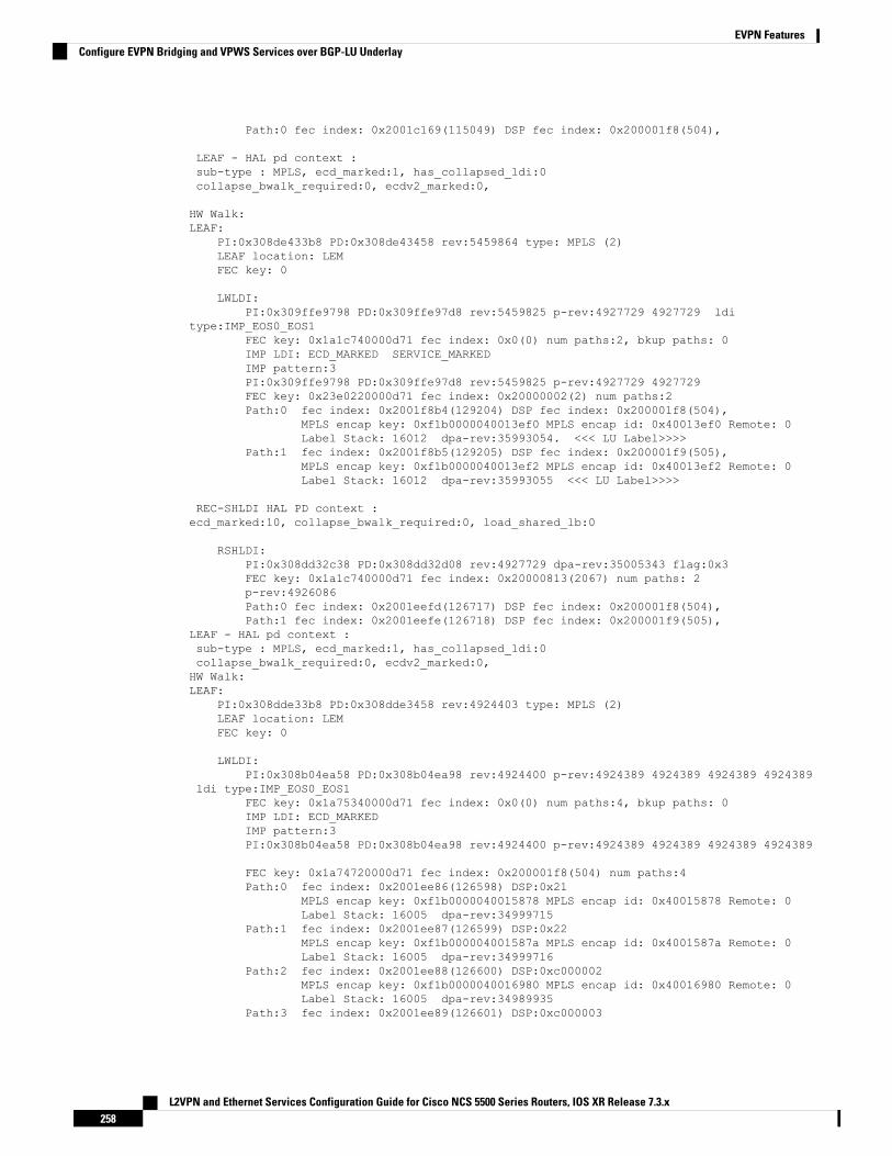
Path:0 fec index: 0x2001c169(115049) DSP fec index: 0x200001f8(504),
LEAF - HAL pd context :sub-type : MPLS, ecd_marked:1, has_collapsed_ldi:0collapse_bwalk_required:0, ecdv2_marked:0,
HW Walk:LEAF:
PI:0x308de433b8 PD:0x308de43458 rev:5459864 type: MPLS (2)LEAF location: LEMFEC key: 0
LWLDI:PI:0x309ffe9798 PD:0x309ffe97d8 rev:5459825 p-rev:4927729 4927729 ldi
type:IMP_EOS0_EOS1FEC key: 0x1a1c740000d71 fec index: 0x0(0) num paths:2, bkup paths: 0IMP LDI: ECD_MARKED SERVICE_MARKEDIMP pattern:3PI:0x309ffe9798 PD:0x309ffe97d8 rev:5459825 p-rev:4927729 4927729FEC key: 0x23e0220000d71 fec index: 0x20000002(2) num paths:2Path:0 fec index: 0x2001f8b4(129204) DSP fec index: 0x200001f8(504),
MPLS encap key: 0xf1b0000040013ef0 MPLS encap id: 0x40013ef0 Remote: 0Label Stack: 16012 dpa-rev:35993054. <<< LU Label>>>>
Path:1 fec index: 0x2001f8b5(129205) DSP fec index: 0x200001f9(505),MPLS encap key: 0xf1b0000040013ef2 MPLS encap id: 0x40013ef2 Remote: 0Label Stack: 16012 dpa-rev:35993055 <<< LU Label>>>>
REC-SHLDI HAL PD context :ecd_marked:10, collapse_bwalk_required:0, load_shared_lb:0
RSHLDI:PI:0x308dd32c38 PD:0x308dd32d08 rev:4927729 dpa-rev:35005343 flag:0x3FEC key: 0x1a1c740000d71 fec index: 0x20000813(2067) num paths: 2p-rev:4926086Path:0 fec index: 0x2001eefd(126717) DSP fec index: 0x200001f8(504),Path:1 fec index: 0x2001eefe(126718) DSP fec index: 0x200001f9(505),
LEAF - HAL pd context :sub-type : MPLS, ecd_marked:1, has_collapsed_ldi:0collapse_bwalk_required:0, ecdv2_marked:0,HW Walk:LEAF:
PI:0x308dde33b8 PD:0x308dde3458 rev:4924403 type: MPLS (2)LEAF location: LEMFEC key: 0
LWLDI:PI:0x308b04ea58 PD:0x308b04ea98 rev:4924400 p-rev:4924389 4924389 4924389 4924389
ldi type:IMP_EOS0_EOS1FEC key: 0x1a75340000d71 fec index: 0x0(0) num paths:4, bkup paths: 0IMP LDI: ECD_MARKEDIMP pattern:3PI:0x308b04ea58 PD:0x308b04ea98 rev:4924400 p-rev:4924389 4924389 4924389 4924389
FEC key: 0x1a74720000d71 fec index: 0x200001f8(504) num paths:4Path:0 fec index: 0x2001ee86(126598) DSP:0x21
MPLS encap key: 0xf1b0000040015878 MPLS encap id: 0x40015878 Remote: 0Label Stack: 16005 dpa-rev:34999715
Path:1 fec index: 0x2001ee87(126599) DSP:0x22MPLS encap key: 0xf1b000004001587a MPLS encap id: 0x4001587a Remote: 0Label Stack: 16005 dpa-rev:34999716
Path:2 fec index: 0x2001ee88(126600) DSP:0xc000002MPLS encap key: 0xf1b0000040016980 MPLS encap id: 0x40016980 Remote: 0Label Stack: 16005 dpa-rev:34989935
Path:3 fec index: 0x2001ee89(126601) DSP:0xc000003
L2VPN and Ethernet Services Configuration Guide for Cisco NCS 5500 Series Routers, IOS XR Release 7.3.x258
EVPN FeaturesConfigure EVPN Bridging and VPWS Services over BGP-LU Underlay

MPLS encap key: 0xf1b00000400157fc MPLS encap id: 0x400157fc Remote: 0Label Stack: 16005 dpa-rev:34989936
SHLDI:PI:0x30927740c8 PD:0x3092774198 rev:4924389 dpa-rev:34999705 flag:0x0FEC key: 0x1a75340000d71 fec index: 0x200001ff(511) num paths: 4 bkup paths: 0
p-rev:4924311 4924329 8779 4920854Path:0 fec index: 0x2001ee8f(126607) DSP:0x21 Dest fec index: 0x0(0)Path:1 fec index: 0x2001ee90(126608) DSP:0x22 Dest fec index: 0x0(0)Path:2 fec index: 0x2001ee91(126609) DSP:0xc000002 Dest fec index: 0x0(0)Path:3 fec index: 0x2001ee92(126610) DSP:0xc000003 Dest fec index: 0x0(0)
TX-NHINFO:PI: 0x308dc51298 PD: 0x308dc51318 rev:4924311 dpa-rev:34994174 Encap hdl:
0x3091632e98Encap id: 0x40010003 Remote: 0 L3 int: 1670 flags: 0x3npu_mask: 0x1 DMAC: 84:78:ac:2d:f8:1f
TX-NHINFO:PI: 0x308dc51c20 PD: 0x308dc51ca0 rev:4924329 dpa-rev:34994264 Encap hdl:
0x30916332c8Encap id: 0x40010001 Remote: 0 L3 int: 1679 flags: 0x3npu_mask: 0x1 DMAC: d4:6d:50:7c:f9:4d
TX-NHINFO:PI: 0x308dc51ff0 PD: 0x308dc52070 rev:8779 dpa-rev:61964 Encap hdl:
0x308e9f4980Encap id: 0x40010007 Remote: 0 L3 int: 1728 flags: 0x807npu_mask: 0x1 DMAC: 84:78:ac:2d:f8:22
TX-NHINFO:PI: 0x308dc51480 PD: 0x308dc51500 rev:4920854 dpa-rev:34989846 Encap hdl:
0x308e9f4db0Encap id: 0x40010005 Remote: 0 L3 int: 1727 flags: 0x807npu_mask: 0x1 DMAC: 40:55:39:11:37:39
LEAF - HAL pd context :sub-type : MPLS, ecd_marked:1, has_collapsed_ldi:0collapse_bwalk_required:0, ecdv2_marked:0,HW Walk:LEAF:
PI:0x308dde35b8 PD:0x308dde3658 rev:4926089 type: MPLS (2)LEAF location: LEMFEC key: 0
LWLDI:PI:0x308b04eb48 PD:0x308b04eb88 rev:4926086 p-rev:4924389 4924389 4924389 4924389
ldi type:IMP_EOS0_EOS1FEC key: 0x1a75340000d71 fec index: 0x0(0) num paths:4, bkup paths: 0IMP LDI: ECD_MARKEDIMP pattern:3PI:0x308b04eb48 PD:0x308b04eb88 rev:4926086 p-rev:4924389 4924389 4924389 4924389
FEC key: 0x1a74820000d71 fec index: 0x200001f9(505) num paths:4Path:0 fec index: 0x2001ee81(126593) DSP:0x21
MPLS encap key: 0xf1b000004001587c MPLS encap id: 0x4001587c Remote: 0Label Stack: 16006 dpa-rev:35002526
Path:1 fec index: 0x2001ee82(126594) DSP:0x22MPLS encap key: 0xf1b000004001588a MPLS encap id: 0x4001588a Remote: 0Label Stack: 16006 dpa-rev:35002527
Path:2 fec index: 0x2001ee83(126595) DSP:0xc000002MPLS encap key: 0xf1b0000040016964 MPLS encap id: 0x40016964 Remote: 0Label Stack: 16006 dpa-rev:34991843
Path:3 fec index: 0x2001ee84(126596) DSP:0xc000003
L2VPN and Ethernet Services Configuration Guide for Cisco NCS 5500 Series Routers, IOS XR Release 7.3.x259
EVPN FeaturesConfigure EVPN Bridging and VPWS Services over BGP-LU Underlay

MPLS encap key: 0xf1b00000400157fe MPLS encap id: 0x400157fe Remote: 0Label Stack: 16006 dpa-rev:34991844
SHLDI:PI:0x30927740c8 PD:0x3092774198 rev:4924389 dpa-rev:34999705 flag:0x0FEC key: 0x1a75340000d71 fec index: 0x200001ff(511) num paths: 4 bkup paths: 0
p-rev:4924311 4924329 8779 4920854Path:0 fec index: 0x2001ee8f(126607) DSP:0x21 Dest fec index: 0x0(0)Path:1 fec index: 0x2001ee90(126608) DSP:0x22 Dest fec index: 0x0(0)Path:2 fec index: 0x2001ee91(126609) DSP:0xc000002 Dest fec index: 0x0(0)Path:3 fec index: 0x2001ee92(126610) DSP:0xc000003 Dest fec index: 0x0(0)
TX-NHINFO:PI: 0x308dc51298 PD: 0x308dc51318 rev:4924311 dpa-rev:34994174 Encap hdl:
0x3091632e98Encap id: 0x40010003 Remote: 0 L3 int: 1670 flags: 0x3npu_mask: 0x1 DMAC: 84:78:ac:2d:f8:1f
TX-NHINFO:PI: 0x308dc51c20 PD: 0x308dc51ca0 rev:4924329 dpa-rev:34994264 Encap hdl:
0x30916332c8Encap id: 0x40010001 Remote: 0 L3 int: 1679 flags: 0x3npu_mask: 0x1 DMAC: d4:6d:50:7c:f9:4d
TX-NHINFO:PI: 0x308dc51ff0 PD: 0x308dc52070 rev:8779 dpa-rev:61964 Encap hdl:
0x308e9f4980Encap id: 0x40010007 Remote: 0 L3 int: 1728 flags: 0x807npu_mask: 0x1 DMAC: 84:78:ac:2d:f8:22
TX-NHINFO:PI: 0x308dc51480 PD: 0x308dc51500 rev:4920854 dpa-rev:34989846 Encap hdl:
0x308e9f4db0Encap id: 0x40010005 Remote: 0 L3 int: 1727 flags: 0x807npu_mask: 0x1 DMAC: 40:55:39:11:37:39
Related Topics
EVPN Bridging and VPWS Services over BGP-LU Underlay, on page 249
Associated Commands
• show l2vpn bridge-domain
• show bgp l2vpn evpn neighbors
• show cef vrf
Support for DHCPv4 and DHCPv6 Client over BVIThe Support for DHCPv4 and DHCPv6 Client over the BVI feature allows you to configure DHCPv4 andDHCPv6 client on the Bridged Virtual Interface (BVI). You can configure a BVI, and request DHCP IPv4or IPv6 address on the BVI. This allows your customer’s device to have initial connectivity to your networkwithout user intervention in the field. After the device is connected to your network, the customer devicescan push a node-specific configuration with static IP addresses on a different BVI for customer deployment.
Configure DHCPv4 and DHCPv6 Client over BVIPerform the following tasks to configure DHCPv4 and DHCPv6 client over BVI:
L2VPN and Ethernet Services Configuration Guide for Cisco NCS 5500 Series Routers, IOS XR Release 7.3.x260
EVPN FeaturesSupport for DHCPv4 and DHCPv6 Client over BVI

• Configure AC interface
• Configure L2VPN
• Configure BVI
Configuration Example
/* Configure AC interface */Router# configureRouter(config)# interface tenGigE 0/5/0/1/1Router(config-if)# bundle id 1 mode onRouter(config-if)# exitRouter(config)# interface Bundle-Ether1Router(config-if)# no shutRouter(config-if)# exitRouter(config)# interface bundle-ether 1.100 l2transportRouter(config-l2vpn-subif)# encapsulation dot1q 100Router(config-l2vpn-subif)# rewrite ingress tag pop 1 symmetricRouter(config-l2vpn-subif)# commit
/* Configure L2VPN */Router # configureRouter(config)# l2vpnRouter(config-l2vpn)# bridge group BVIRouter(config-l2vpn-bg)# bridge-domain bviRouter(config-l2vpn-bg-bd)# interface Bundle-Ether1.100Router(config-l2vpn-bg-bd-ac)#exitRouter(config-l2vpn-bg-bd)# routed interface BVI1Router(config-l2vpn-bg-bd-bvi)# commit
/* Configure BVI */Router# configureRouter(config)# interface BVI1Router(config-if)# ipv4 address dhcpRouter(config-if)# ipv6 address dhcpRouter(config-if)# commit
Running Configuration
This section shows the DHCPv4 and DHCPv6 client over BVI running configuration.
interface TenGigE0/5/0/1/1bundle id 1 mode on!interface Bundle-Ether1!interface Bundle-Ether1.100 l2transportencapsulation dot1q 100rewrite ingress tag pop 1 symmetric!l2vpnbridge group BVIbridge-domain bviinterface Bundle-Ether1.100!routed interface BVI1!!
!
L2VPN and Ethernet Services Configuration Guide for Cisco NCS 5500 Series Routers, IOS XR Release 7.3.x261
EVPN FeaturesConfigure DHCPv4 and DHCPv6 Client over BVI

interface BVI1ipv4 address dhcpipv6 address dhcp!
Verification
The show output given in the following section display the details of DHCPv4 and DHCPv6 client over BVIconfiguration.
Router# show l2vpn bridge-domainLegend: pp = Partially Programmed.Bridge group: BVI, bridge-domain: bvi, id: 0, state: up, ShgId: 0, MSTi: 0Aging: 300 s, MAC limit: 64000, Action: none, Notification: syslogFilter MAC addresses: 0ACs: 2 (2 up), VFIs: 0, PWs: 0 (0 up), PBBs: 0 (0 up), VNIs: 0 (0 up)List of ACs:BV1, state: up, BVI MAC addresses: 1BE1.100, state: up, Static MAC addresses: 0
List of Access PWs:List of VFIs:List of Access VFIs:
Router# show dhcp ipv4 client
Interface name IP Address Binding State Lease Time Rem---------------------- ------------ --------------- ----------------------BVI1 172.16.0.2 BOUND 3598 secs (00:59:58)-----------------------------------------------------------------------------------Router# show dhcp ipv6 client
Interface name IPv6 Address State Lease Time Rem---------------------- -------------- --------------- --------------------BVI1 2000::1 BOUND 2591982------------------------------------------------------------------------------------
Router# show dhcp ipv4 client bvi1 detail
-----------------------------------------------------Client Interface name : BVI1Client Interface handle : 0x8804054Client ChAddr : 008a.9628.ac8aClient ID : BVI1.00:8a:96:28:ac:8aClient State : BOUNDClient IPv4 Address (Dhcp) : 172.16.0.2Client IPv4 Address Mask : 255.240.0.0Client Lease Time Allocated : 3600 secs (01:00:00)Client Lease Time Remaining : 3571 secs (00:59:31)Client Selected Server Address: 172.16.0.1Client Next Hop Address : 0.0.0.0-----------------------------------------------------
Router# show dhcp ipv4 client BVI1 statistics
Client Interface name : BVI1-------------------------------------------------
CLIENT COUNTER(s) | VALUE-------------------------------------------------Num discovers sent : 44Num requests sent : 1Num offers received : 1Num acks received : 1-------------------------------------------------
L2VPN and Ethernet Services Configuration Guide for Cisco NCS 5500 Series Routers, IOS XR Release 7.3.x262
EVPN FeaturesConfigure DHCPv4 and DHCPv6 Client over BVI

Router# show dhcp ipv6 client
Interface name IPv6 Address State Lease Time Rem---------------------- -------------- --------------- --------------------BVI1 2000::1 BOUND 2591685------------------------------------------------------------------------------------
Router# show dhcp ipv6 client statistics-all
Interface name : BVI1Interface handle : 0x8804054VRF : 0x60000000
TYPE | TRANSMIT | RECEIVE | DROP |----------------------------------------------------------------------SOLICIT | 17 | 0 | 0 |ADVERTISE | 0 | 1 | 0 |REQUEST | 1 | 0 | 0 |REPLY | 0 | 2 | 0 |CONFIRM | 0 | 0 | 0 |RENEW | 1 | 0 | 0 |REBIND | 0 | 0 | 0 |RELEASE | 0 | 0 | 0 |RECONFIG | 0 | 0 | 0 |INFORM | 0 | 0 | 0 |
TIMER | STARTED | STOPPED | EXPIRED |-----------------------------------------------------------------------
INIT | 1 | 0 | 1 |VBIND | 0 | 0 | 0 |RENEW | 2 | 1 | 0 |REBIND | 2 | 1 | 0 |RETRANS | 19 | 3 | 16 |VALID | 2 | 1 | 0 |
Configure DHCPv6 Client Options
You can configure different DHCPv6 client options to differentiate between clients as required. Configuredifferent DHCPv6 client options to differentiate how a DHCPv6 client communicates with a DHCPv6 server.The different DHCPv6 client options that you can configure are:
• DUID: If the DUID DHCPv6 client option is configured on an interface, DHCPv6 client communicateswith the DHCPv6 server through the link layer address.
• Rapid Commit: If the Rapid Commit DHCPv6 client option is configured on an interface, DHCPv6client can obtain configuration parameters from the DHCPv6 server through a rapid two-step exchange(solicit and reply) instead of the default four-step exchange (solicit, advertise, request, and reply).
• DHCP Options: The various other DHCPv6 options that can be configured on a DHCPv6 client are:
• Option 15: Option 15 is also known as the User Class option and it is used by a DHCPv6 client toidentify the type or category of users or applications it represents.
• Option 16: Option 16 is also known as the Vendor ID option and it is used by a DHCPv6 a clientto identify the vendor that manufactured the hardware on which the client is running.
L2VPN and Ethernet Services Configuration Guide for Cisco NCS 5500 Series Routers, IOS XR Release 7.3.x263
EVPN FeaturesConfigure DHCPv4 and DHCPv6 Client over BVI

• Option 23: Option 23 is also known as the Domain name Server (DNS) option provides a list ofone or more IPv6 addresses of DNS recursive name servers to which a client's DNS resolver cansend DNS queries.
• Option 24: Option 24 is also known as the Domain List option and it specifies the domain searchlist that the client uses to resolve hostnames with the DNS.
• DHCP Timers: This option is used to set different timer value for DHCP client configurations. Thevarious DHCP timer options are:
• Release-timeout: It is used to set retransmission timeout value for the initial release message.
• Req-max-rt: It is used to set the maximum retransmission timeout value for the request message.
• Req-timeout: It is used to set the initial request timeout value of the request message.
• Sol-max-delay: It is used to set the maximum delay time of the first solicit message.
• Sol-max-rt: It is used to set the maximum solicit retransmission time.
• Sol-time-out: It is used to set the intial timeout value of the solicit message.
Configuration Example
Perform this task to configure DHCPv6 client options on a BVI interface.Router# configureRouter(config)# interface BVI 10Router(config-if)# ipv6 address dhcp-client-optionsRouter(config-dhcpv6-client)# duid linked-layer-addressRouter(config-dhcpv6-client)# rapid-commitRouter(config-dhcpv6-client)# timers release-timeout 3Router(config-dhcpv6-client)# timers sol-max-delay 1Router(config-dhcpv6-client)# timers sol-time-out 1Router(config-dhcpv6-client)# timers sol-max-rt 120Router(config-dhcpv6-client)# timers req-max-rt 30Router(config-dhcpv6-client)# timers req-timeout 1Router(config-dhcpv6-client)# commit
Verification
To verify the DHCPv6 client options, use the show dhcp ipv6 client BVI10 detail command.Router# show dhcp ipv6 client BVI10 detailWed Jun 10 16:19:21.272 IST
-----------------------------------------------------Client Interface name : MgmtEth0/0/CPU0/1Client Interface handle : 0x4040Client MACAddr : 02f0.2b39.44beClient State : BOUNDClient Link Local Address : fe80::f0:2bff:fe39:44beClient IPv6 Address (Dhcp) : 600:1::12Lease Remaining (in secs) : 74DUID : 0003000102f02b3944be
Client ConfigurationTimersSOL_MAX_DELAY : 1 secs (00:00:01)SOL_TIMEOUT : 1 secs (00:00:01)
L2VPN and Ethernet Services Configuration Guide for Cisco NCS 5500 Series Routers, IOS XR Release 7.3.x264
EVPN FeaturesConfigure DHCPv4 and DHCPv6 Client over BVI

SOL_MAX_RT : 120 secs (00:02:00)REQ_TIMEOUT : 1 secs (00:00:01)REQ_MAX_RT : 30 secs (00:00:30)REL_TIMEOUT : 3 secs (00:00:01)
OptionsRAPID-COMMIT : TrueUSER-CLASS : ciscoupnnpVENDOR-CLASS : vendorDNS-SERVERS : TrueDOMAIN-LIST : True
DUID Type : DUID_LL
Server InformationServer Address : fe80::d2:a1ff:feb2:3b9fPreference : 0DUID : 000300010206826e2e00Status : SUCCESSIA-NAStatus : SUCCESSIAID : 0x40400001T1 : 60 secs (00:01:00)T2 : 96 secs (00:01:36)IA-ADDRIA NA Address : 600:1::12Preferred Time : 120 secs (00:02:00)Valid Time : 120 secs (00:02:00)Flags : 0x0
Related Topics
• Support for DHCPv4 and DHCPv6 Client over BVI, on page 260
Associated Commands
• show l2vpn bridge-domain
• show dhcp ipv4 client
• show dhcp ipv6 client
• show dhcp ipv4 client bvi
MSTI Flush and FloodTable 17: Feature History Table
Feature DescriptionReleaseInformation
Feature Name
L2VPN and Ethernet Services Configuration Guide for Cisco NCS 5500 Series Routers, IOS XR Release 7.3.x265
EVPN FeaturesMSTI Flush and Flood

In the event of a link failure, this feature enables the router to switchtraffic quickly to a precomputed loop-free alternative (LFA) pathby allocating a label to the incoming traffic. Thus minimizes thetraffic loss ensuring fast convergence. This feature is supportedonly when PE devices are in an EVPN single-flow-active mode.
This feature introduces the convergence mac-mobility command.
Release 7.3.1MSTI Flush andFlood
The Multiple Spanning Tree Instance (MSTI) Flush and Flood feature reduces traffic loss during the failureof a primary link. You can use this feature only when PE devices are in EVPN single-flow active mode.
When the primary link connected to the PE device fails, the PE takes a few seconds to switch over from onePE to another. The convergence depends on MAC mobility or MAC-IP mobility. As the number of hostsconnected to the CE device increases, convergence becomes slower, causing traffic loss during the switchover.This feature mitigates the traffic loss independent of the number of hosts.
When you enable this feature, the primary PE floods the received traffic to the peering PE and to the attachedlocal AC soon after it detects the link failure. The primary PE continues to flood the traffic to the peering PEuntil the backup PE learns the MAC address of all the hosts.
Topology
• Host 1 and Host 2 are multihomed in the ring topology.
• PE1 and PE2 are part of the access ring. The ring uses the G.8032 legacy protocol to prevent looping.
• Both PE1 and PE2 that forms the ring must be configured with the same ESI. Peering PEs must sharethe same ESI.
• Host 1 and Host 3 are configured with the same EV1 100.
• Host 2 and Host 4 are configured with the same EV1 200.
Traffic Flow
• When you send traffic from Host 1 to Host 3, the traffic is sent to CE1. In this ring topology, the linkbetween CE1 to CE2 is in the blocked state; the link between CE1 to CE3 is in the forwarding state.Hence, CE1 sends the traffic to PE2 through CE3.
L2VPN and Ethernet Services Configuration Guide for Cisco NCS 5500 Series Routers, IOS XR Release 7.3.x266
EVPN FeaturesMSTI Flush and Flood

• PE2 first learns the MAC address of Host1 through CE1. PE2 advertises the learnt MAC address to thepeering PE1.
• As PE2 has learnt the MAC address directly from Host 1, PE2 sends the traffic to PE3, which is a remotePE, with a local preference of 100. The PE which originates the MAC route due to access learning setsa local preference of 100 by default.
• The redundant PE1 also sends the traffic to PE3, but with a local preference of 80, as it has learned theMAC address from PE2. The reoriginated route on the peer PE sets a local preference of 80.
• PE3 always sends the traffic through the PE that has a local preference of 100.
• PE3 forwards the traffic to Host 3. Similarly, Host 3 sends the traffic to Host 1 always through PE2.
MSTI Flush and Flood
• When the link between CE1 and CE3 is down or when the link between CE3 and PE2 is down, the ringsends an MSTI Flush request for each MSTI instance to PE2.
• MAC addresses attached to all bridge ports under each MSTI instance are deleted. Therefore, when thetraffic reaches the bridge, the traffic is flooded in the absence of the destination MAC address in theforwarding MAC table.
• Until PE1 learns the MAC address of all the hosts, PE2 floods traffic received from PE3. PE3 also keepssending the traffic to PE2 until complete convergence occurs. There is no traffic loss even during theevent of a failure.
• PE1 learns the MAC address of Host 1 directly and advertises the learnt MAC address to PE2.
• PE1 sends the traffic to Host 3 through the remote PE3 with a local preference of 100.
• PE3 sends and receives the traffic from PE1 until the access link between CE1 and CE3 becomes active.
Configuration Example
Router# configureRouter(config)# evpnRouter(config-evpn)# evi 100Router(config-evpn-instance)# advertise-macRouter(config-evpn-instance-mac)# commitRouter(config-evpn-instance-mac)# root
L2VPN and Ethernet Services Configuration Guide for Cisco NCS 5500 Series Routers, IOS XR Release 7.3.x267
EVPN FeaturesMSTI Flush and Flood

Router(config)# evpnRouter(config-evpn)# interface bundle-ether 1Router(config-evpn-ac)# ethernet-segmentRouter(config-evpn-ac-es)# identifier type 0 00.00.00.00.00.00.00.00Router(config-evpn-ac-es)# load-balancing-mode single-flow-activeRouter(config-evpn-ac-es)# convergenceRouter(config-evpn-ac-es)# mac-mobilityRouter(config-evpn-ac-es)# commitRouter(config-evpn-ac-es)# root
Router(config)# l2vpnRouter(config-l2vpn)# bridge group 100Router(config-l2vpn-bg)# bridge-domain 100Router(config-l2vpn-bg-bd)# interface Bundle-Ether1Router(config-l2vpn-bg-bd-ac)# evi 100Router(config-l2vpn-bg-bd-evi)# commit
Running Configuration
evpnevi 100advertise-mac!!interface Bundle-Ether1ethernet-segmentidentifier type 0 00.00.00.00.00.00.00.00.01load-balancing-mode single-flow-activeconvergencemac-mobility
!!
l2vpnbridge group 100bridge-domain 100interface Bundle-Ether1evi 100!
Verification
Router# show evpn ethernet-segment carving detailThu Aug 6 13:00:37.988 ISTLegend:B - No Forwarders EVPN-enabled,C - Backbone Source MAC missing (PBB-EVPN),RT - ES-Import Route Target missing,E - ESI missing,H - Interface handle missing,I - Name (Interface or Virtual Access) missing,M - Interface in Down state,O - BGP End of Download missing,P - Interface already Access Protected,Pf - Interface forced single-homed,R - BGP RID not received,S - Interface in redundancy standby state,X - ESI-extracted MAC ConflictSHG - No local split-horizon-group label allocated
Ethernet Segment Id Interface Nexthops------------------------ ---------------------------------- --------------------0000.0000.0000.0000.0001 BE1 10.0.0.1
L2VPN and Ethernet Services Configuration Guide for Cisco NCS 5500 Series Routers, IOS XR Release 7.3.x268
EVPN FeaturesMSTI Flush and Flood

172.16.0.1ES to BGP Gates : ReadyES to L2FIB Gates : ReadyMain port :
Interface name : Bundle-Ether1Interface MAC : 008a.96ee.88dcIfHandle : 0x20005f5cState : UpRedundancy : Not Defined
ESI type : 0Value : 00.0000.0000.0000.0001
ES Import RT : 0000.0000.0001 (Local)Source MAC : 0000.0000.0000 (N/A)Topology :
Operational : MH, Single-flow-activeConfigured : Single-flow-active
Service Carving : Auto-selectionMulticast : Disabled
Convergence : MAC-Mobility,Mobility-Flush : Debounce 13 sec, Count 1, Skip 1499
: Last 01/01 05:57:42.468Peering Details : 2 Nexthops10.0.0.1[MOD:P:00:T]172.16.0.1 [MOD:P:7fff:T]
Service Carving Synchronization:Mode : NONEPeer Updates :
Service Carving Results:Forwarders : 1000Elected : 1000
EVI E : 1, 2, 3, 4, 5, 6EVI E : 7, 8, 9, 10, 11, 12,EVI E : 13, 14, 15, 16, 17, 18,EVI E : 19, 20, 21, 22, 23, 24,
[........]EVI E : 979, 980, 981, 982, 983, 984,EVI E : 985, 986, 987, 988, 989, 990,EVI E : 991, 992, 993, 994, 995, 996,EVI E : 997, 998, 999, 1000
Not Elected : 0EVPN-VPWS Service Carving Results:
Primary : 0Backup : 0Non-DF : 0
MAC Flushing mode : STP-TCNPeering timer : 3 sec [not running]Recovery timer : 30 sec [not running]Carving timer : 0 sec [not running]Local SHG label : 29096Remote SHG labels : 1
29096 : nexthop 10.0.0.1Access signal mode: Bundle OOS (Default)
Associated Commands
• convergence mac-mobility
• show evpn ethernet-segment
L2VPN and Ethernet Services Configuration Guide for Cisco NCS 5500 Series Routers, IOS XR Release 7.3.x269
EVPN FeaturesMSTI Flush and Flood

Layer 2 Fast RerouteTable 18: Feature History Table
Feature DescriptionRelease InformationFeatureName
In the event of a link failure, this feature enables the routerto switch traffic quickly to a precomputed loop-freealternative (LFA) path by allocating a label to the incomingtraffic. This minimizes the traffic loss ensuring fastconvergence.
This feature introduces the convergencereroute command.
Release 7.3.1Layer 2 FastReroute
When there is a link failure, a network experiences traffic loss for a brief period until the convergence iscomplete. The extent of traffic loss depends on various factors such as the performance of the control plane,tuning of fast convergence, and the choice of technologies of the control plane on each node in the network.
Certain fault-tolerant applications are impacted by the traffic loss. To reduce this traffic loss, a technique fordata plane convergence is essential. Fast Reroute (FRR) is one such technique that is primarily applicable tothe network core.
The Layer 2 Fast Reroute (L2 FRR) feature enables the router to quickly send the traffic through the backuppath when a primary link fails. The feature helps to minimise traffic loss and ensures fast convergence.
L2 FRR precomputes the loop-free alternative (LFA) path in the hardware. When a link or a router fails,distributed routing algorithms takes the failure into account and compute new routes. The time taken forcomputation is called routing transition. The routing transition in BGP convergence can take up to severalhundreds of milliseconds.
Use LFA FRR to reduce the routing transition time to less than 50 milliseconds using a precomputed alternatebackup path. When a router detects a link failure, FRR allocates a label to the incoming traffic, and the routerimmediately switches the traffic over to the backup path to reduce traffic loss.
Benefits
This feature provides fast and predictable convergence:
• Convergence time is 50 ms
• Fast failure notification even in large rings with high number of nodes
• Manual configuration for predictable failover behavior
• You do not have to change the topology
Restrictions
• You can use L2 FRR only when PE devices are in EVPN active-active or single-active mode.
• L2 FRR is applicable only for unicast traffic and not for BUM traffic.
L2VPN and Ethernet Services Configuration Guide for Cisco NCS 5500 Series Routers, IOS XR Release 7.3.x270
EVPN FeaturesLayer 2 Fast Reroute

Figure 46: Layer 2 Fast Reroute
In this topology:
• CE2 is multihomed to PE1 and PE2.
• PE1 and PE2 are in EVPN active-active or single-active mode. They are connected to a remote routerPE3 over the MPLS core network.
• CE1 is connected to PE3.
• Both PE1 and PE2 are L2 FRR enabled. An FRR label is added per EVI for the backup path.
Consider a traffic flow from CE1 to CE2 in a regular scenario:
• The traffic is sent from CE1 to PE3.
• PE3 distributes the traffic over PE1 and PE2.
• PE1 and PE2 sends the traffic to CE2.
When FRR is enabled:
• When the PE1-CE2 link goes down, L2 FRR is triggered on PE1. Traffic is redirected to PE2 until theconvergence is complete.
• When you enable FRR on PE1, the logical backup path is pre-programmed in the hardware. When PE1detects a failure on the access side (CE2), PE1 identifies the backup PE2 as has been programmed in thehardware.
• PE1 allocates the FRR label to the incoming traffic to reach PE2.
• All incoming traffic to PE1 is redirected to PE2 using this FRR label.
• PE1 encapsulates all the traffic with the label of PE2 and forwards the traffic to PE2.
• PE2 receives the traffic with the label.
• Each interface has an unique label.
• PE2 removes the FRR label and forwards the traffic to the correct AC.
L2VPN and Ethernet Services Configuration Guide for Cisco NCS 5500 Series Routers, IOS XR Release 7.3.x271
EVPN FeaturesLayer 2 Fast Reroute

Configure Layer 2 Fast Reroute
Router# configureRouter(config)# evpnRouter(config-evpn)# interface Bundle-Ether100Router(config-evpn-ac)# ethernet-segmentRouter(config-evpn-ac-es)# identifier type 0 00.00.00.00.00.00.05.01.02Router(config-evpn-ac-es)# convergenceRouter(config-evpn-ac-es-conv)# rerouteRouter(config-evpn-ac-es-conv)# bgp route-target 5000.5000.5002Router(config-evpn-ac-es-conv)# exitRouter(config-evpn-ac-es)# l2vpnRouter(config-l2vpn)# bridge group bg1Router(config-l2vpn-bg)# bridge-domain bd1Router(config-l2vpn-bg-bd)# interface Bundle-Ether100.100 > L2FRR enabled bridge-port (BP),primary and backup paths will be pre-programmed in the NPU hardware for this BPRouter(config-l2vpn-bg-bd-ac)# routed interface BVI100Router(config-l2vpn-bg-bd-bvi)# evi 990Router(config-l2vpn-bg-bd-evi)# commit
L2FRR enabled bridge-port (BP),Primary and backup paths will be pre-programmed in the NPU hardwarefor this BP"
Running Configuration
This section shows the Layer 2 Fast Reroute running configuration.
evpninterface Bundle-Ether100ethernet-segmentidentifier type 0 00.00.00.00.00.00.05.01.02convergencereroute!bgp route-target 5000.5000.5002!!!l2vpnbridge group bg1bridge-domain bd1interface Bundle-Ether100.100!routed interface BVI100!evi 990!!!!end
Verification
Verify that you have configured Layer 2 Fast Reroute successfully.Check ESI bundle carving details, andensure convergence reroute is enabled.
Router:PE1#show evpn ethernet-segment interface bundle-Ether 100 carving detailsMon Dec 7 11:04:37.604 UTCLegend:
L2VPN and Ethernet Services Configuration Guide for Cisco NCS 5500 Series Routers, IOS XR Release 7.3.x272
EVPN FeaturesLayer 2 Fast Reroute

B - No Forwarders EVPN-enabled,C - Backbone Source MAC missing (PBB-EVPN),RT - ES-Import Route Target missing,E - ESI missing,H - Interface handle missing,I - Name (Interface or Virtual Access) missing,M - Interface in Down state,O - BGP End of Download missing,P - Interface already Access Protected,Pf - Interface forced single-homed,R - BGP RID not received,S - Interface in redundancy standby state,X - ESI-extracted MAC ConflictSHG - No local split-horizon-group label allocated
Ethernet Segment Id Interface Nexthops------------------------ ---------------------------------- --------------------0000.0000.0000.0005.0102 BE200 2.2.2.2
8.8.8.8ES to BGP Gates : ReadyES to L2FIB Gates : ReadyMain port :
Interface name : Bundle-Ether200Interface MAC : 008a.960e.70d9IfHandle : 0x20004064State : UpRedundancy : Not Defined
ESI type : 0Value : 00.0000.0000.0005.0102
ES Import RT : 5000.5000.5002 (Local)Source MAC : 0000.0000.0000 (N/A)Topology :
Operational : MH, All-activeConfigured : All-active (AApF) (default)
Service Carving : Auto-selectionMulticast : Disabled
Convergence : Reroute, <<<<<<<< Check reroute is enabled on this ESI bundleMobility-Flush : Debounce 1 sec, Count 0, Skip 0
: Last n/aPeering Details : 2 Nexthops
2.2.2.2 [MOD:P:7fff:T]8.8.8.8 [MOD:P:00:T]
Service Carving Synchronization:Mode : NONEPeer Updates :
Service Carving Results:Forwarders : 2Elected : 1
EVI E : 990Not Elected : 1
EVI NE : 991EVPN-VPWS Service Carving Results:
Primary : 0Backup : 0Non-DF : 0
MAC Flushing mode : STP-TCNPeering timer : 3 sec [not running]Recovery timer : 30 sec [not running]Carving timer : 0 sec [not running]Local SHG label : 28098Remote SHG labels : 1
28098 : nexthop 8.8.8.8Access signal mode: Bundle OOS (Default)
L2VPN and Ethernet Services Configuration Guide for Cisco NCS 5500 Series Routers, IOS XR Release 7.3.x273
EVPN FeaturesLayer 2 Fast Reroute

Check multihoming nodes per bridge-port (BP) AC backup information is programmed correctly.
Router:PE1#show l2vpn forwarding interface bundle-Ether100.100 private location 0/0/CPU0
Mon Dec 7 11:04:37.604 UTC
Xconnect ID 0xa0000007
Xconnect info:Base info: version=0xaabbcc13, flags=0xc110, type=2, reserved=0, address=0x308b25c448xcon_bound=TRUE, switching_type=0, data_type=12xcon_name=
AC info:Base info: version=0xaabbcc11, flags=0x0, type=3, reserved=0, address=0x308b25c570xcon_id=0xa0000007, ifh=0x2000403c, subifh=0x20004046, ac_id=0, ac_type=21,ac_mtu=1500, iw_mode=1, adj_valid=TRUE, adj_addr=0x20004046, adj_ptr=0x30887ab5c8r_aps_channel=FALSE, prot_exclusion=FALSErg_id=0, ro_id=0x0000000000000000evpn internal label = NoneE-Tree = RootFXC local-switch AC xcid = 0x0 (Invalid)FXC local-switch PW xcid = 0xffffffff (Invalid)Statistics:packets: received 0 (multicast 0, broadcast 0, unknown unicast 0, unicast 0), sent 0bytes: received 0 (multicast 0, broadcast 0, unknown unicast 0, unicast 0), sent 0MAC move: 0packets dropped: PLU 0, tail 0bytes dropped: PLU 0, tail 0
AC Backup info:Base info: version=0xaabbcc39, flags=0x0, type=43, reserved=0, address=0x308b264b70
VC label: 28100 << FRR label advertised by remote multihome peer node. Check thislabel details on the multihoming peer node is correct or not. Note down this label and checkon MH2 node.
Object: AC_BACKUPBase info: version=0xaabbcc39, flags=0x0, type=43, reserved=0, address=0x308b264b70Event Trace History [Total events: 1]
--------------------------------------------------------------------------------Time Event Flags==== ===== =====Jul 23 08:59:49.658 Create 0x0 - -
--------------------------------------------------------------------------------
Nexthop info:Base info: version=0xaabbcc14, flags=0x10000, type=7, reserved=0, address=0x308b25b4f8nh_addr=2.2.2.2ecd_plat_data_valid=TRUE, ecd_plat_data_len=104, plat_data_size=496child_count=0, child_evpn_ole_count=2, child_mac_count=0, child_pwhe_mp_count=0,
child_ac_backup_count=2
Object: NHOPBase info: version=0xaabbcc14, flags=0x10000, type=7, reserved=0, address=0x308b25b4f8Event Trace History [Total events: 5]
--------------------------------------------------------------------------------Time Event Flags==== ===== =====Jul 16 17:01:54.093 Create 0x0 - -Jul 16 17:01:54.093 FIB reg 0x2300 - -Jul 16 17:01:54.093 PD create 0x300 - -Jul 16 17:01:54.093 FIB ecd 0x200 - SJul 16 17:01:54.093 PD bind 0x10200 - -
L2VPN and Ethernet Services Configuration Guide for Cisco NCS 5500 Series Routers, IOS XR Release 7.3.x274
EVPN FeaturesLayer 2 Fast Reroute

--------------------------------------------------------------------------------
Bridge port info:Base info: version=0xaabbcc1a, flags=0x0, type=12, reserved=0, address=0x308b25c690xcon_id=0xa0000007, bridge_id=0, shg_id=0, mac_limit=64000, mac_limit_action=0,bridge_ptr=0x8b263f68, shg_ptr=0x0, msti_ptr=0x8b2613a0, segment_ptr=0x8b25c570segment_type=0x2, mtu=1500, msti=7, mvrp_seq_number=0, learn_key = 0is_flooding_disabled=FALSE, is_mac_learning_disabled=FALSE,
is_mac_port_down_flush_disabled=FALSE, mtu=1500, msti=7,aging_timeout=300, bridge_ptr=0x8b263f68, shg_ptr=0x0, segment_type=2,segment_ptr=0x8b25c570MAC learning: enabledSoftware MAC learning: enabledMAC port down flush: enabledFlooding:Broadcast & Multicast: enabledUnknown unicast: enabled
MAC aging time: 300 s, Type: inactivityMAC limit: 64000, Action: none, Notification: syslogMAC limit reached: no, threshold: 75%MAC Secure: disabled, Logging: disabled, Accept-Shutdown: enabledDHCPv4 snooping: profile not known on this node, disabledDynamic ARP Inspection: disabled, Logging: disabledIP Source Guard: disabled, Logging: disabledIGMP snooping profile: profile not known on this nodeMLD snooping profile: profile not known on this nodeRouter guard disabledSTP participating: disabledStorm control: disabledPD System Data: AF-LIF-IPv4: 0x00014003 AF-LIF-IPv6: 0x00014004 FRR-LIF: 0x00014002
Object: XCONBase info: version=0xaabbcc13, flags=0xc110, type=2, reserved=0, address=0x308b25c448Event Trace History [Total events: 14]
--------------------------------------------------------------------------------Time Event Flags==== ===== =====Jul 23 08:59:48.126 Create 0x80000 - -Jul 23 08:59:48.126 Modify_RED 0x113 M -Jul 23 08:59:48.126 PD create 0x100110 - -Jul 23 08:59:48.126 PD create 0x2110 - - (seg2)Jul 23 08:59:48.126 PD bind 0x110 - -Jul 23 08:59:48.126 PD bind 0x2110 - - (seg2)Jul 23 08:59:48.126 Modify_RED 0x113 M -Jul 23 08:59:48.126 DHCP upd 0xc110 - -Jul 23 08:59:48.126 AIB upd 0xc110 - -Jul 23 08:59:48.126 PD modify 0x110 - -Jul 23 08:59:49.662 Modify 0x100110 - -Jul 23 08:59:49.662 Modify_RED 0x110 - -Jul 23 08:59:49.662 PD modify 0x110 - -Jul 23 08:59:49.662 DHCP upd 0xc110 - -
--------------------------------------------------------------------------------Modify Event History, oldest - 0x0 - 0x100110
RP/0/RP0/CPU0:shan-evpn-leaf1#
/* Check MH2 node FRR-label 28100 output */Router:PE#show mpls forwarding labels 28100Mon Dec 7 11:04:37.604 UTCvLocal Outgoing Prefix Outgoing Next Hop BytesLabel Label or ID Interface Switched------ ----------- ------------------ ------------ --------------- ------------28100 Pop PW(127.0.0.1:4254701977609) \
BE200.200 point2point 0
L2VPN and Ethernet Services Configuration Guide for Cisco NCS 5500 Series Routers, IOS XR Release 7.3.x275
EVPN FeaturesLayer 2 Fast Reroute

Associated Commands
• convergence reroute
• show evpn ethernet-segment
• show evpn evi
• show evpn evi ead private
EVPN Preferred NexthopTable 19: Feature History Table
Feature DescriptionReleaseInformation
Feature Name
With this feature, you can set an active and backup path, in adual-homed mode based on the nexthop IP address, therebyallowing greater control over traffic patterns. If you are unable touse single-active mode due to hardware, topology, or technologicallimitations, this feature enables you to direct traffic to a specificremote PE.
This feature introduces the preferred nexthop command.
Release 7.3.1EVPN PreferredNexthop
The EVPN Preferred Nexthop feature allows you to choose a primary nexthop and backup nexthop amongthe remote PE devices in dual-homed mode. By default, in an all-active dual-homed topology, traffic is loadbalanced using ECMP across both remote PE devices.
Configure the preferred-nexthop command when you want to direct traffic to one specific remote PE, andyou are unable to use single-active mode due to hardware, topology, or technological limitations. The routerallocates an internal label and will not allocate or consume ECMP FEC. The internal label enables fastswitchover to backup PE when the primary link fails.
When remote PEs are operating in EVPN all-active mode, configure the preferred-nexthop command perEVI to choose an active and backup path based on the nexthop IP address. You can set the highest IP addressas primary, which results in the lower IP address as a backup or vice versa.This feature provides you greatercontrol over traffic patterns, that is to achieve symmetric traffic flow, and to allow support when a topologycannot support an all-active remote PE. Preferred nexthop is supported for native EVPN, EVPN VPWS, andEVPN PWHE. This feature supports a topology that has only two remote nexthops.
Configure EVPN Preferred NexthopPerform the following task to configure EVPN preferred nexthop.
Configuration Example
This example shows the configuration of highest IP address as the preferred nexthop.
Router# configureRouter(config)# evpnRouter(config-evpn)# evi 100
L2VPN and Ethernet Services Configuration Guide for Cisco NCS 5500 Series Routers, IOS XR Release 7.3.x276
EVPN FeaturesEVPN Preferred Nexthop

Router(config-evpn-evi)# preferred-nexthop highest-ipRouter(config-evpn-evi)# commit
This example shows the configuration of lowest IP address as the preferred nexthop.
Router# configureRouter(config)# evpnRouter(config-evpn)# evi 100Router(config-evpn-evi)# preferred-nexthop lowest-ipRouter(config-evpn-evi)# commit
This example shows the configuration of preferred nexthop using the modulo keyword.
Router# configureRouter(config)# evpnRouter(config-evpn)# evi 100Router(config-evpn-evi)# preferred-nexthop moduloRouter(config-evpn-evi)# commit
Running Configuration
This section shows the EVPN preferred nexthop running configuration.
/* Configuration of highest IP address as the preferred nexthop */evpnevi 100preferred-nexthop highest-ip
!
/* Configuration of lowest IP address as the preferred nexthop */evpnevi 100preferred-nexthop lowest-ip
!
/* Configuration of preferred nexthop using the modulo keyword */evpnevi 100preferred-nexthop modulo
Verification
The output shows that the Highest IP is selected as primary (P) and the lowest IP as backup (B). The pathselection is programmed in CEF.
Router#show evpn evi vpn-id 100 detailMon Oct 26 14:00:51.459 EDT
VPN-ID Encap Bridge Domain Type---------- ---------- ---------------------------- -------------------100 MPLS bd100 EVPN…
Preferred Nexthop Mode: Highest IP
Router#show evpn internal-label vpn-id 100 detailMon Oct 26 14:01:46.665 EDT
VPN-ID Encap Ethernet Segment Id EtherTag Label---------- ------ --------------------------- ---------- --------
L2VPN and Ethernet Services Configuration Guide for Cisco NCS 5500 Series Routers, IOS XR Release 7.3.x277
EVPN FeaturesConfigure EVPN Preferred Nexthop

100 MPLS 0100.0000.acce.5500.0100 0 28120Multi-paths resolved: TRUE (Remote all-active) (Preferred NH, Highest IP)Multi-paths Internal label: 28120EAD/ES 192.168.0.1 0
192.168.0.3 0EAD/EVI 192.168.0.1 28099
192.168.0.3 28099Summary pathlist:0xffffffff (P) 192.168.0.3 280990xffffffff (B) 192.168.0.1 28099
Router#show cef mpls local-label 28120 eOSMon Oct 26 14:04:10.851 EDTLabel/EOS 28120/1, version 56, internal 0x1000001 0x30 (ptr 0x4d3ba2a8) [1], 0x0 (0x0),0x208 (0x4e6502c0)Updated Oct 26 14:00:31.225…
via 192.168.0.3/32, 6 dependencies, recursive [flags 0x0]path-idx 0 NHID 0x0 [0x4d3bb58c 0x0], Internal 0x4e7890f8recursion-via-/32next hop 192.168.0.3/32 via 28103/0/21local label 28120next hop 27.27.27.3/32 Gi0/2/0/7 labels imposed {ImplNull 28099}
via 192.168.0.1/32, 6 dependencies, recursive, backup (Local-LFA) [flags 0x300]path-idx 1 NHID 0x0 [0x4d3bb454 0x0]recursion-via-/32next hop 192.168.0.1/32 via 28105/0/21local label 28120next hop 26.26.26.1/32 Gi0/2/0/6 labels imposed {ImplNull 28099}
EVPN Access-Driven DF ElectionTable 20: Feature History Table
Feature DescriptionRelease InformationFeature Name
This feature enables the access network to control EVPNPE devices by defining the backup path much before theevent of a link failure, thereby reducing the traffic loss.
The following keywords are added to the service-carvingcommand:
• preference-based
• access-driven
Release 7.3.1EVPNAccess-DrivenDF Election
This feature includes a preference-based and access-driven DF election mechanism.
In a preference-based DF election mechanism, the weight decides which PE is the DF at any given time. Youcan use this method for topologies where interface failures are revertive. However, for topologies where anaccess-PE is directly connected to the core PE, use the access-driven DF election mechanism.
When access PEs are configured in a non-revertive mode, the access-driven DF election mechanism allowsthe access-PE to choose which PE is the DF.
Consider an interface in an access network that connects PE nodes running Multichassis Link AggregationControl Protocol (mLACP) and the EVPN PE in the core. When this interface fails, there may be a traffic lossfor a longer duration. The delay in convergence is because the backup PE is not chosen before failure occurs.
L2VPN and Ethernet Services Configuration Guide for Cisco NCS 5500 Series Routers, IOS XR Release 7.3.x278
EVPN FeaturesEVPN Access-Driven DF Election

The EVPN Access-Driven DF Election feature allows the EVPN PE to preprogram a backup PE even beforethe failure of the interface. In the event of failure, the PE node will be aware of the next PE that will take over.Thereby reducing the convergence time. Use the preference df weight option for an Ethernet segment identifier(ESI) to set the backup path. By configuring the weight for a PE, you can control the DF election, thus definethe backup path.
Restrictions
• The feature is supported only in an EVPN-VPWS scenario where EVPN PEs are in the port-active mode.
• The bundle attached to the ethernet segment must be configured with lacp mode active.
LACP mode on is not supported.
Topology
Let’s understand the feature on how the backup path is precomputed with the following topology.
Figure 47: EVPN Access-Driven DF Election
• PE1, PE2, and PE3 are PEs for the EVPN core network.
• aPE1, aPE2, and aPE3 are their access PE counterparts and configured in a multichassis link aggregationgroup (MCLAG) redundancy group. Only one link among the three is active at any given time. aPE1,aPE2, and aPE3 are in a non-revertive mode.
• PE1 is directly connected to aPE1, PE2 to aPE2, and PE3 to aPE3. EVPN VPWS is configured on thePE devices in the core.
• All PE devices are attached to the same bundle and shares the same ethernet segment identifier.
L2VPN and Ethernet Services Configuration Guide for Cisco NCS 5500 Series Routers, IOS XR Release 7.3.x279
EVPN FeaturesEVPN Access-Driven DF Election

• PE1, PE2, and PE3 are configured with a weight of 100, 10, and 1 respectively.
Traffic Flow
In this example, consider a traffic flow from a host connected to PE4 to the host connected to the access PE.
• aPE1-PE1 interface state is up. The aPE2-PE2 and aPE3-PE3 remains in OOS state.
• The traffic is sent from PE4 to aPE1 through PE1 as the PE1 is configured with a highest weight of 100.
• The highest weight is modified by adding 32768 to the configured weight. For example, the weight ofPE1 is 100, 32768 is added to this weight. Hence, 32868 is advertised to the peer PEs.
• The highest weight is advertised as P-bit, which is primary. The next highest weight is advertised asB-bit, which is secondary. The lowest weight as non-DF (NDF).
• When the EVPN PE devcies are of same weight, the traffic is sent based on the IP address. Lowest IPaddress takes the precedence.
• Only one PE indicates that the state of the bundle for the Ethernet Segment is up. For all other PEs, theEthernet Segment is standby and the bundle is in OOS state.
• All PE devices are aware of the associated next hop and weights of their peers.
Failure and Recovery Scenarios
The weights configured on the EVPN PE devices cascade in the same order as the protection mechanism onthe access side PEs:
• During the network failure, the redundancy ordering for the access PEs is aPE1, aPE2, aPE3.
• The weights of PE1 through PE3 are weight of PE1 > weight of PE2 > weight of PE3.
L2VPN and Ethernet Services Configuration Guide for Cisco NCS 5500 Series Routers, IOS XR Release 7.3.x280
EVPN FeaturesEVPN Access-Driven DF Election

• If this ordering is not satisfied, the network will eventually converge, but it will not be as efficient as ifthe weights are ordered correctly.
Scenario - 1
Consider a scenario where the aPE1-PE1 interface is down.
When aPE1-PE1 interface is down, the PE1 withdraws the EAD/ES route, and the traffic is sent through thebackup path, which is PE2.
The aPE2-PE2 becomes the primarywith a weight of 32778, and aPE3-PE3 becomes the backup. The aPE2-PE2advertises P-bit to PE4. aPE3-PE3 advertises the B-bit to PE4.
L2VPN and Ethernet Services Configuration Guide for Cisco NCS 5500 Series Routers, IOS XR Release 7.3.x281
EVPN FeaturesEVPN Access-Driven DF Election

Scenario - 2
Consider a scenario where aPE2-PE2 interface is also down.
L2VPN and Ethernet Services Configuration Guide for Cisco NCS 5500 Series Routers, IOS XR Release 7.3.x282
EVPN FeaturesEVPN Access-Driven DF Election

When the aPE2-PE2 interface is also down, the traffic is sent through aPE3-PE3 link. aPE3-PE3 becomes theprimary path with a weight of 32769.
Scenario - 3
When the aPE2-PE2 interface comes up, the aPE3-PE3 link still remains the primary path. aPE2-PE2 interfacebecomes the backup path with a weight of 10.
L2VPN and Ethernet Services Configuration Guide for Cisco NCS 5500 Series Routers, IOS XR Release 7.3.x283
EVPN FeaturesEVPN Access-Driven DF Election

Scenario - 4
When the aPE1-PE1 interface comes up, the aPE3-PE3 link remains the primary path with a weight of 32769.aPE1-PE1 interface becomes the backup path with a weight of 100. The aPE2-PE2 interface becomes NDFwith a weight of 10.
Configure EVPN Access-Driven DF ElectionPerform the following tasks to configure EVPN Access-Driven DF Election feature:
• Configure EVPN access-driven DF election on PE1, PE2, and PE3
• Configure LACP on aPE1, aPE2, and aPE3
• Configure EVPN-VPWS for PE1, PE2, and PE3
See the EVPN Virtual Private Wire Service (VPWS) chapter on how to configure EVPN-VPWS.
Configuration Example
• All PE devices are configured with different weights. PE1, PE2, and PE3 are configured with a weightof 100, 10, and 1 respectively.
• The bundle attached to the ethernet segment is configured with lacp mode active.
• EVPN VPWS is configured on the PE devices.
/* Configure EVPN access-driven DF election on PE1, PE2, and PE3 */
/* PE1 Configuration */Router#configureRouter(config)#evpn
L2VPN and Ethernet Services Configuration Guide for Cisco NCS 5500 Series Routers, IOS XR Release 7.3.x284
EVPN FeaturesConfigure EVPN Access-Driven DF Election

Router(config-evpn)#interface Bundle-Ether1Router(config-evpn-ac)#ethernet-segmentRouter(config-evpn-ac-es)#identifier type 0 01.11.00.00.00.00.00.00.01Router(config-evpn-ac-es)#load-balancing-mode port-activeRouter(config-evpn-ac-es)#service-carving preference-basedRouter(config-evpn-ac-es-sc-pref)#weight 100Router(config-evpn-ac-es-sc-pref)#access-drivenRouter(config-evpn-ac-es-sc-pref)#commit
/* PE2 Configuration */Router#configureRouter(config)#evpnRouter(config-evpn)#interface Bundle-Ether1Router(config-evpn-ac)#ethernet-segmentRouter(config-evpn-ac-es)#identifier type 0 01.11.00.00.00.00.00.00.01Router(config-evpn-ac-es)#load-balancing-mode port-activeRouter(config-evpn-ac-es)#service-carving preference-basedRouter(config-evpn-ac-es-sc-pref)#weight 10Router(config-evpn-ac-es-sc-pref)#access-drivenRouter(config-evpn-ac-es-sc-pref)#commit
/* PE3 Configuration */Router#configureRouter(config)#evpnRouter(config-evpn)#interface Bundle-Ether1Router(config-evpn-ac)#ethernet-segmentRouter(config-evpn-ac-es)#identifier type 0 01.11.00.00.00.00.00.00.01Router(config-evpn-ac-es)#load-balancing-mode port-activeRouter(config-evpn-ac-es)#service-carving preference-basedRouter(config-evpn-ac-es-sc-pref)#weight 1Router(config-evpn-ac-es-sc-pref)#access-drivenRouter(config-evpn-ac-es-sc-pref)#commit
Configure LACP on aPE1, aPE2, and aPE3
/* aPE1 Configuration */Router#configureRouter(config)#interface Bundle-Ether 1Router(config-if)#lacp non-revertiveRouter(config-if)#bundle maximum-active links 1 hot-standbyRouter(config-if)#exitRouter(config-if)#interface GigabitEthernet0/0/0/40Router(config-if)bundle id 10 mode activeRouter(config-if)bundle port-priority 10000Router(config-if)description Connection to PE1Router(config-if)commit
/* aPE2 Configuration */Router#configureRouter(config)#interface Bundle-Ether 1Router(config-if)#lacp non-revertiveRouter(config-if)#bundle maximum-active links 1 hot-standbyRouter(config-if)#exitRouter(config-if)#interface GigabitEthernet0/0/0/39Router(config-if)bundle id 10 mode activeRouter(config-if)bundle port-priority 20000Router(config-if)description Connection to PE2Router(config-if)commit
/* aPE3 Configuration */Router#configure
L2VPN and Ethernet Services Configuration Guide for Cisco NCS 5500 Series Routers, IOS XR Release 7.3.x285
EVPN FeaturesConfigure EVPN Access-Driven DF Election

Router(config)#interface Bundle-Ether 1Router(config-if)#lacp non-revertiveRouter(config-if)#bundle maximum-active links 1 hot-standbyRouter(config-if)#exitRouter(config-if)#interface GigabitEthernet0/0/0/38Router(config-if)bundle id 10 mode activeRouter(config-if)bundle port-priority 30000Router(config-if)description Connection to PE3Router(config-if)commit
Running Configuration
This section shows the running configuration of EVPN Access-Driven DF Election feature.
/* PE1 Configuration */evpninterface Bundle-Ether 1ethernet-segmentidentifier type 0 01.11.00.00.00.00.00.00.01load-balancing-mode port-activeservice-carving preference-basedweight 100access-driven!
!
/* PE2 Configuration */evpninterface Bundle-Ether 1ethernet-segmentidentifier type 0 01.11.00.00.00.00.00.00.01load-balancing-mode port-activeservice-carving preference-basedweight 10access-driven!
!
/* PE3 Configuration */evpninterface Bundle-Ether 1ethernet-segmentidentifier type 0 01.11.00.00.00.00.00.00.01load-balancing-mode port-activeservice-carving preference-basedweight 1access-driven!
!
/* aPE1 Configuration */
interface Bundle-Ether 1lacp non-revertivebundle maximum-active links 1 hot-standby
interface GigabitEthernet0/0/0/40bundle id 10 mode activebundle port-priority 10000description Connection to PE1!
/* aPE2 Configuration */
L2VPN and Ethernet Services Configuration Guide for Cisco NCS 5500 Series Routers, IOS XR Release 7.3.x286
EVPN FeaturesConfigure EVPN Access-Driven DF Election

interface Bundle-Ether 1lacp non-revertivebundle maximum-active links 1 hot-standby
interface GigabitEthernet0/0/0/39bundle id 10 mode activebundle port-priority 20000description Connection to PE2!
/* aPE3 Configuration */
interface Bundle-Ether 1lacp non-revertivebundle maximum-active links 1 hot-standby
interface GigabitEthernet0/0/0/40bundle id 10 mode activebundle port-priority 30000description Connection to PE3!
Verification
Verify that you have configured the EVPN Access-Driven DF Election feature successfully.
Router#show evpn ethernet-segment detailEthernet Segment Id Interface Nexthops------------------------ ---------------------------------- --------------------0001.0001.0001.1b01.001b BE1 192.168.0.1
192.168.0.3ES to BGP Gates : ReadyES to L2FIB Gates : ReadyMain port :
Interface name : Bundle-Ether1Interface MAC : 02ef.af8d.8008IfHandle : 0x00004190State : UpRedundancy : Active
ESI type : 0Value : 01.0001.0001.1b01.001b
ES Import RT : 0100.0100.011b (from ESI)Source MAC : 0000.0000.0000 (N/A)Topology :
Operational : MHConfigured : Port-Active
Service Carving : PreferentialMulticast : Disabled
Convergence :Peering Details : 2 Nexthops
192.168.0.1 [PREF:P:d6ce:T] >> Weight in hexadecimal192.168.0.3 [PREF:P:457]
Service Carving Synchronization:Mode : NONEPeer Updates :
Service Carving Results:Forwarders : 24Elected : 6Not Elected : 0
EVPN-VPWS Service Carving Results:Primary : 18Backup : 0Non-DF : 0
MAC Flushing mode : STP-TCN
L2VPN and Ethernet Services Configuration Guide for Cisco NCS 5500 Series Routers, IOS XR Release 7.3.x287
EVPN FeaturesConfigure EVPN Access-Driven DF Election

Peering timer : 3 sec [not running]Recovery timer : 30 sec [not running]Carving timer : 0 sec [not running]Local SHG label : 28384Remote SHG labels : 0Access signal mode: Bundle OOS (Default)
Associated Commands
• service-carving
• show evpn ethernet-segment
CFM Support for EVPNEthernet Connectivity Fault Management (CFM) is a service-level OAM protocol that provides tools formonitoring and troubleshooting end-to-end Ethernet services per VLAN. This includes proactive connectivitymonitoring, fault verification, and fault isolation. CFM can be deployed in an EVPN network. You can monitorthe connections between the nodes using CFM in an EVPN network.
Restrictions
CFM for EVPN is supported with the following restrictions:
• In an active-active multi-homing scenario, when monitoring the connectivity between a multi-homedCE device and the PE devices to which it is connected, CFM can only be used across each individuallink between a CE and a PE. Attempts to use CFM on the bundle between CE and PE devices causesequence number errors and statistical inaccuracies.
• There is a possibility of artefacts in loopback and linktrace results. Either a loopback or linktrace mayreport multiple results for the same instance, or consecutive instances of a loopback and linktrace betweenthe same two endpoints may produce different results.
For more information about Ethernet Connectivity FaultManagement (CFM), refer to theConfiguring EthernetOAM chapter in the Interface and Hardware Component Configuration Guide for Cisco NCS 5500 SeriesRouters.
CFM on EVPN ELANConnectivity fault management (CFM) is a service-level Operations and Maintenance (OAM) protocol thatprovides tools for monitoring and troubleshooting end-to-end Ethernet services for each VLAN. This includesproactive connectivity monitoring, fault verification, and fault isolation.
Cisco IOSXR Software Release 6.6.1 introduces CFM support for single-homed EVPNEmulated Local AreaNetwork (ELAN) services. This functionality helps you to monitor the ELAN services of users against theircontractual service-level agreements (SLAs), thereby providing high speed Layer 2 and Layer 3 services withhigh resiliency and less operational complexity to different market segments.
Restrictions for CFM on EVPN ELAN
CFM on EVPN ELAN is subjected to these restrictions:
L2VPN and Ethernet Services Configuration Guide for Cisco NCS 5500 Series Routers, IOS XR Release 7.3.x288
EVPN FeaturesCFM Support for EVPN

• Supports only single-homed EVPN ELAN.
• Supports single homing with one AC per PW.
• DOWN MEP on AC interface of EVPN-BD is not supported.
• Does not support loss measurement.
• Does not support Y1731.
Configure CFM on EVPN ELANFigure 48: CFM on EVPN ELAN: Full Mesh Topology
Node 1, 2 and 3 in this topology can be Cisco routers.
Configuring CFM on EVPN ELAN involves these main tasks:
• Enabling CFM service continuity check
• Configuring MEP cross-check
• Enabling CFM for the interface
Configuration Example for CFM on EVPN ELAN: Full Mesh Topology
/* Enabling CFM continuity check */Router# ethernet cfmRouter(config-cfm# domain bd-domain level 1 id nullRouter(config-cfm-dmn)# service bd-domain bridge group bg-elan bridge-domain bd-elan idicc-based MC MCMCRouter(config-cfm-dmn-svc)# continuity-check interval 1m/* Configuring MEP cross-check */Router(config-cfm-dmn-svc)# mep crosscheckRouter(config-cfm-dmn-svc)# mep-id 1112Router(config-cfm-dmn-svc)# mep-id 1113Router(config-cfm-dmn-svc)# commit
Repeat the above configurations for node 2 and node 3, with the respectivemep-id values. For node 2, configureMEP cross-check with respective mep-id values of node 1 and node 3 (1111 and 1113 respectively, in thisexample). For node 3, configure MEP cross-check with respective mep-id values of node 1 and node 2 (1111and 1112 respectively, in this example).
L2VPN and Ethernet Services Configuration Guide for Cisco NCS 5500 Series Routers, IOS XR Release 7.3.x289
EVPN FeaturesConfigure CFM on EVPN ELAN

/* Enabling CFM on the interface */Router(config)# interface gigabitEthernet 0/0/0/2.100 l2transportRouter(config-subif)# description bg-elanRouter(config-subif)# encapsulation dot1q 100Router(config-subif)# rewrite ingress tag pop 1 symmetricRouter(config-subif)# mtu 9100Router(config-subif)# ethernet cfmRouter(config-if-cfm)# mep domain bd-domain service bd-service mep-id 1111Router(config-if-cfm-mep)# commit
You must repeat the above configurations for node 2 and node 3, with the respective mep-id values (that is,1112 for node 2 and 1113 for node 3, in this example).
Running Configuration for CFM on EVPN ELAN: Full Mesh Topology
This sections shows the running configuration on node 1.
ethernet cfmdomain bd-domain level 1 id nullservice bd-domain bridge group bg-elan bridge-domain bd-elan id icc-based MC MCMCcontinuity-check interval 1mmep crosscheckmep-id 1112mep-id 1113!!!!
interface GigabitEthernet0/0/0/2.100 l2transportdescription bg-elanencapsulation dot1q 100rewrite ingress tag pop 1 symmetricmtu 9100ethernet cfmmep domain bd-domain service bd-service mep-id 1111!
Figure 49: CFM on EVPN ELAN: Hub and Spoke Topology
Configuration Example for CFM on EVPN ELAN: Hub and Spoke Topology
The CFM configuration for the hub and spoke topology remains the same as that of full mesh topologymentioned above, except for these additional steps for SLA profile configuration to be done under the interface.
L2VPN and Ethernet Services Configuration Guide for Cisco NCS 5500 Series Routers, IOS XR Release 7.3.x290
EVPN FeaturesConfigure CFM on EVPN ELAN

/* 1112 and 1113 in this example, are the mep-id values of node 2 and node 3 */Router(config)#interface gigabitEthernet 0/0/0/2.100 l2transportRouter(config-subif)# ethernet cfmRouter(config-if-cfm)# mep domain bd-domain service bd-service mep-id 1111Router(config-if-cfm-mep)# sla operation profile test-profile1 target mep-id 1112Router(config-if-cfm-mep)# sla operation profile test-profile2 target mep-id 1112Router(config-if-cfm-mep)# sla operation profile test-profile1 target mep-id 1113Router(config-if-cfm-mep)# sla operation profile test-profile2 target mep-id 1113Router(config-if-cfm-mep)# commit
Running Configuration for CFM on EVPN ELAN: Hub and Spoke Topology
This sections shows the running configuration on node 1.
interface GigabitEthernet0/0/0/2.100 l2transportdescription bg-elanencapsulation dot1q 100rewrite ingress tag pop 1 symmetricmtu 9100ethernet cfmmep domain bd-domain service bd-service mep-id 1111sla operation profile test-profile1 target mep-id 1112sla operation profile test-profile2 target mep-id 1112sla operation profile test-profile1 target mep-id 1113sla operation profile test-profile2 target mep-id 1113
!
Related Topics
CFM on EVPN ELAN, on page 288
Associated Commands
• continuity-check
• ethernet cfm
• mep crosscheck
• mep domain
• sla operation
EVPN Routing PolicyThe EVPN Routing Policy feature provides the route policy support for address-family L2VPN EVPN. Thisfeature adds EVPN route filtering capabilities to the routing policy language (RPL). The filtering is based onvarious EVPN attributes.
A routing policy instructs the router to inspect routes, filter them, and potentially modify their attributes asthey are accepted from a peer, advertised to a peer, or redistributed from one routing protocol to another.
This feature enables you to configure route-policies using EVPN network layer reachability information(NLRI) attributes of EVPN route type 1 to 5 in the route-policy match criteria, which provides more granulardefinition of route-policy. For example, you can specify a route-policy to be applied to only certain EVPN
L2VPN and Ethernet Services Configuration Guide for Cisco NCS 5500 Series Routers, IOS XR Release 7.3.x291
EVPN FeaturesEVPN Routing Policy

route-types or any combination of EVPNNLRI attributes. This feature provides flexibility in configuring anddeploying solutions by enabling route-policy to filter on EVPN NLRI attributes.
To implement this feature, you need to understand the following concepts:
• Routing Policy Language
• Routing Policy Language Structure
• Routing Policy Language Components
• Routing Policy Language Usage
• Policy Definitions
• Parameterization
• Semantics of Policy Application
• Policy Statements
• Attach Points
For information on these concepts, see Implementing Routing Policy.
Currently, this feature is supported only on BGP neighbor "in" and "out" attach points. The route policy canbe applied only on inbound or outbound on a BGP neighbor.
EVPN Route TypesThe EVPN NLRI has the following different route types:
Route Type 1: Ethernet Auto-Discovery (AD) Route
The Ethernet (AD) routes are advertised on per EVI and per Ethernet Segment Identifier (ESI) basis. Theseroutes are sent per Ethernet segment (ES). They carry the list of EVIs that belong to the ES. The ESI field isset to zero when a CE is single-homed.
An Ethernet A-D route type specific EVPN NLRI consists of the following fields:
NLRI Format: Route-type 1:
[Type][Len][RD][ESI][ETag][MPLS Label]
Net attributes: [Type][RD][ESI][ETag]
L2VPN and Ethernet Services Configuration Guide for Cisco NCS 5500 Series Routers, IOS XR Release 7.3.x292
EVPN FeaturesEVPN Route Types

Path attributes: [MPLS Label]
Example
route-policy evpn-policyif rd in (10.0.0.1:0) [and/or evpn-route-type is 1] [and/or esi in
(0a1.a2a3.a4a5.a6a7.a8a9)] [and/or etag is 4294967295] thenset ..
endifend-policy!route-policy evpn-policyif rd in (1.0.0.2:0) [and/or evpn-route-type is 1] [and/or esi in
(00a1.a2a3.a4a5.a6a7.a8a9)] [and/or etag is 4294967295] thenset ..
endifend-policy
Route Type 2: MAC/IP Advertisement Route
The host's IP andMAC addresses are advertised to the peers within NLRI. The control plane learning ofMACaddresses reduces unknown unicast flooding.
A MAC/IP Advertisement Route type specific EVPN NLRI consists of the following fields:
L2VPN and Ethernet Services Configuration Guide for Cisco NCS 5500 Series Routers, IOS XR Release 7.3.x293
EVPN FeaturesEVPN Route Types

NLRI Format: Route-type 2:
[Type][Len][RD][ESI][ETag][MAC Addr Len][MAC Addr][IP Addr Len][IP Addr][MPLS Label1][MPLS
Label2]
Net attributes: [Type][RD][ETag][MAC Addr Len][MAC Addr][IP Addr Len][IP Addr]
Path attributes: [ESI], [MPLS Label1], [MPLS Label2]
Example
route-policy evpn-policyif rd in (10.0.0.2:0) [and/or evpn-route-type is 2] [and/or esi in
(0000.0000.0000.0000.0000)] [and/or etag is 0] [and/or macaddress in (0013.aabb.ccdd)][and/or destination in (1.2.3.4/32)] then
set ..endif
end-policy
Route Type 3: Inclusive Multicast Ethernet Tag Route
This route establishes the connection for broadcast, unknown unicast, and multicast (BUM) traffic from asource PE to a remote PE. This route is advertised on per VLAN and per ESI basis.
An Inclusive Multicast Ethernet Tag route type specific EVPN NLRI consists of the following fields:
NLRI Format: Route-type 3:
[Type][Len][RD][ETag][IP Addr Len][Originating Router's IP Addr]
Net attributes: [Type][RD][ETag][IP Addr Len][Originating Router's IP Addr]
Example
route-policy evpn-policyif rd in (10.0.0.1:300) [and/or evpn-route-type is 3] [and/or etag is 0] [and/or
evpn-originator in (10.0.0.1)] then
L2VPN and Ethernet Services Configuration Guide for Cisco NCS 5500 Series Routers, IOS XR Release 7.3.x294
EVPN FeaturesEVPN Route Types

set ..endif
end-policy
Route Type 4: Ethernet Segment Route
Ethernet segment routes enable to connect a CE device to two or PE devices. ES route enables the discoveryof connected PE devices that are connected to the same Ethernet segment.
An Ethernet Segment route type specific EVPN NLRI consists of the following fields:
NLRI Format: Route-type 4:
[Type][Len][RD][ESI][IP Addr Len][Originating Router's IP Addr]
Net attributes: [Type][RD][ESI][IP Addr Len][Originating Router's IP Addr]
Example
route-policy evpn-policyif rd in (10.0.0.1:0) [and/or evpn-route-type is 4] [and/or esi in
(00a1.a2a3.a4a5.a6a7.a8a9)] [and/or evpn-originator in (10.0.0.1)] thenset ..
endifend-policy
Route Type 5: IP Prefix Route
An IP Prefix Route type specific EVPN NLRI consists of the following fields:
L2VPN and Ethernet Services Configuration Guide for Cisco NCS 5500 Series Routers, IOS XR Release 7.3.x295
EVPN FeaturesEVPN Route Types

NLRI Format: Route-type 5:
[Type][Len][RD][ESI][ETag][IP Addr Len][IP Addr][GW IP Addr][Label]
Net attributes: [Type][RD][ETag][IP Addr Len][IP Addr]
Path attributes: [ESI], [GW IP Addr], [Label]
Example
route-policy evpn-policyif rd in (30.30.30.30:1) [and/or evpn-route-type is 5] [and/or esi in
(0000.0000.0000.0000.0000)] [and/or etag is 0] [and/or destination in (12.2.0.0/16)] [and/orevpn-gateway in (0.0.0.0)] then
set ..endif
end-policy
EVPN RPL Attribute
Route Distinguisher
A Route Distinguisher (rd) attribute consists of eight octets. An rd can be specified for each of the EVPNroute types. This attribute is not mandatory in route-policy.
Example
rd in (1.2.3.4:0)
EVPN Route Type
EVPN route type attribute consists of one octet. This specifies the EVPN route type. The EVPN route typeattribute is used to identify a specific EVPN NLRI prefix format. It is a net attribute in all EVPN route types.
L2VPN and Ethernet Services Configuration Guide for Cisco NCS 5500 Series Routers, IOS XR Release 7.3.x296
EVPN FeaturesEVPN RPL Attribute

Example
evpn-route-type is 3
The following are the various EVPN route types that can be used:1 - ethernet-ad2 – mac-advertisement3 - inclusive-multicast4 - ethernet-segment5 – ip-advertisement
IP Prefix
An IP prefix attribute holds IPv4 or IPv6 prefix match specification, each of which has four parts: an address,a mask length, a minimum matching length, and a maximum matching length. The address is required, butthe other three parts are optional. When IP prefix is specified in EVPN route type 2, it represents either a IPv4or IPv6 host IP Address (/32 or /128). When IP prefix is specified in EVPN route type 5, it represents eitherIPv4 or IPv6 subnet. It is a net attribute in EVPN route type 2 and 5.
Example
destination in (128.47.10.2/32)destination in (128.47.0.0/16)destination in (128:47::1/128)destination in (128:47::0/112)
esi
An Ethernet Segment Identifier (ESI) attribute consists of 10 octets. It is a net attribute in EVPN route type1 and 4, and a path attribute in EVPN route type 2 and 5.
Example
esi in (ffff.ffff.ffff.ffff.fff0)
etag
An Ethernet tag attribute consists of four octets. An Ethernet tag identifies a particular broadcast domain, forexample, a VLAN. An EVPN instance consists of one or more broadcast domains. It is a net attribute in EVPNroute type 1, 2, 3 and 5.
Example
etag in (10000)
L2VPN and Ethernet Services Configuration Guide for Cisco NCS 5500 Series Routers, IOS XR Release 7.3.x297
EVPN FeaturesEVPN RPL Attribute

mac
The mac attribute consists of six octets. This attribute is a net attribute in EVPN route type 2.
Example
mac in (0206.acb1.e806)
evpn-originator
The evpn-originator attribute specifies the originating router's IP address (4 or 16 octets). This is a net attributein EVPN route type 3 and 4.
Example
evpn-originator in (1.2.3.4)
evpn-gateway
The evpn-gateway attribute specifies the gateway IP address. The gateway IP address is a 32-bit or 128-bitfield (IPv4 or IPv6), and encodes an overlay next-hop for the IP prefixes. The gateway IP address field canbe zero if it is not used as an overlay next-hop. This is a path attribute in EVPN route type 5.
Example
evpn-gateway in (1.2.3.4)
EVPN RPL Attribute SetIn this context, the term set is used in its mathematical sense to mean an unordered collection of uniqueelements. The policy language provides sets as a container for groups of values for matching purposes. Setsare used in conditional expressions. The elements of the set are separated by commas. Null (empty) sets areallowed.
prefix-set
A prefix-set holds IPv4 or IPv6 prefix match specifications, each of which has four parts: an address, a masklength, a minimum matching length, and a maximum matching length. The address is required, but the otherthree parts are optional. The prefix-set specifies one or more IP prefixes.
Example
prefix-set ip_prefix_set14.2.0.0/16,54.0.0.0/16,12.12.12.0/24,50:50::1:0/112end-set
L2VPN and Ethernet Services Configuration Guide for Cisco NCS 5500 Series Routers, IOS XR Release 7.3.x298
EVPN FeaturesEVPN RPL Attribute Set

mac-set
The mac-set specifies one or more MAC addresses.
Example
mac-set mac_address_set1234.2345.6789,2345.3456.7890end-set
esi-set
The esi-set specifies one or more ESI's.
Example
esi-set evpn_esi_set1234.2345.3456.4567.5678,1234.2345.3456.4567.5670end-set
etag-set
The etag-set specifies one or more Ethernet tags.
Example
etag-set evpn_etag_set10000,20000end-set
Configure EVPN RPL FeatureThe following section describe how to configure mac-set, esi-set, evpn-gateway, and evpn-originator.
/* Configuring a mac-set and refering it in a route-policy (Attach point - neighbor-in) */Router# configureRouter(config)# mac-set demo_mac_setRouter(config-mac)# 1234.ffff.aaa3,Router(config-mac)# 2323.4444.ffffRouter(config-mac)# end-setRouter(config)# !Router(config)# route-policy policy_use_pass_mac_setRouter(config-rpl)# if mac in demo_mac_set thenRouter(config-rpl-if)# set med 200Router(config-rpl-if)# elseRouter(config-rpl-else)# set med 1000Router(config-rpl-else)# endifRouter(config-rpl)# end-policyRouter(config)# commit
L2VPN and Ethernet Services Configuration Guide for Cisco NCS 5500 Series Routers, IOS XR Release 7.3.x299
EVPN FeaturesConfigure EVPN RPL Feature

Router(config)# router bgp 100Router(config-bgp)# address-family l2vpn evpnRouter(config-bgp-af)# !Router(config-bgp-af)# neighbor 10.0.0.10Router(config-bgp-nbr)# remote-as 8Router(config-bgp-nbr)# address-family l2vpn evpnRouter(config-bgp-nbr-af)# route-policy policy_use_pass_mac_set inRouter(config-bgp-nbr-af)# commit
/* Configuring a esi-set and refering it in a route-policy (Attach point - neighbor-in) */Router# configureRouter(config)# esi-set demo_esiRouter(config-esi)# ad34.1233.1222.ffff.44ff,Router(config-esi)# ad34.1233.1222.ffff.6666Router(config-esi)# end-setRouter(config)# !Router(config)# route-policy use_esiRouter(config-rpl)# if esi in demo_esi thenRouter(config-rpl-if)# set local-preference 100Router(config-rpl-if)# elseRouter(config-rpl-else)# set local-preference 300Router(config-rpl-else)# endifRouter(config-rpl)# end-policyRouter(config)# commit
/* Configuring evpn-gateway/evpn-originator in a route-policy (Attach point - neighbor-inand out) */Router# configureRouter(config)# route-policy gateway_demoRouter(config-rpl)# if evpn-gateway in (10.0.0.0/32) thenRouter(config-rpl-if)# passRouter(config-rpl-if)# endifRouter(config-rpl)# end-policyRouter(config)# commitRouter(config)# route-policy originator_demoRouter(config-rpl)# if evpn-originator in (10.0.0.1/32) thenRouter(config-rpl-if)# set local-preference 100Router(config-rpl-if)# elseRouter(config-rpl-else)# set med 200Router(config-rpl-else)# endifRouter(config-rpl)# end-policyRouter(config)# commitRouter(config)# router bgp 100Router(config-bgp)# address-family ipv4 unicastRouter(config-bgp-af)# !Router(config-bgp-af)# neighbor 10.0.0.10Router(config-bgp-nbr)# remote-as 8Router(config-bgp-nbr)# address-family ipv4 unicastRouter(config-bgp-nbr-af)# route-policy gateway_demo inRouter(config-bgp-nbr-af)# route-policy originator_demo outRouter(config-bgp-nbr-af)# commit
Running Configuration
/* Configuring a mac-set and refering it in a route-policy (Attach point - neighbor-in) */mac-set demo_mac_set1234.ffff.aaa3,2323.4444.ffff
end-set!route-policy policy_use_pass_mac_set
L2VPN and Ethernet Services Configuration Guide for Cisco NCS 5500 Series Routers, IOS XR Release 7.3.x300
EVPN FeaturesRunning Configuration

if mac in demo_mac_set thenset med 200
elseset med 1000
endifend-policy!router bgp 100address-family l2vpn evpn!neighbor 10.0.0.10remote-as 8address-family l2vpn evpnroute-policy policy_use_pass_mac_set in!!!end
/* Configuring a esi-set and refering it in a route-policy (Attach point - neighbor-in) */Wed Oct 26 11:52:23.720 ISTesi-set demo_esiad34.1233.1222.ffff.44ff,ad34.1233.1222.ffff.6666
end-set!route-policy use_esiif esi in demo_esi thenset local-preference 100
elseset local-preference 300
endifend-policy
EVPN Route Policy Examples
route-policy ex_2if rd in (2.2.18.2:1004) and evpn-route-type is 1 thendrop
elseif rd in (2.2.18.2:1009) and evpn-route-type is 1 thendrop
elsepass
endifend-policy!route-policy ex_3if evpn-route-type is 5 thenset extcommunity bandwidth (100:9999)
elsepass
endifend-policy!route-policy sampend-policy!route-policy samp1if rd in (30.0.101.2:0) thenpass
endifend-policy
L2VPN and Ethernet Services Configuration Guide for Cisco NCS 5500 Series Routers, IOS XR Release 7.3.x301
EVPN FeaturesRunning Configuration

!route-policy samp2if rd in (30.0.101.2:0, 1:1) thenpass
endifend-policy!route-policy samp3if rd in (*:*) thenpass
endifend-policy!route-policy samp4if rd in (30.0.101.2:*) thenpass
endifend-policy!route-policy samp5if evpn-route-type is 1 thenpass
endifend-policy!route-policy samp6if evpn-route-type is 2 or evpn-route-type is 5 thenpass
endifend-policy!route-policy samp7if evpn-route-type is 4 or evpn-route-type is 3 thenpass
endifend-policy!route-policy samp8if evpn-route-type is 1 or evpn-route-type is 2 or evpn-route-type is 3 thenpass
endifend-policy!route-policy samp9if evpn-route-type is 1 or evpn-route-type is 2 or evpn-route-type is 3 or evpn-route-typeis 4 then
passendif
end-policy!route-policy test1if evpn-route-type is 2 thenset next-hop 10.2.3.4
elsepass
endifend-policy!route-policy test2if evpn-route-type is 2 thenset next-hop 10.10.10.10
elsedrop
endif
L2VPN and Ethernet Services Configuration Guide for Cisco NCS 5500 Series Routers, IOS XR Release 7.3.x302
EVPN FeaturesRunning Configuration

end-policy!route-policy test3if evpn-route-type is 1 thenset tag 9988
elsepass
endifend-policy!route-policy samp21if mac in (6000.6000.6000) thenpass
endifend-policy!route-policy samp22if extcommunity rt matches-any (100:1001) thenpass
elsedrop
endifend-policy!route-policy samp23if evpn-route-type is 1 and esi in (aaaa.bbbb.cccc.dddd.eeee) thenpass
elsedrop
endifend-policy!route-policy samp24if evpn-route-type is 5 and extcommunity rt matches-any (100:1001) thenpass
elsedrop
endifend-policy!route-policy samp25if evpn-route-type is 2 and esi in (1234.1234.1234.1234.1236) thenpass
elsedrop
endifend-policy!route-policy samp26if etag in (20000) thenpass
elsedrop
endifend-policy!route-policy samp27if destination in (99.99.99.1) and etag in (20000) thenpass
elsedrop
endifend-policy!
L2VPN and Ethernet Services Configuration Guide for Cisco NCS 5500 Series Routers, IOS XR Release 7.3.x303
EVPN FeaturesRunning Configuration

route-policy samp31if evpn-route-type is 1 or evpn-route-type is 2 or evpn-route-type is 3 or evpn-route-typeis 4 or evpn-route-type is 5 then
passelsedrop
endifend-policy!route-policy samp33if esi in evpn_esi_set1 thenpass
elsedrop
endifend-policy!route-policy samp34if destination in (90:1:1::9/128) thenpass
elsedrop
endifend-policy!route-policy samp35if destination in evpn_prefix_set1 thenpass
elsedrop
endifend-policy!route-policy samp36if evpn-route-type is 3 and evpn-originator in (80:1:1::3) thenpass
elsedrop
endifend-policy!route-policy samp37if evpn-gateway in (10:10::10) thenpass
elsedrop
endifend-policy!route-policy samp38if mac in evpn_mac_set1 thenpass
elsedrop
endifend-policy!route-policy samp39if mac in (6000.6000.6002) thenpass
elsedrop
endifend-policy
L2VPN and Ethernet Services Configuration Guide for Cisco NCS 5500 Series Routers, IOS XR Release 7.3.x304
EVPN FeaturesRunning Configuration

!route-policy samp41if evpn-gateway in (10.10.10.10, 10:10::10) thenpass
elsedrop
endifend-policy!route-policy samp42if evpn-originator in (24.162.160.1/32, 70:1:1::1/128) thenpass
elsedrop
endifend-policy!route-policy exampleif rd in (62300:1903) and evpn-route-type is 1 thendrop
elseif rd in (62300:19032) and evpn-route-type is 1 thendrop
elsepass
endifend-policy!route-policy samp100if evpn-route-type is 4 or evpn-route-type is 5 thendrop
elsepass
endifend-policy!route-policy samp101if evpn-route-type is 4 thendrop
elsepass
endifend-policy!route-policy samp102if evpn-route-type is 4 thendrop
elseif evpn-route-type is 5 thendrop
elsepass
endifend-policy!route-policy samp103if evpn-route-type is 2 and destination in evpn_prefix_set1 thendrop
elsepass
endifend-policy!route-policy samp104if evpn-route-type is 1 and etag in evpn_etag_set1 thendrop
L2VPN and Ethernet Services Configuration Guide for Cisco NCS 5500 Series Routers, IOS XR Release 7.3.x305
EVPN FeaturesRunning Configuration

elseif evpn-route-type is 2 and mac in evpn_mac_set1 thendrop
elseif evpn-route-type is 5 and esi in evpn_esi_set1 thendrop
elsepass
endifend-policy!
L2VPN and Ethernet Services Configuration Guide for Cisco NCS 5500 Series Routers, IOS XR Release 7.3.x306
EVPN FeaturesRunning Configuration

C H A P T E R 12Configure EVPN IRB
This chapter introduces you to Ethernet VPN (EVPN) Integrated Routing and Bridging (IRB) feature anddescribe how you can configure the EVPN IRB feature.
• EVPN IRB , on page 307• EVPN Single-Homing Access Gateway , on page 309• EVPN Multihoming All-Active, on page 310• EVPN Single-Active Multihoming for Anycast Gateway IRB, on page 310• Enable Auto-BGP RT with Manual ESI Configuration, on page 314• Supported EVPN IRB Scenarios, on page 315• Distributed Anycast Gateway, on page 315• VM Mobility Support, on page 318• Duplicate IP Address Detection, on page 343• EVPN Automatic Unfreezing of MAC and IP Addresses, on page 346• EVPN E-Tree, on page 348• EVPN E-Tree Using RT Constraints, on page 357• DHCPv4 Relay on IRB, on page 371• DHCPv4 Relay Synchronization for All-Active Multihoming, on page 378• DHCPv6 Relay IAPD on IRB, on page 378• DHCPv6 PD Synchronization for All-Active Multihoming using Session Redundancy , on page 381• IAPD Route Distribution and Withdrawal in DHCPv6 Relay, on page 384
EVPN IRBEVPN IRB feature enables a Layer 2 VPN and an Layer 3 VPN overlay that allows end hosts across theoverlay to communicate with each other within the same subnet and across different subnets within the VPN.
L2VPN and Ethernet Services Configuration Guide for Cisco NCS 5500 Series Routers, IOS XR Release 7.3.x307

Figure 50: EVPN IRB
The benefit of EVPN IRB is that it allows the hosts in an IP subnet to be provisioned anywhere in the datacenter. When a virtual machine (VM) in a subnet is provisioned behind a EVPN PE, and another VM isrequired in the same subnet, it can be provisioned behind another EVPN PE. The VMs do not have to belocalized; they need not be directly connected; or be in the same complex. The VM is allowed to move acrossin the same subnet. Availability of IP MPLS network across all the EVPN PEs enables the provisioning ofVM mobility. The EVPN PEs route traffic to each other through MPLS encapsulation.
The EVPN PEs are connected to each other by a spine so they have IP reachability to each other's loopbackinterfaces. The IP network and MPLS tunnels existing between these EVPN PEs constitute the IP MPLSunderlay fabric.
You can configure the MPLS tunnels to tunnel Layer 2 traffic, and to overlay VPN on these tunnels. EVPNcontrol plane distributes both Layer 2 MAC reachability and Layer 3 IP reachability for hosts within thecontext of the VPN; it overlays a tenant's VPN network on top of the MPLS underlay fabric. Thus you canhave tenant's hosts, which are in the same subnet layer 2 domain, but distributed across the fabric, communicateto each other as if they are in a Layer 2 network.
The Layer 2 VLAN and the corresponding IP subnet are not only a network of physically connected hosts onLayer 2 links, but an overlayed network on top of underlayed IP MPLS fabric which is spread across thedatacenter.
A routing service, which enables stretching of the subnet across the fabric, is available. It also provides Layer3 VPN and performs routing between subnets within the context of the Layer 3 VPN. The EVPN PEs provideLayer 2 bridging service between hosts that are spread across the fabric within a Layer 2 domain that isstretched across the fabric, and Layer 3 VPN service or inter-subnet routing service for hosts in differentsubnets within Layer 3 VPN. For example, as shown in the above topology diagram, the two VM are in thesame subnet but they are not connected directly through each other through a Layer 2 link. The Layer 2 linkis replaced by MPLS tunnels that are connecting them. The whole fabric acts as a single switch and bridgestraffic from one VM to the other. This also enables VM mobility.
Egress marking is not supported on L2 interfaces in a bridge domain.Note
In the above topology diagram, the VMs, VM1 and VM2 are connected each other. When VM2 migrates toa different switch and different server, the VM's current MAC address and IP address are retained. When thesubnet is stretched between two EVPN PEs, the same IRB configuration is applied on both the devices.
L2VPN and Ethernet Services Configuration Guide for Cisco NCS 5500 Series Routers, IOS XR Release 7.3.x308
Configure EVPN IRBEVPN IRB

For stretching within the same subnet, you must configure the AC interface and the EVI; it is not required toconfigure IRB interface or VRF.
Only a single custom MAC address is supported for all BVIs across the system.Note
Limitations
In case static MAC address is configured on a bundle-ether interface, the following limitations are applied:
• Locally generated packets, such as ICMP, BGP, and so on, going out from the interface have the sourceMAC address as the statically configured MAC address.
• Transit (forwarded) packets going out of the interface do not have the configured static MAC as sourceMAC address. In such a scenario, the upper 36-bits come from the system MAC address (or theoriginal/dynamic MAC address) and the lower 12-bits come from the MAC address configured on thebundle. To check the dynamic pool of MAC addresses included, use the show ethernet mac-allocationdetail command.
For example, if the dynamicMAC address was 008A.9624.48D8 and the configured static MAC addressis 0011.2222.ABCD. Then, the source MAC for transit (forwarded) traffic will be 008A.9624.4BCD.
For more information on limitations, refer Limitations and Compatible Characteristics of Ethernet LinkBundles in Interface and Hardware Component Configuration Guide for Cisco NCS 5500 Series Routers
EVPN Single-Homing Access GatewayThe EVPN provider edge (PE) devices learn the MAC address and IP address from the ARP traffic that theyreceive from the customer edge (CE) devices. The PEs create the MAC+IP routes. The PEs advertise theMAC+IP routes to MPLS core. They inject the host IP routes to IP-VPN gateway. Subnet routes are alsoadvertised from the access EVPN PEs in addition to host routes. All the PE nodes add the host routes in theIP-VRF table. The EVPN PE nodes add MAC route to the MAC-VRF table. The IP-VPN PE advertise thesubnet routes to the provider edge devices which add the subnet routes to IP-VRF table. On the PE devices,IRB gateway IP addresses and MAC addresses are not advertised through BGP. IRB gateway IP addressesor MAC addresses are used to send ARP requests towards the datacenter CEs.
Figure 51: EVPN Single-Homing Access Gateway
L2VPN and Ethernet Services Configuration Guide for Cisco NCS 5500 Series Routers, IOS XR Release 7.3.x309
Configure EVPN IRBEVPN Single-Homing Access Gateway

The above topology depicts how EVPN single-homing access gateway enables network connectivity byallowing a CE device to connect to one PE device. The PE device is attached to the Ethernet Segment throughbundle or physical interfaces. Null Ethernet Segment Identifier (ESI) is used for single-homing.
EVPN Multihoming All-ActiveIn EVPN IRB, both EVPN and IP VPN (both VPNv4 and VPNv6) address families are enabled betweenrouters and Data Center Interconnect (DCI) gateways. When Layer 2 (L2) stretch is not available in multipledata centers (DC), routing is established through VPNv4 or VPNv6 routes. When Layer 2 stretch is available,host routing is applied where IP-MAC routes are learnt by ARP and are distributed to EVPN/BGP. In remotepeer gateway, these IP-MAC EVPN routes are imported into IP VPN routing table from EVPN route-type 2routes with secondary label and Layer 3 VRF route-target.
Figure 52: EVPN Multi-Homing All-Active
The above topology describes howEVPNMulti-homing access gateway enables redundant network connectivityby allowing a CE device to connect to more than one PE device. Disruptions to the network connectivity areprevented by allowing a CE device to be connected to a PE device or several PE devices throughmulti-homing.Ethernet segment is the bunch of Ethernet links through which a CE device is connected to more than one PEdevices. The All-Active Link Aggregation Group bundle operates as an Ethernet segment. Only MC bundlesthat operates between two chassis are supported.
EVPN Single-Active Multihoming for Anycast Gateway IRBTable 21: Feature History Table
Feature DescriptionRelease InformationFeature Name
This feature is now supported on Cisco NCS 5700 seriesfixed port routers and the Cisco NCS 5500 series routersthat have the Cisco NC57 line cards installed and operatingin the native and compatible modes.
Release 7.3.1EVPNSingle-ActiveMultihoming
The EVPN Single-Active Multihoming for Anycast Gateway IRB feature supports single-active redundancymode. In this mode, the provider edge (PE) nodes locally connected to an Ethernet Segment load balancetraffic to and from the Ethernet Segment based on EVPN service instance (EVI). Within an EVPN service
L2VPN and Ethernet Services Configuration Guide for Cisco NCS 5500 Series Routers, IOS XR Release 7.3.x310
Configure EVPN IRBEVPN Multihoming All-Active

instance, only one PE forwards traffic to and from the Ethernet Segment (ES). This feature supports intersubnetscenario only.
Figure 53: EVPN: Single-Active Multihoming for Anycast Gateway IRB
Consider a topology where CE1 is multihomed to PE1 and PE2. Bundle Ethernet interfaces BE 1.1, BE 2.1,and the ingress interface must belong to the same switching domain on CE1. Enable host routing and configureanycast gateway IP address on both these peering PEs. PE1 and PE2 are connected to PE3 through MPLScore. PE3 has reachability of subnet 10.0.0.5/8 to both peering PEs. Peering PEs has reachability to PE3 subnet192.0.2.1/24. CE2 is connected to PE3 through an Ethernet interface bundle. PE1 and PE2 advertise Type 4routes, and then performs designated forwarder (DF) election. The non-DF blocks the traffic in both thedirections in single-active mode.
Consider a traffic flow from CE1 to CE2. CE1 sends an address resolution protocol (ARP) broadcast requestto both PE1 and PE2. Peering PEs performs designated forwarder (DF) election for shared ESI. If PE1 is thedesignated forwarder for the EVI, PE1 replies to the ARP request from CE1. PE2 drops the traffic from CE1.Thereafter, all the unicast traffic is sent through PE1. PE2 is set to stand-by or blocked state and traffic is notsent over this path. PE1 advertises MAC to PE3. PE3 always sends and receives traffic through PE1. PE3sends the traffic to CE2 over Ethernet interface bundle. If BE1 fails, PE2 becomes the DF and traffic flowsthrough PE2.
Configure EVPN Single-Active MultihomingPerform the following tasks on PE1 and PE2 to configure EVPN Single-Active Multihoming feature:
• Configure EVPN IRB with host routing
• Configure EVPN Ethernet Segment
• Configure Layer 2 Interface
• Configure a Bridge Domain
• Configure VRF
Configure EVPN IRB with Host RoutingPerform this task to configure EVPN IRB with host routing.
Configuration Example
Router# configure
L2VPN and Ethernet Services Configuration Guide for Cisco NCS 5500 Series Routers, IOS XR Release 7.3.x311
Configure EVPN IRBConfigure EVPN Single-Active Multihoming

Router(config)# l2vpnRouter(config-l2vpn)# bridge group 6005Router(config-l2vpn-bg)# bridge-domain 6005Router(config-l2vpn-bg-bd)# routed interface BVI50Router(config-l2vpn-bg-bd-bvi)# exitRouter(config-l2vpn-bg-bd-bvi)# interface Bundle-Ether2.1Router(config-l2vpn-bg-bd-ac)# evi 6005Router(config-l2vpnbg-bd-evi)# commitRouter(config-l2vpnbg-bd-evi)# exitRouter(config)# interface BVI50Router(config-if)# host-routingRouter(config-if)# vrf 30Router(config-if)# ipv4 address 10.0.0.5 255.0.0.0Router(config-if)# local-proxy-arpRouter(config-if)# mac-address 1.1.1Router(config-if)# commit
Running Configuration
This section shows EVPN IRB with host routing running configuration.
configurel2vpnbridge group 6005bridge-domain 6005interface Bundle-Ether2.1evi 6005
!!
interface BVI34host-routingvrf 30ipv4 address 10.0.0.5 255.0.0.0arp learning locallocal-proxy-arpmac-address 1.1.1
Configure EVPN Ethernet SegmentPerform this task to configure the EVPN Ethernet segment.
Router# configureRouter(config)# evpnRouter(config-evpn)# interface Bundle-Ether1Router(config-evpn-ac)# ethernet-segmentRouter(config-evpn-ac-es)# identifier type 0 40.00.00.00.00.00.00.00.01Router(config-evpn-ac-es)# load-balancing-mode single-activeRouter(config-evpn-ac-es)# bgp route-target 4000.0000.0001Router(config-evpn-ac-es)# commit
Running Configuration
configureevpninterface Bundle-Ether1ethernet-segmentidentifier type 0 40.00.00.00.00.00.00.00.01load-balancing-mode single-activebgp route-target 4000.0000.0001!
L2VPN and Ethernet Services Configuration Guide for Cisco NCS 5500 Series Routers, IOS XR Release 7.3.x312
Configure EVPN IRBConfigure EVPN Ethernet Segment

!!
Configure EVPN Service Instance (EVI) ParametersPerform this task to define EVPN service instance (EVI) parameters.
Router# configureRouter(config)# evpnRouter(config-evpn)# evi 6005Router(config-evpn-evi)# bgpRouter(config-evpn-evi-bgp)# rd 200:50Router(config-evpn-evi-bgp)# route-target import 100:6005Router(config-evpn-evi-bgp)# route-target export 100:6005Router(config-evpn-evi-bgp)# commit
Running Configuration
configureevpnevi 6005bgprd 200:50route-target import 100:6005route-target export 100:6005
!!
Configure Layer 2 InterfacePerform this task to define Layer 2 interface.
Router# configureRouter(config)# interface bundle-ether2.1 l2transportRouter(config-subif-l2)# no shutdownRouter(config-subif-l2)# encapsulation dot1q 1Router(config-subif-l2)# rewrite ingress tag pop 1 symmetricRouter(config-subif-l2)#commitRouter(config-subif-l2)#exit
Running Configuration
This section shows the Layer 2 interface running configuration.
configureinterface bundle-ether2.1 l2transportno shutdownencapsulation dot1q 1rewrite ingress tag pop 1 symmetric
!
Configure a Bridge DomainPerform the following steps to configure the bridge domain on PE1 and PE2.
Router# configureRouter(config)# l2vpn
L2VPN and Ethernet Services Configuration Guide for Cisco NCS 5500 Series Routers, IOS XR Release 7.3.x313
Configure EVPN IRBConfigure EVPN Service Instance (EVI) Parameters

Router(config-l2vpn)# bridge group 6005Router(config-l2vpn-bg)# bridge-domain 6005Router(config-l2vpn-bg-bd)# interface Bundle-Ether2.1Router(config-l2vpn-bg-bd-ac)# evi 6005Router(config-l2vpnbg-bd-evi)# commitRouter(config-l2vpnbg-bd-evi)# exit
Running Configuration
This section shows the bridge domain running configuration.
configurel2vpnbridge group 6005bridge-domain 6005interface Bundle-Ether2.1evi 6005
!
Configure VRFPerform this task to configure VRF.
Configuration Example
Router# configureRouter(config)# vrf vrf1Router(config-vrf)# address-family ipv4 unicastRouter(config-l2vpn-vrf-af)# route-target import 100:6005Router(config-l2vpn-vrf-af)# route-target export 100:6005Router(config-l2vpn-vrf-af)# commit
Running Configuration
This section shows the VRF running configuration.
configurevrf vrf1address-family ipv4 unicastroute-target import 100:6005route-target export 100:6005
!
Enable Auto-BGP RT with Manual ESI ConfigurationConfiguring an ES-Import RT was previously mandatory for Type 0 ESI. The ES-Import RT is auto-extractedby default, and the configuration serves to override the default value. This feature is based on RFC 7432 butapplied specifically to ESI Type 0. For more information, see Section 5 of RFC 7432.
L2VPN and Ethernet Services Configuration Guide for Cisco NCS 5500 Series Routers, IOS XR Release 7.3.x314
Configure EVPN IRBRunning Configuration

Supported EVPN IRB ScenariosEVPN IRB supports the following scenarios:
Dual-homing supports the following methods:
• Only all-active mode is supported
• Only two PE gateways in a redundancy group
Single-homing supports the following methods:
• Physical
• VLAN
• Bundle-ethernet
• QinQ access
• Only IPv4 is supported.
• Subnet-stretch feature with EVPN IRB is only supported in VRF and is not supported in global VRF. inother words, EVPN IRB with EV-LAG multihoming is supported in global VRF without subnet beingstretched beyond the multi-homing leafs
Distributed Anycast GatewayEVPN IRB for the given subnet is configured on all the EVPN PEs that are hosted on this subnet. To facilitateoptimal routing while supporting transparent virtual machine mobility, hosts are configured with a singledefault gateway address for their local subnet. That single (anycast) gateway address is configured with asingle (anycast) MAC address on all EVPN PE nodes locally supporting that subnet. This process is repeatedfor each locally defined subnet requires Anycast Gateway support.
The host-to-host Layer 3 traffic, similar to Layer 3 VPN PE-PE forwarding, is routed on the source EVPNPE to the destination EVPN PE next-hop over an IP or MPLS tunnel, where it is routed again to the directlyconnected host. Such forwarding is also known as Symmetric IRB because the Layer 3 flows are routed atboth the source and destination EVPN PEs.
The following are the solutions that are part of the Distributed Anycast Gateway feature:
EVPNIRBwithAll-ActiveMulti-HomingwithoutSubnetStretchorHost-Routingacross the Fabric
For those subnets that are local to a set of multi-homing EVPN PEs, EVPN IRBDistributed Anycast Gatewayis established through subnet routes that are advertised using EVPN Route Type 5 to VRF-hosting remoteleafs. Though there is no need for the /32 routes within the subnet to be advertised, host MAC and ARP entrieshave to synced across the EVPN PE to which the servers are multi-homed.
This type of multi-homing has the following characteristics:
• All-active EV LAG on access
L2VPN and Ethernet Services Configuration Guide for Cisco NCS 5500 Series Routers, IOS XR Release 7.3.x315
Configure EVPN IRBSupported EVPN IRB Scenarios

• Layer 3 ECMP for the fabric for dual-homed hosts based on subnet routes
• Absence of Layer 2 subnet stretch over the fabric
• Layer 2 stretch within redundancy group of leafs with orphan ports
Prefix-routing solution for a non-stretched subnet is summarized as below:
Across multi-homing EVPN PEs:
• Local ARP cache and MAC addresses are synchronized for dual-homed hosts through EVPN MAC+IPhost route advertisements. They are imported as local, and are based on the local ESI match, for optimalforwarding to the access gateway.
• Orphan MAC addresses and host IP addresses are installed as remote addresses over the fabric.
• ES/EAD routes are exchanges for the designated forwarder (DF) election and split-horizon label.
Across remote EVPN PEs:
• Dual-homed MAC+IP EVPN Route Type 2 is exchanged with the ESI, EVI Label, Layer 2-Route Type.It is not imported across the fabric, if there is no subnet stretch or host-routing.
• The subnet IP EVPN Route Type 5 is exchanged with VRF label and Layer 3-Route Type.
• Layer 3 Route Type for the VRFs is imported that are present locally.
• Layer 2 Route Type for locally present BDs is imported. It is only imported from the leaf in the sameredundancy group, if BD is not stretched.
EVPN IRB with All-Active Multihoming with Subnet Stretch or Host-Routingacross the Fabric
For a bridge domain or subnet that is stretched across remote EVPN PEs, both /32 host routes andMAC routesare distributed in a EVPN overlay control plane to enable Layer 2 and Layer 3 traffic to the end points in astretched subnet.
This type of multihoming has the following characteristics:
• All-active EV-LAG on the access gateway
• Layer 2 or Layer 3 ECMP for the fabric for dual-homed hosts based on Route Type 1 and Route Type2
• Layer 3 unipath over the fabric for single-homed hosts based on Route Type 2
• Layer 2 subnet stretch over the fabric
• Layer 2 stretch within redundancy group of leafs with orphan ports
MAC and host routing solution for a stretched subnet is summarized as follows:
Across multihoming EVPN PEs:
• The Local ARP cache and MAC addresses are synchronized for dual-homed hosts through EVPNMAC+IP host route advertisements. They are imported as local, based on the local ESI match, for optimalforwarding to the access gateway.
L2VPN and Ethernet Services Configuration Guide for Cisco NCS 5500 Series Routers, IOS XR Release 7.3.x316
Configure EVPN IRBEVPN IRB with All-Active Multihoming with Subnet Stretch or Host-Routing across the Fabric

• Synchronized MAC+IP are re-originated for inter-subnet Layer 3 ECMP.
• Orphan MAC address and host IP address are installed as remote addresses over the fabric.
• ES/EAD route is exchanged for designated forwarder (DF) election and split-horizon label.
Across remote EVPN PEs:
• Dual-homed MAC+IP EVPN Route Type 2 is exchange with ESI, EVI label, Layer 2-Route Type, VRFlabel, and Layer 3-Route Type.
• Subnet IP EVPN Route Type 5 is exchanged for VRF label, Layer 3-Route Type for silent hosts, andnon-stretched subnets.
• Layer 3 Route Type is imported for locally present VRFs.
• Layer 2 Route Type is imported for locally present bridge domains.
MAC and IP Unicast Control PlaneThis use case has following types:
Prefix Routing or No Subnet Stretch
IP reachability across the fabric is established using subnet prefix routes that are advertised using EVPNRouteType 5 with the VPN label and VRF RTs. Host ARP and MAC sync are established across multi-homingEVPN PEs using MAC+IP Route Type 2 based on a shared ESI to enable local switching through both themulti-homing EVPN PEs.
Host Routing or Stretched Subnet
When a host is discovered through ARP, the MAC and IP Route Type 2 is advertised with both MAC VRFand IP VRF router targets, and with VPN labels for both MAC-VRF and IP-VRF. Particularly, the VRF routetargets and Layer 3 VPN label are associated with Route Type 2 to achieve PE-PE IP routing identical totraditional L3VPNs. A remote EVPN PE installs IP/32 entries directly in Layer 3 VRF table through theadvertising EVPN PE next-hop with the Layer 3 VPN label encapsulation, much like a Layer 3 VPN impositionPE. This approach avoids the need to install separate adjacency rewrites for each remote host in a stretchedsubnet. Instead, it inherits a key Layer 3 VPN scale benefit of being able to share a common forwarding rewriteor load-balance resource across all IP host entries reachable through a set of EVPN PEs.
ARP and MAC sync
For hosts that are connected through LAG to more that one EVPN PE, the local host ARP and MAC entriesare learnt in data plane on either or both of the multihoming EVPN PEs. Local ARP and MAC entries aresynced across the two multihoming EVPN PEs using MAC and IP Route Type 2 based on a shared ESI toenable local switching through both the multihoming EVPN PEs. Essentially, a MAC and IP Route Type 2that is received with a local ESI causes the installation of a synced MAC entry that points to the local ACport, and a synced ARP entry that is installed on the local BVI interface.
MAC and IP Route Re-origination
MAC and IP Route Type 2 received with a local ESI, which is used to sync MAC and ARP entries, is alsore-originated from the router that installs a SYNC entry, if the host is not locally learnt and advertised basedon local learning. This route re-origination is required to establish overlay IP ECMP paths on remote EVPNPEs, and to minimize traffic hit on local AC link failures, that can result in MAC and IP route withdraw inthe overlay.
L2VPN and Ethernet Services Configuration Guide for Cisco NCS 5500 Series Routers, IOS XR Release 7.3.x317
Configure EVPN IRBMAC and IP Unicast Control Plane

If custom or static MAC address is configured on a BVI interface, the MAC address on the wire may bedifferent than what is configured. This has no operational or functional impact.
Note
Intra-subnet Unicast Data PlaneThe Layer 2 traffic is bridged on the source EVPN PE using ECMP paths to remote EVPN PEs, establishedthrough MAC+IP RT2, for every ES and for every EVI, ES and EAD Route Type 2 routes that are advertisedfrom the local EVPN PEs.
Inter-subnet Unicast Data PlaneInter-subnet traffic is routed on the source ToRs through overlay ECMP to the destination ToR next-hops.Data packet are encapsulated with the VPN label advertised from the ToR and tunnel label for the BGPnext-hop towards the spine. It is then routed again on the destination ToR using a local ARP adjacency towardsthe host. IP ECMP on the remote ToRs is established through local and re-originated routes advertised fromthe local ToRs.
VM Mobility SupportVMmobility is the ability of virtual machines to migrate between one server and another while retaining theirexisting MAC and IP addresses.
The following are the two key components in EVPN Route Type 2 that enable VM Mobility:
• Host MAC advertisement component that is imported into local bridge MAC table, and Layer 2 bridgedtraffic across the network overlay.
• Host IP advertisement component that is imported into the IP routing table in a symmetric IRB design,enables routed traffic across the network overlay.
The above-mentioned components are advertised together in a single MAC + IP host route advertisement. Anadditional MAC-only route could also be advertised.
The following behaviors of VM are supported. The VM can:
• retain existing MAC and acquire a new IP address
• retain existing IP address and acquire a new MAC
• retain both existing MAC and IP address
MAC and MAC-IP Sequence NumbersThe IRB gateway device assigns, manages, and advertises sequence numbers that are associated with thelocally learnt MAC routes through hardware learning, and the locally learnt MAC-IP routes through ARP.
L2VPN and Ethernet Services Configuration Guide for Cisco NCS 5500 Series Routers, IOS XR Release 7.3.x318
Configure EVPN IRBIntra-subnet Unicast Data Plane

Synchronized MAC and MAC-IP Sequence NumbersIn a host that is multi-homed to two ToRs, the locally learntMAC andMAC-IP routes are synchronized acrossthe two multi-homing peers through Route Type 2 learnt routes with a local ESI. So a device could have eitherMAC and MAC-IP, or both of them, learnt through both synchronized and local learning. Sequence numbersare synchronized across local and synchronized routes, because of which the sequence number that is advertisedfrom the two ToRs for a given route is always the same.In certain situations, remote-sync route with sameESI can have a higher sequence number than a local route. In such a case, the local route sequence numberis bumped up to match remote-sync route sequence number.
Local Sequence Number UpdatesHost mobility is triggered when a local route is learnt while a remote route already exists. When mobilityoccurs, the local route is assigned a sequence number that is one higher than the existing remote route. Thisnew local route is then advertised to the rest of the network.
Best Route Selection after Host MovementWhen a host moves, the EVPN-PE at the new location of the host generates and advertises a higher sequenceroute to the network. When a higher sequence number route is received, as per RFC 7432, it is considered asthe new best route and it is used for forwarding traffic. Best route selection is done for bothMAC andMAC-IProutes.
Stale Route Deletion after a Host MovementAfter a host moves from local to remote ESI, if a remote route from a different ESI is received and if a localroute for the same host with a lower sequence number exists, then the local route is deleted and is withdrawnfrom the network.
The new higher sequence number remote MAC route is now considered best and is used to forward traffic.An ARP probe is sent to the host at the old local location. Because the host is at new remote location, probewill not succeed, resulting in clearing old local MAC-IP route.
Host Movement Detection through GARPIf a host sends a Gratuitous ARP (GARP) at its new location after a movement, the local MAC and localMAC-IP learning independently trigger mobility for both routes.
Host Move Detection with Silent HostIf a host does not send a GARP or a data packet at its new location following a move, the aging of the localMAC at the old location triggers mobility for both routes.
Host Move Detection without GARP with Data PacketIf the host does not send a GARP following a move, a data packet from the host triggers a proactive ARPprobe to discover host MAC-IP and trigger mobility for this host across the overlay.
L2VPN and Ethernet Services Configuration Guide for Cisco NCS 5500 Series Routers, IOS XR Release 7.3.x319
Configure EVPN IRBSynchronized MAC and MAC-IP Sequence Numbers

Duplicate MAC DetectionDuplicate MAC detection and freezing is supported as per RFC 7432.
Detection: Duplicate detection and recovery parameters are configurable. The default configuration is fivetimes in 180 seconds and route freezing after three duplicate cycles. With the default configuration, when ahost moves five times in 180 seconds, it is marked as duplicate for 30 seconds. Route advertisement for hostsin Duplicate state is suppressed. Host is taken out of duplicate state after 30 seconds. After a host is detectedas duplicate for 3 times, on the fourth duplicate cycle, the host is permanently frozen. All route advertisementsare suppressed for the frozen hosts.
In multi-homed hosts, a MAC is not necessarily learnt locally but is learnt through synchronization. Duplicatedetection is supported for both local and remote-sync hosts. Remote-sync routes are differentiated from remoteroutes.
MAC-IP Handling: If the MAC route is in duplicate or frozen state, the corresponding local MAC-IP isupdated, except that the route deletes are not withheld.
Duplicate State Handling:When a host is in duplicate state, route advertisements are suppressed. However,local routes are programmed in hardware so that traffic on local EVPN-PE is forwarded to the local host.
Recovery: It is possible to unfreeze permanently frozen hosts. The following is the recommended procedureto clear frozen hosts:
• Shutdown the host which is causing duplicate traffic.
• Use the clear l2route evpn frozen-mac frozen-flag command to clear the frozen hosts.
Configuring EVPN IRB
RP/0/RSP0/CPU0:router# configureRP/0/RSP0/CPU0:router(config)# interface Bundle-Ether 3RP/0/RSP0/CPU0:router(config-if)# lacp system mac 1.1.1RP/0/RSP0/CPU0:router(config-if)# exit
/* Configure EVPN L3VRF per DC tenant. */
RP/0/RSP0/CPU0:router# configureRP/0/RSP0/CPU0:router(config)# vrf irb1RP/0/RSP0/CPU0:router(config-vrf)# address-family ipv4 unicastRP/0/RSP0/CPU0:router(config-vrf-af)# import route-target 1000:1RP/0/RSP0/CPU0:router(config-vrf-af)# export route-target 1000:1RP/0/RSP0/CPU0:router(config-vrf-af)# exit
/* Configure Layer 2 attachment circuit (AC) from multichassis (MC) bundle interface, andbridge-group virtual interface (BVI) per bridge domain. *//* Note: When a VM migrates from one subnet to another (subnet stretching), apply thefollowing IRB configuration to both the EVPN PEs. *\
RP/0/RSP0/CPU0:router# configureRP/0/RSP0/CPU0:router(config)# interface bvi 1001RP/0/RSP0/CPU0:router(config-if)# host-routingRP/0/RSP0/CPU0:router(config-if)# ipv4 address 10.10.0.4 255.255.255.0RP/0/RSP0/CPU0:router(config-if)# ipv4 address 172.16.0.1 secondaryRP/0/RSP0/CPU0:router(config-if)# mac-address 2001:DB8::1
L2VPN and Ethernet Services Configuration Guide for Cisco NCS 5500 Series Routers, IOS XR Release 7.3.x320
Configure EVPN IRBDuplicate MAC Detection

/* Configure EVPN Layer 2 bridging service. Note: This configuration is performed in Layer2 gateway or bridging scenario. */
Router# configureRouter(config)# l2vpnRouter(config-l2vpn)# bridge group 1Router(config-l2vpn-bg)# bridge-domain 1-1Router(config-l2vpn-bg-bd)# interface GigabitEthernet 0/0/0/1.1Router(config-l2vpn-bg-bd-ac)# evi 1Router(config-l2vpn-bg-bd-ac-evi)# commitRouter(config-l2vpnbg-bd-ac-evi)# exit
/* Configure BGP. */
RP/0/RSP0/CPU0:router# configureRP/0/RSP0/CPU0:router(config)# router bgp 3107RP/0/RSP0/CPU0:router(config-bgp)# vrf irb1RP/0/RSP0/CPU0:router(config-bgp-vrf)# rd autoRP/0/RSP0/CPU0:router(config-bgp-vrf)# address-family ipv4 unicastRP/0/RSP0/CPU0:router(config-bgp-vrf-af)# redistribute connectedRP/0/RSP0/CPU0:router(config-bgp-vrf-af)# redistribute staticRP/0/RSP0/CPU0:router(config-bgp-vrf-af)# exitRP/0/RSP0/CPU0:router(config-bgp-vrf-af)# redistribute connectedRP/0/RSP0/CPU0:router(config-bgp-vrf-af)# redistribute static
/* Configure EVPN, and configure main bundle ethernet segment parameters in EVPN. */
RP/0/RSP0/CPU0:router# configureRP/0/RSP0/CPU0:router(config)# evpnRP/0/RSP0/CPU0:router(config-evpn)# evi 2001RP/0/RSP0/CPU0:router(config-evpn-evi)# bgpRP/0/RSP0/CPU0:router(config-evpn-evi-bgp)# route-target import 1000:1RP/0/RSP0/CPU0:router(config-evpn-evi-bgp)# route-target export 1000:1RP/0/RSP0/CPU0:router(config-evpn-evi-bgp)# exitRP/0/RSP0/CPU0:router(config-evpn-evi)# advertise-macRP/0/RSP0/CPU0:router(config-evpn-evi)# unknown-unicast-suppression
/* Configure Layer 2 VPN. */
RP/0/RSP0/CPU0:router# configureRP/0/RSP0/CPU0:router(config)# l2vpnRP/0/RSP0/CPU0:router(config-l2vpn)# bridge group irbRP/0/RSP0/CPU0:router(config-l2vpn-bg)# bridge-domain irb1RP/0/RSP0/CPU0:router(config-l2vpn-bg-bd)# interface bundle-Ether3.1001RP/0/RSP0/CPU0:router(config-l2vpn-bg-bd-ac)# routed interface BVI100RP/0/RSP0/CPU0:router(config-l2vpn-bg-bd-bvi)# split-horizon group coreRP/0/RSP0/CPU0:router(config-l2vpn-bg-bd-bvi)# evi 10001
Running Configuration for EVPN IRB
/* Configure LACP */interface Bundle-Ether3lacp system mac 1.1.1!
/* Configure EVPN Layer 3 VRF per DC tenant. */vrf irb1
L2VPN and Ethernet Services Configuration Guide for Cisco NCS 5500 Series Routers, IOS XR Release 7.3.x321
Configure EVPN IRBRunning Configuration for EVPN IRB

address-family ipv4 unicastimport route-target1000:1!export route-target1000:1!
!!
/* Configure Layer 2 attachment circuit (AC) from multichassis (MC) bundle interface, andbridge-group virtual interface (BVI) per bridge domain./*
interface Bundle-Ether3.1001 l2transportencapsulation dot1q 1001rewrite ingress tag pop 1 symmetric!interface BVI1001host-routingvrf irb1ipv4 address 10.0.1.1 255.255.255.0mac-address 0000.3030.1!
/* Configure BGP. */
router bgp 3107vrf irb1rd autoaddress-family ipv4 unicastredistribute connectedredistribute static
!!
/* Configure EVPN. */
evpnevi 10001bgproute-target import 1000:1route-target export 1000:1!advertise-macunknown-unicast-suppression
!
/* Configure Layer2 VPN. */
l2vpnbridge group irbbridge-domain irb1interface Bundle-Ether3.1001!routed interface BVI1001split-horizon group core!evi 10001!!
L2VPN and Ethernet Services Configuration Guide for Cisco NCS 5500 Series Routers, IOS XR Release 7.3.x322
Configure EVPN IRBRunning Configuration for EVPN IRB

Verify EVPN IRBVerify the Address Resolution Protocol (ARP) protocol entries, and synced entries in multi-homing scenarios.
RP/0/RP0/CPU0:router# show arp vrf evpn1
-----------------------------------------------------------------0/1/CPU0-----------------------------------------------------------------Address Age Hardware Addr State Type Interface
10.1.1.1 - 0010.0001.0001 Interface ARPA BVI110.1.1.11 02:23:46 1000.0001.0001 Dynamic ARPA BVI110.1.1.93 - 0000.f65a.357c EVPN_SYNC ARPA BVI110.1.2.1 - 0011.0112.0001 Interface ARPA BVI210.1.2.91 02:24:14 0000.f65a.3570 Dynamic ARPA BVI210.1.2.93 02:21:52 0000.f65a.357d Dynamic ARPA BVI2---------------------------------------------------------------0/0/CPU0---------------------------------------------------------------Address Age Hardware Addr State Type Interface
10.1.1.1 - 0010.0001.0001 Interface ARPA BVI110.1.1.11 02:23:46 1000.0001.0001 Dynamic ARPA BVI110.1.1.93 - 0000.f65a.357c EVPN_SYNC ARPA BVI110.1.2.1 - 0011.0112.0001 Interface ARPA BVI210.1.2.91 02:24:14 0000.f65a.3570 Dynamic ARPA BVI210.1.2.93 02:21:52 0000.f65a.357d Dynamic ARPA BVI2
Verify the adjacency entries, particularly verify newly added information for synced IPv4 and IP ARP entries.
RP/0/RP0/CPU0:router# show adjacency ipv4 BVI 1 internal detail location 0/0/CPU0
BVI1, 10.1.1.93 (ipv4)Version: 1169, references: 2, transient lock: 0Encapsulation information (14 bytes) 0000f65a357c0000f65a357c0800 MTU: 1500Adjacency pointer is: 0x770a9278Platform adjacency pointer is: 0x7d7bc380Last updated: Feb 28 15:58:21.998Adjacency producer: arp (prod_id: 10)Flags: incomplete adj,Additional Adjacency Information (4 bytes long),Upto first 4 bytes (in hex): 01000000Netio idb pointer not cached Cached interface type: 78
Adjacency references:bfd_agent (JID 150, PID 3637), 0 referencel2fib_mgr (JID 185, PID 4003), 0 referencefib_mgr (JID 294, PID 3605), 1 referenceaib (JID 314, PID 3590), 1 reference
BVI1, 10.1.1.11 (ipv4) Version: 1493,references: 3, transient lock: 0Encapsulation information (14 bytes) 1000000100010010000100010800MTU: 1500Adjacency pointer is: 0x770ab778Platform adjacency pointer is: 0x7d7bcb10Last updated: Mar 2 17:22:00.544Adjacency producer: arp (prod_id: 10)Flags: incomplete adj,
L2VPN and Ethernet Services Configuration Guide for Cisco NCS 5500 Series Routers, IOS XR Release 7.3.x323
Configure EVPN IRBVerify EVPN IRB

Netio idb pointer not cached Cached interface type: 78Adjacency references:bfd_agent (JID 150, PID 3637), 0 referencel2fib_mgr (JID 185, PID 4003), 1 referencefib_mgr (JID 294, PID 3605), 1 referenceaib (JID 314, PID 3590), 1 reference
Verify the entries to obtain details learnt in L2FIB line cards. In multi-homing active-active scenario, thelink-local addresses are also updated and distributed to EVPN peer gateways.
RP/0/RP0/CPU0:router# show l2vpn mac-learning mac-ipv4 all location 0/RP0/CPU0
Topo ID Producer Next Hop(s) Mac Address IP Address
6 0/0/CPU0 BV1 1000.0001.0001 10.1.1.117 0/0/CPU0 BV2 0000.f65a.3570 10.1.2.917 0/0/CPU0 BV2 0000.f65a.357d 10.1.2.93
RP/0/RP0/CPU0:router# show l2vpn mac-learning mac-ipv6 all location 0/RP0/CPU0
Topo ID Producer Next Hop(s) Mac Address IP Address
6 0/0/CPU0 BV1 0000.f65a.357c fe80::200:f6ff:fe5a:357c7 0/0/CPU0 BV2 0000.f65a.3570 10:1:2::917 0/0/CPU0 BV2 0000.f65a.357d 10:1:2::937 0/0/CPU0 BV2 0000.f65a.3570 fe80::200:f6ff:fe5a:3570
Verify sequence ID for VM mobility.
RP/0/RP0/CPU0:router# show l2route evpn mac-ip all detail
Sun Apr 30 18:09:19.368 PDTFlags: (Stt)=Static; (L)=Local; (R)=Remote; (F)=Flood;(N)=No Redistribution; (Rtr)=Router MAC; (B)=Best Route;(P)=Probe; (S)=Peer Sync; (F)=Flush;(D)=Duplicate MAC; (Z)=Frozen MAC;
Topo ID Mac Address IP Address Prod Next Hop(s) Seq No FlagsOpaque Data Type Opaque Data Len Opaque Data Value------- ----------- ---------- ---- ---------- ------ --------------------- --------------- -----------------33 0022.6730.0001 10.130.0.2 L2VPN Bundle-Ether6.1300 0 SB 0 120x06000000 0x22000080 0x00000000
Last Update: Sun Apr 30 15:00:01.911 PDT
33 0022.6730.0002 10.130.0.3 LOCAL Bundle-Ether6.1300 0 B N/AN/A N/A
RP/0/RP0/CPU0:router# show l2route evpn mac all detail
Flags: (Stt)=Static; (L)=Local; (R)=Remote; (F)=Flood;(N)=No Redistribution; (Rtr)=Router MAC; (B)=Best Route;(S)=Peer Sync; (Spl)=Split; (Rcv)=Recd;(D)=Duplicate MAC; (Z)=Frozen MAC;
Topo ID Mac Address Prod Next Hop(s) Seq No Flags Slot ESI Opaque Data
L2VPN and Ethernet Services Configuration Guide for Cisco NCS 5500 Series Routers, IOS XR Release 7.3.x324
Configure EVPN IRBVerify EVPN IRB

Type Opaque Data Len Opaque Data Value-------- -------------- ------ ----------- ------ ------ ---- ---- ------------------------------- -----------------
36 0022.5830.0001 L2VPN Bundle-Ether5.1300 0 BSSpl 0 (F) 012 0x06000000 0x25000080 0x00000000
Last Update: Thu Apr 20 09:04:44.358 PDT
Configuration Example
/* Mac Address Duplicate Detection Configuration */Router# configureRouter(config)# evpnRouter(config-evpn)# host mac-address duplicate-detectionRouter(config-evpn-host-mac-addr-dup-detection)# move-count 2Router(config-evpn-host-mac-addr-dup-detection)# freeze-time 10Router(config-evpn-host-mac-addr-dup-detection)# retry-count 2Router(config-evpn-host-mac-addr-dup-detection)# commit
Running Configuration
/* This section shows the running configuration to detect duplicate IP address */
evpnhost mac-address duplicate-detectionmove-count 2freeze-time 10retry-count 2
Verify the entries to obtain details learnt in L2FIB RP when it is an aggregator. Route processor (RP) entriesare aggregated entries obtained from the line cards. In some cases of MAC move, there could be differentstates for the same MAC. This is displayed in RP aggregated entries. RP determines the update to be sent toL2RIB according to MAC-Learning algorithms.
RP/0/RP0/CPU0:router# show l2vpn mac-learning mac-ipv4 all location 0/RP0/CPU0
Topo ID Producer Next Hop(s) Mac Address IP Address------- -------- ----------- -------------- ----------6 0/0/CPU0 BV1 1000.0001.0001 10.1.1.117 0/0/CPU0 BV2 0000.f65a.3570 10.1.2.917 0/0/CPU0 BV2 0000.f65a.357d 10.1.2.93
Verify the entries in L2RIB that are updated by RP L2FIB. Note the following when you verify the entries:
• The entries with producer as L2VPN and NH as remote IP are learnt from the remote peer gateways,which are learnt from BGP, updated to EVPN, and then updated to L2RIB. So these entries are not fromlocal IP-MAC learning.
• The entries with producer as L2VPN and NH as local bundle interfaces are synced entries fromMH-AApeer gateway.
• The entries with producer as LOCAL and NH as local bundle interfaces are dynamically learnt localentries.
RP/0/RP0/CPU0:router# show l2route evpn mac-ip evi 6
L2VPN and Ethernet Services Configuration Guide for Cisco NCS 5500 Series Routers, IOS XR Release 7.3.x325
Configure EVPN IRBVerify EVPN IRB

Topo ID Mac Address IP Address Prod Next Hop(s)-------- -------------- --------------- ------ -------------6 0000.f65a.3569 10.1.1.101 L2VPN 172.16.0.2/24014/ME6 0000.f65a.3575 10.1.1.97 L2VPN 172.16.0.7/24025/ME6 0000.f65a.3575 10:1:1::97 L2VPN 172.16.0.7/24025/ME6 0000.f65a.3575 fe80::200:f6ff:fe5a:3575 L2VPN 172.16.0.7/24025/ME6 0000.f65a.357c 10.1.1.93 L2VPN Bundle-Ether1.116 0000.f65a.357c 10:1:1::93 L2VPN Bundle-Ether1.116 0000.f65a.357c fe80::200:f6ff:fe5a:357c LOCAL Bundle-Ether1.116 0010.0001.0012 10.1.1.12 L2VPN 172.16.0.7/24025/ME6 1000.0001.0001 10.1.1.11 LOCAL Bundle-Ether1.116 90e2.ba8e.c0c9 10.1.1.102 L2VPN 172.16.0.2/24014/ME
Verify entries to obtain details of EVPN.
RP/0/RP0/CPU0:router# show evpn evi vpn-id 1 mac ipv4 10.1.1.93 detail
EVI MAC address IP address Nexthop Label---- --------------- ---------- ---------- -----1 0000.f65a.357c 10.1.1.93 172.16.0.2 24014
Ethernet Tag : 0Multi-paths Resolved : TrueStatic : NoLocal Ethernet Segment : N/ARemote Ethernet Segment : 0100.6cbc.a77c.c180.0000Local Sequence Number : N/ARemote Sequence Number : 0Local Encapsulation : N/ARemote Encapsulation : MPLS
Verify local BGP entries with appropriate second label and second IP VRF route-target.
RP/0/RP0/CPU0:router# show bgp l2vpn evpn rd 172.16.0.1:1[2][0][48][0000.f65a.357c][32][10.1.1.93]/136
BGP routing table entry for [2][0][48][0000.f65a.357c][32][10.1.1.93]/136, RouteDistinguisher: 172.16.0.1:1Versions:Process bRIB/RIB SendTblVerSpeaker 3772 3772Local Label: 24013Last Modified: Feb 28 16:06:37.073 for 2d19hPaths: (2 available, best #1)Advertised to peers (in unique update groups):172.16.0.9Path #1: Received by speaker 0Advertised to peers (in unique update groups):172.16.0.9Local0.0.0.0 from 0.0.0.0 (172.16.0.1)Second Label 24027 >>>> Second label when IRB host-routingis enabled.Origin IGP, localpref 100, valid, redistributed, best, group-best, import-candidate,rib-installReceived Path ID 0, Local Path ID 0, version 3772
L2VPN and Ethernet Services Configuration Guide for Cisco NCS 5500 Series Routers, IOS XR Release 7.3.x326
Configure EVPN IRBVerify EVPN IRB

Extended community: SoO:172.16.0.2:1 RT:100:100EVPN ESI: 0100.6cbc.a77c.c180.0000Path #2: Received by speaker 0Not advertised to any peerLocal172.16.0.2 (metric 101) from 172.16.0.9 (172.16.0.2)Received Label 24014, Second Label 24031Origin IGP, localpref 100, valid, internal, add-path, import-candidate, imported, rib-installReceived Path ID 0, Local Path ID 2, version 3769Extended community: SoO:172.16.0.2:1 RT:200:1 RT:700:100 >>> Second RT is IP VRF RT forremote to import into IP VRF routing table.Originator: 172.16.0.2, Cluster list: 172.16.0.9EVPN ESI: 0100.6cbc.a77c.c180.0000Source AFI: L2VPN EVPN, Source VRF: default, Source Route Distinguisher: 172.16.0.2:1
RP/0/RP0/CPU0:router# show bgp l2vpn evpn rd 172.16.0.1:1[2][0][48][0000.f65a.357c][128][10:1:1::93]/232
[2][0][48][0000.f65a.357c][128][10:1:1::93]/232BGP routing table entry for [2][0][48][0000.f65a.357c][128][10:1:1::93]/232, RouteDistinguisher: 172.16.0.1:1Versions:Process bRIB/RIB SendTblVerSpeaker 3172 3172Local Label: 24013Last Modified: Feb 28 11:34:33.073 for 3d00hPaths: (2 available, best #1)Advertised to peers (in unique update groups):172.16.0.9Path #1: Received by speaker 0Advertised to peers (in unique update groups):172.16.0.9Local0.0.0.0 from 0.0.0.0 (172.16.0.1)Second Label 24029Origin IGP, localpref 100, valid, redistributed, best, group-best, import-candidate,rib-installReceived Path ID 0, Local Path ID 0, version 3172Extended community: SoO:172.16.0.2:1 RT:100:100EVPN ESI: 0100.6cbc.a77c.c180.0000Path #2: Received by speaker 0Not advertised to any peerLocal172.16.0.2 (metric 101) from 172.16.0.9 (172.16.0.2)Received Label 24014, Second Label 24033Origin IGP, localpref 100, valid, internal, add-path, import-candidate, imported, rib-installReceived Path ID 0, Local Path ID 2, version 3167Extended community: SoO:172.16.0.2:1 RT:200:1 RT:700:100Originator: 172.16.0.2, Cluster list: 172.16.0.9EVPN ESI: 0100.6cbc.a77c.c180.0000Source AFI: L2VPN EVPN, Source VRF: default, Source Route Distinguisher: 172.16.0.2:1
Verify the remote peer gateway BGP entries with correct label and route-target. Particularly verify the localauto-generated RD on a remote EVPN gateway. EVPN type-2 routes are imported into EVPN. The host routesof IPv4 /32 addresses are imported only into IP VRF route-table in the remote EVPN gateway, but not in thelocal EVPN gateway where local BVI adjacency is used to overwrite RIB entries.
L2VPN and Ethernet Services Configuration Guide for Cisco NCS 5500 Series Routers, IOS XR Release 7.3.x327
Configure EVPN IRBVerify EVPN IRB

RP/0/RP0/CPU0:router# show bgp l2vpn evpn rd 172.16.0.7:1[2][0][48][0000.f65a.357c][32][10.1.1.93]/136BGP routing table entry for [2][0][48][0000.f65a.357c][32][10.1.1.93]/136, RouteDistinguisher: 172.16.0.7:1Versions:Process bRIB/RIB SendTblVerSpeaker 16712 16712Last Modified: Feb 28 16:06:36.448 for 2d19hPaths: (2 available, best #1)Not advertised to any peerPath #1: Received by speaker 0Not advertised to any peerLocal172.16.0.1 from 172.16.0.9 (172.16.0.1)Received Label 24013, Second Label 24027 >>>> First label for L2 MAC unicast bridging;second label for EVPN IRB host-routingOrigin IGP, localpref 100, valid, internal, best, group-best, import-candidate, imported,rib-installReceived Path ID 0, Local Path ID 0, version 16712Extended community: SoO:172.16.0.2:1 RT:100:1 RT:100:100Originator: 172.16.0.1, Cluster list: 172.16.0.9EVPN ESI: 0100.6cbc.a77c.c180.0000Source AFI: L2VPN EVPN, Source VRF: default, Source Route Distinguisher: 172.16.0.1:1Path #2: Received by speaker 0Not advertised to any peerLocal172.16.0.2 from 172.16.0.9 (172.16.0.2)Received Label 24014, Second Label 24031Origin IGP, localpref 100, valid, internal, backup, add-path, import-candidate, imported,rib-installReceived Path ID 0, Local Path ID 1, version 16706Extended community: SoO:172.16.0.2:1 RT:200:1 RT:700:100Originator: 172.16.0.2, Cluster list: 172.16.0.9EVPN ESI: 0100.6cbc.a77c.c180.0000Source AFI: L2VPN EVPN, Source VRF: default, Source Route Distinguisher: 172.16.0.2:1
RP/0/RP0/CPU0:router# show bgp l2vpn evpn rd 172.16.0.7:1[2][0][48][0000.f65a.357c][128][10:1:1::93]/232
BGP routing table entry for [2][0][48][0000.f65a.357c][128][10:1:1::93]/232, RouteDistinguisher: 172.16.0.7:1Versions:Process bRIB/RIB SendTblVerSpeaker 6059 6059Last Modified: Feb 28 12:03:22.448 for 2d23hPaths: (2 available, best #1)Not advertised to any peerPath #1: Received by speaker 0Not advertised to any peerLocal172.16.0.1 from 172.16.0.9 (172.16.0.1)Received Label 24013, Second Label 24029Origin IGP, localpref 100, valid, internal, best, group-best, import-candidate, imported,rib-installReceived Path ID 0, Local Path ID 0, version 6043Extended community: SoO:172.16.0.2:1 RT:100:1 RT:100:100Originator: 172.16.0.1, Cluster list: 172.16.0.9EVPN ESI: 0100.6cbc.a77c.c180.0000Source AFI: L2VPN EVPN, Source VRF: default, Source Route Distinguisher: 172.16.0.1:1
L2VPN and Ethernet Services Configuration Guide for Cisco NCS 5500 Series Routers, IOS XR Release 7.3.x328
Configure EVPN IRBVerify EVPN IRB

Path #2: Received by speaker 0Not advertised to any peerLocal172.16.0.2 from 172.16.0.9 (172.16.0.2)Received Label 24014, Second Label 24033Origin IGP, localpref 100, valid, internal, backup, add-path, import-candidate, imported,rib-installReceived Path ID 0, Local Path ID 1, version 6059Extended community: SoO:172.16.0.2:1 RT:200:1 RT:700:100Originator: 172.16.0.2, Cluster list: 172.16.0.9EVPN ESI: 0100.6cbc.a77c.c180.0000Source AFI: L2VPN EVPN, Source VRF: default, Source Route Distinguisher: 172.16.0.2:1
Verify the remote peer gateway with host routes of IPv4 /32 addresses imported into the IP VRF routing table.
RP/0/RP0/CPU0:router# show bgp vpnv4 unicast vrf evpn1 10.1.1.93/32
BGP routing table entry for 10.1.1.93/32, Route Distinguisher: 172.16.0.7:11Versions:Process bRIB/RIB SendTblVerSpeaker 22202 22202Last Modified: Feb 28 16:06:36.447 for 2d19hPaths: (2 available, best #1)Not advertised to any peerPath #1: Received by speaker 0Not advertised to any peerLocal172.16.0.1 from 172.16.0.9 (172.16.0.1)Received Label 24027Origin IGP, localpref 100, valid, internal, best, group-best, import-candidate, importedReceived Path ID 0, Local Path ID 0, version 22202Extended community: SoO:172.16.0.2:1 RT:100:1 RT:100:100Originator: 172.16.0.1, Cluster list: 172.16.0.9Source AFI: L2VPN EVPN, Source VRF: default, Source Route Distinguisher: 172.16.0.1:1>>>> The source from L2VPN and from synced ARP entry.Path #2: Received by speaker 0Not advertised to any peerLocal172.16.0.2 from 172.16.0.9 (172.16.0.2)Received Label 24031Origin IGP, localpref 100, valid, internal, backup, add-path, import-candidate, importedReceived Path ID 0, Local Path ID 1, version 22201Extended community: SoO:172.16.0.2:1 RT:200:1 RT:700:100Originator: 172.16.0.2, Cluster list: 17.0.0.9Source AFI: L2VPN EVPN, Source VRF: default, Source Route Distinguisher: 172.16.0.2:1>>>> source from L2VPN and from dynamic ARP entry
RP/0/RP0/CPU0:router# show bgp vpnv6 unicast vrf evpn1 10:1:1::93/128
BGP routing table entry for 10:1:1::93/128, Route Distinguisher: 172.16.0.7:11Versions:Process bRIB/RIB SendTblVerSpeaker 22163 22163Last Modified: Feb 28 12:09:30.447 for 2d23h
L2VPN and Ethernet Services Configuration Guide for Cisco NCS 5500 Series Routers, IOS XR Release 7.3.x329
Configure EVPN IRBVerify EVPN IRB

Paths: (2 available, best #1)Not advertised to any peerPath #1: Received by speaker 0Not advertised to any peerLocal172.16.0.1 from 172.16.0.9 (172.16.0.1)Received Label 24029Origin IGP, localpref 100, valid, internal, best, group-best, import-candidate, importedReceived Path ID 0, Local Path ID 0, version 22163Extended community: SoO:172.16.0.2:1 RT:100:1 RT:100:100Originator: 172.16.0.1, Cluster list: 172.16.0.9Source AFI: L2VPN EVPN, Source VRF: default, Source Route Distinguisher: 172.16.0.1:1 >>>Source from L2VPN and from synced ARP entry.Path #2: Received by speaker 0Not advertised to any peerLocal172.16.0.2 from 172.16.0.9 (172.16.0.2)Received Label 24033Origin IGP, localpref 100, valid, internal, backup, add-path, import-candidate, importedReceived Path ID 0, Local Path ID 1, version 22163Extended community: SoO:172.16.0.2:1 RT:200:1 RT:700:100Originator: 172.16.0.2, Cluster list: 172.16.0.9Source AFI: L2VPN EVPN, Source VRF: default, Source Route Distinguisher: 172.16.0.2:1 >>>Source from L2VPN and from dynamic ARP entry.
RP/0/RP0/CPU0:router# show bgp vpnv6 unicast vrf evpn1 10:1:1::93/128
BGP routing table entry for 10:1:1::93/128, Route Distinguisher: 172.16.0.7:11Versions:Process bRIB/RIB SendTblVerSpeaker 22163 22163Last Modified: Feb 28 12:09:30.447 for 2d23hPaths: (2 available, best #1)Not advertised to any peerPath #1: Received by speaker 0Not advertised to any peerLocal172.16.0.1 from 172.16.0.9 (172.16.0.1)Received Label 24029Origin IGP, localpref 100, valid, internal, best, group-best, import-candidate, importedReceived Path ID 0, Local Path ID 0, version 22163Extended community: SoO:172.16.0.2:1 RT:100:1 RT:100:100Originator: 172.16.0.1, Cluster list: 172.16.0.9Source AFI: L2VPN EVPN, Source VRF: default, Source Route Distinguisher: 172.16.0.1:1Path #2: Received by speaker 0Not advertised to any peerLocal172.16.0.2 from 172.16.0.9 (172.16.0.2)Received Label 24033Origin IGP, localpref 100, valid, internal, backup, add-path, import-candidate, importedReceived Path ID 0, Local Path ID 1, version 22163Extended community: SoO:172.16.0.2:1 RT:200:1 RT:700:100Originator: 172.16.0.2, Cluster list: 172.16.0.9Source AFI: L2VPN EVPN, Source VRF: default, Source Route Distinguisher: 172.16.0.2:1
L2VPN and Ethernet Services Configuration Guide for Cisco NCS 5500 Series Routers, IOS XR Release 7.3.x330
Configure EVPN IRBVerify EVPN IRB

Verify local forwarding with local adjacency which overwrite the RIB entries, and remote peer that use theIP VRF host route entries for IP VPN forwarding.
RP/0/RP0/CPU0:router# show bgp vpnv4 unicast vrf evpn1 10.1.1.93/32
-- For local routing and forwardingRP/0/RP0/CPU0:PE11-R1#show route vrf evpn1 10.1.1.93Routing entry for 10.1.1.93/32Known via "bgp 3107", distance 200, metric 0, type internalInstalled Feb 28 15:57:28.154 for 2d20hRouting Descriptor Blocks172.16.0.2, from 172.16.0.9 >>> From MH-AA peer.Nexthop in Vrf: "default", Table: "default", IPv4 Unicast, Table Id: 0xe0000000Route metric is 0No advertising protos.
RP/0/RP0/CPU0:PE11-R1# show cef vrf evpn1 10.1.1.93 location 0/0/CPU010.1.1.93/32, version 0, internal 0x1120001 0x0 (ptr 0x7b40052c) [1], 0x0 (0x7b286010), 0x0(0x0)Updated Feb 28 15:58:22.688local adjacency 10.1.1.93Prefix Len 32, traffic index 0, Adjacency-prefix, precedence n/a, priority 15via 10.1.1.93/32, BVI1, 2 dependencies, weight 0, class 0 [flags 0x0]path-idx 0 NHID 0x0 [0x7f531f88 0x0]next hoplocal adjacency >>> Forwarding with local synced ARP adjacency entries.
For remote routing and forwarding:
RP/0/RP0/CPU0:router# show route vrf evpn1 10.1.1.93
Routing entry for 10.1.1.93/32Known via "bgp 3107", distance 200, metric 0Number of pic paths 1 , type internalInstalled Feb 28 16:06:36.431 for 2d20hRouting Descriptor Blocks172.16.0.1, from 172.16.0.9Nexthop in Vrf: "default", Table: "default", IPv4 Unicast, Table Id: 0xe0000000Route metric is 0172.16.0.2, from 172.16.0.9, BGP backup pathNexthop in Vrf: "default", Table: "default", IPv4 Unicast, Table Id: 0xe0000000Route metric is 0No advertising protos.
RP/0/RP0/CPU0:router# show cef vrf evpn1 10.1.1.93 location 0/0/CPU0
10.1.1.93/32, version 86, internal 0x5000001 0x0 (ptr 0x99fac884) [1], 0x0 (0x0), 0x208(0x96c58494)Updated Feb 28 16:06:39.285Prefix Len 32, traffic index 0, precedence n/a, priority 3via 172.16.0.1/32, 15 dependencies, recursive [flags 0x6000]path-idx 0 NHID 0x0 [0x97955380 0x0]recursion-via-/32next hop VRF - 'default', table - 0xe0000000next hop 172.16.0.1/32 via 34034/0/21next hop 100.0.57.5/32 Te0/0/0/3 labels imposed {ImplNull 24011 24027}next hop 100.0.67.6/32 Te0/0/0/1 labels imposed {ImplNull 24009 24027}via 172.16.0.2/32, 11 dependencies, recursive, backup [flags 0x6100]path-idx 1 NHID 0x0 [0x979554a0 0x0]recursion-via-/32next hop VRF - 'default', table - 0xe0000000next hop 172.16.0.2/32 via 34035/0/21
L2VPN and Ethernet Services Configuration Guide for Cisco NCS 5500 Series Routers, IOS XR Release 7.3.x331
Configure EVPN IRBVerify EVPN IRB

next hop 100.0.57.5/32 Te0/0/0/3 labels imposed {ImplNull 24012 24031}next hop 100.0.67.6/32 Te0/0/0/1 labels imposed {ImplNull 24010 24031}
The following sections describe how to verify the subnet stretching.
Verify the VRF.
RP/0/RP0/CPU0:leafW# show run vrf cust130
vrf cust130address-family ipv4 unicastimport route-target130:130!export route-target130:130!
!!
Verify the BGP configuration.RP/0/RP0/CPU0:leafW# show run router bgp | begin vrf cust130
vrf cust130rd autoaddress-family ipv4 unicastlabel mode per-vrfmaximum-paths ibgp 10redistribute connected!
!
Verify the L2VPN.RP/0/RP0/CPU0:leafW# show run l2vpn bridge group bg130
l2vpnbridge group bg130bridge-domain bd130interface Bundle-Ether1.1300!interface Bundle-Ether5.1300!routed interface BVI130evi 130!!
!!
L2VPN and Ethernet Services Configuration Guide for Cisco NCS 5500 Series Routers, IOS XR Release 7.3.x332
Configure EVPN IRBVerify EVPN IRB

EVPN IPv6 Hosts with MobilityEVPN IPv6 Hosts with Mobility feature enables you to provide EVPN IPv6 service over IPv4-MPLS corenetwork. This feature supports all-active multihoming and virtual machine (VM) or host move.
Service Providers (SPs) use a stable and established core with IPv4-MPLS backbone for providing IPv4 VPNservices. The IPv6 VPN Provider Edge Transport over MPLS (IPv6 on Provider Edge Routers [6PE] andIPv6 on VPN Provider Edge Routers [6VPE]) facilitates SPs to offer IPv6 VPN services over IPv4 backbonewithout an IPv6 core. The provide edge (PE) routers run MP-iBGP to advertise IPv6 reachability and IPv6label distribution. For 6PE, the labels are allocated per IPv6 prefix learnt from connected customer edge (CE)routers and for 6VPE, the PE router can be configured to allocate labels on a per-prefix or per-CE and per-VRFlevel.
Mobility Support
In global VRF, mobility is not supported. However, you can move a host from one ES to another ES withinthe same bridge domain. The host gets a new MAC address and IP address. The host can have multiple IPaddresses for the same MAC address.
In non-default VRF, mobility is supported with the following conditions:
• Basic MAC move: The IP address and MAC address remains the same. You can move a host from oneES to another ES with the same IP address and MAC address
• Same MAC address but with a different IP address: The host gets a new IP address
• Same IP address but with a different MAC address: The host gets a new MAC address but retains thesame IP address
• Multiple IP addresses with the sameMAC address: Many VMs are involved in the same the MACmove
Restrictions
• In customer VRFs, when host routing is not configured, MAC-IP advertisement is different between zeroESI and none-zero ESI. When host routing is not configured, MAC-IP with non-zero ESI is advertisedwithout L3 RT (VRF RT). MAC-IP with zero ESI is not advertised. The following table lists the behaviorof MAC-IP advertisement with respect to ESI and host routing.
Without host routingWith host routingESI Type
Advertised without L3 VRF RTAdvertised with L3VRFRTMAC-IP with non-zero ESI
Not advertisedAdvertised with L3VRFRTMAC-IP with zero ESI
• In global VRF, Layer 2 stretch is not supported.
• MACmove in global VRF is only supported if the host is within the same bridge domain. You can movea host from one ES to another ES within the same bridge domain.
• Duplication of IP address detection is not supported.
• Maximum number of leafs allowed per ESI is two.
L2VPN and Ethernet Services Configuration Guide for Cisco NCS 5500 Series Routers, IOS XR Release 7.3.x333
Configure EVPN IRBEVPN IPv6 Hosts with Mobility

Configure EVPN IPv6 Hosts with MobilityPerform the following tasks to configure EVPN IPv6 Hosts with Mobility feature:
• Configure VRF
• Configure ISIS
• Configure BGP
• Configure AC interface
• Configure BVI interface
• Configure EVPN
• Configure L2VPN
A device can contain up to 128K MAC address entries. A bridge domain on adevice can contain up to 65K MAC address entries.
Note
• You cannot configure the EVPN remote peer using the VPNv4 unicast ifyou have configured the advertise vpnv4 unicast re-originated commandunder the L2VPNEVPN address-family. You can either configure theVPNv4unicast or the advertise vpnv4 unicast re-originated under L2VPN EVPNaddress-family.
• You cannot configure the EVPN remote peer using the VPNv6 unicast ifyou have configured the advertise vpnv6 unicast re-originated commandunder the L2VPNEVPN address-family. You can either configure theVPNv6unicast or the advertise vpnv6 unicast re-originated under L2VPN EVPNaddress-family.
Note
/* Configure VRF */
Router# configureRouter(config)# vrf cust102Router(config-vrf)# address-family ipv4 unicastRouter(config-vrf-af)# import route-target 160102:16102Router(config-vrf-af)# export route-target 160102:16102Router(config-vrf-af)# exit!Router(config-vrf)# address-family ipv6 unicastRouter(config-vrf-af)# import route-target 6160102:16102Router(config-vrf-af)# export route-target 6160102:16102Router(config-vrf-af)# commit!
/* Configure ISIS */
Router# configureRoute(config)# router isis v6Route(config-isis)# 49.0001.0000.0160.0005.00
L2VPN and Ethernet Services Configuration Guide for Cisco NCS 5500 Series Routers, IOS XR Release 7.3.x334
Configure EVPN IRBConfigure EVPN IPv6 Hosts with Mobility

Route(config-isis)# nsrRoute(config-isis)# log adjacency changesRoute(config-isis)# lsp-gen-interval maximum-wait 5000 initial-wait 1 secondary-wait20Route(config-isis)# lsp-mtu 1468Route(config-isis)# lsp-refresh-interval 65000Route(config-isis)# max-lsp-lifetime 65535Route(config-isis)# address-family ipv4 unicastRoute(config-isis-af)# metric-style wideRoute(config-isis-af)# microloop avoidance protectedRoute(config-isis-af)# spf-interval maximum-wait 5000 initial-wait 1 secondary-wait 20Route(config-isis-af)# segment-routing mpls sr-preferRoute(config-isis-af)# segment-routing prefix-sid-map advertise-localRoute(config-isis-af)# exit!Route(config-isis)# interface Bundle-Ether10Route(config-isis-if)# point-to-pointRoute(config-isis-if)# address-family ipv4 unicastRoute(config-isis-af)# fast-reroute per-prefixRoute(config-isis-af)# fast-reroute per-prefix ti-lfaRoute(config-isis-af)# metric 10Route(config-isis-af)# exit!Route(config-isis)# interface Bundle-Ether20Route(config-isis-if)# point-to-pointRoute(config-isis-if)# address-family ipv4 unicastRoute(config-isis-af)# fast-reroute per-prefixRoute(config-isis-af)# fast-reroute per-prefix ti-lfaRoute(config-isis-af)# metric 10Route(config-isis-af)# exit!Route(config-isis)# interface loopback0Route(config-isis-if)# passiveRoute(config-isis-if)# address-family ipv4 unicastRoute(config-isis-af)# exit!Route(config-isis)# interface loopback10Route(config-isis-if)# passiveRoute(config-isis-if)# address-family ipv4 unicastRoute(config-isis-af)# prefix-sid index 1605Route(config-isis-af)# commitRoute(config-isis-af)# exit!
/* Configure Segment Routing */
Router# configureRouter(config)# segment-routingRouter(config-sr)# global-block 16000 23999Router(config-sr)# commit
/* Configure BGP */
Router(config)# router bgp 100Router(config-bgp)# bfd minimum-interval 50Router(config-bgp)# bfd multiplier 3Router(config-bgp)# bgp router-id 160.0.0.5Router(config-bgp)# address-family ipv4 unicast ---> To support V4 Global VRFRouter(config-bgp-af)# maximum-paths ibgp 10 unequal-cost ---> ECMPRouter(config-bgp-af)# redistribute connected --> V4 Global VRFRouter(config-bgp-af)# exit!Router(config-bgp)# address-family ipv4 unicast ---> VRF
L2VPN and Ethernet Services Configuration Guide for Cisco NCS 5500 Series Routers, IOS XR Release 7.3.x335
Configure EVPN IRBConfigure EVPN IPv6 Hosts with Mobility

Router(config-bgp-af)# vrf allRouter(config-bgp-af)# label mode per-vrfRouter(config-bgp-af)# exit!Router(config-bgp)# address-family ipv6 unicast ---> For 6PERouter(config-bgp-af)# label mode per-vrfRouter(config-bgp-af)# maximum-paths ibgp 8Router(config-bgp-af)# redistribute staticRouter(config-bgp-af)# allocate-label allRouter(config-bgp-af)# exit!Router(config-bgp)# address-family vpnv6 unicast ---> 6 VPERouter(config-bgp-af)# vrf allRouter(config-bgp-af)# label mode per-vrfRouter(config-bgp-af)# exit!Router(config-bgp)# address-family l2vpn evpn ----> EVPNRouter(config-bgp-af)# bgp implicit-import ----> Global VRFRouter(config-bgp-af)# exit!Router(config-bgp)# neighbor-group evpn-rrRouter(config-bgp-nbr)# remote-as 100Router(config-bgp-nbr)# bfd fast-detectRouter(config-bgp-nbr)# update-source loopback0Router(config-bgp-nbr)# address-family ipv4 unicastRouter(config-bgp-nbr-af)# route-policy pass-all inRouter(config-bgp-nbr-af)# route-policy nh-lo10 outRouter(config-bgp-nbr-af)# exit!Router(config-bgp-nbr)# address-family ipv6 labeled-unicast ----> For 6PERouter(config-bgp-nbr-af)# route-policy pass-all outRouter(config-bgp-nbr-af)# exit!Router(config-bgp-nbr)# address-family l2vpn evpnRouter(config-bgp-nbr-af)# route-policy pass-all inRouter(config-bgp-nbr-af)# route-policy nh-lo10 outRouter(config-bgp-nbr-af)# advertise vpnv4 unicast re-originated -> For Route Type 5Router(config-bgp-nbr-af)# advertise vpnv6 unicast re-originated -> For Route Type 5Router(config-bgp-nbr-af)# exit!Router(config-bgp)# neighbor 160.0.0.1Router(config-bgp-nbr)# use neighbor-group evpn-rrRouter(config-bgp-nbr)# exit!Router(config-bgp)# neighbor 160.0.0.2Router(config-bgp-nbr)# use neighbor-group evpn-rrRouter(config-bgp-nbr)# exit!Router(config-bgp)# vrf allRouter(config-bgp-vrf)# rd 1605:102Router(config-bgp-vrf)# address-family ipv4 unicastRouter(config-bgp-vrf-af)# label mode per-vrfRouter(config-bgp-vrf-af)# maximum-paths ibgp 10 unequal-costRouter(config-bgp-vrf-af)# redistribute connected ---> Triggers Route Type 5Router(config-bgp-vrf-af)# exit!Router(config-bgp-vrf)# address-family ipv6 unicastRouter(config-bgp-vrf-af)# label mode per-vrfRouter(config-bgp-vrf-af)# maximum-paths ibgp 10 unequal-costRouter(config-bgp-vrf-af)# redistribute connectedRouter(config-bgp-vrf-af)# exit!
L2VPN and Ethernet Services Configuration Guide for Cisco NCS 5500 Series Routers, IOS XR Release 7.3.x336
Configure EVPN IRBConfigure EVPN IPv6 Hosts with Mobility

/* Configure AC interface */
Router(config)# interface Bundle-Ether1.102 l2transportRouter(config-l2vpn-subif)# encapsulation dot1q 102Router(config-l2vpn-subif)# rewrite ingress tag pop 1 symmetricRouter(config-l2vpn-subif)# commitRouter(config-l2vpn-subif)# exit
/* Configure BVI interface */
Router(config)# interface BVI100Router(config-if)# ipv4 address 56.78.100.1 255.255.255.0Router(config-if)# ipv6 address 56:78:100::1/64Router(config-if)# mac-address 22.22.22Router(config-if)# exit!Router(config)# interface BVI102Router(config-if)# host-routingRouter(config-if)# vrf cust102Router(config-if-vrf)# ipv4 address 56.78.102.1 255.255.255.0Router(config-if-vrf)# ipv6 address 56:78:100::1/64Router(config-if-vrf)# ipv6 address 56:78:102::1/64Router(config-if-vrf)# mac-address 22.22.22Router(config-if)# commit
/* Configure EVPN, and configure main bundle ethernet segment parameters in EVPN */Router# configureRouter(config)# evpnRouter(config-evpn)# evi 102Router(config-evpn-evi)# bgpRouter(config-evpn-evi)# rd 1605:102Router(config-evpn-evi-bgp)# route-target import 160102:102Router(config-evpn-evi-bgp)# route-target export 160102:102Router(config-evpn-evi-bgp)# exitRouter(config-evpn-evi)# advertise-macRouter(config-evpn-evi)# exit!Router(config-evpn)# interface Bundle-Ether1Router(config-evpn-ac)# ethernet-segmentRouter(config-evpn-ac-es)# identifier type 0 56.56.56.56.56.56.56.56.01Router(config-evpn-ac-es)# exit!Router(config-evpn)# interface Bundle-Ether2Router(config-evpn-ac)# ethernet-segmentRouter(config-evpn-ac-es)# identifier type 0 56.56.56.56.56.56.56.56.02Router(config-evpn-ac-es)# commit
/* Configure L2VPN */
Router# configureRouter(config)# l2vpnRouter(config-l2vpn)# bridge group bg102Router(config-l2vpn-bg)# bridge-domain bd102Router(config-l2vpn-bg-bd)# interface Bundle-Ether1.102Router(config-l2vpn-bg-bd-ac)# exit!Router(config-l2vpn-bg-bd)# interface Bundle-Ether2.102Router(config-l2vpn-bg-bd-ac)# exit!Router(config-l2vpn-bg-bd)# interface Bundle-Ether3.102Router(config-l2vpn-bg-bd-ac)# exit!Router(config-l2vpn-bg-bd)# interface Bundle-Ether4.102
L2VPN and Ethernet Services Configuration Guide for Cisco NCS 5500 Series Routers, IOS XR Release 7.3.x337
Configure EVPN IRBConfigure EVPN IPv6 Hosts with Mobility

Router(config-l2vpn-bg-bd-ac)# exit!Router(config-l2vpn-bg-bd)# interface Bundle-Ether5.102Router(config-l2vpn-bg-bd-ac)# routed interface BVI102Router(config-l2vpn-bg-bd-bvi)# evi 102Router(config-l2vpn-bg-bd-bvi-evi)# commit
Running Configuration
/* Configure VRF */
vrf cust102address-family ipv4 unicastimport route-target160102:16102!export route-target160102:16102!!address-family ipv6 unicastimport route-target6160102:16102!export route-target6160102:16102!!!
/ * Configure ISIS */
router isis v6net 49.0001.0000.0160.0005.00nsrlog adjacency changeslsp-gen-interval maximum-wait 5000 initial-wait 1 secondary-wait 20lsp-mtu 1468lsp-refresh-interval 65000max-lsp-lifetime 65535address-family ipv4 unicastmetric-style widemicroloop avoidance protectedspf-interval maximum-wait 5000 initial-wait 1 secondary-wait 20segment-routing mpls sr-prefersegment-routing prefix-sid-map advertise-local!interface Bundle-Ether10point-to-pointaddress-family ipv4 unicastfast-reroute per-prefixfast-reroute per-prefix ti-lfametric 10!!interface Bundle-Ether20point-to-pointaddress-family ipv4 unicastfast-reroute per-prefixfast-reroute per-prefix ti-lfametric 10!
L2VPN and Ethernet Services Configuration Guide for Cisco NCS 5500 Series Routers, IOS XR Release 7.3.x338
Configure EVPN IRBRunning Configuration

!interface Loopback0passiveaddress-family ipv4 unicast!!interface Loopback10passiveaddress-family ipv4 unicastprefix-sid index 1605!!!
/ * Configure Segment Routing */
segment-routingglobal-block 16000 23999!
/ * Configure BGP */
router bgp 100bfd minimum-interval 50bfd multiplier 3bgp router-id 160.0.0.5address-family ipv4 unicast ---> To support V4 Global VRFmaximum-paths ibgp 10 unequal-cost ---> ECMPredistribute connected --> V4 Global VRF!address-family vpnv4 unicast ---> VRFvrf alllabel mode per-vrf
!address-family ipv6 unicast ---> For 6PElabel mode per-vrfmaximum-paths ibgp 8redistribute connectedredistribute staticallocate-label all!address-family vpnv6 unicast ---> 6VPEvrf alllabel mode per-vrf
!address-family l2vpn evpn ----> EVPNbgp implicit-import ----> Global VRF!
neighbor-group evpn-rrremote-as 100bfd fast-detectupdate-source Loopback0address-family ipv4 unicastroute-policy pass-all inroute-policy nh-lo10 out!address-family ipv6 labeled-unicast ----> For 6PEroute-policy pass-all out!address-family l2vpn evpnroute-policy pass-all inroute-policy nh-lo10 outadvertise vpnv4 unicast re-originated ---> For Route Type 5
L2VPN and Ethernet Services Configuration Guide for Cisco NCS 5500 Series Routers, IOS XR Release 7.3.x339
Configure EVPN IRBRunning Configuration

advertise vpnv6 unicast re-originated ----> For Route Type 5!!neighbor 160.0.0.1use neighbor-group evpn-rr!neighbor 160.0.0.2use neighbor-group evpn-rr!vrf cust102rd 1605:102address-family ipv4 unicastlabel mode per-vrfmaximum-paths ibgp 10 unequal-costredistribute connected <----- Triggers Route Type 5!address-family ipv6 unicastlabel mode per-vrfmaximum-paths ibgp 10 unequal-costredistribute connected!!
/* Configure AC interface */
interface Bundle-Ether1.102 l2transportencapsulation dot1q 102rewrite ingress tag pop 1 symmetric!/* Configure BVI interface */interface BVI100ipv4 address 56.78.100.1 255.255.255.0ipv6 address 56:78:100::1/64mac-address 22.22.22!interface BVI102host-routingvrf cust102ipv4 address 56.78.102.1 255.255.255.0ipv6 address 56:78:100::1/64ipv6 address 56:78:102::1/64mac-address 22.22.22!
/* Configure EVPN */evpnevi 102bgprd 1605:102route-target import 160102:102route-target export 160102:102!advertise-mac!!!interface Bundle-Ether1ethernet-segmentidentifier type 0 56.56.56.56.56.56.56.56.01!!interface Bundle-Ether2ethernet-segmentidentifier type 0 56.56.56.56.56.56.56.56.02!
L2VPN and Ethernet Services Configuration Guide for Cisco NCS 5500 Series Routers, IOS XR Release 7.3.x340
Configure EVPN IRBRunning Configuration

!
/* Configure L2VPN */
l2vpnbridge group bg102bridge-domain bd102interface Bundle-Ether1.102!interface Bundle-Ether2.102!interface Bundle-Ether3.102!interface Bundle-Ether4.102!interface Bundle-Ether5.102!routed interface BVI102!evi 102!!!!
Verification
Verify that you have configured EVPN IPv6 Hosts with Mobility feature is configured.
/* 6PE and Static Route Advertisement */Host route is advertised as EVPN Route Type 2
Router# show bgp ipv6 unicast 56:78:100::2BGP routing table entry for 56:78:100::2/128Versions:Process bRIB/RIB SendTblVerSpeaker 212 212Local Label: 2Last Modified: Oct 31 19:13:10.998 for 00:00:19Paths: (1 available, best #1)Not advertised to any peerPath #1: Received by speaker 0Not advertised to any peerLocal160.5.5.5 (metric 20) from 160.0.0.1 (160.0.0.5)Received Label 2Origin IGP, localpref 100, valid, internal, best, group-best, importedReceived Path ID 0, Local Path ID 0, version 212Extended community: Flags 0x20: SoO:160.5.5.5:100 RT:160100:100mac: 00:06:01:00:01:02Originator: 160.0.0.5, Cluster list: 100.0.0.4Source AFI: L2VPN EVPN, Source VRF: default, Source Route Distinguisher: 1605:100
/* Manually configured static route in global VRF */
Router# show bgp ipv6 unicast 56:78:100::2
BGP routing table entry for 30::1/128Versions:Process bRIB/RIB SendTblVerSpeaker 9 9Local Label: 2Last Modified: Oct 30 20:25:17.159 for 23:15:55
L2VPN and Ethernet Services Configuration Guide for Cisco NCS 5500 Series Routers, IOS XR Release 7.3.x341
Configure EVPN IRBVerification

Paths: (2 available, best #2)Advertised to update-groups (with more than one peer):0.2Path #1: Received by speaker 0Not advertised to any peerLocal160.0.0.6 (metric 20) from 160.0.0.1 (160.0.0.6)Received Label 2Origin incomplete, metric 0, localpref 100, valid, internal, labeled-unicastReceived Path ID 0, Local Path ID 0, version 0mac: 10:11:04:64:f2:7fOriginator: 160.0.0.6, Cluster list: 100.0.0.4Path #2: Received by speaker 0Advertised to update-groups (with more than one peer):0.2Local56:78:100::2 from :: (160.0.0.5)Origin incomplete, metric 0, localpref 100, weight 32768, valid, redistributed, best,group-bestReceived Path ID 0, Local Path ID 0, version 9mac: 10:11:04:64:f2:7f
/* Verify Ethernet Segments are peering for Dual homing */
Router# show evpn ethernet-segment int bundle-Ether 1
Ethernet Segment Id Interface Nexthops------------------------ ---------------------------------- --------------------0056.5656.5656.5656.5601 BE1 160.5.5.5
160.6.6.6-----------------------------------------------------------
/* Verify DF election */
Router# show evpn ethernet-segment int bundle-Ether 1 carving detailLegend:A - Load-balancing mode and Access Protection incompatible,B - No Forwarders EVPN-enabled,C - Backbone Source MAC missing (PBB-EVPN),RT - ES-Import Route Target missing,E - ESI missing,H - Interface handle missing,I - Name (Interface or Virtual Access) missing,M - Interface in Down state,O - BGP End of Download missing,P - Interface already Access Protected,Pf - Interface forced single-homed,R - BGP RID not received,S - Interface in redundancy standby state,X - ESI-extracted MAC ConflictSHG - No local split-horizon-group label allocated
Ethernet Segment Id Interface Nexthops------------------------ ---------------------------------- --------------------0056.5656.5656.5656.5601 BE1 160.5.5.5160.6.6.6ES to BGP Gates : ReadyES to L2FIB Gates : ReadyMain port :Interface name : Bundle-Ether1Interface MAC : 008a.9644.acddIfHandle : 0x080004dcState : UpRedundancy : Not Defined
L2VPN and Ethernet Services Configuration Guide for Cisco NCS 5500 Series Routers, IOS XR Release 7.3.x342
Configure EVPN IRBVerification

ESI type : 0Value : 56.5656.5656.5656.5601ES Import RT : 5656.5656.5656 (from ESI)Source MAC : 0000.0000.0000 (N/A)Topology :Operational : MHConfigured : All-active (AApF) (default)Primary Services : Auto-selectionSecondary Services: Auto-selectionService Carving Results:Forwarders : 161Permanent : 10EVI:ETag P : 700:1, 701:1, 702:1, 703:1, 704:1, 705:1EVI:ETag P : 706:1, 707:1, 708:1, 709:1Elected : 76EVI E : 100, 102, 104, 106, 108, 110EVI E : 112, 114, 116, 118, 120, 122,EVI E : 124, 126, 128, 130, 132, 134,EVI E : 136, 138, 140, 142, 144, 146,EVI E : 148, 150, 152, 154, 156, 158,EVI E : 160, 162, 164, 166, 168, 170,EVI E : 172, 174, 176, 178, 180, 182,EVI E : 184, 186, 188, 190, 192, 194,EVI E : 196, 198, 200, 202, 204, 206,EVI E : 208, 210, 212, 214, 216, 218,EVI E : 220, 222, 224, 226, 228, 230,EVI E : 232, 234, 236, 238, 240, 242,EVI E : 244, 246, 248, 250Not Elected : 75EVI NE : 101, 103, 105, 107, 109, 111EVI NE : 113, 115, 117, 119, 121, 123,EVI NE : 125, 127, 129, 131, 133, 135,EVI NE : 137, 139, 141, 143, 145, 147,EVI NE : 149, 151, 153, 155, 157, 159,EVI NE : 161, 163, 165, 167, 169, 171,EVI NE : 173, 175, 177, 179, 181, 183,EVI NE : 185, 187, 189, 191, 193, 195,EVI NE : 197, 199, 201, 203, 205, 207,EVI NE : 209, 211, 213, 215, 217, 219,EVI NE : 221, 223, 225, 227, 229, 231,EVI NE : 233, 235, 237, 239, 241, 243,EVI NE : 245, 247, 249MAC Flushing mode : STP-TCNPeering timer : 3 sec [not running]Recovery timer : 30 sec [not running]Carving timer : 0 sec [not running]Local SHG label : 68663Remote SHG labels : 168670 : nexthop 160.6.6.6
Duplicate IP Address DetectionTable 22: Feature History Table
Feature DescriptionRelease InformationFeature Name
This feature is now supported on routers that have CiscoNC57 line cards installed and operate in native andcompatibility modes.
Release 7.3.1Duplicate IPAddressDetection
L2VPN and Ethernet Services Configuration Guide for Cisco NCS 5500 Series Routers, IOS XR Release 7.3.x343
Configure EVPN IRBDuplicate IP Address Detection

The Duplicate IP Address Detection feature automatically detects any host with a duplicate IP address andblocks all MAC-IP routes that have a duplicate IP address.
This protects the network from hosts that are assigned duplicate IP addresses unintentionally or by maliciousintent in an EVPN fabric. Hosts with duplicate IP address cause unnecessary churn in a network and causestraffic loss to either or both the hosts with the same IP address.
The system handles mobility of EVPN hosts by keeping track of MAC and IP addresses as they move fromone host to another. If two hosts are assigned the same IP address, the IOS XR system keeps learning andre-learning MAC-IP routes from both the hosts. Each time it learns the MAC-IP route from one host, it iscounted as one move since the newly learnt route supersedes the route previously learnt from the other host.This continues back and forth until the IP address is marked as duplicate based on the configured parameters.
It uses the following parameters to determine when an IP address should be marked as duplicate, and frozenor unfrozen as it moves between different hosts. The configurable parameters are:
• move-interval: The period within which a MAC or IP address has to move certain number of timesbetween different hosts to be considered as duplicate and frozen temporarily. This number is specifiedin the move-count parameter.
• move-count: The number of times a MAC or IP address has to move within the interval specified forthe move-interval parameter between different hosts to be considered a duplicate.
• freeze-time: The length of time a MAC or IP address is locked after it has been detected as a duplicate.After this period, the IP address is unlocked and it is allowed to learn again.
• retry-count: The number of times a MAC or IP address is unlocked after it has been detected as aduplicate before it is frozen permanently.
The system maintains a count of the number of times an IP address has been moved from one host to anotherhost, either to another local host or to a host behind a remote Top of Rack (TOR). If an IP address movescertain number of times specified in the move-count parameter within the interval specified in themove-interval parameter is considered a duplicate IP address. All MAC-IP routes with that IP address isfrozen for the time specified in the freeze-time parameter. A syslog notifies the user that the particular IPaddress is frozen. While an IP address is frozen, any new MAC-IP routes or updates to existing MAC-IProutes with the frozen IP address are ignored.
After freeze-time has elapsed, the correspondingMAC-IP routes are unfrozen and the value of the move-countis reset to zero. For any unfrozen local MAC-IP routes, an ARP probe and flush are initiated while the remoteMAC-IP routes are put in the probe mode. This restarts the duplicate detection process.
The system also maintains the information about the number of times a particular IP address has been frozenand unfrozen. If an IP address is marked as duplicate after it is unfrozen retry-count times, it is frozenpermanently until user manually unfreezes it. Use the following commands to manually unfreeze frozenMAC,IPv4 and IPV6 addresses respectively:
• clear l2route evpn mac{ mac-address} | all [evi evi] frozen-flag
• clear l2route evpn ipv4{ ipv4-address} | all [evi evi] frozen-flag
• clear l2route evpn ipv6{ ipv6-address} | all [evi evi] frozen-flag
Configure Duplicate IP Address DetectionPerfrom these tasks to configure Duplicate IP Address Detection feature.
L2VPN and Ethernet Services Configuration Guide for Cisco NCS 5500 Series Routers, IOS XR Release 7.3.x344
Configure EVPN IRBConfigure Duplicate IP Address Detection

Configuration Example/* Ipv4 Address Duplicate Detection Configuration */Router# configureRouter(config)# evpnRouter(config-evpn)# host ipv4-address duplicate-detectionRouter(config-evpn-host-ipv4-addr)# move-count 2Router(config-evpn-host-ipv4-addr)# freeze-time 10Router(config-evpn-host-ipv4-addr)# retry-count 2Router(config-evpn-host-ipv4-addr)# commit
/* Ipv6 Address Duplicate Detection Configuration */Router# configureRouter(config)# evpnRouter(config-evpn)# host ipv6-address duplicate-detectionRouter(config-evpn-host-ipv6-addr)# move-count 2Router(config-evpn-host-ipv6-addr)# freeze-time 10Router(config-evpn-host-ipv6-addr)# retry-count 2Router(config-evpn-host-ipv6-addr)# commit
Running ConfigurationThis section shows the running configuration to detect duplicate IP address.
evpnhost ipv4-address duplicate-detectionmove-count 2freeze-time 10retry-count 2!evpnhost ipv6-address duplicate-detectionmove-count 2freeze-time 10retry-count 2!
VerificationThe show output given in the following section display the details of the duplicate IP address detection andrecovery parameters.
Router#show l2route evpn mac-ip all detail
Flags: (Stt)=Static; (L)=Local; (R)=Remote; (F)=Flood;(N)=No Redistribution; (Rtr)=Router MAC; (B)=Best Route;(S)=Peer Sync; (Spl)=Split; (Rcv)=Recd;(D)=Duplicate MAC; (Z)=Frozen MAC;
Topo ID Mac Address IP Address Prod Next Hop(s) Seq No FlagsOpaque Data Type Opaque Data Len Opaque Data Value------- ----------- ---------- ---- ---------- ------ --------------------- --------------- -----------------33 0022.6730.0001 10.130.0.2 L2VPN Bundle-Ether6.1300 0 SB 0 120x06000000
L2VPN and Ethernet Services Configuration Guide for Cisco NCS 5500 Series Routers, IOS XR Release 7.3.x345
Configure EVPN IRBConfiguration Example

Related Topics
• Duplicate IP Address Detection, on page 343
Associated Commands
• evpn host ipv4-address duplicate-detection
• evpn host ipv6-address duplicate-detection
• show l2route evpn mac-ip all detail
EVPN Automatic Unfreezing of MAC and IP AddressesThe EVPN Automatic Unfreezing of MAC and IP Addresses feature unfreezes the permanently frozen MACand IP addresses automatically. This feature provides a configurable option to enable a MAC or IP addressto undergo infinite duplicate detection and recovery cycles without being frozen permanently. The MAC orIP address is permanently frozen when duplicate detection and recovery events occur three times within a24-hour window. If any of the duplicate detection events happen outside the 24-hour window, the MAC orIP address undergoes only one duplicate detection event and all previous events are ignored.
Use the infinity keyword to prevent freezing of the duplicate MAC or IP address permanently.
Example
host ipv4-address duplicate-detection retry-count infinityhost ipv6-address duplicate-detection retry-count infinityhost mac-address duplicate-detection retry-count infinity
Use the no form of the above command to enable permanent freezing of MAC or IP address after the defaultretry count.
Example
no host ipv4-address duplicate-detection retry-count infinityno host ipv6-address duplicate-detection retry-count infinityno host mac-address duplicate-detection retry-count infinity
The 24-hour check for consecutive duplicate detection and recovery events before permanent freezing isenabled by default. Use the reset-freeze-count-interval keyword to configure a non-default interval afterwhich the retry-count is reset. The range is from is 1 hour to 48 hours. The default is 24 hours.
Example
host ipv4-address duplicate-detection reset-freeze-count-interval 20host ipv6-address duplicate-detection reset-freeze-count-interval 20host mac-address duplicate-detection reset-freeze-count-interval 20
Use the following commands to manually unfreeze frozen MAC, IPv4 and IPV6 addresses respectively:
• clear l2route evpn mac{ mac-address} | all [evi evi] frozen-flag
• clear l2route evpn ipv4{ ipv4-address} | all [evi evi] frozen-flag
• clear l2route evpn ipv6{ ipv6-address} | all [evi evi] frozen-flag
L2VPN and Ethernet Services Configuration Guide for Cisco NCS 5500 Series Routers, IOS XR Release 7.3.x346
Configure EVPN IRBEVPN Automatic Unfreezing of MAC and IP Addresses

Configure EVPN Automatic Unfreezing of MAC or IP AddressInfinite duplicate detection and recovery is disabled by default. However, you can enable it using the followingconfiguration.
Configuration Example
/* IPv4 Address Duplicate Detection Configuration */Router# configureRouter(config)# evpnRouter(config-evpn)# host ipv4-address duplicate-detectionRouter(config-evpn-host-ipv4-addr)# move-count 5Router(config-evpn-host-ipv4-addr)# move-interval 180Router(config-evpn-host-ipv4-addr)# freeze-time 30Router(config-evpn-host-ipv4-addr)# retry-count 3Router(config-evpn-host-ipv4-addr)# reset-freeze-count-interval 24Router(config-evpn-host-ipv4-addr)# commit
/* IPv6 Address Duplicate Detection Configuration */Router# configureRouter(config)# evpnRouter(config-evpn)# host ipv4-address duplicate-detectionRouter(config-evpn-host-ipv6-addr)# move-count 5Router(config-evpn-host-ipv6-addr)# move-interval 180Router(config-evpn-host-ipv6-addr)# freeze-time 30Router(config-evpn-host-ipv6-addr)# retry-count 3Router(config-evpn-host-ipv6-addr)# reset-freeze-count-interval 24Router(config-evpn-host-ipv6-addr)# commit
/* MAC Address Duplicate Detection Configuration */Router# configureRouter(config)# evpnRouter(config-evpn)# host MAC-address duplicate-detectionRouter(config-evpn-host-mac-addr-dup-detection)# move-count 5Router(config-evpn-host-mac-addr-dup-detection)# freeze-time 30Router(config-evpn-host-mac-addr-dup-detection)# move-interval 180Router(config-evpn-host-mac-addr-dup-detection)# retry-count infiniteRouter(config-evpn-host-mac-addr-dup-detection)# reset-freeze-count-interval 24Router(config-evpn-host-mac-addr-dup-detection)# commit
Running Configuration
This section shows the EVPN automatic unfreezing of MAC or IP address running configuration.
evpnhost ipv4-address duplicate-detectionmove-count 5freeze-time 30retry-count 3reset-freeze-count-interval 24!evpnhost ipv6-address duplicate-detectionmove-count 5freeze-time 30retry-count 3!evpnhost mac-address duplicate-detection
L2VPN and Ethernet Services Configuration Guide for Cisco NCS 5500 Series Routers, IOS XR Release 7.3.x347
Configure EVPN IRBConfigure EVPN Automatic Unfreezing of MAC or IP Address

move-count 5freeze-time 30move-interval 180reset-freeze-count-interval 24!
Verification
The show output given in this section display the details of the duplicate MAC and IP address detection andrecovery parameters.
Router#show l2route summary…Duplicate Detection Parameters------ ---------- -------- ------- ---------- ---------- ----------------Type Disabled Freeze Move Move Retry Freeze-Count
Time Count Interval Count Reset-Interval------ ---------- -------- ------- ---------- ---------- ----------------MAC False 30 5 180 Infinite 24IPv4 False 30 5 180 3 24IPv6 False 30 5 180 3 24--------------------------------------------------------------------------
Related Topics
EVPN Automatic Unfreezing of MAC and IP Addresses, on page 346
Associated Commands
• host ipv4-address duplicate-detection
• host ipv6-address duplicate-detection
• host mac-address duplicate-detection
• show l2route summary
EVPN E-TreeThe EVPNE-Tree feature provides a rooted-multipoint Ethernet service overMPLS core. The EVPN EthernetTree (E-Tree) service enables you to define attachment circuits (ACs) as either a root site or a leaf site, whichhelps in load balancing and avoiding loops in a network.
In this topology, consider PE1, PE2, and PE3 as leaf ACs, and PE4 as root AC. Root ACs can communicatewith all other ACs. Leaf ACs can communicate with root ACs but not with other leaf ACs with either L2unicast or L2 BUM traffic. If a PE is not configured as E-Tree leaf, it is considered as root by default. Thisfeature only supports leaf or root sites per PE.
L2VPN and Ethernet Services Configuration Guide for Cisco NCS 5500 Series Routers, IOS XR Release 7.3.x348
Configure EVPN IRBEVPN E-Tree

Figure 54: EVPN E-Tree
E-Tree leaf is configured for each EVI Bridge Domain (BD). Root and leaf EVI of BD exports or importssingle Routed Targets (RTs). The configuration of E-Tree leaf per EVI implies the following:
• All ACs inherit the leaf indicator.
• Split-horizon group between the ACs (leaf) on same EVI is enabled automatically.
• Each PE leaf advertises per Ethernet Segment per Ethernet Auto Discovery Route (ES-EAD), EthernetSegment Identifier (ESI), ES-EAD ESI 0 route with leaf indicator and E-Tree label to BGP.
• All local MACs learned under this EVI are re-advertised to BGP with E-Tree leaf indicator.
• Each PE maintains a list of remote PEs.
L2VPN and Ethernet Services Configuration Guide for Cisco NCS 5500 Series Routers, IOS XR Release 7.3.x349
Configure EVPN IRBEVPN E-Tree

If you modify the E-Tree leaf configuration, all the locally learned MAC addresses are flushed out. All thelocally learned MAC addresses are flushed out even when bridge port's "encapsulation" or "rewrite" onsub-interface, or "split-horizon group" configuration is modified under the bridge port.
Note
Unicast Rules
The following table describes the unicast rules upon reception of type-2 MAC route on root and leaf.
MAC Route HandlingMAC Route Received
Remote MAC address.MAC address with non-local ESI from root EVI (BD)
MAC address synhronization, re-originate.MAC address with local ESI from root EVI (BD)
Remote MAC address.
Remote MAC route with leaf indicator is dropped.
MAC address with non-local ESI from leaf EVI (BD)
MAC address synhronization, re-originate. MACaddress points to the local AC.
Upon local AC failure, synchronization MAC routebecomes a remote MAC route. Remote MAC routewith leaf indicator is dropped as opposed to pointingto a peering PE.
MAC address with local ESI from leaf EVI (BD)
Multicast Rules
Multicast is used to discover the leaf in the network when:
• RT-1 ES-EAD ESI-0 route with E-Tree extended community is sent per EVI (BD) to indicate to othernetwork PEs which EVIs are setup as E-Tree leaf.
• RT-1 ES-EADESI-0 route with E-Tree extended community route and RT-3 IMCAST route are receivedon a leaf EVI (BD).
Per local EVI (BD) split-horizon group prevents local AC to AC traffic flow.Note
Communication between CE1 and CE4 (Inter-subnet)
1. CE1 sends an ARP request to its gateway, which is IRB interface. CE1 resolves the BVI IP address.
2. ARP request reaches the bridge domain on PE1. It learns the entry and floods it.
3. ARP requests to all remote PEs that have been pruned is dropped. It is replicated to all root remote PEsand to local BVI interface.
4. BVI interface on PE1 sends an ARP response to CE1 using its BVI IP address and BVI MAC address.
L2VPN and Ethernet Services Configuration Guide for Cisco NCS 5500 Series Routers, IOS XR Release 7.3.x350
Configure EVPN IRBEVPN E-Tree

5. At the same time, since host routing is configured, PE1 advertises CE1 host route through EVPN usingroute type-2.
6. After receiving type-2 route, different rules apply based on the PE. After receiving route type-2 on:
a. PE2: MAC and IP address of ESI match local ESI. Program MAC address as synchronization route.Program IP address in RIB to point to PE1, but MAC address points to CE1. Upon link failure toCE1, MAC address is marked as dropped in the hardware instead of pointing to peering PE1.
b. PE3: MAC and IP address of ESI are not local. Since local EVI (BD) is leaf, MAC address is markedas dropped in the hardware. Program IP address in RIB pointing to PE1.
c. PE4:MAC and IP address of ESI are not local. Since local EVI (BD) is root, programMAC as remote.Program IP address in RIB pointing to PE1.
7. PE4 is aware of CE1. CE1 and CE4 communicate with each other.
8. For example, a routing packet coming from CE4 reaches PE4. An IP lookup is performed. PE1 is foundas the best destination due to the host route /32. The packet is forwarded to PE1.
9. On PE1, an IP lookup is performed. The BVI interface is found. The packet is encapsulated with CE1 asdestination MAC address as learned by ARP. Source MAC address remains as the BVI MAC address.DestinationMAC address lookup is performed in the corresponding bridge domain. The packet is forwardedto proper output interface.
If CE4 sends packet to CE1 before CE1 starts communication, the packet may go to peering PE2. GLEANadjacency is affected and traffic is dropped until it is resolved. To resolve the entry, PE2 BVI interface startsprobing.
1. ARP probing coming from BVI is sent to all ACs and EVI as well (L2 stretch).
2. PE1 and PE3 receive the ARP probe from EVI interface and replicate to all local ACs. CE1 sends ARPreply where PE1 BVI interface accepts it since IRB on all the leafs are configured in a distributed anycastgateway.
Note
Communication between CE1 and CE3 (Intra-subnet)
1. CE1 and CE3 are within the same subnet.
2. CE1 sends an ARP request to CE3.
3. ARP request reaches the bridge domain on PE1. It learns the entry and floods it.
4. ARP requests for all remote PEs that have been pruned is dropped. It is replicated to all root remote PEsand to local BVI interface.
5. CE3 does not receive ARP request from CE1. CE1 with does not communicate with CE3.
6. If you want CE1 and CE3 to communicate within intra-subnet, then you must configure local_proxy_arpunder BVI interface on both local and remote PEs.
L2VPN and Ethernet Services Configuration Guide for Cisco NCS 5500 Series Routers, IOS XR Release 7.3.x351
Configure EVPN IRBEVPN E-Tree

Communicatiion between CE1 and CE2 (Intra-subnet)
1. CE1 and CE2 are within the same subnet.
2. CE1 sends an ARP request to CE2.
3. ARP request reaches the bridge domain on PE1. It learns the entry and floods it.
4. ARP requests for all remote PEs that have been pruned is dropped. It is not replicated to any local ACsdue to common split-horizon group.
5. CE2 does not receive ARP request from CE1. CE1 does not communication with CE2.
Communication between local CE1 and remote CE1:
• The BUM traffic from local CE1 on PE1 to remote CE1 on PE2 is dropped as PE2 is pruned.
• The BUM traffic from local CE1 on PE1 to local CE1 on PE1 in the case of AC-Aware VLAN bundlingfeature is dropped due to ESI-filtering.
Note
Configure EVPN E-TreePerform this task to configure EVPN E-Tree feature.
/* Configure EVPN E-Tree service on PE1 and PE2 */
Router# configureRouter(config)# evpnRouter(config-evpn)# evi 1Router(config-evpn-evi)# etree leaf
Configuration Example/* Configure MCLAG on PE1 for dual-home all-active EVPN */
Router# configureRouter(config)# redundancyRouter(config-redundancy)# ICCP group 1Router(config-iccp-group)# mlacp node 1Router(config-iccp-group)# mlacp system mac 000d.0002.0011Router(config-iccp-group)# mlacp system priority 1Router(config-iccp-group)# mode singletonRouter(config-iccp-group)# backboneRouter(config-iccp-group-backbone)# interface Bundle-Ether110!
Router# configureRouter(config)# interface Bundle-Ether1121Router(config-if)# description DH-F2-1Router(config-if)# lacp switchover supress-flaps 300Router(config-if)# mlacp iccp-group 1Router(config-if)# bundle wait-while 100Router(config-if)# load-inerval 30
/* Configure MCLAG on PE2 for dual-home all-active EVPN */
L2VPN and Ethernet Services Configuration Guide for Cisco NCS 5500 Series Routers, IOS XR Release 7.3.x352
Configure EVPN IRBConfigure EVPN E-Tree

Router# configureRouter(config)# redundancyRouter(config-redundancy)# ICCP group 1Router(config-iccp-group)# mlacp node 2Router(config-iccp-group)# mlacp system mac 000d.0002.0011Router(config-iccp-group)# mlacp system priority 1Router(config-iccp-group)# mode singletonRouter(config-iccp-group)# backboneRouter(config-iccp-group-backbone)# interface Bundle-Ether120!Router# configureRouter(config)# interface Bundle-Ether1121Router(config-if)# description DH-F2-1Router(config-if)# lacp switchover supress-flaps 300Router(config-if)# mlacp iccp-group 1Router(config-if)# bundle wait-while 100Router(config-if)# load-inerval 30
/* Configure AC interface on PE1 and PE2*/
Router(config)# interface Bundle-Ether1121.1 l2transportRouter(config-l2vpn-subif)# encapsulation dot1q 1Router(config-l2vpn-subif)# rewrite ingress tag pop 1 symmetric
/* Configure BVI interface on PE1 and PE2 */
Router(config)# interface BVI1Router(config-if)# host-routingRouter(config-if)# vrf vpn1Router(config-if)# ipv4 address 192.0.2.1 255.255.255.0Router(config-if)# proxy-arpRouter(config-if)# local-proxy-arpRouter(config-if)# ipv6 address 2001:DB8::1/32Router(config-if)# mac-address 10.1111.aaaaRouter(config-if)# load-interval 30
/* Configure the bridge on PE1 and PE2 */
Router(config)# l2vpnRouter(config-l2vpn)# bridge group bg1Router(config-l2vpn-bg)# bridge-domain bd1Router(config-l2vpn-bg-bd)# interface Bundle-Ether1121.1Router(config-l2vpn-bg-bd-ac)# exitRouter(config-l2vpn-bg-bd)# routed interface BVI1Router(config-l2vpn-bg-bd-bvi)# exitRouter(config)# evpnRouter(config-evpn)# evi 1Router(config-evpn-evi)# etree leafRouter(config-evpn-instance)# commit
Running ConfigurationThis section shows EVPN E-Tree running configuration.
/* EVPN E-Tree running configuration on PE1 */redundancyiccpgroup 1mlacp node 1mlacp system mac 000d.0002.0011mlacp system priority 1
L2VPN and Ethernet Services Configuration Guide for Cisco NCS 5500 Series Routers, IOS XR Release 7.3.x353
Configure EVPN IRBRunning Configuration

mode singletonbackboneinterface Bundle-Ether110
!interface Bundle-Ether1121description DH-F2-1lacp switchover suppress-flaps 300mlacp iccp-group 1bundle wait-while 100load-interval 30
!
evpnevi 1etree leaf!
l2vpnbridge group bg1bridge-domain bd1interface Bundle-Ether1121.1routed interface BVI1!evi 1
interface Bundle-Ethe1121.1l2transportencapsulation dot1q 1rewrite ingress tag pop 1 symmetric!!interface BVI1host-routingvrf vpn1ipv4 address 192.0.2.1 255.255.255.0proxy-arplocal-proxy-arpipv6 address 2001:DB8::1/32mac-address 10.1111.aaaaload-interval 30!!
/* EVPN E-Tree running configuration On PE2 */redundancyiccpgroup 1mlacp node 2mlacp system mac 000d.0002.0011mlacp system priority 1mode singletonbackboneinterface Bundle-Ether120
!!interface Bundle-Ether1121description DH-F2-1lacp switchover suppress-flaps 300mlacp iccp-group 1bundle wait-while 100load-interval 30
L2VPN and Ethernet Services Configuration Guide for Cisco NCS 5500 Series Routers, IOS XR Release 7.3.x354
Configure EVPN IRBRunning Configuration

evpnevi 1etree leaf!!
l2vpnbridge group bg1bridge-domain bd1interface Bundle-Ether1121.1routed interface BVI1!evi!interface Bundle-Ethe1121.1l2transportencapsulation dot1q 1rewrite ingress tag pop 1 symmetric!!interface BVI1host-routingvrf vpn1ipv4 address 192.0.2.1 255.255.255.0proxy-arplocal-proxy-arpipv6 address 2001:DB8::1/32mac-address 10.1111.aaaaload-interval 30!!
VerificationThe show output given in the following section display the details of the EVPN E-Tree configuration.
Router#show bgp l2vpn evpn rd 10.0.0.1:0Route Distinguisher: 10.0.0.1:0*> [1][10.0.0.1:1][0000.0000.0000.0000.0000][4294967295]/184
0.0.0.0 0 i*> [1][10.0.0.1:2][0000.0000.0000.0000.0000][4294967295]/184
0.0.0.0 0 i
Each RT-1 ES0 has up to 200 RTs. Two RT-1 ES0 is displayed if you have 250 RTs.
The following output shows Leaf excom advertised in RT-1 ES0.
Router#show bgp l2vpn evpn rd 10.0.0.1:0[1][10.0.0.1:1][0000.0000.0000.0000.0000][4294967295]/184Extended community: EVPN E-TREE:0x00:824348 RT:100:1 RT:100:2 RT:100:3 RT:100:4 RT:100:5RT:100:10 RT:100:11RT:100:12 RT:100:13 RT:100:14 RT:100:15 RT:100:16 RT:100:17 RT:100:18 RT:100:19 RT:100:20RT:100:21 RT:100:22 RT:100:23RT:100:24 RT:100:25 RT:100:26 RT:100:27 RT:100:28 RT:100:29 RT:100:30 RT:100:31 RT:100:32RT:100:33 RT:100:34 RT:100:35RT:100:36 RT:100:37 RT:100:38 RT:100:39 RT:100:40 RT:100:41 RT:100:42 RT:100:43 RT:100:44RT:100:45 RT:100:46 RT:100:47RT:100:48 RT:100:49 RT:100:50
The following output shows RT-2 of MAC advertisement.
Router#show bgp l2vpn evpn rd 10.0.0.1:1 [2][1][48][0011.1100.0001][0]/104
L2VPN and Ethernet Services Configuration Guide for Cisco NCS 5500 Series Routers, IOS XR Release 7.3.x355
Configure EVPN IRBVerification

Paths: (2 available, best #1)Advertised to peers (in unique update groups):172.16.0.1
Path #1: Received by speaker 0Advertised to peers (in unique update groups):172.16.0.1
Local0.0.0.0 from 0.0.0.0 (10.0.0.1)Origin IGP, localpref 100, valid, redistributed, best, group-best, import-candidate,
rib-installReceived Path ID 0, Local Path ID 1, version 315227Extended community: SoO:192.168.0.1:1 EVPN E-TREE:0x01:0 RT:100:1EVPN ESI: 0020.0000.0000.0000.1121
The following output shows one RT-2 of MAC address and IP address advertisement.
Router#show bgp l2vpn evpn rd 10.0.0.1:1 [2][1][48][0011.1100.0001][32][101.0.1.103]/136Tue Oct 2 16:44:26.755 EDTBGP routing table entry for [2][1][48][0011.1100.0001][32][101.0.1.103]/136, RouteDistinguisher: 10.0.0.1:1Versions:Process bRIB/RIB SendTblVerSpeaker 313139 313139Local Label: 820002
Last Modified: Oct 2 13:26:08.477 for 03:18:18Paths: (2 available, best #1)Advertised to peers (in unique update groups):172.16.0.1
Path #1: Received by speaker 0Advertised to peers (in unique update groups):172.16.0.1
Local0.0.0.0 from 0.0.0.0 (10.0.0.1)Second Label 825164Origin IGP, localpref 100, valid, redistributed, best, group-best, import-candidate,
rib-installReceived Path ID 0, Local Path ID 1, version 313139Extended community: Flags 0xe: SoO:192.168.0.1:1 EVPN E-TREE:0x01:0 RT:100:1 RT:991:1
EVPN ESI: 0020.0000.0000.0000.1121
The following output shows aggregation of RT-3 inclusive-multicast and RT-1 ES0 routes in EVPN.
Router#show evpn evi vpn-id 1 inclusive-multicast detail1 MPLS 0 192.168.0.1
TEPid : 0x02000001PMSI Type: 0Nexthop: 192.168.0.1Label : 810120Source : RemoteE-Tree: Leaf
1 MPLS 0 10.0.0.1TEPid : 0xffffffffPMSI Type: 6Nexthop: ::Label : 820120Source : LocalE-Tree: Leaf
1 MPLS 0 172.16.0.1TEPid : 0x02000003PMSI Type: 0Nexthop: 172.16.0.1Label : 840120
L2VPN and Ethernet Services Configuration Guide for Cisco NCS 5500 Series Routers, IOS XR Release 7.3.x356
Configure EVPN IRBVerification

Source : RemoteE-Tree: Root
Related Topics
• EVPN E-Tree, on page 348
Associated Commands
• etree leaf
• show bgp l2vpn evpn rd
EVPN E-Tree Using RT ConstraintsThe EVPN E-Tree using RT constraints feature enables you to configure BGP RT import and export policiesfor an attachment circuit. This feature allows you to define communication between the leaf and root nodes.The provider edge (PE) nodes can receive L2 traffic either from the attachment circuit (AC) of a bridge domain(BD) or from the remote PE node. For a given BD, L2 communication can only happen from root to leaf andleaf to root. This feature does not allow any L2 communication between the ACs of two or more leafs. Thisfeature uses two BGP RTs for every EVI. Associate one RT with root ACs and the other with leaf ACs. Forexample, there are two distinct sets of RTs, one for root-rt and another for leaf-rt.
This feature provides you with the following benefits by performing filtering of unicast and multicast trafficat the ingress PE nodes:
• Achieve efficiency of the BGP MAC routes scale
• Reduce the consumption of hardware resources
• Utilize the link bandwidth efficiently
Rules for Import and Export Policies under the BGP of EVPN EVI Instances
• Root PE exports its ROOT-RT using BGP export policy. It also imports other ROOT-RT from thecorresponding root PE for the same EVI. This is necessary where there is more than one root for aparticular BD and EVPNEVI. For example, in amultihome active-active scenario ormultihome port-activeand single-active scenarios.
• Root PE imports LEAF-RT using BGP import policy for a EVPN EVI. This enables the root to be awareof all remote L2 MAC addresses through EVPN RT2 advertisement of leaf PE node for a given E-TreeEVI.
• Leaf PE exports its LEAF-RT using BGP export policy to let the root to be aware of the reachability ofits directly connected L2 endpoints through EVPN RT2 advertisement.
• Leaf PE imports ROOT-RT using BGP import policy. It helps the leaf to know about the L2 endpointswhich are reachable through the AC of BD under EVPN EVI instance of root PE. You must not importLEAF-RT using BGP Import policy to avoid L2 Communication between two leaf PEs.
• Use split-horizon filtering to block traffic among leaf ACs on a BD for a given E-Tree EVI.
The BGP import and export policies applies to all EVPN RTs along with the RT2 advertisement.
L2VPN and Ethernet Services Configuration Guide for Cisco NCS 5500 Series Routers, IOS XR Release 7.3.x357
Configure EVPN IRBEVPN E-Tree Using RT Constraints

MAC Address Learning
• L2 MAC addresses are learnt on AC of a particular BD on leaf PE as type LOCAL. The same MACaddress is advertised to root PE as EVPN RT2. On the remote root PE, the MAC table replicates theentry of MAC address with the learn type as L2VPN. Also, it associates the MPLS label of its BGP peer,which advertises RT2 to root PE node.
• L2 MAC addresses are learnt on AC of a particular BD on the root as type LOCAL. The same MACaddress is advertised to peer root (except for MH A/A) or leaf PE as EVPN RT2. On the remote root PEor leaf PE, the MAC table replicates the entry of MAC address with the learn type as L2VPN. Also, itassociates the MPLS label of its BGP peer, which advertises RT2 to PE node.
• L2 MAC addresses are learnt on AC of a particular BD on the root as type LOCAL. The same MACaddress is advertised to peer root for MH A/A as EVPN RT2. The MAC table of the peer root nodesynchronizes the replicated entry of MAC address with the learn type as L2VPN for same the ESI andwith the same AC as the next hop. This avoids flooding and duplication of known unicast traffic.
The following scenario describes the feature topology::
CE with Multihoming Active-Active and CE with Multihoming Active-ActiveConsider a topologywhere you connect CE-02 and CE-03 to PE-01 and PE-02. Both the CEs are inmultihomingactive-active mode. Connect CE-02 to PE-01 and PE-02 using AC BE-800.305. Connect CE-03 to PE-01 andPE-02 using AC BE-820.305. Connect CE-06 and CE-07 to PE-03 and PE-04. Connect CE-06 to PE-03 andPE-04 using ACBE-700.305. Connect CE-07 to PE-03 and PE-04 using ACBE-720.305. Associate the bridgedomain BD-305 with other AC on the respective PEs along with EVI-305 instance. Configure the respectiveRT on root and leaf with its import and export RTs for EVI-305. Configure PE-01 and PE-02 as root. ConfigurePE-03 and PE-04 as leaf.
L2VPN and Ethernet Services Configuration Guide for Cisco NCS 5500 Series Routers, IOS XR Release 7.3.x358
Configure EVPN IRBCE with Multihoming Active-Active and CE with Multihoming Active-Active

Configuration
Perform the following tasks on PE-01, PE-02, PE-03, and PE-04.
• Configure bridge domain
• Configure attachment circuit
• Configure EVPN EVI
• Configure bundle Ethernet
• Configure EVPN interface
Use the etree rt-leaf command only if the leaf sites are in the EVPN all-active multihoming mode and notrequired for EVPN single homing mode.
Note
Configuration Example
/* Configure PE-01 (as root) */
/* Configure bridge domain */Router # configure
L2VPN and Ethernet Services Configuration Guide for Cisco NCS 5500 Series Routers, IOS XR Release 7.3.x359
Configure EVPN IRBCE with Multihoming Active-Active and CE with Multihoming Active-Active

Router(config)# l2vpnRouter(config-l2vpn)# bridge group EVPN_BDRouter(config-l2vpn-bg)# bridge-domain evpn_bvi_305Router(config-l2vpn-bg-bd)# interface Bundle-Ether800.305Router(config-l2vpn-bg-bd-ac)# exitRouter (config-l2vpn-bg-bd)# interface Bundle-Ether820.305Router(config-l2vpn-bg-bd-ac)# exitRouter (config-l2vpn-bg-bd)# evi 305Router (config-l2vpn-bg-bd-evi)# commit
/* Configure attachment circuit */Router# configureRouter(config)# interface Bundle-Ether800.305 l2transportRouter(config-l2vpn-subif)# encapsulation dot1q 305Router(config-l2vpn-subif)# rewrite ingress tag pop 1 symmetricRouter(config-l2vpn-subif)# commit
Router# configureRouter(config)# interface Bundle-Ether820.305 l2transportRouter(config-l2vpn-subif)# encapsulation dot1q 305Router(config-l2vpn-subif)# rewrite ingress tag pop 1 symmetricRouter(config-l2vpn-subif)# commit
/* Configure EVPN EVI */Router# configureRouter(config)# evpnRouter(config-evpn)# evi 305Router(config-evpn-instance)# bgpRouter(config-evpn-instance-bgp)# route-target import 1001:305Router(config-evpn-instance-bgp)# route-target export 1001:305Router(config-evpn-instance-bgp)# route-target import 1001:5305Router(config-evpn-instance-bgp)# exitRouter(config-evpn-instance)# control-word-disableRouter(config-evpn-instance)# advertise-macRouter(config-evpn-instance-mac)# commit
/* Configure bundle Ethernet */Router# configureRouter(config)# interface Bundle-Ether800Router(config-if)# lacp system mac 00aa.aabb.2020Router(config-if)# lacp switchover suppress-flaps 300Router(config-if)# lacp cisco enable link-order signaledRouter(config-if)# bundle wait-while 100Router(config-if)# commit
Router# configureRouter(config)# interface Bundle-Ether820Router(config-if)# lacp system mac 00aa.aabb.2222Router(config-if)# lacp switchover suppress-flaps 300Router(config-if)# lacp cisco enable link-order signaledRouter(config-if)# bundle wait-while 100Router(config-if)# commit
/* Configure EVPN interface */Router(config)# evpnRouter(config-evpn)# interface Bundle-Ether800Router(config-evpn-ac)# ethernet-segmentRouter(config-evpn-ac-es)# identifier type 0 00.88.88.88.88.88.88.88.00Router(config-evpn-ac-es)# bgp route-target 0001.0000.0001Router(config-evpn-ac-es)# commit
Router(config)# evpnRouter(config-evpn)# interface Bundle-Ether820
L2VPN and Ethernet Services Configuration Guide for Cisco NCS 5500 Series Routers, IOS XR Release 7.3.x360
Configure EVPN IRBCE with Multihoming Active-Active and CE with Multihoming Active-Active

Router(config-evpn-ac)# ethernet-segmentRouter(config-evpn-ac-es)# identifier type 0 00.88.88.88.88.88.88.88.20Router(config-evpn-ac-es)# bgp route-target 0001.0000.0020Router(config-evpn-ac-es)# commit
/* Configure PE-02 (as root) */
/* Configure bridge domain */Router # configureRouter(config)# l2vpnRouter(config-l2vpn)# bridge group EVPN_BDRouter(config-l2vpn-bg)# bridge-domain evpn_bvi_305Router(config-l2vpn-bg-bd)# interface Bundle-Ether800.305Router(config-l2vpn-bg-bd-ac)# exitRouter (config-l2vpn-bg-bd)# interface Bundle-Ether820.305Router(config-l2vpn-bg-bd-ac)# exitRouter (config-l2vpn-bg-bd)# evi 305Router (config-l2vpn-bg-bd-evi)# commit
/* Configure attachment circuit */Router# configureRouter(config)# interface Bundle-Ether800.305 l2transportRouter(config-l2vpn-subif)# encapsulation dot1q 305Router(config-l2vpn-subif)# rewrite ingress tag pop 1 symmetricRouter(config-l2vpn-subif)# commit
Router# configureRouter(config)# interface Bundle-Ether820.305 l2transportRouter(config-l2vpn-subif)# encapsulation dot1q 305Router(config-l2vpn-subif)# rewrite ingress tag pop 1 symmetricRouter(config-l2vpn-subif)# commit
/* Configure EVPN EVI */Router# configureRouter(config)# evpnRouter(config-evpn)# evi 305Router(config-evpn-instance)# bgpRouter(config-evpn-instance-bgp)# route-target import 1001:305Router(config-evpn-instance-bgp)# route-target export 1001:305Router(config-evpn-instance-bgp)# route-target import 1001:5305Router(config-evpn-instance-bgp)# exitRouter(config-evpn-instance)# control-word-disableRouter(config-evpn-instance)# advertise-macRouter(config-evpn-instance-mac)# commit
/* Configure bundle Ethernet */Router# configureRouter(config)# interface Bundle-Ether800Router(config-if)# lacp system mac 00aa.aabb.2020Router(config-if)# lacp switchover suppress-flaps 300Router(config-if)# lacp cisco enable link-order signaledRouter(config-if)# bundle wait-while 100Router(config-if)# commit
Router# configureRouter(config)# interface Bundle-Ether820Router(config-if)# lacp system mac 00aa.aabb.2222Router(config-if)# lacp switchover suppress-flaps 300Router(config-if)# lacp cisco enable link-order signaledRouter(config-if)# bundle wait-while 100Router(config-if)# commit
L2VPN and Ethernet Services Configuration Guide for Cisco NCS 5500 Series Routers, IOS XR Release 7.3.x361
Configure EVPN IRBCE with Multihoming Active-Active and CE with Multihoming Active-Active

/* Configure EVPN interface */Router(config)# evpnRouter(config-evpn)# interface Bundle-Ether800Router(config-evpn-ac)# ethernet-segmentRouter(config-evpn-ac-es)# identifier type 0 00.88.88.88.88.88.88.88.00Router(config-evpn-ac-es)# bgp route-target 0001.0000.0001Router(config-evpn-ac-es)# commit
Router(config)# evpnRouter(config-evpn)# interface Bundle-Ether820Router(config-evpn-ac)# ethernet-segmentRouter(config-evpn-ac-es)# identifier type 0 00.88.88.88.88.88.88.88.20Router(config-evpn-ac-es)# bgp route-target 0001.0000.0020Router(config-evpn-ac-es)# commit
/* Configure PE-03 (as leaf) */
/* Configure bridge domain */Router # configureRouter(config)# l2vpnRouter(config-l2vpn)# bridge group EVPN_BDRouter(config-l2vpn-bg)# bridge-domain evpn_bvi_305Router(config-l2vpn-bg-bd)# interface Bundle-Ether700.305Router(config-l2vpn-bg-bd-ac)# split-horizon groupRouter (config-l2vpn-bg-bd-ac)# exitRouter(config-l2vpn-bg-bd)# interface Bundle-Ether720.305Router(config-l2vpn-bg-bd-ac)# split-horizon groupRouter (config-l2vpn-bg-bd-ac)# exitRouter (config-l2vpn-bg-bd)# evi 305Router (config-l2vpn-bg-bd-evi)# commit
/* Configure attachment circuit */Router# configureRouter(config)# interface Bundle-Ether700.305 l2transportRouter(config-l2vpn-subif)# encapsulation dot1q 305Router(config-l2vpn-subif)# rewrite ingress tag pop 1 symmetricRouter(config-l2vpn-subif)# commit
Router# configureRouter(config)# interface Bundle-Ether720.305 l2transportRouter(config-l2vpn-subif)# encapsulation dot1q 305Router(config-l2vpn-subif)# rewrite ingress tag pop 1 symmetricRouter(config-l2vpn-subif)# commit
/* Configure EVPN EVI */Router# configureRouter(config)# evpnRouter(config-evpn)# evi 305Router(config-evpn-instance)# bgpRouter(config-evpn-instance-bgp)# route-target import 1001:305Router(config-evpn-instance-bgp)# route-target export 1001:5305Router(config-evpn-instance-bgp)# exitRouter(config-evpn-instance)# etreeRouter(config-evpn-instance-etree)# rt-leafRouter(config-evpn-instance)# exitRouter(config-evpn-instance)# control-word-disableRouter(config-evpn-instance)# advertise-macRouter(config-evpn-instance-mac)# commit
/* Configure bundle Ethernet */Router# configureRouter(config)# interface Bundle-Ether700
L2VPN and Ethernet Services Configuration Guide for Cisco NCS 5500 Series Routers, IOS XR Release 7.3.x362
Configure EVPN IRBCE with Multihoming Active-Active and CE with Multihoming Active-Active

Router(config-if)# lacp system mac 00aa.aabb.1010Router(config-if)# lacp switchover suppress-flaps 300Router(config-if)# lacp cisco enable link-order signaledRouter(config-if)# bundle wait-while 100Router(config-if)# commit
Router# configureRouter(config)# interface Bundle-Ether720Router(config-if)# lacp system mac 00aa.aabb.1212Router(config-if)# lacp switchover suppress-flaps 300Router(config-if)# lacp cisco enable link-order signaledRouter(config-if)# bundle wait-while 100Router(config-if)# commit
/* Configure EVPN interface */Router(config)# evpnRouter(config-evpn)# interface Bundle-Ether700Router(config-evpn-ac)# ethernet-segmentRouter(config-evpn-ac-es)# identifier type 0 00.77.77.77.77.77.77.77.00Router(config-evpn-ac-es)# bgp route-target 0000.0000.0001Router(config-evpn-ac-es)# commit
Router(config)# evpnRouter(config-evpn)# interface Bundle-Ether720Router(config-evpn-ac)# ethernet-segmentRouter(config-evpn-ac-es)# identifier type 0 00.77.77.77.77.77.77.77.20Router(config-evpn-ac-es)# bgp route-target 0000.0000.0020Router(config-evpn-ac-es)# commit
/* Configure PE-04 (as leaf) */
/* Configure bridge domain */Router # configureRouter(config)# l2vpnRouter(config-l2vpn)# bridge group EVPN_BDRouter(config-l2vpn-bg)# bridge-domain evpn_bvi_305Router(config-l2vpn-bg-bd)# interface Bundle-Ether700.305Router(config-l2vpn-bg-bd-ac)# split-horizon groupRouter (config-l2vpn-bg-bd-ac)# exitRouter(config-l2vpn-bg-bd)# interface Bundle-Ether720.305Router(config-l2vpn-bg-bd-ac)# split-horizon groupRouter (config-l2vpn-bg-bd-ac)# exitRouter (config-l2vpn-bg-bd)# evi 305Router (config-l2vpn-bg-bd-evi)# commit
/* Configure attachment circuit */Router# configureRouter(config)# interface Bundle-Ether700.305 l2transportRouter(config-l2vpn-subif)# encapsulation dot1q 305Router(config-l2vpn-subif)# rewrite ingress tag pop 1 symmetricRouter(config-l2vpn-subif)# commit
Router# configureRouter(config)# interface Bundle-Ether720.305 l2transportRouter(config-l2vpn-subif)# encapsulation dot1q 305Router(config-l2vpn-subif)# rewrite ingress tag pop 1 symmetricRouter(config-l2vpn-subif)# commit
/* Configure EVPN EVI */Router# configureRouter(config)# evpnRouter(config-evpn)# evi 305
L2VPN and Ethernet Services Configuration Guide for Cisco NCS 5500 Series Routers, IOS XR Release 7.3.x363
Configure EVPN IRBCE with Multihoming Active-Active and CE with Multihoming Active-Active

Router(config-evpn-instance)# bgpRouter(config-evpn-instance-bgp)# route-target import 1001:305Router(config-evpn-instance-bgp)# route-target export 1001:5305Router(config-evpn-instance-bgp)# exitRouter(config-evpn-instance)# etreeRouter(config-evpn-instance-etree)# rt-leafRouter(config-evpn-instance)# exitRouter(config-evpn-instance)# control-word-disableRouter(config-evpn-instance)# advertise-macRouter(config-evpn-instance-mac)# commit
/* Configure bundle Ethernet */Router# configureRouter(config)# interface Bundle-Ether700Router(config-if)# lacp system mac 00aa.aabb.1010Router(config-if)# lacp switchover suppress-flaps 300Router(config-if)# lacp cisco enable link-order signaledRouter(config-if)# bundle wait-while 100Router(config-if)# commit
Router# configureRouter(config)# interface Bundle-Ether720Router(config-if)# lacp system mac 00aa.aabb.1212Router(config-if)# lacp switchover suppress-flaps 300Router(config-if)# lacp cisco enable link-order signaledRouter(config-if)# bundle wait-while 100Router(config-if)# commit
/* Configure EVPN interface */Router(config)# evpnRouter(config-evpn)# interface Bundle-Ether700Router(config-evpn-ac)# ethernet-segmentRouter(config-evpn-ac-es)# identifier type 0 00.77.77.77.77.77.77.77.00Router(config-evpn-ac-es)# bgp route-target 0000.0000.0001Router(config-evpn-ac-es)# commit
Router(config)# evpnRouter(config-evpn)# interface Bundle-Ether720Router(config-evpn-ac)# ethernet-segmentRouter(config-evpn-ac-es)# identifier type 0 00.77.77.77.77.77.77.77.20Router(config-evpn-ac-es)# bgp route-target 0000.0000.0020Router(config-evpn-ac-es)# commit
Running Configuration
This section shows the PE-01, PE-02, PE-3, and PE-04 running configuration.
/* PE-01 Configuration */l2vpnbridge group EVPN_BDbridge-domain evpn_bvi_305interface Bundle-Ether800.305!interface Bundle-Ether820.305!evi 305!!!interface Bundle-Ether800.305 l2transportencapsulation dot1q 305rewrite ingress tag pop 1 symmetric
L2VPN and Ethernet Services Configuration Guide for Cisco NCS 5500 Series Routers, IOS XR Release 7.3.x364
Configure EVPN IRBCE with Multihoming Active-Active and CE with Multihoming Active-Active

!interface Bundle-Ether820.305 l2transportencapsulation dot1q 305rewrite ingress tag pop 1 symmetric!evpnevi 305bgproute-target import 1001:305route-target export 1001:305route-target import 1001:5305!control-word-disableadvertise-mac!!!interface Bundle-Ether800lacp system mac 00aa.aabb.2020lacp switchover suppress-flaps 300lacp cisco enable link-order signaledbundle wait-while 100!interface Bundle-Ether820lacp system mac 00aa.aabb.2222lacp switchover suppress-flaps 300lacp cisco enable link-order signaledbundle wait-while 100!evpninterface Bundle-Ether800ethernet-segmentidentifier type 0 00.88.88.88.88.88.88.88.00bgp route-target 0001.0000.0001!!!evpninterface Bundle-Ether820ethernet-segmentidentifier type 0 00.88.88.88.88.88.88.88.20bgp route-target 0001.0000.0020!!!
/* PE-02 Configuration */l2vpnbridge group EVPN_BDbridge-domain evpn_bvi_305interface Bundle-Ether800.305!interface Bundle-Ether820.305!evi 305!!interface Bundle-Ether800.305 l2transportencapsulation dot1q 305rewrite ingress tag pop 1 symmetric!interface Bundle-Ether820.305 l2transportencapsulation dot1q 305rewrite ingress tag pop 1 symmetric
L2VPN and Ethernet Services Configuration Guide for Cisco NCS 5500 Series Routers, IOS XR Release 7.3.x365
Configure EVPN IRBCE with Multihoming Active-Active and CE with Multihoming Active-Active

!evpnevi 305bgproute-target import 1001:305route-target export 1001:305route-target import 1001:5305!control-word-disableadvertise-mac!!interface Bundle-Ether800lacp system mac 00aa.aabb.2020lacp switchover suppress-flaps 300lacp cisco enable link-order signaledbundle wait-while 100!interface Bundle-Ether820lacp system mac 00aa.aabb.2222lacp switchover suppress-flaps 300lacp cisco enable link-order signaledbundle wait-while 100!evpninterface Bundle-Ether800ethernet-segmentidentifier type 0 00.88.88.88.88.88.88.88.00bgp route-target 0001.0000.0001!!evpninterface Bundle-Ether820ethernet-segmentidentifier type 0 00.88.88.88.88.88.88.88.20bgp route-target 0001.0000.0020!!
/* PE-03 Configuration */l2vpnbridge group EVPN_BDbridge-domain evpn_bvi_305interface Bundle-Ether700.305split-horizon group!interface Bundle-Ether720.305split-horizon group!evi 305!!!interface Bundle-Ether700.305 l2transportencapsulation dot1q 305rewrite ingress tag pop 1 symmetric!interface Bundle-Ether720.305 l2transportencapsulation dot1q 305rewrite ingress tag pop 1 symmetric!evpnevi 305bgp
L2VPN and Ethernet Services Configuration Guide for Cisco NCS 5500 Series Routers, IOS XR Release 7.3.x366
Configure EVPN IRBCE with Multihoming Active-Active and CE with Multihoming Active-Active

route-target import 1001:305route-target export 1001:5305!etreert-leaf!control-word-disableadvertise-mac!!!interface Bundle-Ether700lacp system mac 00aa.aabb.1010lacp switchover suppress-flaps 300lacp cisco enable link-order signaledbundle wait-while 100!interface Bundle-Ether720lacp system mac 00aa.aabb.1212lacp switchover suppress-flaps 300lacp cisco enable link-order signaledbundle wait-while 100!evpninterface Bundle-Ether700ethernet-segmentidentifier type 0 00.77.77.77.77.77.77.77.00bgp route-target 0000.0000.0001!!!evpninterface Bundle-Ether720ethernet-segmentidentifier type 0 00.77.77.77.77.77.77.77.20bgp route-target 0000.0000.0020!!!
/* PE-04 Configuration */l2vpnbridge group EVPN_BDbridge-domain evpn_bvi_305interface Bundle-Ether700.305split-horizon group!interface Bundle-Ether720.305split-horizon group!evi 305!!!interface Bundle-Ether700.305 l2transportencapsulation dot1q 305rewrite ingress tag pop 1 symmetric!interface Bundle-Ether720.305 l2transportencapsulation dot1q 305rewrite ingress tag pop 1 symmetric!evpnevi 305
L2VPN and Ethernet Services Configuration Guide for Cisco NCS 5500 Series Routers, IOS XR Release 7.3.x367
Configure EVPN IRBCE with Multihoming Active-Active and CE with Multihoming Active-Active

bgproute-target import 1001:305route-target export 1001:5305!etreert-leaf!control-word-disableadvertise-mac!!!interface Bundle-Ether700lacp system mac 00aa.aabb.1010lacp switchover suppress-flaps 300lacp cisco enable link-order signaledbundle wait-while 100!interface Bundle-Ether720lacp system mac 00aa.aabb.1212lacp switchover suppress-flaps 300lacp cisco enable link-order signaledbundle wait-while 100!evpninterface Bundle-Ether700ethernet-segmentidentifier type 0 00.77.77.77.77.77.77.77.00bgp route-target 0000.0000.0001!!!evpninterface Bundle-Ether720ethernet-segmentidentifier type 0 00.77.77.77.77.77.77.77.20bgp route-target 0000.0000.0020!!!
Verification
This section shows how the L2 MAC addresses are synchronized as LOCAL and L2VPN with multihomingactive-active peers PE. Also, the root PE is aware of MAC addresses learnt on leaf PE remotely through RT2advertisements.
Router:PE-01# show l2route evpn mac allTopo ID Mac Address Producer Next Hop(s)-------- -------------- ----------- ----------------------------------------204 001f.0100.0001 LOCAL Bundle-Ether820.305, N/A204 001f.0100.0001 L2VPN Bundle-Ether820.305, N/A204 001f.0100.0002 LOCAL Bundle-Ether820.305, N/A204 001f.0100.0002 L2VPN Bundle-Ether820.305, N/A204 001f.0100.0003 LOCAL Bundle-Ether820.305, N/A204 001f.0100.0003 L2VPN Bundle-Ether820.305, N/A204 001f.0100.0004 LOCAL Bundle-Ether820.305, N/A204 001f.0100.0004 L2VPN Bundle-Ether820.305, N/A204 001f.0100.0005 LOCAL Bundle-Ether820.305, N/A204 001f.0100.0005 L2VPN Bundle-Ether820.305, N/A204 0020.0100.0001 L2VPN 26791/I/ME, N/A204 0020.0100.0002 L2VPN 26791/I/ME, N/A
L2VPN and Ethernet Services Configuration Guide for Cisco NCS 5500 Series Routers, IOS XR Release 7.3.x368
Configure EVPN IRBCE with Multihoming Active-Active and CE with Multihoming Active-Active

204 0020.0100.0003 L2VPN 26791/I/ME, N/A204 0020.0100.0004 L2VPN 26791/I/ME, N/A204 0020.0100.0005 L2VPN 26791/I/ME, N/A204 0021.0100.0001 L2VPN Bundle-Ether800.305, N/A204 0021.0100.0002 L2VPN Bundle-Ether800.305, N/A204 0021.0100.0003 LOCAL Bundle-Ether800.305, N/A204 0021.0100.0004 L2VPN Bundle-Ether800.305, N/A204 0021.0100.0005 LOCAL Bundle-Ether800.305, N/A204 0022.0100.0001 L2VPN 26790/I/ME, N/A204 0022.0100.0002 L2VPN 26790/I/ME, N/A204 0022.0100.0003 L2VPN 26790/I/ME, N/A204 0022.0100.0004 L2VPN 26790/I/ME, N/A204 0022.0100.0005 L2VPN 26790/I/ME, N/A
Router:PE-02# show l2route evpn mac allTopo ID Mac Address Producer Next Hop(s)-------- -------------- ----------- ----------------------------------------204 001f.0100.0001 LOCAL Bundle-Ether820.305, N/A204 001f.0100.0001 L2VPN Bundle-Ether820.305, N/A204 001f.0100.0002 LOCAL Bundle-Ether820.305, N/A204 001f.0100.0002 L2VPN Bundle-Ether820.305, N/A204 001f.0100.0003 LOCAL Bundle-Ether820.305, N/A204 001f.0100.0003 L2VPN Bundle-Ether820.305, N/A204 001f.0100.0004 LOCAL Bundle-Ether820.305, N/A204 001f.0100.0004 L2VPN Bundle-Ether820.305, N/A204 001f.0100.0005 LOCAL Bundle-Ether820.305, N/A204 001f.0100.0005 L2VPN Bundle-Ether820.305, N/A204 0020.0100.0001 L2VPN 27367/I/ME, N/A204 0020.0100.0002 L2VPN 27367/I/ME, N/A204 0020.0100.0003 L2VPN 27367/I/ME, N/A204 0020.0100.0004 L2VPN 27367/I/ME, N/A204 0020.0100.0005 L2VPN 27367/I/ME, N/A204 0021.0100.0001 LOCAL Bundle-Ether800.305, N/A204 0021.0100.0002 LOCAL Bundle-Ether800.305, N/A204 0021.0100.0003 L2VPN Bundle-Ether800.305, N/A204 0021.0100.0004 LOCAL Bundle-Ether800.305, N/A204 0021.0100.0005 L2VPN Bundle-Ether800.305, N/A204 0022.0100.0001 L2VPN 27366/I/ME, N/A204 0022.0100.0002 L2VPN 27366/I/ME, N/A204 0022.0100.0003 L2VPN 27366/I/ME, N/A204 0022.0100.0004 L2VPN 27366/I/ME, N/A204 0022.0100.0005 L2VPN 27366/I/ME, N/A
The following output shows how the multihoming PE is aware of its local L2 MAC addresses as well as theMAC addresses learnt on the root node only. Leaf multihoming PE is not aware of any other MAC addresseslearnt on other leaf PE nodes except if they are learnt on a multihoming active-active ethernet-segment on thepeer leaf PE.
Router:PE-03# show l2route evpn mac allTopo ID Mac Address Producer Next Hop(s)-------- -------------- ----------- ----------------------------------------200 0011.0100.0003 L2VPN 30579/I/ME, N/A200 0011.0100.0005 L2VPN 30579/I/ME, N/A204 001f.0100.0001 L2VPN 30588/I/ME, N/A204 001f.0100.0002 L2VPN 30588/I/ME, N/A204 001f.0100.0003 L2VPN 30588/I/ME, N/A204 001f.0100.0004 L2VPN 30588/I/ME, N/A204 001f.0100.0005 L2VPN 30588/I/ME, N/A204 0020.0100.0001 LOCAL Bundle-Ether720.305, N/A204 0020.0100.0001 L2VPN Bundle-Ether720.305, N/A204 0020.0100.0002 LOCAL Bundle-Ether720.305, N/A204 0020.0100.0002 L2VPN Bundle-Ether720.305, N/A204 0020.0100.0003 LOCAL Bundle-Ether720.305, N/A
L2VPN and Ethernet Services Configuration Guide for Cisco NCS 5500 Series Routers, IOS XR Release 7.3.x369
Configure EVPN IRBCE with Multihoming Active-Active and CE with Multihoming Active-Active

204 0020.0100.0003 L2VPN Bundle-Ether720.305, N/A204 0020.0100.0004 LOCAL Bundle-Ether720.305, N/A204 0020.0100.0004 L2VPN Bundle-Ether720.305, N/A204 0020.0100.0005 LOCAL Bundle-Ether720.305, N/A204 0020.0100.0005 L2VPN Bundle-Ether720.305, N/A204 0021.0100.0001 L2VPN 30587/I/ME, N/A204 0021.0100.0002 L2VPN 30587/I/ME, N/A204 0021.0100.0003 L2VPN 30587/I/ME, N/A204 0021.0100.0004 L2VPN 30587/I/ME, N/A204 0021.0100.0005 L2VPN 30587/I/ME, N/A204 0022.0100.0001 LOCAL Bundle-Ether700.305, N/A204 0022.0100.0001 L2VPN Bundle-Ether700.305, N/A204 0022.0100.0002 LOCAL Bundle-Ether700.305, N/A204 0022.0100.0002 L2VPN Bundle-Ether700.305, N/A204 0022.0100.0003 LOCAL Bundle-Ether700.305, N/A204 0022.0100.0003 L2VPN Bundle-Ether700.305, N/A204 0022.0100.0004 LOCAL Bundle-Ether700.305, N/A204 0022.0100.0004 L2VPN Bundle-Ether700.305, N/A204 0022.0100.0005 LOCAL Bundle-Ether700.305, N/A204 0022.0100.0005 L2VPN Bundle-Ether700.305, N/A
Router:PE-04# show l2route evpn mac allTopo ID Mac Address Producer Next Hop(s)-------- -------------- ----------- ----------------------------------------200 0011.0100.0003 L2VPN 30545/I/ME, N/A200 0011.0100.0005 L2VPN 30545/I/ME, N/A204 001f.0100.0001 L2VPN 30550/I/ME, N/A204 001f.0100.0002 L2VPN 30550/I/ME, N/A204 001f.0100.0003 L2VPN 30550/I/ME, N/A204 001f.0100.0004 L2VPN 30550/I/ME, N/A204 001f.0100.0005 L2VPN 30550/I/ME, N/A204 0020.0100.0001 LOCAL Bundle-Ether720.305, N/A204 0020.0100.0001 L2VPN Bundle-Ether720.305, N/A204 0020.0100.0002 LOCAL Bundle-Ether720.305, N/A204 0020.0100.0002 L2VPN Bundle-Ether720.305, N/A204 0020.0100.0003 LOCAL Bundle-Ether720.305, N/A204 0020.0100.0003 L2VPN Bundle-Ether720.305, N/A204 0020.0100.0004 LOCAL Bundle-Ether720.305, N/A204 0020.0100.0004 L2VPN Bundle-Ether720.305, N/A204 0020.0100.0005 LOCAL Bundle-Ether720.305, N/A204 0020.0100.0005 L2VPN Bundle-Ether720.305, N/A204 0021.0100.0001 L2VPN 30549/I/ME, N/A204 0021.0100.0002 L2VPN 30549/I/ME, N/A204 0021.0100.0003 L2VPN 30549/I/ME, N/A204 0021.0100.0004 L2VPN 30549/I/ME, N/A204 0021.0100.0005 L2VPN 30549/I/ME, N/A204 0022.0100.0001 LOCAL Bundle-Ether700.305, N/A204 0022.0100.0001 L2VPN Bundle-Ether700.305, N/A204 0022.0100.0002 LOCAL Bundle-Ether700.305, N/A204 0022.0100.0002 L2VPN Bundle-Ether700.305, N/A204 0022.0100.0003 LOCAL Bundle-Ether700.305, N/A204 0022.0100.0003 L2VPN Bundle-Ether700.305, N/A204 0022.0100.0004 LOCAL Bundle-Ether700.305, N/A204 0022.0100.0004 L2VPN Bundle-Ether700.305, N/A204 0022.0100.0005 LOCAL Bundle-Ether700.305, N/A204 0022.0100.0005 L2VPN Bundle-Ether700.305, N/A
Related Topics
• #unique_315
L2VPN and Ethernet Services Configuration Guide for Cisco NCS 5500 Series Routers, IOS XR Release 7.3.x370
Configure EVPN IRBCE with Multihoming Active-Active and CE with Multihoming Active-Active

Associated Commands
• etree rt-leaf
• show l2route evpn mac all
DHCPv4 Relay on IRBDHCPv4 Relay on Integrated Routing and Bridging (IRB) feature provides DHCP support for the end usersin EVPN all-active multihoming scenario. This feature enables reduction of traffic flooding, increase in loadsharing, optimize traffic, faster convergence during link and device failures, and simplification of data centerautomation.
DHCPv4 relay agent sends request packets coming over access interface towards external DHCPv4 server torequest address (/32) allocation for the end user. DHCPv4 relay agent acts as stateless for end users by notmaintaining any DHCPv4 binding and respective route entry for the allocated address.
DHCPv4 relay profiles are configured on bridge-group virtual interface (BVI) interfaces which act as accessinterfaces by integrating routing and bridge domains for the end users. It relays DHCPv4 requests from Layer2 attachment circuit (AC) to external DHCP servers for host IPv4 addresses (/32).
Multihoming All-Active EVPN Gateways
Multihoming all-active EVPN gateways are configured with anycast IP address and MAC addresses. TheCisco routers have centralized L2 or L3 gateway. Based on native EVPN and MAC learning, IRB usesdistributed anycast IP address and anycast MAC address. Static clients are configured with anycast gatewayaddress as the default gateway. DHCP client sends DHCP requests for IP address allocation over the BVIinterface. L2 access can be either single homing or multihoming, not all access protocols are supported withIRB. BVI IP address acts as a default gateway for the end user. The external DHCPv4 server provides thisBVI interface IP address as default gateway in route options. No EVPN is configured on the Internet gateway.
EVPN IRB Route Distribution
In EVPN IRBDHCPv4, DHCP application processes and DHCP packet forwarding are independent of EVPNIRB L2 and L3 routing. There is no subscriber routing information with the stateless DHCP relay. But DHCPclients work similar to static clients in the EVPN core for L2 and L3 bridging and routing. When the relayinformation option and relay information option vpn commands are configured on the DHCP relay agent,the DHCP relay agent inserts the sub options of DHCP Option 82, such as subnet selection and VPN IDoptions. These options are considered by DHCP server while allocating the IP addresses.
The IP address allocation for the end user at DHCPv4 server is based on relay agent information option(Remote-ID+ Circuit-ID) values. DHCP clients use the L2 AC interface to access EVPN bridge domain anduse BVI interface as default gateway. So the clients must get the IP addresses from the DHCP server fromthe same subnet of BVI interface.
After the DHCPv4 application receive the access side DHCPv4 packets over BVI interface based onrelay-option policy {encapsulate | drop | keep} command, DHCPv4 application includes option-82Relay-Agent Information, Remote-ID, and Circuit-ID for DHCPv4 Server.
The following table provides the attributes that qualify the DHCPv4 relay packets for the configuredRelay-Information details. The information given in the table is used for configuring relay-option policy{encapsulate | drop | keep} command.
L2VPN and Ethernet Services Configuration Guide for Cisco NCS 5500 Series Routers, IOS XR Release 7.3.x371
Configure EVPN IRBDHCPv4 Relay on IRB

DHCPv4 Relay PacketDecision
Local ConfigurationDHCPv4 Access SidePacket
Relay-Option Policy
Relay-Agent withRemote-ID andCircuit-ID
DHCPv4-Profile withRemote-ID
L2Transport AC withCircuit-ID
No Relay-InformationEncapsulate
Override Relay-AgentInformation with LocalConfiguration (Remote-IDand Circuit-ID)
DHCPv4-Profile withRemote-ID
L2Trasnsport AC withCircuit-ID
Relay-Information(Remote-ID andCircuit-ID)
Encapsulate
Relay-Agent withRemote-ID, Circuit-IDand VPN-Information
DHCPv4-Profile withRemote-ID andVPN-Information
L2Transport AC withCircuit-ID
No Relay-InformationEncapsulate
DHCPv4 Relay-Agentdoes not change anyRelay-Information
No configurationRelay-Information(Remote-ID andCircuit-ID)
Keep
DHCPv4 Relay-Agentdoes not change anyRelay-Information
DHCPv4-Profile withRemote-ID
L2 Transport AC withCircuit-ID
Relay-Information(Remote-ID andCircuit-ID)
Keep
DHCPv4 Relay-Agentdoes not change anyRelay-Information
DHCPv4-Profile withRemote-ID andVPN-Information
L2 Transport AC withCircuit-ID
Relay-Information(Remote-ID andCircuit-ID)
Keep
Exclude Relay-AgentInformation and includeNone in Relayed-Packet
No configurationRelay-Information(Remote-ID andCircuit-ID)
Drop
Exclude Relay-AgentInformation and includeNone in Relayed-Packet
DHCPv4-Profile withRemote-ID
L2 Transport AC withCircuit-ID
Relay-Information(Remote-ID andCircuit-ID)
Drop
Exclude Relay-AgentInformation and includeNone in Relayed-Packet
DHCPv4-Profile withRemote-ID andVPN-Information
L2 Transport AC withCircuit-ID
Relay-Information(Remote-ID andCircuit-ID)
Drop
L2VPN and Ethernet Services Configuration Guide for Cisco NCS 5500 Series Routers, IOS XR Release 7.3.x372
Configure EVPN IRBDHCPv4 Relay on IRB

DHCP Request Forwarding Path
Clients broadcast requests to the access switch with DH-AA to EVPN PE routers. The access switch doesload balancing. The load balancing configurations in access switch impacts PE in DH-AA and DHCP to sendthe DHCP requests. The DHCP request reaches the Bridge Domain (BD) BVI interface which is configuredwith DHCP relay. Because all-active PE routers are configured with the same IP address, BVI IP addressescannot be used as DHCP relay source IP address. For DHCPv4 relay, access (BVI) interface is tied-up withrelay profile. The device intercept packets are received over BVI interface and each relay profile is definedwith Gateway IP Address (GIADDR), which acts as source IP address for initiated relayed packets towardsDHCPv4 server. This GIADDR is unique across Top of Racks (ToRs) for respective BVI interfaces. Loopbackinterface with unique IPv4 address can be configured in VRF that is reachable to DHCP servers. ConfiguringDHCP relay source address is not supported.
Figure 55: PON behavior in handling DHCPv4 Server for EVPN All-Active Multihoming
L2VPN and Ethernet Services Configuration Guide for Cisco NCS 5500 Series Routers, IOS XR Release 7.3.x373
Configure EVPN IRBDHCPv4 Relay on IRB

PON behavior in handling DHCPv4 Server for EVPN All-Active Multihoming
In this topology, PE1 and PE2 are edge routers for access side, which serve CEs (10G-OLT) over BVI interfacesby associating routing and bridging domains to process DHCPv4 packets. CEs (L2 OLT, PONs, any L2domain switches) hashes the incoming control packets (DHCPv4 packets) towards port channels that areconnected to respective PEs. The CEs leverage the hashing mechanism based on five tuples (src mac, dst mac,src-ip, dst-ip, L4 (tcp/udp) dst/src port) of packets that are received from the end user. Defines the forwardingmechanism by selecting the port channel on load balancing the control packets to respective PEs in dual-homeactive-active model.
DHPCv4 Relay Handling for EVPN and DHCPv4 Server in Default VRF
DHCPv4 relay over EVPN IRB and DHCPv4 servers resides in the same default VRFs. The DHCPv4 relayprofiles are associated with helper-addresses of DHCPv4 address under default VRFs. In this particularscenario, PEs do not include any relay-agent information in relayed DHCPv4 packets towards DHCPv4 server.However, DHCPv4 relay profile is defined in unique GIADDR across ToRs other than the anycast IRBaddress. Else, it is difficult for DHCPv4 server to perform address allocation for end user of not having linkselection or subnet selection. The PEs include relay-agent information by including VPN information withVPN value as 0xFF.
Figure 56: DHPCv4 Relay Handling for EVPN and DHCPv4 Server in Default VRF
DHPCv4 Relay Handling for EVPN and DHCPv4 Server in Different VRF
DHCPv4 relay over EVPN IRB and DHCPv4 servers reside in different VRFs or DHCPv4 server has anunique GIADDR across ToRs which is different from the anycast IRB address. Else, it is difficult for DHCPv4server to perform address allocation for end user of not having link selection or subnet selection. To ensureDHCPv4 server to provide address allocation from pool of subnet of related anycast IRB address of evpn,there is a way that ToRs of DHCPv4 relay agent intimate Virtual-Subnet-Selection (link-selection, server-id,
L2VPN and Ethernet Services Configuration Guide for Cisco NCS 5500 Series Routers, IOS XR Release 7.3.x374
Configure EVPN IRBDHCPv4 Relay on IRB

vrf-id) by including Relay-Agent-Information (Option-82) in DHCPv4 relayed Discover and Request packetstowards DHCPv4 Server.
In this topology, the 10G PON distributes equally the DHCP broadcast towards respective point of attachment(PoA) #1, #2, and packets are relayed to external DHCPv4 server.
Figure 57: DHPCv4 Relay Handling for EVPN and DHCPv4 Server in Different VRF
Configure DHCPv4 Relay on IRBPerfrom these tasks to configure DHCPv4 Relay on IRB.
Configuration Example
/* PE1 configuration */
Router# configureRouter(config)# interface BVI1Router(config-if)# host-routingRouter(config-if)# vrf-evpn1Router(config-if)# ipv4 address 192.0.2.1 255.255.255.0Router(config-if)# exitRouter(config)# mac-address 0.12.3456!Router# configureRouter(config)# dhcp ipv4Router(config-dhcpv4)# profile PoA1 relayRouter(config-dhcpv4-relay-profile)# helper-address 192.0.2.2 giaddr 198.51.100.1Router(config-dhcpv4-relay-profile)# relay information option vpnRouter(config-dhcpv4-relay-profile)# relay information option vpn-mode rfc
L2VPN and Ethernet Services Configuration Guide for Cisco NCS 5500 Series Routers, IOS XR Release 7.3.x375
Configure EVPN IRBConfigure DHCPv4 Relay on IRB

Router(config-dhcpv4-relay-profile)# commit
/* PE2 configuration */
Router# configureRouter(config)# interface BVI1Router(config-if)# host-routingRouter(config-if)# vrf-evpn1Router(config-if)# ipv4 address 192.0.2.1 255.255.255.0Router(config-if)# exitRouter(config)# mac-address 0.12.3456!Router# configureRouter(config)# dhcp ipv4Router(config-dhcpv4)# profile PoA2 relayRouter(config-dhcpv4-relay-profile)# helper-address 192.0.2.2 giaddr 198.51.100.2Router(config-dhcpv4-relay-profile)# relay information option vpnRouter(config-dhcpv4-relay-profile)# relay information option vpn-mode rfcRouter(config-dhcpv4-relay-profile)# commit
The following example shows a configuration of DHCPv4 relay agent to include Relay-Agent Informationwith Remote-ID and Circuit-ID. The Remote-ID is configured under DHCPv4-Relay-Profile, which isassociated under BVI interface. DHCPv4 is configured with L2Transport ACs with Circuit-ID.
Dhcp ipv4Profile RELAY relayRelay information option remote-id format-type asci ciscoRelay information policy encapsulate!
interface BE1.100 relay information option circuit-id format-type hex cisco!interface bvi relay RELAY!
Running ConfigurationThis section shows DHCPv4 relay on IRB running configuration.
/* PE1 Configuration */interface BVI1host-routingvrf-evpn1ipv4 address 192.0.2.1 255.255.255.0!mac-address 0.12.3456!dhcp ipv4 profile PoA1 relayhelper-address 192.0.2.2 giaddr 198.51.100.1relay information optionrelay information option vpn-mode rfc
/* PE2 Configuration */interface BVI1host-routingvrf-evpn1ipv4 address 192.0.2.1 255.255.255.0!mac-address 0.12.3456!dhcp ipv4 profile PoA2 relay
L2VPN and Ethernet Services Configuration Guide for Cisco NCS 5500 Series Routers, IOS XR Release 7.3.x376
Configure EVPN IRBRunning Configuration

helper-address 192.0.2.2 giaddr 198.51.100.2relay information optionrelay information option vpn-mode rfc
Verification
Verify DHCPv4 Relay on IRB configuration.
/* Verify DHCPv4 relay statisticsRouter# show dhcp vrf default ipv4 relay statistics
DHCP IPv4 Relay Statistics for VRF default:
TYPE | RECEIVE | TRANSMIT | DROP |-------------------------------------------------------------------DISCOVER | 2000 | 2000 | 0 |OFFER | 2000 | 2000 | 0 |REQUEST | 5500 | 5500 | 0 |DECLINE | 0 | 0 | 0 |ACK | 5500 | 5500 | 0 |NAK | 0 | 0 | 0 |RELEASE | 500 | 500 | 0 |INFORM | 0 | 0 | 0 |LEASEQUERY | 0 | 0 | 0 |LEASEUNASSIGNED | 0 | 0 | 0 |LEASEUNKNOWN | 0 | 0 | 0 |LEASEACTIVE | 0 | 0 | 0 |BOOTP-REQUEST | 0 | 0 | 0 |BOOTP-REPLY | 0 | 0 | 0 |BOOTP-INVALID | 0 | 0 | 0 |
/* Verify DHCPv4 relay profile details */Router# show dhcp ivp4 profile name PoA1 relay
Profile: PoA1 relayHelper Addresses:
192.0.2.2, vrf default, giaddr 198.51.100.1Remote-Id Format : [ascii | hex]Remote-Id value : ciscoInformation Option: EnabledInformation Option Allow Untrusted: EnabledInformation Option VPN: EnabledInformation Option VPN Mode: RFCInformation Option Policy: Replace
Related Topics
• DHCPv4 Relay on IRB, on page 371
Associated Commands
• show dhcp vrf default ipv4 relay statistics
• show dhcp ivp4 profile name
L2VPN and Ethernet Services Configuration Guide for Cisco NCS 5500 Series Routers, IOS XR Release 7.3.x377
Configure EVPN IRBRunning Configuration

DHCPv4 Relay Synchronization for All-Active MultihomingDHCPv4 Relay Synchronization for All-active Multihoming feature enables a transitory entity between theend user and DHCPv4 server and does not create any DHCPv4 binding. This feature supports the equaldistribution of DHCP control-plane packets among end users across Point of Attachments (PoAs). All DHCPcontrol packets for single users exist on the same DHCPv4 relay (PoA) so that end users can lease IP addressallocation without any intervention and delay.
Multiprotocol extension BGP session is established between PEs to edge routers over MPLS-SR so that thelearned MAC-IP information is sent over BGP to the edge router. MP-BGP advertises the learned MAC-IPinformation using route type-2 for a given Ethernet Segment Identifier (ESI) and Ethernet tag. The edge routerhas the capability of redistributing the routes to other PEs that are learnt from PE1 or PE2, and vice-versa.This mechanism ensures that the MAC-IP routes are distributed to the edge router so that individual PEs havecomplete MAC-IP routing information.
This feature ensures forwarding of bidirectional traffic. For high availability, during node (PoA#1 or PoA#2)failures, access interface failures, or core link failures, the other PoA forwards data traffic.
DHCPv6 Relay IAPD on IRBTheDynamic Host Configuration Protocol for IPv6 (DHCPv6) Relay Identity Association for Prefix Delegation(IAPD) on IRB feature allows the user to manage link, subnet, and site addressing changes. This featureautomates the process of assigning prefixes to a customer for use within their network. The prefix delegationoccurs between a provider edge (PE) device and customer edge (CE) device using the DHCPv6 prefix delegationoption. After the delegated prefixes are assigned to a user, the user may further subnet and assign prefixes tothe links in the network.
DHCPv6 relay transmits all request packets that comes over access interface towards external DHCPv6 serverto request IAPD (::/64 or ::/48) allocation for the end user. DHCPv6 relay also receives response packets fromDHCPv6 server and forwards the packets towards the end users over access interface. DHCPv6 relay acts asstateful for the end users by maintaining DHCPv6 PD binding and respective route entry for the allocatedIAPD. DHCPv6 relay supports Internet Assigned Numbers Authority (IANA) and Identity Association forPrefix Delegation (IAPD) address allocation for the end-user. The IAPD prefix is based on prefix-pool thatis configured on DHCPv6 server.
For DHCPv6 relay, access (BVI) interface is tied up with relay profile. Whenever ToRs relay the DHCPv6packets that are received from client to DHCPv6 server, ToR discovers the best source IP address for a givendefined VRF of DHCPv6 server IP address. ToRs maintain unique source IP address for each VRF to reachout DHCPv6 server. DHCPv6 relay has unique IPv4 source IP address defined under loopback interfaces forthe defined VRFs of DHCPv6 helper-addresses and routable through MPLS core network.
Anycast IP address configured on the BVI interface acts as a default gateway for end users and addressallocation occurs on the same subnet. ToRs maintain unique source IP address to relay DHCPv6 packetstowards DHCPv6 server over IPVPN of MPLS core network. The same ToRs receive response packets fromexternal DHCPv6 server. Unique source address on each ToR under DHCPv6 relay is required for DHCPv6process to maintain the context of packet received over access interface and relayed packet. This mechanismhelps to send reply response to end users over BVI interface.
L2VPN and Ethernet Services Configuration Guide for Cisco NCS 5500 Series Routers, IOS XR Release 7.3.x378
Configure EVPN IRBDHCPv4 Relay Synchronization for All-Active Multihoming

DHPCv6 relay Handling for EVPN and DHCPv6 Server in Default VRF
DHCPv6 relay over EVPN IRB and DHCPv6 servers resides in the same default VRFs. The DHCPv6 relayprofiles are associated with helper-addresses of DHCPv6 address under default VRFs. The PEs do not includeRelay-Information option in DHPCv6-Relayed packets unlike DHCPv4.
Figure 58: DHPCv6 relay Handling for EVPN and DHCPv6 Server in Default VRF
Configure DHCPv6 Relay IAPD on IRBPerfrom these tasks to configure DHCPv6 Relay IAPD on IRB.
Configuration Example
/* PE1 configuration */
Router# configureRouter(config)# interface BVI1Router(config-if)# host-routingRouter(config-if)# vrf-evpn1Router(config-if)# ipv6 address 2001:DB8::1/32Router(config-if)# exitRouter(config)# mac-address 0.12.3456!Router# configureRouter(config)# dhcp ipv6Router(config-dhcpv6)# profile DHCPv6_Relay1 relayRouter(config-dhcpv6-relay-profile)# helper-address vrf default 2001: DB8:0:ABCD::1Router(config-dhcpv6-relay-profile)# interface BVI1 relay profile DHCPv6_RelayRouter(config-dhcpv6-relay-profile)# commit
L2VPN and Ethernet Services Configuration Guide for Cisco NCS 5500 Series Routers, IOS XR Release 7.3.x379
Configure EVPN IRBConfigure DHCPv6 Relay IAPD on IRB

/* PE2 configuration */
Router# configureRouter(config)# interface BVI1Router(config-if)# host-routingRouter(config-if)# vrf-evpn1Router(config-if)# ipv6 address 2001:DB8::1/32Router(config-if)# exitRouter(config)# mac-address 0.12.3456!Router# configureRouter(config)# dhcp ipv6Router(config-dhcpv6)# profile DHCPv6_Relay1 relayRouter(config-dhcpv6-relay-profile)# helper-address vrf default 2001: DB8:0:ABCD::1Router(config-dhcpv6-relay-profile)# interface BVI1 relay profile DHCPv6_RelayRouter(config-dhcpv6-relay-profile)# commit
Running ConfigurationThis section shows DHCPv6 Relay IAPD on IRB running configuration.
/* PE1 Configuration */interface BVI1host-routingvrf-evpn1ipv6 address 2001:DB8::1/32!mac-address 0.12.3456!dhcp ipv6 profile DHCPv6_Relay1 relayhelper-address vrf default 2001: DB8:0:ABCD::1interface BVI1 relay profile DHCPv6_Relay1!
/* PE2 Configuration */interface BVI1host-routingvrf-evpn1ipv6 address 2001:DB8::1/32!mac-address 0.12.3456!dhcp ipv6 profile DHCPv6_Relay1 relayhelper-address vrf default 2001: DB8:0:ABCD::1interface BVI1 relay profile DHCPv6_Relay1!
Verification
Verify DHCPv46 Relay IAPD on IRB configuration.
/* Verify DHCPv6 relay statisticsRouter# show dhcp vrf default ipv6 relay statistics
DHCP IPv6 Relay Statistics for VRF default:
TYPE | RECEIVE | TRANSMIT | DROP |-------------------------------------------------------------------DISCOVER | 2000 | 2000 | 0 |OFFER | 2000 | 2000 | 0 |REQUEST | 5500 | 5500 | 0 |
L2VPN and Ethernet Services Configuration Guide for Cisco NCS 5500 Series Routers, IOS XR Release 7.3.x380
Configure EVPN IRBRunning Configuration

DECLINE | 0 | 0 | 0 |ACK | 5500 | 5500 | 0 |NAK | 0 | 0 | 0 |RELEASE | 500 | 500 | 0 |INFORM | 0 | 0 | 0 |LEASEQUERY | 0 | 0 | 0 |LEASEUNASSIGNED | 0 | 0 | 0 |LEASEUNKNOWN | 0 | 0 | 0 |LEASEACTIVE | 0 | 0 | 0 |BOOTP-REQUEST | 0 | 0 | 0 |BOOTP-REPLY | 0 | 0 | 0 |BOOTP-INVALID | 0 | 0 | 0 |
Related Topics
• DHCPv6 Relay IAPD on IRB, on page 378
Associated Commands
• show dhcp ipv6 relay statistics vrf default
DHCPv6 PD Synchronization for All-Active Multihoming usingSession Redundancy
DHCPv6 PD Synchronization for All-Active Multihoming using Session Redundancy feature provides loadbalancing for both control and data packets. This feature helps in efficient utilization of devices with respectto throughput (line rate) and processing power.
Prior to this release, Session Redundancy (SeRG) mechanism supported active-standby to address accessfailure, core failure, and node or chassis failures. In all these cases, one active PoA is responsible to createsessions and synchronize binding information using SeRG across the PoA. This mechanism did not serve thepurpose of EVPN all-active multihoming as PoAs are in primary-secondary mode for a given access-link inSeRG group. This restricts only one node that acts as primary to process control packets, create bindings, andforward data path.
With DHCPv6 PD Synchronization for All-active Multihoming feature using SeRG group configuration, youcan define both POAs to be active unlike in primary-secondary mode. Also, there is no need to exchange ornegotiate the roles of respective PoAs.
SeRG does not distribute IAPD prefix routes over BGP in any of the route types. The routed BVI interfaceis configured with DHCPv6 relay to provide PD allocation for the end user.
Each individual multihoming peer SeRG role is ACTIVE only. SeRG does not support any roles other thanNONE and ACTIVE. Define interface-list under SeRG as BVI interface, typically use one or more BVI interfaces.However, it is not recommended to define L2 transport ACs under SeRG interface list because the L2 transportACs are defined under L2VPN BD, and SeRG-client DHCPv6 is unaware of these AC information.
In SeRG active-active mode, IPv6-ND synchronization is supressed across POAs.
Restrictions
• SeRG does not support core link failures.
• SeRG does not support core and access tracking mechanism.
L2VPN and Ethernet Services Configuration Guide for Cisco NCS 5500 Series Routers, IOS XR Release 7.3.x381
Configure EVPN IRBDHCPv6 PD Synchronization for All-Active Multihoming using Session Redundancy

• Ensure that there are no bindings while configuring ACTIVE-ACTIVE mode.
• Ensure that you have the same configuration on all PoAs. The Bundle-Ether L2transport ACs configurationhas to be same on both the sides along with BD and BVI configuration.
• clear session-redundancy command is not supported in any mode to avoid system inconsistency.
• In SeRG active-active mode, ensure that both PoAs are reachable over core links always. It isrecommended to configure EVPN Core Isolation feature, which maps core links to access link. Thismechanism ensures to eliminate respective access links whenever core links are down.
Configure DHCPv6 PD SynchronizationPerfrom these tasks to configure DHCPv6 PD synchronization using SeRG.
Configuration Example
/* PoA1 configuration */Router# configureRouter(config)# session redundancyRouter(config-session-red)# source-interface Loopback0Router(config-session-red)# group 1Router(config-session-red-group)# peer 192.0.2.1Router(config-session-red-group)# mode active-activeRouter(config-session-red-group)# interface-listRouter(config-session-red-group-inft)# interface BVI1 id 1Router(config-session-red-group-intf)# commit
/* PoA2 configuration */Router# configureRouter(config)# session redundancyRouter(config-session-red)# source-interface Loopback0Router(config-session-red)# group 1Router(config-session-red-group)# peer 198.51.100.1Router(config-session-red-group)# mode active-activeRouter(config-session-red-group)# interface-listRouter(config-session-red-group-intf)# interface BVI1 id 1Router(config-session-red-group-intf)# commit
Running ConfigurationThis section shows DHCPv6 PD synchronization running configuration.
/* PoA1 Configuration */session-redundancysource-interface Loopback0group 1peer 192.0.2.1mode active-activeinterface-listinterface BVI1 id 1!
!!/* PoA2 Configuration */session-redundancy
L2VPN and Ethernet Services Configuration Guide for Cisco NCS 5500 Series Routers, IOS XR Release 7.3.x382
Configure EVPN IRBConfigure DHCPv6 PD Synchronization

source-interface Loopback0group 1peer 198.51.100.1mode active-activeinterface-listinterface BVI1 id 1!
!
!
Verification
Verify DHCPv6 PD synchronization configuration.
/* Verify the session redundancy group */
Router# show session-redundancy groupWed Nov 28 16:00:36.559 UTCSession Redundancy Agent Group SummaryFlags : E - Enabled, D - Disabled, M - Preferred Master, S - Preferred Slave
H - Hot Mode, W - Warm Mode, T - Object Tracking EnabledP/S : Peer Status
I - Initialize, Y - Retry, X - Cleanup, T - ConnectingL - Listening, R- Registered, C - Connected, E - Established
I/F-P Count: Interface or Pool CountSS Count : Session Count-----------------------------------------------------------------------------------------------------------------------
Node Name | Group ID | Role | Flags | Peer Address | P/S | I/F-P Count| SS Count | Sync Pending-----------------------------------------------------------------------------------------------------------------------0/RP0/CPU0 1 Active E-H- 120.1.1.1 E 1
1 00/RP0/CPU0 2 Active E-H- 120.1.1.1 E 1
0 00/RP0/CPU0 3 Active E-H- 120.1.1.1 E 1
0 00/RP0/CPU0 4 Active E-H- 120.1.1.1 E 1
0 00/RP0/CPU0 5 Active E-H- 120.1.1.1 E 1
0 0-----------------------------------------------------------------------------------------------------------------------Session Summary Count(Master/Slave/Active/Total): 0/0/1/1
/* Verify IPv6 relay binding */
Router# show dhcp ipv6 relay bindingSummary:Total number of clients: 1
IPv6 Prefix: 60:1:1:1::/64 (BVI1)Client DUID: 000100015bfeb921001094000000IAID: 0x0VRF: defaultLifetime: 120 secs (00:02:00)Expiration: 91 secs (00:01:31)L2Intf AC: Bundle-Ether1.1SERG State: SERG-ACTIVESERG Intf State: SERG-ACTIVE
L2VPN and Ethernet Services Configuration Guide for Cisco NCS 5500 Series Routers, IOS XR Release 7.3.x383
Configure EVPN IRBRunning Configuration

Related Topics
• DHCPv6 PD Synchronization for All-Active Multihoming using Session Redundancy , on page 381
Associated Commands
• show session-redundancy group
• show dhcp ipv6 relay binding
IAPD Route Distribution and Withdrawal in DHCPv6 RelayIf there is an EVPN Multi-Homing Active-Active scenario, DHCPv6 relay agent is supported over L2VPNbridge domain associated with Attachment Circuits (ACs) and BVI interface with allocation of IdentityAssociation for Prefix Delegation (IAPD) routes. Also, DHCPv6 relay agent performs route distribution usingiBGP over the MPLS core network. During core-to-subscriber traffic, few ACs can be down, but BVI is stillup because not all ACs are down. This scenario can result in unreported traffic drop for subscribers in ACsthat are down. The cause being the IAPD routes that are still intact with the MPLS core network though theACs are down.
To prevent unreported traffic drop, the DHCPv6 relay agent is enabled to perform IAPD route withdrawalfrom the MPLS core network over iBGP for sessions. The route withdrawals occur whenever the L2VPNbridge domain ACs are down. Also, whenever the ACs return to the up state, the DHCPv6 relay agent candistribute IAPD routes to the MPLS core network over iBGP.
L2VPN and Ethernet Services Configuration Guide for Cisco NCS 5500 Series Routers, IOS XR Release 7.3.x384
Configure EVPN IRBIAPD Route Distribution and Withdrawal in DHCPv6 Relay

C H A P T E R 13L2VPN Services over Segment Routing for TrafficEngineering Policy
Segment Routing (SR) is a flexible and scalable way of performing source routing. The source device selectsa path and encodes it in the packet header as an ordered list of segments. Segments are identifiers for any typeof instruction.
Segment routing for traffic engineering (SR-TE) takes place through a tunnel between a source and destinationpair. SR-TE uses the concept of source routing, where the source calculates the path and encodes it in thepacket header as a segment. In SR-TE preferred path, each segment is an end-to-end path from the source tothe destination, and instructs the routers in the provider core network to follow the specified path instead ofthe shortest path calculated by the IGP. The destination is unaware of the presence of the tunnel.
The user can achieve better resilience and convergence for the network traffic, by transporting MPLS L2VPNservices using segment routing, instead of MPLS LDP. Segment routing can be directly applied to the MPLSarchitecture without changing the forwarding plane. In a segment-routing network that uses the MPLS dataplane, LDP or other signaling protocol is not required; instead label distribution is performed by IGP. Removingprotocols from the network simplifies its operation and makes it more robust and stable by eliminating theneed for protocol interaction. Segment routing utilizes the network bandwidth more effectively than traditionalMPLS networks and offers lower latency.
Preferred tunnel path functionality allows you map pseudowires to specific traffic-engineering tunnel paths.Attachment circuits are cross-connected to specific SR traffic engineering tunnel interfaces instead of remotePE router IP addresses reachable using IGP or LDP. Using preferred tunnel path, the traffic engineering tunneltransports traffic between the source and destination PE routers. A path is selected for an SR Policy when thepath is valid and its preference is the best (highest value) among all the candidate paths of the SR Policy.
The following L2VPN services are supported over SR-TE policy:
• L2VPN Preferred path, on page 386• EVPN VPWS Preferred Path over SR-TE Policy, on page 386• L2VPN VPWS Preferred Path over SR-TE Policy, on page 399• EVPN VPWS On-Demand Next Hop with SR-TE, on page 412• Overview of Segment Routing , on page 426• How Segment Routing Works , on page 427• Segment Routing Global Block , on page 428
L2VPN and Ethernet Services Configuration Guide for Cisco NCS 5500 Series Routers, IOS XR Release 7.3.x385

L2VPN Preferred pathIt is recommended to use preferred-path way for L2VPN services over any TE (SR-TE, and RSPV-TE).Preferred-path CLI should be set to ensure that the L2VPN traffic is tunnel bound. This will bring up or teardown the L2VPN session based on the tunnel status.
The use of auto-route announce is not recommended as it impacts the way L2VPN tracks the nexthopereachability and causes the L2VPN to be independent of tunnel status.
EVPN VPWS Preferred Path over SR-TE PolicyEVPN VPWS Preferred Path over SR-TE Policy feature allows you to set the preferred path between the twoend-points for EVPN VPWS pseudowire (PW) using SR-TE policy. SR policy allows you to choose the pathon a per EVPN instance (EVI) basis. This feature is supported on bundle attachment circuit (AC) and physicalAC.
Restrictions
• If EVPN VPWS with On Demand Next Hop (ODN) is configured, and EVPN VPWS with preferredpath is also configured for the same PW, then the preferred-path will take precedence.
• EVPN VPWS SR policy is not supported on EVPN VPWS dual homing.
• EVPN validates if the route is for a single home next hop, otherwise it issues an error message about adangling SR TE policy, and continue to set up EVPN-VPWS without it. EVPN relies on ESI value beingzero to determine if this is a single home or not. If the AC is a Bundle-Ether interface running LACPthen you need to manually configure the ESI value to zero to overwrite the auto-sense ESI as EVPNVPWS multihoming is not supported.
To disable EVPN dual homing, configure bundle-Ether AC with ESI value set to zero.
evpninterface Bundle-Ether12ethernet-segmentidentifier type 0 00.00.00.00.00.00.00.00.00
/* Or globally */Evpnethernet-segment type 1 auto-generation-disable
L2VPN and Ethernet Services Configuration Guide for Cisco NCS 5500 Series Routers, IOS XR Release 7.3.x386
L2VPN Services over Segment Routing for Traffic Engineering PolicyL2VPN Preferred path

Topology
Figure 59: EVPN VPWS Preferred Path over SR-TE Policy
Consider a topology where PE1 and PE3 are the two EVPN VPWS PW end-points. Traffic is sent from PE1to PE3 through SR in the core. Traffic from PE1 can be sent to PE3 either through P1 or P2 node. In thisexample, the EVPN VPWS preferred path over SR policy is configured to show the traffic flow from PE1 toPE3 using prefix-SID. Using adjacency-SID, you can steer traffic flow from PE1 to PE3 and specify whetherit should pass through P1 or P2 node.
Configure EVPN VPWS Preferred Path over SR-TE PolicyYou must complete these tasks to ensure the successful configuration of EVPN VPWS Preferred Path overSR-TE Policy feature:
• Configure Prefix-SID on IGP — The following examples show how to configure prefix-SID in IS-IS.
• Configure Adjacency-SID on IGP — The following examples show how to configure Adjacency-SIDin IS-IS.
• Configure segment-list
• Configure SR-TE policy
• Configure EVPN VPWS over SR-TE policy
Configure Prefix-SID in ISISConfigure Prefix-SID on PE1, P1, P2, and PE3.
/* Configure Prefix-SID on PE1 */
Router# configureRouter(config)# segment-routingRouter(config-sr)# global-block 180000 200000
L2VPN and Ethernet Services Configuration Guide for Cisco NCS 5500 Series Routers, IOS XR Release 7.3.x387
L2VPN Services over Segment Routing for Traffic Engineering PolicyConfigure EVPN VPWS Preferred Path over SR-TE Policy

Router(config-sr)# exit!Router# configureRoute(config)# router isis coreRoute(config-isis)# is-type level-2-onlyRoute(config-isis)# net 49.0002.0330.2000.0031.00Route(config-isis)# nsrRoute(config-isis)# nsf ietfRoute(config-isis)# log adjacency changesRoute(config-isis)# address-family ipv4 unicastRoute(config-isis-af)# metric-style wide level 2Route(config-isis-af)# mpls traffic-eng level-2-onlyRoute(config-isis-af)# mpls traffic-eng router-id 10.0.0.1Route(config-isis-af)# segment-routing mpls sr-preferRoute(config-isis-af)# segment-routing prefix-sid-map advertise-localRoute(config-isis-af)# exit!Route(config-isis)# interface loopback 0Route(config-isis-if)# address-family ipv4 unicastRoute(config-isis-af)# prefix-sid index 180010Route(config-isis-af)# commitRoute(config-isis-af)# exit
/* Configure Prefix-SID on P1 */
Router# configureRouter(config)# segment-routingRouter(config-sr)# global-block 180000 200000Router(config-sr)# exit!Router# configureRouter(config)# router isis coreRouter(config-isis)# is-type level-2-onlyRouter(config-isis)# net 49.0002.0330.2000.0021.00Router(config-isis)# nsrRouter(config-isis)# nsf ietfRouter(config-isis)# log adjacency changesRouter(config-isis)# address-family ipv4 unicastRouter(config-isis-af)# metric-style wide level 2Router(config-isis-af)# mpls traffic-eng level-2-onlyRouter(config-isis-af)# mpls traffic-eng router-id loopback0Router(config-isis-af)# segment-routing mpls sr-preferRouter(config-isis-af)# segment-routing prefix-sid-map advertise-localRouter(config-isis-af)# exit!Router(config-isis)# interface loopback 0Router(config-isis-if)# address-family ipv4 unicastRouter(config-isis-af)# prefix-sid index 180015Router(config-isis-af)# commitRouter(config-isis-af)# exit
/* Configure Prefix-SID on P2 */
Router# configureRouter(config)# segment-routingRouter(config-sr)# global-block 180000 200000Router(config-sr)# exit!Router# configureRoute(config)# router isis coreRoute(config-isis)# is-type level-2-onlyRoute(config-isis)# net 49.0002.0330.2000.0022.00Route(config-isis)# nsr
L2VPN and Ethernet Services Configuration Guide for Cisco NCS 5500 Series Routers, IOS XR Release 7.3.x388
L2VPN Services over Segment Routing for Traffic Engineering PolicyConfigure Prefix-SID in ISIS

Route(config-isis)# nsf ietfRoute(config-isis)# log adjacency changesRoute(config-isis)# address-family ipv4 unicastRoute(config-isis-af)# metric-style wide level 2Route(config-isis-af)# mpls traffic-eng level-2-onlyRoute(config-isis-af)# mpls traffic-eng router-id loopback0Route(config-isis-af)# segment-routing mpls sr-preferRoute(config-isis-af)# segment-routing prefix-sid-map advertise-localRoute(config-isis-af)# exit!Route(config-isis)# interface loopback 0Route(config-isis-if)# address-family ipv4 unicastRoute(config-isis-af)# prefix-sid index 180025Route(config-isis-af)# commitRoute(config-isis-af)# exit
/* Configure Prefix-SID on PE3 */
Router# configureRouter(config)# segment-routingRouter(config-sr)# global-block 180000 200000Router(config-sr)# exit!Router# configureRoute(config)# router isis coreRoute(config-isis)# is-type level-2-onlyRoute(config-isis)# net 49.0002.0330.2000.3030.0030.0035.00Route(config-isis)# address-family ipv4 unicastRoute(config-isis-af)# metric-style wide level 2Route(config-isis-af)# mpls traffic-eng level-2-onlyRoute(config-isis-af)# mpls traffic-eng router-id loopback0Route(config-isis-af)# segment-routing mpls sr-preferRoute(config-isis-af)# segment-routing prefix-sid-map advertise-localRoute(config-isis-af)# exit!Route(config-isis)# interface loopback0Route(config-isis-if)# address-family ipv4 unicastRoute(config-isis-af)# prefix-sid index 180020Route(config-isis-af)# commitRoute(config-isis-af)# exit
Configure Adjacency-SID in ISISConfigure Adjacency-SID on PE1, P1, P2, and PE3.
/* Configure Adjacency-SID on PE1 */
Router# configureRouter(config)# segment-routingRouter(config-sr)# local-block 15000 15999!Router# configureRoute(config)# router isis coreRoute(config-isis)# interface Bundle-Ether121Route(config-isis-if)# circuit-type level-2-onlyRoute(config-isis-if)# point-to-pointRoute(config-isis-if)# hello-padding disableRoute(config-isis-if)# address-family ipv4 unicastRoute(config-isis-if-af)# adjacency-sid absolute 15101Route(config-isis-if-af)# exit
L2VPN and Ethernet Services Configuration Guide for Cisco NCS 5500 Series Routers, IOS XR Release 7.3.x389
L2VPN Services over Segment Routing for Traffic Engineering PolicyConfigure Adjacency-SID in ISIS

!Router# configureRoute(config)# router isis coreRoute(config-isis)# interface TenGigE0/0/1/6Route(config-isis-if)# circuit-type level-2-onlyRoute(config-isis-if)# point-to-pointRoute(config-isis-if)# hello-padding disableRoute(config-isis-if)# address-family ipv4 unicastRoute(config-isis-if-af)# adjacency-sid absolute 15102Route(config-isis-if-af)# commit
/* Configure Adjacency-SID on P1 */
Router# configureRouter(config)# segment-routingRouter(config-sr)# local-block 15000 15999!Router# configureRoute(config)# router isis coreRoute(config-isis)# interface Bundle-Ether121Route(config-isis-if)# circuit-type level-2-onlyRoute(config-isis-if)# point-to-pointRoute(config-isis-if)# hello-padding disableRoute(config-isis-if)# address-family ipv4 unicastRoute(config-isis-if-af)# metric 20Route(config-isis-if-af)# adjacency-sid absolute 15200Route(config-isis-if-af)# commit!Router# configureRoute(config)# router isis coreRoute(config-isis)# interface TenGigE0/0/0/7Route(config-isis-if)# circuit-type level-2-onlyRoute(config-isis-if)# point-to-pointRoute(config-isis-if)# hello-padding disableRoute(config-isis-if)# address-family ipv4 unicastRoute(config-isis-if-af)# adjacency-sid absolute 15202Route(config-isis-if-af)# commit!/* Configure Adjacency-SID on P2 */
Router# configureRouter(config)# segment-routingRouter(config-sr)# local-block 15000 15999!Router# configureRoute(config)# router isis coreRoute(config-isis)# interface TenGigE0/0/0/7Route(config-isis-if)# circuit-type level-2-onlyRoute(config-isis-if)# point-to-pointRoute(config-isis-if)# hello-padding disableRoute(config-isis-if)# address-family ipv4 unicastRoute(config-isis-if-af)# metric 20Route(config-isis-if-af)# adjacency-sid absolute 15201Route(config-isis-if-af)# exit!Router# configureRoute(config)# router isis coreRoute(config-isis)# interface TenGigE0/0/0/5Route(config-isis-if)# circuit-type level-2-onlyRoute(config-isis-if)# point-to-pointRoute(config-isis-if)# hello-padding disableRoute(config-isis-if)# address-family ipv4 unicastRoute(config-isis-if-af)# metric 20
L2VPN and Ethernet Services Configuration Guide for Cisco NCS 5500 Series Routers, IOS XR Release 7.3.x390
L2VPN Services over Segment Routing for Traffic Engineering PolicyConfigure Adjacency-SID in ISIS

Route(config-isis-if-af)# adjacency-sid absolute 15204Route(config-isis-if-af)# commit
/* Configure Adjacency-SID on PE3 */
Router# configureRouter(config)# segment-routingRouter(config-sr)# local-block 15000 15999!Router# configureRoute(config)# router isis coreRoute(config-isis)# interface TenGigE0/0/0/1Route(config-isis-if)# circuit-type level-2-onlyRoute(config-isis-if)# point-to-pointRoute(config-isis-if)# hello-padding disableRoute(config-isis-if)# address-family ipv4 unicastRoute(config-isis-if-af)# adjacency-sid absolute 15301Route(config-isis-if-af)# exit!Router# configureRoute(config)# router isis coreRoute(config-isis)# interface TenGigE0/0/0/2Route(config-isis-if)# circuit-type level-2-onlyRoute(config-isis-if)# point-to-pointRoute(config-isis-if)# hello-padding disableRoute(config-isis-if)# address-family ipv4 unicastRoute(config-isis-if-af)# adjacency-sid absolute 15302Route(config-isis-if-af)# commit
Configure Segment-list
/* Configure Segment-list on PE1 using prefix-SID */
Router# configureRouter(config)# segment-routingRouter(config-sr)# global-block 180000 200000Router(config-sr)# traffic-engRouter(config-sr-te)# loggingRouter(config-sr-te-log)# policy statusRouter(config-sr-te-log)# exit!Router# configureRouter(config)# segment-routingRouter(config-sr)# traffic-engRouter(config-sr-te)# segment-list name pref_sid_to_PE3Router(config-sr-te-sl)# index 1 mpls label 180020 <-----------------------using prefix-SIDRouter(config-sr-te-sl)# exit
/* Configure Segment-list on PE1 using adjacency-SID */
Router# configureRouter(config)# segment-routingRouter(config-sr)# local-block 15000 15999Router(config-sr)# traffic-engRouter(config-sr-te)# loggingRouter(config-sr-te-log)# policy statusRouter(config-sr-te-log)# exit!Router# configureRouter(config)# segment-routingRouter(config-sr)# traffic-eng
L2VPN and Ethernet Services Configuration Guide for Cisco NCS 5500 Series Routers, IOS XR Release 7.3.x391
L2VPN Services over Segment Routing for Traffic Engineering PolicyConfigure Segment-list

Router(config-sr-te)# segment-list name pref_adj_sid_to_PE3Router(config-sr-te-sl)# index 1 mpls label 15101 <-----------------------using adjacency-SIDRouter(config-sr-te-sl)# index 2 mpls label 15202 <-----------------------using adjacency-SIDRouter(config-sr-te-sl)# exit
Configure SR-TE Policy
/* Configure SR-TE Policy */
Router# configureRouter(config)# segment-routingRouter(config-sr)# traffic-engRouter(config-sr-te)# policy pref_sid_to_PE3Router(config-sr-te-policy)# color 9001 end-point ipv4 172.16.0.1Router(config-sr-te-policy)# candidate-pathsRouter(config-sr-te-policy-path)# preference 10Router(config-sr-te-pp-info)# explicit segment-list pref_sid_to_PE3Router(config-sr-te-pp-info)# commitRouter(config-sr-te-pp-info)# exit!Router# configureRouter(config)# segment-routingRouter(config-sr)# traffic-engRouter(config-sr-te)# policy pref_adj_sid_to_PE3Router(config-sr-te-policy)# color 9001 end-point ipv4 172.16.0.1Router(config-sr-te-policy)# candidate-pathsRouter(config-sr-te-policy-path)# preference 200Router(config-sr-te-pp-info)# explicit segment-list pref_adj_sid_to_PE3Router(config-sr-te-pp-info)# commitRouter(config-sr-te-pp-info)# exit
/* You can configure multiple preferences for an SR policy. Among the configured preferences,the largest number takes the highest precedence */
Router# configureRouter(config)# segment-routingRouter(config-sr)# global-block 180000 200000Router(config-sr)# local-block 15000 15999Router(config-sr)# traffic-engRouter(config-sr-te)# policy 1013Router(config-sr-te-policy)# color 1013 end-point ipv4 2.2.2.2Router(config-sr-te-policy)# candidate-pathsRouter(config-sr-te-policy-path)# preference 100Router(config-sr-te-pp-info)# explicit segment-list PE1-P1_BE121Router(config-sr-te-pp-info)# exit!Router(config-sr-te-policy-path)# preference 200Router(config-sr-te-pp-info)# explicit segment-list PE1-PE3-P1-t0016Router(config-sr-te-pp-info)# exit!Router(config-sr-te-policy-path)# preference 700 <----------largest number takes theprecendenceRouter(config-sr-te-pp-info)# explicit segment-list PE1-P1Router(config-sr-te-pp-info)# commitRouter(config-sr-te-pp-info)# exit
L2VPN and Ethernet Services Configuration Guide for Cisco NCS 5500 Series Routers, IOS XR Release 7.3.x392
L2VPN Services over Segment Routing for Traffic Engineering PolicyConfigure SR-TE Policy

Configure EVPN VPWS over SR-TE Policy
Use the auto-generated SR-TE policy name to attach the policy to the L2VPN instance. The auto-generatedpolicy name is based on the policy color and end-point. Use the show segment-routing traffic-eng policycandidate-path name policy_name command to display the auto-generated policy name.
Note
Router# show segment-routing traffic-eng policy candidate-path name pref_sid_to_PE3
SR-TE policy database---------------------Color: 9001, End-point: 172.16.0.1Name: srte_c_9001_ep_172.16.0.1
Router# configureRouter(config)# l2vpnRouter(config-l2vpn)# pw-class 1001Router(config-l2vpn-pwc)# encapsulation mplsRouter(config-l2vpn-pwc-mpls)# preferred-path sr-te policy srte_c_9001_ep_172.16.0.1 fallbackdisableRouter(config-l2vpn-pwc-mpls)# commitRouter(config-l2vpn-pwc-mpls)# exit!Router(config)# l2vpnRouter(config-l2vpn)# xconnect group evpn_vpwsRouter(config-l2vpn-xc)# p2p evpn_vpws_1001Router(config-l2vpn-xc-p2p)# interface tengi0/1/0/1.1001Router(config-l2vpn-xc-p2p)# neighbor evpn evi 1001 target 10001 source 20001Router(config-l2vpn-xc-p2p-pw)# pw-class 1001Router(config-l2vpn-xc-p2p-pw)# commitRouter(config-l2vpn-xc-p2p-pw)# exit
/* If Fallback Enable is configured, which is the default option, and if the SR-policy isdown, then EVPN VPWS will still continue to be UP using the regular IGP path, and not usingthe SR-policy */show l2vpn xconnect detailEVPN: neighbor 172.16.0.1, PW ID: evi 1001, ac-id 10001, state is up ( established )Preferred path Inactive : SR TE srte_c_9001_ep_172.16.0.1, Statically configured,
fallback enabledTunnel : DownLSP: Up
/* If Fallback Disable is configured, and if the SR-policy is down, or if it misconfiguredin dual homed mode, then the L2VPN PW will be down */show l2vpn xconnect detailEVPN: neighbor 172.16.0.1, PW ID: evi 1001, ac-id 10001, state is down ( local ready )Preferred path Active : SR TE srte_c_9001_ep_172.16.0.1, Statically configured, fallbackdisabledTunnel : Down
Running Configuration
/* Configure Prefix-SID in ISIS */PE1:
L2VPN and Ethernet Services Configuration Guide for Cisco NCS 5500 Series Routers, IOS XR Release 7.3.x393
L2VPN Services over Segment Routing for Traffic Engineering PolicyConfigure EVPN VPWS over SR-TE Policy

configuresegment-routingglobal-block 180000 200000
!router isis coreis-type level-2-onlynet 49.0002.0330.2000.0031.00nsrnsf ietflog adjacency changesaddress-family ipv4 unicastmetric-style wide level 2mpls traffic-eng level-2-onlympls traffic-eng router-id 10.0.0.1segment-routing mpls sr-prefersegment-routing prefix-sid-map advertise-local
interface Loopback0address-family ipv4 unicastprefix-sid index 180010
P1:
configuresegment-routingglobal-block 180000 200000
router isis coreis-type level-2-onlynet 49.0002.0330.2000.0021.00nsrnsf ietflog adjacency changesaddress-family ipv4 unicastmetric-style wide level 2mpls traffic-eng level-2-onlympls traffic-eng router-id Loopback0segment-routing mpls sr-prefersegment-routing prefix-sid-map advertise-local
interface Loopback0address-family ipv4 unicastprefix-sid index 180015
P2:
configuresegment-routingglobal-block 180000 200000
router isis coreis-type level-2-onlynet 49.0002.0330.2000.0022.00nsrnsf ietflog adjacency changesaddress-family ipv4 unicastmetric-style wide level 2mpls traffic-eng level-2-onlympls traffic-eng router-id Loopback0segment-routing mpls sr-prefersegment-routing prefix-sid-map advertise-local
L2VPN and Ethernet Services Configuration Guide for Cisco NCS 5500 Series Routers, IOS XR Release 7.3.x394
L2VPN Services over Segment Routing for Traffic Engineering PolicyRunning Configuration

interface Loopback0address-family ipv4 unicastprefix-sid index 180025
PE3:
configuresegment-routingglobal-block 180000 200000
router isis coreis-type level-2-onlynet 49.0002.0330.2000.3030.0030.0035.00address-family ipv4 unicastmetric-style wide level 2mpls traffic-eng level-2-onlympls traffic-eng router-id Loopback0segment-routing mpls sr-prefersegment-routing prefix-sid-map advertise-local
interface Loopback0address-family ipv4 unicastprefix-sid index 180020
/* Configure Adjacency-SID in ISIS */
PE1:
configuresegment-routinglocal-block 15000 15999
!
router isis core!interface Bundle-Ether121circuit-type level-2-onlypoint-to-pointhello-padding disableaddress-family ipv4 unicastadjacency-sid absolute 15101
interface TenGigE0/0/1/6circuit-type level-2-onlypoint-to-pointhello-padding disableaddress-family ipv4 unicastadjacency-sid absolute 15102
P1:
configuresegment-routinglocal-block 15000 15999
router isis core!interface Bundle-Ether121circuit-type level-2-onlypoint-to-pointhello-padding disableaddress-family ipv4 unicastmetric 20adjacency-sid absolute 15200
L2VPN and Ethernet Services Configuration Guide for Cisco NCS 5500 Series Routers, IOS XR Release 7.3.x395
L2VPN Services over Segment Routing for Traffic Engineering PolicyRunning Configuration

interface TenGigE0/0/0/0/7circuit-type level-2-onlypoint-to-pointhello-padding disableaddress-family ipv4 unicastmetric 20adjacency-sid absolute 15202
P2:
configuresegment-routinglocal-block 15000 15999
router isis core!interface TenGigE0/0/0/5circuit-type level-2-onlypoint-to-pointhello-padding disableaddress-family ipv4 unicastmetric 20adjacency-sid absolute 15204
interface TenGigE0/0/0/0/7circuit-type level-2-onlypoint-to-pointhello-padding disableaddress-family ipv4 unicastmetric 20adjacency-sid absolute 15201
PE3:
configuresegment-routinglocal-block 15000 15999
router isis core!
interface TenGigE0/0/0/1circuit-type level-2-onlypoint-to-pointhello-padding disableaddress-family ipv4 unicastadjacency-sid absolute 15301!!interface TenGigE0/0/0/2circuit-type level-2-onlypoint-to-pointhello-padding disableaddress-family ipv4 unicastadjacency-sid absolute 15302
/* Configure Segment-list */PE1:
configuresegment-routingglobal-block 180000 200000traffic-englogging
L2VPN and Ethernet Services Configuration Guide for Cisco NCS 5500 Series Routers, IOS XR Release 7.3.x396
L2VPN Services over Segment Routing for Traffic Engineering PolicyRunning Configuration

policy status
segment-routingtraffic-engsegment-list name pref_sid_to_PE3index 1 mpls label 180020!!configuresegment-routinglocal-block 15000 15999traffic-engloggingpolicy status
segment-routingtraffic-engsegment-list name pref_adj_sid_to_PE3index 1 mpls label 15101index 2 mpls label 15202!!
/* Configure SR-TE policy */
segment-routingtraffic-engpolicy pref_sid_to_PE3color 9001 end-point ipv4 172.16.0.1candidate-pathspreference 10explicit segment-list pref_sid_to_PE3!!
segment-routingtraffic-engpolicy pref_adj_sid_to_PE3color 9001 end-point ipv4 172.16.0.1candidate-pathspreference 200explicit segment-list pref_adj_sid_to_PE3!!
/* You can configure multiple preferences for an SR policy. Among the configured preferences,the largest number takes the highest precedence */
segment-routingtraffic-engpolicy 1013color 1013 end-point ipv4 2.2.2.2candidate-pathspreference 100explicit segment-list PE1-P1_BE121!preference 200explicit segment-list PE1-PE3-P1-t0016!preference 700explicit segment-list PE1-P1!
/* Configure EVPN VPWS over SR-TE policy */PE1:
L2VPN and Ethernet Services Configuration Guide for Cisco NCS 5500 Series Routers, IOS XR Release 7.3.x397
L2VPN Services over Segment Routing for Traffic Engineering PolicyRunning Configuration

configurel2vpnpw-class 1001encapsulation mplspreferred-path sr-te policy srte_c_9001_ep_172.16.0.1 fallback disable
xconnect group evpn_vpwsp2p evpn_vpws_1001interface tengi0/1/0/1.1001neighbor evpn evi 1001 target 10001 source 20001pw-class 1001!
Verify EVPN VPWS Preferred Path over SR-TE Policy Configuration
PE1#show segment-routing traffic-eng forwarding policy name pref_sid_to_PE3 detailPolicy Segment Outgoing Outgoing Next Hop BytesName List Label Interface Switched------------- --------------- ----------- ------------------- --------------- ------------pref_sid_to_PE3
15102 TenGigE0/0/1/6 172.16.0.1 81950960Label Stack (Top -> Bottom): { 15101, 15102 }Path-id: 1, Weight: 0Packets Switched: 787990
Local label: 34555Packets/Bytes Switched: 1016545/105720680(!): FRR pure backup
PE1#show segment-routing traffic-eng policy candidate-path name pref_sid_to_PE3
SR-TE policy database---------------------
Color: 9001, End-point: 172.16.0.1Name: srte_c_9001_ep_172.16.0.1
PE1#show mpls forwarding tunnels sr-policy name pref_sid_to_PE3Tunnel Outgoing Outgoing Next Hop BytesName Label Interface Switched------------- ----------- ------------ --------------- ------------pref_sid_to_PE3 (SR) 15102 TenGigE0/0/1/6 172.16.0.1 836516512
PE1#show l2vpn xconnect group evpn_vpws xc-name evpn_vpws_1001 detailGroup evpn_vpws, XC evpn_vpws_1001, state is up; Interworking noneAC: Bundle-Ether12.1001, state is upType VLAN; Num Ranges: 1Outer Tag: 1000Rewrite Tags: []VLAN ranges: [1, 1]MTU 1500; XC ID 0xc0000018; interworking noneStatistics:packets: received 642304, sent 642244bytes: received 61661184, sent 61655424drops: illegal VLAN 0, illegal length 0
EVPN: neighbor 172.16.0.1, PW ID: evi 1001, ac-id 10001, state is up ( established )XC ID 0xa0000007Encapsulation MPLSSource address 10.10.10.10Encap type Ethernet, control word enabledSequencing not set
L2VPN and Ethernet Services Configuration Guide for Cisco NCS 5500 Series Routers, IOS XR Release 7.3.x398
L2VPN Services over Segment Routing for Traffic Engineering PolicyVerify EVPN VPWS Preferred Path over SR-TE Policy Configuration

Preferred path Active : SR TE pref_sid_to_PE3, Statically configured, fallback disabledTunnel : UpLoad Balance Hashing: src-dst-mac
Associated Commands• adjacency-sid
• index
• prefix-sid
• router isis
• segment-routing
The applicable segment routing commands are described in the Segment Routing Command Reference forCisco NCS 5500 Series Routers and Cisco NCS 540 Series Routers
Related Topics• Overview of Segment Routing , on page 426
• How Segment Routing Works , on page 427
• Segment Routing Global Block , on page 428
L2VPN VPWS Preferred Path over SR-TE PolicyL2VPN VPWS Preferred Path over SR-TE Policy feature allows you to set the preferred path between thetwo end-points for L2VPN Virtual Private Wire Service (VPWS) using SR-TE policy.
Configure L2VPN VPWS Preferred Path over SR-TE PolicyPerform the following steps to configure L2VPN VPWS Preferred Path over SR-TE Policy feature. Thefollowing figure is used as a reference to explain the configuration steps.
L2VPN and Ethernet Services Configuration Guide for Cisco NCS 5500 Series Routers, IOS XR Release 7.3.x399
L2VPN Services over Segment Routing for Traffic Engineering PolicyAssociated Commands

Figure 60: L2VPN VPWS Preferred Path over SR-TE Policy
• Configure Prefix-SID on IGP — The following examples show how to configure prefix-SID in IS-IS.
• Configure Adjacency-SID on IGP — The following examples show how to configure Adjacency-SIDin IS-IS.
• Configure segment-list
• Configure SR-TE policy
• Configure VPWS over SR-TE policy
Configure Prefix-SID in IS-ISConfigure Prefix-SID on PE1, PE2, and PE3.
/* Configure Prefix-SID on PE1 */
Router# configureRoute(config)# router isis coreRoute(config-isis)# is-type level-2-onlyRoute(config-isis)# net 49.0002.0330.2000.0031.00Route(config-isis)# nsrRoute(config-isis)# nsf ietfRoute(config-isis)# log adjacency changesRoute(config-isis)# address-family ipv4 unicastRoute(config-isis-af)# metric-style wide level 2Route(config-isis-af)# mpls traffic-eng level-2-onlyRoute(config-isis-af)# mpls traffic-eng router-id 10.0.0.1Route(config-isis-af)# segment-routing mpls sr-preferRoute(config-isis-af)# segment-routing prefix-sid-map advertise-localRoute(config-isis-af)# exit!Route(config-isis)# interface loopback 0Route(config-isis-if)# address-family ipv4 unicastRoute(config-isis-af)# prefix-sid index 16100
L2VPN and Ethernet Services Configuration Guide for Cisco NCS 5500 Series Routers, IOS XR Release 7.3.x400
L2VPN Services over Segment Routing for Traffic Engineering PolicyConfigure Prefix-SID in IS-IS

Route(config-isis-af)# commitRoute(config-isis-af)# exit
/* Configure Prefix-SID on PE2 */
Router# configureRoute(config)# router isis coreRoute(config-isis)# is-type level-2-onlyRoute(config-isis)# net 49.0002.0330.2000.0021.00Route(config-isis)# nsrRoute(config-isis)# nsf ietfRoute(config-isis)# log adjacency changesRoute(config-isis)# address-family ipv4 unicastRoute(config-isis-af)# metric-style wide level 2Route(config-isis-af)# mpls traffic-eng level-2-onlyRoute(config-isis-af)# mpls traffic-eng router-id loopback0Route(config-isis-af)# segment-routing mpls sr-preferRoute(config-isis-af)# segment-routing prefix-sid-map advertise-localRoute(config-isis-af)# exit!Route(config-isis)# interface loopback 0Route(config-isis-if)# address-family ipv4 unicastRoute(config-isis-af)# prefix-sid index 16200Route(config-isis-af)# commitRoute(config-isis-af)# exit
/* Configure Prefix-SID on PE3 */
Router# configureRoute(config)# router isis coreRoute(config-isis)# is-type level-2-onlyRoute(config-isis)# net 49.0002.0330.2000.3030.0030.0035.00Route(config-isis)# address-family ipv4 unicastRoute(config-isis-af)# metric-style wide level 2Route(config-isis-af)# mpls traffic-eng level-2-onlyRoute(config-isis-af)# mpls traffic-eng router-id loopback0Route(config-isis-af)# segment-routing mpls sr-preferRoute(config-isis-af)# segment-routing prefix-sid-map advertise-localRoute(config-isis-af)# exit!Route(config-isis)# interface loopback 0Route(config-isis-if)# address-family ipv4 unicastRoute(config-isis-af)# prefix-sid index 16300Route(config-isis-af)# commitRoute(config-isis-af)# exit
Configure Adjacency-SID in IS-ISConfigure Adjacency-SID on PE1, PE2, and PE3.
/* Configure Adjacency-SID on PE1 */
Router# configureRoute(config)# router isis coreRoute(config-isis)# interface Bundle-Ether121Route(config-isis-if)# circuit-type level-2-onlyRoute(config-isis-if)# point-to-pointRoute(config-isis-if)# hello-padding disableRoute(config-isis-if)# address-family ipv4 unicastRoute(config-isis-if-af)# adjacency-sid absolute 15100
L2VPN and Ethernet Services Configuration Guide for Cisco NCS 5500 Series Routers, IOS XR Release 7.3.x401
L2VPN Services over Segment Routing for Traffic Engineering PolicyConfigure Adjacency-SID in IS-IS

Route(config-isis-if-af)# exit!Router# configureRoute(config)# router isis coreRoute(config-isis)# interface TenGigE0/0/1/6Route(config-isis-if)# circuit-type level-2-onlyRoute(config-isis-if)# point-to-pointRoute(config-isis-if)# hello-padding disableRoute(config-isis-if)# address-family ipv4 unicastRoute(config-isis-if-af)# adjacency-sid absolute 15101Route(config-isis-if-af)# exit!Router# configureRoute(config)# router isis coreRoute(config-isis)# interface TenGigE0/0/1/9Route(config-isis-if)# circuit-type level-2-onlyRoute(config-isis-if)# point-to-pointRoute(config-isis-if)# hello-padding disableRoute(config-isis-if)# address-family ipv4 unicastRoute(config-isis-if-af)# adjacency-sid absolute 15102Route(config-isis-if-af)# commit
/* Configure Adjacency-SID on PE2 */
Router# configureRoute(config)# router isis coreRoute(config-isis)# interface Bundle-Ether121Route(config-isis-if)# circuit-type level-2-onlyRoute(config-isis-if)# point-to-pointRoute(config-isis-if)# hello-padding disableRoute(config-isis-if)# address-family ipv4 unicastRoute(config-isis-if-af)# adjacency-sid absolute 15200Route(config-isis-if-af)# exit!Router# configureRoute(config)# router isis coreRoute(config-isis)# interface TenGigE0/0/1/4Route(config-isis-if)# circuit-type level-2-onlyRoute(config-isis-if)# point-to-pointRoute(config-isis-if)# hello-padding disableRoute(config-isis-if)# address-family ipv4 unicastRoute(config-isis-if-af)# adjacency-sid absolute 15201Route(config-isis-if-af)# exit!Router# configureRoute(config)# router isis coreRoute(config-isis)# interface TenGigE0/0/0/7Route(config-isis-if)# circuit-type level-2-onlyRoute(config-isis-if)# point-to-pointRoute(config-isis-if)# hello-padding disableRoute(config-isis-if)# address-family ipv4 unicastRoute(config-isis-if-af)# adjacency-sid absolute 15202Route(config-isis-if-af)# commit
/* Configure Adjacency-SID on PE3 */
Router# configureRoute(config)# router isis coreRoute(config-isis)# interface TenGigE0/0/0/1Route(config-isis-if)# circuit-type level-2-onlyRoute(config-isis-if)# point-to-pointRoute(config-isis-if)# hello-padding disable
L2VPN and Ethernet Services Configuration Guide for Cisco NCS 5500 Series Routers, IOS XR Release 7.3.x402
L2VPN Services over Segment Routing for Traffic Engineering PolicyConfigure Adjacency-SID in IS-IS

Route(config-isis-if)# address-family ipv4 unicastRoute(config-isis-if-af)# adjacency-sid absolute 15301Route(config-isis-if-af)# exit!Router# configureRoute(config)# router isis coreRoute(config-isis)# interface TenGigE0/0/0/2Route(config-isis-if)# circuit-type level-2-onlyRoute(config-isis-if)# point-to-pointRoute(config-isis-if)# hello-padding disableRoute(config-isis-if)# address-family ipv4 unicastRoute(config-isis-if-af)# adjacency-sid absolute 15302Route(config-isis-if-af)# commit
Configure Segment-listConfigure segment-list on PE1, PE2, and PE3.
/* Configure segment-list on PE1 */
Router# configureRouter(config)# segment-routingRouter(config-sr)# global-block 16000 23999Router(config-sr)# local-block 15000 15999Router(config-sr)# traffic-engRouter(config-sr-te)# segment-list segment-list name PE1-PE2Router(config-sr-te-sl)# index 1 mpls label 16200Router(config-sr-te-sl)# exit!Router(config-sr-te)# segment-list segment-list name PE1-PE3Router(config-sr-te-sl)# index 1 mpls label 16300Router(config-sr-te-sl)# exit!Router(config-sr-te)# segment-list segment-list name PE1-PE2-PE3Router(config-sr-te-sl)# index 1 mpls label 16200Router(config-sr-te-sl)# index 2 mpls label 16300Router(config-sr-te-sl)# exit!Router(config-sr-te)# segment-list segment-list name PE1-PE2_badRouter(config-sr-te-sl)# index 1 mpls label 16900Router(config-sr-te-sl)# exit!Router(config-sr-te)# segment-list segment-list name PE1-PE3-PE2Router(config-sr-te-sl)# index 1 mpls label 16300Router(config-sr-te-sl)# index 2 mpls label 16200Router(config-sr-te-sl)# exit!Router(config-sr-te)# segment-list segment-list name PE1-PE2_BE121Router(config-sr-te-sl)# index 1 mpls label 15100Router(config-sr-te-sl)# exit!Router(config-sr-te)# segment-list segment-list name PE1-PE3-PE2_linkRouter(config-sr-te-sl)# index 1 mpls label 15101Router(config-sr-te-sl)# index 2 mpls label 15302Router(config-sr-te-sl)# exit!Router(config-sr-te)# segment-list segment-list name PE1-PE3-PE2-t0016Router(config-sr-te-sl)# index 1 mpls label 15101Router(config-sr-te-sl)# index 2 mpls label 16200Router(config-sr-te-sl)# commit
L2VPN and Ethernet Services Configuration Guide for Cisco NCS 5500 Series Routers, IOS XR Release 7.3.x403
L2VPN Services over Segment Routing for Traffic Engineering PolicyConfigure Segment-list
/* Configure segment-list on PE2 */
Router# configureRouter(config)# segment-routingRouter(config-sr)# global-block 16000 23999Router(config-sr)# local-block 15000 15999Router(config-sr)# traffic-engRouter(config-sr-te)# segment-list segment-list name PE2-PE1Router(config-sr-te-sl)# index 1 mpls label 16100Router(config-sr-te-sl)# exit!Router(config-sr-te)# segment-list segment-list name PE2-PE3-PE1Router(config-sr-te-sl)# index 1 mpls label 16300Router(config-sr-te-sl)# index 2 mpls label 16100Router(config-sr-te-sl)# commit
/* Configure segment-list on PE3 */
Router# configureRouter(config)# segment-routingRouter(config-sr)# global-block 16000 23999Router(config-sr)# local-block 15000 15999Router(config-sr)# traffic-engRouter(config-sr-te)# segment-list segment-list name PE3-PE1Router(config-sr-te-sl)# index 1 mpls label 16100Router(config-sr-te-sl)# exit!Router(config-sr-te)# segment-list segment-list name PE3-PE2-PE1Router(config-sr-te-sl)# index 1 mpls label 16200Router(config-sr-te-sl)# index 2 mpls label 16100Router(config-sr-te-sl)# commit
Configure SR-TE Policy
/* Configure SR-TE policy */
Router# configureRouter(config)# segment-routingRouter(config-sr)# traffic-engRouter(config-sr-te)# policy 100Router(config-sr-te-policy)# color 1 end-point ipv4 172.16.0.1Router(config-sr-te-policy)# candidate-pathsRouter(config-sr-te-policy)# preference 400Router(config-sr-te-pp-info)# explicit segment-list PE1-PE3-PE2Router(config-sr-te-pp-info)# exit!Router(config-sr-te-policy)# preference 500 <-----------------largest number takes theprecedenceRouter(config-sr-te-pp-info)# explicit segment-list PE1-PE2Router(config-sr-te-pp-info)# commitRouter(config-sr-te-pp-info)# exit!Router# configureRouter(config)# segment-routingRouter(config-sr)# traffic-engRouter(config-sr-te)# policy 1013Router(config-sr-te-policy)# color 1013 end-point ipv4 172.16.0.1Router(config-sr-te-policy)# candidate-pathsRouter(config-sr-te-policy)# preference 100
L2VPN and Ethernet Services Configuration Guide for Cisco NCS 5500 Series Routers, IOS XR Release 7.3.x404
L2VPN Services over Segment Routing for Traffic Engineering PolicyConfigure SR-TE Policy

Router(config-sr-te-pp-info)# explicit segment-list PE1-PE2_BE121Router(config-sr-te-pp-info)# exit!Router(config-sr-te-policy)# preference 200Router(config-sr-te-pp-info)# explicit segment-list PE1-PE3-PE2-t0016Router(config-sr-te-pp-info)# exit!Router(config-sr-te-policy)# preference 500Router(config-sr-te-pp-info)# explicit segment-list PE1-PE2Router(config-sr-te-pp-info)# exit!Router(config-sr-te-policy)# preference 600Router(config-sr-te-pp-info)# explicit segment-list PE1-PE3-PE2Router(config-sr-te-pp-info)# exit!Router(config-sr-te-policy)# preference 700Router(config-sr-te-pp-info)# explicit segment-list PE1-PE3-PE2_linkRouter(config-sr-te-pp-info)# commit!Router# configureRouter(config)# segment-routingRouter(config-sr)# traffic-engRouter(config-sr-te)# policy 1300Router(config-sr-te-policy)# color 1300 end-point ipv4 192.168.0.1Router(config-sr-te-policy)# candidate-pathsRouter(config-sr-te-policy)# preference 100Router(config-sr-te-pp-info)# explicit segment-list PE1-PE3Router(config-sr-te-pp-info)# commit!
Configure VPWS over SR-TE Policy
Use the auto-generated SR-TE policy name to attach the policy to the L2VPN instance. The auto-generatedpolicy name is based on the policy color and end-point. Use the show segment-routing traffic-eng policycandidate-path name policy_name command to display the auto-generated policy name.
Note
Router# show segment-routing traffic-eng policy candidate-path name 1300
SR-TE policy database---------------------Color: 1300, End-point: 192.168.0.1Name: srte_c_1300_ep_192.168.0.1
Router# configureRouter(config)# l2vpnRouter(config-l2vpn)# pw-class pw1300Router(config-l2vpn-pwc)# encapsulation mplsRouter(config-l2vpn-pwc-mpls)# load-balancingRouter(config-l2vpn-pwc-mpls-load-bal)# flow-label bothRouter(config-l2vpn-pwc-mpls-load-bal)# exit!Router(config-l2vpn-pwc-mpls)# preferred-path sr-te policy srte_c_1300_ep_192.168.0.1fallback disableRouter(config-l2vpn-pwc-mpls)# exit!Router(config)# l2vpnRouter(config-l2vpn)# xconnect group xcon1Router(config-l2vpn-xc)# p2p vplw1002
L2VPN and Ethernet Services Configuration Guide for Cisco NCS 5500 Series Routers, IOS XR Release 7.3.x405
L2VPN Services over Segment Routing for Traffic Engineering PolicyConfigure VPWS over SR-TE Policy

Router(config-l2vpn-xc-p2p)# interface TenGigE0/0/1/1.1002Router(config-l2vpn-xc-p2p)# neighbor 192.168.0.1 pw-id 1002Router(config-l2vpn-xc-p2p-pw)# pw-class pw1300Router(config-l2vpn-xc-p2p-pw)# commitRouter(config-l2vpn-xc-p2p-pw)# exit
Running Configuration
/* Configure prefix-SID */PE1:router isis coreis-type level-2-onlynet 49.0002.0330.2000.0031.00nsrnsf ietflog adjacency changesaddress-family ipv4 unicastmetric-style wide level 2mpls traffic-eng level-2-onlympls traffic-eng router-id 10.0.0.1segment-routing mpls sr-prefersegment-routing prefix-sid-map advertise-local
interface Loopback0address-family ipv4 unicastprefix-sid index 16100
PE2:router isis coreis-type level-2-onlynet 49.0002.0330.2000.0021.00nsrnsf ietflog adjacency changesaddress-family ipv4 unicastmetric-style wide level 2mpls traffic-eng level-2-onlympls traffic-eng router-id Loopback0segment-routing mpls sr-prefersegment-routing prefix-sid-map advertise-local
interface Loopback0address-family ipv4 unicastprefix-sid index 16200
PE3:router isis coreis-type level-2-onlynet 49.0002.0330.2000.3030.0030.0035.00address-family ipv4 unicastmetric-style wide level 2mpls traffic-eng level-2-onlympls traffic-eng router-id Loopback0segment-routing mpls sr-prefersegment-routing prefix-sid-map advertise-local
interface Loopback0address-family ipv4 unicastprefix-sid index 16300
/* Configure Adjacency-SID */
L2VPN and Ethernet Services Configuration Guide for Cisco NCS 5500 Series Routers, IOS XR Release 7.3.x406
L2VPN Services over Segment Routing for Traffic Engineering PolicyRunning Configuration

PE1:router isis core!interface Bundle-Ether121circuit-type level-2-onlypoint-to-pointhello-padding disableaddress-family ipv4 unicastadjacency-sid absolute 15100!interface TenGigE0/0/1/6
circuit-type level-2-onlypoint-to-pointhello-padding disableaddress-family ipv4 unicastadjacency-sid absolute 15101!interface TenGigE0/0/1/9circuit-type level-2-onlypoint-to-pointhello-padding disableaddress-family ipv4 unicastadjacency-sid absolute 15102
PE2router isis core!interface Bundle-Ether121circuit-type level-2-onlypoint-to-pointhello-padding disableaddress-family ipv4 unicastadjacency-sid absolute 15200
interface TenGigE0/0/0/0/4circuit-type level-2-onlypoint-to-pointhello-padding disableaddress-family ipv4 unicastadjacency-sid absolute 15201
interface TenGigE0/0/0/0/7circuit-type level-2-onlypoint-to-pointhello-padding disableaddress-family ipv4 unicastadjacency-sid absolute 15202
PE3:router isis core!interface TenGigE0/0/0/1circuit-type level-2-onlypoint-to-pointhello-padding disableaddress-family ipv4 unicastadjacency-sid absolute 15301!!interface TenGigE0/0/0/2circuit-type level-2-onlypoint-to-pointhello-padding disable
L2VPN and Ethernet Services Configuration Guide for Cisco NCS 5500 Series Routers, IOS XR Release 7.3.x407
L2VPN Services over Segment Routing for Traffic Engineering PolicyRunning Configuration

address-family ipv4 unicastadjacency-sid absolute 15302
/* Configure segment-list */PE1:segment-routingglobal-block 16000 23999local-block 15000 15999traffic-engsegment-list name PE1-PE2index 1 mpls label 16200!segment-list name PE1-PE3index 1 mpls label 16300!segment-list name PE1-PE2-PE3index 1 mpls label 16200index 2 mpls label 16300!segment-list name PE1-PE2_badindex 1 mpls label 16900!segment-list name PE1-PE3-PE2index 1 mpls label 16300index 2 mpls label 16200!segment-list name PE1-PE2_BE121index 1 mpls label 15100
!segment-list name PE1-PE3-PE2_linkindex 1 mpls label 15101index 2 mpls label 15302!
segment-list name PE1-PE3-PE2-t0016index 1 mpls label 15101index 2 mpls label 16200
PE2:segment-routingglobal-block 16000 23999local-block 15000 15999traffic-engsegment-list name PE2-PE1index 1 mpls label 16100!segment-list name PE2-PE3-PE1index 1 mpls label 16300index 2 mpls label 16100
PE3:segment-routingglobal-block 16000 23999local-block 15000 15999traffic-engsegment-list name PE3-PE1index 1 mpls label 16100!segment-list name PE3-PE2-PE1index 1 mpls label 16200index 2 mpls label 16100
/* Configure SR-TE policy */
L2VPN and Ethernet Services Configuration Guide for Cisco NCS 5500 Series Routers, IOS XR Release 7.3.x408
L2VPN Services over Segment Routing for Traffic Engineering PolicyRunning Configuration

segment-routingtraffic-engpolicy 100color 1 end-point ipv4 172.16.0.1candidate-pathspreference 400explicit segment-list PE1-PE3-PE2!preference 500explicit segment-list PE1-PE2
policy 1013color 1013 end-point ipv4 172.16.0.1candidate-pathspreference 100explicit segment-list PE1-PE2_BE121!preference 200explicit segment-list PE1-PE3-PE2-t0016!preference 500explicit segment-list PE1-PE2!
preference 600explicit segment-list PE1-PE3-PE2!preference 700explicit segment-list PE1-PE3-PE2_link!
policy 1300color 1300 end-point ipv4 192.168.0.1candidate-pathspreference 100explicit segment-list PE1-PE3!
/*Configure VPWS over SR-TE policyl2vpnpw-class pw1300encapsulation mplsload-balancingflow-label bothpreferred-path sr-te policy srte_c_1300_ep_192.168.0.1 fallback disable
Xconnect group xcon1p2p vplw1002interface TenGigE0/0/1/1.1002neighbor 192.168.0.1 pw-id 1002pw-class pw1300
Verify L2VPN VPWS Preferred Path over SR-TE Policy Configuration
/* The prefix-sid and Adjacency-sid must be in the SR topology */
PE1#show segment-routing traffic-eng ipv4 topology | inc PrefixThu Feb 1 20:28:43.343 ESTPrefix SID:Prefix 10.0.0.1, label 16100 (regular)
Prefix SID:Prefix 192.168.0.1, label 16300 (regular)
L2VPN and Ethernet Services Configuration Guide for Cisco NCS 5500 Series Routers, IOS XR Release 7.3.x409
L2VPN Services over Segment Routing for Traffic Engineering PolicyVerify L2VPN VPWS Preferred Path over SR-TE Policy Configuration

Prefix SID:Prefix 172.16.0.1, label 16200 (regular)
PE1#show segment-routing traffic-eng ipv4 topology | inc Adj SIDThu Feb 1 20:30:25.760 EST
Adj SID: 61025 (unprotected) 15102 (unprotected)Adj SID: 61023 (unprotected) 15101 (unprotected)Adj SID: 65051 (unprotected) 15100 (unprotected)Adj SID: 41516 (unprotected) 15301 (unprotected)Adj SID: 41519 (unprotected) 15302 (unprotected)Adj SID: 46660 (unprotected) 15201 (unprotected)Adj SID: 24003 (unprotected) 15202 (unprotected)Adj SID: 46675 (unprotected) 15200 (unprotected)
PE1# show segment-routing traffic-eng policy candidate-path name 100
SR-TE policy database---------------------
Color: 100, End-point: 172.16.0.1Name: srte_c_1_ep_172.16.0.1
PE1#show segment-routing traffic-eng policy name 100Thu Feb 1 23:16:58.368 EST
SR-TE policy database---------------------
Name: 100 (Color: 1, End-point: 172.16.0.1)Status:Admin: up Operational: up for 05:44:25 (since Feb 1 17:32:34.434)
Candidate-paths:Preference 500:Explicit: segment-list PE1-PE2 (active)Weight: 0, Metric Type: IGP16200 [Prefix-SID, 172.16.0.1]
Preference 400:Explicit: segment-list PE1-PE3-PE2 (inactive)Inactive Reason: unresolved first labelWeight: 0, Metric Type: IGP
Attributes:Binding SID: 27498Allocation mode: dynamicState: ProgrammedPolicy selected: yes
Forward Class: 0
PE1#show segment-routing traffic-eng policy name 1013Thu Feb 1 21:20:57.439 EST
SR-TE policy database---------------------Name: 1013 (Color: 1013, End-point: 172.16.0.1)Status:Admin: up Operational: up for 00:06:36 (since Feb 1 21:14:22.057)
Candidate-paths:Preference 700:Explicit: segment-list PE1-PE3-PE2_link (active)Weight: 0, Metric Type: IGP15101 [Adjacency-SID, 13.1.1.1 - 13.1.1.2]15302
Preference 600:
L2VPN and Ethernet Services Configuration Guide for Cisco NCS 5500 Series Routers, IOS XR Release 7.3.x410
L2VPN Services over Segment Routing for Traffic Engineering PolicyVerify L2VPN VPWS Preferred Path over SR-TE Policy Configuration

Explicit: segment-list PE1-PE3-PE2 (inactive)Inactive Reason:Weight: 0, Metric Type: IGP
Preference 500:Explicit: segment-list PE1-PE2 (inactive)Inactive Reason:Weight: 0, Metric Type: IGP
Preference 200:Explicit: segment-list PE1-PE3-PE2-t0016 (inactive)Inactive Reason: unresolved first labelWeight: 0, Metric Type: IGP
Preference 100:Explicit: segment-list PE1-PE2_BE121 (inactive)Inactive Reason: unresolved first labelWeight: 0, Metric Type: IGP
Attributes:Binding SID: 27525Allocation mode: dynamicState: ProgrammedPolicy selected: yes
Forward Class: 0
PE1#show segment-routing traffic-eng forwarding policy name 100Thu Feb 1 23:19:28.951 ESTPolicy Segment Outgoing Outgoing Next Hop BytesName List Label Interface Switched------------- --------------- ----------- ------------------- --------------- ------------100 PE1-PE2 Pop Te0/0/1/9 12.1.9.2 0
Pop BE121 121.1.0.2 0
PE1#show segment-routing traffic-eng forwarding policy name 1013 detailThu Feb 1 21:22:46.069 ESTPolicy Segment Outgoing Outgoing Next Hop BytesName List Label Interface Switched------------- --------------- ----------- ------------------- --------------- ------------1013 PE1-PE3-PE2_link
15302 Te0/0/1/6 13.1.1.2 0Label Stack (Top -> Bottom): { 15302 }Path-id: 1, Weight: 0Packets Switched: 0
Local label: 24005Packets/Bytes Switched: 0/0(!): FRR pure backup
PE1#show mpls forwarding tunnels sr-policy name 1013Thu Feb 1 21:23:22.743 ESTTunnel Outgoing Outgoing Next Hop BytesName Label Interface Switched------------- ----------- ------------ --------------- ------------1013 (SR) 15302 Te0/0/1/6 13.1.1.2 0
Associated Commands• adjacency-sid
• index
• prefix-sid
L2VPN and Ethernet Services Configuration Guide for Cisco NCS 5500 Series Routers, IOS XR Release 7.3.x411
L2VPN Services over Segment Routing for Traffic Engineering PolicyAssociated Commands

• router isis
• segment-routing
The applicable segment routing commands are described in the Segment Routing Command Reference forCisco NCS 5500, NCS 540 Series Routers, and NCS 560 Series Routers.
Related Topics• Overview of Segment Routing , on page 426
• How Segment Routing Works , on page 427
• Segment Routing Global Block , on page 428
EVPN VPWS On-Demand Next Hop with SR-TEThe EVPNVPWSOn-Demand Next Hop with SR-TE feature enables you to fetch the best path to send trafficfrom the source to destination in a point-to-point service using IOSXRTraffic Controller (XTC). On-DemandNext Hop (ODN) with SR-TE is supported on EVPN Virtual Private Wire Service (VPWS) and FlexibleCross Connect (FXC) VLAN-unaware service.
When redistributing routing information across domains, provisioning of multi-domain services (Layer2 VPNand Layer 3 VPN) poses complexity and scalability issues. ODN with SR-TE feature delegates computationof an end-to-end Label Switched Path (LSP) to a path computation element (PCE). This PCE includesconstraints and policies without any redistribution. It then installs the reapplied multi-domain LSP for theduration of the service into the local forwarding information base(FIB).
ODN uses BGP dynamic SR-TE capabilities and adds the path to the PCE. The PCE has the ability to findand download the end-to-end path based on the requirements. ODN triggers an SR-TE auto-tunnel based onthe defined BGP policy. The PCE learns real-time topologies through BGP and/or IGP.
IOS XR Traffic Controller (XTC)
The path computation element (PCE) describes a set of procedures by which a path computation client (PCC)reports and delegates control of head-end tunnels sourced from the PCC to a PCE peer. The PCE peer requeststhe PCC to update and modify parameters of LSPs it controls. It also enables a PCC to allow the PCE toinitiate computations and to perform network-wide orchestration.
Restrictions
• Maximum number of auto-provisioned TE policies is 1000.
• EVPN VPWS SR policy is not supported on EVPN VPWS dual homing.
EVPN validates if the route is for a single home next hop, otherwise it issues an error message about adangling SR-TE policy, and continue to setup EVPN-VPWS without it. EVPN relies on ESI value beingzero to determine if this is a single home or not. If the AC is a Bundle-Ether interface running LACPthen you need to manually configure the ESI value to zero to overwrite the auto-sense ESI as EVPNVPWS multihoming is not supported.
To disable EVPN dual homing, configure bundle-Ether AC with ESI value set to zero.
evpn
L2VPN and Ethernet Services Configuration Guide for Cisco NCS 5500 Series Routers, IOS XR Release 7.3.x412
L2VPN Services over Segment Routing for Traffic Engineering PolicyRelated Topics

interface Bundle-Ether12ethernet-segmentidentifier type 0 00.00.00.00.00.00.00.00.00/* Or globally */evpnethernet-segment type 1 auto-generation-disable
Configure EVPN VPWS On Demand Next Hop with SR-TEPerform the following steps to configure EVPN VPWS On Demand Next Hop with SR-TE. The followingfigure is used as a reference to explain the configuration steps:
• Configure Prefix-SID in ISIS
• Configure SR-TE
• Configure PCE and PCC
• Configure SR color
• Configure EVPN route policy
• Configure BGP
• Configure EVPN VPWS
• Configure Flexible Cross-connect Service (FXC) VLAN-unaware
TopologyConsider a topology where EVPN VPWS is configured on PE1 and PE2. Traffic is sent from PE1 to PE2using SR-TE in the core. The PCE, which is configured on the P router, calculates the best path from PE1 toPE2. Path computation client (PCC) is configured on PE1 and PE2.
Figure 61: EVPN VPWS On Demand Next Hop with SR-TE
Configuration Example
Configure Prefix-SID in ISISConfigure Prefix-SID in ISIS and topology-independent loop-free alternate path (TI-LFA) in the core suchthat each router uses a unique segment identifier associated with the prefix.
/* Configure Prefix-SID in ISIS and TI-LFA on PE1 */
Router# configureRoute(config)# router isis ringRoute(config-isis)# is-type level-2-onlyRoute(config-isis)# net 49.0001.1921.6800.1001.00Route(config-isis)# segment-routing global-block 30100 39100
L2VPN and Ethernet Services Configuration Guide for Cisco NCS 5500 Series Routers, IOS XR Release 7.3.x413
L2VPN Services over Segment Routing for Traffic Engineering PolicyConfigure EVPN VPWS On Demand Next Hop with SR-TE

Route(config-isis)# nsrRoute(config-isis)# distribute link-stateRoute(config-isis)# nsf ciscoRoute(config-isis)# address-family ipv4 unicastRoute(config-isis-af)# metric-style wideRoute(config-isis-af)# mpls traffic-eng level-1Route(config-isis-af)# mpls traffic-eng router-id loopback0Route(config-isis-af)# segment-routing mplsRoute(config-isis-af)# exit!Route(config-isis)# interface loopback0Route(config-isis-if)# address-family ipv4 unicastRoute(config-isis-af)# prefix-sid index 30101Route(config-isis-af)# exit!Route(config-isis)# interface HundredGigE0/0/0/0Route(config-isis-if)# circuit-type level-1Route(config-isis-if)# point-to-pointRoute(config-isis-if)# hello-padding disableRoute(config-isis-if)# fast-reroute per-prefixRoute(config-isis-if-af)# fast-reroute per-prefix ti-lfaRoute(config-isis-if-af)# commit
/*Configure Prefix-SID in ISIS and TI-LFA on P router */
Router# configureRoute(config)# router isis ringRoute(config-isis)# net 49.0001.1921.6800.1002.00Route(config-isis)# segment-routing global-block 30100 39100Route(config-isis)# nsrRoute(config-isis)# distribute link-stateRoute(config-isis)# nsf ciscoRoute(config-isis)# address-family ipv4 unicastRoute(config-isis-af)# metric-style wideRoute(config-isis-af)# mpls traffic-eng level-1Route(config-isis-af)# mpls traffic-eng router-id loopback0Route(config-isis-af)# segment-routing mplsRoute(config-isis-af)# exit!Route(config-isis)# interface loopback0Route(config-isis-if)# address-family ipv4 unicastRoute(config-isis-af)# prefix-sid index 30102Route(config-isis-af)# exit!Route(config-isis)# interface HundredGigE0/0/0/0Route(config-isis-if)# circuit-type level-1Route(config-isis-if)# point-to-pointRoute(config-isis-if)# hello-padding disableRoute(config-isis-if)# fast-reroute per-prefixRoute(config-isis-if-af)# fast-reroute per-prefix ti-lfaRoute(config-isis-if-af)# exit!Route(config-isis)# interface HundredGigE0/0/0/1Route(config-isis-if)# circuit-type level-1Route(config-isis-if)# point-to-pointRoute(config-isis-if)# hello-padding disableRoute(config-isis-if)# fast-reroute per-prefixRoute(config-isis-if-af)# fast-reroute per-prefix ti-lfaRoute(config-isis-if-af)# commit
/* Configure Prefix-SID in ISIS and TI-LFA on PE2 */
Router# configure
L2VPN and Ethernet Services Configuration Guide for Cisco NCS 5500 Series Routers, IOS XR Release 7.3.x414
L2VPN Services over Segment Routing for Traffic Engineering PolicyConfigure Prefix-SID in ISIS

Route(config)# router isis ringRoute(config-isis)# net 49.0001.1921.6800.1003.00Route(config-isis)# segment-routing global-block 30100 39100Route(config-isis)# nsrRoute(config-isis)# distribute link-stateRoute(config-isis)# nsf ciscoRoute(config-isis)# address-family ipv4 unicastRoute(config-isis-af)# metric-style wideRoute(config-isis-af)# mpls traffic-eng level-1Route(config-isis-af)# mpls traffic-eng router-id loopback0Route(config-isis-af)# segment-routing mplsRoute(config-isis-af)# exit!Route(config-isis)# interface loopback0Route(config-isis-if)# address-family ipv4 unicastRoute(config-isis-af)# prefix-sid index 30103Route(config-isis-af)# exit!Route(config-isis)# interface HundredGigE0/0/0/1Route(config-isis-if)# circuit-type level-1Route(config-isis-if)# point-to-pointRoute(config-isis-if)# hello-padding disableRoute(config-isis-if)# fast-reroute per-prefixRoute(config-isis-if-af)# fast-reroute per-prefix ti-lfaRoute(config-isis-if-af)# commit
Configure SR-TEConfigure SR-TE for P and PE routers.
/Configure SR-TE on PE1 */
Router# configureRouter(config)# segment-routingRouter(config-sr)# traffic-engRouter(config-sr-te)# on-demand color 1Router(config-sr-te-color)# dynamic mplsRouter(config-sr-te-color-dyn-mpls)# pcepRouter(config-sr-te-color-dyn-mpls)# exit!Router(config-sr-te)# on-demand color 2Router(config-sr-te-color)# dynamic mplsRouter(config-sr-te-color-dyn-mpls)# pcepRouter(config-sr-te-color-dyn-mpls)# exit!Router(config-sr-te)# on-demand color 3Router(config-sr-te-color)# dynamic mplsRouter(config-sr-te-color-dyn-mpls)# pcepRouter(config-sr-te-color-dyn-mpls)# commit
/*Configure SR-TE on P router */Router# configureRouter(config)# segment-routingRouter(config-sr)# traffic-engRouter(config-sr-te)# commit
/Configure SR-TE on PE2 */
Router# configureRouter(config)# segment-routing
L2VPN and Ethernet Services Configuration Guide for Cisco NCS 5500 Series Routers, IOS XR Release 7.3.x415
L2VPN Services over Segment Routing for Traffic Engineering PolicyConfigure SR-TE

Router(config-sr)# traffic-engRouter(config-sr-te)# on-demand color 11Router(config-sr-te-color)# dynamic mplsRouter(config-sr-te-color-dyn-mpls)# pcepRouter(config-sr-te-color-dyn-mpls)# exit!Router(config-sr-te)# on-demand color 12Router(config-sr-te-color)# dynamic mplsRouter(config-sr-te-color-dyn-mpls)# pcepRouter(config-sr-te-color-dyn-mpls)# exit!Router(config-sr-te)# on-demand color 13Router(config-sr-te-color)# dynamic mplsRouter(config-sr-te-color-dyn-mpls)# pcepRouter(config-sr-te-color-dyn-mpls)# commit
Configure PCE and PCCConfigure PCE on P router, and PCC on PE1 and PE2. Optionally, you can configure multiple PCEs as well.
/* Configure PCC on PE1 */
Router# configureRouter(config)# segment-routingRouter(config-sr)# traffic-engRouter(config-sr-te)# pccRouter(config-sr-te-pcc)# source-address ipv4 205.1.0.1Router(config-sr-te-pcc)# pce address ipv4 205.2.0.2Router(config-sr-te-pcc)# commit
/* Configure PCE on P router */
Router# configureRouter(config)# segment-routingRouter(config-sr)# traffic-engRouter(config-sr-te)# exitRouter(config)# pceRouter(config-pce)# address ipv4 205.2.0.2Router(config-pce)# commit
/* Configure PCC on PE2 */
Router# configureRouter(config)# segment-routingRouter(config-sr)# traffic-engRouter(config-sr-te)# pccRouter(config-sr-te-pcc)# source-address ipv4 205.3.0.3Router(config-sr-te-pcc)# pce address ipv4 205.2.0.2Router(config-sr-te-pcc)# commit
Configure SR ColorConfigure SR colors on PE routers.
/* Define SR color on PE1 */
Router# configureRouter(config)# extcommunity-set opaque color1Router(config-ext)# 1
L2VPN and Ethernet Services Configuration Guide for Cisco NCS 5500 Series Routers, IOS XR Release 7.3.x416
L2VPN Services over Segment Routing for Traffic Engineering PolicyConfigure PCE and PCC

Router(config-ext)# end-set!Router(config)# extcommunity-set opaque color2Router(config-ext)# 2Router(config-ext)# end-set!Router(config)# extcommunity-set opaque color3Router(config-ext)# 3Router(config-ext)# end-set!/* Define SR color on PE2 */
Router# configureRouter(config)# extcommunity-set opaque color11Router(config-ext)# 11Router(config-ext)# end-set!Router(config)# extcommunity-set opaque color12Router(config-ext)# 12Router(config-ext)# end-set!Router(config)# extcommunity-set opaque color13Router(config-ext)# 13Router(config-ext)# end-set!
Configure EVPN Route PolicyConfigure EVPN route policy on PE1 and PE2. This example shows how to define the route policy languageand track the EVPN route. The "rd" refers to the address of the PE and acts as Ethernet virtual interconnectfor the L2 service.
/* Configure EVPN route policy on PE1 */
Router# configureRouter(config)# route-policy evpn_odn_policyRouter(config-rpl)# if rd in (205.3.0.3:2) thenRouter(config-rpl-if)# set extcommunity color color1Router(config-rpl-if)# set next-hop 205.3.0.3Router(config-rpl-if)# elseif rd in (205.3.0.3:3) thenRouter(config-rpl-elseif)# set extcommunity color color2Router(config-rpl-elseif)# set next-hop 205.3.0.3Router(config-rpl-elseif)# elseif rd in (205.3.0.3:4) thenRouter(config-rpl-elseif)# set extcommunity color color3Router(config-rpl-elseif)# set next-hop 205.3.0.3Router(config-rpl-elseif)# endifRouter(config-rpl)# passRouter(config-rpl)# end-policy
/* Configure EVPN route policy on PE2 */
Router# configureRouter(config)# route-policy evpn_odn_policyRouter(config-rpl)# if rd in (205.1.0.1:2) thenRouter(config-rpl-if)# set extcommunity color color11Router(config-rpl-if)# set next-hop 205.1.0.1Router(config-rpl-if)# elseif rd in (205.1.0.1:3) thenRouter(config-rpl-elseif)# set extcommunity color color12Router(config-rpl-elseif)# set next-hop 205.1.0.1Router(config-rpl-elseif)# elseif rd in (205.1.0.1:4) then
L2VPN and Ethernet Services Configuration Guide for Cisco NCS 5500 Series Routers, IOS XR Release 7.3.x417
L2VPN Services over Segment Routing for Traffic Engineering PolicyConfigure EVPN Route Policy

Router(config-rpl-elseif)# set extcommunity color color13Router(config-rpl-elseif)# set next-hop 205.1.0.1Router(config-rpl-elseif)# endifRouter(config-rpl)# passRouter(config-rpl)# end-policy
Configure BGPConfigure BGP on PE1 and PE2.
/* Configure BGP on PE1 */
Router# configureRouter(config)# router bgp 100Routerconfig-bgp)# bgp router-id 205.1.0.1Routerconfig-bgp)# bgp graceful-restartRouter(config-bgp)# address-family l2vpn evpnRouter(config-bgp-af)# exit!Router(config-bgp)# neighbor 205.3.0.3Router(config-bgp-nbr)# remote-as 100Router(config-bgp-nbr)# update-source loopback 0Router(config-bgp-nbr)# address-family l2vpn evpnRouter(config-bgp-nbr-af)# route-policy evpn_odn_policy inRouter(config-rpl)# commit
/* Configure BGP on PE2 */
Router# configureRouter(config)# router bgp 100Routerconfig-bgp)# bgp router-id 205.3.0.3Routerconfig-bgp)# bgp graceful-restartRouter(config-bgp)# address-family l2vpn evpnRouter(config-bgp-af)# exit!Router(config-bgp)# neighbor 205.1.0.1Router(config-bgp-nbr)# remote-as 100Router(config-bgp-nbr)# update-source loopback 0Router(config-bgp-nbr)# address-family l2vpn evpnRouter(config-bgp-nbr-af)# route-policy evpn_odn_policy inRouter(config-rpl)# commit
Configure EVPN VPWSConfigure EVPN VPWS on PE1 and PE2.
/* Configure EVPN VPWS on PE1 */
Router# configureRouter(config)# interface GigE0/0/0/2.2 l2transportRouter(config-subif)# encapsulation dot1q 1Router# exit!Router(config)# l2vpnRouter(config-l2vpn)# xconnect group evpn_vpwsRouter(config-l2vpn-xc)# p2p e1_10Router(config-l2vpn-xc-p2p)# interface GigE0/0/0/2.2Router(config-l2vpn-xc-p2p)# neighbor evpn evi 2 target 10 source 10
L2VPN and Ethernet Services Configuration Guide for Cisco NCS 5500 Series Routers, IOS XR Release 7.3.x418
L2VPN Services over Segment Routing for Traffic Engineering PolicyConfigure BGP

Router(config-l2vpn-xc-p2p)#commit
/* Configure EVPN VPWS on PE2 */
Router# configureRouter(config)# interface GigE0/0/0/2.4 l2transportRouter(config-subif)# encapsulation dot1q 1Router# exit!Router(config)# l2vpnRouter(config-l2vpn)# xconnect group evpn_vpwsRouter(config-l2vpn-xc)# p2p e3_30Router(config-l2vpn-xc-p2p)# interface GigE0/0/0/2.4Router(config-l2vpn-xc-p2p)# neighbor evpn evi 2 target 10 source 10Router(config-l2vpn-xc-p2p)#commit
Configure Flexible Cross-connect Service (FXC) VLAN-unaware
/* Configure FXC on PE1 */
Router# configureRouter(config)# interface GigE0/0/0/2.3 l2transportRouter(config-subif)# encapsulation dot1q 3Router# exit!Router(config)# l2vpnRouter(config-l2vpn)# flexible-xconnect-service vlan-unaware evpn_vuRouter(config-l2vpn-fxs-vu)# interface GigE0/0/0/2.3Router(config-l2vpn-fxs-vu)# neighbor evpn evi 3 target 20Router(config-l2vpn-fxs-vu)#commit
/* Configure FXC on PE2 */
Router# configureRouter(config)# interface GigE0/0/0/2.3 l2transportRouter(config-subif)# encapsulation dot1q 3Router# exit!Router(config)# l2vpnRouter(config-l2vpn)# flexible-xconnect-service vlan-unaware evpn_vuRouter(config-l2vpn-fxs-vu)# interface GigE0/0/0/2.3Router(config-l2vpn-fxs-vu)# neighbor evpn evi 3 target 20Router(config-l2vpn-fxs-vu)#commit
Running Configuration
/* Configure Prefix-SID in ISIS and TI-LFA */
PE1:
configurerouter isis ringnet 49.0001.1921.6800.1001.00segment-routing global-block 30100 39100nsrdistribute link-statensf ciscoaddress-family ipv4 unicastmetric-style wide
L2VPN and Ethernet Services Configuration Guide for Cisco NCS 5500 Series Routers, IOS XR Release 7.3.x419
L2VPN Services over Segment Routing for Traffic Engineering PolicyConfigure Flexible Cross-connect Service (FXC) VLAN-unaware

mpls traffic-eng level-1mpls traffic-eng router-id Loopback0segment-routing mpls
!interface Loopback0address-family ipv4 unicastprefix-sid index 30101!!interface HundredGigE0/0/0/0circuit-type level-1point-to-pointhello-padding disableaddress-family ipv4 unicastfast-reroute per-prefixfast-reroute per-prefix ti-lfa!!
P:
configurerouter isis ringnet 49.0001.1921.6800.1002.00segment-routing global-block 30100 39100nsrdistribute link-statensf ciscoaddress-family ipv4 unicastmetric-style widempls traffic-eng level-1mpls traffic-eng router-id Loopback0segment-routing mpls
!interface Loopback0address-family ipv4 unicastprefix-sid index 30102!!interface HundredGigE0/0/0/0circuit-type level-1point-to-pointhello-padding disableaddress-family ipv4 unicastfast-reroute per-prefixfast-reroute per-prefix ti-lfa!!interface HundredGigE0/0/0/1circuit-type level-1point-to-pointhello-padding disableaddress-family ipv4 unicastfast-reroute per-prefixfast-reroute per-prefix ti-lfa!
PE2:
configurerouter isis ringnet 49.0001.1921.6800.1003.00segment-routing global-block 30100 39100nsr
L2VPN and Ethernet Services Configuration Guide for Cisco NCS 5500 Series Routers, IOS XR Release 7.3.x420
L2VPN Services over Segment Routing for Traffic Engineering PolicyRunning Configuration

distribute link-statensf ciscoaddress-family ipv4 unicastmetric-style widempls traffic-eng level-1mpls traffic-eng router-id Loopback0segment-routing mpls
!interface Loopback0address-family ipv4 unicastprefix-sid index 30103!!interface HundredGigE0/0/0/1circuit-type level-1point-to-pointhello-padding disableaddress-family ipv4 unicastfast-reroute per-prefixfast-reroute per-prefix ti-lfa!!
/* Configure SR-TE */
PE1:
configuresegment-routingtraffic-engon-demand color 1dynamic mplspce
!!on-demand color 2dynamic mplspce!!!on-demand color 3dynamic mplspce!
P:
configuresegment-routingtraffic-eng
!
PE2:
configuresegment-routingtraffic-engon-demand color 11dynamic mplspce
!!on-demand color 12
L2VPN and Ethernet Services Configuration Guide for Cisco NCS 5500 Series Routers, IOS XR Release 7.3.x421
L2VPN Services over Segment Routing for Traffic Engineering PolicyRunning Configuration

dynamic mplspce!!!on-demand color 13dynamic mplspce!
/* Configure PCE and PCC */
PE1:
configuresegment-routingtraffic-engpccsource-address ipv4 205.1.0.1pce address ipv4 205.2.0.2!
P:
configuresegment-routingtraffic-engpceaddress ipv4 205.2.0.2!
PE2:
configuresegment-routingtraffic-engpccsource-address ipv4 205.3.0.3pce address ipv4 205.2.0.2!
/* Configure SR Color */
PE1:
configureextcommunity-set opaque color11
end-set!extcommunity-set opaque color22
end-set!extcommunity-set opaque color33
end-set!
PE2:
configureextcommunity-set opaque color1111
end-set
L2VPN and Ethernet Services Configuration Guide for Cisco NCS 5500 Series Routers, IOS XR Release 7.3.x422
L2VPN Services over Segment Routing for Traffic Engineering PolicyRunning Configuration

!extcommunity-set opaque color1212
end-set!extcommunity-set opaque color1313
end-set!
/* Configure EVPN route policy */
PE1:
configureroute-policy evpn_odn_policyif rd in (205.3.0.3:2) thenset extcommunity color color1set next-hop 205.3.0.3
elseif rd in (205.3.0.3:3) thenset extcommunity color color2set next-hop 205.3.0.3
elseif rd in (205.3.0.3:4) thenset extcommunity color color3set next-hop 205.3.0.3
endifpassend-policy
PE2:
configureroute-policy evpn_odn_policyif rd in (205.1.0.1:2) thenset extcommunity color color11set next-hop 205.1.0.1
elseif rd in (205.1.0.1:3) thenset extcommunity color color12set next-hop 205.1.0.1
elseif rd in (205.1.0.1:4) thenset extcommunity color color13set next-hop 205.1.0.1
endifpassend-policy
/* Configure BGP */
PE1:
configurerouter bgp 100bgp router-id 205.1.0.1bgp graceful-restartaddress-family l2vpn evpn!neighbor 205.3.0.3remote-as 100update-source Loopback0address-family l2vpn evpnroute-policy evpn_odn_policy in!
PE2:
L2VPN and Ethernet Services Configuration Guide for Cisco NCS 5500 Series Routers, IOS XR Release 7.3.x423
L2VPN Services over Segment Routing for Traffic Engineering PolicyRunning Configuration

configurerouter bgp 100bgp router-id 205.3.0.3bgp graceful-restartaddress-family l2vpn evpn!neighbor 205.1.0.1remote-as 100update-source Loopback0address-family l2vpn evpnroute-policy evpn_odn_policy in!
/* Configure EVPN VPWS */
PE1:
configureinterface GigE0/0/0/2.2 l2transportencapsulation dot1q 1
!l2vpnxconnect group evpn_vpwsp2p e1_10interface GigE0/0/0/2.2neighbor evpn evi 2 target 10 source 10!!
PE2:
configureinterface GigE0/0/0/2.4 l2transportencapsulation dot1q 1
!l2vpnxconnect group evpn_vpwsp2p e3_30interface GigE0/0/0/2.4neighbor evpn evi 2 target 10 source 10!!!
/* Configure Flexible Cross-connect Service (FXC) */
PE1:
configureinterface GigE0/0/0/2.3 l2transportencapsulation dot1q 3
!l2vpnflexible-xconnect-service vlan-unaware evpn_vuinterface GigE0/0/0/2.3neighbor evpn evi 3 target 20!!
PE2:
configureinterface GigE0/0/0/2.3 l2transport
L2VPN and Ethernet Services Configuration Guide for Cisco NCS 5500 Series Routers, IOS XR Release 7.3.x424
L2VPN Services over Segment Routing for Traffic Engineering PolicyRunning Configuration

encapsulation dot1q 3!l2vpnflexible-xconnect-service vlan-unaware evpn_vuinterface GigE0/0/0/2.3neighbor evpn evi 3 target 20!!
Verify EVPN VPWS On Demand Next Hop with SR-TE Configuration
Verify if SR-TE policy is auto-provisioned for each L2 service configured on EVPN ODN.
PE1# show segment-routing traffic-eng policy
SR-TE policy database---------------------
Name: bgp_AP_1 (Color: 1, End-point: 205.3.0.3)Status:Admin: up Operational: up for 07:16:59 (since Oct 3 16:47:04.541)
Candidate-paths:Preference 100:Dynamic (pce 205.2.0.2) (active)Weight: 030103 [Prefix-SID, 205.3.0.3]
Attributes:Binding SID: 68007Allocation mode: dynamicState: ProgrammedPolicy selected: yes
Forward Class: 0Distinguisher: 0
Auto-policy info:Creator: BGPIPv6 caps enable: no
PE1#show l2vpn xconnect group evpn_vpws xc-name evpn_vpws_1001 detailGroup evpn_vpws, XC evpn_vpws_1001, state is up; Interworking noneAC: Bundle-Ether12.1001, state is upType VLAN; Num Ranges: 1Outer Tag: 1000Rewrite Tags: []VLAN ranges: [1, 1]MTU 1500; XC ID 0xc0000018; interworking noneStatistics:packets: received 642304, sent 642244bytes: received 61661184, sent 61655424drops: illegal VLAN 0, illegal length 0
EVPN: neighbor 20.20.20.20, PW ID: evi 1001, ac-id 10001, state is up ( established )XC ID 0xa0000007Encapsulation MPLSSource address 10.10.10.10Encap type Ethernet, control word enabledSequencing not setPreferred path Active : SR TE pref_sid_to_PE3, On-Demand, fallback enabledTunnel : UpLoad Balance Hashing: src-dst-mac
PE1#show bgp l2vpn evpn route-type 1
BGP router identifier 205.1.0.1, local AS number 100BGP generic scan interval 60 secs
L2VPN and Ethernet Services Configuration Guide for Cisco NCS 5500 Series Routers, IOS XR Release 7.3.x425
L2VPN Services over Segment Routing for Traffic Engineering PolicyVerify EVPN VPWS On Demand Next Hop with SR-TE Configuration

Non-stop routing is enabledBGP table state: ActiveTable ID: 0x0 RD version: 0BGP main routing table version 36BGP NSR Initial initsync version 25 (Reached)BGP NSR/ISSU Sync-Group versions 36/0BGP scan interval 60 secs
Status codes: s suppressed, d damped, h history, * valid, > besti - internal, r RIB-failure, S stale, N Nexthop-discardOrigin codes: i - IGP, e - EGP, ? - incompleteNetwork Next Hop Metric LocPrf Weight PathRoute Distinguisher: 205.1.0.1:2 (default for vrf VPWS:2)*>i[1][0000.0000.0000.0000.0000][1]/120205.3.0.3 T:bgp_AP_1100 0 i
PE1# show evpn evi ead detail
EVI Ethernet Segment Id EtherTag Nexthop Label SRTE IFH----- ------------------------ -------- --------------------------------------- ------------------2 0000.0000.0000.0000.0000 1 205.3.0.3 24000 0x5a0Source: Remote, MPLS
Associated Commands
• adjacency-sid
• index
• prefix-sid
• router isis
• segment-routing
The applicable segment routing commands are described in the Segment Routing Command Reference forCisco NCS 5500 Series Routers, Cisco NCS 540 Series Routers, and Cisco NCS 560 Series Routers.
Related Topics• Overview of Segment Routing , on page 426
• How Segment Routing Works , on page 427
• Segment Routing Global Block , on page 428
Overview of Segment RoutingSegment Routing (SR) is a flexible, scalable way of doing source routing. The source chooses a path andencodes it in the packet header as an ordered list of segments. Segments are identifier for any type of instruction.Each segment is identified by the segment ID (SID) consisting of a flat unsigned 32-bit integer. Segmentinstruction can be:
• Go to node N using the shortest path
• Go to node N over the shortest path to node M and then follow links Layer 1, Layer 2, and Layer 3
L2VPN and Ethernet Services Configuration Guide for Cisco NCS 5500 Series Routers, IOS XR Release 7.3.x426
L2VPN Services over Segment Routing for Traffic Engineering PolicyAssociated Commands

• Apply service S
With segment routing, the network no longer needs to maintain a per-application and per-flow state. Instead,it obeys the forwarding instructions provided in the packet.
Segment Routing relies on a small number of extensions to Cisco Intermediate System-to-Intermediate System(IS-IS) and Open Shortest Path First (OSPF) protocols. It can operate with an MPLS (Multiprotocol LabelSwitching) or an IPv6 data plane, and it integrates with the rich multi service capabilities of MPLS, includingLayer 3 VPN (L3VPN), Virtual Private Wire Service (VPWS), and Ethernet VPN (EVPN).
Segment routing can be directly applied to the Multiprotocol Label Switching (MPLS) architecture with nochange in the forwarding plane. Segment routing utilizes the network bandwidth more effectively thantraditional MPLS networks and offers lower latency. A segment is encoded as an MPLS label. An orderedlist of segments is encoded as a stack of labels. The segment to process is on the top of the stack. The relatedlabel is popped from the stack, after the completion of a segment.
Segment Routing provides automatic traffic protection without any topological restrictions. The networkprotects traffic against link and node failures without requiring additional signaling in the network. ExistingIP fast re-route (FRR) technology, in combination with the explicit routing capabilities in Segment Routingguarantees full protection coverage with optimum backup paths. Traffic protection does not impose anyadditional signaling requirements.
How Segment Routing WorksA router in a Segment Routing network is capable of selecting any path to forward traffic, whether it is explicitor Interior Gateway Protocol (IGP) shortest path. Segments represent subpaths that a router can combine toform a complete route to a network destination. Each segment has an identifier (Segment Identifier) that isdistributed throughout the network using new IGP extensions. The extensions are equally applicable to IPv4and IPv6 control planes. Unlike the case for traditional MPLS networks, routers in a Segment Router networkdo not require Label Distribution Protocol (LDP) and Resource Reservation Protocol - Traffic Engineering(RSVP-TE) to allocate or signal their segment identifiers and program their forwarding information.
There are two ways to configure segment routing:
• SR-TE policy under "segment-routing traffic-eng" sub-mode
• TE tunnel with SR option under "mpls traffic-eng" sub-mode
However, you can configure the above mentioned L2VPN and EVPN services using only "segment-routingtraffic-eng" sub-mode.
Note
Each router (node) and each link (adjacency) has an associated segment identifier (SID). Node segmentidentifiers are globally unique and represent the shortest path to a router as determined by the IGP. The networkadministrator allocates a node ID to each router from a reserved block. On the other hand, an adjacencysegment ID is locally significant and represents a specific adjacency, such as egress interface, to a neighboringrouter. Routers automatically generate adjacency identifiers outside of the reserved block of node IDs. In anMPLS network, a segment identifier is encoded as an MPLS label stack entry. Segment IDs direct the dataalong a specified path. There are two kinds of segment IDS:
• Prefix SID: A segment ID that contains an IP address prefix calculated by an IGP in the service providercore network. Prefix SIDs are globally unique. A prefix segment represents the shortest path (as computed
L2VPN and Ethernet Services Configuration Guide for Cisco NCS 5500 Series Routers, IOS XR Release 7.3.x427
L2VPN Services over Segment Routing for Traffic Engineering PolicyHow Segment Routing Works

by IGP) to reach a specific prefix; a node segment is a special prefix segment that is bound to the loopbackaddress of a node. It is advertised as an index into the node specific SR Global Block or SRGB.
• Adjacency SID: A segment ID that contains an advertising router's adjacency to a neighbor. An adjacencySID is a link between two routers. Since the adjacency SID is relative to a specific router, it is locallyunique.
A node segment can be a multi-hop path while an adjacency segment is a one-hop path.
Segment Routing Global BlockSegment Routing Global Block (SRGB) is the range of labels reserved for segment routing. SRGB is localproperty of an segment routing node. In MPLS, architecture, SRGB is the set of local labels reserved forglobal segments. In segment routing, each node can be configured with a different SRGB value and hencethe absolute SID value associated to an IGP Prefix Segment can change from node to node.
The SRGB default value is 16000 to 23999. The SRGB can be configured as follows:
Router(config)# router isis 1Router(config-isis)#segment-routing global-block 45000 55000
L2VPN and Ethernet Services Configuration Guide for Cisco NCS 5500 Series Routers, IOS XR Release 7.3.x428
L2VPN Services over Segment Routing for Traffic Engineering PolicySegment Routing Global Block

C H A P T E R 14Configure BPDU Transparency with MACsec
This chapter describes the BPDU Transparency with MACsec feature which enables you to create tunnelbetween a source customer edges (CE) device and a destination CE device and use this tunnel to carry trafficbetween these two CEs.
• Layer 2 Control Plane Tunneling in MACsec, on page 429• MACsec and MKA Overview, on page 429• L2CP Tunneling, on page 430• L2CP Tunneling in MACsec, on page 430• Configuration , on page 430
Layer 2 Control Plane Tunneling in MACsecThe punt decision in Layer 2 Control Plane Tunneling depends on the interface that is configured withMACsec.If the main interface is configured with MACsec policy, all the MACsec packets are punted so that MACsecsessions are established between customer edge (CE) device and the provider edge (PE) device. If the maininterface is not configured with MACsec, all MACsec packets are tunnelled to the remote CE.
MACsec and MKA OverviewMACsec is an IEEE 802.1AE standards based Layer 2 hop-by-hop encryption that provides data confidentialityand integrity for media access independent protocols.
MACsec, provides MAC-layer encryption over wired networks by using out-of-band methods for encryptionkeying. The MACsec Key Agreement (MKA) Protocol provides the required session keys and manages therequired encryption keys. Only host facing links (links between network access devices and endpoint devicessuch as a PC or IP phone) can be secured using MACsec.
The 802.1AE encryption withMACsec KeyAgreement (MKA) is supported on downlink ports for encryptionbetween the host devices.
MACsec encrypts the entire data except for the Source and DestinationMAC addresses of an Ethernet packet.
To provide MACsec services over the WAN or Metro Ethernet, service providers offer Layer 2 transparentservices such as E-Line or E-LAN using various transport layer protocols such as Ethernet over MultiprotocolLabel Switching (EoMPLS) and L2TPv3.
L2VPN and Ethernet Services Configuration Guide for Cisco NCS 5500 Series Routers, IOS XR Release 7.3.x429
The packet body in an EAP-over-LAN (EAPOL) Protocol Data Unit (PDU) is referred to as a MACSec KeyAgreement PDU (MKPDU).When noMKPDU is received from participants after 3 heartbeats (each heartbeatis of 2 seconds), peers are deleted from the live peer list. For example, if a client disconnects, the participanton the switch continues to operate MKA until 3 heartbeats have elapsed after the last MKPDU is receivedfrom the client.
The MKA feature support provides tunneling information such as VLAN tag (802.1Q tag) in the clear so thatthe service provider can provide service multiplexing such that multiple point to point services can co-existon a single physical interface and differentiated based on the now visible VLAN ID.
In addition to service multiplexing, VLAN tag in the clear also enables service providers to provide qualityof service (QoS) to the encrypted Ethernet packet across the SP network based on the 802.1P (CoS) field thatis now visible as part of the 802.1Q tag.
L2CP TunnelingThe Layer 2 control plane is divided into many customer and provider control planes. As defined in the IEEEStandard 802.1Q-2011, an L2CP frame is a frame that contains a destination MAC address that is one amongthe 32 addresses which are reserved for control protocols. You can transport traffic using VPWS or VPLSservice.
L2CP Tunneling in MACsecThe decision to punt depends on the interface that is configured with MACsec. If the interface is configuredwith MACsec policy, all MACsec packets are punted so that MACsec sessions are established between twocustomer edge (CE) devices. If the interface is not configured withMACSec, all MACsec packets are tunneledto the remote CE. MACsec cannot be configured on a sub-interface.
When CEs are configured with MACsec and PEs are configured with L2VPN VPWS, all MACsec packetsare tunneled through VPWS.
When MACsec is configured on PE on any CE connected interface, all MACsec packets on this interface arepunted. These packets are not forwarded to remote CEs. When MACsec is configured on the PE’s interface,MACsec session is not established between PE and CE devices.
ConfigurationThe following sections describes the procedure for configuring BPDU Transparency with MACsec feature.
• Configure an MPLS core
• Configure L2VPN Xconnect
• Configure MACsec on CE device
Configuring L2VPN Xconnect
Configure IPv4 address on an interface connecting to the core.
Router# configureRouter(config)# interface tengige 0/1/0/8/2.1
L2VPN and Ethernet Services Configuration Guide for Cisco NCS 5500 Series Routers, IOS XR Release 7.3.x430
Configure BPDU Transparency with MACsecL2CP Tunneling

Router(config-subif)# no shutRouter(config-subif)# ipv4 address 192.0.2.1/24
Configure an IPv4 loopback interface.
Router# configureRouter(config)# interface loopback 0Router(config)# ipv4 address 10.0.0.1/32
Configure OSPF as IGP.
Router# configureRouter(config)# router ospf 100 area 0Router(config-ospf-ar)# interface Tengige 0/1/0/8/3Router(config-ospf-ar-if)# exitRouter(config-ospf-ar)# interface loopback 1
Configure MPLS LDP for the physical core interface.
Router(config-ospf-ar)# mpls ldpRouter(config-ldp)# interface TenGigE 0/1/8/3
Configure IPv4 address on an interface that connects to the core.
Router# configureRouter(config)# router bgp 100Router(config-bgp)# bgp router-id 10.10.10.1Router(config-bgp)# address-family ipv4 unicastRouter(config-bgp-af)# exitRouter(config-bgp)# address-family l2vpn vpls-vpwsRouter(config-bgp-af)# exitRouter(config-bgp)# neighbor 172.16.0.1Router(config-bgp-nbr)# remote-as 2002Router(config-bgp-nbr)# update-source loopback 2Router(config-bgp-nbr)# address-family l2vpn vpls-vpwsRouter(config-bgp-nbr-af)# next-hop-self
Configure the AC as Layer 2 transport to forward packets to the remote pseudowire.
Router# configureRouter(config)# interface TenGigE 0/1/0/8/2.1 l2tranportRouter(config-if)# encap dot1q 1
Configure L2VPN Xconnect with a neighbour which is a pseudowire.
Router# configureRouter(config)# l2vpnRouter(config-l2vpn)# xconnect group g1Router(config-l2vpn-xc)# p2p g1Router(config-l2vpn-xc-p2p)# interface TenGigE 0/1/0/2.1Router(config-l2vpn-xc-p2p)# neighbor 172.16.0.1 pw-id 1Router(config-l2vpn-xc-p2p-pw)#
Configure MACsec on CE device
Router# configureRouter(config)# key chain KC1 macsecRouter(config-kc1-MacSec)# key 5010Router(config-kc1-MacSec-5010)# key-string password
L2VPN and Ethernet Services Configuration Guide for Cisco NCS 5500 Series Routers, IOS XR Release 7.3.x431
Configure BPDU Transparency with MACsecConfiguration

04795B232C766A6C513A5C4E37582F220F0871781167033124465525017A0C7101 cryptographic-algorithmaes-128-cmacRouter(config-kc1-MacSec-5010)# lifetime 11:08:00 Aug 08 2017 infiniteRouter(config-kc1-MacSec-5010)# commit!Router# configureRouter(config)# interface HundredGigE 0/0/0/3Router(config-if)# macsec psk-keychain KC1Router(config-if)# commit
Running ConfigurationThis section shows BPDU Transparency with MACsec running configuration./* Configuring MPLS core.*/
/* Configure an IPv4 address on an interface that connects to the MPLS core. */
interface tengige 0/1/0/8/3no shutipv4 address 192.0.2.0/24!
/* Configure an IPv4 loopback interface. */
interface loop 0ipv4 address 10.0.0.1/32
/* Configure OSPF as IGP. */
router ospf 100 area 0interface TenGige 0/1/0/8/3interface loop 0
!
/* Configure MPLS LDP for the physical core interface. */
mpls ldpinterface TenGige 0/1/0/8/3!
!
/* Configuring L2VPN Xconnect. */
/* Configure an IPv4 address on an interface that connects to the MPLS core. */
router bgp 100bgp router-id 192.1.2.22address-family ipv4 unicastexitaddress-family l2vpn vpls-vpwsneighbor 172.16.0.1remote-as 100update-source Loopback2address-family l2vpn vpls-vpwsnext-hop-self
/* Configure L2VPN Xconnect with a neighbour which is a pseudowire. */
l2vpnxconnect group g1p2p g1interface tengige 0/1/0/8/2.1
L2VPN and Ethernet Services Configuration Guide for Cisco NCS 5500 Series Routers, IOS XR Release 7.3.x432
Configure BPDU Transparency with MACsecRunning Configuration

neighbor 172.16.0.1 pw-id 1
/* Configure MACSec on CE device */configurekey chain KC1 macseckey 5010key-string password 04795B232C766A6C513A5C4E37582F220F0871781167033124465525017A0C7101
cryptographic-algorithm aes-128-cmaclifetime 11:08:00 Aug 08 2017 infinite
commit!configureinterface HundredGigE0/0/0/3macsec psk-keychain KC1
commitend
VerificationThe show outputs given in the following section display the details of the configuration of the BPDUtransparency with MACsec feature, and the status of their configuration.
/* Verify if IGP on the core is up. */Router# show ospf neighborGroup Wed Aug 16 20:32:33.665 UTCIndicates MADJ interface# Indicates Neighbor awaiting BFD session upNeighbors for OSPF 100Neighbor ID Pri State Dead Time Address Interface172.16.0.1 1 FULL/DR 00:00:30 10.1.1.2 TenGigE0/1/0/8/0Neighbor is up for 06:05:27Total neighbor count: 1
/* Verify if the MPLS core is up. */Router# show mpls ldp neighborWed Aug 16 20:32:38.851 UTC
Peer LDP Identifier: 172.16.0.1:0TCP connection: 172.16.0.1:64932 - 172.31.255.254:646Graceful Restart: NoSession Holdtime: 180 secState: Oper; Msgs sent/rcvd: 487/523; Downstream-UnsolicitedUp time: 06:05:24LDP Discovery Sources:IPv4: (2)TenGigE0/1/0/8/0Targeted Hello (172.31.255.254 -> 172.16.0.1, active)
IPv6: (0)Addresses bound to this peer:IPv4: (8)10.0.0.1 10.0.0.2 10.0.0.200 172.16.0.1192.168.0.1 172.31.255.255 172.16.0.2 10.255.255.254
IPv6: (0)
/* Verify if the BGP neighbor is up. */Router# show bgp neighbor 10.10.10.1
Wed Aug 16 20:32:52.578 UTC
BGP neighbor is 10.10.10.1Remote AS 15169, local AS 15169, internal linkRemote router ID 172.31.255.255
L2VPN and Ethernet Services Configuration Guide for Cisco NCS 5500 Series Routers, IOS XR Release 7.3.x433
Configure BPDU Transparency with MACsecVerification

BGP state = Established, up for 06:03:40NSR State: NoneLast read 00:00:34, Last read before reset 00:00:00Hold time is 180, keepalive interval is 60 secondsConfigured hold time: 180, keepalive: 60, min acceptable hold time: 3Last write 00:00:34, attempted 19, written 19Second last write 00:01:34, attempted 19, written 19Last write before reset 00:00:00, attempted 0, written 0*****************
Connections established 1; dropped 0
/* Verify if the BGP neighbor’s next-hop information is valid. */Router# show cef 10.10.10.1Wed Aug 16 20:33:18.949 UTC10.10.10.1/32, version 16, internal 0x1000001 0x0 (ptr 0x8e0ef628) [1], 0x0 (0x8e287bc0),0xa20 (0x8e9253e0)Updated Aug 16 14:27:15.149local adjacency 172.16.0.1Prefix Len 32, traffic index 0, precedence n/a, priority 3via 172.16.0.1/32, TenGigE0/1/0/8/0, 5 dependencies, weight 0, class 0 [flags 0x0]path-idx 0 NHID 0x0 [0x8eb60568 0x8eb60e70]next hop 172.16.0.1/32local adjacencylocal label 64001 labels imposed {ImplNull}
/* Verify if L2VPN Xconnect is up. */Router# show l2vpn xconnect
Wed Aug 16 20:47:01.053 UTCLegend: ST = State, UP = Up, DN = Down, AD = Admin Down, UR = Unresolved,
SB = Standby, SR = Standby Ready, (PP) = Partially Programmed
XConnect Segment 1 Segment 2Group Name ST Description ST Description ST------------------------ ----------------------------- -----------------------------b1 b1 UP BE100 UP 10.10.10.1 1 UP----------------------------------------------------------------------------------------
/* Note: If L2VPN is down even though the MPLS LDP neighbor is up, check if the AC is down.
To do this, use the show l2vpn xconnect detail command. */
/* Verify if L2VPN Xconnect is up */Router# show l2vpn xconnect detail
!!
AC: Bundle-Ether100, state is up <<<< This indicates that the AC is up.Type EthernetMTU 1500; XC ID 0xa0000002; interworking noneStatistics:packets: received 761470, sent 0bytes: received 94326034, sent 0
PW: neighbor 10.10.10.1, PW ID 1, state is up ( established )PW class not set, XC ID 0xc0000001Encapsulation MPLS, protocol LDPSource address 172.16.0.2PW type Ethernet, control word disabled, interworking nonePW backup disable delay 0 secSequencing not set
!
L2VPN and Ethernet Services Configuration Guide for Cisco NCS 5500 Series Routers, IOS XR Release 7.3.x434
Configure BPDU Transparency with MACsecVerification

!
L2VPN and Ethernet Services Configuration Guide for Cisco NCS 5500 Series Routers, IOS XR Release 7.3.x435
Configure BPDU Transparency with MACsecVerification

L2VPN and Ethernet Services Configuration Guide for Cisco NCS 5500 Series Routers, IOS XR Release 7.3.x436
Configure BPDU Transparency with MACsecVerification

C H A P T E R 15References
This section provides additional information on understanding and implementing Layer 2 VPNs.
• Gigabit Ethernet Protocol Standards, on page 437• Carrier Ethernet Model References, on page 437• Default Configuration Values for Gigabit Ethernet and 10-Gigabit Ethernet, on page 439• References for Configuring Link Bundles, on page 440
Gigabit Ethernet Protocol StandardsThe 10-Gigabit Ethernet architecture and features deliver network scalability and performance, while enablingservice providers to offer high-density, high-bandwidth networking solutions designed to interconnect therouter with other systems in the point-of-presence (POP), including core and edge routers and L2 and Layer3 (L3) switches.
The Gigabit Ethernet interfaces in Cisco NCS 5500 Series Routers support these standards:
• Protocol standards:
• IEEE 802.3 Physical Ethernet Infrastructure
• IEEE 802.3ae 10 Gbps Ethernet
• Ethernet standards
• Ethernet II framing also known as DIX
• IEEE 802.3 framing also includes LLC and LLC/SNAP protocol frame formats
• IEEE 802.1q VLAN tagging
• IEEE 802.1ad Provider Bridges
For more information, see Carrier Ethernet Model References, on page 437.
Carrier Ethernet Model ReferencesThis topic covers the references for Gigabit Ethernet Protocol Standards.
L2VPN and Ethernet Services Configuration Guide for Cisco NCS 5500 Series Routers, IOS XR Release 7.3.x437

IEEE 802.3 Physical Ethernet Infrastructure
The IEEE 802.3 protocol standards define the physical layer andMAC sublayer of the data link layer of wiredEthernet. IEEE 802.3 uses Carrier Sense Multiple Access with Collision Detection (CSMA/CD) access at avariety of speeds over a variety of physical media. The IEEE 802.3 standard covers 10 Mbps Ethernet.Extensions to the IEEE 802.3 standard specify implementations for Gigabit Ethernet, 10-Gigabit Ethernet,and Fast Ethernet.
IEEE 802.3ae 10 Gbps Ethernet
Under the International Standards Organization’s Open Systems Interconnection (OSI) model, Ethernet isfundamentally a L2 protocol. 10-Gigabit Ethernet uses the IEEE 802.3 Ethernet MAC protocol, the IEEE802.3 Ethernet frame format, and the minimum and maximum IEEE 802.3 frame size. 10 Gbps Ethernetconforms to the IEEE 802.3ae protocol standards.
Just as 1000BASE-X and 1000BASE-T (Gigabit Ethernet) remained true to the Ethernet model, 10-GigabitEthernet continues the natural evolution of Ethernet in speed and distance. Because it is a full-duplex onlyand fiber-only technology, it does not need the carrier-sensing multiple-access with the CSMA/CD protocolthat defines slower, half-duplex Ethernet technologies. In every other respect, 10-Gigabit Ethernet remainstrue to the original Ethernet model.
General Ethernet Standards
• IEEE 802.1q VLAN tagging—This standard defines VLAN tagging, and also the traditional VLANtrunking between switches. Cisco NCS 5500 Series Routers do NOT support ISL.
• IEEE 802.1ad Provider Bridges—This standard is a subset of 802.1q and is often referred to as 802.1ad.Cisco NCS 5500 Series Routers do not adhere to the entire standard, but large portions of the standard'sfunctionality are supported.
Ethernet MTU
The Ethernet Maximum Transmission Unit (MTU) is the size of the largest frame, minus the 4-byte FrameCheck Sequence (FCS), that can be transmitted on the Ethernet network. Every physical network along thedestination of a packet can have a different MTU.
Cisco NCS 5500 Series Routers support two types of frame forwarding processes:
• Fragmentation for IPV4 packets—In this process, IPv4 packets are fragmented as necessary to fit withinthe MTU of the next-hop physical network.
IPv6 does not support fragmentation.Note
• MTU discovery process determines largest packet size—This process is available for all IPV6 devices,and for originating IPv4 devices. In this process, the originating IP device determines the size of thelargest IPv6 or IPV4 packet that can be sent without being fragmented. The largest packet is equal to thesmallest MTU of any network between the IP source and the IP destination devices. If a packet is largerthan the smallest MTU of all the networks in its path, that packet will be fragmented as necessary. Thisprocess ensures that the originating device does not send an IP packet that is too large.
Jumbo frame support is automatically enable for frames that exceed the standard frame size. The default valueis 1514 for standard frames and 1518 for 802.1Q tagged frames. These numbers exclude the 4-byte FCS.
L2VPN and Ethernet Services Configuration Guide for Cisco NCS 5500 Series Routers, IOS XR Release 7.3.x438
ReferencesCarrier Ethernet Model References

Flow Control on Ethernet Interfaces
The flow control used on 10-Gigabit Ethernet interfaces consists of periodically sending flow control pauseframes. It is fundamentally different from the usual full- and half-duplex flow control used on standardmanagement interfaces. By default, both ingress and egress flow control are off on Cisco NCS 5500 SeriesRouters.
DefaultConfigurationValuesforGigabitEthernetand10-GigabitEthernet
The below table describes the default interface configuration parameters that are present when an interface isenabled on a Gigabit Ethernet or 10-Gigabit Ethernet modular services card and its associated PLIM.
You must use the shutdown command to bring an interface administratively down. The interface default isno shutdown. When a modular services card is first inserted into the router, if there is no establishedpreconfiguration for it, the configuration manager adds a shutdown item to its configuration. This shutdowncan be removed only be entering the no shutdown command.
Note
Table 23: Gigabit Ethernet and 10-Gigabit Ethernet Modular Services Card Default Configuration Values
RestrictionsDefault ValueConfiguration File EntryParameter
noneegress on ingress offflow-controlFlow control
none1514 bytes for normalframes
1518 bytes for 802.1Qtagged frames
1522 bytes for QinQframes
mtuMTU
L3 onlyHardware burned-inaddress (BIA2)
mac addressMAC address
L2 subinterfaces must have L3main parent interface
off/L3l2transportL2 port
noneoffEthernet egress-filterEgress filtering
physical main interfaces onlyoffnegotiationLink negotiation
configured on main interfaceonly; applied to subinterfacesonly
0X8100tunneling ethertypeTunneling Ethertype
L2VPN and Ethernet Services Configuration Guide for Cisco NCS 5500 Series Routers, IOS XR Release 7.3.x439
ReferencesDefault Configuration Values for Gigabit Ethernet and 10-Gigabit Ethernet

RestrictionsDefault ValueConfiguration File EntryParameter
encapsulation command onlysubinterfaces
all frames for maininterface; only onesspecified forsubinterfaces
encapsulationVLAN tag matching
1. The restrictions are applicable to L2 main interface, L2 subinterface, L3 main interface, interflex L2interface etc.
2. burned-in address
References for Configuring Link BundlesThis section provides references to configuring link bundles. For an overview of link bundles and configurations,see Configure Link Bundles for Layer 2 VPNs, on page 51.
Characteristics of Link Bundles• Any type of Ethernet interfaces can be bundled, with or without the use of LACP (Link AggregationControl Protocol).
• Physical layer and link layer configuration are performed on individual member links of a bundle.
• Configuration of network layer protocols and higher layer applications is performed on the bundle itself.
• A bundle can be administratively enabled or disabled.
• Each individual link within a bundle can be administratively enabled or disabled.
• Ethernet link bundles are created in the same way as Etherokinet channels, where the user enters thesame configuration on both end systems.
• The MAC address that is set on the bundle becomes the MAC address of the links within that bundle.
• When LACP configured, each link within a bundle can be configured to allow different keepalive periodson different members.
• Load balancing is done by flow instead of by packet. Data is distributed to a link in proportion to thebandwidth of the link in relation to its bundle.
• QoS is supported and is applied proportionally on each bundle member.
• Link layer protocols, such as CDP, work independently on each link within a bundle.
• Upper layer protocols, such as routing updates and hello messages, are sent over any member link of aninterface bundle.
• Bundled interfaces are point to point.
• A link must be in the UP state before it can be in distributing state in a bundle.
• Access Control List (ACL) configuration on link bundles is identical to ACL configuration on regularinterfaces.
L2VPN and Ethernet Services Configuration Guide for Cisco NCS 5500 Series Routers, IOS XR Release 7.3.x440
ReferencesReferences for Configuring Link Bundles

• Multicast traffic is load balanced over the members of a bundle. For a given flow, internal processesselect the member link and all traffic for that flow is sent over that member.
Methods of Forming Bundles of Ethernet InterfacesCisco IOS-XR software supports the following methods of forming bundles of Ethernet interfaces:
• IEEE 802.3ad—Standard technology that employs a Link Aggregation Control Protocol (LACP) toensure that all the member links in a bundle are compatible. Links that are incompatible or have failedare automatically removed from a bundle.
For each link configured as bundle member, information is exchanged between the systems that hosteach end of the link bundle:
• A globally unique local system identifier
• An identifier (operational key) for the bundle of which the link is a member
• An identifier (port ID) for the link
• The current aggregation status of the link
This information is used to form the link aggregation group identifier (LAG ID). Links that share acommon LAG ID can be aggregated. Individual links have unique LAG IDs.
The system identifier distinguishes one router from another, and its uniqueness is guaranteed throughthe use of a MAC address from the system. The bundle and link identifiers have significance only to therouter assigning them, which must guarantee that no two links have the same identifier, and that no twobundles have the same identifier.
The information from the peer system is combinedwith the information from the local system to determinethe compatibility of the links configured to be members of a bundle.
Bundle MAC addresses in the routers come from a set of reservedMAC addresses in the backplane. ThisMAC address stays with the bundle as long as the bundle interface exists. The bundle uses this MACaddress until the user configures a different MAC address. The bundle MAC address is used by allmember links when passing bundle traffic. Any unicast or multicast addresses set on the bundle are alsoset on all the member links.
It is recommended that you avoid modifying the MAC address, because changesin the MAC address can affect packet forwarding.
Note
• EtherChannel—Cisco proprietary technology that allows the user to configure links to join a bundle, buthas no mechanisms to check whether the links in a bundle are compatible.
Link Aggregation Through LACPThe optional Link Aggregation Control Protocol (LACP) is defined in the IEEE 802 standard. LACPcommunicates between two directly connected systems (or peers) to verify the compatibility of bundlemembers.For a router, the peer can be either another router or a switch. LACP monitors the operational state of linkbundles to ensure these:
L2VPN and Ethernet Services Configuration Guide for Cisco NCS 5500 Series Routers, IOS XR Release 7.3.x441
ReferencesMethods of Forming Bundles of Ethernet Interfaces

• All links terminate on the same two systems.
• Both systems consider the links to be part of the same bundle.
• All links have the appropriate settings on the peer.
LACP transmits frames containing the local port state and the local view of the partner system’s state. Theseframes are analyzed to ensure both systems are in agreement.
L2VPN and Ethernet Services Configuration Guide for Cisco NCS 5500 Series Routers, IOS XR Release 7.3.x442
ReferencesLink Aggregation Through LACP